Embed Size (px)
Citation preview
buildings
Article
Strengthening Masonry Arches with Lime-BasedMortar Composite
Valerio Alecci 1,*, Mario De Stefano 1, Francesco Focacci 2, Raimondo Luciano 3, Luisa Rovero 1
and Gianfranco Stipo 1
1 Department of Architecture, University of Florence, piazza Brunelleschi 6, 50121 Firenze, Italy;[email protected] (M.D.S.); [email protected] (L.R.); [email protected] (G.S.)
2 eCampus University, via Isimbardi 10, Novedrate, 22060 Como, Italy; [email protected] Department of Mechanics, Structures and Environment, University of Cassino, via G. Di Biasio 43,
03043 Cassino, Italy; [email protected]* Correspondence: [email protected]
Received: 13 April 2017; Accepted: 8 June 2017; Published: 13 June 2017
Abstract: In recent decades, many strengthening interventions on masonry elements were performedby using fiber reinforced polymers (FRPs). These advanced materials proved to be effective to increasethe load-carrying capacity of masonry elements and to improve their structural behavior, avoiding themost critical failure modes. Despite the advantages of this technique compared to more traditionalmethods, FRP systems have disadvantages related to their low resistance to high temperatures,impossibility of application on wet surfaces, low permeability, and poor compatibility with masonrysupports. Therefore, composite materials made of a fiber textile embedded in an inorganic matrixwere recently proposed as alternatives to FRPs for strengthening historic masonry constructions.These composite materials are easier to install, have higher resistance to high temperatures, andpermit higher vapor permeability than FRPs. The inorganic matrix is frequently a cement-basedmortar, and the composite materials made of a fiber textile embedded in a cement-based mortar areusually identified as FRCM (fabric reinforced cementitious matrix) composites. More recently,the use of natural lime mortar as an inorganic matrix has been proposed as an alternative tocement-based mortars when historic compatibility with the substrate is strictly required, as incase of restoration of historic buildings. In this paper, the effectiveness of a fabric made of basaltfibers embedded in lime mortar matrix (Basalt-FRLM) for the strengthening of masonry arches isinvestigated. An experimental investigation was performed on 1:2 scaled brick masonry archesstrengthened at the extrados with a layer of Basalt-FRLM and tested under vertical load. The resultsobtained are compared with previous results obtained by the authors by testing masonry archesstrengthened at their extrados with FRCM and FRP composites. This investigation highlights theeffectiveness of Basalt-FRLM in increasing load-currying and the displacement capacities of masonryarches. The Basalt-FRLM-strengthened arch exhibited higher displacement capacity when comparedto arches strengthened with polymeric and cementitious matrix composites.
Keywords: masonry arch; strengthening; composite material; FRCM; lime mortar
1. Introduction
Masonry constructions are an important part of historical and artistic heritage. Recent seismicevents have increased the attention of architects and engineers towards the assessment of theseismic response of historical buildings through more appropriate strategies, based on differentapproaches such as rocking analyses [1–6], energy-based methods [7], and numerical and experimentalprocedures [8–11].
Buildings 2017, 7, 49; doi:10.3390/buildings7020049 www.mdpi.com/journal/buildings
Buildings 2017, 7, 49 2 of 11
Masonry arches and vaults are often present in historical buildings, representing elements ofremarkable architectural value, but, at the same time, showing high seismic vulnerability. For thisreason, there is an increasing interest in the development of innovative strengthening techniquesto improve the structural performances of masonry arches and vaults. Traditional strengtheningtechniques (i.e., steel profiles or reinforced concrete hoods), which revealed many drawbacks, havebeen replaced by advanced strengthening solutions, based on the use of polymeric-based compositematerials (fiber reinforced polymer, FRP). Innovative composite materials constituted by a fabricembedded in a cement-based matrix (FRCM, fabric reinforced cementitious mortar) are beingstudied [12–18] as an alternative to FRPs [19–23], mainly to strengthen historic buildings due totheir high compatibility with masonry substrate in terms of resistance to high temperature andvapor permeability. Recently, a natural lime mortar matrix has been proposed as alternative to thecement-based matrix [24] when historic compatibility with the substrate is required, as in case ofrestorations of monumental buildings.
In this paper, the effectiveness of a composite material made of a basalt fiber textile embedded in anatural lime mortar (Basalt-FRLM) for strengthening masonry structures is investigated. In particular,the paper deals with an experimental campaign on brick masonry arches strengthened at the extradoswith Basalt-FRLM. The structural behavior of Basalt-FRLM-strengthened arches is analyzed andcompared with the structural behavior of un-strengthened arches and arches strengthened with FRPand FRCM composites tested in a previous step of this research [17,18,25]. The purpose of this researchis to provide the first experimental evaluation of the structural effectiveness of lime matrix compositematerials for strengthening masonry structures, and to compare it with the effectiveness which can beachieved with more traditional composite materials such as FRPs and FRCMs.
2. Experimental Program
An experimental campaign was performed on un-strengthened and extrados-strengthened modelsof brick masonry arches, in a scale of 1:2, subjected to a vertical force. The mechanical properties of themasonry components, cement-lime mortar, and bricks were obtained according to References [26,27],respectively. The masonry mechanical properties were evaluated with compressive tests on sixmasonry prisms in a scale of 1:2. Table 1 summarizes the mechanical properties of the masonry andits components.
Table 1. Results of tests performed on bricks, cement-lime mortar, and masonry (standard deviationand coefficient of variation are reported in parentheses). εu = failure strain; fc = compressive strength;Ec = compressive Young modulus; ftf = tensile flexural strength.
Materialεu fc Ec ftf
[MPa] [MPa] [MPa]
Cement-limemortar
/3.22 727.7 1.49
(0.31; 9.72) (69.82; 9.59) (0.025;1.68)
Brick /24.08 2701.81 5.60
(2.73; 11.37) (585.05; 21.65) (0.58; 10.44)
Masonry 0.0076 8.53 1753.7/(0.002; 17.66) (1.29; 13.95) (282.52; 16.11)
The Basalt-FRLM strengthening system used in this experimental investigation, produced byKeraKoll S.p.A (Sassuolo, Modena, Italy), is made up of a basalt bidirectional balanced textile(Figure 1a), named GeoSteel Grid 200, embedded in an Natural Hydraulic Limes (NHL) 3.5 limemortar named GeoCalce® Fino (Sassuolo, Modena, Italy). The basalt fibers are provided with analkali-resistant protective treatment made of solvent-free water-based resin and AISI 304 stainless steelmicro-threads welded together to guarantee a stable sheet. The textile is made of 17-mm spaced rovings.Its equivalent thickness in both fiber directions is equal to 0.032 mm. The matrix has compressive
Buildings 2017, 7, 49 3 of 11
strength class M15 in agreement with EN 998-2. This mortar contains strictly raw, natural, and recycledminerals, with low CO2 emissions material and very low emissions of volatile organic compounds.It is recycled as inert at the end of its life. The properties of basalt fibers and natural lime mortar aresummarized in Table 2.
1
(a) (b) (c)
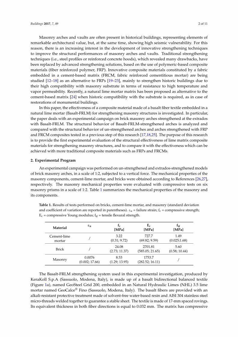
Figure 1. (a) Poliparafenilenbenzobisoxazole (PBO) balanced textile; (b) basalt balanced
textile; (c) unidirectional carbon sheet. Dimensions in mm. Figure 1. (a) Poliparafenilenbenzobisoxazole (PBO) balanced textile; (b) basalt balanced textile;(c) unidirectional carbon sheet. Dimensions in mm.
Table 2. Properties of the composite materials provided by the manufacturer. tf = equivalent thickness;ff = fiber tensile strength; Ef = fiber Young modulus; εfu = fiber failure strain fmc = compressive strength;Em = matrix Young modulus; fmtf = tensile flexural strength. (*) Experimentally determined.
CompositeMaterial
FibersMaterial
tf ff Ef εfu MatrixMaterial
fmc Em fmtf[mm] [MPa] [GPa] [%] [MPa] [GPa] [MPa]
Basalt-FRLM Basalt 0.032 ≥3000 ≥87 - Lime 11.2 (*) 1.3 (*) 3.72 (*)
PBO-FRCM PBO 0.014 5800 270 2.5 Cement 20 (*) 2.8 (*) 6.15 (*)
CFRP Carbon 0.17 4800 240 2.00 Epoxy >50 - -
An FRCM composite and an FRP composite produced by Ruredil S.p.A Company (San DonatoMilanese, Milano, Italy) were also considered in this experimental investigation for comparisonpurposes. The FRCM composite, Ruregold® (San Donato Milanese, Milano) XR Muratura, is madeup of a poliparafenilenbenzobisoxazole (PBO) fiber bidirectional balanced textile (Figure 1b) made of14-mm spaced rovings (equivalent thickness 0.014 mm) embedded in a pozzolanic cement-based mortar.The FRP composite, Ruredil X Wrap 310, is made up of a unidirectional carbon sheet with an equivalentthickness 0.17 mm (Figure 1c), impregnated and glued to the substrate through a two-componentepoxy-based matrix. These composites are denoted as PBO-FRCM and CFRP, respectively. Theirproperties are summarized in Table 2.
Experimental tests were carried out on five 1:2 scaled masonry arch models. The arch models hada 1500 mm span, 866 mm intrados radius, 961 mm extrados radius, 432.5 mm rise, and 95 mm × 95 mmcross-section (Figure 2). The dimensions of the bricks and the thickness of the mortar layers werescaled according to the scale of the model. Bricks had dimensions of 95 mm × 46 mm × 21 mm andwere obtained by cutting standard bricks my means of a circular saw with water. The mortar jointswere 5 mm thick. To obtain proper masonry mechanical properties, the compressive tests on masonryprisms, whose results are summarized in Table 1, were performed on specimens made of scaled bricksand thickness of the mortar joints.
Buildings 2017, 7, 49 4 of 11
Buildings 2017, 7, 49 4 of 11
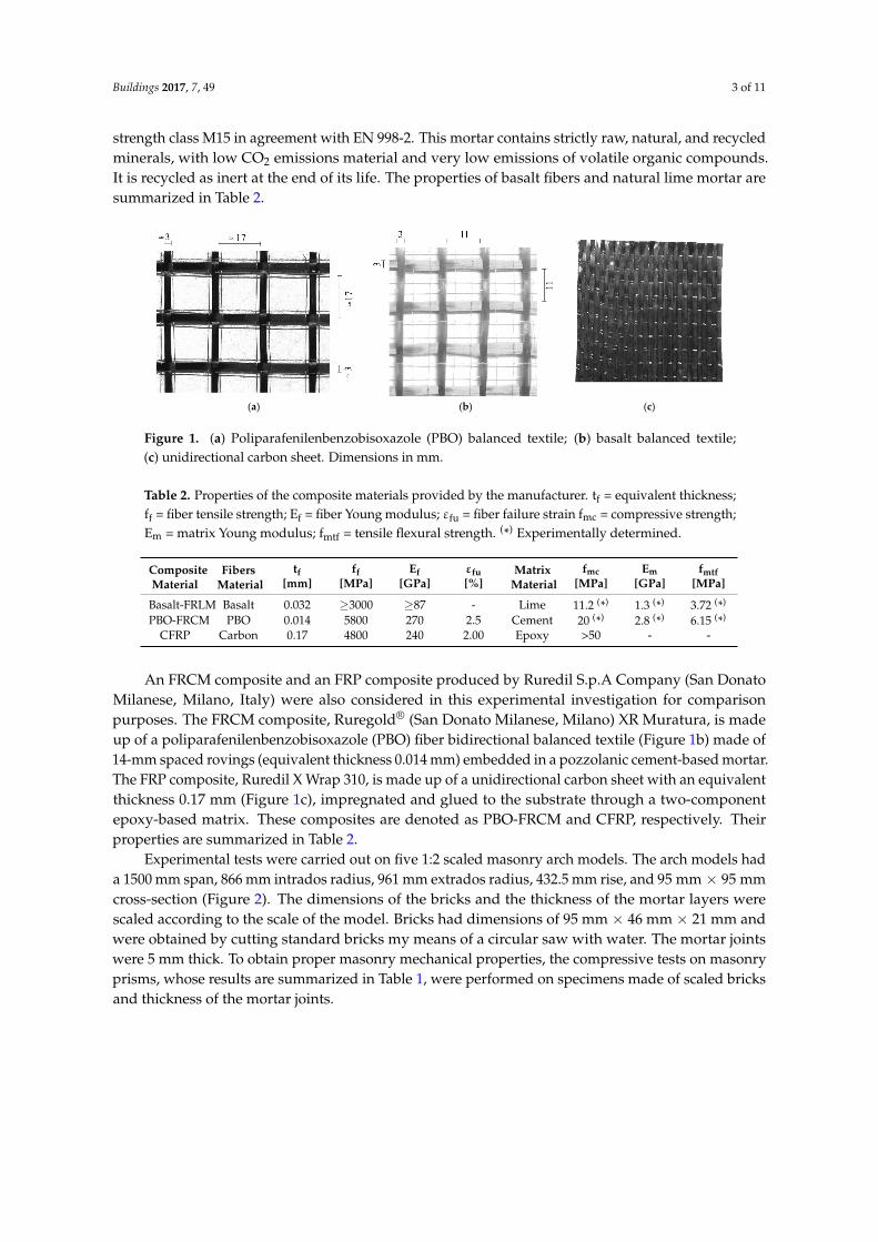
Figure 2. Scheme of the arch model test.
The choice to test 1:2 scaled models was decided by the limited dimension of the steel frame
employed to perform the tests. It was impossible to scale the dimensions of the strengthening
materials in terms of size of the mesh and size of the particles of the matrix, since commercial
composites have been adopted in this study. Furthermore, the scaled models can be considered
representative of masonry arches strengthened with two layers of textile. Two un‐strengthened
(specimens 1‐US and 2‐US) and three strengthened (specimens B‐FRLM, P‐FRCM, and CFRP) arches
were tested. The adopted strengthening configuration consisted of the application of a layer of
composite material on the whole extrados surface of the arches.
The compatibility between the masonry substrate and lime and cement matrices allowed their
application without special treatments. After cleaning and damping the extrados surface, a first 3 mm
thick layer of lime or cement matrix was applied. Subsequently, the textile was applied and finally
another matrix layer of the same thickness was applied. For the CFRP composite, after cleaning the
extrados surface, the classical hand layup procedure was applied; a thin layer of primer was applied
prior to the application of the matrix. Subsequently, the epoxy matrix and the carbon sheet were
applied. Finally, the composite material was completed with the application of a further layer of
epoxy matrix.
Each arch was subjected to a vertical force applied at a quarter of the arch span (375 mm from
one abutment, Figure 2). A displacement control device made of a screw jack controlled through a
flywheel was used to register the loading history, up to the point of a conventional test‐end
corresponding to a residual strength equal to 80% of the maximum load. The load was measured
through a load cell with a capacity of 100 kN (TCLP‐10B tension/compression load cell). Two
displacement transducers (type cantilever) were used to measure vertical displacements. The test
apparatus and arch dimensions are represented in Figure 2.
3. Test Results
The experimental results are summarized in Table 3 in terms of failure load, tangent stiffness,
kinematic ductility, and increase of failure load per unit cross‐sectional area of fibers. The tangent
stiffness is calculated as the slope of the linear phase of the load–displacement curve. The kinematic
ductility is determined as the ratio of the displacement at the failure load to the displacement at the
end of the linear phase of the load–displacement curve. The increase of the failure load per unit cross‐
sectional area of fibers is evaluated as:
f
0maxmax
A
FFf
(1)
where Fmax and Fmax0 are the failure loads of the strengthened and un‐strengthened arches,
respectively, and Af is the cross‐sectional area of the fibers in the composite material. Parameter ∆f is
representative of the strengthening effectiveness of the composite materials in terms of increase of
failure load, while kinematic ductility represents the capacity of the specimen to exhibit
displacements after the linear elastic range, up to the peak load.
Figure 2. Scheme of the arch model test.
The choice to test 1:2 scaled models was decided by the limited dimension of the steel frameemployed to perform the tests. It was impossible to scale the dimensions of the strengthening materialsin terms of size of the mesh and size of the particles of the matrix, since commercial compositeshave been adopted in this study. Furthermore, the scaled models can be considered representativeof masonry arches strengthened with two layers of textile. Two un-strengthened (specimens 1-USand 2-US) and three strengthened (specimens B-FRLM, P-FRCM, and CFRP) arches were tested. Theadopted strengthening configuration consisted of the application of a layer of composite material onthe whole extrados surface of the arches.
The compatibility between the masonry substrate and lime and cement matrices allowed theirapplication without special treatments. After cleaning and damping the extrados surface, a first 3 mmthick layer of lime or cement matrix was applied. Subsequently, the textile was applied and finallyanother matrix layer of the same thickness was applied. For the CFRP composite, after cleaning theextrados surface, the classical hand layup procedure was applied; a thin layer of primer was appliedprior to the application of the matrix. Subsequently, the epoxy matrix and the carbon sheet wereapplied. Finally, the composite material was completed with the application of a further layer ofepoxy matrix.
Each arch was subjected to a vertical force applied at a quarter of the arch span (375 mm from oneabutment, Figure 2). A displacement control device made of a screw jack controlled through a flywheelwas used to register the loading history, up to the point of a conventional test-end corresponding to aresidual strength equal to 80% of the maximum load. The load was measured through a load cell witha capacity of 100 kN (TCLP-10B tension/compression load cell). Two displacement transducers (typecantilever) were used to measure vertical displacements. The test apparatus and arch dimensions arerepresented in Figure 2.
3. Test Results
The experimental results are summarized in Table 3 in terms of failure load, tangent stiffness,kinematic ductility, and increase of failure load per unit cross-sectional area of fibers. The tangentstiffness is calculated as the slope of the linear phase of the load–displacement curve. The kinematicductility is determined as the ratio of the displacement at the failure load to the displacement at theend of the linear phase of the load–displacement curve. The increase of the failure load per unitcross-sectional area of fibers is evaluated as:
∆f =Fmax − Fmax0
Af(1)
where Fmax and Fmax0 are the failure loads of the strengthened and un-strengthened arches, respectively,and Af is the cross-sectional area of the fibers in the composite material. Parameter ∆f is representativeof the strengthening effectiveness of the composite materials in terms of increase of failure load, while
Buildings 2017, 7, 49 5 of 11
kinematic ductility represents the capacity of the specimen to exhibit displacements after the linearelastic range, up to the peak load.
Table 3. Structural parameters identified during tests on arch models.
Specimen Failure Load Tangent Stiffness KinematicDuctility
∆f[N] [N/mm] [N/mm2]
1-US 910 7179 1.85 -2-US 1066 6197 1.11 -
Basalt-FRLM 5366 7200 36.6 1.37PBO-FRCM 4968 16,221 20.32 2.84
CFRP 11,345 10,106 10.93 0.61
3.1. Un-Strengthened Arch Models
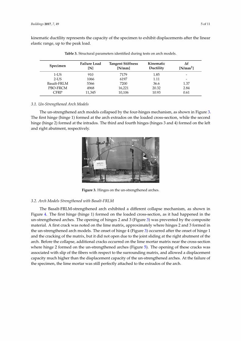
The un-strengthened arch models collapsed by the four-hinges mechanism, as shown in Figure 3.The first hinge (hinge 1) formed at the arch extrados on the loaded cross-section, while the secondhinge (hinge 2) formed at the intrados. The third and fourth hinges (hinges 3 and 4) formed on the leftand right abutment, respectively.
Buildings 2017, 7, 49 5 of 11
Table 3. Structural parameters identified during tests on arch models.
Specimen Failure Load Tangent Stiffness
Kinematic Ductility ∆f
[N] [N/mm] [N/mm2]
1‐US 910 7179 1.85 ‐
2‐US 1066 6197 1.11 ‐
Basalt‐FRLM 5366 7200 36.6 1.37
PBO‐FRCM 4968 16,221 20.32 2.84
CFRP 11,345 10,106 10.93 0.61
3.1. Un‐Strengthened Arch Models
The un‐strengthened arch models collapsed by the four‐hinges mechanism, as shown in Figure
3. The first hinge (hinge 1) formed at the arch extrados on the loaded cross‐section, while the second
hinge (hinge 2) formed at the intrados. The third and fourth hinges (hinges 3 and 4) formed on the
left and right abutment, respectively.
Figure 3. Hinges on the un‐strengthened arches.
3.2. Arch Models Strengthened with Basalt‐FRLM
The Basalt‐FRLM‐strengthened arch exhibited a different collapse mechanism, as shown in
Figure 4. The first hinge (hinge 1) formed on the loaded cross‐section, as it had happened in the un‐
strengthened arches. The opening of hinges 2 and 3 (Figure 3) was prevented by the composite
material. A first crack was noted on the lime matrix, approximately where hinges 2 and 3 formed in
the un‐strengthened arch models. The onset of hinge 4 (Figure 3) occurred after the onset of hinge 1
and the cracking of the matrix, but it did not open due to the joint sliding at the right abutment of the
arch. Before the collapse, additional cracks occurred on the lime mortar matrix near the cross‐section
where hinge 2 formed on the un‐strengthened arches (Figure 5). The opening of these cracks was
associated with slip of the fibers with respect to the surrounding matrix, and allowed a displacement
capacity much higher than the displacement capacity of the un‐strengthened arches. At the failure of
the specimen, the lime mortar was still perfectly attached to the extrados of the arch.
Figure 4. Basalt‐FRLM‐strengthened arch: (a) collapse mechanism; (b) opening of hinge 1; (c) opening
of hinge 4.
Figure 3. Hinges on the un-strengthened arches.
3.2. Arch Models Strengthened with Basalt-FRLM
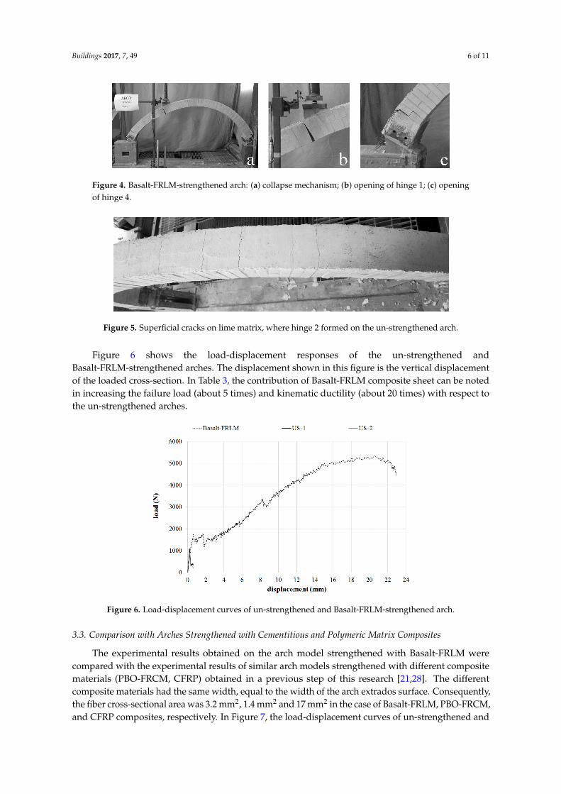
The Basalt-FRLM-strengthened arch exhibited a different collapse mechanism, as shown inFigure 4. The first hinge (hinge 1) formed on the loaded cross-section, as it had happened in theun-strengthened arches. The opening of hinges 2 and 3 (Figure 3) was prevented by the compositematerial. A first crack was noted on the lime matrix, approximately where hinges 2 and 3 formed inthe un-strengthened arch models. The onset of hinge 4 (Figure 3) occurred after the onset of hinge 1and the cracking of the matrix, but it did not open due to the joint sliding at the right abutment of thearch. Before the collapse, additional cracks occurred on the lime mortar matrix near the cross-sectionwhere hinge 2 formed on the un-strengthened arches (Figure 5). The opening of these cracks wasassociated with slip of the fibers with respect to the surrounding matrix, and allowed a displacementcapacity much higher than the displacement capacity of the un-strengthened arches. At the failure ofthe specimen, the lime mortar was still perfectly attached to the extrados of the arch.
Buildings 2017, 7, 49 6 of 11
Buildings 2017, 7, 49 5 of 11
Table 3. Structural parameters identified during tests on arch models.
Specimen Failure Load Tangent Stiffness
Kinematic Ductility ∆f
[N] [N/mm] [N/mm2]
1‐US 910 7179 1.85 ‐
2‐US 1066 6197 1.11 ‐
Basalt‐FRLM 5366 7200 36.6 1.37
PBO‐FRCM 4968 16,221 20.32 2.84
CFRP 11,345 10,106 10.93 0.61
3.1. Un‐Strengthened Arch Models
The un‐strengthened arch models collapsed by the four‐hinges mechanism, as shown in Figure
3. The first hinge (hinge 1) formed at the arch extrados on the loaded cross‐section, while the second
hinge (hinge 2) formed at the intrados. The third and fourth hinges (hinges 3 and 4) formed on the
left and right abutment, respectively.
Figure 3. Hinges on the un‐strengthened arches.
3.2. Arch Models Strengthened with Basalt‐FRLM
The Basalt‐FRLM‐strengthened arch exhibited a different collapse mechanism, as shown in
Figure 4. The first hinge (hinge 1) formed on the loaded cross‐section, as it had happened in the un‐
strengthened arches. The opening of hinges 2 and 3 (Figure 3) was prevented by the composite
material. A first crack was noted on the lime matrix, approximately where hinges 2 and 3 formed in
the un‐strengthened arch models. The onset of hinge 4 (Figure 3) occurred after the onset of hinge 1
and the cracking of the matrix, but it did not open due to the joint sliding at the right abutment of the
arch. Before the collapse, additional cracks occurred on the lime mortar matrix near the cross‐section
where hinge 2 formed on the un‐strengthened arches (Figure 5). The opening of these cracks was
associated with slip of the fibers with respect to the surrounding matrix, and allowed a displacement
capacity much higher than the displacement capacity of the un‐strengthened arches. At the failure of
the specimen, the lime mortar was still perfectly attached to the extrados of the arch.
Figure 4. Basalt‐FRLM‐strengthened arch: (a) collapse mechanism; (b) opening of hinge 1; (c) opening
of hinge 4. Figure 4. Basalt-FRLM-strengthened arch: (a) collapse mechanism; (b) opening of hinge 1; (c) openingof hinge 4.Buildings 2017, 7, 49 6 of 11
Figure 5. Superficial cracks on lime matrix, where hinge 2 formed on the un‐strengthened arch.
Figure 6 shows the load‐displacement responses of the un‐strengthened and Basalt‐FRLM‐
strengthened arches. The displacement shown in this figure is the vertical displacement of the loaded
cross‐section. In Table 3, the contribution of Basalt‐FRLM composite sheet can be noted in increasing
the failure load (about 5 times) and kinematic ductility (about 20 times) with respect to the un‐
strengthened arches.
Figure 6. Load‐displacement curves of un‐strengthened and Basalt‐FRLM‐strengthened arch.
3.3. Comparison with Arches Strengthened with Cementitious and Polymeric Matrix Composites
The experimental results obtained on the arch model strengthened with Basalt‐FRLM were
compared with the experimental results of similar arch models strengthened with different
composite materials (PBO‐FRCM, CFRP) obtained in a previous step of this research [21,28]. The
different composite materials had the same width, equal to the width of the arch extrados surface.
Consequently, the fiber cross‐sectional area was 3.2 mm2, 1.4 mm2 and 17 mm2 in the case of Basalt‐
FRLM, PBO‐FRCM, and CFRP composites, respectively. In Figure 7, the load‐displacement curves of
un‐strengthened and Basalt‐FRLM‐strengthened arches are compared with the load‐displacement
curves of PBO‐FRCM‐ and CFRP‐strengthened arches.
Figure 5. Superficial cracks on lime matrix, where hinge 2 formed on the un-strengthened arch.
Figure 6 shows the load-displacement responses of the un-strengthened andBasalt-FRLM-strengthened arches. The displacement shown in this figure is the vertical displacementof the loaded cross-section. In Table 3, the contribution of Basalt-FRLM composite sheet can be notedin increasing the failure load (about 5 times) and kinematic ductility (about 20 times) with respect tothe un-strengthened arches.
Buildings 2017, 7, 49 6 of 11
Figure 5. Superficial cracks on lime matrix, where hinge 2 formed on the un‐strengthened arch.
Figure 6 shows the load‐displacement responses of the un‐strengthened and Basalt‐FRLM‐
strengthened arches. The displacement shown in this figure is the vertical displacement of the loaded
cross‐section. In Table 3, the contribution of Basalt‐FRLM composite sheet can be noted in increasing
the failure load (about 5 times) and kinematic ductility (about 20 times) with respect to the un‐
strengthened arches.
Figure 6. Load‐displacement curves of un‐strengthened and Basalt‐FRLM‐strengthened arch.
3.3. Comparison with Arches Strengthened with Cementitious and Polymeric Matrix Composites
The experimental results obtained on the arch model strengthened with Basalt‐FRLM were
compared with the experimental results of similar arch models strengthened with different
composite materials (PBO‐FRCM, CFRP) obtained in a previous step of this research [21,28]. The
different composite materials had the same width, equal to the width of the arch extrados surface.
Consequently, the fiber cross‐sectional area was 3.2 mm2, 1.4 mm2 and 17 mm2 in the case of Basalt‐
FRLM, PBO‐FRCM, and CFRP composites, respectively. In Figure 7, the load‐displacement curves of
un‐strengthened and Basalt‐FRLM‐strengthened arches are compared with the load‐displacement
curves of PBO‐FRCM‐ and CFRP‐strengthened arches.
Figure 6. Load-displacement curves of un-strengthened and Basalt-FRLM-strengthened arch.
3.3. Comparison with Arches Strengthened with Cementitious and Polymeric Matrix Composites
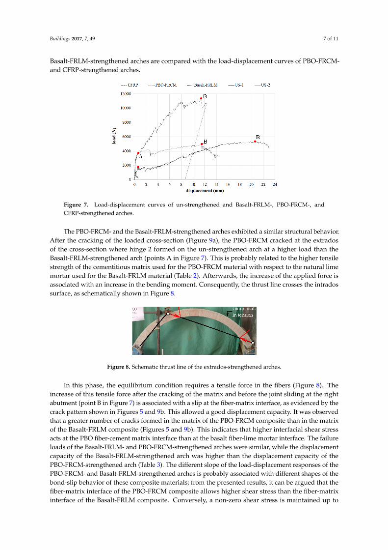
The experimental results obtained on the arch model strengthened with Basalt-FRLM werecompared with the experimental results of similar arch models strengthened with different compositematerials (PBO-FRCM, CFRP) obtained in a previous step of this research [21,28]. The differentcomposite materials had the same width, equal to the width of the arch extrados surface. Consequently,the fiber cross-sectional area was 3.2 mm2, 1.4 mm2 and 17 mm2 in the case of Basalt-FRLM, PBO-FRCM,and CFRP composites, respectively. In Figure 7, the load-displacement curves of un-strengthened and
Buildings 2017, 7, 49 7 of 11
Basalt-FRLM-strengthened arches are compared with the load-displacement curves of PBO-FRCM-and CFRP-strengthened arches.
Buildings 2017, 7, 49 7 of 11
Figure 7. Load‐displacement curves of un‐strengthened and Basalt‐FRLM‐, PBO‐FRCM‐, and CFRP‐
strengthened arches.
The PBO‐FRCM‐ and the Basalt‐FRLM‐strengthened arches exhibited a similar structural
behavior. After the cracking of the loaded cross‐section (Figure 9a), the PBO‐FRCM cracked at the
extrados of the cross‐section where hinge 2 formed on the un‐strengthened arch at a higher load than
the Basalt‐FRLM‐strengthened arch (points A in Figure 7). This is probably related to the higher
tensile strength of the cementitious matrix used for the PBO‐FRCM material with respect to the
natural lime mortar used for the Basalt‐FRLM material (Table 2). Afterwards, the increase of the
applied force is associated with an increase in the bending moment. Consequently, the thrust line
crosses the intrados surface, as schematically shown in Figure 8.
Figure 8. Schematic thrust line of the extrados‐strengthened arches.
In this phase, the equilibrium condition requires a tensile force in the fibers (Figure 8). The
increase of this tensile force after the cracking of the matrix and before the joint sliding at the right
abutment (point B in Figure 7) is associated with a slip at the fiber‐matrix interface, as evidenced by
the crack pattern shown in Figures 5 and 9b. This allowed a good displacement capacity. It was
observed that a greater number of cracks formed in the matrix of the PBO‐FRCM composite than in
the matrix of the Basalt‐FRLM composite (Figures 5 and 9b). This indicates that higher interfacial
shear stress acts at the PBO fiber‐cement matrix interface than at the basalt fiber‐lime mortar interface.
The failure loads of the Basalt‐FRLM‐ and PBO‐FRCM‐strengthened arches were similar, while the
displacement capacity of the Basalt‐FRLM‐strengthened arch was higher than the displacement
capacity of the PBO‐FRCM‐strengthened arch (Table 3). The different slope of the load‐displacement
responses of the PBO‐FRCM‐ and Basalt‐FRLM‐strengthened arches is probably associated with
different shapes of the bond‐slip behavior of these composite materials; from the presented results,
it can be argued that the fiber‐matrix interface of the PBO‐FRCM composite allows higher shear stress
than the fiber‐matrix interface of the Basalt‐FRLM composite. Conversely, a non‐zero shear stress is
maintained up to larger fiber‐matrix slip in the case of the Basalt‐FRLM composite than in the case of
the PBO‐FRCM composite. This statement needs to be confirmed by the results of shear bond tests to
be performed on the Basalt‐FRLM composite, while the bond behavior of the PBO‐FRCM composite
Figure 7. Load-displacement curves of un-strengthened and Basalt-FRLM-, PBO-FRCM-, andCFRP-strengthened arches.
The PBO-FRCM- and the Basalt-FRLM-strengthened arches exhibited a similar structural behavior.After the cracking of the loaded cross-section (Figure 9a), the PBO-FRCM cracked at the extradosof the cross-section where hinge 2 formed on the un-strengthened arch at a higher load than theBasalt-FRLM-strengthened arch (points A in Figure 7). This is probably related to the higher tensilestrength of the cementitious matrix used for the PBO-FRCM material with respect to the natural limemortar used for the Basalt-FRLM material (Table 2). Afterwards, the increase of the applied force isassociated with an increase in the bending moment. Consequently, the thrust line crosses the intradossurface, as schematically shown in Figure 8.
Buildings 2017, 7, 49 7 of 11
Figure 7. Load‐displacement curves of un‐strengthened and Basalt‐FRLM‐, PBO‐FRCM‐, and CFRP‐
strengthened arches.
The PBO‐FRCM‐ and the Basalt‐FRLM‐strengthened arches exhibited a similar structural
behavior. After the cracking of the loaded cross‐section (Figure 9a), the PBO‐FRCM cracked at the
extrados of the cross‐section where hinge 2 formed on the un‐strengthened arch at a higher load than
the Basalt‐FRLM‐strengthened arch (points A in Figure 7). This is probably related to the higher
tensile strength of the cementitious matrix used for the PBO‐FRCM material with respect to the
natural lime mortar used for the Basalt‐FRLM material (Table 2). Afterwards, the increase of the
applied force is associated with an increase in the bending moment. Consequently, the thrust line
crosses the intrados surface, as schematically shown in Figure 8.
Figure 8. Schematic thrust line of the extrados‐strengthened arches.
In this phase, the equilibrium condition requires a tensile force in the fibers (Figure 8). The
increase of this tensile force after the cracking of the matrix and before the joint sliding at the right
abutment (point B in Figure 7) is associated with a slip at the fiber‐matrix interface, as evidenced by
the crack pattern shown in Figures 5 and 9b. This allowed a good displacement capacity. It was
observed that a greater number of cracks formed in the matrix of the PBO‐FRCM composite than in
the matrix of the Basalt‐FRLM composite (Figures 5 and 9b). This indicates that higher interfacial
shear stress acts at the PBO fiber‐cement matrix interface than at the basalt fiber‐lime mortar interface.
The failure loads of the Basalt‐FRLM‐ and PBO‐FRCM‐strengthened arches were similar, while the
displacement capacity of the Basalt‐FRLM‐strengthened arch was higher than the displacement
capacity of the PBO‐FRCM‐strengthened arch (Table 3). The different slope of the load‐displacement
responses of the PBO‐FRCM‐ and Basalt‐FRLM‐strengthened arches is probably associated with
different shapes of the bond‐slip behavior of these composite materials; from the presented results,
it can be argued that the fiber‐matrix interface of the PBO‐FRCM composite allows higher shear stress
than the fiber‐matrix interface of the Basalt‐FRLM composite. Conversely, a non‐zero shear stress is
maintained up to larger fiber‐matrix slip in the case of the Basalt‐FRLM composite than in the case of
the PBO‐FRCM composite. This statement needs to be confirmed by the results of shear bond tests to
be performed on the Basalt‐FRLM composite, while the bond behavior of the PBO‐FRCM composite
Figure 8. Schematic thrust line of the extrados-strengthened arches.
In this phase, the equilibrium condition requires a tensile force in the fibers (Figure 8). Theincrease of this tensile force after the cracking of the matrix and before the joint sliding at the rightabutment (point B in Figure 7) is associated with a slip at the fiber-matrix interface, as evidenced by thecrack pattern shown in Figures 5 and 9b. This allowed a good displacement capacity. It was observedthat a greater number of cracks formed in the matrix of the PBO-FRCM composite than in the matrixof the Basalt-FRLM composite (Figures 5 and 9b). This indicates that higher interfacial shear stressacts at the PBO fiber-cement matrix interface than at the basalt fiber-lime mortar interface. The failureloads of the Basalt-FRLM- and PBO-FRCM-strengthened arches were similar, while the displacementcapacity of the Basalt-FRLM-strengthened arch was higher than the displacement capacity of thePBO-FRCM-strengthened arch (Table 3). The different slope of the load-displacement responses of thePBO-FRCM- and Basalt-FRLM-strengthened arches is probably associated with different shapes of thebond-slip behavior of these composite materials; from the presented results, it can be argued that thefiber-matrix interface of the PBO-FRCM composite allows higher shear stress than the fiber-matrixinterface of the Basalt-FRLM composite. Conversely, a non-zero shear stress is maintained up to
Buildings 2017, 7, 49 8 of 11
larger fiber-matrix slip in the case of the Basalt-FRLM composite than in the case of the PBO-FRCMcomposite. This statement needs to be confirmed by the results of shear bond tests to be performedon the Basalt-FRLM composite, while the bond behavior of the PBO-FRCM composite has beenanalyzed in several papers [14,28–32]. In References [16–18,25], it is shown that the failure load ofstrengthened arches can be analytically evaluated with the approach of the limit analysis. This requiresthe knowledge of the fiber debonding strain, i.e., the fibers strain associated with debonding at thefiber-matrix interface. The debonding strain of PBO-FRCM composites was experimentally determinedby means of shear bond tests [14,28–32], while the debonding strain of the Basalt-FRLM material is notcurrently available. Therefore, the next step of this research work will involve the characterizationof the Basalt-FRLM material in terms of bond behavior and the use of bond properties within theframework of the limit analysis to evaluate the collapse load of the Basalt-FRLM-strengthened arches.
Buildings 2017, 7, 49 8 of 11
has been analyzed in several papers [14,28–32]. In References [16–18,25], it is shown that the failure
load of strengthened arches can be analytically evaluated with the approach of the limit analysis. This
requires the knowledge of the fiber debonding strain, i.e., the fibers strain associated with debonding
at the fiber‐matrix interface. The debonding strain of PBO‐FRCM composites was experimentally
determined by means of shear bond tests [14,28–32], while the debonding strain of the Basalt‐FRLM
material is not currently available. Therefore, the next step of this research work will involve the
characterization of the Basalt‐FRLM material in terms of bond behavior and the use of bond
properties within the framework of the limit analysis to evaluate the collapse load of the Basalt‐
FRLM‐strengthened arches.
Figure 9. PBO‐FRCM‐strengthened arch: (a) hinge 1; (b) cracks in cementitious mortar matrix; (c) joint
sliding at the right abutment [16].
The CFRP‐strengthened arch exhibited brittle behavior. After the formation of the first hinge on
the loaded cross‐section and the cracking of the masonry where hinge 2 formed on the un‐
strengthened arch, the force in the fibers increased. This required lower interfacial slip than in the
case of the PBO‐FRCM and Basalt‐FRLM composites, since the debonding phenomenon of FRP‐
masonry joints is associated with the formation of an interfacial crack within the supporting masonry
[33–36]. The collapse was caused by the sudden shear sliding at the right abutment (Figure 10c). The
collapse load of the CFRP‐strengthened arch was roughly twice the collapse load of the PBO‐FRCM‐
and Basalt‐FRLM‐strengthened arches. Conversely, the load‐displacement response of the CFRP‐
strengthened arch showed lower displacement capacity than the PBO‐FRCM‐ and Basalt‐FRLM‐
strengthened arches.
Figure 10. CFRP‐strengthened arch: (a) hinge 1; (b) opening of hinge 2; (c) joint sliding at the right
abutment.
A comparison of the specific effectiveness of the strengthening of the composite materials
considered in this experimental work can be performed considering the parameter ∆f defined by
Equation (1) (Table 3). ∆f is representative of the strengthening effectiveness of the composite
materials even though the collapse of the arches was always associated with the shear force, since the
composite materials bonded on the surface of an arch produces an increase in both the flexural and
shear capacity of the strengthened cross‐sections, as observed in References [17,25]. It can be observed
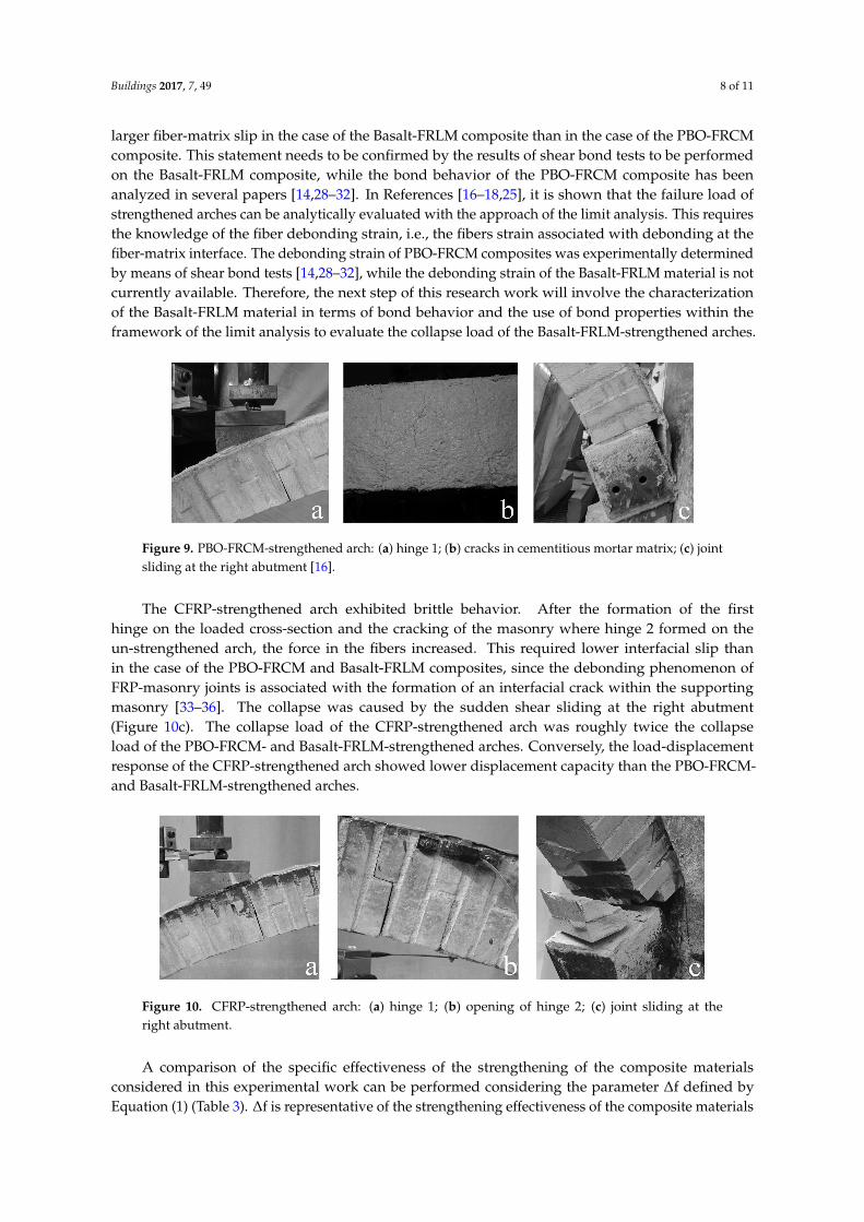
Figure 9. PBO-FRCM-strengthened arch: (a) hinge 1; (b) cracks in cementitious mortar matrix; (c) jointsliding at the right abutment [16].
The CFRP-strengthened arch exhibited brittle behavior. After the formation of the firsthinge on the loaded cross-section and the cracking of the masonry where hinge 2 formed on theun-strengthened arch, the force in the fibers increased. This required lower interfacial slip thanin the case of the PBO-FRCM and Basalt-FRLM composites, since the debonding phenomenon ofFRP-masonry joints is associated with the formation of an interfacial crack within the supportingmasonry [33–36]. The collapse was caused by the sudden shear sliding at the right abutment(Figure 10c). The collapse load of the CFRP-strengthened arch was roughly twice the collapseload of the PBO-FRCM- and Basalt-FRLM-strengthened arches. Conversely, the load-displacementresponse of the CFRP-strengthened arch showed lower displacement capacity than the PBO-FRCM-and Basalt-FRLM-strengthened arches.
Buildings 2017, 7, 49 8 of 11
has been analyzed in several papers [14,28–32]. In References [16–18,25], it is shown that the failure
load of strengthened arches can be analytically evaluated with the approach of the limit analysis. This
requires the knowledge of the fiber debonding strain, i.e., the fibers strain associated with debonding
at the fiber‐matrix interface. The debonding strain of PBO‐FRCM composites was experimentally
determined by means of shear bond tests [14,28–32], while the debonding strain of the Basalt‐FRLM
material is not currently available. Therefore, the next step of this research work will involve the
characterization of the Basalt‐FRLM material in terms of bond behavior and the use of bond
properties within the framework of the limit analysis to evaluate the collapse load of the Basalt‐
FRLM‐strengthened arches.
10
Figure 9. PBO‐FRCM‐strengthened arch: (a) hinge 1; (b) cracks in cementitious mortar matrix; (c) joint
sliding at the right abutment [16].
The CFRP‐strengthened arch exhibited brittle behavior. After the formation of the first hinge on
the loaded cross‐section and the cracking of the masonry where hinge 2 formed on the un‐
strengthened arch, the force in the fibers increased. This required lower interfacial slip than in the
case of the PBO‐FRCM and Basalt‐FRLM composites, since the debonding phenomenon of FRP‐
masonry joints is associated with the formation of an interfacial crack within the supporting masonry
[33–36]. The collapse was caused by the sudden shear sliding at the right abutment (Figure 10c). The
collapse load of the CFRP‐strengthened arch was roughly twice the collapse load of the PBO‐FRCM‐
and Basalt‐FRLM‐strengthened arches. Conversely, the load‐displacement response of the CFRP‐
strengthened arch showed lower displacement capacity than the PBO‐FRCM‐ and Basalt‐FRLM‐
strengthened arches.
Figure 10. CFRP‐strengthened arch: (a) hinge 1; (b) opening of hinge 2; (c) joint sliding at the right
abutment.
A comparison of the specific effectiveness of the strengthening of the composite materials
considered in this experimental work can be performed considering the parameter ∆f defined by
Equation (1) (Table 3). ∆f is representative of the strengthening effectiveness of the composite
materials even though the collapse of the arches was always associated with the shear force, since the
composite materials bonded on the surface of an arch produces an increase in both the flexural and
shear capacity of the strengthened cross‐sections, as observed in References [17,25]. It can be observed
Figure 10. CFRP-strengthened arch: (a) hinge 1; (b) opening of hinge 2; (c) joint sliding at theright abutment.
A comparison of the specific effectiveness of the strengthening of the composite materialsconsidered in this experimental work can be performed considering the parameter ∆f defined byEquation (1) (Table 3). ∆f is representative of the strengthening effectiveness of the composite materials
Buildings 2017, 7, 49 9 of 11
even though the collapse of the arches was always associated with the shear force, since the compositematerials bonded on the surface of an arch produces an increase in both the flexural and shear capacityof the strengthened cross-sections, as observed in References [17,25]. It can be observed that theincrease of the collapse load associated with a unit fiber cross-section is higher for the PBO-FRCM andBasalt-FRLM composites with respect to the CFRP composite.
4. Conclusions
This paper concerns a preliminary study on the effectiveness of a composite material made ofbasalt textile and lime-based mortar matrix (Basalt-FRLM) for strengthening masonry structures.The structural behavior of arches strengthened at the extrados with Basalt-FRLM is experimentallyevaluated. The results obtained highlight the effectiveness of the Basalt-FRLM composite; themaximum load and kinematic ductility results highly increased with respect to the un-strengthenedarches (about 5 and about 20 times, respectively).
The Basalt-FRLM-strengthened arch exhibited similar failure load to and higher ductilitythan a similar arch strengthened with a composite material made of PBO fibers embedded in acement-based matrix (PBO-FRCM). The different displacement capacity of the Basalt-FRLM- andPBO-FRCM-strengthened arches can be associated with the different fiber-matrix bond properties ofthese composite materials and to the lower elastic modulus of the basalt fibers with respect to carbonfibers. Furthermore, the Basalt-FRLM- and PBO-FRCM-strengthened arches exhibited a lower (roughlyhalf) failure load than a similar arch strengthened with a carbon fiber reinforced polymer (CFRP)composite. This can be associated with the higher cross-sectional area of fibers in the CFRP compositethan in the Basalt-FRCM composite (roughly 5 times) and PBO-FRCM composite (roughly 12 times).
The presented preliminary experimental results encourage further research on the use of theBasalt-FRCM composite for strengthening masonry structures, especially in terms of characterizationof the basalt fibers-lime mortar bond properties, since the tests highlighted the excellent adhesion atthe masonry-lime matrix interface.
The use of this type of composite is of interest to applications aimed at strengtheninghistorical and monumental buildings where the historical compatibility with the substrate is strictlyrequired. Moreover, the tested strengthening system responds to the increasing requirements ofsustainable interventions.
Author Contributions: All the Authors contributes in the same way to the research.
Conflicts of Interest: The authors declare no conflict of interest.
References
1. Giresini, L.; Sassu, M. Horizontally restrained rocking blocks: evaluation of the role of boundary conditionswith static and dynamic approaches. Bull. Earthq. Eng. 2016, 15, 385–410. [CrossRef]
2. Giresini, L.; Fragiacomo, M.; Sassu, M. Rocking analysis of masonry walls interacting with roofs. Eng. Struct.2016, 116, 107–120. [CrossRef]
3. D’Ambrisi, A.; Feo, L.; Focacci, F. Masonry arches strengthened with composite unbonded tendons. Compos.Struct. 2013, 98, 323–329. [CrossRef]
4. Foraboschi, P. Resisting system and failure modes of masonry domes. Eng. Fail. Anal. 2014, 44, 315–337.[CrossRef]
5. Foraboschi, P.; Vanin, A. Non-linear static analysis of masonry buildings based on a strut-and-tie modeling.Soil Dyn. Earthq. Eng. 2013, 55, 44–58. [CrossRef]
6. Misseri, G.; Rovero, L. Parametric investigation on the dynamic behaviour of masonry pointed arches. Arch.Appl. Mech. 2017, 87, 385–404. [CrossRef]
7. Giresini, L. Energy-based method for identifying vulnerable macro-elements in historic masonry churches.Bull. Earthq. Eng. 2015, 14, 919–942. [CrossRef]
8. Andreini, M; De Falco, A.; Giresini, L.; Sassu, M. Structural damage in the cities of Reggiolo and Carpi afterthe earthquake on May 2012 in Emilia Romagna. Bull. Earthq. Eng. 2014, 12, 2445–2480. [CrossRef]
Buildings 2017, 7, 49 10 of 11
9. Andreini, M.; De Falco, A.; Giresini, L.; Sassu, M. Structural analysis and consolidation strategy of thehistoric Mediceo Aqueduct in Pisa (Italy). Appl. Mech. Mater. 2013, 351–352, 1354–1357. [CrossRef]
10. De Falco, A.; Giresini, L.; Sassu, M. Temporary preventive seismic reinforcements on historic churches:Numerical modeling of San Frediano in Pisa. Appl. Mech. Mater. 2013, 352, 1393–1396. [CrossRef]
11. Giresini, L.; Sassu, M. Tests Results and Simple Structural Analysis of the Main Lighthouse in the Harbor ofLivorno (Italy). Adv. Mater. Res. 2014, 834, 1299–1303. [CrossRef]
12. Larrinaga, P.; Chastre, C.; San-José, J.T.; Garmendia, L. Non-linear analytical model of composites based onbasalt textile reinforced mortar under uniaxial tension. Compos. Part B Eng. 2013, 55, 518–527. [CrossRef]
13. Prota, A.; Marcari, G.; Fabbrocino, G.; Manfredi, G.; Aldea, C. Experimental In-Plane Behavior of TuffMasonry Strengthened with Cementitious Matrix–Grid Composites. J. Compos. Constr. 2006, 10, 223–233.[CrossRef]
14. Alecci, V.; De Stefano, M.; Luciano, R.; Rovero, L.; Stipo, G. Experimental Investigation on Bond Behaviorof Cement-Matrix–Based Composites for Strengthening of Masonry Structures. J. Compos. Constr. 2015, 20,04015041. [CrossRef]
15. Garmendia, L.; Larrinaga, P.; San-Mateos, R.; San-José, J.T. Strengthening masonry vaults with organic andinorganic composites: an experimental approach. Mater. Des. 2015, 85, 102–114. [CrossRef]
16. D’Ambrisi, A.; Focacci, F.; Luciano, R.; Alecci, V.; De Stefano, M. Carbon-FRCM materials for structuralupgrade of masonry arch road bridges. Compos. Part B Eng. 2015, 75, 355–366. [CrossRef]
17. Alecci, V.; Focacci, F.; Rovero, L.; Stipo, G.; De Stefano, M. Extrados strengthening of brick masonry archeswith PBO-FRCM composites: Experimental and analytical investigations. Compos. Struct. 2016, 149, 184–196.[CrossRef]
18. Alecci, V.; Misseri, G.; Rovero, L.; Stipo, G.; De Stefano, M.; Feo, L.; Luciano, R. Experimental investigationon masonry arches strengthened with PBO-FRCM composite. Compos. Part B Eng. 2016, 100, 228–239.[CrossRef]
19. Rovero, L.; Focacci, F.; Stipo, G. Structural behavior of arch models strengthened using FRP strips of differentlengths. J. Compos. Constr. 2013, 17, 249–258. [CrossRef]
20. Briccoli Bati, S.; Rovero, L.; Tonietti, U. Strengthening of masonry arches with composite materials. J. Compos.Mater. 2007, 11, 33–42. [CrossRef]
21. Briccoli Bati, S.; Rovero, L. Towards a methodology for estimating strength and collapse mechanism inmasonry arches strengthened with fibre reinforced polymer applied on external surfaces. Mater. Struct. 2008,41, 1291–1306. [CrossRef]
22. Rotunno, T.; Rovero, L.; Tonietti, U.; Briccoli Bati, S. Experimental study of bond behavior of CFRP-to-brickjoints. J. Compos. Constr. 2015, 19, 04014063. [CrossRef]
23. Alecci, V.; Briccoli Bati, S.; Ranocchiai, G. Study of brickwork columns confined with CFRP composite.J. Compos. Constr. 2009, 13, 179–187. [CrossRef]
24. De Felice, G.; De Santis, S.; Garmendia, L.; Ghiassi, B.; Larrinaga, P.; Lourenco, P.B.; Oliveira, D.V.; Paolacci, F.;Papanicolaou, C.G. Mortar-based systems for externally bonded strengthening of masonry. Mater. Struct.2014, 47, 2021–2037. [CrossRef]
25. Alecci, V.; Focacci, F.; Rovero, L.; Stipo, G.; De Stefano, M. Intrados strengthening of brick masonry archeswith different FRCM composites: experimental and analytical investigations. Compos. Struct. 2017, in press.[CrossRef]
26. UNI EN 1015-11. Methods of Test for Mortar for Masonry—Determination of Flexural and Compressive Strength ofHardened Mortar; European Standard; BSI: London, UK, 2007.
27. UNI EN 772-1. Methods of Test for Masonry Units—Determination of Compressive Strength; European Standard:Milton Keynes, UK, 2011.
28. D’Ambrisi, A.; Feo, L.; Focacci, F. Bond-slip relations for PBO–FRCM materials externally bonded to concrete.Compos. Part B Eng. 2012, 43, 2938–2949. [CrossRef]
29. Caggegi, C.; Carozzi, F.G.; De Santis, S.; Fabbrocino, F.; Focacci, F.; Hojdys, Ł.; Lanoye, E.; Zuccarino, L.Experimental analysis on tensile and bond properties of PBO and aramid fabric reinforced cementitiousmatrix for strengthening masonry structures. Compos Part B Eng. 2017, in press. [CrossRef]
30. Carloni, C.; D’Antino, T.; Sneed, L.; Pellegrino, C. Role of the matrix layers in the stress transfer mechanismof FRCM composites bonded to a concrete substrate. J. Eng. Mech. 2014, 141. [CrossRef]
Buildings 2017, 7, 49 11 of 11
31. D’Antino, T.; Carloni, C.; Sneed, L.H.; Pellegrino, C. Matrix-fiber bond behavior in PBO FRCM composites:A fracture mechanics approach. Eng. Fract. Mech. 2014, 117, 94–111. [CrossRef]
32. Focacci, F.; D’Antino, T.; Carloni, C.; Sneed, L.H.; Pellegrino, C. An indirect method to calibrate the interfacialcohesive material law for FRCM-concrete joints. Mater. Des. 2017, 128, 206–217. [CrossRef]
33. Focacci, F.; Carloni, C. Periodic variation of the transferable load at the FRP-masonry interface. Compos.Struct. 2015, 129, 90–100. [CrossRef]
34. Carloni, C.; Focacci, F. FRP-masonry interfacial debonding: An energy balance approach to determine theinfluence of the mortar joints. Eur. J. Mech.—A/Solids 2016, 55, 122–133. [CrossRef]
35. Malena, M.; Focacci, F.; Carloni, C.; De Felice, G. The effect of the shape of the cohesive material law on thestress transfer at the FRP-masonry interface. Compos. Part B Eng. 2017, 110, 368–380. [CrossRef]
36. Foraboschi, P. Effectiveness of novel methods to increase the FRP-masonry bond capacity. Compos. Part BEng. 2016, 107, 214–232. [CrossRef]
© 2017 by the authors. Licensee MDPI, Basel, Switzerland. This article is an open accessarticle distributed under the terms and conditions of the Creative Commons Attribution(CC BY) license (http://creativecommons.org/licenses/by/4.0/).


