Embed Size (px)
Citation preview
9th International Masonry Conference 2014 in Guimarães
9th
International Masonry Conference, Guimarães 2014 1
Hollowed clay brick masonry elements with chases: behaviour under compression
VICENTE, ROMEU1; VARUM, HUMBERTO2; FIGUEIREDO, ANTÓNIO3; FERREIRA, TIAGO M.4, MENDES DA SILVA, J.A.R.
ABSTRACT: For all types of masonry wall construction, no matter the brick or block material, the
cutting of chases in order to accommodate electrical cables, piping and other installations is a common practice. In many situations, the cutting of chases in masonry is carried out indiscriminately and with no respect for maximum dimensions and adequate mortar filling. Thus, with this research paper it will be exposed and thoroughly evaluated and discussed the mechanical behaviour of hollowed clay brick masonry walls with chase cutting, within the limits of the Eurocode 6. Therefore, an experimental campaign over twelve wall specimens was carried out, in which the shape and direction of the chase differs (horizontal, vertical and inclined) all with the same depth and width. After the cutting of the chases, it was placed a ring tube to simulate a pipeline, and later the chase was filled with mortar, leaving one of each specimen type with the chase unfilled. All specimens were fully instrumented and tested under vertical central compression. The results obtained in this experimental campaign are discussed and presented in detail.
Keywords: Masonry, chases, mortar joints, compression, strain, stress, cracking pattern
NOTATION
E youngs modulus Fmax maximum compressive strength σmax maximum compressive stress t wall thickness; tch,h maximum depth of the horizontal or sloped chase; tch,v maximum depth of the vertical chase
1 INTRODUCTION
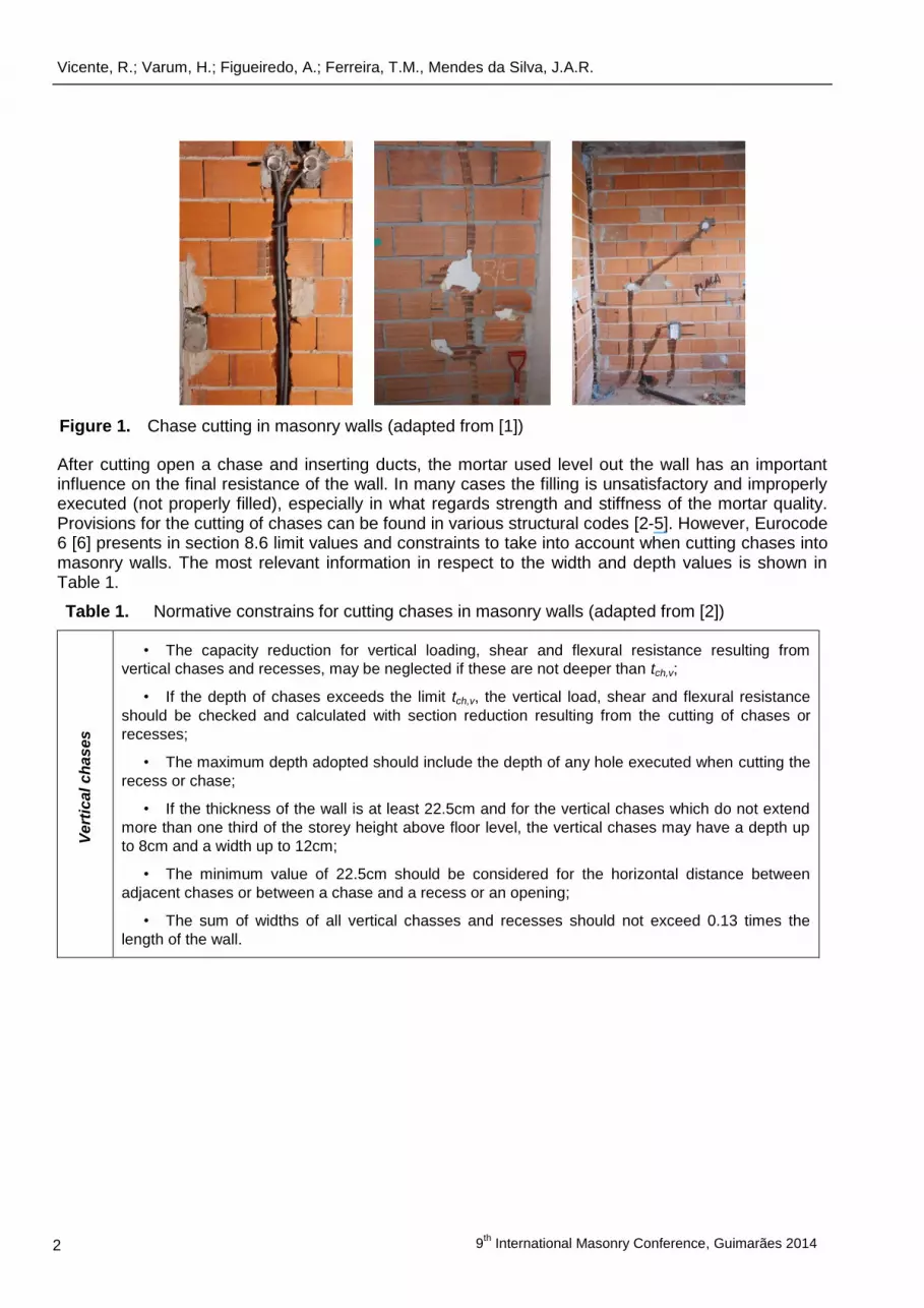
The cutting of chases and recesses in masonry walls for the accommodation of electrical wiring, sewage and water distribution piping, is an ineligible, and sometimes paradoxical reality of building construction. Generally the cutting of chases is vertical or horizontal, but in many cases these are opened indiscriminately and arbitrarily, and unfortunately in some cases have the depth of total wall thickness, destroying completely the wall, compromising strength and leading to cracking (see Figure 1).
1) Assistant Professor, University of Aveiro, Department of Civil Engineering, [email protected]
2) Associate Professor, University of Aveiro, Department of Civil Engineering, [email protected]
3) Researcher, University of Aveiro, Department of Civil Engineering, [email protected]
4) Researcher, University of Aveiro, Department of Civil Engineering, [email protected]
Vicente, R.; Varum, H.; Figueiredo, A.; Ferreira, T.M., Mendes da Silva, J.A.R.
9
th International Masonry Conference, Guimarães 2014 2
After cutting open a chase and inserting ducts, the mortar used level out the wall has an important influence on the final resistance of the wall. In many cases the filling is unsatisfactory and improperly executed (not properly filled), especially in what regards strength and stiffness of the mortar quality. Provisions for the cutting of chases can be found in various structural codes [2-5]. However, Eurocode 6 [6] presents in section 8.6 limit values and constraints to take into account when cutting chases into masonry walls. The most relevant information in respect to the width and depth values is shown in Table 1.
Table 1. Normative constrains for cutting chases in masonry walls (adapted from [2])
Vert
ical
ch
as
es
• The capacity reduction for vertical loading, shear and flexural resistance resulting from
vertical chases and recesses, may be neglected if these are not deeper than tch,v;
• If the depth of chases exceeds the limit tch,v, the vertical load, shear and flexural resistance
should be checked and calculated with section reduction resulting from the cutting of chases or
recesses;
• The maximum depth adopted should include the depth of any hole executed when cutting the
recess or chase;
• If the thickness of the wall is at least 22.5cm and for the vertical chases which do not extend
more than one third of the storey height above floor level, the vertical chases may have a depth up
to 8cm and a width up to 12cm;
• The minimum value of 22.5cm should be considered for the horizontal distance between
adjacent chases or between a chase and a recess or an opening;
• The sum of widths of all vertical chasses and recesses should not exceed 0.13 times the
length of the wall.
Figure 1. Chase cutting in masonry walls (adapted from [1])
Hollowed clay brick masonry elements with chases: behaviour under compression
9th
International Masonry Conference Guimarães 2014 3
Ho
rizo
nta
l an
d in
cli
ned
ch
ases
• The horizontal and inclined chases should be placed within one eighth of the clear height of
the wall, above or below a floor;
• The total depth of the chase should be less than tch,h, providing that the eccentricity in the
chase region is less than t/3;
• If the limit tch,h, has been exceeded, the vertical load, shear and flexural resistance should be
checked and calculated with section reduction resulting from the chases;
• The maximum depth of the chase adopted should be include the depth of any hole executed
when forming the chase;
• The horizontal distance between the edge of a chase and an opening should not be less than
50cm;
• The horizontal distance between adjacent chases with limited length, on the same side or on
opposite sides of the wall, should be not less than twice the length of the longest chase;
• For walls of thickness greater than 17.5cm, the depth of the chase may be increased by 1cm
if the cutting machine is accurate in cutting to the required depth. For walls with thickness lower than
22.5cm, and if a cutting machine is used, chases may be increased by 1cm deep in both sides of
walls;
• The width of the chase should not exceed half the residual wall thickness.
2 EXPERIMENTAL CAMPAIGN
2.1. Wall specimens
Twelve wall specimens with fired clay horizontally hollowed clay bricks with dimension 30x20x15 (cm) were constructed. Vertical, horizontal and inclined chases were opened only on one side of the wall. Brick laying and chase infill mortar composition formulation is a 1:1:6 (cement:lime:sand). Chase cutting was carried out after the total curing of the wall specimens in laboratory conditions (28 days). The testing campaign approach was based on the EN 1052-1 standard [7]. In order to follow crack development and to measure crack width, the specimens were painted white prior to testing.
2.2.1 Geometry of specimens
Each wall specimen is constituted by six layers of bricks, with mortar bed and head joints of 1 to 1,5cm thick. Each layer is constituted by four bricks, with half bricks at the extremities. The test specimens dimensions were are 122cm (length) and 119cm (height). The walls thickness was about 15cm.
2.2.2 Specimen type
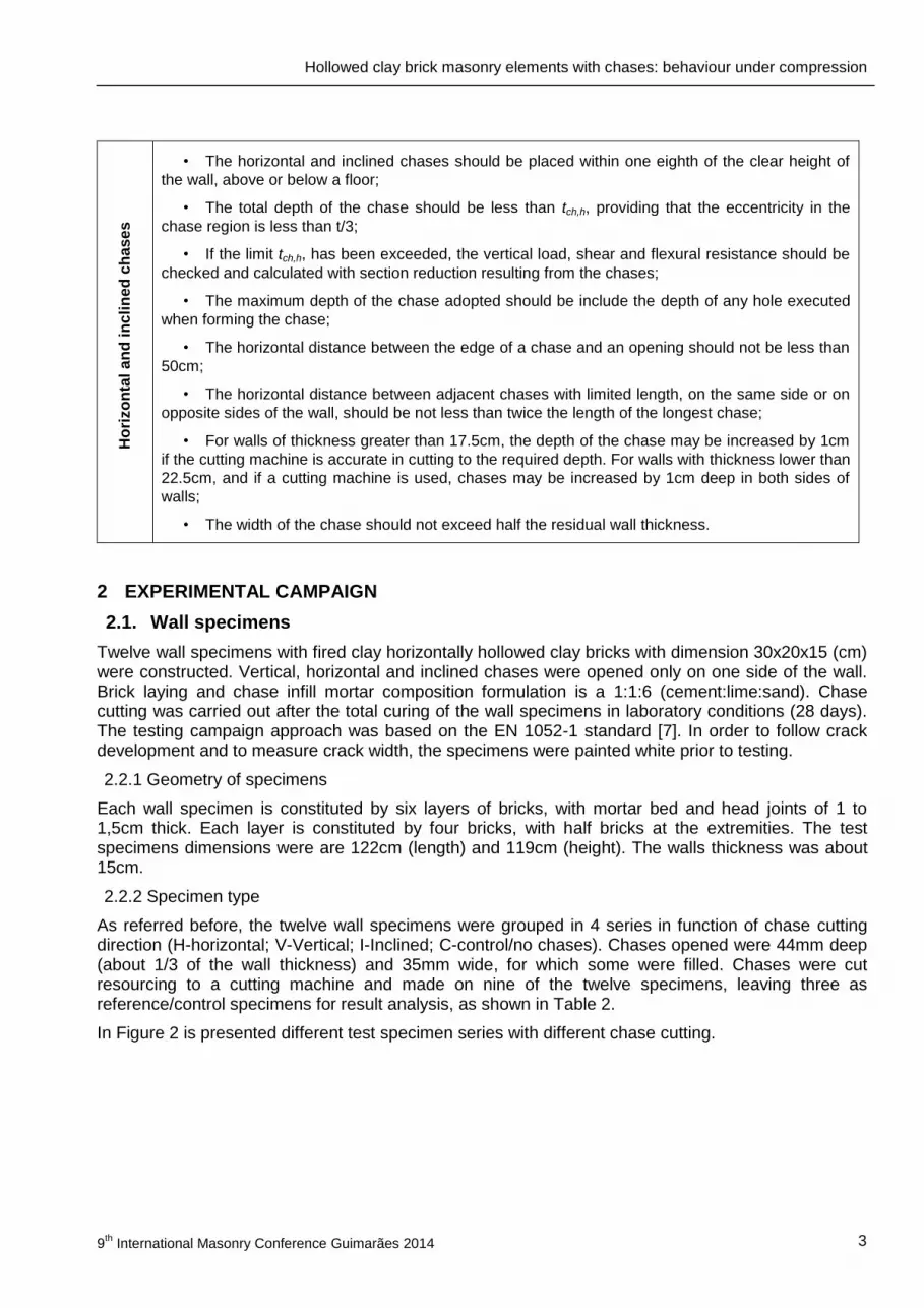
As referred before, the twelve wall specimens were grouped in 4 series in function of chase cutting direction (H-horizontal; V-Vertical; I-Inclined; C-control/no chases). Chases opened were 44mm deep (about 1/3 of the wall thickness) and 35mm wide, for which some were filled. Chases were cut resourcing to a cutting machine and made on nine of the twelve specimens, leaving three as reference/control specimens for result analysis, as shown in Table 2.
In Figure 2 is presented different test specimen series with different chase cutting.

Vicente, R.; Varum, H.; Figueiredo, A.; Ferreira, T.M., Mendes da Silva, J.A.R.
9
th International Masonry Conference, Guimarães 2014 4
Table 2. Specimen series for testing
Type of chase Number of specimen Specimen designation
Control (C) 3 C1; C2; C3
Horizontal (H) 3 H1; H2(f); H3(f)
Vertical (V) 3 V1; V2(f); V3(f)
Inclined (I)5 3 I1; I2(f); I3(f)
(f) – chases filled
(a) Control (C) (b) Horizontal chase (H) (c) Vertical chase (V) (d) Inclined chase (I)
2.2. Testing apparatus and instrumentation
For applying vertical load a hydraulic jack with 300kN capacity was used. A steel HEB 300 spreader beam was linked to the hydraulic jack to assure a distribution of force at the top of the specimen. A high-density membrane and sand layer at the top of the specimen was used to reassure a uniform load distribution and better contact over the specimen. To level out specimen imperfections of the clay bricks, a sand box at the base was used. Figure 3 shows the test apparatus. All measuring devices were connected to a data logger and computer, which processed the data in real time.
(a) (b) (c)
5 slope: tan α = 2/3
Figure 2. Test specimens types
Figure 3. (a) Test setup; (b) Measuring devices – LVDTs; (c) Displacement transducer alignments on specimen surface

Hollowed clay brick masonry elements with chases: behaviour under compression
9th
International Masonry Conference Guimarães 2014 5
Eight LVDTs were used, four on each face – see Figure 3(b) – in order to measure vertical and horizontal movements of the specimens - see Figure 3(c). Based on movement recordings using LVDTs, vertical (V1, V2 e V3) and horizontal (H) strains were determined.
3 TEST RESULTS AND STRUCTURAL BEHAVIOUR
All specimens were tested until failure. Since the aim of the testing campaign was to understand different chase cutting influence over compressive strength and cracking pattern, specimens were compared to the control specimens (without chase cutting). For calculating the failure stress, σmax, EN 1052-01 [3] indications was used and for calculating the Young’s modulus, E, linear regression analysis using the stress-strain data. In Table 3 are indicated ultimate vertical strength load (defined as failure load) and stress values for the three control specimens.
Table 3. Test results: compressive strength for control specimens and maximum vertical stress
Specimen Fmax (kN)
σmax (MPa)
E (GPa)
maximum average
C1 175.01 0.96
1.03 1.10 C2 164.29 0.91
C3 221.93 1.22
3.1. Specimen H1
From the comparison between the values obtained for specimen H1 and the average values obtained for the control specimens (C), it is possible to observe a reduction of 40.41% in strength capacity and an increase of about 6.34% in stiffness. Table 4 presents the results obtained for specimen H1, both in terms of ultimate vertical strength and stress, Youngs modulus and stress-strain curve..
Table 4. Test results for specimen H1
Specimen Fmax (kN) σmax (MPa) E (GPa)
H1 111.51 0.62 1.05
0.0 0.2 0.4 0.6 0.8 1.0 1.2 1.4
0.0
0.2
0.4
0.6
0.8
1.0
1.2
1.4
0.0
0.2
0.4
0.6
0.8
1.0
1.2
1.4
0.0 0.2 0.4 0.6 0.8 1.0 1.2 1.4
Str
ess (
MP
a)
Strain (‰)
Specimens C - Average
Specimen H1
Vicente, R.; Varum, H.; Figueiredo, A.; Ferreira, T.M., Mendes da Silva, J.A.R.
9
th International Masonry Conference, Guimarães 2014 6
Although unfilled horizontal chases are not a usual practice, it is possible to conclude that the cutting of such kind of chases can reduce the compressive strength of the masonry elements and lead to the early onset of cracking.
3.2. Specimens H2 and H3
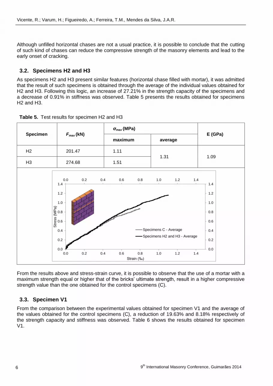
As specimens H2 and H3 present similar features (horizontal chase filled with mortar), it was admitted that the result of such specimens is obtained through the average of the individual values obtained for H2 and H3. Following this logic, an increase of 27.21% in the strength capacity of the specimens and a decrease of 0.91% in stiffness was observed. Table 5 presents the results obtained for specimens H2 and H3.
Table 5. Test results for specimen H2 and H3
Specimen Fmax (kN)
σmax (MPa)
E (GPa)
maximum average
H2 201.47 1.11
1.31 1.09
H3 274.68 1.51
From the results above and stress-strain curve, it is possible to observe that the use of a mortar with a maximum strength equal or higher that of the bricks’ ultimate strength, result in a higher compressive strength value than the one obtained for the control specimens (C).
3.3. Specimen V1
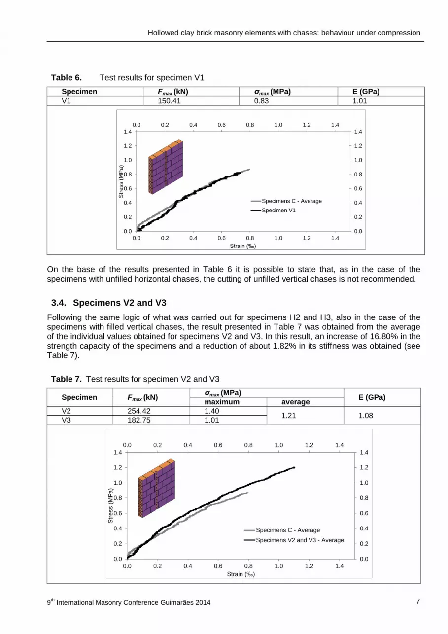
From the comparison between the experimental values obtained for specimen V1 and the average of the values obtained for the control specimens (C), a reduction of 19.63% and 8.18% respectively of the strength capacity and stiffness was observed. Table 6 shows the results obtained for specimen V1.
0.0 0.2 0.4 0.6 0.8 1.0 1.2 1.4
0.0
0.2
0.4
0.6
0.8
1.0
1.2
1.4
0.0
0.2
0.4
0.6
0.8
1.0
1.2
1.4
0.0 0.2 0.4 0.6 0.8 1.0 1.2 1.4
Str
ess (
MP
a)
Strain (‰)
Specimens C - Average
Specimens H2 and H3 - Average
Hollowed clay brick masonry elements with chases: behaviour under compression
9th
International Masonry Conference Guimarães 2014 7
Table 6. Test results for specimen V1
Specimen Fmax (kN) σmax (MPa) E (GPa)
V1 150.41 0.83 1.01
On the base of the results presented in Table 6 it is possible to state that, as in the case of the specimens with unfilled horizontal chases, the cutting of unfilled vertical chases is not recommended.
3.4. Specimens V2 and V3
Following the same logic of what was carried out for specimens H2 and H3, also in the case of the specimens with filled vertical chases, the result presented in Table 7 was obtained from the average of the individual values obtained for specimens V2 and V3. In this result, an increase of 16.80% in the strength capacity of the specimens and a reduction of about 1.82% in its stiffness was obtained (see Table 7).
Table 7. Test results for specimen V2 and V3
Specimen Fmax (kN) σmax (MPa)
E (GPa) maximum average
V2 254.42 1.40 1.21 1.08
V3 182.75 1.01
0.0 0.2 0.4 0.6 0.8 1.0 1.2 1.4
0.0
0.2
0.4
0.6
0.8
1.0
1.2
1.4
0.0
0.2
0.4
0.6
0.8
1.0
1.2
1.4
0.0 0.2 0.4 0.6 0.8 1.0 1.2 1.4
Str
ess (
MP
a)
Strain (‰)
Specimens C - Average
Specimen V1
0.0 0.2 0.4 0.6 0.8 1.0 1.2 1.4
0.0
0.2
0.4
0.6
0.8
1.0
1.2
1.4
0.0
0.2
0.4
0.6
0.8
1.0
1.2
1.4
0.0 0.2 0.4 0.6 0.8 1.0 1.2 1.4
Str
ess (
MP
a)
Strain (‰)
Specimens C - Average
Specimens V2 and V3 - Average
Vicente, R.; Varum, H.; Figueiredo, A.; Ferreira, T.M., Mendes da Silva, J.A.R.
9
th International Masonry Conference, Guimarães 2014 8
The filling of the vertical chases with mortar has not lead to the global weakening of the masonry, a fact that can suggest that this solution can be suitable in the same conditions of this experimental campaign.
3.5. Specimen I1
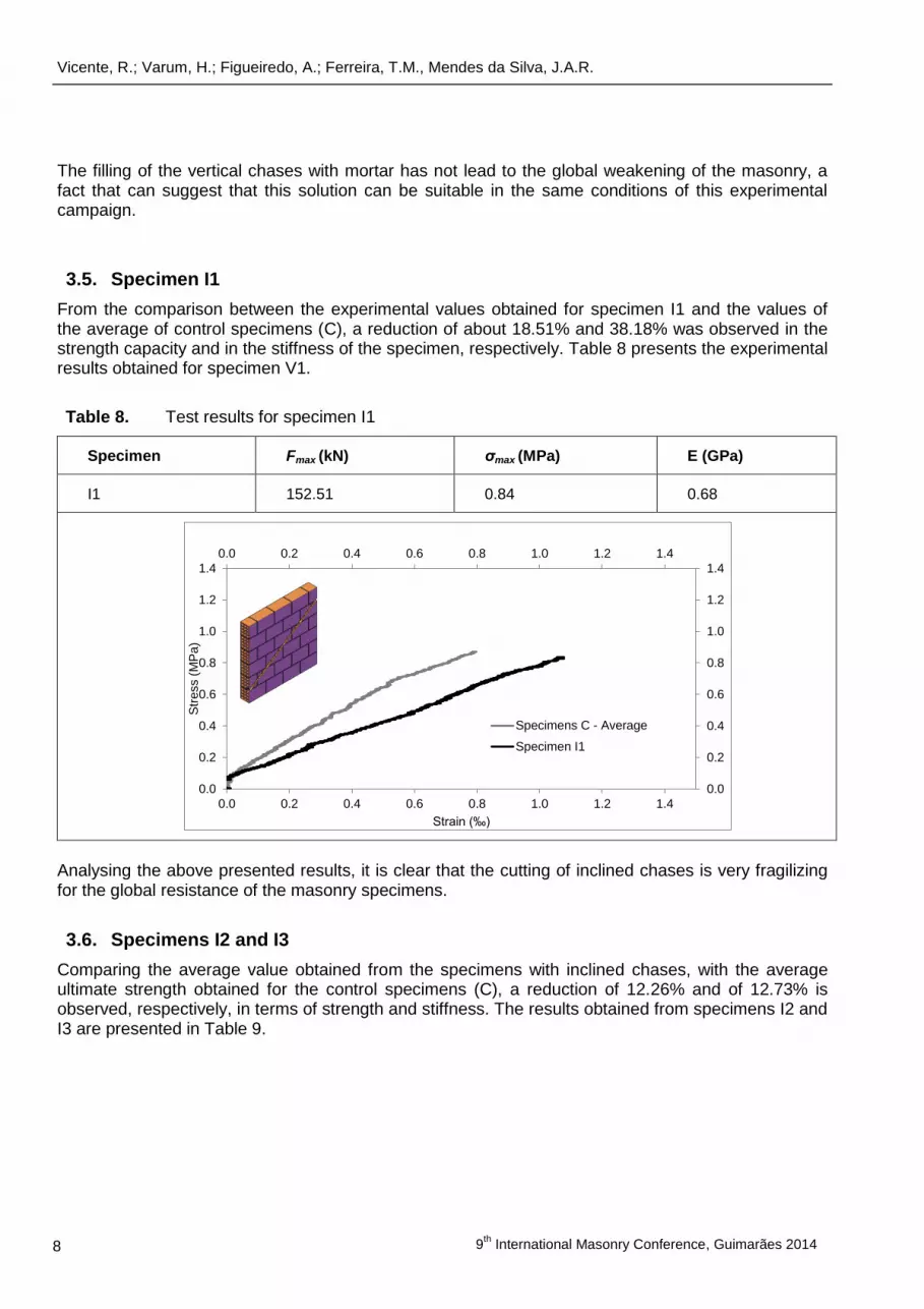
From the comparison between the experimental values obtained for specimen I1 and the values of the average of control specimens (C), a reduction of about 18.51% and 38.18% was observed in the strength capacity and in the stiffness of the specimen, respectively. Table 8 presents the experimental results obtained for specimen V1.
Table 8. Test results for specimen I1
Specimen Fmax (kN) σmax (MPa) E (GPa)
I1 152.51 0.84 0.68
Analysing the above presented results, it is clear that the cutting of inclined chases is very fragilizing for the global resistance of the masonry specimens.
3.6. Specimens I2 and I3
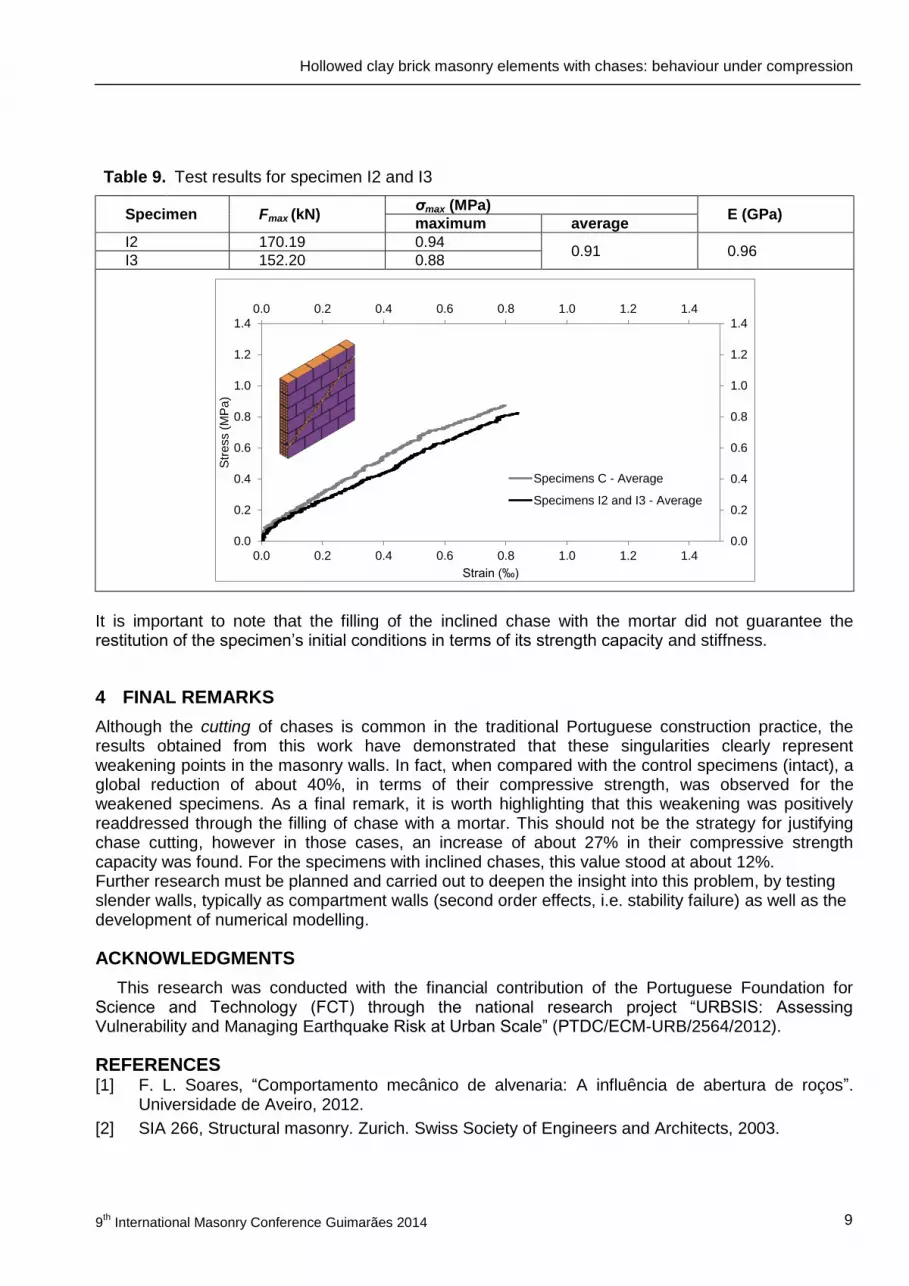
Comparing the average value obtained from the specimens with inclined chases, with the average ultimate strength obtained for the control specimens (C), a reduction of 12.26% and of 12.73% is observed, respectively, in terms of strength and stiffness. The results obtained from specimens I2 and I3 are presented in Table 9.
0.0 0.2 0.4 0.6 0.8 1.0 1.2 1.4
0.0
0.2
0.4
0.6
0.8
1.0
1.2
1.4
0.0
0.2
0.4
0.6
0.8
1.0
1.2
1.4
0.0 0.2 0.4 0.6 0.8 1.0 1.2 1.4
Str
ess (
MP
a)
Strain (‰)
Specimens C - Average
Specimen I1
Hollowed clay brick masonry elements with chases: behaviour under compression
9th
International Masonry Conference Guimarães 2014 9
Table 9. Test results for specimen I2 and I3
Specimen Fmax (kN) σmax (MPa)
E (GPa) maximum average
I2 170.19 0.94 0.91 0.96
I3 152.20 0.88
It is important to note that the filling of the inclined chase with the mortar did not guarantee the restitution of the specimen’s initial conditions in terms of its strength capacity and stiffness.
4 FINAL REMARKS
Although the cutting of chases is common in the traditional Portuguese construction practice, the results obtained from this work have demonstrated that these singularities clearly represent weakening points in the masonry walls. In fact, when compared with the control specimens (intact), a global reduction of about 40%, in terms of their compressive strength, was observed for the weakened specimens. As a final remark, it is worth highlighting that this weakening was positively readdressed through the filling of chase with a mortar. This should not be the strategy for justifying chase cutting, however in those cases, an increase of about 27% in their compressive strength capacity was found. For the specimens with inclined chases, this value stood at about 12%. Further research must be planned and carried out to deepen the insight into this problem, by testing slender walls, typically as compartment walls (second order effects, i.e. stability failure) as well as the development of numerical modelling.
ACKNOWLEDGMENTS
This research was conducted with the financial contribution of the Portuguese Foundation for Science and Technology (FCT) through the national research project “URBSIS: Assessing Vulnerability and Managing Earthquake Risk at Urban Scale” (PTDC/ECM-URB/2564/2012).
REFERENCES [1] F. L. Soares, “Comportamento mecânico de alvenaria: A influência de abertura de roços”.
Universidade de Aveiro, 2012.
[2] SIA 266, Structural masonry. Zurich. Swiss Society of Engineers and Architects, 2003.
0.0 0.2 0.4 0.6 0.8 1.0 1.2 1.4
0.0
0.2
0.4
0.6
0.8
1.0
1.2
1.4
0.0
0.2
0.4
0.6
0.8
1.0
1.2
1.4
0.0 0.2 0.4 0.6 0.8 1.0 1.2 1.4
Str
ess (
MP
a)
Strain (‰)
Specimens C - Average
Specimens I2 and I3 - Average
Vicente, R.; Varum, H.; Figueiredo, A.; Ferreira, T.M., Mendes da Silva, J.A.R.
9
th International Masonry Conference, Guimarães 2014 10
[3] ACI 530-08/ASCE 5-08/TMS 402-08. Building code requirements and specifications for masonry structures. Masonry Standards Joint Committee (MSJC), Boulder/Farmington Hills/Reston, USA, 2008.
[4] AS3700 Masonry structures. Sydney: Standards Australia, 2001.
[5] CSA standard S304.1-04. Design of masonry structures. Canadian Standards, Association, Mississauga, Ontario, Canada, 2004.
[6] CEN, Eurocode 6: Design of Masonry Structures. Part 1-1: Rules for Reinforced and Unreinforced Masonry, European Standard NF EN, Brussels. CEN: Brussels, Belgium, 2005.
[7] NP EN 1052-1:2002, “Métodos de ensaio para alvenaria. Parte 1: Determinação da resistência à compressão.” IPQ, Lisboa, 2002.