Embed Size (px)
Citation preview
www.ijcrt.org © 2021 IJCRT | Volume 9, Issue 6 June 2021 | ISSN: 2320-2882
IJCRT2106599 International Journal of Creative Research Thoughts (IJCRT) www.ijcrt.org f124
Confined Masonry Structure
1Aminullah Mastorst, 2Mr. Mahendra Kumar, 3 Dr. Ravi Kant Pareek 1Research Scholar, 2Supervisor, 3HOD of Civil Engineering Vivekananda Global University
1Department of Structural Engineering, 1Vivekananda Global University, Jaipur, Rajasthan, India
Abstract: The paper elaborates the seismic behavior of a typical masonry building in B&H
built in the 60’s without any seismic guidelines. Numerical modelling has been done in two
different software packages, namely 3MURI AND DAINA. In both approaches, adequate
constitutive assumptions were assumed to take into account the nonlinear behavior of masonry.
Seismic vulnerability has been conducted by performing pushover and time history analyses. A
comparison in terms of dynamic properties, crack pattern and capacity curves was done and a
good agreement has been found between the two software packages. The paper's aim was to
assess the seismic safety of this type of construction. A further objective was to investigate if
simple software packages could be used for the assessment of these buildings. As a wide stock
of this type of buildings is located through the former territory of ex-Yugoslavia, this work
would enable a better understanding of this type of structures and quick overview of their actual
seismic behavior.
Keywords: Masonry, Nonlinear Analysis, B&H Residential Masonry Buildings, Pushover,
Time- History Analysis
1. INTRODUCTION
The vulnerability of Indian constructions in the past earthquakes has been amply demonstrated by the
recent damaging earthquakes. These include not only the non- engineered constructions carried out by
the common man, but also many “engineered” buildings. Addressing this problem requires simultaneous
work on several fronts. On one hand, we need to ensure that more and more constructions comply with
the design and construction requirements of the building codes. On the other hand, we need to develop
and propagate construction typologies that are inherently better in responding to earthquakes.
Construction typologies differ from place to place for various reasons, including availability of local
materials and skills, climatic conditions, living habits and traditions. There have been successful
interventions in the Indian sub-continent towards introducing construction typologies that resists
earthquakes better. For instance, after the 1897 Assam earthquake in India, a new Assam Type Housing
was developed that became prevalent in the entire north-eastern India. Similarly, after the devastating
1935 earthquake in Quetta (Baluchistan), a new type of masonry (Quetta Bond) was evolved. Most houses
of up to four stores in India are built of burnt clay brick masonry with reinforced concrete slab. Depending
on the building and the seismic zone of its location, certain earthquake resistant features are required in
such buildings as per the Indian codes, e.g., the lintel band, corner reinforcement, etc. However, such
aseismic features are often not provided in the buildings due to a variety of reasons. On the other hand, a
number of such buildings in the urban areas now tend to include a number of small reinforced concrete
columns. One could combine these building elements into a rational structural system of “confined
masonry” which will have far better earthquake performance. Similarly, many new four or five story
“reinforced concrete frame” buildings being constructed in small and large towns lack a proper frame
system, and either do not undergo formal structural engineering or undergo inappropriate structural
engineering. Most of the 130 multi-story apartment buildings that collapsed in Ahmedabad in the
2001earthquake fall in this category. Again, it should be possible to construct such apartment buildings
in confine masonry without incurring additional costs and without having to go for newer building
materials.

www.ijcrt.org © 2021 IJCRT | Volume 9, Issue 6 June 2021 | ISSN: 2320-2882
IJCRT2106599 International Journal of Creative Research Thoughts (IJCRT) www.ijcrt.org f125
1.2 Effect on length due to load
Unreinforced masonry (URM) walls are pushed sideways during a strong earthquake, along their length and
thickness directions. When shaken along their length, they develop diagonal cracks along their length and/or
separate at wall junctions. When walls collapse, they bring down the roof along with them. This is the main
reason for large loss of lives during earthquakes that have occurred in different regions of the country.
1.2 Effect on thickness due to load
Unreinforced masonry (URM) walls are pushed sideways during a strong earthquake, along their length
directions. When shaken along their thickness, they collapse. When load applied due to seismic and wind load
on the side towards thickness due to load introduced directly collapse but not having cracks introduced on wall.
Figure 1: Shaking along thickness direction of masonry wall can result in collapse
1.3 Effect of gravity load on confined wall
Its confined masonry also resists gravity load also and not affected to wall these types of load its down ward
side direction when axial load applied on wall in vertical side on gravity direction it resisted by masonry
wall like as dead load, point load wind loads its resisted by confined walls and no cracking due to gravity
load on thickness and length direction and other load act taking walls perpendicular to horizontal surface
towards sides width of confined masonry walls.
1.4 Plane behavior of confined masonry
Confined masonry construction consists of unreinforced masonry walls confined with reinforced concrete
(RC) tie-columns and bond beams. This type of construction is used in urban and rural areas for low rise
buildings in some earthquake prone countries in the world. As reported in the World Housing Encyclopedia,
the following countries use confined masonry in housing construction: Slovenia, Serbia and Montenegro,
Iran, Mexico, Chile, Peru, and Argentina. This type of construction seems to have strength, ductility and
stiffness more than URM. If the confined masonry construction is properly constructed, it is expected to
show satisfactory performance in earthquakes. Based on past studies, the most common modes of failure of
confined
1.4.1 masonry buildings are:
1) Shear cracks in masonry panels that propagate into the tie-columns,
2) Horizontal cracks at the joints between masonry walls and reinforced concrete floors or foundations,
3) Crushing of concrete at the joints between vertical tie columns and horizontal bond-beams
4) cracks in window piers and walls due to in plane and or out of plane action in Inadequately
Figure 1: Shaking along length direction of masonry wall results in diagonal cracking

www.ijcrt.org © 2021 IJCRT | Volume 9, Issue 6 June 2021 | ISSN: 2320-2882
IJCRT2106599 International Journal of Creative Research Thoughts (IJCRT) www.ijcrt.org f126
1.5 Euro code 8 recommendation
a) Euro code 8, denoted in general by EN 1998: “Design of structures for earthquake resistance”,
applies to the design and construction of buildings and civil engineering works in seismic regions. It
covers common structures and, although its provisions are of general validity, special structures, such as
nuclear power plants, large dams or offshore structures are beyond its scope. Its seismic design should
satisfy additional requirements and be subject to complementary verifications. The objectives of seismic
design in accordance with Euro code 8 are explicitly stated. Its purpose is to ensure that in the event of
earthquakes:
a) human lives are protected;
b) damage is limited; and
c) structures important for civil protection remain operational. These objectives are present throughout
the code and condition the principles and application rules there in included.
Euro code 8 is composed by 6 parts dealing with different types of constructions or subjects:
o EN1998-1: General rules, seismic actions and rules for buildings
o EN1998-2: Bridges
o EN1998-3: Assessment and retrofitting of buildings
o EN1998-4: Silos, tanks and pipelines
o EN1998-5: Foundations, retaining structures and geotechnical aspects
o EN1998-6: Towers, masts and chimneys
Out of these parts, Part 1, Part 3 and Part 5 are those relevant to the design of buildings and therefore are
those dealt with in the Workshop.
E. C. Carvalho 6
In particular Part 1 is the leading part since it presents the basic concepts, the definition of the seismic
action and the rules for buildings of different structural materials. Its basic concepts and objectives are
described in the following.
1.5.1 Scope of EN 1998-1
EN 1998-1 (it is noticed that, herein, all references are made to EN 1998-1 published by CEN in 2005) applies to
the design of buildings and civil engineering works in seismic regions and is subdivided into 10 sections: 1
Section 2 contains the basic performance requirements and compliance criteria applicable to buildings and civil
engineering works in seismic regions. 2 Section 3 gives the rules for the representation of seismic actions and for
their combination with other actions.
3 Section 4 contains general design rules relevant specifically to buildings. 4 Sections 5 to 9 contain
specific rules for various structural materials and elements, relevant specifically to buildings (concrete,
steel, composite steel- concrete, timber and masonry buildings).
a) Section 10 contains the fundamental requirements and other relevant aspects of design and safety
related to base isolation of structures and specifically to base isolation of buildings.
3.5.2 Performance requirements and compliance criteria
3.5.2.1 Fundamental requirements
EN 1998-1 asks for a two level seismic design establishing explicitly the two following
requirements:
1.5.1.1 No-collapse requirement
The structure shall be designed and constructed to withstand the design seismic action without local or global
collapse, thus retaining its structural integrity and a residual load bearing capacity after the seismic event.
1.5.1.2 Damage limitation requirement
The structure shall be designed and constructed to withstand a seismic action having a larger probability of
occurrence than the design seismic action, without the occurrence of damage and the associated limitations of use,
the costs of which would be disproportionately high in comparison with the costs of the structure itself.
The first requirement is related to the protection of life under a rare event, through the prevention of the global or
local collapse of the structure that, after the event, should retain its integrity and a sufficient residual load bearing
capacity. After the event the structure may present substantial damages, including permanent drifts, to the point
that it may be economically unrecoverable, but it should be able to protect human life in the evacuation
process or during aftershocks. In the framework of the Eurocodes, that uses the concept of Limit S tates, this
performance requirement is associated with the Ultimate Limit State (ULS) since it deals with the safety of people
or the whole structure.

www.ijcrt.org © 2021 IJCRT | Volume 9, Issue 6 June 2021 | ISSN: 2320-2882
IJCRT2106599 International Journal of Creative Research Thoughts (IJCRT) www.ijcrt.org f127
The second requirement is related to the reduction of economic losses in frequent earthquakes, both in what
concerns structural and non-structural damages. Under such kind of events, the structure should not have
permanent deformations and its elements should retain its original strength and stiffness and hence should not
need structural repair. In view of the minimization of nonstructural damage the structure should have adequate
stiffness to limit, under such frequent events, its deformation to levels that do not cause important damage on such
elements. Some damage to nonstructural elements is acceptable but they should not impose significant limitations
of use and should be repairable economically.
1.5.2 Ultimate limit state
The no-collapse performance level is considered as the Ultimate Limit State in the framework of the Eurocode
“design system”, namely in accordance with EN 1990 – Basis of Design. Satisfaction of this limit state asks for
the verification that the structural system has simultaneously lateral resistance and energy-dissipation capacity.
This recognizes that the fulfilment of the no-collapse requirement does not require that the structure remains
elastic under the design seismic action. On the contrary it allows/accepts the development of significant inelastic
deformations in the structural members, provided that integrity of the structure is kept. It also relies on the (stable)
energy dissipation capacity of the structure to control the build up of energy in the structure resulting from the
seismic energy input that, otherwise, would result in much larger response amplitudes of the structure. Damage
limitation state
As indicated above the performance requirement associated with this Limit State requires the structure to support
a relatively frequent earthquake without significant damage or loss of operationally. Damage is only expected in
nonstructural elements and its occurrence depends on the deformation that the structure, in response to the
earthquake, imposes on such elements. The same essentially applies to the loss of operationally of systems and
networks (although in some equipment’s acceleration may also be relevant to cause damage). Accordingly, an
adequate degree of reliability against unacceptable damage is needed and checks have to be made on the
deformation of the structure and its comparison with deformation limits that depend on the characteristics of the
nonstructural elements. For instance, for buildings EN 1998-1 establishes the following limits to the inters Torey
drift (relative displacement divided by the inters Torey height) due to the frequent earthquake (Serviceabilit y
seismic action):
0,5 % for buildings having non-structural elements of brittle materials attached to the structure:
0,75 % for buildings having ductile non-structural elements:
1,0 % for buildings having non-structural elements fixed in a way so as not to interfere with structural
deformations or without non-structural elements
additional requirements may be imposed in structures important for civil protection so that the function of the
vital services in the facilities is maintained.
3.5.2.5 Specific measures
As indicated in 1.2.2.3 above, EN 1998-1 aims at providing implicitly the satisfaction of a third performance
level that intends to prevent global collapse during a very strong and rare earthquake. This is not achieved by
specific checks for an higher level of the design seismic action but rather by imposing some so called specific
measures to be taken in consideration along the design process. These specific measures, which aim at reducing
the uncertainty of the structural response, indicate that:
To the extent possible, structures should have simple and regular forms both in plan and elevation.
In order to ensure an overall dissipative and ductile behavior, brittle failure or the premature formation of unstable
mechanisms should be avoided. To this end resort is made to capacity design procedures. This is used to obtain a
hierarchy of resistance of the various structural components and of the failure modes necessary for ensuring a
suitable plastic mechanism and for avoiding brittle failure modes.
Special care should be exercised in the design of the regions where nonlinear response is foreseeable since the
seismic performance of a structure is largely dependent on the behavior of these critical regions or elements.
Hence the detailing of the structure in general and of these regions or elements in particular, should aim at ensuring
that it maintains the capacity to transmit the necessary forces and to dissipate energy under cyclic conditions.
The analysis should be based on adequate structural models, which, when necessary, should take into account the
influence of soil deformability and of non- structural elements
The stiffness of the foundations shall be adequate for transmitting the actions received from the superstructure to
the ground as uniformly as possible.
The design documents should be quite detailed and include all relevant information regarding materials
characteristics, sizes of all members, details and special devices to be applied.
1.5.3 Seismic action
The seismic action to be considered for design purposes should be based on the estimation of the ground motion
expected at each location in the future, i.e. it should be based on the hazard assessment.
Seismic hazard is normally represented by hazard curves that depict the exceedance probability of a certain
seismologic parameter (for instance the peak ground acceleration, velocity or displacement) for a given period of
exposure, at a certain location (normally assuming a rock ground condition). It is widely recognized that peak
values of the ground motion parameters (namely the peak ground acceleration) are not good descriptors of the
severity of an earthquake and of its possible consequences on constructions. Hence the more recent trend is to
describe the seismic hazard by the values of the spectral ordinates (at certain key periods in the response spectrum).
In spite of this, for the sake of simplicity, in EN1998-1 the seismic hazard is still described only by the value of
the reference peak ground acceleration on ground type A, (agR). For each country, the seismic hazard is described
by a zonation map defined by the National Authorities. For this purpose, the national territories should be

www.ijcrt.org © 2021 IJCRT | Volume 9, Issue 6 June 2021 | ISSN: 2320-2882
IJCRT2106599 International Journal of Creative Research Thoughts (IJCRT) www.ijcrt.org f128
subdivided into seismic zones, depending on the local hazard. By definition (in the context of EN1998-1) the
hazard within each zone is assumed to be constant i.e. the reference peak ground acceleration is constant.
The reference peak ground acceleration (agR), for each seismic zone, corresponds to the reference return period
TNCR, chosen by the National Authorities for the seismic action for the no-collapse requirement (it is recalled
that, as indicated above, the recommended value is TNCR = 475 years). Hazard maps, from which the zonation
maps result, are derived from attenuation relationships that describe (with empirical expressions) the variation of
the ground motion with the Magnitude (M) and Distance (R) from the source. The attenuation of ag is given by
the expression: log ag 1,48 0,27 M 0,92log R Where M is the Magnitude and R is the epicentral
distance. The expression is valid for 4 < M < 7,3 and for 3 km < R < 200 km.
1.6 Key Factors Influencing Seismic Resistance of Confined Masonry Structures
Confined masonry resistance by key factor those influence resistance of confined masonry details
also given below one by one
1.6.1 Wall density
Wall density is believed to be one of the key parameters influencing the seismic performance of confined masonry
buildings. It can be determined as the transverse area of walls in each principal direction divided by the total floor
area of the building. In Mexico, a simplified procedure was developed to determine the required wall density for
buildings in which the wall seismic resistance is governed by shear effects (Meli, 1994). After the 1985 Mexico
earthquake, the Mexico City Building Code imposed more stringent wall density requirements for masonry
buildings.
These requirements were based on the fact that, due to the reality of Mexican construction practice, it was not
possible to prescribe the use of higher strength materials or the provision of reinforcement as an alternative
approach for increasing earthquake resistance. Therefore, after the 1985 earthquake, the code required a 40%
increase in the design seismic resistance; this resulted in a significant increase in wall density requirements in
confined masonry construction. As an example, for a five-story building in Mexico City, it is now required to
provide wall density of around 6% in each direction, whereas in the areas of highest seismic risk (the State of
Guererro), this value is close to 10%. A diagram showing the wall density requirements in Mexico is presented in
Figure 3.3 (Meli, 1994). A comprehensive study done in Chile after the 1985 Llolleo earthquake showed that the
extent of damage in masonry building related to the wall density in the following way: buildings with a wall
density of less than 0.5% sustained severe damage, while the buildings with wall density of 1.15%
Figure 3: wall density (d) versus the number of stories for confined masonry building on soft soil

www.ijcrt.org © 2021 IJCRT | Volume 9, Issue 6 June 2021 | ISSN: 2320-2882
IJCRT2106599 International Journal of Creative Research Thoughts (IJCRT) www.ijcrt.org f129
sustained only light damage. The survey performed in Chile showed that over 50% of surveyed confined masonry
building have a wall density of over 1.15%. An average wall density for confined masonry buildings in Chile is
estimated to be on the order of 3.3% (Moroni, Astroza, and Acevedo, 2004).
1.6.2 Masonry Units and Mortar
The tests have shown that the lateral load resistance of confined masonry walls strongly depends on the strength
of the masonry units and the mortar used. The walls built using low-strength bricks or Ung routed hollow block
units had the lowest strength while the ones built using grouted or solid units had the largest strength. However,
the use of grouted and solid units results in an increase both in wall mass and seismic loads. Also, the weaker the
mortar the lower the masonry strength (due to the unit-mortar interaction, the masonry strength is always lower
than the unit strength). Test results have also shown that there is no significant difference in strength between
unreinforced and confined masonry wall specimens with the same geometry and material properties.
1.6.3 Tie-Columns
ie-columns significantly influence the ductility and stability of cracked confined masonry walls. Note that the
effect of tie columns on increasing lateral resistance of confined masonry structures has only recently been
recognized (Alcocer, 2006). The provision of closely spaced transverse reinforcement (ties) at the top and bottom
ends of tie-columns results in improved wall stability and ductility in the post-cracking stage (Alcocer and
Klingner, 1994).
1.6.4 Horizontal Wall Reinforcement
In many countries where confined masonry construction is practiced, reinforcement is usually not provided in
masonry walls. However, in four-to-five storey construction in Peru there is a tendency to provide horizontal joint
reinforcement in the form of one or two wires laid in the mortar bed joints (Casabonne, 1994), as shown in Figure
4.
The Mexican Code NTC-M 2004 prescribes that the horizontal reinforcement, when provided, be placed
continuously along the wall length. Horizontal rebars should be anchored into the tie-columns; the anchorage
should be provided with 90o hooks at the far end of the tie-column (see Figure 4). The hooks should be embedded
in the concrete within the tie-column (note that the tie-column reinforcement was omitted from the figure). The
bar diameter should be larger than 3.5 mm and less than ¾ the joint thickness
Figure 2: Horizontal reinforcement in confined masonry walls

www.ijcrt.org © 2021 IJCRT | Volume 9, Issue 6 June 2021 | ISSN: 2320-2882
IJCRT2106599 International Journal of Creative Research Thoughts (IJCRT) www.ijcrt.org f130
Research studies have shown that horizontal reinforcement has a beneficial effect on wall ductility. Specimens
with horizontal reinforcement showed a more uniform distribution of inclined shear cracks than the unreinforced
specimens. Recent Mexican codes (starting from NTC-M 2002 and followed by NTC-M 2004) have recognized
the contribution of horizontal reinforcement to the overall shear strength of confined masonry walls.
A special efficiency factor has been introduced to account for the effect of the horizontal reinforcement ratio; its
values are based on experimental studies, which have revealed that the horizontal reinforcement is less efficient
in heavily reinforced walls. It should be noted that cold-drawn steel wires are used as horizontal reinforcement in
Mexico; these wires are made of without a defined yield plateau, where strain hardening develops at very small
strains (0.002 to 0.0025) (Alcocer, 2006; Alcocer et al. 2003). The type of steel used for horizontal reinforcement
influences its effectiveness in enhancing masonry shear resistance. Early experimental studies used horizontal
reinforcement made of high carbon steel that exhibited elasto-plastic behaviour. These studies showed that the
provision of horizontal reinforcement does not result in a significant strength increase (Alcocer and Klingner,
1994; Aguilar et al. 1996).
1.6.5 Openings
An experimental research study showed that, when the opening area is less than approximately 10% of the total
wall area, the wall lateral load resistance is not significantly reduced as compared to a solid wall (i.e. Wall without
openings) (Yanez et al. 2004). The walls with larger openings develop diagonal cracks (same as solid walls),
except that the cracks are formed in the piers between the openings; thus, diagonal struts form in the piers, as
shown in Figure 4.5 The study recommends estimating the lateral strength of walls with window openings based
on the net transverse wall area (equal to the wall thickness times the wall length reduced by the sum of window
lengths). Note that, in this study, the vertical reinforcement bars were provided around the openings. Most building
codes prescribe the maximum permitted opening size beyond which the tie-columns need to be provided
Figure 3: Failure modes in the confined masonry walls with opening
1.7 Seismic performance of confined building
We are discourse in this performance of confined building structure
3.7.1 How its make building ductile for good seismic performance
3.7.1.1 Construction Materials
In India, most non-urban buildings are made in masonry. In the plains, masonry is generally made of burnt clay
bricks and cement mortar. However, in hilly areas, stone masonry with mud mortar is more prevalent; but, in
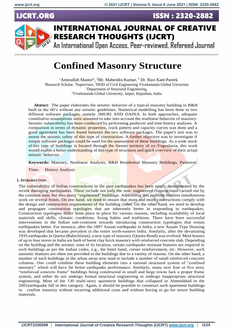
recent times, it is being replaced with cement mortar. Masonry can carry loads that cause compression (i.e.,
pressing together), but can hardly take load that causes tension (i.e., pulling apart) (Figure 4.6) Concrete is another
material that has been popularly used in building construction particularly over the last four decades. Cement
concrete is made of crushed stone pieces (called aggregate), sand, cement and water mixed in appropriate
proportions. Concrete is much stronger than masonry under compressive loads, but again its behavior in tension
is poor. The properties of concrete critically depend on the amount of water used in making concrete; too much
and too little water, both can cause havoc. In general, both masonry and concrete are brittle, and fail suddenly.
Steel is used in masonry and concrete buildings as reinforcement bars of diameter ranging from 6mm to 40mm.
Reinforcing steel can carry both tensile and compressive loads. Moreover, steel is a ductile material. This
important property of ductility enables steel bars to undergo large elongation before breaking. Concrete is used in
buildings along with steel reinforcement bars. This composite material is called reinforced cement concrete or
simply reinforced concrete (RC). The amount and location of steel in a member should be such that the failure of
the member is by steel reaching its strength in tension before concrete reaches its strength in compression. This
type of failure is ductile failure, and hence is preferred over a failure where concrete fails first in compression.
Therefore, contrary to common thinking, providing too much steel in RC buildings can be harmful even
www.ijcrt.org © 2021 IJCRT | Volume 9, Issue 6 June 2021 | ISSN: 2320-2882
IJCRT2106599 International Journal of Creative Research Thoughts (IJCRT) www.ijcrt.org f131
Figure 4: masonry is strong in compression but weak in tension
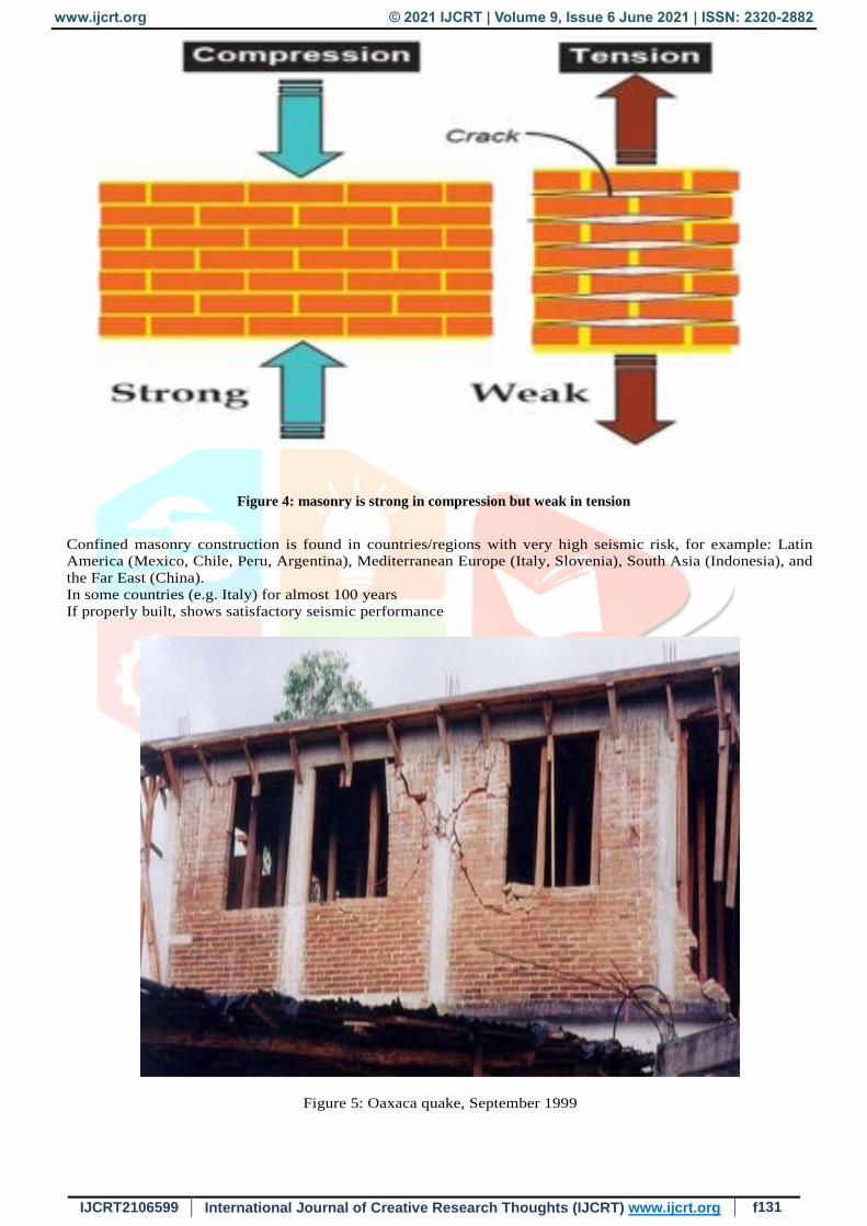
Confined masonry construction is found in countries/regions with very high seismic risk, for example: Latin
America (Mexico, Chile, Peru, Argentina), Mediterranean Europe (Italy, Slovenia), South Asia (Indonesia), and
the Far East (China).
In some countries (e.g. Italy) for almost 100 years
If properly built, shows satisfactory seismic performance
Figure 5: Oaxaca quake, September 1999
www.ijcrt.org © 2021 IJCRT | Volume 9, Issue 6 June 2021 | ISSN: 2320-2882
IJCRT2106599 International Journal of Creative Research Thoughts (IJCRT) www.ijcrt.org f132
Figure 6: japan quake, September 1999
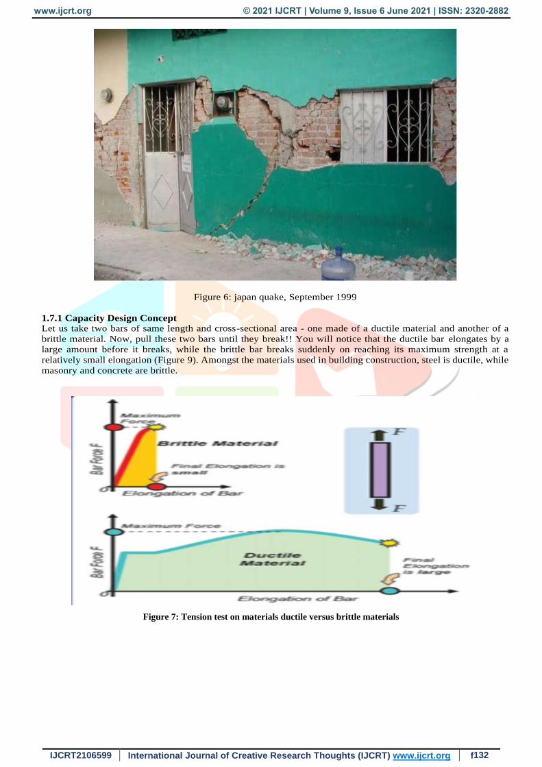
1.7.1 Capacity Design Concept
Let us take two bars of same length and cross-sectional area - one made of a ductile material and another of a
brittle material. Now, pull these two bars until they break!! You will notice that the ductile bar elongates by a
large amount before it breaks, while the brittle bar breaks suddenly on reaching its maximum strength at a
relatively small elongation (Figure 9). Amongst the materials used in building construction, steel is ductile, while
masonry and concrete are brittle.
Figure 7: Tension test on materials ductile versus brittle materials

www.ijcrt.org © 2021 IJCRT | Volume 9, Issue 6 June 2021 | ISSN: 2320-2882
IJCRT2106599 International Journal of Creative Research Thoughts (IJCRT) www.ijcrt.org f133
Conclusion
In this study, various walls having different size of opening have been studied. The carried out study has
shown that opening area is dangerous for masonry walls during earthquake. There is some conclusion
which found in the analysis: The shear failure of the wall can be reduced by avoiding large opening in wall
and number of opening in wall because opening reduces moment of inertia of the wall which reduces the
stiffness of the wall. This increases possibility of shear failure in the wall. Large opening in masonry walls
increases flexibility which increases top displacement in the wall. Different stiffness of walls in a building
cause twisting moment in the structure which causes bending failure of the masonry wall. Because of
different stiffness in walls, the centre of rotation will displace from the centre of gravity of the structure
and structure will move and displace at a same time which increases top storey displacement in the wall.
The length of wall also affects the stiffness of the wall because length of wall is inversely proportional to
the stiffness of the wall. Location of opening is important in masonry walls. It has seen that the wall having
door is failed but in same case of a window the wall shows better results. Both the openings obstruct the
flow path of load but the door is open at the end. So, due to stiffness at the end of door is zero, the wall
collapse.
REFERENCES
[1] Naida Ademović, and Daniel V. Oliveira “Seismic Assessment of a Typical Masonry Residential Building in Bosnia
and Herzegovina” 15 wcee lisboa 2012
[2] Andreas J. Kappos and Georgios Panagopoulos “performance-based seismic design of 3d r/c buildings using inelastic
static and dynamic analysis procedures” ISET Journal of Earthquake Technology, Paper No. 444, Vol. 41, No. 1, March
2004, pp. 141-158
[3] Dr Svetlana Brzev “Earthquake-Resistant Confined Masonry Construction” (NICEE 2011
[4] Edoardo Fusco1, Andrea Penna2, Andrea Prota1, Alessandro Galasco2 and Gaetano Manfredi “seismic assessment of
historical natural stone masonry buildings through non-linear analysis” The 14th World Conference on Earthquake
Engineering October 12-17, 2008, Beijing, China
[5] Naida Ademović,, Daniel V. Oliveira “Seismic Assessment of a Typical Masonry Residential Building in Bosnia and
Herzegovina” 15 WCEE 2012
[6] Alessandro Galasco1, Sergio Lagomarsino1 And Andrea Penna2 “on the use of pushover analysis for existing masonry
buildings
[7] A.Simões, R. Bento, A. Gago & M. Lopes “Seismic Vulnerability of Old Masonry ‘Gaioleiro’ B Buildings in Lisbo”15
WCEE lisboa 2012
[8] Sudhir K. Jain, C.V.R.Murty and Navin Chandak “The September 29, 1993, M6.4 Killari, Maharashtra Earthquake in
Central India.”EERI Special Earthquake Report, EERI Newsletter, Vol. 28, No. 1, January 1994
[9] Dr. S R.Uma, A. Meher Prasad “Seismic behaviour of beam column joints in reinforced concrete moment resisting
frame a review” Department of Civil Engineering, IIT Madras, Chennai, India- 600 036.
[10] Roberto Meli, Mexico (Co-Chair) Svetlana Brzev, Canada (Co-Chair Maximiliano Astroza, Chile Teddy Boen, Indonesia
Francisco Crisafulli,
[11] Argentina Junwu Dai, China Mohammed Farsi, Algeria Tim Hart, USA Ahmed Mebarki, France A.S. Moghadam,
Iran Daniel Quiun, Peru Miha Tomazevic, Slovenia Luis Yamin, Colombia “Seismic Design Guide for Low-Rise
Confined Masonry Buildings” EERI & IAEE August 2011
[12] Dr Sudhir K. Jain “Experimental Study on Brick Masonry Infilled Reinforced Concrete Frames under Lateral Load”
IIT KANPUR January 1989
[13] Svetlana Brzev “Earthquake-Resistant Confined Masonry Construction” Nicee December 2007 Kamu Iyer 1,Shibani
M. Kulkarni 2,Shantanu Subramaniam 3,C. V. R. Murty4,RupenGoswami5,A R.Vijayanarayana6,“Build A Safe House
With Confined Masonry”GSDMA
[14] Kamu Iyer 1,Shibani M. Kulkarni 2, Shantanu Subramaniam C. V. R. Murty4,Rupen Goswami5, A. R.
Vijayanarayana6, “Build A Safe House With Confined Masonry”GSDMA
[15] Sassan Eshghi1,*, Khashaiar Pourazin2 “In-plane behavior of confined masonry walls –with and without opening”
International Journal of Civil Engineerng. Vol. 7, No. 1, March 2009


