Embed Size (px)
Citation preview
1
GENERAL CONCEPTS OF EARTHQUAKE RESISTANT DESIGN
Chapter 3
GENERAL CONCEPTS OF EARTHQUAKERESISTANT DESIGN
3.1 INTRODUCTIONExperience in past earthquakes has dem-onstrated that many common buildingsand typical methods of construction lackbasic resistance to earthquake forces. Inmost cases this resistance can be achievedby following simple, inexpensive princi-ples of good building construction prac-tice. Adherence to these simple rules willnot prevent all damage in moderate or largeearthquakes, but life threatening collapsesshould be prevented, and damage limitedto repairable proportions. These principlesfall into several broad categories:
(i) Planning and layout of the buildinginvolving consideration of the loca-tion of rooms and walls, openingssuch as doors and windows, thenumber of storeys, etc. At this stage,site and foundation aspects shouldalso be considered.
(ii) Lay out and general design of thestructural framing system with spe-cial attention to furnishing lateralresistance, and
(iii) Consideration of highly loaded andcritical sections with provision of
reinforcement as required.
Chapter 2 has provided a good overviewof structural action, mechanism of damageand modes of failure of buildings. Fromthese studies, certain general principleshave emerged:
(i) Structures should not be brittle orcollapse suddenly. Rather, theyshould be tough, able to deflect ordeform a considerable amount.
(ii) Resisting elements, such as bracingor shear walls, must be providedevenly throughout the building, inboth directions side-to-side, as wellas top to bottom.
(iii) All elements, such as walls and theroof, should be tied together so as toact as an integrated unit duringearthquake shaking, transferringforces across connections and pre-venting separation.
(iv) The building must be well connectedto a good foundation and the earth.Wet, soft soils should be avoided, andthe foundation must be well tied to-gether, as well as tied to the wall.

3
GENERAL CONCEPTS OF EARTHQUAKE RESISTANT DESIGN
Soft: Those soils, which have allowablebearing capacity less than or equalto 10 t/m2.
Weak: Those soils, which are liable to largedifferential settlement, or liquefac-tion during an earthquake.
Buildings can be constructed on firmand soft soils but it will be dangerous tobuild them on weak soils. Hence appropri-ate soil investigations should be carried outto establish the allowable bearing capacityand nature of soil. Weak soils must beavoided or compacted to improve them soas to qualify as firm or soft.
3.2.4 Combination ofparametersFor defining the categories of buildings forseismic strengthening purposes, four cat-egories I to IV are defined in Table 3.1. inwhich category I will require maximumstrengthening and category IV the least in-puts. The general planning and designingprinciples are, however, equally applica-ble to them.
3.3. GENERAL PLANNING ANDDESIGN ASPECTS3.3.1. Plan of building
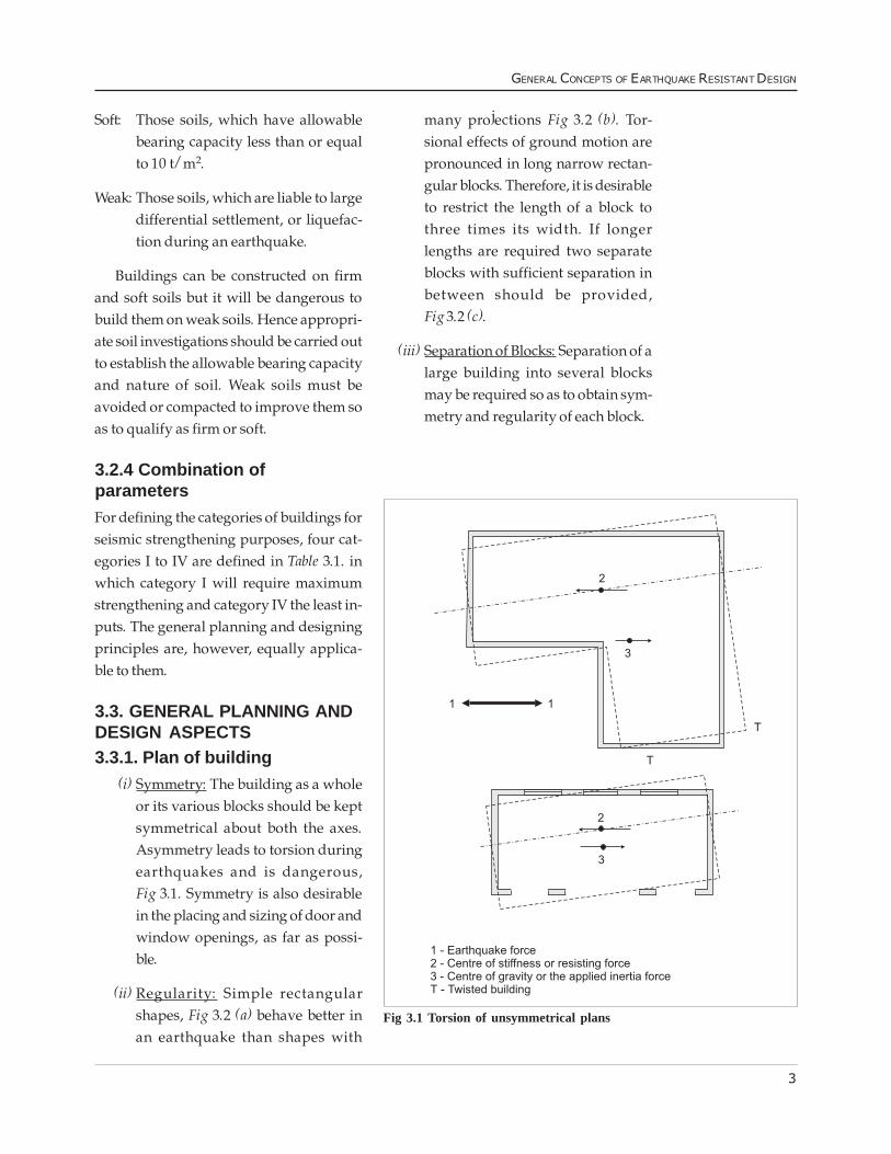
(i) Symmetry: The building as a wholeor its various blocks should be keptsymmetrical about both the axes.Asymmetry leads to torsion duringearthquakes and is dangerous,Fig 3.1. Symmetry is also desirablein the placing and sizing of door andwindow openings, as far as possi-ble.
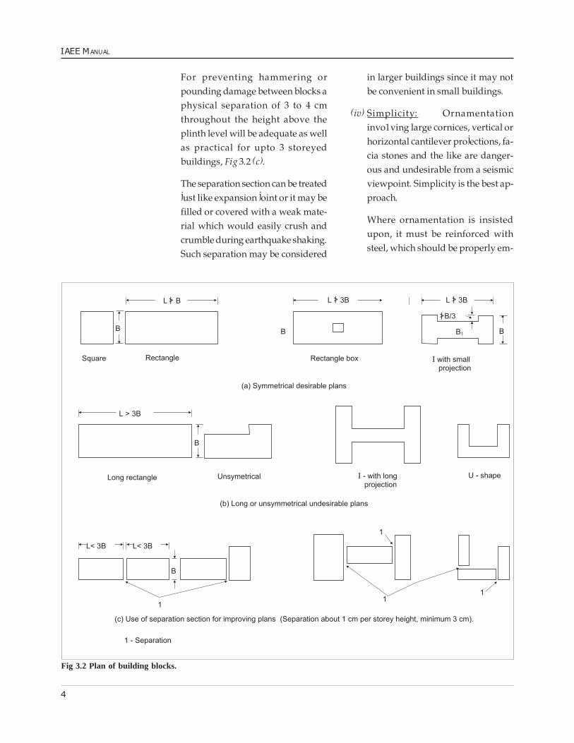
(ii) Regularity: Simple rectangularshapes, Fig 3.2 (a) behave better inan earthquake than shapes with
many projections Fig 3.2 (b). Tor-sional effects of ground motion arepronounced in long narrow rectan-gular blocks. Therefore, it is desirableto restrict the length of a block tothree times its width. If longerlengths are required two separateblocks with sufficient separation inbetween should be provided,Fig 3.2 (c).
(iii) Separation of Blocks: Separation of alarge building into several blocksmay be required so as to obtain sym-metry and regularity of each block.
Fig 3.1 Torsion of unsymmetrical plans
4
IAEE MANUAL
For preventing hammering orpounding damage between blocks aphysical separation of 3 to 4 cmthroughout the height above theplinth level will be adequate as wellas practical for upto 3 storeyedbuildings, Fig 3.2 (c).
The separation section can be treatedjust like expansion joint or it may befilled or covered with a weak mate-rial which would easily crush andcrumble during earthquake shaking.Such separation may be considered
in larger buildings since it may notbe convenient in small buildings.
(iv) Simplicity: Ornamentationinvo1ving large cornices, vertical orhorizontal cantilever projections, fa-cia stones and the like are danger-ous and undesirable from a seismicviewpoint. Simplicity is the best ap-proach.
Where ornamentation is insistedupon, it must be reinforced withsteel, which should be properly em-
Fig 3.2 Plan of building blocks.
5
GENERAL CONCEPTS OF EARTHQUAKE RESISTANT DESIGN
bedded or tied into the main struc-ture of the building.
Note: If designed, a seismic coeffi-cient about 5 times the coefficientused for designing the main struc-ture should be used for cantileverornamentation.
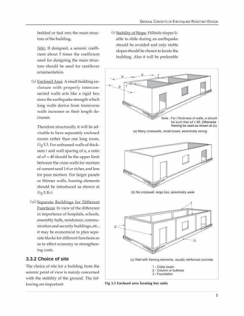
(v) Enclosed Area: A small building en-closure with properly intercon-nected walls acts like a rigid boxsince the earthquake strength whichlong walls derive from transversewalls increases as their length de-creases.
Therefore structurally it will be ad-visable to have separately enclosedrooms rather than one long room,Fig 3.3. For unframed walls of thick-ness t and wall spacing of a, a ratioof a/t = 40 should be the upper limitbetween the cross walls for mortarsof cement sand 1:6 or richer, and lessfor poor mortars. For larger panelsor thinner walls, framing elementsshould be introduced as shown atFig 3.3(c).
(vi) Separate Buildings for DifferentFunctions: In view of the differencein importance of hospitals, schools,assembly halls, residences, commu-nication and security buildings, etc.,it may be economical to plan sepa-rate blocks for different functions soas to affect economy in strengthen-ing costs.
3.3.2 Choice of siteThe choice of site for a building from theseismic point of view is mainly concernedwith the stability of the ground. The fol-lowing are important:
(i) Stability of Slope: Hillside slopes li-able to slide during an earthquakeshould be avoided and only stableslopes should be chosen to locate thebuilding. Also it will be preferable
Fig 3.3 Enclosed area forming box units
6
IAEE MANUAL
3.3.4 Fire resistanceIt is not unusual during earthquakes thatdue to snapping of electrical fittings shortcircuiting takes place, or gas pipes maydevelop leaks and catch fire. Fire could alsobe started due to kerosene lamps andkitchen fires. The fire hazard sometimescould even be more serious than the earth-quake damage. The buildings should there-fore preferably be constructed of fire resist-ant materials.
3.4 STRUCTURAL FRAMINGThere are basically two types structuralframing possible to withstand gravity andseismic load, viz. bearing wall constructionand framed construction. The framed con-struction may again consist of:
(i) Light framing members which musthave diagonal bracing such as woodframes (see Chapter 6) or infill wallsfor lateral load resistance, Fig 3.3 (c),or
(ii) Substantial rigid jointed beams andcolumns capable of resisting the lat-eral loads by themselves.
The latter will be required for large col-umn free spaces such as assembly halls.
The framed constructions can be usedfor a greater number of storeys compared tobearing wall construction. The strength andductility can be better controlled in framedconstruction through design. The strengthof the framed construction is not affectedby the size and number of openings. Suchframes fall in the category of engineeredconstruction, hence outside the scope of thepresent book.
to have several blocks on terracesthan have one large block withfootings at very different elevations.A site subject to the danger of rockfalls has to be avoided.
(ii) Very Loose Sands or Sensitive Clays:These two types of soils are liable tobe destroyed by the earthquake somuch as to lose their original struc-ture and thereby undergocompaction. This would result inlarge unequal settlements and dam-age the building. If the loosecohesionless soils are saturated withwater they are apt to lose their shearresistance altogether during shakingand become liquefied.
Although such soils can be compacted,for small buildings the operation may betoo costly and these soils are better avoided.For large building complexes, such as hous-ing developments, new towns, etc., this fac-tor should be thoroughly investigated andappropriate action taken.
Therefore a site with sufficient bearingcapacity and free from the above defectsshould be chosen and its drainage condi-tion improved so that no water accumu-lates and saturates the ground close to thefooting level.
3.3.3. Structural designDuctility (defined in Section 3.6) is the mostdesirable quality for good earthquake per-formance and can be incorporated to someextent in otherwise brittle masonry con-structions by introduction of steel reinforc-ing bars at critical sections as indicatedlater in Chapters 4 and 5.
7
GENERAL CONCEPTS OF EARTHQUAKE RESISTANT DESIGN
The strengthening measures necessaryto meet these safety requirements are pre-sented in the following Chapters for vari-ous building types. In view of the lowseismicity of Zone D, no strengtheningmeasures from seismic consideration areconsidered necessary except an emphasison good quality of construction. The fol-lowing recommendations are therefore in-tended for Zones A, B and C. For this pur-pose certain categories of construction in anumber of situations were defined inTable 3.1.
3.6 CONCEPTS OF DUCTILITY,DEFORMABILITY ANDDAMAGEABILITYDesirable properties of earthquake-resist-ant design include ductility, deformabilityand damageability. Ductility anddeformability are interrelated concepts sig-nifying the ability of a structure to sustainlarge deformations without collapse.Damageability refers to the ability of a struc-
3.5 REQUIREMENTS OFSTRUCTURAL SAFETYAs a result of the discussion of structuralaction and mechanism of failure of Chap-ter 2, the following main requirements ofstructural safety of buildings can be arrivedat.
(i) A free standing wall must be de-signed to be safe as a vertical canti-lever.
This requirement will be difficult toachieve in un-reinforced masonry inZone A. Therefore all partitions in-side the buildings must be held onthe sides as well as top. Parapets ofcategory I and II buildings must bereinforced and held to the mainstructural slabs or frames.
(ii) Horizontal reinforcement in walls isrequired for transferring their ownout-of-plane inertia load horizon-tally to the shear walls.
(iii) The walls must be effectively tiedtogether to avoid separation at verti-cal joints due to ground shaking.
(iv) Shear walls must be present alongboth axes of the building.
(v) A shear wall must be capable of re-sisting all horizontal forces due toits own mass and those transmittedto it.
(vi) Roof or floor elements must be tiedtogether and be capable of exhibit-ing diaphragm action.
(vii) Trusses must be anchored to the sup-porting walls and have an arrange-ment for transferring their inertiaforce to the end walls.
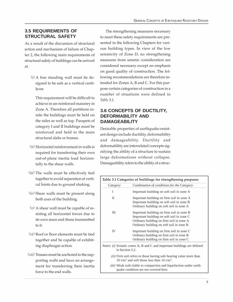
Table 3.1 Categories of buildings for strengthening purposes
Category Combination of conditions for the Category
I Important building on soft soil in zone A
II Important building on firm soil in zone AImportant building on soft soil in zone BOrdinary building on soft soil in zone A
III Important building on firm soil in zone BImportant building on soft soil in zone COrdinary building on firm soil in zone AOrdinary building on soft soil in zone B
IV Important building on firm soil in zone COrdinary building on firm soil in zone BOrdinary building on firm soil in zone C
Notes: (i)Seismic zones A, B and C and important buildings are definedin Section 3.2.
(ii) Firm soil refers to those having safe bearing value more than10 t/m2 and soft those less than 10 t/m2.
(iii) Weak soils liable to compaction and liquefaction under earth-quake condition are not covered here.
8
IAEE MANUAL
together so that excessive stress concentra-tions are avoided and forces are capable ofbeing transmitted from one component toanother even through large deformations.
Ductility is a term applied to materialand structures, while deformability is ap-plicable only to structures.
Even when ductile materials are presentin sufficient amounts in structural compo-nents such as beams and walls, overallstructural deformability requires that geo-metrical and material instability beavoided. That is, components must haveproper aspect ratios (that is not be too high),must be adequately connected to resistingelements (for example sufficient wall tiesfor a masonry wall, tying it to floors, roofand shear walls), and must be well tied to-gether (for example positive connection atbeam seats, so that deformations do notpermit a beam to simply fall off a post) soas to permit large deformations and dy-namic motions to occur without suddencollapse.
3.6.3 DamageabilityDamageability is also a desirable qualityfor construction, and refers to the ability ofa structure to undergo substantial damages,without partial or total collapse
A key to good damageability is redun-dancy, or provision of several supports forkey structural members, such as ridgebeams, and avoidance of central columnsor walls supporting excessively large por-tions of a building. A key to achieving gooddamageability is to always ask the ques-tion, �if this beam or column, wall connec-tion, foundation, etc. fails, what is the con-sequence?�. If the consequence is total col-
ture to undergo substantial damage, with-out partial or total collapse. This is desir-able because it means that structures canabsorb more damage, and because it per-mits the deformations to be observed andrepairs or evacuation to proceed, prior tocollapse. In this sense, a warning is receivedand lives are saved.
3.6.1 DuctilityFormally, ductility refers to the ratio of thedisplacement just prior to ultimate dis-placement or collapse to the displacementat first damage or yield. Some materials areinherently ductile, such as steel, wroughtiron and wood. Other materials are notductile (this is termed brittle), such as castiron, plain masonry, adobe or concrete, thatis, they break suddenly, without warning.Brittle materials can be made ductile, usu-ally by the addition of modest amounts ofductile materials, Such as wood elementsin adobe construction, or steel reinforcingin masonry and concrete constructions.
For these ductile materials to achieve aductile effect in the overall behaviour of thecomponent, they must be proportioned andplaced so that they come in tension and aresubjected to yielding. Thus, a necessary re-quirement for good earthquake-resistantdesign is to have sufficient ductile materi-als at points of tensile stresses.
3.6.2 DeformabilityDeformability is a less formal term refer-ring to the ability of a structure to displaceor deform substantial amounts withoutcollapsing. Besides inherently relying onductility of materials and components,deformability requires that structures bewell-proportioned, regular and well tied
9
GENERAL CONCEPTS OF EARTHQUAKE RESISTANT DESIGN
lapse of the structure, additional supportsor alternative structural layouts should beexamined, or an additional factor of safetybe furnished for such critical members orconnections.
3.7 CONCEPT OF ISOLATIONThe foregoing discussion of earthquake-resistant design has emphasized the tradi-tional approach of resisting the forces anearthquake imposes on a structure. An al-ternative approach which is presentlyemerging is to avoid these forces, by isola-tion of the structure from the ground mo-tions which actually impose the forces onthe structure.
This is termed base-isolation. For sim-ple buildings, base- friction isolation maybe achieved by reducing the coefficient offriction between the structure and its foun-dation, or by placing a flexible connectionbetween the structure and its foundation.
For reduction of the coefficient of fric-tion between the structure and its founda-tion, one suggested technique is to placetwo layers of good quality plastic betweenthe structure and its foundation, so that theplastic layers may slide over each other.
Flexible connections between the struc-ture and its foundation are also difficult toachieve on a permanent basis. One tech-nique that has been used for generationshas been to build a house on short postsresting on large stones, so that under earth-quake motions, the posts are effectively pin-connected at the top and bottom and thestructure can rock to and fro somewhat.This has the advantage of substantially re-ducing the lateral forces, effectively isolat-ing the structure from the high amplitude
high frequency motions. Unfortunately, tra-ditional applications of this technique usu-ally do not account for occasional largedisplacements of this pin-connectedmechanism, due to rare very large earth-quakes or unusually large low-frequencycontent in the ground motion, so that whenlateral displacements reach a certain point,collapse results. A solution to this problemwould be provision of a plinth slightly be-low the level of the top of the posts, so thatwhen the posts rock too far, the structure isonly dropped a centimeter or so.
3.8 FOUNDATIONSFor the purpose of making a building trulyearthquake resistant, it will be necessary tochoose an appropriate foundation type forit. Since loads from typical low heightbuildings will be light, providing the re-quired bearing area will not usually be aproblem. The depth of footing in the soilshould go below the zone of deep freezingin cold countries and below the level ofshrinkage cracks in clayey soils. For choos-ing the type of footing from the earthquakeangle, the soils may be grouped as Firm andSoft (see Section 3.2.3) avoiding the weaksoil unless compacted and brought to Softor Firm condition.
3.8.1 Firm soilIn firm soil conditions, any type of footing(individual or strip type) can be used. Itshould of course have a firm base of lime orcement concrete with requisite width overwhich the construction of the footing maystart. It will be desirable to connect the in-dividual reinforced concrete columnfootings in Zone A by means of RC beamsjust below plinth level intersecting at rightangles.
10
IAEE MANUAL
3.8.2 Soft soilIn soft soil, it will be desirable to use a plinthband in all walls and where necessary toconnect the individual column footings bymeans of plinth beams as suggested above.It may be mentioned that continuous rein-forced concrete footings are considered tobe most effective from earthquake consid-erations as well as to avoid differential set-tlements under normal vertical loads. De-tails of plinth band and continuous RC
footings are presented in Chapters 4 and 9respectively.
These should ordinarily be providedcontinuously under all the walls. Continu-ous footing should be reinforced both inthe top and bottom faces, width of the foot-ing should be wide enough to make thecontact pressures uniform, and the depthof footing should be below the lowest levelof weathering.
���