Embed Size (px)
Citation preview
IS 1893 (Part 1) : 2002Edition 6.1
(2005-01)
B U R E A U O F I N D I A N S T A N D A R D SMANAK BHAVAN, 9 BAHADUR SHAH ZAFAR MARG
NEW DELHI 110002
Price Group 12
© BIS 2007
Indian Standard
CRITERIA FOR EARTHQUAKE RESISTANT DESIGN OF STRUCTURESPART 1 GENERAL PROVISIONS AND BUILDINGS
( Fifth Revision )(Incorporating Amendment No. 1)
ICS 91.120.25
IS 1893 (Part 1) : 2002
1
Indian Standard
CRITERIA FOR EARTHQUAKE RESISTANT DESIGN OF STRUCTURESPART 1 GENERAL PROVISIONS AND BUILDINGS
( Fifth Revision )FOREWORD
This Indian Standard (Part 1) (Fifth Revision) was adopted by the Bureau of Indian Standards,after the draft finalized by the Earthquake Engineering Sectional Committee had been approvedby the Civil Engineering Division Council.
Himalayan-Nagalushai region, Indo-Gangetic Plain, Western India, Kutch and Kathiawar regionsare geologically unstable parts of the country, and some devastating earthquakes of the worldhave occurred there. A major part of the peninsular India has also been visited by strongearthquakes, but these were relatively few in number occurring at much larger time intervals atany site, and had considerably lesser intensity. The earthquake resistant design of structurestaking into account seismic data from studies of these Indian earthquakes has become veryessential, particularly in view of the intense construction activity all over the country. It is to servethis purpose that IS 1893 : 1962 ‘Recommendations for earthquake resistant design of structures’was published and revised first time in 1966.
As a result of additional seismic data collected in India and further knowledge and experiencegained since the publication of the first revision of this standard, the sectional committee felt theneed to revise the standard again incorporating many changes, such as revision of maps showingseismic zones and epicentres, and adding a more rational approach for design of buildings andsub-structures of bridges. These were covered in the second revision of IS 1893 brought out in1970.
As a result of the increased use of the standard, considerable amount of suggestions were receivedfor modifying some of the provisions of the standard and, therefore, third revision of the standardwas brought out in 1975. The following changes were incorporated in the third revision:
The fourth revision, brought out in 1984, was prepared to modify some of the provisions of thestandard as a result of experience gained with the use of the standard. In this revision, a numberof important basic modifications with respect to load factors, field values of N, base shear andmodal analysis were introduced. A new concept of performance factor depending on the structuralframing system and on the ductility of construction was incorporated. Figure 2 for averageacceleration spectra was also modified and a curve for zero percent damping incorporated.
a) The standard incorporated seismic zone factors (previously given as multiplying factors inthe second revision) on a more rational basis.
b) Importance factors were introduced to account for the varying degrees of importance forvarious structures.
c) In the clauses for design of multi-storeyed buildings, the coefficient of flexibility wasgiven in form of a curve with respect to period of buildings.
d) A more rational formula was used to combine modal shear forces.
e) New clauses were introduced for determination of hydrodynamic pressures in elevatedtanks.
f) Clauses on concrete and masonry dams were modified, taking into account their dynamicbehaviour during earthquakes. Simplified formulae for design forces were introducedbased on results of extensive studies carried out since second revision of the standard waspublished.
IS 1893 (Part 1) : 2002
2
In the fifth revision, with a view to keep abreast with the rapid development and extensiveresearch that has been carried out in the field of earthquake resistant design of various structures,the committee has decided to cover the provisions for different types of structures in separateparts. Hence, IS 1893 has been split into the following five parts:
Part 1 General provisions and buildings
Part 2 Liquid retaining tanks — Elevated and ground supported
Part 3 Bridges and retaining walls
Part 4 Industrial structures including stack like structures
Part 5 Dams and embankments
Part 1 contains provisions that are general in nature and applicable to all structures. Also, itcontains provisions that are specific to buildings only. Unless stated otherwise, the provisions inParts 2 to 5 shall be read necessarily in conjunction with the general provisions in Part 1.
NOTE — Pending finalization of Parts 2 to 5 of IS 1893, provisions of Part 1 will be read along with the relevant clausesof IS 1893 : 1984 for structures other than buildings.
The following are the major and important modifications made in the fifth revision:
It is not intended in this standard to lay down regulation so that no structure shall suffer anydamage during earthquake of all magnitudes. It has been endeavoured to ensure that, as far aspossible, structures are able to respond, without structural damage to shocks of moderateintensities and without total collapse to shocks of heavy intensities. While this standard isintended for the earthquake resistant design of normal structures, it has to be emphasized that inthe case of special structures, such as large and tall dams, long-span bridges, major industrialprojects, etc, site-specific detailed investigation should be undertaken, unless otherwise specifiedin the relevant clauses.
a) The seismic zone map is revised with only four zones, instead of five. Erstwhile Zone I hasbeen merged to Zone II. Hence, Zone I does not appear in the new zoning; only Zones II,III, IV and V do.
b) The values of seismic zone factors have been changed; these now reflect more realisticvalues of effective peak ground acceleration considering Maximum ConsideredEarthquake (MCE) and service life of structure in each seismic zone.
c) Response spectra are now specified for three types of founding strata, namely rock andhard soil, medium soil and soft soil.
d) Empirical expression for estimating the fundamental natural period Ta of multi-storeyedbuildings with regular moment resisting frames has been revised.
e) This revision adopts the procedure of first calculating the actual force that may beexperienced by the structure during the probable maximum earthquake, if it were toremain elastic. Then, the concept of response reduction due to ductile deformation orfrictional energy dissipation in the cracks is brought into the code explicitly, byintroducing the ‘response reduction factor’ in place of the earlier performance factor.
f) A lower bound is specified for the design base shear of buildings, based on empiricalestimate of the fundamental natural period Ta.
g) The soil-foundation system factor is dropped. Instead, a clause is introduced to restrictthe use of foundations vulnerable to differential settlements in severe seismic zones.
h) Torsional eccentricity values have been revised upwards in view of serious damagesobserved in buildings with irregular plans.
j) Modal combination rule in dynamic analysis of buildings has been revised.
k) Other clauses have been redrafted where necessary for more effective implementation.
IS 1893 (Part 1) : 2002
3
Though the basis for the design of different types of structures is covered in this standard, it is notimplied that detailed dynamic analysis should be made in every case. In highly seismic areas,construction of a type which entails heavy debris and consequent loss of life and property, such asmasonry, particularly mud masonry and rubble masonry, should preferably be avoided. Forguidance on precautions to be observed in the construction of buildings, reference may be made toIS 4326, IS 13827 and IS 13828.
Earthquake can cause damage not only on account of the shaking which results from them but alsodue to other chain effects like landslides, floods, fires and disruption to communication. It is,therefore, important to take necessary precautions in the siting, planning and design of structuresso that they are safe against such secondary effects also.
The Sectional Committee has appreciated that there cannot be an entirely scientific basis forzoning in view of the scanty data available. Though the magnitudes of different earthquakes whichhave occurred in the past are known to a reasonable degree of accuracy, the intensities of theshocks caused by these earthquakes have so far been mostly estimated by damage surveys andthere is little instrumental evidence to corroborate the conclusions arrived at. Maximum intensityat different places can be fixed on a scale only on the basis of the observations made and recordedafter the earthquake and thus a zoning map which is based on the maximum intensities arrived at,is likely to lead in some cases to an incorrect conclusion in view of (a) incorrectness in theassessment of intensities, (b) human error in judgment during the damage survey, and (c) variationin quality and design of structures causing variation in type and extent of damage to the structuresfor the same intensity of shock. The Sectional Committee has therefore, considered that a rationalapproach to the problem would be to arrive at a zoning map based on known magnitudes and theknown epicentres ( see Annex A ) assuming all other conditions as being average and to modifysuch an idealized isoseismal map in light of tectonics ( see Annex B ), lithology ( see Annex C )andthe maximum intensities as recorded from damage surveys. The Committee has also reviewed sucha map in the light of the past history and future possibilities and also attempted to draw the linesdemarcating the different zones so as to be clear of important towns, cities and industrial areas,after making special examination of such cases, as a little modification in the zonal demarcationsmay mean considerable difference to the economics of a project in that area. Maps shown in Fig. 1and Annexes A, B and C are prepared based on information available upto 1993.
In the seismic zoning map, Zone I and II of the contemporary map have been merged and assignedthe level of Zone II. The Killari area has been included in Zone III and necessary modifications made,keeping in view the probabilistic hazard evaluation. The Bellary isolated zone has been removed.The parts of eastern coast areas have shown similar hazard to that of the Killari area, the level ofZone II has been enhanced to Zone III and connected with Zone III of Godawari Graben area.
The seismic hazard level with respect to ZPA at 50 percent risk level and 100 years service lifegoes on progressively increasing from southern peninsular portion to the Himalayan main seismicsource, the revised seismic zoning map has given status of Zone III to Narmada Tectonic Domain,Mahanandi Graben and Godawari Graben. This is a logical normalization keeping in view theapprehended higher strain rates in these domains on geological consideration of higher neotectonicactivity recorded in these areas.
Attention is particularly drawn to the fact that the intensity of shock due to an earthquake couldvary locally at any place due to variation in soil conditions. Earthquake response of systems wouldbe affected by different types of foundation system in addition to variation of ground motion due tovarious types of soils. Considering the effects in a gross manner, the standard gives guidelines forarriving at design seismic coefficients based on stiffness of base soil.
It is important to note that the seismic coefficient, used in the design of any structure, isdependent on many variable factors and it is an extremely difficult task to determine the exactseismic coefficient in each given case. It is, therefore, necessary to indicate broadly the seismiccoefficients that could generally be adopted in different parts or zones of the country though, ofcourse, a rigorous analysis considering all the factors involved has to be made in the case of allimportant projects in order to arrive at a suitable seismic coefficients for design. The SectionalCommittee responsible for the formulation of this standard has attempted to include a seismiczoning map ( see Fig. 1 ) for this purpose. The object of this map is to classify the area of thecountry into a number of zones in which one may reasonably expect earthquake shaking of more orless same maximum intensity in future. The Intensity as per Comprehensive Intensity Scale(MSK64) ( see Annex D ) broadly associated with the various zones is VI (or less), VII, VIII and IX(and above) for Zones II, III, IV and V respectively. The maximum seismic ground acceleration in
IS 1893 (Part 1) : 2002
4
each zone cannot be presently predicted with accuracy either on a deterministic or on aprobabilistic basis. The basic zone factors included herein are reasonable estimates of effectivepeak ground accelerations for the design of various structures covered in this standard. Zonefactors for some important towns are given in Annex E.
Base isolation and energy absorbing devices may be used for earthquake resistant design. Onlystandard devices having detailed experimental data on the performance should be used. Thedesigner must demonstrate by detailed analyses that these devices provide sufficient protection tothe buildings and equipment as envisaged in this standard. Performance of locally assembledisolation and energy absorbing devices should be evaluated experimentally before they are used inpractice. Design of buildings and equipment using such device should be reviewed by thecompetent authority.
Base isolation systems are found useful for short period structures, say less than 0.7s includingsoil-structure interaction.
In the formulation of this standard, due weightage has been given to international coordinationamong the standards and practices prevailing in different countries in addition to relating it to thepractices in the field in this country. Assistance has particularly been derived from the followingpublications:
In the preparation of this standard considerable assistance has been given by the Department ofEarthquake Engineering, University of Roorkee; Indian Institute of Technology, Kanpur; IITBombay, Mumbai; Geological Survey of India; India Meteorological Department, and several otherorganizations.
The units used with the items covered by the symbols shall be consistent throughout thisstandard, unless specifically noted otherwise.
The composition of the Committee responsible for the formulation of this standard is given inAnnex F.
This edition 6.1 incorporates Amendment No. 1 (January 2005). Side bar indicates modification ofthe text as the result of incorporation of the amendment.
For the purpose of deciding whether a particular requirement of this standard is complied with,the final value observed or calculated, expressing the result of a test or analysis, shall be roundedoff in accordance with IS 2 : 1960 ‘Rules for rounding off numerical values ( revised )’. The numberof significant places retained in the rounded off value should be the same as that of the specifiedvalue in this standard.
(Earthquake Engineering Sectional Committee, CED 39)
a) UBC 1994, Uniform Building Code, International Conference of Building Officials,Whittier, California, U. S. A. 1994.
b) NEHRP 1991, NEHRP Recommended Provisions for the Development of SeismicRegulations for New Buildings, Part 1 : Provisions, Report No. FEMA 222, FederalEmergency Management Agency, Washington, D. C., U. S. A., January 1992.
c) NEHRP 1991, NEHRP Recommended Provisions for the Development of SeismicRegulations for New Buildings, Part 2 : Commentary, Report No.FEMA 223, FederalEmergency Management Agency, Washington, D. C., U. S. A., January 1992.
d) NZS 4203 : 1992, Code of Practice for General Structural Design and Design Loadings forBuildings, Standards Association of New Zealand, Wellington, New Zealand, 1992

IS 1893 (Part 1) : 2002
5

As in the Original Standard, this Page is Intentionally Left Blank
IS 1893 (Part 1) : 2002
7
Indian Standard
CRITERIA FOR EARTHQUAKE RESISTANT DESIGN OF STRUCTURES
PART 1 GENERAL PROVISIONS AND BUILDINGS
( Fifth Revision )1 SCOPE
1.1 This standard (Part 1) deals withassessment of seismic loads on variousstructures and earthquake resistant design ofbuildings. Its basic provisions are applicable tobuildings; elevated structures; industrial andstack like structures; bridges; concrete masonryand earth dams; embankments and retainingwalls and other structures.
1.2 Temporary elements such as scaffolding,temporary excavations need not be designed forearthquake forces.
1.3 This standard does not deal with theconstruction features relating to earthquakeresistant design in buildings and otherstructures. For guidance on earthquakeresistant construction of buildings, referencemay be made to the following IndianStandards:
IS 4326, IS 13827, IS 13828, IS 13920 and IS13935.
2 REFERENCES
2.1 The following Indian Standards arenecessary adjuncts to this standard:
IS No. Title
456 : 2000 Code of practice for plain andreinforced concrete ( fourthrevision )
800 : 1984 Code of practice for generalconstruction in steel ( secondrevision )
875 Code of practice for design loads(other than earthquake) forbuildings and structures:
(Part 1) : 1987 Dead loads — Unit weights ofbuilding material and storedmaterial ( second revision )
(Part 2) : 1987 Imposed loads ( second revision )
(Part 3) : 1987 Wind loads ( second revision )
(Part 4) : 1987 Snow loads ( second revision )
(Part 5) : 1987 Special loads and loadcombinations ( second revision )
IS No. Title1343 : 1980 Code of practice for pre-stressed
concrete ( first revision )
1498 : 1970 Classification and identificationof soil for general engineeringpurposes ( first revision )
1888 : 1982 Method of load test on soils( second revision )
1893 (Part 4) Criteria for earthquake resistantdesign of structures : Part 4Industrial structures includingstack like structures
2131 : 1981 Method of standard penetrationtest for soils ( first revision )
2809 : 1972 Glossary of terms and symbolsrelating to soil engineering ( firstrevision )
2810 : 1979 Glossary of terms relating to soildynamics ( first revision )
4326 : 1993 Earthquake resistant design andconstruction of buildings — Codeof practice ( second revision )
6403 : 1981 Code of practice fordetermination of bearingcapacity of shallow foundations( first revision )
13827 : 1993 Improving earthquake resistanceof earthen buildings —Guidelines
13828 : 1993 Improving earthquake resistanceof low strength masonrybuildings — Guidelines
13920 : 1993 Ductile detailing of reinforcedconcrete structures subjected toseismic forces — Code of practice
13935 : 1993 Repair and seismicstrengthening of buildings —Guidelines
SP 6 (6) : 1972 Handbook for structuralengineers: Application of plastictheory in design of steelstructures
IS 1893 (Part 1) : 2002
8
3 TERMINOLOGY FOR EARTHQUAKE ENGINEERING
3.1 For the purpose of this standard, thefollowing definitions shall apply which areapplicable generally to all structures.
NOTE — For the definitions of terms pertaining to soilmechanics and soil dynamics references may be made toIS 2809 and IS 2810.
3.2 Closely-Spaced Modes
Closely-spaced modes of a structure are those ofits natural modes of vibration whose naturalfrequencies differ from each other by 10 percentor less of the lower frequency.
3.3 Critical Damping
The damping beyond which the free vibrationmotion will not be oscillatory.
3.4 Damping
The effect of internal friction, imperfectelasticity of material, slipping, sliding, etc inreducing the amplitude of vibration and isexpressed as a percentage of critical damping.
3.5 Design Acceleration Spectrum
Design acceleration spectrum refers to anaverage smoothened plot of maximumacceleration as a function of frequency or timeperiod of vibration for a specified damping ratiofor earthquake excitations at the base of asingle degree of freedom system.
3.6 Design Basis Earthquake (DBE)
It is the earthquake which can reasonably beexpected to occur at least once during thedesign life of the structure.
3.7 Design Horizontal Acceleration Coefficient ( Ah )
It is a horizontal acceleration coefficient thatshall be used for design of structures.
3.8 Design Lateral Force
It is the horizontal seismic force prescribed bythis standard, that shall be used to design astructure.
3.9 Ductility
Ductility of a structure, or its members, is thecapacity to undergo large inelastic deformationswithout significant loss of strength or stiffness.
3.10 Epicentre
The geographical point on the surface of earthvertically above the focus of the earthquake.
3.11 Effective Peak Ground Acceleration(EPGA)
It is 0.4 times the 5 percent damped averagespectral acceleration between period 0.1 to0.3 s. This shall be taken as Zero PeriodAcceleration (ZPA).3.12 Floor Response Spectra
Floor response spectra is the response spectrafor a time history motion of a floor. This floormotion time history is obtained by an analysis ofmulti-storey building for appropriate materialdamping values subjected to a specifiedearthquake motion at the base of structure.3.13 Focus
The originating earthquake source of theelastic waves inside the earth which causeshaking of ground due to earthquake.3.14 Importance Factor ( I )
It is a factor used to obtain the design seismicforce depending on the functional use of thestructure, characterised by hazardousconsequences of its failure, its post-earthquakefunctional need, historic value, or economicimportance.3.15 Intensity of Earthquake
The intensity of an earthquake at a place is ameasure of the strength of shaking during theearthquake, and is indicated by a numberaccording to the modified Mercalli Scale orM.S.K. Scale of seismic intensities ( seeAnnex D ).3.16 Liquefaction
Liquefaction is a state in saturatedcohesionless soil wherein the effective shearstrength is reduced to negligible value for allengineering purpose due to pore pressurecaused by vibrations during an earthquakewhen they approach the total confiningpressure. In this condition the soil tends tobehave like a fluid mass.3.17 Lithological Features
The nature of the geological formation of theearths crust above bed rock on the basis of suchcharacteristics as colour, structure,mineralogical composition and grain size.3.18 Magnitude of Earthquake (Richter’s Magnitude)
The magnitude of earthquake is a number,which is a measure of energy released in anearthquake. It is defined as logarithm to thebase 10 of the maximum trace amplitude,expressed in microns, which the standardshort-period torsion seismometer (with a periodof 0.8 s, magnification 2 800 and dampingnearly critical) would register due to theearthquake at an epicentral distance of 100 km.
IS 1893 (Part 1) : 2002
9
3.19 Maximum Considered Earthquake (MCE)
The most severe earthquake effects consideredby this standard.
3.20 Modal Mass ( Mk )
Modal mass of a structure subjected tohorizontal or vertical, as the case maybe,ground motion is a part of the total seismicmass of the structure that is effective in mode kof vibration. The modal mass for a given modehas a unique value irrespective of scaling of themode shape.
3.21 Modal Participation Factor ( Pk )
Modal participation factor of mode k ofvibration is the amount by which mode kcontributes to the overall vibration of thestructure under horizontal and verticalearthquake ground motions. Since theamplitudes of 95 percent mode shapes can bescaled arbitrarily, the value of this factordepends on the scaling used for mode shapes.
3.22 Modes of Vibration ( see Normal Mode )
3.23 Mode Shape Coefficient (φik)
When a system is vibrating in normal mode k,at any particular instant of time, the amplitudeof mass i expressed as a ratio of the amplitudeof one of the masses of the system, is known asmode shape coefficient (φik).
3.24 Natural Period ( T )
Natural period of a structure is its time periodof undamped free vibration.
3.24.1 Fundamental Natural Period ( T1 )
It is the first (longest) modal time period ofvibration.
3.24.2 Modal Natural Period ( Tk )
The modal natural period of mode k is the timeperiod of vibration in mode k.
3.25 Normal Mode
A system is said to be vibrating in a normalmode when all its masses attain maximumvalues of displacements and rotationssimultaneously, and pass through equilibriumpositions simultaneously.
3.26 Response Reduction Factor ( R )
It is the factor by which the actual base shearforce, that would be generated if the structurewere to remain elastic during its response to theDesign Basis Earthquake (DBE) shaking, shallbe reduced to obtain the design lateral force.
3.27 Response Spectrum
The representation of the maximum response
of idealized single degree freedom systemshaving certain period and damping, duringearthquake ground motion. The maximumresponse is plotted against the undampednatural period and for various damping values,and can be expressed in terms of maximumabsolute acceleration, maximum relativevelocity, or maximum relative displacement.3.28 Seismic Mass
It is the seismic weight divided by accelerationdue to gravity.3.29 Seismic Weight ( W )
It is the total dead load plus appropriateamounts of specified imposed load.3.30 Structural Response Factors ( Sa/g )
It is a factor denoting the acceleration responsespectrum of the structure subjected toearthquake ground vibrations, and depends onnatural period of vibration and damping of thestructure.3.31 Tectonic Features
The nature of geological formation of the bedrock in the earth’s crust revealing regionscharacterized by structural features, such asdislocation, distortion, faults, folding, thrusts,volcanoes with their age of formation, whichare directly involved in the earth movement orquake resulting in the above consequences.3.32 Time History Analysis
It is an analysis of the dynamic response of thestructure at each increment of time, when itsbase is subjected to a specific ground motiontime history.3.33 Zone Factor ( Z )
It is a factor to obtain the design spectrumdepending on the perceived maximum seismicrisk characterized by Maximum ConsideredEarthquake (MCE) in the zone in which thestructure is located. The basic zone factorsincluded in this standard are reasonableestimate of effective peak ground acceleration.3.34 Zero Period Acceleration (ZPA)
It is the value of acceleration responsespectrum for period below 0.03 s (frequenciesabove 33 Hz).
4 TERMINOLOGY FOR EARTHQUAKE ENGINEERING OF BUILDINGS4.1 For the purpose of earthquake resistantdesign of buildings in this standard, thefollowing definitions shall apply.4.2 Base
It is the level at which inertia forces generatedin the structure are transferred to thefoundation, which then transfers these forces tothe ground.
IS 1893 (Part 1) : 2002
10
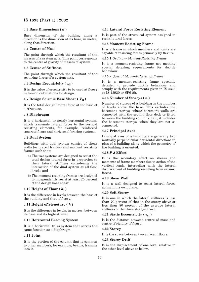
4.3 Base Dimensions ( d )
Base dimension of the building along adirection is the dimension at its base, in metre,along that direction.
4.4 Centre of Mass
The point through which the resultant of themasses of a system acts. This point correspondsto the centre of gravity of masses of system.
4.5 Centre of Stiffness
The point through which the resultant of therestoring forces of a system acts.
4.6 Design Eccentricity ( edi )
It is the value of eccentricity to be used at floor iin torsion calculations for design.
4.7 Design Seismic Base Shear ( VB )
It is the total design lateral force at the base ofa structure.
4.8 Diaphragm
It is a horizontal, or nearly horizontal system,which transmits lateral forces to the verticalresisting elements, for example, reinforcedconcrete floors and horizontal bracing systems.
4.9 Dual System
Buildings with dual system consist of shearwalls (or braced frames) and moment resistingframes such that:
a) The two systems are designed to resist thetotal design lateral force in proportion totheir lateral stiffness considering theinteraction of the dual system at all floorlevels; and
b) The moment resisting frames are designedto independently resist at least 25 percentof the design base shear.
4.10 Height of Floor ( hi )
It is the difference in levels between the base ofthe building and that of floor i.
4.11 Height of Structure ( h )
It is the difference in levels, in metres, betweenits base and its highest level.
4.12 Horizontal Bracing System
It is a horizontal truss system that serves thesame function as a diaphragm.
4.13 Joint
It is the portion of the column that is commonto other members, for example, beams, framinginto it.
4.14 Lateral Force Resisting Element
It is part of the structural system assigned toresist lateral forces.
4.15 Moment-Resisting Frame
It is a frame in which members and joints arecapable of resisting forces primarily by flexure.
4.15.1 Ordinary Moment-Resisting Frame
It is a moment-resisting frame not meetingspecial detailing requirements for ductilebehaviour.
4.15.2 Special Moment-Resisting Frame
It is a moment-resisting frame speciallydetailed to provide ductile behaviour andcomply with the requirements given in IS 4326or IS 13920 or SP6 (6).
4.16 Number of Storeys ( n )
Number of storeys of a building is the numberof levels above the base. This excludes thebasement storeys, where basement walls areconnected with the ground floor deck or fittedbetween the building columns. But, it includesthe basement storeys, when they are not soconnected.
4.17 Principal Axes
Principal axes of a building are generally twomutually perpendicular horizontal directions inplan of a building along which the geometry ofthe building is oriented.
4.18 P-∆∆∆∆ Effect
It is the secondary effect on shears andmoments of frame members due to action of thevertical loads, interacting with the lateraldisplacement of building resulting from seismicforces.
4.19 Shear Wall
It is a wall designed to resist lateral forcesacting in its own plane.
4.20 Soft Storey
It is one in which the lateral stiffness is lessthan 70 percent of that in the storey above orless than 80 percent of the average lateralstiffness of the three storeys above.
4.21 Static Eccentricity ( esi )
It is the distance between centre of mass andcentre of rigidity of floor i.
4.22 Storey
It is the space between two adjacent floors.
4.23 Storey Drift
It is the displacement of one level relative tothe other level above or below.
IS 1893 (Part 1) : 2002
11
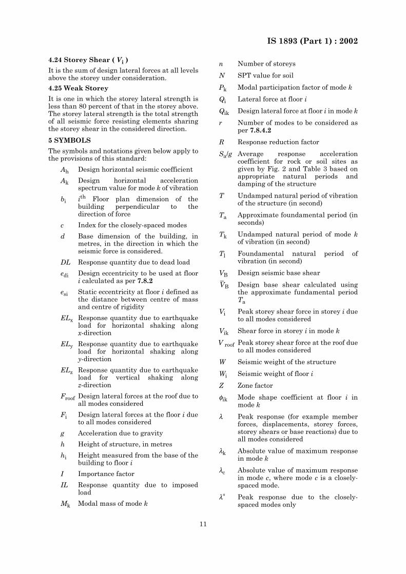
4.24 Storey Shear ( Vi )
It is the sum of design lateral forces at all levelsabove the storey under consideration.
4.25 Weak Storey
It is one in which the storey lateral strength isless than 80 percent of that in the storey above.The storey lateral strength is the total strengthof all seismic force resisting elements sharingthe storey shear in the considered direction.
5 SYMBOLS
The symbols and notations given below apply tothe provisions of this standard:
Ah Design horizontal seismic coefficient
Ak Design horizontal accelerationspectrum value for mode k of vibration
bi ith Floor plan dimension of thebuilding perpendicular to thedirection of force
c Index for the closely-spaced modes
d Base dimension of the building, inmetres, in the direction in which theseismic force is considered.
DL Response quantity due to dead load
edi Design eccentricity to be used at floori calculated as per 7.8.2
esi Static eccentricity at floor i defined asthe distance between centre of massand centre of rigidity
ELx Response quantity due to earthquakeload for horizontal shaking alongx-direction
ELy Response quantity due to earthquakeload for horizontal shaking alongy-direction
ELz Response quantity due to earthquakeload for vertical shaking alongz-direction
Froof Design lateral forces at the roof due toall modes considered
Fi Design lateral forces at the floor i dueto all modes considered
g Acceleration due to gravity
h Height of structure, in metres
hi Height measured from the base of thebuilding to floor i
I Importance factor
IL Response quantity due to imposedload
Mk Modal mass of mode k
n Number of storeys
N SPT value for soil
Pk Modal participation factor of mode k
Qi Lateral force at floor i
Qik Design lateral force at floor i in mode k
r Number of modes to be considered asper 7.8.4.2
R Response reduction factor
Sa/g Average response accelerationcoefficient for rock or soil sites asgiven by Fig. 2 and Table 3 based onappropriate natural periods anddamping of the structure
T Undamped natural period of vibrationof the structure (in second)
Ta Approximate foundamental period (inseconds)
Tk Undamped natural period of mode kof vibration (in second)
Tl Foundamental natural period ofvibration (in second)
VB Design seismic base shear
Design base shear calculated usingthe approximate fundamental periodTa
Vi Peak storey shear force in storey i dueto all modes considered
Vik Shear force in storey i in mode k
V roof Peak storey shear force at the roof dueto all modes considered
W Seismic weight of the structure
Wi Seismic weight of floor i
Z Zone factor
φik Mode shape coefficient at floor i inmode k
λ Peak response (for example memberforces, displacements, storey forces,storey shears or base reactions) due toall modes considered
λk Absolute value of maximum responsein mode k
λc Absolute value of maximum responsein mode c, where mode c is a closely-spaced mode.
λ∗ Peak response due to the closely-spaced modes only
VB

IS 1893 (Part 1) : 2002
12
6 GENERAL PRINCIPLES AND DESIGN CRITERIA6.1 General Principles
6.1.1 Ground MotionThe characteristics (intensity, duration, etc) ofseismic ground vibrations expected at anylocation depends upon the magnitude ofearthquake, its depth of focus, distance fromthe epicentre, characteristics of the paththrough which the seismic waves travel, andthe soil strata on which the structure stands.The random earthquake ground motions, whichcause the structure to vibrate, can be resolvedin any three mutually perpendicular directions.The predominant direction of ground vibrationis usually horizontal.Earthquake-generated vertical inertia forces areto be considered in design unless checked andproven by specimen calculations to be notsignificant. Vertical acceleration should beconsidered in structures with large spans, thosein which stability is a criterion for design, or foroverall stability analysis of structures. Reductionin gravity force due to vertical component ofground motions can be particularly detrimentalin cases of prestressed horizontal members andof cantilevered members. Hence, specialattention should be paid to the effect of verticalcomponent of the ground motion on prestressedor cantilevered beams, girders and slabs.6.1.2 The response of a structure to groundvibrations is a function of the nature offoundation soil; materials, form, size and mode ofconstruction of structures; and the duration andcharacteristics of ground motion. This standardspecifies design forces for structures standing onrocks or soils which do not settle, liquefy or slidedue to loss of strength during ground vibrations.6.1.3 The design approach adopted in thisstandard is to ensure that structures possess atleast a minimum strength to withstand minorearthquakes (<DBE), which occur frequently,without damage; resist moderate earthquakes(DBE) without significant structural damagethough some non-structural damage may occur;and aims that structures withstand a majorearthquake (MCE) without collapse. Actualforces that appear on structures duringearthquakes are much greater than the designforces specified in this standard. However,ductility, arising from inelastic materialbehaviour and detailing, and overstrength,arising from the additional reserve strength instructures over and above the design strength,are relied upon to account for this difference in
actual and design lateral loads.Reinforced and prestressed concrete membersshall be suitably designed to ensure thatpremature failure due to shear or bond does notoccur, subject to the provisions of IS 456 and IS1343. Provisions for appropriate ductiledetailing of reinforced concrete members aregiven in IS 13920.In steel structures, members and theirconnections should be so proportioned that highductility is obtained vide SP 6 (Part 6), avoidingpremature failure due to elastic or inelasticbuckling of any type.The specified earthquake loads are based uponpostelastic energy dissipation in the structureand because of this fact, the provision of thisstandard for design, detailing and constructionshall be satisfied even for structures andmembers for which load combinations that donot contain the earthquake effect indicatelarger demands than combinations includingearthquake.6.1.4 Soil-Structure InteractionThe soil-structure interaction refers to theeffects of the supporting foundation medium onthe motion of structure. The soil-structureinteraction may not be considered in theseismic analysis for structures supported onrock or rock-like material.6.1.5 The design lateral force specified in thisstandard shall be considered in each of the twoorthogonal horizontal directions of thestructure. For structures which have lateralforce resisting elements in the two orthogonaldirections only, the design lateral force shall beconsidered along one direction at a time, andnot in both directions simultaneously.Structures, having lateral force resistingelements (for example frames, shear walls) indirections other than the two orthogonaldirections, shall be analysed considering theload combinations specified in 6.3.2.Where both horizontal and vertical seismicforces are taken into account, load combinationsspecified in 6.3.3 shall be considered.6.1.6 Equipment and other systems, which aresupported at various floor levels of thestructure, will be subjected to motionscorresponding to vibration at their supportpoints. In important cases, it may be necessaryto obtain floor response spectra for design ofequipment supports. For detail reference bemade to IS 1893 (Part 4).6.1.7 Additions to Existing StructuresAdditions shall be made to existing structuresonly as follows:
a) An addition that is structurallyindependent from an existing structuresshall be designed and constructed inaccordance with the seismic requirementsfor new structures.
ρij Coefficient used in the CompleteQuadratic Combination (CQC)method while combining responses ofmodes i and j
ωi Circular frequency in rad/second inthe ith mode
IS 1893 (Part 1) : 2002
13
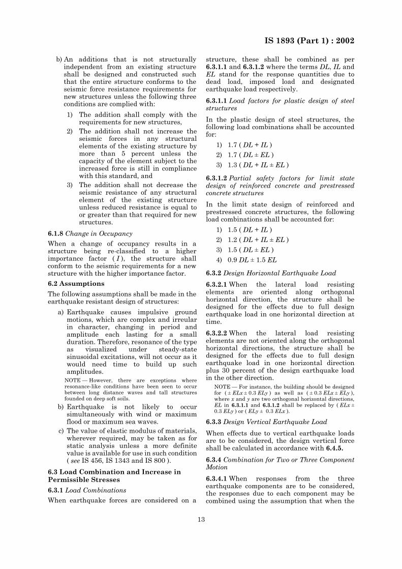
b) An additions that is not structurallyindependent from an existing structureshall be designed and constructed suchthat the entire structure conforms to theseismic force resistance requirements fornew structures unless the following threeconditions are complied with:
6.1.8 Change in Occupancy
When a change of occupancy results in astructure being re-classified to a higherimportance factor ( I ), the structure shallconform to the seismic requirements for a newstructure with the higher importance factor.
6.2 Assumptions
The following assumptions shall be made in theearthquake resistant design of structures:
6.3 Load Combination and Increase in Permissible Stresses
6.3.1 Load Combinations
When earthquake forces are considered on a
structure, these shall be combined as per6.3.1.1 and 6.3.1.2 where the terms DL, IL andEL stand for the response quantities due todead load, imposed load and designatedearthquake load respectively.
6.3.1.1 Load factors for plastic design of steelstructures
In the plastic design of steel structures, thefollowing load combinations shall be accountedfor:
6.3.1.2 Partial safety factors for limit statedesign of reinforced concrete and prestressedconcrete structures
In the limit state design of reinforced andprestressed concrete structures, the followingload combinations shall be accounted for:
6.3.2 Design Horizontal Earthquake Load
6.3.2.1 When the lateral load resistingelements are oriented along orthogonalhorizontal direction, the structure shall bedesigned for the effects due to full designearthquake load in one horizontal direction attime.
6.3.2.2 When the lateral load resistingelements are not oriented along the orthogonalhorizontal directions, the structure shall bedesigned for the effects due to full designearthquake load in one horizontal directionplus 30 percent of the design earthquake loadin the other direction.
NOTE — For instance, the building should be designedfor ( ± ELx ± 0.3 ELy ) as well as ( ± 0.3 ELx ± ELy ),where x and y are two orthogonal horizontal directions,EL in 6.3.1.1 and 6.3.1.2 shall be replaced by ( ELx ±0.3 ELy ) or ( ELy ± 0.3 ELx ).
6.3.3 Design Vertical Earthquake Load
When effects due to vertical earthquake loadsare to be considered, the design vertical forceshall be calculated in accordance with 6.4.5.
6.3.4 Combination for Two or Three ComponentMotion
6.3.4.1 When responses from the threeearthquake components are to be considered,the responses due to each component may becombined using the assumption that when the
1) The addition shall comply with therequirements for new structures,
2) The addition shall not increase theseismic forces in any structuralelements of the existing structure bymore than 5 percent unless thecapacity of the element subject to theincreased force is still in compliancewith this standard, and
3) The addition shall not decrease theseismic resistance of any structuralelement of the existing structureunless reduced resistance is equal toor greater than that required for newstructures.
a) Earthquake causes impulsive groundmotions, which are complex and irreularin character, changing in period andamplitude each lasting for a smallduration. Therefore, resonance of the typeas visualized under steady-statesinusoidal excitations, will not occur as itwould need time to build up suchamplitudes.
NOTE — However, there are exceptions whereresonance-like conditions have been seen to occurbetween long distance waves and tall structuresfounded on deep soft soils.
b) Earthquake is not likely to occursimultaneously with wind or maximumflood or maximum sea waves.
c) The value of elastic modulus of materials,wherever required, may be taken as forstatic analysis unless a more definitevalue is available for use in such condition( see IS 456, IS 1343 and IS 800 ).
1) 1.7 ( DL + IL )2) 1.7 ( DL ± EL )3) 1.3 ( DL + IL ± EL )
1) 1.5 ( DL + IL )2) 1.2 ( DL + IL ± EL )3) 1.5 ( DL ± EL )4) 0.9 DL ± 1.5 EL
IS 1893 (Part 1) : 2002
14
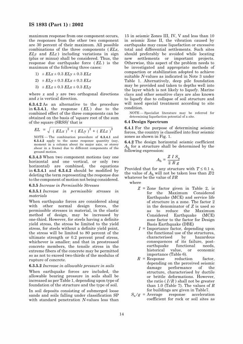
maximum response from one component occurs,the responses from the other two componentare 30 percent of their maximum. All possiblecombinations of the three components ( ELx,ELy and ELz ) including variations in sign(plus or minus) shall be considered. Thus, theresponse due earthquake force ( EL ) is themaximum of the following three cases:
where x and y are two orthogonal directionsand z is vertical direction.6.3.4.2 As an alternative to the procedurein 6.3.4.1, the response ( EL ) due to thecombined effect of the three components can beobtained on the basis of ‘square root of the sumof the square (SRSS)’ that is
NOTE — The combination procedure of 6.3.4.1 and6.3.4.2 apply to the same response quantity (say,moment in a column about its major axis, or storeyshear in a frame) due to different components of theground motion.
6.3.4.3 When two component motions (say onehorizontal and one vertical, or only twohorizontal) are combined, the equationsin 6.3.4.1 and 6.3.4.2 should be modified bydeleting the term representing the response dueto the component of motion not being considered.6.3.5 Increase in Permissible Stresses6.3.5.1 Increase in permissible stresses inmaterialsWhen earthquake forces are considered alongwith other normal design forces, thepermissible stresses in material, in the elasticmethod of design, may be increased byone-third. However, for steels having a definiteyield stress, the stress be limited to the yieldstress, for steels without a definite yield point,the stress will be limited to 80 percent of theultimate strength or 0.2 percent proof stress,whichever is smaller; and that in prestressedconcrete members, the tensile stress in theextreme fibers of the concrete may be permittedso as not to exceed two-thirds of the modulus ofrupture of concrete.6.3.5.2 Increase in allowable pressure in soilsWhen earthquake forces are included, theallowable bearing pressure in soils shall beincreased as per Table 1, depending upon type offoundation of the structure and the type of soil.In soil deposits consisting of submerged loosesands and soils falling under classification SPwith standard penetration N-values less than
15 in seismic Zones III, IV, V and less than 10in seismic Zone II, the vibration caused byearthquake may cause liquefaction or excessivetotal and differential settlements. Such sitesshould preferably be avoided while locatingnew settlements or important projects.Otherwise, this aspect of the problem needs tobe investigated and appropriate methods ofcompaction or stabilization adopted to achievesuitable N-values as indicated in Note 3 underTable 1. Alternatively, deep pile foundationmay be provided and taken to depths well intothe layer which is not likely to liquefy. Marineclays and other sensitive clays are also knownto liquefy due to collapse of soil structure andwill need special treatment according to sitecondition.
NOTE — Specialist literature may be referred fordetermining liquefaction potential of a site.
6.4 Design Spectrum
6.4.1 For the purpose of determining seismicforces, the country is classified into four seismiczones as shown in Fig. 1.6.4.2 The design horizontal seismic coefficientAh for a structure shall be determined by thefollowing expression:
Provided that for any structure with T ≤ 0.1 s,the value of Ah will not be taken less than Z/2whatever be the value of I/R
where
1) ± ELx ± 0.3 ELy ± 0.3 ELz
2) ± ELy ± 0.3 ELx ± 0.3 ELz
3) ± ELz ± 0.3 ELx ± 0.3 ELy
EL = ELx ( )2 + ELy ( )2 + ELz ( )2
Ah =
Z = Zone factor given in Table 2, isfor the Maximum ConsideredEarthquake (MCE) and service lifeof structure in a zone. The factor 2in the denominator of Z is used soas to reduce the MaximumConsidered Earthquake (MCE)zone factor to the factor for DesignBasis Earthquake (DBE)
I = Importance factor, depending uponthe functional use of the structures,characterised by hazardousconsequences of its failure, post-earthquake functional needs,historical value, or economicimportance (Table 6).
R = Response reduction factor,depending on the perceived seismicdamage performance of thestructure, characterised by ductileor brittle deformations. However,the ratio ( I/R ) shall not be greaterthan 1.0 (Table 7). The values of Rfor buildings are given in Table7.
Sa/g = Average response accelerationcoefficient for rock or soil sites as
Z I Sa2 R g------------------
IS 1893 (Part 1) : 2002
15
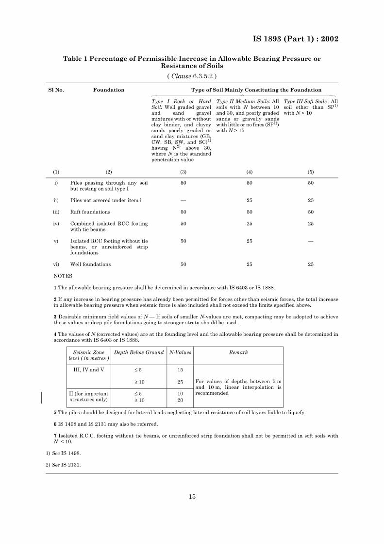
Table 1 Percentage of Permissible Increase in Allowable Bearing Pressure or Resistance of Soils
( Clause 6.3.5.2 )
Sl No. Foundation Type of Soil Mainly Constituting the Foundation
Type I Rock or HardSoil: Well graded graveland sand gravelmixtures with or withoutclay binder, and clayeysands poorly graded orsand clay mixtures (GB,CW, SB, SW, and SC)1)
having N2) above 30,where N is the standardpenetration value
Type II Medium Soils: Allsoils with N between 10and 30, and poorly gradedsands or gravelly sandswith little or no fines (SP1))with N > 15
Type III Soft Soils : Allsoil other than SP1)
with N < 10
(1) (2) (3) (4) (5)
i) Piles passing through any soilbut resting on soil type I
50 50 50
ii) Piles not covered under item i — 25 25
iii) Raft foundations 50 50 50
iv) Combined isolated RCC footingwith tie beams
50 25 25
v) Isolated RCC footing without tiebeams, or unreinforced stripfoundations
50 25 —
vi) Well foundations 50 25 25
NOTES
1 The allowable bearing pressure shall be determined in accordance with IS 6403 or IS 1888.
2 If any increase in bearing pressure has already been permitted for forces other than seismic forces, the total increasein allowable bearing pressure when seismic force is also included shall not exceed the limits specified above.
3 Desirable minimum field values of N — If soils of smaller N-values are met, compacting may be adopted to achievethese values or deep pile foundations going to stronger strata should be used.
4 The values of N (corrected values) are at the founding level and the allowable bearing pressure shall be determined inaccordance with IS 6403 or IS 1888.
Seismic Zone level ( in metres )
Depth Below Ground N-Values Remark
III, IV and V ≤ 5
≥ 10
15
25 For values of depths between 5 mand 10 m, linear interpolation isrecommendedII (for important
structures only)≤ 5≥ 10
1020
5 The piles should be designed for lateral loads neglecting lateral resistance of soil layers liable to liquefy.
6 IS 1498 and IS 2131 may also be referred.
7 Isolated R.C.C. footing without tie beams, or unreinforced strip foundation shall not be permitted in soft soils withN < 10.
1) See IS 1498.
2) See IS 2131.
IS 1893 (Part 1) : 2002
16
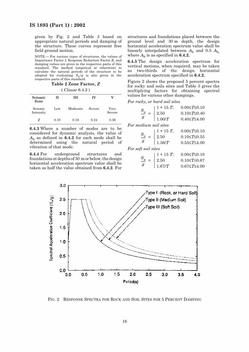
given by Fig. 2 and Table 3 based onappropriate natural periods and damping ofthe structure. These curves represent freefield ground motion.NOTE — For various types of structures, the values ofImportance Factor I, Response Reduction Factor R, anddamping values are given in the respective parts of thisstandard. The method (empirical or otherwise) tocalculate the natural periods of the structure to beadopted for evaluating Sa/g is also given in therespective parts of this standard.
6.4.3 Where a number of modes are to beconsidered for dynamic analysis, the value ofAh as defined in 6.4.2 for each mode shall bedetermined using the natural period ofvibration of that mode.
6.4.4 For underground structures andfoundations at depths of 30 m or below, the designhorizontal acceleration spectrum value shall betaken as half the value obtained from 6.4.2. For
structures and foundations placed between theground level and 30 m depth, the designhorizontal acceleration spectrum value shall belinearly interpolated between Ah and 0.5 Ah,where Ah is as specified in 6.4.2.
6.4.5 The design acceleration spectrum forvertical motions, when required, may be takenas two-thirds of the design horizontalacceleration spectrum specified in 6.4.2.
Figure 2 shows the proposed 5 percent spectrafor rocky and soils sites and Table 3 gives themultiplying factors for obtaining spectralvalues for various other dampings.
Table 2 Zone Factor, Z( Clause 6.4.2 )
Seismic Zone
II III IV V
Seismic Intensity
Low Moderate Severe Very Severe
Z 0.10 0.16 0.24 0.36
For rocky, or hard soil sites
=1 + 15 T; 0.00≤T≤0.102.50 0.10≤T≤0.401.00/T 0.40≤T≤4.00
For medium soil sites
=1 + 15 T, 0.00≤T≤0.102.50 0.10≤T≤0.551.36/T 0.55≤T≤4.00
For soft soil sites
=1 + 15 T; 0.00≤T≤0.102.50 0.10≤T≤0.671.67/T 0.67≤T≤4.00
Sa
g------
Sa
g------
Sa
g------
FIG. 2 RESPONSE SPECTRA FOR ROCK AND SOIL SITES FOR 5 PERCENT DAMPING
IS 1893 (Part 1) : 2002
17
6.4.6 In case design spectrum is specificallyprepared for a structure at a particular projectsite, the same may be used for design at thediscretion of the project authorities.
7 BUILDINGS
7.1 Regular and Irregular Configuration
To perform well in an earthquake, a buildingshould possess four main attributes, namelysimple and regular configuration, and adequatelateral strength, stiffness and ductility.Buildings having simple regular geometry anduniformly distributed mass and stiffness inplan as well as in elevation, suffer much lessdamage than buildings with irregularconfigurations. A building shall be consideredas irregular for the purposes of this standard, ifat least one of the conditions given in Tables 4and 5 is applicable.
7.2 Importance Factor I and Response Reduction Factor R
The minimum value of importance factor, I, fordifferent building systems shall be as given inTable 6. The response reduction factor, R, fordifferent building systems shall be as given inTable 7.
7.3 Design Imposed Loads for Earthquakes Force Calculation
7.3.1 For various loading classes as specified inIS 875 (Part 2), the earthquake force shall becalculated for the full dead load plus thepercentage of imposed load as given in Table 8.
7.3.2 For calculating the design seismic forcesof the structure, the imposed load on roof neednot be considered.
7.3.3 The percentage of imposed loads givenin 7.3.1 and 7.3.2 shall also be used for ‘Wholeframe loaded’ condition in the loadcombinations specified in 6.3.1.1 and 6.3.1.2where the gravity loads are combined with the
earthquake loads [that is, in load combinations(3) in 6.3.1.1, and (2) in 6.3.1.2]. No furtherreduction in the imposed load will be used asenvisaged in IS 875 (Part 2) for number ofstoreys above the one under consideration orfor large spans of beams or floors.
7.3.4 The proportions of imposed load indicatedabove for calculating the lateral design forcesfor earthquakes are applicable to averageconditions. Where the probable loads at thetime of earthquake are more accuratelyassessed, the designer may alter theproportions indicated or even replace the entireimposed load proportions by the actualassessed load. In such cases, where the imposedload is not assessed as per 7.3.1 and 7.3.2 onlythat part of imposed load, which possessesmass, shall be considered. Lateral design forcefor earthquakes shall not be calculated oncontribution of impact effects from imposedloads.
7.3.5 Other loads apart from those given above(for example snow and permanent equipment)shall be considered as appropriate.
7.4 Seismic Weight
7.4.1 Seismic Weight of Floors
The seismic weight of each floor is its full deadload plus appropriate amount of imposed load,as specified in 7.3.1 and 7.3.2. While computingthe seismic weight of each floor, the weight ofcolumns and walls in any storey shall beequally distributed to the floors above andbelow the storey.
7.4.2 Seismic Weight of Building
The seismic weight of the whole building is thesum of the seismic weights of all the floors.
7.4.3 Any weight supported in between storeysshall be distributed to the floors above andbelow in inverse proportion to its distance fromthe floors.
Table 3 Multiplying Factors for Obtaining Values for Other Damping( Clause 6.4.2 )
Damping, percent
0 2 5 7 10 15 20 25 30
Factors 3.20 1.40 1.00 0.90 0.80 0.70 0.60 0.55 0.50
IS 1893 (Part 1) : 2002
18
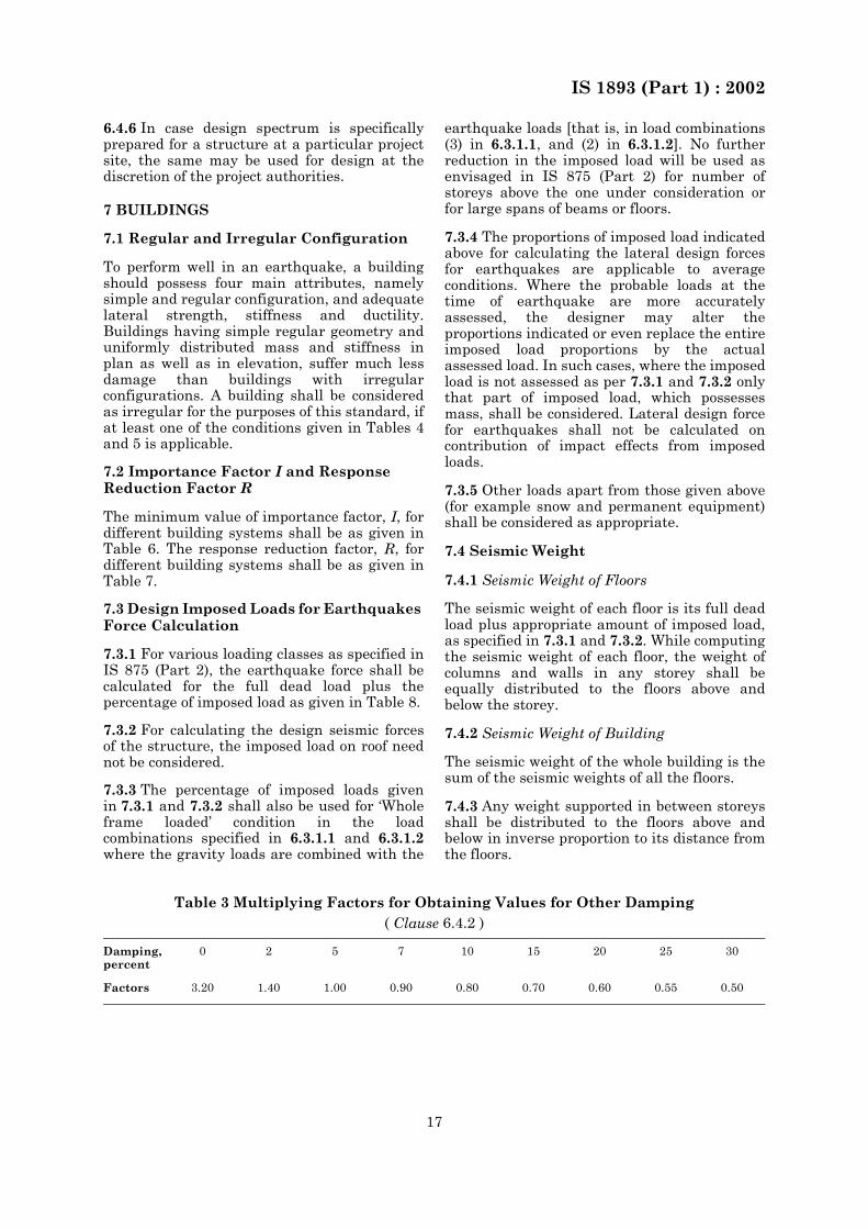
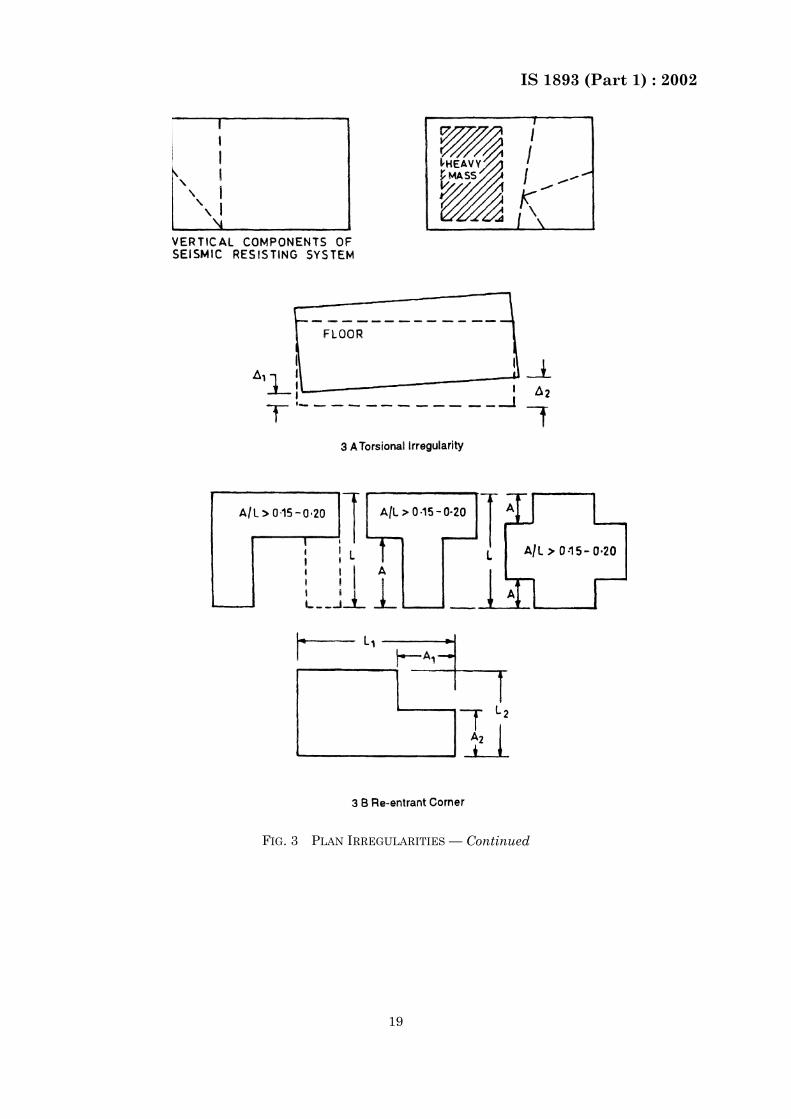
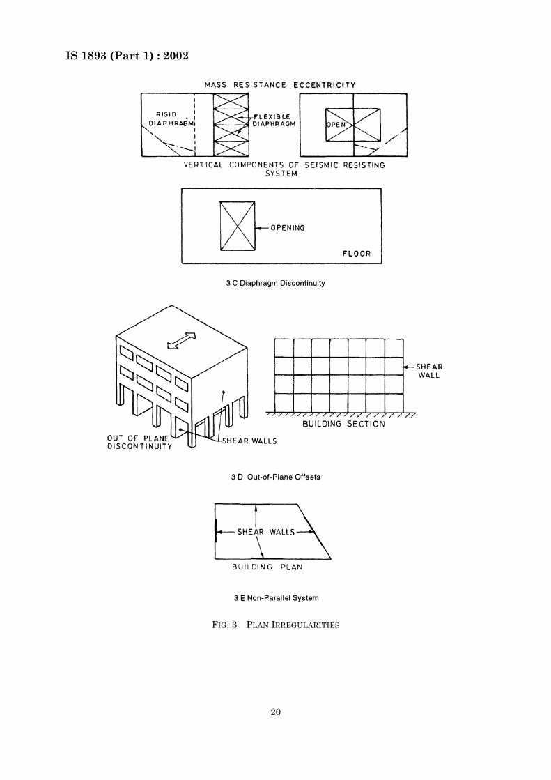
Table 4 Definitions of Irregular Buildings — Plan Irregularities (Fig. 3)
( Clause 7.1 )Sl No. Irregularity Type and Description
(1) (2)i) Torsion Irregularity
To be considered when floor diaphragms are rigid intheir own plan in relation to the vertical structuralelements that resist the lateral forces. Torsionalirregularity to be considered to exist when themaximum storey drift, computed with designeccentricity, at one end of the structures transverseto an axis is more than 1.2 times the average of thestorey drifts at the two ends of the structure
ii) Re-entrant CornersPlan configurations of a structure and its lateralforce resisting system contain re-entrant corners,where both projections of the structure beyond there-entrant corner are greater than 15 percent of itsplan dimension in the given direction
iii) Diaphragm DiscontinuityDiaphragms with abrupt discontinuities orvariations in stiffness, including those havingcut-out or open areas greater than 50 percent of thegross enclosed diaphragm area, or changes ineffective diaphragm stiffness of more than 50percent from one storey to the next
iv) Out-of-Plane OffsetsDiscontinuities in a lateral force resistance path,such as out-of-plane offsets of vertical elements
v) Non-parallel SystemsThe vertical elements resisting the lateral force arenot parallel to or symmetric about the majororthogonal axes or the lateral force resisting elements
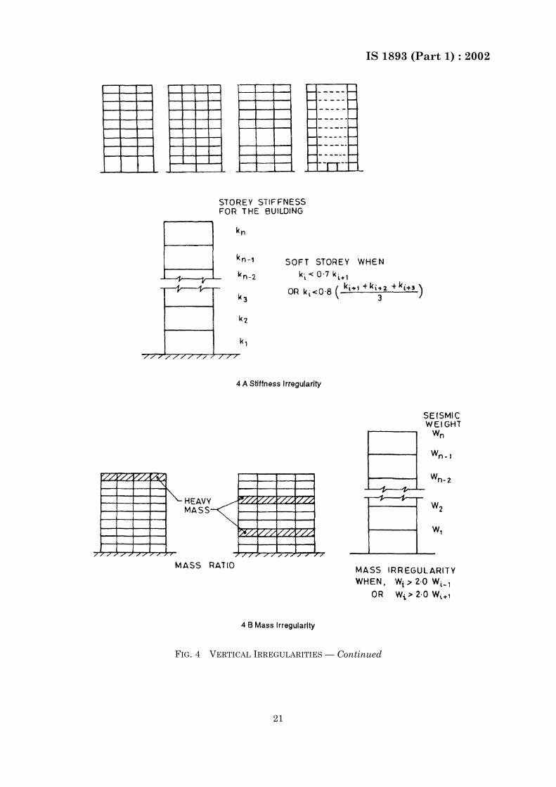
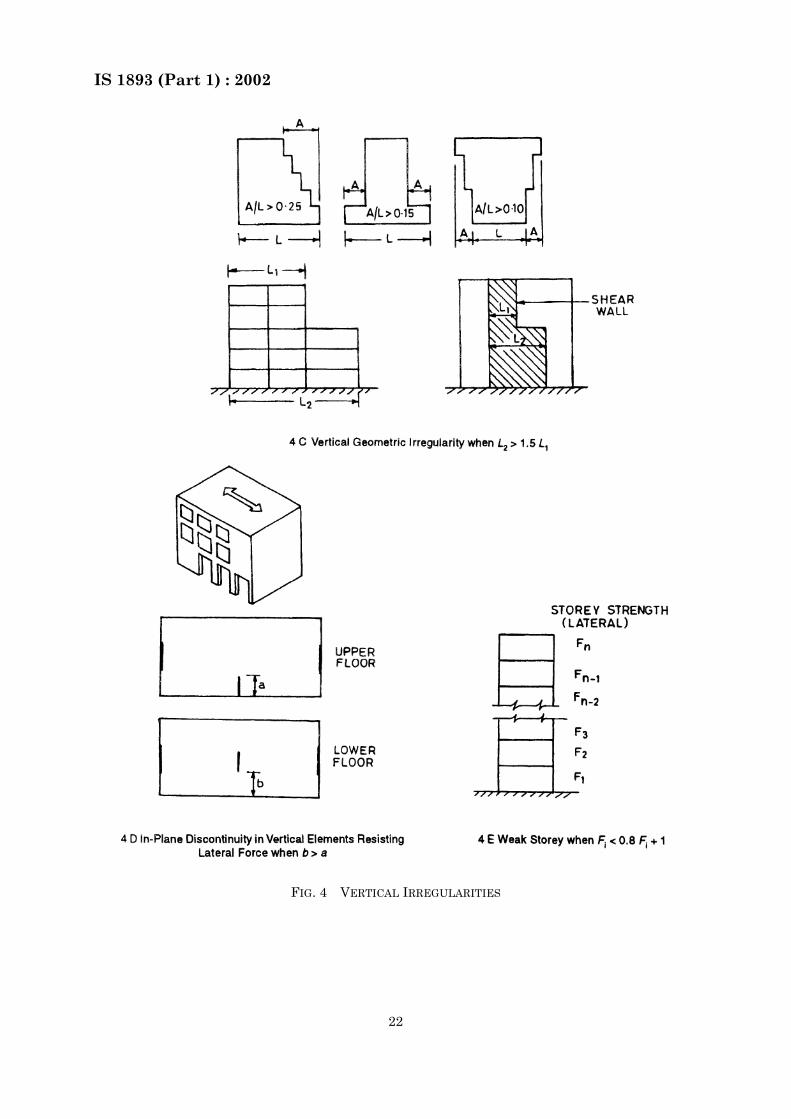
Table 5 Definition of Irregular Buildings — Vertical Irregularities (Fig.4)
( Clause 7.1 )
Sl No. Irregularity Type and Description
(1) (2)
i) a) Stiffness Irregularity — Soft Storey
A soft storey is one in which the lateral stiffness isless than 70 percent of that in the storey above orless than 80 percent of the average lateral stiffnessof the three storeys above
b) Stiffness Irregularity — Extreme Soft Storey
A extreme soft storey is one in which the lateralstiffness is less than 60 percent of that in the storeyabove or less than 70 percent of the averagestiffness of the three storeys above. For example,buildings on STILTS will fall under this category.
Table 5 — Concluded
Sl No. Irregularity Type and Description
(1) (2)
ii) Mass Irregularity
Mass irregularity shall be considered to exist wherethe seismic weight of any storey is more than 200percent of that of its adjacent storeys. Theirregularity need not be considered in case of roofs
iii) Vertical Geometric Irregularity
Vertical geometric irregularity shall be consideredto exist where the horizontal dimension of thelateral force resisting system in any storey is morethan 150 percent of that in its adjacent storey
iv) In-Plane Discontinuity in Vertical ElementsResisting Lateral Force
A in-plane offset of the lateral force resistingelements greater than the length of those elements
v) Discontinuity in Capacity — Weak Strorey
A weak storey is one in which the storey lateralstrength is less than 80 percent of that in the storeyabove. The storey lateral strength is the totalstrength of all seismic force resisting elementssharing the storey shear in the considered direction.
Table 6 Importance Factors, I( Clause 6.4.2 )
Sl No. Structure Importance Factor
(1) (2) (3)
i) Important service and communitybuildings, such as hospitals; schools;monumental structures; emergencybuildings like telephone exchange,television stations, radio stations,railway stations, fire station buildings;large community halls like cinemas,assembly halls and subway stations,power stations
1.5
ii) All other buildings 1.0
NOTES
1 The design engineer may choose values of importancefactor I greater than those mentioned above.
2 Buildings not covered in SI No. (i) and (ii) above maybe designed for higher value of I, depending on economy,strategy considerations like multi-storey buildingshaving several residential units.
3 This does not apply to temporary structures likeexcavation, scaffolding etc of short duration.
IS 1893 (Part 1) : 2002
19
FIG. 3 PLAN IRREGULARITIES — Continued
IS 1893 (Part 1) : 2002
20
FIG. 3 PLAN IRREGULARITIES
IS 1893 (Part 1) : 2002
21
FIG. 4 VERTICAL IRREGULARITIES — Continued
IS 1893 (Part 1) : 2002
22
FIG. 4 VERTICAL IRREGULARITIES
IS 1893 (Part 1) : 2002
23
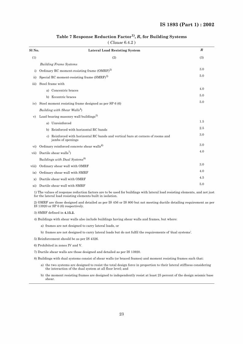
Table 7 Response Reduction Factor1), R, for Building Systems( Clause 6.4.2 )
Sl No. Lateral Load Resisting System R
(1) (2) (3)
Building Frame Systems
i) Ordinary RC moment-resisting frame (OMRF)2) 3.0
ii) Special RC moment-resisting frame (SMRF)3) 5.0
iii) Steel frame with
a) Concentric braces 4.0
b) Eccentric braces 5.0
iv) Steel moment resisting frame designed as per SP 6 (6) 5.0
Building with Shear Walls4)
v) Load bearing masonry wall buildings5)
a) Unreinforced 1.5
b) Reinforced with horizontal RC bands 2.5
c) Reinforced with horizontal RC bands and vertical bars at corners of rooms andjambs of openings
3.0
vi) Ordinary reinforced concrete shear walls6) 3.0
vii) Ductile shear walls7) 4.0
Buildings with Dual Systems8)
viii) Ordinary shear wall with OMRF 3.0
ix) Ordinary shear wall with SMRF 4.0
x) Ductile shear wall with OMRF 4.5
xi) Ductile shear wall with SMRF 5.0
1) The values of response reduction factors are to be used for buildings with lateral load resisting elements, and not justfor the lateral load resisting elements built in isolation.
2) OMRF are those designed and detailed as per IS 456 or IS 800 but not meeting ductile detailing requirement as perIS 13920 or SP 6 (6) respectively.
3) SMRF defined in 4.15.2.
4) Buildings with shear walls also include buildings having shear walls and frames, but where:
a) frames are not designed to carry lateral loads, or
b) frames are not designed to carry lateral loads but do not fulfil the requirements of ‘dual systems’.
5) Reinforcement should be as per IS 4326.
6) Prohibited in zones IV and V.
7) Ductile shear walls are those designed and detailed as per IS 13920.
8) Buildings with dual systems consist of shear walls (or braced frames) and moment resisting frames such that:
a) the two systems are designed to resist the total design force in proportion to their lateral stiffness considering the interaction of the dual system at all floor level; and
b) the moment resisting frames are designed to independently resist at least 25 percent of the design seismic base shear.
IS 1893 (Part 1) : 2002
24
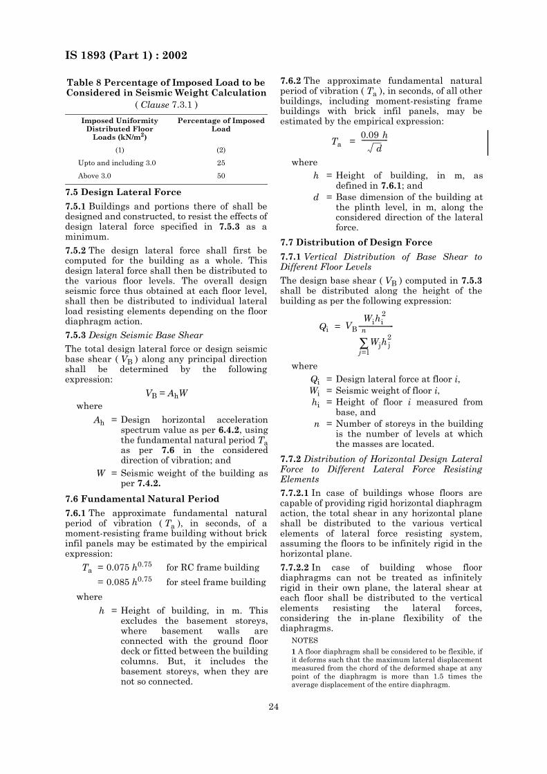
7.5 Design Lateral Force
7.5.1 Buildings and portions there of shall bedesigned and constructed, to resist the effects ofdesign lateral force specified in 7.5.3 as aminimum.
7.5.2 The design lateral force shall first becomputed for the building as a whole. Thisdesign lateral force shall then be distributed tothe various floor levels. The overall designseismic force thus obtained at each floor level,shall then be distributed to individual lateralload resisting elements depending on the floordiaphragm action.
7.5.3 Design Seismic Base Shear
The total design lateral force or design seismicbase shear ( VB ) along any principal directionshall be determined by the followingexpression:
VB = AhWwhere
7.6 Fundamental Natural Period
7.6.1 The approximate fundamental naturalperiod of vibration ( Ta ), in seconds, of amoment-resisting frame building without brickinfil panels may be estimated by the empiricalexpression:
where
7.6.2 The approximate fundamental naturalperiod of vibration ( Ta ), in seconds, of all otherbuildings, including moment-resisting framebuildings with brick infil panels, may beestimated by the empirical expression:
where
7.7 Distribution of Design Force
7.7.1 Vertical Distribution of Base Shear toDifferent Floor Levels
The design base shear ( VB ) computed in 7.5.3shall be distributed along the height of thebuilding as per the following expression:
where
7.7.2 Distribution of Horizontal Design LateralForce to Different Lateral Force ResistingElements
7.7.2.1 In case of buildings whose floors arecapable of providing rigid horizontal diaphragmaction, the total shear in any horizontal planeshall be distributed to the various verticalelements of lateral force resisting system,assuming the floors to be infinitely rigid in thehorizontal plane.
7.7.2.2 In case of building whose floordiaphragms can not be treated as infinitelyrigid in their own plane, the lateral shear ateach floor shall be distributed to the verticalelements resisting the lateral forces,considering the in-plane flexibility of thediaphragms.
NOTES
1 A floor diaphragm shall be considered to be flexible, ifit deforms such that the maximum lateral displacementmeasured from the chord of the deformed shape at anypoint of the diaphragm is more than 1.5 times theaverage displacement of the entire diaphragm.
Table 8 Percentage of Imposed Load to be Considered in Seismic Weight Calculation
( Clause 7.3.1 )
Imposed Uniformity Distributed Floor
Loads (kN/m2)
Percentage of Imposed Load
(1) (2)
Upto and including 3.0 25
Above 3.0 50
Ah = Design horizontal accelerationspectrum value as per 6.4.2, usingthe fundamental natural period Taas per 7.6 in the considereddirection of vibration; and
W = Seismic weight of the building asper 7.4.2.
Ta = 0.075 h0.75 for RC frame building
= 0.085 h0.75 for steel frame building
h = Height of building, in m. Thisexcludes the basement storeys,where basement walls areconnected with the ground floordeck or fitted between the buildingcolumns. But, it includes thebasement storeys, when they arenot so connected.
Ta =
h = Height of building, in m, asdefined in 7.6.1; and
d = Base dimension of the building atthe plinth level, in m, along theconsidered direction of the lateralforce.
Qi =
Qi = Design lateral force at floor i,Wi = Seismic weight of floor i,hi = Height of floor i measured from
base, andn = Number of storeys in the building
is the number of levels at whichthe masses are located.
0.09 h d
-----------------
VBWihi
2
Wjh2j
j=l
n
∑-----------------------
IS 1893 (Part 1) : 2002
25
2 Reinforced concrete monolithic slab-beam floors orthose consisting of prefabricated/precast elements withtopping reinforced screed can be taken a rigiddiaphragms.
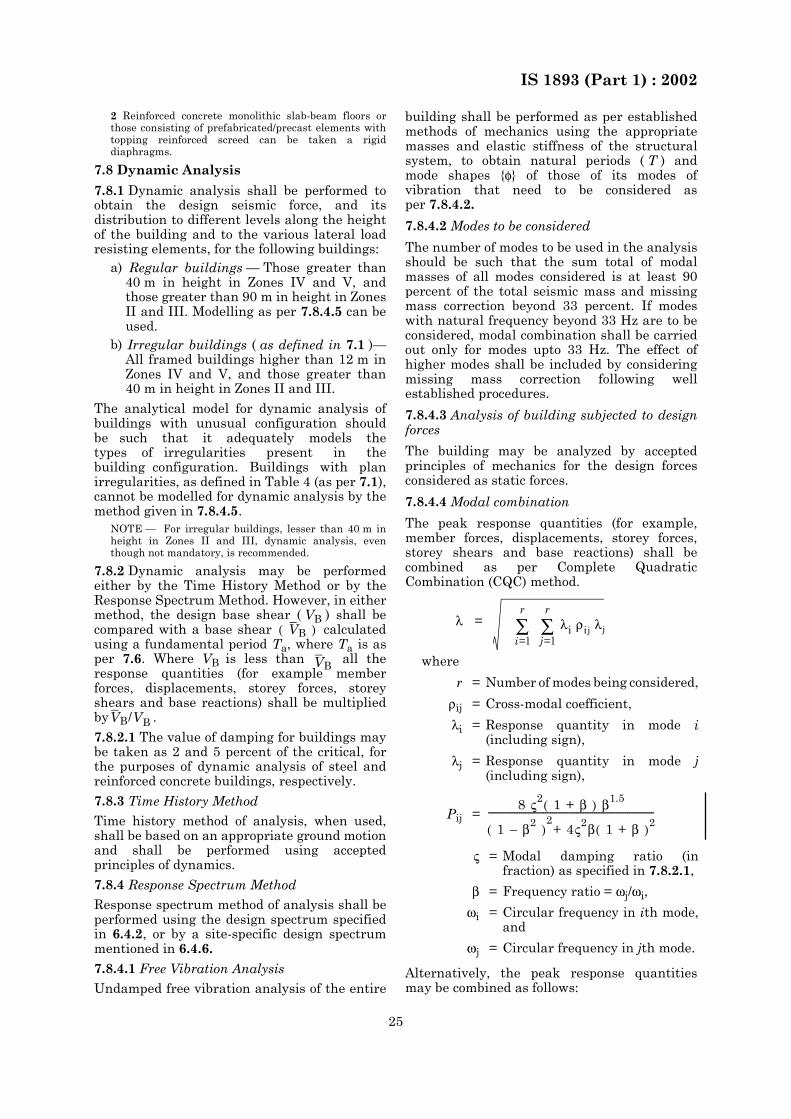
7.8 Dynamic Analysis
7.8.1 Dynamic analysis shall be performed toobtain the design seismic force, and itsdistribution to different levels along the heightof the building and to the various lateral loadresisting elements, for the following buildings:
a) Regular buildings — Those greater than40 m in height in Zones IV and V, andthose greater than 90 m in height in ZonesII and III. Modelling as per 7.8.4.5 can beused.
b) Irregular buildings ( as defined in 7.1 )—All framed buildings higher than 12 m inZones IV and V, and those greater than40 m in height in Zones II and III.
The analytical model for dynamic analysis ofbuildings with unusual configuration shouldbe such that it adequately models thetypes of irregularities present in thebuilding configuration. Buildings with planirregularities, as defined in Table 4 (as per 7.1),cannot be modelled for dynamic analysis by themethod given in 7.8.4.5.
NOTE — For irregular buildings, lesser than 40 m inheight in Zones II and III, dynamic analysis, eventhough not mandatory, is recommended.
7.8.2 Dynamic analysis may be performedeither by the Time History Method or by theResponse Spectrum Method. However, in eithermethod, the design base shear ( VB ) shall becompared with a base shear calculatedusing a fundamental period Ta, where Ta is asper 7.6. Where VB is less than all theresponse quantities (for example memberforces, displacements, storey forces, storeyshears and base reactions) shall be multipliedby .
7.8.2.1 The value of damping for buildings maybe taken as 2 and 5 percent of the critical, forthe purposes of dynamic analysis of steel andreinforced concrete buildings, respectively.
7.8.3 Time History Method
Time history method of analysis, when used,shall be based on an appropriate ground motionand shall be performed using acceptedprinciples of dynamics.
7.8.4 Response Spectrum Method
Response spectrum method of analysis shall beperformed using the design spectrum specifiedin 6.4.2, or by a site-specific design spectrummentioned in 6.4.6.
7.8.4.1 Free Vibration Analysis
Undamped free vibration analysis of the entire
building shall be performed as per establishedmethods of mechanics using the appropriatemasses and elastic stiffness of the structuralsystem, to obtain natural periods ( T ) andmode shapes {φ} of those of its modes ofvibration that need to be considered asper 7.8.4.2.
7.8.4.2 Modes to be considered
The number of modes to be used in the analysisshould be such that the sum total of modalmasses of all modes considered is at least 90percent of the total seismic mass and missingmass correction beyond 33 percent. If modeswith natural frequency beyond 33 Hz are to beconsidered, modal combination shall be carriedout only for modes upto 33 Hz. The effect ofhigher modes shall be included by consideringmissing mass correction following wellestablished procedures.
7.8.4.3 Analysis of building subjected to designforces
The building may be analyzed by acceptedprinciples of mechanics for the design forcesconsidered as static forces.
7.8.4.4 Modal combination
The peak response quantities (for example,member forces, displacements, storey forces,storey shears and base reactions) shall becombined as per Complete QuadraticCombination (CQC) method.
where
Alternatively, the peak response quantitiesmay be combined as follows:
VB( )
VB
VB/VB
λ =
r = Number of modes being considered,
ρij = Cross-modal coefficient,
λi = Response quantity in mode i(including sign),
λj = Response quantity in mode j(including sign),
Pij =
ς = Modal damping ratio (infraction) as specified in 7.8.2.1,
β = Frequency ratio = ωj/ωi,
ωi = Circular frequency in ith mode,and
ωj = Circular frequency in jth mode.
i=l
r
∑ j=l
r
∑ λi ρi j λj
8 ς2 1 + β ( ) β1.5
1 – β2 ( )2+ 4ς2β 1 + β ( )2
---------------------------------------------------------------------------
IS 1893 (Part 1) : 2002
26
where
where the summation is for the closely-spacedmodes only. This peak response quantity due tothe closely spaced modes (λ*) is then combinedwith those of the remaining well-separatedmodes by the method described in 7.8.4.4 (a).
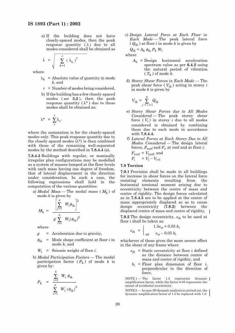
7.8.4.5 Buildings with regular, or nominallyirregular plan configurations may be modelledas a system of masses lumped at the floor levelswith each mass having one degree of freedom,that of lateral displacement in the directionunder consideration. In such a case, thefollowing expressions shall hold in thecomputation of the various quantities:
where
b) Modal Participation Factors — The modalparticipation factor ( Pk ) of mode k isgiven by:
c) Design Lateral Force at Each Floor inEach Mode — The peak lateral force( Qik ) at floor i in mode k is given by
Qik = Ak φik Pk Wiwhere
7.9 Torsion
7.9.1 Provision shall be made in all buildingsfor increase in shear forces on the lateral forceresisting elements resulting from thehorizontal torsional moment arising due toeccentricity between the centre of mass andcentre of rigidity. The design forces calculatedas in 7.8.4.5 are to be applied at the centre ofmass appropriately displaced so as to causedesign eccentricity (7.9.2) between thedisplaced centre of mass and centre of rigidity.
7.9.2 The design eccentricity, edi to be used atfloor i shall be taken as:
whichever of these gives the more severe effectin the shear of any frame where
NOTE 1 — The factor 1.5 represents dynamicamplification factor, while the factor 0.05 represents theextent of accidental eccentricity.
NOTE 2 — In case 3D dynamic analysis is carried out, thedynamic amplification factor of 1.5 be replaced with 1.0.
a) If the building does not haveclosely-spaced modes, then the peakresponse quantity ( λ ) due to allmodes considered shall be obtained as
λ =
λk = Absolute value of quantity in modek, and
r = Number of modes being considered.
b) If the building has a few closely-spacedmodes ( see 3.2 ), then the peakresponse quantity ( λ* ) due to thesemodes shall be obtained as:
λ* =
a) Modal Mass — The modal mass ( Mk ) ofmode k is given by
Mk =
g = Acceleration due to gravity,
φik = Mode shape coefficient at floor i inmode k, and
Wi = Seismic weight of floor i.
Pk =
k=l
r
∑ λk ( )2
λc ′c
r
∑
Wiφiki=l
n
∑
g Wi φik( )2i=l
n
∑------------------------------------------
2
Wi φiki=l
n
∑
Wi φik( )2
i=l
n
∑------------------------------------
Ak = Design horizontal accelerationspectrum value as per 6.4.2 usingthe natural period of vibration( Tk ) of mode k.
d) Storey Shear Forces in Each Mode — Thepeak shear force ( Vik ) acting in storey iin mode k is given by
e) Storey Shear Forces due to All ModesConsidered — The peak storey shearforce ( Vi ) in storey i due to all modesconsidered is obtained by combiningthose due to each mode in accordancewith 7.8.4.4.
f) Lateral Forces at Each Storey Due to AllModes Considered — The design lateralforces, Froof and Fi, at roof and at floor i:Froof = Vroof, andFi = Vi – Vi+l
edi =or
1.5esi + 0.05 bi
esi – 0.05 bi
edi = Static eccentricity at floor i definedas the distance between centre ofmass and centre of rigidity, and
bi = Floor plan dimension of floor i,perpendicular to the direction offorce.
Vik = Qikj = i + l
n
∑
IS 1893 (Part 1) : 2002
27
7.9.3 In case of highly irregular buildingsanalyzed according to 7.8.4.5, additive shearswill be superimposed for a statically appliedeccentricity of ± 0.05bi with respect to thecentre of rigidity.
7.10 Buildings with Soft Storey
7.10.1 In case buildings with a flexible storey,such as the ground storey consisting of openspaces for parking that is Stilt buildings,special arrangement needs to be made toincrease the lateral strength and stiffness ofthe soft/open storey.
7.10.2 Dynamic analysis of building is carriedout including the strength and stiffness effectsof infills and inelastic deformations in themembers, particularly, those in the soft storey,and the members designed accordingly.
7.10.3 Alternatively, the following designcriteria are to be adopted after carrying out theearthquake analysis, neglecting the effect ofinfill walls in other storeys:
a) the columns and beams of the soft storeyare to be designed for 2.5 times the storeyshears and moments calculated underseismic loads specified in the otherrelevant clauses; or.
b) besides the columns designed and detailedfor the calculated storey shears andmoments, shear walls placedsymmetrically in both directions of thebuilding as far away from the centre of thebuilding as feasible; to be designedexclusively for 1.5 times the lateral storeyshear force calculated as before.
7.11 Deformations
7.11.1 Storey Drift Limitation
The storey drift in any storey due to theminimum specified design lateral force, withpartial load factor of 1.0, shall not exceed 0.004times the storey height.
For the purposes of displacement requirementsonly ( see 7.11.1,7.11.2 and 7.11.3 only ), it ispermissible to use seismic force obtained fromthe computed fundamental period ( T ) of thebuilding without the lower bound limit ondesign seismic force specified in 7.8.2.
There shall be no drift limit for single storeybuilding which has been designed toaccommodate storey drift.
7.11.2 Deformation Compatibility of Non-SeismicMembers
For building located in seismic Zones IV and V,it shall be ensured that the structuralcomponents, that are not a part of the seismic
force resisting system in the direction underconsideration, do not lose their vertical load-carrying capacity under the induced momentsresulting from storey deformations equal to Rtimes the storey displacements calculated asper 7.11.1, where R is specified in Table 7.
NOTE — For instance, consider a flat-slab building inwhich lateral load resistance is provided by shear walls.Since the lateral load resistance of the slab-columnsystem is small, these are often designed only for thegravity loads, while all the seismic force is resisted bythe shear walls. Even though the slabs and columns arenot required to share the lateral forces, these deformwith rest of the structure under seismic force. Theconcern is that under such deformations, theslab-column system should not lose its vertical loadcapacity.
7.11.3 Separation Between Adjacent Units
Two adjacent buildings, or two adjacent units ofthe same building with separation joint inbetween shall be separated by a distance equalto the amount R times the sum of the calculatedstorey displacements as per 7.11.1 of each ofthem, to avoid damaging contact when the twounits deflect towards each other. When floorlevels of two similar adjacent units or buildingsare at the same elevation levels, factor R in thisrequirement may be replaced by R/2.
7.12 Miscellaneous
7.12.1 Foundations
The use of foundations vulnerable to significantdifferential settlement due to ground shakingshall be avoided for structures in seismic ZonesIII, IV and V. In seismic Zones IV and V,individual spread footings or pile caps shall beshall be interconnected with ties, ( see 5.3.4.1 ofIS 4326 ) except when individual spreadfootings are directly supported on rock. All tiesshall be capable of carrying, in tension and incompression, an axial force equal to Ah/4 timesthe larger of the column or pile cap load, inaddition to the otherwise computed forces.Here, Ah is as per 6.4.2.
7.12.2 Cantilever Projections
7.12.2.1 Vertical projections
Tower, tanks, parapets, smoke stacks (chimneys)and other vertical cantilever projectionsattached to buildings and projecting above theroof, shall be designed and checked for stabilityfor five times the design horizontal seismiccoefficient Ah specified in 6.4.2. In the analysis ofthe building, the weight of these projectingelements will be lumped with the roof weight.
7.12.2.2 Horizontal projection
All horizontal projections like cornices andbalconies shall be designed and checked forstability for five times the design vertical

IS 1893 (Part 1) : 2002
28
coefficient specified in 6.4.5 (that is = 10/3 Ah).
7.12.2.3 The increased design forces specifiedin 7.12.2.1 and 7.12.2.2 are only for designingthe projecting parts and their connections withthe main structures. For the design of the mainstructure, such increase need not be considered.
7.12.3 Compound Walls
Compound walls shall be designed for thedesign horizontal coefficient Ah withimportance factor I = 1.0 specified in 6.4.2.
7.12.4 Connections Between Parts
All parts of the building, except between theseparation sections, shall be tied together to actas integrated single unit. All connectionsbetween different parts, such as beams tocolumns and columns to their footings, shouldbe made capable of transmitting a force, in allpossible directions, of magnitude ( Qi/Wi ) timesbut not less than 0.05 times the weight of thesmaller part or the total of dead and imposedload reaction. Frictional resistance shall not berelied upon for fulfilling these requirements.

IS 1893 (Part 1) : 2002
29
ANNEX A( Foreword )
© Government of India, Copyright Year 2001.
Based upon Survey of India map with the permission of the Surveryor General of India.
The responsibility for the correctness of internal details rests with the publisher.
The territorial waters of India extend into the sea to distance of twelve nautical miles measured from the appropriatebase line.
The administrative headquarters of Chandigarh, Haryana and Punjab are at Chandigarh.
The interstate boundaries between Arunachal Prades, Assam and Meghalaya shown on this map are as interpretedfrom the North-Eastern Areas (Reorganization) Act, 1971, but have yet to be verified.
The external boundaries and coastlines of India agree with the Record/Master Copy certified by Survey of India.


As in the Original Standard, this Page is Intentionally Left Blank
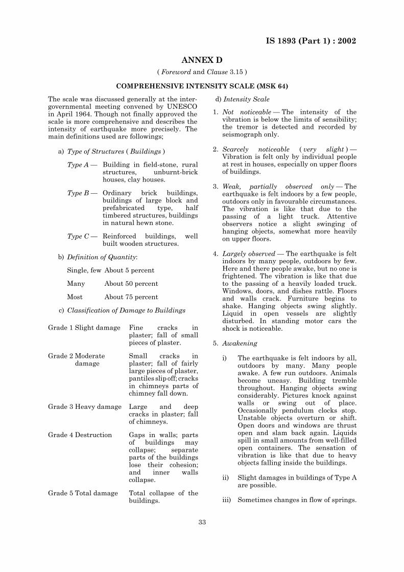
IS 1893 (Part 1) : 2002
33
ANNEX D( Foreword and Clause 3.15 )
COMPREHENSIVE INTENSITY SCALE (MSK 64)
The scale was discussed generally at the inter-governmental meeting convened by UNESCOin April 1964. Though not finally approved thescale is more comprehensive and describes theintensity of earthquake more precisely. Themain definitions used are followings;
d) Intensity Scale
a) Type of Structures ( Buildings )
Type A — Building in field-stone, ruralstructures, unburnt-brickhouses, clay houses.
Type B — Ordinary brick buildings,buildings of large block andprefabricated type, halftimbered structures, buildingsin natural hewn stone.
Type C — Reinforced buildings, wellbuilt wooden structures.
b) Definition of Quantity:
Single, few About 5 percent
Many About 50 percent
Most About 75 percent
c) Classification of Damage to Buildings
Grade 1 Slight damage Fine cracks inplaster; fall of smallpieces of plaster.
Grade 2 Moderatedamage
Small cracks inplaster; fall of fairlylarge pieces of plaster,pantiles slip off; cracksin chimneys parts ofchimney fall down.
Grade 3 Heavy damage Large and deepcracks in plaster; fallof chimneys.
Grade 4 Destruction Gaps in walls; partsof buildings maycollapse; separateparts of the buildingslose their cohesion;and inner wallscollapse.
Grade 5 Total damage Total collapse of thebuildings.
1. Not noticeable — The intensity of thevibration is below the limits of sensibility;the tremor is detected and recorded byseismograph only.
2. Scarcely noticeable ( very slight ) —Vibration is felt only by individual peopleat rest in houses, especially on upper floorsof buildings.
3. Weak, partially observed only — Theearthquake is felt indoors by a few people,outdoors only in favourable circumstances.The vibration is like that due to thepassing of a light truck. Attentiveobservers notice a slight swinging ofhanging objects, somewhat more heavilyon upper floors.
4. Largely observed — The earthquake is feltindoors by many people, outdoors by few.Here and there people awake, but no one isfrightened. The vibration is like that dueto the passing of a heavily loaded truck.Windows, doors, and dishes rattle. Floorsand walls crack. Furniture begins toshake. Hanging objects swing slightly.Liquid in open vessels are slightlydisturbed. In standing motor cars theshock is noticeable.
5. Awakening
i) The earthquake is felt indoors by all,outdoors by many. Many peopleawake. A few run outdoors. Animalsbecome uneasy. Building tremblethroughout. Hanging objects swingconsiderably. Pictures knock againstwalls or swing out of place.Occasionally pendulum clocks stop.Unstable objects overturn or shift.Open doors and windows are thrustopen and slam back again. Liquidsspill in small amounts from well-filledopen containers. The sensation ofvibration is like that due to heavyobjects falling inside the buildings.
ii) Slight damages in buildings of Type Aare possible.
iii) Sometimes changes in flow of springs.
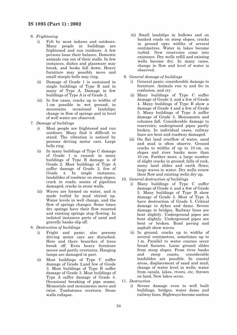
IS 1893 (Part 1) : 2002
34
iii) Small landslips in hollows and onbanked roads on steep slopes; cracksin ground upto widths of severalcentimetres. Water in lakes becometurbid. New reservoirs come intoexistence. Dry wells refill and existingwells become dry. In many cases,change in flow and level of water isobserved.
6. Frighteningi) Felt by most indoors and outdoors.
Many people in buildings arefrightened and run outdoors. A fewpersons loose their balance. Domesticanimals run out of their stalls. In fewinstances, dishes and glassware maybreak, and books fall down. Heavyfurniture may possibly move andsmall steeple bells may ring.
ii) Damage of Grade 1 is sustained insingle buildings of Type B and inmany of Type A. Damage in fewbuildings of Type A is of Grade 2.
iii) In few cases, cracks up to widths of1 cm possible in wet ground; inmountains occasional landslips;change in flow of springs and in levelof well water are observed.
7. Damage of buildingsi) Most people are frightened and run
outdoors. Many find it difficult tostand. The vibration is noticed bypersons driving motor cars. Largebells ring.
ii) In many buildings of Type C damageof Grade 1 is caused; in manybuildings of Type B damage is ofGrade 2. Most buildings of Type Asuffer damage of Grade 3, few ofGrade 4. In single instances,landslides of roadway on steep slopes;crack in roads; seams of pipelinesdamaged; cracks in stone walls.
iii) Waves are formed on water, and ismade turbid by mud stirred up.Water levels in well change, and theflow of springs changes. Some timesdry springs have their flow resortedand existing springs stop flowing. Inisolated instances parts of sand andgravelly banks slip off.
8. Destruction of buildingsi) Fright and panic; also persons
driving motor cars are disturbed.Here and there branches of treesbreak off. Even heavy furnituremoves and partly overturns. Hanginglamps are damaged in part.
ii) Most buildings of Type C sufferdamage of Grade 2,and few of Grade3. Most buildings of Type B sufferdamage of Grade 3. Most buildings ofType A suffer damage of Grade 4.Occasional breaking of pipe seams.Memorials and monuments move andtwist. Tombstones overturn. Stonewalls collapse.
9. General damage of buildingsi) General panic; considerable damage to
furniture. Animals run to and fro inconfusion, and cry.
ii) Many buildings of Type C sufferdamage of Grade 3, and a few of Grade4. Many buildings of Type B show adamage of Grade 4 and a few of Grade5. Many buildings of Type A sufferdamage of Grade 5. Monuments andcolumns fall. Considerable damage toreservoirs; underground pipes partlybroken. In individual cases, railwaylines are bent and roadway damaged.
iii) On flat land overflow of water, sandand mud is often observe. Groundcracks to widths of up to 10 cm, onslopes and river banks more than10 cm. Further more, a large numberof slight cracks in ground; falls of rock,many land slides and earth flows;large waves in water. Dry wells renewtheir flow and existing wells dry up.
10. General destruction of buildingsi) Many buildings of Type C suffer
damage of Grade 4, and a few of Grade5. Many buildings of Type B showdamage of Grade 5. Most of Type Ahave destruction of Grade 5. Criticaldamage to dykes and dams. Severedamage to bridges. Railway lines arebent slightly. Underground pipes arebent slightly. Underground pipes arebent or broken. Road paving andasphalt show waves.
ii) In ground, cracks up to widths ofseveral centimetres, sometimes up to1 m. Parallel to water courses occurbroad fissures. Loose ground slidesfrom steep slopes. From river banksand steep coasts, considerablelandslides are possible. In coastalareas, displacement of sand and mud;change of water level in wells; waterfrom canals, lakes, rivers, etc, thrownon land, New lakes occur.
11. Destructioni) Severe damage even to well built
buildings, bridges, water dams andrailway lines. Highways become useless
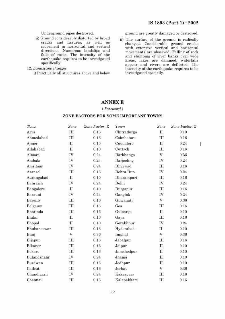
IS 1893 (Part 1) : 2002
35
Underground pipes destroyed.ii) Ground considerably distorted by broad
cracks and fissures, as well asmovement in horizontal and verticaldirections. Numerous landslips andfalls of rocks. The intensity of theearthquake requires to be investigatedspecifically.
12. Landscape changesi) Practically all structures above and below
ground are greatly damaged or destroyed.
ii) The surface of the ground is radicallychanged. Considerable ground crackswith extensive vertical and horizontalmovements are observed. Falling of rockand slumping of river banks over wideareas, lakes are dammed; waterfallsappear and rivers are deflected. Theintensity of the earthquake requires to beinvestigated specially.
ANNEX E( Foreword )
ZONE FACTORS FOR SOME IMPORTANT TOWNS
Town Zone Zone Factor, Z
Agra III 0.16
Ahmedabad III 0.16
Ajmer II 0.10
Allahabad II 0.10
Almora IV 0.24
Ambala IV 0.24
Amritsar IV 0.24
Asansol III 0.16
Aurangabad II 0.10
Bahraich IV 0.24
Bangalore II 0.10
Barauni IV 0.24
Bareilly III 0.16
Belgaum III 0.16
Bhatinda III 0.16
Bhilai II 0.10
Bhopal II 0.10
Bhubaneswar III 0.16
Bhuj V 0.36
Bijapur III 0.16
Bikaner III 0.16
Bokaro III 0.16
Bulandshahr IV 0.24
Burdwan III 0.16
Cailcut III 0.16
Chandigarh IV 0.24
Chennai III 0.16
Town Zone Zone Factor, Z
Chitradurga II 0.10
Coimbatore III 0.16
Cuddalore II 0.24
Cuttack III 0.16
Darbhanga V 0.36
Darjeeling IV 0.24
Dharwad III 0.16
Dehra Dun IV 0.24
Dharampuri III 0.16
Delhi IV 0.24
Durgapur III 0.16
Gangtok IV 0.24
Guwahati V 0.36
Goa III 0.16
Gulbarga II 0.10
Gaya III 0.16
Gorakhpur IV 0.24
Hyderabad II 0.10
Imphal V 0.36
Jabalpur III 0.16
Jaipur II 0.10
Jamshedpur II 0.10
Jhansi II 0.10
Jodhpur II 0.10
Jorhat V 0.36
Kakrapara III 0.16
Kalapakkam III 0.16
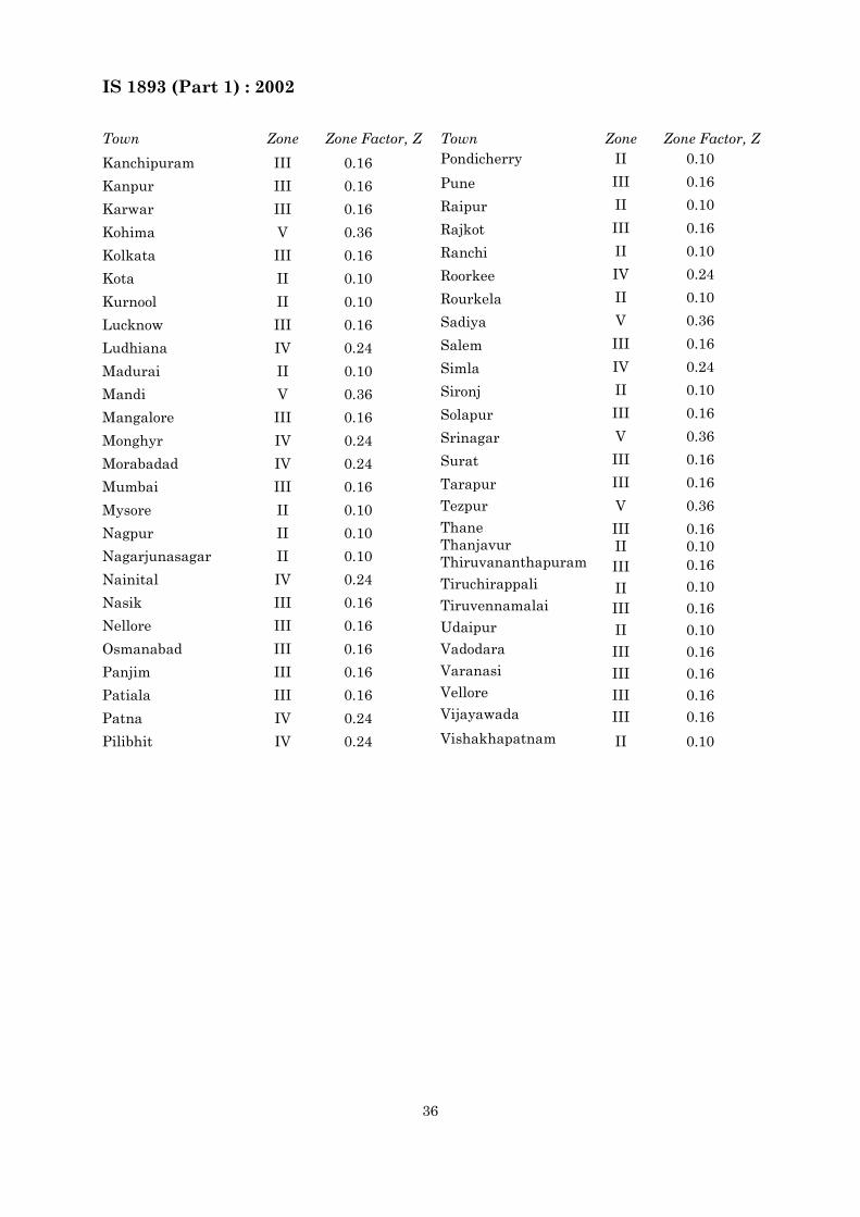
IS 1893 (Part 1) : 2002
36
Town Zone Zone Factor, Z
Kanchipuram III 0.16
Kanpur III 0.16
Karwar III 0.16
Kohima V 0.36
Kolkata III 0.16
Kota II 0.10
Kurnool II 0.10
Lucknow III 0.16
Ludhiana IV 0.24
Madurai II 0.10
Mandi V 0.36
Mangalore III 0.16
Monghyr IV 0.24
Morabadad IV 0.24
Mumbai III 0.16
Mysore II 0.10
Nagpur II 0.10
Nagarjunasagar II 0.10
Nainital IV 0.24
Nasik III 0.16
Nellore III 0.16
Osmanabad III 0.16
Panjim III 0.16
Patiala III 0.16
Patna IV 0.24
Pilibhit IV 0.24
Town Zone Zone Factor, ZPondicherry
Pune
Raipur
Rajkot
Ranchi
Roorkee
Rourkela
Sadiya
Salem
Simla
Sironj
Solapur
Srinagar
Surat
Tarapur
Tezpur
ThaneThanjavurThiruvananthapuram
Tiruchirappali
Tiruvennamalai
Udaipur
Vadodara
Varanasi
Vellore
Vijayawada
Vishakhapatnam
II
III
II
III
II
IV
II
V
III
IV
II
III
V
III
III
V
IIIIIIII
IIIII
II
III
III
III
III
II
0.10
0.16
0.10
0.16
0.10
0.24
0.10
0.36
0.16
0.24
0.10
0.16
0.36
0.16
0.16
0.36
0.160.100.16
0.10
0.16
0.10
0.16
0.16
0.16
0.16
0.10
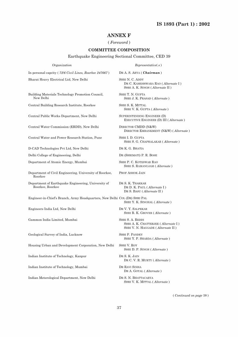
IS 1893 (Part 1) : 2002
37
ANNEX F( Foreword )
COMMITTEE COMPOSITION
Earthquake Engineering Sectional Committee, CED 39
Organization Representative( s )
In personal capcity ( 72/6 Civil Lines, Roorkee 247667 ) DR A. S. ARYA ( Chairman )
Bharat Heavy Electrical Ltd, New Delhi SHRI N. C. ADDY
DR C. KAMESHWARA RAO ( Alternate I )SHRI A. K. SINGH ( Alternate II )
Building Materials Technology Promotion Council,New Delhi
SHRI T. N. GUPTA
SHRI J. K. PRASAD ( Alternate )
Central Building Research Institute, Roorkee SHRI S. K. MITTAL
SHRI V. K. GUPTA ( Alternate )
Central Public Works Department, New Delhi SUPERINTENDING ENGINEER (D)EXECUTIVE ENGINEER (D) III ( Alternate )
Central Water Commission (ERDD), New Delhi DIRECTOR CMDD (N&W)DIRECTOR EMBANKMENT (N&W) ( Alternate )
Central Water and Power Research Station, Pune SHRI I. D. GUPTA
SHRI S. G. CHAPHALAKAR ( Alternate )
D-CAD Technologies Pvt Ltd, New Delhi DR K. G. BHATIA
Delhi College of Engineering, Delhi DR (SHRIMATI) P. R. BOSE
Department of Atomic Energy, Mumbai SHRI P. C. KOTESWAR RAO
SHRI S. RAMANUJAM ( Alternate )
Department of Civil Engineering, University of Roorkee, Roorkee
PROF ASHOK JAIN
Department of Earthquake Engineering, University of Roorkee, Roorkee
DR S. K. THAKKAR
DR D. K. PAUL ( Alternate I )DR S. BASU ( Alternate II )
Engineer-in-Chief’s Branch, Army Headquarters, New Delhi COL (DR) SHRI PAL
SHRI Y. K. SINGHAL ( Alternate )
Engineers India Ltd, New Delhi DR V. Y. SALPEKAR
SHRI R. K. GROVER ( Alternate )
Gammon India Limited, Mumbai SHRI S. A. REDDI
SHRI A. K. CHATTERJEE ( Alternate I )SHRI V. N. HAGGADE ( Alternate II )
Geological Survey of India, Lucknow SHRI P. PANDEY
SHRI Y. P. SHARDA ( Alternate )
Housing Urban and Development Corporation, New Delhi SHRI V. ROY
SHRI D. P. SINGH ( Alternate )
Indian Institute of Technology, Kanpur DR S. K. JAIN
DR C. V. R. MURTY ( Alternate )
Indian Institute of Technology, Mumbai DR RAVI SINHA
DR A. GOYAL ( Alternate )
Indian Meterological Department, New Delhi DR S. N. BHATTACARYA
SHRI V. K. MITTAL ( Alternate )
( Continued on page 38 )
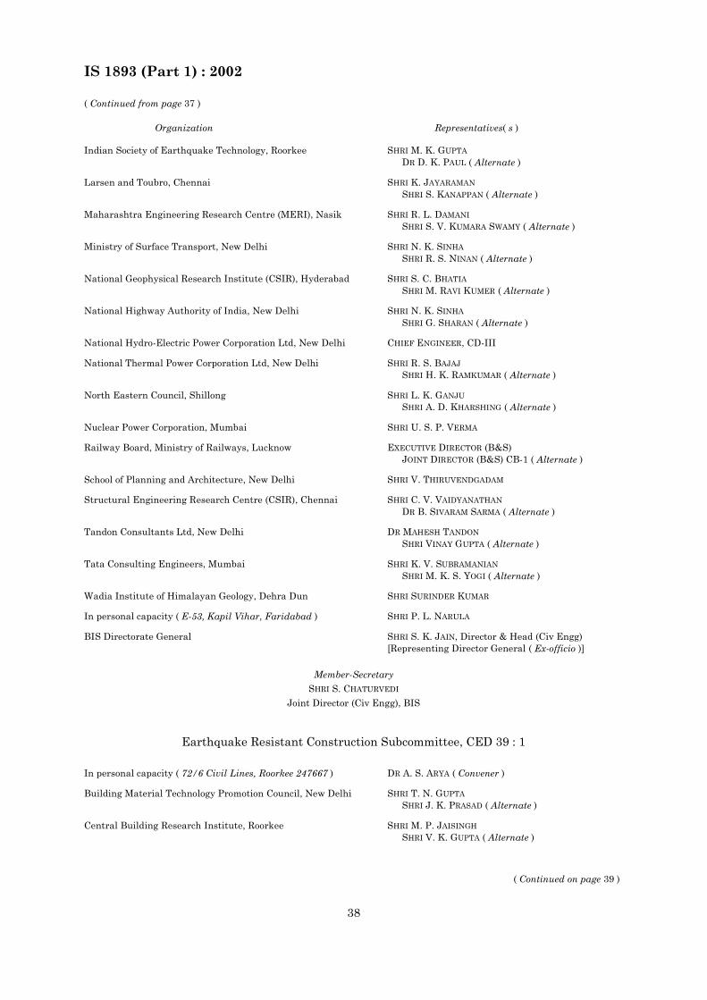
IS 1893 (Part 1) : 2002
38
( Continued from page 37 )
Organization Representatives( s )
Indian Society of Earthquake Technology, Roorkee SHRI M. K. GUPTA
DR D. K. PAUL ( Alternate )
Larsen and Toubro, Chennai SHRI K. JAYARAMAN
SHRI S. KANAPPAN ( Alternate )
Maharashtra Engineering Research Centre (MERI), Nasik SHRI R. L. DAMANI
SHRI S. V. KUMARA SWAMY ( Alternate )
Ministry of Surface Transport, New Delhi SHRI N. K. SINHA
SHRI R. S. NINAN ( Alternate )
National Geophysical Research Institute (CSIR), Hyderabad SHRI S. C. BHATIA
SHRI M. RAVI KUMER ( Alternate )
National Highway Authority of India, New Delhi SHRI N. K. SINHA
SHRI G. SHARAN ( Alternate )
National Hydro-Electric Power Corporation Ltd, New Delhi CHIEF ENGINEER, CD-III
National Thermal Power Corporation Ltd, New Delhi SHRI R. S. BAJAJ
SHRI H. K. RAMKUMAR ( Alternate )
North Eastern Council, Shillong SHRI L. K. GANJU
SHRI A. D. KHARSHING ( Alternate )
Nuclear Power Corporation, Mumbai SHRI U. S. P. VERMA
Railway Board, Ministry of Railways, Lucknow EXECUTIVE DIRECTOR (B&S)JOINT DIRECTOR (B&S) CB-1 ( Alternate )
School of Planning and Architecture, New Delhi SHRI V. THIRUVENDGADAM
Structural Engineering Research Centre (CSIR), Chennai SHRI C. V. VAIDYANATHAN
DR B. SIVARAM SARMA ( Alternate )
Tandon Consultants Ltd, New Delhi DR MAHESH TANDON
SHRI VINAY GUPTA ( Alternate )
Tata Consulting Engineers, Mumbai SHRI K. V. SUBRAMANIAN
SHRI M. K. S. YOGI ( Alternate )
Wadia Institute of Himalayan Geology, Dehra Dun SHRI SURINDER KUMAR
In personal capacity ( E-53, Kapil Vihar, Faridabad ) SHRI P. L. NARULA
BIS Directorate General SHRI S. K. JAIN, Director & Head (Civ Engg)[Representing Director General ( Ex-officio )]
Member-Secretary
SHRI S. CHATURVEDI
Joint Director (Civ Engg), BIS
Earthquake Resistant Construction Subcommittee, CED 39 : 1
In personal capacity ( 72/6 Civil Lines, Roorkee 247667 ) DR A. S. ARYA ( Convener )
Building Material Technology Promotion Council, New Delhi SHRI T. N. GUPTA
SHRI J. K. PRASAD ( Alternate )
Central Building Research Institute, Roorkee SHRI M. P. JAISINGH
SHRI V. K. GUPTA ( Alternate )
( Continued on page 39 )
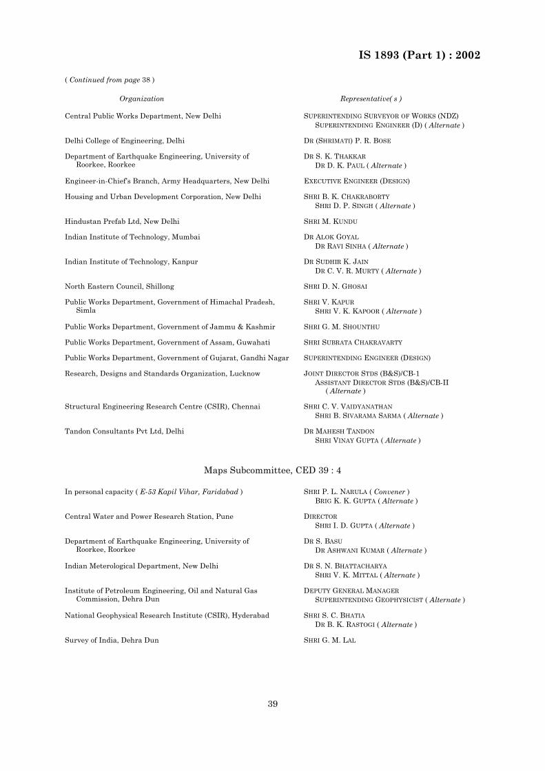
IS 1893 (Part 1) : 2002
39
( Continued from page 38 )
Organization Representative( s )
Central Public Works Department, New Delhi SUPERINTENDING SURVEYOR OF WORKS (NDZ)SUPERINTENDING ENGINEER (D) ( Alternate )
Delhi College of Engineering, Delhi DR (SHRIMATI) P. R. BOSE
Department of Earthquake Engineering, University ofRoorkee, Roorkee
DR S. K. THAKKAR
DR D. K. PAUL ( Alternate )
Engineer-in-Chief’s Branch, Army Headquarters, New Delhi EXECUTIVE ENGINEER (DESIGN)
Housing and Urban Development Corporation, New Delhi SHRI B. K. CHAKRABORTY
SHRI D. P. SINGH ( Alternate )
Hindustan Prefab Ltd, New Delhi SHRI M. KUNDU
Indian Institute of Technology, Mumbai DR ALOK GOYAL
DR RAVI SINHA ( Alternate )
Indian Institute of Technology, Kanpur DR SUDHIR K. JAIN
DR C. V. R. MURTY ( Alternate )
North Eastern Council, Shillong SHRI D. N. GHOSAI
Public Works Department, Government of Himachal Pradesh,Simla
SHRI V. KAPUR
SHRI V. K. KAPOOR ( Alternate )
Public Works Department, Government of Jammu & Kashmir SHRI G. M. SHOUNTHU
Public Works Department, Government of Assam, Guwahati SHRI SUBRATA CHAKRAVARTY
Public Works Department, Government of Gujarat, Gandhi Nagar SUPERINTENDING ENGINEER (DESIGN)
Research, Designs and Standards Organization, Lucknow JOINT DIRECTOR STDS (B&S)/CB-1ASSISTANT DIRECTOR STDS (B&S)/CB-II
( Alternate )
Structural Engineering Research Centre (CSIR), Chennai SHRI C. V. VAIDYANATHAN
SHRI B. SIVARAMA SARMA ( Alternate )
Tandon Consultants Pvt Ltd, Delhi DR MAHESH TANDON
SHRI VINAY GUPTA ( Alternate )
Maps Subcommittee, CED 39 : 4
In personal capacity ( E-53 Kapil Vihar, Faridabad ) SHRI P. L. NARULA ( Convener )BRIG K. K. GUPTA ( Alternate )
Central Water and Power Research Station, Pune DIRECTOR
SHRI I. D. GUPTA ( Alternate )
Department of Earthquake Engineering, University ofRoorkee, Roorkee
DR S. BASU
DR ASHWANI KUMAR ( Alternate )
Indian Meterological Department, New Delhi DR S. N. BHATTACHARYA
SHRI V. K. MITTAL ( Alternate )
Institute of Petroleum Engineering, Oil and Natural GasCommission, Dehra Dun
DEPUTY GENERAL MANAGER
SUPERINTENDING GEOPHYSICIST ( Alternate )
National Geophysical Research Institute (CSIR), Hyderabad SHRI S. C. BHATIA
DR B. K. RASTOGI ( Alternate )
Survey of India, Dehra Dun SHRI G. M. LAL
Bureau of Indian Standards
BIS is a statutory institution established under the Bureau of Indian Standards Act, 1986 to promoteharmonious development of the activities of standardization, marking and quality certification of goods andattending to connected matters in the country.
Copyright
BIS has the copyright of all its publications. No part of these publications may be reproduced in any formwithout the prior permission in writing of BIS. This does not preclude the free use, in the course ofimplementing the standard, of necessary details, such as symbols and sizes, type or grade designations.Enquiries relating to copyright be addressed to the Director (Publications), BIS.
Review of Indian Standards
Amendments are issued to standards as the need arises on the basis of comments. Standards are alsoreviewed periodically; a standard along with amendments is reaffirmed when such review indicates that nochanges are needed; if the review indicates that changes are needed, it is taken up for revision. Users ofIndian Standards should ascertain that they are in possession of the latest amendments or edition byreferring to the latest issue of ‘BIS Catalogue’ and ‘Standards : Monthly Additions’.
This Indian Standard has been developed from Doc : No. CED 39 (5341).
Amendments Issued Since Publication
Amend No. Date of Issue
Amd. No. 1 January 2005
BUREAU OF INDIAN STANDARDS
Headquarters:
Manak Bhavan, 9 Bahadur Shah Zafar Marg, New Delhi 110002.Telephones: 323 01 31, 323 33 75, 323 94 02
Telegrams: Manaksanstha(Common to all offices)
Regional Offices: Telephone
Central : Manak Bhavan, 9 Bahadur Shah Zafar MargNEW DELHI 110002
323 76 17323 38 41
Eastern : 1/14 C. I. T. Scheme VII M, V. I. P. Road, KankurgachiKOLKATA 700054
337 84 99, 337 85 61337 86 26, 337 91 20
Northern : SCO 335-336, Sector 34-A, CHANDIGARH 160022 60 38 4360 20 25
Southern : C. I. T. Campus, IV Cross Road, CHENNAI 600113 235 02 16, 235 04 42235 15 19, 235 23 15
Western : Manakalaya, E9 MIDC, Marol, Andheri (East)MUMBAI 400093
832 92 95, 832 78 58832 78 91, 832 78 92
Branches : AHMED ABAD . BANG ALOR E. BHO PAL. BH UBANE SH WAR . C OI MB ATOR E. FARI DA BAD. G HAZI ABA D. GUWAH ATI . H YDER ABAD . JAI PUR . K ANPUR . LUCKNOW. NAGPUR. NALAGARH. PATNA. PUNE. RAJKOT. THIRUVANANTHAPURAM.VISHAKHAPATNAM.