Embed Size (px)
Citation preview
■ C
hristchurc
h ea
rthqua
ke 22.2.2011
■ Fo
unda
tion G
routing
■ M
uldo
on’s C
orne
r Rea
lignm
ent ■
Cyc
lone
Wilm
a D
am
ag
e
jun
e 2
011 issu
e 81
NZ
GS
nZ G
eo
me
ch
an
ics
new
s
www.nzgs.org
nZ Geomechanics newsjune 2011 issue 81
Newsletter of the New Zealand Geotechnical Society Inc. issn 0111–6851
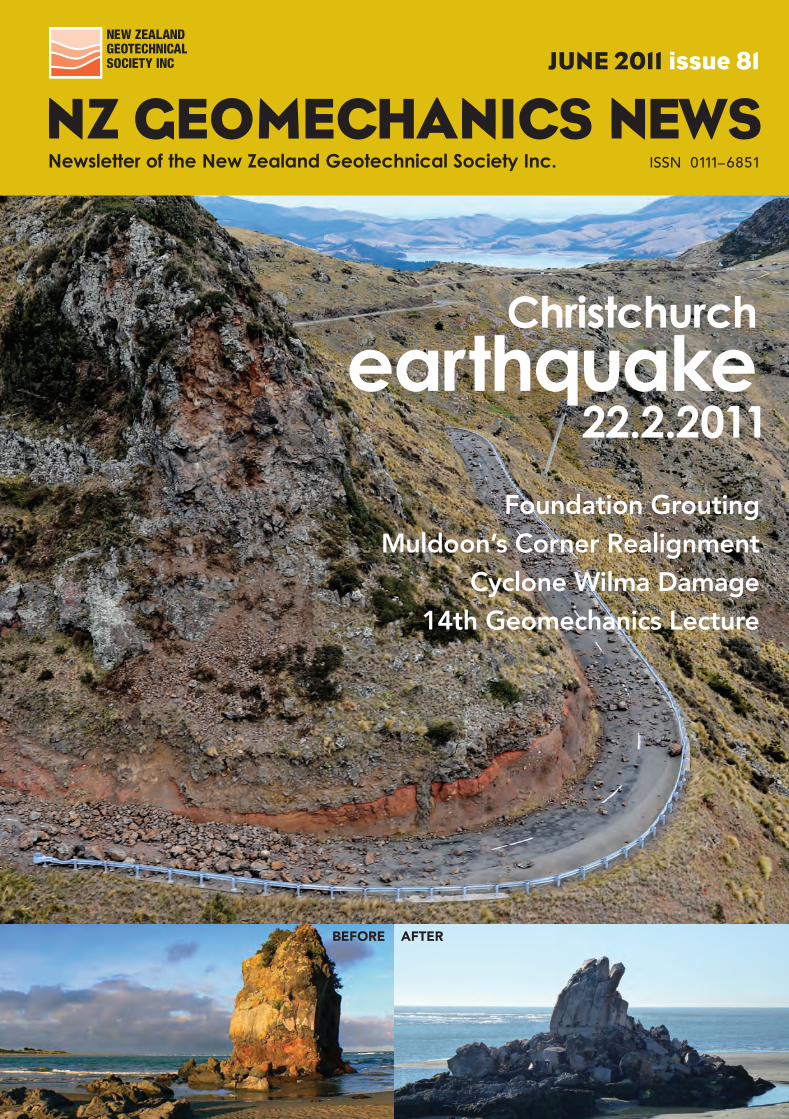
22.2.2011earthquake
Christchurch
Foundation GroutingMuldoon’s Corner Realignment
Cyclone Wilma Damage14th Geomechanics Lecture
BEFORE AFTER
NZGSJunecv.indd 1 25/05/14 12:04 pm
AVALON// ROPE ACCESS SERVICES
New ZealaNd GeomechaNics News
Cover images: thanks to G.Hancox (GNS), URS, Tonkin & Taylor
coNteNts juNe 2011, issue 81
chairman’s corner ............................................ 2
editorial ................................................................ 3
letters to the editors .......................................... 4
editorial Policy .................................................... 5
the secretary’s News ........................................ 6
international society Reports
IAEG .............................................................. 7 ISSMGE .......................................................... 8 ISRM ............................................................ 14
NZGs Branch activities..................................... 18
standards, law and industry News Update on the Professional Registration
of Engineering Geologists .............................. 24 IPENZ Forum 2011 ...................................... 25 NZGS Young Geotechnical Professionals ......... 26 Fellows of IPENZ ........................................... 28 Warwick Prebble retirement ............................ 29
awards NZGS Scholarship ......................................... 30 2011 Geomechanics Lecture, David Bell ......... 31 NZGS Student Award .................................... 32
conference Reports 14th Australasian Tunnelling Conference 2011 .... 34 Ninth Pacific Conference on Earthquake
Engineering .................................................... 36
special Feature: 2011 christchurch eQ ........ 38
IPENZ fact sheets ........................................... 42
Seismic Data for the 22 Feb 2011 Earthquake .... 48 Landslides and related ground damage ............ 53 Geosynthetic Structures................................... 68
Photo Competition ......................................... 71 Q & A with EQC Field Office Staff ................ 73 Personal Observations, Alun Davies ................. 76 Emergency Rockfall Remediation ................... 79 Geotech input in USAR teams ....................... 84
Project News Cyclone Wilma Engineering Assessments ......... 85 Kaeo and Tauranga Bay Flood Mitigation ........ 86 SH2 Rimutaka (Muldoon’s) Corner ............. 88 Case Study – Terramesh Barriers .................. 91
technical articles Newmarket Viaduct Grouting ......................... 92
Book Review Rudolph Glossop and the Rise of
Geotechnology .............................................. 98
company Profile CLL, Contract Landscapes ............................... 99 AECOM ..................................................... 104
Foreign correspondent Peter Jenner – Africa .................................... 106
member Profiles Gavin Alexander, Beca ................................. 108 Hamish Maclean, Tonkin & Taylor .............. 109
Past member’s contribution NZGS Chairman 1995 .................................. 110
Geotech Teaser 111; Events Diary 112; December Crossword answers 113; Information 114; Advertisers Directory 115; Membership 116; NZGS Inc. Publications 118; Advertising Information 119; Geotech Crossword 120.
82 9058
New Zealand Geomechanics News
Newsletter of the New Zealand Geotechnical Society Inc.
New Zealand Geomechanics News
2
chaiRmaN’s coRNeR
Welcome to this issue of NZ Geomechanics News, the first under the new editorial leadership of ‘senior’ co-editor Paul Salter ably assisted by Hamish Maclean. The Society owes a great deal of thanks to Kate Williams as co-editor over the past five years; Kate’s appetite for hard work and vision has seen Geomechanics News grow in the quality of both the magazine’s content and production values. A truly sterling effort. Paul and Hamish have continued that standard with the current issue.
NZGS Management CommitteeThe value of the role of Vice-chair was made clear to me over the past two years while working with our immediate Past Chair, Phil Robins. It was a privilege to work with Phil and I hope to continue the initiatives he championed while Chairman. Phil will continue in his ex-officio role of immediate Past Chair and he will represent NZGS on the organising committee for the 2012 Melbourne ANZ conference.
The committee has two new members who were elected earlier this year. Welcome to Gavin Alexander from Auckland and Tony Fairclough in Christchurch. Gavin has taken on the roles of Vice-chair and Treasurer. I would like to record my appreciation for the efforts and commitment over the past 2½ years of outgoing committee member David Stewart.
Erica Cammack has taken over the role of Young Geotechnical Professionals representative from Kate Williams. Thanks again Kate and welcome Erica.
Canterbury EarthquakesWith the establishment of the Canterbury Earthquake Recovery Authority, activity in and around Christchurch will now move into a new phase. Emphasis for the Society will be to ensure that members’ views and opinions are well represented in any reviews of engineering statutes, standards and codes being promoted under the auspices of CERA. The objectives and content of the NZGS Seismic Guidelines modules will also be reviewed by the Committee to ensure that they include consideration of the earthquakes’ lessons. The second module of the guidelines (retaining walls) is currently being prepared by a subcommittee led by Dr CY Chin and a third, covering slopes, is being considered by the committee.
ConferencesCongratulations to Misko Cubrinovski for securing the hosting of the 6th International Conference on Earthquake Geotechnical Engineering, to be held in Christchurch in 2015. The Committee has offered its support to the organisers of the conference and we look forward to a repeat of last year’s very successful IAEG Congress.
Newsletter of the New Zealand Geotechnical society inc.
The next (19th) NZGS Symposium is tentatively set down for 2013 in Queenstown. With other conferences and events squeezing the calendar in recent years we have not had a symposium since the September 2008 event in Auckland. More details will emerge through the course of this year.
A Young Geotechnical Professionals conference was scheduled for this year in Australia; however the status of the event is a little unclear at present, but it is likely that it will now be held in 2012 at about the time of the ANZ conference. Further updates will be circulated to members and posted on the website when available.
Geomechanics LectureThe Committee is very happy to announce that Dave Bell of Canterbury University’s Geology Department will deliver the 14th Geomechanics Lecture throughout New Zealand this year. Further details of this prestigious award can be found in this edition of Geomechanics News. Also in this edition is an announcement of a call for nominations for the Geomechanics Award. This recognises an outstanding published contribution to the development of geotechnical engineering in New Zealand. The award was last presented in 2008..
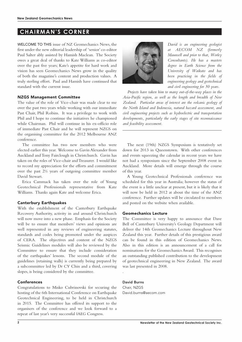
David BurnsChair, [email protected]
David is an engineering geologist at AECOM NZ (formerly Maunsell and prior to that, Worley Consultants). He has a masters degree in Earth Science from the University of Waikato and has been practicing in the fields of engineering geology and geotechnical and civil engineering for 30 years.
Projects have taken him to many out-of-the-way places in the Asia-Pacific region, as well as the length and breadth of New Zealand. Particular areas of interest are the volcanic geology of the North Island and Indonesia, natural hazard assessment, and civil engineering projects such as hydroelectric and transportation developments, particularly the early stages of site reconnaissance and feasibility assessment.
New Zealand Geomechanics News
33june 2011, issue 81
editoRial
A speciAl FeAture on the Mw 6.3 Christchurch Earthquake of 22 February dominates this issue, as it should for an event that has cost many lives and devastated the centre of our second biggest city. It is little comfort that, technically, this was an aftershock of September’s Mw 7.1 Darfield Earthquake and that the possibility of such a quake was known (a Mw 7.3 aftershock occurred 10 days after the Mw 7.9 Napier EQ in 1931).
It was the unfavourable location and unusually strong ground motions - the strongest ever recorded in NZ - that contributed to this chaos. We have reprinted some of the raw seismic data, and spectra analysis by Graeme McVerry of GNS, which show the ground motions in the CBD far exceeding the design motions for most buildings. An excellent paper by Graham Hancox and others at GNS focuses on the landsliding and related ground damage around the Port Hills caused by this strong shaking – phenomena that were largely absent in September’s EQ.
It’s hard to imagine a time when geotechnical practitioners could provide more direct input into the recovery, re-building and future-proofing of a major city in NZ. As reported on p84, this practical help started within the first 24 hours as geotechnical engineers assigned to Urban Search and Rescue teams assisted with rescues in the CBD and provided advice on rockfall issues. Other articles deal with how certain structures have performed (p68), urgent rockfall mitigation measures (p79), and EQC’s on-going response (p73) – all demonstrating the considerable efforts geologists, engineers, scientists and contractors are collaboratively putting in. Our input can contribute to rebuilding a more resilient society and now is our opportunity to excel.
Of course, other geotechnical projects are on-going and are reflected in this issue, along with industry news such awarding of the NZGS Geomechanics Lecture, the recognition of several NZGS members as IPENZ Fellows, moves for engineering geologist registration, conference news and book reviews.
The current co-editors would also like to thank Kate Williams for all her editorial efforts in recent years. The NZ Geomechanics News newsletter has grown from an initial 30 pages, edited by John Blakely, in 1970. At the last Management Committee meeting it was suggested we canvas opinion on officially calling the publication a magazine, rather than a newsletter. The merits of reviewing the full title were also briefly discussed, with a possible change to NZ Geotechnical News suggested as better reflecting the Society’s name and members spheres of work, although it was also noted this would change a long tradition and the status quo may be best. It’s is interesting to read the background behind the Society’s name change 15 years ago, so this has been reproduced on p110. If
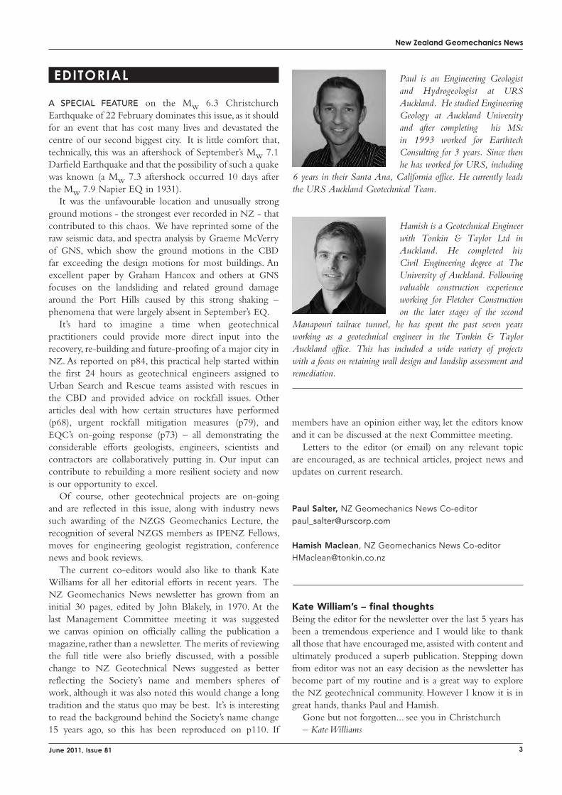
Paul is an Engineering Geologist and Hydrogeologist at URS Auckland. He studied Engineering Geology at Auckland University and after completing his MSc in 1993 worked for Earthtech Consulting for 3 years. Since then he has worked for URS, including
6 years in their Santa Ana, California office. He currently leads the URS Auckland Geotechnical Team.
Hamish is a Geotechnical Engineer with Tonkin & Taylor Ltd in Auckland. He completed his Civil Engineering degree at The University of Auckland. Following valuable construction experience working for Fletcher Construction on the later stages of the second
Manapouri tailrace tunnel, he has spent the past seven years working as a geotechnical engineer in the Tonkin & Taylor Auckland office. This has included a wide variety of projects with a focus on retaining wall design and landslip assessment and remediation.
members have an opinion either way, let the editors know and it can be discussed at the next Committee meeting.
Letters to the editor (or email) on any relevant topic are encouraged, as are technical articles, project news and updates on current research.
Paul Salter, NZ Geomechanics News [email protected]
Hamish Maclean, NZ Geomechanics News Co-editor [email protected]
Kate William’s – final thoughtsBeing the editor for the newsletter over the last 5 years has been a tremendous experience and I would like to thank all those that have encouraged me, assisted with content and ultimately produced a superb publication. Stepping down from editor was not an easy decision as the newsletter has become part of my routine and is a great way to explore the NZ geotechnical community. However I know it is in great hands, thanks Paul and Hamish.
Gone but not forgotten... see you in Christchurch – Kate Williams
New Zealand Geomechanics News
4 Newsletter of the New Zealand Geotechnical Society Inc.
letteRs to the editoR
Dear Ann,
I am extremely concerned about the sad news from your country. I still remember last September’s quake during our visit to the same area, but this time I see nature has been harsher with the humans.
On another matter, I am trying to compare the opinions of all ExCom members about HK and when I send a decision to Steve, I will forward you a copy.
I would appreciate if you send me information about the situation and if you need any collaboration from IAEG please do not hesitate to ask.
Best wishesProfessor Carlos Delgado
President of the International AssociationFor Engineering Geology and the Environment (IAEG)Polytechnic University of MadridSchool of Civil Engineering______________________________________________
Dear Ann,
Thank you for the information given about the recent Christchurch Earthquake. My wife and I express our sympathy to your family and to you and the Christchurch people for the gate tragedy hidden you all. I followed the whole event through the internet and was surprised with the destruction to buildings and the other facilities. I was also surprised with great extent of the land covered by liquefaction. I have never seen such big extent. Somebody said that the city is built on sand, silt and gravel. We wish and hope that the restoration of the city will be quick and better.
RegardsGeorge Xeidakis
Xanthi, Greece______________________________________________
Dear Ann,
I have been shocked by the pictures I have seen of the effects of the recent Christchurch earthquake. I have been there three times (and two of them staying at Cathedral Square!) so, in some sense, I felt it in a personal way. Have you been down there? Are you involved in the investigations?
I hope that nobody close to you was affected. In any case, please accept my sympathy in this difficult time for New Zealand (as you know, one of my favourite countries!).
All the bestAntonio Gens
Professor of Geotechnical EngineeringDepartamento de Ingenieria del Terreno Tel:34-93-4016867(direct)Jordi Girona 1-3 Edificio D-2 34-93-4017250 (secretaries)Universitat Politecnica de Catalunya Fax:34-93-401725108034 Barcelona, SpainE-mail: [email protected]
______________________________________________
Messages of Condolence
New Zealand Geomechanics News
5
editoRial Policy
NZ Geomechanics News is a biannual newsletter issued to members of the NZ Geotechnical Society Inc. It is designed to keep members in touch with matters of interest within the geo-professions both locally and internationally. The statements made or opinions expressed do not necessarily reflect the views of the New Zealand Geotechnical Society Inc. The editorial team are happy to receive submissions of any sort for future editions of NZ Geomechanics News. The following comments are offered to assist potential contributors. Technical contributions can include any of the following:
• technical papers which may, but need not necessarily be, of a standard which would be required by international journals and conferences
• technical notes• comments on papers published in NZ Geomechanics
News• descriptions of geotechnical projects of special
interest
General articles for publication may include:• letters to the NZ Geotechnical Society• letters to the Editor• articles and news of personalities• news of current projects• industry news
Submission of text material in Microsoft Word is encouraged, particularly via email to the editor or on CD. We can receive and handle file types in most formats. Contact us if you have a query about format or content.
Diagrams and tables should be of a size and quality appropriate for direct reproduction. Photographs should be good contrast, black and white gloss prints or high resolution digital images. Diagrams and photos should be supplied with the article, but also saved seperately as 300 dpi .jpgs. Articles need to be set up so that they can be reproduced in black and white, as colour is limited.
NZ Geomechanics News is a newsletter for Society members and articles and papers are not necessarily refereed. Authors and other contributors must be responsible for the integrity of their material and for permission to publish. Letters to the Editor about articles and papers submitted by members will be forwarded to the contributing member for a right of reply.
Persons interested in applying for membership of the Society are invited to complete the application form in the back of the newsletter. Members of the Society are required to affiliate to at least one International Society and the rates are included with the membership information details.
> The NZGS has a very informative easily navigable and stunningly laid out website to keep you up to date.
> If you have an image that you would like to see on the website’s header, please forward to [email protected]
> The most visited website pages are publications and guidelines, conferences and jobs.
> In the last six months there were approximately 14,500 page views by visitors from 104 different countries.
> Most visitors were from NZ, Australia, UK, US and Hong Kong.
> Website traffic is at its lowest in the weekends perhaps indicating that people visit the site from work.
NZGS on the WEB
www.nzgs.org
Request for Retaining Walls
The editors are calling for some examples
of retaining wall design to feature in the December
2011 issue of NZ Geomechanics News. We would like
to summarise a range of current technologies available
for retaining slopes and, ideally, contributions would
be in the form of a photo(s) of the completed wall
and a brief description of the geotechnical situation,
design features of the wall and any construction
challenges/benefits involved. Examples from suppliers,
contractors, consultants and others are encouraged.
New Zealand Geomechanics News
6 Newsletter of the New Zealand Geotechnical Society Inc.
the secRetaRy’s News
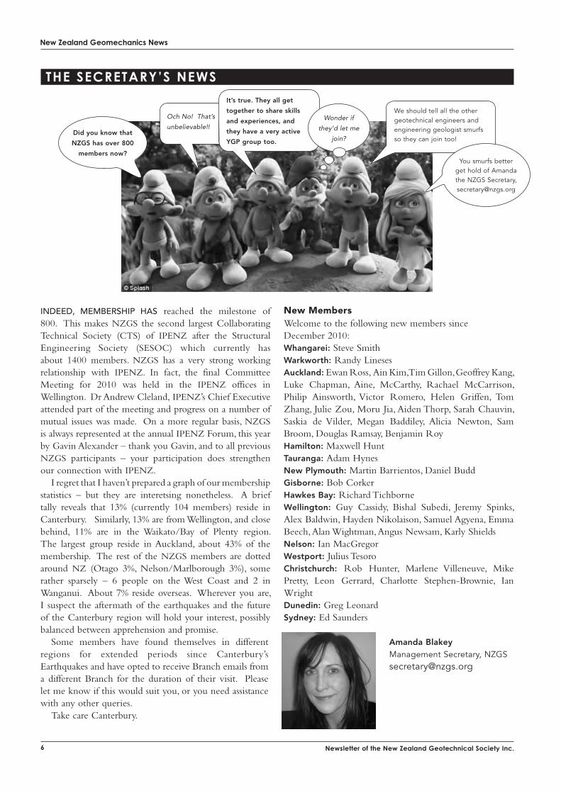
indeed, membership hAs reached the milestone of 800. This makes NZGS the second largest Collaborating Technical Society (CTS) of IPENZ after the Structural Engineering Society (SESOC) which currently has about 1400 members. NZGS has a very strong working relationship with IPENZ. In fact, the final Committee Meeting for 2010 was held in the IPENZ offices in Wellington. Dr Andrew Cleland, IPENZ’s Chief Executive attended part of the meeting and progress on a number of mutual issues was made. On a more regular basis, NZGS is always represented at the annual IPENZ Forum, this year by Gavin Alexander – thank you Gavin, and to all previous NZGS participants – your participation does strengthen our connection with IPENZ.
I regret that I haven’t prepared a graph of our membership statistics – but they are interetsing nonetheless. A brief tally reveals that 13% (currently 104 members) reside in Canterbury. Similarly, 13% are from Wellington, and close behind, 11% are in the Waikato/Bay of Plenty region. The largest group reside in Auckland, about 43% of the membership. The rest of the NZGS members are dotted around NZ (Otago 3%, Nelson/Marlborough 3%), some rather sparsely – 6 people on the West Coast and 2 in Wanganui. About 7% reside overseas. Wherever you are, I suspect the aftermath of the earthquakes and the future of the Canterbury region will hold your interest, possibly balanced between apprehension and promise.
Some members have found themselves in different regions for extended periods since Canterbury’s Earthquakes and have opted to receive Branch emails from a different Branch for the duration of their visit. Please let me know if this would suit you, or you need assistance with any other queries.
Take care Canterbury.
New MembersWelcome to the following new members since December 2010:Whangarei: Steve SmithWarkworth: Randy LinesesAuckland: Ewan Ross, Ain Kim, Tim Gillon, Geoffrey Kang, Luke Chapman, Aine, McCarthy, Rachael McCarrison, Philip Ainsworth, Victor Romero, Helen Griffen, Tom Zhang, Julie Zou, Moru Jia, Aiden Thorp, Sarah Chauvin, Saskia de Vilder, Megan Baddiley, Alicia Newton, Sam Broom, Douglas Ramsay, Benjamin RoyHamilton: Maxwell HuntTauranga: Adam HynesNew Plymouth: Martin Barrientos, Daniel BuddGisborne: Bob CorkerHawkes Bay: Richard TichborneWellington: Guy Cassidy, Bishal Subedi, Jeremy Spinks, Alex Baldwin, Hayden Nikolaison, Samuel Agyena, Emma Beech, Alan Wightman, Angus Newsam, Karly ShieldsNelson: Ian MacGregorWestport: Julius TesoroChristchurch: Rob Hunter, Marlene Villeneuve, Mike Pretty, Leon Gerrard, Charlotte Stephen-Brownie, Ian WrightDunedin: Greg LeonardSydney: Ed Saunders
Amanda BlakeyManagement Secretary, [email protected]
Och No! That’s
unbelievable!!
It’s true. They all get
together to share skills
and experiences, and
they have a very active
YGP group too.
We should tell all the other geotechnical engineers and engineering geologist smurfs so they can join too!
Did you know that
NZGS has over 800
members now? You smurfs better
get hold of Amanda the NZGS Secretary, [email protected]
Wonder if
they’d let me
join?
New Zealand Geomechanics News
7
iNteRNatioNal society RePoRts
International Association for Engineering Geology and the Environment Australasia VP Report: March 2011
CouNCiL MEEtiNGThe IAEG Executive and Council meetings were held in Auckland on 4 and 5 September immediately prior to the opening of the 11th IAEG Congress in Auckland. Major items discussed included presentation and discussion of the modernisation plan (a plan to streamline and improve the efficiency and efficacy of IAEG), selection of Torino, Italy as the venue for the 12th International Congress in 2014, and election of the new Executive. Carlos Delgado was elected as President; Fred Baynes will remain on the Executive as the Immediate Past President; the new Secretary-General is Faquan Wu from China, who served as VP Asia on the Executive over the last 4 years. Giorgio Lollino has the newly created role of Web-Editor for the period 2010 to 2013. Giorgio is leading a team that will create a new interactive website that will better facilitate informing and networking amongst the membership. There are 12 active IAEG Commissions and it is expected that the commissions will report their findings on the website for members to download and correspond on. Brian Hawkins will continue in his role as Editor of the Bulletin and it is planned that authors will be able to submit and have published abstracts in their native language (in addition to English and French).
Ann Williams takes on the role of Vice President (Australasia) and Mark Eggers, the role of Australian liaison. Mark has agreed to lead organisation of the Engineering Geology Session at the 34th IGC (International Geological Congress) to be held in Brisbane in 2012 with support from Francisco de Jorge (Immediate Past Vice President, South America).
FEDiGS (Federation of international Geo-engineering Societies)There was an extraordinary meeting of the FedIGS Board on 28 May 2010. It was agreed that FedIGS would continue to operate within the Co-operation agreement endorsed by the sister societies but it will change to become a smaller, less powerful organisation. Professor William Van Impe’s resignation as FedIGS President was accepted and Professor Nielen van der Merve will chair the Board for the next 12 months. JTC1 JTC2 and JTC3 (Geoengineering Data, Landslides and Education) will continue to exist and be managed by the FedIGS Board but all other JTCs will be disbanded. The Liaison Committee (made up of industry representatives) will also be disbanded.
MoDErNiSatioN PLaNThis is essentially the Strategic Plan of the IAEG to enable it to provide relevant, timely, cost effective services to its members, in particular in relation to the Bulletin, the website, the newsletter, organisation of conferences and symposia, activities relating to education and training, maintaining an archive and encouragement of greater interaction amongst members.
A LinkedIn Group has been established to facilitate discussion of any matter relating to engineering geology amongst members. Apply to join from the website www.iaeg.info. See also the reports of Commission C25 Geological Models.
YouNG ProFESSioNaLSA particular objective is to encourage the participation of Young Professionals and membership of this group. A new Commission, C30 was established at IAEG2010. The Group, led by Beverley Curley (NZ), has already representatives from 11 countries, including Darren Paul of Australia, winner of the Richard Wolters Prize in 2010 and currently correspond via facebook.
CoNFErENCESAn excellent conference, ICUST (International Conference on Underground Space Technology) was held in Bangalore, India, in January under the aegis of IAEG and organized by the Indian Society of Engineering Geology and National Institute of Rock Mechanics. Key outcomes from the discussion can be accessed on www.isegindia.org.
The next IAEG Executive and Council meetings will be held in Moscow in September 2011 on the occasion of Engeopro-2011. Submission of Abstracts closes 31 March 2011 on http://www.engeopro2011.com/index_eng.htm.
Ann WilliamsIAEG Vice President (Australasia)
New Zealand Geomechanics News
8 Newsletter of the New Zealand Geotechnical Society Inc.
International Society of Soil Mechanics and Geotechnical Engineering Australiasia VP Report: March 2011
As members oF the society will probably be aware, the ISSMGE Board meets twice a year. Since the formation of the current Board in 2009 one or two conference calls are held between each of these meetings. As you will have read in my earlier reports, our President, Professor Jean-Louis Briaud, has introduced a new structure of committees reporting into the Board which to date have been very active. The additional meetings have, therefore, proved to be extremely necessary to keep pace with these committees and permit the business of the ISSMGE to move along.
The most recent “face to face” Board meeting took place in New Delhi in November of last year. As is the normal practice, the meeting coincided with a major ISSMGE international conference. In this case it was the 6th International Congress on Environmental Geotechnics (6ICEG). Since the introduction of this series of Environmental Geotechnics conferences in 1994 the congress has enjoyed a special status as a pan ISSMGE event, in the same way as the quadrennial international conferences of the society, rather than being associated with a specific Technical Committee as with other specialist conferences. With the maturity of the area of Environmental Geotechnics it was decided at the Moscow Board meeting that the status of the ICEG be changed to a conference of TC215 on Environmental Geotechnics. The next conference (7ICEG) will, therefore, be organised under auspices of TC215.
The ISSMGE is now a very mature - but still vibrant - organisation! The Society’s age is calculated from its origins at the 1936 International Conference held at Cambridge, Massachusetts and, therefore, in 2011 the ISSMGE is celebrating its 75th Anniversary. The ISSMGE is marking this milestone in its history by holding special celebratory sessions at each of the regional conferences that are taking place this year. In addition, the celebrations began with a session at the 6th International Congress on Environmental Geotechnics. Indeed, as well as starting the celebrations early in November of 2010, they will also be extended into 2012 because our own regional conference, the 11th ANZ Conference (to be held in Melbourne) has been delayed from 2011 to July 2012! Special sessions are also to be held in the Regional conferences for Asia (May), Africa (June), Europe (September) and Pan America (October). The celebratory sessions will each have the same format with presentations from a distinguished senior member of the society, a young geotechnical engineer and the President or Regional Vice President. They will be speaking about the ISSMGE in the past, the future and the present, respectively. At the 6ICEG these talks were presented by Professor
Kenji Ishihara (ISSMGE past President), Dr Imen Said and Professor Jean-Louis Briaud.
As I have indicated above, members of the new Board level committees have put in a great deal of effort for the Society. The Technical Oversight Committee (TOC), having managed the process of appointing Chairs and agreeing membership the Technical Committees, has been engaged in approving the terms of reference for each TC. The Board is very keen for as many people as is reasonably possible to be involved with the technical activities of the society and it has been suggested that the establishment of a grade of “corresponding member” might be a good way of increasing active membership of TCs. This proposal is currently being addressed by TOC. The Board also proposed to the Membership, Practitioners, Academicians, Committee (MPAC) the formation of a Corporate Associates Presidential Group (CAPG) that would be made up of representatives of the companies which are corporate associates of ISSMGE. The purpose of the CAPG is to assist the ISSMGE in developing actions and activities that will enhance the commercial sector of the geotechnical profession. The CAPG members will have direct access to the President of ISSMGE and will be able to have a direct impact on the future of the Society.
The Innovation and Development Committee (IDC) has been exceptionally busy on a number of projects, some of which I have described in previous reports. Probably the most pressing current task for the IDC is to make proposals for the updating of the ISSMGE website. Members of IDC have been working with the ISSMGE Secretariat to develop proposals for an updated web presence that will maintain the identity and professional image of the ISSMGE but be relevant to members by providing links to up-to-date information relevant to their technical interests. The IDC will be presenting a detailed proposal to the next Board meeting and in my next report I hope to be able to report on the outcome of this in detail.
Last, but by no means least, the Students and Young Member Presidential Group (SYMPG) has also been very active. The SYMPG has established four sub-groups that are investigating ways to allow young members to engage more in the Society and, indeed, make a unique contribution to its activities. The areas that have been identified are: the website; communications between the ISSMGE and its young members; young members’ involvement in Technical Committees; and developing and increasing the membership of students and younger practitioners in the ISSMGE. The membership of the SYMPG includes three representatives from each region of the ISSMGE. In
june 2011, issue 81
New Zealand Geomechanics News
addition, it has corresponding members who receive the news about the SYMPG and who are able to participate in – and influence - the discussions of the SYMPG by email. At present our region has only two members and so if you are under 35 and interested in becoming a member or corresponding member of the SYMPG please either contact me or the Secretary of AGS or NZGS, as appropriate, for more details.
Professor Michael C.R. DaviesVice-President for Australasia and First Vice-President ISSMGE
Ph: 09 412 7048 E: [email protected]
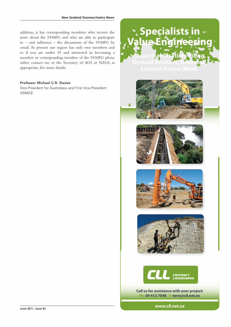
www.cll.net.nz
Call us for assistance with your project:
Specialists inValue Engineering
Slope Stabilisation, Piling,Ground Anchors, Drainage,
Limited Access Work.
“UNRIVALED RESULTS EVEN IN THE MOST COMPLEX ENVIRONMENTS.” - Boart Longyear Drilling Services
Boart Longyear is meeting the demands of today’s challenges with modern drilling technology. Our experienced team provides quality solutions, even in the most difficult and sensitive conditions.
Experienced crews in all conditions ■ and techniques
Quality Assured; Quality results ■
Professional management systems ■
Explore our world at www.boartlongyear.com.
Copyright © 2007 Boart Longyear Ltd. All rights reserved. ISO 14001 | OHSAS 18001 Certified
For more information on our projects and services, contact your Boart Longyear representative today. Tel: 09 267 9100 Email: [email protected]
SPECIALISED DRILLING SERVICES FOR:
ENVIRONMENTAL ASSESSMENTS
GEOTECHNICAL INVESTIGATIONS
INSTRUMENTATION INSTALLATION, MONITORING WELLS ANDFOUNDATION INVESTIGATIONS
SITES OF SPECIAL SCIENTIFIC INTEREST (SSSI)
EXPLORATION, MINERAL AND WATER BORE DRILLING
LANDFILLS, BRIDGES, DAMS, RAIL ROADS, EMBANKMENTS
A4_DS Geotechnical Advert_NZ_102007.indd 1 6/03/2008 4:18:06 PM

»»
»»
»»
»»
»»
»»
»»
»»
»»
»»
»»
HD180 RigPower and performanceHigh performance purpose designed anchoring rig with twin-rotation heads. Used recently on Victory Christian Church, Victoria Park Tunnel and Newmarket Viaduct projects to advance large diameter casing through steel and concrete obstructions.
Ground Anchor TestingVerify and validateExtensive data base of testing information throughout New Zealand. Test load capability ranging from 100kN to 10,000kN.
Post-tensioningActive in the reinforcement ofconcrete structuresRecent projects include Lion Breweries new warehousing and processing facility (50,000sq.m slab on grade), Britomart Oriental Markets Carpark (36,000sq.m suspended slab), Victory Christian Church Carpark (12,000sq.m suspended slab), Eden Park South and East Stands (40km prestressing strand).
Driven Kite AnchorsInstant load locking capabilityAnchor design loads range from 5kN to 300kN and have been tested in ground conditions from Auckland to the Coromandel.
Grouting Services has delivered some of New Zealand’s largest Ground Anchoring and Post Tensioning contracts with great results, creating an ever growing repeat business market.It’s not what we do but how we do it that distinguishes our company from the rest and we fi nd solutions around problems that make things possible. We work in close liaison with our clients from inception to hand-over with strong emphasis on personal attention and close monitoring of all projects.
We specialise in design and construct solutions for:
> Ground Anchoring > Post Tensioning
If you’re interested in working with us or fi nding out more about the results we’ve achieved for our clients call 09 837 2510 or visit our website and watch this space for advances in removable ground anchor technology.
ENGINEERING EXCELLENCE SINCE 1971
09 837 2150 or 021 75 75 66T W www.groutingservices.co.nz
Retaining your business is our business.
110606 GS NZGS Mag FP V3.indd 1 8/06/11 11:47 AM

»»
»»
»»
»»
»»
»»
»»
»»
»»
»»
»»
HD180 RigPower and performanceHigh performance purpose designed anchoring rig with twin-rotation heads. Used recently on Victory Christian Church, Victoria Park Tunnel and Newmarket Viaduct projects to advance large diameter casing through steel and concrete obstructions.
Ground Anchor TestingVerify and validateExtensive data base of testing information throughout New Zealand. Test load capability ranging from 100kN to 10,000kN.
Post-tensioningActive in the reinforcement ofconcrete structuresRecent projects include Lion Breweries new warehousing and processing facility (50,000sq.m slab on grade), Britomart Oriental Markets Carpark (36,000sq.m suspended slab), Victory Christian Church Carpark (12,000sq.m suspended slab), Eden Park South and East Stands (40km prestressing strand).
Driven Kite AnchorsInstant load locking capabilityAnchor design loads range from 5kN to 300kN and have been tested in ground conditions from Auckland to the Coromandel.
Grouting Services has delivered some of New Zealand’s largest Ground Anchoring and Post Tensioning contracts with great results, creating an ever growing repeat business market.It’s not what we do but how we do it that distinguishes our company from the rest and we fi nd solutions around problems that make things possible. We work in close liaison with our clients from inception to hand-over with strong emphasis on personal attention and close monitoring of all projects.
We specialise in design and construct solutions for:
> Ground Anchoring > Post Tensioning
If you’re interested in working with us or fi nding out more about the results we’ve achieved for our clients call 09 837 2510 or visit our website and watch this space for advances in removable ground anchor technology.
ENGINEERING EXCELLENCE SINCE 1971
09 837 2150 or 021 75 75 66T W www.groutingservices.co.nz
Retaining your business is our business.
110606 GS NZGS Mag FP V3.indd 1 8/06/11 11:47 AM
New Zealand Geomechanics News
14 Newsletter of the New Zealand Geotechnical Society Inc.
International Society for Rock Mechanics Australasia VP Report : March 2011
1 CurrENt BoarD tENurEThe ISRM Congress in Beijing in October 2011 represents the end of the four year tenure of the current Board and of the President of the Society. During this tenure the Board has implemented many modernisation initiatives in the areas of:
• Availability of literature: Francois Malan, VP Africa• Communication with members, Nuno Grossman,
VP Europe• Improving benefits to members: Tony Meyers, VP
Australasia• International symposia and conferences, Xia-Ting
Feng, VP at large• Interaction with other societies, Alvaro Gonzales, VP
South America• Lecture tours and educational material, Claus
Erichsen, VP at large• Prizes and certificates, John Hudson, President• Technical issues: Derek Martin, VP North America• Website strategy, Abdolhadi Ghazvinian, VP AsiaThe remaining months will see many of the loose ends
of these initiatives being tied up. Currently nine ISRM Commissions are active, seven
with Asian Chairman. The work of these Commissions represents one of the key outputs from the Society to its Members. The Commission Chairs are required to have their final reports finished by the end of the tenure of the current Board.
2 iSrM 50tH aNNiVErSarY YouNG MEMBErS’ SLiDE SHoW CoMPEtitioN In October 2011, the ISRM will begin the celebrations to commemorate its 50th anniversary; these celebrations will include a number of special events and initiatives.
One of the initiatives consists of a competition open to Young Members of the Society to present their vision of “The Future Directions for Engineering Rock Mechanics”.
The winner will be invited to present the slide show at the Second ISRM International Young Scholars’ Symposium on Rock Mechanics, which will take place in Beijing, China, in October 2011 immediately preceding the 12th ISRM Congress also being held in Beijing. In addition, the winning slide show will be announced and published on the ISRM website. The winner will also be formally acknowledged with a certificate during the ISRM Congress.
The winner will be granted a financial contribution to the air travel cost plus free registration and inexpensive accommodation at both the Young Scholars’ Symposium and the Congress.
The ISRM invites all its members who are aged 35 years or less during 2011 to submit a fully explanatory PowerPoint slide show explaining, illustrating and justifying their vision of “The Future Directions for Engineering Rock Mechanics”. The show must be presented in English, and consist of exactly 40 slides. It shall be submitted to the ISRM Secretariat ([email protected]) by 30 June 2011.
3 roCK MECHaNiCS aND roCK ENGiNEEriNG JourNaL: NEW ForMatIn February 2010 the journal “Rock Mechanics and Rock Engineering” abandoned its traditional “pocket size” and started being published in A4 size.
Having now six issues published per year and more content in each issue, the Editors have announced a significant reduction in the time between a paper being accepted and being printed.
With an 80 year history, this journal was for a long time the official journal of the ISRM. As a result of this close relationship with the Society, the publishers offer ISRM members personal subscriptions at a discounted price.
The Editorial of the first issue with the new format can be downloaded at http://www.ISRM.net/fotos/editor2/nl12/rmre.pdf.
4 NEW JourNaL: GÉotECHNiQuE LEttErSICE Publishers has launched a new journal – Géotechnique Letters. This online only journal will cover the same content range of geotechnical engineering as Géotechnique. Papers are limited to 2000 words and will be published within six weeks of submission, whilst still maintaining rigorous peer reviewing standards.
Géotechnique regularly publishes high quality work by rock mechanics practitioners, and so this new publication should be of interest to ISRM members.
The Call for Papers can be downloaded at http://www.icevirtuallibrary.com/upload/journals/geolettcfp.pdf.
5 DiGitaL LiBrarYMembers are slowly becoming aware of the new digital library. The library currently has over 3000 pages from 10 conferences uploaded and this number is constantly increasing.
Members registered to use the Members Only section of the ISRM website are able to download up to 100 papers each year for free. ISRM Corporate members can download 250 papers per annum for free.
The library is hosted by OnePetro, a large online library managed by the Society of Petroleum Engineers, SPE.

New Zealand Geomechanics News
15
To register on their site (www.onepetro.org), the only information necessary are the Member’s username and password that were assigned when the Member gained access to the ISRM website.
Any Member that does not have these details should contact the Regional VP, Tony Meyers, who will organise to have these details sent out by the Secretariat.
6 ProJECt: SEiSMiC riSK iN SoutH aFriCa’S PLatiNuM MiNiNG SECtorEarlier this year, the South African Mine Health and Safety Council awarded a 1-year research project to a consortium of mine seismology and rock engineering experts to establish contributing factors driving seismicity and rockbursting in platinum mines. The project will be completed by July 2011.
In its proposal, the project team suggested building on the gold mines’ experience when it comes to managing seismic risk. Gold mines have been operating digital seismic networks for over twenty years during which valuable insight has been gained into the relationship between geotechnical setting, stress fields, mining practice and seismicity.
Notwithstanding past experience, there are clear differences between gold and platinum mines: Rock types, virgin and mining induced field stresses, and an almost
complete absence of regional fault systems on the platinum side to name a few.
The project aims to exploit similarities in the underlying principles of mining induced seismicity and focus on the differences between Witwatersrand gold mines and platinum mines in the Western Bushveld Complex. One of the two main task groups in the project is carrying out a detailed rockburst investigations while the other group is considering practical initiatives for seismic risk management including seismic monitoring, geological mapping, rock mass characteristic determination and stress measurements.
7 rEPort oN tHE Vii SoutH aMEriCaN CoNGrESS oN roCK MECHaNiCS iN LiMa, PEru – a rECorD attENDaNCEThe ISRM South American Congress on Rock Mechanics was held during December 2010 at the Sheraton Lima Hotel and Convention Centre in Lima, Peru. The event was very successful with over 500 delegates and 21 exhibitors.
The Congress included Keynote presentations by Nick Barton, Carlos Carranza-Torres, Tarsicio Celestino, Xia-Ting Feng, Evert Hoek (who gave the Premier Keynote), John A Hudson, Rimas Pakalnis and David Wood. All presentations were well attended, right up until the Closing Ceremony.

Drill Force NZ LTD is a multi-disciplined mobile drilling company which delivers unparalleled quality and services throughout New Zealand. Drill Force specialises in Geotechnical, Environmental, Construction, Water Well, Exploration, Coal and CBM drilling markets. We have the capabilities to drill from 1m to 1500m deep.
Geotechical capabilities:• TrackandTractorMountedRigs•Tightsiteaccess•BargeDrilling• HelicopterDrilling• WireLineCoringHQandPQ• InSituTesting–SPT,Shear Vane,PackerTesting,etc• DeepInstrumentation Installation
WaTeRWeLLCaPaBILITIeS:• DomestictoMunicipalWater SupplySchemes• 100mmto400mmwide• Upto1500mdeep
Phone: 09 294 9038Zane Mobile: 021 842 475Bruce Mobile: 021 274 2404Email: [email protected] Web: www.drillforce.co.nz
New Zealand Geomechanics News
17
8 rEPort oN 6tH aSiaN roCK MECHaNiCS SYMPoSiuM
The Indian National Group of the ISRM hosted the ISRM International Symposium 2010 and the 6th Asian Rock Mechanics Symposium in New Delhi in October 2010.
More than 150 papers were submitted from 27 countries including 25 papers from Australia, Canada, China, France, India, Iran, Japan, Singapore, South Korea and USA. 275 delegates from 35 countries participated in the Symposium.
The keynote lectures were:• Dr. Shinichi Akutagawa, Kobe University, Japan -
On Site Visualization as a New Paradigm for Field Measurement in Rock Engineering
• Prof. Giovanni Barla, Politechnico di Tornio, Italy - Progress in the Understanding of Deep-Seated Landslides from Massive Rock Slope Failure
• Prof. Maurice Dusseault, University of Waterloo, Canada - Deep Injection Disposal: Environmental and Petroleum Geomechanics
• Dr. C. Erichsen, WBI, Germany - Challenges in the Design and Construction of Tunnels in Jointed Rock
• Prof. Xia-Ting Feng, Institute of Rock and Soil Mechanics, China and ISRM Vice President at Large - Application of Intelligent Rock Mechanics Methodology to Rock Engineering
• Prof. Yossef H. Hatzor, Ben-Gurion University of Neger, Israel - Modelling Dynamic Deformation in Natural Rock Slopes and Underground Openings with Numerical DDA Method
• Dr. John A. Hudson, Imperial College, UK and President, ISRM - Underground Radioactive Waste Disposal -- The Rock Mechanics Contribution
• Prof. Guowei Ma and Prof. Yingxin Zhou, Singapore - Rock Dynamics Research in Singapore: Fundamentals and Practices
• Dr. John Read, CSIRO LOP Project, Australia – The Large Open Pit Project
• Prof. Herb Wang, University of Wisconsin, USA – Deep Underground Instrumentation and Monitoring
9 rEPort oN tHE iSrM WorKSHoP oN roCK DYNaMiCS
The ISRM Commission on Rock Dynamics held its second international workshop in Wuhan, China, in December 2010. The workshop was attended by more than 30 participants from Australia, Canada, China, Norway, Singapore, and the USA.
The main objective of the workshop was to discuss the drafts of the Suggested Methods for Determining the Dynamic Strength Parameters and Fracture Toughness of Rock Materials. The four suggested methods discussed were:
• Part 1: Suggested Method for Determining the Dynamic Uniaxial Compressive Strength of Rock Materials with Split Hopkinson Pressure Bar
• Part 2: Suggested Method for Determining Dynamic Indirect Tensile Strength by the Brazil Test
• Part 3: Suggested Method for Determining Dynamic Fracture Toughness
• Part 4: Suggested Method for Determining Dynamic Flexural Strength by the Semi-Circular Bend Test
The workshop also included other presentations on rock dynamic testing, blasting, and dynamic support, and visits to the various dynamic testing laboratories at the Institute of Rock and Soil Mechanics in Wuhan and the Central South University in Changsha. The presentations given at the workshop included:
• “Advances in rock fragmentation study”, by Bibhu Mahonty
• “Dynamic testing of rock bolts”, by Charlie Li• “Full stress-strain curves from dynamic compression
tests”, by Xibing Li• “Dynamic fracture toughness anisotropy of Barre
granite”, by Feng Dai• “Dynamic punch shear tests”, by Kaiwen XIA• “Dynamic compressive testing method for rocks”, by
Zilong Zhou• “Dynamic tension and fracture testing methods for
rocks”, by Kaiwen Xia
10 uPCoMiNG EVENtS15th to 17th October 2011. Beijing, China. 2nd International Young Scholars Symposium on Rock Mechanics. An ISRM Specialised Conference.
16th to 21st October 2011. Beijing, China. zzHarmonizing Rock Mechanics and the Environment: the ISRM 12th International Congress on Rock Mechanics.
27th to 30th May 2012. Stockholm, Sweden. 2nd EUROCK 2012. Rock Engineering and Technology. An ISRM Regional Symposium and 2012 ISRM International Symposium.
21st to 26th September 2013. Wroclaw, Poland. 2nd EUROCK 2013. Application of Rock Mechanics to Civil and Mining Engineering. An ISRM Regional Symposium.
29th April to 6th May 2015. Montreal, Canada. Innovations in Applied and Theoretical Rock Mechanics. The 13th ISRM International Congress.
Tony Meyers ISRM Vice President (Australasia)
Drill Force NZ LTD is a multi-disciplined mobile drilling company which delivers unparalleled quality and services throughout New Zealand. Drill Force specialises in Geotechnical, Environmental, Construction, Water Well, Exploration, Coal and CBM drilling markets. We have the capabilities to drill from 1m to 1500m deep.
Geotechical capabilities:• TrackandTractorMountedRigs•Tightsiteaccess•BargeDrilling• HelicopterDrilling• WireLineCoringHQandPQ• InSituTesting–SPT,Shear Vane,PackerTesting,etc• DeepInstrumentation Installation
WaTeRWeLLCaPaBILITIeS:• DomestictoMunicipalWater SupplySchemes• 100mmto400mmwide• Upto1500mdeep
Phone: 09 294 9038Zane Mobile: 021 842 475Bruce Mobile: 021 274 2404Email: [email protected] Web: www.drillforce.co.nz
New Zealand Geomechanics News
18 Newsletter of the New Zealand Geotechnical Society Inc.
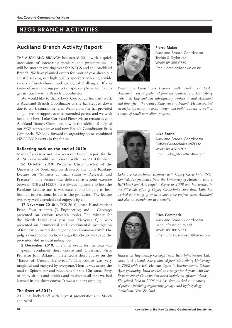
Erica Cammack Auckland Branch CoordinatorBeca Infrastructure LtdWork: 09 300 9371Email: [email protected]
Erica is an Engineering Geologist with Beca Infrastructure Ltd, based in Auckland. She graduated from Canterbury University in 2002 with a BSc Honours degree in Environmental Science. After graduating Erica worked as a ranger for 4 years with the Department of Conservation based mainly on offshore islands. She joined Beca in 2006 and has since worked on a variety of projects involving engineering geology and hydrogeology throughout New Zealand.
Pierre Malan Auckland Branch CoordinatorTonkin & Taylor LtdWork: 09 355 0759Email: [email protected]
Pierre is a Geotechnical Engineer with Tonkin & Taylor Auckland. Pierre graduated from the University of Canterbury with a M.Eng and has subsequently worked around Auckland and throughout the United Kingdom and Ireland. He has worked on major infrastructure work, design and build contracts as well as a range of small to medium projects.
NZGs BRaNch activities
the AucklAnd brAnch has started 2011 with a quick succession of interesting speakers and presentations. It will be another exciting year for NZGS and the Auckland Branch. We have planned events for most of year ahead but are still seeking out high quality speakers covering a wide variety of geotechnical and geological challenges. If you know of an interesting project or speaker, please feel free to get in touch with a Branch Coordinator.
We would like to thank Lucy Coe for all her hard work as Auckland Branch Coordinator as she has stepped down due to work commitments in Wellington. She has provided a high level of support over an extended period and we wish her all the best. Luke Storie and Pierre Malan remain as your Auckland Branch Coordinators with the additional help of our YGP representative and new Branch Coordinator Erica Cammack. We look forward to organising some combined NZGS/YGP events in the future.
reflecting back on the end of 2010:Many of you may not have seen our Branch report for the AGM so we would like to recap with how 2010 finished:
26 October 2010: Professor Chris Clayton of the University of Southampton delivered the 50th Rankine Lecture on “Stiffness at small strain – Research and Practice”. The lecture was delivered as a joint exercise between ICE and NZGS. It is always a pleasure to host the Rankine Lecture and it was excellent to be able to hear from an international leader in the profession. The lecture was very well attended and enjoyed by all.
17 November 2010: NZGS 2010 North Island Student Prize. Four students (3 Engineering and 1 Geology) presented on various research topics. The winner for the North Island this year was Xiaoyang Qin who presented on “Numerical and experimental investigation of foundation material and geometrical non-linearity”. The judges commented on how tough the choice was as all the presenters did an outstanding job.
2 December 2010: The final event for the year was a special combined short course and Christmas Party. Professor John Atkinson presented a short course on the “Basics of Ground Behaviour”. This course was very insightful and enjoyed by everyone. Then it was across the road to Spicers bar and restaurant for the Christmas Party to enjoy drinks and nibbles and to discuss all that we had learned in the short course. It was a superb evening.
the Start of 2011:2011 has kicked off with 2 great presentations in March and April
Auckland Branch Activity Report
Luke Storie Auckland Branch CoordinatorCoffey Geotechnics (NZ) LtdWork: 09 426 9707Email: [email protected]
Luke is a Geotechnical Engineer with Coffey Geotechnics (NZ) Limited. He graduated from the University of Auckland with a BE(Hons) and Arts conjoint degree in 2009 and has worked in the Silverdale office of Coffey Geotechnics since then. Luke has worked on a range of small to large scale projects across Auckland and also on secondment in Australia.
New Zealand Geomechanics News
19
Bay of Plenty and Waikato Branch Activity Report
recent activityon 15th April a tour of the recently completed Meridian Energy Te Uku Windfarm was held as a joint NZGS and IPENZ event with support from Meridian Energy.
The 28-turbine farm is situated in the Wharauroa Plateau, near Raglan covering approximately 55.8 square kilometres of privately owned working sheep and cattle farms. A 26 kilometre access road was constructed over steep and challenging terrain, along with a switching-station and onsite concrete batching plant.
The bus departed from Hamilton and the group took in the public views on the way to the Windfarm before being joined by Robert Batters and Warner Nichol of Meridian Energy to host the group on site. The tour started at the Te Mata quarry that supplied over 200,000 tonnes of basalt aggregate for roading and foundation construction.
8 March 2011 Following the 2011 NZGS AGM we had a presentation by Sjoerd Van Ballegooy from Tonkin and Taylor. Sjoerd had initially planned to present on the Darfield Earthquake Recovery but following the February Earthquake in Christchurch quickly adjusted his talk to include observations made in the aftermath of the Earthquake and the road ahead in terms of rebuilding Christchurch. It was great to see such an impressive turnout for the AGM with over 100 people attending.
13 April 2011 Dr Gopal Madabhushi from the University of Cambridge presented on the Seismic Design of Pile Foundations while he was in the country for the Pacific Conference on Earthquake Engineering. Thanks very much to NZGS committee member CY Chin for organising to have Dr Madabhushi present in both Christchurch and Auckland. It was a very well presented and insightful presentation. This was also our first trial of streaming a presentation live, which Pierre has been driving with the University of Auckland. We have had some very good feedback from the trial and we hope to make this a semi-permanent feature of our presentations in the future. Watch this space!
Looking forward in 2011:We have a number of new initiatives for 2011, as you have already seen with the trial of live streaming of our presentation and which could also include holding branch meetings outside of the central city to accommodate our Northland and South Auckland members and trying to instigate social gatherings after branch meetings. We are
also building relationships with SESOC and NZSEE for any interesting cross-discipline lectures that arise.
We have a busy schedule for the year ahead, with presentations pencilled in until August/September. Topics are still to be confirmed but we will update everyone closer to the time.
Please note that the dates of the June to August presentations may be subject to change but we will email the Auckland Branch members closer to the time.
Date Details
24 May Jacqui Coleman from Beca will present on on
her work on Waitahora wind farm.
28 June Trevor Matucshka from Engineering Geology
will be presenting.
26 July Dr. Marc-Andre Brideau, Geology lecturer at the
University of Auckland, will be presenting on his
research into landslides in New Zealand from
the work he has undertaken this summer.
30 August Grant Murray from SKM, will be presenting on
tunnelling works associated with hydro-power
projects he has worked on in the Phillippines.
September John Hawley a semi-retired geotechnical
consultant who has also spent a number of
years as a research and survey team leader
at the National Water and Soil Conservation
Authority will present on his experiences
throughout his career.
October Numerical Modelling (TBC)
The bus then travelled up the newly formed access road with Robert providing interesting commentary on various construction aspects and challenges. Robert described how the change in the primary road alignment where it ascends the steep climb to the Wharauroa Plateau was a pivotal point in the construction phase and helped the earthworks construction phase to be completed on time. Accordingly, the new alignment was named Bobs Ridge as a tribute to Bob Hick (from the Hick Spartan Joint Venture) and his experience and innovation. The bus then arrived at the first stop on the plateau at one of the turbine platforms. One needs to stand at the base of the 80 metre high turbine tower and to see the 49 metre long blades cleanly slicing the air above to really appreciate the scale of these structures (quite impressive). Warner then discussed details of the turbine construction, operation, energy outputs and transmission requirements including 70 km of buried and overhead cabling, before the bus continued through the site to several more fantastic view points.
During the tour Ken Read of Opus Consultants provided information from the investigation and design
New Zealand Geomechanics News
20 Newsletter of the New Zealand Geotechnical Society Inc.
of the Windfarm earthworks and turbine foundations and discussed some of the challenging, highly variable and deeply weathered ground conditions encountered accross the Windfarm site. Mark Mitchell (Mark T Mitchell Consultants) added comment from his geotechnical involvement and Kori Lentfer of Coffey Geotechnics also discussed some of the earthworks construction challenges including soft/sensitive soils, huge corestone boulders (some requiring individual blasting to be removed) and the rapidly changing weather conditions. Unfortunately Tony Keyte of Bloxam Burnett & Olliver wasn’t able to join the tour to comment on the key role they played as lead civil engineer in the successful delivery of the project.
The access roading and turbines are located alongside ecologically sensitive wetlands and native forest. Major efforts went into protecting and enhancing these environments. The site is also located within the stream catchment above Bridal Veil Falls (one of the most visited tourist sites in the Waikato). Needless to say, the construction team were very focused on ensuring robust sediment and erosion control structures were constructed and well maintained during all phases of construction. As a mark of the efforts made by the construction team, the project was awarded the Earthworks Project of the Year by Environment Waikato.
The tour attendees included diverse group of geotechnical, civil, structural, electrical and mechanical engineers and geologists, which reflects the complex combination of skills and knowledge necessary to construct a modern windfarm of this size and on such challenging terrain. It was evident that the client, design and construction team worked collaboratively to successfully deliver a first class project overcoming many challenges to deliver an environmentally-friendly resource.
Thanks to Meridian Energy for hosting this extremely interesting and informative tour.
On 18 and 19 April Laurie Wesley presented a very interesting talk to Waikato / Bay of Plenty branch members in Hamilton and Tauranga respectively on the interpretation of oedometer tests and compaction of residual soils. Laurie examined the interpretation of oedometer test results from residual soils and warned how conventional interpretation of the e – log(p) plot can be misleading. He advised the use of a linear plot as a preferred alternative, and provided examples that clearly depicted strain softening/hardening effects on soils under loading. He also discussed how determination of the coefficient of consolidation can be difficult with residual soils. He went on to discuss the relevance of conventional compaction control methods to residual soils. He identified difficulties that can arise when using the standard Proctor method and discussed the potential advantages of using undrained shear strength and air voids as the control parameters. He gave special attention throughout the talk to volcanic soils, making the presentation well related to local geological conditions.
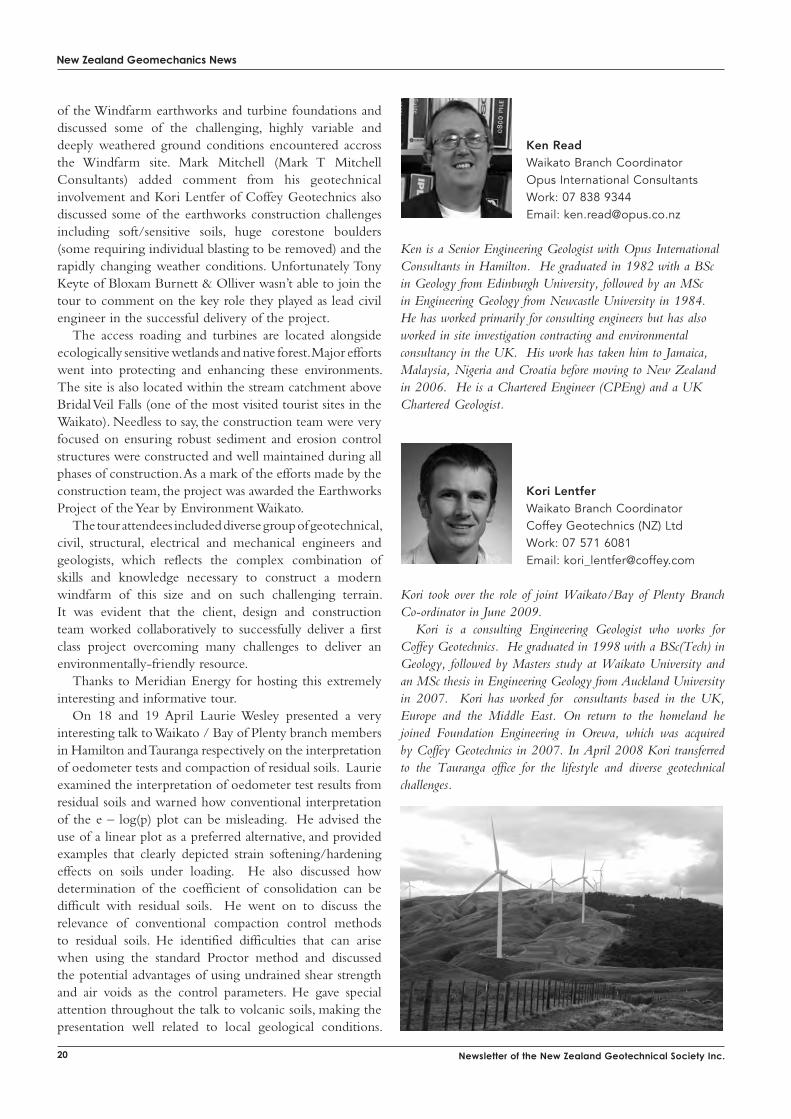
Ken ReadWaikato Branch CoordinatorOpus International ConsultantsWork: 07 838 9344Email: [email protected]
Ken is a Senior Engineering Geologist with Opus International Consultants in Hamilton. He graduated in 1982 with a BSc in Geology from Edinburgh University, followed by an MSc in Engineering Geology from Newcastle University in 1984. He has worked primarily for consulting engineers but has also worked in site investigation contracting and environmental consultancy in the UK. His work has taken him to Jamaica, Malaysia, Nigeria and Croatia before moving to New Zealand in 2006. He is a Chartered Engineer (CPEng) and a UK Chartered Geologist.
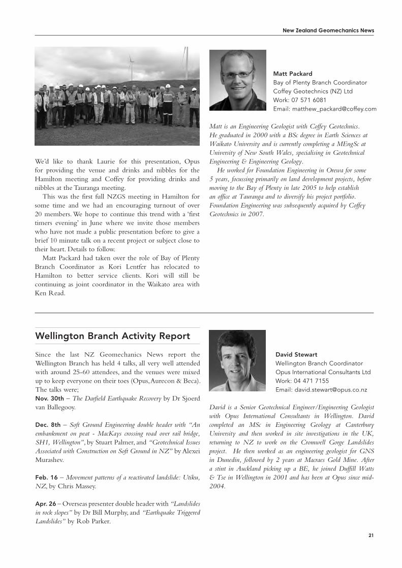
Kori LentferWaikato Branch CoordinatorCoffey Geotechnics (NZ) LtdWork: 07 571 6081Email: [email protected]
Kori took over the role of joint Waikato/Bay of Plenty Branch Co-ordinator in June 2009.
Kori is a consulting Engineering Geologist who works for Coffey Geotechnics. He graduated in 1998 with a BSc(Tech) in Geology, followed by Masters study at Waikato University and an MSc thesis in Engineering Geology from Auckland University in 2007. Kori has worked for consultants based in the UK, Europe and the Middle East. On return to the homeland he joined Foundation Engineering in Orewa, which was acquired by Coffey Geotechnics in 2007. In April 2008 Kori transferred to the Tauranga office for the lifestyle and diverse geotechnical challenges.
New Zealand Geomechanics News
21
Wellington Branch Activity Report
David is a Senior Geotechnical Engineer/Engineering Geologist with Opus International Consultants in Wellington. David completed an MSc in Engineering Geology at Canterbury University and then worked in site investigations in the UK, returning to NZ to work on the Cromwell Gorge Landslides project. He then worked as an engineering geologist for GNS in Dunedin, followed by 2 years at Macraes Gold Mine. After a stint in Auckland picking up a BE, he joined Duffill Watts & Tse in Wellington in 2001 and has been at Opus since mid-2004.
David StewartWellington Branch CoordinatorOpus International Consultants LtdWork: 04 471 7155Email: [email protected]
Since the last NZ Geomechanics News report the Wellington Branch has held 4 talks, all very well attended with around 25-60 attendees, and the venues were mixed up to keep everyone on their toes (Opus, Aurecon & Beca). The talks were;Nov. 30th – The Darfield Earthquake Recovery by Dr Sjoerd van Ballegooy.
Dec. 8th – Soft Ground Engineering double header with “An embankment on peat - MacKays crossing road over rail bridge, SH1, Wellington”, by Stuart Palmer, and “Geotechnical Issues Associated with Construction on Soft Ground in NZ” by Alexei Murashev.
Feb. 16 – Movement patterns of a reactivated landslide: Utiku, NZ, by Chris Massey.
Apr. 26 – Overseas presenter double header with “Landslides in rock slopes” by Dr Bill Murphy, and “Earthquake Triggered Landslides” by Rob Parker.
Matt PackardBay of Plenty Branch CoordinatorCoffey Geotechnics (NZ) LtdWork: 07 571 6081Email: [email protected]
Matt is an Engineering Geologist with Coffey Geotechnics. He graduated in 2000 with a BSc degree in Earth Sciences at Waikato University and is currently completing a MEngSc at University of New South Wales, specialising in Geotechnical Engineering & Engineering Geology.
He worked for Foundation Engineering in Orewa for some 5 years, focussing primarily on land development projects, before moving to the Bay of Plenty in late 2005 to help establish an office at Tauranga and to diversify his project portfolio. Foundation Engineering was subsequently acquired by Coffey Geotechnics in 2007.
We’d like to thank Laurie for this presentation, Opus for providing the venue and drinks and nibbles for the Hamilton meeting and Coffey for providing drinks and nibbles at the Tauranga meeting.
This was the first full NZGS meeting in Hamilton for some time and we had an encouraging turnout of over 20 members. We hope to continue this trend with a ‘first timers evening’ in June where we invite those members who have not made a public presentation before to give a brief 10 minute talk on a recent project or subject close to their heart. Details to follow.
Matt Packard had taken over the role of Bay of Plenty Branch Coordinator as Kori Lentfer has relocated to Hamilton to better service clients. Kori will still be continuing as joint coordinator in the Waikato area with Ken Read.
New Zealand Geomechanics News
Newsletter of the New Zealand Geotechnical Society Inc.
Venues for the talks will continue to be varied to account for the number of expected attendees and to spread out the work involved in hosting at talk. If you know of a potentially suitable venue please drop an email to one of the branch co-ordinators (see NZGS Wellington Branch webpage). Also if your company would like to sponsor the refreshments for one of the talks let us know similarly.
upcoming Events include
More talks are in the pipeline, just keep an eye on the Wellington Branch NZGS webpage, as it is frequently updated with local talks.
22 Newsletter of the New Zealand Geotechnical society inc.
Nelson Branch Activity Report
i Arrived in Nelson in August 2010 and am slowly finding my feet in the area. The majority of my work to date has been outside of Nelson so I would like to take this opportunity to introduce myself to those members in the Nelson region. If anyone in the Nelson region has any ideas or offers of presentations feel free to contact me to arrange.
Andrew Smith is a Senior Engineering Geologist with Golder Associates (NZ) Ltd in Nelson. He graduated in 1997 with a BSc (Hons) in Exploration Geology followed by a MSc in Geo-environmental Engineering from Cardiff University in 2004. Andrew is a Chartered Geologist with the Geological Society of London. He was worked for both marine site investigation contractors and environmental consultancies in the UK before moving to NZ in 2010.
Andrew SmithNelson Branch CoordinatorGolder Associates (NZ) LtdWork: 03 548 1707Email: [email protected]
Beverley is a Senior Engineering Geologist with GHD Ltd in Wellington. She graduated in 1998 with a BSc(Hons) in Geology from Kingston University, UK, followed a few years later in 2002 by an MSc in Geohazard Assessment from Portsmouth University, UK. Prior to January 2010 she was with Opus International Consultants in Wellington since her arrival in NZ in November 2004. In the UK she worked for Mouchel Parkman. Beverley loves being in NZ and finds working here excellent as, being so young geologically and seismically active, slopes tend to fall down quite regularly.
Beverley CurleyWellington Branch CoordinatorGHDWork: 04 495 5832Email: [email protected]
Date Location Details
May 17 Field tripField trip to SH2
Muldoon’s corner
realignment works
(attendees looking to
be 30-40 at the time
of writing).
June
Early to mid
GNS Darfield and
Christchurch earthquake
talks by GNS.
New Zealand Geomechanics News
23
We Are holding earthquake forums jointly with NZSEE and CSG/SESOC every fortnight or so. These provide updates and forum for discussion on topics including seismicity, Port Hills stability issues and liquefaction assessment.
We are currently working in a state of flux regarding best-practice advice for assessment and rebuild in earthquake-damaged areas as we await reports from various advisory bodies including DBH, GNS, EQC and University of Canterbury.
Canterbury Branch Activity ReportNick HarwoodCanterbury Branch CoordinatorCoffey Geotechnics (NZ) LtdWork: 03 374 9600Email: [email protected]
Nick is a consulting Geotechnical Engineer who works for Coffey Geotechnics. He graduated in 1990 with a BEng(Hons) degree in Engineering Geology & Geotechnics, followed by a MSc in Soil Mechanics & Engineering Seismology from Imperial College in 1994. Nick started out as a graduate working for British Waterways before moving onto Brown & Root (London) and Buro Happold (Bath) before finally escaping to New Zealand in 2002. He loves living and working in New Zealand, a place that combines sublime scenery and diverse assignments.
Joyce SealeCanterbury Branch CoordinatorPattle Delamore Partners Ltd Work : 03 363 3117Email: [email protected]
Joyce is an environmental scientist working for Pattle Delamore Partners Limited in Christchurch. She graduated from the University of Canterbury in 2002 with a BSc in Geology followed by a MSc in Engineering Geology in 2006. This is Joyce’s “third” career, her first being a teacher and the second a mum. She is enjoying applying engineering geological principles to contaminated site investigations.
Otago Branch Activity Report
geotechnicAl prActicioners in the Otago branch have had a full start to the year helping out with assessment and recovery from the February shake in Christchurch. In Dunedin we have had a tour of the SH88 realignment around the new Forsyth Barr Stadium and a presentation on Opus Consultant’s involvement in TrustPower’s Mahinerangi Wind Farm. The realignment tour highlighted the use of lightweight poly fill, keystone retaining structures, settlement monitoring and foundation issues in reclaimed land. The wind farm talk outlined geological challenges encountered in inspecting and verifying bearing capacity in highly to moderately weathered schist with a long erosion history and complex groundwater system. Turnout from NZGS members was relatively low for both events as a result of so many people away in Christchurch. I will be e-mailing people again shortly to see if anyone else is keen to give a talk or host a site visit.
Shane is an Engineering Geologist with Opus International Consultants in Dunedin. Shane came to New Zealand from Canada in January 2006 and has been working with the Opus Geotechnical Team since that time. Shane has specialisations in Hydrogeology and Contaminated Land Assessment however since coming to New Zealand has turned his hand to everything from foundations to slope stability investigations.
Shane GreeneOtago Branch CoordinatorOpus International Consultants LtdWork: 03 471 5509Email: [email protected]
New Zealand Geomechanics News
24 Newsletter of the New Zealand Geotechnical Society Inc.
Update on the Professional Registration of Engineering Geologists
staNdaRds, law aNd iNdustRy News
nZgs members Will be aware that the registration of engineering geologists has been an item on the Management Committee’s agenda recently, and issues around this topic were featured in depth in the June 2010 issue of NZ Geomechanics News.
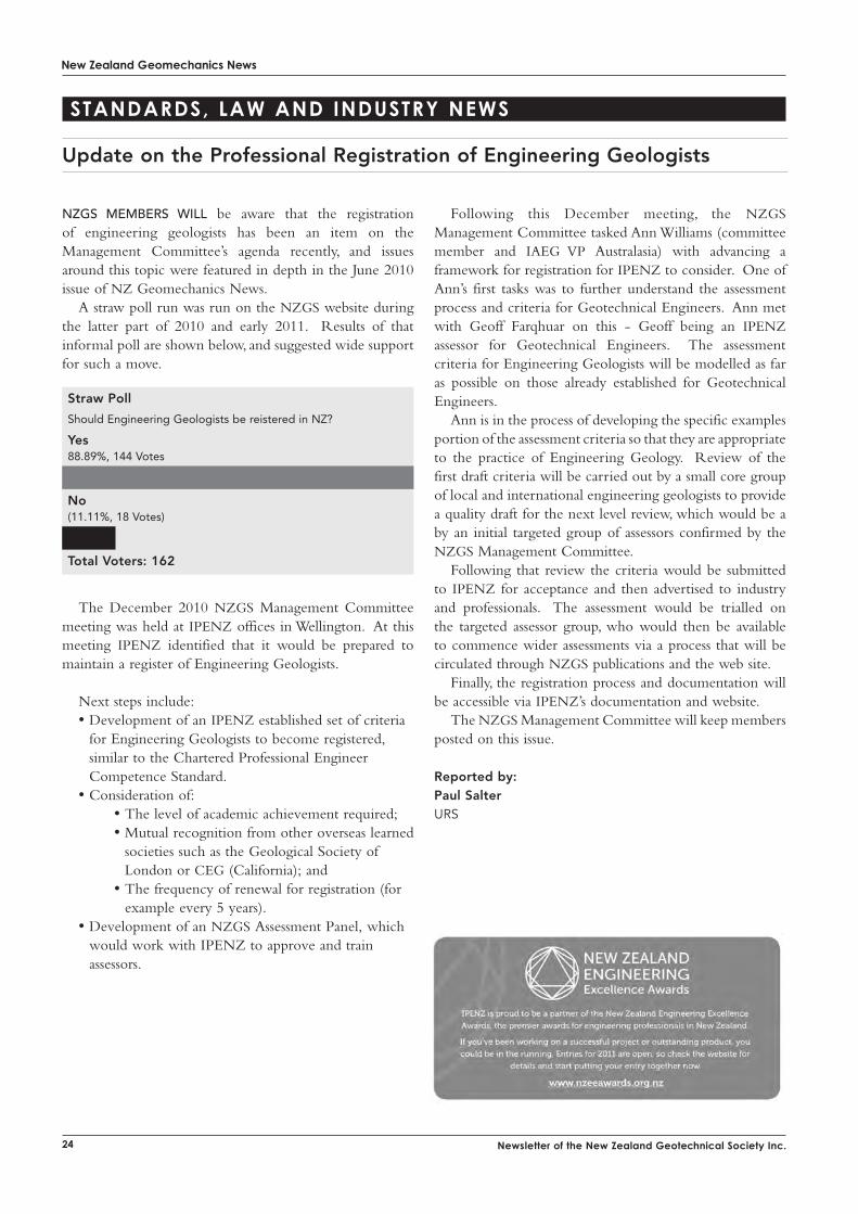
A straw poll run was run on the NZGS website during the latter part of 2010 and early 2011. Results of that informal poll are shown below, and suggested wide support for such a move.
The December 2010 NZGS Management Committee meeting was held at IPENZ offices in Wellington. At this meeting IPENZ identified that it would be prepared to maintain a register of Engineering Geologists.
Next steps include:• Development of an IPENZ established set of criteria
for Engineering Geologists to become registered, similar to the Chartered Professional Engineer Competence Standard.
• Consideration of: • The level of academic achievement required; • Mutual recognition from other overseas learned
societies such as the Geological Society of London or CEG (California); and
• The frequency of renewal for registration (for example every 5 years).
• Development of an NZGS Assessment Panel, which would work with IPENZ to approve and train assessors.
Following this December meeting, the NZGS Management Committee tasked Ann Williams (committee member and IAEG VP Australasia) with advancing a framework for registration for IPENZ to consider. One of Ann’s first tasks was to further understand the assessment process and criteria for Geotechnical Engineers. Ann met with Geoff Farqhuar on this - Geoff being an IPENZ assessor for Geotechnical Engineers. The assessment criteria for Engineering Geologists will be modelled as far as possible on those already established for Geotechnical Engineers.
Ann is in the process of developing the specific examples portion of the assessment criteria so that they are appropriate to the practice of Engineering Geology. Review of the first draft criteria will be carried out by a small core group of local and international engineering geologists to provide a quality draft for the next level review, which would be a by an initial targeted group of assessors confirmed by the NZGS Management Committee.
Following that review the criteria would be submitted to IPENZ for acceptance and then advertised to industry and professionals. The assessment would be trialled on the targeted assessor group, who would then be available to commence wider assessments via a process that will be circulated through NZGS publications and the web site.
Finally, the registration process and documentation will be accessible via IPENZ’s documentation and website.
The NZGS Management Committee will keep members posted on this issue.
Reported by:Paul SalterURS
Straw Poll
Should Engineering Geologists be reistered in NZ?
Yes88.89%, 144 Votes
No(11.11%, 18 Votes)
Total Voters: 162
New Zealand Geomechanics News
25
IPENZ Forum 2011
IPENZ holds an annual forum where representatives from its head office, branches, young and student engineers, and a wide range of affiliated engineering organisations gather to discuss issues of importance to the profession as a whole. This year’s forum was held in Wellington on Friday 18th and Saturday 19th March, with the annual Fellows’ and Achievers’ Dinner held on the evening of the 18th.
The forum commenced with representatives of the many affiliated organisations (there are at least 45) giving a brief introduction of their particular group, and moved on to group discussions and feedback sessions on engineering as a self-regulating profession, competence assessment and opportunities to assert engineering leadership. IPENZ leadership was provided with some useful guidance for its future direction. Friday afternoon largely comprised a number of separate breakout groups, with the Geotechnical Society being represented in the Collaborating Technical Societies (CTS) discussion. That focused on possible areas of interaction between CTS’s and with IPENZ. Of particular interest to the geotechnical engineering profession are moves, through CETANZ, to develop a Civil Engineering Laboratory Technician qualification, and to update the materials specs.
Highlights of the Fellows’ and Achievers’ were recognition of three of our members, Bruce Melville, David Carter and Alexei Murashev for their contributions to the profession, and the standing ovation for the recipients of the Fulton Downer Gold Medal for Public Service, given
to all engineers who responded to the 2010 and 2011 Canterbury earthquakes.
Saturday started with a presentation on the learned society role of IPENZ and newly acquired access to an Informit database of engineering information hosted by the RMIT. Participants were encouraged to submit information to IPENZ for inclusion in the database. Roger Blakeley, the Chief Planning Officer for the new Auckland Council then gave an up-beat presentation on the about to be released (at that time) new Auckland Spatial Plan. For this Aucklander, at least, the plan indicates a promising future for the city.
Forum 2011 finished with an Engineering Practice Forum, where the technical groups and societies were able to explore and try and bridge disconnects across our diverse practice areas. Two subjects of particular interest were wide ranging debate around Council held “competence registers” (IPENZ has measures underway to address this) and different recurrence intervals for extreme events for the same development (50yr ARI for flooding vs 500yr ARI for earthquake, for example).
All in all, the IPENZ Forum was a great opportunity to share ideas and develop networks across our profession and beyond it.
reported by:Gavin Alexander Beca
Fulton-Downer Gold Medal awarded to Engineers involved in the Earthquake response The Fulton-Downer Gold Medal is awarded, when appropriate, to acknowledge the effort and achievement of a member of the Institution of Professional Engineers New Zealand (IPENZ), or group of members, particularly when that achievement has demonstrated the strengths of the engineering profession in its role of public service. The award comes directly and personally from the President, and is one of the highest accolades the Institution can bestow. The award consists of a gold medal and rarely is more than one award made each year.
The recipients of the 2011 President’s Award are the IPENZ Members who were active in the response phase following the 2010 and 2011 Canterbury earthquakes. These Members share this award in recognition of their outstanding contribution to public service. The award recognises engineers involved in all areas of the response including; building safety evaluation, urban search and rescue and restoration of infrastructural utility services.
congratulations to those members of the geotechnical society who were awarded the Fulton-downer gold medal.
New Zealand Geomechanics News
26 Newsletter of the New Zealand Geotechnical Society Inc.
NZGS Young Geotechnical Professionals
Firstly i Would like to thank Kate Williams for the awesome effort she has made to promote and encourage the NZGS Young Geotechnical Professionals (YGPs) during her role as YGP Representative. As Kate said when she took over, there are some big shoes to fill and I hope to make them fit!
The Young Geotechnical Professionals group has been formed to represent, support and provide a voice for the young professionals in the NZ Geotechnical Society. We represent a lively, increasingly influential and rapidly growing section of Geotechnical Engineers and Engineering Geologists nationwide. Through a social culture of innovation, integrity, networking and the pursuit of excellence, we anticipate facilitating in the professional and personal development of the young professionals.
This role is about keeping young professionals informed on, and involved with, developments within the society and abroad; this involves working in coordination with other Young Professionals across the international societies NZGS represents.
Latest activities:• Presentation to students in Geology Department at
Auckland University 5 May 2011. Thank you to Marc-Andre Brideau for kindly allowing me to gate crash a lecture.
upcoming activities:• Aim to continue talks at universities throughout
New Zealand with the possible help of YGP’s in other branches.
• Announcement should soon be made of the next ANZ Young Geotechnical Professionals Conference in Australia.
• Student Awards coming up at the end of this year, entries to open soon.
• Watch this space for a 2011 YGP/NZGS Auckland branch quiz night later in the year.
We welcome support and inspiration from the young geotechnical professional community and envision that all branch events, workshops, conferences/ congresses and symposiums that the NZGS hold will promote the ongoing development of the Young Geotechnical Profession.
If you have any ideas or activities you would like to see happen please contact the new YGP Representative Erica Cammack ([email protected]).
Reported by: Erica CammackYGP Representative, NZGSEmail: [email protected]
FOR GEOTECHNICAL / ENVIRONMENTAL
SITE INVESTIGATIONS &HEAVY CIVIL FOUNDATION /
RETENTION SOLUTIONS
DOWNHOLE SEISMIC PROFILING
NOW ALSO AVAILABLE
WHAT LIES BENEATH?
120 High Street, Southbridge, Canterbury, New ZealandPh: +64 3 324 2571 Fax: +64 3 324 2431

ground investigation
ad
supplied separately
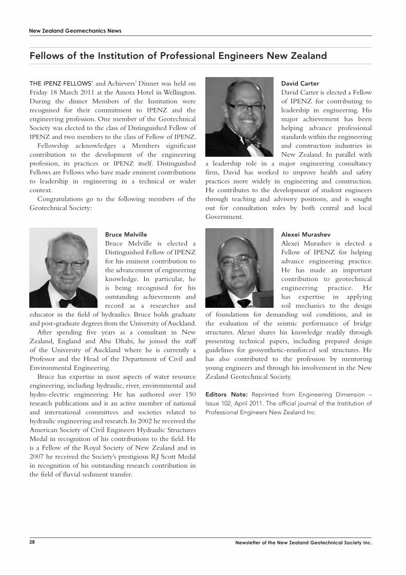
New Zealand Geomechanics News
28 Newsletter of the New Zealand Geotechnical Society Inc.
Fellows of the Institution of Professional Engineers New Zealand
the ipenZ FelloWs’ and Achievers’ Dinner was held on Friday 18 March 2011 at the Amora Hotel in Wellington. During the dinner Members of the Institution were recognised for their commitment to IPENZ and the engineering profession. One member of the Geotechnical Society was elected to the class of Distinguished Fellow of IPENZ and two members to the class of Fellow of IPENZ.
Fellowship acknowledges a Members significant contribution to the development of the engineering profession, its practices or IPENZ itself. Distinguished Fellows are Fellows who have made eminent contributions to leadership in engineering in a technical or wider context.
Congratulations go to the following members of the Geotechnical Society:
Bruce MelvilleBruce Melville is elected a Distinguished Fellow of IPENZ for his eminent contribution to the advancement of engineering knowledge. In particular, he is being recognised for his outstanding achievements and record as a researcher and
educator in the field of hydraulics. Bruce holds graduate and post-graduate degrees from the University of Auckland.
After spending five years as a consultant in New Zealand, England and Abu Dhabi, he joined the staff of the University of Auckland where he is currently a Professor and the Head of the Department of Civil and Environmental Engineering.
Bruce has expertise in most aspects of water resource engineering, including hydraulic, river, environmental and hydro-electric engineering. He has authored over 150 research publications and is an active member of national and international committees and societies related to hydraulic engineering and research. In 2002 he received the American Society of Civil Engineers Hydraulic Structures Medal in recognition of his contributions to the field. He is a Fellow of the Royal Society of New Zealand and in 2007 he received the Society’s prestigious RJ Scott Medal in recognition of his outstanding research contribution in the field of fluvial sediment transfer.
David CarterDavid Carter is elected a Fellow of IPENZ for contributing to leadership in engineering. His major achievement has been helping advance professional standards within the engineering and construction industries in New Zealand. In parallel with
a leadership role in a major engineering consultancy firm, David has worked to improve health and safety practices more widely in engineering and construction. He contributes to the development of student engineers through teaching and advisory positions, and is sought out for consultation roles by both central and local Government.
Alexei MurashevAlexei Murashev is elected a Fellow of IPENZ for helping advance engineering practice. He has made an important contribution to geotechnical engineering practice. He has expertise in applying soil mechanics to the design
of foundations for demanding soil conditions, and in the evaluation of the seismic performance of bridge structures. Alexei shares his knowledge readily through presenting technical papers, including prepared design guidelines for geosynthetic-reinforced soil structures. He has also contributed to the profession by mentoring young engineers and through his involvement in the New Zealand Geotechnical Society.
Editors Note: Reprinted from Engineering Dimension – Issue 102, April 2011. The official journal of the Institution of Professional Engineers New Zealand Inc.
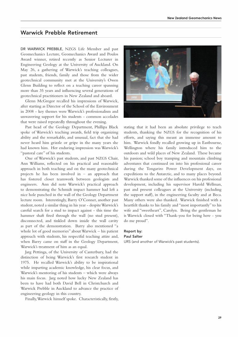
New Zealand Geomechanics News
29
Warwick Prebble Retirement
dr WArWick prebble, NZGS Life Member and past Geomechanics Lecture, Geomechanics Award and Poulos Award winner, retired recently as Senior Lecturer in Engineering Geology at the University of Auckland. On May 26, a gathering of Warwick’s teaching colleagues, past students, friends, family and those from the wider geotechnical community met at the University’s Owen Glenn Building to reflect on a teaching career spanning more than 35 years and influencing several generations of geotechnical practitioners in New Zealand and aboard.
Glenn McGregor recalled his impressions of Warwick, after starting as Director of the School of the Environment in 2008 - key themes were Warwick’s professionalism and unwavering support for his students - common accolades that were raised repeatedly throughout the evening.
Past head of the Geology Department, Phillipa Black spoke of Warwick’s teaching awards, field trip organizing ability and the remarkable, and unusual, fact that she had never heard him grizzle or gripe in the many years she had known him. Her enduring impression was Warwick’s “pastoral care” of his students.
One of Warwick’s past students, and past NZGS Chair, Ann Williams, reflected on his practical and reasonable approach in both teaching and on the many geotechnical projects he has been involved in – an approach that has fostered closer teamwork between geologists and engineers. Ann did note Warwick’s practical approach to demonstrating the Schmidt impact hammer had left a nice hole punched in the wall of the Geology Department lecture room. Interestingly, Barry O’Conner, another past student, noted a similar thing in his year - despite Warwick’s careful search for a stud to impact against - this time the hammer shaft fired through the wall (no stud present), disconnected, and tinkled down inside the wall cavity as part of the demonstration. Barry also mentioned “a whole lot of good memories” about Warwick – his patient approach with students, his respectful teaching attire and, when Barry came on staff in the Geology Department, Warwick’s treatment of him as an equal.
Jarg Pettinga, of the University of Canterbury, had the distinction of being Warwick’s first research student in 1975. He recalled Warwick’s ability to be inspirational while imparting academic knowledge, his clear focus, and Warwick’s mentoring of his students – which were always his main focus. Jarg noted how lucky New Zealand has been to have had both David Bell in Christchurch and Warwick Prebble in Auckland to advance the practice of engineering geology in this country.
Finally, Warwick himself spoke. Characteristically, firstly,
stating that it had been an absolute privilege to teach students, thanking the NZGS for the recognition of his efforts, and saying this meant an immense amount to him. Warwick fondly recalled growing up in Eastbourne, Wellington where his family introduced him to the outdoors and wild places of New Zealand. These became his passion; school boy tramping and mountain climbing adventures that continued on into his professional career during the Tongariro Power Development days, on expeditions to the Antarctic, and to many places beyond. Warwick thanked some of the influences on his professional development, including his supervisor Harold Wellman, past and present colleagues at the University (including the support staff), in the engineering faculty and at Beca. Many others were also thanked. Warwick finished with a heartfelt thanks to his family and “most importantly” to his wife and “sweetheart”, Carolyn. Being the gentleman he is Warwick closed with “Thank-you for being here - you do me proud”.
Report by:Paul SalterURS (and another of Warwick’s past students).

30 Newsletter of the New Zealand Geotechnical society inc.
New Zealand Geomechanics News
awaRds
Preliminary schedule AucklAnd, HAmilton and tAurAngA 29th August - 1st September 2011
Wellington and nelson 13th and 14th September 2011
otAgo - 28th September 2011
cHristcHurcH - 12th October 2011
Final dates and venue details will be circulated to all NZGS members closer to the time.
2011 Geomechanics Lecture
GEo-loGic and thE art of GEotEchnical practicEThe NZ Geomechanics Lecture is the premier award of the New Zealand Geotechnical Society. The award was established to honour individuals who have made a notable lifetime contribution to New Zealand geotechnics.
The New Zealand Geotechnical Society is proud to announce the 2011 Geomechanics Lecture will be presented by David Bell.
David is a Senior Lecturer in Engineering & Mining Geology at the University of Canterbury, Christchurch.
The title of David’s lecture is “Geo-Logic and the Art of Geotechnical Practice”. David will be drawing on more than 35 years of teaching and professional practice, including
extensive experience of working on a number of difficult sites. The Lecture will cover a range of case studies that will emphasise the fundamentals of sound geotechnical practice. “If we cannot “read the ground”, as John Hutchinson termed it, then we are likely to end up with the “garbage in – garbage out” scenario. Geo-logic alone does not provide all the answers, but without it the practice of geotechnical engineering becomes simply “technical engineering”, and we fail to fully appreciate or understand the landscape into which we are placing the structure.”
David’s lecture will be presented at a number of venues around New Zealand. Members and friends are invited to attend what are frequently rewarding, not to mention entertaining evenings.
coronet Peak skifield rocky gully storage
Young river landslide dam
makarora river bund
During 2010, the NZGS Management Committee agreed to provide funding for a scholarship that would enable a member of the Society to undertake research in New Zealand that would advance the objectives of the Society. The fields of research would be in the fields of Engineering Geology and/or Geotechnical Engineering. The award of such a scholarship would include agreed milestones and deliverables including a publication or thesis. A nominated representative from the NZGS will act as a liaison with the scholar and the supervisor (where applicable).
At its meeting in November 2010 the NZGS Management Committee agreed on the following Terms of Reference for the NZGS Scholarship:1. A scholarship termed the “New Zealand Geotechnical Society
Scholarship” wholly funded by the New Zealand Geotechnical Society (NZGS) and administered by the NZGS Management Committee is available for members (defined to be either a Student Member or Normal Member) of the NZGS.
2. The scholarship is provided to enable the member to undertake research work in the fields of Engineering Geology and/or Geotechnical Engineering in New Zealand.
3. This research work can lead to the award of a post-graduate degree but is not necessarily restricted to such an award. It is expected that research work will be undertaken at a post-graduate level and not an undergraduate level
4. A publication at the end of the research work in the form of a thesis or report is a requirement of the award of the scholarship.
5. The scholarship is awarded on an ad-hoc basis at the sole discretion of the NZGS Management Committee. This is dependent on proposals submitted for consideration by the Committee.
6. Research proposals for consideration by the Committee should be submitted to the Management Secretary by 31st August of each year.
7. The period of research work is to be agreed with the NZGS Management Committee.
8. The value of the scholarship is up to a sum of NZ$10,000.
ScholarShip
Features:• Pileinspectionsupto2mdiameterand40mdepth
• LiveviewingthroughaLCDmonitor• Permanentrecordofpileinspectionswhichcanbeusedforpresentations,analysisandreporting
• Alternativetopersonnelentryinspections• Identifybeddingplanes,rockfracturesanddefects,roughnessandconditionofpileshaftandbase
• Quickandeasytosetupanduse.
ENVIRONMENTAL AND ENGINEERING CONSULTANTS
Video Pile Inspections made easy!
For more information contact Cory Pointon on: (09) 355 6000 or email: [email protected]
www.tonkin.co.nz
Tonkin&TaylornowoffersaVideoPileInspectionserviceusingahighresolutioncolourcameraandDVDrecordingwitheitheraxialorcloseupsidewallviewing.
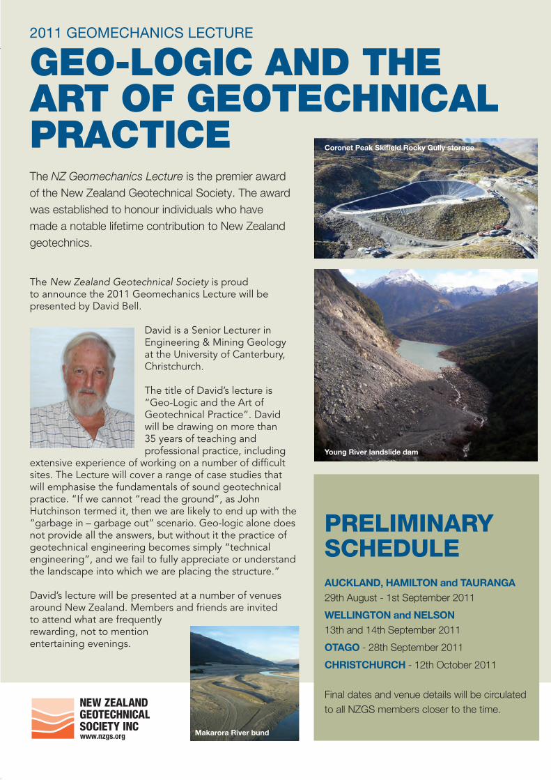
Preliminary schedule AucklAnd, HAmilton and tAurAngA 29th August - 1st September 2011
Wellington and nelson 13th and 14th September 2011
otAgo - 28th September 2011
cHristcHurcH - 12th October 2011
Final dates and venue details will be circulated to all NZGS members closer to the time.
2011 Geomechanics Lecture
GEo-loGic and thE art of GEotEchnical practicEThe NZ Geomechanics Lecture is the premier award of the New Zealand Geotechnical Society. The award was established to honour individuals who have made a notable lifetime contribution to New Zealand geotechnics.
The New Zealand Geotechnical Society is proud to announce the 2011 Geomechanics Lecture will be presented by David Bell.
David is a Senior Lecturer in Engineering & Mining Geology at the University of Canterbury, Christchurch.
The title of David’s lecture is “Geo-Logic and the Art of Geotechnical Practice”. David will be drawing on more than 35 years of teaching and professional practice, including
extensive experience of working on a number of difficult sites. The Lecture will cover a range of case studies that will emphasise the fundamentals of sound geotechnical practice. “If we cannot “read the ground”, as John Hutchinson termed it, then we are likely to end up with the “garbage in – garbage out” scenario. Geo-logic alone does not provide all the answers, but without it the practice of geotechnical engineering becomes simply “technical engineering”, and we fail to fully appreciate or understand the landscape into which we are placing the structure.”
David’s lecture will be presented at a number of venues around New Zealand. Members and friends are invited to attend what are frequently rewarding, not to mention entertaining evenings.
coronet Peak skifield rocky gully storage
Young river landslide dam
makarora river bund
Student Prize 2011InvItatIon to partIcIpate – Closing date 31 august 2011The New Zealand Geotechnical Society wishes to recognise and encourage student participation in the fields of rock mechanics, soil mechanics, geotechnical engineering and engineering geology.
two Regions: north Island and South Islandtwo awaRds: one for each region valued at nZ $1,000 plus certificate
RequiRements:■ candidates are required to present an 800 words or fewer typed abstract on any aspect
of, or topic in the field of, geotechnical engineering and/or engineering geology.
■ Finalists will be invited to present their topic in person at a branch meeting in auckland and/or christchurch in September/october 2011.
■ presentations will be 15 minutes followed by 5 minutes of questions.
■ awards are open to both current undergraduate and postgraduate full-time students of a recognised tertiary institution in new Zealand.
Finalists will be assessed on the Following CRiteRia
the prizes shall be awarded to the finalists who are judged to have made the best presentation according to the above criteria. the judges' decision shall be final.
abstRaCts must be submitted in wRiting and emailed by Close oF 31 august 2011 please provide author details, your abstract and university affiliation to the branch co-ordinator in your region as listed below. For further information or to join the Society (membership is free for students) please visit our website www.nzgs.org or contact the Society Management Secretary at [email protected]
Written abstract 10% Content 10%Structure 20% Visual presentation 20%Clarity of explanation 20% Question handling 10%Time 10%
noRth islandPierre malan auckland Branch [email protected]
south islandnick harwood canterbury Branch [email protected]
neW zeALAnd GeOteCHniCAL SOCietY inc.
www.nzgs.org
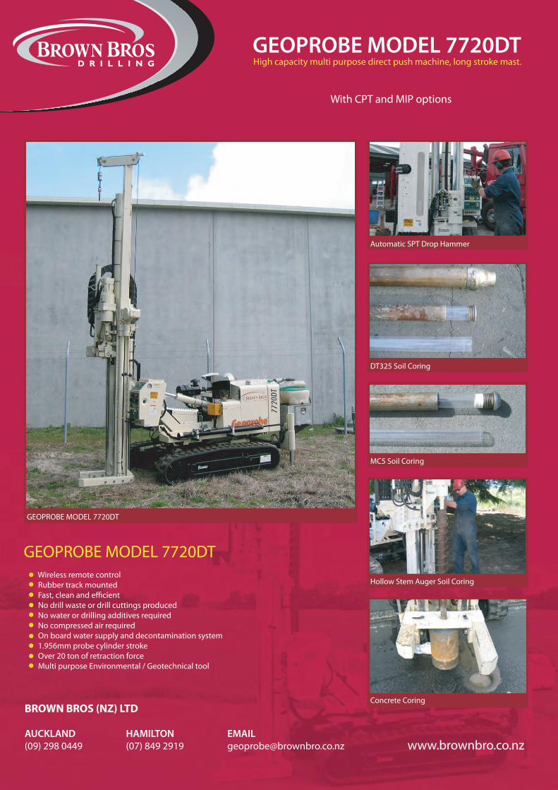
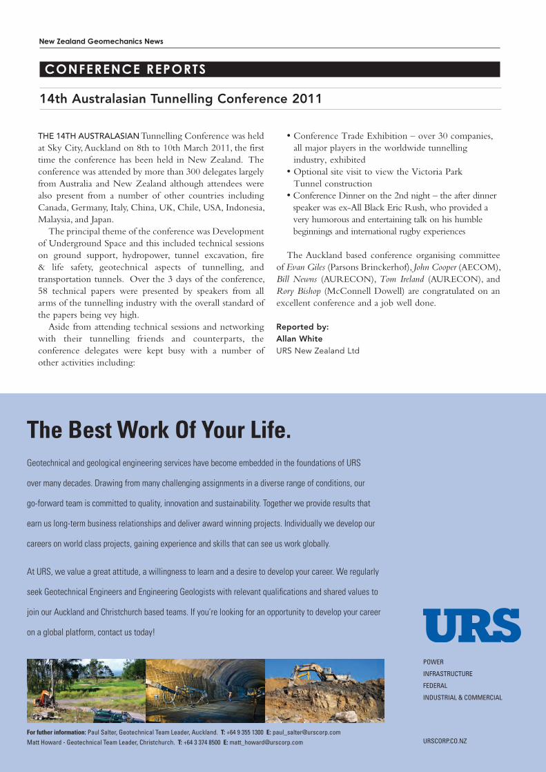
New Zealand Geomechanics News
34 Newsletter of the New Zealand Geotechnical Society Inc.
14th Australasian Tunnelling Conference 2011
coNFeReNce RePoRts
GROUND ENGINEERING IN A CHANGING WORLD15 – 18 July 2012Crown Promenade Hotel, Melbourne, Australiawww.anz2012.com.au
11th Australia - New Zealand Conference on Geomechanics
Ground Engineering in a Changing World
15 – 18 July 2012Crown Promenade Hotel Melbourne Australia
Abstract Submission is open until 1 July 2011!
Please visit the conference website for updated information on conference themes, abstract submission, confirmed invited speakers and conference program.
www.anz2012.com.au
the 14th AustrAlAsiAn Tunnelling Conference was held at Sky City, Auckland on 8th to 10th March 2011, the first time the conference has been held in New Zealand. The conference was attended by more than 300 delegates largely from Australia and New Zealand although attendees were also present from a number of other countries including Canada, Germany, Italy, China, UK, Chile, USA, Indonesia, Malaysia, and Japan.
The principal theme of the conference was Development of Underground Space and this included technical sessions on ground support, hydropower, tunnel excavation, fire & life safety, geotechnical aspects of tunnelling, and transportation tunnels. Over the 3 days of the conference, 58 technical papers were presented by speakers from all arms of the tunnelling industry with the overall standard of the papers being vey high.
Aside from attending technical sessions and networking with their tunnelling friends and counterparts, the conference delegates were kept busy with a number of other activities including:
• Conference Trade Exhibition – over 30 companies, all major players in the worldwide tunnelling industry, exhibited
• Optional site visit to view the Victoria Park Tunnel construction
• Conference Dinner on the 2nd night – the after dinner speaker was ex-All Black Eric Rush, who provided a very humorous and entertaining talk on his humble beginnings and international rugby experiences
The Auckland based conference organising committee of Evan Giles (Parsons Brinckerhof), John Cooper (AECOM), Bill Newns (AURECON), Tom Ireland (AURECON), and Rory Bishop (McConnell Dowell) are congratulated on an excellent conference and a job well done.
Reported by:Allan WhiteURS New Zealand Ltd
The Best Work Of Your Life.Geotechnical and geological engineering services have become embedded in the foundations of URS
over many decades. Drawing from many challenging assignments in a diverse range of conditions, our
go-forward team is committed to quality, innovation and sustainability. Together we provide results that
earn us long-term business relationships and deliver award winning projects. Individually we develop our
careers on world class projects, gaining experience and skills that can see us work globally.
At URS, we value a great attitude, a willingness to learn and a desire to develop your career. We regularly
seek Geotechnical Engineers and Engineering Geologists with relevant qualifications and shared values to
join our Auckland and Christchurch based teams. If you’re looking for an opportunity to develop your career
on a global platform, contact us today!
POWER
INFRASTRUCTURE
FEDERAL
INDUSTRIAL & COMMERCIAL
URSCORP.CO.NZFor futher information: Paul Salter, Geotechnical Team Leader, Auckland. T: +64 9 355 1300 E: [email protected]
Matt Howard - Geotechnical Team Leader, Christchurch. T: +64 3 374 8500 E: [email protected]

GROUND ENGINEERING IN A CHANGING WORLD15 – 18 July 2012Crown Promenade Hotel, Melbourne, Australiawww.anz2012.com.au
11th Australia - New Zealand Conference on Geomechanics
Ground Engineering in a Changing World
15 – 18 July 2012Crown Promenade Hotel Melbourne Australia
Abstract Submission is open until 1 July 2011!
Please visit the conference website for updated information on conference themes, abstract submission, confirmed invited speakers and conference program.
www.anz2012.com.au
The Best Work Of Your Life.Geotechnical and geological engineering services have become embedded in the foundations of URS
over many decades. Drawing from many challenging assignments in a diverse range of conditions, our
go-forward team is committed to quality, innovation and sustainability. Together we provide results that
earn us long-term business relationships and deliver award winning projects. Individually we develop our
careers on world class projects, gaining experience and skills that can see us work globally.
At URS, we value a great attitude, a willingness to learn and a desire to develop your career. We regularly
seek Geotechnical Engineers and Engineering Geologists with relevant qualifications and shared values to
join our Auckland and Christchurch based teams. If you’re looking for an opportunity to develop your career
on a global platform, contact us today!
POWER
INFRASTRUCTURE
FEDERAL
INDUSTRIAL & COMMERCIAL
URSCORP.CO.NZFor futher information: Paul Salter, Geotechnical Team Leader, Auckland. T: +64 9 355 1300 E: [email protected]
Matt Howard - Geotechnical Team Leader, Christchurch. T: +64 3 374 8500 E: [email protected]
New Zealand Geomechanics News
36 Newsletter of the New Zealand Geotechnical Society Inc.
the neW ZeAlAnd Society for Earthquake Engineering (NZSEE) hosted the Ninth Pacific Conference on Earthquake Engineering (PCEE) in Auckland from the 14 to 16 April 2011. The Ninth PCEE, like others in its series, provided an important forum for earthquake engineering professionals to discuss observations, lessons and developments in the science and practice for the preceding four years. The 2011 Conference was destined to be an important gathering given the large number of devastating earthquakes in the wider pacific, with the 2011 and 2010 Canterbury earthquakes, the 2010 Maule earthquake, the 2009 Sumatra earthquake and the 2008 Sichuan earthquake being just five examples.
The 2011 Conference was attended by over 340 earthquake engineering professionals from 18 other countries. The timing of the Conference was particularly significant for the New Zealand attendees, many of whom had been directly involved in the response and are still fully engaged in the recovery, as it would had been one of their first opportunities to discuss the recovery direction and the pressing research needs. The Conference technical programme included 128 oral presentations and 38 posters presentations. Papers presented at the conference are available for free download from the Publications section of the NZSEE web site: http://www.nzsee.org.nz/ .
There were many highlights during the Conference. The five keynote presentations by Prof. Nigel Preistley, Mr. Ernesto Rios, Dr. Robin McGuire, Prof. Robin Spence and Prof. Roberto Leon addressed a wide spectrum of topics ranging from structural engineering, economical
Ninth Pacific Conference on Earthquake Engineering: Building an Earthquake-Resilient Society
issues, engineering seismology to the modelling of human casualties. A Christchurch earthquakes plenary session with eleven invited speakers summarised the immediate and ongoing scientific, social and economical response to the Christchurch earthquakes. Three themed discussion forums provided opportunities for Conference attendees to share their observations and ideas for building community resilience to earthquakes.
The PCEE and the New Zealand Institute of Architects also hosted the Before and after: Let’s build a better Canterbury exhibition and the Design for Post-Earthquake Resilience of Cities: Multidisciplinary Design Ideas competition.
Attendees at the Conference banquet were treated to a sincere and meticulously detailed address by the guest speaker the Hon. Dr. Nick Smith. Dr. Smith thanked the engineers for their efforts assisting the Christchurch response and recovery and for the decades of research and engineering that limited the damage to Christchurch infrastructure.
I wish to record my thanks to the PCEE Organising Committee and our event manager Dr. Bruce Deam, for all their hard work running the conference. I also thank the sponsors, speakers, authors and reviewers who all contributed to such a successful conference.
Reported by: Conference Co-convenor: Dr. Quincy MaUniversity of Auckland
Nominations must be made in writing and close 30 August 2011. Please provide author details, a brief comment on the contribution the paper makes and a hard copy of the paper to the NZGS Management Secretary.
Amanda Blakey, Management Secretary email: [email protected]
Nominations are now sought for consideration for the NZGS Geomechanics Award 2011.
The award shall be made to the Society member or members producing the adjudged “best” published paper during the three year period 31 July 2008 to 31 July 2011, in any publication at the discretion of the Management Committee.
The Geomechanics Award is bestowed on the author (s) of papers that are distinguished in their contribution to the development of geotechnical engineering and/ or engineering geology in New Zealand and that advances the objectives of the society.
All Society members who are authors of any paper published within the previous three years shall be eligible, provided that at least one author is a member and that another member nominates the paper in writing prior to 30 August 2011.
AwArd VAlue: $2000 plus certificate
International Society for Rock Mechanics
ROCHA MEDAL 2013
Since 1982 a bronze medal and a cash prize have been awarded annually by the ISRM for an outstanding doctoral thesis in rock mechanics or rock engineering, to honour the memory of Past President Manuel Rocha while stimulating young researchers.
In addition to the Rocha Medal award to the winning submission, one or two runner-up certificates may also be awarded.
An invitation is now extended to the rock mechanics community for nominations for the Rocha Medal 2013.
Full details on the Rocha Medal are provided in ISRM By-law No. 7.
Application
To be considered for an award the candidate must be nominated within two years of the date of the official doctorate degree certification.
Nominations shall be by the nominee, or by the nominee's National Group, or by some other person or organization acquainted with the nominee's work.
Nominations shall be sent electronically, addressed to the Secretary General, and shall contain:
a one page curriculum vitae;
a written confirmation by the candidate’s National Group that he/she is a member of the ISRM;
a thesis summary, written in English, with between 5,000 and 10,000 words, detailed enough to convey the full impact of the thesis and accompanied by selected tables and figures; one copy of the complete thesis and one copy of the doctorate degree certificate;
a letter of copyright release, allowing the ISRM to copy the thesis for purposes of review and selection only; an undertaking by the nominee to submit an article describing the work, for publication in the ISRM News Journal.
Application Deadline
The nomination must reach the ISRM Secretary General by 31 December 2011.
Past Recipients
1982 A.P. Cunha PORTUGAL 1983 S. Bandis GREECE 1984 B. Amadei FRANCE 1985 P.M. Dight AUSTRALIA 1986 W. Purrer AUSTRIA 1987 D. Elsworth UK 1988 S. Gentier FRANCE 1989 B. Fröhlich GERMANY 1990 R.K. Brummer SOUTH AFRICA 1991 T.H. Kleine AUSTRALIA 1992 A. Ghosh INDIA 1993 O. Reyes W. PHILIPPINES 1994 S. Akutagawa JAPAN 1995 C. Derek Martin CANADA 1996 M.P. Board USA 1997 M. Brudy GERMANY 1998 F. Mac Gregor AUSTRALIA 1999 A. Daehnke SOUTH AFRICA 2000 P. Cosenza FRANCE 2001 D.F. Malan SOUTH AFRICA 2002 M.S. Diederichs CANADA 2003 L. M. Andersen SOUTH AFRICA 2004 G. Grasselli ITALY 2005 M. Hildyard UK 2006 D. Ask SWEDEN 2007 H. Yasuhara JAPAN 2008 Z.Z. Liang CHINA 2009 G. Li CHINA 2010 J.C. Andersson SWEDEN 2011 D. Park REP. OF KOREA
All relevant information can be obtained from the ISRM website, at http://www.isrm.net.
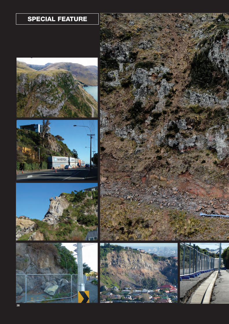
38
Special feature
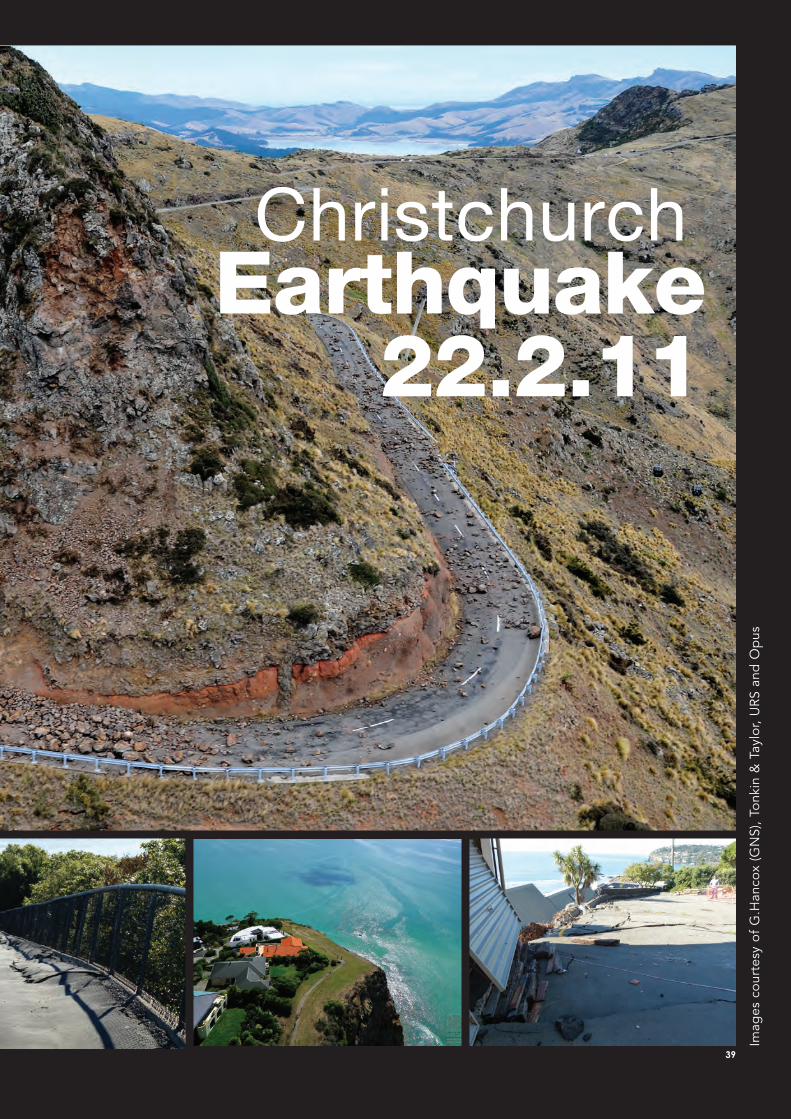
New Zealand Geomechanics News
39
earthquake22.2.11
Christchurch
Imag
es c
our
tesy
of
G.H
anco
x (G
NS)
, To
nkin
& T
aylo
r, U
RS
and
Op
us
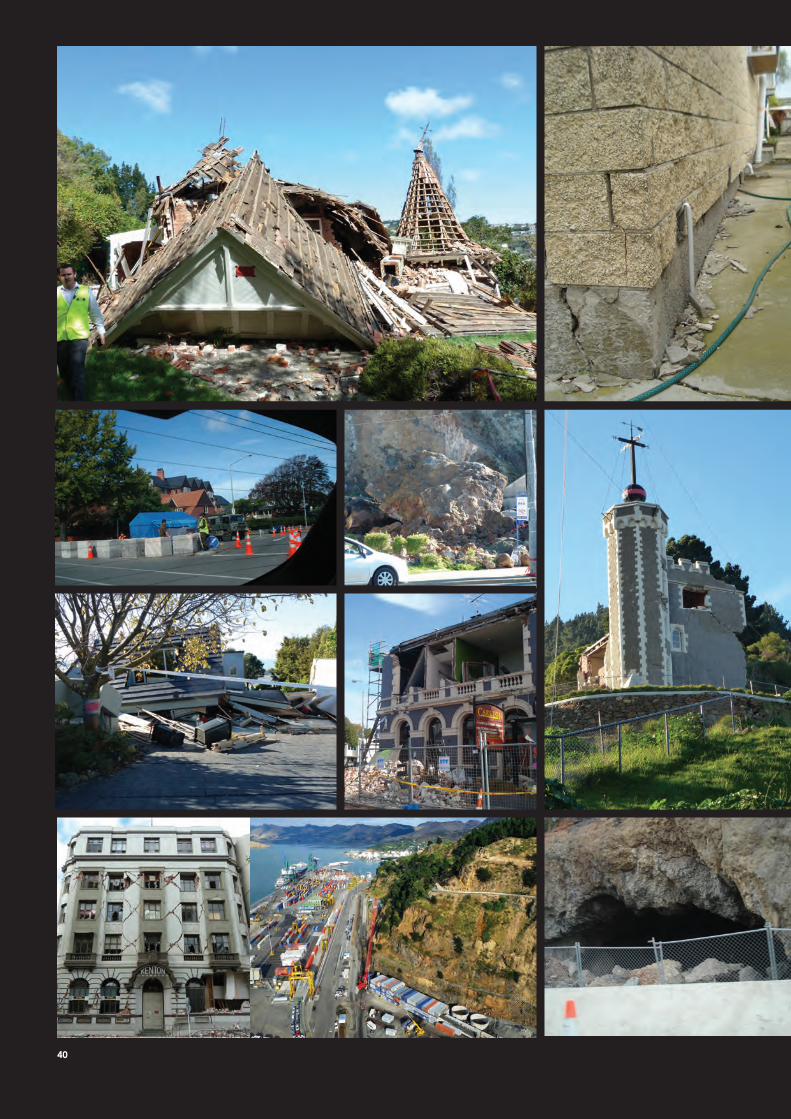
40
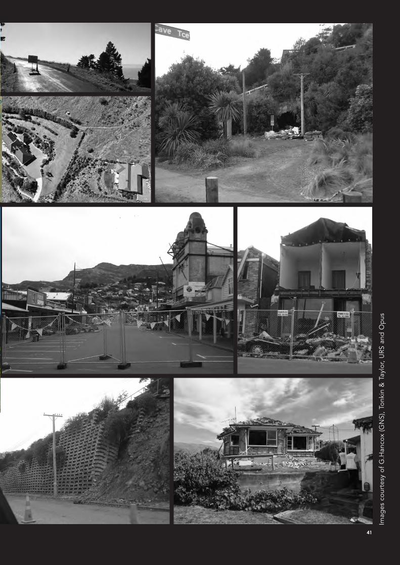
41
Imag
es c
our
tesy
of
G.H
anco
x (G
NS)
, To
nkin
& T
aylo
r, U
RS
and
Op
us
New Zealand Geomechanics News
42 Newsletter of the New Zealand Geotechnical Society Inc.
IPENZ Fact Sheets – Christchurch Earthquake and Liquefaction
1Fact sheets compiled and distributed by the Institution of Professional Engineers of New Zealand
Christchurch Earthquake - an overviewThE EarThquakEGNS Science believe that the earthquake arose from the rupture of an 8 x 8 km fault running east-northeast at a depth of 1-2 km depth beneath the southern edge of the Avon-Heathcote Estuary and dipping southwards at an angle of about 65 degrees from the horizontal beneath the Port Hills. The amount of slip between the two sides of the fault was up to 1.5 m. The Port Hills have risen by about 40 cm, the mouth of the estuary has moved westward by a few tens of cm, and the land just north of the estuary by tens of cm to the east. Land west of the estuary, and the estuary itself, will have sunk by roughly 10 cm as a direct result of the fault rupture. However, there may be additional subsidence on top of this as a result of ground compaction during the strong shaking.
Earthquake records show that some buildings may have experienced shaking more than two times more intense than a new building would be currently designed for, but perhaps for a lesser duration than envisaged by the loadings code (NZS 1170.5). The intensity of shaking appears to have died out rapidly as it travelled westwards from the fault.
DEsign of builDings for EarThquakEsNon-residential buildings designed before 1976 were not explicitly required to have ductility incorporated in them. In the early 1980s, the design standard for reinforced concrete was revised significantly to ensure non-brittle behaviour under design-level earthquake loadings, and the strong-columns/weak beams philosophy was introduced so that life safety could be achieved under design-level earthquake shaking.
During the 1990s, the understanding of the faults and historic earthquakes came together as the NZ Seismicity Model developed by GNS Science, and this is the basis for the current seismic zoning of New Zealand. This is considered internationally as a state-of-the-art model. The September and February earthquakes are thought to be consistent with this model.
Buildings are not designed to be earthquake-proof. Two design levels are considered. A building of ordinary importance is designed for a level of shaking that has a 10 % probability of being exceeded in its design life of 50 years. The design standards are formulated to ensure that life safety is achieved during that shaking, but the building might be an economic write-off because of the damage. It must not collapse at this level. The designer is also required to check that the building does not have damage at a level about 1/6th of this design level. This Serviceability Level is set to correspond with shaking that has a 10% probability of being exceeded in one year. To put it another way, The Life Safety design level can be expected to be exceeded on average (over a very long period of time) once every 500 years, and the Serviceability Level once every 20 years.
Note that no mention has been made of earthquake (Richter) Magnitude, as the building responds the same way to shaking that comes from a small close earthquake or a large distant one.
obsErvED pErformanCE of CommErCial builDings in ThE CbDThe buildings designed to the current standards have, with few exceptions, performed well and as intended, with little damage. Notable exceptions are the failures of stairs in the Forsyth Barr building, and the tilting of a 10-storey building on Oxford Terrace near the river. The two buildings which have catastrophically collapsed (the Pyne Gould Corproration and CTV buildings), while described by the press as modern, are understood to have been constructed in about 1963 and 1986 respectively. Many buildings designed before the early 1980s
Following the 22 February 2011 Christchurch Earthquake, IPENZ produced several Fact Sheets, with input from NZGS, to help explain key technical aspects of the event. In particular, the NZGS Management Committee provided text on liquefaction and John Underhill (AECOM) provided graphics of possible liquefaction effects. The Fact Sheets can also be found on the IPENZ website.
New Zealand Geomechanics News
43
2Fact sheets compiled and distributed by the Institution of Professional Engineers of New Zealand
may have experienced earthquake loads significantly above that for which they were designed. Nevertheless, many of them have experienced no or minimal structural damage. A number of experienced structural engineers have observed that buildings with well-conceived and simple structural systems with minimal irregularities have exhibited superior performance to those which may have only nominally or theoretically met codified requirements.
In buildings of all ages, ceiling systems, and in-ceiling services such as light fittings and air conditioning/supply systems, have been damaged to various degrees. While significant non-life-threatening damage is acceptable in the levels of shaking probably experienced, it is clear that lessons can be learnt in how to minimise this damage. The relevant Standard has recently been revised so as to address many of these known issues.
DamagE To infrasTruCTurE anD grounDMost of the infrastructure damage is directly attributable to liquefaction. The likelihood of liquefaction in the wider Christchurch area in this level of earthquake has been known for more than 15 years, and was documented in great detail in studies commissioned and publically disseminated by Environment Canterbury and the Christchurch City Council more than eight years ago. The propensity for buried services to be disrupted and uplifted by the buoyancy of the liquefied material is well-known from the experiences of other earthquakes around the world, but the scale of the damage experienced in Christchurch may be the greatest ever recorded anywhere in a modern city.
posT-EarThquakE builDing EvaluaTionVoluntary committees of the NZ Society of Earthquake Engineering have worked for more than 20 years to develop and refine guidelines for the rapid evaluation of building safety after a damaging earthquake. The Society’s guidelines have been implemented by the Civil Defence in both the Christchurch earthquakes, and this is likely to be seen as an exemplary model by the international community. Similarly, the rapid development of Urban Search and Rescue teams with internationally-consistent training and methods over the last ten years has been heavily supported by professional engineers, and is attracting huge praise from all those who have observed them in action. IPENZ has planned for the provision of voluntary support from the profession for such a disaster as this earthquake, and has implemented those plans.
Despite the tragic losses of life, professional engineers should be extremely proud of the efforts made over many decades that have minimised the effects of this extreme event.
Prepared with the assistance of Members of the New Zealand Society for Earthquake Engineering • 4 March 2011
New Zealand Geomechanics News
44 Newsletter of the New Zealand Geotechnical Society Inc.
3Fact sheets compiled and distributed by the Institution of Professional Engineers of New Zealand
building safety EvaluationThe rapid evaluation placarding of buildings is a useful and pragmatic way to quickly ‘triage’ the structural condition of buildings in the aftermath of an earthquake, in much the same way that accident victims are triaged in emergency care wards.
• Red carded buildings are considered unsafe to enter.
• Yellow carded are considered suitable only for restricted use or access until repairs are completed.
• Green carded buildings are considered safe to enter and appear to be in much the same structural condition as prior to the earthquake.
• Green placards state that building owners are “encouraged to obtain a detailed structural assessment of the building as soon as possible” and “report any unsafe conditions” to the Territorial Authority”.
Detailed structural evaluations of damage, and strengthening of buildings up to current standards once the state of emergency is over, remains the responsibility of the building owner.
• All building owners are recommended to contact a structural engineer for a thorough assessment after an earthquake if they suspect some damage has occurred whether it is placarded or not.
• Some damage may not be obvious until linings are removed in critical areas to allow detailed inspection.
• The placards are a ‘snapshot’ of the condition of the building after a particular event and do not indicate compliance with the building regulations or whether the building can sustain another event of similar or greater intensity.
The placarding system was first used in New Zealand after the Gisborne earthquake and is an adaptation of the system used in the USA.
• It was developed by the New Zealand Society of Earthquake Engineering in conjunction with the Department of Building and Housing.
• It was further refined by a team of New Zealand engineers who used it to evaluate buildings damaged in Padang, Indonesia, after the earthquake there in September 2009.
• It was implemented to assist the building safety evaluation work of the Christchurch City Council after the Darfield Earthquake in September 2010 and allowed swift communication of damage information to local and national agencies.
• Further improvements of the system have been made by Christchurch City Council since then, to cope with the effects of aftershocks on the placarding process.
The rapid evaluations are done and placards are placed during the period in which a state of emergency has been declared after an earthquake has occurred.
• Placards assist emergency managers identify buildings that may cause danger to the community.
• They identify buildings the public may reasonably return to, that have much the same ability to resist future earthquakes as before.
• In their aggregate they allow emergency managers and relevant agencies to make decisions around moving safety cordons, opening roads to traffic and estimating the economic impact of the earthquake.
New Zealand Geomechanics News
45
4Fact sheets compiled and distributed by the Institution of Professional Engineers of New Zealand
The rapid evaluations are done in two stages; Level 1 and Level 2, by teams of qualified structural engineers and building control officers.
• Level 1 evaluations are usually based on observations made from the outside of the building.
• Level 2 evaluations take longer and require the assessors to enter the building if it is greater than two storeys high. They are only undertaken once the Level 1 evaluation has shown the building to be sufficiently stable for a team to enter.
• A Level 2 evaluation supersedes an earlier Level 1 evaluation.
The rapid evaluations and placards posted during a state of emergency are recorded in the building control database of the relevant local authority.
• As aftershocks occur these assessments may be updated.
• Once a state of emergency is lifted the yellow and red placard records are converted to ‘dangerous’ or ‘restricted use’ building notices, which are changed once the local authority is advised that repairs have been effected to bring the building back to a condition comparable to that prior to the earthquake.
The building safety evaluation system has become an increasingly valuable tool in managing both the initial management of earthquake damaged buildings, and also as a means for managing the recovery process in the months and years following a quake.
• It is hoped that all territorial authorities around New Zealand take up the same system in preparedness for a similar event that may occur in their locality, recognising that it is an international best practice system.
• The system allows people to make informed decisions about reoccupying buildings after an earthquake.
• The ability of a yellow or red carded building to safely resist a future earthquake of similar intensity is reduced,
• The ability of a green carded building to resist a future earthquake remains largely unchanged from prior to the event, but does not indicate that it will survive a larger earthquake in the future.
There is a mandatory requirement that old buildings be strengthened to provide resistance to earthquake loads to a minimum of 33% of the current design level. The New Zealand Society of Earthquake Engineering recommends a minimum of 67% of current design level.
• Building owners must recognise the need for them to undertake further work, even for green-labelled buildings to ensure the minimum legal obligations are met, but are recommended to consider strengthening to 67% of current design levels.
• The strengthening process should also increase the ability of the structure to sustain damage without collapsing and causing loss of life.
Prepared with the assistance of Members of the New Zealand Society for Earthquake Engineering • 4 March 2010
New Zealand Geomechanics News
46 Newsletter of the New Zealand Geotechnical Society Inc.
5Fact sheets compiled and distributed by the Institution of Professional Engineers of New Zealand
liquefaction The recent sequence of earthquakes and aftershocks in the Christchurch area has highlighted a phenomenon that previously has had a very low public profile. Now, ‘liquefaction’ is visible. Its effects in Christchurch are extensive and have resulted in significant damage to property, buildings and infrastructure, not to mention creating a widespread mess. Silt, sand and water bubbled up in people’s backyards, in streets and parks and even through the concrete floors of buildings. Some refer to the sand and silt as liquefaction, but that is not correct. The soil at the surface is a result of liquefaction.
WhaT is liquEfaCTion anD Why DoEs iT oCCur?Liquefaction is the process that leads to a soil suddenly losing strength, most commonly as a result of ground shaking during a large earthquake. Not all soils however, will liquefy in an earthquake. The following are particular features of soils that potentially can liquefy:
• They are sands and silts and quite loose in the ground. Such soils do not stick together the way clay soils do.
• They are below the watertable, so all the space between the grains of sand and silt are filled with water. Dry soils above the watertable won’t liquefy.
When an earthquake occurs the shaking is so rapid and violent that the sand and silt grains try to compress the spaces filled with water, but the water pushes back and pressure builds up until the grains ‘float’ in the water. Once that happens the soil loses its strength – it has liquefied. Soil that was once solid now behaves like a fluid.
WhaT happEns nExT?Liquefied soil, like water, cannot support the weight of whatever is lying above it – be it the surface layers of dry soil or the concrete floors of buildings. The liquefied soil under that weight is forced into any cracks and crevasses it can find, including those in the dry soil above, or the cracks between concrete slabs. It flows out onto the surface as boils, sand volcanoes and rivers of silt. In some cases the liquefied soil flowing up a crack can erode and widen the crack to a size big enough to accommodate a car.
Some other consequences of the soil liquefying are:
• Settlement of the ground surface due to the loss of soil from underground.
• Loss of support to building foundations.
• Floating of manholes, buried tanks and pipes in the liquefied soil - but only if the tanks and pipes are mostly empty.
• Near streams and rivers, the dry surface soil layers can slide sideways on the liquefied soil towards the streams. This is called lateral spreading and can severly damage a building. It typically results in long tears and rips in the ground surface that look like a classic fault line.
Not all of a building’s foundations might be affected by liquefaction. The affected part may subside (settle) or be pulled sideways by lateral spreading, which can severely damage the building. Buried services such as sewer pipes can be damaged as they are warped by lateral spreading, ground settlement or floatation.
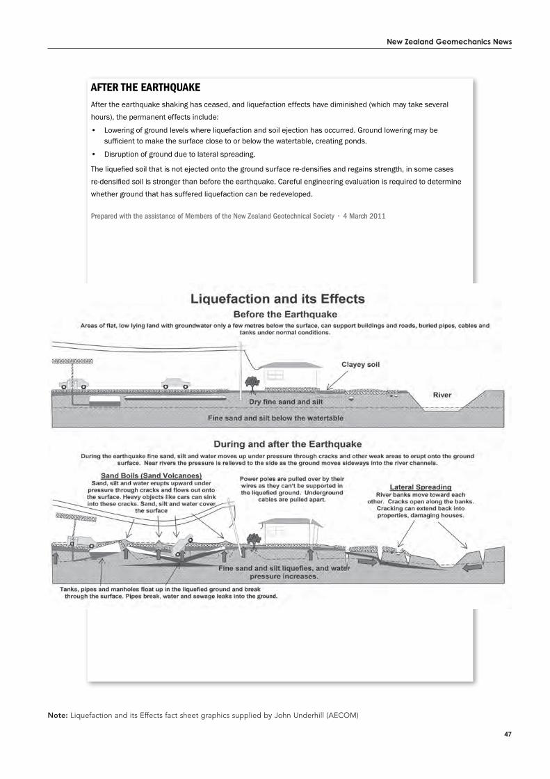
New Zealand Geomechanics News
47
6Fact sheets compiled and distributed by the Institution of Professional Engineers of New Zealand
afTEr ThE EarThquakEAfter the earthquake shaking has ceased, and liquefaction effects have diminished (which may take several hours), the permanent effects include:
• Lowering of ground levels where liquefaction and soil ejection has occurred. Ground lowering may be sufficient to make the surface close to or below the watertable, creating ponds.
• Disruption of ground due to lateral spreading.
The liquefied soil that is not ejected onto the ground surface re-densifies and regains strength, in some cases re-densified soil is stronger than before the earthquake. Careful engineering evaluation is required to determine whether ground that has suffered liquefaction can be redeveloped.
Prepared with the assistance of Members of the New Zealand Geotechnical Society • 4 March 2011
Note: Liquefaction and its Effects fact sheet graphics supplied by John Underhill (AECOM)
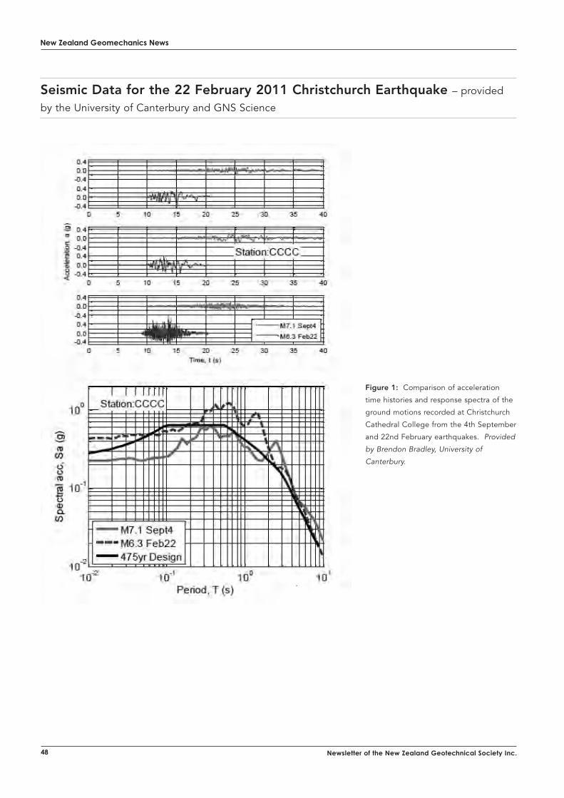
New Zealand Geomechanics News
48 Newsletter of the New Zealand Geotechnical Society Inc.
Seismic Data for the 22 February 2011 Christchurch Earthquake – provided
by the University of Canterbury and GNS Science
Figure 1: Comparison of acceleration
time histories and response spectra of the
ground motions recorded at Christchurch
Cathedral College from the 4th September
and 22nd February earthquakes. Provided
by Brendon Bradley, University of
Canterbury.
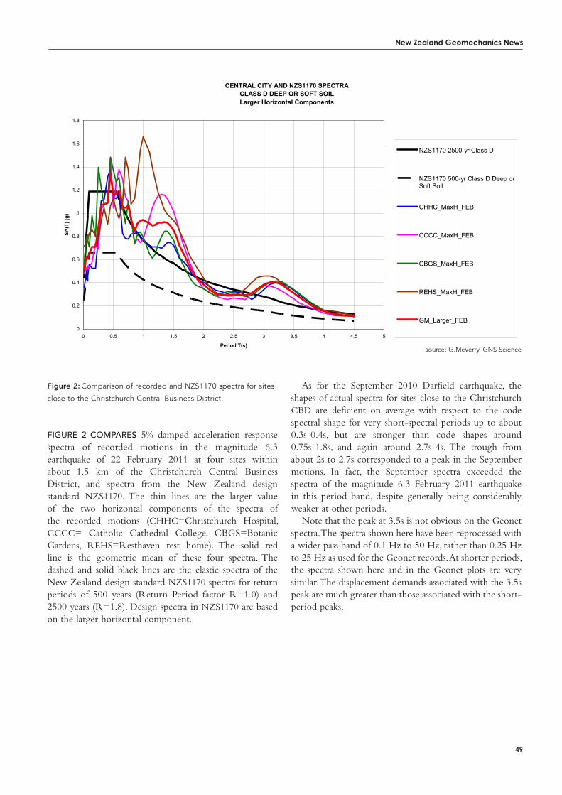
New Zealand Geomechanics News
49
Figure 2: Comparison of recorded and NZS1170 spectra for sites
close to the Christchurch Central Business District.
Figure 2 compAres 5% damped acceleration response spectra of recorded motions in the magnitude 6.3 earthquake of 22 February 2011 at four sites within about 1.5 km of the Christchurch Central Business District, and spectra from the New Zealand design standard NZS1170. The thin lines are the larger value of the two horizontal components of the spectra of the recorded motions (CHHC=Christchurch Hospital, CCCC= Catholic Cathedral College, CBGS=Botanic Gardens, REHS=Resthaven rest home). The solid red line is the geometric mean of these four spectra. The dashed and solid black lines are the elastic spectra of the New Zealand design standard NZS1170 spectra for return periods of 500 years (Return Period factor R=1.0) and 2500 years (R=1.8). Design spectra in NZS1170 are based on the larger horizontal component.
As for the September 2010 Darfield earthquake, the shapes of actual spectra for sites close to the Christchurch CBD are deficient on average with respect to the code spectral shape for very short-spectral periods up to about 0.3s-0.4s, but are stronger than code shapes around 0.75s-1.8s, and again around 2.7s-4s. The trough from about 2s to 2.7s corresponded to a peak in the September motions. In fact, the September spectra exceeded the spectra of the magnitude 6.3 February 2011 earthquake in this period band, despite generally being considerably weaker at other periods.
Note that the peak at 3.5s is not obvious on the Geonet spectra. The spectra shown here have been reprocessed with a wider pass band of 0.1 Hz to 50 Hz, rather than 0.25 Hz to 25 Hz as used for the Geonet records. At shorter periods, the spectra shown here and in the Geonet plots are very similar. The displacement demands associated with the 3.5s peak are much greater than those associated with the short-period peaks.
CHRISTCHURCH CENTRAL BUSINESS DISTRICT SPECTRA
CENTRAL CITY AND NZS1170 SPECTRACLASS D DEEP OR SOFT SOILLarger Horizontal Components
0
0.2
0.4
0.6
0.8
1
1.2
1.4
1.6
1.8
0 0.5 1 1.5 2 2.5 3 3.5 4 4.5 5
Period T(s)
SA(T
) (g)
NZS1170 2500-yr Class D
NZS1170 500-yr Class D Deep orSoft Soil
CHHC_MaxH_FEB
CCCC_MaxH_FEB
CBGS_MaxH_FEB
REHS_MaxH_FEB
GM_Larger_FEB
Figure 1 Comparison of recorded and NZS1170 spectra for sites close to the Christchurch Central Business District.
Figure 1 compares 5% damped acceleration response spectra of recorded motions in the magnitude 6.3 earthquake of 22 February 2011 at four sites within about 1.5 km of the Christchurch Central Business District, and spectra from the New Zealand design standard NZS1170. The thin lines are the larger value of the two horizontal components of the spectra of the recorded motions (CHHC=Christchurch Hospital, CCCC= Catholic Cathedral College, CBGS=Botanic Gardens, REHS=Resthaven rest home). The solid red line is the geometric mean of these four spectra. The dashed and solid black lines are the elastic spectra of the New Zealand design standard NZS1170 spectra for return periods of 500 years (Return Period factor R=1.0) and 2500 years (R=1.8). Design spectra in NZS1170 are based on the larger horizontal component.
As for the September 2010 Darfield earthquake, the shapes of actual spectra for sites close to the Christchurch CBD are deficient on average with respect to the code spectral shape for very short-spectral periods up to about 0.3s-0.4s, but are stronger than code shapes around 0.75s-1.8s, and again around 2.7s-4s. The trough from about 2s to 2.7s corresponded to a peak in the September motions. In fact, the September spectra exceeded the spectra of the magnitude 6.3 February 2011 earthquake in this period band, despite generally being considerably weaker at other periods.
Note that the peak at 3.5s is not obvious on the Geonet spectra. The spectra shown here have been reprocessed with a wider pass band of 0.1 Hz to 50 Hz, rather than 0.25 Hz to 25 Hz as used for the Geonet records. At shorter periods, the spectra shown here and in the Geonet plots are very similar. The displacement demands associated with the 3.5s peak are much greater than those associated with the short-period peaks.
source: G.McVerry, GNS Science
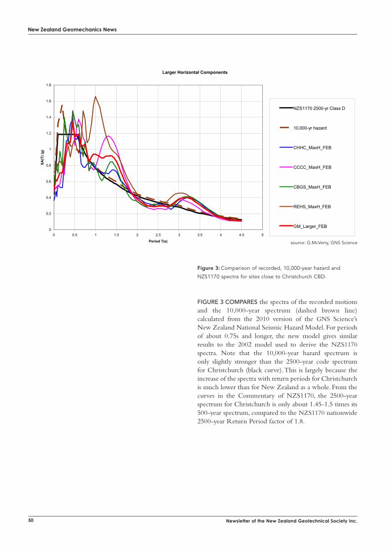
New Zealand Geomechanics News
50 Newsletter of the New Zealand Geotechnical Society Inc.
PLAXIS 2D Dynamics“The PLAXIS Dynamics module offers the tools to analyse the propagation of waves through the soil and their influence on structures.”
PLAXIS 2D Dynamics contains these specific modelling features:• Time-dependent dynamic load systems for point loads, distributed loads
and prescribed displacements• Independent application of horizontal and vertical displacement
components• Absorbent (viscous) boundaries to absorb waves at the model boundaries• Rayleigh damping per material data set for soil layers and structures• Smooth meshes, to prevent numerical oscillations and internal reflections• HSsmall model including small-strain stiffness, modulus reduction and
hysteretic damping• UDSM: upon request: UBCSAND liquefaction model
PLAXIS 3D Dynamics to be released later this year!
PLAXIS 2D
For vibrations and earthquake simulationPLAXIS 2D Dynamics
For PLAXIS Software in Australasia:
Lev 2, 37 Bligh Street, Sydney, NSW 2000, AustraliaTel : +02 8257 3337, Fax : +02 8257 [email protected], www.techsoft.com.au
The PLAXIS 2D program including the PLAXIS Dynamics and PLAXIS PlaxFlow modules make up a finite element package intended for the two dimensional analysis of deformation and stability in geotechnical engineering. It is a robust and user-friendly finite element package, developed for Geotechnical Engineering. It offers the tools professionals need in today’s and tomorrow’s world of high-tech building to analyse complex projects.
Figure 3: Comparison of recorded, 10,000-year hazard and
NZS1170 spectra for sites close to Christchurch CBD.
Figure 3 compAres the spectra of the recorded motions and the 10,000-year spectrum (dashed brown line) calculated from the 2010 version of the GNS Science’s New Zealand National Seismic Hazard Model. For periods of about 0.75s and longer, the new model gives similar results to the 2002 model used to derive the NZS1170 spectra. Note that the 10,000-year hazard spectrum is only slightly stronger than the 2500-year code spectrum for Christchurch (black curve). This is largely because the increase of the spectra with return periods for Christchurch is much lower than for New Zealand as a whole. From the curves in the Commentary of NZS1170, the 2500-year spectrum for Christchurch is only about 1.45-1.5 times its 500-year spectrum, compared to the NZS1170 nationwide 2500-year Return Period factor of 1.8.
CENTRAL CITY, NZS1170 AND 10,000-YEAR HAZARD SPECTRACLASS D DEEP OR SOFT SOILLarger Horizontal Components
0
0.2
0.4
0.6
0.8
1
1.2
1.4
1.6
1.8
0 0.5 1 1.5 2 2.5 3 3.5 4 4.5 5
Period T(s)
SA(T
) (g)
NZS1170 2500-yr Class D
10,000-yr hazard
CHHC_MaxH_FEB
CCCC_MaxH_FEB
CBGS_MaxH_FEB
REHS_MaxH_FEB
GM_Larger_FEB
Figure 2 Comparison of recorded, 10,000-year hazard and NZS1170 spectra for sites close to Christchurch CBD
Figure 2 compares the spectra of the recorded motions and the 10,000-year spectrum (dashed brown line) calculated from the 2010 version of the GNS Science’s New Zealand National Seismic Hazard Model. For periods of about 0.75s and longer, the new model gives similar results to the 2002 model used to derive the NZS1170 spectra. Note that the 10,000-year hazard spectrum is only slightly stronger than the 2500-year code spectrum for Christchurch (black curve). This is largely because the increase of the spectra with return periods for Christchurch is much lower than for New Zealand as a whole. From the curves in the Commentary of NZS1170, the 2500-year spectrum for Christchurch is only about 1.45-1.5 times its 500-year spectrum, compared to the NZS1170 nationwide 2500-year Return Period factor of 1.8.
source: G.McVerry, GNS Science
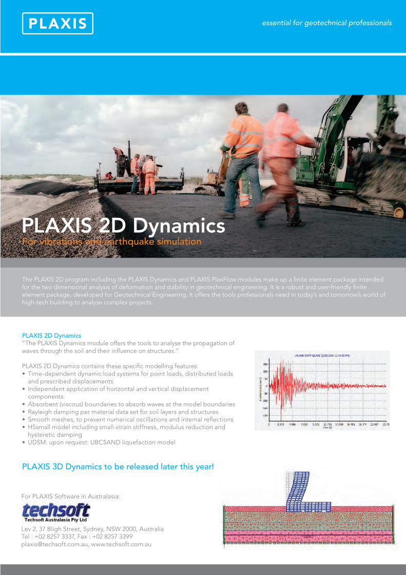
PLAXIS 2D Dynamics“The PLAXIS Dynamics module offers the tools to analyse the propagation of waves through the soil and their influence on structures.”
PLAXIS 2D Dynamics contains these specific modelling features:• Time-dependent dynamic load systems for point loads, distributed loads
and prescribed displacements• Independent application of horizontal and vertical displacement
components• Absorbent (viscous) boundaries to absorb waves at the model boundaries• Rayleigh damping per material data set for soil layers and structures• Smooth meshes, to prevent numerical oscillations and internal reflections• HSsmall model including small-strain stiffness, modulus reduction and
hysteretic damping• UDSM: upon request: UBCSAND liquefaction model
PLAXIS 3D Dynamics to be released later this year!
PLAXIS 2D
For vibrations and earthquake simulationPLAXIS 2D Dynamics
For PLAXIS Software in Australasia:
Lev 2, 37 Bligh Street, Sydney, NSW 2000, AustraliaTel : +02 8257 3337, Fax : +02 8257 [email protected], www.techsoft.com.au
The PLAXIS 2D program including the PLAXIS Dynamics and PLAXIS PlaxFlow modules make up a finite element package intended for the two dimensional analysis of deformation and stability in geotechnical engineering. It is a robust and user-friendly finite element package, developed for Geotechnical Engineering. It offers the tools professionals need in today’s and tomorrow’s world of high-tech building to analyse complex projects.
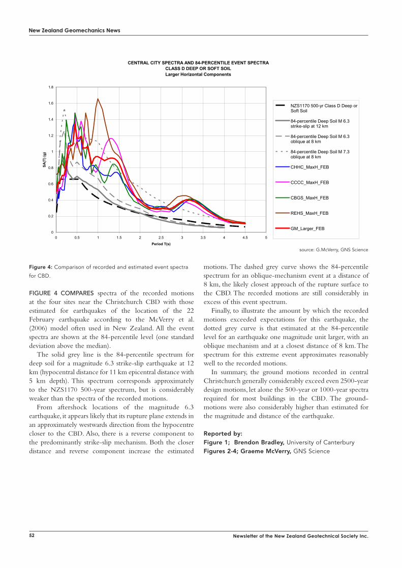
New Zealand Geomechanics News
52 Newsletter of the New Zealand Geotechnical Society Inc.
Figure 4: Comparison of recorded and estimated event spectra
for CBD.
Figure 4 compAres spectra of the recorded motions at the four sites near the Christchurch CBD with those estimated for earthquakes of the location of the 22 February earthquake according to the McVerry et al. (2006) model often used in New Zealand. All the event spectra are shown at the 84-percentile level (one standard deviation above the median).
The solid grey line is the 84-percentile spectrum for deep soil for a magnitude 6.3 strike-slip earthquake at 12 km (hypocentral distance for 11 km epicentral distance with 5 km depth). This spectrum corresponds approximately to the NZS1170 500-year spectrum, but is considerably weaker than the spectra of the recorded motions.
From aftershock locations of the magnitude 6.3 earthquake, it appears likely that its rupture plane extends in an approximately westwards direction from the hypocentre closer to the CBD. Also, there is a reverse component to the predominantly strike-slip mechanism. Both the closer distance and reverse component increase the estimated
motions. The dashed grey curve shows the 84-percentile spectrum for an oblique-mechanism event at a distance of 8 km, the likely closest approach of the rupture surface to the CBD. The recorded motions are still considerably in excess of this event spectrum.
Finally, to illustrate the amount by which the recorded motions exceeded expectations for this earthquake, the dotted grey curve is that estimated at the 84-percentile level for an earthquake one magnitude unit larger, with an oblique mechanism and at a closest distance of 8 km. The spectrum for this extreme event approximates reasonably well to the recorded motions.
In summary, the ground motions recorded in central Christchurch generally considerably exceed even 2500-year design motions, let alone the 500-year or 1000-year spectra required for most buildings in the CBD. The ground-motions were also considerably higher than estimated for the magnitude and distance of the earthquake.
Reported by:Figure 1; Brendon Bradley, University of Canterbury Figures 2-4; Graeme McVerry, GNS Science
CENTRAL CITY SPECTRA AND 84-PERCENTILE EVENT SPECTRACLASS D DEEP OR SOFT SOILLarger Horizontal Components
0
0.2
0.4
0.6
0.8
1
1.2
1.4
1.6
1.8
0 0.5 1 1.5 2 2.5 3 3.5 4 4.5 5
Period T(s)
SA(T
) (g)
NZS1170 500-yr Class D Deep orSoft Soil
84-percentile Deep Soil M 6.3strike-slip at 12 km
84-percentile Deep Soil M 6.3oblique at 8 km
84-percentile Deep Soil M 7.3oblique at 8 km
CHHC_MaxH_FEB
CCCC_MaxH_FEB
CBGS_MaxH_FEB
REHS_MaxH_FEB
GM_Larger_FEB
Figure 3 Comparison of recorded and estimated event spectra for CBD
Figure 3 compares spectra of the recorded motions at the four sites near the Christchurch CBD with those estimated for earthquakes of the location of the 22 February earthquake according to the McVerry et al. (2006) model often used in New Zealand. All the event spectra are shown at the 84-percentile level (one standard deviation above the median).
The solid grey line is the 84-percentile spectrum for deep soil for a magnitude 6.3 strike-slip earthquake at 12 km (hypocentral distance for 11 km epicentral distance with 5 km depth). This spectrum corresponds approximately to the NZS1170 500-year spectrum, but is considerably weaker than the spectra of the recorded motions.
From aftershock locations of the magnitude 6.3 earthquake, it appears likely that its rupture plane extends in an approximately westwards direction from the hypocentre closer to the CBD. Also, there is a reverse component to the predominantly strike-slip mechanism. Both the closer distance and reverse component increase the estimated motions. The dashed grey curve shows the 84-percentile spectrum for an oblique-mechanism event at a distance of 8 km, the likely closest approach of the rupture surface to the CBD. The recorded motions are still considerably in excess of this event spectrum.
Finally, to illustrate the amount by which the recorded motions exceeded expectations for this earthquake, the dotted grey curve is that estimated at the 84-percentile level for an earthquake one magnitude unit larger, with an oblique mechanism and at a closest distance of 8 km. The spectrum for this extreme event approximates reasonably well to the recorded motions.
In summary, the ground motions recorded in central Christchurch generally considerably exceed even 2500-year design motions, let alone the 500-year or 1000-year spectra required for most buildings in the CBD. The ground-motions were also considerably higher than estimated for the magnitude and distance of the earthquake.
source: G.McVerry, GNS Science
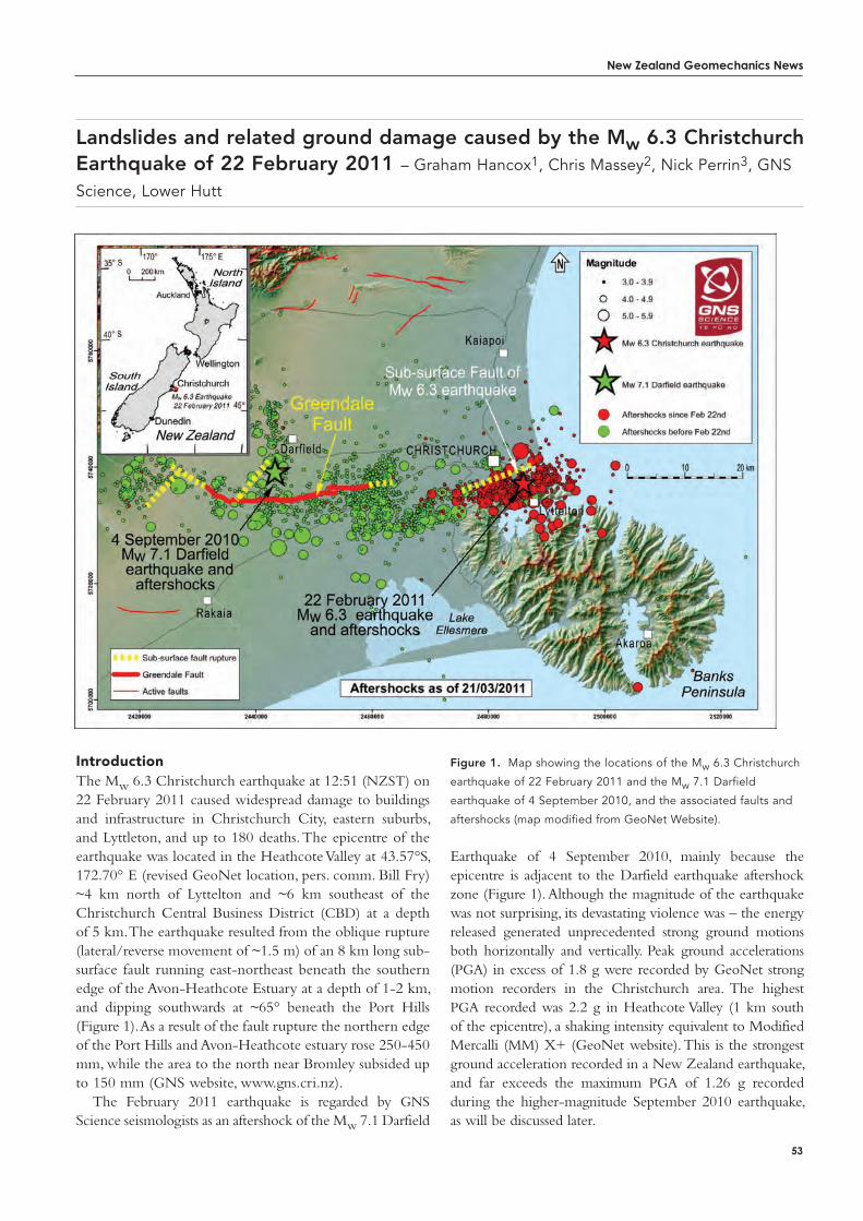
New Zealand Geomechanics News
53
introductionThe Mw 6.3 Christchurch earthquake at 12:51 (NZST) on 22 February 2011 caused widespread damage to buildings and infrastructure in Christchurch City, eastern suburbs, and Lyttleton, and up to 180 deaths. The epicentre of the earthquake was located in the Heathcote Valley at 43.57°S, 172.70° E (revised GeoNet location, pers. comm. Bill Fry) ~4 km north of Lyttelton and ~6 km southeast of the Christchurch Central Business District (CBD) at a depth of 5 km. The earthquake resulted from the oblique rupture (lateral/reverse movement of ~1.5 m) of an 8 km long sub-surface fault running east-northeast beneath the southern edge of the Avon-Heathcote Estuary at a depth of 1-2 km, and dipping southwards at ~65° beneath the Port Hills (Figure 1). As a result of the fault rupture the northern edge of the Port Hills and Avon-Heathcote estuary rose 250-450 mm, while the area to the north near Bromley subsided up to 150 mm (GNS website, www.gns.cri.nz).
The February 2011 earthquake is regarded by GNS Science seismologists as an aftershock of the Mw 7.1 Darfield
Landslides and related ground damage caused by the Mw 6.3 Christchurch Earthquake of 22 February 2011 – Graham Hancox1, Chris Massey2, Nick Perrin3, GNS
Science, Lower Hutt
Earthquake of 4 September 2010, mainly because the epicentre is adjacent to the Darfield earthquake aftershock zone (Figure 1). Although the magnitude of the earthquake was not surprising, its devastating violence was – the energy released generated unprecedented strong ground motions both horizontally and vertically. Peak ground accelerations (PGA) in excess of 1.8 g were recorded by GeoNet strong motion recorders in the Christchurch area. The highest PGA recorded was 2.2 g in Heathcote Valley (1 km south of the epicentre), a shaking intensity equivalent to Modified Mercalli (MM) X+ (GeoNet website). This is the strongest ground acceleration recorded in a New Zealand earthquake, and far exceeds the maximum PGA of 1.26 g recorded during the higher-magnitude September 2010 earthquake, as will be discussed later.
Figure 1. Map showing the locations of the Mw 6.3 Christchurch
earthquake of 22 February 2011 and the Mw 7.1 Darfield
earthquake of 4 September 2010, and the associated faults and
aftershocks (map modified from GeoNet Website).
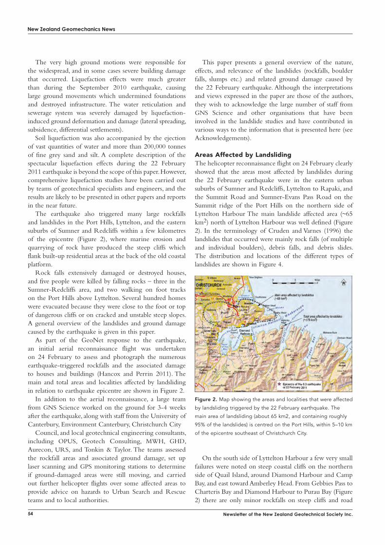
New Zealand Geomechanics News
54 Newsletter of the New Zealand Geotechnical Society Inc.
The very high ground motions were responsible for the widespread, and in some cases severe building damage that occurred. Liquefaction effects were much greater than during the September 2010 earthquake, causing large ground movements which undermined foundations and destroyed infrastructure. The water reticulation and sewerage system was severely damaged by liquefaction-induced ground deformation and damage (lateral spreading, subsidence, differential settlements).
Soil liquefaction was also accompanied by the ejection of vast quantities of water and more than 200,000 tonnes of fine grey sand and silt. A complete description of the spectacular liquefaction effects during the 22 February 2011 earthquake is beyond the scope of this paper. However, comprehensive liquefaction studies have been carried out by teams of geotechnical specialists and engineers, and the results are likely to be presented in other papers and reports in the near future.
The earthquake also triggered many large rockfalls and landslides in the Port Hills, Lyttelton, and the eastern suburbs of Sumner and Redcliffs within a few kilometres of the epicentre (Figure 2), where marine erosion and quarrying of rock have produced the steep cliffs which flank built-up residential areas at the back of the old coastal platform.
Rock falls extensively damaged or destroyed houses, and five people were killed by falling rocks – three in the Sumner-Redcliffs area, and two walking on foot tracks on the Port Hills above Lyttelton. Several hundred homes were evacuated because they were close to the foot or top of dangerous cliffs or on cracked and unstable steep slopes. A general overview of the landslides and ground damage caused by the earthquake is given in this paper.
As part of the GeoNet response to the earthquake, an initial aerial reconnaissance flight was undertaken on 24 February to assess and photograph the numerous earthquake-triggered rockfalls and the associated damage to houses and buildings (Hancox and Perrin 2011). The main and total areas and localities affected by landsliding in relation to earthquake epicentre are shown in Figure 2.
In addition to the aerial reconnaissance, a large team from GNS Science worked on the ground for 3-4 weeks after the earthquake, along with staff from the University of Canterbury, Environment Canterbury, Christchurch City
Council, and local geotechnical engineering consultants, including OPUS, Geotech Consulting, MWH, GHD, Aurecon, URS, and Tonkin & Taylor. The teams assessed the rockfall areas and associated ground damage, set up laser scanning and GPS monitoring stations to determine if ground-damaged areas were still moving, and carried out further helicopter flights over some affected areas to provide advice on hazards to Urban Search and Rescue teams and to local authorities.
This paper presents a general overview of the nature, effects, and relevance of the landslides (rockfalls, boulder falls, slumps etc.) and related ground damage caused by the 22 February earthquake. Although the interpretations and views expressed in the paper are those of the authors, they wish to acknowledge the large number of staff from GNS Science and other organisations that have been involved in the landslide studies and have contributed in various ways to the information that is presented here (see Acknowledgements).
areas affected by LandslidingThe helicopter reconnaissance flight on 24 February clearly showed that the areas most affected by landslides during the 22 February earthquake were in the eastern urban suburbs of Sumner and Redcliffs, Lyttelton to Rapaki, and the Summit Road and Sumner-Evans Pass Road on the Summit ridge of the Port Hills on the northern side of Lyttelton Harbour The main landslide affected area (~65 km2) north of Lyttelton Harbour was well defined (Figure 2). In the terminology of Cruden and Varnes (1996) the landslides that occurred were mainly rock falls (of multiple and individual boulders), debris falls, and debris slides. The distribution and locations of the different types of landslides are shown in Figure 4.
Figure 2. Map showing the areas and localities that were affected
by landsliding triggered by the 22 February earthquake. The
main area of landsliding (about 65 km2, and containing roughly
95% of the landslides) is centred on the Port Hills, within 5–10 km
of the epicentre southeast of Christchurch City.
On the south side of Lyttelton Harbour a few very small
failures were noted on steep coastal cliffs on the northern side of Quail Island, around Diamond Harbour and Camp Bay, and east toward Amberley Head. From Gebbies Pass to Charteris Bay and Diamond Harbour to Purau Bay (Figure 2) there are only minor rockfalls on steep cliffs and road
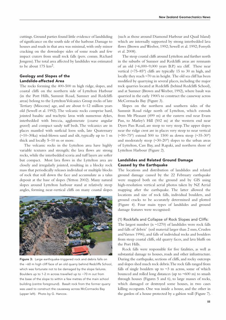
New Zealand Geomechanics News
55
cuttings. Ground parties found little evidence of landsliding of significance on the south side of the harbour. Damage to houses and roads in that area was minimal, with only minor cracking on the downslope sides of some roads and few impact craters from small rock falls (pers. comm. Richard Jongens). The total area affected by landslides was estimated to be about 175 km2.
Geology and Slopes of the Landslide-affected areaThe rocks forming the 400-500 m high ridge, slopes, and coastal cliffs on the northern side of Lyttelton Harbour (in the Port Hills, Summit Road, Sumner and Redcliffs areas) belong to the Lyttelton Volcanics Group rocks of late Tertiary (Miocene) age, and are about 6–12 million years old (Sewell et al. 1992). The volcanic rocks comprise hard, jointed basaltic and trachytic lavas with numerous dykes, interbedded with breccia, agglomerate (coarse angular gravel) and compact sandy tuff beds. The volcanics are in places mantled with surficial loess soils, late Quaternary (~10–30ka) wind-blown sand and silt, typically up to 1 m thick and locally 5–10 m or more.
The volcanic rocks in the Lyttelton area have highly variable textures and strength; the lava flows are strong rocks, while the interbedded scoria and tuff layers are softer but compact. Most lava flows in the Lyttelton area are closely and irregularly jointed, resulting in a blocky rock mass that periodically releases individual or multiple blocks of rock that roll down the face and accumulate as a talus deposit at the base of slopes (Yetton 2002). Many natural slopes around Lyttelton harbour stand at relatively steep angles, forming near-vertical cliffs on many coastal slopes
(such as those around Diamond Harbour and Quail Island) which are internally supported by strong interbedded lava flows (Brown and Weeber, 1992; Sewell et al. 1992; Forsyth et al. 2008).
The steep coastal cliffs around Lyttelton and further north in the suburbs of Sumner and Redcliffs areas are remnants of an old (~6,000–9,000 years B.P.) sea cliff. These near vertical (~75–85°) cliffs are typically 15 to 30 m high, and locally they reach ~70 m in height. The old sea cliff has been modified by quarrying in several places, including the major rock quarries located at Redcliffs (behind Redcliffs School), and at Sumner (Brown and Weeber, 1992), where basalt was quarried in the early 1900’s to construct the causeway across McCormacks Bay (Figure 3).
Slopes on the northern and southern sides of the Summit Road ridge north of Lyttelton, which extends from Mt Pleasant (499 m) at the eastern end near Evans Pass, to Marley’s Hill (502 m) at the western end near Dyers Pass Road, are steep to very steep. The upper slopes near the ridge crest are in places very steep to near vertical (~50–75°) extend 500 to 1500 m down steep (~35-30°) and moderately steep (~30-20°) slopes to the urban areas of Lyttelton, Cass Bay, and Rapaki, and northern shore of Lyttelton Harbour (Figure 2).
Landslides and related Ground Damage Caused by the EarthquakeThe locations and distribution of landslides and related ground damage caused by the 22 February earthquake were mapped both on the ground and by GIS using high-resolution vertical aerial photos taken by NZ Aerial mapping after the earthquake. The latter allowed the locations and size of rock falls, individual boulders, and ground cracks to be accurately determined and plotted (Figure 4). Four main types of landslides and ground damage features were recognised:
(1) Rockfalls and Collapse of Rock Slopes and Cliffs:The largest number (n ~1270) of landslides were rock falls and falls of ‘debris’ (soil material larger than 2 mm, Cruden and Varnes 1996), and falls of individual rocks and boulders from steep coastal cliffs, old quarry faces, and lava bluffs on the Port Hills.
Rock falls were responsible for five fatalities, as well as substantial damage to houses, roads and other infrastructure. During the earthquake, sections of cliffs, and rocky outcrops and slopes shed much rock debris. The rock falls ranged from falls of single boulders up to ~3 m across, some of which bounced and rolled long distances (up to ~600 m) to smash through houses (Figures 5 and 6), to large masses of rocks, which damaged or destroyed some houses, in two cases killing occupants. One was inside a house, and the other in the garden of a house protected by a gabion wall (Figure 7).
Figure 3: Large earthquake-triggered rock and debris falls on
the ~60 m high cliff face of an old quarry behind Redcliffs School,
which was fortunate not to be damaged by the slope failures.
Boulders up to 1-2 m across travelled up to ~70 m out from
the base of the slope to within a few metres of the main school
building (centre foreground). Basalt rock from the former quarry
was used to construct the causeway across McCormacks Bay
(upper left). Photo by G. Hancox.
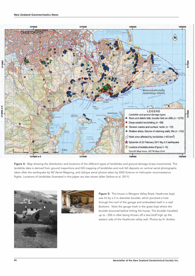
New Zealand Geomechanics News
56 Newsletter of the New Zealand Geotechnical Society Inc.
Figure 5: This house in Morgans Valley Road, Heathcote (top)
was hit by a 2 m diameter boulder, which punched a hole
through the roof of the garage and embedded itself in a wall
(bottom). Note the gouge mark in the grass (top) where the
boulder bounced before hitting the house. The boulder travelled
up to ~350 m after being thrown off a lava bluff high up the
eastern side of the Heathcote valley wall. Photos by N. Andres.
Figure 4: Map showing the distribution and locations of the different types of landslides and ground damage (mass movements). The
landslide data is derived from ground inspections and GIS mapping of landslides and rock fall deposits on vertical aerial photographs
taken after the earthquake by NZ Aerial Mapping, and oblique aerial photos taken by GNS Science on helicopter reconnaissance
flights. Locations of landslides illustrated in this paper are also shown (after Dellow et al. 2011).
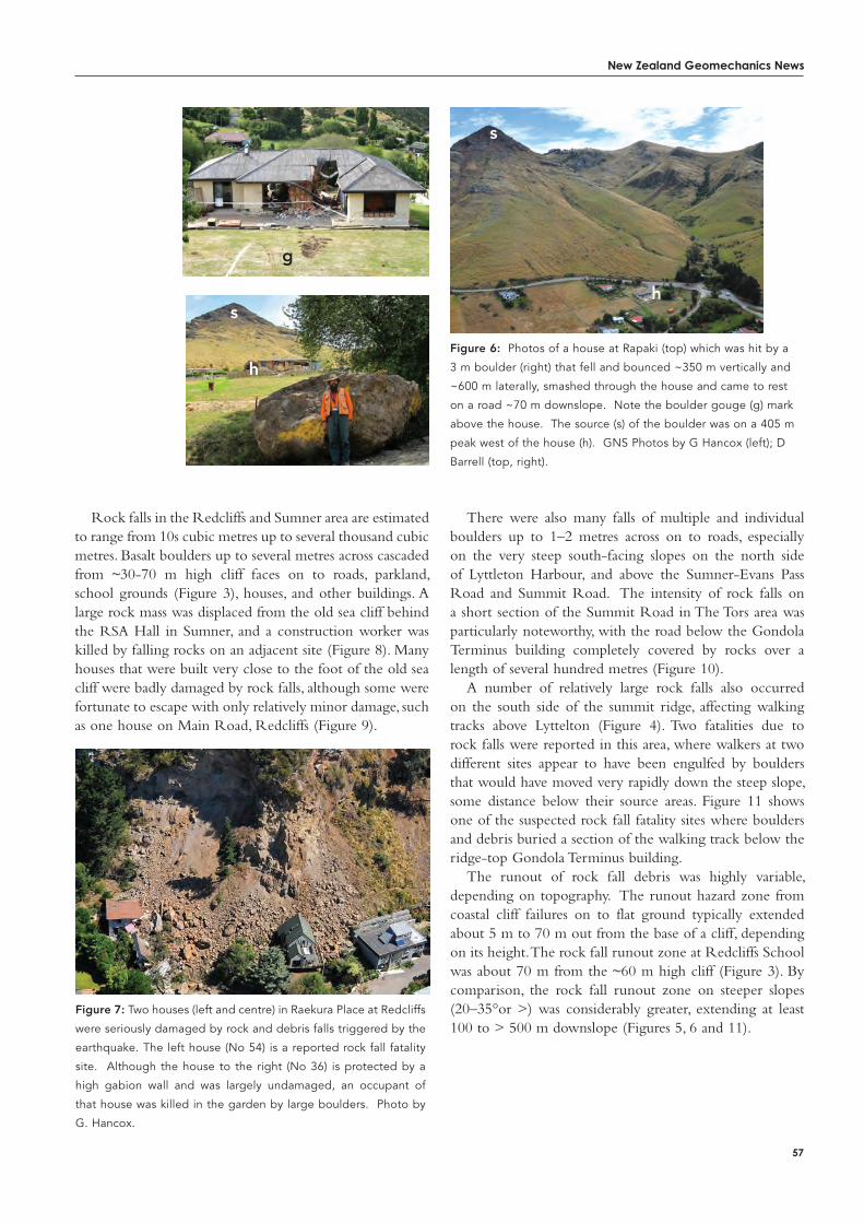
New Zealand Geomechanics News
57
Rock falls in the Redcliffs and Sumner area are estimated to range from 10s cubic metres up to several thousand cubic metres. Basalt boulders up to several metres across cascaded from ~30-70 m high cliff faces on to roads, parkland, school grounds (Figure 3), houses, and other buildings. A large rock mass was displaced from the old sea cliff behind the RSA Hall in Sumner, and a construction worker was killed by falling rocks on an adjacent site (Figure 8). Many houses that were built very close to the foot of the old sea cliff were badly damaged by rock falls, although some were fortunate to escape with only relatively minor damage, such as one house on Main Road, Redcliffs (Figure 9).
There were also many falls of multiple and individual boulders up to 1–2 metres across on to roads, especially on the very steep south-facing slopes on the north side of Lyttleton Harbour, and above the Sumner-Evans Pass Road and Summit Road. The intensity of rock falls on a short section of the Summit Road in The Tors area was particularly noteworthy, with the road below the Gondola Terminus building completely covered by rocks over a length of several hundred metres (Figure 10).
A number of relatively large rock falls also occurred on the south side of the summit ridge, affecting walking tracks above Lyttelton (Figure 4). Two fatalities due to rock falls were reported in this area, where walkers at two different sites appear to have been engulfed by boulders that would have moved very rapidly down the steep slope, some distance below their source areas. Figure 11 shows one of the suspected rock fall fatality sites where boulders and debris buried a section of the walking track below the ridge-top Gondola Terminus building.
The runout of rock fall debris was highly variable, depending on topography. The runout hazard zone from coastal cliff failures on to flat ground typically extended about 5 m to 70 m out from the base of a cliff, depending on its height. The rock fall runout zone at Redcliffs School was about 70 m from the ~60 m high cliff (Figure 3). By comparison, the rock fall runout zone on steeper slopes (20–35°or >) was considerably greater, extending at least 100 to > 500 m downslope (Figures 5, 6 and 11).
Figure 6: Photos of a house at Rapaki (top) which was hit by a
3 m boulder (right) that fell and bounced ~350 m vertically and
~600 m laterally, smashed through the house and came to rest
on a road ~70 m downslope. Note the boulder gouge (g) mark
above the house. The source (s) of the boulder was on a 405 m
peak west of the house (h). GNS Photos by G Hancox (left); D
Barrell (top, right).
Figure 7: Two houses (left and centre) in Raekura Place at Redcliffs
were seriously damaged by rock and debris falls triggered by the
earthquake. The left house (No 54) is a reported rock fall fatality
site. Although the house to the right (No 36) is protected by a
high gabion wall and was largely undamaged, an occupant of
that house was killed in the garden by large boulders. Photo by
G. Hancox.
g
s
hs
h
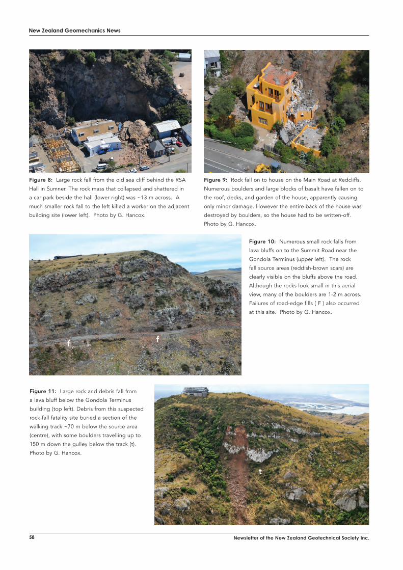
New Zealand Geomechanics News
58 Newsletter of the New Zealand Geotechnical Society Inc.
Figure 9: Rock fall on to house on the Main Road at Redcliffs.
Numerous boulders and large blocks of basalt have fallen on to
the roof, decks, and garden of the house, apparently causing
only minor damage. However the entire back of the house was
destroyed by boulders, so the house had to be written-off.
Photo by G. Hancox.
Figure 8: Large rock fall from the old sea cliff behind the RSA
Hall in Sumner. The rock mass that collapsed and shattered in
a car park beside the hall (lower right) was ~13 m across. A
much smaller rock fall to the left killed a worker on the adjacent
building site (lower left). Photo by G. Hancox.
Figure 10: Numerous small rock falls from
lava bluffs on to the Summit Road near the
Gondola Terminus (upper left). The rock
fall source areas (reddish-brown scars) are
clearly visible on the bluffs above the road.
Although the rocks look small in this aerial
view, many of the boulders are 1-2 m across.
Failures of road-edge fills ( F ) also occurred
at this site. Photo by G. Hancox.
Figure 11: Large rock and debris fall from
a lava bluff below the Gondola Terminus
building (top left). Debris from this suspected
rock fall fatality site buried a section of the
walking track ~70 m below the source area
(centre), with some boulders travelling up to
150 m down the gulley below the track (t).
Photo by G. Hancox.
ff
t

Percussion Drilling Services
For more information call us on: Ph: (09) 356 3510 or visit www.geotechnics.co.nz
Auckland Tauranga Wellingtonp. +64 9 356 3510 p. +64 7 571 0280 p. +64 4 381 [email protected] www.geotechnics
Window Sampler• Soilsamplingto10mdependingonground
materials encountered
• Piezometerinstallation
• Idealfordifficultaccessorspaceconstraints, ieinsidebuildings,gardens
• 45mmøclearplasticlinersforenvironmentalsampling.
Terrier Sampling and Testing Rig• Compactandmanoeuvrable
with a quick set up time
• Minimalsitedisturbance
• Specialistsamplinginclear plastic liners which makes it easy for logging and sub-sampling
• Idealforsamplingtodepthsof 10 m depending on ground materials encountered
• StandardPenetrationTest(SPT)
• Concreteandasphaltcoringattachment
• Dynamicprobingto30minsuitableground-excellent for locating voids or obstructions
• Instrumentationinstallation-piezometers,gasand water wells.
Assuring your pile construction...
Cross-hole Sonic Logging
Results available as 3d Tomography, First Arrival Time (FAT) and Waterfall.
1 / 3
080220 P21A 20/02/2008 Diameter: 1.50m
12 32.6m Distance: 0.90m Filter: 1
13 32.6m Distance: 1.14m Filter: 1
0m
2.5
5.0
7.5
10.0
12.5
15.0
17.5
20.0
22.5
25.0
27.5
30.0
32.5
32.60.0 0.1 0.2 0.3 0.4 0.5 0.6 0.7 0.8
Arrival time [ms]
Relative EnergyLow High
0m
2.5
5.0
7.5
10.0
12.5
15.0
17.5
20.0
22.5
25.0
27.5
30.0
32.5
32.60.0 0.1 0.2 0.3 0.4 0.5 0.6 0.7 0.8
Arrival time [ms]
Relative EnergyLow High
REMARKS:
080220 P21A/12: anomaly @ 17 m 080220 P21A/13: Minor anomaly @ 19 m
1 / 4
080220 P21A 20/02/2008
12 32.6m Distance: 0.90m Filter: 2
13 32.6m Distance: 1.14m Filter: 2
0m
2.0
4.0
6.0
8.0
10.0
12.0
14.0
16.0
18.0
20.0
22.0
24.0
26.0
28.0
30.0
32.0
32.60.0 0.1 0.2 0.3 0.4 0.5 0.6 0.7 0.8
Arrival time [ms]
0m
2.0
4.0
6.0
8.0
10.0
12.0
14.0
16.0
18.0
20.0
22.0
24.0
26.0
28.0
30.0
32.0
32.60.0 0.1 0.2 0.3 0.4 0.5 0.6 0.7 0.8
Arrival time [ms]
Contact: Paul Burton on 021 610 067 or [email protected]
GEOTECHNICS LTD23 Morgan Street, Newmarket Auckland 1023, PO Box 9360Newmarket, Auckland 1149, New Zealand
p. + 64 9 356 3510f. + 64 9 356 3511e. [email protected]. www.geotechnics.co.nz
CEL
EB
RATING 50 YEAR
S
1959 - 2009

ENVIRONMENTAL AND ENGINEERING CONSULTANTS
Geotechnical Professionals
KAWARAU FALLS QUEENSTOWN
KAWAKAWA BAY AUCKLAND
CHRISTCHURCH REBUILD
Demand for our geotechnical services are at an unprecedented high. The reason for this is simple - we are New Zealand’s leading geotechnical consultancy.
We have built this reputation on 50 years of success through our award
winning solutions and talented people. We are proudly employee owned and
live and breathe our goal to be the “best to work for and best to work with”.
In front of us lies the incredible challenge of assisting Christchurch’s
recovery following its twin earthquakes. Alongside that we have an exciting
schedule of work involving multi-disciplinary engineering projects
throughout New Zealand and a growing presence overseas. Due to our
ongoing success and increasing commitments, we have opportunities from
intermediate to senior level.
You may be attracted to the rewarding and challenging prospect of helping
rebuild Christchurch or you may want to apply yourself to some of the
largest and most complicated infrastructure projects seen in New Zealand.
You may be interested in a short stint or a permanent role, moving to a large
city or be based where you are. Either way - we would like to hear from you!
We are seeking individuals who are passionate about Geotechnical
Engineering and have solid project management skills, industry experience
and knowledge. You will have a technical grounding in geotechnics, a
relevant bachelor degree and 5+ years consulting experience. Other qualities
will include excellent report writing capability, ability to work in a multi-
disciplinary team and business development experience.
Your core responsibilities will include project management, designing and
modelling all varieties of geotechnical structures and client management.
This is a great opportunity for you to remain technically hands on, but
also get involved in business development and people management if that
interests you.
If you are not already convinced about joining us, we also offer competitive
compensation packages and a range of rewards. Tonkin & Taylor is not just
a place to work - it’s a playground with rewards for innovation, technical
rigour and achievement of results. It is a place where you can work alongside
New Zealand’s leading geotechnical experts to solve some of the most
challenging, interesting, and meaningful projects worldwide.
If you would like any more information about this role, please contact Arun Kumar on (09) 355 0768 or visit our careers page at www.tonkin.co.nz
An
indispensable
tool for
engineers of
any discipline
- PC Pro
Download YourMathcad Trial Today!
Visit www.hrs.co.nz/2752.aspxor contact HRS on 0800 477 776.
More than 1.8 million individuals around the world use Mathcad to perform, document, and share valuable calculation and design work.
The unique Mathcad visual format and scratchpad interface integrate standard mathematical notation, text, and graphs in a single worksheet – making Mathcad ideal for knowledge capture, calculation reuse, and engineering collaboration.
You work with updatable, interactive designs, allowing you to capture the critical methods and values behind each of your engineering.
• Calculate, model, and visualise your ideas. • Make fewer errors and work faster. • Easily re-use and audit existing documents.• Verify, validate, and annotate your solutions. • Present easily understood documents
to clients and managers.• Do mathematical operations not present
in spreadsheets.
ExperienceMathcad Today! Easy, auditablecalculations
2011 June - Mathcad Advert - Geomechanics News.indd 2 4/6/2011 4:02:31 PM
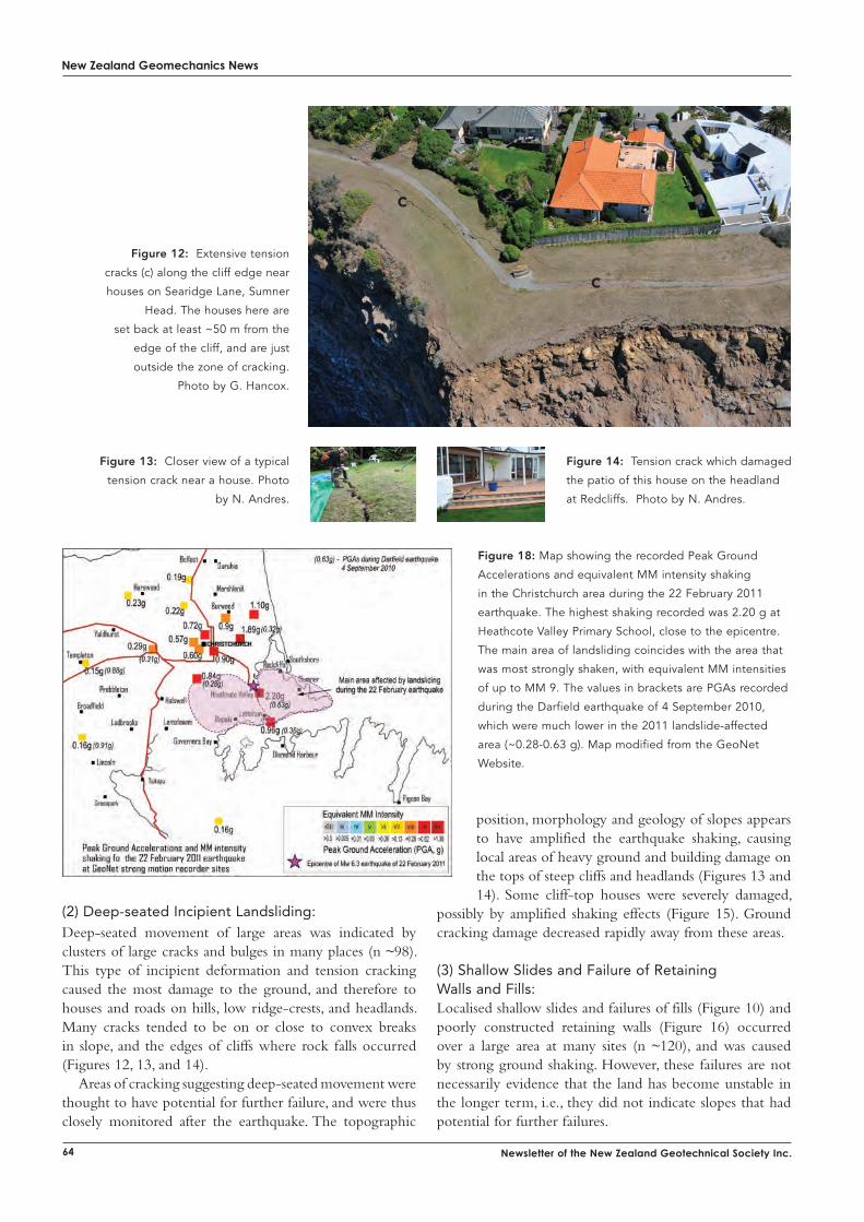
New Zealand Geomechanics News
64 Newsletter of the New Zealand Geotechnical Society Inc.
position, morphology and geology of slopes appears to have amplified the earthquake shaking, causing local areas of heavy ground and building damage on the tops of steep cliffs and headlands (Figures 13 and 14). Some cliff-top houses were severely damaged,
possibly by amplified shaking effects (Figure 15). Ground cracking damage decreased rapidly away from these areas.
(3) Shallow Slides and Failure of Retaining Walls and Fills:Localised shallow slides and failures of fills (Figure 10) and poorly constructed retaining walls (Figure 16) occurred over a large area at many sites (n ~120), and was caused by strong ground shaking. However, these failures are not necessarily evidence that the land has become unstable in the longer term, i.e., they did not indicate slopes that had potential for further failures.
Figure 12: Extensive tension
cracks (c) along the cliff edge near
houses on Searidge Lane, Sumner
Head. The houses here are
set back at least ~50 m from the
edge of the cliff, and are just
outside the zone of cracking.
Photo by G. Hancox.
Figure 13: Closer view of a typical
tension crack near a house. Photo
by N. Andres.
Figure 14: Tension crack which damaged
the patio of this house on the headland
at Redcliffs. Photo by N. Andres.
Figure 18: Map showing the recorded Peak Ground
Accelerations and equivalent MM intensity shaking
in the Christchurch area during the 22 February 2011
earthquake. The highest shaking recorded was 2.20 g at
Heathcote Valley Primary School, close to the epicentre.
The main area of landsliding coincides with the area that
was most strongly shaken, with equivalent MM intensities
of up to MM 9. The values in brackets are PGAs recorded
during the Darfield earthquake of 4 September 2010,
which were much lower in the 2011 landslide-affected
area (~0.28-0.63 g). Map modified from the GeoNet
Website.
(2) Deep-seated Incipient Landsliding:Deep-seated movement of large areas was indicated by clusters of large cracks and bulges in many places (n ~98). This type of incipient deformation and tension cracking caused the most damage to the ground, and therefore to houses and roads on hills, low ridge-crests, and headlands. Many cracks tended to be on or close to convex breaks in slope, and the edges of cliffs where rock falls occurred (Figures 12, 13, and 14).
Areas of cracking suggesting deep-seated movement were thought to have potential for further failure, and were thus closely monitored after the earthquake. The topographic
c
c
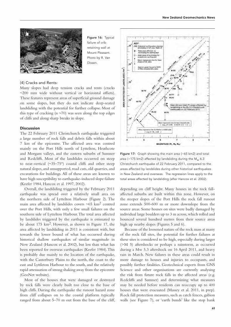
New Zealand Geomechanics News
65
(4) Cracks and Rents:Many slopes had deep tension cracks and rents (cracks ~200 mm wide without vertical or horizontal offsets). These features represent areas of superficial ground damage on some slopes, but they do not indicate deep-seated landsliding with the potential for further collapse. Most of this type of cracking (n ~70) was seen along the top edges of cliffs and along sharp breaks in slope.
DiscussionThe 22 February 2011 Christchurch earthquake triggered a large number of rock falls and debris falls within about 7 km of the epicentre. The affected area was centred mainly on the Port Hills north of Lyttelton, Heathcote and Morgans valleys, and the eastern suburbs of Sumner and Redcliffs. Most of the landslides occurred on steep to near-vertical (~35–75°) coastal cliffs and other steep natural slopes, and unsupported, road cuts, old quarries, and excavations for buildings. All of these areas are known to have high susceptibility to earthquake-induced slope failure (Keefer 1984, Hancox et al. 1997, 2002).
Overall, the landsliding triggered by the February 2011 earthquake was spread over a relatively small area on the northern side of Lyttelton Harbour (Figure 2). The main area affected by landslides covers ~65 km2 centred over the Port Hills, with only a few small failures on the southern side of Lyttelton Harbour. The total area affected by landslides triggered by the earthquake is estimated to be about 175 km2. However, as shown in Figure 17, the area affected by landsliding in 2011 is consistent with, but towards the lower bound of what has occurred during historical shallow earthquakes of similar magnitude in New Zealand (Hancox et al. 2002), but less than what has been reported for overseas earthquakes (Keefer 1984). This is probably due mainly to the location of the earthquake, with the Canterbury Plains to the north, the coast to the east and Lyttleton Harbour to the south, and the relatively rapid attenuation of strong shaking away from the epicentre (GeoNet website).
Most of the houses that were damaged or destroyed by rock falls were clearly built too close to the base of high cliffs. During the earthquake the runout hazard zone from cliff collapses on to the coastal platform typically ranged from about 5–70 m out from the base of the cliff,
depending on cliff height. Many houses in the rock fall-affected suburbs are built within this zone. However, on the steeper slopes of the Port Hills the rock fall runout zone extends 500-600 m or more downslope from the source areas. Some houses on sites were badly damaged by individual large boulders up to 3 m across, which rolled and bounced several hundred metres from their source areas high up nearby slopes (Figures 5 and 6).
Because of the loosened nature of the rock mass at many of the rock fall sites, the potential for further failures at these sites is considered to be high, especially during larger (>M 5) aftershocks or perhaps a rainstorm, as occurred during a Mw 5.3 aftershock on 16 April 2011, and heavy rain in March. New failures in these areas could result in more damage to houses and injuries to occupants, and possibly further fatalities. Geotechnical experts from GNS Science and other organisations are currently analysing the risk from future rock falls in the affected areas (e.g. Redcliffs and Sumner) and determining what measures may be needed before residents can reoccupy up to 400 houses that were evacuated (Massey et al. 2011, in prep). Rock fall protection measures, such as catch fences, gabion walls (see Figure 7), or ‘earth bunds’ like the stop bank
Figure 16: Typical
failure of crib
retaining wall at
Mount Pleasant.
Photo by R. Van
Dissen.
Figure 17: Graph showing the main area (~65 km2) and total
area (~175 km2) affected by landsliding during the Mw 6.3
Christchurch earthquake of 22 February 2011, compared to the
areas affected by landslides during other historical earthquakes
in New Zealand and overseas. The regression lines apply to the
total areas affected by landsliding (after Hancox et al. 2002).
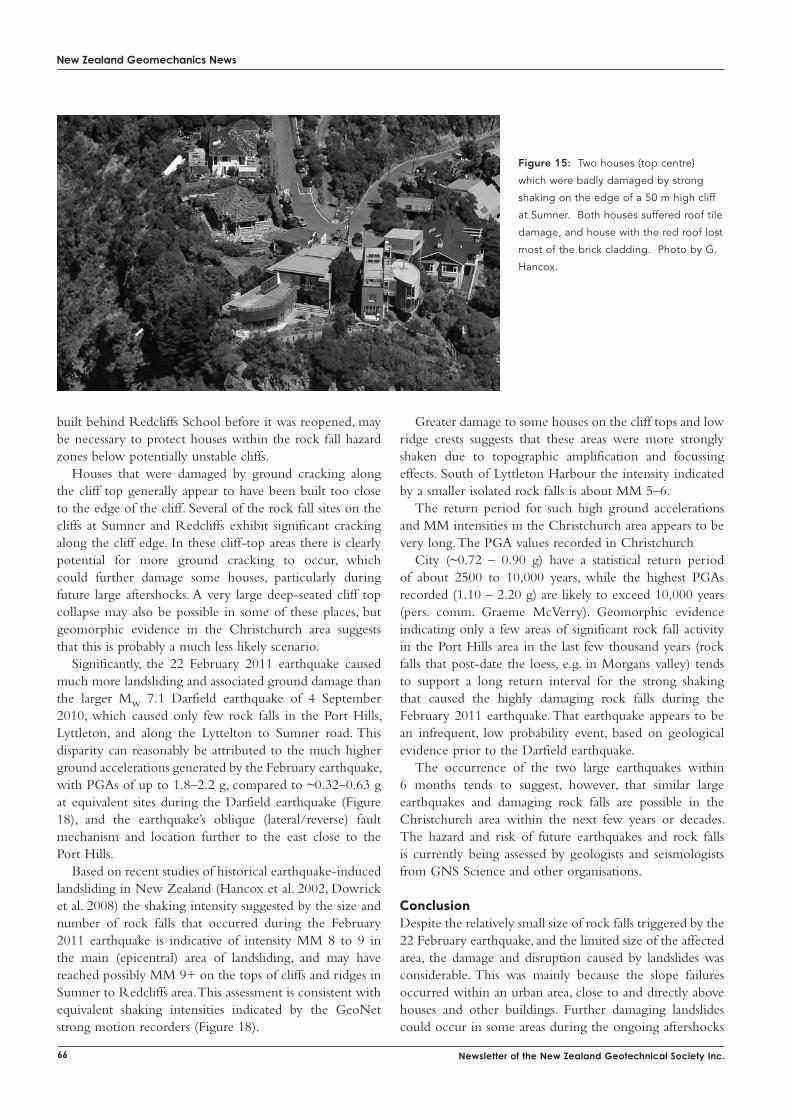
New Zealand Geomechanics News
66 Newsletter of the New Zealand Geotechnical Society Inc.
built behind Redcliffs School before it was reopened, may be necessary to protect houses within the rock fall hazard zones below potentially unstable cliffs.
Houses that were damaged by ground cracking along the cliff top generally appear to have been built too close to the edge of the cliff. Several of the rock fall sites on the cliffs at Sumner and Redcliffs exhibit significant cracking along the cliff edge. In these cliff-top areas there is clearly potential for more ground cracking to occur, which could further damage some houses, particularly during future large aftershocks. A very large deep-seated cliff top collapse may also be possible in some of these places, but geomorphic evidence in the Christchurch area suggests that this is probably a much less likely scenario.
Significantly, the 22 February 2011 earthquake caused much more landsliding and associated ground damage than the larger Mw 7.1 Darfield earthquake of 4 September 2010, which caused only few rock falls in the Port Hills, Lyttleton, and along the Lyttelton to Sumner road. This disparity can reasonably be attributed to the much higher ground accelerations generated by the February earthquake, with PGAs of up to 1.8–2.2 g, compared to ~0.32–0.63 g at equivalent sites during the Darfield earthquake (Figure 18), and the earthquake’s oblique (lateral/reverse) fault mechanism and location further to the east close to the Port Hills.
Based on recent studies of historical earthquake-induced landsliding in New Zealand (Hancox et al. 2002, Dowrick et al. 2008) the shaking intensity suggested by the size and number of rock falls that occurred during the February 2011 earthquake is indicative of intensity MM 8 to 9 in the main (epicentral) area of landsliding, and may have reached possibly MM 9+ on the tops of cliffs and ridges in Sumner to Redcliffs area. This assessment is consistent with equivalent shaking intensities indicated by the GeoNet strong motion recorders (Figure 18).
Greater damage to some houses on the cliff tops and low ridge crests suggests that these areas were more strongly shaken due to topographic amplification and focussing effects. South of Lyttleton Harbour the intensity indicated by a smaller isolated rock falls is about MM 5–6.
The return period for such high ground accelerations and MM intensities in the Christchurch area appears to be very long. The PGA values recorded in Christchurch
City (~0.72 – 0.90 g) have a statistical return period of about 2500 to 10,000 years, while the highest PGAs recorded (1.10 – 2.20 g) are likely to exceed 10,000 years (pers. comm. Graeme McVerry). Geomorphic evidence indicating only a few areas of significant rock fall activity in the Port Hills area in the last few thousand years (rock falls that post-date the loess, e.g. in Morgans valley) tends to support a long return interval for the strong shaking that caused the highly damaging rock falls during the February 2011 earthquake. That earthquake appears to be an infrequent, low probability event, based on geological evidence prior to the Darfield earthquake.
The occurrence of the two large earthquakes within 6 months tends to suggest, however, that similar large earthquakes and damaging rock falls are possible in the Christchurch area within the next few years or decades. The hazard and risk of future earthquakes and rock falls is currently being assessed by geologists and seismologists from GNS Science and other organisations.
ConclusionDespite the relatively small size of rock falls triggered by the 22 February earthquake, and the limited size of the affected area, the damage and disruption caused by landslides was considerable. This was mainly because the slope failures occurred within an urban area, close to and directly above houses and other buildings. Further damaging landslides could occur in some areas during the ongoing aftershocks
Figure 15: Two houses (top centre)
which were badly damaged by strong
shaking on the edge of a 50 m high cliff
at Sumner. Both houses suffered roof tile
damage, and house with the red roof lost
most of the brick cladding. Photo by G.
Hancox.
New Zealand Geomechanics News
67
or heavy rain. In general the risk of further rock falls is likely to be highest where there is loose rock on the cliffs that failed, and where there is already extensive cracking along the edge of cliff faces.
We hope that this description of the landsliding caused by the February 2011 earthquake in Christchurch provides a timely reminder of the dangers of building too close to high cliffs and unsupported steep slopes, and the importance of safe ‘set-back’ distances on or below steep slopes where landslides can occur. It also emphasises the considerable risk posed by earthquake-induced landslides in other hilly parts of New Zealand, especially in cities such as Wellington and Nelson where there are steep potentially unstable slopes, and large earthquakes are expected to occur in the foreseeable future.
referencesBrown, L.J., Weeber, J.H. 1992. Geology of the Christchurch
urban area. Scale 1:25,000. Institute of Geology & Nuclear Sciences geological map 1. 1 sheet + 104 p. Institute of Geological & Nuclear Sciences Limited.
Cruden, D.M. and Varnes, D.J., 1996. Landslide Types and Processes: Chapter 3 in Turner A.K. and Schuster R.L. (Eds.) Landslides - Investigation and mitigation. Special Report 247, Transportation Research Board. National Research Council. Washington DC, National Academy Press, 36–75.
Dellow, G.D., Massey, C.I., Davies, T.R.H., Read, S.A.L., Bruce, Z.R.V, Van Dissen, R., Barrell, D., Jongens, R., Heron, D., Glassey, P., Hancox, G.T., Perrin, N., McSaveney, M.J., Archibald, G.C., Palmer, N. McSaveney, E.R., Lukovic, B., Andres, N.M., and Hasse, M., Beavan, J., Edwards, S., Thomas, J. 2011. Rockfalls and landslides triggered by the February 2011 Christchurch (NZ) earthquake: the GeoNet response. Poster presented at the EGU2011-14230 Special Session US4: The 22 February 2011 Christchurch NZ Earthquake. 2011 EGU General Assembly 2011, Vienna.
Dowrick, D.J., Hancox, G.T., Perrin, N.D., Dellow, G.D. 2008. The Modified Mercalli Intensity Scale – Revisions arising from New Zealand experience. Bulletin of the New Zealand Society for Earthquake Engineering, Vol. 41 No. 3, September 2008, pp 193–205.
Forsyth, P.J., Barrell, D.J.A., Jongens, R. (compilers) 2008. Geology of the Christchurch area. Institute of Geological and Nuclear Sciences 1:250,000 geological map 16. 1 sheet +67 p. Lower Hutt, New Zealand, GNS Science.
Hancox, G.T., Perrin, N.D., Dellow, G.D. 1997. Earthquake-induced landslides in New Zealand and implications for MM intensity and seismic hazard assessment. GNS Science Client Report 43601B, for New Zealand Earthquake Commission Research Project 95/196.
Hancox, G.T., Perrin, N.D., Dellow, G.D. 2002. Recent
studies of historical earthquake-induced landsliding, ground damage, and MM Intensity in New Zealand. Bulletin of the New Zealand Society for Earthquake Engineering 35:(2) pp59–95.
Hancox, G.T., Perrin, N.D. 2011. Report on Landslide Reconnaissance Flight on 24 February 2011 following the Mw 6.3 Christchurch Earthquake of 22 February 2011. GNS Science Immediate Report, GeoNet Project No. 460W6303, File No. LD8 (NZTopo50-BX24)/941-947.
Keefer, D.K. 1984. Landslides caused by earthquakes. Geological Society of America Bulletin 95: 406–421.
Massey, C., Buxton, R., McSaveney, M., Lukovic, B., Heron, D., Davies, T., Andres, N. 2011 (in prep). Interim guide to life-safety risk from earthquake-triggered boulder falls in the Port Hills, Christchurch, New Zealand. GNS Science Science Report 2011/xxx.
Sewell, R.J., Weaver, S.D., Reay, M.B., 1992. Geology of Banks Peninsula, Scale 1:100,000. Institute of Geological and Nuclear Sciences Map 3. Institute of Geological and Nuclear Sciences Limited, Lower Hutt, New Zealand.
Yetton, M.D., 2002. Report on the geotechnical zonation of land within and adjoining the deferred LHA Planning Zone, Upper Heathcote Valley. Report Reference 1371 - prepared for Christchurch City Council, May 2002.
acknowledgmentsThe authors wish to acknowledge the GNS Science staff who contributed to this study, including Noreen Andres, Garth Archibald, David Barrell, Zane Bruce, Philip Carthew, Grant Dellow, Jane Forsyth, Bill Fry, Phil Glassey, Dave Heron, Richard Jongens, Biljana Lukovic, Mauri McSaveney, Graeme McVerry, Stuart Read, Martin Reyners, John Ristau, and Russ Van Dissen. We also acknowledge the other geotechnical specialists involved with GNS in assessing the post-earthquake landslide effects and risk, including: Tim Davies (University of Canterbury); S. Bensberg (Christchurch City Council); Helen Grant (Environment Canterbuy; the Ministry of Civil Defence; and the Port Hills Geotechnical Team, which comprised: Mark Yetton (Chair) and Nick Traylen (Geotechical consulting), David Bell (University of Canterbury), Don MacFarlane, C. Price, and R. Green (URS), M. Easton (OPUS), Ian McPherson and C. Gibbons (Aurecon), and J. Molloy (GHD). We also wish to thank Grant Dellow and Dick Beetham for helpful reviews of this paper. Finally, we would like to acknowledge the support and funding provided by the Earthquake Commission under the GeoNet Project to undertake this study.
GNS Science, PO Box 30368, Lower Hutt, N.Z. email: [email protected]; [email protected];[email protected]
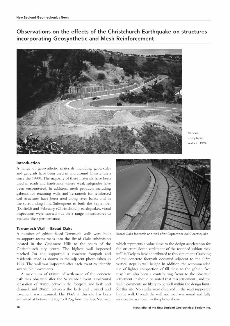
New Zealand Geomechanics News
68 Newsletter of the New Zealand Geotechnical Society Inc.
introductionA range of geosynthetic materials including geotextiles and geogrids have been used in and around Christchurch since the 1990’s. The majority of these materials have been used in roads and hardstands where weak subgrades have been encountered. In addition, mesh products including gabions for retaining walls and Terramesh for reinforced soil structures have been used along river banks and in the surrounding hills. Subsequent to both the September (Darfield) and February (Christchurch) earthquakes, visual inspections were carried out on a range of structures to evaluate their performance.
terramesh Wall – Broad oaksA number of gabion faced Terramesh walls were built to support access roads into the Broad Oaks subdivision located in the Cashmere Hills to the south of the Christchurch city centre. The highest wall inspected reached 7m and supported a concrete footpath and residential road as shown in the adjacent photo taken in 1994. The wall was inspected after each event to identify any visible movements.
A maximum of 60mm of settlement of the concrete path was observed after the September event. Horizontal separation of 10mm between the footpath and kerb and channel, and 20mm between the kerb and channel and pavement was measured. The PGA at this site has been estimated at between 0.20g to 0.25g from the GeoNet map,
Observations on the effects of the Christchurch Earthquake on structures incorporating Geosynthetic and Mesh Reinforcement
which represents a value close to the design acceleration for the structure. Some settlement of the rounded gabion rock infill is likely to have contributed to this settlement. Cracking of the concrete footpath occurred adjacent to the 0.5m vertical steps in wall height. In addition, the recommended use of lighter compaction of fill close to the gabion face may have also been a contributing factor to the observed settlement. It should be noted that this settlement , and the wall movements are likely to be well within the design limits for this site. No cracks were observed in the road supported by the wall. Overall, the wall and road was sound and fully serviceable as shown in the photo above.
Broad Oaks footpath and wall after September 2010 earthquake
Various
completed
walls in 1994
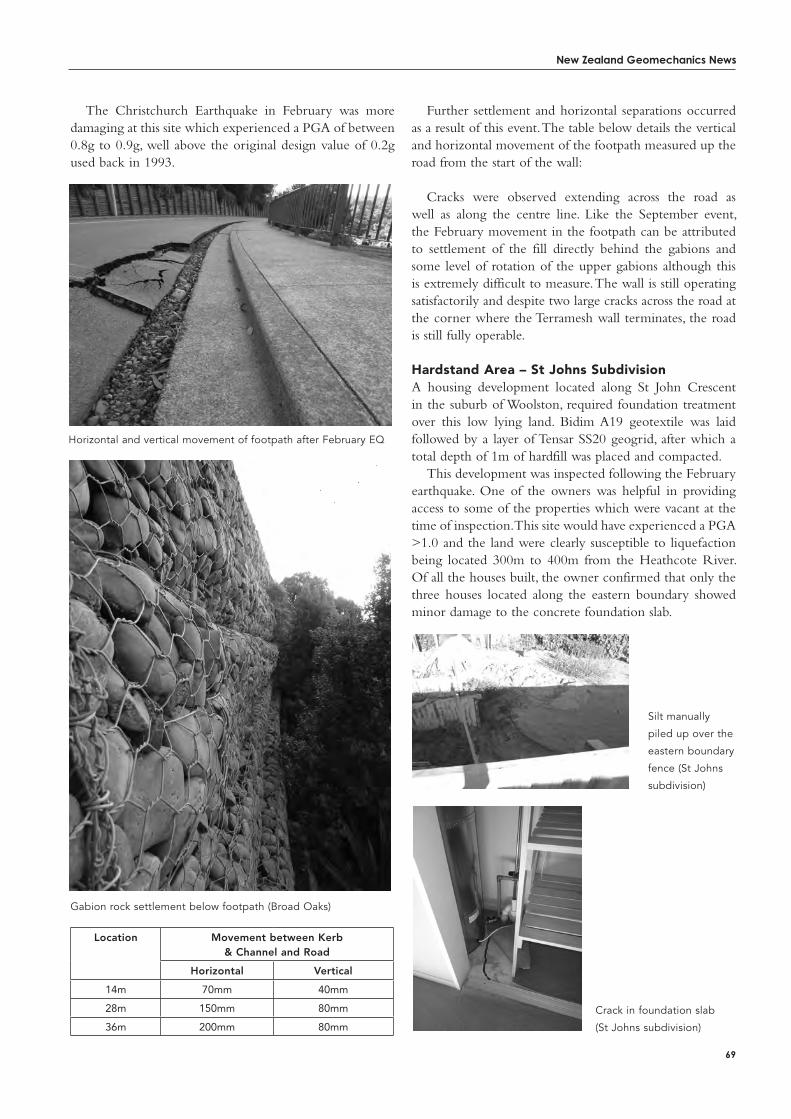
New Zealand Geomechanics News
69
The Christchurch Earthquake in February was more damaging at this site which experienced a PGA of between 0.8g to 0.9g, well above the original design value of 0.2g used back in 1993.
Location Movement between Kerb & Channel and Road
Horizontal Vertical
14m 70mm 40mm
28m 150mm 80mm
36m 200mm 80mm
Gabion rock settlement below footpath (Broad Oaks)
Horizontal and vertical movement of footpath after February EQ
Further settlement and horizontal separations occurred as a result of this event. The table below details the vertical and horizontal movement of the footpath measured up the road from the start of the wall:
Cracks were observed extending across the road as well as along the centre line. Like the September event, the February movement in the footpath can be attributed to settlement of the fill directly behind the gabions and some level of rotation of the upper gabions although this is extremely difficult to measure. The wall is still operating satisfactorily and despite two large cracks across the road at the corner where the Terramesh wall terminates, the road is still fully operable.
Hardstand area – St Johns SubdivisionA housing development located along St John Crescent in the suburb of Woolston, required foundation treatment over this low lying land. Bidim A19 geotextile was laid followed by a layer of Tensar SS20 geogrid, after which a total depth of 1m of hardfill was placed and compacted.
This development was inspected following the February earthquake. One of the owners was helpful in providing access to some of the properties which were vacant at the time of inspection. This site would have experienced a PGA >1.0 and the land were clearly susceptible to liquefaction being located 300m to 400m from the Heathcote River. Of all the houses built, the owner confirmed that only the three houses located along the eastern boundary showed minor damage to the concrete foundation slab.
Silt manually
piled up over the
eastern boundary
fence (St Johns
subdivision)
Crack in foundation slab
(St Johns subdivision)
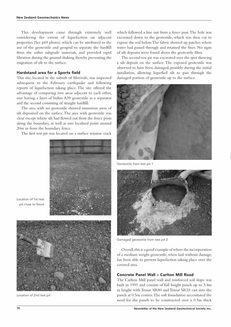
New Zealand Geomechanics News
70 Newsletter of the New Zealand Geotechnical Society Inc.
This development came through extremely well considering the extent of liquefaction on adjacent properties (See p69 photo), which can be attributed to the use of the geotextile and geogrid to separate the hardfill from the softer subgrade materials, and provided rapid filtration during the ground shaking thereby preventing the migration of silt to the surface.
Hardstand area for a Sports fieldThis site, located in the suburb of Merivale, was inspected subsequent to the February earthquake and following reports of liquefaction taking place. The site offered the advantage of comparing two areas adjacent to each other, one having a layer of bidim A39 geotextile as a separator and the second consisting of straight hardfill.
The area with no geotextile showed numerous areas of silt deposited on the surface. The area with geotextile was clear except where silt had flowed out from the fence posts along the boundary, as well as one localised point around 20m in from the boundary fence.
The first test pit was located on a surface tension crack
Location of 1st test
pit close to fence
Location of 2nd test pit
which followed a line out from a fence post. The hole was excavated down to the geotextile, which was then cut to expose the soil below. The fabric showed up patches where water had passed through and retained the fines. No signs of silt deposits were found above the geotextile filter.
The second test pit was excavated over the spot showing a silt deposit on the surface. The exposed geotextile was observed to have been damaged, possibly during the initial installation, allowing liquefied silt to pass through the damaged portion of geotextile up to the surface.
Geotextile from test pit 1
Damaged geotextile from test pit 2
Overall, this is a good example of where the incorporation of a medium weight geotextile, when laid without damage, has been able to prevent liquefaction taking place over the covered area.
Concrete Panel Wall – Carlton Mill roadThe Carlton Mill panel wall and reinforced soil slope was built in 1991 and consists of full height panels up to 3.4m in height with Tensar SR80 and Tensar SR55 cast into the panels at 0.5m centres. The soft foundation necessitated the need for the panels to be constructed over a 0.5m thick

NZ Geotechnical Society 2011Photo coMpetitioN
The winning photo will be printed in the December 2011 issue of the NZ Geomechanics News and put onto the Society web page.
SEND YOUR ENTRY TO:• NZ Geomechanics News Editor,
Paul Salter, URS Centre, PO Box 821, Auckland
1140
• email to: [email protected]
(send as jpgs)
• Entries close 28 October 2011
• Clearly mark your entry with your name and
provide a caption for your photo
CONDITIONS OF ENTRY:1. Only amateur photographers may enter.
2. Photos must be taken by the entrant.
3. No computer generated pictures.
4. Any photographs received may be published
in subsequent NZ Geotechnical Society publications and material.
5. Winning entries will be final and no correspondence will be entered into.
6. NZ Geotechnical Society members only may enter.
WiN $250
The 2011 theme is:
…you don’t see that every day!
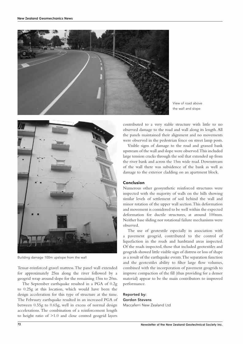
New Zealand Geomechanics News
72 Newsletter of the New Zealand Geotechnical Society Inc.
Tensar-reinforced gravel mattress. The panel wall extended for approximately 25m along the river followed by a geogrid wrap around slope for the remaining 15m to 20m.
The September earthquake resulted in a PGA of 0.2g to 0.25g at this location, which would have been the design acceleration for this type of structure at the time. The February earthquake resulted in an increased PGA of between 0.55g to 0.65g, well in excess of normal design accelerations. The combination of a reinforcement length to height ratio of >1.0 and close centred geogrid layers
contributed to a very stable structure with little to no observed damage to the road and wall along its length. All the panels maintained their alignment and no movements were observed in the pedestrian fence on street lamp posts.
Visible signs of damage to the road and grassed bank upstream of the wall and slope were observed. This included large tension cracks through the soil that extended up from the river bank and across the 15m wide road. Downstream of the wall there was subsidence of the bank as well as damage to the exterior cladding on an apartment block.
ConclusionNumerous other geosynthetic reinforced structures were inspected with the majority of walls on the hills showing similar levels of settlement of soil behind the wall and minor rotation of the upper wall section. This deformation and movement is considered to be well within the expected deformation for ductile structures, at around 100mm. Neither base sliding nor rotational failure mechanisms were observed.
The use of geotextile especially in association with a pavement geogrid, contributed to the control of liquefaction in the roads and hardstand areas inspected. Of the roads inspected, those that included geotextiles and geogrids showed little visible sign of distress or loss of shape as a result of the earthquake events. The separation function and the geotextiles ability to filter large flow volumes, combined with the incorporation of pavement geogrids to improve compaction of the fill (thus providing for a denser material) appear to be the main contributors to improved performance.
Reported by:Gordon StevensMaccaferri New Zealand Ltd
View of road above
the wall and slope
Building damage 100m upslope from the wall
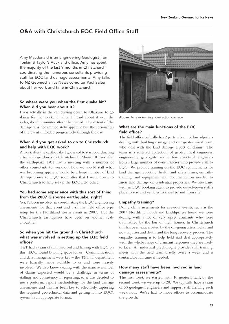
New Zealand Geomechanics News
73
Amy Macdonald is an Engineering Geologist from Tonkin & Taylor’s Auckland office. Amy has spent the majority of the last 9 months in Christchurch, coordinating the numerous consultants providing staff for EQC land damage assessments. Amy talks to NZ Geomechanics News co-editor Paul Salter about her work and time in Christchurch.
So where were you when the first quake hit? When did you hear about it?I was actually in the car, driving down to Ohakune to go skiing for the weekend when I heard about it over the radio, about 5 minutes after it happened. The extent of the damage was not immediately apparent but the seriousness of the event unfolded progressively through the day.
When did you get asked to go to Christchurch and help with EQC work?A week after the earthquake I got asked to start coordinating a team to go down to Christchurch. About 10 days after the earthquake T&T had a meeting with a number of other consultants to work out how we would staff what was becoming apparent would be a huge number of land damage claims to EQC, soon after that I went down to Christchurch to help set up the EQC field office.
You had some experience with this sort of thing from the 2007 Gisborne earthquake, right?Yes, I’d been involved in coordinating the EQC engineering assessments for that event and a similar field office type setup for the Northland storm events in 2007. But the Christchurch earthquakes have been on another scale altogether.
So when you hit the ground in Christchurch, what was involved in setting up the EQC field office?T&T had a team of staff involved and liaising with EQC on this. EQC found building space for us. Communications and data management were key – the T&T IT department were basically made available to us and were heavily involved. We also knew dealing with the massive number of claims expected would be a challenge in terms of staffing and consistency in reporting, so it was decided to use a proforma report methodology for the land damage assessments and this has been key to effectively capturing the required geotechnical data and getting it into EQC’s system in an appropriate format.
Q&A with Christchurch EQC Field Office Staff
What are the main functions of the EQC field office?The field office basically has 2 parts, a team of loss adjusters dealing with building damage and our geotechnical team, who deal with the land damage aspect of claims. The team is a rostered collection of geotechnical engineers, engineering geologists, and a few structural engineers from a large number of consultancies who provide staff to EQC. We provide training on the EQC requirements for land damage reporting, health and safety issues, empathy training, and equipment and documentation needed to assess land damage on residential properties. We also liaise with an EQC booking agent to provide out-of-town staff a place to stay and vehicles to travel to and from site.
Empathy training?Doing claim assessments for previous events, such as the 2007 Northland floods and landslips, we found we were dealing with a lot of very upset claimants who were traumatised by the loss of their homes. In Christchurch this has been exacerbated by the on-going aftershocks, and now injuries and death, and the long recovery process. The empathy training is to help field staff deal appropriately with the whole range of claimant responses they are likely to face. An industrial psychologist provides staff training, meets with the field team briefly twice a week, and is contactable full time if needed.
How many staff have been involved in land damage assessments? The first week we started with 10 geotech staff, by the second week we were up to 20. We typically have a team of 50 geologists, engineers and support staff arriving each week now. We’ve had to move offices to accommodate the growth.
Above: Amy examining liquefaction damage
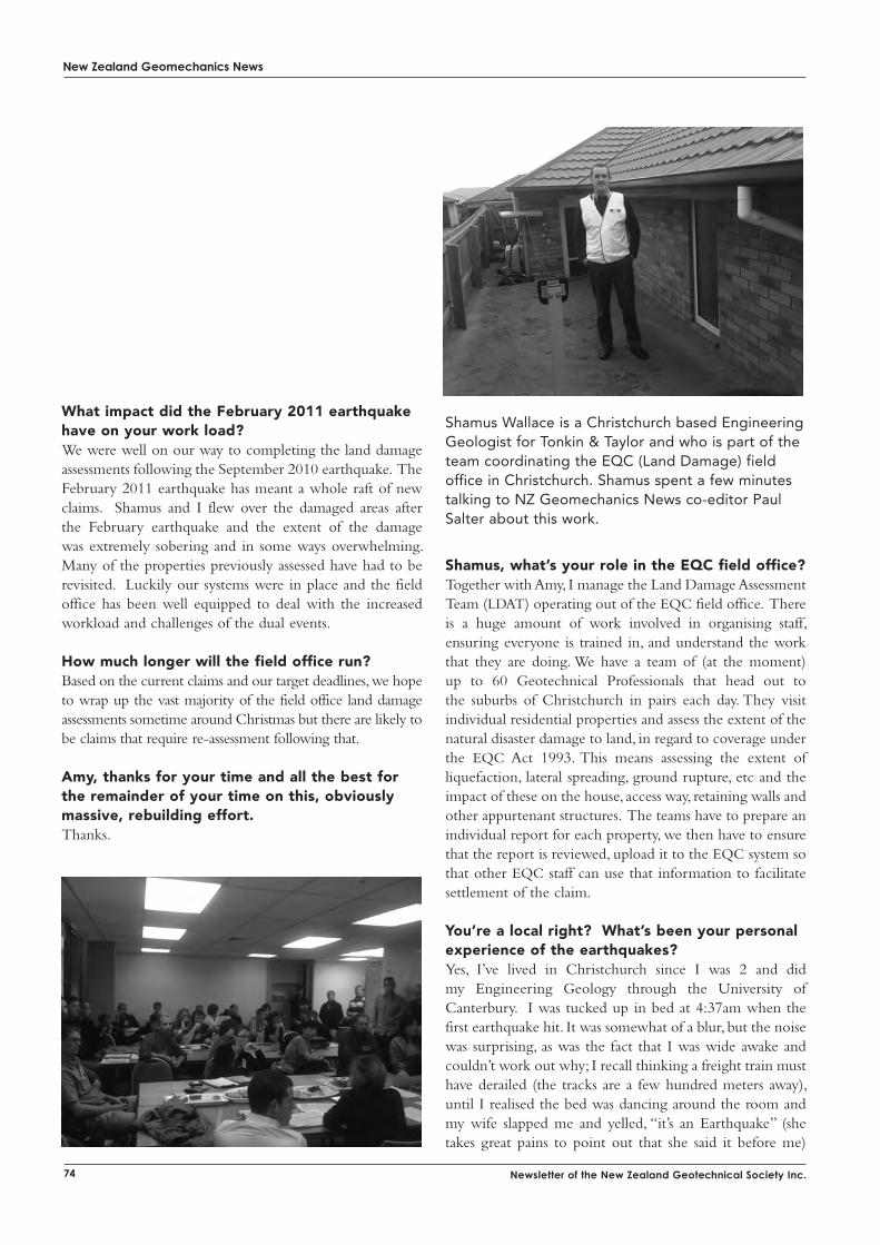
New Zealand Geomechanics News
74 Newsletter of the New Zealand Geotechnical Society Inc.
What impact did the February 2011 earthquake have on your work load?We were well on our way to completing the land damage assessments following the September 2010 earthquake. The February 2011 earthquake has meant a whole raft of new claims. Shamus and I flew over the damaged areas after the February earthquake and the extent of the damage was extremely sobering and in some ways overwhelming. Many of the properties previously assessed have had to be revisited. Luckily our systems were in place and the field office has been well equipped to deal with the increased workload and challenges of the dual events.
How much longer will the field office run?Based on the current claims and our target deadlines, we hope to wrap up the vast majority of the field office land damage assessments sometime around Christmas but there are likely to be claims that require re-assessment following that.
amy, thanks for your time and all the best for the remainder of your time on this, obviously massive, rebuilding effort.Thanks.
Shamus Wallace is a Christchurch based Engineering Geologist for Tonkin & Taylor and who is part of the team coordinating the EQC (Land Damage) field office in Christchurch. Shamus spent a few minutes talking to NZ Geomechanics News co-editor Paul Salter about this work.
Shamus, what’s your role in the EQC field office? Together with Amy, I manage the Land Damage Assessment Team (LDAT) operating out of the EQC field office. There is a huge amount of work involved in organising staff, ensuring everyone is trained in, and understand the work that they are doing. We have a team of (at the moment) up to 60 Geotechnical Professionals that head out to the suburbs of Christchurch in pairs each day. They visit individual residential properties and assess the extent of the natural disaster damage to land, in regard to coverage under the EQC Act 1993. This means assessing the extent of liquefaction, lateral spreading, ground rupture, etc and the impact of these on the house, access way, retaining walls and other appurtenant structures. The teams have to prepare an individual report for each property, we then have to ensure that the report is reviewed, upload it to the EQC system so that other EQC staff can use that information to facilitate settlement of the claim.
You’re a local right? What’s been your personal experience of the earthquakes?Yes, I’ve lived in Christchurch since I was 2 and did my Engineering Geology through the University of Canterbury. I was tucked up in bed at 4:37am when the first earthquake hit. It was somewhat of a blur, but the noise was surprising, as was the fact that I was wide awake and couldn’t work out why; I recall thinking a freight train must have derailed (the tracks are a few hundred meters away), until I realised the bed was dancing around the room and my wife slapped me and yelled, “it’s an Earthquake” (she takes great pains to point out that she said it before me)
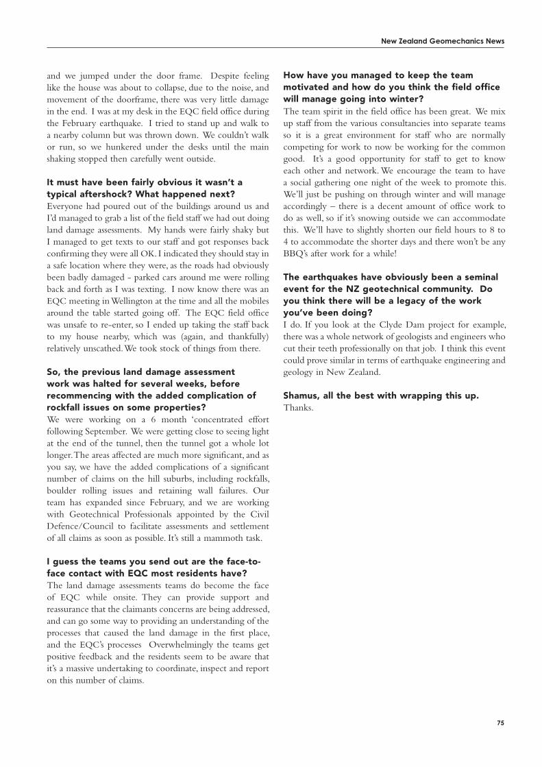
New Zealand Geomechanics News
75
and we jumped under the door frame. Despite feeling like the house was about to collapse, due to the noise, and movement of the doorframe, there was very little damage in the end. I was at my desk in the EQC field office during the February earthquake. I tried to stand up and walk to a nearby column but was thrown down. We couldn’t walk or run, so we hunkered under the desks until the main shaking stopped then carefully went outside.
it must have been fairly obvious it wasn’t a typical aftershock? What happened next?Everyone had poured out of the buildings around us and I’d managed to grab a list of the field staff we had out doing land damage assessments. My hands were fairly shaky but I managed to get texts to our staff and got responses back confirming they were all OK. I indicated they should stay in a safe location where they were, as the roads had obviously been badly damaged - parked cars around me were rolling back and forth as I was texting. I now know there was an EQC meeting in Wellington at the time and all the mobiles around the table started going off. The EQC field office was unsafe to re-enter, so I ended up taking the staff back to my house nearby, which was (again, and thankfully) relatively unscathed. We took stock of things from there.
So, the previous land damage assessment work was halted for several weeks, before recommencing with the added complication of rockfall issues on some properties? We were working on a 6 month ‘concentrated effort following September. We were getting close to seeing light at the end of the tunnel, then the tunnel got a whole lot longer. The areas affected are much more significant, and as you say, we have the added complications of a significant number of claims on the hill suburbs, including rockfalls, boulder rolling issues and retaining wall failures. Our team has expanded since February, and we are working with Geotechnical Professionals appointed by the Civil Defence/Council to facilitate assessments and settlement of all claims as soon as possible. It’s still a mammoth task.
i guess the teams you send out are the face-to-face contact with EQC most residents have? The land damage assessments teams do become the face of EQC while onsite. They can provide support and reassurance that the claimants concerns are being addressed, and can go some way to providing an understanding of the processes that caused the land damage in the first place, and the EQC’s processes Overwhelmingly the teams get positive feedback and the residents seem to be aware that it’s a massive undertaking to coordinate, inspect and report on this number of claims.
How have you managed to keep the team motivated and how do you think the field office will manage going into winter?The team spirit in the field office has been great. We mix up staff from the various consultancies into separate teams so it is a great environment for staff who are normally competing for work to now be working for the common good. It’s a good opportunity for staff to get to know each other and network. We encourage the team to have a social gathering one night of the week to promote this. We’ll just be pushing on through winter and will manage accordingly – there is a decent amount of office work to do as well, so if it’s snowing outside we can accommodate this. We’ll have to slightly shorten our field hours to 8 to 4 to accommodate the shorter days and there won’t be any BBQ’s after work for a while!
the earthquakes have obviously been a seminal event for the NZ geotechnical community. Do you think there will be a legacy of the work you’ve been doing? I do. If you look at the Clyde Dam project for example, there was a whole network of geologists and engineers who cut their teeth professionally on that job. I think this event could prove similar in terms of earthquake engineering and geology in New Zealand.
Shamus, all the best with wrapping this up.Thanks.
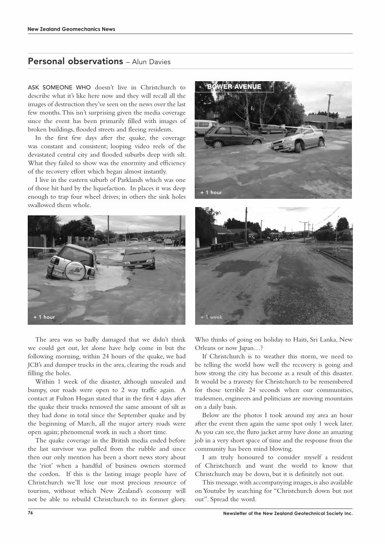
New Zealand Geomechanics News
76 Newsletter of the New Zealand Geotechnical Society Inc.
Personal observations – Alun Davies
Ask someone Who doesn’t live in Christchurch to describe what it’s like here now and they will recall all the images of destruction they’ve seen on the news over the last few months. This isn’t surprising given the media coverage since the event has been primarily filled with images of broken buildings, flooded streets and fleeing residents.
In the first few days after the quake, the coverage was constant and consistent; looping video reels of the devastated central city and flooded suburbs deep with silt. What they failed to show was the enormity and efficiency of the recovery effort which began almost instantly.
I live in the eastern suburb of Parklands which was one of those hit hard by the liquefaction. In places it was deep enough to trap four wheel drives; in others the sink holes swallowed them whole.
The area was so badly damaged that we didn’t think we could get out, let alone have help come in but the following morning, within 24 hours of the quake, we had JCB’s and dumper trucks in the area, clearing the roads and filling the holes.
Within 1 week of the disaster, although unsealed and bumpy, our roads were open to 2 way traffic again. A contact at Fulton Hogan stated that in the first 4 days after the quake their trucks removed the same amount of silt as they had done in total since the September quake and by the beginning of March, all the major artery roads were open again; phenomenal work in such a short time.
The quake coverage in the British media ended before the last survivor was pulled from the rubble and since then our only mention has been a short news story about the ‘riot’ when a handful of business owners stormed the cordon. If this is the lasting image people have of Christchurch we’ll lose our most precious resource of tourism, without which New Zealand’s economy will not be able to rebuild Christchurch to its former glory.
Who thinks of going on holiday to Haiti, Sri Lanka, New Orleans or now Japan…?
If Christchurch is to weather this storm, we need to be telling the world how well the recovery is going and how strong the city has become as a result of this disaster. It would be a travesty for Christchurch to be remembered for those terrible 24 seconds when our communities, tradesmen, engineers and politicians are moving mountains on a daily basis.
Below are the photos I took around my area an hour after the event then again the same spot only 1 week later. As you can see, the fluro jacket army have done an amazing job in a very short space of time and the response from the community has been mind blowing.
I am truly honoured to consider myself a resident of Christchurch and want the world to know that Christchurch may be down, but it is definitely not out.
This message, with accompanying images, is also available on Youtube by searching for “Christchurch down but not out”. Spread the word.
boWer aveNue
+ 1 hour
+ 1 week+ 1 hour
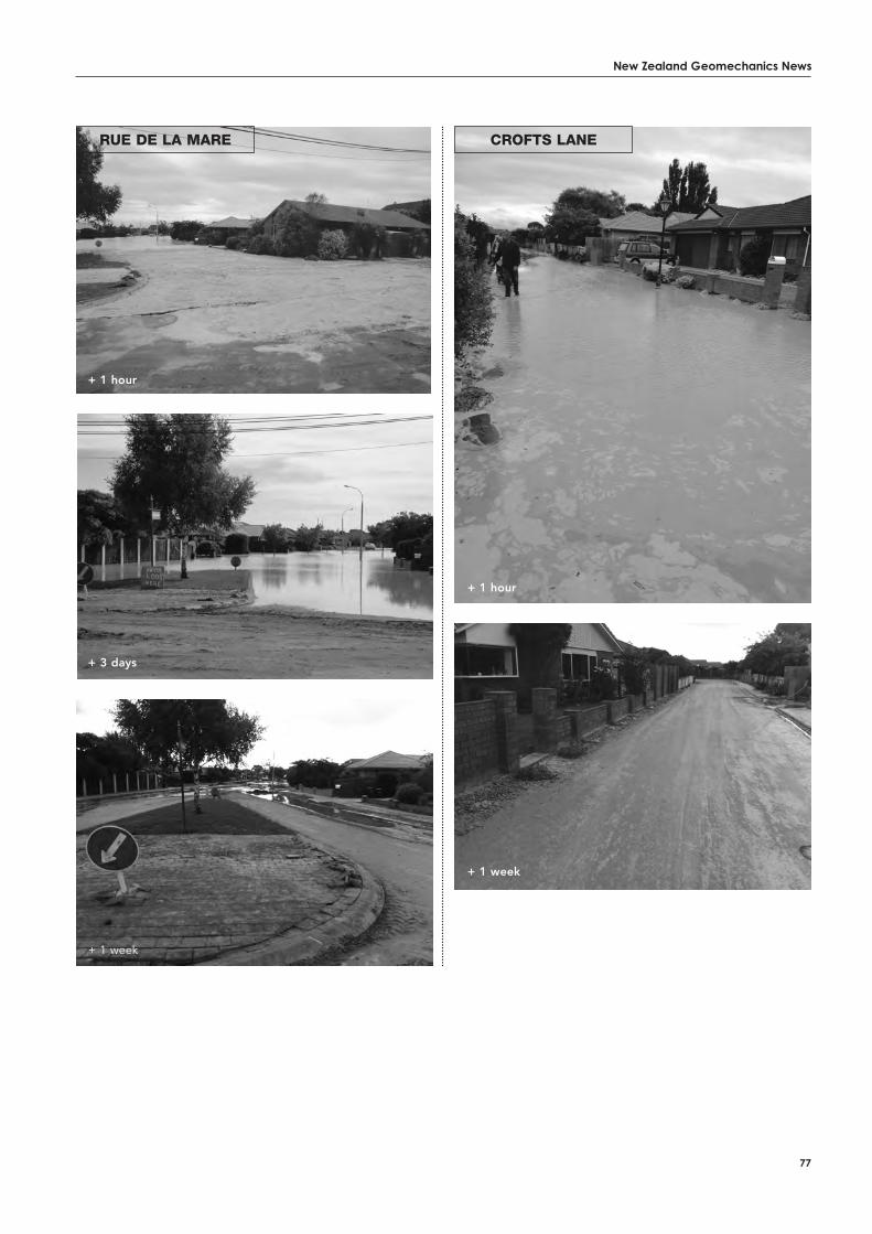
New Zealand Geomechanics News
77
rue de la Mare croftS laNe
+ 1 hour
+ 1 week
+ 1 hour
+ 3 days
+ 1 week
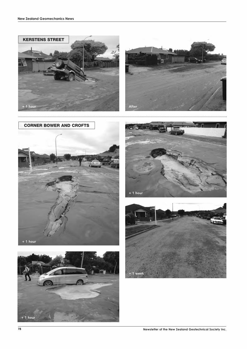
New Zealand Geomechanics News
78 Newsletter of the New Zealand Geotechnical Society Inc.
KerSteNS Street
corNer boWer aNd croftS
+ 1 hour
+ 1 hour After
+ 1 hour
+ 1 hour
+ 1 week
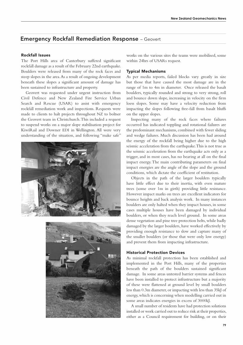
New Zealand Geomechanics News
79
rockfall issuesThe Port Hills area of Canterbury suffered significant rockfall damage as a result of the February 22nd earthquake. Boulders were released from many of the rock faces and steep slopes in the area. As a result of ongoing development beneath these slopes a significant amount of damage has been sustained to infrastructure and property.
Geovert was requested under urgent instruction from Civil Defence and New Zealand Fire Service Urban Search and Rescue (USAR) to assist with emergency rockfall remediation work and inspections. Requests were made to clients to halt projects throughout NZ to boltser the Geovert team in Christchurch. This included a request to suspend works on a major slope stabilisation project for KiwiRail and Downer EDI in Wellington. All were very understanding of the situation, and following “make safe”
Emergency Rockfall Remediation Response – Geovert
works on the various sites the teams were mobilised, some within 24hrs of USARs request.
typical MechanismsAs per media reports, failed blocks vary greatly in size but those that have caused the most damage are in the range of 1m to 4m in diameter. Once released the basalt boulders, typically rounded and strong to very strong, roll and bounce down slope, increasing in velocity on the firm loess slopes. Some may have a velocity reduction from impacting the slopes following free-fall from basalt bluffs on the upper slopes.
Inspecting many of the rock faces where failures occurred has indicated toppling and rotational failures are the predominant mechanisms, combined with fewer sliding and wedge failures. Much discussion has been had around the energy of the rockfall being higher due to the high seismic acceleration from the earthquake. This is not true as the seismic acceleration from the earthquake acts only as a trigger, and in most cases, has no bearing at all on the final impact energy. The main contributing parameters on final impact energies are the angle of the slope and the ground conditions, which dictate the coefficient of restitution.
Objects in the path of the larger boulders typically have little effect due to their inertia, with even mature trees (some over 1m in girth) providing little resistance. However impact marks on trees are excellent indicators for bounce heights and back analysis work. In many instances boulders are only halted when they impact houses, in some cases multiple houses have been damaged by individual boulders, or when they reach level ground. In some areas dense vegetation and pine tree protection belts, while badly damaged by the larger boulders, have worked effectively by providing enough resistance to slow and capture many of the smaller boulders (or those that were only low energy) and prevent them from impacting infrastructure.
Historical Protection DevicesAs minimal rockfall protection has been established and implemented in the Port Hills, many of the properties beneath the path of the boulders sustained significant damage. In some areas untested barrier systems and fences have been installed to protect infrastructure but a majority of these were flattened at ground level by small boulders less than 0.3m diameter, or impacting with less than 35kJ of energy, which is concerning when modelling carried out in some areas indicates energies in excess of 3000kJ.
A small number of residents have had protection solutions installed or work carried out to reduce risk at their properties, either as a Council requirement for building, or on their
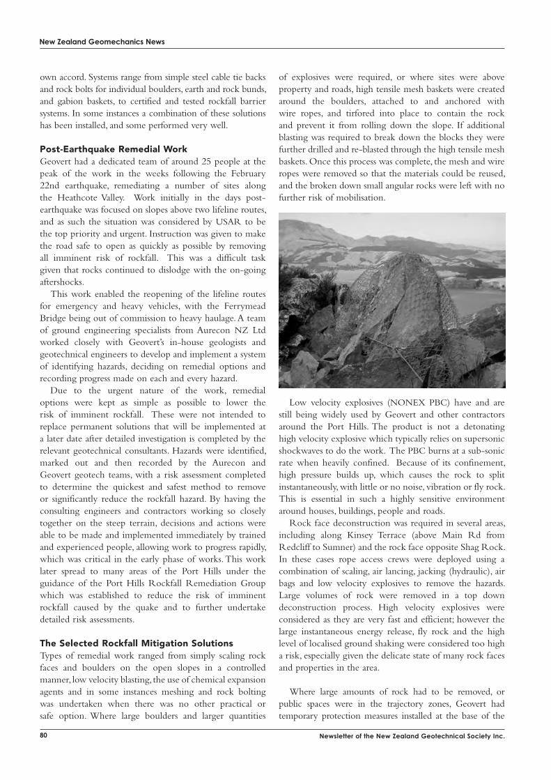
New Zealand Geomechanics News
80 Newsletter of the New Zealand Geotechnical Society Inc.
own accord. Systems range from simple steel cable tie backs and rock bolts for individual boulders, earth and rock bunds, and gabion baskets, to certified and tested rockfall barrier systems. In some instances a combination of these solutions has been installed, and some performed very well.
Post-Earthquake remedial WorkGeovert had a dedicated team of around 25 people at the peak of the work in the weeks following the February 22nd earthquake, remediating a number of sites along the Heathcote Valley. Work initially in the days post-earthquake was focused on slopes above two lifeline routes, and as such the situation was considered by USAR to be the top priority and urgent. Instruction was given to make the road safe to open as quickly as possible by removing all imminent risk of rockfall. This was a difficult task given that rocks continued to dislodge with the on-going aftershocks.
This work enabled the reopening of the lifeline routes for emergency and heavy vehicles, with the Ferrymead Bridge being out of commission to heavy haulage. A team of ground engineering specialists from Aurecon NZ Ltd worked closely with Geovert’s in-house geologists and geotechnical engineers to develop and implement a system of identifying hazards, deciding on remedial options and recording progress made on each and every hazard.
Due to the urgent nature of the work, remedial options were kept as simple as possible to lower the risk of imminent rockfall. These were not intended to replace permanent solutions that will be implemented at a later date after detailed investigation is completed by the relevant geotechnical consultants. Hazards were identified, marked out and then recorded by the Aurecon and Geovert geotech teams, with a risk assessment completed to determine the quickest and safest method to remove or significantly reduce the rockfall hazard. By having the consulting engineers and contractors working so closely together on the steep terrain, decisions and actions were able to be made and implemented immediately by trained and experienced people, allowing work to progress rapidly, which was critical in the early phase of works. This work later spread to many areas of the Port Hills under the guidance of the Port Hills Rockfall Remediation Group which was established to reduce the risk of imminent rockfall caused by the quake and to further undertake detailed risk assessments.
the Selected rockfall Mitigation SolutionsTypes of remedial work ranged from simply scaling rock faces and boulders on the open slopes in a controlled manner, low velocity blasting, the use of chemical expansion agents and in some instances meshing and rock bolting was undertaken when there was no other practical or safe option. Where large boulders and larger quantities
of explosives were required, or where sites were above property and roads, high tensile mesh baskets were created around the boulders, attached to and anchored with wire ropes, and tirfored into place to contain the rock and prevent it from rolling down the slope. If additional blasting was required to break down the blocks they were further drilled and re-blasted through the high tensile mesh baskets. Once this process was complete, the mesh and wire ropes were removed so that the materials could be reused, and the broken down small angular rocks were left with no further risk of mobilisation.
Low velocity explosives (NONEX PBC) have and are still being widely used by Geovert and other contractors around the Port Hills. The product is not a detonating high velocity explosive which typically relies on supersonic shockwaves to do the work. The PBC burns at a sub-sonic rate when heavily confined. Because of its confinement, high pressure builds up, which causes the rock to split instantaneously, with little or no noise, vibration or fly rock. This is essential in such a highly sensitive environment around houses, buildings, people and roads.
Rock face deconstruction was required in several areas, including along Kinsey Terrace (above Main Rd from Redcliff to Sumner) and the rock face opposite Shag Rock. In these cases rope access crews were deployed using a combination of scaling, air lancing, jacking (hydraulic), air bags and low velocity explosives to remove the hazards. Large volumes of rock were removed in a top down deconstruction process. High velocity explosives were considered as they are very fast and efficient; however the large instantaneous energy release, fly rock and the high level of localised ground shaking were considered too high a risk, especially given the delicate state of many rock faces and properties in the area.
Where large amounts of rock had to be removed, or public spaces were in the trajectory zones, Geovert had temporary protection measures installed at the base of the
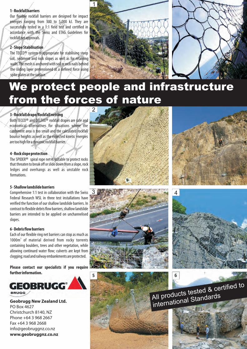
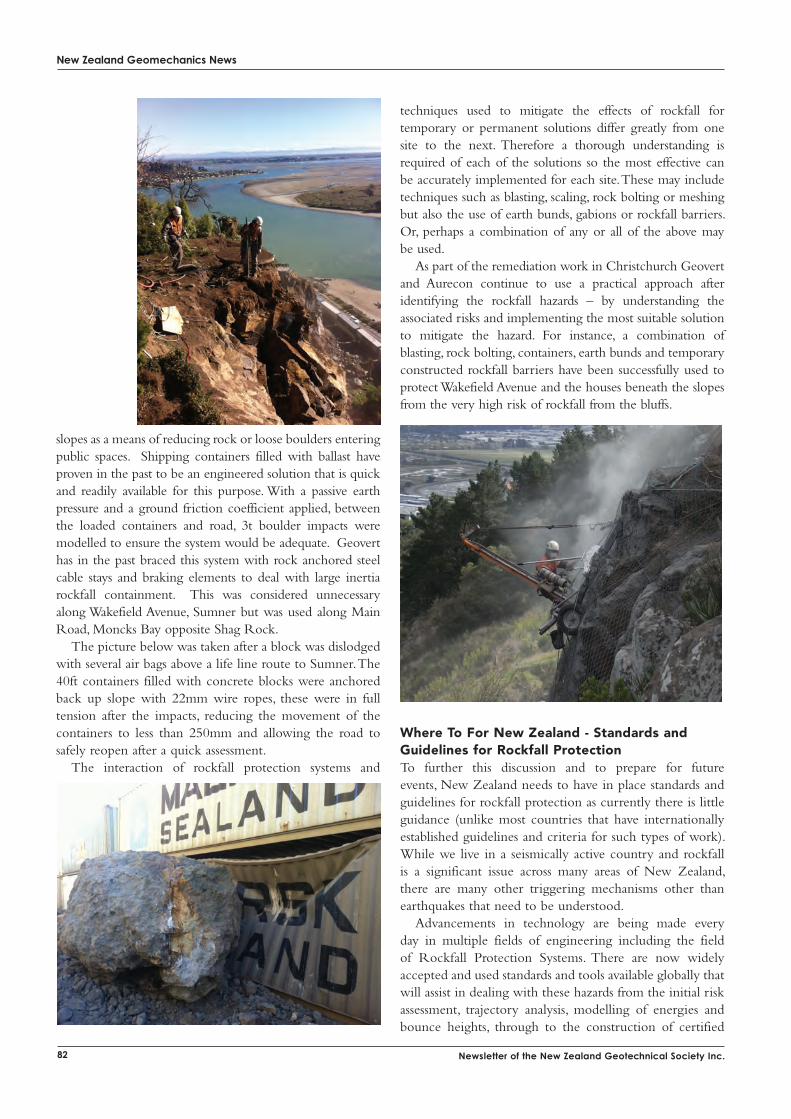
New Zealand Geomechanics News
82 Newsletter of the New Zealand Geotechnical Society Inc.
slopes as a means of reducing rock or loose boulders entering public spaces. Shipping containers filled with ballast have proven in the past to be an engineered solution that is quick and readily available for this purpose. With a passive earth pressure and a ground friction coefficient applied, between the loaded containers and road, 3t boulder impacts were modelled to ensure the system would be adequate. Geovert has in the past braced this system with rock anchored steel cable stays and braking elements to deal with large inertia rockfall containment. This was considered unnecessary along Wakefield Avenue, Sumner but was used along Main Road, Moncks Bay opposite Shag Rock.
The picture below was taken after a block was dislodged with several air bags above a life line route to Sumner. The 40ft containers filled with concrete blocks were anchored back up slope with 22mm wire ropes, these were in full tension after the impacts, reducing the movement of the containers to less than 250mm and allowing the road to safely reopen after a quick assessment.
The interaction of rockfall protection systems and
techniques used to mitigate the effects of rockfall for temporary or permanent solutions differ greatly from one site to the next. Therefore a thorough understanding is required of each of the solutions so the most effective can be accurately implemented for each site. These may include techniques such as blasting, scaling, rock bolting or meshing but also the use of earth bunds, gabions or rockfall barriers. Or, perhaps a combination of any or all of the above may be used.
As part of the remediation work in Christchurch Geovert and Aurecon continue to use a practical approach after identifying the rockfall hazards – by understanding the associated risks and implementing the most suitable solution to mitigate the hazard. For instance, a combination of blasting, rock bolting, containers, earth bunds and temporary constructed rockfall barriers have been successfully used to protect Wakefield Avenue and the houses beneath the slopes from the very high risk of rockfall from the bluffs.
Where to For New Zealand - Standards and Guidelines for rockfall ProtectionTo further this discussion and to prepare for future events, New Zealand needs to have in place standards and guidelines for rockfall protection as currently there is little guidance (unlike most countries that have internationally established guidelines and criteria for such types of work). While we live in a seismically active country and rockfall is a significant issue across many areas of New Zealand, there are many other triggering mechanisms other than earthquakes that need to be understood.
Advancements in technology are being made every day in multiple fields of engineering including the field of Rockfall Protection Systems. There are now widely accepted and used standards and tools available globally that will assist in dealing with these hazards from the initial risk assessment, trajectory analysis, modelling of energies and bounce heights, through to the construction of certified
and tested rockfall protections systems. The US (AASHTO), Europe (EOTA) and Switzerland (BAFU) all have standards and processes in place that ensure when a system is installed it will provide the level of protection that is required. Protection systems are 1:1 field tested to make sure they comply with these standards. A new European standard ETAG 027 (European Technical Approval Guideline) has recently been developed to service Europe as a whole.
Currently in New Zealand a rockfall protection system can be built with no requirement for any form of standard to be met or at the very least following readily available industry Best Practice processes. With rockfall protection systems in place throughout the country people are under the impression that these systems will be sufficient to protect them, or their property, in the event of rockfall whether induced by earthquakes or any other triggering mechanism. Some of them may work entirely appropriately, but many of them will not, as has been evidenced recently on the Port Hills.
Understanding the risk of rockfall, the damage and potential for loss of life it can cause even at low energies, and the solutions that are now available, is critical to the success of the on-going remedial works that many geotechnical consultants and contractors are undertaking around the Port Hills. Looking to the future, careful
consideration needs to be given to the selection and use of current techniques to improve the way we assess and analyse the risk the rockfall, and the protection systems we select to protect people and infrastructure from the on-going risk of rockfall throughout New Zealand.
Reported by:Paul TeenGeovert
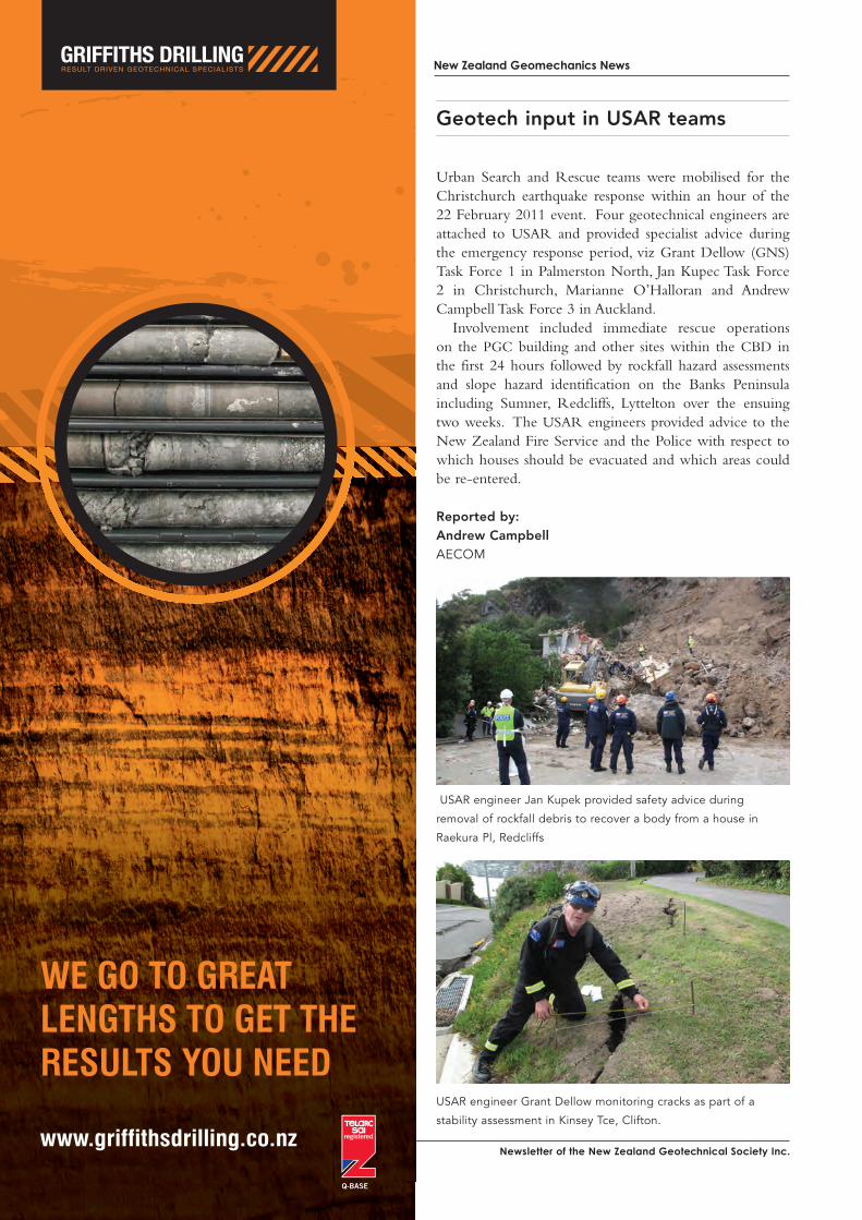
Newsletter of the New Zealand Geotechnical society inc.
New Zealand Geomechanics News
Urban Search and Rescue teams were mobilised for the Christchurch earthquake response within an hour of the 22 February 2011 event. Four geotechnical engineers are attached to USAR and provided specialist advice during the emergency response period, viz Grant Dellow (GNS) Task Force 1 in Palmerston North, Jan Kupec Task Force 2 in Christchurch, Marianne O’Halloran and Andrew Campbell Task Force 3 in Auckland.
Involvement included immediate rescue operations on the PGC building and other sites within the CBD in the first 24 hours followed by rockfall hazard assessments and slope hazard identification on the Banks Peninsula including Sumner, Redcliffs, Lyttelton over the ensuing two weeks. The USAR engineers provided advice to the New Zealand Fire Service and the Police with respect to which houses should be evacuated and which areas could be re-entered.
Reported by:Andrew CampbellAECOM
Geotech input in USAR teams
USAR engineer Jan Kupek provided safety advice during
removal of rockfall debris to recover a body from a house in
Raekura Pl, Redcliffs
USAR engineer Grant Dellow monitoring cracks as part of a
stability assessment in Kinsey Tce, Clifton.
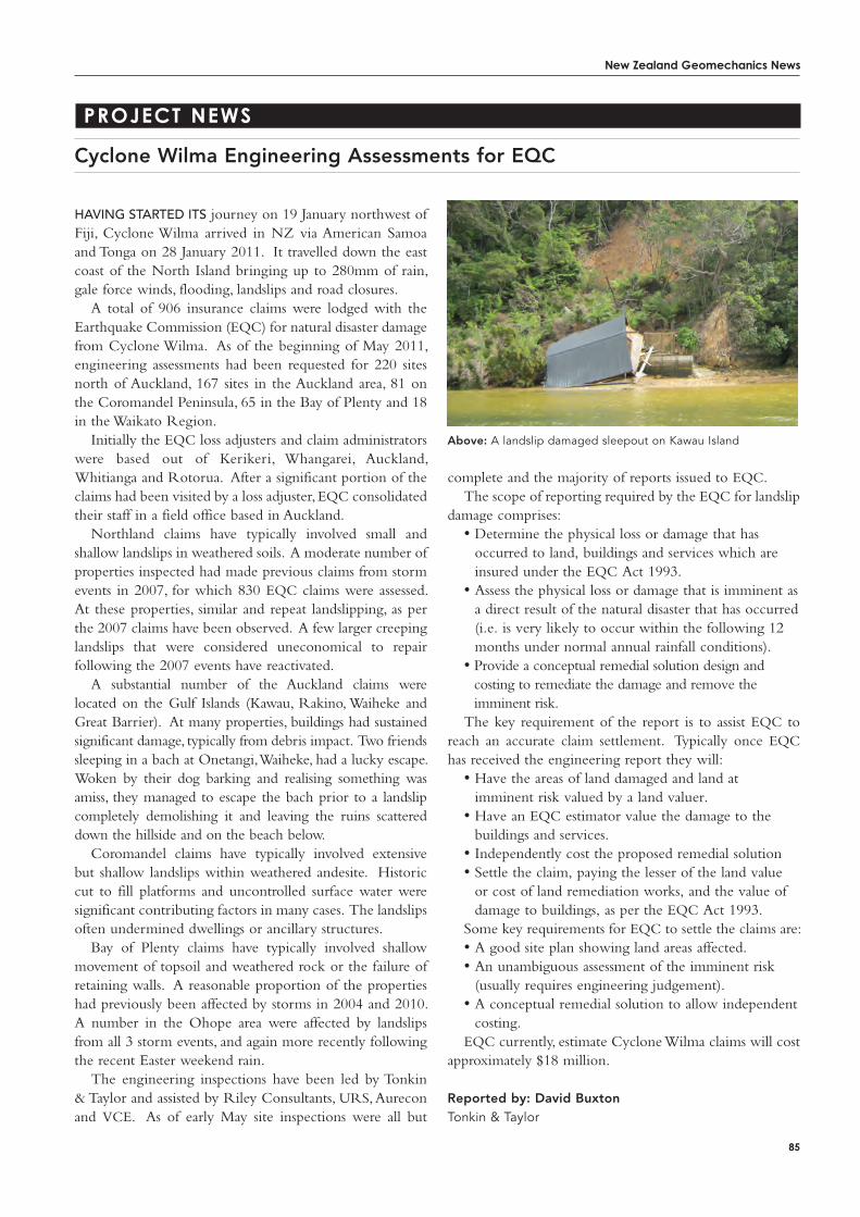
New Zealand Geomechanics News
85
PRoject News
Cyclone Wilma Engineering Assessments for EQC
complete and the majority of reports issued to EQC.The scope of reporting required by the EQC for landslip
damage comprises:• Determine the physical loss or damage that has
occurred to land, buildings and services which are insured under the EQC Act 1993.
• Assess the physical loss or damage that is imminent as a direct result of the natural disaster that has occurred (i.e. is very likely to occur within the following 12 months under normal annual rainfall conditions).
• Provide a conceptual remedial solution design and costing to remediate the damage and remove the imminent risk.
The key requirement of the report is to assist EQC to reach an accurate claim settlement. Typically once EQC has received the engineering report they will:
• Have the areas of land damaged and land at imminent risk valued by a land valuer.
• Have an EQC estimator value the damage to the buildings and services.
• Independently cost the proposed remedial solution• Settle the claim, paying the lesser of the land value
or cost of land remediation works, and the value of damage to buildings, as per the EQC Act 1993.
Some key requirements for EQC to settle the claims are:• A good site plan showing land areas affected.• An unambiguous assessment of the imminent risk
(usually requires engineering judgement).• A conceptual remedial solution to allow independent
costing.EQC currently, estimate Cyclone Wilma claims will cost
approximately $18 million.
Reported by: David BuxtonTonkin & Taylor
hAving stArted its journey on 19 January northwest of Fiji, Cyclone Wilma arrived in NZ via American Samoa and Tonga on 28 January 2011. It travelled down the east coast of the North Island bringing up to 280mm of rain, gale force winds, flooding, landslips and road closures.
A total of 906 insurance claims were lodged with the Earthquake Commission (EQC) for natural disaster damage from Cyclone Wilma. As of the beginning of May 2011, engineering assessments had been requested for 220 sites north of Auckland, 167 sites in the Auckland area, 81 on the Coromandel Peninsula, 65 in the Bay of Plenty and 18 in the Waikato Region.
Initially the EQC loss adjusters and claim administrators were based out of Kerikeri, Whangarei, Auckland, Whitianga and Rotorua. After a significant portion of the claims had been visited by a loss adjuster, EQC consolidated their staff in a field office based in Auckland.
Northland claims have typically involved small and shallow landslips in weathered soils. A moderate number of properties inspected had made previous claims from storm events in 2007, for which 830 EQC claims were assessed. At these properties, similar and repeat landslipping, as per the 2007 claims have been observed. A few larger creeping landslips that were considered uneconomical to repair following the 2007 events have reactivated.
A substantial number of the Auckland claims were located on the Gulf Islands (Kawau, Rakino, Waiheke and Great Barrier). At many properties, buildings had sustained significant damage, typically from debris impact. Two friends sleeping in a bach at Onetangi, Waiheke, had a lucky escape. Woken by their dog barking and realising something was amiss, they managed to escape the bach prior to a landslip completely demolishing it and leaving the ruins scattered down the hillside and on the beach below.
Coromandel claims have typically involved extensive but shallow landslips within weathered andesite. Historic cut to fill platforms and uncontrolled surface water were significant contributing factors in many cases. The landslips often undermined dwellings or ancillary structures.
Bay of Plenty claims have typically involved shallow movement of topsoil and weathered rock or the failure of retaining walls. A reasonable proportion of the properties had previously been affected by storms in 2004 and 2010. A number in the Ohope area were affected by landslips from all 3 storm events, and again more recently following the recent Easter weekend rain.
The engineering inspections have been led by Tonkin & Taylor and assisted by Riley Consultants, URS, Aurecon and VCE. As of early May site inspections were all but
Above: A landslip damaged sleepout on Kawau Island
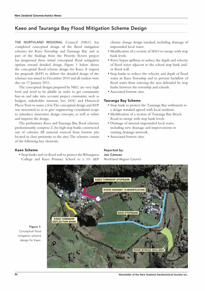
New Zealand Geomechanics News
86 Newsletter of the New Zealand Geotechnical Society Inc.
THINK IMPACT ROLLING—THINK BROONS
BROONS “SQUARE” IMPACT ROLLERRolling Dynamic Compaction
HELPING TO REBUILD CHRISTCHURCH
With a proven track record in excess of 800 projects around the world over more than 25 years, the professional team at Broons are the ground improvement specialists when it comes to Impact Rolling technology. From advice during project conception right through to site treatment, settlement monitoring and reporting we’re alongside you and your client all the way.
Available New Zealand wideTel: +61 8 8268 [email protected] www.broons.com
the northlAnd regionAl Council (NRC) has completed conceptual design of the flood mitigation schemes for Kaeo Township and Tauranga Bay and as part of the findings from the Priority Rivers project has progressed these initial conceptual flood mitigation options toward detailed design. Figure 1 below shows the conceptual flood scheme design for Kaeo. A request for proposals (RFP) to deliver the detailed design of the schemes was issued in December 2010 and all tenders were due on 17 January 2011.
The conceptual designs prepared by NRC are very high level and need to be pliable in order to get community buy-in and take into account project constraints, such as budgets, stakeholder interests, Iwi, DOC and Historical Places Trust to name a few. The conceptual design and RFP was structured so as to give engineering consultants scope to introduce innovative design concepts, as well as refine and improve the design.
The preliminary Kaeo and Tauranga Bay flood schemes predominantly comprise 2-3m high stop banks constructed out of cohesive fill material sourced from borrow pits located in close proximity to the sites. The schemes consist of the following key elements:
Kaeo Scheme• Stop banks and/or flood wall to protect the Whangaroa
College and Kaeo Primary School to a 1% AEP
Kaeo and Tauranga Bay Flood Mitigation Scheme Design
climate change design standard, including drainage of impounded local water.
• Modification of a section of SH10 to merge with stop bank levels.
• River bypass spillway to reduce the depth and velocity of flood water adjacent to the school stop bank and/or flood wall.
• Stop banks to reduce the velocity and depth of flood water in Kaeo Township and to prevent backflow of flood water from entering the area defended by stop banks between the township and schools.
• Associated borrow sites.
tauranga Bay Scheme• Stop bank to protect the Tauranga Bay settlement to
a design standard agreed with local residents. • Modification of a section of Tauranga Bay Beach
Road to merge with stop bank levels. • Drainage of internal impounded local water,
including new drainage and improvements to existing drainage network.
• Associated borrow sites.
Reported by:Joe CamusoNorthland Region Council
Figure 1:
Conceptual flood
mitigation scheme
design for Kaeo.

THINK IMPACT ROLLING—THINK BROONS
BROONS “SQUARE” IMPACT ROLLERRolling Dynamic Compaction
HELPING TO REBUILD CHRISTCHURCH
With a proven track record in excess of 800 projects around the world over more than 25 years, the professional team at Broons are the ground improvement specialists when it comes to Impact Rolling technology. From advice during project conception right through to site treatment, settlement monitoring and reporting we’re alongside you and your client all the way.
Available New Zealand wideTel: +61 8 8268 [email protected] www.broons.com
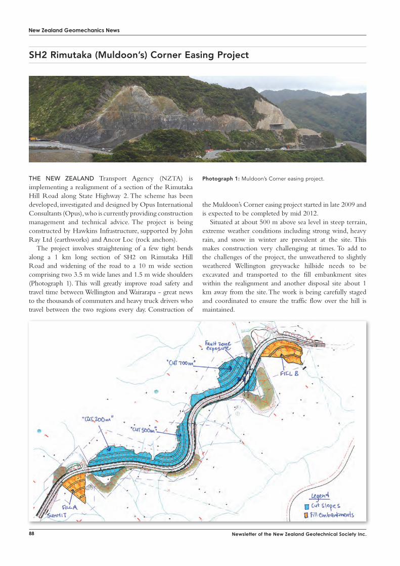
New Zealand Geomechanics News
88 Newsletter of the New Zealand Geotechnical Society Inc.
the neW ZeAlAnd Transport Agency (NZTA) is implementing a realignment of a section of the Rimutaka Hill Road along State Highway 2. The scheme has been developed, investigated and designed by Opus International Consultants (Opus), who is currently providing construction management and technical advice. The project is being constructed by Hawkins Infrastructure, supported by John Ray Ltd (earthworks) and Ancor Loc (rock anchors).
The project involves straightening of a few tight bends along a 1 km long section of SH2 on Rimutaka Hill Road and widening of the road to a 10 m wide section comprising two 3.5 m wide lanes and 1.5 m wide shoulders (Photograph 1). This will greatly improve road safety and travel time between Wellington and Wairarapa - great news to the thousands of commuters and heavy truck drivers who travel between the two regions every day. Construction of
the Muldoon’s Corner easing project started in late 2009 and is expected to be completed by mid 2012.
Situated at about 500 m above sea level in steep terrain, extreme weather conditions including strong wind, heavy rain, and snow in winter are prevalent at the site. This makes construction very challenging at times. To add to the challenges of the project, the unweathered to slightly weathered Wellington greywacke hillside needs to be excavated and transported to the fill embankment sites within the realignment and another disposal site about 1 km away from the site. The work is being carefully staged and coordinated to ensure the traffic flow over the hill is maintained.
Photograph 1: Muldoon’s Corner easing project.
SH2 Rimutaka (Muldoon’s) Corner Easing Project
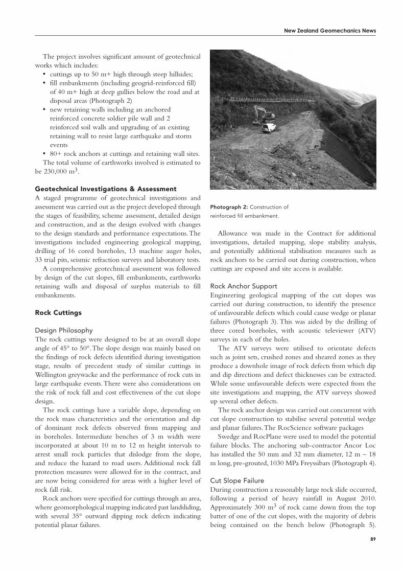
New Zealand Geomechanics News
89
The project involves significant amount of geotechnical works which includes:
• cuttings up to 50 m+ high through steep hillsides;• fill embankments (including geogrid-reinforced fill)
of 40 m+ high at deep gullies below the road and at disposal areas (Photograph 2)
• new retaining walls including an anchored reinforced concrete soldier pile wall and 2 reinforced soil walls and upgrading of an existing retaining wall to resist large earthquake and storm events
• 80+ rock anchors at cuttings and retaining wall sites.The total volume of earthworks involved is estimated to
be 230,000 m3.
Geotechnical investigations & assessmentA staged programme of geotechnical investigations and assessment was carried out as the project developed through the stages of feasibility, scheme assessment, detailed design and construction, and as the design evolved with changes to the design standards and performance expectations. The investigations included engineering geological mapping, drilling of 16 cored boreholes, 13 machine auger holes, 33 trial pits, seismic refraction surveys and laboratory tests.
A comprehensive geotechnical assessment was followed by design of the cut slopes, fill embankments, earthworks retaining walls and disposal of surplus materials to fill embankments.
rock Cuttings
Design PhilosophyThe rock cuttings were designed to be at an overall slope angle of 45° to 50°. The slope design was mainly based on the findings of rock defects identified during investigation stage, results of precedent study of similar cuttings in Wellington greywacke and the performance of rock cuts in large earthquake events. There were also considerations on the risk of rock fall and cost effectiveness of the cut slope design.
The rock cuttings have a variable slope, depending on the rock mass characteristics and the orientation and dip of dominant rock defects observed from mapping and in boreholes. Intermediate benches of 3 m width were incorporated at about 10 m to 12 m height intervals to arrest small rock particles that dislodge from the slope, and reduce the hazard to road users. Additional rock fall protection measures were allowed for in the contract, and are now being considered for areas with a higher level of rock fall risk.
Rock anchors were specified for cuttings through an area, where geomorphological mapping indicated past landsliding, with several 35° outward dipping rock defects indicating potential planar failures.
Photograph 2: Construction of
reinforced fill embankment.
Allowance was made in the Contract for additional investigations, detailed mapping, slope stability analysis, and potentially additional stabilisation measures such as rock anchors to be carried out during construction, when cuttings are exposed and site access is available.
Rock Anchor SupportEngineering geological mapping of the cut slopes was carried out during construction, to identify the presence of unfavourable defects which could cause wedge or planar failures (Photograph 3). This was aided by the drilling of three cored boreholes, with acoustic televiewer (ATV) surveys in each of the holes.
The ATV surveys were utilised to orientate defects such as joint sets, crushed zones and sheared zones as they produce a downhole image of rock defects from which dip and dip directions and defect thicknesses can be extracted. While some unfavourable defects were expected from the site investigations and mapping, the ATV surveys showed up several other defects.
The rock anchor design was carried out concurrent with cut slope construction to stabilise several potential wedge and planar failures. The RocScience software packages
Swedge and RocPlane were used to model the potential failure blocks. The anchoring sub-contractor Ancor Loc has installed the 50 mm and 32 mm diameter, 12 m – 18 m long, pre-grouted, 1030 MPa Freyssibars (Photograph 4).
Cut Slope FailureDuring construction a reasonably large rock slide occurred, following a period of heavy rainfall in August 2010. Approximately 300 m3 of rock came down from the top batter of one of the cut slopes, with the majority of debris being contained on the bench below (Photograph 5).
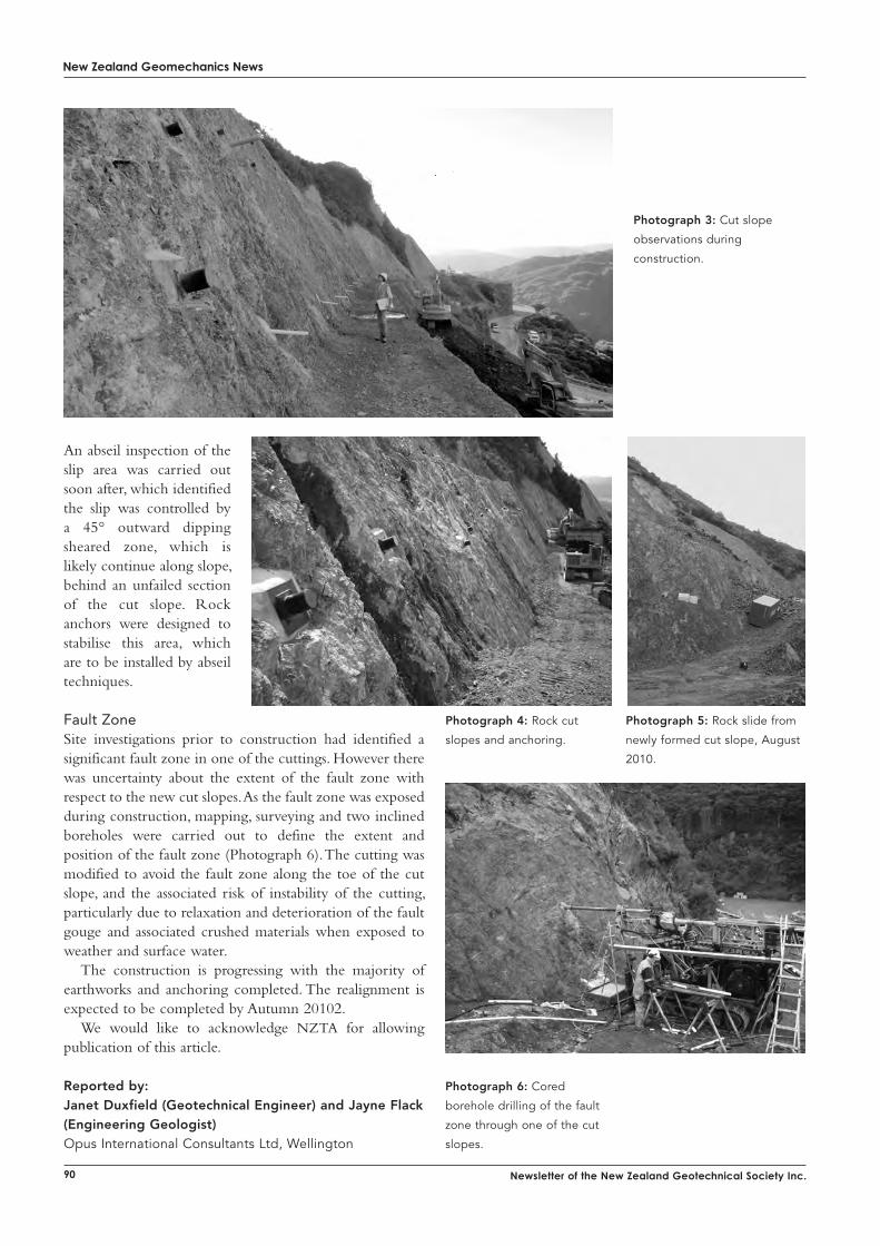
New Zealand Geomechanics News
90 Newsletter of the New Zealand Geotechnical Society Inc.
Photograph 3: Cut slope
observations during
construction.
Photograph 4: Rock cut
slopes and anchoring.
An abseil inspection of the slip area was carried out soon after, which identified the slip was controlled by a 45° outward dipping sheared zone, which is likely continue along slope, behind an unfailed section of the cut slope. Rock anchors were designed to stabilise this area, which are to be installed by abseil techniques.
Fault ZoneSite investigations prior to construction had identified a significant fault zone in one of the cuttings. However there was uncertainty about the extent of the fault zone with respect to the new cut slopes. As the fault zone was exposed during construction, mapping, surveying and two inclined boreholes were carried out to define the extent and position of the fault zone (Photograph 6). The cutting was modified to avoid the fault zone along the toe of the cut slope, and the associated risk of instability of the cutting, particularly due to relaxation and deterioration of the fault gouge and associated crushed materials when exposed to weather and surface water.
The construction is progressing with the majority of earthworks and anchoring completed. The realignment is expected to be completed by Autumn 20102.
We would like to acknowledge NZTA for allowing publication of this article.
Reported by:Janet Duxfield (Geotechnical Engineer) and Jayne Flack (Engineering Geologist)Opus International Consultants Ltd, Wellington
Photograph 5: Rock slide from
newly formed cut slope, August
2010.
Photograph 6: Cored
borehole drilling of the fault
zone through one of the cut
slopes.
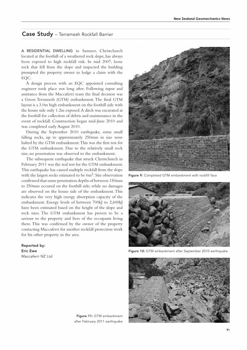
New Zealand Geomechanics News
91
Case Study – Terramesh Rockfall Barrier
A residentiAl dWelling in Sumner, Christchurch located at the foothill of a weathered rock slope, has always been exposed to high rockfall risk. In mid 2007, loose rock that fell from the slope and impacted the building prompted the property owner to lodge a claim with the EQC.
A design process with an EQC appointed consulting engineer took place not long after. Following input and assistance from the Maccaferri team the final decision was a Green Terramesh (GTM) embankment. The final GTM layout is a 3.0m high embankment on the foothill side with the house side only 1.2m exposed. A ditch was excavated at the foothill for collection of debris and maintenance in the event of rockfall. Construction began mid-June 2010 and was completed early August 2010.
During the September 2010 earthquake, some small falling rocks, up to approximately 250mm in size were halted by the GTM embankment. This was the first test for the GTM embankment. Due to the relatively small rock size, no penetration was observed to the embankment.
The subsequent earthquake that struck Christchurch in February 2011 was the real test for the GTM embankment. This earthquake has caused multiple rockfall from the slope with the largest rocks estimated to be 6m3. Site observation confirmed that some penetration depths of between 150mm to 250mm occured on the foothill side; while no damages are observed on the house side of the embankment. This indicates the very high energy absorption capacity of the embankment. Energy levels of between 700kJ to 2,600kJ have been estimated based on the height of the slope and rock sizes. The GTM embankment has proven to be a saviour to the property and lives of the occupants living there. This was confirmed by the owner of the property contacting Maccaferri for another rockfall protection work for his other property in the area.
Reported by: Eric Ewe Maccaferri NZ Ltd
Figure 11: GTM embankment
after February 2011 earthquake
Figure 10: GTM embankment after September 2010 earthquake
Figure 9: Completed GTM embankment with rockfill face
New Zealand Geomechanics News
92 Newsletter of the New Zealand Geotechnical Society Inc.
Upfront in Auckland – The Newmarket Connection: Viaduct Replacement Project – Robert Hillier and Michael Wulff - NGA Newmarket (Alliance)
introduction
in the december 2009 issue of NZ Geomechanics News we provided a brief overview of progress on the high profile Newmarket Viaduct replacement project. In this article we provide some further details and insights into the ground conditions associated with some of the shallow bearing pad foundations which have been constructed on the Basalt flows from the Mt. Eden and Mt. Hobson volcanoes.
The Newmarket Viaduct spans above 12 pairs of piers, towering up to 20m over Broadway in central Newmarket. The double curvature structure spans a total distance of approximately 700m. The existing structure is being replaced to provide a robust, seismically qualified lifeline structure for Auckland. One of the major challenges addressed by the project was to maintain existing motorway traffic flows of up to 160,000vpd. This has been achieved though a staged construction process with half of the new structure (southbound lanes) being constructed prior to staged demolition and reconstruction of the existing viaduct. This has resulted in numerous challenges in designing for and undertaking construction adjacent to the live motorway.
Twelve of the bridge piers are founded on shallow pads overlying the Mt. Eden and Mt. Hobson basalt flows. These pads are typically 6m or 7m square. The remaining 12 bridge piers are founded on piles that are either socket into the East Coast Bays Formation (ECBF) Sandstone (where the basalt is either absent or too thin to support the imposed loading) or into basalt where the basalt surface is too deep for a shallow foundation option.
The shallow pad foundations have been designed for loads typically of the order of 25MN, equating to average bearing pressures beneath the 6m or 7m square pads of approximately 500kPa. Under seismic load conditions, peak bearing pressures (overturning) beneath the edges of the pads have been calculated to be of the order of 5MPa.
investigations of the BasaltDescriptions of the basalt structure, as identified from investigations, range from gravel to massive competent layers. Strength descriptions indicated weak to moderately strong consistencies. Fractures within the massive basalt were variably described as planar, wavey, undulating or stepped. The fractures were sub-horizontal to steeply dipping and in some localities had been identified with grout infill (from the original viaduct construction). Pockets of cohesive soils (ash or alluvium) were also locally
encountered between each flow.Typically, the basalt within the centre of an individual
flow tends to be massive, with fractures widely spaced. However, towards the upper and lower extremes of each flow, the basalt becomes more vesicular and fractured, to the degree where the basalt is recovered from the coreholes as an un-cemented gravel. The depositional sequence of multiple flows therefore results in a highly variable profile of basalt characteristics, in both plan and depth. There is also the risk that the basalt is locally voided.
Philosophy for Drilling and Grouting of the BasaltGiven the variability of the basalt and potential for voids to affect the performance of the structure, particularly under the high seismic loading scenarios, an extensive programme of drilling and grout consolidation was undertaken under each and every pad foundation.
Gravity grouting of the basalt was principally targeted at testing and treating the 4m depth of basalt immediately below the proposed founding level. However, due to the variable nature of the basalt it was also necessary to check the characteristics of the basalt to greater depths (8m below formation level beneath the corners of each pad) to check for any larger potential voids.
The philosophy of the grout consolidation works was to provide a flexible and adaptable framework which would provide consistent drilling and grout coverage beneath each foundation. Staged grid drilling and gravity grouting was therefore to be undertaken and the process was adjusted during the course of the works to target weaker and voided areas of basalt (including adoption of pressure grouting processes where ground conditions dictated).
Drilling followed an initial primary grid layout, with secondary infill holes where drill and grout records indicated larger voids or grout acceptance. Locally tertiary and quaternary infill drilling and grouting at closer spacings would also be required. Perimeter drilling was undertaken first to try to stem any potential excessive lateral grout flow beyond the immediate foundation footprint (NB this would not however prevent grout loss through vertically orientated fractures).These grout holes were drilled using a percussive drilling rig. Proof drilling was undertaken post grouting to check on the efficiency of the grouting process.
The basic gravity grouting process is outlined briefly below:
1) Perimeter grout holes were drilled and grouted around the pad location. All holes were cased with PVC pipes to keep the holes open prior to grouting
techNical aRticles
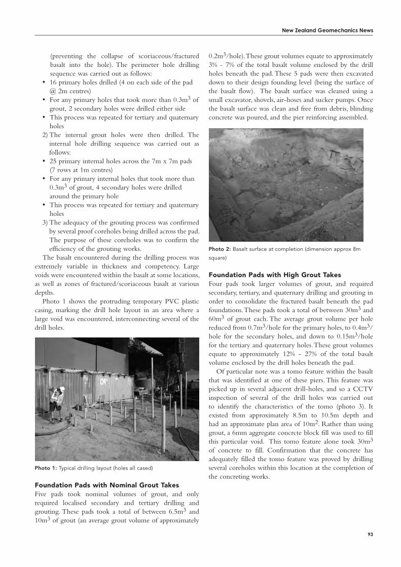
New Zealand Geomechanics News
93
(preventing the collapse of scoriaceous/fractured basalt into the hole). The perimeter hole drilling sequence was carried out as follows:
• 16 primary holes drilled (4 on each side of the pad @ 2m centres)
• For any primary holes that took more than 0.3m3 of grout, 2 secondary holes were drilled either side
• This process was repeated for tertiary and quaternary holes
2) The internal grout holes were then drilled. The internal hole drilling sequence was carried out as follows:
• 25 primary internal holes across the 7m x 7m pads (7 rows at 1m centres)
• For any primary internal holes that took more than 0.3m3 of grout, 4 secondary holes were drilled around the primary hole
• This process was repeated for tertiary and quaternary holes
3) The adequacy of the grouting process was confirmed by several proof coreholes being drilled across the pad. The purpose of these coreholes was to confirm the efficiency of the grouting works.
The basalt encountered during the drilling process was extremely variable in thickness and competency. Large voids were encountered within the basalt at some locations, as well as zones of fractured/scoriaceous basalt at various depths.
Photo 1 shows the protruding temporary PVC plastic casing, marking the drill hole layout in an area where a large void was encountered, interconnecting several of the drill holes.
Photo 1: Typical drilling layout (holes all cased)
Foundation Pads with Nominal Grout takesFive pads took nominal volumes of grout, and only required localised secondary and tertiary drilling and grouting. These pads took a total of between 6.5m3 and 10m3 of grout (an average grout volume of approximately
0.2m3/hole). These grout volumes equate to approximately 3% - 7% of the total basalt volume enclosed by the drill holes beneath the pad. These 5 pads were then excavated down to their design founding level (being the surface of the basalt flow). The basalt surface was cleaned using a small excavator, shovels, air-hoses and sucker pumps. Once the basalt surface was clean and free from debris, blinding concrete was poured, and the pier reinforcing assembled.
Photo 2: Basalt surface at completion (dimension approx 8m
square)
Foundation Pads with High Grout takesFour pads took larger volumes of grout, and required secondary, tertiary, and quaternary drilling and grouting in order to consolidate the fractured basalt beneath the pad foundations. These pads took a total of between 30m3 and 60m3 of grout each. The average grout volume per hole reduced from 0.7m3/hole for the primary holes, to 0.4m3/hole for the secondary holes, and down to 0.15m3/hole for the tertiary and quaternary holes. These grout volumes equate to approximately 12% - 27% of the total basalt volume enclosed by the drill holes beneath the pad.
Of particular note was a tomo feature within the basalt that was identified at one of these piers. This feature was picked up in several adjacent drill-holes, and so a CCTV inspection of several of the drill holes was carried out to identify the characteristics of the tomo (photo 3). It existed from approximately 8.5m to 10.5m depth and had an approximate plan area of 10m2. Rather than using grout, a 6mm aggregate concrete block fill was used to fill this particular void. This tomo feature alone took 30m3 of concrete to fill. Confirmation that the concrete has adequately filled the tomo feature was proved by drilling several coreholes within this location at the completion of the concreting works.
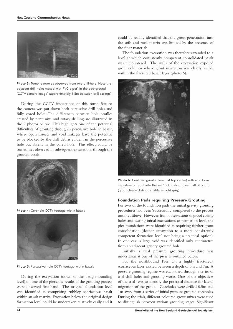
New Zealand Geomechanics News
94 Newsletter of the New Zealand Geotechnical Society Inc.
Photo 3: Tomo feature as observed from one drill-hole. Note the
adjacent drill-holes (cased with PVC pipes) in the background
(CCTV camera image) (approximately 1.5m between drill casings)
During the CCTV inspections of this tomo feature, the camera was put down both percussive drill holes and fully cored holes. The differences between hole profiles created by percussive and rotary drilling are illustrated in the 2 photos below. This highlights one of the potential difficulties of grouting through a percussive hole in basalt, where open fissures and void linkages have the potential to be blocked by the drill debris evident in the percussive hole but absent in the cored hole. This effect could be sometimes observed in subsequent excavations through the grouted basalt.
Photo 4: Corehole CCTV footage within basalt
Photo 5: Percussive hole CCTV footage within basalt
During the excavation (down to the design founding level) on one of the piers, the results of the grouting process were observed first-hand. The original foundation level was identified as comprising rubbley, scoriacious basalt within an ash matrix. Excavation below the original design formation level could be undertaken relatively easily and it
could be readily identified that the grout penetration into the soils and rock matrix was limited by the presence of the finer materials.
The foundation excavation was therefore extended to a level at which consistently competent consolidated basalt was encountered. The walls of the excavation exposed grout columns where grout migration was clearly visible within the fractured basalt layer (photo 6).
Photo 6: Confined grout column (at top centre) with a bulbous
migration of grout into the soil/rock matrix lower half of photo
(grout clearly distinguishable as light grey)
Foundation Pads requiring Pressure GroutingFor two of the foundation pads the initial gravity grouting procedures had been ‘successfully’ completed to the process outlined above. However, from observations of proof coring holes and during initial excavations to formation level, the pier foundations were identified as requiring further grout consolidation (deeper excavation to a more consistently competent formation level not being a practical option). In one case a large void was identified only centimetres from an adjacent gravity grouted hole.
Initially a trial pressure grouting procedure was undertaken at one of the piers as outlined below.
For the northbound Pier C’, a highly fractured/scoriaceous layer existed between a depth of 3m and 7m. A pressure grouting regime was established through a series of trial drill-holes and grouting works. One of the objectives of the trial was to identify the potential distance for lateral migration of the grout. Coreholes were drilled 0.5m and 1m away from a series of initial pressure grouted coreholes. During the trials, different coloured grout mixes were used to distinguish between various grouting stages. Significant
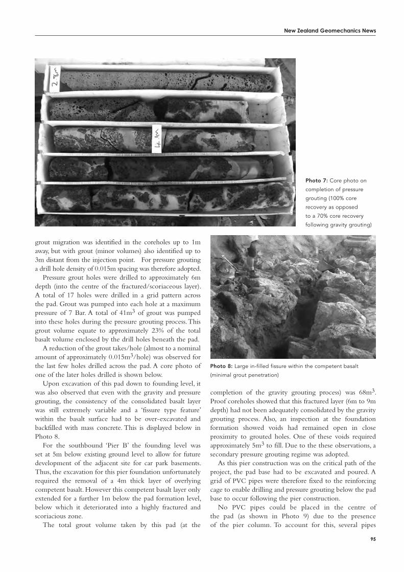
New Zealand Geomechanics News
95
grout migration was identified in the coreholes up to 1m away, but with grout (minor volumes) also identified up to 3m distant from the injection point. For pressure grouting a drill hole density of 0.015m spacing was therefore adopted.
Pressure grout holes were drilled to approximately 6m depth (into the centre of the fractured/scoriaceous layer). A total of 17 holes were drilled in a grid pattern across the pad. Grout was pumped into each hole at a maximum pressure of 7 Bar. A total of 41m3 of grout was pumped into these holes during the pressure grouting process. This grout volume equate to approximately 23% of the total basalt volume enclosed by the drill holes beneath the pad.
A reduction of the grout takes/hole (almost to a nominal amount of approximately 0.015m3/hole) was observed for the last few holes drilled across the pad. A core photo of one of the later holes drilled is shown below.
Upon excavation of this pad down to founding level, it was also observed that even with the gravity and pressure grouting, the consistency of the consolidated basalt layer was still extremely variable and a ‘fissure type feature’ within the basalt surface had to be over-excavated and backfilled with mass concrete. This is displayed below in Photo 8.
For the southbound ‘Pier B’ the founding level was set at 5m below existing ground level to allow for future development of the adjacent site for car park basements. Thus, the excavation for this pier foundation unfortunately required the removal of a 4m thick layer of overlying competent basalt. However this competent basalt layer only extended for a further 1m below the pad formation level, below which it deteriorated into a highly fractured and scoriacious zone.
The total grout volume taken by this pad (at the
completion of the gravity grouting process) was 68m3. Proof coreholes showed that this fractured layer (6m to 9m depth) had not been adequately consolidated by the gravity grouting process. Also, an inspection at the foundation formation showed voids had remained open in close proximity to grouted holes. One of these voids required approximately 5m3 to fill. Due to the these observations, a secondary pressure grouting regime was adopted.
As this pier construction was on the critical path of the project, the pad base had to be excavated and poured. A grid of PVC pipes were therefore fixed to the reinforcing cage to enable drilling and pressure grouting below the pad base to occur following the pier construction.
No PVC pipes could be placed in the centre of the pad (as shown in Photo 9) due to the presence of the pier column. To account for this, several pipes
Photo 7: Core photo on
completion of pressure
grouting (100% core
recovery as opposed
to a 70% core recovery
following gravity grouting)
Photo 8: Large in-filled fissure within the competent basalt
(minimal grout penetration)
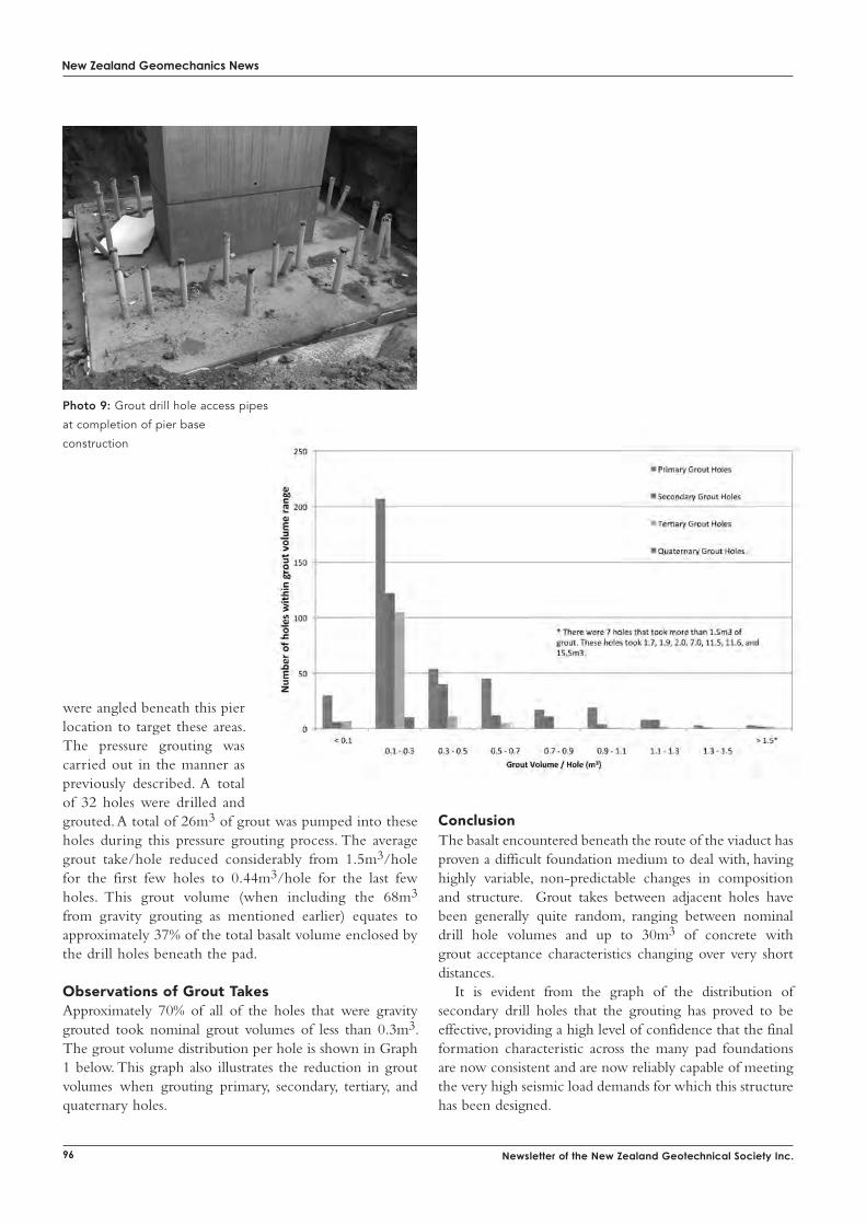
New Zealand Geomechanics News
96 Newsletter of the New Zealand Geotechnical Society Inc.
New Calibration ServicesIn addition to our existing suite of services, we have recently gained IANZ accreditation for:
- Compression machines - Tension machines - Balances - Load cells - Proving rings
Civil Testing EquipmentNuclear Density Meters, Shear Vanes, Impact Testers,
Concrete Airmeters, Schmidt Hammers, Measuring Wheels,
Scala Penetrometers, Skid Resistance Testers and more...
Metrology and Lab Testing EquipmentDial Gauges, Callipers, Liquid Limit Devices, Length Bars,
Micrometers, Rubber Hardness Testing (ShoreA, IRHD),
Measuring Tapes, Steel Rules, Weight Gauges, Engineers
Squares, Spirit Levels, Dumpy Levels, Bevel Protractors,
Inclinometers (Bevel), Graticules, Paint Gauges, Gauge Blocks,
Thread Gauges, Surface Texture, Surface Plate and more...
Calibration and repairWe’ve got a new look, a new location and increased services. Now calibrating and servicing just about all your civil testing gear.
MCC - The Measurement and Calibration CentreFor more information call us on: Ph: (09) 362-1720 or visit our website www.themcc.co.nz
19 Morgan Street, Newmarket, Auckland, New Zealand
The Measurement &Calibration Centre
were angled beneath this pier location to target these areas. The pressure grouting was carried out in the manner as previously described. A total of 32 holes were drilled and grouted. A total of 26m3 of grout was pumped into these holes during this pressure grouting process. The average grout take/hole reduced considerably from 1.5m3/hole for the first few holes to 0.44m3/hole for the last few holes. This grout volume (when including the 68m3
from gravity grouting as mentioned earlier) equates to approximately 37% of the total basalt volume enclosed by the drill holes beneath the pad.
observations of Grout takesApproximately 70% of all of the holes that were gravity grouted took nominal grout volumes of less than 0.3m3. The grout volume distribution per hole is shown in Graph 1 below. This graph also illustrates the reduction in grout volumes when grouting primary, secondary, tertiary, and quaternary holes.
Photo 9: Grout drill hole access pipes
at completion of pier base
construction
Conclusion The basalt encountered beneath the route of the viaduct has proven a difficult foundation medium to deal with, having highly variable, non-predictable changes in composition and structure. Grout takes between adjacent holes have been generally quite random, ranging between nominal drill hole volumes and up to 30m3 of concrete with grout acceptance characteristics changing over very short distances.
It is evident from the graph of the distribution of secondary drill holes that the grouting has proved to be effective, providing a high level of confidence that the final formation characteristic across the many pad foundations are now consistent and are now reliably capable of meeting the very high seismic load demands for which this structure has been designed.

New Calibration ServicesIn addition to our existing suite of services, we have recently gained IANZ accreditation for:
- Compression machines - Tension machines - Balances - Load cells - Proving rings
Civil Testing EquipmentNuclear Density Meters, Shear Vanes, Impact Testers,
Concrete Airmeters, Schmidt Hammers, Measuring Wheels,
Scala Penetrometers, Skid Resistance Testers and more...
Metrology and Lab Testing EquipmentDial Gauges, Callipers, Liquid Limit Devices, Length Bars,
Micrometers, Rubber Hardness Testing (ShoreA, IRHD),
Measuring Tapes, Steel Rules, Weight Gauges, Engineers
Squares, Spirit Levels, Dumpy Levels, Bevel Protractors,
Inclinometers (Bevel), Graticules, Paint Gauges, Gauge Blocks,
Thread Gauges, Surface Texture, Surface Plate and more...
Calibration and repairWe’ve got a new look, a new location and increased services. Now calibrating and servicing just about all your civil testing gear.
MCC - The Measurement and Calibration CentreFor more information call us on: Ph: (09) 362-1720 or visit our website www.themcc.co.nz
19 Morgan Street, Newmarket, Auckland, New Zealand
The Measurement &Calibration Centre
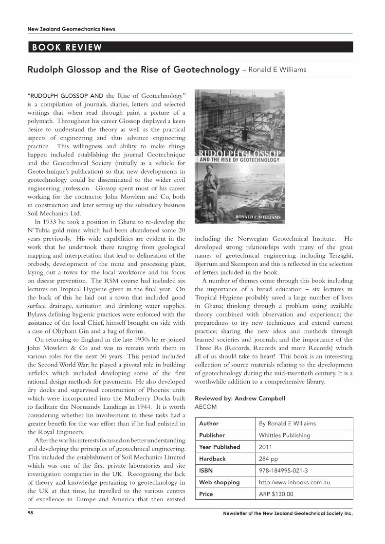
New Zealand Geomechanics News
98 Newsletter of the New Zealand Geotechnical Society Inc.
Book Review
Author By Ronald E Willaims
Publisher Whittles Publishing
Year Published 2011
Hardback 284 pp
ISBN 978-184995-021-3
Web shopping http:/www.inbooks.com.au
Price ARP $130.00
“rudolph glossop And the Rise of Geotechnology” is a compilation of journals, diaries, letters and selected writings that when read through paint a picture of a polymath. Throughout his career Glossop displayed a keen desire to understand the theory as well as the practical aspects of engineering and thus advance engineering practice. This willingness and ability to make things happen included establishing the journal Geotechnique and the Geotechnical Society (initially as a vehicle for Geotechnique’s publication) so that new developments in geotechnology could be disseminated to the wider civil engineering profession. Glossop spent most of his career working for the contractor John Mowlem and Co, both in construction and later setting up the subsidiary business Soil Mechanics Ltd.
In 1933 he took a position in Ghana to re-develop the N’Tubia gold mine which had been abandoned some 20 years previously. His wide capabilities are evident in the work that he undertook there ranging from geological mapping and interpretation that lead to delineation of the orebody, development of the mine and processing plant, laying out a town for the local workforce and his focus on disease prevention. The RSM course had included six lectures on Tropical Hygiene given in the final year. On the back of this he laid out a town that included good surface drainage, sanitation and drinking water supplies. Bylaws defining hygienic practices were enforced with the assistance of the local Chief, himself brought on side with a case of Oliphant Gin and a bag of florins.
On returning to England in the late 1930s he re-joined John Mowlem & Co and was to remain with them in various roles for the next 30 years. This period included the Second World War; he played a pivotal role in building airfields which included developing some of the first rational design methods for pavements. He also developed dry docks and supervised construction of Phoenix units which were incorporated into the Mulberry Docks built to facilitate the Normandy Landings in 1944. It is worth considering whether his involvement in these tasks had a greater benefit for the war effort than if he had enlisted in the Royal Engineers.
After the war his interests focussed on better understanding and developing the principles of geotechnical engineering. This included the establishment of Soil Mechanics Limited which was one of the first private laboratories and site investigation companies in the UK. Recognising the lack of theory and knowledge pertaining to geotechnology in the UK at that time, he travelled to the various centres of excellence in Europe and America that then existed
Rudolph Glossop and the Rise of Geotechnology – Ronald E Williams
including the Norwegian Geotechnical Institute. He developed strong relationships with many of the great names of geotechnical engineering including Terzaghi, Bjerrum and Skempton and this is reflected in the selection of letters included in the book.
A number of themes come through this book including the importance of a broad education – six lectures in Tropical Hygiene probably saved a large number of lives in Ghana; thinking through a problem using available theory combined with observation and experience; the preparedness to try new techniques and extend current practice; sharing the new ideas and methods through learned societies and journals; and the importance of the Three Rs (Records, Records and more Records) which all of us should take to heart! This book is an interesting collection of source materials relating to the development of geotechnology during the mid-twentieth century. It is a worthwhile addition to a comprehensive library.
Reviewed by: Andrew CampbellAECOM
New Zealand Geomechanics News
99
part ad10
For A construction-relAted company to have come through the recent recession with a major increase in turnover and the creation of about 30 more jobs, it has to be doing something right.
Managing director of Contract Landscapes Ltd (CLL) Terry Donnelly says this, and the many other successes of his Auckland-based company, come down to a few simple attitudes which stem right back to its small beginnings 25 years ago.
The company’s basic principles of Service and Solutions have permeated the culture and are applied from the top down in all aspects of operation. The principles are seen in action from giving top priority to client service, looking after staff, to digging deep to solve technological problems - and never running away from a challenge.
Terry started out 25 years ago doing fencing with one employee, a Falcon station wagon and a trailer. Progressing to concrete and general landscape work, he then designed and built a pile driver based on fencing technology but much larger. With this new equipment he moved into larger piling work.
A series of milestones has seen CLL expand over the years until now it employs 110 full-time staff and specializes in piling, foundations, slip stabilization, retaining walls, civil structures, drainage, rope access, excavations and remediation of contaminated sites. The company works in residential, commercial and public infrastructure sectors. Based in Kumeu, Auckland, it has a branch in Tauranga and takes on work throughout New Zealand.
Terry says he has enjoyed the challenge of expanding the company’s skills and technology over the years. A key to CLL’s success has been his ability to communicate well and learn from others which, in turn, has attracted like-minded people to the company.
“Our people communicate well with each other and clients, and have the same drive as myself to expand services and consolidate with good training and good internal systems,” he says.
“Contract Landscapes has a very low staff turnover and stable workforce and a general atmosphere of trust. As a result of regular communication and trust within the company, CLL staff personally takes the responsibility of serving clients and generating goodwill very seriously.
“In turn they know they will be looked after through good times and bad.”
Terry says when facing the downturn caused by the Global Financial Crisis, senior management and staff met together and made a conscious decision to diversify and
comPaNy PRoFile
CLL – Contract Landscapes Ltd
increases the level of service. As a result of decisions from that time, CLL annual
turnover increased thirty three percent during the recession and staff numbers went from 80 to 110.
Terry says significant milestones enabled CLL to expand and consolidate its position in the market.
About 10 years ago – after Terry ‘’dreamt up” the idea one night – CLL designed and built an excavator-mounted 2.1ton hydraulic drop hammer. Along with this, the company started buying larger excavators and drilling equipment which enabled it to expand into the larger-scale piling market.
Another landmark was an Auckland Zoo contract to develop the pridelands and the hippopotamus, baboon and flamingos enclosures which enhanced the company’s profile and reputation for public works.
Terry has a long-standing interest in land stabilization and limited access work. As a result CLL has specialized in developing limited access drilling, piling, anchoring and soil nailing methodologies.
The team now has four rope access crews with all the necessary certification and associated equipment necessary to install rock anchors, soil nails, soil anchors and erosion protection.
CLL has also expanded into the field of contaminated or hazardous site remediation.
“We’ve done a number of difficult projects including dismantling a large quarantine incinerator and consequent disposal of highly toxic waste to France,” he says.
CLL, in conjunction with Hawkins Infrastructure, also remediated a site at Bankside, south of Christchurch, which had been used as a pesticide and herbicide dump for 50 years.
Terry has close ties with John O’Grady who is a chemical engineer with wide experience dealing with hazardous waste. As a result CLL has been able to produce onsite treatment plants for wastewater which enable the water to be cleaned out and discharged in the normal manner with toxic residues separated out and dealt with appropriately.
CLL has also expanded out into concrete repair work with wharves and jetties and undertaken a number of successful projects in this area.
It also developed proprietary concrete slab foundation designs that do not require footings, which have been well received by residential building companies and engineers. These systems overcome problems with expansive soils and excavation of foundations.
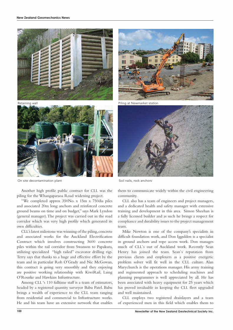
New Zealand Geomechanics News
100 Newsletter of the New Zealand Geotechnical Society Inc.
Retaining wall Piling at Newmarket station
Soil nails, rock anchorsOn site decontamination plant
Another high profile public contract for CLL was the piling for the Whangaparaoa Road widening project.
“We completed approx 350No. x 15m x 750dia piles and associated 20m long anchors and reinforced concrete ground beams on time and on budget,” says Mark Lyndon (general manager). The project was carried out in the road corridor which was very high profile which generated its own difficulties.
CLL’s latest milestone was winning of the piling, concrete and associated works for the Auckland Electrification Contract which involves constructing 3600 concrete piles within the rail corridor from Swanson to Papakura, utilizing specialized “high railed” excavator drilling rigs. Terry says that thanks to a huge and effective effort by the team and in particular Rob O’Grady and Nic McGowan, this contract is going very smoothly and they enjoying are positive working relationship with KiwiRail, Laing O’Rourke and Hawkins Infrastructure.
Among CLL ‘s 110 fulltime staff is a team of estimators, headed by a registered quantity surveyor Babu Patel. Babu brings a wealth of experience to the CLL team ranging from residential and commercial to Infrastructure works. He and his team have an extensive network that enables
them to communicate widely within the civil engineering community.
CLL also has a team of engineers and project managers, and a dedicated health and safety manager with extensive training and development in this area. Simon Sheehan is a fully licensed builder and as such he brings a respect for compliance and durability issues to the project management team.
Mike Newton is one of the company’s specialists in difficult foundation work, and Don Iggulden is a specialist in ground anchors and rope access work. Don manages much of CLL`s out of Auckland work. Recently Sean Henry has joined the team. Sean`s reputation from previous clients and employers as a positive energetic problem solver will fit well in the CLL culture. Alan Marychurch is the operations manager. His army training and regimented approach to scheduling machines and planning programmes is well appreciated by all. He has been associated with heavy equipment for 25 years which has proved invaluable in keeping the CLL fleet upgraded and well maintained.
CLL employs two registered drainlayers and a team of experienced men in this field which enables them to
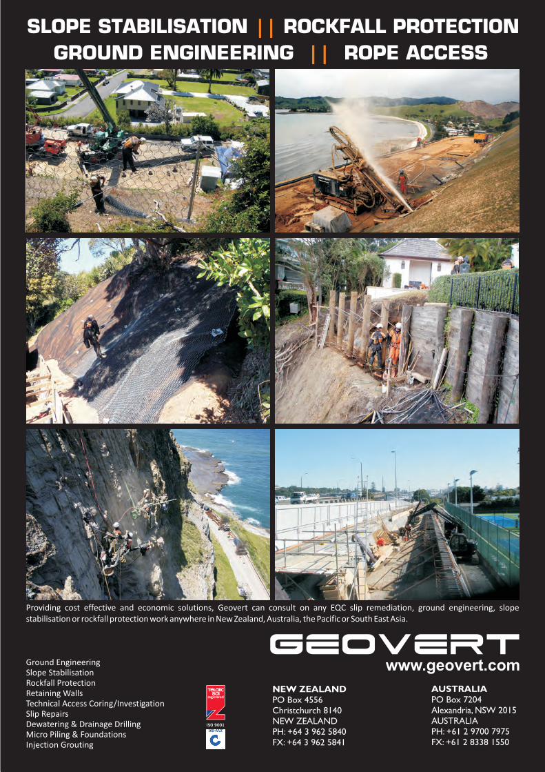
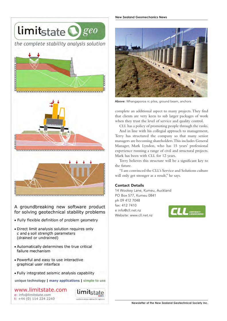
Newsletter of the New Zealand Geotechnical society inc.
New Zealand Geomechanics News
Above: Whangaporoa rc piles, ground beam, anchors
complete an additional aspect to many projects. They find that clients are very keen to sub larger packages of work when they trust the level of service and quality control.
CLL has a policy of promoting people through the ranks. And in line with his collegial approach to management,
Terry has structured the company so that many senior managers are becoming shareholders. This includes General Manager, Mark Lyndon, who has 15 years’ professional experience running a range of civil and structural projects. Mark has been with CLL for 12 years.
Terry believes this structure will be a significant key to the future.
“I am convinced the CLL’s Service and Solutions culture will only get stronger as a result,” he says.
Contact Details14 Wookey Lane, Kumeu, AucklandPO Box 577, Kumeu 0841ph 09 412 7048fax: 412 7410e [email protected]: www.cll.net.nz
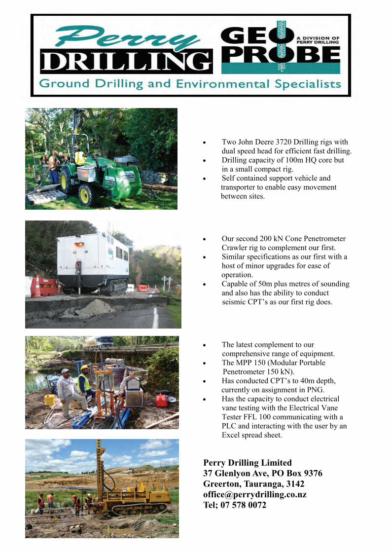
• Two John Deere 3720 Drilling rigs with dual speed head for efficient fast drilling.
• Drilling capacity of 100m HQ core but in a small compact rig.
• Self contained support vehicle and transporter to enable easy movement between sites.
• Our second 200 kN Cone Penetrometer Crawler rig to complement our first.
• Similar specifications as our first with a host of minor upgrades for ease of
operation. • Capable of 50m plus metres of sounding
and also has the ability to conduct seismic CPT’s as our first rig does.
• The latest complement to our comprehensive range of equipment. • The MPP 150 (Modular Portable Penetrometer 150 kN). • Has conducted CPT’s to 40m depth, currently on assignment in PNG. • Has the capacity to conduct electrical
vane testing with the Electrical Vane Tester FFL 100 communicating with a PLC and interacting with the user by an Excel spread sheet.
Perry Drilling Limited 37 Glenlyon Ave, PO Box 9376 Greerton, Tauranga, 3142 [email protected] Tel; 07 578 0072
Newsletter of the New Zealand Geotechnical society inc.
New Zealand Geomechanics News
Homer Tunnel saftey improvements
We are a Hawkes Bay based surveying and engineering consultancy who can undertake a variety of specialised work for you, assisting with your project, including:
• Project & Contract Management
• Engineering Surveying & Setout
• Topographical Surveys
• GPS Surveys
• Complex Quantity Calculations
• Site & Quality Assurance Testing
• As Built Surveys & Plans From slips to subdivisions, wind farms to airstrips, driveways to expressways, pile holes to pipelines, erosion to settlement monitoring, we can cover all your surveying and site testing requirements. Our friendly team
Call us today for a no obligation quote
Ph/Fax 06 843 6996
88 Taradale Road PO Box 5011, Napier
Aecom is A leading provider of advanced design, engineering, environmental, management, planning and advisory services in New Zealand, Australia and around the world.
As one of New Zealand’s oldest and largest engineering consultants, the company has operated for more than 90 years under various operating names including Meritec, Worley, and more recently Maunsell. In 2009 we became AECOM and are now part of a global network with approximately 45,000 employees in offices in 125 countries around the world.
AECOM has more than 4,200 professionals working in over 25 offices throughout Australia and New Zealand. Our work includes some of our region’s most iconic projects, such as the multi-award-winning Inner Northern Busway Alliance (Queensland, Australia), the Rosedale Water Treatment Plant Outfall Project (Auckland, New Zealand), and Telfer Deeps Gold Mine (Western Australia, Australia).
AECOM’s geotechnical team of engineers and engineering geologists provide a comprehensive range of geotechnical services throughout New Zealand, Australia and South East Asia. With more than 170 ground engineering and tunnelling staff in Australia and New Zealand, our dynamic team has a thorough understanding of the importance of ground engineering and has a strong track record in undertaking geotechnical investigations and providing design expertise on many challenging and exciting projects. We understand that the viability of a project can hinge on the geotechnical and geological conditions and that input from a wider team of ground engineering staff, such as civil engineers and environmental services, can be vital in risk management and implementing best-for-project solutions.
AECOM
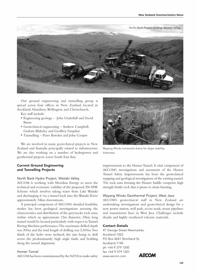
New Zealand Geomechanics News
105
improvements to the Homer Tunnel. A vital component of AECOM’s investigations and assessment of the Homer Tunnel Safety Improvements has been the geotechnical mapping and geological investigations of the existing tunnel. The rock mass forming the Homer Saddle comprises high strength brittle rock that is prone to strain bursting.
Wayang Windu Geothermal Project, West JavaAECOM’s geotechnical staff in New Zealand are undertaking investigations and geotechnical design for a new power station, well pads, access roads, steam pipelines and transmission lines in West Java. Challenges include deeply and highly weathered volcanic materials.
Contact Details47 George Street Newmarket, Auckland 1023PO Box 4241 Shortland St, Auckland 1140ph +64 9 379 1200 fax +64 9 379 1201www.aecom.com
Wayang Windu horizontal drains for slope stability
Indonesia
Our ground engineering and tunnelling group is spread across four offices in New Zealand, located in Auckland, Hamilton, Wellington and Christchurch.
Key staff include:• Engineering geology - John Underhill and David
Burns • Geotechnical engineering – Andrew Campbell,
Graham Blakeley and Geoffrey Farquhar• Tunnelling – Peter Bawden and John Cooper
We are involved in many geotechnical projects in New Zealand and Australia principally related to infrastructure. We are also working on a number of hydropower and geothermal projects across South East Asia.
Current Ground Engineering and tunnelling Projects
North Bank Hydro Project, Waitaki ValleyAECOM is working with Meridian Energy to assess the technical and economic viability of the proposed 250 MW Scheme which involves taking water from Lake Waitaki and discharging it via a tunnel back into the Waitaki River approximately 34km downstream.
A principal component of AECOM’s detailed feasibility studies has been geological investigations assessing the characteristics and distribution of the greywacke rock mass, within which an approximate 12m diameter, 35km long tunnel would be located particularly with respect to Tunnel Boring Machine performance. The maximum drilled depth was 200m and the total length of drilling was 2,500m. Two thirds of the holes were inclined, the aim being to drill across the predominantly high angle faults and bedding along the tunnel alignment.
Homer TunnelAECOM has been commissioned by the NZTA to make safety
North Bank Project Drilling, Waitaki Valley
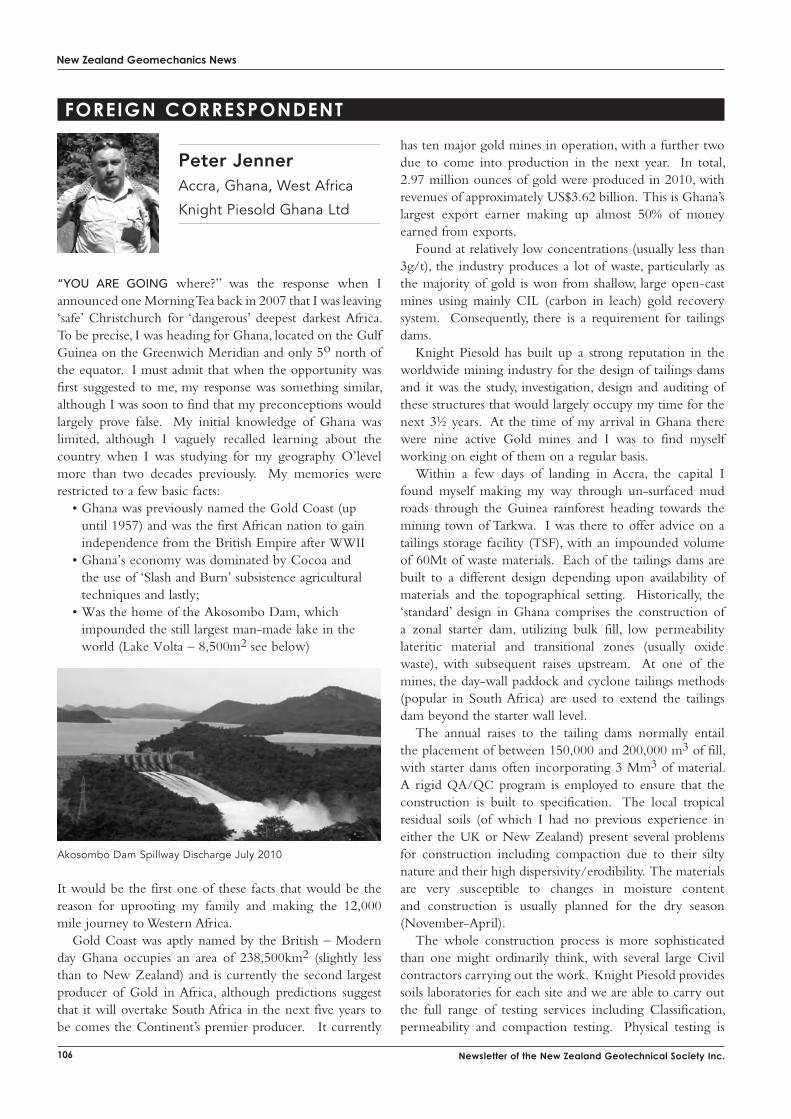
New Zealand Geomechanics News
106 Newsletter of the New Zealand Geotechnical Society Inc.
Peter Jenner Accra, Ghana, West Africa
Knight Piesold Ghana Ltd
has ten major gold mines in operation, with a further two due to come into production in the next year. In total, 2.97 million ounces of gold were produced in 2010, with revenues of approximately US$3.62 billion. This is Ghana’s largest export earner making up almost 50% of money earned from exports.
Found at relatively low concentrations (usually less than 3g/t), the industry produces a lot of waste, particularly as the majority of gold is won from shallow, large open-cast mines using mainly CIL (carbon in leach) gold recovery system. Consequently, there is a requirement for tailings dams.
Knight Piesold has built up a strong reputation in the worldwide mining industry for the design of tailings dams and it was the study, investigation, design and auditing of these structures that would largely occupy my time for the next 3½ years. At the time of my arrival in Ghana there were nine active Gold mines and I was to find myself working on eight of them on a regular basis.
Within a few days of landing in Accra, the capital I found myself making my way through un-surfaced mud roads through the Guinea rainforest heading towards the mining town of Tarkwa. I was there to offer advice on a tailings storage facility (TSF), with an impounded volume of 60Mt of waste materials. Each of the tailings dams are built to a different design depending upon availability of materials and the topographical setting. Historically, the ‘standard’ design in Ghana comprises the construction of a zonal starter dam, utilizing bulk fill, low permeability lateritic material and transitional zones (usually oxide waste), with subsequent raises upstream. At one of the mines, the day-wall paddock and cyclone tailings methods (popular in South Africa) are used to extend the tailings dam beyond the starter wall level.
The annual raises to the tailing dams normally entail the placement of between 150,000 and 200,000 m3 of fill, with starter dams often incorporating 3 Mm3 of material. A rigid QA/QC program is employed to ensure that the construction is built to specification. The local tropical residual soils (of which I had no previous experience in either the UK or New Zealand) present several problems for construction including compaction due to their silty nature and their high dispersivity/erodibility. The materials are very susceptible to changes in moisture content and construction is usually planned for the dry season (November-April).
The whole construction process is more sophisticated than one might ordinarily think, with several large Civil contractors carrying out the work. Knight Piesold provides soils laboratories for each site and we are able to carry out the full range of testing services including Classification, permeability and compaction testing. Physical testing is
“you Are going where?” was the response when I announced one Morning Tea back in 2007 that I was leaving ‘safe’ Christchurch for ‘dangerous’ deepest darkest Africa. To be precise, I was heading for Ghana, located on the Gulf Guinea on the Greenwich Meridian and only 5o north of the equator. I must admit that when the opportunity was first suggested to me, my response was something similar, although I was soon to find that my preconceptions would largely prove false. My initial knowledge of Ghana was limited, although I vaguely recalled learning about the country when I was studying for my geography O’level more than two decades previously. My memories were restricted to a few basic facts:
• Ghana was previously named the Gold Coast (up until 1957) and was the first African nation to gain independence from the British Empire after WWII
• Ghana’s economy was dominated by Cocoa and the use of ‘Slash and Burn’ subsistence agricultural techniques and lastly;
• Was the home of the Akosombo Dam, which impounded the still largest man-made lake in the world (Lake Volta – 8,500m2 see below)
Akosombo Dam Spillway Discharge July 2010
It would be the first one of these facts that would be the reason for uprooting my family and making the 12,000 mile journey to Western Africa.
Gold Coast was aptly named by the British – Modern day Ghana occupies an area of 238,500km2 (slightly less than to New Zealand) and is currently the second largest producer of Gold in Africa, although predictions suggest that it will overtake South Africa in the next five years to be comes the Continent’s premier producer. It currently
FoReiGN coRResPoNdeNt
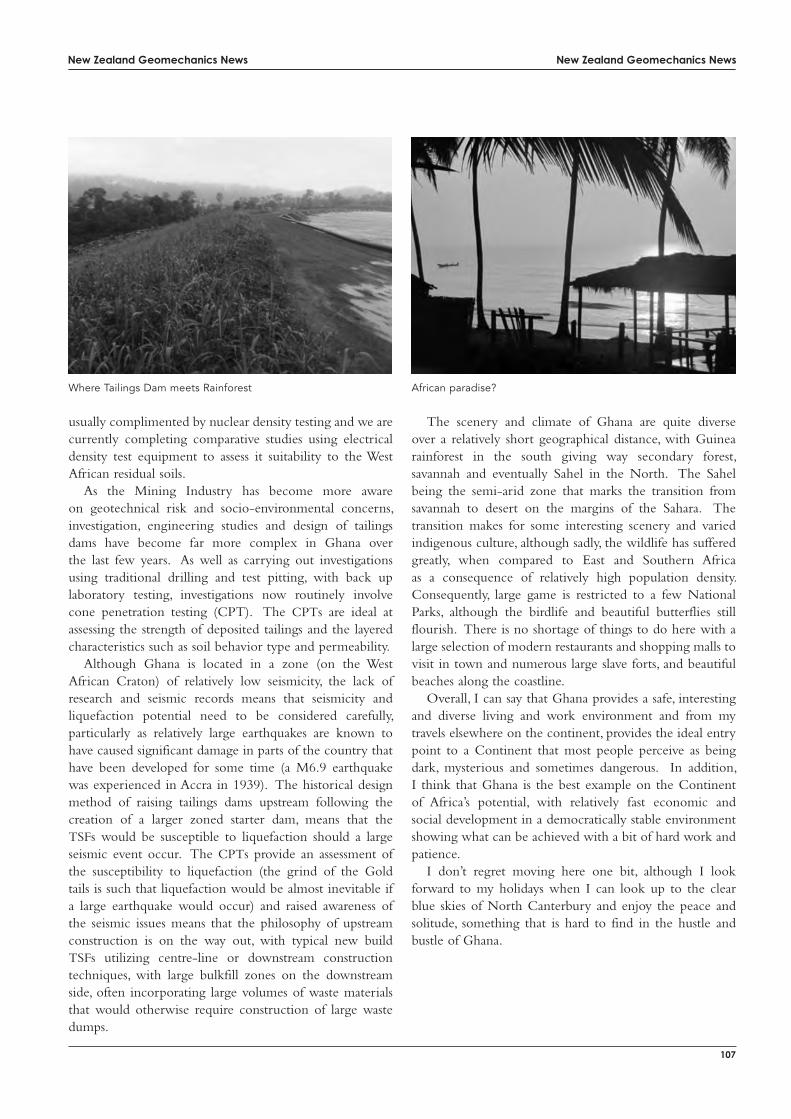
New Zealand Geomechanics News
107
New Zealand Geomechanics News
usually complimented by nuclear density testing and we are currently completing comparative studies using electrical density test equipment to assess it suitability to the West African residual soils.
As the Mining Industry has become more aware on geotechnical risk and socio-environmental concerns, investigation, engineering studies and design of tailings dams have become far more complex in Ghana over the last few years. As well as carrying out investigations using traditional drilling and test pitting, with back up laboratory testing, investigations now routinely involve cone penetration testing (CPT). The CPTs are ideal at assessing the strength of deposited tailings and the layered characteristics such as soil behavior type and permeability.
Although Ghana is located in a zone (on the West African Craton) of relatively low seismicity, the lack of research and seismic records means that seismicity and liquefaction potential need to be considered carefully, particularly as relatively large earthquakes are known to have caused significant damage in parts of the country that have been developed for some time (a M6.9 earthquake was experienced in Accra in 1939). The historical design method of raising tailings dams upstream following the creation of a larger zoned starter dam, means that the TSFs would be susceptible to liquefaction should a large seismic event occur. The CPTs provide an assessment of the susceptibility to liquefaction (the grind of the Gold tails is such that liquefaction would be almost inevitable if a large earthquake would occur) and raised awareness of the seismic issues means that the philosophy of upstream construction is on the way out, with typical new build TSFs utilizing centre-line or downstream construction techniques, with large bulkfill zones on the downstream side, often incorporating large volumes of waste materials that would otherwise require construction of large waste dumps.
The scenery and climate of Ghana are quite diverse over a relatively short geographical distance, with Guinea rainforest in the south giving way secondary forest, savannah and eventually Sahel in the North. The Sahel being the semi-arid zone that marks the transition from savannah to desert on the margins of the Sahara. The transition makes for some interesting scenery and varied indigenous culture, although sadly, the wildlife has suffered greatly, when compared to East and Southern Africa as a consequence of relatively high population density. Consequently, large game is restricted to a few National Parks, although the birdlife and beautiful butterflies still flourish. There is no shortage of things to do here with a large selection of modern restaurants and shopping malls to visit in town and numerous large slave forts, and beautiful beaches along the coastline.
Overall, I can say that Ghana provides a safe, interesting and diverse living and work environment and from my travels elsewhere on the continent, provides the ideal entry point to a Continent that most people perceive as being dark, mysterious and sometimes dangerous. In addition, I think that Ghana is the best example on the Continent of Africa’s potential, with relatively fast economic and social development in a democratically stable environment showing what can be achieved with a bit of hard work and patience.
I don’t regret moving here one bit, although I look forward to my holidays when I can look up to the clear blue skies of North Canterbury and enjoy the peace and solitude, something that is hard to find in the hustle and bustle of Ghana.
Where Tailings Dam meets Rainforest African paradise?
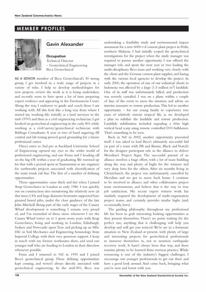
New Zealand Geomechanics News
108 Newsletter of the New Zealand Geotechnical Society Inc.
memBeR PRoFiles
As A senior member of Beca Geotechnical’s 50 strong group, I get involved in a wide range of projects in a variety of roles. I help to develop methodologies for new projects, review the work as it is being undertaken, and recently seem to have spent a lot of time preparing expert evidence and appearing in the Environment Court. Along the way, I endeavor to guide and coach those I am working with. All this feels like a long way from where I started my working life, initially as a land surveyor in the mid-1970’s and then as a civil engineering technician. I got hooked on geotechnical engineering in the early 80’s while working as a civil/survey/geotechnical technician with Babbage Consultants. A year or two of hand augering, fill control and lab testing proved good grounding for a future professional career.
Direct entry to 2nd pro at Auckland University School of Engineering opened my eyes to the wider world of professional engineering, and saw Fiona and I heading off on the big OE within a year of graduating. We warmed up for that with a period spent in Taumarunui as site engineer for earthworks projects associated with electrification of the main trunk rail line. The first of a number of defining opportunities.
Those opportunities came thick and fast when I joined Arup Geotechnics in London in early 1986. I was quickly out on construction sites monitoring the relatively new (at that time) CFA and large diameter bentonite supported base grouted bored piles, under the close guidance of the late John Mitchell. Being part of the early stages of the Canary Wharf development is something I remain very proud of, and I’m reminded of those times whenever I see the Canary Wharf tower on tv. I spent seven years with Arup Geotechnics, living and working in London, Edinburgh, Sydney and Newcastle upon Tyne and picking up an MSc DIC in Soil Mechanics and Engineering Seismology from Imperial College with their very generous support. I keep in touch with my former workmates there, and send our younger staff who are heading to London in their direction whenever possible.
Fiona and I returned to NZ in 1993 and I joined Beca’s geotechnical group. Those defining opportunities kept coming, and weren’t always directly associated with geotechnical engineering. In the mid-90’s, Beca was
Gavin Alexander
occupationTechnical Director – Geotechnical EngineeringBeca Geotechnical
undertaking a feasibility study and environmental impact assessment for a new 6000 t/d cement plant project in Perlis, northern Malaysia. I had initially scoped the geotechnical investigations for the project when the study manager was required to pursue another opportunity. I was offered the manager role, and spent the next year or two leading the multi-disciplinary Beca team and working very closely with the client and the German cement plant supplier, and liasing with the various local agencies to develop the project. In early 2000, the operation of one of our industrial clients in Indonesia was affected by a large (1.5 million m3) landslide. One of its staff was unfortunately killed, and production was severely curtailed. I was on a plane within a couple of days of the event to assess the situation and advise on interim measures to restore production. This led to another opportunity – for our young family to experience two years of relatively remote tropical life, as we developed a plan to stabilize the landslide and restore production. Landslide stabilization included regrading a 60m high vertical head scarp using remote controlled D10 bulldozers. That’s something to be seen.
Back in NZ in 2002, another opportunity presented itself. I was asked to lead Beca’s ultimately successful bid (as part of a team with PB and Binnie, Black and Veatch) for the designer participant role in the alliance to deliver Meridian’s Project Aqua. The successful pursuit of an alliance involves a huge effort, with a lot of team building along the way, and plenty of highs for the winners and very deep lows for the others. After six months living in Christchurch, the project was unfortunately cancelled by Meridian and we got to move back home. I continue to be involved in alliance and other collaborative project team environments, and believe that is the way to true job satisfaction. My recent expert witness work has similarly required the development of multi-organisation project teams, and certainly provides similar highs (and, occasionally, lows).
The guiding philosophy throughout my professional life has been to grab interesting looking opportunities as they present themselves. There’s no point waiting for the perfect one, anything that is challenging will help you develop and will get you noticed. We’re are in a fortunate situation in New Zealand at present, with plenty of large and interesting projects for geotechnical professionals to immerse themselves in, not to mention earthquake recovery work. It hasn’t always been that way, and there remains plenty to be learned from overseas practice. While resourcing is one of the industry’s biggest challenges, I encourage our younger professionals to get out there and have a good look around. And come back, bringing what you’ve seen and learnt with you.
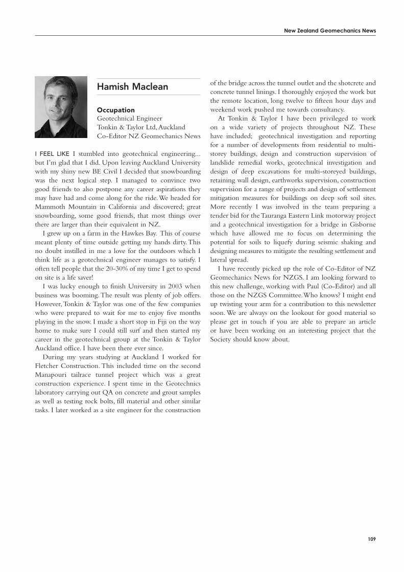
New Zealand Geomechanics News
109
Hamish Maclean
occupationGeotechnical EngineerTonkin & Taylor Ltd, AucklandCo-Editor NZ Geomechanics News
i Feel like I stumbled into geotechnical engineering...but I’m glad that I did. Upon leaving Auckland University with my shiny new BE Civil I decided that snowboarding was the next logical step. I managed to convince two good friends to also postpone any career aspirations they may have had and come along for the ride. We headed for Mammoth Mountain in California and discovered; great snowboarding, some good friends, that most things over there are larger than their equivalent in NZ.
I grew up on a farm in the Hawkes Bay. This of course meant plenty of time outside getting my hands dirty. This no doubt instilled in me a love for the outdoors which I think life as a geotechnical engineer manages to satisfy. I often tell people that the 20-30% of my time I get to spend on site is a life saver!
I was lucky enough to finish University in 2003 when business was booming. The result was plenty of job offers. However, Tonkin & Taylor was one of the few companies who were prepared to wait for me to enjoy five months playing in the snow. I made a short stop in Fiji on the way home to make sure I could still surf and then started my career in the geotechnical group at the Tonkin & Taylor Auckland office. I have been there ever since.
During my years studying at Auckland I worked for Fletcher Construction. This included time on the second Manapouri tailrace tunnel project which was a great construction experience. I spent time in the Geotechnics laboratory carrying out QA on concrete and grout samples as well as testing rock bolts, fill material and other similar tasks. I later worked as a site engineer for the construction
of the bridge across the tunnel outlet and the shotcrete and concrete tunnel linings. I thoroughly enjoyed the work but the remote location, long twelve to fifteen hour days and weekend work pushed me towards consultancy.
At Tonkin & Taylor I have been privileged to work on a wide variety of projects throughout NZ. These have included; geotechnical investigation and reporting for a number of developments from residential to multi-storey buildings, design and construction supervision of landslide remedial works, geotechnical investigation and design of deep excavations for multi-storeyed buildings, retaining wall design, earthworks supervision, construction supervision for a range of projects and design of settlement mitigation measures for buildings on deep soft soil sites. More recently I was involved in the team preparing a tender bid for the Tauranga Eastern Link motorway project and a geotechnical investigation for a bridge in Gisborne which have allowed me to focus on determining the potential for soils to liquefy during seismic shaking and designing measures to mitigate the resulting settlement and lateral spread.
I have recently picked up the role of Co-Editor of NZ Geomechanics News for NZGS. I am looking forward to this new challenge, working with Paul (Co-Editor) and all those on the NZGS Committee. Who knows? I might end up twisting your arm for a contribution to this newsletter soon. We are always on the lookout for good material so please get in touch if you are able to prepare an article or have been working on an interesting project that the Society should know about.
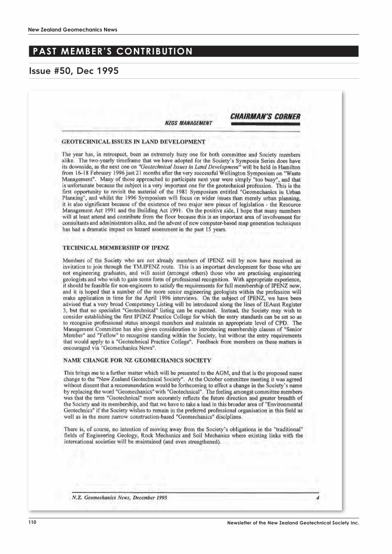
New Zealand Geomechanics News
110 Newsletter of the New Zealand Geotechnical Society Inc.
Past memBeR’s coNtRiButioN
Issue #50, Dec 1995
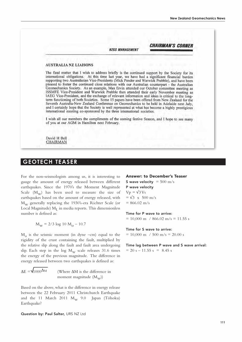
New Zealand Geomechanics News
111
Geotech teaseR
answer: to December’s teaser S wave velocity = 500 m/sP wave velocity Vp = √3 Vs= √3 x 500 m/s= 866.02 m/s
Time for P wave to arrive:= 10,000 m / 866.02 m/s = 11.55 s Time for S wave to arrive:= 10,000 m / 500 m/s = 20.00 s
Time lag between P wave and S wave arrival:= 20 s – 11.55 s = 8.45 s
For the non-seismologists among us, it is interesting to gauge the amount of energy released between different earthquakes. Since the 1970’s the Moment Magnitude Scale (Mw) has been used to measure the size of earthquakes based on the amount of energy released, with Mw generally replacing the 1930’s-era Richter Scale (or Local Magnitude) ML in media reports. This dimensionless number is defined as:
Mw = 2/3 log 10 Mo – 10.7
Mo is the seismic moment (in dyne –cm) equal to the rigidity of the crust containing the fault, multiplied by the relative slip along the fault and fault area undergoing slip. Each step in the log Mw scale releases 31.6 times the energy of the previous magnitude. The difference in energy released between two earthquakes is defined as:
ΔE = 1000ΔM (Where ΔM is the difference in moment magnitude (Mw))
Based on the above, what is the difference in energy release between the 22 February 2011 Christchurch Earthquake and the 11 March 2011 Mw 9.0 Japan (Töhoku) Earthquake?
Question by: Paul Salter, URS NZ Ltd

New Zealand Geomechanics News
112 Newsletter of the New Zealand Geotechnical Society Inc.
eveNts diaRy
Links are available from the NZ Geotechnical Society website – www.nzgs.org
2011
19-25 June, 2011Bulgaria11th International Multidisciplinary Scientific Geo-Conference & Expo – SEGEM 2011www.sgem.org
19-22 June, 2011San Francisco, California, USA2011 Rapid Excavation & Tunneling Conferencewww.retc.org
26-29 June, 2011San Francisco, USA45th US Rock Mechanics Geomechanics Symposiumwww.armasymposium.org
26-28 June, 2011Atlanta, USAGeorisk 2011 – Risk Assessment and Management in Geoengineeringhttp://content.asce.org/conferences/GeoRisk2011/
4-6 July, 2011Leuven, Belgium,Eurodyn 2011 – 8th International Conference on Structural Dynamics, and a Minisymposium on Dynamic soil-structure interaction and wave propagation (MS03)www.eurodyn2011.org
8-9 July, 2011Brisbane, AustraliaTwo-Day Short Course on rock fracture geometry characterization and network Modeling in 3D including validations
10 July, 2011Brisbane, AustraliaOne-Day Short Course on Measurement and Quantification of Joint Roughness, Normal Deformation, Peak Shear Strength, Aperture and Fluid Flow through Single Joints
11-12 July, 2011Brisbane, AustraliaTwo-Day Short Course on Rock Slope Stability Analyses
13-14 July, 2011Brisbane, AustraliaTwo-Day Short Course on Block Theory & Applications for Surficial and Underground Rock Excavations
25-29 July, 2011Toronto, Canada9th U.S. National and 10th Canadian Conference on Earthquake Engineering. http://2010eqconf.org
31 august-3 September, 2011 Seoul, KoreaThe Fifth International Symposium onDeformation Characteristics of Geomaterialswww.isseoul2011.org
6-8 September, 2011Moscow, RussiaEnvironmental Geosciences and Engineering Survey for Territory Protection and Population Safety (EngeoPro 2011)www.engeopro2011.com
6-10 Setember, 2011Vienna, Austria2nd Conference on Slope Tectonicswww.geologie.ac.at/slope_tecto_2011
13-19 September, 2011 Athens, GreeceXV European Conference on Soil Mechanics and Geotechnical Engineeringwww.athens2011ecsmge.org
18-21 September 2011Vancouver, CanadaSlope Stability 2011www.slopestability2011.ca
2-6 october, 2011Toronto, Ontario, Canada XIV Panamerican Conference on Soil Mechanics and Geotechnical Engineering & V PanAmerican Conference on Learning and Teaching of Geotechnical Engineering, & 64th Canadian Geotechnical Conferencehttp://www.panam-cgc2011.ca/
6-7 october, 2011Hanoi, VietnamGeotech Hanoi 2011 www.geotechn2011.vn
16-21 october, 2011Beijing, China12th International Congress on Rock Mechanics – Harmonising Rock Engineering and the Environmentwww.isrm2011.com
2-5 November, 2011Sao Paulo, Brazil13th Brazilian Congress on Engineering Geology and Environmentalwww.acquacon.com.br/13cbge
7-9 November, 2011 Perth, AustraliaInternational Conference on Advances in Geotechnical Engineeringwww.icage2011.com.au
14-16 November, 2011Pattaya, Thailand5th Asia-Pacific conference on unsaturated soilswww.unsat.eng.ku.ac.th
1-2 December, 2011SingaporeInternational Symposium on Advances in Ground Technology and Geo-Information (IS-AGTG)www.is-agtg.com
8-9 December, 2011Ankara, TurkeyXTH REGIONAL ROCK MECHANICS SYMPOSIUMwww.tukmd.org.tr/sempozyumlar/index_eng.php
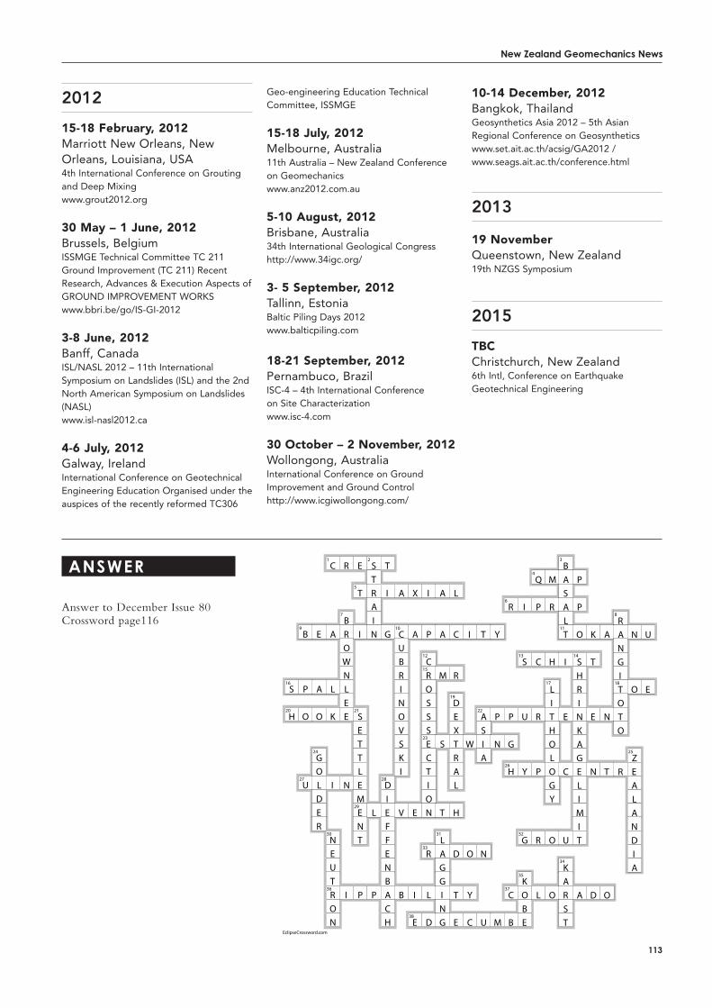
New Zealand Geomechanics News
113
2012
15-18 February, 2012Marriott New Orleans, New Orleans, Louisiana, USA4th International Conference on Grouting and Deep Mixingwww.grout2012.org
30 May – 1 June, 2012Brussels, BelgiumISSMGE Technical Committee TC 211 Ground Improvement (TC 211) Recent Research, Advances & Execution Aspects of GROUND IMPROVEMENT WORKSwww.bbri.be/go/IS-GI-2012
3-8 June, 2012Banff, CanadaISL/NASL 2012 – 11th International Symposium on Landslides (ISL) and the 2nd North American Symposium on Landslides (NASL)www.isl-nasl2012.ca
4-6 July, 2012 Galway, IrelandInternational Conference on Geotechnical Engineering Education Organised under the auspices of the recently reformed TC306
Geo-engineering Education Technical Committee, ISSMGE
15-18 July, 2012Melbourne, Australia11th Australia – New Zealand Conference on Geomechanicswww.anz2012.com.au
5-10 august, 2012Brisbane, Australia34th International Geological Congresshttp://www.34igc.org/
3- 5 September, 2012Tallinn, EstoniaBaltic Piling Days 2012www.balticpiling.com
18-21 September, 2012Pernambuco, BrazilISC-4 – 4th International Conference on Site Characterizationwww.isc-4.com
30 october – 2 November, 2012Wollongong, AustraliaInternational Conference on Ground Improvement and Ground Controlhttp://www.icgiwollongong.com/
10-14 December, 2012Bangkok, ThailandGeosynthetics Asia 2012 – 5th Asian Regional Conference on Geosyntheticswww.set.ait.ac.th/acsig/GA2012 / www.seags.ait.ac.th/conference.html
2013
19 NovemberQueenstown, New Zealand19th NZGS Symposium
2015
tBCChristchurch, New Zealand6th Intl, Conference on Earthquake Geotechnical Engineering
aNsweR
Answer to December Issue 80 Crossword page116
1 2 3
4
5
6
7 8
9 10 11
12 13 14
15
16 17 18
19
20 21 22
23
24 25
26
27 28
29
30 31 32
33
34
35
36 37
38
EclipseCrossword.com
S
H
B
P
O
U
E
A
O
GOLDER
C
A
L
K
I
NEUTRON
R
BROWNLEE
N
I
E
T
I
SETTLEMENT
P
STRAIN
L
P
T
I
G
DIEFFENBACH
A
CUBRINOVSKI
V
B
X
A
E
I
E
I
P
CROSSSECTION
R
L
D
A
A
M
S
T
LAGGING
L
C
R
DEXTRAL
H
D
T
E
I
W
O
Y
C
T
ASIA
N
U
Y
P
N
M
R
P
G
H
C
B
I
S
U
Y
G
KOBE
Q
P
C
R
P
R
L
M
R
H
LITHOLOGY
O
O
BASALT
I
E
C
U
KARST
P
P
O
SHRINKAGELIMIT
A
K
T
E
N
D
A
N
T
O
RANGITOTO
R
N
O
ZEALANDIA
U
E
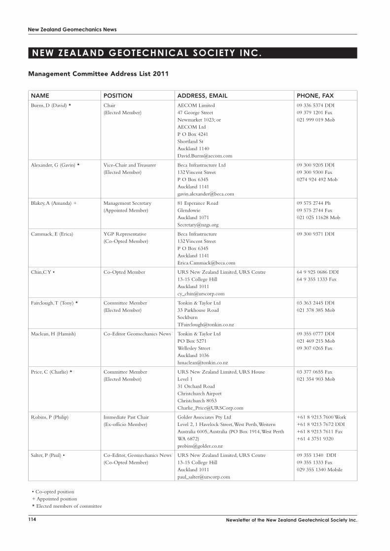
New Zealand Geomechanics News
114 Newsletter of the New Zealand Geotechnical Society Inc.
NAME POSITION ADDRESS, EMAIL PHONE, FAX
Burns, D (David) * Chair(Elected Member)
AECOM Limited47 George StreetNewmarket 1023; orAECOM LtdP O Box 4241Shortland StAuckland [email protected]
09 336 5374 DDI09 379 1201 Fax021 999 019 Mob
Alexander, G (Gavin) * Vice-Chair and Treasurer(Elected Member)
Beca Infrastructure Ltd132 Vincent StreetP O Box 6345Auckland [email protected]
09 300 9205 DDI09 300 9300 Fax0274 924 492 Mob
Blakey, A (Amanda) + Management Secretary(Appointed Member)
81 Esperance RoadGlendowieAuckland [email protected]
09 575 2744 Ph09 575 2744 Fax021 025 11628 Mob
Cammack, E (Erica) YGP Representative(Co-Opted Member)
Beca Infrastructure132 Vincent StreetP O Box 6345Auckland [email protected]
09 300 9371 DDI
Chin,C Y • Co-Opted Member URS New Zealand Limited, URS Centre13-15 College HillAuckland [email protected]
64 9 925 0686 DDI64 9 355 1333 Fax
Fairclough, T (Tony) * Committee Member(Elected Member)
Tonkin & Taylor Ltd33 Parkhouse [email protected]
03 363 2445 DDI021 378 385 Mob
Maclean, H (Hamish) Co-Editor Geomechanics News Tonkin & Taylor LtdPO Box 5271Wellesley StreetAuckland [email protected]
09 355 0777 DDI021 469 215 Mob09 307 0265 Fax
Price, C (Charlie) * Committee Member(Elected Member)
URS New Zealand Limited, URS HouseLevel 131 Orchard RoadChristchurch AirportChristchurch [email protected]
03 377 0655 Fax021 354 903 Mob
Robins, P (Philip) Immediate Past Chair(Ex-officio Member)
Golder Associates Pty Ltd Level 2, 1 Havelock Street, West Perth, Western Australia 6005, Australia (PO Box 1914, West Perth WA 6872) [email protected]
+61 8 9213 7600 Work +61 8 9213 7672 DDI+61 8 9213 7611 Fax+61 4 3751 9320
Salter, P (Paul) • Co-Editor, Geomechanics News (Co-Opted Member)
URS New Zealand Limited, URS Centre13-15 College HillAuckland [email protected]
09 355 1340 DDI09 355 1333 Fax029 355 1340 Mobile
• Co-opted position+ Appointed position* Elected members of committee
New ZealaNd GeotechNical society iNc.
Management Committee address List 2011

New Zealand Geomechanics News
115
Van Ballegooy, S (Sjoerd) * Committee Member(Elected Member)
Tonkin & Taylor LtdPO Box 5271Wellesley StreetAuckland [email protected]
09 355 0715 Ph021 378 964 Mob09 307 0265 Fax
Woodward, S (Simon) * Committee Member(Elected Member)
Geotek Services LtdP O 39015HowickManuaku [email protected]
09 535 9814 Ph09 535 7243 Fax0274 735 712 Mob
Davies, M (Prof. Michael) ISSMGE Australasian Vice President
Dean of EngineeringFaculty of EngineeringUniversity of AucklandPrivate Bag [email protected]
09 373 7599 Ext 87924
Meyers, A (Tony) ISRM Australasian Vice President
PO Box 210Rundle MallSA [email protected]
+61 8 8376 9096 Work+61 412 903 222 Cell
St George, J(John)
NZ ISRM Representative Department of Civil and Environmental EngineeringUniversity of AucklandPrivate Bag [email protected]
+64 9 373 7599 ext 88195 Work+64 9 373 7462 Fax
Williams, A (Ann) IAEG Australasian Vice President
Beca Infrastructure132 Vincent StreetP O Box 6345Auckland [email protected]
09 300 9172 Ph09 300-9300 Fax021-809-162 Mob
Gitte Abildgaard NZGS Web Manager Contact Gitte:[email protected]
Website: www.nzgs.org
Avalon ...............................................................................inside front cover
BECA Geotest .............................................................................................10
Boart Longyear (NZ) Ltd .....................................................................11
Broons ...............................................................................................................87
Brown Bros Ltd ...........................................................................................33
Civil Services (HB) Ltdz ..................................................................104
Contract Landscapes Ltd .........................................................................9
DCN Drilling Ltd .....................................................................................83
Drill Force NZ Ltd ..................................................................................16
Geogrubb ........................................................................................................81
Geotechnics Ltd .................................60-61,97, inside back cover
Geovert Ltd ...............................................................................................101
Griffiths.............................................................................................................84
Ground Investigation ...............................................................................27
Grouting Services NZ Ltd ...................................................................13
HRS Hoare Research Software .......................................................62
LimitState Limited .................................................................................102
Maccaferri NZ .....................................................outside back cover
McMillan Specialist Drilling Services ..........................................26
Opus International Hamilton ............................................................12
Peak Recruitment .....................................................................................15
Perry Drilling ............................................................................................103
RDCL ...............................................................................................................59
Techsoft Australasia Pty Ltd ...............................................................51
Tonkin and Taylor ............................................................................... 30,63
URS....................................................................................................................34
adveRtiseRs diRectoRy
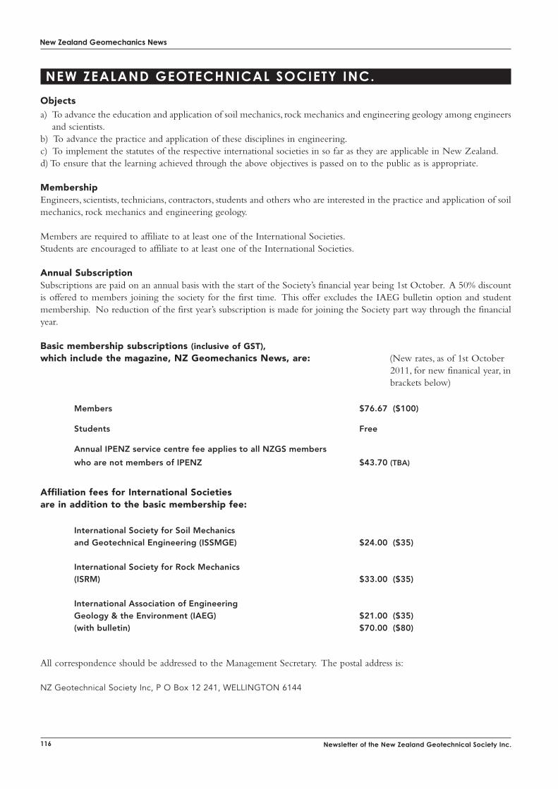
New Zealand Geomechanics News
116 Newsletter of the New Zealand Geotechnical Society Inc.
objectsa) To advance the education and application of soil mechanics, rock mechanics and engineering geology among engineers
and scientists.b) To advance the practice and application of these disciplines in engineering.c) To implement the statutes of the respective international societies in so far as they are applicable in New Zealand.d) To ensure that the learning achieved through the above objectives is passed on to the public as is appropriate.
MembershipEngineers, scientists, technicians, contractors, students and others who are interested in the practice and application of soil mechanics, rock mechanics and engineering geology.
Members are required to affiliate to at least one of the International Societies.Students are encouraged to affiliate to at least one of the International Societies.
annual Subscription Subscriptions are paid on an annual basis with the start of the Society’s financial year being 1st October. A 50% discount is offered to members joining the society for the first time. This offer excludes the IAEG bulletin option and student membership. No reduction of the first year’s subscription is made for joining the Society part way through the financial year.
Basic membership subscriptions (inclusive of GSt), which include the magazine, NZ Geomechanics News, are: (New rates, as of 1st October 2011, for new finanical year, in
brackets below) Members $76.67 ($100)
Students Free
Annual IPENZ service centre fee applies to all NZGS members
who are not members of IPENZ $43.70 (TBA)
affiliation fees for international Societies are in addition to the basic membership fee:
International Society for Soil Mechanics and Geotechnical Engineering (ISSMGE) $24.00 ($35)
International Society for Rock Mechanics (ISRM) $33.00 ($35)
International Association of Engineering Geology & the Environment (IAEG) $21.00 ($35) (with bulletin) $70.00 ($80)
All correspondence should be addressed to the Management Secretary. The postal address is:
NZ Geotechnical Society Inc, P O Box 12 241, WELLINGTON 6144
New ZealaNd GeotechNical society iNc.
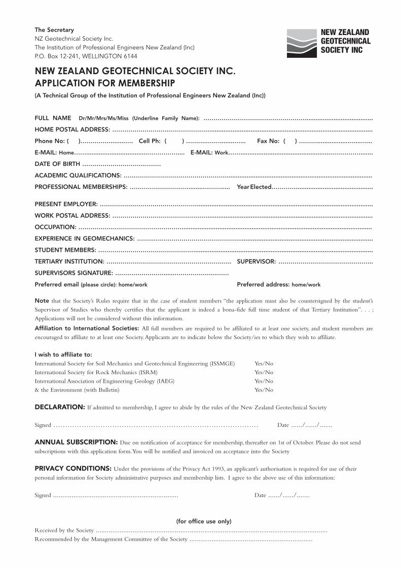
The SecretaryNZ Geotechnical Society Inc.The Institution of Professional Engineers New Zealand (Inc)P.O. Box 12-241, WELLINGTON 6144
New ZealaNd GeotechNical society iNc.aPPlicatioN FoR memBeRshiP(A Technical Group of the Institution of Professional Engineers New Zealand (Inc))
FULL NAME Dr/Mr/Mrs/Ms/Miss (Underline Family Name): …………………………………………….....................................
HOME POSTAL ADDRESS: …………………………………………...........................................................................................
Phone No: ( )……………........…. Cell Ph: ( ) ………..……........…... Fax No: ( ) ……….................…....…...
E-MAIL: Home……..................................…………….... E-MAIL: Work……..................................................…………….......
DATE OF BIRTH …………………………………
ACADEMIC QUALIFICATIONS: …………………………………………….................................................................................
PROFESSIONAL MEMBERSHIPS: ………………………….......………..... Year Elected…………...........................................
PRESENT EMPLOYER: …………………………………………..................................................................................................
WORK POSTAL ADDRESS: …………………………………………...........................................................................................
OCCUPATION: ……………………………………………..........................................................................................................
EXPERIENCE IN GEOMECHANICS: ……………………………………………..........................................................................
STUDENT MEMBERS: …………………………………………...................................................................................................
TERTIARY INSTITUTION: …………………………………………………….. SUPERVISOR: ………………………………………..
SUPERVISORS SIGNATURE: ……………………......………………………
Preferred email (please circle): home/work Preferred address: home/work
Note that the Society’s Rules require that in the case of student members “the application must also be countersigned by the student’s
Supervisor of Studies who thereby certifies that the applicant is indeed a bona-fide full time student of that Tertiary Institution”. . . ;
Applications will not be considered without this information.
Affiliation to International Societies: All full members are required to be affiliated to at least one society, and student members are
encouraged to affiliate to at least one Society. Applicants are to indicate below the Society/ies to which they wish to affiliate.
I wish to affiliate to:International Society for Soil Mechanics and Geotechnical Engineering (ISSMGE) Yes/No
International Society for Rock Mechanics (ISRM) Yes/No
International Association of Engineering Geology (IAEG) Yes/No
& the Environment (with Bulletin) Yes/No
DECLaratioN: If admitted to membership, I agree to abide by the rules of the New Zealand Geotechnical Society
Signed …………………………………………………………………………… Date ....../....../.......
aNNuaL SuBSCriPtioN: Due on notification of acceptance for membership, thereafter on 1st of October. Please do not send
subscriptions with this application form. You will be notified and invoiced on acceptance into the Society
PriVaCY CoNDitioNS: Under the provisions of the Privacy Act 1993, an applicant’s authorisation is required for use of their
personal information for Society administrative purposes and membership lists. I agree to the above use of this information:
Signed .................................................................... Date ....../....../.......
(for office use only)Received by the Society ..............................................................................................................................Recommended by the Management Committee of the Society ...................................................................
www.nzgs.org
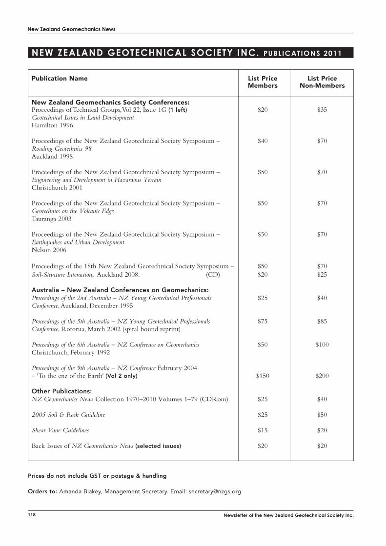
New Zealand Geomechanics News
118 Newsletter of the New Zealand Geotechnical Society Inc.
Publication Name List Price List Price Members Non-Members
New Zealand Geomechanics Society Conferences:Proceedings of Technical Groups, Vol 22, Issue 1G (1 left) $20 $35Geotechnical Issues in Land DevelopmentHamilton 1996
Proceedings of the New Zealand Geotechnical Society Symposium – $40 $70Roading Geotechnics 98Auckland 1998
Proceedings of the New Zealand Geotechnical Society Symposium – $50 $70Engineering and Development in Hazardous TerrainChristchurch 2001
Proceedings of the New Zealand Geotechnical Society Symposium – $50 $70Geotechnics on the Volcanic EdgeTauranga 2003
Proceedings of the New Zealand Geotechnical Society Symposium – $50 $70Earthquakes and Urban DevelopmentNelson 2006
Proceedings of the 18th New Zealand Geotechnical Society Symposium – $50 $70Soil-Structure Interaction, Auckland 2008. (CD) $20 $25
Australia – New Zealand Conferences on Geomechanics:Proceedings of the 2nd Australia – NZ Young Geotechnical Professionals $25 $40Conference, Auckland, December 1995
Proceedings of the 5th Australia – NZ Young Geotechnical Professionals $75 $85Conference, Rotorua, March 2002 (spiral bound reprint)
Proceedings of the 6th Australia – NZ Conference on Geomechanics $50 $100 Christchurch, February 1992
Proceedings of the 9th Australia – NZ Conference February 2004– 'To the enz of the Earth' (Vol 2 only) $150 $200
Other Publications:NZ Geomechanics News Collection 1970–2010 Volumes 1–79 (CDRom) $25 $40
2005 Soil & Rock Guideline $25 $50
Shear Vane Guidelines $15 $20
Back Issues of NZ Geomechanics News (selected issues) $20 $20
Prices do not include GST or postage & handling
Orders to: Amanda Blakey, Management Secretary. Email: [email protected]
New ZealaNd GeotechNical society iNc. PuBlicatioNs 2011
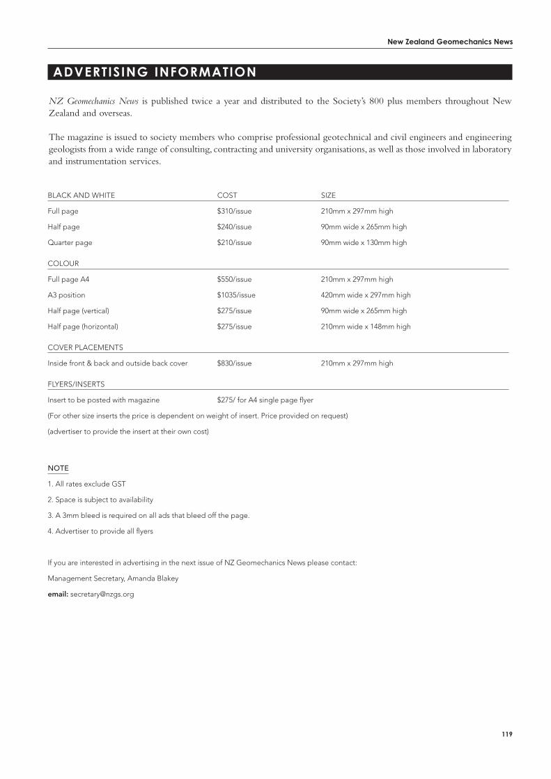
New Zealand Geomechanics News
119
adveRtisiNG iNFoRmatioN
NZ Geomechanics News is published twice a year and distributed to the Society’s 800 plus members throughout New Zealand and overseas.
The magazine is issued to society members who comprise professional geotechnical and civil engineers and engineering geologists from a wide range of consulting, contracting and university organisations, as well as those involved in laboratory and instrumentation services.
BLACK AND WHITE COST SIZE
Full page $310/issue 210mm x 297mm high
Half page $240/issue 90mm wide x 265mm high
Quarter page $210/issue 90mm wide x 130mm high
COLOUR
Full page A4 $550/issue 210mm x 297mm high
A3 position $1035/issue 420mm wide x 297mm high
Half page (vertical) $275/issue 90mm wide x 265mm high
Half page (horizontal) $275/issue 210mm wide x 148mm high
COVER PLACEMENTS
Inside front & back and outside back cover $830/issue 210mm x 297mm high
FLYERS/INSERTS
Insert to be posted with magazine $275/ for A4 single page flyer
(For other size inserts the price is dependent on weight of insert. Price provided on request)
(advertiser to provide the insert at their own cost)
note
1. All rates exclude GST
2. Space is subject to availability
3. A 3mm bleed is required on all ads that bleed off the page.
4. Advertiser to provide all flyers
If you are interested in advertising in the next issue of NZ Geomechanics News please contact:
Management Secretary, Amanda Blakey
email: [email protected]
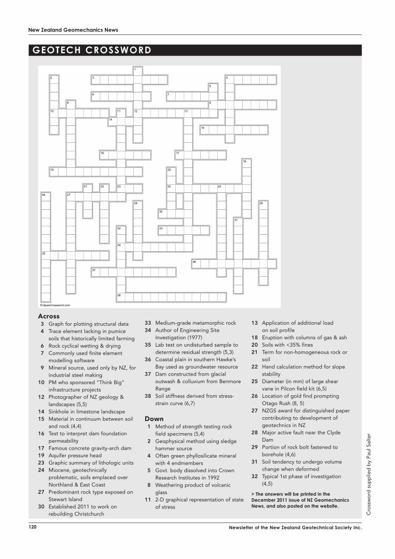
New Zealand Geomechanics News
120 Newsletter of the New Zealand Geotechnical Society Inc.
Geotech cRosswoRd
across 3 Graph for plotting structural data 4 Trace element lacking in pumice
soils that historically limited farming 6 Rock cyclical wetting & drying 7 Commonly used finite element
modelling software 9 Mineral source, used only by NZ, for
industrial steel making 10 PM who sponsored “Think Big”
infrastructure projects 12 Photographer of NZ geology &
landscapes (5,5) 14 Sinkhole in limestone landscape 15 Material in continuum between soil
and rock (4,4) 16 Test to interpret dam foundation
permeability 17 Famous concrete gravity-arch dam 19 Aquifer pressure head 23 Graphic summary of lithologic units 24 Miocene, geotechnically
problematic, soils emplaced over Northland & East Coast
27 Predominant rock type exposed on Stewart Island
30 Established 2011 to work on rebuilding Christchurch
33 Medium-grade metamorphic rock 34 Author of Engineering Site
Investigation (1977) 35 Lab test on undisturbed sample to
determine residual strength (5,3) 36 Coastal plain in southern Hawke’s
Bay used as groundwater resource 37 Dam constructed from glacial
outwash & colluvium from Benmore Range
38 Soil stiffness derived from stress-strain curve (6,7)
Down 1 Method of strength testing rock
field specimens (5,4) 2 Geophysical method using sledge
hammer source 4 Often green phyllosilicate mineral
with 4 endmembers 5 Govt. body dissolved into Crown
Research Institutes in 1992 8 Weathering product of volcanic
glass 11 2-D graphical representation of state
of stress
13 Application of additional load on soil profile
18 Eruption with columns of gas & ash 20 Soils with <35% fines 21 Term for non-homogeneous rock or
soil 22 Hand calculation method for slope
stability 25 Diameter (in mm) of large shear
vane in Pilcon field kit (6,5) 26 Location of gold find prompting
Otago Rush (8, 5) 27 NZGS award for distinguished paper
contributing to development of geotechnics in NZ
28 Major active fault near the Clyde Dam
29 Portion of rock bolt fastened to borehole (4,6)
31 Soil tendency to undergo volume change when deformed
32 Typical 1st phase of investigation (4,5)
> the answers will be printed in the december 2011 issue of NZ Geomechanics News, and also posted on the website.
Cro
ssw
ord
sup
plie
d b
y P
aul S
alte
r
1
2 3 4
5
6 7
8 9
10 11 12 13
14
15
16 17
18
19 20
21 22 23 24 25
26 27
28 29
30
31
32 33
34
35
36
37
38
EclipseCrossword.com


