Embed Size (px)
Citation preview

A R C H I V E S O F M E T A L L U R G Y A N D M A T E R I A L S
Volume 56 2011 Issue 4
DOI: 10.2478/v10172-011-0101-1
E. BEŁTOWSKA-LEHMAN∗, A. GÓRAL∗, P. INDYKA∗
ELECTRODEPOSITION AND CHARACTERIZATION OF Ni/Al2O3 NANOCOMPOSITE COATINGS
ELEKTROOSADZANIE I CHARAKTERYSTYKA NANOKOMPOZYTOWYCH POWŁOK Ni/Al2O3
The composite coatings containing of nanocrystalline Ni matrix and hard nano-sized γ-Al2O3 were electrodeposited in asystem with a rotating disk electrode. The bath composition (nickel salts and buffer concentration, presence of surface-activeagents and inert particles) influence on kinetics of Ni electrodeposition as well as on structural properties (morphology, phasecomposition, texture, residual stresses) and microhardness of Ni/Al2O3 coatings has been investigated. SEM and TEM studiesshow more uniform arrangement of Al2O3 particles in the matrix, however a tendency to agglomeration is observed. Surfactantapplication to a saccharine containing bath effectively improves the dispersion of nanoparticles into the nickel matrix. Theaddition of Al2O3 particles results in decrease of the average Ni crystallite size. The introduction of additive into electrolytesolution resulted in change of stress character of composite coatings (from tensile to compressive). The microhardness of Nimatrix was enhanced (about 40%) due to incorporation of ceramic particles.
Keywords: electrodeposition, nanocomposite, nickel coatings, Al2O3 nanoparticles
Nanokrystaliczne powłoki kompozytowe z osnową Ni zawierające ceramiczną fazę dyspersyjną w postaci γ-Al2O3 o roz-miarach nanometrycznych zostały elektroosadzone w układzie z wirującą elektrodą dyskową. W pracy analizowano wpływskładu kąpieli (zawartość soli niklu, obecność związków powierzchniowo-czynnych i cząstek obojętnych) na kinetykę procesuelektroosadzania, jak również na właściwości strukturalne (morfologię, skład fazowy, teksturę, naprężenia własne) oraz mikro-twardość powłok Ni/Al2O3. Badania wykonane za pomocą SEM i TEM wykazały, że cząstki Al2O3 są w znacznym stopniurównomiernie rozmieszczone w osnowie, jednak z tendencją do aglomeracji. Dodanie środka powierzchnio-czynnego do kąpielizawierającej sacharynę zwiększyło dyspersję nanocząstek w osnowie niklu. Stwierdzono, że obecność cząstek Al2O3 powodujeobniżenie wielkości krystalitów osnowy Ni. Wprowadzenie dodatków do elektrolitu wpłynęło na zmianę charakteru naprężeńwłasnych uzyskanych powłok, jak również na ich mikrotwardość (wzrost o około 40%).
1. Introduction
Particle-reinforced metal matrix composite (MMC)coatings have found wide use in various engineering ap-plications due to excellent mechanical properties com-pared to their components [1]. In composite materials,the metal matrix properties are modified by addition ofvarious insoluble substances e.g. hard oxides as Al2O3,ZrO2, SiO2, carbides SiC and WC, diamond or solidlubricants (graphite, MoS2 or PTFE) [2, 3]. The MMCstructure allows to appear the interaction in phase bound-ary between the ductile matrix and embedded particles,which results in their specific characteristics differ fromthe component properties. The presence of ceramic par-ticles could prevent migration of grain boundaries anddislocation movements resulting in enhanced thermalstability and hardness of MMC coating. The coatings
demonstrate the metallic features (e.g. electric and ther-mal conductivity, plasticity) and the modifier properties(e.g. hardness, wear resistance). The composition andmicrostructure of electrodeposited composites controltheir functional properties, however the particles of suit-able dimension must be uniformly dispersed to exhibitthe dispersion-hardening effect.
Several metals, such as nickel, copper, chromium,gold, zinc, cobalt or alloys (e.g. Ni-Cu, Zn-Co, Co-Ni,Ni-Fe) were mainly used as a metallic matrix [4-7].Among others nickel as a durable and tough metalhas been widely used, due to its resistant to corro-sion and abrasion. Moreover, some properties could beimproved using nickel of nanocrystalline instead mi-crocrystalline structure, as nanomaterials exhibit uniquephysico-chemical characteristics. Furthermore, dispersedhard particles (oxides, carbides) incorporated into a nick-
∗ INSTITUTE OF METALLURGY AND MATERIALS SCIENCE, POLISH ACADEMY OF SCIENCES, 30-059 KRAKÓW, 25 REYMONTA STR., POLAND

920
el deposit can enhance significantly technical parametersof such material, including its mechanical, tribologicaland anti-corrosion behavior. The inert particles can varyfrom micrometric to nanometric sizes. Typical diameterof most often used particles are within the range between1 and 100 µm, but recently the application of ultrafineparticles become increasingly important.
Nanocrystalline materials have been mainly pro-duced by inert gas condensation, ball milling, mechani-cal alloying, mechanochemical processing and electrode-position. Compared to other methods, electrodeposition,as a low-temperature, cheap and simple method, is a su-perior technique for preparation of nanocrystalline met-als and alloys as well as nanocomposite coatings in asingle step without secondary treatment [8,9]. Electro-chemical deposition shows also the additional advantagessuch as high deposition rate, simple equipment, the au-tomation possibility, easy control of microstructure andthickness (from nanometers up to several tens of mi-crometers) of deposits plated uniformly on substrates ofcomplicated shapes and large surfaces.
During electrodeposition process, insoluble ceramicparticles suspended in the multicomponent galvanic bathare embedded in the simultaneously growing metal. Thecodeposition mechanism for the dispersion of inert parti-cles into metallic coatings is still not entirely understooddespite numerous theories presented in literature (e.g.electrophoresis, mechanical entrapment, adsorption andconvective-diffusion [2]), due to many factors influenc-ing the electrodeposition process and their interaction.Incorporation of the ceramic particles into a nickel ma-trix requires the stable suspension in electrolyte, whichis difficult to perform especially in the case of nanodis-persed phases. Ultrafine ceramic particles show a tenden-cy to agglomerate in the bath due to high surface freeenergy. Ceramic particles of considerably developed sur-face form with the electrolyte solution the heterogeneousand thermodynamic unstable binary system, which sta-bility depends mainly on the type, dimensions, concen-tration and structure of particles as well as on electrolyteparameters.
Over the past decade electrodeposition of Ni-matrixcomposite coatings has been the subject of numerousinvestigations. A variety of particles of different sizeranging from 4 nm to 100 µm have been incorporated in-to nickel electrodeposits: e.g. silicon carbide (SiC) [10,11], cerium dioxide (CeO2) [12], boron carbide (B4C)[13], silicon dioxide (SiO2) [14], silicon nitride (Si3N4)[15] titanium dioxide (TiO2) [16,17], zirconium dioxide(ZrO2) [18], aluminum dioxide (Al2O3) [19-28] and oth-ers. One of the most promising materials is the Ni/Al2O3nanocomposite, that can find wide engineering appli-
cation as coatings for engine cylinders, high-pressurevalves, car accessories, aircraft microelectronics etc.
The main aim of the present study was to uniformlyembedded nano-Al2O3 particles into the nanocrystallinenickel matrix by electrochemical deposition from aque-ous baths of different composition and to characterizethe microstructural and micromechanical properties ofobtained Ni/Al2O3 coatings.
The influence of embedded non-conducting Al2O3nanoparticles on structure characteristics of the resultingNi/Al2O3 coatings was investigated in order to obtainnanocomposite with high hardness and relatively lowresidual stresses. As a comparison, the pure Ni coatingswere also prepared and characterized under the sameconditions.
2. Experimental details
The nickel metallic and Ni/Al2O3 nanocompos-ite coatings were electrochemically deposited in mod-ified low (LC) and high-concentrated (HC) Watt’s-typebaths into which Al2O3 nanopowder (Sigma Aldrich) inamount of 20 g dm−3 was added. The pH of the elec-trolytes was adjusted to 4. For optimized composition ofplating solution, the additive EP, consisting of organiccompounds mixture was used to reduce both agglomera-tion of ceramic particles and residual stresses in deposits.The basic chemical composition of the electrolytes usedis given in Table 1.
TABLE 1Chemical composition of the electrolytes of pH 4
Bath numberConcentration [g dm−3]
NiSO4·6H2O NiCl2·6H2O H3BO3 Al2O3
High-concentrated (HC)
1 300 50 40 —
2 300 50 40 20
Low-concentrated (LC)
3 120 70 50 —
4 120 70 50 20
Low-concentrated (LC) with 2.78 g EP additive
5 120 70 50 20
The electrolysis was carried out in 0.75 dm3cell,at room temperature, under galvanostatic regime (3-5 Adm−2), in a system with a rotating disc electrode (RDE).The low-carbon steel cathode of 0.028 dm2, rotating at25 rad s−1 was supplied by potentiostat/galvanostat PAR273A. The platinum or nickel sheets (∼0.05 dm2) wereused as an anode.
921
Prior to each experiment, the steel substrates weredegreased, chemically polished in solution of oxalic acidand hydrogen peroxide at 35◦C and then rinsed in dis-tilled water. The cathode potentials were referred to thesaturated calomel electrode (SCE) and were correctedfor ohmic drop by the current interupt method (CI).Electrochemical measurements were performed in po-tentiostatic or potentiodynamic (2 mV s−1) regimes inthe potential range from -0.6 V/SCE to -2.2 V/SCE.Before the co-deposition process, the alumina particleswere dispersed in the bath using mechanical stirrer (500rpm) for 24 hours, at room temperature. During last 5hours, the suspension was extra treated by ultrasounds. Inelectrodeposition process, additionally to the disk cath-ode rotating at 25 rad s−1, the intensive mechanical stir-ring (300 rpm) was employed, in order to maintain theAl2O3 powder in suspension. After electrolysis the sam-ples were ultrasonically cleaned in ethanol for 1 min toremove loosely adsorbed particles from the coating sur-face and then dried. Mass of deposits was determinedby the analytical balance KERN ALT 220-5DAM, withaccurate to five points. The coating thicknesses (in therange of 2-35 µm) were estimated on the basis of thedeposit weight and the cross-section observations. Thesurface morphology and cross-section of coatings wereexamined by scanning electron microscopy (ESEM FEIXL30). Concentrations of elements (Ni, Al, O, Fe) in theelectrodeposits were determined using energy-dispersiveX-ray spectroscopy (EDS). The cross-section microstruc-ture observations of samples prepared by FIB (FocusedIon Beam) technique were performed by TECNAI G2
F20-TWINTM Transmission electron microscope. Thephase composition, crystallite size, texture and residualstresses of the deposits were studied by X-ray diffractiontechnique using CoKα radiation (diffractometers: PhilipsPW 1710, Philips X’Pert equipped with texture goniome-ter ATC3). The crystallite size was evaluated by peak
broadening analysis of X-ray diffraction patterns, usingthe Scherrer equation: d = Kλ
β cos θ , where d – averagecrystallite dimension, K – Scherrer constant (assumedas 0.9), λ – the incident radiation wavelength, β – thecorrected peak width at half-maximum intensity, θ – an-gular position. The crystallographic texture of Ni andNi/Al2O3 layers deposited on the polycrystalline steelsubstrates was analyzed based on the back-reflection polefigures. The analysis was performed using the orientationdistribution function (ODF) calculated by the discreteADC method from the incomplete pole figures [29]. Theresidual stresses in coatings were estimated by a sin2ψmethod based on X-ray diffraction data. The hardness ofthe coatings was measured using a Vickers microinden-tator (Micro-Hardness Tester CSM Instrument) under anapplied load of 200 mN (an average of 10 measurements)in different locations of each coating surface.
3. Results and discussion
3.1. Characterization of the Al2O3 dispersive phase
The commercial Al2O3powder produced by SigmaAldrich has been used as original material. XRD andTEM methods were used to characterize the dispersivephase parameters.
3.1.1. XRD technique
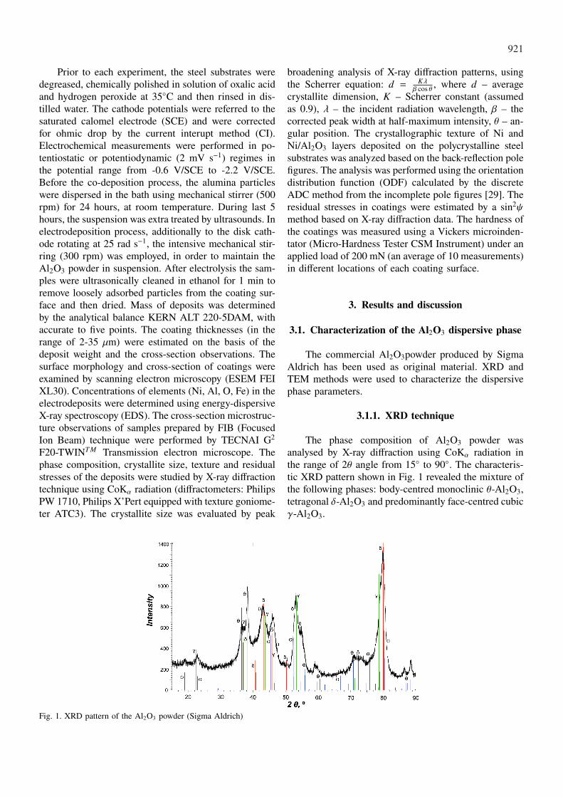
The phase composition of Al2O3 powder wasanalysed by X-ray diffraction using CoKα radiation inthe range of 2θ angle from 15◦ to 90◦. The characteris-tic XRD pattern shown in Fig. 1 revealed the mixture ofthe following phases: body-centred monoclinic θ-Al2O3,tetragonal δ-Al2O3 and predominantly face-centred cubicγ-Al2O3.
Fig. 1. XRD pattern of the Al2O3 powder (Sigma Aldrich)

922
3.1.2. TEM technique
TEM microstructure observations show, that Al2O3powder contained the fine needle-shaped crystallites ofsize definitely below 100 nm and the irregular frac-tion of crystallites dimension in the range of 20-50 nm(Fig. 2). The average particle size has been estimated asabout 30 nm. Electron diffraction patterns of examinedpowder revealed the presence of the three strong andtwo weak rings related to the interplanar distance inthe range of 0.14-0.28 nm (Table 2). The interplanardistance analysis confirmed predominantly the presenceof γ phase and relatively smaller amount of the θ and δphases. However, similarly to XRD analysis, the α phaseof corundum has been excluded.
The impact of ceramic particles in galvanic bath onthe electrodeposition process characteristics is ambigu-ous. Regarding the literature data, it has been found insome cases, that powder suspended in electrolyte solu-tion promotes the higher current densities (depolariza-tion effect) and the ( j – E) metal-matrix reduction curvesare shifted to the less negative potentials [5, 20-32].However, in other systems polarization of electrodepo-sition process is observed [6, 33]. The presence of inertparticles could influence the metal deposition processin different way [11]. Incomplete embedding of parti-cles into the growing metal matrix results in apparentdecrease of active cathode surface due to the blockingeffect. On the other hand, the ceramic nano-particlescompletely incorporated into nickel matrix could lead tosurface development and in consequence to the decreaseof effective current density of electrodeposition process.
Fig. 2. TEM microstructure of Al2O3 powder
TABLE 2Identification of interplanar distances of γ-Al2O3 planes
No.d [ ]Å
measuredd [ ]Å
databaseγ-Al2O3
planes
1 2.77 2.79 220
2 2.42 2.38 311
3 1.98 1.98 400
4 1.40 1.40 440

923
Figure 3 shows polarization curves for the steel cath-ode in the Ni plating solutions of different composi-tions, with and without Al2O3 dispersive phase (Table1), recorded under potentiodynamic conditions (2 mVs−1) at 25 rad s−1 disk rotation speed. Table 3 and Ta-ble 4 present respectively: the rate (expressed in ca-thodic current density) of the nickel electrodepositionprocess and the current density ratio determined (at se-lected cathode potentials) in examined electrolyte solu-tions. As expected, over the whole polarization range,the rate of Ni electrodeposition process from the Ni(II)high-concentrated bath increases (about 1.3 times) com-pared to the low-concentrated solution.
P)
Fig. 3. Global polarization curves recorded under potentiodynam-ic conditions (2 mV s−1), at 25 rad s−1, in examined solutions ofcomposition given in Table 1
TABLE 3Ni electrodeposition rate ( j), A dm−2
Bathnumber inTable 1
Bath typeCathode potential, -V/SCE
1.2 1.4 1.6 1.8 2.0 2.2
1 HC 3.66 5.94 8.42 10.97 13.14 16.12
3 LC 2.87 4.69 6.68 8.70 10.61 12.51
2 HC+Al2O3 2.09 3.77 5.23 6.75 7.29 4.69
4 LC+Al2O3 1.86 3.18 4.47 5.90 7.22 8.43
5LC+Al2O3
+EPadditive
2.22 3.76 5.32 6.75 8.5 9.93
The Ni/Al2O3 composite deposition is strongly in-hibited in relation to Ni(II) separate discharge, regardlessof the nickel concentration in solution. However, thiseffect is more pronounced for high-concentrated bath(HC), where at the cathode potentials more negativethan about – 2 V/SCE the electrode surface blocking by
ceramic particles is noticed. For low-concentrated solu-tion (LC), practically constant (about 1.5 times) decreaseof the Ni/Al2O3 deposition current density without theblocking effect (as found for the higher Ni(II) concen-tration in bath) is observed. It is also necessary to takeinto consideration that the cathode surface was calcu-lated from the geometrical area and the current densi-ty was referred to it. Moreover, for the disk workingelectrode of 18 mm diameter used in the coating elec-trodeposition, the resistance of the solution (Rs) whichdepends on specific solution conductivity and cathodearea, is substantial and cannot be neglected. The effectof the electrolyte composition on the IR potential dropin solutions is shown in Figure 4 and in Table 5 (forthe current density of 3 A dm−2). Indeed, due to lowerspecific conductivity of the suspension compared to thepure Ni(II) bath, for low-concentrated solution contain-ing inert particles the maximum IR potential drop (370mV) was observed. However, the presence of the EPadditive (2.78 g dm−3) in that electrolyte (LC) resultedin increase of its conductivity (particle de-agglomerationand promotion of specific cationic adsorption) and thedifference in IR potential reached value of about 60 mVcompared to solution containing only hard ceramic par-ticles.
TABLE 4The ratio of cathodic current densities
Bath typeCathode potential, -V/SCE
1.2 1.4 1.6 1.8 2.0 2.2
HC/LC 1.3 1.3 1.3 1.3 1.2 1.3
HC/HC+Al2O3 1.8 1.8 1.6 1.6 1.8 3.4
LC/LC+Al2O3 1.5 1.5 1.5 1.5 1.5 1.5LC/LC+Al2O3
+EP additive 1.3 1.3 1.3 1.3 1.3 1.3
Fig. 4. IR potential drop in examined solutions versus cathode currentdensity

924
TABLE 5Deposition potentials, IR potential drop and deposition rate of the metallic and composite coatings for the current density of 3 A dm−2
Bath typeDepositionpotential,mV/SCE
IR potentialdrop, mV
Tafel slope,V/decade
Deposition rate
mg dm−2 s−1 µm dm−2 s−1
HC -1162 -235 0.13 0.84 0.26
LC -1218 -256 0.12 0.77 0.23
HC+Al2O3 -1322 -317 0.10 0.86 0.34
LC+Al2O3 -1394 -370 0.10 0.90 0.40LC+Al2O3
+ EP additive -1320 -314 0.10 0.85 0.26
For characterization, the coatings of different thick-nesses (in the range of 2-35 µm) were obtained in all ex-amined baths, under galvanostatic conditions (3 A dm−2)at the disk speed of 25 rad s−1. The calculated rate (ex-pressed in mg dm−2 s−1 and µm dm−2 s−1) of Ni/Al2O3composite deposition was closed and slightly higher thanfor pure Ni coatings obtained in the same operating con-ditions (Table 5). The cathodic current efficiency wasfound to be typical for nickel electrodeposition fromWatts bath: 95% – 98.9% for deposition at current den-sity of 3 A dm−2 from solutions without particles. In thepresence of the Al2O3 phase only a slight decrease inthe current efficiency to approximately 90% – 96.5%was observed. Also, the Tafel slopes in the presenceand absence of suspended Al2O3 particles were simi-lar (Table 5): 120-130 mV/decade for the pure bath and
100 mV/decade for the bath with particles, the differenceis within the range of accuracy of the measurements.
The presence of Al2O3 particles in the electrolytescauses an increase in the cathodic polarization, but theslope is unchanged. The adsorption of particles on cath-ode surface hinders the deposition of Ni(II), but does notsignificantly affect the electrochemical reaction mecha-nism.
3.2. Characterization of coatings
3.2.1. XRD phase analysis and residual stresses
XRD investigations of phase composition and resid-ual stresses of all deposits examined were performedusing CoKα filtered radiation. The crystallite size of thecoatings was evaluated by peak broadening analysis ofX-ray diffraction patterns (Scherrer equation).
Fig. 5. XRD patterns of Ni and Ni/Al2O3 coatings of thickness about 6 µm obtained from different baths

925
TABLE 6Residual stress values of Ni and Ni/Al2O3 coatings
Coating andbath types
Ni (HC) Ni (LC)Ni/Al2O3
(HC+Al2O3)Ni/Al2O3
(LC+Al2O3)
Ni/Al2O3(LC+Al2O3
+ EP additive)
Residual stress σav, [MPa]
Thickness,µm
6 124 ± 35 136 ± 37 120 ± 23 116 ± 24 -370 ± 47
10 115 ± 23 92 ± 27 93 ± 32 84 ± 34 -238 ± 39
Fig. 5 shows the exemplary XRD patterns of nick-el and Ni/Al2O3 coatings produced from LC and HCbaths. The XRD patterns of Ni/Al2O3 coatings showedthat structure exhibits a nickel matrix at different 2θ an-gles, no peaks characterized Al2O3 were visible. It isknown that a small amount of light elements (low Z)in a heavy-element (high Z) matrix are invisible due tothe absorption of the X-ray [34]. In addition, the Al2O3particles have nanometer sizes hence, extensively broad-ened diffraction peaks are difficult to observe. On theother hand, the grain size of deposits is strongly influ-enced by the presence of additive in electroplating bath.The addition of small amount of Al2O3 has consider-able effect on the grain refining of nickel deposits. Onthe basis of XRD reflection line broadening (using theAPD program) [35] the Ni crystallite sizes in metalliccoatings were evaluated (reference to (200) reflection) tobe: 30 nm (LC) and 26 nm (HC).
Addition of Al2O3 particles into nickel matrix virtu-ally does not change the Ni crystallite size in compositecoatings obtained from both LC and HC baths. Howev-er, in coatings obtained from the low-concentrated (LC)bath with EP additive it was significantly lower – about13 nm. These results indicated that the addition of hardAl2O3 particles led to decrease in the average Ni crys-tallite size in Ni coatings obtained from LC bath. It iswell known that the grain size of deposits is stronglyinfluenced by the presence of additives in electroplatingbath [36]. The important role of additive as a grain re-finer is its effect on blocking the surface by formation ofcomplex compounds which increases the frequency ofnucleation and decreases the surface diffusion of nickelions adsorbed on cathode surface, and hence retards thecrystallite growth [37].
X-ray diffraction plays a prominent role amongnon-destructive methods for determination of residualstresses in materials. Values of residual stresses of ex-amined coatings were calculated for 220 plane (2θ =91.8◦) regarding the diffraction elastic constants [38]by the Reuss model using a computer program Stress[39]. Evaluated residual stresses are mean values forthe volume defined by the cross section of X-ray beam
and by the penetration depth of the used radiation. Thestresses have been calculated by sin2ψ procedure [38].Table 6 presents stress values determined for coatings(with thickness of 6 and 10 µm) electrodeposited fromdifferent baths.
The values of tensile stresses estimated in the coat-ings electrodeposited from LC and HC solutions of thick-ness 6 µm were at level of about 120 MPa, however inthe coatings of thickness 10 µm they were lower (100MPa). Additionally, the coatings containing Al2O3 par-ticles were characterized by insignificantly lower values(within limits of error) of residual stress than these with-out ceramic particles. This relation was observed for bothinvestigated baths LC and HC. The Ni/Al2O3 depositsobtained from LC solution with 2.78 g EP additive werefound to possess compressive residual stresses, whichvalues diminished with increasing coating thickness.
3.2.2. Texture
The pure electroplated nickel films frequently re-vealed a fibre texture of different components: <100>(observed the most frequently), <110>, <210>, <111>,<211> depending on plating conditions, mainly pH andcurrent density of metallic deposition [22,27,40]. Thetextural developments are usually attributed to the exis-tence or formation of different chemical species duringthe cathodic process [41]. Molecular or atomic hydro-gen as well as hydroxyl groups adsorbed on the cath-ode predominantly act as inhibitors and selectively pro-mote the growth in different crystallographic directions[27, 41]. Texture of examined Ni and Ni/Al2O3 coat-ings was analysed using the orientation distribution func-tions (ODF) calculated by the discrete ADC method[29] from the incomplete pole figures measured usingX-ray diffraction. Analysis of pole figures and orienta-tion distribution functions revealed occurrence of strong{210}<uvw> fibre texture component in all examinedcoatings. The {100}<uvw> texture was observed only inthe Ni electrodeposited from LC bath. In examined sam-ples the codeposited Al2O3 particles have not influencedthe preferred growth orientations for Ni grains. How-ever, the Ni/Al2O3 coating obtained from LC solution

926
with EP additive exhibited the most diverse texture of all and it also revealed {110}<uvw> fibre texture besidementioned above. Figure 6 presents created 3D plots ofthe characteristic ODF sections (for φ2 = 0) [42].
Fig. 6. ODF sections (for φ2 = 0) of Ni and Ni/Al2O3 deposits (thickness of 6 µm): a) Ni (LC), b) Ni/Al2O3 (LC), c) Ni (HC), d) Ni/Al2O3
(HC), e) Ni/Al2O3 (LC with 2.78 g EP additive)
Fig. 7. SEM (secondary electron) image of surface and cross-section of Ni coatings deposited from high-concentrated (a) and low-concentrated(b) baths

927
3.2.3. Microstructure
Figure 7 presents the SEM images of surface andcross-section of metallic nickel coatings electrodepositedfrom both examined solutions (HC and LC). A regularpyramidal structure was observed at the surface of thenickel coatings, especially for Ni (HC) (Fig. 7a). As seen,the average dimension of the pyramids on the surface ofNi coatings obtained from solution of lower Ni(II) con-centration is substantially reduced, resulting in more reg-ular morphology and a smaller surface roughness grade(Fig. 7b). The cross-section SEM images revealed the allcoatings were well adhered to the steel substrate.
The addition of γ-alumina nanoparticles (20 g dm−3)into nickel plating baths (HC and LC) resulting in thesignificantly changes in the surface morphology of thecomposite coatings. Figure 8 exemplifies the element
concentration distribution along the line presented inSEM image of obtained Ni/Al2O3 coating.
Figure 9 compares the surface of the composite de-posits produced in the both type of baths. As seen, thetypical pyramidal morphology of nickel deposits fromadditive-free baths (Fig. 7) has changed into greatly re-fined (spherical) globular microstructure. The same ef-fect related to the change from preferred orientation torandom oriented composite deposits was observed forthe nickel coatings with SiC nanoparicles [43]. More-over, the Ni/Al2O3 composite coatings (Fig. 9b) elec-trodeposited from low-concentrated solution (bath no.4, Table 1) are more fine, compact and uniform thanthat of the HC nickel deposits (Fig. 9a). The similarionic strength effect of the solution on the particle ag-glomeration was observed for Ni/Al2O3 deposited fromsulfamate bath [24].
Fig. 8. Element distribution (linescan) of exampled Ni/Al2O3 composite coating electrodeposited from HC solution
Fig. 9. SEM backscattered electron image of surface of Ni/Al2O3 coatings deposited from high-concentrated (a) and low-concentrated (b)baths

928
Fig. 10. The cross-sectional morphology of Ni/Al2O3 electrodeposited from high-concentrated (a) and low-concentrated (b) baths
Fig. 11. SEM image of surface and cross-section of composite coatings deposited from bath with organic additions (bath no. 5, Table 1)
The SEM backscattered electron images ofcross-section of nanocomposite Ni/Al2O3 coatings elec-trodeposited from HC an LC solutions are shown inFigure 10. As seen the Al2O3 particles (in dark con-trast) are more homogeneously dispersed in the volumeof composite deposit obtained in low-concentrated so-lution (Fig. 10b) compared to HC bath, although someof them formed agglomerated clusters. Moreover, thesecoatings are characterized by a smoother surface mor-phology. Hence, it was adopted that the low-concentratedbath is most attractive for further optimization of particledispersion.
The introduction of the EP surfactant intolow-concentrated bath led to de-agglomeration ofnano-alumina particles as seen in Fig. 11, in which SEMimages of surface and cross-section of composite coat-ings deposited from bath with organic additions are pre-sented.
The chemical composition of Ni/Al2O3 compositeselectrodeposited from different electrolyte solutions was
determined by EDS technique (Table 7). The embeddedweight percentage (wt. %) of Al2O3 in the compositewas found to be comparable within all investigated typeof coatings.
TABLE 7Ceramic phase content in Ni/Al2O3 electrodeposits obtained in
different solutions
Coating and bath typesAl2O3 content,
wt. %Ni/Al2O3
(HC+Al2O3)1.3 ± 0.1
Ni/Al2O3
(LC+Al2O3)1.0 ± 0.1
Ni/Al2O3 (LC+Al2O3
+ EP additive) 0.9 ± 0.1
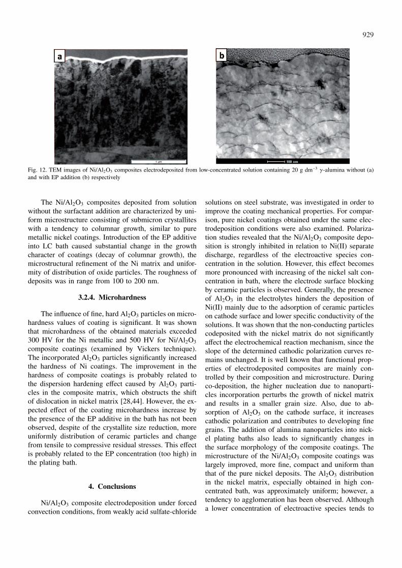
The microstructure of the Ni/Al2O3 composites ob-tained in pure low-concentrated bath and containing EPadditive was examined by TEM technique (Fig. 12). Asseen a noticeable difference between the microstructureswas observed.
929
Fig. 12. TEM images of Ni/Al2O3 composites electrodeposited from low-concentrated solution containing 20 g dm−3 γ-alumina without (a)and with EP addition (b) respectively
The Ni/Al2O3 composites deposited from solutionwithout the surfactant addition are characterized by uni-form microstructure consisting of submicron crystalliteswith a tendency to columnar growth, similar to puremetallic nickel coatings. Introduction of the EP additiveinto LC bath caused substantial change in the growthcharacter of coatings (decay of columnar growth), themicrostructural refinement of the Ni matrix and unifor-mity of distribution of oxide particles. The roughness ofdeposits was in range from 100 to 200 nm.
3.2.4. Microhardness
The influence of fine, hard Al2O3 particles on micro-hardness values of coating is significant. It was shownthat microhardness of the obtained materials exceeded300 HV for the Ni metallic and 500 HV for Ni/Al2O3composite coatings (examined by Vickers technique).The incorporated Al2O3 particles significantly increasedthe hardness of Ni coatings. The improvement in thehardness of composite coatings is probably related tothe dispersion hardening effect caused by Al2O3 parti-cles in the composite matrix, which obstructs the shiftof dislocation in nickel matrix [28,44]. However, the ex-pected effect of the coating microhardness increase bythe presence of the EP additive in the bath has not beenobserved, despite of the crystallite size reduction, moreuniformly distribution of ceramic particles and changefrom tensile to compressive residual stresses. This effectis probably related to the EP concentration (too high) inthe plating bath.
4. Conclusions
Ni/Al2O3 composite electrodeposition under forcedconvection conditions, from weakly acid sulfate-chloride
solutions on steel substrate, was investigated in order toimprove the coating mechanical properties. For compar-ison, pure nickel coatings obtained under the same elec-trodeposition conditions were also examined. Polariza-tion studies revealed that the Ni/Al2O3 composite depo-sition is strongly inhibited in relation to Ni(II) separatedischarge, regardless of the electroactive species con-centration in the solution. However, this effect becomesmore pronounced with increasing of the nickel salt con-centration in bath, where the electrode surface blockingby ceramic particles is observed. Generally, the presenceof Al2O3 in the electrolytes hinders the deposition ofNi(II) mainly due to the adsorption of ceramic particleson cathode surface and lower specific conductivity of thesolutions. It was shown that the non-conducting particlescodeposited with the nickel matrix do not significantlyaffect the electrochemical reaction mechanism, since theslope of the determined cathodic polarization curves re-mains unchanged. It is well known that functional prop-erties of electrodeposited composites are mainly con-trolled by their composition and microstructure. Duringco-deposition, the higher nucleation due to nanoparti-cles incorporation perturbs the growth of nickel matrixand results in a smaller grain size. Also, due to ab-sorption of Al2O3 on the cathode surface, it increasescathodic polarization and contributes to developing finegrains. The addition of alumina nanoparticles into nick-el plating baths also leads to significantly changes inthe surface morphology of the composite coatings. Themicrostructure of the Ni/Al2O3 composite coatings waslargely improved, more fine, compact and uniform thanthat of the pure nickel deposits. The Al2O3 distributionin the nickel matrix, especially obtained in high con-centrated bath, was approximately uniform; however, atendency to agglomeration has been observed. Althougha lower concentration of electroactive species tends to
930
favour well-dispersed and less agglomerated nanoparti-cles. The properties of composite coatings depend main-ly on the size and content of the codeposited particlesbut also on distribution of the particles in the metallicmatrix. The influence of the electroactive species con-centration and the presence of the surfactant additiveconsisting of the organic compound mixture (wetting,anti-stress, smooting agents in adequate proportions) onthe dispersion of codeposited ceramic particles were de-termined. The presence of surface-active agents caused(under investigated experimental conditions) a loweringof overpotential of nickel ion reduction. Changes in ki-netics of the nickel ions reduction from examined bathscontaining additive caused an increase of the electro-chemical reaction rate versus this rate for a bath withoutadditives. It was found that surface morphology and mi-crostructure are strongly influenced by the additive. Thesubstantial changes in the growth character of coatings(decay of columnar growth), the further microstructuralrefinement of the Ni matrix and uniformity of distrib-ution of oxide particles have been observed. Comparedto coatings electrodeposited from additive free solutions,which revealed the tensile residual stresses, the Ni/Al2O3deposits obtained from bath with surfactant were foundto possess compressive residual stresses, which valuesdiminished with increasing coating thickness. The allelectrodeposited Ni and Ni/Al2O3 coatings were com-pact and well adhered to the steel substrate. The resultsindicate that the electrodeposited nanocomposite coat-ings with uniformly dispersed nano-particles Al2O3 inthe nickel matrix could be obtained by use a suitablesurfactant addition. The composite coatings obtained inthese conditions have a more uniform and fine surfacemicrostructure. It has been shown that agglomerationof Al2O3 nanoparticles can be reduced also by using alower concentration of nickel ions solutions. It has beenfirmly established that the preliminary stage of prepara-tion of suspension in electrolyte solution is crucial forMMC plating as Al2O3 nanoparticles aggregate easilyin the bath. Applying surfactant addition and ultrasoundcould efficiently improve the dispersion.
Acknowledgements
The results presented have been partially obtained within theproject “KomCerMet” (contract no. POIG.01.03.01-14-013/08-00with the Polish Ministry of Science and Higher Education) inthe framework of the Operational Programme Innovative Economy2007-2013.
REFERENCES
[1] C. K e r r, D. B a r k e r, F. W a l s h, Trans IMF 78(5),171-78 (2000).
[2] C.T.J. L o w, R.G.A. W i l l s, F.C. W a l s h, Surf CoatTech 201, 371-383 (2006).
[3] J. N i e d b a l a, A. B u d n i o k, E. L a g i e w k a,Thin Solid Films 516, 6191-6196 (2008).
[4] A. L o z a n o - M o r a l e s, E.J. P o d l a h a, J. Appl.Electrochem. 38, 1707-1714 (2008).
[5] P.C. T u l i o, I.A. C a r l o s, J. Appl. Electrochem. 39,283-291 (2009).
[6] G. W u, N. L i, D. Z h o u, K. M i t s u o, Surf CoatTech 176, 157-164 (2004).
[7] H. A t a e e - E s f a h a n i, M.R. V a e z i, L.N i k z a d, B. Y a z d a n i, S.K. S a d r n e z h a a d, JAlloys Comp 484, 540-544 (2009).
[8] N.S. Q u, D. Z h u, K.C. C h a n, W.N. L e i, Surf CoatTech 168, 123-128 (2003).
[9] A. G ó r a l, J. D e d a, E. B e ł t o w s k a - L e h m a n,B. M a j o r, Arch Metall Mater 53, 979-984 (2008).
[10] N.K. S h r e s t h a, M. M a s u k o, T. S a j i, Wear 254,555-564 (2003).
[11] R.P. S o c h a, K. L a a j a l e h t o, P. N o w a k, Col-loids and Surfaces A: Physicochemical and EngineeringAspects 208, 267-275 (2002).
[12] S.T. A r u n a, C.N. B i n d u, V.E. S e l v i, V.K.W i l l i a m G r i p s, K.S. R a j a m, Surf Coat Tech200, 6871-6880 (2006).
[13] V. M e d e l i e n, Surf Coat Tech 154, 104-111 (2002).[14] P. N o w a k, R.P. S o c h a, M. K a i s h e v a, J.
F r a n s a e r, J.P. C e l i s, Z. S t o i n o v, J Appl Elec-trochem 30, 429-437 (2000).
[15] M. T r z a s k a, A. W y s z y n s k a, M.K o w a l e w s k a, Composites 2, 338-341 (2002).
[16] A.A. A a l, H.B. H a s s a n, J Alloys Comp 477,652-656 (2009).
[17] M. Z h o u, N.R. T a c c o n i, K. R a j e s h w a r, JElectroanal Chem 421, 111-120 (1997).
[18] L. B e n e a, J Appl Electrochem 39, 1671-1681 (2009).[19] Y.S. D o n g, P.H. L i n, H.X. W a n g, Surf Coat Tech
200 , 3633-3636 (2006).[20] M. V e r e l s t, J.P. B o n i n o, M. B r i e u, A. R o u s -
s e t, Mat Sci Eng A-Struct 191, 165-169 (1995).[21] J. S t e i n b a c h, H. F e r k e l, Scripta Mater 44,
1813-1816 (2001).[22] T. L a m p k e, B. W i e l a g e, D. D i e t r i c h, A.
L e o p o l d, Appl Surf Sci 253, 2399-2408 (2006).[23] B.F. L e v i n, J.N. D u P o n d, A.R. M a r e r, Wear
238, 160-167 (2000).[24] S.L. K u o, Y.Ch. C h e n, M.D. G e r, W.H. H w u,
Mater Chem Phys 86, 5-10 (2004).[25] A.B. V i d r i n e, E.J. P o d l a h a, J Appl Electrochem
31, 461-468 (2001).[26] C. G h e o r g h i e s, G. C a r a c, I.V. S t a s i, J Opto-
electron Adv M 8, 1234-1237 (2006).[27] L. C h e n, L. W a n g, Z.G.J. Z h a n g, Mat Sci Eng
A-Struct 434, 319-325 (2006).

931
[28] H. G u l, F. K i l i c, A. A l p, H. A k b u l u t, Wear267, 976-990 (2009).
[29] K. P a w l i k, Phys Status Solidi B 134, 477-483 (1986).[30] L. B e n e a, P.L. B o n o r a, A. B o r e l l o, S.
M a r t e l l i, F. W e n g e r, P. P o n t h o a u x, J Elec-trochem Soc 148, C461-C465 (2001).
[31] E.C. L e e, J.W. C h o i, Surf Coat Tech 148, 234-240(2001).
[32] R.P. S o c h a, P. N o w a k, K. L a a j a l e h t o, J.V a y r y n e n, Colloid Surface A 235, 45-55 (2004).
[33] B. S z e p t y c k a, A. G a j e w s k a, Composites 3,23-29 (2003).
[34] B.D. C u l l i t y, Elements of X-ray Diffraction,Addison-Wesley Publishing Co., Inc., London 1959.
[35] Software Operation PC-APD, Philips Analytical X-RayCustomer Support 1989.
[36] D.A. V e r m i l y e a, J. Electrochem. Soc. 109, 295-301(1962).
[37] Rashidi, A. Amadeh, Surf Coat Tech 204, 353-358(2009).
[38] I.C. N o y a n, J.B. C o h e n, Residual stress-es – Measurement by Diffraction and Interpolation.Springer-Verlag, New York, 1987.
[39] A. B a c z m a ń s k i, Program Stressfit, AGH, Krakow,2004.
[40] M.G. M a u r i n, Contribution a l’etude des depots elec-trolytiques textures de nickel et de cobalt. PhD Thesis,Zurich, 1970.
[41] J. A m b l a r d, I. E p e l b o i n, M. F r o m e n t, G.M a u r i n, J Appl Electrochem 9 (2), 233-242 (1979).
[42] M. S w i e t e k, Orientation distribution function analy-sis of crystallites. Computer program creation. MA The-sis (in Polish), Technical Institute UP, Krakow, 2009.
[43] Y. Z h o u, H. Z h a n g, B. Q i a n, Appl Surf Sci 253,8335-8339 (2007).
[44] G. W u, N. L i, D. Z h o u, K. M i t s u o, Surf CoatTech 176, 157-164 (2004).
Received: 20 April 2011.