Embed Size (px)
Citation preview

CSIRO PUBLISHINGReview
Aust. J. Chem. 2005, 58, 246–262 www.publish.csiro.au/journals/ajc
The Rotating Cylinder Electrode (RCE) and its Application tothe Electrodeposition of Metals∗
C. T. John Low,A Carlos Ponce de Leon,A and Frank C. WalshA,B
A Surface and Electrochemical Engineering Groups, School of Engineering Sciences,University of Southampton, Southampton SO17 1BJ, UK.
B Corresponding author. Email: F. [email protected]
The application of rotating cylinder electrodes (RCEs) to electrodeposition has progressed significantly over the lastdecade. New tools for theoretical and experimental investigations have been developed in academia and in industry,with some RCE devices being commercially developed. This paper reviews the continued application of RCEsto quantitative electrodeposition studies of single metals, alloys, and composite, multilayered, and nanostructuredelectrodeposits with a constant or controlled range of current densities along the RCE under turbulent flow con-ditions. Rotating cylinder electrode electrochemical reactors, enhanced mass transport, rotating cylinder Hull cell,and uniform and non-uniform current and potential distributions are considered. The applications of ultrasound,porous reticulated vitreous carbon cathodes, expanded metal/baffles, and jet flow around the RCE are also included.The effects of electrolyte flow and cathode current density on electrodeposition have been rationalized. Directionsfor future RCE studies are proposed.
Manuscript received: 26 January 2005.Final version: 1 March 2005.
Introduction
Many types of rotating electrode geometries have been con-sidered for laboratory investigations of electrode kinetics.Four categories can be identified, namely single electrode,roughened electrodes, two electrode systems, and other
∗ Parts of this paper were presented as a keynote address by F. C. Walsh at the 12th Australasian Electrochemistry Conference (12AEC), 4–8 July 2004, GoldCoast, Australia.
Chee Tong John Low was born in 1980 in Kuala Lumpur. He studied at Taylor’s College, Malaysia, then obtained a B.Eng. degreeat the University of Bath, UK (2003). His current Ph.D. programme, supervised by Frank Walsh, involves current distribution,mass transport, and metal deposition at rotating cylinder electrodes. His research interests include alloy deposition, surfacefinishing of metals, nanoparticle inclusions in to deposits, and computer modelling of current distribution.
Carlos Ponce de Leon holds a B.Sc. and an M.Sc. in chemistry from the Autonomous Metropolitan University, Mexico, anda Ph.D. in electrochemistry/electrochemical engineering from the University of Southampton (1995). He has extensive industrialexperience in quality control (Schering/Proquina), data acquisition and fuel cells (Mexican Petroleum Institute), and analyticalchemistry (Ciba Geigy). His research interests include electrochemical techniques, metal ion removal, characterization of novelelectrode materials, electrochemical strategies for pollution control, and redox flow cells for energy conversion, resulting in over20 scientific papers. He holds the post of Research Fellow in the Research Institute for Industry at the University of Southampton.
Frank Walsh holds a B.Sc. in applied chemistry (Portsmouth Polytechnic, 1975), M.Sc. in materials protection (UMIST/ Lough-borough University, 1976), and a Ph.D. in electrodeposition in rotating cylinder electrode reactors (Loughborough University,1981). He is the author of over 200 papers and three books in the areas of electrochemistry and electrochemical engineering.He is a chartered and registered European engineer, an international consultant and leads a research group in electrochemicalengineering. Currently, he is Professor in Electrochemical Engineering at the University of Southampton and takes a particularinterest in the training of students and industrial engineers in the areas of energy conversion and surface engineering.
electrodes[1–6] as shown in Fig. 1. The ‘single electrode’ cat-egory includes the rotating cylinder electrode (RCE) and therecessed rotating cylinder electrode. The ‘roughened elec-trodes’ category includes the longitudinal fins electrode,the knurled (staggered) diamond pyramids electrode, the
© CSIRO 2005 10.1071/CH05034 0004-9425/05/040246

The Rotating Cylinder Electrode and its Application to the Electrodeposition of Metals 247
(I)
(II)
(III)
(IV)
(a) (b)
(c) (d ) (e) (f )
(m) (n) (o) (p) (q) (r )
(g) (h) (i ) ( j ) (k) (l )
Fig. 1. Types of rotating electrode geometries: (I) single RCEelectrodes,[1–3] (II) roughened RCE electrodes,[3–5] (III) two RCEelectrodes,[1–3] and (IV) other rotating electrodes.[1,3,6] Specific elec-trodes are (a) rotating cylinder electrode (RCE), (b) recessed rotatingcylinder electrode (rRCE), (c) longitudinal fins, (d) knurled (stag-gered) diamond pyramids, (e) wrapped with cylindrical wire, (f ) metalpowder deposit, (g) rotating ring disk electrode (RRDE), (h) doublerotating cylinder electrode (DRCE), (i) double rotating cone elec-trode (DRConE), (j) micropoint-rotating disk electrode (µ-PERDE),(k) micropoint-rotating cylinder electrode (µ-PERCE), (l) microline-rotating cylinder electrode (µ-LERCE), (m) rotating wire electrode(RWE), (n) rotating disk electrode (RDE), (o) rotating cone electrode(RConE), (p) rotating hemisphere electrode (RHsE), (q) rotating disk-hemisphere electrode (RDHsE), and (r) recessed rotating disk electrode(rRDE).
wrapped with cylindrical wire electrode, and the metal pow-der deposit electrode. The ‘two electrodes’ category includesthe double rotating cylinder electrode, the rotating ring diskelectrode, the double rotating cone electrode, the micropoint-electrode rotating disk electrode, the micropoint-electroderotating cylinder electrode, and the micro-line electroderotating cylinder electrode. The ‘other’ electrode categoryincludes the rotating wire electrode, the rotating disk elec-trode (RDE), the rotating cone electrode, the rotating hemi-sphere electrode, the rotating disk-hemisphere electrode, andthe recessed rotating disk electrode.
Among these different geometries, the RDE and the RCEare the most frequently used electrodes for laboratory and
industrial investigations. Hydrodynamic theory for theseelectrodes may be considered to have originated withLevich,[7] where the RDE remains the best-known geome-try employed and has been explored extensively, particularlydue to an exact and rigorous solution for the mass transportconditions. Although the fundamental theory of the RDEis established and well understood, there are many exper-imental and industrial shortcomings, particularly the lackof high mass transport and non-uniform current distribu-tion. Non-uniform current distribution imposes non-uniformconcentration changes and Ohmic potential drops at the elec-trode surface[8] while modest power supplies can be used,[2]
particularly for kinetic studies in laminar flow.Since the introduction of RCEs over a century ago,[1] sev-
eral literature reviews have illustrated improvements in ourunderstanding of this electrode geometry and its developingapplications in areas such as electrodeposition, electrowin-ning, and corrosion studies.[1–3,6,9–11] The first review in1974[1] broadly discussed the fundamental concepts whilethe second review in 1983[2] refined and extended the theoryand noted progress towards experimental developments andindustrial practice, particularly in the case of RCE reactors.The reviews published in 1990[6,12] considered the under-lying theory and electrochemical application of RCEs. Areview in 1992[13] and book in 1993[9] have further demon-strated the established role of RCE reactors in metal ionremoval and described the fundamental principles. A 1998review[3] summarized the continued development and estab-lishing opportunities for electrochemical studies with itsunique experimental aspects where many novel electrochem-ical reactors and diverse applications in electrodepositionand corrosion have been demonstrated. RCEs have foundmany industrial applications including photographic silverrecovery,[10,14] hydrometallurgical extraction,[15,16] preciousmetal refining,[12,17] and effluent treatment.[6,11,12,18]
In this Review, the application of RCEs to electro-deposition studies is discussed and recent investigations ofRCEs for electrodepositing of single metals, alloys, com-posites, and multilayered electrodeposits are considered.The continued development of RCE electrochemical reac-tors, enhanced mass transport including the application ofultrasound, porous reticulated vitreous carbon materials,expanded metal/baffles, and jet flow around the RCE, rotat-ing cylinder Hull (RCH) cell, and uniform and non-uniformcurrent and potential distributions are considered. Our under-standing of the application of RCEs to electrodepositionstudies and related areas has progressed significantly andnew tools for theoretical and experimental investigations havebeen developed in the laboratory and industrially and manyhave become commercially available. Readers are directedto earlier reviews[1–7] for further details of hydrodynamics,mass transport, and the fundamental characteristics of RCEs.
Mass Transport
RCEs are particularly well suited for high mass transportstudies of the turbulent flow regime.[1–3] RCEs can bedesigned with controlled primary and secondary current

248 C. T. J. Low, C. P. de Leon and F. C. Walsh
distributions which enable good control of mass transportconditions.[2,6,9] When fluid flow is generated entirely by aninner RCE, the characteristics of mass transport conditionscan be described by a dimensionless group correlation of theform:[1,2]
Sh = a Reb Scc Led (1)
where Sh is the Sherwood number describing the mass trans-port due to forced convection, Re is the Reynolds numberdescribing the fluid flow, Sc is the Schmidt number describingthe electrolyte transport properties, Le is the dimensionlesslength number describing the ratio of surface roughness tothe RCE diameter, and a, b, c, and d are constants (all termsare collated in the Glossary). Expansion of the dimensionlessgroups in Eqn (1) gives:
kmd
D= a
(Ud
ν
)b ( ν
D
)c ( ε
d
)d(2)
where km is the mass transport coefficient, D is the diffusioncoefficient of the electroactive species, and U is the periph-eral velocity of the inner RCE. The Sherwood number andReynolds number in Eqn (2) utilize the diameter of the innerRCE. The exact form of the mass transport correlation isbest evaluated through analysis of experimental data and willdepend on the electrode geometry (smooth or rough surface,shape, and dimension), electrochemical cell geometry (flatplates, annulus, conical, disk), and types of fluid flow (lami-nar or turbulent, forced or natural convection). Since the firstsystematic study of a mass transport correlation for a smoothRCE by Eisenberg, Tobias, and Wilke,[19,20] many examplesof mass transport enhancement due to surface roughness havebeen studied. In Eqns (1) and (2), the dimensionless lengthnumber Le and the constants a and b are very dependenton the type of roughness, the degree of roughness, the elec-trolyte composition, the temperature, and the morphology ofelectrodeposits.[9,17,21–24]
A comparison of mass transport correlations for varioustypes of surface roughness on RCEs is shown in Fig. 2and details are provided in Table 1. Surface roughness canbe provided by, for example, roughened electrodeposits, thethree-dimensional form of the RCE itself, the presence ofparticles, additional structures (such as wire, fins, orexpanded mesh), or by machining. The classical mass trans-port correlation for smooth RCE surfaces[19,20] provides abaseline for performance. Surface roughness is vital forenhanced mass transport and the extent of enhancement,compared to a smooth surface, is dependent on the natureand size of the roughness. This is particularly evident inmetal deposition, where the marked effects of roughness havebeen exploited industrially in metal powder deposition byHolland and Walsh and their co-workers in several Eco-CellRCE reactors.[15–18,25] The principle of operation is to depositmetal onto the RCE from a low metal concentration at a highcurrent efficiency using currents from 50 A to over 5000 A,where powdery metal can be stripped off or re-dissolved tohigh electrolyte concentration. The design has suggested thatthe dimensionless group correlation has the following form,
where the constant b is 0.92 for rough electrodeposits insteadof the value 0.7 found for a hydrodynamically smooth RCE:
kmd
D= 0.079
(Ud
ν
)0.92 ( ν
D
)0.36(3)
In the case of such roughened (and often powdery) deposits,increases in the observed limiting current are due to a combi-nation of higher surface area and improved microturbulence.Later in this Review, we will consider jet electrolyte flowand ultrasonic stimulation as methods for increasing masstransport rates to RCEs.
Applications of the RCE in Electrodeposition
Electrodeposition provides a controllable technique for thefabrication of functional and decorative coatings of thick-ness ranging from nanometres to tens of micrometres. Thistechnique has suited a wide range of electrochemical indus-tries to enhance the metal surfaces, which provides necessarycorrosion resistance and physical and mechanical properties.It is an essential part of modern engineering and has founddiverse applications in the surface finishing, engineering, andelectronics industries, such as in the electrodeposition of met-als, alloys, composites, and multilayers in the manufacture ofprinted circuit boards, electrical contacts, machines bearings,car components, kitchen utensils, screws, and metal frames.
Since the beginning of quantitative electrodeposition stud-ies a trapezoidal cell, first introduced in 1939,[29] has beenused as an experimental tool for these investigations. TheHull cell consists of an inclined cathode that enables a rangeof current densities to be achieved on the cathode in a singleexperiment. According to West et al.,[30] an analytical solu-tion for the non-uniform primary current distribution of thistype of Hull cell can be described by:
jx/L
jave= (x/L)1.273
(1 − x/L)0.359[1.733 − 0.763(x/L)] (4)
where x is the distance along the cathode from the high currentdensity edge (the electrode edge that forms an acute angleof intersection with the insulating wall) and L is the totallength of the cathode. The current density rises to infinity asx approaches L.
Although the classical Hull cell has been used for manyyears, particularly in electroplating process-control laborato-ries, it has many experimental limitations including poorlydefined hydrodynamic conditions. In addition, the trape-zoidal dimension may introduce non-uniform stirring ofelectrolyte where local variations of temperature, pH, con-ductivity, and composition can occur. These shortcomingshave restricted the use of the Hull cell for controllable andreproducible mass transport conditions. However, the devicestill remains an ubiquitous tool for routine quality control ofelectroplating baths. In order to achieve controllable hydro-dynamic conditions, many design modifications of the Hullcell have been explored. An early study by Graham andPinkerton[31] in 1961 incorporated a RCE into a Hull cell forquantitative electrodeposition studies. The design consistedof a conical counter electrode placed symmetrically around

The Rotating Cylinder Electrode and its Application to the Electrodeposition of Metals 249
Re
102
103
104
105
106
Sh
101
102
103
104
105
(a)
(b)
(f)
(d)
(c)
(e)
(g)
(h)
Fig
.2.
Com
pari
son
ofm
ass
tran
spor
tco
rrel
atio
nsto
elec
trod
epos
itio
nst
udie
sus
ing
RC
Es.
The
She
rwoo
dan
dR
eyno
lds
num
ber
are
base
don
the
diam
eter
ofth
ein
ner
RC
E,
and
vari
atio
nsof
corr
elat
ions
are
due
toth
ety
pes
ofsu
rfac
ero
ughn
ess
onth
eR
CE
.S
tudi
esin
clud
e(a
)m
etal
pow
der
depo
sits
(Hol
land
[25]
and
Wal
sh[1
7,18
] ),(b
)ex
pand
edm
etal
(Gra
uan
dB
isan
g[28]
),(c
)po
rous
thre
e-di
men
sion
alre
ticu
late
dvi
treo
usca
rbon
mat
eria
l(N
ahlé
etal
.[26]
),(d
)pa
cked
bed
RC
Ere
acto
r(K
reys
a[27]
),(e
,f,g
)lo
ngit
udin
alfi
ns,c
ylin
dric
alw
ire,
and
knur
led
diam
ond
pyra
mid
s(G
abe
and
Mak
anju
ola[4
,5] ),
and
(h)
hydr
odyn
amic
ally
smoo
thsu
rfac
es(E
isen
berg
etal
.[19,
20] ).
Tab
le1.
Con
diti
ons
used
inse
lect
edR
CE
stud
ies
ofm
ass
tran
spor
tO
vera
llm
ass
tran
spor
tcor
rela
tion
sfr
omth
ese
RC
Es
are
show
nin
Fig.
2.
Lin
eR
CE
surf
ace
RC
Ech
arac
teri
stic
sA
ppro
xim
ate
Mas
str
ansp
ortc
orre
lati
onC
Rea
ctio
nA
utho
rsin
Re
rang
eSh
=Fi
g.2
d b[c
m]
l b[c
m]
ω[r
pm]C
(a)
Met
alpo
wde
rde
posi
ts6.
3–74
4.3–
7718
0–12
3080
000–
8700
000
0.07
9R
e0.92
Sc0.
356
Cop
per
depo
siti
onH
olla
nd[2
5]&
Wal
sh[1
7,18
]
(b)
Exp
ande
dm
etal
3.5A
3.2–
3.7
100–
900
4800
–92
000
1.35
6R
e0.63
Sc0.
333( d h 2r
m
) 0.63( A r m
) 0.94( d d h
)R
educ
tion
ofG
rau
&B
isan
g[28]
(Ae=
5.5–
16.3
cm−1
)Cfe
rric
yani
de
(c)
RV
C(1
00pp
icar
bon
foam
)1.
01.
225
0–25
0010
00–1
000
00.
44R
e0.63
Sc0.
333
Cop
per
depo
siti
onN
ahlé
,Rea
de,&
Wal
sh[2
6]
(d)
Pack
edbe
dof
carb
onpa
rtic
les
0–2D
N/A
B0–
2000
100–
500
000
0.45
4R
e0.58
Sc0.
333( d h
2βr m
) 0.58(
d hr 2
−r1
) 1.116
( d d h
)C
oppe
rde
posi
tion
Kre
ysa[2
7]
(e)
Lon
gitu
dina
lfin
s3.
06.
320
0–18
0010
50–1
050
00.
714
Re0.
61Sc
0.35
6L
e−0.
2C
oppe
rde
posi
tion
Gab
e&
Mak
anju
ola[4
,5]
(f)
Cyl
indr
ical
wir
ew
rapp
ing
3.0
6.3
200–
1800
4500
–71
000
0.00
62R
eSc
0.35
6C
oppe
rde
posi
tion
Gab
e&
Mak
anju
ola[4
,5]
(g)
Knu
rled
diam
ond
3.0
6.3
200–
1800
600–
250
000
Re
Sc0.
356
Le−
2.0
Cop
per
depo
siti
onG
abe
&M
akan
juol
a[4,5
]
pyra
mid
s(R
F=
1.07
–3.3
7)
(h)
Hyd
rody
nam
ical
lysm
ooth
1.98
–5.9
815
.11
30–1
650
210–
240
000
0.07
9R
e0.7
Sc0.
356
Red
oxof
ferr
icya
nide
Eis
enbe
rg,T
obia
s,&
Wil
ke[1
9,20
]
AT
hedi
amet
erof
the
RC
Eex
clud
ing
the
expa
nded
mes
hes.
BN
otav
aila
ble.
CS
ymbo
lsar
e:A
eel
ectr
ode
area
per
unit
elec
trod
evo
lum
e,d b
base
diam
eter
,lb
base
leng
th,R
Fro
ughn
ess
fact
or(a
rea
ofro
ugh
divi
ded
byar
eaof
smoo
thel
ectr
ode)
,dp
diam
eter
ofpa
rtic
le,r
1in
tern
alra
dius
ofth
eex
pand
edm
etal
ofR
CE
,r2
exte
rnal
radi
usof
the
expa
nded
met
alof
RC
E,A
aper
ture
ofsh
ortm
esh
ofth
eex
pand
edm
etal
ofR
CE
,βpo
rosi
ty,d
hhy
drau
lic
diam
eter
,rm
mea
nra
dius
ofR
CE
.D
Hyd
raul
icdi
amet
erof
part
icle
s.

250 C. T. J. Low, C. P. de Leon and F. C. Walsh
the RCE. The device was used for controlled hydrodynamicstudies of non-uniform current distribution and throwingpower effects in electrodeposition.
Several research groups have proposed a variety of mod-ifications for quantitative and high-speed electrodepositionstudies using a RCH cell, for example Landolt et al.,[32–34]
Abys et al.,[35] and Gabe et al.[36] Two types of RCHcell design are considered in Fig. 3, which use an offsetdisc/cylinder counter electrode or conical electrode with anRCE. These designs have commonality where non-uniformcurrent distribution can be achieved at the RCE under con-trolled hydrodynamic conditions, and hence allowed one todeposit single metal, alloy, composite, or multilayer overa wide range of current densities in a single experiment.The variation of current distribution that occurs can beassociated with the varying distance between the workingand counter electrode, where the highest current density isachieved with the shortest distance between the working andcounter electrode. A controlled, non-uniform current distri-bution is important in some high-speed electrodepositionstudies where variations in current density can arise from
CE
WE WE
CE
CE
WE WE
CE
(a) (b)
(c) (d )
End cap(PTFE insulator)
Separator(polycarbonate)
Holding cap(PTFE insulator)
End cap(PTFE insulator)
Holding cap(PTFE insulator)
v
v
v
v
Fig. 3. Common types of RCH cell. WE represents the working elec-trode and CE the counter electrode. CE is an offset cylinder in (a), anoffset disc in (b), and a conical electrode in (c). WE is conical electrodein (d). The design aims to achieve a non-uniform current distribution forhigh-speed electrodeposition studies that, hence, allows investigation ofa controlled variation of current density in a single experiment.
Table 2. Major features of RCEs for electrodeposition
Requirements Features
Experimental data analysis Well developed mass transport equation (empirical dimensionless correlation)Convenient and simple design Utilizes a rotating inner cylinder electrode as cathode and stationary concentric outer cylinder as anodeWell defined hydrodynamics Controlled agitation
Turbulent flow is established at low electrode rotation speedPeripheral velocity and concentration profiles of are reproducible
Controlled global and local Potential and current distributions can be uniform or non-uniform depending on the position and geometry ofreaction rates the working and counter electrodesEnhanced mass transport Mass transport is high and can be enhanced through roughened surfaces, ultrasound, expanded meshes, jet
electrolyte flow, and porous materials
changes in charge transfer and mass transport overpotentialsand electrolyte compositions.
Among the many variants, the RCH cell proposed byLandolt et al.[32] provides an analytical solution for primarycurrent distribution that is similar to the Hull cell. Secondaryand tertiary current distributions have been evaluated throughthe Butler–Volmer and limiting current density expressions.The main features of RCEs used in electrodeposition studiesunder controlled hydrodynamic conditions are summarizedin Table 2. Two categories of electrodeposition studies usingthe RCE can be identified: (a) numerical and semi-analyticalmodelling of electrodeposition mechanism and current dis-tribution and (b) quantitative studies of electrodepositionusing electrochemical techniques. For numerical and semi-analytical modelling, the objective is to develop theoreticalmodels capable of predicting the current density againstpotential relationship, current and potential distributions, cur-rent efficiency, and uniformity and composition of depositsat various operating conditions. For quantitative studies, thesubject of investigations includes high-speed electrodeposi-tion of materials using RCEs, RCH cells, reaction mecha-nisms, and morphology studies.The application of RCH cellsare considered further below.
RCE electrochemical reactors are well established,[1–3,6,9,24]
particularly for metal ion removal from dilute aqueous solu-tions where the enhanced mass transport around RCEsunder controlled turbulent flow conditions is a majoradvantage.[9,12,17] The design principles for RCE reactorswere proposed by Holland and further developed by Walshet al.,[13,18] and were developed and commercialized as theEco-Cell[18] and the Eco-Cascade cell[37] in the 1980s. Otherexamples of industrial RCE reactors which have been com-mercially available include the Rotex silver recovery cell,[38]
the Turbocel,[39] the Ethone-OMI cell,[40] and the HeraeusElektrochemie cell.[41] It is common to use RCE reactors forrecovery of precious metals from industrial process liquors,and Walsh[42] has summarized the possible fault conditionsexperienced in industrial RCE reactors for photographicsilver removal over a period of 20 years (Fig. 4).
Investigations of RCE reactors have continued on a lab-oratory scale including the examination of ultrasound,[43,44]
novel designs of reactors for spatially controlled microstruc-ture variations of deposits in a narrow range of operat-ing conditions,[45,46] deposition of Ni-Cu and compositealloys onto recessed microelectrode RCEs,[47] deposition of
The Rotating Cylinder Electrode and its Application to the Electrodeposition of Metals 251
Au-Cu/B4C composites,[48] enhanced mass transport usingjet flow,[49] and expanded metal around the RCE.[50,51]
The advantages of ultrasonic stimulation of electrochem-ical systems have long been realized for improved currentefficiency, enhanced mass transport, lower overpotentials,
1
v
6
7
8
10
5
15
13
11
9
1416
2
3
4
12
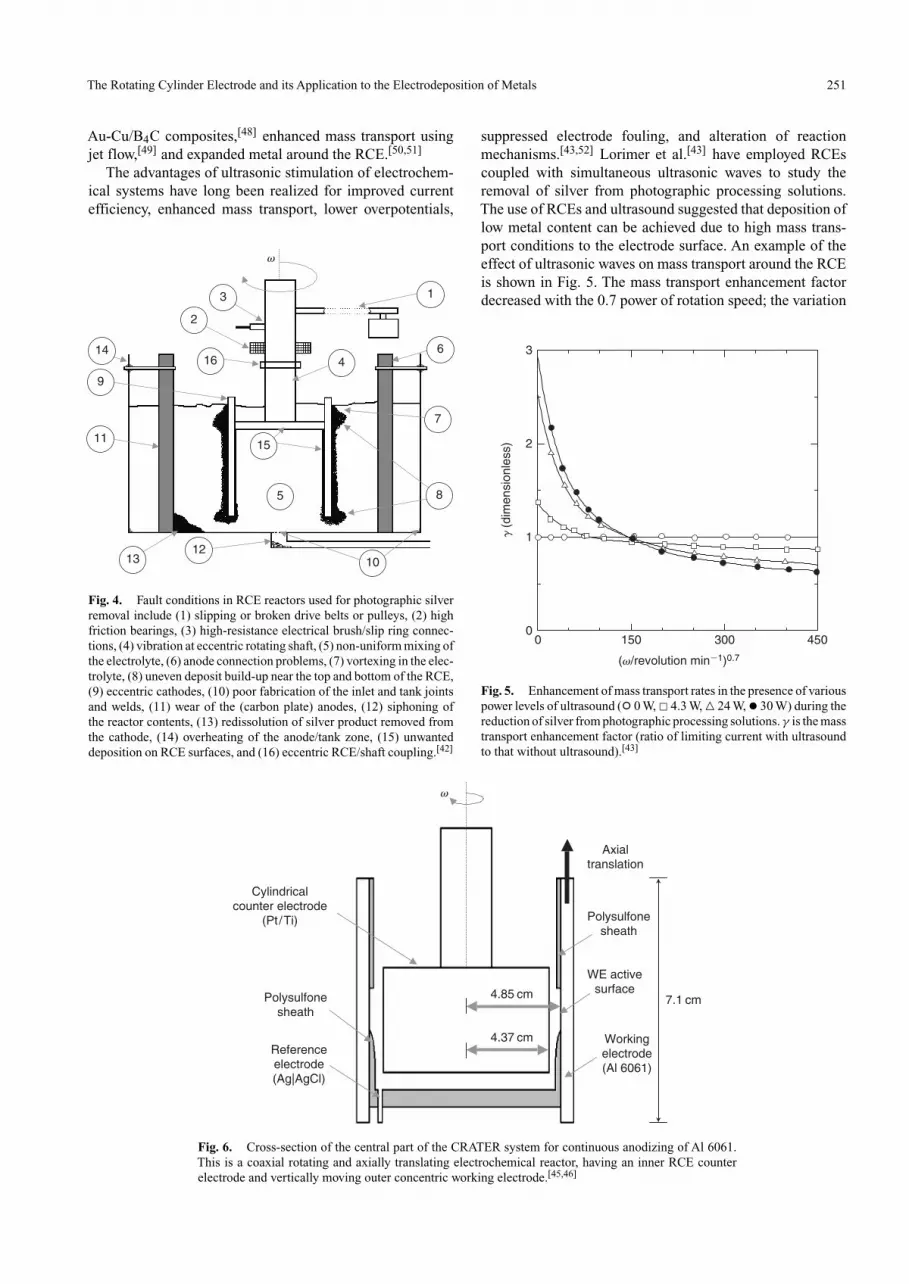
Fig. 4. Fault conditions in RCE reactors used for photographic silverremoval include (1) slipping or broken drive belts or pulleys, (2) highfriction bearings, (3) high-resistance electrical brush/slip ring connec-tions, (4) vibration at eccentric rotating shaft, (5) non-uniform mixing ofthe electrolyte, (6) anode connection problems, (7) vortexing in the elec-trolyte, (8) uneven deposit build-up near the top and bottom of the RCE,(9) eccentric cathodes, (10) poor fabrication of the inlet and tank jointsand welds, (11) wear of the (carbon plate) anodes, (12) siphoning ofthe reactor contents, (13) redissolution of silver product removed fromthe cathode, (14) overheating of the anode/tank zone, (15) unwanteddeposition on RCE surfaces, and (16) eccentric RCE/shaft coupling.[42]
Workingelectrode(Al 6061)
WE activesurface
Polysulfonesheath
Polysulfonesheath
Cylindricalcounter electrode
(Pt/Ti)
Referenceelectrode(Ag|AgCl)
Axialtranslation
7.1 cm4.85 cm
4.37 cm
v
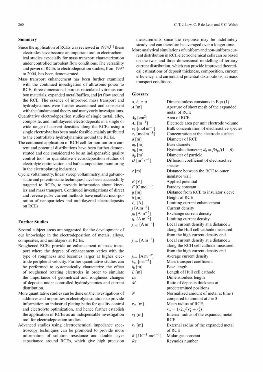
Fig. 6. Cross-section of the central part of the CRATER system for continuous anodizing of Al 6061.This is a coaxial rotating and axially translating electrochemical reactor, having an inner RCE counterelectrode and vertically moving outer concentric working electrode.[45,46]
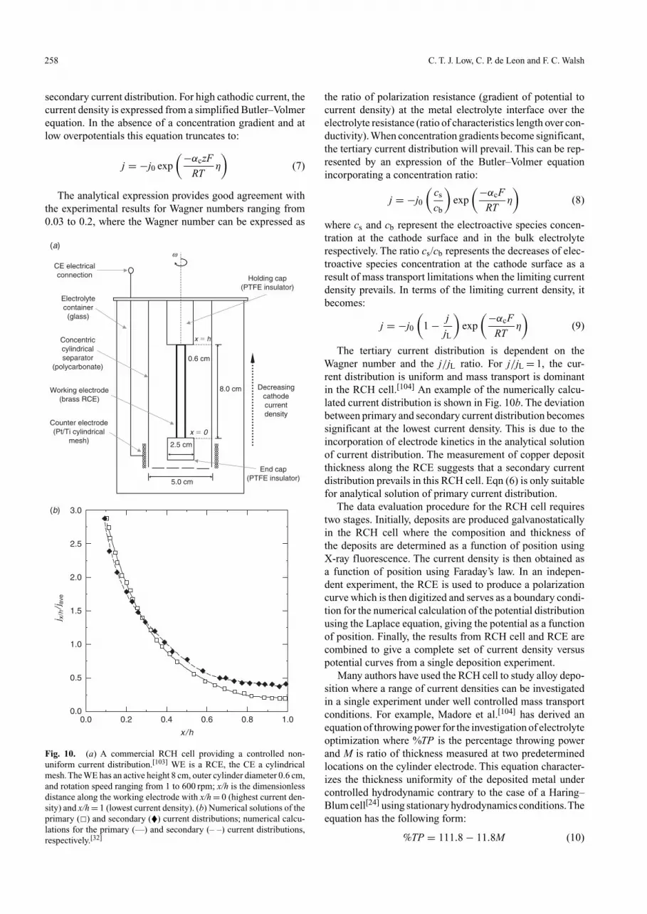
suppressed electrode fouling, and alteration of reactionmechanisms.[43,52] Lorimer et al.[43] have employed RCEscoupled with simultaneous ultrasonic waves to study theremoval of silver from photographic processing solutions.The use of RCEs and ultrasound suggested that deposition oflow metal content can be achieved due to high mass trans-port conditions to the electrode surface. An example of theeffect of ultrasonic waves on mass transport around the RCEis shown in Fig. 5. The mass transport enhancement factordecreased with the 0.7 power of rotation speed; the variation
(v/revolution min�1)0.7
0 150 300 450
g (
dim
ensi
onle
ss)
0
1
2
3
Fig. 5. Enhancement of mass transport rates in the presence of variouspower levels of ultrasound (◦ 0 W, � 4.3 W, � 24 W, • 30 W) during thereduction of silver from photographic processing solutions. γ is the masstransport enhancement factor (ratio of limiting current with ultrasoundto that without ultrasound).[43]

252 C. T. J. Low, C. P. de Leon and F. C. Walsh
of limiting current in the presence of ultrasound is non-uniform and the effect of ultrasound depends on the rotationspeed, electrode geometry, and ultrasonic transducer config-urations. Pollet et al.[44] have continued to investigate theeffect of various positions of ultrasonic waves in the RCEreactor, employing face-on and/or side-on ultrasonic probearrangements, and reported the visual quality of deposits andthe mass transport coefficient were improved with face-onarrangement while the arrangement of all three ultrasonicprobes in the electrolyte did not increase the mass transportsignificantly.
Gao et al.[45,46] have constructed a coaxial rotating andaxially translating electrochemical reactor (CRATER) foranodic oxidation studies of aluminium alloys. The designhas allowed continuous electrochemical studies in a singleworking electrode under well-defined conditions of masstransport, electrode potential, and residence time, where iden-tification of desirable microstructures in a narrow rangeof operating conditions is made possible. It is stated thatthe design differed conceptually from that of RCH cell.In the RCH cell, the microstructures variation along therotating working electrode is due to spatially variation ofcurrent distribution and mass transport conditions due tothe cell geometry. In the CRATER system, the variation inmicrostructure is solely due to programmed process parame-ters that eliminates the effects of non-uniform mass transportassociated with the flow variation parallel to the workingelectrode. The working electrode is non-rotating but has anupward translation controlled by a motor while the counterelectrode rotates along its axis. Fig. 6 shows the cross-sectionof the central part containing the main features of the elec-trodes and reactive windows. Linear sweep voltammetrytechnique and well defined mass transport conditions havebeen employed to demonstrate the capability of the systemto grow oxide films with controlled microstructure variationon aluminium alloy (Al 6061).
Mass transport to an electrode surface can be enhanced bya flowing jet of electrolyte impinging on the surface and thisprinciple has been exploited in electroanalytical studies asthe ‘wall-jet’ configuration, where the electrode is normallya static disc. Jet flow to the surface of a rotating cylinderof reticulated vitreous carbon (RVC) has been considered byReade et al.[49] The high volumetric surface area of the RVCand the jet flow combine to give high rates of mass trans-port. The typical performance of such an electrode is shownin Fig. 7a for the case of copper deposition from an acidsulfate solution. The limiting current enhancement for a 100pores per inch (ppi) RVC RCE (d 1.0 cm, h 1.2 cm) was mea-sured when a jet flow of 3.5 cm3 s−1 was applied at a constantpotential of −500 mV (versus SCE) at rotation speeds in therange 500, 1000, 1500, and 2000 rpm. Fig. 7a shows the cur-rent versus time curves for these experiments in which theflow jet was imposed for 4 s. When the electrolyte jet wasturned on, at ton, the current rose steeply and attained a steady-state value in ∼2.5 s. In Fig. 7b a mass transport enhancementfactor γ has been used to express the ratio of limiting cur-rents in the presence and absence of jet flow as a functionof rotation speed. γ values of 1.08–1.46 and 1.03–1.26 were
found for the 60 ppi and the 100 ppi electrode, respectively,the enhancement factor decreasing at higher rotation speedswhere RCE movement dominated the mass transport rates.
During the removal of metal ions by electrodeposition, it iscommon to find that the metal ions have a very low concen-tration, typically less than 1000 ppm. In order to achieve ahigh removal rate with a reasonable current efficiency, highmass transport rates to the RCE surface and/or high surfacearea RCE are needed.[42] Reade et al.[53,54] have investigated
Time, t /s
�2 10 1286420
Lim
iting
cur
rent
, IL/
mA
24
28
32
36
40
(a)
(b)
(c)
(d )
ton toffJet flow No jet flowNo jet flow
24.5 mA
31.9 mA
35.0 mA
39.2 mA
v / rad s�1
0 50 100 150 200 250
g �
I L (
jet)/I L
(no
jet)
1.0
1.1
1.2
1.3
1.4
1.5
50% enhancementdue to jet flow
Zero enhancementdue to jet flow
(a)
(b)
Fig. 7. Mass transport to an RCE made of RVC experiencing jet elec-trolyte flow (3.5 cm3 s−1 of 0.85 mM Cu(ii) in deoxygenated 0.5 MNa2SO4 at pH 2, T 298 K, E −500 mV versus SCE). (a) Current versustime curves for a 100 ppi rotating cylinder RVC electrode (d 1.0 cm,h 1.2 cm) subjected to jet flow conditions at four rotation speeds. Jeton (ton) and jet off (toff ) for each rotation speed are indicated. Rotationspeeds ω are (a) 52, (b) 104, (c) 157, and (d) 209 rad s−1. (b) Limitingcurrent enhancement factor (γ) due to jet flow versus rotation speed (ω)for 100 and 60 ppi RVC cylinder electrodes (d 1.0 cm, h 1.2 cm) at 60 (•)and 100 (◦) ppi. γ = 1 corresponds to no mass transport enhancement,i.e. the data experienced by a RCE with zero jet flow.

The Rotating Cylinder Electrode and its Application to the Electrodeposition of Metals 253
the application of a porous, three-dimensional, RVC materialas the RCE in the removal of copper and cadmium ions oper-ated under mass transport control in a batch reactor (100 ppiRVC, d 1.0 cm, h 1.2 cm).An example of their results is shownin Fig. 8, where the normalized concentration and currentefficiency are shown as a function of time.An efficient recov-ery of metal concentration could be achieved, typically from56 ppm to less than 1 ppm cadmium ions and from 65 ppmto less than 1 ppm copper ions. It was shown that such elec-trodes are useful for recovery of mixed metals over a widerrange of concentration.The authors have also investigated thecombination effect of jet flow and presence of baffles aroundan RVC RCE for enhanced mass transport studies.[49] Theintroduction of baffles around the RCE appeared to have nosignificant effect on mass transport enhancement while jet
t /s0 3000 6000 9000
N �
mt/
m0
0.001
0.01
0.1
1
Cd
Cu
t / ttotal
0.0 0.2 0.4 0.6 0.8 1.0
1.0
0.8
0.6
f
0.4
0.2
0.0
Cd
Cu
(a)
(b)
Fig. 8. Removal of Cu(ii) ions at −0.5 V (versus SCE), followed byremoval of Cd(ii) ions at −1.0 V (versus SCE) using RVC material asthe RCE. Electrolyte: 200 cm3 of 0.5 mM Cu(ii) and 0.5 mM Cd(ii) in0.5 mM Na2SO4, pH 2, 25◦C, 1500 rpm. (a) Semilogarithmic plot ofnormalized amount of metal, N, versus time, t; (b) current efficiency, φ,versus normalized time.[53,54]
flow profoundly increased the mass transport rates over arange of rotation rates.[55]
Various authors have utilized RCE reactors for electro-chemical studies of metal ion removal. Examples includeelectrodeposition of tin and cadmium using an expandedmetal of RCE in a batch and continuous undivided reac-tor respectively,[50,51] electrodeposition of cadmium in batchand continuous undivided reactor,[56,57] electrodeposition ofzinc from mine residue recycling processes using a batchundivided reactor,[58] electrodeposition of cadmium, nickel,and cobalt from waste solutions produced in the dissolutionof spent nickel-cadmium batteries using a batch undividedreactor,[59] and electrodeposition of silver from liquid wastesgenerated from the mediated electrochemical oxidation pro-cesses using a divided batch reactor and electrodeposition ofcopper.[60] These evaluations of RCE electrochemical reactorperformances are consistent with the established observa-tions found in early investigations, by for example, Gabe andWalsh.[23]
Single Metal and Alloy Electrodeposits
The application of RCEs for single metal and alloys elec-trodeposition studies has received considerable attentionmainly attributed to its controllable hydrodynamics and welldeveloped fundamental principles.A summary of these inves-tigations from 1997 to 2004 are tabulated inTables 3 and 4 forsingle metal and alloy electrodeposition studies, respectively,showing the RCE characteristics, range of rotation speeds,and current densities. Many of these investigations havefully exploited the characteristics of RCEs for quantitativeelectrodeposition studies in turbulent flow conditions.
The development of surface roughness during cop-per electrodeposition has been investigated by Walsh andGabe[15,52,83] and by Roy and Landolt.[61] Surface rough-ness plays an essential role in some metal deposition andmetallurgical powder processes. The properties of coppermetal powder production from acidic solutions have beenwell studied in many early investigations using galvanostatic,potentiostatic, and pulsating potentiostatic techniques.[52]
Fig. 9 illustrates the surface roughness development in apotentiostatic condition of copper electrodeposition from14 mM CuSO4 in 1 M Na2SO4.[52] SEM images of the depositmorphology formed under the conditions described in Fig. 9revealed the transition of deposits from smooth, to compact,to dendritic, and eventually to rough and powdery structures.
Employing a reverse pulse current technique, Roy andLandolt have studied the surface roughness development ofcopper deposits from 50 mM CuSO4 in 1 M H2SO4.[61] TheRCE had a diameter of 1.3 mm and the rotation speed wasmaintained at 1000 rpm. The deposit microstructure fromreverse pulse current technique revealed that a compactstructure is obtainable in contrast to the rough deposit struc-ture obtained from a potentiostatic technique. They discussedthat during current reversal mode, the smaller and less stablecrystallites, which have a high energy of formation, dissolvedalmost instantaneously while larger and stable crystallitecontinued to form, leading to more compact deposits.

254 C. T. J. Low, C. P. de Leon and F. C. Walsh
Table 3. Examples of single metal electrodeposition studies during 1997–2004 using RCE or RCH cells
Materials Rotation speed Peripheral velocity Current density RCE characteristics Ref.deposited ω [rpm] U [cm s−1] j [mA cm−2]
db [cm] lb [cm] Ab [cm2] Surface material
Ag 0–8000 0–293 NGA 0.7 5.43 11.94 316 SS [43]Ag 0–8000 0–209 NG 0.5 7.61 11.95 316 SS [44](K3Fe(CN)6/K4Fe(CN)6) 3–180 1.4–82.0 0–350 8.7 7.1 194.08 Pt [45]Sn 500 91.6 0–1200 3.5 3.3 298.19 316 SS [50]Cd 1000 183 0–1.5 3.5 3.3 298.19 316 SS [51]Cd 1000–1750 198–347 0–55.1 3.79 3.05 36.32 316 SS [56]Cd 500–1500 99.2–297 0–27.5 3.79 3.05 36.32 316 SS [57]Cu 1000 2.62 NG 0.05 NG NG Cu [61]Sn 500–2000 50.5–202 6–600 1.93 5.7 34.57 S [62]Sn 150–480 115–369 7–340 14.7 14.6 674.3 NG [63]Ag 125–1000 7.9–62.3 26.5–106 1.2 2.5 9.43 Pt [64]CaSO4 50–2000 3.1–125 NG 1.2 1.2 4.52 316 SS [65]BaSO4 1000–3000 62.8–188 NG 1.2 1.2 4.52 316 SS [66]Cu 0–6500 0–408 0–140 1.2 0.8 3.02 Cu, Pb [67]Cu 1500–7000 94.3–439 0–140 1.2 0.8 3.02 Cu, Pb [68]Cu, Fe 240–2160 339–305 NG 2.7 2.7 22.91 90/10 Cu-Ni [69]
A Not given.
Table 4. Examples of alloy electrodeposition studies during 1997–2004 using RCE or RCH cells
Materials Rotation speed Peripheral velocity Current density RCE characteristics Ref.deposited ω [rpm] U [cm s−1] j [mA cm−2]
db [cm] lb [cm] Ab [cm2] Surface material
Ni, Mo 300–3500 23.6–274 0–60 1.5 2 9.43 Cu [70]Ni, Co, Fe 700–2000 55.0–157 35, 50 1.5 6 28.28 Cu [71]Cd, Ni, Co 0–900 0–43.5 20–100 2.9 NGA NG SS [59]Ni, B 0–909 0–200 1–80 4.2 10 131.9 Cu [72]Ni, W 2000 20.9 15 0.2 1 0.63 Au [73]Cu, Zn 1000 52.4 NG 1.0 6 18.85 Cu [74]Fe, Ni, Co 300–1400 23.6–110 25 1.5 6 28.28 Cu [75]Ni, Co 35–935 2.75–73.4 5.9–90.8 1.5 6 28.28 Ti [76]Ni, Mo 0–4000 0–314 0–180 1.5 6 28.28 Cu [77]Sn, Ag 70, 100 5.5–7.5 0–35 1.43 6 27 Cu [78]Zn, Fe 0, 1500 0–117 0–35 1.5 6 28.28 Cu [79]Fe, Ni, Co 800 6.3 1–100 1.5 2 9.43 Cu [80]Fe, Ni, Co 2000–3000 10.5–15.7 0.05–500 1.0 1.2 3.77 Cu [81]Fe, Ni, Co 2000 130 5–15 1.0 1.2 3.77 Cu [82]
A Not given.
Quantitative studies of tin deposit morphology have beenundertaken by various authors.[62,63] Yau[62] has quantita-tively illustrated the effect of rotation speed and currentdensity on the morphology of tin electrodeposits using amethanesulfonic acid solution while Longley et al.[63] haveinvestigated the morphology of tin electrodeposits using aphenolsulfonic acid solution. The morphology of tin elec-trodeposits can be subdivided into three distinct regions,namely dendritic deposits (achieved at low rotation speedsand high current density), compact polycrystalline ones(achieved at high rotation speed and low current density),and micronodular deposits (achieved between dendritic andcompact polycrystalline regions).
RCE cells have been utilized to provide a uniform currentdistribution and controlled hydrodynamics for the inves-tigations of electrolyte additives in electrodeposition. Forexample, Farndon et al.[84] studied the effects of organic addi-tives on the kinetics of copper deposition from dilute acidic
solutions. This study considered the potentiostatic techniqueon limiting current and copper ion concentration decay asa function of time, in the presence of organic additives (4,5-dithiaoctane-1,8-disulphonic acid, thiourea, benzotriazole) atvarious rotation speeds, copper ion concentrations, organicconcentrations, and electrode potentials. James et al.[85] stud-ied the roles of bis(3-sulfopropyl) disulfide and Janus GreenB additives on the levelling behaviour of copper depositionfrom an acidic sulfate electrolyte containing polyethyleneglycol and chloride ions. The authors have utilized a micro-profiled, threaded RCE (90 µm deep grooves, 125 µm apart)and reported that levelling only occurred when all additiveswere present, and highlighted the importance of synergy inthe levelling mechanisms.
Other examples of metal and alloy studies include elec-trodeposition of Ni-B amorphous alloys with metastablestructures,[72] current efficiency investigations of Cu-Znalloy electrodeposition,[74] and electrodeposition of

The Rotating Cylinder Electrode and its Application to the Electrodeposition of Metals 255
(a)
(b)
(c)
(d )
(e)
(f )
20 �m
Fig. 9. SEM images showing the development of surface roughness during potentiostatic copper deposition onto acopper RCE (from smooth to dendritic and eventually rough deposits) after (a) 0, (b) 2, (c) 5, (d) 10, (e) 20, and (f) 45 mintime. Conditions −1.0V (versus Hg|Hg2SO4), 1 M Na2SO4, 14 mM CuSO4, 22◦C, 6.3 cm RCE diameter, ω 340 rpm.[52]
amorphous Ni-W alloys in the absence of ammonia.[73] Inthese studies, the effects of operating parameters on elec-trodeposition and microstructure include peripheral velocity,current density, and electrolyte conditions. Experimentaland analytical techniques involved are cyclic voltammetry,linear sweep voltammetry, galvanostatics, scanning elec-tron microscopy, X-ray diffraction, X-ray fluorescence,differential scanning calorimetry, and scanning tunnellingmicroscopy. In summary, recent investigations are consis-tent with the established features of the RCE that have
made it an attractive research tool in quantitative, high-speedelectrodeposition studies.
Multilayered and Composite Electrodeposits
Multilayered and composite electrodeposits have been madeaddressable with the continued development of RCEs for con-trolled hydrodynamics studies. Interest in these investigationshas been mainly driven by the need for enhanced surface prop-erties including improved microhardness, high yield and/ortensile strengths, good wear resistance, excellent magnetic

256 C. T. J. Low, C. P. de Leon and F. C. Walsh
Table 5. Examples of multilayered and composite electrodeposition studies during 1997–2004 using RCE or RCH cells
Materials Rotation speed Peripheral velocity Current density RCE characteristics Ref.deposited ω [rpm] U [cm s−1] j [mA cm−2]
db [cm] lb [cm] Ab [cm2] Surface material
Cu, Co (µm)A 2500 130.9 −90.10 1.0 1.28 4.02 Au-Ni [91]32 nm γ-Al2O3, Cu 800 41.9 100–−100 1.0 1.2 3.77 Au [86]32 nm α-Al2O3, Ni 225–1600 11.8–83.8 140–−140 1.0 1.2 3.77 Au [87]Cu, Fe, Co (µm) 1000 52.4 0–−7.5 1.0 1.28 4.02 Ag [92]37 nm γ-Al2O3, Cu 800 41.9 100–−100 1.0 1.2 3.77 Au [93]Ni, P, W (µm) 500 13.1 20, 200 0.5 0.6 0.94 Cu [96]Cu, Ni (µm) 1500 78.6 0.4, 0.8, 50 1.0 1.2 3.77 Cu [97]50 nm Al2O3, Cu 500–1500 31.4–94.3 0–100 1.2 0.8 3.02 SS [98]0.8 µm PS, Zn NG NG 0–1000 NGB NG 6.7 Al [99]Ni-Cu, 32 nm Al2O3 1000 52.4 0–50 1.0 1.2 3.77 Au [47]B4C, Au (µm) 120 NG 3–12 NG NG 6.25 Cu [48]
A (µm) and (nm) indicate that the materials are present in micrometre or nanometre dimensions.B Not given.
strength, functional optical properties, and controlled compo-sitional and structure differences for microdevices.[61,86–89]
Recent investigations of multilayered and composite elec-trodeposits have involved direct[90–92]and reverse[62,86,87,93,94]
pulsed current techniques. The application of pulsed currenthas produced a wide range of deposit composition and prop-erties. Two types of direct pulse plating conditions can beidentified, namely short cycle times (less than 1 s deposition)and long cycle times (more that 1 s deposition), where theformer gives uniform alloy concentration perpendicular tothe substrate surface and the latter gives non-uniform alloyconcentration perpendicular to the substrate surface.[95] Theuse of direct pulse plating provides a means of controllingthe current distribution. For instance in the absence of masstransport conditions the current distribution in pulse plat-ing is less uniform than in direct current plating due to thelower Wagner number; in the presence of non steady-statemass transport conditions, more uniform current distribu-tions occurs in pulse plating as compared to direct currentplating.[89] Reverse pulse plating imposes a cathodic currentduring the on time and an anodic or reverse current during thereverse time. This method allows one to eliminate a fractionof the electrodeposited metal and thus eventually increasesthe particle concentration.[87] Five important variables can beidentified when reverse pulse plating is employed on a RCE,namely cathodic and anodic/reverse current, pulse time, dutycycle, and hydrodynamics.[61]
A summary of recent investigations is shown in Table 5,showing the characteristics of RCE and the range of rotationspeeds and current densities. Landolt et al. have theoreti-cally and experimentally examined the direct pulse platingof binary copper-cobalt[90] and ternary copper-iron-cobaltalloys[92] using a recessed RCE of 1.0 cm diameter and1.28 cm length. They studied the effect of displacement reac-tions on the composition and phase structure of copper-cobaltalloys pulse-plated at short cycle times. A model developedpreviously[91] was used to predict the alloy composition as afunction of pulse off-time. SEM images revealed that distinctphases, rich in copper and cobalt, are formed in a columnarstructure, and the authors concluded that even after prolongedpulse off-times the displacement reaction did not cease
completely. Another example is by Papachristos et al.[96]
who studied the effect of annealing at 200◦C and 800◦Con a nickel-phosphorus-tungsten multilayered alloy, pro-duced using a direct pulse current technique. Cross-sectionaltransmission electron microscopy, X-ray diffraction, and dif-ferential thermal analysis were used in the analysis. Theyreported that high (50/5/45 wt.-% Ni-P-W) and low (77/8/15wt.-% Ni-P-W) tungsten content can be deposited to achievea 25 µm thickness.
Application of the reverse pulse technique to RCEs hasbeen successfully demonstrated for composite electrodepo-sition by various authors. Podlaha et al.[86,87,93,94] have usedthis technique on a recessed RCE to incorporate nanometricsize γ-alumina spherical particles (37 nm diameter, surfacearea 52 m2 g−1) onto copper and nickel matrices using twodifferent citrate and chloride electrolytes. They suggestedthat pulse reverse method is useful for selectively incorpo-rate nanometric size particles into metal matrices, and thatshear stress and adsorption forces are also the rate-limitingsteps besides mass transport conditions, where an increasein electrode rotation speed increases the shear forces act-ing on the particles and resulted in a lower particle depositconcentration.[87] The particle concentration using a pulsereverse method can be improved six-fold over the directcurrent method,[86,93] which can be attributed to the micro-convective eddies produced by particle movement in the shearfield adjacent to the surface of the RCE. Roy and Landolt[61]
have developed an analytical solution based on electron trans-fer and steady-state and transient mass transport conditionsto determine the practical range parameters for reverse pulsecurrent plating using a 50 mM CuSO4 in 1 M H2SO4 elec-trolyte. They reported that small duty cycles (<0.5), pulseperiods in the range 1–1000 ms, and dimensionless reversepulse currents up to 2.0 were suitable conditions.
The deposition of nanometric multilayered and com-posite layers using galvanostatic techniques has also beenstudied.[97,100] Bonhote and Landolt[97] have galvanostati-cally electrodeposited a multilayered Ni-Cu alloy from acitrate electrolyte using a recessed RCE. The deposits wereproduced at 0.4 mA cm−2 or 0.8 mA cm−2 for copper sub-layers and 50 mA cm−2 for nickel sublayers at 1500 rpm. By

The Rotating Cylinder Electrode and its Application to the Electrodeposition of Metals 257
controlling the deposition times, 10 nm and 20 nm thick-nesses were obtained for copper and nickel, respectively.The microstructure of the nanometric multilayers were char-acterized using SEM, TEM, and X-ray diffraction, and themicrostructure of deposits depended critically on the appliedcurrent density for copper deposition with respect to lim-iting current density and the deposit thickness depends onthe charge passed during a given cycle. The authors havediscussed the effects of current density and substrate onthe deposits microstructure, the relationship between sur-face morphology and grain structure, and demonstrated thatthe microstructure and Ni-Cu multilayer thickness can becontrolled independently.
Incorporation of nanoparticles into deposits on RCEshas also been studied.[47,48,98,99] For example, Stojak andTalbot[98,100] have studied electrodeposition of compositefilms containing alumina particles in a copper matrix wherethe effect of hydrodynamics, particle loading in suspension,particle characteristics, and electrode orientation were inves-tigated. Hovenstad et al.[99] have studied electrodeposition ofzinc and polystyrene particles on aluminium RCE.The effectsof surfactants, particle concentrations, and electrode rotationspeed were investigated. They discussed particle incorpo-ration mechanisms, adhesion, friction, and removal forcesthat govern the composite deposition processes. A study byPanda and Podlaha[47] has demonstrated the codeposition ofalumina nanoparticles in Ni-Cu and Ni-Co deposits from acitrate bath. Under the experimental conditions, addition ofalumina particles caused no significant changes in the per-centage of copper concentration in the Cu-Ni deposit overthe current density studied ranging from 0 to 45 mA cm−2,although the copper level decreased over the range of 0 to20 mA cm−2. Bozzini et al.[48] have investigated the elec-trodeposition of Au-Cu alloy with B4C composites from analkaline bath. They successfully demonstrated a galvanody-namic technique, where the current density was stepped at arate of 1 mA min−1 from 4 to 12 mA cm−2. They reportedthat such deposition conditions have produced depositsof constant composition and uniform morphology withoutbanded structures. Vidrine et al.[87] have electrodeposited32 nm γ-Al2O3 particles in a nickel matrix, using citrateand chloride electrolytes. They have employed both directcurrent and reserve pulse current techniques and reportedthat the reverse pulse current method leads to an enhance-ment of the γ-Al2O3 deposit concentration in a chlorideelectrolyte.
Recent treatments of composite electrodeposition havebeen discussed by Walsh et al.[101,102] The authors have
Table 6. Major features of the RCHs for electrodeposition
Features Advantages to quantitative electrodeposition studies
Deliberately non-uniform current distribution A range of current density can be investigated on a single RCEControlled mass transport Reproducible deposit quality and monitoring of industrial electrolytesHigh mass transport rates Enables the study of additive efficiency and electrolyte sensitivity of impuritiesAnalytical equation for current density versus Facilitates a comparison of experimental data with theoretical simulations of current distribution
positionThrowing power measurement Allows the investigation of electrolyte optimization under controlled operating conditions
concisely reviewed the recent development of compositeelectrodeposition and highlighted the inaccuracies and short-comings of current theories for predicting deposit compo-sition. The importance of process parameters (electrolyteagitation, pH, temperature, particle dimensions, additives,concentrations, and current density) is discussed, and thefuture development of composite electrodeposition was out-lined. Aspects considered here include the emergence ofcompositionally and hydrodynamically modulated layer coat-ings, gradual release coatings for tribological applications,and modification of diffusion coatings by heat treatment.
Rotating Cylinder Hull (RCH) Cells
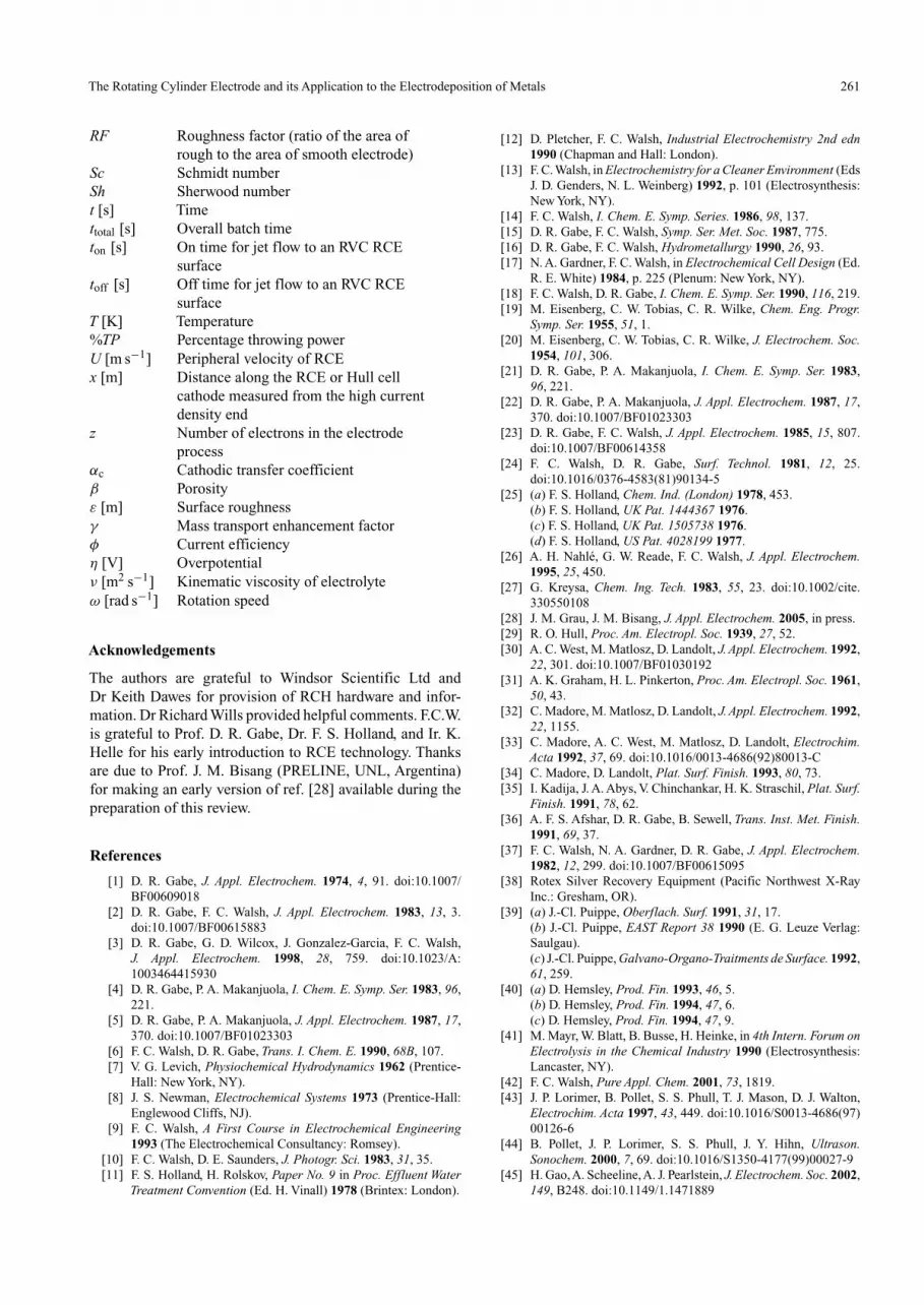
The main features of controlled, non-uniform current distri-bution RCH cells and their significance for electrodepositionstudies are summarized in Table 6. A typical commercial cellhas been derived from this design, shown schematically inFig. 10a.[103] The rotating cylinder working electrode has adiameter of 0.6 cm and is 12 cm in height. The active length is8 cm with 0.15 dm2 active surface area.The counter electrodeis cylindrical, with an inner diameter of 5 cm and outer diam-eter of 5.6 cm; it is placed at a distance of 1.5 cm from thebottom of the electrolyte container (450 cm3 volume). Theupper and lower sleeves protrude by 0.8 cm from the RCEand form a 90◦ angle with it.[103]
Landolt et al.[32–34] have reported that, to achieve a sim-ilarity in primary current distribution for the RCH cell asfound in the Hull cell, the following design conditions arenecessary:[33]
h
e= 3
g
e≥ 0.3 (5)
where h is the active height of RCE, e is the gap distance fromRCE surface to the outer insulating wall, and g is the distanceprotrudes from the RCE surface to the insulator sleeve. Theexpression for primary current distribution has been obtainedanalytically using boundary element method, which gives:
jx/h
jave= 0.535 − 0.458(x/h)
[0.0233 + (x/h)2]0.5+ 8.52 × 10⁻⁵ exp [7.17(x/h)]
(6)
where x/h is the dimensionless distance along the workingelectrode. It is found that x/h = 0 corresponds to the positionof highest current density and x/h = 1 corresponds to the posi-tion of lowest current density. The local current density jx/h
as a function of position can be calculated assuming that theaverage current density jave is the applied galvanostatic cur-rent density. The Tafel approximation is used to provide the
258 C. T. J. Low, C. P. de Leon and F. C. Walsh
secondary current distribution. For high cathodic current, thecurrent density is expressed from a simplified Butler–Volmerequation. In the absence of a concentration gradient and atlow overpotentials this equation truncates to:
j = −j0 exp
(−αczF
RTη
)(7)
The analytical expression provides good agreement withthe experimental results for Wagner numbers ranging from0.03 to 0.2, where the Wagner number can be expressed as
x � 0
ω
Electrolytecontainer
(glass)
CE electricalconnection Holding cap
(PTFE insulator)
Concentriccylindricalseparator
(polycarbonate)
x � h
Counter electrode(Pt/Ti cylindrical
mesh)
8.0 cm
5.0 cm
0.6 cm
Working electrode(brass RCE)
2.5 cm
Decreasingcathodecurrentdensity
End cap(PTFE insulator)
(a)
x/h
0.0 0.4 0.6 0.8 1.0
j x/h
/jav
e
0.2
3.0
2.5
2.0
1.5
1.0
0.5
0.0
(b)
Fig. 10. (a) A commercial RCH cell providing a controlled non-uniform current distribution.[103] WE is a RCE, the CE a cylindricalmesh.The WE has an active height 8 cm, outer cylinder diameter 0.6 cm,and rotation speed ranging from 1 to 600 rpm; x/h is the dimensionlessdistance along the working electrode with x/h = 0 (highest current den-sity) and x/h = 1 (lowest current density). (b) Numerical solutions of theprimary (�) and secondary (�) current distributions; numerical calcu-lations for the primary (—) and secondary (– –) current distributions,respectively.[32]
the ratio of polarization resistance (gradient of potential tocurrent density) at the metal electrolyte interface over theelectrolyte resistance (ratio of characteristics length over con-ductivity). When concentration gradients become significant,the tertiary current distribution will prevail. This can be rep-resented by an expression of the Butler–Volmer equationincorporating a concentration ratio:
j = −j0
(cs
cb
)exp
(−αcF
RTη
)(8)
where cs and cb represent the electroactive species concen-tration at the cathode surface and in the bulk electrolyterespectively. The ratio cs/cb represents the decreases of elec-troactive species concentration at the cathode surface as aresult of mass transport limitations when the limiting currentdensity prevails. In terms of the limiting current density, itbecomes:
j = −j0
(1 − j
jL
)exp
(−αcF
RTη
)(9)
The tertiary current distribution is dependent on theWagner number and the j/jL ratio. For j/jL = 1, the cur-rent distribution is uniform and mass transport is dominantin the RCH cell.[104] An example of the numerically calcu-lated current distribution is shown in Fig. 10b. The deviationbetween primary and secondary current distribution becomessignificant at the lowest current density. This is due to theincorporation of electrode kinetics in the analytical solutionof current distribution. The measurement of copper depositthickness along the RCE suggests that a secondary currentdistribution prevails in this RCH cell. Eqn (6) is only suitablefor analytical solution of primary current distribution.
The data evaluation procedure for the RCH cell requirestwo stages. Initially, deposits are produced galvanostaticallyin the RCH cell where the composition and thickness ofthe deposits are determined as a function of position usingX-ray fluorescence. The current density is then obtained asa function of position using Faraday’s law. In an indepen-dent experiment, the RCE is used to produce a polarizationcurve which is then digitized and serves as a boundary condi-tion for the numerical calculation of the potential distributionusing the Laplace equation, giving the potential as a functionof position. Finally, the results from RCH cell and RCE arecombined to give a complete set of current density versuspotential curves from a single deposition experiment.
Many authors have used the RCH cell to study alloy depo-sition where a range of current densities can be investigatedin a single experiment under well controlled mass transportconditions. For example, Madore et al.[104] has derived anequation of throwing power for the investigation of electrolyteoptimization where %TP is the percentage throwing powerand M is ratio of thickness measured at two predeterminedlocations on the cylinder electrode. This equation character-izes the thickness uniformity of the deposited metal undercontrolled hydrodynamic contrary to the case of a Haring–Blum cell[24] using stationary hydrodynamics conditions.Theequation has the following form:
%TP = 111.8 − 11.8M (10)

The Rotating Cylinder Electrode and its Application to the Electrodeposition of Metals 259
Landolt et al.[75] have galvanostatically deposited singlemetals and binary alloys of iron, nickel, and cobalt.They haveinvestigated the deposition at various rotation rates and con-firmed that the inhibiting effect of less noble metal on thedeposition of the more noble metal and acknowledged thatthe numerical approach taken is viable where the conversionof a length scale into potential scale gives correct results.Fig. 11 showed a good correlation between the experimen-tal results obtained from both the RCE and RCH cell.[75]
Goldbach et al.[76] have galvanostatically deposited nickel-cobalt from a sulfamate bath in the presence of boric acid andtwo additives, namely saccharin and FC95 surfactant. Theyconcluded that cobalt deposition is a diffusion-controlled pro-cess and the cobalt content decreases with applied currentdensity relative to the limiting current density. They showedthat 40% of cobalt composition can be deposited at lowcurrent densities but decreases with high current densities.Podlaha et al.[77] have galvanostatically induced the code-position of nickel-molybdenum alloys. The RCH cell wasused to investigate the optimization of deposition parameterswhere the current density, electrode rotation rates, electrolytetemperature, and species concentrations were shown to influ-ence the alloy composition. They have reported that compactnickel-molybdenum alloys having a molybdenum contentin excess of 50% can be electrodeposited and a periodicvariation of the applied current density can produced compo-sition modulated nickel-molybdenum alloy films consistingof alternating sublayers with a molybdenum content of 15and 45%, respectively.
Direct and pulse current techniques have been examinedby Roy et al.[105] during an investigation of gold deposits froma sulphite bath. The effect of hydrodynamics, current density,and pulse on/off time on the microstructure was investigated.The RCH cell has provided a basis for the prediction of depositproperties in a flow cell (patterned wafers, 24.5 cm2 activearea) with identical mass transport conditions. They showedthat smooth and coherent deposits are obtained up to currentdensities of 6.2 mA cm2 for direct current experiments whilefiner grained and dense deposits could be achieved from thepulsed current experiments.
Another example of an RCH cell application is theelectrodeposition of solder for flip-chip bonding using apyrophosphate/iodide tin-silver alloy bath.[78] The alloy com-position as a function of local current density was investigatedfor various operating parameters including pH values, tem-perature, silver concentration, and rotation rates. Silver (themost noble metal) was deposited first and the amount of sil-ver in the deposit decreases as the current density increases.The authors commented that tin-silver alloy may be an alter-native for tin-lead alloy plating because it is very stable, hasa eutectic solder melting point of 221◦C (1◦C below that ofpure tin) and preliminary applications in flip-chip bondingexperiments have demonstrated that the plating process isfully compatible with the current electrophoretic photoresistsystem. The electrodeposition of zinc-iron alloy in a chlorideelectrolyte has been studied by Liao et al.[79] They reportedthat two layer deposits (10% and 80% iron content) can beobtained in a single solution by varying the current density
j/m
A c
m�
2j/
mA
cm
�2
0.1
1
10
100
Ni metal
Fe metal
�1.0 �0.5 0.0 0.5 1.0 1.5
E vs SCE/V
�1.0 �0.5 0.0 0.5 1.0 1.5
E vs SCE/V
0.1
1
10
100
Ni alloy
Fe alloy
(a)
(b)
Fig. 11. Partial current densities of Ni and Fe determined using RCEand RCH cells. The experiments were conducted at 800 rpm and 25◦C.Filled and empty symbols represent determinations made from the RCEand RCH respectively; circles represent Ni and triangles Fe. (a) Sin-gle metal deposition (250 mM Fe and 0.2 M Ni). (b) Alloy deposition(250 mM Fe + 0.2 M Ni).[75]
and electrode rotation speed. Addition of ammonium chlo-ride has acted as a conductivity salt as well as grain refiner.The use of chloride solution has enabled the production ofcomposition modulated alloy with 90% or greater currentefficiency and a wide range of composition by varying thecurrent density and rotation speed.
RCH cells have enabled the investigations of a variationof current densities in a single experiment under control-lable hydrodynamics conditions. RCH cell devices provideattractive research tools for quantitative electrodepositionstudies and quality control tools for the electroplating indus-try to enable optimization of electrolyte composition andmonitoring of process conditions.
260 C. T. J. Low, C. P. de Leon and F. C. Walsh
Summary
Since the application of RCEs was reviewed in 1974,[1] theseelectrodes have become an important tool in electrochem-ical studies especially for mass transport characterizationunder controlled turbulent flow conditions. The versatilityand power of RCEs to electrodeposition studies, from 1997to 2004, has been demonstrated.
Mass transport enhancement has been further examinedwith the continued investigation of ultrasonic power toRCE, three-dimensional porous reticulated vitreous car-bon materials, expanded metal/baffles, and jet flow aroundthe RCE. The essence of improved mass transport andhydrodynamics were further ascertained and consistentwith the fundamental theory and many early investigations.
Quantitative electrodeposition studies of single metal, alloy,composite, and multilayered electrodeposits in a single orwide range of current densities along the RCEs using asingle electrolyte has been made feasible, mainly attributedto the controllable hydrodynamics around the RCEs.
The continued application of RCH cell for non-uniform cur-rent and potential distributions have been further demon-strated and one considered to be an indispensable qualitycontrol tool for quantitative electrodeposition studies ofelectrolyte optimization and bath composition monitoringin the electroplating industries.
Cyclic voltammetry, linear sweep voltammetry, and galvano-static and potentiostatic techniques have been successfullytargeted to RCEs, to provide information about kinet-ics and mass transport. Continued investigations of directand reverse pulse current methods have enabled incorpo-ration of nanoparticles and multilayered electrodepositson RCEs.
Further Studies
Several subject areas are suggested for the development ofour knowledge in the electrodeposition of metals, alloys,composites, and multilayers at RCEs.Roughened RCEs provide an enhancement of mass trans-
port where the degree of enhancement varies with thetype of roughness and becomes larger at higher elec-trode peripheral velocity. Further quantitative studies canbe performed to systematically characterize the effectof roughened rotating electrodes in order to simulatethe importance of geometrical and roughness changesof deposits under controlled hydrodynamics and currentdistribution.
More quantitative studies can be done on the investigations ofadditives and impurities in electrolyte solutions to provideinformation on industrial plating baths for quality controland electrolyte optimization, and hence further establishthe application of RCEs as an indispensable investigationtool for electrodeposition studies.
Advanced studies using electrochemical impedance spec-troscopy techniques can be promoted to provide moreinformation of solution resistance and double layercapacitance around RCEs, which give high precision
measurements since the response may be indefinitelysteady and can therefore be averaged over a longer time.
More analytical simulations of uniform and non-uniform cur-rent distribution in RCE electrochemical cells can be basedon the two- and three-dimensional modelling of tertiarycurrent distribution, which can provide improved theoreti-cal estimations of deposit thickness, composition, currentefficiency, and current and potential distributions, at masstransport conditions.
Glossary
a, b, c, d Dimensionless constants in Eqn (1)A [m] Aperture of short mesh of the expanded
metal of RCEAb [cm2] Area of RCEAe [m−1] Electrode area per unit electrode volumecb [mol m−3] Bulk concentration of electroactive speciescs [mol m−3] Concentration at the electrode surfaced [m] Diameter of RCEdb [m] Base diameterdh [m] Hydraulic diameter; dh = βdp/(1 − β)dp [m] Diameter of particleD [m2 s−1] Diffusion coefficient of electroactive
speciese [m] Distance between the RCE to outer
insulator wallE [V] Applied potentialF [C mol−1] Faraday constantg [m] Distance from RCE to insulator sleeveh [m] Height of RCEIL [A] Limiting current enhancementj [A m−2] Current densityj0 [A m−2] Exchange current densityjL [A m−2] Limiting current densityjx/L [A m−2] Local current density at a distance x
along the Hull cell cathode measuredfrom the high current density end
jx/h [A m−2] Local current density at a distance xalong the RCH cell cathode measuredfrom the high current density end
jave [A m−2] Average current densitykm [m s−1] Mass transport coefficientlb [m] Base lengthL [m] Length of Hull cell cathodeLe Dimensionless lengthM Ratio of deposits thickness at
predetermined positionsN Normalized amount of metal at time t
compared to amount at t = 0rm [m] Mean radius of RCE,
rm = 1/2√
(r21 + r2
2)r1 [m] Internal radius of the expanded metal
RCEr2 [m] External radius of the expanded metal
of RCER [J K−1 mol−1] Molar gas constantRe Reynolds number
The Rotating Cylinder Electrode and its Application to the Electrodeposition of Metals 261
RF Roughness factor (ratio of the area ofrough to the area of smooth electrode)
Sc Schmidt numberSh Sherwood numbert [s] Timettotal [s] Overall batch timeton [s] On time for jet flow to an RVC RCE
surfacetoff [s] Off time for jet flow to an RVC RCE
surfaceT [K] Temperature%TP Percentage throwing powerU [m s−1] Peripheral velocity of RCEx [m] Distance along the RCE or Hull cell
cathode measured from the high currentdensity end
z Number of electrons in the electrodeprocess
αc Cathodic transfer coefficientβ Porosityε [m] Surface roughnessγ Mass transport enhancement factorφ Current efficiencyη [V] Overpotentialν [m2 s−1] Kinematic viscosity of electrolyteω [rad s−1] Rotation speed
Acknowledgements
The authors are grateful to Windsor Scientific Ltd andDr Keith Dawes for provision of RCH hardware and infor-mation. Dr Richard Wills provided helpful comments. F.C.W.is grateful to Prof. D. R. Gabe, Dr. F. S. Holland, and Ir. K.Helle for his early introduction to RCE technology. Thanksare due to Prof. J. M. Bisang (PRELINE, UNL, Argentina)for making an early version of ref. [28] available during thepreparation of this review.
References
[1] D. R. Gabe, J. Appl. Electrochem. 1974, 4, 91. doi:10.1007/BF00609018
[2] D. R. Gabe, F. C. Walsh, J. Appl. Electrochem. 1983, 13, 3.doi:10.1007/BF00615883
[3] D. R. Gabe, G. D. Wilcox, J. Gonzalez-Garcia, F. C. Walsh,J. Appl. Electrochem. 1998, 28, 759. doi:10.1023/A:1003464415930
[4] D. R. Gabe, P. A. Makanjuola, I. Chem. E. Symp. Ser. 1983, 96,221.
[5] D. R. Gabe, P. A. Makanjuola, J. Appl. Electrochem. 1987, 17,370. doi:10.1007/BF01023303
[6] F. C. Walsh, D. R. Gabe, Trans. I. Chem. E. 1990, 68B, 107.[7] V. G. Levich, Physiochemical Hydrodynamics 1962 (Prentice-
Hall: New York, NY).[8] J. S. Newman, Electrochemical Systems 1973 (Prentice-Hall:
Englewood Cliffs, NJ).[9] F. C. Walsh, A First Course in Electrochemical Engineering
1993 (The Electrochemical Consultancy: Romsey).[10] F. C. Walsh, D. E. Saunders, J. Photogr. Sci. 1983, 31, 35.[11] F. S. Holland, H. Rolskov, Paper No. 9 in Proc. Effluent Water
Treatment Convention (Ed. H. Vinall) 1978 (Brintex: London).
[12] D. Pletcher, F. C. Walsh, Industrial Electrochemistry 2nd edn1990 (Chapman and Hall: London).
[13] F. C. Walsh, in Electrochemistry for a Cleaner Environment (EdsJ. D. Genders, N. L. Weinberg) 1992, p. 101 (Electrosynthesis:New York, NY).
[14] F. C. Walsh, I. Chem. E. Symp. Series. 1986, 98, 137.[15] D. R. Gabe, F. C. Walsh, Symp. Ser. Met. Soc. 1987, 775.[16] D. R. Gabe, F. C. Walsh, Hydrometallurgy 1990, 26, 93.[17] N. A. Gardner, F. C. Walsh, in Electrochemical Cell Design (Ed.
R. E. White) 1984, p. 225 (Plenum: New York, NY).[18] F. C. Walsh, D. R. Gabe, I. Chem. E. Symp. Ser. 1990, 116, 219.[19] M. Eisenberg, C. W. Tobias, C. R. Wilke, Chem. Eng. Progr.
Symp. Ser. 1955, 51, 1.[20] M. Eisenberg, C. W. Tobias, C. R. Wilke, J. Electrochem. Soc.
1954, 101, 306.[21] D. R. Gabe, P. A. Makanjuola, I. Chem. E. Symp. Ser. 1983,
96, 221.[22] D. R. Gabe, P. A. Makanjuola, J. Appl. Electrochem. 1987, 17,
370. doi:10.1007/BF01023303[23] D. R. Gabe, F. C. Walsh, J. Appl. Electrochem. 1985, 15, 807.
doi:10.1007/BF00614358[24] F. C. Walsh, D. R. Gabe, Surf. Technol. 1981, 12, 25.
doi:10.1016/0376-4583(81)90134-5[25] (a) F. S. Holland, Chem. Ind. (London) 1978, 453.
(b) F. S. Holland, UK Pat. 1444367 1976.(c) F. S. Holland, UK Pat. 1505738 1976.(d) F. S. Holland, US Pat. 4028199 1977.
[26] A. H. Nahlé, G. W. Reade, F. C. Walsh, J. Appl. Electrochem.1995, 25, 450.
[27] G. Kreysa, Chem. Ing. Tech. 1983, 55, 23. doi:10.1002/cite.330550108
[28] J. M. Grau, J. M. Bisang, J. Appl. Electrochem. 2005, in press.[29] R. O. Hull, Proc. Am. Electropl. Soc. 1939, 27, 52.[30] A. C. West, M. Matlosz, D. Landolt, J. Appl. Electrochem. 1992,
22, 301. doi:10.1007/BF01030192[31] A. K. Graham, H. L. Pinkerton, Proc. Am. Electropl. Soc. 1961,
50, 43.[32] C. Madore, M. Matlosz, D. Landolt, J. Appl. Electrochem. 1992,
22, 1155.[33] C. Madore, A. C. West, M. Matlosz, D. Landolt, Electrochim.
Acta 1992, 37, 69. doi:10.1016/0013-4686(92)80013-C[34] C. Madore, D. Landolt, Plat. Surf. Finish. 1993, 80, 73.[35] I. Kadija, J. A. Abys, V. Chinchankar, H. K. Straschil, Plat. Surf.
Finish. 1991, 78, 62.[36] A. F. S. Afshar, D. R. Gabe, B. Sewell, Trans. Inst. Met. Finish.
1991, 69, 37.[37] F. C. Walsh, N. A. Gardner, D. R. Gabe, J. Appl. Electrochem.
1982, 12, 299. doi:10.1007/BF00615095[38] Rotex Silver Recovery Equipment (Pacific Northwest X-Ray
Inc.: Gresham, OR).[39] (a) J.-Cl. Puippe, Oberflach. Surf. 1991, 31, 17.
(b) J.-Cl. Puippe, EAST Report 38 1990 (E. G. Leuze Verlag:Saulgau).(c) J.-Cl. Puippe, Galvano-Organo-Traitments de Surface. 1992,61, 259.
[40] (a) D. Hemsley, Prod. Fin. 1993, 46, 5.(b) D. Hemsley, Prod. Fin. 1994, 47, 6.(c) D. Hemsley, Prod. Fin. 1994, 47, 9.
[41] M. Mayr, W. Blatt, B. Busse, H. Heinke, in 4th Intern. Forum onElectrolysis in the Chemical Industry 1990 (Electrosynthesis:Lancaster, NY).
[42] F. C. Walsh, Pure Appl. Chem. 2001, 73, 1819.[43] J. P. Lorimer, B. Pollet, S. S. Phull, T. J. Mason, D. J. Walton,
Electrochim. Acta 1997, 43, 449. doi:10.1016/S0013-4686(97)00126-6
[44] B. Pollet, J. P. Lorimer, S. S. Phull, J. Y. Hihn, Ultrason.Sonochem. 2000, 7, 69. doi:10.1016/S1350-4177(99)00027-9
[45] H. Gao,A. Scheeline,A. J. Pearlstein, J. Electrochem. Soc. 2002,149, B248. doi:10.1149/1.1471889

262 C. T. J. Low, C. P. de Leon and F. C. Walsh
[46] H. Gao, A. Scheeline, A. J. Pearlstein, Proc. Electrochem. Soc.1999, 116.
[47] A. Panda, E. J. Podlaha, Electrochem. Solid-State Letters. 2003,6, C149. doi:10.1149/1.1614452
[48] B. Bozzini, G. Giovannelli, P. L. Cavallotti, J. Appl. Electro-chem. 1999, 29, 687. doi:10.1023/A:1003509923754
[49] G.W. Reade, C. Ponce-de-Leon, F. C. Walsh, unpublished.[50] J. C. Bazan, J. M. Bisang, J. Appl. Electrochem. 2004, 34, 501.
doi:10.1023/B:JACH.0000021894.86112.63[51] J. M. Grau, J. M. Bisang, J. Chem. Technol. Biotechnol. 2003,
78, 1032. doi:10.1002/JCTB.899[52] F. C. Walsh, Ph.D. Thesis 1981 (Loughborough University:
Loughborough).[53] G. W. Reade, P. Bond, C. Ponce de Leon, F. C. Walsh, J. Chem.
Technol. Biotechnol. 2004, 79, 946. doi:10.1002/JCTB.1097[54] G. W. Reade, A. H. Nahlé, P. Bond, J. M. Friedrich, F. C. Walsh,
J. Chem. Technol. Biotechnol. 2004, 79, 935. doi:10.1002/JCTB.1076
[55] J. M. Friedrich, C. Ponce de Leon, G. W. Reade, F. C. Walsh, J.Electroanal. Chem. 2004, 561, 203. doi:10.1016/J.JELECHEM.2003.07.019
[56] J. M. Grau, J. M. Bisang, J. Chem. Technol. Biotechnol. 2002,77, 465.
[57] J. M. Grau, J. M. Bisang, J. Chem. Technol. Biotechnol. 2001,76, 161.
[58] J. St-Pierre, N. Masse, E. Frechette, M. Bergeron, J. Appl.Electrochem. 1996, 26, 369. doi:10.1007/BF00251321
[59] A. F. S. Mota de Oliveira, S. R. F. Soares, P. S. D. Brito, C. A.C. Sequeira, Mater. Sci. Forum (Advanced Materials Forum I)2002, 230–232, 365.
[60] J. L. Nava-M. de Oca, E. Sosa, C. Ponce de Leon, M.T. Oropeza,Chem. Eng. Sci. 2001, 56, 2695. doi:10.1016/S0009-2509(00)00514-5
[61] S. Roy, D. Landolt, J. Appl. Electrochem. 1997, 27, 299.doi:10.1023/A:1018480713718
[62] Y. H. Yau, J. Electrochem. Soc. 1999, 147, 1071. doi:10.1149/1.1393315
[63] A. Longley, K. Williams, T. Thomas, Ironmaking Steelmaking.1997, 24, 90.
[64] W. K. Choi, K. W. Lee, Y. M. Kim, B. G. Ahn, W. Z. Oh,J. Nucl. Sci. Technol. 2000, 37, 173.
[65] A. Quddus, Desalination 2002, 142, 57. doi:10.1016/S0011-9164(01)00425-8
[66] A. Quddus, I. M. Allam, Desalination 2000, 127, 219.doi:10.1016/S0011-9164(00)00012-6
[67] I. Z. Selim, A. M. Ahmed, A. A. Khedr, H. M. A. Soliman, Bull.Electrochem. 2001, 17, 27.
[68] I. Z. Selim, A. M. Ahmed, H. M. A. Soliman, Bull. Electrochem.2001, 17, 203.
[69] J. M. Maciel, S. M. L. Agostinho, J. Appl. Electrochem. 1999,29, 745. doi:10.1023/A:1003519115265
[70] E. J. Podlaha, D. Landolt, J. Electrochem. Soc. 1996, 143, 893.[71] E. J. Podlaha, D. Landolt, J. Electrochem. Soc. 1997, 144, 1672.[72] M. Onoda, S. Kazuo, Y. Tateishi, T. Watanabe, Trans. Inst. Met.
Finish. 1998, 76, 41.[73] O. Younes, L. Zhu, Y. Rosenberg, Y. Shacham-Diamand,
E. Gileadi, Langmuir 2001, 17, 8270. doi:10.1021/LA010660X
[74] K. Johannsen, D. Page, S. Roy, Electrochim.Acta 2000, 45, 3691.doi:10.1016/S0013-4686(00)00461-8
[75] N. Zech, E. J. Podlaha, D. Landolt, J. Appl. Electrochem. 1998,28, 1251. doi:10.1023/A:1003416328942
[76] S. Goldbach, R. de Kermadec, F. Lapicque, J.Appl. Electrochem.2000, 30, 277. doi:10.1023/A:1003938310824
[77] E. J. Podlaha, D. Landolt, J. Electrochem. Soc. 1996, 143, 885.[78] P. T. Tang, E. H. Pedersen, G. Bech-Nielsen, J. F. Kuhmann,
Proc. Electrochem. Soc. 2000, 44.[79] Y. Liao, D. R. Gabe, G. D. Wilcox, Plat. Surf. Finish. 1998, 60.[80] N. Zech, E. J. Podlaha, D. Landolt, J. Electrochem. Soc. 1999,
146, 2886. doi:10.1149/1.1392024[81] Y. Zhuang, E. J. Podlaha, J. Electrochem. Soc. 1999, 147, 2231.
doi:10.1149/1.1393512[82] Y. Zhuang, E. J. Podlaha, J. Electrochem. Soc. 2003, 150, C219.
doi:10.1149/1.1554916[83] D. R. Gabe, F. C. Walsh, J. Appl. Electrochem. 1984, 14, 555.
doi:10.1007/BF00626299[84] E. E. Farndon, S.A. Campbell, F. C. Walsh, J.Appl. Electrochem.
1995, 25, 574. doi:10.1007/BF00573215[85] J. J. Kelly, C. Tian, A. C. West, J. Electrochem. Soc. 1999, 146,
2540. doi:10.1149/1.1391968[86] E. J. Podlaha, Nano Lett. 2001, 1, 413. doi:10.1021/NL015508U[87] A. B. Vidrine, E. J. Podlaha, J.Appl. Electrochem. 2001, 31, 461.
doi:10.1023/A:1017532103622[88] D. R. Gabe, Trans. Inst. Met. Finish. 2001, 79, B39.[89] D. Landolt, J. Electrochem. Soc. 2002, 149, S9.[90] D. Landolt, P. E. Bradley, Electrochim. Acta 1999, 45, 1077.
doi:10.1016/S0013-4686(99)00301-1[91] P. E. Bradley, D. Landolt, Electrochim. Acta 1997, 42, 993.
doi:10.1016/S0013-4686(97)83305-1[92] P. E. Bradley, B. Janossy, D. Landolt, J.Appl. Electrochem. 2001,
31, 137. doi:10.1023/A:1004155000693[93] E. J. Podlaha, D. Landolt, J. Electrochem. Soc. 1997, 144, L200.[94] E. J. Podlaha, D. Landolt, in Proc. SURFIN Ann. Int. Technol.
Conf. 1998, p. 761 (AESF: Orlando, FL).[95] M. Alper, W. Schwarzacher, S. J. Lane, J. Electrochem. Soc.
1997, 144, 2346.[96] V. D. Papachristos, C. N. Panagopoulos, U. Wahlstrom,
L. W. Christoffersen, P. Leisner, Mat. Sci. Eng. 2000, A279, 217.[97] Ch. Bonhote, D. Landolt, Electrochim. Acta 1997, 42, 2407.
doi:10.1016/S0013-4686(97)82474-7[98] J. L. Stojak, J. B. Talbot, J. Appl. Electrochem. 2001, 31, 559.
doi:10.1023/A:1017558430864[99] A. Hovenstad, R. J. C. H. L. Heesen, L. J. J. Janssen, Trans. Met.
Finish. Assoc. India 1997, 6, 2.[100] J. L. Stojak, J. B. Talbot, J. Electrochem. Soc. 1999, 146, 4504.
doi:10.1149/1.1392665[101] K. Helle, F. C. Walsh, Trans. Inst. Met. Finish. 1997, 75, 53.[102] C. Kerr, D. Barker, F. C. Walsh, J. Archer, Trans. Inst. Met.
Finish. 2000, 78, 171.[103] Rota-Hull, The Hull Cell with the Rotating Cylinder Electrode
2001 (Windsor Scientific: Slough).[104] C. Madore, D. Landolt, C. Hasenpflug, J. A. Hermann, Plat.
Surf. Finish. 1995, 36.[105] S. Roy, S. Caprodossi, Proc. Electrochem. Soc., Electrochem.
Technology Applications in Electronics 2000, 99, 145.


