Embed Size (px)
Citation preview
1
REVISED / EDITED
Electrodeposition of Silk Fibroin on Metal
Substrates
Devid Maniglio*, Walter Bonani, Gabrio Bortoluzzi, Eva Servoli, Antonella Motta,
Claudio Migliaresi
Department of Materials Engineering and Industrial Technologies and BIOtech Research Center, University of Trento,
via Mesiano 77, 38100, Trento, Italy.
[email protected] Telephone: +39 0461 882751 Fax:+39 0461 883659
ABSTRACT
Silk fibroin is one of the most promising natural materials for tissue engineering,
having positive interactions with the biological environment, particularly in the
field of bone and cartilage regeneration. We developed a new approach to
creating hydrogels from water based fibroin solutions by applying an electric field
to effect protein migration and coagulation at the anode (Aluminium or Ti6Al4V
alloy) of an electrochemical cell. The process was easily controlled by the
voltage applied to the electrodes (3, 10, 30 V), solution concentration (1%, 2%,
2.6% w/v), time (up to 100 s) and electrode distance (1 - 6 mm). The hydrogel
thickness can be increased up to 60 µm and, depending on processing
conditions, porous coatings or compact films can be obtained. The ability of
electrodeposited fibroin hydrogels to coat metal objects with complex shape and
surface morphology, together with the acclaimed properties of fibroin, makes it a
promising technique to enhance the osteointegration of dental or orthopaedic
prostheses.
2
Keywords: electrodeposition, electrophoretic deposition, electrophoretic coating,
silk fibroin, electro-assisted assembly, natural polymers.
INTRODUCTION
The application of an electric field to induce ion migration in solution has been
widely used since its discovery. This procedure has been used to coat metallic
objects with a thin layer of another metal able to resist corrosion, wear or to
impart the object with a specific look. In the early 20th century the same principle
was applied to charged particles, to induce their migration under electric field in a
colloidal suspension towards one of the two electrodes (electrophoresis). The
main requirement is that the particles have to form a stable colloid suspension
and to carry a net charge. Thus, with a simple and cost-effective process, highly
homogeneous and conformal coatings of different materials (e.g. polymers,
pigments, dyes, ceramics and, of course, metals) can be applied to conductive
objects of any shape.1, 2
Natural polymers are polyelectrolites, and electrophoresis has been used for
analysis with respect to species, separation and recognition 3-5, the possibility to
employ an electric field to coat other materials has not been widely studied
except for polysaccharides 6-12. Many biopolymers are particularly attractive for
biomedical applications, where their intrinsic bioactive properties can be
favourably exploited fabricate biocompatible prostheses and tissue engineering
scaffolds. The conjugation of the mechanical properties of some metals (i.e.
titanium or titanium based alloys) with the acclaimed bioactive properties of

3
some biopolymer coatings could create surface engineered metal prostheses,
with optimal behaviour in terms of biocompatibility and cell interactions.
Recently, regenerated silk fibroin implants have been reported to induce a mild
inflammatory reaction in the body, exhibit antithrombogenic properties, and
promote cell adhesion and tissue repair 13-19. Fibroin can be processed in
different ways in order to prepare gels, powders, fibers or membranes 20-25 . As a
protein, silk fibroin is a polyampholyte with anionic and cationic side chains and
an isoelectric point around pH 4 26. Dissolved in water, silk fibroin has a net
negative charge, due to the negatively charged aminoacids (Aspartic Acid,
Glutamic acid) with respect to positively charged aminiacids (Lysine, Arginine). If
subjected to an electric field, the protein will experience a net force towards the
positive electrode and will accumulate on it, forming a gel-like adhering coating.
In this study we examined whether fibroin could be deposited onto the surface
of a positive electrode immersed in a fibroin solution in response to an applied
voltage. We examined the main variables controlling the process, compared the
results with the theoretical model proposed, and finally analyzed the deposited
fibroin.
Materials and Methods:
Materials
Mechanical polished grade 5 Ti6Al4V Titanium alloy and Aluminium discs
(15mm diameter) kindly provided by Eurocoating S.p.a (Italy) were used as
4
substrates for the deposition.
Anhydrous Na2CO3 (minimum 99% from Sigma-Aldrich) and LiBr (98% from
Fluka Chemical) were used for sericin removal and fibroin dissolution. Slide-A-
Lyzer Cassettes from Pierce/Por, Biotech Cellulose Ester Films, 3500 MWCO
were used for fibroin solution dialysis.
Preparation of Fibroin Solutions
Bombyx mori cocoons were degummed in boiling water to remove sericin. The
silk was treated twice with 1.1 g/L and 0.4 g/mL Na2CO3 water solution at 98°C
for 1 h each (10 g silk in 1 liter of water), washed in de-ionised water and air-
dried 27. Once degummed, silk was dissolved in LiBr 9.3M (1g fibroin each 10 mL
solution) at 65°C overnight. The solution was then dialyzed in a Slide-A-Lyzer
Cassette against distilled water for three days, to remove the salt 28; the fibroin
concentration in the solution was measured with a UV/Vis spectrophotomer
(Nanodrop, ND1000). The concentration was adjusted by adding water to form
2.6%, 2.0% and 1.0% w/v solutions. Control fibroin gels were prepared according
to the procedure reported in literature 29. Briefly, gels were prepared by adding
drop by drop to the 2% fibroin water solution a 0.1M citric acid solution until pH
3.55 was reached.
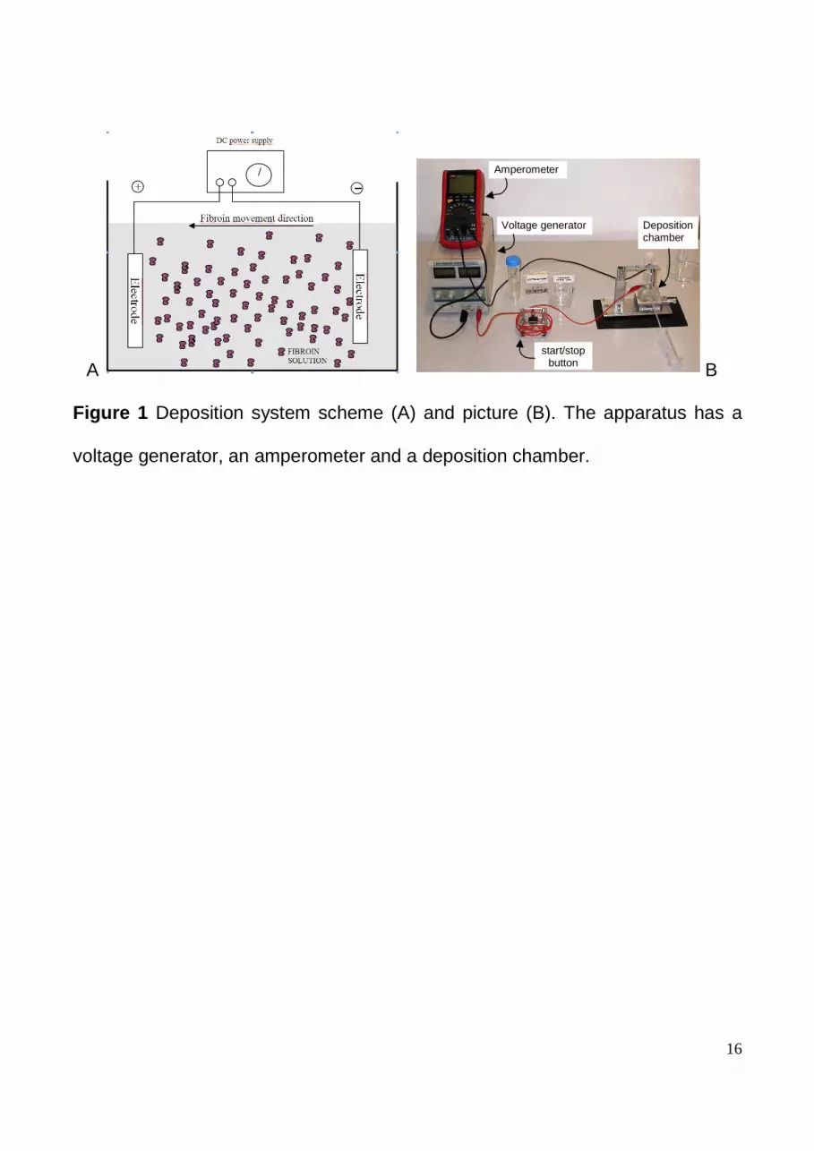
Electrodeposition Apparatus
A power generator, an amperometer and a deposition chamber, containing the
5
protein-water solution and the positive and the negative electrodes, composed
the electrodeposition system. A scheme and the electrodeposition chamber are
shown in Figure 1 . The chamber was placed on a precision stage to control the
electrodes distance. Current was measured by means of an amperometer.
Film Deposition
Fibroin coatings were generated on the metal anodes by applying different
voltages (3V, 10V, 30V) for up to 2000 seconds to the electrodes immersed in
the fibroin-water solution (1.0%, 2.0%, 2.6% w/v). After the deposition, the anode
resulted coated by a gel-like fibroin material. To make the coating insoluble in
water, the fibroin gel was stabilized by immersion in a methanol-water solution
(80%) for 5 min and then rinsed with water. Following the methanol treatment,
the coated anode was freeze dried generating a gel layer with open porosity.
Characterization of the Hydrogel Coating
The FTIR spectra of electrodeposited fibroin and water fibroin solutions
were obtained on a FTIR-ATR Perkin Elmer Spectrum One in the
spectral region of 4000-600 cm-1 (average of 8 acquisitions, 2 cm-1
spectral resolution). The contribution of pure water was subtracted from
the spectra .
Cambridge Stereoscan 200 Scanning Electron Microscope (SEM) or
6
Philips XL30 TMP Environmental Scanning Electron Microscope (ESEM)
were used to analyze the coating morphology.
The thickness of the deposited material was measured by means of optical
microscopy (Zeiss Axiotech at 100x magnification, resolution 2 µm) and by a
micrometer. Thickness was calculated by averaging the measurements obtained
on 5 different areas on freeze-dried samples. The values obtained with both
methods were compared each other and then with the theoretical model.
RESULTS AND DISCUSSION
It was demonstrated that fibroin could be deposited onto the anode surface of
an electrochemical cell. In these experiments a two parallel plate electrode
system was immersed in water fibroin solutions at constant electric potential
using different concentrations. After deposition, the electrodes were
disconnected from the power supply and removed from the solution. During the
process, especially at higher voltages, together with the deposition, bubbles
were generated because of the hydrolysis. Referring to the scheme of Figure 1a,
the first process on the metal electrode is the hydrolysis:
−+ ++→ eHOOH 442 22 (1)
thus, as the concentration of H+ was locally increased, the pH was lowered.
When the local pH of the solution was below the isoelectric point of fibroin, it

7
reduced the net charge of fibroin and triggers protein gelation at the surface of
the anode. Assuming that the following pseudo first order reactions takes place,
coatingB
BAk
k
→
→2
1
(2)
the process can be described by the Miskovic-Stankovic model 13, 30 proposed for
a cathodic deposition of epoxy coatings, where A is water, B is hydronium, k1
and k2 are the rate constants of the first and second step of the deposition.
Setting the rate of the film growth as:
( )djjdt
d −= βδ (3)
where β is the electric field, jd, the dissolution current density, j, the current
density; Miskovic – Stankovic proposed the following equation:
[ ]
( )( )
tR
dtktk
eyjkk
AckkK
jjeeKj
0
12
0221
021
2
−
−−
=−
=
++−=
(4)
Where k1 is the electrolysis rate constant (A), k2, the deposition rate constant (B),
c, the concentration, j2, the current density on the deposited film, and δ0, the
starting thickness (equal to zero for a non coated surface). The current j, typically
bimodal behaviour, slightly increased from zero to a maximum value, then
progressively decreased with the reduction in the reaction rate due to the
shielding effect of the coating.
The combination of eq (3) and eq (4) and the subsequent integration gave the

8
following thickness-time relationship:
tjk
e
k
eK
tktk
212
0
12 11 ββδδ +
−−−+=−−
(5)
The SEM images of deposited fibroin after freeze-drying where; (a, b) refer to a
thick deposition (100 s) with open porosity and overlapping sheets. In thinner
depositions (c) (10 s) the structure has greater variability in the porosity,
revealing a more compact structure at lower deposition times. The porous
structure is maintained also in the bulk (d, e), emphasized in proximity of the
metal layer (particularly at lower concentrations) and including the formation of
beads together with overlapping pitted thin sheets. The contact between the
fibroin coating and the surface was characterized by the presence of small
anchoring fibrils (f). While the main porosity was due to the freeze-drying
process, the presence of large regions containing fibrils and beads or other
region where overlapping sheet were prevalent as reported by Tsukada et al 26.
These images were obtained from a 2% w/v solution with 3V applied voltage and
2mm electrodes distance, but are representative of all the other conditions
analysed.
The material obtained had an open porosity with randomly distributed pores.
The porosity was effected by the elimination of water from the gel and the gas
bubbling at the anode; the size of the pores ranged from a few microns to about
9
100 µm. As the deposition proceeded, the coating formed an electrical insulate
on the anode and the deposition current progressively decreased. For short
deposition times, the coating was more compact and maintained a network-like
structure.
In some areas the structure showed an overlap of the large pitted sheets
(Figure 2 d, e) with many beads in the terminal portions. Shown in Figure 2 f is a
side-view of the structure with fibroin fibrils anchored to the metal surface. This
dependency of fibroin structure on pH was also described by Tsukada et al 26
who maintained that fibrous structures are expected at low pH, while at higher
pH overlapped sheet structures with larger pores are prevalent.
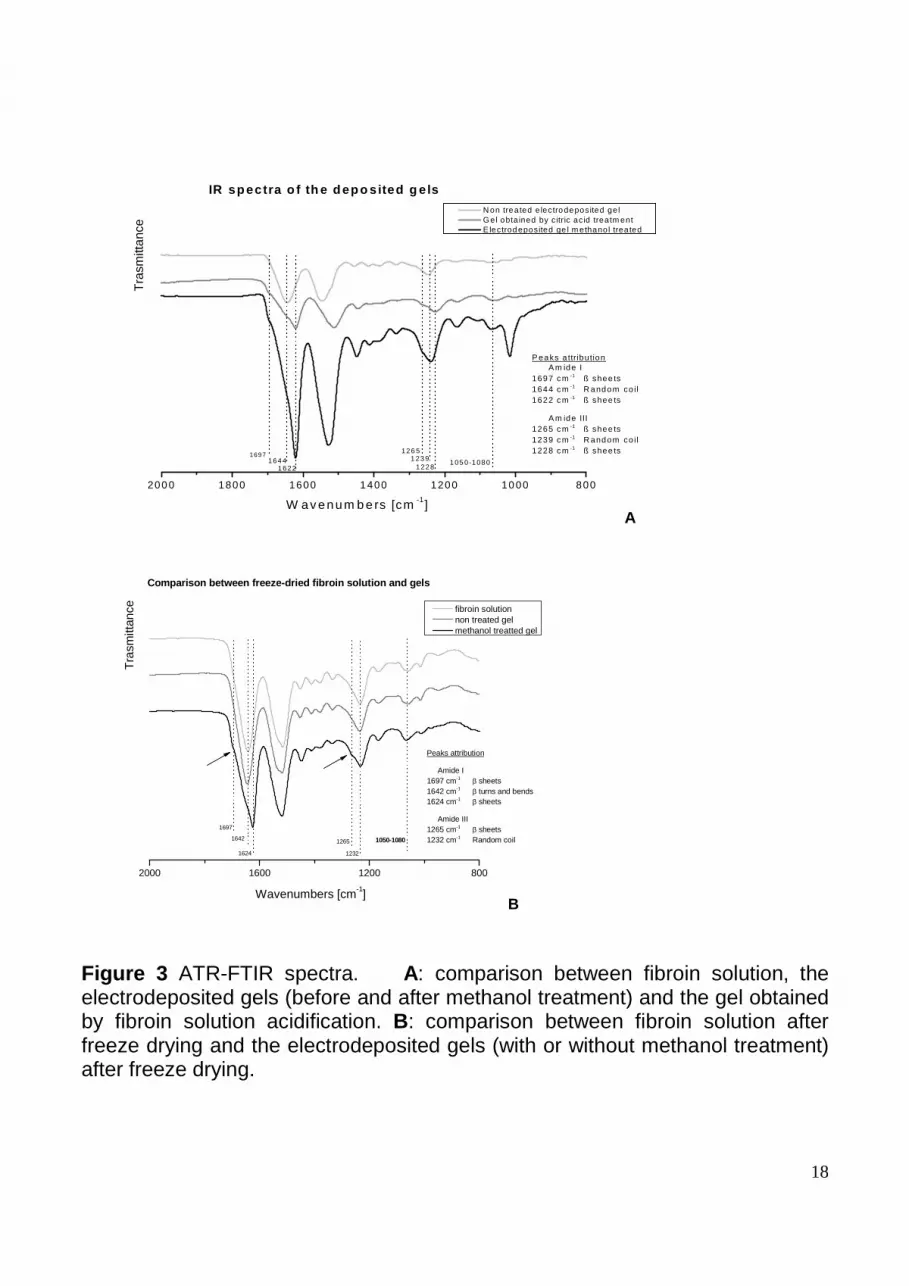
The IR spectroscopy of the electrodeposited coatings, before and after the
methanol stabilization, were compared with those of gels produced by solution
acidification via citric acid (Figure 3A). These gels were considered to be good
references as they were obtained at a pH lower than the iso-electric point, which
is proposed to occurs at the anode during the electrodeposition processes. For
the coating gel before methanol treatment, the strong absorption of amide I at
1644 cm-1 was attributed to a prevalent random coil conformation; however, after
being treated in methanol, the sample showed absorption bands at 1622 cm-1
(amide I) and 1265 cm-1 (amide III) that are representative of the β-sheet
conformation 31. It is reported in the literature, that with a shift to higher
crystallinity, the β-sheet structure enhances the stability of the coating in water
10
32.
The IR spectrum of the electrodeposited gel after methanol treatment was similar
to the gel obtained by acidification, confirming the analogy of the molecular
assembly mechanism related to the increase of β-sheet content.
The IR spectra of freeze dried materials were also analyzed. The spectrum of
the fibroin solution was compared with those on the coating (with and without
methanol treatment) after freeze-drying (Figure 3B). The strong absorption
bands at 1642-1644 cm-1 (amide I) and 1235 cm-1 (amide III) is indicative of a
random coil conformation and/or β turns and bends structures, indicating that the
electrodeposition did not induce significant changes in the secondary structure of
fibroin. Conversely, the gel after methanol treatment presented absorption bands
at 1624 cm-1 (amide I) and a characteristic shoulder band at 1265 cm-1, which
were attributed to the β-sheet protein conformation.
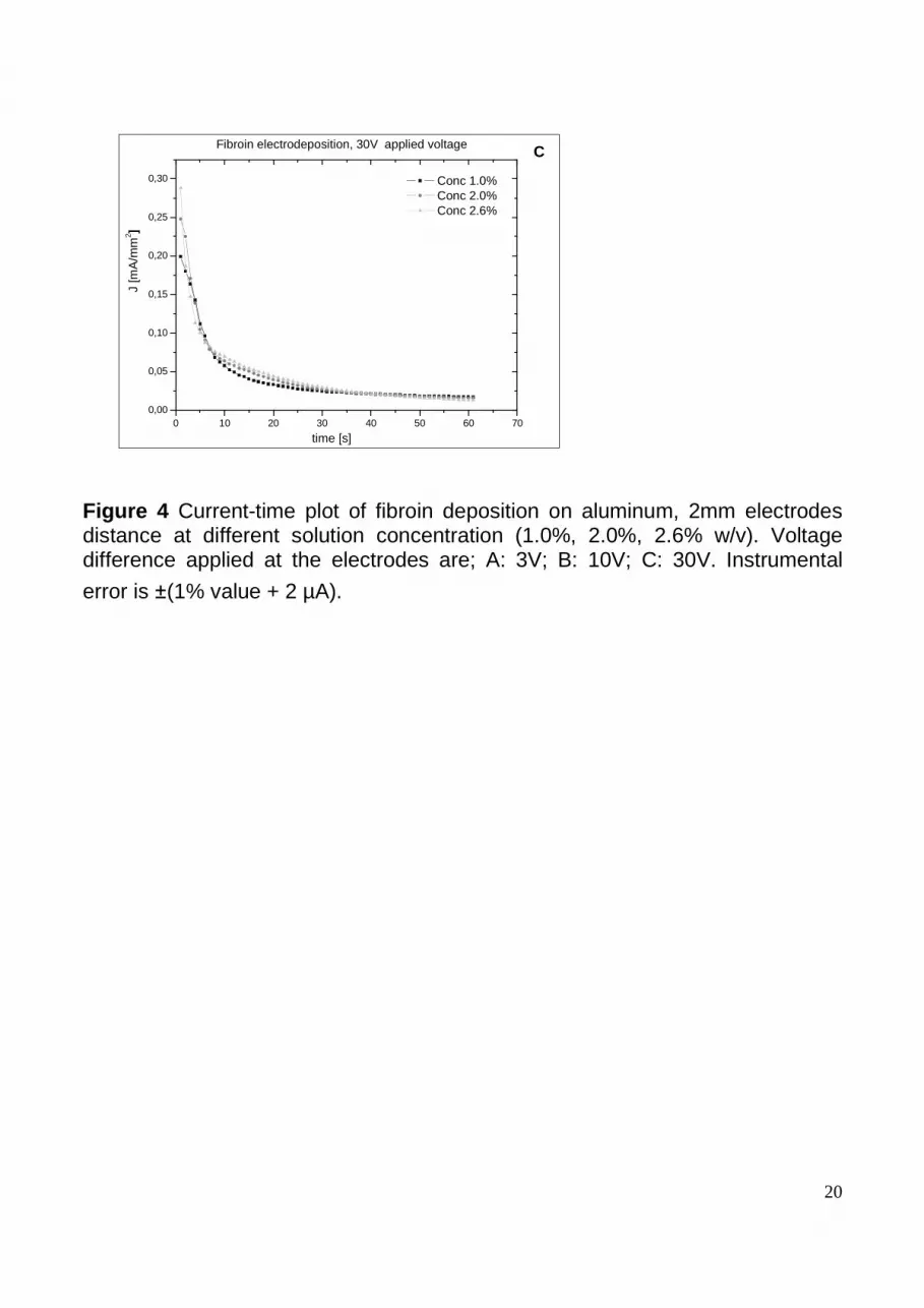
The effect of applied voltage, distance between the electrodes and
concentration of the solution were analysed with respect to the deposition
thickness and the current density. The variation in the current density with
solution concentration at different applied voltages is shown in Figure 4 (these
curves are highly reproducible). As described by Miskovic-Stankovic, in the case
of cathodic deposition, the process was compatible with the presence of two
pseudolinear reactions: a monotonic decreasing function (30V Figure 4C) or a
function with a rapid increment followed by a slow decreasing stage at 3 V. In the
first stage of the process, the current-time graph, a single short spike (10V
11
curves), generally attributed to water discharge phenomena at the electrodes,
was observed. The deposition could be described by focusing on the second part
of the curves, in which the deposition contribution is dominant, to ensure the full
control of the process.
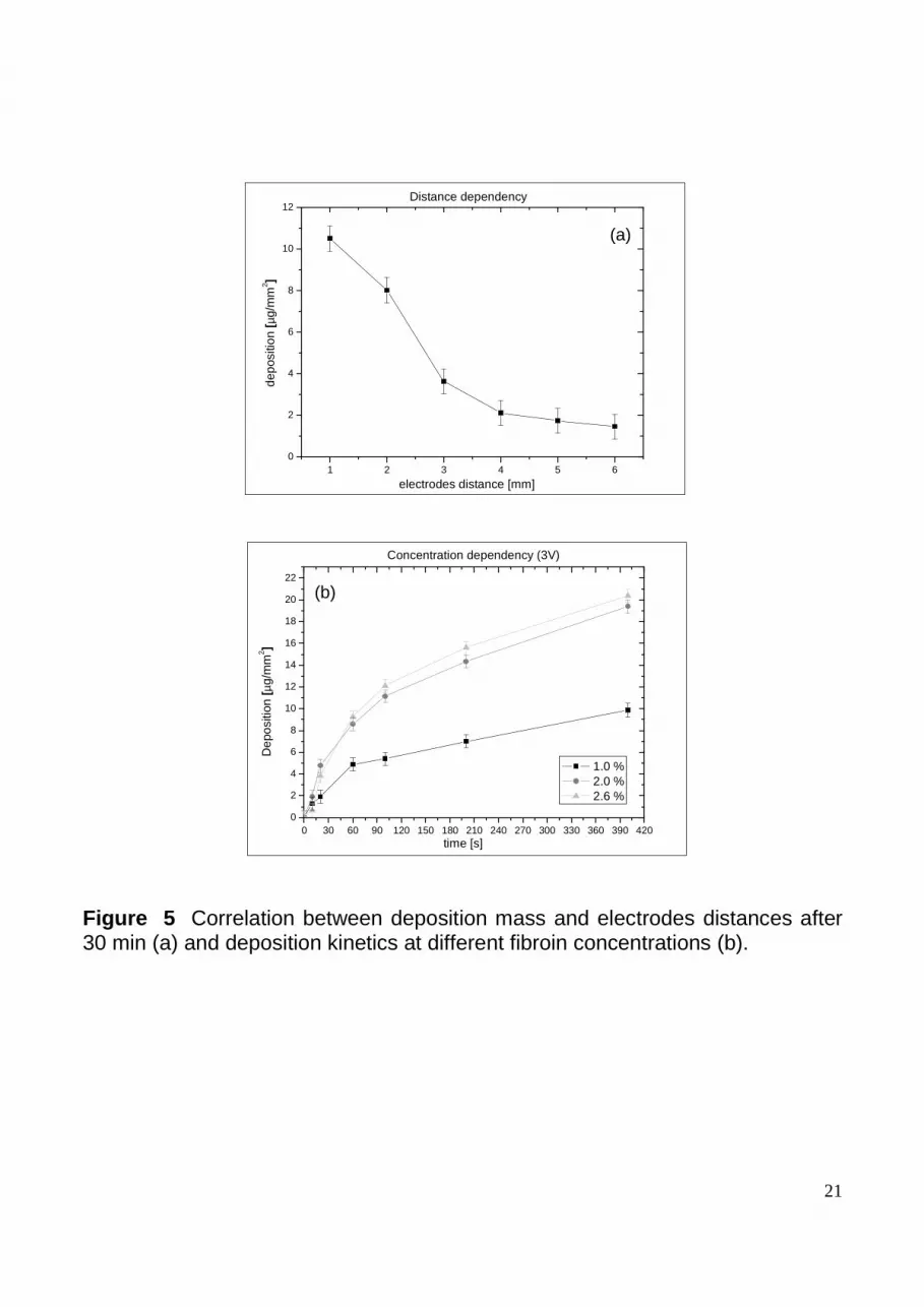
Another important parameter in the process is the distance between the two
electrodes. When the specific mass of the deposition, after drying, was plotted
against the electrode distance an inverse proportionality of the two variables was
observed. The deposition kinetics decreased because of the reduction of the
electric field due to the shielding effect of the deposited fibroin (Figure 5a). The
concentration of fibrin was critical because it is proportional to the amount of
polyelectrolytes available in the solution; thus, a higher current was developed by
increasing the charged species in solution. In Figure 5b, the deposition mass
(upon drying) deposited at different concentrations was plotted versus time
showed the dependency of the process, starting from the concentration after
dialysis (2.6 %) and diluting it to 2% and 1%.
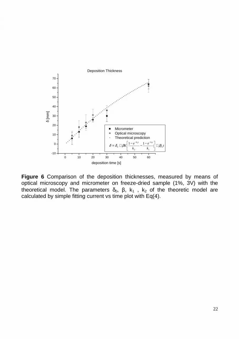
To compare the process evolution using equation (5) proposed by Miskovic-
Stankovic, the thickness of the deposition after freeze drying was measured by
means of optical microscopy and a micrometer. No tests on gel-like coatings
could be done because of the difficulties encountered evaluating their thickness.
Although, the micrometer measurements seemed to give lower values than
those obtained by optical microscopy (probably due to a contact compression,
not present in the optical measurement), the data were in good agreement with

12
the theoretical model (Figure 6). These results confirmed the suitability of the
model for anodic deposition of cationic polyelectrolytes, at least in the case of
freeze-dried fibroin. Based on the agreement of the data with the model, the
material growth on the electrodes can be controlled by adjusting the conditions to
obtain both thin layers and thick depositions.
CONCLUSIONS
In an aqueous solution after the regeneration, fibroin is negatively charged and
thus undergoes electrophoresis under an applied electric field. Its structure-
sensitivity to acid pH changes permitted coagulation in the proximity of the
anode, which led to the deposition of a gel-like material on the positive electrode
in layers of variable thickness, while no deposition took place at the negative
electrode. The process was very fast (in the order of seconds or minutes,
depending on the desired deposited mass) and highly reproducible. This method
is a novel approach to fibroin processing, as it permits solution gelation without
chemically changing the pH of the bulk solution, and thus, the possibility to
process it in a wide variety of devices. This technique could be employed in the
self assembly of fibroin and to coat metallic objects of any shape with a fibroin
layer or to obtain three-dimensional self supporting scaffolds. Fibroin
electrodeposition could be used to coat orthopaedic or dental prostheses to
enhance their bioactivity by stimulating the osteointegration process.
13
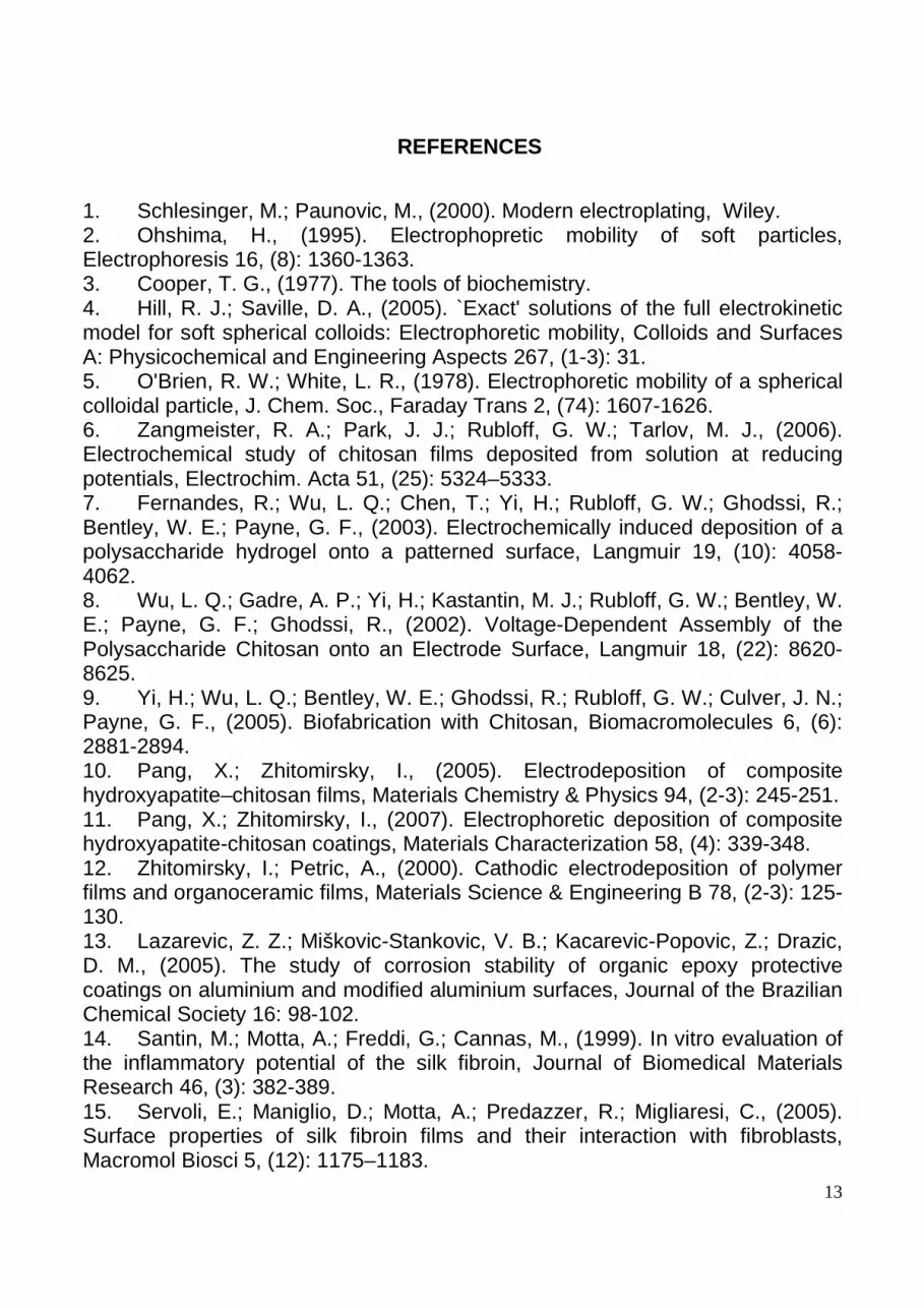
REFERENCES
1. Schlesinger, M.; Paunovic, M., (2000). Modern electroplating, Wiley. 2. Ohshima, H., (1995). Electrophopretic mobility of soft particles, Electrophoresis 16, (8): 1360-1363. 3. Cooper, T. G., (1977). The tools of biochemistry. 4. Hill, R. J.; Saville, D. A., (2005). `Exact' solutions of the full electrokinetic model for soft spherical colloids: Electrophoretic mobility, Colloids and Surfaces A: Physicochemical and Engineering Aspects 267, (1-3): 31. 5. O'Brien, R. W.; White, L. R., (1978). Electrophoretic mobility of a spherical colloidal particle, J. Chem. Soc., Faraday Trans 2, (74): 1607-1626. 6. Zangmeister, R. A.; Park, J. J.; Rubloff, G. W.; Tarlov, M. J., (2006). Electrochemical study of chitosan films deposited from solution at reducing potentials, Electrochim. Acta 51, (25): 5324–5333. 7. Fernandes, R.; Wu, L. Q.; Chen, T.; Yi, H.; Rubloff, G. W.; Ghodssi, R.; Bentley, W. E.; Payne, G. F., (2003). Electrochemically induced deposition of a polysaccharide hydrogel onto a patterned surface, Langmuir 19, (10): 4058-4062. 8. Wu, L. Q.; Gadre, A. P.; Yi, H.; Kastantin, M. J.; Rubloff, G. W.; Bentley, W. E.; Payne, G. F.; Ghodssi, R., (2002). Voltage-Dependent Assembly of the Polysaccharide Chitosan onto an Electrode Surface, Langmuir 18, (22): 8620-8625. 9. Yi, H.; Wu, L. Q.; Bentley, W. E.; Ghodssi, R.; Rubloff, G. W.; Culver, J. N.; Payne, G. F., (2005). Biofabrication with Chitosan, Biomacromolecules 6, (6): 2881-2894. 10. Pang, X.; Zhitomirsky, I., (2005). Electrodeposition of composite hydroxyapatite–chitosan films, Materials Chemistry & Physics 94, (2-3): 245-251. 11. Pang, X.; Zhitomirsky, I., (2007). Electrophoretic deposition of composite hydroxyapatite-chitosan coatings, Materials Characterization 58, (4): 339-348. 12. Zhitomirsky, I.; Petric, A., (2000). Cathodic electrodeposition of polymer films and organoceramic films, Materials Science & Engineering B 78, (2-3): 125-130. 13. Lazarevic, Z. Z.; Miškovic-Stankovic, V. B.; Kacarevic-Popovic, Z.; Drazic, D. M., (2005). The study of corrosion stability of organic epoxy protective coatings on aluminium and modified aluminium surfaces, Journal of the Brazilian Chemical Society 16: 98-102. 14. Santin, M.; Motta, A.; Freddi, G.; Cannas, M., (1999). In vitro evaluation of the inflammatory potential of the silk fibroin, Journal of Biomedical Materials Research 46, (3): 382-389. 15. Servoli, E.; Maniglio, D.; Motta, A.; Predazzer, R.; Migliaresi, C., (2005). Surface properties of silk fibroin films and their interaction with fibroblasts, Macromol Biosci 5, (12): 1175–1183.
14
16. Altman, G. H.; Diaz, F.; Jakuba, C.; Calabro, T.; Horan, R. L.; Chen, J.; Lu, H.; Richmond, J.; Kaplan, D. L., (2003). Silk-based biomaterials, Biomaterials 24, (3): 401-16. 17. Ramesh Dandu, Hamidreza Ghandehari, and Joseph Cappello Characterization of Structurally Related Adenovirus-laden Silk-elastinlike Hydrogels J. Bioact. Compat. Polym.,2008 23: 5-19. 18. Horan, R. L.; Antle, K.; Collette, A. L.; Wang, Y.; Huang, J.; Moreau, J. E.; Volloch, V.; Kaplan, D. L., (2005). In vitro degradation of silk fibroin, Biomaterials 26, (17): 3385-3393. 19. Unger, R. E.; Wolf, M.; Peters, K.; Motta, A.; Migliaresi, C.; Kirkpatrick, C. J., (2004). Growth of human cells on a non-woven silk fibroin net: a potential for use in tissue engineering, Biomaterials 25, (6): 1069-1075. 20. Chen, G.; Zhou, P.; Mei, N.; Chen, X.; Shao, Z.; Pan, L.; Wu, C., (2004). Silk fibroin modified porous poly (e-caprolactone) scaffold for human fibroblast culture in vitro, Journal of Materials Science: Materials in Medicine 15, (6): 671-677. 21. Li, M.; Lu, S.; Wu, Z.; Tan, K.; Minoura, N.; Kuga, S., (2002). Structure and properties of silk fibroin-poly(vinyl alcohol) gel, International Journal of Biological Macromolecules 30, (2): 89. 22. Min, B. M.; Lee, G.; Kim, S. H.; Nam, Y. S.; Lee, T. S., (2004). Electrospinning of silk fibroin nanofibers and its effect on the adhesion and spreading of normal human keratinocytes and fibroblasts in vitro, Biomaterials 25, (7): 1289-1297. 23. Motta, A.; Fambri, L.; Migliaresi, C., (2002). Regenerated silk fibroin films: Thermal and dynamic mechanical analysis, Macromolecular Chemistry and Physics 203, (10-11): 1658-1665. 24. dal Pra, I.; Petrini, P.; Charini, A.; Bozzini, S.; Fare, S.; Armato, U., (2003). Silk Fibroin-Coated Three-Dimensional Polyurethane Scaffolds for Tissue Engineering: Interactions with Normal Human Fibroblasts, Tissue Engineering 9, (6): 1113-1121. 25. Meinel, L.; Hofmann, S.; Karageorgiou, V.; Kirker-Head, C.; McCool, J.; Gronowicz, G.; Zichner, L.; Langer, R.; Vunjak-Novakovic, G.; Kaplan, D. L., (2005). The inflammatory responses to silk films in vitro and in vivo, Biomaterials 26, (2): 147-155. 26. Masuhiro Tsukada, G. F. N. M. G. A., (1994). Preparation and application of porous silk fibroin materials, Journal of Applied Polymer Science 54, (4): 507-514. 27. Valluzzi, R.; He, S. J.; Gido, S. P.; Kaplan, D., (1999). Bombyx mori silk fibroin liquid crystallinity and crystallization at aqueous fibroin–organic solvent interfaces, International Journal of Biological Macromolecules 24, (2): 227-236. 28. Magoshi, J.; Magoshi, Y.; Nakamura, S., (1985). Crystallization, liquid crystal, and fiber formation of silk fibroin, J. Appl. Polymer Sci 41: 187-204. 29. Fini, M.; Motta, A.; Torricelli, P.; Giavaresi, G.; Nicoli Aldini, N.; Tschon, M.; Giardino, R.; Migliaresi, C., (2005). The healing of confined critical size

15
cancellous defects in the presence of silk fibroin hydrogel, Biomaterials 26, (17): 3527-3536. 30. Miškovic-Stankovic, V. B., (2002). The mechanism of cathodic electrodeposition of epoxy coatings and the corrosion behaviour of the electrodeposited coatings, Journal of the Serbian Chemical Society 67, (5): 305-324. 31. Wilson, D.; Valluzzi, R.; Kaplan, D., (2000). Conformational Transitions in Model Silk Peptides, Biophys. J. 78, (5): 2690-2701. 32. Tsukada, M., Gotoh, Y., Nagura, M., Minoura, N., Kasai, N., Freddi, G., structural-changes of silk fibroin membranes induced by immersion in methanol aqueous-solutions, Journal Of Polymer Science: Part B-Polymer Physics, 32, (5): 961-968.
16
A B
Figure 1 Deposition system scheme (A) and picture (B). The apparatus has a
voltage generator, an amperometer and a deposition chamber.
Amperometer
Voltage generator
start/stop button
Deposition chamber

17
a b
c d
e f
Figure 2 The final SEM structure of fibroin coatings deposited after different deposition times
30 µm 30 µm
30 µm 100 µm
10 µm 30 µm
18
200 0 1800 1600 1 400 1200 10 00 800
A
P eaks a ttribution A m ide I1697 cm -1 ß shee ts1644 cm -1 R andom co il1622 cm -1 ß shee ts
A m ide III1265 cm -1 ß shee ts1239 cm -1 R andom co il1228 cm -1 ß shee ts
105 0 -10801228
126 5
N on treated e lectrodeposited ge l G el obta ined by citric acid treatm ent E lectrodeposited ge l m ethanol treated
1644
W av enum b ers [cm -1]
Tra
smitt
ance
IR spectra o f th e depo sited g els
1622
16971 239
2000 1600 1200 800
1697
Peaks attribution
Amide I1697 cm-1 β sheets1642 cm-1 β turns and bends1624 cm-1 β sheets
Amide III1265 cm-1 β sheets1232 cm-1 Random coil
Comparison between freeze-dried fibroin solution and gels
Wavenumbers [cm-1]
Tra
smitt
ance
fibroin solution non treated gel methanol treatted gel
1642
1624
1265
1232
1050-1080
B
Figure 3 ATR-FTIR spectra. A: comparison between fibroin solution, the electrodeposited gels (before and after methanol treatment) and the gel obtained by fibroin solution acidification. B: comparison between fibroin solution after freeze drying and the electrodeposited gels (with or without methanol treatment) after freeze drying.

19
0 10 20 30 40 50 60 70 80 90 100 1100,000
0,002
0,004
0,006
0,008
0,010
0,012
0,014
0,016 Conc 1.0% Conc 2.0% Conc 2.6%
J [m
A/m
m2 ]
time [s]
Fibroin electrodeposition, 3 V applied voltage A
0 20 40 60 80 1000,00
0,02
0,04
0,06
0,08
0,10
0,12
0,14 Conc 1.0% Conc 2.0% Conc 2.6%
J
[mA
/mm
2 ]
time [s]
Fibroin electrodeposition, 10V applied voltage B
20
0 10 20 30 40 50 60 700,00
0,05
0,10
0,15
0,20
0,25
0,30 Conc 1.0% Conc 2.0% Conc 2.6%
J [m
A/m
m2 ]
time [s]
Fibroin electrodeposition, 30V applied voltage C
Figure 4 Current-time plot of fibroin deposition on aluminum, 2mm electrodes distance at different solution concentration (1.0%, 2.0%, 2.6% w/v). Voltage difference applied at the electrodes are; A: 3V; B: 10V; C: 30V. Instrumental
error is ±(1% value + 2 µA).
21
1 2 3 4 5 60
2
4
6
8
10
12
de
posi
tion
[ µg/
mm
2 ]
electrodes distance [mm]
Distance dependency
(a)
0 30 60 90 120 150 180 210 240 270 300 330 360 390 4200
2
4
6
8
10
12
14
16
18
20
22
Concentration dependency (3V)
time [s]
Dep
ositi
on [
µg/m
m2 ]
1.0 % 2.0 % 2.6 %
(b)
Figure 5 Correlation between deposition mass and electrodes distances after 30 min (a) and deposition kinetics at different fibroin concentrations (b).
22
0 10 20 30 40 50 60-10
0
10
20
30
40
50
60
70
Deposition Thickness
tj
k
e
k
eK
tktk
212
0
12 11 ββδδ +
−−−+=−−
δ [m
m]
deposition time [s]
Micrometer Optical microscopy Theoretical prediction
Figure 6 Comparison of the deposition thicknesses, measured by means of optical microscopy and micrometer on freeze-dried sample (1%, 3V) with the theoretical model. The parameters δ0, β, k1 , k2 of the theoretic model are calculated by simple fitting current vs time plot with Eq(4).

23


