Embed Size (px)
Citation preview
Foreword
Thank you for purchasing your new Chery automobile. To correctly operate and maintain your vehicle and understand itsfeatures and controls, please take the time to read this manual carefully.
After you read this manual, it should be stored in the vehicle for convenient reference and remain with the vehiclewhen sold so that the new owner will be aware of all safety warnings.
Chery Automobile Co., Ltd. reserves the right to make changes in design and specifications, and / or make additionsto or improvement to its products without imposing any obligation upon itself to install them on products previouslymanufactured.
Authorized Chery dealers are service professionals and are exclusively authorized by Chery Automobile Co., Ltd. Whenit comes to service, remember that your authorized dealer knows your vehicle best, has the factory-trained techniciansand OEM parts to best provide the customer satisfaction that you require.
Depending on the vehicle equipment or features specific to your vehicle, some descriptions and illustrations may dif-fer from the equipment found on your vehicle.
Please access our website for further information.Website: www.cheryinternational.com
� 2008 Chery Automobile Co., Ltd.
All rights reserved. This material may not be reproduced or copied, in whole or in part, without the written permissionof Chery Automobile Co., Ltd.
Chery Automobile Co., Ltd.
TABLE OF CONTENTSCHAPTER PAGE
1 INTRODUCTION . . . . . . . . . . . . . . . . . . . . . . . . . . . . . . . . . . . . . . . . . . . . . . . . . . . . . . . . . . . . . . . . . . 3
2 BEFORE OPERATING YOUR VEHICLE . . . . . . . . . . . . . . . . . . . . . . . . . . . . . . . . . . . . . . . . . . . . . . . . . 15
3 FEATURES OF YOUR VEHICLE . . . . . . . . . . . . . . . . . . . . . . . . . . . . . . . . . . . . . . . . . . . . . . . . . . . . . . 33
4 STARTING AND OPERATING YOUR VEHICLE . . . . . . . . . . . . . . . . . . . . . . . . . . . . . . . . . . . . . . . . . . . 51
5 YOUR INSTRUMENT PANEL . . . . . . . . . . . . . . . . . . . . . . . . . . . . . . . . . . . . . . . . . . . . . . . . . . . . . . . . 67
6 IN CASE OF AN EMERGENCY . . . . . . . . . . . . . . . . . . . . . . . . . . . . . . . . . . . . . . . . . . . . . . . . . . . . . . . 87
7 CUSTOMER ASSISTANCE . . . . . . . . . . . . . . . . . . . . . . . . . . . . . . . . . . . . . . . . . . . . . . . . . . . . . . . . . . 97
8 PROPER MAINTENANCE OF YOUR VEHICLE . . . . . . . . . . . . . . . . . . . . . . . . . . . . . . . . . . . . . . . . . . 101
9 MAINTENANCE SCHEDULES . . . . . . . . . . . . . . . . . . . . . . . . . . . . . . . . . . . . . . . . . . . . . . . . . . . . . . 117
10 INDEX . . . . . . . . . . . . . . . . . . . . . . . . . . . . . . . . . . . . . . . . . . . . . . . . . . . . . . . . . . . . . . . . . . . . . . . 135
2
Chery Automobile Co., Ltd.
INTRODUCTION
CONTENTS
� Introduction 4
� How to Read This Manual 4
� Table of Contents 4
� Vehicle Symbols 4
� Index 4
� Vehicle Features 6
� New Vehicle Inspection 6
� Inspection Certification forVehicle Delivery 7
� Vehicle Delivery Card 8
� Personal Service 10� �PERSON-TO-PERSON�
Service Advisor Card 11
� Warnings and Cautions 13
� Vehicle IdentificationNumber 13
� Vehicle Modifications 13
3
Chery Automobile Co., Ltd.
IntroductionCongratulations on selecting your newChery vehicle. To correctly operateand maintain your vehicle and under-stand its features and controls, pleasetake the time to read this manual care-fully.
This manual contains important in-structions and tips concerning the rou-tine driving and regular maintenanceof your vehicle. The more familiar youare with the operation of your vehicle,the more you will ensure your safetyand overall economic benefit whiledriving. Failure to operate this vehiclecorrectly may result in loss of controlor an accident.
Regular routine maintenance will keepyour vehicle operating at its best. Wesuggest you have your vehicle ser-viced at recommended intervals by anauthorized Chery dealer who uses au-thorized Chery replacement parts. Anydamage caused by failing to followrecommended operation or mainte-nance may not be covered by yourwarranty.
How to Read This Manual
Table of Contents
Consult the Table of Contents to de-termine which section of the Owner’sManual contains the information youdesire.
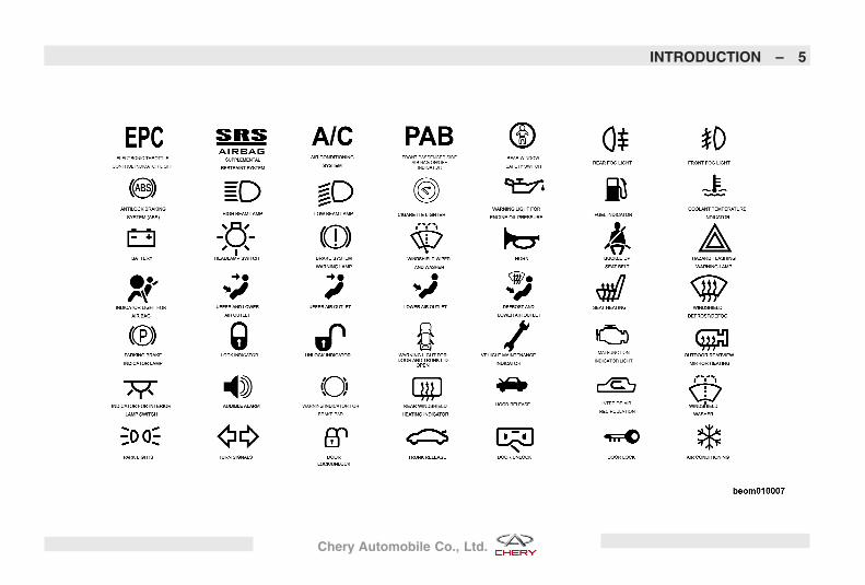
Vehicle Symbols
Consult the symbol table on the fol-lowing page for a description of thesymbols that may be used on your ve-hicle and throughout the Owner’sManual.
Index
The detailed index at the back of thisOwner’s Manual contains a completelisting for all vehicle subject matter.
4 – INTRODUCTION
Chery Automobile Co., Ltd.
INTRODUCTION – 5
Chery Automobile Co., Ltd.
Vehicle FeaturesThis manual includes the current fea-tures and information regarding theChery A5 series of vehicles. All material(including all standard and availablefeatures) contained in this publicationis based on the latest information atthe time it was printed. Therefore,please note that some of the equip-
ment and accessories in this publica-tion may not appear on your vehicle.
New Vehicle InspectionPrior to your purchase, your autho-rized Chery dealer inspected your ve-hicle based upon the guidelines of theChery Automobile Co., Ltd. The dealerwill record the delivery date and affixits common seal to the inspection cer-tificate.
Before you sign the inspection certifi-cation, your authorized dealer will in-struct you regarding your vehicle’sperformance capabilities according toits Vehicle Delivery Card, as well asprovide you with general knowledgeof its features and regular operation.
6 – INTRODUCTION
Chery Automobile Co., Ltd.
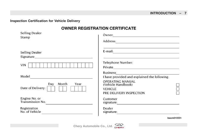
Inspection Certification for Vehicle Delivery
INTRODUCTION – 7
Chery Automobile Co., Ltd.
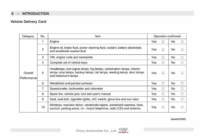
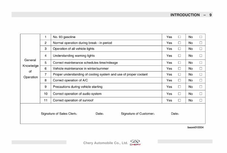
Vehicle Delivery Card
8 – INTRODUCTION
Chery Automobile Co., Ltd.
INTRODUCTION – 9
Chery Automobile Co., Ltd.
Personal ServiceTo provide you the best service, yourauthorized Chery dealer will provide apersonal service advisor for you dur-ing your purchase. If you have anyquestions regarding your vehicle,please ask your service advisor.
10 – INTRODUCTION
Chery Automobile Co., Ltd.
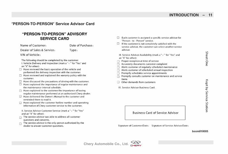
�PERSON-TO-PERSON� Service Advisor Card
INTRODUCTION – 11
Chery Automobile Co., Ltd.

12 – INTRODUCTION
Chery Automobile Co., Ltd.
Warnings and CautionsThe Owner’s Manual contains Warn-ings and Cautions regarding operatingprocedures that could result in an ac-cident or damage to your vehicle.Please observe all Warnings and Cau-tions before operating your vehicle.
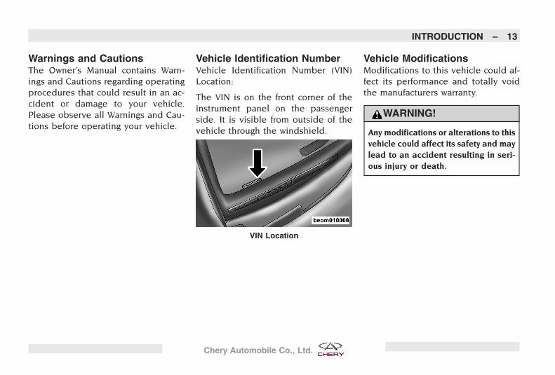
Vehicle Identification NumberVehicle Identification Number (VIN)Location:
The VIN is on the front corner of theinstrument panel on the passengerside. It is visible from outside of thevehicle through the windshield.
Vehicle ModificationsModifications to this vehicle could af-fect its performance and totally voidthe manufacturers warranty.
WARNING!
Any modifications or alterations to thisvehicle could affect its safety and maylead to an accident resulting in seri-ous injury or death.
VIN Location
INTRODUCTION – 13
Chery Automobile Co., Ltd.

14
Chery Automobile Co., Ltd.
BEFORE OPERATING YOUR VEHICLE
CONTENTS
� Ignition Key 17� Ignition Key Removal 17
� Key-In-Ignition Reminder 17
� Locking Doors With TheKey 17
� Replacement Keys 17
� Remote Keyless Entry 18
� Transmitter BatteryReplacement 18
� Electronic Key Identification 19
� Anti-Theft SecurityProtection 19� Vehicle Alarm 19
� Anti-Theft System 19
� Steering Wheel 19
� Adjusting Steering Wheel 19
� Horn 20
� Door Locks 20
� Manual Door Locks 20
� Power Door Locks 21
� “Child-Protection” Door LockSystem (Rear Doors) 21
� Power Windows 22
� Power Window Switches 22
� Auto - Down Feature 22
� Rear Window Safety Switch 22
� Occupant Restraints 22
� Lap/Shoulder Belts 22
� Lap/Shoulder Belt WarningLight 23
� Lap/Shoulder Belt OperatingInstructions 23
� Central Two-Point Seat BeltFor Rear Seat 23
� Adjustable Upper ShoulderBelt Anchorage 24
� Maintenance For Seat Belt 24
� Airbag 25
� Supplemental FrontSeat-Mounted Side Airbags 26
� Airbag Warning Light 27
� Child Restraint 27
� Operating Safety Tips 28
� Transporting Passengers 28
� Locking Your Vehicle 29
� Exhaust Gas 29
15
Chery Automobile Co., Ltd.
� Interior Vehicle SafetyInspection 29
� Exterior Vehicle SafetyInspection 30
� New Vehicle Break-InRecommendations 30� Engine Break-In
Recommendations 30
� Braking System Break-InRecommendations 31
� Tire and Wheel Break-InRecommendations 31
16 – BEFORE OPERATING YOUR VEHICLE
Chery Automobile Co., Ltd.
Ignition Key
Ignition Key Removal
Automatic Transaxle
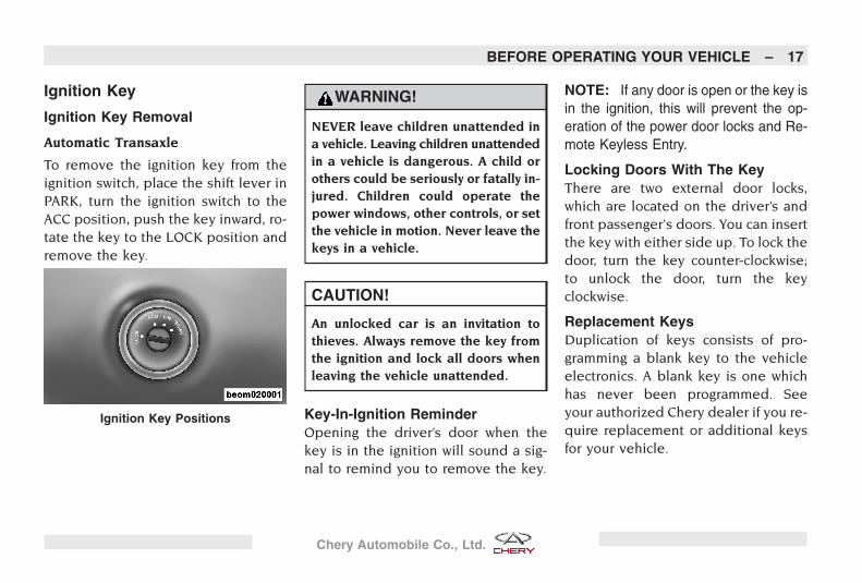
To remove the ignition key from theignition switch, place the shift lever inPARK, turn the ignition switch to theACC position, push the key inward, ro-tate the key to the LOCK position andremove the key.
WARNING!
NEVER leave children unattended ina vehicle. Leaving children unattendedin a vehicle is dangerous. A child orothers could be seriously or fatally in-jured. Children could operate thepower windows, other controls, or setthe vehicle in motion. Never leave thekeys in a vehicle.
CAUTION!
An unlocked car is an invitation tothieves. Always remove the key fromthe ignition and lock all doors whenleaving the vehicle unattended.
Key-In-Ignition ReminderOpening the driver’s door when thekey is in the ignition will sound a sig-nal to remind you to remove the key.
NOTE: If any door is open or the key isin the ignition, this will prevent the op-eration of the power door locks and Re-mote Keyless Entry.
Locking Doors With The KeyThere are two external door locks,which are located on the driver’s andfront passenger’s doors. You can insertthe key with either side up. To lock thedoor, turn the key counter-clockwise;to unlock the door, turn the keyclockwise.
Replacement KeysDuplication of keys consists of pro-gramming a blank key to the vehicleelectronics. A blank key is one whichhas never been programmed. Seeyour authorized Chery dealer if you re-quire replacement or additional keysfor your vehicle.
Ignition Key Positions
BEFORE OPERATING YOUR VEHICLE – 17
Chery Automobile Co., Ltd.
CAUTION!
Always remove the key from the vehicleand lock all doors when leaving the ve-hicle unattended.
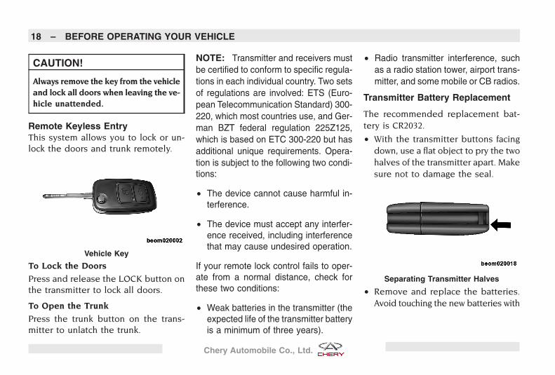
Remote Keyless EntryThis system allows you to lock or un-lock the doors and trunk remotely.
To Lock the Doors
Press and release the LOCK button onthe transmitter to lock all doors.
To Open the Trunk
Press the trunk button on the trans-mitter to unlatch the trunk.
NOTE: Transmitter and receivers mustbe certified to conform to specific regula-tions in each individual country. Two setsof regulations are involved: ETS (Euro-pean Telecommunication Standard) 300-220, which most countries use, and Ger-man BZT federal regulation 225Z125,which is based on ETC 300-220 but hasadditional unique requirements. Opera-tion is subject to the following two condi-tions:
• The device cannot cause harmful in-terference.
• The device must accept any interfer-ence received, including interferencethat may cause undesired operation.
If your remote lock control fails to oper-ate from a normal distance, check forthese two conditions:
• Weak batteries in the transmitter (theexpected life of the transmitter batteryis a minimum of three years).
• Radio transmitter interference, suchas a radio station tower, airport trans-mitter, and some mobile or CB radios.
Transmitter Battery Replacement
The recommended replacement bat-tery is CR2032.
• With the transmitter buttons facingdown, use a flat object to pry the twohalves of the transmitter apart. Makesure not to damage the seal.
• Remove and replace the batteries.Avoid touching the new batteries with
Vehicle Key
Separating Transmitter Halves
18 – BEFORE OPERATING YOUR VEHICLE
Chery Automobile Co., Ltd.
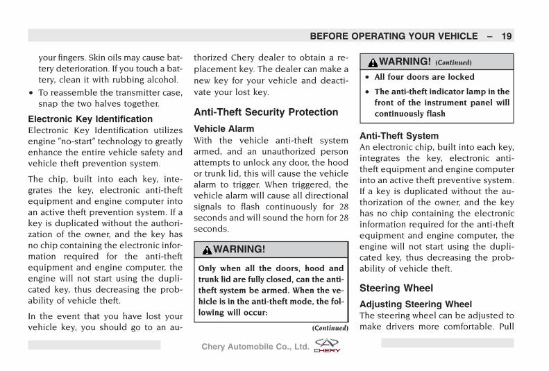
your fingers. Skin oils may cause bat-tery deterioration. If you touch a bat-tery, clean it with rubbing alcohol.
• To reassemble the transmitter case,snap the two halves together.
Electronic Key IdentificationElectronic Key Identification utilizesengine �no-start� technology to greatlyenhance the entire vehicle safety andvehicle theft prevention system.
The chip, built into each key, inte-grates the key, electronic anti-theftequipment and engine computer intoan active theft prevention system. If akey is duplicated without the authori-zation of the owner, and the key hasno chip containing the electronic infor-mation required for the anti-theftequipment and engine computer, theengine will not start using the dupli-cated key, thus decreasing the prob-ability of vehicle theft.
In the event that you have lost yourvehicle key, you should go to an au-
thorized Chery dealer to obtain a re-placement key. The dealer can make anew key for your vehicle and deacti-vate your lost key.
Anti-Theft Security Protection
Vehicle AlarmWith the vehicle anti-theft systemarmed, and an unauthorized personattempts to unlock any door, the hoodor trunk lid, this will cause the vehiclealarm to trigger. When triggered, thevehicle alarm will cause all directionalsignals to flash continuously for 28seconds and will sound the horn for 28seconds.
WARNING!
Only when all the doors, hood andtrunk lid are fully closed, can the anti-theft system be armed. When the ve-hicle is in the anti-theft mode, the fol-lowing will occur:
(Continued)
WARNING! (Continued)
• All four doors are locked
• The anti-theft indicator lamp in thefront of the instrument panel willcontinuously flash
Anti-Theft SystemAn electronic chip, built into each key,integrates the key, electronic anti-theft equipment and engine computerinto an active theft preventive system.If a key is duplicated without the au-thorization of the owner, and the keyhas no chip containing the electronicinformation required for the anti-theftequipment and engine computer, theengine will not start using the dupli-cated key, thus decreasing the prob-ability of vehicle theft.
Steering Wheel
Adjusting Steering WheelThe steering wheel can be adjusted tomake drivers more comfortable. Pull
BEFORE OPERATING YOUR VEHICLE – 19
Chery Automobile Co., Ltd.
down the locking lever to move thesteering wheel upward and downward.After the proper adjustment, pull thelocking lever back to its original posi-tion to secure the steering wheel inplace.
WARNING!
Do not adjust the steering wheel whiledriving. Adjusting the steering wheelwhile driving could cause the driver tolose control of the vehicle.
HornPress the center push pad on thesteering wheel to operate the horn.The horn will still work with the igni-tion switch in the OFF position.
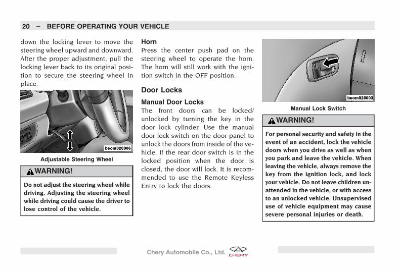
Door Locks
Manual Door LocksThe front doors can be locked/unlocked by turning the key in thedoor lock cylinder. Use the manualdoor lock switch on the door panel tounlock the doors from inside of the ve-hicle. If the rear door switch is in thelocked position when the door isclosed, the door will lock. It is recom-mended to use the Remote KeylessEntry to lock the doors.
WARNING!
For personal security and safety in theevent of an accident, lock the vehicledoors when you drive as well as whenyou park and leave the vehicle. Whenleaving the vehicle, always remove thekey from the ignition lock, and lockyour vehicle. Do not leave children un-attended in the vehicle, or with accessto an unlocked vehicle. Unsuperviseduse of vehicle equipment may causesevere personal injuries or death.
Adjustable Steering Wheel
Manual Lock Switch
20 – BEFORE OPERATING YOUR VEHICLE
Chery Automobile Co., Ltd.
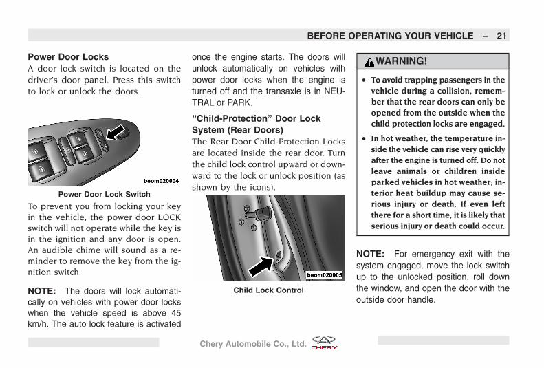
Power Door LocksA door lock switch is located on thedriver’s door panel. Press this switchto lock or unlock the doors.
To prevent you from locking your keyin the vehicle, the power door LOCKswitch will not operate while the key isin the ignition and any door is open.An audible chime will sound as a re-minder to remove the key from the ig-nition switch.
NOTE: The doors will lock automati-cally on vehicles with power door lockswhen the vehicle speed is above 45km/h. The auto lock feature is activated
once the engine starts. The doors willunlock automatically on vehicles withpower door locks when the engine isturned off and the transaxle is in NEU-TRAL or PARK.
“Child-Protection” Door LockSystem (Rear Doors)The Rear Door Child-Protection Locksare located inside the rear door. Turnthe child lock control upward or down-ward to the lock or unlock position (asshown by the icons).
WARNING!
• To avoid trapping passengers in thevehicle during a collision, remem-ber that the rear doors can only beopened from the outside when thechild protection locks are engaged.
• In hot weather, the temperature in-side the vehicle can rise very quicklyafter the engine is turned off. Do notleave animals or children insideparked vehicles in hot weather; in-terior heat buildup may cause se-rious injury or death. If even leftthere for a short time, it is likely thatserious injury or death could occur.
NOTE: For emergency exit with thesystem engaged, move the lock switchup to the unlocked position, roll downthe window, and open the door with theoutside door handle.
Power Door Lock Switch
Child Lock Control
BEFORE OPERATING YOUR VEHICLE – 21
Chery Automobile Co., Ltd.
Power Windows
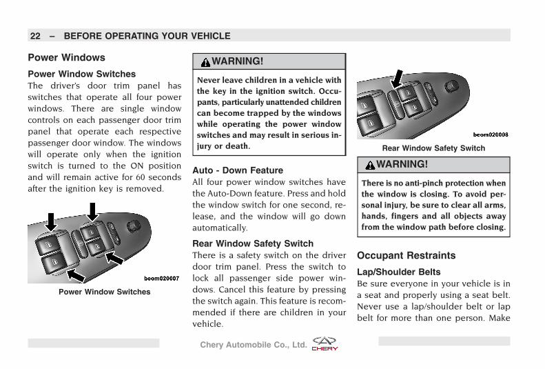
Power Window SwitchesThe driver’s door trim panel hasswitches that operate all four powerwindows. There are single windowcontrols on each passenger door trimpanel that operate each respectivepassenger door window. The windowswill operate only when the ignitionswitch is turned to the ON positionand will remain active for 60 secondsafter the ignition key is removed.
WARNING!
Never leave children in a vehicle withthe key in the ignition switch. Occu-pants, particularly unattended childrencan become trapped by the windowswhile operating the power windowswitches and may result in serious in-jury or death.
Auto - Down FeatureAll four power window switches havethe Auto-Down feature. Press and holdthe window switch for one second, re-lease, and the window will go downautomatically.
Rear Window Safety SwitchThere is a safety switch on the driverdoor trim panel. Press the switch tolock all passenger side power win-dows. Cancel this feature by pressingthe switch again. This feature is recom-mended if there are children in yourvehicle.
WARNING!
There is no anti-pinch protection whenthe window is closing. To avoid per-sonal injury, be sure to clear all arms,hands, fingers and all objects awayfrom the window path before closing.
Occupant Restraints
Lap/Shoulder BeltsBe sure everyone in your vehicle is ina seat and properly using a seat belt.Never use a lap/shoulder belt or lapbelt for more than one person. Make
Power Window Switches
Rear Window Safety Switch
22 – BEFORE OPERATING YOUR VEHICLE
Chery Automobile Co., Ltd.
sure that the seat belt is properly fas-tened without looseness, twists, or ob-struction.
WARNING!
A lap belt worn too high can increasethe risk of internal injury in a collision.The belt forces won’t be at the stronghip and pelvic bones, but across yourabdomen. Always wear the lap belt aslow and snug as possible.
In a collision, an unrestrained child,even a tiny baby, can be propelled in-side the vehicle if not properly re-strained. The force required to holdeven an infant on your lap could be-come so great that you could not holdthe child, no matter how strong youare. The child and others can be badlyinjured. Any child riding in the vehicleshould be in an appropriate restraintfor the child’s size.
Lap/Shoulder Belt Warning Light
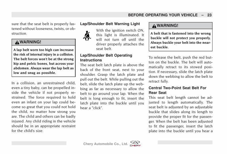
With the ignition switch ON,this light is illuminated. Itwill not turn off until thedriver properly attaches theseat belt.
Lap/Shoulder Belt OperatingInstructionsThe seat belt latch plate is above theback of the front seat, next to yourshoulder. Grasp the latch plate andpull out the belt. While pulling out thebelt, slide the latch plate up the web-bing as far as necessary to allow thebelt to go around your lap. When thebelt is long enough to fit, insert thelatch plate into the buckle until youhear a �click�.
WARNING!
A belt that is fastened into the wrongbuckle will not protect you properly.Always buckle your belt into the near-est buckle.
To release the belt, push the red but-ton on the buckle. The belt will auto-matically retract to its stowed posi-tion. If necessary, slide the latch platedown the webbing to allow the belt toretract fully.
Central Two-Point Seat Belt ForRear SeatThis seat belt length cannot be ad-justed to length automatically. Theseat belt is adjusted by an adjustablebuckle that slides along its length toprovide the proper fit for the passen-ger. When the belt has been adjustedto fit the passenger, insert the latchplate into the buckle until you hear a
BEFORE OPERATING YOUR VEHICLE – 23
Chery Automobile Co., Ltd.
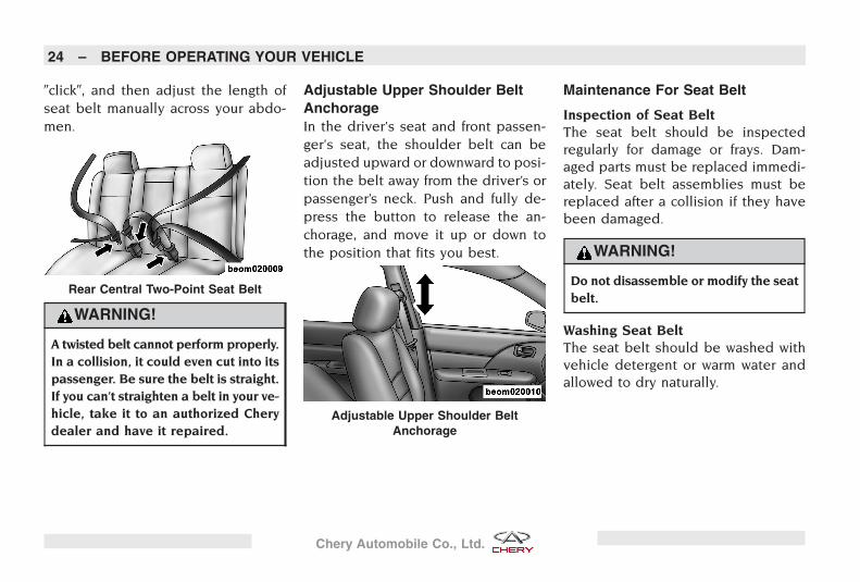
�click�, and then adjust the length ofseat belt manually across your abdo-men.
WARNING!
A twisted belt cannot perform properly.In a collision, it could even cut into itspassenger. Be sure the belt is straight.If you can’t straighten a belt in your ve-hicle, take it to an authorized Cherydealer and have it repaired.
Adjustable Upper Shoulder BeltAnchorageIn the driver’s seat and front passen-ger’s seat, the shoulder belt can beadjusted upward or downward to posi-tion the belt away from the driver’s orpassenger’s neck. Push and fully de-press the button to release the an-chorage, and move it up or down tothe position that fits you best.
Maintenance For Seat Belt
Inspection of Seat BeltThe seat belt should be inspectedregularly for damage or frays. Dam-aged parts must be replaced immedi-ately. Seat belt assemblies must bereplaced after a collision if they havebeen damaged.
WARNING!
Do not disassemble or modify the seatbelt.
Washing Seat BeltThe seat belt should be washed withvehicle detergent or warm water andallowed to dry naturally.
Rear Central Two-Point Seat Belt
Adjustable Upper Shoulder BeltAnchorage
24 – BEFORE OPERATING YOUR VEHICLE
Chery Automobile Co., Ltd.
WARNING!
Never use chemical detergents, boiledwater, bleach or dye to wash the seatbelt.
Never allow water to enter the belt re-tractor.
AirbagThe airbags work with the seat belts toproperly restrain the driver and front-seat passenger in the event of a colli-sion.
NOTE: As the airbags deflate you maysee some smoke-like particles. The par-ticles are a normal by-product of the pro-cess that generates the nontoxic gasused for airbag inflation.
The front occupants must be sitting asupright as possible in order to be ef-fectively protected.
WARNING!
Always properly position your seat beltto maintain the proper distance fromthe steering wheel. Only then can theairbag provide optimal protection dur-ing a collision.
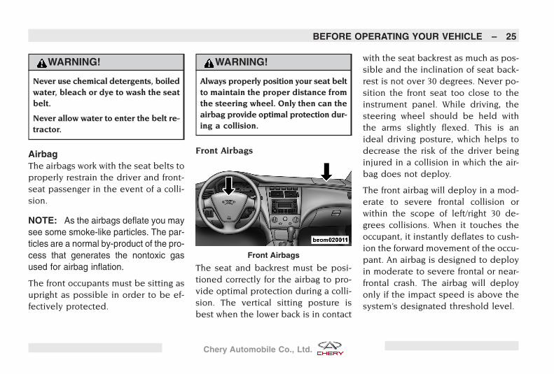
Front Airbags
The seat and backrest must be posi-tioned correctly for the airbag to pro-vide optimal protection during a colli-sion. The vertical sitting posture isbest when the lower back is in contact
with the seat backrest as much as pos-sible and the inclination of seat back-rest is not over 30 degrees. Never po-sition the front seat too close to theinstrument panel. While driving, thesteering wheel should be held withthe arms slightly flexed. This is anideal driving posture, which helps todecrease the risk of the driver beinginjured in a collision in which the air-bag does not deploy.
The front airbag will deploy in a mod-erate to severe frontal collision orwithin the scope of left/right 30 de-grees collisions. When it touches theoccupant, it instantly deflates to cush-ion the forward movement of the occu-pant. An airbag is designed to deployin moderate to severe frontal or near-frontal crash. The airbag will deployonly if the impact speed is above thesystem’s designated threshold level.
Front Airbags
BEFORE OPERATING YOUR VEHICLE – 25
Chery Automobile Co., Ltd.
WARNING!
Do not put anything on or around thefront airbag covers or attempt tomanually open them. Take your vehicleto an authorized Chery dealer for steer-ing wheel, steering column and airbagsystem service or you could be injuredbecause of accidental airbag deploy-ment.
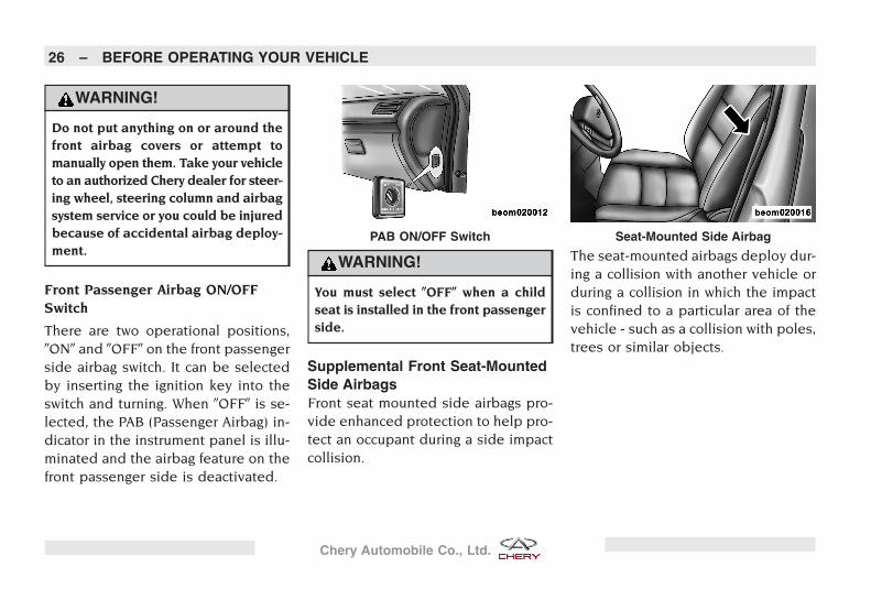
Front Passenger Airbag ON/OFFSwitch
There are two operational positions,�ON� and �OFF� on the front passengerside airbag switch. It can be selectedby inserting the ignition key into theswitch and turning. When �OFF� is se-lected, the PAB (Passenger Airbag) in-dicator in the instrument panel is illu-minated and the airbag feature on thefront passenger side is deactivated.
WARNING!
You must select �OFF� when a childseat is installed in the front passengerside.
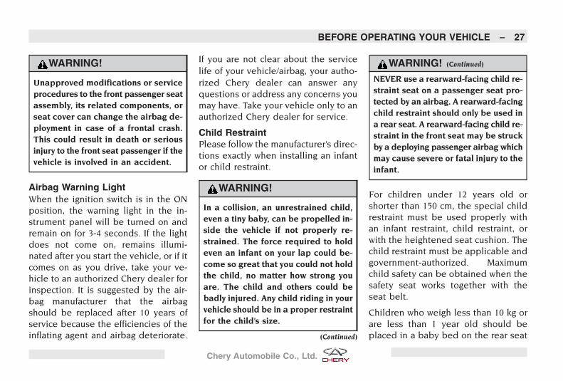
Supplemental Front Seat-MountedSide AirbagsFront seat mounted side airbags pro-vide enhanced protection to help pro-tect an occupant during a side impactcollision.
The seat-mounted airbags deploy dur-ing a collision with another vehicle orduring a collision in which the impactis confined to a particular area of thevehicle - such as a collision with poles,trees or similar objects.
PAB ON/OFF Switch Seat-Mounted Side Airbag
26 – BEFORE OPERATING YOUR VEHICLE
Chery Automobile Co., Ltd.
WARNING!
Unapproved modifications or serviceprocedures to the front passenger seatassembly, its related components, orseat cover can change the airbag de-ployment in case of a frontal crash.This could result in death or seriousinjury to the front seat passenger if thevehicle is involved in an accident.
Airbag Warning LightWhen the ignition switch is in the ONposition, the warning light in the in-strument panel will be turned on andremain on for 3-4 seconds. If the lightdoes not come on, remains illumi-nated after you start the vehicle, or if itcomes on as you drive, take your ve-hicle to an authorized Chery dealer forinspection. It is suggested by the air-bag manufacturer that the airbagshould be replaced after 10 years ofservice because the efficiencies of theinflating agent and airbag deteriorate.
If you are not clear about the servicelife of your vehicle/airbag, your autho-rized Chery dealer can answer anyquestions or address any concerns youmay have. Take your vehicle only to anauthorized Chery dealer for service.
Child RestraintPlease follow the manufacturer’s direc-tions exactly when installing an infantor child restraint.
WARNING!
In a collision, an unrestrained child,even a tiny baby, can be propelled in-side the vehicle if not properly re-strained. The force required to holdeven an infant on your lap could be-come so great that you could not holdthe child, no matter how strong youare. The child and others could bebadly injured. Any child riding in yourvehicle should be in a proper restraintfor the child’s size.
(Continued)
WARNING! (Continued)
NEVER use a rearward-facing child re-straint seat on a passenger seat pro-tected by an airbag. A rearward-facingchild restraint should only be used ina rear seat. A rearward-facing child re-straint in the front seat may be struckby a deploying passenger airbag whichmay cause severe or fatal injury to theinfant.
For children under 12 years old orshorter than 150 cm, the special childrestraint must be used properly withan infant restraint, child restraint, orwith the heightened seat cushion. Thechild restraint must be applicable andgovernment-authorized. Maximumchild safety can be obtained when thesafety seat works together with theseat belt.
Children who weigh less than 10 kg orare less than 1 year old should beplaced in a baby bed on the rear seat
BEFORE OPERATING YOUR VEHICLE – 27
Chery Automobile Co., Ltd.
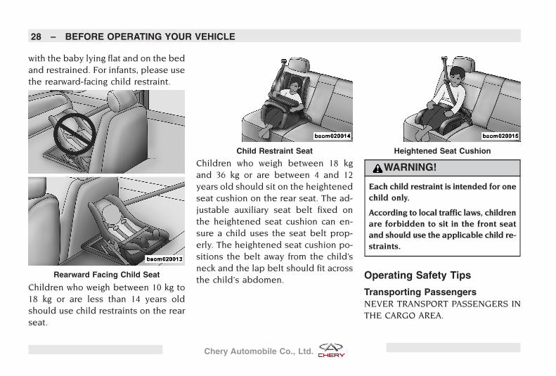
with the baby lying flat and on the bedand restrained. For infants, please usethe rearward-facing child restraint.
Children who weigh between 10 kg to18 kg or are less than 14 years oldshould use child restraints on the rearseat.
Children who weigh between 18 kgand 36 kg or are between 4 and 12years old should sit on the heightenedseat cushion on the rear seat. The ad-justable auxiliary seat belt fixed onthe heightened seat cushion can en-sure a child uses the seat belt prop-erly. The heightened seat cushion po-sitions the belt away from the child’sneck and the lap belt should fit acrossthe child’s abdomen.
WARNING!
Each child restraint is intended for onechild only.
According to local traffic laws, childrenare forbidden to sit in the front seatand should use the applicable child re-straints.
Operating Safety Tips
Transporting PassengersNEVER TRANSPORT PASSENGERS INTHE CARGO AREA.
Rearward Facing Child Seat
Child Restraint Seat Heightened Seat Cushion
28 – BEFORE OPERATING YOUR VEHICLE
Chery Automobile Co., Ltd.
WARNING!
It is extremely dangerous to ride in acargo area, inside or outside of a ve-hicle. In a collision, people riding inthese areas are more likely to be se-riously injured or killed.
Do not allow people to ride in any areaof your vehicle that is not equippedwith seats and seat belts.
Be sure everyone in your vehicle is ina seat and using a seat belt properly.
Locking Your VehicleAlways remove the key from the igni-tion and lock all doors when leavingthe vehicle unattended, even in yourown driveway or garage. Try to parkyour vehicle in a well-lit area and avoidleaving articles of value exposed.
Exhaust Gas
WARNING!
Exhaust gases can injure or kill. Theycontain carbon monoxide (CO), whichis colorless and odorless. Breathing itcan make you unconscious and caneventually poison you.
Do not run the engine in a closed ga-rage or in confined areas any longerthan needed to move your vehicle inor out of the area.
If it is necessary to sit in a parked ve-hicle with the engine running, adjustyour heating or cooling controls toforce outside air into the vehicle. Setthe blower at high speed.
If you are required to drive with thetrunk open, make sure that all win-dows are closed and the climate con-trol BLOWER switch is set at highspeed. DO NOT use the recirculationmode.
The best protection against carbonmonoxide entry into the vehicle pas-senger compartment is a properlymaintained engine exhaust system.
Interior Vehicle Safety Inspection
Seat Belts
Inspect the belt system periodically,checking for cuts, frays, and looseparts. Damaged parts must be re-placed immediately. Do not disas-semble or modify the system.
Front seat belt assemblies must be re-placed after a collision. Rear seat beltassemblies must be replaced after acollision if they have been damaged(i.e., bent retractor, torn webbing,etc.). If there is any question regardingbelt or retractor condition, replace thebelt.
Airbag Warning Light
The light should come on and remainon for 3-4 seconds as a bulb checkwhen the ignition switch is first turned
BEFORE OPERATING YOUR VEHICLE – 29
Chery Automobile Co., Ltd.
ON. If the light is not lit during start-ing, see your authorized Chery dealer.If the light stays on, flickers, or comeson while driving, have the systemchecked by an authorized Cherydealer.
Defroster
Check the operation by selecting thedefrost mode and place the blowercontrol on high speed. You should beable to feel the air directed againstthe windshield. See your authorizedChery dealer for service if your de-froster is inoperable.
Exterior Vehicle Safety Inspection
Tires
Examine tires for excessive tread wearand uneven wear patterns. Check thetires for the following:
• Stones, nails, glass, or other objectslodged in the tread
• Tread and sidewall for cuts and cracks
• Proper pressure (including spare)
• Wheel nuts for proper torque
LightsHave an assistant observe the opera-tion of exterior lights while you workthe controls. Check turn signal andhigh beam indicator lights on the in-strument panel. Check the followinglights for proper operation:
• Low beam headlamps
• High beam headlamps
• Turn signals
• Tail Lamps
• Stoplamps
Fluid LeaksCheck the area under the vehicle afterovernight parking. If a leak is sus-pected, the cause should be locatedand corrected immediately. Check thefollowing for possible leakage:
• Fuel
• Engine coolant
• Engine oil
• Power steering fluid
• Brake fluid
New Vehicle Break-InRecommendations
Engine Break-InRecommendationsVehicle frictional resistance is muchgreater when the vehicle is new. Theresult of proper engine break-in willimpact the service life, operating reli-ability and vehicle economical effi-ciency. The following is the proper en-gine break-in procedure:
During first 1,000 km of operation:
• Do not allow the engine speed to ex-ceed 3,000 rpm
• Do not exceed 100 km/h
• Do not operate the engine at maxi-mum speed when upshifting
30 – BEFORE OPERATING YOUR VEHICLE
Chery Automobile Co., Ltd.
During 1,000-1,500 km of operation:
• Driving speed can be gradually in-creased to greater than 100 km/h
• Engine speed can be gradually in-creased to its maximum
Safety Tips During Engine Break-InThe maximum engine speed is 6,000rpm. If the vehicle is equipped with amanual transmission, the vehicle mustbe shifted into the next highest gearbefore the needle of tachometer is inthe red range.
NOTE: To utilize your vehicle effi-ciently, avoid operating the engine at un-necessary high speeds. It should beshifted to the highest gear position as
early as possible in order to save fuel,decrease operational noise and help re-duce environmental pollution.
NOTE: The engine is also at risk if it isoperated at too low an engine speed. Itshould be shifted to a lower gear posi-tion in order to maintain the proper en-gine speed.
NOTE: The engine must be at normaloperating temperature before operatingthe engine at high speed.
Braking System Break-InRecommendationsThe brakes cannot provide the idealfriction to stop during the vehicle’sfirst 200 km of operation. You should
depress the brake pedal firmly to in-crease friction and improve stoppingcapability.
Tire and Wheel Break-InRecommendationsNew tires also require a brief break-inperiod. Your vehicle should be drivenslowly and especially carefully withinthe first 100 km of driving.
Vehicle wheel nuts must be re-tightened to the specified torque afterthe first 800 km of driving. Also, whena wheel has been replaced or afterwheel nuts have been loosened, theymust be re-tightened to the specifiedtorque after driving 800 km.
BEFORE OPERATING YOUR VEHICLE – 31
Chery Automobile Co., Ltd.
32
Chery Automobile Co., Ltd.
FEATURES OF YOUR VEHICLE
CONTENTS
� Mirrors 35
� Inside Rearview Mirror 35
� Outside Mirror 35
� Outside Mirrors FoldingFeature 35
� Power Remote ControlMirrors 35
� Heated Remote ControlMirrors 36
� Illuminated Vanity Mirror 36
� Windshield Wipers andWashers 36
� High and Low SpeedFeature 37
� Mist Feature 37
� Intermittent Wiper Feature 37
� Auto Wiper Feature(If Equipped) 37
� Windshield Washers 37
� Seats 38
� Manual Front SeatAdjustments 38
� Recliner Adjustment 38
� Power Seats (If Equipped) 39
� Lumbar Support 39
� Head Restraints 40
� Heated Seats (If Equipped) 40
� Folding Rear Seat CenterArmrest 41
� Lights 41� Headlights, Parking
Lights/Front Position Lights,Instrument Panel Lights andLicense Light 41
� High Beam/Low BeamSelect Switch 41
� Flash to Pass 42
� Front Fog Lights(If Equipped) 42
� Rear Fog Lights 42
� Turn Signals 42
� Dimmer Control 43
� Headlight Leveling System 43
� Front Interior Lighting 43
� Rear Interior Lighting 44
� Trunk Light 44
33
Chery Automobile Co., Ltd.
� Keyhole Light 44
� Vanity Mirror Light 44
� Brake Lights 44
� Reverse Lights 44
� Electrical Power Outlet 44
� Sunroof 45
� Opening Sunroof 45
� Closing Sunroof 45
� Anti-Pinch Feature 46
� Anti-Pinch Override 46� Tilt UP Feature 46� Tilt Down Feature 46� Sunshade Operation 46
� Cigarette Lighter andAshtray 46� Front Ashtray 46� Rear Ashtray 47
� Trunk Release 47� Trunk Release Switch 47
� Cup and Bottle Holders 47
� Cupholders 47
� Storage Areas 48
� Center Console 48
� Cargo Area 48
� Vehicle Loading 48
� Reversing Sonar System 49
� Reversing Sonar(If Equipped) 49
34 – FEATURES OF YOUR VEHICLE
Chery Automobile Co., Ltd.
Mirrors
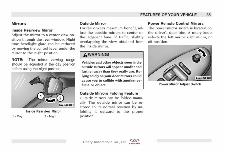
Inside Rearview MirrorAdjust the mirror to a center view po-sition through the rear window. Nighttime headlight glare can be reducedby moving the control lever under themirror to the night position.
NOTE: The mirror viewing rangeshould be adjusted in the day positionbefore using the night position.
Outside MirrorFor the driver’s maximum benefit, ad-just the outside mirrors to center onthe adjacent lane of traffic, slightlyoverlapping the view obtained fromthe inside mirror.
WARNING!
Vehicles and other objects seen in theoutside mirrors will appear smaller andfarther away than they really are. Re-lying solely on your door mirrors couldcause you to collide with another ve-hicle or object.
Outside Mirrors Folding FeatureOutside mirrors can be folded manu-ally. The outside mirror can be re-stored to its normal position by un-folding it outward to the properposition.
Power Remote Control MirrorsThe power mirror switch is located onthe driver’s door trim. A rotary knobselects the left mirror, right mirror, oroff position.
Inside Rearview Mirror
1 - Day 2 - Night
Power Mirror Adjust Switch
FEATURES OF YOUR VEHICLE – 35
Chery Automobile Co., Ltd.
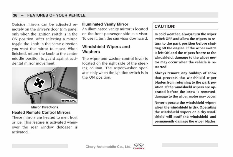
Outside mirrors can be adjusted re-motely on the driver’s door trim panelonly when the ignition switch is in theON position. After selecting a mirror,toggle the knob in the same directionyou want the mirror to move. Whenfinished, return the knob to the centermiddle position to guard against acci-dental mirror movement.
Heated Remote Control MirrorsThese mirrors are heated to melt frostor ice. This feature is activated when-ever the rear window defogger isactivated.
Illuminated Vanity MirrorAn illuminated vanity mirror is locatedon the front passenger side sun visor.To use it, turn the sun visor downward.
Windshield Wipers andWashers
The wiper and washer control lever islocated on the right side of the steer-ing column. The wiper/washer oper-ates only when the ignition switch is inthe ON position.
CAUTION!
In cold weather, always turn the wiperswitch OFF and allow the wipers to re-turn to the park position before shut-ting off the engine. If the wiper switchis left ON and the wipers freeze to thewindshield, damage to the wiper mo-tor may occur when the vehicle is re-started.
Always remove any buildup of snowthat prevents the windshield wiperblades from returning to the park po-sition. If the windshield wipers are op-erated before the snow is removed,damage to the wiper motor may occur.
Never operate the windshield wiperswhen the windshield is dry. Operatingthe windshield wipers on a dry wind-shield will scuff the windshield andpermanently damage the wiper blades.
Mirror Directions
36 – FEATURES OF YOUR VEHICLE
Chery Automobile Co., Ltd.
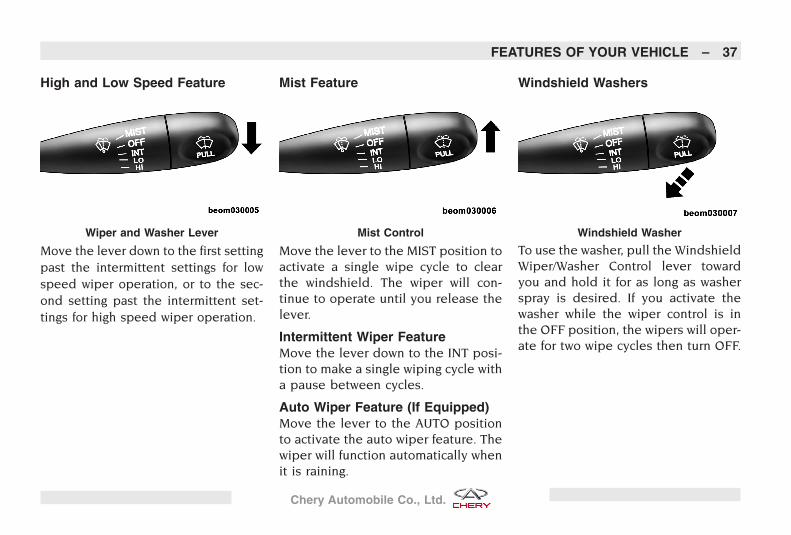
High and Low Speed Feature
Move the lever down to the first settingpast the intermittent settings for lowspeed wiper operation, or to the sec-ond setting past the intermittent set-tings for high speed wiper operation.
Mist Feature
Move the lever to the MIST position toactivate a single wipe cycle to clearthe windshield. The wiper will con-tinue to operate until you release thelever.
Intermittent Wiper FeatureMove the lever down to the INT posi-tion to make a single wiping cycle witha pause between cycles.
Auto Wiper Feature (If Equipped)Move the lever to the AUTO positionto activate the auto wiper feature. Thewiper will function automatically whenit is raining.
Windshield Washers
To use the washer, pull the WindshieldWiper/Washer Control lever towardyou and hold it for as long as washerspray is desired. If you activate thewasher while the wiper control is inthe OFF position, the wipers will oper-ate for two wipe cycles then turn OFF.
Wiper and Washer Lever Mist Control Windshield Washer
FEATURES OF YOUR VEHICLE – 37
Chery Automobile Co., Ltd.
CAUTION!
The windshield washer operating timeshould be no longer than 10 seconds.
Operating the windshield washer whenthe fluid tank is empty may damagethe washer motor.
Seats
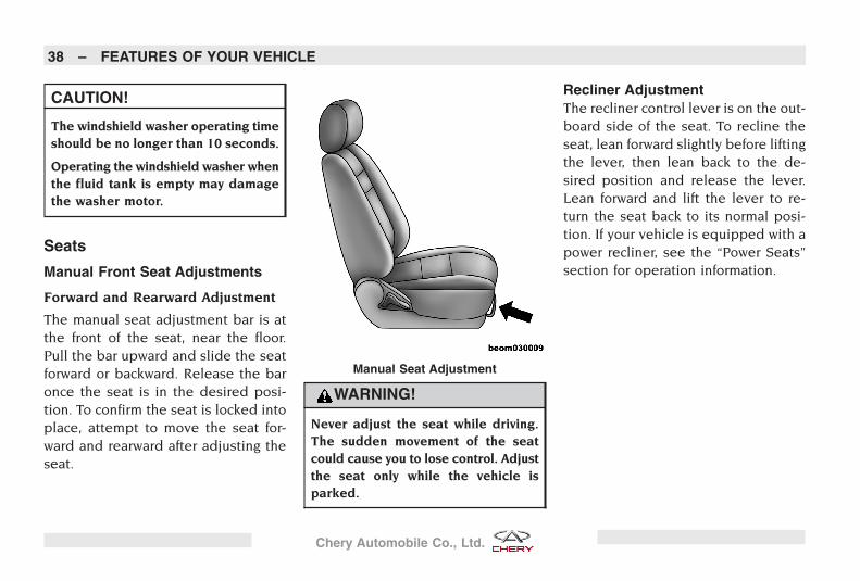
Manual Front Seat Adjustments
Forward and Rearward Adjustment
The manual seat adjustment bar is atthe front of the seat, near the floor.Pull the bar upward and slide the seatforward or backward. Release the baronce the seat is in the desired posi-tion. To confirm the seat is locked intoplace, attempt to move the seat for-ward and rearward after adjusting theseat.
WARNING!
Never adjust the seat while driving.The sudden movement of the seatcould cause you to lose control. Adjustthe seat only while the vehicle isparked.
Recliner AdjustmentThe recliner control lever is on the out-board side of the seat. To recline theseat, lean forward slightly before liftingthe lever, then lean back to the de-sired position and release the lever.Lean forward and lift the lever to re-turn the seat back to its normal posi-tion. If your vehicle is equipped with apower recliner, see the “Power Seats”section for operation information.
Manual Seat Adjustment
38 – FEATURES OF YOUR VEHICLE
Chery Automobile Co., Ltd.
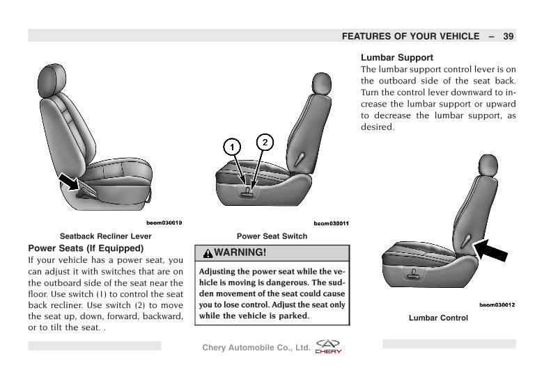
Power Seats (If Equipped)If your vehicle has a power seat, youcan adjust it with switches that are onthe outboard side of the seat near thefloor. Use switch (1) to control the seatback recliner. Use switch (2) to movethe seat up, down, forward, backward,or to tilt the seat. .
WARNING!
Adjusting the power seat while the ve-hicle is moving is dangerous. The sud-den movement of the seat could causeyou to lose control. Adjust the seat onlywhile the vehicle is parked.
Lumbar SupportThe lumbar support control lever is onthe outboard side of the seat back.Turn the control lever downward to in-crease the lumbar support or upwardto decrease the lumbar support, asdesired.
Seatback Recliner Lever Power Seat Switch
Lumbar Control
FEATURES OF YOUR VEHICLE – 39
Chery Automobile Co., Ltd.
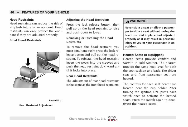
Head RestraintsHead restraints can reduce the risk ofwhiplash injury in an accident. Headrestraints can only protect the occu-pant if they are adjusted properly.
Front Head Restraints
Adjusting the Head Restraints
Press the lock release button, thenpull up on the head restraint to raiseand push down to lower.
Removing or Installing the HeadRestraints
To remove the head restraint, youmust simultaneously press the lock re-lease button and pull out the head re-straint. To reinstall the head restraint,insert the posts into the sleeves andpush the head restraint downward un-til it locks into place.
Rear Head Restraints
The adjustment of rear head restraintsis the same as the front head restraints.
WARNING!
Never sit in a seat or allow a passen-ger to sit in a seat without having thehead restraint in place and adjustedproperly as it may result in personalinjury to you or your passenger in anaccident.
Heated Seats (If Equipped)Heated seats provide comfort andwarmth in cold weather. The heatersprovide the same heat level for boththe seat cushion and back. The driverseat and front passenger seat areheated.
The controls for each seat heater arelocated near the cup holder. Afterturning the ignition ON, press eachswitch once to activate the heatedseats. Press the switch again to deac-tivate the heated seats.Head Restraint Adjustment
40 – FEATURES OF YOUR VEHICLE
Chery Automobile Co., Ltd.
Folding Rear Seat Center ArmrestThe rear seat is equipped with a fold-ing armrest with cup holders.
Lights
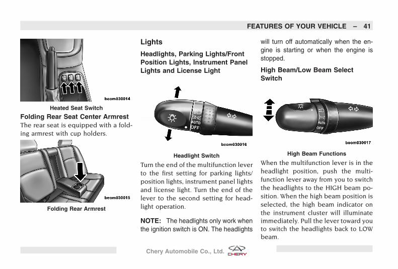
Headlights, Parking Lights/FrontPosition Lights, Instrument PanelLights and License Light
Turn the end of the multifunction leverto the first setting for parking lights/position lights, instrument panel lightsand license light. Turn the end of thelever to the second setting for head-light operation.
NOTE: The headlights only work whenthe ignition switch is ON. The headlights
will turn off automatically when the en-gine is starting or when the engine isstopped.
High Beam/Low Beam SelectSwitch
When the multifunction lever is in theheadlight position, push the multi-function lever away from you to switchthe headlights to the HIGH beam po-sition. When the high beam position isselected, the high beam indicator onthe instrument cluster will illuminateimmediately. Pull the lever toward youto switch the headlights back to LOWbeam.
Heated Seat Switch
Folding Rear Armrest
Headlight Switch High Beam Functions
FEATURES OF YOUR VEHICLE – 41
Chery Automobile Co., Ltd.
Flash to PassWhile driving, you can signal anothervehicle with your headlights by lightlypulling the multifunction lever towardyou. This will cause the headlights toswitch from low beam operation tohigh beam operation and remain onuntil the lever is released. Repeatingthis operation can flash the high beamheadlights continuously.
Front Fog Lights (If Equipped)The front fog light switch is located inthe center of the instrument panelabove the center air outlets. With themultifunction switch in the first or sec-ond lighting position, press the frontfog light switch to turn on the front foglights. When the front fog lights areON, the indicator on the instrumentcluster illuminates immediately. Thefront fog light should only be used infoggy, snowy, or rainy conditions.
Rear Fog LightsThe rear fog light switch is on the cen-ter console of the instrument panel.With the multifunction switch in thesecond lighting position or when thefront fog lights are turned on first,press the rear fog light switch to turnon the rear fog lights. When the rearfog lights are ON, the indicator on theinstrument cluster illuminates imme-diately. The rear fog lights may distractor affect visibility of drivers behindyou. Operating this light is recom-mended only under the lowest visibil-ity conditions.
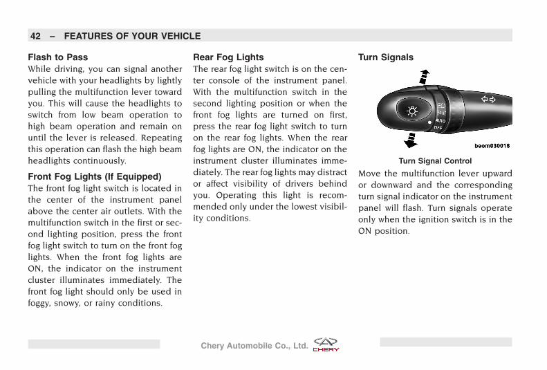
Turn Signals
Move the multifunction lever upwardor downward and the correspondingturn signal indicator on the instrumentpanel will flash. Turn signals operateonly when the ignition switch is in theON position.
Turn Signal Control
42 – FEATURES OF YOUR VEHICLE
Chery Automobile Co., Ltd.
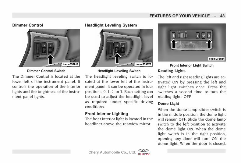
Dimmer Control
The Dimmer Control is located at thelower left of the instrument panel. Itcontrols the operation of the interiorlights and the brightness of the instru-ment panel lights.
Headlight Leveling System
The headlight leveling switch is lo-cated at the lower left of the instru-ment panel. It can be operated in fourpositions: 0, 1, 2, or 3. Each setting canbe used to adjust the headlight levelas required under specific drivingconditions.
Front Interior LightingThe front interior light is located in theheadliner above the rearview mirror.
Reading Lights
The left and right reading lights are ac-tivated ON by pressing the left andright light switches once. Press theswitches a second time to turn thereading lights OFF.
Dome Light
When the dome lamp slider switch isin the middle position, the dome lightwill remain OFF. Slide the dome lampswitch to the left position to activatethe dome light ON. When the domelight switch is in the right position,opening any door will turn ON thedome light. When the door is closed,
Dimmer Control Switch Headlight Leveling Switch
Front Interior Light Switch
FEATURES OF YOUR VEHICLE – 43
Chery Automobile Co., Ltd.
the dome light will remain illuminatedfor 15 seconds. This delay feature isdeactivated when the ignition switchis in the ON position.
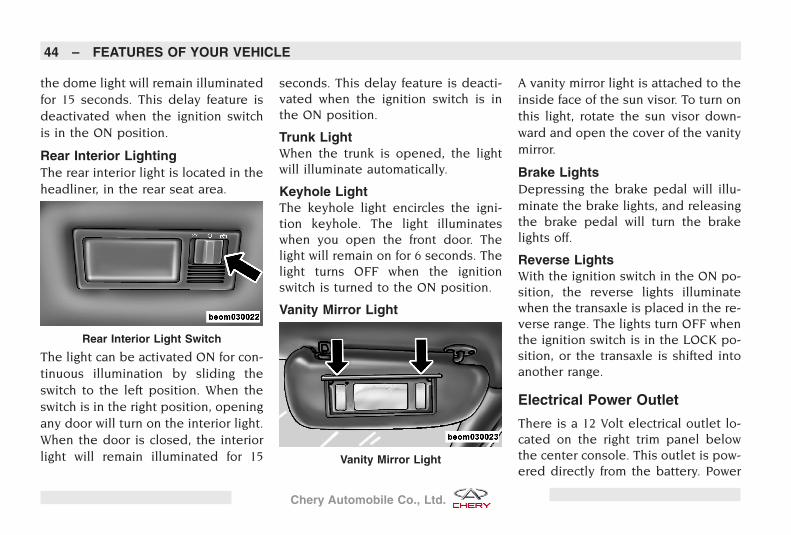
Rear Interior LightingThe rear interior light is located in theheadliner, in the rear seat area.
The light can be activated ON for con-tinuous illumination by sliding theswitch to the left position. When theswitch is in the right position, openingany door will turn on the interior light.When the door is closed, the interiorlight will remain illuminated for 15
seconds. This delay feature is deacti-vated when the ignition switch is inthe ON position.
Trunk LightWhen the trunk is opened, the lightwill illuminate automatically.
Keyhole LightThe keyhole light encircles the igni-tion keyhole. The light illuminateswhen you open the front door. Thelight will remain on for 6 seconds. Thelight turns OFF when the ignitionswitch is turned to the ON position.
Vanity Mirror Light
A vanity mirror light is attached to theinside face of the sun visor. To turn onthis light, rotate the sun visor down-ward and open the cover of the vanitymirror.
Brake LightsDepressing the brake pedal will illu-minate the brake lights, and releasingthe brake pedal will turn the brakelights off.
Reverse LightsWith the ignition switch in the ON po-sition, the reverse lights illuminatewhen the transaxle is placed in the re-verse range. The lights turn OFF whenthe ignition switch is in the LOCK po-sition, or the transaxle is shifted intoanother range.
Electrical Power Outlet
There is a 12 Volt electrical outlet lo-cated on the right trim panel belowthe center console. This outlet is pow-ered directly from the battery. Power
Rear Interior Light Switch
Vanity Mirror Light
44 – FEATURES OF YOUR VEHICLE
Chery Automobile Co., Ltd.
is available at all times, regardless ifthe ignition is ON or OFF.
CAUTION!
• Accessories, even when not in use(i.e. cellular phone, etc.) will drawpower from the vehicle’s battery.Eventually, if accessories areplugged in long enough, the vehi-cle’s battery will discharge and de-grade the battery life and/or preventengine starting.
(Continued)
CAUTION! (Continued)
• Accessories that draw excessivepower (i.e. coolers, vacuum clean-ers, lights, etc.) will quickly drain thebattery. Only use these intermittentlyand with caution.
• After the use of high power draw-ing accessories, or long periods oftime without starting the vehicle(with accessories still plugged in),the vehicle must be driven a suffi-cient length of time to allow the gen-erator to recharge the vehicle’s bat-tery.
• This power outlet is designed for12V (120W) only. Do not use anytype of accessory above this voltage.
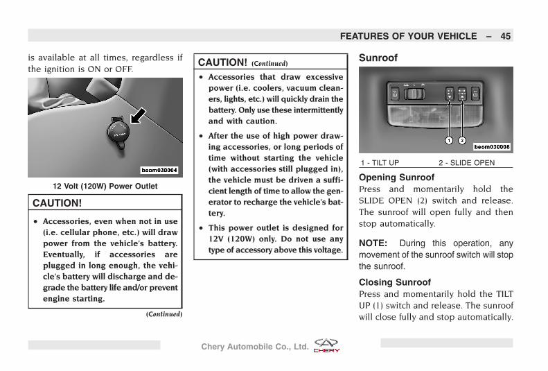
Sunroof
Opening SunroofPress and momentarily hold theSLIDE OPEN (2) switch and release.The sunroof will open fully and thenstop automatically.
NOTE: During this operation, anymovement of the sunroof switch will stopthe sunroof.
Closing SunroofPress and momentarily hold the TILTUP (1) switch and release. The sunroofwill close fully and stop automatically.
12 Volt (120W) Power Outlet
1 - TILT UP 2 - SLIDE OPEN
FEATURES OF YOUR VEHICLE – 45
Chery Automobile Co., Ltd.
NOTE: During this operation, anymovement of the sunroof switch will stopthe sunroof.
Anti-Pinch FeatureThis feature will detect an obstructionin the sunroof’s path while closing. Ifan obstruction is detected, the sun-roof will automatically retract. If thisoccurs, remove the obstruction, thenpress the switch and release to close.
Anti-Pinch OverrideIf the sunroof retracts more than threetimes continuously, the sunroof’s auto-closing feature will be lost. The anti-pinch feature and auto-closing fea-tures can be restored only by pressingand holding the switch until the sun-roof is closed completely.
NOTE: The anti-pinch feature is dis-abled while the switch is pressed.
WARNING!
There is no anti-pinch protection whenthe sunroof is almost closed. To avoidpersonal injury, be sure to clear yourarms, hands, fingers and all objectsfrom the sunroof path before closing.
Tilt UP FeatureWith the sunroof closed, press andmomentarily hold the TILT UP (1)switch and the end of the sunroofglass will tilt up automatically. Duringthis operation, any movement of thesunroof switch will stop the sunroof.
Tilt Down FeaturePress and momentarily hold the TILTUP (1) switch and the end of the sun-roof glass will automatically tilt down-wards into the closed position.
Sunshade OperationThe sunshade can be opened manu-ally. However, the sunshade will openautomatically as the sunroof opens.
NOTE: The sunshade cannot beclosed if the sunroof is open.
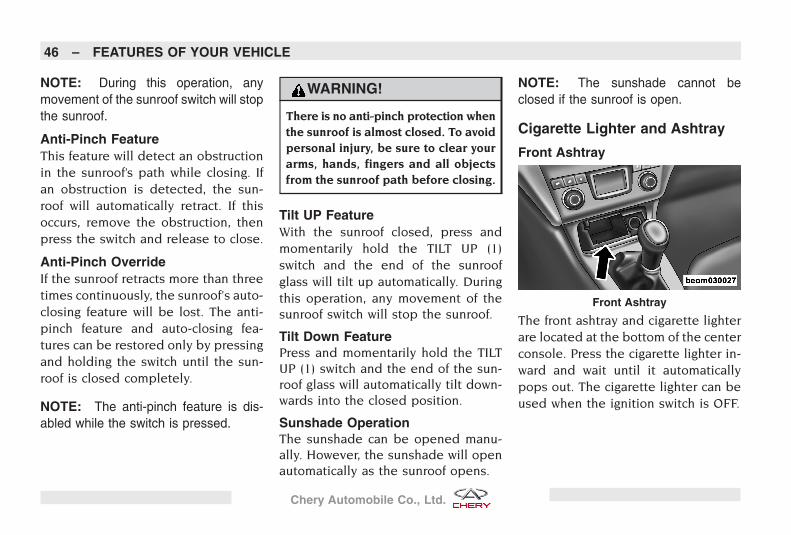
Cigarette Lighter and Ashtray
Front Ashtray
The front ashtray and cigarette lighterare located at the bottom of the centerconsole. Press the cigarette lighter in-ward and wait until it automaticallypops out. The cigarette lighter can beused when the ignition switch is OFF.
Front Ashtray
46 – FEATURES OF YOUR VEHICLE
Chery Automobile Co., Ltd.
WARNING!
To prevent injury to passengers anddamage to your vehicle, never pressand hold the cigarette lighter for anextended period of time. If childrenare left in the vehicle, the cigarettelighter should be removed.
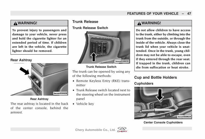
Rear Ashtray
The rear ashtray is located in the backof the center console, behind thearmrest.
Trunk Release
Trunk Release Switch
The trunk can be opened by using anyof the following methods:
• Remote Keyless Entry (RKE) trans-mitter
• Trunk Release switch located next tothe steering wheel on the instrumentpanel
• Vehicle key
WARNING!
Do not allow children to have accessto the trunk, either by climbing into thetrunk from the outside, or through theinside of the vehicle. Always close thetrunk lid when your vehicle is unat-tended. Once in the trunk, young chil-dren may not be able to escape, evenif they entered through the rear seat.If trapped in the trunk, children candie from suffocation or heat stroke.
Cup and Bottle Holders
Cupholders
Rear Ashtray
Trunk Release Switch
Center Console Cupholders
FEATURES OF YOUR VEHICLE – 47
Chery Automobile Co., Ltd.
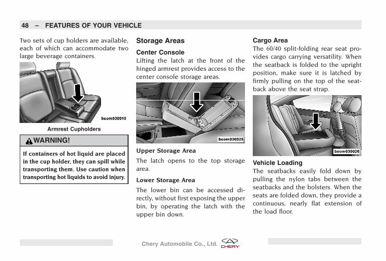
Two sets of cup holders are available,each of which can accommodate twolarge beverage containers.
WARNING!
If containers of hot liquid are placedin the cup holder, they can spill whiletransporting them. Use caution whentransporting hot liquids to avoid injury.
Storage Areas
Center ConsoleLifting the latch at the front of thehinged armrest provides access to thecenter console storage areas.
Upper Storage Area
The latch opens to the top storagearea.
Lower Storage Area
The lower bin can be accessed di-rectly, without first exposing the upperbin, by operating the latch with theupper bin down.
Cargo AreaThe 60/40 split-folding rear seat pro-vides cargo carrying versatility. Whenthe seatback is folded to the uprightposition, make sure it is latched byfirmly pulling on the top of the seat-back above the seat strap.
Vehicle LoadingThe seatbacks easily fold down bypulling the nylon tabs between theseatbacks and the bolsters. When theseats are folded down, they provide acontinuous, nearly flat extension ofthe load floor.
Armrest Cupholders
48 – FEATURES OF YOUR VEHICLE
Chery Automobile Co., Ltd.
WARNING!
Always place cargo evenly on the cargofloor. Put heavier objects as low andas far forward as possible.
Place as much cargo as possible infront of the rear axle. Too much weightor improperly placed weight over orbehind the rear axle can cause the rearof the vehicle to sway.
Do not pile luggage or cargo higherthan the top of the seatback. Thiscould impair visibility or become adangerous projectile in a sudden stopor collision.
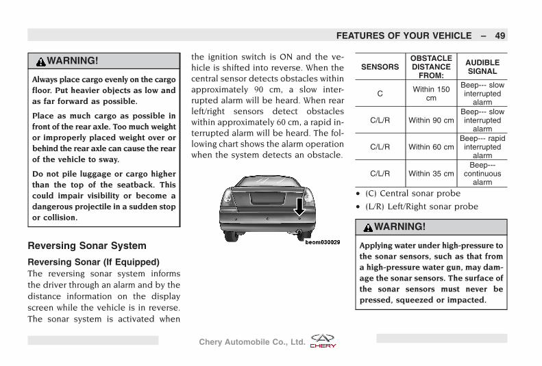
Reversing Sonar System
Reversing Sonar (If Equipped)The reversing sonar system informsthe driver through an alarm and by thedistance information on the displayscreen while the vehicle is in reverse.The sonar system is activated when
the ignition switch is ON and the ve-hicle is shifted into reverse. When thecentral sensor detects obstacles withinapproximately 90 cm, a slow inter-rupted alarm will be heard. When rearleft/right sensors detect obstacleswithin approximately 60 cm, a rapid in-terrupted alarm will be heard. The fol-lowing chart shows the alarm operationwhen the system detects an obstacle.
SENSORSOBSTACLEDISTANCE
FROM:
AUDIBLESIGNAL
C Within 150cm
Beep--- slowinterrupted
alarm
C/L/R Within 90 cmBeep--- slowinterrupted
alarm
C/L/R Within 60 cmBeep--- rapidinterrupted
alarm
C/L/R Within 35 cmBeep---
continuousalarm
• (C) Central sonar probe
• (L/R) Left/Right sonar probe
WARNING!
Applying water under high-pressure tothe sonar sensors, such as that froma high-pressure water gun, may dam-age the sonar sensors. The surface ofthe sonar sensors must never bepressed, squeezed or impacted.
FEATURES OF YOUR VEHICLE – 49
Chery Automobile Co., Ltd.
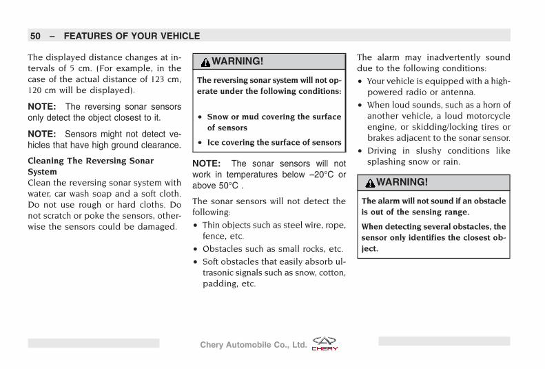
The displayed distance changes at in-tervals of 5 cm. (For example, in thecase of the actual distance of 123 cm,120 cm will be displayed).
NOTE: The reversing sonar sensorsonly detect the object closest to it.
NOTE: Sensors might not detect ve-hicles that have high ground clearance.
Cleaning The Reversing SonarSystemClean the reversing sonar system withwater, car wash soap and a soft cloth.Do not use rough or hard cloths. Donot scratch or poke the sensors, other-wise the sensors could be damaged.
WARNING!
The reversing sonar system will not op-erate under the following conditions:
• Snow or mud covering the surfaceof sensors
• Ice covering the surface of sensors
NOTE: The sonar sensors will notwork in temperatures below –20°C orabove 50°C .
The sonar sensors will not detect thefollowing:
• Thin objects such as steel wire, rope,fence, etc.
• Obstacles such as small rocks, etc.
• Soft obstacles that easily absorb ul-trasonic signals such as snow, cotton,padding, etc.
The alarm may inadvertently sounddue to the following conditions:
• Your vehicle is equipped with a high-powered radio or antenna.
• When loud sounds, such as a horn ofanother vehicle, a loud motorcycleengine, or skidding/locking tires orbrakes adjacent to the sonar sensor.
• Driving in slushy conditions likesplashing snow or rain.
WARNING!
The alarm will not sound if an obstacleis out of the sensing range.
When detecting several obstacles, thesensor only identifies the closest ob-ject.
50 – FEATURES OF YOUR VEHICLE
Chery Automobile Co., Ltd.
STARTING AND OPERATING YOUR VEHICLE
CONTENTS
� Starting and Operating 52� Preparation Before Starting 52
� Normal Starting Procedure 52
� Failed Starting Procedure 53
� After Starting 53
� Starting and OperatingCautions 53
� Hood Release 54
� Automatic Transaxle 55� 4-Speed Automatic
Transaxle 55
� Gear Ranges 55
� Manual Transaxle 56� 5-Speed Manual Transaxle 56
� Shifting 56
� Downshifting 57
� Brake System 57
� Parking Brake 57
� Dual Circuit Brake System 58
� Brake Booster 58
� Operating Cautions 58
� Antilock Brake System(ABS) 59
� Utilizing ABS Braking 59
� ABS Self-Check 60
� Power Steering 60
� Driving Through Water 60
� Driving In SlipperyConditions 61
� Tires 61
� General Information 61
� Tire Pressure 62
� Tire Rotation 63
� Spare Tire 64
� Tread Wear 64
� Replacement Tires 64
� Fuel 65
� General Information 65
� Clean Air Gasoline 65
� Adding Fuel 65
51
Chery Automobile Co., Ltd.
Starting and Operating
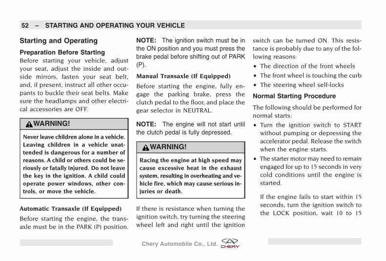
Preparation Before StartingBefore starting your vehicle, adjustyour seat, adjust the inside and out-side mirrors, fasten your seat belt,and, if present, instruct all other occu-pants to buckle their seat belts. Makesure the headlamps and other electri-cal accessories are OFF.
WARNING!
Never leave children alone in a vehicle.Leaving children in a vehicle unat-tended is dangerous for a number ofreasons. A child or others could be se-riously or fatally injured. Do not leavethe key in the ignition. A child couldoperate power windows, other con-trols, or move the vehicle.
Automatic Transaxle (If Equipped)
Before starting the engine, the trans-axle must be in the PARK (P) position.
NOTE: The ignition switch must be inthe ON position and you must press thebrake pedal before shifting out of PARK(P).
Manual Transaxle (If Equipped)
Before starting the engine, fully en-gage the parking brake, press theclutch pedal to the floor, and place thegear selector in NEUTRAL.
NOTE: The engine will not start untilthe clutch pedal is fully depressed.
WARNING!
Racing the engine at high speed maycause excessive heat in the exhaustsystem, resulting in overheating and ve-hicle fire, which may cause serious in-juries or death.
If there is resistance when turning theignition switch, try turning the steeringwheel left and right until the ignition
switch can be turned ON. This resis-tance is probably due to any of the fol-lowing reasons:
• The direction of the front wheels
• The front wheel is touching the curb
• The steering wheel self-locks
Normal Starting Procedure
The following should be performed fornormal starts:
• Turn the ignition switch to STARTwithout pumping or depressing theaccelerator pedal. Release the switchwhen the engine starts.
• The starter motor may need to remainengaged for up to 15 seconds in verycold conditions until the engine isstarted.
If the engine fails to start within 15seconds, turn the ignition switch tothe LOCK position, wait 10 to 15
52 – STARTING AND OPERATING YOUR VEHICLE
Chery Automobile Co., Ltd.
seconds, then repeat the normalstarting procedure. If the enginestill doesn’t start, see �Failed Start-ing Procedure�.
Failed Starting Procedure
The following should be performed ifthe engine fails to start after two con-secutive attempts:
• Press the accelerator pedal to thefloor and hold it there.
• Turn the ignition switch to the STARTposition and crank the engine till itstarts.
• Once started, release the acceleratorpedal slowly as the engine warms up.
CAUTION!
To prevent damage to the starter, donot crank the engine for more than 15seconds at a time. Wait 10 to 15 sec-onds before trying again.
After StartingThe idle speed will automatically de-crease as the engine warms up.
Self-Adapting Function Of EngineControl System
If the battery cable has been removedfrom the battery, the vehicle may runirregularly for a short time after thecable is reconnected. This is normalbecause the engine control system isreadapting to the engine.
Limiting Engine Speed
To protect the engine from over-speed, the engine is electronicallylimited by the Engine Control Module(ECM).
Starting and Operating Cautions
Exhaust Gases
WARNING!
Engine exhaust gas can injure or kill.It contains carbon monoxide (CO)which is colorless and odorless.Breathing it can cause unconscious-ness and even death. To avoid breath-ing CO, follow these safety tips:
• Do not run the engine in a closedgarage or confined area any longerthan needed before moving your ve-hicle from the area.
• If it is necessary to sit in a parkedvehicle with the engine running inan open area, adjust your heatingor cooling controls to force outsideair into the vehicle. Set the blowerat high speed.
(Continued)
STARTING AND OPERATING YOUR VEHICLE – 53
Chery Automobile Co., Ltd.
WARNING! (Continued)
• If you are required to drive with thetrunk lid open, make sure that allwindows are closed and the climatecontrol blower switch is set at highspeed. DO NOT use the recircula-tion mode.
Turn Off Your Engine
Before turning off your engine, alwaysallow the engine to resume normalidling speed and run for several sec-onds. This assures that the engine’stemperature can fall gradually. This isparticularly necessary after any periodof hard driving.
CAUTION!
The engine’s temperature will remainhigh after you turn the engine off. Af-ter the engine is turned off, the ve-hicles electric cooling fan will continueto run for approximately 10 minutes.Even if the cooling fan stops, it may runagain suddenly because of the hightemperature. Therefore, extra atten-tion and caution must be given whenworking in the engine compartment.
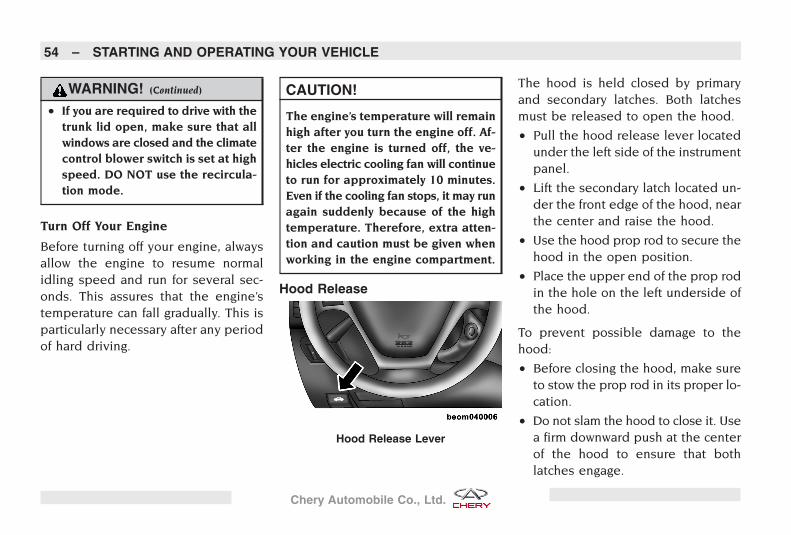
Hood Release
The hood is held closed by primaryand secondary latches. Both latchesmust be released to open the hood.
• Pull the hood release lever locatedunder the left side of the instrumentpanel.
• Lift the secondary latch located un-der the front edge of the hood, nearthe center and raise the hood.
• Use the hood prop rod to secure thehood in the open position.
• Place the upper end of the prop rodin the hole on the left underside ofthe hood.
To prevent possible damage to thehood:
• Before closing the hood, make sureto stow the prop rod in its proper lo-cation.
• Do not slam the hood to close it. Usea firm downward push at the centerof the hood to ensure that bothlatches engage.
Hood Release Lever
54 – STARTING AND OPERATING YOUR VEHICLE
Chery Automobile Co., Ltd.
WARNING!
If the hood is not fully latched it couldfly up when the vehicle is moving andblock your forward vision. You couldhave a collision. Be sure all hoodlatches are fully latched before driv-ing.
Automatic Transaxle
4-Speed Automatic TransaxleThe electronically controlled transaxleprovides precise shifting. The trans-axle electronics are self-calibrating,therefore, the first few shifts on a newvehicle may be somewhat abrupt. Thisis a normal condition, and precisionshifts will develop within a few hun-dred miles.
Shifting from DRIVE to PARK or RE-VERSE should be done only after theaccelerator pedal is released and thevehicle is stopped. Be sure to keep
your foot on the brake when movingthe shift lever between these gears.
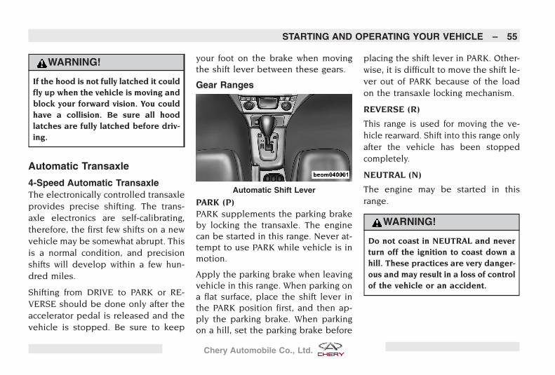
Gear Ranges
PARK (P)PARK supplements the parking brakeby locking the transaxle. The enginecan be started in this range. Never at-tempt to use PARK while vehicle is inmotion.
Apply the parking brake when leavingvehicle in this range. When parking ona flat surface, place the shift lever inthe PARK position first, and then ap-ply the parking brake. When parkingon a hill, set the parking brake before
placing the shift lever in PARK. Other-wise, it is difficult to move the shift le-ver out of PARK because of the loadon the transaxle locking mechanism.
REVERSE (R)
This range is used for moving the ve-hicle rearward. Shift into this range onlyafter the vehicle has been stoppedcompletely.
NEUTRAL (N)
The engine may be started in thisrange.
WARNING!
Do not coast in NEUTRAL and neverturn off the ignition to coast down ahill. These practices are very danger-ous and may result in a loss of controlof the vehicle or an accident.
Automatic Shift Lever
STARTING AND OPERATING YOUR VEHICLE – 55
Chery Automobile Co., Ltd.
DRIVE (D)
This range should be used for mostcity and highway driving. It providesthe smoothest shifting and best fueleconomy.
WINTER MODE (W)
Press the �W� switch on the shift paneland you can then start to accelerate insecond gear. This function is used insnowy or icy conditions.
Manual Transaxle
5-Speed Manual TransaxleTo utilize your manual transaxle effi-ciently for both fuel economy and per-formance, it should be upshifted as ef-fectively as possible.
NOTE: During cold weather, it is nor-mal to experience increased effort inshifting until the transaxle fluid warmsup.
CAUTION!
Never drive with your foot resting onthe clutch pedal.
Never attempt to hold the vehicle ona hill with the clutch pedal partially en-gaged.
WARNING!
You or others could be injured if youleave the vehicle unattended withouthaving the parking brake fully applied.
The parking brake should always beapplied when the driver is not in thevehicle, especially on an incline.
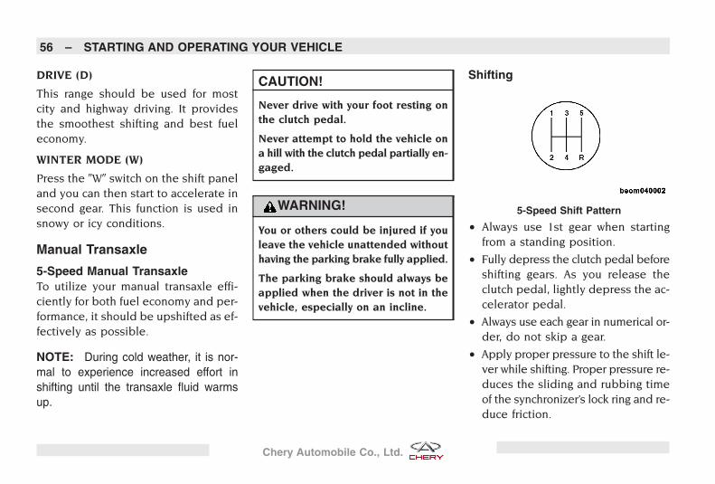
Shifting
• Always use 1st gear when startingfrom a standing position.
• Fully depress the clutch pedal beforeshifting gears. As you release theclutch pedal, lightly depress the ac-celerator pedal.
• Always use each gear in numerical or-der, do not skip a gear.
• Apply proper pressure to the shift le-ver while shifting. Proper pressure re-duces the sliding and rubbing timeof the synchronizer’s lock ring and re-duce friction.
5-Speed Shift Pattern
56 – STARTING AND OPERATING YOUR VEHICLE
Chery Automobile Co., Ltd.
• Do not press the shift lever whendriving, extra pressure and stress willbe placed on the shift fork.
• Shift to reverse gear only when thevehicle is stopped completely.
• Stop and inspect the vehicle if youhear abnormal sounds inside thetransaxle.
Downshifting• When driving down steep hills, down-
shift to help preserve brakes.
• For better low speed acceleration,downshift when attempting to resumespeed.
• To avoid over-speeding the engineand clutch, downshift progressivelyand do not skip gears.
WARNING!
Do not downshift for additional enginebraking on a slippery surface. Thedrive wheels could lose their tractionand the vehicle could skid.
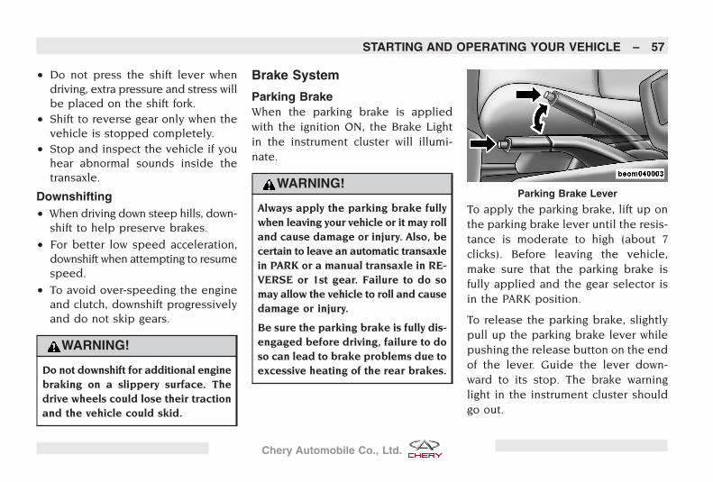
Brake System
Parking BrakeWhen the parking brake is appliedwith the ignition ON, the Brake Lightin the instrument cluster will illumi-nate.
WARNING!
Always apply the parking brake fullywhen leaving your vehicle or it may rolland cause damage or injury. Also, becertain to leave an automatic transaxlein PARK or a manual transaxle in RE-VERSE or 1st gear. Failure to do somay allow the vehicle to roll and causedamage or injury.
Be sure the parking brake is fully dis-engaged before driving, failure to doso can lead to brake problems due toexcessive heating of the rear brakes.
To apply the parking brake, lift up onthe parking brake lever until the resis-tance is moderate to high (about 7clicks). Before leaving the vehicle,make sure that the parking brake isfully applied and the gear selector isin the PARK position.
To release the parking brake, slightlypull up the parking brake lever whilepushing the release button on the endof the lever. Guide the lever down-ward to its stop. The brake warninglight in the instrument cluster shouldgo out.
Parking Brake Lever
STARTING AND OPERATING YOUR VEHICLE – 57
Chery Automobile Co., Ltd.
NOTE: You should always apply theparking brake before leaving the vehicle.
Dual Circuit Brake SystemYour vehicle is equipped with a diago-nal dual circuit brake system. If onecircuit fails, the other circuit can stillwork.
CAUTION!
If one brake circuit fails to work, youneed to press the brake pedal muchharder during braking. The brakingdistance will also increase. When thishappens, take your vehicle to an au-thorized Chery dealer for repair.
Brake BoosterThe brake booster provides addedbraking assist and is controlled by en-gine vacuum. The brake booster worksonly when the engine is operating.
CAUTION!
If the vehicle is being towed, the brakebooster will not provide the normalbraking assist. It will be necessary topress the brake pedal harder to com-pensate for the booster’s loss of assist.
WARNING!
The brake booster is controlled by en-gine vacuum and works only when theengine is operating. Therefore, do notturn the engine off and coast whiledriving down hill.
Operating Cautions
Brake System
• If there is consistent noise or vibra-tion being transferred to the steeringwheel during braking, take your ve-hicle to an authorized Chery dealerfor repair.
• New brake pads require a 200 kmbreak-in period. During the first 200km, higher pedal pressure will be re-quired for adequate stopping.
• Brake pad wear depends greatly onthe driving habits of the operator. Forvehicles mainly used for city traffic,frequent starting and stopping willsignificantly shorten the life of thebrake pads. It is necessary to takeyour vehicle to an authorized Cherydealer for regular maintenance andproper service.
• When driving down a steep grade hill,shift to a lower gear to make full useof the engine’s braking action. Thiswill reduce the load on the brake sys-tem.
• A damp brake rotor may reduce brak-ing efficiency. After driving throughwater, driving in a rainstorm, or wash-ing the vehicle, press the brake pedallightly to dry the brakes and restorenormal braking.
58 – STARTING AND OPERATING YOUR VEHICLE
Chery Automobile Co., Ltd.
WARNING!
Keeping the brake pressed while driv-ing – commonly known as “riding thebrake” – can lead to brake failure andpossibly an accident. Driving with yourfoot resting or “riding” on the brakepedal can result in abnormally highbrake temperatures, excessive liningwear, and possible brake damage. Thisalso deteriorates full braking capac-ity in case of an emergency stop.
Brake Fluid
Check the brake fluid level at regularintervals.
WARNING!
Add brake fluid to the brake fluid res-ervoir to maintain the �MAX� level. Ifa brake fluid leak is suspected, takeyour vehicle to an authorized Cherydealer for repair.
Antilock Brake System (ABS)The ABS provides increased vehiclestability and braking performance un-der most braking conditions. The sys-tem automatically modulates brakepressure during severe braking condi-tions to prevent wheel lockup.
WARNING!
The ABS cannot prevent accidents, in-cluding those resulting from excessivespeed in turns, following another ve-hicle too closely, or hydroplaning. Onlya safe, attentive, and skillful driver canprevent accidents.
The capabilities of an ABS equippedvehicle must never be exploited in areckless or dangerous manner, whichcould jeopardize your safety or thesafety of others.
When the brake system goes into anantilock stop, you may also experi-ence the following:
• The ABS motor running (it may con-tinue to run for a short time after thestop)
• The clicking sound of the solenoidvalves
NOTE: These are all normal charac-teristics of ABS.
Utilizing ABS BrakingFirmly pressing the brake pedal in anemergency stop may start the ABS im-mediately, which will allow you toproperly control the vehicle.
STARTING AND OPERATING YOUR VEHICLE – 59
Chery Automobile Co., Ltd.
WARNING!
Pumping of the antilock brakes will di-minish their effectiveness and may leadto an accident. Pumping makes thestopping distance longer. Just pressfirmly on your brake pedal when youneed to slow down or stop.
ABS Self-CheckWhen the engine is started, you mayhear a slight clicking sound as well assome related motor noises. Thesenoises are the ABS performing its self-check cycle to ensure that the systemis working properly.
NOTE: If the ABS light comes on whiledriving, it indicates that the antilock por-tion of the brake system is not function-ing and that service is required.
Power SteeringPower steering is standard equipmenton this vehicle. The power steeringsystem will give you good vehicle re-sponse and increased ease of maneu-verability in tight spaces. The systemwill provide mechanical steering capa-bility if power assist is lost.
If the power assist is interrupted, itwill still be possible to steer your ve-hicle. Under these conditions, you willfeel a substantial increase in steeringeffort, especially at very low vehiclespeeds and during parking maneu-vers.
NOTE: Review the following to avoiddamaging the power steering system :
• Prolonged or excessive turns of thesteering wheel can increase thesteering fluid temperature. Thisshould be avoided when possible asdamage to the power steering pumpmay occur.
• Fill the power steering fluid reservoironce its level is under the �MIN� markin its reservoir. Do not drive the ve-hicle with the fluid level below �MIN�.
WARNING!
Continued operation with reducedpower steering assist could pose asafety risk to yourself and others.
Check the following if the vehicle isexperiencing steering difficulty:
• Tires are properly inflated
• Tires are wearing evenly
• Loose or worn suspension compo-nents
• Loose or worn steering components
• Proper wheel alignment
Driving Through WaterDrive carefully and slowly when goingthrough water more than a few inchesdeep.
60 – STARTING AND OPERATING YOUR VEHICLE
Chery Automobile Co., Ltd.
CAUTION!
The following guidelines apply to driv-ing through water:• Never drive through standing water
that is deeper than the bottom ofyour vehicle’s tire rims.
• Water inside your vehicle’s enginecan cause it to lockup, stall, orcause serious internal damage.
• Vehicle traction and braking perfor-mance will decrease while drivingthrough water.
• Driving through water may causedamage to your vehicle’s drivetraincomponents. Always inspect your ve-hicle’s fluids (e.g., engine oil, trans-mission, axle, etc.) for signs of con-tamination (e.g., fluid that is milkyor foamy in appearance) after driv-ing through water. Do not continueto operate the vehicle if any fluidappears contaminated as this mayresult in further damage.
WARNING!
Driving through water limits your ve-hicle’s braking performance, which in-creases brake distances. After drivingthrough water, drive slowly and lightlypress on the brake pedal several timesto dry the brakes.
Getting water inside your vehicle’s en-gine can cause it to lockup, stall, andleave you stranded.
Failure to follow these warnings mayresult in serious injuries or death foryou, your passengers, and othersaround your vehicle.
Driving In Slippery ConditionsRapid acceleration on snow covered,wet, or other slippery surfaces maycause the front wheels to pull errati-cally to the right or left. This phenom-enon occurs when there is a differencein the surface traction under the front(driving) wheels.
When driving on wet or slushy roads, itis possible for a wedge of water tobuild up between the tire and roadsurface. This is hydroplaning and maycause partial or complete loss of ve-hicle control and stopping ability. Toreduce this possibility, the followingprecautions should be observed:
• Slow down during rainstorms or whenroads are slushy.
• Slow down if the road has standingwater or puddles.
• Replace the tires when tread wear in-dicators first become visible.
• Keep the tires properly inflated.
• Maintain a safe following distance toavoid a collision in a sudden stop.
Tires
General InformationTires are designed and engineered foreach specific vehicle. They providethe best overall performance for nor-mal operation. The ride and handling
STARTING AND OPERATING YOUR VEHICLE – 61
Chery Automobile Co., Ltd.
characteristics match the vehicle’s re-quirements. With proper care they willgive excellent reliability, traction, skidresistance, and tread life.
Tire LifeThe service life of a tire is dependentupon varying factors including but notlimited to:
• Driving style
• Tire pressure
• Distance driven
WARNING!
Tires and spare tire should be re-placed after six years, regardless of theremaining tread. Failure to follow thiswarning can result in sudden tire fail-ure. You could lose control and havean accident resulting in serious injuryor death.
Tire LoadingThe vehicle maximum load must notexceed the load carrying capacity of
the tires on your vehicle. You will notexceed the tire’s load carrying capac-ity if you adhere to the loading condi-tions, tire size, and cold tire inflationpressures specified on the Tire andLoading Information placard and inthe “Vehicle Loading” section of thismanual.
Alignment and Balance
Improper alignment may result in:
• Excessive tire wear
• Uneven tire wear (feathering and onesided wear)
• Vehicle directional pull (left or right)
Tires may also cause the vehicle topull left or right. Alignment will notcorrect this problem. Take your ve-hicle to an authorized Chery dealer forrepair.
Tire Chains
Tire chains are used during heavysnow and winter conditions and canonly be used on the drive wheels.
WARNING!
Vehicle speed must not exceed 50km/h when using tire chains.
If equipped with wheel covers, theyshould be removed before installingtire chains. The wheel covers shouldbe reinstalled once the tire chainshave been removed.
Tire PressureThe proper tire inflation pressure islisted on a placard either on the faceof the driver’s door or on the driver’sside door jam. Proper tire inflationpressure is essential to the safe andsatisfactory operation of your vehicle.
Three primary areas are affected byimproper tire pressure:
Safety
• Improperly inflated tires are danger-ous and can cause accidents.
• Under inflation increases tire flexingand can result in tire failure.
62 – STARTING AND OPERATING YOUR VEHICLE
Chery Automobile Co., Ltd.
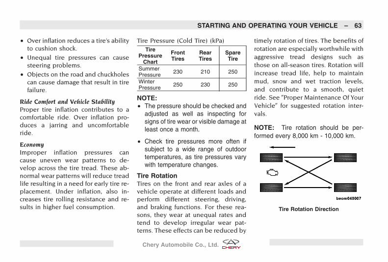
• Over inflation reduces a tire’s abilityto cushion shock.
• Unequal tire pressures can causesteering problems.
• Objects on the road and chuckholescan cause damage that result in tirefailure.
Ride Comfort and Vehicle StabilityProper tire inflation contributes to acomfortable ride. Over inflation pro-duces a jarring and uncomfortableride.
EconomyImproper inflation pressures cancause uneven wear patterns to de-velop across the tire tread. These ab-normal wear patterns will reduce treadlife resulting in a need for early tire re-placement. Under inflation, also in-creases tire rolling resistance and re-sults in higher fuel consumption.
Tire Pressure (Cold Tire) (kPa)Tire
PressureChart
FrontTires
RearTires
SpareTire
SummerPressure 230 210 250
WinterPressure 250 230 250
NOTE:• The pressure should be checked and
adjusted as well as inspecting forsigns of tire wear or visible damage atleast once a month.
• Check tire pressures more often ifsubject to a wide range of outdoortemperatures, as tire pressures varywith temperature changes.
Tire RotationTires on the front and rear axles of avehicle operate at different loads andperform different steering, driving,and braking functions. For these rea-sons, they wear at unequal rates andtend to develop irregular wear pat-terns. These effects can be reduced by
timely rotation of tires. The benefits ofrotation are especially worthwhile withaggressive tread designs such asthose on all-season tires. Rotation willincrease tread life, help to maintainmud, snow and wet traction levels,and contribute to a smooth, quietride. See �Proper Maintenance Of YourVehicle� for suggested rotation inter-vals.
NOTE: Tire rotation should be per-formed every 8,000 km - 10,000 km.
Tire Rotation Direction
STARTING AND OPERATING YOUR VEHICLE – 63
Chery Automobile Co., Ltd.
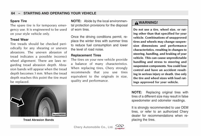
Spare TireThe spare tire is for temporary emer-gency use. It is engineered to be usedon your style vehicle only.
Tread WearTire treads should be checked peri-odically for any shearing or unevenabrasions. The uneven abrasion oftread indicates a possible incorrectwheel alignment. There are laws re-garding tread abrasion depth. Abra-sion bands will appear when the treaddepth becomes 3 mm. When the treaddepth reaches this point the tire mustbe replaced.
NOTE: Abide by the local environmen-tal protection provisions for the disposalof worn tires.
Once the driving conditions permit, re-place the winter tires with summer tiresto reduce fuel consumption and lowerthe level of road noise.
Replacement TiresThe tires on your new vehicle providea balance of many characteristics.When replacing tires, Chery stronglyrecommends that you use tiresequivalent to the originals in size,quality and performance.
WARNING!
Do not use a tire, wheel size, or rat-ing other than that specified for yourvehicle. Combinations of unapprovedtires and wheels may change suspen-sion dimensions and performancecharacteristics, resulting in changes tosteering, handling, and braking of yourvehicle. This can cause unpredictablehandling and stress to steering andsuspension components. You could losecontrol and have an accident result-ing in serious injury or death. Use onlythe tire and wheel sizes with load rat-ings approved for your vehicle.
NOTE: Replacing original tires withtires of a different size may result in falsespeedometer and odometer readings.
It is strongly recommended to use OEMtires, or refer to an authorized Cherydealer for recommendations when re-placing the tires.Tread Abrasion Bands
64 – STARTING AND OPERATING YOUR VEHICLE
Chery Automobile Co., Ltd.
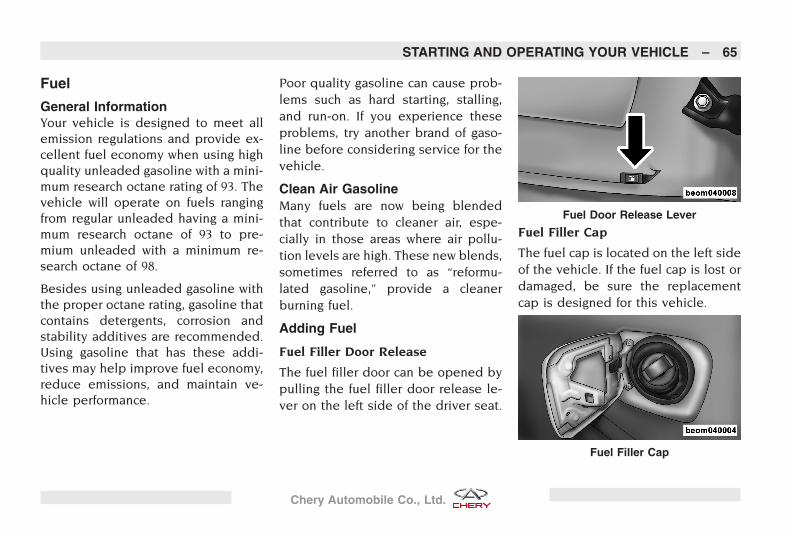
Fuel
General InformationYour vehicle is designed to meet allemission regulations and provide ex-cellent fuel economy when using highquality unleaded gasoline with a mini-mum research octane rating of 93. Thevehicle will operate on fuels rangingfrom regular unleaded having a mini-mum research octane of 93 to pre-mium unleaded with a minimum re-search octane of 98.
Besides using unleaded gasoline withthe proper octane rating, gasoline thatcontains detergents, corrosion andstability additives are recommended.Using gasoline that has these addi-tives may help improve fuel economy,reduce emissions, and maintain ve-hicle performance.
Poor quality gasoline can cause prob-lems such as hard starting, stalling,and run-on. If you experience theseproblems, try another brand of gaso-line before considering service for thevehicle.
Clean Air GasolineMany fuels are now being blendedthat contribute to cleaner air, espe-cially in those areas where air pollu-tion levels are high. These new blends,sometimes referred to as “reformu-lated gasoline,” provide a cleanerburning fuel.
Adding Fuel
Fuel Filler Door Release
The fuel filler door can be opened bypulling the fuel filler door release le-ver on the left side of the driver seat.
Fuel Filler Cap
The fuel cap is located on the left sideof the vehicle. If the fuel cap is lost ordamaged, be sure the replacementcap is designed for this vehicle.
Fuel Door Release Lever
Fuel Filler Cap
STARTING AND OPERATING YOUR VEHICLE – 65
Chery Automobile Co., Ltd.
NOTE: Damage to the fuel system oremission control system could resultfrom using an improper fuel cap. Apoorly fitting cap could let impurities intothe fuel system.
Refueling Instructions
Observe the following instructionswhen refueling:
• Turn the engine off.
• Open the fuel filler door by pullingthe fuel filler door release lever.
• Remove the fuel cap by rotating thefuel cap to the left.
• Insert the fuel nozzle to fill the tank.When the fuel nozzle �clicks� or shutsoff, the fuel tank is full.
• To replace the cap, insert it into thefiller neck and tighten to the right.
• If your vehicle is equipped with a fuelcap that has a tether strap make surethe tether strap is not caught underthe fuel cap.
NOTE: To avoid fuel spillage and over-filling, do not “top off” the fuel tank afterfilling.
WARNING!
Observe the following guidelines whenrefueling:
• Remove the fuel cap (gas cap)slowly to prevent fuel spray from thefiller neck which may cause injury.
• Never have any smoking materialslit in or near the vehicle when thefuel cap is removed or the tankfilled.
• Never add fuel to the vehicle whenthe engine is running.
66 – STARTING AND OPERATING YOUR VEHICLE
Chery Automobile Co., Ltd.
YOUR INSTRUMENT PANEL
CONTENTS
� Instrument Panel Features 68
� LHD Instrument PanelFeatures 68
� RHD Instrument PanelFeatures 69
� Instrument Cluster 70
� Instrument ClusterFunctions 71
� Audio System 75� General Information 75� Radio Faceplate 76� Radio Faceplate Description 77� Clock Setting 78� Radio Operation 78� CD/MP3 Player Operation 79� Remote Audio System
Controls (If Equipped) 79
� Climate Control 80� General Information 80� Manual Air Conditioning and
Heating System 81� Automatic Temperature
Control (If Equipped) 82
� Rear Window Defroster 86� Rear Window Defroster
(If Equipped) 86
67
Chery Automobile Co., Ltd.
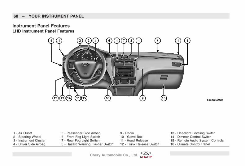
Instrument Panel FeaturesLHD Instrument Panel Features
1 - Air Outlet 5 - Passenger Side Airbag 9 - Radio 13 - Headlight Leveling Switch2 - Steering Wheel 6 - Front Fog Light Switch 10 - Glove Box 14 - Dimmer Control Switch3 - Instrument Cluster 7 - Rear Fog Light Switch 11 - Hood Release 15 - Remote Audio System Controls4 - Driver Side Airbag 8 - Hazard Warning Flasher Switch 12 - Trunk Release Switch 16 - Climate Control Panel
68 – YOUR INSTRUMENT PANEL
Chery Automobile Co., Ltd.
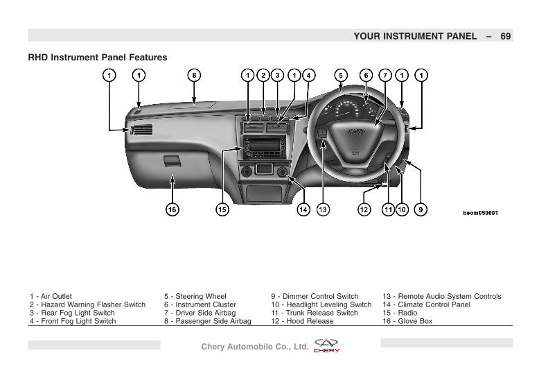
RHD Instrument Panel Features
1 - Air Outlet 5 - Steering Wheel 9 - Dimmer Control Switch 13 - Remote Audio System Controls2 - Hazard Warning Flasher Switch 6 - Instrument Cluster 10 - Headlight Leveling Switch 14 - Climate Control Panel3 - Rear Fog Light Switch 7 - Driver Side Airbag 11 - Trunk Release Switch 15 - Radio4 - Front Fog Light Switch 8 - Passenger Side Airbag 12 - Hood Release 16 - Glove Box
YOUR INSTRUMENT PANEL – 69
Chery Automobile Co., Ltd.
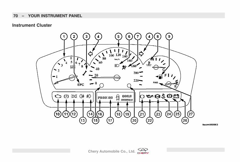
Instrument Cluster
70 – YOUR INSTRUMENT PANEL
Chery Automobile Co., Ltd.
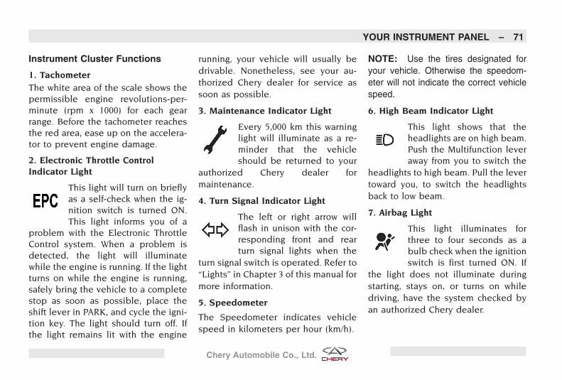
Instrument Cluster Functions
1. TachometerThe white area of the scale shows thepermissible engine revolutions-per-minute (rpm x 1000) for each gearrange. Before the tachometer reachesthe red area, ease up on the accelera-tor to prevent engine damage.
2. Electronic Throttle ControlIndicator Light
This light will turn on brieflyas a self-check when the ig-nition switch is turned ON.This light informs you of a
problem with the Electronic ThrottleControl system. When a problem isdetected, the light will illuminatewhile the engine is running. If the lightturns on while the engine is running,safely bring the vehicle to a completestop as soon as possible, place theshift lever in PARK, and cycle the igni-tion key. The light should turn off. Ifthe light remains lit with the engine
running, your vehicle will usually bedrivable. Nonetheless, see your au-thorized Chery dealer for service assoon as possible.
3. Maintenance Indicator Light
Every 5,000 km this warninglight will illuminate as a re-minder that the vehicleshould be returned to your
authorized Chery dealer formaintenance.
4. Turn Signal Indicator Light
The left or right arrow willflash in unison with the cor-responding front and rearturn signal lights when the
turn signal switch is operated. Refer to“Lights” in Chapter 3 of this manual formore information.
5. Speedometer
The Speedometer indicates vehiclespeed in kilometers per hour (km/h).
NOTE: Use the tires designated foryour vehicle. Otherwise the speedom-eter will not indicate the correct vehiclespeed.
6. High Beam Indicator Light
This light shows that theheadlights are on high beam.Push the Multifunction leveraway from you to switch the
headlights to high beam. Pull the levertoward you, to switch the headlightsback to low beam.
7. Airbag Light
This light illuminates forthree to four seconds as abulb check when the ignitionswitch is first turned ON. If
the light does not illuminate duringstarting, stays on, or turns on whiledriving, have the system checked byan authorized Chery dealer.
YOUR INSTRUMENT PANEL – 71
Chery Automobile Co., Ltd.
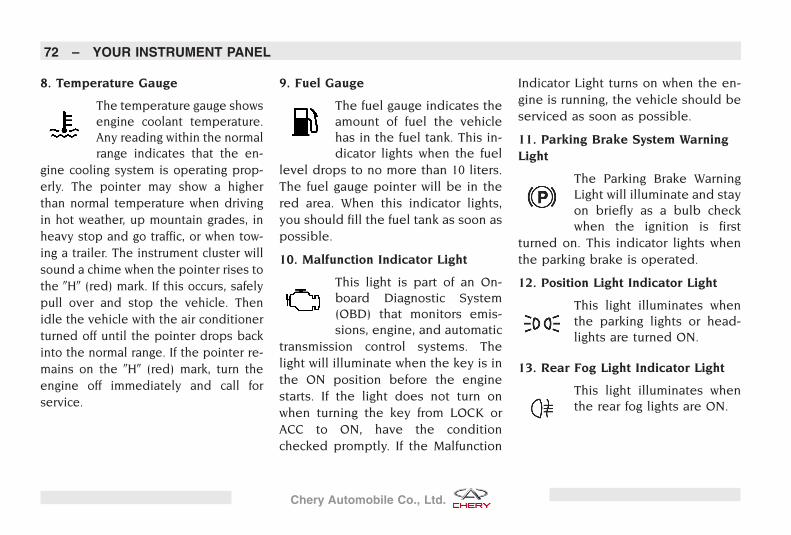
8. Temperature Gauge
The temperature gauge showsengine coolant temperature.Any reading within the normalrange indicates that the en-
gine cooling system is operating prop-erly. The pointer may show a higherthan normal temperature when drivingin hot weather, up mountain grades, inheavy stop and go traffic, or when tow-ing a trailer. The instrument cluster willsound a chime when the pointer rises tothe �H� (red) mark. If this occurs, safelypull over and stop the vehicle. Thenidle the vehicle with the air conditionerturned off until the pointer drops backinto the normal range. If the pointer re-mains on the �H� (red) mark, turn theengine off immediately and call forservice.
9. Fuel Gauge
The fuel gauge indicates theamount of fuel the vehiclehas in the fuel tank. This in-dicator lights when the fuel
level drops to no more than 10 liters.The fuel gauge pointer will be in thered area. When this indicator lights,you should fill the fuel tank as soon aspossible.
10. Malfunction Indicator Light
This light is part of an On-board Diagnostic System(OBD) that monitors emis-sions, engine, and automatic
transmission control systems. Thelight will illuminate when the key is inthe ON position before the enginestarts. If the light does not turn onwhen turning the key from LOCK orACC to ON, have the conditionchecked promptly. If the Malfunction
Indicator Light turns on when the en-gine is running, the vehicle should beserviced as soon as possible.
11. Parking Brake System WarningLight
The Parking Brake WarningLight will illuminate and stayon briefly as a bulb checkwhen the ignition is first
turned on. This indicator lights whenthe parking brake is operated.
12. Position Light Indicator Light
This light illuminates whenthe parking lights or head-lights are turned ON.
13. Rear Fog Light Indicator Light
This light illuminates whenthe rear fog lights are ON.
72 – YOUR INSTRUMENT PANEL
Chery Automobile Co., Ltd.
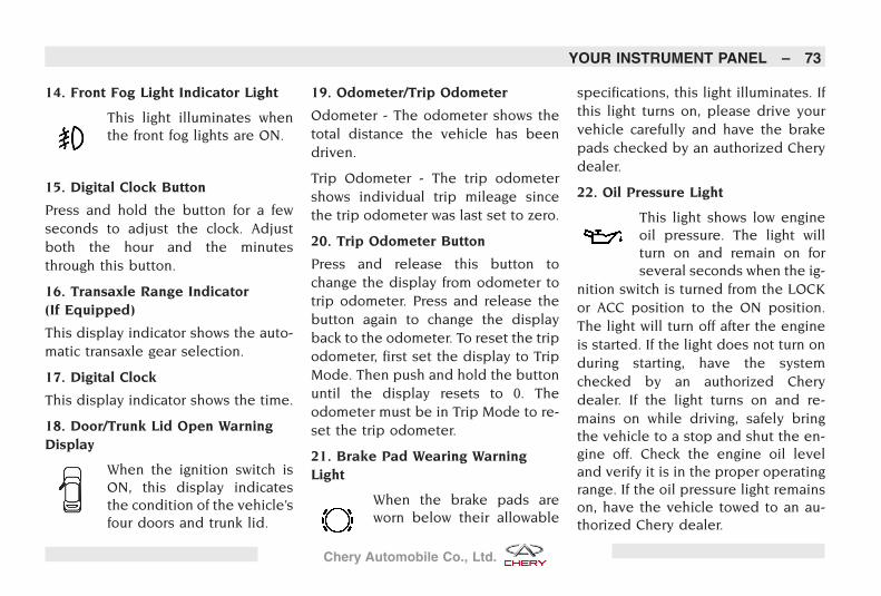
14. Front Fog Light Indicator Light
This light illuminates whenthe front fog lights are ON.
15. Digital Clock Button
Press and hold the button for a fewseconds to adjust the clock. Adjustboth the hour and the minutesthrough this button.
16. Transaxle Range Indicator(If Equipped)
This display indicator shows the auto-matic transaxle gear selection.
17. Digital Clock
This display indicator shows the time.
18. Door/Trunk Lid Open WarningDisplay
When the ignition switch isON, this display indicatesthe condition of the vehicle’sfour doors and trunk lid.
19. Odometer/Trip Odometer
Odometer - The odometer shows thetotal distance the vehicle has beendriven.
Trip Odometer - The trip odometershows individual trip mileage sincethe trip odometer was last set to zero.
20. Trip Odometer Button
Press and release this button tochange the display from odometer totrip odometer. Press and release thebutton again to change the displayback to the odometer. To reset the tripodometer, first set the display to TripMode. Then push and hold the buttonuntil the display resets to 0. Theodometer must be in Trip Mode to re-set the trip odometer.
21. Brake Pad Wearing WarningLight
When the brake pads areworn below their allowable
specifications, this light illuminates. Ifthis light turns on, please drive yourvehicle carefully and have the brakepads checked by an authorized Cherydealer.
22. Oil Pressure Light
This light shows low engineoil pressure. The light willturn on and remain on forseveral seconds when the ig-
nition switch is turned from the LOCKor ACC position to the ON position.The light will turn off after the engineis started. If the light does not turn onduring starting, have the systemchecked by an authorized Cherydealer. If the light turns on and re-mains on while driving, safely bringthe vehicle to a stop and shut the en-gine off. Check the engine oil leveland verify it is in the proper operatingrange. If the oil pressure light remainson, have the vehicle towed to an au-thorized Chery dealer.
YOUR INSTRUMENT PANEL – 73
Chery Automobile Co., Ltd.
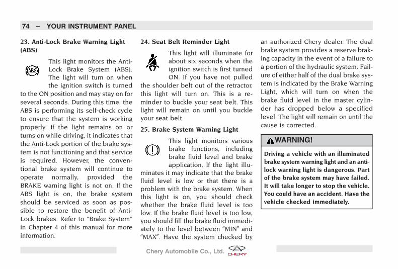
23. Anti-Lock Brake Warning Light(ABS)
This light monitors the Anti-Lock Brake System (ABS).The light will turn on whenthe ignition switch is turned
to the ON position and may stay on forseveral seconds. During this time, theABS is performing its self-check cycleto ensure that the system is workingproperly. If the light remains on orturns on while driving, it indicates thatthe Anti-Lock portion of the brake sys-tem is not functioning and that serviceis required. However, the conven-tional brake system will continue tooperate normally, provided theBRAKE warning light is not on. If theABS light is on, the brake systemshould be serviced as soon as pos-sible to restore the benefit of Anti-Lock brakes. Refer to “Brake System”in Chapter 4 of this manual for moreinformation.
24. Seat Belt Reminder Light
This light will illuminate forabout six seconds when theignition switch is first turnedON. If you have not pulled
the shoulder belt out of the retractor,this light will turn on. This is a re-minder to buckle your seat belt. Thislight will remain on until you buckleyour seat belt.
25. Brake System Warning Light
This light monitors variousbrake functions, includingbrake fluid level and brakeapplication. If the light illu-
minates it may indicate that the brakefluid level is low or that there is aproblem with the brake system. Whenthis light is on, you should checkwhether the brake fluid level is toolow. If the brake fluid level is too low,you should fill the brake fluid immedi-ately to the level between �MIN� and�MAX�. Have the system checked by
an authorized Chery dealer. The dualbrake system provides a reserve brak-ing capacity in the event of a failure toa portion of the hydraulic system. Fail-ure of either half of the dual brake sys-tem is indicated by the Brake WarningLight, which will turn on when thebrake fluid level in the master cylin-der has dropped below a specifiedlevel. The light will remain on until thecause is corrected.
WARNING!
Driving a vehicle with an illuminatedbrake system warning light and an anti-lock warning light is dangerous. Partof the brake system may have failed.It will take longer to stop the vehicle.You could have an accident. Have thevehicle checked immediately.
74 – YOUR INSTRUMENT PANEL
Chery Automobile Co., Ltd.
26. Charging System Light
This light shows the status ofthe electrical charging sys-tem. The light should illumi-nate when the ignition switch
is first turned ON and remain onbriefly as a bulb check. If the light re-mains on or turns on while driving, turnoff some of the vehicle’s electrical de-vices, such as the fog lights or rear de-froster. If the light remains on, it indi-cates that the charging system isexperiencing a problem. See your au-thorized Chery dealer for serviceimmediately.
27. Front Passenger Side AirbagON/OFF Switch Light
The front passenger side air-bag ON/OFF switch is locatedin the front passenger sideinstrument panel. It operates
in two positions (ON or OFF) which canbe selected by inserting the ignitionkey. If the OFF position is selected, the
PAB (Passenger Airbag) indicator is on,and the front passenger side airbag willnot work. When the ON position is se-lected, the indicator will turn off.
Audio System
General InformationThe radio will provide excellent re-ception under most operating condi-tions. However, like any system, ra-dios have performance limitations. Tohelp you understand and avoid con-cern about these possible malfunc-tions, you must understand how radiosignals are transmitted and received.
Radio Signals
There are two basic types of radio sig-nals:
• AM (Amplitude Modulation), in whichthe transmitted sound causes the am-plitude, or height of the radio wavesto vary.
• FM (Frequency Modulation), in whichthe frequency of the wave is variedto carry the sound.
AM Reception
AM sound is based on wave ampli-tude, so AM reception can be dis-rupted by such things as lightning,power lines and neon signs.
FM Reception
Because FM transmission is based onfrequency variations, interference thatconsists of amplitude variations canbe filtered out, leaving the receptionrelatively clear, which is the major fea-ture of FM radio.
YOUR INSTRUMENT PANEL – 75
Chery Automobile Co., Ltd.
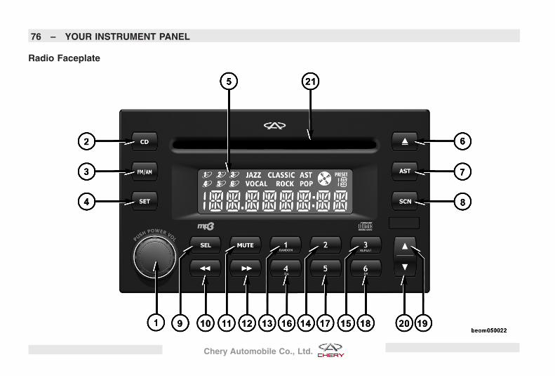
Radio Faceplate
76 – YOUR INSTRUMENT PANEL
Chery Automobile Co., Ltd.
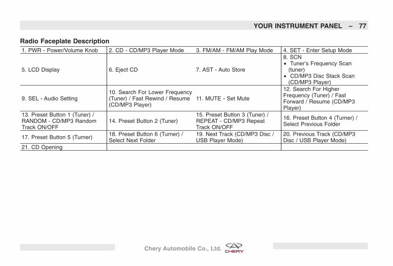
Radio Faceplate Description1. PWR - Power/Volume Knob 2. CD - CD/MP3 Player Mode 3. FM/AM - FM/AM Play Mode 4. SET - Enter Setup Mode
5. LCD Display 6. Eject CD 7. AST - Auto Store
8. SCN• Tuner’s Frequency Scan
(tuner)• CD/MP3 Disc Stack Scan
(CD/MP3 Player)
9. SEL - Audio Setting10. Search For Lower Frequency(Tuner) / Fast Rewind / Resume(CD/MP3 Player)
11. MUTE - Set Mute
12. Search For HigherFrequency (Tuner) / FastForward / Resume (CD/MP3Player)
13. Preset Button 1 (Tuner) /RANDOM - CD/MP3 RandomTrack ON/OFF
14. Preset Button 2 (Tuner)15. Preset Button 3 (Tuner) /REPEAT - CD/MP3 RepeatTrack ON/OFF
16. Preset Button 4 (Turner) /Select Previous Folder
17. Preset Button 5 (Turner) 18. Preset Button 6 (Turner) /Select Next Folder
19. Next Track (CD/MP3 Disc /USB Player Mode)
20. Previous Track (CD/MP3Disc / USB Player Mode)
21. CD Opening
YOUR INSTRUMENT PANEL – 77
Chery Automobile Co., Ltd.
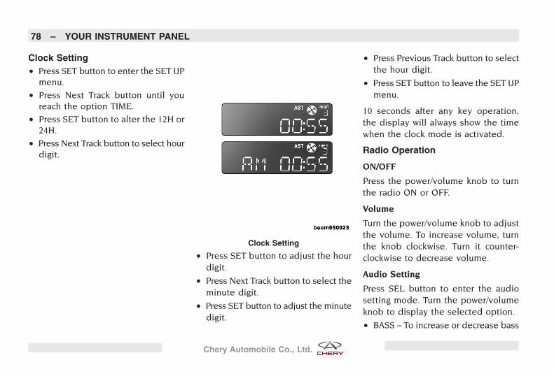
Clock Setting• Press SET button to enter the SET UP
menu.
• Press Next Track button until youreach the option TIME.
• Press SET button to alter the 12H or24H.
• Press Next Track button to select hourdigit.
• Press SET button to adjust the hourdigit.
• Press Next Track button to select theminute digit.
• Press SET button to adjust the minutedigit.
• Press Previous Track button to selectthe hour digit.
• Press SET button to leave the SET UPmenu.
10 seconds after any key operation,the display will always show the timewhen the clock mode is activated.
Radio Operation
ON/OFF
Press the power/volume knob to turnthe radio ON or OFF.
Volume
Turn the power/volume knob to adjustthe volume. To increase volume, turnthe knob clockwise. Turn it counter-clockwise to decrease volume.
Audio Setting
Press SEL button to enter the audiosetting mode. Turn the power/volumeknob to display the selected option.
• BASS – To increase or decrease bass
Clock Setting
78 – YOUR INSTRUMENT PANEL
Chery Automobile Co., Ltd.
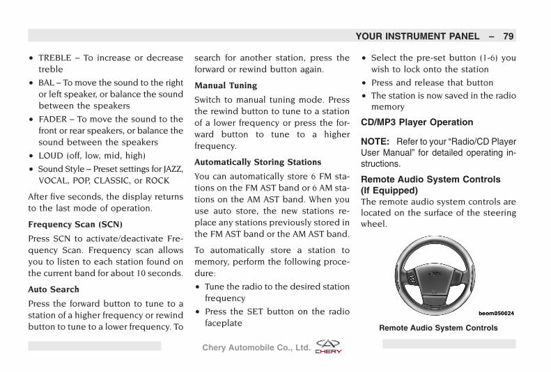
• TREBLE – To increase or decreasetreble
• BAL – To move the sound to the rightor left speaker, or balance the soundbetween the speakers
• FADER – To move the sound to thefront or rear speakers, or balance thesound between the speakers
• LOUD (off, low, mid, high)
• Sound Style – Preset settings for JAZZ,VOCAL, POP, CLASSIC, or ROCK
After five seconds, the display returnsto the last mode of operation.
Frequency Scan (SCN)
Press SCN to activate/deactivate Fre-quency Scan. Frequency scan allowsyou to listen to each station found onthe current band for about 10 seconds.
Auto Search
Press the forward button to tune to astation of a higher frequency or rewindbutton to tune to a lower frequency. To
search for another station, press theforward or rewind button again.
Manual Tuning
Switch to manual tuning mode. Pressthe rewind button to tune to a stationof a lower frequency or press the for-ward button to tune to a higherfrequency.
Automatically Storing Stations
You can automatically store 6 FM sta-tions on the FM AST band or 6 AM sta-tions on the AM AST band. When youuse auto store, the new stations re-place any stations previously stored inthe FM AST band or the AM AST band.
To automatically store a station tomemory, perform the following proce-dure:
• Tune the radio to the desired stationfrequency
• Press the SET button on the radiofaceplate
• Select the pre-set button (1-6) youwish to lock onto the station
• Press and release that button
• The station is now saved in the radiomemory
CD/MP3 Player Operation
NOTE: Refer to your “Radio/CD PlayerUser Manual” for detailed operating in-structions.
Remote Audio System Controls(If Equipped)The remote audio system controls arelocated on the surface of the steeringwheel.
Remote Audio System Controls
YOUR INSTRUMENT PANEL – 79
Chery Automobile Co., Ltd.
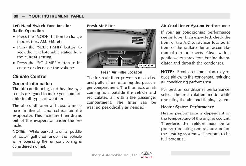
Left-Hand Switch Functions forRadio Operation
• Press the �MODE� button to changemodes (i.e., AM, FM, etc).
• Press the �SEEK BAND� button toseek the next listenable station fromthe current setting.
• Press the “VOLUME” button to in-crease or decrease the volume.
Climate Control
General InformationThe air conditioning and heating sys-tem is designed to make you comfort-able in all types of weather.
The air conditioner will absorb mois-ture in the air and collect on theevaporator. This moisture then drainsout of the evaporator under the ve-hicle.
NOTE: While parked, a small puddleof water gathered under the vehiclewhile operating the air conditioning isconsidered normal.
Fresh Air Filter
The fresh air filter prevents most dustand pollen from entering the passen-ger compartment. The filter acts on aircoming from outside the vehicle andrecirculated air within the passengercompartment. The filter can bewashed periodically as needed.
Air Conditioner System Performance
If your air conditioning performanceseems lower than expected, check thefront of the A/C condenser located infront of the radiator for an accumula-tion of dirt or insects. Clean with agentle water spray from behind the ra-diator and through the condenser.
NOTE: Front fascia protectors may re-duce airflow to the condenser, reducingair conditioning performance.
For best air conditioner performance,select the recirculation mode whileoperating the air conditioning system.
Heater System Performance
Heater performance is dependant onthe temperature of the engine coolant.Therefore, the vehicle must be atproper operating temperature beforethe heating system will perform to itsfull potential.
Fresh Air Filter Location
80 – YOUR INSTRUMENT PANEL
Chery Automobile Co., Ltd.
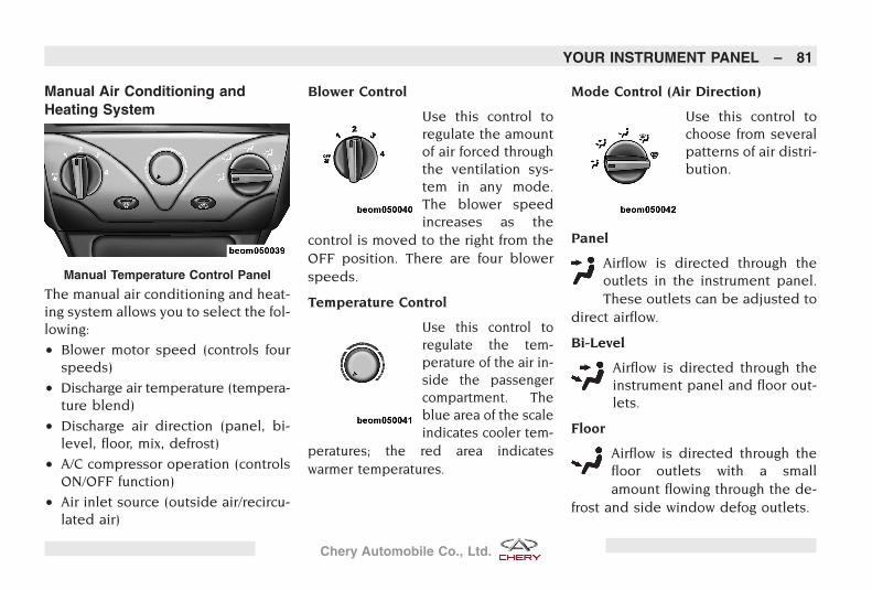
Manual Air Conditioning andHeating System
The manual air conditioning and heat-ing system allows you to select the fol-lowing:
• Blower motor speed (controls fourspeeds)
• Discharge air temperature (tempera-ture blend)
• Discharge air direction (panel, bi-level, floor, mix, defrost)
• A/C compressor operation (controlsON/OFF function)
• Air inlet source (outside air/recircu-lated air)
Blower Control
Use this control toregulate the amountof air forced throughthe ventilation sys-tem in any mode.The blower speedincreases as the
control is moved to the right from theOFF position. There are four blowerspeeds.
Temperature Control
Use this control toregulate the tem-perature of the air in-side the passengercompartment. Theblue area of the scaleindicates cooler tem-
peratures; the red area indicateswarmer temperatures.
Mode Control (Air Direction)
Use this control tochoose from severalpatterns of air distri-bution.
Panel
Airflow is directed through theoutlets in the instrument panel.These outlets can be adjusted to
direct airflow.
Bi-Level
Airflow is directed through theinstrument panel and floor out-lets.
Floor
Airflow is directed through thefloor outlets with a smallamount flowing through the de-
frost and side window defog outlets.
Manual Temperature Control Panel
YOUR INSTRUMENT PANEL – 81
Chery Automobile Co., Ltd.
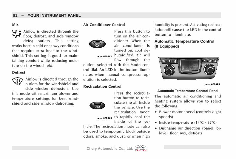
Mix
Airflow is directed through thefloor, defrost, and side windowdefog outlets. This setting
works best in cold or snowy conditionsthat require extra heat to the wind-shield. This setting is good for main-taining comfort while reducing mois-ture on the windshield.
Defrost
Airflow is directed through theoutlets for the windshield andside window defrosters. Use
this mode with maximum blower andtemperature settings for best wind-shield and side window defrosting.
Air Conditioner Control
Press this button toturn on the air con-ditioner. When theair conditioner isturned on, cool de-humidified air willflow through the
outlets selected with the Mode con-trol dial. An LED in the button illumi-nates when manual compressor op-eration is selected.
Recirculation Control
Press the recircula-tion button to recir-culate the air insidethe vehicle. Use therecirculation modeto rapidly cool theinside of the ve-
hicle. The recirculation mode can alsobe used to temporarily block outsideodors, smoke, and dust, or when high
humidity is present. Activating recircu-lation will cause the LED in the controlbutton to illuminate.
Automatic Temperature Control(If Equipped)
The automatic air conditioning andheating system allows you to selectthe following:
• Blower motor speed (controls eightspeeds)
• Inside temperature (18°C - 32°C)
• Discharge air direction (panel, bi-level, floor, mix, defrost)
Automatic Temperature Control Panel
82 – YOUR INSTRUMENT PANEL
Chery Automobile Co., Ltd.
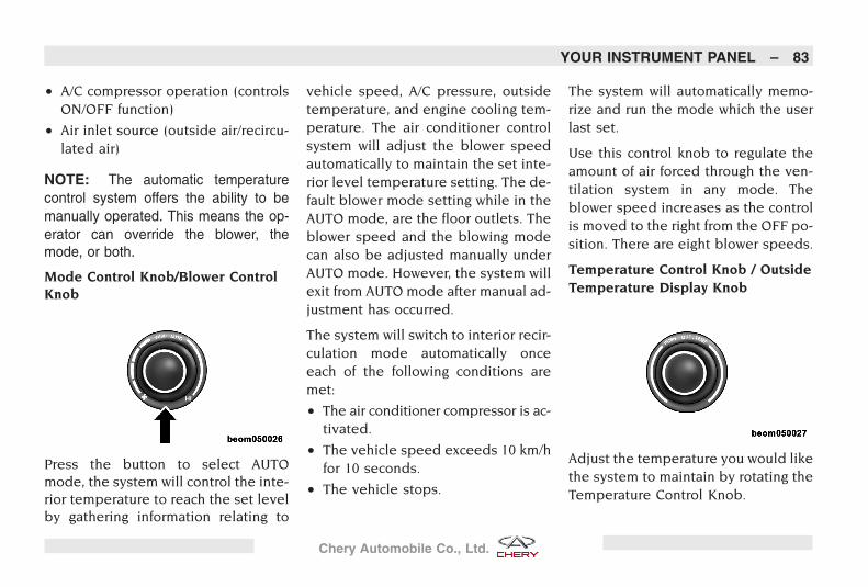
• A/C compressor operation (controlsON/OFF function)
• Air inlet source (outside air/recircu-lated air)
NOTE: The automatic temperaturecontrol system offers the ability to bemanually operated. This means the op-erator can override the blower, themode, or both.
Mode Control Knob/Blower ControlKnob
Press the button to select AUTOmode, the system will control the inte-rior temperature to reach the set levelby gathering information relating to
vehicle speed, A/C pressure, outsidetemperature, and engine cooling tem-perature. The air conditioner controlsystem will adjust the blower speedautomatically to maintain the set inte-rior level temperature setting. The de-fault blower mode setting while in theAUTO mode, are the floor outlets. Theblower speed and the blowing modecan also be adjusted manually underAUTO mode. However, the system willexit from AUTO mode after manual ad-justment has occurred.
The system will switch to interior recir-culation mode automatically onceeach of the following conditions aremet:
• The air conditioner compressor is ac-tivated.
• The vehicle speed exceeds 10 km/hfor 10 seconds.
• The vehicle stops.
The system will automatically memo-rize and run the mode which the userlast set.
Use this control knob to regulate theamount of air forced through the ven-tilation system in any mode. Theblower speed increases as the controlis moved to the right from the OFF po-sition. There are eight blower speeds.
Temperature Control Knob / OutsideTemperature Display Knob
Adjust the temperature you would likethe system to maintain by rotating theTemperature Control Knob.
YOUR INSTRUMENT PANEL – 83
Chery Automobile Co., Ltd.
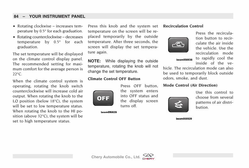
• Rotating clockwise – increases tem-perature by 0.5° for each graduation.
• Rotating counterclockwise – decreasestemperature by 0.5° for eachgraduation.
The set temperature will be displayedon the climate control display panel.The recommended setting for maxi-mum comfort for the average person is22°C.
When the climate control system isoperating, rotating the knob switchcounterclockwise will increase cold airoutput. When rotating the knob to theLO position (below 18°C), the systemwill be set to low temperature status.When rotating the knob to the HI po-sition (above 32°C), the system will beset to high temperature status.
Press this knob and the system settemperature on the screen will be re-placed temporarily by the outsidetemperature. After three seconds, thescreen will display the set tempera-ture again.
NOTE: While displaying the outsidetemperature, rotating the knob will notchange the set temperature.
Climate Control OFF Button
Press OFF button,the system entersinto OFF status andthe display screenturns off.
Recirculation Control
Press the recircula-tion button to recir-culate the air insidethe vehicle. Use therecirculation modeto rapidly cool theinside of the ve-
hicle. The recirculation mode can alsobe used to temporarily block outsideodors, smoke, and dust.
Mode Control (Air Direction)
Use this control tochoose from severalpatterns of air distri-bution.
84 – YOUR INSTRUMENT PANEL
Chery Automobile Co., Ltd.
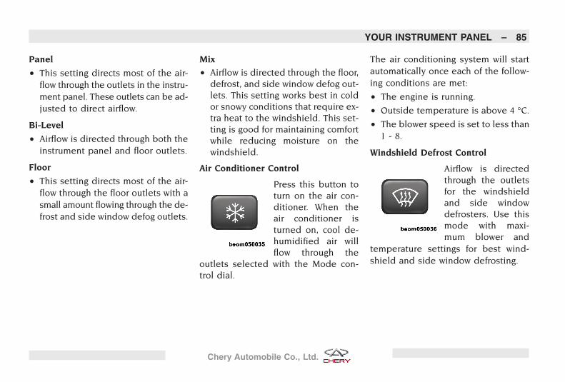
Panel
• This setting directs most of the air-flow through the outlets in the instru-ment panel. These outlets can be ad-justed to direct airflow.
Bi-Level
• Airflow is directed through both theinstrument panel and floor outlets.
Floor
• This setting directs most of the air-flow through the floor outlets with asmall amount flowing through the de-frost and side window defog outlets.
Mix
• Airflow is directed through the floor,defrost, and side window defog out-lets. This setting works best in coldor snowy conditions that require ex-tra heat to the windshield. This set-ting is good for maintaining comfortwhile reducing moisture on thewindshield.
Air Conditioner Control
Press this button toturn on the air con-ditioner. When theair conditioner isturned on, cool de-humidified air willflow through the
outlets selected with the Mode con-trol dial.
The air conditioning system will startautomatically once each of the follow-ing conditions are met:
• The engine is running.
• Outside temperature is above 4 °C.
• The blower speed is set to less than1 - 8.
Windshield Defrost Control
Airflow is directedthrough the outletsfor the windshieldand side windowdefrosters. Use thismode with maxi-mum blower and
temperature settings for best wind-shield and side window defrosting.
YOUR INSTRUMENT PANEL – 85
Chery Automobile Co., Ltd.
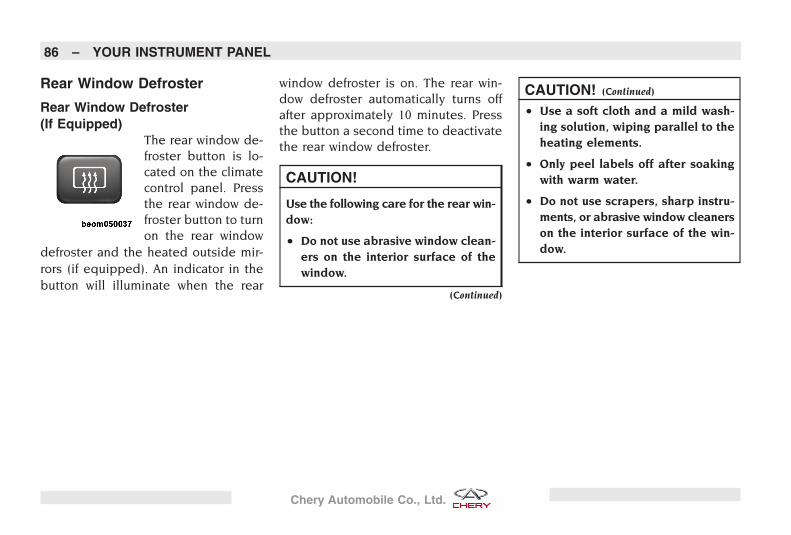
Rear Window Defroster
Rear Window Defroster(If Equipped)
The rear window de-froster button is lo-cated on the climatecontrol panel. Pressthe rear window de-froster button to turnon the rear window
defroster and the heated outside mir-rors (if equipped). An indicator in thebutton will illuminate when the rear
window defroster is on. The rear win-dow defroster automatically turns offafter approximately 10 minutes. Pressthe button a second time to deactivatethe rear window defroster.
CAUTION!
Use the following care for the rear win-dow:
• Do not use abrasive window clean-ers on the interior surface of thewindow.
(Continued)
CAUTION! (Continued)
• Use a soft cloth and a mild wash-ing solution, wiping parallel to theheating elements.
• Only peel labels off after soakingwith warm water.
• Do not use scrapers, sharp instru-ments, or abrasive window cleanerson the interior surface of the win-dow.
86 – YOUR INSTRUMENT PANEL
Chery Automobile Co., Ltd.
IN CASE OF AN EMERGENCY
CONTENTS
� Hazard Warning Flasher 88
� Jacking and Tire Changing 88� Jack Location 88
� Spare Tire Location 88
� Preparations For Jacking 89
� Jacking Instructions 89
� Wheel Nut TorqueSpecification 91
� Vehicle Overheating 91
� Fuse Replacement 92
� Towing A Disabled Vehicle 93
� Removing and InstallingVehicle Battery 94
� Jump-Starting ProceduresDue to A Low Battery 94
87
Chery Automobile Co., Ltd.
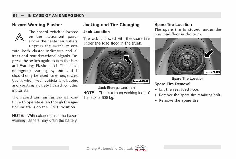
Hazard Warning Flasher
The hazard switch is locatedon the instrument panel,above the center air outlets.Depress the switch to acti-
vate both cluster indicators and allfront and rear directional signals. De-press the switch again to turn the Haz-ard Warning Flashers off. This is anemergency warning system and itshould only be used for emergencies.Use it when your vehicle is disabledand creating a safety hazard for othermotorists.
The hazard warning flashers will con-tinue to operate even though the igni-tion switch is on the LOCK position.
NOTE: With extended use, the hazardwarning flashers may drain the battery.
Jacking and Tire Changing
Jack Location
The jack is stowed with the spare tireunder the load floor in the trunk.
NOTE: The maximum working load ofthe jack is 800 kg.
Spare Tire LocationThe spare tire is stowed under therear load floor in the trunk.
Spare Tire Removal
• Lift the rear load floor.
• Remove the spare tire retaining bolt.
• Remove the spare tire.
Jack Storage Location
Spare Tire Location
88 – IN CASE OF AN EMERGENCY
Chery Automobile Co., Ltd.
Preparations For Jacking• Park the vehicle on a firm, level sur-
face. Avoid steep, icy, or slippery ar-eas.
• Set the parking brake firmly. For ve-hicles equipped with an automatictransaxle, place the vehicle in PARK.For a manual transmission equippedvehicle, place the transaxle in RE-VERSE.
• Turn off the engine.
• Turn on the hazard warning flashers.
• Put wheel blocks at the front and rearof the tire diagonally opposite the tirebeing changed. For example, if chang-ing the right front tire, block the leftrear wheel.
WARNING!
Do not attempt to change a tire on theside of the vehicle close to moving traf-fic. Pull far enough off the road toavoid the danger of being hit when op-erating the jack or changing the tire.
Jacking Instructions• Remove the spare tire, jack, and jack-
handle from the trunk.
• Loosen, but do not remove, the wheelnuts on the wheel with the flat tire.Turn the wheel nuts counterclockwisewhile the wheel is still on the ground.
• Place the jack underneath the lift areathat is closest to the flat tire. Turn thejack screw clockwise to firmly engagethe jack saddle with the lift area ofthe sill flange.
IN CASE OF AN EMERGENCY – 89
Chery Automobile Co., Ltd.
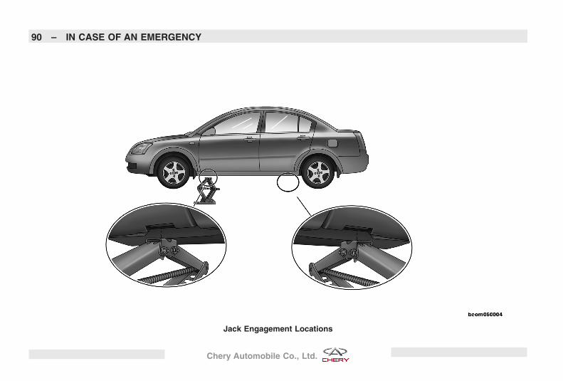
Jack Engagement Locations
90 – IN CASE OF AN EMERGENCY
Chery Automobile Co., Ltd.
• Raise the vehicle by turning the jackscrew clockwise with the jack handle.Raise the vehicle until the tire justclears the ground surface and thereis enough clearance to install thespare tire.
WARNING!
Minimum tire lift provides maximumstability.
• Remove the wheel nuts.
• Remove the wheel and tire assem-bly from the hub.
• Install the spare tire.
• Install the wheel nuts with the ta-pered end of the nuts toward thewheel. Lightly tighten the nuts byhand.
• Lower the vehicle by turning the jackscrew counterclockwise with the jackhandle.
• Finish tightening the wheel nuts. Al-ternate tightening wheel nuts firmlyin a criss-cross pattern until each nuthas been tightened twice. Correctwheel nut torque is 110 N•m.
CAUTION!
To verify correct wheel nut torque,have them checked with a torquewrench by your authorized Cherydealer as soon as possible after the re-pair.
• Lower the jack to its fully closed po-sition.
• Stow the jack-handle and jack.
• Place the flat tire in the trunk. Haveit repaired or replaced as soon aspossible.
Wheel Nut Torque SpecificationDescription Torque (N•m)Wheel Nuts 110
Vehicle Overheating
WARNING!
A hot engine cooling system is danger-ous. You or others could be badlyburned by steam or boiling coolant.You may want to call a service centerif your vehicle overheats.
There are steps that you can take toslow down an impending overheatcondition. If your air conditioner is on,turn it off. The air conditioning systemadds heat to the engine cooling sys-tem and turning the air conditioner offcan help remove this heat. You canalso turn the temperature control tothe maximum heat setting, the modecontrol to floor and the fan control tohigh. This allows the heater core to actas a supplement to the radiator andaids in removing heat from the enginecooling system.
IN CASE OF AN EMERGENCY – 91
Chery Automobile Co., Ltd.
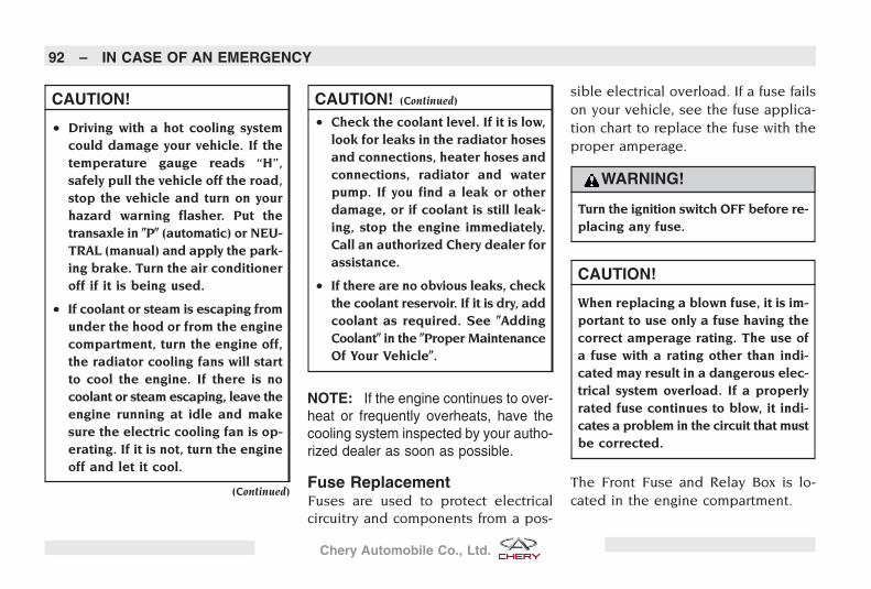
CAUTION!
• Driving with a hot cooling systemcould damage your vehicle. If thetemperature gauge reads “H”,safely pull the vehicle off the road,stop the vehicle and turn on yourhazard warning flasher. Put thetransaxle in �P� (automatic) or NEU-TRAL (manual) and apply the park-ing brake. Turn the air conditioneroff if it is being used.
• If coolant or steam is escaping fromunder the hood or from the enginecompartment, turn the engine off,the radiator cooling fans will startto cool the engine. If there is nocoolant or steam escaping, leave theengine running at idle and makesure the electric cooling fan is op-erating. If it is not, turn the engineoff and let it cool.
(Continued)
CAUTION! (Continued)
• Check the coolant level. If it is low,look for leaks in the radiator hosesand connections, heater hoses andconnections, radiator and waterpump. If you find a leak or otherdamage, or if coolant is still leak-ing, stop the engine immediately.Call an authorized Chery dealer forassistance.
• If there are no obvious leaks, checkthe coolant reservoir. If it is dry, addcoolant as required. See �AddingCoolant� in the �Proper MaintenanceOf Your Vehicle�.
NOTE: If the engine continues to over-heat or frequently overheats, have thecooling system inspected by your autho-rized dealer as soon as possible.
Fuse ReplacementFuses are used to protect electricalcircuitry and components from a pos-
sible electrical overload. If a fuse failson your vehicle, see the fuse applica-tion chart to replace the fuse with theproper amperage.
WARNING!
Turn the ignition switch OFF before re-placing any fuse.
CAUTION!
When replacing a blown fuse, it is im-portant to use only a fuse having thecorrect amperage rating. The use ofa fuse with a rating other than indi-cated may result in a dangerous elec-trical system overload. If a properlyrated fuse continues to blow, it indi-cates a problem in the circuit that mustbe corrected.
The Front Fuse and Relay Box is lo-cated in the engine compartment.
92 – IN CASE OF AN EMERGENCY
Chery Automobile Co., Ltd.
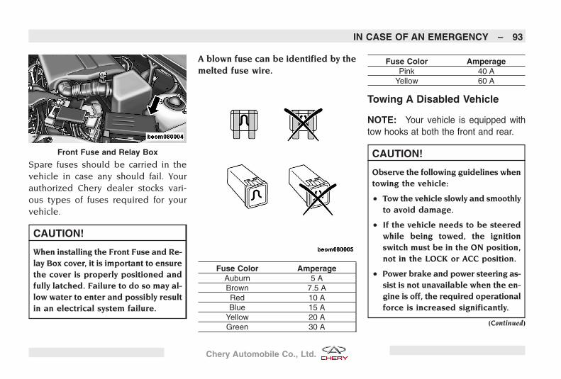
Spare fuses should be carried in thevehicle in case any should fail. Yourauthorized Chery dealer stocks vari-ous types of fuses required for yourvehicle.
CAUTION!
When installing the Front Fuse and Re-lay Box cover, it is important to ensurethe cover is properly positioned andfully latched. Failure to do so may al-low water to enter and possibly resultin an electrical system failure.
A blown fuse can be identified by themelted fuse wire.
Fuse Color AmperageAuburn 5 ABrown 7.5 ARed 10 ABlue 15 A
Yellow 20 AGreen 30 A
Fuse Color AmperagePink 40 A
Yellow 60 A
Towing A Disabled Vehicle
NOTE: Your vehicle is equipped withtow hooks at both the front and rear.
CAUTION!
Observe the following guidelines whentowing the vehicle:
• Tow the vehicle slowly and smoothlyto avoid damage.
• If the vehicle needs to be steeredwhile being towed, the ignitionswitch must be in the ON position,not in the LOCK or ACC position.
• Power brake and power steering as-sist is not unavailable when the en-gine is off, the required operationalforce is increased significantly.
(Continued)
Front Fuse and Relay Box
IN CASE OF AN EMERGENCY – 93
Chery Automobile Co., Ltd.
CAUTION! (Continued)
• Do not attempt to tow this vehiclefrom the front with sling type tow-ing equipment. Damage to the frontfascia will occur.
Removing and InstallingVehicle Battery
The following steps must be takenwhen removing and installing the bat-tery:
• Turn the ignition switch and all elec-trical devices off.
• Remove the negative (-) batterycable.
• Remove the protective cover from thepositive (+) battery cable, and re-move the cable.
• Remove the battery hold down, andremove the battery.
• Install the new battery, when install-ing the battery, connect the positive
(+) battery cable first and then thenegative (-) battery cable.
• After the new battery is installed, thevehicle may perform unusually whiledriving. This is normal due to the en-gine control system readapting to thevehicle’s driving conditions.
NOTE: Please discard the used bat-tery for disposal to an authorized dealeror local qualified waste disposal station.
Jump-Starting Procedures Dueto A Low Battery
WARNING!
Observe the following guidelines whenjump-starting the battery:
• Take care to avoid the radiator cool-ing fan whenever the hood is raised.It can start anytime the ignitionswitch is ON. You can be hurt by thefan.
(Continued)
WARNING! (Continued)
• Do not attempt to push or tow yourvehicle to get it started. Vehiclesequipped with an automatic trans-axle cannot be started this way. Un-burned fuel could enter the catalyticconverter and once the engine hasstarted, ignite and damage the con-verter and vehicle. If the vehicle hasa discharged battery, booster cablesmay be used to obtain a start fromanother vehicle. This type of startcan be dangerous if done improp-erly, so follow this procedure care-fully.
• Do not use a booster battery or anyother booster source with an outputthat exceeds 12 volts.
94 – IN CASE OF AN EMERGENCY
Chery Automobile Co., Ltd.
The following prevention measuresmust be taken when jump starting thevehicle:
• When boosting from a battery in an-other vehicle, park that vehicle withinbooster cable reach, but without al-lowing the vehicles to touch.
• Set the parking brake.
• Place an automatic transaxle equippedvehicle in PARK, and a manual trans-axle equipped vehicle in NEUTRAL.
• Turn the ignition switch to LOCK forboth vehicles.
• Turn off all unnecessary electricalloads.
• Remove the protective cover over thepositive battery post (+). Connect oneend of the jumper cable to the posi-tive battery post. Connect the otherend of the same cable to the posi-tive terminal of the booster battery.
• Connect the other cable, first to thenegative terminal of the booster bat-tery and then to the engine ground(-) of the vehicle with the dischargedbattery. Make sure you have a goodconnection on the engine ground.
• Start the engine in the vehicle thathas the booster battery, let the en-gine idle for a few minutes, and thenstart the engine in the vehicle withthe discharged battery.
• When removing the jumper cables,reverse the sequence exactly. Becareful of the moving belts and fan.
• Reinstall the protective cover over thepositive battery post (+).
IN CASE OF AN EMERGENCY – 95
Chery Automobile Co., Ltd.

96
Chery Automobile Co., Ltd.
CUSTOMER ASSISTANCE
CONTENTS
� Service for Your Vehicle 98� Service Appointments 98� Service List 98� Service Requests 98
� If You Need Assistance 98� Vehicle Satisfaction 98
� Authorized Chery DealerService 99
� After-Sales ServiceDepartment CheryInternational 99
97
Chery Automobile Co., Ltd.
Service for Your Vehicle
Service AppointmentsIf you’re having warranty work done,be sure to have the proper vehicledocuments with you. Take your war-ranty folder. All work to be performedmay not be covered by the warranty.Discuss additional charges with theservice advisor. Keep a maintenancelog of your vehicle’s service history.This can often provide a clue to thecurrent problem.
Service ListPrepare a written list of your vehicle’sproblems or the specific work youwant done. If you’ve had an accidentor work done that is not on your main-tenance log, let the service advisorknow.
Service RequestsIf you list a number of items and youmust have your vehicle by the end ofthe day, discuss the situation with theservice advisor and list the items in or-der of priority. At many authorizedChery dealers, you may obtain a rentalvehicle at a minimal daily charge. Ifyou need a rental, it is advisable tomake these arrangements when youcall for an appointment.
If You Need Assistance
Vehicle SatisfactionChery and its authorized dealers arecommitted to your satisfaction withtheir products and services. Your hap-piness with our vehicle is important tous.
If a service problem or other difficultyoccurs, we recommend that you takethe following steps:
• Discuss the problem with your autho-rized Chery dealership’s service man-ager. Management personnel at theauthorized dealer are in the best po-sition to resolve your questions andconcerns quickly.
• In the event you are still not satisfied,talk to the general manager or theowner of the authorized dealership.They want you to be satisfied.
• If the dealership is unable to resolveyour concern, please contact theAfter-Sales Service Department CheryInternational.
98 – CUSTOMER ASSISTANCE
Chery Automobile Co., Ltd.
Authorized Chery Dealer ServiceOnly Original Equipment Manufac-turer (OEM) parts and materials canextend your vehicles life. Chery Auto-mobile Co., Ltd. only supplies OEMparts to authorized Chery dealers lo-cated world wide. Therefore, only useauthorized OEM parts from an autho-rized Chery dealer.
Authorized Chery dealers are serviceprofessionals and are exclusively au-thorized by Chery Automobile Co.,Ltd. For vehicle service, rememberthat your authorized dealer knowsyour vehicle best, has the factory-trained technicians and OEM parts tobest provide the customer satisfactionthat you require.
After-Sales Service DepartmentChery InternationalThe following is the address, zip code,E-mail, website and telephone hotlinenumber of the After-Sales Service De-partment Chery International:
Address: After-Sales Service DepartmentChery International,No.8 Changchun Road,Economic & TechnicalDevelopment Zone, Wuhu,Anhui Province, China
Zip Code: 241009
E-mail: [email protected]
Website: www.cheryinternational.com
Hotline: +86-553-5923830
Any communication sent to the After-Sales Service Department Chery In-ternational should include the follow-ing information:
• Owner’s name and address
• Owner’s telephone number
• Owner’s E-mail
• Selling and servicing dealer
• Vehicle Identification Number (VIN)
• Vehicle’s delivery date and currentodometer reading
• Service history of your vehicle
• An accurate description of the prob-lem and the conditions under whichit occurs.
CUSTOMER ASSISTANCE – 99
Chery Automobile Co., Ltd.
100
Chery Automobile Co., Ltd.
PROPER MAINTENANCE OF YOUR VEHICLE
CONTENTS
� Proper Maintenance OfYour Vehicle 102� LHD Engine Compartment 102� RHD Engine Compartment 103� Maintenance Procedures 104
� Bulb Replacement 110� Fluids And Capacities 112� Fluids, Lubricants, and
Genuine Parts 113� Vehicle Weight 113
� Fuel Consumption 114
� Vehicle Dimensions 115
101
Chery Automobile Co., Ltd.
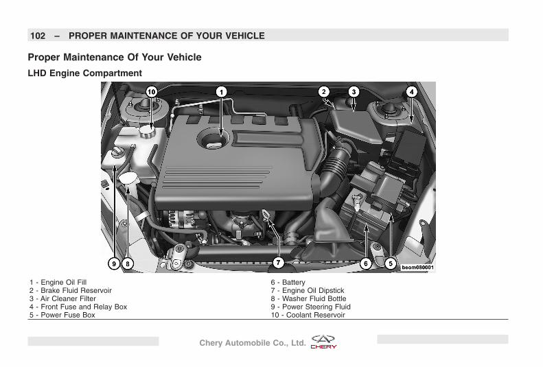
Proper Maintenance Of Your Vehicle
LHD Engine Compartment
1 - Engine Oil Fill 6 - Battery2 - Brake Fluid Reservoir 7 - Engine Oil Dipstick3 - Air Cleaner Filter 8 - Washer Fluid Bottle4 - Front Fuse and Relay Box 9 - Power Steering Fluid5 - Power Fuse Box 10 - Coolant Reservoir
102 – PROPER MAINTENANCE OF YOUR VEHICLE
Chery Automobile Co., Ltd.
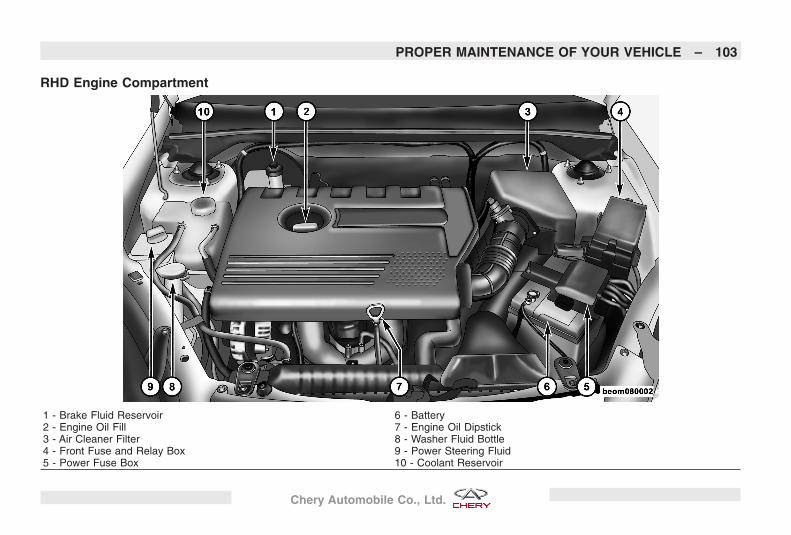
RHD Engine Compartment
1 - Brake Fluid Reservoir 6 - Battery2 - Engine Oil Fill 7 - Engine Oil Dipstick3 - Air Cleaner Filter 8 - Washer Fluid Bottle4 - Front Fuse and Relay Box 9 - Power Steering Fluid5 - Power Fuse Box 10 - Coolant Reservoir
PROPER MAINTENANCE OF YOUR VEHICLE – 103
Chery Automobile Co., Ltd.
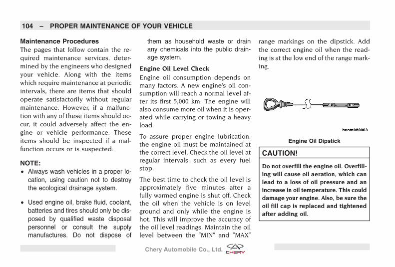
Maintenance ProceduresThe pages that follow contain the re-quired maintenance services, deter-mined by the engineers who designedyour vehicle. Along with the itemswhich require maintenance at periodicintervals, there are items that shouldoperate satisfactorily without regularmaintenance. However, if a malfunc-tion with any of these items should oc-cur, it could adversely affect the en-gine or vehicle performance. Theseitems should be inspected if a mal-function occurs or is suspected.
NOTE:• Always wash vehicles in a proper lo-
cation, using caution not to destroythe ecological drainage system.
• Used engine oil, brake fluid, coolant,batteries and tires should only be dis-posed by qualified waste disposalpersonnel or consult the supplymanufactures. Do not dispose of
them as household waste or drainany chemicals into the public drain-age system.
Engine Oil Level CheckEngine oil consumption depends onmany factors. A new engine’s oil con-sumption will reach a normal level af-ter its first 5,000 km. The engine willalso consume more oil when it is oper-ated while carrying or towing a heavyload.
To assure proper engine lubrication,the engine oil must be maintained atthe correct level. Check the oil level atregular intervals, such as every fuelstop.
The best time to check the oil level isapproximately five minutes after afully warmed engine is shut off. Checkthe oil when the vehicle is on levelground and only while the engine ishot. This will improve the accuracy ofthe oil level readings. Maintain the oillevel between the �MIN� and �MAX�
range markings on the dipstick. Addthe correct engine oil when the read-ing is at the low end of the range mark-ing.
CAUTION!
Do not overfill the engine oil. Overfill-ing will cause oil aeration, which canlead to a loss of oil pressure and anincrease in oil temperature. This coulddamage your engine. Also, be sure theoil fill cap is replaced and tightenedafter adding oil.
Engine Oil Dipstick
104 – PROPER MAINTENANCE OF YOUR VEHICLE
Chery Automobile Co., Ltd.
Engine Oil AdditivesThe manufacture strongly recom-mends against the addition of any ad-ditives (other than leak detectiondyes) to the engine oil. Engine oil isan engineered product and its perfor-mance may be impaired by supple-mental additives.
Disposing of Used Engine OilCare should be taken in disposing ofused engine oil from your vehicle.Used oil, indiscriminately discarded,can present a problem to the environ-ment. Contact your authorized Cherydealer, service station, or governmentagency for advice on how and whereused oil can be safely discarded inyour area.
Engine Oil FilterThe engine oil filter should be re-placed at every engine oil change.
Catalytic ConverterThe catalytic converter requires theuse of unleaded fuel only. Leaded
gasoline will destroy the effectivenessof the catalyst as an emissions controldevice.Under normal operating condi-tions, the catalytic converter will notrequire maintenance. However, it isimportant to keep the engine properlytuned to assure proper catalyst opera-tion and prevent possible catalystdamage.
CAUTION!
Damage to the catalytic converter canresult if your vehicle is not kept inproper operating condition. In theevent of engine malfunction, particu-larly involving engine misfire or otherapparent loss of performance, haveyour vehicle serviced promptly. Contin-ued operation of your vehicle with asevere malfunction could cause theconverter to overheat, resulting in pos-sible damage to the converter and thevehicle.
WARNING!
A hot exhaust system can start a fireif you park over material that can burn.Such materials, such as grass or leavescoming into contact with your exhaustsystem could start a fire. Do not parkor operate your vehicle in areas whereyour exhaust system can contact any-thing that can burn.
Brake Fluid Level CheckCheck the fluid level in the master cyl-inder whenever performing under-hood services. The fluid level shouldbe between the �MIN� and �MAX� indi-cator on the reservoir. If necessary,add fluid to the reservoir to raise thefluid to the proper level.
PROPER MAINTENANCE OF YOUR VEHICLE – 105
Chery Automobile Co., Ltd.
Adding Brake Fluid
• Check the fluid level in the mastercylinder immediately if the brake sys-tem warning light indicates a systemfailure.
• Overfilling fluid is not recommendedbecause it may cause leaking in thesystem.
• Use only brake fluid that has beenstored in a tightly closed containerto avoid contamination from foreignmatter or moisture.
• Only use brake fluid that meets Cheryspecifications. Refer to �Fluids andCapacities� in this chapter for thebrake fluid capacity and type.
CAUTION!
Do not allow petroleum based fluid tocontaminate the brake fluid, brakeseal components could be damagedcausing partial or complete brake fail-ure.
WARNING!
Never allow brake fluid to contact yourskin or eyes. If brake fluid splashes inyour eyes, or on your skin, flush thearea immediately with large amountsof water and seek medical treatmentimmediately.
Coolant Level Check
WARNING!
Never add coolant when the engine isoverheated. Do not loosen or removethe cap to cool an overheated engine.Heat causes pressure to build up in thecooling system. Therefore, to preventscalding or injury, do not remove thecap while the system is hot or underpressure.
The coolant bottle provides a quick vi-sual method for determining that thecoolant level is adequate. With the en-gine idling and warmed to normal op-
erating temperature, the level of thecoolant should be between the �MIN�
and �MAX� lines shown on the bottle.
WARNING!
Coolant is toxic fluid. If the coolantcomes into contact with skin or eyes,immediately wash the affected areawith abundant water and seek medi-cal attention.
Adding Coolant
• Remove the coolant reservoir cap andadd coolant to the �MAX� indicatedmark. Start and run the engine untilthe coolant temperature reaches ap-proximately 90ºC. At that time, thecoolant level will drop down in thereservoir.
• Turn the engine off, add more cool-ant to the coolant reservoir asneeded, and repeat above processuntil the coolant level does not drop
106 – PROPER MAINTENANCE OF YOUR VEHICLE
Chery Automobile Co., Ltd.
down any more. After that, install thecoolant reservoir cap.
• Only use coolant that meets Cheryspecifications.
NOTE: Do not mix coolant types foryour vehicle.
Power Steering Fluid CheckChecking the power steering fluidlevel at a defined service interval isnot required. The fluid should only bechecked if a leak is suspected, abnor-mal noises are apparent, and/or thesystem is not functioning as designed.If necessary, add fluid to restore to theproper indicated level. With a cleancloth, wipe any spilled fluid from allsurfaces.
Maintenance-Free BatteryYou will never have to add water, noris periodic maintenance required forthis battery. It is recommended not touse any other type of battery. The cur-rent and capacity of the replacementbattery must be the same as the origi-
nal battery, and it must meet Cheryspecifications. Please consult your au-thorized Chery dealer for the correctbattery specification.
WARNING!
• Battery fluid is a corrosive acid so-lution and can burn or even blindyou. Never allow battery fluid tocontact your eyes, skin, or clothing.Never lean over a battery when at-taching battery charger clamps. Ifacid splashes in eyes or on skin,flush the area immediately withlarge amounts or water. Seek medi-cal treatment immediately if batteryacid is swallowed.
(Continued)
WARNING! (Continued)
• Battery gas is flammable and explo-sive. Keep flame or sparks awayfrom the battery. Never use abooster battery or any other boostersource with an output greater than12 volts. Never allow battery cableclamps to touch each other.
• Keep children away from batteryfluid.
• The ignition system uses high volt-age. Never touch any ignition sys-tem components when the engineis running.
Windshield Washer Fluid Check
The windshield washer fluid reservoiris located in the engine compartment.Be sure to check the reservoir fluidlevel at regular intervals. Fill the reser-voir with windshield washer solventand operate the system for a few sec-onds to flush out the residual water.
PROPER MAINTENANCE OF YOUR VEHICLE – 107
Chery Automobile Co., Ltd.
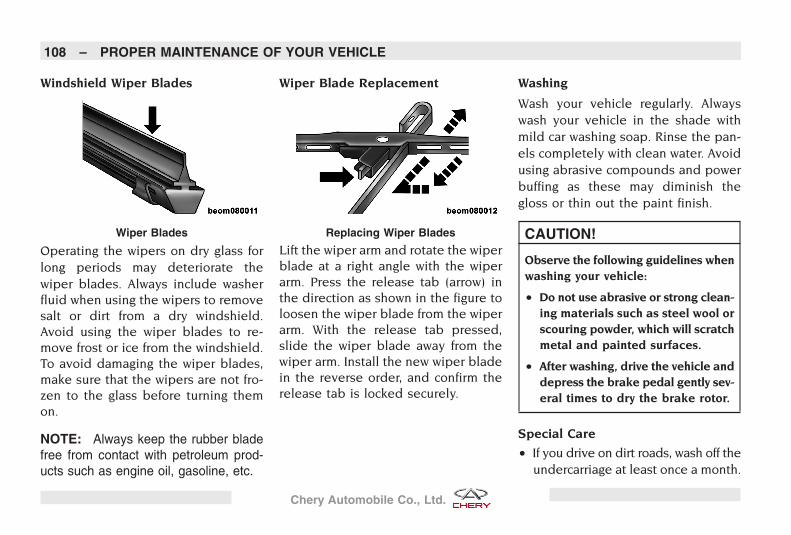
Windshield Wiper Blades
Operating the wipers on dry glass forlong periods may deteriorate thewiper blades. Always include washerfluid when using the wipers to removesalt or dirt from a dry windshield.Avoid using the wiper blades to re-move frost or ice from the windshield.To avoid damaging the wiper blades,make sure that the wipers are not fro-zen to the glass before turning themon.
NOTE: Always keep the rubber bladefree from contact with petroleum prod-ucts such as engine oil, gasoline, etc.
Wiper Blade Replacement
Lift the wiper arm and rotate the wiperblade at a right angle with the wiperarm. Press the release tab (arrow) inthe direction as shown in the figure toloosen the wiper blade from the wiperarm. With the release tab pressed,slide the wiper blade away from thewiper arm. Install the new wiper bladein the reverse order, and confirm therelease tab is locked securely.
Washing
Wash your vehicle regularly. Alwayswash your vehicle in the shade withmild car washing soap. Rinse the pan-els completely with clean water. Avoidusing abrasive compounds and powerbuffing as these may diminish thegloss or thin out the paint finish.
CAUTION!
Observe the following guidelines whenwashing your vehicle:
• Do not use abrasive or strong clean-ing materials such as steel wool orscouring powder, which will scratchmetal and painted surfaces.
• After washing, drive the vehicle anddepress the brake pedal gently sev-eral times to dry the brake rotor.
Special Care
• If you drive on dirt roads, wash off theundercarriage at least once a month.
Wiper Blades Replacing Wiper Blades
108 – PROPER MAINTENANCE OF YOUR VEHICLE
Chery Automobile Co., Ltd.
• If you detect any stone chips orscratches in the paint, touch them upimmediately.
• If your vehicle is damaged due to anaccident or similar cause, which de-stroys the paint and protective coat-ing, have your vehicle repaired assoon as possible.
• If regularly driving on gravel roads,consider installing mud/stone guardson the vehicle.
Wheel and Wheel Trim CareAll wheels and wheel trim, especiallyaluminum and chrome-plated wheels,should be cleaned regularly with amild soap and water to prevent corro-sion. Do not use oven cleaner. Avoidautomatic car washes that use acidicsolutions or harsh brushes that maydamage the wheels’ protective finish.
Cleaning ClothIn order to achieve the best results, al-ways use a soft cleaning cloth forproper vehicle care.
Cleaning Leather Upholstery
Your leather upholstery can be bestpreserved by regular cleaning with adamp soft cloth. Small particles of dirtcan act as an abrasive and damage theleather upholstery and should be re-moved promptly with a damp cloth.Care should be taken to avoid soakingyour leather upholstery with any liq-uid.
WARNING!
Do not use volatile solvents for clean-ing purposes. Many are potentiallyflammable, and if used in closed ar-eas they may cause respiratory harm.
Cleaning Headlights
Your vehicle has plastic headlightsthat are lighter and less susceptible tostone breakage than glass headlights.Do not use abrasive cleaning compo-nents, solvents, steel wool or other ag-gressive material to clean the lenses.
Cleaning Rear Window
The rear window can be cleaned with adamp, soft cloth. Do not use abrasivecleaning components, solvents, steelwool or other such material to cleanthe rear window.
Cleaning Radiator
Over time, the engine radiator and airconditioning condenser can becomeblocked by insects, leaves and otherobjects. This debris can block the flowof air to these components and affectthe performance of the cooling systemand the air conditioner, causing abnor-mal air conditioner operation and en-gine overheating. To provide the mostefficient cooling system and air condi-tioner operation, periodic cleaningshould be performed on the radiatorand condenser. It is recommended toclean the radiator and condenser cool-ing fins once every year. The radiatormay be cleaned with compressed airor water. The condenser may be
PROPER MAINTENANCE OF YOUR VEHICLE – 109
Chery Automobile Co., Ltd.
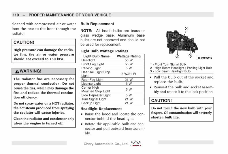
cleaned with compressed air or waterfrom the rear to the front through theradiator.
CAUTION!
High pressure can damage the radia-tor fins, the air or water pressureshould not exceed to 150 kPa.
WARNING!
The radiator fins are necessary forproper thermal conduction. Do notbrush the fins, which may damage thefins and reduce the thermal conduc-tion efficiency.
Do not spray water on a HOT radiator,the hot steam produced from sprayingthe radiator will cause injuries.
Clean the radiator and condenser onlywhen the engine is turned off.
Bulb Replacement
NOTE: All inside bulbs are brass orglass wedge base. Aluminum basebulbs are not approved and should notbe used for replacement.
Light Bulb Wattage RatingsLight Bulb Name Wattage Rating
Headlight 55 WFront Fog Light 55 WParking Light 5 WRear Tail Light/StopLight 5 W/21 W
Rear Fog Light 21 WLicense Light 5 WCenter HighMounted Stop Light 5 W
Side Repeater Light 5 WTurn Signal Light 21 WBackup Light 21 W
Headlight Replacement
• Raise the hood and locate the con-nector behind the headlight.
• Rotate the applicable bulb and con-nector and pull outward from assem-bly.
• Pull the bulb out of the socket andreplace the bulb.
• Reinsert the bulb and socket assem-bly and rotate it to the lock position.
CAUTION!
Do not touch the new bulb with yourfingers. Oil contamination will severelyshorten bulb life.
1 - Front Turn Signal Bulb2 - High Beam Headlight / Parking Light Bulb3 - Low Beam Headlight Bulb
110 – PROPER MAINTENANCE OF YOUR VEHICLE
Chery Automobile Co., Ltd.
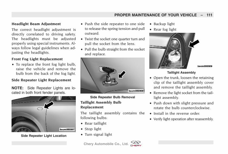
Headlight Beam Adjustment
The correct headlight adjustment isdirectly correlated to driving safety.The headlights must be adjustedproperly using special instruments. Al-ways follow legal guidelines when ad-justing the headlights.
Front Fog Light Replacement
• To replace the front fog light bulb,raise the vehicle and remove thebulb from the back of the fog light.
Side Repeater Light Replacement
NOTE: Side Repeater Lights are lo-cated in both front fender panels.
• Push the side repeater to one sideto release the spring tension and pulloutward.
• Twist the socket one quarter turn andpull the socket from the lens.
• Pull the bulb straight from the socketand replace.
Taillight Assembly BulbReplacement
The taillight assembly contains thefollowing bulbs:
• Rear taillight
• Stop light
• Turn signal light
• Backup light
• Rear fog light
• Open the trunk, loosen the retainingclip of the taillight assembly coverand remove the taillight assembly.
• Remove the light socket from the tail-light assembly.
• Push down with slight pressure androtate the bulb counterclockwise.
• Install in the reverse order.
• Verify light operation after reassembly.
Side Repeater Light Location
Side Repeater Bulb Removal
Taillight Assembly
PROPER MAINTENANCE OF YOUR VEHICLE – 111
Chery Automobile Co., Ltd.
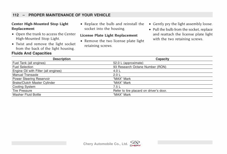
Center High-Mounted Stop LightReplacement
• Open the trunk to access the CenterHigh-Mounted Stop Light.
• Twist and remove the light socketfrom the back of the light housing.
• Replace the bulb and reinstall thesocket into the housing.
License Plate Light Replacement
• Remove the two license plate lightretaining screws.
• Gently pry the light assembly loose.
• Pull the bulb from the socket, replaceand reattach the license plate lightwith the two retaining screws.
Fluids And CapacitiesDescription Capacity
Fuel Tank (all engines) 52.0 L (approximate)Fuel Selection 93 Research Octane Number (RON)Engine Oil with Filter (all engines) 4.0 LManual Transaxle 2.0 LPower Steering Reservoir �MAX� MarkBrake/Clutch Master Cylinder �MAX� MarkCooling System 7.5 LTire Pressure Refer to tire placard on driver’s door.Washer Fluid Bottle �MAX� Mark
112 – PROPER MAINTENANCE OF YOUR VEHICLE
Chery Automobile Co., Ltd.
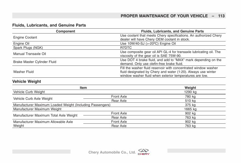
Fluids, Lubricants, and Genuine PartsComponent Fluids, Lubricants, and Genuine Parts
Engine Coolant Use coolant that meets Chery specifications. An authorized Cherydealer will have Chery OEM coolant in stock.
Engine Oil Use 10W/40-SJ (>-20ºC) Engine OilSpark Plugs (NGK) R7DTC
Manual Transaxle Oil Use composite gear oil API GL-4 for transaxle lubricating oil. Theviscosity of the gear oil is SAE 75W-90.
Brake Master Cylinder Fluid Use DOT 4 brake fluid, and add to �MAX� mark depending on thedemand. Only use olefin-free brake fluid.
Washer FluidFill the washer fluid reservoir with concentrated window washerfluid designated by Chery and water (1:20). Always use winterwindow washer fluid when exterior temperatures are low.
Vehicle Weight
Item WeightVehicle Curb Weight 1290 kg
Vehicle Curb Axle WeightFront Axle 780 kgRear Axle 510 kg
Manufacturer Maximum Loaded Weight (Including Passengers) 375 kgManufacturer Maximum Weight 1665 kg
Manufacturer Maximum Total Axle WeightFront Axle 902 kgRear Axle 763 kg
Manufacturer Maximum Allowable AxleWeight
Front Axle 902 kgRear Axle 763 kg
PROPER MAINTENANCE OF YOUR VEHICLE – 113
Chery Automobile Co., Ltd.
Fuel Consumption
Under Half-Load Status:
Item 2.0L Engine 1.6L EngineFuel Consumption at 90 km/h (L/100 km) 6.8 6.6Fuel Consumption at 120 km/h (L/100 km) 8.7 8.5
NOTE: The above fuel consumptionchart is for reference only.
114 – PROPER MAINTENANCE OF YOUR VEHICLE
Chery Automobile Co., Ltd.
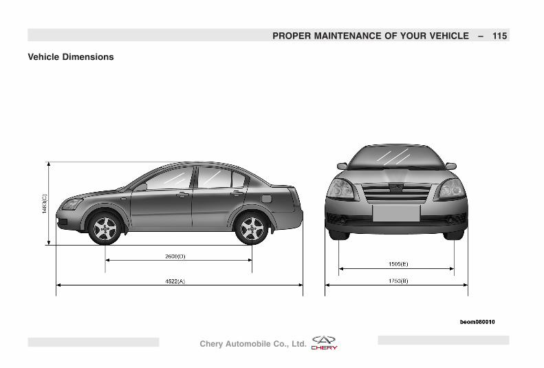
Vehicle Dimensions
PROPER MAINTENANCE OF YOUR VEHICLE – 115
Chery Automobile Co., Ltd.
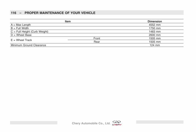
Item DimensionA = Max Length 4552 mmB = Full Width 1750 mmC = Full Height (Curb Weight) 1483 mmD = Wheel Base 2600 mm
E = Wheel TrackFront 1505 mmRear 1505 mm
Minimum Ground Clearance 124 mm
116 – PROPER MAINTENANCE OF YOUR VEHICLE
Chery Automobile Co., Ltd.
MAINTENANCE SCHEDULES
CONTENTS
� Maintenance Schedules 118� Periodic Care and
Maintenance Provision 119
� Care and MaintenanceCertificate 125
� Safety Protection System 131
117
Chery Automobile Co., Ltd.
Maintenance Schedules
There is a maintenance schedule thatshows the required service for yourvehicle.
CAUTION!
Failure to perform the required main-tenance items may result in damageto the vehicle.
Daily Check
• Inspect the working condition of allthe exterior and interior lights. Re-place any bulbs that are inoperableor dim , and verify all lenses areclean.
At Each Stop for Fuel
• Check the engine oil level about 5minutes after a fully warmed engineis shut off. Checking the oil level whilethe vehicle is on level ground will im-prove the accuracy of the oil levelreading. Add oil only when the levelis at or below the �MIN� mark.
• Check the windshield washer solventand add if required.
Once A Month
• Check the tires for proper tire pres-sure and look for unusual wear ordamage.
• Inspect the battery, and clean andtighten the terminals as required.
• Check the fluid levels of the coolantreservoir and brake master cylinder,and add as needed.
• Check all lights and all other electri-cal items for correct operation.
• Check rubber seals on each side ofthe radiator for proper fit.
At Each Oil Change
• Change the engine oil filter.
• Inspect the exhaust system.
• Inspect the brake hoses.
• Inspect the CV joints and front andrear suspension components.
• Check the coolant level, hoses, andclamps.
118 – MAINTENANCE SCHEDULES
Chery Automobile Co., Ltd.
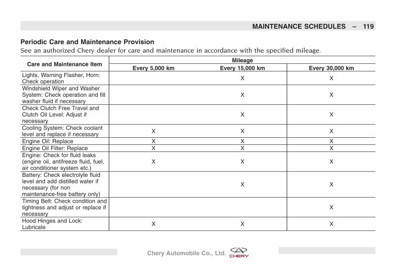
Periodic Care and Maintenance ProvisionSee an authorized Chery dealer for care and maintenance in accordance with the specified mileage.
Care and Maintenance ItemMileage
Every 5,000 km Every 15,000 km Every 30,000 kmLights, Warning Flasher, Horn:Check operation X X
Windshield Wiper and WasherSystem: Check operation and fillwasher fluid if necessary
X X
Check Clutch Free Travel andClutch Oil Level: Adjust ifnecessary
X X
Cooling System: Check coolantlevel and replace if necessary X X X
Engine Oil: Replace X X XEngine Oil Filter: Replace X X XEngine: Check for fluid leaks(engine oil, antifreeze fluid, fuel,air conditioner system etc.)
X X X
Battery: Check electrolyte fluidlevel and add distilled water ifnecessary (for nonmaintenance-free battery only)
X X
Timing Belt: Check condition andtightness and adjust or replace ifnecessary
X
Hood Hinges and Lock:Lubricate X X X
MAINTENANCE SCHEDULES – 119
Chery Automobile Co., Ltd.
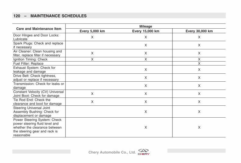
Care and Maintenance ItemMileage
Every 5,000 km Every 15,000 km Every 30,000 kmDoor Hinges and Door Locks:Lubricate X X X
Spark Plugs: Check and replaceif necessary X X
Air Cleaner: Clean housing andfilter, replace filter if necessary X X X
Ignition Timing: Check X X XFuel Filter: Replace XExhaust System: Check forleakage and damage X X
Drive Belt: Check tightness,adjust or replace if necessary X X
Transmission: Check for leaks ordamage X X
Constant Velocity (CV) UniversalJoint Boot: Check for damage X X X
Tie Rod End: Check theclearance and boot for damage X X X
Steering Universal JointAssembly Bushing: Check fordisplacement or damage
X X
Power Steering System: Checkpower steering fluid level andwhether the clearance betweenthe steering gear and rack isreasonable
X X
120 – MAINTENANCE SCHEDULES
Chery Automobile Co., Ltd.
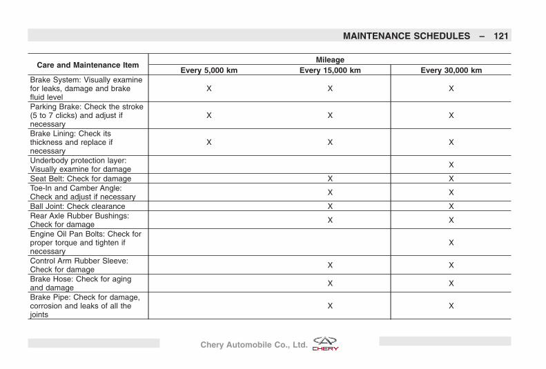
Care and Maintenance ItemMileage
Every 5,000 km Every 15,000 km Every 30,000 kmBrake System: Visually examinefor leaks, damage and brakefluid level
X X X
Parking Brake: Check the stroke(5 to 7 clicks) and adjust ifnecessary
X X X
Brake Lining: Check itsthickness and replace ifnecessary
X X X
Underbody protection layer:Visually examine for damage X
Seat Belt: Check for damage X XToe-In and Camber Angle:Check and adjust if necessary X X
Ball Joint: Check clearance X XRear Axle Rubber Bushings:Check for damage X X
Engine Oil Pan Bolts: Check forproper torque and tighten ifnecessary
X
Control Arm Rubber Sleeve:Check for damage X X
Brake Hose: Check for agingand damage X X
Brake Pipe: Check for damage,corrosion and leaks of all thejoints
X X
MAINTENANCE SCHEDULES – 121
Chery Automobile Co., Ltd.
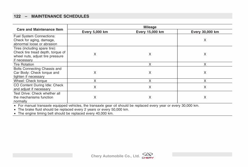
Care and Maintenance ItemMileage
Every 5,000 km Every 15,000 km Every 30,000 kmFuel System Connections:Check for aging, damage,abnormal loose or abrasion
X
Tires (including spare tire):Check tire tread depth, torque ofwheel nuts, adjust tire pressureif necessary
X X X
Tire Rotation X XBolts Connecting Chassis andCar Body: Check torque andtighten if necessary
X X X
Wheel: Check torque X X XCO Content During Idle: Checkand adjust if necessary X X X
Test Drive: Check whether allthe mechanisms functionnormally
X X X
• For manual transaxle equipped vehicles, the transaxle gear oil should be replaced every year or every 30,000 km.• The brake fluid should be replaced every 2 years or every 50,000 km.• The engine timing belt should be replaced every 40,000 km.
122 – MAINTENANCE SCHEDULES
Chery Automobile Co., Ltd.
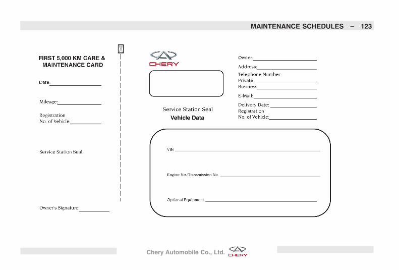
MAINTENANCE SCHEDULES – 123
Chery Automobile Co., Ltd.
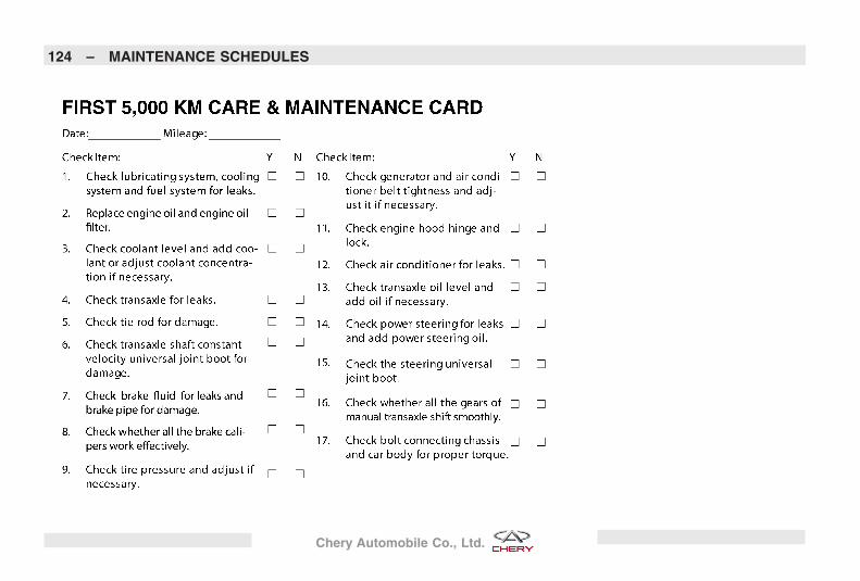
124 – MAINTENANCE SCHEDULES
Chery Automobile Co., Ltd.
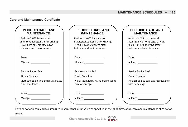
Care and Maintenance Certificate
MAINTENANCE SCHEDULES – 125
Chery Automobile Co., Ltd.

126 – MAINTENANCE SCHEDULES
Chery Automobile Co., Ltd.
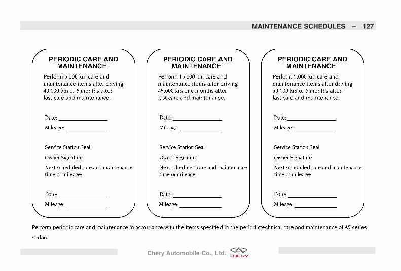
MAINTENANCE SCHEDULES – 127
Chery Automobile Co., Ltd.

128 – MAINTENANCE SCHEDULES
Chery Automobile Co., Ltd.

MAINTENANCE SCHEDULES – 129
Chery Automobile Co., Ltd.
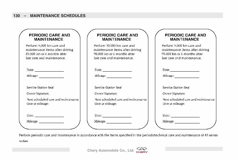
130 – MAINTENANCE SCHEDULES
Chery Automobile Co., Ltd.
Safety Protection SystemThe airbags must be replaced 10 yearsfrom the initial installation date. Thismust be performed by an authorizedChery dealer.
In order to ensure the proper opera-tion of the airbag system, always havethe airbags replaced at the specifieddate by an authorized Chery dealer.
If the airbags have been replaced be-fore the specified date (such as afteran accident), please fill in the replace-ment record for future reference.
MAINTENANCE SCHEDULES – 131
Chery Automobile Co., Ltd.
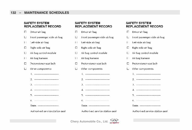
132 – MAINTENANCE SCHEDULES
Chery Automobile Co., Ltd.
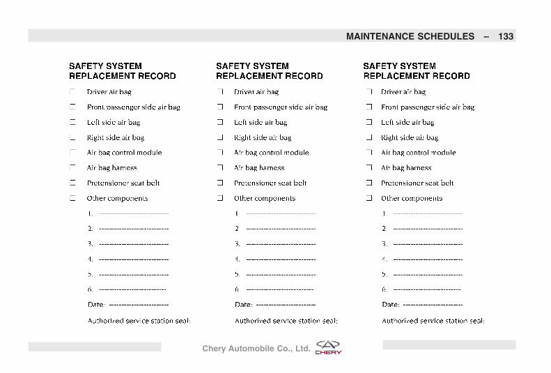
MAINTENANCE SCHEDULES – 133
Chery Automobile Co., Ltd.

134
Chery Automobile Co., Ltd.
INDEX
135
Chery Automobile Co., Ltd.
A
ABS Self-Check . . . . . . . . . . . . . . . .60
Adding Fuel . . . . . . . . . . . . . . . . . .65
Adjustable Upper Shoulder BeltAnchorage . . . . . . . . . . . . . . . . . .24
Adjusting Steering Wheel . . . . . . . . . .19
After Starting . . . . . . . . . . . . . . . . . .53
After-Sales Service Department CheryInternational . . . . . . . . . . . . . . . . .99
Airbag . . . . . . . . . . . . . . . . . . . . . .25
Airbag Warning Light . . . . . . . . . . . . .27
Anti-Pinch Feature . . . . . . . . . . . . . .46
Anti-Pinch Override. . . . . . . . . . . . . .46
Anti-Theft Security Protection . . . . . . .19
Anti-Theft System . . . . . . . . . . . . . . .19
Antilock Brake System (ABS). . . . . . . .59
Audio System . . . . . . . . . . . . . . . . .75
Authorized Chery Dealer Service . . . . .99
Auto - Down Feature . . . . . . . . . . . . .22
Auto Wiper Feature (If Equipped) . . . .37
Automatic Temperature Control(If Equipped) . . . . . . . . . . . . . . . .82
Automatic Transaxle . . . . . . . . . . . . .55
BBrake Booster . . . . . . . . . . . . . . . . .58Brake Lights . . . . . . . . . . . . . . . . . .44Brake System. . . . . . . . . . . . . . . . . .57Braking System Break-In
Recommendations . . . . . . . . . . . . .31Bulb Replacement. . . . . . . . . . . . . .110
CCare and Maintenance Certificate. . . .125Cargo Area . . . . . . . . . . . . . . . . . . .48CD/MP3 Player Operation. . . . . . . . . .79Center Console . . . . . . . . . . . . . . . .48Central Two-Point Seat Belt For Rear
Seat . . . . . . . . . . . . . . . . . . . . . .23Child Restraint . . . . . . . . . . . . . . . . .27Child-Protection Door Lock System
(Rear Doors) . . . . . . . . . . . . . . . . .21Cigarette Lighter and Ashtray . . . . . . .46Clean Air Gasoline . . . . . . . . . . . . . .65Climate Control . . . . . . . . . . . . . . . .80Clock Setting . . . . . . . . . . . . . . . . . .78Closing Sunroof . . . . . . . . . . . . . . . .45Cup and Bottle Holders . . . . . . . . . . .47Cupholders . . . . . . . . . . . . . . . . . . .47
DDimmer Control . . . . . . . . . . . . . . . .43Door Locks . . . . . . . . . . . . . . . . . . .20Downshifting . . . . . . . . . . . . . . . . . .57Driving In Slippery Conditions . . . . . .61Driving Through Water . . . . . . . . . . . .60Dual Circuit Brake System . . . . . . . . .58
EElectrical Power Outlet . . . . . . . . . . .44Electronic Key Identification . . . . . . . .19Engine Break-In Recommendations . . .30Exhaust Gas . . . . . . . . . . . . . . . . . .29Exterior Vehicle Safety Inspection . . . .30
FFailed Starting Procedure. . . . . . . . . .53Flash to Pass . . . . . . . . . . . . . . . . . .42Fluids And Capacities . . . . . . . . . . .112Fluids, Lubricants,
and Genuine Parts . . . . . . . . . . . .113Folding Rear Seat Center Armrest . . . .41Front Ashtray . . . . . . . . . . . . . . . . . .46Front Fog Lights (If Equipped) . . . . . .42Front Interior Lighting . . . . . . . . . . . .43Fuel . . . . . . . . . . . . . . . . . . . . . . . .65
136 – INDEX
Chery Automobile Co., Ltd.
Fuel Consumption. . . . . . . . . . . . . .114
Fuse Replacement . . . . . . . . . . . . . .92
GGear Ranges . . . . . . . . . . . . . . . . . .55
General Information . . . . . . . . . . . . .61
General Information . . . . . . . . . . . . .65
General Information . . . . . . . . . . . . .75
General Information . . . . . . . . . . . . .80
HHazard Warning Flasher . . . . . . . . . . .88
Head Restraints . . . . . . . . . . . . . . . .40
Headlight Leveling System. . . . . . . . .43
Headlights, Parking Lights/FrontPosition Lights, Instrument PanelLights and License Light . . . . . . . . .41
Heated Remote Control Mirrors. . . . . .36
Heated Seats (If Equipped) . . . . . . . .40
High and Low Speed Feature . . . . . . .37
High Beam/Low Beam Select Switch. . .41
Hood Release . . . . . . . . . . . . . . . . .54
Horn . . . . . . . . . . . . . . . . . . . . . . .20
How to Read This Manual . . . . . . . . . .4
IIf You Need Assistance . . . . . . . . . . .98Ignition Key. . . . . . . . . . . . . . . . . . .17Ignition Key Removal . . . . . . . . . . . .17Illuminated Vanity Mirror . . . . . . . . . .36Index . . . . . . . . . . . . . . . . . . . . . . . .4Inside Rearview Mirror. . . . . . . . . . . .35Inspection Certification for Vehicle
Delivery . . . . . . . . . . . . . . . . . . . .7Instrument Cluster . . . . . . . . . . . . . .70Instrument Cluster Functions . . . . . . .71Instrument Panel Features . . . . . . . . .68Interior Vehicle Safety Inspection . . . .29Intermittent Wiper Feature . . . . . . . . .37Introduction . . . . . . . . . . . . . . . . . . .4
JJack Location . . . . . . . . . . . . . . . . . .88Jacking and Tire Changing . . . . . . . . .88Jacking Instructions . . . . . . . . . . . . . .89Jump-Starting Procedures Due toA Low Battery . . . . . . . . . . . . . . . . .94
KKey-In-Ignition Reminder . . . . . . . . . .17Keyhole Light . . . . . . . . . . . . . . . . .44
L
Lap/Shoulder Belt OperatingInstructions . . . . . . . . . . . . . . . . .23
Lap/Shoulder Belt Warning Light . . . . .23
Lap/Shoulder Belts . . . . . . . . . . . . . .22
LHD Engine Compartment . . . . . . . .102
LHD Instrument Panel Features. . . . . .68
Lights. . . . . . . . . . . . . . . . . . . . . . .41
Locking Doors With The Key. . . . . . . .17
Locking Your Vehicle . . . . . . . . . . . . .29
Lumbar Support . . . . . . . . . . . . . . . .39
M
Maintenance For Seat Belt . . . . . . . . .24
Maintenance Procedures . . . . . . . . .104
Maintenance Schedules . . . . . . . . . .118
Manual Air Conditioning and HeatingSystem . . . . . . . . . . . . . . . . . . . .81
Manual Door Locks . . . . . . . . . . . . . .20
Manual Front Seat Adjustments. . . . . .38
Manual Transaxle . . . . . . . . . . . . . . .56
Mirrors . . . . . . . . . . . . . . . . . . . . . .35
Mist Feature . . . . . . . . . . . . . . . . . .37
INDEX – 137
Chery Automobile Co., Ltd.
NNew Vehicle Break-InRecommendations . . . . . . . . . . . . . .30New Vehicle Inspection . . . . . . . . . . . .6Normal Starting Procedure . . . . . . . . .52
OOccupant Restraints . . . . . . . . . . . . .22Opening Sunroof . . . . . . . . . . . . . . .45Operating Cautions . . . . . . . . . . . . . .58Operating Safety Tips . . . . . . . . . . . .28Outside Mirror . . . . . . . . . . . . . . . . .35Outside Mirrors Folding Feature . . . . .35
PParking Brake. . . . . . . . . . . . . . . . . .57Periodic Care and Maintenance
Provision . . . . . . . . . . . . . . . . . .119PERSON-TO-PERSON Service Advisor
Card . . . . . . . . . . . . . . . . . . . . . .11Personal Service. . . . . . . . . . . . . . . .10Power Door Locks. . . . . . . . . . . . . . .21Power Remote Control Mirrors . . . . . .35Power Seats (If Equipped) . . . . . . . . .39Power Steering. . . . . . . . . . . . . . . . .60Power Window Switches. . . . . . . . . . .22
Power Windows . . . . . . . . . . . . . . . .22Preparation Before Starting. . . . . . . . .52Preparations For Jacking. . . . . . . . . . .89Proper Maintenance Of Your Vehicle. .102
RRadio Faceplate . . . . . . . . . . . . . . . .76Radio Faceplate Description. . . . . . . .77Radio Operation. . . . . . . . . . . . . . . .78Rear Ashtray . . . . . . . . . . . . . . . . . .47Rear Fog Lights . . . . . . . . . . . . . . . .42Rear Interior Lighting . . . . . . . . . . . .44Rear Window Defroster . . . . . . . . . . .86Rear Window Defroster (If Equipped) . .86Rear Window Safety Switch. . . . . . . . .22Recliner Adjustment . . . . . . . . . . . . .38Remote Audio System Controls
(If Equipped) . . . . . . . . . . . . . . . .79Remote Keyless Entry . . . . . . . . . . . .18Removing and Installing VehicleBattery . . . . . . . . . . . . . . . . . . . . . .94Replacement Keys . . . . . . . . . . . . . .17Replacement Tires . . . . . . . . . . . . . .64Reverse Lights . . . . . . . . . . . . . . . . .44Reversing Sonar (If Equipped) . . . . . .49Reversing Sonar System. . . . . . . . . . .49RHD Engine Compartment . . . . . . . .103
RHD Instrument Panel Features . . . . .69
SSafety Protection System . . . . . . . . .131Seats . . . . . . . . . . . . . . . . . . . . . . .38Service Appointments . . . . . . . . . . . .98Service for Your Vehicle . . . . . . . . . . .98Service List . . . . . . . . . . . . . . . . . . .98Service Requests . . . . . . . . . . . . . . .98Shifting. . . . . . . . . . . . . . . . . . . . . .56Spare Tire . . . . . . . . . . . . . . . . . . . .64Spare Tire Location. . . . . . . . . . . . . .88Starting and Operating . . . . . . . . . . .52Starting and Operating Cautions . . . . .53Steering Wheel . . . . . . . . . . . . . . . .19Storage Areas . . . . . . . . . . . . . . . . .48Sunroof. . . . . . . . . . . . . . . . . . . . . .45Sunshade Operation . . . . . . . . . . . . .46Supplemental Front Seat-Mounted Side
Airbags . . . . . . . . . . . . . . . . . . . .26
TTable of Contents. . . . . . . . . . . . . . . .4Tilt Down Feature . . . . . . . . . . . . . . .46Tilt UP Feature. . . . . . . . . . . . . . . . .46
138 – INDEX
Chery Automobile Co., Ltd.
Tire and Wheel Break-InRecommendations . . . . . . . . . . . . .31
Tire Pressure . . . . . . . . . . . . . . . . . .62Tire Rotation . . . . . . . . . . . . . . . . . .63Tires . . . . . . . . . . . . . . . . . . . . . . .61Towing A Disabled Vehicle . . . . . . . . .93Transmitter Battery Replacement. . . . .18Transporting Passengers. . . . . . . . . . .28Tread Wear . . . . . . . . . . . . . . . . . . .64Trunk Light . . . . . . . . . . . . . . . . . . .44Trunk Release . . . . . . . . . . . . . . . . .47Trunk Release Switch . . . . . . . . . . . .47
Turn Signals. . . . . . . . . . . . . . . . . . .42
UUtilizing ABS Braking. . . . . . . . . . . . .59
VVanity Mirror Light . . . . . . . . . . . . . .44Vehicle Alarm . . . . . . . . . . . . . . . . .19Vehicle Delivery Card . . . . . . . . . . . . .8Vehicle Dimensions . . . . . . . . . . . . .115Vehicle Features . . . . . . . . . . . . . . . .6Vehicle Identification Number. . . . . . .13
Vehicle Loading . . . . . . . . . . . . . . . .48Vehicle Modifications . . . . . . . . . . . .13Vehicle Overheating . . . . . . . . . . . . .91Vehicle Satisfaction . . . . . . . . . . . . . .98Vehicle Symbols . . . . . . . . . . . . . . . .4Vehicle Weight . . . . . . . . . . . . . . . .113
WWarnings and Cautions . . . . . . . . . . .13Wheel Nut Torque Specification . . . . .91Windshield Washers . . . . . . . . . . . . .37Windshield Wipers and Washers . . . . .36
INDEX – 139
Chery Automobile Co., Ltd.


![Z] yZ§ µzl´ Z·](https://img.dokumen.tips/doc/110x75/63205a9faaa3e1b19f07797b/z-yz-zl-z.jpg)


