Embed Size (px)
Citation preview
WIFO-Anema B.V. Hegebeintumerdyk 37 – 9172 GP Ferwert – Holland Telefoon (0031) 518411318 – Telefax (0031) 518411563 www.wifo.nl – email: [email protected]
Manual and safety instructions
K54A-(Z)/K54C-(Z)/SK54A-(Z)/SK54C-(Z) Box rotator
GB
K54A-O/K54C-O SK54A-O/SK54C-O
K54A-I/K54C-I
K54A-Z-O/K54C-Z-O

1
English
Table of contents
1. TO THE USER ................................................................................................................................................................... 2
1.1 INTRODUCTION ...................................................................................................................................................................... 2 1.2 SAFETY PRECAUTIONS AND WARNINGS ........................................................................................................................................ 3
1.2.1 Safety precautions .................................................................................................................................................... 3 1.2.2 Safety stickers and warning signs ............................................................................................................................. 5 1.2.3 Placement of the safety stickers on the machine ..................................................................................................... 6
1.3 PURPOSE OF USE .................................................................................................................................................................... 7 1.4 LIABILITY ............................................................................................................................................................................... 8 1.5 WARRANTY ........................................................................................................................................................................... 8
2. TECHNICAL DATA ............................................................................................................................................................ 9
2.1 GENERAL TECHNICAL DATA ...................................................................................................................................................... 9 2.2 K54A-I AND K54C-I ............................................................................................................................................................ 10
2.2.1 Parts list ................................................................................................................................................................. 10 2.2.2 Commencement of operation K54A-I and K54C-I ................................................................................................... 12
2.3 K54A-O AND K54C-O......................................................................................................................................................... 13 2.3.1 Parts list ................................................................................................................................................................. 13 2.3.2 Commencement of operation K54A-O and K54C-O ................................................................................................ 15
2.4 K54A-Z-O/K54C-Z-O ......................................................................................................................................................... 16 2.4.1 Parts list .................................................................................................................................................................. 16 2.4.2 Commencement of operation K54A-Z-O and K54C-Z-O .......................................................................................... 18
2.5 SK54A-O/SK54C-O ........................................................................................................................................................... 19 2.5.1 Parts list .................................................................................................................................................................. 19 2.5.2 Provisions for connecting SK54A-O and SK54C-O ................................................................................................... 21 2.5.3 Commencement of operation SK54A-O and SK54C-O ............................................................................................ 22
3. FAULTS AND MAINTENANCE ....................................................................................................................................................... 23 3.1 PREVENTIVE MAINTENANCE AND LUBRICATION .......................................................................................................................... 23 3.2 TROUBLESHOOTING .............................................................................................................................................................. 24 3.3 WORK TO BE CARRIED OUT BY A COMPETENT MECHANIC .............................................................................................................. 25
3.3.1 Instructions for replacing the sleeve bearing of K54A/K54C/SK54A/SK54C ........................................................... 25 3.3.2 Instructions for replacing the tapered roller bearings of K54A-Z/K54C-Z/SK5A-Z/SK54C-Z .................................... 26
2
1. To the user
1.1 Introduction
This manual gives information about the commencement of operation, use and maintenance of your newly purchased WIFO box rotator. Also included in this manual are a number of safety instructions to create a safe working environment.
WIFO-Anema B.V. continuously aims to improve its products. WIFO-Anema B.V. reserves the right to introduce any changes and improvements deemed necessary without prior notice.
Please read the manual thoroughly and observe the safety procedures before putting the unit into operation. Contact your dealer for any further questions or concerns you may have.
We hope you will enjoy working with your WIFO box rotator.
Keep this manual in a safe place for future reference!
WIFO-Anema B.V.
Dealer:
PLEASE NOTE: Carefully read this manual before you put the machine into operation and act upon all directions that are given. This is to guarantee its safe, trouble-free operation.
3
1.2 Safety precautions and warnings
Please read this manual before you put the machine into operation for the first time, and observe the safety instructions at all times. The most important instructions are marked with a symbol.
Any person in charge of the commencement of operation, the operation itself or the maintenance of the machine is urged to carefully read and observe the following instructions.
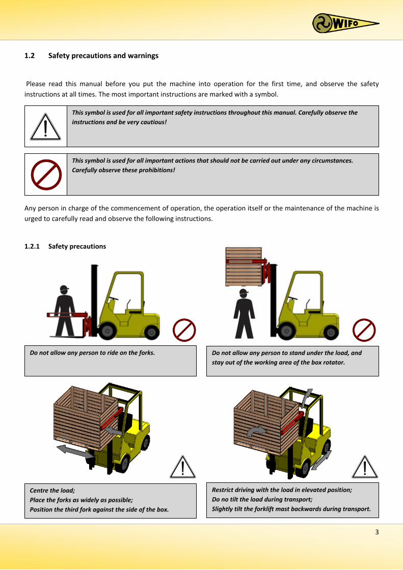
1.2.1 Safety precautions
Centre the load; Place the forks as widely as possible; Position the third fork against the side of the box.
Restrict driving with the load in elevated position; Do no tilt the load during transport; Slightly tilt the forklift mast backwards during transport.
Do not allow any person to ride on the forks.
This symbol is used for all important safety instructions throughout this manual. Carefully observe the instructions and be very cautious!
This symbol is used for all important actions that should not be carried out under any circumstances. Carefully observe these prohibitions!
Do not allow any person to stand under the load, and stay out of the working area of the box rotator.
4
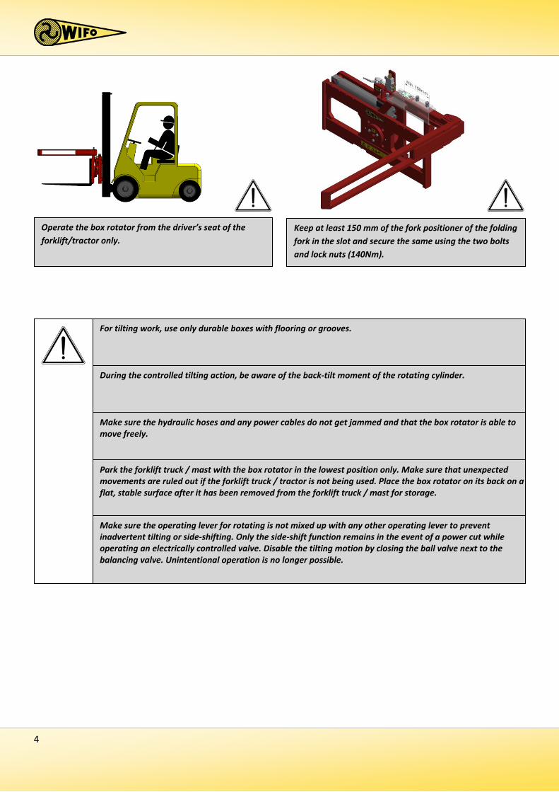
Keep at least 150 mm of the fork positioner of the folding fork in the slot and secure the same using the two bolts and lock nuts (140Nm).
Operate the box rotator from the driver’s seat of the forklift/tractor only.
Park the forklift truck / mast with the box rotator in the lowest position only. Make sure that unexpected movements are ruled out if the forklift truck / tractor is not being used. Place the box rotator on its back on a flat, stable surface after it has been removed from the forklift truck / mast for storage.
For tilting work, use only durable boxes with flooring or grooves.
Make sure the operating lever for rotating is not mixed up with any other operating lever to prevent inadvertent tilting or side-shifting. Only the side-shift function remains in the event of a power cut while operating an electrically controlled valve. Disable the tilting motion by closing the ball valve next to the balancing valve. Unintentional operation is no longer possible.
Make sure the hydraulic hoses and any power cables do not get jammed and that the box rotator is able to move freely.
During the controlled tilting action, be aware of the back-tilt moment of the rotating cylinder.
5
1.2.2 Safety stickers and warning signs
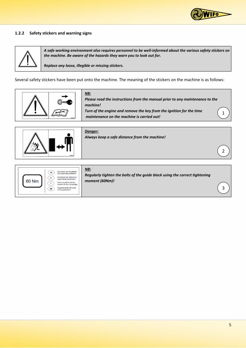
Several safety stickers have been put onto the machine. The meaning of the stickers on the machine is as follows:
NB: Regularly tighten the bolts of the guide block using the correct tightening moment (60Nm)! 3
NB: Please read the instructions from the manual prior to any maintenance to the machine! Turn of the engine and remove the key from the ignition for the time maintenance on the machine is carried out!
1
Danger: Always keep a safe distance from the machine!
2
A safe working environment also requires personnel to be well-informed about the various safety stickers on the machine. Be aware of the hazards they warn you to look out for. Replace any loose, illegible or missing stickers.
6
3
2
1
3
2
1
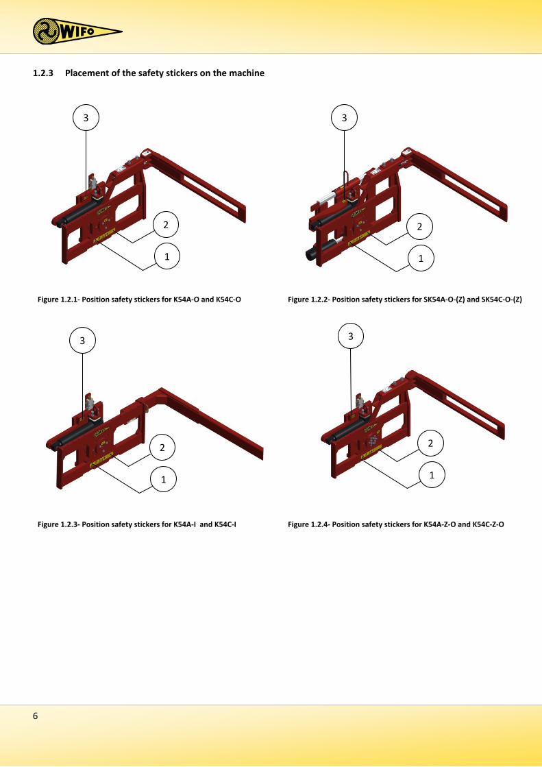
Figure 1.2.1- Position safety stickers for K54A-O and K54C-O Figure 1.2.2- Position safety stickers for SK54A-O-(Z) and SK54C-O-(Z)
3
2
1
3
2
1
Figure 1.2.3- Position safety stickers for K54A-I and K54C-I Figure 1.2.4- Position safety stickers for K54A-Z-O and K54C-Z-O
1.2.3 Placement of the safety stickers on the machine
7
1.3 Purpose of use
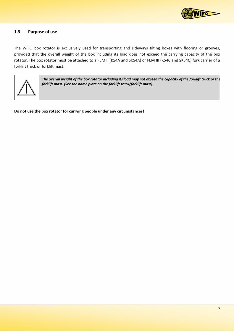
The WIFO box rotator is exclusively used for transporting and sideways tilting boxes with flooring or grooves, provided that the overall weight of the box including its load does not exceed the carrying capacity of the box rotator. The box rotator must be attached to a FEM II (K54A and SK54A) or FEM III (K54C and SK54C) fork carrier of a forklift truck or forklift mast.
Do not use the box rotator for carrying people under any circumstances!
The overall weight of the box rotator including its load may not exceed the capacity of the forklift truck or the forklift mast. (See the name plate on the forklift truck/forklift mast)
8
1.4 Liability
Any person working with or on the machine must have read this manual. The machine is to be used for its intended purpose only. Included in the intended purpose are, among other things:
1. Work must be carried out in accordance with the directions and within the functional restrictions (e.g. maximum hydraulic working pressure) as outlined in the regulations. Use only sound and appropriate tools.
2. Electric/electronic equipment and accessories (e.g. cables) must be treated in accordance with the general accepted policy for using non-waterproof portable electric and electronic equipment, such as:
a) Storing and keeping in a clean, dry environment away from rodents and the like; and b) Protecting the equipment against severe, uncushioned shocks and water (precipitation).
3. Use only original or compatible spare parts. Such parts must be assembled as directed (e.g. by observing the
recommended tightening moments). Spare parts (as well as lubricants) are considered compatible only if explicitly approved by WIFO or in the event that the customer is able to prove they possess the required properties for the purpose(s) they are used.
4. Use only lubricants that meet the specifications as described in the directions. 5. Always observe the local regulations in terms of accident prevention, safety, traffic and transport. 6. Only trained personnel with knowledge of the possible hazards have permission to work with/on the
machine. 7. WIFO-Anema B.V. will assume no liability in any shape or form for losses or damage caused following
modifications to the machine, which have not been explicitly approved by WIFO.
1.5 Warranty
WIFO-Anema B.V. guarantees the soundness of its products in terms of materials used and/or structural defects. However, in any event this warranty is limited to the free-of-charge replacement or repairs of the defect product, or part thereof. WIFO-Anema B.V. assumes no liability for any loss or damage arising from faulty deliveries and/or the breakdown of purchased goods before the warranty period has expired. The warranty period for this product is twelve months.
Noncompliance with the rules and directions from this manual will be considered as serious negligence, for the consequences of which WIFO-Anema B.V. accepts no liability whatsoever. In such cases, the user will bear the full risk of his actions.
WIFO-Anema B.V. is continuously working on the improvement of its products. For that reason, WIFO-Anema B.V. reserves the right to introduce any changes and improvements deemed necessary without prior notice. However, it does not imply an obligation to make any such changes or improvements to machines bought by customers in the past.
9
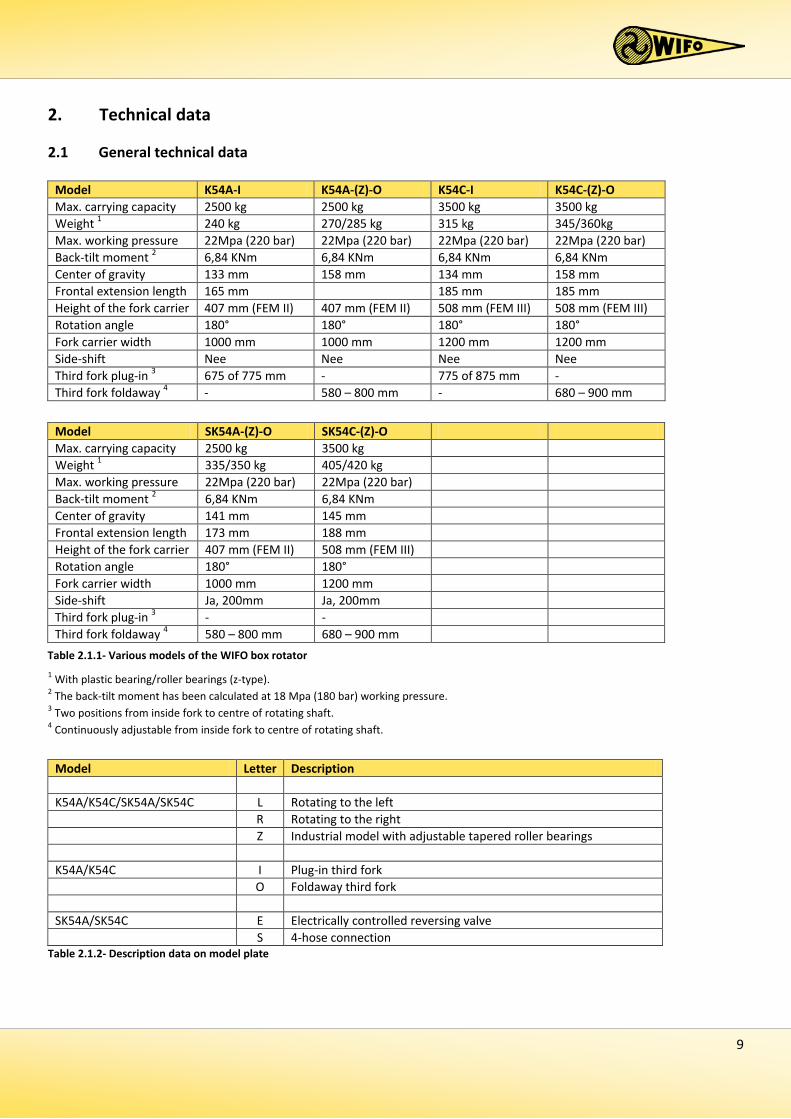
2. Technical data
2.1 General technical data
1 With plastic bearing/roller bearings (z-type). 2 The back-tilt moment has been calculated at 18 Mpa (180 bar) working pressure. 3 Two positions from inside fork to centre of rotating shaft. 4 Continuously adjustable from inside fork to centre of rotating shaft.
Model Letter Description K54A/K54C/SK54A/SK54C L Rotating to the left R Rotating to the right Z Industrial model with adjustable tapered roller bearings K54A/K54C I Plug-in third fork O Foldaway third fork SK54A/SK54C E Electrically controlled reversing valve S 4-hose connection
Table 2.1.2- Description data on model plate
Model K54A-I K54A-(Z)-O K54C-I K54C-(Z)-O Max. carrying capacity 2500 kg 2500 kg 3500 kg 3500 kg Weight 1 240 kg 270/285 kg 315 kg 345/360kg Max. working pressure 22Mpa (220 bar) 22Mpa (220 bar) 22Mpa (220 bar) 22Mpa (220 bar) Back-tilt moment 2 6,84 KNm 6,84 KNm 6,84 KNm 6,84 KNm Center of gravity 133 mm 158 mm 134 mm 158 mm Frontal extension length 165 mm 185 mm 185 mm Height of the fork carrier 407 mm (FEM II) 407 mm (FEM II) 508 mm (FEM III) 508 mm (FEM III) Rotation angle 180° 180° 180° 180° Fork carrier width 1000 mm 1000 mm 1200 mm 1200 mm Side-shift Nee Nee Nee Nee Third fork plug-in 3 675 of 775 mm - 775 of 875 mm - Third fork foldaway 4 - 580 – 800 mm - 680 – 900 mm
Model SK54A-(Z)-O SK54C-(Z)-O Max. carrying capacity 2500 kg 3500 kg Weight 1 335/350 kg 405/420 kg Max. working pressure 22Mpa (220 bar) 22Mpa (220 bar) Back-tilt moment 2 6,84 KNm 6,84 KNm Center of gravity 141 mm 145 mm Frontal extension length 173 mm 188 mm Height of the fork carrier 407 mm (FEM II) 508 mm (FEM III) Rotation angle 180° 180° Fork carrier width 1000 mm 1200 mm Side-shift Ja, 200mm Ja, 200mm Third fork plug-in 3 - - Third fork foldaway 4 580 – 800 mm 680 – 900 mm
Table 2.1.1- Various models of the WIFO box rotator
10
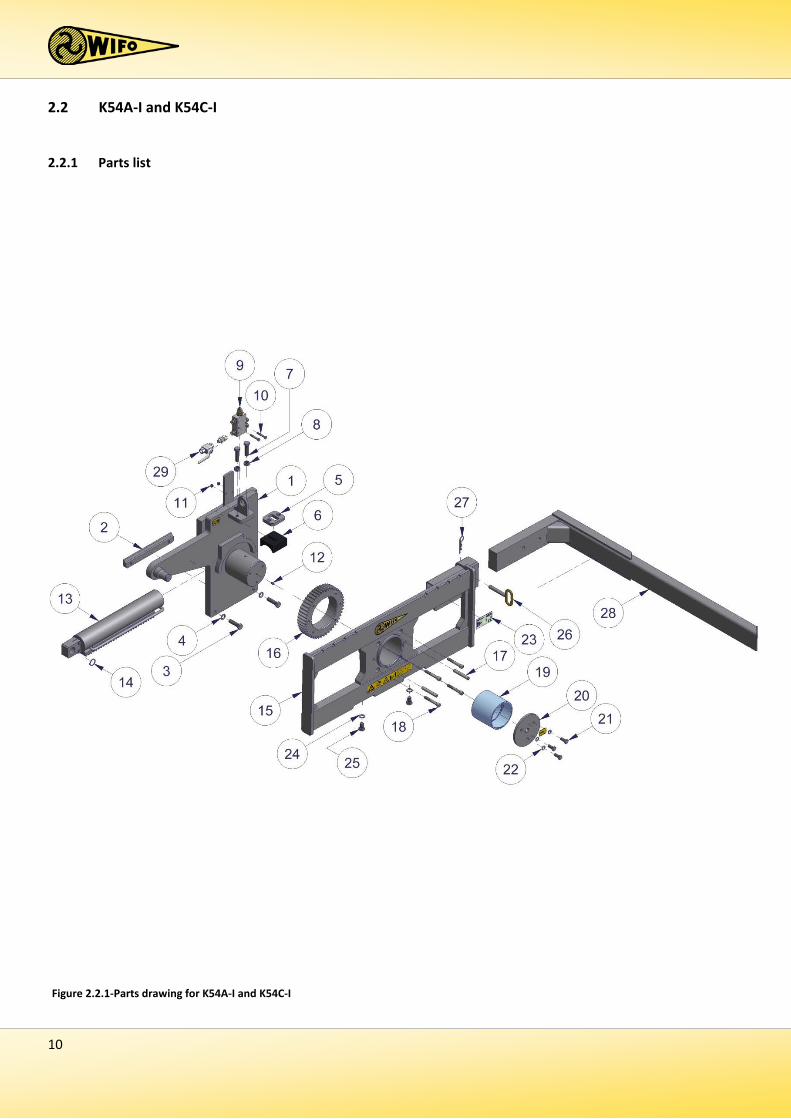
2.2 K54A-I and K54C-I
2.2.1 Parts list
Figure 2.2.1-Parts drawing for K54A-I and K54C-I
11
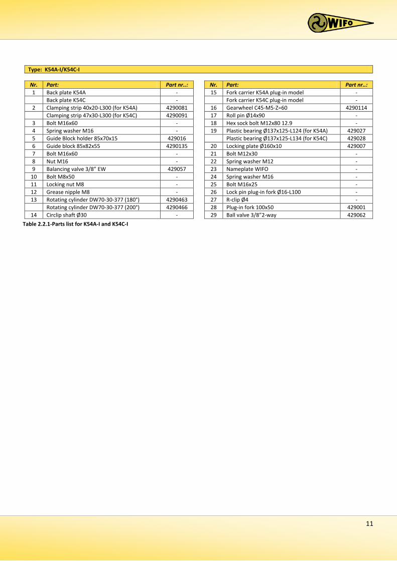
Table 2.2.1-Parts list for K54A-I and K54C-I
Type: K54A-I/K54C-I Nr. Part: Part nr..: Nr. Part: Part nr..: 1 Back plate K54A - 15 Fork carrier K54A plug-in model - Back plate K54C - Fork carrier K54C plug-in model -
2 Clamping strip 40x20-L300 (for K54A) 4290081 16 Gearwheel C45-M5-Z=60 4290114 Clamping strip 47x30-L300 (for K54C) 4290091 17 Roll pin Ø14x90 -
3 Bolt M16x60 - 18 Hex sock bolt M12x80 12.9 - 4 Spring washer M16 - 19 Plastic bearing Ø137x125-L124 (for K54A) 429027 5 Guide Block holder 85x70x15 429016 Plastic bearing Ø137x125-L134 (for K54C) 429028 6 Guide block 85x82x55 4290135 20 Locking plate Ø160x10 429007 7 Bolt M16x60 - 21 Bolt M12x30 - 8 Nut M16 - 22 Spring washer M12 - 9 Balancing valve 3/8” EW 429057 23 Nameplate WIFO -
10 Bolt M8x50 - 24 Spring washer M16 - 11 Locking nut M8 - 25 Bolt M16x25 - 12 Grease nipple M8 - 26 Lock pin plug-in fork Ø16-L100 - 13 Rotating cylinder DW70-30-377 (180°) 4290463 27 R-clip Ø4 -
Rotating cylinder DW70-30-377 (200°) 4290466 28 Plug-in fork 100x50 429001 14 Circlip shaft Ø30 - 29 Ball valve 3/8”2-way 429062
12
2.2.2 Commencement of operation K54A-I and K54C-I 1. Remove the clamping strip (2). 2. Remove the forks from the forklift truck or forklift mast. 3. Make sure the fork carrier is straight and clean. 4. Place the box rotator onto the fork carrier of the forklift truck or forklift mast. 5. Make sure the locking cam slots into the recess in the centre of the fork carrier. If no recess is available:
a) Grind such a recess, or b) Grind the locking cam from the box rotator and attach a sound locking cam on the spot of an existing recess
in the fork carrier. In doing so, make sure the box rotator sits secure in the centre in front of the fork carrier, so it is unable to slide sideways.
6. Attach the clamping strip (8) using two bolts M16x60 (3). Secure these bolts tight! (140 Nm)! 7. Check to make sure the hydraulic hoses are clean before connecting them to the rapid-action couplings, to
prevent any debris from entering the hydraulics of the machine. 8. Connect the hydraulic hoses to the dual-action connection on the fork carrier. 9. Remove the check nuts M16x25 (25) in the lower plate of the fork carrier of the box rotator. Suspend the
forks to the fork carrier and attach the check nuts M16x25 (25). 10. Adjust the plug-in fork (28), depending on the width of the boxes to be rotated. 11. Secure the plug-in fork (28) using the lock pin plug-in fork (26) and secure this with the r-clip Ø4 (27). 12. Turn the lever of the ball valve (29) so it opens, before rotating. It will be open when the lever is parallel to
the hydraulic pipe. 13. Subsequently check that the hydraulic hoses can move freely and check that the system is not leaking oil. 14. Check the correct operation of the box rotator by controlling the hydraulic functions.
The WIFO box rotator is now ready to be used.
13
2.3 K54A-O and K54C-O
2.3.1 Parts list
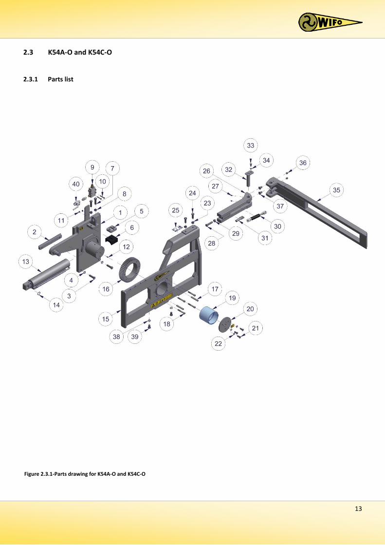
Figure 2.3.1-Parts drawing for K54A-O and K54C-O
14
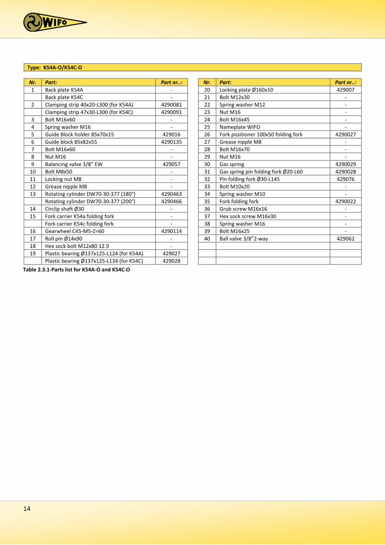
Type: K54A-O/K54C-O Nr. Part: Part nr..: Nr. Part: Part nr..: 1 Back plate K54A - 20 Locking plate Ø160x10 429007 Back plate K54C - 21 Bolt M12x30 -
2 Clamping strip 40x20-L300 (for K54A) 4290081 22 Spring washer M12 - Clamping strip 47x30-L300 (for K54C) 4290091 23 Nut M16 -
3 Bolt M16x60 - 24 Bolt M16x45 - 4 Spring washer M16 - 25 Nameplate WIFO - 5 Guide Block holder 85x70x15 429016 26 Fork positioner 100x50 folding fork 4290027 6 Guide block 85x82x55 4290135 27 Grease nipple M8 - 7 Bolt M16x60 - 28 Bolt M16x70 - 8 Nut M16 - 29 Nut M16 - 9 Balancing valve 3/8” EW 429057 30 Gas spring 4290029
10 Bolt M8x50 - 31 Gas spring pin folding fork Ø20-L60 4290028 11 Locking nut M8 - 32 Pin folding fork Ø30-L145 429076 12 Grease nipple M8 - 33 Bolt M10x20 - 13 Rotating cylinder DW70-30-377 (180°) 4290463 34 Spring washer M10 -
Rotating cylinder DW70-30-377 (200°) 4290466 35 Fork folding fork 4290022 14 Circlip shaft Ø30 - 36 Grub screw M16x16 - 15 Fork carrier K54a folding fork - 37 Hex sock screw M16x30 -
Fork carrier K54c folding fork - 38 Spring washer M16 - 16 Gearwheel C45-M5-Z=60 4290114 39 Bolt M16x25 - 17 Roll pin Ø14x90 - 40 Ball valve 3/8”2-way 429062 18 Hex sock bolt M12x80 12.9 - 19 Plastic bearing Ø137x125-L124 (for K54A) 429027
Plastic bearing Ø137x125-L134 (for K54C) 429028 Table 2.3.1-Parts list for K54A-O and K54C-O
15
2.3.2 Commencement of operation K54A-O and K54C-O 1. Remove the clamping strip (2). 2. Remove the forks from the forklift truck or forklift mast. 3. Make sure the fork carrier is straight and clean. 4. Place the box rotator onto the fork carrier of the forklift truck or forklift mast. 5. Make sure the locking cam slots into the recess in the centre of the fork carrier. If no recess is available:
a) Grind such a recess, or b) Grind the locking cam from the box rotator and attach a sound locking cam on the spot of an existing recess
in the fork carrier. In doing so, make sure the box rotator sits secure in the centre in front of the fork carrier, so it is unable to slide sideways.
6. Attach the clamping strip (2) using two bolts M16x60 (3). Secure these bolts tight! (140 Nm)! 7. Check to make sure the hydraulic hoses are clean before connecting them to the rapid-action couplings, to
prevent any debris from entering the hydraulics of the machine. 8. Connect the hydraulic hoses to the dual-action connection on the fork carrier. 9. Remove the check nuts M16x25 (39) in the lower plate of the fork carrier of the box rotator. Suspend the
forks to the fork carrier and attach the check nuts M16x25 (39). 10. Adjust the third fork, foldaway model (35), depending on the width of the boxes to be rotated. The fork
positioner (26) of the folding fork must reach at least 150mm into the slot. 11. Secure the fork positioner, foldaway model (26) using the pressure bolts M16x45 (24); tightly secure first
the bolts and then the lock nuts M16 (23). 12. Turn the lever of the ball valve (40) so it opens, before rotating. It will be open when the lever is parallel to
the hydraulic pipe. 13. Subsequently check that the hydraulic hoses can move freely and check that the system is not leaking oil. 14. Check the correct operation of the box rotator by controlling the hydraulic functions.
The WIFO box rotator is now ready to be used
16
2.4 K54A-Z-O/K54C-Z-O
2.4.1 Parts list
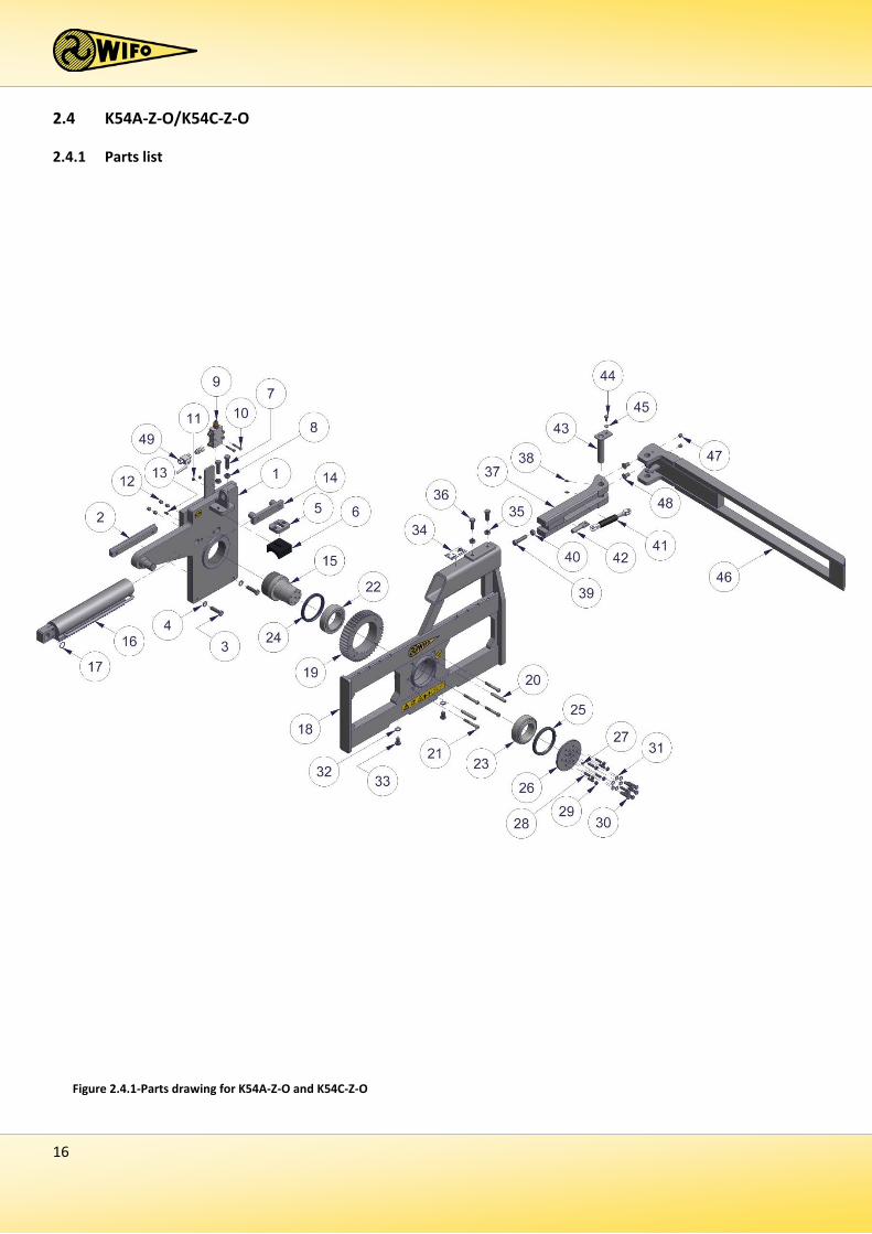
Figure 2.4.1-Parts drawing for K54A-Z-O and K54C-Z-O
17
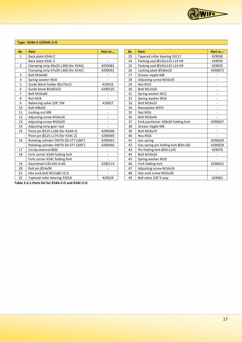
Type: K54A-Z-O/K54C-Z-O Nr. Part: Part nr..: Nr. Part: Part nr..: 1 Back plate K54A-Z - 23 Tapered roller bearing 33117 429030 Back plate K54C-Z - 24 Packing seal Ø145x125-L14 H9 429035
2 Clamping strip 40x20-L300 (for K54A) 4290081 25 Packing seal Ø145x125-L14 H9 429035 Clamping strip 47x30-L300 (for K54C) 4290091 26 Locking plate Ø160x10 4290073
3 Bolt M16x60 - 27 Grease nipple M8 - 4 Spring washer M16 - 28 Adjusting screw M10x35 - 5 Guide Block holder 85x70x15 429016 29 Nut M10 - 6 Guide block 85x82x55 4290135 30 Bolt M12x50 - 7 Bolt M16x60 - 31 Spring washer M12 - 8 Nut M16 - 32 Spring washer M16 - 9 Balancing valve 3/8” EW 429057 33 Bolt M16x25 -
10 Bolt M8x50 - 34 Nameplate WIFO - 11 Locking nut M8 - 35 Nut M16 - 12 Adjusting screw M16x16 - 36 Bolt M16x45 - 13 Adjusting screw M10x20 - 37 Fork positioner 100x50 folding fork 4290027 14 Adjusting strip gear rack - 38 Grease nipple M8 - 15 Pivot pin Ø125-L166 (for K54A-Z) 4290048 39 Bolt M16x70 -
Pivot pin Ø125-L174 (for K54C-Z) 4290049 40 Nus M16 - 16 Rotating cylinder DW70-30-377 (180°) 4290463 41 Gas spring 4290029
Rotating cylinder DW70-30-377 (200°) 4290466 42 Gas spring pin folding fork Ø20-L60 4290028 17 Circlip external Ø30 - 43 Pin folding fork Ø30-L145 429076 18 Fork carrier K54A folding fork - 44 Bolt M10x20 -
Fork carrier K54C folding fork - 45 Spring washer M10 - 19 Gearwheel C45-M5-Z=60 4290114 46 Fork folding fork 4290022 20 Roll pin Ø14x90 - 47 Adjusting screw M16x16 - 21 Hex sock bolt M12x80 12.9 - 48 Hex sock screw M16x30 - 22 Tapered roller bearing 33018 429029 49 Ball valve 3/8”2-way 429062
Table 2.4.1-Parts list for K54A-Z-O and K54C-Z-O
18
2.4.2 Commencement of operation K54A-Z-O and K54C-Z-O 1. Remove the clamping strip (2). 2. Remove the forks from the forklift truck or forklift mast. 3. Make sure the fork carrier is straight and clean. 4. Place the box rotator onto the fork carrier of the forklift truck or forklift mast. 5. Make sure the locking cam slots into the recess in the centre of the fork carrier. If no recess is available:
a) Grind such a recess, or b) Grind the locking cam from the box rotator and attach a sound locking cam on the spot of an existing recess
in the fork carrier. In doing so, make sure the box rotator sits secure in the centre in front of the fork carrier, so it is unable to slide sideways.
6. Attach the clamping strip (2) using two bolts M16x60 (3). Secure these bolts tight! (140 Nm)! 7. Check to make sure the hydraulic hoses are clean before connecting them to the rapid-action couplings, to
prevent any debris from entering the hydraulics of the machine. 8. Connect the hydraulic hoses to the dual-action connection on the fork carrier. 9. Remove the check nuts M16x25 (33) in the lower plate of the fork carrier of the box rotator. Suspend the
forks to the fork carrier and attach the check nuts M16x25 (33). 10. Adjust the third fork, foldaway model (46), depending on the width of the boxes to be rotated. The fork
positioner (37) of the folding fork must reach at least 150mm into the slot. 11. Secure the fork positioner, foldaway model (37) using the pressure bolts M16x45 (36); tightly secure first
the bolts and then the lock nuts M16 (35). 12. Turn the lever of the ball valve (49) so it opens, before rotating. It will be open when the lever is parallel to
the hydraulic pipe. 13. Subsequently check that the hydraulic hoses can move freely and check that the system is not leaking oil. 14. Check the correct operation of the box rotator by controlling the hydraulic functions.
The WIFO box rotator is now ready to be used
19
2.5 SK54A-O/SK54C-O
2.5.1 Parts list
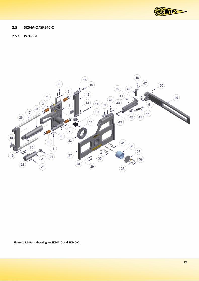
Figure 2.5.1-Parts drawing for SK54A-O and SK54C-O
20
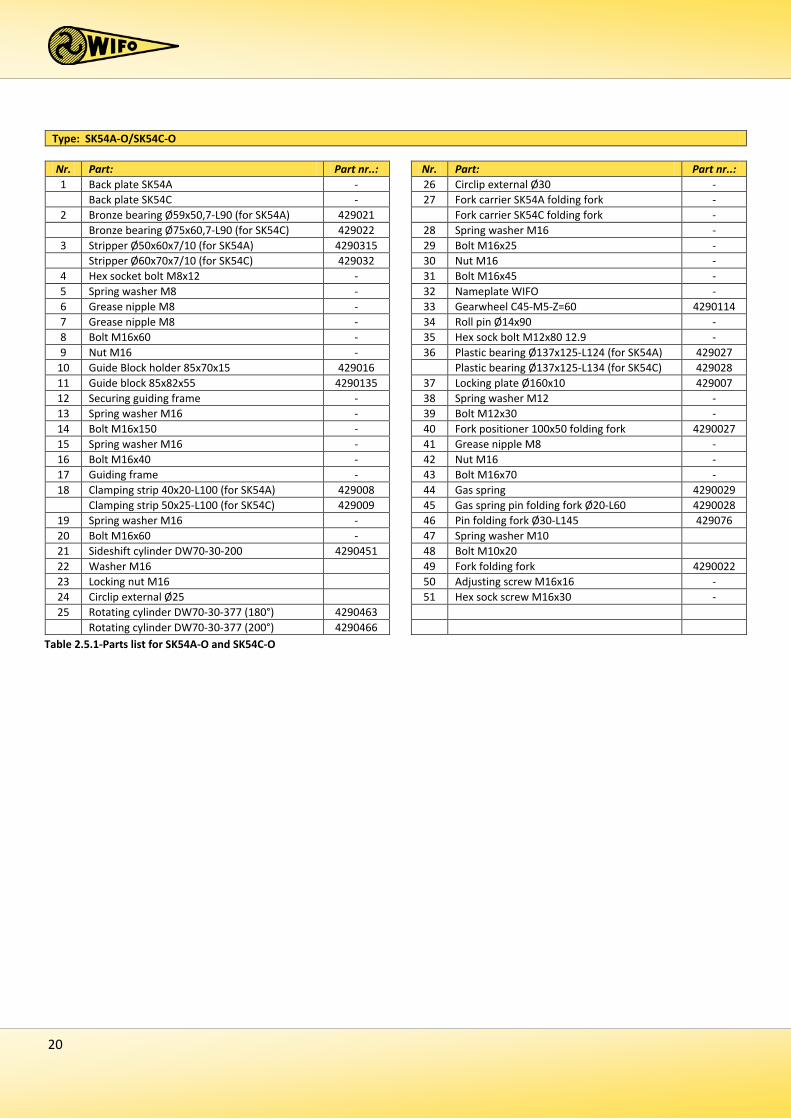
Type: SK54A-O/SK54C-O Nr. Part: Part nr..: Nr. Part: Part nr..: 1 Back plate SK54A - 26 Circlip external Ø30 - Back plate SK54C - 27 Fork carrier SK54A folding fork -
2 Bronze bearing Ø59x50,7-L90 (for SK54A) 429021 Fork carrier SK54C folding fork - Bronze bearing Ø75x60,7-L90 (for SK54C) 429022 28 Spring washer M16 -
3 Stripper Ø50x60x7/10 (for SK54A) 4290315 29 Bolt M16x25 - Stripper Ø60x70x7/10 (for SK54C) 429032 30 Nut M16 -
4 Hex socket bolt M8x12 - 31 Bolt M16x45 - 5 Spring washer M8 - 32 Nameplate WIFO - 6 Grease nipple M8 - 33 Gearwheel C45-M5-Z=60 4290114 7 Grease nipple M8 - 34 Roll pin Ø14x90 - 8 Bolt M16x60 - 35 Hex sock bolt M12x80 12.9 - 9 Nut M16 - 36 Plastic bearing Ø137x125-L124 (for SK54A) 429027
10 Guide Block holder 85x70x15 429016 Plastic bearing Ø137x125-L134 (for SK54C) 429028 11 Guide block 85x82x55 4290135 37 Locking plate Ø160x10 429007 12 Securing guiding frame - 38 Spring washer M12 - 13 Spring washer M16 - 39 Bolt M12x30 - 14 Bolt M16x150 - 40 Fork positioner 100x50 folding fork 4290027 15 Spring washer M16 - 41 Grease nipple M8 - 16 Bolt M16x40 - 42 Nut M16 - 17 Guiding frame - 43 Bolt M16x70 - 18 Clamping strip 40x20-L100 (for SK54A) 429008 44 Gas spring 4290029
Clamping strip 50x25-L100 (for SK54C) 429009 45 Gas spring pin folding fork Ø20-L60 4290028 19 Spring washer M16 - 46 Pin folding fork Ø30-L145 429076 20 Bolt M16x60 - 47 Spring washer M10 21 Sideshift cylinder DW70-30-200 4290451 48 Bolt M10x20 22 Washer M16 49 Fork folding fork 4290022 23 Locking nut M16 50 Adjusting screw M16x16 - 24 Circlip external Ø25 51 Hex sock screw M16x30 - 25 Rotating cylinder DW70-30-377 (180°) 4290463
Rotating cylinder DW70-30-377 (200°) 4290466 Table 2.5.1-Parts list for SK54A-O and SK54C-O
21
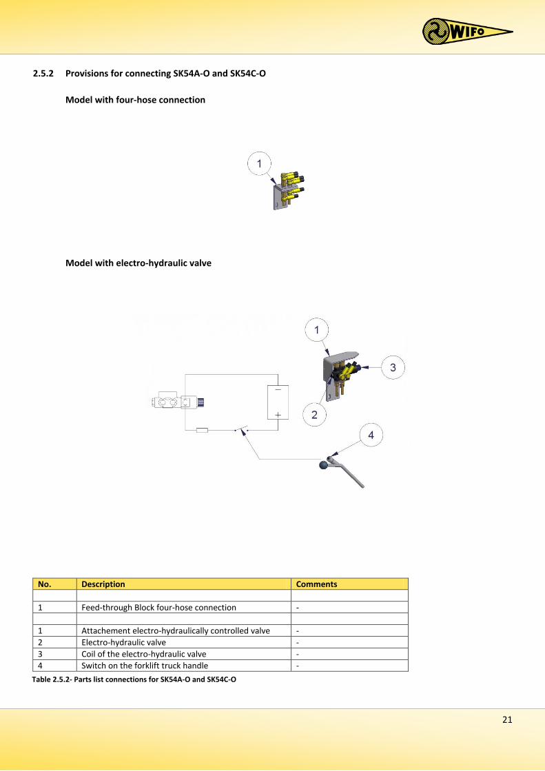
2.5.2 Provisions for connecting SK54A-O and SK54C-O
Model with four-hose connection
Model with electro-hydraulic valve
No. Description Comments 1 Feed-through Block four-hose connection - 1 Attachement electro-hydraulically controlled valve - 2 Electro-hydraulic valve - 3 Coil of the electro-hydraulic valve - 4 Switch on the forklift truck handle -
Table 2.5.2- Parts list connections for SK54A-O and SK54C-O
22
2.5.3 Commencement of operation SK54A-O and SK54C-O 1. Remove the clamping strips (18). 2. Remove the forks from the forklift truck or forklift mast. 3. Make sure the fork carrier is straight and clean. 4. Place the box rotator onto the fork carrier of the forklift truck or forklift mast. 5. Make sure the locking cam slots into the recess in the centre of the fork carrier. If no recess is available:
a) Grind such a recess, or b) Grind the locking cam from the box rotator and attach a sound locking cam on the spot of an existing recess
in the fork carrier. In doing so, make sure the box rotator sits secure in the centre in front of the fork carrier, so it is unable to slide sideways.
6. Attach the clamping strips (18) with four bolts M16x60 (20). Secure these bolts tight! (140 Nm) 7. Check to make sure the hydraulic hoses are clean before connecting them to the rapid-action couplings, to
prevent any debris from entering the hydraulics of the machine. 8. Depending on the model, the following hydraulic hoses are connected:
a) Electrically controlled reversing valve: Connect the hydraulic supply/discharge hoses to the dual-action connection on the fork carrier. Mount the switch (4), see chapter 2.5.2, supplied in such a location that the lifting equipment operator will be able to turn it on and off from his control post, without the risk of mixing it up with any other controls. For a safe working environment, avoid situations such as inadvertently starting the machine or not being able to control it. Keep an eye on the correct voltage of the lifting device and the valve. The voltage is shown on the coil. Connect a 2-core cable as per the electric diagram. Include a warning light, fuse and/or plug socket in the circuit, if so required.
b) Four-hose connection: Connect the two pairs of hydraulic supply/discharge hoses to the dual-action connection on the fork carrier.
9. Remove the two bolts M16x25 (29) in the lower plate of the fork carrier of the box rotator. Suspend the
forks to the fork carrier and attach the two bolts M16x25 (29). 10. Adjust the folding fork (49) depending on the width of the boxes to be rotated. The fork positioner (40)
must reach at least 150 mm into the slot. 11. Secure the fork positioner (40) with two bolts M16x45 (31) and secure these with two lock nuts M16 (30). 12. Turn the lever of the ball valve so it opens, before rotating. It will be open when the lever is parallel to the
hydraulic pipe. 13. Subsequently check that the hydraulic hoses can move freely and check that the system is not leaking oil. 14. Check the correct operation of the box rotator by controlling the hydraulic functions.
The WIFO box rotator is now ready to be used.
23
3. Faults and maintenance
Make sure the box rotator is always in the lowest position during maintenance or repairs to the machine. Extra measures can be taken, e.g. putting the locking pin behind the rotating cylinder and/or disconnecting the hydraulic hoses.
3.1 Preventive maintenance and lubrication
After the First 8 working hours:
- Aansluitingen en wartels van de hydraulische slangen natrekken. - Check the bolts of the locking plate (100Nm) and clamping strips (140Nm). - Check the clamping bolts of the piston rod head of the rotating cylinder; these must be firmly secured. - Fasten the tap bolts on the guide block of the rotating cylinder tight (60 Nm), and secure using the lock nuts. After every 40 working hours:
- Check the bolts of the locking plate and tighten if necesarry (100Nm). - Clean and grease the gear Wheel and gear rack of the rotating cylinder (2). Check both for wear and tear.
Replace after excessive wear and tear. - Check if there is any clearance between the cylinderhead and cylindertube. - Grease the rotating cylinder at the sliding strip of the guide block.
Check the tension of the guide block on the cylinder, readjust using the adjusting bolts, if necessary (60Nm), and secure using the lock nuts.
Regularly check the hydraulic section for any leaks. Never try and search for leaks or stop a leak by hand. Liquid under high pressure can easily penetrate skin and clothing, and may cause serious injuries. Replace any damaged hydraulic hoses to prevent them from breaking and any accidents as a result.
Regularly check the oil level of the hydraulic system of your forklift truck / tractor.
NB: Please read the instructions from the manual prior to any maintenance to the machine! Turn off the engine and remove the key from the ignition for the time maintenance on the machine is carried out!
This sticker shows the position of a grease nipple on the machine. Lubricate the machine after every 10 working hours. Recommended lubricants include SAE 30 oil and Grade 2 grease based on lithium.
24
3.2 Troubleshooting
Box rotator model Problem Solution All models. The box rotator is not in a horizontal position if
the piston rod of the cylinder is fully retracted. Loosen the clamping bolts at the ends of the piston rod and screw/unscrew the piston into/from the block. Proceed until the fork carrier is in a horizontal position with the back plate. Tightly secure the clamping bolts.
The cylinder head has clearance in the cylinder tube.
If there is any clearance, please contact WIFO-Anema BV. We strongly recommend not to use the machine till further instructions.
K54A/K54C/SK54A/SK54C There is some play in the bearing (sleeve bearing) on the shaft of the fork positioner.
The bearing is worn-out and must be replaced by a skilled mechanic.
K54A-Z/K54C-Z/SK54A-Z/SK54C-Z
There is some play in the bearing (tapered roller bearing) on the shaft of the fork positioner.
Loosen the lock nuts of the socket set bolts; fasten the socket set bolts by hand in the locking plate and turn one quarter back. Proceed with tightening the lock nuts.
Table 3.2.1-Troubleshooting
Please contact your dealer for any further concerns you may have. He will be pleased to assist.
25
3.3 Work to be carried out by a competent mechanic
3.3.1 Instructions for replacing the sleeve bearing of K54A/K54C/SK54A/SK54C
1. Disconnect the hydraulic hoses. 2. Remove the forks from the forklift truck. 3. Take the box rotator from the forklift truck / tractor and put it on its back on a flat, stable surface. 4. Take the pressure off the guide block by loosening the pressure bolts M16x60. 5. Support the rotating cylinder so it will no longer rest on the gear wheel of the fork carrier foldaway
model/fork carrier plug-in model (use appropriate lifting equipment; the minimum lifting capacity must exceed the weight of the box rotator; see technical data in chapter 2.1)
6. Remove the locking plate after unscrewing the socket bolts M12x30. Prevent the fork carrier of the back plate from unexpected movements.
7. Pull the fork carrier from the shaft of the fork positioner, clean the shaft of the fork positioner of the back plate and check for wear and tear. Contact the dealer after detecting any wear. Also check the lubrication. The lubricant must be applied to the bearing bush via the grease nipple and the opening on the shaft of the fork positioner. Clean the lubrication duct, if necessary.
8. Push the old sleeve bearing out of the bearing housing from the gear wheel side to the front of the fork carrier. Clean the bearing housing and the shaft of the fork positioner.
9. Push the new sleeve bearing into the bearing housing. Make sure the sleeve bearing fits well and avoid any damage. The front of the sleeve bearing must be flush with the front of the bearing housing.
10. Return the fork carrier with the new sleeve bearing onto the back plate. Avoid any damage to the sleeve bearing by means of good support and guidance. Make sure the fork carrier and the rotating cylinder are correctly repositioned.
11. Mount the locking plate with three bolts M12x30 and secure firmly (100Nm). 12. Return the guide block and put it under pressure by using the pressure bolts M16x60 (60Nm). Secure the
bolts using the lock nuts M16. 13. Put the box rotator back onto the forklift truck/tractor and return the forks. 14. Lubricate the bearings, connect the hydraulic hoses, and check that the box rotator is working correctly.
Always use original WIFO parts for replacement in order to comply with the warranty terms and conditions.
26
3.3.2 Instructions for replacing the tapered roller bearings of K54A-Z/K54C-Z/SK5A-Z/SK54C-Z
1. Disconnect the hydraulic hoses. 2. Remove the forks of the forklift truck. 3. Take the box rotator from the forklift truck / tractor and put it on its back on a flat, stable surface. 4. Take the pressure off the guide block by loosening the pressure bolts M16x60. 5. Support the rotating cylinder so it will no longer rest on the gear wheel of the fork carrier foldaway
model/fork carrier plug-in model (use appropriate lifting equipment; the minimum lifting capacity must exceed the weight of the box rotator; see technical data in chapter 2.1)
6. Turn the adjusting bolts M10x35 of the bearings in the locking plate back one full stroke. 7. Remove the locking plate after unscrewing the bolts M12x50. Prevent the fork carrier of the back plate from
unexpected movements. 8. Pull the fork carrier from the shaft of the screwable fork positioner. Remove the tapered roller bearings
from the shaft of the fork positioner and from the bearing housing of the fork carrier. Clean the bearing housing and the shaft of the fork positioner, and check for wear and tear. Contact the dealer after detecting any wear. Also check the lubrication. The lubricant must be applied to the bearing bush via the grease nipple and the opening on the shaft of the fork positioner. Clean the lubrication duct, if necessary.
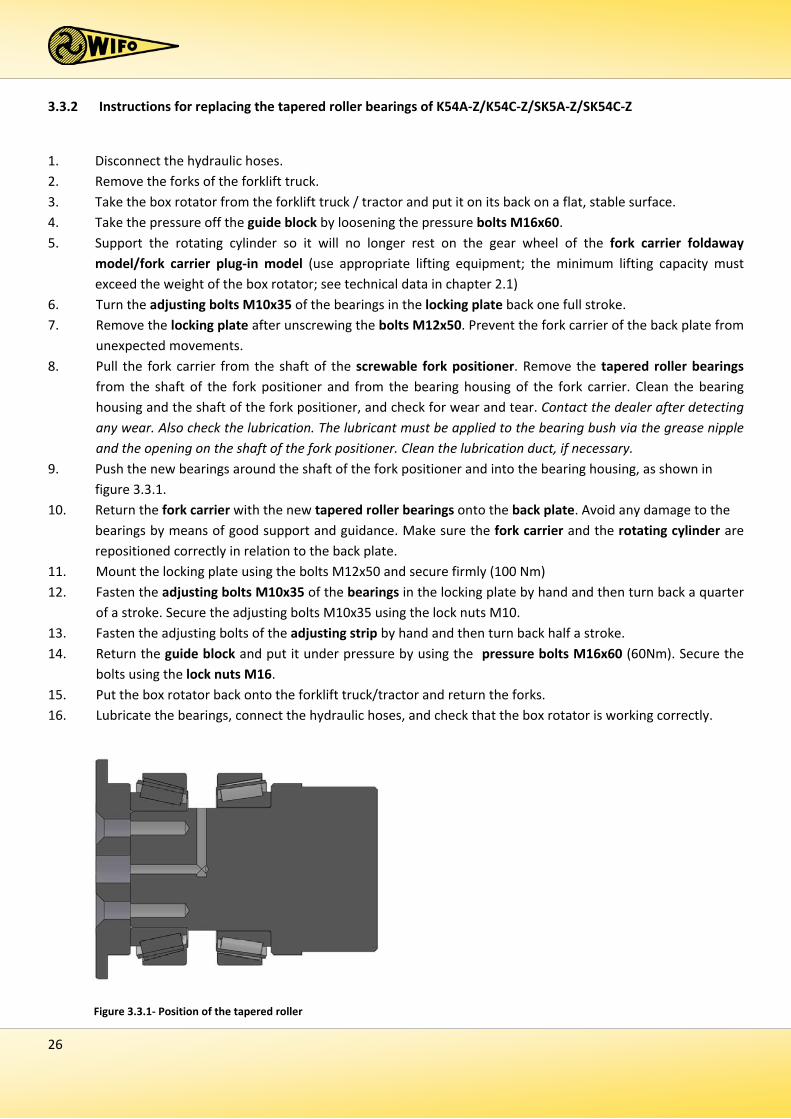
9. Push the new bearings around the shaft of the fork positioner and into the bearing housing, as shown in figure 3.3.1.
10. Return the fork carrier with the new tapered roller bearings onto the back plate. Avoid any damage to the bearings by means of good support and guidance. Make sure the fork carrier and the rotating cylinder are repositioned correctly in relation to the back plate.
11. Mount the locking plate using the bolts M12x50 and secure firmly (100 Nm) 12. Fasten the adjusting bolts M10x35 of the bearings in the locking plate by hand and then turn back a quarter
of a stroke. Secure the adjusting bolts M10x35 using the lock nuts M10. 13. Fasten the adjusting bolts of the adjusting strip by hand and then turn back half a stroke. 14. Return the guide block and put it under pressure by using the pressure bolts M16x60 (60Nm). Secure the
bolts using the lock nuts M16. 15. Put the box rotator back onto the forklift truck/tractor and return the forks. 16. Lubricate the bearings, connect the hydraulic hoses, and check that the box rotator is working correctly.
Figure 3.3.1- Position of the tapered roller


EG-VERKLARING VAN OVEREENSTEMMING VOOR MACHINES EC-DECLARATION OF CONFORMITY FOR MACHINERY EG-MASCHINENÜBEREINSTIMMUNGSERKLÄRUNG DÉCLARATION DE CONFORMITÉ “CE” POUR MACHINES
Fabrikant/Manufacturer/Fabrikant/Fabricant:
WIFO-Anema B.V.
Adres/Address/Adresse/Adresse:
Hegebeintumerdyk 37 9172 GP Ferwert The Netherlands Verklaart hiermede dat /Herwith declares that/Erklärt hiermit, daβ/Déclare ci-après que Serienummer/Serial number/Serienummer/Numéro de série: Uitvoering/Model/Ausführung/Modèle:
- Voldoet aan de bepalingen van de Machinerichtlijn (Richtlijn 2006/42/EG, zoals laatstelijk gewijzigd) en de nationale wetgeving ter uitvoering van deze richtlijn;
- Is in conformity with the provisions of the Machine Directive (Directive 2006/43/EC, as amended) and with national implementing legislation;
- Konform ist min den einschlägigen Bestimmungen der EG-Maschinerichtlinie (EG-Richtlinie 2006/42/EG), inclusive deren Änderunge, sowie mit dem entsprechenden Rechtserlaβ zur Umsetzung der Richtlinie in nationales Recht;
- Est conforme aux dispositions de la Directive “Machines” (Directive 2006/42/EC telle que dernièrement modifiée) et la législation nationale adoptée en application de ladite directive.
Ferwert, January 2015 Wytze Anema (Director)

![Synthesis of (9 Z,12 E)- and (9 E,12 Z)-[1- 14C]linoleic acid and (5 Z,8 Z,11 Z,14 E)-[1- 14C]arachidonic ácid](https://img.dokumen.tips/doc/110x75/63346fbee9e768a27a100b80/synthesis-of-9-z12-e-and-9-e12-z-1-14clinoleic-acid-and-5-z8-z11-z14.jpg)


