Embed Size (px)
Citation preview

z/OS and z/VM
Hardware Configuration Manager User'sGuideVersion 2 Release 2
SC34-2670-04
IBM

NoteBefore using this information and the product it supports, read the information in “Notices” on page 459.
This edition applies to Version 2 Release 2 of IBM z/OS (5650-ZOS), Version 6 Release 2 of z/VM (5741-A05) and toall subsequent releases and modifications until otherwise indicated in new editions.
© Copyright IBM Corporation 1995, 2016.US Government Users Restricted Rights – Use, duplication or disclosure restricted by GSA ADP Schedule Contractwith IBM Corp.

Contents
Figures . . . . . . . . . . . . . . . ix
Tables . . . . . . . . . . . . . . . xi
About this document . . . . . . . . xiiiWho this document is for . . . . . . . . . xiiiHow this document is organized . . . . . . . xiiiRelated information . . . . . . . . . . . xv
How to send your comments to IBM xviiIf you have a technical problem . . . . . . . xviiIf you have a technical problem . . . . . . . xvii
Summary of changes . . . . . . . . xixSummary of changes for z/OS Version 2 Release 2(V2R2) as updated September 2016 . . . . . . xixSummary of changes for z/OS Version 2 Release 2(V2R2) as updated March 2016. . . . . . . . xixSummary of changes for z/OS Version 2 Release 2(V2R2) . . . . . . . . . . . . . . . . xxSummary of changes for Version 2 Release 1 (V2R1)as updated February, 2015 . . . . . . . . . xxChanges made in z/OS Version 2 Release 1 . . . xxChanges made in z/VM Version 6 Release 2. . . xxiiiChanges made in z/VM Version 6 Release 1. . . xxiii
Chapter 1. Overview . . . . . . . . . 1Physical and logical data in one place . . . . . . 1
Easy to use . . . . . . . . . . . . . . 2Accurate system configuration . . . . . . . 2Support for different user groups . . . . . . 2
Chapter 2. Installing HCM . . . . . . . 3Prerequisites . . . . . . . . . . . . . . 3
Workstation hardware requirements . . . . . 3Software requirements . . . . . . . . . . 3
Installing HCM on your workstation . . . . . . 4Purpose and location of the HCM INI file . . . 5
Installation problems . . . . . . . . . . . 6Installing service levels . . . . . . . . . . . 6Installing HCM in a LAN environment . . . . . 6Establishing the host communication . . . . . . 7
Setting up TCP/IP definitions for z/OS . . . . 7Setting up TCP/IP definitions for z/VM. . . . 12Verifying TCP/IP host communication . . . . 22TCP/IP problem determination. . . . . . . 22
Uninstalling HCM . . . . . . . . . . . . 23
Chapter 3. Getting started . . . . . . 25Starting and stopping HCM for z/OS . . . . . 25Starting and stopping HCM for z/VM . . . . . 26Working with the user interface . . . . . . . 27
Keyboard . . . . . . . . . . . . . . 27Mouse . . . . . . . . . . . . . . . 28
Dialogs . . . . . . . . . . . . . . . 29Online help . . . . . . . . . . . . . 29User data fields . . . . . . . . . . . . 30Messages . . . . . . . . . . . . . . 32
Maintaining the configuration diagram . . . . . 34Filtering your view . . . . . . . . . . . 34Connections in the diagram . . . . . . . . 36Saving views . . . . . . . . . . . . . 37Vertical view of XMP processors . . . . . . 38Visualizing ESCON or FICON switch andcrossbar switch configurations . . . . . . . 39Showing page breaks . . . . . . . . . . 42Zooming the view . . . . . . . . . . . 43Scrolling the view . . . . . . . . . . . 43Controlling text detail . . . . . . . . . . 43Setting preferences . . . . . . . . . . . 43Showing screen elements . . . . . . . . . 44Specifying options . . . . . . . . . . . 44Showing system status information . . . . . 45Receiving visual warnings . . . . . . . . 45Printing the configuration diagram . . . . . 45Selecting objects . . . . . . . . . . . . 45Locating objects . . . . . . . . . . . . 46Filtering objects . . . . . . . . . . . . 47
Creating objects . . . . . . . . . . . . . 48Editing objects . . . . . . . . . . . . . 48Deleting objects . . . . . . . . . . . . . 49Reversing an action. . . . . . . . . . . . 49Ordering objects . . . . . . . . . . . . . 50
Chapter 4. Building your configuration 51HCM and HCD . . . . . . . . . . . . . 51
Relation of configuration files and IODFs . . . 52Data integrity between IODF and configurationfile . . . . . . . . . . . . . . . . 55The IODF load / resync process . . . . . . 55
Introduction to the master configuration file concept 57Physical and logical objects in HCM . . . . . . 58
Graphical representation of physical objects . . 59Creating a new configuration from an IODF . . . 60
Preparing the IODF. . . . . . . . . . . 61Loading the IODF . . . . . . . . . . . 63
Creating a new configuration from scratch . . . . 70Opening an existing configuration . . . . . . . 72
Opening an existing configuration file andassociated IODF . . . . . . . . . . . . 72Opening an existing configuration file with anew IODF . . . . . . . . . . . . . . 73Upgrading configuration files . . . . . . . 74
Working with your IODFs and configuration files 76Copying an existing IODF . . . . . . . . 76Making a work or a production IODF . . . . 76Using the CHPID Mapping Tool Support utility 78Creating work and production IODFs withoutthe associated configuration files . . . . . . 80
© Copyright IBM Corp. 1995, 2016 iii

Exporting and importing IODFs . . . . . . 81Deleting an existing IODF . . . . . . . . 81Checking a configuration . . . . . . . . . 81Copying a configuration . . . . . . . . . 82Creating work and production IODFs with theassociated configuration files . . . . . . . 83Compressing configuration files . . . . . . 84Naming convention of your configuration filesand IODFs. . . . . . . . . . . . . . 85Deleting a configuration file . . . . . . . . 85Saving and closing your configuration . . . . 85
Using the master configuration file (MCF) . . . . 86Enabling/disabling a configuration forMCF-sharing . . . . . . . . . . . . . 87Granting access to the MCF on the host . . . . 88How to work with MCF-enabled configurations:Scenarios . . . . . . . . . . . . . . 89How to resolve physical mismatches in a sharedconfiguration . . . . . . . . . . . . . 93
How to work with configuration packages . . . . 96How to create and edit a configuration package 97How to work with configuration package objects 98How to transmit a configuration package . . . 99
Chapter 5. Stand-alone mode . . . . 103Invoking the stand-alone mode . . . . . . . 103Working with the stand-alone mode . . . . . . 103
Creating objects . . . . . . . . . . . 103Viewing objects. . . . . . . . . . . . 104Printing reports, diagrams, cable labels . . . . 104No host connection . . . . . . . . . . 104Work configuration file . . . . . . . . . 104Production configuration file . . . . . . . 104Upgrading . . . . . . . . . . . . . 105Resynchronizing . . . . . . . . . . . 105VOLSER reconciliation . . . . . . . . . 105
Chapter 6. Modifying objects in yourconfiguration . . . . . . . . . . . 107General concepts of the copy wizards . . . . . 107How HCM handles connections when using thecopy wizards . . . . . . . . . . . . . 108
Mapping CHPIDs . . . . . . . . . . . 108Connections in the Upgrade scenario . . . . 109Connections in the Repeat scenario . . . . . 112
Processors . . . . . . . . . . . . . . 115Creating a processor . . . . . . . . . . 118Copying a processor using a wizard . . . . . 119Editing a processor . . . . . . . . . . 120Deleting a processor . . . . . . . . . . 120Managing PCIe functions . . . . . . . . 120
Channel subsystems . . . . . . . . . . . 123Creating or editing a channel subsystem . . . 123Copying a channel subsystem . . . . . . . 123Deleting a channel subsystem . . . . . . . 124
Partitions . . . . . . . . . . . . . . . 125Creating a partition . . . . . . . . . . 125Copying a partition . . . . . . . . . . 126Editing a partition . . . . . . . . . . . 127Deleting a partition . . . . . . . . . . 127
CHPIDs . . . . . . . . . . . . . . . 127CHPID interface type. . . . . . . . . . 129CHPID operation mode . . . . . . . . . 130CHPID operation mode symbols . . . . . . 130Unmanaged/managed CHPIDs . . . . . . 131Selecting a CHPID to view details . . . . . 131Create CHPIDs . . . . . . . . . . . . 132Editing a CHPID . . . . . . . . . . . 136Deleting a CHPID . . . . . . . . . . . 137Assigning CHPIDs to partitions . . . . . . 137Support of spanned CHPIDs . . . . . . . 138Aggregating CHPIDs . . . . . . . . . . 140
Controllers . . . . . . . . . . . . . . 141Creating a controller . . . . . . . . . . 142Editing a controller . . . . . . . . . . 143Editing the fiber links above the controller . . 148Changing the channel interface type. . . . . 148Deleting a controller . . . . . . . . . . 149
Control units . . . . . . . . . . . . . 149Creating a control unit . . . . . . . . . 150Editing a control unit. . . . . . . . . . 150Deleting a control unit . . . . . . . . . 151Moving an existing switch 's control unit into aswitch . . . . . . . . . . . . . . . 151
Strings . . . . . . . . . . . . . . . 152Creating a string . . . . . . . . . . . 152Editing a string. . . . . . . . . . . . 154Deleting a string . . . . . . . . . . . 156
Units . . . . . . . . . . . . . . . . 156Creating a unit . . . . . . . . . . . . 156Editing a unit . . . . . . . . . . . . 156Deleting a unit . . . . . . . . . . . . 157
I/O devices . . . . . . . . . . . . . . 157Creating an I/O device in a string . . . . . 158Editing an I/O device . . . . . . . . . 159Defining devices to OS configurations . . . . 160Deleting an I/O device . . . . . . . . . 160Changing the subchannel set for devices . . . 160
Converters . . . . . . . . . . . . . . 162Creating a converter . . . . . . . . . . 162Deleting a converter . . . . . . . . . . 163Editing a converter . . . . . . . . . . 163
Switches . . . . . . . . . . . . . . . 164Creating a switch . . . . . . . . . . . 165Editing a switch . . . . . . . . . . . 165Deleting a switch . . . . . . . . . . . 168Managing switch configurations . . . . . . 168
Crossbar switches . . . . . . . . . . . . 173Creating a crossbar switch . . . . . . . . 174Editing a crossbar switch . . . . . . . . 174Visualizing a crossbar switch configuration . . 176Deleting a crossbar switch . . . . . . . . 176
Cabinets . . . . . . . . . . . . . . . 176Creating a cabinet . . . . . . . . . . . 177Editing a cabinet . . . . . . . . . . . 178Deleting a cabinet . . . . . . . . . . . 178
Patchports . . . . . . . . . . . . . . 178Cabinet dialog controls . . . . . . . . . 179Syntax of the user-defined patchport/generalbox port naming format . . . . . . . . . 181
General boxes . . . . . . . . . . . . . 183
iv z/OS V2R2 and z/VM V6R2.0 HCM User's Guide

Creating a general box . . . . . . . . . 183Editing a general box. . . . . . . . . . 184Deleting a general box . . . . . . . . . 185
Chapter 7. Connecting objects in yourconfiguration . . . . . . . . . . . 187Connecting objects . . . . . . . . . . . 188
Positioning objects along daisy-chainedconnections . . . . . . . . . . . . . 188
Connecting devices to controllers . . . . . . . 189Creating a string under a controller . . . . . 190Selecting an existing string under a controller 190Connecting the string to a controller deviceinterface . . . . . . . . . . . . . . 191Disconnecting the string interface from a deviceinterface . . . . . . . . . . . . . . 195
Connecting controllers to processors and switches 195Selecting a channel interface for a controller . . 196Connecting the channel interface to a CHPID 196Disconnecting the channel interface from aCHPID . . . . . . . . . . . . . . 204
Connecting controllers to controllers (PPRCconnections) . . . . . . . . . . . . . . 204
Physically connecting a channel interface to achannel interface of another controller . . . . 205Creating a PPRC connection . . . . . . . 205Editing a PPRC connection . . . . . . . . 206Importing and exporting PPRC connections . . 206Deleting a PPRC connection . . . . . . . 206Disconnecting a channel interface from achannel interface . . . . . . . . . . . 206
Connecting switches to processors or otherswitches . . . . . . . . . . . . . . . 206
Disconnecting the switch port from a targetinterface . . . . . . . . . . . . . . 209
Connecting CHPIDs via CTC connections . . . . 209Creating a CTC connection . . . . . . . . 210Editing a CTC connection . . . . . . . . 211Validating CTC connections . . . . . . . 215
Connecting CHPIDs via coupling facilityconnections . . . . . . . . . . . . . . 217
Creating a coupling facility connection . . . . 219Deleting a coupling facility connection . . . . 219
Chapter 8. Physical connections . . . 221Managing physical cables . . . . . . . . . 221
Assigning cables to connections . . . . . . 222Creating and editing cables. . . . . . . . 223Printing cable labels . . . . . . . . . . 225
Editing fiber links . . . . . . . . . . . . 227Infrastructure connections . . . . . . . . 227Disconnecting permanent connections frompatchports . . . . . . . . . . . . . 229Jumper connections . . . . . . . . . . 230Editing fiber links in the dialog . . . . . . 230Adding a patchport to the fiber link . . . . . 231Removing a patchport from the fiber link . . . 231Assigning cables between the objects in a fiberlink. . . . . . . . . . . . . . . . 231
Disconnecting a fiber link . . . . . . . . . 232
Connecting crossbar switches . . . . . . . . 233Connecting a crossbar switch . . . . . . . 234Positioning a crossbar switch on a daisy-chain 234Disconnecting a crossbar channel interface . . 234
Chapter 9. Utilities . . . . . . . . . 235Performing I/O Autoconfiguration . . . . . . 236
How to start I/O Autoconfiguration. . . . . 236How to define the scope and mode of discovery 236How to work with discovered controllers . . . 237How to work with proposed control units . . . 238How to work with proposed devices . . . . 239How to apply your own numbering scheme forPAV devices . . . . . . . . . . . . . 240How to work on the Summary page. . . . . 242How to define autoconfiguration policies . . . 242How changed control units may affect HCM 245
Moving port connections . . . . . . . . . 245Implied ports . . . . . . . . . . . . 247Procedure . . . . . . . . . . . . . 247
Aggregating CHPIDs . . . . . . . . . . . 247Converting CNC channels to FICON channels . . 248Priming the IODF with sensed data . . . . . . 249Changing the CHPID link address format . . . . 249Creating/Copying/Editing an I/O subsystem . . 249
Invocation . . . . . . . . . . . . . 250Using the utility to create an I/O subsystem . . 250Using the utility to copy an I/O subsystem . . 250Using the utility to edit an I/O subsystem . . 251
Exporting IOCP or I/O configuration statements 251Importing I/O configuration statements . . . . 252Browsing performance data . . . . . . . . 253
Objects that provide performance data . . . . 256Using the WWPN Prediction Tool Support . . . 259
Chapter 10. Operating systemconfigurations . . . . . . . . . . . 261Listing the OS configuration-EDT-esoteric hierarchy 261
Creating an OS configuration . . . . . . . 262Editing an OS configuration . . . . . . . 263Copying an OS configuration . . . . . . . 264Deleting an OS configuration . . . . . . . 264Listing devices for an OS configuration. . . . 264Listing consoles for an OS configuration . . . 269
Eligible device tables (EDTs) . . . . . . . . 270Creating an EDT . . . . . . . . . . . 270Editing an EDT. . . . . . . . . . . . 271Copying an EDT . . . . . . . . . . . 271Deleting an EDT . . . . . . . . . . . 271
Esoteric device groups (esoterics) . . . . . . . 271Creating an esoteric . . . . . . . . . . 271Editing an esoteric. . . . . . . . . . . 272Copying an esoteric . . . . . . . . . . 272Deleting an esoteric . . . . . . . . . . 272Listing devices for an esoteric . . . . . . . 272
Generic device groups (generics) . . . . . . . 274Listing system-defined generics . . . . . . 274Listing user-defined generics . . . . . . . 275
Contents v

Chapter 11. User interface to I/OOperations . . . . . . . . . . . . 277Viewing the active sysplex and its status . . . . 277
Operations menu . . . . . . . . . . . 279Color dialog . . . . . . . . . . . . . 280
Manipulating and activating switch matrices . . . 280Issuing I/O Operations commands . . . . . . 281
Chapter 12. Reports and diagrams 283Printing configuration diagrams . . . . . . . 283Generating text reports and diagram reports . . . 284
Sample text reports and diagram reports . . . 287Sample cable labels . . . . . . . . . . 296
Viewing HCD configuration reports . . . . . . 298Viewing HCD compare reports . . . . . . 299
Comparing HCM configurations . . . . . . . 301
Chapter 13. Scenarios. . . . . . . . 305Scenario I – Adding and connecting newequipment . . . . . . . . . . . . . . 305
Add four new channels to an existing processor 305Connect the new CHPIDs to patchports . . . 308Add a new FICON switch . . . . . . . . 310Connect the new switch to one of the newCHPIDs . . . . . . . . . . . . . . 311Connect another switch to the second newCHPID . . . . . . . . . . . . . . 312Add a new controller. . . . . . . . . . 312Connect the controller to CHPIDs . . . . . 313Connect the controller to the FICON switches 316Define the fiber links for the connections . . . 317Add some strings to the new controller . . . 319Define the devices to the operating system . . 321
Scenario II – Defining a CTC connection . . . . 322Connect a switch to the CHPIDs . . . . . . 322Create the first CTC connection . . . . . . 324Create the second CTC connection . . . . . 327Create the third CTC connection . . . . . . 329Create the last CTC connection . . . . . . 329Define the CTC devices to the OS configuration 329
Scenario III – Defining a fiber cabling infrastructure 332Create the cabinets . . . . . . . . . . 332Trunk the two cabinets together . . . . . . 332Trunk the zone cabinet to the processor . . . 333Connect a switch to CHPIDs through thepatchport cabinets . . . . . . . . . . . 336Assign a cable to the new connection . . . . 337Connect a controller to the CHPID via theswitch . . . . . . . . . . . . . . . 338
Scenario IV – Configuration changes for installinga FICON bridge card in a 9032–5 ESCON director . 340Scenario V – Establish a PPRC connectionconsisting of several PPRC links . . . . . . . 345
Chapter 14. HCD-only tasks . . . . . 349Defining and viewing configuration data . . . . 349
Adding similar objects to a configuration . . . 349Copying configurations and merging IODFs . . 349Transferring partition configurations. . . . . 349
Upgrade an IODF from an earlier version ofHCD . . . . . . . . . . . . . . . 349Querying supported hardware and installedUIMs . . . . . . . . . . . . . . . 349Viewing and printing the activity log . . . . 350Support of large IODFs . . . . . . . . . 350
Activating and processing configuration data. . . 350Building IOCDSs . . . . . . . . . . . 350Managing IPL attributes . . . . . . . . . 350Dynamic activate . . . . . . . . . . . 350Build configuration data sets . . . . . . . 351Building and processing CONFIGxx members 351
Chapter 15. Importing and exportingdata . . . . . . . . . . . . . . . 353Data format for importing and exporting . . . . 353
File structure . . . . . . . . . . . . 354Record structure . . . . . . . . . . . 354Column formats . . . . . . . . . . . 356Hierarchical object keys . . . . . . . . . 357Unique key . . . . . . . . . . . . . 358Future compatibility and extensibility . . . . 358
Working with the import and export function . . 358Importing data . . . . . . . . . . . . 358Exporting data . . . . . . . . . . . . 364Importing in stand-alone mode . . . . . . 366Exporting in stand-alone mode . . . . . . 366
Using import as a migration aid . . . . . . . 366Table summary . . . . . . . . . . . . . 368Detailed table formats . . . . . . . . . . 370
PROC table . . . . . . . . . . . . . 371PART table . . . . . . . . . . . . . 372CHPID table. . . . . . . . . . . . . 373DIR table . . . . . . . . . . . . . . 375PORT table . . . . . . . . . . . . . 375CONTRLLR table . . . . . . . . . . . 376Controller channel interface (CCI) table. . . . 378Controller device interface (CDI) table . . . . 380CU table . . . . . . . . . . . . . . 380STRING table . . . . . . . . . . . . 381String interface (SI) table . . . . . . . . 383UNIT table . . . . . . . . . . . . . 384DEVICE table . . . . . . . . . . . . 384XBAR table . . . . . . . . . . . . . 385XBARCFG table . . . . . . . . . . . 386Crossbar channel interface (XCI) table . . . . 386Crossbar control unit interface (XCUI) table . . 387CABINET table . . . . . . . . . . . . 387PANEL table . . . . . . . . . . . . 388PATCHPRT table . . . . . . . . . . . 388CONVERTR table . . . . . . . . . . . 389CABLE table . . . . . . . . . . . . 390LOGLINK table . . . . . . . . . . . 391CONNECT table . . . . . . . . . . . 393PPRCLINK table . . . . . . . . . . . 396DEVCU table (export-only) . . . . . . . . 397CUCHPID table (export-only) . . . . . . . 397DEVIMAGE table (export-only) . . . . . . 398
vi z/OS V2R2 and z/VM V6R2.0 HCM User's Guide

Chapter 16. Physical description files(PDF) . . . . . . . . . . . . . . . 399Loading PDFs . . . . . . . . . . . . . 399Customizing PDFs. . . . . . . . . . . . 399PDF syntax . . . . . . . . . . . . . . 400Controller PDF syntax . . . . . . . . . . 400String PDF syntax . . . . . . . . . . . . 403
Chapter 17. Problem determination 407Identifying and handling problems . . . . . . 407
Product identifiers. . . . . . . . . . . 408Application error . . . . . . . . . . . 408Controlled exit at the workstation . . . . . 408Communication problems using TCP/IP underz/OS . . . . . . . . . . . . . . . 408Communication problems using TCP/IP underz/VM . . . . . . . . . . . . . . . 409Message problems . . . . . . . . . . . 409Incorrect results . . . . . . . . . . . 410Incorrect configuration diagram . . . . . . 410Problems printing reports/configurationdiagrams . . . . . . . . . . . . . . 410Abnormal termination of HCD host . . . . . 411HCD host problems . . . . . . . . . . 411Problems when using I/O Operations . . . . 412Problems when using the RMF DDS. . . . . 412Problems with HCM User's Guide . . . . . 412Exporting an MCF. . . . . . . . . . . 413Incorrect help information . . . . . . . . 413
Using the HCD trace facility . . . . . . . . 413Using the z/VM HCD TCP/IP Dispatcher forHCM trace facility. . . . . . . . . . . . 414z/VM HCD TCP/IP Dispatcher for HCMcommands . . . . . . . . . . . . . . 414The HCMERR.LOG PC file . . . . . . . . . 415Searching problem reporting databases andreporting problems . . . . . . . . . . . 416Reporting problems to IBM. . . . . . . . . 416
Chapter 18. HCM messages . . . . . 417
Appendix A. Alternate processordefinitions. . . . . . . . . . . . . 435Managing shadow processors during an HCMsession . . . . . . . . . . . . . . . 435
Creating a new processor under a machine . . 435Deleting a processor from a machine . . . . 435Changing the processor style . . . . . . . 435Making a processor primary or alternate . . . 435
Assigning processors to machines during IODFload/resync . . . . . . . . . . . . . . 436
Appendix B. One Processor PerPartition (OPPP) machines . . . . . 437IODF load and resync . . . . . . . . . . 437
Creating and deleting OPPP machines . . . . 437Editing OPPP processors . . . . . . . . 438CHPIDs, channels, and CHPID mapping . . . 438Connecting OPPP machines . . . . . . . 439CTC connections to OPPP machines . . . . . 439
Appendix C. Naming conventions indialogs and reports. . . . . . . . . 441Cable descriptions . . . . . . . . . . . . 442
Appendix D. Menu bar choicessummary . . . . . . . . . . . . . 445File menu . . . . . . . . . . . . . . 445Edit menu . . . . . . . . . . . . . . 446View menu . . . . . . . . . . . . . . 447Locate menu . . . . . . . . . . . . . 448Create menu. . . . . . . . . . . . . . 448Operations menu . . . . . . . . . . . . 449Utilities . . . . . . . . . . . . . . . 449Options menu . . . . . . . . . . . . . 450Help menu . . . . . . . . . . . . . . 450
Appendix E. Special setupconsiderations for z/OS . . . . . . . 451HCM client: configurable login parameters . . . 451Host messages . . . . . . . . . . . . . 453HCM Client: TCP/IP related messages . . . . . 454
Appendix F. Accessibility . . . . . . 455Accessibility features . . . . . . . . . . . 455Consult assistive technologies . . . . . . . . 455Keyboard navigation of the user interface . . . . 455Dotted decimal syntax diagrams . . . . . . . 455
Notices . . . . . . . . . . . . . . 459Policy for unsupported hardware. . . . . . . 460Minimum supported hardware . . . . . . . 461
Trademarks . . . . . . . . . . . . 463
Accessing licensed books on the web(z/OS). . . . . . . . . . . . . . . 465
Accessing licensed books on the web(z/VM). . . . . . . . . . . . . . . 467
Glossary . . . . . . . . . . . . . 469
Index . . . . . . . . . . . . . . . 481
Contents vii

viii z/OS V2R2 and z/VM V6R2.0 HCM User's Guide

Figures
1. Relationship between HCM Client, HCMDispatcher, and HCM Agent . . . . . . . 8
2. Sample Job for Trace Data Set Allocation 123. Login dialog . . . . . . . . . . . . 254. Customize Field Names . . . . . . . . 315. Adding User data into customized user fields 326. HCD Error Message. . . . . . . . . . 327. Message Details dialog . . . . . . . . . 338. Message List Dialog. . . . . . . . . . 339. HCM Message . . . . . . . . . . . 34
10. Change View Attributes Dialog . . . . . . 3511. Comparison of horizontal and vertical
processor view . . . . . . . . . . . 3912. Context menu of a spanned CHPID in a
vertical processor view. . . . . . . . . 3913. Highlighting an Object, without Visualized
Configuration . . . . . . . . . . . . 4114. Highlighting an Object, with Visualized
Configuration . . . . . . . . . . . . 4215. Selection List for Locating Objects, in this
Example: Locating Devices . . . . . . . 4616. Filter dialog . . . . . . . . . . . . 4817. Build New Processor Order for the Diagram 5018. Configuration Files and IODFs . . . . . . 5319. Confirm Database Resynchronization dialog 5720. After loading the IODF in which control units
have no or different serial numbers. . . . . 6221. After loading the IODF in which control units
have the same serial numbers. . . . . . . 6222. High-level Qualifier dialog . . . . . . . 6323. IODFs dialog . . . . . . . . . . . . 6424. Choose Local File dialog . . . . . . . . 6525. IODF Details . . . . . . . . . . . . 6626. IODFs dialog for z/VM . . . . . . . . 6827. Machines dialog . . . . . . . . . . . 6928. File Open dialog . . . . . . . . . . . 7229. Confirm Database Upgrade . . . . . . . 7430. CHPID Mapping Tool Support . . . . . . 7931. Export IODF . . . . . . . . . . . . 8132. Import IODF . . . . . . . . . . . . 8133. Check Configuration File . . . . . . . . 8234. Save Production File dialog . . . . . . . 8435. Activity Log dialog . . . . . . . . . . 8636. Set Access Mode . . . . . . . . . . . 8837. Physical Mismatch Resolution . . . . . . 9438. Configuration Packages . . . . . . . . 9739. Create Configuration Package . . . . . . 9840. Configuration Package Objects . . . . . . 9941. Add OS configuration objects . . . . . . 9942. Transmit a configuration package . . . . . 10043. Specify Import JCL. . . . . . . . . . 10144. Message EEQ0212E . . . . . . . . . 10445. VOLSER Reconciliation dialog . . . . . . 10546. Wizard page flow and work flow . . . . . 10847. Processor dialog for SMP processors . . . . 11748. Processor dialog for XMP processors . . . . 117
49. Create Processor . . . . . . . . . . 11850. PCIe Functions dialog. . . . . . . . . 12151. Add PCIe Function dialog . . . . . . . 12252. Create Channel Subsystem . . . . . . . 12353. Partitions . . . . . . . . . . . . . 12554. CHPIDs . . . . . . . . . . . . . 12855. Choose Columns . . . . . . . . . . 12956. CHPID Operation Mode Symbols . . . . . 13157. CHPID. . . . . . . . . . . . . . 13258. Create CHPIDs . . . . . . . . . . . 13359. Edit IQD Channel Parameters . . . . . . 13460. Allow for more than 160 TCP/IP stacks 13561. Specify HCA attributes . . . . . . . . 13562. Assign Partitions . . . . . . . . . . 13863. Spanned CHPIDs in the Configuration
Diagram . . . . . . . . . . . . . 13964. Physical connection information for spanned
CHPIDs . . . . . . . . . . . . . 14065. Controller . . . . . . . . . . . . . 14266. Edit Controller . . . . . . . . . . . 14467. Arrange Controller. . . . . . . . . . 14568. Arrange Control Units and Connections 14769. Group Controllers . . . . . . . . . . 14870. Interface Attribute . . . . . . . . . . 14971. Control Unit List . . . . . . . . . . 15072. Add Existing Control Unit to Internal
Controller . . . . . . . . . . . . . 15173. String . . . . . . . . . . . . . . 15274. Create String. . . . . . . . . . . . 15375. Physical Descriptions dialog . . . . . . 15476. Edit String . . . . . . . . . . . . 15477. Units/Devices . . . . . . . . . . . 15578. Edit Unit . . . . . . . . . . . . . 15679. I/O Device List . . . . . . . . . . . 15880. Create I/O Devices . . . . . . . . . 15981. Selecting processors for changing the
subchannel set placement for devices . . . 16182. Edit Subchannel Set ID . . . . . . . . 16183. Converters . . . . . . . . . . . . 16284. Create Converter . . . . . . . . . . 16385. Edit Converter . . . . . . . . . . . 16386. Replace Converter . . . . . . . . . . 16487. Switch . . . . . . . . . . . . . . 16688. Edit Switch . . . . . . . . . . . . 16789. Port Attributes . . . . . . . . . . . 16890. Configuration for Switch XX . . . . . . 16991. Configuration Port Matrix . . . . . . . 17092. Configuration Port Matrix - Filtered and
CHPIDs on Top . . . . . . . . . . . 17293. Edit Crossbar Switch . . . . . . . . . 17494. Crossbar Configurations . . . . . . . . 17595. Cabinet . . . . . . . . . . . . . 17996. Create General Box . . . . . . . . . 18497. Positioning an Object for Daisy-Chained
Connections . . . . . . . . . . . . 18998. Select Controller Device Interface . . . . . 191
© Copyright IBM Corp. 1995, 2016 ix
||||

99. Reachable Control Units . . . . . . . . 192100. Affected I/O Devices . . . . . . . . . 193101. I/O Device <=> Processor Definitions 193102. Edit I/O Device <=> Processor Definitions 194103. Select Connection Target(s) . . . . . . . 197104. Affected Control Units . . . . . . . . 199105. Processor and CHPID Connections . . . . 199106. Processor and CHPID Connections . . . . 201107. Processor and CHPID Connections . . . . 201108. Choose Channel Subsystems . . . . . . 202109. Edit Control Unit <=> Processor Definitions 203110. Add Control Unit <=> Processor Definitions 204111. Switch . . . . . . . . . . . . . . 207112. Select Multiple Connection Target(s) . . . . 208113. CHPID's Dynamic Switch Modification 209114. CTC connection between two CHPIDs on
different processors through a switch . . . 210115. Create CTC Connection . . . . . . . . 210116. CTC Connections . . . . . . . . . . 211117. Edit CTC Connection . . . . . . . . . 212118. View CTC Connection Details . . . . . . 213119. View Unused CTC Control Units, Devices,
and CHPID Connections . . . . . . . . 215120. Coupling Facility Connection . . . . . . 218121. Coupling Facility Connections . . . . . . 218122. Create Coupling Facility Connection . . . . 219123. Choose CU and Device Numbers . . . . . 219124. Cable Assignments Dialog . . . . . . . 222125. Assign Cable Dialog . . . . . . . . . 224126. Select Cable Labels to Print Dialog . . . . 225127. Choose a Cable Label Format to Print Dialog 226128. Cabinet Dialog . . . . . . . . . . . 228129. Select Connection Target(s) . . . . . . . 229130. Edit Fiber Link . . . . . . . . . . . 231131. Configuration Diagram . . . . . . . . 232132. Disconnect Dialog . . . . . . . . . . 233133. Autoconfiguration - Options . . . . . . 237134. Discovered Controller List . . . . . . . 238135. Proposed Control Unit List . . . . . . . 239136. Edit Proposed Control Unit . . . . . . . 239137. Proposed Device List . . . . . . . . . 240138. Edit Proposed Devices . . . . . . . . 240139. Map Proposed Control Units . . . . . . 241140. Map Proposed Devices . . . . . . . . 241141. Autoconfiguration - Summary (excerpt) 242142. Autoconfiguration Policies . . . . . . . 243143. Autoconfiguration Policies - LP Groups 243144. Add LP Group . . . . . . . . . . . 244145. Autoconfiguration Policies - OS Groups 244146. Edit OS Group . . . . . . . . . . . 245147. Example for Implied Ports . . . . . . . 247148. Export IOCP or I/O Configuration Statements 252149. Import I/O Configuration Statements 253
150. Available performance data for a processor 255151. Total utilization of the processors by
partitions . . . . . . . . . . . . . 256152. Partition performance data . . . . . . . 257153. Partition related performance data . . . . 258154. Specify RMF resource type . . . . . . . 258155. WWPN Prediction Tool Support . . . . . 259156. Operating System Configurations dialog 262157. Create Operating System Configuration 263158. List Devices for OS Configuration dialog 265159. Add I/O Devices to OS Configuration dialog 266160. Define Device <=> OS Configuration
Parameters dialog . . . . . . . . . . 267161. List Device <=> OS Configuration Definitions
dialog . . . . . . . . . . . . . . 268162. Include Devices in Esoterics dialog . . . . 269163. List Consoles dialog . . . . . . . . . 269164. Add Console dialog . . . . . . . . . 270165. Edit Console dialog . . . . . . . . . 270166. Create Eligible Device Table dialog . . . . 271167. Create Esoteric Device Group dialog . . . . 272168. List Devices for Esoteric dialog . . . . . 273169. Add I/O Devices to Esoteric dialog . . . . 274170. List System-Defined Generics dialog . . . . 275171. List User-Defined Generic dialog . . . . . 276172. System Status dialog . . . . . . . . . 278173. I/O Device Status . . . . . . . . . . 278174. I/O Operations Command window . . . . 281175. Printing a configuration diagram . . . . . 284176. Generate Reports . . . . . . . . . . 287177. Printer format sample. . . . . . . . . 288178. XML/HTML format sample. . . . . . . 289179. CSV format sample . . . . . . . . . 289180. IODF Reports . . . . . . . . . . . 299181. IODF Compare Reports . . . . . . . . 300182. IODF Compare CSS/OS Reports . . . . . 301183. HCM Compare Reports . . . . . . . . 302184. HCM Compare Reports - Options. . . . . 302185. Create PPRC Connection (1) . . . . . . 346186. Create PPRC Connection (2) . . . . . . 347187. Create PPRC Connection (3) . . . . . . 347188. Create PPRC Connection (4) . . . . . . 348189. Hardware Configuration Manager
Confirmation Message . . . . . . . . 359190. Choose HCM File for Import Dialog . . . . 359191. File Open Dialog . . . . . . . . . . 360192. Choose IODF Dialog . . . . . . . . . 361193. Choose Import Files Dialog . . . . . . . 361194. Text File Options dialog . . . . . . . . 362195. Proposed Description Updates Dialog 363196. Export Data Dialog . . . . . . . . . 365197. CHPID <> Channel Mapping Dialog 439
x z/OS V2R2 and z/VM V6R2.0 HCM User's Guide

Tables
1. Related z/VM I/O Configuration References xv2. Required Minidisks . . . . . . . . . . 133. Required Minidisks for Installation. . . . . 134. Optional Minidisks . . . . . . . . . . 135. Quick File Reference . . . . . . . . . 156. Configuration diagram connections . . . . 367. IODF Load versus IODF Synchronize . . . . 568. Opening an existing configuration file with a
new IODF . . . . . . . . . . . . . 749. I/O configuration: responsibilities and tasks 89
10. I/O configuration: required access rights andtasks . . . . . . . . . . . . . . . 89
11. Printing of reports . . . . . . . . . . 10412. Symbols in port matrix . . . . . . . . 17013. Table summary . . . . . . . . . . . 36914. PROC Table . . . . . . . . . . . . 37115. PART Table . . . . . . . . . . . . 37216. CHPID Table. . . . . . . . . . . . 37317. DIR Table . . . . . . . . . . . . . 37518. PORT Table . . . . . . . . . . . . 37519. CONTRLLR Table . . . . . . . . . . 37620. CCI Table . . . . . . . . . . . . . 37821. CDI Table . . . . . . . . . . . . . 38022. CU Table . . . . . . . . . . . . . 380
23. STRING Table . . . . . . . . . . . 38124. SI Table . . . . . . . . . . . . . 38325. UNIT Table . . . . . . . . . . . . 38426. DEVICE Table . . . . . . . . . . . 38427. XBAR Table . . . . . . . . . . . . 38528. XBARCFG Table . . . . . . . . . . 38629. XCI Table . . . . . . . . . . . . . 38630. XCUI table . . . . . . . . . . . . 38731. CABINET Table (also containing general
boxes) . . . . . . . . . . . . . . 38732. PANEL Table . . . . . . . . . . . 38833. PATCHPRT Table . . . . . . . . . . 38834. CONVERTR Table . . . . . . . . . . 38935. CABLE Table . . . . . . . . . . . 39036. LOGLINK Table . . . . . . . . . . 39137. CONNECT Table . . . . . . . . . . 39338. PPRCLINK Table . . . . . . . . . . 39639. DEVCU Table (export-only) . . . . . . . 39740. CUCHPID Table (export-only) . . . . . . 39741. DEVIMAGE Table (export-only) . . . . . 39842. Controller PDF attributes . . . . . . . 40243. String PDF Attributes . . . . . . . . . 40444. DDS problem handling (1) . . . . . . . 41245. DDS problem handling (2) . . . . . . . 412
© Copyright IBM Corp. 1995, 2016 xi

xii z/OS V2R2 and z/VM V6R2.0 HCM User's Guide

About this document
This guide explains how to use Hardware Configuration Manager (HCM), acomprehensive, graphical hardware configuration and operations tool. HCM is aPC-based client/server interface to z/OS Hardware Configuration Definition(HCD) that combines the logical and physical aspects of hardware configurationmanagement. HCM allows system administrators to easily and efficiently manageall information about the hardware and connectivity of their systems.
Who this document is forThe HCM User's Guide explains to system administrators, system programmers,system operators, system planners, and your hardware support staff how to installand use HCM to create and maintain hardware configuration information.
It is assumed that the person who is responsible for defining and managinghardware configuration for a z/OS or a z/VM system has basic knowledge ofz/OS and z/VM and hardware configuration.
For information about configuration planning for z/OS refer to z/OS HCDPlanning. For information about configuration planning for z/VM, refer to z/VM:I/O Configuration.
How this document is organizedThis document contains the following chapters:
Chapter 1, “Overview,” on page 1summarizes HCM’s major features and benefits.
Chapter 2, “Installing HCM,” on page 3explains how to install the software to be used for z/OS and z/VM andhow to establish the host communication for both operating systems.
Chapter 3, “Getting started,” on page 25explains how to use the configuration diagram, dialogs, menus andreports, as well as the mouse and keyboard shortcuts in HCM.
Chapter 4, “Building your configuration,” on page 51describes the relationship between HCM and HCD (IODFs, configurationfiles); explains physical and logical objects; provides information abouthow to create a configuration from an IODF or from scratch; providesinformation about how to open an existing configuration and how to save,close or copy the configuration.
Chapter 5, “Stand-alone mode,” on page 103explains how to invoke and work with the stand-alone mode.
Chapter 6, “Modifying objects in your configuration,” on page 107explains how to manipulate all the elements of your hardwareconfiguration with the interactive configuration diagram and dialogs:processors, partitions, CHPIDs, controllers, control units, strings, units,devices, converters, directors, crossbar switches, cabinets, and patchports.
Chapter 7, “Connecting objects in your configuration,” on page 187explains how to connect and define logical objects.
© Copyright IBM Corp. 1995, 2016 xiii

Chapter 8, “Physical connections,” on page 221explains how to add purely physical objects to existing connections: cables,patchports, and crossbar switches.
Chapter 9, “Utilities,” on page 235describes utilities HCM provides to make complex configuration taskseasier.
Chapter 10, “Operating system configurations,” on page 261explains how to specify OS configurations, EDTs, esoteric device groups,and generic device groups, as well as how to define I/O devices to the OSconfiguration.
Chapter 11, “User interface to I/O Operations,” on page 277describes how HCM can function as a graphical user interface to I/OOperations (ESCON Manager) on the host.
Chapter 12, “Reports and diagrams,” on page 283describes how to print various reports, context diagrams and configurationdiagrams from HCM, and gives examples.
Chapter 13, “Scenarios,” on page 305contains a number of configuration scenarios, step-by-step, for you tofollow.
Chapter 14, “HCD-only tasks,” on page 349lists the tasks which cannot be carried out using HCM.
Chapter 15, “Importing and exporting data,” on page 353explains how to exchange data between your processes, application, anddata bases and the configuration data of HCM via ASCII files.
Chapter 16, “Physical description files (PDF),” on page 399describes the different PDFs and their syntax.
Chapter 17, “Problem determination,” on page 407explains how to diagnose problems that may arise using HCM.
Chapter 18, “HCM messages,” on page 417contains all HCM messages.
Appendix A, “Alternate processor definitions,” on page 435explains how HCM handles multiple logical processors in one physicalmachine.
Appendix B, “One Processor Per Partition (OPPP) machines,” on page 437explains how HCM handles machines not represented in IBM's processorpartitioning scheme.
Appendix C, “Naming conventions in dialogs and reports,” on page 441shows how objects in HCM are typically described.
Appendix D, “Menu bar choices summary,” on page 445lists all commands that can be used in the different menus.
Appendix E, “Special setup considerations for z/OS,” on page 451discusses special considerations related to set up the communicationbetween HCM an d z/OS.
Accessibilitydiscusses z/OS product accessibility features that help users who have aphysical disability to use the software.
xiv z/OS V2R2 and z/VM V6R2.0 HCM User's Guide

Related informationFor an overview of the documentation associated with z/OS, see the z/OS V2R2Information Roadmap.
To view, search, and print z/OS publications, go to the z/OS Internet Library athttp://www.ibm.com/systems/z/os/zos/bkserv/.
Softcopy documentation is available as online collection kit that is available incompressed format for download from the IBM publication center.
Also visit our HCM home page
http://www.ibm.com/systems/z/os/zos/features/hcm/
which provides information concerning product updates, newsletters, conferences,and more. For more information about z/OS HCD, see z/OS HCD User's Guide.
If you want to use HCM for defining I/O configurations on z/VM systems, thefollowing documentation associated with z/VM or other products might be useful:
Table 1. Related z/VM I/O Configuration References
Title Order Number
z/VM: I/O Configuration
This book contains detailed information about z/VM HCD.
SC24–6100
z/VM CP Command and Utility Reference SC24–5967
z/VM CP Planning and Administration SC24–6043
z/VM: System Messages and Codes – CP GC24–6030
z/VM Diagnosis Guide GC24–6039
z/OS and z/VM HCD Messages SC33–7986
z/OS MVS Device Validation Support GA22-7525
IOCP User's Guide and ESCON Channel–to–Channel Reference GC38–0401
Input/Output Configuration Program User's Guide for IYP IOCP SB10–7029
Input/Output Configuration Program User's Guide for ICP IOCP SB10–7037
ES/9000 Processor Complex Operator Guide SC38–0085
The latest editions of most z/VM publications are available in Adobe PortableDocument Format (PDF) from the z/VM Internet Library available athttp://www.ibm.com/eserver/zseries/zvm/library.
About this document xv

xvi z/OS V2R2 and z/VM V6R2.0 HCM User's Guide

How to send your comments to IBM
We appreciate your input on this documentation. Please provide us with anyfeedback that you have, including comments on the clarity, accuracy, orcompleteness of the information.
Use one of the following methods to send your comments:
Important: If your comment regards a technical problem, see instead “If you havea technical problem.”v Send an email to [email protected] Send an email from the Contact z/OS.
Include the following information:v Your name and addressv Your email addressv Your phone or fax numberv The publication title and order number:
z/OS V2R2 and z/VM V6R2.0 HCM User's GuideSC34-2670-04
v The topic and page number or URL of the specific information to which yourcomment relates
v The text of your comment.
When you send comments to IBM®, you grant IBM a nonexclusive right to use ordistribute the comments in any way appropriate without incurring any obligationto you.
IBM or any other organizations use the personal information that you supply tocontact you only about the issues that you submit.
If you have a technical problemDo not use the feedback methods that are listed for sending comments. Instead,take one or more of the following actions:v Visit the IBM Support Portal (support.ibm.com).v Contact your IBM service representative.v Call IBM technical support.
If you have a technical problemDo not use the feedback methods listed above. Instead, do one of the following:v Contact your IBM service representativev Call IBM technical supportv Visit the IBM support portal at http://www.ibm.com/systems/z/support/.
© Copyright IBM Corp. 1995, 2016 xvii

xviii z/OS V2R2 and z/VM V6R2.0 HCM User's Guide

Summary of changes
Summary of changes for z/OS Version 2 Release 2 (V2R2) as updatedSeptember 2016
The following changes are made to z/OS Version 2 Release 2 (V2R2).
Hardware Support
PCIe function enhancement:
HCM supports a new attribute for PCIe function called PCIe UID, which iscombination with a new partition attribute called UID uniqueness checking flag.
HCM supports creating multiple-PCIe function in one step.
Partition enhancement:
HCM supports a new attribute for partition on the appropriate processor calledUID uniqueness checking flag.v To partitions with UID=NO, meaning that UID checking for the partition is
disabled. You can assign PCIe functions with any UID value, even duplicatedones. Specifying a UID for these PCIe functions is optional.
v To partitions with UID=YES, meaning that UID checking for the partition isenabled. You can assign only PCIe functions that have a UID defined and allUIDs need to be unique in the scope of that partition.
v For a processor, you can have a mix of partitions with and without UIDchecking.
Summary of changes for z/OS Version 2 Release 2 (V2R2) as updatedMarch 2016
This document contains information that was previously presented in the z/OS®
Hardware Configuration Manager User's Guide, SC34-2670-02, which supportsz/OS Version 2 Release 2.
Hardware support
Processors support:
HCM supports a new support level for the IBM z13 processor family (processortypes 2964-N30, -N63, -N96, -NC9, -NE1) and a new processor family (processortypes 2965-N10, -N20).
PCIe function enhancement:
Two new PCIe function types ISM and RCE are supported on the new supportlevel for the z13 processor family and the new processor family. The PCIefunctions of type ISM require a virtual function number and a virtual channel ID(VCHID) instead of PCHID, and allow only 1 PNET ID for its external physicalnetwork assignments.
© Copyright IBM Corp. 1995, 2016 xix
LinuxONE support:
HCM supports a new support level for the existing processor type 2964 (thesupported models are: L30, L63, L96, LC9, LE1) and a new support level for thenew processor type 2695 (the supported models are L10, L20).
Summary of changes for z/OS Version 2 Release 2 (V2R2)The following changes are made for z/OS Version 2 Release 2 (V2R2).
Newv The Choose Channel Subsystems dialog has been added. See “Making a
standard connection” on page 198.
Summary of changes for Version 2 Release 1 (V2R1) as updatedFebruary, 2015
This document contains information that was previously presented in z/OSHardware Configuration Manager User's Guide, SC34–2670–00, which supports z/OSVersion 2 Release 1.
It contains terminology, maintenance, and editorial changes to improve consistencyand retrievability. Technical changes or additions to the text and illustrations areindicated by a vertical line to the left of the change.
New
HCM provides the following new hardware support:v Support of new processor family (processor type 2964-N30, N63, N96, NC9,
NE1)v Support of a fourth subchannel setv Support of 6 Channel Subsystemsv Support of 85 LPARv Support of IQD VCHIDv New channel path types(CS5)
Changes made in z/OS Version 2 Release 1This document contains information previously presented in z/OS HardwareConfiguration Definition User's Guide, SC33-7989-13, which supports z/OS Version 1Release 13..
Enhancements of the I/O Autoconfiguration function
HCM provides the following enhancements of the I/O Autoconfiguration functionthat has been introduced in z/OS V1R12:v In addition to switched FICON connected controllers, I/O Autoconfiguration can
now discover FICON directly attached controllers and devices and proposespoint-to-point connection paths if available.
v I/O Autoconfiguration supports the inclusion or exclusion of specific switches orCHPIDs into the discovery and proposal process, that users can explicitly specifywith the invocation of an I/O Autoconfiguration request. For this purpose, HCDintroduces four new autoconfiguration policy keywords:
xx z/OS V2R2 and z/VM V6R2.0 HCM User's Guide

– AUTO_CHPID_INCLUDE– AUTO_CHPID_EXCLUDE– AUTO_SWAD_INCLUDE– AUTO_SWAD_EXCLUDE
v The autoconfiguration policy keyword AUTO_SS_DEVNUM_SCHEME accepts a newvalue NONE. This value bypasses control unit and device number proposals byHCM and lets the user manually apply the numbers for detected objects.
v I/O Autoconfiguration allows discovery by controller serial number and filtersthe discovered controllers accordingly.
v HCM can process an I/O Autoconfiguration request that is partially directedagainst unavailable systems of an LPAR group or a sysplex, or against systemsthat are not capable to support I/O Autoconfiguration. Users can specify thatthe request applies to appropriate systems only, and that unavailable/uncapablesystems are tolerated but ignored.
v HCM allows users to change certain I/O Autoconfiguration policies betweentwo subsequent controller discoveries without the need to make a new fabricdiscovery. This enables I/O Autoconfiguration to perform each new controllerdiscovery with changed policies.
HMC-wide activate
You can use a new HMC-wide activate function of HCD to remotely distribute andactivate a new production IODF from a single managing z/OS system on all targetsystems of those CPCs that are configured in the Hardware Management Console(HMC) and that are defined in a specified TCP/IP connection table.
Launch this function from the z Systems Cluster List using action Work with CPCimages introduced in z/OS V1R13. The upcoming CPC Image List now displaysthe activation status of the connected z/OS and z/VM systems and provides newactions to activate the accessed production IODF for hardware and/or softwarechanges at the selected z/OS or z/VM system. The new production IODF is sent tothe target system if necessary. You can remotely issue any operational commandsthat are required for the activation. The messages resulting from the activation orfrom processing system commands are displayed in a message list.
For the HMC-wide activate function on remote z/OS and z/VM systems,HCD toHCD communication needs to be set-up. For this communication, the HCD agentis used. In previous releases, the HCD agent was only required when using HCM.The description of this set-up is now provided as a copy and adaption from thez/OS and z/VM HCM User's Guide in “Establishing the host communication” onpage 7.
Support of PCIe functions
Peripheral Component Interconnect Express (PCIe) adapters offer new functionalityto systems running on IBM zEnterprise EC12 and BC12 (zEC12 and zBC12)processors in order to connect, for example, to an IBM zEnterprise BladeCenterExtension (zBX). Therefore, HCM introduces a new dialog where users can definePCIe functions, assign them to LPARs, and activate them via IOCP or dynamically.
In addition, HCD provides the following new reports:v The PCIe Function Summary Report displays the partitions in the access and
candidate lists which are entitled to access the available PCIe functions.v The PCIe Function Compare Report shows the changes of PCIe functions
between processors of two IODFs.
Summary of changes xxi

Validation enhancements
HCD implements several new validation checks to help users to avoid unintendedresults:v New warning message when a CF CIB connection changes due to connectivity
updates:– HCD issues a new warning message CBDG422I, when users add or delete a
CSS to/from a CIB CHPID that involves a change of the coupling facilityconnection, affecting the definition of the connected processor. This messageinforms the user about the change and a potentially required dynamicactivation of the target processor.
v Warning message CBDA845I now also issued for ACTIVATE SOFT systemcommand:– For users of the HCD Activate ... dialogs, if required, HCD issues warning
message CBDA845I when users specify an ACTIVATE software-only requestwithout hardware validation, because this will not process involved changesto coupling facility control units and devices for the software. This message isnow also issued, if users specify an ACTIVATE SOFT system commandwithout hardware validation.
Enhanced CF Channel Path Connectivity List
A new column in the CF Channel Path Connectivity List shows for both thesource and destination channel path either the physical channel identifier (PCHID)to which the channel path is assigned or its host communication adapter ID andport number.
OS group change action available for device groups
The OS group change action up to now has been available from the I/O Device Listshowing single devices only. Starting with this release, this action is also availablefrom the I/O Device List showing device groups.
HCD batch enhancements
HCD provides the following new batch utility features:v Filter parameters for graphical reports created via batch utility:
– As with the HCD dialog for creating graphical reports, you now can specifyfilter parameters when creating graphical reports with the batch utilityfunction.
v ACTIVATE command now available as an HCD batch command:– Users can now issue the ACTIVATE command as an HCD batch command.
The syntax is the same as described in z/OS MVS System Commands.
New profile options
There are the following new keywords that you can specify in the HCD profile forthe following purposes:v Unconditional generation of D/R site OS configurations: Use profile option
UNCOND_GENERATE_DROS to regenerate D/R site OS configurationswhenever a new production IODF is built, independent from whether theconfigurations have been previously modified or not.
xxii z/OS V2R2 and z/VM V6R2.0 HCM User's Guide
v Specify remote call connection table: Use profile option CONNECTION_TABLEto specify the name of a data set that contains the connection table forestablishing connectivity to the remote systems while working with CPC images.
v Enable remote call logging: Use profile option RCALL_LOG to activate loggingof remote calls into a data set while working with CPC images.
v Set initial remote call timeout value: Use profile option RCALL_TIMEOUT toset the timeout value for the initial connection to a remote system when workingwith CPC images.
CHID Summary Report
The CHID Summary Report as part of the CSS Summary Report lists all definedchannel paths and PCIe functions grouped by their defined CHID values or, asapplicable, by their HCA adapter or port IDs.
Verify a configuration by means of I/O Autoconfiguration (zDAC)
With HCM you can now verify the active or target configuration by means ofz/OS discovery and I/O Autoconfiguration (zDAC), if Tivoli System Automation(TSA) I/O operations is not installed or not working. This is possible for aprocessor supporting I/O Autoconfiguration and for a system in the local sysplex,which is capable for dynamic activates. The verification is limited to FICONattached storage devices.
When generating the I/O path report, HCD includes information about singlepoint of failures (SPOFs) into the sensed data if the report is produced for the localsystem. This is done when getting the report via (TSA) I/O operations as well asvia zDAC.
Hardware support
HCM supports the IBM zEnterprise EC12 and BC12 (zEC12 and zBC12) processorfamily (processor types 2827-H20, -H43, -H66, -H89, -HA1 and 2828-H06, -H13).
Changes made in z/VM Version 6 Release 2Summary of changes for SC33–7989–13 issued December 2011
HCM for z/VM V6R2 includes the new functions available with HCM for z/OS.
The following functions of previous HCM releases are also made available forz/VM V6R2:v HCM for z/VM supports the Internet Protocol, Version 6 (IPv6), which can be
used when establishing a communication session with z/VM.v Users of HCM for z/VM can now use the dialogs for working with
configuration packages as described in “How to work with configurationpackages” on page 96.
Note: I/O Autoconfiguration is not available for z/VM.
Changes made in z/VM Version 6 Release 1HCM for z/VM V6R1 includes all functions available with HCM for z/OS V1R10and also provides support of the WWPN Prediction Tool (see “Using the WWPNPrediction Tool Support” on page 259).
Summary of changes xxiii

z/VM V6R1 supports the zEnterprise 196 (z196) processor family (processor types2817-M15, -M32, -M49, -M66, -M80), and also supports the new OSM and OSXchannel paths and a third subchannel set with ID 2 for these processors.
Note that HCM's handling of MUA enabled IODFs is only available on z/OS.
xxiv z/OS V2R2 and z/VM V6R2.0 HCM User's Guide

Chapter 1. Overview
Traditionally, hardware configuration is carried out on the z/OS or z/VM hostusing Hardware Configuration Definition (HCD). With HCD, you can define thehardware configuration for both the channel subsystem and the operating system.The configuration you define with HCD can consist of multiple processors withmultiple channel subsystems, each containing multiple partitions. HCD stores theentire configuration data in a central repository, the Input/Output definition file(IODF). The IODF as single source for all hardware and software definitions for amulti-processor system is used to build the IOCDS using the IOCP program and toIPL the operating system.
The z/OS and z/VM Hardware Configuration Manager (HCM) is a PC-basedclient/server interface to HCD that combines the logical and physical aspects ofhardware configuration management.
In addition to the logical connections, you can also manage the physical aspects ofa configuration. For example, you can effectively manage the flexibility offered bythe FICON infrastructure (cabinet, cabling). All updates to your configuration aredone via HCM’s intuitive graphical user interface and, most important, due to theclient/server relationship with HCD, all changes of the logical I/O configurationare written into the IODF and fully validated and checked for accuracy andcompleteness by HCD, thus avoiding unplanned system outages due to incorrectdefinitions. For z/OS only, HCM also allows you to display operational data suchas system status information and operate on the switch using an interface to theI/O Operations function of System Automation on the host.
For more information about how HCM and HCD work together, see Chapter 4,“Building your configuration,” on page 51.
Physical and logical data in one placeHCM presents an interactive configuration diagram which allows you to maintainnot only the logical connectivity data in the IODF, but also the physical informationabout a configuration. The logical information in the IODF represents the operatingsystem and the channel subsystem definitions; the physical information - cabinets,patchports, crossbar switches, cables, locations, and so on - adds the infrastructureto the logical data.
Furthermore, the logical and physical information for each object in theconfiguration match because they are created by the same process. When you createan object, you add its logical and physical information at the same time. When youconnect, for example, a controller to a processor, the selected control units arelogically defined to the selected CHPID through a controller channel interface; thephysical connection, including the cable, is displayed visually in the configurationdiagram.
Finding and fixing configuration problems is made much easier since physical andlogical information cannot diverge. You can, therefore, use HCM to accuratelyrepresent your hardware configuration, by supplementing the IODF data.
© Copyright IBM Corp. 1995, 2016 1

Easy to useHCM’s intuitive graphical user interface allows you to navigate easily around theconfiguration diagram and dialogs to edit information. You can readily create ordelete objects, including physical-only objects such as cabinets, patchports, crossbarswitches, or converters. You can modify any object: editing is as simple asdouble-clicking the wanted object in the configuration diagram, and adjusting itsinformation in the resulting dialog. After you have created or modified objects, youcan physically connect and logically define them. HCM intelligently adjusts thepositions of objects in the diagram to clearly display all connections. You can alsogenerate reports and wall charts to analyze, plan, and implement changes to yourconfiguration.
You can tailor your view of the diagram to display only the objects of interest.Zoom in to focus on one area of the diagram, or crop, reorder, show, or hideselected objects. HCM highlights all connections to selected objects.
Although you can perform nearly all configuration tasks in HCM, some functionssuch as activating a configuration must be done in HCD (see Chapter 14,“HCD-only tasks,” on page 349).
Accurate system configurationThe data you define with HCM is used to activate your system. You can use thesame data to automatically generate reports and diagrams, eliminatinginconsistencies and ensuring accurate documentation of system definitions. Byskipping the tedious process of manual data entry, you make fewer errors and savesignificant amounts of time.
Support for different user groupsHCM addresses the needs of several different user groups involved inconfiguration management. System programmers can use HCM to more easily createand edit configuration definitions that have been traditionally maintained in HCD.For example, HCM supports control unit and device definitions by proposingdefault parameters. Hardware support groups can use HCM to add physical data tothe configuration; for example, cabinets and patchports which are not dealt with inthe IODF. System planners can generate reports and diagrams to develop futureand/or alternate configurations for planning purposes. Operators can convenientlyretrieve information about the active status or about objects in the configuration ofa system, and can perform operation tasks on the switch. It is thus possible for theoperators to have immediate access to an overview of the configuration to helpthem analyze and solve problems. This is also possible when HCM is running instand-alone mode.
2 z/OS V2R2 and z/VM V6R2.0 HCM User's Guide

Chapter 2. Installing HCM
The installation of HCM is performed in three steps:1. Install HCM on the host (z/OS or z/VM)
This procedure is performed by the system administrator at the host and isdescribed in the HCD and HCM for z/VM Program Directory for z/VM.
2. Install HCM on the workstation
This process is described for both platforms (z/OS and z/VM) in “InstallingHCM on your workstation” on page 4. Before you start this process, ensurethat you meet the requirements as stated in “Prerequisites.”
3. Set up the TCP/IP definitions
Depending on the operating system, follow the steps described in “Setting upTCP/IP definitions for z/OS” on page 7 or “Setting up TCP/IP definitions forz/VM” on page 12.
Furthermore, the following additional information is contained in this chapter:v “Installing service levels” on page 6v “Installing HCM in a LAN environment” on page 6v “Uninstalling HCM” on page 23
PrerequisitesThe following requirements must be met to run HCM.
Workstation hardware requirementsHardware requirements to run HCM effectively are:v About 200 MB of free disk spacev Color display (1024 x 768 resolution is required)v network adapter
Processing large configurations míght require additional disk space and maybenefit from additional memory.
Software requirementsThe following software requirements must be met to run HCM.
WorkstationOn your workstation, you need the following:
Operating system: You need to run one of the following operating systems:v Windows Vistav Windows 7v Windows 8
HCM installation: You need a method to download the code from the host to theworkstation (for example, FTP or Personal Communications).
© Copyright IBM Corp. 1995, 2016 3

For Windows Vista and later versions, you need to have administrator rights toinstall HCM.
HostHCM is a client/server application using HCD on the host as its server. Thecommunication protocol between the workstation and the host is TCP/IP.
For PTFs that need to be installed for the current z/OS and z/VM operatingsystem releases, see the PSP-bucket or refer to the HCM readme file readme.rtf.
Communication: UNIX System Services and TCP/IP must be running and theHCM user ID must be entitled to access the UNIX System Services. Note:Superuser authority is not necessary, but a home directory must be provided forthe user.
Browsing performance data: To access RMF Monitor III performance data for aselected object from an HCM configuration diagram, you must have RMF installedwith the RMF Distributed Data Server (DDS) set up and running. Since the DDS isonly available on z/OS, you cannot access performance data from z/VM.
I/O Operations functions: To use the I/O Operations functions offered in HCM,(see Chapter 11, “User interface to I/O Operations,” on page 277), SystemAutomation for z/OS (I/O Operations) must be installed and running.
Note: Access to the I/O Operations tasks is not possible when using z/VM HCD.
Installing HCM on your workstationNote:
The information contained in this section is valid for operating systems z/OS andz/VM.
Before you can install HCM on your workstation, the code needs to be installed onthe z/OS host using SMP/E or on the z/VM host using VMSES/E. You can thenstart to download the HCM MSI installation package on your workstation:1. The HCM MSI installation package is availablev in the data set member SYS1.SEEQINST(EEQINSTM) on the z/OS hostv or in file EEQINSTM MSIBIN on the z/VM host from minidisk CBDIODSP
400.
Note: If the product has been installed on your host system in a different dataset, ask your system administrator for its name and use this name for thedownload.Download the HCM MSI package in binary mode onto your workstation into atemporary folder and rename it to 'eeqinst.msi'.
Note: If you want to install HCM V1R11 or later for the first time, withcurrently having an HCM version V1R10 or earlier installed, you first mustuninstall your current HCM version.
Your current settings in the HCM INI file are not deleted during uninstall, butare used for the new installation. See also “Uninstalling HCM” on page 23.
2. Distinguish the following cases:
4 z/OS V2R2 and z/VM V6R2.0 HCM User's Guide

v If you do not have any HCM version installed, then install the HCM MSIpackage using the Windows Installer by double-clicking on the package fileor by issuing the command:msiexec /package eeqinst.msi
v If you already have HCM V1R11 or later installed, you can either start theinstallation directly in a Windows command prompt with the command:msiexec /i eeqinst.msi REINSTALLMODE=voums REINSTALL=ALL
or you must uninstall it before starting the new installation.3. The Windows Installer guides you through the installation. During the
installation, you are asked for the destination location of HCM. You can choosethe default folder:C:\Program Files\IBM\Hardware Configuration Manager\
or specify a different folder by clicking the Change button.
Note: If you install HCM into the default folder and want to use your ownphysical description files (PDF), you must have administrator rights to accessthe default folder. Otherwise, you must install HCM into a different folderwhere you have write access.
4. The HCM installation creates a program folder IBM Hardware ConfigurationManager in your Start menu from where you can launch HCM. Once HCM issuccessfully installed on your system, you can delete the HCM MSI package.
Purpose and location of the HCM INI fileThe HCM INI file (EEQHCM.INI) is created after the first successful login to HCM.HCM uses this file to store information and user-specific settings across HCMsessions, for example, column settings in dialogs or folder names.
In HCM releases prior to z/OS V1R11 HCM, this HCM INI file was stored in theC:\WINDOWS folder. Starting with z/OS V1R11 HCM, the INI file is located inthe user-specific application data folder. This folder depends on the Windowsoperating system, as shown in the following examples:
Default folder for Windows XP and for user usrx:C:\Documents and Settings\usrx\Application Data\IBM\Hardware Configuration Manager
Default folder for Windows 7 and for user usry:C:\Users\usry\AppData\Roaming\IBM\Hardware Configuration Manager
Thus you can store multiple user-specific instances of the EEQHCM.INI file on oneworkstation.
During installation, HCM checks if an INI file exists in the user-specific folder. IfHCM finds an EEQHCM.INI file there, it keeps it and uses it for all subsequentHCM sessions. Otherwise, if no INI file is found, HCM looks for an existing copyof this file in the C:\WINDOWS folder. If one exists there, HCM copies this file tothe new location and keeps the old version in its original location. If no INI fileinstance is found, a new one is created. All future updates are done in the newuser-specific file.Extracts from an example INI file:
[HCM]...
Chapter 2. Installing HCM 5

CONFGDIR=D:\hcmcfg...TCPIPHOST=hostname.company.comTCPIPPORT=51107...
Note:
1. If you get timeout messages (like EEQX305E or EEQX414E) when trying toestablish an HCM-HCD session for the first time, increasing timeout values inthe INI file might not help, because the defaults are usually sufficient. Theproblem might be the TCP/IP configuration/customization (LE environment,DNS name server, and so on. First check the reason for the timeout beforeincreasing the defaults. See Chapter 17, “Problem determination,” on page 407for more details.
2. There might be situations when you need an INI file for the first login request,for example, with very slow JES queues. In this case, you can simply use aneditor and create the INI file manually with the desired contents.
Installation problemsIf you have problems after starting the installation program, first check to seewhether your files have been corrupted. It may be necessary to download themagain in binary mode and retry the installation. If this does not help, obtain thecurrent host PTF once more and install it. Download the files again and retry theinstallation. If this still does not solve your problem, contact IBM.
Installing service levelsFrom time to time, IBM makes available service levels to update HCM. Theseservice levels are numbered in ascending order according to their release date. Anew service level comprises the complete product with the new updates as well asall updates from earlier service levels. That is, you only have to install the newestservice level to obtain all product updates.
During installation, HCM displays the contents of the README file, whichcontains information about the current enhancements. This file is called readme.rtfand resides in the installation folder after you have installed the service level.Always see the readme.rtf file before you install or use the new service level.
For information about service levels, see the HCM home page available athttp://www.ibm.com/systems/z/os/zos/features/hcm/.
Installing HCM in a LAN environmentFor shared access of HCM you can install HCM in a LAN environment. This hasseveral advantages.
When you keep the HCM product folder on a LAN disk, all HCM users are usingthe same service level of HCM and a service update has only to be installed once.
When you run HCM in a LAN environment, consider the following:v The installation utility of HCM creates an entry in the Start menu of the PC
from which HCM has been installed. If you want to use HCM from the LANresource on a different PC, you must create an icon on your desktop or in yourStart menu to work with HCM.
6 z/OS V2R2 and z/VM V6R2.0 HCM User's Guide

v If a controlled exit occurs, or if some logging mechanism is activated fordebugging purposes, HCM writes some log files to the installation folder. If inyour environment the HCM installation folder on the LAN is write protected,the log files could not be created. Additionally, if you want each LAN user tokeep own log files, you can specify a folder other than the default one, using theERRLOGDIR parameter in the [HCM] section of the EEQHCM.INI file. See “TheHCMERR.LOG PC file” on page 415 for more information about the error logfile.
v As the installation utility keeps some data locally on the workstation from whichHCM is installed, it is recommended that the HCM program on the LAN is onlydeleted and updated by the PC from which it has been installed originally.
Establishing the host communicationAfter you have successfully installed HCM on your workstation, you must link thehost and the workstation depending on your operating system:v “Setting up TCP/IP definitions for z/OS”v “Setting up TCP/IP definitions for z/VM” on page 12
Setting up TCP/IP definitions for z/OSWhen the HCM client is running on your workstation, it needs a server programrunning on the host. The server program is a TCP/IP program that listens forincoming HCM requests on a specific TCP/IP port. These HCM requests arepassed to HCD to be executed. The server program - called HCM agent - has to bestarted before HCM requests are passed. The HCM agent (HCD server) is startedby a daemon program (HCM dispatcher) as soon as a HCM login request has beenissued. This HCM dispatcher program must be started before the first HCM loginrequest is issued. It can run permanently on the z/OS host.
Note: Starting with z/OS V1R11, HCM supports the Internet Protocol IPv6 inaddition to IPv4 to establish a communication session with the HCD host.
The following picture provides an overview of the structure and illustrates therelations between the HCM client, HCM dispatcher, and the HCM agent.
Chapter 2. Installing HCM 7

The HCM dispatcher listens on a specific TCP/IP port and waits for incomingHCM login requests. For each HCM login request �1�, the HCM dispatcher checksthe passed user ID and password for correctness. If user ID and password arecorrect, the HCM dispatcher looks for a free IP port. Then it starts an HCM agentprogram (HCD server program) which listens to HCM requests on that particularIP port �2�. As soon as the HCM agent is started and ready �3�, the HCMdispatcher passes the particular IP port to the HCM client �4�. The HCM clientthen closes the session to the HCM dispatcher and starts a session to the startedHCM agent using the passed IP port �5�. As soon as the HCM client hasconnected the HCM agent, the HCM dispatcher is free again to wait for otherincoming HCM login requests on its IP port. As soon as HCM terminates the HCMclient server connection, the HCM agent is terminated and the used port is freedagain.
The advantage of having an HCM dispatcher which waits permanently on aspecific port for incoming HCM login requests is, that each HCM user performs alogin request to a fixed port ID and does not have to specify a particular job inputto start the HCD server. This means, that all HCM users automatically have thesame setup, and that this has only to be done once. As the HCM dispatcher isalways running, all HCM users always use the same IP port for the login request.HCM saves the IP port across sessions and offers it in the login window. Therefore,the user has to specify it only once.
The TCP/IP port for the HCM login requests is determined when the HCMdispatcher is started. If during the start of the HCM dispatcher nothing special isspecified, the default TCP/IP port number is 51107. This is also the default portnumber which is used by HCM for a login request if no port is specified.
The HCM dispatcher creates a job out of a skeleton and submits this job to startthe HCM agent (for an example of the job skeleton, see “Skeleton used to start theHCM agent” on page 9). After the HCM agent has been started and is running, theHCM client communicates with the HCM agent. The HCM client uses the same
Figure 1. Relationship between HCM Client, HCM Dispatcher, and HCM Agent
8 z/OS V2R2 and z/VM V6R2.0 HCM User's Guide

host name for the communication with the HCM agent as it has used for the loginrequest to the HCM dispatcher. Therefore, the HCM agent must run on a systemwith the same host name as the HCM dispatcher. This fact might be especiallyimportant, if your system is within a parallel sysplex. In this case, you can specifythe system on which the agent must run in the provided skeleton.
You can start the HCM dispatcher in two ways:v Starting the HCM dispatcher as a started task by using the procedure
CBDQDISP provided in the library SYS1.PROCLIB. Consider to start the HCMdispatcher automatically after IPL of your z/OS system (for example, by usingSystem Automation). See “Starting the HCM dispatcher as a started task” onpage 10 for an example on how to start the HCM dispatcher as a started task.
v Starting the HCM dispatcher by submitting a batch job. A sample of a job, whichcan be used to start the HCM dispatcher is provided as CBDQDISJ in'SYS1.SAMPLIB'. Adapt this job, before you submit it.
If you do not want to accept the default port number, you can choose your own bychanging the procedure or the sample job to start the HCM dispatcher. Inform theHCM users of the TCP/IP port for the login requests. The HCM client will notaccept a port number 0 or port numbers bigger than 65535.
Each HCM session needs its own dedicated server, and each active HCM serverneeds its own unique TCP/IP port number. The HCM dispatcher looks for a freeport number in a specific range. Per default a port number is chosen in the rangeof 10000 to 65535 for the server. It is possible to determine a different range for theports to be chosen for the HCM agent during start of the HCM dispatcher.
The user ID under which the HCM dispatcher is running, as well as the user IDsused for working with HCM must have permission to use UNIX System Services.Note that superuser authority is not required, but a home directory is to beprovided for these user IDs. For example, you can use /u/userid (where userid isyour own user ID) as a home directory for the HCM user ID.
Depending on your general TCP/IP setup, it might be necessary that you include aDD statement for SYSTCPD for the HCM dispatcher and the HCM agent.
Skeleton used to start the HCM agentThere is a sample of skeleton CBDQAJSK provided in SYS1.PROCLIB. The HCMdispatcher uses this sample job to build up a job, which is submitted to start theHCM agent.
You can adapt this skeleton according to your installation needs. Especially youmay want to specify accounting information in the job card of the skeleton, if yourinstallation requires accounting information. Note, if your installation requiresaccounting information, and there is no accounting information specified in theskeleton, each HCM user will have to provide this information in theEEQHCM.INI file. For all other substitutable parameters, the HCM dispatcherprovides default values, for example, &SYSUID..HCD.PROFILE and&SYSUID..HCM.TRACE as data set names for the HCD profile and the HCM tracedata set. If you specify values for substitutable parameters, then these values areused, and not the default values or values specified in the HCM user's EEQHCM.INIfile, for example, an increased REGION size for the HCM agent.
In any case, check, whether you have to adapt this skeleton for your environmentregarding the JOBPARM SYSAFF parameter for JES2 or MAIN SYSTEM parameter
Chapter 2. Installing HCM 9

for JES3. The job must be executed on the system with the system name specifiedduring HCM client logging to the HCM dispatcher.
Furthermore, an HCM user can take this skeleton, make a copy of it, and specifyvalues for personal needs. To use this private copy, the HCM user needs an entryin the EEQHCM.INI file to tell the HCM dispatcher not to use the default skeleton,but the user-specified skeleton.
Starting the HCM dispatcher as a started taskThere is a procedure CBDQDISP provided in SYS1.PROCLIB, which you can use tostart the HCM dispatcher as a started task.
You can create a new user ID or use an existing one to be associated with the taskof the HCM dispatcher. This user ID has to have permission to use UNIX SystemServices.
After the procedure has been adapted to your installation needs, you can start it byusing the start command. Start the HCM dispatcher always after the system hasbeen IPLed. You can also start the HCM dispatcher automatically using SystemAutomation for z/OS.
You can change the following parameters in the procedure:
Job nameThe HCM dispatcher submits a job for each incoming HCM login request.Per default the job name of this job starts with CBD. If you want the jobnames to start with something different than CBD, you can specify adifferent string for the beginning of the job name by setting the JNPvariable. If you want the job name to contain the user ID of the HCM user,specify +U and the HCM dispatcher will substitute the +U with therequester's user ID. You can also add a prefix to the user ID or append astring to the user ID. For example, a X+UY for a passed user ID BMGN wouldresult in XBMGNY for the beginning of the job name. Note, the HCMdispatcher does not accept more than 7 digits for the beginning of a jobname. Strings longer than 7 digits are truncated. The HCM dispatchergenerates a job name using the JNP variable and fills it up to 8 digits. If theJNP variable contains 3 digits, the job name is filled up to 8 digits by usingparts of the port address of the HCM dispatcher and parts of the portaddress of the HCM client, which will be started. If the JNP variable doesnot have 3 digits, it will be filled up to 8 digits by using 0...9 and A...Z.
Logging informationFor special cases (debugging or better control), the HCM dispatcher canwrite logging information into a data set. In this case, change the LOGvariable.
Port If there is any reason to use another port than 51107 on which the HCMdispatcher listens for incoming HCM login requests, you can specify yourport by setting the PORT variable.
SkeletonYou can specify another skeleton to be used to start the HCM agent bychanging the JSK variable.
Port rangeIt is possible to determine a different range for the ports chosen by theHCM dispatcher for communication with the HCM agent during start ofthe dispatcher. The port range used must be configured to be available and
10 z/OS V2R2 and z/VM V6R2.0 HCM User's Guide

permitted to the HCM agent. Set the variables P0 and P1 to appropriatevalues. Note that ports bigger than 65535 are not allowed.
Creating a user ID: If you want to run the HCM dispatcher as a started task, youmust create a user ID for it.1. Create a user ID to be used as started task for the procedure CBDQDISP. This
user ID must have permission for running UNIX System Services.2. Define the user ID to be used for the started task procedure CBDQDISP.3. Refresh RACF®.
The following figure shows a sample job in which the user ID for the HCMdispatcher can also be used by the UNIX System Services. (Note that the specifiedhome directory for the HCM dispatcher is the root directory in this example).
Sample JCL for creating a user ID for UNIX System Services//ADDUSER EXEC PGM=IKJEFT01...//SYSIN DD *
AU CBDQDISP NAME(’STARTED-T. M. GNIRSS’) OWNER(STCGROUP) +DFLTGRP(STCGROUP) +OMVS(HOME(/) PROGRAM(/bin/sh) UID(4711))
//*//DEFRACF EXEC PGM=IKJEFT01...//SYSTSIN DD *
RDEF STARTED CBDQDISP.* STDATA(USER(CBDQDISP) GROUP(STCGROUP))//*//REFRESH EXEC PGM=IKJEFT01...//SYSTSIN DD *
SETR REFRESH RACLIST(STARTED) GENCMD(*) GENERIC(*)/*
Starting the HCM dispatcher as a batch jobYou can either start the HCM dispatcher as a started task, or by submitting a batchjob. For this purpose, you can use the sample job CBDQDISJ in SYS1.SAMPLIB andsubmit it after you have adapted it to your needs.
Stopping the HCM dispatcherTo stop the HCM dispatcher, use the cancel command. The stop command is notsupported.
Define an HCD profileHCM uses HCD on the host as its server. This allows you to define an HCD profileto tailor HCD supplied defaults and processing options to your installation needs.Using a profile is optional. The profile file data set must have the followingcharacteristics:v Be either a sequential or a member of a partitioned data setv Have fixed length (80 bytes), fixed blocked record format
For more information, see z/OS HCD User's Guide.
Note: If you do not need an HCD profile, remove the substitutable variable<HCDPROF> from the skeleton, which is used to start the HCM agent.
Allocate the HCM trace data setBefore you can start an HCM agent (HCD server) on the host, you have to allocatea data set that will be used by this HCM agent's trace facility. This trace data set
Chapter 2. Installing HCM 11

must have a different name than the standard HCD trace data set (which is calleduserid.HCD.TRACE), allowing you to use HCM and HCD concurrently. Therecommended name for the HCM agent's trace data set is userid.HCM.TRACE.
The following job can be used to allocate the trace data set.
Specifying TCP/IP on your workstationBefore you can use HCM with TCP/IP, the TCP/IP networking protocol must beinstalled and configured on your workstation. See your TCP/IP documentation forinformation about how to do that.
To verify that TCP/IP is enabled, try one of the the following commands from theWindows command prompt:v ipconfig /all - this displays your Windows IP configuration.v ping hostaddress - where hostaddress is the IP name or address of
your z/OS host where the HCM dispatcher runs.
Setting up TCP/IP definitions for z/VMBefore you can use HCM with TCP/IP, the TCP/IP networking protocol must beinstalled and configured on your workstation. See your TCP/IP documentation forinformation about how to do that.
The HCM graphical user interface uses the z/VM HCD TCP/IP dispatcher forHCM to route incoming HCM requests to HCD on z/VM. For this communication,you must provide a certain setup as described in the following topics:v “Setting up the service virtual machine”v “Setting up the z/VM HCD TCP/IP Dispatcher for HCM” on page 15
How to invoke HCM as the interface to z/VM HCD is described in “Starting andstopping HCM for z/VM” on page 26.
The z/VM HCD TCP/IP dispatcher is based on the Reusable Server Kernel (RSK)as described in the z/VM Reusable Server Kernel - Programmer's Guide and Reference.For more detailed information about the purpose of the z/VM HCD TCP/IPdispatcher, refer to the description of z/VM HCD in z/VM: I/O Configuration.
Setting up the service virtual machineHCM on the workstation communicates with z/VM HCD on the host using thez/VM HCD TCP/IP dispatcher, which is also located on the host, as a mediator,using TCP/IP. The z/VM HCD TCP/IP dispatcher and z/VM HCD must run onthe same service virtual machine (SVM). Exactly one dispatcher SVM is needed foreach HCM client program which wants a connection to z/VM HCD.
A complete SVM for the z/VM HCD TCP/IP dispatcher for the default user IDCBDIODSP is shipped with z/VM. To set up your own customized SVM, performthe steps described in the following subsections:
//ALLOC JOB (DE03141,,),’GNIRSS’,CLASS=A,MSGCLASS=H,MSGLEVEL=(1,1)//*//STEP1 EXEC PGM=IEFBR14//DUMMY DD DSN=WAS.HCM.TRACE,// DCB=(RECFM=FB,LRECL=80,BLKSIZE=6160),// SPACE=(CYL,(5,20)),DISP=(NEW,CATLG),UNIT=SYSALLDA//
Figure 2. Sample Job for Trace Data Set Allocation
12 z/OS V2R2 and z/VM V6R2.0 HCM User's Guide

v “Required minidisks”v “CP directory entry for service virtual machine” on page 14
Required minidisks: Most of the files needed or generated by the z/VM HCDTCP/IP dispatcher and z/VM HCD may reside on minidisks as well as in sharedfile system (SFS). There are only two file types which must be located on aminidisk:v the IODF file(s) used by z/VM HCDv the trace file(s) generated by z/VM HCD
Most of the files needed or generated by the z/VM HCD TCP/IP dispatcher andz/VM HCD are rather small. Files of the following types, however, may grow verylarge, depending on your I/O configuration and the used trace settings:v the IODF file(s)v the trace file(s) generated by z/VM HCDv the trace file(s) generated by the z/VM HCD TCP/IP dispatcher
Typically, you will maintain several IODF files reflecting different I/Oconfigurations at the same time. For this reason, you may consider to use aseparate minidisk for your IODF file management.
A trace file generated by z/VM HCD will use a maximum of 20% of free space onthe minidisk. If this amount is exhausted, z/VM HCD wraps around and starts towrite records into the trace from the beginning. Ensure that enough minidisk spaceis available if you expect large z/VM HCD trace files.
A trace file generated by the z/VM HCD TCP/IP dispatcher is not written inwrap-around mode, but will use all available space. Note that this file may residein minidisk or SFS. Ensure that enough space is available if you expect large z/VMHCD TCP/IP dispatcher trace files.
The following tables provide an overview of required and optional minidisks.
Table 2. Required Minidisks
Minidisk Description
CBDIODSP 400 z/VM production build/code disk
MAINT 190 Production disk containing the RSK American English message text file and the RSKrun-time environment
MAINT 19E Production disk containing z/VM system
Table 3. Required Minidisks for Installation
Minidisk Description
6VMHCD20 2C2 z/VM HCD sample file and user local modification disk
MAINT 193 Production disk containing Reusable Server Kernel (RSK) library files
Table 4. Optional Minidisks
Minidisk Description
MAINT 19D Production disk containing American English help files for z/VM HCD
Chapter 2. Installing HCM 13

Table 4. Optional Minidisks (continued)
Minidisk Description
TCPMAINT 592 Production disk containing TCP/IP client code. These clients are useful for testingand troubleshooting TCP/IP connection problems. So this disk must be accessed ifyou want to use any of these programs: ping, traceroute (tracerte), telnet, nslookup,netstat, hometest, ftp.
CP directory entry for service virtual machine: In order to enable an HCM clientprogram to communicate with z/VM HCD, you need one CP directory entry foreach SVM introduced in “Setting up the service virtual machine” on page 12. Thefollowing example shows parts of a default CP directory entry as shipped with theproduct. If you want to use different settings, change according to your needs. CPdirectory entries can only be updated by a z/VM system administrator with therequired authority.�1� USER CBDIODSP <password> 256M 999M BCEFG�2� INCLUDE IBMDFLT�3� MACH XC�4� OPTION MAXCONN 64 QUICKDSP SVM APPLMON DIAG88�5� XCONFIG ADDR MAXNUMBER 5 TOTSIZE 5G NOSHARE�6� MDISK 0191 ... adapt to your needs
The values specified in this example are recommended.
The statements are explained in more detail:
�1� In our example, the user on the service virtual machine has the user IDCBDIODSP. When creating a new user ID, the second parameter (password)defines the password to be used.
256M means that the virtual machine has 256M of primary address spaceavailable after logging in. This value is recommended if large IODFs haveto be processed.
999M means that the user on the virtual machine is allowed to enlarge theprimary address space size up to 999M (using the CP command DEFINESTORAGE).
BCEFG means that the user ID CBDIODSP is allowed to enter CP commandsof privilege classes B, C, E, F and G.
You can find a list of privilege classes in z/VM CP Command and UtilityReference. How privilege classes are used in z/VM HCD, is described inz/VM: I/O Configuration.
�2� Includes the profile IBMDFLT.
�3� The dispatcher virtual machine is restricted to run in an XC virtualmachine which simulates ESA/XC architecture. This is why the 'MACHXC' entry is required.
�4� MAXCONN 64 specifies the maximum number of IUCV and APPC/VMconnections allowed for this virtual machine. The TCP/IP line driver of theReusable Server Kernel (RSK) needs this value to be set high enough. Seez/VM Reusable Server Kernel - Programmer's Guide and Reference for details.
QUICKDSP causes a virtual machine to be added to the dispatch listimmediately when it has work to do, without waiting in the eligible list.
SVM specifies that the virtual machine is a service virtual machine. Themonitor data records associated with this virtual machine include the
14 z/OS V2R2 and z/VM V6R2.0 HCM User's Guide

SVMSTAT setting. The only purpose is to allow products that processmonitor data to report on service virtual machines separate from end-uservirtual machines. No other operations, such as transaction or wait stateclassification, are affected by this operand.
APPLMON: The RSK uses application monitoring. Option APPLMON is onlyneeded if application monitoring is desired. APPLMON authorizes the virtualmachine to issue DIAGNOSE code X'DC' by which an application maydeclare or delete a buffer for CP monitoring. After the buffer has beendeclared for monitoring, all data in it is collected by CP into monitorrecords at each sample interval. For more information about DIAGNOSEcode X'DC', see z/VM: CP Programming Services. You can find further usefulinformation in z/VM Reusable Server Kernel - Programmer's Guide andReference, chapter Monitor Data and chapter Command Description.
DIAG88 specifies that the virtual machine is authorized to use DIAGNOSEcode X‘88’ to validate user authorizations. For information about diagnosecode X‘88’, see “Setting up Security” on page 19 and refer to z/VM: CPProgramming Services.
�5� The XCONFIG statement specifies control parameters for the extendedconfiguration facilities provided in the XC virtual machine architecture.The XCONFIG ADDRSPACE operand specifies the maximum number ofnonprimary address spaces (sometimes known as data spaces) and thetotal size in bytes of all nonprimary address spaces that the virtualmachine can own simultaneously.
MAXNUMBER 5 specifies the maximum number of nonprimary address spacesthat this virtual machine can create and have existing concurrently.
TOTSIZE 5G specifies the maximum total size of all address spaces that thisvirtual machine can create and have existing concurrently, in our example,5 gigabytes.
NOSHARE tells CP that the virtual machine is not allowed to make itsaddress spaces available for access by other virtual machines.
�6� MDISK 0191 ... defines an A disk. IODFs in VM must reside on a minidiskthat is formatted with 4 K blocksize.
Setting up the z/VM HCD TCP/IP Dispatcher for HCMAfter the previous preparations have been performed by the z/VM systemadministrator, you now need to perform the steps described in the followingsections to set up the z/VM HCD TCP/IP dispatcher on your z/VM machine:v “How to set up required files” on page 16v “Setting up Security” on page 19
Table 5 provides an overview of files that you need to prepare for this purpose. Formore detailed information see “How to set up required files” on page 16.
Table 5. Quick File Reference
File Name Description
PROFILE EXECA REXX EXEC which is executed upon login to the z/VM HCDTCP/IP dispatcher.
User Map file(USERID MAP) This file contains a mapping for incoming clients to user IDs used
by the z/VM HCD TCP/IP dispatcher. It can be used to controlaccess to the z/VM HCD TCP/IP dispatcher.
Chapter 2. Installing HCM 15

Table 5. Quick File Reference (continued)
File Name Description
Storage Group file(SGP FILE) The storage groups known to the Reusable Server Kernel (RSK) are
recorded in this file. Although storage groups are not used by thez/VM HCD TCP/IP dispatcher, this file must be provided.
Authorization filesFiles used to hold authorization data managed by the RSK. TheRSK will create these files if they do not exist.
PROFILE RSKREXX EXEC which is executed when the z/VM HCD TCP/IPdispatcher is started.
CBDCONF NAMESz/VM HCD names file defining default file names and settings.
CBDSDISP EXECREXX EXEC used to start the z/VM HCD TCP/IP dispatcher.
z/VM HCD Profile(HCD PROFILE) Profile defining the settings of your z/VM HCD session.
How to set up required files: This section handles the required files asintroduced in Table 5 on page 15, that the z/VM HCD TCP/IP dispatcher needs tostartup and run.
PROFILE EXEC:
The PROFILE EXEC should contain the following statements:v ’SET LANGUAGE ( ADD BKW USER’: This statement makes available American
English messages of the RSK.v ’GLOBAL LOADLIB CBDMOD’: This statement inserts the z/VM HCD load library
into the library chain, so that the z/VM HCD TCP/IP dispatcher can load z/VMHCD.
v RPIUCMS INIT: By default, the CP security model is used. If you prefer to useRACF/VM as the external security manager (ESM), you must use this statementto establish the connection to the RACF/VM virtual machine.
A sample PROFILE EXEC file named CBDSDPRF SAMPPROF is shipped with the product.
For more information about the statements required by RACF/VM, you may referto External Security Interface (RACROUTE) - Macro Reference for MVS™ and VM.
USERID MAP (User Map File):
The user ID mapping file USERID MAP A contains information about which users areallowed to connect to the server over which transport mechanism. See z/VMReusable Server Kernel - Programmer''s Guide and Reference for more information. Thefollowing is a sample user ID mapping file:** User ID mapping file for RSK*MAP TCP *.*.* * CBDIODSP
This sample defines that any user connecting via TCP/IP with an arbitrary IPaddress is accepted and is internally mapped to user ID CBDIODSP. The z/VM
16 z/OS V2R2 and z/VM V6R2.0 HCM User's Guide

HCD TCP/IP dispatcher does not use the mapped user ID. For that reason, themapped user ID can be chosen arbitrarily.
A sample USERID MAP file named CBDSDUID SAMPMAP is shipped with theproduct. It is recommended to copy this file to the A disk of dispatcher virtualmachine. Ensure that the name you choose for the user map file corresponds to theCONFIG UMAP_FILE setting in the RSK PROFILE. The sample PROFILE RSKexpects the user map file under USERID MAP A.
In general, there is no need to change the USERID MAP sample. You may changeit to restrict access to the dispatcher by specifying a list of IP addresses allowed tocontact the dispatcher.
SGP FILE (Storage Group File):
The storage group file needs to be set up manually before the z/VM HCD TCP/IPdispatcher is started for the first time. This is required, although the z/VM HCDTCP/IP dispatcher does not use storage groups.
The PROFILE RSK sample contains file name, file mode, and file type (SGP FILE A)of the storage group file using command CONFIG SGP_FILE. To create the storagegroup file for the first time, open XEDIT and type an asterisk (*) in the firstcolumn of the first line and save the file. See z/VM Reusable Server Kernel -Programmer's Guide and Reference for more details.
A sample storage group file named CBDSDSGP FILE is shipped with the product.You can copy this file to the A disk of dispatcher virtual machine. Ensure that thename you choose for the storage group file corresponds to the CONFIG SGP_FILEsetting in the RSK PROFILE. The sample PROFILE RSK expects the storage groupfile under SGP FILE A.
Authorization Files:
The authorization files need not exist upon first start of the z/VM HCD TCP/IPdispatcher. They are created automatically. See z/VM Reusable Server Kernel -Programmer's Guide and Reference for more details. According to this manual, theauthorization files should be located on separate minidisks (or in SFS). Because thez/VM HCD TCP/IP dispatcher does not use the RSK authorization service, theycan be located on the A disk without any harm.
The sample PROFILE RSK creates these files on the A disk.
PROFILE RSK:
The PROFILE RSK controls the behavior of the Reusable Server Kernel (RSK) andthe z/VM HCD TCP/IP dispatcher. See z/VM Reusable Server Kernel - Programmer'sGuide and Reference for information about the profile.
A sample PROFILE RSK named CBDSDRPF SAMPPROF is shipped with theproduct. It is recommended to copy this profile to the A disk of the dispatchervirtual machine. In general, there is no need to change this sample. It ispreconfigured for storing the authorization files, the storage group file and the usermap file on a minidisk using the default file names and types. If you want to storethese files under SFS or want to control the file names and types you have tochange the sample profile according to your needs.
Chapter 2. Installing HCM 17

Note:
If the name of your TCP/IP service virtual machine is not equal to ’TCPIP’, thenyou have to change the TCP START command in PROFILE RSK. Refer to the z/VMReusable Server Kernel - Programmer's Guide and Reference for information about theTCP START command.
CBDCONF NAMES:
A sample CBDCONF NAMES file is shipped with the product which should workfor most users without modifications. Ensure that the default TCP port setting of51107 contained in the CBDSDISP section fits with your environment and isreserved for the z/VM HCD TCP/IP dispatcher.
Therefore, the following port entries must be in PROFILE TCPIP:PORT51107 TCP CBDIODSP51107 UDP CBDIODSP
where CBDIODSP is the user ID of your z/VM HCD TCP/IP dispatcher.
If more than one dispatcher shall be started working on the same IP address, theyall need different port numbers.
If there is a need to adapt the settings in CBDCONF NAMES, copy the file to the Adisk of the virtual machine. Apply all changes to the local copy of the CBDCONFNAMES file.
CBDCONF NAMES contains a section called CBDSDISP (’:NICK.CBDSDISP’) whichcontains the following list of variables:v CBDTRANT: Defines the file name and file type of the trace file written by the
z/VM HCD TCP/IP dispatcher. Default: ’:CBDTRANT.CBDSDISP TRACE’.v CBDTRAMD: Defines either a minidisk file mode or an SFS directory name to
which the z/VM HCD TCP/IP dispatcher for the HCM trace file is written.Default: ’:CBDTRAMD.A’.
v PORT: Defines the TCP port to which the z/VM HCD TCP/IP dispatcher listens.Default: ’:PORT.51107’.
v SECURITY: Defines the security model which the z/VM HCD TCP/IP dispatcheruses for user ID / password validation. The value 'CP' stands for native CPsecurity for user ID / password validation basing on DIAG88. The value 'ESM'means usage of an external security manager (ESM), for example, RACF/VM.Default: ’:SECURITY.CP’.
v DSPTRACE: Determines whether the trace written by the z/VM HCD TCP/IPdispatcher is to be switched off after successful startup. The value 'YES' lets thedispatcher continue tracing. The value 'NO' causes the trace to be switched offafter startup. Default: ’:DSPTRACE.NO’.
v TRACELOG: Defines the file name, type, and mode of the z/VM HCD trace file.This trace file is always needed and will be filled with at least one record whenHCM closes a connection to the z/VM HCD TCP/IP dispatcher. Default:’:TRACELOG.CBDMGHOM TRACE A’.
v MSGLOG: Defines the file name, type, and mode of the z/VM HCD message logfile. Default: ’:MSGLOG.CBDMGHOM MSGLOG A’.
v PROFILE: Defines the file name, type, and mode of the z/VM HCD profile.Default: ’:PROFILE.HCD PROFILE *’.
18 z/OS V2R2 and z/VM V6R2.0 HCM User's Guide
CBDSDISP EXEC:
A REXX utility named CBDSDISP EXEC is used to start the z/VM HCD TCP/IPdispatcher. CBDSDISP does not support any parameters. CBDSDISP recognizes the'(VERBOSE ' option which can be used to obtain information about variablesettings and allocations of the z/VM HCD profile.
CBDSDISP is configurable in a way such that several variable settings are readfrom the file CBDCONF NAMES. A sample file CBDCONF NAMES is shippedwith the product.
CBDSDISP expects exactly one CBDSDISP section in CBDCONF NAMES andexactly one definition for each of the variables listed above.
CBDSDISP allocates the following files which the z/VM HCD TCP/IP dispatcherneeds to run z/VM HCD:v HCDLOAD: CBDMOD LOADLIB *.v HCDTRACE: Filename specified by the TRACELOG variable setting from
CBDCONF NAMES *.v HCDMLOG: Filename specified by the MSGLOG variable setting from CBDCONF
NAMES *.v HCDPROF: Filename specified by the PROFILE variable setting from CBDCONF
NAMES *. Allocation only takes place if the file really exists. If it does not exist,the processing continues without allocating HCDPROF.
HCD PROFILE (z/VM HCD Profile):
A sample HCD PROFILE named CBDSDHPF SAMPPROF is shipped with theproduct and contains a profile skeleton. You may copy this file to the A disk of thedispatcher virtual machine and adapt it. It must at least contain a comment as thefirst line.
See z/VM: I/O Configuration for details on updating the HCD PROFILE.
Note:
All of the required files have been copied to the A disk of the shipped defaultz/VM HCD TCP/IP dispatcher service virtual machine for user ID CBDIODSP.
Setting up SecurityYou can exploit native CP methods to set up security or you can use an externalsecurity manager (ESM) for this purpose. Depending on your choice, read one ofthe following sections:v “How to set up security with native CP” on page 20v “How to set up security using an external security manager” on page 20: In this
section, RACF/VM is used as an example of an external security manager.
To set up security on your z/VM system, you need to have system administratorauthority.
You can use the following z/VM HCD TCP/IP dispatcher commands (also furtherdescribed in “z/VM HCD TCP/IP Dispatcher for HCM commands” on page 414)to either display your current security setup or enforce CP security or ESMsecurity:
Chapter 2. Installing HCM 19

v CBDIODSP SECURITY CP: Enforces logon verification according to CP security(DIAG88 is used). This setting is default.
v CBDIODSP SECURITY ESM: Enforces logon verification according to ESM settings.ESM must be initialized.
v CBDIODSP SECURITY LIST: Prints the security model in effect for the dispatcher(CP or ESM).
How to set up security with native CP: If you want to set up security with thehelp of native CP, ensure that the following prerequisites are fulfilled:v In file CBDCONF NAMES, specify the following entry:
:SECURITY.CP /* :SECURITY.ESM | :SECURITY.CP */
v In the CP directory entry for the service virtual machine, specify OPTION DIAG88as described in �4� of “CP directory entry for service virtual machine” on page14. Then the password specified like �1� in the CP directory entry is authorizedto use the z/VM HCD TCP/IP dispatcher for HCM.
If you select this security alternative, you can skip the next section and continue toread “Verifying TCP/IP host communication” on page 22.
How to set up security using an external security manager: This sectiondescribes the interfaces used to access z/VM security-related services and thespecific actions that must be taken if you use RACF/VM as external securitymanager (ESM).
Note:
For any ESM, in file CBDCONF NAMES, specify the following entry::SECURITY.ESM
Client Authentication:Note:
In the descriptions that follow, it is assumed that you use the following routines orprograms:v the CSL routine DMSPASS provided by IBMv RACF/VM as external security manager (ESM)v RACROUTE provided by IBM as the request handler
If :SECURITY.ESM is specified in CBDCONF NAMES, and an HCM client requestsaccess to z/VM HCD, the z/VM HCD TCP/IP dispatcher will call DMSPASS toensure that the provided user ID and password are valid. Expired passwords maynot be used to access the system and the servers do not provide a mechanism forclients to change the password.
Setting up security with RACF/VM: Use the following procedure to authorizevirtual machines to issue RACROUTE requests. This authorization applies to allRACROUTE requests that specify RELEASE=1.9 or any later release.
You should limit the number of virtual machines that are authorized to use theRACROUTE interface on VM. The performance of RACF/VM may be affected ifmany virtual machines are issuing RACROUTE requests to the RACF/VM servicemachine.
20 z/OS V2R2 and z/VM V6R2.0 HCM User's Guide

This section gives an outline of the actions. For more information about this topic,refer to External Security Interface (RACROUTE) - Macro Reference for MVS and VM.1. Identify the RACF/VM service machine to which RACROUTE requests will be
sent. Make sure the dispatcher virtual machine has access to the RACFSERVMACH file.See the RACF System Programmer's Guide for more information.
2. Enable HCD/HCM to access DIAGNOSE X‘88’:You must enable the CBDIODSP service machine for DIAGNOSE X‘88’ access.If RACF is being used to control DIAGNOSE X‘88’ access, enable DIAGNOSEX‘88’ access for CBDIODSP by completing the following steps:Step 1. Enable RACF/VM profile protection for DIAGNOSE X‘88’:a. Confirm that there are no members called DIAG088/NOCTL in the active
VMXEVENT profile.b. Create a profile called DIAG088 in the VMCMD class with a default access
of NONE:RDEFINE VMCMD DIAG088 UACC(NONE)
c. Ensure that the VMCMD class is active:SETROPTS CLASSACT(VMCMD)
Note: If you do not enable RACF profile protection, the CBDIODSP servermust be defined with OPTION DIAG88 in its directory entry.Step 2. Give the CBDIODSP server permission to perform password validationusing DMSPASS (which uses DIAGNOSE X‘88’ subcode 8):PERMIT DIAG088 CLASS(VMCMD) ID(CBDIODSP) ACCESS(READ)
For more information, see the z/OS Security Server RACF Security Administrator'sGuide.
3. Make sure the z/VM HCD TCP/IP dispatcher virtual machine has IUCVauthorization by performing one of these two steps:v Update the RACF/VM service machine's CP directory entry by adding IUCV
ALLOW to provide global IUCV authorization, so that any user in the systemcan connect to the RACF/VM service machine.
v To give IUCV authorization to a single user, update the RACROUTE issuer'sCP directory entry (for example, the default CBDIODSP z/VM HCD TCP/IPdispatcher) by adding an IUCV statement that specifies the RACF/VMservice machine with which the RACROUTE issuer will be communicating,for example: IUCV RACFVM PRIORITY MSGLIMIT 255.
See z/VM: CP Planning and Administration for more information.4. RACF-authorize a connection to the RACF/VM service machine with the
following substeps:v Log on with a user ID having the system-SPECIAL attribute.v Create a profile named ICHCONN in the FACILITY class: RDEFINE FACILITY
ICHCONN UACC(NONE).v Give UPDATE access authority to appropriate dispatcher service machines:
PERMIT ICHCONN CLASS(FACILITY) ID(user-ID|group-ID) ACCESS(UPDATE)
Update access to profile ICHCONN allows the z/VM HCD TCP/IPdispatcher service machine to issue certain RACROUTE requests on VM.
v Activate the FACILITY class (if this class is not already active): SETROPTSCLASSACT(FACILITY).
Chapter 2. Installing HCM 21

5. In your PROFILE EXEC (see page “How to set up required files” on page 16),initialize the connection to the RACF/VM virtual machine by removing thecomment characters in the following line:/* RPIUCMS INIT */
6. To access the HCD services remotely on z/VM, a user needs to logon to theHCD dispatcher. The logon is done with a user ID and password as defined tothe external security manager, for example, IBM Security Server RACF. Theuser must have the same access rights as for using HCD directly in theoperating system.If the APPL class for the security product is active, a profile can be defined toallow only certain users to log on to the HCD Dispatcher. You can manageaccess to the HCD application by profile CBDSERVE in the APPL class. Userswho are allowed to use HCD need READ access to this profile. Sampledefinitions for user HCDUSER for RACF would look like:RDEFINE APPL CBDSERVE UACC(NONE)PERMIT CBDSERVE CLASS(APPL) ID(HCDUSER) ACCESS(READ)
Verifying TCP/IP host communicationNote:
The information contained in this section is valid for operating systems z/OS andz/VM.
If you cannot establish a connection to the host, first check whether you specifiedthe correct host name in the HCM login dialog. If the host name is correct, use theping command to check the network accessibility. In a command prompt window,enter the following command:
ping <hostname>
where <hostname> is your HCM host name.
If the ping command reports an error, make sure you can reach your TCP/IP nameserver. Enter the following command:
ping <nameserver>
where <nameserver> is your name server's IP address in dotted-decimal notation(for example, 9.164.182.32). If this ping command also reports an error, make surethat you specified the correct IP address for the name server (provided by yournetwork administrator) in your Windows TCP/IP configuration notebook. If youspecified the name server IP address correctly, contact your network administratorto verify that all your TCP/IP configuration parameters are correct (router IPaddress, subnet mask, your workstation's IP address).
TCP/IP problem determinationNote:
The information contained in this section is valid for operating systems z/OS andz/VM.
HCM displays error messages if the TCP/IP connection fails. For informationabout error messages, see Chapter 18, “HCM messages,” on page 417. You may
22 z/OS V2R2 and z/VM V6R2.0 HCM User's Guide

also check for documentation updates in HCM Documentation under ProductUpdates provided on the HCM home page (http://www.ibm.com/systems/z/os/zos/features/hcm/).
If you get messages that are not listed in Chapter 18, “HCM messages,” on page417, inform IBM and provide the complete and exact message text (especially theinternal description and the error stack information). If possible, make a screenshotof the message and provide information about the circumstances that caused themessage.
Uninstalling HCMLike most Windows applications, you can uninstall HCM using the standardWindows uninstall feature. Or, you can use the Uninstall function provided byHCM from the program folder IBM Hardware Configuration Manager.
Note:
1. Uninstalling HCM only removes those folders and files that were originallyinstalled by HCM. If you added files after the installation, for example physicaldescription files (PDFs), these files and their associated folders are notremoved. If desired, remove these files or folders manually. Also, your HCMconfiguration files are not deleted and you can keep them for later use.
2. The EEQHCM.INI file is not deleted when you uninstall HCM.
Chapter 2. Installing HCM 23

24 z/OS V2R2 and z/VM V6R2.0 HCM User's Guide
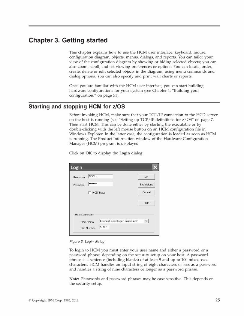
Chapter 3. Getting started
This chapter explains how to use the HCM user interface: keyboard, mouse,configuration diagram, objects, menus, dialogs, and reports. You can tailor yourview of the configuration diagram by showing or hiding selected objects; you canalso zoom, scroll, and set viewing preferences or options. You can locate, order,create, delete or edit selected objects in the diagram, using menu commands anddialog options. You can also specify and print wall charts or reports.
Once you are familiar with the HCM user interface, you can start buildinghardware configurations for your system (see Chapter 4, “Building yourconfiguration,” on page 51).
Starting and stopping HCM for z/OSBefore invoking HCM, make sure that your TCP/IP connection to the HCD serveron the host is running (see “Setting up TCP/IP definitions for z/OS” on page 7.Then start HCM. This can be done either by starting the executable or bydouble-clicking with the left mouse button on an HCM configuration file inWindows Explorer. In the latter case, the configuration is loaded as soon as HCMis running. The Product Information window of the Hardware ConfigurationManager (HCM) program is displayed.
Click on OK to display the Login dialog.
To login to HCM you must enter your user name and either a password or apassword phrase, depending on the security setup on your host. A passwordphrase is a sentence (including blanks) of at least 9 and up to 100 mixed-casecharacters. HCM handles an input string of eight characters or less as a passwordand handles a string of nine characters or longer as a password phrase.
Note: Passwords and password phrases may be case sensitive. This depends onthe security setup.
Figure 3. Login dialog
© Copyright IBM Corp. 1995, 2016 25

If you start HCM for the first time after installing it, you must enter a host nameand a port number. In the Host Name entry field, HCM accepts symbolic hostnames or numeric IP addresses, which you can specify in either IPv4 or IPv6format, depending on your network environment. The default port number is51107. If your HCM dispatcher uses another port number, contact your systemadministrator.
HCM saves the entered values in the EEQHCM.INI file. Therefore, for subsequentlog-ins, you only need to enter your password. This INI file is created after the firstHCM session. It is located in a user-specific application data directory (see also“Purpose and location of the HCM INI file” on page 5).
If the host machine accepts the given user name and password, the Login dialogdisappears and you can begin your HCM session. Otherwise, a message appears,notifying you of login failure. Choosing Cancel terminates HCM.
If the login fails due to an expired password, you must logon to the host to changeyour password. You cannot change the password in your HCM session.
For login troubleshooting, click in the HCD Trace check box in the Login dialog toenable the HCD host to trace all activity during the HCM session. Alternatively,during the session you can activate (or deactivate) the trace by toggling theActivate HCD Trace command in the Options menu. The HCD Trace is normallyused only for troubleshooting HCM system problems; see “Using the HCD tracefacility” on page 413 for details on how to configure the host to properly store thetrace information.
Starting and stopping HCM for z/VMBefore invoking HCM, make sure that the TCP/IP connection to z/VM HCD isestablished as described in “Setting up TCP/IP definitions for z/VM” on page 12.Then do the following:1. Log-on to your z/VM host (service virtual machine) for which you want to use
z/VM HCD. The default user ID is CBDIODSP.2. Start the z/VM HCD TCP/IP dispatcher for HCM by issuing command
CBDSDISP in CMS. Wait for text messages and verify that all services startedcorrectly. Here is an excerpt of the messages you will see after issuingCBDSDISP:
IBM VM/ESA Reusable Server Kernel(C) Copyright 1993, 1994, 1995, 1996, 1997, 1998International Business Machines Corporation.All Rights Reserved.
RSK>SUBCOM BKWSCM0000I Operation completed OK.SUBCOM BKWSCM0000I Operation completed OK....CONSOLE BKWCNS0000I Operation completed OK.CONSOLE BKWCNS0000I Operation completed OK....TCP BKWTCP0000I Operation completed OK.CBDD200I z/VM 6.2.1 HCD TCP/IP dispatcher for HCM successfully started.TCP BKWTCP0000I Operation completed OK.SUBCOM BKWSCM0000I Operation completed OK.CONSOLE BKWCNS0000I Operation completed OK.
You may disconnect now and let the session run in the background.
26 z/OS V2R2 and z/VM V6R2.0 HCM User's Guide

3. On your workstation, start HCM as described in “Starting and stopping HCMfor z/OS” on page 25.
4. Enter user ID (default: CBDIODSP) and password of your service virtualmachine (SVM) into the Login dialog (see also Figure 3 on page 25). Use theTCP/IP host connection with the hostname or IP address of your SVM andyour port number (51107 is the default).
5. Optionally you can switch on HCD trace.6. Work with HCM.7. Exit from HCM on your workstation.8. Optionally, stop the z/VM HCD TCP/IP dispatcher for HCM by issuing the
command SERVER STOP on your z/VM HCD TCP/IP dispatcher servicevirtual machine. Here is the text you see:
SERVER STOPRSK>SERVER BKWSRV0300I Shutdown initiated.CBDD210I z/VM 6.2.1 HCD TCP/IP dispatcher for HCM stopped.Ready;
Note:
Before you can use a final configuration on a z/VM system, make sure that theprerequisites described in chapter Specify a Production IODF for IPL in z/VM: I/OConfiguration are satisfied.
Working with the user interfaceThis chapter describes how you can interact with the HCM user interface.
KeyboardUse the function keys and special keys as shortcuts for pull down choices. HCMoffers the following keyboard functions:
F1 Opens the Help dialog.
F2 Shortcut for the Fit to Window command, which scales the diagram tocompletely fit in the display window.
F3 Shortcut for most recently used named view saved with Save NamedView from the View menu. When selected, the current view will includeonly objects specified by the named view.
F4 Shortcut for Highlighted Objects on the View menu. Crops the view toinclude only currently selected objects and those objects which are eitherdirectly connected to them or which are on a fiber link where the selectedobjects are involved. The settings of the Change View Attributes dialog areconsidered.
SHIFT+F4Shortcut for Connected Objects on the View menu. Crops the view toinclude only the selected object plus the objects logically connected to thisobject without considering the settings in the Change View Attributesdialog.
Using SHIFT+F4, the diagram normally contains less objects in the viewthan using F4.
Chapter 3. Getting started 27

F5 Opens the Assign Cable dialog for the connection on the selected interface.Note that the interface at the lower end of the connection must be selected.
F8 Shortcut for the Locate Selected Object pull down choice. This pull downchoice scrolls the most recently selected object into view – useful aftercreating an object.
F9 Opens the Edit dialog for the currently selected object.
F12 Displays the previously saved view of a configuration diagram. HCMsaves a view whenever an object is included or excluded from the currentview.
PAGE UP/DOWNScrolls the diagram up or down a screen at a time. Can move the displayto the left half of a screen at a time with CTRL+PAGE UP, or to the righthalf with CTRL+PAGE DOWN.
HOMEZooms out.
CTRL+HOMEZooms out all the way to Fit to Window (same as F2).
END Zooms in.
CTRL+ENDZooms in all the way to Actual Size, which scales the diagram so thatobjects are viewed at their approximate size when a diagram is printed atfull size.
ALT+BACKSPACEShortcut for Undo most recent action.
DEL Shortcut for Delete selected object. If the selected object is a connectedchannel interface or a switch port connected to a CHPID, the interface willbe disconnected.
MouseThe mouse can be used to interact with the diagram in the following ways.
Click left buttonSelects the object under the mouse cursor and deselects all other selectedobjects. In addition, all connections to the object are highlighted. If aspanned CHPID is selected, then all instances of that spanned CHPID arehighlighted.
Holding CTRL while clicking selects or deselects the object under thecursor without deselecting other objects. This is used to select multipleobjects.
Holding SHIFT while clicking selects the object under the mouse cursorand displays only those cables connected to the selected object.
Note: Click again without holding SHIFT to show all cables.
Click right buttonProvides a context menu giving access to appropriate actions on the objectunder the cursor.
Double-click left buttonEdits the selected object. Exception: Double clicking an interface at the
28 z/OS V2R2 and z/VM V6R2.0 HCM User's Guide

lower end of a connection when the Select Interface Option is set to“Select Cable“ will open the Assign Cable dialog for that connection.
Press and drag left mouse buttonZooms in on the part of the diagram enclosed by the rectangle formed bydragging the mouse.
Press and drag right mouse buttonZooms out so that the part of the diagram that currently fills the windowwill fit in the rectangle formed by dragging the mouse.
Note that certain selectable objects appear within another object in theconfiguration diagram, for example, interfaces and segments within a controller. Toselect the controller, click on the text in the middle of the object; the entirecontroller and connections will highlight. To select a controller interface, click inone of the small boxes above or below which represent a channel interface or adevice interface. Only the interface and its connections will highlight. Controllerssuch as the 3990 are divided into two or more segments; to select a controllersegment, click in the segment’s lower third. The segment and its connections willhighlight.
DialogsHCM provides a series of dialogs to help you create, edit, delete, and connectobjects, as well as manipulate the configuration diagram. For example, dialogsallow you to edit physical and logical information for a selected object, tailor yourview of the diagram, or set parameters for a printed report.
Dialogs carry out two major functions: navigation and editing. You can navigatefrom a dialog to related dialogs, and edit data for a selected object. For example,you can navigate from the Processor dialog to the Partitions, CHPIDs and EditProcessor dialogs; in the Edit Processor dialog, you can edit information for thecurrently selected processor.
Configurations are hierarchical by nature. To reflect the hierarchy and to facilitateconfiguration maintenance, HCM provides an easy way to edit a lower object froma higher one by nesting dialogs. For example, after editing a processor, you cannavigate to the appropriate dialogs to add or edit CHPIDs or partitions - withoutgoing back to the diagram.
Multiple-action dialogs include additional buttons that allow you to initiate actionswithout closing the dialog. If you have performed some action using these buttonsthat changes the data irreversibly, the Cancel button changes to a Close button.Note that the effect of the last update can be reversed with the Undo command.
Online helpIn addition to the User's Guide, HCM comes with extensive, context-sensitiveonline help which describes each dialog in detail. Use the HCM User's Guide tofind out how to do a particular task (for example, ‘Connecting a patchport’), or tolook up overview or reference information. Use the online help to finddialog-specific information while you are working in HCM (for example, what theEdit... button in the CHPIDs dialog does).
Most HCM dialogs have a Help... button which you can press to get informationspecific to the dialog currently open. You can also access online help at any time inHCM by using the Help menu:v The Index pull down choice displays the index of help topics.
Chapter 3. Getting started 29

v The Keyboard pull down choice displays the Keyboard Shortcuts topic.v The About... pull down choice displays program specific information including
the latest service level.
Each help topic in the HCM help system has a non-scrollable area at the topcontaining the dialog title and a See Also pop-up list box. Use the scroll bar andarrows to move up and down the help topic text. Notice that most help topicshave words or phrases in the text highlighted in another color. You can browserelated help topics by clicking on the jumps (highlighted phrases with singleunderline) in the text or under the “See Also” list box. You can click on a pop-up(highlighted word or phrase with dotted underline) in the text to display thedefinition for an HCM term. Jumps to related help topics can appear withinpop-up windows.
Use the Back or History buttons in the help menu bar to retrace your path throughthe help topics. Use the Contents button to display the Index of help topics.
User data fieldsIn addition to characterizing an object with an ID, description, serial number, type,and so on, HCM allows you to define twenty data fields unique to yourconfiguration. For example, you may wish to record information such as the leasestatus, corporate asset number, or physical location (building and/or data centermap grid) for a given piece of hardware.
Using the Customize Field Names dialog, you can apply meaningful names to thefields as shown in Figure 4 on page 31. You reach this dialog from the menu bar:Options → Field Names....
Tip:
Consider using some of the fields for global items such as asset number andphysical location, and some for local items such as data usage (for example “IMSdatabases”) for a string.
These fields can be used to appear in particular reports. Any empty user field foran object is not be printed. For example, if “Usage” is used as a field for definingthe data on a string, it only appears in the String reports. The reports will be easierreadable if the names are 12 characters or less (for example, Asset No., not Assetmanagement number).
30 z/OS V2R2 and z/VM V6R2.0 HCM User's Guide
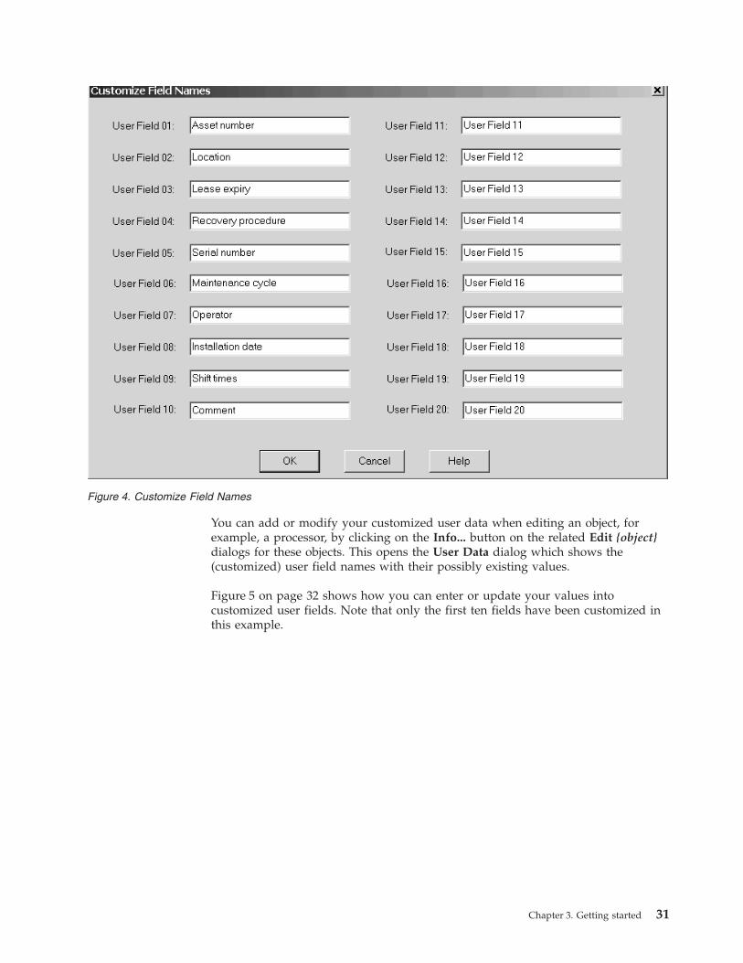
You can add or modify your customized user data when editing an object, forexample, a processor, by clicking on the Info... button on the related Edit {object}dialogs for these objects. This opens the User Data dialog which shows the(customized) user field names with their possibly existing values.
Figure 5 on page 32 shows how you can enter or update your values intocustomized user fields. Note that only the first ten fields have been customized inthis example.
Figure 4. Customize Field Names
Chapter 3. Getting started 31
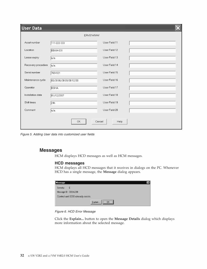
MessagesHCM displays HCD messages as well as HCM messages.
HCD messagesHCM displays all HCD messages that it receives in dialogs on the PC. WheneverHCD has a single message, the Message dialog appears.
Click the Explain... button to open the Message Details dialog which displaysmore information about the selected message.
Figure 5. Adding User data into customized user fields
Figure 6. HCD Error Message
32 z/OS V2R2 and z/VM V6R2.0 HCM User's Guide
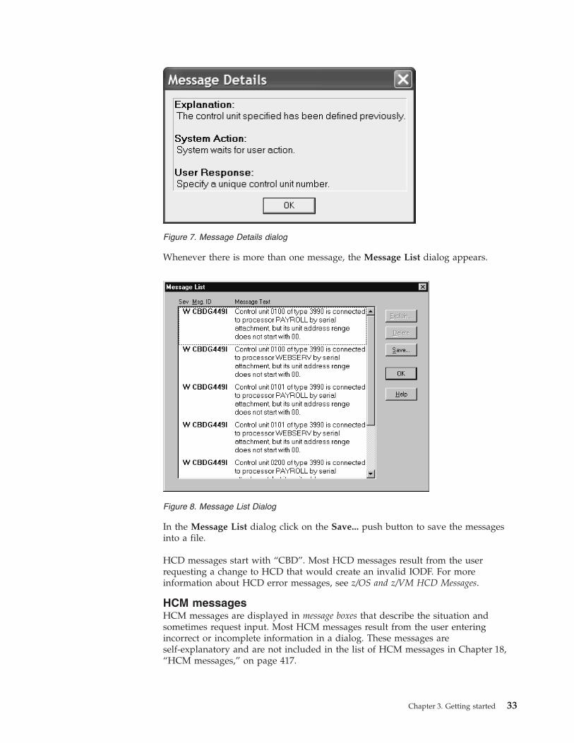
Whenever there is more than one message, the Message List dialog appears.
In the Message List dialog click on the Save... push button to save the messagesinto a file.
HCD messages start with “CBD”. Most HCD messages result from the userrequesting a change to HCD that would create an invalid IODF. For moreinformation about HCD error messages, see z/OS and z/VM HCD Messages.
HCM messagesHCM messages are displayed in message boxes that describe the situation andsometimes request input. Most HCM messages result from the user enteringincorrect or incomplete information in a dialog. These messages areself-explanatory and are not included in the list of HCM messages in Chapter 18,“HCM messages,” on page 417.
Figure 7. Message Details dialog
Figure 8. Message List Dialog
Chapter 3. Getting started 33

Serious HCM messages are also displayed in message boxes and only have an OKbutton for you to acknowledge them. These messages start with “EEQ” and can befound under Chapter 18, “HCM messages,” on page 417.
Maintaining the configuration diagramWith HCM, you can build and maintain an interactive configuration diagramcontaining all the physical and logical information about your hardwareconfiguration. HCM draws the objects, connections, and text annotations in theconfiguration diagram in the clearest possible way. You need not worry about howthe diagram looks when you create, edit, or delete objects, or when you filter yourview. HCM automatically redraws the diagram.
Note:
1. If you position a cursor over an object in the diagram, HCM displaysinformation about this object in the upper left corner of the diagram windowbeneath the menu bar (fly-over annotations).
2. Information about the current or last selected object is displayed in the lowerleft corner of the window.
3. In the lower right corner, in connected mode, you see information about thesystem environment: the host name, the port number, and the sysplex namewhere the host is a member.
Filtering your viewYou can tailor your view of the configuration diagram to focus on the objects ofinterest only. This results in a more readable diagram. Working with a subset of theconfiguration is easier than working with the entire diagram. Since many useractions require the diagram to be rebuilt (for example, connecting objects), youmight have to zoom back into the area of interest after each of these actions.Cropping the diagram also results in better performance, since only that smallerportion must be recreated.
You can tailor a view to your needs in the following way:
Open the Change View Attributes dialog by choosing Filter Diagram... from theView menu.
Figure 9. HCM Message
34 z/OS V2R2 and z/VM V6R2.0 HCM User's Guide

Use this dialog to include and exclude the types of objects you want to see. Youcan specify which processors, partitions, and controllers should be displayed toreduce the number of objects in the current view. Use the Include only list in theController Types section to select the controller device types for just thosecontrollers that you want to see in the view. Press OK after you specified all yourdesired view attributes.
You can use the Save Named View pull down choice from the View menu to savethe current view attributes to a named view. Use the Restore Named View pulldown choice to select a saved named view to be shown as active configurationdiagram.
Note that you may also set exceptions to the selected controller types by pressingthe Exceptions ... button to invoke the Include/Exclude Controllers dialog. Thisdialog lets you add or remove individual controllers from the view regardless ofwhether or not you included controllers of this device type in the Include only list.You can also display objects connected to processors but not to controllers, orobjects not connected to processors.
To return to the original diagram, press the Clear Exceptions push button.Alternatively, you can press the F12 key to restore the view that you had beforepressing F4 or SHIFT+F4.
By clicking the Active Sysplex check box, it is possible to filter the diagram tothose objects, which are part of the active sysplex on which the HCD host isrunning.
Figure 10. Change View Attributes Dialog
Chapter 3. Getting started 35

If the Active Sysplex checkbox is selected, the Show Managed CHPIDs checkboxbecomes visible if there are any CHPIDs that:v are contained in one of the processors that comprise the active sysplex,v are defined as managed, andv have an I/O Cluster value that corresponds to the name of the active sysplex.
By selecting this checkbox, an asterisk ('*') in the diagram at the correspondingchannel interface indicates that a channel path is manageable.
Clicking the Exclude all reserved partitions checkbox excludes all these partitionsfrom the view in one step, so that you need not select all individual reservedpartitions and press the Exclude button.
The last specified filter is stored in the HCM configuration file across HCMsessions.
You can use further pull down choices in the View menu to tailor your view:
Highlighted Objects - F4Displays only those objects selected (highlighted) in the current view,resulting in a “cropped” view of the diagram. A cropped diagram is a subsetof the entire configuration comprising the selected objects and any objectsto which they connect. You can print customized cropped views as part ofa report. Shortcut: press the F4 key. This applies the settings made in theChange View Attributes dialog.
The Highlighted Objects pull down choice works as a shortcut for settingexceptions. For example, if you have the DASD class selected for controllersin the Change View Attributes dialog, select a single DASD controller inthe diagram, and press F4, all other DASD controllers are set to“excluded”. That is, the diagram will display all controllers of class DASDwith the exception of the DASD controllers which have been explicitlyexcluded. This results in a diagram containing only the selected controller.
To return to the original diagram, press the Clear Exceptions push buttonin the Change View Attributes dialog or press F12.
Connected Objects - SHIFT+F4Crops the view to display only the selected objects plus the objectslogically connected to this object without applying the settings in theChange View Attributes dialog. This usually results in diagrams whichcontain even fewer objects than pressing F4.
If you restore a named view that has been created with SHIFT+F4 , youwill see the currently connected objects, even if the connections changedafter the view was saved. You can return to the uncropped diagram at anytime by pressing F12.
Connections in the diagramConnection lines on the diagram are drawn with different thickness, style, andgraphics, with the following meanings.
Table 6. Configuration diagram connections
Line type Meaning
Thick line Bus and tag cable, permanent connections
Thin line Mutable connections
36 z/OS V2R2 and z/VM V6R2.0 HCM User's Guide
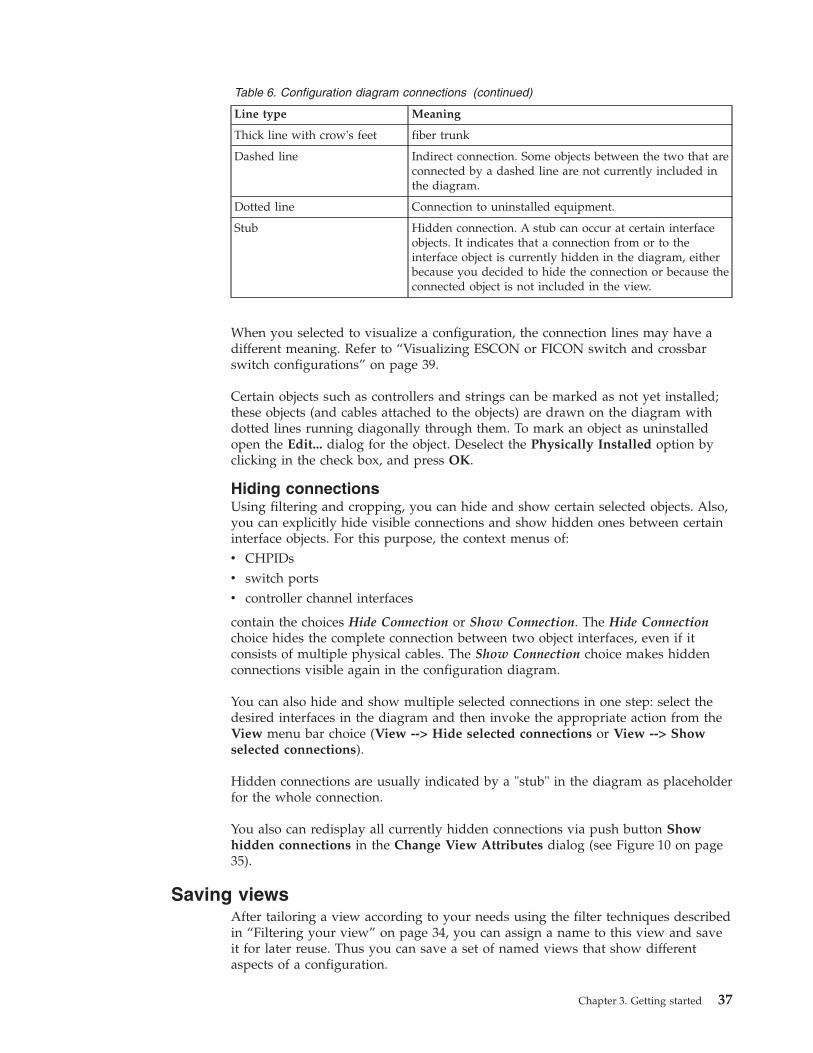
Table 6. Configuration diagram connections (continued)
Line type Meaning
Thick line with crow's feet fiber trunk
Dashed line Indirect connection. Some objects between the two that areconnected by a dashed line are not currently included inthe diagram.
Dotted line Connection to uninstalled equipment.
Stub Hidden connection. A stub can occur at certain interfaceobjects. It indicates that a connection from or to theinterface object is currently hidden in the diagram, eitherbecause you decided to hide the connection or because theconnected object is not included in the view.
When you selected to visualize a configuration, the connection lines may have adifferent meaning. Refer to “Visualizing ESCON or FICON switch and crossbarswitch configurations” on page 39.
Certain objects such as controllers and strings can be marked as not yet installed;these objects (and cables attached to the objects) are drawn on the diagram withdotted lines running diagonally through them. To mark an object as uninstalledopen the Edit... dialog for the object. Deselect the Physically Installed option byclicking in the check box, and press OK.
Hiding connectionsUsing filtering and cropping, you can hide and show certain selected objects. Also,you can explicitly hide visible connections and show hidden ones between certaininterface objects. For this purpose, the context menus of:v CHPIDsv switch portsv controller channel interfaces
contain the choices Hide Connection or Show Connection. The Hide Connectionchoice hides the complete connection between two object interfaces, even if itconsists of multiple physical cables. The Show Connection choice makes hiddenconnections visible again in the configuration diagram.
You can also hide and show multiple selected connections in one step: select thedesired interfaces in the diagram and then invoke the appropriate action from theView menu bar choice (View --> Hide selected connections or View --> Showselected connections).
Hidden connections are usually indicated by a "stub" in the diagram as placeholderfor the whole connection.
You also can redisplay all currently hidden connections via push button Showhidden connections in the Change View Attributes dialog (see Figure 10 on page35).
Saving viewsAfter tailoring a view according to your needs using the filter techniques describedin “Filtering your view” on page 34, you can assign a name to this view and saveit for later reuse. Thus you can save a set of named views that show differentaspects of a configuration.
Chapter 3. Getting started 37

Choosing Save Named View... from the View menu, you can save such views thatyou might want to display again. Whenever you want to display a saved view,you can either press (F3) to display the most recently used named view or chooseRestore Named View... to select a view from a list box.
A useful capability of named views is to create views that show all objectsconnected to a particular processor or partition, possibly filtered by controller type.For example, in a configuration where processors have test and productionpartitions, it may be useful to create one view for production equipment andanother view for test equipment.
Note: A named view saves the individual processor and partition objects as theyare currently drawn on the diagram. When you restore a view, it does not showprocessors or partitions that you added after saving that view. Subsequently addedcontrollers are displayed depending on the currently active view attributes (see“Filtering your view” on page 34).
The following pull down choices under the View menu support you in savingviews:
Restore Named ViewAllows you to choose a saved named view you want to display. To displaythe most currently saved named view you can use the shortcut F3.
Save Named ViewAllows you to either save the displayed view under a new name or toupdate an existing saved named view.
Delete Named ViewAllows you to delete one or more named views.
Vertical view of XMP processorsThe default view of a processor in the configuration diagram is the logicalhorizontal view, where all of a processors's channel subsystems are displayed sideby side. If you want to have a more physically oriented view of a processor'sspanned channels instead, select the vertical processor view. This view displays thechannel subsystems on top of each other and each PCHID appears only once.
You can select your preferred processor view in the Preferences dialog that youreach from the View ---> Preferences... menu bar choice (see “Setting preferences”on page 43).
Figure 11 on page 39 shows the horizontal (above) and vertical view (below) of thesame processor.
38 z/OS V2R2 and z/VM V6R2.0 HCM User's Guide
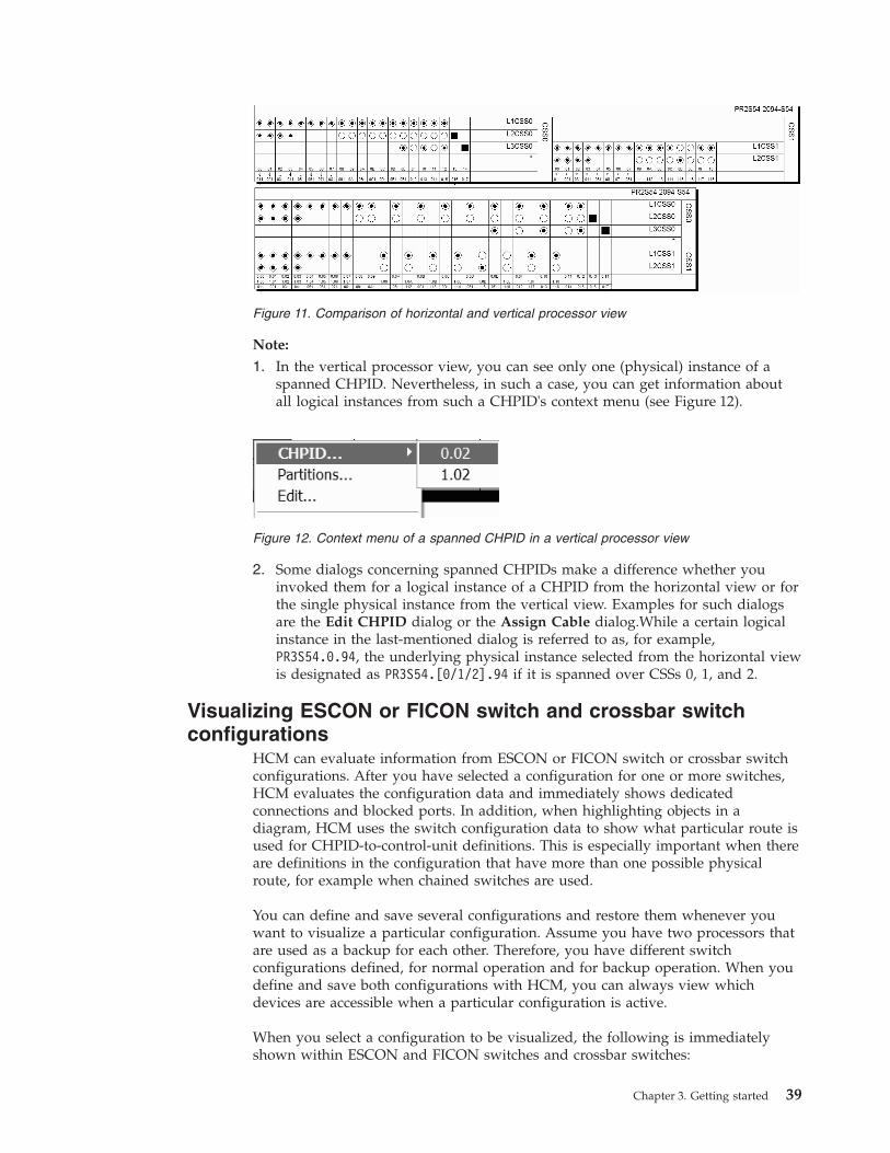
Note:
1. In the vertical processor view, you can see only one (physical) instance of aspanned CHPID. Nevertheless, in such a case, you can get information aboutall logical instances from such a CHPID's context menu (see Figure 12).
2. Some dialogs concerning spanned CHPIDs make a difference whether youinvoked them for a logical instance of a CHPID from the horizontal view or forthe single physical instance from the vertical view. Examples for such dialogsare the Edit CHPID dialog or the Assign Cable dialog.While a certain logicalinstance in the last-mentioned dialog is referred to as, for example,PR3S54.0.94, the underlying physical instance selected from the horizontal viewis designated as PR3S54.[0/1/2].94 if it is spanned over CSSs 0, 1, and 2.
Visualizing ESCON or FICON switch and crossbar switchconfigurations
HCM can evaluate information from ESCON or FICON switch or crossbar switchconfigurations. After you have selected a configuration for one or more switches,HCM evaluates the configuration data and immediately shows dedicatedconnections and blocked ports. In addition, when highlighting objects in adiagram, HCM uses the switch configuration data to show what particular route isused for CHPID-to-control-unit definitions. This is especially important when thereare definitions in the configuration that have more than one possible physicalroute, for example when chained switches are used.
You can define and save several configurations and restore them whenever youwant to visualize a particular configuration. Assume you have two processors thatare used as a backup for each other. Therefore, you have different switchconfigurations defined, for normal operation and for backup operation. When youdefine and save both configurations with HCM, you can always view whichdevices are accessible when a particular configuration is active.
When you select a configuration to be visualized, the following is immediatelyshown within ESCON and FICON switches and crossbar switches:
Figure 11. Comparison of horizontal and vertical processor view
Figure 12. Context menu of a spanned CHPID in a vertical processor view
Chapter 3. Getting started 39

Diagram object Meaning
Solid black line Dedicated link between the ports
Gray port This port is blocked
Black dot In crossbar switches, a link between a crossbar channelinterface and a crossbar control unit interface
In addition, when you highlight an object, HCM evaluates the configuration dataand highlights the valid path from the CHPID to the control unit. It uses thefollowing highlighting rules:v Within ESCON and FICON switches (internal routes)
Diagram object Meaning
Solid line There is dedicated link between the ports
Dotted line There is a dynamic allowed link between the ports. If thelink is prohibited, there is no line between the ports.
v For cables (physical routes)
Diagram object Meaning
Solid line Allowed physical route.
Dotted line The visualized configuration does not allow the physicalroute.
In the following example, control unit 500 is logically defined to CHPID 20 andCHPID 21 using switch 3 as dynamic switch. Without visualizing theconfiguration, HCM would show all possible paths through switch 4.
40 z/OS V2R2 and z/VM V6R2.0 HCM User's Guide

Considering the switch configuration data of switch 4 that defines dedicatedconnections between C2 and C4, and C3 and C5, HCM highlights only the validpaths as shown. Note that the route in the dynamic switch is highlighted as adotted line whereby the dedicated link is highlighted as a solid line.
Figure 13. Highlighting an Object, without Visualized Configuration
Chapter 3. Getting started 41
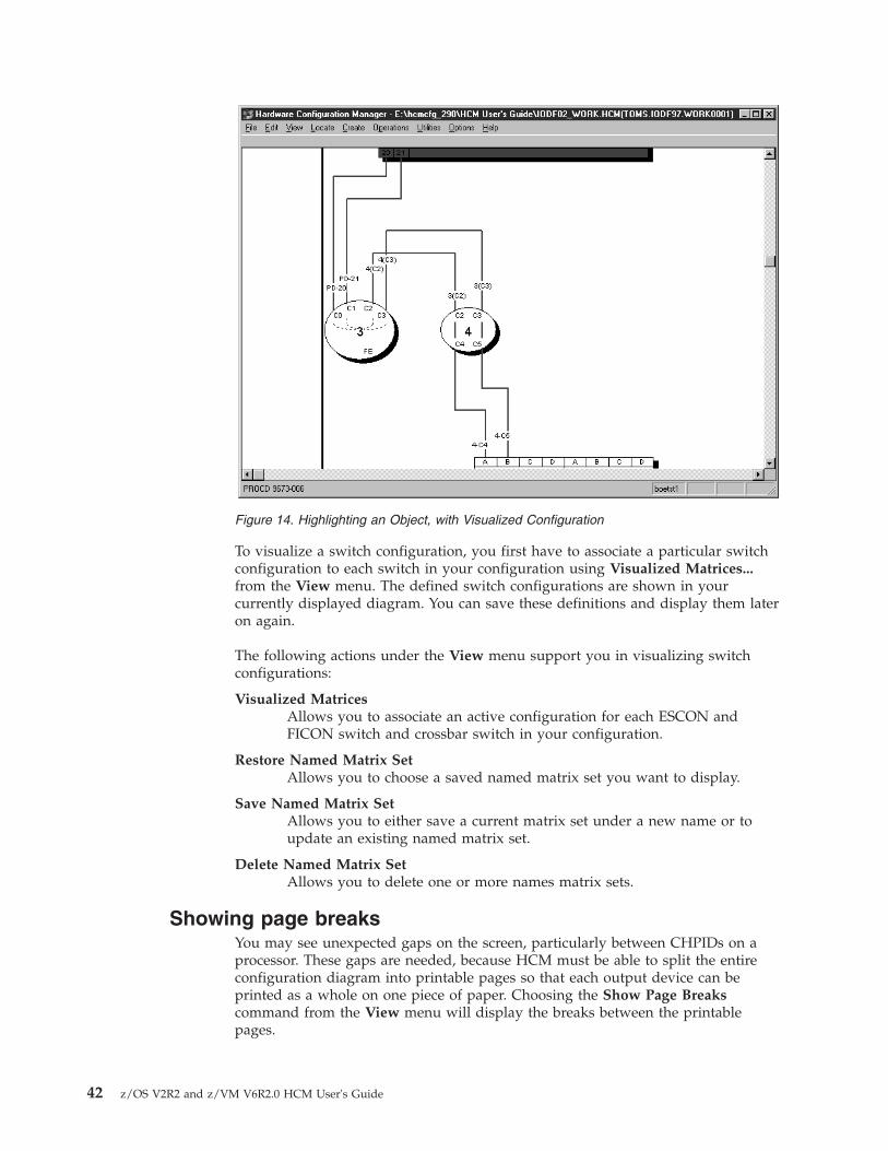
To visualize a switch configuration, you first have to associate a particular switchconfiguration to each switch in your configuration using Visualized Matrices...from the View menu. The defined switch configurations are shown in yourcurrently displayed diagram. You can save these definitions and display them lateron again.
The following actions under the View menu support you in visualizing switchconfigurations:
Visualized MatricesAllows you to associate an active configuration for each ESCON andFICON switch and crossbar switch in your configuration.
Restore Named Matrix SetAllows you to choose a saved named matrix set you want to display.
Save Named Matrix SetAllows you to either save a current matrix set under a new name or toupdate an existing named matrix set.
Delete Named Matrix SetAllows you to delete one or more names matrix sets.
Showing page breaksYou may see unexpected gaps on the screen, particularly between CHPIDs on aprocessor. These gaps are needed, because HCM must be able to split the entireconfiguration diagram into printable pages so that each output device can beprinted as a whole on one piece of paper. Choosing the Show Page Breakscommand from the View menu will display the breaks between the printablepages.
Figure 14. Highlighting an Object, with Visualized Configuration
42 z/OS V2R2 and z/VM V6R2.0 HCM User's Guide

Zooming the viewOther pull down choices from the View menu allow you to change the size of theconfiguration diagram view:
Fit to WindowScales the diagram to completely fit in the HCM window. Shortcut: pressthe F2 key or CTRL+HOME.
Zoom OutShrinks the diagram such that more of it fits in the window. Shortcut: pressthe HOME key. You can also zoom out by holding down the right mousebutton and dragging; see “Mouse” on page 28. Note that as you zoom out,text becomes smaller and simpler, until it is no longer displayed because itis too small to read.
Zoom InMagnifies a portion of the diagram for a closer, more detailed look atobjects. Shortcut: press the END key. You can also zoom in by holdingdown the left mouse button and dragging; see “Mouse” on page 28 above.Use the scroll bars which appear when you zoom in to navigate aroundthe diagram. As you zoom in, text may appear as it becomes large enoughto read.
Actual SizeScales the diagram such that objects are viewed at their approximate sizewhen a diagram is printed at full size. Full size, or 100% scale, is the largestscale for printing diagrams. At this size, each controller will be about oneinch tall and all text information for each object is visible. Shortcut: pressthe CTRL+END keys.
Scrolling the viewAs you zoom in to the configuration diagram, scroll bars will appear at the bottomand right hand side of the screen. Click the arrow buttons, click in the scroll bar, ordrag the scroll box along the scroll bar to navigate around the diagram.Alternatively, press the arrow keys on the keyboard to scroll the diagram up,down, left or right. To scroll the diagram half a page at a time, use PAGE UP (up),PAGE DOWN (down), CTRL+PAGE UP (left), and CTRL+PAGE DOWN (right).
Note that making or breaking a connection may move the selected object such thatit is no longer visible in the current view. You may have to zoom out and then in,or scroll around to find the selected object.
Controlling text detailYou can control the text that will appear in the diagram by selecting the TextDetail pull down choice from the View menu.
Setting preferencesUsing the Preferences dialog from the View ---> Preferences... menu bar choice,you can select alternative settings how to display the configuration, which will besaved for future HCM sessions:
Processor viewWith this setting you can modify the view of XMP processors: Select thehorizontal processor view to display the channel subsystems side by side.Select the vertical processor view to display channel subsystems on top of
Chapter 3. Getting started 43

each other. In the vertical view, you achieve a physically oriented view ofspanned CHPIDs and their PCHID value appears only once in thediagram.
Channel and Device Adapter GroupingFor controllers that have channel or device adapters, use this option tochoose whether these adapters are grouped on the diagram by adapter orby segment. For example, a bus architecture controller may have twobuses, 0 and 1 (represented by segments in HCM) with four adapters each,A,B,C,D. Choosing Grouped by Adapter will order the adapters:0A,1A,0B,1B,0C,1C,0D,1D. Choosing Grouped by Segment will order theadapters: 0A,0B,0C,0D,1A,1B,1C,1D.
Converter shapeDisplay all converters in the diagram as either elongated hexagons orpentagons.
Connector linesWith this setting, you can select whether connections between objectsshould always be drawn with rectangular (horizontal and vertical) lines orwhether diagonal lines should be used where possible.
Compress diagram horizontallyCompresses the width of objects to result in a more concise diagram. Lesspaper will be used to print the diagram, but cable descriptions mayoverlap, making them difficult to read.
Showing screen elementsYou can show or hide elements of the HCM screen with the following pull downchoices from the View menu:
Object Information BarShows or hides the Object Information Bar at the top of the screen. Thisbar contains information about the objects and their connections currentlyunder the mouse cursor. Moving the cursor across objects causes thisinformation to constantly change.
Status BarShows or hides the Status Bar at the bottom of the screen. This barcontains information about the most recently selected object as well asmiscellaneous messages. If you have selected more than one object, theinformation shown pertains to the last one selected. In addition, you canfind information about the Login target, Active Sysplex name, Focus hostand Time of last Refresh.
Show Page BreaksShows or hides the page breaks that occur when the diagram is printed atfull size. The white space between each pair of lines represents areas thatare unprintable with the currently selected printer and paper size.
Specifying optionsYou can ask HCM to always confirm a Delete command; that is, when you deletean object or disconnect an interface, HCM will ask you if you are sure you want todelete or disconnect. Choose Confirmation from the Options menu, select thecheckbox and press OK (confirmation “on” is the default).
44 z/OS V2R2 and z/VM V6R2.0 HCM User's Guide
HCM offers the possibility to choose the action that is performed whendouble-clicking on a Control Unit or String interface. You can choose to either editthe physical cable assignment for the interface or edit the Control Unit or Stringthat contains the interface.
Showing system status informationStatus information is available only with I/O Operations for z/OS. HCM interfaceswith I/O Operations on the host, which enables you to graphically view theobjects in the active sysplex. For details, see Chapter 11, “User interface to I/OOperations,” on page 277.
Receiving visual warningsHCM will warn you of any likely errors between physical connections and logicaldefinitions. The warnings take the form of coloring objects and connections in theconfiguration diagram. You can specify which warnings are enabled, as well as thecolor each warning displays.
To display physical-logical inconsistencies, objects are filled and cables are drawnwith the appropriate color. If an object has more than one warning, HCM displaysthe highest priority warning. Note that selected objects and cables appearhighlighted in the standard red color, and take priority over visual warning colors.
Note that when you run in a video mode with only 16 colors, the visual warningcolors may be different for objects than for cables: objects are painted with brusheswhich support patterns, but cables are painted with pens which do not. You candisplay the Colors dialog by choosing Colors... in the View menu. Use this dialogto customize the visual warnings for a given workstation.
Note: You can use the visual warning colors, for example, after a loading or aresynchronization process. This has an impact on the performance. For informationabout the resynchronization process, see “Resynchronizing configuration files andIODFs” on page 56.
Printing the configuration diagramYou can print the entire configuration diagram or only those objects in the currentview (see “Filtering your view” on page 34). Choose Print Diagram in the Filemenu to scale the diagram, calculate the number of pages that will print at theselected scaling factor, or fit the diagram to print on one page. See Chapter 12,“Reports and diagrams,” on page 283 for more details.
Color printing is also supported.
Selecting objectsClick to select an object in the configuration diagram; the object and all itsconnections will highlight, and the Edit and Locate menus automatically list theobject in temporary menu commands. You can SHIFT+click (left) to highlight anddisplay only those cables connected to the selected object to simplify your view(click to re-display all cables).
Tip:
Since objects in the diagram can be quite small, zoom in to the area of interestbefore selecting the desired object. You can also identify the object using the Locatemenu or the Object Information Bar at the top of the screen.
Chapter 3. Getting started 45

Some objects are contained within other objects: for example, controllers containsegments and switches contain switch ports. To select a controller, click in themiddle of the area below the channel interfaces. To select a segment, click in theregion just above its device interfaces. To select a switch, click on it anywhereexcept on a switch port. To select a switch port, click immediately inside the switchadjacent to its connection, or on its connection up to the first bend. In general, youcan select objects by clicking on their text labels.
In the configuration diagram, each logical instance of a spanned CHPID (see“CHPID operation mode” on page 130) is shown in the channel subsystem itbelongs to. This means that if a CHPID is spanned over three channel subsystems,for example, then three single CHPIDs - one in each channel subsystem where it isspanned - will be shown. Selecting or locating one out of the three logical instancesof the CHPID from our example, selects or locates all logical instances in thediagram at once.
Actions such as delete or locate act on the most recently selected object. Note thatyou can highlight the connections for more than one object at a time by usingCTRL+click (left). However, highlighted objects are not multiple selected objects, soyou cannot delete or locate more than one object at a time.
Locating objectsIn a large configuration diagram, it may be difficult to find the object in which youare interested. Use the Locate menu to quickly find an object. When you select atype of object from the menu, a dialog appears listing objects and their attributes.You can select one or more objects in this list. The selected object or objects will bemade visible and highlighted in your configuration diagram
Select the Columns... push button to choose other attributes to be shown in thedialog. You can change the width of each column by selecting the black line that
Figure 15. Selection List for Locating Objects, in this Example: Locating Devices
46 z/OS V2R2 and z/VM V6R2.0 HCM User's Guide

separates the column headings and dragging it to the left or to the right. You cansort the order in a column from ascending to descending by clicking on thecolumn header.
If you locate an instance of a spanned CHPID via the Locate one or More CHPIDsdialog, then besides locating and selecting this instance, also all other instances ofthis spanned CHPID are selected and included in the view. See also “Selectingobjects” on page 45.
When running multiple partitions, adding the OS Configs column shows usefulinformation. Columns and filter settings are saved across HCM session.
With the button Change SCHS, which appears only on the Edit a Device and theLocate One or More Devices dialog, you can change the placement of (multiple)eligible devices in a subchannel set. This is further described in “Changing thesubchannel set for devices” on page 160.
Tip:
After using the edit, create, scrolling, or zooming commands, you may lose sight ofyour most recently selected object. To relocate it, simply open the Locate menu andselect the object which is shown as the first item in the menu list. (Shortcut: pressF8).
The first menu item in the Locate menu is only valid, if you recently selected onlyone object.
The Locate object and Edit object windows contain a Save As... button. This buttonallows all the listed objects, including the displayed columns, to be saved to a filein a format that can be used by a spreadsheet program (such as Lotus 1-2-3).Together with the capabilities of the enhanced Filter mechanism in the Locate andEdit menu, this allows HCM configuration reports to be created according tocriteria specified by the user.
Filtering objectsUse the Filter... button in the Locate and Edit dialogs to reduce the list of objectsdisplayed in the resulting window. HCM opens a dialog in which you can specifyfilter criteria for the objects you want to locate or edit. These criteria are storedacross HCM sessions.
Figure 16 on page 48 shows a filter dialog for CHPIDs:
Chapter 3. Getting started 47
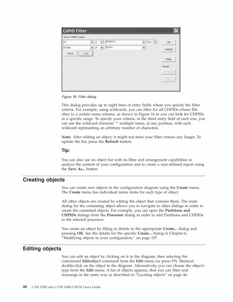
This dialog provides up to eight lines of entry fields where you specify the filtercriteria. For example, using wildcards, you can filter for all CHPIDs whose IDsobey to a certain name schema, as shown in Figure 16 or you can look for CHPIDsin a specific range. To specify your criteria, in the third entry field of each row, youcan use the wildcard character '*' multiple times, at any position, with eachwildcard representing an arbitrary number of characters.
Note: After editing an object, it might not meet your filter criteria any longer. Toupdate the list, press the Refresh button.
Tip:
You can also use an object list with its filter and arrangement capabilities toanalyze the content of your configuration and to create a user-defined report usingthe Save As... button.
Creating objectsYou can create new objects in the configuration diagram using the Create menu.The Create menu has individual menu items for each type of object.
All other objects are created by editing the object that contains them. The maindialog for the containing object allows you to navigate to other dialogs in order tocreate the contained objects. For example, you can open the Partitions andCHPIDs dialogs from the Processor dialog in order to add Partitions and CHPIDsto the selected processor.
You create an object by filling in details in the appropriate Create... dialog andpressing OK. See the details for the specific Create... dialog in Chapter 6,“Modifying objects in your configuration,” on page 107.
Editing objectsYou can edit an object by clicking on it in the diagram, then selecting thecustomized Edit:object command from the Edit menu (or press F9). Shortcut:double-click on the object in the diagram. Alternatively, you can choose the object'stype from the Edit menu. A list of objects appears, that you can filter andrearrange in the same way as described in “Locating objects” on page 46.
Figure 16. Filter dialog
48 z/OS V2R2 and z/VM V6R2.0 HCM User's Guide

For more details, see the section for the specific Edit... dialog in Chapter 6,“Modifying objects in your configuration,” on page 107.
The Interface Selection... pull down choice under the Options menu allows you toselect which type of dialog will appear when you select an interface to edit: youcan either edit the physical cable assignment for the interface, or edit the objectwhich contains the interface.
Edit dialogs often lead to related dialogs allowing you to connect objects. See thesection for the specific dialogs in Chapter 6, “Modifying objects in yourconfiguration,” on page 107 for more details.
Deleting objectsTo delete one or more objects, click to select them in the diagram, and chooseDelete from the Edit menu. Shortcut: press the DEL key after selecting the object.HCM will first disconnect the object and then delete it. If the Confirm on Deleteoption is on, HCM will ask you if you want to delete the object before actuallydeleting it. See “Specifying options” on page 44 for more details.
You can use the Undo command immediately after a Delete to reverse it.
Note:
Most subobjects, such as partitions, segments, and interfaces (including paths)cannot be deleted from the diagram. You can delete subobjects by editing theircontaining objects. For example, to delete a CHPID, double-click on theappropriate processor, click on the CHPIDs... button, select the CHPID from thelist box displayed, and press the Delete button.
Selecting an interface and pressing the DEL key will only disconnect it. This onlyapplies to interfaces at the bottom of a connection: channel interfaces, stringinterfaces, crossbar channel interfaces, and upwards-facing switch ports.
Strings and units that are integrated into a controller are not visible in theconfiguration diagram. They can only be accessed through the Edit menu or in theController dialog. Select a string and press the Delete button in the Strings sectionof the Controller dialog; HCM will display a confirmation dialog before deletingthe string.
Note:
Besides the possibility to delete multiple objects via selection on the configurationdiagram, users can now select multiple objects on some Edit <object> dialogs anddelete them in one step by pressing the Delete... button on these dialogs.
Reversing an actionThe single level Undo command will reverse or “undo” your most recent action inHCM. Select the command from the Edit menu. If the previous action cannot beundone, the command changes to Can't Undo.
Chapter 3. Getting started 49

Ordering objectsYou can order objects on the screen and in reports by using the Order dialog. Pressthe Order... button in the appropriate dialog. For processors, select the OrderProcessors... command from the Edit menu. The standard order dialog appearswith two list boxes, one showing the objects in the current order, the othershowing the objects in the new order after they have been rearranged with theAdd>> button. The Add>> button adds an object selected in the Current Order listbox to the end of the New Order list box. The <<Remove button removes theobject selected in the New Order list box and places it back in the Current Orderlist box. Shortcut: Double-click on any item to move it.
Figure 17. Build New Processor Order for the Diagram
50 z/OS V2R2 and z/VM V6R2.0 HCM User's Guide

Chapter 4. Building your configuration
HCD uses the IODF to store the logical configuration data defined for theoperating system and the channel subsystem. HCM, running on a PC, acts as a“graphical front end” to HCD: loading the IODF into HCM allows you to build anassociated, interactive configuration diagram in a configuration file. You cansupplement the IODF logical data with physical information about the physicalhardware aspects, such as cabinets. Each physical object is a graphical object in thediagram. HCM keeps the IODF in sync with its associated configuration file as youmake changes. Due to the client/server relationship with HCD, all changes of thelogical I/O configuration are immediately written into the IODF at input time andfully validated and checked for accuracy and completeness by HCD.
You can create a new configuration either from the scratch or by populating a newconfiguration file with data from an existing, prepared IODF. You can open and/orresynchronize an existing configuration by opening the configuration file with itsassociated IODF or against a different IODF. Copy the configuration file and IODFto backup files before making changes. This is useful when planning possiblefuture alternatives to your system configuration.
After you have created or opened a configuration, you can modify it. HCM allowsyou to easily create, edit, connect, disconnect, or delete objects in the diagram. (SeeChapter 6, “Modifying objects in your configuration,” on page 107 or Chapter 7,“Connecting objects in your configuration,” on page 187). When you are finished,close your configuration. This saves your changes in the config file and associatedIODF.
Read the following topics to learn how HCD and HCM keep their configurationdata consistent and how you can create and work with HCM configuration files:v “HCM and HCD”v “Physical and logical objects in HCM” on page 58v “Introduction to the master configuration file concept” on page 57v “Creating a new configuration from an IODF” on page 60v “Creating a new configuration from scratch” on page 70v “Opening an existing configuration” on page 72v “Working with your IODFs and configuration files” on page 76
HCM and HCDHCM is the graphical user interface to HCD. However, HCM runs on aworkstation and HCD runs on the host. The host systems require an internalmodel of their connections to devices, but it is far more convenient and efficient foryou to maintain (and supplement) that model in a visual form. HCM maintains theconfiguration data as a diagram in a configuration file in sync with the IODF.
The IODF contains only logical definitions; the configuration file contains a subset ofthe logical data from the IODF, plus physical information added using HCM.Together the IODF and the configuration file data form a single data source orrepository. This gives you a complete view of both the logical and physical aspectsof the hardware configuration.
© Copyright IBM Corp. 1995, 2016 51

HCM interacts with HCD in a client/server relationship:v HCD ‘owns’ all data stored in the IODF, and carries out all validation of that
data. Error messages relating to the IODF come from HCD. Note that an IODFcreated in HCM does not differ from an IODF created in HCD; no HCM data isstored in the IODF.
v HCM owns the data in the configuration file; all validation of the physical dataand error messages relating to that data come from HCM.
Each configuration file is associated with a single IODF; think of the configurationfile as an extension to the IODF. When you open the configuration file, itsassociated IODF is automatically opened. You can open the configuration fileagainst a different IODF, for example, if the associated IODF was damaged orrenamed in HCD.
You can have multiple configuration files associated with a single IODF. However,this is not recommended. Every time the IODF is updated through one of itsconfiguration files, all the rest must resynchronize with the IODF the next timethey are opened (see “Data integrity between IODF and configuration file” on page55).
HCM works with one IODF at a time. Use a single IODF in your data center tomake the most effective use of HCM. Note that you can merge IODFs.
HCM can be used with work IODFs or production IODFs, but can only updatework IODFs. A work IODF can be modified and updated; it serves as your‘working copy’. A production IODF cannot be updated; it is the machine-readableIODF used by z/OS and z/VM to define the system configuration. (You can copya production IODF to a work IODF, or create a production IODF from a workIODF; see “Copying a configuration” on page 82).
You may wish to backup the IODF and configuration file before making changes.Use the Copy Configuration Files... pull-down choice of the File menu to copyboth files and leave the originals open for you to work on. To only copy the IODF,use the Copy... command on the IODFs dialog. See “Copying a configuration” onpage 82 for more details.
Relation of configuration files and IODFsWith HCM you can create work configuration files and production configuration files.These configuration files are associated with the IODF data sets, forming a work orproduction pair. Figure 18 on page 53 illustrates the relationship.
52 z/OS V2R2 and z/VM V6R2.0 HCM User's Guide

HCM provides menu choices for the transformation of the currently opened IODFinto either a work IODF data set or a production IODF data set. You can selectthese choices from the File menu. The choices are Build Production... and MakeWork.... According to the action, a work configuration (*.hcm/*.hcmz) file or aproduction configuration (*.hcr/*.hcrz) file on the PC is created.
Note: If you choose the option to compress your configuration files, they get theextensions *.hcmz or *.hcrz (see “Compressing configuration files” on page 84).
The function Build Production... creates a production IODF as well as aproduction configuration file. These two production files are associated. Thatmeans when you open the production configuration file, the production IODF isopened as well.
When you create a production IODF, a production configuration file is created.This new file is:v Synchronized with the host production IODF.v Marked internally as different from a work configuration file.
The function Make Work... creates a pair of associated work files, the work IODFand the work configuration file.
Either a production pair or a work pair can be used as a starting point for furtherchanges.
ProductionConfiguration
File
WorkConfiguration
File
WorkIODF
ProductionIODF
Host
PWS
Build production IODF
Build productionconfiguration file
Build work IODF
Build workconfiguration file
Ass
ocia
ted
Ass
ocia
ted
Figure 18. Configuration Files and IODFs
Chapter 4. Building your configuration 53

Characteristics of the production and work configuration fileThis section describes the characteristics of the production configuration file andthe work configuration file that you can create in HCM.
Production configuration file: Within an opened production configuration (*.hcr)file the physical and logical data cannot be modified. Like the production IODF,the production configuration file is a read only file for HCM. Trying to performactions causing a configuration change results in an error message.
However, under the following circumstances HCM alters the content of aproduction configuration file:v An upgrade (and potentially a resynchronization) of the file content is required.
One possible reason is that the file was saved by a former release of HCM.v A resynchronization of the file is necessary if the IODF is no longer in a state of
synchronization.
A production configuration file contains the complete information that aproduction IODF contains and, in addition, the physical information stored inHCM.
Note: A production configuration file contains the complete information about thelogical and physical configuration, but you cannot create an IODF out of aproduction configuration file.
This allows the production configuration file to display information about alldialogs, diagrams, and reports in the stand-alone mode. For more information referto Chapter 5, “Stand-alone mode,” on page 103. This information is stored in theproduction configuration file (as well as in the production IODF) and cannot bechanged. This additional information is the reason for the larger size of theproduction configuration file. It is larger than the work configuration file fromwhich it was created.
The additional information includes:v Switch and port configurationsv Operating system related definitionsv Unit addresses and some other information from the device <=> processor and
CU <=> processor relationships
If you work with HCM in online mode and you open a production configurationfile, you can create a work IODF/*.HCM file pair from the production IODF/*.hcrfile pair. To perform this task, use the Make Work... command in the File menu.See “Making a work or a production IODF” on page 76 for more information.
Work configuration file: If the open file is a work configuration (*.HCM) file, youcan change the configuration. If you are in online mode, all physical and logicaldata is available in HCM. In stand-alone mode, HCM cannot report or displaycertain data because the data is not present in the *.HCM file. This data is onlystored in the IODF data set on the host. In detail, the following data is notavailable in stand-alone mode:v Switch configuration datav Operating system datav Logical data of control unit - processor definitionsv Logical data of device - processor definitions
54 z/OS V2R2 and z/VM V6R2.0 HCM User's Guide

HCM configuration files
The term configuration file is used for both work configuration files (*.hcm/*.hcmz)and production configuration files (*.hcr/*.hcrz).
Data integrity between IODF and configuration fileThe IODF is updated automatically during an HCM session. The configuration fileis only updated when you save or close the configuration, or if you exit HCM. TheSave command under the File menu commits any IODF changes (no longer able toUndo), and saves the configuration file. The Close and Exit commands alsocommit all changes. You cannot close the IODF and configuration file withoutcommitting your changes.
There are cases where the IODF gets out of sync with the configuration file; that is,the connectivity data in all configuration files associated with that IODF no longermatch the contents of the IODF. See “The IODF load / resync process” for caseswhere the local IODF database must be refreshed from the host. HCM detects andresolves this situation by examining a last-updated specific token when the IODFis opened with a configuration file. HCM resynchronizes the configuration file withthe IODF if necessary.
Concurrent use by multiple usersMore than one user can use HCM with the same IODF and configuration file,provided none of the users is updating. HCM initially opens the IODF andconfiguration file for read-only use, only acquiring update access for each userwhen required. HCM attempts to acquire exclusive update access when a userwants to update. Only one user is allowed to have access for update. If this fails,the update is refused (that is, someone else is accessing). The session continues inread-only mode.
You may grant certain users access to only the IODF or only the config file, byusing the workstation and host security facilities (for example, RACF on z/OS). Auser with configuration file access may only update some physical data (forexample, configuring fiber management cabinets), but cannot alter the IODF logicaldata (for example, connecting controllers to processors).
To provide read access for multiple users, you can distribute a productionconfiguration file electronically, or place the file on a central shared disk resource(for example, LAN) for common access.
Note: In case a SAMBA/SMB server is running on the host, it is also possible toprovide access to the file system of z/OS UNIX for your workstation. You then canaccess the file system of z/OS UNIX as if it were a local drive or a LAN drive.Storing an HCM configuration file on the file system of z/OS UNIX means that theHCM configuration file then resides on the host. Note that when you establish theconnection between HCM on your workstation and HCD on the host via TCP/IP,you always have access to z/OS UNIX as well as a home directory in z/OS UNIX.Hence, you could also save HCM configuration files in your z/OS UNIX directory(or any other location in the z/OS UNIX file system where you have access).
The IODF load / resync processIn addition to the physical data which resides only in the configuration file, HCMmaintains a local copy of relevant logical connectivity data from the IODF. This localcopy enables HCM to display logical information without time-consuminginteractions with the host. Any changes you make are written both to the local
Chapter 4. Building your configuration 55
copy and to the IODF on the host. Since the local data is saved with theconfiguration file, HCM does not have to re-read it from the host each time theconfiguration file is opened. However, there are some cases where the entirecontents of the local IODF database must be refreshed from the host:1. The first time a configuration file is created from an IODF (IODF Load). See
“Loading the IODF” on page 63 for more details.2. When the IODF on the host is modified outside of HCM by using, for example,
the HCD ISPF interface. HCM detects that the IODF on the host is out of syncwith the local copy, and re-reads the local IODF data when the configurationfile is next opened (IODF Resync).
3. Updating only one configuration file of several associated with the IODF (IODFLoad and Resync).
4. If the connection between the workstation and host is lost during an HCMsession, IODF data may be more current than configuration file data, since theIODF is updated automatically but the configuration file is only updated on aSave, Close or Exit (IODF Resync).
Generally, resynchronizing the IODF logical data has the following effect on thephysical configuration:1. New physical objects are created where appropriate.2. New physical connections are made as long as they do not conflict with an already
existing physical connection. Existing physical connections remain.3. Any old physical objects and connections that are no longer mentioned in the
IODF remain, except for certain physical objects that depend on the existence ofcorresponding logical objects. For example, a physical director is disconnectedand deleted if its switch has been deleted from the IODF.
The following table gives an overview on what happens when you load an IODFor when an IODF is synchronized:
Table 7. IODF Load versus IODF Synchronize
Action Result More Information
Loading an IODF Creates a new configurationfile. If you specify an alreadyexisting configuration filename, all currently storedinformation in the existingconfiguration file iscompletely overwritten. It islost.
See “Loading the IODF” onpage 63
Resynchronizing IODF andconfiguration file
The local copy of all logicalconfiguration data in theconfiguration file isoverwritten with the data ofthe IODF. The physical datais generally kept.
See “Resynchronizingconfiguration files andIODFs”
Resynchronizing configuration files and IODFsResynchronization between a configuration file and an IODF is a time consumingprocess - the definitions of both files are compared and then the configuration fileis updated. HCM can resynchronize both work configuration files and productionconfiguration files.
56 z/OS V2R2 and z/VM V6R2.0 HCM User's Guide

When you open a configuration file, HCM checks whether the configuration file onthe workstation and the related IODF on the host are in sync. If they are out ofsync, HCM canv Resynchronize the content of the configuration file with the IODF on the hostv Access the content of the configuration file as read-only.
When you select to synchronize the content, the local copy of all logicalconfiguration data in the configuration file is overwritten with the data of theIODF. Generally, the physical data is kept.
The resynchronization operation is indicated by the following dialog:
If you select the Continue button, HCM performs the resynchronization operation.Visual warnings may pop up to indicate inconsistencies between logical data andthe physical infrastructure. Before you work with the configuration file or save it,resolve these conflicts. See “Receiving visual warnings” on page 45 for informationabout how visual warnings work and on how you can enable them.
If you select the Open as Read-Only button, a resynchronization takes place butthe configuration file is not saved and you are not allowed to edit theconfiguration file - regardless whether a work or production configuration file isopen.
Introduction to the master configuration file conceptThe HCM master configuration file (MCF) is an HCM configuration stored on thehost. It provides a central shared repository, allowing several HCD/HCM users towork on a single configuration cooperatively and safely. This does not meanconcurrent access to the configuration: the MCF enforces sequential access, oneuser (in connected mode) at a time. Physical changes committed to the MCF byone HCM user are automatically made available to the next user.
The master configuration file also helps to resolve situations when one user workson a configuration in connected mode, performing physical and logical updatesand another user works on a local copy of the same configuration in stand-alonemode, doing physical-only changes. If this user accesses the configuration plus the
Figure 19. Confirm Database Resynchronization dialog
Chapter 4. Building your configuration 57

related IODF later, a physical mismatch resolution dialog is invoked. This ensuresthat consistency is maintained for physical configuration changes among multiplecopies of a configuration.
Note: The MCF feature is new with z/OS 1.9. Its exploitation is optional. Adetailed description is provided in “Using the master configuration file (MCF)” onpage 86. Also, several usage scenarios are provided in “How to work withMCF-enabled configurations: Scenarios” on page 89.
Without using this feature, processing of HCM configurations continues to work asin previous releases.
Physical and logical objects in HCMThe IODF contains information about logical objects and how they are defined toeach other. HCM displays physical objects and their connections in theconfiguration diagram, and contains the logical information associated with thephysical objects in dialogs. For example, a device may be logically defined to aprocessor; however, physically, the device may reside in a unit in a string whichconnects to a controller daisy-chained to another controller, leading to a series ofcrossbar switches which finally connect through a CHPID to the processor. Theconfiguration diagram shows all the connected physical objects; the device <=>processor logical definition information can be found in the appropriate dialog.
The processor only needs to know the logical routing that reaches the desireddevice–the logical definition. As a system administrator, you need to know howthe processor and device are connected–the physical configuration–as well as thelogical links.
Tip
Since HCM usually makes both the physical connection and logical definitions inthe same step, the logical definitions usually have corresponding physical routes.However, situations may occur where the logical definitions and physical routes donot match. HCM highlights these cases in the configuration diagram; see“Receiving visual warnings” on page 45 for details.
In HCM, most physical objects contain logical objects (for example, cabinets do notcontain logical objects, but patchports, and patchports are physical objects). Alogical object is contained in a physical object and in most cases, permanentlyassociated with it. However, an operating system is a logical object, but is notcontained in a physical object. Physical and logical objects are associated duringIODF Load or Resync, or when the logical object is created and added to aphysical object in HCM. To identify the logical objects that are associated to aphysical object, the serial numbers are a major guide. For example, when assigningcontrol units to controllers, especially in dual mode controllers.
The process of mapping logical definitions into physical objects during the Loadprocess creates the configuration diagram in HCM. This process requires thefollowing data:
For processors:Any multiple logical processors in the IODF which belong to the samephysical processor should have the same serial number or SNA address.
For control units:Control units which belong to the same controller should have the same
58 z/OS V2R2 and z/VM V6R2.0 HCM User's Guide

serial number (for example, the two control units in a 3990 DASDsubsystem). HCM relies on this to resolve ambiguities where otherinformation is insufficient to make this determination.
For devices:Devices which are physically in the same string should have the sameserial number. If you have more than one device with the same devicenumber, HCM uses the serial number to determine whether the devices arephysically identical. Usualla, it is sufficient to assign serial numbers to justthe first device in each string, as devices with the same serial number areplaced in the same string. If two devices have different device numbers butthe same serial number, they are considered to be in the same physicalstring.
See “Preparing the IODF” on page 61 for details.
Note: HCM does not check if the serial numbers are accurate, but checks if theserial numbers are identical or not.
Graphical representation of physical objectsHCM represents controllers and string objects in the configuration diagram basedon their physical descriptions. The physical description files, or PDFs, are templatesthat you can tailor. They are similar to HCD UIMs, except that the PDFs containphysical rather than logical information.
HCM comes with generic PDFs for controllers and strings, as well as PDFs forselected IBM equipment. For example, the PDF for a 3990 controller specifies that itis divided into two sections, each of which contain control units. Sample PDFs arealso included which may serve as examples of how you might create PDFs fornon-IBM equipment.
You can modify the PDFs for objects as part of preparing the IODF for use inHCM (see “Preparing the IODF” on page 61).
Unlike HCD UIMs, you do not need a PDF for each controller and string type inyour configuration. PDFs are only required in special circumstances, where thecontroller or string would not appear correctly in the diagram using the defaultPDF. For example, PDFs are required in the following situations:1. For most DASD controllers, which typically contain two segments. (Note:
segments may also be known as storage clusters, storage directors or buses,depending upon manufacturer and model.)
2. For controllers, which have a hierarchical internal architecture, such as theinterfaces within channel adapters contained in buses (generically referred to assegments in HCM).
3. For tape controllers, such as the 3803 and 3480, which connect to peers viacommunicator cables.
4. For controllers and strings which number their interfaces with a scheme thatdiffers from A, B, C...
Note: The filename extension for physical description files was changed from".pdf" to ".txt" for HCM 2.9 Service Level 3 and higher. Nevertheless, HCM 2.9Service Level 3 and higher can still read physical description files having theextension ".pdf".
Chapter 4. Building your configuration 59

How PDFs are assigned to objectsA controller is assigned to a particular PDF in one of the following ways:1. When an HCM file is first created by loading an IODF (or when opening an
existing file which causes an IODF resync), HCM uses the preferred PDF forthe controllers it automatically creates. The preferred PDF for a given controlunit type is determined by searching the three controller PDF directories for aPDF with a matching control unit type. The CPDFA directory is searched first,then CPDFB and CPDFC. The preferred PDF comes from the first directorywhere a match is found. If more than one matching PDF is found in thatdirectory, the one that comes first alphabetically is used as the preferred PDF. Ifno PDFs are found in any directory, HCM uses the default PDF, which is asingle-segment controller with one channel interface labeled "A".
2. When a new controller is created within an existing HCM configuration, HCMfinds all of the PDFs in all three directories that match the control unit typechosen by the user. If exactly one is found, then that one is used. If two ormore are found, users are prompted to choose the correct one. If none arefound, the default PDF is used.
3. An existing controller can be edited and given a different PDF. In this case, anyPDF may be chosen, even ones that do not match the control unit type.
When an IODF load is first performed, HCM (as shipped) assigns IBM PDFs to allequipment requiring PDFs, such as 3990 controllers. However, if most of yourequipment is brand X, or if there are multiple IBM PDFs for a given control unittype (for example, 3990), you may wish to move the PDF best representing yourequipment of that type into the CPDFA directory before loading your configurationfor the first time. See Chapter 16, “Physical description files (PDF),” on page 399for more details.
PDFs are assigned to strings in a similar manner. PDF selection is possible duringthe Load IODF process and via the Import function when importing into a newconfiguration file. See Chapter 15, “Importing and exporting data,” on page 353 formore information.
Creating a new configuration from an IODFThis section leads you through the process of creating a new (and possibly yourfirst) configuration from an existing IODF. If you want to create a newconfiguration from scratch, see “Creating a new configuration from scratch” onpage 70.
Essentially, you create a new configuration by loading data from the desired IODFon the host into a configuration file which is created on the PC. However, thelogical data in the IODF is not sufficient by itself to create an accurate physicalrepresentation of your hardware configuration. Although HCM can correctly infercertain physical relationships from the logical data, in general, the logicalinformation is either lacking or ambiguous.
HCM makes extensive use of serial numbers added to the IODF to resolve theseambiguities and create an initial physical configuration diagram that is as correctas possible. If you have not consistently and accurately maintained serial numbersin the IODF on the host, you need to rectify this by preparing the IODF beforeloading.
60 z/OS V2R2 and z/VM V6R2.0 HCM User's Guide
HCM can recognize CTC connections, if all control units composing a CTCconnection of a CNC/CTC channel pair through a switch are connected to switchports.
Point-to-point CTC connections are recognized, if the involved CUs of a CNC/CTCchannel pair have the same serial numbers.
If the used IODF is MCF-enabled ...
... HCM informs you with a message, that it is going to create and open your newconfiguration file as a copy of the downloaded MCF. In such a case, your newconfiguration may already contain physical definitions, like cables or generalboxes. Read more detailed information:v “Loading the IODF” on page 63v “Loading an IODF with associated MCF” on page 89
If the used IODF is MUA-enabled ...
... be aware of how you can work with and how HCM handles suchconfigurations. Refer to “Working with multi-user access enabled IODFs” on page67.
Preparing the IODFTo get an accurate configuration diagram for HCM, you have to prepare yourIODF before using it with HCM. If you start with a production IODF, you firsthave to create a work IODF out of your production IODF (see “Creating work andproduction IODFs without the associated configuration files” on page 80). In thefollowing description it is assumed that you use a work IODF for the preparationsteps and for the loading into HCM.
If you have switches in your configuration, HCM can only represent connections ofcontrol units to channels of processors in an adequate manner, if thecontrol-unit-to-port connections and the port-to-CHPID connections are defined inthe IODF. Therefore, first of all, check the IODF and define all control-unit-to-portconnections and port-to-CHPID connections if not already defined. If you do notdefine these connections, your resulting configuration is incomplete and you getlogical-physical inconsistencies (see “Receiving visual warnings” on page 45). It isrecommended that you use the HCD ISPF dialog to define these connections in theIODF.
As already mentioned above, HCM relies on serial numbers to resolve ambiguities.Therefore, it is highly recommended that you provide serial numbers at least tothose objects in the IODF for which those ambiguities can occur (see “Physical andlogical objects in HCM” on page 58) and for point-to-point CTC connections. Notethat you do not need to provide serial numbers for all objects.
You can add serial numbers to prepare the IODF in two ways:1. Load the IODF as is into a configuration file, update the IODF using HCM,
discard the configuration file, and then reload the IODF.2. Use HCD to update the IODF before loading an HCM configuration file (see
the applicable z/OS HCD User's Guide or the z/VM: I/O Configuration fordetails).
Chapter 4. Building your configuration 61
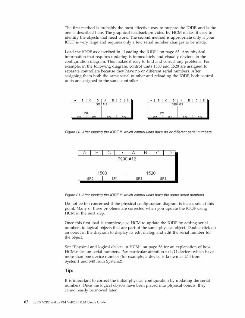
The first method is probably the most effective way to prepare the IODF, and is theone is described here. The graphical feedback provided by HCM makes it easy toidentify the objects that need work. The second method is appropriate only if yourIODF is very large and requires only a few serial number changes to be made.
Load the IODF as described in “Loading the IODF” on page 63. Any physicalinformation that requires updating is immediately and visually obvious in theconfiguration diagram. This makes it easy to find and correct any problems. Forexample, in the following diagram, control units 1500 and 1520 are assigned toseparate controllers because they have no or different serial numbers. Afterassigning them both the same serial number and reloading the IODF, both controlunits are assigned to the same controller.
Do not be too concerned if the physical configuration diagram is inaccurate at thispoint. Many of these problems are corrected when you update the IODF usingHCM in the next step.
Once this first load is complete, use HCM to update the IODF by adding serialnumbers to logical objects that are part of the same physical object. Double-click onan object in the diagram to display its edit dialog, and edit the serial number forthe object.
See “Physical and logical objects in HCM” on page 58 for an explanation of howHCM relies on serial numbers. Pay particular attention to I/O devices which havemore than one device number (for example, a device is known as 240 fromSystem1 and 540 from System2).
Tip:
It is important to correct the initial physical configuration by updating the serialnumbers. Once the logical objects have been placed into physical objects, theycannot easily be moved later.
Figure 20. After loading the IODF in which control units have no or different serial numbers.
Figure 21. After loading the IODF in which control units have the same serial numbers.
62 z/OS V2R2 and z/VM V6R2.0 HCM User's Guide

The other thing you should do before reloading the IODF is to review your needfor physical description files. HCM comes with a number of PDF text files whichyou can use and/or modify, or you can create your own. You can then select whichPDFs to apply to which controllers and strings. For more details, refer to thefollowing topics:v “Choosing a physical description” on page 143 for controllersv “Choose physical description” on page 153 for stringsv Chapter 16, “Physical description files (PDF),” on page 399
See Chapter 16, “Physical description files (PDF),” on page 399 for more details. Ifyou have “brand X” equipment, ensure that you have read and understood the“Graphical representation of physical objects” on page 59. Controllers which havebeen assigned incorrectly to a PDF can always be changed later, but if most ofyour equipment is not well-served by the installation-supplied defaults, you willfind it easier to correct this before reloading the IODF.
After making your changes, save the configuration file. This implicitly saves theIODF. Then discard the configuration file by closing and deleting it. Reload theupdated IODF into a new configuration file. Use the configuration diagram tocheck if your changes are correct. If the changes are not yet correct, change theIODF by providing the serial numbers to your logical objects again, and reload theupdated IODF.
Then, you can modify the configuration in HCM, adding any desired physicalinformation (see Chapter 6, “Modifying objects in your configuration,” on page107).
Loading the IODFThis step loads the IODF data set into a configuration file. If the configuration filealready exists, HCM requests you to confirm that it is OK to completely overlaythis file.
Display the IODFs dialog by choosing IODFs... in the File menu.
z/OS:
For z/OS, the High-level Qualifier dialog is displayed (Figure 22). In this dialog,specify a high-level qualifier and click OK.
z/VM:
For z/VM, the High-level Qualifier dialog is omitted. Instead, all IODFs aredisplayed that are available on your accessed minidisks.
Figure 22. High-level Qualifier dialog
Chapter 4. Building your configuration 63

The contents of the list of existing host IODFs displayed in the IODFs dialogdepends on the qualifier specified (see also “Specifying a high-level qualifier forz/OS” on page 67. The currently used high-level qualifier is always displayedbelow the Qualifier... button on the IODFs dialog. In the example in Figure 23, thehigh-level qualifier specified is "DOCU".
Note: For migrated IODFs (identified by MIGRAT in column Volume), HCM cannotdetermine the MUA status and the size, and therefore columns MUA-enabled andSize remain blank.
Select an IODF and click on the Load... button to request the loading of theselected IODF into a configuration file.
Once the Load... function starts, HCM displays the Choose Local File dialog(Figure 24 on page 65). You are then taken through steps to select or create aconfiguration file to receive the IODF information. In other words, the Load...function creates a new configuration based on the contents of the IODF. Theconfiguration file is automatically associated with the selected work IODF.
Figure 23. IODFs dialog
64 z/OS V2R2 and z/VM V6R2.0 HCM User's Guide
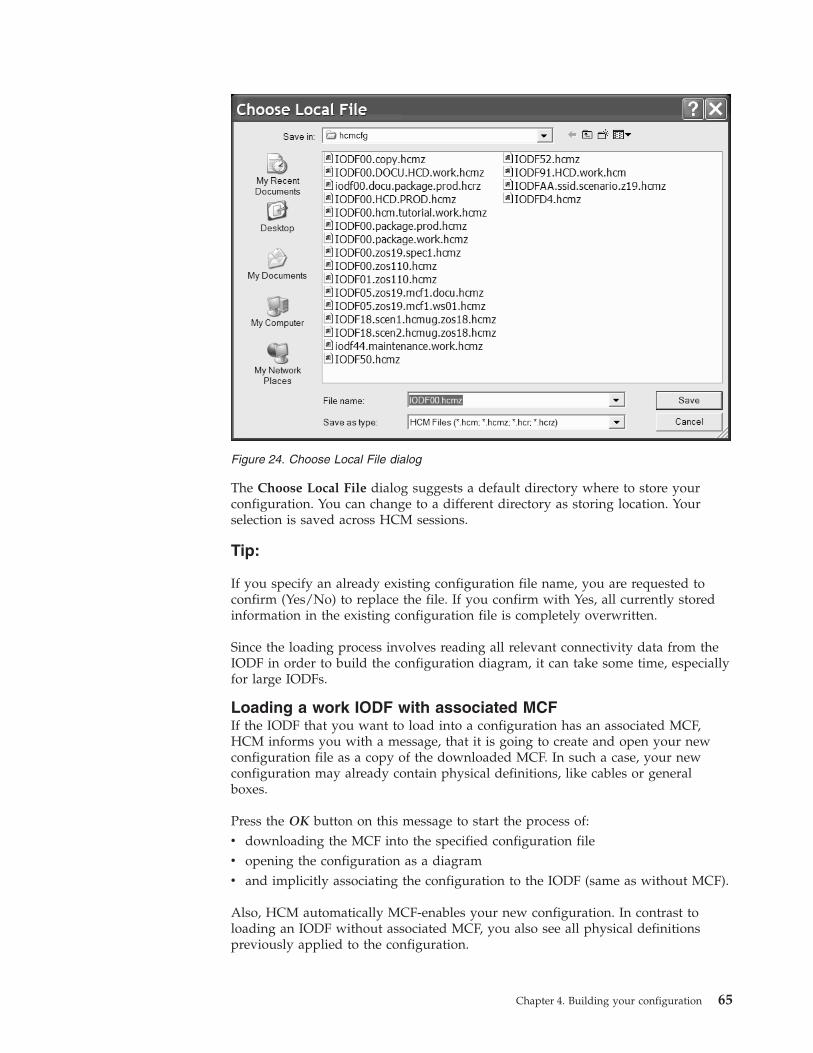
The Choose Local File dialog suggests a default directory where to store yourconfiguration. You can change to a different directory as storing location. Yourselection is saved across HCM sessions.
Tip:
If you specify an already existing configuration file name, you are requested toconfirm (Yes/No) to replace the file. If you confirm with Yes, all currently storedinformation in the existing configuration file is completely overwritten.
Since the loading process involves reading all relevant connectivity data from theIODF in order to build the configuration diagram, it can take some time, especiallyfor large IODFs.
Loading a work IODF with associated MCFIf the IODF that you want to load into a configuration has an associated MCF,HCM informs you with a message, that it is going to create and open your newconfiguration file as a copy of the downloaded MCF. In such a case, your newconfiguration may already contain physical definitions, like cables or generalboxes.
Press the OK button on this message to start the process of:v downloading the MCF into the specified configuration filev opening the configuration as a diagramv and implicitly associating the configuration to the IODF (same as without MCF).
Also, HCM automatically MCF-enables your new configuration. In contrast toloading an IODF without associated MCF, you also see all physical definitionspreviously applied to the configuration.
Figure 24. Choose Local File dialog
Chapter 4. Building your configuration 65

Before loading the IODF into a (new) configuration, you may want to find outwhether this IODF has an associated MCF data set or whether it is enabled formulti-user access (MUA). Select the IODF from the list of existing IODFs in theIODFs dialog and press the Details... button to display the IODF Details panel(Figure 25) which indicates the status of the IODF (MCF/MUA status enabled ordisabled).
Loading a production IODF with associated MCFIf you are loading a production IODF with an associated MCF, HCM downloadsthe MCF and opens the master configuration. Since the master configurationassociated with a production IODF is always a work configuration file, you nowhave an in-sync, up-to-date configuration, but you may not be ready to continue towork with it.
Note:
When loading a production IODF, HCM always creates a work configuration filefirst. Therefore, hcm(z) is offered as the default file type in the Choose Local Filedialog. This behavior is not new with the MCF functionality. The created workconfiguration is immediately usable only for viewing or for physical-only updates.
When loading an MCF-enabled production IODF, HCM offers to additionallycreate a production configuration file. Creating an associated productionconfiguration file is recommended, but not mandatory (for example, for justviewing an up-to-date state of the master configuration).
Even if you do let HCM create the production configuration, it still opens thedownloaded work configuration file first. This is to keep the behavior consistentwith older releases of HCM. At this point, you cannot apply logical changesbecause the associated production IODF cannot be changed. Also, the menu choiceFile ---> Make Work is disabled, because HCM enables it only for productionconfiguration files. If you want to just view an up-to-date state of the masterconfiguration (or if you want to apply purely physical changes), the opened workconfiguration is sufficient for that purpose.
Figure 25. IODF Details
66 z/OS V2R2 and z/VM V6R2.0 HCM User's Guide

Often however, you now want to apply (physical and logical) changes to a newpair [work IODF, work configuration file]. In order to be able to create such a pair,you first have to close the work configuration and open the productionconfiguration (which you previously allowed HCM to create during loading of theMCF-enabled production IODF). Here, the menu choice File ---> Make Work isenabled and allows you to create the new work configuration pair.
Working with multi-user access enabled IODFsFor an IODF on the host, HCD users can specify a multi-user access (MUA) option,so that multiple users can simultaneously update this IODF using HCD.
HCM provides information about an IODF's MUA status, either in the IODFsdialog or in the IODF Details dialog, so that before working with an IODF inHCM, you can check its MUA status (enabled or disabled).
HCM users can work with MUA-enabled IODFs in the following way:v You can load a multi-user access enabled IODF from HCD into a new HCM
configuration file and you can open an existing HCM configuration associatedwith a MUA-enabled IODF. HCM informs you when the accessed IODF isMUA-enabled:
After pressing OK, you can apply physical changes and you can use the viewingand reporting features of HCM on this configuration. However, you cannotapply logical updates that would affect the associated IODF.
v When opening a configuration with a multi-user access enabled IODF, you seeand keep the current status of the IODF during your complete HCM session.You will not be aware of any changes that other HCD users might apply duringthat time.If you close the configuration and re-open it at a later point in time, HCM willconduct any required resynchronization (see “Resynchronizing configurationfiles and IODFs” on page 56).
v Operations on MCF-enabled configurations work in the same way for associatedMUA-enabled or MUA-disabled> IODFs, with one exception: You cannot changethe MCF status of a configuration associated with a MUA-enabled IODF.
For more information about multi-user access on IODFs, refer to the z/OS HCDUser's Guide.
Specifying a high-level qualifier for z/OSz/OS:
For z/OS you can click on the Qualifier... button in the IODFs dialog to open theHigh-Level Qualifier dialog. You can then specify the qualifier which determinesthe list of IODFs displayed in the IODFs dialog. The qualifier is the string of up toeight characters that precedes the first period in the data set name. Changing thequalifier displays the list of IODFs beginning with that qualifier.
Chapter 4. Building your configuration 67

z/VM:
For z/VM this dialog is not applicable. There is no filter to reduce the number oflisted IODFs in the IODFs dialog. Instead, all IODFs are displayed that areavailable on your accessed minidisks as shown in Figure 26.
Choosing alternate processor definitionsIf there is more than one processor defined in the IODF, HCM asks you during theloading process whether the processors are physically separate or alternate processordefinitions for the same processor.
The physical processor, known in HCM as the machine, can have multiple logicalprocessors known as shadows. For example, a processor may be defined once inBASIC mode and once in LPAR mode. The primary processor in the machine is thatwhich is in the current logical view; at IODF load time, machine connections arebuilt for primary processors only. Alternate or shadow processors are those not in thecurrent view; no physical connections are built for alternate processors at IODFload time. Every processor must be assigned to a new or existing machine. Thename of the machine is the name of the primary processor.
During the IODF load (or resync) process, you can confirm or change whichprocessors are assigned to which machines. The Machines dialog automaticallyappears when there are new processors (added to the IODF on the host) whichmust be assigned to new or existing machines, or any time that some machine hasmore than one processor.
Figure 26. IODFs dialog for z/VM
68 z/OS V2R2 and z/VM V6R2.0 HCM User's Guide

HCM attempts to assign processors and primary / alternate status intelligently.The Machines dialog asks you to confirm or change HCM's assignments; typically,you press OK to confirm. For details on how to change HCM assignments, andhow to manage shadow processors in general, see Appendix A, “Alternateprocessor definitions,” on page 435.
After loading the IODF, the PC configuration file and the IODF are savedautomatically.
Inspecting the initial configurationThe result of the IODF load process is the creation of an initial configuration in aconfiguration file, using the logical data and serial numbers from the prepared andloaded IODF. At this point, you can take the time to examine the configuration forany inaccuracies caused by incorrect serial numbers:1. Ensure that you have the correct number of physical processors in the diagram.
If you do not, the serial numbers are incorrect. You must reload the IODF withthe correct processor serial numbers.
2. Ensure that all control units have been placed in the correct controllers. If thereare control units in the wrong controllers, the control unit serial numbers areincorrect. The control unit cannot be moved into another controller. You caneither correct the serial numbers and reload the IODF, or use HCM to deletethe controller and control unit(s) and recreate and reconnect the control unitproperly.
Note: Do not worry about control units being in the correct segments, orcontroller interfaces being attached to the correct cables at this >point.
Adding physical data to the configurationAt this point, you have a configuration that is as accurate as possible from the dataavailable in the loaded IODF. All necessary serial numbers are available. Proceednow with updating the physical data in HCM.
Note:
Figure 27. Machines dialog
Chapter 4. Building your configuration 69

1. After you have made any physical changes, do not load the IODF again,because a load replaces the existing configuration file and all physical data willbe lost.
2. If you loaded an IODF with an associated MCF data set, HCM has created yournew configuration as a download copy from that MCF, so that it most probablyalready contains physical definitions.
How to update physical data is described in the following topics:v Changing PDF assignments for controllers and strings (see “Graphical
representation of physical objects” on page 59 and Chapter 16, “Physicaldescription files (PDF),” on page 399).
v Moving control units between controller segments (see “Arranging controllercomponents” on page 145).
v Ordering the interfaces on controllers and strings (see “Arranging controllercomponents” on page 145).
v Ordering daisy-chained controllers and strings in the proper sequence on theircables (see “Connecting objects” on page 188 and “Positioning objects alongdaisy-chained connections” on page 188).
v Creating and connecting crossbar switches and fiber management cabinets (see“Crossbar switches” on page 173 and “Cabinets” on page 176 and “Editing fiberlinks” on page 227 and “Connecting crossbar switches” on page 233).
v Importing physical objects, changing physical connectivity, updating descriptivefields in both the PC file and the IODF, resynchronizing the PC file and theIODF, (see Chapter 15, “Importing and exporting data,” on page 353).
v Managing cables (see Chapter 8, “Physical connections,” on page 221).
After you have made physical changes, use the Copy Configuration Files...pull-down choice of the File menu to make a backup copy of your configurationfile.
Creating a new configuration from scratchWhen building a configuration from scratch, you must create an empty IODF fileas well as a new configuration file. From the File menu, choose IODFs... to displaythe IODFs dialog. Click on the Create... button to open the Create IODF dialog tocreate the new IODF on the host.
After a successful creation, the new IODF is added to the list of IODFs displayedin IODFs dialog.
Then, on the same dialog, with the new IODF selected, press the Load... button.This offers you a dialog to specify and save an HCM configuration file which isassociated to the new HCD IODF. Now you are ready to create configurationobjects. More information is in “Loading the IODF” on page 63.
z/OS:
For z/OS, HCM follows TSO/E data set naming rules. In addition, the IODF namemust have the following format
hhhhhhhh.IODFcc.yyyyyyyy.yyyyyyyy
where:
70 z/OS V2R2 and z/VM V6R2.0 HCM User's Guide

hhhhhhhhis the TSO/E high level qualifier. If the name is enclosed in quotationmarks then it must begin with a high-level qualifier. Otherwise, it must notand your user ID is used as the high-level qualifier.
cc is a set of any two hexadecimal characters (0..9 or A..F)
yyyyyyyyare optional qualifiers.
You must allocate enough space for the IODF. The minimum work size is 16; thedefault is 1024, which allows you to define at least 4000 devices, in general. Youcannot change the space for an IODF later. If the configuration expands beyondthis size, the IODF must be copied to a larger data set, using the Copy... button onthe IODFs dialog (see “Copying an existing IODF” on page 76).
After you have entered the information, press OK to create the new IODF. Nowselect the IODF and load it as described in “Loading the IODF” on page 63.
z/VM
For z/VM, the name of an IODF is given by the file identifier of the CMS file.z/VM requires a certain naming convention in order to identify IODFs andaccompanying files.
The CMS file name of an IODF must be IODFxx, where xx are two hexadecimaldigits.
The CMS file type is:
WORKIODFfor a work IODF
PRODIODFfor a production IODF
BACKIODFfor a backup IODF
The file ID of the corresponding activity log consists of the CMS file name of theIODF and one of the following file types:
WORKACTLfor the activity log file of a work IODF
PRODACTLfor the activity log file of a production IODF
BACKACTLfor the activity log file of a backup IODF
WORKCLOGchange log file for automatic activity logging
Examples:IODF01 WORKIODF AIODF01 PRODIODF A
For more information about naming conventions for z/VM HCD refer to z/VM: I/OConfiguration (SC24-6100).
Chapter 4. Building your configuration 71

To populate a new configuration file with data from an existing IODF, see“Creating a new configuration from an IODF” on page 60.
Opening an existing configurationIf you are opening an existing configuration to edit, you can either:v Open an existing configuration file and associated IODF, orv Open an existing configuration file and an alternate IODF, andv Upgrade earlier versions of configuration files.
Opening an existing configuration file and associated IODFChoose the Open... command from the File menu. Select an existing configurationfile to open from the list in the standard File Open dialog that appears. Note thatHCM appends the file extension *.HCM to your configuration file in case noextension is specified yet. HCM opens the configuration file against the particularIODF to ensure they are in sync.
If the configuration file and IODF are out of sync, HCM asks if you wish to openthe configuration file anyway. Either the IODF has been replaced with an earlier oreven unrelated IODF, or it has been updated on the host, outside HCM. If youopen the configuration file, HCM will resynchronize; the configuration file will bealtered to match the changed IODF.
If the configuration is MCF-enabled ...1. ... and HCM finds a more recent MCF than the used existing configuration and
there are no stand-alone mode changes in this configuration, then the MCFautomatically replaces the existing configuration after requesting confirmation.
2. ... and HCM finds a more recent MCF than the used existing configuration andthere are stand-alone mode changes in this configuration, then HCM opens the
Figure 28. File Open dialog
72 z/OS V2R2 and z/VM V6R2.0 HCM User's Guide

Physical Mismatch Resolution dialog to allow the user to get his existingconfiguration in sync with the MCF (see “Using the master configuration file(MCF)” on page 86).
If the used IODF is MUA-enabled ...
... be aware of how you can work with and how HCM handles suchconfigurations. Refer to “Working with multi-user access enabled IODFs” on page67.
Opening an existing configuration file with a new IODFYou can deliberately open a configuration file with a new IODF, other than the oneassociated with it. For example, you may wish to fix a mistake using an earlierIODF, or want to copy the IODF to a new (alternate) one with a larger allocatedsize. If the IODF has been renamed on the host, this feature allows you to open theconfiguration file against the renamed IODF.
Choose Open Special... from the File menu. The File Open dialog is displayed.Select a configuration file and click on Open.
Then, when working on z/OS, the High-level Qualifier dialog is displayed whereyou can specify a qualifier which determines the list of IODFs to be displayed.Click on OK. When working on z/VM, this dialog is skipped.
The Select an Alternate IODF dialog is displayed:v for z/OS, listing the IODFs with the specified qualifier,v for z/VM, listing all IODFs available on your accessed minidisks.
Select an IODF from the list and press OK. The configuration file is opened andresynchronized against the selected IODF.
If you exploit the MCF concept (see “Introduction to the master configuration fileconcept” on page 57 and “Using the master configuration file (MCF)” on page 86),both IODFs involved in the Open Special... operation (‘old’ and ‘new’ IODF) mayhave associated MCF data sets. HCM first of all checks whether the old IODF stillexists:v If it does exist, but without associated MCF, it is ignored, just like without MCF
exploitation.v If the old IODF does exist with an associated MCF, then there are the following
possibilities:– The existing configuration is MCF-enabled: in this case, HCM starts the
following processing:If the local configuration has set an LC flag, HCM alerts the user and offersthe choice to abort the Open Special... operation. The user can re-open theconfiguration with the old IODF and associated IODF in order to propagatethe configuration's local changes to the (old) MCF.
– The existing configuration is not MCF-enabled: in this case, the MCFassociated to the old IODF is ignored, and processing is just like withoutMCF concept.
After HCM has decided about how to process the old IODF, it decides how tocontinue processing with the new IODF. Table 8 on page 74 lists all possiblecombinations and describes how HCM reacts while opening the configuration.
Chapter 4. Building your configuration 73

Table 8. Opening an existing configuration file with a new IODF
new IODF with associated MCF new IODF without MCF
existing config is MCF-enabled If the local configuration has set anLC flag, HCM compares the MCF onthe host with the local configurationand offers the Physical MismatchResolution dialog. Then, if necessary,an IODF resynchronization isinvoked.
HCM will MCF-disable theconfiguration. If required, an IODFresynchronization is started.
existing config is not MCF-enabled The existing configuration isautomatically MCF-enabled. To allowthe user to bring physical definitionsin sync between MCF and localconfiguration, HCM starts thePhysical Mismatch Resolutiondialog. Then, if necessary, an IODFresynchronization is invoked.
No special action required. Ifnecessary, an IODF resynchronizationis started.
Upgrading configuration filesUsing a configuration file created with an earlier version or service level of HCMcan require an upgrade if you try to open this configuration file with a newerversion of HCM. HCM applies an upgrade to both work configuration files andproduction configuration files. With HCM you can:v upgrade the content of work and production configuration files (older *.hcr and
*.hcm files are usable with newer versions or service levels of HCM)v access the content of work and production configuration files as read-only (the
*.hcr and *.hcm files are not upgraded)
HCM automatically detects whether a configuration file of an earlier version orservice level needs to be upgraded for the use with the current level of HCM. Theupgrade operation is indicated by the following dialog box:
If you select the Upgrade button, HCM performs the upgrade operation and thensaves the configuration file.
Figure 29. Confirm Database Upgrade
74 z/OS V2R2 and z/VM V6R2.0 HCM User's Guide

After the upgrade of the configuration to the new version or service level has beendone, a resync of the configuration with the IODF is performed automatically.
If you select the Open as Read-Only button, the configuration file is not saved andyou are not allowed to edit the configuration file - regardless whether a work orproduction configuration file is open.
Note: In case you want to continue to use your configuration file with an olderversion or service level of HCM, you must create a backup before upgrading,which you can use with the older version or service level of HCM.
Upgrading the associated IODF from version 4 to version 5formatStarting with z/OS V1R7, HCD uses the new version 5 IODF format. To upgradeboth:v the HCM configuration file to the new data base format,v the associated version 4 IODF to a new version 5 IODF,
choose one of the following alternatives, depending on your requirements:
Alternative 1: Upgrade the IODF within HCM
1. Open the pre-V1R7 configuration file (File → Open). HCM prompts you toeither upgrade or open the file as read-only (Figure 29 on page 74). It isrecommended to use the read-only option, because this choice keeps a backupof the original configuration file. Or you can load a pre-V1R7 IODF into a newor existing, pre-V1R7 configuration file (File → IODF). Depending on the size ofthe IODF, this process can take quite some time because HCD converts theloaded IODF data into the new version 5 format.
2. In both cases, you get an HCD message (CBDG549I), indicating that theassociated IODF is temporarily upgraded in-storage only to a version 5 IODF. Ifyou press the OK button in this message, HCM loads the configuration file. Atthis stage, you can perform physical changes only. Logical changes (those thataffect the associated IODF) are still prohibited.
3. Use the function Copy Configuration Files... from the File menu to upgradeboth the HCM configuration file and the associated IODF to the new formats.On the Select Target IODF for Copy window, select New... to create a newIODF. Since the conversion process in step 1 releases space within the usedblocks, you can usually reduce the allocated space for the new IODF down tothe number of used blocks. Save the upgraded HCM configuration file under anew name. You will receive message CBDA483I informing you that theupgraded IODF has been stored in a new IODF.
4. Close the current configuration file and open the upgraded one created in step3. As you used the Copy Configuration Files... function, the copied HCMconfiguration file is already associated with the new version 5 IODF, and henceno resynchronization step is needed in this scenario. You are now ready toupdate your configuration with logical changes, too.
Note: Next time you build a new production IODF from the upgraded IODF, youmay further reduce the number of allocated blocks, since now the IODF data iscondensed.
Alternative 2: Upgrade the IODF within HCD
1. You can also use the task Upgrade I/O definition file to new format underHCD option Maintain I/O definition files to upgrade the version 4 IODF to aversion 5 IODF (see z/OS HCD User's Guide for a detailed description). This
Chapter 4. Building your configuration 75

method allows you to condense the IODF in a single step. Depending on thesize of the IODF this process - as step 1 on page 75 from alternative 1 abovecan take quite some time, because HCD converts the loaded IODF data into thenew format.
2. In HCM, associate the HCM configuration file or a copy of it with theupgraded IODF (File → Open Special...). This way, HCM prompts you for anecessary data base upgrade together with a mandatory resynchronizationprocess which, depending on the IODF size, may take quite some time.
Working with your IODFs and configuration filesYou can perform the following tasks with your IODF files using HCM:v “Copying an existing IODF”v “Making a work or a production IODF”v “Using the CHPID Mapping Tool Support utility” on page 78v “Creating work and production IODFs without the associated configuration
files” on page 80v “Exporting and importing IODFs” on page 81v “Deleting an existing IODF” on page 81v “Checking a configuration” on page 81v “Copying a configuration” on page 82v “Creating work and production IODFs with the associated configuration files”
on page 83v “Compressing configuration files” on page 84v “Naming convention of your configuration files and IODFs” on page 85v “Deleting a configuration file” on page 85v “Saving and closing your configuration” on page 85
Copying an existing IODFSelect an IODF from the list and click on the Copy... button in the IODFs dialog toopen the Target IODF dialog. If you are copying to a new IODF file, type in thenew IODF filename in the text field. If you are copying to an existing IODF file,HCM confirms overwriting the file.
You can also copy the IODF to increase the IODF file size.
If a master configuration file (MCF) is associated to the IODF, it is copied alongwith the IODF. For information about the MCF concept, refer to “Introduction tothe master configuration file concept” on page 57 and “Using the masterconfiguration file (MCF)” on page 86.
Making a work or a production IODFA work IODF can be modified and updated; it serves as your “working copy”.
A production IODF is used by IPL to build UCBs and EDTs. It is also used to buildIOCDSs and IOCP input data sets. Several users can view a production IODFconcurrently and make reports of it, but it cannot be modified.v To create a pair of associated work files, the work IODF and the work
configuration file, from a production IODF/configuration pair, use action File---> Make Work....
76 z/OS V2R2 and z/VM V6R2.0 HCM User's Guide

v To create a pair of associated production files from a work IODF/configurationpair, use action File ---> Build Production....
When building a production IODF from a work IODF where XMP processors aredefined, a production IODF can only be built if all logical channels (CHPIDs) of allXMP processors have PCHID values defined. If at least one PCHID value ismissing, HCM does not build a production IODF, but flags the work IODF asvalidated. In this case, you receive at least one error message saying that channelpath(s) do not have a physical channel assigned, and you also get an informalmessage saying that the current IODF is now valid except of missing PCHIDs.Select one of the following alternatives to integrate the missing PCHIDs into thework IODF:v Alternative 1: The most comfortable method is to invoke the CHPID Mapping
Tool Support from either the Utilities menu or from the Edit Processor dialog(see “Editing a processor” on page 120). This alternative is further described in“Using the CHPID Mapping Tool Support utility” on page 78.
v Alternative 2: Switch to HCD and use the validated work IODF to generate anIOCP input file suitable for the use with the CHPID Mapping Tool. You can finddetailed information about how HCD can interact with the CHPID MappingTool in the applicable z/OS HCD User's Guide or z/VM: I/O Configuration book.The output of this process now is a complete and valid work IODF from whichyou can build the production IODF. When loading the modified IODF back intoHCM again, you need to resynchronize HCD and HCM data as described in“The IODF load / resync process” on page 55.
v Alternative 3: You can use the mapping information provided by the CHPIDMapping Tool to type in the PCHIDs manually into the HCM Create CHPIDsdialog (see “Create CHPIDs” on page 132).
For any OS configuration that specifies a D/R site OS configuration name asdescribed in “D/R site OS configurations” on page 263, the D/R site OSconfiguration is automatically generated when building the production IODF.
If the configuration is MCF-enabled...
... the MCF will be copied to the production IODF when it is built. The other wayround, the MCF will be copied back to the work IODF when creating a work IODFagain from a production IODF.
The master configuration associated with a production IODF is a workconfiguration file. However, when loading an MCF-enabled production IODF viaFile ---> IODFs... ---> Load, HCM offers to create a production configuration file(.hcr/.hcrz).
Production configuration files are considered 'read-only snapshots' of aconfiguration. Therefore, they do not participate in the normal MCF operations:they are not refreshed via download from the host MCF, and they do not updatethe host MCF via upload.
If a production IODF does not yet have an associated MCF, a user with aproduction configuration file may enable the configuration for MCF sharing. Hemay not disable the configuration for MCF sharing, however, for the followingreason:v Other users may own a work configuration file associated with the production
IODF. They may apply changes to their configurations (affecting non-IODFobjects only). These changes will be propagated to (and from) the MCF as usual.
Chapter 4. Building your configuration 77

The user owning a production configuration file associated with the same IODFis not aware of such changes, because a production configuration file is notrefreshed with updates from the MCF. Therefore, HCM does not allow you toset the access mode to Single user mode for production configuration files,because this would delete the central MCF and other users could not receivethese applied changes.
For more information about how to create work and production IODFs, read thefollowing topics:v “Creating work and production IODFs without the associated configuration
files” on page 80v “Creating work and production IODFs with the associated configuration files”
on page 83
Using the CHPID Mapping Tool Support utilityHCM can prepare an IOCP file as input to the CHPID Mapping Tool (CMT) inorder to add or update PCHIDs to this IOCP for XMP processors. You candownload the CHPID Mapping Tool from the Internet at the IBM Resource Link®
Web site at:http://www.ibm.com/servers/resourcelink
It runs on a Windows workstation. Input to the CHPID Mapping Tool is thehardware configuration file (CFReport 1) of your machine and a valid IOCP inputfile (with missing or obsolete PCHIDs).
In HCM, invoke the CHPID Mapping Tool Support dialog from either the Utilitiesmenu or from the Edit Processor dialog (see “Editing a processor” on page 120).This utility offers the following functions:v It exports (downloads) an IOCP file of a selected processor from the host.v It launches the CHPID Mapping Tool with the exported IOCP file as input.
Using the CHPID Mapping Tool, you can assign PCHID values to CHPIDs. Themodified IOCP file is saved on the workstation.
v It imports (uploads) the modified IOCP file back to the host where itautomatically invokes a PCHID migration. Then it also refreshes the localconfiguration with the new CHPID-PCHID assignment.
1. When a machine is ordered, the output of the order process is a binary file that represents the physical description of the finalmachine. One of the components of that file is the type and physical location, including the Physical Channel Identifier (PCHID)value assigned to that location, of all the I/O features in the final machine. This file is called a CFReport.
78 z/OS V2R2 and z/VM V6R2.0 HCM User's Guide

Using the dialog shown in Figure 30 you can update PCHID values in yourconfiguration performing the following steps:1. From the Processor listbox, you must select a processor, if you invoked this
utility from the Utilities menu. If invoked from the Edit Processor dialog, thislistbox contains the current processor, and you cannot select a different one.
2. Selecting the Export IOCP File for CMT radio button receives the IOCP file forthe selected processor from the host. The IODF for the current configurationmust be a work IODF. The dialog proposes a name for the file where to storethe IOCP file on the workstation, or, using the "..." button, you can browse fora file where to store the retrieved IOCP. When you press the OK button, HCDcreates a validated work IODF on the host and exports an IOCP file for theselected processor. HCM then downloads the exported IOCP file and saves iton the workstation in the previously specified file. If HCD encounters errorsduring generation of the validated work IODF, HCM displays thecorresponding messages and does not download any IOCP file.
3. Following a successful download of the exported IOCP file, select the LaunchCMT radio button. However, this button is only enabled if the CHPID MappingTool is correctly installed on your workstation. Note that the feature to belaunched from HCM is available for the CHPID Mapping Tool version 4.02 orlater.In the Input IOCP File for CMT entry field, specify the IOCP file exported instep 2. In the Output IOCP File for CMT entry field, specify the output filewhere the CHPID Mapping Tool should write the modified IOCP file with thenew PCHID assignment. For IOCP input and output, you can use the same file.When you press the OK button, HCM starts the CHPID Mapping Tool, passingthe selected file names as parameters. Now use the CMT to perform the PCHID
Figure 30. CHPID Mapping Tool Support
Chapter 4. Building your configuration 79

assignment and save the updated IOCP file. The new IOCP file contains theoriginal I/O definitions together with inserted and/or updated PCHID values.The original hardware configuration token is still contained in the generatedstatements.For information about how to use the CMT, refer to its online help and relateddocumentation.
4. Now, back in the CHPID Mapping Tool Support dialog, select the Import IOCPFile from CMT radio button and press the OK button to send the updatedIOCP file back to the host. This action automatically migrates the newCHPID-PCHID assignment into the affected IODF on the host, thus creating anupdated work IODF without further need to use the HCD dialog. This actionalso refreshes the HCM configuration file on the workstation with the PCHIDassignment, thus keeping the configurations on host and workstationconsistent.
Note:
1. If for any reasons for an XMP processor you want to define a channel that isnot physically installed on the machine yet, you can use the method ofover-defining a channel path as described in “Over-defining a CHPID” on page135. Thus you can avoid to let the CHPID Mapping Tool run into an error,because it cannot find the PCHID.
2. If the PCHID migration produces an assembler error listing, you can use buttonShow Listing to display an assembler listing for error analyzing purposes.
3. When during importing an IOCP data set from the CHPID Mapping Tool, youget a message due to insufficient space allocation, you can use the HCD profilekeyword ALLOC_SPACE to overwrite the default space allocation. For moreinformation, refer to the z/OS HCD User's Guide.
4. The CHPID Mapping Tool support is not available for configurations with anassociated MUA-enabled IODF.
Creating work and production IODFs without the associatedconfiguration files
To make a work IODF from a production IODF, click on the Make Work... buttonin the IODFs dialog. The Create IODF dialog appears, allowing you to create thework IODF. HCM deletes an existing IODF, and creates the new IODF.
To make a production IODF from a work IODF, click on the Build Prod... button inthe IODFs dialog. The Create Production IODF dialog appears to allow you tocreate the production IODF.
When you make a production IODF, a “post-validation” is performed which mightissue messages you have to deal with, according to their severity. The productionIODF is not created if any errors with a severity higher than ‘warning’ areproduced.
In order to use a production IODF for IPL and dynamic activate, its name musthave the format, ‘hhhhhhhh.IODFcc’ where ‘hhhhhhhh’ is the high-level qualifier,up to 8 characters long, and ‘cc’ are any two hexadecimal characters. Optionalqualifiers that are allowed for work IODFs must be omitted.
For information about naming conventions for IODFs on z/VM refer to “Creatinga new configuration from scratch” on page 70.
80 z/OS V2R2 and z/VM V6R2.0 HCM User's Guide

Exporting and importing IODFsHCM provides functions to export an IODF from the host to the workstation andto import an exported IODF back to the host. You can use these functions forexample, to easily transfer IODFs between systems.
Launch the export/import functions by pressing the Export or Import button fromthe IODFs dialog (see Figure 23 on page 64).
Select an IODF from the list, press Export, then use the Export IODF dialog, toexport an IODF from the host and save it as a file on the PC. In the ExportedIODF file entry field, HCM proposes a workstation file name for the exportedIODF, consisting of the fully qualified IODF name and the extension .expiodf.When you press the OK button, HCD saves the exported IODF on the PC andindicates the storage location in a message (this is normally the directory whereyour configuration files are stored).
Using the Import IODF dialog, you can import an IODF from a file that waspreviously exported and saved on the workstation. This function builds an IODFon the host, as it is used by HCD. In the IODF entry field, you enter a fullyqualified IODF name for the imported target IODF on the host. If you selected anIODF from the IODFs dialog, this entry field is filled with the name of thisselected IODF. If you specify a new name, a new IODF is created on the host.
Deleting an existing IODFSelect an IODF from the list in the IODFs dialog, and click on the Delete... button.HCM displays a confirmation dialog prior to deleting the IODF.
Checking a configurationYou can check a configuration file for structural consistency. Select CheckConfiguration File... from the Utilities menu. This opens the dialog shown in
Figure 31. Export IODF
Figure 32. Import IODF
Chapter 4. Building your configuration 81
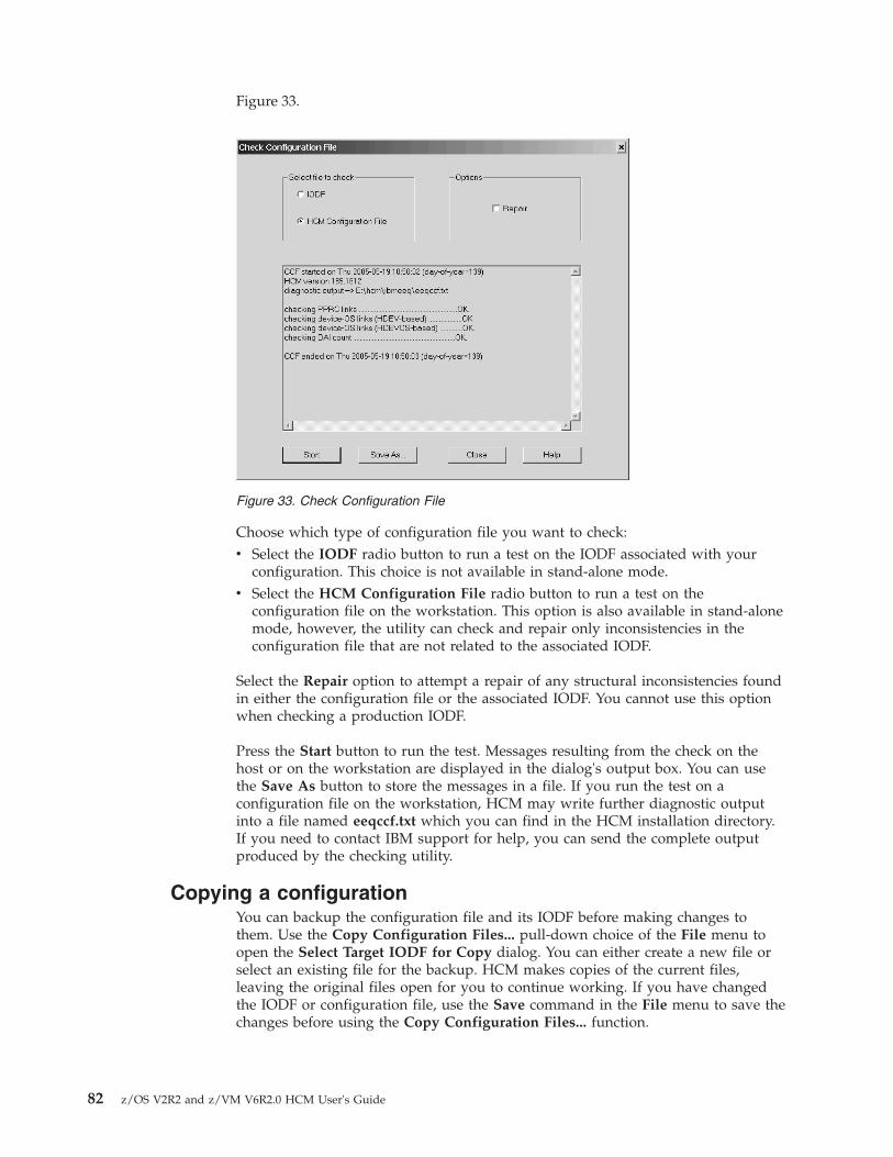
Figure 33.
Choose which type of configuration file you want to check:v Select the IODF radio button to run a test on the IODF associated with your
configuration. This choice is not available in stand-alone mode.v Select the HCM Configuration File radio button to run a test on the
configuration file on the workstation. This option is also available in stand-alonemode, however, the utility can check and repair only inconsistencies in theconfiguration file that are not related to the associated IODF.
Select the Repair option to attempt a repair of any structural inconsistencies foundin either the configuration file or the associated IODF. You cannot use this optionwhen checking a production IODF.
Press the Start button to run the test. Messages resulting from the check on thehost or on the workstation are displayed in the dialog's output box. You can usethe Save As button to store the messages in a file. If you run the test on aconfiguration file on the workstation, HCM may write further diagnostic outputinto a file named eeqccf.txt which you can find in the HCM installation directory.If you need to contact IBM support for help, you can send the complete outputproduced by the checking utility.
Copying a configurationYou can backup the configuration file and its IODF before making changes tothem. Use the Copy Configuration Files... pull-down choice of the File menu toopen the Select Target IODF for Copy dialog. You can either create a new file orselect an existing file for the backup. HCM makes copies of the current files,leaving the original files open for you to continue working. If you have changedthe IODF or configuration file, use the Save command in the File menu to save thechanges before using the Copy Configuration Files... function.
Figure 33. Check Configuration File
82 z/OS V2R2 and z/VM V6R2.0 HCM User's Guide

Creating work and production IODFs with the associatedconfiguration files
Building a work or production IODF using the Build Production... or the MakeWork... function of the File menu means, that the associated configuration files arealso created.
To make a production IODF from a work IODF select File from the menu and thenselect the Build Production... action.
Two dialogs appear. The first one is Create Production IODF followed by SaveProduction File.
HCM checks whether the target IODF exists on the host. If it already exists, HCMdeletes the existing IODF and proceeds with the Create Production IODFoperation.
The following results may occur when the Build Production... action is performedon the host. The first two results indicate that the operation was performedsuccessfully.
SUCCESSNo warnings or errors. The *.hcr file is to be saved under the namesupplied in the Save Production File dialog.
SUCCESS WITH WARNINGSNo errors. You can view the warnings. HCM continues with the SaveProduction File dialog. If you do not want to continue, the productionIODF is still available. There is no automatic deletion of the IODF.
ERRORNo production IODF has been created. You can view the error andwarning messages.
If the production IODF is successfully created, HCM displays the Save ProductionFile dialog. The *.hcr/.hcrz file is saved under the name supplied in the SaveProduction File dialog.
Chapter 4. Building your configuration 83

When saving a production configuration file, you can specify the path in theDirectories and Drives section, the file name in the File Name section, and the filetype in the Save File as Type section. The defaults are:
Path The same path as for the *.HCM file, based on the last used directory.
File NameThe same file name as for the *.HCM file name.
File Type*.hcr (If no extension is specified, the default is used.)
To make a work IODF from a production IODF, select Make Work... from the Filemenu. Two dialogs appear. The first one is Create IODF followed by Save WorkFile.
You can reach the Create IODF dialog from various menus. The followingdescription is for the path via the Make Work... action.
HCM checks whether the target IODF exists on the host. If it exists, HCM deletesthe existing IODF and proceeds with the Create IODF operation. If the work IODFwas successfully created, HCM displays the Save Work File dialog.
When saving a work configuration file, you can specify the path in the Directoriesand Drives section, the file name in the File Name section, and the file type in theSave File as Type section. The default extension is *.HCM.
Compressing configuration filesUsing Options ---> File Compression... from the menu bar, you can choose to storeyour HCM configuration in a compressed format. This choice is recommended,because compressed files consume less disk space and provide a betterperformance while opening and saving. Compressed work configuration files have
Figure 34. Save Production File dialog
84 z/OS V2R2 and z/VM V6R2.0 HCM User's Guide

a file extension of .hcmz while uncompressed ones have the traditional extension.hcm. Likewise, compressed production configuration files have a file extension of.hcrz while uncompressed ones have the extension .hcr.
If you compress an MCF-enabled configuration, the associated MCF is alsocompressed.
HCM can read and load both the uncompressed and the compressed formats. Thefile compression option is checked only when storing the files on the disk. Thedefault format is uncompressed.
Note: Compressed HCM configurations cannot be opened with HCM releasesprior to z/OS V1R9. To uncompress a configuration, first select the option to notcompress configurations, then open the compressed configuration, apply at leastone minor, unimportant change, and save the configuration.
Naming convention of your configuration files and IODFsNormally, a given production IODF will repeatedly go through a cycle of beingconverted into a work IODF so that it may be altered, then converted back into aproduction IODF for use in the production environment. A standard namingconvention for PC files and IODFs which are part of this cycle can simplifyadministration. For instance, one possible convention would assign to eachproduction IODF a name that has an ever increasing version number. In an HCMenvironment, that IODF would be paired with, for example, an iodf92.hcr file (oriodf92.hcrz for compressed files) on the PC. When IODF92 requires modification, awork IODF and a work PC file are generated. The IODF receives the nameIODF93.WORK and the PC file receives the name iodf93.hcm (or iodf93.hcmz).Once the changes are made, new production versions are built with the namesIODF93 and iodf93.hcr (iodf93.hcrz).
Deleting a configuration fileYou cannot delete a configuration file together with its associated IODF with onefunction in HCM. You can delete them separately.
Saving and closing your configurationThe Save command in the File menu explicitly copies the configuration file frommemory to disk, but keeps it in memory so you can keep working. The Savecommand also saves the IODF, and tags the configuration file and IODF withmatching tokens.
After having updated the configuration, the Close command saves both the IODFand the configuration file, then closes both files. When you close the IODF withClose or Exit, the Activity Log dialog will appear if activity logging has beenenabled for the IODF (see “Creating a new configuration from scratch” on page70).
Closing an MCF-enabled configuration also updates the associated MCF on thehost.
You can enable automatic activity logging by entering the following keyword intothe HCD profile:CHANGE_LOG = YES
Chapter 4. Building your configuration 85

With this setting, HCD uses a subset of the change log entries to generateautomatic entries into the activity log for updates on configuration data, like forexample for add/delete or connect/disconnect activities. These entries are HCDproposals which you can edit.
Note: If on HCD, for any reason, the change log data set (CHLOG) is notaccessible, no automatic activity log entries can be created.
For more information, refer to the z/OS HCD User's Guide .
For z/OS, use the HCD dialog to view the complete activity log. For z/VM, useBROWSE or XEDIT to view the activity log. See “Creating a new configurationfrom scratch” on page 70 for this file's naming convention.
File → Exit performs a Save before exiting HCM.
If HCM terminates because of a host abend, a loss of network connection, or anHCM abend, then the next time you open your configuration file HCM may needto resynchronize it with the IODF. Furthermore, whether a resync is required ornot, the last modification made before the termination may need to be made again.
Using the master configuration file (MCF)The master configuration file (MCF) is an HCM configuration stored on the host asa central shared repository. The MCF concept is introduced in “Introduction to themaster configuration file concept” on page 57 and brings along the following mainadvantages:v Several HCM users can work cooperatively and safely on a single configuration,
sequentially sharing the configuration in connected mode.v There is no longer the need to keep this critical data on workstations, maybe
even distributed as multiple local copies across your installation, but you canmaintain a single consistent data set on the mainframe.
Sharing an HCM configuration via MCF is recommended when two or more usersneed to make changes to the configuration. Although in cases of conflict, MCFsharing provides a Physical Mismatch Resolution dialog (see “How to resolvephysical mismatches in a shared configuration” on page 93), the respective tasks ofthe users should be carefully planned and agreed upon. This eases later mismatchresolutions.
Figure 35. Activity Log dialog
86 z/OS V2R2 and z/VM V6R2.0 HCM User's Guide

The local configuration file and the master configuration file both carry atimestamp to allow HCM to detect changes done to non-IODF objects.Resynchronization and physical mismatch resolution is then based both on the LCflag and the various timestamps: the MCF physical timestamps, timestamps of thelocal configuration and on the IODF timestamp.
Using the HCD profile keyword MCF_VOL lets you specify a volume serialnumber where to store the MCF on the host (refer to the z/OS HCD User's Guide).
Here is an outline of the MCF mode of operation:v If you work in connected mode, the MCF is updated and stored on the host
whenever you close your configuration.v If you work in stand-alone mode, you work on a local copy of your
configuration. HCM cannot synchronize with the host-based MCF immediately,but sets a so-called LC flag, indicating that the configuration was locallychanged.
v During Open configuration processing, HCM compares the timestamps of thelocal configuration and the master configuration and distinguishes the followingscenarios:– If the timestamps of the local and the master configuration are the same, your
configuration is opened as usual.– If the local configuration is older than the MCF, and no local changes (no LC
flag) are found in the configuration, then, after the user's confirmation, HCMoverwrites the local configuration by downloading the MCF from the host.This ensures, that logical changes to the IODF and physical changes to theMCF are propagated to the current user.
– If HCM encounters the LC flag to be set, then the following cases aredistinguished:1. Timestamps of MCF and local configuration are the same:
This is the case, if a user had accessed the MCF in connected mode andended the session with MCF, local configuration and IODF in sync. Later,the same user has updated the local configuration in stand-alone mode.Even later again, the same user accesses the configuration in connectedmode, without any other user having accessed the configuration in themeantime. Opening processing continues as usual and only at closing timeof the configuration, HCM updates the MCF on the host with all of theuser's changes (from the previous stand-alone and the current connectedsession).
2. Timestamps of MCF and local configuration are different:This is the case, if another user has accessed the MCF in connected mode.In this case, HCM opens the Physical Mismatch Resolution to let thecurrent user resolve physical mismatches due to the changes in his localconfiguration.
Note: The MCF feature is new with z/OS 1.9. Its exploitation is optional. Withoutusing this feature, processing of HCM configurations continues to work as inprevious releases.
Enabling/disabling a configuration for MCF-sharingWith action File ---> Set Access Mode, you invoke a corresponding dialog (seeFigure 36 on page 88) where you can enable the current configuration to use theMCF concept by selecting the Master configuration file mode radio button.
Chapter 4. Building your configuration 87

When you mark a configuration as MCF-enabled, HCM creates the MCF anduploads it to the host when you close the configuration:v In z/OS, the MCF is stored on the host in a data set 'hlq.IODFnn....MCF' (that
is, the name of the associated IODF + suffix .MCF).v In z/VM the MCF is stored in a CMS file where the name consists of the CMS
file name of the IODF and one of the following file types:
WORKMCF for the master configuration file of a work IODFPRODMCF for the master configuration file of a production IODFBACKMCF for the master configuration file of a backup IODF
By selecting the Single-user mode radio button, you can MCF-disable the currentconfiguration. This operation deletes the existing MCF from the host.
Granting access to the MCF on the hostIn your installation, you may have several users with different roles concerning thetask to manage I/O configurations. These users must have different access rights tothe IODFs and the MCF data sets on the host. This section offers a proposal for asecurity set up based on RACF or a different security product for the followinguser groups:v System programmer: responsible for all of an installation's I/O configurations
and must have comprehensive access rights on IODFs and MCFs.v I/O Configuration manager (class A): responsible for physical configurations,
like cabling, and the consistency of MCF-enabled configurations, but notauthorized to perform logical changes like creating or configuring processors. Isauthorized to enable/disable configurations for being shared and authorized toupdate MCFs. Also must be able to retrieve any information (physical andlogical) about configurations.
v I/O Configuration manager (class B): must be able to perform physical changeson MCF-enabled configurations and therefore needs authorization to update(upload) MCFs on the host. Must be able to retrieve any information aboutconfigurations, but is not authorized to enable/disable MCFs.
v System operator: must be able to retrieve any information about configurations,but is not authorized to perform any updates.
Table 9 on page 89 shows the I/O configuration tasks that users of the describedgroups must perform. Table 10 on page 89 shows the proposals on how to specifythe appropriate staged access rights.
Figure 36. Set Access Mode
88 z/OS V2R2 and z/VM V6R2.0 HCM User's Guide
Table 9. I/O configuration: responsibilities and tasks
Configuration taskSystemprogrammer
I/O Configurationmanager (class A)
I/O Configurationmanager (class B)
Systemoperator
Perform all required I/O configuration tasks:update all IODFs and MCFs
yes no no no
Apply physical changes only (includes physicalmismatch resolution): update MCFs
yes yes yes no
Observe consistency among shared physicalconfigurations: enable/create anddisable/delete shared MCFs on the host
yes yes no no
Viewing I/O configurations: loadIODF/download MCF to PC
yes yes yes yes
Table 10. I/O configuration: required access rights and tasks
Data set specificationSystemprogrammer
I/O Configurationmanager (class A)
I/O Configurationmanager (class B)
Systemoperator
HLQ.IODF%%.** alter read read read
HLQ.IODF%%.**.MCFHLQ.IODF%%.**.MCF.CLUSTER
alter alter update read
Note: Applying many physical updates to a configuration may require to enlargean MCF data set by deleting the old and allocate a new data set on the host. Toallow users to insert a great amount of physical configuration information, youmay in advance enlarge the MCF data set beyond the space that would beallocated per default. Use the HCD profile option MCF_EXTENSION to specify thepercentage of additional space that is to be allocated when defining an MCF dataset. For a detailed description of the MCF_EXTENSION keyword, refer to the z/OSHCD User's Guide.
How to work with MCF-enabled configurations: ScenariosThis section presents the following usage scenarios for working with MCF-enabledconfigurations:v “Loading an IODF with associated MCF”v “Opening an MCF-enabled configuration” on page 90v “Opening a configuration that was MCF-disabled by another user” on page 90v “Processing an MCF-enabled configuration stand-alone and connected” on page
90v “Version checking: using an old HCM version” on page 92v “Version checking: using an old HCD version” on page 93
Loading an IODF with associated MCFPressing the Load... button on the IODFs... dialog (Figure 23 on page 64), loads anHCD IODF onto your workstation. If you want to load an existing IODF as astarting point for a new configuration, an MCF data set may already be associatedwith the specified IODF. In such a case, you inherit the HCM configuration filefrom the MCF according to the following scenario:
Scenario: Loading an IODF with associated MCF- User A creates a new IODF for a new configuration or works with an
existing IODF/configuration, makes a few logical changes that affect the IODF,and also makes some physical-only changes (for example, create a
Chapter 4. Building your configuration 89

cabinet/general box, named cables, and so on).- User A MCF-enables the new configuration and closes it.
The MCF is uploaded to the host.- User B selects File ---> IODFs ---> Load...
for the IODF just saved by user A and associates it to a new configuration.- Result: The HCM configuration file for user B is created from the MCF, and user B
sees the physical-only changes done by user A.
Opening an MCF-enabled configurationThe HCM Open... operation on existing configuration files checks whether thisconfiguration is MCF-enabled. If an associated MCF is found, HCM checks theconsistency of the user's> local configuration with the MCF by comparing thetimestamps. If they are in sync, the opening processing continues as usual, with anIODF resynchronization, if required.
When HCM finds a more recent MCF than the user's> local configuration (andthere are no stand-alone mode changes in the local configuration), the MCFautomatically replaces the user' configuration file after his confirmation.
Scenario: Opening an MCF-enabled configuration- Steps from scenario Loading an IODF with associated MCF are completed:
---> User B is accessing the configuration/IODF- User B makes further logical and physical-only changes- User B closes the configuration, MCF is uploaded to the host- User A opens his local configuration (in connected mode):
result: local configuration is outdated, therefore:1) The MCF is downloaded and replaces the local configuration.2) The replaced local configuration is opened.
Since user B left the MCF in sync with the IODF, no IODFresynchronization is required for user A.
User A now sees additional physical-only and logical changes done by user B
Opening a configuration that was MCF-disabled by another userWhen one HCM user MCF-disables a configuration, another HCM user of thesame configuration will be notified when he connects to the associated IODF thenext time. This user's local configuration is also set into MCF-disabled mode.
Scenario: Opening a configuration that was MCF-disabled by another user- Steps from both scenarios are completed:
Loading an IODF with associated MCFOpening an MCF-enabled configuration
---> User A is accessing the configuration/IODF- User A makes additional changes: both logical and physical-only- User A MCF-disables the configuration (MCF data set is deleted on the host)
and closes the configuration- User B opens his local configuration (in connected mode)
result: HCM issues a message to user B:“No Master Configuration File was found on the host for your configuration.It is therefore currently marked as disabled for MCF sharing.You may want to re-enable MCF sharing after your configuration is loaded.”
- Standard resync processing without MCF-enabling takes place;User B sees IODF changes done by user A, but no physical-only changes.User B may MCF-enable his configuration again.
Processing an MCF-enabled configuration stand-alone andconnectedBesides the sequential sharing in connected-mode, the MCF concept also allowsseveral HCM users to work stand-alone on different local copies of a singleconfiguration. When the users later connect to the IODF, HCM detects inconsistentor conflicting changes and starts the Physical Mismatch Resolution dialog. Thisdialog will list these conflicts and allow the user to decide which variant to keep.
90 z/OS V2R2 and z/VM V6R2.0 HCM User's Guide

When mismatch resolution and resynchronization are complete, the resultingconsistent configuration is sent to the host as the new MCF, ready and available forthe next user.
When an HCM user A edits an MCF-enabled configuration in stand-alone mode,HCM sets the LC flag to indicate that the configuration was locally changed. UserA can make physical changes to the configuration in one or more stand-alonesessions.
When user A opens the configuration in connected mode the next time, HCMchecks the LC flag. Provided, no other user changed the MCF on the host in themeantime, the MCF on the host will be automatically refreshed with user A's localconfiguration (when the configuration is closed).
Another possibility is that another user B has applied changes in connected modein the meantime. That is, the MCF data set on the host has been updated withthese latest changes. When user A re-opens the configuration, HCM checks the LCflag and starts the Physical Mismatch Resolution dialog.
Here are the scenarios in detail:
Scenario: Reconnect after stand-alone changes with logical changes made in themeantime by another HCM user (without mismatch resolution or IODFresynchronization)- User A opens a local copy of an MCF-enabled configuration in stand-alone mode,
which is in sync with the host MCF and IODF.- User A makes physical-only changes (for example, create general box, named cable),
closes the configuration and exits HCM.HCM sets the LC flag indicating local modifications.
- User A opens the configuration again in connected mode.- Though the LC flag is set, HCM recognizes that no other user has changed the
MCF in the meantime. HCM can postpone the update of the MCF until user Aends the current connected session.
- No IODF resynchronization is required and the session proceeds normally.- User A makes additional changes, then closes the HCM configuration.- HCM updates the MCF with previous and additional changes done by user A
and clears the LC flag.- Later, user A opens the configuration again in connected mode:
Supposed, another user B has modified the IODF meanwhile using HCM andtherefore left an updated MCF on the host. As user A’s configurationhas no longer set the LC flag, it is just refreshed by an MCF-download fromthe host. Therefore, user A is completely in sync with the IODF and the MCF,and neither an IODF resynchronization nor a physical mismatch resolutionis performed.
Scenario: Reconnect after stand-alone changes with logical changes made in themeantime by another HCD user (without mismatch resolution, with IODFresynchronization)- User A opens a local copy of an MCF-enabled configuration in stand-alone mode,
which is in sync with the host MCF and IODF.- User A makes physical-only changes, closes the configuration and exits HCM.
HCM sets the LC flag in user A’s configuration.- HCD user B opens the IODF using HCD and modifies IODF objects (logical changes).
Note: Updates on the IODF using HCD on the host do not touch the associated MCF.- User A opens the configuration again in connected mode.- Though the LC flag is set, HCM recognizes that no other user has changed the
MCF in the meantime. HCM can postpone the update of the MCF until user Aends the current connected session.
- However, HCM recognizes that the IODF has been changed by HCD user B,and therefore, IODF resynchronization is started.
- User A makes additional changes, then closes the HCM configuration.
Chapter 4. Building your configuration 91

- HCM updates the MCF with previous and additional changes of user Aand with logical changes applied by HCD user B and clears the LC flagin user A’s configuration.
- IODF and MCF are now consistent and no other updates are pending.
Scenario: Multiple logical changes by HCM/HCD users on an MCF-enabledconfiguration (with mismatch resolution and IODF resynchronization)- User A opens a local copy of an MCF-enabled configuration in stand-alone mode
which is in sync with the host MCF and IODF.- User A makes physical-only changes, closes the configuration and exits HCM.
HCM sets the LC flag in user A’s configuration.- User B connects to this IODF with his local configuration and makes several
physical and logical changes. User B closes the configuration.- HCD user C opens the IODF, modifies IODF objects (logical changes)
and closes the IODF.Note that the associated MCF on the host is not updated by HCD.Only HCM can update an MCF in connected mode.
- User A opens the configuration again in connected mode.As another user B meanwhile has applied physical and logical changesto the configuration, HCM shows the explanatory message:“Your configuration is marked as modified in stand-alone mode.The Master Configuration File contains changes done in connected mode.You can resolve mismatches in the following dialog.”
- HCM downloads and compares the MCF with the local configuration file of user A.- HCM invokes Physical Mismatch Resolution dialog; user A resolves conflicts.- As the MCF configuration (left on the host by user B)
is still not in sync with the latest version of the IODF asmodified by user C, HCM invokes IODF resynchronization, so thatthe following status is achieved:- non-IODF objects are as defined by physical mismatch resolution by user A- IODF objects are as defined by HCD users B and C- When user A closes the configuration,
HCM will upload the consolidated MCF
Scenario: Shared logical changes on an initially MCF-disabled configuration- HCM users A and B are both keeping local copies of a configuration associatedwith the same IODF. Both local configurations are not yet MCF-enabled.
- User A connects to this IODF, then MCF-enables his configuration and exits.An MCF which is in sync with the IODF is created and uploaded to the host.From now on, all users of this IODF will be informed about any changes appliedto the MCF.
- User B connects to this IODF with his configuration. HCM detects thatthe configuration has been MCF-enabled and issues the following message:
“Your configuration was previously disabled for MCF sharing.A Master Configuration File now exists for the associated IODF.Your configuration will be enabled for MCF sharing now.You can resolve mismatches in the following dialog.”
HCM checks if the Physical Mismatch Resolution dialog needs to beinvoked to let the user resolve physical mismatches.
- User B can now work on the configuration as usual.The resulting updated configuration will be uploaded as the new MCF when user Bcloses the configuration.
Version checking: using an old HCM versionHCM users can connect to an MCF-enabled configuration using an older HCMversion without MCF support. However, HCD alerts these users that theconfiguration is MCF-enabled and that the HCM version being used is outdated.
Scenario: Connecting to an MCF-enabled configuration using an HCM versionearlier than z/OS 1.9- A user accesses an MCF-enabled configuration in connected mode, using
an HCM version earlier than z/OS 1.9- Result: Open action succeeds, but HCM gives a warning message:
92 z/OS V2R2 and z/VM V6R2.0 HCM User's Guide

“The configuration you are opening has an associated master configurationfile (MCF). You are using an old HCM version without MCF capability.Physical modifications (i.e., non-IODF changes like cabling, cabinets etc.)previously done by others will not be visible to you.Physical modifications done by you in this session will not be propagatedto the MCF. Please continue only if this is acceptable.”
Version checking: using an old HCD versionHCM users can connect to an MCF-enabled configuration on a host running anHCD version without MCF support. An MCF-capable HCM detects this versionmismatch and alerts the user.
Scenario: Connecting to an MCF-enabled configuration using an HCD versionearlier than z/OS 1.9- A user accesses an MCF-enabled configuration in connected mode, using an HCM
version with MCF capability to connect to an IODF on an HCD version earlierthan z/OS 1.9
- Result: HCM displays a message:“The configuration you are opening indicates that an associated masterconfiguration file (MCF) on the host is expected. HCM cannot use(or even verify the existance of) the MCF because the HCD (host) version useddoes not yet support MCFs. Physical modifications (i.e., non-IODF changes likecabling, cabinets etc.) done by others will not be visible to you. Physicalmodifications done by you in this session will not be propagated to the MCF.Do you wish to continue?”
- A) User answers “no”:opening the configuration is aborted (the IODF will not be opened).
- B) User answers “yes”:processing the configuration continues without exploiting the MCF capability.However, HCM sets the LC flag for local changes, just like in stand-alone mode.This will trigger the Physical Mismatch Resolution dialog later, if the userconnects to an MCF-enabled HCD version (z/OS 1.9 or later).
How to resolve physical mismatches in a shared configurationAs indicated in several scenarios from “How to work with MCF-enabledconfigurations: Scenarios” on page 89, physical mismatches in configurations canoccur if users access different local copies associated with the same IODF. If HCMin connected mode detects mismatches between a user's local configuration and theMCF data set on the host, the Physical Mismatch Resolution dialog (Figure 37 onpage 94) is started to allow the user to get his local configuration in sync with theMCF.
Chapter 4. Building your configuration 93

The Physical Mismatch Resolution dialog displays the mismatches between thelocal configuration and the master configuration downloaded from the host. Eachrow of the dialog displays one mismatch. By clicking either on the local variant incolumn Local Configuration or on the MCF variant in column MasterConfiguration, users can now select for each mismatch, which variant should bekept in the final configuration.
By default, the master configuration variant of a mismatch is preselected.
Double-click on the plus (+) sign of an object or connection to see the individualattributes of that object/connection.
Only the complete object can be selected in the resolution dialog, that is, youcannot select individual attributes of objects. Also, you can only select completeconnections.
In our example from Figure 37, if the user presses the OK button, the masterconfiguration on the host will be updated with the local changes that had beenperformed in stand-alone mode. HCM displays a textual summary of the physicalmismatch resolution as selected by the user. The summary is divided into thefollowing sections:v Resolution of the following mismatches was successful: lists mismatches that
were successfully resolved.v Resolution of the following mismatches failed: may list mismatches that cannot
be resolved, for example, because the user made conflicting selections.v The following mismatches are not resolvable by MCF physical mismatch
resolution: may list mismatches for which no resolution was attempted, forexample, because they affect attributes of the configuration that are of a logicalnature and therefore are stored in the IODF.
Figure 37. Physical Mismatch Resolution
94 z/OS V2R2 and z/VM V6R2.0 HCM User's Guide

If you mark the Show full mismatch list check box, you can also see potentiallogical mismatches. However, you cannot resolve these mismatches in this dialog.With this check box unmarked, only physical mismatches that you can resolve withthis dialog are displayed.
Note:
Comparing MCFs for mismatch resolution is based on the contents of files createdby the HCM Export Data... function (see Chapter 15, “Importing and exportingdata,” on page 353). Therefore, messages EEQ0260E and EEQ0261E that mayappear while exporting the involved data, can also appear while processing MCFs.Just ignore the messages.
Recommendations and guidelines for mismatch resolutionThe mismatch resolution dialog allows you to resolve mismatches that occur ifseveral users modify multiple local copies of the same configuration either inconnected mode or in stand-alone mode. Depending on the changes, the PhysicalMismatch Resolution dialog may get very voluminous and requires a carefulselection of the changes that should be taken into the MCF. Therefore, it is stronglyrecommended to plan the changes between the co-workers. The followingguidelines and recommendations assist you in taking advantage from working inparallel using the MCF mismatch resolution.
To avoid rework after the mismatch resolution, note the following guidelines:v Rename complete objects, for example, controller labels or string labels, only in
connected mode and when no other configuration work is done in parallel. Thesame is true for the renaming of panel IDs or device types. This is recommendedbecause the comparison of configurations is based on the contents of the keycolumns in the exported files from the HCM Export Data... function. Therefore, arenamed object is interpreted as both a deleted old and an added new object,thus resulting in an unexpected amount of mismatches.
v Converter labels are implicitly assigned with a name that includes a sequencenumber when connecting a parallel to a serial interface. Since the PhysicalMismatch Resolution dialog shows a modification for matching labels, it isrecommended to apply unique names to the converter labels in a configuration.
v Avoid to perform changes on controllers or strings when working in parallel orin stand-alone mode, for example, rearranging controller channel or deviceinterfaces, or reassigning units or devices. HCM may not be able to resolve sucha mismatch properly. The same is true for modifying connections betweencontrollers and strings, as well as for changing the physical description file(PDF) of a controller.
v Before working in stand-alone mode, first connect to the host to download thelatest version of the MCF configuration.
v After having finished work in stand-alone mode, do not defer reconnecting tothe host in order to put the changes into the MCF.
Therefore, when performing mismatch resolution, respect the followingrecommendations:v If a connection is selected, make sure that also the connecting objects (with
matching interface types) are included in the target configuration. Otherwise, theconnection cannot be established.
Chapter 4. Building your configuration 95

v Carefully review the Summary page displayed by the Physical MismatchResolution dialog, especially for mismatches that are not successfully resolved.If this is due to an inconsistent selection, press the Discard Resolution buttonand correct the current selection.
Consider, for example, a straight connection between a controller and a channelpath: the controller and the connection may exist in the master configuration, butnot in the local configuration. This results in one mismatch for the controller and aseparate mismatch for the connection. The user might now select the connection tobe included into the local configuration, but not the controller. This selection isinconsistent: when trying to establish the connection, HCM fails on this particularmismatch because one of the two objects to be connected is not present in the localconfiguration (the controller that was de-selected). This is listed on the dialog'sSummary page as a failed mismatch with the reason indicated such as 'object notfound <controller interface name>'.
Note: Changes to the position attribute of patchports and converters are notresolved during mismatch resolution. Subsequent manual adjustment may berequired.
The following changes may be done in stand-alone mode and later includedsmoothly in the MCF:v creation, deletion and modifications of physical-only connections between
processors, switches, crossbar switches, and controllersv inclusion and modification of cables in the configurationv definitions of cabinets and general boxesv inclusion of patchports into physical connectionsv definition and modifications of user fields
You can use mismatch resolution for efficient work in the following scenario of aconfiguration file that includes two sites, A and B:1. The system programmer responsible for the I/O configuration of site A
performs changes working directly with the MCF in host-connected mode.At the same time, the hardware planner of site A defines cables for the physicalconnections in stand-alone mode. Afterwards, the hardware planner connects tothe host and updates the MCF via the Physical Mismatch Resolution dialog.
2. Now, the system programmer who is responsible for the I/O configuration ofsite B performs changes in connected mode, based on the previous changes thatare contained in the MCF. The hardware planner of site B may performphysical-only changes in stand-alone mode and include them later in the MCFvia mismatch resolution when the system programmer has finished his work.
How to work with configuration packagesLarge enterprises may want to manage their I/O configurations from centrallyadministered large master IODFs. Nevertheless, there might be the need totransmit a subset of a master IODF for use on a certain target system. To preservethis benefit of keeping a single repository for all I/O definitions, users can buildsubset IODFs from a centrally administered master IODF. Such a subset IODF iscalled a configuration package. Configuration packages allow selective distributionof I/O data to target systems, while keeping the processor token in sync.
Up to z/OS 1.9, the concept of configuration packages had only been implementedin HCD. Starting with z/OS 1.10, HCM also provides an interface to the
96 z/OS V2R2 and z/VM V6R2.0 HCM User's Guide

functionality of configuration packages, except for the merge and replace functions,which remain available in HCD only. Starting with z/VM 6.2, z/VM users can alsoexploit this functionality using the HCM dialogs described in this topic.
Working with configuration packages is similar in HCD and HCM. In case youneed further information, it is recommended to refer to the following topics in thez/OS HCD User's Guide:v The master IODF concept
v Work with configuration packages
v Problems with the Transmit Configuration Package action
v User authentication for unattended mode
To work with configuration packages in HCM, from an open configuration, selectConfiguration Packages... from the Edit menu to display the ConfigurationPackages dialog. This dialog displays a list of defined packages. From here, youcan perform all applicable actions on selected configuration packages.
Some brief rules for working with configuration packages:
v You can create or edit configuration packages only from an accessed work IODF.v You can transmit configuration packages only from an accessed production
IODF.v You can transmit configuration packages only if they contain at least one
processor or operating system configuration.v Before transmitting an edited configuration package, you must rebuild the
production IODF from the master IODF.
How to create and edit a configuration packageTo create a configuration package as part of a (master) IODF, open a configurationwith this associated work IODF, open the Configuration Packages dialog and pressthe Add... button. HCM displays the Create Configuration Package dialog. For justdefining a package, only a name for the package and the target IODF data set
Figure 38. Configuration Packages
Chapter 4. Building your configuration 97

name are required. For later transmitting the package, the target user ID and node,and the target IODF data set name are required.
Note that for z/OS, HCM inserts the HLQ of the accessed work IODF in front ofthe specified target IODF if you do not enclose the target IODF name in quotationmarks.
To edit a defined configuration package, select this package and press the Edit...button in the Configuration Packages dialog to display the Edit ConfigurationPackage dialog, which is similar to the Create Configuration Package dialog. Youcan edit all package attributes except for the package name.
z/VM:
The Target IODF Name entry field also accepts a z/VM file name. Therefore, if youspecify a filetype of PRODIODF, HCM knows that you want to work with z/VMand validates the syntax against VM IODF naming conventions. This target IODFname (IODFxx) is used for building the production IODF that is sent to the targetsystem. (xx in the IODF name stands for any two hexadecimal characters.)
As HCM allocates a new WORKIODF on the user's A-disk, an IODF with thename IODFxx WORKIODF must not exist, because otherwise, the package can not bebuilt when trying to transmit it.
How to work with configuration package objectsConfiguration packages contain objects, which are a selection of operating systemsor processors defined in the accessed work IODF. You copy these objects as asubset from this IODF to include them into the configuration package. Before youcan transmit the package with the contained objects, you must rebuild theproduction IODF from the master work IODF.
To fill a configuration package with objects, select the package from the list in theConfiguration Packages dialog and press the Objects... button to display the
Figure 39. Create Configuration Package
98 z/OS V2R2 and z/VM V6R2.0 HCM User's Guide

Configuration Package Objects dialog. This dialog displays the objects containedin the selected package.
Use one of the buttons Add OS Configs... or Add Processors... to add objects of therelated type to the selected package. HCM displays the appropriate dialogs whichlook similar. Figure 41 is shown as an example.
How to transmit a configuration packageTransmitting a configuration package means building a subset IODF from theobjects contained in the package and sending it to the specified target system.
Figure 40. Configuration Package Objects
Figure 41. Add OS configuration objects
Chapter 4. Building your configuration 99
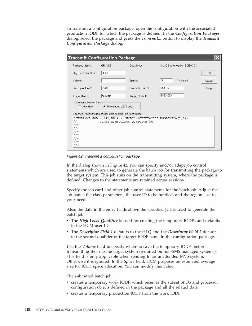
To transmit a configuration package, open the configuration with the associatedproduction IODF for which the package is defined. In the Configuration Packagesdialog, select the package and press the Transmit... button to display the TransmitConfiguration Package dialog.
In the dialog shown in Figure 42, you can specify and/or adapt job controlstatements which are used to generate the batch job for transmitting the package tothe target system. This job runs on the transmitting system, where the package isdefined. Changes to the statements are retained across sessions.
Specify the job card and other job control statements for the batch job. Adjust thejob name, the class parameters, the user ID to be notified, and the region size toyour needs.
Also, the data in the entry fields above the specified JCL is used to generate thebatch job:v The High Level Qualifier is used for creating the temporary IODFs and defaults
to the HCM user ID.v The Descriptor Field 1 defaults to the HLQ and the Descriptor Field 2 defaults
to the second qualifier of the target IODF name in the configuration package.
Use the Volume field to specify where to save the temporary IODFs beforetransmitting them to the target system (required on non-SMS managed systems).This field is only applicable when sending to an unattended MVS system.Otherwise it is ignored. In the Space field, HCM proposes an estimated averagesize for IODF space allocation. You can modify this value.
The submitted batch job:v creates a temporary work IODF, which receives the subset of OS and processor
configuration objects defined in the package and all the related datav creates a temporary production IODF from the work IODF
Figure 42. Transmit a configuration package
100 z/OS V2R2 and z/VM V6R2.0 HCM User's Guide

v and sends the production IODF either to an attended or unattended targetsystem.
z/VM:
The target IODF is built on the z/VM user's A-disk by:v allocating a new WORKIODF, using the target IODF file name (IODFxx)v exporting and migrating the I/O configuration statements for the processors,
that are included in the transmitted configuration package, into the work IODF(including the affected switch definitions)
v exporting and migrating the I/O configuration statements for the operatingsystems, that are included in the transmitted configuration package, into thework IODF
v building a production IODFv transmitting the production IODF to the target system
The used work files are removed from the A-disk after a successful transmission. Ifany of the above steps fails, the work files remain on the A-disk for failurediagnostic and must be manually deleted before a new package transmission withthe same IODF file name can be performed.
How to send a package to an unattended nodeIf you have specified to send the selected package to a target system running inunattended mode, use the Specify Import JCL dialog (Figure 43) to provideappropriate job card parameters and job control language (JCL) for a job that willrun on that unattended system to import the package into the desired target IODF.Modify the job statement to your needs, for example, specify the correct JESrouting statement.
Also, on the receiving unattended node, you need to ensure that userauthentication is correctly set up. How to do this, is described in detail in the z/OSHCD User's Guide.
Figure 43. Specify Import JCL
Chapter 4. Building your configuration 101

102 z/OS V2R2 and z/VM V6R2.0 HCM User's Guide

Chapter 5. Stand-alone mode
In addition to the HCM online mode of operation where you have a connection toyour host, HCM offers the stand-alone mode. In this mode, you can open aconfiguration file without a host connection. The stand-alone mode extends thescope of HCM with a view to mobility and problem situations.
In stand-alone mode, you can open both work and production configuration files.The production configuration file contains the complete IODF information,therefore, you can view the data associated with that configuration even if the hostis not available. In this case you can use HCM as a browser for the configuration,but you cannot update any data (read-only mode).
If the configuration file is a work configuration file, its physical data (excludingconnections) can be edited. This allows you to gather cable information, VOLSERs,user data fields, and other information for example, in the machine room floorwhile editing the configuration on a portable workstation. In the workconfiguration file, you can shuffle control units between physical controllersegments and move devices from one unit in a string to another unit. This ispossible as long as the logical definitions are not affected.
Note: If in stand-alone mode, you apply physical changes to a local copy of anMCF-enabled configuration, HCM cannot synchronize with the host-based MCFimmediately, but sets a so-called LC flag, indicating that the configuration waslocally changed. Synchronizing then is processed with the next reconnection.
Invoking the stand-alone modeTo invoke the stand-alone mode select the Standalone button on the Login dialog(see Figure 3 on page 25). As a prerequisite, your configuration file must reside ona resource on the workstation (or accessible from the workstation).
Working with the stand-alone modeThe stand-alone mode disables all actions within a configuration which:v Require a connection to the host.v Are related to objects and relations not stored in the work configuration file.
Refer to “Work configuration file” on page 104.v Require a resynchronization between the IODF and the configuration file.
If you work with the stand-alone mode, the most obvious deviation from theonline mode are that several menu choices are disabled. The tables presented inAppendix D, “Menu bar choices summary,” on page 445 indicate, which choicesare available.
Creating objectsMost operations to create objects in stand-alone mode are not allowed because theyimply the creation of at least one logical IODF object. For instance, HCM does notprovide a means of creating an empty controller. At least one CU is always created.Therefore, the creation of empty strings and empty controllers is not supported instand-alone mode.
© Copyright IBM Corp. 1995, 2016 103

The only creation operation which is allowed is the creation of physical objects,like for example, cabinets, general boxes or crossbar switches. Physical objects maybe connected and disconnected. The connection and disconnection of logical objectsis not allowed.
Viewing objectsYou can view detailed information when you select Edit from the menu.
Printing reports, diagrams, cable labelsYou can print reports, existing diagrams, and cable labels in stand-alone mode forwork and production configuration files. The following table illustrates which kindof report may be printed from which configuration file:
Table 11. Printing of reports
Type of printing *.hcm/hcmz file *.hcr/hcrz file
Report Partially2 Yes
Existing diagrams Yes Yes
Cable labels Yes Yes
No host connectionRegardless of whether a work or a production configuration file is open, any actionthat requires a host connection, produces the message EEQ0212E:
Work configuration fileIf the open file is a work configuration file, HCM is not able to report or displaycertain data because the data is not present in the work configuration file. Thisdata is only stored in the IODF on the host. In detail the following information isnot available in stand-alone mode:v Switch and port configurationsv Operating system related datav Logical data of control unit-processor definitionsv Logical data of device-processor definitions
Production configuration fileWithin an opened production configuration file, you cannot modify the physicaland logical data. The production configuration file is read-only.
2. Report printing requires some data which is available only from the host or from production configuration files.
Figure 44. Message EEQ0212E
104 z/OS V2R2 and z/VM V6R2.0 HCM User's Guide

Note: Some data can only be displayed after selecting the Edit button in theappropriate dialogs even if the production configuration file is read-only.
You can use the stand-alone mode in combination with production configurationfiles in your enterprise for online documentation of the configuration because youcan distribute the files electronically or you can place it on a central LAN resourcefor common access.
UpgradingIf HCM is running in stand-alone mode, the upgrade operation is not possible:upgrading requires a host connection.
ResynchronizingIf HCM is running in stand-alone mode the resynchronization operation is notpossible.
VOLSER reconciliationIf you have updated VOLSER data in the HCM configuration in stand-alone mode,there might be a mismatch between the VOLSER data in an HCM configurationfile and its corresponding IODF on the host.
The next time you open your configuration file in HCM in online mode by usingOpen... or Open Special... from the File menu, differences between the VOLSERsstored in your HCM configuration file and those stored in the IODF will bedetected. These differences must be unified, or reconciled, and so HCM willpresent the VOLSER Reconciliation dialog to resolve the differences beforedisplaying the configuration diagram.
The listbox contains one line for every device in the configuration for which theVOLSER value in the IODF on the z/OS host and the associated configuration file
Figure 45. VOLSER Reconciliation dialog
Chapter 5. Stand-alone mode 105

on the PC differ. On entry, all lines are preselected. But you can also work withonly one or several devices by clicking on the appropriate lines.
Each line of the listbox shows the device ID, the device type and model, the serialnumber, and the VOLSER values for the configuration file and the current VOLSERrecorded in the IODF on the host.
You can process the selected lines in the listbox as follows:v Click the button with the >> symbol to accept the HCM VOLSER value for the
selected device. This button symbolically sets the direction of the VOLSERtransfer for the selected lines and copies the HCM VOLSER values into theIODF.
v Click the button with the << symbol to reject the HCM VOLSER value for theselected device. This button symbolically sets the direction of the VOLSERtransfer for the selected lines and copies the IODF VOLSER values into theHCM configuration file.
Once a line has been processed, the selected lines are grayed and a >> or <<symbol is inserted between the HCM VOLSER value and the IODF VOLSER value.
To unprocess your selection you can use the Reset button to mark all the lines inthe listbox as requiring processing again. The lines can now be reprocessed again.
When you have processed every item in your listbox, click on the OK button.HCM then updates the local and/or the remote database with the acceptedVOLSER changes.
Note: HCM offers a "Prime the IODF with Sensed Data" utility in the Utilitiesmenu. Using this utility, sensed data can be stored in the IODF. See “Priming theIODF with sensed data” on page 249 for details.
106 z/OS V2R2 and z/VM V6R2.0 HCM User's Guide

Chapter 6. Modifying objects in your configuration
Once you have built your initial configuration, you can modify objects in the HCMconfiguration file. This section explains how to manipulate all the elements of yourhardware configuration with the interactive configuration diagram and dialogs.After you have edited objects in the diagram, you can connect (or disconnect)them, see Chapter 7, “Connecting objects in your configuration,” on page 187.
To support you in performing complex processor configuration tasks, HCM offersseveral copy wizards, for example, to copy an SMP processor into a channelsubsystem of an XMP processor, or to copy a partition. How to use these wizards,is described in the following topics:v “Copying a processor using a wizard” on page 119v “Copying a channel subsystem” on page 123v “Copying a partition” on page 126
Before using one of these wizards, you should read the general informationpresented in the subsequent sections:v “General concepts of the copy wizards”v “How HCM handles connections when using the copy wizards” on page 108
The remainder of this chapter then tells you how to create and modify all objectsof an I/O configuration, starting with “Processors” on page 115 through “Generalboxes” on page 183.
General concepts of the copy wizardsThe copy wizards support two scenarios:v Choose the Repeat scenario to copy the source object to the target object without
moving physical connections. Only the logical connections are copied to thetarget.The purpose of this scenario is to create a new object and keep the source objectoperative for further use.
v Choose Upgrade scenario to create a new object with physical connectionsmoved. The wizard copies the source object to the target object, moving thephysical and copying the logical connections from the source to the target. Thesource object remains with the logical connections only.The purpose of this scenario is to create a new object with full functionality anddismantle the source object. This scenario therefore helps you to consolidateyour resources, for example, you may copy several SMP processors into differentchannel subsystems of an XMP processor.
Figure 46 on page 108 illustrates how the wizards' page flow relates to the workand data flow when using the wizards with the different scenarios:
© Copyright IBM Corp. 1995, 2016 107

How HCM handles connections when using the copy wizardsWhen copying a processor, a channel subsystem or a partition, you must map theCHPID connections of the source object to the corresponding connections for thetarget processor/channel subsystem/partition. You achieve this using the wizards 'Map CHPIDs pages, if applicable, and - in case of the Repeat scenario - theAssign Switch Ports and Assign Controller Interfaces pages.
This chapter lists the rules how the involved copy wizards handle logical andphysical connections during the copy process of source objects that contain suchconnections. CTC connections and CF connections are especially considered.
Mapping CHPIDsWhen you copy objects, the copy wizards support you in integrating the object'sconnections into the context of the target. For example, when copying a partition,you can adapt the access and candidate lists of CHPIDs on the target. Whencopying a CSS, you can adjust spanned CHPIDs in the target. To achieve this, thecopy wizards invoke the appropriate Map CHPIDs pages where required (see alsoFigure 46):
Figure 46. Wizard page flow and work flow
108 z/OS V2R2 and z/VM V6R2.0 HCM User's Guide

v When copying a partition, CHPID mapping allows you to use the same ordifferent existing CHPIDs on the target processor/CSS or to specify newCHPIDs that will be created by the copy operation.
v To handle spanned CHPIDs, CHPID mapping is also invoked when copying anSMP processor to a CSS of an XMP processor or a CSS of an XMP processor to atarget CSS of the same or another XMP processor. You can select to have theCHPIDs spanned in the target in the same or a different way as they arespanned in the source.
Rules for CHPID mapping when CF connections are involvedCHPIDs involved in a CF connection cannot be spanned in the target, whichimplies that spanned CHPIDs cannot be used as a copy target for source CHPIDsinvolved in a CF connection. However, if you copy within a CSS, you can reuse aspanned CHPID, but you cannot change the existing spannings.
Connections in the Upgrade scenarioRemember: The Upgrade scenario creates a new object by moving the physical andcopying the logical connections from the source to the target (see “Generalconcepts of the copy wizards” on page 107).
Logical connectionsConsider a logically connected CHPID which is not a CF CHPID. A CHPID mightbe logically connected to one or more control units, and additionally to a switchport. Any logical connection is copied from a source CHPID to the correspondingtarget CHPID, regardless of the type of connection. Note that logical connectionsare indeed copied, not moved. There are, however, two exceptions that apply forthe Upgrade scenario, where a logical connection is not copied, but moved andwhere, to enable moving the connection as required, the source CHPID isdisconnected from the switch port:1. if the source CHPID is not spanned, and the source CHPID differs from the
target channel path ID, and the target channel path ID is not connected2. also , if the source CHPID equals the target CHPID, and the source processor
equals the target processor, and the source CHPID is not spanned, and thetarget CHPID is not connected.
Moving existing physical connectionsPhysical connections are only moved in the Upgrade scenario but not in the Repeatscenario. Logical connections which might use the physical connection that ismoved, are not considered in this section.
Using the copy wizards for handling a physical connection indeed means movingthe physical connection from a source CHPID to a target CHPID: after a successfulcopy operation, the target CHPID will have the source CHPID 's physicalconnection, while the source CHPID no longer will have a physical connection.Logical connections remain on the source CHPID, though. For further discussion,you need to distinguish different types of physical connections, where the lastconnection object of the fiber link is the distinguishing attribute:1. CHPID <---> switch port connections2. CHPID <---> controller interface connections3. CHPID <---> patchport/general box port connections where the
patchport/general box port is not further connected to a switch port, controllerinterface, crossbar switch, or CHPID
4. CHPID <---> crossbar switch connections5. CHPID <---> CHPID connections (which can only be CTC or CF connections)
Chapter 6. Modifying objects in your configuration 109

Each of these connections may also contain an arbitrary number of patchports,general box ports or cables.
In case of any of the first four connection types, this physical connection is movedfrom the source CHPID to the corresponding target CHPID. This means that thetarget CHPID is being physically connected exactly the same way as the sourceCHPID has been connected before the copy operation. All physical objects whichare part of the connection (patchports, general box ports, converters) are alsomoved from the source link to the target link in exactly the same order, and allcables are also moved from the source CHPID's link to the target CHPID's link.Consequently, the source CHPID no longer will be physically connected whichmeans that if the source CHPID was involved in a logical connection before thecopy operation, ‘logical without physical connection’ visual warnings will appear inthe configuration diagram.
With the fifth connection type, you either have a CTC connection or a CFconnection. The following sections discuss the rules that apply to theseconnections:v “Rules for CTC connections”v “Rules for CF connections” on page 111
Rules for CTC connections:
v If both CHPIDs of the CTC connection are located on the source object, and bothsource CHPIDs are mapped to target CHPIDs, HCM ensures that the CTCconnections are completed for the target object. HCM also ensures that CUADDvalues are also correctly set (if such a change is needed). This way, it is ensuredthat both physical and logical connections are established correctly on the target.This is also true if you have an FCTC connection over a single FC CHPID.
v If both CHPIDs of the CTC connection are located on the source object, and ifjust one of the source CHPIDs is mapped to a target CHPID, then a CTCconnection is established between the new target CHPID and the unmappedsource CHPID.The physical part of the link on the source CHPIDs is removed from the sourceCTC connection and is connected to the new target CHPID.As the logical connection between the source CHPID and the CTC control unit(s)and CTC device(s) is not disconnected, the Unused... button will be available onthe CTC Connections dialog. For details on unused CTC control units, devicesand connections to CHPIDs, see “Editing a CTC connection” on page 211.The Unused... button will also be available if just one CHPID of the CTCconnection is located on the source object and is mapped to a CHPID on thetarget object, and if the connected destination CHPID is located on a differentprocessor or channel subsystem. That is, HCM establishes the new CTCconnection between the mapped CHPID on the target processor and theunmapped destination CHPID. The reason is as before, that the logicalconnection between the mapped source CHPID and CTC control unit(s) andCTC device(s) is not disconnected.
After successful copy operations, you should verify your CTC connections via theCTC Connections dialog and check whether some unused CTC control units, CTCdevices or CTC CHPIDs are reported.
110 z/OS V2R2 and z/VM V6R2.0 HCM User's Guide
Rules for CF connections: Moving a CF connection to a target object (processors,CSSs or partitions) must not influence objects on the target. Therefore, in certaincases, CF connections cannot be copied because this operation would affect otherconnections.
If one of the CF connection CHPIDs is not copied (deselected in the Map CHPIDspage), then the CF connection is not copied and the physical connectivity is alsokept on the source CF connection.
The following rules apply for the different object types:v Copying a processor
– All CF connections which are not deselected in the Map CHPIDs page arecopied to the new target processor.
– For CF connections within the processor, both source and target of theconnection are moved to the new processor.
– If the CF connection to be copied is completely within the same processor, thesource connection is kept in the source processor. Otherwise, if both ends ofthe connections are in different processors, the origin of the connection ismoved to the target and disconnected in the source.
v Copying a CSS– All CF connections are copied to the new target CSS, with the following
exceptions:- Connections established with spanned CHPIDs in the source CSS are not
copied.- If a CSS with internal CF connections is copied to another processor, both
connection ends must be within the same CSS. Otherwise, the CFconnections are not copied.
– If both connection ends of the source CF connection are within the sourceCSS, the source connection is kept. Otherwise, if the connection target is in adifferent CSS, the source connection is moved to the target and disconnectedin the source.
v Copying a partition– All CF connections using dedicated CHPIDs are moved to the target partition.– If a source OS partition that you want to copy within the same CSS is
involved in CF connections, then the following applies:A CF connection using a spanned, shared or reconfigurable CHPID is copiedif the CHPID is not mapped to a different CHPID in the target. Shared orspanned source CHPIDs must not be spanned to different CSSs in the target(then the same physical cable is used and the copy operation just enhancesthe access list).
– A CF connection using a spanned, shared or reconfigurable CHPID is notcopied if the target partition is in a different processor or CSS. A CFconnection is also not copied if the copied partition is a CF or CF/OSpartition.
– Internal CF connections are not copied if the partition is copied to a differentprocessor.
– If the partition is copied within the same CSS, the source connection is kept,except for a dedicated CHPID. Otherwise, if the partition is copied to adifferent processor/CSS, the source connection is moved to the target anddisconnected in the source.
Chapter 6. Modifying objects in your configuration 111

Remarks on converters: If the interface type of the source and the target CHPIDcoincide, you need not care about converters. If a converter has been part of thesource CHPID 's link, the link of the target CHPID will also contain a converter. Ifthis converter is labelled , then it will become part of the target CHPID's link.Otherwise, a generic converter will be added .
If the interface type of the source CHPID differs from that one of the targetCHPID, then a converter might either be removed or added to the configuration. Ifa generic converter was part of the source link, it is just removed from theconfiguration. Otherwise, in case of a labelled converter, this converter still existsin the configuration, but it is no longer used in any link. You can use this labelledconverter to replace, for example, another generic converter. If a new converterneeds to be added into the target link, a generic converter will be created . This isalso true if labelled , but currently unused converters exist in the configuration.
Exception:
No physical connection is being copied:v if the source CHPID gets mapped to a target CHPID in the following scenarios:
– copy SMP processor to channel subsystem– copy channel subsystem to channel subsystem– copy partition
v and if at the same time the target CHPID is physically connected
Note: If the target CHPID to which the source CHPID is mapped, is not the lowestinstance of a spanned CHPID definition, but the lowest CHPID instance is alreadyphysically connected, then the selected target CHPID is also considered to bephysically connected.
Remarks on visual warnings: ‘Logical without physical connection’ visual warningscan appear in the diagram after you completed an Upgrade scenario, because boththe source and the target CHPID will be logically connected to the sameconnection target - if none of the mentioned exceptions applied - for example inthe following cases:v CHPID <---> switch port connection: if the physical connection has been moved,
the switch port no longer has a physical connection to the source CHPID andwill be flagged with this warning.
v CHPID <---> controller interface connection: if the physical connection has beenmoved, the controller interface no longer has a physical connection to the sourceCHPID. The affected controller segment will be flagged with this warning.
Connections in the Repeat scenarioRemember: The Repeat scenario copies the source object to the target objectwithout physical connections. Only the logical connections, but no physicalconnections, are copied to the target (see “General concepts of the copy wizards”on page 107).
Logical connections in the Repeat scenarioAs in “Logical connections” on page 109, consider a logically connected CHPIDwhich is not a CF CHPID. As in the Upgrade scenario, any logical connection iscopied from a source CHPID to the corresponding target CHPID, regardless of thetype of connection. The subsequent sections handle in detail CTC connections andalso CF connections. Once more, note that logical connections are indeed copied,not moved.
112 z/OS V2R2 and z/VM V6R2.0 HCM User's Guide

Assigning new connectionsNew physical connections are only established in the Repeat scenario. You achievethis via the Assign Switch Ports and Assign Controller Interfaces wizard pages.Existing physical connections are only copied in the Upgrade scenario, but no newphysical connection is assigned in such a scenario. Also, any logical connectionsare not considered in this section which might use the physical connection that isassigned. Emphasis is on CTC connections and CF connections.
As only new physical connections are established in this scenario, and as noexisting physical connections are copied, the link (physical connection between thetarget CHPID and its connection targets) will not contain any patchport , generalbox port, or cable. If required, you must define all such physical configurationobjects manually to the link after the copy operation succeeded.
As mentioned above , there are two wizard pages which help you establish thenew physical connections for the target CHPIDs. The Assign Switch Ports pageonly lists those target CHPIDs for which the corresponding source CHPID isconnected to a switch port. For all shown target CHPIDs, you can select a switchport as connection target in order to establish a complete physical path from thetarget CHPID onto controllers.
On the Assign Controller Interfaces wizard page, you can assign controlleradapter interfaces to target CHPIDs. Only those target CHPIDs are listed on thiswizard page for which the corresponding source CHPID is connected to acontroller interface. The target CHPID must be connected to the same controller asthe corresponding source CHPID. If not enough labelled controller adapterinterfaces are available on a controller, HCM will provide unlabeled controlleradapters and unlabeled controller adapter interfaces which are indicated by ’INT’.You can label those adapters and their interfaces yourself afterwards, see “Editinglabels of adapters and interfaces” on page 147.
Several CHPID types are usually connected to specific control unit types. SomeCHPID <---> controller connections cannot be selected on the Assign ControllerInterfaces page, but are automatically established by HCM. Connections to whichthis applies involve a controller with either an OSA type control unit, an IQDcontrol unit or an FCP control unit.
When connecting a mapped target CHPID to a controller interface, the interfacetype of the controller interface may differ from the interface type to which thesource CHPID is connected. In such a case, HCM adds a generic converter to theconfiguration or removes the previously needed converter.
Note that a mapped target CHPID will be neither shown in the Assign SwitchPorts page nor in the Assign Controller Interfaces page and therefore will have nophysical connection at all in the following cases:v A source CHPID is just connected to a patchport or a general box port, but not
connected to a switch port or to a controller adapter interface.v A source CHPID is connected to a crossbar switch, but not connected to a switch
port or to a controller adapter interface.
If , however, a CHPID is connected to a crossbar switch, and furthermore isconnected to either a switch port or a controller adapter interface, then this CHPIDis shown on either the Assign Switch Ports page or on the Assign Controller
Chapter 6. Modifying objects in your configuration 113

Interfaces page. The logical connection is copied and the physical connection willbe established between the CHPID and the selected switch port or controlleradapter interface.
Rules for CTC connectionsYou need to distinguish between switched CTC connections and point-to-pointCTC connections. For FCTC connections, we have a two-digit CUADD valuewhere the first digit indicates the CSS ID for XMP processors and the second digitindicates the MIF ID. If a channel subsystem is involved in the copy operation fora FCTC connection, the CUADD value might need to be considered as well.
Note that all CTC control units and devices which are connected to any sourceCHPID are logically connected to the corresponding target CHPID, but theCUADD values are not updated so that the CTC connections on the target CHPIDmight not be complete.1. Switched CTC connections: no new CTC connection is established.
a. Case 1: Only one of the involved CTC CHPIDs is defined to the copiedsource object.1) If the source CHPID is not mapped to a target CHPID, a new CTC
connection cannot be established anyway.2) If the source CHPID is mapped to a target CHPID, then the target
CHPID is connected to a different switch port than the CTC controlunits to which a logical connection is established. Hence, as the linkaddress is not correct, no new CTC connection can be established,neither for SCTC nor for FCTC connections.
b. Case 2: Both of the involved CTC CHPIDs are defined to the copied sourceobject.1) If not both CHPIDs are mapped to a corresponding target CHPID, a
new CTC connection cannot be established even though the logicalCHPID <---> control unit connection is established. If one CTC CHPIDis mapped to a target CHPID, the same situation as for scenario 1a2)applies.
2) If both involved CTC connections are mapped to a target CHPID, thelogical connection between the CTC control units and the CTC CHPIDsis established, but the link addresses of the CTC control units do notcoincide with the ports on the switch(es) to which the CTC CHPIDs areconnected (see also previous scenarios) . Hence, the CTC control unitdefinitions are not correct for a complete CTC connection.
2. Point-to-Point CTC connections: As no physical connection is copied or moved,the source CHPID(s) is (are) physically still connected to the connection target.As also the logical connections between the source objects are not modified, allsource CTC connections remain unchanged.a. Case 1: Only one of the involved CTC CHPIDs is defined to the copied
source object1) If the source CHPID is not mapped to a target CHPID, a new CTC
connection cannot be established anyway.2) As this CHPID has no connection target, no new point-to-point CTC
connection can be established. This applies to both the SCTC and theFCTC case.
b. Case 2: Both of the involved CTC CHPIDs are defined to the copied sourceobject
114 z/OS V2R2 and z/VM V6R2.0 HCM User's Guide

1) If not both CHPIDs are mapped to a corresponding target CHPID, anew CTC connection cannot be established as either no CHPID ismapped anyway, or a connection target is missing for the other mappedtarget CHPID.
2) If both involved CTC connections are mapped to a target CHPID, a newCTC connection is established in any case for an ESCON point-to-pointCTC connection, as both the logical and the physical connections areestablished. In case of FICON point-to-point CTC connections, a CTCconnection is established as long as the two-digit CUADD value for thesource as well as the target CTC connection are correct. If the CUADDvalue needed for the mapped target CHPIDs differs from that of thesource CHPIDs, no new FCTC connection is established.
After the copy operation succeeded, you should verify your CTC connections viathe CTC Connections dialog and check whether some unused CTC control units,CTC devices or CTC CHPIDs are reported.
Rules for CF connectionsThe logical and physical connections between source CF CHPIDs and theirconnected target CF CHPIDs remain unchanged on the source. Copying them tothe target (both physically and logically) works as follows:v Copying a processor:
– CF connections within the source processor (either with internal or externalCF CHPIDs) are also established at the target processor with new CF controlunits and devices. Otherwise, CF connections that connect to a differentprocessor are not established at the copy target processor/CSS.
v Copying a CSS:– If the CF connection is within the source CSS (either with internal or external
CF CHPIDs), a new connection will be established in the target processorwith new CF control units and devices . If the CF connection is across CSSboundaries (which includes connections with spanned CHPIDs), noconnection is established at the target processor.
v Copying a partition:– CF connections are not copied; that is, no new CF connection is established at
the target.– An OS partition is included in the access list of a matching shared or spanned
CF CHPID that may already have a CF connection at the copy target (that is,if a CF connection already exists between the two target CHPIDs).
– A CF or CF/OS partition is not included in the access list of a matchingshared or spanned CF CHPID. (If a dedicated CF CHPID does not yet exist inthe CSS of the target, it is copied without establishing a CF connection.)
ProcessorsA note on terminology:
Throughout this document, the following terms are used:
XMP processor and SMP processorThe term XMP processor designates processors that support multiplelogical channel subsystems. It is used in contrast to the term SMPprocessor, which designates processors of previous generations thatsupport only one channel subsystem.
Chapter 6. Modifying objects in your configuration 115

For XMP processors, HCM offers methods to explicitly define multiplelogical channel subsystems (LCSS). For SMP processors, the single channelsubsystem is implicitly defined with the processor.
Wherever a channel subsystem of an XMP processor is referenced in dialogs, youwill see the channel subsystem ID (CSS ID) appended to the correspondingprocessor ID, like procname.n where n is the CSS ID.
You can create, edit or delete processors by invoking the appropriate dialogs forthe desired processor object in the configuration diagram. Double-clicking on aprocessor object displays the Processor dialog where you can define partitions andCHPIDs, or for XMP processors, you can also define channel subsystems.Alternatively, choose Processor... from the Edit menu and select the processorname from the list that appears. Note that you can rearrange and filter the listaccording to your needs.
The Processor dialog displays detailed information for the selected processor andthe associated system. It allows you to navigate to other related dialogs. You canadd or edit partitions, CHPIDs, the processor details or check the system status(only active when online and in BASIC mode and when I/O Operations is up andrunning) by pressing the appropriate button.
You can also change a processor's style, make it a primary or alternate processor,or assign processors to machines during IODF load / resync. See Appendix A,“Alternate processor definitions,” on page 435 >.>
There are two versions of the Processor dialog, one for SMP processors(Figure 47on page 117) and one for XMP processors (Figure 48 on page 117). The one forXMP processors contains a Channel Subsystems section which lists the channelsubsystems (CSS) defined for the processor. For each channel subsystem, you cansee the maximum number of devices that can be defined in each availablesubchannel set and the actual number of defined devices.
You can tailor the information that you want to be displayed in the ChannelSubsystems section. Pressing the Columns... button lets you add or removecolumns to or from the Channel Subsystems box.
116 z/OS V2R2 and z/VM V6R2.0 HCM User's Guide

Figure 47. Processor dialog for SMP processors
Figure 48. Processor dialog for XMP processors
Chapter 6. Modifying objects in your configuration 117

To edit partitions and channels for XMP processors, you must select a CSS first, asthese objects are pertaining to a specific CSS.
Use the Copy... button in the Channel Subsystems section to open the CopyChannel Subsystem wizard. This wizard lets you copy a channel subsystem of anXMP processor into the same or another existing XMP processor or into a newSMP processor. For more information refer to “Copying a channel subsystem” onpage 123.
Creating a processorDisplay the Create Processor dialog by choosing Processor... from the Createmenu. Type in the fields or select data from the drop down boxes. The ID andType-Model fields are the only required ones. Note that Type-Model is a singlefield; you can select a type and model from the drop down box or type in thefield.
For XMP processors, in the field Number of Channel Subsystems you may specifythe number of channel subsystems to be defined for your current processor. ForXMP processors, the default value is 1. This will create a channel subsystem withID 0. A value of 2 will create CSS 0 and CSS 1 and so on . The value is ignored forSMP processor. Also, the configuration mode defaults to LPAR, which is the onlyallowed mode for XMP processors.
After you have filled in the information, press OK to create the new processor,which will appear in the configuration diagram. You can then double - click on theprocessor to display the Processor dialog (see “Processors” on page 115).
Note that the Short name of a processor is part of the physical machine.
Figure 49. Create Processor
118 z/OS V2R2 and z/VM V6R2.0 HCM User's Guide

Tip:
To create another processor for “one processor per partition” processors, use theCreate... button in the Processors dialog. (Display the Processors dialog bychoosing Manage Shadow Processors... from the Edit menu.) See “Managingshadow processors during an HCM session” on page 435 for details.
Choosing a support levelIf there is more than one support level for the type and model of processor thatyou specify in the Create Processor or Edit Processor dialog, the Choose SupportLevel dialog appears when you press OK. Select the support level for the selectedprocessor and press OK.
Selecting the correct support level is important for validation processing, as thesupport level controls the rules that apply to the processor (for example, thenumber of CHPIDs). If you are unsure about a support level's properties, you canpress the Details button to receive an explanation of the used terms andabbreviations.
Copying a processor using a wizardTwo wizards are available for copying processors:v Copy XMP Processor: Invoke this wizard from the context menu of a selected
XMP processor or from the Edit a Processor dialog.v Copy SMP Processor: Invoke this wizard from the context menu of a selected
SMP processor or from the Edit a Processor dialog. It lets you copy thisprocessor into a new SMP processor or into an XMP processors channelsubsystem. As the functionality for copying an SMP processor into a CSS isbasically the same as just copying a channel subsystem, see “Copying a channelsubsystem” on page 123 for information about how to use the Copy ChannelSubsystem wizard.
These Copy Processor wizards help you to create a copy of an existing XMPprocessor or SMP processor within the same IODF / HCM configuration file. Thetarget processor must not yet exist.
This wizard helps you to perform the following steps:1. Specify a target processor for the copy request.2. Choose either the Repeat or the Upgrade scenario. If you choose the Repeat
scenario, then no physical connection of CHPIDs on the source processor aremoved. If you select the Upgrade scenario, the physical connections of theCHPIDs on the source processor are moved to the target CHPIDs (if possible).Check the wizard page and the corresponding help page for more detailedinformation about the two scenarios.
3. Assign switch port connections for all target CHPIDs whose correspondingsource CHPIDs have a switch port connection. Target channel path IDs withexisting switch port connections are not shown in this step. This step is onlyinvoked if you select the Repeat scenario in step 2.
4. Assign controller interface connections for all target CHPIDs whosecorresponding source CHPIDs are physically connected to a controller. Targetchannel path IDs with existing physical connections are not shown in this step.This step is only invoked if you select the Repeat scenario in step 2.
5. Examine the summary of the processor information that is to be copied. ClickFinish to perform the operation.
Chapter 6. Modifying objects in your configuration 119

Editing a processorClick on the Edit... button in the Processor dialog to display the Edit Processordialog. You can then add or edit processor information and press OK. The changeswill appear in the Processor dialog's list box. If there is more than one supportlevel for the type and model of processor specified, the Choose Support Leveldialog appears with the current support level highlighted when you press OK.
If you have changed the Type/Model or Support Level for an SMP processor,pressing OK in the Edit Processor dialog will display the CHPID Renumberingdialog, allowing you to renumber the CHPIDs as required.
The Edit Processor dialog contains the buttons to invoke special utilities:
PCIe... This button invokes the PCIe Functions dialog. Use this dialog to create,modify, or delete PCIe functions of the selected processor. See “ManagingPCIe functions” for further information.
CMT... This button invokes the CHPID Mapping Tool Support dialog. Use thisdialog to interact with the CHPID Mapping Tool to assign missing PCHIDsto CHPIDs (or update existing PCHID-CHPID assignments) for XMPprocessors. See “Using the CHPID Mapping Tool Support utility” on page78 for further information.
WPT... This button invokes the WWPN Prediction Tool Support dialog. Use thisdialog to export the FCP channel/device specific data of the I/Oconfiguration from the currently accessed IODF into a comma-separatedvalue (CSV) output format. The generated file can be used as input to theWWPN Prediction Tool to assign world-wide port names to virtualizedFCP ports for configuring SAN devices. See “Using the WWPN PredictionTool Support” on page 259 for further information.
Adding user data to a processorAdd or edit user data by pressing the Info... button in the Edit Processor dialog todisplay the standard user data dialog. For more details, see “User data fields” onpage 30.
Deleting a processorSelect the processor object in the configuration diagram and press the Delete keyon your keyboard. HCM displays a confirmation dialog before deleting theprocessor.
You can also delete processors in the Processors dialog, called by choosing ManageShadow Processors... from the Edit menu. Select a logical processor in a machineand press the Delete button. HCM displays a confirmation dialog, then delete theprocessor, provided that it is not the last one within the machine. The primary andalternate settings are adjusted for the remaining processors in the machine. SeeAppendix A, “Alternate processor definitions,” on page 435.>
Managing PCIe functionsTo define, delete or change PCIe functions, click on the Edit... button in theProcessor dialog to display the Edit Processor dialog. Then click on the PCIe...button to open the PCIe Functions dialog (see Figure 50 on page 121).
120 z/OS V2R2 and z/VM V6R2.0 HCM User's Guide
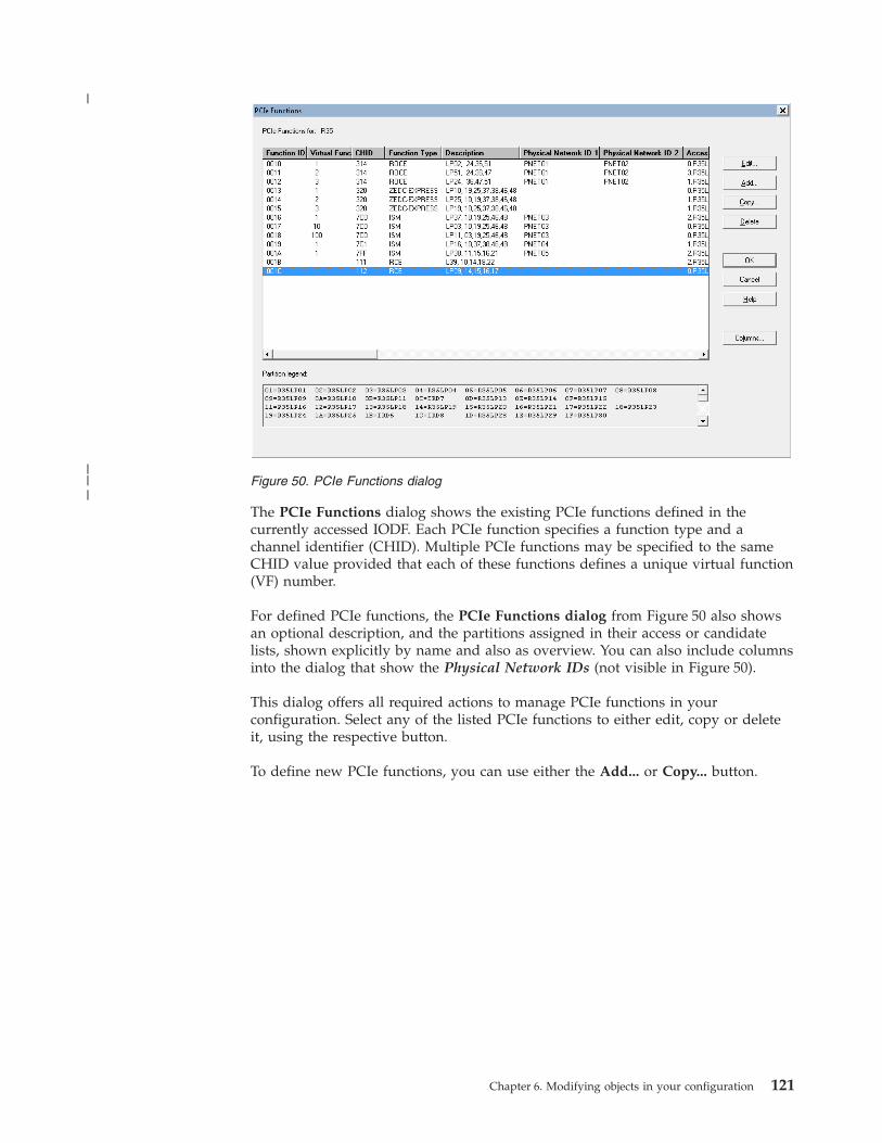
The PCIe Functions dialog shows the existing PCIe functions defined in thecurrently accessed IODF. Each PCIe function specifies a function type and achannel identifier (CHID). Multiple PCIe functions may be specified to the sameCHID value provided that each of these functions defines a unique virtual function(VF) number.
For defined PCIe functions, the PCIe Functions dialog from Figure 50 also showsan optional description, and the partitions assigned in their access or candidatelists, shown explicitly by name and also as overview. You can also include columnsinto the dialog that show the Physical Network IDs (not visible in Figure 50).
This dialog offers all required actions to manage PCIe functions in yourconfiguration. Select any of the listed PCIe functions to either edit, copy or deleteit, using the respective button.
To define new PCIe functions, you can use either the Add... or Copy... button.
Figure 50. PCIe Functions dialog
Chapter 6. Modifying objects in your configuration 121
|
|||

You specify a new PCIe function by its required Function ID, Function type (ROCEor ZEDC-EXPRESS), and a CHID value. These attributes describe the related PCIeadapter card in the assigned slot of the I/O drawer. The description is optional.The Virtual function number is supported for specific function types. Multiple PCIefunctions may be defined for the same CHID by assigning a unique virtualfunction number to each of these functions. The UID is supported for theappropriate PCIe functions. If any partitions with UID uniqueness checking flagYES are in the Access list or Candidate list, the UID value has to be unique in thescope of the partitions.
HCM supports creating multiple-PCIe functions in one step by specifying thenumber.
At least one partition must be assigned in either the access or candidate list.
HCM also supports overgenned PCIe functions. You define overgenned PCIefunctions by providing an asterisk (*) for the CHID value. Overgenned functionsare validated like other PCIe functions but they are excluded from the IOCP inputstatements and from any dynamic activation.
You can edit any properties of a PCIe function later, except for the Function ID.
Figure 51. Add PCIe Function dialog
122 z/OS V2R2 and z/VM V6R2.0 HCM User's Guide
|
||||||||||||
||

Channel subsystemsNote:
All tasks described in this chapter's subsections are only available for XMPprocessors.
Once you have created an XMP processor, you can add and modify its channelsubsystems. First select an XMP processor by double-clicking on the processorobject in the configuration diagram; alternatively, choose Processor... from the Editmenu and select the processor name from the list that appears. In the upcomingProcessor dialog, you see the Channel Subsystems section which lists the channelsubsystems defined for this processor.
Creating or editing a channel subsystemInvoke the Create Channel Subsystem dialog from the Create... button in theChannel Subsystems section of the Processor dialog. It contains three controls: ID,Maximum number of devices and Description. The ID field is initialized with thefirst unused CSS number.
If you want to edit an existing CSS, select it and press the Edit... button in theChannel Subsystems section. The upcoming Edit Channel Subsystem dialog letsyou change the maximum number of devices for all supported subchannel sets andthe description for the selected CSS.
Note:
A channel subsystem becomes visible in the configuration diagram only after youhave created its first partition. From then on, a channel subsystem's context menuoffers you choices to edit the channel subsystem or to work with its CHPIDs andpartitions.
Copying a channel subsystemHCM offers the Copy Channel Subsystem wizard that supports you to copy achannel subsystem:v copy a channel subsystem into the same or another existing XMP processorv copy a channel subsystem into a new SMP processor
Invoke this wizard by pressing the Copy... button in the Channel Subsystemssection of the Processor dialog for XMP processors(Figure 48 on page 117).
Figure 52. Create Channel Subsystem
Chapter 6. Modifying objects in your configuration 123

The wizard guides you through the following steps.1. Choose the target channel subsystem or SMP processor.
a. If you have chosen to copy the channel subsystem into a new SMPprocessor, the wizard offers a dialog which is similar to the CreateProcessor dialog. Then it proceeds to step 4.
b. If you have chosen to copy the channel subsystem into a new target channelsubsystem, specify the attributes of the target CSS. The wizard continueswith step 2.
2. Assign partition names in the target CSS for all partitions which are copiedfrom the source CSS. The partition names of the source CSS are used as thedefault for the target CSS, if these names will be unique also within the targetXMP processor . For duplicate names, you need to specify new names for thetarget CSS.
3. Map CHPIDs of the source CSS to CHPIDs in the target. CHPIDs that can bedefined as 'spanned', can be spanned over existing CHPIDs in other channelsubsystems of the target processor.
4. Choose how you want to handle the connections:v If you want to copy the logical connections without moving the physical
connections, choose the Repeat scenario.v If you want to copy the logical connections and move the physical ones from
the source to the target, choose the Upgrade scenario.
Note: For a better understanding of the Repeat and Upgrade scenarios and thewizard 's panel flow depending from your selection, refer to “General conceptsof the copy wizards” on page 107.
5. If you select the Upgrade scenario, the physical connections of the CHPIDs onthe source CSS are moved to the target CHPIDs, if possible.If you selected the Repeat scenario, then the wizard helps you to perform thefollowing steps:a. Assign switch port connections for all target CHPIDs whose corresponding
source CHPIDs have a switch port connection. Target CHPIDs with existingswitch port connections are not shown in this step.
b. Assign controller interface connections for all target CHPIDs whosecorresponding source CHPIDs are physically connected to a controller.Target CHPIDs with existing physical connections are not shown in thisstep.
6. View the messages at the summary page, verify the results and click the Finishbutton.
The wizard displays appropriate dialogs as you proceed through these steps. Forfurther information about how to complete these dialogs, refer to the online helpthat is available for each wizard page. Also refer to “How HCM handlesconnections when using the copy wizards” on page 108.
Deleting a channel subsystemSelect a channel subsystem from the list box in the Channel Subsystem section inthe Processor dialog and click on the Delete button. HCM displays a confirmationdialog before deleting the channel subsystem.
124 z/OS V2R2 and z/VM V6R2.0 HCM User's Guide

PartitionsOnce you have created a processor and a channel subsystem for an XMP processor,you can add and modify its partitions. First select a processor by double-clickingon the processor object in the configuration diagram; alternatively, chooseProcessor... from the Edit menu and select the processor name from the list thatappears. Display the Partitions dialog for the processor by clicking on thePartitions... button in the Processor dialog. For XMP processors, this button is inthe Channel Subsystems section.
The list box in the Partitions dialog lists all partitions for the selected processor, orfor XMP processors, the list of partitions includes only partitions in the selectedCSS.
You can create a new partition, or select a partition to edit or delete it.
Creating a partitionYou can create a new partition for the selected processor. Click on the Create...button in the Partitions dialog to display the Create Partition dialog. Enter theinformation defining the partition and press OK. The partition appears in thePartitions dialog list box. It also appears as an object in the configuration diagramwithin the processor or within a processor's channel subsystem where it has beencreated. Note that the Usage option determines if the partition will be used solelyfor standard operating system connections (OS), as a coupling facility (CF), or both(CF/OS).
After creating one or more partitions, they can be assigned to the access andcandidate lists of CHPIDs. See “Assigning CHPIDs to partitions” on page 137 formore information.
Partitions for dynamic I/O configurationOn XMP processors with the appropriate support level, you can add or removepartitions via dynamic I/O configuration. HCM supports this functionality: withan * as placeholder ID, you can define reserved partitions, which you plan to add
Figure 53. Partitions
Chapter 6. Modifying objects in your configuration 125

dynamically to a configuration at a later point in time. With this *, they appear inthe Partitions dialog of a channel subsystem and in the configuration diagram.Dynamic partitions do not appear in the Assign Partitions dialog of a CHPID, sothat you cannot attach any CHPIDs or devices to such partitions.
You can only activate a reserved partition dynamically, if this partition had beenincluded in the initial POR. To activate a reserved partition, you need to edit thepartition by changing the * name to a valid partition name before building a newproduction IODF.
Granting I/O devices access to the new partitionIf there are already I/O devices connected to the processor containing the newpartition, pressing OK in the Create Partition dialog will display the I/O Deviceswith Explicit Candidate Lists dialog. You can select the I/O devices which shouldbe granted access to the new partition before HCM creates the partition.
Copying a partitionHCM offers a Copy Partition wizard to let you copy a source partitionconfiguration to a target partition. You can create the target partition on the sameprocessor as the source partition, or on a different processor or channel subsystem.Reserved partitions can be neither source nor target of the copy action.
You can invoke this wizard with the Copy... button for a selected partition fromthe Partitions dialog, or from the Edit a Partition list. Also, you can invoke it fromthe Copy... menu item of a partition 's context menu .
This wizard helps you to perform the following steps. For a better understandingof the wizard 's panel flow, refer to Figure 46 on page 108.1. Specify the target partition. The wizard dialog for this step queries all
information required for the target partition, for example, its target processorand channel subsystem, if the target is an XMP processor, the partition ID andnumber. You cannot change, however, the usage (OS or CF) for the target.
2. Map those CHPIDs which have the source partition in their access or candidatelist to CHPIDs on the target processor or channel subsystem.
3. Decide whether you want to move the physical connections from the source tothe target by choosing either the Upgrade or the Repeat scenario.
Note: For a better understanding of the Repeat and Upgrade scenarios and thewizard 's panel flow depending from your selection, refer to “General conceptsof the copy wizards” on page 107.
4. If you selected the Repeat scenario, perform the following :a. You need to assign connections between the source CHPIDs and switch
ports to new corresponding connections in the target.b. You need to assign connections of the source CHPIDs to new controller
interfaces to the target.5. Examine the summary of the partition information that is to be copied. Click
Finish to perform the operation.
The wizard displays appropriate dialogs as you proceed through these steps. Forfurther information about how to complete these dialogs, refer to the online helpthat is available for each wizard page. Also refer to “How HCM handlesconnections when using the copy wizards” on page 108.
126 z/OS V2R2 and z/VM V6R2.0 HCM User's Guide

Editing a partitionYou can edit a partition in different ways:v In the Partitions dialog select a partition and click on the Edit... button to open
the Edit Partition dialog for the selected partition.v Double - click on the partition object within the processor in the configuration
diagram.v Choose Partition... from the Edit menu and select the partition name from the
list that appears. Note that you can rearrange and filter the list according toyour needs.
Edit the partition data in the fields and press OK.
The Status button allows you to retrieve information about this partition and tocheck system status.
Adding user data to a partitionAdd or edit user data by pressing the Info... button in the Edit Partition dialog todisplay the standard user data dialog. For more details, see “User data fields” onpage 30.
Deleting a partitionSelect a partition from the list box in the Partitions dialog and click on the Deletebutton. HCM will display a confirmation dialog before deleting the partition. Notethat you cannot delete a partition directly from the configuration diagram.
CHPIDsChannel path IDs or CHPIDs can be added or modified once you have created aprocessor or a channel subsystem within an XMP processor. First display theProcessor dialog by double-clicking on the processor in the configuration diagram,or by choosing Processor... from the Edit menu and selecting a processor from thelist box that appears. Then click on the CHPIDs... button in the Processor dialog todisplay the CHPIDs dialog. For XMP processors, this button is in the ChannelSubsystems section of the Processor dialog.
Note:
Wherever a CHPID for an XMP processor needs to be identified, it is named in theformat procname.n.xx where:v procname is the name of the XMP processorv n is the CSS ID within the processorv xx is the CHPID within the CSS (two hexadecimal digits).
Example:MCSSPR01.1.0B
Also, for CHPIDs in XMP processors, you can make the physical channelinformation visible by adding column PCHID into the window.
Chapter 6. Modifying objects in your configuration 127

The list box in the CHPIDs dialog shows all CHPIDs for the selected processor orthe selected channel subsystem of an XMP processor. You can create or deleteCHPIDs from this dialog. You can select one or more CHPIDs to view details orassign them to partitions.
Pressing the Columns... button opens the Choose Columns dialog which lets youadd or remove columns to or from the CHPIDs dialog. Figure 55 on page 129shows how the columns have been selected that are displayed in Figure 54. In theleft hand box, you can read the columns that are additionally available, butcurrently excluded from the CHPIDs dialog.
Figure 54. CHPIDs
128 z/OS V2R2 and z/VM V6R2.0 HCM User's Guide

There may be four special cases of CHPID text displayed in the list box, forexample:
ID Interface type Type Mode Meaning
AC S CNC SHR Normal case
AC* CNC SHR CHPID without a physical channel
AC* S – – Physical channel without a CHPID(columns Type and Mode are blank)
AC/32 S CNC SHR A CHPID mapped to Channel 32 (onlyappears on “one processor perpartition” machines)
CHPID interface typeThe (physical) interface type is independent of the (logical) CHPID type, and doesnot always match (physical-logical inconsistency). To correct inconsistencies,change the CHPID interface type:v Go to the CHPIDs dialog
– either via the CHPIDs button in the Channel Subsystems section of theProcessor dialog or
– by directly double-clicking a channel subsystem's CHPIDs from a Processorcontext menu.
v In the CHPIDs dialog, press the Interface Type... button to reach the ChangePath Interface Type dialog
Crossbar switch interfaces are always parallel. ESCON or FICON switch interfaces(ports) are always serial. CHPIDs can be any of the five path interface types.Controller channel interfaces can be parallel, serial, IOC or OSA. Note that
Figure 55. Choose Columns
Chapter 6. Modifying objects in your configuration 129

converters can only convert between parallel and serial; interfaces of the typecoupling, IOC or OSA can only connect to each other.
Changing between serial and parallel interface types can usually be done while theinterface is connected; converters are inserted or removed as appropriate.
CHPID operation modeThe operation mode determines how CHPIDs are assigned to partitions. A CHPIDcan be dedicated (DED), reconfigurable (REC), shared (SHR), or spanned (SPAN).A dedicated CHPID is assigned to one partition and only that partition can accessI/O devices on this CHPID. A reconfigurable CHPID is an unshared CHPID thatyou can reconfigure off-line from one partition, then online to another (forexample, after a power-on reset). Only one partition can access I/O devices on thisCHPID at a time. A CHPID that can dynamically access more than one partition isa shared CHPID; one or more partitions can access I/O devices using this CHPID.
With XMP processors, it is possible to access I/O devices using one CHPID that isaccessed by partitions from multiple logical channel subsystems. Such a CHPID iscalled a spanned CHPID.
More about spanned channel paths in multiple LCSSsDepending on the processor type, in the HCD dialog you can define certainchannel paths with operation mode SPAN, with the result that - depending onwhat is defined - you are offered partitions from multiple logical channelsubsystems in the access and candidate list.
A spanned channel path is created with the same CHPID number in all channelsubsystems that are using it. For example, if you have a processor MCSSPRO1with channel subsystems 0 through 3, and you create CHPID 1A (type IQD, SPAN)and let it access partitions from CSS 0, 2, and 3, you get this CHPID 1A in CSSs 0,2, and 3, but not in CSS 1.
If you define a channel as SPAN, but connect it to partitions from a single channelsubsystem only, then HCM displays its operation mode as SHR. The other wayround, if a shared channel path accessing partitions from one channel subsystemonly, is eligible for being spanned over multiple logical channel subsystems, andyou enlarge its access or candidate list with partitions from multiple logicalchannel subsystems, then HCM displays this channel's operation mode as SPAN.
A channel subsystem that is not using a spanned channel can use the CHPID ofthat spanned channel for a separate channel path definition.
Note:
It is dependent on the processor support level which channel path types can bedefined as spanned. Managed channels cannot be defined as spanned.
CHPID operation mode symbolsOn the configuration diagram, access from a partition to a CHPID is representedby a symbol at the intersection between the CHPID's column and the partition'srow. The symbols represent the CHPID's mode (DED, REC, SHR, or SPAN) andwhether the partition is in the CHPID's access or candidate list.
130 z/OS V2R2 and z/VM V6R2.0 HCM User's Guide

Unmanaged/managed CHPIDsHCM supports the definition and visualization of manageable channel paths.Dynamic Channel Path Management is a capability designed to dynamically adjustthe channel configuration in response to shifting workload patterns. Itautomatically adds and removes I/O paths to disk control units in an attempt toprovide the most effective resource utilization from the available hardware andconfiguration. It also coordinates these changes across the systems that share thepaths eligible to be reconfigured.
When you define a CHPID as managed, you have to click the Managed checkboxon the Create CHPIDs dialog and specify an I/O Cluster when the processor isrunning in LPAR mode.
Selecting a CHPID to view detailsSelect one or more CHPIDs in the CHPIDs dialog and press the Edit... button.Alternatively, double-click on a CHPID in the configuration diagram. The CHPIDdialog opens, displaying the details for the selected CHPID, including ID,description, type, mode, and to what objects the CHPID is connected. If you haveselected more than one CHPID, pressing OK will cycle through each CHPID'sdetails. You can then edit the CHPID or assign it to one or more partitions.
Figure 56. CHPID Operation Mode Symbols
Chapter 6. Modifying objects in your configuration 131

Furthermore, you can retrieve the following details:v The Status button leads you to the CHPID status dialog which displays the
I/O-Operations status for the selected CHPID.v The Performance... button lets you access performance data provided by RMF
for the current CHPID.
Editing objects connected to a CHPIDThe CHPID dialog lists the objects connected to a selected CHPID. If you choosethe Physical option in the View section, select an object, and press the EditObject... button, the Edit dialog for that physical object opens. That is, select acontroller to open the Controller dialog; select a crossbar switch to open the EditCrossbar Switch dialog; or select a switch to open the Switch dialog.
If you choose the Logical option in the View section, select an object, and press theEdit Object... button, the Edit dialog for that logical object will open. Select acontrol unit to open the Control Unit List dialog, or select a CTC connection toopen the CTC Connection dialog.
Ordering objects connected to a CHPIDFrom the CHPID dialog, press the Order... button. This opens an order dialog,allowing you to change the order in which objects are daisy-chained on thisCHPID.
Create CHPIDsYou can create new CHPIDs for a selected processor or channel subsystem. Clickon the Create... button in the CHPIDs dialog to open the Create CHPID dialogand enter the CHPID information. For XMP processors, the CHPIDs dialog isworking in the context of the previously selected CSS.
Figure 57. CHPID
132 z/OS V2R2 and z/VM V6R2.0 HCM User's Guide
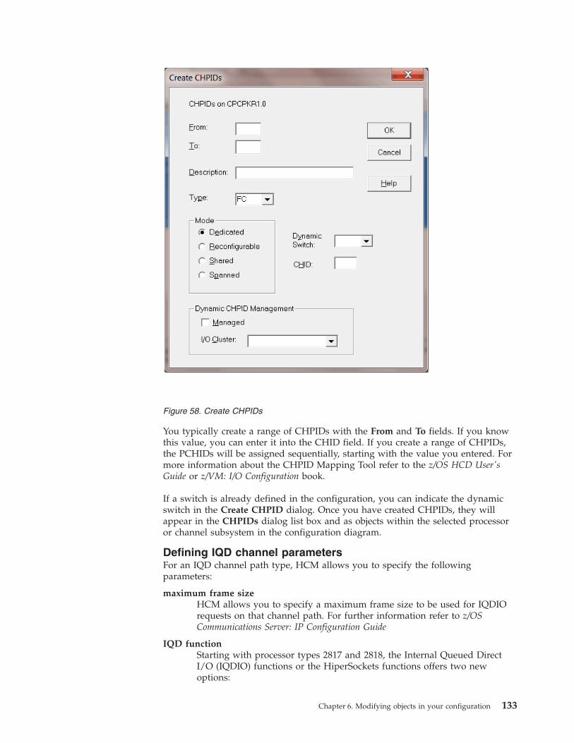
You typically create a range of CHPIDs with the From and To fields. If you knowthis value, you can enter it into the CHID field. If you create a range of CHPIDs,the PCHIDs will be assigned sequentially, starting with the value you entered. Formore information about the CHPID Mapping Tool refer to the z/OS HCD User'sGuide or z/VM: I/O Configuration book.
If a switch is already defined in the configuration, you can indicate the dynamicswitch in the Create CHPID dialog. Once you have created CHPIDs, they willappear in the CHPIDs dialog list box and as objects within the selected processoror channel subsystem in the configuration diagram.
Defining IQD channel parametersFor an IQD channel path type, HCM allows you to specify the followingparameters:
maximum frame sizeHCM allows you to specify a maximum frame size to be used for IQDIOrequests on that channel path. For further information refer to z/OSCommunications Server: IP Configuration Guide
IQD functionStarting with processor types 2817 and 2818, the Internal Queued DirectI/O (IQDIO) functions or the HiperSockets functions offers two newoptions:
Figure 58. Create CHPIDs
Chapter 6. Modifying objects in your configuration 133

v integration with the intraensemble data network (IEDN) controlled bythe zManager functions which provide access controls, virtualization andmanagement functions necessary to secure and manage the IEDN. Thisfunctionality is called extended IQD (IQDX).
v bridging an IQD channel to an external (customer managed) network
To support these functions, for IQD channels, HCD offers three choices:
Basic HiperSocketsThe IQD channel path is connected to the internal HiperSocketsnetwork and is used without connection to the IEDN or anexternal network. This is the default.
IEDN Access (IQDX)The IQD channel path supports IEDN via the Internal QueuedDirect I/O Extensions (IQDX) function.
External BridgeThe IQD channel path works in basic HiperSockets mode and canbe transparently bridged to an external (customer managed)network via the z/VM Virtual Switch bridge support.
Defining more than 160 TCP/IP stacksWhen defining or changing channel paths of type OSD, OSM, or OSX forprocessors with the corresponding support level, HCM prompts you with a dialogwhether you want to define more than 160 TCP/IP stacks with this channel(Figure 60 on page 135). In this dialog, select the related checkbox if you want tohave more than 160 TCP/IP stacks for the current channel. This choice, however,will disable priority queuing.
OSM channels require that more than 160 TCP/IP stacks are allowed.
Figure 59. Edit IQD Channel Parameters
134 z/OS V2R2 and z/VM V6R2.0 HCM User's Guide
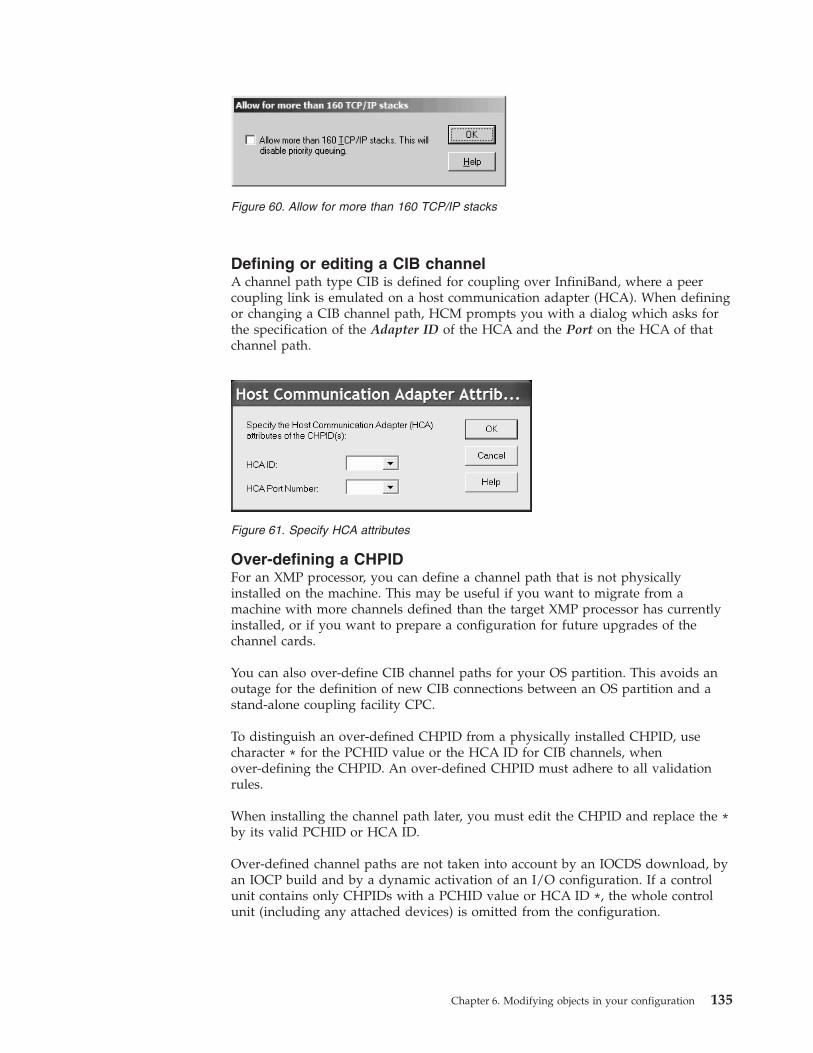
Defining or editing a CIB channelA channel path type CIB is defined for coupling over InfiniBand, where a peercoupling link is emulated on a host communication adapter (HCA). When definingor changing a CIB channel path, HCM prompts you with a dialog which asks forthe specification of the Adapter ID of the HCA and the Port on the HCA of thatchannel path.
Over-defining a CHPIDFor an XMP processor, you can define a channel path that is not physicallyinstalled on the machine. This may be useful if you want to migrate from amachine with more channels defined than the target XMP processor has currentlyinstalled, or if you want to prepare a configuration for future upgrades of thechannel cards.
You can also over-define CIB channel paths for your OS partition. This avoids anoutage for the definition of new CIB connections between an OS partition and astand-alone coupling facility CPC.
To distinguish an over-defined CHPID from a physically installed CHPID, usecharacter * for the PCHID value or the HCA ID for CIB channels, whenover-defining the CHPID. An over-defined CHPID must adhere to all validationrules.
When installing the channel path later, you must edit the CHPID and replace the *by its valid PCHID or HCA ID.
Over-defined channel paths are not taken into account by an IOCDS download, byan IOCP build and by a dynamic activation of an I/O configuration. If a controlunit contains only CHPIDs with a PCHID value or HCA ID *, the whole controlunit (including any attached devices) is omitted from the configuration.
Figure 60. Allow for more than 160 TCP/IP stacks
Figure 61. Specify HCA attributes
Chapter 6. Modifying objects in your configuration 135

If a CHPID changes its PCHID or HCA ID from * to a valid value during adynamic activation, an Add CHPID request is generated. Correspondingly, if thePCHID or HCA ID is changed from a valid value to an *, a Delete CHPID requestis generated.
When building a CONFIGxx member, CHPIDs with a PCHID/HCA ID * areskipped. Attached control units including attached devices are also omitted.
When copying a configuration or generating I/O configuration statements, channelpath definitions with PCHID=* and AID=* are included.
When building a production IODF, HCD requires that the CIB channels areconnected, even if they are over-defined. If the connection is within the sameprocessor, a mix of over-defined and fully-defined HCA IDs is not accepted. In thiscase, error message CBDG541I is issued and the production IODF is not built.
Editing a CHPIDYou can edit a CHPID's details in different ways:v Select one or more CHPIDs and press the Edit... button in the CHPIDs dialog to
open the CHPID dialog. If you have selected more than one CHPID, you cancycle through each CHPID's details by pressing OK, until you find the one youwish to edit.
v Double-click on the desired CHPID in the configuration diagram.v Choose CHPID... from the Edit menu and select the CHPID name from the Edit
a CHPID dialog. You can include and exclude columns and filter the listaccording to your needs.
In the following CHPID dialog press the Edit... button to display the Edit CHPIDdialog.
Note that changing the CHPID type (logical) in this dialog does not automaticallychange the interface type (physical). If you change the CHPID type such that theinterface type is no longer consistent, you must update the interface type with theChange Path Interface Type dialog to avoid a physical-logical inconsistency (see“CHPID interface type” on page 129 for more details). Note that you can changethe CHPID type while the CHPID is connected.
When you change the CHPID type from a type corresponding to a parallelinterface (BL, BY) to a type corresponding to a serial interface (CNC, CTC, CVC,CBY), or if you change the operation mode to or from shared (SHR), you mustchange all other CHPIDs on the same processor that are connected to commoncontrol units. In this situation, the CHPIDs To Be Updated dialog appears to allowyou to change these CHPIDs at the same time.
For a CHPID that is connected to a controller through a switch, this dialog allowsyou to enter a two digit hex number for the connected switch. The DynamicSwitch drop down box only lists those switches that are physically reachable,either directly or via one chained switch. If the CHPID is connected directly to acontroller, this list is empty. See “Connecting switches to processors or otherswitches” on page 206 for more details.
Note:
1. For OSD CHPIDs, the Edit CHPID dialog contains a checkbox which allowsyou to define more than 160 TCP/IP stacks for this channel.
136 z/OS V2R2 and z/VM V6R2.0 HCM User's Guide

2. For IQD CHPIDs, the Edit CHPID dialog containsv a drop down box that lets you define the maximum frame size in kilobytesv a group of radio buttons to select the IQD function.For more information, see “Defining more than 160 TCP/IP stacks” on page134 and “Defining IQD channel parameters” on page 133.
Deleting a CHPIDSelect one or more CHPIDs from the list box in the CHPIDs dialog and click onthe Delete button. HCM displays a confirmation dialog before deleting theCHPID(s). Note that you cannot delete a CHPID directly from the configurationdiagram.
If you delete a spanned CHPID, it is deleted in all channel subsystems where it isdefined.
For spanned CHPIDs, removing all partitions of the access and candidate list froma specific channel subsystem (using the Assign Partitions dialog shown inFigure 62 on page 138) causes that the CHPID of that particular channel subsystemis removed.
Assigning CHPIDs to partitionsUsing the Assign Partitions dialog, you assign CHPIDs to partitions in a processorby adding each partition to the CHPID 's Access or Candidate list. Each CHPIDhas two partition lists, Access and Candidate: if a CHPID is either shared orreconfigurable, you can specify which partitions have access to that CHPID, andwhich are only “candidates” for access. Use the CHPID Access list with or withoutthe CHPID Candidate list.
If you assign partitions to a dedicated or reconfigurable CHPID on an XMPprocessor, the Assign Partitions dialog is filled with the partitions of thecorresponding channel subsystem. The partitions are shown in the formatCSSID.PARTID, where CSSID is the channel subsystem ID and PARTID is the partitionname. For shared and spanned CHPIDs, the dialog is filled with the partitions ofall defined and eligible channel subsystems. Channel subsystems are eligible ifthey have no different channel path defined with the same channel path identifieras the one you are currently working with.
Examples:
Let us assume you have a processor with three channel subsystems named CSS0,CSS1, and CSS2. Let us further assume that the following shared CHPIDs arealready defined: CHPID 10 and 20 to CSS0, CHPID 10 to CSS1, and no CHPID yetto CSS2. If you want to define a new spanned CHPID 30, you can span this newCHPID over all three channel subsystems, as there is no CHPID 30 yet defined inany channel subsystem. Hence, the Assign Partitions dialog contains all partitionsdefined in CSS0, CSS1, and CSS2. If you want to define a new spanned CHPID 20in CSS2, you can only span it over CSS2 and CSS1, as there is already a CHPID 20defined in CSS0. Therefore, the Assign Partitions dialog is filled with partitionsfrom CSS 1 and CSS2, while no partition from CSS0 is shown in the dialog. Finally,if you want to define a new CHPID 10 in CSS2, you can only define it as SHR (orDED / REC), but not as spanned, as there are already CHPIDs 10 defined to bothCSS0 and CSS1. In this case, the Assign Partitions dialog only contains partitionsfrom CSS2, but not from the other two channel subsystems.
Chapter 6. Modifying objects in your configuration 137

To display the Assign Partitions dialog, select one or more CHPIDs in the CHPIDsdialog and press the Partitions... button. Only CHPIDs with the same initial Mode,and Access and Candidate lists can be selected at the same time. Alternatively,press the Partitions... button in the CHPID dialog. Use the Add>> and <<Removebuttons to assign partitions to the CHPID Access or Candidate list.
If you assign partitions from multiple channel subsystems to a shared CHPID, thenits mode is changed from 'shared' to 'spanned' if the channel can be spanned.Otherwise, if the channel cannot be spanned, you get a message saying that youcannot assign partitions from multiple channel subsystems. Also, if you removepartitions from a spanned CHPID's access or candidate lists, such that it can accessonly partitions from one channel subsystem, its mode is changed from spanned toshared. A message lets you decide whether you want to accept these changes.
In our example from Figure 62, we are currently assigning partitions to a sharedCHPID (see the text below the Unassigned Partitions box). Partitions from twodifferent channel subsystems (0 and 1) are available. You see that one partition(LPARC01) from CSS 0 is already assigned. A second partition (LPARC11) from adifferent channel subsystem (CSS 1) is selected to be added to the Access list.Pressing Add>> and then OK will display a message that the channel 's mode ischanged from 'shared' to 'spanned'.
Support of spanned CHPIDsFor your ease of use, a special treatment is applied to spanned CHPIDs in theconfiguration diagram and in some dialogs.
Physical and logical aspects of spanned CHPIDsWhen working with physical CHPIDs (in contrast to internal CHPIDs like IQD orICP), the difference between their physical and logical aspect might be of interest.Considering the physical view, a spanned physical CHPID has exactly one external
Figure 62. Assign Partitions
138 z/OS V2R2 and z/VM V6R2.0 HCM User's Guide
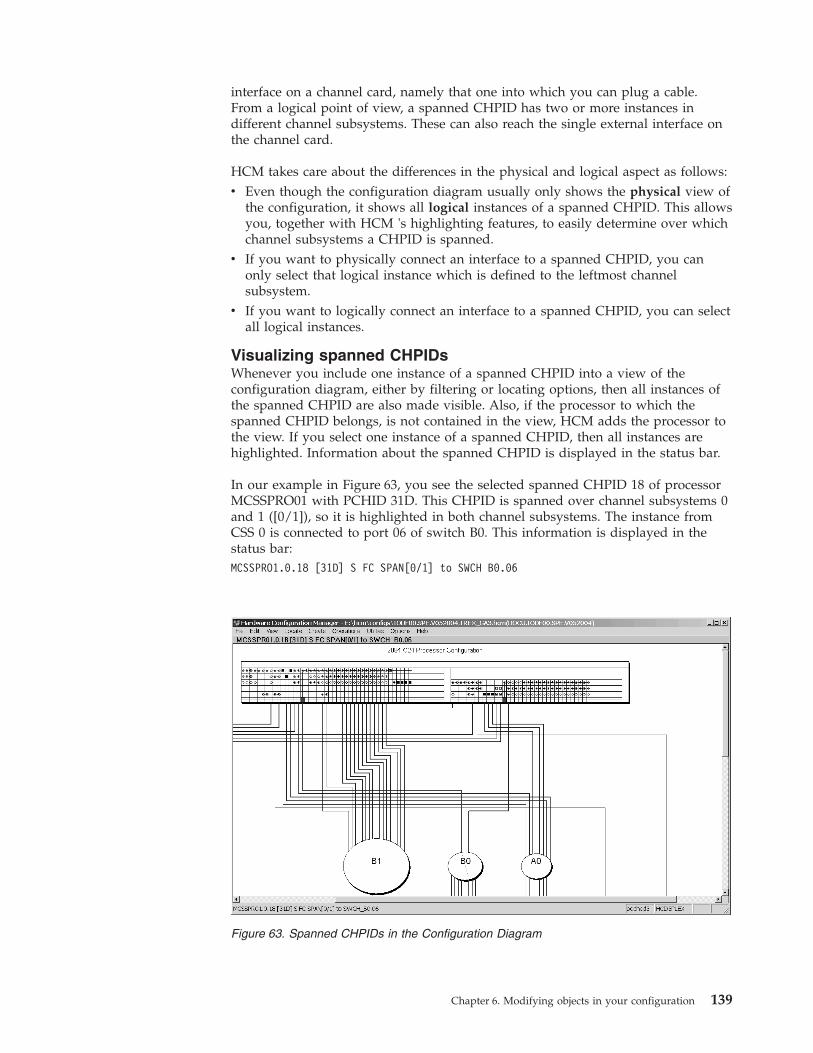
interface on a channel card, namely that one into which you can plug a cable.From a logical point of view, a spanned CHPID has two or more instances indifferent channel subsystems. These can also reach the single external interface onthe channel card.
HCM takes care about the differences in the physical and logical aspect as follows:v Even though the configuration diagram usually only shows the physical view of
the configuration, it shows all logical instances of a spanned CHPID. This allowsyou, together with HCM 's highlighting features, to easily determine over whichchannel subsystems a CHPID is spanned.
v If you want to physically connect an interface to a spanned CHPID, you canonly select that logical instance which is defined to the leftmost channelsubsystem.
v If you want to logically connect an interface to a spanned CHPID, you can selectall logical instances.
Visualizing spanned CHPIDsWhenever you include one instance of a spanned CHPID into a view of theconfiguration diagram, either by filtering or locating options, then all instances ofthe spanned CHPID are also made visible. Also, if the processor to which thespanned CHPID belongs, is not contained in the view, HCM adds the processor tothe view. If you select one instance of a spanned CHPID, then all instances arehighlighted. Information about the spanned CHPID is displayed in the status bar.
In our example in Figure 63, you see the selected spanned CHPID 18 of processorMCSSPRO01 with PCHID 31D. This CHPID is spanned over channel subsystems 0and 1 ([0/1]), so it is highlighted in both channel subsystems. The instance fromCSS 0 is connected to port 06 of switch B0. This information is displayed in thestatus bar:MCSSPRO1.0.18 [31D] S FC SPAN[0/1] to SWCH B0.06
Figure 63. Spanned CHPIDs in the Configuration Diagram
Chapter 6. Modifying objects in your configuration 139

In the configuration diagram, spanned CHPIDs are shown with one instance ineach channel subsystem over which they are spanned. However, HCM ensures thatyou can physically connect only the leftmost of these instances to a target. Theconfiguration diagram shows which of the instances is physically connected. Youcan zoom into a processor or a channel subsystem in the diagram to see thefollowing graphical hints as shown in the example from Figure 64:v An arrow down (↓) indicates that this CHPID instance is physically connected to
a target interface.v An arrow to the left (←) or to the right (→) indicates that another CHPID instance
of the current spanned CHPID is physically connected to a target.v For dedicated, reconfigurable or shared CHPIDs, you see an empty field.
Navigating with spanned CHPIDsThe context menu for spanned CHPIDs in the configuration diagram containsselections with which you can navigate from the current instance to other instancesof the spanned CHPID:
Locate Cablenavigates to the instance that is physically connected to a target object.This is always the leftmost instance.
Locate Left Instancenavigates to the next left instance.
Locate Right Instancenavigates to the next right instance.
Support of spanned CHPIDs in the HCM dialogBesides the enhanced visualization of spanned CHPIDs in the configurationdiagram, special handling is reflected and enhanced in various places in the dialog.You can find the related information where appropriate:v “Making a standard connection” on page 198v “Assigning CHPIDs to partitions” on page 137
Please also read the information contained in “Physical and logical aspects ofspanned CHPIDs” on page 138.
Aggregating CHPIDsIf you need to combine attachments of several CHPIDs onto a single CHPIDwithin the same processor, HCM offers you the Aggregate CHPID wizard under
Figure 64. Physical connection information for spanned CHPIDs
140 z/OS V2R2 and z/VM V6R2.0 HCM User's Guide

the Utilities menu . All CHPIDs must be connected to the same switch and use thesame dynamic switch. See “Aggregating CHPIDs” on page 247 for a description ofthis wizard.
ControllersYou can create, edit or delete controllers by calling up the appropriate dialogs forthe controller object in the configuration diagram. You can also physically connectand logically define controllers to processors; once the connection is made, you canadd physical objects to it, such as patchports, crossbar switches, converters orswitches.
There are different possibilities to open the Controller dialog:v Double - click on a controller in the configuration diagram.v Choose Controller... from the Edit menu, and select the desired controller from
the list which appears. Note that you can rearrange and filter the list accordingto your needs.
v Press the Controller... button in the Edit Switch dialog, to edit the switch controlunits and devices. See “Editing switch port attributes” on page 167 for moredetails.
The Controller dialog lists all channel interfaces and their connections for theselected controller. You can access related dialogs to edit the controller or list thecontrol units it contains.
You can also select a channel interface to connect to a target, edit the fiber link fora connection, or change the type of a channel interface.
Note that when you select a channel interface to connect to a target, pressing theConnect... button begins the process of connecting the controller and one or moreprocessors. The Connect Channel Interface dialog which appears leads to otherdialogs which allow you to create any necessary logical definitions for the physicalconnection. See “Connecting controllers to processors and switches” on page 195.
The Controller dialog also lists any strings/devices connected to the controllerthrough its device interfaces. If I/O devices have no physical string (they areintegrated into the controller), the “virtual strings” containing them are displayed(see “Editing a controller” on page 143). You can select a string to edit, or create astring under the selected controller. See “Strings” on page 152 for moreinformation.
Chapter 6. Modifying objects in your configuration 141

Creating a controllerTo create a new controller, open the Create Controller dialog by choosingController... from the Create menu. Enter the information for the controller andpress OK.
If there is more than one physical description of the control unit type, the ChoosePhysical Description dialog will be opened .
If the physical description for the controller has more than one segment, the AddControl Unit dialog will be opened for you to create control units for the othersegment(s) .
The controller object will appear in the configuration diagram.
After creating the controller, you can edit it and connect its interfaces to objects,using dialogs accessed through the Controller dialog. Additional control units maybe added to the controller through the Create Control Unit dialog.
Note: HCM offers a wizard that lets you create a complete I/O subsystemconsisting ofv controllers (with segments and control units) andv strings (with devices).
See “Creating/Copying/Editing an I/O subsystem” on page 249 for moreinformation.
Figure 65. Controller
142 z/OS V2R2 and z/VM V6R2.0 HCM User's Guide

Choosing a physical descriptionThe physical description file, or PDF, is a template associated with the controller orstring that describes its physical characteristics. See Chapter 16, “Physicaldescription files (PDF),” on page 399 for more details.
In the Create Controller dialog, if the control unit type selected has only onepossible physical description, then HCM simply creates the controller when youpress OK. If the control unit type selected has more than one possible physicaldescription, pressing OK causes the Choose Physical Description dialog toautomatically appear. (You can deliberately open this dialog; see “Editing acontroller”). Select a physical description and press OK to create the newcontroller.
Changing the physical description affects all controllers within a subsystem (forexample, dual frame); you may only change to a physical description for asubsystem with the same or fewer number of components.
Adding control units to controller segmentsIf you are creating a controller with more than one segment in the CreateController dialog, pressing OK displays the Add Control Unit dialog to allow youto create control units for the second (and subsequent) segment. You need onlyenter the control unit number and description; the serial number and type iscopied from the control unit in the first segment.
Ordering strings connected to the controllerIn the Controller dialog press the Order... button in the Strings/Devices section.This opens an order dialog, allowing you to order the strings for a selected deviceinterface. If there is more than one device interface on this controller, HCM opens adialog to choose on which device interface you want to re-order strings.
Editing a controllerClick on the Edit... button in the Controller dialog to open the Edit Controllerdialog. Edit the information for the selected controller, or access related dialogs toadd user data, change the physical description, arrange components within thecontroller, or group controllers into subsystems (for example, dual frame).
Note that if the Physically Installed check box is not enabled, the controller isun-installed, and drawn with dotted lines in the configuration diagram.
If the Devices are Integrated check box is enabled, all strings connected to theselected controller are integrated into the controller. Integrated strings and devicesare not drawn in the configuration diagram, but can be accessed through the Editmenu or the Strings section of the Controller dialog. When you first create acontroller, if its type is anything except DASD or Tape, it is automatically markedas devices are integrated.
The Display Class list box allows you to select a display class of the subsystem towhich the controller belongs. The display class only affects the display by HCM ofcertain classes of controllers; the display class is initially set by HCM during IODFload/resync according to the first control unit added to the subsystem (see“Filtering your view” on page 34 for details).
Chapter 6. Modifying objects in your configuration 143
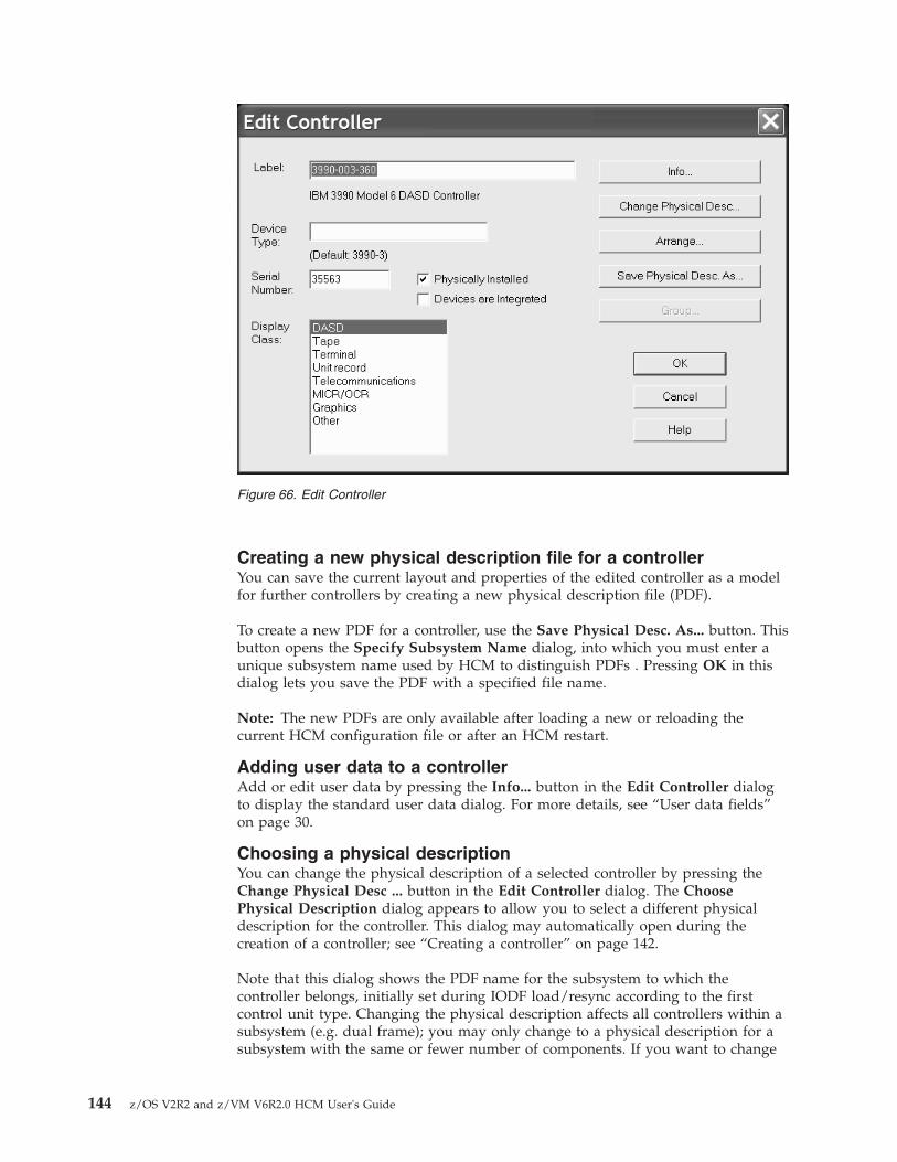
Creating a new physical description file for a controllerYou can save the current layout and properties of the edited controller as a modelfor further controllers by creating a new physical description file (PDF).
To create a new PDF for a controller, use the Save Physical Desc. As... button. Thisbutton opens the Specify Subsystem Name dialog, into which you must enter aunique subsystem name used by HCM to distinguish PDFs . Pressing OK in thisdialog lets you save the PDF with a specified file name.
Note: The new PDFs are only available after loading a new or reloading thecurrent HCM configuration file or after an HCM restart.
Adding user data to a controllerAdd or edit user data by pressing the Info... button in the Edit Controller dialogto display the standard user data dialog. For more details, see “User data fields”on page 30.
Choosing a physical descriptionYou can change the physical description of a selected controller by pressing theChange Physical Desc ... button in the Edit Controller dialog. The ChoosePhysical Description dialog appears to allow you to select a different physicaldescription for the controller. This dialog may automatically open during thecreation of a controller; see “Creating a controller” on page 142.
Note that this dialog shows the PDF name for the subsystem to which thecontroller belongs, initially set during IODF load/resync according to the firstcontrol unit type. Changing the physical description affects all controllers within asubsystem (e.g. dual frame); you may only change to a physical description for asubsystem with the same or fewer number of components. If you want to change
Figure 66. Edit Controller
144 z/OS V2R2 and z/VM V6R2.0 HCM User's Guide
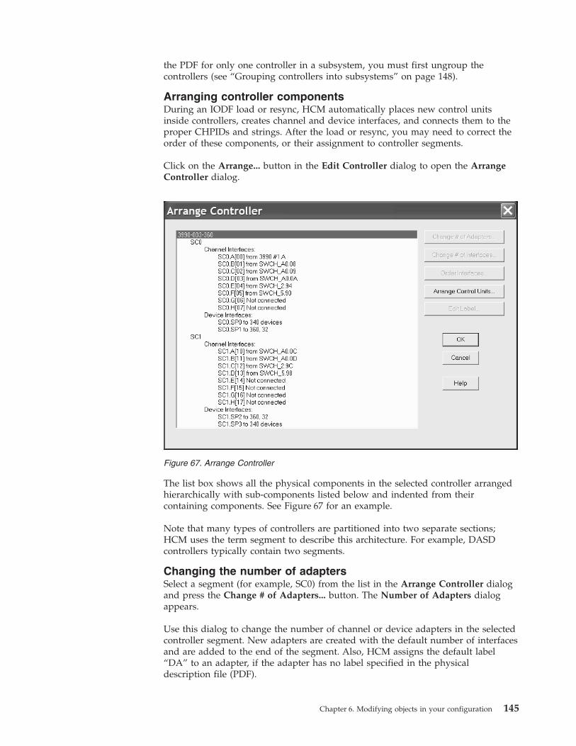
the PDF for only one controller in a subsystem, you must first ungroup thecontrollers (see “Grouping controllers into subsystems” on page 148).
Arranging controller componentsDuring an IODF load or resync, HCM automatically places new control unitsinside controllers, creates channel and device interfaces, and connects them to theproper CHPIDs and strings. After the load or resync, you may need to correct theorder of these components, or their assignment to controller segments.
Click on the Arrange... button in the Edit Controller dialog to open the ArrangeController dialog.
The list box shows all the physical components in the selected controller arrangedhierarchically with sub-components listed below and indented from theircontaining components. See Figure 67 for an example.
Note that many types of controllers are partitioned into two separate sections;HCM uses the term segment to describe this architecture. For example, DASDcontrollers typically contain two segments.
Changing the number of adaptersSelect a segment (for example, SC0) from the list in the Arrange Controller dialogand press the Change # of Adapters... button. The Number of Adapters dialogappears.
Use this dialog to change the number of channel or device adapters in the selectedcontroller segment. New adapters are created with the default number of interfacesand are added to the end of the segment. Also, HCM assigns the default label“DA” to an adapter, if the adapter has no label specified in the physicaldescription file (PDF).
Figure 67. Arrange Controller
Chapter 6. Modifying objects in your configuration 145

An adapter cannot be deleted if any of its interfaces are connected. New channelinterfaces are created as serial interfaces if the first control unit in the segment isDASD or tape, otherwise they are created as parallel interfaces.
If you reduce the number of adapters, HCM removes them from the end of thesegment. If you want to remove unused adapters from the front of the segment,you must reorder the adapters so that all unused adapters are grouped together atthe end of the segment. Then you can reduce the number of adapters.
Changing the number of interfacesSelect a segment (e.g. SC0) from the Arrange Controller list box and press theChange # of Interfaces... button. The Number of Interfaces dialog appears. Youcan select a number from the drop down box or type in the field. If you are addinginterfaces, the new ones are added to the end of the segment and assigned labelsfrom the physical description; interfaces over the maximum supported by thephysical description will be assigned the label “INT”. Note that new channelinterfaces are created as serial interfaces if the first control unit in the segment isDASD or Tape, otherwise they are created as parallel interfaces.
Changing the order of controller interfacesSelect a segment from the Arrange Controller list box and press the OrderInterfaces... button. The Order Controller Interfaces dialog appears, allowing youto move channel and devices interfaces from list boxes on the left (old order) to thelist boxes on the right (new order) . Use the >> and << buttons to move selectedinterfaces, or double - click on an interface to move it to the opposite list box. Notethat you cannot leave this dialog without completely specifying the order for bothchannel and device interfaces; that is, either the left or right list boxes must becompletely full.
Arranging control units and connections in a controllerSelect a controller that contains more than one segment from the Edit Controllerlist box and press the Arrange Control Units... button. The Arrange Control Unitsand Connections dialog appears to allow you to move the control units, theprocessor connections, and the string connections between the segments.
146 z/OS V2R2 and z/VM V6R2.0 HCM User's Guide

You can move components between the segments by using the >> and << buttonsto move selected items; alternatively, double - click on a component to move it tothe opposite list box . After you have arranged the components, it may benecessary to use the Order Controller Interfaces dialog (see “Changing the orderof controller interfaces” on page 146) to further correct the order of interfaceswithin each segment.
Editing labels of adapters and interfacesWith HCM, users may utilize more controller adapters, more controller adapterinterfaces, more controller device adapters and more controller device adapterinterfaces than being defined in the controller ' >s> physical description file. Alladapters and interfaces without an explicit label provided by the correspondingphysical description file, get a default name, for example, ‘CA’ for a controlleradapter. If you prefer your own naming for labels, HCM lets you modify adapterand interface labels. For this purpose, use the Edit Label... button. Depending onthe selected object, one of the following dialogs is invoked:
Selected object Invoked dialog
controller adapter Edit Controller Adapter Label
controller adapter interface Edit Controller Adapter Interface Label
controller device adapter Edit Controller Device Adapter Label
controller device adapter interface Edit Controller Device Adapter Interface Label
Each of these dialogs also contains a radio button that allows you to haveunlabeled adapters or interfaces instead of default or user-specified labels.
Figure 68. Arrange Control Units and Connections
Chapter 6. Modifying objects in your configuration 147

Grouping controllers into subsystemsSome controller types can be grouped together in a subsystem, for example, 3990dual frame controllers or 3803s linked via communication cables.
Click on the Group... button in the Edit Controller dialog to open the GroupControllers dialog (see Figure 69). The Independent Controllers listbox lists allcontrollers of the appropriate type that are currently not grouped. You can move aselected controller into or out of a subsystem; HCM makes the appropriatephysical changes. Use the >> and << buttons to move selected items; alternatively,double-click on a controller to move it to the opposite list box.
Editing the fiber links above the controllerIn the Controller dialog, select a channel interface and press the Fiber Link...button to open the Edit Fiber Link dialog. See “Editing fiber links in the dialog”on page 230 for information about connecting patchports.
Changing the channel interface typeSelect a channel interface from the Interfaces list box in the Controller dialog andpress the Type... button (see Figure 65 on page 142). The Interface Attributesdialog will appear , allowing you to make the selected channel interface eitherserial, parallel (bus and tag), IOC or OSA. See “CHPIDs” on page 127 for moredetails.
Figure 69. Group Controllers
148 z/OS V2R2 and z/VM V6R2.0 HCM User's Guide

Deleting a controllerSelect the controller object in the configuration diagram and press the DEL key.HCM will display a confirmation dialog before deleting the controller.
Control unitsYou can create or modify control units for a selected controller. There are twopossibilities to open the Control Unit List dialog (Figure 71 on page 150):v Select a controller by double - clicking on it in the configuration diagram, or by
choosing the Controller... command from the Edit menu and selecting thedesired controller from the list which appears. The Controller dialog will openfor the selected controller; press the Control Units... button to display theControl Unit List dialog.
v Choose Control Unit... from the Edit menu and select the control unit namefrom the list that appears. Note that you can rearrange and filter the listaccording to your needs. Clicking OK causes the Controller dialog to open. Inthis dialog click the Control Units... button to display the Control Unit Listdialog. This dialog lists the control unit you selected from the Edit menu.
In the Control Unit List dialog you can access related dialogs to create, edit ordelete control units. You can view the devices connected to a control unit byselecting the control unit and pressing the I/O Devices... button to display the I/ODevice List.
Note:
You can also access the Control Unit <=> Processor Definition dialog by pressingthe CU<=> Proc ... button. This dialog allows you to logically define the selectedcontrol unit to all or some of the processors that the controller can reach throughphysical connections.
See “Making a standard connection” on page 198 for details.
You can modify the switch control unit by accessing the Controller dialog. Formore details, see “Editing switch port attributes” on page 167.
The Status button allows you to retrieve information by control unit and to checksystem status.
Figure 70. Interface Attribute
Chapter 6. Modifying objects in your configuration 149

Creating a control unitYou can create additional control units for a selected controller. Click on theCreate... button in the Control Unit List dialog to display the Create Control Unitdialog. Enter the control unit information and press OK. Note that control unitshave the same serial number as the controller containing them; thus, the serialnumber shown in this dialog can be only edited in the Edit Controller dialog . Thecontrol unit is added to the controller in the diagram, and appears in the ControlUnit List dialog for the controller.
You can also create one or more switch 's control units inside a switch. When youcreate a new switch 's control unit inside a switch, it is always connected to portFE of the switch. If you define an existing control unit for a switch, note that thiscontrol unit is added into the appropriate switch 's internal structures. Internalstructures of the switch are the switch 's control units and devices. You mustspecify either both a control unit and a device or neither.
Choosing a controller segment to assign the control unitIf the controller has only one segment, any new control units created in the CreateControl Unit dialog are placed in that segment. If the controller has more than onesegment, pressing OK in the Create Control Unit dialog displays the ChooseController Segment dialog. Choose the segment to which the new control unit willbe assigned and press OK.
Note that you can assign the control unit to a different segment using the ArrangeControl Units and Connections dialog (see “Arranging controller components” onpage 145).
Editing a control unitSelect a control unit from the list box and click the Edit... button in the ControlUnit List dialog. Alternatively, choose Control Unit... from the Edit menu andselect the control unit name from the list that appears. Note that you can rearrange
Figure 71. Control Unit List
150 z/OS V2R2 and z/VM V6R2.0 HCM User's Guide

and filter the list according to your needs. The Edit Control Unit dialog appearsfor the selected control unit. You can edit the control unit number, type, anddescription.
Edit the information and press OK. Note that you cannot edit the control unitserial number in this dialog; since it is the same as its controller, you can only editit in the Edit Controller dialog.
Deleting a control unitSelect a control unit from the list box in the Control Unit List dialog and press theDelete button. HCM will display a confirmation dialog before deleting the controlunit from the selected controller.
Deleting a switch 's control unitYou can delete a switch 's control unit from a switch. If the control unit has switch's devices defined, a warning message appears stating that HCM will causeimplicit deletion of the devices. The reason for implicitly deleting the devices isthat leaving a switch 's device in an internal string creates a corrupt configuration.Devices are not allowed to reside in the internal string of a switch unless they arelogically defined in the IODF to a switch 's control unit which is defined to port FEof the switch.
Moving an existing switch 's control unit into a switchIf your configuration contains control units which are meant to be internal to aswitch but are not yet connected to the internal control unit port of the switch, youcan move a control unit with its associated devices into a switch. To do this , clickon the Add Existing ... button in the Control Unit List dialog.
The Add Existing.... button is only displayed on the Control Unit List dialog whenyou reached this dialog via an internal controller. The Add Existing Control Unitto Internal Controller dialog is displayed.
The drop-down box will display the numbers of all control units in theconfiguration with the same type as the switch which do not have any connectionsto switch ports. Thus, the drop-down box does not show control units which arealready internal to switches. After your selection of the appropriate control unit,click on OK to connect the control unit to port FE of the current switch. Youcannot move a control unit which is already connected to another switch port. Ifthe selected control unit has devices under it, they are also moved into the switch'sinternal string.
The controller which contained the switch-internal control unit will not be deletedafter this control unit has been moved into the switch. If you do no longer needthe controller, you can delete it manually.
Figure 72. Add Existing Control Unit to Internal Controller
Chapter 6. Modifying objects in your configuration 151

StringsA string is a collection of one or more I/O devices. The term usually refers to aphysical string of units, where a unit is a collection of I/O devices in a physicalbox; however, it may also refer to I/O devices integrated into a control unit . Youcan create, edit or delete strings, units, and devices by calling up the appropriatedialogs for the string object in the configuration diagram. You can also connectstrings to controllers.
You can open the String dialog in different ways:v Double-click on the top rectangle of a string in the configuration diagram.v Choose String... from the Edit menu, and select the desired string from the list
which appears. Note that you can rearrange and filter the list according to yourneeds.
v Double-click on a controller in the configuration diagram (or choose Controller...from the Edit menu) to display the Controller dialog; then select a string andpress the Edit... button in the Strings/Devices section to open the String dialog.
The String dialog lists all string interfaces and their connections to controllers. Youcan access related dialogs to edit the string or its I/O devices, or connect a stringinterface to a controller device interface.
Selecting a string interface and pressing the Connect... button begins the process ofconnecting the I/O devices in the string to the controller, and any processorsreachable through the controller. The Select Controller Device Interface dialogwhich appears leads to other dialogs allowing you to create any necessary logicaldefinitions for the physical connection. See “Connecting devices to controllers” onpage 189.
Creating a stringTo create a string, choose String... from the Create menu to open the Create Stringdialog. Enter the string information and press OK. The string object will appear inthe configuration diagram. You can then use the String dialog and related dialogsto edit the string, its units and its I/O devices, and to connect the string to acontroller.
Figure 73. String
152 z/OS V2R2 and z/VM V6R2.0 HCM User's Guide

For DASD devices, you can optionally define a PPRC (peer-to-peer remote copy)usage type. A classification as FLASHCOPY, SIMPLEX, UTILITY, or NONSYSPLEXdevice is of descriptive character only. DUPLEX devices, attached to a primaryoperating system configuration with OFFLINE=YES are defined to an optionalD/R site operating system configuration with OFFLINE=NO and vice versa, whenthe D/R site OS configuration is generated. For more information about PPRCusage type DUPLEX refer to “D/R site OS configurations” on page 263.
To create a string under a controller, first double-click on the controller in theconfiguration diagram (or choose Controller... from the Edit menu) to display theController dialog. Select a string and press the Create... button in theStrings/Devices section to open the Create String dialog. After you enter the stringinformation in this dialog, pressing OK opens the String dialog to allow you toconnect the new string to the selected controller (or another controller). You maychoose not to connect the string, in which case the string is created, but it is notconnected.
Note that serial numbers are assigned in the Edit Unit or Edit I/O Devices dialog;VOLSERs can be assigned in the latter dialog as well.
Choose physical descriptionThe physical description file, or PDF, is a template associated with the controller orstring that describes its physical characteristics. See “Graphical representation ofphysical objects” on page 59 for more details.
If there is more than one physical description possible for the string, pressing OKin the Create String dialog opens the Choose Physical Description dialog. Select aphysical description and press OK to create the string. If the string was createdunder a controller, pressing OK opens the Select Controller Device Interfacedialog to allow you to connect the string to the controller.
Figure 74. Create String
Chapter 6. Modifying objects in your configuration 153
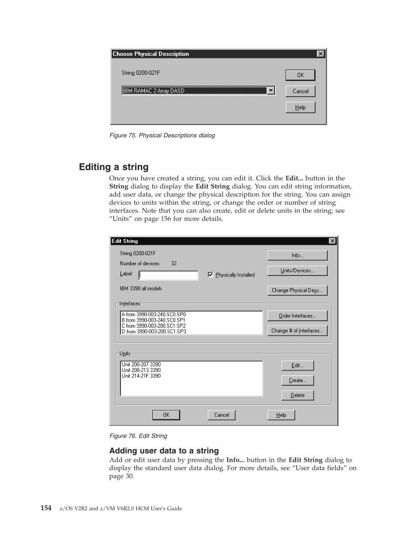
Editing a stringOnce you have created a string, you can edit it. Click the Edit... button in theString dialog to display the Edit String dialog. You can edit string information,add user data, or change the physical description for the string. You can assigndevices to units within the string, or change the order or number of stringinterfaces. Note that you can also create, edit or delete units in the string; see“Units” on page 156 for more details.
Adding user data to a stringAdd or edit user data by pressing the Info... button in the Edit String dialog todisplay the standard user data dialog. For more details, see “User data fields” onpage 30.
Figure 75. Physical Descriptions dialog
Figure 76. Edit String
154 z/OS V2R2 and z/VM V6R2.0 HCM User's Guide

Assigning devices to units in the stringClick on the Units/Devices... button in the Edit String dialog to open theUnits/Devices dialog. Select one or more I/O devices from the listbox and pressAssign... to open the Assign to Unit dialog.
Choose the unit to which the devices will be assigned . Use the checkboxes in theView box either to show only the units of this string or to show all units in allstrings.
Changing the physical descriptionThe physical description file, or PDF, is a template associated with the controller orstring that describes its physical characteristics. See “Graphical representation ofphysical objects” on page 59 for more details.
You can change the physical description for a string. Click on the Change PhysicalDesc... button in the Edit String dialog to open the Choose Physical Descriptiondialog. When you select a different physical description, the existing I/O devicesunder the string may be reassigned to units. New units are created as needed;there may be empty units left at the end of the string.
Ordering string interfacesThe string interfaces for a selected string are shown in the Interfaces section of theEdit String dialog. Click on the Order Interfaces... button to open the OrderString Interfaces dialog. You can then re-order the string interfaces by movingthem from the Current Order list box to the New Order list box. See “Orderingobjects” on page 50 for an example of an ordering dialog.
Changing the number of string interfacesClick on the Change # of Interfaces... button in the Interfaces section of the EditString dialog. The Number of String Interfaces dialog appears to allow you tochange the number of string interfaces.
Figure 77. Units/Devices
Chapter 6. Modifying objects in your configuration 155

Deleting a stringSelect the string object in the configuration diagram and press the DEL key. HCMwill display a confirmation dialog before deleting the string. Alternatively, you canselect a string and its devices from the list and press Delete in the Controllerdialog.
UnitsA unit is a collection of I/O devices in a physical box; a string is a collection ofunits containing I/O devices. You can create, edit or delete units within a selectedstring. First, open the String dialog by double - clicking on a string in theconfiguration diagram, choosing the String... command from the Edit menu, orselecting a string and pressing the Edit... button in the Strings/Devices section ofthe Controller dialog. Then click on the Edit... button in the String dialog to openthe Edit String dialog. This dialog lists all units in the selected string. Create, editor delete units by selecting one or more units and pressing the appropriate buttonsin the Units section of the dialog.
Creating a unitClick on the Create... button in the Units section of the Edit String dialog. TheCreate Unit dialog appears; enter the information and press OK to create a newunit under the string. Note that you can add units before they are actuallyphysically available; indicated whether the unit is physically installed by clickingin the check box.
You can assign I/O devices to the unit by clicking on the Units/Devices... buttonto open the Units/Devices dialog. See “Assigning devices to units in the string” onpage 155.
Editing a unitSelect a unit and click on the Edit... button in the Units section of the Edit Stringdialog. The Edit Unit dialog appears, allowing you to edit the unit ’ >s> serialnumber and label, and add user data. You can also indicate whether the unit isactually physically installed, and if the unit serial number should be applied to alldevices within the unit. Note that if some of the devices have a different serialnumber, HCM will warn you that this information will be lost by applying the unitserial number to all its devices.
Figure 78. Edit Unit
156 z/OS V2R2 and z/VM V6R2.0 HCM User's Guide

Adding user data to a unitAdd or edit user data by pressing the Info... button in the Edit Unit dialog todisplay the standard user data dialog. For more details, see “User data fields” onpage 30.
Deleting a unitSelect the unit in the configuration diagram and press the DEL key. HCM willdisplay a confirmation dialog before deleting the unit. Alternatively, you can selecta unit from the list and press Delete in the String dialog.
I/O devicesI/O devices are grouped into units (physical boxes), which in turn are groupedinto a string. You can create, edit or delete the I/O devices for a selected string.When the string is connected to a controller, the I/O devices can be logicallydefined through the physical connection not only to the controller, but also to anyprocessors that are physically reachable through the connected controller. See“Connecting devices to controllers” on page 189 for details.
There are different possibilities to open the I/O Device List:v Select a string from the configuration diagram and select I/O Devices ... from its
context menu , or choose String... from the Edit menu, select a string, press OKand then click on the I/O Devices... button in the String dialog.
v Press the I/O Devices... button in the Control Unit List dialog; note that the I/ODevice List dialog will not display the Create... or Delete... buttons when calledthis way.
v Choose Device... from the Edit menu and select a device name or a range ofdevices from the list that appears. Note that you can rearrange and filter the listaccording to your needs. Clicking OK causes the String dialog to appear. In thisdialog, click on the I/O Devices... button.
Chapter 6. Modifying objects in your configuration 157

The I/O Device List dialog allows you to display the serial numbers andVOLSERs, device descriptions, control unit numbers and further information aboutdevices in the list box by clicking the Columns... button to include selectedcolumns into the list.
You can open related dialogs to create, edit or delete I/O devices by selecting oneor more devices from the list box and pressing the appropriate button.
Note that you can access the I/O Device <=> Processor Definition dialog bypressing the Dev <=>Proc ... button. This dialog allows you to select one or moreprocessors from a list to which you define your selected device. For XMPprocessors, there will be one line per CSS in the list. See “Making a customconnection” on page 192.
Note: You can edit the device connected to the switch control unit by accessing theController dialog.
For more details, see “Editing switch attributes” on page 166.
Creating an I/O device in a stringClick on the Create... button in the I/O Device List dialog to open the Create I/ODevice(s) dialog. Fill in the device information and press OK. Devices will beallocated to units appropriately. You can change the assignment of devices to unitslater. See “Assigning devices to units in the string” on page 155 for moreinformation.
Figure 79. I/O Device List
158 z/OS V2R2 and z/VM V6R2.0 HCM User's Guide
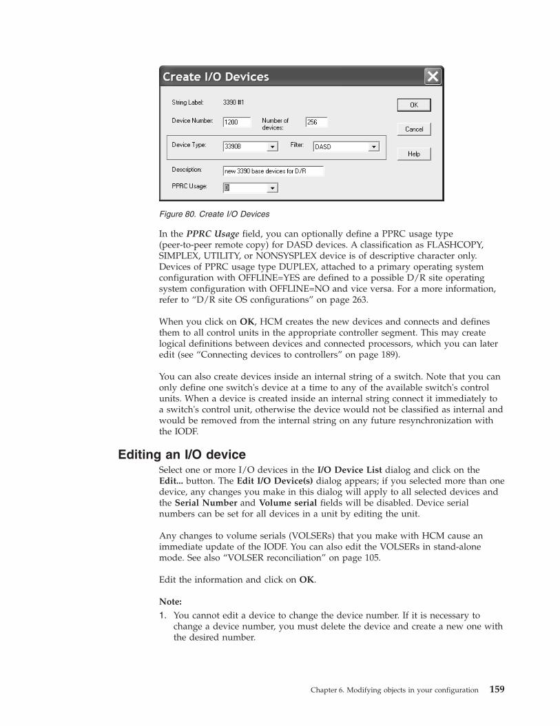
In the PPRC Usage field, you can optionally define a PPRC usage type(peer-to-peer remote copy) for DASD devices. A classification as FLASHCOPY,SIMPLEX, UTILITY, or NONSYSPLEX device is of descriptive character only.Devices of PPRC usage type DUPLEX, attached to a primary operating systemconfiguration with OFFLINE=YES are defined to a possible D/R site operatingsystem configuration with OFFLINE=NO and vice versa. For a more information,refer to “D/R site OS configurations” on page 263.
When you click on OK, HCM creates the new devices and connects and definesthem to all control units in the appropriate controller segment. This may createlogical definitions between devices and connected processors, which you can lateredit (see “Connecting devices to controllers” on page 189).
You can also create devices inside an internal string of a switch. Note that you canonly define one switch's device at a time to any of the available switch's controlunits. When a device is created inside an internal string connect it immediately toa switch's control unit, otherwise the device would not be classified as internal andwould be removed from the internal string on any future resynchronization withthe IODF.
Editing an I/O deviceSelect one or more I/O devices in the I/O Device List dialog and click on theEdit... button. The Edit I/O Device(s) dialog appears; if you selected more than onedevice, any changes you make in this dialog will apply to all selected devices andthe Serial Number and Volume serial fields will be disabled. Device serialnumbers can be set for all devices in a unit by editing the unit.
Any changes to volume serials (VOLSERs) that you make with HCM cause animmediate update of the IODF. You can also edit the VOLSERs in stand-alonemode. See also “VOLSER reconciliation” on page 105.
Edit the information and click on OK.
Note:
1. You cannot edit a device to change the device number. If it is necessary tochange a device number, you must delete the device and create a new one withthe desired number.
Figure 80. Create I/O Devices
Chapter 6. Modifying objects in your configuration 159

2. If you want to change the device type of a device that is defined in asubchannel set other than 0, then the device type change will only be acceptedif the target device type can also be defined in an alternative subchannel set.
Defining devices to OS configurationsTo define devices to OS configurations, select the device(s) and press the OSConfigs ... button. This opens the List Device <=> OS Configuration Definitionsdialog. See “Listing OS configurations to which devices are defined” on page 268.
Deleting an I/O deviceYou can only delete an I/O device from the I/O Device List dialog, not from theconfiguration diagram. Select the device(s) in the list box and press the Delete...button in the dialog. HCM will display a confirmation dialog before deleting thedevice(s) .
Changing the subchannel set for devicesSome scenarios may require to change the subchannel set placement of devices. Forexample, when you copy a channel subsystem from one processor to a targetprocessor, but in the target processor you want to have a different placement ofdevices. Or, you may want to use your devices in a different placement in differentoperating systems. Therefore, you can change the placement of devices in regard toeither one or both of the following aspects:v Device <-> Processor relationv Device <-> Operating System relation.
You have several possibilities to invoke the dialogs for changing the subchannel setID for devices:
Modifying the subchannel set ID for 'Device <-> Processor' and 'Device <->Operating System' at the same time:
Start from one of the following dialogs:v From the Edit menu bar choice, select Device... to reach the Edit a Device
dialog.v From the Locate menu bar choice, select Device... to reach the Locate One or
More Devices dialog.
Both dialogs contain the Change SCHS button which lets you change thesubchannel set placement of (multiple) eligible devices. HCM first prompts you forwhich processor(s) and then for which operating system(s) you want to change thesubchannel set:1. In the Object List for Subchannel Set ID Change dialog for processors, you
select the processor(s) for which you want to change the subchannel set ID forthe device <-> processor definition and press OK.
160 z/OS V2R2 and z/VM V6R2.0 HCM User's Guide

2. In the subsequent Edit Subchannel Set ID dialog for processors, you set thesubchannel set ID for the device <-> processor relation.
3. In the Object List for Subchannel Set ID Change dialog for operating systems,you select the operating system(s) for which you want to change thesubchannel set ID for the device <-> operating system definition. This step issimilar to step 1 on page 160.
4. In the subsequent Edit Subchannel Set ID dialog for operating systems, younow set the subchannel set ID for the device <-> operating system relation.This step is similar to step 3.
Modifying the subchannel set ID for 'Device <-> Operating System' only:
Start from the menu bar choice Edit and select OS configurations.... Then selectone operating system from the Operating System Configurations dialog and pressthe I/O Devices... button. This invokes the List Devices for OS Configurationwhere you select a single device or a group of devices and press either the Edit...button or the Group Edit... button. This leads you to the Define Device <==> OSConfiguration Parameters dialog where you can modify the subchannel set ID.
Modifying the subchannel set ID for 'Device <-> Processor Definitions' only:
From an I/O Device List select one or more devices and press the Dev <=>Proc ...button. From the I/O Device <=> Processor Definitions dialog select one or moreprocessors / channel subsystems and press either the Edit... button or the GroupEdit... button to invoke the Edit I/O Device <==> Processor Definitions dialogwhere you can modify the subchannel set ID.
Figure 81. Selecting processors for changing the subchannel set placement for devices
Figure 82. Edit Subchannel Set ID
Chapter 6. Modifying objects in your configuration 161

ConvertersThere are two types of converters: those that are used to connect serial ESCONcables to parallel bus-and-tag cables (9034 or S->P), and those that connect parallelto serial cables (9035, or P->S) . HCM automatically creates and connects genericconverters during an IODF load or resync and when you connect a serial to aparallel interface (or vice versa).
Generic converters can be replaced with “real” converters that can be assigned alabel, serial number, user data, and graphical position on the diagram. HCMmaintains an inventory of “real” converters that can replace generic converters inyour configuration.
Choose Converter ... from the Edit menu to display the Converters dialog, that listconverters and their attributes. Note that you can rearrange and filter the listaccording to your needs. Real converters that are in use can be edited but notdeleted. Unused converters can be deleted.
Creating a converterIn the Converters dialog, press Create to open the Create Converter dialog.
Figure 83. Converters
162 z/OS V2R2 and z/VM V6R2.0 HCM User's Guide
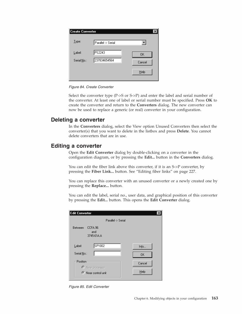
Select the converter type (P->S or S->P) and enter the label and serial number ofthe converter. At least one of label or serial number must be specified. Press OK tocreate the converter and return to the Converters dialog. The new converter cannow be used to replace a generic (or real) converter in your configuration.
Deleting a converterIn the Converters dialog, select the View option Unused Converters then select theconverter(s) that you want to delete in the listbox and press Delete. You cannotdelete converters that are in use.
Editing a converterOpen the Edit Converter dialog by double-clicking on a converter in theconfiguration diagram, or by pressing the Edit... button in the Converters dialog.
You can edit the fiber link above this converter, if it is an S->P converter, bypressing the Fiber Link... button. See “Editing fiber links” on page 227.
You can replace this converter with an unused converter or a newly created one bypressing the Replace... button.
You can edit the label, serial no., user data, and graphical position of this converterby pressing the Edit... button. This opens the Edit Converter dialog.
Figure 84. Create Converter
Figure 85. Edit Converter
Chapter 6. Modifying objects in your configuration 163

Note: If this is a generic converter, then you can only edit its position.
Replacing a converterTo replace a converter with an unused converter or a newly created one, press theReplace... button in the Converter dialog. This opens the Replace Converterdialog.
The Available converters listbox lists all the unused converters of the appropriatetype. To replace the converter with one of these, select the replacement and clickOK. To create a new replacement converter, press Create. This opens the CreateConverter dialog (see “Creating a converter” on page 162).
SwitchesFor switches you can dynamically restrict internal connections by specifying aswitch configuration. The switch configuration is a set of connection rules used todetermine which switch ports are connected at any one time. That is, each switchconfiguration deems that only certain intersections between switch ports are active.Any switch port may connect to any other switch port. HCM allows you to create,view, edit or delete switch configurations. You can also visualize switchconfigurations by defining a certain switch configuration for each switch. See“Visualizing ESCON or FICON switch and crossbar switch configurations” on page39 for information about how to visualize switch configuration.
A switch can be connected through its switch ports to objects above it (processors),beside it (other switches), or below it (controllers or crossbar switches). All switchconnections are either ESCON or FICON. See Chapter 7, “Connecting objects inyour configuration,” on page 187 for more information.
The switch contains switch control units which can receive and interpret processormessages to set the switch configuration dynamically. They are always connectedto the switch port with the address FE. Each switch control unit is connected to adevice, also within the switch. The switch control units and devices do not appearas objects in the configuration diagram. But the reports that are produced via thePrint Reports... menu, report more than one switch 's control unit and device per
Figure 86. Replace Converter
164 z/OS V2R2 and z/VM V6R2.0 HCM User's Guide

switch as appropriate. And access is provided for editing and viewing purposesvia the Edit... button on the Switch dialog.
It is possible to specify a switch without, with one and with multiple switch 'scontrol units and devices. The switch 's control units and devices are also calledinternal controller, internal string or internal structures.
You can create, edit or delete switches and their ports, control units, devices andfiber links. You can also manage switch configurations for a selected switch.
Note: HCM supports a generic FC switch (type FCS) supporting port addresses 00to FF. This switch type does not support a switch control unit and switch deviceand therefore cannot be accessed by I/O Operations functions like migrate oractivate switch configuration.
Creating a switchChoose Switch... from the Create menu to open the Create Switch dialog. Fill inthe information and press OK to create a new switch. Note that switch ports willbe automatically created and assigned initial addresses based on the type andmodel of the switch specified.
Note: The default for installed switch ports is the minimum range, as specified inthe appropriate UIM. To install additional ports, see “Editing switch attributes” onpage 166.
When you create a switch, the following criteria for the switch 's control units anddevices must be met:v If either a control unit number or a device number is specified, both must be
specified.v If existing control unit numbers and device numbers are specified, the control
units and devices must already be connected to one another.
After you have created a switch, you can edit its attributes, ports, control units anddevices. You can also connect its switch ports to processor CHPIDs or other switchports. To connect the switch to controllers below, you must go through thecontroller dialogs.
Editing a switchOpen the Switch dialog by choosing Switch... from the Edit menu and selecting aswitch from the resulting list. Note that you can rearrange and filter the listaccording to your needs. Alternatively, double - click on the desired switch in theconfiguration diagram. You can view a selected switch 's installed ports andconnections in this dialog. You can access related dialogs to edit switch or portattributes, or connect the ports to target interfaces such as CHPIDs or other switchports. You can also open dialogs to edit the switch configurations for the switch,which determine its internal connectivity at any time.
The plus sign beside the control unit number and the device number in Figure 87on page 166 is displayed if there are more than one switch's control units ordevices defined to a switch. The switch's control unit number shown is always theone which is numerically the lowest. The switch's device number shown is alwaysthe one which is defined to the switch's control unit shown. If the displayedswitch's control unit has no switch's device defined to it, no device number but
Chapter 6. Modifying objects in your configuration 165

only the plus sign is shown to indicate that there are switch's devices defined forthe switch, but not for the shown switch's control unit.
Note:
1. By pressing the Port Status... button you get the status of a port, whereaspressing the Status button provides you with the switch status.
2. Pressing the Save Port List... button lets you save the information from thePorts list into a text file.
Editing switch attributesClick on the Edit... button in the Switch dialog to open the Edit Switch dialog,which allows you to edit switch attributes as well as to view the switch's port,control unit and device characteristics.
Figure 87. Switch
166 z/OS V2R2 and z/VM V6R2.0 HCM User's Guide

From this dialog, you can access related dialogs to add user data, install or removeswitch ports, edit the switch's control units or I/O devices, and set up connectionsto the control units.
Add or edit user data by pressing the Info... button to display the standard userdata dialog. For more details, see “User data fields” on page 30.
In the Ports section, you see how many ports are installed from the possible range.To change the installed ports or port ranges of the switch, click on the Edit...button in the Ports section to open the Switch Ports dialog. You can then selectone or more ports from the list box to be removed (uninstalled), or, if not yet allports are installed from the possible range, you can extend the switch's installedport range by installing new ports. HCM assigns to all installed ports the typeindicated in the Newly Installed Ports Are... section: either Multimode (LED) orSingle-mode (Laser).
The switch's control units and attached devices are displayed in the Internalsection. Clicking on the Controller... button opens the Controller dialog. Fromhere, you can access related dialogs to create or edit the switch control units anddevices. See “Controllers” on page 141 and “I/O devices” on page 157 for moredetails.
As in the Switch dialog in Figure 87 on page 166 the plus sign in the Internalsection indicates that there are more than one switch's control units or devicesdefined to the selected switch.
The Status button displays the switch status, and the Port Status button displaysthe port status.
Editing switch port attributesIn the Switch dialog, select one or more switch ports from the list box and click onthe Port Attributes... button. The Port Attributes dialog appears, allowing you toedit the attributes of the selected switch port(s). If you select more than one port,this dialog appears for you to edit each in succession.
Figure 88. Edit Switch
Chapter 6. Modifying objects in your configuration 167
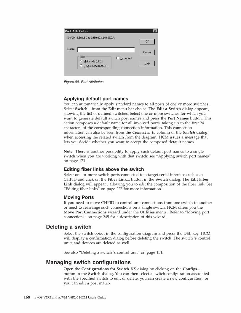
Applying default port namesYou can automatically apply standard names to all ports of one or more switches.Select Switch... from the Edit menu bar choice. The Edit a Switch dialog appears,showing the list of defined switches. Select one or more switches for which youwant to generate default switch port names and press the Port Names button. Thisaction composes a default name for all involved ports, taking up to the first 24characters of the corresponding connection information. This connectioninformation can also be seen from the Connected to column of the Switch dialog,when accessing the related switch from the diagram. HCM issues a message thatlets you decide whether you want to accept the composed default names.
Note: There is another possibility to apply such default port names to a singleswitch when you are working with that switch: see “Applying switch port names”on page 173.
Editing fiber links above the switchSelect one or more switch ports connected to a target serial interface such as aCHPID and click on the Fiber Link... button in the Switch dialog. The Edit FiberLink dialog will appear , allowing you to edit the composition of the fiber link. See“Editing fiber links” on page 227 for more information.
Moving PortsIf you need to move CHPID-to-control-unit connections from one switch to anotheror need to rearrange such connections on a single switch, HCM offers you theMove Port Connections wizard under the Utilities menu . Refer to “Moving portconnections” on page 245 for a description of this wizard.
Deleting a switchSelect the switch object in the configuration diagram and press the DEL key. HCMwill display a confirmation dialog before deleting the switch. The switch 's controlunits and devices are deleted as well.
See also “Deleting a switch 's control unit” on page 151.
Managing switch configurationsOpen the Configurations for Switch XX dialog by clicking on the Configs...button in the Switch dialog. You can then select a switch configuration associatedwith the specified switch to edit or delete, you can create a new configuration, oryou can edit a port matrix.
Figure 89. Port Attributes
168 z/OS V2R2 and z/VM V6R2.0 HCM User's Guide

For ESCON and FICON switches, the configurations can be stored either in theIODF or on the switch itself. For z/OS, you can work with the configurationsstored on the switch, provided the ESCON Manager or I/O Operations is installedand running (see Chapter 11, “User interface to I/O Operations,” on page 277).
Creating a switch configurationClick on the Create... button in the Configurations for Switch XX dialog to openthe Create Switch Configuration dialog. You can set the default connection state tobe allowed or prohibited.
If the radio button IODF is active in the Location field, the Create SwitchConfiguration dialog will include a checkbox Generate default matrix. This checkbox is disabled if Switch is active instead.
When generating switch port matrices, all defined logical paths are analyzed byHCD and in the case of chained connections, all possible paths of chainingswitches are determined by the visualized configurations.
Editing a switch configurationClick on the Edit... button in the Configurations for Switch XX dialog to open theEdit Configuration for Switch XX dialog. You can change the default connectionstate to be allowed or prohibited.
Editing a port matrixOpen the Edit Port Matrix XX for Switch YY dialog by selecting a switchconfiguration from the list box and clicking on the Port Matrix... button in theConfiguration for Switch XX dialog. You can also double-click on a switchconfiguration.
Figure 90. Configuration for Switch XX
Chapter 6. Modifying objects in your configuration 169

The large scrollable window to the right is the configuration port matrix. Each rowor column in the matrix corresponds to a port; each cell represents the intersectionbetween a row port and a column port.
The scrollable window to the left of the port matrix is the port attributes window,displaying the attributes for each switch port (each row in the matrix). Thecolumns in this window display the port name, whether the port is blocked ordedicated, and the identity of the CHPID or control unit (if any) connected to theport. This window will scroll vertically with the port matrix window.
You can drag the gray separator between the two windows to alter their relativewidths.
You can select individual cells or you can select ports by clicking on the row orcolumn header. Select a number of cells or ports by holding the Shift or CTRL keywhile clicking, or by clicking and dragging. Besides the window functions, you canalso use the keyboard (arrow keys, page-up, page-down...) to move around theport matrix. In order to get more information about a port intersection or portheading, keep the cursor over an intersection or a heading. After a short delay asmall pop - up window appears that shows more detailed information (forexample, how a port is connected).
Cells may contain different symbols with the following meaning:
Table 12. Symbols in port matrix
Symbol Description
Black square These ports have a dedicated link to each other.
Figure 91. Configuration Port Matrix
170 z/OS V2R2 and z/VM V6R2.0 HCM User's Guide

Table 12. Symbols in port matrix (continued)
Symbol Description
Hollow square, hollowcircle
There is a logical connection defined between the control unitand the CHPID connected to the ports of this intersection.
Square: A connection requires a dedicated link.
Circle: The intersection is used for a dynamic connection.
A green color indicates that the port matrix data allows aconnection, a black color indicates that the port matrix data doesnot allow a connection.
Broken square, brokencircle
These symbols are used if there are several possible paths forcontrol unit to CHPID connections through chained switches.
Square: A connection requires a dedicated link.
Circle: The intersection is used for a dynamic connection.
Letter A or P, or blank These symbols indicate explicit "allows" or "prohibits" ofdynamic connections.
A: Dynamic connections are allowed.
P: Dynamic connections are prohibited.
Blank: The default connection is used.
Speckled background Either the row port or the column port is blocked. If a port isblocked, the whole row or column appears with speckledbackground.
Slash (/) For ESCON port matrices, you cannot specify a value (default,allow, prohibit) for the diagonal of the port matrix whichhandles connections from a port to itself. Hence, the matrixcontains a '/' on the diagonal indicating that the switch matrixdiagonal cannot be edited.
Click on the Allow or Prohibit buttons to change the connection state of allselected cells in the port matrix to allowed or prohibited, respectively .
Clicking the Default button changes the connection state of all selected cells in theport matrix window to whatever the default is set. To set the default connectionstate, click on the Edit button in the Configurations for Switch XX dialog.
Changing the view of the matrix: HCM allows you to filter and rearrange theview of the matrix according to your needs.
Click on the Expanded columns check box to enlarge the column header and showabbreviated text indicating to what the port is connected.
The radio buttons of the Filter group allow you to reduce the number of ports thatwill be shown in the matrix. Working in conjunction with the Filter radio buttonsis the Show Related push button that operates on selected ports. To enable thisbutton select one or more ports by clicking on the row or column heading. Whenyou click the Show Related push button, HCM filters the matrix to show onlythose ports that have intersections of interest with the selected ports. Anintersection of interest is one that contains a logical control unit to CHPIDdefinition or a dedicated connection. Clicking the now available Restore Filterbutton returns the matrix to the view when the Show Related button was clicked.
Chapter 6. Modifying objects in your configuration 171

The radio buttons of the Sort by group controls the order of the ports in the rowsand columns.
Use the radio buttons under View to rearrange rows and columns. TheSymmetrical radio button shows the matrix in the traditional symmetrical format.Thus, each port is shown twice, once in row and once in column. The CHPIDs ontop radio button shows ports connected to CHPIDs as columns and portsconnected to control units as rows.
The following figure shows a configuration matrix that is filtered to show onlythose ports that are connected and that has the CHPIDs on top radio buttonselected. The columns are expanded and the cursor rested over an intersection toshow more information.
Editing port-to-port connections: For ESCON switches, you cannot edit thediagonal entries of the port matrix; that is you cannot define a connection from aswitch port to itself. However , for FICON switches only, you can set the matrixentry on the diagonal explicitly to the values Allow or Prohibit for a portconnection to itself (loopback connection).
For switches other than FICON, in the Edit Port Matrix xxx for Director yyydialog, the matrix contains a '/' on the diagonal indicating that the switch matrixdiagonal cannot be edited . If you attempt to update the diagonal of an ESCONport matrix, HCM shows a message that this action is not allowed.
Visualizing a switch configurationHCM can evaluate information from switch configurations. The diagram can showdedicated connections or blocked ports. In addition, when highlighting objects in adiagram, HCM can use the switch configuration data to show what particularroute is used for CHPID-to-control-unit definitions (see “Visualizing ESCON orFICON switch and crossbar switch configurations” on page 39 for more detailedinformation).
To visualize a switch configuration, you first have to associate one particularswitch configuration to each switch. Select Visualized Matrices... from the Viewmenu. In the following Define Matrix Set dialog, you can associate one switch
Figure 92. Configuration Port Matrix - Filtered and CHPIDs on Top
172 z/OS V2R2 and z/VM V6R2.0 HCM User's Guide

configuration to each switch. Alternatively, you can select a configuration for aspecific switch in the Switch dialog. You can save these definitions and displaythem later on again using Save Named Matrix Set and Restore Named Matrix Setunder the View menu.
Applying switch port namesThere are two possibilities to apply names to switch ports: you can apply a defaultname to all connected ports in one step or you can edit names of single ports.
To edit a single port name, select a port from the Edit Port Matrix dialog(Figure 91 on page 170) and press the Edit Port... button. This invokes the EditSwitch Port... dialog which lets you specify a name.
To automatically apply standard names to all ports, press the Default Port Namesbutton from the Edit Port Matrix dialog. HCM then composes a default name foreach connected port. This name is composed from the port 's connectioninformation (shown in the Connected to column). If no connection information isavailable, no name is applied. You can afterwards change the default name forsingle ports as described above .
Editing switch ports in a configurationOpen the Edit Switch Port dialog by selecting one or more ports and clicking onthe Edit Port... button in the Edit Port Matrix XX for Switch YY dialog. If morethan one port is selected, this dialog will appear for each port in succession.Alternatively, you can double - click on a port in the port attributes window of theEdit Port Matrix XX for Switch YY dialog.
You can block the selected switch port, such that it can never be connected whileblocked. Blocked ports are indicated as rows of cells with a light gray background,in the port matrix window of the Edit Port Matrix XX for Switch YY dialog.
You can also choose a port to which to create a dedicated connection. Note thatports with dedicated connections are not available for other connections. Ports withdedicated connections are indicated as rows of cells with a light gray background,in the port matrix window of the Edit Port Matrix XX for Switch YY dialog.
Activating a switch configuration for z/OSUsing the Activate button in the Edit Port Matrix dialog, you can activate a switchconfiguration after editing it.
Deleting a Switch ConfigurationSelect the switch configuration in the list box of the Configurations for Switch XXdialog and press the Delete button. HCM will display a confirmation dialog beforedeleting the switch.
Crossbar switchesA crossbar is a static switch through which you can route physical connectionsbetween controllers and processors. The crossbar switch contains a number ofchannel interfaces on its top, which can connect to objects above it, such asprocessors, ESCON switches or other crossbars . It also contains a number ofcontrol unit interfaces on its side, which can be connected to objects below it, suchas controllers or other crossbars. (See Chapter 7, “Connecting objects in yourconfiguration,” on page 187 for more details).
Chapter 6. Modifying objects in your configuration 173
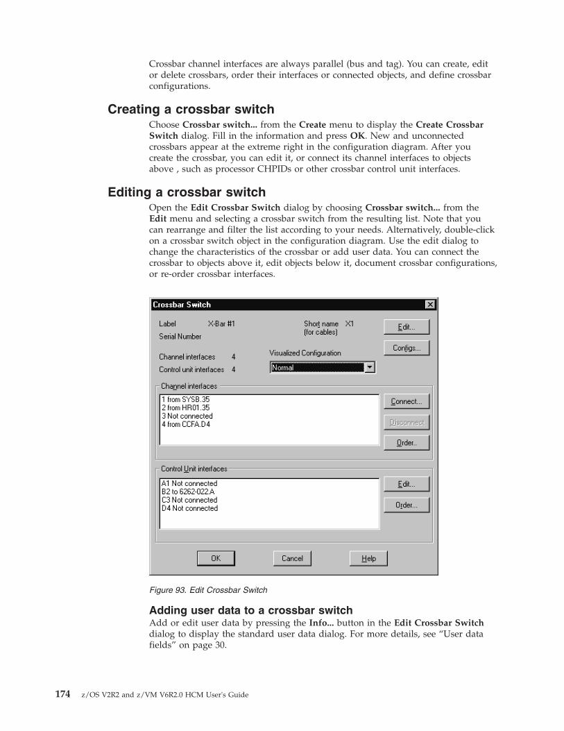
Crossbar channel interfaces are always parallel (bus and tag). You can create, editor delete crossbars, order their interfaces or connected objects, and define crossbarconfigurations.
Creating a crossbar switchChoose Crossbar switch... from the Create menu to display the Create CrossbarSwitch dialog. Fill in the information and press OK. New and unconnectedcrossbars appear at the extreme right in the configuration diagram. After youcreate the crossbar, you can edit it, or connect its channel interfaces to objectsabove , such as processor CHPIDs or other crossbar control unit interfaces.
Editing a crossbar switchOpen the Edit Crossbar Switch dialog by choosing Crossbar switch... from theEdit menu and selecting a crossbar switch from the resulting list. Note that youcan rearrange and filter the list according to your needs. Alternatively, double-clickon a crossbar switch object in the configuration diagram. Use the edit dialog tochange the characteristics of the crossbar or add user data. You can connect thecrossbar to objects above it, edit objects below it, document crossbar configurations,or re-order crossbar interfaces.
Adding user data to a crossbar switchAdd or edit user data by pressing the Info... button in the Edit Crossbar Switchdialog to display the standard user data dialog. For more details, see “User datafields” on page 30.
Figure 93. Edit Crossbar Switch
174 z/OS V2R2 and z/VM V6R2.0 HCM User's Guide

Recording Crossbar ConfigurationsYou can record different settings of crossbar switch connectivity as crossbarconfigurations. These are not used in the IODF, and do not change the logicalconfiguration of the crossbar. Click on the Configs ... button in the CrossbarSwitch dialog to open the Crossbar Configurations dialog. You can add, delete orrename crossbar configurations for the selected crossbar switch, as well as set adefault configuration.
Use the crossbar configuration diagram to document a configuration. Click on anintersection point between the crossbar 's channel interface and control unitinterface; a large dot appears to indicate a connection. Click on a dot to remove theconnection. You can move around the diagram by using the scroll bars and arrows.
After you have documented switch connectivity in the crossbar configurationdiagram, you can name the configuration to record it. Click on the Add... button inthe Crossbar Configurations dialog to open a standard name dialog. Type in thename of the new crossbar configuration. Note that all crossbar configurations willbe produced in hardcopy format when you choose the Switch Reports option inthe Print Reports dialog. To rename the crossbar configuration, select it and clickon the Rename... button to open the standard name dialog.
You can select a crossbar configuration and delete it. Pressing the Delete buttondisplays a confirmation dialog before deleting the configuration. Note that the lastcrossbar configuration for a crossbar switch cannot be deleted.
Use the default configuration to designate the crossbar configuration typicallyused. Select a crossbar configuration and click on the Set button. The default willbe displayed in the Normal/Default configuration field.
Figure 94. Crossbar Configurations
Chapter 6. Modifying objects in your configuration 175

Setting the size of a crossbar switchOpen the Edit Crossbar Switch dialog by clicking on the Edit... button in theCrossbar Switch dialog. You can change the number of channel or control unitinterfaces for the selected crossbar switch by selecting one or more values from theappropriate drop down list boxes.
Editing controllers connected to crossbar control unit interfacesIn the Crossbar Switch dialog, select a control unit interface and press the Edit...button in the Control Unit Interfaces section. This opens the Edit Crossbar ControlUnit Interface dialog which lists all controllers (and possibly other crossbars)connected to the control unit interface. Select one and press the Edit Object...button.
Ordering controllers connected to a crossbarFrom the Edit Crossbar Control Unit Interface dialog, press the Order... button.This opens an order dialog, allowing you to order the controllers (and possiblyother crossbars) that are daisy-chained on this interface.
Ordering crossbar channel or control unit interfacesClick on the Order... button in either the Channel Interfaces or Control UnitInterfaces section of the Crossbar Switch dialog. A standard order dialog appears,allowing you to reorder the channel or control unit interfaces for the selectedcrossbar switch. See “Ordering objects” on page 50. chapter for an example of anordering dialog.
Visualizing a crossbar switch configurationHCM can evaluate information from crossbar switch configurations. Whenhighlighting objects in a diagram, HCM can now use the configuration data toshow what particular route is used for CHPID-to-control-unit definitions (see“Visualizing ESCON or FICON switch and crossbar switch configurations” on page39 for more information).
To visualize a crossbar switch configuration, you first have to associate oneparticular configuration to each crossbar switch. Select Visualized Matrices... fromthe View dialog. In the following Define Matrix Set dialog, you can associate oneconfiguration to each crossbar switch. Alternatively, you can select a configurationfor a specific switch in the Crossbar Switch dialog. You can save these definitionsand display them later using Save Matrix Set and Restore Matrix Set under theView menu.
Deleting a crossbar switchSelect the crossbar switch object in the configuration diagram and press the DELkey. HCM will display a confirmation dialog before deleting the crossbar switch.
CabinetsFiber management cabinets are an important part of many configurations. HCMsupports the routing of fiber links through any number of patchports. See “Editingfiber links” on page 227 for more information.
In HCM, all fiber management cabinets are simply called ”cabinets” regardless ofhow they are used. Cabinets are part of the physical information that you can addin HCM to supplement the logical information from the IODF. Each cabinet canhave one or more panels, arranged one above the other. A cabinet has a number of
176 z/OS V2R2 and z/VM V6R2.0 HCM User's Guide

places to hold panels, called panel spaces in HCM. Panels can be numberedstarting from zero or one, from the top or the bottom of the cabinet.
A patchport comprises a pair of ESCON/FICON adapters or couplers. Any numberof patchports can participate in a fiber link. To determine the total number ofpatchports in a cabinet, you must add the number of patchports of each definedpanel of the cabinet.
HCM provides a predefined set of patchport naming formats. In addition, you cancreate your own customized naming formats. In either case this is done byproviding a Patchport Naming Format to the cabinet definition. Individual patchportlabels can be edited explicitly to overwrite the naming format in those cases wherethe format language is not adequate. See “Syntax of the user-definedpatchport/general box port naming format” on page 181 for more information.
In the case where HCM provides a predefined set of patchport naming formats, aunique patchport label is created for every patchport . A patchport label is four orfive characters long, in one of the following formats:v Consecutive numbers. The first one or two letters are the short name of the
cabinet. The following three numbers are the patchport number within thecabinet.
v Port and group consists of alternating letters and numbers. The first one or twoletters are the short name of the cabinet. This is followed by the panel number(within the cabinet), the port group letter (within the panel), and the patchportnumber (within the port group). For example, the patchport label F2C4 denotespatchport 4 within port group C of panel 2 in cabinet F. Port groups are letteredfrom A to Z, skipping the letters I and O. Patchport numbers can start from 0 or1.
Graphically, cabinets appear as unconnected boxes to the right of other objects tosimplify the configuration diagram. However, the cabinet 's patchports that formpart of the fiber link between two objects are drawn as small rectangles in theconnection. Selecting a patchport highlights the entire fiber link through thatpatchport .
You can include or exclude cabinets and patchports from your view of theconfiguration diagram with the appropriate View menu commands. After youhave created cabinets and patchports, you can make any permanent connectionsamong them, before making the logical connections in your configuration andediting the fiber links . For more information, see “Editing fiber links” on page 227and “Infrastructure connections” on page 227.
Creating a cabinetChoose Cabinet... from the Create menu to open the Create Cabinet dialog.
Enter the cabinet information and press OK. The following guidelines arerecommended for creating a unique ID of one or two letters for the cabinet:1. The ID is alphabetic to distinguish it from the panel number that follows.2. If all cabinets are in the same building, use one letter for the ID.3. If the cabinets are in different buildings, use two letters for the ID, with the
first letter indicating the building.
Chapter 6. Modifying objects in your configuration 177

You can suggest where HCM should draw the cabinet and its patchports inrelation to other objects in the configuration diagram. Change the position ofindividual patchports using the Position Patchport dialog.
Note: You can change the number of patchports of a panel using the PanelAttributes dialog.
Editing a cabinetOnce the cabinet is created, you can edit cabinet information, add user data, andadd or remove panels. You can also add or modify patchports (see “Patchports”).To display the Cabinet dialog, choose the Cabinet... command from the Editmenu. Select the desired cabinet from the list that appears. Note that you canrearrange and filter the list according to your needs.
To edit the cabinet information, click on the Edit... button in the Cabinet dialog toopen the Edit Cabinet Details dialog. Make your changes by overtyping the fieldsand press OK. The changes appear in the Cabinet dialog.
If you increase the number of panel spaces, the new panel spaces are created at thebottom if they are numbered top down, or vice versa. Decreasing the numbercreates the opposite effect; the highest numbered panels are deleted first. Note thatyou can only delete a panel if none of its patchports is part of the configurationdiagram.
Adding user data to a cabinetAdd or edit user data by pressing the Info... button in the Cabinet dialog todisplay the standard user data dialog. For more details, see “User data fields” onpage 30.
Deleting a cabinetSelect the cabinet object in the configuration diagram and press the DEL key. HCMwill display a confirmation dialog before deleting the cabinet.
As the user-defined formats will be deleted as well, you can save your formats(through cut & paste) in a separate file, so you can use your own created formatsagain.
PatchportsA patchport comprises a pair of ESCON/FICON adapters or couplers. Any numberof patchports can participate in a fiber link. To determine the total number ofpatchports in a cabinet, you must add the number of patchports of each definedpanel of the cabinet. HCM creates a unique patchport label for every patchport .
To add a panel of patchports, press the Add... button in the Panels section of theCabinet dialog (Figure 95 on page 179). This will open the Add Panels dialog. Inthis dialog you can now choose the Patchport Naming Format. The drop-down listcontains a number of predefined format strings as well as any additionaluser-defined format strings that are defined in currently existing cabinets in thisHCM configuration file . See also “Syntax of the user-defined patchport/generalbox port naming format” on page 181.
To remove a defined panel of patchports, press the Remove... button. To changethe order of panels, select a panel and press the Move Up or Move Down buttons.
178 z/OS V2R2 and z/VM V6R2.0 HCM User's Guide

To change the naming format of a specific panel the patchports, select that paneland press the Attributes... button in the Panels section.
To view the patchport dialog panel, double - click on a cabinet in the configurationdiagram (or choose Cabinet... from the Edit menu and double-click the appropriatecabinet). This opens the panel similar to that shown in Figure 95.
You can view all patchports and their connections, make or break connections,position patchports in the configuration diagram, locate the currently selectedpatchport , or edit the fiber link of which the selected patchport is a part. Buttonsare disabled when they are not valid for the selected patchport .
To change your view of the patchports in a selected panel, use the scroll bar.Display or hide the cables and objects connected to the front or back of eachpatchport by clicking the Front or Back check box. You can display all cables andobjects connected to each patchport, or only the nearest cable and object, using theShow Entire Link check box.
The Cabinet dialog offers the possibility of viewing the patchport from the front orthe back. For this purpose two radio buttons have been provided on the frontpanel in the View box.
It is also possible to select a number of patchports simultaneously. This gives youthe possibility of performing operations on the selected patchports as a group.Specifically, the Connect..., Disconnect, Attributes..., and Locate buttons canoperate on all of the selected patchports at once.
Cabinet dialog controlsThe following explains the controls on the Cabinet dialog:
Figure 95. Cabinet
Chapter 6. Modifying objects in your configuration 179

1. Patchports for panel X group box. This large group of controls shows theattributes and patchports for the panel selected in the Panels list box. As theselection in the Panels list box changes, the label of this group box changes todisplay the panel ID and description. The text fields indicating panel size andthe sequencing attribute are also updated. Of course , the patchport viewingarea is updated, too, to show the patchports for the selected panel, but thehorizontal scrolling position remains constant, as long as the new panel beingdisplayed has enough columns . The patchport viewing area shows patchportsfor the selected panel and may be scrolled vertically or horizontally to show allthe patchports. The patchport label is shown in bold near the center of thepatchport . Connection information for the back of the patchport is shownabove the label, while connection information for the front is shown below. Acouple of visual cues indicate what view is being shown:v An F is shown in the bottom right corner of every patchport if the front view
is shown. This is changed to a B in the top left when the back is shown.v To indicate the connections that are affected by Disconnect, connections
extending from the "viewing" side are written in black, and connectionsextending from the other side are shown in gray.
2. Panels group box. This box shows the labels of all of the panels in the cabinet.The Add and Attributes... buttons lead to dialogs that have an editable combobox for the panel 's patchport naming format. Changing the naming format inthis dialog and clicking OK will update the patchport viewing area to reflectthe new patchport names. This box is also used to add or remove panels andmove up or down the Panels to change the order.
3. Patchport detail box. The check boxes here control the level of detail shown inthe patchport viewing area. Connection information for the patchport 'simmediate neighbor is always displayed for the side being shown.v The Show Back/Show Front check box changes depending on the particular
view. If it is checked, then the viewing area shows (in gray) connectioninformation for the side not currently being viewed.
v The Show Entire Link check box determines how much of the connection isdisplayed. If this is not checked, then only the neighbor immediatelyconnected to the back or front of the patchport is shown. Checking thisoption causes the patchport to expand so it shows not only the immediateneighbor(s), but also all the other interfaces in the complete fiber link. Thisoption affects only the side being viewed if the Show Back/Show Frontoption is turned off.
v The Show Cables check box expands the patchport further, to accommodatethe labels of cables involved in the fiber link. The names of the cables (or - - -for anonymous cables, or Trunk for anonymous trunks) are shown betweenthe interfaces they serve.
4. Connect button. This is disabled if the "viewing" side of one or more of theselected patchports is already connected. Clicking it invokes the SelectConnection Target(s) dialog. The interface(s) that are selected from thesubdialog are connected directly to the patchports selected in this dialog.Interfaces that are already involved in complete fiber links will be validconnection targets for patchports. Connecting to such interfaces will insert thepatchport and its trailing patchports into the fiber link (HCM asks you toconfirm this type of connection). This allows infrastructure connections to beestablished after a load.
5. Disconnect button. This is disabled if none of the selected patchports areconnected on the "viewing" side. Clicking this button will attempt to disconnectall the selected patchports that are connected on the viewing side. Disconnectworks as follows:
180 z/OS V2R2 and z/VM V6R2.0 HCM User's Guide

v If one or more of the patchports is connected "permanently" on the viewingside, then HCM will ask the user to confirm the disconnect action. In thiscase, these connections will be marked as mutable before proceeding.
v For each of the patchports:– If the patchport is involved in a "logically complete" connection, then
HCM will remove this patchport from the chain together with any othersthat are permanently connected to it without breaking the logical link . Ifall of the connections extending from the other side of the patchport arepermanent, then the disconnect action will be refused . If the disconnectaction succeeds, HCM will issue a message to indicate that the patchportchain(s) were removed without breaking the logical connection.
– If the patchport is not involved in a "logically complete" connection, thenthe patchport will simply be disconnected from its partner.
Note: HCM has deliberately been designed so that "logically complete"connections cannot be created or broken via the Cabinet dialog. The primarypurpose of Connect... and Disconnect on the Cabinet dialog is to make (or inrare cases, break) infrastructure connections. Otherwise, use the Switch orController dialog to establish or break connections.
6. Attributes... button Clicking this button will invoke the Patchport Attributesdialog panel.
7. Fiber Link... button This is disabled if none of the selected patchports isinvolved in a complete fiber link. Clicking this button will invoke the EditFiber Link dialog (a number of times in succession if necessary). See “Editingfiber links” on page 227 for information about connecting patchports.
8. Locate button This is disabled if none of the selected patchports is involved ina complete fiber link. Clicking it will close the dialog and highlight all theselected patchports that are permitted to appear in the dialog. This option isonly available for patchports that are part of the configuration diagram.
Syntax of the user-defined patchport/general box port namingformat
To create user-defined patchport/general box port names, you must define aformat string to the cabinet definition. A format string consists of any sequence ofcharacters that may be embedded with proxy strings. Proxy strings are delimitedby '%' characters and are replaced with the appropriate text when a port name isdisplayed.
Following proxies are allowed:
%CABINET% or %NAME%ID of the cabinet or name of the general box. Both proxies are synonymsand can be used for either cabinets or general boxes.
%PANEL%panel number
%GROUP%port group number
%PORT%patchport/general box port number
%ROW%the row within the panel containing the port
Chapter 6. Modifying objects in your configuration 181

%COLUMN%the column within the panel containing the port
The numerical proxies (%PANEL%, %GROUP%, %PORT%, %ROW% and%COLUMN%) can be qualified by width, conversion, and ordering specifications,so that the general syntax of a numerical proxy is:
%[width][conversion] <proxy>{/<qualifier>}%
where [ ] indicates that the enclosed items are optional, and { } indicates that theenclosed items may appear zero or more times. The individual items are brokendown as follows:
width A decimal number in the range of 0 to 4. This indicates the width incharacters of the actual text that should appear here. If the conversion isdecimal or hex (see below, leading zeroes are used to pad to theappropriate width; if the conversion is alphabetical, leading underscorecharacters are used. If the width is zero or omitted, the actual text usesonly as many characters as necessary.
conversion
d Convert number to text using decimal format
x Convert number to text using hexadecimal format
c Convert number to text using alphabetical format (i.e. 0 converts toA, 1 converts to B, etc. ). The letters 'I' and 'O' are left out of thealphabet. Wrapping past Z will use an extra letter (e.g. AA).
If no conversion character is specified, decimal conversion is used.
<proxy>CABINET, NAME, PANEL, GROUP, PORT, ROW or COLUMN
<qualifier>Always preceded by '/'
0 Start numbering at zero (not valid for alphabetical conversion)
1 Start numbering at one (not valid for alphabetical conversion)
L Start numbering at left (numbers increase as we move from left toright)
R Start numbering at right (numbers increase as we move from rightto left)
T Start numbering at top (numbers increase as we move from top tobottom)
B Start numbering at bottom (numbers increase as we move frombottom to top)
H Numbering proceeds in horizontal direction from origin,proceeding to the next row when the end of the row is reached
V Numbering proceeds in vertical direction from origin, proceedingto the next column when the end of the column is reached
182 z/OS V2R2 and z/VM V6R2.0 HCM User's Guide

G Port numbering is with respect to group
P Port or group numbering is with respect to panel
C Port, group, or panel numbering is with respect to cabinet
Note: Those qualifiers that are grouped together above may not be usedin combination; for instance %PORT/0/1% would not be valid(numbering may start from either 0 or 1, but not both).
Defaults:The default qualifiers are /0/L/T/H, indicating that ordering startsat zero from the top left and proceeds horizontally first.
For the scope qualifier (G, P, or C), the default is /G for proxy%PORT%, /P for proxy %GROUP%, and /C for proxy %PANEL%.
Regular text can be included in the format string.
Comments, delimited by curly braces, can be embedded in the format string. Allcharacters between the leading '{' and the trailing '}' will be ignored. Comments arenot allowed within the proxy delimiters.
The backslash '\' character can be used (outside of comments and proxies) to allowthe '%', '{', and '}' characters to be treated as regular characters.
In addition, '\\' is treated as a single backslash.
General boxesYou can create general boxes for purposes that are not covered by other HCMobjects described in the previous sections of this chapter. Such general boxes canrepresent physical devices and their connections in your configuration that are notpart of the logical definitions of an I/O configuration. For example, you can usegeneral boxes for network devices or non-zSeries boxes and their connections.These objects or connections are stored in the HCM configuration file, but not inthe associated IODF. The general boxes appear in the configuration diagram, sothat you can have a complete view of the physical objects. Another purpose ofgeneral objects is to document the complete cabling of your devices in yourconfiguration.
A general box is a container for resources. General boxes are organized likecabinets: one general box can contain several panels, and each panel can containgeneral box ports, ordered in rows and columns. You can organize your resourceswith general boxes according to your needs.
Creating a general boxInvoke the Create General Box dialog (Figure 96 on page 184) from the Createmenu.
Chapter 6. Modifying objects in your configuration 183

Enter the required information for the general box. In the Panel box, whenchecking the Create Panel check box, you can select to create the general boxtogether with a first panel. Pressing OK just creates the general box, while pressingCreate and Connect directly leads you to the General Box dialog where you canspecify the connections of your objects (see General Box dialog in “Editing ageneral box”).
Editing a general boxUse the following dialogs to edit the properties of a general box:v The Edit General Box dialog is for editing certain box attributes, for example the
name, description and graphical position. For this purpose, use the Edit GeneralBox dialog, which you invoke using Edit... from the context menu of the generalbox.
v The General Box dialog is for editing the connectivity contents, for example toadd new panels or connect the general box ports. For this purpose, double-clickon the general box in the configuration diagram. Alternatively, from the Editmenu bar choice, select General Box..., then select a general box from the list andpress OK.In both cases, you reach the General Box dialog where you can specify theconnections of your objects. This dialog looks similar to the Cabinet dialogshown in Figure 95 on page 179. Y ou can work with general box ports in theGeneral Box dialog just like you work with patchports in the Cabinet dialog asdescribed in “Patchports” on page 178.Especially, you can link two general box ports together using the Connect buttonin the General Box dialog and then assign a cable to that link as described in“Managing physical cables” on page 221.
Figure 96. Create General Box
184 z/OS V2R2 and z/VM V6R2.0 HCM User's Guide

Deleting a general boxIf you want to delete a general box, you must disconnect the used general boxports first using the Disconnect button in the General Box dialog. Then select theobject in the configuration diagram and use the Delete choice from its contextmenu or press the DEL key.
Chapter 6. Modifying objects in your configuration 185

186 z/OS V2R2 and z/VM V6R2.0 HCM User's Guide

Chapter 7. Connecting objects in your configuration
This section explains how to connect objects to one another, after you have builtyour configuration and modified objects in the configuration diagram. Connectinginvolves making both physical connections between physical objects (strings,controllers, switches, machines) and logical definitions between logical objects(devices, control units, switch ports, CHPIDs, and so on).
A connection is a known physical path ‘realized’ by one or more cables. Note thatpurely physical objects such as cables, patchports, crossbar switches, or convertersmay appear in the connection between a controller and a processor, but are nottaken into account by the connection. These objects are not represented in theIODF; you must add and connect them in HCM.
The physical connection between two objects enables appropriate logical definitionsbetween these and other “reachable” objects to be made. Objects must bephysically connected before they can be logically defined. When an IODF is loadedinto HCM, the IODF logical definitions are represented as connections betweenobjects in the diagram, and as attribute information in the appropriate dialogs. UseHCM to add, delete or modify physical connections and associated logicaldefinitions.
In HCM, you connect objects that are lower on the diagram to those that arehigher. For example, you connect strings to controllers (not vice versa) and youconnect controllers to processors (not vice versa).
The recommended order in which you connect objects is from the top of thediagram down. For example, connect controllers (to processors) before connectingstrings (to controllers), and connect switches (to processors) before connectingcontrollers to switches.
Objects are actually connected through their interfaces. A string interface for a stringof I/O devices can connect to the device interface of a controller. The controller inturn can connect through its channel interface to a processor CHPID, possiblythrough switch ports, crossbar control unit and channel interfaces, cabinetpatchports or converter interfaces.
There are two types of connections: serial and parallel. Serial connections (alsocalled fiber link) are always point-to- point from one serial interface to another.Serial connections use optical fiber technology.
Parallel connections use “bus and tag” cables. Parallel interfaces can be daisychained. A controller with a parallel interface typically has two plugs: one isconnected to a processor CHPID, the other to another controller or terminator cap.Note that any devices attached to daisy chained controllers can “reach” theprocessor connected to the first controller in the chain. That is, all devices arephysically connected and logically defined to the processor, even though only onecontroller is directly connected.
Controllers and crossbar switches can be daisy chained. The rule of thumb is “anyinterface on the top side of an object which is a parallel interface can be daisychained to similar object interfaces”. You can order daisy chained objects.
© Copyright IBM Corp. 1995, 2016 187

Processor CHPIDs and controller channel interfaces can be serial or parallel.ESCON and FICON switches have serial interfaces; crossbar switches have parallel.Converters (P->S or S->P) may, therefore, be required in the connection between acontroller and processor.
Connecting objectsTo make a typical connection, double-click on the object that you wish to connectupwards to another. An appropriate edit dialog will appear; select the object’sinterface and press the Connect... button. Another dialog appears from which youcan select a target object interface to connect.
In the case of connecting devices to controllers, or controllers to processors,switches, or crossbars, you can choose to make a physical, standard or customconnection.v Physical connection:
Makes a physical connection with no logical definitions.v Standard connection:
Makes the physical connection and all appropriate logical definitions, usingstandard values. The standard values are determined by HCD and dependon the UIMs for the control units or devices involved, the type of CHPIDsinvolved, and existing connections.
v Custom connection
Makes the physical connection, and allows you to customize the attributes ofselected logical definitions. Note that you can customize connections betweena controller and a processor, ESCON or FICON switch, or crossbar using theStandard ... button in the Select Connection Target(s) dialog. For details, see“Connecting controllers to processors and switches” on page 195.
You will typically choose to make standard connections.
HCM will check that the connections you make are valid. HCM automaticallycreates ESCON converters when they are required. Note that you do not have todisconnect a connection before reconnecting to another interface.
The new connection will initially have no physical cable assigned. You can assign acable from the unused cables pool or from inventory. Cables assigned toconnections which have been disconnected or reconnected become unused cableswhich “remember” where they were last used. Cables in inventory are generallyavailable for use by any object. See Chapter 8, “Physical connections,” on page 221for more details.
Tip:
Note that making or breaking a connection may move the selected object such thatit is no longer visible in the current view. You may have to zoom out and then in,or scroll around to find the selected object.
Positioning objects along daisy-chained connectionsA number of controllers can be daisy-chained on a CHPID. Daisy-chains can alsoexist under crossbar switches, S->P converters, and controllers.
If you are connecting an object to a target that is already connected to one or moreobjects, the standard Position Interface dialog will appear to allow you to position
188 z/OS V2R2 and z/VM V6R2.0 HCM User's Guide

the object you are connecting with respect to the others.
Select an object in the list box and drag it through the list to the object that willimmediately follow it. Release the mouse button; the object will be repositioned inthe daisy-chain. Alternatively, select the object and use the arrow keys on thekeyboard to move it up or down the list. By default, HCM attaches the new objectto the end of the chain.
Connecting devices to controllersI/O devices connect to processors through controllers. If the controller is daisychained to other controllers, all devices attached to controllers in the chain can“reach” any connected processors.
More specifically, the string interface on a string of devices connects to the deviceinterface on a controller; the controller channel interface in turn eventually connectsto one or more processor CHPIDs. The connection between device and controller isalways between parallel (bus and tag) interfaces, whereas the connection betweencontroller and processor may be parallel and/or serial.
In some cases the I/O devices may be integrated into the controller.
In the Select Controller Device Interface dialog, there are three types ofconnection. You can make a purely physical connection with no logical definitions.Or you can make a standard connection with appropriate logical definitions, fromthe device to all “reachable” processors through the selected control unit. In thismost common type of connection, the device is defined to all control units in thecontrollers, any connected processors, and all partitions in any connected
Figure 97. Positioning an Object for Daisy-Chained Connections
Chapter 7. Connecting objects in your configuration 189

processors. Alternatively, you can customize the logical definition attributesyourself by making a custom connection, first selecting the specific device andcontrol unit for which definitions will be made.
Creating a string under a controllerDouble-clicking on a controller in the configuration diagram opens the Controllerdialog. Alternatively, choose Controller... from the Edit menu, and select thedesired controller from the list which appears. Select the Create... button in theStrings/Devices section to display the Create String dialog. Fill in the informationand press OK. Strings and their I/O devices created from the Controller dialog arenot automatically connected and defined to the selected controller. Instead, theString dialog appears, where you can choose how to connect the string's interfaces.
If there is more than one physical description possible for the string, pressing OKwill first display the Choose Physical Description dialog before the connectiondialog.
Selecting an existing string under a controllerDouble-click on the desired controller to open the Controller dialog. TheStrings/Devices section in the dialog lists any strings/devices connected to thecontroller through its device interfaces. If I/O devices have no physical string (theyare integrated into the controller), the “virtual strings” containing them aredisplayed.
Select a string/device and press the Edit... button to display the String dialog. Youcan then open the Select Controller Device Interface dialog by selecting one ormore string interfaces and pressing the Connect... button.
Note that you can also open the String dialog by choosing String... from the Editmenu, or by double-clicking on a string in the configuration diagram.
190 z/OS V2R2 and z/VM V6R2.0 HCM User's Guide

Connecting the string to a controller device interfaceOnce you have displayed the Select Controller Device Interface dialog (see“Selecting an existing string under a controller” on page 190), you can select acontroller device interface as the target to which you wish to connect the selectedstring interface(s).
The list box lists all device interfaces on controllers that are available to connect tothe selected string interface(s). Double-click on a controller with a plus (+) sign toexpand it to display all possible device interfaces for selection. Double-click on acontroller with a minus (-) sign to contract it.
Invalid targets (device interfaces or controllers containing device interfaces whichcannot reach any valid control units) are disabled. The validity of control units forconnection is determined from HCD.
You can also choose which type of connection to make: physical, standard, orcustom.
Making a physical connectionSelect a controller device interface from the list box in the Select Controller DeviceInterface dialog and press the Physical Only button. This option will connect theselected devices to the controller. However, no logical definitions are createdbetween the devices and all processors connected to the controller.
Making a standard connectionSelect a controller device interface from the list box in the Select Controller DeviceInterface dialog and press the Standard button. If there is only one control unit in
Figure 98. Select Controller Device Interface
Chapter 7. Connecting objects in your configuration 191

the segment of the selected controller, this option will connect the selected devicesto the controller. HCM will automatically create the necessary logical definitionsbetween the devices and all processors connected to the controller, using standardvalues. The standard values are determined by HCD and depend on the UIMs forthe control units or devices involved, the type of CHPIDs involved, and existingconnections. If standard values cannot be determined, HCM proceeds as if theCustom... button was pressed.
If there is more than one control unit in the segment of the selected controller, theReachable Control Units dialog appears to allow you to specify the control unit(s)to which to connect. Add the physically reachable control units that you wish toinclude in the connection to the Include list and press OK. HCM makes theconnection and all appropriate logical definitions.
Making a custom connectionSelect a controller device interface from the list box in the Select Controller DeviceInterface dialog and press the Custom... button. This option will display theAffected I/O Devices dialog to allow you to select one or more devices for whichto make the device <=> processor definitions.
Note that you can view control unit numbers, serial numbers, VOLSERs,descriptions, etc., for the devices in the Affected I/O Devices list box depending onthe selection made in the Columns dialog.
Figure 99. Reachable Control Units
192 z/OS V2R2 and z/VM V6R2.0 HCM User's Guide

After you selected one or more devices, press the Connect... button. If there ismore than one control unit in the controller segment, the Reachable Control Unitsdialog opens. Add the physically reachable control units that you wish to includein the connection to the Include list and press OK. The I/O Device <=> ProcessorDefinition dialog appears. Otherwise, HCM opens the I/O Device <=> ProcessorDefinition dialog directly.
The I/O Device <=> Processor Definition dialog lists the parameters for theconnection between this control unit and each processor to which it is defined.Select one or more processors and press the Edit... or Group Edit... button. TheEdit I/O Device <=> Processor Definition dialog appears which lets you edit thespecified logical definition. If you pressed Edit..., this dialog will appear once for
Figure 100. Affected I/O Devices
Figure 101. I/O Device <=> Processor Definitions
Chapter 7. Connecting objects in your configuration 193
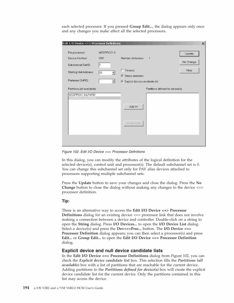
each selected processor. If you pressed Group Edit..., the dialog appears only onceand any changes you make affect all the selected processors.
In this dialog, you can modify the attributes of the logical definition for theselected device(s), control unit and processor(s). The default subchannel set is 0.You can change this subchannel set only for PAV alias devices attached toprocessors supporting multiple subchannel sets.
Press the Update button to save your changes and close the dialog. Press the NoChange button to close the dialog without making any changes to the device <=>processor definition.
Tip:
There is an alternative way to access the Edit I/O Device <=> ProcessorDefinitions dialog for an existing device <=> processor link that does not involvemaking a connection between a device and controller. Double-click on a string toopen the String dialog. Press I/O Devices... to open the I/O Device List dialog.Select a device(s) and press the Dev<=>Proc... button. The I/O Device <=>Processor Definition dialog appears; you can then select a processor(s) and pressEdit... or Group Edit... to open the Edit I/O Device <=> Processor Definitiondialog.
Explicit device and null device candidate listsIn the Edit I/O Device <=> Processor Definitions dialog from Figure 102, you cancheck the Explicit device candidate list box. This selection fills the Partitions (allavailable) box with a list of partitions that are reachable for the current device.Adding partitions to the Partitions defined for device(s) box will create the explicitdevice candidate list for the current device. Only the partitions contained in thislist may access the device.
Figure 102. Edit I/O Device <=> Processor Definitions
194 z/OS V2R2 and z/VM V6R2.0 HCM User's Guide

For XMP processors, if devices are connected to a control unit which is sharedbetween multiple channel subsystems, some (not all) of these devices may specifyan explicit null device candidate list for one or more CSSs. If you define a nulldevice candidate list of a device for a certain CSS, then no partition of this CSSmay have access to the device. Specifying a null device candidate list in HCMmeans to check the Explicit device candidate list box without adding candidatesto the Partitions defined for device(s) box.
Disconnecting the string interface from a device interfaceOpen the Strings dialog by double-clicking on a string in the configurationdiagram, or by choosing String... from the Edit menu. Alternatively, double-clickon a controller to open the Controller dialog, then select a string from theString/Devices section and click on Edit... to open the String dialog. Select theconnected string interface(s) from the Interfaces list box and press the Disconnectbutton. HCM will ask you for confirmation before disconnecting.
A disconnection involves physically disconnecting the string interface from thecontroller and deleting any logical definitions between the devices and any controlunits and processors that can no longer be physically reached.
Connecting controllers to processors and switchesControllers connect devices to processors. Controllers can be daisy chained, makingall connected processors physically reachable to all attached devices.
More specifically, the channel interface on the top of a controller can connect to aCHPID on a processor. This connection may be direct, or it may be throughESCON or FICON switches, crossbar switches, cabinet patchports, converters, ordaisy chained controllers. The connection between controller and processor may beparallel (bus & tag) and/or serial. Converters are automatically added as necessary.
Connections between serial channel interfaces on controllers and serial CHPIDsform fiber links. Initially, the fiber link comprises a direct connection, but it can alsoinclude patchports, trunks, and jumper cables. See “Editing fiber links” on page227 for more details.
In the Select Connection Target(s) dialog, you can ask HCM to make a physicalconnection or a standard connection, where you can also adjust several parameters toyour needs. The physical connection is a simple physical connection, with nological definitions. The standard connection creates logical definitions between thecontrollers and reachable processors. This is the most common type of connection:all control units are defined to the CHPID and processor, and all devices connectedto the controller are defined to the processor and all its partitions. Depending onwhether you connect a controller directly to a CHPID or to a switch, thesubsequent dialogs may differ. In the first case, the Edit Control Unit <=>Processor Definitions dialog might appear, where you can specify someparameters in order to customize selected logical definitions. Note that defaultparameters are always provided in this dialog, which can then be modified. In thesecond case, that is, when you connect a controller with a port of a switch, theProcessor and CHPID Connections dialog appears. There, you can customize yourconnections by pressing the Attributes ... button. Again, the Edit Control Unit <=>Processor Definitions dialog then appears, where you can adjust the defaultparameters to your needs.
Chapter 7. Connecting objects in your configuration 195

Selecting a channel interface for a controllerOpen the Controller dialog by choosing Controller... from the Edit menu andselecting a controller from the resulting list, or by double-clicking on the controllerin the configuration diagram. Select an interface from the controller and press theConnect... button to open the Select Connection Target(s) dialog. This dialogallows you to connect the controller channel interface to a target interface, such asa processor CHPID, switch port or crossbar control unit interface. The dialog leadsto others which allow you to create any necessary logical definitions for thephysical connection.
Note: You can also select multiple controller interfaces before pressing theConnect... button. This opens the Select Multiple Connection Target(s) dialogwhich allows you to establish several connections in one step. For informationabout how to use this dialog, refer to “Connecting switches to processors or otherswitches” on page 206.
Connecting the channel interface to a CHPIDConnecting a channel interface to a CHPID creates a physical route between controlunits in the controller and the processor. If there is an ESCON or FICON switch orcrossbar switch in the connection, the control units may access more than oneprocessor. See “Connecting crossbar switches” on page 233 and “Connectingswitches to processors or other switches” on page 206 for details.
Note:
Although the rest of this section deals with connecting the controller channelinterface to a processor CHPID, you can connect the controller to a crossbar switchor an ESCON or FICON switch which eventually leads to the processor CHPID,using the Select Connection Target(s) dialog.
196 z/OS V2R2 and z/VM V6R2.0 HCM User's Guide

Open the Select Connection Target(s) dialog by selecting a channel interface andpressing the Connect... button in the Controller dialog.
Note: If the selected controller is part of a switch, and you accessed the Controllerdialog from the Edit Switch dialog, pressing the Connect... button displays thedialog that would appear if you had already pressed the Standard button in theSelect Connection Target(s) dialog. (That is, the Select Connection Target(s) dialogis skipped.)
Select a processor CHPID as the target interface to which to connect. TheConnection target list box lists all physical connection targets to which you canconnect. Double-click on a target object with a plus (+) sign to expand it to displayall possible target interfaces. Double-click on a target with a minus (-) sign tocontract it. Note that double-clicking on a target interface triggers the Standardconnect button. Invalid targets are disabled.
If you are connecting the channel interface to a CHPID that is already connected toanother controller, pressing Standard... or Physical Only... will first display thePosition Interface dialog. You can position the channel interfaces on the targetobject before connecting. See “Positioning objects along daisy-chained connections”on page 188 for more information about the Position Interface dialog.
After selecting the target CHPID, you choose which type of connection to make:physical or standard (customization of the connection is possible here). Dependingon whether a connection should be established directly to a CHPID or to a switchport, further user interaction differs. Let's consider first that a connection should beestablished between a controller and a port of a switch. Depending on the user
Figure 103. Select Connection Target(s)
Chapter 7. Connecting objects in your configuration 197

interaction on the Processor and CHPID Connections dialog, HCM uses standardvalues for the attributes of the connection or the ones that the user has specified inthe Edit Control Unit <=> Processor Definitions dialog, which appears afterpressing the Attributes... button in the Processor and CHPID Connections dialog.The standard values for the attributes are determined by HCD and depend on theUIMs for the control units or devices involved, the type of CHPID involved, andexisting connections. In the second case, where a connection between a controllerand a CHPID is considered, HCM allows you to customize the attributes ofselected logical definitions via the Edit Control Unit <=> Processor Definitionsdialog.
Making a physical connectionSelect a CHPID from the Connection target list box and press the Physical Only...button in the Select Connection Target(s) dialog. This option will connect theselected controller to the processor. However, no logical definitions are createdbetween the controller and processor. Note that this will cause the connection to becolored as a logical/physical inconsistency on the diagram. See “Receiving visualwarnings” on page 45 for more information.
Making a standard connectionSelect a CHPID from the Connection target list box and press the Standard ...button in the Select Connection Target(s) dialog. This option makes the physicalconnection and all appropriate logical definitions. Depending on whether you wantto establish a connection between a controller and a CHPID or a port of a switch,this option will take you through a series of dialogs, depending on certainconditions, to allow you to edit control unit <=> processor logical definitions.
Considering that a connection between a controller and a port of a CHPID isplanned, the following dialogs might appear:v Affected Control Units
v Processor and CHPID Connections
v Position Interface
v Control Unit <=> Processor Definitions
v Edit Control Unit <=> Processor Definitions dialogv Choose Channel Subsystems
In the simplest case of connecting a controller with one control unit with onechannel interface to a CHPID that has no physical connections, clicking Standard...might immediately establish the connection without further user interaction.
198 z/OS V2R2 and z/VM V6R2.0 HCM User's Guide
|

The Affected Control Units dialog appears if the selected controller channelinterface can be reached by more than one control unit. Select a single control unitto define to the processor(s) and press the Connect... button.
The Processor and CHPID Connections dialog appears if you connect the controlunit via a switch.
If you selected multiple control units that do not have the same static CHPIDconnections, HCM asks for your permission to proceed: the dialog presents onlythe connections of the first selected control unit. Changes will, however, affect allselected control units, by establishing exactly the shown connections (which maybreak existing CHPID connections that are not shown in the dialog).
You can select the available channel paths of a processor by clicking theappropriate processor tab in the dialog. The summary tab in this dialog gives an
Figure 104. Affected Control Units
Figure 105. Processor and CHPID Connections
Chapter 7. Connecting objects in your configuration 199

overview of which CHPIDs the connection is established. The interface you areconnecting is shown on each individual tab. Selecting the Show partitions checkbox displays additional lines of text showing access and candidate lists for theCHPIDs in each list box entry. Selecting the Show control units check box displaysan additional line of text for each attached control unit below the CHPID. This lineshows the control unit number, its type, and attached device ranges with theirtypes.
If more than one CHPID can be reached, you can then include or exclude certainCHPIDs in the connection and press OK before specifying logical definitionattributes.
Besides static connections, a control unit can also have connections to manageablechannel paths. In order to indicate the maximum number of manageable channelpaths allowed to connect between the processor to which a connection is to beestablished and the control unit of interest, enter the correct number in therespective entry field on this dialog. The usual configuration rules apply.
If a spanned CHPID is connected to a control unit, for example via a switch or acontroller interface, then the Processor and CHPID Connections dialog offers tabsfor each channel subsystem over which the CHPID is spanned, as shown inFigure 106 on page 201.
If you connect a control unit to an FC CHPID via cascaded FICON directors, and ifall involved objects can handle two-byte link addresses, then a two-byte linkaddress might be created in case a switch address is provided for the switch towhich the control unit gets connected. The following list contains all possible caseswhen HCM creates a two-byte link address:
(1) If there are no connections on the CHPID, and both the processor and theswitch support cascading, and the switch has a switch address, then atwo-byte link address is used per default.
(2) If there are connections on the CHPID, and the first one uses a two-bytelink address, then the new connection must use a two-byte link address.
(3) If the CHPID does not connect to the same switch as the controllerinterface used for the connection, then HCM must use a two-byte linkaddress.
In all other cases, HCM creates a one-byte link address whenever there is the needto decide between a one-byte link address and a two-byte link address. ForESCON connections running over ESCON switches, two-byte link addresses arenot eligible.
200 z/OS V2R2 and z/VM V6R2.0 HCM User's Guide

The Position Interface dialog appears if the selected CHPID is already connectedto another controller (daisy chaining). This dialog allows you to position thechannel interface on the daisy chain. See “Positioning objects along daisy-chainedconnections” on page 188 for more information.
If you click on the Summary tab of the Processor and CHPID Connections dialog,you obtain the processor definitions for the control unit under focus. You can thenspecify the processor(s) for which you want to edit the control unit <=> processorlogical definitions and press the Group Edit ... button.
Ultimately, the Edit Control Unit <=> Processor Definitions dialog appearsallowing you to edit the control unit <=> processor logical definitions for theselected control unit and one or more selected processors. This dialog appears alsofor selected logical definitions when a connection has to be established directlybetween a controller and a CHPID without going through a switch.
Figure 106. Processor and CHPID Connections
Figure 107. Processor and CHPID Connections
Chapter 7. Connecting objects in your configuration 201
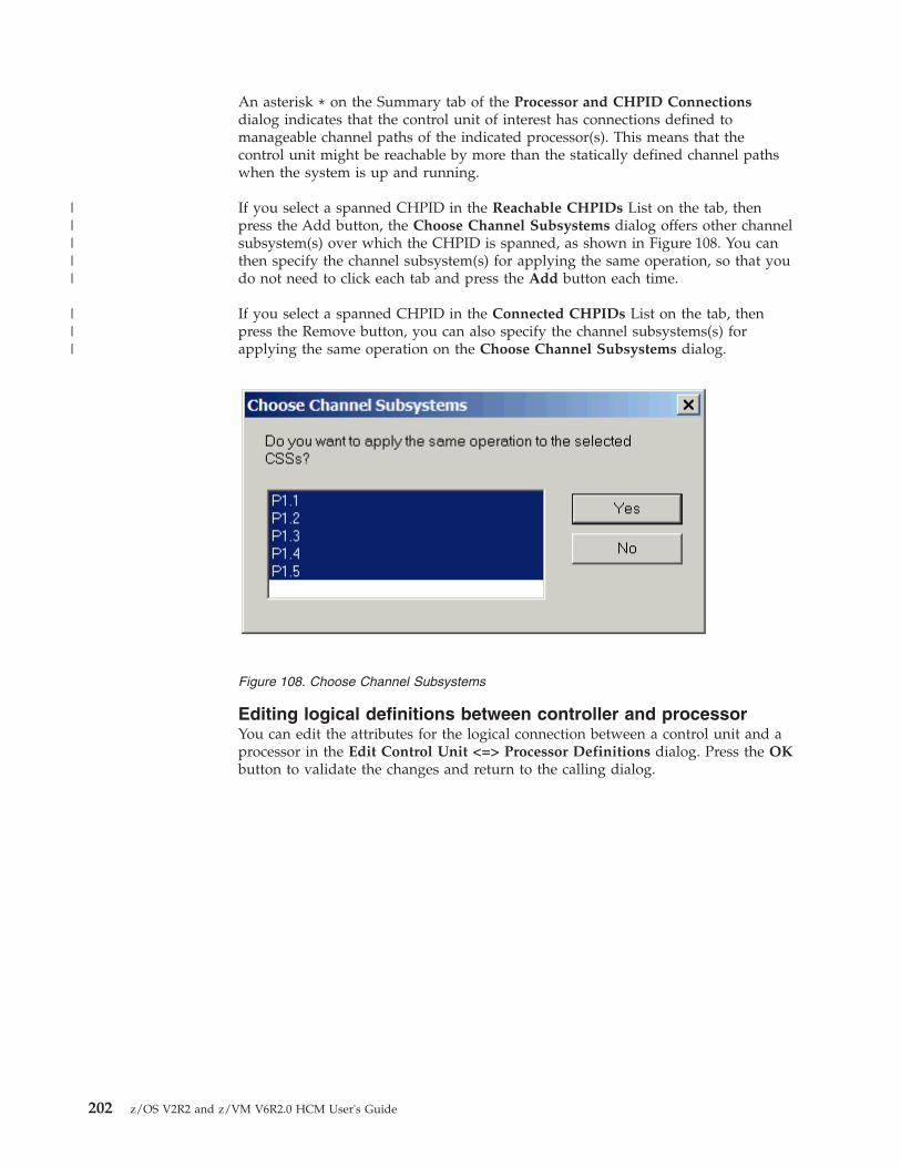
An asterisk * on the Summary tab of the Processor and CHPID Connectionsdialog indicates that the control unit of interest has connections defined tomanageable channel paths of the indicated processor(s). This means that thecontrol unit might be reachable by more than the statically defined channel pathswhen the system is up and running.
If you select a spanned CHPID in the Reachable CHPIDs List on the tab, thenpress the Add button, the Choose Channel Subsystems dialog offers other channelsubsystem(s) over which the CHPID is spanned, as shown in Figure 108. You canthen specify the channel subsystem(s) for applying the same operation, so that youdo not need to click each tab and press the Add button each time.
If you select a spanned CHPID in the Connected CHPIDs List on the tab, thenpress the Remove button, you can also specify the channel subsystems(s) forapplying the same operation on the Choose Channel Subsystems dialog.
Editing logical definitions between controller and processorYou can edit the attributes for the logical connection between a control unit and aprocessor in the Edit Control Unit <=> Processor Definitions dialog. Press the OKbutton to validate the changes and return to the calling dialog.
Figure 108. Choose Channel Subsystems
202 z/OS V2R2 and z/VM V6R2.0 HCM User's Guide
|||||
|||

You can specify or edit unit addresses and ranges when more than one range existsfor the selected control unit. Click on the Unitadds... button to open the UnitAddress Ranges dialog.
If you have more than one unit address range, and if your selection for UnitAddress and No. of Units comprises units from different ranges, then arenumbering of unit addresses is performed. Always make sure that you selectcorrect unit address ranges for making updates.
Tip:
There is an alternative way to access the Edit Control Unit <=> ProcessorDefinition dialog for an existing control unit <=> processor definition that doesnot involve making a connection between a controller and processor. Double-clickon a controller to open the Controller dialog. Press Control Units... to open theControl Unit List dialog. Select a control unit and press the Connections... button.The Processor and CHPID Connections dialog appears on which you can selectthe tab of that processor or channel subsystem for which you are interested in thecontrol unit <=> processor definition. Pressing the Attributes... button opens theEdit Control Unit <=> Processor Definitions dialog.
Connecting multiple control units to multiple CHPIDsThe Add Control Unit <=> Processor Definitions dialog allows you to assignCUADD values to the connections of multiple control units in ascending order. Youmay choose an Offset (or step size) other than 1 to implement your ownnumbering schemes.
Figure 109. Edit Control Unit <=> Processor Definitions
Chapter 7. Connecting objects in your configuration 203

HCM displays this dialog when you establish the first CHPID connection of acontrol unit. Use this dialog to specify the connection attributes.
For control units that already have processor connections, HCM does not displaythis dialog. When adding more connections, the previously defined CUADD valueis used for the new connection(s).
Disconnecting the channel interface from a CHPIDOpen the Controller dialog by double-clicking on a controller in the configurationdiagram, or by choosing Controller... from the Edit menu. Select the connectedchannel interface(s) from the Interfaces list box and press the Disconnect button.HCM will ask you for confirmation before disconnecting.
A disconnection involves logically disconnecting any control units from any CHPIDsthat were only reachable via the controller channel interface, as well as physicallydisconnecting.
Connecting controllers to controllers (PPRC connections)Controllers can be connected to other controllers either directly via a point-to-pointconnection, or via one or more switches. Such connections are used for PPRCconnections, and they can be defined and documented with HCM. Creating aPPRC connection in HCM consists of two steps:
Figure 110. Add Control Unit <=> Processor Definitions
204 z/OS V2R2 and z/VM V6R2.0 HCM User's Guide

1. The physical connections need to be established. Therefore, connect the channelinterfaces either via a point-to-point connection or via one or more switcheswith each other.
2. Create a PPRC connection consisting of up to 8 PPRC links using HCM's PPRCutility reachable via the PPRC Connections ... menu item in the Edit menu.
“Scenario V – Establish a PPRC connection consisting of several PPRC links” onpage 345 runs a scenario in which a PPRC connection is set up in detail, consistingof point-to-point and switched links.
Physically connecting a channel interface to a channelinterface of another controller
Before you can create a PPRC connection in HCM, the physical connections mustbe available to HCD. Connecting a channel interface of a controller directly to asecond channel interface creates a physical route between two controllers. Afterdefining such a connection, no logic connection has been established. When youdefine connections between channel interfaces and switches, you also establish thephysical environment for the PPRC connection regardless whether one or moreswitches are involved.
First, consider the case of establishing a point-to-point connection via two channelinterfaces. The process of connecting two channel interfaces with each other issimilar to connecting a channel interface to a CHPID (see “Connecting the channelinterface to a CHPID” on page 196). In the Controller dialog, select a controllerinterface and press the Connect ... button. In the following Select ConnectionTarget(s) dialog, select an interface of one of the controllers in your configurationto which you want to establish a point-to-point connection, and press the Physicalonly ... button. Note that you can only establish a physical connection, but no logicconnection, when connecting two channel interfaces with each other, hence, theStandard button is disabled when you select a channel interface in the SelectConnection Target(s) dialog.
Consider now the case of a chained or cascaded connection between two channelinterfaces. Again, this process is similar to connecting a channel interface to aCHPID. Here, you have to connect the involved controller interfaces with ports ofa switch. For details, please refer to “Connecting the channel interface to a CHPID”on page 196. In case of a chained switch environment, you also have to connect theswitches with each other. For details, please refer to “Connecting switches toprocessors or other switches” on page 206.
Creating a PPRC connectionAfter having established physical connections between the involved objects of aPPRC connection, you can create the PPRC connection itself. Open the PPRCConnections dialog via the Edit menu and press the Create button. This will leadyou to the first page of the Create PPRC Connections dialog in which you canselect the primary (source) subsystem. Press Next to open the second page of thisutility on which you can select the secondary (target) subsystem to be connected tothe primary subsystem. After pressing the Next button again, you are prompted onthe third page of the utility to choose the interfaces used to connect the selectedsubsystems. Here, you can specify up to eight single PPRC links. When you arefinished selecting the interfaces, press Next once more to arrive at the last page ofthe utility. Here, you can enter the remaining parameters for each PPRC link.When you have specified all needed values, press the Finish button to completeyour PPRC connection.
Chapter 7. Connecting objects in your configuration 205

Editing a PPRC connectionYou can edit existing PPRC connections and modify them accordingly. Open thePPRC Connections dialog via the Edit menu. Select a PPRC connection listed inthe dialog, and press the Edit button which leads you to the first page of the EditPPRC Connections utility. Here you can select which interfaces of the involvedcontrollers should participate in a PPRC connection. After you have selected theinterfaces under focus, press the Next button which leads you to the second pageof the Edit PPRC Connections utility. Here, you can adjust the remainingparameters for each PPRC link. When you have specified all needed values, pressthe Finish button to complete your PPRC connection.
Importing and exporting PPRC connectionsYou can edit existing PPRC connections and modify them accordingly. Open thePPRC Connections dialog via the Edit menu. Select a PPRC connection in thedialog, and press the Import/Export ... button. This will lead you to theImport/Export PPRC Connections utility. On the first page of that utility, you canselect whether to export or to import PPRC connections. After pressing the Nextbutton, you can select whether you want to process CESTPATH commands orGEOPARM control statements. On the third page, you can specify a filename forimport and export, depending on which action you have selected on page one ofthe wizard.
Deleting a PPRC connectionYou can delete existing PPRC connections by opening the PPRC Connectionsdialog via the Edit menu. Select a PPRC connection listed in the dialog, and pressthe Delete button. A PPRC link is also deleted when a controller interface thatparticipates in that particular PPRC link is disconnected either from the targetcontroller interface in case of a point-to-point PPRC link, or from the switch port inthe chained case.
Disconnecting a channel interface from a channel interfaceDisconnecting a channel interface from a channel interface works exactly the sameway as disconnecting the channel interface from a CHPID, see “Disconnecting thechannel interface from a CHPID” on page 204. After having disconnected acontroller interface from another controller interface or from a switch port, PPRClinks in which that controller interface was involved are deleted.
Connecting switches to processors or other switchesYou can insert a switch into the connection between controllers and processors. Theswitch port can connect upwards to either a CHPID or another switch port, usingthe Switch dialog and the Select Connection Target(s) dialog or the SelectMultiple Connection Target(s) dialog. When you connect controllers to an ESCONor FICON switch, you also use the Select Connection Target(s)/Select MultipleConnection Target(s) dialog. If you connect the controller to a switch which isalready connected to several CHPIDs, the controller (and any already connectedI/O devices) can establish communication with all reachable processors.
Note: If you want to connect channel interfaces of a crossbar switch to an ESCONor FICON switch or to CHPIDs, you can select only one channel interface at a timeand therefore you will reach the Select Connection Target(s) dialog only, but notthe Select Multiple Connection Target(s) dialog.
206 z/OS V2R2 and z/VM V6R2.0 HCM User's Guide
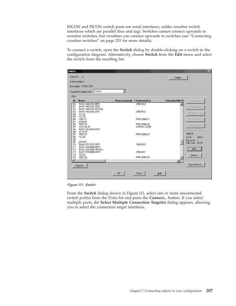
ESCON and FICON switch ports are serial interfaces, unlike crossbar switchinterfaces which are parallel (bus and tag). Switches cannot connect upwards tocrossbar switches, but crossbars can connect upwards to switches (see “Connectingcrossbar switches” on page 233 for more details).
To connect a switch, open the Switch dialog by double-clicking on a switch in theconfiguration diagram. Alternatively, choose Switch from the Edit menu and selectthe switch from the resulting list.
From the Switch dialog shown in Figure 111, select one or more unconnectedswitch port(s) from the Ports list and press the Connect... button. If you selectmultiple ports, the Select Multiple Connection Target(s) dialog appears, allowingyou to select the connection target interfaces.
Figure 111. Switch
Chapter 7. Connecting objects in your configuration 207

In the right list box, you can double-click on a target object with a plus (+) sign tonavigate to its interfaces. Targets that are not eligible for connection are disabled.
In the left list box containing the previously selected switch ports, select one ofthem and then select an eligible connection target from the right list box (aprocessor CHPID or another switch port). These selections enable the <<Connectbutton. Pressing this button copies the selected connection target from the right listbox into the left list box, thus displaying a pair of connection origin and target.
Repeat this process for every connection that you want to establish. After you havespecified all necessary connections in the dialog, press the Physical Only button.
Pressing the Physical Only button causes HCM to attempt to make the physicalconnection between the selected switch port and target. If you are connectingswitch ports to CHPIDs, and if the switch ID of the selected switch ports does notcoincide with the dynamic switch defined with the CHPID, then HCM shows theCHPID's Dynamic Switch Modification dialog (Figure 113 on page 209) where youcan update the dynamic switch for all involved CHPIDs.
Figure 112. Select Multiple Connection Target(s)
208 z/OS V2R2 and z/VM V6R2.0 HCM User's Guide

Disconnecting the switch port from a target interfaceOpen the Switch dialog by double-clicking on a switch in the configurationdiagram, or by choosing Switch... from the Edit menu. Select the connected switchport from the Ports list box and press the Disconnect button. HCM will ask you toconfirm the disconnection before doing it.
Connecting CHPIDs via CTC connectionsYou can create a CTC (channel to channel) connection between two CHPIDs on thesame or different processors, either directly or through a switch. When connectingthrough a switch, both CHPIDs must be able to access the same dynamic switch.One CHPID must be CNC or FCV, the other CTC in case of an SCTC connection.For FCTC connections, two FC CHPIDs have to be connected.
If you want to have a CTC connection involving spanned CHPIDs, you mustestablish a CTC connection between each CHPID instance that should be involvedin the CTC connection.
HCM considers a CTC connection as a single entity comprising selected controlunits and I/O devices connected to the CHPIDs. The following diagram representstwo CTC connections, connecting two CHPIDs through a switch. Note that theCTC controllers and devices are not explicitly shown.
Figure 113. CHPID's Dynamic Switch Modification
Chapter 7. Connecting objects in your configuration 209

Creating a CTC connectionChoose CTC Connection... from the Create menu or press Create... in the CTCConnections dialog to open the Create CTC Connection dialog. Select the twoCHPIDs at either end of the CTC connection by pressing the appropriateCHPID...button and choosing a CHPID from the resulting list box. Double-click ona processor in the list with a plus (+) sign to expand it to display all possible targetinterfaces (CHPIDs); double-click on a processor with a minus (-) sign to collapseit. Select a CHPID and press OK; alternatively, double-click on the CHPID.
Selecting OK will validate whether or not the CHPIDs may be involved in a CTCconnection. One of the following conditions must be met:v Neither of the CHPIDs are physically connected to anything, (for a new point to
point), orv Both of the CHPIDs are connected to a switch, both CHPIDs have the same
dynamic switch defined, and both CHPIDs have physical access to the dynamicswitch either directly or via at least one port-to-port connection from the entryswitch to the dynamic switch. If a CHPID is on a chained switch, and there ismore than one possible route between the chained switches (that is more thanone choice for the exit link address), the user will be prompted to choose one, or
Figure 114. CTC connection between two CHPIDs on different processors through a switch
Figure 115. Create CTC Connection
210 z/OS V2R2 and z/VM V6R2.0 HCM User's Guide

v (usual case) The CHPIDs are already physically connected to each other, butneither CHPID has any control units defined, (to fix up a point-to-point).
If none of the above conditions are met, you will be informed and the dialog willremain displayed so that different CHPIDs may be chosen.
Once this has been done, the Create CTC Connection dialog will disappear, andbe replaced with either the Accept Proposed CTC Control Units dialog or the EditCTC Connection dialog, allowing the user to specify the control units and devicesused in the connection.
Editing a CTC connectionSince CTC connections are not displayed as visible objects in the configurationdiagram (only their cables are shown), they cannot be selected directly for editing.Choose CTC Connections... from the Edit menu to open the CTC Connectionsdialog. Select a connection from the list and press Edit... the Edit CTC Connectiondialog appears. Alternatively, after you have created a CTC connection, pressingOK in the Create CTC Connection dialog automatically displays the edit dialog.
In the Edit CTC Connection dialog, you can view all control units and I/Odevices comprising the selected CTC connection. The dialog shows two lists, sideby side.
Figure 116. CTC Connections
Chapter 7. Connecting objects in your configuration 211

The left-hand listbox shows all of the control units connected to the CTC CHPID,or FC CHPID in case of an FCTC connection, that represent images available viathe CNC or FCV CHPID, or FC CHPID in case of an FCTC connection.
Note: For purposes of this discussion, the term “image” refers to either a partitionon an LPAR host, or the processor itself if it is running in BASIC mode.
There is at least one entry per image, even if there is no control unit connected thatrepresents the partition, in which case all data columns except “Destination on ....”will be blank. If the control unit has a discontinuous range of devices connected toit, or if the device range is made up of a mixture of CTC and BCTC devices, thenthere will be one or more subentries under the main entry that show additionaldevice ranges. For instance, if control unit 4110 had devices 4110-4113 and4116-4117 connected (discontinuous), and control unit 4120 had devices 4120,4(CTC) and 4124,4 (BCTC), the entries would look like shown:4110 4110,4 00 LPAR11
4116,2 064120 4120,4 00 LPAR12
4124,4 (B) 04
Each control unit or image comprises a single selectable row, even if it consists ofmultiple lines of text showing different device ranges; for instance, selecting eitherthe 4110,4 line or the 4116,2 line will select the entire 2-line entry for CU 4110,which represents image PART11.
The right-hand listbox is identical; the only difference is that it displays all of thecontrol units connected to the CNC or FCV CHPID, or FC CHPID in case of anFCTC connection, that represent images available via the CTC CHPID, or FCCHPID in case of an FCTC connection.
For images that have no control units to represent them, you may click Add New...to create new control units and devices to represent the image, or Add Existing...to select an existing CTC control unit that may be connected to the CHPID so as torepresent the selected image. For images that have control units, you may click
Figure 117. Edit CTC Connection
212 z/OS V2R2 and z/VM V6R2.0 HCM User's Guide

Edit... to open the Edit Control Unit dialog, CU <=> Proc... to open the ControlUnit <=> Processor Definitions dialog, or I/O Devices... to open the I/O DeviceList dialog. You may also choose to disconnect the control unit from the CHPID(and possibly delete the control unit and its devices) by clicking Remove.
Note: The Edit CTC Connection dialog can sometimes be preceded by the AcceptProposed CTC Control Units dialog. It will appear in those cases where HCMfinds that not all images in the connection are represented by control units, andwhere there are CTC control units already in the IODF that would be suitable torepresent those images based on current usage. These control units will appear ingray in the listboxes. After you accept or reject these proposed CHPID-control unitconnections, the Accept Proposed CTC Control Units dialog will be replaced bythe normal Edit CTC Connection dialog.
Viewing a connectivity report for a CTC connectionSelect the connection from the CTC Connections and press Details..., the ViewCTC Connection Details dialog will appear, showing all image-to-imageconnections showing the control units and devices that each image uses to accessthe other image.
It is possible for each image-to-image connection to span multiple listbox entries.As an example, if all of the images used in the example above used 4 CTC devicesand 4 BCTC devices, there would be 12 listbox entries, the first 4 showing:LPAR11 4110 4110,4 00 5110,4 5110 LPAR12LPAR11 4110 4114,4 (B) 04 5114,4 (B) 5110 LPAR12LPAR12 4120 4120,4 00 5120,4 5120 LPAR11LPAR12 4120 4124,4 (B) 04 5124,4 (B) 5120 LPAR11
Furthermore, this listbox will have entries to show devices that use unit addressesnot mirrored on the destination image. These entries will show blanks in controlunit and device columns on either the left or right side. To illustrate, assumeLPAR12 is excluded from device 5112’s explicit candidate list. The first listbox itemwould be split into three entries as follows:
Figure 118. View CTC Connection Details
Chapter 7. Connecting objects in your configuration 213

LPAR11 4110 4110,2 00 5110,2 5110 LPAR12LPAR11 4110 4112,1 02 LPAR12LPAR11 4110 4113,1 03 5113,1 5110 LPAR12
This shows that LPAR11 is able to communicate to LPAR12 via unit address 02, butLPAR12 has no device defined on this UA to communicate back.
Deleting a CTC connectionSelect the connection from the CTC Connections and press Delete. All of thecontrol units that are connected to the CHPIDs for this connection will bedisconnected. The control units that no longer have any CHPID connections will bedeleted along with their attached devices.
Editing the fiber links for CTC connectionsYou can edit the fiber link for a point-to-point CTC connection. Open the CTCConnections dialog by choosing CTC Connections... from the Edit menu. Choosethe point-to-point connection and press the Fiber Link... button to open the EditFiber Link dialog. You can then edit the composition of the Fiber link between theCHPIDs. For more details, see “Editing fiber links” on page 227.
Note that CTC connections through switches have two fiber links, one on eachswitch port. To edit those fiber links, open the Switch dialog by double-clicking onthe switch in the configuration diagram. Select the desired switch port and click onthe Fiber Link... button to display the Edit Fiber Link dialog.
Viewing and deleting unused CTC control units, devices, andconnections to CHPIDsIt is possible that the IODF contains CTC control units, devices, or connectionsbetween CHPIDs and CTC control units that cannot be attributed to any valid CTCconnection. This can happen in the following circumstances:v Unconnected CTC control units or devices were created using HCD followed by
an IODF load or resync.v Connections via switches were made using HCD without specifying CHPID-port
or port-CU links followed by an IODF load or resync.v Only one side of a logical CTC connection was made using either HCD or HCM.v An action within either HCD or HCM was made that affects the validity of
existing CHPID-control unit connections, such as unlinking a port from a CHPIDor control unit, deleting a partition involved in a CTC connection, or changingthe mode of a CHPID involved in a CTC connection from shared to non-sharedor vice-versa.
Under these circumstances, the Unused... button appears on the CTC Connectionsdialog. Clicking this button opens the View Unused CTC Control Units, Devices,and CHPID Connections dialog.
214 z/OS V2R2 and z/VM V6R2.0 HCM User's Guide

All invalid (that is not involved in a valid CTC connection) CTC-related IODFobjects appear in this dialog. Usually the easiest way to recover from thesesituations is to click Delete All to get rid of the invalid items, and re-create theCTC connections that were affected.
To prevent this dialog from ever having to make an appearance, adhere to thefollowing precautions:v Before loading an IODF, make sure that all control units and CHPIDs involved
in CTC connections via switches have appropriate links to switch ports, and thatall control units involved in new point-to-point CTC connections have serialnumbers specified to match up the two sides of the connection. Also ensure thatunconnected CTC control units and devices are deleted. See also “Preparing theIODF” on page 61.
v Whenever you create or modify a CTC connection in HCM, make sure that bothCHPIDs (that is both sides of the Edit CTC Connection dialog) have one controlunit connected to represent an image on the other CHPID.
Validating CTC connectionsSeveral actions can influence your CTC connections. Even when you have correctlyset up a CTC connection using HCM, actions in your configuration that youperform after defining your CTC connection might influence your CTC connectionin a way so that the CTC connection does no longer work. Among these actionsare the following:v Updating the access/candidate lists for a CHPIDv Changing a CHPID's mode (SHR/DED)
Figure 119. View Unused CTC Control Units, Devices, and CHPID Connections
Chapter 7. Connecting objects in your configuration 215

v Changing an LPAR numberv Deleting an LPARv Adding an LPARv Disconnecting/reconnecting a CHPIDv Deleting a CHPIDv Deleting a switch.
Whenever you make one of these actions, you should verify your CTC connectionsin HCM. For instance, when you create a CTC connection via HCM, the CUADDvalues representing logical partitions are automatically correctly set by HCM/HCDat the time the CTC connection is created. If you now modify the LPAR number,the CUADD value stored does no longer represent the chosen logical partition, asthe LPAR number and CUADD no longer coincide. Though correctly definedbefore, the CTC connection will no longer work because of an action thatinfluences the CTC connection.
CTC connection reportHCM offers you the possibility to create a CTC connection report via the PrintReports dialog, reachable via the File menu. You can see an example of such areport in “Sample text reports and diagram reports” on page 287(Channel-to-Channel Connections). The CTC connection report containsinformation about all CTC connections known to HCM in your configuration. Atleast before building a production IODF, use this report to carefully verify that allthe CTC connections that you have defined before, are still existing as previouslydefined.
View CTC connection detailsBesides the HCM CTC connection report, you can also verify the CTC connectionsdefined in the configuration via the CTC Connection Details dialog, see Figure 118on page 213. With this dialog, you can view the connectivity details for a selectedCTC connection. This dialog shows you information about the involvedprocessor(s) and channel paths, gives details about the route itself, and providesinsight in the used images on the processor, the used CTC control units and CTCdevices. In general, if blanks appear in any column in the list box (with theexception of the OS columns), then there is some gap in the connectivity and thetwo images will not be able to communicate using the unit address shown. Eventhough CTC definitions have been correctly defined before, you might find gapsindicating that some mismatch occurs due to one of the above mentioned actions.
View unused CTC control units, devices, and CHPID connectionsUse this dialog to view (and clean up, if necessary) unused CTC control units anddevices, or connections from CHPIDs to CTC control units that are not used in anyCTC connection. To display this dialog, press the Unused... button on the CTCConnections dialog. Note that this button is available only if there are unuseditems to examine. When using HCM to define CTC connections, this dialog willonly be available if CTC connections are incomplete. Therefore, the appearance ofthe Unused... button on the CTC Connections dialog serves as an indication thatsomething is amiss with the logical definitions that make up the configuration'sCTC connections. See also “Viewing and deleting unused CTC control units,devices, and connections to CHPIDs” on page 214.
Create / establish CTC connections after loading an IODFAfter loading an IODF, HCM is able to detect CTC connections. In general, HCMrecognizes CTC connections if all control units composing a CTC connection
216 z/OS V2R2 and z/VM V6R2.0 HCM User's Guide

through a switch are connected to switch ports. Point-to-point connections arerecognized if the involved control units have the same serial number.
In case the involved control units of a point-to-point CTC connection do havedifferent serial numbers, HCM can not detect that CTC connection. In order toestablish such a CTC connection so that also HCM recognizes these CTCconnections, you can do the following steps. Note that it is assumed here thatcorrect point-to-point connections have been defined in the IODF via HCD.v Create the CTC connection under focus via the CTC Connections dialog where
you press the Create... button in order to obtain the Create CTC Connectiondialog.
v In the Create CTC Connection dialog, select the CHPIDs that are involved inthe CTC connection, and press the OK button.
Now, the Accept Proposed CTC Control Units dialog appears showing the CTCcontrol units to which the selected channel paths are already connected. Eitheraccept the proposal via the Accept button, or reject it with the Reject button. Incase you have accepted the proposal, the Edit CTC Connection dialog appears,prefilled with the accepted proposed control unit and device information. Checkthe information in this dialog, and if the CTC connection is already as it should be,press the Close button. The CTC connection is now defined, and HCM alsorecognized this CTC connection. In case you have rejected the proposedinformation, you should be able to select the correct control units and devices viapressing the Add Existing ... button on the Edit CTC Connection dialog. Select thecorrect CTC control units and the connected CTC devices in the Select CTCControl Unit dialog, press the OK button, and return to the Edit CTC Connectiondialog. After having selected all CTC correct control units and devices, the CTCconnection is complete. Note that under the above assumption, HCM eitherproposes the correct CTC control units, or you find the CTC control units anddevices in the Select CTC Control Unit dialog.
Connecting CHPIDs via coupling facility connectionsA coupling facility is a special logical partition that provides high-speed caching, listprocessing, and locking functions in a processor. It involves connecting a partitionon one processor to a partition on another processor.
The following diagram represents two CF-connections involving CHPIDs 70 and 10respectively 71 and 11. Note, that the CF control units and devices are notexplicitly shown.
You can determine if a selected partition will be used solely for standard operatingsystem connections (OS), as a coupling facility (CF) or both (CF/OS) by selecting aUsage option in the Create Partition dialog from the Create menu.
Chapter 7. Connecting objects in your configuration 217

You can only create a coupling facility connection between a sending CF CHPIDon one processor or partition and a receiving CF CHPID on another. You can viewall coupling facility connections in the dialog of the same name. Open theCoupling Facility Connections dialog with the CF Connections... option in theEdit menu, and use the View section options to sort the list box contents by CFsender or receiver CHPID.
Figure 120. Coupling Facility Connection
Figure 121. Coupling Facility Connections
218 z/OS V2R2 and z/VM V6R2.0 HCM User's Guide
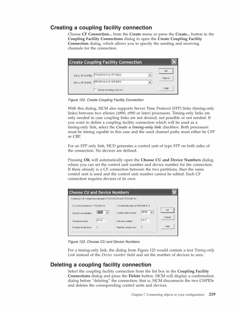
Creating a coupling facility connectionChoose CF Connection... from the Create menu or press the Create... button in theCoupling Facility Connections dialog to open the Create Coupling FacilityConnection dialog, which allows you to specify the sending and receivingchannels for the connection.
With this dialog, HCM also supports Server Time Protocol (STP) links (timing-onlylinks) between two zSeries (z890, z990 or later) processors. Timing-only links areonly needed in case coupling links are not desired, not possible or not needed. Ifyou want to define a coupling facility connection which will be used as atiming-only link, select the Create a timing-only link checkbox. Both processorsmust be timing capable in this case and the used channel paths must either be CFPor CBP.
For an STP only link, HCD generates a control unit of type STP on both sides ofthe connection. No devices are defined.
Pressing OK will automatically open the Choose CU and Device Numbers dialog,where you can set the control unit number and device number for the connection.If there already is a CF connection between the two partitions, then the samecontrol unit is used and the control unit number cannot be edited. Each CFconnection requires devices of its own.
For a timing-only link, the dialog from Figure 123 would contain a text Timing-onlyLink instead of the Device number field and set the number of devices to zero.
Deleting a coupling facility connectionSelect the coupling facility connection from the list box in the Coupling FacilityConnections dialog and press the Delete button. HCM will display a confirmationdialog before “deleting” the connection; that is, HCM disconnects the two CHPIDsand deletes the corresponding control units and devices.
Figure 122. Create Coupling Facility Connection
Figure 123. Choose CU and Device Numbers
Chapter 7. Connecting objects in your configuration 219

220 z/OS V2R2 and z/VM V6R2.0 HCM User's Guide

Chapter 8. Physical connections
This chapter explains how to add strictly physical elements to the connections ofyour configuration; specifically: cables, patchports, and crossbar switches.
In HCM, connections are made initially without concern for physical cables andpatchports (see Chapter 7, “Connecting objects in your configuration,” on page187). Cables and patchports are assigned to connections after the connections havebeen made. These physical aspects of the connection are not reflected in the IODFand are not required in order to build a correct production IODF.
Managing physical cablesNew connections initially have no physical cables assigned. You can either assign acable immediately after creating the connection, or assign cables after a series ofconnections.
HCM displays cable IDs and length information in the Object Information Bar (atthe top of the screen) when the mouse cursor is placed over an interface with anassigned physical cable. This information will appear in reports and on printedconfiguration diagrams.
HCM interprets trunk cable IDs as two fields separated by a slash, ‘/’. The firstfield identifies the trunk; the second indicates the pair of conductors (channel)within the trunk. For example, trunk cable ID TR1234/07 is Channel 07 in TrunkTR1234.
Cables can have three states: in use, unused or in inventory.v In Use: Cables that are currently assigned to connections. Cables are assigned to
connections using the Assign Cable dialog.v Unused: Cables that were once assigned to connections. A cable becomes unused
when its connection is broken or when a new cable is assigned to theconnection. Unused cables retain information about where they were last used,to make it easy to identify them when you re-connect them. Note thatre-connecting an interface or re-positioning it on a daisy-chain will disconnectthe physical cable on the interface.
v In Inventory: Cables that are not currently assigned to a connection and forwhich there is no record of any previous connection they might have beenassigned to. They can be assigned to connections.
Cables come to be in inventory in two ways.v Unused cables can be moved to inventory using the Cable Assignments dialog.
The only difference between unused cables and cables in inventory is thatunused cables retain information about their last connection. You would moveunused cables into inventory when you know that they will not be reused in thenear future.
v The inventory can be populated by importing cable descriptions from an ASCIIfile. See Chapter 15, “Importing and exporting data,” on page 353 for moreinformation.
© Copyright IBM Corp. 1995, 2016 221
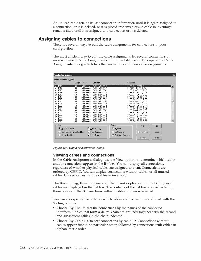
An unused cable retains its last connection information until it is again assigned toa connection, or it is deleted, or it is placed into inventory. A cable in inventory,remains there until it is assigned to a connection or it is deleted.
Assigning cables to connectionsThere are several ways to edit the cable assignments for connections in yourconfiguration.
The most efficient way to edit the cable assignments for several connections atonce is to select Cable Assignments... from the Edit menu. This opens the CableAssignments dialog which lists the connections and their cable assignments.
Viewing cables and connectionsIn the Cable Assignments dialog, use the View options to determine which cablesand/or connections appear in the list box. You can display all connections,regardless of whether physical cables are assigned to them. Connections areordered by CHPID. You can display connections without cables, or all unusedcables. Unused cables include cables in inventory.
The Bus and Tag, Fiber Jumpers and Fiber Trunks options control which types ofcables are displayed in the list box. The contents of the list box are unaffected bythese options if the “Connections without cables” option is selected.
You can also specify the order in which cables and connections are listed with theSorting options.v Choose "By Use" to sort the connections by the names of the connected
interfaces. Cables that form a daisy- chain are grouped together with the secondand subsequent cables in the chain indented.
v Choose "By Cable ID" to sort connections by cable ID. Connections withoutcables appear first in no particular order, followed by connections with cables inalphanumeric order.
Figure 124. Cable Assignments Dialog
222 z/OS V2R2 and z/VM V6R2.0 HCM User's Guide

Creating or editing cablesSelect either “All connections” or “Connections without cables” in the View sectionof the Cable Assignments dialog, then select the connection(s) and press the Edit...button. The Assign Cable dialog is opened allowing you to create or edit the cableassigned to the connection.
Transferring unused cables to inventorySelect “Unused cables” in the View section of the Cable Assignments dialog, thenselect the cable(s) to be moved to inventory. Press the To Inventory button. Notethat cables in inventory, as well as unused cables, appear as possible choices whenediting cable assignments in the Assign Cable dialog.
Deleting cablesSelect the “Unused cables” option in the View section of the Cable Assignmentsdialog, then select the cable(s) and press the Delete button. HCM does not retainany information about these cables, once they are deleted.
Note: You can only delete a cable if it is unused. If you want to delete a cablewhich is in use, you first have to unassign the cable from the current fiber link.
Other ways to assign cablesBesides using the Cable Assignments dialog, you can use any of the followingmethods of accessing the Assign Cable dialog.v To edit a single cable assignment from the diagram, select the lower interface of
the connection, and select Edit cable on selected interface... from the Edit menu(Shortcut: press F5).
v To edit several cable assignments from the diagram, choose Interface Selection...from the Options menu and check “Edit the physical cable assignment for theinterface”. Now double-click on the lower interface of each connection to openthe Assign Cable dialog.
v You can edit the cable assignments for connections within a fiber link from theEdit Fiber Link dialog by selecting a cable or dashes (unlabeled cable) andclicking on the Edit Cable... button. See “Editing fiber links” on page 227 formore details.
Creating and editing cablesUse any of the methods described under “Assigning cables to connections” onpage 222 to open the Assign Cable dialog for a particular connection.
Chapter 8. Physical connections 223

Creating a new cable to assign to a connectionPerform this task using the Assign Cable dialog which can be reached as follows:v Edit --> Cable Assignments... opens the Cable Assignments dialog, where you
select a connection without a cable and press Edit.v From a connection's context menu, you select Edit Cable....
Then, in the Assign Cable dialog, you can create a new cable for a connection byentering a new Cable ID, cable type, and (optionally) the cable’s length and dbloss, then press OK. The ID must be unique.
HCM currently supports the following cable types:
Parallel
Gray Fully PopulatedGray Partially PopulatedBlue Fully PopulatedBlue Partially PopulatedBidirectional
Serial
Single Mode JumperMulti Mode JumperSingle Mode TrunkMulti Mode Trunk
Note: HCM supports different interface types for CHPIDs and controller interfacesand also supports different cable types for serial and parallel interface types (see
Figure 125. Assign Cable Dialog
224 z/OS V2R2 and z/VM V6R2.0 HCM User's Guide
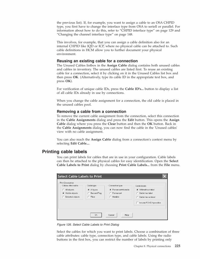
the previous list). If, for example, you want to assign a cable to an OSA CHPIDtype, you first have to change the interface type from OSA to seriell or parallel. Forinformation about how to do this, refer to “CHPID interface type” on page 129 and“Changing the channel interface type” on page 148.
This involves, for example, that you can assign a cable definition also for aninternal CHPID like IQD or ICP, where no physical cable can be attached to. Suchcable definitions in HCM allow you to further document your physicalenvironment.
Reusing an existing cable for a connectionThe Unused Cables listbox in the Assign Cable dialog contains both unused cablesand cables in inventory. The unused cables are listed first. To reuse an existingcable for a connection, select it by clicking on it in the Unused Cables list box andthen press OK. (Alternatively, type its cable ID in the appropriate text box, andpress OK).
For verification of unique cable IDs, press the Cable ID's... button to display a listof all cable IDs already in use by connections.
When you change the cable assignment for a connection, the old cable is placed inthe unused cables pool.
Removing a cable from a connectionTo remove the current cable assignment from the connection, select this connectionin the Cable Assignments dialog and press the Edit button. This opens the AssignCable dialog where you press the Clear button and then the OK button. Back inthe Cable Assignments dialog, you can now find the cable in the 'Unused cables'view with no cable assignment.
You can also reach the Assign Cable dialog from a connection's context menu byselecting Edit Cable....
Printing cable labelsYou can print labels for cables that are in use in your configuration. Cable labelscan then be attached to the physical cables for easy identification. Open the SelectCable Labels to Print dialog by choosing Print Cable Labels... from the File menu.
Select the cables for which you want to print labels. Choose a combination of threecable attributes: cable type, connection type, and cable labels. Using the radiobuttons in the first box, you can restrict the number of labels by printing only
Figure 126. Select Cable Labels to Print Dialog
Chapter 8. Physical connections 225

those attached to visible objects (those currently included in the diagram), or onlythose attached to currently selected objects.
Pressing OK opens the Choose a Cable Label Format to Print dialog. You canprint labels directly to the printer with the standard format, or to an ASCII filewhere you can customize the formatting.v Standard printable labels prints the labels to the current printer, which is
presumably loaded with appropriate label forms. These self laminating labelsmust comply to the following specifications:
Color Clear
Write-on area (width x length)1.00 x 0.47
Total label (width x length)1.00 x 1.33
Number of columns7
Number of rows7
Labels per sheet49
v Comma delimited ASCII file prompts you for the filename to write theinformation to. There are programs available that can read, format and print thecable label information.
If you select the Include PCHID if possible check box from the dialog shown inFigure 126 on page 225, then, if applicable, the PCHID of the channel that isconnected by the cable, is also included in the output (in parenthesis), like forexample in a comma delimited ASCII file:
without PCHIDERV01.3.98,2105 #1.6.A[24],2006-05-31,c_1234,ERV01.3.98,2105 #1.6.A[24]2105 #1.6.A[24],ERV01.3.98,2006-05-31,c_1234,ERV01.3.98,2105 #1.6.A[24]
with PCHIDERV01.3.98(398),2105 #1.6.A[24],2006-05-31,c_1234,ERV01.3.98(398),2105 #1.6.A[24]2105 #1.6.A[24],ERV01.3.98(398),2006-05-31,c_1234,ERV01.3.98(398),2105 #1.6.A[24]
See “Sample cable labels” on page 296 for examples of standard printable labelsand comma delimited ASCII file labels.
Figure 127. Choose a Cable Label Format to Print Dialog
226 z/OS V2R2 and z/VM V6R2.0 HCM User's Guide

Editing fiber linksAs described in Chapter 7, “Connecting objects in your configuration,” on page187, a logical connection may be "realized" by more than one physical cable, oftenpassing through a number of patchports. For serial connections, HCM uses theterm "fiber link" to describe the complete connection between two interfaces(optical transceivers). HCM allows you to insert patchports into a fiber link, toassign cables to each segment of the link, and to mark certain connections as"permanent" so they will not disappear when connections between active ESCONor FICON objects are broken. There are two methods for setting up fiber links. For"infrastructure" connections (i.e., trunk cables), you should use the Cabinet dialog.To document the jumper cables and patchports that are used in a connectionbetween active ESCON or FICON objects, you should use the Edit Fiber Linkdialog. In general, you should use the following sequence:1. Create any cabinets and patchports and make necessary permanent connections
between them. This is normally done when new cabinets are installed andconnected with trunk cables.
2. Make permanent connections from patch panels to CHPIDs and switch ports.3. Make all logical connections (between CHPIDs, switch ports, and channel
interfaces). This step can be performed separately and without regard for fiberlinks.
4. Add patchports and cables to the fiber link (that is, make mutable connectionsby editing the fiber link).
This section covers steps 1 and 2 (Infrastructure Connections) and 4 (JumperConnections), plus information about disconnecting fiber links. For moreinformation about step 3, see Chapter 7, “Connecting objects in yourconfiguration,” on page 187.
Infrastructure connectionsHCM has the concept of a "permanent" connection to model infrastructureconnections that are set up as a permanent fixture of the data center. Any serialconnection that does not involve a converter may be marked as "permanent" inHCM, but normally this attribute is used for trunk connections that:v link the backs of two patch panels,v link a group of CHPIDs to the back of a patch panel, orv link a group of switch ports to the back of a patch panel
If a patchport is connected to a CHPID or switch port in this way, the patchport(and any other patchports connected to it) are automatically added to the fiber linkwhen the CHPID or switch port is logically connected. Furthermore, theseconnections will remain in place when logical connections are broken. Suchconnections should be made from the Cabinet dialog. As an example, to connectthe back of one panel to the back of another, start by double-clicking the cabinet inthe configuration diagram (or choose Cabinet... from the Edit menu anddouble-click the appropriate cabinet to open the Cabinet dialog shown in thefollowing figure:
Chapter 8. Physical connections 227

Make sure the Back radio button in the View group box is selected. This tellsHCM that subsequent connect operations are made to the back of patchports.Select the appropriate panel from the Panels list, and then select all of thepatchports in the panel by clicking (and holding) the left mouse button on the firstpatchport and moving the pointer to the last patchport. Now click Connect....HCM opens the Select Connection Target(s) dialog.
Figure 128. Cabinet Dialog
228 z/OS V2R2 and z/VM V6R2.0 HCM User's Guide
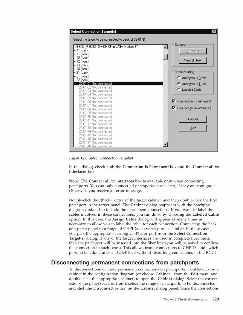
In this dialog, check both the Connection is Permanent box and the Connect all xxinterfaces box.
Note: The Connect all xx interfaces box is available only when connectingpatchports. You can only connect all patchports in one step, if they are contiguous.Otherwise you receive an error message.
Double-click the "(back)" entry of the target cabinet, and then double-click the firstpatchport in the target panel. The Cabinet dialog reappears with the patchportdiagram updated to include the permanent connections. If you want to label thecables involved in these connections, you can do so by choosing the Labeled Cableoption. In this case, the Assign Cable dialog will appear as many times asnecessary to allow you to label the cable for each connection. Connecting the backof a patch panel to a range of CHPIDs or switch ports is similar. In these cases,you pick the appropriate starting CHPID or port from the Select ConnectionTarget(s) dialog. If any of the target interfaces are used in complete fiber links,then the patchport will be inserted into the fiber link (you will be asked to confirmthe connection in such cases). This allows trunk connections to CHPIDs and switchports to be added after an IODF load without disturbing connections in the IODF.
Disconnecting permanent connections from patchportsTo disconnect one or more permanent connections on patchports: Double-click on acabinet in the configuration diagram (or choose Cabinet... from the Edit menu anddouble-click the appropriate cabinet) to open the Cabinet dialog. Select the correctside of the panel (back or front), select the range of patchports to be disconnected,and click the Disconnect button on the Cabinet dialog panel. Since the connections
Figure 129. Select Connection Target(s)
Chapter 8. Physical connections 229

are marked as permanent, you will be asked to confirm that you want todisconnect. If any of the patchports are involved in complete fiber links, they willbe removed from the fiber link when the permanent connection is broken.
Jumper connectionsJumper connections are usually made using the Edit Fiber Link dialog after logicalconnections have been set up. As an example, when you are configuring a newcontroller, typically you will create the controller and connect it to CHPIDs and/orswitch ports as described in previous chapters. Once this is done, you candocument the physical cables and patchports that are used to realize the logicalconnections by selecting the "bottom" end of each connection (e.g. the controllerinterface connected to a switch port, or a switch port connected to a CHPID) andclicking "Fiber Link..."
Editing fiber links in the dialogOpen the Edit Fiber Link dialog by pressing the Fiber Link... button in the editdialog for the active ESCON or FICON object “below” the fiber link (this includesEdit Converter, Controller, Director, and Edit CTC Connection dialogs). See panelin Figure 130 on page 231. Note that if the Fiber Link... button is disabled, there isno fiber link for the selected interface; you must make a connection before you canedit the fiber link.
Alternatively, in the Cabinet dialog panel, select the patchport whose fiber link isto be edited. Open the Edit Fiber Link dialog by pressing the Fiber Link... buttonin the Cabinet dialog. Note that if the Fiber Link... button is disabled, there is nofiber link for the selected interface; you must make a connection before you canedit the fiber link.
The Current Fiber Link composition list box shown in Figure 130 on page 231displays all objects in the fiber link, including cables which are indented, andundefined cables which are represented by dashes (- - -). The Available Patchportslist box on the left displays all cabinets and their patchports. This box is emptyunless dashes are selected in the Current Fiber link composition list box.Double-click on a cabinet with a plus (+) sign to expand it to display its availablepatchports; double-click a cabinet with a minus (-) sign to contract it. Invalidpatchports are disabled.
230 z/OS V2R2 and z/VM V6R2.0 HCM User's Guide
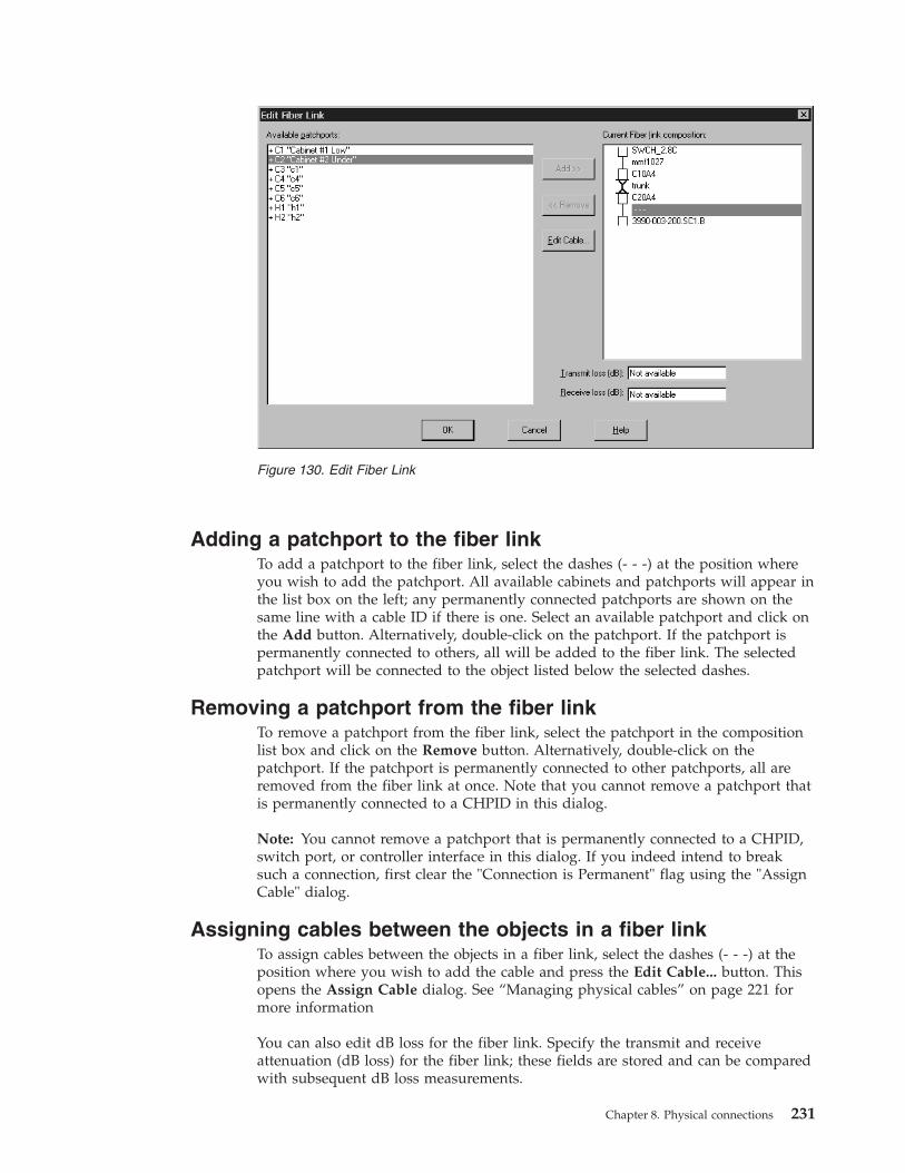
Adding a patchport to the fiber linkTo add a patchport to the fiber link, select the dashes (- - -) at the position whereyou wish to add the patchport. All available cabinets and patchports will appear inthe list box on the left; any permanently connected patchports are shown on thesame line with a cable ID if there is one. Select an available patchport and click onthe Add button. Alternatively, double-click on the patchport. If the patchport ispermanently connected to others, all will be added to the fiber link. The selectedpatchport will be connected to the object listed below the selected dashes.
Removing a patchport from the fiber linkTo remove a patchport from the fiber link, select the patchport in the compositionlist box and click on the Remove button. Alternatively, double-click on thepatchport. If the patchport is permanently connected to other patchports, all areremoved from the fiber link at once. Note that you cannot remove a patchport thatis permanently connected to a CHPID in this dialog.
Note: You cannot remove a patchport that is permanently connected to a CHPID,switch port, or controller interface in this dialog. If you indeed intend to breaksuch a connection, first clear the "Connection is Permanent" flag using the "AssignCable" dialog.
Assigning cables between the objects in a fiber linkTo assign cables between the objects in a fiber link, select the dashes (- - -) at theposition where you wish to add the cable and press the Edit Cable... button. Thisopens the Assign Cable dialog. See “Managing physical cables” on page 221 formore information
You can also edit dB loss for the fiber link. Specify the transmit and receiveattenuation (dB loss) for the fiber link; these fields are stored and can be comparedwith subsequent dB loss measurements.
Figure 130. Edit Fiber Link
Chapter 8. Physical connections 231

Disconnecting a fiber linkWhen a switch port or a serial interface on a controller is disconnected (eitherexplicitly or implicitly via reconnect), HCM will prompt the user to choose whichmutable link is to be broken if there is more than one. Consider the example fromFigure 131 showing four CHPIDs connected to two switches. From the diagram, itis evident that both the CHPIDs and the switch ports are trunked to the backs ofcabinets, and that the link from each CHPID to its connected port also passesthrough another trunk connection linking the backs of two other cabinets:
In such a configuration, all of the trunk connections would be marked aspermanent to indicate that they will not change. If you wanted to disconnect oneof the ports, say D9 (perhaps so it could be connected later to another CHPID),HCM would detect that there are two cable positions at which the connectioncould be broken (that is, the two jumper connections linking the fronts of cabinets)and ask you to choose one of those two positions as follows:
Figure 131. Configuration Diagram
232 z/OS V2R2 and z/VM V6R2.0 HCM User's Guide

This dialog indicates the mutable connections by an arrow and preselects thelowest mutable connection. Clicking OK or double-clicking a mutable link willbreak the connection.
If you choose to break the connection in the lower position (using cable JD119), theother jumper cable (JA304, in this case) will remain in place even though it is not apermanent connection. This means that if you later connect, say, a switch port toCHPID SYS2.18, patchport Q1_5_03 and jumper JA304 will automatically beincluded in the fiber link of the new connection.
This dialog will not appear if there is only one mutable connection (for example,there is only one jumper connecting the CHPID and port). In such cases, theconnection is broken at the one mutable link. Also, if the connection involves aP->S or S->P converter, HCM will automatically disconnect in such a way as toremove the converter and leave all the other connections intact. Finally, if all thelinks in the chain are marked as permanent, HCM will refuse to break theconnection.
Connecting crossbar switchesCrossbar switches can be inserted into the connection between controllers andprocessors. The crossbar channel interface can connect upwards to either a processorCHPID or another crossbar’s control unit interface. A crossbar may also connectupwards to a switch (through a converter), but not vice versa. That is, a crossbarchannel interface can connect to a switch port, but a switch port may not connectto a crossbar control unit interface. Crossbar interfaces are parallel (bus and tag),unlike switch interfaces, which are serial (ESCON or FICON). Thus crossbars arenever part of fiber links.
To insert a crossbar switch into an existing connection, you must first disconnectthe controller from the processor. Then connect the crossbar to the processor.Finally, connect the controller upwards to the crossbar (see “Connecting controllersto processors and switches” on page 195 for more information).
Figure 132. Disconnect Dialog
Chapter 8. Physical connections 233

Connecting a crossbar switchTo connect a crossbar switch, open the Crossbar Switch dialog by double-clickingon a crossbar or choosing Crossbar Switch... from the Edit menu. Select a crossbarchannel interface and press the Connect... button. The Connect Channel Interfacedialog (similar to the one used to connect controller channel interfaces) opens toallow you to select a target interface.
Select a processor CHPID, another crossbar or a switch in the list box. You candouble-click on a target object with a plus (+) sign to expand it to display itsinterfaces; double-click on a target with a minus (-) sign to contract it. After youhave selected the target, press the OK button. Alternatively, double-click on thetarget interface.
Positioning a crossbar switch on a daisy-chainIf you are connecting the crossbar channel interface to a CHPID which is alreadyconnected to another crossbar switch, the Position Interface dialog appears for youto position the crossbar in the connection. Select a crossbar in the ChannelInterfaces list box and drag it to the desired position in the list. See “Positioningobjects along daisy-chained connections” on page 188 for more details.
Disconnecting a crossbar channel interfaceOpen the Edit Crossbar Switch dialog by double-clicking on a crossbar in theconfiguration diagram. Select the connected crossbar channel interface from theChannel Interfaces list box and press the Disconnect button. HCM will ask you toconfirm the disconnection before doing it.
234 z/OS V2R2 and z/VM V6R2.0 HCM User's Guide

Chapter 9. Utilities
HCM offers several utilities for performing time-consuming configuration tasks,which you can invoke from the Utilities menu. These utilities support you inmaking complex configuration changes without violating any logical definitionsthat are valid in your configuration. They are wizards that guide you through thevarious functions. At the end, you see a summary of your changes where you canaccept or discard them. You can also save the summary to a file. These utilities aredescribed in the following sections of this chapter:v “Performing I/O Autoconfiguration” on page 236v “Moving port connections” on page 245v “Aggregating CHPIDs” on page 247v “Converting CNC channels to FICON channels” on page 248v “Priming the IODF with sensed data” on page 249v “Changing the CHPID link address format” on page 249v “Creating/Copying/Editing an I/O subsystem” on page 249
Besides these utilities that assist you in configuration tasks, you can use furtherutilities for special purposes:v To assign physical channel identifiers (PCHIDs) to logical CHPIDs, use the
CHPID Mapping Tool Support (described in “Using the CHPID Mapping ToolSupport utility” on page 78).
v To assign world-wide port names to the FCP device paths, use the WWPNPrediction Tool Support (described in “Using the WWPN Prediction ToolSupport” on page 259).
v To create an IOCP input file or an I/O configurations file by extracting datafrom the currently accessed IODF for later migration into a different target IODF,you can use the Export IOCP or I/O Configuration statements utility (describedin “Exporting IOCP or I/O configuration statements” on page 251)
v To check configuration files for structural consistency, use the Configuration filechecker (described in “Checking a configuration” on page 81).
v To create an exported MCF and send it to IBM Support for MCF problemdiagnosis, select Exporting Master Configuration File (described in “Exportingan MCF” on page 413).
v To examine performance data of objects in your active sysplex, and to discoverpotential bottlenecks, select menu item Browse Performance Data... (describedin “Browsing performance data” on page 253).
v To migrate I/O configuration statements from an existing input file into aselected work IODF, use the Import I/O Configuration Statements dialog(described in “Importing I/O configuration statements” on page 252).
You invoke all available utilities described in this chapter from the Utilities menu,except for the following ones:v Invoke the Create I/O Subsystem utility from the I/O Subsystem... pull-down in
the Create menu bar choice.v Invoke the Copy I/O Subsystem and Edit I/O Subsystem utilities from a
controller's context menu.
© Copyright IBM Corp. 1995, 2016 235

v Invoke the Import I/O Configuration Statements dialog by pressing theImport... button in the Cfg. Statements section from the IODFs dialog (Figure 23on page 64).
Performing I/O AutoconfigurationThe Autoconfiguration wizard discovers and automatically defines switchedFICON connected DASD and tape control units and devices. The definition ofdevices and control units is guided by user-defined policies. You can either acceptthe proposed definitions without changes, or you can update the changes beforecommitting them to your IODF. The wizard is available only when HCM isconnected to a z/OS system and a work configuration is opened.
I/O Autoconfiguration tasks are similar between HCD and HCM. Refer to topicHow to perform automatic I/O configuration in the z/OS HCD User's Guide for moreinformation.
Before using I/O Autoconfiguration in HCM ...
... it is recommended to read topic “Preparing the IODF” on page 61. In particular,you should specify correct and matching serial numbers for control units residingin controllers that are chosen for autoconfiguration. This means that the controlunit serial numbers should match the number of the containing controller.
When loading an IODF, HCM groups control units into controllers guided by theirserial numbers. Established groupings are normally not changed by IODFresynchronization. If the grouping in the HCM configuration does not match theactual physical grouping of the control units, I/O Autoconfiguration may beunable to correct this. In this case, newly established logical connections will oftenresult in footnotes for the affected control units: control unit xxxx has logicalconnection(s) without a physical route.
How to start I/O AutoconfigurationTo start the wizard, select Utilities ---> Autoconfiguration... from the menu bar.This invokes the wizard's Welcome page. The Next button proceeds to theAutoconfiguration - Options page (Figure 133 on page 237).
You may want to check the configuration policies in effect by pressing thePolicies... button on this page. Details on how to define these policies are in topic“How to define autoconfiguration policies” on page 242.
How to define the scope and mode of discoveryOn the Autoconfiguration - Options page (Figure 133 on page 237), select thescope of discovery to determine, which controllers should be detected. In the Scopeof discovery section, you can select from:
New controllers onlyThis indicates that HCM should discover new controllers only.
All controllersThis indicates that HCM should discover new and changed controllers.
Controller containing CU:This indicates that HCM should discover the controller containing thespecified control unit only. This specified control unit must be a DASD ortape control unit that is already defined in the IODF.
236 z/OS V2R2 and z/VM V6R2.0 HCM User's Guide

Controller with serial number:This indicates that HCM should only discover a single controller matchingthe specified serial number or multiple controllers matching a serialnumber pattern. You can specify a complete serial number, or look formultiple controllers using a wildcard (*) as prefix or suffix or both of thepattern. For example, F30WD, F3*, *F3*, *WD, or *WD* are valid values toinclude controller F30WD.
Control units in a controller are discovered by sequentially checking for configuredCUADDs. If the configured CUADDs have gaps, you should use the Full modediscovery option. Otherwise, discovery stops after several consecutive unusedCUADD values that do not exist on the target controller.
With the Policies... button you can invoke a dialog to set or edit user-definedautoconfiguration policies as described in “How to define autoconfigurationpolicies” on page 242.
How to work with discovered controllersWith appropriate configuration policies and options defined, press the Next buttonon the Autoconfiguration - Options page (Figure 133). The wizard now shows theDiscovered Controller List (Figure 134 on page 238). It acts as a focal point for I/OAutoconfiguration: here you select an operation mode and controllers to beconfigured. And you will return to this page, either to select more controllers forconfiguration or to exit the wizard when you are done.
Figure 133. Autoconfiguration - Options
Chapter 9. Utilities 237
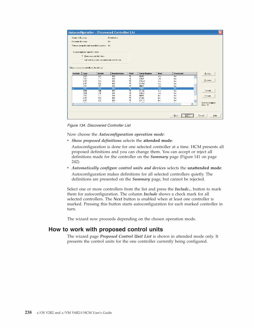
Now choose the Autoconfiguration operation mode:v Show proposed definitions selects the attended mode:
Autoconfiguration is done for one selected controller at a time. HCM presents allproposed definitions and you can change them. You can accept or reject alldefinitions made for the controller on the Summary page (Figure 141 on page242).
v Automatically configure control units and devices selects the unattended mode:Autoconfiguration makes definitions for all selected controllers quietly. Thedefinitions are presented on the Summary page, but cannot be rejected.
Select one or more controllers from the list and press the Include... button to markthem for autoconfiguration. The column Include shows a check mark for allselected controllers. The Next button is enabled when at least one controller ismarked. Pressing this button starts autoconfiguration for each marked controller inturn.
The wizard now proceeds depending on the chosen operation mode.
How to work with proposed control unitsThe wizard page Proposed Control Unit List is shown in attended mode only. Itpresents the control units for the one controller currently being configured.
Figure 134. Discovered Controller List
238 z/OS V2R2 and z/VM V6R2.0 HCM User's Guide

You can include or exclude control units from definition in the IODF. You can alsoedit control units by pressing the Edit... button, with a single control unit selected.
Press the Next button on the Proposed Control Unit List to proceed to theProposed Device List (Figure 137 on page 240).
How to work with proposed devicesThe wizard page Proposed Device List is shown in attended mode only. It presentsthe device ranges for the one controller currently being configured.
Figure 135. Proposed Control Unit List
Figure 136. Edit Proposed Control Unit
Chapter 9. Utilities 239

You can include or exclude device ranges from definition in the IODF. You can alsoedit device ranges by pressing the Edit... button, with a single range selected.
Press the Next button on the the Proposed Device List to proceed to the Summarypage (Figure 141 on page 242).
How to apply your own numbering scheme for PAV devicesIf you work with PAV base and alias devices, you can let I/O Autoconfigurationassign device numbers according to a scheme as specified with theAUTO_SS_DEVNUM_SCHEME autoconfiguration policy. For details about theoffered schemes, you can press the ? buttons in the Autoconfiguration Policiesdialog, or refer to the z/OS HCD User's Guide.
However, if you set this policy to NONE, I/O Autoconfiguration offers you dialogsto assign your own numbering to the discovered control units and devices. Fromthe Discovered Controller List, I/O Autoconfiguration first navigates to the MapProposed Control Units (Figure 139 on page 241) where you assign your
Figure 137. Proposed Device List
Figure 138. Edit Proposed Devices
240 z/OS V2R2 and z/VM V6R2.0 HCM User's Guide

appropriate control unit numbers.
If you work in attended mode, pressing the Next button navigates to the ProposedControl Unit List which reflects your assigned numbers. You have the opportunityto edit the shown values as described in “How to work with proposed controlunits” on page 238.
In attended mode, I/O Autoconfiguration proceeds to the Map Proposed Devicesdialog (Figure 140) where you now can assign appropriate device numbers.
If you work in attended mode, pressing the Next button navigates to the ProposedDevice List which reflects your assigned numbers. You have the opportunity toedit the shown values as described in “How to work with proposed devices” onpage 239.
Figure 139. Map Proposed Control Units
Figure 140. Map Proposed Devices
Chapter 9. Utilities 241

How to work on the Summary pageThe Summary page is shown in both operation modes:v In attended mode, it shows the definitions made for the current controller only,
and you can reject them.v In unattended mode, it shows the definitions made for all controllers. You
cannot reject them.
Both buttons, Accept and Reject, lead back to the Discovered Controller List(Figure 134 on page 238). The column Processed in the controller list shows whichcontrollers were configured (and accepted). The check mark in column Include iscleared for configured controllers. In attended mode, this happens for onecontroller at a time.
You can now either:v mark further controllers for autoconfiguration and press the Next button, orv leave the wizard using the Close button.
How to define autoconfiguration policiesMany aspects of autoconfiguration are determined by user-defined policies. To editthem, press the Policies... button on the Autoconfiguration - Options page(Figure 133 on page 237). This invokes the Autoconfiguration Policies dialogshown in Figure 142 on page 243.
Figure 141. Autoconfiguration - Summary (excerpt)
242 z/OS V2R2 and z/VM V6R2.0 HCM User's Guide

On the Profile Options tab of this dialog, you can edit policies represented byentries in the HCD profile. To see all available policy keywords, scroll down to theend of the list. For details on the effect of these policies, you can press the ?buttons or refer to the z/OS HCD User's Guide for an explanation of this keyword.
For keywords that you may specify multiple times with different values, like forexample, AUTO_CHPID_EXCLUDE, the dialog provides actions Add (button with the +sign) and Remove (button with the - sign) to insert or delete policy entries.
On the LP Groups tab of this dialog, you can add, edit, or delete named logicalpartition groups. LP groups are stored in the IODF. They determine to whichpartitions discovered devices are defined.
The buttons Add, Copy or Edit open the respective dialogs. These dialogs all havethe same layout. They allow you to assign or remove partitions from a group justby clicking the respective button. You can filter the list of unassigned partitions byprocessor ID.
Figure 142. Autoconfiguration Policies
Figure 143. Autoconfiguration Policies - LP Groups
Chapter 9. Utilities 243

On the OS Groups tab of this dialog, you can add, edit, or delete named operatingsystem groups. OS groups are also stored in the IODF. They determine to whichoperating systems discovered devices are defined.
Working with OS groups is very similar to working with LP groups. Figure 146 onpage 245 shows an example for editing an OS group.
Figure 144. Add LP Group
Figure 145. Autoconfiguration Policies - OS Groups
244 z/OS V2R2 and z/VM V6R2.0 HCM User's Guide

How changed control units may affect HCMDuring I/O Autoconfiguration, HCM may change definitions of existing controlunits. For example, all control units of an existing controller may have their typechanged from 2105 to 2107.
This does not change the physical label of the controller. For example, thecontroller may have had an automatically generated physical label 2105 #1. Even ifall contained control units change their type from 2105 to 2107, the physical labelof the controller remains unchanged.
This is the same behavior as performed by resynchronization. HCM can, ingeneral, not reliably tell whether a physical label was generated or user-defined.
Also, the physical description file (PDF) associated with the controller is notchanged in this case. HCM cannot reliably tell whether, for example, the DS8000PDF file would be more appropriate, because users may have adapted the existingphysical description manually to match their needs.
Moving port connectionsThis utility allows moving port connections. In particular, you can move completeCHPID-to-control-unit connections that have a path through an ESCON or FICONswitch from one switch to another, or rearranging those connections on a singleswitch. Using this utility, you no longer have to manually disconnect and connectthe involved objects.
When moving port connections using the utility, the following data isautomatically updated:v Link address of affected control unitsv Dynamic switch parameter of the affected CHPIDs
Figure 146. Edit OS Group
Chapter 9. Utilities 245

v Port configurations of source and target port when moving within the sameswitch
You can only move ports that are connected to another object.
When you move a port connection to another switch, note that all otherconnections that are implied by this move are also moved. That is, in addition tothe selected CHPID-to-control-unit connection, HCM also moves all connectionsthat are required to keep the logical definitions between CHPIDs and control unitsvalid. For example, moving a CHPID from switch A to switch B implies a move ofthe control unit connections that are serviced by that CHPID and, furthermore, allCHPIDs that have access to those control units via switch A. See “Implied ports”on page 247 for an example of implied ports.
Since a move of one port connection may imply a move of several other portconnections, be aware that there might not be enough empty ports available on thetarget switch.
You cannot move port FE if this port is the switch control unit port of the switchof interest. Therefore, if port FE is implied in a port move, the move cannot beperformed. You first have to disconnect port FE by disconnecting the internalcontrol unit from the related CHPIDs.
If you move a port connection on the same switch, all port matrices are updatedaccordingly. If you move a port to another switch neither the target port matricesnor the source port matrices are updated. You have to manually update yoursource and target configurations.
If a port or connection, which is involved in the move, has a logical or physicalinconsistency, the move will not be allowed. For example, a control unit has a linkaddress to a port but physically the control unit is not available. If this is the case,a move that involves this port is not allowed. See “Receiving visual warnings” onpage 45 for more information about physical inconsistencies.
The following example explains that moving a port connection might imply thatother port connections also need to be moved. Assume, you want to move CHPID21 that connects to port C1 to another switch in the following example.
246 z/OS V2R2 and z/VM V6R2.0 HCM User's Guide

Assume a CHPID 21 connected to a port C1 has a path to two control units thatare connected to port D1 and D2. Furthermore, the control unit of port D2 is alsoserviced by a CHPID 22 connected to port C2. When you want to move port C1with its connections, the utility will also automatically move ports D1, D2, and C2to the target switch.
Implied ports
ProcedureThe utility guides you through the following steps:1. Select Move Port Connections... from the Utilities menu.2. Select a switch as target.3. Choose one or more ports whose connections you want to move to the target
switch. The ports may be from any switch, including the target switch.4. Choose ports on the target switch for all ports to be moved.5. Before you finish the moving of port connections, a list shows you all changes
that will be made. Save this list and finish the move.
Aggregating CHPIDsThis utility allows you to combine attachments of several CHPIDs onto a singleCHPID. That is, all control units connected to the source CHPIDs will bedisconnected from the source CHPIDs and connected to a target CHPID.
All the CHPIDs should be connected to the same switch and use the samedynamic switch.
When you aggregate CHPIDs, HCM does not change the reachability of devices bylogical partitions (LPARs). The LPARs in the access or candidate list of the sourceCHPID must be a subset or equal the LPARs in the access or candidate list of thetarget CHPID. If the target CHPID is shared and the LPARs in the access or
Figure 147. Example for Implied Ports
Chapter 9. Utilities 247

candidate list of the CHPIDs to be aggregated are a subset of the LPARs in theaccess or candidate list of the target CHPID, then an explicit device candidate listwill be built. When the device already had an explicit device candidate list, it willbe left unchanged.
If a CHPID was involved in a CTC connection, all CTC control units connected tothe CHPID entry port are moved to the CHPID entry port of the target switch. TheCU link addresses are updated accordingly to create valid CTC connections.
The utility guides you through the following steps:1. Select Aggregate CHPIDs... from the Utilities menu.2. Choose a CHPID as the target and press Next.3. Choose one or more CHPIDs to aggregate with the target CHPID.4. Before you finish the aggregation of CHPIDs, a list shows you all changes that
will be made. Save this list and finish the aggregation.
Converting CNC channels to FICON channelsThis utility supports you in making the necessary I/O configuration changes whenyou install a new FICON bridge card on an ESCON switch. Before you can start aconversion, the following prerequisites must be met:v You can only convert a CHPID that is already connected to a port and defined
as type CNC or FCV. If the CHPID is CNC, it must be eligible to be an FCVchannel. HCM automatically performs a CHPID type change.
v The ESCON port that connects to the CHPID must be FCV eligible.
HCM checks whether the correct number of unconnected port addresses follow theESCON port that connects to the new channel. If the installation of the new cardcauses a conflict with already connected ports, HCM initiates moving of theaffected ports or aggregating CHPID-to-control-unit definitions. Refer to thedescription of the wizards “Moving port connections” on page 245 and“Aggregating CHPIDs” on page 247 for considerations on those subjects.
The utility guides you through the following steps:1. Select Convert ESCON Port to FC Port... from the Utilities menu.2. Choose an ESCON port that is FCV eligible and already connected to a CNC or
FCV channel.3. A dialog appears that lets you aggregate source CHPIDs to a target CHPID.
Refer to “Aggregating CHPIDs” on page 247 for an example on things toconsider when aggregating CHPIDs.
4. If some of the switch ports displaced by the fiber channel port were previouslyconnected, you are prompted to move the required port. Refer to “Moving portconnections” on page 245 for an example on things to consider when movingports.
5. Before you finish the conversion, a list shows you all changes that will bemade. Save this list and finish the conversion.
See “Scenario IV – Configuration changes for installing a FICON bridge card in a9032–5 ESCON director” on page 340 for an example of the use of this utility.
248 z/OS V2R2 and z/VM V6R2.0 HCM User's Guide

Priming the IODF with sensed dataThis utility allows you to save sensed data such as serial numbers and volumeserial numbers (VOLSER) into the IODF. Before you can start working with thiswizard, data must first be sensed. To do this, use the 'Sense' command from theOperations menu to populate the configuration with sensed data. A prerequisite forthis wizard is the availability of the I/O Operations functions; otherwise, sensingof data is not possible.
Note:
The I/O Operations functions are not available if your system is running as a hostunder z/VM.
The utility guides you through the following steps:1. Choose the set of IODF serial numbers (on processors, switches, control units
and devices) that will be updated with the sensed serial number value.2. Choose the set of IODF VOLSERs that will be updated with the sensed
VOLSER value.3. Examine a summary of the sensed data that is to be updated. Before you finish
the utility, you can save the list of changes. Click 'Finish' to perform theoperation you selected in the previous steps.
Data which has been sensed can be deleted later by selecting Clear PreviousSensing Data in the Sense submenu of the Operations menu.
Changing the CHPID link address formatThis utility allows you to modify the link address format for FC channel paths.Starting with a specific processor support level for the 2064 processor family, thechannel paths support the definition of two–byte link addresses. Using this utility,you can explicitly upgrade one–byte link addresses for a selected FC channel pathto two–byte link addresses. Similarly, you can also downgrade two–byte linkaddresses for a selected FC channel path to one–byte link addresses. Rememberthat no link address format mix is allowed for FC channel paths, that means allconnections are defined either via one–byte link addresses or two–byte linkaddresses.
The utility guides you through the following steps:1. Choose whether to convert one–byte link addresses into two–byte link
addresses or vice versa.2. Select the CHPID(s) for which the link address format has to be converted.3. Examine the summary of modified link addresses.
Before you finish the utility, you can save the list of changes. Click Finish toperform the operation you selected in the previous steps.
Creating/Copying/Editing an I/O subsystemHCM offers utilities that allow you to create, copy or edit an I/O subsystemconsisting of:v controllers (with segments and control units) andv strings (with devices).
Chapter 9. Utilities 249

If you use the Create I/O Subsystem or Copy I/O Subsystem utility, you select thecontroller model as the first step:v If you select a PDF as your controller model, a new I/O subsystem is created on
base of the selected controller-PDF.v If you select a certain controller as the controller model, a new I/O subsystem is
created as a copy on base of the selected controller.
InvocationYou can invoke the utilities in the following ways:v using the Copy I/O Subsystem... or Edit I/O Subsystem... choices from a
controller's context menuv using the I/O Subsystem... pull-down choice from the Create menu bar choice
Using the utility to create an I/O subsystemThe utility guides you through the following steps:1. Set Controller Attributes and Subsystem Type: Select a controller or a
controller's physical description file (PDF). You can define a label prefix for thecontroller, and, if applicable, the number of controllers within the I/Osubsystem.
2. Add control units: Attributes for control units consist of type, number,subsystem identifier (SSID), offset between subsequent CU numbers, serial CUnumber, and description.
3. Connect control units: Connect control units to controllers (and theirsegments).
4. Define strings: Select a string PDF (based on a selected type). Set the followingattributes: number of devices inside string, starting device number, offsetbetween subsequent device numbers, label prefix, and description.
5. Connect string interfaces: Connect string interfaces and controller deviceinterfaces. Selectable interfaces are based on the settings made in steps 1 and 4.
6. Connect strings: Connect strings and control units. Selectable objects are basedon the settings made in steps 3 and 5.
Using the utility to copy an I/O subsystemWith this utility you can also copy an existing I/O subsystem with its topology.That is, the utility duplicates the quantity and attributes of contained control units,the quantity and attributes of strings (with devices), and the connections betweencontained objects.
The utility guides you through the following steps:1. Set Controller Attributes and Subsystem Type: Select an existing controller.
To create a valid new I/O subsystem, you must change the CU numbers(which must be unique in a valid configuration). Also, you can change otherI/O subsystem attributes (like a controller's serial number or subsystemidentifier (SSID), a string's label and I/O device IDs). The utility supports youin globally changing CU numbers and I/O device IDs via specification of anew first CU number and I/O device ID. All other CU numbers and I/Odevice IDs are changed according to the original topology (That means, that theoriginal gaps between the values will remain).
2. Add control units: Accept or change the generated new control unit numbers.The utility may issue a message on the current page if you must changepossibly invalid control unit numbers before continuing.
250 z/OS V2R2 and z/VM V6R2.0 HCM User's Guide

3. The rest of the steps of the copy functionality are similar to steps 3 on page 250through 6 on page 250 from the create functionality. However, they provideonly information about the topology that the copied I/O subsystem will have,and no updates are possible.
Using the utility to edit an I/O subsystemTo ease the task of modifying an existing I/O subsystem consisting of manycontrol units and devices, HCM offers an Edit I/O Subsystem wizard which youcan invoke from a controller's context menu. This wizard lets a user performsimilar actions in a single step when upgrading a controller. For example, it letsthe user, in a single work unit, increase the number of control units, strings, anddevices, and change the object topology inside the I/O subsystem.
This utility guides you through the same steps as the Copy I/O Subsystem utility,allowing you to apply the desired appropriate changes in each step.
Exporting IOCP or I/O configuration statementsIn connected mode, you can use the dialog shown in Figure 148 on page 252 tocreate IOCP input data or I/O configuration statements for the currently accessedIODF. You can export the created output either into a data set on the host or into afile on the workstation.
Exporting IOCP input data is only available for accessed production IODFs. Youneed to select the processor for which you want to build the IOCP input file. Intothe Title field, enter the identification information you want to be written on thefirst header line of the IOCP input file. Also, you need to specify whether to buildthe IOCP input file for stand-alone IOCP or for batch IOCP.
For exporting I/O configuration statements, you can select which type ofconfiguration statements the data set or file should contain, namely either:v for a processor configuration,v for an OS configuration, orv for a switch configuration.
Note: This HCM dialog offers the same services as the functionality implementedin HCD on the host. For detailed information required to fill the HCM dialogs,either refer to the HCM online help or to the topic Build an IOCP input data setin z/OS HCD User's Guide.
Chapter 9. Utilities 251

Importing I/O configuration statementsIn connected mode, you can use the dialog shown in Figure 149 on page 253 toimport/migrate I/O configuration statements or IOCP input data into an IODF.You can select whether the specified input data will be taken from the host or fromthe workstation.
To display this dialog, choose IODFs from the File menu to open the IODFsdialog. Select the work IODF to which you want to migrate your input data andclick the Import button in the Cfg. Statements section.
Note:
1. This HCM dialog offers the same services as the functionality implemented inHCD on the host. For detailed information required to fill the HCM dialogs,either refer to the HCM online help or to the topic Migrating input data setsusing the HCD dialog in z/OS HCD User's Guide.
2. This task just changes the IODF on the host without updating the associatedHCM configuration file accordingly. Therefore, HCM will perform aresynchronization when opening the configuration the next time.
Figure 148. Export IOCP or I/O Configuration Statements
252 z/OS V2R2 and z/VM V6R2.0 HCM User's Guide
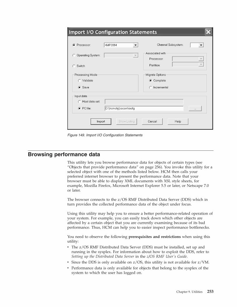
Browsing performance dataThis utility lets you browse performance data for objects of certain types (see“Objects that provide performance data” on page 256). You invoke this utility for aselected object with one of the methods listed below. HCM then calls yourpreferred internet browser to present the performance data. Note that yourbrowser must be able to display XML documents with XSL style sheets, forexample, Mozilla Firefox, Microsoft Internet Explorer 5.5 or later, or Netscape 7.0or later.
The browser connects to the z/OS RMF Distributed Data Server (DDS) which inturn provides the collected performance data of the object under focus.
Using this utility may help you to ensure a better performance-related operation ofyour system. For example, you can easily track down which other objects areaffected by a certain object that you are currently examining because of its badperformance. Thus, HCM can help you to easier inspect performance bottlenecks.
You need to observe the following prerequisites and restrictions when using thisutility:v The z/OS RMF Distributed Data Server (DDS) must be installed, set up and
running in the sysplex. For information about how to exploit the DDS, refer toSetting up the Distributed Data Server in the z/OS RMF User's Guide.
v Since the DDS is only available on z/OS, this utility is not available for z/VM.v Performance data is only available for objects that belong to the sysplex of the
system to which the user has logged on.
Figure 149. Import I/O Configuration Statements
Chapter 9. Utilities 253

Note: It is recommended to focus your current view to the active sysplex: Openthe Change View Attributes dialog ( see “Filtering your view” on page 34) andclick the Active Sysplex check box.
v The loaded HCM configuration file/IODF should describe the current sysplexcomprising the system to which you logged on.
v You cannot browse performance data in stand-alone mode.
You have the following alternatives for accessing an object's performance data:
Alternative 1:
You can directly access performance data of a selected object as described in thefollowing:v Use the Performance... choice from an object's context menu where applicable,
for example, from a processor's context menu.v Use the Performance... button from an object's dialog where applicable, for
example, from the CHPID dialog.
However, from the opened browser windows, you cannot navigate to childresources.
Alternative 2:
You can also use the Browse Performance Data... pull-down choice of the Utilitiesmenu bar choice. This choice opens the web browser which offers the followingnavigation features:v You can retrieve performance metrics for the sysplex as a whole.v You can step down the hierarchy of objects in the sysplex and retrieve metrics
for available child objects of the sysplex, for example, the capacity or free spacefor a certain I/O device (volume) defined for a certain operating system (MVSimage), or the percentage of used capacity for a logical partition. In the row thatshows the resource object that you want to examine, click on Metrics.
v On all browser windows in this hierarchy, you can also view attributes of thelisted objects by clicking on the entry in column Attributes for an object.
As an example, let us assume you want to view performance data of a 2094processor in your sysplex: Open the Processor dialog for this processor and pressthe Performance... button. A browser window showing the available metrics forthis processor opens:
254 z/OS V2R2 and z/VM V6R2.0 HCM User's Guide

If you want to understand the meaning of a metric, click on Explanation in theHelp column.
If you want to know the total utilization of the physical standard processors by thepartitions in the CPC, click on % total physical utilization (CP) by partition. Clickingon this metric opens another view presenting the desired results, in our example, alist of partitions, showing the percentage of utilization for each (Figure 151 on page256).
Figure 150. Available performance data for a processor
Chapter 9. Utilities 255

Note: If you run into problems when trying to access this utility, look for help in“Problems when using the RMF DDS” on page 412.
Objects that provide performance dataHCM can show performance data for the following objects. Depending on the DDSsetup, a TSO user ID and password is required to access the RMF data. Otherwise,no further user interaction is necessary.v
Processor:
HCM displays information about CPCs and their contained LPARs.v
Partition:
Partition metrics may be related to the partition as a hardware object, or to theOS image running in the current partition. Therefore, you must choose thecategory for which you want the performance data. For this purpose, HCMdisplays the Partition Performance Data dialog to let you specify the RMFresource type and category for which performance data shall be displayed.In the example of Figure 152 on page 257, the user wants to get metrics from allvolumes defined to the OS running in the current partition.
Figure 151. Total utilization of the processors by partitions
256 z/OS V2R2 and z/VM V6R2.0 HCM User's Guide

v
CHPID:
A CHPID may be accessible by one or more partitions as defined in their accessand candidate lists. If you want to see metrics for a selected CHPID, you mustspecify one of these partitions. For this purpose, HCM displays the PartitionRelated Performance Data dialog. If only one partition can access the currentCHPID, this dialog is omitted.
Figure 152. Partition performance data
Chapter 9. Utilities 257

v
Control Unit:
RMF has two different resource types that correspond to a control unit: asubsystem identifier (SSID) identifies the control unit as a hardware object and alogical control unit (LCU) identifies it to the operating system. HCM lets youspecify which aspect of a control unit you want to monitor:
If no SSID is specified for the control unit, this dialog is omitted.As a control unit may be related to more than one partition, you need to selectone of these. For this purpose, as for CHPIDs, HCM displays the PartitionRelated Performance Data (see Figure 153). If only one partition can access thecurrent control unit, this dialog is omitted.
v
Devices:
HCM provides performance data for DASD volumes only.If more than one partition can access the device, HCM displays the PartitionRelated Performance Data dialog to let you select one of these (see Figure 153).
Figure 153. Partition related performance data
Figure 154. Specify RMF resource type
258 z/OS V2R2 and z/VM V6R2.0 HCM User's Guide

Using the WWPN Prediction Tool SupportThis utility allows you to export the FCP channel/device specific data of the I/Oconfiguration from the currently accessed IODF into a file with comma-separatedvalue (CSV) output format. The generated file can be used as input to the WWPNPrediction Tool to assign world-wide port names to virtualized FCP ports forconfiguring SAN devices.
You can invoke the WWPN Prediction Tool Support utility from the Utilities menuor from the Edit Processor dialog pressing the WPT... button.
The utility helps you to perform the following tasks:1. Export FCP data from a selected processor into a specified output file2. Launch the WWPN Prediction Tool using a specified input file which is usually
the one that you created in step 1. This task is only enabled if the WWPNPrediction Tool is installed on your workstation.
After launching, the WWPN Prediction Tool can be used to assign WWPN valuesto paths between CHPIDs and devices. It returns:v The .CSV file, updated with WWPNs, which can be imported by an SAN
Manager to configure SAN devices in a fabric.v A binary definition file, which can be transferred to the support element to be
stored into the HSA for the next IML.
Figure 155. WWPN Prediction Tool Support
Chapter 9. Utilities 259

260 z/OS V2R2 and z/VM V6R2.0 HCM User's Guide
Chapter 10. Operating system configurations
Each device can be defined to one or more operating systems. The hardwareconfiguration contains this definition information, known as the operating system(OS) configuration. Note that you may define devices and their associatedparameters to an OS configuration, even if they are not explicitly connected.
Typically, the OS configuration is associated with a processor or partition. Eachprocessor can run different OS configurations at different times. There are twotypes of OS configuration: MVS and VM.
An MVS OS configuration can contain one or more EDTs. An Eligible Device Table orEDT is a list of esoteric device groups, plus the names of the generic device typeswhich determine how devices are used (order of preference) within each esoteric.The EDT is identified by a two-digit ID; you must define at least one EDT for eachMVS OS configuration.
An esoteric device group or esoteric is an installation-defined and named grouping ofI/O devices under an EDT. An esoteric acts as a single “virtual device” which canbe allocated without using a specific device number. Devices within an esoteric areusually from the same device group, but can be of different device types.
Every device type is associated with a generic device group or generic. A generic is anMVS-defined grouping of devices with similar characteristics, which determineshow devices are used in an esoteric device group. Each generic has a preferencenumber which governs the order of allocation of devices to jobs within an esoteric.For example, if the esoteric contains the device types 3390, 3380 and 3350, and thegenerics associated with the device types have preference numbers 280, 290 and300, respectively, then the preference numbers are used by the MVS allocationcomponent to assign the devices in that order of preference.
Faster devices have lower preference numbers. You can change the preferencenumber of a generic under an EDT (user-defined generic), but not under an OSconfiguration (system-defined generic).
You can mark one or more of the devices defined to an OS configuration to beyour consoles. A console displays system-related information (for example, errormessages) directly from MVS. For the MVS system, you can specify NIP consoles;for z/VM, you can specify primary and alternative VM consoles.
Note:
Under z/VM, you can only view z/OS IODFs, but you cannot define z/OSoperation system configurations.
Listing the OS configuration-EDT-esoteric hierarchyOpen the Operating System Configuration dialog by choosing OSconfigurations... from the Edit menu. The list box contains all OS configurations,EDTs and esoterics in a hierarchy in alphabetical order. You can double-click on anOS configuration (MVS only) with a plus (+) sign to display its EDTs; double-click
© Copyright IBM Corp. 1995, 2016 261

on an EDT with a plus (+) sign to display its esoteric device groups. Double-clickon an item with a minus (-) sign to close it. Double-clicking on an esoteric opensthe List Devices for Esoteric dialog.
The static text fields below the list box display information for the item currentlyselected in the list box. If an OS configuration is selected, its name, type anddescription are displayed. If an EDT is selected, its ID, parent OS configuration,description, time of last update, and updating user name are displayed. If anesoteric is selected, its name, parent OS configuration, state, token, andVIO-eligibility are displayed. The name of an esoteric follows the EE.SSSSSSSSformat, where EE is the EDT name and SSSSSSSS is the esoteric name. The state ofan esoteric can be one of the following:v no devices
v has devices
v no-DASD devices but VIO=YES
You can access almost every dialog dealing with OS configuration from theOperating System Configuration dialog. You can create or edit OS configurations,EDTs or esoterics, as well as list and/or edit generics, consoles or the devicesdefined to the OS configuration or esoteric.
Creating an OS configurationOpen the Create Operating System Configuration dialog by pressing the CreateOS Config... button in the Operating System Configurations dialog. Fill in thename, type, and description of the OS configuration and press OK; the new OSconfiguration appears in the Operating System Configurations dialog box. Afteryou have created an MVS OS configuration, you can add EDTs and esoteric devicegroups under it, as well as define devices to it.
Figure 156. Operating System Configurations dialog
262 z/OS V2R2 and z/VM V6R2.0 HCM User's Guide

D/R site OS configurationsYou can optionally type the name of a disaster recovery (D/R) site operatingsystem configuration into the OS config name for D/R site field. You need a D/Rsite OS configuration in a GDPS managed environment, where storage devices aremirrored over peer-to-peer remote copy (PPRC) connections in order to have abackup system defined for an emergency situation.
During the Build production IODF task, the named D/R site OS configuration isautomatically created as copy of the primary OS configuration. The resulting OSconfiguration is called generated OS configuration. It has all DASD devices, thatare classified by PPRC usage type DUPLEX, attached with reversed OFFLINEparameter value. That is, if the primary OS configuration specifies OFFLINE=NO,the D/R site OS configuration attaches the devices with OFFLINE=YES and viceversa.
Following rules apply to generated D/R site OS configurations:v A generated OS configuration is re-created with every Build production IODF
from its primary OS configuration.v With any kind of changes done to a D/R site OS configuration, (for example,
modifying device-to-operating-system-relations, or changing EDT definitions), itloses its generated status. It is not automatically re-created with the next Buildproduction IODF, so that the user modifications are preserved. To let it generateagain from the primary site OS configuration, you must delete the modifiedD/R site OS configuration first.However, changing the description of a D/R site OS configuration does notchange its generated status.
v You cannot specify the name of a D/R site OS configuration for a generated OSconfiguration.
The generated status of an OS configuration is indicated in the Operating SystemConfigurations dialog (Figure 156 on page 262).
Editing an OS configurationSelect an OS configuration and press the Edit... button in the Operating SystemConfigurations dialog. The Edit Operating System Configuration dialog appears.Edit the description and press OK.
Figure 157. Create Operating System Configuration
Chapter 10. Operating system configurations 263

Copying an OS configurationHCM offers a Copy Operating System Configuration wizard to let you copy asource operating system configuration to a new target operating systemconfiguration. All EDT definitions (and their esoterics) of the source and all deviceconnections are copied to the target OS configuration.
You can invoke this wizard from the Copy... button in the Operating SystemConfigurations dialog (which you reach by selecting OS Configurations... fromthe Edit menu bar choice).
You only need to specify the name and optionally a description for the target OSconfiguration. You cannot change the type of the source OS configuration.
Deleting an OS configurationSelect the OS configuration in the list box and press the Delete button in theOperating System Configurations dialog. HCM will display a confirmation dialogbefore deleting the OS configuration.
Listing devices for an OS configurationOpen the List Devices for OS Configuration dialog by selecting an OSconfiguration and pressing the I/O Devices... button in the Operating SystemConfigurations dialog. This dialog displays all the devices defined for the selectedOS configuration. Groups of consecutive device numbers appear on one line eachwith a plus (+) sign. Double-click on a device group with a plus (+) sign to displayeach device on its own line. Double-click on a device range with a minus (-) signto contract it. Note that the information about a device group line applies only tothe first device in the group. Other devices in the group may have column valuesthat differ from the first device. To see the column values for individual devices,double-click on the plus sign.
You can display the parameters, attached control units, serial numbers ordescriptions for the devices by choosing the appropriate View option. If youchoose the Parameters view radio button, you can select which parameters todisplay from the Show Parameters / Features as Columns dialog. Open this dialogby pressing the Columns... button. Add or remove parameters or features to orfrom the Exclude and Include list boxes. Default parameters displayed for z/OSoperating systems are DYNAMIC and OFFLINE, those displayed for z/VMoperating systems are UIRATE and OFFLINE.
You can also choose to restrict the number of devices in the Devices list box byclicking in the Use Filter check box, and then selecting a set of filters from theFilter I/O Device List dialog (press the Filter... button to open the dialog). Deviceswhich appear in the list box match all the filtering criteria that you set in thisdialog. You can set the device type, class, serial number, or description; connected,unconnected, or specific control units; and/or the processor or partition. TheParameters / Features section at the bottom of the filtering dialog shows onlythose parameters or features selected in the Show Parameters / Features dialogwhich you can use as filtering criteria. (The Parameters / Features section appearsonly when the filtering dialog is called from the List Devices for an OSConfiguration dialog).
264 z/OS V2R2 and z/VM V6R2.0 HCM User's Guide

Note:
1. Using the Save As... button, you can save the list of devices into a text file. Thissaved file contains all information about the devices, whereas in the dialog, atmost five device parameters are visible at a time.
2. An '*' in column SCHS behind the subchannel set ID for a group of devicesdesignates that not all devices of this group are defined in the same subchannelset for the current operating system. Double - click on the plus (+) sign in frontof the device group to see the settings for the individual devices.
Adding devices to an OS configurationYou can define devices to the selected OS configuration. In the List Devices for anOS Configuration dialog, press the Add... button to open the Add I/O Devices toOS Configuration dialog.
The list box in this dialog shows all devices defined in the IODF which are notcurrently defined to the selected OS configuration, and which match the currentfilter (if enabled). Groups of consecutive device numbers appear on one line eachwith a plus (+) sign. Double-click on a device range with a plus (+) sign to expandit to display each device on its own line. Double-click on a device range with aminus (-) sign to contract it. Note that the information about a device group lineapplies only to the first device in the group. Therefore, other devices in the groupmay have column values that differ from the first device. To see the column valuesfor individual devices, these entries must be expanded.
Select one or more devices and press OK to add them to the OS configuration.Alternatively, double-click on the device. The Define Device <=> OSConfiguration Parameters dialog appears, to allow you to update the parametersdefining the connection between the device and the OS configuration. If you haveselected more than one device, the parameters dialog appears only once, but any
Figure 158. List Devices for OS Configuration dialog
Chapter 10. Operating system configurations 265

changes made to parameters apply to all selected devices. For more details, see“Editing device <=> OS configuration parameters.”
You can determine what device information appears in the list box by selecting oneof the View options: connected control units, device descriptions, or serialnumbers. You can also choose to restrict the number of devices which appear inthe list box by using the filtering option (see “Listing devices for an OSconfiguration” on page 264 for more details on filtering).
Note that an Operating Systems section appears at the bottom of the Filter I/ODevice List dialog only when the dialog is called from the Add I/O Devices to OSConfigurations dialog. If you select the No OS Filtering option, all devices matchand are displayed in the list box; if you select Not Defined, a device will match thecriterion if it is not defined to any OS configuration. If you select Defined, a devicewill match if it is defined to any OS configuration.
Removing devices from an OS configurationIn the List Devices for OS Configuration dialog, select one or more devices andpress the Remove button. HCM displays a confirmation dialog beforedisconnecting the selected device(s) from the OS configuration.
Editing device <=> OS configuration parametersSelect one or more devices from the list box in the List Devices for OSConfiguration dialog (Figure 158 on page 265), and press either the Edit... orGroup Edit... button to open the Define Device <=> OS ConfigurationParameters dialog (Figure 160 on page 267). You can then modify the parameterswhich define the selected device(s) to the OS configuration. Note that you can use
Figure 159. Add I/O Devices to OS Configuration dialog
266 z/OS V2R2 and z/VM V6R2.0 HCM User's Guide

the Group Edit... button only for selected devices of the same device type. HCMdisplays an error message if the selected devices are of different types, becausethey would be incompatible for a group edit. Also note that an '*' left to aparameter name indicates that this parameter value is not the same for all devicesin a group.
If you select more than one device and press Edit..., the parameters dialog appearsrepeatedly, once for each device. If you selected more than one device and pressedGroup Edit..., the dialog appears only once, displaying the parameters for the firstselected device. Any changes affect all selected devices.
The checkboxes in column Update indicate whether the related parameter isupdated or not when you press the OK button. If the checkbox is selected, thenthis parameter gets updated for all selected devices. This allows you to select onlythose parameters which you want to update for a single device or a device group,while leaving all other parameters unchanged. For a device group, all devices getthe same updated value, even if the parameter value had not been the same for alldevices before (indicated by an *).
Column Update is not visible when the devices are initially added to the OSconfiguration.
You can also reach the parameters dialog from the Add I/O Devices to OSConfiguration dialog or the List Device <=> OS Configuration Definitionsdialog. See “Adding devices to an OS configuration” on page 265 or “Selecting OSconfigurations to which to define devices” on page 268 for more details.
The static text fields at the top of the Define Device <=> OS ConfigurationParameters dialog identify the device and OS configuration involved in theconnection. In the Parameters section below, each row of information contains theparameter name, value, whether it is required, and a description. You can updatethe value of a parameter by selecting one from the drop down box, typing in a textbox, or clicking in a check box, as appropriate. To get a more detailed explanationof a parameter ’ >s> meaning, click on the “?” button on its row.
In the field Subchannel Set ID you must specify the ID of the subchannel set whereyou want to put the devices. You must set this field to '0' for all devices that arenot eligible for alternative subchannel sets.
Figure 160. Define Device <=> OS Configuration Parameters dialog
Chapter 10. Operating system configurations 267

Listing OS configurations to which devices are definedYou can select one or more devices and list the OS configurations to which thosedevices are defined. Open the I/O Device List dialog by clicking on the I/ODevices... button in the String dialog to display all devices for a selected string.Alternatively, click on the I/O Devices... button in the Control Unit List dialog(which is called from the Controller dialog) to display all devices for a selectedcontrol unit.
Select a device(s) from the I/O Device List dialog and press the OS Configs...button to open the List Device <=> OS Configuration Definitions dialog. The listbox in this dialog displays all OS configurations available in the IODF. A checkmark under the “Defined” column indicates the selected device is defined to theOS configuration. If more than one device is selected, the check mark only appliesto the first device.
Selecting OS configurations to which to define devicesYou can select one or more OS configurations in the list box to define to theselected device(s). Press the Define... button to open the Define Device <=> OSConfiguration Parameters dialog. You can then update the parameters determiningthe device <=> OS configuration definition. See “Editing device <=> OSconfiguration parameters” on page 266 for more details on this dialog.
Selecting OS configurations from which to remove devicesSelect one or more OS configurations and press the Remove button. HCM displaysa confirmation dialog before removing the devices selected in the I/O Device Listdialog from all selected OS configurations.
Adding devices to an esoteric within the OS configurationSelect an OS configuration(s) and press the Esoterics... button to open the IncludeDevices in Esoterics dialog. In this dialog, you can include (or exclude) thedevices selected in the I/O Device List in esoteric device groups within theselected OS configuration. If you selected more than one OS configuration, the
Figure 161. List Device <=> OS Configuration Definitions dialog
268 z/OS V2R2 and z/VM V6R2.0 HCM User's Guide

esoterics dialog appears repeatedly, once for each selection.
Listing consoles for an OS configurationOpen the List Consoles dialog by selecting an OS configuration in the OperatingSystem Configurations dialog and pressing the Consoles... button. The list boxdisplays all the devices which have been marked as consoles for the selected OSconfiguration, organized by order number.
Adding a console to an OS configurationPress the Add... button in the List Consoles dialog to open the Add Consoledialog. You can then select a device to define as a console for the selected OSconfiguration. The drop down box displays all devices defined to the OSconfiguration which are eligible to be used as consoles.
Figure 162. Include Devices in Esoterics dialog
Figure 163. List Consoles dialog
Chapter 10. Operating system configurations 269
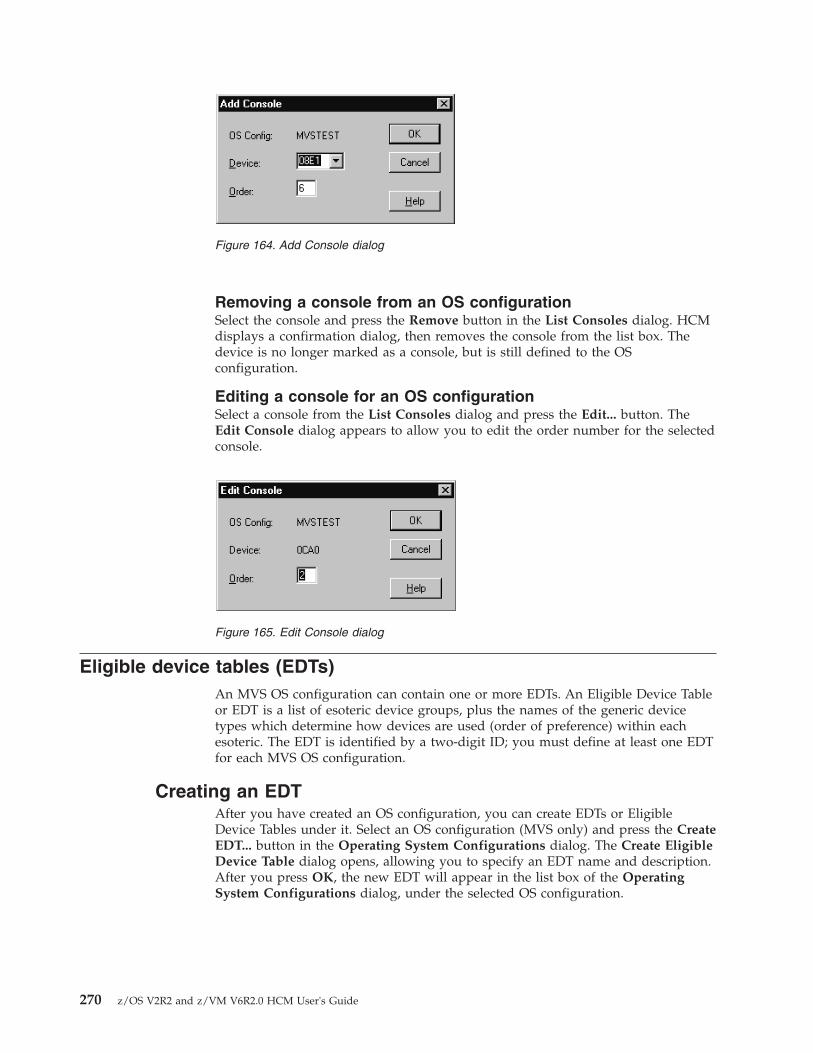
Removing a console from an OS configurationSelect the console and press the Remove button in the List Consoles dialog. HCMdisplays a confirmation dialog, then removes the console from the list box. Thedevice is no longer marked as a console, but is still defined to the OSconfiguration.
Editing a console for an OS configurationSelect a console from the List Consoles dialog and press the Edit... button. TheEdit Console dialog appears to allow you to edit the order number for the selectedconsole.
Eligible device tables (EDTs)An MVS OS configuration can contain one or more EDTs. An Eligible Device Tableor EDT is a list of esoteric device groups, plus the names of the generic devicetypes which determine how devices are used (order of preference) within eachesoteric. The EDT is identified by a two-digit ID; you must define at least one EDTfor each MVS OS configuration.
Creating an EDTAfter you have created an OS configuration, you can create EDTs or EligibleDevice Tables under it. Select an OS configuration (MVS only) and press the CreateEDT... button in the Operating System Configurations dialog. The Create EligibleDevice Table dialog opens, allowing you to specify an EDT name and description.After you press OK, the new EDT will appear in the list box of the OperatingSystem Configurations dialog, under the selected OS configuration.
Figure 164. Add Console dialog
Figure 165. Edit Console dialog
270 z/OS V2R2 and z/VM V6R2.0 HCM User's Guide

Editing an EDTSelect an EDT from the list box in the Operating System Configurations dialogand press the Edit... button. The Edit Eligible Device Table dialog appears,allowing you to edit the EDT description.
Copying an EDTHCM offers a Copy Eligible Device Table wizard to let you copy an EDT. Allesoteric device group definitions and all device connections of the source EDT arealso copied to the target EDT. The target EDT must not yet exist. It may be amember of the same or of a different OS configuration as the source EDT.
To invoke this wizard, open the Operating System Configurations dialog (whichyou reach by selecting OS Configurations... from the Edit menu bar choice). Thenselect an EDT and press the Copy... button.
To create the target EDT, the wizard queries the required information, which isbasically the same as when creating a new EDT:v the OS configuration to which it shall belongv the target EDT IDv and optionally a description.
Deleting an EDTSelect the EDT in the list box and press the Delete button in the Operating SystemConfigurations dialog. HCM will displays a confirmation dialog before deletingthe EDT.
Esoteric device groups (esoterics)An esoteric device group or esoteric is an installation-defined and named grouping ofI/O devices under an EDT. An esoteric acts as a single virtual device which can beallocated without using a specific device number. Devices within an esoteric areusually from the same device group, but can be of different device types.
Creating an esotericAfter you have created an OS configuration and EDT, you can add esoteric devicegroups. Open the Create Esoteric Device Group dialog by selecting an EDT andpressing the Create Esoteric... button in the Operating System Configurationsdialog. Fill in the name, token, and VIO eligibility. After you press OK, the newesoteric will appear in the list box of the Operating System Configurations dialog,
Figure 166. Create Eligible Device Table dialog
Chapter 10. Operating system configurations 271

under the selected OS configuration and EDT.
Editing an esotericSelect an esoteric from the list box in the Operating System Configurations dialogand press the Edit... button. The Edit Esoteric Device Group dialog appears,allowing you to edit the esoteric token and VIO eligibility.
Copying an esotericHCM offers a Copy Esoteric Device Group wizard. The target esoteric must notyet exist. It may be a member of the same or of a different EDT as the source.
The devices and device connections of the source esoteric are also copied.
To invoke this wizard, open the Operating System Configurations dialog (whichyou reach by selecting OS Configurations... from the Edit menu bar choice). Thenselect an esoteric device group and press the Copy... button.
To create the target esoteric, the wizard queries the following attributes, which arebasically the same as when creating a new esoteric device group (see also“Creating an esoteric” on page 271):v the name of the esoteric device groupv the esoteric tokenv and whether the VIO eligibility should be set to YES.
Deleting an esotericSelect the esoteric in the list box and press the Delete button in the OperatingSystem Configurations dialog. HCM displays a confirmation dialog beforedeleting the esoteric.
Listing devices for an esotericSelect an esoteric and press the I/O Devices... button in the Operating SystemConfigurations dialog. The List Devices for Esoteric dialog appears, allowing youto examine the devices defined for the selected esoteric. List box entries may beeither a single device or range of devices. Range entries use the format XXXX, YY,where XXXX is the first device number and YY indicates the number of devices inthe range. Double-click on a range with a plus (+) sign to expand it to display eachdevice on its own line. This allows you to delete some but not all of the devices inthe range. Double-click on a range with a minus (-) sign to collapse it.
Figure 167. Create Esoteric Device Group dialog
272 z/OS V2R2 and z/VM V6R2.0 HCM User's Guide

Adding devices to an esotericOpen the Add I/O Devices to Esoteric dialog by pressing the Add... button in theList Devices for Esoteric dialog. You can then select one or more devices from thelist box to add to the esoteric. The list box displays all devices currently defined tothe OS configuration which contains the esoteric, and which match the currentfilter (if enabled). Groups of consecutive device numbers appear on one line eachwith a plus (+) sign. Double-click on a device range with a plus (+) sign to expandit to display each device on its own line. Double-click on a device range with aminus (-) sign to contract it. Note that the information about a device group lineapplies only to the first device in the group. Therefore, other devices in the groupmay have column values that differ from the first device. To see the column valuesfor individual devices, these entries must be expanded.
You can determine what device information appears in the list box by selecting oneof the View options: connected control units, device descriptions, or serialnumbers. You can also choose to restrict the number of devices which appear inthe list box by using the filtering option (see “Listing devices for an OSconfiguration” on page 264 for more details on filtering).
Figure 168. List Devices for Esoteric dialog
Chapter 10. Operating system configurations 273

Removing devices from an esotericSelect one or more devices and press the Remove button in the List Devices forEsoteric dialog. HCM displays a confirmation dialog before disconnecting theselected device(s) from the esoteric.
Generic device groups (generics)Every device type is associated with a generic device group or generic. A generic is anMVS-defined grouping of devices with similar characteristics, which determineshow devices are used in an esoteric device group. Each generic has a preferencenumber which governs the order of allocation of devices to jobs within an esoteric.For example, if the esoteric contains the device types 3990, 3880 and 3850, and thegenerics associated with the device types have preference numbers 280, 290, and300, respectively, then the preference numbers are used by the z/OS allocationcomponent to assign the devices in that order of preference.
Faster devices have lower preference numbers. You can change the preferencenumber of a generic under an EDT (user-defined generic), but not under an OSconfiguration (system-defined generic).
Listing system-defined genericsOpen the List System-defined Generics dialog by selecting an MVS OSconfiguration and pressing the Generics... button in the Operating SystemConfigurations dialog. You can then browse the list of generic device groups
Figure 169. Add I/O Devices to Esoteric dialog
274 z/OS V2R2 and z/VM V6R2.0 HCM User's Guide
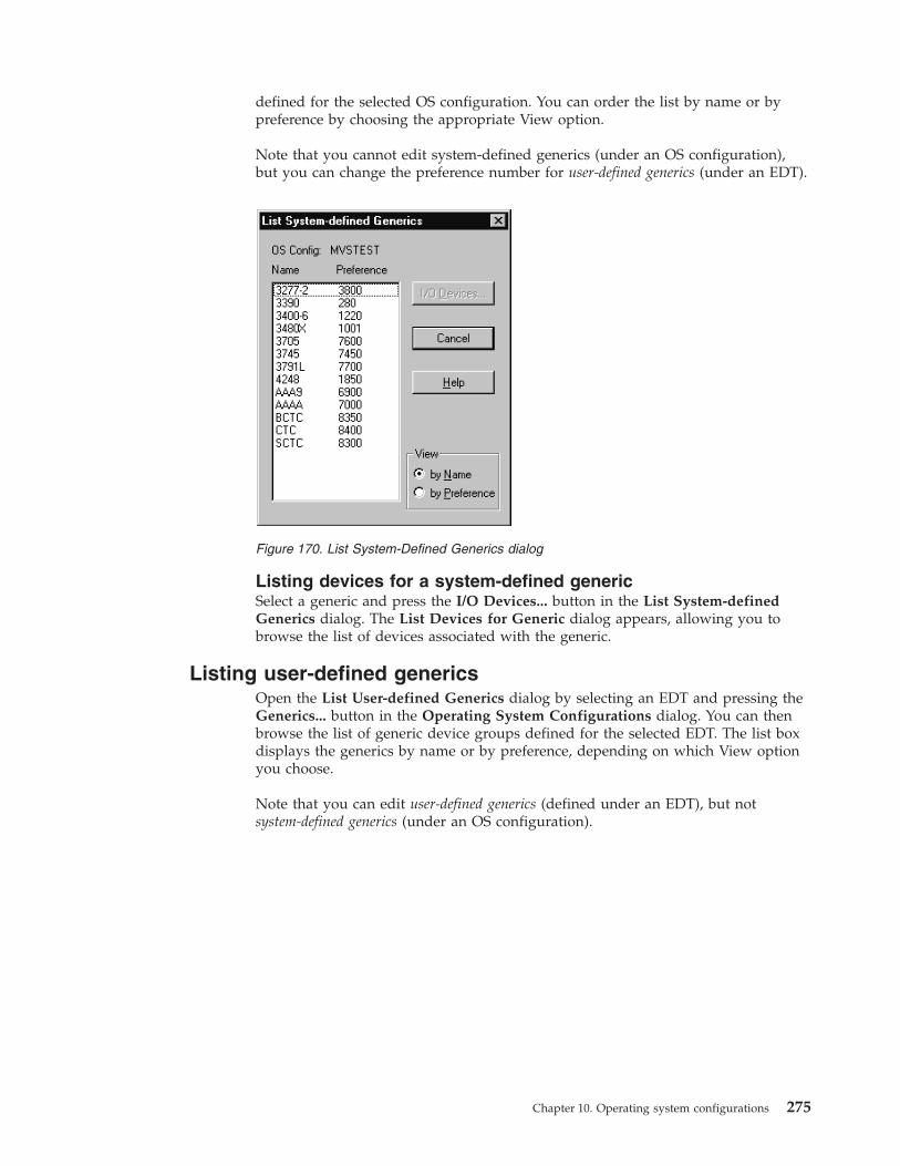
defined for the selected OS configuration. You can order the list by name or bypreference by choosing the appropriate View option.
Note that you cannot edit system-defined generics (under an OS configuration),but you can change the preference number for user-defined generics (under an EDT).
Listing devices for a system-defined genericSelect a generic and press the I/O Devices... button in the List System-definedGenerics dialog. The List Devices for Generic dialog appears, allowing you tobrowse the list of devices associated with the generic.
Listing user-defined genericsOpen the List User-defined Generics dialog by selecting an EDT and pressing theGenerics... button in the Operating System Configurations dialog. You can thenbrowse the list of generic device groups defined for the selected EDT. The list boxdisplays the generics by name or by preference, depending on which View optionyou choose.
Note that you can edit user-defined generics (defined under an EDT), but notsystem-defined generics (under an OS configuration).
Figure 170. List System-Defined Generics dialog
Chapter 10. Operating system configurations 275

Listing devices for a user-defined genericSelect a generic and press the I/O Devices... button in the List User-definedGenerics dialog. The List Devices for Generic dialog appears, allowing you tobrowse the list of devices associated with the generic.
Editing a user-defined genericYou can change the preference value and VIO eligibility of a user-defined genericin the Edit Generic dialog. To display this dialog, select a user-defined generic andpress the Edit... button in the List User-defined Generics dialog. Note that leavingthe preference number text box blank and pressing OK will reinstate thesystem-defined preference number for the generic.
Figure 171. List User-Defined Generic dialog
276 z/OS V2R2 and z/VM V6R2.0 HCM User's Guide

Chapter 11. User interface to I/O Operations
HCM provides additional capabilities which allow I/O Operations tasks on thehost to be performed via HCM. To be able to perform these functions, I/OOperations must be up and running. The following functions are available withHCM:v Viewing the active sysplex and the status of its objects graphically,v Retrieving, manipulating, and activating switch matrices,v Issuing I/O Operations commands.
To carry out these functions, you must have the necessary RACF authorization toperform I/O Operations (see IBM Tivoli System Automation for z/OS User's Guide).To view the status information of the active system, it is obvious that the activeconfiguration must correspond with the HCM configuration. This is theresponsibility of the user. If the HCM configuration does not represent the activeIODF, misleading results may occur. Note that to manipulate an active switchmatrix you require access to the active IODF.
To access the I/O Operations on the host, the prerequisites mentioned under “I/OOperations functions” on page 4 are necessary.
Note:
The I/O Operations functions are not available if your system is running as a hostunder z/VM.
Viewing the active sysplex and its statusHCM knows the systems of the active sysplex (that is, the sysplex on which HCDis running) and associates them with partitions and processors (for basic mode).Because of this, partitions and basic mode processors can be labelled with theirassociated system name in the configuration diagram according to the OperationsPreferences you have selected.
To display all the objects of the active sysplex, use the filter option in the Viewmenu and select the Active sysplex checkbox. The resulting diagram will consist ofthe desired systems and their objects.
To see the status of the objects in the sysplex, use the menu item Status under theOperations, Refresh menu items. HCM now retrieves the status information viaI/O Operations and shows it on the diagram in various colors having differentmeanings which can be defined in the Color dialog (see “Color dialog” on page280).
Detailed information for a selected object can be obtained by clicking on the objectwith the right mouse button and selecting Status in the upcoming context menu.
If you do this for a Processor or Partition object, the following dialog appears.
© Copyright IBM Corp. 1995, 2016 277
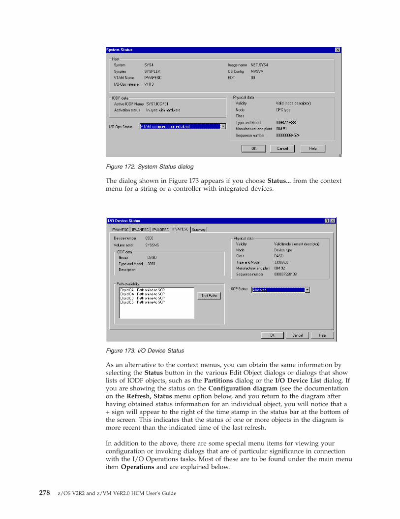
The dialog shown in Figure 173 appears if you choose Status... from the contextmenu for a string or a controller with integrated devices.
As an alternative to the context menus, you can obtain the same information byselecting the Status button in the various Edit Object dialogs or dialogs that showlists of IODF objects, such as the Partitions dialog or the I/O Device List dialog. Ifyou are showing the status on the Configuration diagram (see the documentationon the Refresh, Status menu option below, and you return to the diagram afterhaving obtained status information for an individual object, you will notice that a+ sign will appear to the right of the time stamp in the status bar at the bottom ofthe screen. This indicates that the status of one or more objects in the diagram ismore recent than the indicated time of the last refresh.
In addition to the above, there are some special menu items for viewing yourconfiguration or invoking dialogs that are of particular significance in connectionwith the I/O Operations tasks. Most of these are to be found under the main menuitem Operations and are explained below.
Figure 172. System Status dialog
Figure 173. I/O Device Status
278 z/OS V2R2 and z/VM V6R2.0 HCM User's Guide

Operations menuThe items of this top level menu item are enabled whenever you are logged on toHCD (i.e. not in stand-alone mode). It will appear to the left of the Utilities menu.The Operations feature of HCM consists of the following menu items:1. Refresh This command is the primary means by which the data about the
system status is obtained. This information is volatile i.e. it is not rememberedacross different HCM sessions, and if you change the Focus on host. TheRefresh menu consists of the following four submenus:v Status This refreshes the status information for all objects in the
configuration diagram. This allows you to see the changes you have made tothe active sysplex by showing the updated objects in a different color. Thestatus bar at the bottom of the screen will display the time at which thiscommand was issued.
v Sysplex This refreshes the current contents of the Sysplex without updatingthe status bar refresh timestamp. This command is issued implicitlywhenever a configuration is opened, but the menu option is also provided sothat the command can be manually issued to detect changes to the Sysplexor changes to the availability of I/O Operations that may have occurredduring the session.
v Switch configurations This refreshes the visualized matrix data for matricesthat are being used in the current diagram. If one or more matrices are notavailable, messages will appear to tell the user that these matrices cannot bevisualized. Visualization will proceed as if none had been selected as theVisualized Configuration for the affected switches. This action willautomatically issue a "Refresh Sysplex" if one has not yet been issued. Thestatus bar refresh timestamp is unaffected by this command.
v All This refreshes all of the above information. The status bar refreshtimestamp is updated by this command.
2. Sense This command is the only means by which "Sensed" data from the hostis obtained. The menu item consists of three submenus listed below. Dataobtained by the Sense operation appears in the appropriate columns of theEdit/Locate dialogs. This action will automatically issue a "Refresh Sysplex" ifone has not yet been issued.v Selected This refreshes sensing information for the object(s) selected in the
diagram.v Visible This refreshes information for all objects visible in the diagram.v All This refreshes sensing information for all objects in the configuration.
Since this is likely to be a very long operation, a confirmation dialog willappear. The sensed information is stored in the HCM configuration file andis non-volatile. Hence, it is retained across HCM sessions. This information isalso available in all List Boxes in which a Columns button is to be found e.g.the Edit and Locate dialogs.
v Clear Previous Sensing Data This clears the sensed information for allobjects in the configuration.
3. Focus on host This dialog allows you to select the host for which the statusinformation is to be displayed.
4. Next focus host This is a shortcut to select (from the list that would appear inthe Focus on host dialog) the next host as the focus host.
5. Command... This starts the I/O Operations command dialog which not onlyallows you to issue I/O Operations commands but also allows you to view theresults of them (see “Issuing I/O Operations commands” on page 281).
Chapter 11. User interface to I/O Operations 279

6. Preferences... This dialog allows you to set various preferences specific only tothe Operations feature of HCM e.g. the format of the system name is selectedhere.
Color dialogThis dialog allows you to assign the colors shown in the configuration diagram tothe features they represent. It is called by the View, Colors... menu item. Thisdialog allows you to allocate your own colors for warnings and status.
If the user has selected the Show status on diagram checkbox in the Colors dialog,then the Refresh, Status menu option can be used to color objects to reflect statusinformation with respect to the focus host. The following objects on the HCMdiagram will be affected by the coloring:v CHPIDs - Color will be determined by the status of the CHPID itself plus the
SCP status of all CTC (or BCTC) devices that represent the CHPID in CTCconnections to the focus host.
v Switches - Color will be determined by the operating status of the switch plusthe SCP status of the switch's device.
v Integrated controllers - Color will be determined by the SCP status of thedevices that the controller contains.
v Units within strings - Color will be determined by the SCP status of the devicesthat the unit contains.
Where more than one state or visual warning needs to be presented, the singlemost important state will be shown. Furthermore, for units and integratedcontrollers there will usually be more than one IODF object contained in thephysical object. In such cases, the color displayed will reflect the status of thecontained object with the most important state.
The status colors remain in effect on the diagram as long as the view contains onlyobjects that were visible at the time of the last status refresh. The status time stamp inthe status bar reflects this time. However, as soon as the view changes to includeobjects that were not visible when the time stamp was updated, then the coloring(and the time stamp) will be cleared.
This means that you can filter the diagram to show a large set of objects (e.g. allDASD in the active sysplex), invoke Refresh, Status once, and then switch backand forth between this larger view and views that show only subsets (e.g. use F4to crop to one controller, and then F3 to go back to the larger view) withoutinvalidating the status information. As soon as another object is shown in the view(e.g. a tape controller), then the colors and the status time stamp will be cleared,and "Refresh Status" would have to be issued again to show the status colors.
Manipulating and activating switch matricesSwitch matrices can reside inside an IODF or on a switch. HCM supports themanipulation of both kinds of matrices. Switch matrices that reside on switchescan be listed, examined, modified, created or deleted in the same way as IODFmatrices can. Every existing matrix is tagged with a label that indicates where itresides (in IODF or on a switch). When creating a matrix you can specify whetherto place it in an IODF or on a switch.
The active switch configuration is treated in the same way as other switchconfigurations. It can be recognized by a special marker.
280 z/OS V2R2 and z/VM V6R2.0 HCM User's Guide

Certain restrictions apply to the manipulation of switch matrices. When access tothe switch matrices is not possible, HCM informs the user accordingly.
HCM can activate any of the matrices that it can manipulate. This includes theactive matrix. HCD will ensure that HCM can activate a matrix only when theactive IODF is open.
Issuing I/O Operations commandsHCM offers a facility of passing I/O Operations commands to the HCD server. Toissue I/O Operations commands, open the following I/O Operations Commandwindow which can be found under the menu item Operations, Command.
In this window, you can enter commands that will be passed on to I/OOperations. The response of the executed command is then displayed in thewindow. You can scroll in the buffer to display the last few responses and savethem to a file. To clear the buffer, click on the Clear button. It is also possible toretrieve the last few commands for executing again if necessary.
For valid I/O Operations commands see IBM Tivoli System Automation for z/OSOperator's Commands.
The return and reason codes resulting from the execution of the I/O Operationscommand are shown in the message CBDG133I. These codes are explained in IBMTivoli System Automation for z/OS Messages and Codes.
Figure 174. I/O Operations Command window
Chapter 11. User interface to I/O Operations 281

282 z/OS V2R2 and z/VM V6R2.0 HCM User's Guide

Chapter 12. Reports and diagrams
HCM can produce a wide selection of reports and diagrams on a variety ofprinting devices, including plotters. Using the Windows print driver, HCM canwork effectively with all printing devices supported by Windows. Since HCM isaware of the paper dimensions in the active printer, changing the paper size ororientation (portrait / landscape) affects the appearance of the configurationdiagram on the screen.
Besides printing the generated text reports, you can store them in softcopy formats:v the XML/HTML file format enables users, for example, to view the generated
XML reports as HTML files using a web browser.v the CSV file format for example, allows you to load HCM reports into
spreadsheet programs for further processing.
Tips:
Some laser printers may print selected connections as patterned lines; you cangenerally force the printer to print solid lines by adjusting the printer driversettings.
Before printing diagram reports, turn off the display of cabinets using the Viewmenu. This will reduce the number of pages per diagram.
Printing configuration diagramsYou can print configuration diagrams with the Print Diagram... command underthe File menu. First ensure that the current configuration diagram contains all theobjects you want to print in the current view. Open the Page Setup dialog bychoosing the Page Setup option in the File menu. Select either Portrait orLandscape in the Orientation section. Clicking on the Printer button allows you toselect the printer of your choice.
In the Print Diagram dialog, you can choose to print the exact portion of thediagram that appears on the screen, print the entire diagram on a single page, orscale the size of printed diagram. You can either specify a certain scaling factor oryou can have HCM calculate the optimal scaling factor which ensures that all textsare readable. Row/column numbers are printed on each page to allow a correctplacing when combining the single pages to a complete picture.
Tip:
Screen snapshots typically look best if printed in landscape mode.
© Copyright IBM Corp. 1995, 2016 283

There are the following options for printing the configuration diagram:v Snapshot of Screen: Prints the exact portion of the configuration diagram that
appears on the screen. Use this to produce diagrams of a particular subset of theconfiguration.
v One Page:. Prints the configuration diagram on one page, giving you anoverview of the entire diagram. Note that configurations printed on one pagewill be difficult to read.
v Full Diagram: Prints the diagram over several pages as indicated in the Pagerange section and at the scale specified in the Scaling (%) field. You can selectany scaling factor between 20% and 100%. Use the Preview button to see howthe diagram will be split between pages.
v Calculate optimal Scale: Prints the complete diagram as small as possible, butso that all contained text is still readable. Pressing this button selects the FullDiagram radio button and calculates the optimal scale and displays this value inthe editable Scaling (%) field. Note that in most cases still several pages will berequired to print the scaled diagram.
Generating text reports and diagram reportsIn HCM, you can generate and print text reports and diagram reports. A diagramreport is a configuration diagram showing one particular object of interest and theequipment connected to it.
You can select from the following output formats:v XML/HTML saves all selected reports in an XML file format to a user-specified
directory. HCM provides the appropriate XSL and CSS style sheets and XSDschema definitions to enable users, for example, to view the generated XMLreports as HTML files using a web browser.
Figure 175. Printing a configuration diagram
284 z/OS V2R2 and z/VM V6R2.0 HCM User's Guide

v CSV saves all selected reports in an CSV (comma separated values) file format toa user-specified directory. The CSV file format, for example, allows you to loadHCM reports into spreadsheet programs for further processing.The applications which you want to use for further processing the generatedCSV files, may expect different separation characters. Therefore, if you select theCSV option, HCM offers a dialog to set the appropriate separation characterbefore it generates the output.
v Printer prints all selected reports on the current printer, or, depending on yourPage Setup selection, stores the reports in your specified file.
In stand-alone mode, you can print complete reports only from a productionconfiguration file (see “Printing reports, diagrams, cable labels” on page 104).
Before printing a text report or a diagram report, you can specify parameters forthe page layout and printer options. Open the Page Setup dialog by choosing PageSetup... from the File menu. Here you can select, for example, the orientation,(Portrait is recommended), a scaling factor and a printer.
Now open the Generate Reports dialog (Figure 176 on page 287) by choosingGenerate HCM Reports... from the File menu. This dialog allows you to setoptions for the reports you are generating:v Output Format: Here you specify the format of the generated report (one of
XML/HTML, CSV or Printer).v Report Description: The Title Page and Contents and the Index check box are
only selectable for the Printer output format. Report Title and Note 1 and Note2 are available for any output format.Checking the Title Page and Contents box, you can generate a title page and atable of contents for the report. The table of contents lists the sections that youinclude and the pages where each begins. This option is selected by default, butyou may want to suppress these pages when printing reports on individualobjects.The title page optionally contains the report title and two notes. If for yourcurrent configuration, you have specified a title and footnotes (using the Titles& Footnotes... dialog from the Edit menu), then these texts appear as a defaultin the Report Title and Note 1, Note 2 fields. You may overtype any of these foryour current report generation.Selecting the Index check box, generates an index in the report output. Thischoice also enables the Index Options... button. Pressing this button invokes theIndex Options dialog which lets you select which user fields should be includedas optional index entries in the report. For example, clicking on User Field 01which is, say, “Asset number” will result in all objects being indexed by assetnumber as long as they have entries in this user field (see also “User data fields”on page 30).
v Scope: Lets you specify whether you want to generate a report for all objects,visible objects only, selected objects only, or for certain objects only, that youspecify in the Limitations section.
v Text Reports: Lets you specify the objects and further details of the specifiedobjects, for which you want to generate a detailed report depending on thescope:– Processor: Processor Summary prints for each processor a summary that
includes a description, and lists of partitions and CHPID types. Channel PathConnections prints a detailed CHPID report which describes the attached
Chapter 12. Reports and diagrams 285

controllers and cable IDs. CTC Connections prints a detailed CTC report on allpoint-to-point CTCs and switched CTCs.
– Cables and Links: Fiber Links prints a detailed report of all patchports andcables in each fiber link. The report is divided into sections for each type ofESCON or FICON object. Used Cables prints all cables that are connected tothe set of objects specified by All, Visible or Selected options. Unused Cablesprints all cables that are connected to the set of objects specified by All,Visible, Selected or Limited options.
– Cabinet and General Box: creates a tabular view for cabinets (specified byAll, Visible or Selected) showing all connections to each patchport. You maygenerate a separate report for the Front View and Back View of each panelshowing its patchports arrayed as they appear on the panel when viewedfrom the appropriate side.
– Switches, Controllers, Strings, Crossbar Switches: specifies the types ofobjects for which detailed text reports and diagram reports will be printedaccording to your selected scope.
v Diagram Reports: This section is only usable for the Printer output format. Itlets you specify the objects, for which a diagram report (depending on thescope) should be generated. Note that you cannot print a diagram report forcable or cabinet objects. These checkboxes are only available for output formatPrinter and not available for scope Limited.
v Limitations: If you selected the Limited radio button in the Scope section, youcan further limit the report to certain (single or multiple) objects for each objectcategory.
Using the Save Options... button, you can save a certain set of report options intoan option file. At a later point in time, using the Load Options... button, you canload a set of report options from the related option file. HCM invokes theSave/Load Report Option File dialogs respectively. This functionality helps you toquickly generate reports that you need to obtain frequently.
Note: Option files use the Windows .ini file format.
286 z/OS V2R2 and z/VM V6R2.0 HCM User's Guide
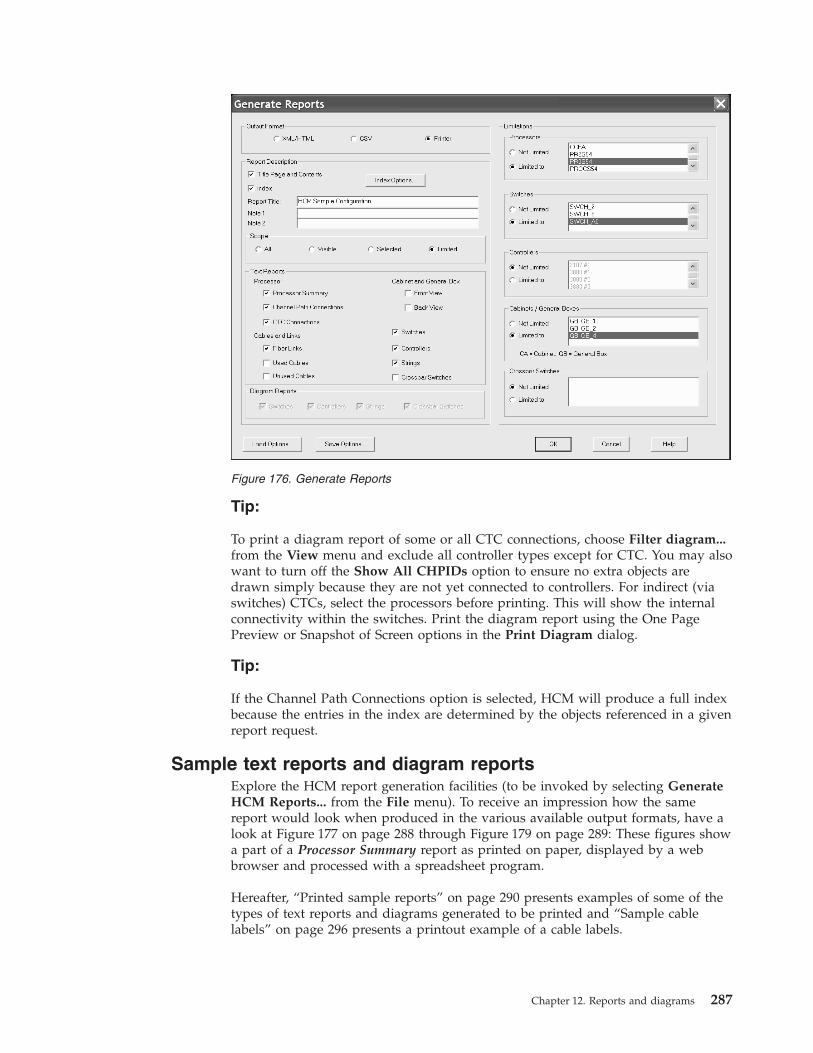
Tip:
To print a diagram report of some or all CTC connections, choose Filter diagram...from the View menu and exclude all controller types except for CTC. You may alsowant to turn off the Show All CHPIDs option to ensure no extra objects aredrawn simply because they are not yet connected to controllers. For indirect (viaswitches) CTCs, select the processors before printing. This will show the internalconnectivity within the switches. Print the diagram report using the One PagePreview or Snapshot of Screen options in the Print Diagram dialog.
Tip:
If the Channel Path Connections option is selected, HCM will produce a full indexbecause the entries in the index are determined by the objects referenced in a givenreport request.
Sample text reports and diagram reportsExplore the HCM report generation facilities (to be invoked by selecting GenerateHCM Reports... from the File menu). To receive an impression how the samereport would look when produced in the various available output formats, have alook at Figure 177 on page 288 through Figure 179 on page 289: These figures showa part of a Processor Summary report as printed on paper, displayed by a webbrowser and processed with a spreadsheet program.
Hereafter, “Printed sample reports” on page 290 presents examples of some of thetypes of text reports and diagrams generated to be printed and “Sample cablelabels” on page 296 presents a printout example of a cable labels.
Figure 176. Generate Reports
Chapter 12. Reports and diagrams 287
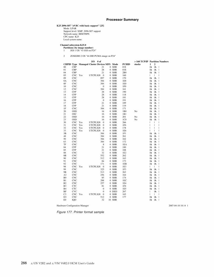
Processor Summary
K25 2096-S07 "z9 BC with basic support" [25]Mode: LPARSupport level: XMP, 2096-S07 supportNetwork name: IBM390PSCPC name: K25Local system name:
Channel subsystem K25.0Partitions (by image number)1 JG0 1 OS "43 JG0 on P24"
2 ZOSEJH0 2 OS "44 JH0 PUMA image on P24"
I/O # of > 160 TCP/IP Partition NumbersCHPID Type Managed Cluster Devices MFS Mode PCHID stacks 1 200 CBP 21 0 SHR 018 |A |A |01 CBP 28 0 SHR 01E |A |A |04 CBP 21 0 SHR 2B0 |A |A |05 CNC Yes UTCPLXJ8 0 0 SHR 160 | | |09 CNC 897 0 SHR 170 |A |A |0A CNC 384 0 SHR 1E8 |A |A |0F CNC 384 0 SHR 1E0 |A |A |10 CNC 0 0 SHR 1F0 |A |A |12 CNC 384 0 SHR 161 |A |A |13 CFP 28 0 SHR 190 |A |A |14 CFP 28 0 SHR 118 |A |A |15 CFP 28 0 SHR 181 |A |A |16 CFP 0 0 SHR 191 |A |A |17 CFP 21 0 SHR 189 |A |A |18 CFP 21 0 SHR 119 |A |A |1F CNC 384 0 SHR 171 |A |A |20 OSD 16 0 SHR 1B0 No |A |A |21 OSC 16 0 SHR 1B1 |A |A |22 OSD 16 0 SHR 201 No |A |A |23 OSD 16 0 SHR 1C0 No |A |A |30 CNC Yes UTCPLXJ8 0 0 SHR 266 | | |31 CNC Yes UTCPLXJ8 0 0 SHR 1F6 | | |32 CNC Yes UTCPLXJ8 0 0 SHR 178 | | |33 CNC Yes UTCPLXJ8 0 0 SHR 1E6 | | |3B CNC 384 0 SHR 1F1 |A |A |48 CNC 384 0 SHR 261 |A |A |50 CNC 384 0 SHR 162 |A |A |63 CNC 384 0 SHR 172 |A |A |7F CNC 8 0 SHR 1EA |A |A |84 CFP 21 0 SHR 180 |A |A |85 CFP 21 0 SHR 188 |A |A |88 CNC 32 0 SHR 1E2 |A |A |8B CNC 552 0 SHR 262 |A |A |90 CNC 512 0 SHR 163 |A |A |91 CNC 84 0 SHR 173 |A |A |92 CNC 171 0 SHR 1EB |A |A |98 CNC Yes UTCPLXJ8 0 0 SHR 1E3 | | |99 CNC 325 0 SHR 1F3 |A |A |9B CNC 513 0 SHR 263 |A |A |A3 CNC 256 0 SHR 164 |A |A |B0 CNC 85 0 SHR 174 |A |A |B1 CNC 288 0 SHR 1EC |A |A |B2 CNC 257 0 SHR 1E4 |A |A |B3 CTC 81 0 SHR 1F4 |A |A |B4 CTC 0 0 SHR 1E5 |A |A |BF CVC 0 0 DED 267 | |A |C3 CNC Yes UTCPLXJ8 0 0 SHR 165 | | |D3 CNC 512 0 SHR 177 |A |A |E0 IQD 32 16 SHR |A |A |
2007-04-18 18:14 1Hardware Configuration Manager
Figure 177. Printer format sample
288 z/OS V2R2 and z/VM V6R2.0 HCM User's Guide

Figure 178. XML/HTML format sample
Figure 179. CSV format sample
Chapter 12. Reports and diagrams 289

Printed sample reports
�������������������
����������� �����������������������������
�������������
�� ���� ��� �������������
��������� ���� ������
��������� �
���� !"#$% &'�&
( � �� ��)���* +���,��� ��+��� ������� ��+��� ��$ ���
��������� �
� �- $�.���� �)
���� !"#$% &'�&
���� � �� ������������ +���,��� "�����
/0� ���� ��1�� � $�$ ����+����+
���*����)��
�������� �
� �- $�.���� �)
���� !"#$% &'�&
��*� � �� ������������ +���,��� "�����
/0� ���� ��1�� � $�$ ����+����+
���*����)��
��������� �
� �- $�.���� �)
���� !"#$% &'�&
����0 � �� ������������ +���,��� "�����
/0� ���� ��1�� � $�$ ����+����+
���*����)��
�������� �
� �- $�.���� �)
���� !"#$% &'�&
��*�0 � �� ������������ +���,��� "�����
/0� ���� ��1�� � $�$ ����+����+
���*����)��
!�������� �
� �- $�.���� *��
���� !"#$% &'�&
��-*��� �� �� 23���+
�4�56���
���*��)������
���*�*��** *)�)� *5�+17�+� ���-��3+����� ������+
290 z/OS V2R2 and z/VM V6R2.0 HCM User's Guide
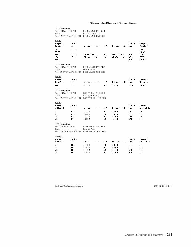
Channel-to-Channel Connections
CTC ConnectionFrom CTC or FC CHPID: BOESYS.27 S CTC SHRRoute: ESCD_5(A6..AA)From CNC/FCV or FC CHPID: BOESYS.28 S CNC SHR
Details:Image on Control Control Image on
BOESYS Unit Devices OS UA Devices OS Unit BOESYS
TEST 0D02 TEST
TEST PROD
PROD 0D02 0D00,8 (B) Y 00 0D00,8 (B) Y 0D03 TEST
PROD 0D02 0D08,8 Y 08 0D08,8 Y 0D03 TEST
PROD 0D03 PROD
CTC ConnectionFrom CTC or FC CHPID: BOESYS.61 S CTC DEDRoute: Point-to-PointFrom CNC/FCV or FC CHPID: BOESYS.66 S CNC DED
Details:Image on Control Control Image on
BOESYS Unit Devices OS UA Devices OS Unit BOESYS
PROD 1000 1000,4 00 1005,4 1005 PROD
CTC ConnectionFrom CTC or FC CHPID: ESERVER.A1 S FC SHRRoute: ESCD_40(A1..B1)From CNC/FCV or FC CHPID: ESERVER2.B1 S FC SHR
Details:Image on Control Control Image on
ESERVER Unit Devices OS UA Devices OS Unit ESERVER2
XA 4200 4200,4 00 5200,4 5200 YA
XA 4210 4210,4 00 5200,4 5200 YB
XB 4200 4200,4 00 5210,4 5210 YA
XB 4210 4210,4 00 5210,4 5210 YB
CTC ConnectionFrom CTC or FC CHPID: ESERVER.A3 S FC SHRRoute: Point-to-PointFrom CNC/FCV or FC CHPID: ESERVER2.B3 S FC SHR
Details:Image on Control Control Image on
ESERVER Unit Devices OS UA Devices OS Unit ESERVER2
XA 4100 4100,4 00 5100,4 5100 YA
XA 4110 4110,4 00 5100,4 5100 YB
XB 4100 4100,4 00 5110,4 5110 YA
XB 4110 4110,4 00 5110,4 5110 YB
2001-12-20 16:42 1Hardware Configuration Manager
Chapter 12. Reports and diagrams 291

Cabinet C1, Panel 0, 6 by 6, Front View������������ ������������������������������������������ !����"#$%����$#�!&��
�������������������� ������������������
����������� ��
��� � ��
�������������������� �������������������
������������ �
��� � ��
��������������������� ������������������
������������ ��
��� � ��
��������������������� ������
������������ ��
��� � ��
�������������
��� � ��
�������������
��� � ��
��������������������� ������������������
������������ ��
��� ����
��������������������� �������������������
������������ �
��� ����
��������������������� ������������������
������������ ��
��� ����
�������������
��� ����
�������������
��� ����
�������������
��� ����
�������������������� ������������������
������������ ��
��� ����
��������������������� �������������������
������������ ��
��� ����
��������������������� ������������������
������������ ��
��� ����
��������������������� �������������������
�������� ��� �
��� ����
�������������
��� ����
�������������
��� ����
��������������������� ������������������
������������ ��
��� ����
��������������������� �������������������
������������ ��
��� ����
��������������������� ������������������
������������ ��
��� ����
��������������������� �������������������
������������ �
��� ������� ���� ��� ����
�������������������� ������������������
�������� ��� ��
��� ����
��������������������� �������������������
������������ ��
��� ����
��������������������� ������
����������� ��
��� ����
��������������������� �������������������
������������ ��
��� ������� ���� ��� ����
��������������������� ������������������
������������ ��
��� ����
��������������������� �������������������
������������ ��
��� ������� ����
��������������������� �������������������
������������ ��
��� ������� ���� ��� ����
&'''()'(**&+�&,*-��.���/�� ���0����� �� ��/�
292 z/OS V2R2 and z/VM V6R2.0 HCM User's Guide

�������������� ����� ������ ����
������� ������� �� ����
��� ��� ������� �������� ��������
��� ��� ������� �������� ��������
��� ��� ������ �������� �������
��� ��� ������� �������� ��������
��� ��� ������� �������� ��� �!���"� �� ������#�� �$$�����������%
��� ��� ������� ������$� ��� & �!���"� �� & ������&&� �$$�����������%
��� ��� ������& ��������� ���%� �!���"� ��%� ������&� �$$����&������'
��� ��� ������# �������#� ���� �!���"� ��� ��������� �$$����&�������'
��� ��� ������� �������� ��������
��� ��� ������$ �������� ��������
��� ��� ������ �������� �������&
��� ��� ������� ������#� ��� � �!���"� �� � ������#� �$$�����������%
��� ��� ������( ��������� ���% �!���"� ��% ������&�� �$$�����������%
��� ��� ������) ��������� ���%& �!���"� ��%& ������&�� �$$����&������'
��� ��� ������' �������$� ����� �!���"� ���� ������&�� �$$����&�������'
��� ��� �����$� ��������� ����& �������� �$$�������&����'
��� ��� �����$� ��������� ���(� �!���"� ��(� �������$� �$$����&�������'
��� ��� �����$� �������� �$$�������&����'
��� ��� �����$( ��������� ���(& �!���"� ��(& ��������� �$$����&�������'
��� ��� �������� �������� �$$����&�������*
��� ��� �������� �������� �$$����&�������*
��� ��� �������� �������� ��� � �!���"� �� � ������&$� �$$�����������
��� ��� �������� �������� ��� � �!���"� �� � ������&�� �$$�����������
��� ��� ������� �������� ���%� �!���"� ��%� ������&�� �$$����&������)
��� ��� �������� �������&� ����� �!���"� ���� �������#� �$$����&�������)
��� ��� �������� �������� ��+�
��� ��� �������� ������&� ��� � �!���"� �� � ������#�� �$$�����������
��� ��� �������$ ��������� ���%� �!���"� ��%� ������&#� �$$�����������
��� ��� ������� ��������� ���%� �!���"� ��%� ������&�� �$$����&������)
��� ��� �������% ��������� ����� �!���"� ���� �������$� �$$����&�������)
��� ��� ������$� ��������� ����� �!���"� ���� �������� �$$�������&����)
��� ��� ������$� ��������� ���(� �!���"� ��(� ��������� �$$����&�������)
��� ��� ������$� �������&� ���(� �������� �$$�������&����)
��� ��� ������$$ �������� ���(� �!���"� ��(� ��������� �$$����&�������)
��� ��� ������ ������#�� %�)�,�&
��� ��� ������ & ������#$� %�)�,�#
��� ��� ������ $ ��������� %�)�,��
��� ��� ������ ��������� %�)�,��
��� ��� ������ % �������� %�)�,�$
��� ��� ������� � �������� )�)�-)� �
��� ��� ������� � �������� )�)�-)� �
��� ��� ������� �������� )�)�-)�
��� ��� �������%� �������� )�)�-)�%�
��� ��� �������%� �������� )�)�-)�%�
��� ��� �������% �������� )�)�-)�%
��������� ��.�� ���/0��� �1��23���!21� 4���3��
Chapter 12. Reports and diagrams 293

String 0360-037F SN:761885431
����������
��� ���������� ������������������� ���������� �� ��� � !���"�� ��
��������#$%�&�'�($)* ��
+���,��� ��������--���-��-'. �- ���������� /! 0��,��-�-/
���� ���������� 1�� ��-�--��-��+-��(- ��2--� �- #�3 �43��
$3�� ��,����-��4��� 1�� ��-�--��-��+-��(� ��2--. �- #�3 �43��
$3�� ��,����-��4�#� 1�� ��-�--��-��+���(. ��2-- �- #�3 �43��
$3�� ��,����-��4�+� 1�� ��-�--��-��+���( ��2-- �- #�3 �43��
$3�� ��,����-��4�!
�������,������
������������� ���������� ������������������� �����+���� �� ��� � !���"�� ��
�-���5�-�- �����5�-�� �.���5�-�. ����5�-� ����5�-������5�-�� �����5�-�� �����5�-��
��,�����.���������.
��� ���������� ������������������� �����+���� �� ��� � !���"�� ��
�����5�-�� �����5�-�� �����5�-�� �#���5�-�# �+'���,�����
������������ ���������� ������������������� �����+���� �� ��� � !���"�� ��
����5�-� �����5�-�� �����5�-�� �����5�-�� ��'�
�����-��..����.���6�,78�, �+��2��3,����������� ,
294 z/OS V2R2 and z/VM V6R2.0 HCM User's Guide

��������������������� ���������������������
3990-33990-003-360
35563
340
A B C D E
75mmf50015-90
F
75mmf50022-94
SP0
mmf400150
SP1
mmf400250
341
A B C D E
90mmf51015-98
F
90mmf51022-9C
SP2
mmf400350
SP3
mmf400450
C10C5
60mmf10445-90
mmf500175
C10D1
60mmf10465-98
mmf510190
280
30mmf5201PR-00
81
30mmf6624PR-01
94
mmf500275
9C
mmf510290
5A2
85mmf1078BS-26
A9
85mmf1080BS-25
AA
85mmf1081BS-28
90
mmf104460
98
mmf104660
*0360-037F3390
A
50mmf4001
B
50mmf4002
C
50mmf4003
D
50mmf4004
3390360-367String A431761885431
TS0360TS0361TS0362TS0363
TS0364TS0365TS0366TS0367
3390368-373String A432761885432
TS0368TS0369TS036ATS036B
3390374-37FString A433761885433
TS0374TS0375TS0376TS0377
String 340-35F3390
A B C D
3390340-347
3390348-353
3390354-35F
String 0360-037F
Chapter 12. Reports and diagrams 295
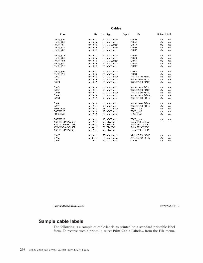
Sample cable labelsThe following is a sample of cable labels as printed on a standard printable labelform. To receive such a printout, select Print Cable Labels... from the File menu.
Cables
���� �� �� ��� ����� �� �� ���� � � �
������� �� ����� ���������� ����� ��� ���������� �� ����� ���������� ����� ��� ���������� �� ����� ���������� ����� ��� ���������� �� ����� ���������� ����� ��� ���������� �� ����� ���������� ����� ��� ���
������� �� ����� ���������� ����� ��� ���������� �� ����� ���������� ����� ��� ���������� �� ����� ���������� ����� ��� ���������� �� ����� ���������� ����� ��� ���������� �� ����� ���������� ����� ��� ���
������� �� ����� ���������� ����� ��� ���������� �� ����� ���������� ����� ��� ���������� ��� ����� ������ ������������������ ��� ���������� ��� ����� ������ ������������������ ��� ���������� ��� ����� ������ ������������������ ��� ���
������� ��� ����� ������ ������������������ ��� ���������� ��� ����� ������ ������������������ ��� ���������� ��� ����� ������ ������������������ ��� ���������� ��� ����� ������ ������������������ ��� ���������� ��� ����� ������ ������������������ ��� ���
������� ��� ����� ������ ������������������ ��� ���������� ��� ����� ������ ������������������ ��� ���������� �� ����� �� ��!���� ��������� ��� ���������� �� ����� �� ��!���� ��������� ��� ���������� �� ����� �� ��!���� ��������� ��� ���
������� �� ����� �� ��!���� ��������� ��� ���������� �� �"� #�""������������������$� �%�&�'��������#��������� �� �"� #�""������������������$� �%�&�'��������#��������� �� �"� #�""������������������$� �%�&�'��������#��������� �� �"� #�""������������������$� �%�&�'��������#��
������� �� ����� ������ ������������������ ��� ���������� �� ����� ������ ������������������ ��� ���
%���( �� ����� ������ ����� ��� ���
������������)���*��+,�� �-��&'���%&-�����' �
296 z/OS V2R2 and z/VM V6R2.0 HCM User's Guide

The following is a sample of cable labels as saved in a comma delimited ASCII file.SWCH_F1.10,1750 #1.01.A0[00],2006-02-28,????,SWCH_F1.10,1750 #1.01.A0[00]1750 #1.01.A0[00],SWCH_F1.10,2006-02-28,????,SWCH_F1.10,1750 #1.01.A0[00]SWCH_F2.10,1750 #1.02.A1[04],2006-02-28,????,SWCH_F2.10,1750 #1.02.A1[04]1750 #1.02.A1[04],SWCH_F2.10,2006-02-28,????,SWCH_F2.10,1750 #1.02.A1[04]1750 #2.C1,1750 #1.C1,2006-02-28,????,1750 #2.C1,1750 #1.C1
Chapter 12. Reports and diagrams 297

1750 #1.C1,1750 #2.C1,2006-02-28,????,1750 #2.C1,1750 #1.C1ERV01.0.F2,ERV01.0.F7,2006-02-28,CF03,ERV01.0.F2,ERV01.0.F7ERV01.0.F7,ERV01.0.F2,2006-02-28,CF03,ERV01.0.F2,ERV01.0.F7ERV01.0.F1,ERV01.0.F5,2006-02-28,CF02,ERV01.0.F1,ERV01.0.F5ERV01.0.F5,ERV01.0.F1,2006-02-28,CF02,ERV01.0.F1,ERV01.0.F5ERV01.0.F3,ERV01.0.F6,2006-02-28,CF04,ERV01.0.F3,ERV01.0.F6ERV01.0.F6,ERV01.0.F3,2006-02-28,CF04,ERV01.0.F3,ERV01.0.F6ERV01.2.E0(1E0),ERV02.1.E0(1E0),2006-02-28,CF05,ERV01.2.E0(1E0),ERV02.1.E0(1E0)ERV02.1.E0(1E0),ERV01.2.E0(1E0),2006-02-28,CF05,ERV01.2.E0(1E0),ERV02.1.E0(1E0)ERV01.2.E1(1E1),ERV02.1.E1(1E1),2006-02-28,CF06,ERV01.2.E1(1E1),ERV02.1.E1(1E1)ERV02.1.E1(1E1),ERV01.2.E1(1E1),2006-02-28,CF06,ERV01.2.E1(1E1),ERV02.1.E1(1E1)String 0060-007F.B,3174 #2.A,2006-02-28,????,3174 #2.A,String 0060-007F.BString 0060-007F.B,String 0080-009F.B,2006-02-28,????,3174 #2.A,String 0080-009F.BString 0080-009F.B,String 0060-007F.B,2006-02-28,????,3174 #2.A,String 0080-009F.BERV03A2.1.01(101),ERV03A2.1.05(105),2006-02-28,A026,ERV03A2.1.01(101),ERV03A2.1.05(105)ERV03A2.1.05(105),ERV03A2.1.01(101),2006-02-28,A026,ERV03A2.1.01(101),ERV03A2.1.05(105)ERV03A2.3.00(200),ERV03A2.3.04(204),2006-02-28,A030,ERV03A2.3.00(200),ERV03A2.3.04(204)ERV03A2.3.04(204),ERV03A2.3.00(200),2006-02-28,A030,ERV03A2.3.00(200),ERV03A2.3.04(204)ERV03A2.3.01(201),ERV03A2.3.05(205),2006-02-28,A031,ERV03A2.3.01(201),ERV03A2.3.05(205)ERV03A2.3.05(205),ERV03A2.3.01(201),2006-02-28,A031,ERV03A2.3.01(201),ERV03A2.3.05(205)
↑ ↑ ↑ ↑ ↑ ↑| | | | | || | | | | || | | | | |_ Link target| | | | | (with PCHID,| | | | | if possible)| | | | |_____ Link source| | | | (with PCHID, if possible)| | | || | | |____________ Cable ID| | | (????, if no ID provided)| | || | |________________________ today’s date| || |_________ Cable destination (with PCHID, if possible)||___________ Cable source (with PCHID, if possible)
Viewing HCD configuration reportsBesides the reports produced by HCM, you can also view HCD configurationreports on your HCM workstation in connected mode. Use the pull-down choiceView IODF Reports... from the File menu to invoke the IODF Reports dialog(Figure 180 on page 299) from where you can select HCD configuration reportsabout the logical I/O configuration data in the current IODF. Optionally, you canlimit the reports to selected objects (for example, a processor or an OSconfiguration).
Also, for these reports, you can select from various output formats. You can viewthe contents of the selected reports in a window and optionally you can save theoutput into a file on your workstation. Or you can save the reports in CSV (commaseparated values) format for later processing the data, and you can also save thereports in XML format. To view the generated XML reports in a web browser, youneed to provide the appropriate XSL and CSL style sheets and XSD schemadefinitions.
Note: The applications which you want to use for further processing the generatedCSV files, may expect different separation characters. Therefore, if you select theCSV option, HCM offers a dialog to set the appropriate separation character beforeit generates the output.
298 z/OS V2R2 and z/VM V6R2.0 HCM User's Guide

Viewing HCD compare reportsOn your HCM workstation you can view IODF compare reports produced by HCDon the host. These reports are displayed in an HCM window, and optionally youcan save the output from this window to a file.
There are two flavors of this compare facility. You can:v view reports that compare two different IODFs (see “Viewing IODF compare
reports”)v view reports that compare the hardware (channel subsystem/CSS) and software
(operating system/OS) definition in the currently accessed IODF. Such reportsspecifically compare the device definitions of a selected CSS and OSconfiguration, showing which devices (their numbers and types) are defined toeither the CSS or the OS, or both (see “Viewing CSS/OS compare reports” onpage 300).
For information about the contents and layout of these reports, refer to the z/OSHCD User's Guide.
Viewing IODF compare reportsYou can view HCD IODF compare reports on your workstation. Select View IODFCompare Reports... from the File menu bar choice. The following dialog appears,in which you can specify report types and limitations:
Figure 180. IODF Reports
Chapter 12. Reports and diagrams 299

Specify your selections and press the OK button. HCM invokes another dialog thatlets you specify one or more options of what information you want to see:v Print inserted data to show added data of definitions, connections, or
attachments from the new IODF, or of added attributes or relations of existingitems.
v Print deleted data to show deleted data of definitions, connections, orattachments from the old IODF, or of deleted attributes or relations of existingitems.
v Print unchanged data to show data of unchanged definitions, connections, orattachments, as well as their unchanged attributes or relations.
v Print unchanged item IDs to show IDs of all definitions, connections, orattachments whose values have not been changed.
Viewing CSS/OS compare reportsYou can view HCD CSS/OS compare reports on your workstation. Use this facilityto display and save reports that compare devices of an CSS or OS within oneIODF.
You can invoke this function selecting View IODF Compare CSS/OS Report...from the File menu bar choice. The following dialog appears, in which you specifyyour CSS and OS limitations:
Figure 181. IODF Compare Reports
300 z/OS V2R2 and z/VM V6R2.0 HCM User's Guide

Specify your selections and press the OK button. HCM invokes another dialog thatlets you specify whether you want to print all data or different data only.
Comparing HCM configurationsYou can compare HCM configurations with respect to physical information. Youcan generate a configuration compare report using menu item File → CompareHCM Files.... No configuration must currently be loaded, otherwise this selection isnot enabled. HCM opens the following dialog:
Figure 182. IODF Compare CSS/OS Reports
Chapter 12. Reports and diagrams 301
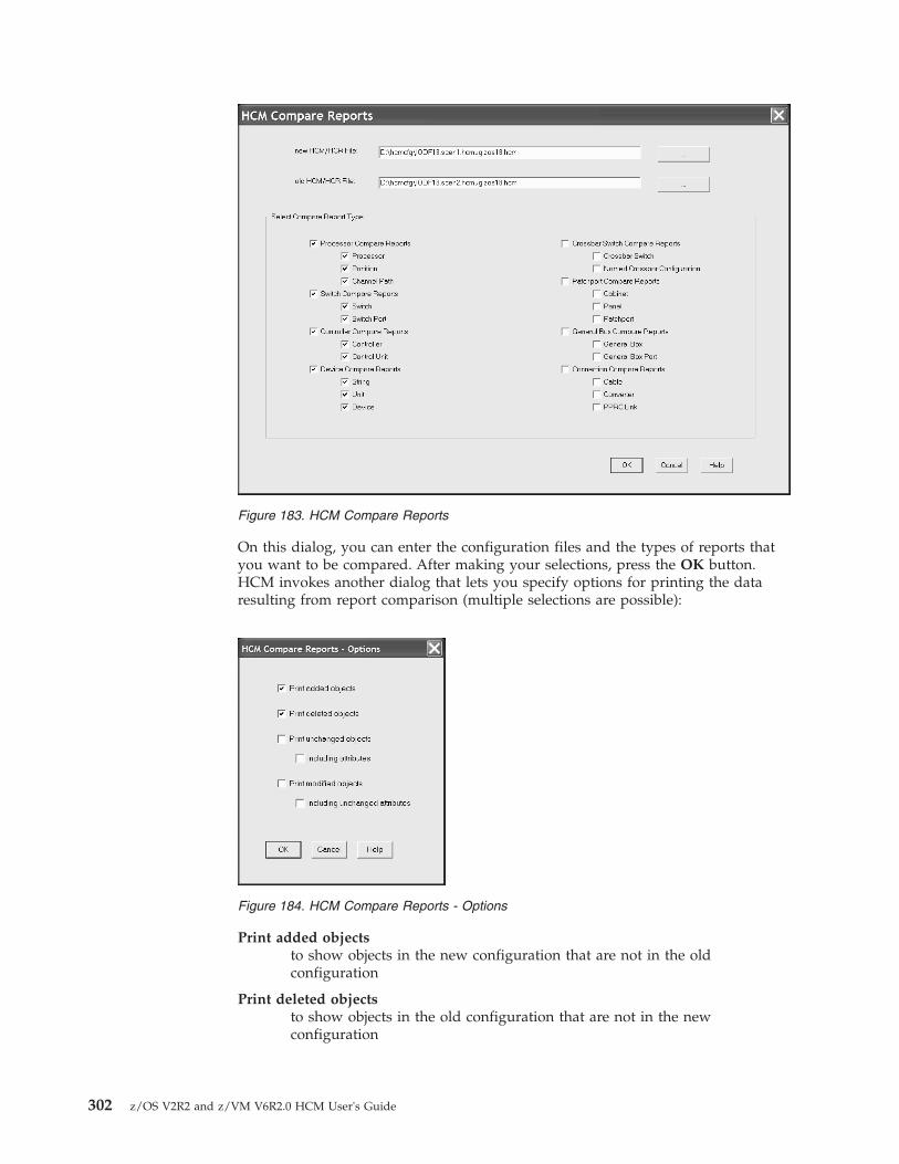
On this dialog, you can enter the configuration files and the types of reports thatyou want to be compared. After making your selections, press the OK button.HCM invokes another dialog that lets you specify options for printing the dataresulting from report comparison (multiple selections are possible):
Print added objectsto show objects in the new configuration that are not in the oldconfiguration
Print deleted objectsto show objects in the old configuration that are not in the newconfiguration
Figure 183. HCM Compare Reports
Figure 184. HCM Compare Reports - Options
302 z/OS V2R2 and z/VM V6R2.0 HCM User's Guide
Print unchanged objectsto show objects that are unchanged in both configurations (including ornot including the attributes of these unchanged objects).
Print modified objectsto show objects that appear in both configurations with at least onemodified attribute value. You can select to include the unchangedattributes values in the output, too, or to print the modified attributevalues only.
The output of the compare report is displayed in a separate window and you cansave it as plain text into a file. The layout of the HCM Compare Reports is thesame as the layout of the HCD Compare Reports (see z/OS HCD User's Guide). Theoutput of the compare report shows whether:v an object exists in both configurations, or has been added or deletedv object attributes are identical or modified in each configuration.
Note:
For comparison, both configurations are loaded in the same manner as during File→ Open... processing. To avoid unexpected updates to either configuration duringload, while you are connected to the host, it is recommended to run thecomparison only when both configurations are in sync with their IODF.Alternatively, you can run the comparison in stand-alone mode.
Comparing HCM configurations is based on the contents of files created by theHCM Export Data... function (see Chapter 15, “Importing and exporting data,” onpage 353). This means that each configuration is opened, exported to a temporarydirectory, and closed again. Then the exported files are compared. Therefore,messages EEQ0260E and EEQ0261E that may appear while opening/closing aconfiguration and exporting the involved data, can also appear while comparingHCM configurations. As a consequence, all data that cannot be exported intoexternal files, cannot be compared. Just ignore the messages.
Chapter 12. Reports and diagrams 303

304 z/OS V2R2 and z/VM V6R2.0 HCM User's Guide

Chapter 13. Scenarios
The scenarios in this chapter have been designed to represent typical proceduresthat you would go through in the course of maintaining your configuration. Theycover the following tasks:v “Scenario I – Adding and connecting new equipment”v “Scenario II – Defining a CTC connection” on page 322v “Scenario III – Defining a fiber cabling infrastructure” on page 332v “Scenario IV – Configuration changes for installing a FICON bridge card in a
9032–5 ESCON director” on page 340v “Scenario V – Establish a PPRC connection consisting of several PPRC links” on
page 345
Scenario I – Adding and connecting new equipmentIn this scenario we create new CHPIDs and strings for a processor with twopartitions in channel subsystem 0 and connect them to each other through a newcontroller, a new FICON switch, and a patchport cabinet. An operation systemconfiguration already exists.
Add four new channels to an existing processor1. Edit the processor by selecting Edit --> Processor. This opens the Edit a
Processor dialog.
2. Choose the processor from the list (in our example, SYSB) and press OK ordouble-click on the processor in the list. This opens the Processor dialog.
© Copyright IBM Corp. 1995, 2016 305

3. Click CHPIDs.... This opens the CHPIDs dialog.
4. Click Create.... This opens the Create CHPIDs dialog.
306 z/OS V2R2 and z/VM V6R2.0 HCM User's Guide

5. Fill in the fields as shown, specifying appropriate CHPID numbers, to createfour new shared (SHR) FC CHPIDs that can connect to a FICON switch:
6. Click OK. This opens the Assign Partitions dialog to choose which partitionsto assign to the access and candidate lists of the new CHPIDs.
Chapter 13. Scenarios 307

7. Select all of the partitions and click Add>> beside the access list. This adds theselected partitions to the access list of the four CHPIDs.
8. Click OK on all open dialogs to close them. The new CHPIDs have now beenadded.
9. Select View --> Filter Diagram... and select the Show All CHPIDs >checkboxto force the new CHPIDs to be included in the diagram.
Connect the new CHPIDs to patchports1. Edit an existing patchport cabinet by either selecting Edit --> Cabinet and
choosing the cabinet from the selection list or by double clicking on the cabinetin the diagram. This opens the Cabinet dialog.
2. Select a panel from the Panels listbox (in our example, P1).
308 z/OS V2R2 and z/VM V6R2.0 HCM User's Guide

3. Find four consecutive free patchports on the diagram of the patchport paneland select them. You may have to scroll the panel diagram.
4. Click Connect. HCM opens the Select Connection Target(s) dialog. In thelistbox, double-click on the processor with the new CHPIDs (SYSB.0). Thisexpands the list, showing all CHPIDs in the processor.
5. Select a CHPID and the Connect all 4 interfaces checkbox. Choose the type ofconnection you want to use and whether the connection should be permanent.
6. Press the Physical Only... button. The patchports are connected to fourconsecutive CHPIDs, starting with the one you have just selected.
7. Close all open dialogs.
Chapter 13. Scenarios 309

8. Select the View --> Filter Diagram menu item and select the ObjectsConnected to Processors and the Show Patchports, General Box Ports, andCables checkbox. The patchports connected to the new CHPIDs appear in thediagram.
Add a new FICON switch1. Select Create --> Switch. This opens a Create Switch dialog.2. Fill in the dialog, specifying appropriate control unit and device numbers, and
click OK. The new switch appears selected in the diagram.3. Edit the new switch by either selecting Edit --> Switch and choosing the switch
from the list or by double-clicking on the switch in the diagram. This opens theSwitch dialog.
4. Before connecting switch ports to the CHPIDs, we want to mark all ports asinstalled. Click Edit. This opens the Edit Switch dialog.
5. Click Edit in the Ports box. This opens the Switch Ports dialog.6. Select the ports you want to install and click Install. The selected ports are now
installed.7. Click on the Close button, then OK on the Edit Switch dialog to return to the
Switch dialog.
310 z/OS V2R2 and z/VM V6R2.0 HCM User's Guide

Connect the new switch to one of the new CHPIDsAlthough the new CHPIDs are already connected to patchports in the cabinet, wespecify the CHPID as the target for the connection. The patchport is connectedbetween the switch port and the CHPID.1. With the Switch dialog still open, select one of the switch ports and click
Connect. This opens the Select Connection Target(s) dialog.2. In the list box, double-click on the processor (in our example SYSB.0) with the
four new CHPIDs. This expands the list, showing all CHPIDs in the processor.
Chapter 13. Scenarios 311

3. Double-click on the first of the four new CHPIDs. The connection is madebetween the switch port and the CHPID.
4. Click OK on all open dialogs to close them. The new connection between theswitch and the new CHPID can be seen on the diagram.
Connect another switch to the second new CHPIDFollow the procedure above to connect another switch to the second new CHPID.You may have to create the second switch following the previous procedure. Ifthere are no free installed switch ports you may have to mark some ports installedas described earlier.
Add a new controller
Note: Since HCM for z/OS 1.8, you could also use the Create I/O Subsystemwizard (see “Creating/Copying/Editing an I/O subsystem” on page 249) toachieve this task and the task described in “Add some strings to the newcontroller” on page 319 in contiguous steps and then establish the connections toCHPIDs and switches and define the cables for these connections as described inthe rest of this scenario.
We are going to add a 2107 DASD subsystem.1. Select Create --> Controller. This opens the Create Controller dialog. Fill in the
values as shown, specifying an unused control unit number, and click OK.
312 z/OS V2R2 and z/VM V6R2.0 HCM User's Guide

2. The Choose Physical Description dialog may open. The dialog is displayedwhen there is more than one physical description possible for the control unittype selected. Select the description as shown and click OK.
3. If you have defined your own PDF that allows two segments for yourcontroller, the Add Control Unit dialog is opened to create a second controlunit for the second segment.
4. Enter an unused control unit number and click OK.5. The new controller appears selected on the diagram.
Connect the controller to CHPIDsThere are two ways to connect a string of devices to a processor with HCM. Oneway is to connect the controller(s) to the CHPID(s) first (possibly through switchesand patchport cabinets), then connect the strings to the controllers. We call this“connecting top-down”. Alternately, you can connect the strings to the controllersfirst, then connect the controllers to the CHPID(s). We call this “connectingbottom-up”.
The advantage of connecting top-down is that you are given immediate feedbackabout available unit addresses when you connect strings to controllers. The
Chapter 13. Scenarios 313

advantage of connecting bottom-up is that when you connect a controller withstrings to a CHPID, only the unit address ranges that are used by the connecteddevices are defined for the controller, instead of the default unit address range of00 through 64.
We are connecting top-down, starting with connecting one channel interface oneach segment of the new controller to a CHPID.1. Edit the new controller by either selecting Edit --> Controller and choosing the
controller from the list or by double- clicking on the controller in the diagram.This opens the Controller dialog.
2. Select a free channel interface on the first segment (for example, 01.A) and clickConnect. This opens the Select Connection Target(s) dialog.
314 z/OS V2R2 and z/VM V6R2.0 HCM User's Guide

3. Choose the desired processor (in our example SYSB.0) from the list anddouble-click it to expand it. This lists all of the CHPIDs in the processor.
4. Select a SHR FC CHPID with no connection and click Standard in the Connectbox. A standard connection makes the physical connection and all appropriatelogical definitions, using standard values. The following dialog opens:
In this dialog, you can edit the attributes for the logical definitions between theselected control unit and one or more processors. In our scenario, you can leavethe values unchanged and press the OK button.The connection is now made including all definitions between the control unitand the CHPID and its processor. Had there been devices connected to thecontrol unit, definitions would also have been made between the devices andthe partitions and the processor.
Chapter 13. Scenarios 315

5. You are now back in the Controller dialog. If you have defined your own PDFthat allows two segments for your controller, select a free channel interface onthe second segment and connect it to another SHR FC CHPID following theprevious procedure.
6. Click OK on all open dialogs to close them. The connections between thecontroller and the CHPIDs appear on the diagram. When the controller isselected, the full connection is highlighted from the controller to the CHPIDs,and to any partitions that can access the CHPIDs.
Connect the controller to the FICON switchesWe connect a second channel interface of the new controller through a switch andon to the new CHPIDs.1. Open the Controller dialog for the new controller as before.2. Select a free channel interface and click Connect. This opens the Select
Connection Target(s) dialog.3. Choose the new switch from the list and double-click it to expand it. This lists
all of the installed ports in the new switch.
4. Select a port with no connection and click Standard in the Connect box. Astandard connection makes the physical connection and all appropriate logicaldefinitions, using standard values.
5. The Processor and CHPID Connections dialog is opened, where you canspecify the CHPIDs to which the control unit will be defined.
316 z/OS V2R2 and z/VM V6R2.0 HCM User's Guide
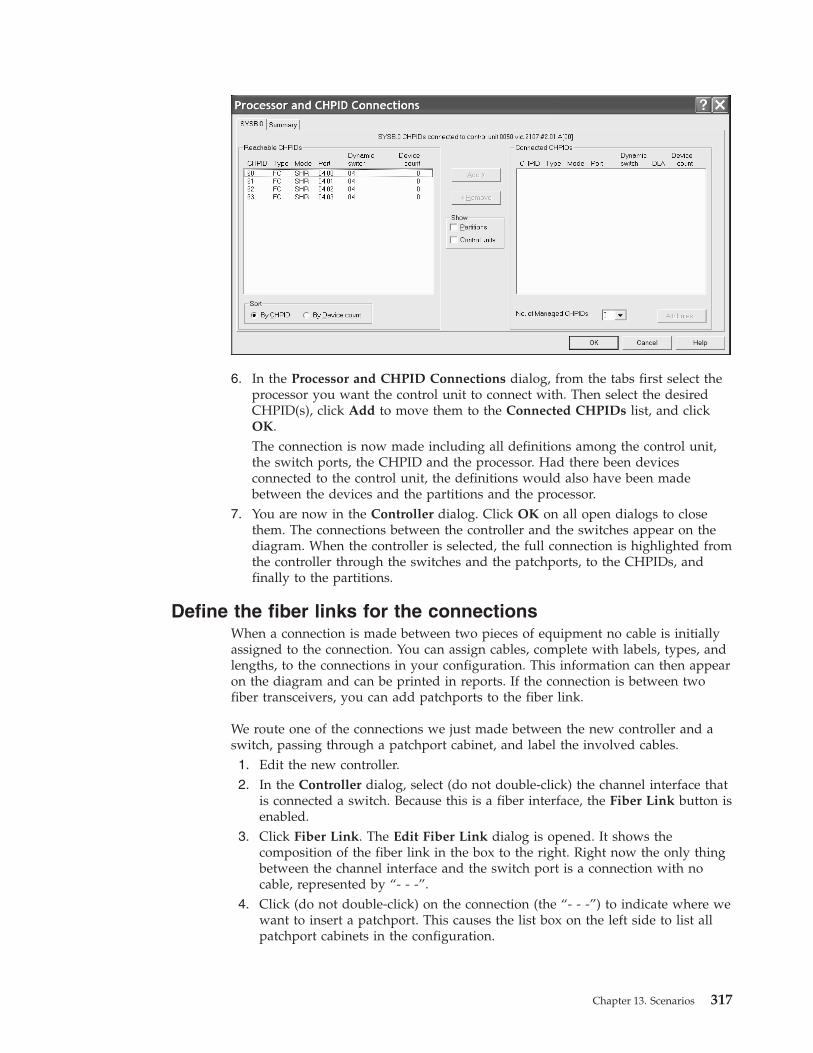
6. In the Processor and CHPID Connections dialog, from the tabs first select theprocessor you want the control unit to connect with. Then select the desiredCHPID(s), click Add to move them to the Connected CHPIDs list, and clickOK.The connection is now made including all definitions among the control unit,the switch ports, the CHPID and the processor. Had there been devicesconnected to the control unit, the definitions would also have been madebetween the devices and the partitions and the processor.
7. You are now in the Controller dialog. Click OK on all open dialogs to closethem. The connections between the controller and the switches appear on thediagram. When the controller is selected, the full connection is highlighted fromthe controller through the switches and the patchports, to the CHPIDs, andfinally to the partitions.
Define the fiber links for the connectionsWhen a connection is made between two pieces of equipment no cable is initiallyassigned to the connection. You can assign cables, complete with labels, types, andlengths, to the connections in your configuration. This information can then appearon the diagram and can be printed in reports. If the connection is between twofiber transceivers, you can add patchports to the fiber link.
We route one of the connections we just made between the new controller and aswitch, passing through a patchport cabinet, and label the involved cables.1. Edit the new controller.2. In the Controller dialog, select (do not double-click) the channel interface that
is connected a switch. Because this is a fiber interface, the Fiber Link button isenabled.
3. Click Fiber Link. The Edit Fiber Link dialog is opened. It shows thecomposition of the fiber link in the box to the right. Right now the only thingbetween the channel interface and the switch port is a connection with nocable, represented by “- - -”.
4. Click (do not double-click) on the connection (the “- - -”) to indicate where wewant to insert a patchport. This causes the list box on the left side to list allpatchport cabinets in the configuration.
Chapter 13. Scenarios 317
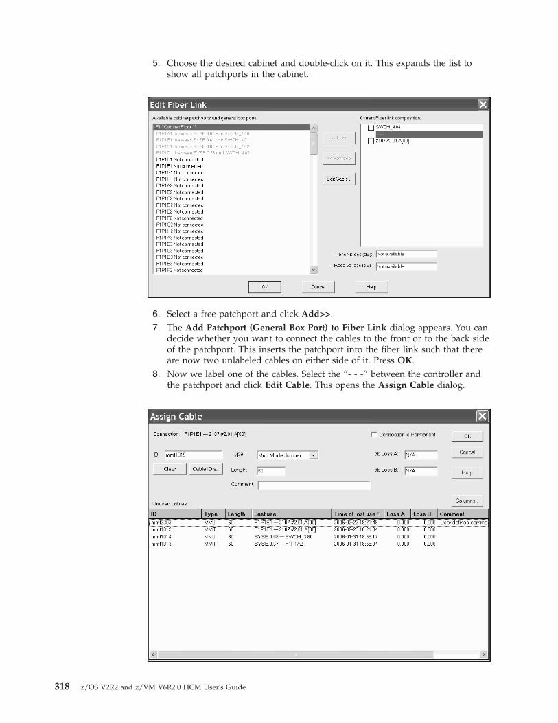
5. Choose the desired cabinet and double-click on it. This expands the list toshow all patchports in the cabinet.
6. Select a free patchport and click Add>>.7. The Add Patchport (General Box Port) to Fiber Link dialog appears. You can
decide whether you want to connect the cables to the front or to the back sideof the patchport. This inserts the patchport into the fiber link such that thereare now two unlabeled cables on either side of it. Press OK.
8. Now we label one of the cables. Select the “- - -” between the controller andthe patchport and click Edit Cable. This opens the Assign Cable dialog.
318 z/OS V2R2 and z/VM V6R2.0 HCM User's Guide

9. Fill in the cable's ID, type, length, and optionally the Comment field, or selectan existing cable from the unused cables list. Then, click OK. The cable's newlabel now appears in the Edit Fiber Link dialog.
10. Label the other cable in the same way.11. Click OK to return to the Controller dialog. You can edit the fiber links of the
other connected channel interfaces by following the same procedure.12. Click OK on all open dialogs to close them.13. Use the Locate --> Controller menu item to zoom in on the new controller.
Select View --> Text Detail and check the Cable Description checkbox. Thecable labels now appear on the diagram.
Add some strings to the new controller1. Select Create --> String. This opens the Create String dialog.
2. Fill in the Create String dialog as shown, specifying an appropriate devicenumber.
3. Since there is more than one physical description for this unit type, the ChoosePhysical Description dialog is opened. Choose the appropriate physicaldescription and click OK.
4. This creates a string of 32 devices. Double-click on the new string on thediagram to open the String dialog. (Tip: position the mouse cursor in the toprectangle of the string.)
Chapter 13. Scenarios 319
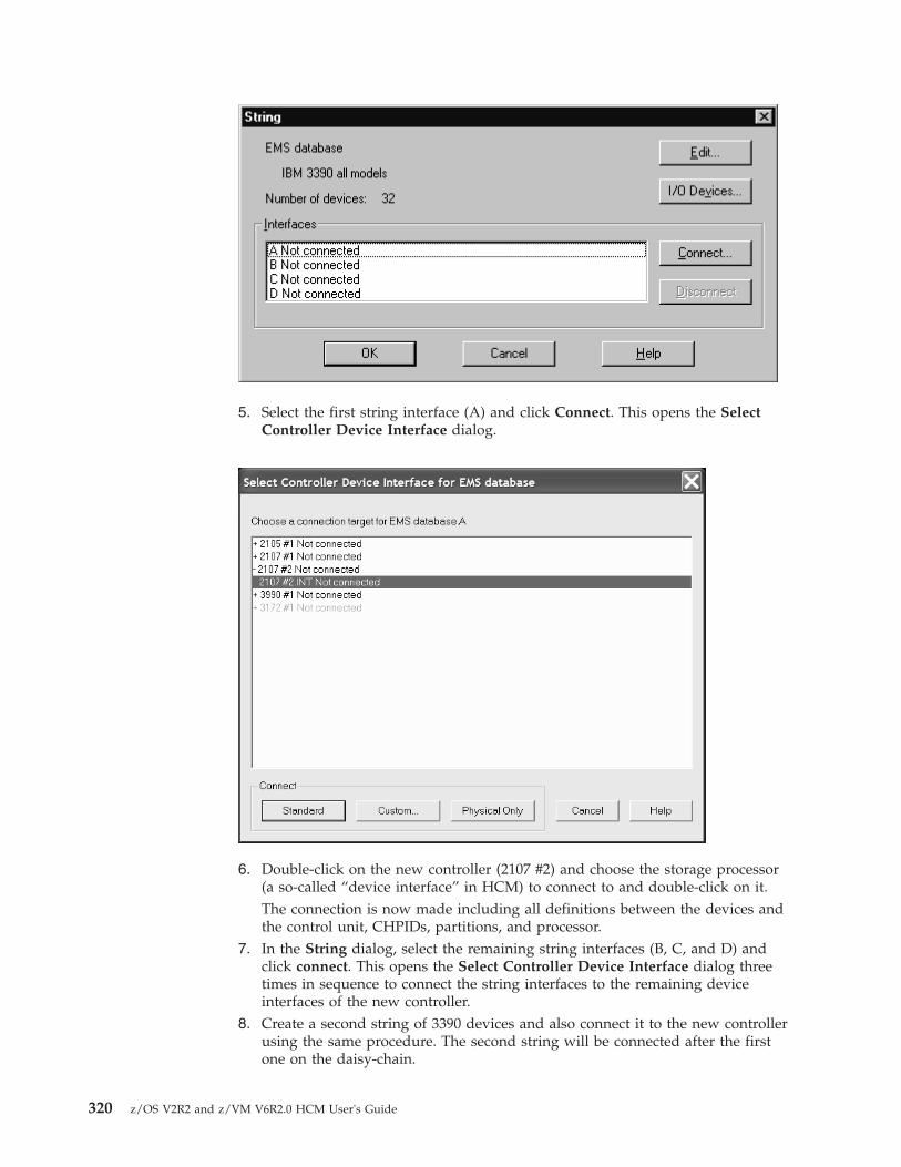
5. Select the first string interface (A) and click Connect. This opens the SelectController Device Interface dialog.
6. Double-click on the new controller (2107 #2) and choose the storage processor(a so-called “device interface” in HCM) to connect to and double-click on it.The connection is now made including all definitions between the devices andthe control unit, CHPIDs, partitions, and processor.
7. In the String dialog, select the remaining string interfaces (B, C, and D) andclick connect. This opens the Select Controller Device Interface dialog threetimes in sequence to connect the string interfaces to the remaining deviceinterfaces of the new controller.
8. Create a second string of 3390 devices and also connect it to the new controllerusing the same procedure. The second string will be connected after the firstone on the daisy-chain.
320 z/OS V2R2 and z/VM V6R2.0 HCM User's Guide

9. Click OK on all open dialogs to close them. The connections between the stringand the controller appear on the diagram. When the string is selected, the fullconnection is highlighted from the string all the way to the partitions.
Define the devices to the operating systemThe newly created devices still need to be defined to the appropriate operatingsystem.1. Edit one of the new strings by either selecting Edit--> String and choosing the
string from the list or by double-clicking on the string in the diagram. Thisopens the String dialog.
2. Click I/O Devices. This opens the I/O Device List dialog. By default all devicesin the string are selected so that we can define them all to the operating systemat once.
3. Click OS Configs. This opens a dialog that lists all operating systemconfigurations in the IODF.
4. Choose the operating system configuration to which you want to define thesedevices and click Define. This opens the Define Device <==> OSConfiguration Parameters dialog that lists all of the parameters that determinethe device <==> OS definitions.
Chapter 13. Scenarios 321

5. Set the parameters appropriately and click OK. This defines the devices to theselected OS configuration.
6. Click OK or Close on all open dialogs to close them.7. Save your configuration file.
You have now completely installed and connected the new strings and thecontroller through the new switch.
Scenario II – Defining a CTC connectionIn this scenario we create CTC connections involving three processors routedthrough a switch. We assume that the following processors and unconnectedCHPIDs exist:v SMP Processor PROC1 (type 2064 with partitions LPAR11 and LPAR12) with
CHPID:– 20 CTC SHR (LPAR11 in the access list)
v SMP Processor PROC2 (type 2064 with partitions LPAR21 and LPAR22) withCHPIDs:– 20 CTC SHR (both partitions in the access list)– 21 CNC SHR (both partitions in the access list)
v XMP processor PROC3 (with LCSS 0 and partition LPAR31) with CHPID:– 21 CNC SHR (LPAR31 in the access list)
We also assume that an operating system exists (OS1 of type MVS) and that anESCON Director 01 (9032-5) exists with ports E0-E3 free.
We create four CTC connections:
PROC1.20 CTC to PROC2.21 CNCPROC2.20 CTC to PROC2.21 CNCPROC1.20 CTC to PROC3.0.21 CNCPROC2.20 CTC to PROC3.0.21 CNC
Connect a switch to the CHPIDs1. Edit the switch by either selecting Switch from the Edit menu and choosing the
switch from the list or by double-clicking on the switch in the diagram. Thisopens the Switch dialog.
322 z/OS V2R2 and z/VM V6R2.0 HCM User's Guide

2. Select four free ports (E0 through E3) and click Connect. This opens the SelectMultiple Connection Target(s) dialog, allowing you to select the connectiontarget interfaces.
3. In the right list box of the Select Multiple Connection Target(s) dialog,double-click on the + signs beside processors PROC1, PROC2 and PROC3 toshow the contained CHPIDs in these processors. Then from PROC1, select thisone: CHPID PROC1.20 CTC SHR.
4. In the left list box, select port E0 and press the enabled <<Connect button at thebottom of the window. This establishes the requested connection between portand CHPID.
5. Repeat steps 3 and 4 to connect CHPIDs PROC2.20, PROC2.21 and PROC3.0.21to the switch ports E1 – E3. Then press button Physical Only ....
Chapter 13. Scenarios 323

6. In the CHPID's Dynamic Switch Modification dialog, enter 01 into the Newdyn. Switch id fields for all CHPIDs and then press OK.
7. Close the Switch dialog to return to the diagram. Now select Filter Diagram...from the View menu. Enable the following check boxes:v CTC Connections
v Objects with physical-only connections
v Show Processors
v Show All CHPIDs
The new connections appear in the diagram.
Create the first CTC connectionHCM considers a CTC connection as a single entity comprising selected controlunits and I/O devices connected to the CHPIDs.1. Select CTC connection... from the Create menu. This opens the Create CTC
Connection dialog.2. Click the CTC or FC CHPID button, and from the emerging Select CHPID
for CTC connection dialog, double-click on the + sign besides PROC1, thenselect PROC1.20 S CTC SHR and finally press OK. Even though the CHPIDsare connected to switch ports, we select the CHPIDs that are to be connected.Click the second CNC/FCV or FC CHPID button and select PROC2.21 CNCSHR.
324 z/OS V2R2 and z/VM V6R2.0 HCM User's Guide

3. Click OK in the Create CTC Connection dialog. The Edit CTC Connectiondialog appears to allow you to define the control units that are part of theconnection.
4. Click the Add New... button on the left-hand side to create the control unitsand devices that are connected to PROC1.20 CTC to represent the imagesavailable via PROC2.21 CNC.
5. Enter control unit number 4110 to represent LPAR11 and control unit number4120 to represent LPAR12. Leave the other controls as they appear and clickOK. This creates control unit 4110 CTC with devices 4110,4 CTC and controlunit 4120 CTC and devices 4120,4 CTC and connect them to CHPID PROC1.20CTC to represent the two partitions.
6. Click the Add New... button on the right-hand side of the Edit CTCConnection dialog to create the control unit and devices that are connected toPROC2.21 CNC to represent the images available via PROC1.20 CTC.
Chapter 13. Scenarios 325

7. Enter control unit numbers 5110 to represent the image and click OK. TheEdit CTC Connection dialog appears again as follows:
This dialog shows that the connection is fully specified with all images dulyrepresented by control units.
8. Close the Edit CTC Connection dialog and choose CTC connections... fromthe Edit menu to open the CTC Connections dialog. The connection betweenPROC1.20 CTC and PROC2.21 CNC appear in the dialog.
326 z/OS V2R2 and z/VM V6R2.0 HCM User's Guide

9. Select the entry in the list box and click Details... to open the View CTCConnection Details dialog.
10. This gives another view of the connection. The partition image LPAR11 onPROC1 can communicate with partitions LPAR21 and LPAR22 on PROC2.
11. Click Cancel to return to the CTC Connections dialog.
Create the second CTC connectionThe second connection is between PROC2.20 CTC and PROC2.21 CNC. In thiscase, we have already created control units and devices that may be used torepresent partitions LPAR21 and LPAR22 via PROC2.21 CNC; we need onlyconnect them appropriately to PROC2.20 CTC . We will have to create a controlunit and 4 devices to represent partition LPAR21 that is available via PROC2.20CTC.1. Click Create... on the CTC Connections dialog.
Chapter 13. Scenarios 327

2. Click the CTC or FC CHPID button and select PROC2.20 CTC SHR.3. Click the second CNC/FCV or FC CHPID button and select PROC2.21 CNC
SHR.4. Click OK. This displays the Accept Proposed CTC Control Units dialog which
proposes control units 4110 and 4120 to be connected to PROC2.20 CTC torepresent LPAR21 and LPAR22, respectively.
5. Click Accept to connect the control units to PROC2.20. The Edit CTCConnection dialog appears, showing that the CTC side has been defined. Notethat the CNC side of the dialog shows that there are two images to berepresented. This is because PROC2.20 CTC has two partitions in its access list,LPAR21 and LPAR22. As yet, there are no control units to represent thesepartitions.
328 z/OS V2R2 and z/VM V6R2.0 HCM User's Guide

6. Click the Add New... button on the right hand side to create the control unitsand devices that are connected to PROC2.21 CNC to represent the partitions(LPAR21 and LPAR22) available via PROC2.20 CTC. Use control units 5210 and5220 and devices 5210,4 and 5220,4 respectively.
7. Close the Edit CTC Connection dialog to return to the CTC Connectionsdialog showing the new connection.
Create the third CTC connectionThe third connection is between PROC1.20 CTC and PROC3.0.21 CNC. In this casewe have a control unit and 4 devices that may be used to represent LPAR11 viaPROC1.20 CTC, but we need to create a control unit and devices to representPROC3.0 via PROC3.0.21 CNC.1. Click Create... on the CTC Connections dialog.2. Click the CTC or FC CHPID button and select PROC1.20 CTC SHR.3. Click the second CNC/FCV or FC CHPID button and select PROC3.0.21 CNC
SHR.4. Click OK. The Accept Proposed CTC Control Units dialog proposes control
unit 5110 to be connected to PROC3.0.21 CNC to represent LPAR11.5. Click Accept to connect the control unit to PROC3.0.21.6. The Edit CTC Connection dialog appears, showing that the CNC side has been
defined, but there is no control unit to represent image PROC3.0 on PROC1.20CTC.
7. Click the Add New... button on the left hand side to create the control unit anddevices that will be connected to PROC1.20 CTC to represent PROC3.0 viaPROC3.0.21 CNC. Use control unit 4300 and devices 4300,4 .
8. Close the Edit CTC Connection dialog. The CTC Connections dialog appearsagain showing the new connection.
Create the last CTC connectionThe final connection is between PROC2.20 CTC and PROC3.0.21 CNC. In this casecontrol unitseady been created to represent all of the images involved. During thecreate process, HCM proposes these control units to be connected to the CHPIDs,and we need only accept these proposals to complete the connection.1. Click Create... on the CTC Connections dialog.2. Click the CTC or FC CHPID button and select PROC2.20 CTC SHR.3. Click the second CNC/FCV or FC CHPID button and select PROC3.0.21 CNC
SHR.4. Click OK. This invokes the Accept Proposed CTC Control Units dialog which
proposes control unit 4300 to connected to PROC2.20 CTC to represent LPAR31on PROC3.0, and control units 5210 and 5220 to be connected to PROC3.0.21CNC to represent LPAR21 and LPAR22 PROC2.
5. Click Accept to connect the control units. The Edit CTC Connection dialogappears, showing the fully defined connection.
6. Close the Edit CTC Connection dialog. The CTC Connections dialog appearsagain, now showing all four connections. Close theCTC Connections dialog.
Define the CTC devices to the OS configurationAssuming one OS configuration (OS1) is used for all four images in the connection,the last step is to define the new devices to the OS configuration.
Chapter 13. Scenarios 329
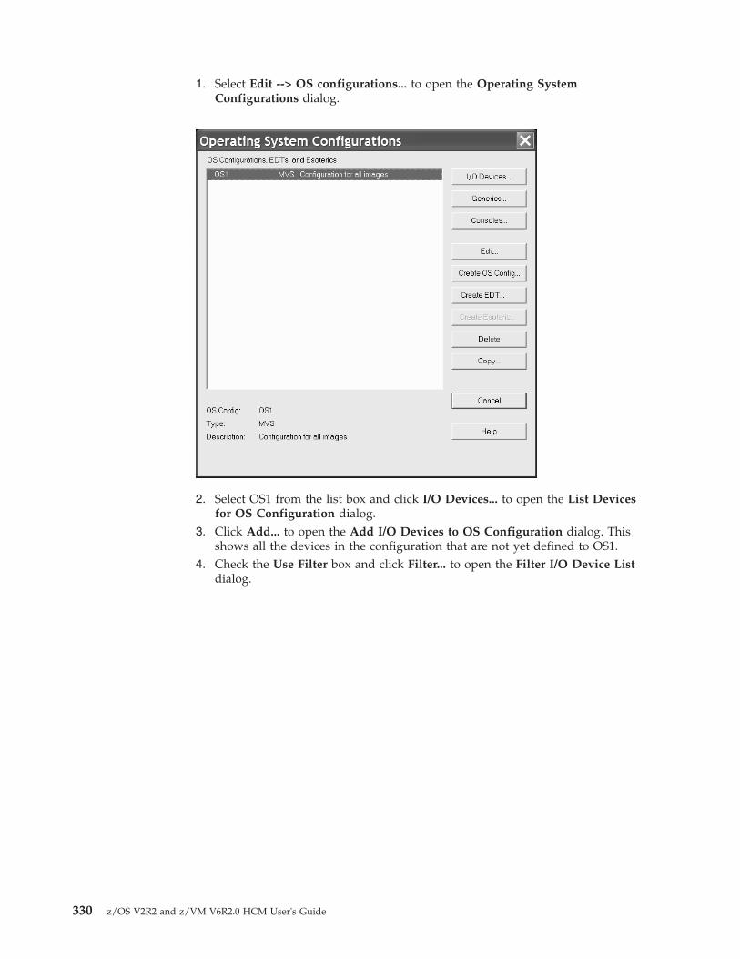
1. Select Edit --> OS configurations... to open the Operating SystemConfigurations dialog.
2. Select OS1 from the list box and click I/O Devices... to open the List Devicesfor OS Configuration dialog.
3. Click Add... to open the Add I/O Devices to OS Configuration dialog. Thisshows all the devices in the configuration that are not yet defined to OS1.
4. Check the Use Filter box and click Filter... to open the Filter I/O Device Listdialog.
330 z/OS V2R2 and z/VM V6R2.0 HCM User's Guide

5. Enter “SCTC” in the Type field and click OK. The Add I/O Devices to OSConfiguration will re appear showing only SCTC devices.
6. Select all of the devices in the list and click OK. The Define Device <==> OSConfiguration Parameters dialog will appear .
Chapter 13. Scenarios 331

7. Set up the OFFLINE and DYNAMIC parameters as appropriate and click OK.This will define all of the CTC devices to the OS configuration.Close all open dialogs to return to the configuration diagram.
Scenario III – Defining a fiber cabling infrastructureIn this example, the logical configuration already exists . Within this scenario wewill describe how you can add the physical objects to an already existing logicalconfiguration, for example, after a Load process.
We will createnets, a processor zone cabinet and a central cabinet which ispresumably located near one or more switches. We will trunk the two cabinetstogether, then trunk the zone cabinet to a processor. Finally, we will route aswitch-to-processor connection through the cabinets using a labeled fiber jumper.
Create the cabinetsWe will create the zone cabinet first.1. Select Create --> Cabinet from the menu. This opens the Create Cabinet dialog.2. Select IBM Zone Cabinet for Model and enter P for the cabinet ID to denote the
processor zone. Select Near processors as the Graphical Position for the cabinet.You can also enter a cabinet description and a serial number.
3. Click OK. The new cabinet appears on the right side of the diagram.4. Now create the second cabinet with IBM Main Distribution Frame for Model, ID
C, and as Graphical Position select Central.
Trunk the two cabinets togetherWe will now connect the two cabinets back-to-back using a permanent trunk.1. Edit the processor zone cabinet by either selecting Edit --> Cabinet and
choosing the cabinet from the list or by double-clicking on the cabinet in thediagram. This opens the Cabinet dialog.
2. Add a panel by clicking "Add" in the panel section. This opens the Add Panelsdialog. Add a panel with seven rows and columns for the requested panel.
3. Click the "Front" radio button in the View section of the Cabinet dialog. Select7 patchports and click "Connect". This opens the Select Connection Target(s)dialog.
4. In the list box, double - click on the back-marked central cabinet. This expandsthe list, showing the backs of all patchports in that cabinet.
332 z/OS V2R2 and z/VM V6R2.0 HCM User's Guide
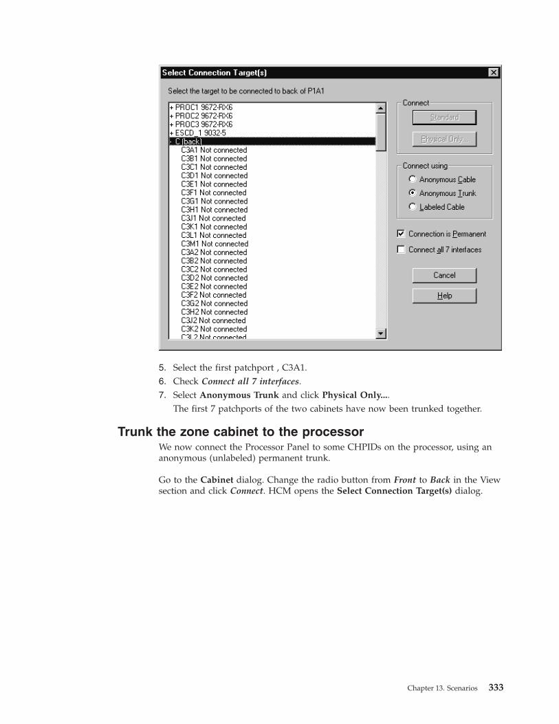
5. Select the first patchport , C3A1.6. Check Connect all 7 interfaces.7. Select Anonymous Trunk and click Physical Only....
The first 7 patchports of the two cabinets have now been trunked together.
Trunk the zone cabinet to the processorWe now connect the Processor Panel to some CHPIDs on the processor, using ananonymous (unlabeled) permanent trunk.
Go to the Cabinet dialog. Change the radio button from Front to Back in the Viewsection and click Connect. HCM opens the Select Connection Target(s) dialog.
Chapter 13. Scenarios 333

1. In the list box, double-click the processor you are connecting. This expands thelist, showing all CHPIDs in the processor.
2. Find a sequence of 7 free CHPIDs and select the first one.3. Click Connect all 7 interfaces.4. Select Labeled Cable and click OK. HCM opens the Assign Cable dialog six
times in sequence for you to assign labels to the individual lines of the trunk.
334 z/OS V2R2 and z/VM V6R2.0 HCM User's Guide

5. Label each line with the same trunk designator followed by a “/” and the linenumber. E.g. TR0001/00”, “TR0001/01”, etc.
6. Click OK to return to the Cabinet dialog, where you can see that thepatchports are now connected to the CHPIDs, as well as to the patchports inthe other cabinet.
7. Click OK on all open dialogs to close them.
Chapter 13. Scenarios 335

Connect a switch to CHPIDs through the patchport cabinetsPermanent connections between pairs of patchports must be made beforepermanent connections between patchports and CHPIDs. It is also necessary tomake all permanent (trunk) connections among patchports before adding thosepatchports to fiber links.
We connect an existing switch port to one of the trunked CHPIDs. Although theCHPIDs are already connected to patchports in the cabinet, we will specify theCHPID as the connection target. The patchports will automatically be connectedbetween the switch port and the CHPID.1. Edit the switch by either selecting Edit --> Switch and choosing the switch
from the selection list or by double - clicking on the switch in the diagram. Thisopens the Switch dialog.
2. Select one of the free switch ports and click Connect. This opens the SelectConnection Target(s) dialog.
336 z/OS V2R2 and z/VM V6R2.0 HCM User's Guide

3. In the list box, double - click on the processor with the trunked CHPIDs. Thisexpands the list, showing all CHPIDs in the processor.
4. Double - click nt BackColor="#7DFB87">on one of the trunked CHPIDs. Theconnection is made between the switch port and the CHPID.
Assign a cable to the new connection1. In the Switch dialog, select the newly connected switch port and click Fiber
Link. This opens the Edit Fiber Link dialog which shows the composition ofthe fiber link in the box to the right.
Chapter 13. Scenarios 337

2. Select the “--” between the switch port and patchport C3A1 and click EditCable. This opens the Assign Cable dialog.
3. Fill nt BackColor="#FFC0FF">in the cable 's ID, type, and length, then click OK.The cable 's new label now appears in the Fiber link dialog.
4. Click OK on all open dialogs to close them. The new connection between theswitch and the CHPID through both patchports can be seen on the diagram.
Connect a controller to the CHPID via the switch1. Edit an existing controller by selecting Edit --> Controller from the menu.
This opens the Edit a controller... dialog. Select the controller that you want toconnect from the list and click OK. This opens the Controller dialog. As analternative, you can directly look for and double-click on the desired controllerin the diagram to reach the Controller dialog.
2. Select a free channel interface (Not connected) from the Interfaces section inthe dialog and click Connect. This opens the Select Connection Target(s)dialog.
338 z/OS V2R2 and z/VM V6R2.0 HCM User's Guide

3. Choose the switch that we trunked to a CHPID from the list and double-clickit to expand it. This lists all installed ports in the new switch.
4. Select a port with no connection and click Standard in the Connect box.5. Since we are connecting through a switch, the Processor and CHPID
Connections dialog is opened for you to choose the CHPIDs to which thecontrol unit will be defined.
6. Select PROC2 from the shown tabs on the top of the dialog and select CHPID21 CNC that we trunked to this switch and click Add>> to move this CHPIDto the Connected CHPIDs list. This opens the Add Control Unit <=>Processor Definitions dialog.
7. In the Add Control Unit <=> Processor Definitions dialog, select the desiredconnection properties and click OK.
Chapter 13. Scenarios 339

8. HCM returns to the Processor and CHPID Connections dialog where CHPID21 CNC moved to the Connected CHPIDs list. Click OK. The connection isnow made and HCM returns to the Controller dialog.
9. Click OK on all open dialogs to close them. The connection between thecontroller and the switch appears on the diagram. When the controller isselected, the full connection is highlighted from the controller through theswitch and the patchports, to the CHPID.
10. Save your configuration file.
Scenario IV – Configuration changes for installing a FICON bridge cardin a 9032–5 ESCON director
The new FICON Conversion Channels ( FCVs ), with their wider bandwidthcompared to classical ESCON channels, allow connecting more I/O equipment to asingle channel. To use the FCV channels, they must be connected to a FICONbridge card installed in a 9032-5 ESCON director. To install FCV channels and aFICON bridge card in an 9032-5 you must follow some configuration rules:v FCV channels can only be installed in specific locations in the processor and
have particular CHPID numbers depending on the processor type.v FICON bridge cards can have only one port address (and link address), on a
modulo 8 + 4 port address.v The 7 consecutive subsequent port addresses of a FICON bridge port address are
used by the FICON bridge card and cannot be used for other connections.
340 z/OS V2R2 and z/VM V6R2.0 HCM User's Guide

The FICON conversion utility can be used for adapting an IODF to use FCVchannels. The following scenario shows an example of how an I/O configurationcan easily be changed using the utility. The starting point in this scenario is aconfiguration in which a CNC CHPID D4 is connected to a port 74. CNC CHPIDD7 is also connected to the ESCD. Three additional CHPIDs are connected to ports75, 78, and 79. The objective of the configuration changes is to have a FICONbridge card at position 74, and CHPID D4 must be converted from CHPID typeCNC to FCV. Also, all attached I/O equipment of CHPID D7 is disconnected andreconnected to the FCV CHPID D4 (aggregation of CHPID D7 to D4) to make useof the wider bandwidth of the FCV channel. The original connection betweenESCD port E0 and CHPID D7 will be disconnected (since this connection is nolonger used). The connections between ports 75, 78, and 79 and their channelsmust be relocated to different positions on the director, since the original portaddresses can no longer be used after installing a FICON Bridge card . Re locatingthe connections from 75, 78, and 79 to different positions using this utility will notaffect the connectivity of the respective CHPIDs to their I/O equipment.
To perform the changes, proceed as follows:1. Invoke the Convert ESCON Port to FC... utility from the Utilities menu.2. The wizard will appear and explain the following steps.
Click the Next > button to continue.
3. A list of all possible ports that can be used to hold a FICON bridge card will beshown . The only selectable ports will be those with an appropriate portaddress (starting with 04 modulo 8 + 4 of 9032-5) and which are alreadyconnected to an FCV or to an FCV-eligible CHPID (for example, a CHPIDwhose type can be changed to FCV). All ports that are not usable for a FICONbridge card are grayed out .
Chapter 13. Scenarios 341

Select port 74 of director 05 connected to CHPID D4 of processor SYSB andclick Next >.
4. In the following step, you have the chance to aggregate I/O equipment of otherCHPIDs to CHPID D4. Select CHPID D7 of processor SYSB to be aggregated toD4 and click the ADD > button.In the bottom part of the window you see CHPIDs and their I/O equipment as
it is aggregated. Click Next > to continue.5. In the following window, you can specify whether or not to disconnect the just
selected CHPID for aggregation of D7 from its port of the ESCD.
342 z/OS V2R2 and z/VM V6R2.0 HCM User's Guide

Click Next > to continue to displace port connections.6. You can now determine where to move port connections from connections to
port addresses which must be freed, since they follow directly after the portaddress of the FICON bridge port address. For port address 75 connected toCHPID DF of processor SYSB, specify the new port address 06. For portaddress 78 connected to CHPID EA of processor SYSB, specify the new portaddress 07. For 79 connected to CHPID DD of processor SYSB, specify the newport address 08. You can use the prompting capability to check for free portaddresses. After selecting new port addresses for connections that must bedisplaced, click Next > to see the final summary.
7. You now see the final summary of all changes to the configuration. Thissummary lists all affected objects including the changes to be performed to theIODF. Scroll down to examine the complete list, which will contain informationsuch as:v CHPID that will be the FCVv Aggregated CHPIDsv Possibly disconnected CHPIDsv Control unit connections movedv Port connections movedv Uninstalled ports
Chapter 13. Scenarios 343

Scroll down to see the complete summary. You can save the summary to a fileto store the list of changes for archive purposes or to use the list as a worksheetfor guidance for changing the cable connections directly at the hardware box.As long as you do not click the Finish button, no changes are written to theHCM configuration and no changes are made to the IODF. It is still possible torefrain from performing the specified changes. Click the Finish button to allowthe wizard to complete. Confirm the configuration changes after you haveexamined all the listed items in the summary and agree with it.
If you save this summary to a file, you will have the following list of configurationchanges:v CHPID SYSB.D4 's type will be changed from CNC to FCV.v The following CHPIDs will be aggregated with SYSB.D4:
SYSB.D7
v The following CHPIDs will be disconnected :CHPID PortSYSB.D7 05.E0
v Port names will be moved with their ports.v The following connections will be moved :
From ToSYSB.DF 05.75 05.06SYSB.E4 05.78 05.07SYSB.DD 05.79 05.08
v The IODF will beont BackColor="#7DFB87">updated as follows:CHPID Type changes From ToSYSB.D4 CNC FCV
v The following control unit connections will be moved :From To
CU 0241 (3990-3) SYSB.D7 SYSB.D4
v Any devices using a source CHPID as the preferred CHPID will be updated touse the target CHPID.
344 z/OS V2R2 and z/VM V6R2.0 HCM User's Guide

v The following port connections will be moved :From To
SYSB.D7 05.E0 -----SYSB.DD 05.79 05.08SYSB.DF 05.75 05.06SYSB.E4 05.78 05.07
v The switch configurations on director 05 (if any) will be updated as required.v The following ports will be un installed :
05.7505.7605.7705.7805.7905.7A05.7B
Scenario V – Establish a PPRC connection consisting of several PPRClinks
PPRC ( peer - to - peer remote copy ) connections are direct connections betweenDASD controller subsystems that are used primarily to provide a hot standbycapability. These connections can be point-to-point from one DASD controller toanother, or they may pass through switches, just as connections from CHPIDs tocontrol units can. Note that HCM provides methods to physically document PPRCconnections, and to export PPRC connection information into CESTPATHcommand and GEOPARM control statement format for further use on the host.HCM does not validate whether the entered PPRC links are valid links in a realconfiguration, but HCM only provides documentation for this type of connections.In this scenario, we will set up a PPRC connection that consists of several singlePPRC links. To demonstrate what you can do with this utility, some of the PPRClinks will directly connect two subsystems with each other, while other PPRC linksinvolve a director . Let us consider a basic configuration where we have thefollowing I/O objects already defined:v A FICON director, type 2032, Id =05v An IBM Enterprise Storage Server® (ESS) DASD subsystem #1, consisting of
control units 3000 and 3010, both having SSID 3000 specified, that hasconnections as follows:– Interface 04.A[0C] connected to director 05.40– Interface 04.B[0D] connected to director 05.41
v A second IBM Enterprise Storage Server (ESS) DASD subsystem #2, consisting ofcontrol units 4000 and 4010, both having SSID 4000 specified, that hasconnections as follows:– Interface 04.A[0C] connected to director 05.50– Interface 04.B[0D] connected to director 05.51
v Devices of type 3390 which are connected to the control units as follows: devicerange 3000,32 connected to control units 3000 and 3010, and device range4000,32 connected to control units 4000 and 4010
To establish a PPRC connection, proceed as follows:1. Edit the subsystem #1 by either selecting Edit:Controller and choosing the
controller from the list or by double-clicking on the controller in the diagram.This opens the Controller dialog.
2. Select interface 12.A[8C] and click Connect. This opens the Select ConnectionTarget(s) dialog.
Chapter 13. Scenarios 345

3. Choose interface 12.A[8C] of DASD subsystem #2 as target, and click Physicalonly to connect both interfaces.
4. Repeat steps 2 and 3, now connecting the interfaces 12.B[8D] of both DASDsubsystems #1 and #2 with each other. Click Close to leave the Controllerdialog.
5. Select Create: PPRC Connection. This opens the Create PPRC Connectiondialog. This utility guides you through 4 pages on which you can specifycertain information needed to create a PPRC connection.
6. Click on the first entry of the list (SSID 3000) in order to select the primary(source) subsystem of the PPRC connection, and click Next. This will showpage two of the Create PPRC Connection dialog.
7. Click on the second entry of the list (SSID 4000) in order to select the secondary(target) subsystem of the PPRC connection, and click again Next which willlead you to page 3 of the utility.
8. We want to create a PPRC connection consisting of four single PPRC links.Therefore, click the More button three times to obtain altogether 4 possibleentries for a source and a target interface. As source interfaces on the left sideof the dialog, select the interfaces 4.A[0C], 4.B[0D], 12.A[8C], 12.B[8D] whichare interfaces of the DASD subsystem #1. As the latter two interfaces aredirectly connected to interfaces of DASD subsystem #2, HCM automatically fillsthe entries on the right side (target interfaces). Your Create PPRC Connectiondialog should now look similar to the following:
Figure 185. Create PPRC Connection (1)
346 z/OS V2R2 and z/VM V6R2.0 HCM User's Guide

Select the target interfaces 4.A[0C] and 4.B[0D] of DASD subsystem #2 to finishspecifying the interfaces for both the source and the target subsystem.
Click Next which will show the last page of the utility.
Figure 186. Create PPRC Connection (2)
Figure 187. Create PPRC Connection (3)
Chapter 13. Scenarios 347

9. Specify the parameters as needed, and finally click Finish to complete settingup the PPRC connection.
You have now defined a new PPRC connection consisting of 4 single PPRClinks. Using Locate:PPRC Connection, you can locate and highlight the PPRCconnection in the diagram at any time.
Figure 188. Create PPRC Connection (4)
348 z/OS V2R2 and z/VM V6R2.0 HCM User's Guide

Chapter 14. HCD-only tasks
The following tasks cannot be carried out using HCM. They must be done usingHCD on the host.
Defining and viewing configuration dataYou can use HCD to define and view configuration data for the following tasks.
Adding similar objects to a configurationYou can use the Add like function of HCD to add a new object, that has adefinition similar to a previously added object. For devices and control units, thisfunction copies also the defined relations.
Note: This Add like function is not available for z/VM HCD.
Copying configurations and merging IODFsThe existing Repeat function in HCD allows you to copy a selected object togetherwith its dependent objects and I/O attachments not only within the same IODFbut also to another IODF. This is useful if you want to consolidate configurationdata from different IODFs in one IODF.
Note: For z/VM HCD, this function is available via REXX utility CBDSMIGR, seez/VM: I/O Configuration (SC24-6100).
Transferring partition configurationsUse the Transfer (move) partition configs function to transfer control units anddevices attached to a channel path from one partition to another within the sameIODF. In contrast to the Repeat function, you do not copy the partition andchannel paths, but move the attached control units and devices to anotherpartition, possibly in another processor.
Note: For z/VM HCD, this function is available via REXX utility CBDSMIGR, seez/VM: I/O Configuration (SC24-6100).
Upgrade an IODF from an earlier version of HCDz/OS V1.7 HCD starts using the new V5 IODF format. If you want to use a lowerversion IODF with z/OS 1.7 HCD or higher, you first have to upgrade the IODFinto the new format before using it.
You can also perform this task using HCM: see “Upgrading the associated IODFfrom version 4 to version 5 format” on page 75.
Querying supported hardware and installed UIMsYou can query supported processors, switches, control units, devices, and installedUIMs.
Note: With z/VM HCD, this information is only accessible via the SupportedHardware Report.
© Copyright IBM Corp. 1995, 2016 349

Viewing and printing the activity logUse HCD to either view or print the activity log. Select Print or compareconfiguration data from the HCD primary task selection panel and then either theView the activity log or Print the activity log option.
Note: With z/VM HCD, you can view the activity log for an IODF using an editoror browser.
Support of large IODFsOnly on HCD, configuration packages allow configuration changes made at aremote system to be merged back into the master IODF.
Note: The support of configuration packages via a dialog is not available withz/VM HCD.
Activating and processing configuration dataYou can use HCD to activate and process configuration data for the followingtasks.
Building IOCDSsYou have to use HCD to build an IOCDS from a production IODF. Processors mayhave varying numbers of IOCDSs. One IOCDS is used at POR time to make theconfiguration data known to the channel subsystem.
HCD allows you to build an IOCDS for processors that do not have an SNAaddress defined as well as for processors with an SNA address configured in anS/390 microprocessor cluster and controlled by the Hardware ManagementConsole. You can do the following:v Display the IOCDS statusv Write a new IOCDSv Switch IOCDS to become the active one for the next PORv Enable/disable the write protection of the IOCDS (only for S/390 microprocessor
cluster)
For more information, refer to Build an IOCDS in the z/OS HCD User's Guide.
Managing IPL attributesWith HCD you can get a list of all CPCs that are configured in an S/390microprocessor cluster and controlled by the Hardware Management Console. Youcan use this list to do the following:v Display the IPLADDR and IPLPARM attribute values of the last and for the next
IPLv Modify IPLADDR and IPLPARM attribute parameters to be used for next IPL
Dynamic activateHCD allows you to activate your configuration dynamically, that is to change acurrently active configuration without the need to POR or IPL your system again.
You can do this for local processors HCD is running on as well as for systems thatare configured in a sysplex. You can:v Activate software configuration changes only
350 z/OS V2R2 and z/VM V6R2.0 HCM User's Guide

v Activate software and hardware configuration changesv Activate a configuration sysplex widev Switch IOCDS for the next POR
For more information, refer to Activate a configuration dynamically in the z/OS HCDUser's Guide.
Build configuration data setsWith HCD you can build configuration data sets for JES3 initialization streamchecker and HCPRIO.
Building and processing CONFIGxx membersHCD allows to build individual CONFIGxx members from a production IODF.Existing CONFIGxx members can be updated or replaced.
For systems which are members of a sysplex, CONFIGxx members can be verifiedagainst selected systems. Responses are displayed in a message list.
Chapter 14. HCD-only tasks 351

352 z/OS V2R2 and z/VM V6R2.0 HCM User's Guide

Chapter 15. Importing and exporting data
The HCM Import and Export facility allows you to exchange data between yournon-HCM processes, applications, and data bases and the configuration data ofHCM. The import and export data format used by HCM is designed to becompatible with relational databases. It is conceptually organized as tables, and thedata exchange is done via data stored in tables as text files.
For more information about the data format, see “Data format for importing andexporting.” For a list of tables that are available in HCM, see “Table summary” onpage 368.
With the Import Data function, you can use existing physical configuration data ofyour non-HCM application to update existing configuration data in HCM as wellas to setup a new configuration file for HCM. Imported data overwrites existingHCM configuration data. In addition, import provides a method to build aconfiguration from the combination of a text file and an IODF.
The import function performs the following types of actions:v Creating physical objectsv If necessary, resynchronizing the configuration file and the IODFv Updating descriptive fields in both the configuration file and the IODFv Creating or changing physical and some logical connectivity
With the Export Data function, you can use configuration data of the HCM workand production files for your non-HCM applications and databases (for example,asset management). HCM configuration data can be stored in your externaldatabase for example, to create reports tailored to your needs. Or, you can create alist of devices including its VOLSERs.
Note:
1. Not all IODF data is exported.2. Not all data which is exported can be imported to update the configuration.3. When you are exporting data from HCM, the export file does not contain the
complete IODF information. For example, no logical data for control unit -processor connection. However, all physical objects and physical connectionsare contained in the export file.
Tip
For ease of use if you have huge non-HCM configuration data, you can write aprogram (for example with REXX or C) to extract data from the tables you haveexported with HCM and convert these data into a format that you can use for yourapplications. Or you can write a program which creates tables for the HCM formatfrom your existing data for import.
Data format for importing and exportingThe import and export data are organized in tables. Each line of text in the tablecorresponds to a row of data in a database table or in a text file.
© Copyright IBM Corp. 1995, 2016 353
Each table type corresponds to an object that appears in an HCM diagram. Everyline of text is processed. The tables contain a header line (the column definitionrecord) with column names that describe the subsequent rows, the data records. Adata record always begins with the table name followed by fields with data values.See also “Record structure.”
HCM uses the first column (table name) and the second column (column namewhich in most cases is the object ID) to identify an object in the configuration. Ifthe physical object does not exist, it is created. Logical objects cannot be created.Subsequent columns are used to update data values in the object. If an existingobject is not mentioned in the import file, it remains unchanged in theconfiguration. This allows the import file to contain a subset of the objects in theconfiguration. Therefore, it is not possible to delete an object via the Import facility.
Some IODF objects are included in the import data format so that they can beproperly placed within physical objects and that fields like descriptions and serialnumbers can be updated. Furthermore, these records include a number of fieldsthat will be ignored during the import operation. These fields are exported becausethey are useful for reports, but cannot be used as input except through HCM's userinterface because they require extensive validation.
Example for a processor table:"PROC","ID","Short Name","Model","Description","Serial Number"�1�"PROC","PROC1","P1","9021-822","Main Processor","1234569021" �2�"PROC","PROC2","P2","3090-600S","Old Processor","6543213090" �3�
�1� header line (column definition record)
�2� and �3�data record
File structureThe HCM Import and Export facility works with multiple files, one for each table.All files must be in the same PC directory. The filenames are fixed 8 character tablenames. For a summary of the table names and for detailed table information, see“Table summary” on page 368 and “Detailed table formats” on page 370.
With the Import Data function, you can read multiple import files from a directory.For import-only, you can also combine one or more tables into a single file. Blanklines are not tolerated in files being imported. They result in the same errormessage as if column one of the line contained an unrecognized table name.
During export with the Export Data function, you are asked for the directorywhere the data tables should be created. Export writes each table in one file for thespecified directory.
Record structureEvery row in a table represents one record. The first row of each table file is thecolumn definition record (header line) which contains the column names. Thecolumn definition record defines the structure of the subsequent rows. Thesubsequent rows are the data records.
Each record contains several columns. Columns are separated with a character ofyour choice, for example, a comma or a tab. In this document a comma is used asa separator.
354 z/OS V2R2 and z/VM V6R2.0 HCM User's Guide

Compound names, such as partition names which are constructed from theprocessor name and the partition name are separated by a character of your choice,for example, a dot or a slash. In this document, a slash "/" is used as a separator.For example, PROC1/PART1 could also be PROC1.PART1.
The first column of each data record contains the table name, the second columncontains the column name (in most cases it is the object ID) to identify a particularrow. Subsequent columns contain the data for the description values of the tablerow.
For the import operation, it is required that each table starts with a columndefinition record. For the export operation, the column definition record is createdby default, but you can suppress this behavior.
On import, each table can contain a subset of the columns in the table. Thefollowing examples could be used to update the description field of the processor(for example, PROC.TXT) and partition (for example, PART.TXT) tables, leaving allother values unchanged.
Example to update a processor table:"PROC"�1�, "ID"�2�, "Description"�3�"PROC", "PROC1", "Main processor"�4�
Example to update a partition table:"PART"�1�, "ID"�2�, "Description"�3�"PART", "PROC1/LPAR1", "Test Partition"�4�"PART", "PROC1/LPAR2", "Production"�4�
�1�table name�2�column name (object ID)�3�column name (for example, description)�4�record data
The first reference to the table type must be the column definitions record. Thecolumn names are not processed in a case-sensitive way by HCM. If you readexported files using programs other than HCM, ensure that the programs are notcase-sensitive when processing the table column names (column definition record).
The records for a particular table need not be contiguous in the input stream. Forexample, all column definition records (header lines) can be at the start of a filecontaining several tables. See the following examples of some possible ways yourdata can look like in a file containing several tables.
All column definition records appear at the beginning of the file:"PROC", "ID", "Description""PART", "ID", "Description""PROC", "PROC1", "Main processor""PART", "PROC1/LPAR1", "Test Partition""PART", "PROC1/LPAR2", "Production"
The records can also appear in random order, as long as the column definitionrecord precedes the record data:"PART", "ID", "Description""PART", "PROC1/LPAR1", "Test Partition""PROC", "ID", "Description""PROC", "PROC1", "Main processor""PART", "PROC1/LPAR2", "Production"
Chapter 15. Importing and exporting data 355

or, more likely:"PROC", "ID", "Description""PROC", "PROC1", "Main processor""PART", "ID", "Description""PART", "PROC1/LPAR1", "Test Partition""PART", "PROC1/LPAR2", "Production"
There must be only one column definition record for each table. Once the columndefinition records are known, subsequent column definition records are interpretedas data just like any other record.
An error message is issued by HCM if it encounters two or more records referringto the same object, but processing continues. For a given object, only the firstrecord referring to it will be processed, all subsequent ones will be ignored.
Column formatsHCM recognizes six types of data columns:
Text Text fields are free-format fields of a predefined length and can contain anysequence of keyboard characters. The maximum length of the text varieswith each column. The text can contain imbedded spaces as well ascharacters that are used as separators. If you use, for example, a comma asa separator, you need to enclose it in double quotation marks (the usualquotation marks used in prose, for example, "A, and B"), or in singlequotation marks (the apostrophe character, for example, 'C, and D'). Use ""within a double-quoted string to embed the double quotation marks - "Hesaid ""Hello"".". Single quotation marks can be used similarly, when singlequotation marks are used to enclose the entire string. The Export functionencloses text fields in double quotation marks.
Text fields are case sensitive. Fields which update IODF data must beentered in the appropriate case for the IODF field.
The maximum length of a text field is 254 characters.
Note: As HCM Version 1.1.0 allows 255 character user fields, the lastcharacter may be truncated on export. A warning message is generated insuch cases.
When updating existing records, a text field updates the configuration evenif the field is all blanks or empty. Blank or empty is a valid value for a textfield. If the entire column is not present in the input file, the field will beleft unchanged.
Boolean (Bool)These are fields with a Yes or No value. Accepted values in these fields areYes, No, Y, N, 1, and 0 in upper or lower case.
A value enclosed in single or double quotation marks is also acceptedalthough there is no need to do this. When updating existing records, ablank or empty Boolean field has no effect.
Numeric (Num)Sequence of digits. Where appropriate, definitions of these columns willindicate acceptable ranges for these values. A value enclosed in single ordouble quotation marks is also accepted although there is no need to dothis.
When updating existing records, a blank or empty Numeric field has noeffect.
356 z/OS V2R2 and z/VM V6R2.0 HCM User's Guide

Hex Sequence of hexadecimal digits (0..9, A..F). The field is checked that it is avalid hexadecimal number. Where appropriate, definitions of thesecolumns indicate acceptable ranges for these values.
A value enclosed in single or double quotation marks is also acceptedalthough there is no need to do this. The processing of hex digits greaterthan 9 is not case sensitive, so an import accepts a..f, though an exportproduces A..F.
When updating existing records, a blank or empty Hex field has no effect.
Float Any floating point number which follows this generic format can beimported:[whitespace] [sign] [ddd] [.] [ddd] [e│E[sign]ddd]
Where appropriate, definitions of these columns indicate acceptable rangesfor these values.
A value enclosed in single or double quotation marks is also acceptedalthough there is no need to do this.
When updating existing records, a blank or empty Float field has no effect.
On export, floats are expressed in this compatible format which avoids theuse of exponential notation, with leading and trailing zeroes removed:[ddd] [.] [ddd]
Enumerated (Enum)These are fields that accept a single value from a predefined set of textvalues. As an example, physical ports on an ESCON director may be either"LED" or "Laser". Values are not case sensitive, i.e. Laser and LASER areequivalent.
A value enclosed in single or double quotation marks is also acceptedalthough there is no need to do this.
When updating existing records, a blank or empty Enumerated field hasno effect.
In all cases, leading and trailing spaces are ignored.
Hierarchical object keysWhere applicable, the object keys in the tables are structured in a hierarchicalmanner. This has the following benefits:v The key itself, with the object type implied by the table containing the data, is
sufficient to completely identify the object without reference to other tables toobtain the contained-in relationships. This simplifies reporting.
v A sorted list of table rows groups related objects together. For example, theController Channel Interface (CCI) table would contain the following object keys:3990 #12/SC0/A3990 #12/SC0/B3990 #12/SC1/A3990 #12/SC1/B
v A database query could collect items using keys containing wild cards. Forexample, from the Controller Channel Interface (CCI) table:3990 #12/* All channel interfaces on 3990 #123990 #12/SC0/* All channel interfaces on segment SC0 of
3990 #12
Chapter 15. Importing and exporting data 357
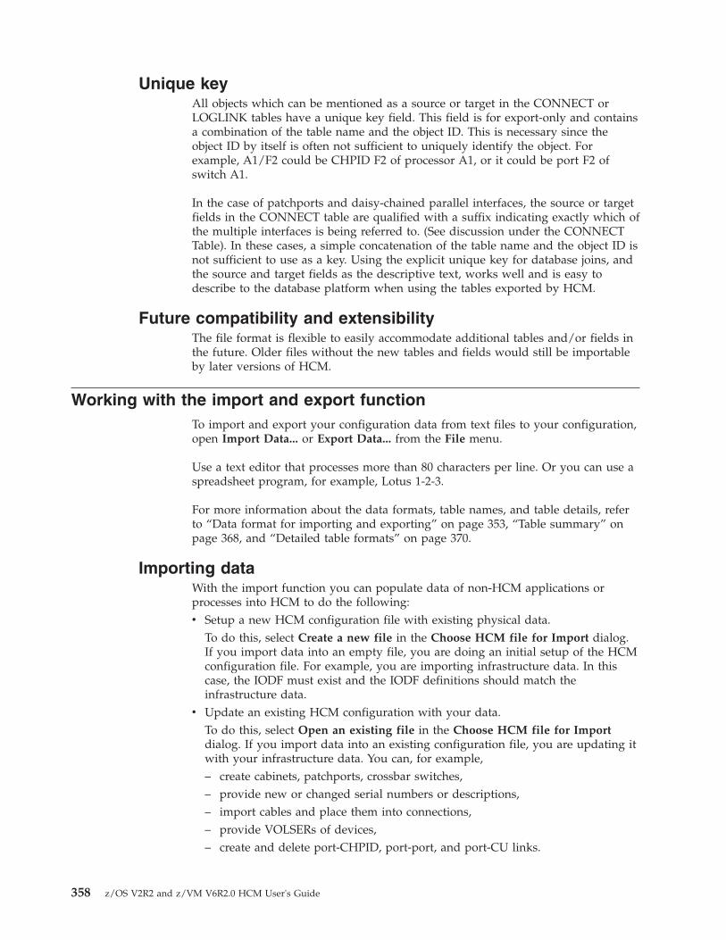
Unique keyAll objects which can be mentioned as a source or target in the CONNECT orLOGLINK tables have a unique key field. This field is for export-only and containsa combination of the table name and the object ID. This is necessary since theobject ID by itself is often not sufficient to uniquely identify the object. Forexample, A1/F2 could be CHPID F2 of processor A1, or it could be port F2 ofswitch A1.
In the case of patchports and daisy-chained parallel interfaces, the source or targetfields in the CONNECT table are qualified with a suffix indicating exactly which ofthe multiple interfaces is being referred to. (See discussion under the CONNECTTable). In these cases, a simple concatenation of the table name and the object ID isnot sufficient to use as a key. Using the explicit unique key for database joins, andthe source and target fields as the descriptive text, works well and is easy todescribe to the database platform when using the tables exported by HCM.
Future compatibility and extensibilityThe file format is flexible to easily accommodate additional tables and/or fields inthe future. Older files without the new tables and fields would still be importableby later versions of HCM.
Working with the import and export functionTo import and export your configuration data from text files to your configuration,open Import Data... or Export Data... from the File menu.
Use a text editor that processes more than 80 characters per line. Or you can use aspreadsheet program, for example, Lotus 1-2-3.
For more information about the data formats, table names, and table details, referto “Data format for importing and exporting” on page 353, “Table summary” onpage 368, and “Detailed table formats” on page 370.
Importing dataWith the import function you can populate data of non-HCM applications orprocesses into HCM to do the following:v Setup a new HCM configuration file with existing physical data.
To do this, select Create a new file in the Choose HCM file for Import dialog.If you import data into an empty file, you are doing an initial setup of the HCMconfiguration file. For example, you are importing infrastructure data. In thiscase, the IODF must exist and the IODF definitions should match theinfrastructure data.
v Update an existing HCM configuration with your data.To do this, select Open an existing file in the Choose HCM file for Importdialog. If you import data into an existing configuration file, you are updating itwith your infrastructure data. You can, for example,– create cabinets, patchports, crossbar switches,– provide new or changed serial numbers or descriptions,– import cables and place them into connections,– provide VOLSERs of devices,– create and delete port-CHPID, port-port, and port-CU links.
358 z/OS V2R2 and z/VM V6R2.0 HCM User's Guide

You can either import all the data in a table, or you can import a subset of thetable. For example, when it is not necessary for all columns or objects to beimported, you can import just the ones you need.
The fields and columns mentioned in the import stream must match currentvalues, or an update is done. Blanks and 0 are valid values. Some table fieldscannot be imported. They are ignored.
You cannot delete an object using the Import function.
Tip
To create the tables for import,v you can convert your data to the HCM format with a program (for example, C
or REXX), orv use the export function first, then edit the tables, and import the changed tables
into HCM.
The data format for importing, for example, how each row of data in the filecorresponds to an object in the configuration is explained in the chapter “Dataformat for importing and exporting” on page 353.
Choose Import Data... from the File menu. (This menu option is disabled, when anHCM configuration file is open.) A confirmation message is displayed whichinforms you that the import operation is a major update to your configuration andthat it cannot be undone. Therefore, this message recommends that you save yourconfiguration before importing data.
No terminates the import and returns to the main menu. Choose Yes (the default)to continue. The Choose HCM file for Import dialog appears.
You can choose to update an existing HCM file or to create a new one. Whenimporting against an existing HCM file, the IODF may or may not be in sync with
Figure 189. Hardware Configuration Manager Confirmation Message
Figure 190. Choose HCM File for Import Dialog
Chapter 15. Importing and exporting data 359

the HCM file. Therefore, it is possible to build, or add to, an HCM file byprocessing input from both the import file and an IODF concurrently.
Note: The option Create a new file is disabled when you are running instand-alone mode.
Select Open an existing file (this is the default) and click on OK.
(You can also select Create a new file. Then, the New dialog appears instead.Specify a filename and click OK. The High-level Qualifier dialog appears whereyou can confirm or specify a high-level qualifier before the list of IODFs appears inthe Select IODF dialog.)
The dialog File Open appears. Select an existing HCM file for update and click onOpen.
On the following Choose IODF dialog, you can select if you want to work withthe already associated IODF or if you want to work with an IODF that is notassociated with the opened HCM file.
General Concept on IODF Update Processing: The fields which update the IODFreceive special handling, that is, IODF objects which do not exist in theconfiguration yet, cannot be created and the following update types must beconfirmed:v Serial numbers in Processor, Switch, Control Unit, and I/O Device objects.v Descriptions in Processor, Partition, CHPID, Switch, Control Unit, and I/O
Device objects.v VOLSERs in I/O Device objects.v Labels in Port objects.v Creation and deletion of Port-CHPID, Port-Port, and Port-CU links.
There will be one dialog for each of these fields. The dialogs only appear asneeded.
Note: There could be several thousand items in each list. In such cases, the list boxwill not be able to contain all of the items. Should this occur, the user will beinformed that the dialog will appear repeatedly to process the updates in "batches".
Figure 191. File Open Dialog
360 z/OS V2R2 and z/VM V6R2.0 HCM User's Guide
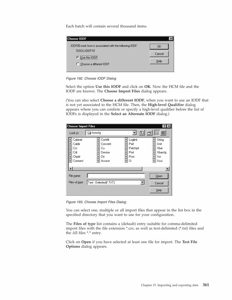
Each batch will contain several thousand items.
Select the option Use this IODF and click on OK. Now the HCM file and theIODF are known. The Choose Import Files dialog appears.
(You can also select Choose a different IODF, when you want to use an IODF thatis not yet associated to the HCM file. Then, the High-level Qualifier dialogappears where you can confirm or specify a high-level qualifier before the list ofIODFs is displayed in the Select an Alternate IODF dialog.)
You can select one, multiple or all import files that appear in the list box in thespecified directory that you want to use for your configuration.
The Files of type list contains a (default) entry suitable for comma-delimitedimport files with the file extension *.csv, as well as text-delimited (*.txt) files andthe All files *.* entry.
Click on Open if you have selected at least one file for import. The Text FileOptions dialog appears.
Figure 192. Choose IODF Dialog
Figure 193. Choose Import Files Dialog
Chapter 15. Importing and exporting data 361

On this dialog you can specify how the import file should be interpreted by HCM.In the section Separate fields with you can specify the separator to be usedbetween fields in each record. The Other field is one character long.
In the section Build compound keys with you can specify the separator betweenparts of compound names such as a CHPID name (Processor name {separator}CHPID number).
Examples:PROC1.30PROC1/30
In the Other field, HCM will not allow a parenthesis symbol "(" or ")" as aseparator for compound names.
The First row contains field names check box is disabled. This checkbox is alwaysselected and left disabled when importing data, because all import files must havecolumn definition records.
The actual import processing occurs immediately after you have clicked on OK inthe Text File Options dialog. The status bar shows progress information.
Cancel terminates the import operation and returns to the main menu.
However, HCM examines the import sources to determine if the IODF needs to beupdated. If updates are required, for example, the Proposed Description Updatesdialog appears where you can confirm the updates.
Figure 194. Text File Options dialog
362 z/OS V2R2 and z/VM V6R2.0 HCM User's Guide

The list box shows one line for every object in the configuration for which thedescription value in the IODF and in the import files differ. On entry, all the linesare preselected. You can select one or more objects.
You can process lines in the list box through the use of the push buttons >> and<<. Once a line has been processed, HCM grays it. Processing a line means that thedirection of the intended transfer is set as follows:v pressing >> will update the IODF with the imported valuev pressing << will retain the current IODF value.
Each line of the list box shows the object identifier, the value of the descriptionfield in the import files read by HCM, and the value of the description field in theIODF on the host.
The dialog remains displayed even if all lines have been grayed, because the Resetbutton allows you to change the value of assignment for already processed lines.This button can be used to mark selected lines as requiring processing again,which removes their gray color and the >> or << symbol from those lines. Thisbutton unprocesses the selected processed lines.
Click on the OK button when you are satisfied with the transfer for each processedline. HCM will then proceed to update the local and/or the remote database. If,however, any unprocessed lines remain in the list box, clicking OK results in anerror message stating that you must process all lines in the list box before clickingOK.
Port <> CHPID/PORT/CU Links:
Figure 195. Proposed Description Updates Dialog
Chapter 15. Importing and exporting data 363

The normal behavior of HCM in the dialog when making or breaking a connectioninvolving a switch port is to update the IODF with the appropriate IODF links.Making or breaking a connection via the import file will behave in a similarfashion, with the exception that you will have the opportunity to overwrite theIODF update.
Note: Physical connections are always made in the configuration file even if theIODF definitions are not updated.
A dialog will appear to display and confirm the Port link updates. For each portaffected by the import, it will indicate the current state in the IODF and theproposed changes from the import file. For each affected port, all port links aredisplayed so that you can see the information in context.
Updating the Controller Serial Numbers:
The serial numbers assigned to control units come from the CONTRLLR records inthe import file, not the control unit records. Control unit records have a serialnumber field, but this data is used for export-only. When a serial number isimported for a controller, HCM attempts to ensure that all control units in thecontroller have that serial number already. If there are any that do not, HCMsuggests updates for those control units. If you accept the IODF values for thecontrol unit serial numbers (rather than the imported values), the control units'serial numbers remain unchanged but the controller itself receives the new serialnumber.
Note: This can also occur as a result of a rejected host update which forces you toaccept existing IODF values.At the end of the import process, HCM steps through all controllers and ensuresthat there are no mismatches between the controller serial number and the serialnumbers of control units contained in the controller. This is done in two steps:1. If all the CUs in a controller have the same serial number, but the controller's
serial number is different, the controller's serial number is changed to matchthe CUs.
2. If the CUs within a controller have serial numbers that differ from each other,CUs are moved out, one at a time, into other controllers. To avoid serialnumber conflicts, new controllers are created if necessary to hold the CUsmoved out.
After moving out a CU, step 1 above is applied again, then step 2, repeating untilthere are no remaining conflicts. Thus, if you reject the suggested imported controlunit serial numbers for any reason, it may result in the creation of additionalcontrollers.
If your import is complete, an informational message is shown.
Exporting dataChoose Export Data... from the File menu. This menu option is only enabled,when an HCM configuration file is open. The Export Data dialog is opened.
Tip
Export to an empty directory. A non-empty directory can already contain exportedfiles from a previous export operation. If you do not choose to export exactly thesame tables in the current export operation, some of the old files will continue to
364 z/OS V2R2 and z/VM V6R2.0 HCM User's Guide
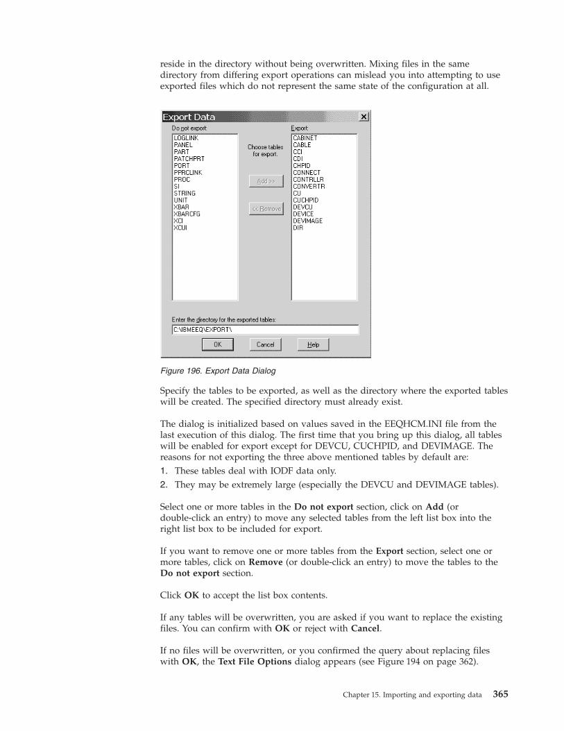
reside in the directory without being overwritten. Mixing files in the samedirectory from differing export operations can mislead you into attempting to useexported files which do not represent the same state of the configuration at all.
Specify the tables to be exported, as well as the directory where the exported tableswill be created. The specified directory must already exist.
The dialog is initialized based on values saved in the EEQHCM.INI file from thelast execution of this dialog. The first time that you bring up this dialog, all tableswill be enabled for export except for DEVCU, CUCHPID, and DEVIMAGE. Thereasons for not exporting the three above mentioned tables by default are:1. These tables deal with IODF data only.2. They may be extremely large (especially the DEVCU and DEVIMAGE tables).
Select one or more tables in the Do not export section, click on Add (ordouble-click an entry) to move any selected tables from the left list box into theright list box to be included for export.
If you want to remove one or more tables from the Export section, select one ormore tables, click on Remove (or double-click an entry) to move the tables to theDo not export section.
Click OK to accept the list box contents.
If any tables will be overwritten, you are asked if you want to replace the existingfiles. You can confirm with OK or reject with Cancel.
If no files will be overwritten, or you confirmed the query about replacing fileswith OK, the Text File Options dialog appears (see Figure 194 on page 362).
Figure 196. Export Data Dialog
Chapter 15. Importing and exporting data 365
In this dialog you can specify how the export file should be constructed regardingthe separators. The dialog is initialized with the values last used for import orexport in the current HCM session. The defaults on first use in each session arecommas, dots, and the First row contains field names is checked. In the sectionSeparate fields with you can specify the separator between fields in each record.When you type data into theOther field, the adjacent radio button is automaticallyselected.
In the section Build compound keys with you can specify the separator betweenparts of compound names such as a CHPID name (Processor name {separator}CHPID number). For example, PROC1.30, PROC1/30. Because of the way tags areconstructed for unlabeled strings, HCM will not allow a left or a right parenthesisas a separator for compound names.
The First row contains field names check box is enabled when you are exporting.If it is checked, HCM ensures that the first line in all export files is the columndefinition record.
Click on OK to perform the export. The status bar will contain progressinformation.
HCM informs you with an informational message that exporting completedsuccessfully.
Importing in stand-alone modeImport is allowed in stand-alone mode, or with read-only access to the IODF. Thetables can be imported to work configuration files.
An import operation that requires an update to the IODF is not possible. If aninput record is encountered which would require an update to the IODF, forexample, updating the description of a CHPID, an error message is issued. In otherwords, you can include CHPID records with descriptions, as long as thosedescriptions match the current description of the CHPID. The entire record is notdiscarded, just the data columns which required update access to the IODF. In allcases, update access to the HCM file is required.
In particular, importing of VOLSERs is permitted in stand-alone mode, though thismay cause appearance of the VOLSER Reconciliation dialog the next time theconfiguration is opened online. For more information see “VOLSER reconciliation”on page 105.
Exporting in stand-alone modeExporting is possible in stand-alone mode.
Some tables cannot be exported in stand-alone mode from a work configurationfile, because they contain data which is only available from the IODF (DEVCU,CUCHPID, DEVIMAGE).
All tables can be exported from a production configuration file.
Using import as a migration aidMany of the fields, and tables are optional when a new configuration file is beingcreated from an import file and an IODF. This section provides guidelines of whatis really necessary.
366 z/OS V2R2 and z/VM V6R2.0 HCM User's Guide

PROC Entries in this table need only be provided when updating or specifyingattributes for these objects. Alternate processors, and processors which arein the "One Processor Per Partition" style need to appear in the import file.In the normal case, processors are created based on the IODF.
PART Entries in this table need only be provided when updating or specifyingattributes for these objects. Partitions are created based on the IODF.
CHPIDEntries in this table need only be provided when updating or specifyingattributes for these objects. CHPIDs are created based on the IODF.
DIR (Switches)Entries in this table need only be provided when updating or specifyingattributes for these objects. Switches are created based on the IODF.
PORT (Switch Ports)Ports which have a LASER interface instead of a LED need to appear inthe import file. All others are created (as LED interface) based on the IODF.
CONTRLLRControllers which need to be associated with a specific physical description(for example, 3990s) need to appear in the import file. Controllers whichare grouped with other controllers (for example, Dual Frame, and tapecontrollers grouped with communicator cables) need to be mentioned inthe import file. All controllers mentioned in the CONNECT table mustappear in the import file.
CCI (Controller Channel Interfaces)For controllers which have more than the minimum number of channelinterfaces allowed by their physical description file, all interfaces beyondthe minimum need to appear in the import file. These records are alsonecessary to specify the interface type if the default interface type for thecontroller is not appropriate.
CDI (Controller Device Interfaces)These can usually be omitted. For controllers which have more than theminimum number of device interfaces allowed by their physicaldescription file, all interfaces beyond the minimum need to appear in theimport file. Controllers with a variable number of device interfaces arevery rare.
CU (Control Units)CUs which are contained in a controller which has more than one segmentshould appear in the import file. This ensures that the load/resync processwill place the CU into the proper segment. If a proper serial number hasbeen assigned to a control unit in the IODF, it need not appear in theimport file.
STRINGStrings which need to be associated with a specific physical description(for example, 3880s, RAMAC) need to appear in the import file. All stringsmentioned in the CONNECT table must appear in the import file.
SI (String Interface)This table can usually be omitted. The minimum number of stringinterfaces are created as necessary based on the physical description.
UNIT Entries in this table need only be provided when updating or specifyingattributes for these objects. Units are created as necessary based on thephysical description.
Chapter 15. Importing and exporting data 367

DEVICEWhere the string which contains this device has been included in theimport file, the first DEVICE in the string should also appear in the importfile.
XBAR All crossbar switches you wish to create need to appear in the import file.
XCI (Crossbar Channel Interface)The import operation does not read this table.
XCUI (Crossbar Control Unit Interface)The import operation does not read this table.
XBARCFGEntries in this table need only be provided when updating or specifyingattributes for these objects. This table can be omitted.
CABINETAll cabinets and general boxes that you wish to create need to appear inthe import file.
PANELAll panels you wish to create within a specific cabinet or general box.
PATCHPRTEntries in this table need only be provided when updating or specifyingattributes for these objects. Patchports or general box ports are createdbased on the information in the CABINET table.
CONVERTRAll converters mentioned in the CONNECT table must appear in theimport file.
CABLEAll named cables mentioned in the CONNECT table must appear in theImport file.
LOGLINKEntries in this table need only be provided when updating or specifyingattributes for these objects.
CONNECTEach connection you wish to create must appear in the import file. (Theload/resync process may create additional connections as well.)
PPRCLINKAll PPRC links/PPRC connections you wish to create, need to appear inthe import file.
Table summaryMany of these tables are optional. See “Using import as a migration aid” on page366 for a discussion of the tables required to create a configuration using import.The DEVCU, CUCHPID, and DEVIMAGE tables are provided to facilitatereporting of logical connectivity based on exported files.
The table names have been limited to 8 characters to maintain a one to onecorrespondence between the table names and the filenames used by the exportprocess, and by defining the database tool reading the exported data. For example,the PATCHPRT table is written to PATCHPRT.TXT.
368 z/OS V2R2 and z/VM V6R2.0 HCM User's Guide

Note: In HCM, by default the table fields are separated by a comma (",") andcompound keys or fields are connected by a dot ("."). You can change thesedefaults during the Export Data dialog. The description of the tables and examplesin this chapter assume a slash ("/"). See also “Record structure” on page 354.
Table 13. Table summary
Category Table name Description
Processor related PROC a processor, see “PROC table” onpage 371
PART a partition, see “PART table” on page372
CHPID a CHPID, see “CHPID table” on page373
Switch related DIR a switch, see “DIR table” on page 375
PORT a switch port, see “PORT table” onpage 375
Controller/Control unit related CONTRLLR a physical controller, see “CONTRLLRtable” on page 376
CCI a controller channel interface, theinterfaces on the top of a controller: A,B, C ..., see “Controller channelinterface (CCI) table” on page 378
CDI a controller device interface, theinterfaces on the bottom of thecontroller: SP0, SP1, ..., see “Controllerdevice interface (CDI) table” on page380
CU an IODF control unit, see “CU table”on page 380
String/Device related STRING a physical string, see “STRING table”on page 381
SI a string interface, the interfaces on thetop of a string: A0, A1 ..., see “Stringinterface (SI) table” on page 383
UNIT a physical unit of a string, see “UNITtable” on page 384
DEVICE an IODF I/O device, see “DEVICEtable” on page 384
Crossbar switch related XBAR a physical crossbar switch, see “XBARtable” on page 385
XBARCFG a named crossbar configurationdescribing the crossbar connectivity,see “XBARCFG table” on page 386
XCI a crossbar channel interface (not readby the import function), see “Crossbarchannel interface (XCI) table” on page386
XCUI a crossbar control unit interface (notread by the import function), see“Crossbar control unit interface(XCUI) table” on page 387
Chapter 15. Importing and exporting data 369
Table 13. Table summary (continued)
Category Table name Description
Patchport related andgeneral box port related
CABINET a patchport cabinet or general box, see“CABINET table” on page 387
PANEL a patchport or general box port panel,see “PANEL table” on page 388
PATCHPRT a patchport or general box port, see“PATCHPRT table” on page 388
Connection related CABLE a physical cable, see “CABLE table”on page 390
CONVERTR a converter, see “CONVERTR table”on page 389
LOGLINK describes the end points of a logicallycomplete series (see “LOGLINK table”on page 391). Useful for reportingpurposes. See “LOGLINK table” onpage 391.
CONNECT a connection between two objects, see“CONNECT table” on page 393
PPRCLINK a PPRC link/PPRC connection, see“PPRCLINK table” on page 396
Logical connection related DEVCU device - control unit connections, see“DEVCU table (export-only)” on page397
CUCHPID control unit - CHPID connections, see“CUCHPID table (export-only)” onpage 397
DEVIMAGE device - processor image connections(an image being a logical partition orthe single image in a BASIC modeprocessor), see “DEVIMAGE table(export-only)” on page 398
Detailed table formatsFields which are always required are in boldface type. All other fields are optional,at least when updating an object. Optional fields which are required when creatingan object are noted as such in the column description.
The tag EO means export-only and indicates that the field is filled in by export,and is read in by import but is not used to update the object. These fields containIODF data.
Data columns which update the IODF are marked with <Updates the IODF>.
Objects which must be present in the IODF are marked with <IODF Key>.
Fields which are ignored in certain contexts, are still validated for correctness (forexample, any data supplied in a numeric column must be numeric).
For a number of fields, a default value is indicated. When importing, it isimportant to realize that the default value is only used when a new object is beingcreated and when no data is provided in the import file for that field.
370 z/OS V2R2 and z/VM V6R2.0 HCM User's Guide

PROC tableTable 14. PROC Table
Field Name Format Description
Table Name Text PROC
ID Text <IODF Key> The ID of the IODF object. (This is theprocessor's name.)
Grouped with Text Applicable only for new processors that are not alreadyin the PC configuration.
For alternate processors, and OPPP (One Processor PerPartition) style processors, the name of the primaryprocessor that this processor should be grouped with.
Ignored for processors which are already in the PCconfiguration file (they have already been placed).
Style Enum Applicable only for new processors that are not alreadyin the PC configuration.
If Grouped with is specified:
v This field defaults to the style of the Grouped withprocessor.
If specified here, it must match the style of theGrouped with processor.
If Grouped with is blank, or contains your processorname (grouped with itself):
v This field defaults to IBM.
v Either value may be coded.
Valid values are IBM or OPPP (One Processor PerPartition). Ignored for processors which are already inthe PC configuration file.
Status Enum Applicable only for new processors that are not alreadyin the PC configuration.
If Grouped with is specified and that processor is IBMstyle:
v Alternate is the only valid value.
v This field defaults to alternate in this case.
If Grouped with is specified and that processor is OPPPstyle:
v Either value is valid.
v This field defaults to alternate in this case.
If Grouped with is blank, or contains your processorname (grouped with itself):
v Primary is the only valid value.
v This field defaults to primary in this case.
Valid values are: primary, alternate.
Ignored for processors which are already in the PCconfiguration file.
Chapter 15. Importing and exporting data 371

Table 14. PROC Table (continued)
Field Name Format Description
Short name Text The short name of the physical machine which containsthis processor.
Defaults to the first two characters of the processor ID(or first character in the case of single character IDs).
Export will place the same value in this column for allprocessors in the physical machine.
On import, all processors in the machine are expected tohave the same value for this attribute, but this is notstrictly enforced. If the specified value does not matchthat of other PROC records in the import file having thesame machine, the last PROC record found in theimport file will be taken. You will not be informed witha warning message.
Valid values: any string of one, or two text filecharacters in which each character must be eithernon-alphabetic or uppercase alphabetic. An empty stringis not a valid value.
Serial number Text <Updates the IODF> The serial number of the IODFobject.
Description Text <Updates the IODF> The description of the IODF object.
Model Text EO Value taken from the IODF object. For example,9021-720.
Support level Text EO Value taken from the IODF object.
Mode Text EO Value taken from the IODF object, for example, BASIC.
Network name Text EO Value taken from the IODF object.
CPC name Text EO Value taken from the IODF object.
ufi01 Text User field 1, or customized user field name.
ufi02 Text User field 2, or customized user field name.
... ... ...
ufi20 Text User field 20, or customized user field name.
Local sysname Text EO Value taken from the IODF object. Blank if notapplicable.
PART tableTable 15. PART Table
Field Name Format Description
Table Name Text PART
ID Text <IODF Key> The ID of the IODF object. This consists ofthe processor name followed by a dot, followed by anumber for the CSS ID (for XMP processors only),followed by the partition name. For reserved partitions,also specify the MIF ID in parenthesis, for example,PROC2084.2.* (5).
Description Text <Updates the IODF> The description of the IODF object.
372 z/OS V2R2 and z/VM V6R2.0 HCM User's Guide

Table 15. PART Table (continued)
Field Name Format Description
Number Text EO Value taken from the IODF object. The partition numberin hex. Blank if not applicable.
Usage Text EO Value taken from the IODF object. For example, CF.
ufi01 Text User field 1, or customized user field name
ufi02 Text User field 2, or customized user field name
... ... ...
ufi20 Text User field 20, or customized user field name
CHPID tableTable 16. CHPID Table
Field Name Format Description
Table Name Text CHPID
ID Text <IODF Key> The ID of the IODF object. This consists ofthe processor name, followed by a dot (.), followed by anumber for the CSS ID (for XMP processors only),followed by the hex CHPID number.
Unique Key Text EO The unique key for this object. Composed of "TableName:ID"
Description Text <Updates the IODF> The description of the IODF object.
Type Text EO Value taken from the IODF object.
Mode Text EO Value taken from the IODF object. For example, SHR.
Dynamic switch Text EO Value taken from the IODF object. Blank if notapplicable. For example, 0F.
Physical number Hex The physical channel onto which this CHPID is mapped.Defaults to the CHPID number.
This is only applicable for OPPP style processors, andneed only be specified if the logical CHPID is mappedonto a different physical channel.
In cases where the CHPID has no correspondingphysical object, 0 will appear here on export. It is notpossible to import CHPIDs without a correspondingphysical object. Valid values are: 0, 1, 2, ..., 1FF
Interface Type Enum One of HCM's allowed CHPID interface types.
Defaults based on the CHPID type of the CHPID in theIODF.
This need only be specified if the physical interface typeis not compatible with the logical CHPID type.
Valid values are: serial, parallel, IOC, OSA.
PCHID Text EO Value taken from the IODF object. Applicable only forXMP processors. Blank if not applicable.
Spanned with Text EO Value taken from the IODF object. Only applicable forspanned CHPIDs. Lists all channel subsystems thisCHPID is spanned with, separated by blanks. Example:PROC1.1 PROC1.2
Chapter 15. Importing and exporting data 373

Table 16. CHPID Table (continued)
Field Name Format Description
>160 TCP/IP stacks Text EO Value taken from the IODF object. Indicates if theCHPID supports queue prioritization. Either empty orYes.
HCA ID Text EO ID of the host communication adapter. Value taken fromthe IODF object. Blank if not applicable.
HCA Port Text EO Port on the host communication adapter. Value takenfrom the IODF object. Blank if not applicable.
Maximum framesize
Text EO Maximum frame size of an IQD channel. Value takenfrom the IODF object. Blank if not applicable.
IQD function Text EO IQD function of an IQD channel. Value taken from theIODF object. Blank if not applicable. Valid values are:Basic Hipersockets, IEDN Access (IQDX), ExternalBridge.
Sparse CHPID mapping for OPPP processorsWhen processors are defined using the One Processor Per Partition (OPPP) style,several logical processors can share the same physical hardware, including thelimited set of channel paths physically present on the machine. A one-to-oneassociation of logical CHPIDs to physical channel paths is set up on a perprocessor basis. Usually, CHPID nn maps to path nn, regardless of which processorCHPID nn belongs to. However, it is possible to make non-default associationssuch that, for instance, CHPIDs 00 through 1F for PROC1 map to paths 00 to 1F,while CHPIDs 00 through 1F for PROC2 map to paths 100 to 11F.
Any non-default CHPID-to-path mapping can be represented in the CHPID recordby filling in the "Physical number" field. It is only possible to representCHPID-to-path mapping for CHPIDs which actually exist in the configuration,because CHPID import records are rejected by HCM unless the CHPID exists.When editing an existing configuration using the HCM interface you can specifymappings for CHPIDs which have yet to be created. This cannot be done using theImport function.
Example: If you were to map CHPID 00 to path 10, CHPID 00 must exist in theconfiguration. If CHPID 10 existed, you could also specify a path for it to map to.Assuming, however, that CHPID 10 does not exist, no mapping can be specifiedfor it in an import file, and HCM will automatically assign a mapping to it thatdoes not conflict with any other mappings. If the next free path number (after 10)that is free is 100, then CHPID 10 will be mapped to path 100. (100 is a likelychoice, because HCM looks for an unmapped path starting with the path thatCHPID 10 used to be mapped to, in this case 10. All the paths up to FF are spokenfor due to the default mapping.)CHPID 00 ====> Path 10 assigned by CHPID record in import fileCHPID 10 ====> Path 100 assigned by default (first free path)
This is known as sparse CHPID mapping, because the import file does not containa record to map every CHPID slot to a path slot. Some CHPID slots are allowed todefault. Export practices sparse CHPID mapping on output.
OPPP and shadow processor CHPID/path mapping issuesIf a configuration contains shadow processors or One Processor Per Partition styleprocessors, it is possible for more than one CHPID to use the same physicalchannel path. LOGLINK and CONNECT records mention CHPIDs when
374 z/OS V2R2 and z/VM V6R2.0 HCM User's Guide

identifying a physical channel path. A problem arises if a set of import/export filesdescribes more than one connection to a path. Therefore, during export, LOGLINKand CONNECT records are only generated once for each path, not for each CHPIDusing the path.
If you are generating files for import using tools other than HCM's export use thesame approach. That is, you should not generate duplicate LOGLINK andCONNECT records when the configuration contains paths which map to multipleCHPIDs.
DIR tableTable 17. DIR Table
Field Name Format Description
Table Name Text DIR
ID Hex <IODF Key> The ID of the IODF object.
Serial number Text <Updates the IODF> The serial number of the IODFobject.
Description Text <Updates the IODF> The description of the IODF object.
Model Text EO Value taken from the IODF object. For example, 9032-3.
Controller Label Text Applicable only for new switches that are not already inthe PC configuration.
The label which should be applied to the internalcontroller of this switch.
Ignored for switches which are already in the PCconfiguration file.
String Label Text Applicable only for new switches that are not already inthe PC configuration.
The label which should be applied to the internal stringof this switch.
Ignored for switches which are already in the PCconfiguration file.
ufi01 Text User field 1, or customized user field name
ufi02 Text User field 2, or customized user field name
... ... ...
ufi20 Text User field 20, or customized user field name
PORT tableTable 18. PORT Table
Field Name Format Description
Table Name Text PORT
ID Text <IODF Key> The hex switch number followed by aslash "/" and the hex port number.
Unique Key Text EO The unique key for this object. Composed of "TableName:ID"
Chapter 15. Importing and exporting data 375
Table 18. PORT Table (continued)
Field Name Format Description
Interface type Enum One of HCM's allowed Port interface types. Valid valuesare: LED, Laser.
Name Text <Updates the IODF> The descriptive name of the IODFport.
Note: Ports which are not "installed" in the IODF are not exported, and cannot be imported.
CONTRLLR tableTable 19. CONTRLLR Table
Field Name Format Description
Table Name Text CONTRLLR
Label Text Unique label of an HCM physical controller. Forexample, 3990 #12.
Serial number Text <Updates the IODF> In addition to updating thecontroller object (a PC object), this field is used toupdate the IODF for all control units that the controllercontains.
IODF control unittype
Text The type-model of the controller. For example, 3990-6.
Applicable only for new controllers that are not alreadyin the PC configuration. Ignored for controllers whichare already in the PC configuration file.
Export places the following in this field:
The type-model of one of the control units in thecontroller. The assumption is that all control units in thecontroller are of the same type. Where the controllercontains more than one control unit, the specific controlunit chosen is undefined. If the controller contains nocontrol units, this field will be blank.
See the Usage Note in the PDF Name column.
PDF AbbrevId Text The abbreviated ID (AbbrevId = ) of one of HCM'sphysical description templates. For example, RAMAC2.
Applicable only for new controllers that are not alreadyin the PC configuration. Ignored for controllers whichare already in the PC configuration file.
Export places the following in this field:
If a specific PDF was used, and that PDF has anabbreviated ID, it will appear here. Otherwise this fieldwill be blank.
See the Usage Note in the PDF Name column.
376 z/OS V2R2 and z/VM V6R2.0 HCM User's Guide

Table 19. CONTRLLR Table (continued)
Field Name Format Description
PDF Name Text The label (Subsystem =) of one of HCM's physicaldescription templates. For example, IBM 3990 Model 6DASD Controller.
Applicable only for new controllers that are not alreadyin the PC configuration. Ignored for controllers whichare already in the PC configuration file.
Export places the following in this field:
If a specific PDF (physical description file) was used, thephysical description name (Subsystem =) will appearhere. Otherwise this field will be blank.Usage Note: Import usage of the IODF Control UnitType, PDF AbbrevId, and PDF Name fields:
These fields are used to determine which HCM physicaldescription should be associated with a new controller.Only one of these fields is used on input. They areevaluated in the following order:
1. PDF name is used if the column is present andcontains data. If specified it must be valid.
2. PDF AbbrevId is used if the column is present andcontains data. If specified it must be valid.
3. HCM's normal search for a PDF based on the IODFControl Unit Type field. If the IODF Device Type isblank or invalid, the default PDF is assigned.
Display class Enum One of HCM's controller display classes.
If the controller is being created, and this field is notspecified, it will default as follows:
1. if the PDF specifies a display class, that class will beused.
2. the display class will default based on the firstcontrol unit that is placed into this controller.
3. if neither of the above apply, the display class willdefault to "Other".
Valid values are: DASD, Tape, Terminal, Unit record,Telecommunications, MICR/OCR, Graphics, CTC, Other.
Installed Bool Yes (this is the default) indicates that the controllershould be marked as installed.
Integrated Bool Yes indicates that the controller should be marked ascontaining integrated devices (a 3745, for example). Thedefault is based on the display class:
DASD and Tape: No
All others: Yes
Chapter 15. Importing and exporting data 377

Table 19. CONTRLLR Table (continued)
Field Name Format Description
Grouped with Text Applicable only for new controllers that are not alreadyin the PC configuration.
For controllers which can be grouped together withcommunicator cables (3803 and 3480 for example), andDual Frame controllers, this column specifies theController Label of the leftmost controller in thesubsystem. This field is valid only for controller withPDFs which allow more than one controller in asubsystem.
Ignored for controllers which are already in the PCconfiguration file (they have already been placed).
ufi01 Text User field 1, or customized user field name
ufi02 Text User field 2, or customized user field name
... ... ...
ufi20 Text User field 20, or customized user field name
Interfaces on controllersWhen controllers are created with the import facility, each controller is created withthe minimum number of channel and device interfaces. This is different fromnormal HCM behavior. Normally HCM would create the controller with thedefault number of interfaces as specified in the PDF. The minimum number ofchannel interfaces is the lowest value specified in the Allow clause of the PDF, or 1for the default PDF. Additional interfaces are created by mentioning them in theCCI table.
Note that it is possible with HCM to decrease the number of interfaces below theminimum number of interfaces specified in the PDF Allow clause. For example, itis possible to decrease the number of interfaces on a 3990 segment so that eachsegment contains only one interface. It is not possible to create this configurationwith import without altering the PDF to allow a minimum of one interface on a3990. This is a known instance where an export, followed by an import into anempty file, will not re-create the original configuration exactly.
Controller channel interface (CCI) tableTable 20. CCI Table
Field Name Format Description
Table Name Text CCI
378 z/OS V2R2 and z/VM V6R2.0 HCM User's Guide

Table 20. CCI Table (continued)
Field Name Format Description
Interface name Text The name of the controller channel interface, in thefollowing form:
controller label[/segment name][/adapter name]/interface label
controller labellabel of controller
segment namesegment label (used only with controllershaving more than one segment)
adapter namechannel adapter label (used only withcontrollers using channel adapter scheme)
interface labelchannel interface label (A, B, ...)
In cases where the components (segment, channeladapter, or interface) are not given explicit names in thePDF, a zero-based index is used instead. (for example,channel adapter 2 is the third channel adapter in thesegment or controller which contains it).
Examples:
3480 #9/A3990 #12/SC0/A6100 #5/Bus 0/A/0
Unique Key Text EO The unique key for this object. Composed of "TableName:Interface name".
Interface type Enum One of HCM's allowed interface types.
The default is based on the display class of thecontroller:
DASD and tape: serial
All others: parallel
Note: If the interface type of an existing interface isbeing changed, this interface will be disconnected ifnecessary before being updated. This is necessary sincethe interface type change will mean that the cablecurrently connected to this interface will no longer be ofthe correct type.
Valid values are: serial, parallel, IOC, OSA.
Note: All controller channel interfaces beyond the minimum must be explicitly created withthis record. If a CCI must be created, all intervening CCIs and channel adapters will becreated as necessary. For example, creating the fourth CCI will automatically create thesecond and third if they do not already exist. In this example, the interface types of thesecond and third interfaces would be assigned so that they match the type of the fourthinterface.
Chapter 15. Importing and exporting data 379

Controller device interface (CDI) tableTable 21. CDI Table
Field Name Format Description
Table Name Text CDI
Interface name Text The name of the controller device interface, in thefollowing form:
controller label[/segment name][/adapter name]/interface label
controller labellabel of controller
segment namesegment label (used only with controllershaving more than one segment)
adapter namedevice adapter label (used only with controllersusing device adapter scheme)
interface labeldevice interface label. When there is only onedevice interface on the adapter or segment, theinterface label may be omitted.
In cases where the components (segment, deviceadapter, or interface) are not given explicit names in thePDF, a zero-based index is used instead. For example,device adapter 2 is the third device adapter in thesegment or controller which contains it.
Examples:
6100 #5/Bus 0/3 (interface label omitted)5500 #3/Y-Bus/6/1 (second unnamed interface
on adapter 6)
Export always omits the interface name when there isonly one device interface on the adapter or segment.
Unique Key Text EO The unique key for this object. Composed of "TableName:Interface Name".
Note: For those controller types which support a variable number of device interfaces, allcontroller device interfaces beyond the minimum number (which are created automatically)must be explicitly created with this record. If a CDI must be created, all intervening CDIsand device adapters will be created as necessary.
CU tableTable 22. CU Table
Field Name Format Description
Table Name Text CU
ID Hex <IODF Key> The ID of the IODF object.
380 z/OS V2R2 and z/VM V6R2.0 HCM User's Guide

Table 22. CU Table (continued)
Field Name Format Description
Container Text Applicable only for new control units that are notalready in the PC configuration.
Specifies the exact placement of the "new" control unitwithin a physical controller. A container object is either acontroller label (for single segment controllers such as3174), or a controller label/segment name, for controllerswhich have two segments. If not specified, HCM willplace the device using the normal heuristics employedduring the IODF load/resync process (this placement isbased primarily on serial number). For example, 3174 #5,3990 #12/SC0.
Internal switch control units (those which are logicallyconnected to port FE), and control units of type CTC orCFS, receive special treatment as follows:
v Import ignores this field and the objects are placedautomatically.
v For CTC and CFS control units, export leaves thisfield blank since there is no meaningful containerobject for these control units.
Ignored for control units which are already in the PCconfiguration file (they have already been placed).
Serial number Text EO The serial number of the IODF object.Note: HCM uses the serial number of the containercontroller to update the IODF with control unit serialnumbers.
Description Text <Updates the IODF> The description of the IODF object.
Type Text EO Value taken from the IODF object.
SSID Text The subsystem ID of the control unit.
STRING tableTable 23. STRING Table
Field Name Format Description
Table Name Text STRING
Chapter 15. Importing and exporting data 381

Table 23. STRING Table (continued)
Field Name Format Description
Tag Text A unique tag to identify the string. This tag has nomeaning outside the context of this import file.
For new strings, any meaningful tag may be used. Werecommend using the first device number in the string.
For existing strings, HCM will first attempt to locate theone string which has this value as an explicit label. If nostring was found, HCM will interpret the tag as a deviceID and look for the string, labeled or not, that containsthe device.Usage Note: unlabeled strings. If the string containsdevices, the tag will be the device ID of the first (thelowest device number) of the string. If an unlabeledstring has no devices, its tag will be of the form"String #n" where n is an integer value which is simplyincremented each time such a tag is generated in orderto guarantee uniqueness.
Examples:
TSO POOL 10400-00000400-0000(MVS1)
IODF device type Text The type-model of the string. For example, 3390.
Applicable only for new strings that are not already inthe PC configuration. Ignored for strings which arealready in the PC configuration file.
Export places the following in this field:
The type-model of one of the device in the string withthe lowest device number. If the string contains nodevices, this field will be blank.
See the Usage Note in the PDF Name column.
PDF AbbrevId Text The abbreviated ID (AbbrevId = ) of one of HCM'sphysical description templates. For example, RAMAC2.
Applicable only for new strings that are not already inthe PC configuration. Ignored for strings which arealready in the PC configuration file.
Export places the following in this field:
If a specific PDF was used, and that PDF has anabbreviated ID, it will appear here. Otherwise this fieldwill be blank.
See the Usage Note in the PDF Name column.
382 z/OS V2R2 and z/VM V6R2.0 HCM User's Guide
Table 23. STRING Table (continued)
Field Name Format Description
PDF Name Text The label (String =) of one of HCM's physicaldescription templates. For example, IBM RAMAC 2Array DASD.
Applicable only for new strings that are not already inthe PC configuration. Ignored for strings which arealready in the PC configuration file.
Export places the following in this field:
If a specific PDF was used, the physical descriptionname (String =) will appear here. Otherwise this fieldwill be blank.Usage Note: Import usage of the "IODF Device Type","PDF AbbrevId", and "PDF Name" fields:
These fields are used to determine which HCM PhysicalDescription should be associated with a new string.Only one of these fields is used on input. They areevaluated in the following order:
1. PDF Name is used if the column is present andcontains data. If specified it must be valid.
2. PDF AbbrevId is used if the column is present andcontains data. If specified it must be valid.
3. HCM's normal search for a PDF based on the IODFDevice Type field. If the IODF Device Type is blankor invalid, the default PDF is assigned.
Label Text A label for the string. Strings in HCM need not beexplicitly assigned a label. When the label is absent,HCM will display a label of the form "String xxxx-yyyy"where xxxx is the device number of the first device inthe string and yyyy is the device number of the lastdevice number in the string. For example, string 300-31F.
Installed Bool Yes (this is the default) indicates that the string shouldbe marked as installed.
ufi01 Text User field 1, or customized user field name
ufi02 Text User field 2, or customized user field name
... ... ...
ufi20 Text User field 20, or customized user field name
String interface (SI) tableTable 24. SI Table
Field Name Format Description
Table Name Text SI
Interface name Text The string tag followed by a slash "/" and the interfacename. The interface name must be an allowable value interms of the string PDF. For example, TSO POOL0001-0000/A0, 0400-0000/A0, or 0400-0000(MVS1)/A0.
Unique Key Text EO The unique key for this object. Composed of "TableName:Interface Name".
Chapter 15. Importing and exporting data 383
Table 24. SI Table (continued)
Field Name Format Description
Note: All string interfaces beyond the minimum must be explicitly created with this record.If an SI must be created, all intervening SIs will be created as necessary.
UNIT tableTable 25. UNIT Table
Field Name Format Description
Table Name Text UNIT
Tag Text Identifier consisting of string tag followed by a slash "/"and a zero-based unit index. Units are numbered 0 ton-1 in row-major order. In strings which have thetwoheaded attribute in the PDF, such as 4-path 3380, theunits are counted from top to bottom in the left column,and then top to bottom in the right column. If the unitdoes not yet exist in the string, intervening units arecreated as necessary when creating the new unit.
It is not possible to create additional units in the internalstring of a switch.
Serial number Text The physical serial number of the unit.
Label Text The label of the unit.
Installed Bool Yes (this is the default) indicates that the string shouldbe marked as installed.
ufi01 Text User field 1, or customized user field name
ufi02 Text User field 2, or customized user field name
... ... ...
ufi20 Text User field 20, or customized user field name
DEVICE tableTable 26. DEVICE Table
Field Name Format Description
Table Name Text DEVICE
ID Text <IODF Key> The ID of the IODF object. This is normallythe device number, followed by a four-digit hexadecimalsuffix, appended with a '-', which helps to distinguishdevices with duplicate IDs. Also, to help ensureuniqueness, the device number is followed by the name,enclosed in parenthesis, of one of the operating systemconfigurations to which the device is defined. If thedevice is not defined to any operating system, nothing isadded to the device number. On input, any of thedefined operating systems will serve to uniquelyidentify the device. On output, export will choose thefirst defined operating system as sorted alphabetically inEBCDIC. Examples:
0400-00000400-0000(MVS1)
384 z/OS V2R2 and z/VM V6R2.0 HCM User's Guide

Table 26. DEVICE Table (continued)
Field Name Format Description
Container Text Applicable only for new devices that are not already inthe PC configuration.
Specifies the exact placement of the device into aphysical container. Container is a string tag or a unittag. If a unit tag is specified, the device is placed intothat unit. If a string tag is specified, the device is placedinto the first available position in that string usingHCM's normal heuristics. If this field is not specified,HCM places the device using the normal heuristicsemployed during the IODF load/resync process. Forexample, 400, 400/0.
On output, export always places a unit tag in this field.
Internal switch devices (those which are logicallyconnected via a control unit to port FE), and devices oftype SCTC, BCTC, FCTC, CFS, or CFP, receive specialtreatment as follows:
v Import ignores this field and the objects are placedautomatically.
v For SCTC, BCTC, FCTC, CFS and CFP devices, exportleaves this field blank since there is no meaningfulcontainer object for these devices.
Ignored for devices which are already in the PCconfiguration file (they have already been placed).
Serial number Text <Updates the IODF> The serial number of the IODFobject.
Description Text <Updates the IODF> The description of the IODF object.
VOLSER Text <Updates the IODF> The VOLSER of the IODF object.
Type Text EO Value taken from the IODF object.
PPRC Usage Text EO Value taken from the IODF object. The PPRC Usage typeof the device.
XBAR tableTable 27. XBAR Table
Field Name Format Description
Table Name Text XBAR
Label Text The physical label of the crossbar switch.
# of ChannelInterfaces
Num The number of interfaces across the top of the crossbarswitch.
For existing crossbars, decreasing the number of channelinterfaces will cause connected channel interfaces to bedisconnected before being deleted.
This is an optional field. If a crossbar is being created,and this field is absent, the default number of channelinterfaces ( 1 ) will be created.
Chapter 15. Importing and exporting data 385

Table 27. XBAR Table (continued)
Field Name Format Description
# of Control UnitInterfaces
Num The number of interfaces across the side of the crossbarswitch.
For existing crossbars, decreasing the number of controlunit interfaces will cause connected control unitinterfaces to be disconnected before being deleted.
This is an optional field. If a crossbar is being created,and this field is absent, the default number of controlunit interfaces (1) will be created.
Serial number Text The serial number of the crossbar switch.
Short name Text The short name of the crossbar switch.
Default XBARCFG Text Default crossbar switch configuration.
ufi01 Text User field 1, or customized user field name
ufi02 Text User field 2, or customized user field name
... ... ...
ufi20 Text User field 20, or customized user field name
XBARCFG tableTable 28. XBARCFG Table
Field Name Format Description
Table Name Text XBARCFG
Name Text The name of the crossbar configuration. This consists ofthe XBAR label followed by a slash "/" and theconfiguration name. The name of the defaultconfiguration "normal" is also accepted.
Row 1 ChannelInterface
Text The label of the channel interface to which this row(control unit interface) is connected. If this field is absentor blank, the row will be assigned no connectivity inthis crossbar configuration. For example, 4.
Row 2 ChannelInterface
Text The label of the channel interface to which this row isconnected. For example, 4.
...
Row 32 ChannelInterface
Text The label of the channel interface to which this row isconnected. For example, 4.
Crossbar channel interface (XCI) tableTable 29. XCI Table
Field Name Format Description
Table Name Text XCI
Interface name Text The XBAR label followed by a slash "/" and theinterface name. The interface name is an integer from 1to n where n is the number of channel interfaces.
Unique Key Text EO The unique key for this object. Composed of "TableName:Interface Name"
386 z/OS V2R2 and z/VM V6R2.0 HCM User's Guide

Table 29. XCI Table (continued)
Field Name Format Description
Note: This record is exported, but ignored on import.
Crossbar control unit interface (XCUI) tableTable 30. XCUI table
Field Name Format Description
Table Name Text XCUI
Interface name Text The XBAR label followed by a slash "/" and theinterface label. The interfaces are labeled A1, B2, C3, ...,Z26, AA27, AB28, ...
Unique Key Text EO The unique key for this object. Composed of "TableName:Interface Name"
Note: This record is exported, but ignored on import.
CABINET tableTable 31. CABINET Table (also containing general boxes)
Field Name Format Description
Table Name Text CABINET
Id Text This serves as the identifier for cabinets or generalboxes, since HCM enforces that it is unique.
Description Text The description of the cabinet or general box.
Model Text Applies to cabinets only. The descriptive text describingthe cabinet model. Any character string. Typically one ofHCM's predefined cabinet models. For example, IBMMain Distribution Frame.
Serial number Text The serial number of the cabinet (applies to cabinetsonly).
Graphical Position Enum One of HCM's values for "Graphical Position".
Valid values are: near processors, central (this is thedefault), near devices.
ufi01 Text User field 1, or customized user field name
ufi02 Text User field 2, or customized user field name
... ... ...
ufi20 Text User field 20, or customized user field name
Container Type Text Contains 'Yes' if the object is a general box, contains 'No'if the object is a cabinet.
Long Description Text Contains the text from the 'Comments' field in the'Create/Edit General Box' dialogs (applies to generalboxes only).
Note: The fields 'Naming format', '# of Panel Spaces', '# of Groups per Panel', '# ofPorts per Group', 'Sequenced Row First' are no longer exported in the CABINETtable, but they are accepted as input. If any of these fields are supplied, the importfiles will be treated as "old style".
Chapter 15. Importing and exporting data 387

PANEL tableTable 32. PANEL Table
Field Name Format Description
Table Name Text PANEL
ID Text This consists of the cabinet ID or general box namefollowed by a slash "/" and a panel ID.
If a panel of this ID does not exist in the cabinet orgeneral box, it will be added to the bottom of thecabinet or general box.
Description Text The description of the panel.
Naming format Text The format string used to generate patchport or generalbox port labels for this panel.
This must be specified and must be a valid format stringif the panel is being created.
# of rows Num The number of rows of patchports or general box portsin the panel. Used only if the panel is being created;ignored if the panel already exists.
This field must be specified.
# of columns Num The number of columns of patchports or general boxports in the panel. Used only if the panel is beingcreated; ignored if the panel already exists.
This field must be specified.
Sequenced rowfirst
Bool If Yes, patchports or general box ports are sequenced ina row-first manner when displayed in lists or used inoperations involving multiple patchports or general boxports.
PATCHPRT tableTable 33. PATCHPRT Table
Field Name Format Description
Table Name Text PATCHPRT
Name Text The name of the patchport or general box port asgenerated by the naming format for this cabinet orgeneral box. Resolution of patchport or general box portnames is made after all cabinets or general boxes havebeen updated with the naming format values in theimport file.
Unique Key Text EO The unique key for this object. Composed of "TableName:Patchport Name" or "Table Name:General BoxPort Name".
Cabinet Text EO The ID of the cabinet which contains this patchport, orthe name of the general box which contains this generalbox port.
Explicit Label Text A name specified by you that is explicitly assigned tothe patchport or general box port (overriding the namewhich would be assigned with the naming format).
388 z/OS V2R2 and z/VM V6R2.0 HCM User's Guide
Table 33. PATCHPRT Table (continued)
Field Name Format Description
Installed Bool Yes, if the group containing this patchport or generalbox port should be marked as installed. There is nodefault for this field. When no data are present here, theinstalled status is left unchanged. When panel spaces arecreated, all groups are marked as installed.
Since patchports/general box ports are installed ingroups, export will place the same value in this columnfor all patchports/general box ports in the group.
On import, all patchports/general box ports in thegroup are expected to have the same value for thisattribute, but this is not strictly enforced. If the specifiedvalue does not match with other PATCHPRT records inthe import file having the same group, the lastPATCHPRT record found in the import file will win. Youwill not be informed with a warning message.
Position Enum One of HCM's allowed values for position. Valid valuesare: Near processor, Above switch, Below switch, Neardevice.
CONVERTR tableTable 34. CONVERTR Table
Field Name Format Description
Table Name Text CONVERTR
Label Text The label of the converter. If this label is not unique inthe configuration, the row cannot be processed.Note: Export will assign names to generic converters(converters which have no label). Importing this file willresult in these labels being assigned to the converters.Export will assign names in the following format:
v S->P #nnn
v P->S #nnn
This is an instance where an export operation followedby an import operation will not recreate the originalconfiguration exactly.
Unique Key Text EO The unique key for this object. Composed of "TableName:Converter Label".
Type Enum One of HCM's allowed converter types, as they appearin the Type: combo box of the Create Converter dialog.
Valid values are: parallel->serial, serial->parallel.
Position Enum One of HCM's allowed values for position.
Valid values are: top, bottom.
This value is not used for unused converters (forexample, for ones which are not connected). Exportplaces the value "top" in this field for unused converters.
Serial number Text The serial number of the converter.
ufi01 Text User field 1, or customized user field name
Chapter 15. Importing and exporting data 389

Table 34. CONVERTR Table (continued)
Field Name Format Description
ufi02 Text User field 2, or customized user field name
... ... ...
ufi20 Text User field 20, or customized user field name
CABLE tableTable 35. CABLE Table
Field Name Format Description
Table Name Text CABLE
ID Text The cable identifier.
Type Enum The three-character abbreviation for one of HCM'sallowed cable types:
GFP Gray Fully Populated
GPP Gray Partially Populated
BFP Blue Fully Populated
BPP Blue Partially Populated
BDI Bidirectional
SMJ Single Mode Jumper (fiber)
MMJ Multi Mode Jumper (fiber)
SMT Single Mode Trunk (fiber)
MMT Multi Mode Trunk (fiber)
This field is required when creating a new cable.
Note: If the type of an existing cable is changed to beincompatible with the interfaces it connects with, thecable will be removed from the connection and placedinto the pool of "Unused cables". The interfaces willremain connected with a generic cable.
Length Text A free form character string describing the length. Forexample, 50m.
Loss A Float The value for dB Loss A of this fiber cable, in dB.
For cables which are not composed of fiber optic:
v Import ignores the value.
v Export places 0 in this field.
On import, the value 0 is treated as "N/A" (notavailable) by HCM. This is the default for new cables.
Loss B Float The value for dB Loss B of this fiber cable, in dB. Sameconsiderations as Loss A.
Comment Text User defined comments and text.
390 z/OS V2R2 and z/VM V6R2.0 HCM User's Guide

LOGLINK tableTable 36. LOGLINK Table
Field Name Format Description
Table Name Text LOGLINK
Source Text The name of the object which begins this logicallycomplete series. For example, PROC1/30.
Source Type Enum Object type qualifier (table name) for the source. This isonly necessary if the source does not uniquely identify aconnectable object (for example, it is legal to have aprocessor named A1 and a switch also named A1, soA1/D2 could be a CHPID or a PORT; in such a casesource type must be supplied to distinguish which ofthe two objects is being connected). If it is supplied,source must identify an object of the given type.
If omitted, the source is assumed to be unique and theobject type will be inferred.
Valid values are: CHPID, PORT, XCUI, CDI,CONVERTR, PATCHPRT.
Source Unique Key Text EO The unique key for the source object. Composed of"Table Name:Object Name".
Target Text The name of the object which ends this logicallycomplete series. For example, 3990_#12/SC0/A.
Target Type Enum Object type qualifier for target. Follows the same rulesas source type.
Valid values are: CCI, XCI, SI, PORT, CHPID,CONVERTR, PATCHPRT
Target Unique Key Text EO The unique key for the target object. Composed of"Table Name:Object Name".
Transmit Loss Float The transmit loss of the entire fiber link, in dB.
For series which are not composed of fiber cables:
v Import ignores the value.
v Export places 0 in this field.
On import, the value 0 is treated as "N/A" (notavailable) by HCM.
Receive Loss Float The receive loss of the entire fiber link, in dB. Sameconsiderations as transmit loss.
Note: This table is used in two ways:
1. On import, its only purpose is to update the transmit and receive loss values for a fiberlink.
2. On export, each LOGLINK row serves as an anchor for one or more rows of theCONNECT table.
Each LOGLINK row represents a "Logically Complete" seriesA series of connections is logically complete if it starts at a logical connectionsource and ends at a logical connection target. For fiber connections, this is usuallyequivalent to a fiber link. For example, the sequence of connections from PROC1,CHPID 30 to patchport A1C6, then from patchport A1C6 to 3990 #2/SC0/A is alogically complete series from PROC1/30 to 3990 #2/SC0/A.
Chapter 15. Importing and exporting data 391

The source and target columns identify the end points of a logically completeseries.
Valid sources for a "Logically Complete" series: Think of a LOGLINK source asthe electronics which send signals, the originator of the signal on this cable:
CHPIDsPORTs (Switch ports, when used as control unit ports, or ports connecting tochained switches)XCUIs (Crossbar control unit interfaces)CDIs (Controller device interfaces)CONVERTRs (the "bottom" of the converter. Both sides of the converter mustbe connected.)PATCHPRTs (only when permanently connected on one side, and not connectedon the other)
Valid targets: Think of a LOGLINK target as the electronics which receive signals,the eventual destination:
CCIs (Controller channel interfaces)XCIs (Crossbar channel interfaces)SIs (String interfaces)PORTs (Switch ports, when used as CHPID ports, or ports connecting tochained switches)CHPIDs (when used in point to point CTC connections and Coupling Facilityconnections)CONVERTRs (the "top" of the converter. Both sides of the converter must beconnected.)PATCHPRTs (only when permanently connected on one side, and not connectedon the other)
Note: Not all combinations are possible or meaningful. For example, it is notpossible to create a series between a string interface and a CHPID.
Special considerations for daisy-chained connections: Where daisy-chainedconnections are involved, the logically complete series will be between the sourceand the final destination at the end of the daisy chain. For example, a connectionfrom CHPID 01 to 3172 #1 then daisy-chained to 3172 #2 would be represented bya LOGLINK between CHPID 01 and 3172 #2.
Special considerations for converters: Each converter in a chain of connectionsstarts a new logically complete series. Thus, any LOGLINK that has a parallelsource will have a parallel target. Any LOGLINK that has a serial source will havea serial target. Breaking up series based on converter positions is useful for tworeasons:1. It allows a LOGLINK which specifies transmit loss and receive loss values to
associate those losses just with the serial portion of a chain of connections.2. That fact that a chain of connections may "branch" at a parallel to serial (P->S)
converter due to daisy chaining.
Consider the following example, in which a connection "branches" at a P->Sconverter such that two controller interfaces are reachable by one CHPID:
392 z/OS V2R2 and z/VM V6R2.0 HCM User's Guide

CHPID 01 ==== > /In P->S Converter ----> Serial Controller Interface (A)!== < /Out!!== > /In Parallel Controller Interface (B)
Read the above example as a sideways pictorial diagram. Double lines "===" areparallel, single lines "---" are serial.
In this case, there will be two logically complete series, and two LOGLINK records:From CHPID 01 to Interface B (because for daisy chains the target is the "final"one); andfrom the P->S Converter to Interface A.
As a further illustration, consider how many LOGLINK records would be neededif the daisy chaining were not to a parallel controller interface, but rather toanother serial controller interface (via another P->S converter):CHPID 01 ==== > /In P->S Converter ----> Serial Controller Interface (A)
!== < /Out!!== > /In P->S Converter ----> Serial Controller Interface (C)
In this case, there will be three LOGLINK records:From CHPID 01 to the second P->S Converter.From the first P->S Converter to Interface A.From the second P->S Converter to Interface C.
Order of processing: LOGLINK table is processed after all other records havebeen processed, regardless of their order in the import data stream. This is becausethe validity of the series depends on the existence and type of connections, some ofwhich may not be mentioned until later in the import file.
Connections from CHPIDs on OPPP processorsWhen dealing with OPPP (One Processor Per Partition) style processors, it ispossible to have more than one CHPID (from different logical processors)correspond to the same physical channel path number. That physical channel pathmay be connected to something. In that case, export will only produce oneLOGLINK record for that path. Consider a case in which two CHPIDs map to thesame path. The single, exported LOGLINK record will contain the CHPID sourceidentification of one of the two CHPIDs. No other LOGLINK record is requiredbecause the connectivity of the second CHPID can be inferred from theconnectivity of the first, since the physical manifestation as a path is shared.
If you are creating files for import you should use the same philosophy as thatused by export, and avoid entering more than one LOGLINK record per path.
The same applies to CONNECT records, described below. That is, for each path,there should be only one CONNECT record that lists a CHPID on that path as itssource.
CONNECT tableTable 37. CONNECT Table
Field Name Format Description
Table Name Text CONNECT
Chapter 15. Importing and exporting data 393

Table 37. CONNECT Table (continued)
Field Name Format Description
Source Text The name of the source of this connection. This field iscomposed of the object name, followed by an optionalqualifier for those objects such as patchports which havetwo interfaces (front and back). See “Source and targetoptional qualifiers” on page 395
Source Type Enum Object type qualifier (table name) for the source. This isonly necessary if the source does not uniquely identify aconnectable object (for example, it is legal to have aprocessor named A1 and an ESCON switch also namedA1, so A1/D2 could be a CHPID or a PORT; in such acase source type must be supplied to distinguish whichof the two objects is being connected). If it is supplied,source must identify an object of the given type.
If omitted, the source is assumed to be unique and theobject type will be inferred.
Valid values are: CHPID, PORT, XCUI, CDI,CONVERTR, PATCHPRT. Also valid (for daisy-chainingsupport) are: CCI, SI, XCI.
Source Unique Key Text EO The unique key of the source object. Composed of "TableName:Object Name".
Target Text The name of the target of this connection. Follows thesame rules as Source.
Target Type Enum Object type qualifier (table name) for the target. Followsthe same rules as source type.
Valid values are: CCI, XCI, SI, PORT, CHPID,CONVERTR, PATCHPRT.
Target Unique Key Text EO The unique key of the target object. Composed of "TableName:Object Name".
LOGLINK TargetUnique Key
Text EO The unique key of the target object in the logicallycomplete series which contains this connection. Allconnections in a logically complete series have the samevalue for this field.
This field, along with the sequence field, enables areport program to collect the individual connections in alogically complete series.
Sequence Num EO The sequence of this connection in the logically completeseries. Connections are numbered from the bottom up(from the target to the source), starting with 1.
Cable ID Text The cable ID to be used for this connection. Thespecified cable must exist in the configuration, and itscable type must be compatible with this connection.
If the cable is already used in another connection, it willbe reassigned to this connection. The previousconnection will not be broken.
If this field is omitted, mutable connections will bemade without a named cable, and permanentconnections will be made with an anonymous trunk.
Permanent Bool Yes will mark this connection as permanent.
394 z/OS V2R2 and z/VM V6R2.0 HCM User's Guide

Table 37. CONNECT Table (continued)
Field Name Format Description
Note: The sequence field is numbered from the target towards to source. It could have beendone the other way around. The target to source sequence was chosen since in HCM, youalways connect targets to sources, and usually view connections (fiber links) from thetarget's perspective. To maintain consistency with HCM base, the sequence starts at thetarget and looks upwards.
Each row in the CONNECT table represents a discrete connection between two adjacentobjects, a connection which can be described with a single cable. A logically complete series(LOGLINK) is often composed of several CONNECTS. For example, the sequence ofconnections from PROC1, CHPID 30 to patchport A1C6, then from patchport A1C6 to 3990#2/SC0/A requires two CONNECT rows:
PROC1/30 to patchport A1C6/back, and
patchport A1C6/front to 3990 #2/SC0/A
The LOGLINK table serves as a means to associate these two connection records. TheLOGLINK table, with the sequence field of the CONNECT rows, is sufficient to report onthe complete sequence of connections from the original source to the eventual target.
The source and target columns identify the end points (interfaces) of the connection. Beforemaking the connection, HCM will remove current connections from the objects if necessary.
For connections on the same level (for example, between patchports), there is no definedorder. The source/target association is defined according to the interface that you selected inorder to establish the connection.
Source and target optional qualifiersSome objects have more than one possible cable connection. In these cases, anadditional qualifier is necessary to precisely indicate the interface. These qualifiersare:v For patchports:
/front (or just /f)/back (or just /b)The /front or /back qualifier is always required for CONNECTs involvingPATCHPRTs.
v For interfaces which can be daisy-chained, including parallel interfaces andstring interfaces:
/in/outIf this qualifier is absent during import, HCM assumes /in.
Note:
1. Including /in and /out makes it easier to understand reports generated fromexport data.
2. The slash "/" used in the examples above is meant to represent theconcatenation character, for which you can select a different symbol.
Valid sources and targetsSources and targets are any interfaces that can be connected to HCM. Thefollowing are valid sources or targets:v CHPIDsv PORTs
Chapter 15. Importing and exporting data 395

v XCUIs (Crossbar control unit interfaces)v CDIs (Controller device interfaces)v PATCHPRTs (always qualified with /front or /back)
The following are daisy-chained connections proceeding onwards from a parallelinterface:v XCIs (Crossbar channel interfaces, optionally qualified with /out)v CONVERTRs (may be qualified with /in or /out if it is the top of a
parallel->serial converter)v CCIs (Controller channel interfaces; if they are bus-and-tag, they may optionally
be qualified with /in or /out)v SIs (String interfaces, optionally qualified with /out)
If you use OPPP (One Processor Per Partition) style processors, you should onlycreate one CONNECT record per physical channel path in your import files, evenif the path is shared by more than one CHPID. You can find more information inthe “LOGLINK table” on page 391 under “Connections from CHPIDs on OPPPprocessors” on page 393. Export automatically restricts its output so that there isonly one CONNECT record per physical channel path.
Regardless of the type of connection, the following general rules apply:v An object may not be connected to itself.v The interface types (parallel, serial, ...) of the source and target must match.v A connection source, or target, with explicit or defaulted qualifiers, may appear
only once in the CONNECT table.v A cable ID may appear only once in the CONNECT table.v Converter connections are only honored if they complete a connection from a
signal source (e.g. CHPID or PORT) to a receiver (e.g. XCI or CCI).
Connections involving ports on switchesPhysical connections involving ports on switches are present in both the PC fileand the IODF. For every physical connection or disconnection caused by theimport file, appropriate changes will also be recorded in the IODF. HCM willupdate the Port<>CU, Port<>CHPID, and Port<>Port links in the IODF in asimilar manner to the actions which would have been taken if you had connectedor disconnected using the standard HCM user interface.
Note: All IODF updates are confirmed by you. See General Concept on IODFUpdate Processing for more information.
Order of processingThe CONNECT table is processed before the LOGLINK table, and after all othertables have been processed, regardless of their order in the import file. This isbecause connections depend on the existence and type of interfaces and cables,some of which may not be mentioned until later in the import file.
PPRCLINK tableTable 38. PPRCLINK Table
Field Name Format Description
Table Name Text PPRCLINK
Source Interface Text The interface of the primary subsystem that is involvedin the PPRC link.
396 z/OS V2R2 and z/VM V6R2.0 HCM User's Guide

Table 38. PPRCLINK Table (continued)
Field Name Format Description
Source ControlUnit
Hex The control unit of the primary subsystem that isinvolved in the PPRC link.
Target Control Unit Hex The control unit of the secondary subsystem that isinvolved in the PPRC link.
Link Address Text The two-digit link address used for the PPRC connectionif the connection involves a switch.
CUADD Text The CUADD value (two-digit hexadecimal number)used for the PPRC connection.
Description Text The description of the PPRC link.
DEVN Text Four-digit hexadecimal number indicating the targetdevice of CESTPATH commands, also provided by theuser when creating or editing a PPRC connection. Thisshould be a device within the primary subsystem.
Primary SSID Text The subsystem ID of the primary subsystem.
Secondary SSID Text The subsystem ID of the secondary subsystem.
Link Text This 8-digit hexadecimal number has a format borrowedfrom host-based PPRC tools: 'SSSSLLCC' where SSSS isthe four-digit System Adapter Identifier (SAID), LL isthe two digit link address, and CC is the two-digitdestination LCU (i.e. CUADD).
DEVCU table (export-only)Table 39. DEVCU Table (export-only)
Field Name Format Description
Table Name Text DEVCU
Device ID Text EO <IODF Key> The ID of the IODF object. Normally thedevice number, but may be further qualified asdescribed for the ID field of the DEVICE table.
CU ID Hex EO <IODF Key> The ID of the IODF object.
Note: This table is provided to facilitate the use of export files to create reports on logicalconnectivity of devices to control units.
CUCHPID table (export-only)Table 40. CUCHPID Table (export-only)
Field Name Format Description
Table Name Text CUCHPID
CU ID Hex EO <IODF Key> The ID of the IODF object.
CHP ID Text EO <IODF Key> The ID of the IODF object, formatted asdescribed in the CHPID table for the ID field.
DLA Hex EO Dynamic link address, valid only if the DLA Set fieldevaluates to a Yes.
DLA Set Bool EO Yes if there is a dynamic link address (DLA).
Note: This table is provided to facilitate the use of export files to create reports on logicalconnectivity of control units to CHPIDs.
Chapter 15. Importing and exporting data 397

DEVIMAGE table (export-only)Table 41. DEVIMAGE Table (export-only)
Field Name Format Description
Table Name Text DEVIMAGE
Device ID Text EO <IODF Key> The ID of the IODF object. Normally thedevice number, but may be further qualified asdescribed for the ID field of the DEVICE table.
Image ID Text EO <IODF Key>
For images on BASIC mode processors, consists of aprocessor ID (for example, PROC1).
For images on LPAR mode processors, consists of aprocessor ID, a separator, and a logical partition name(for example, PROC1/LPAR1).
The presence or absence of a separator in this field canthus be used as an indicator of what type of image thisis.
Link type Enum EO Valid values are:
A Device reaches image via a CHPID that has thatimage in its access list.
C Device reaches image via a CHPID that has thatimage in its candidate list.
- Device reaches image via a CHPID that has thatimage in either its access or candidate list, butthe image is not in the device's explicitcandidate list.
+ Device does not connect to any CHPID that hasthis partition in its access or candidate list, yetthe device's explicit candidate list includes thatimage.
Subchannel Set ID Text EO The ID of the subchannel set where the device is placedrelated to the device-processor definition.
Note: This table is provided to facilitate the use of export files to create reports on logicalconnectivity of devices to images (taking into account any explicit candidate lists). Normally,this table can be exported regardless of whether you are running in stand-alone or onlinemode. However, if the configuration has devices which are connected to a processor via areconfigurable (REC) CHPID, communication with the host is required in order to determinewhether the processor model is EMIF capable or not. In online mode, the communicationtakes place automatically and transparently. In stand-alone mode, you will see anappropriate error message indicating that the attempted operation is not permitted instand-alone mode. The name of the table currently being exported appears in the status bar,so you will know which table required host access.
398 z/OS V2R2 and z/VM V6R2.0 HCM User's Guide

Chapter 16. Physical description files (PDF)
Controllers and strings come in various physical arrangements. In some cases thereare alternate physical arrangements available for the same unit type. HCM usesphysical description files (PDF) to represent the non-default physical arrangements ofcontrollers and strings. A default controller is one that has one or more channelinterfaces, one segment, and one device interface. It cannot be grouped with othercontrollers. A default string is one that has one interface and eight devices per unit.
A PDF is an ASCII text file containing one or more (usually one) physicaldescriptions for controllers or strings. The physical description is a template of anobject hierarchy that can be used to characterize a controller (or set of controllers)or a string.
Note: The filename extension for physical description files was changed from .pdfto .txt for HCM 2.9 Service Level 3 and higher. Nevertheless, HCM 2.9 ServiceLevel 3 and higher can still read physical description files having the extension.pdf.
Loading PDFsPDFs are stored on the PC disk where HCM is installed. Controller PDFs are in thefollowing directories: CPDFA, CPDFB, CPDFC. String PDFs are in the followingdirectories: SPDFA, SPDFB, SPDFC. The prefix 'C' or 'S' designates controller orstring. The final 'A', 'B', or 'C' determines the precedence given to PDFs during anIODF load or resync (for more details, see “How PDFs are assigned to objects” onpage 60). HCM loads all PDFs from these directories when a new configuration iscreated or an existing one is opened.
Customizing PDFsPDFs can be changed and new PDFs can be added to the appropriate directories asneeded. Changes to PDFs do not take effect until the next time an HCMconfiguration is created or opened. If a PDF for an existing controller or string ischanged (e.g. the maximum number of channel interfaces on a controller segmentis increased or decreased), then any further changes to the physical arrangement ofthat piece of equipment will be constrained by the new PDF.
Note:
1. Changing a PDF never causes physical changes to a controller or stringautomatically.
2. The easiest way to create your own PDF is to copy an existing PDF that is closeto your needs. Then modify the copied PDF according to your needs, forexample, adjust the number of segments or interfaces. Save your modified PDFfile for example in one of the directories CPDFA or SPDFA, depending onwhether you have modified a controller or string PDF. Load your HCMconfiguration file, and apply now the new PDF to all objects to which youwant to apply it.
3. Do not store your private changed or modified PDFs in the 'B' directory. Aninstallation of a new HCM version or service level might reset all your privatechanges and activities of PDFs.
© Copyright IBM Corp. 1995, 2016 399

PDF syntaxIn PDFs, an exclamation mark (!) indicates the beginning of a comment; parsingresumes on the next line. Indentation is recommended but not necessary forparsing. Recognition of keywords is not case-sensitive (i.e. they may be in mixedupper or lowercase). Labels will be stored as they appear in the PDF (the parserdoes not convert labels to upper or lowercase). Labels can contain spaces if theyare enclosed in double quotation marks.
Brackets [ ] indicate an optional clause.
Braces { } indicate a choice of entry; unless a default is indicated, you must selectone of the entries.
Items separated by a vertical bar | represent alternative items. Select one of theseitems.
An ellipsis (...) indicates that multiple entries of the type immediately precedingthe ellipsis are allowed.
Parentheses (not-bold) are used to enclose clauses of which multiple entries areallowed.
CAPITAL LETTERS (including punctuation) indicates the exact characters to beentered. Such items must be entered exactly as illustrated, except that letters can beupper case or lower case.
CAPITAL LETTERS UNDERSCORED indicates a default value that is used if youomit the clause.
Controller PDF syntaxA controller PDF is an ASCII text file that contains one or more controller physicaldescriptions. A controller physical description has the following syntax.
400 z/OS V2R2 and z/VM V6R2.0 HCM User's Guide

For controllers that have multiple channel interfaces per channel adapter, thesyntax of the SEGMENT clause is as follows:
The ALLOW clause lists the possible numbers of sub-objects that can be created.When an ALLOW clause is present, the maximum allowed number must match thenumber of sub-object definitions that follow.
The DEFAULT clause specifies the number of sub-objects that are created initially.If there is no default clause, then the first allowed value is used. If there is noALLOW clause then the default is the number of sub-object definitions that follow.
The allowed values for subsystem attributes are:
SUBSYSTEM = label[ABBREVID = id]UNITTYPE = unit
CLASS = { DASD | TAPE | TERMINAL | "UNIT RECORD" |TELECOMMUNICATIONS | MICR/OCR | GRAPHICS |OTHER | "ESCON CTC" ]
[COMGROUP = {TRUE | FALSE}][CANGROUPADAPTERS = {TRUE | FALSE}][OWNSALLDEVICES = {TRUE | FALSE}][INTEGRATED = {TRUE | FALSE}]
( CONTROLLER [ = label ][ [ALLOW {number | (number[,number]...)}]
[DEFAULT number]SEGMENTS
]
( SEGMENT [ = label ][ALLOW {number | (number[,number]...)}][DEFAULT number]CUINTS = ( label [[number]] [,label [[number]]]... )
[ALLOW {number | (number[,number]...)}][DEFAULT number]DEVINTS = ( label (,label)... )
)...)...
SEGMENT [ = label ][ALLOW {number | (number[,number]...)}][DEFAULT number]CAS
( CA [= label]
[ALLOW {number | (number[,number]...)}][DEFAULT number]CUINTS = ( label [[number]] [,label [[number]]]... )
)...
[ALLOW {number | (number[,number]...)}][DEFAULT number]DAS
( DA [= label]
[ALLOW {number | (number[,number]...)}][DEFAULT number]DEVINTS = ( label (,label)... )
)...
Chapter 16. Physical description files (PDF) 401

Table 42. Controller PDF attributes
Attribute Allowed Values Description
ABBREVID String of up to 8characters
An optional identifier that can be used toselect a particular physical descriptionduring IODF load or re-synchronization.
UNITTYPE String of up to 13characters
A valid control unit type (required) andmodel (optional).
(e.g. “3990-3”)
COMGROUPTRUE orFALSE
If TRUE, can be grouped via communicatorcables. Default: “FALSE”.
CANGROUPADAPTERSTRUE orFALSE
If TRUE will respond to the HCM viewpreference that causes channel adapters anddevice adapters to be grouped together byadapter number. The default value isFALSE.
OWNSALLDEVICESTRUE orFALSE
If TRUE controllers of this PDF are the soleowners of their devices. Used during IODFload and resynchronization to matchcontroller segments. The default value isFALSE.
The standard IBM PDF for 3990-3 controllers is as follows:
Every controller has at least one device adapter, containing at least one deviceinterface to connect to a string. Depending on the number of device adapters anddevice interfaces which you decide to include in the view (often this numberequals the number of device adapters and device interfaces defined in the PDFfile), either the adapter labels or the interface labels are shown in the diagram. Dueto space limitations, only one kind of label is displayed. The decision which labelis shown is made as follows:
Case 1: If at least one device adapter of the controller is labelled in the controller'scurrent physical description, and if there are two or more device adapters defined
SubSystem = "IBM 3990 Model 3 DASD Controller"UnitType = "3990-3"Class = "DASD"OwnsAllDevices = TrueControllerAllow 2 SegmentsSegment = "SC0"Allow (2,4,6,8) Default 4 CuInts=(A,B,C,D,E,F,G,H)Allow 2 DevInts=(SP0,SP1)Segment = "SC1"Allow (2,4,6,8) Default 4 CuInts=(A,B,C,D,E,F,G,H)Allow 2 DevInts=(SP2,SP3)ControllerAllow 2 SegmentsSegment = "SC2"Allow (2,4,6,8) Default 4 CuInts=(A,B,C,D,E,F,G,H)Allow 2 DevInts=(SP0,SP1)Segment = "SC3"Allow (2,4,6,8) Default 4 CuInts=(A,B,C,D,E,F,G,H)Allow 2 DevInts=(SP2,SP3)
402 z/OS V2R2 and z/VM V6R2.0 HCM User's Guide
where every device adapter has at most one device interface, the adapter labels areshown. Else, if two or more device interfaces are defined per device adapter, thenthe device labels are shown.
Case 2: If no device adapter is labelled in the controller's current physicaldescription, and if you have multiple device adapters, each containing multipledevice interfaces, then no label is shown. Else, if you have at least two deviceadapters where each adapter has exactly one device interface, then the deviceinterface is shown.
Case 3: If the controller's PDF describes a controller which has one device adaptercontaining one device interface, the control unit number is shown instead of anylabel, regardless whether the device adapter or the device interface is labelled ornot.
The controller's current physical description is either the chosen physicaldescription contained in a PDF file, or it is the physical description that youmanually created for the controller by changing the number of device adapters andinterfaces in the Arrange Controller dialog. If device labels are selected to beshown in the configuration diagram, HCM can only show a reasonable label if oneis provided in the physical description file.
Depending on what kind of label(s) you expect to see in the diagram at the bottomof your controller, you will have to set up the device adapter and device interfacelabels for your controller in the PDF files appropriately.
String PDF syntaxA string PDF is an ASCII text file that contains one or more string physicaldescriptions. A string physical description has the following syntax.
Explanation of PDF changes
DEFAULTThe DEFAULT clause for the number of units indicates the number of unitsthe string is created with. If the EXACTLY clause is used, this number doesnot change during the string is installed. The number of the unitdefinitions must be equal or larger as the number specified in the clause -if EXACTLY is used, no unit definitions are allowed.
DEVICES DEVICERANGEThe DEVICES and DEVICERANGE clauses in the unit definitions specify either acount of devices or ranges of devices. Each range of devices owns a
STRING = label[ABBREVID = id]UNITTYPE = unit[COLUMNS = number][TWOHEADED = {TRUE | FALSE}]
[ (DEFAULT | EXACTLY) number UNITS ]
( UNIT [= label] (DEVICES = number |...DEVICERANGE = (position,count) [,(position,count)]...)
)...
[ALLOW {number | (number[,number]...)}][DEFAULT number]HOSINTS = ( label (,label)... )
Chapter 16. Physical description files (PDF) 403

position and count. If the first unit definition uses the DEVICES keyword, allsubsequent unit definition must use the DEVICES keyword. In the sameway, if the first unit uses DEVICERANGE, all subsequent units must useDEVICERANGE. These definitions control the assignment of I/O devicenumbers to units when the string is created or when devices are added tothe string. If the DEVICES keyword is used, new devices will be assigned tounits in the string sequentially - each unit owns the specified number ofdevices. If DEVICERANGE is used, the position of the device in a sequence ofnew device numbers being added to the string will be compared with theDEVICERANGE definition for the units to determine which unit the deviceshould be added to.
The allowed values for string attributes are:
Table 43. String PDF Attributes
Attribute Allowed Values Description
ABBREVID String of up to 8characters
An optional identifier that can be used toselect a particular physical descriptionduring IODF load or re-synchronization.
UNITTYPE String of up to 13characters
A valid device type (required), e.g. “3390”
COLUMNS Positive integer A number indicating the number of units ineach row (default is 1).
TWOHEADED TRUE or FALSE If TRUE, the string is drawn with twostrings of units and two sets of interfaces.The default value is FALSE.
The IBM PDF for 3390 strings is as follows:
The IBM PDF for IBM RAMAC Array DASD is as follows:
String = "IBM 3390 all models"UnitType = "3390"Default 3 Units
Unit Devices=8Unit Devices=12Unit Devices=12
Allow (4) Default 4 hosInts=(A,B,C,D)
404 z/OS V2R2 and z/VM V6R2.0 HCM User's Guide

This indicates that a RAMAC string contains 16 units arranged in two columns inthe diagram, and that the first two devices (0 and 1) are assigned to the ninth unit(fifth row and first column), and so on.
String = "IBM RAMAC Array DASD"AbbrevId = "RAMAC"UnitType = "3390"Columns = 2Exactly 16 Units
Unit DeviceRange=(30,2)Unit DeviceRange=(28,2)Unit DeviceRange=(26,2)Unit DeviceRange=(24,2)Unit DeviceRange=(22,2)Unit DeviceRange=(20,2)Unit DeviceRange=(18,2)Unit DeviceRange=(16,2)Unit DeviceRange=(0,2)Unit DeviceRange=(2,2)Unit DeviceRange=(4,2)Unit DeviceRange=(6,2)Unit DeviceRange=(8,2)Unit DeviceRange=(10,2)Unit DeviceRange=(12,2)Unit DeviceRange=(14,2)
Allow 4 hosInts=(A0,A1,A2,A3)
Chapter 16. Physical description files (PDF) 405

406 z/OS V2R2 and z/VM V6R2.0 HCM User's Guide

Chapter 17. Problem determination
The information in this chapter is intended to help you diagnose problems thatmay arise from using HCM. It explains:v How to identify problemsv What diagnostic information and tools you can usev How to search problem reporting data bases
Identifying and handling problemsThe basic strategy for handling problems is as follows:v Identify problemv Diagnose problemv Collect problem data, if applicablev Analyze problem datav Develop search argumentv Report problem to IBMv Identify a problem source
More information about how to proceed in handling a problem can be found inv z/OS MVS Diagnosis: Reference
v z/OS MVS Diagnosis: Tools and Service Aids
v z/OS V2R2 Problem Management
v z/VM Diagnosis Guide
v z/VM System Messages and Codes
Errors may occur while:v Installing HCM at the workstation.v Establishing a communication between the workstation and HCD at the host.v Communicating with HCD at the host.v Processing an HCM actionv Drawing the configuration diagram
The following topics are discussed:v “Application error” on page 408v “Controlled exit at the workstation” on page 408v “Communication problems using TCP/IP under z/OS” on page 408v “Communication problems using TCP/IP under z/VM” on page 409v “Message problems” on page 409v “Incorrect results” on page 410v “Incorrect configuration diagram” on page 410v “Problems printing reports/configuration diagrams” on page 410v “Abnormal termination of HCD host” on page 411v “HCD host problems” on page 411v “Problems when using I/O Operations” on page 412
© Copyright IBM Corp. 1995, 2016 407

v “Problems when using the RMF DDS” on page 412v “Problems with HCM User's Guide” on page 412v “Exporting an MCF” on page 413v “Incorrect help information” on page 413
Messages are the primary means by which HCM informs you that an erroroccurred. The message is either issued by HCM or originated from the HCD host.In some cases, an HCD message identifies errors reported by other products.
Product identifiersv Module prefix: EEQ
v Component ID: 5797-11900
For more information about identifiers, refer to the HCD and HCM for z/VMProgram Directory.
Application errorAn application error is a severe error that might occur while working with HCM.It causes the operating system to display a process exception with variousinformation where the error occurred. From the information displayed, record thefollowing:v Type of exception (for example, general protection fault)v Failing modulev Location within failing modulev Dr. Watson log file (if available)
and report the problem to the IBM Support Center.
Controlled exit at the workstationIf HCM detects a "logic error", it terminates with message EEQ0000T and an errorcode. This error code is used to determine the reason of the error.
Provide the following information to the IBM Support Center.1. Task to be accomplished2. Name of the dialog box in error (title)3. Sequence of events that led you to the failing dialog4. Complete error code and the HCMERR.LOG PC file (see “The HCMERR.LOG
PC file” on page 415)
Communication problems using TCP/IP under z/OSThere are a variety of reasons why HCM might fail to setup a TCP/IP connectionwith the host running under z/OS.
Possible causes can be:v TCP/IP is not up and running.v The HCM user ID is not authenticated for use by UNIX System Services or does
not have a home directory.v A DD statement for SYSTCPD is not available.v The HCM agent job is not started as a lack of initiators.v There are problem with the names server.
408 z/OS V2R2 and z/VM V6R2.0 HCM User's Guide

The following suggestions may help to pinpoint the cause of the problem:v Issue a ping command to check whether you have a TCP/IP connection from
your workstation to the host.v Observe the console output for CBDGnnnI messages when you start the HCM
dispatcher.v Try to log in with HCM using a wrong user ID or password: You get an
EEQX401I or EEQX402I message. In addition, you should see the CBDG985Imessage on the console.
v When using a correct user ID and password, check on the console, whether anHCM Agent job has been started, check for CBDGnnnI messages. If the HCMagent job has terminated, check its job output for possible reasons, checkwhether there are any EDCnnnI messages.
Communication problems using TCP/IP under z/VMThere are a variety of reasons why HCM might fail to setup a TCP/IP connectionwith the host running under z/VM.
Possible causes can be:v TCP/IP is not up and running on the host and/or on the workstation.v The z/VM HCD TCP/IP dispatcher for HCM is not up and running on the host.v The external security manager (ESM) is not properly configured on the host.
The following suggestions may help to pinpoint the cause of the problem:v Issue a ping command to check whether your host is reachable from your
workstation.v Check the output from the z/VM HCD TCP/IP dispatcher for HCM on the host.v Try to login with HCM and check for messages from HCM on the workstation
and from the z/VM HCD TCP/IP dispatcher for HCM on the host.v Use the TCP REPORT ON command in the z/VM HCD TCP/IP dispatcher for
HCM on the host to get information about TCP/IP traffic (refer to ReusableServer Kernel Programmer''s Guide and Reference for details).
v Use the TCP LIST and TCP QUERY subtaskid commands in the z/VM HCDTCP/IP dispatcher for HCM on the host to get information about TCP/IPsessions (refer to Reusable Server Kernel Programmer's Guide and Reference fordetails).
Message problemsHCM issues messages that start with the product identifier EEQ. Typically, thesemessages warn you, or report an error condition. The messages are described inChapter 18, “HCM messages,” on page 417.
Report any difficulties you have with an HCM message, for example:v A message is wrong, missing or incorrectly formattedv A message does not adequately explain the problemv It is not clear why the message was issued
Provide the following information when reporting a message problem to the IBMSupport Center:1. Message identifier2. Message text
Chapter 17. Problem determination 409

3. Sequence of events leading to the message4. Description of the problem
Incorrect resultsYou should report a problem when:v HCM output is missing or contains unexpected informationv HCM fails to respond to the requested action, or incorrectly responds to the
requested action without any message.v The information/data displayed in a window is wrong or unclear
The following information is required when reporting the problem to the IBMSupport Center:1. Task to be accomplished2. Sequence of windows (dialog boxes) used3. Name (title) of the window in error4. Last message displayed on the screen
The following is an attempt to give you some guidance for describing the problem:v What operating system version are you running on (Windows 95 or higher)?v What were the symptoms, if any?v What are the other active programs?v Is the problem recurring?v What was the last sequence of events that led to the problem?v Did these events run successfully in the past?v If the problem is associated with a specific action, note the variables and
parameters.
Incorrect configuration diagramIf you encounter that the configuration diagram is incorrectly drawn, report theproblem to the IBM Support Center and provide the following information:v Print Screen of the failing diagram orv Bitmap of the configuration diagramv Sequence of events that led to the failing diagram.
Problems printing reports/configuration diagramsThere are various things that can go wrong when printing a configuration diagramor context report, for examplev Wrong scalingv Clippingv Wrong line and fill patternsv Wrong page breaks
The most common causes of printing problems is an incompatibility between theprinter driver and the printer, or a defect in the printer driver. Make sure that theprinter driver is the correct one for use with the printer you are using and that it isthe latest version of the printer driver.
410 z/OS V2R2 and z/VM V6R2.0 HCM User's Guide

Abnormal termination of HCD hostIf HCD abends on the host, it makes an attempt to recover and automatically startup again. HCM displays one or more messages describing the cause of the hostabend, followed by any initialization message(s).
The abend may be causedv By detecting a logical error (most likely indicated by means of message
CBDA099I)v Broken code
You can obtain more detailed information about the HCD abend by activating theHCD trace in the Options menu before re-attempting the task/action that causedthe host abend. The HCD trace contains diagnostic information about the abend:v System abend code + reason codev HCD module stackv HCD main entry point addressv PC and registersv HOM history table
The following information is required when reporting an HCD host abend:1. Sequence of events leading to the abend, such as the HCM action being
performed, dialog flow, etc..2. HCD host trace (if available)3. HCM message, if any
HCD host problemsYou may be confronted with various failure causes on the host:v Incorrect or incomplete data returned to HCD.v Host failed to respondv Missing or incorrect outputv Incorrect validation of the configuration change requestv Wrong HCD message
The best vehicle to determine whether or not the HCD host is working correctly, isthe HCD trace. Activate the HCD trace prior to performing the action that causedthe host problem. Refer to “Using the HCD trace facility” on page 413 for moredetails on how to use the HCD trace function.
Out of memory conditionIf you receive one of the following HCD messages:v CBDA056I There is not enough virtual storage available,v CBDA474I Insufficient space to read IODF dsname into storage
you should consider providing more virtual storage for the HCD server on thehost or enable HCD to load the IODF into a data space.
For z/OS, to increase the virtual storage, adapt the REGION parameter for the HCDserver as follows:v You can either use an increased hardcoded value for the REGION size in the
Skeleton (see “Skeleton used to start the HCM agent” on page 9),
Chapter 17. Problem determination 411
v or edit the EEQHCM.INI file on the workstation and specify an appropriate valuefor the AREGION in the section [CBDQAGNT] (see “HCM client: configurable loginparameters” on page 451).
For z/VM:
You can use DEFINE STORAGE commands to increase the available storage.
If you load the IODF into a data space, you will get storage relief in your addressspace. To enable HCD to load the IODF into a data space, you should specifyIODF_DATA_SPACE=YES in your HCD profile on the host (refer to the z/OS HCDUser's Guide or to the description of z/VM HCD in z/VM: I/O Configuration).
Problems when using I/O OperationsIf you get unexpected results when working with HCM I/O Operations functions,and some requests to I/O Operations appear to have returned misleading orincomplete data, you can use the command interface to issue a DISPLAY RESULTScommand to display the result of the most recently processed command. You canalso check on the console, which I/O Operations commands have been issued byHCM.
Problems when using the RMF DDSWhen trying to access performance data for HCM objects, you may run intoproblems with using the RMF DDS. The following messages may appear:v HCM is not able to determine the RMF Distributed Data Server (DDS).
Table 44. DDS problem handling (1)
Problem reason User response
The RMF DDS is not yet started. Start the RMF DDS.
A wrong version of the RMF DDSis running or the DDS is runningwith an incorrect configuration.
Ensure that the RMF DDS is the one for z/OS 1.8RMF.
A wrong version of HCD isrunning.
To use the new functions of z/OS 1.8 HCM, youmust run z/OS 1.7 HCD with APAR OA14334.
v The connection to the RMF Distributed Data Server (DDS) failed.
Table 45. DDS problem handling (2)
Problem reason User response
The TCP/IP connection betweenHCM and DDS failed.
Check your network authorization and authenticationmechanisms, because these might block thecommunication. For example, the HCM workstationmay not be allowed to access the required DDS port.This may be caused by a personal firewall or anetwork firewall.
For more information about the RMF Distributed Data Server, refer to Setting upthe Distributed Data Server in the z/OS RMF User's Guide.
Problems with HCM User's GuideReport any incorrect or missing information in the HCM User's Guide, for examplev Essential information for HCM that is missing
412 z/OS V2R2 and z/VM V6R2.0 HCM User's Guide

v Any description of HCM processing that does not match the reality.v Information is so vague that it prevents the effective use of HCMv Conflicting information
If there is an error, ambiguity, or omission in the HCM User's Guide, determine ifthe situation is serious enough to affect the usage of HCM. For example, errorssuch as incorrect page reference or an ambiguity in a general description will notaffect the usage of HCM. However, a wrong sequence in a series of steps that youhave to go through can affect the HCM usage.
If the problem does not affect the usage of HCM, fill out the Reader's Commentprovided at the back of the publication or write to the address shown in theedition notice. Comments help IBM improve future revisions of the publication.
If the problem has affected or can affect HCM usage, report the problem to theIBM Support Center, providing the following information:1. Form number of publication2. Information about the incorrect description (chapter title, page number)
Exporting an MCFAction Utilities ---> Export Master Configuration File is only provided forreporting MCF problems to IBM and is not required for normal use of MCFsharing. IBM Support may ask you to create an exported MCF and send it in forproblem diagnosis. For this purpose, this action lets you export the currentconfiguration's associated MCF, as it is stored on the host, to a file on the PC.
Incorrect help informationIf you encounter problems with content, wording or mismatches, report thefollowing to the IBM Support Center.v Name of the help windowv Name of the last displayed dialog boxv Short description of the action being processed
Problems with UIM-provided helpUIM provided help is not stored in the HCM help file (EEQHCM.HLP). This typeof help will be made available to you by obtaining the help text from the host andconverting it into a displayable format.
In case of an error, provide the following information to the IBM Support Center:v Name of parameter/feature for which help was requestedv Type/model of the device for which the definition is made
Using the HCD trace facilityHCD provides a trace facility that records information that can be used to locateinternal HCD problems. The HCD trace records all data received by the host,passed back to the workstation, as well as the flow between the various HCDmodules within the host.
You can enable the HCD trace facility from HCM. After you have logged on, youcan turn the HCD trace facility on and off using the Activate HCD Trace menu itemunder Options. Thus you can capture trace information for only the operations thatare of interest.
Chapter 17. Problem determination 413
To turn on the HCD trace facility before logging on, select the HCD Trace checkboxin the Login dialog. You should only turn on tracing before logging on if you areinterested in tracing the logon process itself. The logon process generates a largeamount of trace information that you would otherwise not need. To use the HCDtrace facility under z/OS, you must pre-allocate a trace data set with a DD nameof HCDTRACE.
Note: When the trace facility is turned on, all the trace categories will be traceduntil the HCD profile is read. At this point, trace parameters set in the HCD profilewill influence the trace behavior. If the trace facility is turned on later, only thetrace parameters set in the HCD profile will be used. See the section on DiagnosticInformation and Tools in the applicable z/OS HCD User's Guide or in the z/VM: I/OConfiguration for further information.
Using the z/VM HCD TCP/IP Dispatcher for HCM trace facilityTo use the z/VM TCP/IP Dispatcher trace facility, start it with the commandCBDIODSP TRACE START. Trace filename, filetype, and location (minidisk or SFSdirectory) are specified by defining the names CBDTRANT (name and type) andCBDTRAMD (minidisk or directory) in the CBDCONF NAMES file on yourA-disk. For more information about the z/VM HCD TCP/IP dispatcher for HCMtrace see the following section “z/VM HCD TCP/IP Dispatcher for HCMcommands.”
z/VM HCD TCP/IP Dispatcher for HCM commandsThe z/VM HCD TCP/IP dispatcher for HCM recognizes the two commandfamilies TRACE and SECURITY which can be issued via RSK. The dispatcheraccepts commands via the CONSOLE and SUBCOM line drivers.v CBDIODSP TRACE START: Starts dispatcher trace. If trace is already started, nothing
happens. Trace filename, filetype, and location (minidisk or SFS directory) arespecified by defining the names CBDTRANT (name and type) and CBDTRAMD(minidisk or directory) in the CBDCONF NAMES file on your A-disk. If thetrace file already exists when starting the trace, it is erased. The trace file isopened for writing and a starting timestamp is written into the trace. Traceentries will be written to the trace according to the trace category and detailsettings in effect. CBDIODSP TRACE START does not affect trace category anddetail settings. By default, the trace is started when starting the dispatcher.
v CBDIODSP TRACE STOP: Stops dispatcher trace. If trace is already stopped, nothinghappens. The trace file is closed and a closing timestamp is written into thetrace. Trace entries will not be written to the trace file any more until the trace isstarted again (but the current content of the trace file will be erased.) CBDIODSPTRACE STOP does not affect trace category and detail settings.
v CBDIODSP TRACE LIST: The dispatcher prints the trace category and detail settingswhich are currently in effect.
v CBDIODSP TRACE CATEGORY <category-name> (ON | OFF): Switches the categoryspecified by <category-name> on or off. Valid categories are:– DISPATCHER– WORKER– RECEIVE– SEND– CRYPTO– DATAGRAM
414 z/OS V2R2 and z/VM V6R2.0 HCM User's Guide

– COMMAND– INITIALIZATION– TERMINATION– RANDOM– HOM– UTILITY
v CBDIODSP TRACE DETAIL <detail-name> (ON | OFF): Switches the detail specifiedby <detail-name> on or off. Valid details are:– DEBUG– ERROR– ABEND– CONFIDENTIAL– ENTRYEXIT– MESSAGE
v CBDIODSP TRACE NONE: Switches off all category and detail settings supported bythe dispatcher.
v CBDIODSP TRACE ALL: Switches on all category and detail settings supported bythe dispatcher.
v CBDIODSP SECURITY CP: Enforces logon verification according to CP security(DIAG88 is used). This setting is default.
v CBDIODSP SECURITY ESM: Enforces logon verification according to ESM settings.ESM must be initialized.
v CBDIODSP SECURITY LIST: Prints the security model in effect for the dispatcher(CP or ESM).
The HCMERR.LOG PC fileHCM incorporates another aid for problem determination. If a severe orunexpected error or a controlled exit occurs, HCM saves its current processingenvironment in a text file called HCMERR.LOG.
This file is written by default to the same directory from which the HCMexecutable was launched. However, you can determine another than the defaultdirectory. This is useful if you have HCM installed in a LAN environment that hasread access only. To keep the HCMERR.LOG on your local resource, you have tospecify a directory in your EEQHCM.INI file. HCM uses the EEQHCM.INI file tostore information and defaults across HCM sessions. It is located in the Windowssystem directory. Enter a line like the following into the EEQHCM.INI file in the[HCM] section:ERRLOGDIR=C:\HCMLOG
The file is initially created by HCM when the first severe error or a controlled exitoccurs. You can truncate or delete the file. If you do not delete the file, the data ofthe processing environment is appended for each such severe error or controlledexit.
If you want to report a problem to IBM, check whether HCM has written the file.If the file exists, supply the file to IBM.
Chapter 17. Problem determination 415

Searching problem reporting databases and reporting problemsSearch arguments are used to search problem reporting databases. If the problembeing diagnosed was already reported and the symptoms entered into thedatabase, the search will produce a match.
To perform a search, do the following:1. Analyze the problem reporting data base and develop a search argument using
the information provided in the boxes labeled Search Argument.2. Complete the digits (such as ccc, nnnn, s) according to the applicable
conditions. For example, if the message EEQ0000T was received, the developedsearch argument for message identifier would be: MS/EEQ0000T. An example isshown below.
Search Argument Description Example
MS/cccnnnns Message identifier MS/EEQ0000T
3. Use the search arguments to search problem reporting data bases. If the searchfinds that the problem has been reported before, request a fix from IBM.If the search is unsuccessful, report the problem to the IBM Support Center.Submit the information that is listed individually for the various problem areas.
For more detailed information about these steps, refer to z/OS MVS Diagnosis:Reference or to the z/VM Diagnosis Guide.
Reporting problems to IBMBefore reporting a problem to IBM, search the problem-reporting data bases for theproblem and possible solutions. If the problem cannot be resolved using theproblem-solving database, then assemble the following information as appropriatebefore contacting IBM:v Provide the data as stated in the appropriate section for the type of problem.v Operating system type and version you are running HCM on.v Version of HCD on the hostv Service Level of HCMv The type of connection between the host and PC including all software names
and versions.v The last message that HCM displayed in the status bar (bottom of window),
particularly if HCM abends during IODF load/resync.v The exact circumstances and actions that lead up to the error.v Information about content and size of the used IODF and configuration files.
In certain cases IBM might ask you for the configuration file and associatedIODF in order to recreate the problem.
v An HCD trace file of the problem. See “Using the HCD trace facility” on page413 for more information.
v The HCMERR.LOG file, if it exists. Refer to “The HCMERR.LOG PC file” onpage 415 for details.
Be prepared to recreate the error and, if possible, to give IBM copies of your IODFand configuration file (.HCM).
416 z/OS V2R2 and z/VM V6R2.0 HCM User's Guide

Chapter 18. HCM messages
Note: Messages beginning with CBD are issued by HCD. Refer to z/OS and z/VMHCD Messages for an explanation of these messages.
EEQ0000T Controlled Exit. Please contact IBM technical support and refer to this error code: error-code.Additional diagnostic information is available in the HCMERR.LOG file, if it exists.
Explanation: HCM detected a logic error. The cause of the error is described in the error-code. The error-code containsthe name of the module and the statement number where the logic error was detected.
System action: HCM will terminate.
User response: Report this problem to IBM. See “Reporting problems to IBM” on page 416 on how to do that.
EEQ0200E The PWS config file has not been saved. You may retry after rectifying the problem (for example byswitching to File Manager and freeing some disk space). If you Cancel the file will not be saved.
Explanation: The PWS config file has not been saved.
System action: Waits for user to try again or to cancel.
User response: You may retry after rectifying the problem (for example by switching to File Manager and freeingsome disk space).
EEQ0201E Error opening PWS config file filename for read. Access denied. The file may be in use by anotheruser.
Explanation: The PWS config file could not be opened.
System action: Aborts the file I/O operation.
User response: Obtain access to the PWS config file and repeat the file I/O operation.
EEQ0202E Operating system error opening PWS config file filename for read. OS-error-id: OS-error-message
Explanation: Consult the documentation for your PWS operating system for the OS-error-id and OS-error-message.
System action: Aborts the file I/O operation.
User response: Correct the condition described by the OS error and repeat the file I/O operation.
EEQ0203E Error opening PWS config file filename for update. Access denied. The file may be in use by anotheruser or be write-protected.
Explanation: Ensure that the config file can be opened for update.
System action: Aborts the file I/O operation.
User response: Obtain access to the PWS config file and repeat the file I/O operation.
EEQ0204E Operating system error opening PWS config file filename for update. OS-error-id: OS-error-message
Explanation: Consult the documentation for your PWS operating system for the OS-error-id and OS-error-message.
System action: Aborts the file I/O operation.
User response: Correct the condition described by the OS error and repeat the file I/O operation.
© Copyright IBM Corp. 1995, 2016 417

EEQ0205T Re-open of PWS config file filename for read failed. Access denied. The file may be in use byanother user. HCM will terminate.
Explanation: Ensure that the config file can be opened for read.
System action: HCM terminates.
User response: Obtain access to the PWS config file and repeat the file I/O operation.
EEQ0206E Operating system error re-opening PWS config file filename %d: %s HCM will terminate.
Explanation: Consult the documentation for your PWS operating system for the OS-error-id and OS-error-message.
System action: Aborts the file I/O operation.
User response: Correct the condition described by the OS error and repeat the file I/O operation.
EEQ0207E Error opening temporary PWS config file filename. Perhaps the disk is write protected.
Explanation: HCM cannot open a temporary PWS config file.
System action: Aborts the file I/O operation.
User response: Ensure that temporary files can be created and written. Consult the documentation for your PWS todetermine where temporary files are created.
EEQ0208E Error trying to backup PWS config file filename. The changes have been saved to temporary filefilename..
Explanation: HCM cannot backup the PWS config file.
System action: Aborts the file I/O operation.
User response: Ensure that the PWS config file can be created and written.
EEQ0209E Error trying to save PWS config file filename. The original file has been renamed to filename_2 andthe changes have been saved to temporary file filename_3.
Explanation: HCM cannot create the PWS config file.
System action: Aborts the file I/O operation.
User response: Ensure that the PWS config file can be created and written.
EEQ0210E The changes to PWS config file filename have been saved, however the temporary file filename couldnot be removed.
Explanation: HCM cannot delete a temporary PWS config file.
System action: Completes the file I/O operation, except for deleting the named temporary file.
User response: Delete the named temporary file.
EEQ0211E Error opening PWS config file filename. Perhaps the disk is write protected.
Explanation: HCM cannot create the PWS config file. Occurs during a copy operation.
System action: Aborts the file I/O operation.
User response: Ensure that the PWS config file can be created and written.
EEQ0212E Operation not allowed in Stand-alone Mode.
Explanation: Connecting and disconnecting interfaces, as well as operations which require communication with thehost, are not allowed when running HCM in stand-alone Mode.
System action: Aborts the attempted operation.
EEQ0205T • EEQ0212E
418 z/OS V2R2 and z/VM V6R2.0 HCM User's Guide

User response: Open the PWS file again when HCM is not in Stand-alone Mode and attempt the operation again.
EEQ0213E Operation not allowed for production PWS files.
Explanation: Certain operations, such as editing, are forbidden when the currently open PWS file is a productionfile.
System action: Aborts the attempted operation.
User response: Convert the file to a work file using the File | Make Work... menu choice and perform the operationon the work file.
EEQ0214E This configuration is open in Read-Only mode. Updates are not allowed.
Explanation: When the PWS file was opened, it was opened with read-only access. This is either because youselected read-only access from a re-synchronization or upgrade confirmation dialog, or because the configurationcontains advanced features saved by a later release of HCM, which this release would not be able to maintain ifediting were permitted.
System action: Aborts the attempted operation.
User response: Determine the reason for the read-only access. Closing, then opening the PWS file again shouldcause a dialog to be displayed which will indicate the reason. If the reason was that you had chosen read-only accessfrom a confirmation dialog, you may choose read-write access instead. If the reason was that the configurationcontains advanced features, you have two options:
1. Remove the advanced features from the IODF and re-synchronize the PWS file to the IODF. It will then beeditable.
2. Upgrade to a newer release of HCM.
EEQ0215E Necessary PWS file upgrading could not be completed.
Explanation: PWS files saved with an earlier version of HCM sometimes require upgrading (information conversionand supplementation) when opened with a later version. The above message means the upgrading could not becompleted (often because host communication or actions failed, or write access to the PWS file could not be gained).This message usually occurs in conjunction with another message which more specifically states the reason for thefailure.
System action: HCM aborts the attempt to open the PWS file and waits for next user menu selection.
User response: Alleviate the cause of the failure and try opening the PWS file again.
EEQ0216E Operation is not allowed for a MUA-enabled IODF.
Explanation: The accessed IODF is enabled for multi-user access (MUA). You cannot apply updates toMUA-enabled IODFs using HCM.
System action: Aborts the attempted operation.
User response: You can apply physical-only definitions to the configuration. In addition, you can work with theIODF in read-only mode, for example, view the configuration, or generate reports. You can use an HCD versionproviding MUA support to update the IODF. In order to allow HCM to update the IODF, multi-user access has to bedisabled for the IODF in HCD.
EEQ0250E File filename line line-number: Import terminated. Variable text.
Explanation: The import operation can not continue due to one or more severe errors.
System action: HCM aborts the import operation and returns to the main diagram with an empty configuration (nofile open).
User response: Alleviate the cause of the failure and try importing the file again.
EEQ0213E • EEQ0250E
Chapter 18. HCM messages 419

EEQ0251E File filename line line-number: Record not processed. Variable text.
Explanation: The record data is ignored due to one or more errors.
System action: HCM asks you if you want to keep the imported changes.
User response: Respond with "no" to return to the main menu, respond with "yes" to proceed with the IODF updatedialogs.
EEQ0252E File filename line line-number: field-description not processed. Variable text.
Explanation: Aside from the field, the record data was used.
System action: HCM asks you if you want to keep the imported changes.
User response: Respond with "no" to return to the main menu, respond with "yes" to proceed with the IODF updatedialogs.
EEQ0253I File filename line line-number: Variable text.
Explanation: Indicates side effects that can occur while processing an import record, for example, the implicitdisconnect that occurs when two otherwise connected interfaces are connected with each other.
System action: Processing proceeds with the IODF Update dialog.
User response: No action.
EEQ0260E Variable text.
Explanation: The export operation can not continue due to one or more severe errors.
System action: HCM aborts the export operation and returns to the main diagram.
User response: Alleviate the cause of the failure and try exporting the file again.
EEQ0261E Variable text.
Explanation: The record data is ignored due to one or more errors.
System action: No action
User response: No action
EEQ0262E Variable text.
Explanation: Aside from the field, the record data was used.
System action: No action
User response: No action
EEQ0263I Variable text.
Explanation: Indicates side effects that can occur while processing an export record.
System action: Processing proceeds.
User response: No action.
EEQ0400E Error opening controller physical description file: filename
Explanation: HCM cannot open a PDF file.
System action: Waits for user to either cancel or continue, in which case the PDF is ignored.
User response: Ensure that HCM can open the PDF files in the controller PDF directories.
EEQ0251E • EEQ0400E
420 z/OS V2R2 and z/VM V6R2.0 HCM User's Guide
EEQ0401E Error opening string physical description file: filename
Explanation: Ensure that HCM can open the PDF files in the string PDF directories.
System action: Waits for user to either cancel or continue, in which case the PDF is ignored.
User response: Ensure that HCM can open the PDF files in the controller PDF directories.
EEQ0402E Physical description file filename cannot be loaded. specific syntax error and line number. The rest of thisPDF will be ignored. Do you wish to continue?
Explanation: A syntax error has been found in a controller PDF.
System action: Waits for user to either cancel or continue, in which the PDF is ignored.
User response: Correct the error in the PDF file. Consult the syntax grammar for controller PDFs under “ControllerPDF syntax” on page 400.
EEQ0403E Physical description file filename cannot be loaded... specific syntax error and line number. This maycause problems when creating strings. Do you wish to continue?
Explanation: A syntax error has been found in a string PDF.
System action: Waits for user to either cancel or continue, in which case the PDF is ignored.
User response: Correct the error in the PDF file. Consult the syntax grammar for string PDFs under “String PDFsyntax” on page 403.
EEQ0404E Subsystem type typename has already been updated
Explanation: A second definition for this subsystem type was found in a controller PDF.
System action: Waits for user to either cancel or continue. If the user cancels then the file I/O operation is aborted.If the user continues, the second PDF is ignored.
User response: Either cancel and fix the problem or continue.
EEQ0405E Subsystem type typename has already been defined in a previous PDF.
Explanation: A second definition for this string type was found in string PDF.
System action: Waits for user to either cancel or continue. If the user cancels, then the file I/O operation is aborted.If the user continues, the second PDF is ignored.
User response: Either cancel and fix the problem or continue.
EEQ0410W Could not open file apd-file-name.
Explanation: The APD file could not be opened.
System action: HCM offers you the choice of proceeding with the IODF load or re-synchronization despite the factthat the APD file could not be opened, or returning to the Choose Physical Description Assignment File dialog.
User response: You may choose to continue the load or re-synchronization or return to the dialog for choosing anAPD file. Possible reasons that the file could not be opened are:
v incorrect file or directory specification
v lack of read access to the device, directory, or file
v file sharing conflicts.
It is often possible to remedy such problems by switching tasks, using a utility that allows file system manipulation,and then returning to the HCM task to choose the same or another APD file.
EEQ0401E • EEQ0410W
Chapter 18. HCM messages 421

EEQ0411W Line line-number: Control unit cu-id does not exist in the IODF.
Explanation: In the APD file, a control unit id was encountered which does not exist in the IODF that HCM is usingin the current load or re-synchronization operation.
System action: HCM offers you the choice of proceeding with the IODF load or re-synchronization despite the factthat there were problems with the APD file, or returning to the Choose Physical Description Assignment File dialog.
User response: You may continue with the IODF load or re-synchronization despite the errors or discrepancies inthe APD file, or you may go back to the Choose Physical Description Assignment File dialog and choose another APDfile. You may wish to use task switching to edit and correct the APD file before choosing the same APD file again.
EEQ0412W Line line-number: device dev-id does not exist in the IODF.
Explanation: In the APD file, a device string id was encountered which does not exist in the IODF that HCM isusing in the current load or re-synchronization operation.
System action: HCM offers you the choice of proceeding with the IODF load or re-synchronization despite the factthat there were problems with the APD file, or returning to the Choose Physical Description Assignment File dialog.
User response: You may continue with the IODF load or re-synchronization despite the errors or discrepancies inthe APD file, or you may go back to the Choose Physical Description Assignment File dialog and choose another APDfile. You may wish to use task switching to edit and correct the APD file before choosing the same APD file again.
EEQ0413W Line line-number: Controller physical description descrip-name not found.
Explanation: A physical description name for a controller was specified in the APD file, but that name was notfound in the physical description files (PDFs) available to HCM.
System action: HCM offers you the choice of proceeding with the IODF load or re-synchronization despite the factthat there were problems with the APD file, or returning to the Choose Physical Description Assignment File dialog.
User response: You may continue with the IODF load or re-synchronization despite the errors or discrepancies inthe APD file, or you may go back to the Choose Physical Description Assignment File dialog and choose another APDfile. You may wish to use task switching to edit and correct the APD file before choosing the same APD file again.
EEQ0414W Line line-number: String physical description descrip-name not found.
Explanation: A physical description name for a device string was specified in the APD file, but that name was notfound in the physical description files (PDFs) available to HCM.
System action: HCM offers you the choice of proceeding with the IODF load or re-synchronization despite the factthat there were problems with the APD file, or returning to the Choose Physical Description Assignment File dialog.
User response: You may continue with the IODF load or re-synchronization despite the errors or discrepancies inthe APD file, or you may go back to the Choose Physical Description Assignment File dialog and choose another APDfile. You may wish to use task switching to edit and correct the APD file before choosing the same APD file again.
EEQ0415W Line line-number: Invalid syntax: text-from-APD-file.
Explanation: The APD file contained text which could not be parsed because it did not conform to APD filesyntactic requirements.
System action: HCM offers you the choice of proceeding with the IODF load or re-synchronization despite the factthat there were problems with the APD file, or returning to the Choose Physical Description Assignment File dialog.
User response: You may continue with the IODF load or re-synchronization despite the errors or discrepancies inthe APD file, or you may go back to the Choose Physical Description Assignment File dialog and choose another APDfile. You may wish to use task switching to edit and correct the APD file before choosing the same APD file again.
EEQ0411W • EEQ0415W
422 z/OS V2R2 and z/VM V6R2.0 HCM User's Guide

EEQ0416W Line line-number: Too many errors were encountered - the rest of this file will be ignored.
Explanation: Too many errors were found in the APD file to continue to parse it, which may indicate that the filewas not a proper APD file at all.
System action: HCM offers you the choice of proceeding with the IODF load or re-synchronization despite the factthat there were problems with the APD file, or returning to the Choose Physical Description Assignment File dialog.
User response: You may continue with the IODF load or re-synchronization despite the errors or discrepancies inthe APD file, or you may go back to the Choose Physical Description Assignment File dialog and choose another APDfile. You may wish to use task switching to edit and correct the APD file before choosing the same APD file again.
EEQ0600E Logon (HCD session establishment) error has occurred.
Explanation: This message is preceded by another message which tells why the logon attempt failed.
System action: HCM terminates.
User response: Remedy the situation that caused the logon attempt to fail (e.g. wait for the host system to becomeavailable).
EEQ0601E Illegally formatted prompt information returned by HCD host.
Explanation: HCM has sent a prompt request to the HCD host, but the returned data are either incomplete,unrecognized or wrong. One possible reason is an HCD abend on the host or the loss of the communication linkbetween HCM and HCD.
System action: HCM terminates
User response: See Chapter 17, “Problem determination,” on page 407 for diagnostic instructions.
EEQ0602E HCD on host has responded with wrong language (not English).
Explanation: HCD is not correctly configured.
Explanation: An attempt has been made to establish a session with HCD on the host, but the English language partis not installed on the host.
System action: HCM terminates
User response: Make sure that the English FMID is installed, otherwise see Chapter 17, “Problem determination,” onpage 407 for diagnostic instructions.
EEQ0603E HCD on host is running under wrong operating system.
Explanation: An attempt has been made to establish a session with HCD on the host, but HCD does not run underMVS/ESA. This, however, is not possible.
System action: HCM terminates
User response: See Chapter 17, “Problem determination,” on page 407 for diagnostic instructions.
EEQ0604E An incompatible level of HCD is running on the host.
Explanation: Ask your system programmer to upgrade HCD. For more information see the readme.rtf file of HCM.Internal description code: Cw-x Ry-z.
System action: HCM terminates.
User response: Do not retry the action unless and until a newer release of HCD is installed on the host. The internaldescription code allows IBM Support to determine the required release of HCD.
EEQ0416W • EEQ0604E
Chapter 18. HCM messages 423

EEQ0605W The release of the HCD interface available on the host is not up to date with this release of HCM.
Explanation: You may proceed, but some functionality may not be available.
System action: None.
User response: Proceed but expect some requested actions to fail with error.
EEQ0606E feature-description not supported by the HCD interface for the release of HCD in use.
Explanation: Ask your system programmer to upgrade HCD if applicable. For more information see the readme.rtffile of HCM. Internal description code: Cw-x Ry-z.
System action: HCM cancels the current action.
User response: Do not retry the action unless and until a newer release or service of HCD is installed on the host.The internal description code allows IBM Support to determine the required release of HCD.
EEQ0607E Attempt to load library EEQRHOMW.DLL failed. (You may still choose to run in Stand-aloneMode).
Explanation: An attempt has been made to establish a host connection, but the library file EEQRHOMW.DLL cannotbe loaded.
System action: HCM displays the logon panel to allow another logon attempt.
User response: Remedy the situation that caused the logon attempt to fail or choose to press the Standalone buttonif logging in is not possible or not desired.
EEQ0608E GetProcAddress failed on EEQRHOMW.DLL. Your version of EEQRHOMW.DLL may be outdatedor corrupt. (Replace EEQRHOMW.DLL or remove it and run in Stand-alone Mode).
Explanation: An attempt has been made to establish a host connection, using an outdated or corrupt version of thelibrary file EEQRHOMW.DLL
System action: HCM displays the logon panel to allow another logon attempt.
User response: Remedy the situation that caused the logon attempt to fail or choose to press the Standalone buttonif logging in is not possible or not desired.
EEQ0609W The version of HCD on the host does not fully support switches with multiple internal control units(present in this IODF). Some switch related operations may be refused by HCD.
Explanation: See message text.
System action: None.
User response: Do not retry the action unless and until a newer release of HCD is installed on the host.
EEQ0610E The version of HCD on the host does not fully support the following CHPID types in thisconfiguration file: filename. HCM will refuse to open this configuration file when running online,however, you may open it in stand-alone mode.
Explanation: HCD does not fully support some CHPID types which are defined in the configuration. Ask yousystem programmer to update HCD.
System action: HCM cancels the current action when running online, and HCM continues if running in stand-alonemode.
User response: Do not retry the action when running online unless and until a newer release of HCD is installed onyour host.
EEQ0605W • EEQ0610E
424 z/OS V2R2 and z/VM V6R2.0 HCM User's Guide

EEQ0611E The version of HCM is incompatible with the level of the HCD which is running on the host.
Explanation: Ask your system programmer to upgrade HCM as HCM does not support the version of HCD on thehost. Internal description code: Cw-x Ry-z.
System action: HCM cancels the current action.
User response: Do not retry the action unless and until a newer release or service level of HCM is installed on yourPWS. The internal description code allows IBM Support to determine the required release of HCM.
EEQ0991T Invalid HOM storage descriptor. The program will terminate.
Explanation: While retrieving data from HCD, HCM received an unrecognized record.
System action: HCM terminates.
User response: Report this problem to IBM. See “Reporting problems to IBM” on page 416 on how to do that.
EEQ0992T No data conversion defined for this storage descriptor. The program will terminate.
Explanation: The HCM ASCII/EBCDIC conversion routine received a record, but does not know how to convert therecord. Most likely, a wrong record was received from HCD or passed for transmission to the host.
System action: HCM terminates
User response: Report this problem to IBM. See “Reporting problems to IBM” on page 416 on how to do that.
EEQ0993T Corrupted HOM interface record. The program will terminate.
Explanation: A corrupted record was received from HCD.
System action: HCM terminates
User response: Report this problem to IBM. See “Reporting problems to IBM” on page 416 on how to do that.
EEQ0994T A severe error has occurred on the host.
Explanation: HCD is not active on host. Program will terminate.
System action: HCM terminates.
User response: Run HCM again, this time selecting the checkbox for the TRACE option in the login dialog. Supplythe resulting HCD.TRACE data set on the host to the IBM service center. Further clues to the cause of the severeerror may be gained by running HCD manually on the host. If HCD experiences a similar severe error when runmanually, it may be due to the same cause. There may be relevant messages left in the HCD.MSGLOG data set aftera manual HCD session has terminated.
EEQ1000E RHOM_E_NO_CONVERSATION - internal error. RHOM interface violation: Bad conversationhandle.
Explanation: HCM passed an invalid conversation handle to RHOM during an HCD access call.
System action: HCM terminates.
User response: Report this problem to IBM. See “Reporting problems to IBM” on page 416 on how to do that.
EEQ1001E RHOM_E_ALLOC - Insufficient memory (component RHOM)
Explanation: RHOM was unable to allocate memory (usually during host logon).
System action: HCM terminates.
User response: Try closing other Windows applications to free memory.
EEQ0611E • EEQ1001E
Chapter 18. HCM messages 425

EEQ1002E RHOM_E_NO_IBUF - Internal error. RHOM interface violation: Input buffer must not be NULL.
Explanation: The RHOM interface was violated by HCM by not passing a valid input buffer for HCD access.
System action: HCM terminates.
User response: Report this problem to IBM. See “Reporting problems to IBM” on page 416 on how to do that.
EEQ1003E RHOM_E_NO_OBUF - Internal error. RHOM interface violation: Output buffer must not be NULL
Explanation: The RHOM interface was violated by HCM by not passing a valid output buffer for HCD access.
System action: HCM terminates.
User response: Report this problem to IBM. See “Reporting problems to IBM” on page 416 on how to do that.
EEQ1100E RFHOM_E_BAD_REQUEST_CODE - Internal error. RFHOM interface violation: Unknown request.
Explanation: HCM/HCD interface routine received an invalid request code from the workstation. The reason iseither a garbled network transmission or an HCM/HCD interface routine interface violation by component RHOM.
System action: HCM terminates.
User response: Report this problem to IBM. See “Reporting problems to IBM” on page 416 on how to do that.
EEQ1101E RFHOM_E_OPENLOG - Error opening HCD server host logfile
Explanation: HCM/HCD interface routine received a request with the host logfile flag set. The attempt to open thelogfile failed. The default logfile data set name on the host is HLQ.CBDQRHOM.LOG (where HLQ is the user's TSOsession qualifier).
System action: HCM terminates.
User response: Verify that sufficient disk space on the host is available.
EEQ1102E RFHOM_E_CLOSELOG - Error closing HCD server host logfile
Explanation: HCM/HCD interface routine was unable to close the host logfile data set. The default logfile data setname on the host is HLQ.CBDQRHOM.LOG (where HLQ is the user's TSO session qualifier).
System action: HCM terminates.
User response: Verify that sufficient disk space on the host is available.
EEQ1103E RFHOM_E_LOADHOM - Error loading HOM. Please verify that HCD is correctly installed.
Explanation: HCM/HCD interface routine could not load the HCD HOM interface component (CBDMGHOM).
System action: HCM terminates.
User response: Verify that HCD is correctly installed on the host.
EEQ1104E RFHOM_E_DUMPHRB - Internal error (component RFHOM). Error during DumpHRB
Explanation: HCM/HCD interface routine encountered an error in the DumpHRB routine.
System action: HCM terminates.
User response: Report this problem to IBM. See “Reporting problems to IBM” on page 416 on how to do that.
EEQ1105E RFHOM_E_DUMPIOBUF - Internal error (component RFHOM). Error during DumpIOBuf
Explanation: HCM/HCD interface routine encountered an error in the DumpIOBuf routine.
System action: HCM terminates.
User response: Report this problem to IBM. See “Reporting problems to IBM” on page 416 on how to do that.
EEQ1002E • EEQ1105E
426 z/OS V2R2 and z/VM V6R2.0 HCM User's Guide

EEQ5000I Conversion routine started.
Explanation: This message is shown when the routine started working. The input parameters are shown as theywere stated.
EEQ5001I Conversion routine ended.
Explanation: This message is shown when the routine ended working and no error occurred that forced anabnormal or error end.
EEQ5003E Files found: [Path+filename]
Explanation: Shows a list of identified filenames including path which will be processed.
EEQ5004E No file found in directory [Directory]
Explanation: No files were found in the directory.
System action: The conversion tool stops. No conversion took place.
User response: Make sure that you did not specify an empty source directory.
EEQ5005E No file found matching: '[File]'.
Explanation: No file was found matching the name [File].
System action: The conversion tool stops. No conversion took place.
User response: Make sure you specified an existing source file.
EEQ5006I Started processing of file: '[Path+filename]'
Explanation: The mentioned file is being processed.
EEQ5007I Ended processing of file: '[Path+filename]. All [X] data-records correctly processed.
Explanation: The mentioned file has been processed. There were all [X] data records correctly identified.
EEQ5008E Aborted processing file: '[Path+filename]'.
Explanation: The processing of the mentioned file was aborted due to the occurrence of an error.
System action: Processing of the specified file stops. Conversion process continues.
User response: Make sure, you specified only HCM exported files.
EEQ5010E Unable to open file: '[Path+filename]'.
Explanation: There was an error while opening a file.
System action: Conversion process stops.
User response: Make sure, the user running the conversion tool has sufficient access authority to perform the action.
EEQ5011E Unable to access directory: '[Directory]'.
Explanation: There was an error while trying to access a directory.
System action: Conversion process stops.
User response: Make sure, the user running the conversion tool has sufficient access authority to perform the action.
EEQ5000I • EEQ5011E
Chapter 18. HCM messages 427

EEQ5012E Unable to create file: '[Path+filename]'.
Explanation: There was an error while creating a file.
System action: Conversion process stops.
User response: Make sure, the user running the conversion tool has sufficient access authority to perform the action.
EEQ5013E Unable to create directory: '[Directory]'.
Explanation: There was an error while trying to create a directory.
System action: Conversion process stops.
User response: Make sure, the user running the conversion tool has sufficient access authority to perform the action.
EEQ5014E Unable to write to file: '[Path+filename]'.
Explanation: There was an error while trying to write to a file.
System action: Conversion process stops.
User response: Make sure, the user running the conversion tool has sufficient access authority to perform the action.
EEQ5015E Invalid syntax.
Explanation: The conversion tool was invoked with a syntax error.
System action: Conversion process stops. No conversion took place.
User response: Make sure the conversion tool was syntactical correctly invoked.
EEQ5016E No such logical drive: '[Drive]'.
Explanation: The source or target parameter referred to a nonexistent logical drive.
System action: Conversion process stops. No conversion took place.
User response: Make sure the specified source or target directory contains a valid logical drive letter.
EEQ5017E Could not find [Directory].
Explanation: Unable to find a directory.
System action: Conversion process stops. No conversion took place.
User response: Make sure the specified source directory exists.
EEQ5018E Is not a directory: '[String]'
Explanation: The specified target is not a directory.
System action: Conversion process stops. No conversion took place.
User response: Make sure a directory was specified when using the -t option.
EEQ5019E Unable to allocate required memory.
Explanation: The process could not get sufficient memory from the run time system.
System action: Dependent on the severity of the error the conversion process may either stop or continue.
User response: Make sure that enough virtual memory is available from the runtime system.
EEQ5012E • EEQ5019E
428 z/OS V2R2 and z/VM V6R2.0 HCM User's Guide

EEQ5021E Internal error.
Explanation: An error occurred due to the inner structure of the conversion tool.
System action: Conversion process stops.
User response: Report this problem to IBM. See “Reporting problems to IBM” on page 416.
EEQ5022I MIF files may be corrupted.
Explanation: Due to an error during the conversion process, the integrity of the produced MIF files is not granted.
User response: Check log file for error or warning messages, remove their cause, remove produced MIF files andrun the Inventory scan and/or conversion process again.
EEQ5023E Error while reading from file :'[File]'.
Explanation: An error occurred while reading from file [File]. The processing of this file will be aborted.
System action: Conversion process stops.
User response: Check the specified file and associated file system for integrity.
EEQ5024E Unable to get required system information.
Explanation: The conversion tool could not get required information from the runtime system.
System action: Conversion process stops.
User response: Check setting and integrity of the operating system.
EEQ5025E Unable to get file handle.
Explanation: The conversion tool could not get a file handle to search for specific files.
System action: Conversion process stops.
User response: Check uses file system and access authorities.
EEQ5026W At least one error or warning message occurred during conversion.
Explanation: At least one error or warning message came up during the conversion process. For details see screenoutput or log file (if such one is produced).
User response: Examine log file for error and/or warning messages and remove their cause. If necessary, removealready produced MIF files and run the Inventory scan and/or conversion tool again.
EEQ5027I Renaming produced or obsolete MIF files.
Explanation: A set produced or obsolete (e.g. remaining form the previous conversion process) is being renamed to'EEQMIFXX.MI~'.
EEQ5028E Failed to rename file '[File1]' to '[File2]'.
Explanation: The renaming of file [File1] to [File2] failed.
User response: Make sure the user who runs the conversion tool has sufficient access authority to rename thespecified file.
EEQ5029W Set of MIF files in '[Directory]' may not reflect a valid HCM exported configuration.
Explanation: The renaming of MIF files failed in directory [Directory] for at least one file. The reflectedconfiguration by the remaining MIF files may not be valid.
User response: Remove or rename produced MIF files. The set of produced MIF files may contain an invalid HCMexported configuration.
EEQ5021E • EEQ5029W
Chapter 18. HCM messages 429

EEQ5030E Could not process header. File cannot be processed.
Explanation: An error occurred during the processing of the header-record.
System action: Dependent on the severity of the error the conversion process may either stop or continue.
User response: Remove cause of the error from specified file. Make sure a valid set of HCM exported files waschosen for conversion. Make sure the HCM exported files were not changed manually.
EEQ5031W Unknown column name. Column will be ignored.
Explanation: A unknown column-name [Name of column] was found in the header-record. This column will beignored.
System action: Conversion process continues. The referred column will be ignored.
User response: Make sure that corresponding versions of HCM and conversion tool are used.
EEQ5032E Could not process data. Current line will not be processed.
Explanation: The current data-record could not be read due to occurrence of an error.
System action: Conversion process stops.
User response: Remove cause of the error from specified file. Make sure a valid set of HCM exported files waschosen for conversion. Make sure the HCM exported files were not changed manually.
EEQ5050W Not all diagnostic messages were written to the log file. Use the 'xlog' option to get every diagnosticmessage.
Explanation: There occurred more than 10 diagnostic messages and the 'log' option was given (default).
User response: Specify the option '-xlog' to get every diagnostic message written into the log file.
EEQ5051W Full component name of file '[File]' too long, or current directory path too long, or source directorypath too long.
Explanation: Either the fully qualified component name of file [file], or the fully qualified name of the currentdirectory, or the fully qualified name of the source directory is too long to be displayed.
System action: Conversion tool stops. No conversion took place.
User response: Shorten the fully qualified name of the specified file or directory.
EEQ5052E Maximum number of columns or data fields exceeded.
Explanation: There were too much columns or data fields encountered in one row.
System action: Conversion process stops.
User response: Make sure that a valid set of HCM exported files was chosen for the conversion. Make sure theHCM exported files were not changed manually.
EEQ5053E Maximum length of [X] exceeded.
Explanation: The maximum possible length of [X] was exceeded. where [X] = 'name of table', [X] = 'data field', or[X] = 'name of column'.
System action: Conversion process stops.
User response: Make sure that a valid set of HCM exported files was chosen for the conversion. Make sure theHCM exported files were not changed manually.
EEQ5030E • EEQ5053E
430 z/OS V2R2 and z/VM V6R2.0 HCM User's Guide

EEQC401E Host communication error
Explanation: Invalid or expired user ID or password.
EEQX100E Host communication error.
Explanation: The HCM dispatcher on host <name> may be busy or not listening on port <port#>.
System action: No connection to host.
User response: Start the dispatcher and check you have specified the correct port number.
This message can also occur, if the HCM dispatcher has been started at a time, when TCP/IP was not already active.Stop the HCM dispatcher, start TCP/IP, and start the HCM dispatcher again. If TCP/IP is already started, stop thedispatcher and start it again.
EEQX102E Host communication error.
Explanation: The hostname <name> is unknown.
System action: No connection to host.
User response: Verify that you spelled the hostname correctly. If the spelling is correct, use the ping command tocheck the host connection.
EEQX305E Host communication error.
Explanation: Timeout waiting for HCM dispatcher reply.
System action: No connection to host.
User response: Increase <eeqhcm.ini[CBDQTDIS]rtimeout>. Verify that you spelled the hostname correctly.
EEQX306E Host communication error.
Explanation: The message is issued because the error handling is incomplete on the dispatcher side. The login issuccessful, but the dispatcher fails to establish the connection between HCM and HCD. Instead of sending back anerror datagram, the dispatcher just closes the socket connection. The HCM RDTS log file shows what happened.
System action: No connection to host.
User response: Check why the connection between HCM and HCD was disrupted. You can create the HCM log filesby adding these lines to the EEQHCM.ini file:
[COMRDTS]AGENTLOG=D:\ibmeeq\rdts.logCLOGMASK=CDEFIX[COMRHOM]RHOMLOG=1RHOM_EXIT_LOG=1FORCELOG=1CLOGMASK=CDEFIX
EEQX401E Host communication error.
Explanation: Security validation failed.
System action: No connection to host.
User response: Check the spelling of your HCM user id.
EEQX402E Host communication error.
Explanation: Security validation failed.
System action: No connection to host.
User response: Check that your password is valid.
EEQC401E • EEQX402E
Chapter 18. HCM messages 431

EEQX405E Host communication error.
Explanation: No available server port found for new HCM agent.
System action: No connection to host.
User response: Widen <eeqhcm.ini[CBDQAGNT]portmin..portmax>.
EEQX406E Host communication error.
Explanation: The HCM dispatcher does not have read access to the skeleton, which is used to setup the JCL forstarting the HCM agent. Or, the HCM dispatcher could not find the data set for the skeleton, which is to be used tostart the HCM agent; it might not exist.
System action: No connection to host.
User response: Please check the data set to be used as skeleton. It should be one of:
v Default data set name (SYS1.PROCLIB(CBDQAJSK))
v Data set specified in the procedure or JCL, which has been used to start the HCM dispatcher
v Data set specified in the HCM user's ini file in the section [CBDQAGNT] with the keyword AJCLSKEL.
EEQX407E Host communication error.
Explanation: The HCM dispatcher could not write the HCM agent JCL file.
System action: No connection to host.
User response: Specify [CBDQAGNT]ajclofn=<writable data set>.
EEQX410E Host communication error.
Explanation: The HCM dispatcher could not verify a successful start of a new HCM agent.
System action: No connection to host.
User response: Check agent job log / agent trace on host for startup errors.
EEQX414E Host communication error.
Explanation: The HCM dispatcher timed out waiting for a new HCM agent.
System action: No connection to host.
User response: Increasing <eeqhcm.ini[CBDQTDIS]atimeout> Also: check agent job log / agent trace on host forstartup errors.
EEQX415E Host communication error.
Explanation: The HCM dispatcher cannot do security validations.
System action: No connection to host.
User response: Verify that the dispatcher is running as an APF authorized program.
EEQX416E Host communication error.
Explanation: The HCM dispatcher received an invalid request package.
System action: No connection to host.
User response: The HCM client request may have been corrupted during transfer, please retry.
EEQX405E • EEQX416E
432 z/OS V2R2 and z/VM V6R2.0 HCM User's Guide
EEQX500E Host communication error.
Explanation: I/O exception waiting for HCM dispatcher reply.
System action: No connection to host.
User response: The connection to the HCM dispatcher was interrupted, verify that the dispatcher is still running.
EEQX501 Host communication error.
Explanation: Exception receiving HCM agent reply.
System action: No connection to host.
User response: Check if the HCM client-agent connection is lost.
EEQX502E Host communication error.
Explanation: Timeout waiting for HCM agent's reply to client logon request.
System action: No connection to host.
User response: Increase <eeqhcm.ini[CBDQAGNT]rtimeout>.
EEQX503E Host communication error.
Explanation: Timeout waiting for HCM agent reply.
System action: No connection to host.
User response: Check that the HCM agent is still running. Increase <eeqhcm.ini[CBDQAGNT]rtimeout>.
EEQX500E • EEQX503E
Chapter 18. HCM messages 433

434 z/OS V2R2 and z/VM V6R2.0 HCM User's Guide

Appendix A. Alternate processor definitions
The physical machine may have multiple logical processors known as shadows. Theprimary processor in the processor complex is that which is in the current logicalview; at IODF load/resync time, processor complex connections are built forprimary processors only. Alternate or shadow processors are those processors that arenot in the current view; no physical connections are built for alternate processors atIODF load/resync time. Every processor must be assigned to a new or existingprocessor complex. The name of the processor complex is the name of the primaryprocessor.
You can:v Create or delete shadow processors during an HCM sessionv Confirm or change which processors are assigned to which machine during an
IODF load or resync process.
Managing shadow processors during an HCM sessionDisplay the Processors dialog by choosing the Manage Shadow Processors...command in the Edit menu. A list of logical processors, sorted by processor withinprocessor complex, appears. You can create or delete shadow processors, changethe processor style, or make a processor primary or alternate.
Creating a new processor under a machineYou can create a new processor by selecting the machine from the Processorsdialog and pressing the Create... button. The Create Processor dialog allows you tocreate an alternate processor under the selected machine. Note that you can onlycreate an SMP shadow in an SMP machine or an XMP shadow in an XMPmachine. Corresponding channel subsystems are created as well. Combinations ofXMP processorsand SMP processors within a machine are not allowed.
Deleting a processor from a machineYou can delete a processor, provided it is not the only one within the machine.Select a processor from the Processors dialog and press Delete. HCM displays aconfirmation dialog before deleting the processor. Primary and alternate statussettings are adjusted as required for the remaining processors in the machine.
Changing the processor styleSelect a processor from the Processors dialog and press the Change Style... button.The Change Machine Style dialog appears, giving you the choice of an IBM style(default) or a “one processor per partition” style machine. The button is enabled ifthe machine contains only new processors. The button is disabled if any of the newprocessors involved contain partitions.
Making a processor primary or alternateSelect a processor from the Processors dialog and press Primary. For IBM styleprocessors, the selected processor becomes the primary one. The Primary button isenabled only if the machine has more than one processor; it is disabled if theselected processor is already the primary one. Unselected processors within themachine become alternates.
© Copyright IBM Corp. 1995, 2016 435

Both primary and alternate XMP processors, must have the same number ofchannel subsystems with the same CSS IDs. If you delete or add a channelsubsystem to or from a primary processor, the same updates are performed on itsalternate shadow processors, too.
For “one processor per partition” style processors, the button is enabled only ifthere is more than one processor; it is disabled if the selected processor is the onlyprimary processor. Otherwise, the primary/alternate state of the selected processoris toggled. Note that this style of processor may have more than one primaryprocessor.
Assigning processors to machines during IODF load/resyncDuring an IODF load or resync, the Machines dialog automatically appears whenthere are new processors (added to the IODF on the host) which must be assignedto new or existing machines, or any time that some machine has more than oneprocessor.
If HCM discovers that the IODF being loaded contains new processors, it attemptsto assign each processor to a machine by matching first serial numbers, then SNAaddresses. If unsuccessful, HCM tentatively assigns the new processor to a newmachine. When the Machine dialog automaticaly appears, it asks you to confirmor change HCM's assignments before continuing the load/resync process.
If you create a new machine to which to re-assign the new processor (by selectingthe processor and pressing New... in the Machine dialog), it becomes the primaryprocessor. If you re-assign the new processor to a different, existing machine (usingthe Assign... button to display the Assign Machine dialog), it becomes an alternateprocessor. If re-assigning the processor leaves the old machine without processors,it is deleted. Otherwise, primary and alternate settings are adjusted as necessary.
You can change a machine's style, or make it a primary or alternate processor. See“Managing shadow processors during an HCM session” on page 435.
At this point, HCM identifies new processors and labels them as new. HCM alsoidentifies deleted processors and labels them as deleted.
436 z/OS V2R2 and z/VM V6R2.0 HCM User's Guide

Appendix B. One Processor Per Partition (OPPP) machines
An alternative to IBM's processor partitioning scheme is one in which, instead ofeach partition being represented by an LPAR object in the IODF, each partition isrepresented by its own processor. HCM calls this scheme one processor perpartition (OPPP) and provides the following support for it.1. IODF load and resync2. Creating and deleting3. Editing4. CHPID mapping5. Connecting6. CTC connections
HCM represents OPPP machines similarly to the way it represents machines withmultiple logical (alternate or shadow) processors. More than one processor objectin the IODF can be mapped to an HCM machine. For machines with multiplelogical processors, exactly one processor is designated the “primary” processor andcan be edited or have connections made to it in HCM. For OPPP machines, morethan one processor can be designated “primary”, thus allowing you to edit andmake connections to several “partitions” with HCM.
IODF load and resyncWhen HCM encounters new OPPP processors during IODF load or resync it mapsthem to existing or new machines or to its own machine by matching its serialnumber or SNA address. When the Processors dialog is opened the new processorsare listed with status “NEW”.
To assign an OPPP processor to another machine, select it and click Assign.
To change the style of a machine to OPPP, select it and click Change Style.
To toggle an OPPP processor between Primary and Alternate, select it and clickPrimary or Alternate. In OPPP machines, there can be more than one primaryprocessor.
When the new processors have been assigned properly and the machines styles arecorrect, click OK to complete the load or resync processes.
Creating and deleting OPPP machinesTo create a new OPPP machine, add a processor to an OPPP machine, or delete aprocessor from an OPPP machine, select the Edit:Manage Shadow Processorsmenu item.
To create a new OPPP machine, select the Create —>Processor menu item and fillin the Create Processor dialog. Now select Edit—>Manage Shadow Processors,select the new processor and click Change Style.
To add a new processor (partition) to an OPPP machine, select the machine in theShadow Processors dialog and click Create. Fill in the Create Processor dialog tocreate the new processor.
© Copyright IBM Corp. 1995, 2016 437

To delete a processor (partition) from an OPPP machine, select the machine in theShadow Processors dialog and click Delete.
Editing OPPP processorsTo edit an OPPP processor, select the Edit—>Processor menu item anddouble-click on the processor. Note the label of an OPPP machine is the same asthe label of its first processor.
In the Processor dialog, choose the particular processor (partition) from the Labelcombo-box. Now you can edit that particular processor as you would any otherprocessor.
CHPIDs, channels, and CHPID mappingThe distinction between CHPIDs in the IODF and channels in HCM becomes veryimportant for OPPP machines. Each IODF processor has its own set of CHPIDs.However, the OPPP machine has only one set of physical channels.
Usually each CHPID is mapped to a channel with the same number. However thisis not necessary because some OPPP machines support the ability to map CHPIDswith different numbers to the same channel or to map CHPIDs to channels beyondchannel FF.
When you create or re-number CHPIDs in an OPPP processor, a CHPID mapping isused to determine what channel the CHPID should be mapped to. Each processorcan have a different CHPID mapping. The default CHPID mapping is one-to-onebetween CHPID numbers and channel numbers.
To edit the CHPID mapping for an OPPP processor, edit the processor and clickCHPID Mapping in the Processor dialog. This opens the CHPID <> ChannelMapping dialog.
438 z/OS V2R2 and z/VM V6R2.0 HCM User's Guide
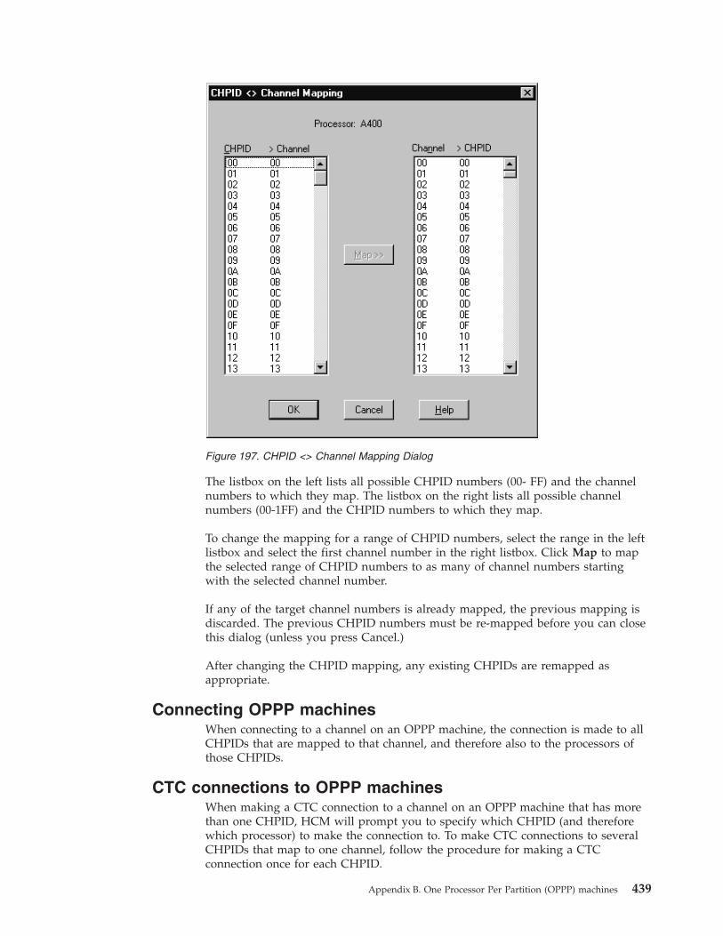
The listbox on the left lists all possible CHPID numbers (00- FF) and the channelnumbers to which they map. The listbox on the right lists all possible channelnumbers (00-1FF) and the CHPID numbers to which they map.
To change the mapping for a range of CHPID numbers, select the range in the leftlistbox and select the first channel number in the right listbox. Click Map to mapthe selected range of CHPID numbers to as many of channel numbers startingwith the selected channel number.
If any of the target channel numbers is already mapped, the previous mapping isdiscarded. The previous CHPID numbers must be re-mapped before you can closethis dialog (unless you press Cancel.)
After changing the CHPID mapping, any existing CHPIDs are remapped asappropriate.
Connecting OPPP machinesWhen connecting to a channel on an OPPP machine, the connection is made to allCHPIDs that are mapped to that channel, and therefore also to the processors ofthose CHPIDs.
CTC connections to OPPP machinesWhen making a CTC connection to a channel on an OPPP machine that has morethan one CHPID, HCM will prompt you to specify which CHPID (and thereforewhich processor) to make the connection to. To make CTC connections to severalCHPIDs that map to one channel, follow the procedure for making a CTCconnection once for each CHPID.
Figure 197. CHPID <> Channel Mapping Dialog
Appendix B. One Processor Per Partition (OPPP) machines 439

440 z/OS V2R2 and z/VM V6R2.0 HCM User's Guide

Appendix C. Naming conventions in dialogs and reports
Objects in HCM are usually described in dialogs, reports, on the configurationdiagram, in the status bar, in the object information bar, and on certain menu itemsusing a standard format. The format used for most situations is described below.
Object Formatting convention (NAME) Examples
Processor ProcessorName PROD1
Partition ProcessorName.PartitionName PROD1.LPARA
CHPID ProcessorName.CHPID PROD1.2F
Switch SwitchName ESCD_1
Switch Port SwitchName.SwitchPortID ESCD_1.E3
Crossbar CrossbarName PRN-XBAR
CrossbarInterface
CrossbarName.CrossbarInterfaceName PRN-XBAR.1 (channel interface)PRN-XBAR.A1 (CU interface)
Controller ControllerName 3990 #5
ControllerSegment
ControllerName.SegmentName 3990 #5.SC0 “SEG” if noneassigned by PDF
Controller(Channel /Device) Adapter
ControllerName.SegmentName.AdapterName“SegmentName” is omitted if none assigned by PDF “AdapterName”is “CA” “DA” if none assigned by PDF.
6110 #1.Bus 0.A (CA) 6110 #1.Bus0.0 (DA)
ControllerInterface
ControllerName.SegmentName.AdapterName.InterfaceName“INT” if none assigned by PDF
3990 #5.SC0.A 3990 #5.SC0.SP06110 #1.Bus 0.A.0 6110 #1.Bus0.0.INT
String StringName “String” plus range of device addresses if noneassigned
BACKUP DASD String 500-51F
Unit StringName.UnitName “Unit” plus range of deviceaddresses if none assigned.
String 500-51F.Unit 500-507
Device DeviceNumber or DeviceNumber,Count 0500 0500,8
String Interface StringName.InterfaceName “INT” if none assigned by PDF String 500-51F.A
Converter ConverterName
“S->P” or “P->S” if no label assigned
S->P between TEST1.22 and3990 #1.SC0.C
Cabinet CabinetName Central Cabinet
Patchport PortId C101
In some situations, the formatted NAME as described above may be followed byadditional information. The exact information that is included varies withcircumstances.
ObjectFormatting convention (NAME plus additionalinformation) Examples
Processor ProcessorName TypeModel “Description” SN:Serial Number PROD1 9021-972 “Production 1”
SN: 1234569021
© Copyright IBM Corp. 1995, 2016 441

ObjectFormatting convention (NAME plus additionalinformation) Examples
Partition (IBMstyle machine)
ProcessorName.PartitionName
ImageNumber Usage “Description”
PROD1.LPARA 01 OS “OSPartition #1”
Partition (oneprocessor perpartition stylemachine)
ProcessorName.PartitionName TypeModel “Description” PROD1.DOM1.3090 “Domain 1”
CHPID ProcessorName.CHPID InterfaceType Type Mode“Description” Connections
PROD1.21 S CNC SHR “DIR 2.E8”to ESCD_2.E8
CHPID with nophysical channel
ProcessorName.CHPID (No Channel)
Type Mode “Description”
PROD1.21 (No Channel) “”
Physical channelwith no CHPID
ProcessorName.CHPID InterfaceType (No CHPID)Connections
PROD1.21 S (No CHPID) toESCD_2.E8
CHPID on oneprocessor perpartition machine
ProcessorName.CHPID InterfaceType (n CHPIDs)Connections
PROD1.21 S (3 CHPIDs) toESCD_2.E8
Switch SwitchName UnitModel “Description” SN:SerialNumber ESCD_2 9032 “DASD Switch”SN:79023454
Switch Port SwitchName.SwitchPortID LASER/LED “Name”Connections
ESCD_2.E8 LED “P1.21” fromPROD1.21
Crossbar CrossbarName SN:SerialNumber PRN_XBAR SN: 0987242
CrossbarInterface
CrossbarName.CrossbarInterfaceName Connections PRN_XBAR.A1 to 4245 #1.A
Controller ControllerName SN:SerialNumber Strings 3990 #5 SN:98734789 reachingString 400-41F String 420-43F
ControllerSegment
ControllerName.SegmentName Strings 3990 #5.SC0 reaching String400-41F String 420-43F
ControllerInterface
ControllerName.SegmentName.AdapterName.InterfaceNameInterfaceType Connections
3990 #5.SC0.A S from ESCD_1.CD
String StringName UnitModel Controllers
“UnitModel” - taken from first device
String 500-51F 3390 on 3990 #5
Unit StringName.UnitName UnitModel SN:SerialNumber
“UnitModel” - taken from first device
String 500-51F.Unit 500-507 3390SN:74329874
Device DeviceNumber VOLSER 0500 489327
String Interface StringName.InterfaceName Connections String 500-51F.A from 3990#5.SC0.SP0
Converter ConverterName SN:SerialNumber Connections P->S 293473284 betweenPROD1.06 and 3990 #11.SC1.A
Cabinet CabinetName SN:SerialNumber Central Cabinet 077349782
Cable descriptionsOn the diagram, cable information is presented in one of the following formats,depending on the zoom level:
442 z/OS V2R2 and z/VM V6R2.0 HCM User's Guide

Number of Lines showing 3 2 1Short name and interface: PR-54 PR-54 PR-54Cable Identification: 5676 5676Cable length: 100
Short name is the two letter abbreviation of the major object that the cable connectsto.
In the above example; 100 is the length of the cable in unspecified units, 5676 isthe cable identification and PR-54 identifies the cable connected to CHPID number54 on the processor with the short name “PR”.
Appendix C. Naming conventions in dialogs and reports 443

444 z/OS V2R2 and z/VM V6R2.0 HCM User's Guide

Appendix D. Menu bar choices summary
The menu bar choices are acting either on the configuration work (*.hcm/hcmz) file oron the configuration production (*.hcr/hcrz) file.
For all choices, the following tables indicate in column Std-alone whether thefunction is also available in stand-alone mode. However, even if a function isindicated as being available, be aware that you can apply the function only tophysical aspects of the configuration, and not to logical aspects that would impactthe associated IODF, which is not accessed in stand-alone mode. Hence, allfunction descriptions in the following tables that relate to an IODF do not applyfor stand-alone mode.
File menu
Choice FunctionStd-alone
Open... Open an existing configuration (.HCM, .HCR) file and the correspondingIODF.
y
Open Special... Open an existing configuration (.HCM, .HCR) file and a specified IODF. n
Save Save the current configuration (.HCM, .HCR) file with a timestamp that issynchronized with the IODF, and continue the session with the files open.
y
Close Save the configuration (.HCM, .HCR) file and the corresponding IODF, andthen close them.
y
IODF Details... Display important IODF information. y
Copy Configuration Files... Copy the configuration (.HCM, .HCR) file to a new file and thecorresponding IODF to a new data set.
n
Build Production... Create a production IODF. n
Make Work... Create a work IODF on the host out of the currently open productionIODF, while at the same time creating a work (*.HCM) file out of thecurrently open production (*.HCR) file on the PC.
n
Set Access Mode A dialog lets you select one of the following access modes for the currentconfiguration:
v Single-user mode - Local configuration disables MCF sharing. Thisoperation deletes the existing MCF from the host. Synchronization ofphysical updates on multiple local copies is now in the user'sresponsibility.
v Master configuration file mode enables the configuration for MCFsharing. This choice creates a master configuration file on the host whichallows several HCM users to work cooperatively and safely on a singleconfiguration, sequentially sharing the configuration in connected mode.
n
IODFs... Open a dialog to manage IODFs. n
View IODF Reports... View HCD I/O configuration reports and save the output in a workstationfile.
n
View IODF Compare Reports... View HCD IODF Compare Reports and save the output in a workstationfile.
n
View IODF Compare CSS/OSReport...
View HCD IODF CSS/OS Compare Reports (comparing devices withindifferent CSSs/OSs in one IODF) and save the output in a workstation file.
n
© Copyright IBM Corp. 1995, 2016 445

Choice FunctionStd-alone
Compare HCM Files... Compare two HCM configuration files with respect to informationcontained in the associated IODF (logical view) and additionally withrespect to physical information like cable connections, patchports,controllers, and so on. The output is presented in a window and you cansave it in a file.
y
Page Setup... Setup the page for printing purposes; setup the printer and its parameters. y
Print Diagram... Print the configuration diagram. y
Generate HCM Reports... Set parameters for the reports that you are going to create and/or print.Also, you can specify a report title, cover page notes, and a table ofcontents. You can determine the report contents and select the objects forreporting, and you can print an index.
y
Print Cable Labels... Print cable labels to a text file or printer. y
Import Data... Import HCM data into a configuration. n
Export Data... Export configuration data to a text file in a directory. y
Exit (Alt+F4) Save and close the configuration (.HCM, .HCR) file and the correspondingIODF and exit HCM.
y
Edit menu
Choice FunctionStd-alone
Undo last change(Alt+Backspace)
Undo the last change made to the configuration. This menu item's textspecifies the action that is currently available to be undone. If the previousaction cannot be undone, the item's text changes to "Can't Undo".
y
Delete/Disconnect selectedobject (Del)
Delete the most recently selected object(s) or disconnect the most recentlyselected interface(s) in the configuration diagram. This menu item's textchanges to describe the most recently selected object. Shortcut: press thedel key after selecting the object.
y
Edit selected object... (F9) Edit the most recently selected object. This menu item's text changes todescribe the most recently selected object. Shortcut: double-click the objectin the diagram, or click on the object and press F9.
y
Edit cable on selected interface(F5)
Edit the cable on the most recently selected object. This menu item's textchanges to describe the most recently selected object.
y
Processor... Edit a particular processor. y
Partition... Edit a particular partition. y
CHPID... Edit a particular CHPID. n
Switch... Edit a particular switch. y
Port... Edit a particular port. n
Crossbar Switch... Edit a particular crossbar switch. y
Controller... Edit a particular controller. y
Control Unit... Edit the controller containing a particular control unit. y
String... Edit a particular string. y
Device... Edit a particular device. n
Converter... Edit a particular converter. y
Patchport... Edit the cabinet containing a particular patchport. y
446 z/OS V2R2 and z/VM V6R2.0 HCM User's Guide

Choice FunctionStd-alone
Cabinet... Edit a particular cabinet. y
General Box Port... Edit a particular port of a general box. y
General Box Edit a general box. y
Cable Assignments... Edit the cable assignments to connections. y
OS Configurations... Edit the OS configurations. n
CTC connections... Edit CTC connections. y
Configuration Packages... Open the Configuration Packages dialog for an accessed work IODF tocreate and edit configuration packages. Open this dialog for an accessedproduction IODF to transmit configuration packages defined from thisIODF.
n
CF connections... Edit CF connections. y
PPRC connections... Edit Peer-to-Peer Remote Copy connections (PPRC connections). y
Order Processors... Change the order of processors in the configuration diagram. y
Titles & Footnotes... Edit the title and footnotes that appear in configuration diagrams andreports.
y
Manage Shadow Processors... Edit the assignment of alternate (shadow) processors to physical machines. y
View menu
Choice FunctionStd-alone
Previous View (F12) Display the previous automatically saved view of a configuration diagram. y
Fit to Window (Ctrl+Home orF2)
Reduce the scale of the configuration diagram to fill the window. y
Zoom Out (Home) Reduce the scale of the configuration diagram by one step. y
Zoom In (End) Enlarge the scale of the configuration diagram by one step. y
Maximum Size (Ctrl+End) Enlarge the scale of the configuration diagram to the maximum size y
Filter Diagram... Specify which objects and connections are included in the diagram. y
Connected Objects (SHIFT+F4) Crop the view to display only objects logically connected to the selectedobject. Settings in the Change View Attributes dialog are not considered.
y
Highlighted Objects (F4) Crop the view to display only objects logically connected to the selectedobject. Settings in the Change View Attributes dialog are considered.
y
Visualized Matrices Define a configuration for each ESCON or FICON switch or crossbarswitch to be visualized.
y
Show selected connections Show connections from multiple selected interfaces. y
Hide selected connections Hide connections from multiple selected interfaces. y
Restore Named View (F3) Select a saved named view to be shown as active configuration diagram. y
Save Named View Save the displayed view. y
Delete Named View Delete a named view. y
Restore Matrix Set Select a saved named matrix view to be shown in the configurationdiagram.
y
Save Matrix Set Save the current matrix set. y
Delete Matrix Set Delete a named matrix set. y
Appendix D. Menu bar choices summary 447

Choice FunctionStd-alone
Text Detail... Specify which text appears in the configuration diagram. y
Preferences... Set certain preferences for the configuration diagram. y
Colors... Enable/disable and set colors for visual warnings for logical/physicalinconsistencies and for status information.
y
Object Information Bar Include or exclude the Object Information Bar. y
Status Bar Include or exclude the Status Bar. y
Show Page Breaks Display the effects of page breaks and printer margins. y
Locate menu
Choice FunctionStd-alone
Selected object (F8) Locate the most recently selected object. This menu item's text changes todescribe the most recently selected object.
y
System Locate a system in a sysplex. This menu item's text changes to describe themost recently selected object.
n
Processor... Locate a particular processor y
Partition... Locate a particular partition y
CHPID... Locate a particular CHPID y
Switch... Locate a particular switch y
Port... Edit a particular port. y
Crossbar Switch... Locate a particular crossbar switch y
Controller... Locate a particular controller. y
Control Unit... Locate the controller containing a particular control unit. y
String... Locate a particular string. y
Device... Locate a particular device. y
Converter... Locate a particular converter. y
Patchport... Locate the cabinet containing a particular patchport. y
Cabinet... Locate a particular cabinet. y
General Box Port... Locate a particular port of a general box. y
General Box... Locate a particular general box. y
CTC connection... Locate a particular CTC connection. y
CF connection... Locate a particular CF connection. y
PPRC connection... Locate a particular Peer-to-Peer Remote Copy connection (PPRCconnection).
y
Cable... Locate a particular cable. y
Create menu
Choice FunctionStd-alone
Processor... Create a new processor. n
448 z/OS V2R2 and z/VM V6R2.0 HCM User's Guide
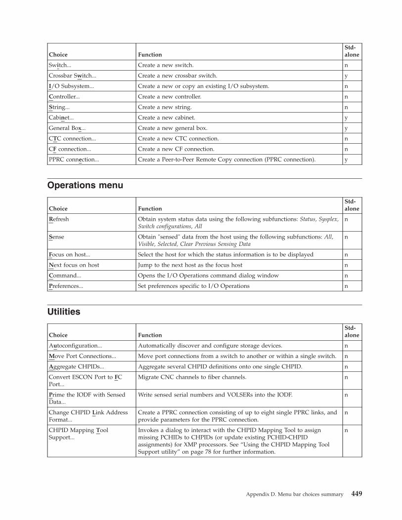
Choice FunctionStd-alone
Switch... Create a new switch. n
Crossbar Switch... Create a new crossbar switch. y
I/O Subsystem... Create a new or copy an existing I/O subsystem. n
Controller... Create a new controller. n
String... Create a new string. n
Cabinet... Create a new cabinet. y
General Box... Create a new general box. y
CTC connection... Create a new CTC connection. n
CF connection... Create a new CF connection. n
PPRC connection... Create a Peer-to-Peer Remote Copy connection (PPRC connection). y
Operations menu
Choice FunctionStd-alone
Refresh Obtain system status data using the following subfunctions: Status, Sysplex,Switch configurations, All
n
Sense Obtain "sensed" data from the host using the following subfunctions: All,Visible, Selected, Clear Previous Sensing Data
n
Focus on host... Select the host for which the status information is to be displayed n
Next focus on host Jump to the next host as the focus host n
Command... Opens the I/O Operations command dialog window n
Preferences... Set preferences specific to I/O Operations n
Utilities
Choice FunctionStd-alone
Autoconfiguration... Automatically discover and configure storage devices. n
Move Port Connections... Move port connections from a switch to another or within a single switch. n
Aggregate CHPIDs... Aggregate several CHPID definitions onto one single CHPID. n
Convert ESCON Port to FCPort...
Migrate CNC channels to fiber channels. n
Prime the IODF with SensedData...
Write sensed serial numbers and VOLSERs into the IODF. n
Change CHPID Link AddressFormat...
Create a PPRC connection consisting of up to eight single PPRC links, andprovide parameters for the PPRC connection.
n
CHPID Mapping ToolSupport...
Invokes a dialog to interact with the CHPID Mapping Tool to assignmissing PCHIDs to CHPIDs (or update existing PCHID-CHPIDassignments) for XMP processors. See “Using the CHPID Mapping ToolSupport utility” on page 78 for further information.
n
Appendix D. Menu bar choices summary 449

Choice FunctionStd-alone
Export IOCP or I/OConfiguration statements
Invokes a dialog that lets you
v export an IOCP input file for a selected processor
v or export a certain type of configuration statements (for processor,operating system or switch)
either into a z/OS data set on the host or into a file on the workstation.
n
Check Configuration File... Invokes a dialog to check configuration files for structural consistency. See“Checking a configuration” on page 81 for further information.
y
Export Master ConfigurationFile
Exporting an MCF-enabled configuration. This operation exports the MCF,as it is stored on the host, to a file on the PC. If required, you can send thisfile to IBM Support to diagnose MCF-related problems.
n
Browse Performance Data... Invokes a utility that lets you examine performance data of objects in youractive sysplex, for example, to discover potential bottlenecks.
y
WWPN Prediction ToolSupport...
Invokes a dialog that lets you
v Export FCP data from a selected processor into a specified output file
v Launch the WWPN Prediction Tool (using the output file with theexported FCP data as input) to assign world-wide port names tovirtualized FCP ports for configuring SAN devices.
n
Options menu
Choice FunctionStd-alone
Confirmation... Instruct HCM whether to prompt for a confirmation before deleting anobject or disconnecting an interface.
y
File Compression... Choose whether to store the HCM configuration files in a compressed oruncompressed format. Compressed configuration files use less disk space.They cannot be opened with HCM versions prior to z/OS V1R9.
y
Field Names... Assign customized names to the user data fields. y
Interface Selection... Choose whether to select the object containing an interface or its cablewhen an interface is selected with the mouse.
y
Activate HCD Trace Turn the HCD trace facility on or off. n
Help menu
Choice FunctionStd-alone
Index Display the main HCM help topic index. y
Keyboard Describe the use of the Function keys and various cursor control keyshortcuts.
y
About... Open a window describing the current release of HCM. y
450 z/OS V2R2 and z/VM V6R2.0 HCM User's Guide
Appendix E. Special setup considerations for z/OS
The following allows special individual adaptation for setup. In general, it is notnecessary to use these parameters. They are provided for special purposes.
Usually, only AJCLACCT or RTIMEOUT for [CBDQAGNT] are of interest forcommon purposes. The other keywords are mainly for debugging purposes.
HCM client: configurable login parametersThe only login parameter needed is the TCP/IP hostname of the MVS hostrunning the HCM dispatcher. If no port is specified (port = 0), the client will usethe pre-configured default port number 51107 to contact the HCM dispatcher.
During HCM login, the HCM client reads the HCM EEQHCM.INI file to accessoptional parameters for the login request (see also “Purpose and location of theHCM INI file” on page 5).
The following parameters can be defined for the sections [COMRDTS],[CBDQTDIS] and [CBDQAGNT]:
[COMRDTS] AGENTLOG=<path-of-client-logfile>This activates the writing of an HCM client log to the specified path andfilename. Directories specified in the path must already exist. The client logcan be helpful in diagnosing HCM login problems.
Example: AGENTLOG=c:\hcm\client.log
[CBDQTDIS] RTIMEOUT=<seconds>This defines the number of seconds the HCM client waits for an answerfrom the HCM dispatcher after sending an HCM login request and beforereporting a timeout error. The default is RTIMEOUT=90. On slow networksor when the priority of the dispatcher is low, this timeout value may haveto be increased.
[CBDQTDIS] ATIMEOUT=<seconds>The HCM dispatcher starts a new HCM agent by writing the agent job tothe JES internal reader. It then attempts to contact the new agent to verifysuccessful startup. The ATIMEOUT parameter specifies the number ofseconds the dispatcher will wait for the agent to start before reporting afailure to the waiting HCM client. The default is ATIMEOUT=60. If the JESinput queue is slow in starting the submitted agent job, this value mayhave to be increased.
[CBDQAGNT] AJCLSKEL=<HCM agent skeleton JCL data set>This overwrites the default JCL skeleton used by the HCM dispatcher togenerate the HCM agent job. This can be used, for example, to start anHCM agent with an experimental version of the HCDPROF data set(instead of the default &SYSUID..HCD.PROFILE).
Fully qualified MVS data set names must be specified within two pairs ofsingle quotation marks, for example: AJCLSKEL=''TEST.CBDQAGNT.JST''
© Copyright IBM Corp. 1995, 2016 451

[CBDQAGNT] AJCLASS=<job class of HCM agent>This overwrites the default job class (0) of the generated HCM agent job. Itcan be used to save the job output of the HCM agent by specifying, forexample, 'AJCLASS=A'.
[CBDQAGNT] AMCLASS=<agent job message class>This defines the message class parameter in the JOB statement of thegenerated agent JCL. The default message class is "0". It may be necessaryto specify a different job message class in order to obtain a job log for theHCM agent. Example: AMCLASS=H
[CBDQAGNT] RTIMEOUT=<seconds>This defines the number of seconds the HCM client waits for an answerfrom the HCM agent after sending a request and before reporting atimeout error. The default is RTIMEOUT=600. For long-running HCDrequests, this timeout value may have to be increased.
[CBDQAGNT] ATIMEOUT=<seconds>When a new HCM agent is started, it is first contacted by the HCMdispatcher. After sending a ready notification to the dispatcher, the agentthen waits to be contacted by the HCM client. If the agent is not contactedby the client after the specified timeout value (e.g., the HCM useraccidentally hits power-off on the PC), the agent will terminate. Thedefault is ATIMEOUT=60. On slow networks, this value may have to beincreased.
[CBDQAGNT] AJCLACCT=<accounting information>This defines the accounting information parameter in the JOB statement ofthe generated agent JCL. If the installation requires accounting information,it may be necessary to supply this parameter if the default accountinginformation supplied by the HCM dispatcher is invalid for the individualHCM user. Example: AJCLACCT=(DE03160,,)
[CBDQAGNT] AREGION=<agent job region size>This defines the region parameter in the JOB statement of the generatedagent JCL. The default region size is AREGION=128M.
[CBDQAGNT] ALOGDSN=<name of agent log data set>This defines the name of a log data set written by the HCM agent. Thedefault is that no log output is written. Log output may be helpful indiagnosing communication problems between the HCM client and theHCM agent.
Example 1: ALOGDSN=CBDQAGNT.LOGWrites the agent log as CBDQAGNT.LOG under the user's HLQ
Example 2: ALOGDSN=''TEMP.CBDQAGNT.LOG''Writes the agent log as 'TEMP.CBDQAGNT.LOG' (fully qualified)
Example 3: ALOGDSN=DD:SYSOUTWrites the agent log to the job log output
[CBDQAGNT] HCDPROF=<DD specification of HCD profile data set>This defines the DD specification of the HCD profile used by the HCMagent. The default is:HCDPROF="//HCDPROF DD DISP=SHR,DSN=&SYSUID..HCD.PROFILE"
Specifying this parameter allows the use of an alternate HCD profile, e.g.,HCDPROF="//HCDPROF DD DISP=SHR,DSN=&SYSUID..MYHCD01.PROFILE"
452 z/OS V2R2 and z/VM V6R2.0 HCM User's Guide
[CBDQAGNT] HCDTRACE=<DD specification of HCD trace data set>This defines the DD specification of the HCD trace data set used by theHCM agent. The default is:HCDTRACE="//HCDTRACE DD DISP=SHR,DSN=&SYSUID..HCM.TRACE"
Specifying this parameter allows the use of an alternate HCD trace dataset, e.g.,HCDTRACE="//HCDTRACE DD DISP=SHR,DSN=&SYSUID..MYHCM01.TRACE"
[CBDQAGNT] ASTEPLIB=<name of steplib data set>This defines a data set name which is appended to the STEPLIBconcatenation. Per default, there is no additional steplib data set.
Example: ASTEPLIB=BMGN.MY.LOADLIB
Host messagesThe following messages can be issued by either the HCM dispatcher or the HCMagent on the host. Theses messages will be written to the system log (issued as aWTO message).
CBDG980I CBDQTDIS -- HCM dispatcher starting, port = <port>The HCM dispatcher is starting and will listen for start-agent requests onthe specified TCP/IP port.
CBDG981E CBDQTDIS -- can't listen on port <port>The HCM dispatcher cannot bind to the specified port and will terminate.The port number may be in use by another program.
Restart the HCM dispatcher, possibly specifying a different (available) portnumber.
CBDG982I CBDQTDIS -- HCM dispatcher terminating.The HCM dispatcher is terminating.
CBDG983I CBDQTDIS -- start-agent request for user <user_id> received.The HCM dispatcher received an HCM start-agent request from a client forthe specified user ID.
CBDG984I CBDQTDIS -- HCM agent started for user <user_id>, port <port>.The HCM dispatcher successfully started an HCM agent for the specifiedclient user ID. The new HCM agent instance listens on the specifiedTCP/IP port number.
CBDG985I CBDQTDIS -- HCM validation for client user id <user_id> failed.The HCM dispatcher could not successfully validate the HCM start-agentrequest for the specified user. Either the dispatcher is not running as anauthorized program or the login information specified by the client isinvalid.
For operators: make sure that the HCM dispatcher is being run from anauthorized library.
For users: check the spelling of your user ID and password. Also checkwhether your TSO password has expired. Then retry the HCM client login.
CBDG986I CBDQAGNT -- HCM agent starting, port = <port>An instance of the HCM agent was started successfully and is expectingHCM requests on the specified TCP/IP port number.
Appendix E. Special setup considerations for z/OS 453

CBDG987I <module_name> <variable_text>The text of this message provides additional information for an alreadyissued message (CBDG980I to CBDQG986I). The content of this messagedepends on the situation.
HCM Client: TCP/IP related messagesMessages indicating a problem related to the TCP/IP communication between theHCM client on the workstation and the HCD server on the host have the messageidentifiers EEQX100E to EEQX503E. For the message text see Chapter 18, “HCMmessages,” on page 417.
454 z/OS V2R2 and z/VM V6R2.0 HCM User's Guide
Appendix F. Accessibility
Accessible publications for this product are offered through IBM KnowledgeCenter (http://www.ibm.com/support/knowledgecenter/SSLTBW/welcome).
If you experience difficulty with the accessibility of any z/OS information, send adetailed message to the Contact z/OS or use the following mailing address.
IBM CorporationAttention: MHVRCFS Reader CommentsDepartment H6MA, Building 7072455 South RoadPoughkeepsie, NY 12601-5400United States
Accessibility features
Accessibility features help users who have physical disabilities such as restrictedmobility or limited vision use software products successfully. The accessibilityfeatures in z/OS can help users do the following tasks:v Run assistive technology such as screen readers and screen magnifier software.v Operate specific or equivalent features by using the keyboard.v Customize display attributes such as color, contrast, and font size.
Consult assistive technologiesAssistive technology products such as screen readers function with the userinterfaces found in z/OS. Consult the product information for the specific assistivetechnology product that is used to access z/OS interfaces.
Keyboard navigation of the user interfaceYou can access z/OS user interfaces with TSO/E or ISPF. The followinginformation describes how to use TSO/E and ISPF, including the use of keyboardshortcuts and function keys (PF keys). Each guide includes the default settings forthe PF keys.v z/OS TSO/E Primer
v z/OS TSO/E User's Guide
v z/OS V2R2 ISPF User's Guide Vol I
Dotted decimal syntax diagramsSyntax diagrams are provided in dotted decimal format for users who access IBMKnowledge Center with a screen reader. In dotted decimal format, each syntaxelement is written on a separate line. If two or more syntax elements are alwayspresent together (or always absent together), they can appear on the same linebecause they are considered a single compound syntax element.
Each line starts with a dotted decimal number; for example, 3 or 3.1 or 3.1.1. Tohear these numbers correctly, make sure that the screen reader is set to read outpunctuation. All the syntax elements that have the same dotted decimal number
© Copyright IBM Corp. 1995, 2016 455

(for example, all the syntax elements that have the number 3.1) are mutuallyexclusive alternatives. If you hear the lines 3.1 USERID and 3.1 SYSTEMID, yoursyntax can include either USERID or SYSTEMID, but not both.
The dotted decimal numbering level denotes the level of nesting. For example, if asyntax element with dotted decimal number 3 is followed by a series of syntaxelements with dotted decimal number 3.1, all the syntax elements numbered 3.1are subordinate to the syntax element numbered 3.
Certain words and symbols are used next to the dotted decimal numbers to addinformation about the syntax elements. Occasionally, these words and symbolsmight occur at the beginning of the element itself. For ease of identification, if theword or symbol is a part of the syntax element, it is preceded by the backslash (\)character. The * symbol is placed next to a dotted decimal number to indicate thatthe syntax element repeats. For example, syntax element *FILE with dotted decimalnumber 3 is given the format 3 \* FILE. Format 3* FILE indicates that syntaxelement FILE repeats. Format 3* \* FILE indicates that syntax element * FILErepeats.
Characters such as commas, which are used to separate a string of syntaxelements, are shown in the syntax just before the items they separate. Thesecharacters can appear on the same line as each item, or on a separate line with thesame dotted decimal number as the relevant items. The line can also show anothersymbol to provide information about the syntax elements. For example, the lines5.1*, 5.1 LASTRUN, and 5.1 DELETE mean that if you use more than one of theLASTRUN and DELETE syntax elements, the elements must be separated by a comma.If no separator is given, assume that you use a blank to separate each syntaxelement.
If a syntax element is preceded by the % symbol, it indicates a reference that isdefined elsewhere. The string that follows the % symbol is the name of a syntaxfragment rather than a literal. For example, the line 2.1 %OP1 means that you mustrefer to separate syntax fragment OP1.
The following symbols are used next to the dotted decimal numbers.
? indicates an optional syntax elementThe question mark (?) symbol indicates an optional syntax element. A dotteddecimal number followed by the question mark symbol (?) indicates that allthe syntax elements with a corresponding dotted decimal number, and anysubordinate syntax elements, are optional. If there is only one syntax elementwith a dotted decimal number, the ? symbol is displayed on the same line asthe syntax element, (for example 5? NOTIFY). If there is more than one syntaxelement with a dotted decimal number, the ? symbol is displayed on a line byitself, followed by the syntax elements that are optional. For example, if youhear the lines 5 ?, 5 NOTIFY, and 5 UPDATE, you know that the syntax elementsNOTIFY and UPDATE are optional. That is, you can choose one or none of them.The ? symbol is equivalent to a bypass line in a railroad diagram.
! indicates a default syntax elementThe exclamation mark (!) symbol indicates a default syntax element. A dotteddecimal number followed by the ! symbol and a syntax element indicate thatthe syntax element is the default option for all syntax elements that share thesame dotted decimal number. Only one of the syntax elements that share thedotted decimal number can specify the ! symbol. For example, if you hear thelines 2? FILE, 2.1! (KEEP), and 2.1 (DELETE), you know that (KEEP) is thedefault option for the FILE keyword. In the example, if you include the FILE
456 z/OS V2R2 and z/VM V6R2.0 HCM User's Guide

keyword, but do not specify an option, the default option KEEP is applied. Adefault option also applies to the next higher dotted decimal number. In thisexample, if the FILE keyword is omitted, the default FILE(KEEP) is used.However, if you hear the lines 2? FILE, 2.1, 2.1.1! (KEEP), and 2.1.1(DELETE), the default option KEEP applies only to the next higher dotteddecimal number, 2.1 (which does not have an associated keyword), and doesnot apply to 2? FILE. Nothing is used if the keyword FILE is omitted.
* indicates an optional syntax element that is repeatableThe asterisk or glyph (*) symbol indicates a syntax element that can berepeated zero or more times. A dotted decimal number followed by the *symbol indicates that this syntax element can be used zero or more times; thatis, it is optional and can be repeated. For example, if you hear the line 5.1*data area, you know that you can include one data area, more than one dataarea, or no data area. If you hear the lines 3* , 3 HOST, 3 STATE, you knowthat you can include HOST, STATE, both together, or nothing.
Notes:
1. If a dotted decimal number has an asterisk (*) next to it and there is onlyone item with that dotted decimal number, you can repeat that same itemmore than once.
2. If a dotted decimal number has an asterisk next to it and several itemshave that dotted decimal number, you can use more than one item from thelist, but you cannot use the items more than once each. In the previousexample, you can write HOST STATE, but you cannot write HOST HOST.
3. The * symbol is equivalent to a loopback line in a railroad syntax diagram.
+ indicates a syntax element that must be includedThe plus (+) symbol indicates a syntax element that must be included at leastonce. A dotted decimal number followed by the + symbol indicates that thesyntax element must be included one or more times. That is, it must beincluded at least once and can be repeated. For example, if you hear the line6.1+ data area, you must include at least one data area. If you hear the lines2+, 2 HOST, and 2 STATE, you know that you must include HOST, STATE, orboth. Similar to the * symbol, the + symbol can repeat a particular item if it isthe only item with that dotted decimal number. The + symbol, like the *symbol, is equivalent to a loopback line in a railroad syntax diagram.
Appendix F. Accessibility 457

458 z/OS V2R2 and z/VM V6R2.0 HCM User's Guide

Notices
This information was developed for products and services offered in the U.S.A. orelsewhere.
IBM may not offer the products, services, or features discussed in this document inother countries. Consult your local IBM representative for information on theproducts and services currently available in your area. Any reference to an IBMproduct, program, or service is not intended to state or imply that only that IBMproduct, program, or service may be used. Any functionally equivalent product,program, or service that does not infringe any IBM intellectual property right maybe used instead. However, it is the user's responsibility to evaluate and verify theoperation of any non-IBM product, program, or service.
IBM may have patents or pending patent applications covering subject matterdescribed in this document. The furnishing of this document does not give youany license to these patents. You can send license inquiries, in writing, to:
IBM Director of LicensingIBM CorporationNorth Castle DriveArmonk, NY 10504-1785U.S.A
For license inquiries regarding double-byte character set (DBCS) information,contact the IBM Intellectual Property Department in your country or sendinquiries, in writing, to:
Intellectual Property LicensingLegal and Intellectual Property LawIBM Japan, Ltd.19-21, Nihonbashi-Hakozakicho, Chuo-kuTokyo 103-8510, Japan
The following paragraph does not apply to the United Kingdom or any othercountry where such provisions are inconsistent with local law: INTERNATIONALBUSINESS MACHINES CORPORATION PROVIDES THIS PUBLICATION “AS IS”WITHOUT WARRANTY OF ANY KIND, EITHER EXPRESS OR IMPLIED,INCLUDING, BUT NOT LIMITED TO, THE IMPLIED WARRANTIES OFNON-INFRINGEMENT, MERCHANTABILITY OR FITNESS FOR A PARTICULARPURPOSE. Some states do not allow disclaimer of express or implied warranties incertain transactions, therefore, this statement may not apply to you.
This information could include technical inaccuracies or typographical errors.Changes are periodically made to the information herein; these changes will beincorporated in new editions of the publication. IBM may make improvementsand/or changes in the product(s) and/or the program(s) described in thispublication at any time without notice.
Any references in this information to non-IBM Web sites are provided forconvenience only and do not in any manner serve as an endorsement of those Websites. The materials at those Web sites are not part of the materials for this IBMproduct and use of those Web sites is at your own risk.
© Copyright IBM Corp. 1995, 2016 459

IBM may use or distribute any of the information you supply in any way itbelieves appropriate without incurring any obligation to you.
Licensees of this program who wish to have information about it for the purposeof enabling: (i) the exchange of information between independently createdprograms and other programs (including this one) and (ii) the mutual use of theinformation which has been exchanged, should contact:
Site CounselIBM Corporation2455 South RoadPoughkeepsie, NY 12601-5400USA
Such information may be available, subject to appropriate terms and conditions,including in some cases, payment of a fee.
The licensed program described in this information and all licensed materialavailable for it are provided by IBM under terms of the IBM Customer Agreement,IBM International Program License Agreement, or any equivalent agreementbetween us.
Information concerning non-IBM products was obtained from the suppliers ofthose products, their published announcements or other publicly available sources.IBM has not tested those products and cannot confirm the accuracy ofperformance, compatibility or any other claims related to non-IBM products.Questions on the capabilities of non-IBM products should be addressed to thesuppliers of those products.
All statements regarding IBM's future direction or intent are subject to change orwithdrawal without notice, and represent goals and objectives only.
If you are viewing this information softcopy, the photographs and colorillustrations may not appear.
COPYRIGHT LICENSE:
This information might contain sample application programs in source language,which illustrate programming techniques on various operating platforms. You maycopy, modify, and distribute these sample programs in any form without paymentto IBM, for the purposes of developing, using, marketing or distributingapplication programs conforming to the application programming interface for theoperating platform for which the sample programs are written. These exampleshave not been thoroughly tested under all conditions. IBM, therefore, cannotguarantee or imply reliability, serviceability, or function of these programs. Thesample programs are provided "AS IS", without warranty of any kind. IBM shallnot be liable for any damages arising out of your use of the sample programs.
Policy for unsupported hardwareVarious z/OS elements, such as DFSMS, HCD, JES2, JES3, and MVS, contain codethat supports specific hardware servers or devices. In some cases, thisdevice-related element support remains in the product even after the hardwaredevices pass their announced End of Service date. z/OS may continue to serviceelement code; however, it will not provide service related to unsupportedhardware devices. Software problems related to these devices will not be accepted
460 z/OS V2R2 and z/VM V6R2.0 HCM User's Guide

for service, and current service activity will cease if a problem is determined to beassociated with out-of-support devices. In such cases, fixes will not be issued.
Minimum supported hardwareThe minimum supported hardware for z/OS releases identified in z/OSannouncements can subsequently change when service for particular servers ordevices is withdrawn. Likewise, the levels of other software products supported ona particular release of z/OS are subject to the service support lifecycle of thoseproducts. Therefore, z/OS and its product publications (for example, panels,samples, messages, and product documentation) can include references tohardware and software that is no longer supported.v For information about software support lifecycle, see: http://www.ibm.com/
software/support/systemsz/lifecycle/v For information about currently-supported IBM hardware, contact your IBM
representative.
Notices 461

462 z/OS V2R2 and z/VM V6R2.0 HCM User's Guide

Trademarks
IBM, the IBM logo, and ibm.com are trademarks or registered trademarks ofInternational Business Machines Corp., registered in many jurisdictions worldwide.Other product and service names might be trademarks of IBM or other companies.A current list of IBM trademarks is available at http://www.ibm.com/legal/copytrade.shtml.
© Copyright IBM Corp. 1995, 2016 463

464 z/OS V2R2 and z/VM V6R2.0 HCM User's Guide

Accessing licensed books on the web (z/OS)
z/OS licensed documentation in PDF format is available on the Internet at the IBMResource Link Web site at:http://www.ibm.com/servers/resourcelink
Licensed books are available only to customers with a z/OS license. Access tothese books requires an IBM Resource Link Web user ID and password, and a keycode. With your z/OS order, you received a memo that includes this key code.
To obtain your IBM Resource Link Web user ID and password log on to:http://www.ibm.com/servers/resourcelink
To register for access to the z/OS licensed books:1. Log on to Resource Link using your Resource Link user ID and password.2. Click on User Profiles located on the left-hand navigation bar.3. Click on Access Profile.
4. Click on Request Access to Licensed books.
5. Supply your key code where requested and click on the Submit button.
If you supplied the correct key code you receive confirmation that your request isbeing processed. After your request is processed you receive an e-mailconfirmation.
Note: You cannot access the z/OS licensed books unless you have registered foraccess to them and received an e-mail confirmation informing you that yourrequest has been processed.
To access the licensed books:1. Log on to Resource Link using your Resource Link user ID and password.2. Click on Library.3. Click on zSeries.4. Click on Software.5. Click on z/OS.6. Access the licensed book by selecting the appropriate element.
© Copyright IBM Corp. 1995, 2016 465

466 z/OS V2R2 and z/VM V6R2.0 HCM User's Guide

Accessing licensed books on the web (z/VM)
The latest editions of most z/VM publications are available in Adobe Acrobat PDFformat or IBM BookManager® format from the z/VM Internet Library available athttp://www.vm.ibm.com/library/.
The IBM VM Internet Library also includes other information about z/VM, suchas:v Program directoriesv Data areas and control blocksv Monitor records
© Copyright IBM Corp. 1995, 2016 467

468 z/OS V2R2 and z/VM V6R2.0 HCM User's Guide

Glossary
This glossary defines technical terms andabbreviations used in the Hardware ConfigurationManager documentation. If you do not find theterm you are looking for, refer to the index of theappropriate HCD manual or view the IBMGlossary of Computing Terms, available from:http://www.ibm.com/ibm/terminology.
access listA CHPID has two partition lists: Accessand Candidate. If a CHPID is eithershared or reconfigurable, you can specifywhich partitions have access to thatCHPID. Use the CHPID access list with orwithout the CHPID candidate list.
That is, CHPIDs are assigned to partitionsby adding each partition to the CHPID’saccess or candidate list. A partition hasinitial access to a CHPID if the logicalpartition is on that CHPID’s access list.
actual sizeActual Size scales the diagram so thatobjects are viewed at their approximatesize when a diagram is printed at fullsize.
alternate processorAlternate refers to a processor which isnot the current logical view of itsassigned machine.
buttonDialog option: click on button to carry outaction. OK, Cancel and Help buttonsappear in almost every dialog. Clicking OKwill close the dialog. If you have morethan one dialog open, click OK or Cancel,or press the ESC key repeatedly to closeall dialogs and return to the diagram.
cabinetCabinets, also known as fibermanagement cabinets contain panelsorganized into port groups of patchports,which are pairs of fiber adapters orcouplers. Cabinets are used to organizelong, complex cables between processorsand controllers, which may be as faraway as different buildings. In theconfiguration diagram, cabinets areshown on the far right.
cable “in inventory”You can put unused cables into inventory;HCM will not “remember” the past usageof these cables. Cables in inventory arecables that are generally available for useto any object.
candidate listA partition can gain access to a CHPID ifthe partition is on that CHPID’sCandidate list. A partition is allowed toconfigure a CHPID online if the logicalpartition is on that CHPID’s Candidatelist.
See also access list.
CFReportWhen a machine is ordered, the output ofthe order process is a binary file thatrepresents the physical description of thefinal machine. One of the components ofthat file is the type and physical location,including the Physical Channel Identifier(PCHID) value assigned to that location,of all the I/O features in the finalmachine. This file is called a CFReport.
channel adapterA channel adapter groups two or morecontroller channel interfaces electronically.
CIB Coupling over InfiniBand. A channel pathtype to exploit InfiniBand technology forcoupling connections.
channel interfaceSee [Controller] channel interface or[Crossbar] channel interface.
channel subsystem (CSS)A collection of subchannels that directsthe flow of information between I/Odevices and main storage. It uses one oremore channel paths as the communicationlink in managing the flow of informationto or from I/O devices. Within the CSS isone subchannel set and logical partitions.One subchannel from the set is providedfor and dedicated to each I/O deviceaccessible to the CSS. Logical partitionsuse subchannels to communicate withI/O devices. The maximum number ofCSSs supported by a processor dependson the processor type. If more than one
© Copyright IBM Corp. 1995, 2016 469

CSS is supported by a processor, each CSShas a processor unique singlehexadecimal digit CSS identifier (CSS ID).
CHPIDA logical processor contains a number ofCHPIDs, or CHannel Path IDs, which arethe logical equivalent of channels in thephysical processor. See also:v dedicated CHPID
v reconfigurable CHPID
v shared CHPID
v spanned CHPID
CHPID mappingUsually, a processor can have up to 256channels and 256 CHPIDs, so there is a1:1 mapping. However, in processors ofthe “one processor per partition” style,there can be up to 512 channels or therelationship between CHPIDs andchannels may not be one to one. Thedefault is to map the CHPIDs to the first256 channels, but you may specify anon-standard CHPID mapping.
CHPID Mapping ToolThe CHPID Mapping Tool aids thecustomer in developing aCHPID-to-PCHID relationship for XMPprocessors. It accepts an IOCP input filewithout PCHID values, allows the user toassign the logical CHPID values in theinput to the PCHIDs available with hisordered machine, and returns an updatedIOCP input file that contains the PCHIDvalues.
CHPID typeThe logical CHPID type typicallycorresponds to a physical path interfacetype.
clusterSee segment.
CMT See CHPID Mapping Tool.
configuration diagramFrom the IODF on the host, HCMconstructs an interactive configurationdiagram to help you visualize and moreeasily maintain your system. You can addor modify objects in the diagram to moreaccurately represent your hardwareconfiguration. You can also print out wallcharts or reports to plan and implementfuture modifications to your system.
configuration file/config fileThe configuration file (*.HCM file) containsHCM’s interactive configuration diagram.You can modify and save differentversions of your hardware configurationin a number of configuration files forhistorical and planning purposes. Theconfiguration file is also called workconfiguration file.
The term configuration files refers to workconfiguration files (*.hcm/*.hcmz file) aswell as to production configuration files(*.hcr/*.hcrz file). They are equivalent tothe work and production IODFs, but arelocated on the PC. File extensions *.hcmzand *.hcrz indicate that the files arecompressed.
See also work configuration file andproduction configuration file.
context diagramA context diagram is a configurationdiagram showing the object of interestand all equipment connected to it. Thinkof a context diagram as the configurationas seen by this object.
croppedA cropped diagram includes a subset of theentire configuration comprising theselected object(s) and any objects thatthey connect to.
controllerA controller translates high level requestsfrom processors to low level requests toI/O devices, and vice versa. Each physicalcontroller contains one or more logicalcontrol units, channel and deviceinterfaces, and a power source.
Controller channel interfaces can connect tothe CHPIDs on one or more processors;controller device interfaces can connect tothe string interfaces on one or morestrings of I/O devices.
Controllers can be divided into segments,or grouped into subsystems.
[controller] channel interfaceA controller has a number of channelinterfaces on the top which can bephysically connected and logicallydefined to CHPIDs on processors,possibly via control unit interfaces oncrossbar switches (if parallel / bus andtag), ports on switches (if serial / ESCON
470 z/OS V2R2 and z/VM V6R2.0 HCM User's Guide

or FICON), or converters (if connectingparallel <=> serial interfaces or viceversa). Note that the serial physical cablesconnecting the controller and processor(s)may travel through cabinets viapatchports.
control unitEach physical controller contains one ormore control units, which translate highlevel requests to low level requestsbetween processors and devices.
control unit interfaceA crossbar switch has a number of controlunit interfaces on its side which canconnect to channel interfaces oncontrollers.
converter [P→S, S→P]There are two types of converter: thosethat are used to connect serial ESCONcables to parallel bus-and-tag cables (9034or S→P), and those that connect parallel toserial cables (9035, or P→S).
HCM automatically creates and connectsconverters when necessary. HCMmaintains an inventory of converterscurrently in use or that were used forconnections which have beensubsequently disconnected.
coupling facilityThe coupling facility is the hardwareelement that provides high speed caching,list processing, and locking functions in asysplex. To enable data sharing between aCF partition and the central machines,special types of high speed CF channelsare required. A CFR channel pathattached to a CF partition can beconnected to a CFS channel path attachedto a partition in which an operatingsystem is running. Besides CF connectionsbetween a CFR and CFS channel path, CFconnections can also be establishedbetween two CFP channel paths.
[crossbar] channel interfaceA crossbar switch has a number of channelinterfaces on top which you can connect toCHPIDs either directly or via othercrossbars.
crossbar configurationYou can document different settings ofcrossbar switch connectivity as crossbarconfigurations.
crossbar switchA crossbar switch is a static switch that canconnect controllers to processors withparallel (bus and tag) interfaces. Thecrossbar contains a number of channelinterfaces on its top, which can connect toobjects above it such as processors orother crossbars. The crossbar switch alsocontains a number of control unit interfaceson its side, which can connect to objectsbelow it such as controllers or othercrossbars.
crossbar switch connectivityThe switch connectivity comprises whichcrossbar channel interfaces are connectedto which control unit interfaces; that is,which internal intersections in thecrossbar are active.
CSS See channel subsystem.
CS5 A new channel path type.
CTC connection (channel to channel connection)You can create a CTC connection(channel-to-channel connection) betweentwo CHPIDs on the same or differentprocessors, either directly or through aswitch. When connecting through aswitch, both CHPIDs must be connectedthrough the same or a chained switch.One CHPID must be CNC or FCV, theother CTC in case of an SCTC connection.For FCTC connections, two FC CHPIDshave to be connected.
HCM considers a CTC connection as asingle entity comprising selected controlunits and I/O devices in the connectedprocessors.
DDS Distributed Data Server. A single dataserver on one system in the sysplex,which gathers the data from the RMFMonitor III distributed on all systems inthe sysplex.
dedicated CHPIDA CHPID can be dedicated to one partition;only that partition can access I/O deviceson this CHPID. All CHPID types canoperate in DED (dedicated) mode.
device See I/O Device.
device adapterA device adapter groups two or morecontroller device interfaces electronically.
Glossary 471

device interfaceA controller has a number of deviceinterfaces on the bottom which canconnect to string interfaces on strings ofI/O devices.
dialog A dialog is an interactive pop-up windowcontaining options which allow you tobrowse or modify information, takespecific action relating to selected objects,or access other dialogs. HCM provides aseries of dialogs to help you create, edit,delete, and connect objects, as well asmanipulate the configuration diagram.
disconnectA controller channel interface may bedisconnected from a CHPID with either astandard disconnection or a physical-onlydisconnection. The standard disconnectioninvolves logically disconnecting anycontrol units from any CHPIDs that wereonly reachable via the controller channelinterface, as well as physicallydisconnecting the controller from theprocessor.
D/R site OS configurationHCD can automatically generate adisaster recovery (D/R) site OSconfiguration as a copy of the primary OSconfiguration. You need a D/R site OSconfiguration in a GDPS managedenvironment, where storage devices aremirrored over peer-to-peer remote copy(PPRC) connections in order to have abackup system defined for an emergencysituation.
drop down list boxDialog option: click on the arrow icon,select an item from the list that dropsdown; your selection appears in the textbox adjacent.
drop down boxDialog option: click on the arrow icon,select an item from the list that dropsdown; your selection appears in the textbox adjacent. Alternatively, type in thetext box.
edit dialogType of dialog allowing you to edit datafor a selected object.
ESCON switchSee switch.
extend-selectYou can select more than one item insome list boxes. Hold down the SHIFTkey while dragging the cursor overseveral sequential list box items (extendselection). See Multi-select.
fiber linkFiber links are the physical fiber opticconnections and transmission mediabetween optical fiber transmitters andreceivers. A fiber link can comprise one ormore fiber cables and patchports in fibermanagement cabinets. Each connection inthe fiber link is either permanent ormutable.
FICON switchSee switch
fiber management cabinetSee Cabinet.
fit to windowFit to Window scales the diagram tocompletely fit in the display window.
full sizeFull size, or 100% scale, is the largest scalefor printing diagrams. At this size, eachcontroller will be about one inch tall.
general boxGeneral box objects represent devices orconnections that are not covered by otherHCM objects so that you can have acomplete view of the physical objects inyour configuration. Examples for generalboxes may be network devices and theirconnections or non-zSeries boxes. Thesegeneral box objects appear as rectangleboxes on the right hand side in theconfiguration diagram. General boxes arenot part of the logical definitions of anI/O configuration and thus are onlystored in the HCM configuration file, butnot in the associated IODF. Connectionsto and from a general box are defined viapanels that contain general box ports.
See also panel and general box port.
general box portA general box port designates a physicalinterface of a general box. With generalbox ports, you can connect general boxesinto your configuration where required.The number and vertical and horizontalorder of general box ports are definedwithin general box panels.
472 z/OS V2R2 and z/VM V6R2.0 HCM User's Guide

See also general box and panel.
HCA With Coupling over InfiniBand, a peercoupling link is emulated on a HostCommunication Adapter (HCA). See alsoCIB.
HCD The Hardware Configuration Definition(HCD) is an interactive interface on thehost which allows you to define thehardware configuration for both thechannel subsystem and operating system.
head of stringThe head of string is the first unit ofdevices in a string. It contains the stringinterfaces which connect to controllerdevice interfaces.
independent controllerAn independent controller is a subsystemwhich contains only that controller.
integrated deviceDevices are said to be integrated into thecontrol unit or controller if they are notattached to the controller by cables (forexample, 3800 printers and TP linesdefined in a 37x5).
interface typeThe interface type is the physical pathinterface type usually corresponding to aparticular CHPID type. Interface typesinclude serial, parallel, IOC and OSA.
internal control unitsSee switch's control unit
internal devicesSee switch's devices
internal structuresThe controller and string structures usedby HCM as containers for a switch'scontrol units and devices are called theinternal structures.
I/O deviceAn I/O device can be a printer, tape drive,hard disk drive, and so on. Devices arelogically grouped inside units, which arein turn grouped into strings. The firstunit, known as the head of string, containsstring interfaces which connect tocontroller device interfaces and eventuallyto processor CHPIDs. Devices arerepresented as lines of text within theappropriate unit object in theconfiguration diagram.
IODF The input/output definition file (IODF)file on the host contains processor andoperating system I/O definitions,describing all logical objects and theirconnectivity in the hardwareconfiguration.
jumper cableFiber jumper cables are usually used tomake mutable connections betweenpatchports.
LCSS Logical channel subsystems. See alsochannel subsystem.
load [IODF load]You can load IODF data from the host tothe PC, for HCM to use when creating theinteractive configuration diagram for thathardware configuration. The selectedIODF file is loaded into a new HCMconfiguration on the workstation. If theselected IODF file has an associated MCFdata set, then HCM creates the newconfiguration as a copy of thedownloaded MCF. In this case, the newconfiguration can already contain physicaldefinitions.
logical definitionYou can create logical definitions forobjects which are physically connectedand therefore, reachable. Logicaldefinitions represent the connectivitybetween logical objects in the processor’slogical view of the hardwareconfiguration.
logical objectLogical objects belong to the processor’slogical view of the hardwareconfiguration. Generally, logical objectscorrespond to physical objects. Forexample, the logical processor has anassociated physical processor (machine),and logical CHPIDs have correspondingphysical channels. However, there areexceptions: logical partitions have nophysical equivalent. Physical cabinets,patchports, or crossbar switches have nological equivalents.
LPAR See partition.
master configuration file (MCF)The HCM master configuration file (MCF)is an HCM configuration stored on thehost. It provides a central sharedrepository, allowing several HCD/HCM
Glossary 473

users to work on a single configurationcooperatively and safely.
MCF See master configuration file.
menu A menu is a drop down list boxcontaining menu commands. Click on amenu title in the menu bar at the top ofthe HCM screen to display the menu.Alternatively, hold down the ALT key andpress the character key corresponding tothe underlined letter in the menu title.For example, ALT+F for File menu.
Select a command by clicking on it;pressing the character key correspondingto the underlined letter in the command,or; pressing up or down arrow keys untilthe desired command is highlighted, thenpressing ENTER.
mode nameThe name of the communication mode.This parameter is the same as the modename on the host (logname). This namemust match a value defined at the host.
multiple exposure deviceA multiple exposure device is allocated by asingle device number, but accessed byseveral device numbers, where eachdevice number represents one exposure.The device number by which the device isallocated is the base exposure; all otherdevice numbers are called non-baseexposures.
multi-selectYou can select more than one item insome list boxes. Press the CTRL key whileclicking on list box items which may ormay not be in sequence (multi-select). SeeExtend-select.
mutable connectionMutable connections are usually made withfiber jumper cables between patchports ina cabinet or between cabinets and activeobjects such as CHPIDs, switches,converters and controllers with ESCON orFICON interfaces. Mutable connectionsare broken when the patchports theyconnect are not in use.
navigation dialogType of dialog allowing you to navigateto related dialogs.
online modeThe mode of operation when a connection
to a host session (running HCD) isestablished for HCM.
option buttonDialog option: click on the button toselect the option; all other options will bede-selected.
operation modeThe operation mode for CHPIDs defineshow partitions may access I/O devicesusing this CHPID. The followingoperation modes are available:v dedicated; see also dedicated CHPID
v reconfigurable; see also reconfigurableCHPID
v shared; see also shared CHPID
v spanned; see also spanned CHPID
option buttonDialog option: click on the button toselect the option; all other options will bede-selected.
panel Each cabinet or general box can have oneor more panels, arranged one above theother. Panels are organized into portgroups of patchports. They can benumbered starting from zero or one, fromthe top or the bottom of the cabinet.
panel spaceA cabinet has a number of places to holdpanels, called panel spaces.
partitionThe logical processor may be divided intoa number of logical partitions (LPARs).Each partition has access to theprocessor’s resources for a limitedamount of time. Partitions may berestricted from using certain CHPIDs andallowed to use others, by being assignedto each CHPID’s Access or CandidateLists. Restricting partitions to certainsubsets of CHPIDs can provide systemsecurity; for example, companydepartments may each be assigned to adifferent partition.
patchportA patchport comprises a pair of fiberadapters or couplers. Any number ofpatchports can participate in a fiber link.To determine the total number ofpatchports in a cabinet, you must add thenumber of patchports of each definedpanel of the cabinet.
474 z/OS V2R2 and z/VM V6R2.0 HCM User's Guide

PCHIDSee physical channel identifier.
PCIe See Peripheral Component InterconnectExpress.
peer-to-peer remote copyPeer-to-peer remote copy (PPRC)connections are direct connectionsbetween DASD controller subsystems thatprovide a synchronous copy of a volumeor disk for disaster recovery, devicemigration, and workload migration. Theseconnections can be point-to-point fromone DASD controller to another, or theymay pass through switches, just asconnections from CHPIDs to control unitscan.
permanent connectionPermanent connections are usually madebetween cabinets with fiber trunk cables.Patchports that are permanentlyconnected remain so even when they arenot in use.
Peripheral Component Interconnect Express(PCIe) Native attached PCIe adapters provide
software with a connection to many newfunctions. The hardware implementationconsists of a fanout card that plugs intothe CEC book. It uses a PCIe interface toconnect to a switch card that is pluggedinto an I/O drawer. Each switch cardcontrols a domain of eight I/O or PCIecards.
physical channel identifier (PCHID)The physical address of a channel path inthe hardware. Logical CHPIDs havecorresponding physical channels. RealI/O hardware is attached to a processorvia physical channels. Channels have aphysical channel identifier (PCHID)which determines the physical location ofa channel in the processor. For XMPprocessors, the PCHIDs must be definedin the configuration. The PCHID is athree hexadecimal digit number and isassigned by the processor. One logicalchannel path (CHPID) provided by achannel subsystem may be associatedwith a physical channel (PCHID). There isno standard mapping between CHPIDsand PCHIDs. The CHPID Mapping Toolaids the customer in developing aCHPID-to-PCHID relationship. See alsoCHPID Mapping Tool.
physical descriptionA physical description is a templateassociated with a controller whichdescribes its physical characteristics, forexample, how to label controllerinterfaces. Most controllers can beassociated with the generic physicaldescription built into HCM. For thosecommon IBM controllers unable to usethe generic description, other physicaldescriptions are provided. Sampletemplates or PDFs (physical descriptionfiles) for other equipment are provided asexamples to allow you to extend HCM’sphysical capabilities.
Physical descriptions are also used whererequired to handle unusual characteristicsof physical strings containing I/O devices.
Note: The filename extension for physicaldescription files was changed from ".pdf"to ".txt" for HCM 2.9 Service Level 3 andhigher. Nevertheless, HCM 2.9 ServiceLevel 3 and higher can still read physicaldescription files having the extension".pdf".
physical-logical inconsistencyA physical / logical inconsistency may occurwhen a physical route exists but a logicaldefinition is missing, or when a logicaldefinition exists without a physicalpathway.
physical objectPhysical objects exist; for example, thephysical processor or machine has a serialnumber and a set of channels. Eachphysical object generally has acorresponding logical object; exceptionsare physical cabinets, patchports andcrossbar switches. You can add thesephysical objects to your configurationdiagram after the IODF load, to moreaccurately portray your hardwareconfiguration.
physical routeA physical route or connection provides apathway between logical objects (such ascontrol units and CHPIDs) that can beused by logical definitions.
port groupPanels are organized into port groups ofpatchports, arranged side by side.
PPRC See peer-to-peer remote copy.
Glossary 475

primary processorPrimary refers to a processor which is thecurrent logical view of its assignedmachine. At IODF Load / Resync time,the machine connections are built only forprimary processors.
processorThe physical processor, or machine, has aserial number, a set of channels, and alogical processor associated with it. Thelogical processor has a number of channelpath IDs, or CHPIDs, which are thelogical equivalent of channels. The logicalprocessor may be divided into a numberof logical partitions (LPARs).
production configuration fileThe production configuration file (*.HCRfile) is the equivalent of the productionIODF, but is located on the PC. You arenot allowed to modify the content of aproduction configuration file. Theproduction configuration file and theproduction IODF form an associated pair.See also configuration files.
reconciliation of VOLSERsThe term reconciliation describes theprocess of synchronizing the VOLSERvalues in the PC configuration file withthose in the IODF.
reconfigurable CHPIDA reconfigurable CHPID is an unsharedCHPID that you can reconfigure offlinefrom one partition, then online to another.That is, the CHPID can be reconfiguredbetween logical partitions after apower-on reset. Only one partition canaccess I/O devices on this CHPID at atime. All CHPID types can operate inREC (reconfigurable) mode.
report You can specify certain parameters tocompile and print HCM information as areport.
resync [IODF resync]If an IODF file has been replaced orupdated since its associated configurationfile was saved, the IODF file andconfiguration file will be out of sync.HCM will resynchronize with the hostIODF in these cases by reloading theIODF and making any appropriatephysical changes.
SAID See system adapter identifier.
sectionDialog option: groups similar dialogoptions together for easier viewing.
segmentCertain types of controller, such as the3990, are divided into two separatesections, or segments. Note that in the 3990controller, segments may be referred to as“storage clusters”; other controllers mayrefer to them as “busses”. DASDcontrollers typically contain twosegments; most other types of controllercontain only one.
Server Time Protocol linkA coupling facility connection which willbe used as a timing-only link, providingthe Server Time Protocol (STP) function.The STP is a time synchronization feature,which is designed to provide thecapability for multiple System z9 andzSeries servers to maintain timesynchronization with each other. STP isdesigned to allow events occurring indifferent System z9 and zSeries servers tobe properly sequenced in time.
shared CHPIDA shared CHPID can be configured onlineto one or more partitions at the sametime. One or more partitions can accessI/O devices at the same time using thisCHPID.
SMP processorIn this book, this term designatesprocessors supporting a single channelsubsystem. For SMP processors, the singlechannel subsystem is implicitly definedwith the processor. This term is used incontrast to the term XMP processor,which designates processors supportingmultiple logical channel subsystems.
spanned CHPIDWith XMP processors, supportingmultiple logical channel subsystems, sometypes of channel paths can be sharedacross partitions from multiple logicalchannel subsystems. It is dependent onthe processor support, which channeltypes can be defined as spanned. Such achannel path is called a spanned channelpath.
A spanned channel path will be createdwith the same CHPID number in allchannel subsystems that are using it. For
476 z/OS V2R2 and z/VM V6R2.0 HCM User's Guide

example, if you have a processorMCSSPRO1 with channel subsystems 0through 3, and you create CHPID 1A(type IQD, SPAN) and let it accesspartitions from CSS 0, 2, and 3, you willget this CHPID 1A in CSSs 0, 2, and 3,but not in CSS 1.
SSID See subsystem identifier.
SNA addressThe system network architecture (SNA)address is used to identify the supportelement of a central processor complex(CPC) configured in a S/390microprocessor cluster. The SNA addresscomprises the name of the network towhich the CPC is connected, and thesystem name identifying the CPC withinthe network. The SNA address is part ofthe processor definition for a CPC,associating the processor defined in theIODF with the CPC configured in theS/390 microprocessor cluster.
stand-alone modeThis mode of operation of HCM allowsyou to open a configuration without aconnection to the host.
STP linkSee Server Time Protocol link.
string A string refers to a collection of one ormore I/O devices. The term usually refersto a physical string of units, but maymean a collection of I/O devices whichare integrated into a control unit.
string interfaceA string has a number of string interfaceson the top which connect to controllerdevice interfaces, and eventually toprocessor CHPIDs.
subchannel setWith a subchannel set you can define theplacement of devices either relative to achannel subsystem or to an operatingsystem. Depending on the processor typeand the z/OS release, users can exploitadditional subchannel sets in a channelsubsystem.
This function relieves the constraint forthe number of devices that can beaccessed by an LPAR, because devicenumbers may be reused across all channelsubsystems and subchannel sets.Depending on the machine
implementation, the exploitation of thealternate subchannel sets is limited tocertain device types.
subsystemSome controller types can be groupedtogether in a subsystem. For example, 3990dual frame controllers or 3803s linked viacommunications cables
subsystem identifierA subsystem identifier (SSID) representsthe four-digit hexadecimal number that isprogrammed into the hardware when it isinstalled, which uniquely identifies alogical control unit to a host system. ForHCM purposes, the SSID is only requiredfor integration with other PPRC tools (likeRCMF). Typically, each DASD logicalsubsystem involved in a PPRC connectionis labeled with a unique SSID, but it isusually not applied to non-DASD logicalsubsystems.
switch A device that provides connectivitycapability and control for attaching anytwo ESCON or FICON links together.
switch configurationYou can create a set of connection rulescalled a switch configuration, which can beused to determine which switch ports areconnected internally (activated) at anyone time. That is, you can dynamicallyrestrict connections between switch ports.Each switch configuration deems thatonly certain connections are “on”; that is,only certain intersections between internalswitch ports are active. Any switch portmay connect to any other switch port.
The control unit inside the switch canreceive messages from the processor,dynamically setting the configuration forthe switch ports at that time. HCM allowsyou to create, view, edit or delete switchconfigurations.
switch connectivityThe switch connectivity comprises theinternal connections between switch ports.Switch connectivity is dynamically set byswitch configurations.
switch controllerThe switch controller contained in anESCON or FICON switch receives andinterprets processor messages to set theswitch configuration dynamically. This
Glossary 477
controller is not drawn in theconfiguration diagram.
The switch controller contains the switch'scontrol unit, which is always connected toits switch port with the address FE. Theswitch's control unit is connected to adevice, also within the switch. You can editthe control unit and device as you wouldnormally.
switch's control unitThe switch's control unit resides in thecontroller within a switch. It can receivemessages from the processor, dynamicallysetting the configuration for the switch’sports at that time. This control unit isalways connected to the switch port withthe address FE, and to a device, also inthe switch.
switch's devicesThe devices which are defined to theswitch's control unit to control a switchare called switch's devices, they areinternal to the switch. See also switchcontroller.
switch portA switch port is an interface on the switchwhich can connect to a processor CHPIDeither directly or via another switch, or toa controller channel interface.
system adapter identifierA system adapter identifier (SAID)represents the two or four-digithexadecimal number that is programmedinto the hardware when it is installed,which uniquely identifies a physicalchannel interface on the controller.
text boxDialog option: click in a text box and typein data. Use TAB or SHIFT-TAB to movebetween text boxes in a dialog.
trunk cableTrunk cables are generally used to makepermanent connections between cabinetswhich remain even when not in use.
unit A unit is a collection of I/O devices in aphysical box. There can be several unitsin a string; the first unit, known as thehead of string, contains string interfaceswhich connect to controller deviceinterfaces.
unused cableUnused cables are physical cables that havebeen recently disconnected, but not yetplaced in inventory. Think of them aslying on the floor, ready to be reused.Unused cables “remember” where theywere last used.
validated work IODFA validated work IODF satisfies allvalidation rules for building productionIODFs. It may lack physical channelidentifiers (PCHIDs) for XMP processors.In cooperation with HCD and the CHPIDMapping Tool a validated work IODF isrequired to accept new or updatedPCHIDs. From such a validated workIODF, an IOCP input deck suitable for theuse with the CHPID Mapping Tool isgenerated. As soon as all PCHIDs areinserted or updated in the validated workIODF, the production IODF can be built.
virtual channel identifier (VCHID)For internal channel paths there does notexist a physical correspondence tohardware, therefore there does not exist aPCHID value. Instead, for internalreasons, a unique virtual channel ID(VCHID) is assigned during IML or aftera dynamic "Add CHPID" request.
work configuration fileThe work configuration file (*.HCM)contains HCM’s interactive configurationdiagram. You can modify and savedifferent versions of your hardwareconfiguration in a number of workconfiguration files for historical andplanning purposes. The workconfiguration file and the work IODFform an associated pair. See alsoconfiguration file.
WWPN Prediction ToolThe worldwide port name (WWPN)prediction tool assists you withpre-planning of your Storage AreaNetwork (SAN) environment. It assignsworld-wide port names to virtualizedFCP ports for configuring SAN devices.This stand alone tool is designed to allowyou to set up your SAN in advance, sothat you can be up and running muchfaster once the server is installed.
XMP processorIn the S/390 context, this term designates
478 z/OS V2R2 and z/VM V6R2.0 HCM User's Guide
||||||||

processors that support multiple logicalchannel subsystems (LCSS). It is used incontrast to the term SMP processor, whichdesignates processors of previousgenerations that support only one channelsubsystem. In general, the different CSSsincluding their channel paths and logicalpartitions provided by an XMP processoroperate independently from each other.Channel paths can be spanned overmultiple logical channel subsystems onthe same processor depending on thechannel path type. See also SMP processorand channel subsystem.
Glossary 479

480 z/OS V2R2 and z/VM V6R2.0 HCM User's Guide

Index
Numerics9034 converters 1629035 converters 162
Aabnormal termination of HCD Host 411About ... pull down choice 29access list
glossary definition 469access rights for MCF data set 88accessibility 455
contact IBM 455features 455
activating configuration data 350activity log
naming convention 71activity log, viewing 350activity logging
automatic 85actual size 43
glossary definition 469adapter labels
editing 147adapters
changing number 145adapters, grouping 43add a new controller 312Add Device
peer-to-peer remote copy 153, 158PPRC 153, 158
add four channels to an existingprocessor 305
add like function (HCD) 349add some strings to the new
controller 319adding
CHPIDs to a processor 132console to an OS configuration 269control units to controller
segments 143devices to an esoteric 273devices to an esoteric within the OS
configuration 268devices to an OS configuration 265patchport to fiber links 231physical data to the configuration 69user data to a cabinet 178user data to a controller 144user data to a crossbar switch 174user data to a partition 127user data to a processor 120user data to a string 154user data to a unit 157
adding and connecting newequipment 305
agent 7HCM agent job 451JCL for starting 432
aggregate CHPIDs 247
allowed switch port 171alternate processor
glossary definition 469alternate processor definitions 435alternate processor definitions,
choosing 68application error 408arranging
control units and connections in acontroller 146
controller components 145assign a cable to the new
connection 337assign cables, other ways to 223assign the control unit, choosing a
controller segment to 150assigning
cables between the objects in a fiberlink 231
cables to connections 222CHPIDs to partitions 137control units to segments 150devices to units in the string 155partitions to CHPIDs 137PDFs to objects 60processors to machines during IODF
load/resync 436assistive technologies 455attended mode 238
applying configurationdefinitions 238
authorization file 17AUTO_SS_DEVNUM_SCHEME
map proposed control units 240autoconfiguration
attended mode 238discovered controllers 237unattended mode 238
autoconfiguration operation mode 238autoconfiguration policy 242
LP groups 243OS groups 244
automatic activity logging 85automatic I/O configuration 236
Bbackup files 6backup IODF
naming convention 70backup your configuration 82blocked ports, visualize 39blocked switch port 171browsing performance data 253building
configuration data sets 351building a production IODF 76building a work IODF 76building CONFIGxx members 351building IOCDSs 350building your configuration 51
buttonglossary definition 469
Ccabinet
glossary definition 469cabinets
adding user data to 178creating 177deleting 178editing 178modifying 176
cable descriptions 442cable from a connection, deleting 225cable labels
how to print 296printed samples 296printing 225
cable types 224cables
assigning between the objects in afiber link 231
assigning to connections 222creating 223deleting 223editing 223in inventory 221in use 221managing 221types 224unused 221
cables to connections, assigning 222candidate list
glossary definition 469candidate lists 126CBDIODSP SECURITY command 20,
414CBDIODSP TRACE command 414CESTPATH commands 206CF connections 217
rules for moving 111rules for the Repeat scenario 115
CFReport 78, 469change password 25changing
channel interface type 148number of string interfaces 155PDFs 399physical description (of strings) 155processor style 435
channel adapterglossary definition 469
channel interfaceconnecting to another channel
interface 205disconnecting 206glossary definition 469
channel interface from a CHPID,disconnecting 204
© Copyright IBM Corp. 1995, 2016 481

channel interface to a CHPID,connecting 196
channel interface type, changing 148channel paths 127channel subsystem 115, 123
copy 123create 123delete 124edit 123glossary definition 469
channel to channel 209choosing a controller segment to assign
the control unit 150choosing a support level 119choosing alternate processor
definitions 68CHPID
glossary definition 470spanned 130
CHPID connectionsunused 216
CHPID Mapping Tool 77, 78glossary definition 470
CHPID operation mode symbols 130CHPID, managed/unmanaged 131CHPIDs
adding to a processor 132assigning to partitions 137deleting 137editing 136editing connected objects 132interface type 129mapping behavior 109modifying 127operation mode 130ordering objects connected to 132partition access 130selecting to view details 131
CHPIDs via coupling facility connections,connecting 217
CHPIDs via CTC connections,connecting 209
CHPIDs, channels, and CHPIDmapping 438
CIB channel 135over-defining 135
client 7HCM client 7
close command 85closing your configuration 85CMT 78color dialog 280column definition record 354combine CHPIDs 247comma delimited ASCII file 226commands
CBDIODSP SECURITY 20, 414CBDIODSP TRACE 414for z/VM HCD TCP/IP
dispatcher 20, 414commands for z/VM HCD TCP/IP
dispatcher for HCM 414communication problem 408communication requirements 4compare
CSS 299IODF 299
compare (continued)IODFs 299
compare HCM configuration files 301compress diagram horizontally 43compressed configuration files 52compressing configuration files 84concurrent use (of IODF) by multiple
users 55config file
glossary definition 470configuration
adding physical data to 69backup 82building 51closing 85connecting Objects 187copying 82creating a new one from scratch 70master configuration file 86modifying objects 107opening an existing one 72saving 85
configuration dataactivating 350processing 350
Configuration Datadefining/viewing with HCD 349viewing/defining with HCD 349
configuration diagram 34glossary definition 470incorrect 410printing 283
configuration file 52deleting an existing one 85glossary definition 470
configuration file and a new IODF,opening an existing one 73
configuration file and associated IODF,opening an existing one 72
configuration file and IODF, dataintegrity between 55
configuration file naming convention 85configuration files
compare 301compressing 84resynchronization 56
configuration package 96create 97send to unattended node 101transmit 99
configuration package objects 98configuration packages 350configuration port matrix 169CONFIGxx members 351connect a controller to the CHPID via the
switch 338connect a switch to CHPIDs 322connect a switch to CHPIDs through the
patchport cabinets 336connect another switch to the other new
CHPID 312connect the controller to CHPIDs 313connect the controller to the FICON
switches 316connect the new CHPIDs to
patchports 308
connect the new switch to one of the newCHPIDs 311
connecting“one processor per partition”
processors 439channel interface to a CHPID 196CHPIDs via coupling facility
connections 217CHPIDs via CTC connections 209controllers to controllers 204controllers to processors 195crossbar switches 233devices to controllers 189objects 188objects in your configuration 187string to a controller device
interface 191strings 191switches to processors or other
switches 206connecting and adding new
equipment 305connection
CTC 211connection targets
multiple selection 196, 208connections
assigning cables 222custom 192hide and show 37jumper 230parallel 187physical 191serial 187standard 191
connections on the diagram 36connectivity report
CTC connection 213connector lines 43consoles
adding to an OS configuration 269contact
z/OS 455context diagram
glossary definition 470control unit interfaces, ordering 176control units
arranging in controllers 145creating 150deleting 151editing 150glossary definition 471modifying 149
controlled exit at the workstation 408controller adapter interface labels 147controller adapter labels 147controller channel interface
glossary definition 470controller components, arranging 145controller device adapter interface
labels 147controller device adapter labels 147controller device interface, connecting the
string to 191controller interfaces
changing order 146controller PDF syntax 400
482 z/OS V2R2 and z/VM V6R2.0 HCM User's Guide

controller segments, adding control unitsto 143
controller to processormaking a physical connection 198making a standard connection 198
controllersadding user data to 144arrange control units and connections
in 146connecting to processors 195creating 142creating a string under 190deleting 149editing 143glossary definition 470grouping 148modifying 141ordering strings connected to 143selecting an existing string 190
controllers, connecting to controllers 204controlling text detail 43converter
rules when moving connections 112converter shape 43converters
9034 1629035 162creating 162deleting 163editing 163modifying 162replacing 164
converting to FICON channels 248copy
channel subsystem 123Repeat scenario 107Upgrade scenario 107
copy wizardmapping CHPIDs 108
copy wizardsconcepts 107
copyingEDTs 271esoterics 272OS configurations 264partitions 126
copying an existing IODF 76copying an I/O subsystem 249copying your configuration 82coupling facility
glossary definition 471coupling facility connections
creating 219deleting 219
create a CTC connection 324, 327, 329create menu choices summary 448creating 224
“one processor per partition”processors 437
cabinets 177cables 223CHPIDs 128configuration from scratch 70control units 150controllers 142converters 162coupling facility connection 219
creating (continued)crossbar switches 174CTC connection 210devices 158EDTs 270esoterics 271I/O devices in a string 158new configuration from IODF 60new configuration from scratch 70new processor under a machine 435objects 48OS configuration 262partitions 125processors 118string under a controller 190strings 152switch configurations 169switch's devices 158switches 165units 156
creating a PPRC connection 205creating an I/O subsystem 249cropped view 34cropping the diagram 34crossbar channel interface,
disconnecting 234crossbar channel interfaces, ordering 176crossbar configurations, recording 175crossbar control unit interfaces, editing
controllers connected to 176crossbar switch configuration
line styles 40visualizing 39
crossbar switchesadding user data to 174connecting 233creating 174deleting 176disconnecting 234editing 174glossary definition 471modifying 173ordering controllers connected to 176positioning on a daisy-chain 234setting the size of 176
CSS 115, 123copy 123create 123delete 124edit 123
CSS/OScompare 299
CSS/OS compare reports 300CTC connection
connectivity report 213deleting 214editing 211
CTC connection detailsdialog 216
CTC connection report 216CTC connections
creating 210glossary definition 471rules for moving 110to “one processor per partition”
machines 439validating 215
CTC control unitsunused 216
CUs 149
DD/R OS configuration 263D/R site OS configurations 263daisy-chain, positioning a crossbar switch
on a 234daisy-chained connections, positioning
objects 188data
importing 358data fields 30data format 353data format for export 353data format for import 353data space 411dB loss 231DDS
problem determination 412dedicated connections, visualize 39default matrix, generating 169define CTC devices to OS
configuration 329define matrix set 39define the devices to the operating
system 321define the fiber links for the
connections 317defining a CTC connection 322defining an fiber cabling
infrastructure 332defining devices to OS configs 160delete named matrix set 39delete named view 38deleting 214
“one processor per partition”processors 437
cabinets 178cable from a connection 225cables 223CHPIDs 137configuration file 85console from an OS
configuration 270control units 151controller 149converters 163coupling facility connection 219crossbar switches 176CTC connection 214devices 266devices from an esoteric 274EDTs 271esoterics 272existing IODF 81I/O devices 160IODF 81multiple 49objects 49OS configurations 264partitions 127patchport from fiber links 231processor from a machine 435processors 120
Index 483
deleting (continued)strings 156switch configurations 173switch's control units 151switches 168units 157
deleting a PPRC connection 206deleting HCM 23device <=> OS configuration parameters,
editing 266device adapter
glossary definition 471device candidate list 247device candidate lists 126device interface
glossary definition 472devices 157
unused 216devices to controllers, connecting 189diagram 34
compress horizontally 43connections 36drawing 34page breaks 42preferences 43printing 45saving 37scrolling 43tailoring 34zooming 43
diagram reports 284, 285samples of 287
diagrams and reports 283dialog
glossary definition 472dialogs 29disconnecting
channel interface from a CHPID 204crossbar channel interface 234permanent connections from
patchports 229string interface from a device
interface 195switch port from a target
interface 209disconnecting a channel interface 206disconnecting an interface 49discovered controllers
autoconfiguration 237discovery scope 236dispatcher 7, 12
HCM dispatcher 432dispatcher for HCM
start and stop 26dispatcher virtual machine 14distributed data server
problem determination 412downloading HCM 4drawing the diagram 34dynamic activate 350dynamic partition 125dynamic switches 164
Eedit menu choices summary 446editing 214
editing (continued)“one processor per partition”
processors 438cabinets 178cables 223CHPIDs 136console for an OS configuration 270control units 150controllers 143controllers connected to crossbar
control unit interfaces 176converters 163crossbar switches 174CTC connection 211device <=> OS configuration
parameters 266EDTs 271esoterics 272fiber link containing a patchport 181fiber links 230Fiber links 227fiber links above the switch 168FICON links above the controller 148footnotes of text or diagram
reports 285generics 276I/O devices 159infrastructure connections 227logical definitions between controller
and processor 202objects 48objects connected to a CHPID 132OS configuration 263partitions 127port matrix 169processors 120report title 285strings 154switch attributes 166switch configurations 169switch port attributes 167switch ports in a configuration 173switches 165units 156user-defined generics 276
editing a PPRC connection 206editing an I/O subsystem 249EDTs 270
copying 271creating 270deleting 271editing 271
EEQ0000T 417EEQ0200E 417EEQ0201E 417EEQ0202E 417EEQ0203E 417EEQ0204E 417EEQ0205T 418EEQ0206E 418EEQ0207E 418EEQ0208E 418EEQ0209E 418EEQ0210E 418EEQ0211E 418EEQ0212E 418EEQ0213E 419
EEQ0214E 419EEQ0215E 419EEQ0216E 419EEQ0250E 419EEQ0251E 420EEQ0252E 420EEQ0253I 420EEQ0260E 420EEQ0261E 420EEQ0262E 420EEQ0263I 420EEQ0400E 420EEQ0401E 421EEQ0402E 421EEQ0403E 421EEQ0404E 421EEQ0405E 421EEQ0410W 421EEQ0411W 422EEQ0412W 422EEQ0413W 422EEQ0414W 422EEQ0415W 422EEQ0416W 423EEQ0600E 423EEQ0601E 423EEQ0602E 423EEQ0603E 423EEQ0604E 423EEQ0605W 424EEQ0606E 424EEQ0607E 424EEQ0608E 424EEQ0609W 424EEQ0610E 424EEQ0611E 425EEQ0991T 425EEQ0992T 425EEQ0993T 425EEQ0994T 425EEQ1000E 425EEQ1001E 425EEQ1002E 426EEQ1003E 426EEQ1100E 426EEQ1101E 426EEQ1102E 426EEQ1103E 426EEQ1104E 426EEQ1105E 426EEQ5000I 427EEQ5001I 427EEQ5003E 427EEQ5004E 427EEQ5005E 427EEQ5006I 427EEQ5007I 427EEQ5008E 427EEQ5010E 427EEQ5011E 427EEQ5012E 428EEQ5013E 428EEQ5014E 428EEQ5015E 428EEQ5016E 428EEQ5017E 428EEQ5018E 428
484 z/OS V2R2 and z/VM V6R2.0 HCM User's Guide

EEQ5019E 428EEQ5021E 429EEQ5022I 429EEQ5023E 429EEQ5024E 429EEQ5025E 429EEQ5026W 429EEQ5027I 429EEQ5028E 429EEQ5029W 429EEQ5030E 430EEQ5031W 430EEQ5032E 430EEQ5050W 430EEQ5051W 430EEQ5052E 430EEQ5053E 430EEQC401E 431EEQHCM.INI 5, 23, 26
defining ERRLOGDIR 415EEQX100E 431EEQX102E 431EEQX305E 431EEQX306E 431EEQX401E 431EEQX402E 431EEQX405E 432EEQX406E 432EEQX407E 432EEQX410E 432EEQX414E 432EEQX415E 432EEQX416E 432EEQX500E 433EEQX501 433EEQX502E 433EEQX503E 433eligible device tables 270ERRLOGDIR 415error log file 415ESM 19esoteric device groups 271esoterics 271
adding devices to 273copying 272creating 271deleting 272editing 272listing devices for 272removing devices from 274
existing cable for a connection,reusing 225
expired password 25explicit device candidate list 194export IODF 81exported files
column definition record 354header line 354
exportingIOCP or I/O configuration
statements 251exporting data 353
table summary 368exporting user data 364
stand-alone mode 366extended IQD 134external security manager 19
FFC port 248fiber channels 248fiber link 187, 195
glossary definition 472fiber link containing a patchport,
editing 181fiber links
editing 230Fiber links
editing 227fiber links above the controller,
editing 148Fiber links for point-to-point CTC
connections 214fiber management cabinets 176FICON
loopback connection 172FICON bridge card 248FICON bridge card, configuration
changes 340FICON devices
I/O Autoconfiguration 236file menu choices summary 445filter diagram pull down choice 34filter, locate objects 46filter, view 34, 46filtering objects 47fit to window pull down choice 43focusing a view 34footnotes, edit 285footnotes, for text and diagram
reports 285formatting conventions 441full mode discovery 236function keys 27
Ggeneral box 183, 368
create 183general box port naming format
syntax of user-defined 181user-defined 181
general box ports 368generate reports 285generating
diagram reports 284text reports 284
generic converters 162generic device groups 274generics
editing a user-defined 276listing devices for
system-defined 275listing devices for user-defined 276listing system-defined 274listing user-defined 275
GEOPARM control statements 206granting I/O devices access to the new
partition 126graphical representation of physical
objects 59grouping adapters on controllers 43grouping controllers into
subsystems 148
Hhandling problems 407hardware requirements 3HCA 135HCD and HCM 51HCD configuration reports
viewing from HCM 299HCD host problems 411HCD messages 32HCD profile, define 11HCD trace facility, using the 26, 413HCD-only tasks 349HCM
installing 3logical objects 58logon 25messages 33, 417overview 1physical objects 58starting 25stopping 25
HCM agent 7, 451JCL for starting 432
HCM and HCD 51HCM client 7HCM configuration files
compare 301HCM dispatcher 7hcm file 52HCM INI file 5HCM trace data allocation 11HCM trace facility, using the 11hcmz 52hcr file 52hcrz 52help
online 29help information, incorrect 413help menu choices summary 450high level qualifier, specifying 67highlighted objects pull down choice 34highlighting objects, using configuration
data 40horizontal view of XMP processors 38host access
IPv6 7TCP/IP protocol 7
host communication adapter 135host communication requirements 4host requirements 4
II/O Autoconfiguration 236
attended/unattended mode 238configuration policy 242discovered controllers 237full mode discovery 236mode of discovery 236scope of discovery 236starting the wizard 236Summary page 242working with proposed control
units 238working with proposed devices 239
Index 485

I/O configuration statementsimporting 252
I/O devicesadding to an esoteric 273assigning to units 155creating them in a string 158defining them to OS configs 160deleting 160editing 159glossary definition 473integrated 189modifying 157VOLSER reconciliation 105
I/O operationrefresh 277sensing the active system 277viewing the active system 277
I/O Operations 277issue commands 281
I/O subsystem 142copying 249creating 249editing 249
IBMDFLT 14identifying problems 407implied ports 246import IODF 81importing
I/O configuration statements 252importing data 353, 358
data format 353exporting data 370table format details 370table summary 368
importing user datastand-alone mode 366
include/exclude controllers 34incorrect configuration diagram 410incorrect help information 413incorrect results 410Index pull down choice 29infrastructure connections
editing 227ini file 5, 23, 415
ERRLOGDIR parameter 6INI file 26initial configuration, inspecting 69inspecting the initial configuration 69installation problems 6installing
HCM in a LAN environment 6installing HCM 3, 4
overview 3prerequisites 3service levels 6TCP/IP enablement 7uninstalling HCM 23upgrading HCM 5
integrated deviceglossary definition 473
integrated I/O devices 189interface labels
editing 147interface type, CHPID 129interfaces
changing number 146
internal control unitsglossary definition 473
internal devicesglossary definition 473
internal structuresglossary definition 473
Internet ProtocolVersion 6 7
inventory cables 223IOCP or I/O configuration statements
exporting 251IODF
copying an existing one 76copying/merging 349creating a new configuration from 60deleting an existing one 81description 445details 445export 81glossary definition 473import 81load / resync process 55load and resync 437loading 63merging/copying 349naming rules 70preparing 61production 76resync / load process 55resynchronization 56upgrade from an earlier version 349work 76
IODF and configuration file, dataintegrity between 55
IODF compare reports 299IODF load
for MCF-enabled configuration 89IODF naming convention 85IODF objects
adding similar objects 349IODF, priming with sensed data 249IODFs
compare 299IPv6 7IQD channel
IEDN access 134IQDX function 134
IQDX 134
JJCL
for creating a user ID for UNIXSystem Services 11
for starting the HCM agent 432HCM agent 451
jumper connections 230
Kkeyboard
navigation 455PF keys 455shortcut keys 455shortcuts 27usage 27
Llabels
of adapters and interfaces 147labels, cable, printing 225LAN environment 6LC flag 91, 103LCSS 130, 473line styles in a diagram 36line styles in port matrix 169line styles, configuration 40link address format
changing 249listing
consoles for an OS configuration 269devices for a system-defined
generic 275devices for a user-defined
generic 276devices for an esoteric 272devices for an OS configuration 264OS configurations to which devices
are defined 268system-defined generics 274user-defined generics 275
load production IODFwith associated MCF 66
load work IODFwith associated MCF 65
loading an IODFfor MCF-enabled configuration 89
loading PDFs 399loading the IODF 63local area network 6locate menu choices summary 448locating a patchport 181locating objects 46log file 415logical and physical objects in HCM 58logical definition
glossary definition 473logical definitions between controller and
processor, editing 202logical object
glossary definition 473logical partition groups 243logical partitions 125logical without physical connection 112logical-physical inconsistencies 45, 61logon HCM 25long hexagon / pentagon command 43loopback connection for FICON
switches 172LP groups 243LPARs 125
Mmaking a processor primary or
alternate 435making a production IODF 76making a work IODF 76managed CHPIDs 131managing
cables 221switch configurations 168
managing IPL attributes 350
486 z/OS V2R2 and z/VM V6R2.0 HCM User's Guide
managing physical cables 221managing shadow processors during an
HCM session 435map proposed control units
AUTO_SS_DEVNUM_SCHEME 240mapping behavior
for CHPIDs 109mapping CHPIDs
in the copy wizards 108master configuration file 86
introduction 57maximum frame size 133MCF 86
access rights 88disabling 88exporting 413HCD version checking 93HCM version checking 92loading an IODF 89opening disabled configuration 90opening enabled configuration 90physical mismatch resolution 92scenarios 89sharing 87stand-alone processing 90
MCF/MUAenabling 87
menu bar choices summary 445menu choices summary
create menu 448edit menu 446file menu 445help menu 450locate menu 448operations menu 449options menu 450utilities menu 449view menu 447
message list 32message problems 409messages 32
HCD 32HCM 33
migrating to FICON channels 248mismatch resolution
guidelines 95modifying
cabinets 176CHPIDs 127control units 149controllers 141converters 162crossbar switches 173I/O devices 157objects in your configuration 107partitions 125patchports 178processors 115strings 152switches 164units 156
mouseusage 28
movingswitch's control units 151
moving port connections 245MSI package 5
MUAmulti-user access 67
multi-user accessMUA 67
multiple access 6multiple CHPIDs
connect to multiple control units 203multiple connection targets
for controllers 196for switches 208
multiple control unitsconnect to multiple CHPIDs 203
multiple exposure deviceglossary definition 474
multiple users, concurrent use (of IODF)by 55
mutable connections 36MVS, OS configurations 261
Nnamed views 37naming convention of activity log 71naming conventions 441navigation
keyboard 455new cable to assign to a connection 224Notices 459null device candidate list 194number of adapters
changing 145number of interfaces
changing 146numbering scheme
AUTO_SS_DEVNUM_SCHEME 240
Oobject information bar 44objects
creating 48deleting 49editing 48filtering 47locating 46ordering 50selecting 45
one processor per partitionmachines 437
online help 29online mode
glossary definition 474open command 72open special function 105opening a configuration MCF-disabled by
another user 90opening an existing configuration 72opening an existing configuration file and
a new IODF 73opening an existing configuration file and
associated IODF 72opening an MCF-enabled
configuration 90operating system configurations 261operating system requirements 3operation mode 238
operation mode (continued)attended/unattended mode 238
operation mode symbols 130operation mode, CHPID 130operations 277operations menu choices summary 449operations, menu item 279OPPP 437OPPP machines, creating and
deleting 437options menu choices summary 450order of controller interfaces
changing 146ordering
control unit interfaces 176controllers connected to a
crossbar 176crossbar channel interfaces 176objects 50objects connected to a CHPID 132string interfaces 155strings connected to the
controller 143OS configuration
D/R site OS configuration 263OS configuration-EDT-esoteric
hierarchy 261OS configurations 261
adding a console 269adding devices 265adding devices to an esoteric
within 268copying 264creating 262deleting 264editing 263editing a console 270listing consoles 269listing devices for 264listing to which devices are
defined 268MVS 261removing a console 270removing devices from 266types 261VM 261
OS groups 244OSD channels 136OSx channel types 134out of memory 411output format of reports 285overview 1
Ppage breaks 44parallel connections 187partition
copying 126dynamic I/O 125reserved for dynamic I/O 125
partitionsadding user data to 127assigning to CHPIDs 137creating 125deleting 127editing 127
Index 487

partitions (continued)glossary definition 474granting I/O devices access to 126modifying 125operation mode 130
password 25password phrase 25password, expired 25patchport naming format
predefined set 177syntax of user-defined 181user-defined 181
patchportsadding to fiber links 231glossary definition 474locating 181modifying 178removing from fiber links 231
PAV alias devices 194PCHID 77
glossary definition 475PCIe xxiPCIe functions
working with 120PDF
for a new controller 144for controllers 144
PDFsassigning to objects 60changing 399loading 399overview 399syntax 400
peer-to-peer remote copy 153, 158, 345glossary definition 475
performance databrowsing 253
Peripheral Component InterconnectExpress xxi
permanent connections 36permanent connections from patchports
disconnecting 229physical and logical objects in HCM 58physical cables 221physical channel identifier
glossary definition 475physical connections 221physical description file
for a new controller 144for controllers 144
physical description files 399physical mismatch resolution 90physical mismatch resolution of an
MCF-enabled configuration 92physical objects, graphical
representation 59physical-logical inconsistencies 45, 61policy for autoconfiguration 242port connections, moving 245port groups
glossary definition 475port matrix
editing 169moving ports 246symbols 169
port matrix, generating default 169
port namesapplying default 173applying defaults 168user specified 173
port number 25port range 167positioning a crossbar switch on a
daisy-chain 234positioning objects along daisy-chained
connections 188PPRC 153, 158
glossary definition 475scenario 345
PPRC connectioncreating 205deleting 206editing 206
PPRC connectionsimporting and exporting 206
PPRC Connections 204PPRCLINK 370preference numbers 261preferences 43preparing the IODF 61prerequisites 3print cable labels 296printing
cable labels 225configuration diagrams 283diagram reports 284text reports 284
printing reports/configuration diagrams,problems 410
printing the diagram 45priority queuing 134problem determination 407problem handling 407problem reporting data bases 416problems
identifying 407problems printing reports/configuration
diagrams 410problems with UIM provided help 413problems, I/O Operations 412processing configuration data 350processing CONFIGxx members 351processor
copy 119XMP processor 115
processor viewhorizontal view 38vertical view 38
processorsadding user data to 120creating 118deleting 120editing 120glossary definition 476modifying 115
product identifiers 408production configuration file 52
glossary definition 476production IODF
naming convention 70production IODF, building 76profile
HCD 11
profile (continued)IBMDFLT 14PROFILE EXEC 16PROFILE RSK 17z/VM HCD 19
PROFILE EXEC 16PROFILE RSK 17prohibited switch port 171
Qquerying
supported hardware 349UIMs 349
Rreconciliation, VOLSERs 105record information 30recording crossbar configurations 175reducing the view 34remote copy, peer-to-peer 345removing 266
cable from a connection 225cables 223
removing HCM 23Repeat scenario 107replacing converters 164reporting problems 416reporting problems to IBM 416reports
footnotes, edit 285generate 285limitations 285output format 285scope 285title, edit 285
reports (text and diagram)generating and printing 284output formats 284
reports and diagrams 283requirements
hardware 3host 4software 3workstation 3
reserved partition 125restore named matrix set 39restore named view 38resync process / IODF load 55resynchronization 56Reusable Server Kernel 14, 17reusing an existing cable for a
connection 225reversing an action 49RMF DDS
problem determination 412RSK 14, 17
SSAID
glossary definition 478SAMBA/SMB server 55sample cable labels 296sample diagram reports 287
488 z/OS V2R2 and z/VM V6R2.0 HCM User's Guide

sample reports 287save as... 46save command 85save list as... 46save named matrix set 39save named view 38saving views 37saving your configuration 85scaling printed diagrams 284scenario
Repeat scenario 107Upgrade scenario 107
scenarios 305scope of discovery 236screen elements 44screen snapshot 283scrolling the view 43searching data bases 416searching problem reporting data
bases 416security
commands for setting 20, 414segment
glossary definition 476selecting a channel interface for a
controller 196selecting a CHPID to view details 131selecting an existing string under a
controller 190selecting objects 45selecting OS configurations from which
to remove devices 268selecting OS configurations to which to
define devices 268selection list 46sending comments to IBM xviisensed data 249sensing 277serial connections 187serial numbers 58, 60, 61Server Time Protocol (STP) link 219service levels 6
installation 6service virtual machine 12, 14setting preferences 43setting the size of a crossbar switch 176shared access of production configuration
file 55sharing a configuration 87sharing an MCF 87shortcut keys 455shortcuts 27show page breaks 44showing configurations 39showing page breaks command 42showing screen elements 44showing status information 45single point of failure xxiiiSMP processor
glossary definition 476term definition 115
snapshot, printing 283software requirements 3sorting selection list 46spanned channel paths 130spanned CHPID 130special setup considerations 451
specifying a high level qualifier 67specifying options 44SPOF xxiiiSSID
glossary definition 477stand-alone mode 103
glossary definition 477invoking 103
stand-alone processing of anMCF-enabled configuration 90
standard printable labels 226starting HCM 25status bar 44status information, showing 45stopping HCM 25storage group file 17STP link 219string interface from a device interface,
disconnecting 195string interfaces, changing the number
of 155string interfaces, ordering 155string PDF Syntax 403strings
adding user data to 154assigning devices to units in 155changing the physical description
of 155connecting 191creating 152deleting 156disconnecting 195editing 154glossary definition 477making a custom connection 192making a physical connection 191making a standard connection 191modifying 152
subchannel setchanging placement of devices 47,
160glossary definition 477placement of devices 160
subsystemglossary definition 477
subsystem identifierglossary definition 477
subsystems, grouping controllersinto 148
summary of changes xix, xxSummary page 242support level, choosing 119support of large IODFs 350SVM 12, 14switch
glossary definition 477switch's control units 150
switch attributesediting 166
switch configurationline styles 40visualizing 39
switch configurationscreating 169deleting 173editing 169managing 168
switch matrix, generating default 169switch port
allowed 171blocked 171prohibited 171
switch port attributesediting 167
switch port from a target interface,disconnecting 209
switch port namesapplying default 173user specified 173
switch portsglossary definition 478
switch ports in a configuration,editing 173
switch's control unitglossary definition 478
switch's control units 150deleting 151moving into a switch 151
switch's devicescreating 158glossary definition 478
switchesconnecting 206creating 165deleting 168disconnecting 209editing 165modifying 164
switches, crossbar 173switches, dynamic 164switches, static 173sysplex-wide activate 351system adapter identifier
glossary definition 478
Ttable format
PPRCLINK table 396table format (export)
CUCHPID table 397DEVCU table 397DEVIMAGE table 398
table format (import/export)CABINET table 387CABLE table 390CCI table 378CDI table 380CHPID table 373CONNECT table 393CONTRLLR table 376CONVERTR table 389CU table 380details 370DEVICE table 384DIR table 375general box port table 388general box table 387LOGLINK table 391PANEL table 388PART table 372PATCHPRT table 388PORT table 375PROC table 371
Index 489

table format (import/export) (continued)SI table 383STRING table 381UNIT table 384XBAR table 385XBARCFG table 386XCI table 386XCUI table 387
tailoring your view 34tasks, HCD-only 349TCP/IP definitions
IPv6 7TCP/IP stacks 134, 136text and diagram reports
footnotes, edit 285title, edit 285
text detail 43text reports 284, 285
samples of 287timing-only link 219title, text and diagram report 285Tivoli System Automation
TSA xxiiitrace facility 11, 26, 413
z/VM HCD TCP/IP dispatcher 414trademarks 463transferring partition configurations 349transferring unused cables to
inventory 223trunk the two cabinets together 332trunk the zone cabinet to the
processor 333TSA
Tivoli System Automation xxiii
UUIM provided help, problems with 413unattended mode 238unattended node 101undo 49uninstalling HCM 23units
adding user data to 157assigning to devices 155creating 156deleting 157editing 156glossary definition 478modifying 156
UNIX System Services 4unmanaged CHPIDs 131unused cables to inventory ,
transferring 223unused CTC connections 214unused CTC control units 214unused CTC CUs, devices, connections,
deleting 214unused CTC CUs, devices, connections,
viewing 214unused CTC devices 214upgrade an IODF from an earlier version
of HCD 349Upgrade scenario 107Upgrading
HCM 74hcr 74
Upgrading (continued)production configuration files 74work configuration files 74
upgrading HCM 5user data
exporting 364exporting in stand-alone mode 366importing in stand-alone mode 366
user data fields 30user ID mapping file 16user interface
ISPF 455TSO/E 455
user map file 16user-defined general box port naming
format 181user-defined patchport naming
format 181using the HCD trace facility 413using the keyboard 27using the mouse 28utilities 235
aggregate CHPIDS 247browsing performance data 253changing link address format 249converting to FICON channels 248Copy Eligible Device Table 271moving port connections 245priming IODF with sensed data 249
utilities menu choices summary 449utility
Copy Channel Subsystem 123Copy Eligible Device Table 271Copy Esoteric Device Group 272Copy Operating System
Configuration 264Copy partition 126Copy SMP Processor 119Copy XMP Processor 119create/copy/edit I/O subsystem 249
Vvalidated work IODF
glossary definition 478version checking of an MCF-enabled
configuration 92, 93vertical view of XMP processors 38, 43view
saving 37scrolling 43tailoring 34zooming 43
view menu choices summary 447view sysplex 277viewing 214
activity log 350cables 222connections 222CSS/OS compare reports 300CTC connection report 213HCD compare reports 299IODF compare reports 299
viewing HCD compare reports 299viewing IODF compare reports 299viewing the active sysplex 277
visual warninglogical without physical
connection 112visual warnings 45, 56visualized matrices 39visualizing configurations 39VM, OS configurations 261VOLSER
editing 105reconciliation 105
VOLSER reconciliationglossary definition 476
Wwizard
Autoconfiguration 237Copy Channel Subsystem 123Copy Eligible Device Table 271Copy Esoteric Device Group 272Copy Operating System
Configuration 264Copy partition 126Copy SMP Processor 119Copy XMP Processor 119create/copy I/O subsystem 142create/copy/edit I/O subsystem 249
work configuration file 52glossary definition 478
work IODFnaming convention 70
work IODF, building 76working with IODFs 76workstation requirements 3writing IOCDSs 350WWPN Prediction Tool 259, 478
XXMP processor 115
glossary definition 478term definition 115vertical view 38, 43
Zz/OS discovery and I/O
AutoconfigurationzDAC xxiii
z/VM HCD Profile 19z/VM HCD TCP/IP dispatcher 12
commands 20, 414z/VM HCD TCP/IP dispatcher for
HCM 12commands 414service virtual machine 14start and stop 26
zoom in 43zoom out 43zooming the view 43
490 z/OS V2R2 and z/VM V6R2.0 HCM User's Guide


IBM®
Product Number: 5650-ZOS
Printed in USA
SC34-2670-04