Embed Size (px)
Citation preview

HRX-OM-X010-E
Operation Manual
Original Instructions
Thermo-Chiller
HRZ002-WS-F HRZ004-WS-F HRZ008-WS-F HRZ008-L-F
HRZ002-W1S-F HRZ004-W1S-F HRZ008-W1S-F HRZ008-L1-F
HRZ002-W2S-F HRZ004-W2S-F HRZ008-W2S-F
HRZ010-WS-F HRZ010-W1S-F HRZ010-W2S-F
Save This Manual Carefully for Use at Any Time
© 2022 SMC CORPORATION All Rights Reserved
To the Customers
Thank you for purchasing our THERMO CHILLER HRZ Series (hereinafter called “This system”).
For the long-term, safe use of this system, be sure to read and understand this manual thoroughly before performing
operation of this system.
Warnings and precautions defined in this manual shall be observed.
This manual provides the explanations of the installation and operation of this system. Only those who have
thorough understanding of the fundamental operating procedure or have basic knowledge and skills of handling
industrial equipment for the installation and operation of this system are qualified to perform installation and
operation.
The contents of this manual and related documents supplied with this system shall be neither regarded as a
provision of the contract nor utilized to correct or modify the existing agreements, commitments and relations.
Copying, duplicating or transferring any part of or whole contents of this manual without the prior written consent
of SMC Corporation is strictly prohibited.
The Service Manual is supplied in addition to this manual and provides the explanations of the inspection,
troubleshooting, and in-depth remedies of this system. The Service Manual is intended for service personnel that
completed service training SMC provides. Only those who fall under the above condition are allowed to perform
maintenance and repair of this system with the use of the Service Manual.
Note: The contents of this manual are subject to change without notice.
HRX-OM-X010
Table of Contents
HRZ Series
TOC-1
Table of Contents
Chapter 1 Safety.................................................................................... 1-1
1.1 Before Using this System ....................................................................................... 1-1
1.2 Danger, Warning, and Caution Used in This Manual............................................. 1-2
1.2.1 Hazard Levels ..................................................................................................................... 1-2
1.2.2 Definitions of “Serious injury” and “Minor injury” ................................................................. 1-2
1.2.3 Symbols ............................................................................................................................... 1-3
1.3 Hazard Warning Label ............................................................................................. 1-4
1.3.1 Type of hazard warning label .............................................................................................. 1-4
1.3.2 Location of hazard warning label ........................................................................................ 1-5
1.4 Location of Model Label ......................................................................................... 1-7
1.5 Safety Measures ...................................................................................................... 1-8
1.5.1 Safety Precautions .............................................................................................................. 1-8
1.5.2 Safety Interlock system ....................................................................................................... 1-9
1.5.3 Lockout/Tagout .................................................................................................................. 1-10
1.5.4 Protective equipment ......................................................................................................... 1-12
1.6 Emergency Measures............................................................................................ 1-13
1.6.1 Emergency off [EMO] switch ............................................................................................. 1-13
1.7 Waste Disposal ...................................................................................................... 1-15
1.7.1 Disposal of refrigerant and compressor oil........................................................................ 1-15
1.7.2 Circulating fluid disposal.................................................................................................... 1-16
1.7.3 System disposal ................................................................................................................ 1-16
1.7.4 Label .................................................................................................................................. 1-16
1.8 Material Safety Data Sheet (SDS) ......................................................................... 1-16
1.8.1 Galden® HT135 ................................................................................................................. 1-17
1.8.2 FluorinertTM FC-3283 ......................................................................................................... 1-29
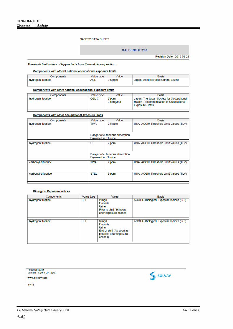
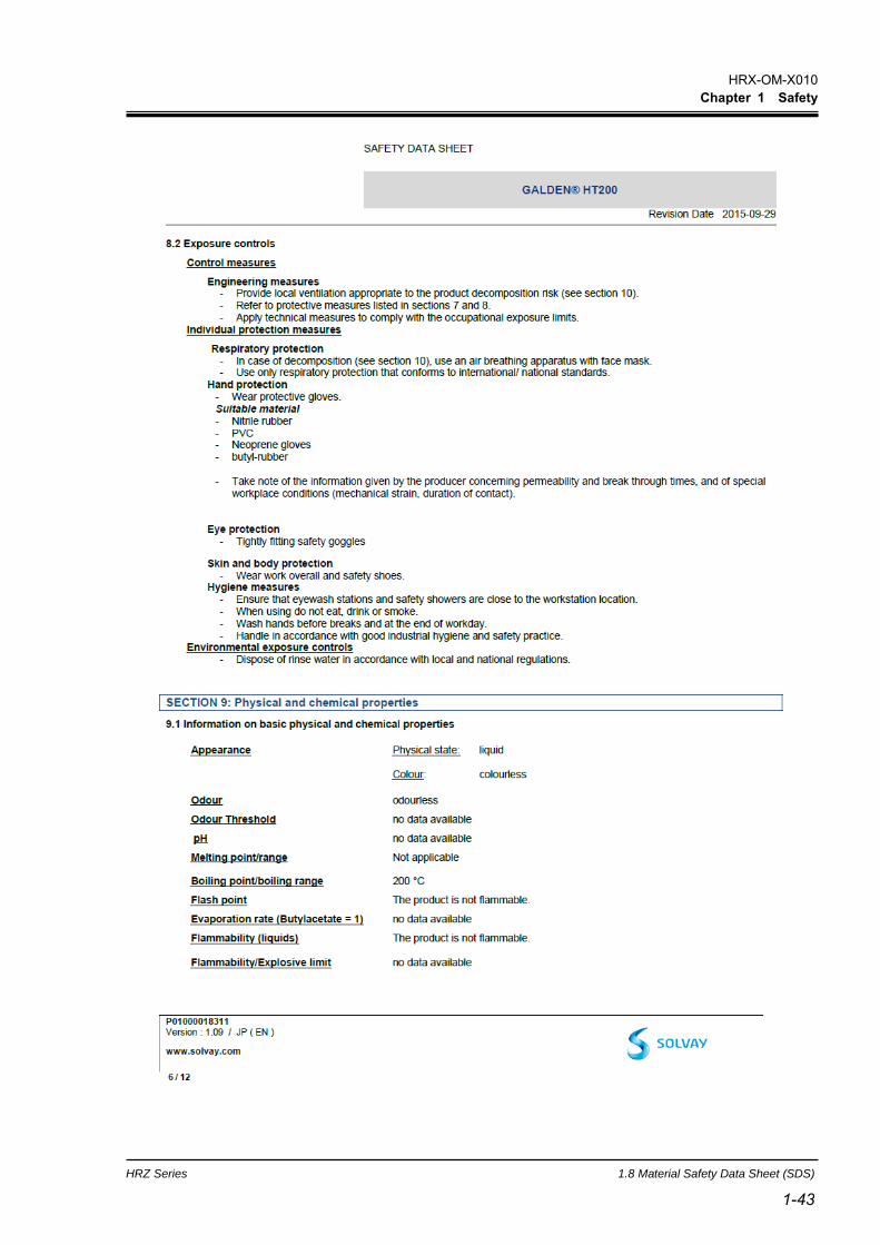
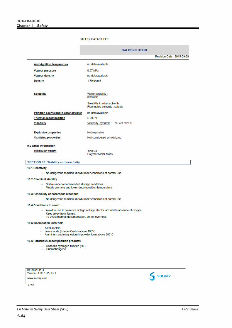
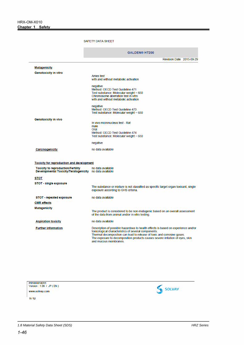
1.8.3 Galden® HT200 ................................................................................................................. 1-38
1.8.4 FluorinertTM FC-40 ............................................................................................................. 1-50
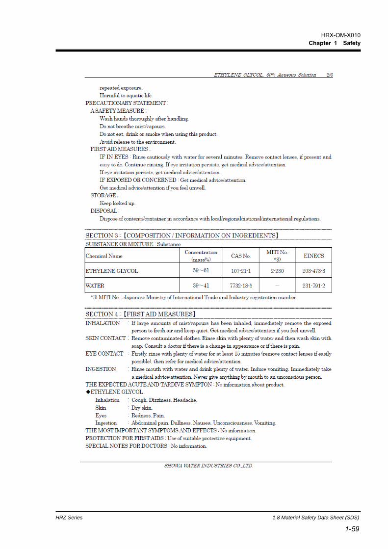
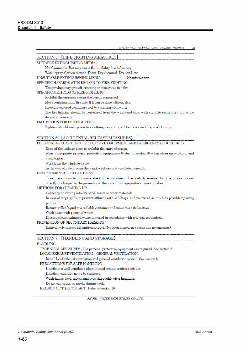
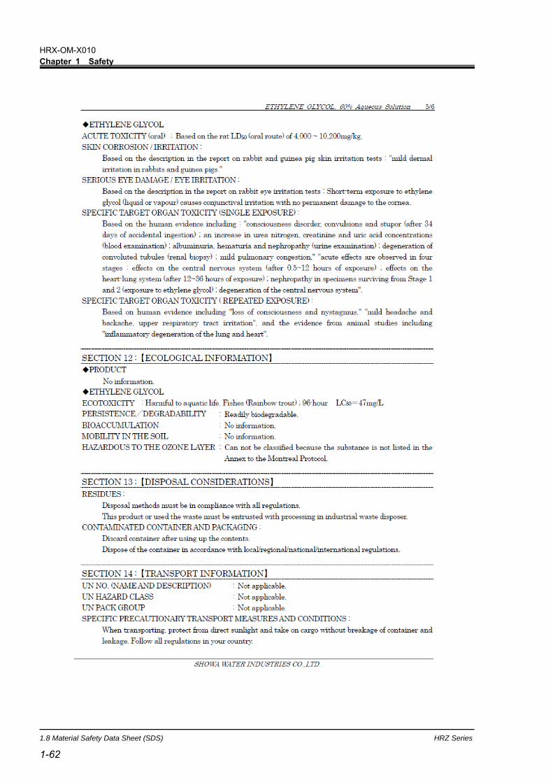
1.8.5 Ethylene glycol aqueous solution 60% .............................................................................. 1-58
1.8.6 Refrigerant R410A ............................................................................................................. 1-64
1.8.7 Refrigerant R448A ............................................................................................................. 1-76
Chapter 2 Name of Each Section ......................................................... 2-1
2.1 Name of Each Section (1) ....................................................................................... 2-1
2.2 Name of Each Section (2) ....................................................................................... 2-2
Chapter 3 Transporting and Installation .............................................. 3-1
3.1 Transporting ............................................................................................................ 3-1
3.1.1 Transporting with forklift ...................................................................................................... 3-2
3.1.2 Transporting with caster ...................................................................................................... 3-3
HRX-OM-X010
Table of Contents
HRZ Series
TOC-2
3.2 Installation ................................................................................................................ 3-3
3.2.1 Installation conditions .......................................................................................................... 3-4
3.2.2 Installation location and maintenance work area ................................................................ 3-5
3.3 Procedure for Installation ........................................................................................ 3-6
3.3.1 Installation ............................................................................................................................ 3-6
3.3.2 Procedure for system securing (1) ...................................................................................... 3-6
3.3.3 Procedure for system securing (2) ...................................................................................... 3-7
3.3.4 Wiring installation ................................................................................................................. 3-8
3.3.5 Procedures for wiring installation ....................................................................................... 3-11
3.3.6 Installation of circulating fluid and facility water piping ...................................................... 3-15
Chapter 4 System Startup and Shutdown ............................................. 4-1
4.1 Pre-check .................................................................................................................. 4-1
4.1.1 Installation condition ............................................................................................................ 4-1
4.1.2 Cable connection ................................................................................................................. 4-1
4.1.3 Installation of circulating fluid and facility water piping ........................................................ 4-1
4.1.4 Operating signal from your system ...................................................................................... 4-1
4.1.5 Check emergency off [EMO] switch .................................................................................... 4-1
4.2 Opening of Facility water Valve .............................................................................. 4-1
4.3 Supply of Circulating Fluid ...................................................................................... 4-2
4.3.1 Preparation of circulating fluid ............................................................................................. 4-2
4.3.2 Supply of circulating fluid ..................................................................................................... 4-3
4.4 Requirement for System Startup ............................................................................ 4-4
4.4.1 Turning ON power................................................................................................................ 4-4
4.4.2 Circulating fluid temperature setting .................................................................................... 4-5
4.5 System Startup and Shutdown ............................................................................... 4-5
4.5.1 System startup ..................................................................................................................... 4-5
4.5.2 System shutdown ................................................................................................................ 4-5
Chapter 5 System Operation ................................................................ 5-1
5.1 Operation Display Panel .......................................................................................... 5-1
5.2 Flow Chart of Operation Screen.............................................................................. 5-2
5.3 Operation Screen ..................................................................................................... 5-4
5.3.1 Model Indication screen ....................................................................................................... 5-4
5.3.2 Status screen 1 .................................................................................................................... 5-5
5.3.3 Status screen 2 .................................................................................................................... 5-6
5.3.4 Status screen 3 .................................................................................................................... 5-7
5.3.5 Status screen 4 .................................................................................................................... 5-8
5.3.6 Alarm Display screen ........................................................................................................... 5-9
5.3.7 Menu screen ........................................................................................................................ 5-9
5.3.8 Setting screen .................................................................................................................... 5-10

HRX-OM-X010
Table of Contents
HRZ Series
TOC-3
5.3.9 Control Setting screen 1 ..................................................................................................... 5-11
5.3.10 Control Setting screen 2 .................................................................................................... 5-13
5.3.11 Control Setting screen 3-1................................................................................................. 5-14
5.3.12 Control Setting screen 3-2................................................................................................. 5-15
5.3.13 Alarm Setting screen 1 ...................................................................................................... 5-16
5.3.14 Alarm Setting screen 2 ...................................................................................................... 5-17
5.3.15 Alarm Setting screen 3 ...................................................................................................... 5-18
5.3.16 Initial Setting screen 1 ....................................................................................................... 5-19
5.3.17 Initial Setting screen 2 ....................................................................................................... 5-20
5.3.18 Initial Setting screen 3 ....................................................................................................... 5-21
5.3.19 Initial Setting screen 4 ....................................................................................................... 5-22
5.3.20 Initial Setting screen 5 ....................................................................................................... 5-23
5.3.21 Initial Setting screen 6 ....................................................................................................... 5-24
5.3.22 Initial Setting screen 7 ....................................................................................................... 5-25
5.3.23 Initial Setting screen 8 ....................................................................................................... 5-26
5.3.24 Mode Selection screen ...................................................................................................... 5-27
5.3.25 Maintenance screen 1 ....................................................................................................... 5-28
5.3.26 Maintenance screen 2 ....................................................................................................... 5-29
5.3.27 Maintenance screen 3 ....................................................................................................... 5-30
5.3.28 Maintenance screen 4 ....................................................................................................... 5-31
5.3.29 Maintenance screen 5 ....................................................................................................... 5-32
5.3.30 Maintenance screen 6 ....................................................................................................... 5-33
5.3.31 Maintenance screen 7 ....................................................................................................... 5-34
5.3.32 Maintenance screen 8 ....................................................................................................... 5-35
5.3.33 System Information screen................................................................................................ 5-36
5.4 Examples of System Operation ............................................................................ 5-37
5.4.1 Example 1: Circulating fluid set temperature is changed from 20.0 deg C to 34.1 deg C. 5-37
5.4.2 Example 2: Communication mode is switched from “LOCAL” to “SER REMOTE”. .......... 5-39
5.4.3 Example 3: PUMP IV is switched from “FLOW” to “FREQ”. ............................................. 5-40
Chapter 6 Error Message and Troubleshooting .................................. 6-1
6.1 Error Message ......................................................................................................... 6-1
6.2 Troubleshooting ...................................................................................................... 6-2
Chapter 7 System Maintenance ........................................................... 7-1
7.1 Water Quality Management ..................................................................................... 7-1
7.2 Inspection and Cleaning ......................................................................................... 7-2
7.2.1 Daily inspection ................................................................................................................... 7-2
7.2.2 Quarterly inspection ............................................................................................................ 7-3
7.3 Storage ..................................................................................................................... 7-3
7.3.1 Draining of circulating fluid out of tank ................................................................................ 7-4
HRX-OM-X010
Table of Contents
HRZ Series
TOC-4
7.3.2 Draining of facility water....................................................................................................... 7-5
7.4 Periodic Replacement Parts .................................................................................... 7-6
Chapter 8 Appendix .............................................................................. 8-1
8.1 Specification ............................................................................................................ 8-1
8.1.1 System specification ............................................................................................................ 8-1
8.1.2 Cooling capacity .................................................................................................................. 8-6
8.1.3 Heating capacity .................................................................................................................. 8-9
8.1.4 Pump Performance Curve ................................................................................................. 8-12
8.1.5 Refrigerant with GWP reference ........................................................................................ 8-15
8.1.6 Communication specification ............................................................................................. 8-16
8.1.7 Alarm signal selection ........................................................................................................ 8-19
8.2 Outer Dimensions .................................................................................................. 8-20
8.2.1 Part 1 ................................................................................................................................. 8-20
8.2.2 Part 2 ................................................................................................................................. 8-20
8.3 Flow Chart .............................................................................................................. 8-21
8.3.1 Part 1 ................................................................................................................................. 8-21
8.3.2 Part 2 ................................................................................................................................. 8-22
8.4 Offset Function ...................................................................................................... 8-23
8.4.1 Example of offset function ................................................................................................. 8-24
8.5 BAND/READY function .......................................................................................... 8-26
8.6 Anchor Bolt Mounting Position ............................................................................ 8-27
8.6.1 Part 1 ................................................................................................................................. 8-27
8.6.2 Part 2 ................................................................................................................................. 8-28
8.7 Compliance ............................................................................................................ 8-29
8.8 Thermo Chiller Daily Inspection Sheet ................................................................. 8-30
Chapter 9 Product Warranty ................................................................ 9-1
HRX-OM-X010
Chapter 1 Safety
HRZ Series 1.1 Before Using this System
1-1 1-1
Chapter 1 Safety
1.1 Before Using this System This "Safety" chapter describes the safety-related items that users should be
aware of upon handling this system.
This system, which is operated under high voltage, is outfitted with the parts that
cause a rise or drop in temperature and rotating parts when it is in action. All
personnel who work with or around this system are required to thoroughly read
and understand the safety-related items in this manual prior to working with or
around this system.
This manual is not intended to be used as a manual for comprehensive safety and
hygiene education. Such a manual should be provided by a safety training
manager.
The product is operated at high voltage and contains components which become
hot and rotate. If a component needs to be replaced or repaired, contact a
specialized vendor for parts and service.
A safety manager is responsible for observing safety standards. Operators and
maintainers, however, are to have individual responsibilies for complying with
the safety standard in his/her daily work.
Operators and maintainers must individually take account of safety and assure a
proper working area and working environment.
The relevant personnel must receive proper safety education prior to work
training on this system. Otherwise, personnel may be exposed to hazards. Never
conduct work training without giving proper consideration to safety.
Do not use the materials that rust or corrode for the circulating fluid and facility
water circuits. Using the materials that tend to rust or corrode may cause clogs
or/and leakages of the circulating fluid and facility water circuits. In case of using
these kind of materials, consider and carry out some prevention against the
rusting or corrosion on the customer side.
Save this manual at a designated place for reference when necessary.
Be sure to read and understand the important precautions defined in this manual thoroughly prior to system use.

HRX-OM-X010
Chapter 1 Safety
1.2 Danger, Warning, and Caution Used in This Manual HRZ Series
1-2
1.2 Danger, Warning, and Caution Used in This Manual
1.2.1 Hazard Levels
This system is designed with its first priority being the safety of workers and the
prevention of system damage. This manual classifies the risks into the following
three categories according to the severity and level of the hazard; Danger, Warning,
and Caution. Read the statements carefully, thoroughly understand them before
operating this system.
DANGER, WARNING and CAUTION signs are in order according to hazard
severity (DANGER > WARNING > CAUTION). See below for the details.
[Tips]
Tips are provided when there is information personnel are required to be
aware of for system operation and maintenance. If the task carries useful
information, the relevant tips are given as well.
1.2.2 Definitions of “Serious injury” and “Minor injury”
◼ “Serious injury”
This term describes injuries such as loss of eyesight, wound, burns, frostbite, electric
shock, fracture, and toxication that leave aftereffects, and/or injury requiring
hospitalization and/or prolonged staying in a hospital.
◼ “Minor injury”
This term describes injuries that do not require hospitalization or prolonged staying
in a hospital (injuries other than “serious injuries” described above).
"DANGER" denotes that there is an imminent hazard which will cause serious personal injury or death during operation.
"WARNING" denotes that there is a hazard which may cause serious personal injury or death during operation.
"CAUTION" denotes that there is a hazard which may cause minor personal injury during operation.
"CAUTION" without an exclamation symbol denotes that there is a hazard which may cause damage or failure of this system, facility, or devices.
HRX-OM-X010
Chapter 1 Safety
HRZ Series 1.2 Danger, Warning, and Caution Used in This Manual
1-3 1-3
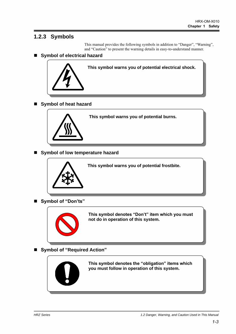
1.2.3 Symbols
This manual provides the following symbols in addition to “Danger”, “Warning”,
and “Caution” to present the warning details in easy-to-understand manner.
◼ Symbol of electrical hazard
◼ Symbol of heat hazard
◼ Symbol of low temperature hazard
◼ Symbol of “Don’ts”
◼ Symbol of “Required Action”
This symbol denotes “Don’t” item which you must not do in operation of this system.
This symbol denotes the “obligation” items which you must follow in operation of this system.
This symbol warns you of potential electrical shock.
This symbol warns you of potential burns.
This symbol warns you of potential frostbite.
HRX-OM-X010
Chapter 1 Safety
1.3 Hazard Warning Label HRZ Series
1-4
1.3 Hazard Warning Label The hazard warning labels are applied to the sections of this system where potential
hazards are present during system operation and maintenance.
The hazard warning labels are in appropriate sizes and colors to get attention of the
operator. They contain symbols in addition to the descriptions of warnings.
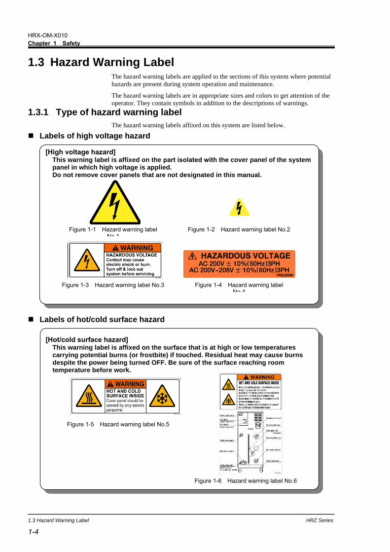
1.3.1 Type of hazard warning label
The hazard warning labels affixed on this system are listed below.
◼ Labels of high voltage hazard
◼ Labels of hot/cold surface hazard
[Hot/cold surface hazard] This warning label is affixed on the surface that is at high or low temperatures carrying potential burns (or frostbite) if touched. Residual heat may cause burns despite the power being turned OFF. Be sure of the surface reaching room temperature before work.
Figure 1-5 Hazard warning label No.5
Figure 1-6 Hazard warning label No.6
[High voltage hazard] This warning label is affixed on the part isolated with the cover panel of the system panel in which high voltage is applied. Do not remove cover panels that are not designated in this manual.
Figure 1-1 Hazard warning label No.1
Figure 1-2 Hazard warning label No.2
Figure 1-3 Hazard warning label No.3 Figure 1-4 Hazard warning label No.4
HRX-OM-X010
Chapter 1 Safety
HRZ Series 1.3 Hazard Warning Label
1-5 1-5
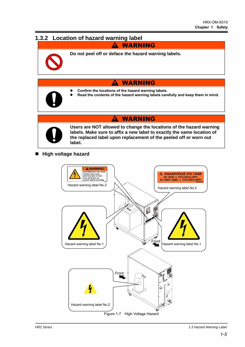
1.3.2 Location of hazard warning label
◼ High voltage hazard
Hazard warning label No.1
Hazard warning label No.2
Front
Hazard warning label No.3
Hazard warning label No.1 Front
Hazard warning label No.4
Figure 1-7 High Voltage Hazard
Confirm the locations of the hazard warning labels. Read the contents of the hazard warning labels carefully and keep them in mind.
Do not peel off or deface the hazard warning labels.
Users are NOT allowed to change the locations of the hazard warning labels. Make sure to affix a new label to exactly the same location of the replaced label upon replacement of the peeled off or worn out label.

HRX-OM-X010
Chapter 1 Safety
1.3 Hazard Warning Label HRZ Series
1-6
◼ Hot/cold surface hazard
Figure 1-8 Hot/Cold Surface Hazard
Front
Rear
Hazard warning label No.5
Hazard warning label No.6
HRX-OM-X010
Chapter 1 Safety
HRZ Series 1.4 Location of Model Label
1-7 1-7
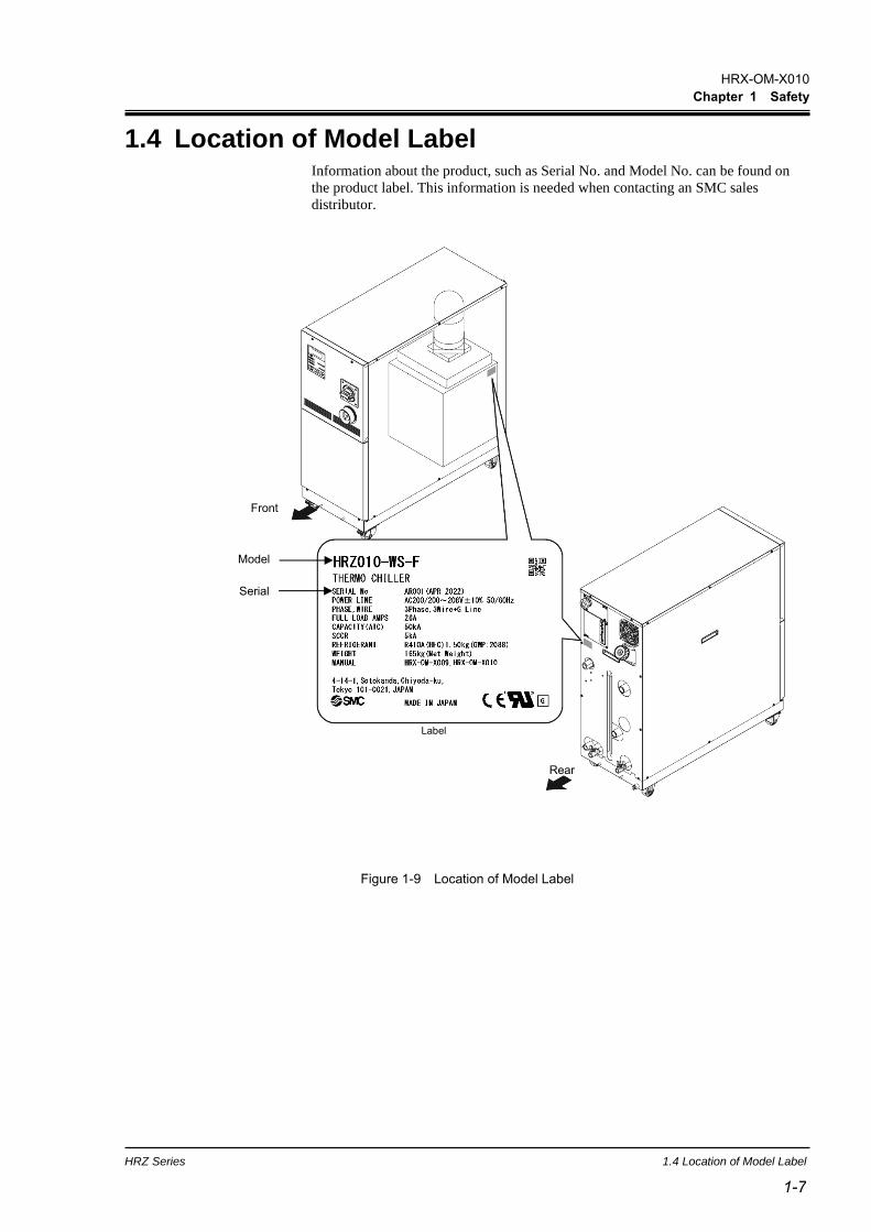
1.4 Location of Model Label Information about the product, such as Serial No. and Model No. can be found on
the product label. This information is needed when contacting an SMC sales
distributor.
Figure 1-9 Location of Model Label
Front
Label
Rear
Model
Serial

HRX-OM-X010
Chapter 1 Safety
1.5 Safety Measures HRZ Series
1-8
1.5 Safety Measures 1.5.1 Safety Precautions
While this system is protected by various safety measures including the safety
interlocks, the following basic safety precautions should be observed to assure
further safe operations.
Read and understand this manual thoroughly before operation of this system.
Before operating the system during maintenance, inform all personnel who are
working in the vicinity of the system to alert them of your action.
Use appropriate tools and follow proper procedures.
See “1.5.4 Protective equipment” on page1-12 to wear protective equipment
properly.
Refer to your safety manual for emergency evacuation.
Use assistance to carry object over 20 kg.
Check that all parts and screws are returned to the pre-work conditions at the end
of work.
Do not work when intoxicated or feeling ill. Accidents may occur if disregarded.
Do not remove a panel unless permitted in this manual.
Do not handle this product by any means other than specified in this Operation
Manual.
Follow the following instructions upon operation of this system. Failure to follow the instructions can lead to personal injury or hazardous accidents.
HRX-OM-X010
Chapter 1 Safety
HRZ Series 1.5 Safety Measures
1-9 1-9
1.5.2 Safety Interlock system
◼ Safety Interlock system
The function of the safety interlock system is not only protect personnel by
restricting operation that may cause damage to this system or the facility around it
but also eliminate the danger relating to safety. This system is outfitted with several
interlock functions that are activated when improper operation or hazardous
conditions occur. System operation shall be terminated when a safety interlock is
activated.
An alarm message is displayed on the LCD screen when a safety interlock is
activated. See “Chapter 6 Error Message and Troubleshooting”on page 6-1 for
details on the alarms and remedies or see section “Troubleshooting” in a separate
volume of the “Service Manual”.
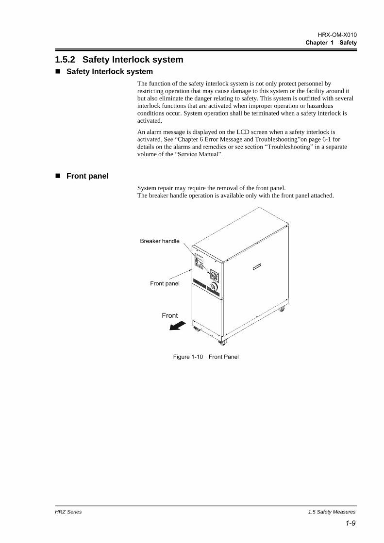
◼ Front panel
System repair may require the removal of the front panel.
The breaker handle operation is available only with the front panel attached.
Figure 1-10 Front Panel
F
r
o
n
t
Front panel
Breaker handle
Front
HRX-OM-X010
Chapter 1 Safety
1.5 Safety Measures HRZ Series
1-10
1.5.3 Lockout/Tagout
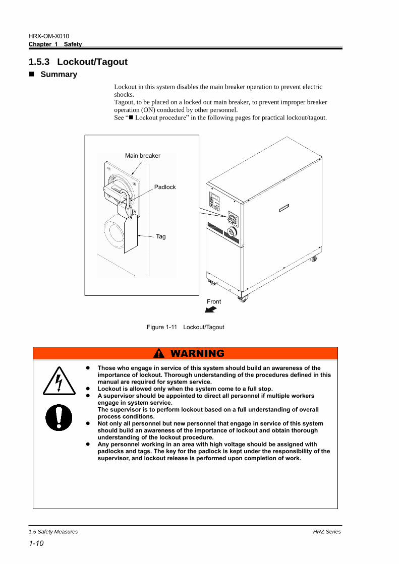
◼ Summary
Lockout in this system disables the main breaker operation to prevent electric
shocks.
Tagout, to be placed on a locked out main breaker, to prevent improper breaker
operation (ON) conducted by other personnel.
See “◼ Lockout procedure” in the following pages for practical lockout/tagout.
Figure 1-11 Lockout/Tagout
Those who engage in service of this system should build an awareness of the importance of lockout. Thorough understanding of the procedures defined in this manual are required for system service.
Lockout is allowed only when the system come to a full stop. A supervisor should be appointed to direct all personnel if multiple workers
engage in system service. The supervisor is to perform lockout based on a full understanding of overall process conditions.
Not only all personnel but new personnel that engage in service of this system should build an awareness of the importance of lockout and obtain thorough understanding of the lockout procedure.
Any personnel working in an area with high voltage should be assigned with padlocks and tags. The key for the padlock is kept under the responsibility of the supervisor, and lockout release is performed upon completion of work.
Front
Main breaker
Padlock
Tag

HRX-OM-X010
Chapter 1 Safety
HRZ Series 1.5 Safety Measures
1-11 1-11
◼ Lockout procedure
1. Turn the breaker handle to ‘OFF ’.
2. Turn the breaker handle to ‘RESET’.
Hold the breaker handle with hand.
The handle turns back to ‘OFF O’ if released.
3. Push the lock pushing part of the
breaker handle, and turn the breaker
handle to ‘OFF ’.
The lock mechanism part is to remain opened.
4. Lock the lock mechanism part with the
padlock.
◼ Releasing lockout
1. Remove the padlock from the lock mechanism part.
2. Turn the breaker handle to ‘RESET’.
The lock mechanism part is closed.
The handle turns back to ‘OFF ’ if released.
Padlock
Figure 1-12 Breaker Handle at ‘OFF ’
Figure 1-13 Breaker Handle at ‘RESET’
Figure 1-14 Pushing of Lock Mechanism Part
Figure 1-15 Breaker Lock
All service personnel must observe the restrictions applied during lockout and are required to perform lockout in accordance with this procedure. No service personnel is allowed to start, energize, or use the locked out system.
Lock pushing part Lock mechanism part

HRX-OM-X010
Chapter 1 Safety
1.5 Safety Measures HRZ Series
1-12
1.5.4 Protective equipment
This manual defines protective equipment according to work type.
Wear proper protective equipment as shown below, according to work type.
◼ For system transportation, installation and removal
Protective footwear Protective gloves Hard hat
◼ For handling circulating fluid
Protective footwear Protective gloves Protective mask
Protective apron Protective goggles
◼ For system operation
Protective footwear Protective gloves
Read and understand the relevant operation manual thoroughly prior to use of protective equipment.

HRX-OM-X010
Chapter 1 Safety
HRZ Series 1.6 Emergency Measures
1-13 1-13
1.6 Emergency Measures 1.6.1 Emergency off [EMO] switch
Press the red emergency off [EMO] switch on the front of the system only if the
need to shut off the power arises due to emergency such as natural disaster, fire,
earthquake or personal injury.
The emergency off [EMO] switch is a large, red mushroom-shaped push button
labeled with ‘EMO’ on it. The system comes to a halt if this button is pressed.
When press the emergency off [EMO] switch, the control power for this system is
shut off to bring the system to a stop. The main breaker of this system, however, is
designed not to trip, which enables the motor circuit to remain partially energized.
“8.1.6Communication specification” in Chapter 8 Appendix on page 8-16 to view
the circuit diagram and see how the EMO switch is interconnected to the system.
Restart of this system is enabled only when this button is reset manually.
◼ Location of emergency off [EMO] switch
Figure 1-16 Location of Emergency Off [EMO] Switch
HRX-OM-X010
Chapter 1 Safety
1.6 Emergency Measures HRZ Series
1-14
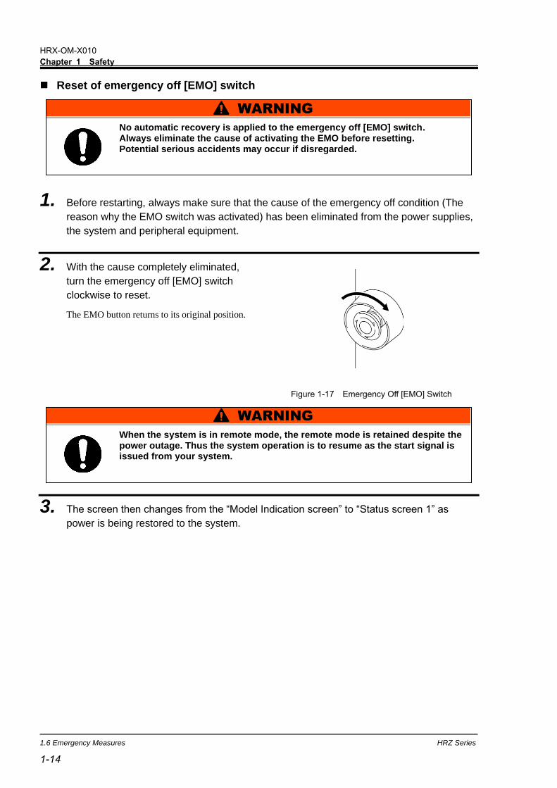
◼ Reset of emergency off [EMO] switch
1. Before restarting, always make sure that the cause of the emergency off condition (The
reason why the EMO switch was activated) has been eliminated from the power supplies,
the system and peripheral equipment.
2. With the cause completely eliminated,
turn the emergency off [EMO] switch
clockwise to reset.
The EMO button returns to its original position.
3. The screen then changes from the “Model Indication screen” to “Status screen 1” as
power is being restored to the system.
Figure 1-17 Emergency Off [EMO] Switch
No automatic recovery is applied to the emergency off [EMO] switch. Always eliminate the cause of activating the EMO before resetting. Potential serious accidents may occur if disregarded.
When the system is in remote mode, the remote mode is retained despite the power outage. Thus the system operation is to resume as the start signal is issued from your system.

HRX-OM-X010
Chapter 1 Safety
HRZ Series 1.7 Waste Disposal
1-15 1-15
1.7 Waste Disposal 1.7.1 Disposal of refrigerant and compressor oil
HFC- refrigerant and compressor oil are present in this system. When recovering the
refrigerant or compressor oil, the precautions provided below should thoroughly be
read and understood in advance. If you have any questions or concerns, contact the
system supplier.
[Tips]
For the type and quantity of the refrigerant, See “Location of Model Label” on
page 1-7.
Only service personnel or those who are qualified are allowed to open the panel of this system.
Do not dispose of the compressor oil as domestic garbage. Incineration is permitted only at an authorized incinerator.
Disposal of the compressor oil must be in accordance with regulations and rules of local authorities.
The release of refrigerant into the air is prohibited by law. Recover the refrigerant with the “refrigerant recovery system”, and request the specialized waste disposal agency for disposal of the recovered refrigerant.
Only personnel with proper licensing, who have adequate knowledge and experiences with not only this system but associated equipment are allowed to implement the recovery of the refrigerant and compressor oil.

HRX-OM-X010
Chapter 1 Safety
1.8 Material Safety Data Sheet (SDS) HRZ Series
1-16
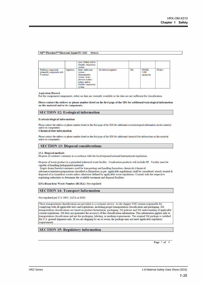
1.7.2 Circulating fluid disposal
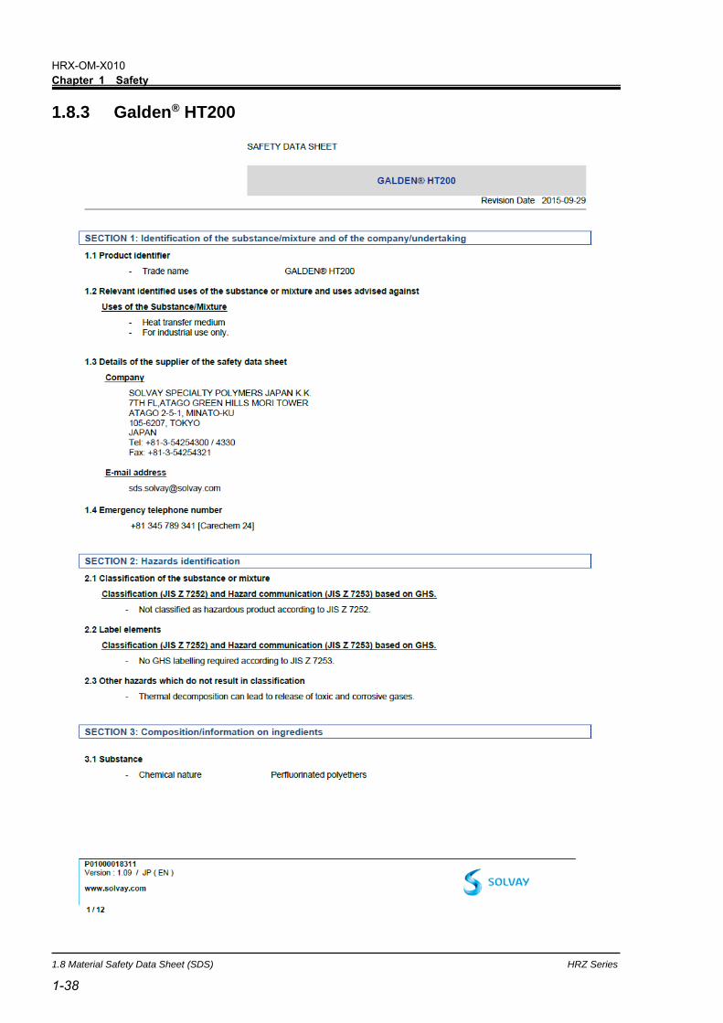
As to the disposal of a circulating fluid (ethylene glycol solution, fluorinated fluid),
consign the specialized industrial waste disposal agency with the contents detailed.
1.7.3 System disposal
As to the disposal of this system, consign the specialized industrial waste disposal
agency in accordance with local laws and regulations.
1.7.4 Label
Label described below which is attached to the top panel of product is that required
by Japanese law, and the content of this label is applicable in Japan only.
Contents of description of this label is shown as follows.
Fluorocarbon Collection and Destruction Law in Japan
This product uses Fluorocarbon (HFC) as a refrigerant.
1. It is strictly forbidden to emit Fluorocarbon to the atomosphere.
2. When disposing this product, Fluorocarbon must be collected in an appropriate
manner.
3. This kind of Fluorocarbon and the amount used in this product is printed on the
name label.
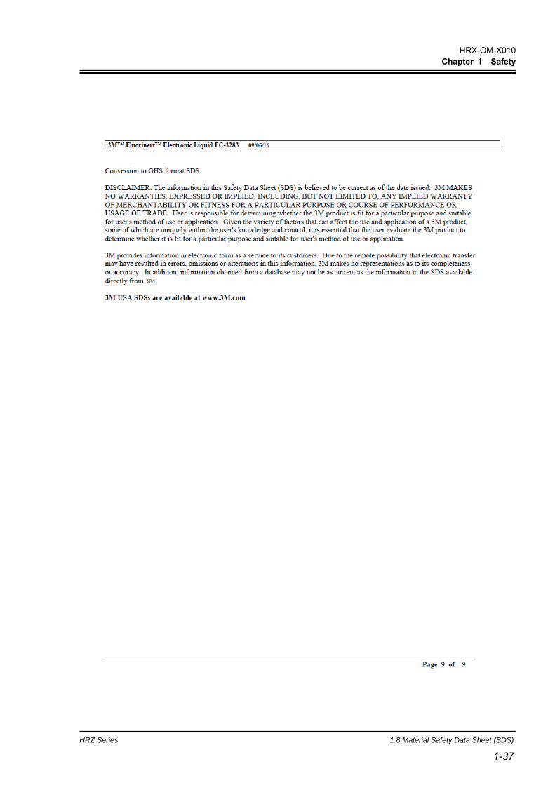
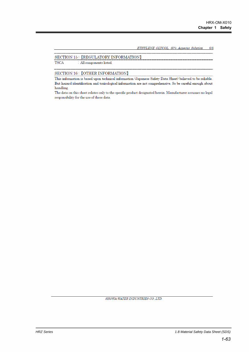
1.8 Material Safety Data Sheet (SDS) Any chemicals used by the user must be accompanied by an SDS.
【About Contents】 Contents documented here are based on references, information and data
available so far. Information given regarding physical/chemical properties, hazard and toxicity here gives no guarantee.
Also, be noted that cautions are for normal handling. Carry out sufficient safety, hygiene, and environmental measures for special handling.
Note the items described as “no documentation” mean our study on those items is not completed yet.

HRX-OM-X010
Chapter 1 Safety
HRZ Series 1.8 Material Safety Data Sheet (SDS)
1-17 1-17
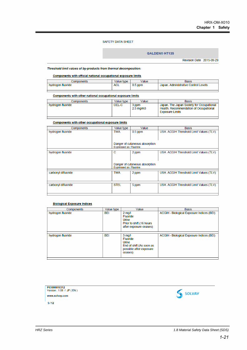
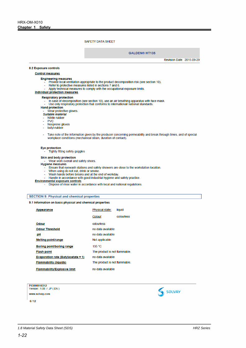
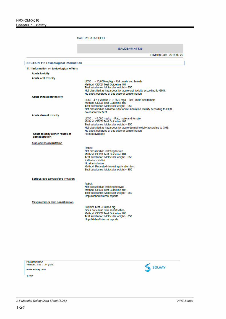
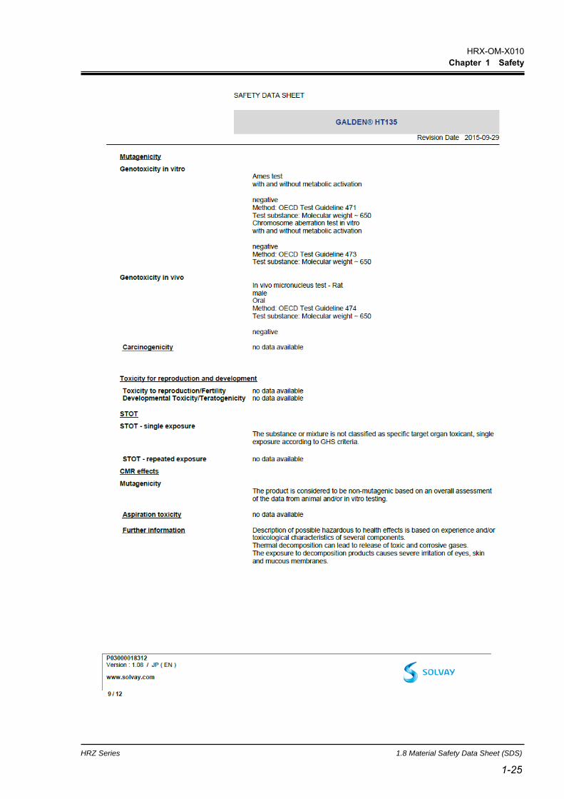
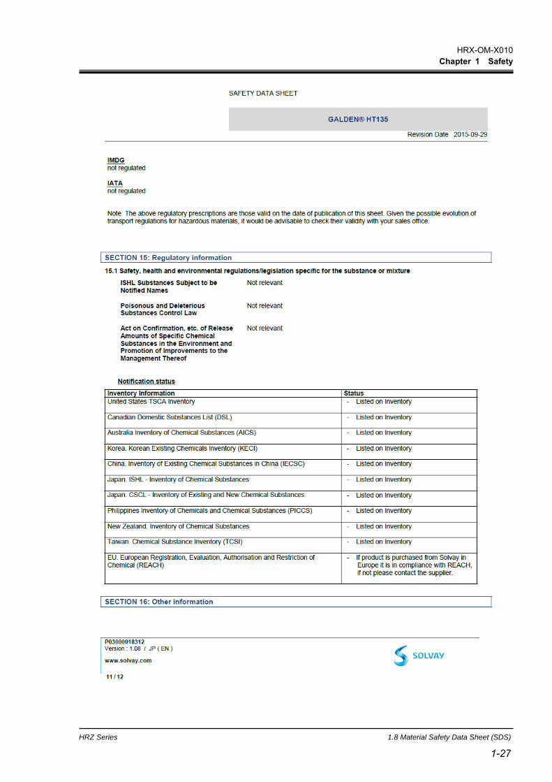
1.8.1 Galden® HT135

HRX-OM-X010
Chapter 1 Safety
1.8 Material Safety Data Sheet (SDS) HRZ Series
1-18

HRX-OM-X010
Chapter 1 Safety
HRZ Series 1.8 Material Safety Data Sheet (SDS)
1-19 1-19

HRX-OM-X010
Chapter 1 Safety
1.8 Material Safety Data Sheet (SDS) HRZ Series
1-20
HRX-OM-X010
Chapter 1 Safety
HRZ Series 1.8 Material Safety Data Sheet (SDS)
1-21 1-21
HRX-OM-X010
Chapter 1 Safety
1.8 Material Safety Data Sheet (SDS) HRZ Series
1-22

HRX-OM-X010
Chapter 1 Safety
HRZ Series 1.8 Material Safety Data Sheet (SDS)
1-23 1-23
HRX-OM-X010
Chapter 1 Safety
1.8 Material Safety Data Sheet (SDS) HRZ Series
1-24
HRX-OM-X010
Chapter 1 Safety
HRZ Series 1.8 Material Safety Data Sheet (SDS)
1-25 1-25

HRX-OM-X010
Chapter 1 Safety
1.8 Material Safety Data Sheet (SDS) HRZ Series
1-26
HRX-OM-X010
Chapter 1 Safety
HRZ Series 1.8 Material Safety Data Sheet (SDS)
1-27 1-27

HRX-OM-X010
Chapter 1 Safety
1.8 Material Safety Data Sheet (SDS) HRZ Series
1-28

HRX-OM-X010
Chapter 1 Safety
HRZ Series 1.8 Material Safety Data Sheet (SDS)
1-29 1-29
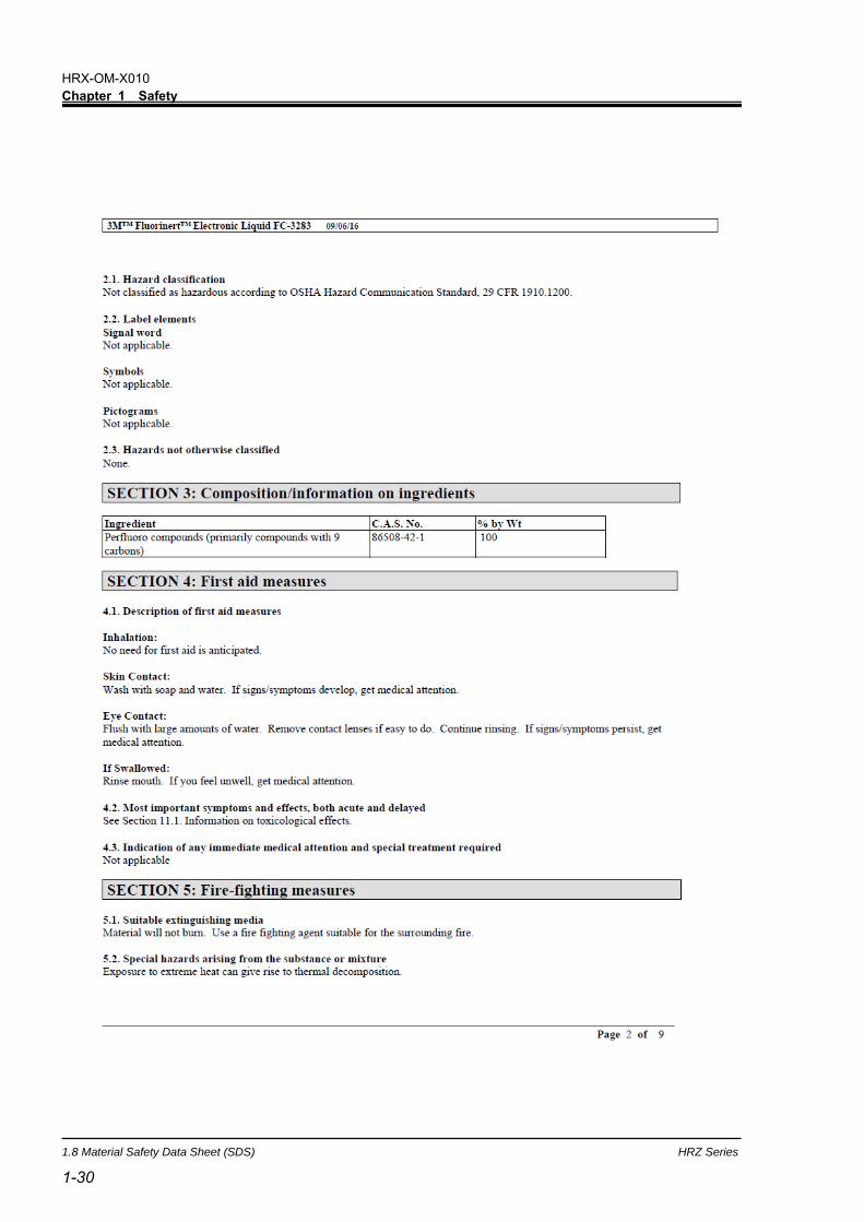
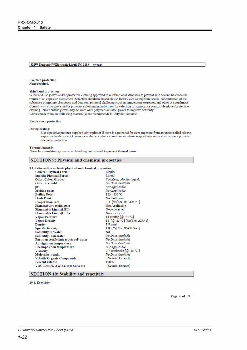
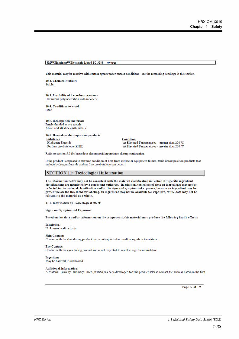
1.8.2 FluorinertTM FC-3283
HRX-OM-X010
Chapter 1 Safety
1.8 Material Safety Data Sheet (SDS) HRZ Series
1-30

HRX-OM-X010
Chapter 1 Safety
HRZ Series 1.8 Material Safety Data Sheet (SDS)
1-31 1-31
HRX-OM-X010
Chapter 1 Safety
1.8 Material Safety Data Sheet (SDS) HRZ Series
1-32
HRX-OM-X010
Chapter 1 Safety
HRZ Series 1.8 Material Safety Data Sheet (SDS)
1-33 1-33

HRX-OM-X010
Chapter 1 Safety
1.8 Material Safety Data Sheet (SDS) HRZ Series
1-34
HRX-OM-X010
Chapter 1 Safety
HRZ Series 1.8 Material Safety Data Sheet (SDS)
1-35 1-35

HRX-OM-X010
Chapter 1 Safety
1.8 Material Safety Data Sheet (SDS) HRZ Series
1-36
HRX-OM-X010
Chapter 1 Safety
HRZ Series 1.8 Material Safety Data Sheet (SDS)
1-37 1-37
HRX-OM-X010
Chapter 1 Safety
1.8 Material Safety Data Sheet (SDS) HRZ Series
1-38
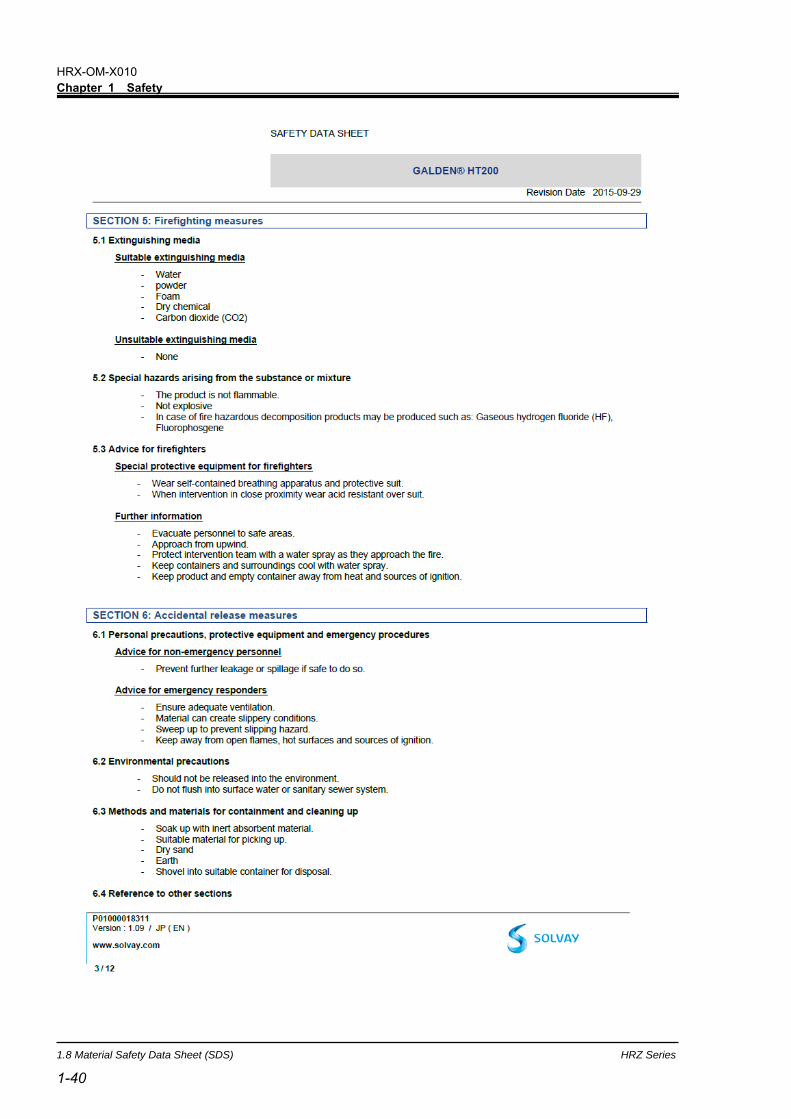
1.8.3 Galden® HT200

HRX-OM-X010
Chapter 1 Safety
HRZ Series 1.8 Material Safety Data Sheet (SDS)
1-39 1-39
HRX-OM-X010
Chapter 1 Safety
1.8 Material Safety Data Sheet (SDS) HRZ Series
1-40

HRX-OM-X010
Chapter 1 Safety
HRZ Series 1.8 Material Safety Data Sheet (SDS)
1-41 1-41
HRX-OM-X010
Chapter 1 Safety
1.8 Material Safety Data Sheet (SDS) HRZ Series
1-42
HRX-OM-X010
Chapter 1 Safety
HRZ Series 1.8 Material Safety Data Sheet (SDS)
1-43 1-43
HRX-OM-X010
Chapter 1 Safety
1.8 Material Safety Data Sheet (SDS) HRZ Series
1-44

HRX-OM-X010
Chapter 1 Safety
HRZ Series 1.8 Material Safety Data Sheet (SDS)
1-45 1-45
HRX-OM-X010
Chapter 1 Safety
1.8 Material Safety Data Sheet (SDS) HRZ Series
1-46

HRX-OM-X010
Chapter 1 Safety
HRZ Series 1.8 Material Safety Data Sheet (SDS)
1-47 1-47

HRX-OM-X010
Chapter 1 Safety
1.8 Material Safety Data Sheet (SDS) HRZ Series
1-48
HRX-OM-X010
Chapter 1 Safety
HRZ Series 1.8 Material Safety Data Sheet (SDS)
1-49 1-49

HRX-OM-X010
Chapter 1 Safety
1.8 Material Safety Data Sheet (SDS) HRZ Series
1-50
1.8.4 FluorinertTM FC-40

HRX-OM-X010
Chapter 1 Safety
HRZ Series 1.8 Material Safety Data Sheet (SDS)
1-51 1-51

HRX-OM-X010
Chapter 1 Safety
1.8 Material Safety Data Sheet (SDS) HRZ Series
1-52

HRX-OM-X010
Chapter 1 Safety
HRZ Series 1.8 Material Safety Data Sheet (SDS)
1-53 1-53

HRX-OM-X010
Chapter 1 Safety
1.8 Material Safety Data Sheet (SDS) HRZ Series
1-54

HRX-OM-X010
Chapter 1 Safety
HRZ Series 1.8 Material Safety Data Sheet (SDS)
1-55 1-55

HRX-OM-X010
Chapter 1 Safety
1.8 Material Safety Data Sheet (SDS) HRZ Series
1-56

HRX-OM-X010
Chapter 1 Safety
HRZ Series 1.8 Material Safety Data Sheet (SDS)
1-57 1-57

HRX-OM-X010
Chapter 1 Safety
1.8 Material Safety Data Sheet (SDS) HRZ Series
1-58
1.8.5 Ethylene glycol aqueous solution 60%
HRX-OM-X010
Chapter 1 Safety
HRZ Series 1.8 Material Safety Data Sheet (SDS)
1-59 1-59
HRX-OM-X010
Chapter 1 Safety
1.8 Material Safety Data Sheet (SDS) HRZ Series
1-60

HRX-OM-X010
Chapter 1 Safety
HRZ Series 1.8 Material Safety Data Sheet (SDS)
1-61 1-61
HRX-OM-X010
Chapter 1 Safety
1.8 Material Safety Data Sheet (SDS) HRZ Series
1-62
HRX-OM-X010
Chapter 1 Safety
HRZ Series 1.8 Material Safety Data Sheet (SDS)
1-63 1-63

HRX-OM-X010
Chapter 1 Safety
1.8 Material Safety Data Sheet (SDS) HRZ Series
1-64
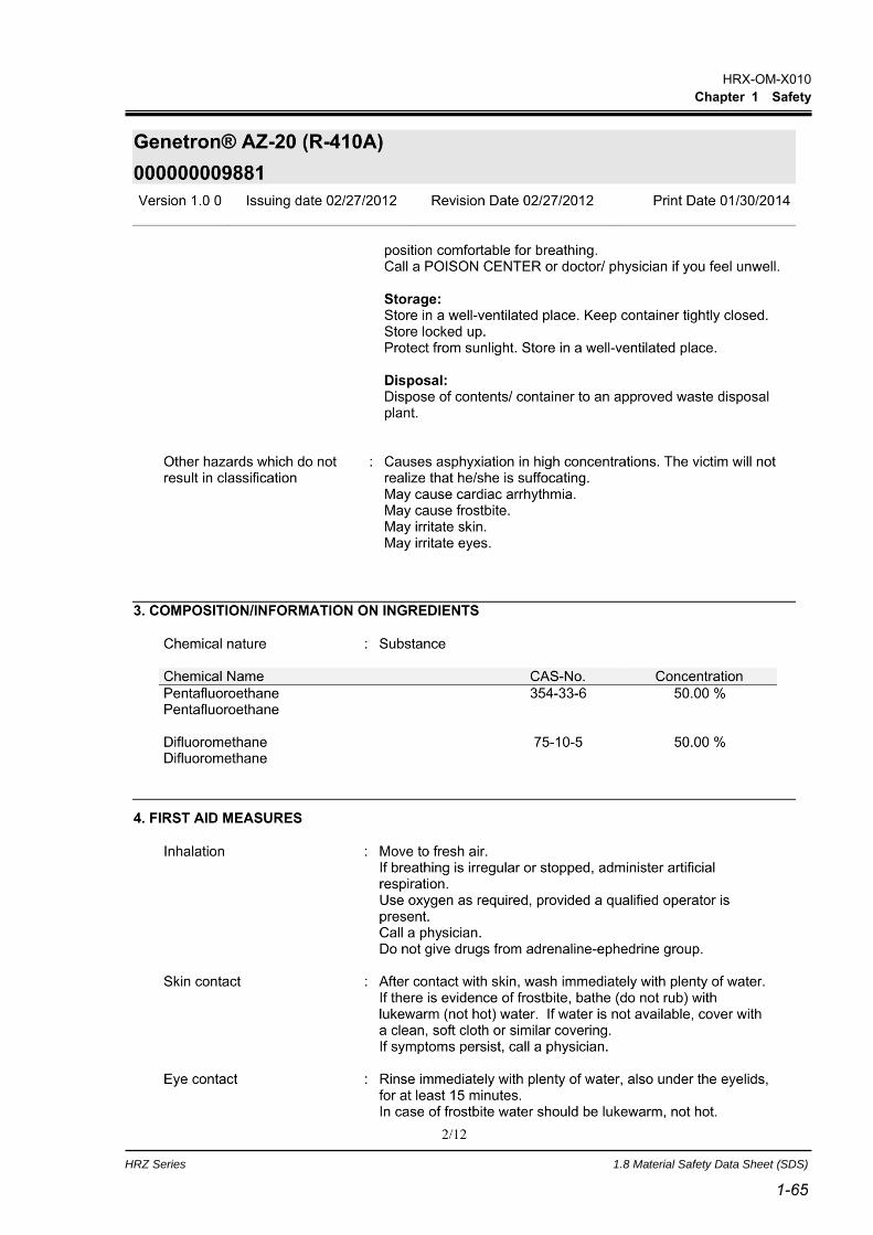
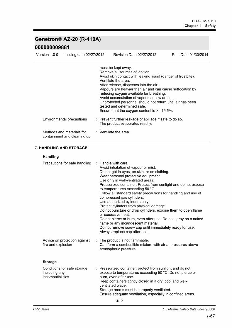
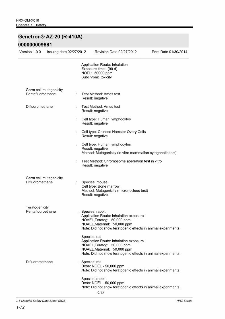
1.8.6 Refrigerant R410A
HRX-OM-X010
Chapter 1 Safety
HRZ Series 1.8 Material Safety Data Sheet (SDS)
1-65 1-65

HRX-OM-X010
Chapter 1 Safety
1.8 Material Safety Data Sheet (SDS) HRZ Series
1-66
HRX-OM-X010
Chapter 1 Safety
HRZ Series 1.8 Material Safety Data Sheet (SDS)
1-67 1-67

HRX-OM-X010
Chapter 1 Safety
1.8 Material Safety Data Sheet (SDS) HRZ Series
1-68

HRX-OM-X010
Chapter 1 Safety
HRZ Series 1.8 Material Safety Data Sheet (SDS)
1-69 1-69

HRX-OM-X010
Chapter 1 Safety
1.8 Material Safety Data Sheet (SDS) HRZ Series
1-70

HRX-OM-X010
Chapter 1 Safety
HRZ Series 1.8 Material Safety Data Sheet (SDS)
1-71 1-71
HRX-OM-X010
Chapter 1 Safety
1.8 Material Safety Data Sheet (SDS) HRZ Series
1-72

HRX-OM-X010
Chapter 1 Safety
HRZ Series 1.8 Material Safety Data Sheet (SDS)
1-73 1-73

HRX-OM-X010
Chapter 1 Safety
1.8 Material Safety Data Sheet (SDS) HRZ Series
1-74
HRX-OM-X010
Chapter 1 Safety
HRZ Series 1.8 Material Safety Data Sheet (SDS)
1-75 1-75

HRX-OM-X010
Chapter 1 Safety
1.8 Material Safety Data Sheet (SDS) HRZ Series
1-76
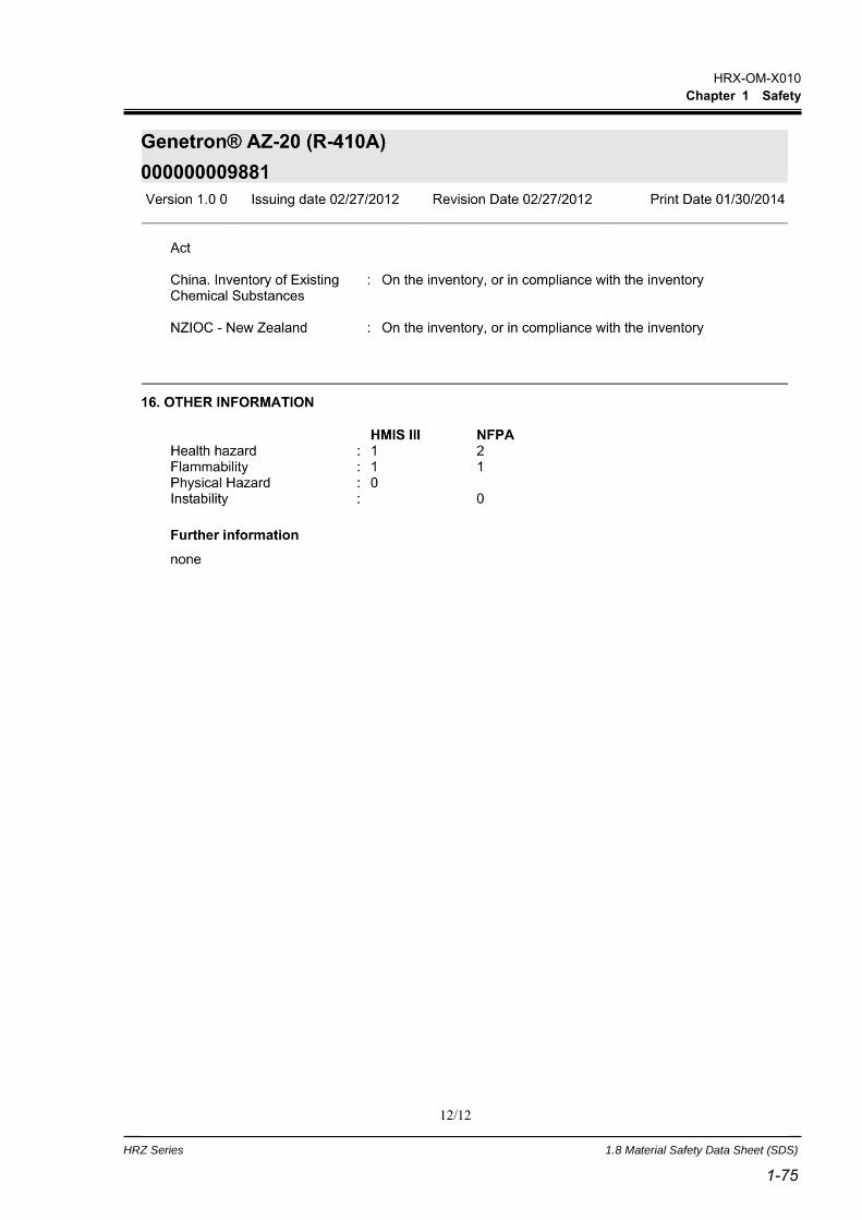
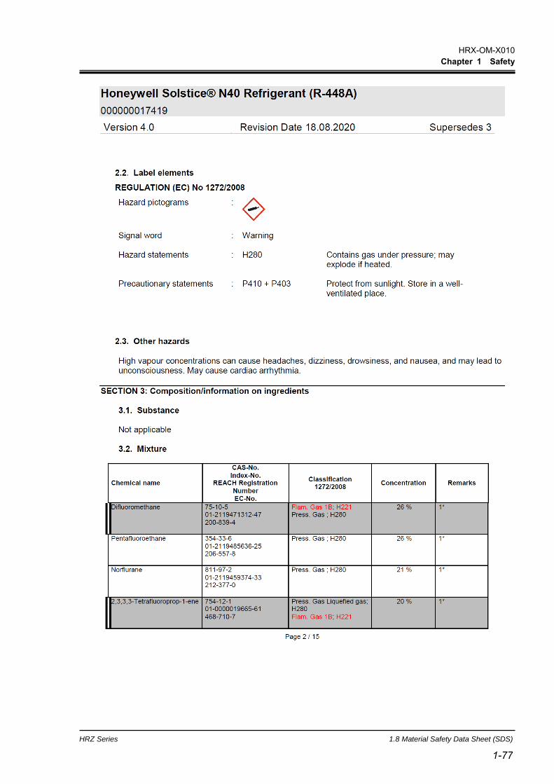
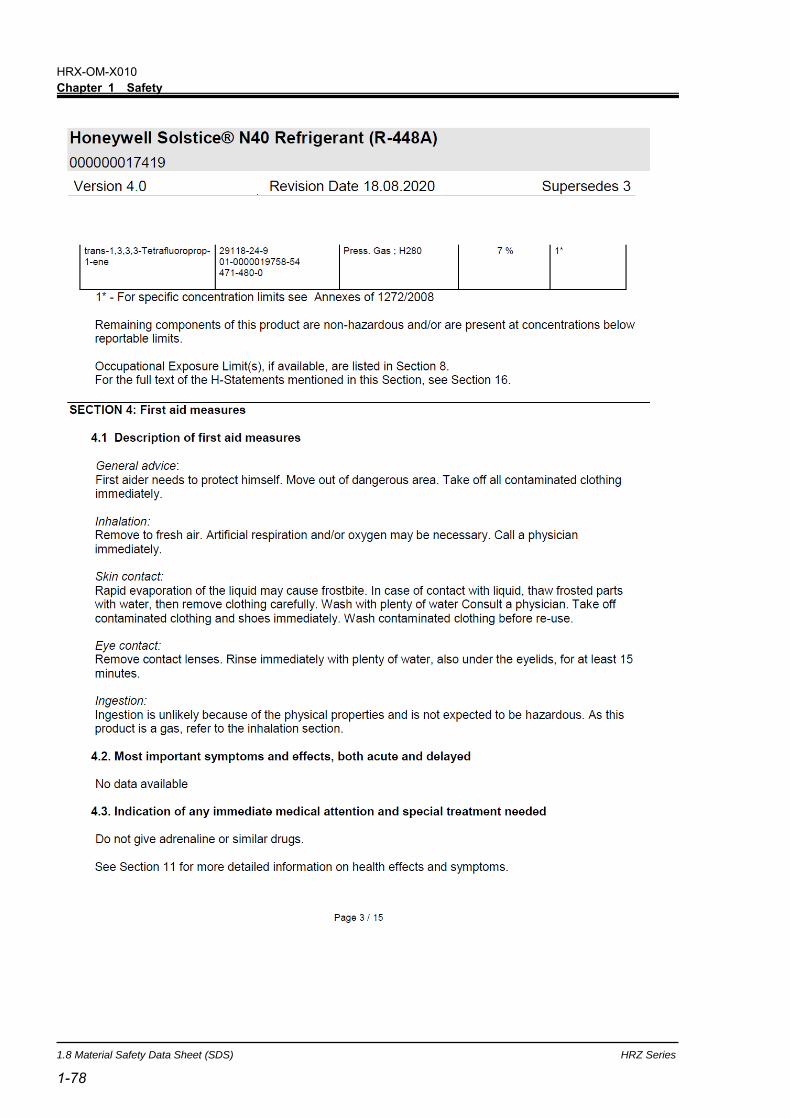
1.8.7 Refrigerant R448A
HRX-OM-X010
Chapter 1 Safety
HRZ Series 1.8 Material Safety Data Sheet (SDS)
1-77 1-77
HRX-OM-X010
Chapter 1 Safety
1.8 Material Safety Data Sheet (SDS) HRZ Series
1-78

HRX-OM-X010
Chapter 1 Safety
HRZ Series 1.8 Material Safety Data Sheet (SDS)
1-79 1-79

HRX-OM-X010
Chapter 1 Safety
1.8 Material Safety Data Sheet (SDS) HRZ Series
1-80

HRX-OM-X010
Chapter 1 Safety
HRZ Series 1.8 Material Safety Data Sheet (SDS)
1-81 1-81

HRX-OM-X010
Chapter 1 Safety
1.8 Material Safety Data Sheet (SDS) HRZ Series
1-82

HRX-OM-X010
Chapter 1 Safety
HRZ Series 1.8 Material Safety Data Sheet (SDS)
1-83 1-83

HRX-OM-X010
Chapter 1 Safety
1.8 Material Safety Data Sheet (SDS) HRZ Series
1-84

HRX-OM-X010
Chapter 1 Safety
HRZ Series 1.8 Material Safety Data Sheet (SDS)
1-85 1-85

HRX-OM-X010
Chapter 1 Safety
1.8 Material Safety Data Sheet (SDS) HRZ Series
1-86

HRX-OM-X010
Chapter 1 Safety
HRZ Series 1.8 Material Safety Data Sheet (SDS)
1-87 1-87

HRX-OM-X010
Chapter 1 Safety
1.8 Material Safety Data Sheet (SDS) HRZ Series
1-88

HRX-OM-X010
Chapter 1 Safety
HRZ Series 1.8 Material Safety Data Sheet (SDS)
1-89 1-89

HRX-OM-X010
Chapter 1 Safety
1.8 Material Safety Data Sheet (SDS) HRZ Series
1-90

HRX-OM-X010
Chapter 2 Name of Each Section
HRZ Series 2.1 Name of Each Section (1)
2-1 2-1
Chapter 2 Name of Each Section 2.1 Name of Each Section (1)
HRZ***-WS-F HRZ***-W1S-F HRZ***-W2S-F
,
Figure 2-1 Name of Each Section (1)
[Tips]
The front casters (2 pcs.) have built-in brakes. The disengagement of the
brakes is required when transporting the system.
Caster w/ brake
Rotates 360°.
Emergency off [EMO] switch
Main breaker
Power cable access
Circulating fluid fill port
Facility water outlet
Circulating fluid return
Circulating fluid level gauge
Circulating fluid supply
Drain pan port
Facility water inlet
Ventilating fan (exhaust side)
Operation display panel
Sub tank drain port
Main tank drain port
Ventilating hole (intake side)

HRX-OM-X010
Chapter 2 Name of Each Section
2.2 Name of Each Section (2) HRZ Series
2-2
2.2 Name of Each Section (2) HRZ008-L-F HRZ008-L1-F
Figure 2-2 Name of Each Section (2)
When transporting the system with the casters, raise the adjustable feet (4 pcs.) to the highest position and lock them with the nuts. The adjustable foot at the lower position may cause damage to this system and personal injury through contact with the floor or steps during system transport.
Operation display panel
Ventilating hole (intake side)
Ventilating fan (exhaust side)
Power cable access
Circulating fluid fill port
Facility water outlet
Circulating fluid supply
Facility water inlet
Main tank drain port
Drain pan port
Circulating fluid return
Circulating fluid level gauge
Caster
Rotates 360°.
Nut
Main breaker
Emergency off [EMO] switch
Sub tank drain port
Adjustable foot

HRX-OM-X010
Chapter 3 Transporting and Installation
HRZ Series 3.1 Transporting
3-1 3-1
Chapter 3 Transporting and Installation
3.1 Transporting This system is heavy, which poses potential danger at transportation.
When transporting this system, the following safety precautions should be observed
to prevent system damage and breakdown.
Proper procedure must be followed when using this system. Exercise caution to assure personnel safety during the installation, operation, maintenance, and inspection of the system.
Only personnel, who have adequate knowledge and experiences with not only this system but associated equipment are allowed to perform transport, installation, and maintenance involving potential hazardous task.
For transporting with the forklift, be sure to insert the fork into a designated position, referring to “3.1.1 Transporting with forklift” on page 3-2.
Do not set this system on its side during transportation. Oil in the compressor drains into the refrigerant pipe, which causes lubricant shortages leading to damage to the compressor.
Drain the remaining fluid out of the pipe as much as possible. The remaining fluid may spill if disregarded.
Exercise caution not to damage the panel and piping with the forklift when transporting the system.

HRX-OM-X010
Chapter 3 Transporting and Installation
3.1 Transporting HRZ Series
3-2
3.1.1 Transporting with forklift
Figure 3-1 Transport with Forklift
This system is heavy, and requires a forklift to safely move it. Forklift insertion positions are on either left or right side of this system. Always
insert the forks all the way through. Becareful not to hit the casters and adjustable feet.
Do not set this system on its side for transportation. Potential damage to this system carrying danger of personnel injury if disregarded.
Do not insert the fork from the back as well as front.
Rear
Front
Forklift insertion side
Forklift insertion side

HRX-OM-X010
Chapter 3 Transporting and Installation
HRZ Series 3.2 Installation
3-3 3-3
3.1.2 Transporting with caster
3.2 Installation
This system is heavy, which requires assistance for this work. Exercise caution and look out for sloped surfaces such as ramps, etc.
Do not grab piping on the back of this system or panel handles when transporting with the casters. Potential damage to piping and panels may occur if disregarded.
System installation should be kept from areas with the potential of flammable gas leak. Ignition may occur if leaked gas is collected around the system.
This system is NOT designed for outside use. Potential electric shock, fire and system damage may occur if exposed to rain, water and dust.
This system is to be installed on a level floor that can withstand the weight of this system. Potential water leak and personal injury due to system tipping over may occur if disregarded.

HRX-OM-X010
Chapter 3 Transporting and Installation
3.2 Installation HRZ Series
3-4
3.2.1 Installation conditions
System installation is not allowed outside or in the conditions described below.
Potential system malfunction and damage may occur if disregarded.
Clean room specifications are not applied to this unit. The pump and ventilating fan
installed in this unit generate particles.
Location that is exposed to water vapor, salt water, and oil
Location that is exposed to dust and powder
Location that is exposed to corrosive gas, solvent, and flammable gas
Location that is exposed to direct sun light or radiant heat
Location where ambient temperature is out of the following range:
In operation 10 to 35 deg C
In storage 0 to 50 deg C(with no water or circulating fluid in piping)
Location where relative humidity is out of the following range:
In operation 30 to 70%
In storage 15 to 85%
Location that is subjected to abrupt changes in temperature
Location that is subjected to intense electromagnetic noise (intense electric field,
intense magnetic field, or surges)
Location that is subjected to static electricity, or condition that discharges static
electricity to the system
Location that is subjected to strong high frequencies
Location that is subjected to potential lightning damage
Location with altitudes of 1000m or higher
Location that is affected by strong vibrations or impacts
Condition that applies external force or weight causing the system deformation
Condition with no adequate space for maintenance as required in the installation
site.

HRX-OM-X010
Chapter 3 Transporting and Installation
HRZ Series 3.2 Installation
3-5 3-5
3.2.2 Installation location and maintenance work area This system does not have ventilating hole on the both right and left sides. Although this can be installed directlycontacting to walls or devices, installation with maintenance space is recommended. (See “Figure3-2)
To save space, this system can be installed to allow access only in front and back for daily operation
and inspection. For maintenance and repair work, additional access space is required for the left and
right side of the system. We recommend a separate repair area, without taking space from installation
site, to accommodate the needed extra space.
Daily inspection area
Operation area
Front
Figure 3-3 Installation Location
Figure 3-2 Recommended Installation Location
800mm 800mm
800mm
800mm
Front
HRX-OM-X010
Chapter 3 Transporting and Installation
3.3 Procedure for Installation HRZ Series
3-6
Anti-seismic bracket is an optional part (except for HRZ008-L-F, HRZ008-L1-F), which is required for the installation of this system (HRZ-TK002).
Preparation of anchor bolts suitable for floor material is your responsibility. M8-anchor bolts (8 pcs.) are required for HRZ008-L-F and HRZ008-L1-F, and M12-anchor bolts (4 pcs.) for other models. See “Appendix 8.6 Anchor Bolt Mounting Position”on page 8-27.
3.3 Procedure for Installation
3.3.1 Installation System installation should be on a vibration-free stable level plane.
See “Appendix 8.2 Outer Dimensions” in Chapter 8 on page 8-20 for the
dimensions of this system.
3.3.2 Procedure for system securing (1)
HRZ***-WS-F HRZ***-W1S-F HRZ***-W2S-F
1. Transfer this system to the installation site.
2. Lock the brakes on casters (2 pcs. on the front).
3. Using a13-mm open end wrench, attach the anti-seismic brackets to the front and back.
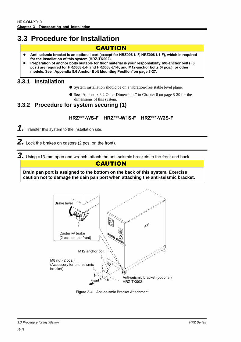
Figure 3-4 Anti-seismic Bracket Attachment
Drain pan port is assigned to the bottom on the back of this system. Exercise caution not to damage the dain pan port when attaching the anti-seismic bracket.
Front Anti-seismic bracket (optional) HRZ-TK002
M8 nut (2 pcs.) (Accessory for anti-seismic bracket)
Caster w/ brake
(2 pcs. on the front)
Brake lever
M12 anchor bolt
HRX-OM-X010
Chapter 3 Transporting and Installation
HRZ Series 3.3 Procedure for Installation
3-7 3-7
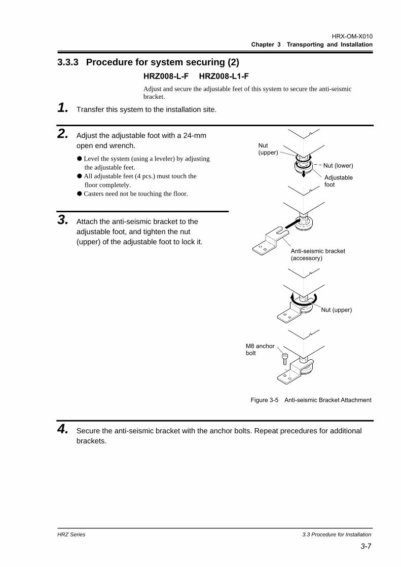
3.3.3 Procedure for system securing (2)
HRZ008-L-F HRZ008-L1-F
Adjust and secure the adjustable feet of this system to secure the anti-seismic
bracket.
1. Transfer this system to the installation site.
2. Adjust the adjustable foot with a 24-mm
open end wrench.
Level the system (using a leveler) by adjusting
the adjustable feet.
All adjustable feet (4 pcs.) must touch the
floor completely.
Casters need not be touching the floor.
3. Attach the anti-seismic bracket to the
adjustable foot, and tighten the nut
(upper) of the adjustable foot to lock it.
4. Secure the anti-seismic bracket with the anchor bolts. Repeat precedures for additional
brackets.
Figure 3-5 Anti-seismic Bracket Attachment
M8 anchor bolt
Anti-seismic bracket (accessory)
Nut (upper)
Nut (upper)
Nut (lower)
Adjustable foot

HRX-OM-X010
Chapter 3 Transporting and Installation
3.3 Procedure for Installation HRZ Series
3-8
3.3.4 Wiring installation
◼ Power cable The power cables are to be prepared under your responsibility, referring to the
following table.
Table 3-1 Power Cable and Main Breaker (This System)
◼ Communication connector The communication connectors are to be prepared under your responsibility,
referring to the following table.
Table 3-2 Communication Connector
Connector Type (for your system) Contact signal (P1 connector) D-Sub 25-pin (male)
Serial RS-485 (P2 connector) D-Sub 9-pin (male)
Item
HRZ002-WS-F
HRZ002-W1S-F
HRZ002-W2S-F
HRZ004-WS-F
HRZ004-W1S-F
HRZ004-W2S-F
HRZ008-WS-F
HRZ008-W1S-F
HRZ008-W2S-F
HRZ008-L-F
HRZ008-L1-F
HRZ010-WS-F
HRZ010-W1S-F
HRZ010-W2S-F
Pow
er
cable
Size (recommended) 10AWG4-conductor 10AWG4-conductor 4AWG4-conductor 10AWG4-conductor
Crimp contact
(recommended)
Breaker R5.5-5 R5.5-5 R22-8 R5.5-8
Earth bar R5.5-8 R5.5-8 R22-8 R5.5-8
Torque
(recommended)
Breaker 2.5N•m (1.84 ft-lbf) 2.5N•m (1.84 ft-lbf) 6N•m (4.43 ft-lbf) 6N•m (4.43 ft-lbf)
Earth bar 12.5N•m (9.22 ft-lbf) 12.5N•m (9.22 ft-lbf) 12.5N•m (9.22 ft-lbf) 12.5N•m (9.22 ft-lbf)
Main breaker (This System) 20A 30A 60A 30A
Only designated personnel are allowed to install wiring. Be sure to turn OFF the power prior to wiring to assure safety.
Do not do any wiring when the system is energized. The system wiring requires not only a thorough connection with the designated
cable but also securing to prevent loose connection. Poor connection and securing may cause electric shock, heat sports, fire or communication errors.
Be sure to supply the power to this system according to specifications. Supply pure AC power. Potential malfunction may occur if a rectified AC with
voltage rise (dv/dt) at zero crossing exceeds 40V /200µ sec.
Always establish a connection to a ground for safety. Be sure that no ground connection is made to
a water pipe, gas pipe and lighting rod.
V
dV
dt
dt = Voltage ratio
on zero-cross point
dV
t
Voltage rise %
Time
Voltage

HRX-OM-X010
Chapter 3 Transporting and Installation
HRZ Series 3.3 Procedure for Installation
3-9 3-9
◼ Selection of the breaker for the customer’s equipment (primary side)
This product is equipped with the breaker which has different operating characteristics depending on each model. For the customer’s equipment (primary side), use the breaker whose operating time is equal to or longer than the breaker of this product. If the breaker with shorter operating time is connected, the customer’s equipment could be cut off du eto the inrush current of the motor of this product.
Current (% to the capacity of the main breaker of this product)
Figure 3-6 Breaker operating characteristics curve
HRZ010-WS-F HRZ010-W1S-F HRZ010-W2S-F
HRZ002-WS-F HRZ002-W1S-F HRZ002-W2S-F
HRZ004-WS-F HRZ004-W1S-F HRZ004-W2S-F
HRZ008-WS-F HRZ008-W1S-F HRZ008-W2S-F
HRZ010-WS-F HRZ010-W1S-F HRZ010-W2S-F
HRZ010-WS-F HRZ010-W1S-F HRZ010-W2S-F
HRZ010-WS-F HRZ010-W1S-F HRZ010-W2S-F
Opera
tin
g t
ime
MAX
MIN
Opera
tin
g t
ime
MAX
MIN

HRX-OM-X010
Chapter 3 Transporting and Installation
3.3 Procedure for Installation HRZ Series
3-10
HRZ008-L-F HRZ008-L1-F
Current (% to the capacity of the main breaker of this product)
MIN
Op
era
ting
tim
e
MAX
MAX
MIN
4h
2h
1h
30min 20min 14min 10min
6min 4min
2min
1min
30s
20s
10s
5s
2s
1s
0.5s
0.2s
0.1s
0.05s
0.02s
0.01s
100 135 200 300 400 500 600 700 1000 1500 2000 3000 4000
Figure 3-8 Breaker operating characteristics curve

HRX-OM-X010
Chapter 3 Transporting and Installation
HRZ Series 3.3 Procedure for Installation
3-11 3-11
Screw
Breaker cover
Breaker
Front panel
Screw
Front
Main breaker OFF
OFF
[In case of following shape]
3.3.5 Procedures for wiring installation
1. Turn OFF the power breaker on customer side (primary side), and then use the assigned
procedures to peform lockout/tagout.
[Tips]
Connection of the power cable with this system must be established first.
Do not connect the cable with the factory side at this point.
2. Turn OFF the main breaker of this system.
3. Undo the screws (2 pcs.) to remove the front panel.
Be sure to use a Phillips screwdriver.
4. Undo the screws (2 pcs.) or press claw to remove the breaker cover.
Be sure to use a Phillips screwdriver.
[Tips]
Be sure to turn OFF the factory side (primary side) power before connection to this system. Use the assigned procedure to peform lockout/tagout (Page 1-10).
Figure 3-9 Main Breaker OFF and Removal of Front Panel/Breaker Cover
Press claw to remove the cover.
HRX-OM-X010
Chapter 3 Transporting and Installation
3.3 Procedure for Installation HRZ Series
3-12
Make sure the breaker is at the ‘OFF’ position.
Otherwise, the removal of the front panel is not possible.
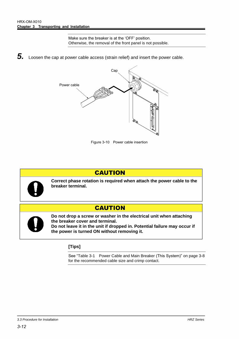
5. Loosen the cap at power cable access (strain relief) and insert the power cable.
[Tips]
See “Table 3-1 Power Cable and Main Breaker (This System)” on page 3-8
for the recommended cable size and crimp contact.
Correct phase rotation is required when attach the power cable to the breaker terminal.
Do not drop a screw or washer in the electrical unit when attaching the breaker cover and terminal. Do not leave it in the unit if dropped in. Potential failure may occur if the power is turned ON without removing it.
Power cable
Cap
Figure 3-10 Power cable insertion
HRX-OM-X010
Chapter 3 Transporting and Installation
HRZ Series 3.3 Procedure for Installation
3-13 3-13
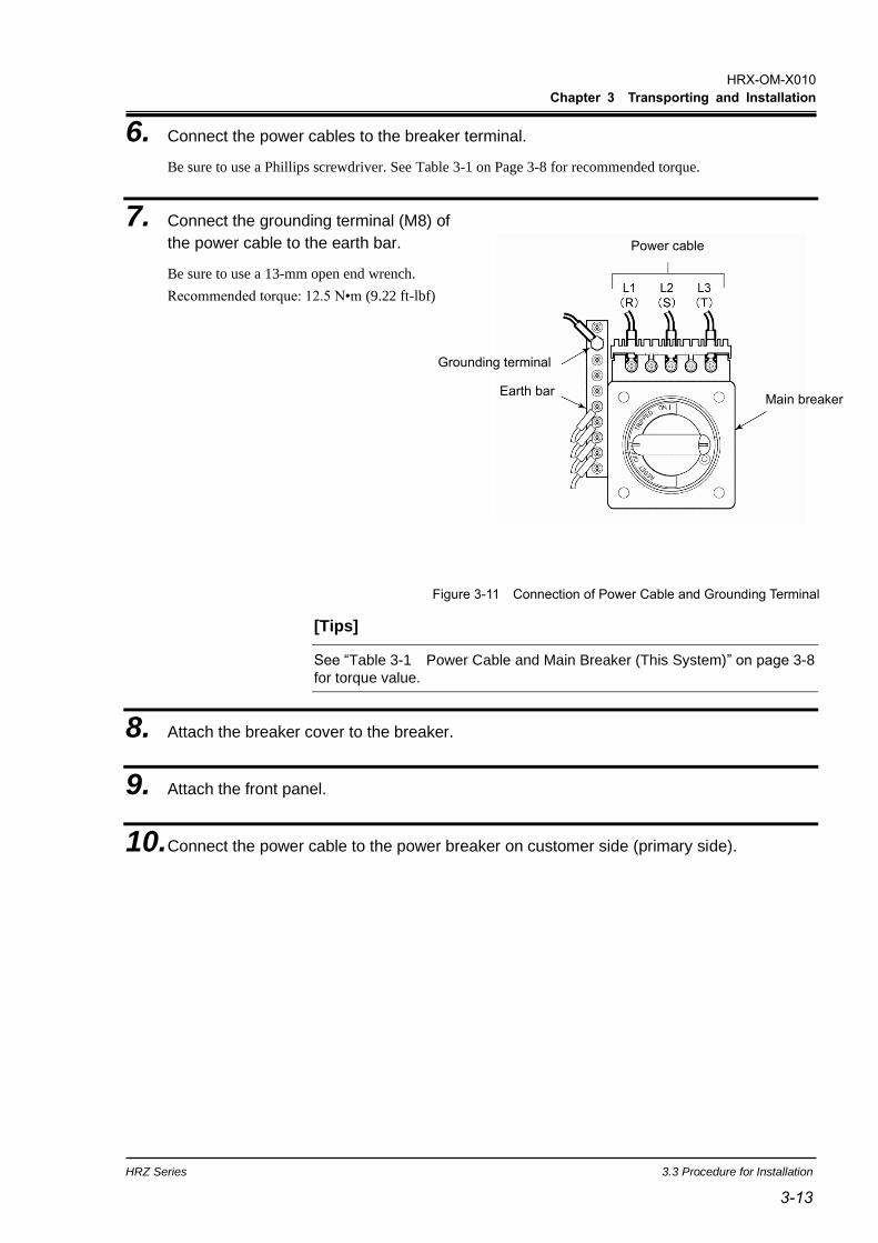
6. Connect the power cables to the breaker terminal.
Be sure to use a Phillips screwdriver. See Table 3-1 on Page 3-8 for recommended torque.
7. Connect the grounding terminal (M8) of
the power cable to the earth bar.
Be sure to use a 13-mm open end wrench.
Recommended torque: 12.5 N•m (9.22 ft-lbf)
[Tips]
See “Table 3-1 Power Cable and Main Breaker (This System)” on page 3-8
for torque value.
8. Attach the breaker cover to the breaker.
9. Attach the front panel.
10. Connect the power cable to the power breaker on customer side (primary side).
Figure 3-11 Connection of Power Cable and Grounding Terminal
Earth bar Main breaker
Grounding terminal
Power cable
HRX-OM-X010
Chapter 3 Transporting and Installation
3.3 Procedure for Installation HRZ Series
3-14
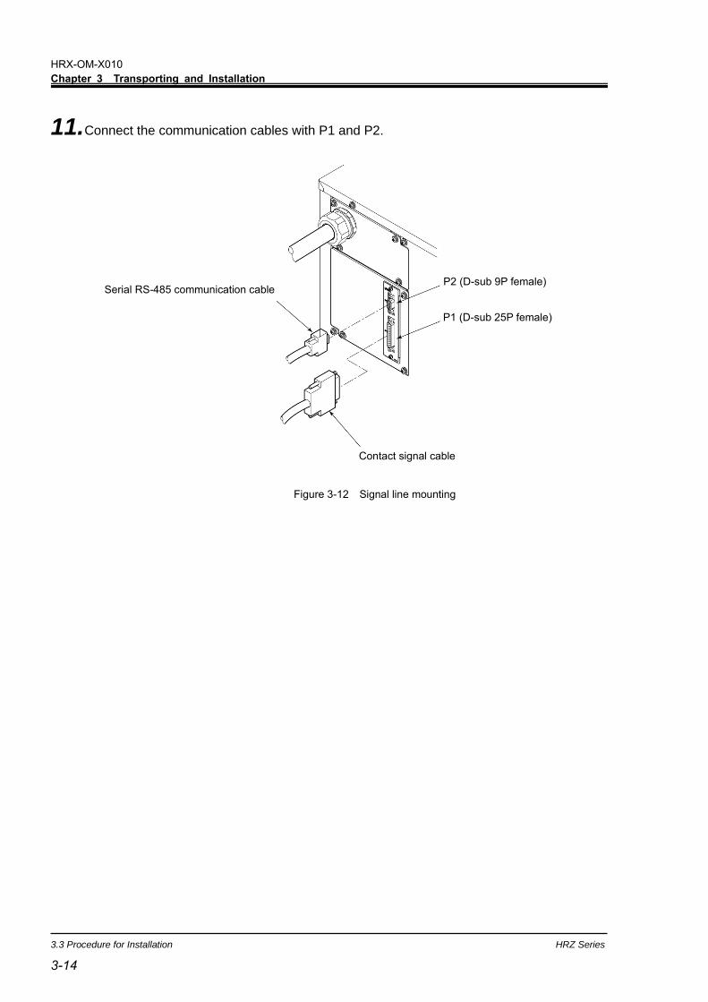
11. Connect the communication cables with P1 and P2.
Serial RS-485 communication cable
P1 (D-sub 25P female)
P2 (D-sub 9P female)
Contact signal cable
Figure 3-12 Signal line mounting

HRX-OM-X010
Chapter 3 Transporting and Installation
HRZ Series 3.3 Procedure for Installation
3-15 3-15
3.3.6 Installation of circulating fluid and facility water piping
◼ Pipe diameter Table 3-3 Pipe Diameter
Pipe Diameter Recommended torque
(Material: SS* vs SS)
Facility water inlet Rc1/2 28 to 30N•m
(20.7 to 22.1ft-lbf)
Facility water outlet Rc1/2 28 to 30N•m
(20.7 to 22.1ft-lbf)
Circulating fluid supply Rc3/4 28 to 30N•m
(20.7 to 22.1ft-lbf)
Circulating fluid return Rc3/4 28 to 30N•m
(20.7 to 22.1ft-lbf)
Main tank drain port Rc3/8 (with valve) Piping not necessary
Sub tank drain port Rc3/8 (with valve) Piping not necessary
Drain pan port Rc3/8 Piping not necessary
*: SS Stainless steel
Regarding the circulating fluid and facility water pipings, consider carefully the suitability for operating pressure,temperature circulating fluid and facility water. If the operating performance is not sufficient, the pipings may burst during
operation. Also, the use of corrosive materials such as aluminum or iron for fluid
contact parts, such as piping, may not only lead to clogging or leakage in the circulating fluid and facility water circuits but also refrigerant leakage and other
unexpected problems. provide protection against corrosion when you use the product.
Always insulate external circulating piping. Potential insufficient cooling performance due to heat absorption from the pipe surface and potential insufficient heating performance caused by thermal radiation if disregarded.
When using fluorinated liquid as the circulating fluid, do not use pipe tape. Liquid leakage may occur around the pipe tape. for sealant, we recommend that you use the following sealant:SMC Part No., HRZ-S0003 (Silicone sealant)
Use clean pipes and pipe fittings, free of particles, oil and moisture. Apply air blow to the parts before using. The presence of particles, oil or moisture in the circulating fluid circuit causes insufficient cooling, system failure attributed to moisture freeze when entering the system, or foaming of the circulating fluid in the tank.
The total capacity of circulating fluid required by external piping should remain under the capacity of the sub tank. Potential problem of tank overflow, when pump stop, may occur if disregarded. See “Appendix 8.1.1 System specification” in Chapter 8 for the capacity of the sub tank.
Be sure to choose a circulating fluid pipe capable of letting the fluid flow at rated flow rate or better. See “Pump performance” defined in “Appendix 8.1.1 System specification” for the flow rate rating.
Have a drip pan available incase of a fluid leak. Do not return the circulating fluid to the unit by installing a pump in the user
system. Make sure of the locations of ports for the circulating fluid supply, return, facility
water inlet, outlet and their corresponding connections are correct. Secure the piping connector section with a pipe wrench, and provide proper
tightening to the pipe. See Figure on page 3-13. Do not give an impact when the piping connector section is fixed or tightened. It
may damage the piping or cause leakage. The flow rate of the facility water is automatically adjusted depending on using
conditions. The facility water outlet temperature can be up to 60 deg.C

HRX-OM-X010
Chapter 3 Transporting and Installation
3.3 Procedure for Installation HRZ Series
3-16
◼ Procedure for piping installation
Secure the pipe coupling section with a pipe wrench, and provide proper tightening
to the pipe.
◼ Recommended piping installation
Table 3-4 Recommended Pipe
No. Name Size Material
1 Valve Rc3/4 Stainless steel
2 Y-strainer (100m) Rc3/4 Stainless steel
3 Valve Rc1/2 Stainless steel
4 Y-strainer (5m) Rc1/2 Stainless steel
Figure 3-13 Pipe Tightening
Figure 3-14 Recommended Piping Installation
Pipe coupling section
System on the customer side
Circulating fluid supply
Circulating fluid return
Facility water inlet
Facility water outlet
HRX-OM-X010
Chapter 3 Transporting and Installation
HRZ Series 3.3 Procedure for Installation
3-17 3-17
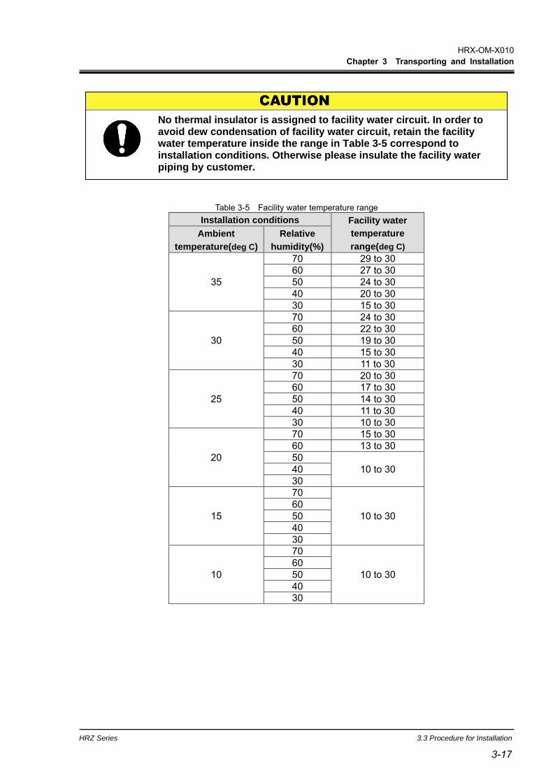
Table 3-5 Facility water temperature range
Installation conditions Facility water
temperature
range(deg C)
Ambient
temperature(deg C)
Relative
humidity(%)
35
70 29 to 30
60 27 to 30
50 24 to 30
40 20 to 30
30 15 to 30
30
70 24 to 30
60 22 to 30
50 19 to 30
40 15 to 30
30 11 to 30
25
70 20 to 30
60 17 to 30
50 14 to 30
40 11 to 30
30 10 to 30
20
70 15 to 30
60 13 to 30
50
10 to 30 40
30
15
70
10 to 30
60
50
40
30
10
70
10 to 30
60
50
40
30
No thermal insulator is assigned to facility water circuit. In order to avoid dew condensation of facility water circuit, retain the facility water temperature inside the range in Table 3-5 correspond to installation conditions. Otherwise please insulate the facility water piping by customer.


HRX-OM-X010
Chapter 4 System Startup and Shutdown
HRZ Series 4.1 Pre-check
4-1 4-1
Chapter 4 System Startup and Shutdown
4.1 Pre-check Check the following items prior to starting up the system.
4.1.1 Installation condition
Make sure that the system is installed in a horizontal position.
No heavy object is placed on this system. This system should not be applied with
an undue force such as caused by piping installation.
Re-check the items defined in “3.2 Installation” on page 3-3.
4.1.2 Cable connection
Make sure proper connection of the power cable, ground, and communication
cables.
4.1.3 Installation of circulating fluid and facility water piping
Make sure that circulating fluid and facility water piping are installed properly.
4.1.4 Operating signal from your system
Make sure that no remote signal is being issued from your system. System startup
takes effect upon power-ON if this system receives a remote signal and it is in
remote mode.
4.1.5 Check emergency off [EMO] switch
Make sure of the location of the emergency off [EMO] switch before operating the
system. See section 1.6.1 “Emergency off [EMO] switch” in Chapter 1 “Safety” for
details.
4.2 Opening of Facility water Valve
Open the facility water valve for water supply.
[Tips]
This system is outfitted with a water regulating valve inside.
Facility water may not flow upon system startup which is normal.
Only personnel, who have adequate knowledge of and experiences with not only this system but associated equipment, are allowed to implement system startup and shutdown.
Check that the facility water complies with not only the water quality standard defined in section 7.1 “Water Quality Management” on page 7-1 but the requirements provided in “8.1.1 System specification” in Chapter 8 Appendix on page 8-1.
HRX-OM-X010
Chapter 4 System Startup and Shutdown
4.3 Supply of Circulating Fluid HRZ Series
4-2
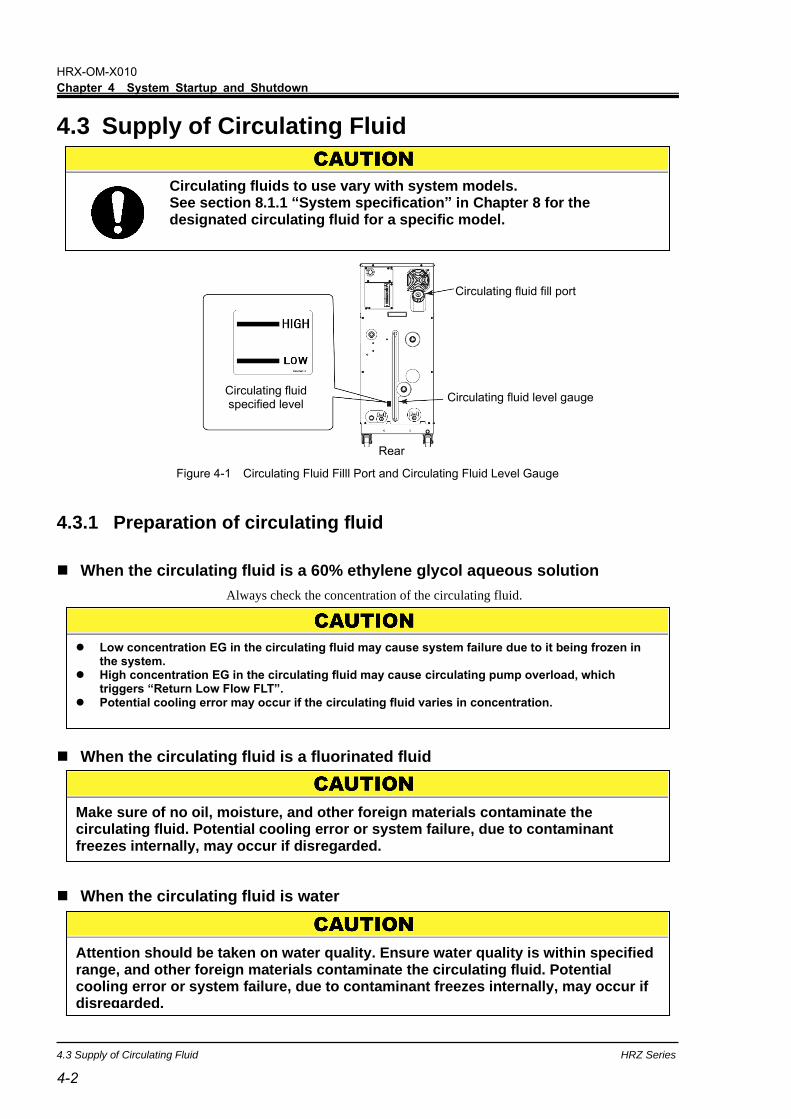
4.3 Supply of Circulating Fluid
4.3.1 Preparation of circulating fluid
◼ When the circulating fluid is a 60% ethylene glycol aqueous solution
Always check the concentration of the circulating fluid.
◼ When the circulating fluid is a fluorinated fluid
◼ When the circulating fluid is water
Figure 4-1 Circulating Fluid Filll Port and Circulating Fluid Level Gauge
Circulating fluids to use vary with system models. See section 8.1.1 “System specification” in Chapter 8 for the designated circulating fluid for a specific model.
Low concentration EG in the circulating fluid may cause system failure due to it being frozen in the system.
High concentration EG in the circulating fluid may cause circulating pump overload, which triggers “Return Low Flow FLT”.
Potential cooling error may occur if the circulating fluid varies in concentration.
Make sure of no oil, moisture, and other foreign materials contaminate the circulating fluid. Potential cooling error or system failure, due to contaminant freezes internally, may occur if disregarded.
Attention should be taken on water quality. Ensure water quality is within specified range, and other foreign materials contaminate the circulating fluid. Potential cooling error or system failure, due to contaminant freezes internally, may occur if disregarded.
Circulating fluid fill port
Circulating fluid level gauge
Rear
Circulating fluid specified level

HRX-OM-X010
Chapter 4 System Startup and Shutdown
HRZ Series 4.3 Supply of Circulating Fluid
4-3 4-3
4.3.2 Supply of circulating fluid
Remove the circulating fluid fill cap, and fill the circulating fluid until it reaches its
specified level.
The circulating fluid specified level is a range between “HIGH” and “LOW” in
Figure 4-1.
Be sure to tighten the cap until it clicks after fluid supply.
If the circulating fluid is supplied over the specified level, follow the procedure
provided in section 7.3.1 “Draining of circulating fluid out of tank” on page 7-4 to
drain excess fluid until it reaches the specified level.
[Tips]
Level between “HIGH” and “LOW” represent liquid level in normal running
condition. Immediately as you start filling up the chiller, the internal
transferring pump start pumping fluid from the Sub Tank into the Main Tank.
Thus the fluid level in the level gauge will start to drop.
During initial priming of the external piping, addition fluid is needed. See
section 8.1.1 “System specification” on page 8-1 for Sub Tank and Main
Tank capacity.
When supplying the circulating fluid, make sure that the fluid inside this system has dropped to room temperature for the prevention of burns.
Circulating fluid must be supplied to be in the range between “HIGH” and “LOW”. Potential overflow of hot circulating fluid may occur due to excessive volume. Total fluid volume use to fill up the system including initial priming should not exceed combined volume of Sub Tank and Main Tank. If level is below the “LOW” mark, this system will trigger an alarm.
To prevent moisture, which is formed by condensation of a flowed air, from finding its way into the tank, ensure the circulating fluid at room temperature when supplying the fluid. Be sure to tighten the cap until it clicks after fluid supply. Potential circulating fluid vaporization or moisture intrusion due to condensation of flowed air may occur if disregarded.

HRX-OM-X010
Chapter 4 System Startup and Shutdown
4.4 Requirement for System Startup HRZ Series
4-4
4.4 Requirement for System Startup 4.4.1 Turning ON power
1. Make sure that the main breaker for this system is OFF, and release lockout/tagout of the
power breaker on customer side (primary side). Then, turn ON the power.
2. Turn ON the main breaker of this system.
The “Model Indication screen” and “System Information screen” are displayed in sequence on the LCD
screen. The screen will change to the “Status screen 1” in approx. 20 seconds, and the system is ready to run.
[Tips]
It is normal if the “System Information screen” is not displayed. See section
5.3.33 “System Information screen ” in “Chapter 5 System Operation” on
page 5-36 for details.
Figure 4-2 Main Breaker at ‘ON’
Press the emergency off [EMO] switch immediately upon ocurrence of abnormal conditions. Be sure to turn OFF the main breaker afterwards.
Front
ON
Model Indication screen
Status screen 1
System Information screen
Thermo Chiller HRZ010ーW S-F Rev.0 SMC Co.
<INFORMATION> Pump Up Mode, Running Start
TEMP PV 23.6TEMP SP 25.0RTN FLOW 20.0LPMPRESS 0.50MPa

HRX-OM-X010
Chapter 4 System Startup and Shutdown
HRZ Series 4.5 System Startup and Shutdown
4-5 4-5
4.4.2 Circulating fluid temperature setting
From the “Setting screen” on the LCD screen, set the circulating fluid at any
temperature. See section 5.4 “Examples of System Operation” in “Chapter 5 System
Operation” on page 5-37 for operating procedure.
[Tips]
See section 8.1.1 “System specification” in “Chapter 8 Appendix” on page 8-
1 for the setting range of circulating fluid temperature.
4.5 System Startup and Shutdown 4.5.1 System startup
Press the [START/STOP] key on the operation display panel.
The [RUN] lamp on the operation display panel comes on, and the “System Information screen” is flashing. The
screen then change to the “Status screen 1”, which initiates system operation.
[Tips]
It is normal if the “System Information screen” is not displayed. See section
5.3.33 “System Information screen“in “Chapter 5 System Operation” on page
5-36 for details.
4.5.2 System shutdown
Press the [START/STOP] key on the operation display panel.
The “System Information screen” is flashing on the LCD screen, and the [RUN] lamp comes on. The compressor
comes to a halt approx, 20 seconds after circulating pump stop for protection of the compressor. The screen is
returned to the “Setting screen 1”, which prompts the [RUN] lamp to go out.
[Tips]
See section 5.3.33 “System Information screen” in “Chapter 5 System
Operation” on page 5-36 for details on the System Information screen.
Internal equipment may remain at elevated or lowered in temperature immediately after system shutdown. Potential burns or frostbite may happen if your skin comes in contact with these surfaces. Further work is allowed only when the system reaches room temperature.
Emergency off [EMO] switch and main breaker (OFF) should not be used for system shutdown unless it is an emergency.
HRX-OM-X010
Chapter 4 System Startup and Shutdown
4.5 System Startup and Shutdown HRZ Series
4-6

HRX-OM-X010
Chapter 5 System Operation
HRZ Series 5.1 Operation Display Panel
5-1 5-1
Chapter 5 System Operation 5.1 Operation Display Panel
Use the operation display panel located in front of the system for the basic
operations.
Figure 5-1 Operation Display Panel
Be sure to use your fingers only to operate the Operation Display Panel. Using sharp object will damage the panel.
Operation Display Panel
[ENT] key Used to determine a set value.
[RESET] key Used to stop an alarm buzzer and initialize the alarm.
“REMOTE” lamp This comes on when the system is in remote mode.
“RUN” lamp This comes on when the equipment is running.
[SEL] key Used to select the screen.
[][] key
Used to move the cursor and change set values.
“LCD screen”
“ALARM” lamp This comes on when an alarm is raised.
[ ]key Used to move the cursor when setting data.
[START/STOP] key Used to start and stop the operation.

HRX-OM-X010
Chapter 5 System Operation
5.2 Flow Chart of Operation Screen HRZ Series
5-2
5.2 Flow Chart of Operation Screen
Figure 5-2 Flow Chart of Operation Screen
POWER ON
TEMP PV 23.6TEMP SP 25.0 <<TEMP READY>>TEMP BAND 1.0
TEMP PV 23.6TEMP SP 25.0RTN FLOW 20.0LPMPRESS 0.50MPa
OFFSET OFFOFFSET 0.0
Thermo Chiller HRZ0 1 0-W S-F Rev.0 SMC Co.
DI PV 0.0MΩDI SP 0.0MΩDI ACC 0hDI SV OFF
<MENU> 1.SETTING2.REMOTE MODE3.MAINTENANCE
<SETTING> 1.CONTROL SET2.ALARM SET 3.INITIAL SET
< REMOTE MODE >MODE:LOCAL
<MONITOR>RTN TEMP 23.1HI PRESS 2.10MPaLO PRESS 0.20MPa
< AUTO PURGE >MSG:READYPURGE TIME: 300sPURGE MODE:STOP
< DI ACC RESET >DI ACC 0h
DATA RESET? No
***ALARM*** 11:Reservoir High Temp WRN
< ALARM SET > LO FLOW WRN ONLO FLOW 8.0LPM
< ALARM SET > HI TEMP 93.0LO TEMP -25.0
< ALARM SET > LOW DI 0.0MΩ
<INITIAL SET> FLOW UNIT LPMPRESS UNIT MPaOFFSET OFF
<INITIAL SET> REM.SD.WRITE ONREM.COM.ERR WRNDEVICE ADRS 1CH
<INITIAL SET> KEY IN BUZZ ONALARM BUZZ ONSETTINGLOCK OFF
<INITIAL SET> PURGE STOP AUTOPURGE TIME 300s
<INITIAL SET> PUMP IV FLOWP.LIMIT FUNC.OFFP.LIMIT 1.00MPa
<INITIAL SET> TEMP BAND 1.0READY TIME 60s
<INITIAL SET> OUT: N/AE_OUT: N/A
<INITIAL SET> CUSTOM DIO OFF
<MAINTENANCE> 1.VALVE OPEN2.ALARM HISTORY 3.RUNNING DATA
< VALVE OPEN >
VALVE CLOSE
<ALARM HIST. 0>11:Reservoir High Temp WRNDRV TIME 17520h
RUN CNT 24DRV TIME 17520hDISV CNT 1435
<ALARM HIST.149>11:Reservoir High Temp WRNDRV TIME 17520h
<MAINTENANCE> 4.MONITOR5.AUTO PURGE6.DI ACC RESET
<CONTROL SET> TEMP SP 25.0OFFSET 0.0PUMP SP 15.0Hz
<PUMP FREQ SET>RTN FLOW 0.0LPMPRESS 0.00MPaFREQ 15.0Hz
<CONTROL SET> TEMP SP 25.0OFFSET 0.0PUMP SP 20.0LPM
<CONTROL SET> DI SP 0.5MΩDI HYS 0.3MΩ
<INFORMATION> CPRSR Down Mode, Running Stop
SEL
ENT
SEL
SEL
ENT ENT
ENT ENT ENT
ENT
SEL
ENT
ENT
ENT
ENT ENTENT
SEL
SEL SEL
SEL
Status screen 1
Status screen 2
Status screen 3
Status screen 4
Model Indication screen
Menu screen
Setting Item screen Mode Selection screen
Initial Setting screen 1
Initial Setting screen 2
Initial Setting screen 3
Maintenance screen3
Alarm Display screen
Alarm Setting screen 1
Alarm Setting screen 2
Alarm Setting screen 3
Initial Setting screen 4
Initial Setting screen 5
Initial Setting screen 6
Initial Setting screen 7
Control Setting screen 1
Control Setting screen 2
Control Setting screen 3-1
Control Setting screen 3-2
Initial Setting screen 8
Maintenance screen2
Maintenance screen6 Maintenance screen7 Maintenance screen8
Maintenance screen4 Maintenance screen5
System Information screen
Maintenance screen1

HRX-OM-X010
Chapter 5 System Operation
HRZ Series 5.2 Flow Chart of Operation Screen
5-3 5-3
[Tips]
1. After the menu screen, pressing the [SEL] key can make the screen return to the previous page.
2. For the items which are set numerically can be set by minimum unit of
displayed value.
3.The contents displayed on the screen may change depending on the
options or settings. Please refer to the description page of each screen.
Table 5-1 Descriptions of Operation Screens
Screen Descriptions Reference
Model Indication screen Displays the model and revision No. of this system. Page 5-4
Status screen 1 to 4 Displays the operating condition of this system. Page 5-5 to 5-8
Alarm Display screen The alarm number and alarm message are displayed in the event of an error in this system. Not displayed if no error.
Page 5-9
Menu screen Allows setting screen selection Page 5-9
Setting screen Allows switching to “Control Setting screen”, “Alarm Setting screen” and “Initial Setting screen”.
Page 5-10
Control screen 1, 2, 3-1, 3-2 Allows the setting of pump frequency, pressure or flow rate by pump inverter.
Page 5-11 to 5-15
Alarm Setting screen 1 to 3 Allows the setting of set values for the alarm of temperature and flow rate.
Page 5-16 to 5-18
Initial Setting screen 1 to 8 Allows the setting of set values. Page 5-19 to 5-26
Mode Selection screen Allows communication mode selelction. Page 5-27
Maintenance screen 1 to 8 Not used during system operation. Not allowed to use unless otherwise specified.
Page 5-28 to 5-35
System Information screen Displays the status of system startup and shutdown.
Page 5-36
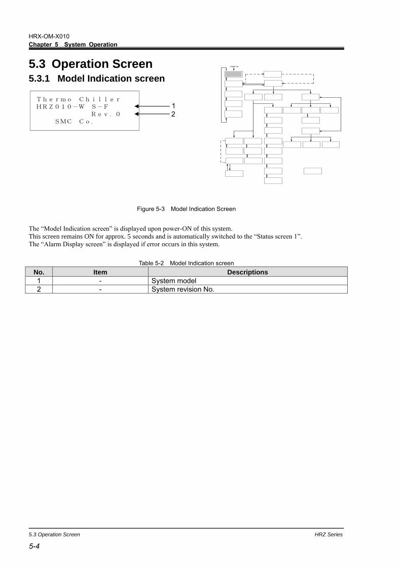
HRX-OM-X010
Chapter 5 System Operation
5.3 Operation Screen HRZ Series
5-4
Thermo Chiller HRZ010-W S-F Rev.0 SMC Co.
5.3 Operation Screen 5.3.1 Model Indication screen
Figure 5-3 Model Indication Screen
The “Model Indication screen” is displayed upon power-ON of this system.
This screen remains ON for approx. 5 seconds and is automatically switched to the “Status screen 1”.
The “Alarm Display screen” is displayed if error occurs in this system.
Table 5-2 Model Indication screen
No. Item Descriptions
1 - System model
2 - System revision No.
1 2
POWER ON

HRX-OM-X010
Chapter 5 System Operation
HRZ Series 5.3 Operation Screen
5-5 5-5
TEMP PV 23.6TEMP SP 25.0RTN FLOW 20.0LPMPRESS 0.50MPa
5.3.2 Status screen 1
Figure 5-4 Status screen 1
Table 5-3 Status screen 1
No. Item Descriptions
1 TEMP PV Discharge temperature of the circulating fluid (A value derived according to the offset*1 if applied)
2 TEMP SP Set value of circulating fluid discharge temperature
3 RTN FLOW Return flow rate of the circulating fluid
4 PRESS Discharge pressure of the circulating fluid
[Tips]
See “Appendix 8.4 Offset Function” in Chapter 8 on page 8-23 for details on
offset (*1).
Unit of RTN FLOW and PRESS can be selected on “Initial Setting screen 1”. See “5.3.16 Initial Setting screen 1” (page 5-19) for details.
1
2 3 4
POWER ON
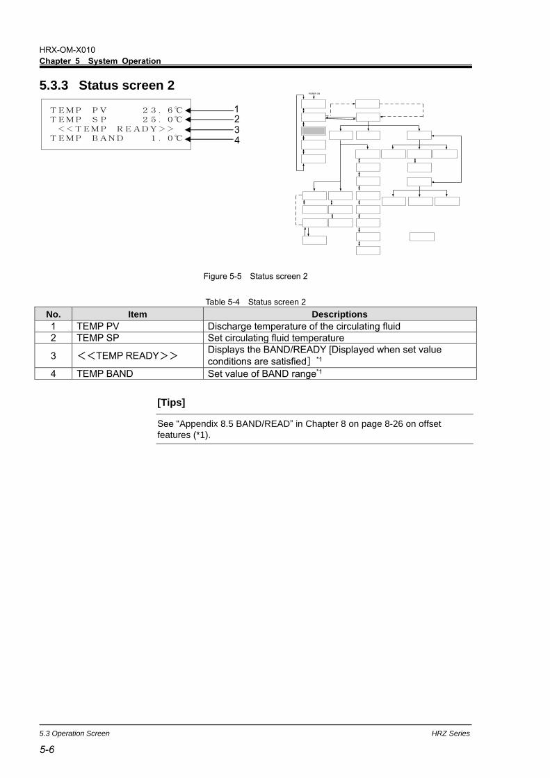
HRX-OM-X010
Chapter 5 System Operation
5.3 Operation Screen HRZ Series
5-6
5.3.3 Status screen 2
TEMP PV 23.6TEMP SP 25.0 <<TEMP READY>>TEMP BAND 1.0
Figure 5-5 Status screen 2
Table 5-4 Status screen 2
No. Item Descriptions
1 TEMP PV Discharge temperature of the circulating fluid
2 TEMP SP Set circulating fluid temperature
3 <<TEMP READY>> Displays the BAND/READY [Displayed when set value
conditions are satisfied]*1
4 TEMP BAND Set value of BAND range*1
[Tips]
See “Appendix 8.5 BAND/READ” in Chapter 8 on page 8-26 on offset
features (*1).
2 1
3 4
POWER ON
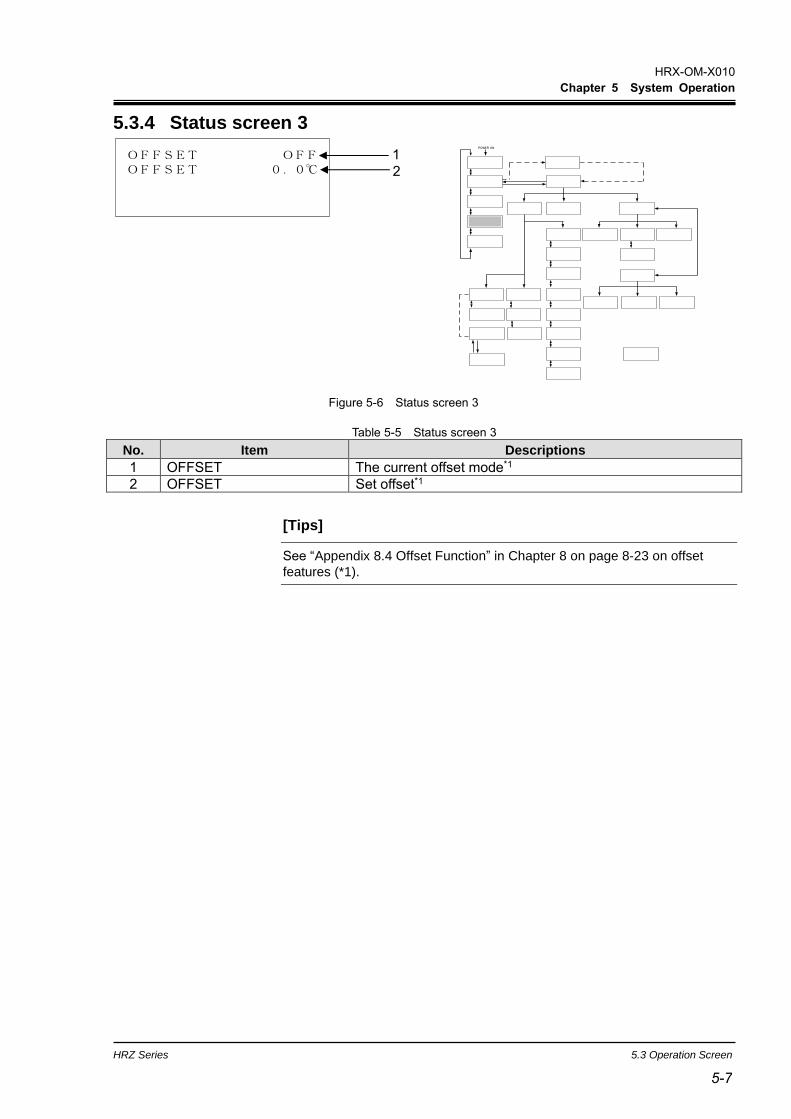
HRX-OM-X010
Chapter 5 System Operation
HRZ Series 5.3 Operation Screen
5-7 5-7
OFFSET OFFOFFSET 0.0
5.3.4 Status screen 3
Figure 5-6 Status screen 3
Table 5-5 Status screen 3
No. Item Descriptions
1 OFFSET The current offset mode*1
2 OFFSET Set offset*1
[Tips]
See “Appendix 8.4 Offset Function” in Chapter 8 on page 8-23 on offset
features (*1).
1
2
POWER ON

HRX-OM-X010
Chapter 5 System Operation
5.3 Operation Screen HRZ Series
5-8
5.3.5 Status screen 4
Figure 5-7 Status screen 4
Table 5-6 Status screen 4
No. Item Descriptions 1 DI PV Circulating fluid electric resistivity.
2 DI SP Set value of circulating fluid electric resistivity.
3 DI ACC Accumulated time that the solenoid valve in DI circuit is activated.
4 DI SV Open/close status of solenoid valve in DI circuit.
[Tips]
It is displayed only if the DI Control Kit (optional) is provided.
DI PV 0.0MΩDI SP 0.0MΩDI ACC 0hDI SV OFF
2
3
1
4
POWER ON

HRX-OM-X010
Chapter 5 System Operation
HRZ Series 5.3 Operation Screen
5-9 5-9
5.3.6 Alarm Display screen
Figure 5-8 Alarm Display screen
In the event of an error in this system, the current screen is switched to the “Alarm Display screen” to display the
relevant alarm code,and message.
The “Alarm Display screen” is displayed only if an error is raised.
See section 6.2 “Troubleshooting” in “Chapter 6 Error Message and Troubleshooting” on page 6-2 for alarm
numbers and messages.
5.3.7 Menu screen
<MENU> 1.SETTING2.REMOTE MODE3.MAINTENANCE
Figure 5-9 Menu screen
Table 5-7 Menu screen
No. Item Descriptions
1 SETTING Switches to the “Setting screen” with the press of the [ENT] key.
2 REMOTE MODE Switches to the “Mode Selection screen” with the press of the [ENT] key.
3 MAINTENANCE Switches to the “Initial Setting screen 1” with the press of the [ENT] key.
[Tips]
[] or [] key is used for selecting “Item.”
2 1
3
POWER ON
POWER ON
***ALARM*** 11:Reservoir High Temp WRN

HRX-OM-X010
Chapter 5 System Operation
5.3 Operation Screen HRZ Series
5-10
<SETTING> 1.CONTROL SET2.ALARM SET 3.INITIAL SET
5.3.8 Setting screen
S
Figure 5-10 Setting screen
Table 5-8 Setting screen
No. Item Descriptions
1 CONTROL SET Switches to the “Control Setting screen 1” with the press of the [ENT] key.
2 ALARM SET Switches to the “Alarm Setting screen 1” with the press of the [ENT] key.
3 INITIAL SET Switches to the “Initial Setting screen 1” with the press of the [ENT] key.
[Tips]
[] or [] key is used for selecting “Item.”
1
3
2
POWER ON
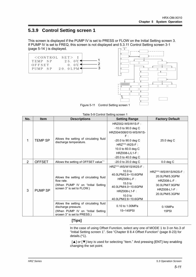
HRX-OM-X010
Chapter 5 System Operation
HRZ Series 5.3 Operation Screen
5-11 5-11
5.3.9 Control Setting screen 1
This screen is displayed if the PUMP IV is set to PRESS or FLOW on the Initial Setting screen 3. If PUMP IV is set to FREQ, this screen is not displayed and 5.3.11 Control Setting screen 3-1 (page 5-14 ) is displayed.
<CONTROL SET> TEMP SP 25.0OFFSET 0.0PUMP SP 20.0LPM
Figure 5-11 Control Setting screen 1
Table 5-9 Control Setting screen 1
No. Item Descriptions Setting Range Factory Default
1 TEMP SP Allows the setting of circulating fluid discharge temperature.
HRZ002-WS/W1S-F:
-10.0 to 90.0 deg C
HRZ004/008/010-WS/W1S-
F:
-20.0 to 90.0 deg C
HRZ***-W2S-F :
10.0 to 60.0 deg C
HRZ008-L/L1-F :
-20.0 to 40.0 deg C
25.0 deg C
2 OFFSET Allows the setting of OFFSET value*1 -20.0 to 20.0 deg C 0.0 deg C
3 PUMP SP
Allows the setting of circulating fluid flow rate.
(When PUMP IV on “Initial Setting screen 3” is set to FLOW.)
HRZ***-WS/W1S/W2S-F:
10.0 to 40.0LPM/2.6~10.6GPM
HRZ008-L-F:
15.0 to 40.0LPM/4.0~10.6GPM
HRZ008-L1-F:
10.0 to 40.0LPM/2.6~10.6GPM
HRZ***-WS/W1S/W2S-F:
20.0LPM/5.3GPM
HRZ008-L-F:
30.0LPM/7.9GPM
HRZ008-L1-F:
20.0LPM/5.3GPM
Allows the setting of circulating fluid discharge pressure.
(When PUMP IV on “Initial Setting srceen 3” is set to PRESS.)
0.10 to 1.00MPa
15~145PSI
0.10MPa
15PSI
[Tips]
In the case of using Offset Function, select any one of MODE 1 to 3 on No.3 of
“Initial Setting screen 1”. See “Chapter 8 8.4 Offset Function“ (page 8-23) for
details.(*1).
[] or [] key is used for selecting “Item.” And pressing [ENT] key enabling
changing the set point.
1
3
2
POWER ON

HRX-OM-X010
Chapter 5 System Operation
5.3 Operation Screen HRZ Series
5-12
Unit of PUMP SP can be selected on “Initial Setting screen 1”. See “5.3.16 Initial
Setting screen 1“ (page 5-19) for details.
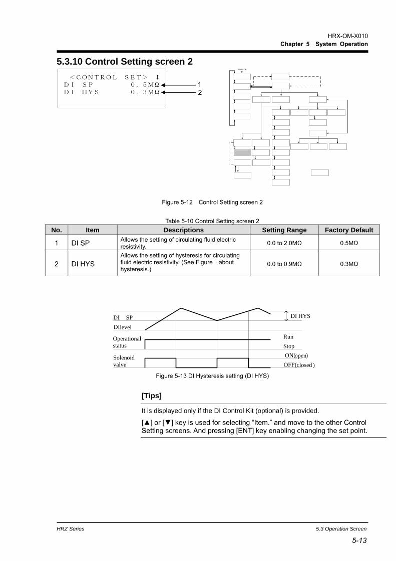
HRX-OM-X010
Chapter 5 System Operation
HRZ Series 5.3 Operation Screen
5-13 5-13
5.3.10 Control Setting screen 2
Figure 5-12 Control Setting screen 2
Table 5-10 Control Setting screen 2
No. Item Descriptions Setting Range Factory Default
1 DI SP Allows the setting of circulating fluid electric resistivity.
0.0 to 2.0MΩ 0.5MΩ
2 DI HYS
Allows the setting of hysteresis for circulating fluid electric resistivity. (See Figure about hysteresis.)
0.0 to 0.9MΩ 0.3MΩ
Figure 5-13 DI Hysteresis setting (DI HYS)
[Tips]
It is displayed only if the DI Control Kit (optional) is provided.
[] or [] key is used for selecting “Item.” and move to the other Control Setting screens. And pressing [ENT] key enabling changing the set point.
<CONTROL SET> DI SP 0.5MΩDI HYS 0.3MΩ
1 2
Solenoid
valve
DI level
DI SP
OFF( closed
ON( open )
Stop
Run
DI HYS
Operational
status
)
POWER ON

HRX-OM-X010
Chapter 5 System Operation
5.3 Operation Screen HRZ Series
5-14
5.3.11 Control Setting screen 3-1
This screen is displayed if the PUMP IV is set to FREQ on the Initial Setting screen 3.
If PUMP IV is set to PRESS or FLOW, this screen will not be displayed and 5.3.9 Control Setting screen 1 (page 5-11) will be displayed.
Figure 5-14 Control Setting screen3-1
Table 5-11 Control Setting screen3-1
No. Item Descriptions Setting Range Factory Default
1 TEMP SP Allows the setting of circulating
fluid discharge temperature.
HRZ002-WS/W1S-F:
-10.0 to 90.0 deg C
HRZ004/008/010-
WS/W1S-F:
-20.0 to 90.0 deg C
HRZ***-W2S-F :
10.0 to 60.0 deg C
HRZ008-L/L1-F :
-20.0 to 40.0 deg C
25.0 deg C
2 OFFSET Allows the setting of OFFSET value*1 -20.0 to 20.0 deg C 0.0 deg C
3 PUMP SP Switched to the “Control Setting screen 3-2”.(Pump frequency setting screen.)
- -
[Tips]
In the case of using Offset Function, select any one of MODE 1 to 3 on No.3 of
“Initial Setting screen 1”. See ”Chapter 8 8.4Offset Function“ (page 8-23) for
details (*1).
[] or [] key is used for selecting “Item.” And pressing [ENT] key enabling to change the set point of TEMP SP and OFFSET.
<CONTROL SET> TEMP SP 25.0OFFSET 0.0PUMP SP 15.0Hz
1 2 3
POWER ON

HRX-OM-X010
Chapter 5 System Operation
HRZ Series 5.3 Operation Screen
5-15 5-15
<PUMP FREQ SET>RTN FLOW 8.0LPMPRESS 0.05 MPaFREQ 15.0Hz
5.3.12 Control Setting screen 3-2
Figure 5-15 Control Setting screen 3-2
Table 5-12 Control Setting screen 3-2
No. Item Descriptions Setting Range Factory Default
1 RTN FLOW Return flow rate of circulating fluid. - -
2 PRESS Discharge pressure of circulating fluid. - -
3 FREQ
Allows the setting of pump frequency.
(“Control Setting screen 3-2” is displayedonly if PUMP IV on “Initial Setting screen 3” is set to FREQ.)
15.0 to 60.0Hz 15.0Hz
[Tips]
Pressing [ENT] key enabling to change the set point of FREQ.
Unit of RTN FLOW and PRESS can be selected on “Initial Setting screen 1”. See “5.3.16 Initial Setting screen 1“(page 5-19) for details.
1 2 3
POWER ON

HRX-OM-X010
Chapter 5 System Operation
5.3 Operation Screen HRZ Series
5-16
5.3.13 Alarm Setting screen 1
Figure 5-16 Alarm Setting screen 1
Table 5-13 Alarm Setting screen 1
No. Item Descriptions Setting Range Factory Default
1 HI TEMP
Allows the setting of temperature to generate “11:Reservoir High Temp. WRN”.
Alarm is raised when circulating fluid temperature exceeds the set value.
HRZ002-WS/W1S-F:
-10.0 to 93.0 deg C
HRZ004/008/010-
WS/W1S-F:
-20.0 to 93.0 deg C
HRZ***-W2S-F:
10.0 to 63.0 deg C
HRZ008-L/L1-F:
-20.0 to 45 deg C
HRZ***-WS/W1S-F:93.0 deg C
HRZ***-W2S-F:
63.0 deg C
HRZ008-L/L1-F:
45.0 deg C
2 LO TEMP
Allows the setting of temperature to generate “32:Reservoir Low Temp. WRN”.
Alarm is raised when circulating fluid temperature falls below the set value.
HRZ002-WS/W1S-F:
-15.0 to 90.0 deg C
HRZ004/008/010-
WS/W1S-F:
-25.0 to 90.0 deg C
HRZ***-W2S-F:
5.0 to 60.0 deg C
HRZ008-L/L1-F:
-25.0 to 40.0 deg C
HRZ002-WS/W1S-F:
-15.0
HRZ004/008/010-
WS/W1S-F:
-25.0
HRZ***-W2S-F:
5.0
HRZ008-L/L1-F:
-25.0
[Tips]
[] or [] key is used for selecting “Item” and move to other Alarm Setting screens. And pressing the [ENT] key enabling to change the set value.
< ALARM SET > HI TEMP 93.0LO TEMP -25.0
1 2
POWER ON

HRX-OM-X010
Chapter 5 System Operation
HRZ Series 5.3 Operation Screen
5-17 5-17
5.3.14 Alarm Setting screen 2
Figure 5-17 Alarm Setting screen2
Table 5-14 Alarm Setting screen 2
No. Item Descriptions Setting Range Factory Default
1 LO FLOW WRN
Allows the setting of “13:Return Low Flow WRN” (valid:ON/invalid: OFF).
Alarm is not raised if invalid:OFF is selected.
OFF,ON ON
2 LO FLOW
Allows the setting of flow rate to generate “13:Return Low Flow WRN”.
Alarm is raised when circulating fluid flow rate falls below the set value.
HRZ***-WS/W1S/W2S-F:
8.0 to 40.0LPM
2.1~10.6GPM
HRZ008-L/L-F:
15.0~40.0LPM
4.0~10.6GPM
HRZ008-L1-F:
8.0~40.0LPM
2.1~10.6GPM
HRZ***-WS/W1S/W2S-F:
8.0LPM
2.1GPM
HRZ008-L/L-F:
15.0LPM
4.0GPM
HRZ008-L1-F:
8.0LPM
2.1GPM
[Tips]
[] or [] key is used for selecting “Item” and move to other Alarm Setting screens. And pressing the [ENT] key enabling to change the set value.
< ALARM SET > LO FLOW WRN ONLO FLOW 8.0LPM
1 2
POWER ON
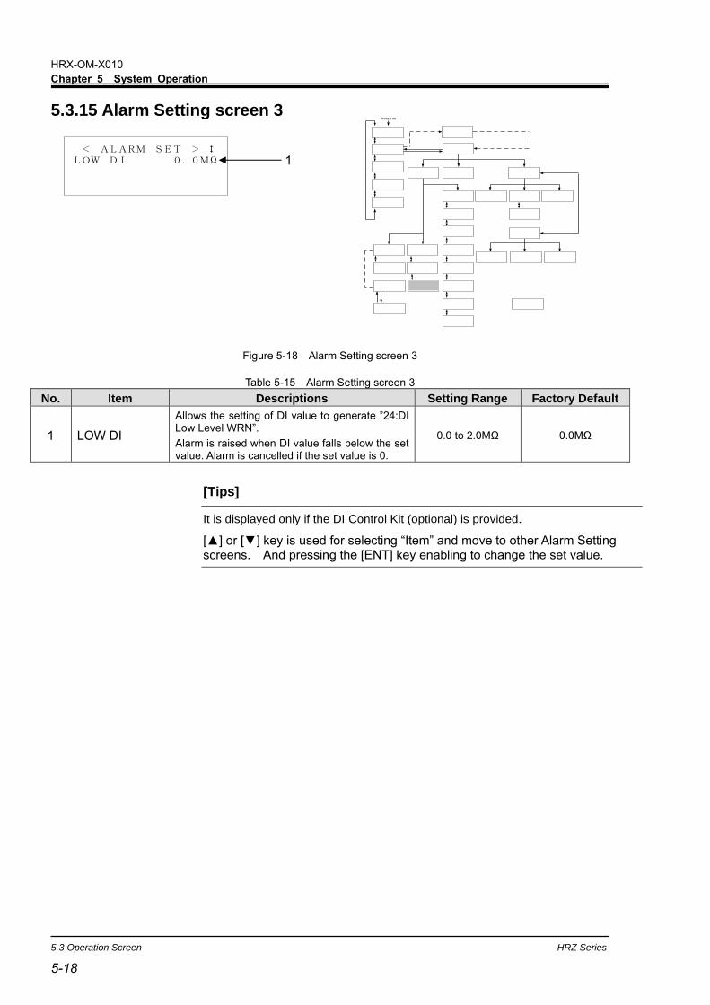
HRX-OM-X010
Chapter 5 System Operation
5.3 Operation Screen HRZ Series
5-18
5.3.15 Alarm Setting screen 3
Figure 5-18 Alarm Setting screen 3
Table 5-15 Alarm Setting screen 3
No. Item Descriptions Setting Range Factory Default
1 LOW DI
Allows the setting of DI value to generate ”24:DI Low Level WRN”.
Alarm is raised when DI value falls below the set value. Alarm is cancelled if the set value is 0.
0.0 to 2.0MΩ 0.0MΩ
[Tips]
It is displayed only if the DI Control Kit (optional) is provided.
[] or [] key is used for selecting “Item” and move to other Alarm Setting screens. And pressing the [ENT] key enabling to change the set value.
< ALARM SET > LOW DI 0.0MΩ 1
POWER ON

HRX-OM-X010
Chapter 5 System Operation
HRZ Series 5.3 Operation Screen
5-19 5-19
<INITIAL SET> FLOW UNIT LPMPRESS UNIT MPaOFFSET OFF
5.3.16 Initial Setting screen 1
Figure 5-19 Initial Setting screen 1
Table 5-16 Initial Setting screen 1
No. Item Descriptions Setting Range Factory Default
1 FLOW UNIT Allows the selection of the unit of flow rate. LPM,GPM LPM
2 PRESS UNIT Allows the selection of the unit of pressure. MPa,PSI MPa
3 OFFSET Allows the selection of Offset MODE. MODE1 to 3,OFF OFF
[Tips]
[] or [] key is used for selecting “Item” and move to other Initial Setting screens. And pressing the [ENT] key enabling to select the setting.
2 1
3
POWER ON

HRX-OM-X010
Chapter 5 System Operation
5.3 Operation Screen HRZ Series
5-20
5.3.17 Initial Setting screen 2
Figure 5-20 Initial Setting screen 2
Table 5-17 Initial Setting screen 2
No. Item Descriptions Setting Range Factory Default
1 REM.SD.WRITE
Store the TEMP SP and FLOW SP value with serial communication. TEMP SP and FLOW SP will be set to stored value after re-turn ON the main breaker.
OFF,ON ON
2 REM.COM.ERR Allows the selection of system condition when serial communication error occurs (WRN : Stop, FLT : Continued).
WRN,FLT WRN
3 DEVICE ADRS*1 Allows the setting of the device address for serial communication.
1 to 32CH 1
[Tips]
[] or [] key is used for selecting “Item” and move to other Initial Setting screens. And pressing the [ENT] key enabling to select the setting.
*1 For HRZ010-W*S-F and HRZ008-L*-F,’’SLAVE ADRS’’ is displayed.
<INITIAL SET> REM.SD.WRITE ONREM.COM.ERR WRNDEVICE ADRS 1CH
1 2 3
POWER ON

HRX-OM-X010
Chapter 5 System Operation
HRZ Series 5.3 Operation Screen
5-21 5-21
<INITIAL SET> PUMP IV FLOWP.LIMIT FUNC.OFFP.LIMIT 1.00MPa
5.3.18 Initial Setting screen 3
Figure 5-21 Initial Setting screen 3
Table 5-18 Initial Setting screen 3
No. Item Descriptions Setting Range Factory Default
1 PUMP IV
Allows the selection of the controlled object for pump operation.
FREQ : Pump frequency control.
FLOW : Circulating fluid Flow rate control.
PRESS : Pump discharge pressure control.
FREQ
FLOW
PRESS
FLOW
2 P.LIMIT FUNC. Allows the setting of pump discharge pressure upper limit function (Valid : ON, Invalid : OFF).
OFF,ON OFF
3 P.LIMIT
Allows the setting of pump discharge pressure upper limit value. This function enables the pump discharge pressure not to exceed the upper limit value to protect your system.
0.10 to 1.00MPa
15~145PSI
1.00MPa
145PSI
[Tips]
[] or [] key is used for selecting “Item” and move to other Initial Setting screens. And pressing the [ENT] key enabling to select the setting or set value.
1 2 3
POWER ON

HRX-OM-X010
Chapter 5 System Operation
5.3 Operation Screen HRZ Series
5-22
<INITIAL SET> PURGE STOP AUTOPURGE TIME 300s
5.3.19 Initial Setting screen 4
Figure 5-22 Initial Setting screen 4
Table 5-19 Initial Setting screen 4
No. Item Descriptions Setting Range Factory Default
1 PURGE STOP
Allows the selection of automatic collection stop mode.
AUTO: Collection operation stops automatically when cllection finished normally.
TIME : Collection continues for the setting time.
AUTO,TIME AUTO
2 PURGE TIME
When “AUTO” mode, allows the setting for the time to raise “TIME OUT”. When “TIME” mode, allows the setting of the time to continue collection operation.
1 to 600sec 300s
[Tips]
It is displayed only if the Circulating Fluid Automatic Collector (optional) is
provided.
[] or [] key is used for selecting “Item” and move to other Initial Setting screens. And pressing the [ENT] key enabling to select the setting.
1
2
POWER ON

HRX-OM-X010
Chapter 5 System Operation
HRZ Series 5.3 Operation Screen
5-23 5-23
<INITIAL SET> KEY IN BUZZ ONALARM BUZZ ONSETTINGLOCK OFF
5.3.20 Initial Setting screen 5
Figure 5-23 Initial Setting screen 5
Table 5-20 Initial Setting screen 5
No. Item Descriptions Setting Range Factory
Default
1 KEY IN BUZZ Allows the setting of buzzer during key input (Valid : ON, Invalid : OFF).
OFF,ON ON
2 ALARM BUZZ Allows the setting of alarm buzzer (Valid : ON, Invalid : OFF).
OFF,ON ON
3 SETTINGLOCK
Allow the selection of “SETTINGLOCK” function.
This function enables to restrict the input from operation display panel to prevent from unintended change of setting value from operaiton touch panel.
・ALL :
・When communication mode is “LOCAL”,
only following operations are possible.
・START/STOP.
・Setting of “SETTINGLOCK” function.
・When communication mode is
“DIO/SEREMOTE”, only following operations are possible.
・Setting of “SETTINGLOCK” function.
・REM :
・When communication mode is “LOCAL”,
normal operation is possible.
・When communication mode is
“DIO/SER REMOTE”, only following operations are possible.
・Setting of communication mode.
・Setting of “SETTINGLOCK” function.
・OFF : “SETTINGLOCK” function is invalid.
OFF
REM
ALL
OFF
[Tips]
[] or [] key is used for selecting “Item” and move to other Initial Setting screens. And pressing the [ENT] key enabling to select the setting.
1
3 2
POWER ON
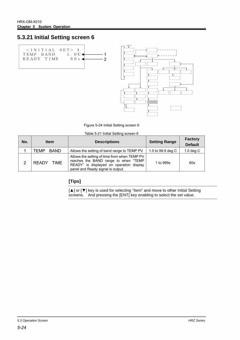
HRX-OM-X010
Chapter 5 System Operation
5.3 Operation Screen HRZ Series
5-24
<INITIAL SET> TEMP BAND 1.0READY TIME 60s
5.3.21 Initial Setting screen 6
Figure 5-24 Initial Setting screen 6
Table 5-21 Initial Setting screen 6
No. Item Descriptions Setting Range Factory
Default
1 TEMP BAND Allows the setting of band range to TEMP PV. 1.0 to 99.9 deg C 1.0 deg C
2 READY TIME
Allows the setting of time from when TEMP PV reaches the BAND range to when “TEMP READY” is displayed on operation display panel and Ready signal is output.
1 to 999s 60s
[Tips]
[] or [] key is used for selecting “Item” and move to other Initial Setting screens. And pressing the [ENT] key enabling to select the set value.
1 2
POWER ON
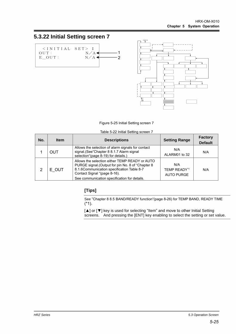
HRX-OM-X010
Chapter 5 System Operation
HRZ Series 5.3 Operation Screen
5-25 5-25
<INITIAL SET> OUT: N/AE_OUT: N/A
5.3.22 Initial Setting screen 7
Figure 5-25 Initial Setting screen 7
Table 5-22 Initial Setting screen 7
No. Item Descriptions Setting Range Factory
Default
1 OUT Allows the selection of alarm signals for contact signal.(See”Chapter 8 8.1.7 Alarm signal selection“(page 8-19) for details.)
N/A
ALARM01 to 32 N/A
2 E_OUT
Allows the selection either TEMP READY or AUTO PURGE signal.(Output for pin No. 8 of “Chapter 8 8.1.6Communication specification Table 8-7 Contact Signal “(page 8-16).
See communication specification for details.
N/A
TEMP READY*1
AUTO PURGE
N/A
[Tips]
See ”Chapter 8 8.5 BAND/READY function“(page 8-26) for TEMP BAND, READY TIME
(*1).
[] or [] key is used for selecting “Item” and move to other Initial Setting screens. And pressing the [ENT] key enabling to select the setting or set value.
1
2
POWER ON

HRX-OM-X010
Chapter 5 System Operation
5.3 Operation Screen HRZ Series
5-26
<INITIAL SET> CUSTOM DIO OFF
5.3.23 Initial Setting screen 8
Figure 5-26 Initial Setting screen 8
Table 5-23 Initial Setting screen 8
No. Item Descriptions Setting Range Factory
Default
1 CUSTOM DIO Allows the setting for DIO signal customize (valid:ON/invalid:OFF). See “Communication Specifications” for details.
OFF,ON OFF
[Tips]
Press the [ENT] key to make the setting changeable. Select the operation mode with the [] or [] key.
1
POWER ON

HRX-OM-X010
Chapter 5 System Operation
HRZ Series 5.3 Operation Screen
5-27 5-27
5.3.24 Mode Selection screen
Figure 5-27 Mode Selection screen
Table 5-24 Mode Selection screen
No. Item Descriptions Setting Range Factory
Default
1 MODE
Allows the selection of communication mode.
LOCAL : System start/stop and TEMP SP value setting are available only from the operation display panel.
DIO REMOTE : System start/stop is allowed only through contact signal. When Analog Communication option is provided, TEMP SP value setting is available through analog signal.
SER REMOTE : System start/stop and TEMP SP value setting are available only through serial RS-485 communication.
DNET REMOTE*1 : System start/stop and TEMP SP
value setting are available only through Device Net communication.
LOCAL
DIO REMOTE
SER REMOTE
DNET REMOTE*1
LOCAL
[Tips]
It is displayed only if the Device Net Communication (optional) is provided (*1).
[] or [] key is used for selecting “Item” And pressing the [ENT] key enabling to select the setting.
< REMOTE MODE >MODE:LOCAL 1
POWER ON

HRX-OM-X010
Chapter 5 System Operation
5.3 Operation Screen HRZ Series
5-28
5.3.25 Maintenance screen 1
Figure 5-28 Maintenance screen 1
Table 5-25 Maintenance screen 1
No. Item Descriptions
1 VALVE OPEN Switches to the “Maintenance ltem screen 3” with the press of the [ENT] key.
2 ALARM HISTORY Switches to the “Maintenance ltem screen 4” with the press of the [ENT] key.
3 RUNNING DATA Switches to the “Maintenance ltem screen 5” with the press of the [ENT] key.
[Tips]
[] or [] key is used for selecting “Item” and move to other Maintenance screens. And pressing the [ENT] key enabling to change the setting or set value.
<MAINTENANCE> 1.VALVE OPEN2.ALARM HISTORY 3.RUNNING DATA
2
1
3
POWER ON
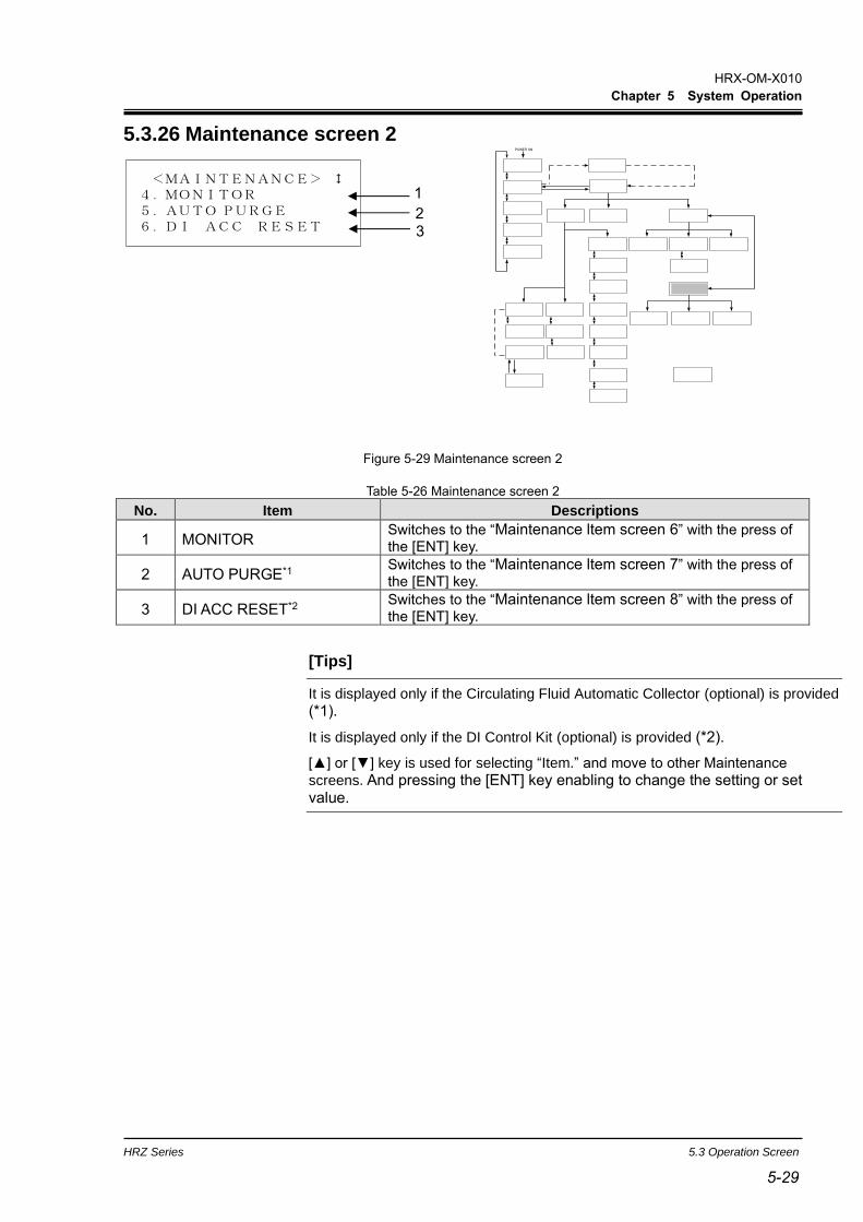
HRX-OM-X010
Chapter 5 System Operation
HRZ Series 5.3 Operation Screen
5-29 5-29
5.3.26 Maintenance screen 2
Figure 5-29 Maintenance screen 2
Table 5-26 Maintenance screen 2
No. Item Descriptions
1 MONITOR Switches to the “Maintenance ltem screen 6” with the press of the [ENT] key.
2 AUTO PURGE*1 Switches to the “Maintenance ltem screen 7” with the press of the [ENT] key.
3 DI ACC RESET*2 Switches to the “Maintenance ltem screen 8” with the press of the [ENT] key.
[Tips]
It is displayed only if the Circulating Fluid Automatic Collector (optional) is provided
(*1).
It is displayed only if the DI Control Kit (optional) is provided (*2).
[] or [] key is used for selecting “Item.” and move to other Maintenance
screens. And pressing the [ENT] key enabling to change the setting or set value.
<MAINTENANCE> 4.MONITOR5.AUTO PURGE6.DI ACC RESET
2
1
3
POWER ON

HRX-OM-X010
Chapter 5 System Operation
5.3 Operation Screen HRZ Series
5-30
5.3.27 Maintenance screen 3
Figure 5-30 Maintenance screen 3
Table 5-27 Maintenance screen 3
No. Item Descriptions
1 VALVE The solenoid valve for DI circuit is opened forcefully.
The solenoid valve for DI circuit is closed forcefully.
[Tips]
It is displayed only if the DI Control Kit (optional) is provided.
For other options, ‘’N/A’’ is displayed on the screen.
If you move the screen from ‘’Maintenance screen 3’’,
The forced operation of the solenoid valve will be canceled.
< VALVE OPEN >
VALVE CLOSE 1
POWER ON

HRX-OM-X010
Chapter 5 System Operation
HRZ Series 5.3 Operation Screen
5-31 5-31
5.3.28 Maintenance screen 4
Figure 5-31 Maintenance screen 4
Table 5-28 Maintenance screen 4
No. Item Descriptions
1 ALARM HIST Data recording stores up to 150 pieces of alarm history data.
If there are 150 or more pieces of data, the alarm history data is to be deleted in order of longest stores.
<ALARM HIST. 0>11:Reservoir High Temp WRNDRV TIME 17520h
<ALARM HIST.149>11:Reservoir High Temp WRNDRV TIME 17520h
1
1
POWER ON

HRX-OM-X010
Chapter 5 System Operation
5.3 Operation Screen HRZ Series
5-32
5.3.29 Maintenance screen 5
Figure 5-32 Maintenance screen 5
Table 5-29 Maintenance screen 5
[Tips]
*1 It is displayed only if the DI Control Kit (optional) is provided.
For other options, ‘’N/A’’ is displayed on the screen.
If you move the screen from ‘’Maintenance screen 3’’,
The forced operation of the solenoid valve will be canceled.
No. Item Descriptions
1 RUN CNT Number of times of operation on the system.
2 DRV TIME Operating time on the system.
3 DISV CNT*1 Number of times that the solenoid valve for DI circuit is activated.
RUN CNT 24DRV TIME 17520hDISV CNT 1435
POWER ON
2 1
3

HRX-OM-X010
Chapter 5 System Operation
HRZ Series 5.3 Operation Screen
5-33 5-33
<MONITOR>RTN TEMP 23.1HI PRESS 2.10MPaLO PRESS 0.20MPa
5.3.30 Maintenance screen 6
Figure 5-33 Maintenance screen 6
Table 5-30 Maintenance screen 6
No. Item Descriptions
1 RTN TEMP Return temperature of circulating fluid.
2 HI PRESS High pressure of refrigerant circuit.
3 LOW PRESS Low pressure of refrigerant circuit.
1 2 3
POWER ON
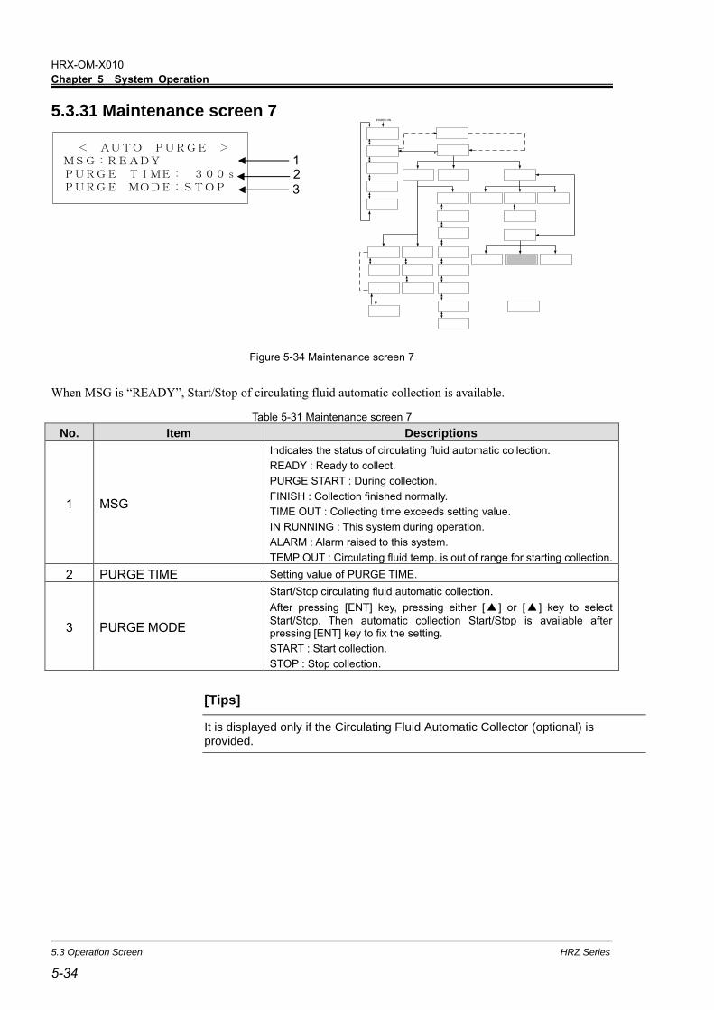
HRX-OM-X010
Chapter 5 System Operation
5.3 Operation Screen HRZ Series
5-34
5.3.31 Maintenance screen 7
Figure 5-34 Maintenance screen 7
When MSG is “READY”, Start/Stop of circulating fluid automatic collection is available.
Table 5-31 Maintenance screen 7
No. Item Descriptions
1 MSG
Indicates the status of circulating fluid automatic collection.
READY : Ready to collect.
PURGE START : During collection.
FINISH : Collection finished normally.
TIME OUT : Collecting time exceeds setting value.
IN RUNNING : This system during operation.
ALARM : Alarm raised to this system.
TEMP OUT : Circulating fluid temp. is out of range for starting collection.
2 PURGE TIME Setting value of PURGE TIME.
3 PURGE MODE
Start/Stop circulating fluid automatic collection.
After pressing [ENT] key, pressing either [ ] or [ ] key to select
Start/Stop. Then automatic collection Start/Stop is available after pressing [ENT] key to fix the setting.
START : Start collection.
STOP : Stop collection.
[Tips]
It is displayed only if the Circulating Fluid Automatic Collector (optional) is provided.
< AUTO PURGE >MSG:READYPURGE TIME: 300sPURGE MODE:STOP
2
3
1
POWER ON

HRX-OM-X010
Chapter 5 System Operation
HRZ Series 5.3 Operation Screen
5-35 5-35
5.3.32 Maintenance screen 8
Figure 5-35 Maintenance screen 8
Table 5-32 Maintenance screen 8
No. Item Descriptions
1 DI ACC Accumulated time that the solenoid valve for DI circuit is activated.
2 DATA RESET?
Allows to reset DI ACC.
After pressing [ENT] key, pressing either [] or [] key to select Yes/No.
Then Reset/Not reset DI ACC after pressing [ENT] key to fix the setting.
Yes : Reset DI ACC.
No : Not reset DI ACC.
[Tips]
It is displayed only if the DI Control Kit (optional) is provided.
< DI ACC RESET >DI ACC 0h
DATA RESET? No
1
2
POWER ON

HRX-OM-X010
Chapter 5 System Operation
5.3 Operation Screen HRZ Series
5-36
5.3.33 System Information screen
Figure 5-36 System Information screen
The “System Information screen”, as shown above, may be displayed upon system Start/Stop.
Table 5-33 System Information screen
No. Item Descriptions
1
INITIALIZE MODE
(CONTROL VALVE)
(RESERVOIR)
Operation preparation mode after turn-On the main breaker. System operation is disabled if this message is displayed.
CONTROL VALVE : Positioning of the electronic expansion valve is performed.
RESERVOIR : The circulating fluid flows in this system through the internal pump.
Pump Up Mode
Running Start
If your piping is supplied with an insufficient amount of thecirculating fluid at system startup, the circulating pump in this system activated (repeating ON/OFF) to replenish piping with the circulating fluid. Continuous operation is initiated once piping is replenished with the fluid.
CPRSR Down Mode.
Running Stop
Compressor operation remains for applox. 20 seconds after circulating pump stop for the protection of the compressor at the time of system shutdown.
<INFORMATION> CPRSR Down Mode, Running Stop 1
POWER ON

HRX-OM-X010
Chapter 5 System Operation
HRZ Series 5.4 Examples of System Operation
5-37 5-37
5.4 Examples of System Operation 5.4.1 Example 1: Circulating fluid set temperature is changed from
20.0 deg C to 34.1 deg C.
Figure 5-37 Change of Set Temperature from 20 deg C to 34.1 deg C
1. Press the [SEL] key to display the
“Menu screen”.
Figure 5-38 Menu screen
2. With the use of the arrow keys ([],
[]), move the cursor to “1. SETTING”
and press the [ENT] key.
The “Setting screen” is displayed.
Figure 5-39 Setting screen
3. With the use of the arrow keys ([], []),
move the cursor to “1. CONTROL SET”
and press the [ENT]] key.
The “Control Setting screen 1” is displayed.
Figure 5-40 Control setting screen1
<MENU> 1.SETTING2.REMOTE MODE3.MAINTENANCE
<SETTING> 1.CONTROL SET2.ALARM SET 3.INITIAL SET
<CONTROL SET> TEMP SP 25.0OFFSET 0.0PUMP SP 20.0LPM
0
POWER ON

HRX-OM-X010
Chapter 5 System Operation
5.4 Examples of System Operation HRZ Series
5-38
4. Press the [ENT] key.
The cursor is now appear on the current value for
TEMP SP, which enables change of the
temperature set value.
Figure 5-41 Control Setting screen 1 : Cursor Display
5. Use the arrow keys ([], [], [ ]) to
change the temperature to 34.1 deg C.
[] key: Used to add one value on which the cursor is placed.
[] key: Used to subtract one value on which the cursor is
placed.
[ ] key: Used to move the cursor to the right.
Figure 5-42 Control Setting screen 1 : Change of set value
6. Press the [SEL] key to display the “Menu screen 1”.
Figure 5-43 Control Setting screen 1 : Setting Confirmation
<CONTROL SET> TEMP SP 25.0OFFSET 0.0PUMP SP 20.0LPM
0
<CONTROL SET> TEMP SP 3 4.1OFFSET 0.0PUMP SP 20.0LPM
<CONTROL SET> TEMP SP 25.0OFFSET 0.0PUMP SP 20.0LPM
3 4

HRX-OM-X010
Chapter 5 System Operation
HRZ Series 5.4 Examples of System Operation
5-39 5-39
< REMOTE MODE >MODE:LOCAL
< REMOTE MODE >MODE:SER REMOTED E V I C E ADRS. 1CH
5.4.2 Example 2: Communication mode is switched from “LOCAL” to “SER REMOTE”.
Figure 5-44 Switching of communication mode from “LOCAL” to “SER REMOTE”
1. Press the [SEL] key to display the
“Menu screen”.
Figure 5-45 Menu screen
2. With the use of the arrow keys ([],
[]), move the cursor to “2. REMOTE
MODE” and press the [ENT] key.
The “Mode Selection screen” is displayed.
Figure 5-46 Mode Selection screen
3. Press the [ENT] key
The name of current mode “LOCAL” flashes
and enable to switch the setting.
Figure 5-47 Mode Selection screen
4. Use the arrow keys ([], []),to select
“SER REMOTE”.
Figure 5-48 Mode Selection screen
5. Press the [ENT]key.
<MENU> 1.SETTING2.REMOTE MODE3.MAINTENANCE
< REMOTE MODE >MODE:LOCAL
POWER ON

HRX-OM-X010
Chapter 5 System Operation
5.4 Examples of System Operation HRZ Series
5-40
5.4.3 Example 3: PUMP IV is switched from “FLOW” to “FREQ”.
Figure 5-49 Swiching of pump operation from FLOW to FREQ
1. Press the [SEL] key to display the
“Menu screen”.
Figure 5-50 Menu screen
2. With the use of the arrow keys ([],
[]), move the cursor to “1.SETTING”
and press the [ENT] key.
The “Setting screen” is displayed.
Figure 5-51 Setting screen
3. With the use of the arrow keys([],
[]),move the cursor to “3.INITIAL SET”
and press the [ENT] key.
The “Initial setting screen 1”is displayed.
Figure 5-52 Initial Setting screen 1
4. With the use of the arrow keys([],[]),
Move the cursor to “Initial Setting screen 3”.
Figure 5-53 Initial Setting screen 3
<MENU> 1.SETTING2.REMOTE MODE3.MAINTENANCE
<SETTING> 1.CONTROL SET2.ALARM SET 3.INITIAL SET
<INITIAL SET> FLOW UNIT LPMPRESS UNIT MPaOFFSET OFF
<INITIAL SET> PUMP IV FLOWP.LIMIT FUNC.OFFP.LIMIT 1.00MPa
POWER ON
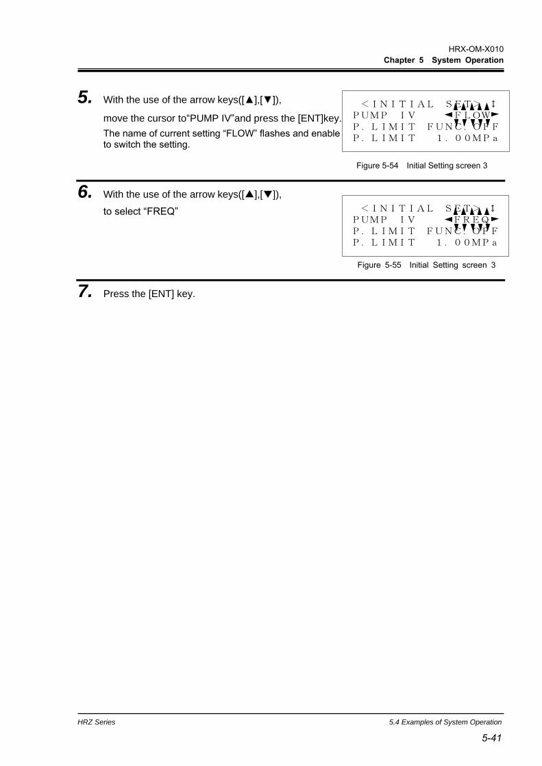
HRX-OM-X010
Chapter 5 System Operation
HRZ Series 5.4 Examples of System Operation
5-41 5-41
<INITIAL SET> PUMP IV FLOWP.LIMIT FUNC.OFFP.LIMIT 1.00MPa
5. With the use of the arrow keys([],[]),
move the cursor to“PUMP IV”and press the [ENT]key.
The name of current setting “FLOW” flashes and enable to switch the setting.
Figure 5-54 Initial Setting screen 3
6. With the use of the arrow keys([],[]),
to select “FREQ”
Figure 5-55 Initial Setting screen 3
7. Press the [ENT] key.
<INITIAL SET> PUMP IV FREQP.LIMIT FUNC.OFFP.LIMIT 1.00MPa


HRX-OM-X010
Chapter 6 Error Message and Troubleshooting
HRZ Series 6.1 Error Message
6-1 6-1
Chapter 6 Error Message and Troubleshooting
6.1 Error Message The following are to be performed in the event of an error in this system.
The “ALARM” lamp comes on.
Alarm buzzer comes on.
The “Alarm Display screen” is displayed on the LCD screen.
Error signal is issued through external communication.
(See section 8.1.6 “Communication specification” in Chapter 8 Appendix for
details.) on page 8-16
This system is brought to a stop forcefully according to error types.
Figure 6-1 Error Occurrence
LCD screen
“ALARM” lamp is ON.
Alarm Display screen (Alarm No. and alarm message)
***ALARM*** 11:Reservoir High Temp WRN
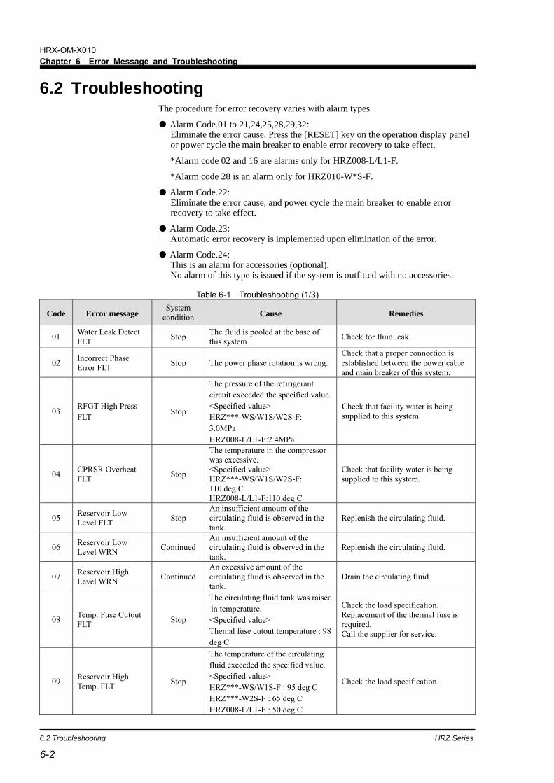
HRX-OM-X010
Chapter 6 Error Message and Troubleshooting
6.2 Troubleshooting HRZ Series
6-2
6.2 Troubleshooting The procedure for error recovery varies with alarm types.
Alarm Code.01 to 21,24,25,28,29,32: Eliminate the error cause. Press the [RESET] key on the operation display panel or power cycle the main breaker to enable error recovery to take effect.
*Alarm code 02 and 16 are alarms only for HRZ008-L/L1-F.
*Alarm code 28 is an alarm only for HRZ010-W*S-F.
Alarm Code.22: Eliminate the error cause, and power cycle the main breaker to enable error recovery to take effect.
Alarm Code.23: Automatic error recovery is implemented upon elimination of the error.
Alarm Code.24: This is an alarm for accessories (optional). No alarm of this type is issued if the system is outfitted with no accessories.
Table 6-1 Troubleshooting (1/3)
Code Error message System
condition Cause Remedies
01 Water Leak Detect
FLT Stop
The fluid is pooled at the base of
this system. Check for fluid leak.
02 Incorrect Phase
Error FLT Stop The power phase rotation is wrong.
Check that a proper connection is
established between the power cable
and main breaker of this system.
03 RFGT High Press
FLT Stop
The pressure of the refirigerant
circuit exceeded the specified value.
<Specified value>
HRZ***-WS/W1S/W2S-F:
3.0MPa
HRZ008-L/L1-F:2.4MPa
Check that facility water is being
supplied to this system.
04 CPRSR Overheat
FLT Stop
The temperature in the compressor
was excessive.
<Specified value>
HRZ***-WS/W1S/W2S-F:
110 deg C
HRZ008-L/L1-F:110 deg C
Check that facility water is being
supplied to this system.
05 Reservoir Low
Level FLT Stop
An insufficient amount of the
circulating fluid is observed in the
tank.
Replenish the circulating fluid.
06 Reservoir Low
Level WRN Continued
An insufficient amount of the
circulating fluid is observed in the
tank.
Replenish the circulating fluid.
07 Reservoir High
Level WRN Continued
An excessive amount of the
circulating fluid is observed in the
tank.
Drain the circulating fluid.
08 Temp. Fuse Cutout
FLT Stop
The circulating fluid tank was raised
in temperature.
<Specified value>
Themal fuse cutout temperature : 98
deg C
Check the load specification.
Replacement of the thermal fuse is
required.
Call the supplier for service.
09 Reservoir High
Temp. FLT Stop
The temperature of the circulating
fluid exceeded the specified value.
<Specified value>
HRZ***-WS/W1S-F : 95 deg C
HRZ***-W2S-F : 65 deg C
HRZ008-L/L1-F : 50 deg C
Check the load specification.
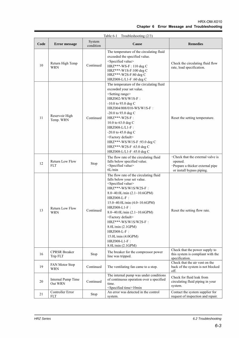
HRX-OM-X010
Chapter 6 Error Message and Troubleshooting
HRZ Series 6.2 Troubleshooting
6-3 6-3
Table 6-1 Troubleshooting (2/3)
Code Error message System
condition Cause Remedies
10 Return High Temp
WRN Continued
The temperature of the circulating fluid
exceeded the specified value.
<Specified value>
HRZ***-WS-F : 110 deg C
HRZ***-W1S-F:100 deg C
HRZ***-W2S-F:80 deg C
HRZ008-L/L1-F :60 deg C
Check the circulating fluid flow
rate, load specification.
11 Reservoir High
Temp. WRN Continued
The temperature of the circulating fluid
exceeded your set value.
<Setting range>
HRZ002-WS/W1S-F:
-10.0 to 93.0 deg C
HRZ004/008/010-WS/W1S-F:
-20.0 to 93.0 deg C
HRZ***-W2S-F :
10.0 to 63.0 deg C
HRZ008-L/L1-F :
-20.0 to 45.0 deg C
<Factory default>
HRZ***-WS/W1S-F :93.0 deg C
HRZ***-W2S-F :63.0 deg C
HRZ008-L/L1-F :45.0 deg C
Reset the setting temperature.
12 Return Low Flow
FLT Stop
The flow rate of the circulating fluid
falls below specified value.
<Specified value>
6L/min
・Check that the external valve is
opened.
・Prepare a thicker external pipe
or install bypass piping.
13 Return Low Flow
WRN Continued
The flow rate of the circulating fluid
falls below your set value.
<Specified value>
HRZ***-WS/W1S/W2S-F:
8.0~40.0L/min (2.1~10.6GPM)
HRZ008-L-F:
15.0~40.0L/min (4.0~10.6GPM)
HRZ008-L1-F:
8.0~40.0L/min (2.1~10.6GPM)
<Factory default>
HRZ***-WS/W1S/W2S-F:
8.0L/min (2.1GPM)
HRZ008-L-F:
15.0L/min (4.0GPM)
HRZ008-L1-F:
8.0L/min (2.1GPM)
Reset the setting flow rate.
16 CPRSR Breaker
Trip FLT Stop
The breaker for the compressor power
line was tripped.
Check that the power supply to
this system is compliant with the
specification.
19 FAN Motor Stop
WRN Continued The ventilating fan came to a stop.
Check that the air vent on the
back of the system is not blocked
off.
20 Internal Pump Time
Out WRN Continued
The internal pump was under conditions
of continuous operation over a specified
time.
<Specified time>10min
Check for fluid leak from
circulating fluid piping in your
system.
21 Controller Error
FLT Stop
An error was detected in the control
system.
Contact the system supplier for
request of inspection and repair.

HRX-OM-X010
Chapter 6 Error Message and Troubleshooting
6.2 Troubleshooting HRZ Series
6-4
Code Error message System
condition Cause Remedies
22 Memory Data Error
FLT Stop
An error was detected in data stored
in the controller of this system.
・Re-turn ON the main breaker to
recover from the error.
・Contact the system supplier for
request of inspection and repair.
23 Communica
-tion Error
0001 Continued
An interruption of serial
communication occurred in this
system.
・Contact the system supplier for
request of inspection and repair.
8000 Continued
An interruption of serial
communication occurred between
this system and your system.
・Check for disconnection of the
communication connector from this
system.
24 DI Low Level WRN Continued
The DI level of the re-circulating
liquid lowered than the your set
value (Optional).
<Setting range>
0.0 to 2.0MΩ
<Factory default>
0.0MΩ
・Lower the setting for resistivity.
・Replacement of the DI filter is
required
25 Pump Inverter Error
FLT Stop
An error was detected in the
inverter for circulating pump.
Contact the system supplier for
request of inspection and repair.
28 CPRSR INV Error
FLT Stop
An error was detected in the
inverter for compressor.
Contact the system supplier for
request of inspection and repair.
29 RFGT Low Press
FLT Stop
The refrigerant pressure falls below
the specified value.
<Specified value> 0.1MPa
Contact the system supplier for
request of inspection and repair.
32 Reservoir Low
Temp. WRN Continued
The temperature of the circulating
fluid falls your set value.
<Setting range>
HRZ002-WS/W1S-F:
-15.0 to 90.0 deg C
HRZ004/008/010-WS/W1S-F:
-25.0 to 90.0 deg C
HRZ***-W2S-F:
5.0 to 60.0 deg C
HRZ008-L/L1-F:
-25.0 to 40.0 deg C
<Factory default>
HRZ002-WS/W1S-F:
-15.0 deg C
HRZ004/008/010-WS/W1S-F:
-25.0 deg C
HRZ***-W2S-F:
5.0 deg C
HRZ008-L/L1-F:
-25.0 deg C
Reset the setting temperature.
Table 6-1 Troubleshooting (3/3)

HRX-OM-X010
Chapter 7 System Maintenance
HRZ Series 7.1 Water Quality Management
7-1 7-1
Chapter 7 System Maintenance 7.1 Water Quality Management
Table 7-1 Water Quality Standards for Fresh Water (Tap Water)
Substance Facility water
spec.
Circulating water
spec.
Standards
pH (25 deg C) 6.5 to 8.2 6.0 to 8.0
Electrical conductivity (25 deg C) (µs/cm) *Circulating fluid 1 to 500
100 to 800 0.5 to 300
Chloride ion (mgCl-/L) Max. 200 Max.50
Sulfate ion (mgSO42-/L) Max.200 Max.50
Acid consumption (pH4.8) (mgCaCO3/L)
Max.100 Max.50
Total hardness (mgCaCO3/L) Max.200 Max.70
Calcium hardness (mgCaCO3/L) Max.150 Max.50
Ionic silica (mgSiO2/L) Max.50 Max.30
Iron (mgFe/L) Max.1.0 Max.0.3
Copper (mgCu/L) Max.0.3 Max.0.1
Sulfide ion (mgS2-/L) Not be detected
Ammonium ion (mgNH4+/L) Max.1.0 Max.0.1
Residual chlorine (mgCl/L) Max.0.3 Max.0.3
Free carbon dioxide (mgCO2/L) Max.4.0 Max.4.0
Filtering (µm) Max.5 * According to the Water quality guideline for refrigeration air-conditioning equipment: JRA-GL-02-1994
Only designated circulating fluid is permitted to use for this system. Potential system failure and fluid leak may occur if disregarded, which results in electric shock, ground fault, and freeze. Be sure to use fresh water (tap water) compliant with water quality standards in the table below for ethylene glycol aqueous solution and facility water.
If the periodic inspection finds a nonconforming substance in the facility water, clean the facility water circuit and recheck the quality of the facility water.

HRX-OM-X010
Chapter 7 System Maintenance
7.2 Inspection and Cleaning HRZ Series
7-2
7.2 Inspection and Cleaning
7.2.1 Daily inspection Table 7-2 Daily Inspection
Inspection item Inspection method
Installation condition
Check of the condition of system installation
No heavy object is placed on this system. This system should not be subjected to external force.
Temperature and humidity fall within the specified range.
Fluid leak Check of the piping connector section
No leak of facility water and circulating fluid from the piping connector section
Fluid level Reading of the level of the circulating fluid
Level falls within the circulating fluid specified level between “High” and “Low”.
Operation display panel
Display check Clarity of letters and numbers on the LCD display should be assured.
Function check [RUN] lamp is ON.
Circulating fluid temperature
Confirm the reading on the LCD screen
Temperature should be within setpoint.
Refrigerant pressure
Reading of the refrigerant pressure gauge
Value of “HI PRESS” in “Maintenance screen 6(page 5-33)” should be in the following range.
HRZ010-W*S-F : 0.5 to 2.5 MPa HRZ008-L/L1-F : 0.5 to 2.0 MPa
Discharge pressure of circulating fluid
Confirm the reading on the LCD screen
Reading should not have deviated much from last inspection.
Circulating fluid flow rate
Confirm the reading on the LCD screen
Reading should not have deviated much from last inspection.
Operating condition
Operating condition check
No abnormal noise, vibration, odor and smoke
Facility water Check of the facility water
Temperature, flow rate and pressure fall within the specified range.
Circulating fluid supply port cap
Check by providing manual tightening
No looseness
Do not touch any electrical parts with wet hands. Keep wet hands away from electrical parts. Potential electric shock can occur if disregarded.
Keep this system from water. Potential electric shock or fire can occur if disregarded.
If the inspection and cleaning require the removal of the panel, be sure to re-attach the panel upon completion. Potential personal injury or electric shock may occur if operated with the panel opened or removed.

HRX-OM-X010
Chapter 7 System Maintenance
HRZ Series 7.3 Storage
7-3 7-3
7.2.2 Quarterly inspection
Table 7-3 Quarterly Inspection
Inspection item Inspection method
Circulating fluid
Circulating fluid is to be drained for check. Fluid should be free of particles, moisture*1 and foreign substances.
For ethylene glycol solution, confirm that the concentration falls within the specified range.
Recommended to replace the water.
Facility water Facility water quality should fall within the standards specified.
Ventilation hole and electrical parts
No particles and dust should be present.
7.3 Storage
The following should be performed for system long-term storage.
1. Drain the circulating fluid. See section 7.3.1 “Draining of circulating fluid out of tank” for details on page 7-4.
2. Drain the facility water. See section 7.3.2 “Draining of facility water” for details on page 7-5.
3. Cover the system with a plastic sheet for storage.
Quarterly inspection requires an advance lockout/tagout of this system. See section 1.5.3 “Lockout/Tagout” in “Chapter 1 Safety” for details on page 1-10.
Moisture trapped in the fluorinated fluid (*1) freezes in the heat exchanger element and piping, which may lead to system failure.

HRX-OM-X010
Chapter 7 System Maintenance
7.3 Storage HRZ Series
7-4
7.3.1 Draining of circulating fluid out of tank
1. Prepare the container for circulating fluid recovery at the back of this system.
2. Connect the drain hoses to the main and
sub tank drain ports each. Insert the tip
of the hose into the container.
Prepare a drain hose (Rc3/8-diameter) on your
responsibility.
3. Remove the cap of the circulating fluid fill port.
4. Open the valves of the main and sub tank drain ports to drain the circulating fluid.
5. Apply air purge from the the circulating fluid return to push the circulating fluid remaining
in the heat exchange back in the tank and drain it.
Max. 10cm
Drain port
Container for circulating fluid recovery
Drain port
Circulating fluid fill port cap
Circulating fluid return
Figure 7-1 Container for Circulating Fluid Recovery
Use the clean container for circulating fluid recovery. Reuse of the recovered circulating fluid with contaminated will cause insufficient cooling and system failure
Be sure to wait until the circulating fluid obtains room temperature for its draining. Potential burns and dew intrusion may occur if disregarded.
If the recovered circulating fluid is contaminated by foreign substances, completely remove them. Do not reuse comtaminated fluid. Potential insufficient cooling, system failure and froth in the circulating fluid may occur if disregarded.
Recovered circulating fluid must be sealed in a container to prevent contamination from moisture or foreign substances. Stored in a cool, dark place. Keep it from flame.

HRX-OM-X010
Chapter 7 System Maintenance
HRZ Series 7.3 Storage
7-5 7-5
6. Upon completion of fluid draining, close the valves of the main and sub tank drain ports.
7. Add plugs to seal off ports on the rear of
this system.
See section 7.3.2 “Draining of facility water”
for plug attachment.
7.3.2 Draining of facility water
1. Place the drain pan underneath the
piping connections on the rear of this
system.
A 7L-capacity or bigger drain pan is required.
Figure 7-2 Plug Attachment
Figure 7-3 Drain Pan Attachment
Be sure to drain the facility water only when it is at room temperature. Trapped fluid inside the system can still be hot. Potential burns can occur if disregarded.
Max. 10cm
Rear
Drain pan
Facility water outlet
Facility water inlet
Plug
Circulating fluid supply
Facility water outlet
Circulating fluid return
Plug
Rear
Drain pan port
Plug
Facility water inlet
Main tank drain port
Sub tank drain port

HRX-OM-X010
Chapter 7 System Maintenance
7.4 Periodic Replacement Parts HRZ Series
7-6
2. Remove facility water piping.
Remove the joints such as unions if present.
3. Drain the facility water using the facility water inlet port.
7.4 Periodic Replacement Parts Replacement of consumables listed in the following table is recommended.
Contact the system supplier for request of part replacement.
Table 7-4 Periodic Replacement Part List
Part Recommended replacement cycle
Internal pump Every 3 yrs
Circulating pump Every 3 yrs
Ventilating fan Every 3 yrs
Inverter Coolong Fan Every 3 yrs
* Note: A replacement cycle may vary with your usage condition.

HRX-OM-X010
Chapter 8 Appendix
HRZ Series 8.1 Specification
8-1 8-1
Chapter 8 Appendix 8.1 Specification 8.1.1 System specification
◼ Specification for fluorinated fluid (wide temperature) Table 8-1 Specification for Fluorinated Fluid (wide temperature)
Model HRZ002-WS-F HRZ004-WS-F HRZ008-WS-F HRZ010-WS-F
Cooling method Water cooled refrigerant
Cooling capacity*1 (50Hz/60Hz)
kW 2.0 4.0 8.0 10.0
Operating temperature range deg C -10 to 90 -20 to 90
Temperature stability deg C ±0.1*2
Circulating fluid
Galden® HT135*3 FluorinertTM FC-3283*3 (-20 to 40 deg C) Galden® HT200*3 FluorinertTM FC-40*3 (20 to 90 deg C)
(No intrusion of foreign body)
Refrigerant R410A(HFC,GWP2088)*11
Quantity of refrigerant kg 1.5
Pump capacity*4 MPa 0.65 (At 20L/min)
(94[PSIG] At 5.3 [gal/min])
0.72 (At 20L/min) (104[PSIG] At 5.3
[gal/min])
Main Tank capacity*5 L Approx.15 (4 [gal])
Sub Tank capacity *6 L Approx.16 (4.2 [gal])
Circulating fluid port Rc 3/4
Facility water deg C /MPa
10 to 30 / 0.3 to 0.7 (45 to 100 [PSIG])
Facility water required flow rate
Rated condition*9 L/min
4 7 14 15
Temp. changing condition*10 10 12 15 15
Facility water port Rc 1/2
Power supply 3-phase 50/60Hz AC200/200 to 208V±10%
Breaker size A 20 30
Dimensions*7 mm W380D870H950
(W14.96xD34.25xH37.40[inch])
Weight*8 kg 165 (364 [lbs])
Communication Serial RS-485 (Dsub-9pin) , Contact signal (Dsub-25pin)
*1: The capacity is derived under the conditions that the circulating fluid temp is 20 deg C, the facility water temp. is 25 deg C and
that the circulating fluid flow rate is obtained at a specified flow rate of pump capacity. *2: This is a system output temperature, with flow rate defined in pump capacity secured, when stabilized with no disturbance. Its
upper limit may be violated if an insufficient amount of the circulating fluid is present or a disturbance to flow rate is observed. *3: Galden® is a registered trademark of Solvay Solexis, and Fluorinert TM is a trademark of U.S. 3M. *4: The capacity is derived at the Outlet of this system when the circulating fluid temp. is at 20 deg C and maximum frequency
operation by inverter. *5: This is a minimum amount of the fluid for operation of the Thermo Chiller outfitted with internal piping and heat exchanger in this
system. Circulating fluid temp.: 20deg C *6: This is an auxiliary space with a main tank capacity excluded. Available for circulating fluid recovery from external piping and
backup supply. *7: This is the dimensions of panels, which is derived without protrusions such as a breaker handle. *8: This is the mass of the system when it contains no circulating fluid. *9: The required flow rate when the cooling capacity load is applied under the condition in *1. *10:Temporarily required flow rate when set temperature is changed under the facility water temp.25 deg C.
*11: The value of IPCC (Intergovernmental Panel on Climate Change) Forth Assignment Report : Climate Change 2007 (AR4).

HRX-OM-X010
Chapter 8 Appendix
8.1 Specification HRZ Series
8-2
◼ Specification for ethylene glycol solution (wide temperature )
Table 8-2 Specification for ethylene glycol solution (wide temperature)
Model HRZ002-W1S-F HRZ004-W1S-F HRZ008-W1S-F HRZ010-W1S-F
Cooling method Water cooled refrigerant
Cooling capacity*1 (50Hz/60Hz)
kW 2.0 4.0 8.0 10.0
Operating temperature range deg C -10 to 90 -20 to 90
Temperature stability deg C ±0.1*2
Circulating fluid
Ethylene glycol aqueous solution 60%*3
(No intrusion of foreign body)
Refrigerant R410A(HFC,GWP2088) *11
Quantity of refrigerant kg 1.5
Pump capacity*4 MPa 0.40 (At 20L/min)
(58 [PSIG] At 5.3 [gal/min])
Main Tank capacity*5 L Approx.15 (4 [gal])
Sub Tank capacity *6 L Approx.16 (4.2 [gal])
Circulating fluid port Rc 3/4
Facility water deg C /MPa
10 to 30 / 0.3 to 0.7 (45 to 100 [PSIG])
Facility water required flow rate
Rated condition*9 L/min
4 6 14 15
Temp. changing condition *10
10 12 15 15
Facility water port Rc 1/2
Power supply 3-phase 50/60Hz AC200/200 to 208V±10%
Breaker size A 20 30
Dimensions*7 mm W380D870H950
(W14.96xD34.25xH37.40[inch])
Weight*8 kg 165 (364 [lbs])
Communication Serial RS-485 (Dsub-9pin) , Contact signal (Dsub-25pin)
*1: The capacity is derived under the conditions that the circulating fluid temp is 20 deg C, the facility water temp. is 25 deg C and
that the circulating fluid flow rate is obtained at a specified flow rate of pump capacity. *2: This is a system output temperature, with flow rate defined in pump capacity secured, when stabilized with no disturbance. Its
upper limit may be violated if an insufficient amount of the circulating fluid is present or a disturbance to flow rate is observed. *3: Pure ethylene glycol needs dilution with fresh water before use.
Ethylene glycol with additives such as preservatives is NOT available. It not only deteriorates the performance, but also lead to cause failure.
*4: The capacity is derived at the Outlet of this system when the circulating fluid temp. is at 20 deg C and maximum frequency operation by inverter.
*5: This is a minimum amount of the fluid for operation of the Thermo Chiller outfitted with internal piping and heat exchanger in this system. Circulating fluid temp.: 20 deg C
*6: This is an auxiliary space with a main tank capacity excluded. Available for circulating fluid recovery from external piping and backup supply.
*7: This is the dimensions of panels, which is derived without protrusions such as a breaker handle. *8: This is the mass of the system when it contains no circulating fluid. *9: The required flow rate when the cooling capacity load is applied under the condition in *1. *10:Temporarily required flow rate when set temperature is changed under the facility water temp.25 deg C. *11: The value of IPCC (Intergovernmental Panel on Climate Change) Forth Assignment Report : Climate Change 2007 (AR4).
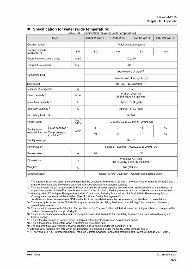
HRX-OM-X010
Chapter 8 Appendix
HRZ Series 8.1 Specification
8-3 8-3
◼ Specification for water (wide temperature) Table 8-3 Specification for water (wide temperature)
Model HRZ002-W2S-F HRZ004-W2S-F HRZ008-W2S-F HRZ010-W2S-F
Cooling method Water cooled refrigerant
Cooling capacity*1 (50Hz/60Hz)
kW 2.0 4.0 8.0 10.0
Operating temperature range deg C 10 to 60
Temperature stability deg C ±0.1*2
Circulating fluid
Pure water / DI water*3
(No intrusion of foreign body)
Refrigerant R410A(HFC,GWP2088) *11
Quantity of refrigerant kg 1.5
Pump capacity*4 MPa 0.38 (At 20L/min)
(55 [PSIG] At 5.3 [gal/min])
Main Tank capacity*5 L Approx.15 (4 [gal])
Sub Tank capacity *6 L Approx.16 (4.2 [gal])
Circulating fluid port Rc 3/4
Facility water deg C /MPa
10 to 30 / 0.3 to 0.7 (45 to 100 [PSIG])
Facility water required flow rate
Rated condition*9 L/min
4 7 14 15
Temp. changing condition *10
10 12 15 15
Facility water port Rc 1/2
Power supply 3-phase 50/60Hz AC200/200 to 208V±10%
Breaker size A 20 30
Dimensions*7 mm W380D870H950
(W14.96xD34.25xH37.40[inch])
Weight*8 kg 165 (364 [lbs])
Communication Serial RS-485 (Dsub-9pin) , Contact signal (Dsub-25pin)
*1: The capacity is derived under the conditions that the circulating fluid temp is 20 deg C, the facility water temp. is 25 deg C and
that the circulating fluid flow rate is obtained at a specified flow rate of pump capacity. *2: This is a system output temperature, with flow rate defined in pump capacity secured, when stabilized with no disturbance. Its
upper limit may be violated if an insufficient amount of the circulating fluid is present or a disturbance to flow rate is observed. *3: Water quality of The Japan Refrigeration and Air Conditioning Industry Association (JRA GL-02-1994/Recirculating fluid of
Cooling water system) shall be satisfied (See “7.1 Water Quality Management’) Additives such as preservative is NOT available. It not only deteriorates the performance, but also lead to cause failure.
*4: The capacity is derived at the Outlet of this system when the circulating fluid temp. is at 20 deg C and maximum frequency operation by inverter.
*5: This is a minimum amount of the fluid for operation of the Thermo Chiller outfitted with internal piping and heat exchanger in this system. Circulating fluid temp.: 20 deg C
*6: This is an auxiliary space with a main tank capacity excluded. Available for circulating fluid recovery from external piping and backup supply.
*7: This is the dimensions of panels, which is derived without protrusions such as a breaker handle. *8: This is the mass of the system when it contains no circulating fluid. *9: The required flow rate when the cooling capacity load is applied under the condition in *1. *10:Temporarily required flow rate when set temperature is changed under the facility water temp.25 deg C. *11: The value of IPCC (Intergovernmental Panel on Climate Change) Forth Assignment Report : Climate Change 2007 (AR4).
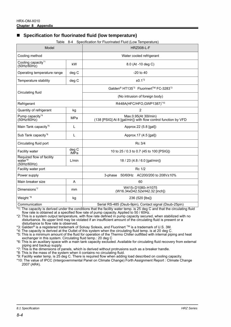
HRX-OM-X010
Chapter 8 Appendix
8.1 Specification HRZ Series
8-4
◼ Specification for fluorinated fluid (low temperature)
Table 8-4 Specification for Fluorinated Fluid (Low Temperature)
Model HRZ008-L-F
Cooling method Water cooled refrigerant
Cooling capacity*1 (50Hz/60Hz)
kW 8.0 (At -10 deg C)
Operating temperature range deg C -20 to 40
Temperature stability deg C ±0.1*2
Circulating fluid Galden® HT135*3 FluorinertTM FC-3283*3
(No intrusion of foreign body)
Refrigerant R448A(HFC/HFO,GWP1387)*10
Quantity of refrigerant kg 2
Pump capacity*4 (50Hz/60Hz)
MPa Max.0.95(At 30l/min)
(138 [PSIG] At 8 [gal/min]) with flow control function by VFD
Main Tank capacity*5 L Approx.22 (5.8 [gal])
Sub Tank capacity*6 L Approx.17 (4.5 [gal])
Circulating fluid port Rc 3/4
Facility water deg C /MPa
10 to 25 / 0.3 to 0.7 (45 to 100 [PSIG])
Required flow of facility water*9
(50Hz/60Hz) L/min 18 / 23 (4.8 / 6.0 [gal/min])
Facility water port Rc 1/2
Power supply 3-phase 50/60Hz AC200/200 to 208V±10%
Main breaker size A 60
Dimensions*7 mm W415D1080H1075
(W16.34xD42.52xH42.32 [inch])
Weight *8 kg 236 (520 [lbs])
Communication Serial RS-485 (Dsub-9pin), Contact signal (Dsub-25pin)
*1: The capacity is derived under the conditions that the facility water temp. is 25 deg C and that the circulating fluid flow rate is obtained at a specified flow rate of pump capacity. Applied to 50 / 60Hz.
*2: This is a system output temperature, with flow rate defined in pump capacity secured, when stabilized with no disturbance. Its upper limit may be violated if an insufficient amount of the circulating fluid is present or a disturbance to flow rate is observed.
*3: Galden® is a registered trademark of Solvay Solexis, and Fluorinert TM is a trademark of U.S. 3M. *4: The capacity is derived at the Outlet of this system when the circulating fluid temp. is at 20 deg C. *5: This is a minimum amount of the fluid for operation of the Thermo Chiller outfitted with internal piping and heat
exchanger in this system. Circulating fluid temp.: 20 deg C *6: This is an auxiliary space with a main tank capacity excluded. Available for circulating fluid recovery from external
piping and backup supply. *7: This is the dimensions of panels, which is derived without protrusions such as a breaker handle. *8: This is the mass of the system when it contains no circulating fluid. *9: Facility water temp. is 25 deg C. There is required flow when adding load described on cooling capacity. *10: The value of IPCC (Intergovernmental Panel on Climate Change) Forth Assignment Report : Climate Change
2007 (AR4).

HRX-OM-X010
Chapter 8 Appendix
HRZ Series 8.1 Specification
8-5 8-5
◼ Specification for ethylene glycol solution (low temperature)
Table 8-5 Specification for Ethylene Glycol Aqueous Solution (Low Temperature)
Model HRZ008-L1-F
Cooling method Water cooled refrigerant
Cooling capacity*1 (50Hz/60Hz)
kW 8.0 (At -10 deg C)
Operating temperature range deg C -20 to 40
Temperature stability deg C ±0.1*2
Circulating fluid Ethylene glycol solution 60%*3
(No intrusion of foreign body)
Refrigerant R448A(HFC/HFO,GWP1387)*10
Quantity of refrigerant kg 2
Pump capacity*4 (50Hz/60Hz)
MPa Max.0.40 (At 20L/min)
(58 [PSIG] At 5.3 [gal/min]) with flow control function by VFD
Main Tank capacity*5 L Approx.22 (5.8 [gal])
Sub Tank capacity *6 L Approx.17 (4.5 [gal])
Circulating fluid port Rc 3/4
Facility water deg C /MPa
10 to 25 / 0.3 to 0.7 (45 to 100 [PSIG])
Required flow of facility water*9
(50Hz/60Hz) L/min 18 / 23 (4.8 / 6.0 [gal/min])
Facility water port Rc 1/2
Power supply 3-phase 50/60Hz AC200/200 to 208V±10%
Main breaker size A 60
Dimensions*7 mm W415D1080H1075
(W16.34xD42.52xH42.32 [inch])
Weight*8 kg 236 (520 [lbs])
Communication Serial RS-485 (Dsub-9pin) , Contact signal (Dsub-25pin)
*1: The capacity is derived under the conditions that the facility water temp. is 25 deg C and that the circulating fluid flow rate is obtained at a specified flow rate of pump capacity. Applied to 50 / 60Hz.
*2: This is a system output temperature, with flow rate defined in pump capacity secured, when stabilized with no disturbance. Its upper limit may be violated if an insufficient amount of the circulating fluid is present or a disturbance to flow rate is observed.
*3: Pure ethylene glycol needs dilution with fresh water before use. Ethylene glycol with additives such as preservatives is NOT available.
*4: The capacity is derived at the Outlet of this system when the circulating fluid temp. is at 20 deg C. *5: This is a minimum amount of the fluid for operation of the Thermo Chiller outfitted with internal piping and heat
exchanger in this system. Circulating fluid temp.: 20 deg C *6: This is an auxiliary space with a main tank capacity excluded. Available for circulating fluid recovery from external
piping and backup supply. *7: This is the dimensions of panels, which is derived without protrusions such as a breaker handle. *8: This is the mass of the system when it contains no circulating fluid. *9: Facility water temp. is 25 deg C. There is required flow when adding load described on cooling capacity. *10: The value of IPCC (Intergovernmental Panel on Climate Change) Forth Assignment Report : Climate Change
2007 (AR4).

HRX-OM-X010
Chapter 8 Appendix
8.1 Specification HRZ Series
8-6
8.1.2 Cooling capacity
0
2
4
6
8
10
12
-20 -10 0 10 20 30 40 50 60 70 80 90
HRZ002-W1S-F
HRZ004-W1S-F
HRZ008-W1S-F
HRZ010-W1S-F
Fluid : Ethylene glycol solution 60%
Flow rate : Rated flow
Facility water temp. : 25deg.C
Co
oli
ng
cap
acit
y[
kW]
Circulating fluid setting temp.[deg.C]
HRZ***-W1S-F
Figure 8-2 Cooling capacity (HRZ-W1S-F)
*Common to 50/60Hz
Fluid : Fluorinated Fluid
Flow rate : Rated flow
Facility water temp. : 25deg.C
Co
oli
ng
cap
acit
y[
kW]
Circulating fluid setting temp.[deg.C]
0
2
4
6
8
10
12
-20 -10 0 10 20 30 40 50 60 70 80 90
HRZ002-WS-F
HRZ004-WS-F
HRZ008-WS-F
HRZ010-WS-F
HRZ***-WS-F
Figure 8-1 Cooling capacity (HRZ-WS-F)
*Common to 50/60Hz

HRX-OM-X010
Chapter 8 Appendix
HRZ Series 8.1 Specification
8-7 8-7
Figure 8-3 Cooling capacity (HRZ-W2S-F)
*Common to 50/60Hz
Fluid : Water
Flow rate : Rated flow
Facility water temp. : 25deg.C
Co
oli
ng
cap
acit
y[
kW]
Circulating fluid setting temp.[deg.C]
0
2
4
6
8
10
12
10 20 30 40 50 60
HRZ002-W2S-F
HRZ004-W2S-F
HRZ008-W2S-F
HRZ010-W2S-F
HRZ***-W2S-F
Fluid : Fluorinated Fluid
Flow rate : Rated flow
Facility water temp. : 25deg. C
Fig. 8-4 Cooling capacity (HRZ008-L-F)
*Common to 50/60Hz
Co
oli
ng
cap
acit
y[
kW]
Circulating fluid setting temp.[deg. C]
0
2
4
6
8
10
12
14
16
-20 -10 0 10 20 30 40
[HRZ008-L-F]
HRZ008-L-F
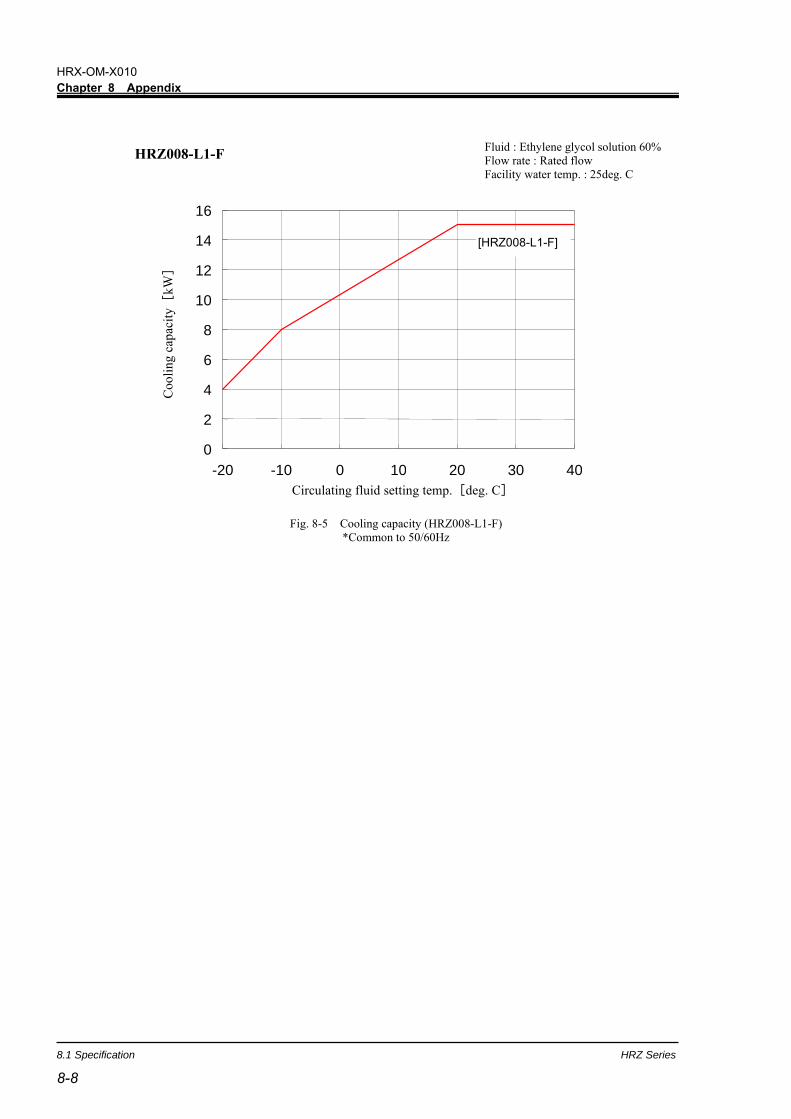
HRX-OM-X010
Chapter 8 Appendix
8.1 Specification HRZ Series
8-8
Fig. 8-5 Cooling capacity (HRZ008-L1-F)
*Common to 50/60Hz
Fluid : Ethylene glycol solution 60%
Flow rate : Rated flow
Facility water temp. : 25deg. C C
oo
lin
g c
apac
ity[
kW]
Circulating fluid setting temp.[deg. C]
0
2
4
6
8
10
12
14
16
-20 -10 0 10 20 30 40
[HRZ008-L1-F]
HRZ008-L1-F

HRX-OM-X010
Chapter 8 Appendix
HRZ Series 8.1 Specification
8-9 8-9
8.1.3 Heating capacity Circulating Fluid: Fluorinated Fluid
Flow rate : Rated flow
Circulating fluid setting temp.[deg.C]
Fig. 8-6 Heating capacity (HRZ-WS-F)
*When pump inverter is operating at frequency of 60Hz (maximum).
Hea
tin
g c
apac
ity[
kW]
Fluid : Ethylene glycol solution 60%
Flow rate : Rated flow
Fig. 8-7 Heating capacity (HRZ-W1S-F)
* When pump inverter is operating at frequency of 60Hz (maximum).
Hea
tin
g c
apac
ity[
kW]
Circulating fluid setting temp.[deg.C] 0
1
2
3
4
5
6
7
-20 -10 0 10 20 30 40 50 60 70 80 90 100
HRZ002-WS-F
HRZ004-WS-F
HRZ008-WS-F
HRZ010-WS-F
0
1
2
3
4
5
6
7
-20 -10 0 10 20 30 40 50 60 70 80 90 100
HRZ002-W1S-F
HRZ004-W1S-F
HRZ008-W1S-F
HRZ010-W1S-F
Circulating fluid setting temp.[deg.C]
HRZ***-WS-F
HRZ***-W1S-F

HRX-OM-X010
Chapter 8 Appendix
8.1 Specification HRZ Series
8-10
Fluid : Water
Flow rate : Rated flow H
eati
ng
cap
acit
y[
kW]
0
1
2
3
4
5
6
7
10 20 30 40 50 60 70
HRZ002-W2S-F
HRZ004-W2S-F
HRZ008-W2S-F
HRZ010-W2S-F
HRZ***-W2S-F
Circulating fluid setting temp.[deg.C]
0
1
2
3
4
5
6
7
-20 -10 0 10 20 30 40
He
atin
g ca
pac
ity[
kW]
Circulating fluid setting temp.[deg.C]
HRZ008-L-F Circulating Fluid: Fluorinated Fluid
Flow rate : Rated flow
Fig. 8-9 Heating capacity (HRZ008-L-F)
* When pump inverter is operating at frequency of 60Hz (maximum).
Fig. 8-8 Heating capacity (HRZ-W2S-F)
* When pump inverter is operating at frequency of 60Hz (maximum).

HRX-OM-X010
Chapter 8 Appendix
HRZ Series 8.1 Specification
8-11 8-11
0
1
2
3
4
5
6
7
-20 -10 0 10 20 30 40
He
atin
g ca
pac
ity[
kW]
Circulating fluid setting temp.[deg.C]
Fluid : Ethylene glycol solution 60%
Flow rate : Rated flow
HRZ008-L1-F
Fig. 8-10 Heating capacity (HRZ008-L1-F)
* When pump inverter is operating at frequency of 60Hz (maximum).
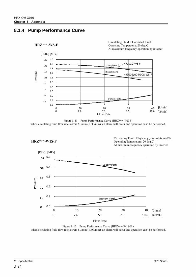
HRX-OM-X010
Chapter 8 Appendix
8.1 Specification HRZ Series
8-12
8.1.4 Pump Performance Curve
Flow Rate
Figure 8-11 Pump Performance Curve (HRZ-WS-F)
When circulating fluid flow rate lowers 6L/min (1.6G/min), an alarm will occur and operation can't be performed.
Circulating Fluid: Fluorinated Fluid
Operating Temperature: 20 deg.C
At maximum frequency operation by inverter
P
ress
ure
.
[G/min]
[L/min] 0.0
0.1
0.2
0.3
0.4
0.5
0.6
0.7
0.8
0.9
1.0
0 10 20 30 40
[Supply Port]
[Return Port]
HRZ010-WS-F
HRZ002/004/008-WS-F
145
131
116
102
87
73
58
44
[Supply Port]
0 2.6 5.3 7.9 10.6Flow Rate
HRZ***-WS-F
[PSIG] [MPa]
Figure 8-12 Pump Performance Curve (HRZ-W1S-F )
When circulating fluid flow rate lowers 6L/min (1.6G/min), an alarm will occur and operation can't be performed.
Circulating Fluid: Ethylene glycol solution 60%
Operating Temperature: 20 deg.C
At maximum frequency operation by inverter
Flow Rate
[G/min]
[L/min]
Pre
ssu
re.
0.0
0.1
0.2
0.3
0.4
0.5
0 10 20 30 40
[Return Port]
[Supply Port]
0 2.6 5.3 7.9 10.6
73
58
44
29
15
0
Flow Rate
HRZ***-W1S-F
[PSIG] [MPa]

HRX-OM-X010
Chapter 8 Appendix
HRZ Series 8.1 Specification
8-13 8-13
Figure 8-13 Pump Performance Curve (HRZ-W2S-F )
When circulating fluid flow rate lowers 6L/min (1.6G/min), an alarm will occur and operation can't be performed.
[PSIG] [MPa] P
ress
ure
.
Flow Rate
[G/min]
[L/min]
0.0
0.1
0.2
0.3
0.4
0.5
0 10 20 30 40
[Supply Port]
[Return Port]
73
58
44
29
15
0
0 2.6 5.3 7.9 10.6
Circulating Fluid: Water
Operating Temperature: 20 deg.C
At maximum frequency operation by inverter
Flow Rate
HRZ***-W2S-F
Circulating Fluid: Fluorinated Fluid
Operating Temperature: 20 deg C
At maximum frequency operation by inverter
Fig. 8-14 Pump Performance Curve ( HRZ008-L-F )
When circulating fluid flow rate lowers 6L/min (1.6G/min), an alarm will occur and operation can't be performed.
[
6
0
H
z
]
[
5
0
H
z
]
[
5
0
H
z
]
[
6
0
H
z
]
HRZ008-L-F
0.0
0.1
0.2
0.3
0.4
0.5
0.6
0.7
0.8
0.9
1.0
1.1
1.2
0 5 10 15 20 25 30 35 40
Pre
ssu
re [
MP
a]
Flow Rate [L/min]
[Supply Port]
[Return Port]

HRX-OM-X010
Chapter 8 Appendix
8.1 Specification HRZ Series
8-14
HRZ008-L1-F
Fig. 8-15 Pump Performance Curve ( HRZ008-L1-F )
When circulating fluid flow rate lowers 6L/min (1.6G/min), an alarm will occur and operation can't be performed.
Circulating Fluid: Ethylene glycol solution 60%
Operating Temperature: 20 deg C
At maximum frequency operation by inverter
0.0
0.1
0.2
0.3
0.4
0.5
0 5 10 15 20 25 30 35 40
Pre
ssu
re[M
Pa
]
Flow Rate [L/min]
[Supply Port]
[Return Port]
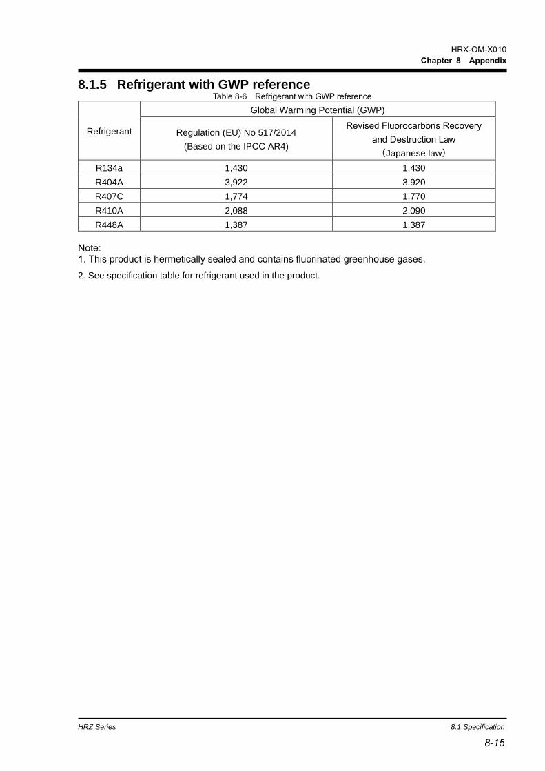
HRX-OM-X010
Chapter 8 Appendix
HRZ Series 8.1 Specification
8-15 8-15
8.1.5 Refrigerant with GWP reference Table 8-6 Refrigerant with GWP reference
Refrigerant
Global Warming Potential (GWP)
Regulation (EU) No 517/2014
(Based on the IPCC AR4)
Revised Fluorocarbons Recovery
and Destruction Law
(Japanese law)
R134a 1,430 1,430
R404A 3,922 3,920
R407C 1,774 1,770
R410A 2,088 2,090
R448A 1,387 1,387
Note: 1. This product is hermetically sealed and contains fluorinated greenhouse gases.
2. See specification table for refrigerant used in the product.

HRX-OM-X010
Chapter 8 Appendix
8.1 Specification HRZ Series
8-16
8.1.6 Communication specification
This section provides the general outline of communications utilized in this system.
For detail specification, we provide a separate system manual “Communication Specification”, which is available
through your local distributor.

HRX-OM-X010
Chapter 8 Appendix
HRZ Series 8.1 Specification
8-17 8-17
◼ Contact signal Table 8-7 Contact Signal
Item Specification
Connector No. P1
Connector type (this system) D-sub25P female connector(M2.6x0.45)
Input signal
Insulation type Photocoupler
Rated input voltage DC24V
Used voltage range DC 21.6V to 26.4V
Rated input current 5mA TYP
Input impedance 4.7k
Contact output signal
(Other than Pin No. 5-18)
Rated load voltage Max. AC48V / Max. DC30V
Max. load current Max. AC/DC 800mA
(Pin No. 15 is common to output signals. Total used load current should be at or below 800mA)
Contact output signal
(Pin No. 5-18)
Rated load voltage Max. AC48V / Max. DC30V
Max. load current AC/DC 800mA (resistance load)
Contact output signal
(EMO signal)
Rated load voltage Max. AC48V / Max. DC30V
Max. load current AC/DC 800mA (resistance load, inductive load)
Analog input signal*2
Input voltage range -10 to +10V
Input impedance 1MΩ
Input accuracy ±0.2% F.S. or less
Analog output signa*2
Output voltage range -10 to +10V
Max. output current 10mA
Output accuracy ±0.2% F.S. or less
Circuit block diagram
*1: The recovery signal can be input only when the circulating fluid automatic collection function (optional) is used, and it does not serve as the DIO REMOTE signal.
*2 :Valid if Analog Communication (optional) is provided. *3 :Valid if DI Control Kit (optional) is provided.
The product
DIGITAL
CIRCUIT
DC24V
+
--15V
100Ω
ANALOG COM
4.7kΩ
24COM
1
24COM
4.7kΩ
4.7kΩ
4.7kΩ
+15V
+
--15V
100Ω
+15V
ANALOG COM
+
- -15V
+15V
ANALOG COM
ANALOG
CIRCUIT
14
3
16
4
17
6
19
7
20
8
15
5
18
11
23
10
22
12
24
13
25
1MΩ
EMO
CIRCUIT
2
DC24V
Pin number
Your system
Pin No. I/O Standard specification CUSTOM DIO
1 Output DC+24V output DC+24V output
2 Intput Input signal COM Input signal COM
14 Output 24COM 24COM
3 Intput Run/Stop signal Run/Stop signal 1
16 Intput - Run/Stop signal 2
4 Intput AUTO PURGE signal*1DIO REMOTE signal 1
AUTO PURGE signal*1
17 Intput - DIO REMOTE signal 2
6 Output Run status signal OUT1
19 Output Warning signal OUT2
7 Output Fault signal OUT3
20 Output Remote signal OUT4
8 OutputTEMP READY signal
AUTO PURGE status signalOUT5
15 Intput Output signal COM Output signal COM
5 Output
18 Output
11 Output
23 Output
10 Output
22 Output
12 Intput
24 Intput
13 Output
25 Output
Temp.SP Analog Input*3
[-100 to 100 deg C:-10 to 10V]
EMO signalEMO signal
Temp.SP Analog Input*3
[-100 to 100 deg C:-10 to 10V]
DI PV Analog Output*3
[0 to 20 MΩ:0 to 10V]
DI PV Analog Output*3
[0 to 20 MΩ:0 to 10V]
Temp.PV Analog Output*2
[-100 to 100deg C:-10 to 10V]
ITEM
OUT6
Temp.PV Analog Output*2
[-100 to 100deg C:-10 to 10V]
Alarm signal

HRX-OM-X010
Chapter 8 Appendix
8.1 Specification HRZ Series
8-18
◼ Serial RS-485 Table 8-8 Serial RS-485
Item Specification
Connector No. P2
Connector type (this system) D-sub9P female connector
Standard EIA RS485
Protocol Modicon Modbus
Circuit block diagram
Internal
circuit
This system Your system
5
SD+
SD-
SG
7
2

HRX-OM-X010
Chapter 8 Appendix
HRZ Series 8.1 Specification
8-19 8-19
8.1.7 Alarm signal selection
User can designate one alarm signal for contact signal. See section 5.3.22 Initial
Setting screen 7 “page 5-25” for signal selecting.
The following table presents the setting-alarm relationship. The alarm signal is
turned OFF if the designated alarm detected. (Alarm signal is ON if no alarm is
detected.)
Table 8-9 Alarm signal selection
Setting Alarm Alarm
N/A Alarm signal remains ON (closed) under normal circumstances. -
ALARM01 Water Leak Detect FLT 01
ALARM03 RFGT High Press FLT 03
ALARM04 CPRSR Overheat FLT 04
ALARM05 Reservoir Low Level FLT 05
ALARM06 Reservoir Low Level WRN 06
ALARM07 Reservoir High Level WRN 07
ALARM08 Temp. Fuse Cutout FLT 08
ALARM09 Reservoir High Temp. FLT 09
ALARM10 Return High Temp・WRN 10
ALARM11 Reservoir High Temp. WRN 11
ALARM12 Return Low Flow FLT 12
ALARM13 Return Low Flow WRN 13
ALARM19 FAN Motor Stop WRN 19
ALARM20 Internal Pump Time Out WRN 20
ALARM21 Controller Error FLT 21
ALARM22 Memory Data Error FLT 22
ALARM23 Communication Error 23
ALARM24*1 DI Low Level WRN 24
ALARM25 Pump Inverter Error FLT 25
ALARM28*2 CPRSR Inverter Error FLT 28
ALARM29 RFGT Low Press FLT 29
ALARM32 Reservoir Low Temp.WRN 32
Example
With parameter “OUT” on the Initial Setting screen set to “Alarm1”, alarm “Water Leak Detect FLT” is
detected, the alarm contact signal is switched to OFF (open).
*1 : Alarm 24 is alarm assigned to accessories (optional).
*2 : Alarm 28 is not assigned for HRZ008-L*-F, the alarm signal always remains ON (closed).

HRX-OM-X010
Chapter 8 Appendix
8.2 Outer Dimensions HRZ Series
8-20
8.2 Outer Dimensions 8.2.1 Part 1
HRZ***-WS-F HRZ***-W1S-F HRZ***-W2S-F
Figure 8-16 Outer Dimensions
8.2.2 Part 2
HRZ008-L-F HRZ008-L1-F
Figure 8-17 Outer Dimensions
Top
Left Back Front
870(34.25[inch])
95
0(
37.4
[in
ch])
380(14.96[inch])
1080(42.52[inch])
10
75(
42
.32[inch
])
415(16.34[inch])
Back Left Front
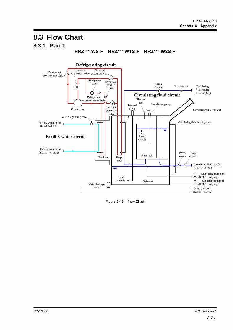
HRX-OM-X010
Chapter 8 Appendix
HRZ Series 8.3 Flow Chart
8-21 8-21
8.3 Flow Chart 8.3.1 Part 1
HRZ***-WS-F HRZ***-W1S-F HRZ***-W2S-F
Facility water circuit
Circulating fluid circuit
Compressor
Refrigerant
filter
Thermal
fuseInternal
pump
Circulating pump
Temp.
sensor
Press.
sensor
Circulating fluid level gauge
Flow sensor
Condenser Evapo
rator
Heater
Level
switch
Level
switch
Refrigerant
pressure
switch
Water leakage
switch
Facility water outlet(Rc1/2 w/plug)
Facility water inlet
(Rc1/2 w/plug)
Circulating
fluid return
(Rc3/4 w/plug)
Sub tank drain port
(Rc3/8 w/plug )
Circulating fluid supply
(Rc3/4 w/plug )
Main tank drain port
(Rc3/8 w/plug )
Drain pan port(Rc3/8 w/plug)
Circulating fluid fill port
Refrigerating circuitElectronic
expansion valve
Electronic
expansion valve
Electronic
expansion
valve
Main tank
Sub tank
Water regulating valve
Temp.
Sensor
Refrigerant
pressure sensor(high)
Refrigerant
pressure sensor(low)
Figure 8-18 Flow Chart
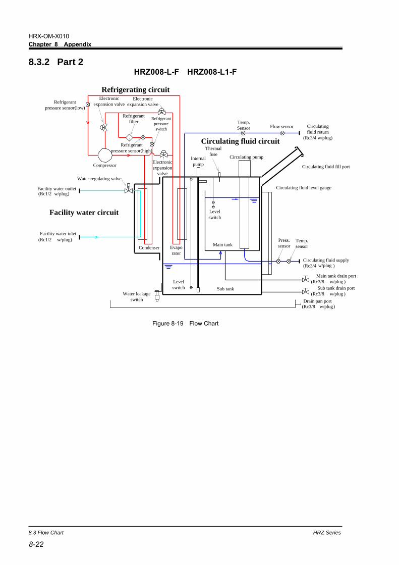
HRX-OM-X010
Chapter 8 Appendix
8.3 Flow Chart HRZ Series
8-22
8.3.2 Part 2 HRZ008-L-F HRZ008-L1-F
Facility water circuit
Circulating fluid circuit
Compressor
Refrigerant
filter
Thermal
fuseInternal
pump
Circulating pump
Temp.
sensor
Press.
sensor
Circulating fluid level gauge
Flow sensor
Condenser Evapo
rator
Level
switch
Level
switch
Refrigerant
pressure
switch
Water leakage
switch
Facility water outlet(Rc1/2 w/plug)
Facility water inlet
(Rc1/2 w/plug)
Circulating
fluid return
(Rc3/4 w/plug)
Sub tank drain port
(Rc3/8 w/plug )
Circulating fluid supply
(Rc3/4 w/plug )
Main tank drain port
(Rc3/8 w/plug )
Drain pan port(Rc3/8 w/plug)
Circulating fluid fill port
Refrigerating circuitElectronic
expansion valve
Electronic
expansion valve
Electronic
expansion
valve
Main tank
Sub tank
Water regulating valve
Temp.
Sensor
Refrigerant
pressure sensor(high)
Refrigerant
pressure sensor(low)
Figure 8-19 Flow Chart
HRX-OM-X010
Chapter 8 Appendix
HRZ Series 8.4 Offset Function
8-23 8-23
8.4 Offset Function Potential deviations in temperature between this system and your system may be
concerned depending on the installation environment. The offset function falling
into three types (MODE1 to 3) is assigned to calibrate deviations in temperature.
See the following descriptions for the offset function. See section 5.3.16“Initial
Setting screen 1”page5-19” for setting.
TEMP PV value, which is displayed on the Status screen, is output as circulating
fluid temperature data in terms of communication.
When MODE1 is selected
This mode is used to exercise temperature control to allow the discharge
temperature of the circulating fluid to be “TEMP SP value + OFFSET value”.
TEMP PV value denotes the discharge temperature of the circulating fluid.
E.g.: TEMP SP value: +20 deg C, OFFSET value: +2 deg C
→ Circulating fluid discharge temp.: +22 deg C, TEMP PV: +22 deg C
When MODE2 is selected
This mode is used to exercise temperature control to allow the discharge
temperature of the circulating fluid to be “TEMP SP value”.
TEMP PV value denotes “Circulating fluid discharge temp. value + OFFSET
value”.
E.g.: TEMP SP value: +20 deg C, OFFSET value: +2 deg C
→ Circulating fluid discharge temp.: +20 deg C, TEMP PV: +22 deg C
When MODE3 is selected
This mode is used to exercise temperature control to allow the discharge
temperature of the circulating fluid to be “TEMP SP value + OFFSET value”.
TEMP PV value denotes “Circulating fluid discharge temp. value - OFFSET
value”.
E.g.: TEMP SP value: +20 deg C, OFFSET value: +2 deg C
→ Circulating fluid discharge temp.: +20 deg C, TEMP PV: +20 deg C
When OFF is selected
If no mode is selected, temperature control is conducted to allow the discharge
temperature of the circulating fluid to be “TEMP SP value”.
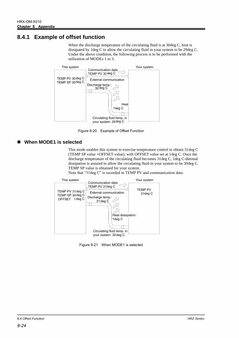
HRX-OM-X010
Chapter 8 Appendix
8.4 Offset Function HRZ Series
8-24
8.4.1 Example of offset function
When the discharge temperature of the circulating fluid is at 30deg C, heat is
dissipated by 1deg C to allow the circulating fluid in your system to be 29deg C.
Under the above condition, the following process is to be performed with the
utilization of MODEs 1 to 3.
Figure 8-20 Example of Offset Function
◼ When MODE1 is selected
This mode enables this system to exercise temperature control to obtain 31deg C
(TEMP SP value +OFFSET value), with OFFSET value set at 1deg C. Once the
discharge temperature of the circulating fluid becomes 31deg C, 1deg C-thermal
dissipation is assured to allow the circulating fluid in your system to be 30deg C.
TEMP SP value is obtained for your system.
Note that “31deg C” is recorded in TEMP PV and communication data.
Figure 8-21 When MODE1 is selected
This system Your system
Discharge temp.: 30
Circulating fluid temp. in your system: 29
TEMP PV 30 deg C TEMP SP 30
External communication
Communication data TEMP PV 30
Heat dissipation:
deg C
deg C
deg C
1deg C
deg C
1deg C
This system Your system
Discharge temp.: 31
Circulating fluid temp. in your system: 30 deg C
TEMP PV 31 TEMP SP 30 OFFSET 1
External communication
Communication data TEMP PV 31
TEMP PV 31
Heat dissipation:
deg C deg C deg C
deg C
deg C
deg C
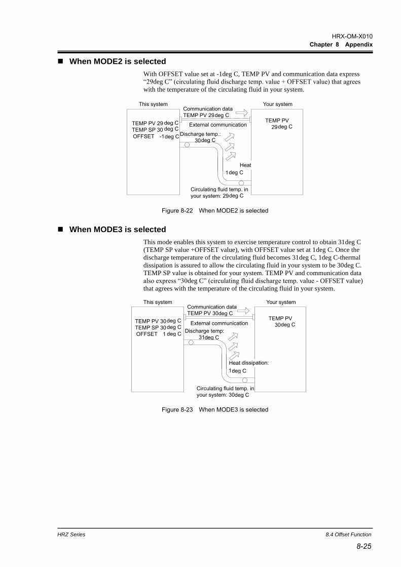
HRX-OM-X010
Chapter 8 Appendix
HRZ Series 8.4 Offset Function
8-25 8-25
◼ When MODE2 is selected
With OFFSET value set at -1deg C, TEMP PV and communication data express
“29deg C” (circulating fluid discharge temp. value + OFFSET value) that agrees
with the temperature of the circulating fluid in your system.
Figure 8-22 When MODE2 is selected
◼ When MODE3 is selected
This mode enables this system to exercise temperature control to obtain 31deg C
(TEMP SP value +OFFSET value), with OFFSET value set at 1deg C. Once the
discharge temperature of the circulating fluid becomes 31deg C, 1deg C-thermal
dissipation is assured to allow the circulating fluid in your system to be 30deg C.
TEMP SP value is obtained for your system. TEMP PV and communication data
also express “30deg C” (circulating fluid discharge temp. value - OFFSET value)
that agrees with the temperature of the circulating fluid in your system.
Figure 8-23 When MODE3 is selected
deg C
1
This system Your system
Discharge temp.: 30
Circulating fluid temp. in your system: 29
TEMP PV 29 TEMP SP 30 OFFSET -1
External communication
Communication data TEMP PV 29
TEMP PV 29
Heat dissipation:
deg C deg C
deg C
deg C
deg C
deg C
deg C
Heat 1 deg C
This system Your system
Discharge temp: 31 deg C
Circulating fluid temp. in your system: 30 deg C
TEMP PV 30 TEMP SP 30 OFFSET 1 deg C
External communication
Communication data TEMP PV 30 deg C
TEMP PV 30 deg C
dissipation:
deg C deg C

HRX-OM-X010
Chapter 8 Appendix
8.5 BAND/READY function HRZ Series
8-26
8.5 BAND/READY function Sets BAND to TEMP SP value, and notifies TEMP PV value reaches within BAND
range by the operation display panel or the communication.
See section “Chapter 5 System Operation 5.3.21 Initial Setting screen 6” on page 5-
24,for the procedure of the setting.
When the setting is ON
Allows the setting of the BAND and REDY TIME. Allows the setting of the
communication output.
Figure 8-24 BAND/READY function
Examples of Setting
TEMP SP:20deg C
BAND:2deg C
READY TIME:60sec.
”TEMP READY” is displayed on the operation display panel 60-sec. after
TEMP PV value becomes 18 deg C to start output by communication.
Necessary condition is that TEMP PV value after 60-sec. is 20+/-2.0 deg C or
less. See “5.3.4 Status screen 3” on page 5-7 for the details of display
position.
When the setting is OFF
BAND/READY function becomes invalid.
BAND
TEMP SP
TEMP PV
TEMP READY not display/not output
TEMP READY display/output
READY
TIME

HRX-OM-X010
Chapter 8 Appendix
HRZ Series 8.6 Anchor Bolt Mounting Position
8-27 8-27
8.6 Anchor Bolt Mounting Position 8.6.1 Part 1
HRZ***-WS-F HRZ***-W1S-F HRZ***-W2S-F
Lock the brakes on casters (2 pcs. on the front), and attach the anti-seismic bracket
(optional: HRZ-TK002) to secure this system.
Figure 8-25 Anchor Bolt Mounting Position
Front Anti-seismic bracket (optional)
Anchor bolt (4-Ø14)
Top
Anti-seismic bracket is an optional accessory, which is required for the installation of this system (HRZ-TK002).
It is your responsibility to prepare anchor bolts suitable for your floor material. M12-anchor bolts (4 pcs.) are required.
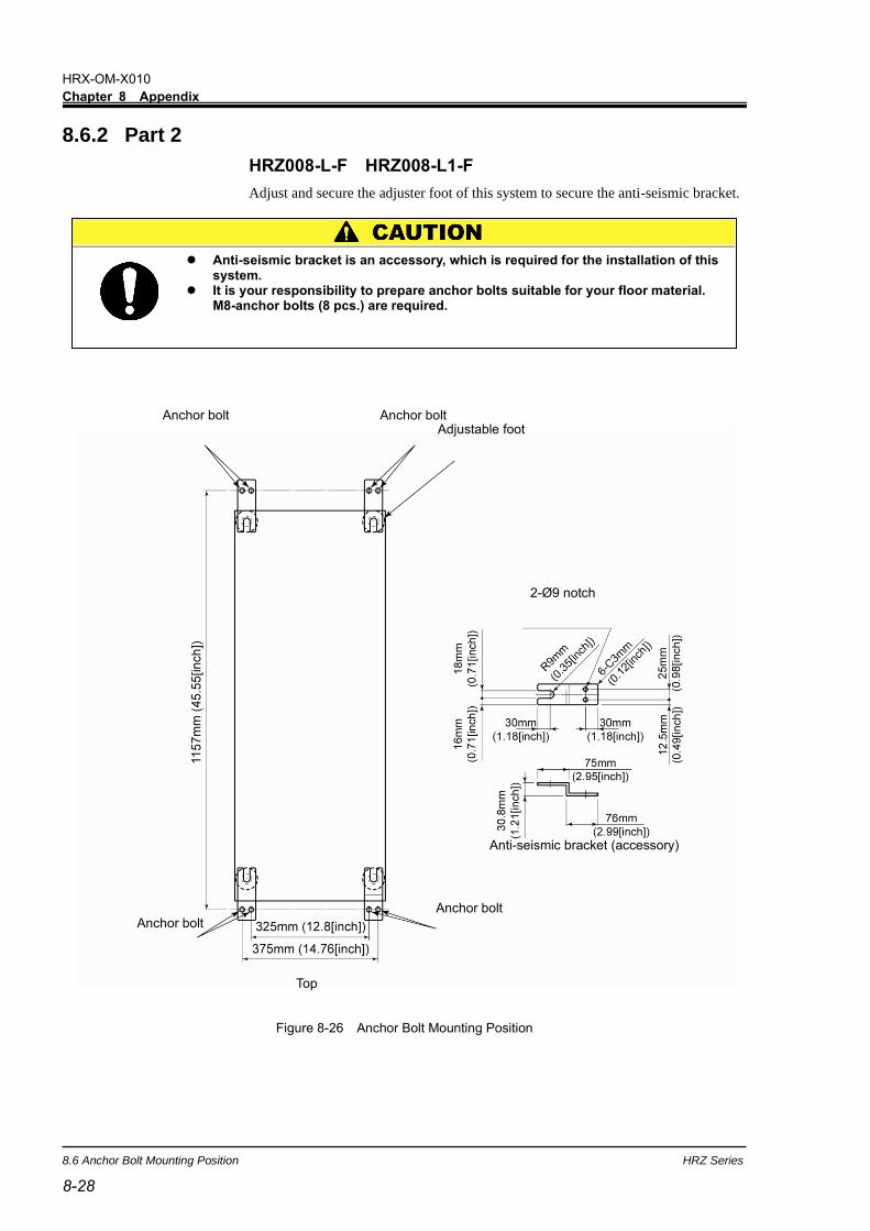
HRX-OM-X010
Chapter 8 Appendix
8.6 Anchor Bolt Mounting Position HRZ Series
8-28
8.6.2 Part 2
HRZ008-L-F HRZ008-L1-F
Adjust and secure the adjuster foot of this system to secure the anti-seismic bracket.
Figure 8-26 Anchor Bolt Mounting Position
Anchor bolt Anchor bolt Adjustable foot
Top
Anchor bolt Anchor bolt
2-Ø9 notch
Anti-seismic bracket (accessory)
Anti-seismic bracket is an accessory, which is required for the installation of this system.
It is your responsibility to prepare anchor bolts suitable for your floor material. M8-anchor bolts (8 pcs.) are required.

HRX-OM-X010
Chapter 8 Appendix
HRZ Series 8.7 Compliance
8-29 8-29
8.7 Compliance This system conforms to the following standards.
Table 8-10 Compliance
CE Marking
EMC Directive 2014/30/EU
Machinery Directive
2006/42/EC
RoHS Directive
2011/65/EU
SEMI S2,S8,F47
UL E229305 / UL1995
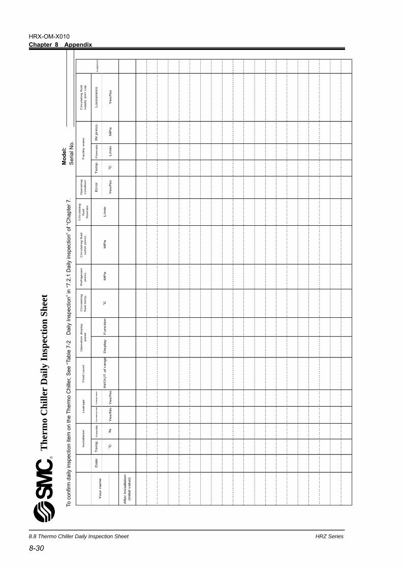
HRX-OM-X010
Chapter 8 Appendix
8.8 Thermo Chiller Daily Inspection Sheet HRZ Series
8-30
8.8 Thermo Chiller Daily Inspection Sheet
To c
onfirm
daily
in
spectio
n ite
m o
n t
he T
herm
o C
hill
er, S
ee “
Table
7-2
D
aily
Inspectio
n”
in “
7.2
.1 D
aily
in
spectio
n”
of
“Chapte
r 7.
Th
erm
o C
hil
ler
Dail
y I
nsp
ecti
on
Sh
eet
Mo
de
l:
Seria
l N
o.
Circula
ting f
luid
supply
port
cap
Looseness
IN p
ress.
Flo
wra
teT
em
p.
Opera
ting
conditio
n
Error
Circula
ting
fluid
flow
rate
Circula
ting f
luid
outlet
pre
ss.
Refr
igera
nt
pre
ss.
Circula
ting
fluid
tem
p.
Flu
id L
evel
Coolin
g w
ate
rC
ircula
ting f
luid
Hum
idity
Tem
p.
Date
After insta
llation
(in
itia
l valu
e)
Your n
am
e
%In
sta
llation
Facility w
ate
r
Yes/N
o
Leakage
Yes/N
o
Ju
dg
me
nt
Function
Dis
pla
y
MP
aM
Pa
L/m
in
Yes/N
oM
Pa
IN/O
UT
of range
Opera
tion d
ispla
y
panel
Yes/N
oL/m
in

HRZ Series Product Warranty
9-1
Chapter 9 Product Warranty
1. Warranty
If a failure is observed in our Thermo Chiller, repair shall be provided in accordance with the warranty period
and preconditions defined below at SMC’s option.
Repair involves the inspection and/or replacement and/or modification of a defective part.
Removed parts shall become the possession of SMC.
2. Warranty period
The warranty period of the product is 1 year in service or 1.5 years after the product is delivered,whicherer is
first.
3. Warranty exemption
SMC’s liability under this warranty shall not be available for the following troubles and damages.
(1) Troubles or damage caused by the neglect of our designated inspection (daily inspection, periodic
inspection).
(2) Troubles or damages caused by mishandling such as using improper operating procedure and using with our
specifications violated.
(3) Troubles or damages caused by unauthorized modification.
(4) Troubles or damages caused by the use of a not-designated circulating fluid and facility water.
(5) Troubles or damages caused by wearing out such as fading on the coated or plated surface.
(6) Sensory phenomena that are considered no effect on the functions (such as noise, vibration).
(7) Troubles or damages caused by natural disaster such as earthquake, typhoon, water, inevitable events and
fire.
(8) Troubles or damages occurred under the installation conditions defined in the Operation Manual.
(9) Troubles or damages that are not compliant with the “5. Warranty preconditions”.
4. Escape clause
(1) Expenses of daily inspection and periodic inspection.
(2) Expenses of repair consigned with neither SMC nor our authorized service station.
(3) Expenses of transport, installation, and removal of this system.
(4) Expenses of removal of non-genuine parts and replenishment of non-genuine fluids.
(5) Unavailability and loss due to this system being disabled.
(such as telephone bill, leave compensation, commercial loss)
(6) Expenses and compensation for terms other than provided in “1. Warranty”.
5. Warranty precondition
Proper use and inspection of this system is required to assure safe use of this system. System warranty shall
satisfy the following preconditions. Please take note that warranted repair shall not be available if these
preconditions are disregarded.
(1) System operation shall be conducted by following operating procedure defined in the Operation Manual.
(2) Daily and periodic inspections designated in the Operation Manual shall be made as scheduled.
(3) Inspection record shall be entered in the Daily Inspection Sheet provided in the Operation Manual.
6. Request for warranted repair
As to warranted repair, please contact the supplier you purchased this system from for service.
Warranted repair shall be on request basis.
Unrequited repair shall be provided in accordance with the warranty period, preconditions and terms defined above.
Therefore, the repair service shall be available on a chargeable basis if a failure is detected after the warranty period.

Revision
Rev.E:May.2022
4-14-1, Sotokanda, Chiyoda-ku, Tokyo 101-0021 JAPAN Tel: + 81 3 5207 8249 Fax: +81 3 5298 5362 URL https://www.smcworld.com Note: Specifications are subject to change without prior notice and any obligation on the part of the manufacturer. © 2022 SMC Corporation All Rights Reserved


