Embed Size (px)
Citation preview
VOLUME II FLYING QUALITIES PHASE
CHAPTER 6 MANEUVERING FLIGHT
Approved
OCTOBER 1990
USAF TEST PILOT SCHOOL EDWARDS AFBCA
19970117 033 DTIG QUALIFY IECPEOTEB 1
6.1 INTRODUCTION
The method used to analyze maneuvering flight will be to determine a
stick-fixed maneuver point (hj and stick-free maneuver point (l/). These
are analogous to their counterparts in static stability, the stick-fixed and
stick-free neutral points. The maneuver points will also be derived in terms
of the neutral points, and their relationship to eg location will be shown.
6.2 DEFINITIONS
(Also see definitions for Chapter 5, Longitudinal Static Stability.)
Acceleration Sensitivity - The ratio n/a is used to determine allowable maneuvering stick force gradients. It is defined in KIL-STD-1797A as the "steady-state normal acceleration change per unit% change in angle of attack for an incremental pitch control deflection at constant speed."
Centripetal Acceleration - The acceleration vector normal to the velocity vector that causes changes in direction (not magnitude) of the velocity vector.
Free Elevator Factor - F = 1 - x (^ / C^ &
A multiplier that accounts for the change in stability caused by freeing the elevator (allowing it to "float").
2U 3C Pitch Damping - A stability derivative. c = °_ # ■
» c 3Q
Damping that is generated by a pitch rate.
Stick-Fixed Maneuver Margin - The distance in percent MAC between the eg and the stick-fixed maneuver point = hm - h.
Stick-Fixed Maneuver Point - hm The eg location where dSo/dn = 0.
Stick-Free Maneuver Margin - The distance, in percent MAC, between the eg and the stick-free maneuver point = hm - h.
Stick-Free Maneuver Point - h'm = The eg location where dFs/dn = 0.
6.1
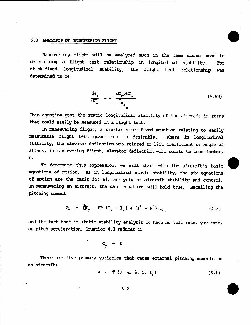
6.3 ANALYSIS OF MANEUVERING FLIGHT
Maneuvering flight will be analyzed much in the same manner used in
determining a flight test relationship in longitudinal stability. For
stick-fixed longitudinal stability, the flight test relationship was
determined to be
£ . dC-/dC^ (5.69)
O e
This equation gave the static longitudinal stability of the aircraft in terms
that could easily be measured in a flight test.
In maneuvering flight, a similar stick-fixed equation relating to easily
measurable flight test quantities is desirable. Where in longitudinal
stability, the elevator deflection was related to lift coefficient or angle of
attack, in maneuvering flight, elevator deflection will relate to load factor,
n.
TO determine this expression, we will start with the aircraft's basic
equations of motion. As in longitudinal static stability, the six equations
of motion are the basis for all analysis of aircraft stability and control.
In maneuvering an aircraft, the same equations will hold true. Recalling the
pitching moment
Gy = QIy - PR (Iz - Ix) + (P2 - R2) Ixz (4.3)
and the fact that in static stability analysis we have no roll rate, yaw rate,
or pitch acceleration, Equation 4.3 reduces to
Gy = 0
There are five primary variables that cause external pitching moments on
an aircraft:
M = f (U, a, a, Q, 8 ) (6.1)
6.2
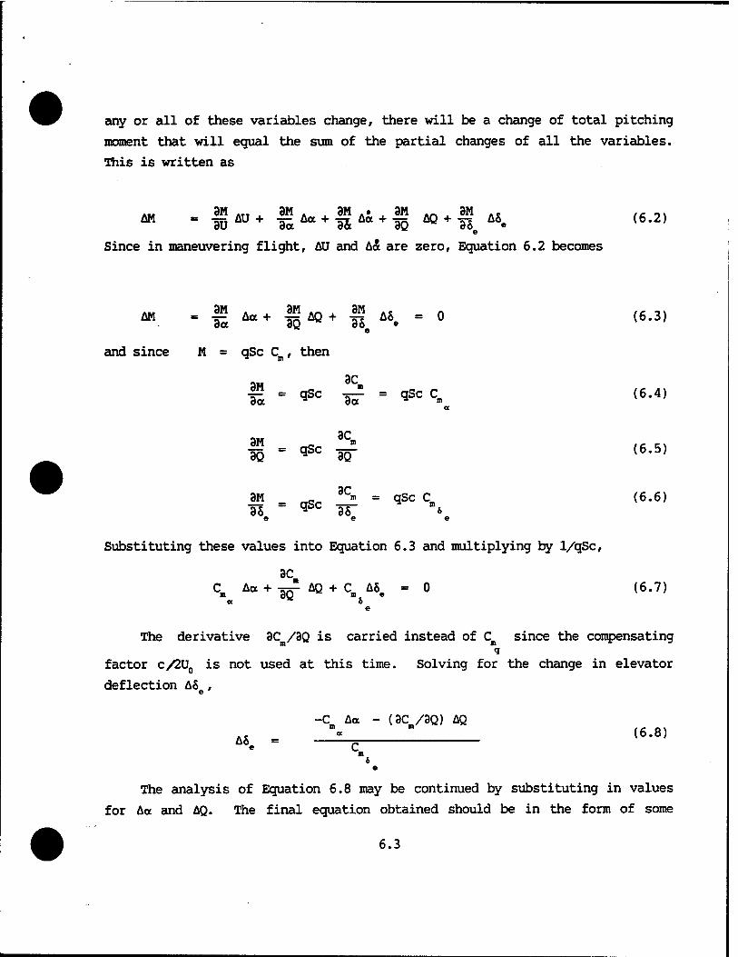
any or all of these variables change, there will be a change of total pitching
moment that will equal the sum of the partial changes of all the variables.
Ihis is written as
e
Since in maneuvering flight, AU and h& are zero, Equation 6.2 becomes
and since M = qSc C , then
3C la = <*Sc ^- - qSc Cm (6.4)
f - qsc *f <6.5)
« = OSC — = ^SC Cn> (6*6) 3Se ** 3&e
Substituting these values into Equation 6.3 and multiplying by 1/qSc,
3C C Äa + -^ AQ + C A8 =0 (6.7)
ex o e
The derivative 3Cm/3Q is carried instead of Cn since the compensating q
factor c/2U0 is not used at this time. Solving for the change in elevator
deflection A8e,
-C Aa - (3C /3Q) AQ A, _J^ ' (6.8)
m & e
The analysis of Equation 6.8 may be continued by substituting in values for Aa and AQ. The final equation obtained should be in the form of some
6.3
flight test relationship. Since maneuvering is related to load factor, the
elevator deflection required to obtain different load factors will define the
stick-fixed maneuver point. The immediate goal then is to determine the
change in angle of attack, Aa, and change in pitch rate, AQ, in terms of load
factor, n.
6.4 THE POLL-UP MANEUVER
In the pull-up maneuver, the change in angle of attack of the aircraft,
Aa, may be related to the lift coefficient of the aircraft. In the pull-up
with constant velocity, the angle of attack of the whole aircraft will be
changed since the aircraft has to fly at a higher CL to obtain the load factor
required. The change in CL required to maneuver at high load factors at a
constant velocity comes from two sources: (1) load factor increase and (2)
elevator deflection. Although often ignored because of its small value when
compared to total CL, the change in lift with elevator deflection Ch ASe
will be included for a more general analysis. •
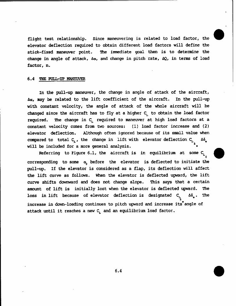
Referring to Figure 6.1, the aircraft is in equilibrium at some CL o
corresponding to some o^ before the elevator is deflected to initiate the
pull-up. If the elevator is considered as a flap, its deflection will affect
the lift curve as follows. When the elevator is deflected upward, the lift
curve shifts downward and does not change slope. This says that a certain
amount of lift is initially lost when the elevator is deflected upward. The
loss in lift because of elevator deflection is designated CL A8e. The 6
increase in down-loading continues to pitch upward and increase its angle of
attack until it reaches a new CL and an equilibrium load factor.
6.4
CLMAN
BEFORE ELEVATOR DEFLECTION
f AFTER ELEVATOR DEFLECTION
FIGURE 6.1. LIFT COEFFICIENT VERSUS ANGLE OF ATTACK
In other words, a pitch rate is initiated and a increases until a maneuvering
lift coefficient CT is reached for the deflected elevator S . The change KAN
in angle of attack is Aa. The change in CL has come partially from the
deflected elevator and mainly from the pitching maneuver. The change in CL
due to the maneuver is from CT to C, L MAN
Since it did not change the
the lift curve, and including the change in lift caused by elevator
deflection, the expression for Aa becomes
CT - aa (6.9)
AC, « aAa It
ACT - AC - CT AS. «= aAa L 1* 1* _ •
MAN 6 (6.10)
6.5
1 ( AC, -C AS.) a \ MAN 6 Aa = i i *x - s. oo.y (6.1D Utt a \ MAN *
To put Equation 6.11 in terms of load factor, AC must be defined. This is MAN
the change in lift coefficient from the initial condition to the final
maneuvering condition. This change can occur from one g flight to some other
load factor or it can start at two or three g's and progress to some new load
factor. If C. is at one g then L
and
C = H_ (6.12) L qS
n0W C -4- (6'13)
where n0 is the initial load factor. Similarly,
CL -2? (6.14) MAN qS
where n is the maneuvering load factor.
MAN MAN 0 **" ^
Finally substituting Equation 6.15 into Equation 6.11
Aa = ^(cL An-CLjASej (6.16) e
Equation 6.16 is now ready for substitution into Equation 6.8.
An expression for AQ in Equation 6.8 will be derived using the pull-up
maneuver analysis.
6.6
(a) (b)
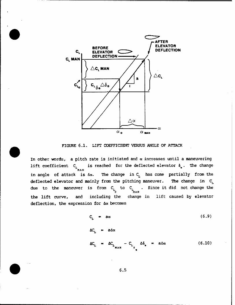
FIGURE 6.2. CURVILINEAR MOTION
Referring to Figure 6.2(a)
From Figure 6.2(b)
Ae = AS R
de Ht "
lim A6 At-K) At
lim At-K)
AS 1 At R
de Ht " 5 = Q R u
AU = U
A6 (small angles wher
de dt =
lim AU At-K) At
1 U
1 = U
dU dt
= e)
Combining Equations 6.21 and 6.19
dU Ht
y2
R
6.7
(6.17)
(6.18)
(6.19)
(6.20)
(6.21)
(6.22)

which may be recognized as the equation for the centripetal acceleration of a
particle moving in a circle of radius R at constant velocity U. The force (or
change in lift, AL) required to achieve this centripetal acceleration can be
derived from (F - ma). Thus,
AL ?Aa w g
u2
R (6.23)
The change in lift can be seen in Figure 6.3 to be
AL = nW - n0W - W(n - n0) (6.24)
' i.
AL
n.w
NW
FIGURE 6.3. WINGS LEVEL PULL-UP
6.8
Again, the change may take place from any original load factor and is not limited to the straight and level flight condition (n0 =1). Therefore, for a
constant velocity maneuver at U0, Equations 6.23 and 6.24 give
W(n-n0) - _(_-_] (6.25)
Using Equation 6.19 and the definition of AQ
R R,,
Equation 6.25 can be written
AQ = 3_ (n _ no) = 2_ An (6.27)
Now Equations 6.27 and 6.16 may be substituted into Equation 6.8.
: \ ICt An - CT A«) »a a ^ L L^ .J -c» 7> (CL **-CL AS.) aq„ g_ An
AS. = ^ — --V2 <6-28> n n 6 S • e
From longitudinal static stability,
C = a (h - h ) (6.29) n n a
Also to help further in reducing the equation to its simplest terms,
2 W uo
and
Uj - ££- (6.30)
w - ^ S (6-31)
6.9

Substituting Equations 6.31, 6.30, and 6.29 into Equation 6.28 results in
(h - K * |ET Ca ) (6.32) -L aCL An = C C_ - C a
• e
Equation 6.32 is now in the form that will define the stick-fixed
maneuver point for the pull-up. The definition of the maneuver point, h , is
the eg position at which the elevator deflection per g goes to zero. Taking the limit of Equation 6.32,
A8e dSe lim __1 = _1 (6#33)
An->0 An dn
d&« aCL / \
^ = C. CL -C a (h " hn + W C» j <6-34> ab b
e
Setting Equation 6.34 equal to zero will give the eg position at the maneuver point h = hB
q
Solving Equation 6.35 for hn and substituting into Equation 6.34,
d5e a CL
dn" = C~C ^C ä— (h_hn> (6-36) n L m ab b
e e
where we now define hm - h as the stick-fixed maneuver margin.
■flie significant points to be made about Equation 6.36 are: 1. The derivative dSe/dn varies with the maneuver margin. The
more forward the eg, the more elevator will be required to obtain the limit load factor. That is, as the eg moves forward, more elevator deflection is necessary to obtain a given load factor.
6.10
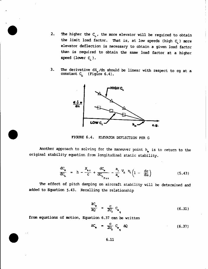
The higher the CL, the more elevator will be required to obtain
the limit load factor, That is, at low speeds (high C ) more
elevator deflection is necessary to obtain a given load factor
than is required to obtain the same load factor at a higher
speed (lower Cr ).
The derivative dSe/dn should be linear with respect to eg at a constant Ct (Figure 6.4).
HIGH CL
FIGURE 6.4. ELEVATOR DEFLECTION PER G
Another approach to solving for the maneuver point h is to return to the
original stability equation from longitudinal static stability.
Fus
(5.43)
The effect of pitch damping on aircraft stability will be determined and
added to Equation 5.43. Recalling the relationship
3C ■ 3Q~ 207 c- 0 q
from equations of motion, Equation 6.37 can be written
c , AC 0 q
6.11
(6.31)
(6.37)
Substituting the value obtained for AQ from Equation 6.27
Substituting
AC . _E2_ c An (6.38) 2U0
2 q
HAN An =
CL
from Equation 6.15 and Equation 6.12
c, - I <6-12' into Equation 6.38 gives
AC = P§C c AC (6.39) ^ ", LKAN
lim AC dC q ^*> aj - acj - lr c- <6-40)
MAN Pitch Damping
This term may now be added to Equation 5.43. If the sign of CB is negative, q
then the term is a stabilizing contribution to the stability equation. Cn q
will be analyzed further.
^ . h-^+^ - -V »vfl-jV* C (6.41) *£ C dCLFUS a« " ^ \ ^7 ^ "*
The maneuver point is found by setting dCm/dCL equal to zero and solving for
the eg position where this occurs.
dCm 3t T7 v, /1 ds\ PSc c " HÖ7 + a" H M J- dal 4m '■
Fus \ '
h. - ^-£ ♦ ^V„,v(l-!1-^C% (6.42)
6.12
The first three terms on the right side of Equation 6.42 may be identified as
the expression for the neutral point hn. If this substitution is made in
Equation 6.42, Equation 6.35 is again obtained.
h -Ac n 4m ■ (6.35)
Hie derivative C^ found in Equations 6.34 and 6.35 needs to be examined
before proceeding with9further discussion.
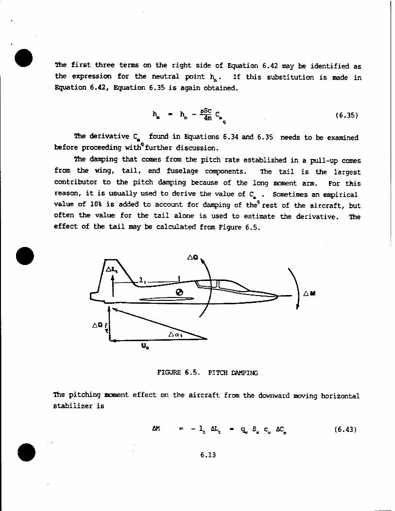
The damping that comes from the pitch rate established in a pull-up comes
from the wing, tail, and fuselage components. The tail is the largest
contributor to the pitch damping because of the long moment arm. For this
reason, it is usually used to derive the value of Cm . Sometimes an empirical
value of 10% is added to account for damping of theq rest of the aircraft, but
often the value for the tail alone is used to estimate the derivative. The
effect of the tail may be calculated from Figure 6.5.
AQ
AM
FIGURE 6.5. PITCH DAMPING
The pitching moment effect on the aircraft from the downward moving horizontal
stabilizer is
AM - 1. AL - a S c AC (6.43)
6.13

where
ALt = "q,. St ACL (6.44) t
Solving for ACB,
*t\ Xt St .. (6.45)
^w w w t
The combination ltSt/cwSw can be recognized as the tail volume coeffi-
cient, VH. The term q^^/% is the tail efficiency factor, n,.. Equation 6.45
may then be written
*c» - - VH \ ACL (6-46) t
which can be further refined to
AC» " " VH \ \ *"t <6.47)
From Figure 6.5, the change in angle of attack at the tail caused by the pitch
rate will be
-i *&t toK Ao,. = tan -g— = ^ jj- (6.48)
Substituting Equation 6.48 into 6.47
AC- - " at VH \ ^^ (6-49)
Taking the limit of Equation 6.49 gives
3C,n K so- - - at VH >\ r (6-50)
6.14
Equation 6.50 shews that the damping expression 3CB/3Q is an inverse function
of airspeed (i.e., this term is greater at lower speeds). Solving for CB q
using Equation 6.31
2uo 3C» \ C = —- ?£ = - 2a, V„ ft -4 (6-5D ^m c 90 t H t c
q
The damping derivative is not a function of airspeed, but rather a value
determined by design considerations only (subsonic flight). The pitch damping
derivative may be increased by increasing St or lt.
When this value for C is substituted into Equation 6.35 o q
h . h + pS at ^ Xt VH (6.52) n 251
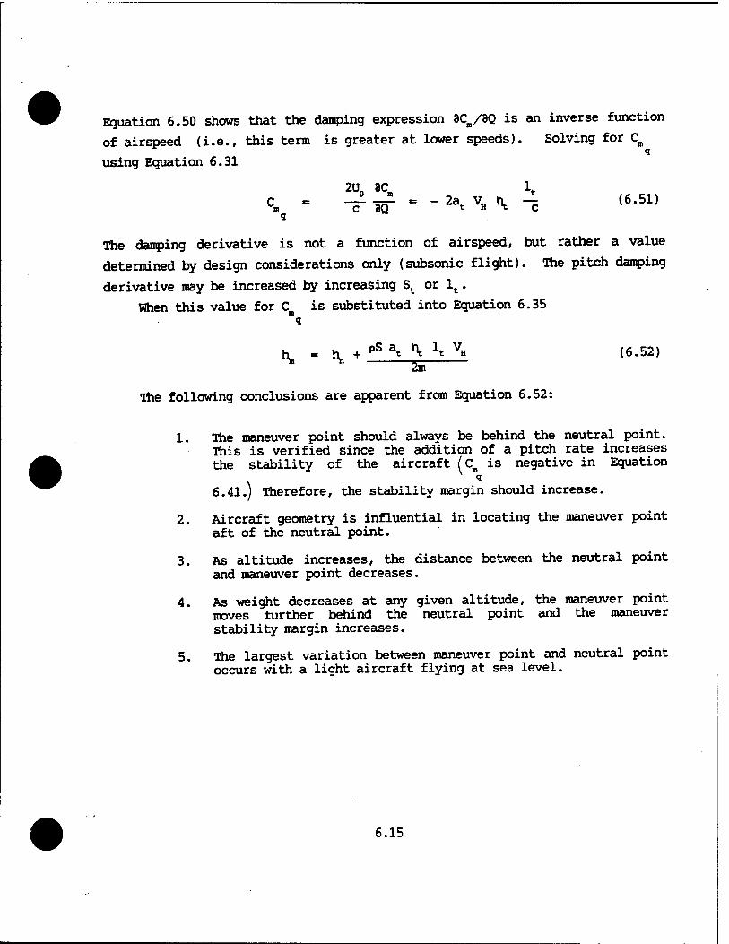
The following conclusions are apparent from Equation 6.52:
1. The maneuver point should always be behind the neutral point. This is verified since the addition of a pitch rate increases the stability of the aircraft (c is negative in Equation
6.41.) Therefore, the stability margin should increase.
2. Aircraft geometry is influential in locating the maneuver point aft of the neutral point.
3. As altitude increases, the distance between the neutral point and maneuver point decreases.
4. As weight decreases at any given altitude, the maneuver point moves further behind the neutral point and the maneuver stability margin increases.
5. The largest variation between maneuver point and neutral point occurs with a light aircraft flying at sea level.
6.15
6.5 AIRCRAFT BENDING
Before the pull-up analysis is completed, one more subject should be
covered. One of the assumptions made early in the equations of motion course
was that the aircraft was a rigid body. In reality, all aircraft bend when a
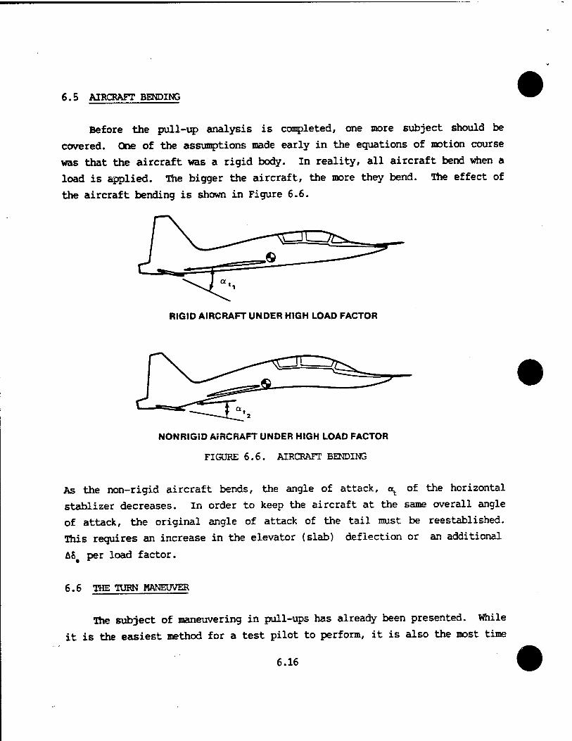
load is applied. The bigger the aircraft, the more they bend. The effect of
the aircraft bending is shown in Figure 6.6.
RIGID AIRCRAFT UNDER HIGH LOAD FACTOR
NONRIGID AIRCRAFT UNDER HIGH LOAD FACTOR
FIGURE 6.6. AIRCRAFT BENDING
As the non-rigid aircraft bends, the angle of attack, o^ of the horizontal
stablizer decreases. In order to keep the aircraft at the same overall angle
of attack, the original angle of attack of the tail must be reestablished.
This requires an increase in the elevator (slab) deflection or an additional
AS per load factor.
6.6 THE TURN MANEUVER
The subject of maneuvering in pull-ups has already been presented. While
it is the easiest method for a test pilot to perform, it is also the most time
6.16
consuming. Therefore, most maneuvering data is collected by turning. There
are several methods used to collect data in a turn.
In order to analyze the maneuvering turn, Equation 6.8 is recalled
-Cm Aa - OCB/3Q) AQ
AS (6.8)
The expression for Aa in Equation 6.16 derived for the pull-up maneuver,
is also applicable to the turning maneuver.
Ac = i (CL An - CL& A5^ (6.16)
Such is not the case for the AQ expression in Equation 6.8. Another
expression (other than Equation 6.27) for AQ pertaining to the turn maneuver,
must be developed.
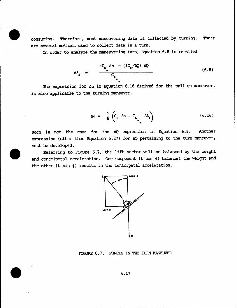
Referring to Figure 6.7, the lift vector will be balanced by the weight
and centripetal acceleration. One component (L cos 4») balances the weight and
the other (L sin <f>) results in the centripetal acceleration.
Leo* *
Lsin c
FIGURE 6.7. FORCES IN THE TURN MANEUVER
6.17
For a level turn,
L sin 4> *=
L cos 4>
n = L/W
W U2
g R
W
cos 4>
Now, dividing Equation 6.53 by Equation 6.54 and rearranging terms
U _ 3 sin <fr R U cos 4>
(6.53)
(6.54)
(6.55)
(6.56)
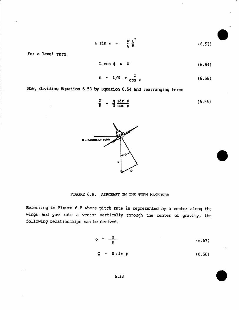
R-RADIUS OF TURN
FIGURE 6.8. AIRCRAFT IN THE TURN MANEUVER
Referring to Figure 6.8 where pitch rate is represented by a vector along the
wings and yaw rate a vector vertically through the center of gravity, the
following relationships can be derived.
U
Q = 2 sin $
(6.57)
(6.58)
6.18
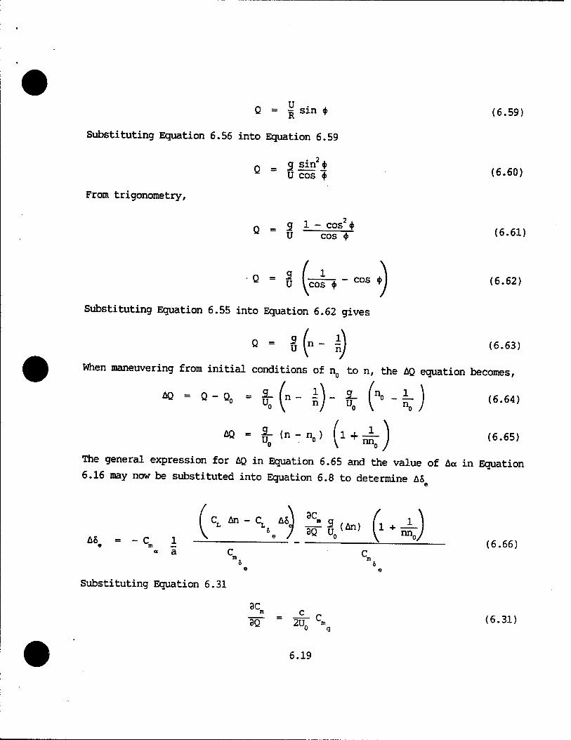
Q = ^ sin * (6.59)
Substituting Equation 6.56 into Equation 6.59
2
From trigonometry,
r, g sin <{> Q " ücöi* (6.60)
3 1 ~ cos2*j> U cos * (6.61)
Q = U IcöT* * cos *J (6-62)
Substituting Equation 6.55 into Equation 6.62 gives
Q - 8 (n " n) (6-63) When maneuvering from initial conditions of n0 to n, the AQ equation becomes,
«-„-*- 2.(n- i). £- (s_L) (6.64)
« " ^<»-I\.) (1+5iJ f6.«5) The general expression for AQ in Equation 6.65 and the value of Aa in Equation
6.16 may now be substituted into Equation 6.8 to determine AS
Cr An - CT A6J 3Cm g , . . /, 1
e m — ~ ~~— «a c c e e
(6.66)
Substituting Equation 6.31
3C m _ C _ 3Q ~ 2U n (6.31)
6.19
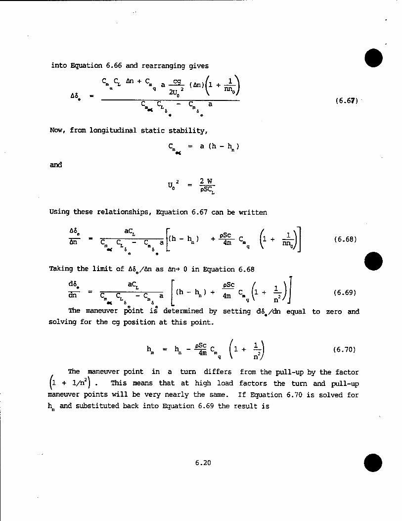
into Equation 6.66 and rearranging gives
c* CL M + C _cg_ (An)
AS 9 2U0
2 <•**)
•< 6 6
(6.67)
Now, from longitudinal static stability,
C, = a (h - hn )
and
U„ 2 w pSCT
Using these relationships, Equation 6.67 can be written
An aC.
Cm CT - C a m L m •< 8 &
e e
(h-hj + pSc 4m \ (1+^)
Taking the limit of ASe/An as An-* 0 in Equation 6.68
dS e dn~
aC. pSc (h - h ) + . C C C ^~C ä \"-",,/^ /im s. \± T — /i (6.69)
m L n •< & 6
The maneuver point is determined by setting dS /dn equal to zero and
(6.68)
solving for the eg position at this point.
h = h -&c (i+ L\ m n 4m m I 2 q \ n/ (6.70)
The maneuver point in a turn differs from the pull-up by the factor
(1 + 1/n2] . This means that at high load factors the turn and pull-up
maneuver points will be very nearly the same. If Equation 6.70 is solved for
h and substituted back into Equation 6.69 the result is
6.20
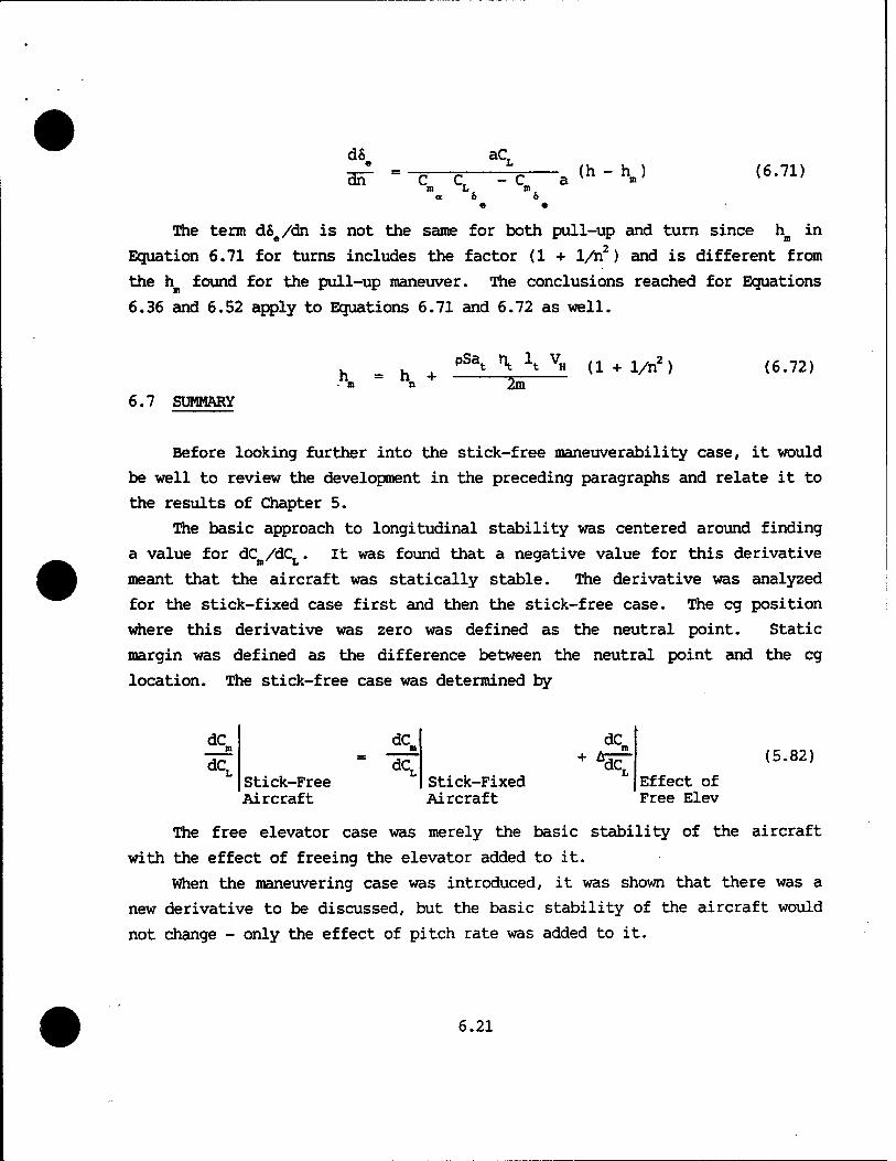
dS « cBT
aC
- C_ -a<h"hJ (6.71)
The term d&e/dn is not the same for both pull-up and turn since hn in
Equation 6.71 for turns includes the factor (1 + 1/n2) and is different from
the hB found for the pull-up maneuver. The conclusions reached for Equations
6.36 and 6.52 apply to Equations 6.71 and 6.72 as well.
h = • n h + n
PSat ht it vH (1 + 1/n2 j
2m (6.72)
6.7 SUMMARY
Before looking further into the stick-free maneuverability case, it would
be well to review the development in the preceding paragraphs and relate it to
the results of Chapter 5.
The basic approach to longitudinal stability was centered around finding
a value for dCB/dCL. It was found that a negative value for this derivative
meant that the aircraft was statically stable. The derivative was analyzed
for the stick-fixed case first and then the stick-free case. The eg position
where this derivative was zero was defined as the neutral point. Static
margin was defined as the difference between the neutral point and the eg
location. The stick-free case was determined by
dc„ da
dC n
dC Stick-Free Aircraft
Stick-Fixed Aircraft
(5.82)
Effect of Free Elev
The free elevator case was merely the basic stability of the aircraft
with the effect of freeing the elevator added to it.
When the maneuvering case was introduced, it was shown that there was a
new derivative to be discussed, but the basic stability of the aircraft would
not change - only the effect of pitch rate was added to it.
6.21
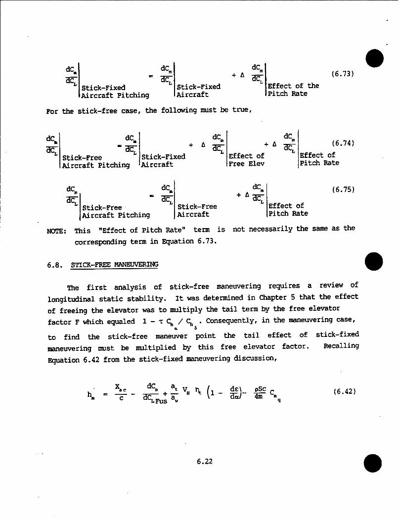
Stick-Fixed Aircraft Pitching
+ A
Stick-Fixed Aircraft
(6.73)
Effect of the Pitch Rate
For the stick-free case, the following must be true,
dc* dC„ dCn dC
*£ Stick-Free Aircraft Pitching
Stick-Fixed Aircraft
Effect of Free Elev
dC. dC <*„
*Z Stick-Free Aircraft Pitch: mg
Stick-Free Aircraft
+ ÄdC" Effect c Pitch Ra
(6.74)
Effect of Pitch Rate
(6.75)
NOTE: This "Effect of Pitch Rate" term is not necessarily the same as the
corresponding term in Equation 6.73.
6.8. STTCK-FREE MANEUVERING
The first analysis of stick-free maneuvering requires a review of
longitudinal static stability. It was determined in Chapter 5 that the effect
of freeing the elevator was to multiply the tail term by the free elevator
factor F which equaled I-TC^/C; . Consequently, in the maneuvering case,
to find the stick-free maneuver point the tail effect of stick-fixed maneuver point the tail effect
maneuvering must be multiplied by this free elevator factor.
Equation 6.42 from the stick-fixed maneuvering discussion,
Recalling
ac
~C~
dCm
^FUS a« £ '■ Mi - £)■ pSc c
4m ■ (6.42)
6.22
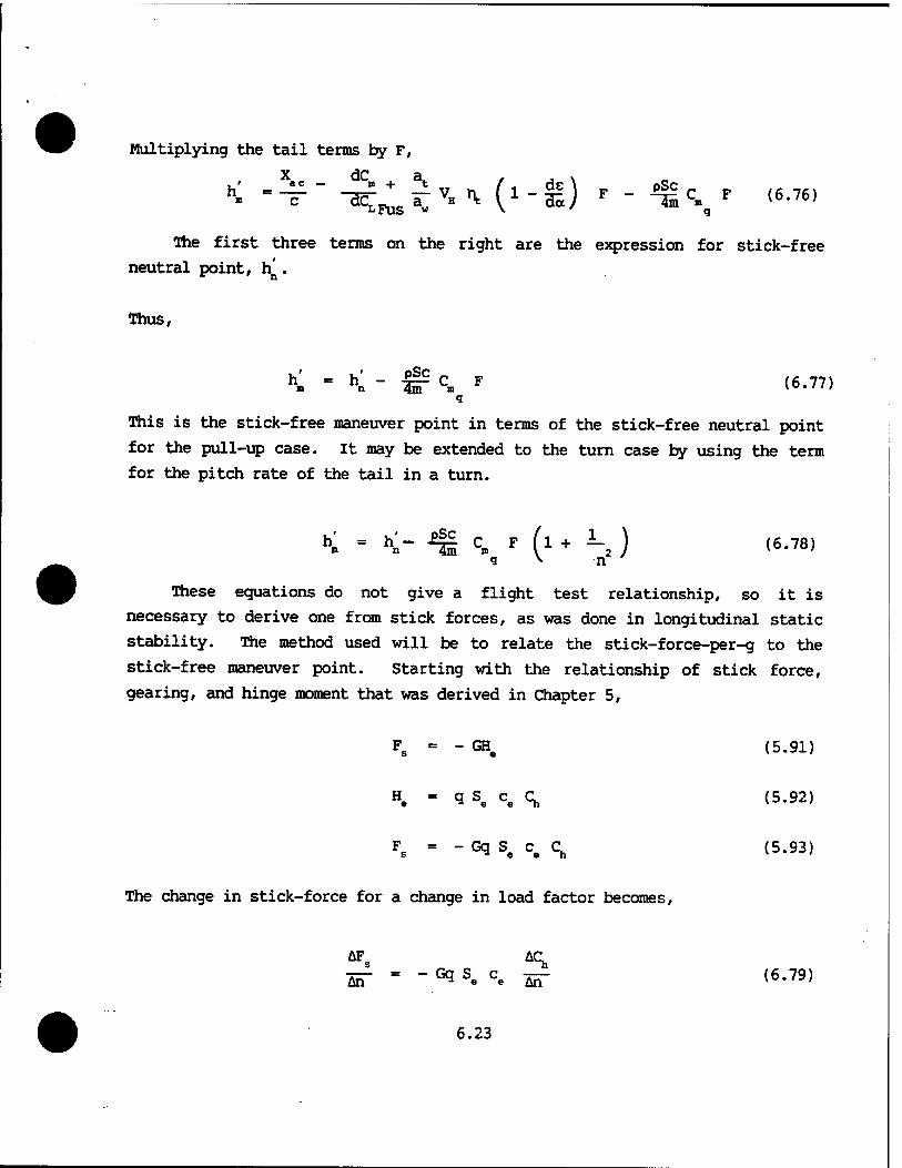
Multiplying the tail terms by F,
The first three terms on the right are the expression for stick-free neutral point, h^.
Thus,
K - K - fr c» F <6-77> q
This is the stick-free maneuver point in terms of the stick-free neutral point
for the pull-up case. It may be extended to the turn case by using the term for the pitch rate of the tail in a turn.
K - K- fc. » (l ♦ i-, ) (6.78, <J
v n
These equations do not give a flight test relationship, so it is necessary to derive one from stick forces, as was done in longitudinal static stability. The method used will be to relate the stick-force-per-g to the
stick-free maneuver point. Starting with the relationship of stick force, gearing, and hinge moment that was derived in Chapter 5,
Fs = - GHe (5.91)
He - «a Se c« Ch (5.92)
Fs = - Gq Se Ce Ch (5.93)
The change in stick-force for a change in load factor becomes,
AFs Aq ST - " °a Se Ce AH" <6'79>
6.23
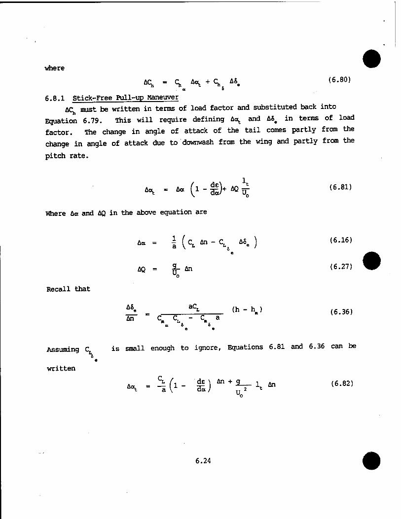
where
ACh = <* H + °h A8. (6,80)
6.8.1 Stick-Free Pull-up Maneuver
AC must be written in terms of load factor and substituted back into
Equation 6.79. This will require defining Ao^ and ASe in terms of load
factor. The change in angle of attack of the tail comes partly from the
change in angle of attack due to downwash from the wing and partly from the
pitch rate.
H - " (i - i)+« k (6-81)
Where Aa and AQ in the above equation are
Aa = | (cL An-C ASe )
e
Recall that
AQ ~ 2_ An
AS. aCL
An % b
e
a e
(6.16)
(6.27)
(h-hJ (6.36)
Assuming C is small enough to ignore, Equations 6.81 and 6.36 can be
written
H -hk- iP*^1 t An (6.82)
6.24

AS.
An (6.83]
Substituting Equations 6.82 and 6.83 into Equation 6.80, gives Equation 6.84
An T> a
Substituting,
(i-S) ♦*. -^-s.
U„2 = 2W/pSCL
and the definition of control power,
' ^- (h- hj (6.84) o SI
(6.30)
:„ - " at VH »V T
O e
5i An
^
(5.50)
into Equation 6.84 and factoring gives
°h , . x ^ pSl 1 l1" SShVH»VT + ö1^^ at vH rvx+ (h-hj
6 (6.85) V From longitudinal stability,
a t hn"hn = C^ t \ \ ^-H) (6.86)
Substituting Equations 6.86, 6.51, and 6.87 into Equation 6.85 gives Equation
6.88
" 2at VH \ C- (6.51)
F - 1 - T c (6.87)
6.25
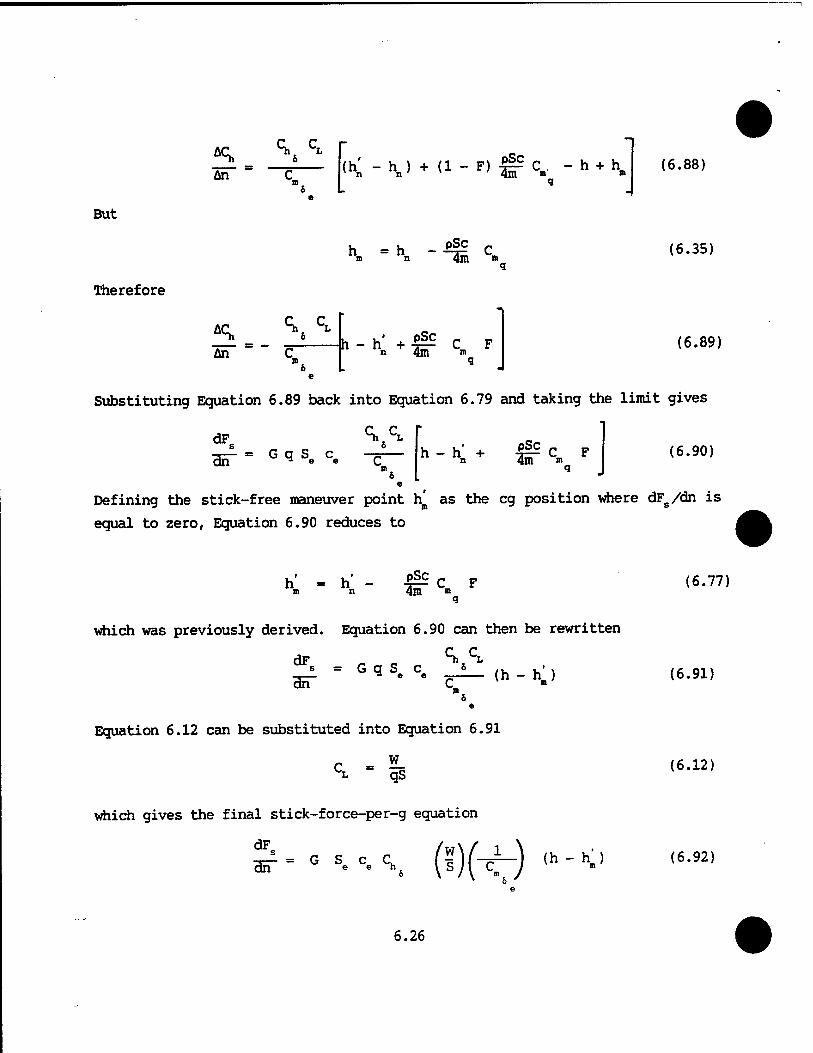
An \^
But
Therefore
<h;-\) + U-*)$ETC« -h + h»
h = h -ü| c. n n 4in m
•
(6.88)
(6.35)
An
<V C* h - h + pSc
4m " C F (6.89)
Substituting Equation 6.89 back into Equation 6.79 and taking the limit gives
dF_ ^
cET G q Se c pSc 4m *"»
(6.90)
Defining the stick-free maneuver point h^ as the eg position where dFg/dn is
equal to zero, Equation 6.90 reduces to
h = h - m n pSc 4m »i
C F (6.77)
which was previously derived. Equation 6.90 can then be rewritten
dF s = G q S c * _— *a e e — dn C
(h-h ) (6.91)
Equation 6.12 can be substituted into Equation 6.91
c - *- T. qS (6.12)
which gives the final stick-force-per-g equation
dF ■a— = G S c C dn e e ~h COW (h - (6.92)
6.26
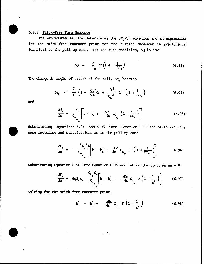
6.8.2 Stick-Free Turn Maneuver
The procedures set for determining the dFs/dn equation and an expression
for the stick-free maneuver point for the turning maneuver is practically
identical to the pull-up case. For the turn condition, AQ is now
* - I *4 + k) (6.93)
The change in angle of attack of the tail, Ao^. becomes
C. , ... glt ^ -■ iM1- H-> + An
U. (-k) and
"-*♦ *g ■>_ * nn„ '
(6.94)
(6.95)
Substituting Equations 6.94 and 6.95 into Equation 6.80 and performing the
same factoring and substitutions as in the pull-up case
5L An
<VCr h - h' + & C F n 4m I»
q ('♦£-) (6.96)
Substituting Equation 6.96 into Equation 6.79 and taking the limit as An -> 0,
dF Ch CLr
ah" = ^SeCe — g n i
Solving for the stick-free maneuver point,
h* = h' - f§S C F m n 4m m
1 (>^)
(6.98)
6.27
Further substitution puts Equation 6.97 into the following form:
dF
«ET - G
Again, the turning stick-force-per-g Equation 6.99 appears identical to
the stick-free pull-up equation. However, the expression for the maneuver
point h^ is different.
The term in the first parenthesis represents the hinge moment of the
elevator and the aircraft size. The second term in parenthesis is wing
loading, and the third term in parenthesis is the reciprocal of elevator
power. The last term is the negative value of the stick-free maneuver margin.
The following conclusions are drawn from this equation:
1. The stick-force-per-g appears to vary directly with the wing loading. However, weight also appears inversely in hm. Therefore, the full effect of weight cannot be truly analyzed since one effect could cancel the other.
2. Since airspeed does not appear in the equation, the stick-force-per-g will be the same at all airspeeds for a fixed eg.
h' - h' - 4£ C F (6.77) q
From Equation 6.77 come the following conclusions:
1. The difference between the stick-fixed and stick-free maneuver point is a function of the free elevator factor, F.
2. The stick-free maneuver point, h', varies directly with altitude, becoming closer to the stick-free neutral point, the higher the aircraft flies.
The location of the stick-free maneuver point occurs where dFs/dn = 0.
It is difficult to fly an aircraft with this type gradient. Consequently,
military specifications limit the minimum value of dFs/dn to three pounds per
g for a center stick, Level 1.
6.28 •
The forward eg may be limited by stick-force-per-g. The maximum value is
limited by the type aircraft (bomber, fighter, or trainer), i.e., heavier
gradients in bomber types and lighter ones in fighters.
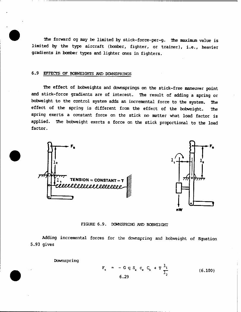
6.9 EFFECTS OF BOBWEIGHTS AND DOWNSPRINGS
The effect of bobweights and downsprings on the stick-free maneuver point
and stick-force gradients are of interest. The result of adding a spring or
bobweight to the control system adds an incremental force to the system. The
effect of the spring is different from the effect of the bobweight. The
spring exerts a constant force on the stick no matter what load factor is
applied. The bobweight exerts a force on the stick proportional to the load
factor.
BT
J~fT}'^n t Fij
I
1, TENSION = CONSTANT = T i 4ic^££^£ee££e£^Jc££eeJe^Je^. |
%
nW
FIGURE 6.9. DOWNSPRING AND BOBWEIGHT
Adding incremental forces for the downspring and bobweight of Equation
5.93 gives
Downspring
F s - G q S
6.29 ■"■2
(6.100)
Bobweight
Fs = -GqS.c^+nwj: (6JL01)
When the derivative is taken with respect to load factor, the effect on
dF8/dn of the spring is zero. The stick force gradient is not affected by the
spring nor is the stick-free maneuver point changed.
Downspring
dF _ _ dC
an1 " ~GqS°c«a? +0 <6-102>
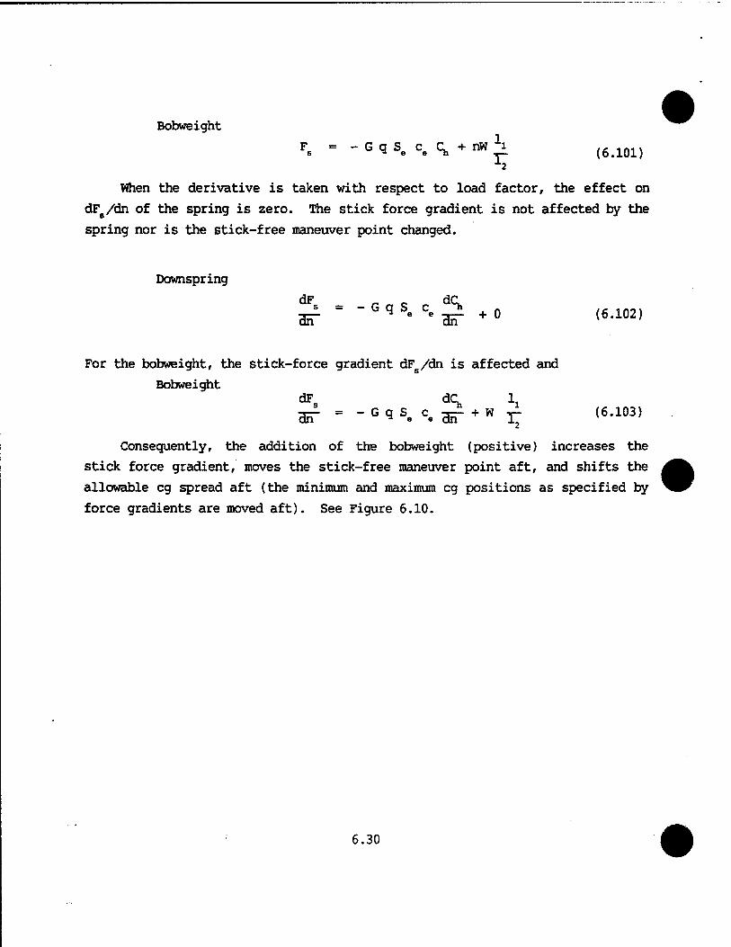
For the bobweight, the stick-force gradient dFs/dn is affected and
Bobweight dF dC 1 cGT - - G 9 Se ce gg- + w 3- (6.103)
Consequently, the addition of the bobweight (positive) increases the
stick force gradient, moves the stick-free maneuver point aft, and shifts the
allowable eg spread aft (the minimum and maximum eg positions as specified by
force gradients are moved aft). See Figure 6.10.
6.30
BOBWEIGHT
dn
MAX-.-V*--^
MIN >yl_J^
FIGURE 6.10. EFFECTS OF ADDING A BOBWEIGHT
Recall from Chapter 5, Longitudinal Static Stability, (Reference Figure
.5.51), that upsprings and bobweights may be used to decrease stick forces.
The bobweight may also decrease the stick force gradient. If a bobweight is
used in this configuration, a downspring may be needed to counter-balance the
bobweight for non-maneuvering (lg) flight conditions, i.e, to preserve the
original speed stability before the bobweight was added.
6.10 AERODYNAMIC BALANCING
Aerodynamic balancing is used to affect the stick force gradient and
stick-free maneuver point. Aerodynamic balancing or varying values of C and
C^ affects the following stick-free eguations:
dF s
B5T = G (*-<^)(m (h - h' ) (6.99)
6.31
h'„ «= h'„ - iff CB F (6-77)
q
F - 1 - T - {6S1)
\
Decreasing (^ and/or increasing (^ by using such aerodynamic balancing
devices as an overhang balance or a lagging balance tab, does the following:
1. The free elevator factor F decreases
2. The stick-free maneuver point h^ moves forward
3. The maneuver margin term (h - h^) decreases
4. The stick force gradient decreases
5. The forward and aft eg limits move forward
Increasing C^ and/or decreasing (^ by using a convex trailing edge or a 8 a
leading balance tab does the following:
1. The free elevator factor F increases
2. The stick-free maneuver point h/ moves aft
3. The maneuver margin term (h - h^) increases
4. The stick force gradient increases
5. The forward and aft eg limits move aft
6.11 CENTER OF GRAVITY RESTRICTIONS
The restrictions on the aircraft's center of gravity location may be
examined by referring to the mean aerodynamic chord in Figure 6.11.
6.32
*4IAX
FWD« .1
*nMIN K h. K m
•AFT
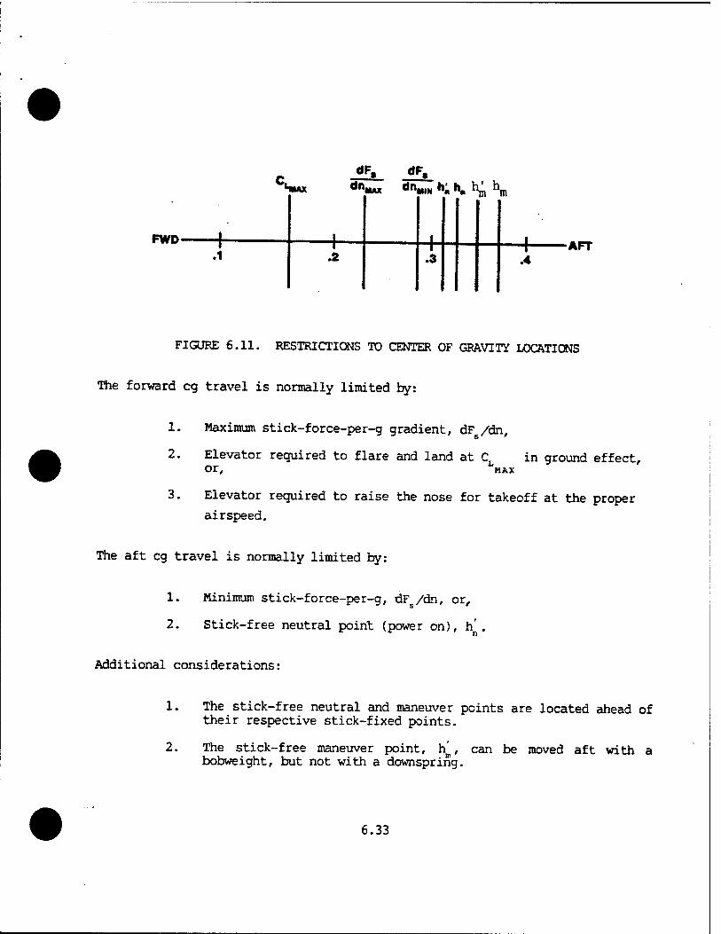
FIGURE 6.11. RESTRICTIONS TO CENTER OF GRAVITY LOCATIONS
The forward eg travel is normally limited by:
1.
2.
3.
Maximum stick-force-per-g gradient, dF /dn,
Elevator required to flare and land at CL in ground effect, or, MAX
Elevator required to raise the nose for takeoff at the proper
airspeed.
The aft eg travel is normally limited by:
1. Minimum stick-force-per-g, dF /dn, or,
2. Stick-free neutral point (power on), h'
Additional considerations:
2.
The stick-free neutral and maneuver points are located ahead of their respective stick-fixed points.
The stick-free maneuver point, ha, can be moved aft with a bobweight, but not with a downspring.
6.33
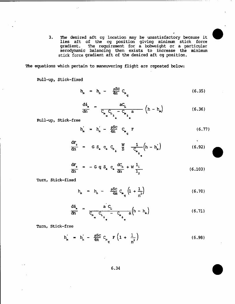
3. The desired aft eg location may be unsatisfactory because it lies aft of the eg position giving minimum stick force gradient. The requirement for a bobweight or a particular aerodynamic balancing then exists to increase the minimum stick force gradient aft of the desired aft eg position.
The equations which pertain to maneuvering flight are repeated below:
Pull-up, Stick-fixed
K = \ ~ Ü5 Cn (6.35) q
d6 _ aC . . cET = C C -C a (h " 0 <6'36>
<x 6 6
Pull-up, Stick-free
_ PSC h- -»- - ec. F ««•■"> q
s W 1 H «5 r P .- dn C Se C* Ss S C
o m 6
e
dF s = Hn"
-GqS c dCh+W1i e e as" 17-
q n
dS _ a C . Brf " C C =—c i(h " hJ m L m »
a 6 6 e e
q n
6.34
(6.92)
(6.103)
Turn, Stick-fixed
h =h- -2^C (l + —) (6.70)
(6.71)
Turn, Stick-free
h' - h' - -Sp C F (l + A-) (6.98)
dF
•
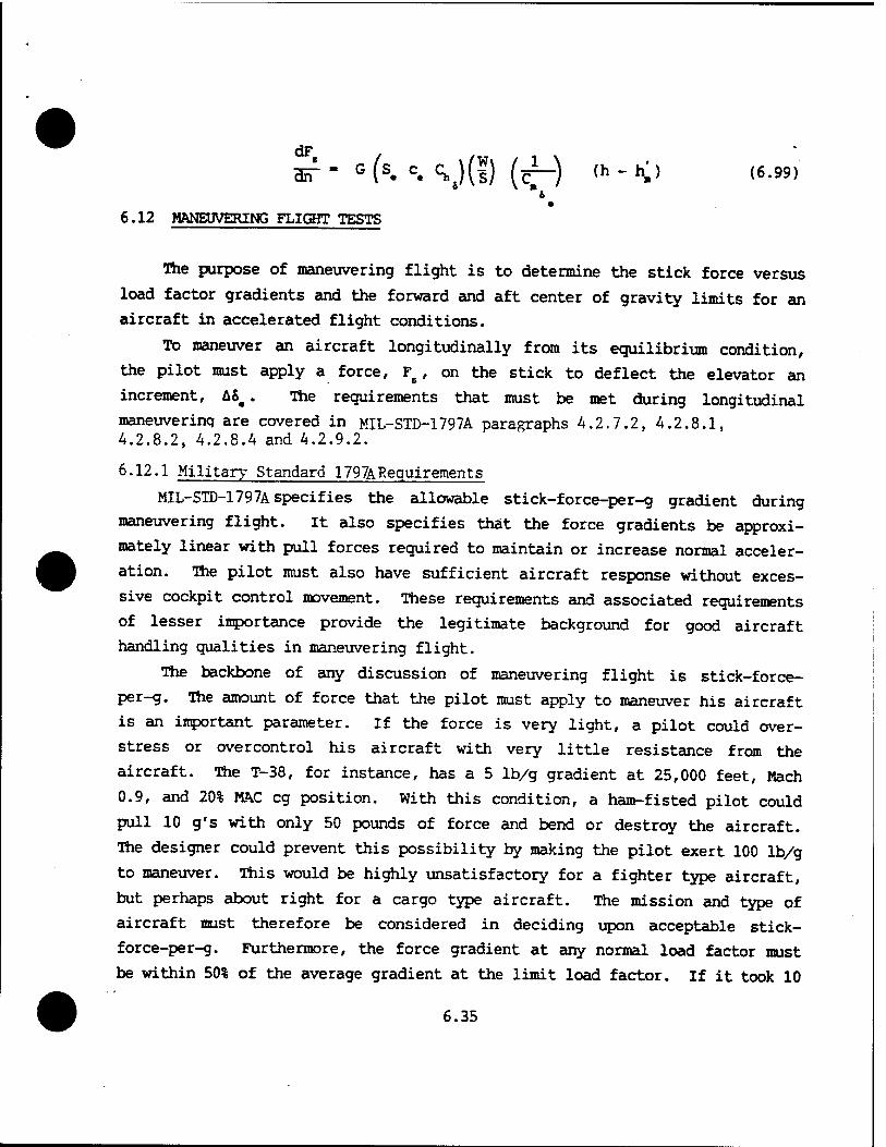
■ST' G (s. c. \)[l) (r~) (h - h.) (6.99)
6.12 MANEUVERING FLIGHT TESTS
a 6
The purpose of maneuvering flight is to determine the stick force versus
load factor gradients and the forward and aft center of gravity limits for an
aircraft in accelerated flight conditions.
To maneuver an aircraft longitudinally from its equilibrium condition,
the pilot must apply a force, F5, on the stick to deflect the elevator an
increment, A8a. The requirements that must be met during longitudinal
maneuverinq are covered in MIL-STD-1797A paragraphs 4.2.7.2, A.2.8.1, 4.2.8.2, 4.2.8.4 and 4.2.9.2.
6.12.1 Military Standard 1797ARequirements
MIL-STD-l797A specifies the allowable stick-force-per-g gradient during
maneuvering flight. It also specifies that the force gradients be approxi-
mately linear with pull forces required to maintain or increase normal acceler-
ation. The pilot must also have sufficient aircraft response without exces-
sive cockpit control movement. These requirements and associated requirements
of lesser importance provide the legitimate background for good aircraft
handling qualities in maneuvering flight.
The backbone of any discussion of maneuvering flight is stick-force-
per-g. The amount of force that the pilot must apply to maneuver his aircraft
is an important parameter. If the force is very light, a pilot could over-
stress or overcontrol his aircraft with very little resistance from the
aircraft. The T-38, for instance, has a 5 lb/g gradient at 25,000 feet, Mach
0.9, and 20% MAC eg position. With this condition, a ham-fisted pilot could
pull 10 g's with only 50 pounds of force and bend or destroy the aircraft.
The designer could prevent this possibility by making the pilot exert 100 lb/g
to maneuver. This would be highly unsatisfactory for a fighter type aircraft,
but perhaps about right for a cargo type aircraft. The mission and type of
aircraft must therefore be considered in deciding upon acceptable stick-
force-per-g. Furthermore, the force gradient at any normal load factor must
be within 50% of the average gradient at the limit load factor. If it took 10
6.35
10 pounds to achieve a 4 g turn, it would be unacceptable for the pilot to
reach the limit load factor of 7.33 g's with only a little additional force.
The position of the aircraft's eg is a critical factor in stick-force-
per-g consideration. The fore and aft limits of eg position may therefore be
established by maneuvering requirements.
6.12.2 Flight Test Methods
There are four general flight test methods for determining maneuvering
flight characteristics such as stick force gradients, maneuver points, and
permissible eg locations. The names given to these methods vary among test
organizations, so make certain that everyone involved is speaking the same
language when discussing a particular test method.
6.12.2.1 Stabilized g Method. This method requires holding a constant
airspeed and varying the load factor. Establish a trim shot at the test
altitude, note the power setting, and climb the aircraft to the upper limit
of the altitude band (+2,000 feet). Reset trim power and roll the aircraft
slowly into a 15° bank while lowering the nose slowly. At 15° of bank, the
stick force required to maintain the condition is only slightly more than
friction and breakout. Record data when the aircraft has been stabilized on
an airspeed and bank angle. The attitude indicator should be used to establish
the bank angle. Increase the bank angle to 30° and record data when stable.
Obtain stabilized data points at 45° and 60° also.
Above 60° the bank angle should be increased so as to obtain 0.5 g
increments in load factor. Stabilize at each 0.5 g increment, and record
data. Terminate the test when heavy buffet or the limit load factor is
reached. Above 2.0 g's only slight increases in bank angle are needed to
obtain 0.5 g increments. Bank angle required can be approximated from
the relationship cos <J> = 1/n (Figure 6.12).
6.36
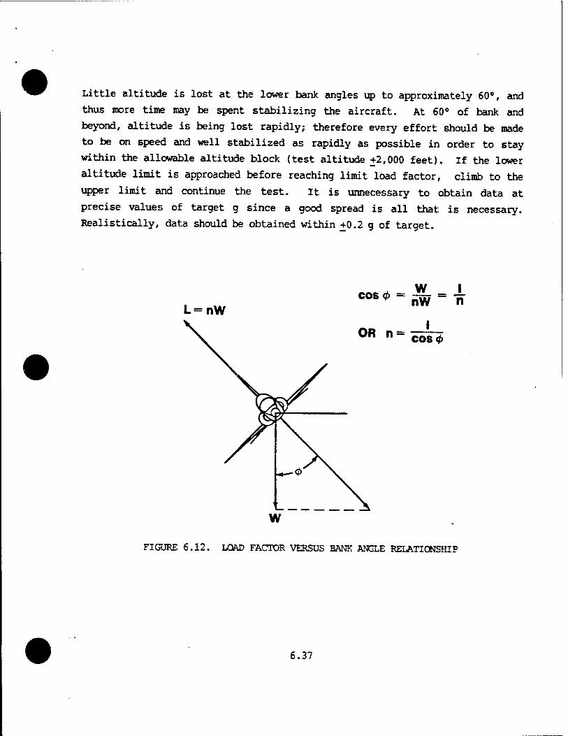
Little altitude is lost at the lower bank angles up to approximately 60°, and
thus more time may be spent stabilizing the aircraft. At 60° of bank and
beyond, altitude is being lost rapidly; therefore every effort should be made
to be on speed and well stabilized as rapidly as possible in order to stay
within the allowable altitude block (test altitude +2,000 feet). If the lower
altitude limit is approached before reaching limit load factor, climb to the
upper limit and continue the test. It is unnecessary to obtain data at
precise values of target g since a good spread is all that is necessary.
Realistically, data should be obtained within +0.2 g of target.
L=nW
W nW
I
X n
CO8 0
FIGURE 6.12. LOAD FACTOR VERSUS BANK ANGLE RELATIONSHIP
6.37
The method of holding airspeed constant within a specified altitude band
is recommended where Mach is not of great importance. In regions where Mach
may be a primary consideration, every effort should be made to hold Mach
rather than airspeed, constant. If power has only a minor effect on the
maneuvering stability and trim, altitude loss and the resulting Mach change
may be minimized by adding power as load factor is increased. At times,
constant Mach is held at the sacrifice of varying airspeed and altitude. For
constant Mach tests, a sensitive Mach meter is required or a programmed
airspeed/altitude schedule is flown. The stabilized g method is usually used
for testing bomber and cargo aircraft and fighters in the power approach
configuration.
6.12.2.2 Slowly Varying g Method. Trim the aircraft as before at the
desired altitude. Note the power and fly to the upper limit of the altitude
band (+2,000 feet). Reset power at the trimmed value and record data.
Increase load factor and bank angle slowly holding airspeed constant until
heavy buffet or limit load factor is reached. The rate of g onset should be
approximately 0.2 g per second. Airspeed is of primary importance and should
be held to within +2 knots of aim airspeed. Take care not to reverse stick
forces during the maneuver.
If the airspeed varies excessively, or the lower altitude limit is
approached, turn off the data recorder and repeat the test up to heavy
buffet onset or limit load factor.
The greatest error made in this method is bank angle control when beyond
60° of bank. Excessive bank causes the aircraft to traverse the g increments
too quickly to be able to accurately hold airspeed. Good bank control is
important to obtain the proper g rate of 0.2 g per second. An error is
induced in this method since the aircraft is in a descent rather than level
flight. Stick forces to obtain a specific g will be less than in level
flight. Fortunately, this error is in the conservative direction.
6.38
The slowly varying g method may be more applicable to fighter aircraft.
Often a combination of the two methods is used in which the stabilized g
method is followed up to 60° bank angle and then the slowly varying g method
is used until heavy buffet or limit load factor is reached.
6.12.2.3 Constant g Method. Stabilize and trim at the desired altitude and
maximum airspeed for the test. Establish a constant g turn. Record data
and climb or descend to obtain a two to five knot per second airspeed bleed
rate at the desired constant load factor. Normally climbs are used to obtain
a bleed rate at low load factors and descents are used to obtain a bleed rate
at high load factors. For high thrust-to-weight ratio aircraft at low
altitudes, the maneuver may have to be initiated at reduced power to avoid
rapidly traversing the altitude band. Maintaining the aim load factor is the
primary requirement while establishing the bleed rate is secondary. Keep the
aircraft within the altitude band of +2,000 feet. Note the airspeed as the
aircraft flies out of the altitude band. Return to the altitude band and
start at an airspeed above the previously noted airspeed so that continuity of
g and airspeed can be maintained. Note airspeed at buffet onset and the g
break (when aim load factor can no longer be maintained). The buffet and
stall flight envelope is determined or verified by this test method. Repeat
the maneuver with 0.5 g increments at high altitudes and 1 g increments at low
altitudes. This method does not define maneuver points or stick force
gradients but is introduced for familiarization with different turn
techniques. The primary use is to define stall/buffet boundaries and elevator
deflections at different loadings.
6.12.2.4 Symmetrical Pull Up Method. Trim the aircraft at the desired test
altitude and airspeed. Climb to an altitude above the test altitude using
power as required. Reset trim power and push over into a dive. The dive
angle and lead airspeed are functions of the target load factor.
Maneuver the aircraft to a lead point that will place it at a given
constant load factor while passing through the test altitude at the test
airspeed. Two methods may be used which yield the same results. The idea
behind both methods is to minimize the number of variables.
6.39

a. Method A - Using a variable dive angle and fixed lead airspeed smoothly increase back pressure so that the airspeed stabilizes at
trim airspeed. There is a specific dive angle which will allow you to stabilize the airspeed as you pass through 10° of dive.
b. Method B - Using a constant dive angle and adjusting lead airspeed, smoothly apply back pressure to establish the target g. If the proper lead airspeed is used, the airspeed will stabilize as the target g is established.
Using either method, the aircraft should pass through level flight (+10
from horizontal) just as the airspeed reaches the trim airspeed with aim g
loading and steady stick forces. Be sure to freeze the stick. Achieving the
trim airspeed through level flight, ±10°, and holding steady stick forces to
give a steady pitch rate are of primary importance. The variation in altitude
(+1,000 feet) at the pull up is less important. The g loading need not be
exact (+0.2g) but must be steady. Record data as the aircraft passes through
level flight +10°
6.40
PROBLEMS
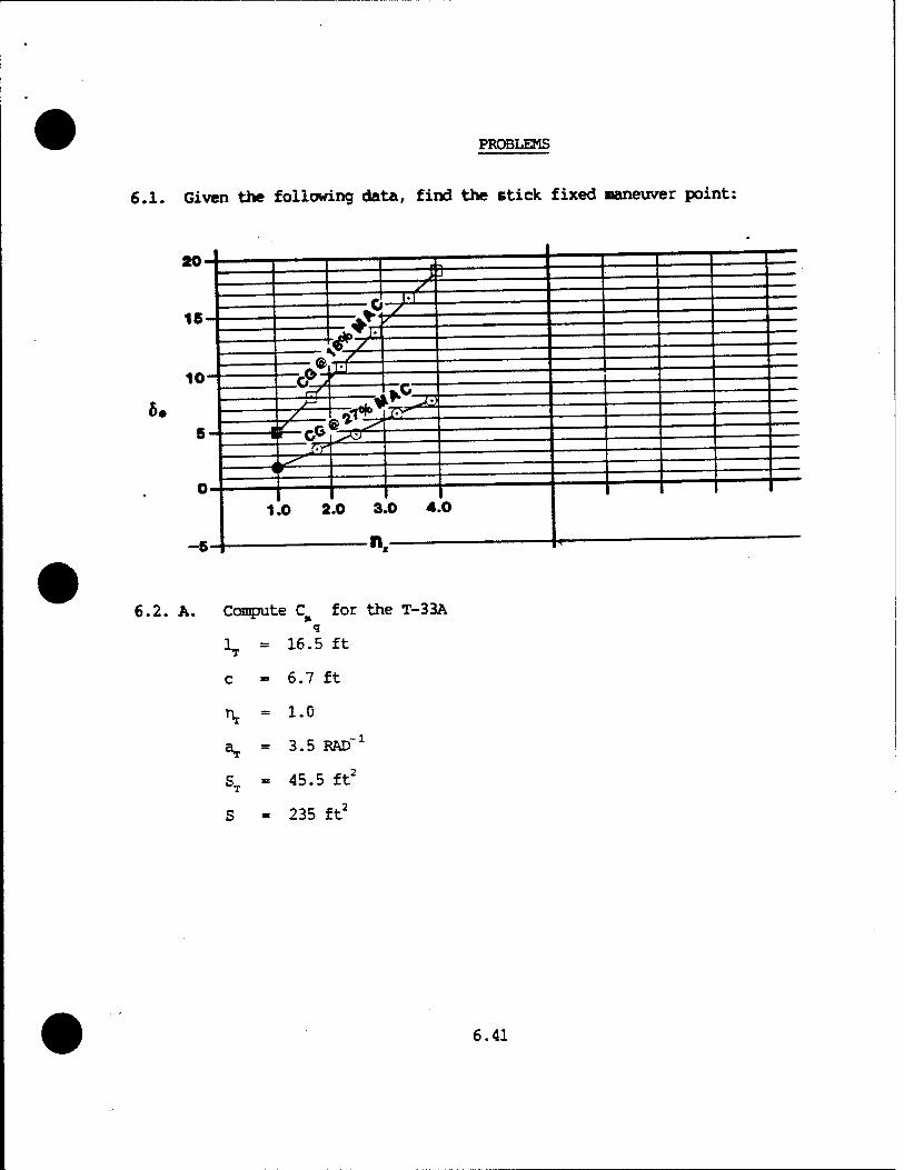
6.1. Given the following data, find the stick fixed maneuver point:
20-
16-
10-
6.
P 2?
A. t<:
-.7*—?e*
Pi »TE^I
*!^22 Li*5zy
1.0 2.0 3.0 4.0
n.
6.2. A. Confute C for the T-33A
1 = 16.5 ft T
c = 6.7 ft
\ = 1.0
aT = 3.5 RAD"1
ST = 45.5 ft2
S = 235 ft2
6.41
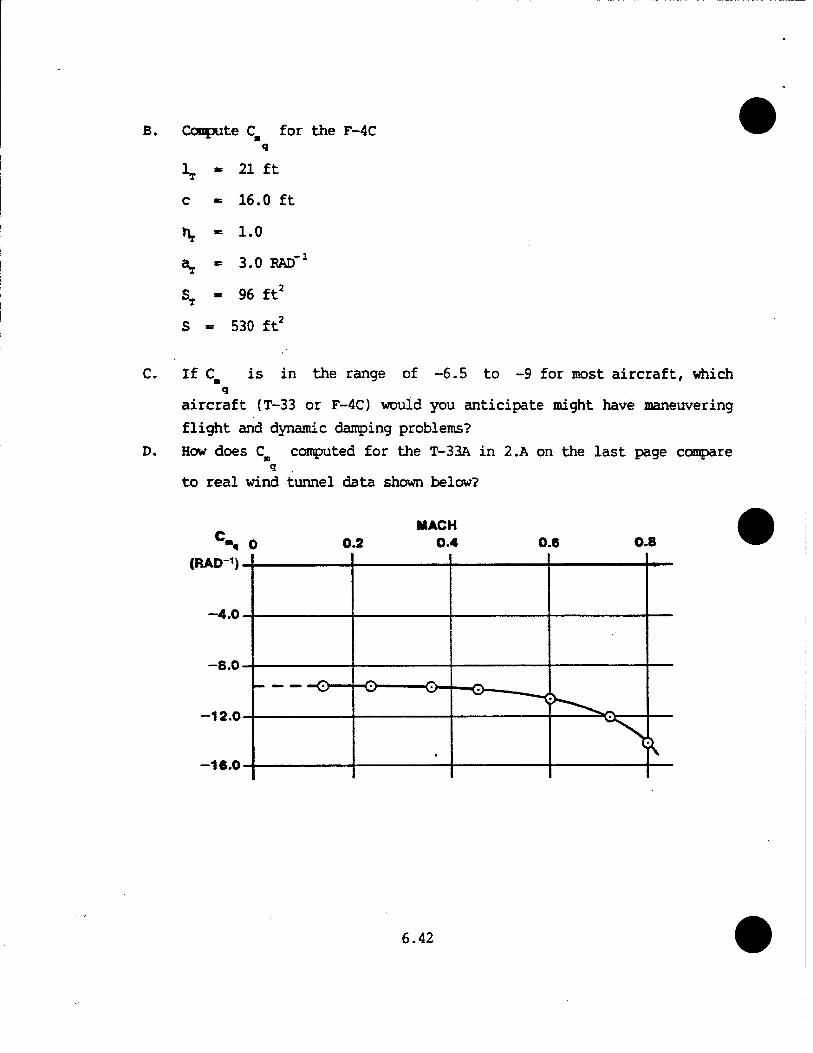
B. Compute Cm for the F-4C q
c
21 ft
16.0 ft
1.0
3.0 RAD"1
96 ft2
530 ft2
C. If Cu is in the range of -6.5 to -9 for most aircraft, which q
aircraft (T-33 or F-4C) would you anticipate might have maneuvering
flight and dynamic damping problems?
D. How does CB computed for the T-33A in 2.A on the last page compare q
to real wind tunnel data shown below?
(RAD"1)
-4.0
-8.0
-12.0
-16.0
6.42
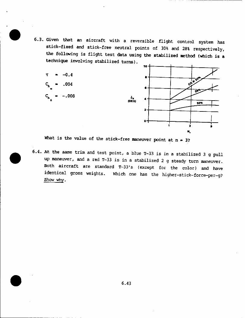
6.3. Given that an aircraft with a reversible flight control system has
stick-fixed and stick-free neutral points of 30% and 28% respectively,
the following is flight test data using the stabilized method (which is a
technique involving stabilized turns) 10
<
-0.4
.004
-.008 6. (DEG)
*S c<
fP^-
v1^ *^^\
S2% 1
1 1 2
1 3
What is the value of the stick-free maneuver point at n » 3?
6.4. At the same trim and test point, a blue T-33 is in a stabilized 3 g pull
up maneuver, and a red T-33 is in a stabilized 2 g steady turn maneuver.
Both aircraft are standard T-33's (except for the color) and have
identical gross weights. Which one has the higher-stick-force-per-g? Show why.
6.43

6.5. For a given set of conditions, an RF-4C had a stick force gradient as
shown below. Compute the weight of the bobweight needed to increase this
gradient to a minimum of five pounds per g.
D-i— h-5 INH A
? w
PULL 20-
20 IN
15-
(lbs) 10-
7777777,
FR & BO-
0
X y s
! w rmi*
1 1
1 1 s ! : \ 4
1 8 6
6.44
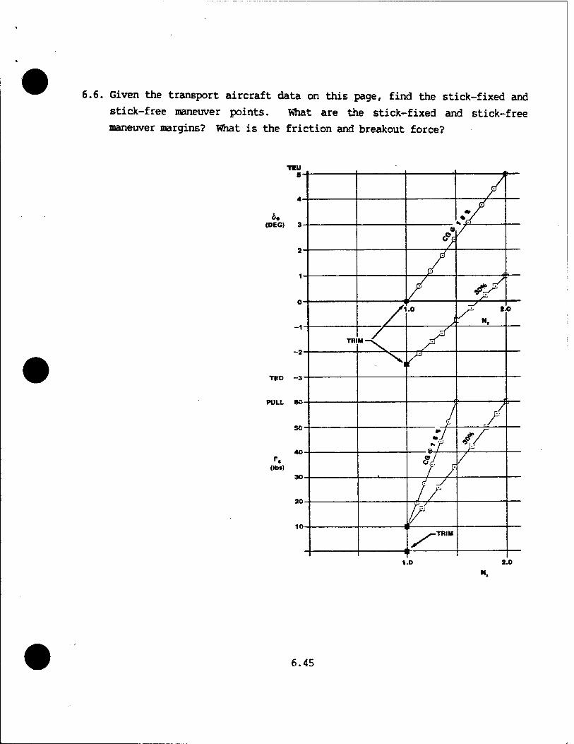
6.6. Given the transport aircraft data on this page, find the stick-fixed and
stick-free maneuver points. What are the stick-fixed and stick-free
maneuver margins? What is the friction and breakout force?
1.0 2.0
6.45

6.7. Given the flight test data at the end of this problem:
A. Calculate the stick-free maneuver point.
B. Calculate the stick-fixed maneuver point.
C. If the minimum desired dFB/dn is 3 lb/g, calculate the aft eg limit.
D. Calculate the maneuver margin at the aft eg limit.
E. If the stick-fixed neutral point was 48% MAC and given the following data, calculate an estimate for CB . NOTE: Ca is very sensitive
i i to h locations so an estimate of C calculated from aircraft
1
geometry is probably as good, or better, than this flight test
derived value. Density at test altitude, p, is 0.002 slugs/ft3.
2 S
c
W
300 ft'
7 ft
18,000 lbs
A new internal fuel tank arrangement is planned for the aircraft which will move the aircraft eg to 40% MAC. If a minimum stick-force-per-g of 3 lb/g is required at this new eg location, what size bobweight is required as a "fix"?
nW
«-F.
6.46
TEU 20
15
10-
(DEG)
0- TED
-5-
7-fr
>'->
^
P
sT
ii-rfft
N.
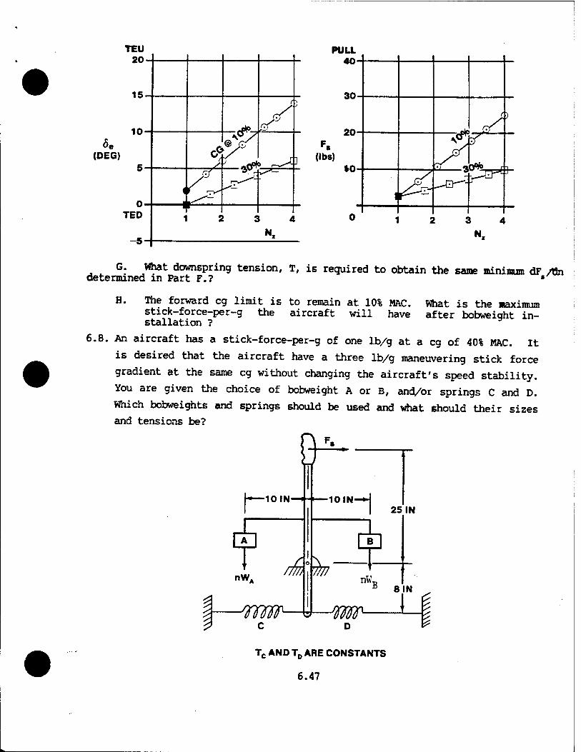
G. What downspring tension, T, is required to obtain the same minimum dF /On determined in Part F.? •
H. The forward eg limit is to remain at 10% MAC. What is the maximum stick-force-per-g the aircraft will have after bobweight in- stallation ?
6.8. An aircraft has a stick-force-per-g of one lb/g at a eg of 40% MAC. It
is desired that the aircraft have a three lb/g maneuvering stick force
gradient at the same eg without changing the aircraft's speed stability.
You are given the choice of bobweight A or B, and/or springs C and D.
Which bobweights and springs should be used and what should their sizes
and tensions be?
8 i- 0IN—•
nW. /m
-Wffir- c
>—10IN—^j
C7
25 IN
m Js- nWT
D
8 IN
_L Tc AND TD ARE CONSTANTS
6.47

6.9. Given the flight test data and MIL-STD-1797Arequirements shown below:
FIO.1 M°-8
(lb*)
MIL- STD LIMITS
////////////// '//////
777777777777,777777,
'UUlhUUi
7777777* 777
20 30 40
CG % MAC
50
A. One set of data on Figure 1 was taken at FWD eg (15% MAC) and the other at an AFT eg (30% MAC). Label the curves FWD and AFT properly.
B. Determine the stick-free maneuver point.
C. What is the AFT eg limit to meet the minimum MIL-STD stick force per g shown on Figure 2?
D. What is the FWD eg limit to meet the maximum MIL-STD stick force per g?
E. Given the control stick geometry shown below and choice of either bobweight A, bobweight B, or upspring C, which weight or spring and what size weight or spring is needed to just meet the maximum MIL' STD stick force per g requirement at eg of 15% MAC?
0 /77Z
12 IN-
6.48
Kf
~1 10 IN
Tc IS CONSTANT
3
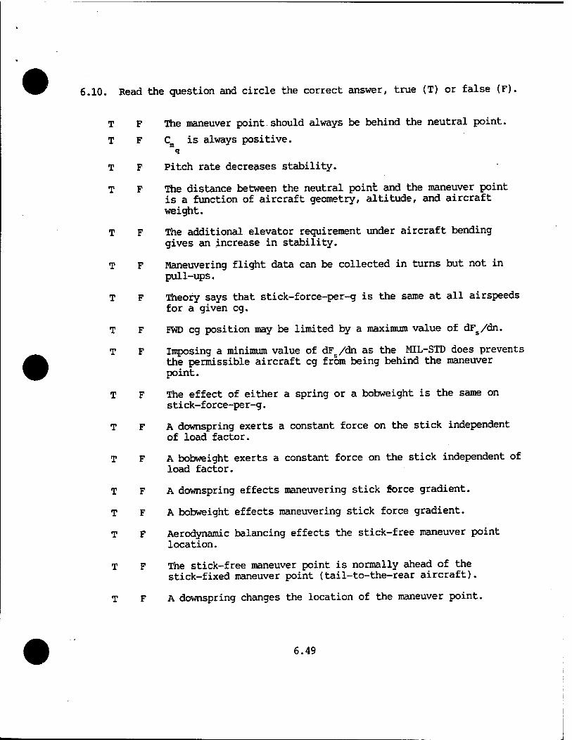
6.10. Read the question and circle the correct answer, true (T) or false (F).
T F The maneuver point should always be behind the neutral point.
T F Cn is always positive.
T F Pitch rate decreases stability.
T F The distance between the neutral point and the maneuver point is a function of aircraft geometry, altitude, and aircraft weight.
T F The additional elevator requirement under aircraft bending gives an increase in stability.
T F Maneuvering flight data can be collected in turns but not in pull-ups.
T F Theory says that stick-force-per-g is the same at all airspeeds for a given eg.
T F FWD eg position may be limited by a maximum value of dFs/dn.
T F Imposing a minimum value of dFs/dn as the MIL-STD does prevents the permissible aircraft eg from being behind the maneuver point.
T F The effect of either a spring or a bobweight is the same on stick-force-per-g.
T F A downspring exerts a constant force on the stick independent of load factor.
T F A bobweight exerts a constant force on the stick independent of load factor.
T F A downspring effects maneuvering stick force gradient.
T F A bobweight effects maneuvering stick force gradient.
T F Aerodynamic balancing effects the stick-free maneuver point location.
T F The stick-free maneuver point is normally ahead of the stick-fixed maneuver point (tail-to-the-rear aircraft).
T F A downspring changes the location of the maneuver point.
6.49
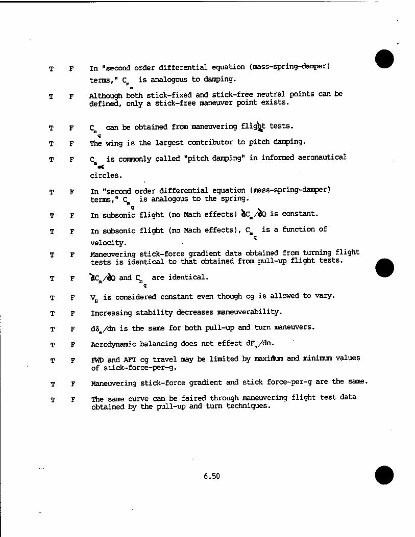
T F In "second order differential equation (mass-spring-damper)
terms," C is analogous to damping. ID a
T F Although both stick-fixed and stick-free neutral points can be defined, only a stick-free maneuver point exists.
T F C can be obtained from maneuvering flight tests. i
T F The wing is the largest contributor to pitch damping.
T F C is commonly called "pitch damping" in informed aeronautical
circles.
T F In "second order differential equation (mass-spring-damper) terms," C is analogous to the spring.
T F In subsonic flight (no Mach effects) fcCB/&Q is constant.
T F In subsonic flight (no Mach effects), CB is a function of q
velocity.
T F Maneuvering stick-force gradient data obtained from turning flight tests is identical to that obtained from pull-up flight tests.
T F "ic /JQ and C are identical. m <3
T F V is considered constant even though eg is allowed to vary. H
T F Increasing stability decreases maneuverability.
T F dS /dn is the same for both pull-up and turn maneuvers.
T F Aerodynamic balancing does not effect dFs/dn.
T F FWD and AFT eg travel may be limited by maximum and minimum values of stick-force-per-g.
T F Maneuvering stick-force gradient and stick force-per-g are the same.
T F The same curve can be faired through maneuvering flight test data obtained by the pull-up and turn techniques.
6.50
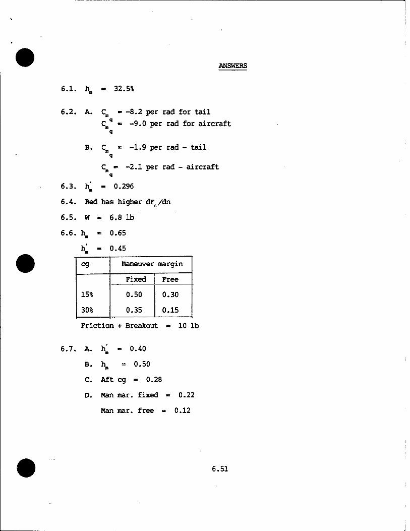
ANSWERS
6.1. h_ 32.5%
6.2. A. C_ -8.2 per rad for tail
-9.0 per rad for aircraft
B. C * -1.9 per rad - tail q
C « -2.1 per rad - aircraft i
6.3. h' - 0.296 n
6.4. Red has higher dFs/dn
6.5. W = 6.8 lb
6.6. h - 0.65
h' = 0.45 n
eg Maneuver margin
15%
30%
Fixed Free
0.50
0.35
0.30
0.15
Friction + Breakout 10 lb
A. h = 0.40 m
B. h = 0.50 ID
C. Aft eg = 0.28
D. Man mar. fixed = 0.22
Man mar. free = 0.12
6.51
E. C -10.64 per rad q
F. W -= 9 lb
G. Can't be done with spring.
H. FB/g - 10.5 lb/g
6.8. W, - 5 lb A
Must be offset by Tc = 6.25 lb at n - 1
6.9. B. h' - 0.45 n
C. Aft lim = 37%
D. Fwd lim - 22%
E. WB - 10 lb
6.52


