Embed Size (px)
Citation preview
Behavior of Laterally Damaged Prestressed Concrete Bridge GirdersRepaired with CFRP Laminates Under Static and Fatigue Loading
Adel ElSafty1),*, Matthew K. Graeff2), and Sam Fallaha3)
(Received May 27, 2013, Accepted August 14, 2013)
Abstract: Many bridges are subject to lateral damage for their girders due to impact by over-height vehicles collision. In this
study, the optimum configurations of carbon fiber reinforced polymers (CFRP) laminates were investigated to repair the laterally
damaged prestressed concrete (PS) bridge girders. Experimental and analytical investigations were conducted to study the
flexural behavior of 13 half-scale AASHTO type II PS girders under both static and fatigue loading. Lateral impact damage due
to vehicle collision was simulated by sawing through the concrete of the bottom flange and slicing through one of the
prestressing strands. The damaged concrete was repaired and CFRP systems (longitudinal soffit laminates and evenly spaced
transverse U-wraps) were applied to restore the original flexural capacity and mitigate debonding of soffit CFRP longitudinal
laminates. In addition to the static load tests for ten girders, three more girders were tested under fatigue loading cycles to
investigate the behavior under simulated traffic conditions. Measurements of the applied load, the deflection at five different
locations, strains along the cross-section height at mid-span, and multiple strains longitudinally along the bottom soffit were
recorded. The study investigated and recommended the proper CFRP repair design in terms of the CFRP longitudinal layers and
U-wrapping spacing to obtain flexural capacity improvement and desired failure modes for the repaired girders. Test results
showed that with proper detailing, CFRP systems can be designed to restore the lost flexural capacity, sustain the fatigue load
cycles, and maintain the desired failure mode.
Keywords: CFRP, repair, prestressed concrete, girder, lateral damage.
1. Introduction
Many bridges have been struck by overheight vehiclecollisions that may result in bridge failure. In the UnitedStates, between 25 and 35 bridges are damaged by collidingoverheight vehicles every year, in each state (Fu et al. 2003).Classifications for degrees of damage and applicable repairmethods are presented in some literature (Kasan 2009). Also,that reference was updated from NCHRP Project 12-21(Shanafelt and Horn 1980, 1985). Previous researchaddressed flexural and shear strengthening of reinforced andprestressed concrete (PS) beams using FRP (Choi et al.2011; Ibrahim Ary and Kang 2012; Kang and Ibrahim Ary2012). Several field studies indicated that FRP materials canbe used to repair impacted PS bridge girders, after largelosses of concrete cross-section and rupture of a small
number of prestressing strands (Di Ludovico 2003; Schiebelet al. 2001; Stallings et al. 2000; Tumialan et al. 2001). Fromthe previously conducted research, issues were reportedrelated to premature debonding failures due to either inad-equate transverse carbon fiber reinforced polymers (CFRP)anchors or inadequate development lengths (Rosenboom andRizkalla 2007; Green et al. 2004). The American ConcreteInstitute reference ACI 440.2R-08 for designing externallybonded CFRP laminate repairs, addresses some debondingbehaviors as ‘‘areas that still require research’’ (ACI Com-mittee 440 2008). In spite of the information available onreinforced concrete (RC) repair, data on the behavior of PSgirders strengthened with CFRP laminates is limited. Also,few studies address PS members with pre-existing damagedrepaired with CFRP (Kasan and Harries 2009; Klaiber et al.2003; Nanni et al. 2001). The CFRP repair can be used forboth flexural and shear strengthening (ACI Committee 4402008; Grace et al. 2003; Razaqpur and Isgor 2006; ElSaftyand Fallaha 2013; Shin and Lee 2003; NCHRP R-655 2010;NCHRP R-514 2004). Thirty-four laterally damage RCbeams were tested after being repaired with various CFRPconfigurations to investigate their behavior (ElSafty andGraeff 2011). The performance of repaired beams is limitedby possible early debonding and the inability of the CFRPsystem to transfer stresses into the concrete substrate throughbond. The debonding problem associated with FRP sheetshinders the ability to utilize the full tensile strength of the
1)Civil Engineering, University of North Florida,
Jacksonville, FL 32224, USA.
*Corresponding Author; E-mail: [email protected])Reynolds, Smith, and Hills (RS&H), Fayetteville,
NC 28314, USA.3)Florida Department of Transportation (FDOT),
Tallahassee, FL 32310, USA.
Copyright � The Author(s) 2013. This article is published
with open access at Springerlink.com
International Journal of Concrete Structures and MaterialsVol.8, No.1, pp.43–59, March 2014DOI 10.1007/s40069-013-0053-0ISSN 1976-0485 / eISSN 2234-1315
43

FRP, thus decreasing the efficiency of the repair. Therefore,there is a great need to investigate the effectiveness of usingCFRP systems that mitigate the debonding problems in therepair of PS girders damaged due to the impact a vehiclecollision.This research addresses specific points of investigation
including the effect of using discrete U-wraps on the straindeveloped in the longitudinal soffit laminates under staticand fatigue loading, the optimum configuration of the dis-crete U-wraps to mitigate debonding strains, the most ben-eficial level of strengthening (number of CFRP layers), andany design criteria needed for efficient repair systems. Thisstudy presents an analysis of the behavior of thirteen half-scale AASHTO type II PS girders under both static andfatigue loading. The laterally damaged PS girders wererepaired with different configurations of CFRP repair sys-tems after the concrete integrity was restored. In thisresearch, ten PS girders were tested in static loading andthree more girders were tested in fatigue loading to evaluateresidual strengths and longevity.
2. Experimental Study
In this research, experimental and analytical study wasconducted to investigate the feasibility, performance, andmost efficient configuration for repairing laterally damagedPC bridge girders using bonded CFRP laminates under bothfatigue and static loading. In this study, the experimentalwork included testing a total of thirteen half-scale AASHTOtype II PS girders. Ten girders were tested in static flexureloading and three were tested in fatigue. Two of the ten PSgirders represented the control damaged and undamagedsamples, without any CFRP. Thirteen PS girders had simu-lated impact damage imposed on them, concrete repair, twoto three layers of CFRP, and U-wraps at various spacing toconstitute the repair. Regarding the concrete repair of the cutand damaged area of the girders, the surfaces exposed bycutting were first roughened with chisels to improve bondingquality. These surfaces were then thoroughly cleaned with awater jet and pressurized air, as specified in both NCHRP514 (2004) and ACI 440.2R-08 (2008). The cleaned cut wasfilled with a high-strength cementitious repair mortar, and ahigh-pressure epoxy injection procedure was performed afterthe mortar set. The procedure resulted in a perfect repair ofthe concrete cross-section. The spacing between U-wrap-pings of CFRP was set at a distance of 12 in. (304.8 mm),20 in. (508 mm), or 36 in. (914.4 mm). Therefore, therepaired girders varied in both CFRP configurations andlevels of strengthening. Ten of the PS girders were tested inflexure until failure under a four point static loadingarrangement. Another three repaired PS girders were testedin flexure under a three point fatigue loading. The first girder(PS-1) was a control girder that represents an undamagedand unrepaired specimen. Similarly, the second girder (PS-2)was a damaged specimen which had received no CFRPrepair (only concrete repair) representing the lower bound ofthe tested samples. The remaining girders (PS-3 to PS-5) had
both simulated impact damage imposed on them, concreterepair, and two layers of CFRP at various spacing to con-stitute the repair. The spacing between U-wrappings was setat a distance of 12 in. (304.8 mm), 20 in. (508 mm), or36 in. (914.4 mm). The three girders (PS-6 through PS-8)were damaged and repaired with three layers of CFRP at thegirder soffit and U-wrappings at spacing of 12 in.(304.8 mm), 20 in. (508 mm), or 36 in. (914.4 mm). Thefinal two girders (PS-9 and PS-10) were fully wrappedgirders (U-wrappings cover entire girder) using two layers ofCFRP for the repairs (soffit and U-wrapping). However, theU-wrappings applied to PS-10 were overlapped by inch(25.4 mm), whereas those applied to PS-9 were not over-lapped. This was intended to investigate the effect of con-tinuity in the direction opposite to that of the fibers.Upon the completion of testing the ten half-scale
AASHTO Type II girders under static loading and analyzingthe results, the three top performing repair configurationsfrom this set were duplicated and applied to the remainingthree half-scale girders for dynamic loading tests (PS-11 toPS-13) to investigate fatigue properties of the repairs. Thethree best performing repairs from the initial ten half-scalegirders that were chosen for fatigue testing were the two-layer and three-layer repairs with 20-in. (508 mm) spacingand the two layer with 36-in. (914.4 mm) spacing. Theseconfigurations were recreated exactly, maintaining the 8-in.(203-mm) wide longitudinal laminates which started at alength of 17 ft (5,181.6 mm) while reduced six in (150 mm)per each additional layer applied. Also, the 12-in. (304.8-mm) wide transverse U-wrappings extended to the top of theweb of each girder. Loads, deflection, strains developedalong the height of the girder, and strains developed alongthe span of the girders’ extreme bottom fiber were recordedfor all girders during their testing. In addition, the modes offailure were also recorded.
2.1 Test Specimens2.1.1 MaterialsThe CFRP used in this study was a unidirectional carbon
fiber fabric. It was used with a saturant, which is an epoxydesigned by the manufacturer specifically for the CFRPproduct. Tables 1 and 2 provide the design values andproperties of the reinforcement and CFRP.
2.1.2 Girder DesignThe investigated PS girders were twenty-foot long and
their cross-sectional dimensions represented a half-scalemodel of an AASHTO type II girder. A four-inch (102-mm)thick deck was cast to simulate a bridge deck composite withthe PS girder. On the days of testing, the concrete used forproducing the girders had a compressive strength of*10,000 psi (68.9 MPa). Each girder was reinforced with atotal of five low-relaxation grade 270 seven-wire prestress-ing strands. In addition, three non-prestressed rebar wereprovided in the girder flanges and two rebar in the decktopping. Half of the shear steel stirrups extended verticallyfrom the girder to the deck while the other half remainedentirely in the girder. They were spaced every
44 | International Journal of Concrete Structures and Materials (Vol.8, No.1, March 2014)
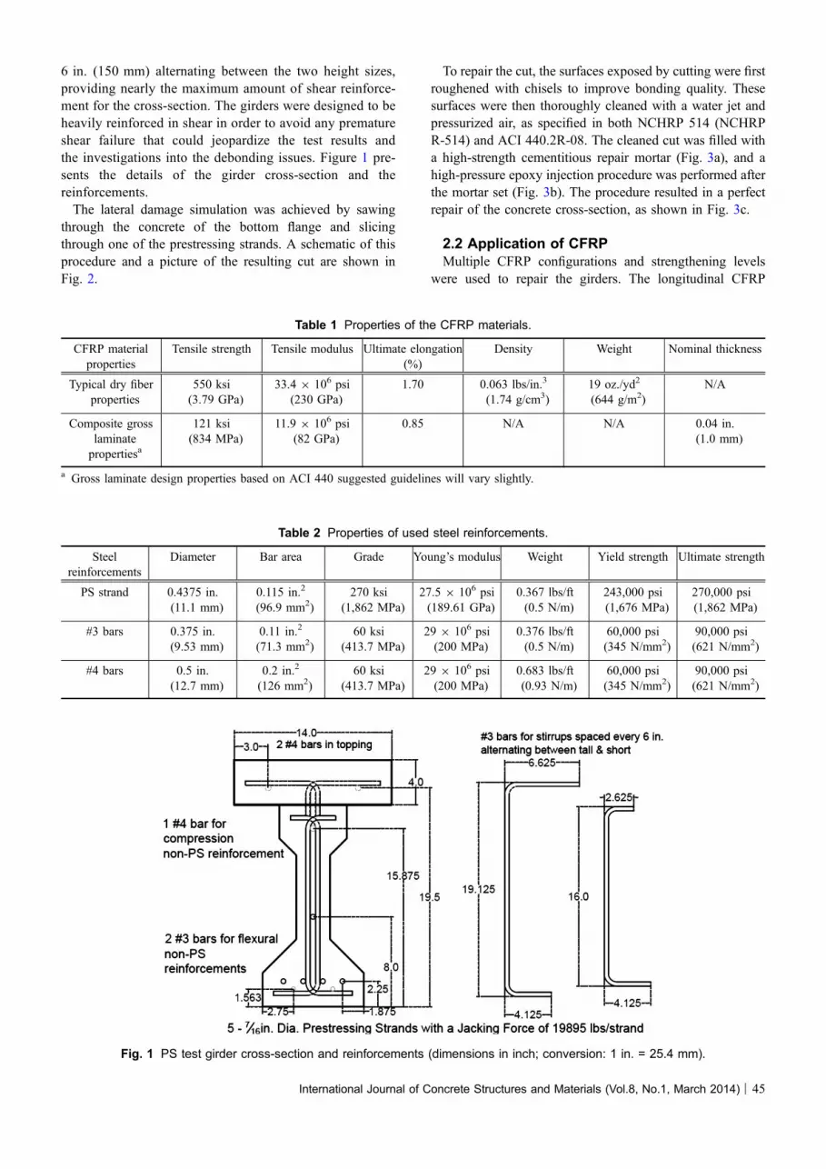
6 in. (150 mm) alternating between the two height sizes,providing nearly the maximum amount of shear reinforce-ment for the cross-section. The girders were designed to beheavily reinforced in shear in order to avoid any prematureshear failure that could jeopardize the test results andthe investigations into the debonding issues. Figure 1 pre-sents the details of the girder cross-section and thereinforcements.The lateral damage simulation was achieved by sawing
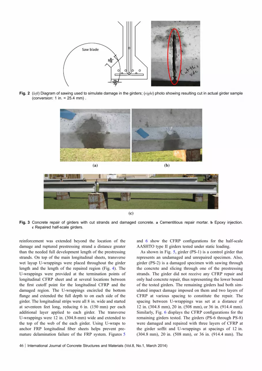
through the concrete of the bottom flange and slicingthrough one of the prestressing strands. A schematic of thisprocedure and a picture of the resulting cut are shown inFig. 2.
To repair the cut, the surfaces exposed by cutting were firstroughened with chisels to improve bonding quality. Thesesurfaces were then thoroughly cleaned with a water jet andpressurized air, as specified in both NCHRP 514 (NCHRPR-514) and ACI 440.2R-08. The cleaned cut was filled witha high-strength cementitious repair mortar (Fig. 3a), and ahigh-pressure epoxy injection procedure was performed afterthe mortar set (Fig. 3b). The procedure resulted in a perfectrepair of the concrete cross-section, as shown in Fig. 3c.
2.2 Application of CFRPMultiple CFRP configurations and strengthening levels
were used to repair the girders. The longitudinal CFRP
Table 1 Properties of the CFRP materials.
CFRP materialproperties
Tensile strength Tensile modulus Ultimate elongation(%)
Density Weight Nominal thickness
Typical dry fiberproperties
550 ksi(3.79 GPa)
33.4 9 106 psi(230 GPa)
1.70 0.063 lbs/in.3
(1.74 g/cm3)19 oz./yd2
(644 g/m2)N/A
Composite grosslaminatepropertiesa
121 ksi(834 MPa)
11.9 9 106 psi(82 GPa)
0.85 N/A N/A 0.04 in.(1.0 mm)
a Gross laminate design properties based on ACI 440 suggested guidelines will vary slightly.
Table 2 Properties of used steel reinforcements.
Steelreinforcements
Diameter Bar area Grade Young’s modulus Weight Yield strength Ultimate strength
PS strand 0.4375 in.(11.1 mm)
0.115 in.2
(96.9 mm2)270 ksi
(1,862 MPa)27.5 9 106 psi(189.61 GPa)
0.367 lbs/ft(0.5 N/m)
243,000 psi(1,676 MPa)
270,000 psi(1,862 MPa)
#3 bars 0.375 in.(9.53 mm)
0.11 in.2
(71.3 mm2)60 ksi
(413.7 MPa)29 9 106 psi(200 MPa)
0.376 lbs/ft(0.5 N/m)
60,000 psi(345 N/mm2)
90,000 psi(621 N/mm2)
#4 bars 0.5 in.(12.7 mm)
0.2 in.2
(126 mm2)60 ksi
(413.7 MPa)29 9 106 psi(200 MPa)
0.683 lbs/ft(0.93 N/m)
60,000 psi(345 N/mm2)
90,000 psi(621 N/mm2)
Fig. 1 PS test girder cross-section and reinforcements (dimensions in inch; conversion: 1 in. = 25.4 mm).
International Journal of Concrete Structures and Materials (Vol.8, No.1, March 2014) | 45
reinforcement was extended beyond the location of thedamage and ruptured prestressing strand a distance greaterthan the needed full development length of the prestressingstrands. On top of the main longitudinal sheets, transversewet layup U-wrappings were placed throughout the girderlength and the length of the repaired region (Fig. 4). TheU-wrappings were provided at the termination points oflongitudinal CFRP sheet and at several locations betweenthe first cutoff point for the longitudinal CFRP and thedamaged region. The U-wrappings encircled the bottomflange and extended the full depth to on each side of thegirder. The longitudinal strips were all 8 in. wide and startedat seventeen feet long, reducing 6 in. (150 mm) per eachadditional layer applied to each girder. The transverseU-wrappings were 12 in. (304.8-mm) wide and extended tothe top of the web of the each girder. Using U-wraps toanchor FRP longitudinal fiber sheets helps prevent pre-mature delamination failure of the FRP system. Figures 5
and 6 show the CFRP configurations for the half-scaleAASHTO type II girders tested under static loading.As shown in Fig. 5, girder (PS-1) is a control girder that
represents an undamaged and unrepaired specimen. Also,girder (PS-2) is a damaged specimen with sawing throughthe concrete and slicing through one of the prestressingstrands. The girder did not receive any CFRP repair andonly had concrete repair, thus representing the lower boundof the tested girders. The remaining girders had both sim-ulated impact damage imposed on them and two layers ofCFRP at various spacing to constitute the repair. Thespacing between U-wrappings was set at a distance of12 in. (304.8 mm), 20 in. (508 mm), or 36 in. (914.4 mm).Similarly, Fig. 6 displays the CFRP configurations for theremaining girders tested. The girders (PS-6 through PS-8)were damaged and repaired with three layers of CFRP atthe girder soffit and U-wrappings at spacings of 12 in.(304.8 mm), 20 in. (508 mm), or 36 in. (914.4 mm). The
Fig. 2 (left) Diagram of sawing used to simulate damage in the girders; (right) photo showing resulting cut in actual girder sample(conversion: 1 in. = 25.4 mm) .
(a) (b)
(c)
Fig. 3 Concrete repair of girders with cut strands and damaged concrete. a Cementitious repair mortar. b Epoxy injection.c Repaired half-scale girders.
46 | International Journal of Concrete Structures and Materials (Vol.8, No.1, March 2014)

two girders (PS-9 and PS-10) were fully wrapped girders(U-wrappings covered entire girder) using two layers ofCFRP for the repairs (soffit and U-wrapping). However, the
U-wrappings applied to PS-10 were overlapped by an inch(25.4 mm), whereas those applied to PS-9 were notoverlapped.
(a) (b)
Fig. 4 Wet layup application of CFRP fabric laminates on PS girder. a Wet layup application of CFRP. b Applying epoxy to CFRP.
Fig. 5 CFRP configurations used for tested girders PS-1 to PS-5 (dimensions in inch; conversion: 1 in. = 25.4 mm).
International Journal of Concrete Structures and Materials (Vol.8, No.1, March 2014) | 47
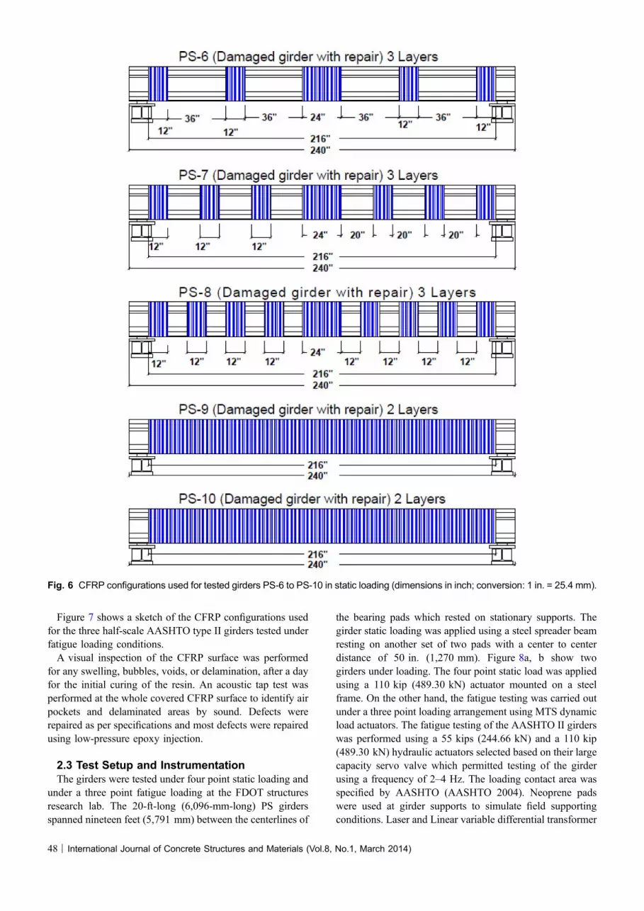
Figure 7 shows a sketch of the CFRP configurations usedfor the three half-scale AASHTO type II girders tested underfatigue loading conditions.A visual inspection of the CFRP surface was performed
for any swelling, bubbles, voids, or delamination, after a dayfor the initial curing of the resin. An acoustic tap test wasperformed at the whole covered CFRP surface to identify airpockets and delaminated areas by sound. Defects wererepaired as per specifications and most defects were repairedusing low-pressure epoxy injection.
2.3 Test Setup and InstrumentationThe girders were tested under four point static loading and
under a three point fatigue loading at the FDOT structuresresearch lab. The 20-ft-long (6,096-mm-long) PS girdersspanned nineteen feet (5,791 mm) between the centerlines of
the bearing pads which rested on stationary supports. Thegirder static loading was applied using a steel spreader beamresting on another set of two pads with a center to centerdistance of 50 in. (1,270 mm). Figure 8a, b show twogirders under loading. The four point static load was appliedusing a 110 kip (489.30 kN) actuator mounted on a steelframe. On the other hand, the fatigue testing was carried outunder a three point loading arrangement using MTS dynamicload actuators. The fatigue testing of the AASHTO II girderswas performed using a 55 kips (244.66 kN) and a 110 kip(489.30 kN) hydraulic actuators selected based on their largecapacity servo valve which permitted testing of the girderusing a frequency of 2–4 Hz. The loading contact area wasspecified by AASHTO (AASHTO 2004). Neoprene padswere used at girder supports to simulate field supportingconditions. Laser and Linear variable differential transformer
Fig. 6 CFRP configurations used for tested girders PS-6 to PS-10 in static loading (dimensions in inch; conversion: 1 in. = 25.4 mm).
48 | International Journal of Concrete Structures and Materials (Vol.8, No.1, March 2014)
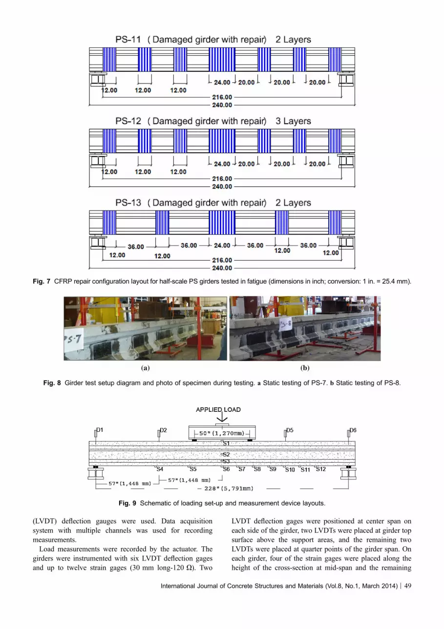
(LVDT) deflection gauges were used. Data acquisitionsystem with multiple channels was used for recordingmeasurements.Load measurements were recorded by the actuator. The
girders were instrumented with six LVDT deflection gagesand up to twelve strain gages (30 mm long-120 X). Two
LVDT deflection gages were positioned at center span oneach side of the girder, two LVDTs were placed at girder topsurface above the support areas, and the remaining twoLVDTs were placed at quarter points of the girder span. Oneach girder, four of the strain gages were placed along theheight of the cross-section at mid-span and the remaining
Fig. 7 CFRP repair configuration layout for half-scale PS girders tested in fatigue (dimensions in inch; conversion: 1 in. = 25.4 mm).
(a) (b)
Fig. 8 Girder test setup diagram and photo of specimen during testing. a Static testing of PS-7. b Static testing of PS-8.
Fig. 9 Schematic of loading set-up and measurement device layouts.
International Journal of Concrete Structures and Materials (Vol.8, No.1, March 2014) | 49

strain gages were distributed along the flexural tension sideat various locations depending on the CFRP configuration.The general placements of all measurement devices areshown in Fig. 9. The loading arrangement for the fatigue testsetup for the half-scale girders is shown in Fig. 10.
2.4 Test Results and Analysis2.4.1 Load and DeflectionFigure 11 shows the control girder with significant
deflection under loading. Table 3 shows the maximum loads,corresponding deflections, and increased capacity resultsfrom testing. It is shown that a comparison between thefailure load of control girder PS-2 (un-strengthened withCFRP) and repaired girders with 2 layers of CFRP showsthat CFRP repair enhanced the flexural capacity by a rangeof 27.53–45.66 % compared to control girder with one lessstrand. Also, for repaired girders with three layers of CFRP,increases in the flexural capacity were reported to range from60.24 to 68.74 % compared to control girder PS-2. Increasesof 24.85–41.69 % in the failure load were observed for thefully wrapped girders PS-9 and PS-10 compared to the un-strengthened control girder PS-2. The load–deflectionbehaviors for tested girders are presented in Figs. 12, 13, 14,15, 16, and 17.The results show that the damage of cutting one of the
prestressing strands (girder PS-2) resulted in 18.44 % loss in
flexural capacity compared to that of the undamaged controlgirder (PS-1). The CFRP repair of damaged girders (PS-3 toPS-10) restored their capacity and exceeded the capacity ofthe undamaged control girder PS-1 by up to 37.63 %. Theresults also show that U-shaped discrete strips or wraps ofCFRP sheets of girders PS-3 to PS-8 enhanced the flexuralcapacity even if the girders were not fully wrapped withcontinuous wrapping covering the entire girder sides.U-wrappings covered the entire girders (PS-9 and PS-10)using 2 layers of CFRP (soffit and U-wraps). However, theU-wraps applied to PS-10 were overlapped by an inch(25.4 mm), whereas the U-wraps applied to PS-9 were notoverlapped. By comparing the two fully wrapped girders(PS-9 and PS-10), an increase in the flexural capacity wasobserved for the girder with an overlap of its wraps (PS-10).That overlapping of transverse U-wraps is needed to developproper continuity; even in a direction perpendicular to thedirection of the fibers. That is in addition to overlapping thefibers along their length for lap splices, as indicated in ACI440.2R-08.The control girders experienced a classic flexural failure
initiated by excessive deflection and widening of flexuralcracks. The repaired girders experienced either CFRP deb-onding, CFRP rupture without debonding, or localizeddebonding followed by rupture of CFRP, as shown inFigs. 18 and 19. Some repaired girders also experienced
Fig. 10 Fatigue loading setup arrangement for half-scale AASHTO PS girders.
Fig. 11 Half-scale control girder displaying excessive deflection under loading.
50 | International Journal of Concrete Structures and Materials (Vol.8, No.1, March 2014)
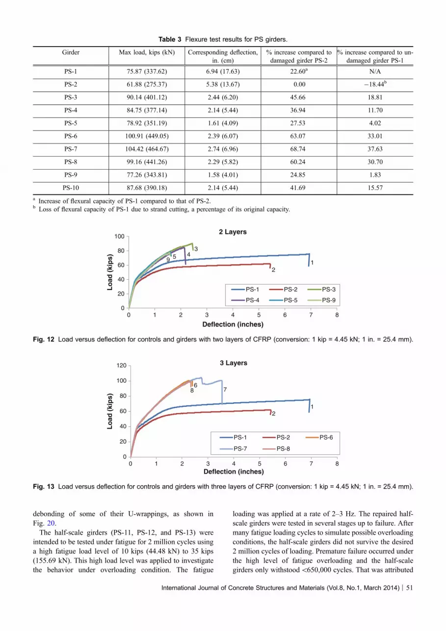
debonding of some of their U-wrappings, as shown inFig. 20.The half-scale girders (PS-11, PS-12, and PS-13) were
intended to be tested under fatigue for 2 million cycles usinga high fatigue load level of 10 kips (44.48 kN) to 35 kips(155.69 kN). This high load level was applied to investigatethe behavior under overloading condition. The fatigue
loading was applied at a rate of 2–3 Hz. The repaired half-scale girders were tested in several stages up to failure. Aftermany fatigue loading cycles to simulate possible overloadingconditions, the half-scale girders did not survive the desired2 million cycles of loading. Premature failure occurred underthe high level of fatigue overloading and the half-scalegirders only withstood\650,000 cycles. That was attributed
Table 3 Flexure test results for PS girders.
Girder Max load, kips (kN) Corresponding deflection,in. (cm)
% increase compared todamaged girder PS-2
% increase compared to un-damaged girder PS-1
PS-1 75.87 (337.62) 6.94 (17.63) 22.60a N/A
PS-2 61.88 (275.37) 5.38 (13.67) 0.00 -18.44b
PS-3 90.14 (401.12) 2.44 (6.20) 45.66 18.81
PS-4 84.75 (377.14) 2.14 (5.44) 36.94 11.70
PS-5 78.92 (351.19) 1.61 (4.09) 27.53 4.02
PS-6 100.91 (449.05) 2.39 (6.07) 63.07 33.01
PS-7 104.42 (464.67) 2.74 (6.96) 68.74 37.63
PS-8 99.16 (441.26) 2.29 (5.82) 60.24 30.70
PS-9 77.26 (343.81) 1.58 (4.01) 24.85 1.83
PS-10 87.68 (390.18) 2.14 (5.44) 41.69 15.57
a Increase of flexural capacity of PS-1 compared to that of PS-2.b Loss of flexural capacity of PS-1 due to strand cutting, a percentage of its original capacity.
0
20
40
60
80
100
0 1 2 3 4 5 6 7 8
Lo
ad (
kip
s)
Deflection (inches)
2 Layers
PS-1 PS-2 PS-3
PS-4 PS-5 PS-9
12
3459
Fig. 12 Load versus deflection for controls and girders with two layers of CFRP (conversion: 1 kip = 4.45 kN; 1 in. = 25.4 mm).
0
20
40
60
80
100
120
0 1 2 3 4 5 6 7 8
Lo
ad (
kip
s)
Deflection (inches)
3 Layers
PS-1 PS-2 PS-6
PS-7 PS-8
12
678
Fig. 13 Load versus deflection for controls and girders with three layers of CFRP (conversion: 1 kip = 4.45 kN; 1 in. = 25.4 mm).
International Journal of Concrete Structures and Materials (Vol.8, No.1, March 2014) | 51

to the high fatigue load level that exceeded the specifiedfatigue load level in AASHTO. There were also some defi-ciencies in anchoring the end of the U-wraps and in coveringthe induced concrete damage with a longitudinal strip tosuppress crack opening. A photograph of the fatigue loadingtests is shown in Fig. 21 for the half-scale girders. Fig-ures 22, 23, and 24 show the fatigue behavior of the repairedgirders PS-11, PS-12, and PS-13. Table 4 represents the test
information for half-scale girders under fatigue loadingincluding the loading rate, load range, and number of fatigueloading cycles.
2.4.2 Strain CharacteristicsFigures 25 and 26 show the strains measured at a load
level of 20 kips (89 kN) and 70 kips (311.5 kN). Half of thespan lengths of the symmetrical girders were instrumented
0
20
40
60
80
100
120
0 1 2 3 4 5 6 7 8
Lo
ad (
kip
s)
Deflection (inches)
36 in (91.44 cm) Spacing
PS-1 PS-2
PS-3 PS-6
1
2
3
6
Fig. 14 Load versus deflection for controls and 36 in (91.44 cm) spacing configurations (conversion: 1 kip = 4.45 kN; 1 in. = 25.4 mm).
0
20
40
60
80
100
120
0 1 2 3 4 5 6 7 8
Lo
ad (
kip
s)
Deflection (inches)
20 in (50.8 cm) Spacing
PS-1 PS-2
PS-4 PS-7
12
47
Fig. 15 Load versus deflection for controls and 20 in (50.8 cm) spacing configurations (conversion: 1 kip = 4.45 kN; 1 in. = 25.4 mm).
0
20
40
60
80
100
120
0 1 2 3 4 5 6 7 8
Lo
ad (
kip
s)
Deflection (inches)
12 in (30.48 cm) Spacing
PS-1 PS-2
PS-5 PS-8
12
5
8
Fig. 16 Load versus deflection for controls and 12 in (30.48 cm) spacing configurations (conversion: 1 kip = 4.45 kN; 1 in. = 25.4 mm).
52 | International Journal of Concrete Structures and Materials (Vol.8, No.1, March 2014)
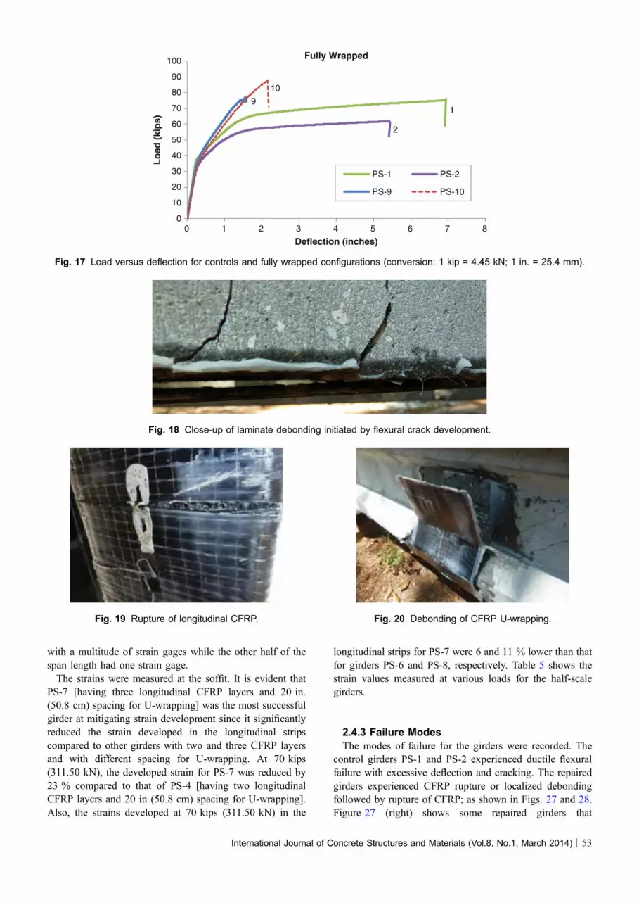
with a multitude of strain gages while the other half of thespan length had one strain gage.The strains were measured at the soffit. It is evident that
PS-7 [having three longitudinal CFRP layers and 20 in.(50.8 cm) spacing for U-wrapping] was the most successfulgirder at mitigating strain development since it significantlyreduced the strain developed in the longitudinal stripscompared to other girders with two and three CFRP layersand with different spacing for U-wrapping. At 70 kips(311.50 kN), the developed strain for PS-7 was reduced by23 % compared to that of PS-4 [having two longitudinalCFRP layers and 20 in (50.8 cm) spacing for U-wrapping].Also, the strains developed at 70 kips (311.50 kN) in the
longitudinal strips for PS-7 were 6 and 11 % lower than thatfor girders PS-6 and PS-8, respectively. Table 5 shows thestrain values measured at various loads for the half-scalegirders.
2.4.3 Failure ModesThe modes of failure for the girders were recorded. The
control girders PS-1 and PS-2 experienced ductile flexuralfailure with excessive deflection and cracking. The repairedgirders experienced CFRP rupture or localized debondingfollowed by rupture of CFRP; as shown in Figs. 27 and 28.Figure 27 (right) shows some repaired girders that
0
10
20
30
40
50
60
70
80
90
100
0 1 2 3 4 5 6 7 8
Lo
ad (
kip
s)
Deflection (inches)
Fully Wrapped
PS-1 PS-2
PS-9 PS-10
1
2
9
10
Fig. 17 Load versus deflection for controls and fully wrapped configurations (conversion: 1 kip = 4.45 kN; 1 in. = 25.4 mm).
Fig. 18 Close-up of laminate debonding initiated by flexural crack development.
Fig. 19 Rupture of longitudinal CFRP. Fig. 20 Debonding of CFRP U-wrapping.
International Journal of Concrete Structures and Materials (Vol.8, No.1, March 2014) | 53

experienced debonding of some of their U-wrappings. Fig-ure 29 shows debonding failure of CFRP laminates for gir-der PS-6.
3. Design Model and Predictions
The ACI 440.2R-08 document (ACI Committee 4402008) included the model used for design and capacity
predictions. The design equations from the design model andthe resulting values for the designed repaired specimen arelisted in the equations from Eqs. (1) to (9). The modelidentifies failure modes through the governing strain limi-tations due to either concrete crushing, FRP rupture, FRPdebonding or prestressing steel rupture. The effective designstrain for FRP rupture at a limit state controlled by concretecrushing can be calculated through Eq. (1).
efe ¼ ecudf � c
c
� �� ebi� efd ð1Þ
Strain values were recorded for specimens with differentCFRP layers. The strain values of 0.0173 in./in. (mm/mm)and 0.0136 in./in. (mm/mm) are calculated for the testspecimen with two layers and three layers of longitudinalCFRP laminates respectfully. However, efd is calculated as0.0079 in./in. (mm/mm) for two layers and 0.0064 in./in.(mm/mm) for three layers. Therefore, debonding is still thelimiting factor. The ultimate limit state with rupture of theprestressing steel as the governing failure mode usesEqs. (2) and (3) for max strain calculations. That results ina strain value of 0.0356 in./in. (mm/mm). That strain value isstill greater than efd, which will still control failure.
Fig. 21 Fatigue loading setup arrangement for half-scale PS girders.
0
5
10
15
20
25
30
35
40
0 0.25 0.5 0.75 1 1.25 1.5
Lo
ad (
kip
)
Deflection (inches)
PS-11 Load vs. Deflection
Ramp 1 60000 Ramp 2
250000 300000 310000
316000 319000 failure
Fig. 22 Fatigue behavior and degradation until failure for girderPS-11 (conversion: 1 kip = 4.45 kN; 1 in. = 25.4 mm).
0
5
10
15
20
25
30
35
40
0 0.1 0.2 0.3 0.4 0.5 0.6 0.7
Loa
d (k
ip)
Deflection (inches)
PS-12 Load vs. Deflection
Ramp 1 20000 60000
Ramp 2 200000 250000
failure
Fig. 23 Fatigue behavior and degradation until failure for girderPS-12 (conversion: 1 kip = 4.45 kN; 1 in. = 25.4 mm).
0
5
10
15
20
25
30
35
40
0 0.25 0.5 0.75 1 1.25
Loa
d (k
ip)
Deflection (inches)
PS-13 Load vs. Deflection
Ramp 5000 200000 400000
500000 550000 600000 failure
Fig. 24 Fatigue behavior and degradation until failure for girderPS-13 (conversion: 1 kip = 4.45 kN; 1 in. = 25.4 mm).
54 | International Journal of Concrete Structures and Materials (Vol.8, No.1, March 2014)

efe ¼ epu � epi� � df � c
dp � c
� �� ebi� efd ð2Þ
epi ¼Pe
ApEpþ Pe
AcEc1þ e2
r2
� �ð3Þ
For FRP rupture or debonding as the ultimate limit state offailure, efe is chosen to be that of efd resulting in values of110.17 ksi (760 MPa) for two layers of CFRP and 89.96 ksi(620 MPa) for three layers for ffe in Eq. (4).
ffe ¼ Ef efe ð4Þ
A neutral axis is assumed to be 1.69 in. (43 mm). Yet,after computing Eqs. (5) to (8), new values for ‘‘c’’ of3.28 in. (83.3 mm) and 4.03 in. (102.4 mm) weredetermined for the two layer and three layer repairs.
eps ¼ epe þPe
AcEc1þ e2
r2
� �þ epnet � 0:035 ð5Þ
epnet ¼ efe � ebi� � dp � c
df � c
� �ð6Þ
fps ¼28;000eps for eps� 0:0086
270� 0:04eps�0:007 for eps [ 0:0086 in-lb units ð7Þ
c ¼ Apfps þ Af ffea1f 0cb1b
: ð8Þ
For the girders repaired with two layers of CFRP, the finalvalues calculated for Eqs. (5) and (7) were 0.0128 in./in.(mm/mm), 0.0066 in./in. (mm/mm), and 263.07 ksi(1,813 MPa), respectfully. Similarly, using the threelayered repair configurations, the values of 0.0116 in./in.(mm/mm), 0.0053 in./in. (mm/mm), and 261.21 ksi(1,801 MPa) were calculated for Eqs. (5) to (7). Thesevalues were all then used to calculate the theoretical ultimate
Table 4 Fatigue testing results for the half-scale AASHTO type II girders.
Half-scale girder designations Loading level ranges Loading rates Number of loading cyclescompleted
PS-11 10–35 kips (44.48–155.69 kN) Started at 4 Hz then to 3 Hz after2,000 cycles, then 2 Hz after
214,000 cycles
322,000
PS-12 10–35 kips (44.48–155.69 kN) Started at 4 Hz then to 3 Hz after6,000 cycles, then 2 Hz after
69,000 cycles
296,000
PS-13 10–35 kips (44.48–155.69 kN) 2 Hz 635,000
0
50
100
150
200
250
300
350
400
450
0 50 100 150 200
mic
rost
rain
, in/
in
distance along girder length, inch
20 kips (89 kN)
PS-1 PS-2PS-3 PS-4PS-5 PS-6PS-7 PS-8PS-9 PS-10
Fig. 25 Strain at extreme bottom fiber of girder soffit versus length for all girders (conversion: 1 in. = 25.4 mm).
0
2000
4000
6000
8000
10000
0 50 100 150 200 250
mic
rost
rain
, in/
in
distance along girder length, inch
70 kips (311.5 kN)PS-3 PS-4
PS-5 PS-6
PS-7 PS-8
PS-9 PS-10
Fig. 26 Strain of CFRP at girder soffit versus length forrepaired girders (conversion: 1 in. = 25.4 mm).
International Journal of Concrete Structures and Materials (Vol.8, No.1, March 2014) | 55

moment capacity of the repaired girders as shown in Eq. 9,which is used in the ACI 440.2R-08.
Mn ¼ Apfps dp �b1c
2
� �þ wf Af ffe df �
b1c
2
� �ð9Þ
The theoretical ultimate moment capacities were295.61 kip-ft (400.8 kN m) and 317.3 kip-ft (430.2 kN m)for the girders with two and three CFRP layers, respectively.These moment values indicate predicted debonding failure
loads of 79.7 kips (354.67 kN) and 85.6 kips (380.92 kN)for the two and three layered designs, respectively. Althoughhaving intermediate U-wrappings may alter the outcomes, itis not accounted for in the ACI design provisions. Table 6presents the predicted values of max loads and the changescompared to predictions.
As shown in Table 6, significant enhancements for thecapacity of the repaired girders were recorded. Also, theanalytical model predicted the maximum loads relatively
Table 5 Strain values measured at various load levels for half-scale girders.
Girder designation Maximum strain values recorded at various loads
At 5 kip(22.25 kN)
At 15 kip(66.75 kN)
At 25 kip(111.3 kN)
At 40 kip(178 kN)
At 60 kip(267 kN)
At 70 kip(311.5 kN)
PS-1 52.58 158.51 280.33 291.40a Broke Broke
PS-2 61.32 200.39 1837.30 Broke Broke Broke
PS-3 51.03 167.19 314.76 1,295.52 2,984.16 4,075.28
PS-4 55.16 172.14 341.49 1,332.85 3,197.49 4,146.04
PS-5 53.03 146.52 316.97 1,270.22 5,213.27 8,939.73
PS-6 51.57 160.54 292.03 1,048.55 2,646.34 3,393.13
PS-7 49.05 150.30 266.07 835.90 2,415.59 3,203.85
PS-8 52.59 161.94 281.84 942.62 2,647.17 3,616.50
PS-9 58.40 180.76 368.50 1,357.88 3,433.54 5.409.16
a Strain gauges have been determined unreliable; italic values represents lowest value recorded at that load level.
Fig. 27 (left) Rupture of longitudinal CFRP; (right) debonding of CFRP U-wrapping.
Fig. 28 (left) Debonding of soffit CFRP; (right) rupture of longitudinal and transverse CFRP.
56 | International Journal of Concrete Structures and Materials (Vol.8, No.1, March 2014)
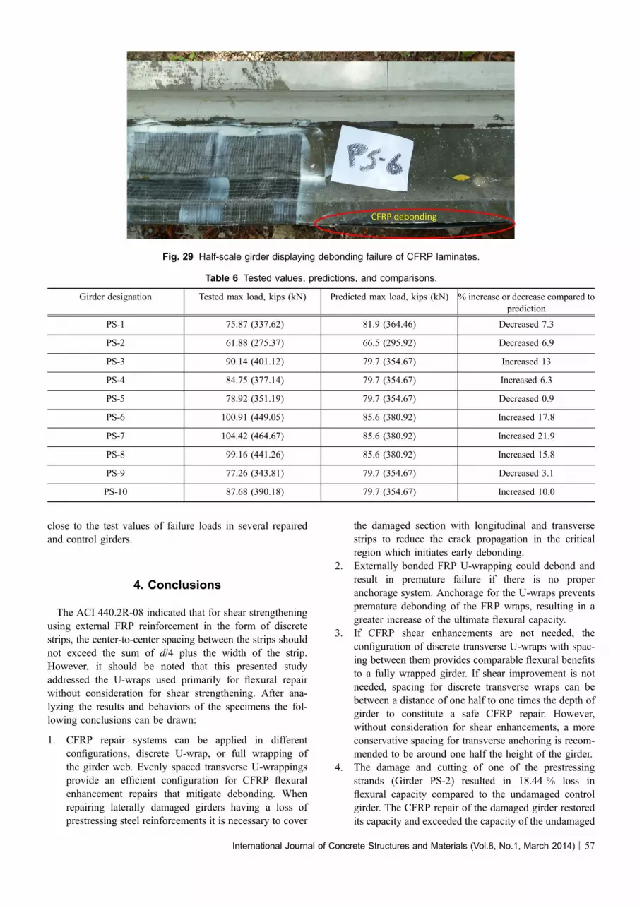
close to the test values of failure loads in several repairedand control girders.
4. Conclusions
The ACI 440.2R-08 indicated that for shear strengtheningusing external FRP reinforcement in the form of discretestrips, the center-to-center spacing between the strips shouldnot exceed the sum of d/4 plus the width of the strip.However, it should be noted that this presented studyaddressed the U-wraps used primarily for flexural repairwithout consideration for shear strengthening. After ana-lyzing the results and behaviors of the specimens the fol-lowing conclusions can be drawn:
1. CFRP repair systems can be applied in differentconfigurations, discrete U-wrap, or full wrapping ofthe girder web. Evenly spaced transverse U-wrappingsprovide an efficient configuration for CFRP flexuralenhancement repairs that mitigate debonding. Whenrepairing laterally damaged girders having a loss ofprestressing steel reinforcements it is necessary to cover
the damaged section with longitudinal and transversestrips to reduce the crack propagation in the criticalregion which initiates early debonding.
2. Externally bonded FRP U-wrapping could debond andresult in premature failure if there is no properanchorage system. Anchorage for the U-wraps preventspremature debonding of the FRP wraps, resulting in agreater increase of the ultimate flexural capacity.
3. If CFRP shear enhancements are not needed, theconfiguration of discrete transverse U-wraps with spac-ing between them provides comparable flexural benefitsto a fully wrapped girder. If shear improvement is notneeded, spacing for discrete transverse wraps can bebetween a distance of one half to one times the depth ofgirder to constitute a safe CFRP repair. However,without consideration for shear enhancements, a moreconservative spacing for transverse anchoring is recom-mended to be around one half the height of the girder.
4. The damage and cutting of one of the prestressingstrands (Girder PS-2) resulted in 18.44 % loss inflexural capacity compared to the undamaged controlgirder. The CFRP repair of the damaged girder restoredits capacity and exceeded the capacity of the undamaged
Fig. 29 Half-scale girder displaying debonding failure of CFRP laminates.
Table 6 Tested values, predictions, and comparisons.
Girder designation Tested max load, kips (kN) Predicted max load, kips (kN) % increase or decrease compared toprediction
PS-1 75.87 (337.62) 81.9 (364.46) Decreased 7.3
PS-2 61.88 (275.37) 66.5 (295.92) Decreased 6.9
PS-3 90.14 (401.12) 79.7 (354.67) Increased 13
PS-4 84.75 (377.14) 79.7 (354.67) Increased 6.3
PS-5 78.92 (351.19) 79.7 (354.67) Decreased 0.9
PS-6 100.91 (449.05) 85.6 (380.92) Increased 17.8
PS-7 104.42 (464.67) 85.6 (380.92) Increased 21.9
PS-8 99.16 (441.26) 85.6 (380.92) Increased 15.8
PS-9 77.26 (343.81) 79.7 (354.67) Decreased 3.1
PS-10 87.68 (390.18) 79.7 (354.67) Increased 10.0
International Journal of Concrete Structures and Materials (Vol.8, No.1, March 2014) | 57
intact control girder with no cut strand by up to37.63 %.
5. A comparison between the failure load of control girder(with cut strand and un-strengthened with CFRP) andrepaired girders with 2 layers of CFRP shows that CFRPrepair enhanced the flexural capacity by 27.53–45.66 %compared to control girder (with cut strand and un-strengthened with CFRP). For repaired girders withthree layers of CFRP, increases in the flexural capacitywere reported to range from 60.24 to 68.74 % comparedto control girder (with cut strand and un-strengthenedwith CFRP). An increase in the failure load of24.85–41.69 % was observed for the two-layered fullyCFRP wrapped repaired girders compared to the un-strengthened control girder. The CFRP repaired girdersfail prematurely at \1 million cycles under overloadfatigue conditions and improper CFRP anchoring.
6. Proper CFRP repair design in terms of the number ofCFRP longitudinal layers and U-wrapping spacingcould result in obtaining significant enhancement forthe capacity and desired failure modes for the repairedgirders. Favorable failure modes of the repaired girderscan be maintained using a CFRP repair configurationutilizing spacing between the U-wrappings to preventundesirable modes of failure such as debonding of thelongitudinal CFRP strips from the girder concrete soffit.
Open Access
This article is distributed under the terms of the CreativeCommons Attribution License which permits any use,distribution, and reproduction in any medium, provided theoriginal author(s) and the source are credited.
References
ACI Committee 440. (2008). ACI 440.2R-08 Guide for the
design and construction of externally bonded FRP systems
for strengthening concrete structures (p. 80). Farmington
Hills, MI: American Concrete Institute.
Choi, D.-U., Kang, T. H.-K., Ha, S.-S., Kim, K.-H., & Kim, W.
(2011). Flexural and bond behavior of concrete beams
strengthened with hybrid carbon-glass fiber-reinforced
polymer sheets. ACI Structural Journal, 108(1), 90–98.
Di Ludovico, M. (2003). Experimental behavior of prestressed
concrete beams strengthened with FRP, Report CIES 03-42.
Rolla, MO: University of Missouri.
ElSafty, A., & Graeff, M. (2011). Investigating the most effec-
tive CFRP configuration in repairing damaged concrete
beams due to collision, The 13th International Conference
on Civil, Structural and Environmental Engineering Com-
puting, Crete, Greece.
ElSafty, A., & Fallaha, S. (2013). Behavior of laterally damaged
bridge girders repaired with CFRP laminates under fatigue
and static loading. Washington, DC: Transportation
Research Board (TRB).
Fu, C. C., Burhouse, J. R., & Chang, G. L. (2003). Study of
overheight vehicles with highway bridges, Transportation
research board.
Grace, N. F., Ragheb, W. F., & Abdel-Sayed, G. (2003). Flex-
ural and shear strengthening of concrete girders using new
triaxially braided ductile fabric. ACI Structural Journal,
100(6), 693.
Green, P. S., Boyd, A. J., & Lammert, K. (2004). CFRP repair
of impact-damaged bridge girders, Vol. I: Structural eval-
uation of impact damaged prestressed concrete I girders
repaired with FRP materials, BC-354 RPWO #55, Florida
Department of Transportation.
Ibrahim Ary, M., & Kang, T. H.-K. (2012). Shear-strengthening
of reinforced and prestressed concrete beams using FRP:
Part I—Review of previous research. International Journal
of Concrete Structures and Materials, 6(1), 41–48.
Kang, T. H.-K., & Ibrahim Ary, M. (2012). Shear-strengthening
of reinforced and prestressed concrete beams using FRP:
Part II—Experimental investigation. International Journal
of Concrete Structures and Materials, 6(1), 49–57.
Kasan, J. L. (2009). Structural repair of prestressed concrete
bridge girders, MSCE Thesis, University of Pittsburgh, PA.
Kasan, J. L., & Harries, K. A. (2009). Repair of impact-dam-
aged prestressed concrete bridge girders with carbon fiber
reinforced polymers, Asia-Pacific Conference on FRP in
Structures, Seoul, Korea.
Klaiber, W. F., Wipf, T. J., & Kempers, B. J. (2003). Repair of
damaged prestressed concrete bridges using CFRP, Mid-
Continent Transportation Research Symposium, Iowa State
University, Ames, IA.
Nanni, A., Huang, P. C., & Tumialan, J. G. (2001). Strength-
ening of impact-damaged bridge girder using FRP lami-
nates’’, 9th International Conference, Structural Faults and
Repair. London, UK: Engineering Technics Press.
NCHRP R-514. (2004). National Cooperative Highway
Research Program. Bonded repair and retrofit of concrete
structures using FRP composites: recommended construc-
tion specifications and process control manual, Washing-
ton, DC.
NCHRP R-655. (2010). National Cooperative Highway
Research Program. Recommended guide specification for
the design of externally bonded FRP systems for repair and
strengthening of concrete bridge elements, Washington,
DC.
Razaqpur, G. A., & Isgor, B. (2006). Proposed shear design
method for FRP-reinforced concrete members without
stirrups. ACI Structural Journal, 103(1), 93.
Rosenboom, O., & Rizkalla, S. (2007). Analytical modeling of
flexural debonding in CFRP strengthened reinforced or
prestressed concrete beams. Proceedings of the 8th Inter-
national Symposium on Fiber Reinforced Polymer Rein-
forcement for Concrete Structures (FRPRCS-8).
Schiebel, S., Parretti, R., & Nanni, A. (2001). Repair and
strengthening of impacted PC girders on bridge, Report
A4845, Missouri Department of Transportation.
58 | International Journal of Concrete Structures and Materials (Vol.8, No.1, March 2014)

Shanafelt, G. O., & Horn, W. B. (1980). Damage evaluation and
repair methods for prestressed concrete bridge members,
NCHRP Report 226, Project No. 12-21, Transportation
Research Board, Washington, DC.
Shanafelt, G. O., & Horn, W. B. (1985). Guidelines for evalu-
ation and repair of prestressed concrete bridge members,
NCHRP Report 280, Project No. 12-21(1), Transportation
Research Board, Washington, DC.
Shin, Y., & Lee, C. (2003). Flexural behavior of reinforced
concrete girders strengthened with carbon fiber-reinforced
polymer laminates at different levels of sustaining load.
ACI Structural Journal, 100(2), 139.
Stallings, J. M., Tedesco, J. W., El-Mihilmy, M., & McCauley,
M. (2000). Field performance of FRP bridge repairs.
Journal of Bridge Engineering, 05(5), 107–113.
Tumialan, J. G., Huang, P. C., & Nanni, A. (2001). Strength-
ening of an impacted PC girder on bridge A10062, Final
Report RDT01-013/RI99-041, Missouri Department of
Transportation.
International Journal of Concrete Structures and Materials (Vol.8, No.1, March 2014) | 59


![[3] SILABUS SMP INGGRIS (Repaired)](https://img.dokumen.tips/doc/110x75/6346d961f88a53192c090c44/3-silabus-smp-inggris-repaired.jpg)


