Embed Size (px)
Citation preview
Page 5
PART - A
UNIT - 1
BASIC CONCEPTS: Principle of operation of transformer, Constructional details of shell
type and core type single-phase and three-phase transformers. EMF equation, operation of
practical power transformer under no load and on load (with phasor diagrams).Concept of
ideal transformers, current inrush in transformers. 6 Hours
Transformers: The static electrical device which transfers the voltage from one
level to another level by the principle of self and mutual induction without change in
frequency.
Michael Faraday propounded the principle of electro-magnetic induction in 1831It
states that a voltage appears across the terminals of an electric coil when the flux linked
with the same changes. The magnitude of the induced voltage is proportional to the rate of
change of the flux linkages. This finding forms the basis for many magneto electric
machines
The earliest use of this phenomenon was in the development of induction coils.
These coils were used to generate high voltage pulses to ignite the explosive charges in the
mines. As the d.c. power system was in use at that time, very little of transformer principle
was made use of. In the d.c. supply system the generating station and the load center have
to be necessarily close to each other due to the requirement of economic transmission of
power.
Transformers can link two or more electric circuits. In its simple form two electric
circuits can be linked by a magnetic circuit, one of the electric coils is used for the creation
of a time varying magnetic field. The second coil which is made to link this field has a
induced voltage in the same. The magnitude of the induced emf is decided by the number of
turns used in each coil. Thus the voltage level can be increased or decreased by changing
www.getmyuni.com
Page 6
the number of turns. This excitation winding is called a primary and the output winding is
called a secondary. As a magnetic medium forms the link between the primary and the
secondary windings there is no conductive connection between the two electric circuits. The
transformer thus provides an electric isolation between the two circuits. The frequency on
the two sides will be the same. As there is no change in the nature of the power, the re
sulting machine is called a ‗transformer‘ and not a ‗converter‘. The electric power at one
Voltage/current level is only ‗transformed‘ into electric power, at the same frequency, to
another voltage/current level.
Even though most of the large-power transformers can be found in the power
systems, the use of the transformers is not limited to the power systems. The use of the
principle of transformers is universal. Transformers can be found operating in the frequency
range starting from a few hertz going up to several mega hertz. Power ratings vary from a
few miliwatts to several hundreds of megawatts. The use of the transformers is so wide
spread that it is virtually impossible to think of a large power system without transformers.
Demand on electric power generation doubles every decade in a developing country. For
every MVA of generation the installed capacity of transformers grows by about 7MVA.
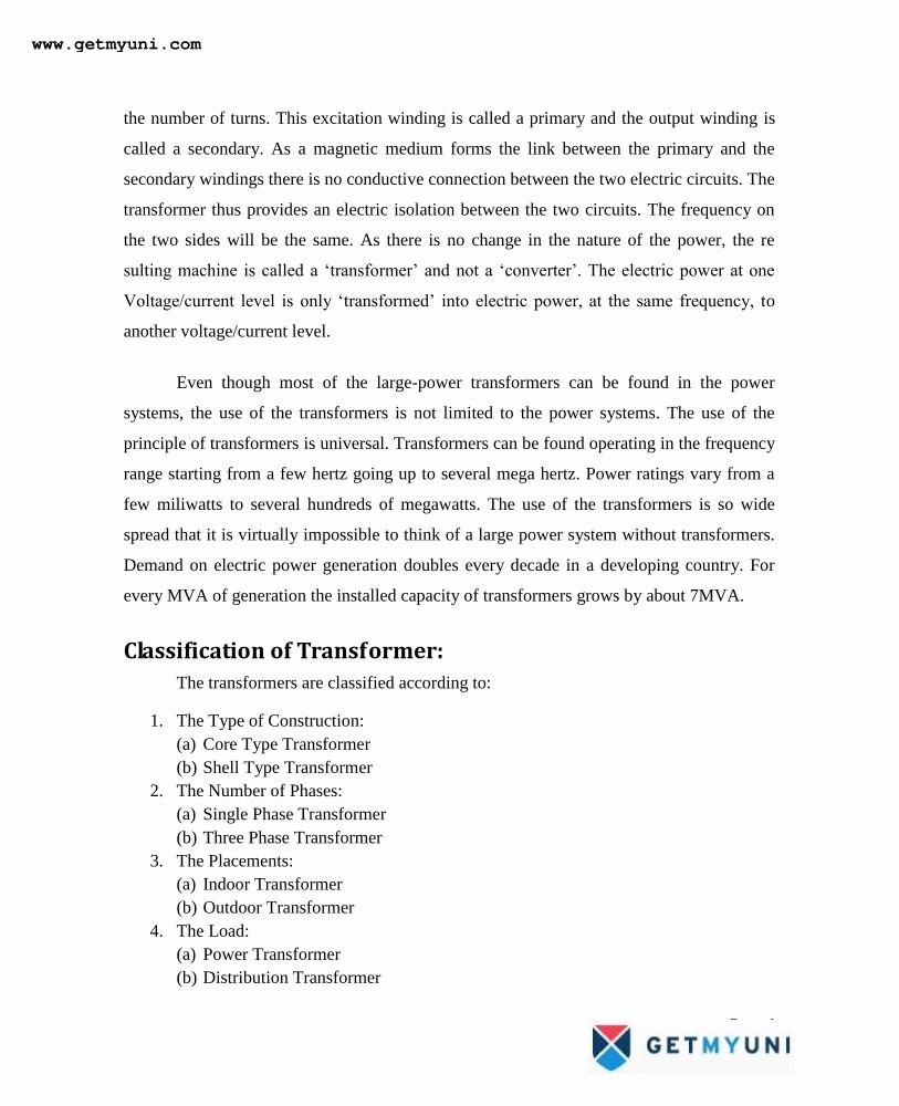
Classification of Transformer:
The transformers are classified according to:
1. The Type of Construction:
(a) Core Type Transformer
(b) Shell Type Transformer
2. The Number of Phases:
(a) Single Phase Transformer
(b) Three Phase Transformer
3. The Placements:
(a) Indoor Transformer
(b) Outdoor Transformer
4. The Load:
(a) Power Transformer
(b) Distribution Transformer
www.getmyuni.com
Page 7
Ideal Transformer
To understand the working of a transformer it is always instructive, to begin with
the concept of an ideal transformer with the following properties.
1. Primary and secondary windings have no resistance.
2. All the flux produced by the primary links the secondary winding i.e., there is no
leakage flux.
3. Permeability μr of the core is infinitely large. In other words, to establish flux in the
core vanishingly small (or zero) current is required.
4. Core loss comprising of eddy current and hysteresis losses are neglected.
Construction of a Transformer
There are two basic parts of a transformer:
1. Magnetic core
2. Winding or coils
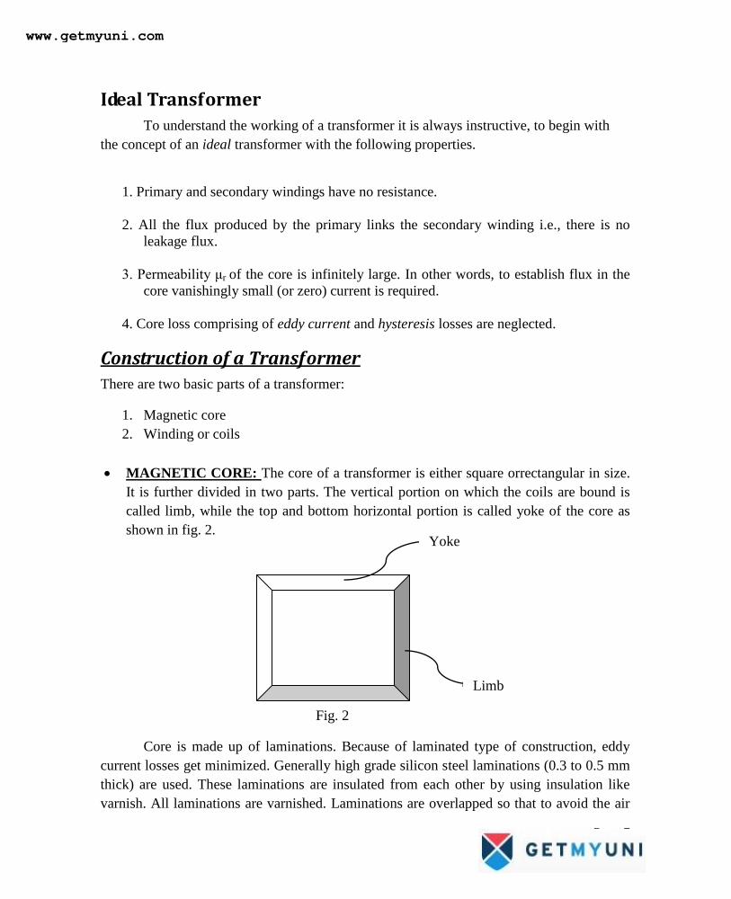
MAGNETIC CORE: The core of a transformer is either square orrectangular in size.
It is further divided in two parts. The vertical portion on which the coils are bound is
called limb, while the top and bottom horizontal portion is called yoke of the core as
shown in fig. 2.
Fig. 2
Core is made up of laminations. Because of laminated type of construction, eddy
current losses get minimized. Generally high grade silicon steel laminations (0.3 to 0.5 mm
thick) are used. These laminations are insulated from each other by using insulation like
varnish. All laminations are varnished. Laminations are overlapped so that to avoid the air
Yoke
Limb
www.getmyuni.com
Page 8
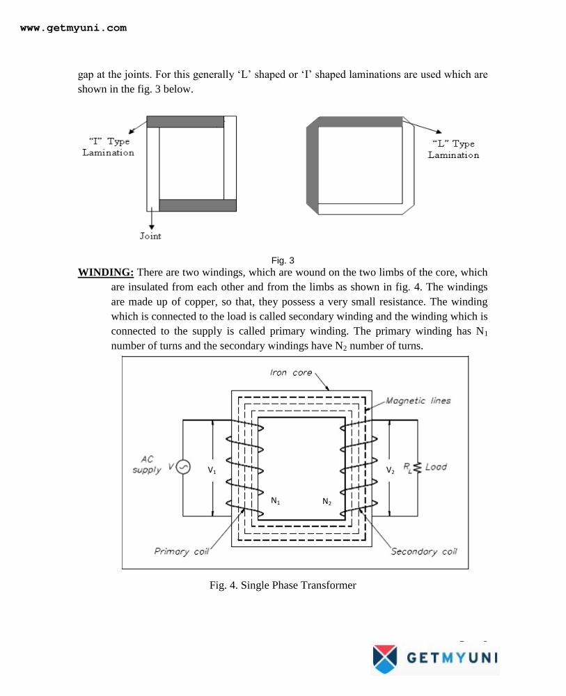
gap at the joints. For this generally ‗L‘ shaped or ‗I‘ shaped laminations are used which are
shown in the fig. 3 below.
Fig. 3
WINDING: There are two windings, which are wound on the two limbs of the core, which
are insulated from each other and from the limbs as shown in fig. 4. The windings
are made up of copper, so that, they possess a very small resistance. The winding
which is connected to the load is called secondary winding and the winding which is
connected to the supply is called primary winding. The primary winding has N1
number of turns and the secondary windings have N2 number of turns.
Fig. 4. Single Phase Transformer
V1 V2
N1 N2
www.getmyuni.com
Page 9
TYPES OF TRANSFORMERS:
The classification of transformer is based on the relative arrangement or disposition of
the core and the windings. There are two main types of transformers.
1. Core type
2. Shell type
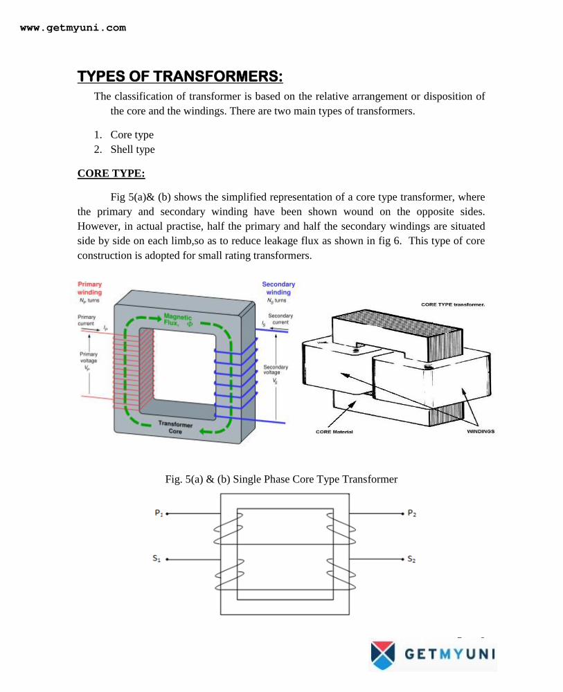
CORE TYPE:
Fig 5(a)& (b) shows the simplified representation of a core type transformer, where
the primary and secondary winding have been shown wound on the opposite sides.
However, in actual practise, half the primary and half the secondary windings are situated
side by side on each limb,so as to reduce leakage flux as shown in fig 6. This type of core
construction is adopted for small rating transformers.
Fig. 5(a) & (b) Single Phase Core Type Transformer
www.getmyuni.com
Page 10
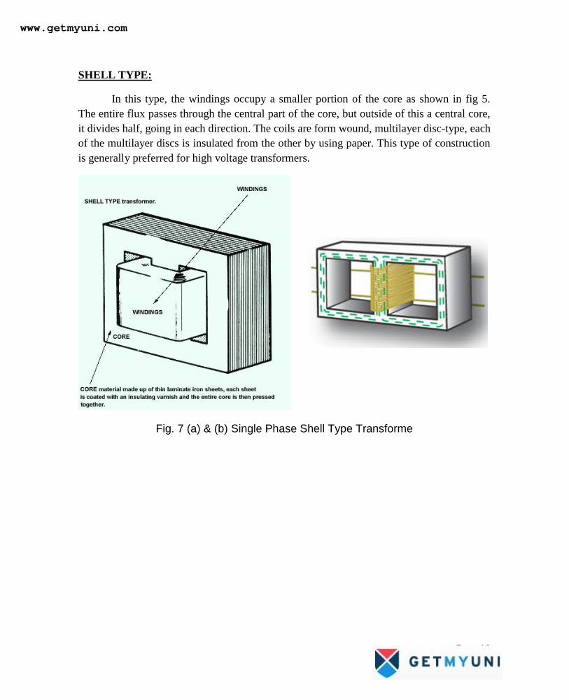
SHELL TYPE:
In this type, the windings occupy a smaller portion of the core as shown in fig 5.
The entire flux passes through the central part of the core, but outside of this a central core,
it divides half, going in each direction. The coils are form wound, multilayer disc-type, each
of the multilayer discs is insulated from the other by using paper. This type of construction
is generally preferred for high voltage transformers.
Fig. 7 (a) & (b) Single Phase Shell Type Transforme
www.getmyuni.com
Page 11
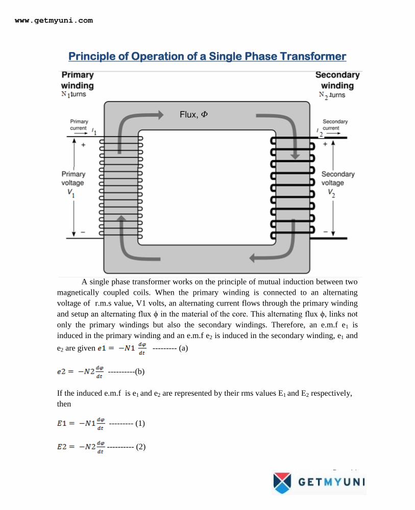
Principle of Operation of a Single Phase Transformer
A single phase transformer works on the principle of mutual induction between two
magnetically coupled coils. When the primary winding is connected to an alternating
voltage of r.m.s value, V1 volts, an alternating current flows through the primary winding
and setup an alternating flux ϕ in the material of the core. This alternating flux ϕ, links not
only the primary windings but also the secondary windings. Therefore, an e.m.f e1 is
induced in the primary winding and an e.m.f e2 is induced in the secondary winding, e1 and
e2 are given --------- (a)
----------(b)
If the induced e.m.f is e1 and e2 are represented by their rms values E1 and E2 respectively,
then
--------- (1)
---------- (2)
www.getmyuni.com
Page 12
Therefore, ---------------- (3)
K is known as the transformation ratio of the transformer. When a load is connected to the
secondary winding, a current I2 flows through the load, V2 is the terminal voltage across the
load. As the power transfered from the primary winding to the secondary winding is same,
Power input to the primary winding = Power output from the secondary winding.
E1I1 = E2I2
(Assuming that the power factor of the primary is equal to the secondary).
Or, ------- (4)
From eqn (3) and (4), we have
--------------- (5)
The directions of emf‘s E1 and E2 induced in the primary and secondary windings are such
that, they always oppose the primary applied voltage V1.
EMF Equation of a transformer:
Consider a transformer having,
N1 =Primary turns
N2 = Secondary turns
Φm = Maximum flux in the core
Φm = Bm × A webers
f= frequency of ac input in hertz (Hz)
www.getmyuni.com
Page 13
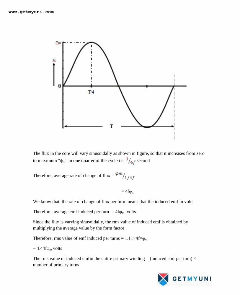
The flux in the core will vary sinusoidally as shown in figure, so that it increases from zero
to maximum ―ϕm‖ in one quarter of the cycle i.e, second
Therefore, average rate of change of flux =
= 4fφm
We know that, the rate of change of flux per turn means that the induced emf in volts.
Therefore, average emf induced per turn = 4fφm volts.
Since the flux is varying sinusoidally, the rms value of induced emf is obtained by
multiplying the average value by the form factor .
Therefore, rms value of emf induced per turns = 1.11×4f×φm
= 4.44fφm volts
The rms value of induced emfin the entire primary winding = (induced emf per turn) ×
number of primary turns
www.getmyuni.com
Page 14
i.e, E1 =4.44fφm×N1 = 4.44fBm×A×N1
Similarly;
E2= 4.44 f φm × N2 = 4.44 f Bm × A × N2
Transformation Ratio:
(1) Voltage Transformation Ratio
(2) Current Transformation Ratio
Voltage Transformation Ratio:
Voltage transformation ratio can be defined as the ratio of the secondary voltage to
the primary voltage denoted by K
Mathematically given as
Current Transformation Ratio:
Consider an ideal transformer and we have the input voltampere is equal to output
voltampere.
Mathematically, Input Voltampere = Output Voltampere
www.getmyuni.com
Page 15
Coupled circuits
When two coils separated by each other, a change in current in one coil will effect
the voltage in another coil by mutual induction
Self Inductance: A coil capable of inducing an emf in itself by changing current
flowing through it, this property of coil is known as self inductance.
The self induced emf is directly proportional to the rate of change of current.
eα di/dt; e =L di/dt
Where L=coefficient of self inductance.
Mutual Inductance
Current in one coil changes, there occurs a change in flux linking with other as
result an emf is induced in the adjacent coils.
The mutually induced emf e2 in the second coil id dependent on the rate of change
of current in the first coil.
e2 α di1/dt; e2=Mdi1/dt
COEFFCIENT OF COUPLING
K= M/(L1L2)
The two coils is said to be tightly or perfectly coupled only when K=1 and therefore
M=L1L2 it‘s said to be maximum mutual inductance
When the distance between the two coils is greater than the coils are said to be
loosely packed
Coefficient of coupling will help in deciding whether the coils are closely packed or
loosely packed.
www.getmyuni.com
Page 16
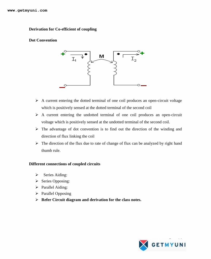
Derivation for Co-efficient of coupling
Dot Convention
A current entering the dotted terminal of one coil produces an open-circuit voltage
which is positively sensed at the dotted terminal of the second coil
A current entering the undotted terminal of one coil produces an open-circuit
voltage which is positively sensed at the undotted terminal of the second coil.
The advantage of dot convention is to find out the direction of the winding and
direction of flux linking the coil
The direction of the flux due to rate of change of flux can be analyzed by right hand
thumb rule.
Different connections of coupled circuits
Series Aiding:
Series Opposing:
Parallel Aiding:
Parallel Opposing
Refer Circuit diagram and derivation for the class notes.
www.getmyuni.com
Page 17
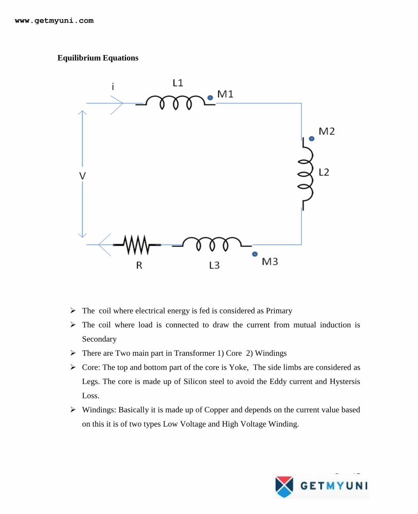
Equilibrium Equations
The coil where electrical energy is fed is considered as Primary
The coil where load is connected to draw the current from mutual induction is
Secondary
There are Two main part in Transformer 1) Core 2) Windings
Core: The top and bottom part of the core is Yoke, The side limbs are considered as
Legs. The core is made up of Silicon steel to avoid the Eddy current and Hystersis
Loss.
Windings: Basically it is made up of Copper and depends on the current value based
on this it is of two types Low Voltage and High Voltage Winding.
www.getmyuni.com
Page 18
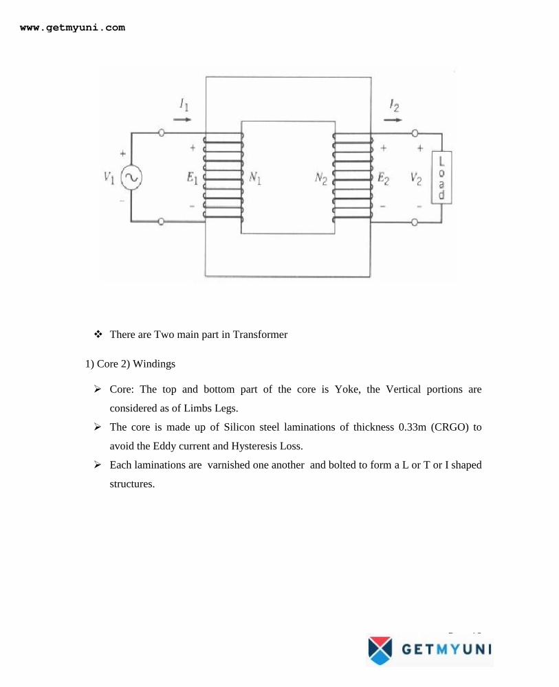
There are Two main part in Transformer
1) Core 2) Windings
Core: The top and bottom part of the core is Yoke, the Vertical portions are
considered as of Limbs Legs.
The core is made up of Silicon steel laminations of thickness 0.33m (CRGO) to
avoid the Eddy current and Hysteresis Loss.
Each laminations are varnished one another and bolted to form a L or T or I shaped
structures.
www.getmyuni.com
Page 19
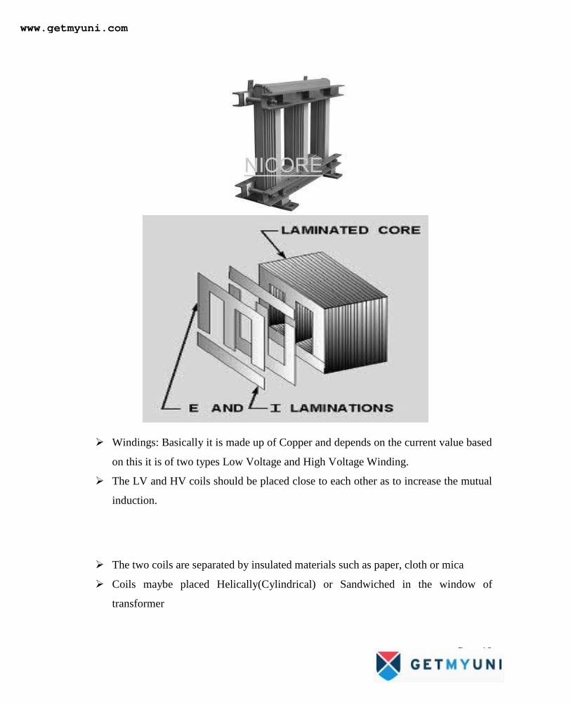
Windings: Basically it is made up of Copper and depends on the current value based
on this it is of two types Low Voltage and High Voltage Winding.
The LV and HV coils should be placed close to each other as to increase the mutual
induction.
The two coils are separated by insulated materials such as paper, cloth or mica
Coils maybe placed Helically(Cylindrical) or Sandwiched in the window of
transformer
www.getmyuni.com
Page 20
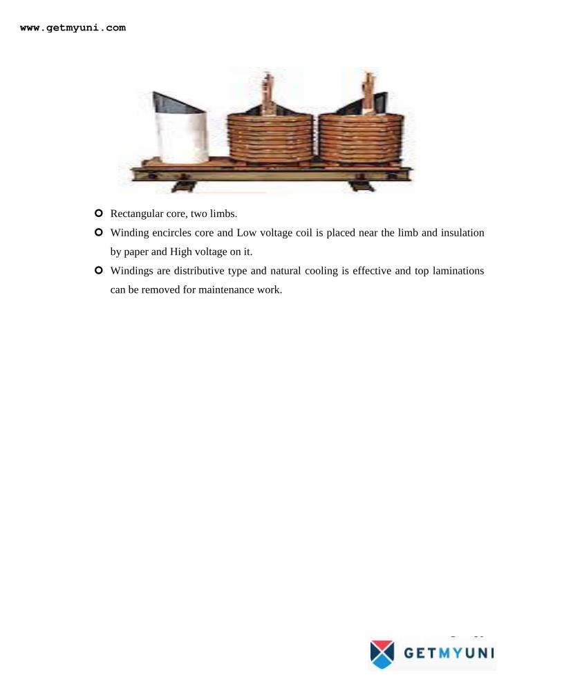
Rectangular core, two limbs.
Winding encircles core and Low voltage coil is placed near the limb and insulation
by paper and High voltage on it.
Windings are distributive type and natural cooling is effective and top laminations
can be removed for maintenance work.
www.getmyuni.com
Page 21
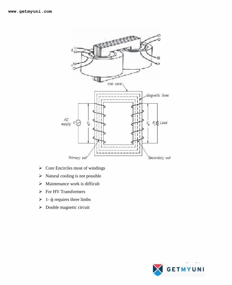
Core Encircles most of windings
Natural cooling is not possible
Maintenance work is difficult
For HV Transformers
1- ф requires three limbs
Double magnetic circuit
www.getmyuni.com
Page 22
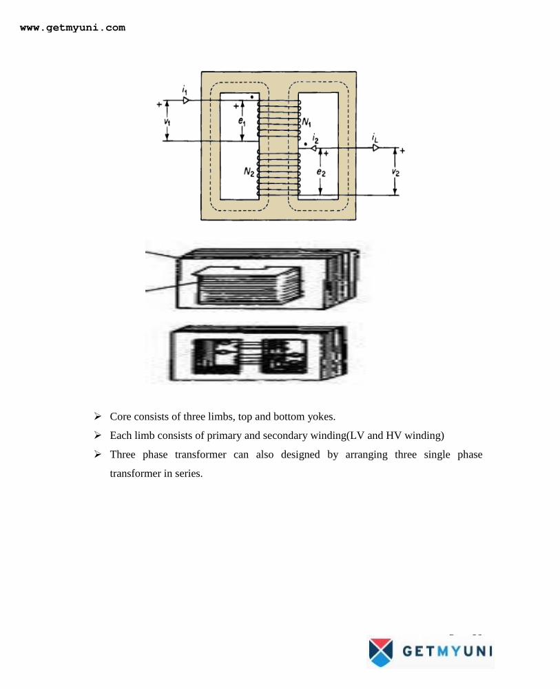
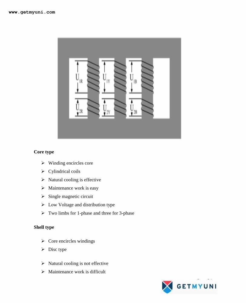
Core consists of three limbs, top and bottom yokes.
Each limb consists of primary and secondary winding(LV and HV winding)
Three phase transformer can also designed by arranging three single phase
transformer in series.
www.getmyuni.com
Page 23
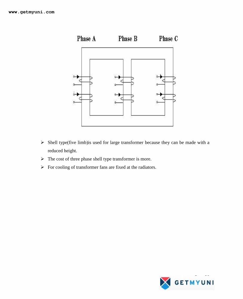
Shell type(five limb)is used for large transformer because they can be made with a
reduced height.
The cost of three phase shell type transformer is more.
For cooling of transformer fans are fixed at the radiators.
www.getmyuni.com
Page 24
Core type
Winding encircles core
Cylindrical coils
Natural cooling is effective
Maintenance work is easy
Single magnetic circuit
Low Voltage and distribution type
Two limbs for 1-phase and three for 3-phase
Shell type
Core encircles windings
Disc type
Natural cooling is not effective
Maintenance work is difficult
www.getmyuni.com
Page 25
Double magnetic circuit
High Voltage transformer
Three limbs for 1-phase and 6-limbs for three phase
Types of Transformer
Power Transformer
Distribution Transformer
Constant Voltage Transformer
Constant Current Transformer
Variable Frequency Transformer
Auto Transformer
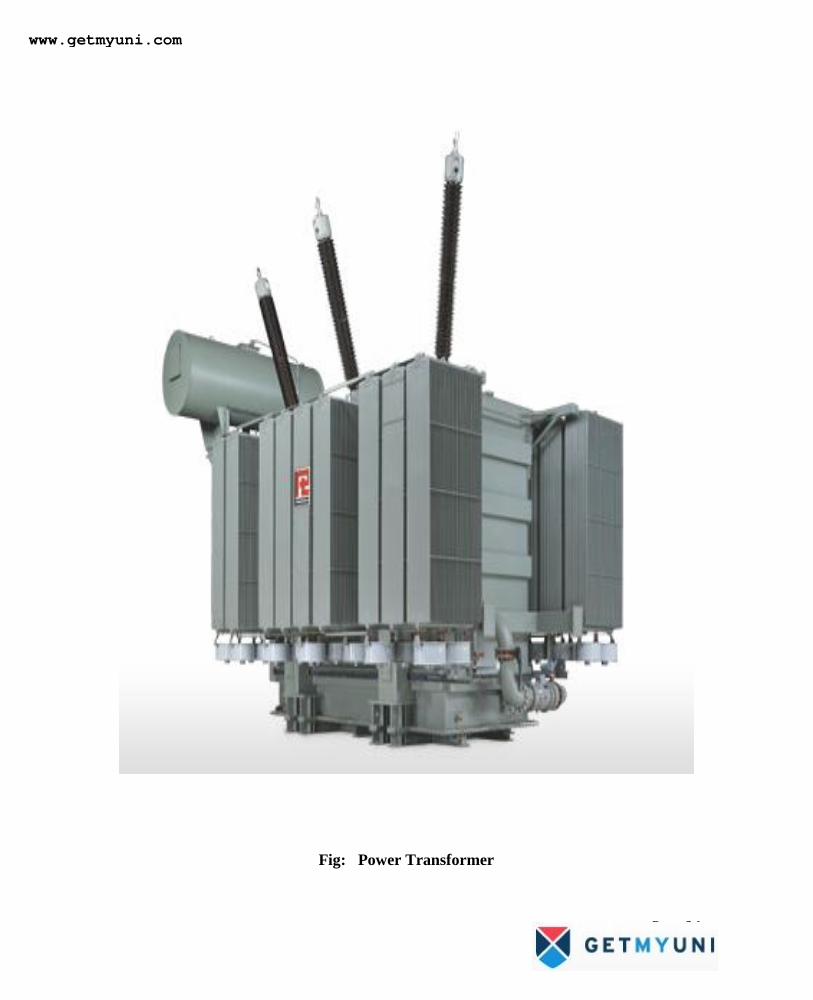
Power transformer of rating 500 mVA 11kv/230v
Transformer having rating more than 200kva is power transformers
Usually this transformers are placed near the generating and substations to either
step up or step down voltage levels
The transformers which are used to transform the transmission voltage to the
voltage level of primary feeders are called substation transformers
www.getmyuni.com
Page 26
Fig: Power Transformer
www.getmyuni.com
Page 27
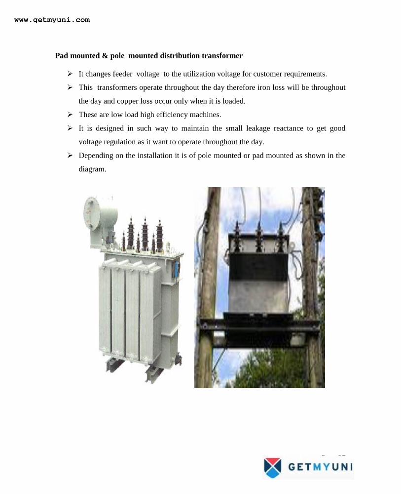
Pad mounted & pole mounted distribution transformer
It changes feeder voltage to the utilization voltage for customer requirements.
This transformers operate throughout the day therefore iron loss will be throughout
the day and copper loss occur only when it is loaded.
These are low load high efficiency machines.
It is designed in such way to maintain the small leakage reactance to get good
voltage regulation as it want to operate throughout the day.
Depending on the installation it is of pole mounted or pad mounted as shown in the
diagram.
www.getmyuni.com
Page 28
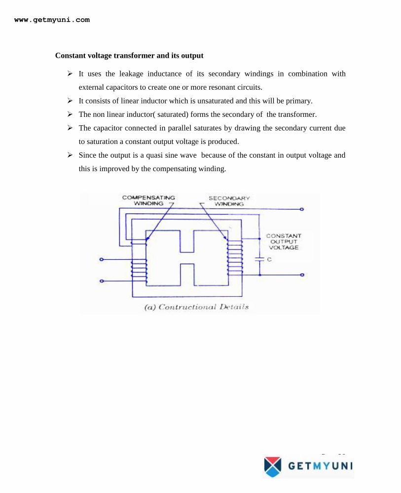
Constant voltage transformer and its output
It uses the leakage inductance of its secondary windings in combination with
external capacitors to create one or more resonant circuits.
It consists of linear inductor which is unsaturated and this will be primary.
The non linear inductor( saturated) forms the secondary of the transformer.
The capacitor connected in parallel saturates by drawing the secondary current due
to saturation a constant output voltage is produced.
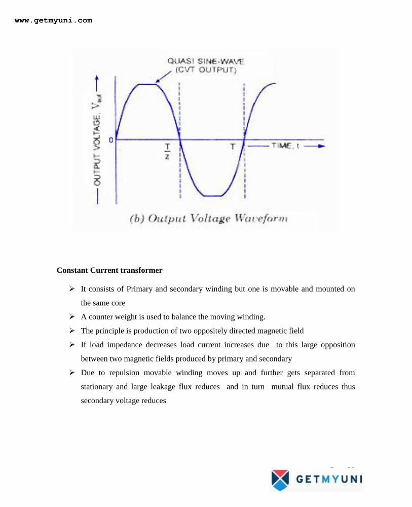
Since the output is a quasi sine wave because of the constant in output voltage and
this is improved by the compensating winding.
www.getmyuni.com
Page 29
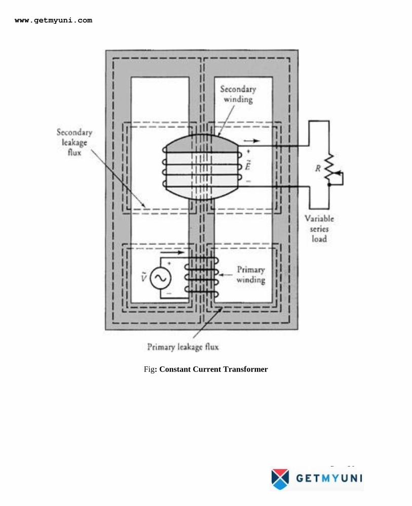
Constant Current transformer
It consists of Primary and secondary winding but one is movable and mounted on
the same core
A counter weight is used to balance the moving winding.
The principle is production of two oppositely directed magnetic field
If load impedance decreases load current increases due to this large opposition
between two magnetic fields produced by primary and secondary
Due to repulsion movable winding moves up and further gets separated from
stationary and large leakage flux reduces and in turn mutual flux reduces thus
secondary voltage reduces
www.getmyuni.com
Page 30
Fig: Constant Current Transformer
www.getmyuni.com
Page 31
Variable frequency transformer
The variable frequency transformer (VFT) is essentially a continuously variable
phase shifting transformer that can operate at an adjustable phase angle
A variable frequency transformer is used to transmit electricity between
two asynchronous alternating current domains.
A variable frequency transformer is a doubly-fed electric machine resembling a
vertical shaft hydroelectric generator with a three-phase wound rotor, connected by
slip rings to one external power circuit. A direct-current torque motor is mounted on
the same shaft
The phase shift between input and output voltage should also be small over the
range of frequencies.
The applications of VFT are Electronic circuits, Communication, Control and
measurement which uses wide band of frequencies.
Auto transformer
Transformer having only one winding such that part of winding common to both
primary and secondary
In the fig 1 the auto transformer is step down because N1>N2 and here N1 is
common to both sides
In the fig2 the autotransformer is step down because N1<N2 and here N2 is
common to both
It works on the principle of both induction and conduction
Power transfer also takes by both induction and conduction.
Weight of copper in autotransformer can be reduced
www.getmyuni.com
Page 32
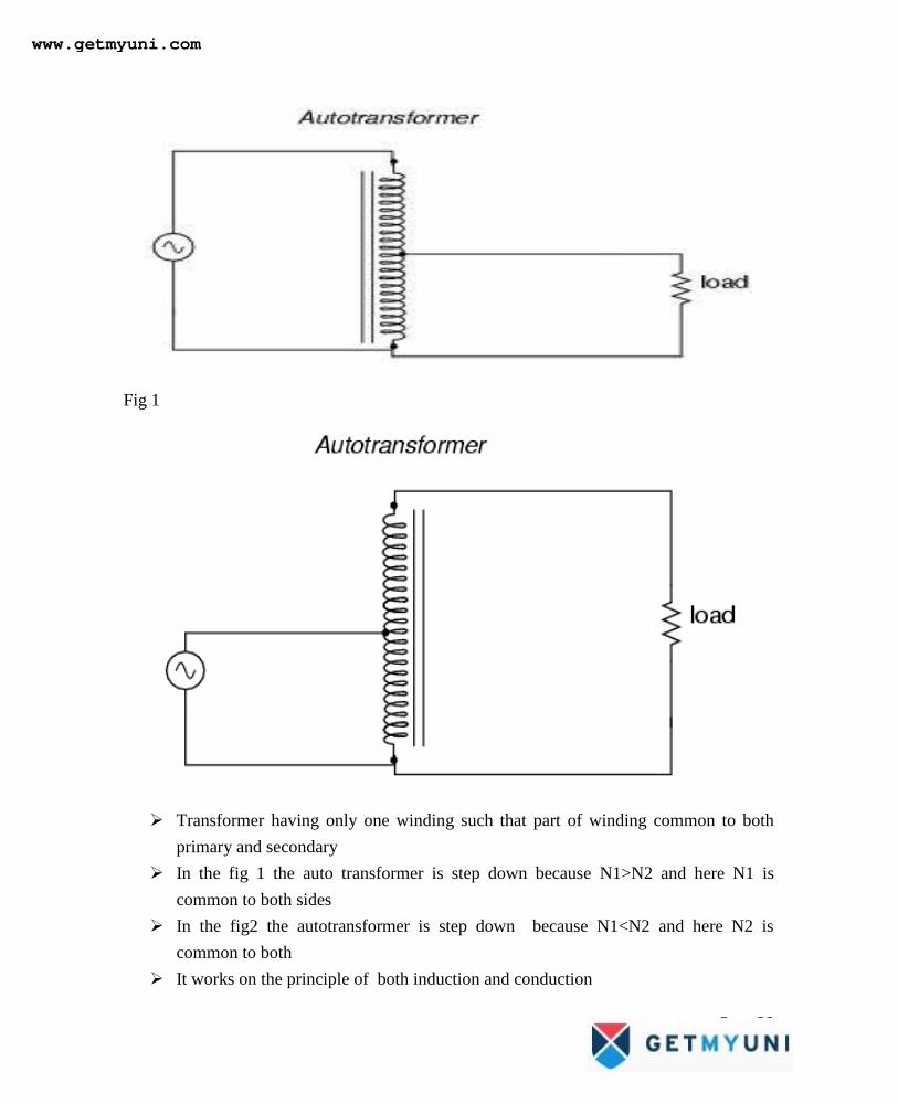
Fig 1
Transformer having only one winding such that part of winding common to both
primary and secondary
In the fig 1 the auto transformer is step down because N1>N2 and here N1 is
common to both sides
In the fig2 the autotransformer is step down because N1<N2 and here N2 is
common to both
It works on the principle of both induction and conduction
www.getmyuni.com
Page 33
Power transfer also takes by both induction and conduction.
Weight of copper in autotransormer can be reduced
Advantages of Autotransformer
Copper required is very less and hence copper loss is reduced.
Efficiency is higher compared to two winding transformer
The power rating is m ore compared to two winding transformer
The size and cost is less compared to two winding transformer
Applications of Autotransformer
It is used as variac for starting of machines like Induction machines, Synchronous
machines.
The voltage drop is compensated and acts as booster.
It used as furnace transformer at the required supply.
It can be connected between two systems operating at same voltage level.
www.getmyuni.com