Embed Size (px)
Citation preview
70072-0153-08TECHNICAL NOTE 09/2011
Schneider Electric2195 Keating Cross RoadSaanichton, BCCanada V8M 2A5Tel: 1-250-652-7100
For technical support:[email protected](00) + 1 250 544 3010
Contact your local Schneider Electric sales representative for assistance or go to www.schneider-electric.com
ION, PowerLogic and Schneider Electric are trademarks or registered trademarks of Schneider Electric in France, the USA and other countries. Other trademarks used are the property of their respective owners.
Electrical equipment should be installed, operated, serviced, and maintained only by qualified personnel. No responsibility is assumed by Schneider Electric for any consequences arising out of the use of this material.
© 2011 Schneider Electric. All rights reserved.
Transformer / line loss calculationsThis document gives a brief overview of transformer loss and line loss calculations and describes how these calculations are implemented in the PowerLogic™ ION8800, ION8650, ION8600, ION7650 and ION7550 meters.
NOTE
The information contained here shows theoretical examples of how the calculations should work, andis only intended to provide guidance in calculating transformer and line losses specific to the meter’sactual electrical connection method and physical installation location.
In this document
Hazard categories and special symbols . . . . . . . . . . . . . . . . . . . . . . . . . . 2
Overview . . . . . . . . . . . . . . . . . . . . . . . . . . . . . . . . . . . . . . . . . . . . . . . . . . . . 3Line loss and transformer loss after the PCC . . . . . . . . . . . . . . . . . . . . . . . . . . . 3
Loss compensation in ION meters . . . . . . . . . . . . . . . . . . . . . . . . . . . . . . 6
Loss compensation input parameters . . . . . . . . . . . . . . . . . . . . . . . . . . . 10Input parameters for Method 1 (Test Sheet Method) . . . . . . . . . . . . . . . . . . . . 10
Use cases: metering point & billing point locations . . . . . . . . . . . . . . . . . . . . . 12
Input parameters for Method 2 (%Loss Constants) . . . . . . . . . . . . . . . . . . . . . 16
Appendix A: Glossary . . . . . . . . . . . . . . . . . . . . . . . . . . . . . . . . . . . . . . . . 20
Appendix B: Loss compensation frameworks . . . . . . . . . . . . . . . . . . . . 22
Hazard categories and special symbols Transformer / line loss calculations
Page 2 of 23 © 2011 Schneider Electric. All rights reserved.
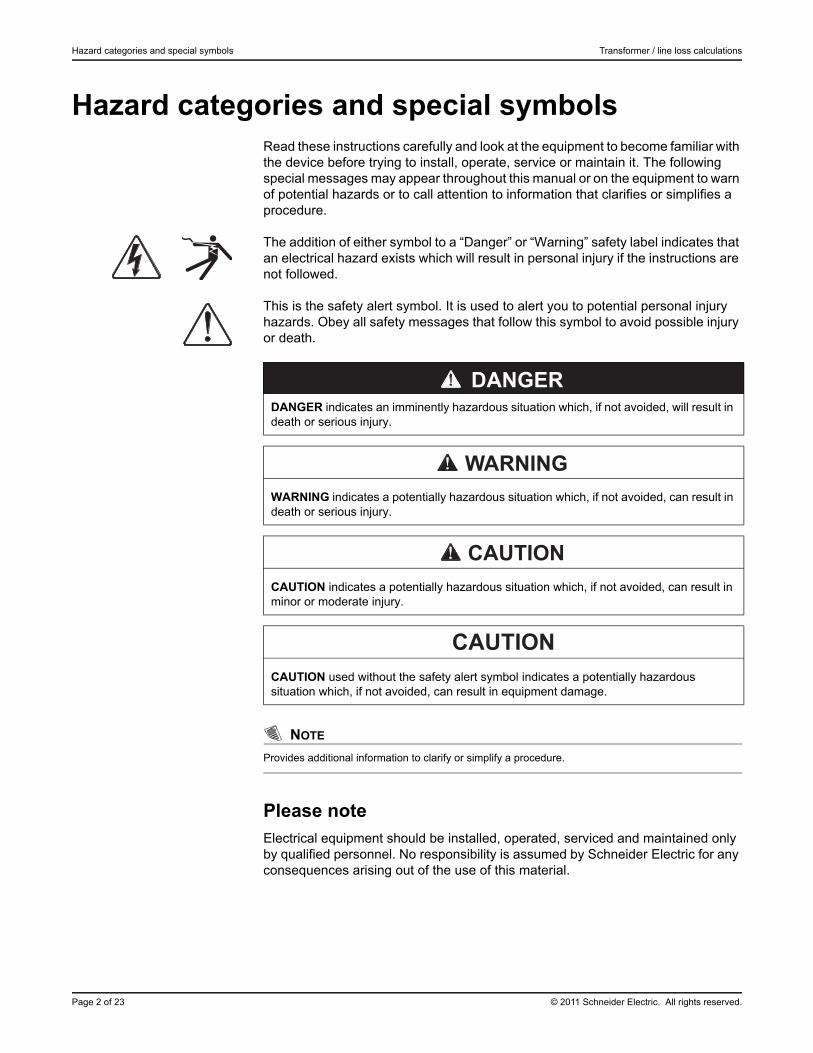
Hazard categories and special symbolsRead these instructions carefully and look at the equipment to become familiar with the device before trying to install, operate, service or maintain it. The following special messages may appear throughout this manual or on the equipment to warn of potential hazards or to call attention to information that clarifies or simplifies a procedure.
The addition of either symbol to a “Danger” or “Warning” safety label indicates that an electrical hazard exists which will result in personal injury if the instructions are not followed.
This is the safety alert symbol. It is used to alert you to potential personal injury hazards. Obey all safety messages that follow this symbol to avoid possible injury or death.
NOTE
Provides additional information to clarify or simplify a procedure.
Please noteElectrical equipment should be installed, operated, serviced and maintained only by qualified personnel. No responsibility is assumed by Schneider Electric for any consequences arising out of the use of this material.
DANGER indicates an imminently hazardous situation which, if not avoided, will result in death or serious injury.
WARNING indicates a potentially hazardous situation which, if not avoided, can result in death or serious injury.
CAUTION indicates a potentially hazardous situation which, if not avoided, can result in minor or moderate injury.
CAUTION
CAUTION used without the safety alert symbol indicates a potentially hazardous situation which, if not avoided, can result in equipment damage.
© 2011 Schneider Electric. All rights reserved. Page 3 of 23
Transformer / line loss calculations Overview
OverviewLoss compensation is used when a meter’s actual location is different from the electrical location where change of ownership occurs; for example, where meters are connected on the low-voltage side of power transformers when the ownership change occurs on the high-side of the transformer. This physical separation between meter and actual billing point results in measurable losses. Compensating for this loss — Loss compensation — is the means of correcting this meter reading. Losses may be added to or subtracted from the meter registration.
Meters are usually installed on the low-voltage side of a transformer because it is more cost-effective. There are also cases where change of ownership may occur halfway along a transmission line where it is impractical to install a meter. In this case, power metering must again be compensated.
Line loss and transformer loss after the PCCThe PCC (Point of Common Coupling) is the interchange point between the distribution grid and a particular customer. Unlike losses that occur within a transmission/distribution network, which cannot be allocated to a single customer and must be rolled into the per-unit cost of electricity, losses that occur after the PCC can be measured and allocated accordingly.
Causes of line lossLine losses are a result of passing current through an imperfect conductor such as copper. The conducting material has characteristic impedance that produce a voltage drop along the line proportional to the current flow. The total line impedance can be determined from these elements:
CAUTION
HAZARD OF UNINTENDED OPERATION AND INACCURATE TEST RESULTS
• The device must only be configured and set by qualified personnel with a thorough understanding of ION architecture and the system in which the meters and software are installed.
• Due to the variation in installations, advanced knowledge of power systems and connection methods is required before transformer loss compensation can be properly implemented.
• Data parameters should only be programmed by qualified personnel that have appropriate training and experience with Transformer Loss Compensation calculations.
Failure to follow these instructions can result in incorrect test reports and/or data results.
Line loss and transformer loss after the PCC Transformer / line loss calculations
Page 4 of 23 © 2011 Schneider Electric. All rights reserved.
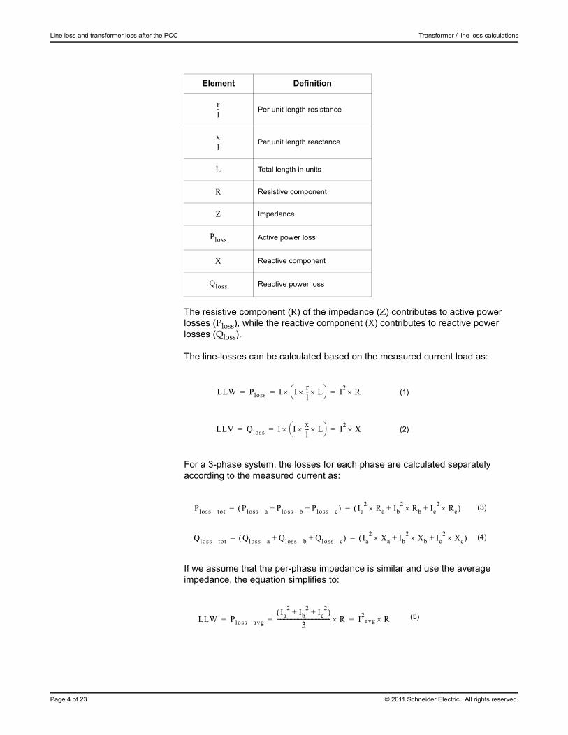
The resistive component (R) of the impedance (Z) contributes to active power losses (Ploss), while the reactive component (X) contributes to reactive power losses (Qloss).
The line-losses can be calculated based on the measured current load as:
For a 3-phase system, the losses for each phase are calculated separately according to the measured current as:
If we assume that the per-phase impedance is similar and use the average impedance, the equation simplifies to:
Element Definition
Per unit length resistance
Per unit length reactance
Total length in units
Resistive component
Impedance
Active power loss
Reactive component
Reactive power loss
(1)
(2)
(3)
(4)
(5)
rl-
xl---
L
R
Z
Ploss
X
Qloss
LLW Ploss I Irl- L
I2
R= = =
LLV Qloss I Ixl--- L
I2
X= = =
Ploss tot– Ploss a– Ploss b– Ploss c–+ + Ia2
Ra Ib2
Rb Ic2
Rc+ + = =
Qloss tot– Qloss a– Qloss b– Qloss c–+ + Ia2
Xa Ib2
Xb Ic2
Xc+ + = =
LLW Ploss avg–
Ia2
Ib2
Ic2
+ + 3
-------------------------------------- R I2
avg R= = =
© 2011 Schneider Electric. All rights reserved. Page 5 of 23
Transformer / line loss calculations Line loss and transformer loss after the PCC
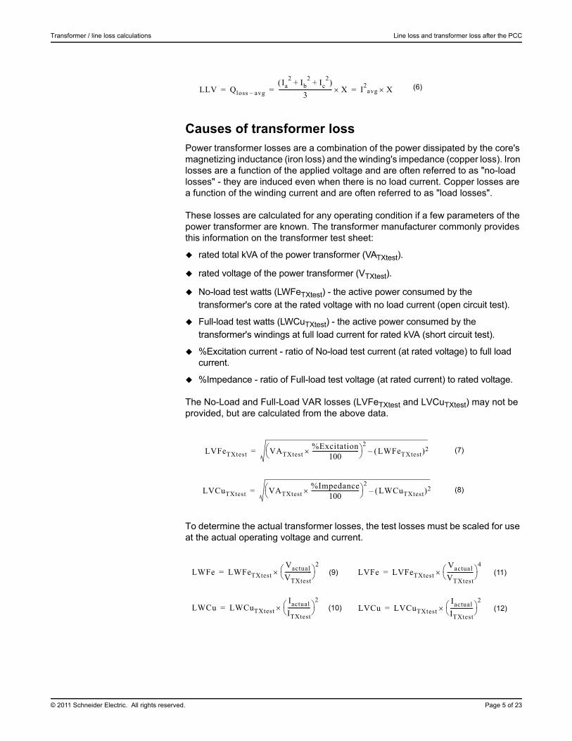
Causes of transformer lossPower transformer losses are a combination of the power dissipated by the core's magnetizing inductance (iron loss) and the winding's impedance (copper loss). Iron losses are a function of the applied voltage and are often referred to as "no-load losses" - they are induced even when there is no load current. Copper losses are a function of the winding current and are often referred to as "load losses".
These losses are calculated for any operating condition if a few parameters of the power transformer are known. The transformer manufacturer commonly provides this information on the transformer test sheet:
rated total kVA of the power transformer (VATXtest).
rated voltage of the power transformer (VTXtest).
No-load test watts (LWFeTXtest) - the active power consumed by the transformer's core at the rated voltage with no load current (open circuit test).
Full-load test watts (LWCuTXtest) - the active power consumed by the transformer's windings at full load current for rated kVA (short circuit test).
%Excitation current - ratio of No-load test current (at rated voltage) to full load current.
%Impedance - ratio of Full-load test voltage (at rated current) to rated voltage.
The No-Load and Full-Load VAR losses (LVFeTXtest and LVCuTXtest) may not be provided, but are calculated from the above data.
To determine the actual transformer losses, the test losses must be scaled for use at the actual operating voltage and current.
(6)
(7)
(8)
(9) (11)
(10) (12)
LLV Qloss avg–
Ia2
Ib2
Ic2
+ + 3
-------------------------------------- X I2
avg X= = =
LVFeTXtest VATXtest%Excitation
100---------------------------------
2LWFeTXtest 2–=
LVCuTXtest VATXtest%Impedance
100----------------------------------
2LWCuTXtest 2–=
LWFe LWFeTXtest
Vactual
VTXtest-------------------
2= LVFe LVFeTXtest
Vactual
VTXtest-------------------
4=
LWCu LWCuTXtest
Iactual
ITXtest----------------
2= LVCu LVCuTXtest
Iactual
ITXtest----------------
2=
Loss compensation in ION meters Transformer / line loss calculations
Page 6 of 23 © 2011 Schneider Electric. All rights reserved.
Loss compensation in ION metersION meters that support loss compensation in their default framework are the ION8800, ION8650, ION8600, ION7650 and ION7550 meters.
The meters have the following transformer and line loss compensation features:
Compensation performed on 1-second total power (kW total, kVAR total, and kVA total).
Unbalanced loads are handled accurately (except in the case of line-loss of neutral conductor in a 4-Wye system).
Losses may be added or subtracted.
Compensation works in all four power quadrants.
Compensation is available in Test Mode. Support for compensation on single-phase test sets is also available in Test Mode.
Compensation works correctly when all revenue parameters are reported in secondary units (meter units).
By default the ION8800, ION8650, ION8600, ION7650 and ION7550 meters come configured to provide the following compensated registers:
For Total kW, Total kVAR, and Total kVA quantities:
Real-time power
Demand: Thermal and Block
Calibration Pulsers
Min/Max
For Total kWh, Total kVARh, and Total kVAh quantities
Energy
Interval Energy
Energy in Test Mode
Energy for each TOU rate
The meters offer two possible loss calculation methods. One must be selected when loss compensation is enabled:
Test Sheet (Method 1)
%Loss Constants (Method 2)
Both methods are based on the same calculations and produce identical results if the correct input parameters are programmed into the meter. The difference between these methods is in the type of parameters required to perform the loss calculations.
NOTE
To simplify verification in Method 2, the user is required to calculate the parameters in advance.
© 2011 Schneider Electric. All rights reserved. Page 7 of 23
Transformer / line loss calculations Loss compensation in ION meters
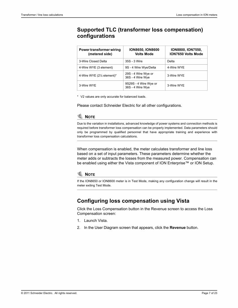
Supported TLC (transformer loss compensation) configurations
* V2 values are only accurate for balanced loads.
Please contact Schneider Electric for all other configurations.
NOTE
Due to the variation in installations, advanced knowledge of power systems and connection methods isrequired before transformer loss compensation can be properly implemented. Data parameters shouldonly be programmed by qualified personnel that have appropriate training and experience withtransformer loss compensation calculations.
When compensation is enabled, the meter calculates transformer and line loss based on a set of input parameters. These parameters determine whether the meter adds or subtracts the losses from the measured power. Compensation can be enabled using either the Vista component of ION Enterprise™ or ION Setup.
NOTE
If the ION8650 or ION8600 meter is in Test Mode, making any configuration change will result in themeter exiting Test Mode.
Configuring loss compensation using VistaClick the Loss Compensation button in the Revenue screen to access the Loss Compensation screen:
1. Launch Vista.
2. In the User Diagram screen that appears, click the Revenue button.
Power transformer wiring (metered side)
ION8650, ION8600 Volts Mode
ION8800, ION7550, ION7650 Volts Mode
3-Wire Closed Delta 35S - 3 Wire Delta
4-Wire WYE (3 element) 9S - 4 Wire Wye/Delta 4-Wire WYE
4-Wire WYE (2½ element)*29S - 4 Wire Wye or36S - 4 Wire Wye
3-Wire WYE
3-Wire WYE9S29S - 4 Wire Wye or36S - 4 Wire Wye
3-Wire WYE
Loss compensation in ION meters Transformer / line loss calculations
Page 8 of 23 © 2011 Schneider Electric. All rights reserved.
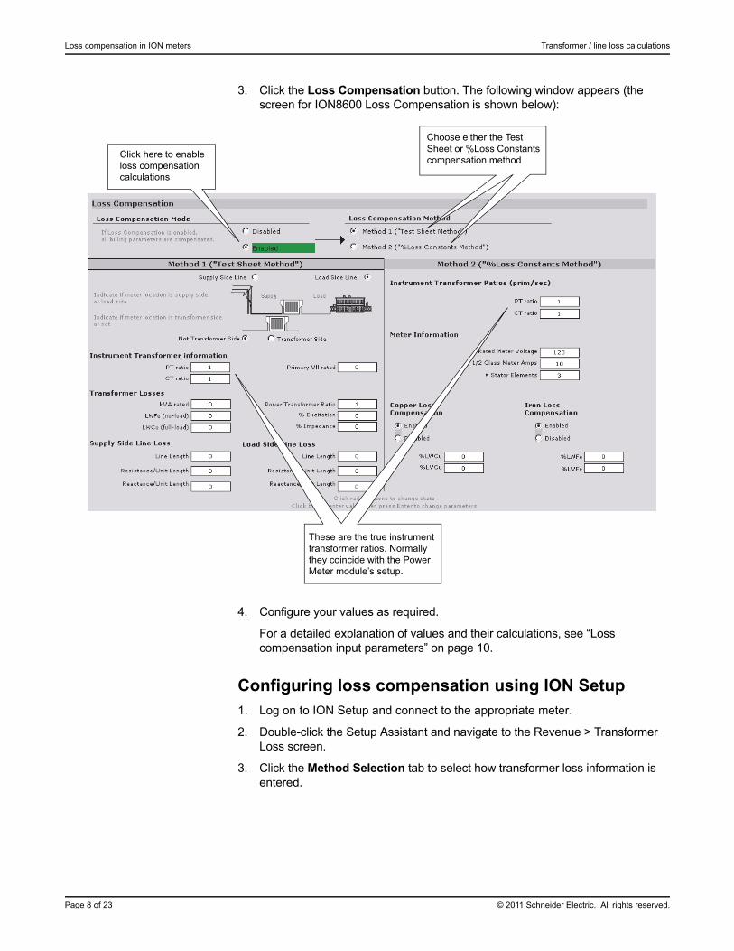
3. Click the Loss Compensation button. The following window appears (the screen for ION8600 Loss Compensation is shown below):
4. Configure your values as required.
For a detailed explanation of values and their calculations, see “Loss compensation input parameters” on page 10.
Configuring loss compensation using ION Setup1. Log on to ION Setup and connect to the appropriate meter.
2. Double-click the Setup Assistant and navigate to the Revenue > Transformer Loss screen.
3. Click the Method Selection tab to select how transformer loss information is entered.
Click here to enable loss compensation calculations
Choose either the Test Sheet or %Loss Constants compensation method
These are the true instrument transformer ratios. Normally they coincide with the Power Meter module’s setup.
© 2011 Schneider Electric. All rights reserved. Page 9 of 23
Transformer / line loss calculations Loss compensation in ION meters
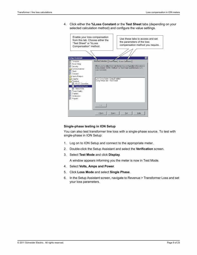
4. Click either the %Loss Constant or the Test Sheet tabs (depending on your selected calculation method) and configure the value settings.
Single-phase testing in ION Setup
You can also test transformer line loss with a single-phase source. To test with single-phase in ION Setup:
1. Log on to ION Setup and connect to the appropriate meter.
2. Double-click the Setup Assistant and select the Verification screen.
3. Select Test Mode and click Display.
A window appears informing you the meter is now in Test Mode.
4. Select Volts, Amps and Power.
5. Click Loss Mode and select Single Phase.
6. In the Setup Assistant screen, navigate to Revenue > Transformer Loss and set your loss parameters.
Enable your loss compensation from this tab. Choose either the “Test Sheet” or %Loss Compensation” method.
Use these tabs to access and set the parameters of the loss compensation method you require.
Loss compensation input parameters Transformer / line loss calculations
Page 10 of 23 © 2011 Schneider Electric. All rights reserved.
Loss compensation input parametersDepending on the method chosen for transformer loss compensation, the meter requires specific data parameters to be programmed into the meter. The data for each method is listed below. All parameters can be programmed into the meter using ION Enterprise or ION Setup software.
The following is a detailed description of the input parameters required by both methods.
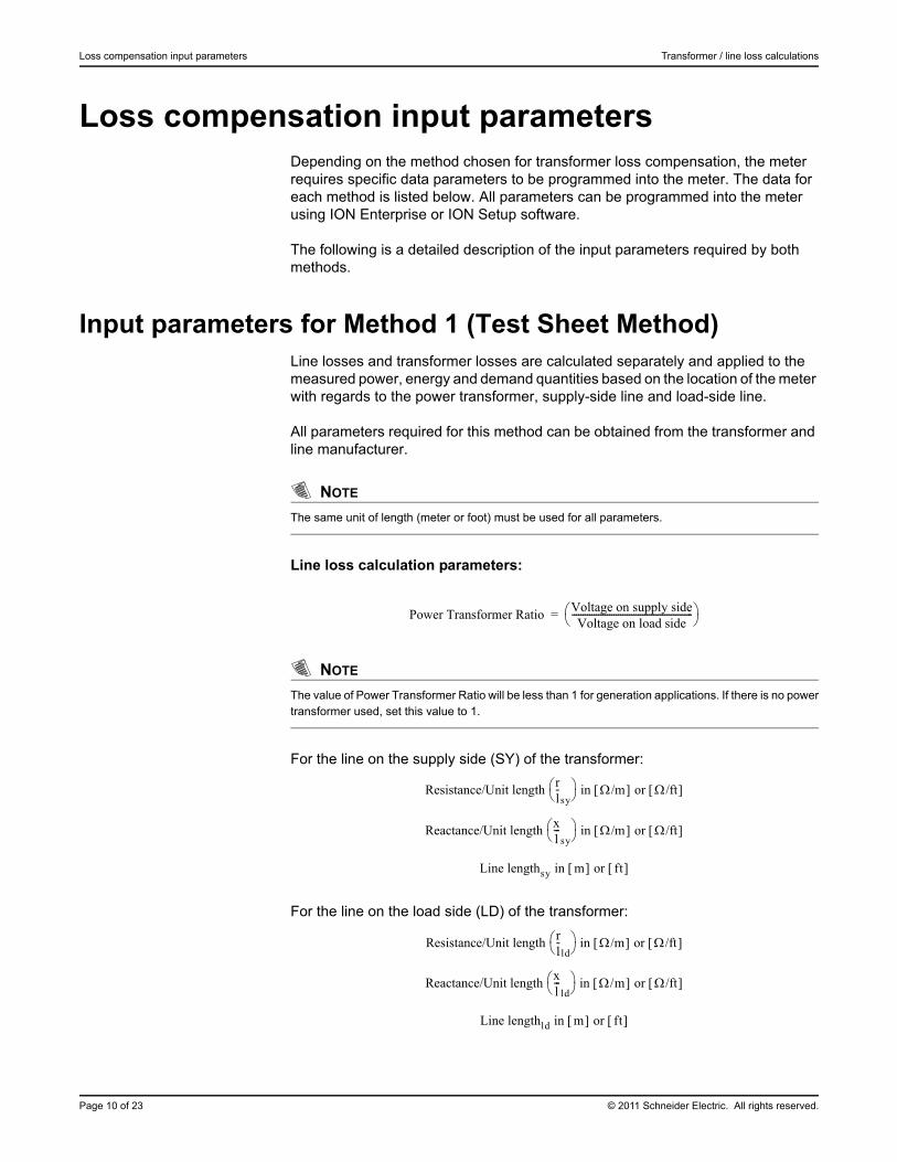
Input parameters for Method 1 (Test Sheet Method)Line losses and transformer losses are calculated separately and applied to the measured power, energy and demand quantities based on the location of the meter with regards to the power transformer, supply-side line and load-side line.
All parameters required for this method can be obtained from the transformer and line manufacturer.
NOTE
The same unit of length (meter or foot) must be used for all parameters.
Line loss calculation parameters:
NOTE
The value of Power Transformer Ratio will be less than 1 for generation applications. If there is no powertransformer used, set this value to 1.
For the line on the supply side (SY) of the transformer:
For the line on the load side (LD) of the transformer:
Power Transformer RatioVoltage on supply sideVoltage on load side
------------------------------------------------------- =
Resistance/Unit length rl-
sy in /m or /ft
Reactance/Unit length xl---
sy in /m or /ft
Line lengthsy in m or ft
Resistance/Unit length rl-
ld in /m or /ft
Reactance/Unit length xl---
ld in /m or /ft
Line lengthld in m or ft
© 2011 Schneider Electric. All rights reserved. Page 11 of 23
Transformer / line loss calculations Input parameters for Method 1 (Test Sheet Method)
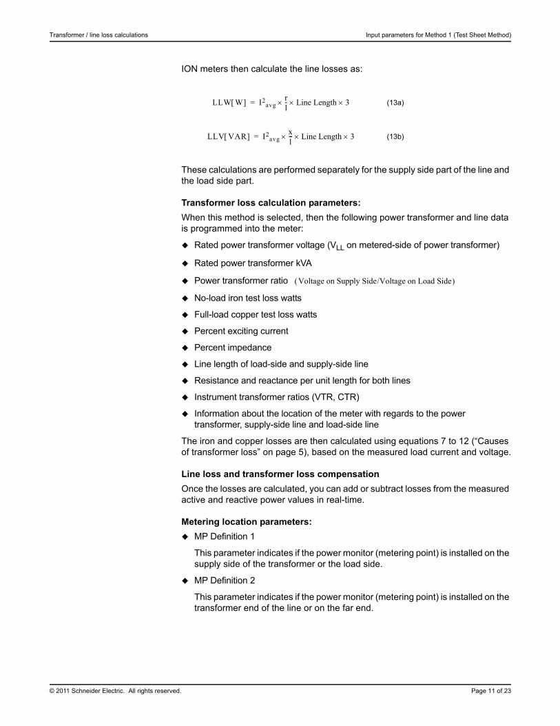
ION meters then calculate the line losses as:
These calculations are performed separately for the supply side part of the line and the load side part.
Transformer loss calculation parameters:
When this method is selected, then the following power transformer and line data is programmed into the meter:
Rated power transformer voltage (VLL on metered-side of power transformer)
Rated power transformer kVA
Power transformer ratio
No-load iron test loss watts
Full-load copper test loss watts
Percent exciting current
Percent impedance
Line length of load-side and supply-side line
Resistance and reactance per unit length for both lines
Instrument transformer ratios (VTR, CTR)
Information about the location of the meter with regards to the power transformer, supply-side line and load-side line
The iron and copper losses are then calculated using equations 7 to 12 (“Causes of transformer loss” on page 5), based on the measured load current and voltage.
Line loss and transformer loss compensation
Once the losses are calculated, you can add or subtract losses from the measured active and reactive power values in real-time.
Metering location parameters:
MP Definition 1
This parameter indicates if the power monitor (metering point) is installed on the supply side of the transformer or the load side.
MP Definition 2
This parameter indicates if the power monitor (metering point) is installed on the transformer end of the line or on the far end.
(13a)
(13b)
LLW W I2avg
rl- Line Length 3=
LLV VAR I2avg
xl--- Line Length 3=
Voltage on Supply Side/Voltage on Load Side
Use cases: metering point & billing point locations Transformer / line loss calculations
Page 12 of 23 © 2011 Schneider Electric. All rights reserved.
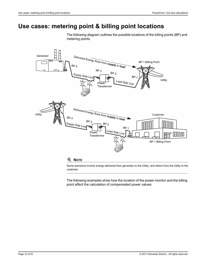
Use cases: metering point & billing point locationsThe following diagram outlines the possible locations of the billing points (BP) and metering points.
NOTE
Some scenarios involve energy delivered from generator to the Utility, and others from the Utility to thecustomer.
The following examples show how the location of the power monitor and the billing point affect the calculation of compensated power values.
Delivered Energy flows from supply to load
Delivered Energy flows from supply to load
BP = Billing Point
Utility
Generator
Power Transformer
Supply Side LineLoad Side Line
BP 4
BP 3BP 2
BP 1
BP = Billing Point
Customer
Supply Side Line
Load Side Line
BP 4BP 3
BP 2BP 1
Power Transformer
Utility
© 2011 Schneider Electric. All rights reserved. Page 13 of 23
Transformer / line loss calculations Use cases: metering point & billing point locations
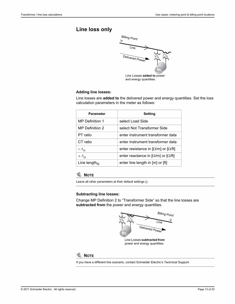
Line loss only
Adding line losses:
Line losses are added to the delivered power and energy quantities. Set the loss calculation parameters in the meter as follows:
NOTE
Leave all other parameters at their default settings ().
Subtracting line losses:
Change MP Definition 2 to “Transformer Side” so that the line losses are subtracted from the power and energy quantities.
NOTE
If you have a different line scenario, contact Schneider Electric’s Technical Support.
Parameter Setting
MP Definition 1 select Load Side
MP Definition 2 select Not Transformer Side
PT ratio enter instrument transformer data
CT ratio enter instrument transformer data
enter resistance in [/m] or [/ft]
enter reactance in [/m] or [/ft]
Line lengthld enter line length in [m] or [ft]
Line Losses added to power and energy quantities.
Delivered Power
Billing Point
Line
r lld
x lld
Line Losses subtracted from power and energy quantities.
Delivered Power
Billing Point
Line
Use cases: metering point & billing point locations Transformer / line loss calculations
Page 14 of 23 © 2011 Schneider Electric. All rights reserved.
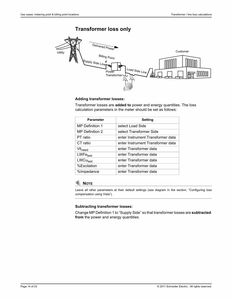
Transformer loss only
Adding transformer losses:
Transformer losses are added to power and energy quantities. The loss calculation parameters in the meter should be set as follows:
NOTE
Leave all other parameters at their default settings (see diagram in the section, “Configuring losscompensation using Vista”).
Subtracting transformer losses:
Change MP Definition 1 to “Supply Side” so that transformer losses are subtracted from the power and energy quantities.
Delivered PowerCustomer
Supply Side Line
Load Side LinePower Transformer
UtilityBilling Point
Parameter Setting
MP Definition 1 select Load Side
MP Definition 2 select Transformer Side
PT ratio enter Instrument Transformer data
CT ratio enter Instrument Transformer data
Vllrated enter Transformer data
LWFetest enter Transformer data
LWCutest enter Transformer data
%Excitation enter Transformer data
%Impedance enter Transformer data
© 2011 Schneider Electric. All rights reserved. Page 15 of 23
Transformer / line loss calculations Use cases: metering point & billing point locations
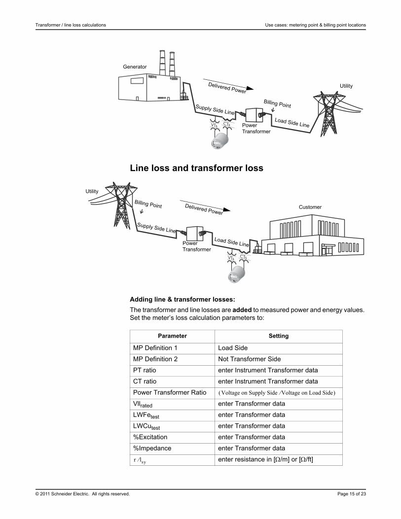
Line loss and transformer loss
Adding line & transformer losses:
The transformer and line losses are added to measured power and energy values. Set the meter’s loss calculation parameters to:
Delivered Power
Supply Side LineLoad Side LinePower
Transformer
Utility
Billing Point
Generator
Delivered PowerCustomer
Supply Side Line
Load Side LinePower Transformer
Utility
Billing Point
Parameter Setting
MP Definition 1 Load Side
MP Definition 2 Not Transformer Side
PT ratio enter Instrument Transformer data
CT ratio enter Instrument Transformer data
Power Transformer Ratio
Vllrated enter Transformer data
LWFetest enter Transformer data
LWCutest enter Transformer data
%Excitation enter Transformer data
%Impedance enter Transformer data
enter resistance in [/m] or [/ft]
Voltage on Supply Side Voltage on Load Side
r lsy
Input parameters for Method 2 (%Loss Constants) Transformer / line loss calculations
Page 16 of 23 © 2011 Schneider Electric. All rights reserved.
NOTE
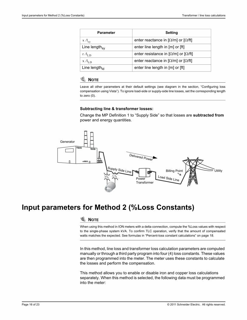
Leave all other parameters at their default settings (see diagram in the section, “Configuring losscompensation using Vista”). To ignore load-side or supply-side line losses, set the corresponding lengthto zero (0).
Subtracting line & transformer losses:
Change the MP Definition 1 to “Supply Side” so that losses are subtracted from power and energy quantities.
Input parameters for Method 2 (%Loss Constants)
NOTE
When using this method in ION meters with a delta connection, compute the %Loss values with respectto the single-phase system kVA. To confirm TLC operation, verify that the amount of compensatedwatts matches the expected. See formulas in “Percent-loss constant calculations” on page 18.
In this method, line loss and transformer loss calculation parameters are computed manually or through a third party program into four (4) loss constants. These values are then programmed into the meter. The meter uses these constants to calculate the losses and perform the compensation.
This method allows you to enable or disable iron and copper loss calculations separately. When this method is selected, the following data must be programmed into the meter:
enter reactance in [/m] or [/ft]
Line lengthsy enter line length in [m] or [ft]
enter resistance in [/m] or [/ft]
enter reactance in [/m] or [/ft]
Line lengthld enter line length in [m] or [ft]
Parameter Setting
x lsy
r lLD
x lLD
Delivered Power
Billing Point Utility
Generator
Power Transformer
Supply Side Line
Load Side Line
© 2011 Schneider Electric. All rights reserved. Page 17 of 23
Transformer / line loss calculations Input parameters for Method 2 (%Loss Constants)
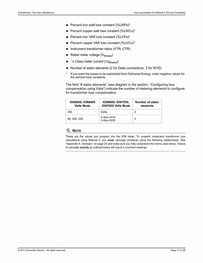
Percent iron watt loss constant (%LWFe)*
Percent copper watt loss constant (%LWCu)*
Percent iron VAR loss constant (%LVFe)*
Percent copper VAR loss constant (%LVCu)*
Instrument transformer ratios (VTR, CTR)
Rated meter voltage (VMrated)
½ Class meter current (½IMrated)
Number of stator elements (2 for Delta connections, 3 for WYE)
* If you want the losses to be subtracted from Delivered Energy, enter negative values for the percent loss constants.
The field “# stator elements” (see diagram in the section, “Configuring loss compensation using Vista”) indicate the number of metering elements to configure for transformer loss compensation:
NOTE
These are the values you program into the ION meter. To properly implement transformer losscalculations using Method 2, you must calculate constants using the following relationships. See“Appendix A: Glossary” on page 20 and make sure you fully understand the terms used below. Failureto calculate exactly as outlined below will result in incorrect readings.
ION8650, ION8600 Volts Mode
ION8800, ION7550, ION7650 Volts Mode
Number of stator elements
35S Delta 2
9S, 36S, 29S4-Wire WYE3-Wire WYE
3
Input parameters for Method 2 (%Loss Constants) Transformer / line loss calculations
Page 18 of 23 © 2011 Schneider Electric. All rights reserved.
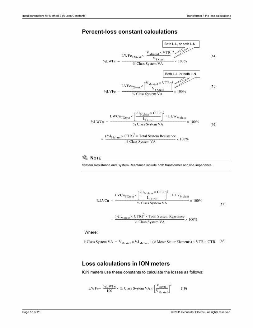
Percent-loss constant calculations
NOTE
System Resistance and System Reactance include both transformer and line impedance.
Loss calculations in ION metersION meters use these constants to calculate the losses as follows:
(17)
Where:
(18)
(19)
(14)
(15)
(16)
%LWFe
LWFeTXtest
VMrated VTRVTXtest
--------------------------------------2
½ Class System VA------------------------------------------------------------------------------------ 100 %=
%LVFe
LVFeTXtest
VMrated VTRVTXtest
--------------------------------------4
½ Class System VA----------------------------------------------------------------------------------- 100 %=
%LWCu
LWCuTXtest
½IMclass CTRITXtest
----------------------------------------2
LLWMclass+
½ Class System VA-------------------------------------------------------------------------------------------------------------------------- 100 %=
½IMclass CTR 2Total System Resistance
½ Class System VA----------------------------------------------------------------------------------------------------------------- 100%=
Both L-L, or both L-N
Both L-L, or both L-N
%LVCu
LVCuTXtest
½IMclass CTRITXtest
----------------------------------------2
LLVMclass+
½ Class System VA------------------------------------------------------------------------------------------------------------------------ 100 %=
½IMclass CTR 2 Total System Reactance½ Class System VA
---------------------------------------------------------------------------------------------------------------- 100%=
½Class System VA VMrated ½IMclass # Meter Stator Elements VTR CTR=
LWFe%LWFe
100-------------------- ½ Class System VA
Vactual
VMrated-------------------
2=
© 2011 Schneider Electric. All rights reserved. Page 19 of 23
Transformer / line loss calculations Input parameters for Method 2 (%Loss Constants)
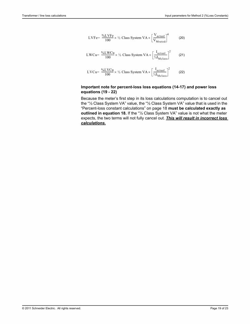
Important note for percent-loss loss equations (14-17) and power loss equations (19 - 22)
Because the meter’s first step in its loss calculations computation is to cancel out the “½ Class System VA” value, the “½ Class System VA” value that is used in the “Percent-loss constant calculations” on page 18 must be calculated exactly as outlined in equation 18. If the “½ Class System VA” value is not what the meter expects, the two terms will not fully cancel out. This will result in incorrect loss calculations.
(20)
(21)
(22)
LVFe%LVFe
100------------------- ½ Class System VA
Vactual
VMrated-------------------
4=
LWCu%LWCu
100--------------------- ½ Class System VA
Iactual
½IMclass---------------------
2=
LVCu%LVCu
100-------------------- ½ Class System VA
Iactual
½IMclass---------------------
2=
Appendix A: Glossary Transformer / line loss calculations
Page 20 of 23 © 2011 Schneider Electric. All rights reserved.
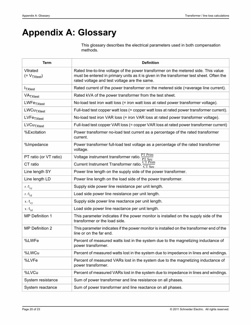
Appendix A: GlossaryThis glossary describes the electrical parameters used in both compensation methods.
Term Definition
Vllrated (= VTXtest)
Rated line-to-line voltage of the power transformer on the metered side. This value must be entered in primary units as it is given in the transformer test sheet. Often the rated voltage and test voltage are the same.
ITXtest Rated current of the power transformer on the metered side (=average line current).
VATXtest Rated kVA of the power transformer from the test sheet.
LWFeTXtest No-load test iron watt loss (= iron watt loss at rated power transformer voltage).
LWCuTXtest Full-load test copper watt loss (= copper watt loss at rated power transformer current).
LVFeTXtest No-load test iron VAR loss (= iron VAR loss at rated power transformer voltage).
LVCuTXtest Full-load test copper VAR loss (= copper VAR loss at rated power transformer current)
%Excitation Power transformer no-load test current as a percentage of the rated transformer current.
%Impedance Power transformer full-load test voltage as a percentage of the rated transformer voltage.
PT ratio (or VT ratio) Voltage instrument transformer ratio.
CT ratio Current Instrument Transformer ratio.
Line length SY Power line length on the supply side of the power transformer.
Line length LD Power line length on the load side of the power transformer.
Supply side power line resistance per unit length.
Load side power line resistance per unit length.
Supply side power line reactance per unit length.
Load side power line reactance per unit length.
MP Definition 1 This parameter indicates if the power monitor is installed on the supply side of the transformer or the load side.
MP Definition 2 This parameter indicates if the power monitor is installed on the transformer end of the line or on the far end.
%LWFe Percent of measured watts lost in the system due to the magnetizing inductance of power transformer.
%LWCu Percent of measured watts lost in the system due to impedance in lines and windings.
%LVFe Percent of measured VARs lost in the system due to the magnetizing inductance of power transformer.
%LVCu Percent of measured VARs lost in the system due to impedance in lines and windings.
System resistance Sum of power transformer and line resistance on all phases.
System reactance Sum of power transformer and line reactance on all phases.
PT PrimPT Sec
--------------------
CT PrimCT Sec--------------------
r lsy
r lld
x lsy
x lld
© 2011 Schneider Electric. All rights reserved. Page 21 of 23
Transformer / line loss calculations Appendix A: Glossary
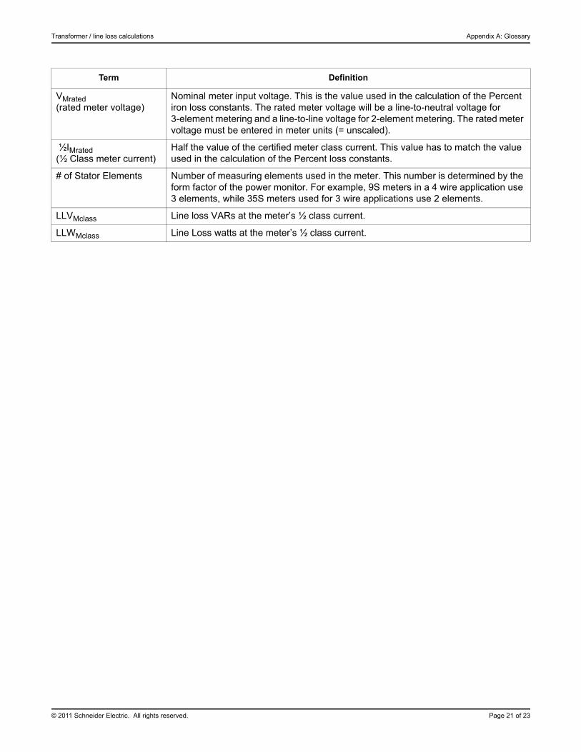
VMrated(rated meter voltage)
Nominal meter input voltage. This is the value used in the calculation of the Percent iron loss constants. The rated meter voltage will be a line-to-neutral voltage for 3-element metering and a line-to-line voltage for 2-element metering. The rated meter voltage must be entered in meter units (= unscaled).
½IMrated(½ Class meter current)
Half the value of the certified meter class current. This value has to match the value used in the calculation of the Percent loss constants.
# of Stator Elements Number of measuring elements used in the meter. This number is determined by the form factor of the power monitor. For example, 9S meters in a 4 wire application use 3 elements, while 35S meters used for 3 wire applications use 2 elements.
LLVMclass Line loss VARs at the meter’s ½ class current.
LLWMclass Line Loss watts at the meter’s ½ class current.
Term Definition
Appendix B: Loss compensation frameworks Transformer / line loss calculations
Page 22 of 23 © 2011 Schneider Electric. All rights reserved.
Appendix B: Loss compensation frameworks
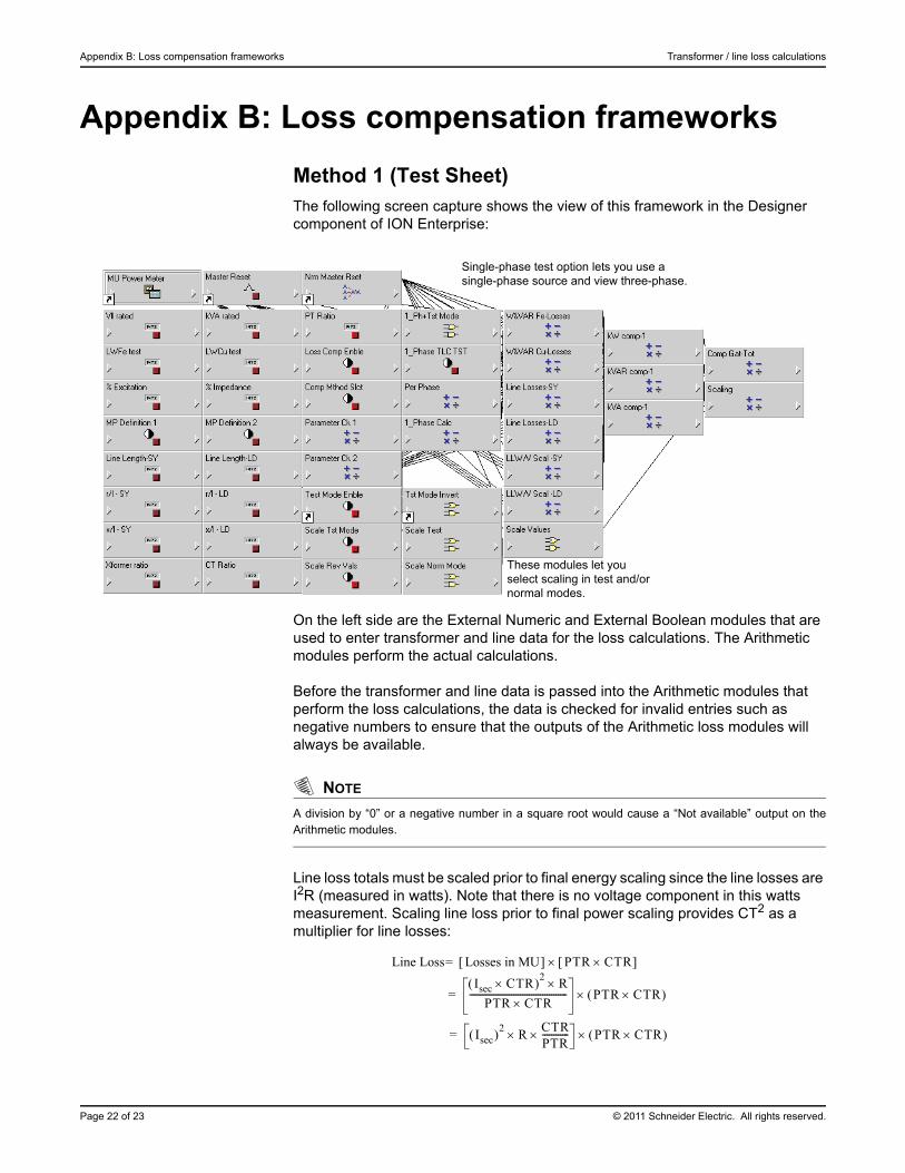
Method 1 (Test Sheet)The following screen capture shows the view of this framework in the Designer component of ION Enterprise:
On the left side are the External Numeric and External Boolean modules that are used to enter transformer and line data for the loss calculations. The Arithmetic modules perform the actual calculations.
Before the transformer and line data is passed into the Arithmetic modules that perform the loss calculations, the data is checked for invalid entries such as negative numbers to ensure that the outputs of the Arithmetic loss modules will always be available.
NOTE
A division by “0” or a negative number in a square root would cause a “Not available” output on theArithmetic modules.
Line loss totals must be scaled prior to final energy scaling since the line losses are I2R (measured in watts). Note that there is no voltage component in this watts measurement. Scaling line loss prior to final power scaling provides CT2 as a multiplier for line losses:
Single-phase test option lets you use a single-phase source and view three-phase.
These modules let you select scaling in test and/or normal modes.
Line Loss Losses in MU PTR CTR =
Isec CTR 2 RPTR CTR
-------------------------------------------- PTR CTR =
Isec 2 RCTRPTR------------ PTR CTR =
© 2011 Schneider Electric. All rights reserved. Page 23 of 23
Transformer / line loss calculations Appendix B: Loss compensation frameworks
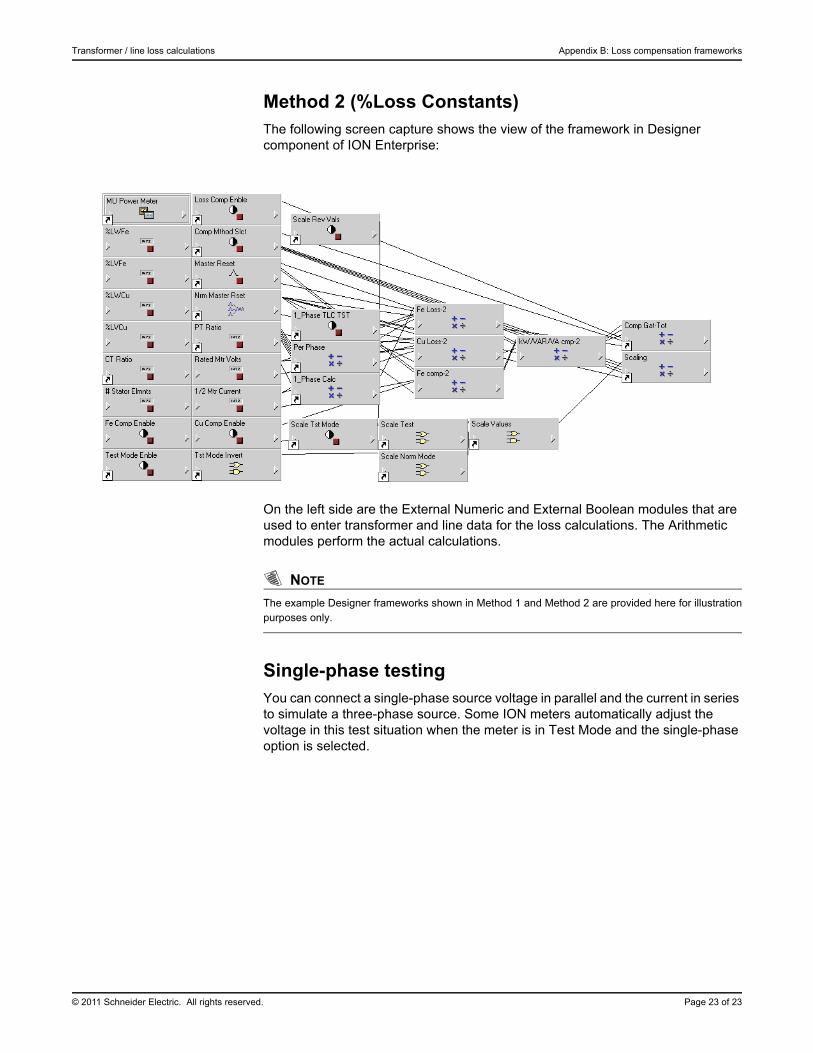
Method 2 (%Loss Constants)The following screen capture shows the view of the framework in Designer component of ION Enterprise:
On the left side are the External Numeric and External Boolean modules that are used to enter transformer and line data for the loss calculations. The Arithmetic modules perform the actual calculations.
NOTE
The example Designer frameworks shown in Method 1 and Method 2 are provided here for illustrationpurposes only.
Single-phase testing You can connect a single-phase source voltage in parallel and the current in series to simulate a three-phase source. Some ION meters automatically adjust the voltage in this test situation when the meter is in Test Mode and the single-phase option is selected.