Embed Size (px)
Citation preview
Anderson Consulting Engineers One Kingdom Street Paddington W2 6BD 0203 755 5084 Project No: S4978
Structural Calculations For
Proposed Basement 39 Anson Road London N7 0AR
One Kingdom Street
Paddington W2 6BD
0203 755 5084
Project
39 Anson Road, N7 0AR Job Ref
S4978 Drawing Ref Calculations by
JSB Checked by Sheet
1a Part of Structure
New basement Date
24/03/17
Rev A: 17.08.18 Foundation beams added at rear Loadings (Service Loads) Flat roof Dead Loads Felt and chippings 0.45 kN/m2 Boards and joists 0.20 kN/m2 Ceiling 0.20 kN/m2 Services 0.15 kN/m2 Total Dead Load 1.00 kN/m2 Imposed Load 0.75 kN/m2 Pitched Roof Dead Loads Slate and felt 0.35 kN/m2 Boards and joists 0.25 kN/m2 Ceiling 0.25 kN/m2 Services 0.15 kN/m2 Total Dead Load 1.00 kN/m2 Imposed Load Roof 0.75 kN/m2 Imposed Load Ceiling 0.25 kN/m2 Total Imposed Loading 1.00 kN/m2 Timber Floors Dead Loads Boards and joists 0.35 kN/m2 Ceiling 0.25 kN/m2 Services 0.20 kN/m2 Total Dead Load 0.80 kN/m2 Imposed Load 1.50 kN/m2 Beam and Block Floors Dead Loads Screed 2.10 kN/m2 Floor swt 2.80 kN/m2 Services 0.20 kN/m2 Total Dead Load 5.10 kN/m2 Imposed Load 1.50 kN/m2 Partitions (to whole floor area) 0.50 kN/m2 Walls 105 Brickwork + plaster 2.60 kN/m2 215 Brickwork + plaster 5.10 kN/m2 330 Brickwork + Plaster 7.20 kN/m2 Cavity brick / block (100/100) 4.20 kN/m2 Stud partitions (on elevation) 0.70 kN/m2

One Kingdom Street
Paddington W2 6BD
0203 755 5084
Project
39 Anson Road, N7 0AR Job Ref
S4978 Drawing Ref Calculations by
JSB Checked by Sheet
2a Part of Structure
New basement Date
24/03/17
New Basement Structure The existing load – bearing structure will be underpinned in a traditional ‘1 to 5’ sequence. The underpins will comprise of a vertical stem which will be immediately beneath the existing wall and will be at least the same thickness as the existing wall. In the case of a party wall, the rear face of the stem will be in line with the face of the wall above so as not to encroach in to the adjacent property’s space, should they wish to construct a similar basement in the future. The reinforcement in the stems will be designed for bending about the top of the base in the permanent case. New steel beams will be designed to support the ground floor joists and load bearing walls with main house and at the rear of the property. The vertical loads applied to the underpin stems from the existing structure will be calculated according to the thickness and height of the existing structure above. Any upper floors and roof loads will be ignored as this will give a minimum value for the vertical load, which will be the most onerous case for overturning and sliding of the underpin section. The underpins will be designed for the temporary and permanent cases, as follows: In the temporary case, the underpins will be designed for soil pressures and a surcharge. The factor of safety against overturning and sliding will be taken as 1.5. In the permanent case, the underpins will be designed for soil pressures, a surcharge and water pressures calculated at 1 m below the retained height. The new basement slab will be structurally connected to the underpinning bases using dowel bars, therefore it will be assumed that the new basement slab will restrain the under pins against sliding. Surcharge on the underpins will be taken as follows: Internal live load (e.g. floors) = 1.5 kN/m2 Space underneath existing timber joists (nominal) = 1.5 kN/m2 External: gardens, footpaths, etc. = 5 kN/m2 External: highways, driveways, etc. = 10 kN/m2 The basement slab will be designed for uplift due to water pressure, spanning between the bases of opposite underpins. The net uplift pressure is taken as the head of water minus the dead load of the basement slab and any permanent finishes, e.g. screed.
One Kingdom Street
Paddington W2 6BD
0203 755 5084
Project
39 Anson Road, N7 0AR Job Ref
S4978 Drawing Ref Calculations by
JSB Checked by Sheet
3a Part of Structure
New basement Date
24/03/17
Geotechnical Design The basement retaining walls have been designed with the following geotechnical design parameters: SOIL PARAMETERS Dry soil = 18 kN/m3 Wet soil = 8 kN/m3 Water = 10 kN/m3 φ = 33˚ Ka = 0.33 The retaining walls will be designed using ‘active’ pressures (where movement of the retaining wall is likely and acceptable), as opposed to ‘at rest’ pressures (where movement of the retaining wall is unlikely or unacceptable). The underpinning process, where soil is excavated underneath an existing load – bearing wall and a vertical shear face of soil is exposed, allows the excavated face of soil to move, thus mobilizing the ‘active’ pressures. In addition, once the underpin has been constructed and is working as a retaining wall, the retaining wall is likely to deflect, thus mobilizing the ‘active’ pressures. These movements will be very slight and will most likely have a negligible effect on the vertical settlement of the retained soil behind the underpinning / retaining walls. These movement are considered acceptable. Ground – bearing pressures below the underpinning bases will be calculated for the temporary condition. In the permanent condition, the new basement slab will be tied in to the retaining wall bases, hence the entire substructure will act as a raft foundation. Ground – bearing pressures will not be an issue in this condition. Water Table An assumed accidental case will be assumed of 1.0 m below ground level for design of uplift on the slab and retaining walls. This will reduce the allowable bearing pressure to 50% of the unsaturated case. Bearing Pressures Allowable Bearing Pressure adopted 150 kN/m2 for the design of the underpin retaining walls (Refer to Geotechnical Investigation Report).
One Kingdom Street
Paddington W2 6BD
0203 755 5084
Project
39 Anson Road, N7 0AR Job Ref
S4978 Drawing Ref Calculations by
JSB Checked by Sheet
4a Part of Structure
New basement Date
24/03/17
Temporary Works The retaining walls will be designed where possible to be self-supporting under surcharge and soil loading in the construction stage of the project. The walls will be propped horizontally to prevent movement in the temporary condition. In the permanent case the walls bases will be propped by the slab and the structural topping. Therefore the most onerous design case is the temporary condition.
One Kingdom Street
Paddington W2 6BD
0203 755 5084
Project
39 Anson Road, N7 0AR Job Ref
S4978 Drawing Ref Calculations by
JSB Checked by Sheet
5a Part of Structure
New basement Date
24/03/17
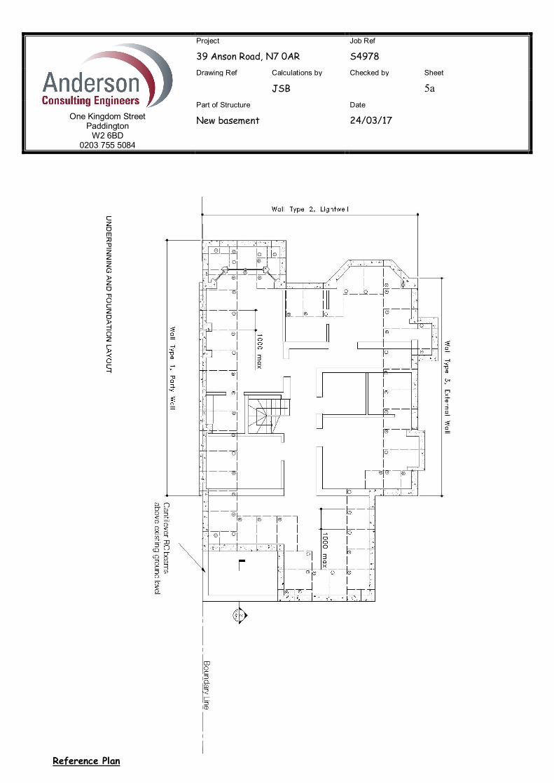
Reference Plan
One Kingdom Street
Paddington W2 6BD
0203 755 5084
Project
39 Anson Road, N7 0AR Job Ref
S4978 Drawing Ref Calculations by
JSB Checked by Sheet
6a Part of Structure
New basement Date
24/03/17
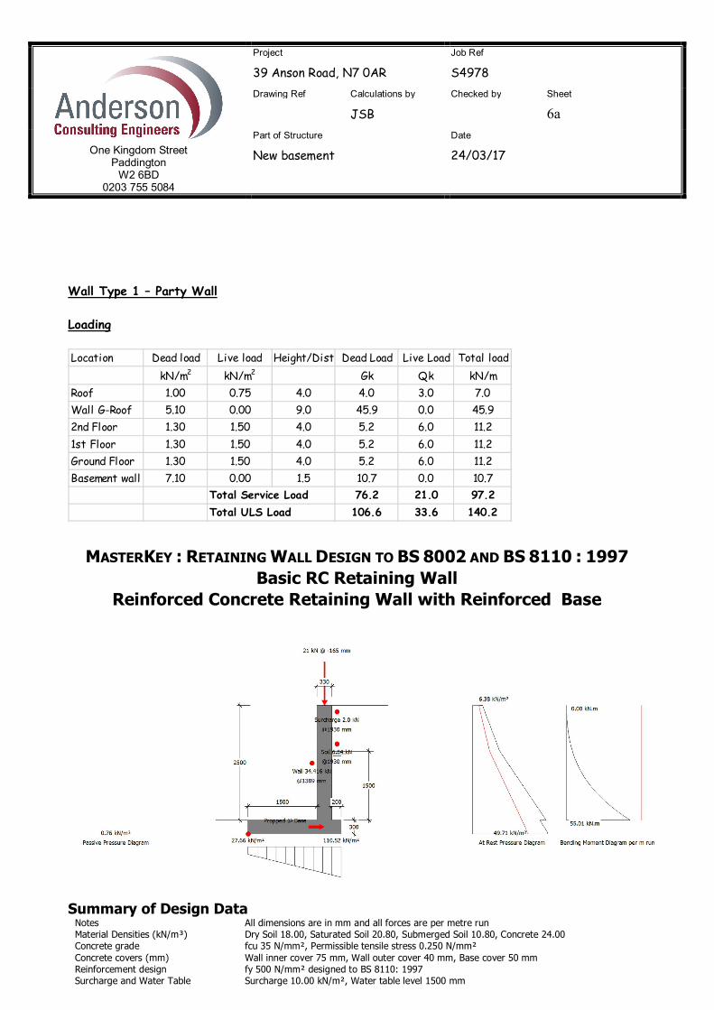
Wall Type 1 – Party Wall Loading
MASTERKEY : RETAINING WALL DESIGN TO BS 8002 AND BS 8110 : 1997 Basic RC Retaining Wall
Reinforced Concrete Retaining Wall with Reinforced Base
Summary of Design Data Notes All dimensions are in mm and all forces are per metre run Material Densities (kN/m³) Dry Soil 18.00, Saturated Soil 20.80, Submerged Soil 10.80, Concrete 24.00 Concrete grade fcu 35 N/mm², Permissible tensile stress 0.250 N/mm² Concrete covers (mm) Wall inner cover 75 mm, Wall outer cover 40 mm, Base cover 50 mm Reinforcement design fy 500 N/mm² designed to BS 8110: 1997 Surcharge and Water Table Surcharge 10.00 kN/m², Water table level 1500 mm
Location Dead load Live load Height/Dist Dead Load Live Load Total loadkN/m2 kN/m2 Gk Qk kN/m
Roof 1.00 0.75 4.0 4.0 3.0 7.0Wall G-Roof 5.10 0.00 9.0 45.9 0.0 45.92nd Floor 1.30 1.50 4.0 5.2 6.0 11.21st Floor 1.30 1.50 4.0 5.2 6.0 11.2Ground Floor 1.30 1.50 4.0 5.2 6.0 11.2Basement wall 7.10 0.00 1.5 10.7 0.0 10.7
Total Service Load 76.2 21.0 97.2Total ULS Load 106.6 33.6 140.2
One Kingdom Street
Paddington W2 6BD
0203 755 5084
Project
39 Anson Road, N7 0AR Job Ref
S4978 Drawing Ref Calculations by
JSB Checked by Sheet
7a Part of Structure
New basement Date
24/03/17
Unplanned excavation depth Front of wall 280 mm † The Engineer must satisfy him/herself to the reinforcement detailing requirements of the relevant codes of practice
Additional Loads Wall Propped at Base Level Therefore no sliding check is required Vertical Line Loads 76 kN/m @ X -165 mm and Y 0 mm - Load type Dead 21 kN/m @ X -165 mm and Y 0 mm - Load type Live † Dimensions Ties, line loads and partial loads are measured from the inner top edge of the wall
Soil Properties Soil bearing pressure Allowable pressure @ front 150.00 kN/m², @ back 150.00 kN/m² Back Soil Friction and Cohesion = Atn(Tan(25)/1.2) = 21.24° Base Friction and Cohesion δ = Atn(0.75xTan(Atn(Tan(30)/1.2))) = 19.84° Front Soil Friction and Cohesion = Atn(Tan(30)/1.2) = 25.69°
Loading Cases GSoil- Soil Self Weight, GWall- Wall & Base Self Weight, FvHeel- Vertical Loads over Heel, Pa- Active Earth Pressure, Psurcharge- Earth pressure from surcharge, Pp- Passive Earth Pressure Case 1: Geotechnical Design 1.00 GSoil+1.00 GWall+1.00 FvHeel+1.00 Pa+1.00 Psurcharge+1.00 Pp Case 2: Structural Ultimate Design 1.40 GSoil+1.40 GWall+1.60 FvHeel+1.00 Pa+1.00 Psurcharge+1.00 Pp
Geotechnical Design Wall Stability - Virtual Back Pressure Case 1 Overturning/Stabilising 48.802/226.367 0.216 OK
Wall Sliding - Virtual Back Pressure Fx/(RxFriction+ RxPassive) 0.000/(50.611+0.000) 0.000 OK Prop Reaction Case 2 (Service) 50.7 kN @ Base
Soil Pressure Virtual Back (No uplift) Max(17.833/150, 120.350/150) kN/m² 0.802 OK Wall Back (No uplift) Max(27.662/150, 110.521/150) kN/m² 0.737 OK
Structural Design At Rest Earth Pressure At rest earth pressures magnification (1+Sin()) x √OCR = (1+Sin(21.24)x√1 1.36
Prop Reaction Maximum Prop Reaction (Ultimate) 76.0 kN @ Base
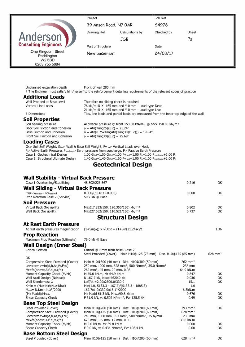
Wall Design (Inner Steel) Critical Section Critical @ 0 mm from base, Case 2 Steel Provided (Cover) Main H10@125 (75 mm) Dist. H10@175 (85 mm) 628 mm² OK Compression Steel Provided (Cover) Main H10@300 (40 mm) Dist. H10@300 (50 mm) 262 mm² Leverarm z=fn(d,b,As,fy,Fcu) 250 mm, 1000 mm, 628 mm², 500 N/mm², 35.0 N/mm² 238 mm Mr=fn(above,As',d',x,x/d) 262 mm², 45 mm, 20 mm, 0.08 64.9 kN.m Moment Capacity Check (M/Mr) M 55.0 kN.m, Mr 64.9 kN.m 0.847 OK Wall Axail Design (N/Ncap) N 167.7 kN, Ncap 4620.0 kN 0.036 OK Wall Slenderness λ Leff/tk =2.00x2500.0/330.0 15.1 OK Kmin = (Nuz-N)/(Nuz-Nbal) Min(1.0, 5133.3 - 167.7)/(5133.3 - 1885.3) 1.0 Madd= N.Kmin.h.λ²/2000 167.7x1.0x330.0x15.1²/2000 6.3kN.m (M+Madd)/MrAxial M+Madd 61.3 kN, MrAxail90.6 kN.m 0.676 OK Shear Capacity Check F 61.9 kN, vc 0.502 N/mm², Fvr 125.5 kN 0.49 OK
Base Top Steel Design Steel Provided (Cover) Main H10@200 (50 mm) Dist. H10@200 (60 mm) 393 mm² OK Compression Steel Provided (Cover) Main H10@125 (50 mm) Dist. H10@200 (60 mm) 628 mm² Leverarm z=fn(d,b,As,fy,Fcu) 245 mm, 1000 mm, 393 mm², 500 N/mm², 35 N/mm² 233 mm Mr=fn(above,As',d',x,x/d) 628 mm², 55 mm, 12 mm, 0.05 39.8 kN.m Moment Capacity Check (M/Mr) M 0.0 kN.m, Mr 39.8 kN.m 0.000 OK Shear Capacity Check F 0.0 kN, vc 0.434 N/mm², Fvr 106.4 kN 0.00 OK
Base Bottom Steel Design Steel Provided (Cover) Main H10@125 (50 mm) Dist. H10@200 (60 mm) 628 mm² OK
One Kingdom Street
Paddington W2 6BD
0203 755 5084
Project
39 Anson Road, N7 0AR Job Ref
S4978 Drawing Ref Calculations by
JSB Checked by Sheet
8a Part of Structure
New basement Date
24/03/17
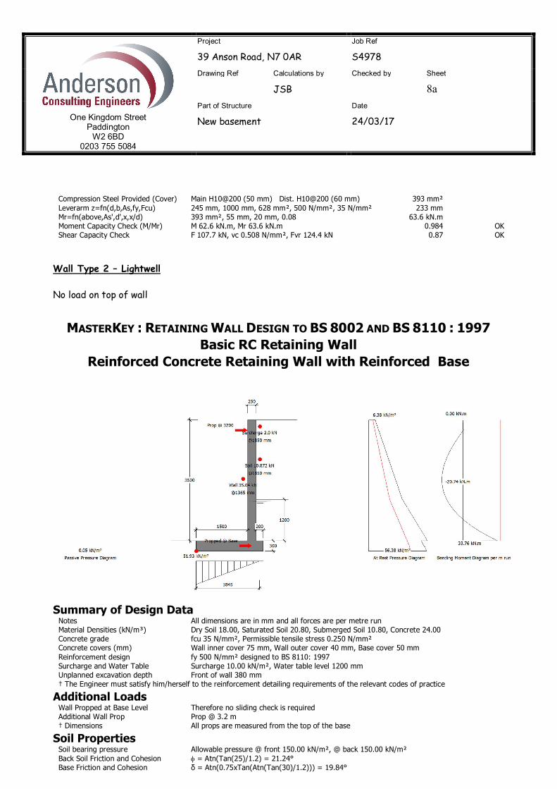
Compression Steel Provided (Cover) Main H10@200 (50 mm) Dist. H10@200 (60 mm) 393 mm² Leverarm z=fn(d,b,As,fy,Fcu) 245 mm, 1000 mm, 628 mm², 500 N/mm², 35 N/mm² 233 mm Mr=fn(above,As',d',x,x/d) 393 mm², 55 mm, 20 mm, 0.08 63.6 kN.m Moment Capacity Check (M/Mr) M 62.6 kN.m, Mr 63.6 kN.m 0.984 OK Shear Capacity Check F 107.7 kN, vc 0.508 N/mm², Fvr 124.4 kN 0.87 OK Wall Type 2 – Lightwell No load on top of wall
MASTERKEY : RETAINING WALL DESIGN TO BS 8002 AND BS 8110 : 1997 Basic RC Retaining Wall
Reinforced Concrete Retaining Wall with Reinforced Base
Summary of Design Data Notes All dimensions are in mm and all forces are per metre run Material Densities (kN/m³) Dry Soil 18.00, Saturated Soil 20.80, Submerged Soil 10.80, Concrete 24.00 Concrete grade fcu 35 N/mm², Permissible tensile stress 0.250 N/mm² Concrete covers (mm) Wall inner cover 75 mm, Wall outer cover 40 mm, Base cover 50 mm Reinforcement design fy 500 N/mm² designed to BS 8110: 1997 Surcharge and Water Table Surcharge 10.00 kN/m², Water table level 1200 mm Unplanned excavation depth Front of wall 380 mm † The Engineer must satisfy him/herself to the reinforcement detailing requirements of the relevant codes of practice
Additional Loads Wall Propped at Base Level Therefore no sliding check is required Additional Wall Prop Prop @ 3.2 m † Dimensions All props are measured from the top of the base
Soil Properties Soil bearing pressure Allowable pressure @ front 150.00 kN/m², @ back 150.00 kN/m² Back Soil Friction and Cohesion = Atn(Tan(25)/1.2) = 21.24° Base Friction and Cohesion δ = Atn(0.75xTan(Atn(Tan(30)/1.2))) = 19.84°
One Kingdom Street
Paddington W2 6BD
0203 755 5084
Project
39 Anson Road, N7 0AR Job Ref
S4978 Drawing Ref Calculations by
JSB Checked by Sheet
9a Part of Structure
New basement Date
24/03/17
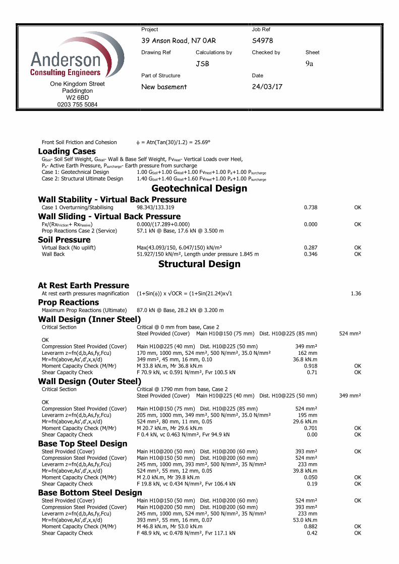
Front Soil Friction and Cohesion = Atn(Tan(30)/1.2) = 25.69°
Loading Cases GSoil- Soil Self Weight, GWall- Wall & Base Self Weight, FvHeel- Vertical Loads over Heel, Pa- Active Earth Pressure, Psurcharge- Earth pressure from surcharge Case 1: Geotechnical Design 1.00 GSoil+1.00 GWall+1.00 FvHeel+1.00 Pa+1.00 Psurcharge Case 2: Structural Ultimate Design 1.40 GSoil+1.40 GWall+1.60 FvHeel+1.00 Pa+1.00 Psurcharge
Geotechnical Design Wall Stability - Virtual Back Pressure Case 1 Overturning/Stabilising 98.343/133.319 0.738 OK
Wall Sliding - Virtual Back Pressure Fx/(RxFriction+ RxPassive) 0.000/(17.289+0.000) 0.000 OK Prop Reactions Case 2 (Service) 57.1 kN @ Base, 17.6 kN @ 3.500 m
Soil Pressure Virtual Back (No uplift) Max(43.093/150, 6.047/150) kN/m² 0.287 OK Wall Back 51.927/150 kN/m², Length under pressure 1.845 m 0.346 OK
Structural Design At Rest Earth Pressure At rest earth pressures magnification (1+Sin()) x √OCR = (1+Sin(21.24)x√1 1.36
Prop Reactions Maximum Prop Reactions (Ultimate) 87.0 kN @ Base, 28.2 kN @ 3.200 m
Wall Design (Inner Steel) Critical Section Critical @ 0 mm from base, Case 2 Steel Provided (Cover) Main H10@150 (75 mm) Dist. H10@225 (85 mm) 524 mm² OK Compression Steel Provided (Cover) Main H10@225 (40 mm) Dist. H10@225 (50 mm) 349 mm² Leverarm z=fn(d,b,As,fy,Fcu) 170 mm, 1000 mm, 524 mm², 500 N/mm², 35.0 N/mm² 162 mm Mr=fn(above,As',d',x,x/d) 349 mm², 45 mm, 16 mm, 0.10 36.8 kN.m Moment Capacity Check (M/Mr) M 33.8 kN.m, Mr 36.8 kN.m 0.918 OK Shear Capacity Check F 70.9 kN, vc 0.591 N/mm², Fvr 100.5 kN 0.71 OK
Wall Design (Outer Steel) Critical Section Critical @ 1790 mm from base, Case 2 Steel Provided (Cover) Main H10@225 (40 mm) Dist. H10@225 (50 mm) 349 mm² OK Compression Steel Provided (Cover) Main H10@150 (75 mm) Dist. H10@225 (85 mm) 524 mm² Leverarm z=fn(d,b,As,fy,Fcu) 205 mm, 1000 mm, 349 mm², 500 N/mm², 35.0 N/mm² 195 mm Mr=fn(above,As',d',x,x/d) 524 mm², 80 mm, 11 mm, 0.05 29.6 kN.m Moment Capacity Check (M/Mr) M 20.7 kN.m, Mr 29.6 kN.m 0.701 OK Shear Capacity Check F 0.4 kN, vc 0.463 N/mm², Fvr 94.9 kN 0.00 OK
Base Top Steel Design Steel Provided (Cover) Main H10@200 (50 mm) Dist. H10@200 (60 mm) 393 mm² OK Compression Steel Provided (Cover) Main H10@150 (50 mm) Dist. H10@200 (60 mm) 524 mm² Leverarm z=fn(d,b,As,fy,Fcu) 245 mm, 1000 mm, 393 mm², 500 N/mm², 35 N/mm² 233 mm Mr=fn(above,As',d',x,x/d) 524 mm², 55 mm, 12 mm, 0.05 39.8 kN.m Moment Capacity Check (M/Mr) M 2.0 kN.m, Mr 39.8 kN.m 0.050 OK Shear Capacity Check F 19.8 kN, vc 0.434 N/mm², Fvr 106.4 kN 0.19 OK
Base Bottom Steel Design Steel Provided (Cover) Main H10@150 (50 mm) Dist. H10@200 (60 mm) 524 mm² OK Compression Steel Provided (Cover) Main H10@200 (50 mm) Dist. H10@200 (60 mm) 393 mm² Leverarm z=fn(d,b,As,fy,Fcu) 245 mm, 1000 mm, 524 mm², 500 N/mm², 35 N/mm² 233 mm Mr=fn(above,As',d',x,x/d) 393 mm², 55 mm, 16 mm, 0.07 53.0 kN.m Moment Capacity Check (M/Mr) M 46.8 kN.m, Mr 53.0 kN.m 0.882 OK Shear Capacity Check F 48.9 kN, vc 0.478 N/mm², Fvr 117.1 kN 0.42 OK

One Kingdom Street
Paddington W2 6BD
0203 755 5084
Project
39 Anson Road, N7 0AR Job Ref
S4978 Drawing Ref Calculations by
JSB Checked by Sheet
10a Part of Structure
New basement Date
24/03/17
Use a beam within wall at top to prop onto butressing walls. Wall Type 3 – External Wall Loading
MASTERKEY : RETAINING WALL DESIGN TO BS 8002 AND BS 8110 : 1997 Basic RC Retaining Wall
Reinforced Concrete Retaining Wall with Reinforced Base
Summary of Design Data Notes All dimensions are in mm and all forces are per metre run Material Densities (kN/m³) Dry Soil 18.00, Saturated Soil 20.80, Submerged Soil 10.80, Concrete 24.00 Concrete grade fcu 35 N/mm², Permissible tensile stress 0.250 N/mm² Concrete covers (mm) Wall inner cover 75 mm, Wall outer cover 40 mm, Base cover 50 mm
Location Dead load Live load Height/Dist Dead Load Live Load Total loadkN/m2 kN/m2 Gk Qk kN/m
Roof 1.00 0.75 2.0 2.0 1.5 3.5Wall G-Roof 5.10 0.00 9.0 45.9 0.0 45.92nd Floor 1.30 1.50 2.0 2.6 3.0 5.61st Floor 1.30 1.50 2.0 2.6 3.0 5.6Ground Floor 1.30 1.50 2.0 2.6 3.0 5.6Basement wall 7.10 0.00 0.0 0.0 0.0 0.0Other 0.00 0.00 1.5 0.0 0.0 0.0
Total Service Load 55.7 10.5 66.2Total ULS Load 78.0 16.8 94.8
One Kingdom Street
Paddington W2 6BD
0203 755 5084
Project
39 Anson Road, N7 0AR Job Ref
S4978 Drawing Ref Calculations by
JSB Checked by Sheet
11a Part of Structure
New basement Date
24/03/17
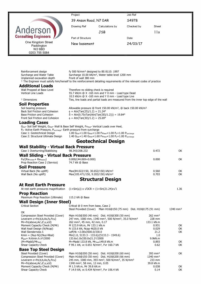
Reinforcement design fy 500 N/mm² designed to BS 8110: 1997 Surcharge and Water Table Surcharge 10.00 kN/m², Water table level 1200 mm Unplanned excavation depth Front of wall 380 mm † The Engineer must satisfy him/herself to the reinforcement detailing requirements of the relevant codes of practice
Additional Loads Wall Propped at Base Level Therefore no sliding check is required Vertical Line Loads 55.7 kN/m @ X -165 mm and Y 0 mm - Load type Dead 10.5 kN/m @ X -165 mm and Y 0 mm - Load type Live † Dimensions Ties, line loads and partial loads are measured from the inner top edge of the wall
Soil Properties Soil bearing pressure Allowable pressure @ front 150.00 kN/m², @ back 150.00 kN/m² Back Soil Friction and Cohesion = Atn(Tan(25)/1.2) = 21.24° Base Friction and Cohesion δ = Atn(0.75xTan(Atn(Tan(30)/1.2))) = 19.84° Front Soil Friction and Cohesion = Atn(Tan(30)/1.2) = 25.69°
Loading Cases GSoil- Soil Self Weight, GWall- Wall & Base Self Weight, FvHeel- Vertical Loads over Heel, Pa- Active Earth Pressure, Psurcharge- Earth pressure from surcharge Case 1: Geotechnical Design 1.00 GSoil+1.00 GWall+1.00 FvHeel+1.00 Pa+1.00 Psurcharge Case 2: Structural Ultimate Design 1.40 GSoil+1.40 GWall+1.60 FvHeel+1.00 Pa+1.00 Psurcharge
Geotechnical Design Wall Stability - Virtual Back Pressure Case 1 Overturning/Stabilising 98.343/208.232 0.472 OK
Wall Sliding - Virtual Back Pressure Fx/(RxFriction+ RxPassive) 0.000/(44.069+0.000) 0.000 OK Prop Reaction Case 2 (Service) 74.7 kN @ Base
Soil Pressure Virtual Back (No uplift) Max(84.022/150, 30.652/150) kN/m² 0.560 OK Wall Back (No uplift) Max(105.471/150, 9.203/150) kN/m² 0.703 OK
Structural Design At Rest Earth Pressure At rest earth pressures magnification (1+Sin()) x √OCR = (1+Sin(21.24)x√1 1.36
Prop Reaction Maximum Prop Reaction (Ultimate) 115.2 kN @ Base
Wall Design (Inner Steel) Critical Section Critical @ 0 mm from base, Case 2 Steel Provided (Cover) Main H16@150 (75 mm) Dist. H10@175 (91 mm) 1340 mm² OK Compression Steel Provided (Cover) Main H10@300 (40 mm) Dist. H10@300 (50 mm) 262 mm² Leverarm z=fn(d,b,As,fy,Fcu) 247 mm, 1000 mm, 1340 mm², 500 N/mm², 35.0 N/mm² 228 mm Mr=fn(above,As',d',x,x/d) 262 mm², 45 mm, 42 mm, 0.17 133.1 kN.m Moment Capacity Check (M/Mr) M 123.9 kN.m, Mr 133.1 kN.m 0.931 OK Wall Axail Design (N/Ncap) N 133.6 kN, Ncap 4620.0 kN 0.029 OK Wall Slenderness λ Leff/tk =2.00x3500.0/330.0 21.2 OK Kmin = (Nuz-N)/(Nuz-Nbal) Min(1.0, 5133.3 - 133.6)/(5133.3 - 1549.6) 1.0 Madd= N.Kmin.h.λ²/2000 133.6x1.0x330.0x21.2²/2000 9.9kN.m (M+Madd)/MrAxial M+Madd 133.8 kN, MrAxail149.8 kN.m 0.893 OK Shear Capacity Check F 99.1 kN, vc 0.651 N/mm², Fvr 160.7 kN 0.62 OK
Base Top Steel Design Steel Provided (Cover) Main H10@200 (50 mm) Dist. H10@200 (60 mm) 393 mm² OK Compression Steel Provided (Cover) Main H16@150 (50 mm) Dist. H10@200 (66 mm) 1340 mm² Leverarm z=fn(d,b,As,fy,Fcu) 245 mm, 1000 mm, 393 mm², 500 N/mm², 35 N/mm² 233 mm Mr=fn(above,As',d',x,x/d) 1340 mm², 58 mm, 12 mm, 0.05 39.8 kN.m Moment Capacity Check (M/Mr) M 1.5 kN.m, Mr 39.8 kN.m 0.038 OK Shear Capacity Check F 14.9 kN, vc 0.434 N/mm², Fvr 106.4 kN 0.14 OK
One Kingdom Street
Paddington W2 6BD
0203 755 5084
Project
39 Anson Road, N7 0AR Job Ref
S4978 Drawing Ref Calculations by
JSB Checked by Sheet
12a Part of Structure
New basement Date
24/03/17
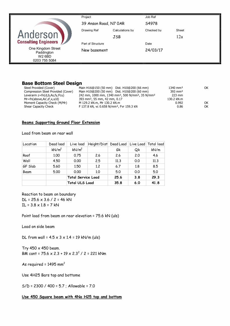
Base Bottom Steel Design Steel Provided (Cover) Main H16@150 (50 mm) Dist. H10@200 (66 mm) 1340 mm² OK Compression Steel Provided (Cover) Main H10@200 (50 mm) Dist. H10@200 (60 mm) 393 mm² Leverarm z=fn(d,b,As,fy,Fcu) 242 mm, 1000 mm, 1340 mm², 500 N/mm², 35 N/mm² 223 mm Mr=fn(above,As',d',x,x/d) 393 mm², 55 mm, 42 mm, 0.17 130.2 kN.m Moment Capacity Check (M/Mr) M 129.2 kN.m, Mr 130.2 kN.m 0.992 OK Shear Capacity Check F 137.8 kN, vc 0.658 N/mm², Fvr 159.3 kN 0.86 OK Beams Supporting Ground Floor Extension Load from beam on rear wall
Reaction to beam on boundary DL = 25.6 x 3.6 / 2 = 46 kN IL = 3.8 x 1.8 = 7 kN Point load from beam on rear elevation = 75.6 kN (uls) Load on side beam DL from wall = 4.5 x 3 x 1.4 = 19 kN/m (uls) Try 450 x 450 beam. BM cant = 75.6 x 2.3 + 19 x 2.32 / 2 = 221 kNm As required = 1495 mm2 Use 4H25 Bars top and bottome S/D = 2300 / 400 = 5.7 ; Allowable = 7.0 Use 450 Square beam with 4No H25 top and bottom
Location Dead load Live load Height/Dist Dead Load Live Load Total loadkN/m2 kN/m2 Gk Qk kN/m
Roof 1.00 0.75 2.6 2.6 2.0 4.6Wall 4.50 0.00 2.5 11.3 0.0 11.3GF Slab 5.60 1.50 1.2 6.7 1.8 8.5Beam 5.00 0.00 1.0 5.0 0.0 5.0
Total Service Load 25.6 3.8 29.3Total ULS Load 35.8 6.0 41.8