Embed Size (px)
Citation preview

1996
Available online through - http://ijifr.com/searchjournal.aspx
www.ijifr.com
Published On: February 26, 2016
International Journal of Informative & Futuristic Research ISSN: 2347-1697
Volume 3 Issue 6 February 2016 Reviewed Paper
Abstract
This paper is focused on a device used for measurement of transformer parameters through wireless system, which has in built step-down transformer with voltage and frequency and measurement circuit for measuring input voltage and frequency of a transformer. This paper will aim to monitor the different parameters like voltage, frequency, temperature, oil level in the transformer tank and also protect the transformer from overload and high voltage and use of GSM module for transmitting the data through wireless media.
1. INTRODUCTION
Initially 230 v ac input voltage from mains supply is stepped down into 12v ac through
12-0-12 step down transformer and then its output given to frequency and voltage
measurement circuit and at end these measurement data output is feed to microcontroller
Wireless Transformer Parameter Measurements
Paper ID IJIFR/ V3/ E6/ 022 Page No. 1996-2011 Subject Area Electrical &
Electronics Engg.
Keywords Transformer, GSM Module, Microcontroller And Wireless Measurement Meter
1st Babu Naik G
Assistant Professor
Department Of Electrical & Electronics Engineering
BMS Institute of Technology & Management,
Yelahanka, Bangalore( Karnataka)-India
2nd Ozwin Dominic Dsouza
Assistant Professor
Department Of Electrical & Electronics Engineering
BMS Institute of Technology & Management,
Yelahanka, Bangalore( Karnataka)-India
3rd Manjunatha Babu P
Assistant Professor
Department Of Electrical & Electronics Engineering
BMS Institute of Technology & Management,
Yelahanka, Bangalore( Karnataka)-India
4th Naresh Kumar CH Engineer, Hindustan Aeronautics Limited
5th Mahipal Bhukya Assistant Professor
Department Of Electrical & Electronics Engineering
Manipal University, Jaipur(Rajasthan)-India

1997
ISSN: 2347-1697
International Journal of Informative & Futuristic Research (IJIFR)
Volume - 3, Issue -6, February 2016
Continuous 30th Edition, Page No.:1996-2011
Babu Naik G, Ozwin Dominic Dsouza, Manjunatha Babu P, Naresh Kumar CH, Mahipal Bhukya :: Wireless Transformer Parameter Measurements
for processing [2]. All these parameter are sending through GSM module. Here we
using P89V51RD2 microcontroller for processing information. 8051 architecture based
P89V51RD2 microcontroller from NxP is used, which controls the whole system [1]. It
contains 1k RAM, 64k Flash, 3 Timers, 2 external interrupts, 1 UART, 32 GPIO’s, ISP programming support etc. KEIL IDE is used to program the microcontroller and the
coding will be done using Embedded C. GSM module is used to send SMS to the
required GSM mobile. This module is programmed using AT commands through
UART. Monitoring of Transformers data related to various parameters, predict and
prevent the failure of transformer by observing deviation of the transformer parameters
expected values [4]. Transformers are the most critical assets of electrical
transmission and distribution system. Transformer failures could cause power outages,
personal and environmental hazards and expensive rerouting or purchase of power from
other suppliers [2]. Transformer in-service interruptions and failures usually result
from dielectric breakdown, winding distortion caused by short-circuit withstand,
winding and magnetic circuit hot spot, electrical disturbances, deterioration
of insulation, lightning, inadequate maintenance, loose connections, overloading, failure
of accessories such as OLTCs, bushings, etc [3]. Integrating the ‘individual cause’ monitoring allows for monitoring the overall condition of transformer.
A. Thermal Modeling
The useful life of a transformer is determined partially by the ability of transformer
to dissipate the internally generated heat to its surroundings. The comparison of actual
and predicted operating temperatures can provide a sensitive diagnosis of the
transformer condition and might indicate abnormal operation. The consequences of
temperature rise may not be sudden, but gradual as long as it is within break down limit.
Among these consequences, insulation deterioration is economically important.
Insulation being very costly, its deterioration is undesirable. Thermal modeling is the
development of a mathematical model that predicts the temperature profile of the power
transformer using the principle of thermal analysis. The thermal model is used to
determine the top oil temperature and hot spot temperature.
B. Dissolved Gas Analysis Gases are produced by degradation of the transformer oil and solid insulating
materials. Gases are generated at a much more rapid rate whenever an electrical fault
occurs. Normal causes of fault gases are classified into three categories: Corona
or partial discharge, thermal heating and arcing. These faults can be detected by
evaluating the quantities of hydrocarbon gases, hydrogen and oxides of carbon that are
present in the transformer. Different gases can serve as markers for different types of
faults. The concentration and the relation of individual gases allow a prediction of
whether a fault has occurred and what type it is likely to be.
C. Frequency Response Analysis
When a transformer is subjected to high currents through fault currents, the
mechanical structure and windings are subjected to severe mechanical stresses causing

1998
ISSN: 2347-1697
International Journal of Informative & Futuristic Research (IJIFR)
Volume - 3, Issue -6, February 2016
Continuous 30th Edition, Page No.:1996-2011
Babu Naik G, Ozwin Dominic Dsouza, Manjunatha Babu P, Naresh Kumar CH, Mahipal Bhukya :: Wireless Transformer Parameter Measurements
winding movement and deformations. It may also result in insulation damage and turn-
to-turn faults. Frequency response analysis (FRA) is a non-intrusive very sensitive
technique for detecting winding movement faults and deformation assessment caused by
loss of clamping pressure or by short circuit forces. FRA technique involves measuring
the impedance of the windings of the transformer with a low voltage sine input varying
in a wide frequency range.
2. HARDWARE REQUIMENTS
A. Transformer
A transformer is a device that transfers electrical energy from one circuit to another
through inductively coupled conductors—the transformer's coils. A varying current in
the first or primary winding creates a varying magnetic flux in the transformer's core and
thus a varying magnetic field through the secondary winding. This varying magnetic
field induces a varying electromotive force (EMF), or "voltage", in the secondary
winding. This effect is called inductive coupling. In the vast majority of transformers,
the windings are coils wound around a ferromagnetic core, air-core transformers being a
notable exception. Transformers range in size from a thumbnail-sized coupling
transformer hidden inside a stage microphone to huge units weighing hundreds of tons
used to interconnect portions of power grids. While new technologies have eliminated
the need for transformers in some electronic circuits, transformers are still found in
nearly all electronic devices designed for household ("mains") voltage. Transformers are
essential for high-voltage electric power transmission, which makes long-distance
transmission economically practical. The primary and secondary coils are wrapped
around a core of very high magnetic permeability, such as iron, so that most of the
magnetic flux passes through both the primary and secondary coils. If a load is
connected to the secondary winding, the load current and voltage will be in the
directions indicated, given the primary current and voltage in the directions indicated
(each will be alternating current in practice).
B. Core
Laminated steel core: Transformers for use
at power or audio frequencies typically have
cores made of high permeability silicon
steel. The steel has a permeability many
times that of free space and the core thus
serves to greatly reduce the magnetizing
current and confine the flux to a path which
closely couples the windings. Early
transformer developers soon realized that cores constructed from solid iron resulted in
prohibitive eddy-current losses, and their designs mitigated this effect with cores
consisting of bundles of insulated iron wires. Later designs constructed the core by
stacking layers of thin steel laminations, a principle that has remained in use. Each
Figure.1: Laminated core transformer

1999
ISSN: 2347-1697
International Journal of Informative & Futuristic Research (IJIFR)
Volume - 3, Issue -6, February 2016
Continuous 30th Edition, Page No.:1996-2011
Babu Naik G, Ozwin Dominic Dsouza, Manjunatha Babu P, Naresh Kumar CH, Mahipal Bhukya :: Wireless Transformer Parameter Measurements
lamination is insulated from its neighbors by a thin non-conducting layer of insulation.
The effect of laminations is to confine eddy currents to highly elliptical paths that
enclose little flux, and so reduce their magnitude. Thinner laminations reduce losses,
but are more laborious and expensive to construct. Thin laminations are generally used
on high frequency transformers, with some types of very thin steel laminations able to
operate up to 10 KHz. One common design of laminated core is made from interleaved
stacks of E-shaped steel sheets capped with I-shaped pieces, leading to its name of "E-I
transformer". Such a design tends to exhibit more losses, but is very economical to
manufacture.
When power is then reapplied, the residual field will cause a high inrush current until the
effect of the remaining magnetism is reduced, usually after a few cycles of the applied
alternating current. Overcurrent protection devices such as fuses must be selected to
allow this harmless inrush to pass. On transformers connected to long, overhead power
transmission lines, induced currents due to geomagnetic disturbances during solar
storms can cause saturation of the core and operation of transformer protection devices.
C. P89V51RD2 Microcontroller
The main center part of the project is the microcontroller. Here we are using the 8051
based Philips P89V51RD2 microcontroller. The P89V51RD2 are 80C51
microcontrollers with 64kB flash and 1024 B of data RAM. A key feature of the
P89V51RD2 is its X2 mode option. The design engineer can choose to run the
application with the conventional 80C51 clock rate (12 clocks per machine cycle) or
select the X2 mode (six clocks per machine cycle) to achieve twice the throughput at the
same clock frequency. The flash program memory supports both parallel programming
and in serial ISP. Parallel programming mode offers gang-programming at high speed,
reducing programming costs and time to market. ISP allows a device to be
reprogrammed in the end product under software control. The capability to field/update
the application firmware makes a wide range of applications possible.
Figure 2: Block Diagram of P89V51RD2
2000
ISSN: 2347-1697
International Journal of Informative & Futuristic Research (IJIFR)
Volume - 3, Issue -6, February 2016
Continuous 30th Edition, Page No.:1996-2011
Babu Naik G, Ozwin Dominic Dsouza, Manjunatha Babu P, Naresh Kumar CH, Mahipal Bhukya :: Wireless Transformer Parameter Measurements
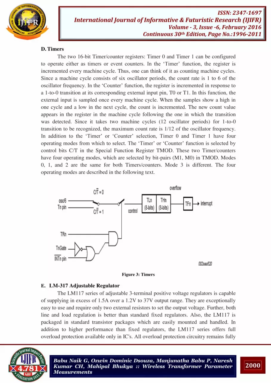
D. Timers
The two 16-bit Timer/counter registers: Timer 0 and Timer 1 can be configured
to operate either as timers or event counters. In the ‘Timer’ function, the register is incremented every machine cycle. Thus, one can think of it as counting machine cycles.
Since a machine cycle consists of six oscillator periods, the count rate is 1 to 6 of the
oscillator frequency. In the ‘Counter’ function, the register is incremented in response to a 1-to-0 transition at its corresponding external input pin, T0 or T1. In this function, the
external input is sampled once every machine cycle. When the samples show a high in
one cycle and a low in the next cycle, the count is incremented. The new count value
appears in the register in the machine cycle following the one in which the transition
was detected. Since it takes two machine cycles (12 oscillator periods) for 1-to-0
transition to be recognized, the maximum count rate is 1/12 of the oscillator frequency.
In addition to the ‘Timer’ or ‘Counter’ selection, Timer 0 and Timer 1 have four
operating modes from which to select. The ‘Timer’ or ‘Counter’ function is selected by control bits C/T in the Special Function Register TMOD. These two Timer/counters
have four operating modes, which are selected by bit-pairs (M1, M0) in TMOD. Modes
0, 1, and 2 are the same for both Timers/counters. Mode 3 is different. The four
operating modes are described in the following text.
Figure 3: Timers
E. LM-317 Adjustable Regulator
The LM117 series of adjustable 3-terminal positive voltage regulators is capable
of supplying in excess of 1.5A over a 1.2V to 37V output range. They are exceptionally
easy to use and require only two external resistors to set the output voltage. Further, both
line and load regulation is better than standard fixed regulators. Also, the LM117 is
packaged in standard transistor packages which are easily mounted and handled. In
addition to higher performance than fixed regulators, the LM117 series offers full
overload protection available only in IC's. All overload protection circuitry remains fully

2001
ISSN: 2347-1697
International Journal of Informative & Futuristic Research (IJIFR)
Volume - 3, Issue -6, February 2016
Continuous 30th Edition, Page No.:1996-2011
Babu Naik G, Ozwin Dominic Dsouza, Manjunatha Babu P, Naresh Kumar CH, Mahipal Bhukya :: Wireless Transformer Parameter Measurements
functional even if the adjustment terminal is disconnected. Normally, no capacitors are
needed unless the device is situated more than 6 inches from the input filter capacitors in
which case an input bypass is needed. An optional output capacitor can be added to
improve transient response. The adjustment terminal can be bypassed to achieve very
high ripple rejection ratios which are difficult to achieve with standard 3-terminal
regulators. Besides replacing fixed regulators, the LM117 is useful in a wide variety of
other applications. Since the regulator is ``floating'' and sees only the input-to-output
differential voltage, supplies of several hundred volts can be regulated.
Figure 4: Voltage Regulator
ADC0809: ADC0809 data acquisition component is a monolithic CMOS device with an
8-bit analog-to-digital converter, 8-channel multiplexer and microprocessor compatible
control logic. The 8-bit A/D converter uses successive approximation as the conversion
technique. The 8-channel multiplexer can directly access any of 8-single-ended analog
signals. The device eliminates the need for external zero and full scale adjustments. Easy
interfacing to microprocessors is provided by the latched and decoded multiplexer
address inputs and latched TTL TRI-STATE Outputs.
Multiplexer Selection: The device contains an 8-channel single-ended analog signal
multiplexer. A particular input channel is selected by using the address decoder. Table
below shows the input states for the address lines to select any channel. The address is
latched into the decoder on the low-to-high transition of the address latch enable signal.
Table 1: Multiplexer selection
ANALOG
CHANNEL
SELECTED
ADDRESS LINE
C B A
IN0 0(L) 0 0
IN1 0 0 1(H)
IN2 0 1 0
IN3 0 1 1
IN4 1 0 0
IN5 1 0 1
IN6 1 1 0
IN7 1 1 1

2002
ISSN: 2347-1697
International Journal of Informative & Futuristic Research (IJIFR)
Volume - 3, Issue -6, February 2016
Continuous 30th Edition, Page No.:1996-2011
Babu Naik G, Ozwin Dominic Dsouza, Manjunatha Babu P, Naresh Kumar CH, Mahipal Bhukya :: Wireless Transformer Parameter Measurements
3. CONVERTER SECTION OF ADC
The heart of this single chip data acquisition system is its 8-bit analog-to-digital
converter. The converter is designed to give fast, accurate, and repeatable conversions
over a wide range of temperatures. The converter is partitioned into 3 major sections: the
256R ladder network, the successive approximation register, and the comparator. The
converter’s digital outputs are positive true.
Figure 5: Block diagram of ADC
The 256R ladder network approach was chosen over the conventional R/2R ladder
because of its inherent monotonicity, which guarantees no missing digital codes.
Monotonicity is particularly important in closed loop feedback control systems.
Additionally, the 256R network does not cause load variations on the reference voltage.
The first output transition with analog signal has reached +1⁄2 LSB and succeeding output transitions at every 1 LSB later up to full-scale. The successive approximation
register (SAR) performs 8 iterations to approximate the input voltage. For any SAR type
converter, n-iterations are required for an n-bit converter and a 3-bit converter. In the
ADC0809, the approximation technique is extended to 8 bits using the 256R network.
The A/D converter’s SAR is reset on the positive edge of the start conversion pulse. The conversion is begun on the falling edge and will process a new pulse. The Continuous
conversion is used to end-of-conversion (EOC) output to the SC input and power up.
End-of-conversion will go low between 0 and 8 clock pulses after the rising edge of start
conversion. The A/D converters compare the comparator and get ultimate accuracy.

2003
ISSN: 2347-1697
International Journal of Informative & Futuristic Research (IJIFR)
Volume - 3, Issue -6, February 2016
Continuous 30th Edition, Page No.:1996-2011
Babu Naik G, Ozwin Dominic Dsouza, Manjunatha Babu P, Naresh Kumar CH, Mahipal Bhukya :: Wireless Transformer Parameter Measurements
Figure 6: ADC Basic circuit
Figure 7: Timing diagram of ADC
A. Group Special Mobile
GSM stands for Global System for Mobile Communications formerly called as Group
Special Mobile.
This is a standard set developed by the European Telecommunications Standards
Institute (ETSI) to describe technologies for second generation (or "2G") digital cellular
networks. Packet data transmission speeds were later increased via EDGE. The GSM
standard is succeeded by the third generation (or "3G") UMTS standard developed by
the 3GPP. GSM networks will evolve further as they begin to incorporate fourth
generation (or "4G") LTE Advanced standards. "GSM" is a trademark owned by the
GSM Association. GSM networks operate in a number of different carrier frequency
ranges (separated into GSM frequency ranges for 2G and UMTS frequency bands for
3G), with most 2G GSM networks operating in the 900 MHz or 1800 MHz bands.
Where these bands were already allocated, the 850 MHz and 1900 MHz bands were
used instead (for example in Canada and the United States). In rare cases the 400 and
450 MHz frequency bands are assigned.
Table 2: GSM carriers
India GSM 900 5 carriers
GSM
900/1800 3 carriers

2004
ISSN: 2347-1697
International Journal of Informative & Futuristic Research (IJIFR)
Volume - 3, Issue -6, February 2016
Continuous 30th Edition, Page No.:1996-2011
Babu Naik G, Ozwin Dominic Dsouza, Manjunatha Babu P, Naresh Kumar CH, Mahipal Bhukya :: Wireless Transformer Parameter Measurements
This allows eight full-rate or sixteen half-rate speech channels per radio frequency.
These eight radio timeslots (or eight burst periods) are grouped into a TDMA frame and
gives 270.833Kbits/s. Half rate channels use alternate frames in the same timeslot and
gives 4.615ms. The transmission power in the handset is limited to a maximum of 2
watts in GSM850/900 and 1 watt in GSM1800/1900. One of the key features of GSM is
the Subscriber Identity Module, commonly known as a SIM card. We are be using
SIM300 GSM Module in our Project. SIM300 is a Tri-band GSM/GPRS engine from
SIMCOM Ltd, that works on frequencies EGSM 900 MHz, DCS 1800 MHz and PCS
1900 MHz SIM300 features GPRS multi-slot class 10 / class 8 (optional) and supports
the GPRS coding schemes CS-1, CS-2, CS-3 and CS-4. With a tiny configuration of
40mm x 33mm x 2.85 mm, SIM300 can fit almost all the space requirement in an
application, such as Smart phone, PDA phone and other mobile device. The physical
interface between SIM300 and the mobile application is through a 60 pins board-to-
board connector, which provides all hardware interfaces from module to customer’s boards except the RF antenna interface.
The keypad and SPI LCD interface will give you the flexibility to develop
customized applications.
Two serial ports can help you easily develop your applications.
Two audio channels include two microphones inputs and two speaker outputs.
These audio interfaces can be easily configured by AT command.
One ADC input
Two GPIO ports and SIM card detection port
Both 1.8V and 3.0V SIM Cards are supported. The SIM interface is powered from an
internal regulator in the module having nominal voltage 2.8V. All pins reset as outputs
driving low. You can use AT Commands "AT" meaning attention, to communicate with
the SIM card. The SIM interface supports the functionality of the GSM Phase 1
specification and also supports the functionality of the new GSM Phase 2+ specification
for FAST 64 kbps SIM. The "AT" or "at" prefix must be set at the beginning of each
command line. To terminate a command line enter <CR>. Commands are usually
followed by a response that includes ”<CR><LF><response><CR><LF>”.
B. Alpha-Numeric LCD Display
A liquid crystal display (LCD) is a flat panel display, electronic visual display, based on
Liquid Crystal Technology. A liquid crystal display consists of an array of tiny segments
(called pixels) that can be manipulated to present information. Liquid crystals do not
emit light directly instead they use light modulating techniques.
The size of LCDs comes in wider varieties.
They do not use Phosphor; hence images are not burnt-in.
Safer disposal
Energy Efficient
Low Power Consumption

2005
ISSN: 2347-1697
International Journal of Informative & Futuristic Research (IJIFR)
Volume - 3, Issue -6, February 2016
Continuous 30th Edition, Page No.:1996-2011
Babu Naik G, Ozwin Dominic Dsouza, Manjunatha Babu P, Naresh Kumar CH, Mahipal Bhukya :: Wireless Transformer Parameter Measurements
It is an electronically modulated optical device made up of any number of segments
filled with liquid crystals and arrayed in front of a light source (backlight) or reflector to
produce images in color or monochrome.
Polarizing filter film with a vertical axis to polarize light as it enters.
Glass substrate with ITO electrodes. The shapes of these electrodes will
determine the shapes that will appear when the LCD is turned ON. Vertical ridges
etched on the surface are smooth.
Glass substrate with common electrode film (ITO) with horizontal ridges to line
up with the horizontal filter.
Polarizing filter film with a horizontal axis to block/pass light.
Reflective surface to send light back to viewer. (In a backlit LCD, this layer is
replaced with a light source.)
Figure 8: JHD162A LCD
C. Operating Voltage Table 3: Operating voltage of LCD
D. Software Requirements
The Keil C51 C Compiler for the 8051 microcontroller is the most popular 8051 C
compiler in the world. It provides more features than any other 8051 C compiler
available today. The C51 Compiler allows you to write 8051 microcontroller
applications in C that, once compiled, have the efficiency and speed of assembly

2006
ISSN: 2347-1697
International Journal of Informative & Futuristic Research (IJIFR)
Volume - 3, Issue -6, February 2016
Continuous 30th Edition, Page No.:1996-2011
Babu Naik G, Ozwin Dominic Dsouza, Manjunatha Babu P, Naresh Kumar CH, Mahipal Bhukya :: Wireless Transformer Parameter Measurements
language. Language extensions in the C51 Compiler give you full access to all resources
of the 8051. The C51 Compiler translates C source files into reloadable object modules
which contain full symbolic information for debugging with the µVision Debugger or an
in-circuit emulator.
E. Specific Objectives
The main aim of this project is to monitor and protection of Distribution
transformer Acquisition of different parameters of the transformer by the use of GSM
Microcontroller used to monitor and protection of the transformer. 8051 architecture
based P89V51RD2 microcontroller from NxP is used to implement this project.
Microcontroller acts as the heart of the project, which controls the whole system. It
contains 1k RAM, 64k Flash, 3 Timers, 2 external interrupts, 1 UART, 32 GPIO’s, ISP programming support etc. KEIL IDE is used to program the microcontroller and the
coding will be done using Embedded C.GSM module is used to send SMS to the
required GSM mobile. This module is programmed using AT commands through
UART. These are the main Objectives of our project
Voltage Measurement.
Frequency Measurements.
Temperature Measurements.
Oil Level Measurements.
Overload Protection.
4. SCOPE OF THE PRESENT WORK
It is a micro-controller based wireless monitoring and protection of the
transformer. Particularly our project is implemented for distribution transformers,
because it is difficult to check the transformer parameters by going there manually. So
this paper will aim to monitor the different parameters like voltage, frequency,
temperature, oil level in the transformer tank and also protect the transformer from
overload and high voltage. Here we are using micro-controller as a controlling unit,
different sensors are being used and it is interfaced with the micro-controller like
temperature sensor, floating sensor. And also different parameter measuring circuits like
frequency, voltage and over-load current. Working of this module has fallows, initially
230V ac input is stepped down into 12V ac through 12-0-12 step down transformer and
then its output given to frequency , voltage, oil level measurement circuit and at end
these measurement data is feed to microcontroller for processing. All these parameter
are sending through GSM module. Here we using P89V51RD2 microcontroller for
processing information. 8051 architecture based P89V51RD2 microcontroller from NxP
is used to implement this project. Microcontroller acts as the heart of the project, which
controls the whole system. It contains 1k RAM, 64k Flash, 3 Timers, 2 external
interrupts, 1 UART, 32 GPIO’s, ISP programming support etc. KEIL IDE is used to program the microcontroller and the coding will be done using Embedded C. GSM

2007
ISSN: 2347-1697
International Journal of Informative & Futuristic Research (IJIFR)
Volume - 3, Issue -6, February 2016
Continuous 30th Edition, Page No.:1996-2011
Babu Naik G, Ozwin Dominic Dsouza, Manjunatha Babu P, Naresh Kumar CH, Mahipal Bhukya :: Wireless Transformer Parameter Measurements
module is used to send SMS to the required GSM mobile. This module is programmed
using AT commands through UART.
Figure 9: Transformer Parameter Measurement
A. Frequency Measurement
Figure 10: Frequency measurement circuit
Input of optocoupler is connected to the output of the transformer and output of the
Optocoupler is connected to the interrupt pin (P 3.2) of the micro-controller.
Optocoupler gives a positive high voltage for every one cycle of voltage. This high
voltage is fed to the interrupt pin, and the micro-controller programmed to count the
interrupts, so we can easily find the frequency of the transformer. Working of Opto
coupler is already discussed in previous chapter. The frequency of the transformer found
by the micro-controller is sent to the mobile using the GSM Module.
B. Tempreature And Oil Level Measurment
One of the main objectives is measurement of temperature and oil level in the
transformer. Temperature sensor LM-35 is used to measure the temperature of the
transformer connected to the micro-controller via ADC. Variable Resistance Float
sensor is used to measure the oil level in the tank connected to micro-controller through
ADC

2008
ISSN: 2347-1697
International Journal of Informative & Futuristic Research (IJIFR)
Volume - 3, Issue -6, February 2016
Continuous 30th Edition, Page No.:1996-2011
Babu Naik G, Ozwin Dominic Dsouza, Manjunatha Babu P, Naresh Kumar CH, Mahipal Bhukya :: Wireless Transformer Parameter Measurements
Figure 10: Temperature and oil Level measurement
.
C. Temperature Measurement
The LM35 series are precision integrated-circuit temperature sensors, whose
output voltage is linearly proportional to the Celsius (Centigrade) temperature. The
LM35 thus has an advantage over linear temperature sensors calibrated in Kelvin, as the
user is not required to subtract a large constant voltage from its output to obtain
convenient Centigrade scaling. The LM35 does not require any external calibration or
trimming to provide typical accuracies of ±1⁄4˚C at room temperature and ±3⁄4˚C over a full −55 to +150˚C temperature range. Low cost is assured by trimming and calibration at the wafer level. The LM35’s low output impedance, linear output, and precise inherent calibration make interfacing to readout or control circuitry especially easy. It
can be used with single power supplies, or with plus and minus supplies. As it draws
only 60 µA from its supply, it has very low self-heating, less than 0.1˚C in still air. The LM35 is rated to operate over a −55˚ to +150˚C temperature range. The LM-35 Sensor is
placed in the transformer, for every degree Celsius it will give the 10milli ampere of the
current output. This will be given to ADC, it will convert analog to digital and gives to a
micro-controller. Micro-controller is programmed to calculate the temperature. Finally
determined temperature will be sent to the mobile by the use of GSM module.
D. Oil Level Measurement
Floating sensor used to measurement of oil in the tank. It is an instrument used to
indicate the level of fuel contained in a tank commonly used in Transformers; these may
also be used for any tank including underground storage tanks.
As used in Transformer, the gauge consists of two parts:
The sensing unit
The indicator
The sensing unit usually uses a float connected to a potentiometer, typically printed ink
design in a modern automobile. As the tank empties, the float drops and slides a moving
contact along the resistor, increasing its resistance. In addition, when the resistance is at
a certain point, it will also turn on a "low fuel" light on some Transformer Tank.

2009
ISSN: 2347-1697
International Journal of Informative & Futuristic Research (IJIFR)
Volume - 3, Issue -6, February 2016
Continuous 30th Edition, Page No.:1996-2011
Babu Naik G, Ozwin Dominic Dsouza, Manjunatha Babu P, Naresh Kumar CH, Mahipal Bhukya :: Wireless Transformer Parameter Measurements
Meanwhile, the indicator unit is measuring and displaying the amount of electrical
current flowing through the sending unit . Depends on the variation in current micro-
controller detects the oil level. Output of the sensor is connected to the ADC, sensor will
change its resistance according to change in the oil level. If the resistance changes then
the output voltage will changes, by this change in voltage we can calculate oil level in
the tank by the use if micro-controller. Micro-controller is programmed to calculate the
oil level in the transformer by the use of change in voltage of the sensor. For every
change in the oil level output current will varies. This measured oil level is sent to
mobile through the GSM Module.
E. Temperature And Oil Level Condition For Sending A Message
Here we programmed the micro-controller for sending a message, if the
temperature of the transformer exceeds the operating temperature (say 40 degree
Celsius) . So if the transformer temperature exceeds the operating temperature then the
warning message will be sent to the cell phone through the GSM Module. Similarly if
the oil level varies than the normal level or if the oil level falls down below the normal
level then micro-controller sends a warning message to the phone through the GSM
Module
F. Overload Protection Of Tranformer
Figure 11: Overload Protection of Transformer, Block diagram.
Normally distribution transformer placed near the consumer side, so if the load
on the transformer is more it will be dangerous to the transformers only. Because by the
increase in the load current, the current in the transformer winding will increases it may
cause failure of the transformer winding. So it is important to protect the transformer
from over load, this is done by the micro-controller and other electrical equipment’s. Above figure shows the functional block diagram of the overload protection of the
transformer. It consists of a current transformer placed in the load circuit side, if the load
current increases the current transformer senses the over load current and it will be fed to
the comparator LM-358.
This voltage comparator will comparers the current transformer voltage and the
reference voltage. If the current transformer voltage is more than the reference value
then the comparator output goes to the high. This high voltage is fed to the micro-

2010
ISSN: 2347-1697
International Journal of Informative & Futuristic Research (IJIFR)
Volume - 3, Issue -6, February 2016
Continuous 30th Edition, Page No.:1996-2011
Babu Naik G, Ozwin Dominic Dsouza, Manjunatha Babu P, Naresh Kumar CH, Mahipal Bhukya :: Wireless Transformer Parameter Measurements
controller, then the micro-controller recognizes the over load detection and activates the
electromagnetic relay. Normally the relay is in the NORMALLY CLOSED (NC). So the
micro-controller energizes the relay and relay contact gets opened, then the whole
system gets switched off. By this way we can protect the transformer from the over load.
Immediately micro-controller send a warning signal alert, by sending a message to the
mobile from the GSM Module. Whole system gets protected from the overload.
5. RESULTS AND DISCUSSIONS
The main application of this project is wireless monitoring and protection of the
distribution transformer. It can be implemented in distribution transformer for
monitoring and protection of the transformers. It protects transformer from fault
conditions. And also it can be implemented for automation purpose, depends upon the
application. For industrial applications like temperature, oil level and protection of
electrical machines, this system can be implemented. So it will reduce the maintenance
cost as the system gives the early warning of any abnormal condition. Time will also be
reduced as we need not to go on checking every transformer manually. So from this
paper distribution transformer will be monitored and protected from faults occurring
during real time, with the help of micro-controller based wireless monitoring system.
6. CONCLUSIONS
The paper focuses much on the efficiency of controlling process of the transformer and
mainly through wireless communication that eliminates the use of large cables which are
of high cost, low reliability and maintenance. The GSM helps in better way of
communication which enhances the improvement steps in this process. So, use of
P89V51RD2 MICROCONTROLLER makes the system real time embedded system and
aids very much in industry needs. The Distribution Transformers failures are effectively
protected against overload, over temperature and over voltage. The parameters of the
transformer are continuously monitored and transmitted to the nearest electrical office
for the necessary actions. Wireless communication systems are used for transmitting and
receiving the data from the transformer and the nearest electrical office by using GSM
communication. In this project the over voltage, temperature and over load are
monitored in signal system. The project is fully automated and require no manual
interface.
7. REFERENCES [1] Tzschoppe, C.; Kostack, R.; Wagner, J.; Paulo, R.; Ellinger, F. “A 2.4 GHz fast switchable
LNA with transformer matching for wireless wake-up receivers” Pages: 178 - 181, DOI:
10.1109/EuMIC.2014.6997821.
[2] Hammou, D.; Nedil, M.; Kandil, N.; Coulibaly, Y.; Moldovan, E.; Tatu, S.O. “Microstrip to
waveguide transition dedicated to wireless millimeter-wave applications” Pages: 1 - 2, DOI:
10.1109/APS.2012.6348786.
[3] Shiba, K.; Morimasa, A.; Hirano, H. “Design and Development of Low-Loss Transformer
for Powering Small Implantable Medical Devices” Pages: 77 - 85, DOI:
10.1109/TBCAS.2009.2034364.

2011
ISSN: 2347-1697
International Journal of Informative & Futuristic Research (IJIFR)
Volume - 3, Issue -6, February 2016
Continuous 30th Edition, Page No.:1996-2011
Babu Naik G, Ozwin Dominic Dsouza, Manjunatha Babu P, Naresh Kumar CH, Mahipal Bhukya :: Wireless Transformer Parameter Measurements
[4] Castello, P.; Ferrari, P.; Flammini, A.; Muscas, C.; Pegoraro, P.A.; Rinaldi, S, “Distributed
PMU for Electrical Substations With Wireless Redundant Process Bus” Pages: 1149 - 1157,
DOI: 10.1109/TIM.2014.2363749.
[5] Liwen Jing; Li, A.; Luo, D.; Rowell, C.R.; Yue, C.P "Millimeter-wave 4∶1 Transformer-
based balun design for CMOS RF IC's” Pages: 1 - 4, DOI: 10.1109/IEEE-
IWS.2015.7164519.
[6] Gill, S.P.S.; Suryadevara, N.K.; Mukhopadhyay, S.C. “Smart Power monitoring system
using wireless sensor networks” Pages: 444 - 449, DOI: 10.1109/ICSensT.2012.6461718.
[7] Long, J.R.; Copeland, M.A “Modeling of monolithic inductors and transformers for silicon
RFIC design” Pages: 129 - 134, DOI: 10.1109/MTTTWA.1995.512338.
BIOGRAPHIES
1st. Babu Naik Gugulothu, has received his masters from the Indian Institute of Science
(IISc), Bangalore, India. Currently working as Assistant professor in the department of
Electrical and Electronics Engg at BMSIT&M, Bangalore. His research interests are in
the field of power systems, Power Electronocs and Industrial drives and applications.
2nd. Ozwin Dominic Dsouza, has received his masters from National Institute of
Engineering, Mysore, India. Currently working as Assistant professor in the department
of Electrical and Electronics Engg at BMSIT&M, Bangalore. His research interests are
in the field of electric drives and control systems.
3rd. Shilpa G, has received her masters from MS Ramaiah Institute Of Technology,
Bangalore, India. Currently working as Assistant professor in the department of
Electrical and Electronics Engg at BMSIT&M, Bangalore. Her research interests are in
the field of Power Electronics and electric drives.


