Embed Size (px)
Citation preview

Transformer Product Catalog

TABLE OF CONTENTS
© Hammond Power Solutions Inc. Data subject to change without notice.
SECTION 2 Buck-Boost Transformers
Why use Buck-Boost Transformers? ..............................................................................................................80 Buck-Boost Transformer Specifications .......................................................................................................80 Steps for Selecting Buck-Boost Transformers ...........................................................................................81 Single Phase Selection Tables ..........................................................................................................................82 Three Phase Selection Tables ...........................................................................................................................85 Single Phase Specification Tables ..................................................................................................................88 Three Phase Specification Tables ...................................................................................................................89 Single Phase Connection Diagrams ...............................................................................................................90 Three Phase Connection Diagrams ................................................................................................................91 Buck-Boost Transformers - Questions & Answers...................................................................................93
SECTION 1 Industrial Control & General Purpose Enclosed Transformers Control Transformer Quick Selection Charts .............................................................................................28 What is a Control Transformer? ......................................................................................................................29 Overcurrent Protection .......................................................................................................................................30
HPS Imperator® Machine Tool Industrial Control Transformers Features & Benefits .............................................................................................................................................34 Selection Tables .....................................................................................................................................................36 Optional Accessories ..........................................................................................................................................43 Wiring Schematic Drawings ..............................................................................................................................62
HPS Spartan® Industrial Open-Style Core & Coil Control Transformers Features and Benefits .........................................................................................................................................45 Selection Tables ...................................................................................................................................................46 Optional Accessories ..........................................................................................................................................51 Wiring Schematic Drawings ............................................................................................................................73
HPS Fusion™ General Purpose Enclosed Transformer Features and Benefits .........................................................................................................................................53 Selection Tables ...................................................................................................................................................54 Optional Accessories ..........................................................................................................................................59 Wiring Schematic Drawings ............................................................................................................................73
Q Series Enclosed Potted Control Transformer Applications, Features and Specifications ...................................................................................................60 Selection Tables .....................................................................................................................................................61 Wiring Schematic Drawings .........................................................................................................................282
INTRODUCTION HPS, The Company .................................................................................................................................................2 Transformer Terminology ....................................................................................................................................4 Types of Transformers ........................................................................................................................................11 General Transformer Construction Features ..............................................................................................14 Transformer Basics ...............................................................................................................................................17 Selecting Transformers .......................................................................................................................................19 Compliance with Engineering Standards ....................................................................................................21 Transformer Test Standards..............................................................................................................................21 Quality Management Systems .........................................................................................................................23 HPS Standard Enclosures ...................................................................................................................................24 HPS Warranty .........................................................................................................................................................26
TC1

TABLE OF CONTENTS
© Hammond Power Solutions Inc. Data subject to change without notice.
SECTION 4 Drive Isolation Transformers
Description & Applications ............................................................................................................................128 Selecting Drive Isolation Transformers .....................................................................................................128
Standard Drive Isolation Transformers Aluminum and Copper Standard Specifications ..................................................................................129 Aluminum Selection Tables ...........................................................................................................................130 Copper Selection Tables ................................................................................................................................134 Termination Details ..........................................................................................................................................139
HPS Tribune™ Energy Efficient Drive Isolation Transformers Aluminum and Copper Standard Specifications ..................................................................................140 Aluminum Selection Table ............................................................................................................................141 Copper Selection Tables ................................................................................................................................145 Termination Details ..........................................................................................................................................150
Enclosure Dimensional Drawings .............................................................................................................. 264 Accessories ......................................................................................................................................................... 276 Electrical Schematics and Connections ................................................................................................... 281
Low Voltage Lighting Transformers
Single Phase Applications, Features and Specifications .....................................................................158 Group A Selection Table .................................................................................................................................159 Group B Selection Table ..................................................................................................................................159 Group C Selection Table .................................................................................................................................159 Enclosure Dimensional Drawings ................................................................................................................266
SECTION 6
SECTION 5 Motor Starting Autotransformers
Description and Applications ........................................................................................................................152 Copper Standard Specifications and Core & Coil Dimensional Drawings .................................153 Copper, Three Phase, 2-Coil Selection Tables .......................................................................................154 Copper, Three Phase, 3-Coil Selection Tables .......................................................................................155 Optional Thermostats ......................................................................................................................................156
SECTION 3 Three Phase Line Reactors and DV/DT Filters Why choose a Line Reactor? ............................................................................................................................98 Construction Features .....................................................................................................................................100
HPS Centurion R Reactor Specifications.......................................................................................................................................................101 Part Number Guide and Selection Tables ................................................................................................102 Core & Coil Specification Table ...................................................................................................................104 Enclosed Specification Table .........................................................................................................................108 Connection Diagrams ......................................................................................................................................122 Termination Details ...........................................................................................................................................123 Core & Coil Reference Drawings .................................................................................................................124
RM Series Reactor Specifications .....................................................................................................................................................112 Part Number Guide and Three Phase Selection Tables ......................................................................113 Core & Coil Specification Tables .................................................................................................................115 Enclosed Specification Tables ......................................................................................................................117 Connection Diagrams ......................................................................................................................................122 Termination Details ..........................................................................................................................................123 Core & Coil Reference Drawings .................................................................................................................125
RC DV/DT Filter Applications .........................................................................................................................................................119 Specifications.......................................................................................................................................................120 Part Number Guide and Selection Table ..................................................................................................121 Core & Coil Reference Drawings .................................................................................................................126
TC2

TABLE OF CONTENTS
© Hammond Power Solutions Inc. Data subject to change without notice.
Energy Efficiency Guidelines for the U.S. ..................................................................................................162 Energy Efficiency Guidelines for Canada . ................................................................................................163 NEMA Premium® Efficiency Transformer Program ...............................................................................164 Product Features and Applications .............................................................................................................165 Energy Efficient Distribution Transformers Product Summary .......................................................165
HPS Sentinel® - Energy Efficient General Purpose Single Phase, Aluminum and Copper Standard Specifications ........................................................168 Single Phase, Selection Tables ......................................................................................................................169 Three Phase, Aluminum and Copper Standard Specifications .........................................................172 Three Phase, Selection Tables .......................................................................................................................173
HPS SuperSentinel® Super Energy Efficient General Purpose Single Phase, Aluminum and Copper Standard Specifications ........................................................181 Single Phase, Selection Tables ......................................................................................................................182 Three Phase, Aluminum and Copper Standard Specifications .........................................................185 Three Phase, Selection Tables .......................................................................................................................186
HPS Synergy® Energy Efficient K-Factor K-Factor, Harmonics and Non-Linear Loads ...........................................................................................193 Aluminum and Copper Standard Specifications ...................................................................................196 Three Phase, Selection Tables .......................................................................................................................197
HPS SuperSynergy® Super Energy Efficient K-Factor Aluminum and Copper Standard Specifications ..................................................................................201 Three Phase, Selection Tables .....................................................................................................................202
HPS Centurion® Energy Efficient Harmonic Mitigating 600V Class Harmonic Mitigating Transformers ....................................................................................206 Three Phase, Aluminum and Copper Standard Specifications .......................................................208 Three Phase, Selection Tables .....................................................................................................................209
HPS SuperCenturion® Super Energy Efficient Harmonic Mitigating Three Phase, Aluminum and Copper Standard Specifications .......................................................218 Three Phase, Selection Tables .....................................................................................................................219
Enclosure Dimensional Drawings ................................................................................................................264 Accessories ...........................................................................................................................................................276 Termination Details ...........................................................................................................................................280 Electrical Schematics and Connections .....................................................................................................281
Energy Efficient Distribution Transformers SECTION 7
SECTION 8 Encapsulated Dry-Type Distribution Transformers
HPS Fortress Commercial Encapsulated Transformers Applications and Features .............................................................................................................................228 Single Phase, Standard Specifications ......................................................................................................230 Single Phase, Selection Tables .................................................................................................................... 231 Three Phase, Standard Specifications ...................................................................................................... 234 Three Phase, Selection Tables .....................................................................................................................235
HPS TITAN Industrial Encapsulated Transformers Applications .........................................................................................................................................................237 Features and Benefits .......................................................................................................................................237 Single Phase Standard Specifications ........................................................................................................238 Single Phase Selection Tables .......................................................................................................................239 Three Phase Standard Specifications .........................................................................................................241 Three Phase Selection Tables ........................................................................................................................242
Enclosure Dimensional Drawings ................................................................................................................266 Accessories ...........................................................................................................................................................278 Electrical Schematics and Connections .....................................................................................................281
TC3

TABLE OF CONTENTS
H2
H1
H3
X1
X2
X0
X3
12
345
© Hammond Power Solutions Inc. Data subject to change without notice.
Detailed Enclosure Dimensional Drawings ..............................................................................................264 Accessories - For General Purpose Transformers .................................................................................276 Termination Details ...........................................................................................................................................280 Electrical Schematics and Connections .....................................................................................................281 Alpha-Numeric Part Number Index ............................................................................................................297 HPS Transformer Literature Request Form ..............................................................................................322
GENERAL INFORMATION
SECTION 11
Autotransformers
Mini Power Plus
Medium Voltage Energy Efficient Guidelines ........................................................................................254 Energy Efficient Guidelines for the U.S. ....................................................................................................254 Energy Efficient Guidelines for Canada ....................................................................................................255
HPS Millennium Energy Efficient Medium Voltage Transformers Medium Voltage Applications and Specifications ................................................................................256 Single Phase Aluminum Selection Tables.................................................................................................257 Single Phase Copper Selection Tables.......................................................................................................258 Three Phase Aluminum Selection Tables .................................................................................................259 Three Phase Copper Selection Tables .......................................................................................................261
Enclosure Dimensional Drawings ................................................................................................................264 Accessories ...........................................................................................................................................................276 Termination Details ...........................................................................................................................................280 Electrical Schematics and Connections .....................................................................................................281
SECTION 10
SECTION 9
General Purpose Medium Voltage Transformers
Description and Applications .......................................................................................................................250 Three Phase Standard Specifications .........................................................................................................250 Three Phase Selection Tables ........................................................................................................................251
Enclosure Dimensional Drawings ................................................................................................................264 Accessories ...........................................................................................................................................................276 Electrical Schematics and Connections .....................................................................................................281
HPS PowerPlus Mini Power Center Description and Applications .......................................................................................................................246 Features and Benefits .......................................................................................................................................247 Single Phase Selection Tables .......................................................................................................................248
Enclosure Dimensional Drawings ................................................................................................................273 Electrical Schematics and Connections .....................................................................................................294
TC4
INTRODUCTION
HPS, The Company ........................................................... 2
Transformer Terminology ................................................. 4
Principles of a Transformer .............................................. 10
Types of Transformers ...................................................... 11
General Transformer Construction Features .................. 14
Transformer Basics ........................................................... 17
Selecting Transformers .................................................... 19
Compliance With Engineering Standards ....................... 21
Transformer Test Standards ............................................. 21
ISO 9001:2008..................................................................... 23
HPS Standard Enclosures ................................................ 24
HPS Transformer Warranty .............................................. 26

IntroductIon
2© Hammond Power Solutions Inc. Data subject to change without notice.
Intr
od
uct
Ion
THE COMPANYEstablished in 1917, Hammond Power Solutions Inc. (HPS), is an industry leader in magnetic transformer design and development. With our headquarters in Guelph, Canada, HPS operates out of multiple facilities globally. HPS has expanded it’s manufacturing and product base to offer the broadest ranges of both standard and specialty transformers
Our engineering experience and capability has resulted in a computer database of over one million transformer designs. We offer the most cost effective, highest quality transformers in order to satisfy your requirements.
There are HPS facilities in Canada, USA, Mexico, Italy and India to service your global needs.
The products featured in this catalog are produced in facilities with the most modern manufacturing processes. All products are available through your local Authorized HPS Distributor.
COMPETITIvE EDGENorth American stand-alone leader for the design and manufacture of standard & custom electrical engineered dry-type transformers.
• Multi-national manurfacturing presence• Mulltiple channels to market• Highly regarded for our engineering expertise• Dominant Supplier in the transformer industry• Globally recognized and respected
APPLICATIONSOffering thousands of standard transformers from 25VA to 5MVA and specials up to 34MVA, HPS can meet the needs of your application.
HPS transformers are suitable for any commercial, industrial, manufacturing or production process application. In addition to conventional indoor applications, our dry-type transformers can be built for outdoor locations, including applications where airborne contaminants pose a risk to electrical equipment.
CUSTOMER SERvICEOur inside sales team are available to answer your questions immediately. They are technically trained and are able to answer most questions on the phone. Stock checks, expediting, quotations or technical information are always readily available. Our commitment to customer service means you will be an informed, relaxed and satisfied customer as quickly as possible. Call our Inside Sales team and let us serve you.

IntroductIon
© Hammond Power Solutions Inc. Data subject to change without notice.3
Intr
od
uctIo
n
DESIGN CAPABILITIESOur history and experience in transformer magnetic design is the very best in the industry. Our extensive testing program, including all qualification tests and short circuit testing, plus an exemplary field service record, ensures that our products not only meet all the standards necessary, but more importantly, fulfill your expectations and requirements.
All HPS designs are cost effective and the transformers are built with modern manufacturing techniques. We particularly emphasize our ‘Value Added Engineering’ where our design staff will work directly with your team to produce the optimum and cost effective solution for your application. Our fully computerized design and CAD facilities permits quick and effective communication when time is vital.
A RELIABLE SOURCEFor over 95 years, HPS has continued to grow from a small family business to the industry leader in dry-type transformer technology. Our customers have come to rely on our products and services and continue to depend on us for support at the most critical stages of their need. Our stability and integrity as a supplier are paramount particularly in an industry where demands must be resolved quickly and effectively.
TECHNICAL SUPPORTThe experienced HPS technical team is available to help you with your application or design questions. Call our regional offices for assistance.
QUALITY ASSURANCEHPS has been regarded for its quality since its very inception. With our commitment to ‘Excellence’ and ‘Continuous Improvement’, we build value and reliability into every HPS product. We feel that no other transformer company can offer comparable flexibility for service and quality in a full range of products. All our units are designed to meet ANSI, CSA, UL, IEC, RoHS and NEMA standards.

IntroductIon
4© Hammond Power Solutions Inc. Data subject to change without notice.
Intr
od
uct
Ion
Air CooledA transformer which uses “air” as the cooling medium. This term is abbreviated with the ANSI designation AA, indicating open, natural draft ventilated construction.
Ambient Noise LevelThe noise level of the surrounding area, measured in decibels (dB).
Ambient TemperatureThe inherent or existing temperature of the atmosphere surrounding a transformer into which its heat is dissipated.
AmpereIs the unit of measurement for electric current flow.
ANSIAmerican National Standards Institute Inc. - one of the recognized organizations which specifies the standards for transformers.
AutotransformerA transformer which has only one winding per phase, part of which is common to both the primary and secondary circuits.
BankedTwo or more single phase transformers connected together to supply a three phase load.
BILBasic impulse level is a means to express the ability of the insulation system to withstand high voltage surges.
Buck Boost TransformerTwo-winding, single phase transformer with low voltage secondary windings which can be connected as an autotransformer. Used to raise or lower single and three phase line voltages by 10 - 20%.
Cast Coil TransformerTransformer with coils solidly cast in epoxy resin under vacuum in a mold. Also called cast resin or epoxy cast coil transformers.
Center TapA reduced capacity tap at the midpoint in a winding.
TRANSFORMER TERMINOLOGYCoilTurns of electrical grade wire or strip conductor material wound on a form, referred to as a winding.
Coil Hot-Spot TemperatureThe absolute maximum temperature present in the transformer. This number is equal to the sum of the ambient temperature, temperature rise and a variable.T Hot Spot = T ambient + T rise + (10-20)°C.
Common ModeElectrical noise or voltage disturbance that occurs between all of the line leads and the common ground, or between the ground plane and either line or the neutral.
Compensated TransformerA transformer with a turns ratio which provides a higher than rated voltage at no load and rated voltage at rated load. These transformers CANNOT be used for reverse feed.
Continuous RatingThe constant load which a transformer can carry its rated primary voltage and frequency, without exceeding its specified temperature rise.
Control TransformerA transformer which is designed to supply good voltage regulation characteristics when low power factor or high inrush current is drawn. Sometimes referred to as an Industrial Control Transformer.
CoreElectrical grade steel laminations which carry the magnetic flux.
Core LossLosses in watts caused by magnetization of the core and its resistance to magnetic flux when excited or energized at rated voltage and frequency. Also referred to as excitation loss or no-load loss.
Current TransformerTransformer generally used in control or instrumentation circuits for measuring current.
Y
IntroductIon
© Hammond Power Solutions Inc. Data subject to change without notice.5
Intr
od
uctIo
n
Delta Connection ( )The delta connection is a standard three phase connection with the ends of each phase winding connected in series to form a closed loop with each phase 120 degrees from the other.
Delta Wye ( )Delta wye is a term indicating the primary connected in delta and the secondary in wye when pertaining to a three phase transformer bank or three phase transformer.
Dielectric TestsThese tests consist of the application of a voltage higher than the rated voltage for a specified time, for the purpose of determining the adequacy against breakdowns of insulating materials and spacings under normal conditions.
Dry-Type TransformerA dry-type transformer is one in which the transformer core and coils are not immersed in liquid.
Dual WindingA winding consisting of two separate parts which can be connected in series or parallel. Also referred to as dual voltage or series-multiple winding.
EfficiencyThe percentage of power transferred from the input of equipment to the output of equipment in Watts. (power out/power in x 100)
Electrostatic ShieldCopper or other conducting material placed between the primary and secondary winding and grounded to reduce electrical interference and to provide additional protection.
Exciting Current (No-Load Current)Current which flows in any winding used to excite the transformer when all other windings are open-circuited. It is usually expressed in percent of the rated current of a winding in which it is measured.
EncapsulatedTransformer with its coils either encased or cast in an epoxy resin or other encapsulating materials.
FCANFull Capacity Above Normal. This designates that a transformer will deliver its rated kVA when connected to a voltage source which is higher than the rated voltage.
FCBNFull Capacity Below Normal. Same as FCAN except that the taps are below rated voltage.
Fan CooledA transformer cooled mechanically to maintain its rated temperature rise, typically using auxiliary fans to accelerate heat dissipation.
Flexible ConnectionA non-rigid connection used to reduce transmission of noise and vibration.
Flux DensityThe magnetic field strength in the core, typically measured in Telsa or Gauss.
FrequencyOn AC circuits, designates the number of times the polarity alternates from positive to negative and back again, such as 60 cycles per second. Measured in Hertz.Full Capacity TapA full capacity tap is one through which the transformer can deliver its rated kVA output without exceeding the specified temperature rise.
Grounding TransformerA special three phase autotransformer for establishing a neutral on a 3-wire delta secondary. Also referred to as a Zig-Zag transformer.
Grounds or GroundingConnecting one side of a circuit to the earth through low resistance or low impedance paths.
HarmonicA Harmonic is a sinusoidal component of a periodic wave having a frequency that is a multiple of the fundamental frequency. For example, a component whose frequency is twice the fundamental frequency is referred to as the second harmonic, (120 Hz is the 2nd harmonic of 60 Hz).

IntroductIon
6© Hammond Power Solutions Inc. Data subject to change without notice.
Intr
od
uct
Ion TERMINOLOGY CONTINUED . . .
Hertz (Hz)A term for AC frequency in cycles per second.
High voltage and Low voltage WindingsThese terms are used to distinguish the winding having the greater voltage rating from that having the lesser in two winding transformers.
Hi PotHigh potential dielectric test impressed on the windings to check insulation materials and clearances.
ImpedanceThe apparent resistance in a circuit to the flow of an alternating current analogous to the actual resistance to a direct current.
Impulse TestDielectric test which determines BIL capability by applying high frequency, steep wave-front voltage between windings and ground.
Induced Potential TestA standard dielectric test which verifies the integrity of insulating materials and electrical clearances between turns and layers of a transformer winding.
InductanceA property which opposes a change in current flow.
Inrush CurrentHigh transient current, caused by residual flux in the core, which may be drawn when a transformer is energized.
Insulating MaterialsThose materials used to electrically insulate the transformer’s windings; turn-to-turn or layer-to-layer, and other assemblies in the transformer such as the core and busswork.
Isolation TransformerA transformer which insulates the primary circuit from the secondary circuit. Also referred to as a two-winding or insulating transformer.
KvAKilovolt ampere rating designates the output which a transformer can deliver for a specified time at rated secondary voltage and rated frequency without exceeding the specified temperature rise. (1 kVA = 1000 VA, or 1000 volt amperes)
KnockoutsEasily removable circle of metal in an enclosure which eliminates the need for punching holes for conduit.
LaminationThin sheets of special steel used to make the core of a transformer.
Line ReactorA device whose primary purpose is to introduce a specific amount of inductive reactance into a circuit, usually to reduce or control current.
LoadThe load of a transformer is the power in kVA or volt amperes supplied by the transformer.
Load LossesLosses in a transformer which are incident to load carrying. Load loses include I2R loss in the windings due to load current, stray loss due to stray fluxes in the windings, core clamps, etc., and to circulating currents (if any), in parallel windings.
Mini Power CenterA pre-wired power center that combines primary breaker, secondary power panel, and a dry-type shielded transformer.
Mid-tapA reduced capacity tap midway in a winding. Also referred to as a ‘Center tap’. Usually in the secondary winding.
Moisture ResistanceMaterials or equipment constructed or treated so that it will not be harmed readily by exposure to a moist atmosphere.

IntroductIon
© Hammond Power Solutions Inc. Data subject to change without notice.7
Intr
od
uctIo
n
NECNational Electric Code
NEMANational Electrical Manufacturers Association.
No-Load Losses (Excitation Losses)Loss in a transformer which is excited at rated voltage and frequency, but without a load connected to the secondary. No-load losses include core loss, dielectric loss, and copper loss in the winding due to exciting current.
OverloadWhen a transformer is overloaded, excessive heat develops and the insulation system begins to breakdown. Life expectancy of the transformer is decreased due to heat exceeding the rating of the insulation system.
Parallel OperationSingle and three phase transformers may be operated in parallel by connecting similarly marked terminals, provided their ratios, voltages, resistances, reactances and ground connections are designed to permit parallel operation. Current and voltage angular displacements are also required to be the same in the case of three phase transformers.
PhaseType of AC electrical circuit, usually single phase 2 wire or 3 wire, or three phase, 3 or 4 wire.
PolarityDesignates the instantaneous direction of voltages in the primary compared to the secondary.
Potential (voltage) TransformerA transformer generally used in instrumentation circuits for measuring or controlling voltage.
Power FactorThe relation of watts to volt amps in a circuit.
Primary TapsTaps added to the primary winding. (see Taps)
Primary voltage RatingDesignates the input circuit voltage for which the primary winding is designed.
Primary WindingThe primary winding is the winding on the energy input (supply) side.
RatingThe design characteristics, such as primary and secondary voltage, kVA capacity, temperature rise, frequency, etc.
Ratio (voltage)A reference to either the primary to secondary winding turns ratio or to the voltage ratio of the transformer.
Ratio TestA standard test of transformers to determine the ratio of the primary to secondary voltage.
ReactanceThe impedance component due to inductance and/or capacitance.
ReactorA single winding device with an air or iron core which produces a specific amount of inductive reactance into a circuit, usually to reduce or control current.
Rectifier TransformerA transformer designed to supply AC input to a rectifier to obtain the desired DC output and have the ability to withstand the heating effects caused by rectifier commutation or ripple.
RCBN - Reduced Capacity Below NormalTaps which carry full-rated winding current only, thus reducing available power because of lower output voltage.
RegulationUsually expressed as the percent change output voltage when the load goes from full load to no load at a given power factor.
SCRA silicon-controlled rectifier.

IntroductIon
8© Hammond Power Solutions Inc. Data subject to change without notice.
Intr
od
uct
Ion
SaturationSaturation is a natural condition in which an increase in current results in a decrease in inductance.
Scott ConnectionConnection for polyphase using two special single phase transformers. Usually used to change from two phase to three phase or three phase to two phase.
Secondary voltage RatingDesignates the no-load circuit voltage for which the secondary winding (winding on the output side) is designed.
Secondary WindingThe transformer winding connected to the load or output side.
Series/MultipleA winding consisting of two or more sections which can be connected for series operation or multiple (parallel) operation. Also referred to as dual voltage or series-parallel.
Short CircuitA short circuit condition occurs when an abnormal connection or relatively low impedance, whether made accidentally or intentionally, occurs between two points of different potential in a circuit.
Solid State DeviceOne which contains components that do not depend on electronic conduction in a vacuum or gas. The electrical function is performed by semiconductors or the use of otherwise completely static components such as resistors or capacitors.
Step-Down TransformerOne in which the high voltage winding (primary) is connected to the input or power source and the low voltage winding (secondary) to the output or load.
Step-Up TransformerA transformer in which the low voltage winding (secondary) is connected to the input or power source and the high voltage winding (primary) is connected to the output or load.
TERMINOLOGY CONTINUED . . .TapA tap is a connection brought out of a winding at some point between its extremities, usually to permit changing the voltage or current ratio.
T-ConnectionA Scott connected three phase transformer utilizing two primary and two secondary coils called the main and the teaser.
Temperature ClassThe maximum temperature that the insulation can continuously withstand. Class of insulation system in a transformer, i.e. Class 105°C Class 150°C Class 180°C Class 220°C
Temperature RiseThe increase over ambient temperature of the winding due to energizing and loading the transformer.
Total LossesThe transformer electrical losses which include no-load losses (core losses) and load losses (winding losses).
TransformerA static electrical device which by electromagnetic induction transforms energy at one voltage and current to another voltage and current at the same frequency.
TransientA temporary or brief change in a given parameter. This is typically associated with input voltage or output load parameters.
Transformer TestsNormal, routine production tests include: (1) core loss; (2) load loss - winding or copper loss; (3) impedance; (4) hi-pot - high voltage between windings and ground; (5) induced - double induced two times voltage. Optional special tests include: (a) heat run - temperature testing; (b) noise tests - sound level measurement; (c) impulse tests - BIL tests: (d) partial discharge.

IntroductIon
© Hammond Power Solutions Inc. Data subject to change without notice.9
Intr
od
uctIo
n
Transverse ModeElectrical noise or voltage disturbance that occurs between phase and neutral (between lines), or from spurious signals across the metallic hot line and the neutral conductor.
ULUnderwriters Laboratories
vPI ImpregnationA vacuum and pressure impregnation process using a resin which is then oven cured to completely seal and protect the surface of a transformer and provides a strong mechanical bond. This process is standard on all HPS transformer products.
voltage RegulationThe change in secondary voltage which occurs when the load is reduced from rated value to zero, with the value of all other quantities remaining unchanged. Regulation may be expressed in percent (per unit) on the basis of rated secondary voltage at full load.
volt-Amperes (vA)The current flowing in a circuit multiplied by the voltage of the circuit. An expression of the output rating of a transformer.
Wye ConnectionA standard 3-wire transformer connection with similar ends of the single phase coils connected. This common point forms the electrical neutral point and may be grounded.
Zig Zag ConnectionSpecial transformer connection commonly used in grounded transformers. See also grounding transformers.
IntroductIon
10© Hammond Power Solutions Inc. Data subject to change without notice.
Intr
od
uct
Ion WHAT IS A TRANSFORMER?
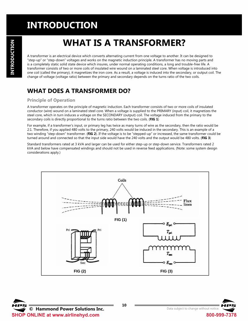
A transformer is an electrical device which converts alternating current from one voltage to another. It can be designed to “step-up” or “step-down” voltages and works on the magnetic induction principle. A transformer has no moving parts and is a completely static solid state device which insures, under normal operating conditions, a long and trouble-free life. A transformer consists of two or more coils of insulated wire wound on a laminated steel core. When voltage is introduced into one coil (called the primary), it magnetizes the iron core. As a result, a voltage is induced into the secondary, or output coil. The change of voltage (voltage ratio) between the primary and secondary depends on the turns ratio of the two coils.
Principle of OperationA transformer operates on the principle of magnetic induction. Each transformer consists of two or more coils of insulated conductor (wire) wound on a laminated steel core. When a voltage is supplied to the PRIMARY (input) coil, it magnetizes the steel core, which in turn induces a voltage on the SECONDARY (output) coil. The voltage induced from the primary to the secondary coils is directly proportional to the turns ratio between the two coils. (FIG 1)
For example, if a transformer’s input, or primary leg has twice as many turns of wire as the secondary, then the ratio would be 2:1. Therefore, if you applied 480 volts to the primary, 240 volts would be induced in the secondary. This is an example of a two winding “step-down” transformer. (FIG 2). If the voltage is to be “stepped-up” or increased, the same transformer could be turned around and connected so that the input side would have the 240 volts and the output would be 480 volts. (FIG 3)
Standard transformers rated at 3 kVA and larger can be used for either step-up or step-down service. Transformers rated 2 kVA and below have compensated windings and should not be used in reverse feed applications. (Note: some system design considerations apply.)
WHAT DOES A TRANSFORMER DO?
FIG (1)
FIG (2) FIG (3)

IntroductIon
© Hammond Power Solutions Inc. Data subject to change without notice.11
Intr
od
uctIo
n
TYPES OF TRANSFORMERSDry-type transformers are manufactured in a variety of ways to meet the requirements of different applications. The following is a list of transformer types found in this catalog with a brief explanation.
Industrial Control and General Purpose Enclosed Transformers - (see Section 1)A control transformer is an isolation transformer designed to provide a high degree of secondary voltage stability (regulation) during a brief period of overload condition (also referred to as “Inrush Current”). Control transformers are usually rated for 600 volts or less.
Buck-Boost Transformers - (see Section 2)Buck-Boost transformers are control transformers with low voltage secondary windings. By field connecting the primary and secondary windings in an autotransformer configuration, they offer an economical solution to the adjustment of line voltages that are slightly above or below normal.
Buck-Boost transformers can be used to adjust stable voltages only. Fluctuating line voltages should be regulated with a Hammond Voltage Conditioner.
Reactors - (see Section 3)Air Core: They are used primarily as current or voltage limiting devices, particularly where large currents can enter a system that uses small amounts of power. An example is the telephone system which uses very small voltages where the current in a fault condition needs to be kept to a minimum.
Iron Core: An iron core reactor provides the same current or voltage control on a system as its air core counterpart. Iron core units tend to be used on smaller applications where the variables need greater or more sensitive control.
Drive Isolation Transformers - (see Section 4)Drive isolation transformers are designed to supply power to AC and DC variable speed drives. The harmonics created by SCR type drives requires careful designing to match the rated hp of each drive system. The duty cycle included is approximately one start every 2 hours. The windings are designed for an overcurrent of 150% for 60 seconds, or 200% for 30 seconds.
Motor Starting Autotransformers - (see Section 5)Motors have a large inrush current component that requires a special design. Motor starting autotransformers are designed to withstand an inrush of upwards of 25 times normal current. Typically, they are tapped on larger sizes to soft-start the motor until it is up to full RPM.
Low voltage General Purpose Transformers - (see Section 6)HPS low voltage general purpose transformers provide a safe, long lasting, highly reliable power source. They are designed for general lighting and other low voltage applications. They are UL listed and CSA certified.

IntroductIon
12© Hammond Power Solutions Inc. Data subject to change without notice.
Intr
od
uct
Ion
Energy Efficient Transformers - (see Section 7)There is a growing movement in the electrical industry towards energy efficient products in all sectors including dry-type transformers. In addition to the benefits to the environment, energy efficient transformers also can realize substantial savings in operating costs thereby having a direct impact on the initial investment evaluated over a period of time.
The standards covering 600 volt class energy efficiency in dry-type transformers in North America are outlined in DOE 10 CFR Part 431, “Energy Conservation Program for Commercial Equipment: Distribution Transformers Energy Conservation Standards; Final Rule”. These specifications have carefully considered the total owning cost unique for industrial or commercial installations where the load factor is an integral part of the efficiency rating.
Energy Efficient General Purpose TransformersThe HPS Sentinel® energy efficient general purpose transformers are designed for linear loads and are most frequently used for applications such as commercial buildings which will supply a variety of general loads.
Energy Efficient K-Factor TransformersThe HPS Synergy® energy efficient k-factor transformers are designed to tolerate heating due to harmonics associated with non-linear loads. Harmonics can indicate their presence in a number of ways: overheating, device malfunctions, telephone interference, equipment vibration and breakers tripping.
Energy Efficient Harmonic Mitigating TransformersThe HPS Centurion® energy efficient, harmonic mitigating transformer with zero sequence flux cancellation technology is specifically designed to treat the harmonics generated by computer equipment and other non-linear, power electronic loads. Combining zero sequence flux cancellation with phase shifting treats 3rd, 5th, 7th, 9th, 15th, 17th and 19th harmonics within its secondary windings. Typical applications of severe non-linear loading conditions include data centers, internet-service providers, telecom sites, call centers, broadcast centers, etc.
Encapsulated (Potted) Transformers - (see Section 8)HPS offers two complete lines of encapsulated transformers to meet both a commercial and industrial environment. These units are encapsulated and completely enclosed.
Encapsulated Transformers for Commercial UseThe FortressTM is designed to provide the ideal solution for commercial applications. All units are encapsulated with electrical grade silica sand and resin compounds, which completely enclose the core and coil to seal out moisture, airborne contaminants and eliminates corrosion and deterioration.
Encapsulated Transformers for Harsh Environments and Hazardous LocationsThe HPS Titan® design is especially suited for installations in harsh environments and hazardous locations which may contain dangerous gasses, liquids, dust, lint, moisture and where corrosive contaminants are present. Typical applications include: institutional, commercial, industrial, petrochemical, pulp and paper; food processing, mines, marine and shipboard installations. They are designed to meet both UL Standard 1604 entitled “Electrical Equipment for use in Class I and Class II, Division 2 and Class III Hazardous (Classified) Locations” and ABS Type Approval for “Marine Duty Service and Offshore Applications - Electrical Distribution and Propulsion”.
Mini Power Centers - (see Section 9)HPS power centers are conveniently pre-wired to save you time, money, and space. They’re designed ideally for industrial locations, temporary power at construction sites, commercial buildings, test equipment, plant assembly lines, etc.
Types of Transformers continued...

IntroductIon
© Hammond Power Solutions Inc. Data subject to change without notice.13
Intr
od
uctIo
n
Autotransformers - (see Section 10)Autotransformers are similar to Buck-Boost transformers in that they are also an economical means of adjusting output voltage. Autotransformers are designed to adjust the supply voltage when isolation from the line is not necessary and where local electrical codes permit. Units are designed in either a step-up or step-down application and meet motor inrush currents.
Energy Efficient Medium voltage Distribution Transformers - (see Section 11)As of January 1st, 2010, all dry-type medium voltage distribution transformers manufactured or imported into North America must comply with the new DOE 10 CFR Part 431/NRCan standards. These standards were put in place to reduce additional energy consumption, as well as reduce greenhouse gases.HPS Millennium™ transformers are really 5kV class dry-type energy efficient distribution transformers. They are designed primarily for use in stepping down medium voltage power (i.e. 4160V or 2400V primary) to a lower voltage for commercial, institutional or industrial applications.
Types of Transformers continued...

Enclosure Mounting Holes
IntroductIon
14© Hammond Power Solutions Inc. Data subject to change without notice.
Intr
od
uct
Ion CONSTRUCTION FEATURES
Standard transformers are designed and constructed to meet or exceed the requirements for general applications. These transformers are provided either ventilated or totally enclosed. To meet special applications or custom requirements, modifications are available as either factory installed options or field installed accessories.
Please note that construction details for our Control Transformers and Reactors are in sections 1 and 3 respectively.
Enclosure Knockouts
Drip Shield
Primary Terminal Connectors c/w
Standard Lugs(up to 340A)
Tap Lead Wire Taps
Laminated SteelCore
Aluminum or Copper Coils
Secondary Terminal Connectors c/w Standard LugsGround Strap
vibration Dampers
Bottom Enclosure vents
NEMA 3R Enclosure
(Note: top cover removed for clarity)
Secondary Neutral
Heavy Duty Mounting Feet/
Channels
IntroductIon
© Hammond Power Solutions Inc. Data subject to change without notice.15
Intr
od
uctIo
n
CONSTRUCTION FEATURES continued . . .
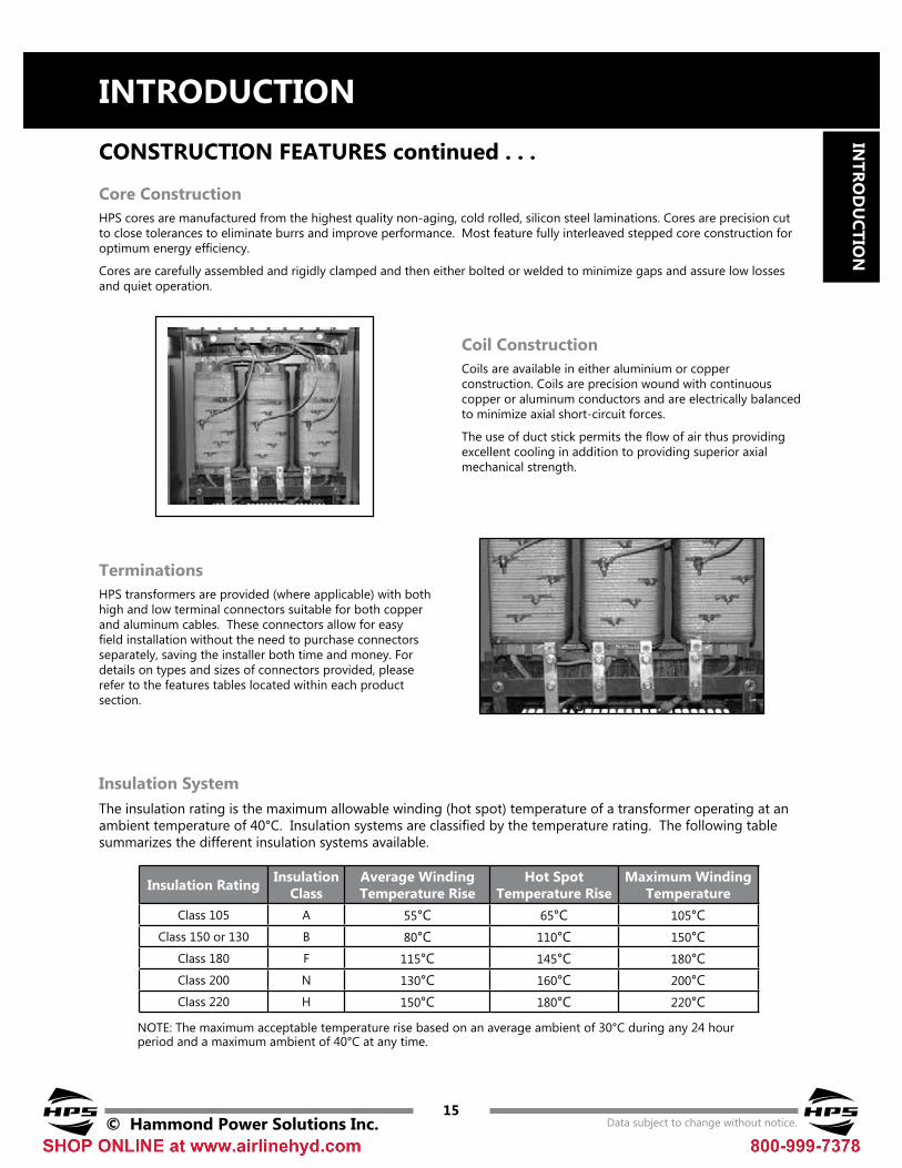
Insulation SystemThe insulation rating is the maximum allowable winding (hot spot) temperature of a transformer operating at an ambient temperature of 40°C. Insulation systems are classified by the temperature rating. The following table summarizes the different insulation systems available.
Coil ConstructionCoils are available in either aluminium or copper construction. Coils are precision wound with continuous copper or aluminum conductors and are electrically balanced to minimize axial short-circuit forces.
The use of duct stick permits the flow of air thus providing excellent cooling in addition to providing superior axial mechanical strength.
TerminationsHPS transformers are provided (where applicable) with both high and low terminal connectors suitable for both copper and aluminum cables. These connectors allow for easy field installation without the need to purchase connectors separately, saving the installer both time and money. For details on types and sizes of connectors provided, please refer to the features tables located within each product section.
NOTE: The maximum acceptable temperature rise based on an average ambient of 30°C during any 24 hour period and a maximum ambient of 40°C at any time.
Core ConstructionHPS cores are manufactured from the highest quality non-aging, cold rolled, silicon steel laminations. Cores are precision cut to close tolerances to eliminate burrs and improve performance. Most feature fully interleaved stepped core construction for optimum energy efficiency.
Cores are carefully assembled and rigidly clamped and then either bolted or welded to minimize gaps and assure low losses and quiet operation.
Insulation Rating Insulation Class
Average Winding Temperature Rise
Hot Spot Temperature Rise
Maximum Winding Temperature
Class 105 A 55°C 65°C 105°CClass 150 or 130 B 80°C 110°C 150°C
Class 180 F 115°C 145°C 180°CClass 200 N 130°C 160°C 200°CClass 220 H 150°C 180°C 220°C

IntroductIon
16© Hammond Power Solutions Inc. Data subject to change without notice.
Intr
od
uct
Ion
For long-term life expectancy, it is critical that transformers maintain the integrity of the dielectric properties of the insulation materials.
At HPS, transformer coils are impregnated with a complete vacuum-pressure impregnating cycle:
• Coils are placed in a sealed tank and a vacuum is drawn
• The resin is then introduced into the chamber and the assembly is completely immersed
• The tank is then pressurized to force the impregnation material to thoroughly penetrate the windings
• The coils or assembly are then removed from the chamber and oven cured
• These steps are then repeated
Polyester Resin ImpregnationFor most applications, regardless of voltage class, HPS’ polyester resin impregnation system is preferred. The polyester resin exhibits a much higher dielectric strength and bonding properties than any varnish previously used, or other encapsulations including oil modified epoxies. This polyester resin exhibits these characteristics:
vACUUM PRESSURE IMPREGNATION (vPI)
CONSTRUCTION FEATURES continued . . .
The following briefly describes our process.
• Low moisture absorption (Non-Hydroscopic)
• High dielectric strength
• High bond strength
• Excellent mechanical properties
• Stability at high temperatures
• Excellent thermal shock properties
• Longevity of life at maximum transformer temperatures
• UL approved for 220°C insulation systems for any voltage class
• Fungus-resistant reactive components makes it environmentally superior
The result is transformers whose coils exhibit virtually corona-free performance, a superior resistance to environmental conditions and a new standard of reliability even for the worst industrial, utility or commercial applications.
vacuum Pressure Chamber Baking Oven

H2 X2
H1 H3
X1 X3
1 2 3
H0
5 4
IntroductIon
© Hammond Power Solutions Inc. Data subject to change without notice.17
Intr
od
uctIo
n
TRANSFORMER BASICSBanking of TransformersTwo or three single phase transformers can be connected to make a three phase bank. The primary windings of the single phase transformers can be connected in delta or wye. The secondary windings can also be connected in either a delta or wye configuration. The equivalent capacity of the bank will be equal to three times the nameplate rating of each single phase transformer. Usually this type of installation is more expensive than using a single three phase transformer.
Primary voltage TapsIn some cases, the actual supply voltage to the primary of the transformer is either slightly higher or lower than the nameplate rating. Taps are provided on most transformers on the primary winding to correct this condition and maintain full rated output voltage and capacity. Standard taps are usually in 2 1/2% or 5% increments. Example: The transformer has a 480V primary rating and the incoming voltage is at 504V. The primary connection should be made at the +5% tap in order to maintain the nominal secondary voltage.
Transformer Operation at 50 HzTransformers rated at 60Hz should not be used on a 50Hz supply due to higher losses and core saturation and the resultant higher temperature rise. Transformers rated for 50Hz, however, can be operated on a 60Hz supply.
Reverse ConnectionIn general, distribution transformers can be reverse connected without derating the nameplate kVA capacity. However, some precautions need to be taken for reverse connection of some smaller transformers. On HPS transformers under 6 kVA three phase and 3 kVA single phase, there is a “turns ratio compensation” on the low voltage winding. When the input voltage, equal to the nameplate rated voltage, is connected to the low voltage winding, the output voltage will be slightly lower than the nameplate rating.
When a three phase transformer is reverse connected thus resulting in a Wye-Delta configuration, the neutral terminal must be isolated.
Further, the reverse connected transformer may draw a higher inrush current during energization. Hence the sizing of the line fusing or circuit breaker may be affected.

IntroductIon
18© Hammond Power Solutions Inc. Data subject to change without notice.
Intr
od
uct
Ion
Sound LevelSound needs to be considered when transformers are located in close proximity to occupied areas. All energized transformers emanate sound due to the alternating flux in the core. This normal sound emitted by the transformer can be a source of annoyance unless it is kept below acceptable levels.
HPS transformers are built to meet the latest ANSI, CSA and UL standards. These standards use NEMA-ST20 (see below table for outline).
HPS also offers “Low Sound” options to most of it distribution style transformers. Please contact your HPS sales representative for details.
Balance Loading on Single and Three Phase TransformersA single phase transformer with 120/240V secondary has two separate 120V secondary windings and is usually connected into a 3 wire system. Care must be exercised in distributing the load on the two 120V windings evenly, so each winding is carrying about half of the total load.
Similarly for a three phase transformer, each phase should be considered as a single phase transformer. When distributing single phase loads between the three phases, each of the three windings should be evenly loaded.
Equivalent Two Winding
kvA
Self Cooled ventilated
voltage Line to Line
Self Cooled Non-ventilated
1.2kv
dB-A
>1.2kv
dB-A dB-A
0-9 40 45 45
10-50 45 50 50
51-150 50 55 55
151-300 55 58 57
301-500 60 60 59
501-700 62 62 61
701-1000 64 64 63
Transformer Basics continued . . .

kvA
Current in Amperes
120v 240v 416v 480v 600v 2400v 4160v0.25 2.08 1.04 0.60 0.52 0.41 - -0.50 4.16 2.08 1.20 1.04 0.83 - -0.75 6.25 3.13 1.80 1.56 1.25 - -1.0 8.33 4.17 2.40 2.08 1.67 - -1.5 12.5 6.25 3.60 3.13 2.50 - -2.0 16.7 8.33 4.81 4.17 3.33 - -3.0 25.0 12.5 7.21 6.25 5.00 1.25 0.725.0 41.6 20.8 12.0 10.4 8.33 2.08 1.207.5 62.5 31.2 18.0 15.6 12.5 3.12 1.8010 83.3 41.6 24.0 20.8 16.6 4.16 2.4015 125 62.5 36.0 31.2 25.0 6.25 3.6025 208 104 60.0 52.0 41.6 10.4 6.00
37.5 312 156 90.1 78.1 62.5 15.6 9.0150 416 208 120 104 83.3 20.8 12.075 625 312 180 156 125 31.2 18.0
100 833 416 240 208 166 41.6 24.0150 1250 825 360 312 250 62.5 36.0167 1391 695 401 347 278 69.5 40.1250 2083 1041 600 520 416 104 60.0333 2775 1387 800 693 555 138 80.0
Horsepower
Full Load Current (Amps) Minimum Transformer
kvA110-120v 208v 220-240v*0.50 HP 9.8 5.4 4.9 1.50.75 HP 13.8 7.6 6.9 2.01.0 HP 16.0 8.8 8.0 3.01.5 HP 20.0 11.0 10.0 3.02.0 HP 24.0 13.2 12.0 5.03.0 HP 34.0 18.7 17.0 5.05.0 HP 56.0 30.8 28.0 7.57.5 HP 80.0 44.0 40.0 15.010 HP 100 55.0 50.0 15.015 HP 135 74.8 68.0 25.020 HP - - 88.0 25.025 HP - - 110 37.530 HP - - 136 37.540 HP - - 176 50.050 HP - - 216 75.0
IntroductIon
© Hammond Power Solutions Inc. Data subject to change without notice.19
Intr
od
uctIo
n
SELECTING TRANSFORMERSSINGLE PHASEA single phase transformer is designed to transform single phase or three phase input (source) voltage to the single phase output (load) voltage required by your equipment. To select the correct single phase transformer you must first determine:
1. The equipment being installed operates on a single phase supply (see your equipment nameplate or installation manual).
2. The Primary voltage of the transformer. This is the same as the line input (or source) voltage, typically 480 or 600 volts AC.
3. The Secondary voltage of the transformer. The equipment being installed will have a specified supply voltage (see equipment nameplate or installation manual). The transformer you select must have a secondary voltage equal to the required supply voltage of the equipment, typically 120/240 VAC.
4. The Frequency in Hertz (cycles-per-second) of the input (source) voltage must be the same as the operating frequency of the equipment being supplied. The transformer selected must operate at the same frequency. Typical operating frequency is 60 Hz.
5. The Total vA of the load is determined by the product of the voltage supplied across the load and the current passing through it. This is normally expressed in VA (Volt-Amperes) or kVA (kilo Volt-Amperes) on the equipment nameplate. The total load is often a combination of various loads (i.e. lights, heaters, motors). You must calculate these individual loads and add them together to obtain the total load of the transformer. The transformer you select must have a kVA rating equal to or greater than the load on the transformer.
Full Load Current Table Single Phase Transformer
Single Phase AC Motor Full Load Running Currents in Amperes and Recommended Transformer Ratings
kVA ratings include 10% overcapacity for frequent motor starts.+ For 200 volt motors increase 220-240V ratings by 15%.
How to use the full load chart to find kvA:
1. Determine the secondary voltage of your transformer.
2. Sum up the total amperes required by the load.
3. From the full load current table below, select a transformer under the corresponding secondary voltage, with a standard kVA capacity and amperage equal to or higher than the sum required by the load.
Calculating kvA: To calculate kVA when volts and amperes are known:
Volts X Amps (load)
1000kVA =

kvA
Current in Amperes
208v 240v 380v 416v 480v 600v 2400v 4160v2 5.55 4.81 3.03 2.77 2.40 1.92 0.48 0.273 8.32 7.21 4.55 4.16 3.60 2.88 0.72 0.416 16.6 14.4 9.11 8.32 7.21 5.77 1.44 0.839 24.9 21.6 13.6 12.4 10.8 8.66 2.16 1.24
15 41.6 36.0 22.7 20.8 18.0 14.4 3.60 2.0830 83.2 72.1 45.5 41.6 36.0 28.8 7.21 4.1645 124 108 68.3 62.4 54.1 43.3 10.8 6.2475 208 180 113 104 90.2 72.1 18.0 10.4
112.5 312 270 170 156 135 108 27.0 15.6150 416 360 227 208 180 144 36.0 20.8225 624 541 341 312 270 216 54.1 31.2300 832 721 455 416 360 288 72.1 41.6450 1249 1082 683 624 541 433 108 62.4500 1387 1202 759 693 601 481 120 69.3600 1665 1443 911 832 721 577 144 83.2750 2081 1804 1139 1040 902 721 180 104
Horsepower
Full Load Current (Amps) Minimum Transformer kvA110-120v 208v 220-240v* 440-480v 550-600v
0.50 HP 4.0 2.2 2.0 1.0 0.8 30.75 HP 5.6 3.1 2.8 1.4 1.1 31.0 HP 7.2 4.0 3.6 1.8 1.4 31.5 HP 10.4 5.7 5.2 2.6 2.1 32.0 HP 13.6 7.5 6.8 3.4 2.7 63.0 HP 19.2 10.7 9.6 4.8 3.9 65.0 HP 30.4 16.7 15.2 7.6 6.1 97.5 HP 44.0 24.0 22.0 11.0 9.0 1510 HP 56.0 31.0 28.0 14.0 11.0 1515 HP 84.0 46.0 42.0 21.0 17.0 3020 HP 108 59.0 54.0 27.0 22.0 3025 HP 136 75.0 68.0 34.0 27.0 4530 HP 160 88.0 80.0 40.0 32.0 4540 HP 208 114 104 52.0 41.0 7550 HP 260 143 130 65.0 52.0 7560 HP - 170 154 77.0 62.0 7575 HP - 211 192 96.0 77.0 112.5
100 HP - 273 248 124 99.0 150
IntroductIon
20© Hammond Power Solutions Inc. Data subject to change without notice.
Intr
od
uct
Ion Selecting Transformers continued . . .
THREE PHASEA three phase transformer is designed to transform a three phase input (source) voltage to the single phase and three phase output (load) voltages required by your equipment.
In order to select the correct three phase transformer you must first determine:
1. The equipment being installed operates on a three phase supply.Note: If both single phase and three phase equipment makes up the load, the single phase equipment is connected to only one phase of the transformer.
2. The Primary voltage of the transformer. This is the same as the line input (or source) voltage, typically 480 or 600 volts AC.
3. The Secondary voltage of the transformer. This is the transformer’s output voltage and must be the same as the voltage required by the equipment being installed (see equipment nameplate, typically 208Y/120 volts).
4. The Frequency in hertz (cycles per second) of the input (source) voltage must be the same as the operating frequency of the equipment being supplied. The transformer selected must operate at the same frequency. Typical operating frequency is 60 Hz.
5. The Total vA of the load is determined by the product of the voltage supplied across the load and the current passing through it. This is normally expressed in VA (Volt-Amperes) or kVA (kilo Volt-Amperes) on the equipment nameplate.
The total load is often a combination of various loads (i.e. lights, heaters, motors). You must calculate these individual loads and add them together to obtain the total load of the transformer.
Full Load Current Table - Three Phase Transformer
Three Phase AC Motor Full Load Running Currents in Amperes and Recommended Transformer Ratings
kVA ratings include 10% overcapacity for frequent motor starts.+ For 200 volt motors increase 220-240V ratings by 15%.
The transformer you select must have a kVA rating equal to or greater than the load requirement.
Note: The three phase transformer must be selected so that any one phase is not overloaded. If you are connecting a single phase load to one phase of the three phase transformer, you must calculate the load as if it were loading all three phases.
Calculating kVA
To calculate kVA when volts and amperes are known:
VLL X IL
1000
VLL = Volts line - line IL = Line Current
3 XkVA =

IntroductIon
© Hammond Power Solutions Inc. Data subject to change without notice.21
Intr
od
uctIo
n
Compliance with Engineering StandardsHPS Dry-Type Transformers are approved, listed, recognized or comply with the following Regulatory Standards. The reference files are:
UL1561 and UL1562 CSA C9-M and CSA C22.2-M ANSI C57.12.51 NEMA TR-1 and ST-1 IEC 76
HPS dry-type transformers can be built to comply with the following engineering standards:
• UL 1561 : Dry-Type General Purpose and Power Transformers
• UL 1562 : Transformers, Distribution, Dry-Type over 600 volts
• IEEE-C57.12.01 : General Requirements for Dry-Type Distribution and Power Transformers
• NEMA ST-20 : Dry-Type Transformers for General Applications
• ANSI-C57.12.51 : Requirements for Ventilated Dry-Type
• ANSI-C57.12.70 : Terminal Markings & Connections for Distribution & Power Transformers
• ANSI-C57.12.91 : Test Code for Dry-Type Distribution and Power Transformers
• ANSI-C57.12.90 : Guide for Short Circuit Testing of Distribution and Power Transformers
• NEMA 250 : Enclosures for Electrical Equipment
• CSA-C22.2 No. 47 : Air-Cooled (Dry-Type) Transformers
• CSA-C9-M : Dry-Type Transformers
• CSA C802.2 and DOE 10 CFR Part 431: Energy Efficiency Standards
TRANSFORMER TEST STANDARDS
Production TestsD.C. Resistance MeasurementCurrent from a D.C. resistance bridge is applied to the transformers windings to determine the D.C. resistance voltage of the coils. This test is important for the calculation of I2R for use in the winding temperature test and as base data for future assessment in the field.
Polarity and Phase-Relation TestPolarity and phase-relation tests are made to determine angular displacement and relative phase sequence to facilitate connections in a transformer. Determining polarity is also essential when paralleling or banking two or more transformers.
All transformers are tested at the manufacturing facility prior to shipment. Transformers must meet very specific criteria to be certified acceptable for release. Tests are categorized as ‘Production Tests’ and ‘Type Tests’. Production Tests are applied to every transformer, where Type Tests are required either to qualify a new product or to further certify a production product. Type tests are optional and are available at an additional cost.

IntroductIon
22© Hammond Power Solutions Inc. Data subject to change without notice.
Intr
od
uct
Ion
No-Load and Excitation Current Test*No-load losses (excitation losses) are the core losses of a transformer that are “excited” at rated voltage and frequency, but which do not supply load. No-load losses include core loss, dielectric loss and losses in the windings due to exciting current.
The transformer is excited at rated voltage with all other windings open circuited. The exciting current and no load loss is then measured.*(Note: This is a standard test only on units over 500kVA. It will only be carried out on lower kVA units when specifically requested.)
voltage Ratio (turns ratio)To confirm the voltage ratio of a transformer, the ratio of the number of turns in the high-voltage winding with respect to the number of turns in the low-voltage winding is measured.
Impedance voltage and Load Loss Test*The voltage required to circulate the rated current under short-circuit conditions when connected on the rated voltage tap is the impedance voltage.
Rated current is circulated through the windings with the secondary short circuited. The impedance voltage and load loss is then measured. They are corrected to rise +20°C reference temperature.*(Note: This is a standard test only on units over 500kVA. It will only be carried out on lower kVA units when specifically requested.)
Transformer Test Standards continued ...
Dielectric TestsThe purpose of dielectric tests is to demonstrate that the transformer has been designed and constructed to withstand the voltages associated with specified insulation levels.
Applied voltage Test A normal power frequency, such as 60 Hz, is applied to each winding for one minute. These tests are in accordance with table (3) in ANSI C57-12-01.
Induced voltage Test The induced voltage test is applied for 7200 cycles or 60 seconds, whichever is shorter. The voltage applied is twice the operating voltage and confirms the integrity of the insulation.
Type TestsType tests are required either to qualify a new product or to further certify a standard product line. The following is a list of type tests performed on HPS Transformers.
• Temperature Rise Test• Sound Level Test• Partial Discharge (corona)• Basic Impulse Insulation Level (BIL)• Short-Circuit Test

IntroductIon
© Hammond Power Solutions Inc. Data subject to change without notice.23
Intr
od
uctIo
n
QUALITY MANAGEMENT SYSTEMS
Hammond Power Solutions facilities, located in Guelph Ontario Canada, Walkerton Ontario Canada, Baraboo Wisconsin USA, Compton California USA and Monterrey Mexico, (which manufacture the transformers featured in this catalog), have implemented Quality Management Systems based on ISO 9001. ISO 9001 includes all processes affecting quality, customer satisfaction and continual improvement. Our customers can be assured of the integrity and quality in all Hammond Power Solutions transformer products.
ISO 9001:2008

IntroductIon
24© Hammond Power Solutions Inc. Data subject to change without notice.
Intr
od
uct
Ion
An enclosure is a surrounding case constructed to provide a degree of protection to personnel against access to hazardous parts and to provide a degree of protection to the enclosed equipment against specified environmental conditions.
Applicable Engineering StandardsHPS Enclosures are designed in accordance with the following standards:
• CSA 22.2 No. 47 (General Purpose)• CSA 22.2 No. 94 (Specialty Enclosures)• NEMA 250• UL 50 and UL 50E
Please ensure to reference all local and national electrical codes and applicable transformer standards before selecting an enclosure for your application.
DefinitionsDegree of protection: The extent of protection provided by an enclosure against access to hazardous parts, against ingress of foreign solid objects and/or against ingress of water and verified by approved standardized test methods.Hazardous parts: A part that is hazardous to approach or to touch. Indoor Locations: Areas which are protected from exposure to the weather.Non-ventilated: Constructed so as to provide no intentional circulation of external air through the enclosure.Outdoor locations: Locations that are exposed to the weather.ventilated: Constructed so as to provide for the circulation of external air through the enclosure to remove excess heat, fumes or vapors.
Enclosure SelectionThe selection of the appropriate enclosure is vital for the long term reliability of your HPS product. The “degree of protection” an enclosure actually provides can only be determined by referencing the appropriate test methods outlined in the above mentioned standards.
The list below is just some of the typical enclosure types available for HPS products, their applications, and the environmental conditions they are designed to meet.
HPS Typical Enclosures TypesThe following lists some of the standard HPS enclosures available and a brief description of their applications:
TYPE 1This is a general purpose ventilated enclosure constructed for indoor use only to provide a degree of protection to personnel against access to hazardous parts; to provide a degree of protection of the equipment inside the enclosure against ingress of solid foreign objects (falling dirt).
TYPE 2This is a general purpose ventilated enclosure constructed for indoor use only to provide a degree of protection to personnel against access to hazardous parts; to provide a degree of protection of the equipment inside the enclosure against the ingress of solid foreign objects (falling dirt); and to provide a degree of protection with respect to harmful effects on the equipment due to the ingress of water (dripping or light splashing).
TYPE 3RIThis is a general purpose ventilated enclosure constructed for indoor use only to provide a degree of protection to personnel against access to hazardous parts; to provide a degree of protection of the equipment inside the enclosure against the ingress of solid foreign objects (falling dirt); and to provide a degree of protection with respect to harmful effects on the equipment due to the ingress of water (sprinkler head spray, light splashing of liquids).
TYPE 3RThis is a general purpose ventilated enclosure constructed for either indoor or outdoor use to provide a degree of protection to personnel against access to hazardous parts; to provide a degree of protection of the equipment inside the enclosure against the ingress of solid foreign objects (falling dirt); and to provide a degree of protection with respect to harmful effects on the equipment due to the ingress of water (rain, sleet, snow); and that will be undamaged by the external formation of ice on the enclosure.
HPS STANDARD ENCLOSURES

IntroductIon
© Hammond Power Solutions Inc. Data subject to change without notice.25
Intr
od
uctIo
n
HPS Standard Enclosures continued ...
IP1st Character NEMA Enclosure Type IP
2nd Character
1 2 3, 3X, 3S,3SX
3R, 3RX 4, 4X 5 6 6P
12, 12K, 13
IP0_ IP_0
IP1_ IP_1
IP2_ IP_2
IP3_ IP_3
IP4_ IP_4
IP5_ IP_5
IP6_ IP_6
IP_7
IP_8
A B A B A B A B A B A B A B A B A B
CONvERSION OF NEMA ENCLOSURE TYPE RATINGS TO IEC 60529 ENCLOSURE CLASSIFICATION DESIGNATIONS (IP)
(Cannot be Used to Convert IEC Classification Designations to NEMA Type Ratings)
IP First Character = The A shaded block in the “A” column represents the first IP character. This indicates that the NEMA Enclosure Type exceeds the requirements for the respective IEC 60529 IP First Character Designation. This IP First Character Designation is the protection against access to hazardous parts and solid foreign objects.
IP Second Character = The B shaded block in the “B” column represents the second IP character. This indicates that the NEMA Enclosure Type exceeds the requirements for the respective IEC 60529 IP Second Character Designation. This IP Second Character Designation is the protection against the ingress of water.
Example: NEMA Type 3R = IP24 Note: Please refer to NEMA standards publication 250-2003 for exact details of the above table.
TYPE 3REThis is a general purpose ventilated enclosure constructed for either indoor or outdoor use to provide a degree of protection to personnel against access to hazardous parts; to provide a degree of protection of the equipment inside the enclosure against the ingress of solid foreign objects (falling dirt and circulating dust); and to provide a degree of protection with respect to harmful effects on the equipment due to the ingress of water (rain, sleet, circulating snow); and that will be undamaged by the external formation of ice on the enclosure.
TYPE 4This is a general purpose non-ventilated enclosure constructed for either indoor or outdoor use to provide a degree of protection to personnel against access to hazardous parts; to provide a degree of protection of the equipment inside the enclosure against the ingress of solid foreign objects (falling dirt and windblown dust); and to provide a degree of protection with respect to harmful effects on the equipment due to the ingress of water (rain, sleet, snow, splashing water, and hose directed water); and that will be undamaged by the external formation of ice on the enclosure. (Note: not submersible)
TYPE 4XThis is a general purpose non-ventilated enclosure constructed for either indoor or outdoor use to provide a degree of protection to personnel against access to hazardous parts; to provide a degree of protection of the equipment inside the enclosure against the ingress of solid foreign objects (windblown dust); and to provide a degree of protection with respect to harmful effects on the equipment due to the ingress of water (rain, sleet, snow, splashing water, and hose directed water); that provides an additional level of protection against corrosion; and that will be undamaged by the external formation of ice on the enclosure. (Note: not submersible)
TYPE 12This is a general purpose non-ventilated enclosure constructed (without knockouts) for indoor use only to provide a degree of protection to personnel against access to hazardous parts; to provide a degree of protection of the equipment inside the enclosure against the ingress of solid foreign objects (falling dirt and circulating dust, lint, fibers, and filings); and to provide a degree of protection with respect to harmful effects on the equipment due to the ingress of water (dripping and light splashing). (Note: not submersible)

IntroductIon
26© Hammond Power Solutions Inc. Data subject to change without notice.
Intr
od
uct
Ion
Exclusive Warranty
Hammond Power Solutions Inc. (“HPS”), warrants to the original purchaser of the standard transformers listed in this catalog (the “Goods”), will be free from defects in materials and workmanship for a period commencing on the date of manufacture of the Goods and expiring at the end of the period specified below (the “Warranty Period”). THIS WARRANTY IS EXCLUSIVE AND IS IN LIEU OF ANY OTHER WARRANTY EXPRESS OR IMPLIED, INCLUDING BUT NOT LIMITED TO ANY IMPLIED WARRANTY OR MERCHANTABILITY OR FITNESS FOR A PARTICULAR PURPOSE.
Warranty Exclusions - Limitation of Damages and Claims Procedure
The above stated warranty does not cover: workmanship of installation; dissatisfaction or damage due to improper installation, vandalism, misuse, accident, excessive wear and tear, unauthorized repair, abnormal use, lack of maintenance, or other cause(s) not within HPS’s control and HPS WILL NOT BE LIABLE, UNDER ANY CIRCUMSTANCES, FOR CONSEQUENTIAL OR INCIDENTAL DAMAGES, INCLUDING BUT NOT LIMITED TO LABOR COSTS OR LOST PROFITS RESULTING FROM THE USE OF OR INABILITY TO USE THE GOODS OR FROM THE GOODS BEING INCORPORATED IN OR BECOMING A COMPONENT OR ANY OTHER PRODUCT. Without limiting the generality of the foregoing, HPS will not be responsible for labor costs involved in the removal of Goods or the installation of replacement Goods.
HPS’s liability and the Buyer’s exclusive remedy hereunder will be limited to repair or replacement of those Goods found in HPS’s reasonable judgment to be defective. HPS reserves the right to accept or reject any claim in whole or in part. HPS will not accept the return of any Goods without its prior written approval. Please consult HPS for instructions on the Return Authorization procedure.
Product Warranty Periods:Industrial Control Transformers (Section 1)
HPS Imperator® Lifetime Warranty
HPS Spartan® 15 Years
Other Control 10 Years
HPS Fusion™ General Purpose Enclosed Transformers (Section 1) 15 Years
HPS Universal™ Buck-Boost/Low voltage Lighting Transformers (Sections 2 & 6) 10 Years
HPS Centurion® R Reactors (Section 3) 10 Years
Line Reactors and Dv/DT Filters (Section 3) 10 Years
HPS Tribune™ and Standard Drive Isolation Transformers (Section 4) 10 Years
Motor Starting Auto Transformers (Section 5) 1 Year
Energy Efficient Distribution Transformers (Section 7) 10 Years
Encapsulated Dry-Type Distribution Transformers (Section 8) 10 Years
HPS PowerPlus™ Mini Power Center (Section 9) Transformer only 15 Year
Mini Power Center 1 Year
Autotransformers (Section 10) 10 Years
HPS Millennium Medium voltage Distribution Transformers (Section 11) 1 Year
All HPS six digit Special and Custom Transformers 1 Year
HAMMOND POwER SOLUTIONS INC. EXCLUSIVE LIMITED wARRANTY