Embed Size (px)
Citation preview
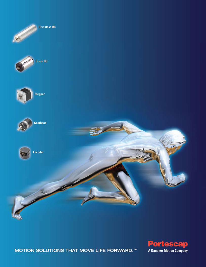
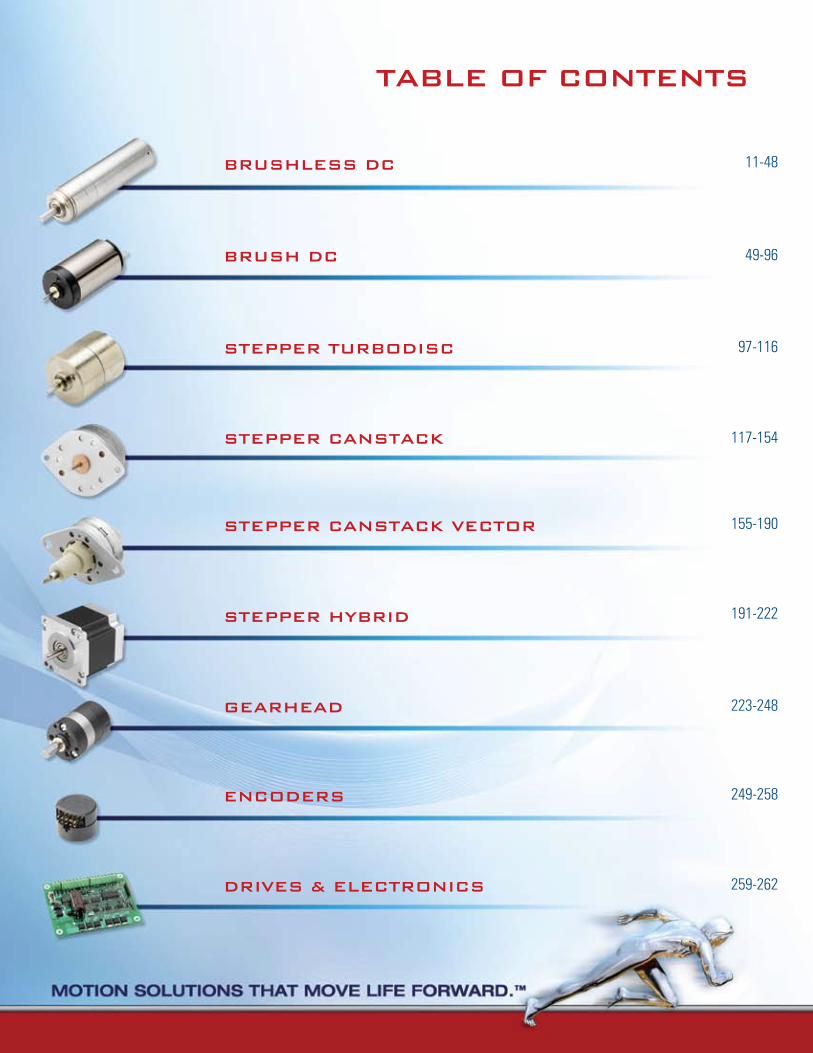
Encoder
Gearhead
Stepper
Brush DC
Brushless DC

EncodErs
drivEs & ElEctronics
GEArHEAd
stEPPEr tUrBodisc
BrUsH dc
11-48BrUsHlEss dc
49-96
97-116
223-248
249-258
259-262
tABlE of contEnts
stEPPEr cAnstAcK
stEPPEr cAnstAcK vEctor
stEPPEr HYBrid
117-154
155-190
191-222
What’s new?Portescap is committed to helping our customers find new
ways to win. We maintain our core values by listening to our
customers, pursuing continuous improvement in all that we do
and the motors we design, and driving excellence and
innovation.
What’s Exciting?Portescap and our customers have been compiling a growing
list of success stories in a breadth of industry categories
around the world. Portescap has provided the right power in
small places in a variety of applications, including medical, civil
aviation, HVAC&R, aerospace and security and access, just to
name a few. To find out how our motion solutions are moving
life forward, go to www.portescap.com.
What Works Best?At Portescap, we optimize the relationships we create. We
offer new and innovative solutions, lean supply chain
management, LCR sourcing, and motor customization that
helps provide our customers with a solution that meets their
needs. We work closely with our customers to analyze every
facet of their motion control need, and then devise smart,
often unexpected ways to do the job better. We never solve
problems in isolation. Instead, we step back, look at their
business, and find new efficiencies or new levels of integration
that translate into bigger wins.
Portescap is a recognized expert in miniature motors and precision motion control
solutions. Portescap has been leading the way since 1931, driven by a passion for
innovation, technical excellence and quality service. Originating in Switzerland,
Portescap generated technology that helped to revolutionize the precision clock
and watch making industry. The company then applied its motion control ingenuity
to miniature motors and is now recognized as one of the global leaders in high
performance electro-mechanical motion systems, including brush DC, brushless,
and stepper motors as well as gearboxes, drive electronics and feedback
devices. Portescap is a global company with offices in the United States, India,
Malaysia, Singapore, and Switzerland. Portescap continues its legacy of
innovation and builds on its growing lists of “firsts” in the industry.
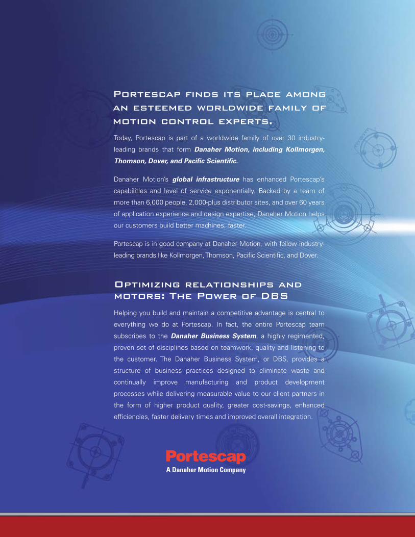
Today, Portescap is part of a worldwide family of over 30 industry-
leading brands that form Danaher Motion, including Kollmorgen,
Thomson, Dover, and Pacific Scientific.
Danaher Motion’s global infrastructure has enhanced Portescap’s
capabilities and level of service exponentially. Backed by a team of
more than 6,000 people, 2,000-plus distributor sites, and over 60 years
of application experience and design expertise, Danaher Motion helps
our customers build better machines, faster.
Portescap is in good company at Danaher Motion, with fellow industry-
leading brands like Kollmorgen, Thomson, Pacific Scientific, and Dover.
optimizing relationships and motors: the Power of dBs
Helping you build and maintain a competitive advantage is central to
everything we do at Portescap. In fact, the entire Portescap team
subscribes to the Danaher Business System, a highly regimented,
proven set of disciplines based on teamwork, quality and listening to
the customer. The Danaher Business System, or DBS, provides a
structure of business practices designed to eliminate waste and
continually improve manufacturing and product development
processes while delivering measurable value to our client partners in
the form of higher product quality, greater cost-savings, enhanced
efficiencies, faster delivery times and improved overall integration.
Portescap finds its place among an esteemed worldwide family of motion control experts.
Purposeful innovation through a deeper, more meaningful understanding of you and your customers.
What We do
We provide customized solutions to optimize every opportunity. At Portescap, we turn your ideas into reality. Often, a
complete solution can be developed from building blocks
that we’ve already created. However, there’s nothing we
like better than putting brand new ideas in motion. In
fact, customization is one of our greatest strengths. Our
long track record of creating unique solutions spans a wide
range of industries and applications.
Our more recent examples include customization of gear
motor assemblies for an articulating surgical handtool, and a
custom stepper motor assembly for refrigeration valves.
Portescap takes rapid prototyping to a more inspired,
interactive level. As your design cycles get tighter, Portescap
will keep you on schedule with some of the fastest turnaround
times in the industry – often as short as two weeks. With
development teams and prototyping facilities in key locations
throughout the world, Portescap can solve the most complex
miniature motion challenges quickly, accurately and cost-
effectively. At Portescap, you talk, we listen. Then, we build
what you need to succeed.
An important factor in our success is the highly collaborative
environment we create between customers and our Sales
and Application Engineering resources. By providing
extraordinary access during the prototyping phase, we’re
able to collaborate as true partners in the process, and be
responsive to often changing needs. This approach also
allows us to take a more active role in the short- and long-
term success of our customers.
Whatever your special needs for high performance
electromechanical systems, Portescap has the experience,
technology and resources to develop the best solution.
When you partner with Portescap, you’re teaming up with
a knowledge leader in the fields of electronics,
electromagnetics and precision micromechanics.
Our commitment to innovation focuses on the issues that
mean the most to you and your customers. This is true
whether we’re raising the bar in autoclavability in medical
and dental devices, maximizing power density for extended
battery life in industrial hand tools, or dramatically increasing
torque output while reducing motor size to enable
miniaturization.
Innovation is part of the corporate DNA at Portescap. It’s
what keeps us moving and improving. Our research and
development teams in North America, Europe and Asia
are equipped to create high-quality precision motion
solutions in virtually any configuration, environment or
envelope. Through our integrated global network, we offer
customers over 70 years of experience in the industry.

We understand that quality is an unending process that
finds expression in both our products and our approach
to doing business. Motion solutions from Portescap are
built to provide reliable high performance in some of the
most demanding applications imaginable. Thorough
motor specifications and material selection, high
manufacturing standards, and a total commitment to
post-sales support ensure that motion solutions from
Portescap will meet your exacting performance
standards – today and in the future.
Consistently high product quality is the result of
manufacturing excellence that has placed Portescap
among the best in its class. Integrated manufacturing
facilities, leading-edge technologies, lean manufacturing
principles and a perpetual drive toward improvement in
design and execution allow us to deliver highly reliable
motion solutions.
Superior performance also means efficiency. Portescap’s
global positioning saves on logistical costs and enhances
value for our customers with efficiencies of supply
chain optimization. Along with this, our high-volume
platforms and vast experience – including 10 years of
Low Cost Region manufacturing experience – help
keep our customers a step ahead in an increasingly
competitive world.
As our world continues to change, Portescap continues
to adapt to changing conditions throughout industrialized
global markets. To help us provide superior service and
support, Portescap Customer Service delivers localized
customer support teams. This demonstrates Portescap’s
commitment to staying in step with the specialized needs
of customers around the world. Customers have come to
highly regard Portescap’s flexibility and adaptability,
and continue to rely on us to share in their success.
Portescap’s Manufacturing Excellence helps keep you first in quality and first to market with key competitive advantages:
High Quality and consistency, delivered.
• A culture of continuous innovation and improvement
• Fast customization and responsive prototyping
• Efficiency, cost control and on-time delivery
• Value added solutions and sub-assemblies to meet your needs
• Exceptional performance, high degree of collaboration
• Leading-edge platform technologies
• Global design, manufacturing and account management
• Experience in key markets and applications
• Worldwide service and support
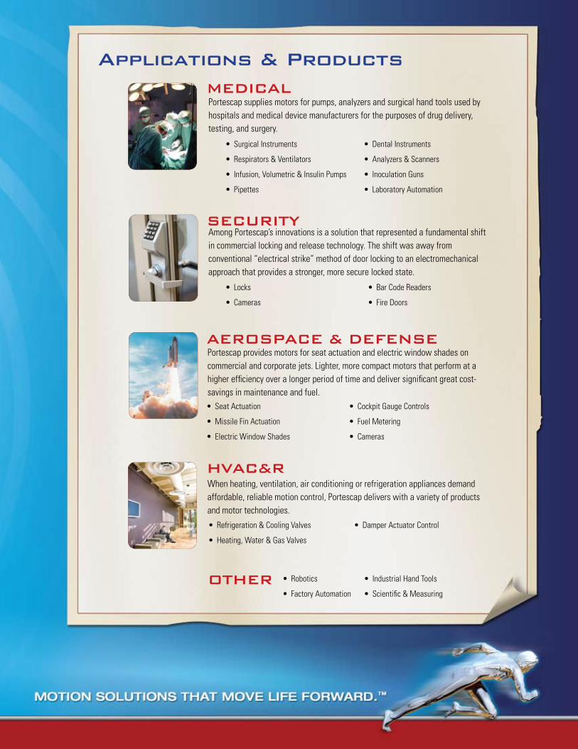
MEdicAlPortescap supplies motors for pumps, analyzers and surgical hand tools used by hospitals and medical device manufacturers for the purposes of drug delivery, testing, and surgery.
Surgical Instruments •
Respirators & Ventilators •
Infusion, Volumetric & Insulin Pumps•
Pipettes•
Dental Instruments•
Analyzers & Scanners •
Inoculation Guns•
Laboratory Automation•
Applications & Products
sEcUritYAmong Portescap’s innovations is a solution that represented a fundamental shift in commercial locking and release technology. The shift was away from conventional “electrical strike” method of door locking to an electromechanical approach that provides a stronger, more secure locked state.
Locks •
Cameras•
Bar Code Readers •
Fire Doors•
AErosPAcE & dEfEnsEPortescap provides motors for seat actuation and electric window shades on commercial and corporate jets. Lighter, more compact motors that perform at a higher efficiency over a longer period of time and deliver significant great cost-savings in maintenance and fuel.
Seat Actuation•
Missile Fin Actuation•
Electric Window Shades•
Cockpit Gauge Controls•
Fuel Metering•
Cameras•
HvAc&r When heating, ventilation, air conditioning or refrigeration appliances demand affordable, reliable motion control, Portescap delivers with a variety of products and motor technologies.
Refrigeration & Cooling Valves•
Heating, Water & Gas Valves•
Damper Actuator Control•
otHEr Robotics•
Factory Automation•
Industrial Hand Tools•
Scientific & Measuring•

Compact, lightweight, and high-precision handtools play a crucial role in a wide range of surgical procedures, increasing both patient safety and comfort. Delivering up to 30% more torque than traditional motors, Portescap’s autoclavable brushless motors generate minimal heat in an ultra-compact package. This means higher performance and better quality of use, especially in minimally invasive procedures. And, with higher acceleration and peak speed, Portescap motors help minimize time required for critical procedures, meaning a faster start on patient recovery.
MEdicAl: Surgical Handtools
HvAc&r: Refrigeration Valve Actuation
civil AviAtion: Seat Actuation
MEdicAl: Diagnostic Analyzer
Energy efficient and leak-proof seals are critical for electric refrigeration valves. Portescap provides geared can stack and direct drive linear actuator solutions with custom subassembly capability that allows for streamlined integration into the valve body and for precision flow controls of refrigerants in the valve system. Our vast experience working with custom valve solutions and our understanding of refrigerant control and electrical connections lets us provide you with cost effective innovative systems that are environmentally protective and space efficient.
Coreless brush DC motors from Portescap address the challenge of energy efficiency in commercial aviation by using state of the art magnetics and coil design, with efficiencies approaching 85–90% while reducing weight of the motors. A seat actuator motor from Portescap can be 50% lighter compared to an iron core technology with similar output power, thus leading to fuel savings due to reduced weight of the airplane. We are able to provide custom brush DC solutions with ball bearings that will not only extend the life of motors in such applications, but will let the passengers relax in peace.
Our coreless brush DC motor technologies deliver class-leading performance across a range of medical device applications. From sample draw on assays, to drug delivery via pumps, these motors offer minimal noise and lower joule heating, creating sustainable performance over the life of your project. An unparalleled speed-to-torque performance provides high energy efficiency and superior space utilization. This means increased turnaround times of diagnostic results and accurate dose delivery to patients and a faster recovery.
oUr Motors At WorK.
BRUSHLESS DC MOTORS
Why a Brushless Motor 12
How to select your Brushless Motor 13
Brushless Terminology 14
Where to apply your Brushless Motor 15
Specifications 16
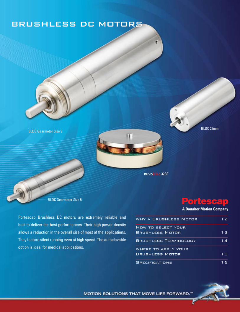
Portescap Brushless DC motors are extremely reliable and
built to deliver the best performances. Their high power density
allows a reduction in the overall size of most of the applications.
They feature silent running even at high speed. The autoclavable
option is ideal for medical applications.
BLDC Gearmotor Size 9
BLDC Gearmotor Size 5
nuvoDisc 32BF
BLDC 22mm
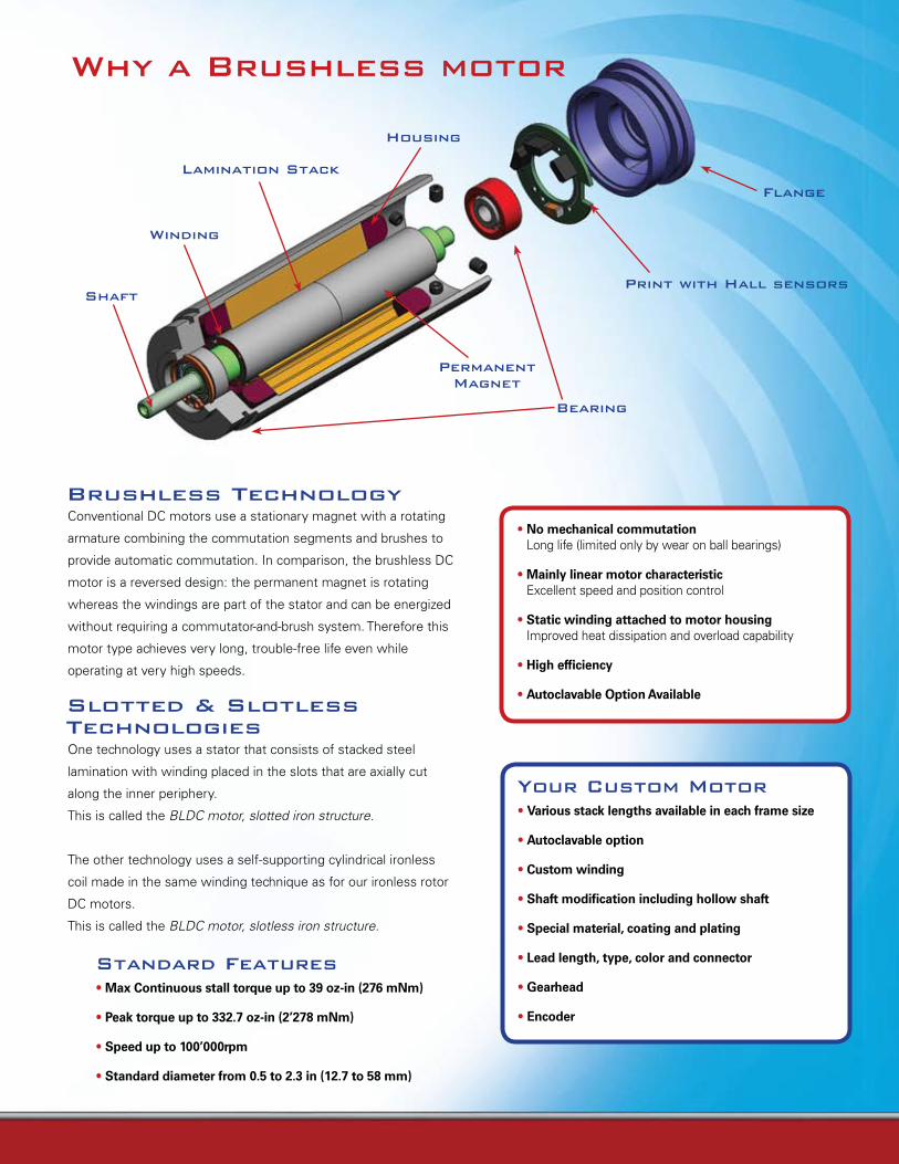
Why a Brushless motor
Shaft
Bearing
Winding
Flange
Housing
Lamination Stack
Print with Hall sensors
Permanent Magnet
• No mechanical commutation Long life (limited only by wear on ball bearings)
• Mainly linear motor characteristic Excellent speed and position control
• Static winding attached to motor housing Improved heat dissipation and overload capability
• High efficiency
• Autoclavable Option Available
Conventional DC motors use a stationary magnet with a rotating
armature combining the commutation segments and brushes to
provide automatic commutation. In comparison, the brushless DC
motor is a reversed design: the permanent magnet is rotating
whereas the windings are part of the stator and can be energized
without requiring a commutator-and-brush system. Therefore this
motor type achieves very long, trouble-free life even while
operating at very high speeds.
One technology uses a stator that consists of stacked steel
lamination with winding placed in the slots that are axially cut
along the inner periphery.
This is called the BLDC motor, slotted iron structure.
The other technology uses a self-supporting cylindrical ironless
coil made in the same winding technique as for our ironless rotor
DC motors.
This is called the BLDC motor, slotless iron structure.
Brushless Technology
Slotted & Slotless Technologies
Your Custom Motor• Various stack lengths available in each frame size
• Autoclavable option
• Custom winding
• Shaft modification including hollow shaft
• Special material, coating and plating
• Lead length, type, color and connector
• Gearhead
• Encoder
Standard Features• Max Continuous stall torque up to 39 oz-in (276 mNm)
• Peak torque up to 332.7 oz-in (2’278 mNm)
• Speed up to 100’000rpm
• Standard diameter from 0.5 to 2.3 in (12.7 to 58 mm)
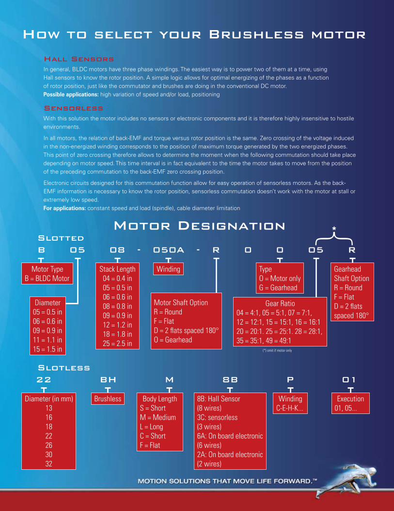
B 05 08 - 050A - R 0 0 05 R
22 BH M 8B P 01
How to select your Brushless motor
Motor DesignationSlottedB 05 08 - 050A - R 0 0 05 R
Diameter05 = 0.5 in06 = 0.6 in09 = 0.9 in11 = 1.1 in15 = 1.5 in
Motor Type B = BLDC Motor
Stack Length04 = 0.4 in05 = 0.5 in06 = 0.6 in08 = 0.8 in09 = 0.9 in12 = 1.2 in18 = 1.8 in25 = 2.5 in
Gearhead Shaft OptionR = RoundF = FlatD = 2 flats spaced 180°
TypeO = Motor onlyG = Gearhead
Winding
In general, BLDC motors have three phase windings. The easiest way is to power two of them at a time, using Hall sensors to know the rotor position. A simple logic allows for optimal energizing of the phases as a function of rotor position, just like the commutator and brushes are doing in the conventional DC motor.Possible applications: high variation of speed and/or load, positioning
Hall Sensors
SensorlessWith this solution the motor includes no sensors or electronic components and it is therefore highly insensitive to hostile environments.
In all motors, the relation of back-EMF and torque versus rotor position is the same. Zero crossing of the voltage induced in the non-energized winding corresponds to the position of maximum torque generated by the two energized phases. This point of zero crossing therefore allows to determine the moment when the following commutation should take place depending on motor speed. This time interval is in fact equivalent to the time the motor takes to move from the position of the preceding commutation to the back-EMF zero crossing position.
Electronic circuits designed for this commutation function allow for easy operation of sensorless motors. As the back-EMF information is necessary to know the rotor position, sensorless commutation doesn’t work with the motor at stall or extremely low speed.For applications: constant speed and load (spindle), cable diameter limitation
Motor Shaft OptionR = RoundF = FlatD = 2 flats spaced 180°O = Gearhead
Gear Ratio04 = 4:1, 05 = 5:1, 07 = 7:1, 12 = 12:1, 15 = 15:1, 16 = 16:120 = 20:1. 25 = 25:1. 28 = 28:1, 35 = 35:1, 49 = 49:1
(*) omit if motor only
Slotless22 BH M 8B P 01
Brushless WindingC-E-H-K...
Execution01, 05...
Diameter (in mm)13161822263032
Body LengthS = ShortM = MediumL = LongC = ShortF = Flat
8B: Hall Sensor (8 wires)3C: sensorless (3 wires)6A: On board electronic (6 wires)2A: On board electronic (2 wires)
Explanation of Specifications
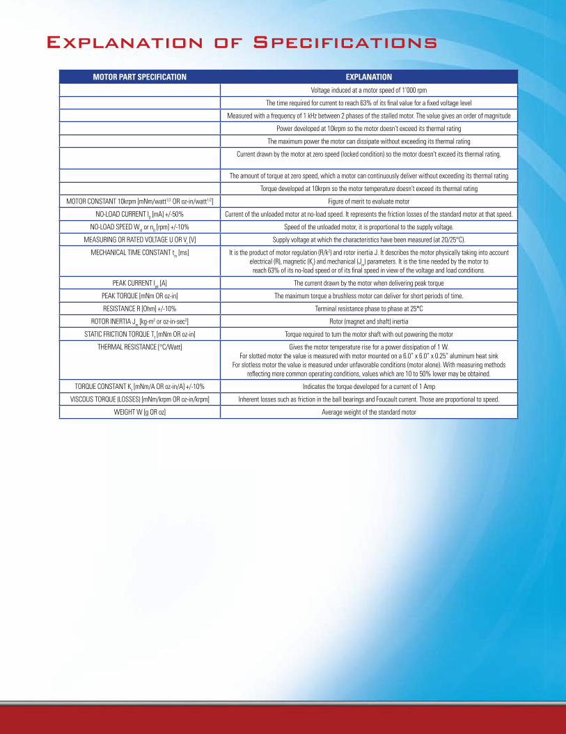
MOTOR PART SPECIFICATION ExPlANATION
BACK-EMF CONSTANT Ke [V/krpm] +/-8% Voltage induced at a motor speed of 1’000 rpm
ELECTRICAL TIME CONSTANT te [ms] The time required for current to reach 63% of its final value for a fixed voltage level
INDUCTANCE L [mH] Measured with a frequency of 1 kHz between 2 phases of the stalled motor. The value gives an order of magnitude
MAX CONTINUOUS POWER AT 10krpm [W] Power developed at 10krpm so the motor doesn’t exceed its thermal rating
MAX CONTINUOUS POWER DISSIPATION [W] The maximum power the motor can dissipate without exceeding its thermal rating
MAX CONTINUOUS STALL CURRENT OR MAX CONTINUOUS CURRENT Ics [A]
Current drawn by the motor at zero speed (locked condition) so the motor doesn’t exceed its thermal rating.
MAX CONTINUOUS STALL TORQUE Tcs [mNm OR oz-in] The amount of torque at zero speed, which a motor can continuously deliver without exceeding its thermal rating
MAX CONTINUOUS TORQUE AT 10krpm [mNm OR oz-in] Torque developed at 10krpm so the motor temperature doesn’t exceed its thermal rating
MOTOR CONSTANT 10krpm [mNm/watt1/2 OR oz-in/watt1/2] Figure of merit to evaluate motor
NO-LOAD CURRENT I0 [mA] +/-50% Current of the unloaded motor at no-load speed. It represents the friction losses of the standard motor at that speed.
NO-LOAD SPEED Wnl or n0 [rpm] +/-10% Speed of the unloaded motor, it is proportional to the supply voltage.
MEASURING OR RATED VOLTAGE U OR Vr [V] Supply voltage at which the characteristics have been measured (at 20/25°C).
MECHANICAL TIME CONSTANT tm [ms] It is the product of motor regulation (R/k2) and rotor inertia J. It describes the motor physically taking into account electrical (R), magnetic (Kt) and mechanical (Jm) parameters. It is the time needed by the motor to
reach 63% of its no-load speed or of its final speed in view of the voltage and load conditions.
PEAK CURRENT Ipk [A] The current drawn by the motor when delivering peak torque
PEAK TORQUE [mNm OR oz-in] The maximum torque a brushless motor can deliver for short periods of time.
RESISTANCE R [Ohm] +/-10% Terminal resistance phase to phase at 25°C
ROTOR INERTIA Jm [kg-m2 or oz-in-sec2] Rotor (magnet and shaft) inertia
STATIC FRICTION TORQUE Tf [mNm OR oz-in] Torque required to turn the motor shaft with out powering the motor
THERMAL RESISTANCE [°C/Watt] Gives the motor temperature rise for a power dissipation of 1 W.For slotted motor the value is measured with motor mounted on a 6.0” x 6.0” x 0.25” aluminum heat sink
For slotless motor the value is measured under unfavorable conditions (motor alone). With measuring methods reflecting more common operating conditions, values which are 10 to 50% lower may be obtained.
TORQUE CONSTANT Kt [mNm/A OR oz-in/A] +/-10% Indicates the torque developed for a current of 1 Amp
VISCOUS TORQUE (LOSSES) [mNm/krpm OR oz-in/krpm] Inherent losses such as friction in the ball bearings and Foucault current. Those are proportional to speed.
WEIGHT W [g OR oz] Average weight of the standard motor
Where to apply your Portescap Brushless motor
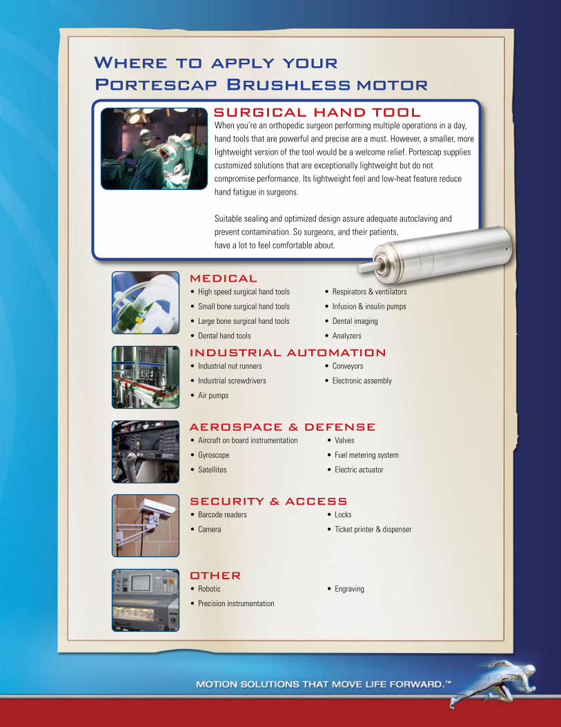
SURGICAL HAND TOOLWhen you’re an orthopedic surgeon performing multiple operations in a day, hand tools that are powerful and precise are a must. However, a smaller, more lightweight version of the tool would be a welcome relief. Portescap supplies customized solutions that are exceptionally lightweight but do not compromise performance. Its lightweight feel and low-heat feature reduce hand fatigue in surgeons.
Suitable sealing and optimized design assure adequate autoclaving and prevent contamination. So surgeons, and their patients,have a lot to feel comfortable about.
MEDICALHigh speed surgical hand tools•
Small bone surgical hand tools•
Large bone surgical hand tools•
Dental hand tools•
Respirators & ventilators•
Infusion & insulin pumps•
Dental imaging•
Analyzers•
INDUSTRIAL AUTOMATIONIndustrial nut runners•
Industrial screwdrivers•
Air pumps•
Conveyors•
Electronic assembly•
AEROSPACE & DEFENSEAircraft on board instrumentation•
Gyroscope•
Satellites•
Valves•
Fuel metering system•
Electric actuator•
OTHERRobotic•
Precision instrumentation•
Engraving•
SECURITY & ACCESSBarcode readers•
Camera•
Locks•
Ticket printer & dispenser•
16 www.portescap.com
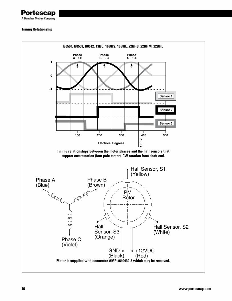
B0504, B0508, B0512, 13BC, 16BHS, 16BHL, 22BHS, 22BHM, 22BHL
Timing relationships between the motor phases and the hall sensors that support cummutation (four pole motor). CW rotation from shaft end.
Motor is supplied with connector AMP #640430-8 which may be removed.
Timing Relationship
Miniature Motors
17www.portescap.com
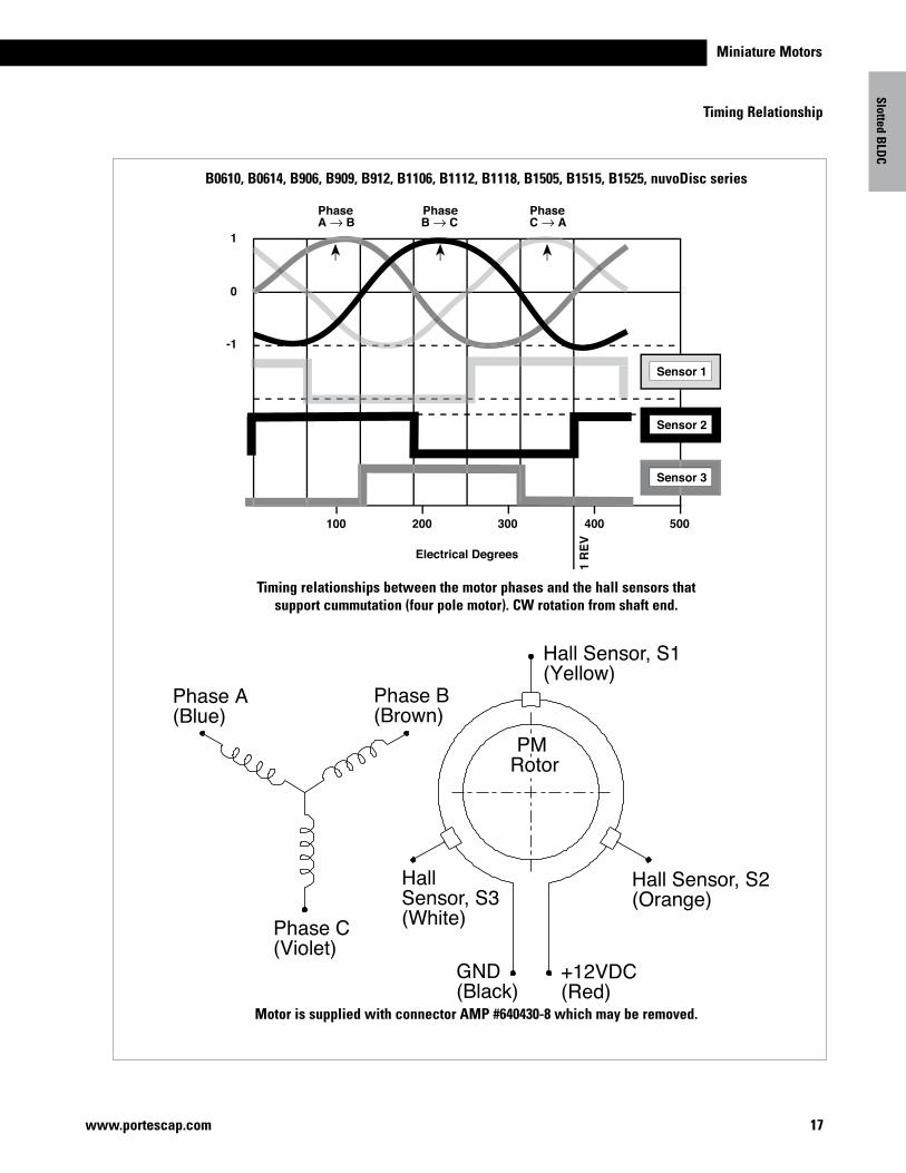
B0610, B0614, B906, B909, B912, B1106, B1112, B1118, B1505, B1515, B1525, nuvoDisc series
Timing relationships between the motor phases and the hall sensors that support cummutation (four pole motor). CW rotation from shaft end.
Motor is supplied with connector AMP #640430-8 which may be removed.
Slotted BLD
C
Timing Relationship
18 www.portescap.com
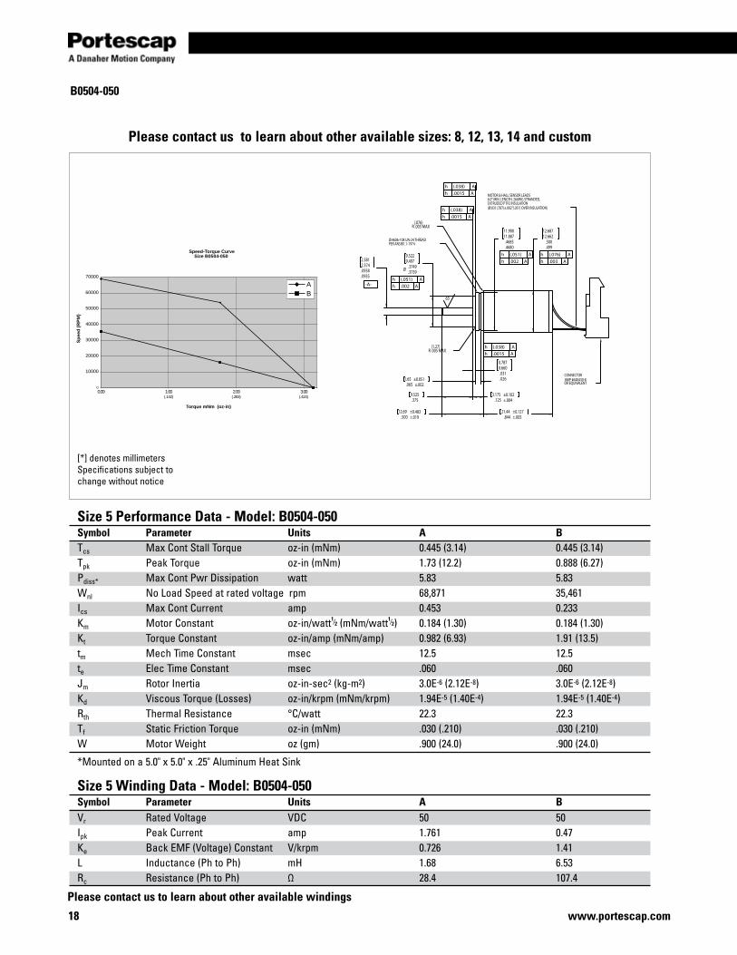
B0504-050
Speed-Torque CurveSize B0504-050
0
10000
20000
30000
40000
50000
60000
70000
00.300.200.100.0
Torque mNm (oz-in)
Sp
eed
(R
PM
)
AB
)424.()382.()241.(
.500
.499
12.68712.662
.4685
.4680
11.90011.887
Ø .3749.3739
9.5229.497
.0938
.0935
2.3812.374
.065 ±.0021.65 ±0.051
.031
.026
0.7870.660
.3759.525
.125 ±.0043.175 ±0.102
.500 ±.01912.69 ±0.483
.844 ±.00521.44 ±0.127
MOTOR & HALL SENSOR LEADS6.0" MIN. LENGTH, 26AWG STRANDED,EXTRUDED PTFE INSULATION(Ø.031(.787)±.002"(.051) OVER INSULATION)
CONNECTORAMP #640430-8OR EQUIVALENT
Ø.4606-108 UN-24 THREADPER ANSIB1.1-1974
(.076)R .003 MAX
(1.27)R .005 MAX
h (.076) Ah .003 A
h (.051) Ah .002 A
h (.038) Ah .0015 A
h (.038) Ah .0015 A
h (.051) Ah .002 A-A-
h (.038) Ah .0015 A
63
[*] denotes millimetersSpecifications subject to change without notice
Size 5 Performance Data - Model: B0504-050Symbol Parameter Units A BTcs Max Cont Stall Torque oz-in (mNm) 0.445 (3.14) 0.445 (3.14)Tpk Peak Torque oz-in (mNm) 1.73 (12.2) 0.888 (6.27)Pdiss* Max Cont Pwr Dissipation watt 5.83 5.83Wnl No Load Speed at rated voltage rpm 68,871 35,461Ics Max Cont Current amp 0.453 0.233Km Motor Constant oz-in/watt1⁄2 (mNm/watt1⁄2) 0.184 (1.30) 0.184 (1.30) Kt Torque Constant oz-in/amp (mNm/amp) 0.982 (6.93) 1.91 (13.5)tm Mech Time Constant msec 12.5 12.5te Elec Time Constant msec .060 .060Jm Rotor Inertia oz-in-sec2 (kg-m2) 3.0E-6 (2.12E-8) 3.0E-6 (2.12E-8)Kd Viscous Torque (Losses) oz-in/krpm (mNm/krpm) 1.94E-5 (1.40E-4) 1.94E-5 (1.40E-4)Rth Thermal Resistance °C/watt 22.3 22.3Tf Static Friction Torque oz-in (mNm) .030 (.210) .030 (.210)W Motor Weight oz (gm) .900 (24.0) .900 (24.0)
*Mounted on a 5.0" x 5.0" x .25" Aluminum Heat Sink
Size 5 Winding Data - Model: B0504-050Symbol Parameter Units A BVr Rated Voltage VDC 50 50Ipk Peak Current amp 1.761 0.47Ke Back EMF (Voltage) Constant V/krpm 0.726 1.41L Inductance (Ph to Ph) mH 1.68 6.53Rc Resistance (Ph to Ph) Ω 28.4 107.4
Please contact us to learn about other available sizes: 8, 12, 13, 14 and custom
Please contact us to learn about other available windings
Miniature Motors
19www.portescap.com
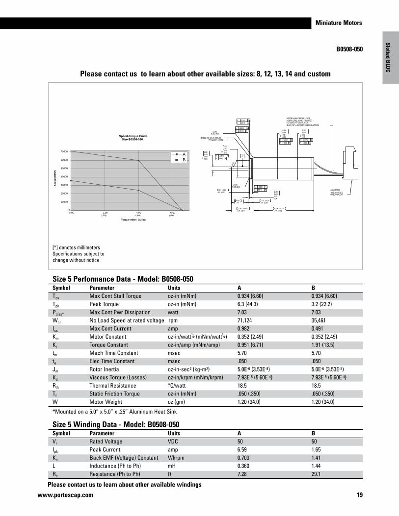
B0508-050
Please contact us to learn about other available windings
[*] denotes millimetersSpecifications subject to change without notice
Please contact us to learn about other available sizes: 8, 12, 13, 14 and custom
Slotted BLD
C
Size 5 Performance Data - Model: B0508-050Symbol Parameter Units A BTcs Max Cont Stall Torque oz-in (mNm) 0.934 (6.60) 0.934 (6.60)Tpk Peak Torque oz-in (mNm) 6.3 (44.3) 3.2 (22.2)Pdiss* Max Cont Pwr Dissipation watt 7.03 7.03Wnl No Load Speed at rated voltage rpm 71,124 35,461Ics Max Cont Current amp 0.982 0.491Km Motor Constant oz-in/watt1⁄2 (mNm/watt1⁄2) 0.352 (2.49) 0.352 (2.49)Kt Torque Constant oz-in/amp (mNm/amp) 0.951 (6.71) 1.91 (13.5)tm Mech Time Constant msec 5.70 5.70te Elec Time Constant msec .050 .050Jm Rotor Inertia oz-in-sec2 (kg-m2) 5.0E-6 (3.53E-8) 5.0E-6 (3.53E-8)Kd Viscous Torque (Losses) oz-in/krpm (mNm/krpm) 7.93E-5 (5.60E-4) 7.93E-5 (5.60E-4)Rth Thermal Resistance °C/watt 18.5 18.5Tf Static Friction Torque oz-in (mNm) .050 (.350) .050 (.350)W Motor Weight oz (gm) 1.20 (34.0) 1.20 (34.0)
*Mounted on a 5.0” x 5.0” x .25” Aluminum Heat Sink
Size 5 Winding Data - Model: B0508-050Symbol Parameter Units A BVr Rated Voltage VDC 50 50Ipk Peak Current amp 6.59 1.65Ke Back EMF (Voltage) Constant V/krpm 0.703 1.41L Inductance (Ph to Ph) mH 0.360 1.44Rc Resistance (Ph to Ph) Ω 7.28 29.1
Speed-Torque CurveSize B0508-050
0
10000
20000
30000
40000
50000
60000
70000
6.004.00.2.000.00
Torque mNm (oz-in)
Sp
eed
(R
PM
)
AB
)058.()665.()382.(
Ø .0938.0935
2.3812.374
Ø .3749.3739
9.5229.497
Ø .4685.4680
11.89911.886
.031
.024
0.7870.610
.065 ±.0021.651 ±0.051
1.344 ±.00534.138 ±0.127
.500 ±.01912.700 ±0.483
.3759.525
.125 ±.0043.175 ±0.10
Ø .500.499
12.68712.662
MOTOR & HALL SENSOR LEADS6.0MIN. LONG, 26AWG STRANDED,EXTRUDED PTFE INSULATION(Ø.031[.787]±.002"[.051] OVER INSULATION)
CONNECTORAMP #640430-8OR EQUIVALENT
Ø.4606-108 UN-24 THREADPER ANSIB1.1-1974
(.076)R .003 MAX
(.127)R .005 MAX
h (.051) Ah .002 A
h (.051) Ah .002 A
h (.076) Ah .002 A
h (.038) Ah .0015 A
h (.038) Ah .0015 A
h (.038) Ah .0015 A
63
A
20 www.portescap.com
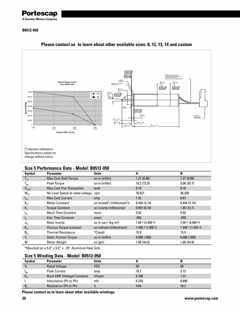
B0512-050
[*] denotes millimetersSpecifications subject to change without notice
Size 5 Performance Data - Model: B0512-050Symbol Parameter Units A BTcs Max Cont Stall Torque oz-in (mNm) 1.27 (8.98) 1.27 (8.98)Tpk Peak Torque oz-in (mNm) 10.2 (72.0) 5.06 (35.7)Pdiss* Max Cont Pwr Dissipation watt 8.18 8.18Wnl No Load Speed at rated voltage rpm 70,621 36,500Ics Max Cont Current amp 1.33 0.67Km Motor Constant oz-in/watt1⁄2 (mNm/watt1⁄2) 0.444 (3.14) 0.444 (3.14) Kt Torque Constant oz-in/amp (mNm/amp) 0.957 (6.76) 1.85 (13.1)tm Mech Time Constant msec 5.02 5.02te Elec Time Constant msec .050 .050Jm Rotor Inertia oz-in-sec2 (kg-m2) 7.0E-6 (4.94E-8) 7.0E-6 (4.94E-8)Kd Viscous Torque (Losses) oz-in/krpm (mNm/krpm) 1.49E-4 (1.05E-3) 1.49E-4 (1.05E-3)Rth Thermal Resistance °C/watt 15.9 15.9Tf Static Friction Torque oz-in (mNm) 0.080 (.560) 0.080 (.560)W Motor Weight oz (gm) 1.60 (44.0) 1.60 (44.0)
*Mounted on a 5.0” x 5.0” x .25” Aluminum Heat Sink
Size 5 Winding Data - Model: B0512-050Symbol Parameter Units A BVr Rated Voltage VDC 50 50Ipk Peak Current amp 10.7 2.73Ke Back EMF (Voltage) Constant V/krpm 0.708 1.37L Inductance (Ph to Ph) mH 0.220 0.890Rc Resistance (Ph to Ph) Ω 4.64 18.3
Please contact us to learn about other available sizes: 8, 12, 13, 14 and custom
Please contact us to learn about other available windings
Speed-Torque CurveSize B0512-050
0
10000
20000
30000
40000
50000
60000
70000
00.900.600.300.0
Torque mNm (oz-in)
Sp
eed
(R
PM
)
AB
)72.1()058.()424.(
Ø .3749.3744
9.5229.510
.031
.026
0.7870.660
1.844 ±.00546.838 ±0.127
.125 ±.0043.175 ±0.10
Ø .500.499
12.68712.662
.065 ±.0021.651 ±0.051
Ø .0938.0935
2.3812.374
Ø .4685.4680
11.90011.887
.500 ±.01912.700 ±0.483
.3759.525
MOTOR & HALL SENSOR LEADS6.0" MIN. LENGTH, 26AWG STRANDED,EXTRUDED PTFE INSULATION(Ø.031[.787]±.002"[.051] OVER INSULATION)
CONNECTORAMP #640430-8OR EQUIVALENT
Ø.4606-108 UN-24 THREADPER ANSIB1.1-1974
(.076)R .003 MAX
(.127)R.005 MAX
h (.051) Ah .002 A
h (.076) Ah .003 A
-A-
h (.051) Ah .002 A
h (.038) Ah .0015 A
h (.038) Ah .0015 A
h (.038) Ah .0015 A
63

21www.portescap.com
Miniature Motors
B0610-024
Size 6 Performance Data - Model: B0610-024 Symbol Parameter Units A BTcs Max Cont Stall Torque oz-in (mNm) 2.65 (18.71) 2.65 (18.71)Tpk Peak Torque oz-in (mNm) 16.0 (113.0) 7.9 (56.0)Pdiss* Max Cont Pwr Dissipation watt 8.77 8.77Wnl No Load Speed at rated voltage rpm 58,394 29,197Ics Max Cont Current amp 4.73 2.4Km Motor Constant oz-in/watt1⁄2 (mNm/watt1⁄2) 0.89 (6.28) 0.89 (6.28) Kt Torque Constant oz-in/amp (mNm/amp) 0.56 (3.95) 1.11 (7.84)tm Mech Time Constant msec 2.32 2.32te Elec Time Constant msec 0.17 0.21Jm Rotor Inertia oz-in-sec2 (kg-m2) 15.0E-6 (1.06E-3) 15.0E-6 (1.06E-3)Kd Viscous Torque (Losses) oz-in/krpm (mNm/krpm) 3.2E-4 (2.3E-3) 3.2E-4 (2.3E-3)Rth Thermal Resistance °C/watt 15.4 15.4Tf Static Friction Torque oz-in (mNm) 0.150 (1.06) 0.150 (1.06)W Motor Weight oz (gm) 2.8 (79) 2.8 (79)
*Mounted on a 5.0” x 5.0” x .25” Aluminum Heat Sink
Size 6 Winding Data - Model: B0610-024 Symbol Parameter Units A BVr Rated Voltage VDC 24 24Ipk Peak Current amp 28.6 7.14Ke Back EMF (Voltage) Constant V/krpm 0.411 0.822L Inductance (Ph to Ph) mH 0.07 0.33Rc Resistance (Ph to Ph) Ω 0.392 1.57
Please contact us to learn about other available windings
Please contact us to learn about other available sizes: 8, 12, 13, 14 and custom
[*] denotes millimetersSpecifications subject to change without notice
Speed-Torque CurveSize B0610-024
0
10000
20000
30000
40000
50000
60000
70000
0 4 8 12 16 20
Torque mNm (oz-in)
Sp
eed
(R
PM
)
AB
(0.6) (1.1) (1.7) (2.3) (2.8)
Ø .650 ±.00116.51 ±0.025Ø .4685
.4680
11.90011.887
Ø .1250.1246
3.1753.165
.625 ±.01515.89 ±0.381
.031 ±.0020.79 ±0.051.156 ±.002
3.96 ±0.051
.250 ±.0046.35 ±0.102
1.792 ±.01045.52 ±0.254
Ø .5765.5760
14.64314.630
MOTOR LEADS6.0MIN. LONG, 24 AWG STRANDED,EXTRUDED PTFE INSULATION(Ø.043±.002 OVER INSULATION)
HALL SENSOR LEADS6.0MIN. LONG, 26 AWG STRANDED,EXTRUDED PTFE INSULATION(Ø.031±.002 OVER INSULATION)
CONNECTOR(AMP P/N 640430-8OR EQUIVALENT)
.5625-32UN-2A
B0610-024A-R00 6S/N: XXXXXXXXXX
h .0015 A
h .0015 A
h .003 Ah .002 A
h .002 A
A
22 www.portescap.com
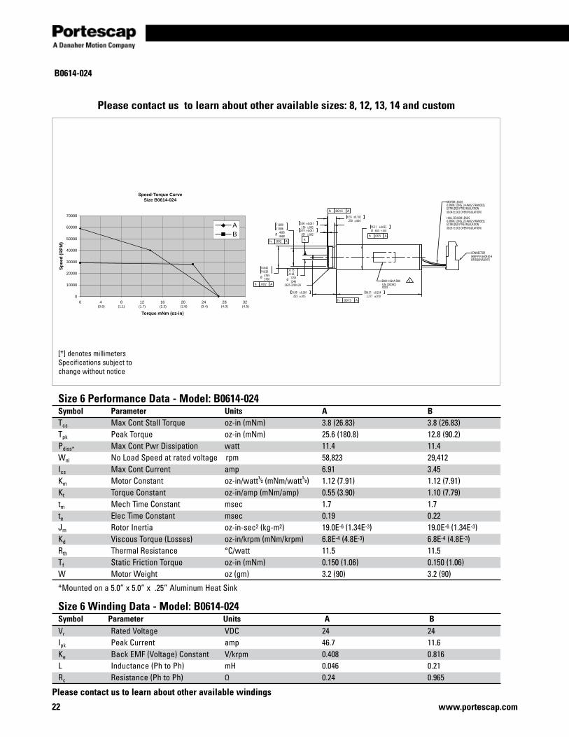
Size 6 Performance Data - Model: B0614-024 Symbol Parameter Units A BTcs Max Cont Stall Torque oz-in (mNm) 3.8 (26.83) 3.8 (26.83)Tpk Peak Torque oz-in (mNm) 25.6 (180.8) 12.8 (90.2)Pdiss* Max Cont Pwr Dissipation watt 11.4 11.4Wnl No Load Speed at rated voltage rpm 58,823 29,412Ics Max Cont Current amp 6.91 3.45Km Motor Constant oz-in/watt1⁄2 (mNm/watt1⁄2) 1.12 (7.91) 1.12 (7.91) Kt Torque Constant oz-in/amp (mNm/amp) 0.55 (3.90) 1.10 (7.79)tm Mech Time Constant msec 1.7 1.7te Elec Time Constant msec 0.19 0.22Jm Rotor Inertia oz-in-sec2 (kg-m2) 19.0E-6 (1.34E-3) 19.0E-6 (1.34E-3)Kd Viscous Torque (Losses) oz-in/krpm (mNm/krpm) 6.8E-4 (4.8E-3) 6.8E-4 (4.8E-3)Rth Thermal Resistance °C/watt 11.5 11.5Tf Static Friction Torque oz-in (mNm) 0.150 (1.06) 0.150 (1.06)W Motor Weight oz (gm) 3.2 (90) 3.2 (90)
*Mounted on a 5.0” x 5.0” x .25” Aluminum Heat Sink
Size 6 Winding Data - Model: B0614-024 Symbol Parameter Units A BVr Rated Voltage VDC 24 24Ipk Peak Current amp 46.7 11.6Ke Back EMF (Voltage) Constant V/krpm 0.408 0.816L Inductance (Ph to Ph) mH 0.046 0.21Rc Resistance (Ph to Ph) Ω 0.24 0.965
B0614-024
[*] denotes millimetersSpecifications subject to change without notice
Please contact us to learn about other available sizes: 8, 12, 13, 14 and custom
Please contact us to learn about other available windings
Speed-Torque CurveSize B0614-024
0
10000
20000
30000
40000
50000
60000
70000
0 4 8 12 16 20 24 28 32
Torque mNm (oz-in)
Sp
eed
(R
PM
)
AB
(0.6) (1.1) (1.7) (2.3) (2.8) (3.4) (4.0) (4.5)
Ø .1250.1246
3.1753.165
Ø .4685.4680
11.89911.886
Ø .5765.5760
14.64214.629
.625 ±.01515.89 ±0.381
.031 ±.0020.79 ±0.051.156 ±.002
3.96 ±0.051.250 ±.004
6.35 ±0.102
2.217 ±.01056.31 ±0.254
Ø .650 ±.00116.51 ±0.025
MOTOR LEADS6.0MIN. LONG, 24 AWG STRANDED,EXTRUDED PTFE INSULATION(Ø.043±.002 OVER INSULATION)
HALL SENSOR LEADS6.0MIN. LONG, 26 AWG STRANDED,EXTRUDED PTFE INSULATION(Ø.031±.002 OVER INSULATION)
CONNECTOR(AMP P/N 640430-8OR EQUIVALENT)
.5625-32UN-2AB0614-024A-R00 6S/N: XXXXXXXXXX
h .0015 A
h .0015 A
h .002 A
h .002 A
h .003 AA
23www.portescap.com
Miniature Motors
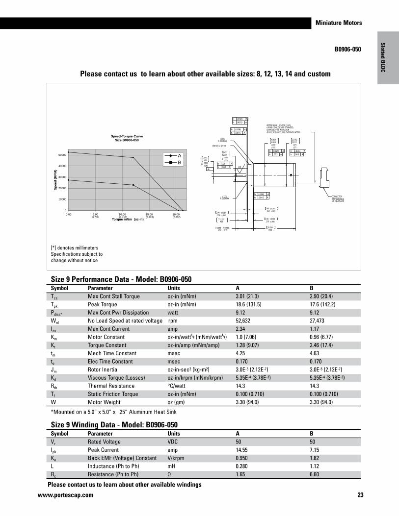
B0906-050
[*] denotes millimetersSpecifications subject to change without notice
Size 9 Performance Data - Model: B0906-050Symbol Parameter Units A BTcs Max Cont Stall Torque oz-in (mNm) 3.01 (21.3) 2.90 (20.4)Tpk Peak Torque oz-in (mNm) 18.6 (131.5) 17.6 (142.2)Pdiss* Max Cont Pwr Dissipation watt 9.12 9.12Wnl No Load Speed at rated voltage rpm 52,632 27,473Ics Max Cont Current amp 2.34 1.17Km Motor Constant oz-in/watt1⁄2 (mNm/watt1⁄2) 1.0 (7.06) 0.96 (6.77)Kt Torque Constant oz-in/amp (mNm/amp) 1.28 (9.07) 2.46 (17.4)tm Mech Time Constant msec 4.25 4.63te Elec Time Constant msec 0.170 0.170Jm Rotor Inertia oz-in-sec2 (kg-m2) 3.0E-5 (2.12E-7) 3.0E-5 (2.12E-7)Kd Viscous Torque (Losses) oz-in/krpm (mNm/krpm) 5.35E-4 (3.78E-3) 5.35E-4 (3.78E-3)Rth Thermal Resistance °C/watt 14.3 14.3Tf Static Friction Torque oz-in (mNm) 0.100 (0.710) 0.100 (0.710)W Motor Weight oz (gm) 3.30 (94.0) 3.30 (94.0)
*Mounted on a 5.0” x 5.0” x .25” Aluminum Heat Sink
Size 9 Winding Data - Model: B0906-050Symbol Parameter Units A BVr Rated Voltage VDC 50 50Ipk Peak Current amp 14.55 7.15Ke Back EMF (Voltage) Constant V/krpm 0.950 1.82L Inductance (Ph to Ph) mH 0.280 1.12Rc Resistance (Ph to Ph) Ω 1.65 6.60
Slotted BLD
C
Please contact us to learn about other available windings
Please contact us to learn about other available sizes: 8, 12, 13, 14 and custom
Speed-Torque CurveSize B0906-050
0
10000
20000
30000
40000
50000
0.00 5.00 10.00 15.00 20.00
Torque mNm (oz-in)
Sp
eed
(R
PM
)
AB
(0.708)
(1.416) (2.124) (2.832)
1.55939.599
.219 ±.0065.56 ±0.152
Ø .4999.4994
12.69712.685
.873
.871
22.16222.111
.8200
.8195
20.82820.815
Ø .1250.1246
3.1753.165
.063 ±.0021.60 ±0.051
.156 ±.0023.96 ±0.051
.438[11.125]
.657 ± .019[16.688 ± 0.483]
Ø.8125-32 UN-2A
MOTOR & HALL SENSOR LEADS,6.0 MIN LONG, 26 AWG STRANDED,EXTRUDED PTFE INSULATION(Ø.031[.787]±.002"[.051] OVER INSULATION)
(.076)R .003 MAX
(.127)R .005 MAX
h (.051) Ah .002 A
h (.076) Ah .003 A
h (.051) Ah .002 A
-A-
h (.038) Ah .0015 A
h (.038) Ah .0015 A
h (.038) Ah .0015 A
63
CONNECTORAMP #640430-8OR EQUIVALENT
24 www.portescap.com
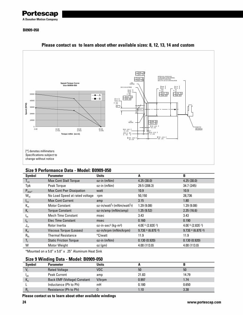
B0909-050
[*] denotes millimetersSpecifications subject to change without notice
Size 9 Performance Data - Model: B0909-050Symbol Parameter Units A BTcs Max Cont Stall Torque oz-in (mNm) 4.25 (30.0) 4.25 (30.0)Tpk Peak Torque oz-in (mNm) 29.5 (208.3) 34.7 (245)Pdiss* Max Cont Pwr Dissipation watt 10.9 10.9Wnl No Load Speed at rated voltage rpm 50,150 28,736Ics Max Cont Current amp 3.15 1.80Km Motor Constant oz-in/watt1⁄2 (mNm/watt1⁄2) 1.29 (9.08) 1.29 (9.08)Kt Torque Constant oz-in/amp (mNm/amp) 1.35 (9.52) 2.35 (16.6)tm Mech Time Constant msec 3.43 3.43te Elec Time Constant msec 0.160 0.190Jm Rotor Inertia oz-in-sec2 (kg-m2) 4.0E-5 (2.82E-7) 4.0E-5 (2.82E-7)Kd Viscous Torque (Losses) oz-in/krpm (mNm/krpm) 9.73E-4 (6.87E-3) 9.73E-4 (6.87E-3)Rth Thermal Resistance °C/watt 11.9 11.9Tf Static Friction Torque oz-in (mNm) 0.130 (0.920) 0.130 (0.920)W Motor Weight oz (gm) 4.00 (113.0) 4.00 (113.0)
*Mounted on a 5.0” x 5.0” x .25” Aluminum Heat Sink
Size 9 Winding Data - Model: B0909-050Symbol Parameter Units A BVr Rated Voltage VDC 50 50Ipk Peak Current amp 21.83 14.79Ke Back EMF (Voltage) Constant V/krpm 0.997 1.74L Inductance (Ph to Ph) mH 0.180 0.650Rc Resistance (Ph to Ph) Ω 1.10 3.38
Please contact us to learn about other available sizes: 8, 12, 13, 14 and custom
Please contact us to learn about other available windings
Speed-Torque CurveSize B0909-050
0
10000
20000
30000
40000
50000
00.0300.0200.0100.0
Torque mNm (oz-in)
Sp
eed
(R
PM
)
AB
)842.4()614.1( (2.832)
-A-
Ø .4999.4994
12.69712.685
Ø .8200.8195
20.82820.815
Ø .873.871
22.17422.123
.219 ±.0065.563 ±0.152
.156 ±.0023.962 ±0.051
.063 ±.0021.600 ±0.051
Ø .1250.1246
3.1753.165
1.889 ±.00447.981 ±0.102
.43811.125
.657 ±.01916.688 ±0.483
Ø.812-32 UN-2A THREAD
MOTOR & HALL SENSOR LEADS,6.0" MIN LENGTH, 26 AWG STRANDED,EXTRUDED PTFE INSULATION(Ø.031[.787±.002"[.051] OVER INSULATION)
(.076)R.003 MAX
(.127)R.005 MAX
CONNECTORAMP #640430-8OR EQUIVALENT
h (.051) Ah .002 A
h (.051) Ah .002 A
h (.076) Ah .003 A
h (.038) Ah .0015 A
h (.038) Ah .0015 A
h (.038) Ah .0015 A
63
Miniature Motors
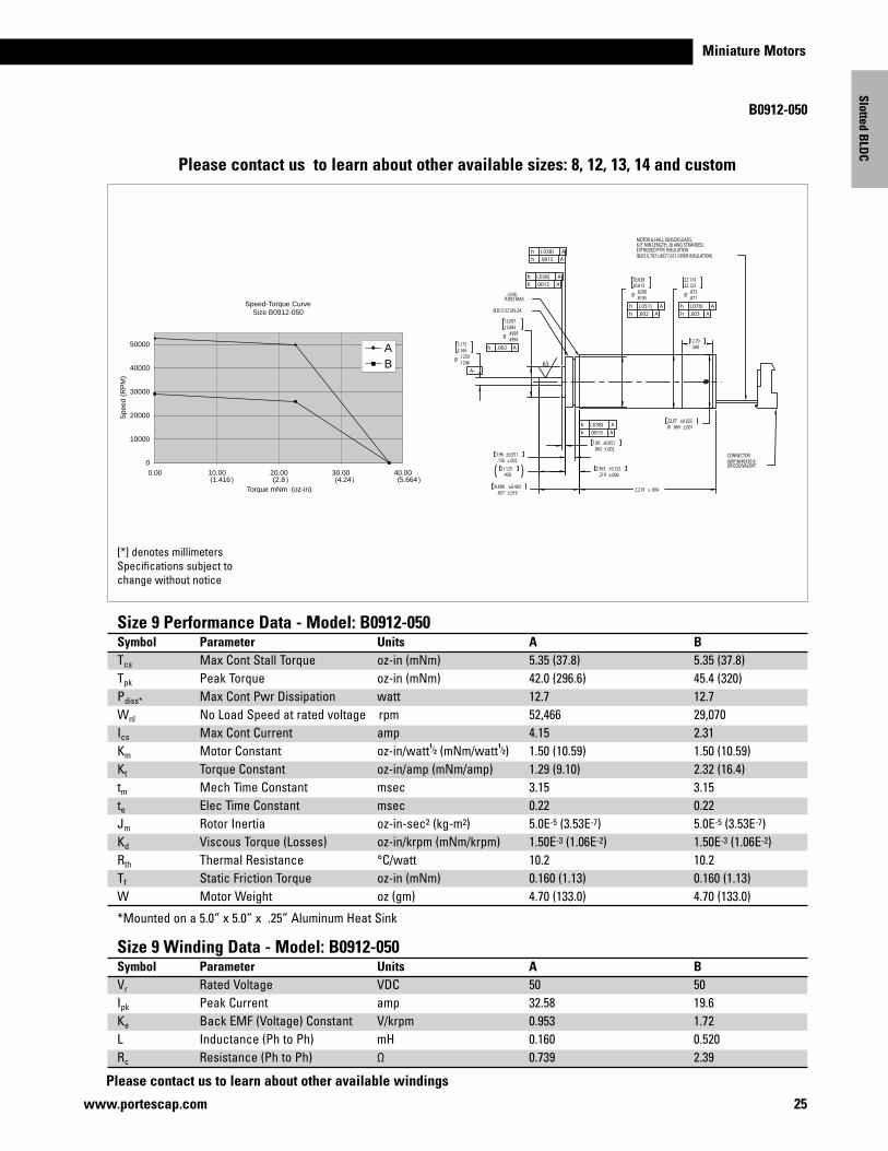
B0912-050
25www.portescap.com
Size 9 Performance Data - Model: B0912-050Symbol Parameter Units A BTcs Max Cont Stall Torque oz-in (mNm) 5.35 (37.8) 5.35 (37.8)Tpk Peak Torque oz-in (mNm) 42.0 (296.6) 45.4 (320)Pdiss* Max Cont Pwr Dissipation watt 12.7 12.7Wnl No Load Speed at rated voltage rpm 52,466 29,070Ics Max Cont Current amp 4.15 2.31Km Motor Constant oz-in/watt1⁄2 (mNm/watt1⁄2) 1.50 (10.59) 1.50 (10.59)Kt Torque Constant oz-in/amp (mNm/amp) 1.29 (9.10) 2.32 (16.4)tm Mech Time Constant msec 3.15 3.15te Elec Time Constant msec 0.22 0.22Jm Rotor Inertia oz-in-sec2 (kg-m2) 5.0E-5 (3.53E-7) 5.0E-5 (3.53E-7)Kd Viscous Torque (Losses) oz-in/krpm (mNm/krpm) 1.50E-3 (1.06E-2) 1.50E-3 (1.06E-2)Rth Thermal Resistance °C/watt 10.2 10.2Tf Static Friction Torque oz-in (mNm) 0.160 (1.13) 0.160 (1.13)W Motor Weight oz (gm) 4.70 (133.0) 4.70 (133.0)
*Mounted on a 5.0” x 5.0” x .25” Aluminum Heat Sink
Size 9 Winding Data - Model: B0912-050Symbol Parameter Units A BVr Rated Voltage VDC 50 50Ipk Peak Current amp 32.58 19.6Ke Back EMF (Voltage) Constant V/krpm 0.953 1.72L Inductance (Ph to Ph) mH 0.160 0.520Rc Resistance (Ph to Ph) Ω 0.739 2.39
Slotted BLD
C
[*] denotes millimetersSpecifications subject to change without notice
Please contact us to learn about other available windings
Please contact us to learn about other available sizes: 8, 12, 13, 14 and custom
Speed-Torque CurveSize B0912-050
0
10000
20000
30000
40000
50000
0.00 10.00 20.00 30.00 40.00
Torque mNm (oz-in)
Spe
ed (
RP
M)
AB
(1.416 (2.8 (4.24 (5.664) ) ) )
Ø .873.871
22.17422.123
2.219 ± .004.657 ±.01916.688 ±0.483
.156 ±.0023.96 ±0.051
.063 ±.0021.60 ±0.051
Ø .8200.8195
20.82820.815
Ø .4999.4994
12.69712.685
Ø .1250.1246
3.1753.165
Ø .869 ±.00122.07 ±0.025
.50012.70
.219 ±.0065.563 ±0.152
.43811.125
Ø.812-32 UN-2A
MOTOR & HALL SENSOR LEADS,6.0" MIN LENGTH, 26 AWG STRANDED,EXTRUDED PTFE INSULATION(Ø.031[.787±.002"[.051] OVER INSULATION)
CONNECTORAMP #640430-8OR EQUIVALENT
(.076)R.003 MAX
h (.076) Ah .003 A
h (.051) Ah .002 A
h .002 A
h (.038) Ah .0015 A
h (.038) Ah .0015 A
-A-
h (.038) Ah .0015 A
63
26 www.portescap.com
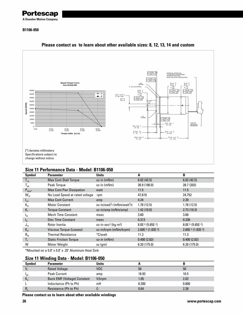
B1106-050
[*] denotes millimetersSpecifications subject to change without notice
Size 11 Performance Data - Model: B1106-050Symbol Parameter Units A BTcs Max Cont Stall Torque oz-in (mNm) 6.02 (42.5) 6.02 (42.5)Tpk Peak Torque oz-in (mNm) 26.9 (190.0) 28.7 (202)Pdiss* Max Cont Pwr Dissipation watt 11.5 11.5Wnl No Load Speed at rated voltage rpm 47,619 24,752Ics Max Cont Current amp 4.24 2.20Km Motor Constant oz-in/watt1⁄2 (mNm/watt1⁄2) 1.78 (12.5) 1.78 (12.5)Kt Torque Constant oz-in/amp (mNm/amp) 1.42 (10.0) 2.73 (19.3)tm Mech Time Constant msec 3.60 3.60te Elec Time Constant msec 0.313 0.336Jm Rotor Inertia oz-in-sec2 (kg-m2) 8.0E-5 (5.65E-7) 8.0E-5 (5.65E-7)Kd Viscous Torque (Losses) oz-in/krpm (mNm/krpm) 2.60E-3 (1.83E-2) 2.60E-3 (1.83E-2)Rth Thermal Resistance °C/watt 11.3 11.3Tf Static Friction Torque oz-in (mNm) 0.400 (2.82) 0.400 (2.82)W Motor Weight oz (gm) 6.20 (175.0) 6.20 (175.0)
*Mounted on a 5.0" x 5.0" x .25" Aluminum Heat Sink
Size 11 Winding Data - Model: B1106-050Symbol Parameter Units A BVr Rated Voltage VDC 50 50Ipk Peak Current amp 18.93 10.5Ke Back EMF (Voltage) Constant V/krpm 1.05 2.02L Inductance (Ph to Ph) mH 0.200 0.800Rc Resistance (Ph to Ph) Ω 0.64 2.38
Please contact us to learn about other available sizes: 8, 12, 13, 14 and custom
Please contact us to learn about other available windings
Speed-Torque CurveSize B1106-050
0
5000
10000
15000
20000
25000
30000
35000
40000
45000
50000
0.00 10.00 20.00 30.00 40.00
Torque mNm (oz-in)
Sp
eed
(R
PM
)
AB
(1.416) (2.832) (4.248) (5.664)
-A-
Ø 1.1001.100
27.94527.932
Ø .9999.9994
25.39725.385
.063 ±.0021.600 ±0.051
1.722 ±.00543.739 ±0.127
Ø .6250.6245
15.87515.862
Ø .1869 ±.00044.747 ±0.010
.791 ±.01920.09 ±0.483
.166 ±.0024.22 ±0.051
.56314.300
.228 ±.0065.791 ±0.152
CONNECTORAMP #640430-8OR EQUIVALENT
MOTOR & HALL SENSOR LEADS,12.0" MIN LENGTH, 24 AWG STRANDED,EXTRUDED PTFE INSULATION,(Ø.043[1.092]±.002"[.051] OVER INSULATION)
Ø 1.00-32 UN-3A THREAD
(.076)R.003 MAX
(.127)R .005 MAX
h (.076) Ah .003 A
h (.051) Ah .002 A
h (.051) Ah .002 A
h (.038) Ah .0015 A
h (.038) Ah .0015 A
h (.038) Ah .0015 A
63
Miniature Motors
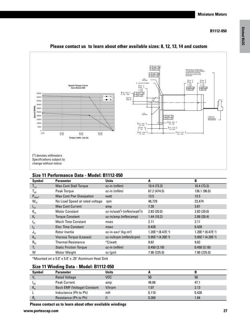
B1112-050
27www.portescap.com
Slotted BLD
C
Size 11 Performance Data - Model: B1112-050Symbol Parameter Units A BTcs Max Cont Stall Torque oz-in (mNm) 10.4 (73.3) 10.4 (73.3)Tpk Peak Torque oz-in (mNm) 67.2 (474.5) 136.1 (96.0)Pdiss* Max Cont Pwr Dissipation watt 13.5 13.5Wnl No Load Speed at rated voltage rpm 46,729 23,474Ics Max Cont Current amp 7.20 3.61Km Motor Constant oz-in/watt1⁄2 (mNm/watt1⁄2) 2.83 (20.0) 2.83 (20.0)Kt Torque Constant oz-in/amp (mNm/amp) 1.44 (10.2) 2.89 (20.4)tm Mech Time Constant msec 2.11 2.11te Elec Time Constant msec 0.420 0.420Jm Rotor Inertia oz-in-sec2 (kg-m2) 1.20E-4 (8.47E-7) 1.20E-4 (8.47E-7)Kd Viscous Torque (Losses) oz-in/krpm (mNm/krpm) 5.95E-3 (4.20E-2) 5.95E-3 (4.20E-2)Rth Thermal Resistance °C/watt 9.62 9.62Tf Static Friction Torque oz-in (mNm) 0.450 (3.18) 0.450 (3.18)W Motor Weight oz (gm) 7.90 (225.0) 7.90 (225.0)
*Mounted on a 5.0" x 5.0" x .25" Aluminum Heat Sink
Size 11 Winding Data - Model: B1112-050Symbol Parameter Units A BVr Rated Voltage VDC 50 50Ipk Peak Current amp 46.66 47.1Ke Back EMF (Voltage) Constant V/krpm 1.07 2.13L Inductance (Ph to Ph) mH 0.110 0.430Rc Resistance (Ph to Ph) Ω 0.260 1.04
[*] denotes millimetersSpecifications subject to change without notice
Please contact us to learn about other available windings
Please contact us to learn about other available sizes: 8, 12, 13, 14 and custom
Speed-Torque CurveSize B1112-050
0
5000
10000
15000
20000
25000
30000
35000
40000
45000
50000
0.00 20.00 40.00 60.00
Torque mNm (oz-in)
Sp
eed
(R
PM
)
AB
)05.8()66.5()38.2(
-A-
2.247 ±.00557.074 ±0.127
Ø 1.1001.093
27.94027.762
Ø .6250.6245
15.87515.862
Ø .9999.9994
25.39725.385
.063 ±.0021.600 ±0.051
.166 ±.0024.216 ±0.051
.791 ±.01920.091 ±0.483
Ø .1869 ±.00044.747 ±0.010
.228 ±.0065.791 ±0.152
.56314.300
CONNECTORAMP #640430-8OR EQUIVALENT
MOTOR AND HALL SENSOR LEADS,12.0" MIN LENGTH, 24 AWG STRANDED, EXTRUDED PTFE INSULATION,(Ø.043[1.092]±.002"[.051] OVER INSULATION)
Ø 1.00-32 UN-3A THREAD
(.076)R .003 MAX
(.127)R .005 MAX
h (.038) Ah .0015 A
h (.038) Ah .0015 A
h (.076) Ah .003 A
h (.051) Ah .002 A
h (.051) Ah .002 A
h (.038) Ah .0015 A
63
28 www.portescap.com
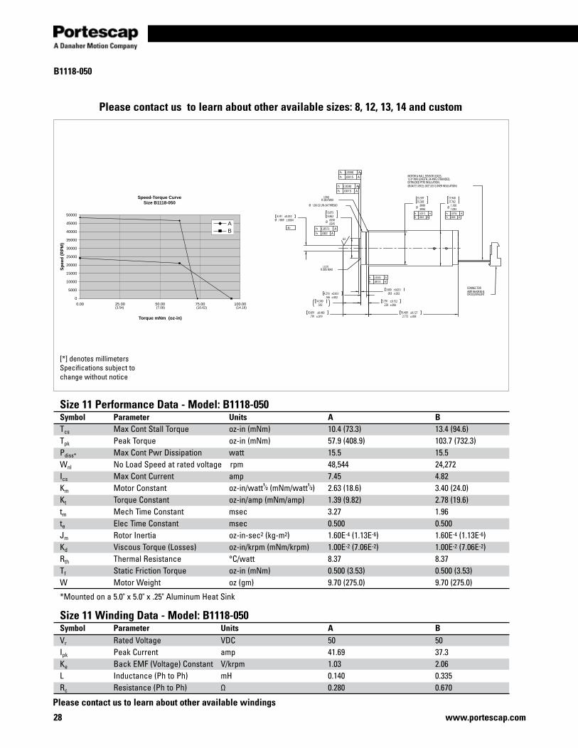
B1118-050
[*] denotes millimetersSpecifications subject to change without notice
Size 11 Performance Data - Model: B1118-050Symbol Parameter Units A BTcs Max Cont Stall Torque oz-in (mNm) 10.4 (73.3) 13.4 (94.6)Tpk Peak Torque oz-in (mNm) 57.9 (408.9) 103.7 (732.3)Pdiss* Max Cont Pwr Dissipation watt 15.5 15.5Wnl No Load Speed at rated voltage rpm 48,544 24,272Ics Max Cont Current amp 7.45 4.82Km Motor Constant oz-in/watt1⁄2 (mNm/watt1⁄2) 2.63 (18.6) 3.40 (24.0) Kt Torque Constant oz-in/amp (mNm/amp) 1.39 (9.82) 2.78 (19.6)tm Mech Time Constant msec 3.27 1.96te Elec Time Constant msec 0.500 0.500Jm Rotor Inertia oz-in-sec2 (kg-m2) 1.60E-4 (1.13E-6) 1.60E-4 (1.13E-6)Kd Viscous Torque (Losses) oz-in/krpm (mNm/krpm) 1.00E-2 (7.06E-2) 1.00E-2 (7.06E-2)Rth Thermal Resistance °C/watt 8.37 8.37Tf Static Friction Torque oz-in (mNm) 0.500 (3.53) 0.500 (3.53)W Motor Weight oz (gm) 9.70 (275.0) 9.70 (275.0)
*Mounted on a 5.0" x 5.0" x .25" Aluminum Heat Sink
Size 11 Winding Data - Model: B1118-050Symbol Parameter Units A BVr Rated Voltage VDC 50 50Ipk Peak Current amp 41.69 37.3Ke Back EMF (Voltage) Constant V/krpm 1.03 2.06L Inductance (Ph to Ph) mH 0.140 0.335Rc Resistance (Ph to Ph) Ω 0.280 0.670
Please contact us to learn about other available sizes: 8, 12, 13, 14 and custom
Please contact us to learn about other available windings
Speed-Torque CurveSize B1118-050
0
5000
10000
15000
20000
25000
30000
35000
40000
45000
50000
0.00 25.00 50.00 75.00 100.00
Torque mNm (oz-in)
Sp
eed
(R
PM
)
AB
(3.54) (7.08) (10.62) (14.16)
2.772 ±.00570.409 ±0.127
Ø 1.1001.093
27.94027.762
Ø .6250.6245
15.87515.862
Ø .9999.9994
25.39725.385
.063 ±.0021.600 ±0.051
.166 ±.0024.216 ±0.051
.791 ±.01920.091 ±0.483
Ø .1869 ±.00044.747 ±0.010
.56314.300
.228 ±.0065.791 ±0.152
CONNECTORAMP #640430-8OR EQUIVALENT
MOTOR & HALL SENSOR LEADS,12.0" MIN LENGTH, 24 AWG STRANDED,EXTRUDED PTFE INSULATION,(Ø.043"[1.092]±.002"[.051] OVER INSULATION)
Ø 1.00-32 UN-3A THREAD
(.076)R .003 MAX
(.127)R .005 MAX
h (.038) Ah .0015 A
h (.038) Ah .0015 A
h (.076) Ah .003 A
h (.051) Ah .002 A
h (.051) Ah .002 A
-A-
h (.038) Ah .0015 A
63
Miniature Motors
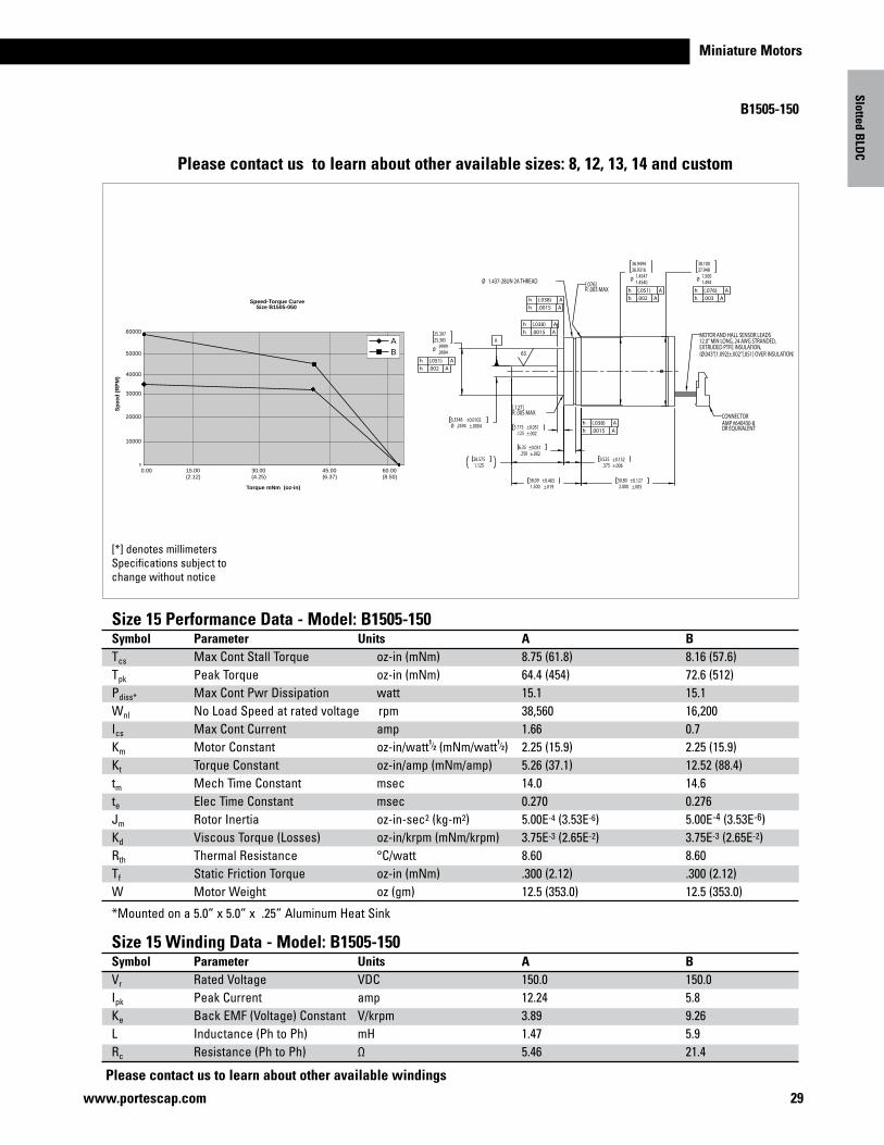
B1505-150
29www.portescap.com
[*] denotes millimetersSpecifications subject to change without notice
Size 15 Performance Data - Model: B1505-150Symbol Parameter Units A BTcs Max Cont Stall Torque oz-in (mNm) 8.75 (61.8) 8.16 (57.6)Tpk Peak Torque oz-in (mNm) 64.4 (454) 72.6 (512)Pdiss* Max Cont Pwr Dissipation watt 15.1 15.1Wnl No Load Speed at rated voltage rpm 38,560 16,200Ics Max Cont Current amp 1.66 0.7Km Motor Constant oz-in/watt1⁄2 (mNm/watt1⁄2) 2.25 (15.9) 2.25 (15.9)Kt Torque Constant oz-in/amp (mNm/amp) 5.26 (37.1) 12.52 (88.4)tm Mech Time Constant msec 14.0 14.6te Elec Time Constant msec 0.270 0.276Jm Rotor Inertia oz-in-sec2 (kg-m2) 5.00E-4 (3.53E-6) 5.00E-4 (3.53E-6)Kd Viscous Torque (Losses) oz-in/krpm (mNm/krpm) 3.75E-3 (2.65E-2) 3.75E-3 (2.65E-2)Rth Thermal Resistance °C/watt 8.60 8.60Tf Static Friction Torque oz-in (mNm) .300 (2.12) .300 (2.12)W Motor Weight oz (gm) 12.5 (353.0) 12.5 (353.0)
*Mounted on a 5.0” x 5.0” x .25” Aluminum Heat Sink
Size 15 Winding Data - Model: B1505-150Symbol Parameter Units A BVr Rated Voltage VDC 150.0 150.0Ipk Peak Current amp 12.24 5.8Ke Back EMF (Voltage) Constant V/krpm 3.89 9.26L Inductance (Ph to Ph) mH 1.47 5.9Rc Resistance (Ph to Ph) Ω 5.46 21.4
Ø .2494 ±.00046.3348 ±0.0102
Ø .9999.9994
25.39725.385
Ø 1.45471.4540
36.949436.9316
Ø 1.5001.494
38.10037.948
2.000 ±.00550.80 ±0.127
1.500 ±.01938.09 ±0.483
.375 ±.0069.525 ±0.152
.125 ±.0023.175 ±0.051
.250 ±.0026.35 ±0.051
1.12528.575
CONNECTORAMP #640430-8OR EQUIVALENT
MOTOR AND HALL SENSOR LEADS12.0" MIN LONG, 24 AWG STRANDED,EXTRUDED PTFE INSULATION,(Ø.043"[1.092]±.002"[.051] OVER INSULATION)
Ø 1.437-28UN 2A THREAD [.076]R .003 MAX
[.127]R .005 MAX
h (.051) Ah .002 A
h (.076) Ah .003 A
h (.051) Ah .002 A
h (.038) Ah .0015 A
h (.038) Ah .0015 A
h (.038) Ah .0015 A
63
A
Slotted BLD
C
Please contact us to learn about other available windings
Please contact us to learn about other available sizes: 8, 12, 13, 14 and custom
Speed-Torque CurveSize B1505-050
0
10000
0.00 15.00 30.00 45.00 60.00(2.12) (4.25) (6.37) (8.50)
20000
30000
40000
50000
60000
Torque mNm (oz-in)
Sp
eed
(R
PM
)
AB
30 www.portescap.com
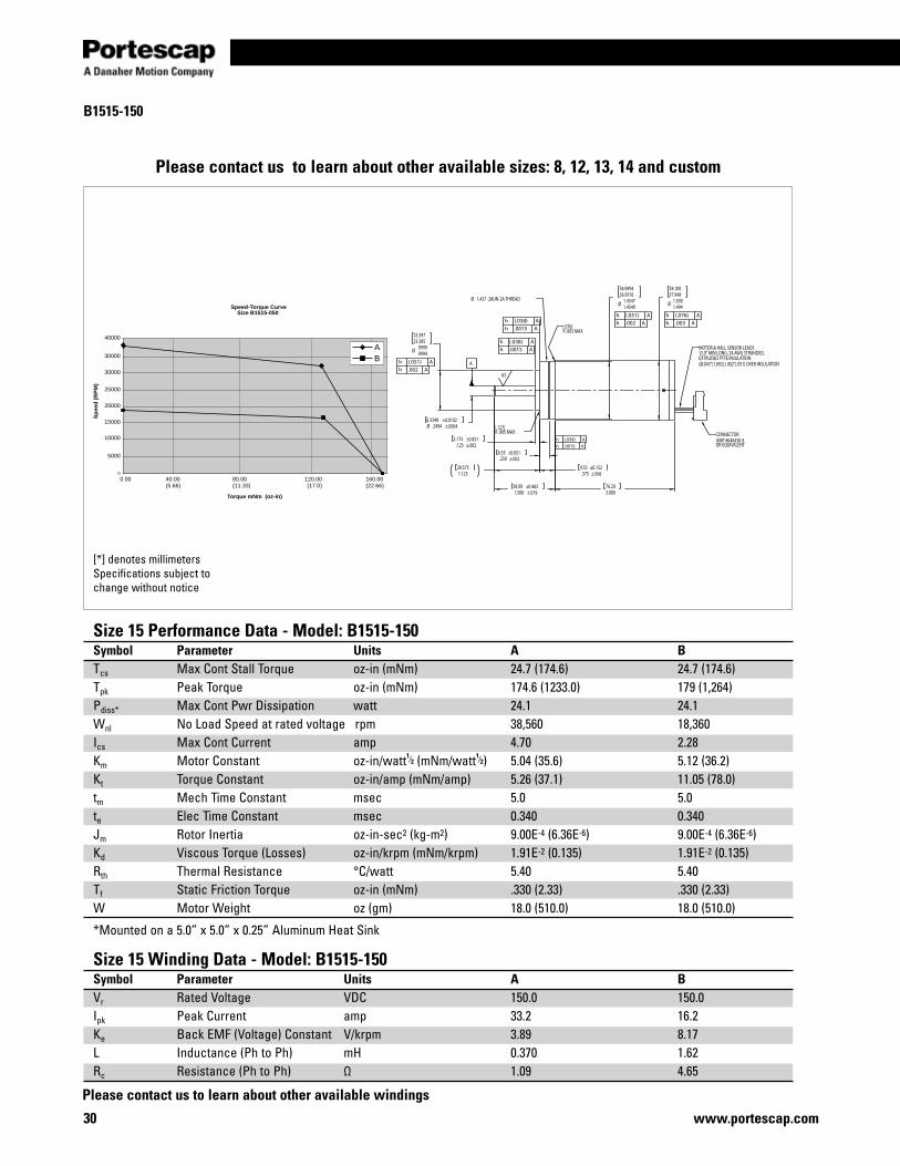
B1515-150
[*] denotes millimetersSpecifications subject to change without notice
Size 15 Performance Data - Model: B1515-150Symbol Parameter Units A BTcs Max Cont Stall Torque oz-in (mNm) 24.7 (174.6) 24.7 (174.6)Tpk Peak Torque oz-in (mNm) 174.6 (1233.0) 179 (1,264)Pdiss* Max Cont Pwr Dissipation watt 24.1 24.1Wnl No Load Speed at rated voltage rpm 38,560 18,360Ics Max Cont Current amp 4.70 2.28Km Motor Constant oz-in/watt1⁄2 (mNm/watt1⁄2) 5.04 (35.6) 5.12 (36.2)Kt Torque Constant oz-in/amp (mNm/amp) 5.26 (37.1) 11.05 (78.0)tm Mech Time Constant msec 5.0 5.0te Elec Time Constant msec 0.340 0.340Jm Rotor Inertia oz-in-sec2 (kg-m2) 9.00E-4 (6.36E-6) 9.00E-4 (6.36E-6)Kd Viscous Torque (Losses) oz-in/krpm (mNm/krpm) 1.91E-2 (0.135) 1.91E-2 (0.135)Rth Thermal Resistance °C/watt 5.40 5.40Tf Static Friction Torque oz-in (mNm) .330 (2.33) .330 (2.33)W Motor Weight oz (gm) 18.0 (510.0) 18.0 (510.0)
*Mounted on a 5.0” x 5.0” x 0.25” Aluminum Heat Sink
Size 15 Winding Data - Model: B1515-150Symbol Parameter Units A BVr Rated Voltage VDC 150.0 150.0Ipk Peak Current amp 33.2 16.2Ke Back EMF (Voltage) Constant V/krpm 3.89 8.17L Inductance (Ph to Ph) mH 0.370 1.62Rc Resistance (Ph to Ph) Ω 1.09 4.65
Please contact us to learn about other available sizes: 8, 12, 13, 14 and custom
Please contact us to learn about other available windings
Speed-Torque CurveSize B1515-050
0
5000
10000
0.00 40.00 80.00 120.00 160.00(5.66) (11.33) (17.0) (22.66)
15000
20000
25000
30000
30000
40000
Torque mNm (oz-in)
Sp
eed
(R
PM
)
AB
A
Ø .2494 ±.00046.3348 ±0.0102
Ø .9999.9994
25.39725.385
Ø 1.45471.4540
36.949436.9316
.125 ±.0023.175 ±0.051
.250 ±.0026.35 ±0.051
1.500 ±.01938.09 ±0.483
3.00076.20
Ø 1.5001.494
38.10037.948
.375 ±.0069.53 ±0.152
1.12528.575
CONNECTORAMP #640430-8OR EQUIVALENT
MOTOR & HALL SENSOR LEADS12.0" MIN LONG, 24 AWG STRANDED,EXTRUDED PTFE INSULATION(Ø.043"[1.092]±.002"[.051] OVER INSULATION)
Ø 1.437 -28UN-2A THREAD
[.076]R .003 MAX
[.127]R .005 MAX
h (.051) Ah .002 A
h (.076) Ah .003 Ah (.038) A
h .0015 A
h (.051) Ah .002 A
h (.038) Ah .0015 A
h (.038) Ah .0015 A
63
Miniature Motors
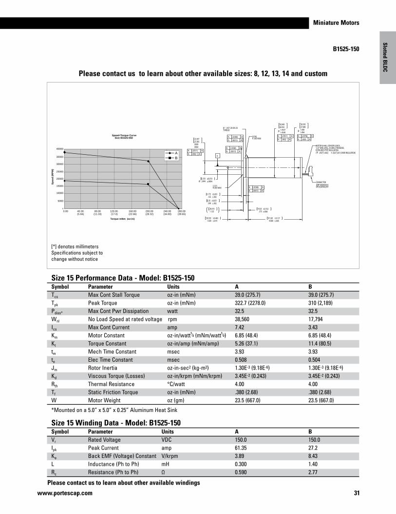
B1525-150
31www.portescap.com
[*] denotes millimetersSpecifications subject to change without notice
Size 15 Performance Data - Model: B1525-150Symbol Parameter Units A BTcs Max Cont Stall Torque oz-in (mNm) 39.0 (275.7) 39.0 (275.7)Tpk Peak Torque oz-in (mNm) 322.7 (2278.0) 310 (2,189)Pdiss* Max Cont Pwr Dissipation watt 32.5 32.5Wnl No Load Speed at rated voltage rpm 38,560 17,794Ics Max Cont Current amp 7.42 3.43Km Motor Constant oz-in/watt1⁄2 (mNm/watt1⁄2) 6.85 (48.4) 6.85 (48.4)Kt Torque Constant oz-in/amp (mNm/amp) 5.26 (37.1) 11.4 (80.5)tm Mech Time Constant msec 3.93 3.93te Elec Time Constant msec 0.508 0.504Jm Rotor Inertia oz-in-sec2 (kg-m2) 1.30E-3 (9.18E-6) 1.30E-3 (9.18E-6)Kd Viscous Torque (Losses) oz-in/krpm (mNm/krpm) 3.45E-2 (0.243) 3.45E-2 (0.243)Rth Thermal Resistance °C/watt 4.00 4.00Tf Static Friction Torque oz-in (mNm) .380 (2.68) .380 (2.68)W Motor Weight oz (gm) 23.5 (667.0) 23.5 (667.0)
*Mounted on a 5.0” x 5.0” x 0.25” Aluminum Heat Sink
Size 15 Winding Data - Model: B1525-150Symbol Parameter Units A BVr Rated Voltage VDC 150.0 150.0Ipk Peak Current amp 61.35 27.2Ke Back EMF (Voltage) Constant V/krpm 3.89 8.43L Inductance (Ph to Ph) mH 0.300 1.40Rc Resistance (Ph to Ph) Ω 0.590 2.77
Please contact us to learn about other available sizes: 8, 12, 13, 14 and custom
Slotted BLD
C
Please contact us to learn about other available windings
Ø 1.5001.494
38.10037.948
.9999
.9994
25.39725.385
Ø .2494 ±.00046.335 ±0.010
4.000 ±.005101.60 ±0.127
1.500 ±.01938.100 ±0.483
Ø 1.45471.4540
36.94936.932
.125 ±.0023.175 ±0.051
.250 ±.0026.35 ±0.051
1.12528.575
.375 ±.0069.525 ±0.152
CONNECTORAMP #640430-8OR EQUIVALENT
MOTOR & HALL SENSOR LEADS,12.0" MIN LONG, 24 AWG STRANDED,EXTRUDED PTFE INSULATION( Ø .043"[1.092] ± .002"[.051] OVER INSULATION)
Ø 1.437-28 UN-2ATHREAD
[.127]R .005 MAX
[.076]R .003 MAX
h (.038) Ah .0015 A
h (.038) Ah .0015 A
h (.051) Ah .002 A
h (.051) Ah .002 A
h (.076) Ah .003 A
h (.038) Ah .0015 A
A
Speed-Torque CurveSize B1525-050
0
5000
10000
0.00 40.00 80.00 240.00(5.66) (11.33)
120.00(17.0)
200.00(28.32) (34.00)
280.00(39.65)
160.00(22.66)
15000
20000
25000
30000
30000
40000
Torque mNm (oz-in)
Sp
eed
(R
PM
)
AB
32 www.portescap.com
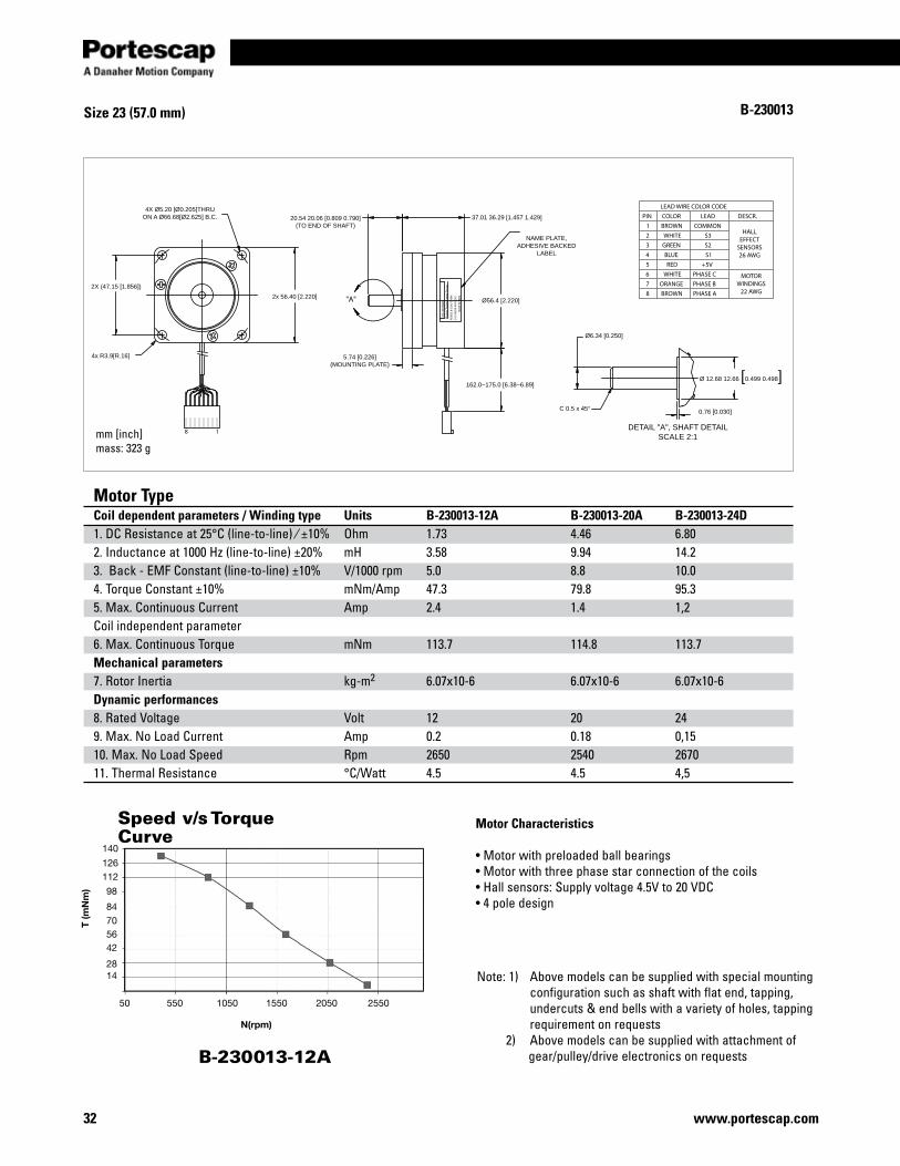
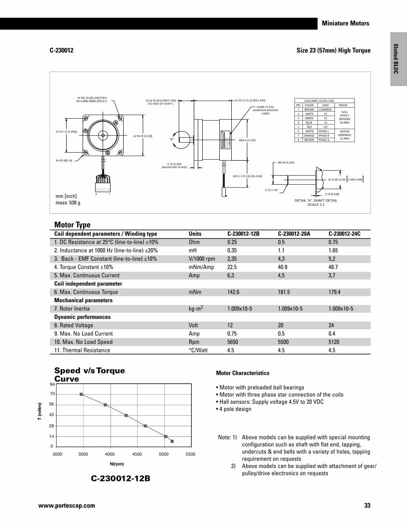
Motor Type Coil dependent parameters / Winding type Units B-230013-12A B-230013-20A B-230013-24D 1. DC Resistance at 25°C (line-to-line) ⁄ ±10% Ohm 1.73 4.46 6.80 2. Inductance at 1000 Hz (line-to-line) ±20% mH 3.58 9.94 14.23. Back - EMF Constant (line-to-line) ±10% V/1000 rpm 5.0 8.8 10.04. Torque Constant ±10% mNm/Amp 47.3 79.8 95.35. Max. Continuous Current Amp 2.4 1.4 1,2 Coil independent parameter 6. Max. Continuous Torque mNm 113.7 114.8 113.7Mechanical parameters7. Rotor Inertia kg-m2 6.07x10⁻⁶ 6.07x10⁻⁶ 6.07x10⁻⁶ Dynamic performances 8. Rated Voltage Volt 12 20 249. Max. No Load Current Amp 0.2 0.18 0,1510. Max. No Load Speed Rpm 2650 2540 267011. Thermal Resistance °C/Watt 4.5 4.5 4,5
Size 23 (57.0 mm)
HALLEFFECT
SENSORS26 AWG
MOTORWINDINGS
22 AWG
DESCR.
PHASE C6 WHITE
8
7 PHASE B
PHASE ABROWN
ORANGE
PIN
4
5
3
2
1
LEAD WIRE COLOR CODE
+5V
LEAD
COMMON
RED
GREEN
BLUE
WHITE
COLOR
BROWN
S1
S2
S3
Ø6.34 [0.250]
DETAIL "A", SHAFT DETAILSCALE 2:1
Ø 12.68 12.66 [0.499 0.498]
0.76 [0.030]C 0.5 x 45°
2X (47.15 [1.856])
4x R3.9[R.16]
4X Ø5.20 [Ø0.205]THRUON A Ø66.68[Ø2.625] B.C.
18
2x 56.40 [2.220]
5.74 [0.226](MOUNTING PLATE)
Ø56.4 [2.220]
162.0~175.0 [6.38~6.89]
"A"
NAME PLATE,ADHESIVE BACKED
LABEL
20.54 20.06 [0.809 0.790](TO END OF SHAFT)
37.01 36.29 [1.457 1.429]
MA
DE
IN IN
DIA
KOLL
MO
RGEN
Mo
tio
n T
ech
no
log
ies
Gro
up
S/N
: XXX
XX-X
XX R
EV.X
MO
DEL
B-2
3001
3-N
NN
T (m
Nm
)
50
1428
42567084
98
112126
140
550 1050 1550 2050 2550
N(rpm)
B-230013-12A
Motor Characteristics
• Motor with preloaded ball bearings• Motor with three phase star connection of the coils• Hall sensors: Supply voltage 4.5V to 20 VDC• 4 pole design
Note: 1) Above models can be supplied with special mounting configuration such as shaft with flat end, tapping, undercuts & end bells with a variety of holes, tapping requirement on requests 2) Above models can be supplied with attachment of gear/pulley/drive electronics on requests
B-230013
mm [inch]mass: 323 g
Speed v/s Torque Curve
Miniature Motors
Size 23 (57mm) High Torque
33www.portescap.com
Slotted BLD
C
Motor Type Coil dependent parameters / Winding type Units C-230012-12B C-230012-20A C-230012-24C 1. DC Resistance at 25°C (line-to-line) ±10% Ohm 0.25 0.5 0.75 2. Inductance at 1000 Hz (line-to-line) ±20% mH 0.35 1.1 1.653. Back - EMF Constant (line-to-line) ±10% V/1000 rpm 2,35 4,3 5,24. Torque Constant ±10% mNm/Amp 22.5 40.9 48.75. Max. Continuous Current Amp 6,3 4,5 3,7 Coil independent parameter 6. Max. Continuous Torque mNm 142.6 181.5 179.4Mechanical parameters7. Rotor Inertia kg-m2 1.009x10⁻⁵ 1.009x10⁻⁵ 1.009x10⁻⁵ Dynamic performances 8. Rated Voltage Volt 12 20 249. Max. No Load Current Amp 0.75 0.5 0.410. Max. No Load Speed Rpm 5650 5500 512011. Thermal Resistance °C/Watt 4.5 4.5 4.5
Ø6.34 [0.250]
DETAIL "A", SHAFT DETAILSCALE 2:1
Ø 12.68 12.66 [0.499 0.498]
0.76 [0.030]
C 0.5 x 45°
2X (47.15 [1.856])
4x R3.9[R.16]
4X Ø5.20 [Ø0.205]THRUON A Ø66.68[Ø2.625] B.C.
18
2x 56.40 [2.220]
5.74 [0.226](MOUNTING PLATE)
Ø56.4 [2.220]
162.0~175.0 [6.38~6.89]
"A"
NAME PLATE,ADHESIVE BACKED
LABEL
20.54 20.06 [0.809 0.790](TO END OF SHAFT)
52.53 51.81 [2.068 2.040]
MA
DE
IN IN
DIA
KOLL
MO
RGEN
Mo
tio
n T
ech
no
log
ies
Gro
up
S/N
: XXX
XX-X
XX R
EV.X
MO
DEL
C-2
3001
2-N
NN
HALLEFFECT
SENSORS26 AWG
MOTORWINDINGS
22 AWG
DESCR.
PHASE C6 WHITE
8
7 PHASE B
PHASE ABROWN
ORANGE
PIN
4
5
3
2
1
LEAD WIRE COLOR CODE
+5V
LEAD
COMMON
RED
GREEN
BLUE
WHITE
COLOR
BROWN
S1
S2
S3
Speed v/s Torque Curve
T (m
Nm
)
3000
14
28
42
56
70
84
N(rpm)
C-230012-12B
Motor Characteristics
• Motor with preloaded ball bearings• Motor with three phase star connection of the coils• Hall sensors: Supply voltage 4.5V to 20 VDC• 4 pole design
Note: 1) Above models can be supplied with special mounting configuration such as shaft with flat end, tapping, undercuts & end bells with a variety of holes, tapping requirement on requests 2) Above models can be supplied with attachment of gear/ pulley/drive electronics on requests
0
3500 4000 4500 5000 5500
C-230012
mm [inch]mass: 538 g
34 www.portescap.com
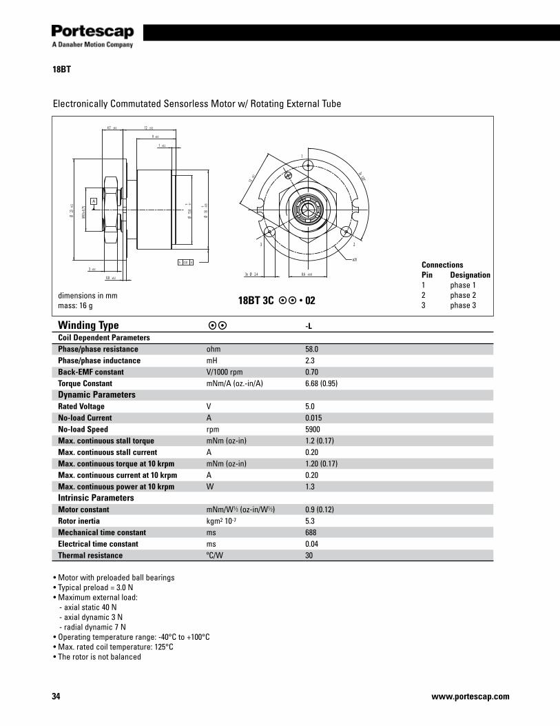
18BT
Winding Type -LCoil Dependent Parameters Phase/phase resistance ohm 58.0Phase/phase inductance mH 2.3Back-EMF constant V/1000 rpm 0.70Torque Constant mNm/A (oz.-in/A) 6.68 (0.95)Dynamic Parameters Rated Voltage V 5.0No-load Current A 0.015No-load Speed rpm 5900Max. continuous stall torque mNm (oz-in) 1.2 (0.17)Max. continuous stall current A 0.20Max. continuous torque at 10 krpm mNm (oz-in) 1.20 (0.17)Max. continuous current at 10 krpm A 0.20Max. continuous power at 10 krpm W 1.3Intrinsic Parameters Motor constant mNm/W1⁄2 (oz-in/W1⁄2) 0.9 (0.12)Rotor inertia kgm2 10-7 5.3Mechanical time constant ms 688Electrical time constant ms 0.04Thermal resistance ºC/W 30
Electronically Commutated Sensorless Motor w/ Rotating External Tube
dimensions in mmmass: 16 g 18BT 3C 02
ConnectionsPin Designation1 phase 12 phase 23 phase 3
• Motor with preloaded ball bearings• Typical preload = 3.0 N• Maximum external load: - axial static 40 N - axial dynamic 3 N - radial dynamic 7 N• Operating temperature range: -40°C to +100°C• Max. rated coil temperature: 125°C• The rotor is not balanced
3x 120°13±0.
1
3x Ø 2.4 8.6 ±0.05
1
23
ø20
M10 x
0.75
1 ±0.2
9 ±0.2
12 ±0.24.7 ±0.2
3 ±0.2
0.8 ±0.2
Ø23
±0.2
Ø15
.6-0
.10
Ø18
-0.050
h 0.03 A
A
Miniature Motors
2x Ø 2 depth 4.5
8 ±0.1
5.5-0
.10
16.9 ±0.2
12.3 0+ 0.1
4.6 ±0.2
Ø22
-0.03
30
Ø17
±0.1
Ø25
.1±0
.2
Ø 13
,5
1 ±0.1
2.6 ±0.5
M 13
x 1
±0.02
t 0.08 A
A
6 5 4 3 2 1
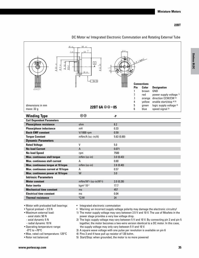
22BT
35www.portescap.com
DC Motor w/ Integrated Electronic Commutation and Rotating External Tube
22BT 6A 05
• Motor with preloaded ball bearings• Typical preload = 3.5 N• Maximum external load: - axial static 50 N - axial dynamic 5 N - radial dynamic 10 N• Operating temperature range: -0°C to +70°C• Max. rated coil temperature: 125°C• Rotor not balanced
dimensions in mmmass: 32 g
ConnectionsPin Color Designation1 brown GND2 red power supply voltage 1)
3 orange direction CCW/CW 4)
4 yellow enable start/stop 4) 5)
5 green logic supply voltage 2)
6 blue speed signal 3)
• Integrated electronic commutation• Warning: an incorrect supply voltage polarity may damage the electronic circuitry!1) The motor supply voltage may vary between 2.5 V and 10 V. The use of Mosfets in the power stage provides a very low voltage drop.2) The logic supply voltage may vary between 5 V and 10 V. By connecting pin 2 and pin 5 together, the motor becomes a two-wire version identical to a DC motor. In this case, the supply voltage may only vary between 5 V and 10 V.3) A square wave voltage with one pulse per revolution is available on pin 64) Pins 3 and 4 have pull up resistor of 120 kohm.5) Start/Stop: when grounded, the motor is no more powered
Slotless BLD
C
Winding Type -P Coil Dependent Parameters Phase/phase resistance ohm 8.2 Phase/phase inductance mH 0.33Back-EMF constant V/1000 rpm 0.59Torque Constant mNm/A (oz.-in/A) 5.63 (0.80)Dynamic Parameters Rated Voltage V 5.0No-load Current A 0.071No-load Speed rpm 7500Max. continuous stall torque mNm (oz-in) 3.0 (0.43)Max. continuous stall current A 0.60Max. continuous torque at 10 krpm mNm (oz-in) 2.8 (0.40)Max. continuous current at 10 krpm A 0.57Max. continuous power at 10 krpm W 3.0Intrinsic Parameters Motor constant mNm/W1⁄2 (oz-in/W1⁄2) 2.0 (0.28)Rotor inertia kgm2 10-7 17.7Mechanical time constant ms 457Electrical time constant ms 0.04Thermal resistance ºC/W 24
A B CPhase
A
BC
NS
230 ±20 28 ±0,2 6 ±0,5
1,5-0,
006
-0,00
9Ö
13±0
,1Ö
36 www.portescap.com
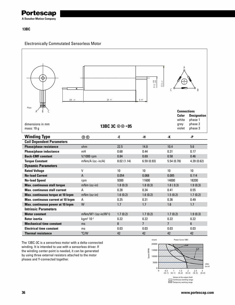
13BC
Winding Type -E -H -K -PCoil Dependent Parameters Phase/phase resistance ohm 22.5 14.8 10.4 5.6Phase/phase inductance mH 0.68 0.44 0.31 0.17Back-EMF constant V/1000 rpm 0.84 0.69 0.58 0.46Torque Constant mNm/A (oz.-in/A) 8.02 (1.14) 6.59 (0.93) 5.54 (0.78) 4.39 (0.62)Dynamic Parameters Rated Voltage V 10 10 10 10No-load Current A 0.054 0.068 0.085 0.114No-load Speed rpm 9300 11600 14000 18200Max. continuous stall torque mNm (oz-in) 1.8 (0.3) 1.8 (0.3) 1.8 ( 0.3) 1.9 (0.3)Max. continuous stall current A 0.28 0.34 0.41 0.55Max. continuous torque at 10 krpm mNm (oz-in) 1.6 (0.2) 1.6 (0.2) 1.5 (0.2) 1.7 (0.2)Max. continuous current at 10 krpm A 0.25 0.31 0.36 0.49Max. continuous power at 10 krpm W 1.7 1.7 1.6 1.7Intrinsic Parameters Motor constant mNm/W1⁄2 (oz-in/W1⁄2) 1.7 (0.2) 1.7 (0.2) 1.7 (0.2) 1.9 (0.3)Rotor inertia kgm2 10-7 0.22 0.22 0.22 0.22Mechanical time constant ms 8 7 7 6Electrical time constant ms 0.03 0.03 0.03 0.03Thermal resistance ºC/W 42 42 42 42
Electronically Commutated Sensorless Motor
13BC 3C 05dimensions in mmmass: 19 g
ConnectionsColor Designationwhite phase 1grey phase 2violet phase 3
20000
15000
10000
5000
0.5 1 1.5 2 2.5 3(0.1) (0.1) (0.2) (0.3) (0.3) (0.4)
00
1 W1 W
2 W2 W
Values at the output shaft
mNm(oz.in)
n(rpm) Power Curve 13BC
Continuous working rangeTemporary working range
Spee
d (R
PM)
The 13BC-3C is a sensorless motor with a delta-connected winding. It is intended to use with a sensorless driver. If the winding center-point is needed, it can be generated by using three external resistors attached to the motor phases and Y-connected together.
Miniature Motors
37www.portescap.com
Spee
d (R
PM)
13 W
0 1 2 3 4 5 6 7 80
10'000
20'000
30'000
40'000
50'000
60'000
70'000
Values at the output shaft
n(rpm) Power Curve 16BHS
Continuous working rangeTemporary working range
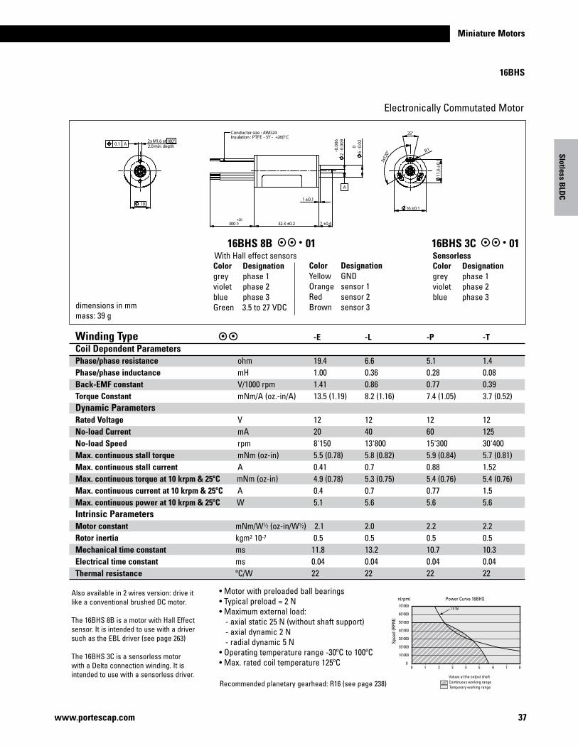
Electronically Commutated Motor
16BHS 8B 01 16BHS 3C 01
dimensions in mmmass: 39 g
With Hall effect sensors SensorlessColor Designationgrey phase 1violet phase 2blue phase 3
Color Designationgrey phase 1violet phase 2blue phase 3Green 3.5 to 27 VDC
Slotless BLD
C
16BHS
°081 ta 6.1M x2
01
°52
11.6
±0.13x
120°
42GWA : ezis rotcudnoCC°062+ - Y5 - EFTP : noitalusnI
0
1.0±1
003
0.00
6
6
2.0±3.23 4.0±7
-0.0
2
2-0
.009
-
A
htped .nim 0.2
1.0±61
R1
002+
A1.0
Winding Type -E -L -P -TCoil Dependent Parameters Phase/phase resistance ohm 19.4 6.6 5.1 1.4Phase/phase inductance mH 1.00 0.36 0.28 0.08Back-EMF constant V/1000 rpm 1.41 0.86 0.77 0.39Torque Constant mNm/A (oz.-in/A) 13.5 (1.19) 8.2 (1.16) 7.4 (1.05) 3.7 (0.52)Dynamic Parameters Rated Voltage V 12 12 12 12No-load Current mA 20 40 60 125No-load Speed rpm 8'150 13'800 15'300 30'400Max. continuous stall torque mNm (oz-in) 5.5 (0.78) 5.8 (0.82) 5.9 (0.84) 5.7 (0.81)Max. continuous stall current A 0.41 0.7 0.88 1.52Max. continuous torque at 10 krpm & 25ºC mNm (oz-in) 4.9 (0.78) 5.3 (0.75) 5.4 (0.76) 5.4 (0.76)Max. continuous current at 10 krpm & 25ºC A 0.4 0.7 0.77 1.5Max. continuous power at 10 krpm & 25ºC W 5.1 5.6 5.6 5.6Intrinsic Parameters Motor constant mNm/W1⁄2 (oz-in/W1⁄2) 2.1 2.0 2.2 2.2Rotor inertia kgm2 10-7 0.5 0.5 0.5 0.5Mechanical time constant ms 11.8 13.2 10.7 10.3Electrical time constant ms 0.04 0.04 0.04 0.04Thermal resistance ºC/W 22 22 22 22
Also available in 2 wires version: drive it like a conventional brushed DC motor.
The 16BHS 8B is a motor with Hall Effect sensor. It is intended to use with a driver such as the EBL driver (see page 263)
The 16BHS 3C is a sensorless motor with a Delta connection winding. It is intended to use with a sensorless driver.
Recommended planetary gearhead: R16 (see page 238)
Color DesignationYellow GNDOrange sensor 1Red sensor 2Brown sensor 3
• Motor with preloaded ball bearings• Typical preload = 2 N• Maximum external load: - axial static 25 N (without shaft support) - axial dynamic 2 N - radial dynamic 5 N• Operating temperature range -30ºC to 100ºC • Max. rated coil temperature 125ºC
+200
j 0.1 A
40°
R 5.7 ±0.1
Ø 16 ±0.1
R 0.9
32.3 ±0.2 7 ±0.4
Ø6
-0.020
1 ±0.1
Ø2
-0.00
9-0
.006
300
Conductor size : AWG24Insulation : UL1061
A
Ø 10
2x M 1.6 at 180°2.0 min. depth
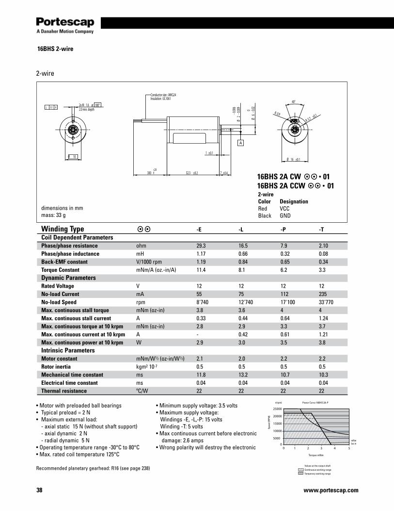
38 www.portescap.com
16BHS 2-wire
Winding Type -E -L -P -TCoil Dependent Parameters Phase/phase resistance ohm 29.3 16.5 7.9 2.10Phase/phase inductance mH 1.17 0.66 0.32 0.08Back-EMF constant V/1000 rpm 1.19 0.84 0.65 0.34Torque Constant mNm/A (oz.-in/A) 11.4 8.1 6.2 3.3Dynamic Parameters Rated Voltage V 12 12 12 12No-load Current mA 55 75 112 235No-load Speed rpm 8'740 12'740 17'100 33'770Max. continuous stall torque mNm (oz-in) 3.8 3.6 4 4Max. continuous stall current A 0.33 0.44 0.64 1.24Max. continuous torque at 10 krpm mNm (oz-in) 2.8 2.9 3.3 3.7Max. continuous current at 10 krpm A - 0.42 0.61 1.21Max. continuous power at 10 krpm W 2.9 3.0 3.5 3.8Intrinsic Parameters Motor constant mNm/W1⁄2 (oz-in/W1⁄2) 2.1 2.0 2.2 2.2Rotor inertia kgm2 10-7 0.5 0.5 0.5 0.5Mechanical time constant ms 11.8 13.2 10.7 10.3Electrical time constant ms 0.04 0.04 0.04 0.04Thermal resistance ºC/W 22 22 22 22
dimensions in mmmass: 33 g
25000
20000
15000
10000
5000
1 2 3 4 5 0
0
Power Curve 16BHS 2A-P
Torque mNm
mNm(oz.in)
Values at the output shaft
Continuous working rangeTemporary working range
Spee
d (R
PM)
n(rpm)
2-wire
2-wireColor DesignationRed VCCBlack GND
16BHS 2A CW 0116BHS 2A CCW 01
• Motor with preloaded ball bearings• Typical preload = 2 N• Maximum external load: - axial static 15 N (without shaft support) - axial dynamic 2 N - radial dynamic 5 N• Operating temperature range -30°C to 80°C• Max. rated coil temperature 125°C
• Minimum supply voltage: 3.5 volts• Maximum supply voltage: Windings -E, -L,-P: 15 volts Winding -T: 5 volts • Max continuous current before electronic damage: 2.6 amps• Wrong polarity will destroy the electronic
Recommended planetary gearhead: R16 (see page 238)
Miniature Motors
39www.portescap.com
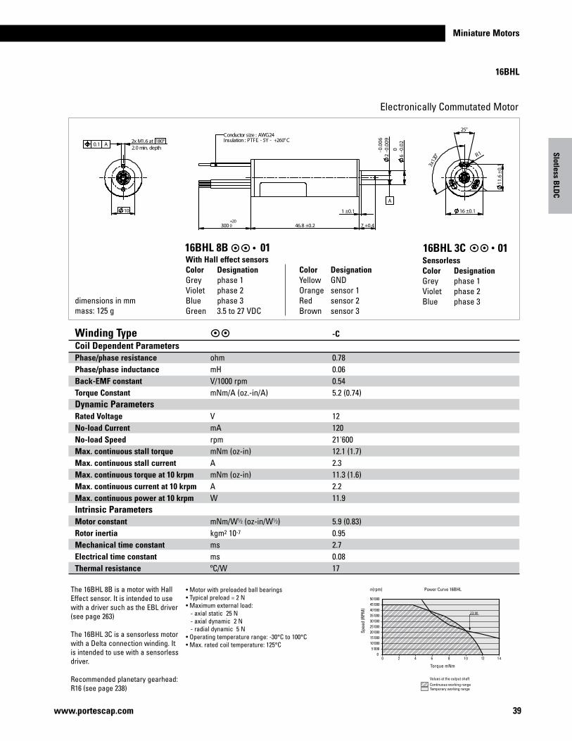
23 W
05'000
10'00015'00020'00025'00030'00035'00040'00045'00050'000
0 2 4 6 8 10 12 14
Power Curve 16BHL
Torque mNm
Values at the output shaftContinuous working rangeTemporary working range
Spee
d (R
PM)
n(rpm)
Electronically Commutated Motor
• Motor with preloaded ball bearings• Typical preload = 2 N• Maximum external load: - axial static 25 N - axial dynamic 2 N - radial dynamic 5 N• Operating temperature range: -30°C to 100°C• Max. rated coil temperature: 125°C
Slotless BLD
C
16BHL
dimensions in mmmass: 125 g
SensorlessColor DesignationGrey phase 1Violet phase 2Blue phase 3
With Hall effect sensorsColor DesignationGrey phase 1Violet phase 2Blue phase 3Green 3.5 to 27 VDC
Color DesignationYellow GNDOrange sensor 1Red sensor 2Brown sensor 3
16BHL 3C 0116BHL 8B 01
01
°081 ta 6.1M x2
11.6
±0.1
°52
3x12
0°
1
4.0±003
- 00.00
9
2.0±8.64
-0.0
06
1.0±
7
2 6-0
.02
A
42GWA : ezis rotcudnoCC°062+ - Y5 - EFTP : noitalusnI
A1.0htped .nim 0.2
1.0±61
R1
002+
The 16BHL 8B is a motor with Hall Effect sensor. It is intended to use with a driver such as the EBL driver (see page 263)
The 16BHL 3C is a sensorless motor with a Delta connection winding. It is intended to use with a sensorless driver.
Recommended planetary gearhead: R16 (see page 238)
Winding Type -C Coil Dependent Parameters Phase/phase resistance ohm 0.78 Phase/phase inductance mH 0.06 Back-EMF constant V/1000 rpm 0.54 Torque Constant mNm/A (oz.-in/A) 5.2 (0.74) Dynamic Parameters Rated Voltage V 12 No-load Current mA 120 No-load Speed rpm 21'600 Max. continuous stall torque mNm (oz-in) 12.1 (1.7) Max. continuous stall current A 2.3 Max. continuous torque at 10 krpm mNm (oz-in) 11.3 (1.6) Max. continuous current at 10 krpm A 2.2 Max. continuous power at 10 krpm W 11.9 Intrinsic Parameters Motor constant mNm/W1⁄2 (oz-in/W1⁄2) 5.9 (0.83) Rotor inertia kgm2 10-7 0.95 Mechanical time constant ms 2.7 Electrical time constant ms 0.08 Thermal resistance ºC/W 17
j 0.1 A
R 8.1 ±0.1
20°
R 1.4
Ø 22 ±0.11.5 ±0.1
Ø10
-0.020
35.3 ±0.2300 10 ±0.4
Ø3
-0.00
9-0
.006
Conductor size : AWG24Insulation : PTFE - 5Y - +260°C
+200
A
3x M 2 at 120°3.0 min. depth
Ø 17
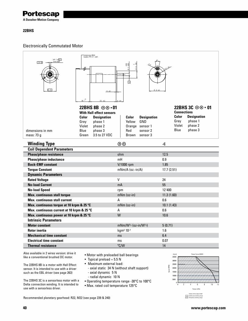
22BHS
Winding Type -C Coil Dependent Parameters Phase/phase resistance ohm 12.5 Phase/phase inductance mH 0.9 Back-EMF constant V/1000 rpm 1.85 Torque Constant mNm/A (oz.-in/A) 17.7 (2.51) Dynamic Parameters Rated Voltage V 24 No-load Current mA 55 No-load Speed rpm 12'400 Max. continuous stall torque mNm (oz-in) 11.3 (1.60) Max. continuous stall current A 0.6 Max. continuous torque at 10 krpm & 25 ºC mNm (oz-in) 10.1 (1.43) Max. continuous current at 10 krpm & 25 ºC A 0.6 Max. continuous power at 10 krpm & 25 ºC W 10.6 Intrinsic Parameters Motor constant mNm/W1⁄2 (oz-in/W1⁄2) 5 (0.71) Rotor inertia kgm2 10-7 1.6 Mechanical time constant ms 6.4 Electrical time constant ms 0.07 Thermal resistance ºC/W 14
Electronically Commutated Motor
dimensions in mmmass: 73 g
25000
30000
35000
20000
15000
10000
5000
2 4 6 8 1 0 1 2 0
0
Power Curve 22BHS
Torque mNm
Values at the output shaftContinuous working rangeTemporary working range
Spee
d (R
PM)
n(rpm)
www.portescap.com40
22BHS 3C 01ConnectionsColor DesignationGrey phase 1Violet phase 2Blue phase 3
• Motor with preloaded ball bearings• Typical preload = 5.5 N• Maximum external load: - axial static 34 N (without shaft support) - axial dynamic 5 N - radial dynamic 10 N• Operating temperature range -30°C to 100°C• Max. rated coil temperature 125°C
Recommended planetary gearhead: R22, M22 (see page 239 & 240)
Also available in 2 wires version: drive it like a conventional brushed DC motor.
The 22BHS 8B is a motor with Hall Effect sensor. It is intended to use with a driver such as the EBL driver (see page 263)
The 22BHS 3C is a sensorless motor with a Delta connection winding. It is intended to use with a sensorless driver.
With Hall effect sensorsColor DesignationGrey phase 1Violet phase 2Blue phase 3Green 3.5 to 27 VDC
Color DesignationYellow GNDOrange sensor 1Red sensor 2Brown sensor 3
22BHS 8B 01
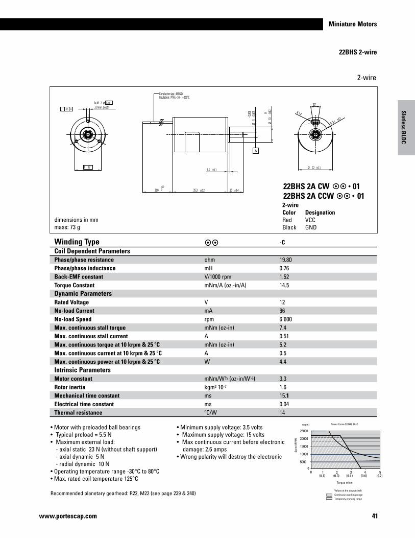
Miniature Motors
j 0.1 A
R 8.1 ±0.1
20°
R 1.4
Ø 22 ±0.11.5 ±0.1
Ø10
-0.020
35.3 ±0.2300 10 ±0.4
Ø3
-0.00
9-0
.006
Conductor size : AWG24Insulation : PTFE - 5Y - +260°C
+200
A
3x M 2 at 120°3.0 min. depth
Ø 17
41www.portescap.com
Winding Type -C Coil Dependent Parameters Phase/phase resistance ohm 19.80 Phase/phase inductance mH 0.76 Back-EMF constant V/1000 rpm 1.52 Torque Constant mNm/A (oz.-in/A) 14.5 Dynamic Parameters Rated Voltage V 12 No-load Current mA 96 No-load Speed rpm 6'600 Max. continuous stall torque mNm (oz-in) 7.4 Max. continuous stall current A 0.51 Max. continuous torque at 10 krpm & 25 ºC mNm (oz-in) 5.2 Max. continuous current at 10 krpm & 25 ºC A 0.5 Max. continuous power at 10 krpm & 25 ºC W 4.4 Intrinsic Parameters Motor constant mNm/W1⁄2 (oz-in/W1⁄2) 3.3 Rotor inertia kgm2 10-7 1.6 Mechanical time constant ms 15.1 Electrical time constant ms 0.04 Thermal resistance ºC/W 14
Torque mNm
25000
20000
15000
10000
5000
1 2 3 4 5(0.1) (0.3) (0.4 ) (0.6) (0.7)
00
Spee
d (R
PM)
Values at the output shaft
n(rpm) Power Curve 22BHS 2A-C
Continuous working rangeTemporary working range
2-wire
dimensions in mmmass: 73 g
Slotless BLD
C
22BHS 2-wire
2-wireColor DesignationRed VCCBlack GND
22BHS 2A CW 0122BHS 2A CCW 01
• Motor with preloaded ball bearings• Typical preload = 5.5 N• Maximum external load: - axial static 23 N (without shaft support) - axial dynamic 5 N - radial dynamic 10 N• Operating temperature range -30°C to 80°C• Max. rated coil temperature 125°C
• Minimum supply voltage: 3.5 volts• Maximum supply voltage: 15 volts • Max continuous current before electronic damage: 2.6 amps• Wrong polarity will destroy the electronic
Recommended planetary gearhead: R22, M22 (see page 239 & 240)
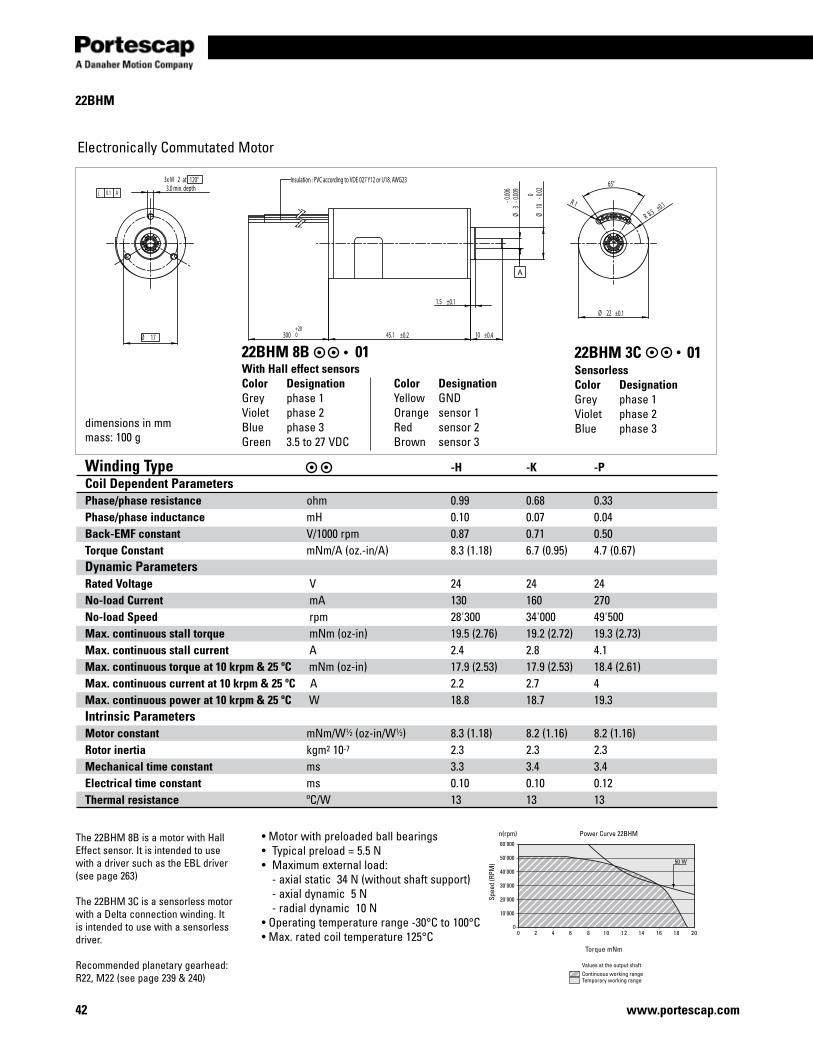
42
22BHM
Winding Type -H -K -P Coil Dependent Parameters Phase/phase resistance ohm 0.99 0.68 0.33 Phase/phase inductance mH 0.10 0.07 0.04Back-EMF constant V/1000 rpm 0.87 0.71 0.50 Torque Constant mNm/A (oz.-in/A) 8.3 (1.18) 6.7 (0.95) 4.7 (0.67) Dynamic Parameters Rated Voltage V 24 24 24 No-load Current mA 130 160 270 No-load Speed rpm 28'300 34'000 49'500 Max. continuous stall torque mNm (oz-in) 19.5 (2.76) 19.2 (2.72) 19.3 (2.73) Max. continuous stall current A 2.4 2.8 4.1 Max. continuous torque at 10 krpm & 25 ºC mNm (oz-in) 17.9 (2.53) 17.9 (2.53) 18.4 (2.61) Max. continuous current at 10 krpm & 25 ºC A 2.2 2.7 4 Max. continuous power at 10 krpm & 25 ºC W 18.8 18.7 19.3 Intrinsic Parameters Motor constant mNm/W1⁄2 (oz-in/W1⁄2) 8.3 (1.18) 8.2 (1.16) 8.2 (1.16) Rotor inertia kgm2 10-7 2.3 2.3 2.3 Mechanical time constant ms 3.3 3.4 3.4 Electrical time constant ms 0.10 0.10 0.12 Thermal resistance ºC/W 13 13 13
Electronically Commutated Motor
dimensions in mmmass: 100 g
10'000
00 2 4 6 8 10 12 14 16 18 20
20'000
30'000
40'000
50'000
60'000
50 W
Power Curve 22BHM
Torque mNm
Values at the output shaftContinuous working rangeTemporary working range
Spee
d (R
PM)
n(rpm)
SensorlessColor DesignationGrey phase 1Violet phase 2Blue phase 3
With Hall effect sensorsColor DesignationGrey phase 1Violet phase 2Blue phase 3Green 3.5 to 27 VDC
Color DesignationYellow GNDOrange sensor 1Red sensor 2Brown sensor 3
22BHM 3C 0122BHM 8B 01
• Motor with preloaded ball bearings• Typical preload = 5.5 N• Maximum external load: - axial static 34 N (without shaft support) - axial dynamic 5 N - radial dynamic 10 N• Operating temperature range -30°C to 100°C• Max. rated coil temperature 125°C
The 22BHM 8B is a motor with Hall Effect sensor. It is intended to use with a driver such as the EBL driver (see page 263)
The 22BHM 3C is a sensorless motor with a Delta connection winding. It is intended to use with a sensorless driver.
Recommended planetary gearhead: R22, M22 (see page 239 & 240)
www.portescap.com
at 120°
j 0.1 A
R 8.5 ±0.1
65°
R 1
Ø 22 ±0.1
Ø3
-0.00
9-0
.006
Ø10
-0.020
1.5 ±0.1
10 ±0.445.1 ±0.2300+200
Insulation : PVC according to VDE 027 Y12 or U18, AWG23
A
Ø 17
3x M 23.0 min. depth
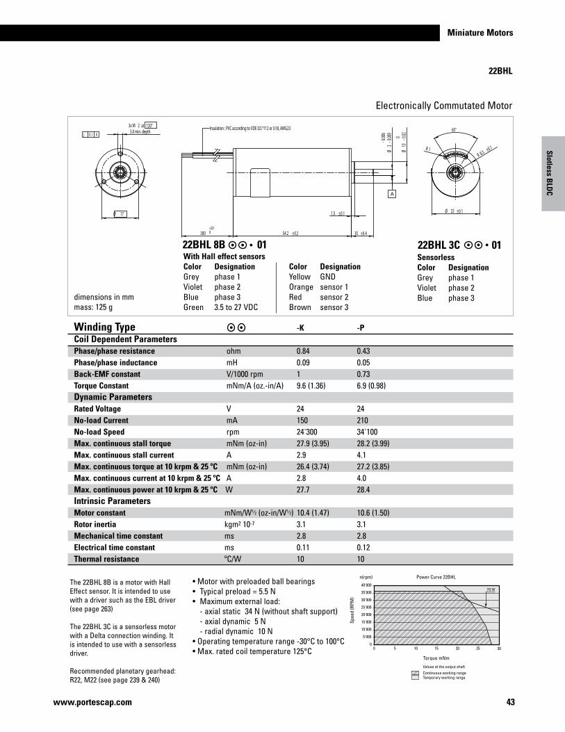
Miniature Motors
22BHL
www.portescap.com
Winding Type -K -P Coil Dependent Parameters Phase/phase resistance ohm 0.84 0.43Phase/phase inductance mH 0.09 0.05Back-EMF constant V/1000 rpm 1 0.73Torque Constant mNm/A (oz.-in/A) 9.6 (1.36) 6.9 (0.98)Dynamic Parameters Rated Voltage V 24 24No-load Current mA 150 210No-load Speed rpm 24'300 34'100Max. continuous stall torque mNm (oz-in) 27.9 (3.95) 28.2 (3.99)Max. continuous stall current A 2.9 4.1Max. continuous torque at 10 krpm & 25 ºC mNm (oz-in) 26.4 (3.74) 27.2 (3.85)Max. continuous current at 10 krpm & 25 ºC A 2.8 4.0Max. continuous power at 10 krpm & 25 ºC W 27.7 28.4Intrinsic Parameters Motor constant mNm/W1⁄2 (oz-in/W1⁄2) 10.4 (1.47) 10.6 (1.50)Rotor inertia kgm2 10-7 3.1 3.1Mechanical time constant ms 2.8 2.8Electrical time constant ms 0.11 0.12Thermal resistance ºC/W 10 10
Electronically Commutated Motor
dimensions in mmmass: 125 g
SensorlessColor DesignationGrey phase 1Violet phase 2Blue phase 3
With Hall effect sensorsColor DesignationGrey phase 1Violet phase 2Blue phase 3Green 3.5 to 27 VDC
Color DesignationYellow GNDOrange sensor 1Red sensor 2Brown sensor 3
22BHL 3C 0122BHL 8B 01
0 5 10 15 20 25 30
5'000
0
10'000
15'000
20'000
25'000
30'000
35'000
40'00070 W
Power Curve 22BHL
Torque mNm
Values at the output shaftContinuous working rangeTemporary working range
Spee
d (R
PM)
n(rpm)
Slotless BLD
C
• Motor with preloaded ball bearings• Typical preload = 5.5 N• Maximum external load: - axial static 34 N (without shaft support) - axial dynamic 5 N - radial dynamic 10 N• Operating temperature range -30°C to 100°C• Max. rated coil temperature 125°C
The 22BHL 8B is a motor with Hall Effect sensor. It is intended to use with a driver such as the EBL driver (see page 263)
The 22BHL 3C is a sensorless motor with a Delta connection winding. It is intended to use with a sensorless driver.
Recommended planetary gearhead: R22, M22 (see page 239 & 240)
43
65°
R 8.5 ±0.1R 1
Ø 22 ±0.11.5 ±0.1
10 ±0.454.2 ±0.2300
Ø3
-0.00
9-0
.006
Ø10
-0.020
+200
Insulation : PVC according to VDE 027 Y12 or U18, AWG23
A
3x M 2 at 120°3.0 min. depth
Ø 17
j 0.1 A
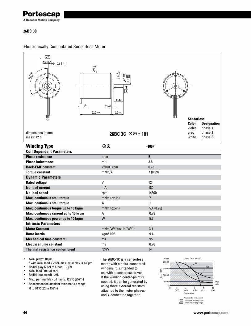
44
26BC 3C
Electronically Commutated Sensorless Motor
Winding Type -109PCoil Dependent Parameters Phase resistance ohm 5Phase inductance mH 3.8Back-EMF constant V/1000 rpm 0.73Torque constant mNm/A 7 (0.99)Dynamic ParametersRated voltage V 12No-load current mA 180No-load speed rpm 14800Max. continuous stall torque mNm (oz-in) 7Max. continuous stall torque A 1Max. continuous torque up to 10 krpm mNm (oz-in) 5.4 (0.76)Max. continuous current up to 10 krpm A 0.78Max. continuous power up to 10 krpm W 5.7Intrinsic ParametersMotor Constant mNm/W1/2 (oz-in/ W1/2) 3.1Rotor inertia kgm2 10-7 9.4Mechanical time constant ms 95Electrical time constant ms 0.76Thermal resistance coil-ambient ºC/W 14
dimensions in mmmass: 72 g
SensorlessColor Designationviolet phase 1grey phase 2white phase 3
20000
15000
10000
5000
2 4 6 8 1 0 0
0
4 W
8 W
(0.3) (0.6) (0.9) (1.1) (1.4)
Power Curve 26BC-3C
Torque mNm
mNm(oz.in)
Values at the output shaftContinuous working rangeTemporary working range
Spee
d (R
PM)
n(rpm)• Axial play*: 10 μm * with axial load > 2.5N, max. axial play is 130μm• Radial play (2.5N rad.load) 10 μm• Axial load (static) 25N• Radial load (static) 25N• Max. permissible coil temp. 125°C (257°F)• Recommended ambient temperature range 0 to 70°C (32 to 158°F)
The 26BC-3C is a sensorless motor with a delta-connected winding. It is intended to usewith a sensorless driver. If the winding center-point is needed, it can be generated by using three external resistors attached to the motor phases and Y-connected together.
www.portescap.com
26BC 3C 101
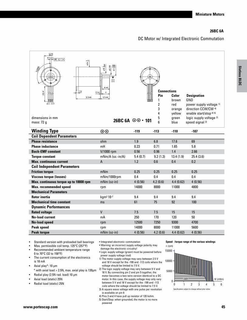
Miniature Motors
26BC 6A
45www.portescap.com
DC Motor w/ Integrated Electronic Commutation
• Standard version with preloaded ball bearings• Max. permissible coil temp. 125°C (257°F)• Recommended ambient temperature range 0 to 70°C (32 to 158°F)• The current consumption of the electronics is 18 mA• Axial play*: 10 μm * with axial load > 2.5N, max. axial play is 130μm • Radial play (2.5N rad. load) 10 μm• Axial load (static) 25N• Radial load (static) 25N
dimensions in mmmass: 72 g
ConnectionsPin Color Designation 1 brown GND 2 red power supply voltage 1) 3 orange direction CCW/CW 4)
4 yellow enable start/stop 4) 5) 5 green logic supply voltage 2)
6 blue speed signal 3)
Winding Type -119 -113 -110 -107Coil Dependent Parameters Phase resistance ohm 1.9 6.8 17.6 69Phase inductance mH 0.23 0.71 1.65 5.8Back-EMF constant V/1000 rpm 0.56 0.96 1.4 2.66Torque constant mNm/A (oz.-in/A) 5.4 (0.7) 9.2 (1.3) 13.4 (1.9) 25.4 (3.6)Max. continuous current A 1.2 0.6 0.4 0.2Coil Independent Parameters Friction torque mNm 0.25 0.25 0.25 0.25Viscous torque (losses) mNm/1000rpm 0.4 0.4 0.4 0.4Max. continuous torque up to 10000 rpm mNm (oz-in) 4 (0.56) 4.2 (0.6) 4.4 (0.62) 4 (0.56)Max. recommended speed rpm 14000 8000 11000 4800Mechanical Parameters Rotor inertia kgm2 10-7 9.4 9.4 9.4 9.4Mechanical time constant ms 61 75 92 100Dynamic Performances Rated voltage V 7.5 7.5 15 15No-load current mA 250 170 120 50No-load speed rpm 12500 7250 9300 4700Peak speed rpm 14000 8000 11000 5600Peak torque mNm (oz-in) 4 (0.56) 4.2 (0.6) 4.4 (0.62) 4 (0.56)
M (mNm)
15000
10000
5000
1 2 3 4 5 60
0
n (rpm)
Speed /torque range of the various windings
Specifications subject to change without prior notice
110
107
Slotless BLD
C
• Integrated electronic commutation• Warning: an incorrect supply voltage polarity may damage the electronic circuitry!• Logic supply voltage (green) must be powered before power supply voltage (red)1) The motor supply voltage may vary between 2.5 V and 18 V except for the -199 and -113 coils where the voltage should be limited to 7.5 V. 2) The logic supply voltage may vary between 5 V and 18 V. By connecting pin 2 and pin 5 together, the motor becomes a two-wire version identical to a DC motor. In this case, the supply voltage may only vary between 5 V and 18 V except for the -199 and -113 coils where the voltage should be limited to 7.5 V. 3) A square wave voltage with one pulse per revolution is available on pin 64) Pins 3 and 4 have pull up resistor of 120 kohm.5) Start/Stop: when grounded, the motor is no more powered
26BC 6A 101
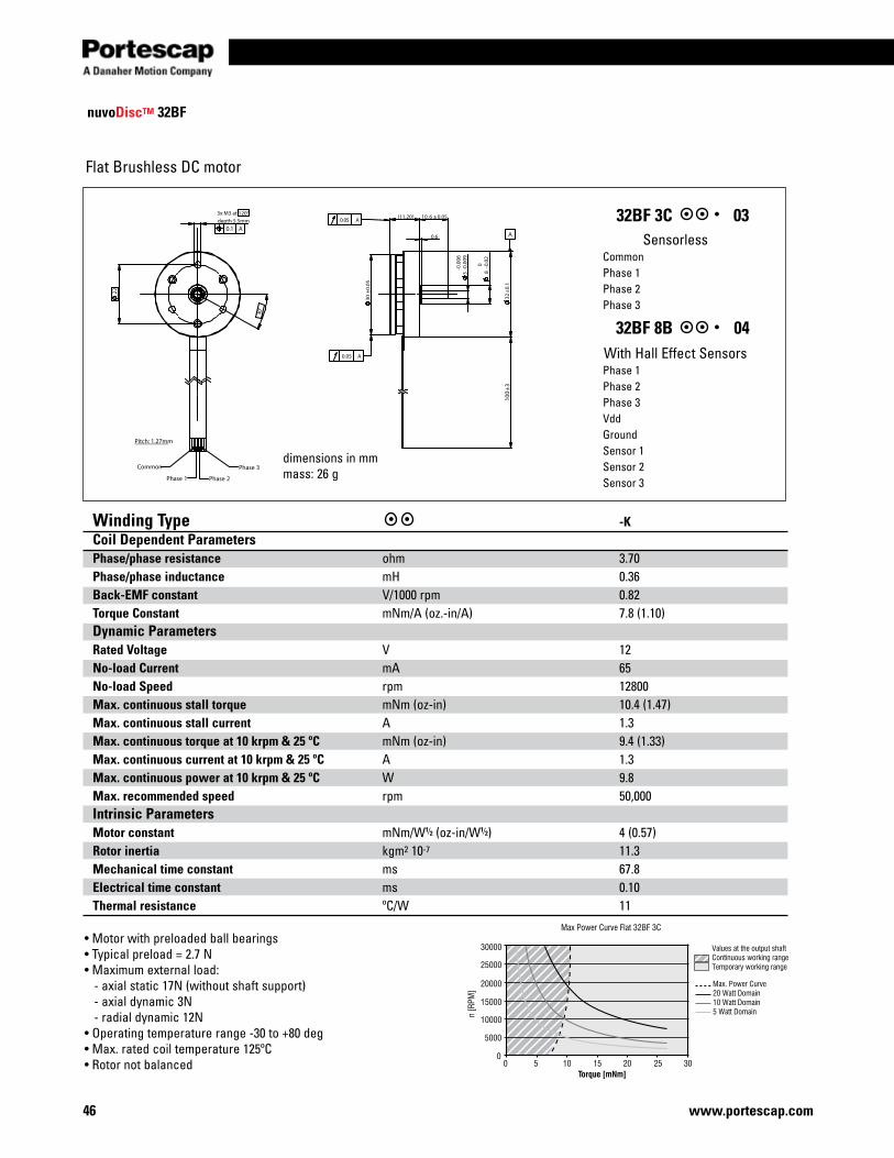
46 www.portescap.com
22
30°
Pitch: 1.27mm
100
10. 6 ±0.05
32
11.2050.0 A
-
0.6
)
0.00
9
8
A
00.00
6
±0.1
0.02
±3
30±0
.05
-
3-
(
0.05
A
Phase 1 Phase 2
3x M3 at 120°
Common
depth 5.5mm
Phase 3
0.1 A
nuvoDiscTM 32BF
Flat Brushless DC motor
• Motor with preloaded ball bearings• Typical preload = 2.7 N• Maximum external load: - axial static 17N (without shaft support) - axial dynamic 3N - radial dynamic 12N• Operating temperature range -30 to +80 deg• Max. rated coil temperature 125ºC • Rotor not balanced 0 305 10 15 20 25
5000
10000
15000
25000
30000
20000
Max Power Curve Flat 32BF 3C
Torque [mNm]
n [R
PM]
0
Max. Power Curve20 Watt Domain10 Watt Domain5 Watt Domain
Values at the output shaftContinuous working rangeTemporary working range
SensorlessCommonPhase 1Phase 2Phase 3
With Hall Effect SensorsPhase 1Phase 2Phase 3VddGroundSensor 1Sensor 2Sensor 3
32BF 3C 03
32BF 8B 04
dimensions in mmmass: 26 g
Winding Type -K Coil Dependent Parameters Phase/phase resistance ohm 3.70Phase/phase inductance mH 0.36 Back-EMF constant V/1000 rpm 0.82Torque Constant mNm/A (oz.-in/A) 7.8 (1.10)Dynamic Parameters Rated Voltage V 12No-load Current mA 65No-load Speed rpm 12800Max. continuous stall torque mNm (oz-in) 10.4 (1.47)Max. continuous stall current A 1.3Max. continuous torque at 10 krpm & 25 ºC mNm (oz-in) 9.4 (1.33)Max. continuous current at 10 krpm & 25 ºC A 1.3Max. continuous power at 10 krpm & 25 ºC W 9.8Max. recommended speed rpm 50,000Intrinsic Parameters Motor constant mNm/W1⁄2 (oz-in/W1⁄2) 4 (0.57)Rotor inertia kgm2 10-7 11.3Mechanical time constant ms 67.8Electrical time constant ms 0.10Thermal resistance ºC/W 11

47www.portescap.com
Miniature Motors
Notes

48 www.portescap.com
Notes
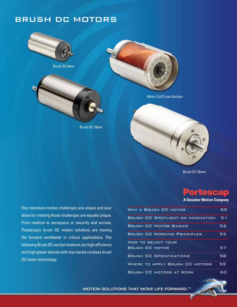
BRUSH DC motoRS
Why a Brush DC motor 50
Brush DC Spotlight on Innovation 51
Brush DC Motor Basics 52
Brush DC Working Principles 55
How to select your Brush DC motor 57
Brush DC Specifications 58
Where to apply Brush DC motors 59
Brush DC motors at Work 60
Your miniature motion challenges are unique and your
ideas for meeting those challenges are equally unique.
From medical to aerospace or security and access,
Portescap’s brush DC motion solutions are moving
life forward worldwide in critical applications. The
following Brush DC section features our high efficiency
and high power density with low inertia coreless brush
DC motor technology.
Brush DC 8mm
Brush DC 16mm
Brush DC 35mm
Motor Coil Cross Section
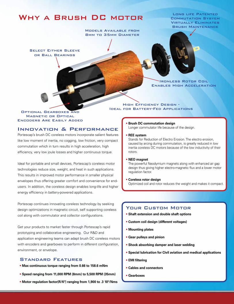
Why a Brush DC motor
• Brush DC commutation design Longer commutator life because of the design.
• REE system Stands for Reduction of Electro Erosion. The electro erosion, caused by arcing during commutation, is greatly reduced in low inertia coreless DC motors because of the low inductivity of their rotors.
• NEO magnet The powerful Neodymium magnets along with enhanced air gap design thus giving higher electro-magnetic flux and a lower motor regulation factor.
• Coreless rotor design Optimized coil and rotor reduces the weight and makes it compact.
Portescap’s brush DC coreless motors incorporate salient features
like low moment of inertia, no cogging, low friction, very compact
commutation which in turn results in high acceleration, high
efficiency, very low joule losses and higher continuous torque.
Ideal for portable and small devices, Portescap’s coreless motor
technologies reduce size, weight, and heat in such applications.
This results in improved motor performance in smaller physical
envelopes thus offering greater comfort and convenience for end-
users. In addition, the coreless design enables long-life and higher
energy efficiency in battery-powered applications.
Portescap continues innovating coreless technology by seeking
design optimizations in magnetic circuit, self supporting coreless
coil along with commutator and collector configurations.
Get your products to market faster through Portescap’s rapid
prototyping and collaborative engineering. Our R&D and
application engineering teams can adapt brush DC coreless motors
with encoders and gearboxes to perform in different configuration,
environment, or envelope.
Innovation & Performance
Your Custom motor• Shaft extension and double shaft options
• Custom coil design (different voltages)
• Mounting plates
• Gear pulleys and pinion
• Shock absorbing damper and laser welding
• Special lubrication for Civil aviation and medical applications
• EMI filtering
• Cables and connectors
• Gearboxes
Standard Features• Max continuous torque ranging from 0.66 to 158.6 mNm
• Speed ranging from 11,000 RPM (8mm) to 5,500 RPM (35mm)
• Motor regulation factor(R/K2) ranging from 1,900 to .3 103/Nms
Select Either Sleeveor Ball Bearings
models Available from8mm to 35mm Diameter
Long life Patented Commutation Sysyem Virtually Eliminates Brush maintenance
optional Gearboxes and magnetic or optical
Encoders Are Easily Added
High Efficiency Design - Ideal for Battery-Fed Applications
Ironless Rotor Coil Enables High Acceleration
Looking for a lighter motor with more torque?35GLT brush dc coreless motor from Portescap might be the solution for your needs. The 35GLT provides a 40% increase in torque-to-volume ratio over most average iron core motors. A featured multi-layer coil improves performance and offers insulating reinforcement, resulting in improved heat dissipation. Weighing in at only 360 grams and providing an energy efficiency of 85%, the 35GLT offers less power draw and excellent space savings.
Innovation is a passion at Portescap. It defines your success, and defines our future. We help you get the
right products to market faster, through rapid prototyping and collaborative engineering. With experienced
R&D and application engineering teams in North America, Europe, and Asia, Portescap is prepared to create
high-quality precision motors, in a variety of configurations and frame sizes for use in diverse environments.
SPOTLIGHT ONINNOVATION
Demanding application?Portescap is up for the challenge. Take our latest innovation Athlonix in high power density motors. Ultra-compact, and designed for lower joule heating for sustainable performance over the life of your product, Portescap’s Athlonix motors deliver unparalleled speed-to-torque performance. And better energy efficiency brings you savings while helping you achieve your green goals.
Athlonix motors are available in 12, 16, and 22mm.More Endurance. Higher Power Density. Smaller Package
The quest for high-resolution feedback with accuracy in speed is the essence of Portescap’s innovative MR2 magneto resistive encoder. These miniature encoders accommodate motors from frame sizes of 8mm to 35mm with superior integration schemes to facilitate a compact assembly with motors. And, with a resolution of 2 to 1024 lines, Portescap’s MR2 encoders meet your application requirements today - while flexibly adapting to your evolving needs.
Brush DC motor Basics
All DC motors, including the ironless rotor motors, are composed of three principle sub assemblies: 1. Stator 2. Brush Holder Endcap 3. Rotor
1. The statorThe stator consists of the central, cylindrical permanent magnet, the core which supports the bearings, and the steel tube which completes the magnetic circuit. All three of these parts are held together by the motor front plate, or the mounting plate. The magnetic core is magnetized diametrically after it has been mounted in the magnetic system
2. The Brush Holder EndcapThe Brush Holder Endcap is made of a plastic material. Depending on the intended use of the motor, the brush could be of two different types:
• Carbon type, using copper grahite or silver graphite, such as those found in conventional motors with iron rotors. • Multiwire type, using precious metals.
3. The RotorOf the three sub-assemblies, the one that is most characteristic of this type of motor is the ironless, bell-shaped rotor. There are primarily four different methods of fabricating these ironless armatures utilized in present-day technology.
A — In the conventional way, the various sections of the armature are wound separately, then shaped and assembled to form a cylindrical shell which is glass yarn reinforced, epoxy resin coated, and cured. It is of interest to note the relatively large coil heads which do not participate in the creation of any torque.
Construction of Portescap motors with iron less rotor DC motors
Cable Clamp
Stator tube
Sleeve or Ball Bearing
metallic Alloy Brush Commutation System
Collector
Self Supporting High Packing Density Rotor Coil
High Efficiency High Strength Rare Earth magnet
Brush DC motor Basics B — A method which avoids these coil heads uses an armature wire that is covered with an outer layer of plastic for adhesion, and is wound on a mobile lozenge-shaped support. Later, the support is removed, and a flat armature package is obtained, which is then formed into a cylindrical shape (Figure 1). The difficulty with this method lies in achieving a completely uniform cylinder. This is necessary for minimum ripple of the created torque, and for a minimum imbalance of the rotor.
c) forming of armature in cylindrical shape
a) support arrangement b) armature as flat package
1
1a
2a3
25
Figure 1 - Continuous winding on mobile support
C — A procedure which avoids having to form a perfect cylinder from a flat package consists of winding the wire directly and continuously onto a cylindrical support. This support then remains inside the rotor. Coil heads are reduced to a minimum.Although a large air gap is necessary to accommodate the armature support; this method is, however, easily automated.
D — The Skew-Wound armature method utilizes the same two-layer plastic coated wire described in Method B. This Wire is directly and continuously wound onto a cylindrical support which is later removed, thus eliminating an excessive air gap and minimizing rotor inertia. In this type of winding, inactive coil heads are non-existent. (Figure 2). This kind of armature winding does require relatively complex coil winding machines. Portescap thru its proprietary know how has developed multiple automated winding machines for different frame sizes and continues to innovate in the space so that dense coil windings can be spun in these automated machines.
Figure 2
Features of Ironless Rotor DC motors
The rotor of a conventional iron core DC motor is made of copper wire which is wound around the poles of its iron core. Designing the rotor in this manner has the following results:• A large inertia due to the iron mass which impedes rapid starts and stops• A cogging effect and rotor preferential positions caused by the attraction of the iron poles to the permanent magnet.• A considerable coil inductance producing arcing during commutation. This arcing is responsible on the one hand for an
electrical noise, and on the other hand for the severe electro—erosion of the brushes. It is for the latter reason that carbon type brushes are used in the conventional motors.
A self supporting ironless DC motor from Portescap has many advantages over conventional iron core motors:• high torque to — inertia ratio• absence of preferred rotor positions• very low torque and back EMF variation with armature positions• essentially zero hysteresis and eddy current losses• negligible electrical time constant • almost no risk of demagnetization, thus fast acceleration• negligible voltage drop at the brushes (with multiwire type brushes)• lower viscous damping• linear characteristics
The two biggest contributors to the commutator life in a brush DC motor are the mechanical brush wear from sliding contacts and the erosion of the electrodes due to electrical arcing. The superior surface finish, commutator precision along with material upgrades such as precious metal commutators with appropriate alloys has helped in reducing the mechanical wear of the brushes. To effectively reduce electro erosion in while extending commutator life Portescap innovated its proprietary REE (Reduced Electro Erosion) system of coils. The REE system reduces the effective inductivity of the brush commutation by optimization of the mutual induction of the coil segments. In order to compare and contrast the benefits of an REE system Portescap conducted tests on motors with and with out REE coil optimization. The commutator surface wear showed improvements ranging from 100 -300 percent as shown in Figure 5. Coils 4, 5 and 6 are REE reinforced while 1, 2 & 3 are without REE reinforcement.
REE System proven to increase motor life up to 1000 percent
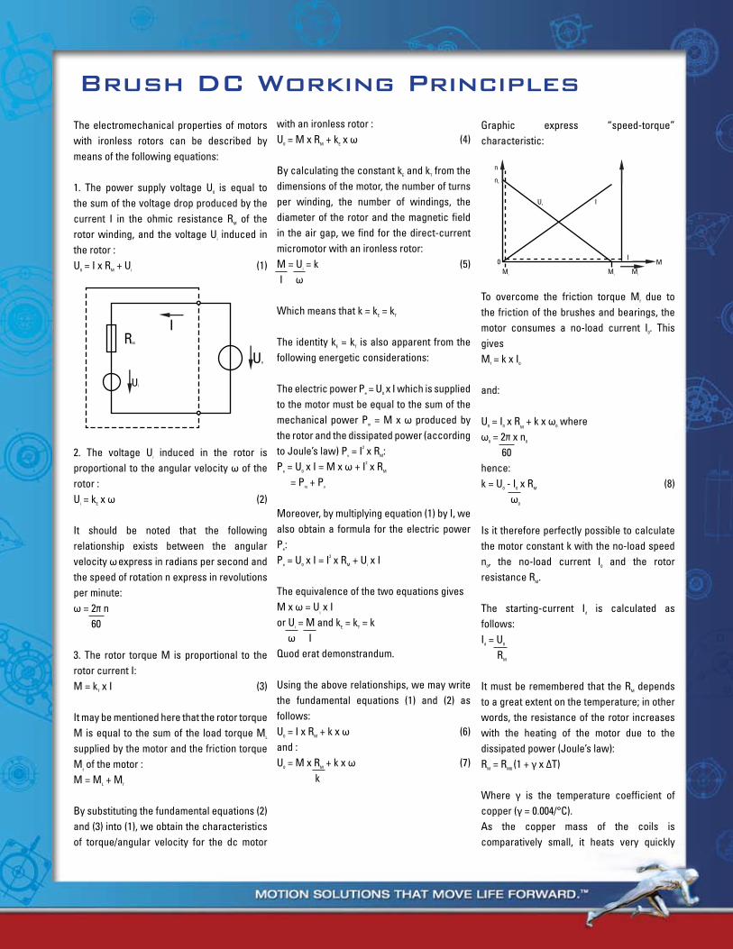
Brush DC Working PrinciplesThe electromechanical properties of motors with ironless rotors can be described by means of the following equations:
1. The power supply voltage U0 is equal to the sum of the voltage drop produced by the current I in the ohmic resistance RM of the rotor winding, and the voltage Ui induced in the rotor :U0 = I x RM + Ui (1)
2. The voltage Ui induced in the rotor is proportional to the angular velocity ω of the rotor :Ui = kE x ω (2)
It should be noted that the following relationship exists between the angular velocity ω express in radians per second and the speed of rotation n express in revolutions per minute:ω = 2π n 60
3. The rotor torque M is proportional to the rotor current I:M = kT x I (3)
It may be mentioned here that the rotor torque M is equal to the sum of the load torque ML
supplied by the motor and the friction torque M
f of the motor :
M = ML + Mf
By substituting the fundamental equations (2) and (3) into (1), we obtain the characteristics of torque/angular velocity for the dc motor
with an ironless rotor :U0 = M x RM + kE x ω (4)
By calculating the constant kE and kT from the dimensions of the motor, the number of turns per winding, the number of windings, the diameter of the rotor and the magnetic field in the air gap, we find for the direct-current micromotor with an ironless rotor:M = Ui = k (5) I ω
Which means that k = kE = kT
The identity kE = kT is also apparent from the following energetic considerations:
The electric power Pe = U0 x I which is supplied to the motor must be equal to the sum of the mechanical power Pm = M x ω produced by the rotor and the dissipated power (according to Joule’s law) Pv = I2 x RM:Pe = U0 x I = M x ω + I2 x RM
= Pm + Pv
Moreover, by multiplying equation (1) by I, we also obtain a formula for the electric power Pe: Pe = U0 x I = I2 x RM + Ui x I
The equivalence of the two equations givesM x ω = U
i x I
or Ui = M and kE = kT = k ω IQuod erat demonstrandum.
Using the above relationships, we may write the fundamental equations (1) and (2) as follows:U0 = I x RM + k x ω (6)and :U0 = M x RM + k x ω (7) k
Graphic express “speed-torque” characteristic:
To overcome the friction torque Mf due to the friction of the brushes and bearings, the motor consumes a no-load current I0. This givesMf = k x I0
and:
U0 = I0 x RM + k x ω0 where
ω0 = 2π x n0
60hence:k = U0 - I0 x RM (8) ω0
Is it therefore perfectly possible to calculate the motor constant k with the no-load speed n0, the no-load current I0
and the rotor resistance RM.
The starting-current Id is calculated as follows:Id = U0
RM
It must be remembered that the RM depends to a great extent on the temperature; in other words, the resistance of the rotor increases with the heating of the motor due to the dissipated power (Joule’s law):RM = RM0 (1 + γ x ∆T)
Where γ is the temperature coefficient of copper (γ = 0.004/°C).As the copper mass of the coils is comparatively small, it heats very quickly
IRM
UI
U0
0MLML
I
I
ML
M
U0
n
n0
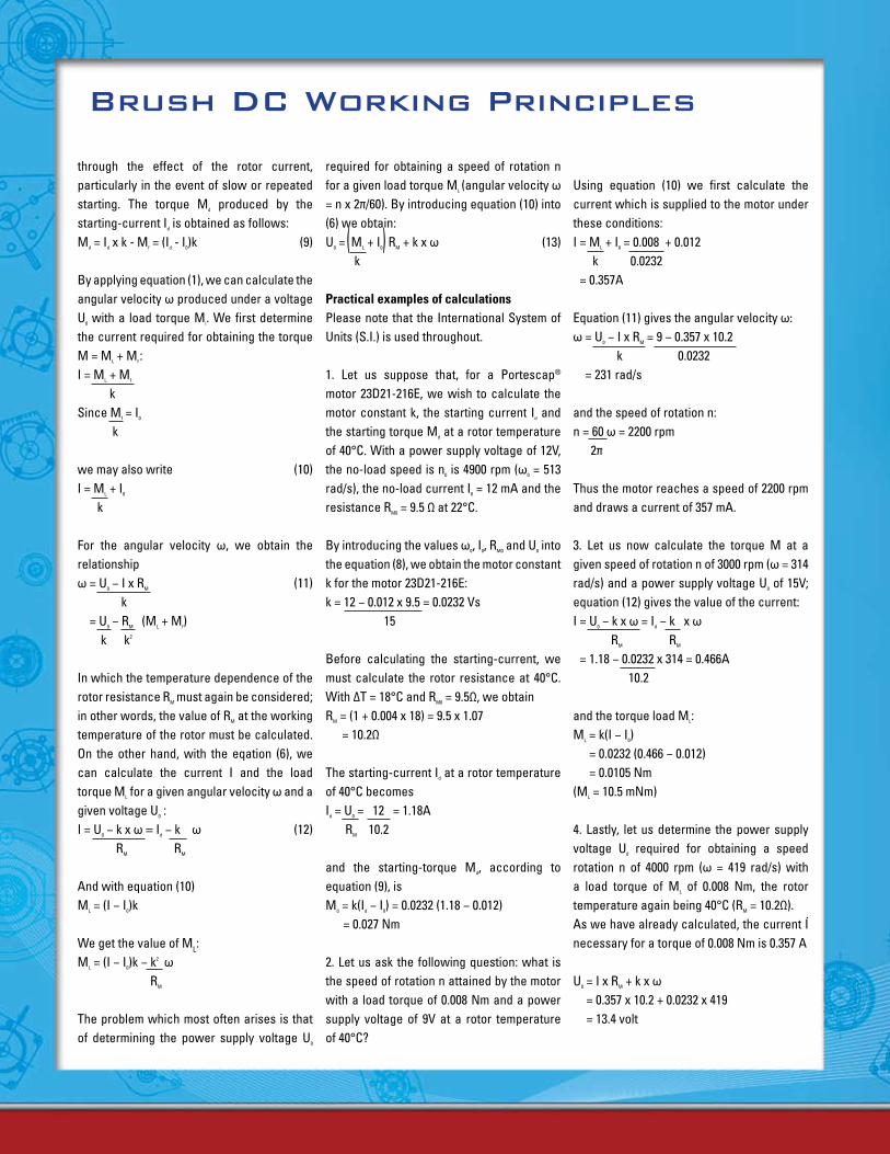
through the effect of the rotor current, particularly in the event of slow or repeated starting. The torque Md produced by the starting-current Id is obtained as follows:Md = Id x k - Mf = (Id - I0)k (9)
By applying equation (1), we can calculate the angular velocity ω produced under a voltage U0 with a load torque Mi. We first determine the current required for obtaining the torque M = ML + Mf :I = ML + Mf
kSince Mf = I0
k
we may also write (10)I = ML + I0
k
For the angular velocity ω, we obtain the relationshipω = U0 − I x RM (11) k
= U0 − RM (ML + Mf) k k2
In which the temperature dependence of the rotor resistance RM must again be considered; in other words, the value of RM at the working temperature of the rotor must be calculated. On the other hand, with the eqation (6), we can calculate the current I and the load torque ML for a given angular velocity ω and a given voltage U0
: I = U0 − k x ω = Id − k ω (12) RM RM
And with equation (10)ML = (I − I0)k
We get the value of ML:ML = (I − I0)k − k2 ω
RM
The problem which most often arises is that of determining the power supply voltage U0
required for obtaining a speed of rotation n for a given load torque ML (angular velocity ω = n x 2π/60). By introducing equation (10) into (6) we obtain:U0 = ML + I0 RM + k x ω (13) k
Practical examples of calculationsPlease note that the International System of Units (S.I.) is used throughout.
1. Let us suppose that, for a Portescap® motor 23D21-216E, we wish to calculate the motor constant k, the starting current Id and the starting torque Md at a rotor temperature of 40°C. With a power supply voltage of 12V, the no-load speed is n0 is 4900 rpm (ω0 = 513 rad/s), the no-load current I0 = 12 mA and the resistance RM0 = 9.5 Ω at 22°C.
By introducing the values ω0, I0, RM0 and U0 into the equation (8), we obtain the motor constant k for the motor 23D21-216E:k = 12 − 0.012 x 9.5 = 0.0232 Vs 15
Before calculating the starting-current, we must calculate the rotor resistance at 40°C. With ∆T = 18°C and RM0 = 9.5Ω, we obtainRM = (1 + 0.004 x 18) = 9.5 x 1.07
= 10.2Ω
The starting-current Id at a rotor temperature of 40°C becomesId = U0 = 12 = 1.18A RM 10.2
and the starting-torque Md, according to equation (9), isMd = k(Id − I0) = 0.0232 (1.18 − 0.012)
= 0.027 Nm
2. Let us ask the following question: what is the speed of rotation n attained by the motor with a load torque of 0.008 Nm and a power supply voltage of 9V at a rotor temperature of 40°C?
Using equation (10) we first calculate the current which is supplied to the motor under these conditions:I = ML + I0 = 0.008 + 0.012 k 0.0232 = 0.357A
Equation (11) gives the angular velocity ω:ω = U0 − I x RM = 9 − 0.357 x 10.2 k 0.0232
= 231 rad/s
and the speed of rotation n:n = 60 ω = 2200 rpm 2π
Thus the motor reaches a speed of 2200 rpm and draws a current of 357 mA.
3. Let us now calculate the torque M at a given speed of rotation n of 3000 rpm (ω = 314 rad/s) and a power supply voltage U0 of 15V; equation (12) gives the value of the current:I = U0 − k x ω = Id − k x ω RM RM
= 1.18 − 0.0232 x 314 = 0.466A 10.2
and the torque load ML:ML = k(I − I0)
= 0.0232 (0.466 − 0.012) = 0.0105 Nm
(ML = 10.5 mNm)
4. Lastly, let us determine the power supply voltage U0 required for obtaining a speed rotation n of 4000 rpm (ω = 419 rad/s) with a load torque of ML of 0.008 Nm, the rotor temperature again being 40°C (RM = 10.2Ω).As we have already calculated, the current I necessary for a torque of 0.008 Nm is 0.357 A
U0 = I x RM + k x ω = 0.357 x 10.2 + 0.0232 x 419 = 13.4 volt
Brush DC Working Principles
22 N 2R 2B - 210E 286
Motor generation/ length:L, C = old generation (C: short, L: long), Alnico MagnetS, N, V = middle generation (S: short, N: normal, V: very long)G, GS = new generation (high power magnet), S: short version
Motor diameter (in mm) Execution codingBearing type:blank = with sleeve bearings2R = with front and rear ball bearings
Coil type:nb of layerwire sizetype connexion
Commutation size & type/ magnet type:Alnico/ Precious Metal = 18, 28, 48, 58 NdFeB/ Precious Metal = 78, 88, 98Alnico/ Graphite & Copper = 12 NdFeB/ Graphite Copper = 82, 83
.
( )
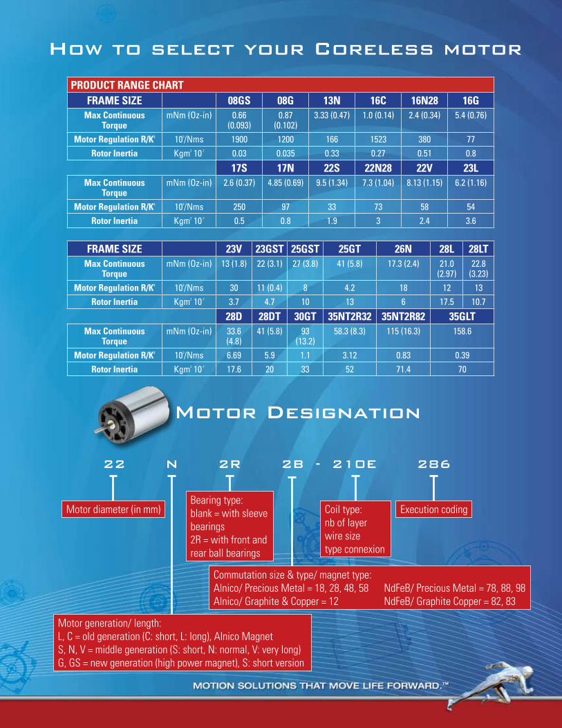
PRODUCT RANGE CHARTFRAME SIZE 08GS 08G 13N 16C 16N28 16G
Max Continuous Torque
mNm (Oz-in) 0.66 (0.093)
0.87 (0.102)
3.33 (0.47) 1.0 (0.14) 2.4 (0.34) 5.4 (0.76)
Motor Regulation R/K2 103/Nms 1900 1200 166 1523 380 77Rotor Inertia Kgm2 10-7 0.03 0.035 0.33 0.27 0.51 0.8
17S 17N 22S 22N28 22V 23LMax Continuous
TorquemNm (Oz-in) 2.6 (0.37) 4.85 (0.69) 9.5 (1.34) 7.3 (1.04) 8.13 (1.15) 6.2 (1.16)
Motor Regulation R/K2 103/Nms 250 97 33 73 58 54Rotor Inertia Kgm2 10-7 0.5 0.8 1.9 3 2.4 3.6
FRAME SIZE 23V 23GST 25GST 25GT 26N 28L 28LTMax Continuous
TorquemNm (Oz-in) 13 (1.8) 22 (3.1) 27 (3.8) 41 (5.8) 17.3 (2.4) 21.0
(2.97)22.8
(3.23)Motor Regulation R/K2 103/Nms 30 11 (0.4) 8 4.2 18 12 13
Rotor Inertia Kgm2 10-7 3.7 4.7 10 13 6 17.5 10.7
28D 28DT 30GT 35NT2R32 35NT2R82 35GLTMax Continuous
TorquemNm (Oz-in) 33.6
(4.8)41 (5.8) 93
(13.2)58.3 (8.3) 115 (16.3) 158.6
Motor Regulation R/K2 103/Nms 6.69 5.9 1.1 3.12 0.83 0.39Rotor Inertia Kgm2 10-7 17.6 20 33 52 71.4 70
How to select your Coreless motor
motor Designation
22 N 2R 2B - 210E 286
Motor generation/ length:L, C = old generation (C: short, L: long), Alnico MagnetS, N, V = middle generation (S: short, N: normal, V: very long)G, GS = new generation (high power magnet), S: short version
Motor diameter (in mm) Execution codingBearing type:blank = with sleeve bearings2R = with front and rear ball bearings
Coil type:nb of layerwire sizetype connexion
Commutation size & type/ magnet type:Alnico/ Precious Metal = 18, 28, 48, 58 NdFeB/ Precious Metal = 78, 88, 98Alnico/ Graphite & Copper = 12 NdFeB/ Graphite Copper = 82, 83
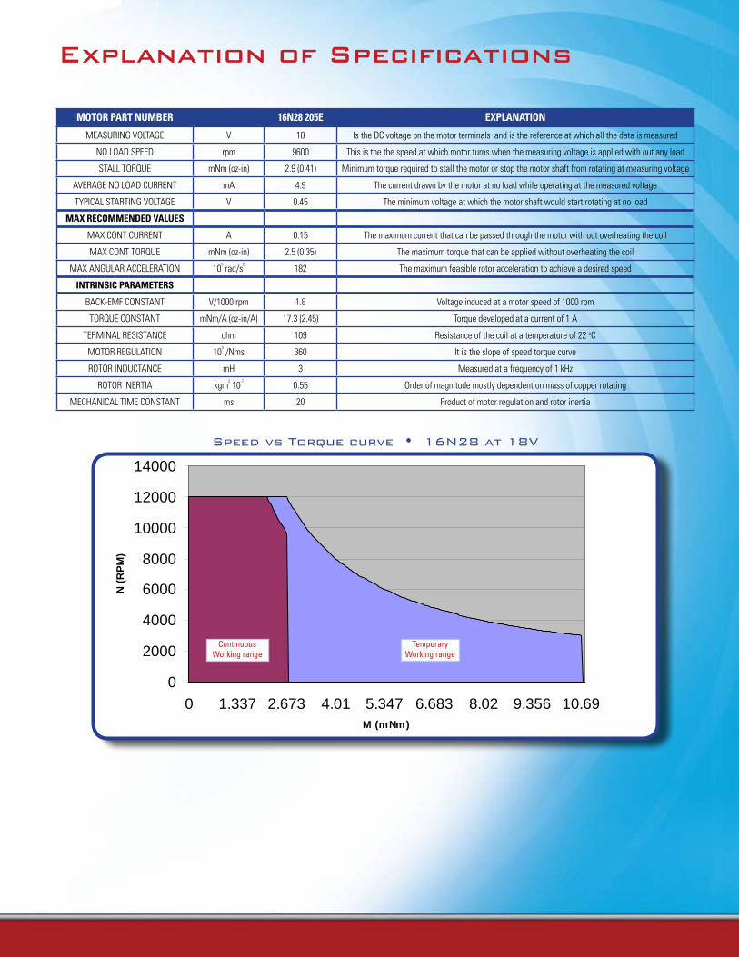
MOTOR PART NUMBER 16N28 205E ExPLANATION
MEASURING VOLTAGE V 18 Is the DC voltage on the motor terminals and is the reference at which all the data is measured
NO LOAD SPEED rpm 9600 This is the the speed at which motor turns when the measuring voltage is applied with out any load
STALL TORQUE mNm (oz-in) 2.9 (0.41) Minimum torque required to stall the motor or stop the motor shaft from rotating at measuring voltage
AVERAGE NO LOAD CURRENT mA 4.9 The current drawn by the motor at no load while operating at the measured voltage
TYPICAL STARTING VOLTAGE V 0.45 The minimum voltage at which the motor shaft would start rotating at no load
MAx RECOMMENDED VALUES
MAX CONT CURRENT A 0.15 The maximum current that can be passed through the motor with out overheating the coil
MAX CONT TORQUE mNm (oz-in) 2.5 (0.35) The maximum torque that can be applied without overheating the coil
MAX ANGULAR ACCELERATION 103 rad/s
2182 The maximum feasible rotor acceleration to achieve a desired speed
INTRINSIC PARAMETERS
BACK-EMF CONSTANT V/1000 rpm 1.8 Voltage induced at a motor speed of 1000 rpm
TORQUE CONSTANT mNm/A (oz-in/A) 17.3 (2.45) Torque developed at a current of 1 A
TERMINAL RESISTANCE ohm 109 Resistance of the coil at a temperature of 22 oC
MOTOR REGULATION 103 /Nms 360 It is the slope of speed torque curve
ROTOR INDUCTANCE mH 3 Measured at a frequency of 1 kHz
ROTOR INERTIA kgm2 10
-70.55 Order of magnitude mostly dependent on mass of copper rotating
MECHANICAL TIME CONSTANT ms 20 Product of motor regulation and rotor inertia
Speed vs Torque curve • 16N28 at 18V
0
2000
4000
6000
8000
10000
12000
14000
0 1.337 2.673 4.01 5.347 6.683 8.02 9.356 10.69M (mNm)
N (
RP
M)
Continuous Working range
Temporary Working range
Explanation of Specifications
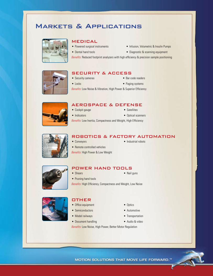
markets & Applications
mEDICALPowered surgical instruments•
Dental hand tools•
Infusion, Volumetric & Insulin Pumps•
Diagnostic & scanning equipment•
Benefits: Reduced footprint analyzers with high efficiency & precision sample positioning
SECURItY & ACCESSSecurity cameras•
Locks•
Bar code readers•
Paging systems•
Benefits: Low Noise & Vibration, High Power & Superior Efficiency
AERoSPACE & DEFENSECockpit gauge•
Indicators•
Satellites•
Optical scanners•
Benefits: Low Inertia, Compactness and Weight, High Efficiency
RoBotICS & FACtoRY AUtomAtIoNConveyors•
Remote controlled vehicles•
Industrial robots•
Benefits: High Power & Low Weight
PoWER HAND tooLSShears•
Pruning hand tools•
Nail guns•
Benefits: High Efficiency, Compactness and Weight, Low Noise
otHEROffice equipment•
Semiconductors•
Model railways•
Document handling•
Optics•
Automotive•
Transportation•
Audio & video•
Benefits: Low Noise, High Power, Better Motor Regulation
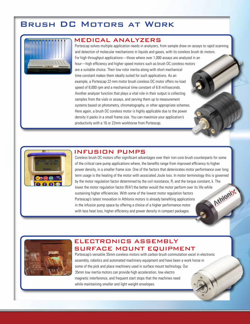
mEDICAL ANALYZERSPortescap solves multiple application needs in analyzers, from sample draw on assays to rapid scanning and detection of molecular mechanisms in liquids and gases, with its coreless brush dc motors. For high throughput applications—those where over 1,000 assays are analyzed in an hour—high efficiency and higher speed motors such as brush DC coreless motors are a suitable choice. Their low rotor inertia along with short mechanical time constant makes them ideally suited for such applications. As an example, a Portescap 22-mm motor brush coreless DC motor offers no-load speed of 8,000 rpm and a mechanical time constant of 6.8 milliseconds. Another analyzer function that plays a vital role in their output is collecting samples from the vials or assays, and serving them up to measurement systems based on photometry, chromatography, or other appropriate schemes. Here again, a brush DC coreless motor is highly applicable due to the power density it packs in a small frame size. You can maximize your application’s productivity with a 16 or 22mm workhorse from Portescap.
Brush DC motors at Work
INFUSIoN PUmPSCoreless brush DC motors offer significant advantages over their iron core brush counterparts for some of the critical care pump applications where, the benefits range from improved efficiency to higher power density, in a smaller frame size. One of the factors that deteriorates motor performance over long term usage is the heating of the motor with associated Joule loss. In motor terminology this is governed by the motor regulation factor determined by the coil resistance, R, and the torque constant, k. The lower the motor regulation factor (R/k2) the better would the motor perform over its life while sustaining higher efficiencies. With some of the lowest motor regulation factors Portescap’s latest innovation in Athlonix motors is already benefiting applications in the infusion pump space by offering a choice of a higher performance motor with less heat loss, higher efficiency and power density in compact packages.
ELECtRoNICS ASSEmBLY SURFACE moUNt EQUIPmENtPortescap’s versatile 35mm coreless motors with carbon brush commutation excel in electronic assembly, robotics and automated machinery equipment and have been a work horse in some of the pick and place machinery used in surface mount technology. Our 35mm low inertia motors can provide high acceleration, low electro magnetic interference, and frequent start stops that the machines need while maintaining smaller and light weight envelopes.

61www.portescap.com
Miniature Motors
Notes
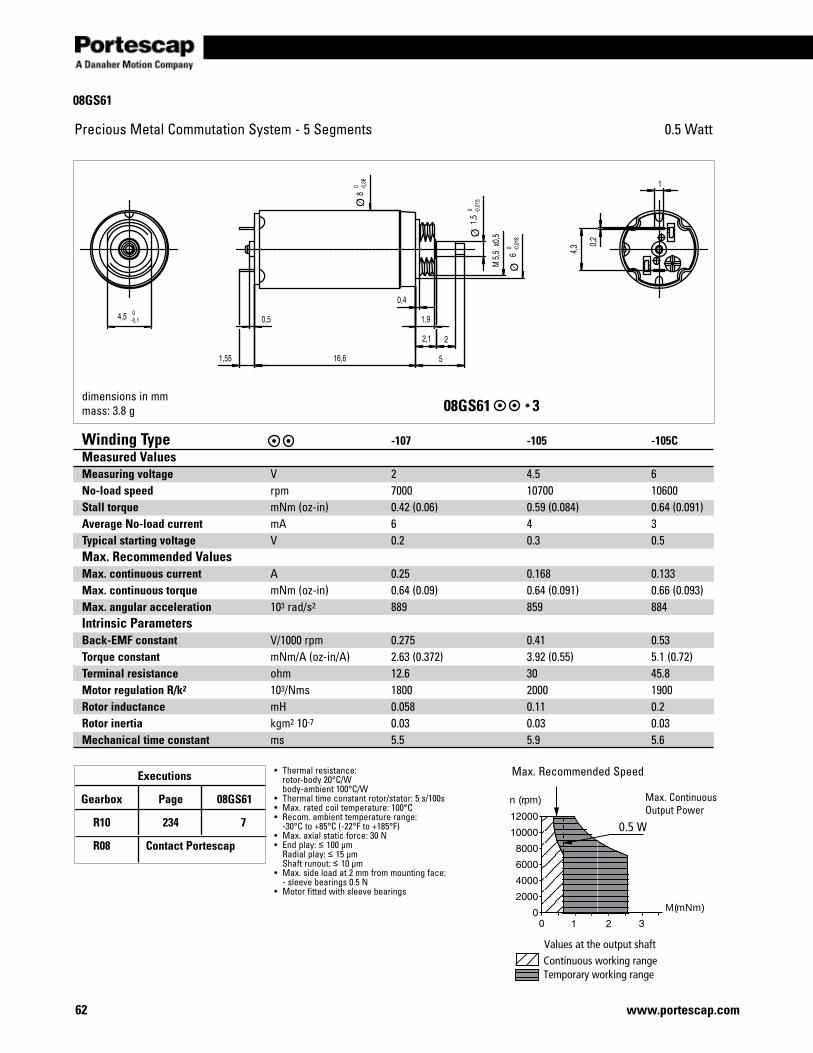
Executions
Gearbox Page 08GS61
R10 234 7
R08 Contact Portescap
62 www.portescap.com
Precious Metal Commutation System - 5 Segments 0.5 Watt
dimensions in mmmass: 3.8 g 08GS61 3
Continuous working rangeTemporary working range
Values at the output shaft
M(mNm)
n (rpm)
0.5 W
• Thermalresistance: rotor-body 20°C/W body-ambient 100°C/W• Thermaltimeconstantrotor/stator:5s/100s• Max.ratedcoiltemperature:100°C• Recom.ambienttemperaturerange: -30°C to +85°C (-22°F to +185°F)• Max.axialstaticforce:30N• Endplay:≤ 100 µm Radialplay:≤ 15 µm Shaftrunout:≤ 10 µm• Max.sideloadat2mmfrommountingface: -sleevebearings0.5N• Motorfittedwithsleevebearings
Max.RecommendedSpeed
Max.ContinuousOutputPower
Winding Type -107 -105 -105CMeasured ValuesMeasuring voltage V 2 4.5 6No-load speed rpm 7000 10700 10600Stall torque mNm(oz-in) 0.42 (0.06) 0.59 (0.084) 0.64 (0.091)Average No-load current mA 6 4 3Typical starting voltage V 0.2 0.3 0.5Max. Recommended Values Max. continuous current A 0.25 0.168 0.133Max. continuous torque mNm(oz-in) 0.64 (0.09) 0.64 (0.091) 0.66 (0.093)Max. angular acceleration 103 rad/s2 889 859 884Intrinsic ParametersBack-EMF constant V/1000rpm 0.275 0.41 0.53Torque constant mNm/A(oz-in/A) 2.63 (0.372) 3.92 (0.55) 5.1 (0.72)Terminal resistance ohm 12.6 30 45.8Motor regulation R/k2 103/Nms 1800 2000 1900Rotor inductance mH 0.058 0.11 0.2Rotor inertia kgm2 10-7 0.03 0.03 0.03Mechanical time constant ms 5.5 5.9 5.6
08GS61
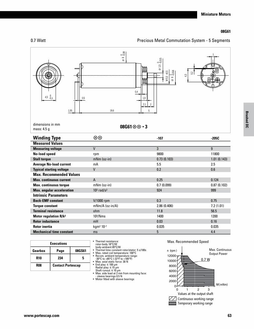
Miniature Motors
63www.portescap.com
Brushed D
C
08G61
Precious Metal Commutation System - 5 Segments0.7 Watt
Continuous working rangeTemporary working range
Values at the output shaft
M(mNm)
n (rpm )
0.7 W
Max.RecommendedSpeed
Max.ContinuousOutputPower
0,54,5 0-0,1
0,2
4,3
1,55 19,6
1,5
0 -0,0
15
1,9
0,4
2
5
2,1
1
8 0 -0
,08
5,5
Mx0
,5
6 0 -0
,018
dimensions in mmmass: 4.5 g 08G61 3
Winding Type -107 -205C Measured ValuesMeasuring voltage V 3 9No-load speed rpm 9800 11800Stall torque mNm(oz-in) 0.73 (0.103) 1.01 (0.143)Average No-load current mA 5.5 2.5Typical starting voltage V 0.2 0.6Max. Recommended Values Max. continuous current A 0.25 0.124Max. continuous torque mNm(oz-in) 0.7 (0.099) 0.87 (0.102)Max. angular acceleration 103 rad/s2 924 999Intrinsic ParametersBack-EMF constant V/1000rpm 0.3 0.75Torque constant mNm/A(oz-in/A) 2.86 (0.406) 7.2 (1.01)Terminal resistance ohm 11.8 56.5Motor regulation R/k2 103/Nms 1400 1200Rotor inductance mH 0.03 0.16Rotor inertia kgm2 10-7 0.035 0.035Mechanical time constant ms 5 4.4
• Thermalresistance: rotor-body 18°C/W body-ambient 85ºC/W• Thermaltimeconstantrotor/stator:5s/100s• Max.ratedcoiltemperature:100°C• Recom.ambienttemperaturerange: -30°C to +85°C (-22°F to +185°F)• Max.axialstaticforce:30N• Endplay:≤ 100 µm Radialplay:≤ 15 µm Shaftrunout:≤ 10 µm• Max.sideloadat2mmfrommountingface: -sleevebearings0.5N• Motorfittedwithsleevebearings
Executions
Gearbox Page 08GS61
R10 234 5
R08 Contact Portescap
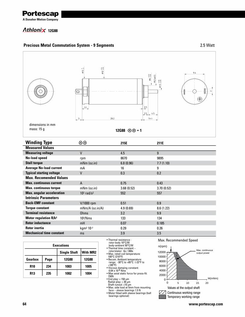
64 www.portescap.com
thloni 12G88
12G88 1
Precious Metal Commutation System - 9 Segments
•Thermalresistance: rotor-body 10°C/W body-ambient 50°C/W•Thermaltimeconstant– rotor/stator: 6s / 300s•Max.ratedcoiltemperature: 100°C (210°F)•Recom.Ambienttemperature range: -30°C to +85°C (-22°F to +185°F)•Viscousdampingconstant:0.04x10⁻⁶Nms•Maxaxialstaticforceforpress-fit:150N•Endplay:≤150μmRadialplay:≤30μmShaftrunout:≤10μm•Max.sideloadat5mmfrommountingface–sleevebearings1.5N•Motorfittedwithsleevebearings(ballbearingsoptional)
dimensions in mmmass: 15 g
Winding Type Measured Values Measuring voltageNo-load speed Stall torqueAverage No-load current Typical starting voltageMax. Recomended ValuesMax. continuous currentMax. continuous torqueMax. angular accelerationIntrinsic Parameters Back-EMF constantTorque constantTerminal resistanceMotor regulation R/k2
Rotor inductanceRotor inertiaMechanical time constant
VrpmmNm(oz.in)mAV
AmNm(oz.in)103 rad/s2
V/1000rpmmNm/A(oz.in/A)Ohms103/NmsmHkgm2 10-7
ms
215E 4.586706.8 (0.96)160.3
0.753.68 (0.52)552
0.514.9 (0.69)3.21330.070.293.9
211E 998957.7 (1.10)90.2
0.433.70 (0.52)557
0.98.6 (1.22)9.91340.1850.263.5
Max.RecommendedSpeed
105 15 20
n(rpm)
M(mNm)
Max. continuous output power
2.5 Watt
Executions
Single Shaft With MR2
Gearbox Page 12G88 12G88
R10 234 1003 1005
R13 235 1002 1004
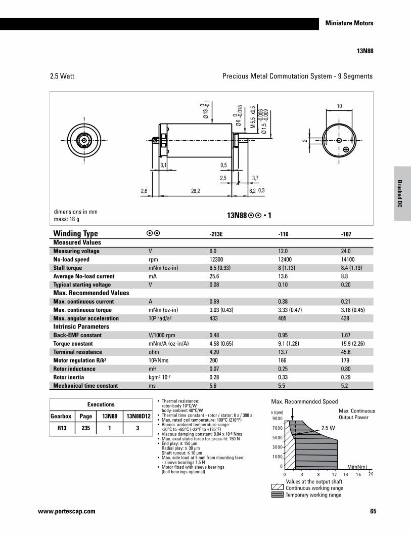
65www.portescap.com
Miniature Motors
13N88
Precious Metal Commutation System - 9 Segments2.5 Watt
dimensions in mmmass: 18 g 13N88 1
Winding Type -213E -110 -107Measured ValuesMeasuring voltage V 6.0 12.0 24.0No-load speed rpm 12300 12400 14100Stall torque mNm(oz-in) 6.5 (0.93) 8 (1.13) 8.4 (1.19)Average No-load current mA 25.6 13.6 8.8Typical starting voltage V 0.08 0.10 0.20Max. Recommended Values Max. continuous current A 0.69 0.38 0.21Max. continuous torque mNm(oz-in) 3.03 (0.43) 3.33 (0.47) 3.18 (0.45)Max. angular acceleration 103 rad/s2 433 405 438Intrinsic ParametersBack-EMF constant V/1000rpm 0.48 0.95 1.67Torque constant mNm/A(oz-in/A) 4.58 (0.65) 9.1 (1.28) 15.9 (2.26)Terminal resistance ohm 4.20 13.7 45.6Motor regulation R/k2 103/Nms 200 166 179Rotor inductance mH 0.07 0.25 0.80Rotor inertia kgm2 10-7 0.28 0.33 0.29Mechanical time constant ms 5.6 5.5 5.2
• Thermalresistance: rotor-body 10°C/W body-ambient 40°C/W• Thermaltimeconstant-rotor/stator:6s/300s• Max.ratedcoiltemperature:100°C(210°F)• Recom.ambienttemperaturerange: -30°C to +85°C (-22°F to +185°F)• Viscousdampingconstant:0.04x10⁻⁶Nms• Max.axialstaticforceforpress-fit:150N• Endplay:≤ 150 µm Radialplay:≤ 30 µm Shaftrunout:≤ 10 µm• Max.sideloadat5mmfrommountingface: -sleevebearings1.5N• Motorfittedwithsleevebearings (ballbearingsoptional)
Max.RecommendedSpeedMax.ContinuousOutputPower
Executions
Gearbox Page 13N88 13N88D12
R13 235 1 3 2.5 W
Brushed D
C
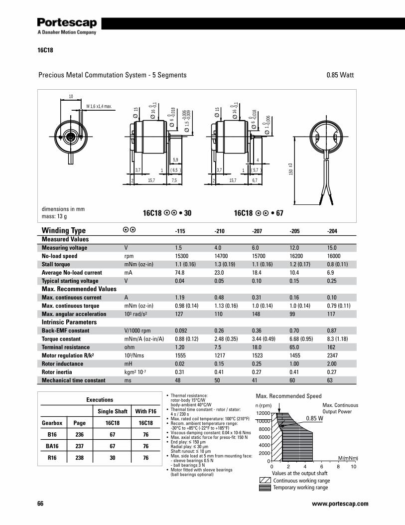
66 www.portescap.com
16C18
Values at the output shaft
Precious Metal Commutation System - 5 Segments 0.85 Watt
- +
4
3,7
5,9
10
1,6M x1,4 max.
3,7
150
±3
6,72 15,7
5,7( )16,5( )1
7,52 15,7
16 0 -0
,1
6 0 -0
,018
1 0 -0,0
06
15
1,5
-0,0
06-0
,00916
0 -0,1
6 0 -0
,01815
dimensions in mmmass: 13 g 16C18•3016C18 •67
Winding Type -115 -210 -207 -205 -204Measured ValuesMeasuring voltage V 1.5 4.0 6.0 12.0 15.0No-load speed rpm 15300 14700 15700 16200 16000Stall torque mNm(oz-in) 1.1 (0.16) 1.3 (0.19) 1.1 (0.16) 1.2 (0.17) 0.8 (0.11)Average No-load current mA 74.8 23.0 18.4 10.4 6.9Typical starting voltage V 0.04 0.05 0.10 0.15 0.25Max. Recommended Values Max. continuous current A 1.19 0.48 0.31 0.16 0.10Max. continuous torque mNm(oz-in) 0.98 (0.14) 1.13 (0.16) 1.0 (0.14) 1.0 (0.14) 0.79 (0.11)Max. angular acceleration 103 rad/s2 127 110 148 99 117Intrinsic ParametersBack-EMF constant V/1000rpm 0.092 0.26 0.36 0.70 0.87Torque constant mNm/A(oz-in/A) 0.88 (0.12) 2.48 (0.35) 3.44 (0.49) 6.68 (0.95) 8.3 (1.18)Terminal resistance ohm 1.20 7.5 18.0 65.0 162Motor regulation R/k2 103/Nms 1555 1217 1523 1455 2347Rotor inductance mH 0.02 0.15 0.25 1.00 2.00Rotor inertia kgm2 10-7 0.31 0.41 0.27 0.41 0.27Mechanical time constant ms 48 50 41 60 63
• Thermalresistance: rotor-body 15°C/W body-ambient 40°C/W• Thermaltimeconstant-rotor/stator: 4 s / 230 s• Max.ratedcoiltemperature:100°C(210°F)• Recom.ambienttemperaturerange: -30°C to +85°C (-22°F to +185°F)• Viscousdampingconstant:0.04x10⁻⁶Nms• Max.axialstaticforceforpress-fit:150N• Endplay:≤ 150 µm Radialplay:≤ 30 µm Shaftrunout:≤ 10 µm• Max.sideloadat5mmfrommountingface: -sleevebearings0.5N -ballbearings3N• Motorfittedwithsleevebearings (ballbearingsoptional)
Max.RecommendedSpeedMax.ContinuousOutputPower
Executions
Single Shaft With F16
Gearbox Page 16C18 16C18
B16 236 67 76
BA16 237 67 76
R16 238 30 76
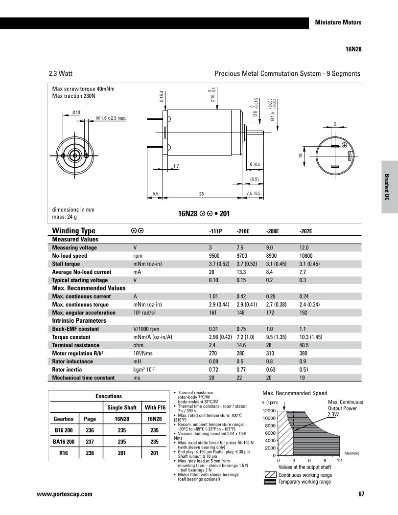
67www.portescap.com
Miniature Motors
2
10
10M 1,6 x 2,5 max.
15,4
116
68
1,5
1,7
5,5 28
(6,5)
7,5
6
16N28
Precious Metal Commutation System - 9 Segments2.3 Watt
dimensions in mmmass: 24 g 16N28•201
)
Winding Type -111P -210E -208E -207EMeasured ValuesMeasuring voltage V 3 7.5 9.0 12.0 No-load speed rpm 9500 9700 8900 10800 Stall torque mNm(oz-in) 3.7 (0.52) 3.7 (0.52) 3.1 (0.45) 3.1 (0.45) Average No-load current mA 28 13.3 8.4 7.7 Typical starting voltage V 0.10 0.15 0.2 0.3 Max. Recommended Values Max. continuous current A 1.01 0.42 0.29 0.24 Max. continuous torque mNm(oz-in) 2.9 (0.44) 2.9 (0.41) 2.7 (0.38) 2.4 (0.34) Max. angular acceleration 103 rad/s2 161 148 172 192 Intrinsic ParametersBack-EMF constant V/1000rpm 0.31 0.75 1.0 1.1 Torque constant mNm/A(oz-in/A) 2.96 (0.42) 7.2 (1.0) 9.5 (1.35) 10.3 (1.45) Terminal resistance ohm 2.4 14.6 28 40.5 Motor regulation R/k2 103/Nms 270 280 310 380 Rotor inductance mH 0.08 0.5 0.8 0.9 Rotor inertia kgm2 10-7 0.72 0.77 0.63 0.51 Mechanical time constant ms 20 22 20 19
• Thermalresistance: rotor-body 7°C/W body-ambient 28°C/W• Thermaltimeconstant-rotor/stator: 7 s / 390 s• Max.ratedcoiltemperature:100°C(210°F)•Recom.ambienttemperaturerange: -30°C to +85°C (-22°F to +185°F)• Viscousdampingconstant:0.04x10⁻⁶Nms• Max.axialstaticforceforpress-fit:100N (withsleevebearingonly)• Endplay:≤150µmRadialplay:≤ 30 µm Shaftrunout:≤ 10 µm• Max.sideloadat5mmfrom mountingface:-sleevebearings1.5N -ballbearings3N• Motorfittedwithsleevebearings (ballbearingsoptional)
Max.RecommendedSpeedMax.ContinuousOutputPower
Executions
Single Shaft With F16
Gearbox Page 16N28 16N28
B16 200 236 235 235
BA16 200 237 235 235
R16 238 201 201
Maxscrewtorque40mNmMaxtraction230N
Brushed D
C
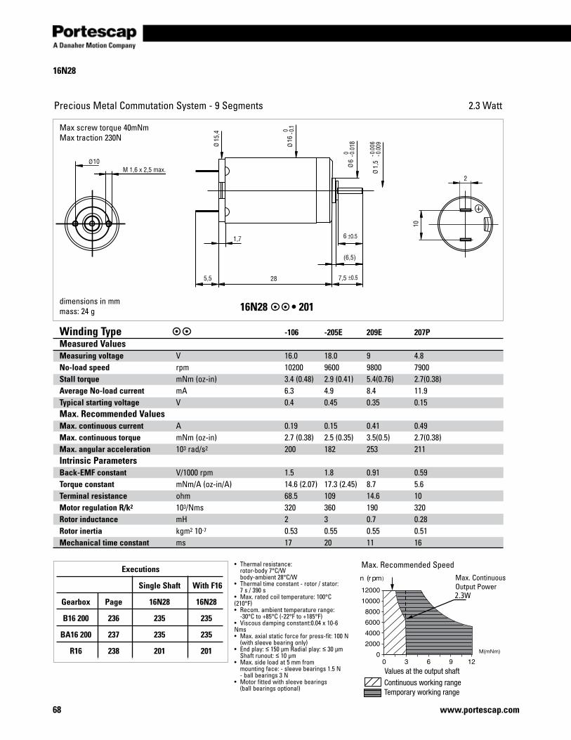
68 www.portescap.com
2
10
10M 1,6 x 2,5 max.
15,4
116
68
1,5
1,7
5,5 28
(6,5)
7,5
6
16N28
Precious Metal Commutation System - 9 Segments 2.3 Watt
dimensions in mmmass: 24 g 16N28 •201
)
Winding Type -106 -205E 209E 207PMeasured ValuesMeasuring voltage V 16.0 18.0 9 4.8No-load speed rpm 10200 9600 9800 7900Stall torque mNm(oz-in) 3.4 (0.48) 2.9 (0.41) 5.4(0.76) 2.7(0.38)Average No-load current mA 6.3 4.9 8.4 11.9Typical starting voltage V 0.4 0.45 0.35 0.15Max. Recommended Values Max. continuous current A 0.19 0.15 0.41 0.49Max. continuous torque mNm(oz-in) 2.7 (0.38) 2.5 (0.35) 3.5(0.5) 2.7(0.38)Max. angular acceleration 103 rad/s2 200 182 253 211Intrinsic Parameters Back-EMF constant V/1000rpm 1.5 1.8 0.91 0.59Torque constant mNm/A(oz-in/A) 14.6 (2.07) 17.3 (2.45) 8.7 5.6Terminal resistance ohm 68.5 109 14.6 10Motor regulation R/k2 103/Nms 320 360 190 320Rotor inductance mH 2 3 0.7 0.28Rotor inertia kgm2 10-7 0.53 0.55 0.55 0.51Mechanical time constant ms 17 20 11 16
• Thermalresistance: rotor-body 7°C/W body-ambient 28°C/W• Thermaltimeconstant-rotor/stator: 7 s / 390 s• Max.ratedcoiltemperature:100°C(210°F)•Recom.ambienttemperaturerange: -30°C to +85°C (-22°F to +185°F)• Viscousdampingconstant:0.04x10⁻⁶Nms• Max.axialstaticforceforpress-fit:100N (withsleevebearingonly)• Endplay:≤150µmRadialplay:≤ 30 µm Shaftrunout:≤ 10 µm• Max.sideloadat5mmfrom mountingface:-sleevebearings1.5N -ballbearings3N• Motorfittedwithsleevebearings (ballbearingsoptional)
Max.RecommendedSpeedMax.ContinuousOutputPower
Executions
Single Shaft With F16
Gearbox Page 16N28 16N28
B16 200 236 235 235
BA16 200 237 235 235
R16 238 201 201
Maxscrewtorque40mNmMaxtraction230N
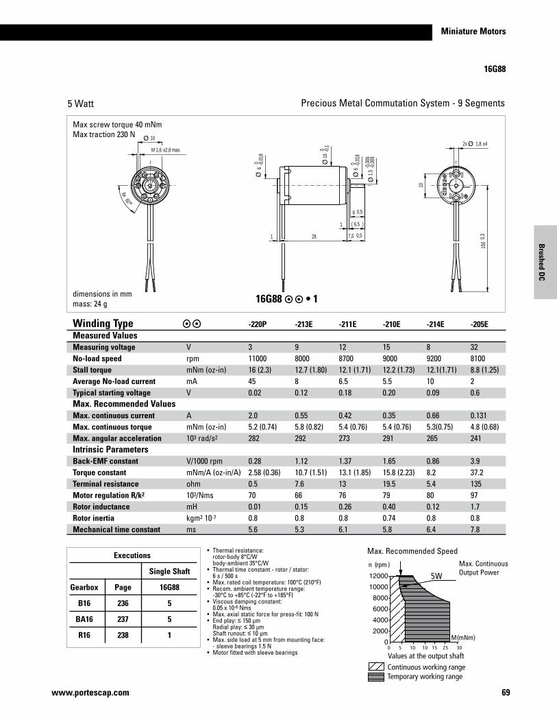
69www.portescap.com
Miniature Motors
Brushed D
C
16G88
Precious Metal Commutation System - 9 Segments5 Watt
Max.RecommendedSpeedMax.ContinuousOutputPower
150
0,3
1,82x x4
28 7,5 0,5
1
6 0,5
10
1,6M x2,8 max.
1
10
6,5( )
606x
16 0 -0
,1
6 0 -0
,018
1,5
-0,0
06-0
,009
6 0 -0
,018
dimensions in mmmass: 24 g 16G88•1
Winding Type -220P -213E -211E -210E -214E -205EMeasured ValuesMeasuring voltage V 3 9 12 15 8 32No-load speed rpm 11000 8000 8700 9000 9200 8100Stall torque mNm(oz-in) 16 (2.3) 12.7 (1.80) 12.1 (1.71) 12.2 (1.73) 12.1(1.71) 8.8 (1.25)Average No-load current mA 45 8 6.5 5.5 10 2Typical starting voltage V 0.02 0.12 0.18 0.20 0.09 0.6Max. Recommended Values Max. continuous current A 2.0 0.55 0.42 0.35 0.66 0.131Max. continuous torque mNm(oz-in) 5.2 (0.74) 5.8 (0.82) 5.4 (0.76) 5.4 (0.76) 5.3(0.75) 4.8 (0.68)Max. angular acceleration 103 rad/s2 282 292 273 291 265 241Intrinsic ParametersBack-EMF constant V/1000rpm 0.28 1.12 1.37 1.65 0.86 3.9Torque constant mNm/A(oz-in/A) 2.58 (0.36) 10.7 (1.51) 13.1 (1.85) 15.8 (2.23) 8.2 37.2Terminal resistance ohm 0.5 7.6 13 19.5 5.4 135Motor regulation R/k2 103/Nms 70 66 76 79 80 97Rotor inductance mH 0.01 0.15 0.26 0.40 0.12 1.7Rotor inertia kgm2 10-7 0.8 0.8 0.8 0.74 0.8 0.8Mechanical time constant ms 5.6 5.3 6.1 5.8 6.4 7.8
• Thermalresistance: rotor-body 8°C/W body-ambient 35°C/W• Thermaltimeconstant-rotor/stator: 6 s / 500 s• Max.ratedcoiltemperature:100°C(210°F)• Recom.ambienttemperaturerange: -30°C to +85°C (-22°F to +185°F)• Viscousdampingconstant: 0.05x10⁻⁶Nms• Max.axialstaticforceforpress-fit:100N• Endplay:≤ 150 µm Radialplay:≤ 30 µm Shaftrunout:≤ 10 µm• Max.sideloadat5mmfrommountingface: -sleevebearings1.5N• Motorfittedwithsleevebearings
Executions
Single Shaft
Gearbox Page 16G88
B16 236 5
BA16 237 5
R16 238 1
Maxscrewtorque40mNmMaxtraction230N
°
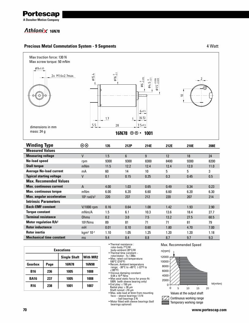
70 www.portescap.com
16N78 1001
Precious Metal Commutation System - 9 Segments
•Thermalresistance: rotor-body 7°C/W body-ambient 28°C/W•Thermaltimeconstant– rotor/stator: 7s / 390s•Max.ratedcoiltemperature: 100°C (210°F)•Recom.Ambienttemperature range: -30°C to +85°C (-22°F to +185°F)•Viscousdampingconstant:0.04x10⁻⁶Nms•Maxaxialstaticforceforpress-fit:100N(withsleevebearingonly)•Endplay:≤150μmRadialplay:≤30μmShaftrunout:≤10μm•Max.sideloadat5mmfrommountingface–sleevebearings1.5N–ballbearings3N•Motorfittedwithsleevebearings(ballbearingsoptional)
dimensions in mmmass: 24 g
Winding Type Measured Values Measuring voltageNo-load speed Stall torqueAverage No-load current Typical starting voltageMax. Recomended ValuesMax. continuous currentMax. continuous torqueMax. angular accelerationIntrinsic Parameters Back-EMF constantTorque constantTerminal resistanceMotor regulation R/k2
Rotor inductanceRotor inertiaMechanical time constant
VrpmmNmmAV
AmNm103 rad/s2
V/1000rpmmNm/AOhms103/NmsmHkgm2 10-7
ms
135 1.5930011.5600.1
4.006.00220
0.161.50.2890.011.109.4
212P 6930012.2140.15
1.036.20237
0.646.13.0810.101.058.4
214E 9830012.4100.25
0.656.60212
1.0810.37.5710.601.258.8
212E 12840012.450.3
0.496.60220
1.4213.613.2711.801.208.7
210E 18930012.050.45
0.346.20207
1.9318.427.5814.701.209.7
208E 24820011.030.5
0.236.30214
2.9027.760.5797.001.189.3
Max.RecommendedSpeed
105 15 20
n(rpm)
M(mNm)
4 Watt
Executions
Single Shaft With MR2
Gearbox Page 16N78 16N98
B16 236 1005 1008
BA16 237 1005 1008
R16 238 1001 1007
Maxtractionforce:130NMaxscrewtorque:50mNm
16N78thloni
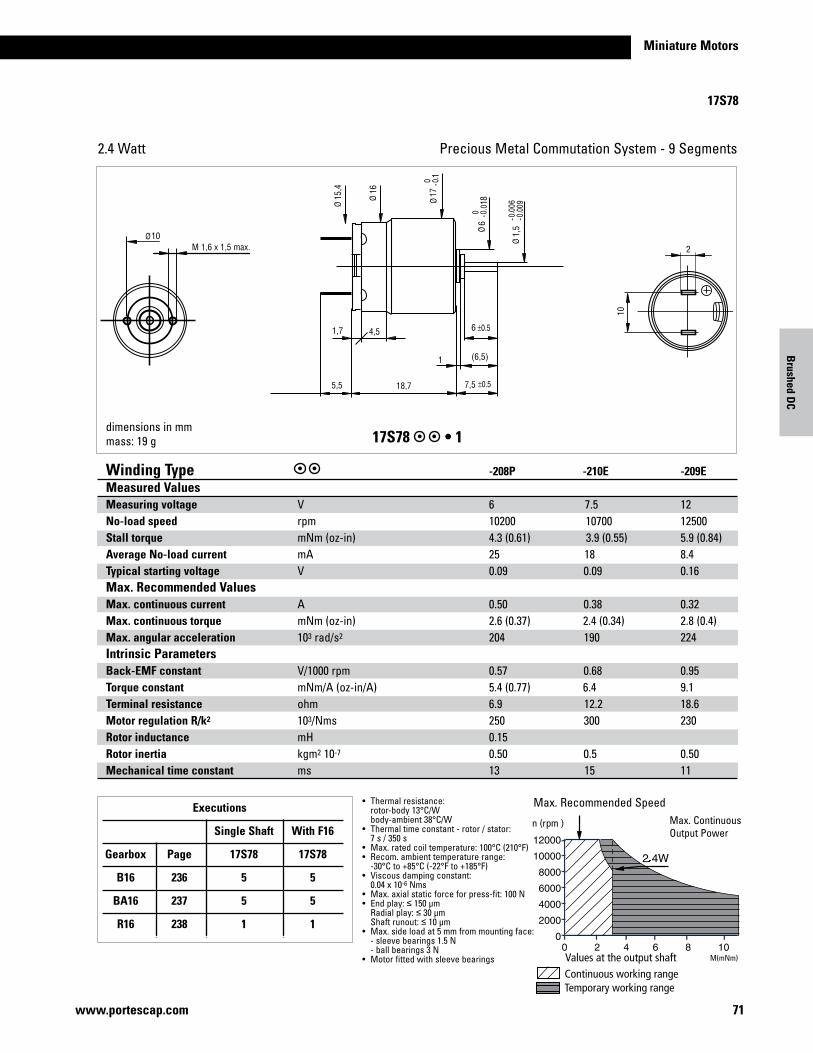
71www.portescap.com
Miniature Motors
2
10
10M 1,6 x 1,5 max.
68
1,5
4,5
5,5 18,7
(6,5)
7,5
6
11715
,4 161
1,7
17S78
Precious Metal Commutation System - 9 Segments2.4 Watt
dimensions in mmmass: 19 g 17S78•1
Continuous working rangeTemporary working range
Values at the output shaft
n (rpm )
Winding Type -208P -210E -209EMeasured ValuesMeasuring voltage V 6 7.5 12No-load speed rpm 10200 10700 12500Stall torque mNm(oz-in) 4.3 (0.61) 3.9 (0.55) 5.9 (0.84)Average No-load current mA 25 18 8.4Typical starting voltage V 0.09 0.09 0.16Max. Recommended Values Max. continuous current A 0.50 0.38 0.32Max. continuous torque mNm(oz-in) 2.6 (0.37) 2.4 (0.34) 2.8 (0.4)Max. angular acceleration 103 rad/s2 204 190 224Intrinsic ParametersBack-EMF constant V/1000rpm 0.57 0.68 0.95Torque constant mNm/A(oz-in/A) 5.4 (0.77) 6.4 9.1Terminal resistance ohm 6.9 12.2 18.6Motor regulation R/k2 103/Nms 250 300 230Rotor inductance mH 0.15 Rotor inertia kgm2 10-7 0.50 0.5 0.50Mechanical time constant ms 13 15 11
• Thermalresistance: rotor-body 13°C/W body-ambient 38°C/W• Thermaltimeconstant-rotor/stator: 7 s / 350 s• Max.ratedcoiltemperature:100°C(210°F)• Recom.ambienttemperaturerange: -30°C to +85°C (-22°F to +185°F)• Viscousdampingconstant: 0.04x10⁻⁶Nms• Max.axialstaticforceforpress-fit:100N• Endplay:≤ 150 µm Radialplay:≤ 30 µm Shaftrunout:≤ 10 µm• Max.sideloadat5mmfrommountingface: -sleevebearings1.5N -ballbearings3N• Motorfittedwithsleevebearings
Max.RecommendedSpeedMax.ContinuousOutputPower
Executions
Single Shaft With F16
Gearbox Page 17S78 17S78
B16 236 5 5
BA16 237 5 5
R16 238 1 1
M(mNm)
Brushed D
C
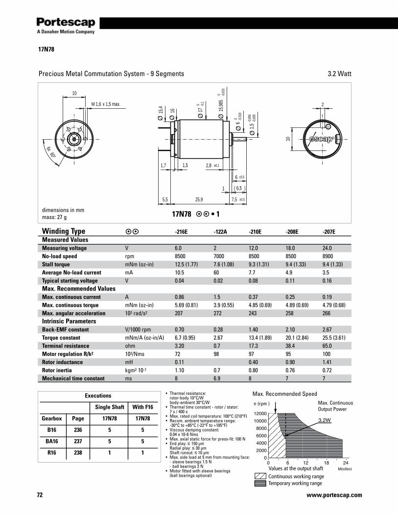
72 www.portescap.com
17N78
Precious Metal Commutation System - 9 Segments 3.2 Watt
Continuous working rangeTemporary working range
Values at the output shaft
n (rpm )
Max.RecommendedSpeedMax.ContinuousOutputPower
1,6M x 1,5 max.
10
6 ±0,5
5,5
2
10
2,8 ±0,1
1 6,5( )
7,5 ±0,525,9
60°6x
1,7 1,515
,4
1,5
-0,0
06-0
,009
6 0 -0
,018
17 0 -0
,1
16 15,9
85 0 -0
,015
17N78 •1
Winding Type -216E -122A -210E -208E -207EMeasured ValuesMeasuring voltage V 6.0 2 12.0 18.0 24.0No-load speed rpm 8500 7000 8500 8500 8900Stall torque mNm(oz-in) 12.5 (1.77) 7.6 (1.08) 9.3 (1.31) 9.4 (1.33) 9.4 (1.33)Average No-load current mA 10.5 60 7.7 4.9 3.5Typical starting voltage V 0.04 0.02 0.08 0.11 0.16Max. Recommended Values Max. continuous current A 0.86 1.5 0.37 0.25 0.19Max. continuous torque mNm(oz-in) 5.69 (0.81) 3.9 (0.55) 4.85 (0.69) 4.89 (0.69) 4.79 (0.68)Max. angular acceleration 103 rad/s2 207 272 243 258 266Intrinsic ParametersBack-EMF constant V/1000rpm 0.70 0.28 1.40 2.10 2.67Torque constant mNm/A(oz-in/A) 6.7 (0.95) 2.67 13.4 (1.89) 20.1 (2.84) 25.5 (3.61)Terminal resistance ohm 3.20 0.7 17.3 38.4 65.0Motor regulation R/k2 103/Nms 72 98 97 95 100Rotor inductance mH 0.11 0.40 0.90 1.41Rotor inertia kgm2 10-7 1.10 0.7 0.80 0.76 0.72Mechanical time constant ms 8 6.9 8 7 7
• Thermalresistance: rotor-body 10°C/W body-ambient 30°C/W• Thermaltimeconstant-rotor/stator: 7 s / 400 s• Max.ratedcoiltemperature:100°C(210°F)• Recom.ambienttemperaturerange: -30°C to +85°C (-22°F to +185°F)• Viscousdampingconstant: 0.04x10⁻⁶Nms• Max.axialstaticforceforpress-fit:100N• Endplay:≤ 150 µm Radialplay:≤ 30 µm Shaftrunout:≤ 10 µm• Max.sideloadat5mmfrommountingface: -sleevebearings1.5N -ballbearings3N• Motorfittedwithsleevebearings (ballbearingsoptional)
Executions
Single Shaft With F16
Gearbox Page 17N78 17N78
B16 236 5 5
BA16 237 5 5
R16 238 1 1
dimensions in mmmass: 27 g
M(mNm)
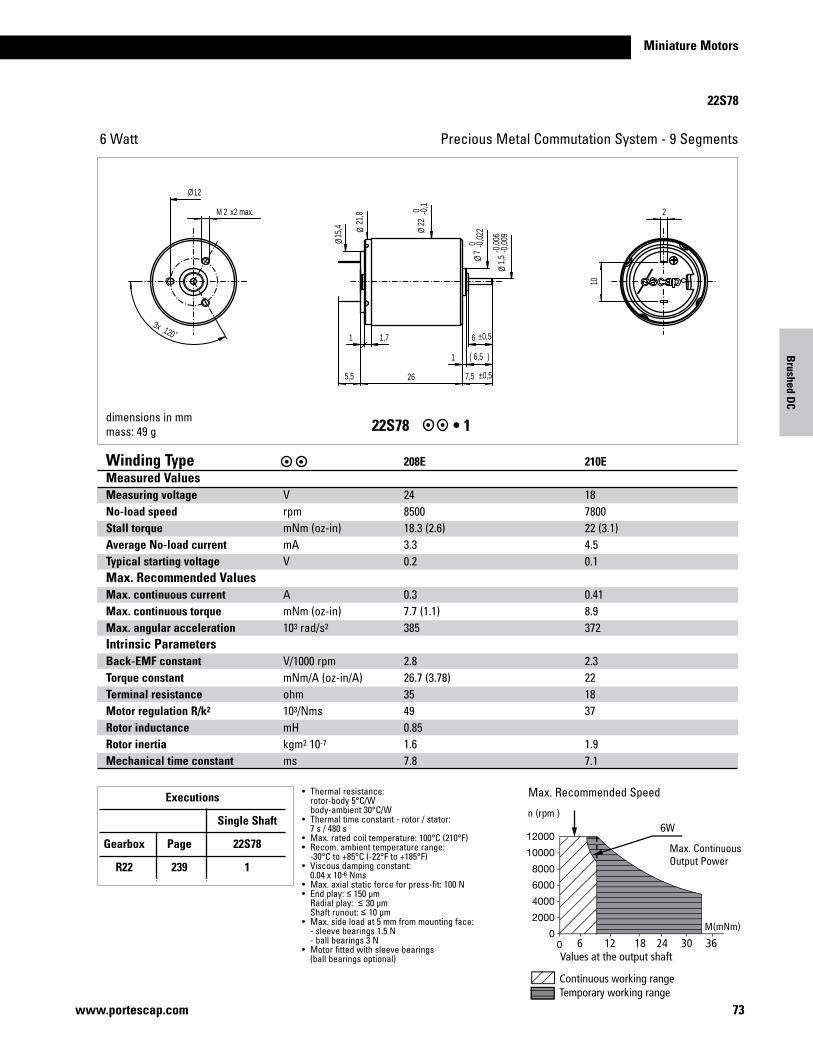
73www.portescap.com
Miniature Motors
M(mNm)
22S78
Precious Metal Commutation System - 9 Segments6 Watt
1 6,5( )
10
22M x2 max.
6 ±0,5
7,5 ±0,55,5 26
120˚3x
1 1,7
12
15,4
1,5
-0,0
06-0
,009
7 0 -0
,022
22 0 -0
,1
21,8
Ø
Ø
Ø Ø
Ø
Ø
dimensions in mmmass: 49 g 22S78 •1
Continuous working rangeTemporary working range
Values at the output shaft
M(mNm)
n (rpm )
6 12 18 24 30 36
6W
Winding Type 208E 210EMeasured ValuesMeasuring voltage V 24 18No-load speed rpm 8500 7800Stall torque mNm(oz-in) 18.3 (2.6) 22 (3.1)Average No-load current mA 3.3 4.5Typical starting voltage V 0.2 0.1Max. Recommended Values Max. continuous current A 0.3 0.41Max. continuous torque mNm(oz-in) 7.7 (1.1) 8.9Max. angular acceleration 103 rad/s2 385 372Intrinsic ParametersBack-EMF constant V/1000rpm 2.8 2.3 Torque constant mNm/A(oz-in/A) 26.7 (3.78) 22 Terminal resistance ohm 35 18 Motor regulation R/k2 103/Nms 49 37 Rotor inductance mH 0.85 Rotor inertia kgm2 10-7 1.6 1.9 Mechanical time constant ms 7.8 7.1
• Thermalresistance: rotor-body 5°C/W body-ambient 30°C/W• Thermaltimeconstant-rotor/stator: 7 s / 480 s• Max.ratedcoiltemperature:100°C(210°F)• Recom.ambienttemperaturerange: -30°C to +85°C (-22°F to +185°F)• Viscousdampingconstant: 0.04x10⁻⁶Nms• Max.axialstaticforceforpress-fit:100N• Endplay:≤ 150 µm Radialplay:≤ 30 µm Shaftrunout:≤ 10 µm• Max.sideloadat5mmfrommountingface: -sleevebearings1.5N -ballbearings3N• Motorfittedwithsleevebearings (ballbearingsoptional)
Max.RecommendedSpeed
Max.ContinuousOutputPower
Executions
Single Shaft
Gearbox Page 22S78
R22 239 1
Brushed D
C
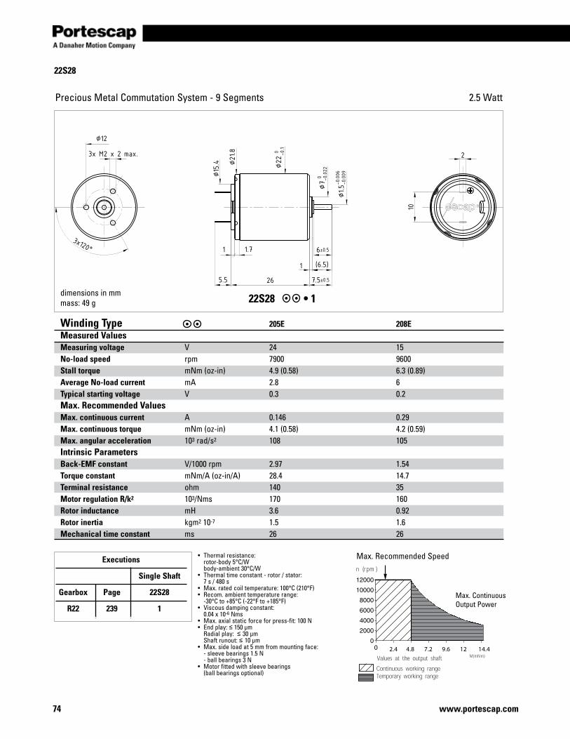
74 www.portescap.com
2.4 4.8 7.2 9.6 12 14.4
22S28
Precious Metal Commutation System - 9 Segments 2.5 Watt
dimensions in mmmass: 49 g 22S28 •1
Winding Type 205E 208E Measured ValuesMeasuring voltage V 24 15 No-load speed rpm 7900 9600 Stall torque mNm(oz-in) 4.9 (0.58) 6.3 (0.89) Average No-load current mA 2.8 6 Typical starting voltage V 0.3 0.2 Max. Recommended Values Max. continuous current A 0.146 0.29 Max. continuous torque mNm(oz-in) 4.1 (0.58) 4.2 (0.59) Max. angular acceleration 103 rad/s2 108 105 Intrinsic ParametersBack-EMF constant V/1000rpm 2.97 1.54 Torque constant mNm/A(oz-in/A) 28.4 14.7 Terminal resistance ohm 140 35 Motor regulation R/k2 103/Nms 170 160 Rotor inductance mH 3.6 0.92 Rotor inertia kgm2 10-7 1.5 1.6 Mechanical time constant ms 26 26
• Thermalresistance: rotor-body 5°C/W body-ambient 30°C/W• Thermaltimeconstant-rotor/stator: 7 s / 480 s• Max.ratedcoiltemperature:100°C(210°F)• Recom.ambienttemperaturerange: -30°C to +85°C (-22°F to +185°F)• Viscousdampingconstant: 0.04x10⁻⁶Nms• Max.axialstaticforceforpress-fit:100N• Endplay:≤ 150 µm Radialplay:≤ 30 µm Shaftrunout:≤ 10 µm• Max.sideloadat5mmfrommountingface: -sleevebearings1.5N -ballbearings3N• Motorfittedwithsleevebearings (ballbearingsoptional)
Max.RecommendedSpeed
Max.ContinuousOutputPower
Executions
Single Shaft
Gearbox Page 22S28
R22 239 1
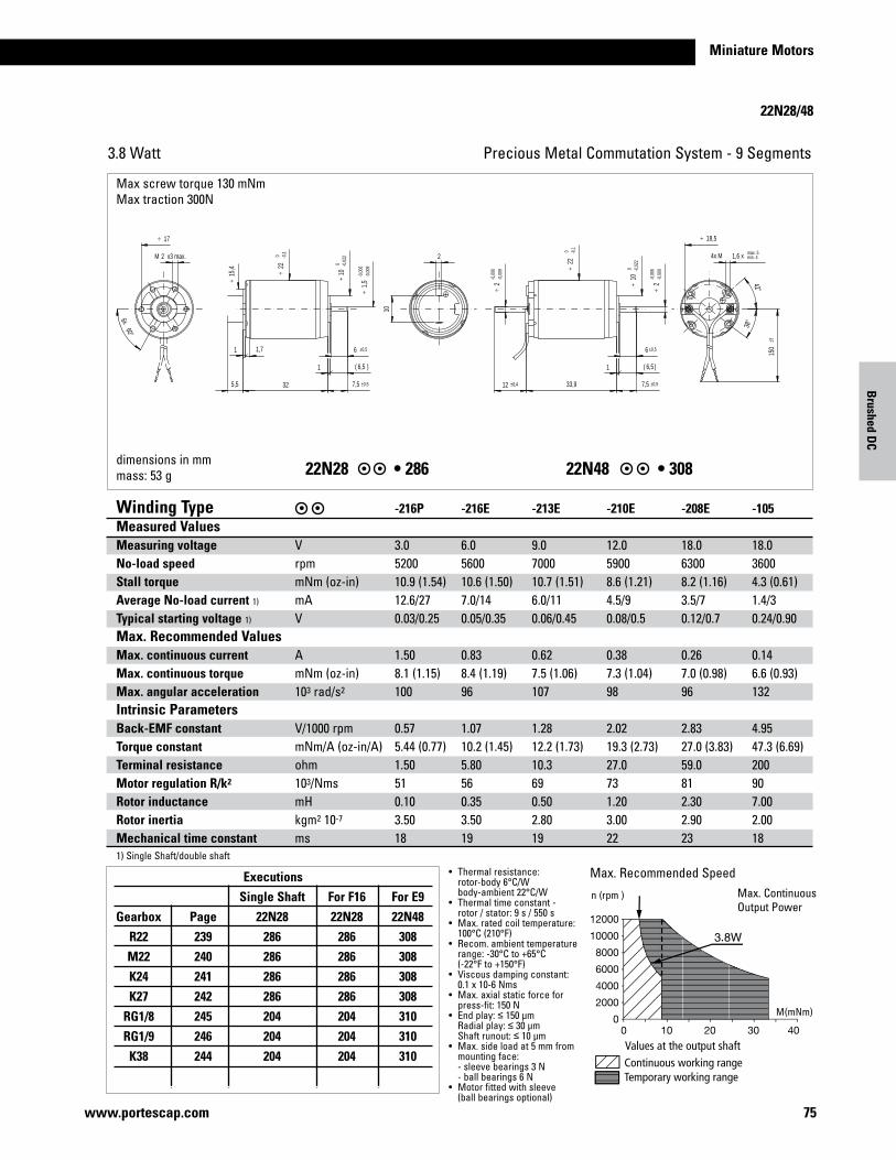
Miniature Motors
22N28/48
75www.portescap.com
Precious Metal Commutation System - 9 Segments3.8 Watt
22N28 •28622N48 •308
M(
Continuous working rangeTemporary working range
Values at the output shaft
M(mNm)
n (rpm )
Max.RecommendedSpeedMax.ContinuousOutputPower
Executions Single Shaft For F16 For E9 Gearbox Page 22N28 22N28 22N48 R22 239 286 286 308 M22 240 286 286 308 K24 241 286 286 308 K27 242 286 286 308 RG1/8 245 204 204 310 RG1/9 246 204 204 310 K38 244 204 204 310
• Thermalresistance: rotor-body 6°C/W body-ambient 22°C/W• Thermaltimeconstant- rotor / stator: 9 s / 550 s• Max.ratedcoiltemperature: 100°C (210°F)• Recom.ambienttemperature range: -30°C to +65°C (-22°F to +150°F)• Viscousdampingconstant: 0.1x10⁻⁶Nms• Max.axialstaticforcefor press-fit:150N• Endplay:≤ 150 µm Radialplay:≤ 30 µm Shaftrunout:≤ 10 µm• Max.sideloadat5mmfrom mountingface: -sleevebearings3N -ballbearings6N• Motorfittedwithsleeve (ballbearingsoptional)
Winding Type -216P -216E -213E -210E -208E -105Measured ValuesMeasuring voltage V 3.0 6.0 9.0 12.0 18.0 18.0No-load speed rpm 5200 5600 7000 5900 6300 3600Stall torque mNm(oz-in) 10.9 (1.54) 10.6 (1.50) 10.7 (1.51) 8.6 (1.21) 8.2 (1.16) 4.3 (0.61)Average No-load current 1) mA 12.6/27 7.0/14 6.0/11 4.5/9 3.5/7 1.4/3Typical starting voltage 1) V 0.03/0.25 0.05/0.35 0.06/0.45 0.08/0.5 0.12/0.7 0.24/0.90Max. Recommended Values Max. continuous current A 1.50 0.83 0.62 0.38 0.26 0.14Max. continuous torque mNm(oz-in) 8.1 (1.15) 8.4 (1.19) 7.5 (1.06) 7.3 (1.04) 7.0 (0.98) 6.6 (0.93)Max. angular acceleration 103 rad/s2 100 96 107 98 96 132Intrinsic ParametersBack-EMF constant V/1000rpm 0.57 1.07 1.28 2.02 2.83 4.95Torque constant mNm/A(oz-in/A) 5.44 (0.77) 10.2 (1.45) 12.2 (1.73) 19.3 (2.73) 27.0 (3.83) 47.3 (6.69)Terminal resistance ohm 1.50 5.80 10.3 27.0 59.0 200Motor regulation R/k2 103/Nms 51 56 69 73 81 90Rotor inductance mH 0.10 0.35 0.50 1.20 2.30 7.00Rotor inertia kgm2 10-7 3.50 3.50 2.80 3.00 2.90 2.00Mechanical time constant ms 18 19 19 22 23 181)SingleShaft/doubleshaft
Brushed D
C
dimensions in mmmass: 53 g
Maxscrewtorque130mNmMaxtraction300N
max. 5min. 4
33,9
6 ±0,5
7,5 ±0,5
2-0
,006
-0,0
09÷
12 ±0,4
2-0
,006
-0,0
09÷
2M x3 max. 2
10
6 ±0,5
1,64x M x
150
±3
7,5 ±0,55,5
42°
38°
60°6x
1 6,5( )
1,71
1 6,5( )
32
22 0 -0
,1÷
10 0 -0
,022
÷
15,4
÷
1,5
-0,0
06-0
,009
÷
10 0 -0
,022
÷
22 0 -0
,1÷
18,5÷17÷
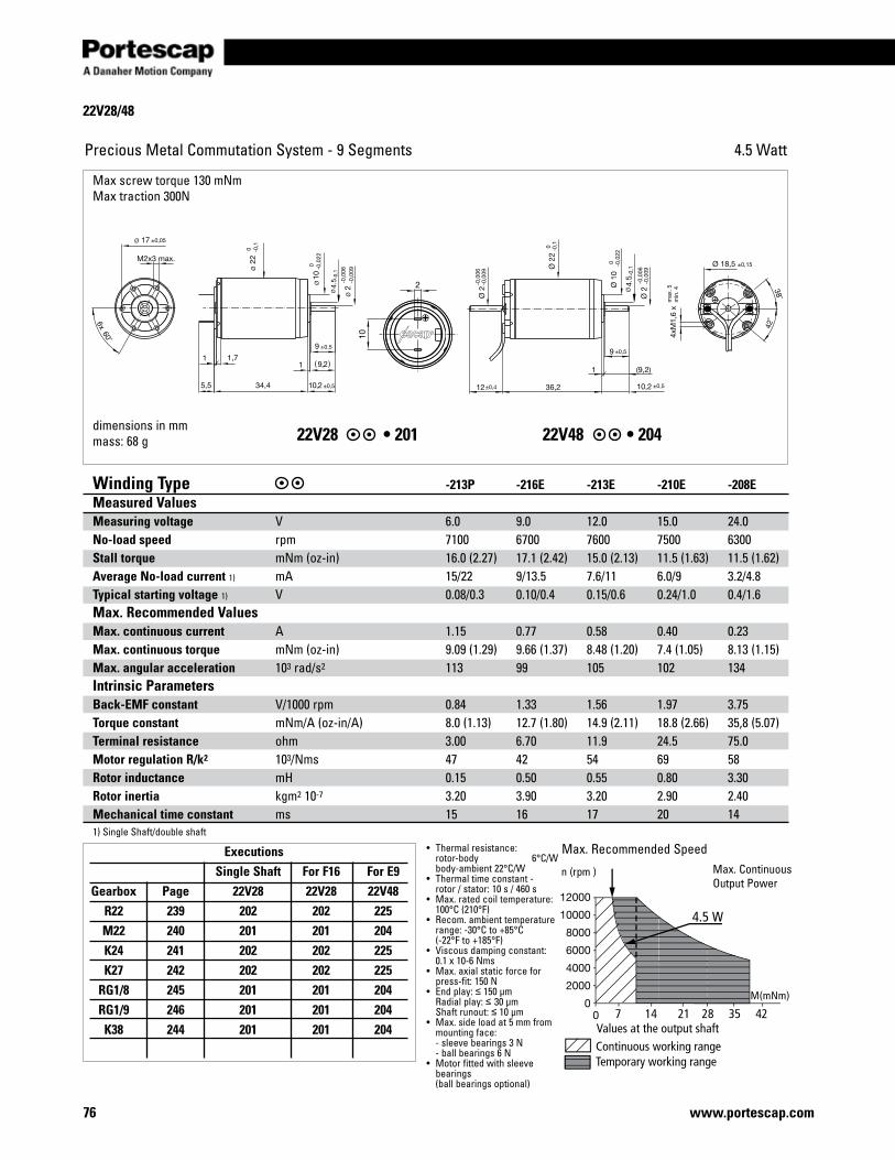
22V28/48
76 www.portescap.com
Precious Metal Commutation System - 9 Segments 4.5 Watt
4.5
4.5
dimensions in mmmass: 68 g 22V28 •20122V48•204
Continuous working rangeTemporary working range
Values at the output shaft
M(mNm)
n (rpm )
7 14 21 28 35 42
4.5 W
• Thermalresistance: rotor-body 6°C/W body-ambient 22°C/W• Thermaltimeconstant- rotor / stator: 10 s / 460 s• Max.ratedcoiltemperature: 100°C (210°F)• Recom.ambienttemperature range: -30°C to +85°C (-22°F to +185°F)• Viscousdampingconstant: 0.1x10⁻⁶Nms• Max.axialstaticforcefor press-fit:150N• Endplay:≤ 150 µm Radialplay:≤ 30 µm Shaftrunout:≤ 10 µm• Max.sideloadat5mmfrom mountingface: -sleevebearings3N -ballbearings6N• Motorfittedwithsleeve bearings (ballbearingsoptional)
Max.RecommendedSpeedExecutions Single Shaft For F16 For E9 Gearbox Page 22V28 22V28 22V48 R22 239 202 202 225 M22 240 201 201 204 K24 241 202 202 225 K27 242 202 202 225 RG1/8 245 201 201 204 RG1/9 246 201 201 204 K38 244 201 201 204
Winding Type -213P -216E -213E -210E -208EMeasured ValuesMeasuring voltage V 6.0 9.0 12.0 15.0 24.0No-load speed rpm 7100 6700 7600 7500 6300Stall torque mNm(oz-in) 16.0 (2.27) 17.1 (2.42) 15.0 (2.13) 11.5 (1.63) 11.5 (1.62)Average No-load current 1) mA 15/22 9/13.5 7.6/11 6.0/9 3.2/4.8Typical starting voltage 1) V 0.08/0.3 0.10/0.4 0.15/0.6 0.24/1.0 0.4/1.6Max. Recommended Values Max. continuous current A 1.15 0.77 0.58 0.40 0.23Max. continuous torque mNm(oz-in) 9.09 (1.29) 9.66 (1.37) 8.48 (1.20) 7.4 (1.05) 8.13 (1.15)Max. angular acceleration 103 rad/s2 113 99 105 102 134Intrinsic ParametersBack-EMF constant V/1000rpm 0.84 1.33 1.56 1.97 3.75Torque constant mNm/A(oz-in/A) 8.0 (1.13) 12.7 (1.80) 14.9 (2.11) 18.8 (2.66) 35,8 (5.07)Terminal resistance ohm 3.00 6.70 11.9 24.5 75.0Motor regulation R/k2 103/Nms 47 42 54 69 58Rotor inductance mH 0.15 0.50 0.55 0.80 3.30Rotor inertia kgm2 10-7 3.20 3.90 3.20 2.90 2.40Mechanical time constant ms 15 16 17 20 141)SingleShaft/doubleshaft
Max.ContinuousOutputPower
Maxscrewtorque130mNmMaxtraction300N
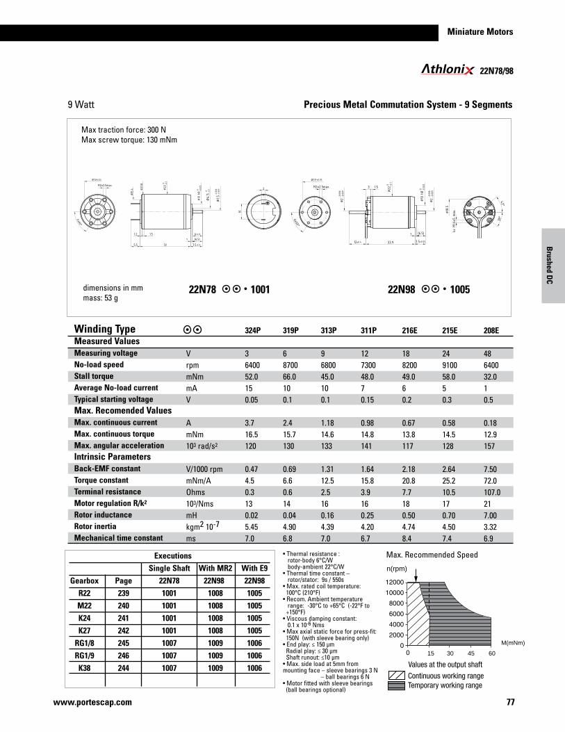
Miniature Motors
77www.portescap.com
Brushed D
C
22N78/98
22N78 22N981001 1005
Precious Metal Commutation System - 9 Segments
•Thermalresistance: rotor-body 6°C/W body-ambient 22°C/W•Thermaltimeconstant– rotor/stator: 9s / 550s•Max.ratedcoiltemperature: 100°C (210°F)•Recom.Ambienttemperature range: -30°C to +65°C (-22°F to +150°F)•Viscousdampingconstant:0.1x10⁻⁶Nms•Maxaxialstaticforceforpress-fit:150N(withsleevebearingonly)•Endplay:≤150μmRadialplay:≤30μmShaftrunout:≤10μm•Max.sideloadat5mmfrom mountingface–sleevebearings3N–ballbearings6N•Motorfittedwithsleevebearings(ballbearingsoptional)
dimensions in mmmass: 53 g
Winding Type Measured Values Measuring voltageNo-load speed Stall torqueAverage No-load current Typical starting voltageMax. Recomended ValuesMax. continuous currentMax. continuous torqueMax. angular accelerationIntrinsic Parameters Back-EMF constantTorque constantTerminal resistanceMotor regulation R/k2
Rotor inductanceRotor inertiaMechanical time constant
VrpmmNmmAV
AmNm103 rad/s2
V/1000rpmmNm/AOhms103/NmsmHkgm2 10-7
ms
324P 3640052.0150.05
3.716.5120
0.474.50.3130.025.457.0
319P 6870066.0100.1
2.415.7130
0.696.60.6140.044.906.8
313P 9680045.0100.1
1.1814.6133
1.3112.52.5160.164.397.0
311P 12730048.070.15
0.9814.8141
1.6415.83.9160.254.206.7
216E 18820049.060.2
0.6713.8117
2.1820.87.7180.504.748.4
215E 24910058.050.3
0.5814.5128
2.6425.210.5170.704.507.4
208E 48640032.010.5
0.1812.9157
7.5072.0107.0217.003.326.9
Max.RecommendedSpeed
3015 45 60
n(rpm)
M(mNm)
9 Watt
Maxtractionforce:300NMaxscrewtorque:130mNm
Executions Single Shaft With MR2 With E9 Gearbox Page 22N78 22N98 22N98 R22 239 1001 1008 1005 M22 240 1001 1008 1005 K24 241 1001 1008 1005 K27 242 1001 1008 1005 RG1/8 245 1007 1009 1006 RG1/9 246 1007 1009 1006 K38 244 1007 1009 1006
thloni
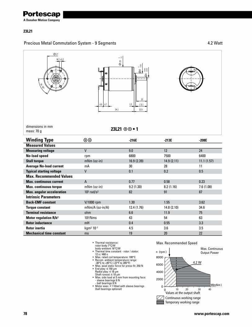
78 www.portescap.com
23L21
Precious Metal Commutation System - 9 Segments 4.2 Watt
10
1,5 11( )
12,534,1
2M x2,2
60°6x
4,6 4,7
23
0 -0,1
10
0 -0,0
22
3-0
,006
-0,0
09
17
23L21 •1
Continuous working rangeTemporary working range
Values at the output shaft
n (rpm )
M(mNm )10 20 30 40
4.2
Winding Type -216E -213E -208E Measured ValuesMeasuring voltage V 9.0 12 24No-load speed rpm 6800 7500 6400Stall torque mNm(oz-in) 16.9 (2.39) 14.9 (2.11) 11.1 (1.57)Average No-load current mA 30 28 11Typical starting voltage V 0.1 0.2 0.5Max. Recommended Values Max. continuous current A 0.77 0.58 0.23Max. continuous torque mNm(oz-in) 9.2 (1.30) 8.2 (1.16) 7.6 (1.08)Max. angular acceleration 103 rad/s2 82 91 87Intrinsic ParametersBack-EMF constant V/1000rpm 1.30 1.55 3.62Torque constant mNm/A(oz-in/A) 12.4 (1.76) 14.8 (2.10) 34.6Terminal resistance ohm 6.6 11.9 75Motor regulation R/k2 103/Nms 43 54 63Rotor inductance mH 0.4 0.55 3.3Rotor inertia kgm2 10-7 4.5 3.6 3.5Mechanical time constant ms 19 20 22
• Thermalresistance: rotor-body 7°C/W body-ambient 16°C/W• Thermaltimeconstant-rotor/stator: 12 s / 460 s • Max.ratedcoiltemperature:100°C• Recom.ambienttemperaturerange: -30°C to +85°C (-22°F to 285°F)• Max.axialstaticforceforpress-fit:250N• Endplay:≤ 150 µm Radialplay:≤ 18 µm Shaftrunout:≤ 10 µm• Max.sideloadat5mmfrommountingface: -sleevebearings6N -ballbearings8N• Motorexec.•1fittedwithsleevebearings (ballbearingsoptional)
Max.RecommendedSpeedMax.ContinuousOutputPower
dimensions in mmmass: 70 g
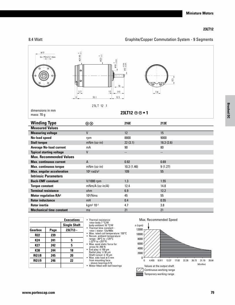
Miniature Motors
79www.portescap.com
Brushed D
C
Executions Single Shaft Gearbox Page 23LT12-- R22 239 K24 241 5 K27 242 5 K38 244 18 RG1/8 245 20 RG1/9 246 22
23LT12
Graphite/CopperCommutationSystem-9Segments8.4 Watt
23LT12 •1
Values at the output shaftContinuous working rangeTemporary working range
0 4.455 8.911 13.37 17.82 22.28 26.73 31.19 35.64
n (rpm)12000
10000
8000
6000
4000
2000
0
Winding Type 216E 213E Measured ValuesMeasuring voltage V 12 15 No-load speed rpm 8800 9000 Stall torque mNm(oz-in) 22 (3.1) 18.3 (2.6) Average No-load current mA 90 80 Typical starting voltage V -- -- Max. Recommended Values Max. continuous current A 0.92 0.69 Max. continuous torque mNm(oz-in) 10.3 (1.46) 9 (1.27) Max. angular acceleration 103 rad/s2 109 55 Intrinsic ParametersBack-EMF constant V/1000rpm 1.3 1.55 Torque constant mNm/A(oz-in/A) 12.4 14.8 Terminal resistance ohm 6.9 12.2 Motor regulation R/k2 103/Nms 45 55 Rotor inductance mH 0.4 0.55 Rotor inertia kgm2 10-7 4.7 3.8 Mechanical time constant ms 21 21
• Thermalresistance: rotor-body 7 °C/W body-ambient 16 °C/W• Thermaltimeconstant- rotor / stator: 12s/460s• Max.ratedcoiltemperature:155°C• Recom.ambienttemperature range: -30°C to +125°C (-22°F to +257°F)• Max.axialstaticforceforpress-fit:250N• Endplay:≤ 150 µm Radialplay:≤ 30 µm Shaftrunout:≤ 10 µm• Max.sideloadat5mmfrommountingface -sleevebearings6N• Motorfittedwithballbearings
Max.RecommendedSpeed
dimensions in mmmass: 70 g
M(mNm)
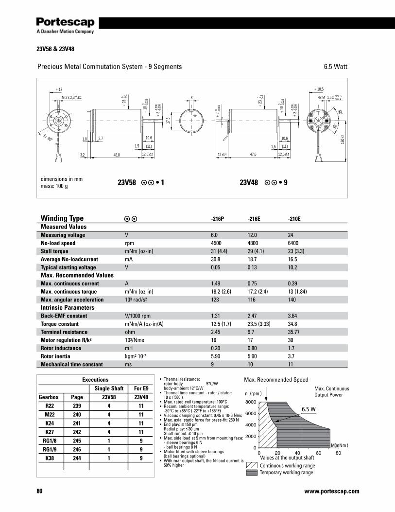
80 www.portescap.com
23V58 & 23V48
Executions Single Shaft For E9 Gearbox Page 23V58 23V48 R22 239 4 11 M22 240 4 11 K24 241 4 11 K27 242 4 11 RG1/8 245 1 9 RG1/9 246 1 9 K38 244 1 9
Precious Metal Commutation System - 9 Segments 6.5 Watt
dimensions in mmmass: 100 g 23V58 •1 23V48•9
Continuous working rangeTemporary working range
Values at the output shaft
n (rpm )
M(mNm )
6.5 W
• Thermalresistance: rotor-body 5°C/W body-ambient 12°C/W• Thermaltimeconstant-rotor/stator: 10 s / 580 s• Max.ratedcoiltemperature:100°C• Recom.ambienttemperaturerange: -30°C to +85°C (-22°F to +185°F)• Viscousdampingconstant:0.45x10⁻⁶Nms• Max.axialstaticforceforpress-fit:250N• Endplay:≤ 150 µm Radialplay:≤30 µm Shaftrunout:≤ 10 µm• Max.sideloadat5mmfrommountingface: -sleevebearings6N -ballbearings8N• Motorfittedwithsleevebearings (ballbearingsoptional)• Withrearoutputshaft,theN-loadcurrentis 50%higher
Max.RecommendedSpeed
Winding Type -216P -216E -210EMeasured ValuesMeasuring voltage V 6.0 12.0 24 No-load speed rpm 4500 4800 6400 Stall torque mNm(oz-in) 31 (4.4) 29 (4.1) 23 (3.3)Average No-loadcurrent mA 30.8 18.7 16.5Typical starting voltage V 0.05 0.13 10.2 Max. Recommended ValuesMax. continuous current A 1.49 0.75 0.39 Max. continuous torque mNm(oz-in) 18.2 (2.6) 17.2 (2.4) 13 (1.84) Max. angular acceleration 103 rad/s2 123 116 140Intrinsic ParametersBack-EMF constant V/1000rpm 1.31 2.47 3.64 Torque constant mNm/A(oz-in/A) 12.5 (1.7) 23.5 (3.33) 34.8Terminal resistance ohm 2.45 9.7 35.77 Motor regulation R/k2 103/Nms 16 17 30 Rotor inductance mH 0.20 0.80 1.7 Rotor inertia kgm2 10-7 5.90 5.90 3.7 Mechanical time constant ms 9 10 11
Max.ContinuousOutputPower
max. 5min. 4
150
±3
2 0 -0
,006
÷
12 ±0,4
1,5
3,2
2M x 2,3max.
3-0
,006
-0,0
09÷
10,6
3
17,5
1,64x M x
47,648,8
3-0
,006
-0,0
09÷
10,6
11( )
12,5±0,5
11( )
12,5±0,5
60°6x
38°
42°
1,8 2,7
1,5
18,5÷17÷
10 0 -0
,022
÷
23 0 -0
,1÷
10 0 -0
,022
÷
23 0 -0
,1÷
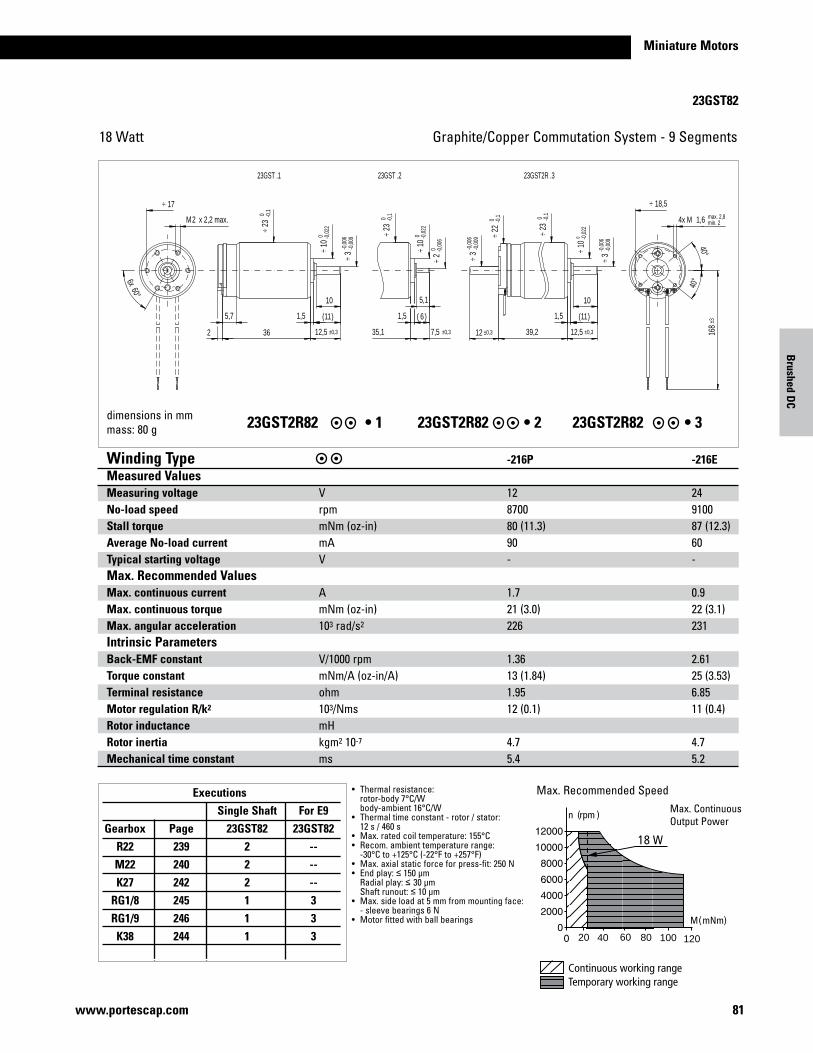
81www.portescap.com
Miniature Motors
23GST82
Graphite/CopperCommutationSystem-9Segments18 Watt
Continuous working rangeTemporary working range
M(mNm)
n (rpm )
18 W
20 40 60 80 100 120
• Thermalresistance: rotor-body 7°C/W body-ambient 16°C/W• Thermaltimeconstant-rotor/stator: 12 s / 460 s • Max.ratedcoiltemperature:155°C• Recom.ambienttemperaturerange: -30°C to +125°C (-22°F to +257°F)• Max.axialstaticforceforpress-fit:250N• Endplay:≤ 150 µm Radialplay:≤ 30 µm Shaftrunout:≤ 10 µm• Max.sideloadat5mmfrommountingface: -sleevebearings6N• Motorfittedwithballbearings
Max.RecommendedSpeedMax.ContinuousOutputPower
dimensions in mmmass: 80 g 23GST2R82 •123GST2R82 •223GST2R82 •3
Winding Type -216P -216E Measured ValuesMeasuring voltage V 12 24 No-load speed rpm 8700 9100 Stall torque mNm(oz-in) 80 (11.3) 87 (12.3) Average No-load current mA 90 60 Typical starting voltage V - - Max. Recommended Values Max. continuous current A 1.7 0.9 Max. continuous torque mNm(oz-in) 21 (3.0) 22 (3.1) Max. angular acceleration 103 rad/s2 226 231 Intrinsic ParametersBack-EMF constant V/1000rpm 1.36 2.61 Torque constant mNm/A(oz-in/A) 13 (1.84) 25 (3.53) Terminal resistance ohm 1.95 6.85 Motor regulation R/k2 103/Nms 12 (0.1) 11 (0.4) Rotor inductance mH Rotor inertia kgm2 10-7 4.7 4.7 Mechanical time constant ms 5.4 5.2
Executions Single Shaft For E9 Gearbox Page 23GST82 23GST82 R22 239 2 -- M22 240 2 -- K27 242 2 -- RG1/8 245 1 3 RG1/9 246 1 3 K38 244 1 3
23GST2R .323GST .223GST .1
max. 2,8min. 2
168
±3
1,64x M
39,212 ±0,3 12,5 ±0,3
11( )
10
1,51,5
7,5 ±0,3
5,1
2M x 2,2 max.
5,7
2 36
1,5
10
11( )
12,5 ±0,3
40°
40°
60°6x
6( )
3-0
,006
-0,0
09÷ 3
-0,0
06-0
,009
÷
10 0 -0
,022
÷
35,1
23 0 -0
,1÷
2 0 -0
,006
÷
10 0 -0
,022
÷
17÷
3-0
,006
-0,0
09÷
10 0 -0
,022
÷
18,5÷
23 0 -0
,1÷22
0 -0,1
÷
23 0 -0
,1÷
Brushed D
C
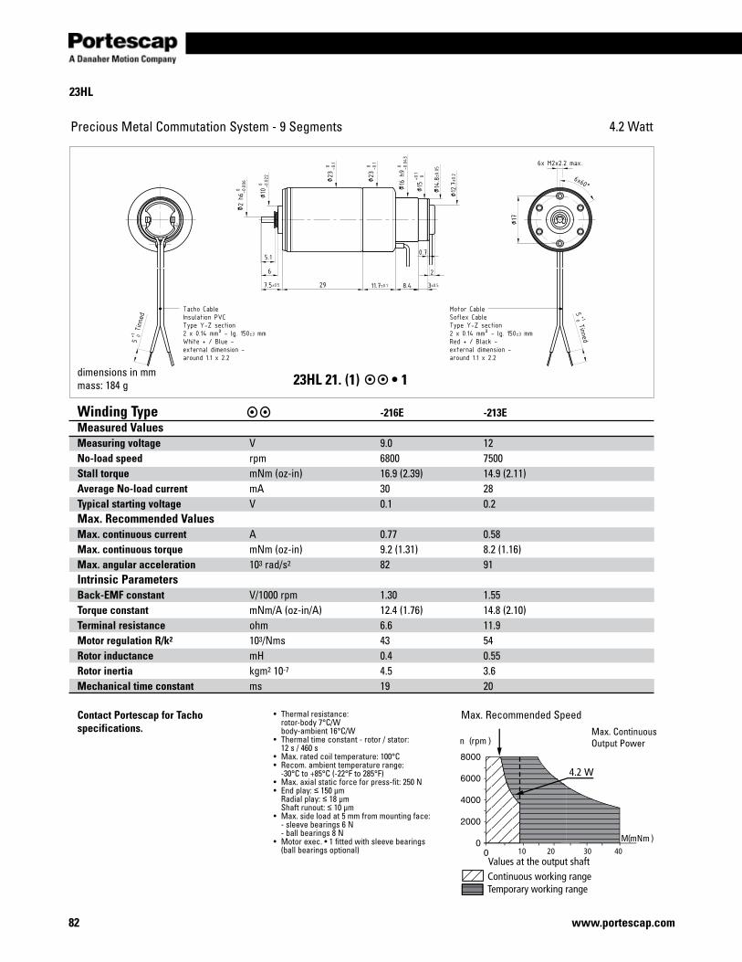
82 www.portescap.com
23HL
Precious Metal Commutation System - 9 Segments 4.2 Watt
23HL 21. (1) •1
Continuous working rangeTemporary working range
Values at the output shaft
n (rpm )
M(mNm )10 20 30 40
4.2
Winding Type -216E -213E Measured ValuesMeasuring voltage V 9.0 12 No-load speed rpm 6800 7500 Stall torque mNm(oz-in) 16.9 (2.39) 14.9 (2.11) Average No-load current mA 30 28 Typical starting voltage V 0.1 0.2 Max. Recommended Values Max. continuous current A 0.77 0.58 Max. continuous torque mNm(oz-in) 9.2 (1.31) 8.2 (1.16) Max. angular acceleration 103 rad/s2 82 91Intrinsic ParametersBack-EMF constant V/1000rpm 1.30 1.55 Torque constant mNm/A(oz-in/A) 12.4 (1.76) 14.8 (2.10) Terminal resistance ohm 6.6 11.9Motor regulation R/k2 103/Nms 43 54 Rotor inductance mH 0.4 0.55 Rotor inertia kgm2 10-7 4.5 3.6 Mechanical time constant ms 19 20
• Thermalresistance: rotor-body 7°C/W body-ambient 16°C/W• Thermaltimeconstant-rotor/stator: 12 s / 460 s • Max.ratedcoiltemperature:100°C• Recom.ambienttemperaturerange: -30°C to +85°C (-22°F to 285°F)• Max.axialstaticforceforpress-fit:250N• Endplay:≤ 150 µm Radialplay:≤ 18 µm Shaftrunout:≤ 10 µm• Max.sideloadat5mmfrommountingface: -sleevebearings6N -ballbearings8N• Motorexec.•1fittedwithsleevebearings (ballbearingsoptional)
Max.RecommendedSpeedMax.ContinuousOutputPower
dimensions in mmmass: 184 g
Contact Portescap for Tacho specifications.
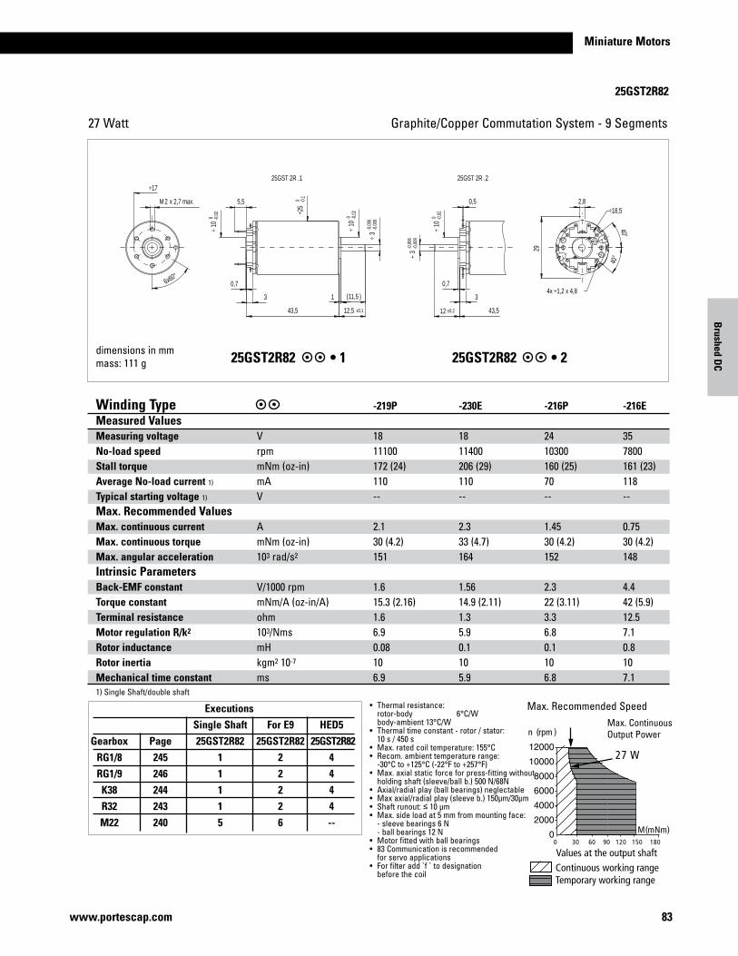
Miniature Motors
83www.portescap.com
Brushed D
C
25GST2R82
Graphite/CopperCommutationSystem-9Segments27 Watt
25GST2R82 •125GST2R82 •2
• Thermalresistance: rotor-body 6°C/W body-ambient 13°C/W• Thermaltimeconstant-rotor/stator: 10 s / 450 s• Max.ratedcoiltemperature:155°C• Recom.ambienttemperaturerange: -30°C to +125°C (-22°F to +257°F)• Max.axialstaticforceforpress-fittingwithout holdingshaft(sleeve/ballb.)500N/68N• Axial/radialplay(ballbearings)neglectable• Maxaxial/radialplay(sleeveb.)150µm/30µm•Shaftrunout:≤ 10 µm• Max.sideloadat5mmfrommountingface: -sleevebearings6N -ballbearings12N• Motorfittedwithballbearings• 83Communicationisrecommended forservoapplications• Forfilteradd`f`todesignation beforethecoil
Max.RecommendedSpeed
dimensions in mmmass: 111 g
Max.ContinuousOutputPower
Winding Type -219P -230E -216P -216E Measured ValuesMeasuring voltage V 18 18 24 35 No-load speed rpm 11100 11400 10300 7800 Stall torque mNm(oz-in) 172 (24) 206 (29) 160 (25) 161 (23) Average No-load current 1) mA 110 110 70 118 Typical starting voltage 1) V -- -- -- -- Max. Recommended Values Max. continuous current A 2.1 2.3 1.45 0.75 Max. continuous torque mNm(oz-in) 30 (4.2) 33 (4.7) 30 (4.2) 30 (4.2) Max. angular acceleration 103 rad/s2 151 164 152 148 Intrinsic ParametersBack-EMF constant V/1000rpm 1.6 1.56 2.3 4.4 Torque constant mNm/A(oz-in/A) 15.3 (2.16) 14.9 (2.11) 22 (3.11) 42 (5.9) Terminal resistance ohm 1.6 1.3 3.3 12.5 Motor regulation R/k2 103/Nms 6.9 5.9 6.8 7.1 Rotor inductance mH 0.08 0.1 0.1 0.8 Rotor inertia kgm2 10-7 10 10 10 10 Mechanical time constant ms 6.9 5.9 6.8 7.11)SingleShaft/doubleshaft
÷18,5
4x ÷1,2 x 4,8
25GST 2R .225GST 2R .1
5,5 0,5
33
0,7
2M x 2,7 max.
29
2,8
43,5
3-0
,006
-0,0
09÷
12 ±0,2
0,7
11,5( )1
12,5 ±0,1
3-0
,006
-0,0
09÷
40°
40°
6x60°
10 0 -0
,02
÷
÷25
0 -0,1
43,5
÷17
10 0 -0
,02
÷
10 0 -0
,02
÷
Executions Single Shaft For E9 HED5 Gearbox Page 25GST2R82 25GST2R82 25GST2R82 RG1/8 245 1 2 4 RG1/9 246 1 2 4 K38 244 1 2 4 R32 243 1 2 4 M22 240 5 6 --
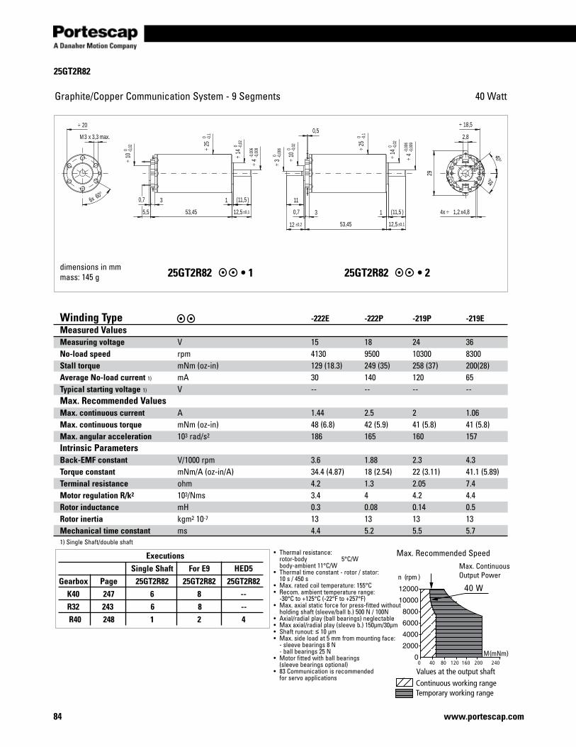
25GT2R82
84 www.portescap.com
40 WattGraphite/CopperCommunicationSystem-9Segments
25GT2R82 •125GT2R82 •2
M(mNm)
Continuous working rangeTemporary working range
Values at the output shaft
40 W n (rpm )
0 40 80 120 160 200 240
• Thermalresistance: rotor-body 5°C/W body-ambient 11°C/W• Thermaltimeconstant-rotor/stator: 10 s / 450 s• Max.ratedcoiltemperature:155°C• Recom.ambienttemperaturerange: -30°C to +125°C (-22°F to +257°F)• Max.axialstaticforceforpress-fittedwithout holdingshaft(sleeve/ballb.)500N/100N• Axial/radialplay(ballbearings)neglectable• Maxaxial/radialplay(sleeveb.)150µm/30µm• Shaftrunout:≤ 10 µm• Max.sideloadat5mmfrommountingface: -sleevebearings8N -ballbearings25N• Motorfittedwithballbearings (sleevebearingsoptional)• 83Communicationisrecommended forservoapplications
Max.RecommendedSpeed
Winding Type -222E -222P -219P -219EMeasured ValuesMeasuring voltage V 15 18 24 36 No-load speed rpm 4130 9500 10300 8300 Stall torque mNm(oz-in) 129 (18.3) 249 (35) 258 (37) 200(28) Average No-load current 1) mA 30 140 120 65 Typical starting voltage 1) V -- -- -- --Max. Recommended Values Max. continuous current A 1.44 2.5 2 1.06 Max. continuous torque mNm(oz-in) 48 (6.8) 42 (5.9) 41 (5.8) 41 (5.8)Max. angular acceleration 103 rad/s2 186 165 160 157Intrinsic ParametersBack-EMF constant V/1000rpm 3.6 1.88 2.3 4.3 Torque constant mNm/A(oz-in/A) 34.4 (4.87) 18 (2.54) 22 (3.11) 41.1 (5.89) Terminal resistance ohm 4.2 1.3 2.05 7.4 Motor regulation R/k2 103/Nms 3.4 4 4.2 4.4 Rotor inductance mH 0.3 0.08 0.14 0.5 Rotor inertia kgm2 10-7 13 13 13 13 Mechanical time constant ms 4.4 5.2 5.5 5.7 1)SingleShaft/doubleshaft
dimensions in mmmass: 145 g
Max.ContinuousOutputPower
Executions Single Shaft For E9 HED5 Gearbox Page 25GT2R82 25GT2R82 25GT2R82 K40 247 6 8 -- R32 243 6 8 -- R40 248 1 2 4
0,52,8
29
11
12 ±0,2 53,45 12,5 ±0,1
1 11,5( ) 1,24x ÷ x4,8
3M x 3,3 max.
12,5 ±0,1
1 11,5( )
53,455,5
40°
40°
60°6x
0,7 3
0,7 3
3 0 -0
,006
÷
4-0
,006
-0,0
09÷10
0 -0,0
2÷
14 0 -0
,02
÷
25 0 -0
,1÷
18,5÷10
0 -0,0
2÷
25 0 -0
,1÷
20÷
14 0 -0
,02
÷ 4-0
,006
-0,0
09÷
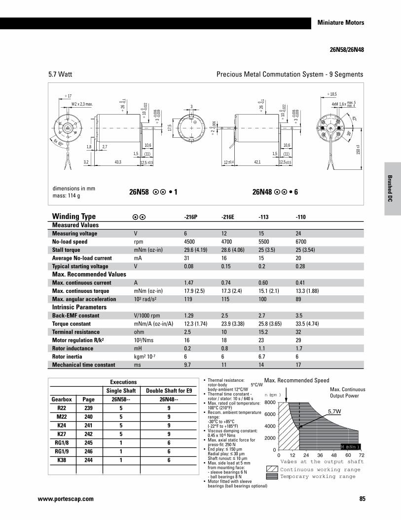
Miniature Motors
85www.portescap.com
Brushed D
C
26N58/26N48
Precious Metal Commutation System - 9 Segments5.7 Watt
dimensions in mmmass: 114 g 26N58 •126N48 •6
Continuous working rangeTemporary working range
Values at the output shaft
n (rpm )
M (mNm )
Winding Type -216P -216E -113 -110Measured ValuesMeasuring voltage V 6 12 15 24No-load speed rpm 4500 4700 5500 6700Stall torque mNm(oz-in) 29.6 (4.19) 28.6 (4.06) 25 (3.5) 25 (3.54)Average No-load current mA 31 16 15 20Typical starting voltage V 0.08 0.15 0.2 0.28Max. Recommended Values Max. continuous current A 1.47 0.74 0.60 0.41Max. continuous torque mNm(oz-in) 17.9 (2.5) 17.3 (2.4) 15.1 (2.1) 13.3 (1.88)Max. angular acceleration 103 rad/s2 119 115 100 89Intrinsic ParametersBack-EMF constant V/1000rpm 1.29 2.5 2.7 3.5Torque constant mNm/A(oz-in/A) 12.3 (1.74) 23.9 (3.38) 25.8 (3.65) 33.5 (4.74)Terminal resistance ohm 2.5 10 15.2 32Motor regulation R/k2 103/Nms 16 18 23 29Rotor inductance mH 0.2 0.8 1.1 1.7Rotor inertia kgm2 10-7 6 6 6.7 6Mechanical time constant ms 9.7 11 14 17
• Thermalresistance: rotor-body 5°C/W body-ambient 12°C/W• Thermaltimeconstant- rotor / stator: 10 s / 640 s• Max.ratedcoiltemperature: 100°C (210°F)• Recom.ambienttemperature range: -30°C to +85°C (-22°F to +185°F)• Viscousdampingconstant: 0.45x10⁻⁶Nms• Max.axialstaticforcefor press-fit:250N• Endplay:≤ 150 µm Radialplay:≤ 30 µm Shaftrunout:≤ 10 µm• Max.sideloadat5mm frommountingface: -sleevebearings6N -ballbearings8N• Motorfittedwithsleeve bearings(ballbearingsoptional)
Max.RecommendedSpeedMax.ContinuousOutputPower
Executions Single Shaft Double Shaft for E9 Gearbox Page 26N58-- 26N48-- R22 239 5 9 M22 240 5 9 K24 241 5 9 K27 242 5 9 RG1/8 245 1 6 RG1/9 246 1 6 K38 244 1 6
max. 5min. 41,64xM x
150
±3
17,5
3
12,5±0,5
11( )
10,6
3-0
,006
-0,0
09÷
43,3 42,1
10,6
3-0
,006
-0,0
09÷
2M x 2,3 max.
3,2
1,5
12 ±0,4
2 0 -0
,006
÷
12,5 ±0,5
11( )
42°
38°
60°6x
1,5
2,71,8
18,5÷
26 0 -0
,1÷
10 0 -0
,022
÷
26 0 -0
,1÷
10 0 -0
,022
÷
17÷
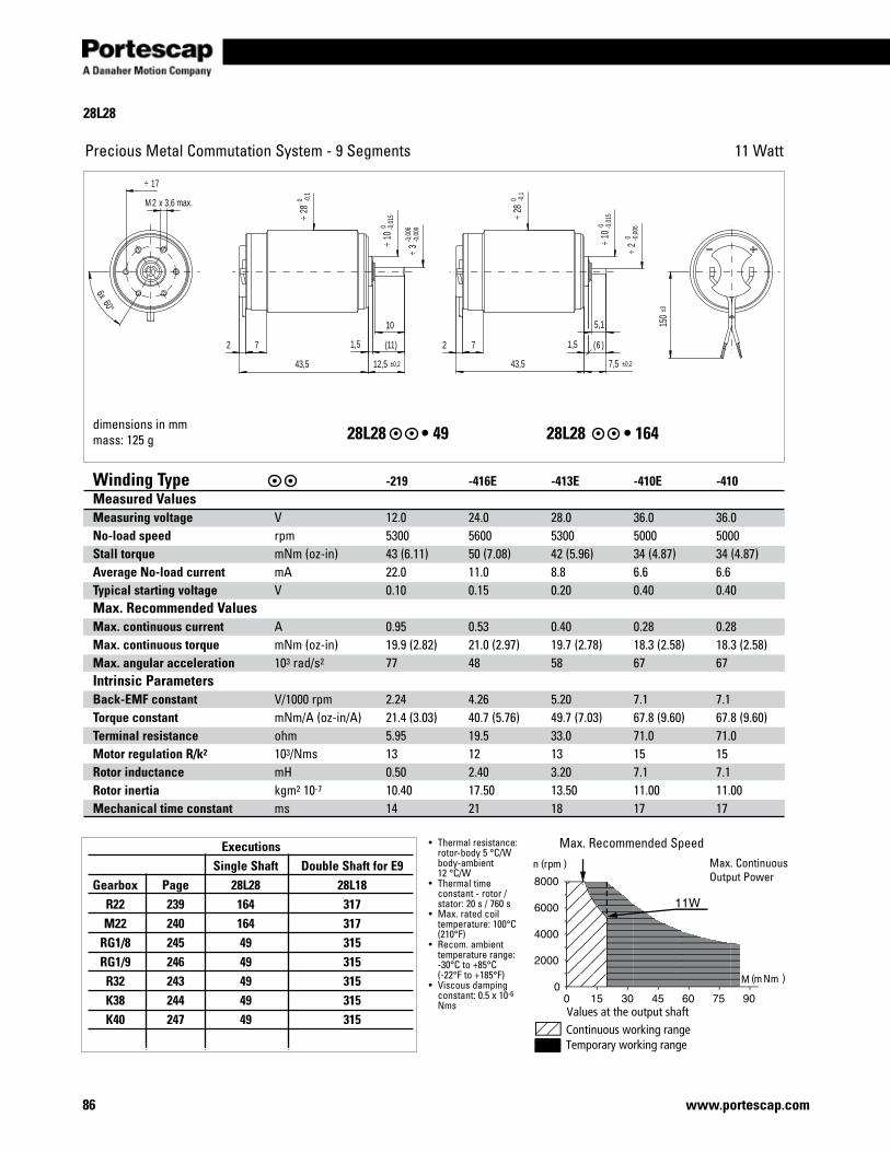
28L28
86 www.portescap.com
Precious Metal Commutation System - 9 Segments 11 Watt
Max.RecommendedSpeedMax.ContinuousOutputPower
dimensions in mmmass: 125 g 28L28 •4928L28 •164
Winding Type -219 -416E -413E -410E -410Measured ValuesMeasuring voltage V 12.0 24.0 28.0 36.0 36.0No-load speed rpm 5300 5600 5300 5000 5000Stall torque mNm(oz-in) 43 (6.11) 50 (7.08) 42 (5.96) 34 (4.87) 34 (4.87)Average No-load current mA 22.0 11.0 8.8 6.6 6.6Typical starting voltage V 0.10 0.15 0.20 0.40 0.40Max. Recommended Values Max. continuous current A 0.95 0.53 0.40 0.28 0.28Max. continuous torque mNm(oz-in) 19.9 (2.82) 21.0 (2.97) 19.7 (2.78) 18.3 (2.58) 18.3 (2.58)Max. angular acceleration 103 rad/s2 77 48 58 67 67Intrinsic ParametersBack-EMF constant V/1000rpm 2.24 4.26 5.20 7.1 7.1Torque constant mNm/A(oz-in/A) 21.4 (3.03) 40.7 (5.76) 49.7 (7.03) 67.8 (9.60) 67.8 (9.60)Terminal resistance ohm 5.95 19.5 33.0 71.0 71.0Motor regulation R/k2 103/Nms 13 12 13 15 15Rotor inductance mH 0.50 2.40 3.20 7.1 7.1Rotor inertia kgm2 10-7 10.40 17.50 13.50 11.00 11.00Mechanical time constant ms 14 21 18 17 17
• Thermalresistance: rotor-body 5 °C/W body-ambient 12 °C/W• Thermaltime constant - rotor / stator: 20 s / 760 s• Max.ratedcoil temperature:100°C (210°F)• Recom.ambient temperaturerange: -30°C to +85°C (-22°F to +185°F)• Viscousdamping constant:0.5x10⁻⁶ Nms
Executions Single Shaft Double Shaft for E9 Gearbox Page 28L28 28L18 R22 239 164 317 M22 240 164 317 RG1/8 245 49 315 RG1/9 246 49 315 R32 243 49 315 K38 244 49 315 K40 247 49 315
150
±3
7
2M x 3,6 max.
10
43,5
2 2
43,5
7
5,1
(11)
12,5 ±0,2 7,5 ±0,2
60°6x
1,5 6( )1,5
10 0
-0,0
15÷
280 -0
,1÷
17÷
3-0
,006
-0,0
09÷
10 0
-0,0
15÷ 2
0 -0,0
06÷
280 -0
,1÷
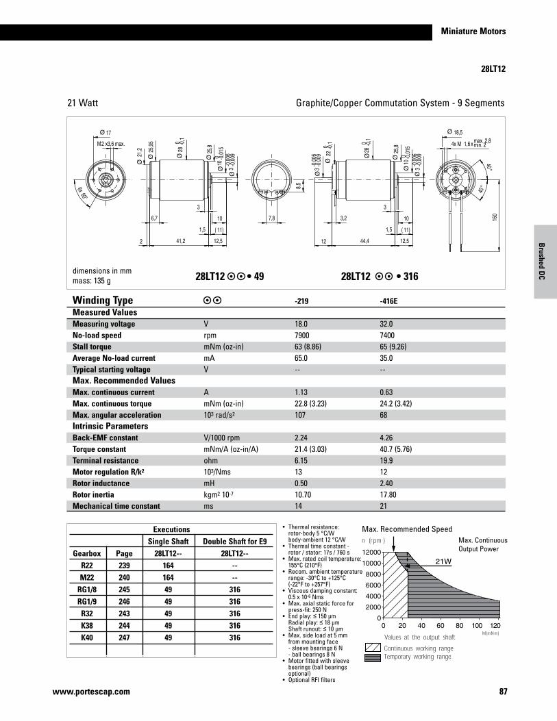
Miniature Motors
87www.portescap.com
Winding Type -219 -416E -413E -410E -410Measured ValuesMeasuring voltage V 12.0 24.0 28.0 36.0 36.0No-load speed rpm 5300 5600 5300 5000 5000Stall torque mNm(oz-in) 43 (6.11) 50 (7.08) 42 (5.96) 34 (4.87) 34 (4.87)Average No-load current mA 22.0 11.0 8.8 6.6 6.6Typical starting voltage V 0.10 0.15 0.20 0.40 0.40Max. Recommended Values Max. continuous current A 0.95 0.53 0.40 0.28 0.28Max. continuous torque mNm(oz-in) 19.9 (2.82) 21.0 (2.97) 19.7 (2.78) 18.3 (2.58) 18.3 (2.58)Max. angular acceleration 103 rad/s2 77 48 58 67 67Intrinsic ParametersBack-EMF constant V/1000rpm 2.24 4.26 5.20 7.1 7.1Torque constant mNm/A(oz-in/A) 21.4 (3.03) 40.7 (5.76) 49.7 (7.03) 67.8 (9.60) 67.8 (9.60)Terminal resistance ohm 5.95 19.5 33.0 71.0 71.0Motor regulation R/k2 103/Nms 13 12 13 15 15Rotor inductance mH 0.50 2.40 3.20 7.1 7.1Rotor inertia kgm2 10-7 10.40 17.50 13.50 11.00 11.00Mechanical time constant ms 14 21 18 17 17
Brushed D
C
Executions Single Shaft Double Shaft for E9 Gearbox Page 28LT12-- 28LT12-- R22 239 164 -- M22 240 164 -- RG1/8 245 49 316 RG1/9 246 49 316 R32 243 49 316 K38 244 49 316 K40 247 49 316
28LT12
Graphite/CopperCommutationSystem-9Segments21 Watt
°
°
°
28LT12 •4928LT12 •316
Winding Type -219 -416EMeasured ValuesMeasuring voltage V 18.0 32.0No-load speed rpm 7900 7400Stall torque mNm(oz-in) 63 (8.86) 65 (9.26)Average No-load current mA 65.0 35.0Typical starting voltage V -- --Max. Recommended Values Max. continuous current A 1.13 0.63Max. continuous torque mNm(oz-in) 22.8 (3.23) 24.2 (3.42)Max. angular acceleration 103 rad/s2 107 68Intrinsic ParametersBack-EMF constant V/1000rpm 2.24 4.26Torque constant mNm/A(oz-in/A) 21.4 (3.03) 40.7 (5.76)Terminal resistance ohm 6.15 19.9Motor regulation R/k2 103/Nms 13 12Rotor inductance mH 0.50 2.40Rotor inertia kgm2 10-7 10.70 17.80Mechanical time constant ms 14 21
• Thermalresistance: rotor-body 5 °C/W body-ambient 12 °C/W• Thermaltimeconstant- rotor / stator: 17s / 760 s• Max.ratedcoiltemperature: 155°C (210°F)• Recom.ambienttemperature range: -30°C to +125°C (-22°F to +257°F)• Viscousdampingconstant: 0.5x10⁻⁶Nms• Max.axialstaticforcefor press-fit:250N• Endplay:≤ 150 µm Radialplay:≤ 18 µm Shaftrunout:≤ 10 µm• Max.sideloadat5mm frommountingface -sleevebearings6N -ballbearings8N• Motorfittedwithsleeve bearings (ball bearings optional)• OptionalRFIfilters
Max.RecommendedSpeedMax.ContinuousOutputPower
dimensions in mmmass: 135 g
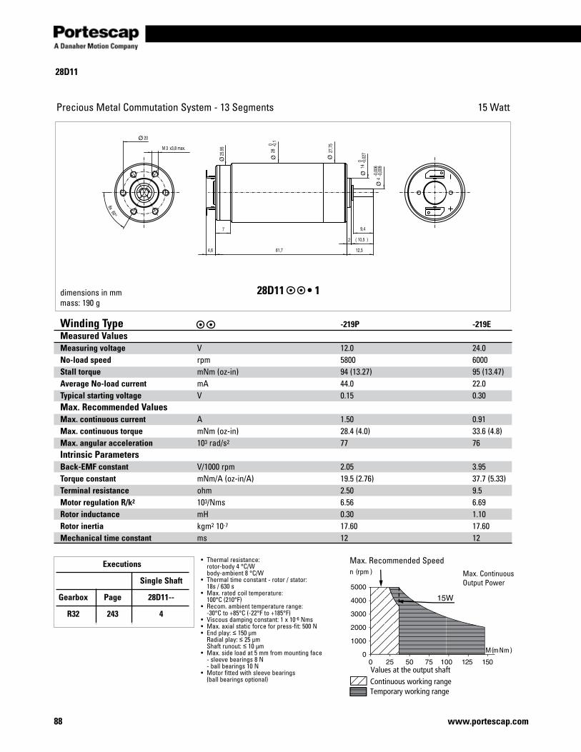
28D11
88 www.portescap.com
Precious Metal Commutation System - 13 Segments 15 Watt
Max.RecommendedSpeedMax.ContinuousOutputPower
°
dimensions in mmmass: 190 g
28D11 •1
Winding Type -219P -219EMeasured ValuesMeasuring voltage V 12.0 24.0No-load speed rpm 5800 6000Stall torque mNm(oz-in) 94 (13.27) 95 (13.47)Average No-load current mA 44.0 22.0Typical starting voltage V 0.15 0.30Max. Recommended Values Max. continuous current A 1.50 0.91Max. continuous torque mNm(oz-in) 28.4 (4.0) 33.6 (4.8)Max. angular acceleration 103 rad/s2 77 76Intrinsic Parameters Back-EMF constant V/1000rpm 2.05 3.95Torque constant mNm/A(oz-in/A) 19.5 (2.76) 37.7 (5.33)Terminal resistance ohm 2.50 9.5Motor regulation R/k2 103/Nms 6.56 6.69Rotor inductance mH 0.30 1.10Rotor inertia kgm2 10-7 17.60 17.60Mechanical time constant ms 12 12
• Thermalresistance: rotor-body 4 °C/W body-ambient 8 °C/W• Thermaltimeconstant-rotor/stator: 18s / 630 s• Max.ratedcoiltemperature: 100°C (210°F)• Recom.ambienttemperaturerange: -30°C to +85°C (-22°F to +185°F)• Viscousdampingconstant:1x10⁻⁶Nms• Max.axialstaticforceforpress-fit:500N• Endplay:≤ 150 µm Radialplay:≤ 25 µm Shaftrunout:≤ 10 µm• Max.sideloadat5mmfrommountingface -sleevebearings8N -ballbearings10N• Motorfittedwithsleevebearings (ballbearingsoptional)
Executions
Single Shaft
Gearbox Page 28D11--
R32 243 4
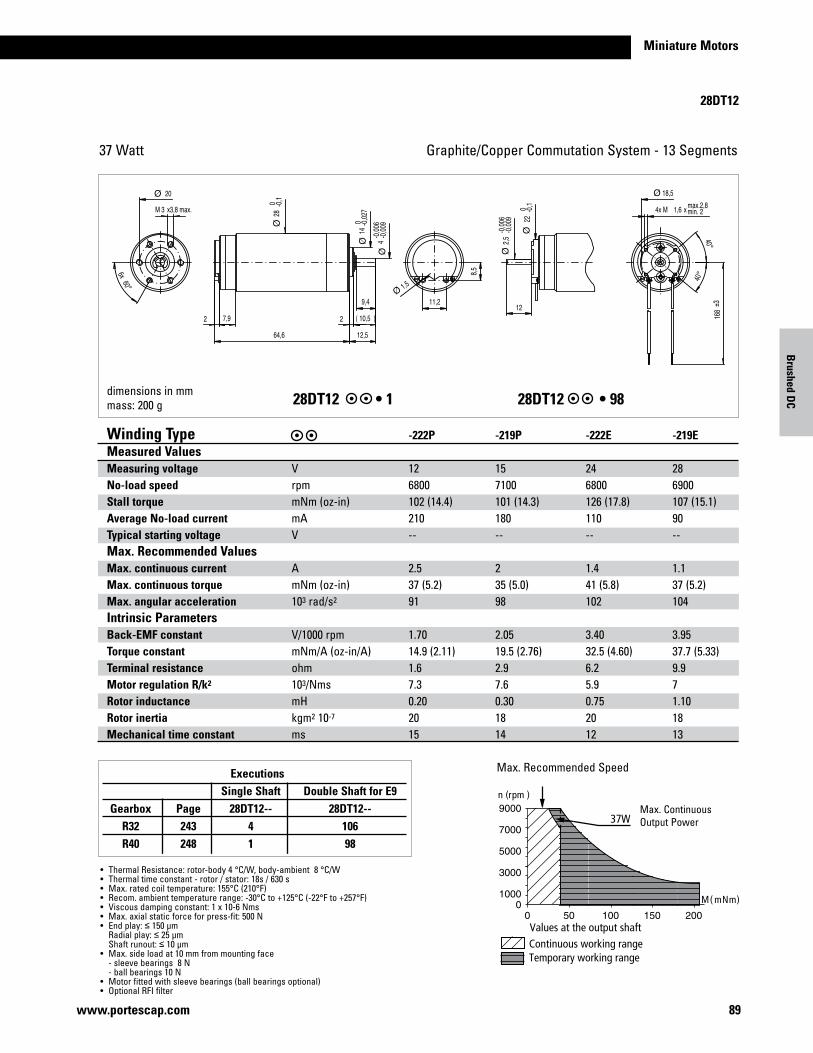
Miniature Motors
89www.portescap.com
28DT12
Graphite/CopperCommutationSystem-13Segments37 Watt
°
°
°
dimensions in mmmass: 200 g28DT12 •128DT12 •98
Winding Type -222P -219P -222E -219EMeasured ValuesMeasuring voltage V 12 15 24 28No-load speed rpm 6800 7100 6800 6900Stall torque mNm(oz-in) 102 (14.4) 101 (14.3) 126 (17.8) 107 (15.1)Average No-load current mA 210 180 110 90Typical starting voltage V -- -- -- --Max. Recommended Values Max. continuous current A 2.5 2 1.4 1.1Max. continuous torque mNm(oz-in) 37 (5.2) 35 (5.0) 41 (5.8) 37 (5.2)Max. angular acceleration 103 rad/s2 91 98 102 104Intrinsic ParametersBack-EMF constant V/1000rpm 1.70 2.05 3.40 3.95Torque constant mNm/A(oz-in/A) 14.9 (2.11) 19.5 (2.76) 32.5 (4.60) 37.7 (5.33)Terminal resistance ohm 1.6 2.9 6.2 9.9Motor regulation R/k2 103/Nms 7.3 7.6 5.9 7Rotor inductance mH 0.20 0.30 0.75 1.10Rotor inertia kgm2 10-7 20 18 20 18Mechanical time constant ms 15 14 12 13
• ThermalResistance:rotor-body4°C/W,body-ambient8°C/W• Thermaltimeconstant-rotor/stator:18s/630s• Max.ratedcoiltemperature:155°C(210°F)• Recom.ambienttemperaturerange:-30°Cto+125°C(-22°Fto+257°F)• Viscousdampingconstant:1x10⁻⁶Nms• Max.axialstaticforceforpress-fit:500N• Endplay:≤ 150 µm Radialplay:≤ 25 µm Shaftrunout:≤ 10 µm• Max.sideloadat10mmfrommountingface -sleevebearings8N -ballbearings10N• Motorfittedwithsleevebearings(ballbearingsoptional)• OptionalRFIfilter
Max.RecommendedSpeed
Max.ContinuousOutputPower
Executions Single Shaft Double Shaft for E9 Gearbox Page 28DT12-- 28DT12-- R32 243 4 106 R40 248 1 98
Brushed D
C
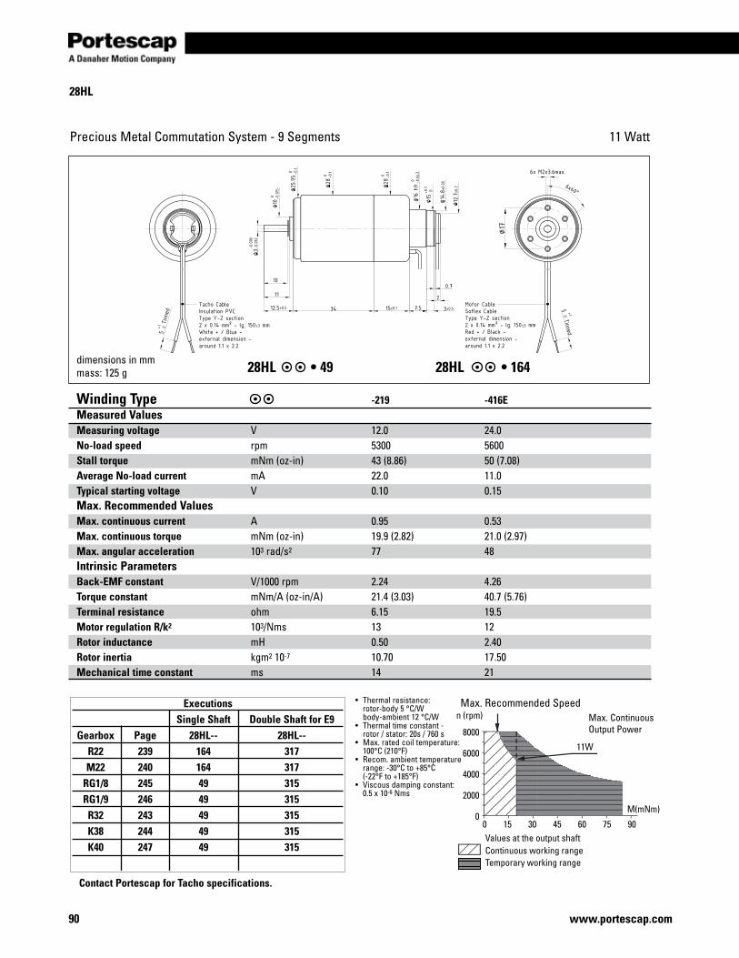
90 www.portescap.com
Executions Single Shaft Double Shaft for E9 Gearbox Page 28HL-- 28HL-- R22 239 164 317 M22 240 164 317 RG1/8 245 49 315 RG1/9 246 49 315 R32 243 49 315 K38 244 49 315 K40 247 49 315
28HL
Precious Metal Commutation System - 9 Segments 11 Watt
28HL •4928HL •164
Values at the output shaftContinuous working rangeTemporary working range
n (rpm)
8000
6000
4000
2000
00 15 30 45 60 75 90
11W
M(mNm)
Winding Type -219 -416EMeasured ValuesMeasuring voltage V 12.0 24.0No-load speed rpm 5300 5600Stall torque mNm(oz-in) 43 (8.86) 50 (7.08)Average No-load current mA 22.0 11.0Typical starting voltage V 0.10 0.15Max. Recommended Values Max. continuous current A 0.95 0.53Max. continuous torque mNm(oz-in) 19.9 (2.82) 21.0 (2.97)Max. angular acceleration 103 rad/s2 77 48Intrinsic ParametersBack-EMF constant V/1000rpm 2.24 4.26Torque constant mNm/A(oz-in/A) 21.4 (3.03) 40.7 (5.76)Terminal resistance ohm 6.15 19.5Motor regulation R/k2 103/Nms 13 12Rotor inductance mH 0.50 2.40Rotor inertia kgm2 10-7 10.70 17.50Mechanical time constant ms 14 21
• Thermalresistance: rotor-body 5 °C/W body-ambient 12 °C/W• Thermaltimeconstant- rotor / stator: 20s / 760 s• Max.ratedcoiltemperature: 100°C (210°F)• Recom.ambienttemperature range: -30°C to +85°C (-22°F to +185°F)• Viscousdampingconstant: 0.5x10⁻⁶Nms
Max.RecommendedSpeedMax.ContinuousOutputPower
dimensions in mmmass: 125 g
Contact Portescap for Tacho specifications.
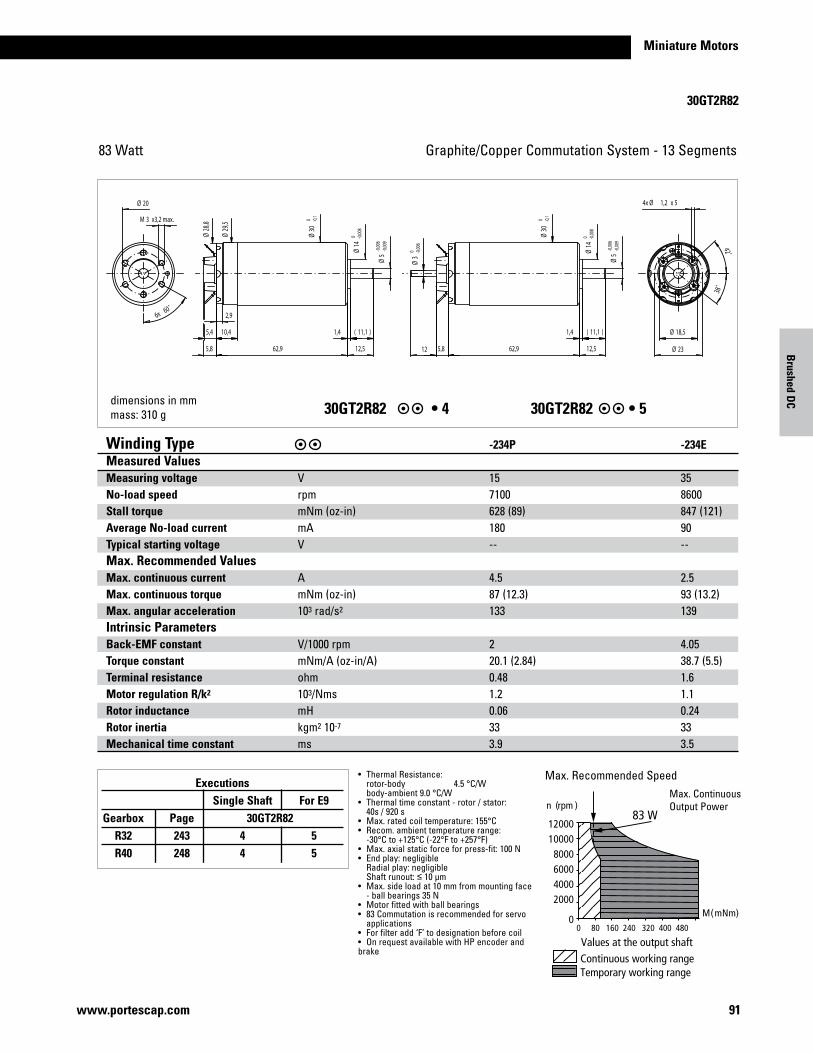
Miniature Motors
30GT2R82
91www.portescap.com
Graphite/CopperCommutationSystem-13Segments83 Watt
Max.RecommendedSpeedMax.ContinuousOutputPower
dimensions in mmmass: 310 g 30GT2R82 •430GT2R82 •5
Winding Type -234P -234EMeasured ValuesMeasuring voltage V 15 35No-load speed rpm 7100 8600Stall torque mNm(oz-in) 628 (89) 847 (121)Average No-load current mA 180 90Typical starting voltage V -- --Max. Recommended Values Max. continuous current A 4.5 2.5Max. continuous torque mNm(oz-in) 87 (12.3) 93 (13.2)Max. angular acceleration 103 rad/s2 133 139Intrinsic ParametersBack-EMF constant V/1000rpm 2 4.05Torque constant mNm/A(oz-in/A) 20.1 (2.84) 38.7 (5.5)Terminal resistance ohm 0.48 1.6Motor regulation R/k2 103/Nms 1.2 1.1Rotor inductance mH 0.06 0.24Rotor inertia kgm2 10-7 33 33Mechanical time constant ms 3.9 3.5
• ThermalResistance: rotor-body 4.5 °C/W body-ambient 9.0 °C/W• Thermaltimeconstant-rotor/stator: 40s / 920 s• Max.ratedcoiltemperature:155°C• Recom.ambienttemperaturerange: -30°C to +125°C (-22°F to +257°F)• Max.axialstaticforceforpress-fit:100N• Endplay:negligible Radialplay:negligible Shaftrunout:≤ 10 µm• Max.sideloadat10mmfrommountingface -ballbearings35N• Motorfittedwithballbearings• 83Commutationisrecommendedforservo applications• Forfilteradd‘F’todesignationbeforecoil• OnrequestavailablewithHPencoderandbrake
Executions Single Shaft For E9 Gearbox Page 30GT2R82 R32 243 4 5 R40 248 4 5
Brushed D
C
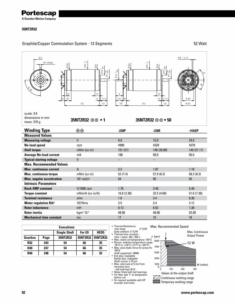
35NT2R32
92 www.portescap.com
Graphite/CopperCommutationSystem-13Segments 52 Watt
scale: 3:4dimensions in mmmass: 310 g35NT2R32•135NT2R32•50
Continuous working rangeTemporary working range
Values at the output shaft
M (mNm)
n (rpm)
0 100 200 300
9000
7000
5000
3000
10000
52 W
Winding Type -228P -228E -416SP Measured ValuesMeasuring voltage V 9.0 15.0 24.0 No-load speed rpm 4990 4320 4370 Stall torque mNm(oz-in) 151 (21) 148 (20.89) 149 (21.11)Average No-load current mA 180 90.0 50.0 Typical starting voltage V -- -- -- Max. Recommended Values Max. continuous current A 3.3 1.87 1.18 Max. continuous torque mNm(oz-in) 52 (7.4) 57.9 (8.2) 58.3 (8.3) Max. angular acceleration 103 rad/s2 54 56 55 Intrinsic ParametersBack-EMF constant V/1000rpm 1.76 3.40 5.40 Torque constant mNm/A(oz-in/A) 16.8 (2.38) 32.5 (4.60) 51.6 (7.30) Terminal resistance ohm 1.0 3.4 8.30 Motor regulation R/k2 103/Nms 3.5 3.4 3.12 Rotor inductance mH 0.13 0.52 1.30 Rotor inertia kgm2 10-7 48.00 48.00 52.00 Mechanical time constant ms 17 15 16
• ThermalResistance: rotor-body 4 °C/W body-ambient 8 °C/W• Thermaltimeconstant- rotor / stator: 40s / 920 s• Max.ratedcoiltemperature:155°C• Recom.ambienttemperaturerange: -55°C to +125°C (-31°F to +257°F)• Max.axialstaticforceforpress-fit: 100N shaftsupported:1000N• Endplay:negligible Radialplay:negligible Shaftrunout:≤ 10 µm• Max.sideloadat5mmfrom mountingface -ballbearings35N• Motorfittedwithballbearings• Forfilteradd`F`todesignation beforecoil• OnrequestavailablewithHP encoder and brake
Max.RecommendedSpeedMax.ContinuousOutputPower
Executions Single Shaft For E9 HED5 Gearbox Page 35NT2R32 35NT2R32 35NT2R32 R32 243 54 66 35 K40 247 54 66 35 R40 248 54 66 35
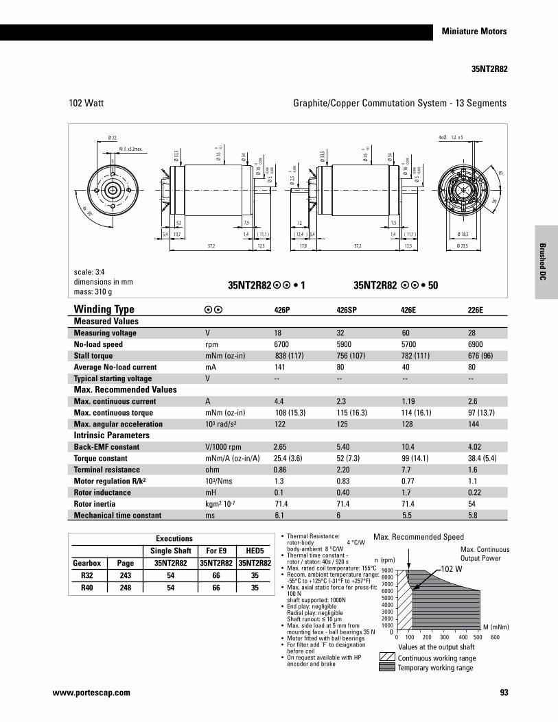
Miniature Motors
35NT2R82
93www.portescap.com
Graphite/CopperCommutationSystem-13Segments102 Watt
Continuous working rangeTemporary working range
Values at the output shaft
M (mNm)
n (rpm)
0 100 200 300 400 500 600
900080007000600050004000300020001000
0
102 W
Max.RecommendedSpeedMax.ContinuousOutputPower
scale: 3:4dimensions in mmmass: 310 g
35NT2R82 •135NT2R82 •50
Winding Type 426P 426SP 426E 226E Measured ValuesMeasuring voltage V 18 32 60 28No-load speed rpm6700 5900 5700 6900Stall torque mNm(oz-in)838 (117) 756 (107) 782 (111) 676 (96)Average No-load current mA 141 80 40 80Typical starting voltage V -- -- -- --Max. Recommended Values Max. continuous current A 4.4 2.3 1.19 2.6Max. continuous torque mNm(oz-in)108 (15.3) 115 (16.3) 114 (16.1) 97 (13.7)Max. angular acceleration 103 rad/s2 122 125 128 144Intrinsic ParametersBack-EMF constant V/1000rpm2.65 5.40 10.4 4.02Torque constant mNm/A(oz-in/A)25.4 (3.6) 52 (7.3) 99 (14.1) 38.4 (5.4)Terminal resistance ohm0.86 2.20 7.7 1.6Motor regulation R/k2 103/Nms1.3 0.83 0.77 1.1Rotor inductance mH 0.1 0.40 1.7 0.22Rotor inertia kgm2 10-7 71.4 71.4 71.4 54Mechanical time constant ms 6.1 6 5.5 5.8
• ThermalResistance: rotor-body 4 °C/W body-ambient 8 °C/W• Thermaltimeconstant- rotor / stator: 40s / 920 s• Max.ratedcoiltemperature:155°C• Recom.ambienttemperaturerange: -55°C to +125°C (-31°F to +257°F)• Max.axialstaticforceforpress-fit: 100N shaftsupported:1000N• Endplay:negligible Radialplay:negligible Shaftrunout:≤ 10 µm• Max.sideloadat5mmfrom mountingface-ballbearings35N• Motorfittedwithballbearings• Forfilteradd`F`todesignation beforecoil• OnrequestavailablewithHP encoder and brake
Executions Single Shaft For E9 HED5 Gearbox Page 35NT2R82 35NT2R82 35NT2R82 R32 243 54 66 35 R40 248 54 66 35
Brushed D
C
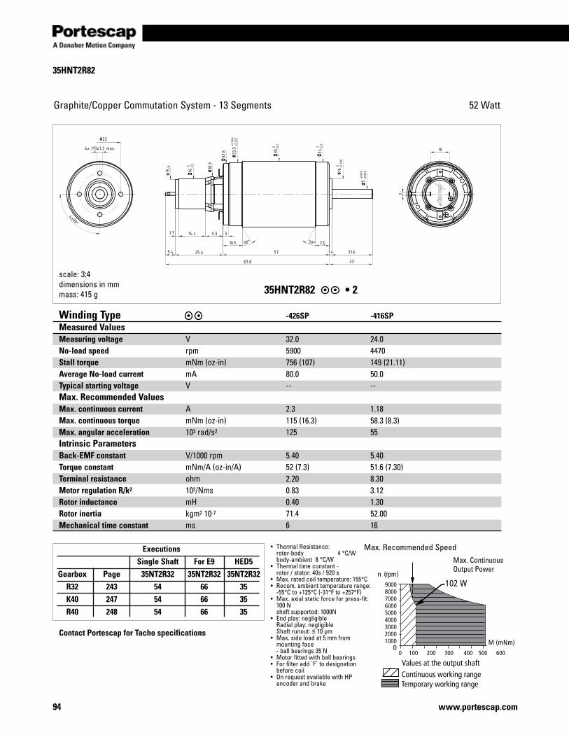
35HNT2R82
94 www.portescap.com
Graphite/CopperCommutationSystem-13Segments 52 Watt
Contact Portescap for Tacho specifications
35HNT2R82•2
Winding Type -426SP -416SP Measured ValuesMeasuring voltage V 32.0 24.0 No-load speed rpm 5900 4470 Stall torque mNm(oz-in) 756 (107) 149 (21.11)Average No-load current mA 80.0 50.0 Typical starting voltage V -- -- Max. Recommended Values Max. continuous current A 2.3 1.18 Max. continuous torque mNm(oz-in) 115 (16.3) 58.3 (8.3) Max. angular acceleration 103 rad/s2 125 55 Intrinsic ParametersBack-EMF constant V/1000rpm 5.40 5.40 Torque constant mNm/A(oz-in/A) 52 (7.3) 51.6 (7.30) Terminal resistance ohm 2.20 8.30 Motor regulation R/k2 103/Nms 0.83 3.12 Rotor inductance mH 0.40 1.30 Rotor inertia kgm2 10-7 71.4 52.00 Mechanical time constant ms 6 16
• ThermalResistance: rotor-body 4 °C/W body-ambient 8 °C/W• Thermaltimeconstant- rotor / stator: 40s / 920 s• Max.ratedcoiltemperature:155°C• Recom.ambienttemperaturerange: -55°C to +125°C (-31°F to +257°F)• Max.axialstaticforceforpress-fit: 100N shaftsupported:1000N• Endplay:negligible Radialplay:negligible Shaftrunout:≤ 10 µm• Max.sideloadat5mmfrom mountingface -ballbearings35N• Motorfittedwithballbearings• Forfilteradd`F`todesignation beforecoil• OnrequestavailablewithHP encoder and brake
Max.RecommendedSpeedMax.ContinuousOutputPower
Executions Single Shaft For E9 HED5 Gearbox Page 35NT2R32 35NT2R32 35NT2R32 R32 243 54 66 35 K40 247 54 66 35 R40 248 54 66 35
Continuous working rangeTemporary working range
Values at the output shaft
M (mNm)
n (rpm)
0 100 200 300 400 500 600
900080007000600050004000300020001000
0
102 W
scale: 3:4dimensions in mmmass: 415 g
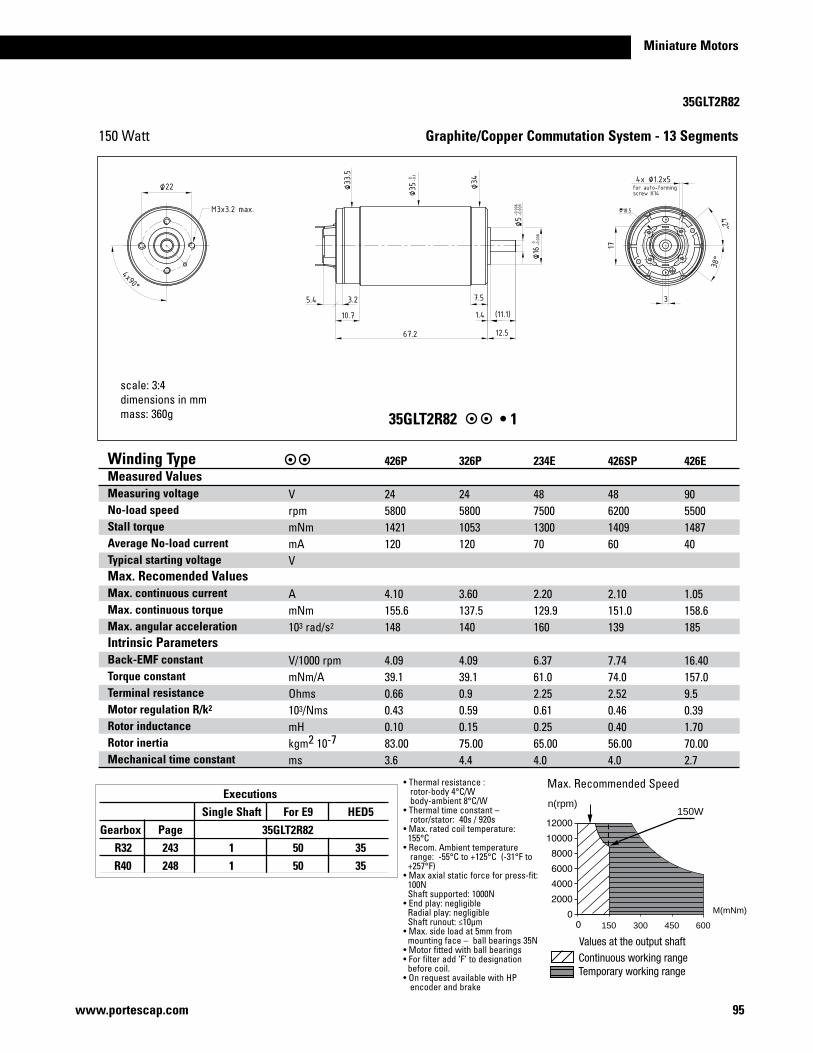
95www.portescap.com
Miniature Motors
35GLT2R82
35GLT2R82 •1
Graphite/Copper Commutation System - 13 Segments
•Thermalresistance: rotor-body 4°C/W body-ambient 8°C/W•Thermaltimeconstant– rotor/stator: 40s / 920s•Max.ratedcoiltemperature: 155°C•Recom.Ambienttemperature range: -55°C to +125°C (-31°F to +257°F)•Maxaxialstaticforceforpress-fit:100NShaftsupported:1000N•Endplay:negligibleRadialplay:negligibleShaftrunout:≤10μm•Max.sideloadat5mmfrommountingface–ballbearings35N•Motorfittedwithballbearings•Forfilteradd‘F’todesignationbeforecoil.•OnrequestavailablewithHP encoder and brake
scale: 3:4dimensions in mmmass: 360g
Winding Type Measured Values Measuring voltageNo-load speed Stall torqueAverage No-load current Typical starting voltageMax. Recomended ValuesMax. continuous currentMax. continuous torqueMax. angular accelerationIntrinsic Parameters Back-EMF constantTorque constantTerminal resistanceMotor regulation R/k2
Rotor inductanceRotor inertiaMechanical time constant
VrpmmNmmAV
AmNm103 rad/s2
V/1000rpmmNm/AOhms103/NmsmHkgm2 10-7
ms
426P 2458001421120
4.10155.6148
4.0939.10.660.430.1083.003.6
326P 2458001053120
3.60137.5140
4.0939.10.90.590.1575.004.4
234E 487500130070
2.20129.9160
6.3761.02.250.610.2565.004.0
426SP 486200140960
2.10151.0139
7.7474.02.520.460.4056.004.0
426E 905500148740
1.05158.6185
16.40157.09.50.391.7070.002.7
Max.RecommendedSpeed
300150 450 600
150Wn(rpm)
M(mNm)
Executions Single Shaft For E9 HED5 Gearbox Page 25GT2R82 25GT2R82 R32 243 1 50 35 R40 248 1 50 35
35GLT2R82
150 Watt

Notes
96 www.portescap.com
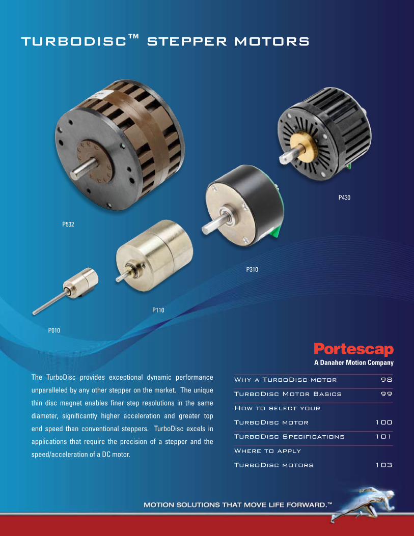
TurboDisc™ sTepper MoTors
Why a TurboDisc motor 98
TurboDisc Motor Basics 99
How to select your
TurboDisc motor 100
TurboDisc Specifications 101
Where to apply
TurboDisc motors 103
The TurboDisc provides exceptional dynamic performance
unparalleled by any other stepper on the market. The unique
thin disc magnet enables finer step resolutions in the same
diameter, significantly higher acceleration and greater top
end speed than conventional steppers. TurboDisc excels in
applications that require the precision of a stepper and the
speed/acceleration of a DC motor.
P010
P110
P310
P430
P532
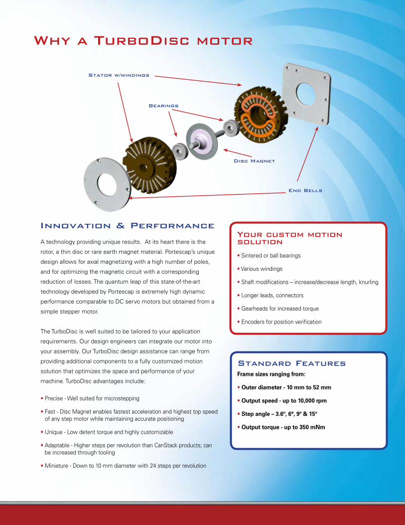
standard FeaturesFrame sizes ranging from:
• Outer diameter - 10 mm to 52 mm
• Output speed - up to 10,000 rpm
• Step angle – 3.6º, 6°, 9º & 15º
• Output torque - up to 350 mNm
Why a TurboDisc motor
stator w/windings
bearings
end bells
Disc Magnet
Your custom motion solution
• Sintered or ball bearings
• Various windings
• Shaft modifications – increase/decrease length, knurling
• Longer leads, connectors
• Gearheads for increased torque
• Encoders for position verification
A technology providing unique results. At its heart there is the
rotor, a thin disc or rare earth magnet material. Portescap’s unique
design allows for axial magnetizing with a high number of poles,
and for optimizing the magnetic circuit with a corresponding
reduction of losses. The quantum leap of this state-of-the-art
technology developed by Portescap is extremely high dynamic
performance comparable to DC servo motors but obtained from a
simple stepper motor.
The TurboDisc is well suited to be tailored to your application
requirements. Our design engineers can integrate our motor into
your assembly. Our TurboDisc design assistance can range from
providing additional components to a fully customized motion
solution that optimizes the space and performance of your
machine. TurboDisc advantages include:
• Precise - Well suited for microstepping
• Fast - Disc Magnet enables fastest acceleration and highest top speed of any step motor while maintaining accurate positioning
• Unique - Low detent torque and highly customizable
• Adaptable - Higher steps per revolution than CanStack products; can be increased through tooling
• Miniature - Down to 10 mm diameter with 24 steps per revolution
innovation & performance
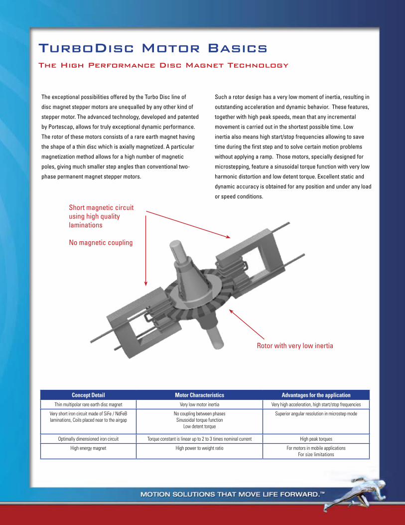
The exceptional possibilities offered by the Turbo Disc line of
disc magnet stepper motors are unequalled by any other kind of
stepper motor. The advanced technology, developed and patented
by Portescap, allows for truly exceptional dynamic performance.
The rotor of these motors consists of a rare earth magnet having
the shape of a thin disc which is axially magnetized. A particular
magnetization method allows for a high number of magnetic
poles, giving much smaller step angles than conventional two-
phase permanent magnet stepper motors.
Such a rotor design has a very low moment of inertia, resulting in
outstanding acceleration and dynamic behavior. These features,
together with high peak speeds, mean that any incremental
movement is carried out in the shortest possible time. Low
inertia also means high start/stop frequencies allowing to save
time during the first step and to solve certain motion problems
without applying a ramp. Those motors, specially designed for
microstepping, feature a sinusoidal torque function with very low
harmonic distortion and low detent torque. Excellent static and
dynamic accuracy is obtained for any position and under any load
or speed conditions.
TurboDisc Motor basicsThe High performance Disc Magnet Technology
Concept Detail Motor Characteristics Advantages for the application
Thin multipolar rare earth disc magnet Very low motor inertia Very high acceleration, high start/stop frequencies
Very short iron circuit made of SiFe / NdFeB laminations, Coils placed near to the airgap
No coupling between phasesSinusoidal torque function
Low detent torque
Superior angular resolution in microstep mode
Optimally dimensioned iron circuit Torque constant is linear up to 2 to 3 times nominal current High peak torques
High energy magnet High power to weight ratio For motors in mobile applicationsFor size limitations
Rotor with very low inertia
Short magnetic circuit using high quality laminations
No magnetic coupling
Why a TurboDisc motor
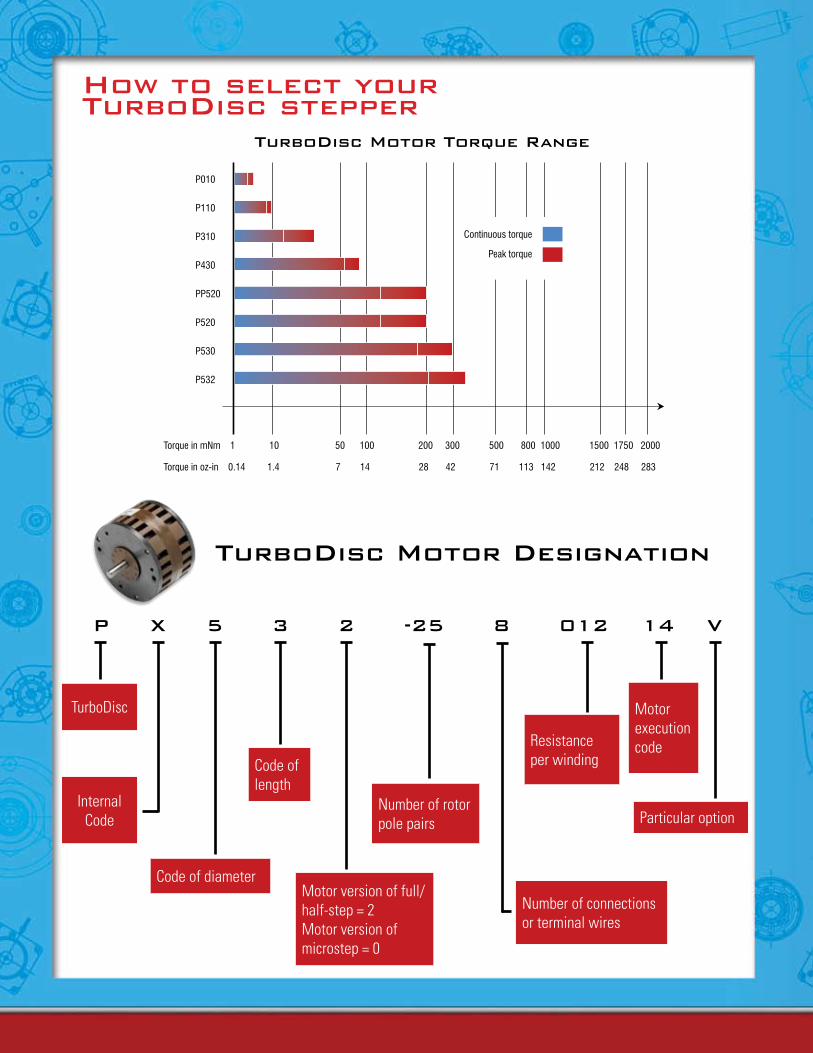
How to select your TurboDisc stepper
TurboDisc Motor Designation
p X 5 3 2 -25 8 012 14 V
Code of length
Code of diameterMotor version of full/half-step = 2Motor version of microstep = 0
Motor execution code
Number of connections or terminal wires
Particular option
TurboDisc
Internal Code
Number of rotor pole pairs
Resistance per winding
TurboDisc Motor Torque range
P010
P110
P310
P430
PP520
P520
P530
P532
Torque in mNm 1 10 50 100 200 300 500 800 1000 1500 1750 2000
Torque in oz-in 0.14 1.4 7 14 28 42 71 113 142 212 248 283
Continuous torque
Peak torque
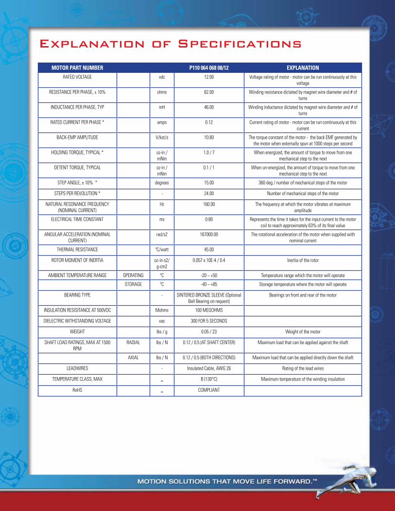
explanation of specifications
MOTOR PART NUMBER P110 064 068 08/12 ExPlANATiON
RATED VOLTAGE vdc 12.00 Voltage rating of motor - motor can be run continuously at this voltage
RESISTANCE PER PHASE, ± 10% ohms 62.00 Winding resistance dictated by magnet wire diameter and # of turns
INDUCTANCE PER PHASE, TYP mH 46.00 Winding inductance dictated by magnet wire diameter and # of turns
RATED CURRENT PER PHASE * amps 0.12 Current rating of motor - motor can be run continuously at this current
BACK-EMP AMPLITUDE V/kst/s 10.80 The torque constant of the motor - the back EMF generated by the motor when externally spun at 1000 steps per second
HOLDING TORQUE, TYPICAL * oz-in / mNm
1.0 / 7 When energized, the amount of torque to move from one mechanical step to the next
DETENT TORQUE, TYPICAL oz-in / mNm
0.1 / 1 When un-energized, the amount of torque to move from one mechanical step to the next
STEP ANGLE, ± 10% * degrees 15.00 360 deg / number of mechanical steps of the motor
STEPS PER REVOLUTION * - 24.00 Number of mechanical steps of the motor
NATURAL RESONANCE FREQUENCY (NOMINAL CURRENT)
Hz 160.00 The frequency at which the motor vibrates at maximum amplitude
ELECTRICAL TIME CONSTANT ms 0.80 Represents the time it takes for the input current to the motor coil to reach approximately 63% of its final value
ANGULAR ACCELERATION (NOMINAL CURRENT)
rad/s2 167000.00 The rotational acceleration of the motor when supplied with nominal current
THERMAL RESISTANCE ºC/watt 45.00
ROTOR MOMENT OF INERTIA oz-in-s2/ g-cm2
0.057 x 10E-4 / 0.4 Inertia of the rotor
AMBIENT TEMPERATURE RANGE OPERATING ºC -20 ~ +50 Temperature range which the motor will operate
STORAGE ºC -40 ~ +85 Storage temperature where the motor will operate
BEARING TYPE - SINTERED BRONZE SLEEVE (Optional Ball Bearing on request)
Bearings on front and rear of the motor
INSULATION RESISITANCE AT 500VDC Mohms 100 MEGOHMS
DIELECTRIC WITHSTANDING VOLTAGE vac 300 FOR 5 SECONDS
WEIGHT lbs / g 0.05 / 23 Weight of the motor
SHAFT LOAD RATINGS, MAX AT 1500 RPM
RADIAL lbs / N 0.12 / 0.5 (AT SHAFT CENTER) Maximum load that can be applied against the shaft
AXIAL lbs / N 0.12 / 0.5 (BOTH DIRECTIONS) Maximum load that can be applied directly down the shaft
LEADWIRES - Insulated Cable, AWG 26 Rating of the lead wires
TEMPERATURE CLASS, MAX - B (130°C) Maximum temperature of the winding insulation
RoHS - COMPLIANT
How to select your TurboDisc stepper
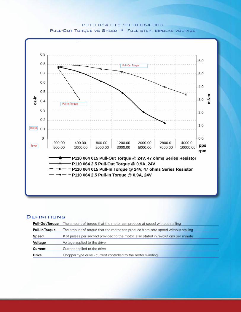
0
0.1
0.2
0.3
0.4
0.5
0.6
0.7
0.8
0.9
200.00 400.00 800.00 1200.00 2000.00 2800.0 4000.0500.00 1000.00 2000.00 3000.00 5000.00 7000.00 10000.00 pps
oz-
in
0.0
1.0
2.0
3.0
4.0
5.0
6.0
rpm
mN
m
P110 064 015 Pull-Out Torque @ 24V, 47 ohms Series ResistorP110 064 2.5 Pull-Out Torque @ 0.9A, 24VP110 064 015 Pull-In Torque @ 24V, 47 ohms Series ResistorP110 064 2.5 Pull-In Torque @ 0.9A, 24V
P010 064 015 /P110 064 003 Pull-Out Torque vs Speed • Full step, bipolar voltage
Definitions
Pull-Out Torque The amount of torque that the motor can produce at speed without stalling
Pull-In Torque The amount of torque that the motor can produce from zero speed without stalling
Speed # of pulses per second provided to the motor, also stated in revolutions per minute
Voltage Voltage applied to the drive
Current Current applied to the drive
Drive Chopper type drive - current controlled to the motor winding
Pull-In Torque
Pull-Out Torque
Torque
Speed
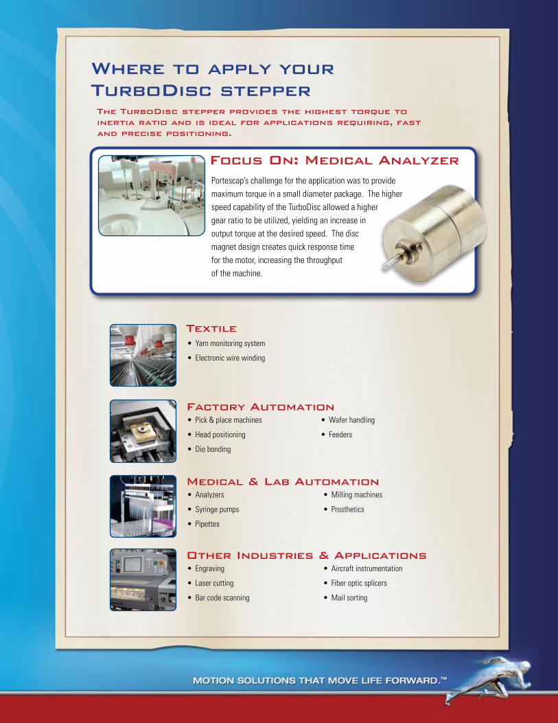
TextileYarn monitoring system•
Electronic wire winding•
Where to apply your TurboDisc stepper
Factory Automation Pick & place machines•
Head positioning•
Die bonding•
Wafer handling•
Feeders•
Medical & Lab AutomationAnalyzers•
Syringe pumps•
Pipettes•
Milling machines•
Prosthetics•
other industries & Applications Engraving•
Laser cutting•
Bar code scanning•
Aircraft instrumentation•
Fiber optic splicers•
Mail sorting•
Focus on: Medical AnalyzerPortescap’s challenge for the application was to provide maximum torque in a small diameter package. The higher speed capability of the TurboDisc allowed a higher gear ratio to be utilized, yielding an increase in output torque at the desired speed. The disc magnet design creates quick response time for the motor, increasing the throughput of the machine.
The TurboDisc stepper provides the highest torque to inertia ratio and is ideal for applications requiring, fast and precise positioning.
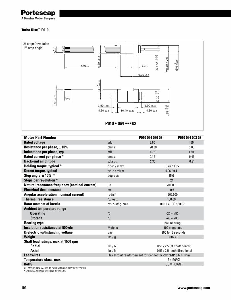
104 www.portescap.com
Motor Part Number P010 064 020 02 P010 064 003 02Rated voltage vdc 3.00 1.50Resistance per phase, ± 10% ohms 20.00 3.00Inductance per phase, typ mH 13.70 1.80Rated current per phase * amps 0.15 0.43Back-emf amplitude V/kst/s 2.30 0.81Holding torque, typical * oz-in / mNm 0.26 / 1.85 Detent torque, typical oz-in / mNm 0.06 / 0.4Step angle, ± 10% * degrees 15.0 Steps per revolution * 24 Natural resonance frequency (nominal current) Hz 200.00 Electrical time constant ms 0.6Angular acceleration (nominal current) rad/s2 265,000 Thermal resistance ºC/watt 100.00Rotor moment of inertia oz-in-s2/ g-cm2 0.010 x 10E-4 / 0.07Ambient temperature range Operating ºC -20 ~ +50 Storage ºC -40 ~ +85 Bearing type ball bearing Insulation resisitance at 500vdc Mohms 100 megohmsDielectric withstanding voltage vac 200 for 5 secondsWeight lbs / g 0.02 / 9Shaft load ratings, max at 1500 rpm Radial lbs / N 0.56 / 2.5 (at shaft center) Axial lbs / N 0.56 / 2.5 (both directions)Leadwires Flex Circuit reinforcement for connector ZIP ZMP pitch 1mmTemperature class, max B (130°C)RoHS COMPLIANT
A+A-
B+B-
1.90 ±0.051.90 ±0.05
4.80 ±0.216.40 ±0.254.80 ±0.2
Ø 6
+0
-0.0
18
Ø 1
0+
0.1
-0
11.2
5+
0.25
+0.
10
6.80
±0.1
0
100 ±3 4±0.2
9.75 ±0.2
5+0.
1-0
.2
Ø 1
.50
-0.0
06-0
.009
M5.
50 x
0.5
Ø 6
+0
-0.0
18
5±0.2
0.30
±0.0
5
Turbo DiscTM P010
24 steps/revolution15º step angle
ALL MOTOR DATA VALUES AT 25ºC UNLESS OTHERWISE SPECIFIED* ENERGISE AT RATED CURRENT, 2 PHASE ON
P010 • 064 §§• 02
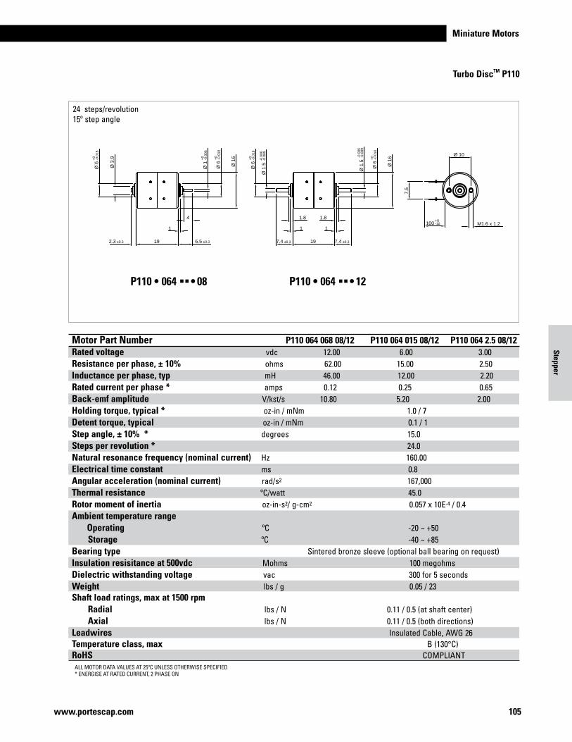
Miniature Motors
105www.portescap.com
Motor Part Number P010 064 020 02 P010 064 003 02Rated voltage vdc 3.00 1.50Resistance per phase, ± 10% ohms 20.00 3.00Inductance per phase, typ mH 13.70 1.80Rated current per phase * amps 0.15 0.43Back-emf amplitude V/kst/s 2.30 0.81Holding torque, typical * oz-in / mNm 0.26 / 1.85 Detent torque, typical oz-in / mNm 0.06 / 0.4Step angle, ± 10% * degrees 15.0 Steps per revolution * 24 Natural resonance frequency (nominal current) Hz 200.00 Electrical time constant ms 0.6Angular acceleration (nominal current) rad/s2 265,000 Thermal resistance ºC/watt 100.00Rotor moment of inertia oz-in-s2/ g-cm2 0.010 x 10E-4 / 0.07Ambient temperature range Operating ºC -20 ~ +50 Storage ºC -40 ~ +85 Bearing type ball bearing Insulation resisitance at 500vdc Mohms 100 megohmsDielectric withstanding voltage vac 200 for 5 secondsWeight lbs / g 0.02 / 9Shaft load ratings, max at 1500 rpm Radial lbs / N 0.56 / 2.5 (at shaft center) Axial lbs / N 0.56 / 2.5 (both directions)Leadwires Flex Circuit reinforcement for connector ZIP ZMP pitch 1mmTemperature class, max B (130°C)RoHS COMPLIANT
Turbo DiscTM P110
Stepper
Motor Part Number P110 064 068 08/12 P110 064 015 08/12 P110 064 2.5 08/12Rated voltage vdc 12.00 6.00 3.00Resistance per phase, ± 10% ohms 62.00 15.00 2.50Inductance per phase, typ mH 46.00 12.00 2.20Rated current per phase * amps 0.12 0.25 0.65Back-emf amplitude V/kst/s 10.80 5.20 2.00Holding torque, typical * oz-in / mNm 1.0 / 7 Detent torque, typical oz-in / mNm 0.1 / 1Step angle, ± 10% * degrees 15.0 Steps per revolution * 24.0 Natural resonance frequency (nominal current) Hz 160.00 Electrical time constant ms 0.8Angular acceleration (nominal current) rad/s2 167,000 Thermal resistance ºC/watt 45.0Rotor moment of inertia oz-in-s2/ g-cm2 0.057 x 10E-4 / 0.4Ambient temperature range Operating ºC -20 ~ +50 Storage ºC -40 ~ +85 Bearing type Sintered bronze sleeve (optional ball bearing on request) Insulation resisitance at 500vdc Mohms 100 megohmsDielectric withstanding voltage vac 300 for 5 secondsWeight lbs / g 0.05 / 23Shaft load ratings, max at 1500 rpm Radial lbs / N 0.11 / 0.5 (at shaft center) Axial lbs / N 0.11 / 0.5 (both directions)Leadwires Insulated Cable, AWG 26Temperature class, max B (130°C)RoHS COMPLIANT
192.3 ±0.3 6.5 ±0.3
4
1
Ø 1
+0
-0.0
06
Ø 6
+0
-0.0
18
Ø 3
.9
Ø 6
+0
-0.0
18
Ø 1
6
197.4 ±0.3 7.4 ±0.3
1.8
1
Ø 1
.5-0
.006
-0.0
09
Ø 6
+0
-0.0
18
Ø 1
.5-0
.006
-0.0
09
Ø 6
+0
-0.0
18
Ø 1
6
1.8
1100
+0-10
7.5
Ø 10
M1.6 x 1.2
24 steps/revolution15º step angle
ALL MOTOR DATA VALUES AT 25ºC UNLESS OTHERWISE SPECIFIED* ENERGISE AT RATED CURRENT, 2 PHASE ON
P110 • 064 §§• 08 P110 • 064 §§• 12
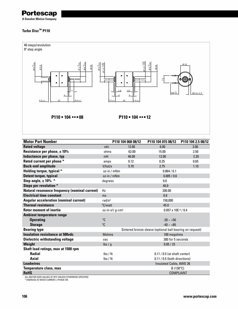
www.portescap.com106
Motor Part Number P110 104 068 08/12 P110 104 015 08/12 P110 104 2.5 08/12Rated voltage vdc 12.00 6.00 3.00Resistance per phase, ± 10% ohms 62.00 15.00 2.50Inductance per phase, typ mH 46.00 12.00 2.20Rated current per phase * amps 0.12 0.25 0.65Back-emf amplitude V/kst/s 5.70 2.75 1.10Holding torque, typical * oz-in / mNm 0.864 / 6.1 Detent torque, typical oz-in / mNm 0.085 / 0.6Step angle, ± 10% * degrees 9.0 Steps per revolution * 40.0 Natural resonance frequency (nominal current) Hz 200.00 Electrical time constant ms 0.8Angular acceleration (nominal current) rad/s2 150,000 Thermal resistance ºC/watt 45.0Rotor moment of inertia oz-in-s2/ g-cm2 0.057 x 10E-4 / 0.4Ambient temperature range Operating ºC -20 ~ +50 Storage ºC -40 ~ +85 Bearing type Sintered bronze sleeve (optional ball bearing on request) Insulation resisitance at 500vdc Mohms 100 megohmsDielectric withstanding voltage vac 300 for 5 secondsWeight lbs / g 0.05 / 23Shaft load ratings, max at 1500 rpm Radial lbs / N 0.11 / 0.5 (at shaft center) Axial lbs / N 0.11 / 0.5 (both directions)Leadwires Insulated Cable, AWG 26Temperature class, max B (130°C)RoHS COMPLIANT
192.3 ±0.3 6.5 ±0.3
4
1
Ø 1
+0
-0.0
06
Ø 6
+0
-0.0
18
Ø 3
.9
Ø 6
+0
-0.0
18
Ø 1
6
197.4 ±0.3 7.4 ±0.3
1.8
1
Ø 1
.5-0
.006
-0.0
09
Ø 6
+0
-0.0
18
Ø 1
.5-0
.006
-0.0
09
Ø 6
+0
-0.0
18
Ø 1
6
1.8
1100
+0-10
7.5
Ø 10
M1.6 x 1.2
Turbo DiscTM P110
40 steps/revolution9º step angle
P110 • 104 §§• 08 P110 • 104 §§• 12
ALL MOTOR DATA VALUES AT 25ºC UNLESS OTHERWISE SPECIFIED* ENERGISE AT RATED CURRENT, 2 PHASE ON
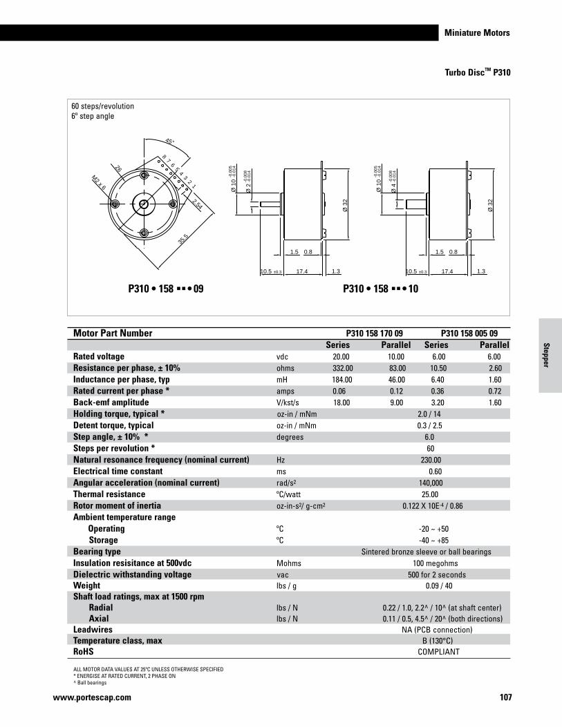
Miniature Motors
107www.portescap.com
Turbo DiscTM P310
Stepper
Ø 2
-0.0
08-0
.014
Ø 1
0-0
.005
-0.0
14
Ø 3
2
10.5 ±0.3 17.4
0.81.5
1.3
Ø 3
2
10.5 ±0.3 17.4
0.81.5
1.3
Ø 4
-0.0
08-0
.014
Ø 1
0-0
.005
-0.0
14
45°
35.5
8 7 6 5 4 3 2 1
2.54
�26
M2 x 6
60 steps/revolution6º step angle
ALL MOTOR DATA VALUES AT 25ºC UNLESS OTHERWISE SPECIFIED* ENERGISE AT RATED CURRENT, 2 PHASE ON^ Ball bearings
P310 • 158 §§• 09 P310 • 158 §§• 10
Motor Part Number P310 158 170 09 P310 158 005 09 Series Parallel Series ParallelRated voltage vdc 20.00 10.00 6.00 6.00Resistance per phase, ± 10% ohms 332.00 83.00 10.50 2.60Inductance per phase, typ mH 184.00 46.00 6.40 1.60Rated current per phase * amps 0.06 0.12 0.36 0.72Back-emf amplitude V/kst/s 18.00 9.00 3.20 1.60Holding torque, typical * oz-in / mNm 2.0 / 14 Detent torque, typical oz-in / mNm 0.3 / 2.5Step angle, ± 10% * degrees 6.0 Steps per revolution * 60 Natural resonance frequency (nominal current) Hz 230.00 Electrical time constant ms 0.60Angular acceleration (nominal current) rad/s2 140,000 Thermal resistance ºC/watt 25.00Rotor moment of inertia oz-in-s2/ g-cm2 0.122 X 10E-4 / 0.86Ambient temperature range Operating ºC -20 ~ +50 Storage ºC -40 ~ +85 Bearing type Sintered bronze sleeve or ball bearings Insulation resisitance at 500vdc Mohms 100 megohmsDielectric withstanding voltage vac 500 for 2 secondsWeight lbs / g 0.09 / 40Shaft load ratings, max at 1500 rpm Radial lbs / N 0.22 / 1.0, 2.2^ / 10^ (at shaft center) Axial lbs / N 0.11 / 0.5, 4.5^ / 20^ (both directions)Leadwires NA (PCB connection)Temperature class, max B (130°C)RoHS COMPLIANT
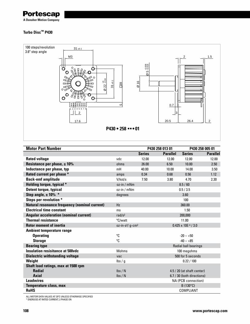
www.portescap.com108
1 2 3 4 5 6 7 8
Ø 2
2+
0-0
.04
31±0
.1
39
31 ±0.1
M3
5
2
17.6 2
1.5
26.420.5
0.7
3
Ø 1
6
Ø 5
-0.0
08-0
.016
2
Turbo DiscTM P430
100 steps/revolution3.6º step angle
P430 • 258 §§• 01
Motor Part Number P430 258 013 01 P430 258 005 01 Series Parallel Series ParallelRated voltage vdc 12.00 12.00 12.00 12.00Resistance per phase, ± 10% ohms 26.00 6.50 10.00 2.50Inductance per phase, typ mH 40.00 10.00 14.00 3.50Rated current per phase * amps 0.34 0.68 0.56 1.12Back-emf amplitude V/kst/s 7.50 3.80 4.70 2.30Holding torque, typical * oz-in / mNm 8.5 / 60 Detent torque, typical oz-in / mNm 0.5 / 3.5Step angle, ± 10% * degrees 3.60 Steps per revolution * 100 Natural resonance frequency (nominal current) Hz 360.00 Electrical time constant ms 1.50Angular acceleration (nominal current) rad/s2 200,000 Thermal resistance ºC/watt 11.00Rotor moment of inertia oz-in-s2/ g-cm2 0.425 x 10E-4 / 3.0Ambient temperature range Operating ºC -20 ~ +50 Storage ºC -40 ~ +85 Bearing type Radial ball bearings Insulation resisitance at 500vdc Mohms 100 megohmsDielectric withstanding voltage vac 500 for 5 secondsWeight lbs / g 0.22 / 100Shaft load ratings, max at 1500 rpm Radial lbs / N 4.5 / 20 (at shaft center) Axial lbs / N 6.7 / 30 (both directions)Leadwires NA (PCB connection)Temperature class, max B (130°C)RoHS COMPLIANTALL MOTOR DATA VALUES AT 25ºC UNLESS OTHERWISE SPECIFIED* ENERGISE AT RATED CURRENT, 2 PHASE ON
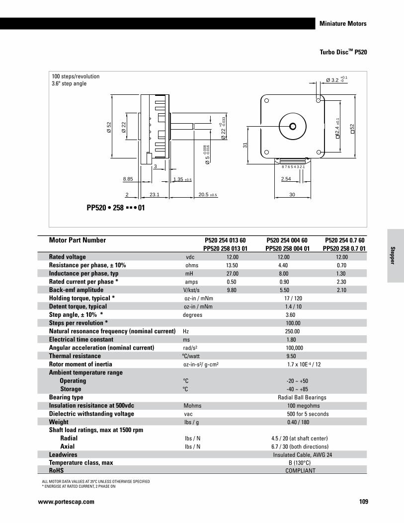
Miniature Motors
109www.portescap.com
Turbo DiscTM P520
Stepper
Motor Part Number P430 258 013 01 P430 258 005 01 Series Parallel Series ParallelRated voltage vdc 12.00 12.00 12.00 12.00Resistance per phase, ± 10% ohms 26.00 6.50 10.00 2.50Inductance per phase, typ mH 40.00 10.00 14.00 3.50Rated current per phase * amps 0.34 0.68 0.56 1.12Back-emf amplitude V/kst/s 7.50 3.80 4.70 2.30Holding torque, typical * oz-in / mNm 8.5 / 60 Detent torque, typical oz-in / mNm 0.5 / 3.5Step angle, ± 10% * degrees 3.60 Steps per revolution * 100 Natural resonance frequency (nominal current) Hz 360.00 Electrical time constant ms 1.50Angular acceleration (nominal current) rad/s2 200,000 Thermal resistance ºC/watt 11.00Rotor moment of inertia oz-in-s2/ g-cm2 0.425 x 10E-4 / 3.0Ambient temperature range Operating ºC -20 ~ +50 Storage ºC -40 ~ +85 Bearing type Radial ball bearings Insulation resisitance at 500vdc Mohms 100 megohmsDielectric withstanding voltage vac 500 for 5 secondsWeight lbs / g 0.22 / 100Shaft load ratings, max at 1500 rpm Radial lbs / N 4.5 / 20 (at shaft center) Axial lbs / N 6.7 / 30 (both directions)Leadwires NA (PCB connection)Temperature class, max B (130°C)RoHS COMPLIANT
23.1
3
1.35 ±0.5
20.5 ±0.5
Ø 2
2+
0-0
.033
Ø 5
-0.0
08-0
.016
Ø 5
2
2
Ø 3.2+0.1-0
Ø 2
2
42.4
±0.1
52
8.85
30
31
2.54
8 7 6 5 4 3 2 1
100 steps/revolution3.6º step angle
ALL MOTOR DATA VALUES AT 25ºC UNLESS OTHERWISE SPECIFIED* ENERGISE AT RATED CURRENT, 2 PHASE ON
PP520 • 258 §§• 01
Motor Part Number P520 254 013 60 P520 254 004 60 P520 254 0.7 60 PP520 258 013 01 PP520 258 004 01 PP520 258 0.7 01Rated voltage vdc 12.00 12.00 12.00Resistance per phase, ± 10% ohms 13.50 4.40 0.70Inductance per phase, typ mH 27.00 8.00 1.30Rated current per phase * amps 0.50 0.90 2.30Back-emf amplitude V/kst/s 9.80 5.50 2.10Holding torque, typical * oz-in / mNm 17 / 120 Detent torque, typical oz-in / mNm 1.4 / 10Step angle, ± 10% * degrees 3.60 Steps per revolution * 100.00 Natural resonance frequency (nominal current) Hz 250.00 Electrical time constant ms 1.80Angular acceleration (nominal current) rad/s2 100,000 Thermal resistance ºC/watt 9.50Rotor moment of inertia oz-in-s2/ g-cm2 1.7 x 10E-4 / 12Ambient temperature range Operating ºC -20 ~ +50 Storage ºC -40 ~ +85 Bearing type Radial Ball Bearings Insulation resisitance at 500vdc Mohms 100 megohmsDielectric withstanding voltage vac 500 for 5 secondsWeight lbs / g 0.40 / 180Shaft load ratings, max at 1500 rpm Radial lbs / N 4.5 / 20 (at shaft center) Axial lbs / N 6.7 / 30 (both directions)Leadwires Insulated Cable, AWG 24Temperature class, max B (130°C)RoHS COMPLIANT
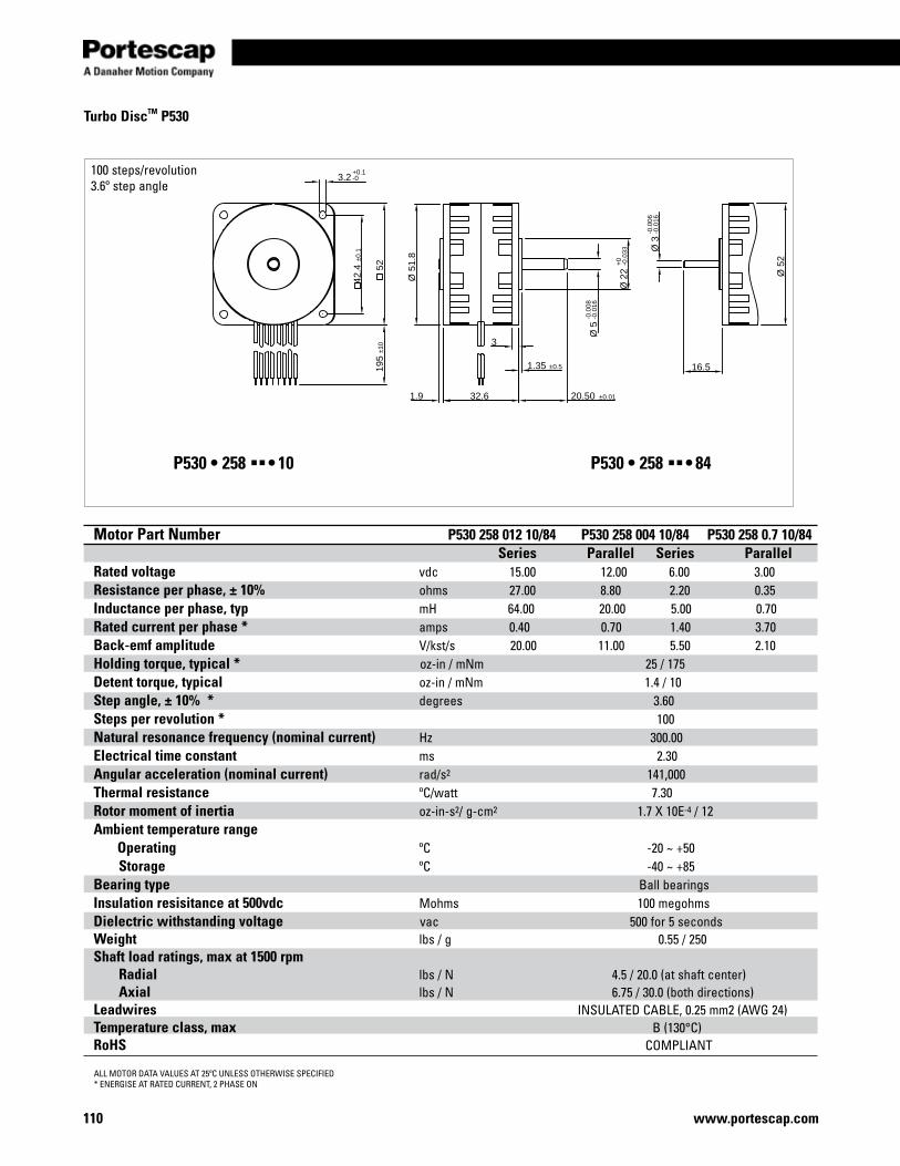
www.portescap.com110
32.6
3
1.35 ±0.5
20.50 ±0.01
Ø 2
2+
0-0
.033
Ø 5
-0.0
08-0
.016
Ø 5
1.8
16.5
Ø 3
-0.0
06-0
.016
Ø 5
2
42.4
±0.1
5219
5±1
0
1.9
3.2+0.1-0
Turbo DiscTM P530
100 steps/revolution3.6º step angle
ALL MOTOR DATA VALUES AT 25ºC UNLESS OTHERWISE SPECIFIED* ENERGISE AT RATED CURRENT, 2 PHASE ON
P530 • 258 §§• 10 P530 • 258 §§• 84
Motor Part Number P530 258 012 10/84 P530 258 004 10/84 P530 258 0.7 10/84 Series Parallel Series ParallelRated voltage vdc 15.00 12.00 6.00 3.00Resistance per phase, ± 10% ohms 27.00 8.80 2.20 0.35Inductance per phase, typ mH 64.00 20.00 5.00 0.70Rated current per phase * amps 0.40 0.70 1.40 3.70Back-emf amplitude V/kst/s 20.00 11.00 5.50 2.10Holding torque, typical * oz-in / mNm 25 / 175 Detent torque, typical oz-in / mNm 1.4 / 10Step angle, ± 10% * degrees 3.60 Steps per revolution * 100 Natural resonance frequency (nominal current) Hz 300.00 Electrical time constant ms 2.30Angular acceleration (nominal current) rad/s2 141,000 Thermal resistance ºC/watt 7.30Rotor moment of inertia oz-in-s2/ g-cm2 1.7 X 10E-4 / 12Ambient temperature range Operating ºC -20 ~ +50 Storage ºC -40 ~ +85 Bearing type Ball bearings Insulation resisitance at 500vdc Mohms 100 megohmsDielectric withstanding voltage vac 500 for 5 secondsWeight lbs / g 0.55 / 250Shaft load ratings, max at 1500 rpm Radial lbs / N 4.5 / 20.0 (at shaft center) Axial lbs / N 6.75 / 30.0 (both directions)Leadwires INSULATED CABLE, 0.25 mm2 (AWG 24)Temperature class, max B (130°C)RoHS COMPLIANT
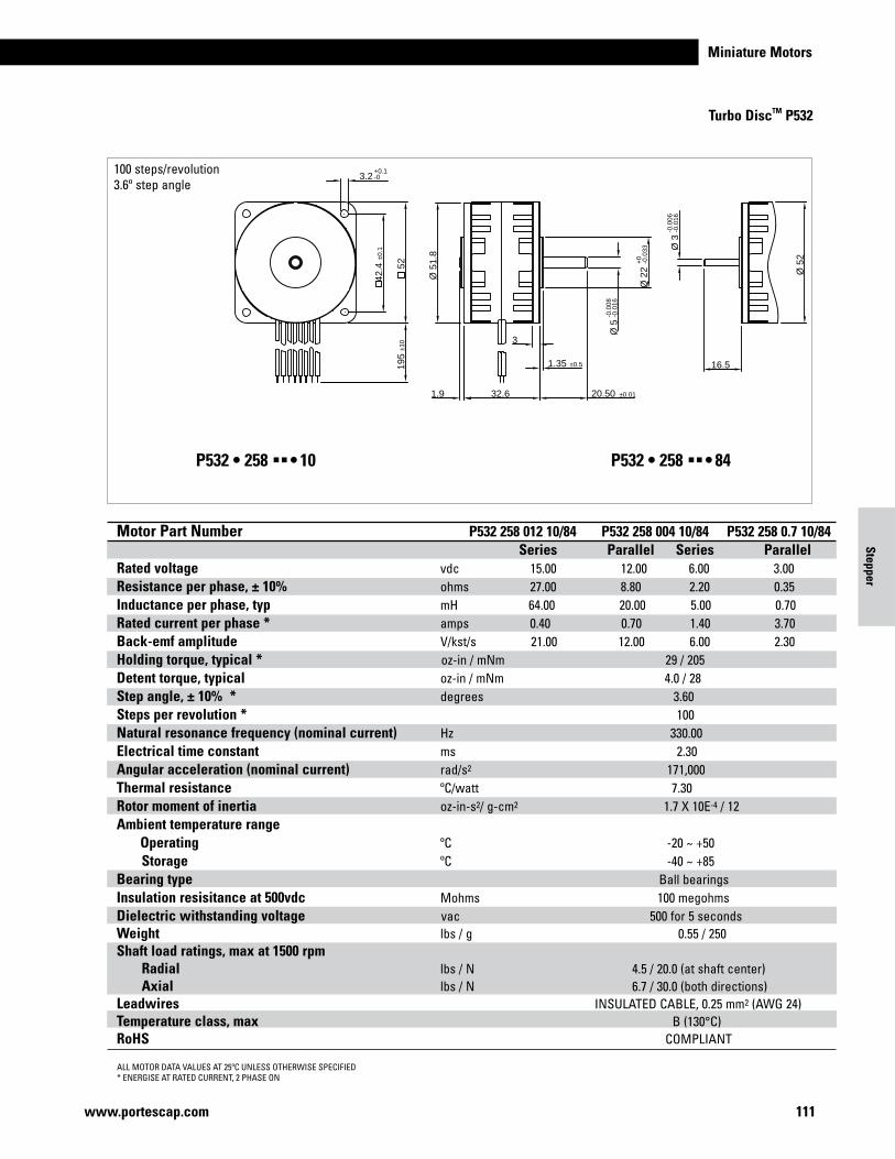
Miniature Motors
111www.portescap.com
Turbo DiscTM P532
Stepper
32.6
3
1.35 ±0.5
20.50 ±0.01
Ø 2
2+
0-0
.033
Ø 5
-0.0
08-0
.016
Ø 5
1.8
16.5
Ø 3
-0.0
06-0
.016
Ø 5
2
42.4
±0.1
5219
5±1
01.9
3.2+0.1-0
100 steps/revolution3.6º step angle
ALL MOTOR DATA VALUES AT 25ºC UNLESS OTHERWISE SPECIFIED* ENERGISE AT RATED CURRENT, 2 PHASE ON
P532 • 258 §§• 10 P532 • 258 §§• 84
Motor Part Number P530 258 012 10/84 P530 258 004 10/84 P530 258 0.7 10/84 Series Parallel Series ParallelRated voltage vdc 15.00 12.00 6.00 3.00Resistance per phase, ± 10% ohms 27.00 8.80 2.20 0.35Inductance per phase, typ mH 64.00 20.00 5.00 0.70Rated current per phase * amps 0.40 0.70 1.40 3.70Back-emf amplitude V/kst/s 20.00 11.00 5.50 2.10Holding torque, typical * oz-in / mNm 25 / 175 Detent torque, typical oz-in / mNm 1.4 / 10Step angle, ± 10% * degrees 3.60 Steps per revolution * 100 Natural resonance frequency (nominal current) Hz 300.00 Electrical time constant ms 2.30Angular acceleration (nominal current) rad/s2 141,000 Thermal resistance ºC/watt 7.30Rotor moment of inertia oz-in-s2/ g-cm2 1.7 X 10E-4 / 12Ambient temperature range Operating ºC -20 ~ +50 Storage ºC -40 ~ +85 Bearing type Ball bearings Insulation resisitance at 500vdc Mohms 100 megohmsDielectric withstanding voltage vac 500 for 5 secondsWeight lbs / g 0.55 / 250Shaft load ratings, max at 1500 rpm Radial lbs / N 4.5 / 20.0 (at shaft center) Axial lbs / N 6.75 / 30.0 (both directions)Leadwires INSULATED CABLE, 0.25 mm2 (AWG 24)Temperature class, max B (130°C)RoHS COMPLIANT
Motor Part Number P532 258 012 10/84 P532 258 004 10/84 P532 258 0.7 10/84 Series Parallel Series ParallelRated voltage vdc 15.00 12.00 6.00 3.00Resistance per phase, ± 10% ohms 27.00 8.80 2.20 0.35Inductance per phase, typ mH 64.00 20.00 5.00 0.70Rated current per phase * amps 0.40 0.70 1.40 3.70Back-emf amplitude V/kst/s 21.00 12.00 6.00 2.30Holding torque, typical * oz-in / mNm 29 / 205 Detent torque, typical oz-in / mNm 4.0 / 28Step angle, ± 10% * degrees 3.60 Steps per revolution * 100 Natural resonance frequency (nominal current) Hz 330.00 Electrical time constant ms 2.30Angular acceleration (nominal current) rad/s2 171,000 Thermal resistance ºC/watt 7.30Rotor moment of inertia oz-in-s2/ g-cm2 1.7 X 10E-4 / 12Ambient temperature range Operating ºC -20 ~ +50 Storage ºC -40 ~ +85 Bearing type Ball bearings Insulation resisitance at 500vdc Mohms 100 megohmsDielectric withstanding voltage vac 500 for 5 secondsWeight lbs / g 0.55 / 250Shaft load ratings, max at 1500 rpm Radial lbs / N 4.5 / 20.0 (at shaft center) Axial lbs / N 6.7 / 30.0 (both directions)Leadwires INSULATED CABLE, 0.25 mm2 (AWG 24)Temperature class, max B (130°C)RoHS COMPLIANT
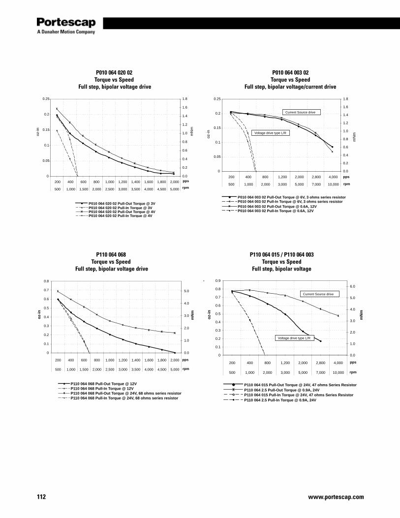
www.portescap.com112
oz-in
mN
m
P010 064 020 02 Pull-Out Torque @ 3VP010 064 020 02 Pull-In Torque @ 3VP010 064 020 02 Pull-Out Torque @ 4VP010 064 020 02 Pull-In Torque @ 4V
0
0.05
0.1
0.15
0.2
0.25
200 400 600 800 1,000 1,200 1,400 1,600 1,800 2,000
500 1,000 1,500 2,000 2,500 3,000 3,500 4,000 4,500 5,000
pps0.0
0.2
0.4
0.6
0.8
1.0
1.2
1.4
1.6
1.8
rpm
0
0.05
0.1
0.15
0.2
0.25
200 400 800 1,200 2,000 2,800 4,000
500 1,000 2,000 3,000 5,000 7,000 10,000
pps
0.0
0.2
0.4
0.6
0.8
1.0
1.2
1.4
1.6
1.8
rpm
P010 064 003 02 Pull-Out Torque @ 6V, 3 ohms series resistorP010 064 003 02 Pull-In Torque @ 6V, 3 ohms series resistorP010 064 003 02 Pull-Out Torque @ 0.6A, 12VP010 064 003 02 Pull-In Torque @ 0.6A, 12V
oz-in
mN
m
Current Source drive
Voltage drive type L/R
P010 064 020 02Torque vs Speed
Full step, bipolar voltage drive
P010 064 003 02Torque vs Speed
Full step, bipolar voltage/current drive
oz-
in
mN
m
0
0.1
0.2
0.3
0.4
0.5
0.6
0.7
0.8
200 400 600 800 1,000 1,200 1,400 1,600 1,800 2,000
500 1,000 1,500 2,000 2,500 3,000 3,500 4,000 4,500 5,000
pps
0.0
1.0
2.0
3.0
4.0
5.0
rpm
P110 064 068 Pull-Out Torque @ 12VP110 064 068 Pull-In Torque @ 12VP110 064 068 Pull-Out Torque @ 24V, 68 ohms series resistorP110 064 068 Pull-In Torque @ 24V, 68 ohms series resistor
oz-
in
mN
m
P110 064 015 Pull-Out Torque @ 24V, 47 ohms Series ResistorP110 064 2.5 Pull-Out Torque @ 0.9A, 24VP110 064 015 Pull-In Torque @ 24V, 47 ohms Series ResistorP110 064 2.5 Pull-In Torque @ 0.9A, 24V
0
0.1
0.2
0.3
0.4
0.5
0.6
0.7
0.8
0.9
200 400 800 1,200 2,000 2,800 4,000
500 1,000 2,000 3,000 5,000 7,000 10,000
pps
0.0
1.0
2.0
3.0
4.0
5.0
6.0
rpm
Voltage drive type L/R
Current Source drive
P110 064 068Torque vs Speed
Full step, bipolar voltage drive
P110 064 015 / P110 064 003Torque vs Speed
Full step, bipolar voltage
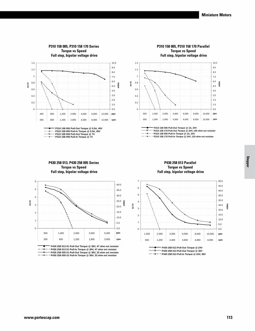
Miniature Motors
113www.portescap.com
Stepper
P430 258 013 01 Pull-Out Torque @ 36V, 47 ohm ext resistorP430 258 013 01 Pull-In Torque @ 36V, 47 ohm ext resistorP430 258 005 01 Pull-Out Torque @ 36V, 33 ohm ext resistorP430 258 005 01 Pull-In Torque @ 36V, 33 ohm ext resistor
oz-
in
mN
m
0
1
2
3
4
5
6
500 1,000 2,000 3,000 5,000
300 600 1,200 1,800 3,000
pps
0.0
5.0
10.0
15.0
20.0
25.0
30.0
35.0
40.0
rpm
oz-
in
mN
m
P430 258 013 Pull-Out Torque @ 24VP430 258 013 Pull-Out Torque @ 36VP430 258 013 Pull-In Torque @ 24V, 36V
0
1
2
3
4
5
6
7
1,000 2,000 4,000 6,000 8,000 10,000
600 1,200 2,400 3,600 4,800 6,000
pps
0.0
5.0
10.0
15.0
20.0
25.0
30.0
35.0
40.0
45.0
50.0
rpm
P430 258 013, P430 258 005 SeriesTorque vs Speed
Full step, bipolar voltage drive
P430 258 013 ParallelTorque vs Speed
Full step, bipolar voltage drive
oz-
in
mN
m
P310 158 005 Pull-Out Torque @ 0.5A, 45VP310 158 005 Pull-In Torque @ 0.5A, 45VP310 158 005 Pull-Out Torque @ 7VP310 158 005 Pull-In Torque @ 7V
0
0.2
0.4
0.6
0.8
1
1.2
1.4
400 800 1,200 2,000 4,000 6,000 12,000
400 800 1,200 2,000 4,000 6,000 12,000
pps
0.0
1.0
2.0
3.0
4.0
5.0
6.0
7.0
8.0
9.0
10.0
rpm
oz-
in
mN
m
P310 158 005 Pull-Out Torque @ 1A, 24VP310 158 170 Pull-Out Torque @ 24V, 120 ohm ext resistorP310 158 005 Pull-In Torque @ 1A, 24VP310 158 170 Pull-In Torque @ 24V, 120 ohm ext resistor
0
0.2
0.4
0.6
0.8
1
1.2
1.4
500 1,000 2,000 4,000 6,000 8,000 10,000
500 1,000 2,000 4,000 6,000 8,000 10,000
pps
0.0
1.0
2.0
3.0
4.0
5.0
6.0
7.0
8.0
9.0
10.0
rpm
P310 158 005, P310 158 170 Series Torque vs Speed
Full step, bipolar voltage drive
P310 158 005, P310 158 170 ParallelTorque vs Speed
Full step, bipolar voltage drive
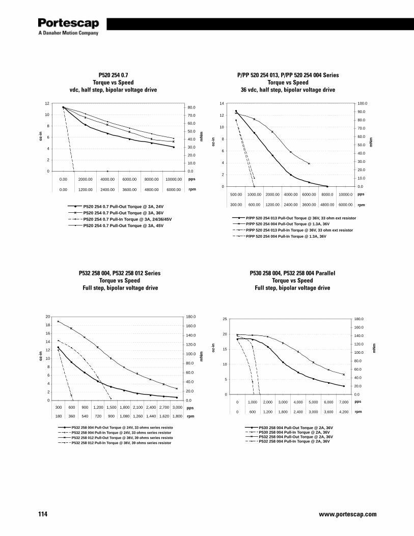
www.portescap.com114
oz-
in
mN
m
0
2
4
6
8
10
12
14
16
18
20
300 600 900 1,200 1,500 1,800 2,100 2,400 2,700 3,000
180 360 540 720 900 1,080 1,260 1,440 1,620 1,800
pps
0.0
20.0
40.0
60.0
80.0
100.0
120.0
140.0
160.0
180.0
rpm
P532 258 004 Pull-Out Torque @ 24V, 33 ohms series resistor
P532 258 004 Pull-In Torque @ 24V, 33 ohms series resistor
P532 258 012 Pull-Out Torque @ 36V, 39 ohms series resistor
P532 258 012 Pull-In Torque @ 36V, 39 ohms series resistor
oz-
in
mN
m
0
5
10
15
20
25
0 1,000 2,000 3,000 4,000 5,000 6,000 7,000
0 600 1,200 1,800 2,400 3,000 3,600 4,200
pps
0.0
20.0
40.0
60.0
80.0
100.0
120.0
140.0
160.0
180.0
rpm
P530 258 004 Pull-Out Torque @ 2A, 36VP530 258 004 Pull-In Torque @ 2A, 36VP532 258 004 Pull-Out Torque @ 2A, 36VP532 258 004 Pull-In Torque @ 2A, 36V
P532 258 004, P532 258 012 SeriesTorque vs Speed
Full step, bipolar voltage drive
P530 258 004, P532 258 004 ParallelTorque vs Speed
Full step, bipolar voltage drive
oz-
in
mN
m
0
2
4
6
8
10
12
0.00 2000.00 4000.00 6000.00 8000.00 10000.00
0.00 1200.00 2400.00 3600.00 4800.00 6000.00
pps
0.0
10.0
20.0
30.0
40.0
50.0
60.0
70.0
80.0
rpm
P520 254 0.7 Pull-Out Torque @ 3A, 24V
P520 254 0.7 Pull-Out Torque @ 3A, 36V
P520 254 0.7 Pull-In Torque @ 3A, 24/36/45V
P520 254 0.7 Pull-Out Torque @ 3A, 45V
oz-
in
mN
m
0
2
4
6
8
10
12
14
500.00 1000.00 2000.00 4000.00 6000.00 8000.0 10000.0
300.00 600.00 1200.00 2400.00 3600.00 4800.00 6000.00
pps
0.0
10.0
20.0
30.0
40.0
50.0
60.0
70.0
80.0
90.0
100.0
rpm
P/PP 520 254 013 Pull-Out Torque @ 36V, 33 ohm ext resistor
P/PP 520 254 004 Pull-Out Torque @ 1.3A, 36V
P/PP 520 254 013 Pull-In Torque @ 36V, 33 ohm ext resistor
P/PP 520 254 004 Pull-In Torque @ 1.3A, 36V
P520 254 0.7Torque vs Speed
vdc, half step, bipolar voltage drive
P/PP 520 254 013, P/PP 520 254 004 SeriesTorque vs Speed
36 vdc, half step, bipolar voltage drive
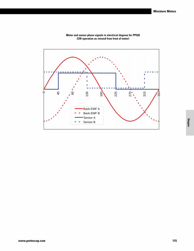
Miniature Motors
115www.portescap.com
-2.5
-2
-1.5
-1
-0.5
0
0.5
1
1.5
2
2.5
0 45 90 135
180
225
270
315
360
Back-EMF A
Back-EMF B
Sensor A
Sensor B
Motor and sensor phase signals in electrical degrees for PP520 (CW operation as viewed from front of motor)
Stepper

www.portescap.com116
Notes
CANSTACK STepper moTorS
Why a CanStack motor 118
What is a canstack motor 119
How to select your
canstack motor 121
Where to apply your canstack motor 123
Specifications 124
Portescap can trace its roots back to the design team who invented
the Permanent Magnet Stepper and AC Synchronous Motor.
Today, this technology is found in a wide variety of applications
for good reason – they have the accuracy and torque to match the
needs of our customers. Portescap has one of the broadest range
of CanStack solutions on the market today. Portescap’s CanStack
motors are intentionally basic to deliver a simple and effective
motion solution for your application.
15M
20M
26M 35M
42M
55M
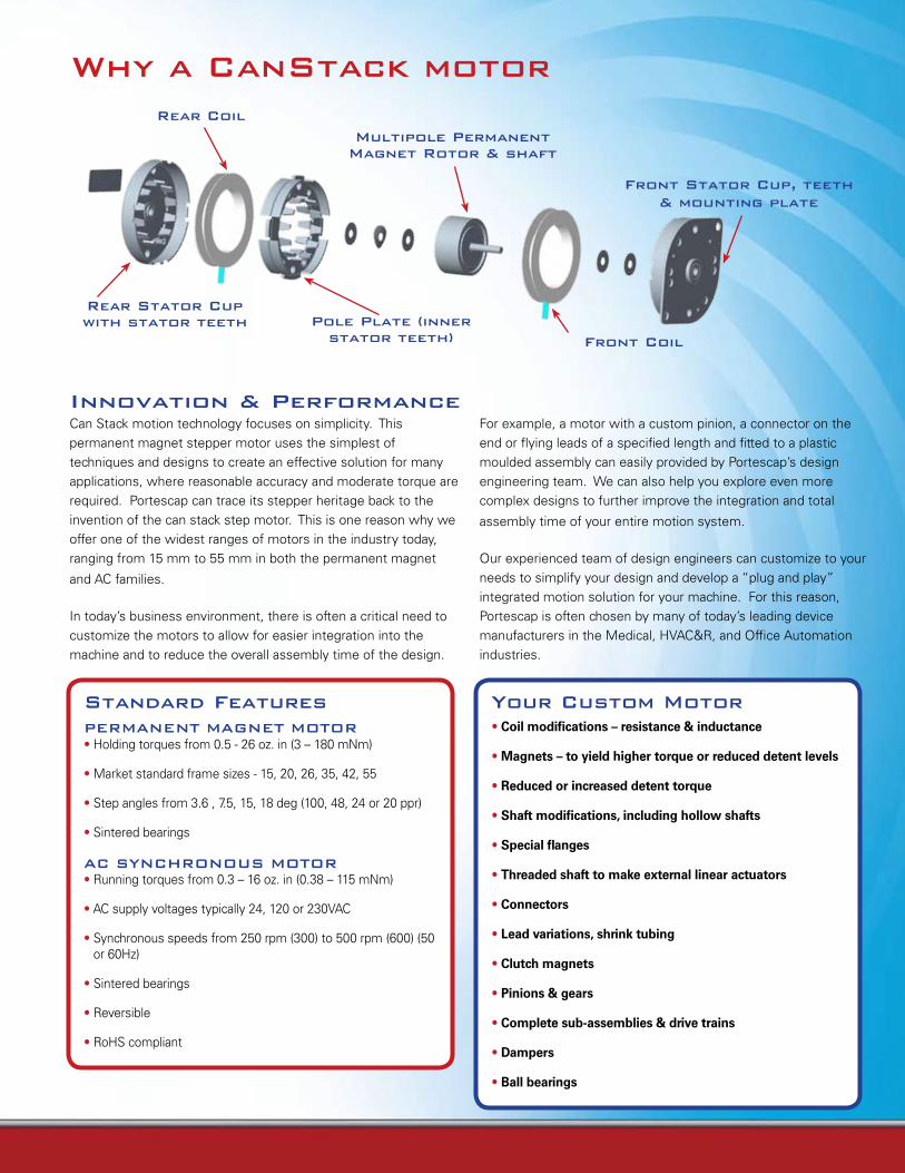
Can Stack motion technology focuses on simplicity. This permanent magnet stepper motor uses the simplest of techniques and designs to create an effective solution for many applications, where reasonable accuracy and moderate torque are required. Portescap can trace its stepper heritage back to the invention of the can stack step motor. This is one reason why we offer one of the widest ranges of motors in the industry today, ranging from 15 mm to 55 mm in both the permanent magnet
and AC families.
In today’s business environment, there is often a critical need to customize the motors to allow for easier integration into the machine and to reduce the overall assembly time of the design.
Innovation & performance
Standard FeaturespermANeNT mAGNeT moTor• Holding torques from 0.5 - 26 oz. in (3 – 180 mNm)
• Market standard frame sizes - 15, 20, 26, 35, 42, 55
• Step angles from 3.6 , 7.5, 15, 18 deg (100, 48, 24 or 20 ppr)
• Sintered bearings
AC SYNCHroNoUS moTor• Running torques from 0.3 – 16 oz. in (0.38 – 115 mNm)
• AC supply voltages typically 24, 120 or 230VAC
• Synchronous speeds from 250 rpm (300) to 500 rpm (600) (50 or 60Hz)
• Sintered bearings
• Reversible
• RoHS compliant
Your Custom motor• Coil modifications – resistance & inductance
• Magnets – to yield higher torque or reduced detent levels
• Reduced or increased detent torque
• Shaft modifications, including hollow shafts
• Special flanges
• Threaded shaft to make external linear actuators
• Connectors
• Lead variations, shrink tubing
• Clutch magnets
• Pinions & gears
• Complete sub-assemblies & drive trains
• Dampers
• Ball bearings
For example, a motor with a custom pinion, a connector on the end or flying leads of a specified length and fitted to a plastic moulded assembly can easily provided by Portescap’s design engineering team. We can also help you explore even more complex designs to further improve the integration and total
assembly time of your entire motion system.
Our experienced team of design engineers can customize to your needs to simplify your design and develop a “plug and play” integrated motion solution for your machine. For this reason, Portescap is often chosen by many of today’s leading device manufacturers in the Medical, HVAC&R, and Office Automation industries.
Why a CanStack motor
multipole permanent magnet rotor & shaft
rear Coil
Front Stator Cup, teeth & mounting plate
Front Coilpole plate (inner
stator teeth)
rear Stator Cup with stator teeth
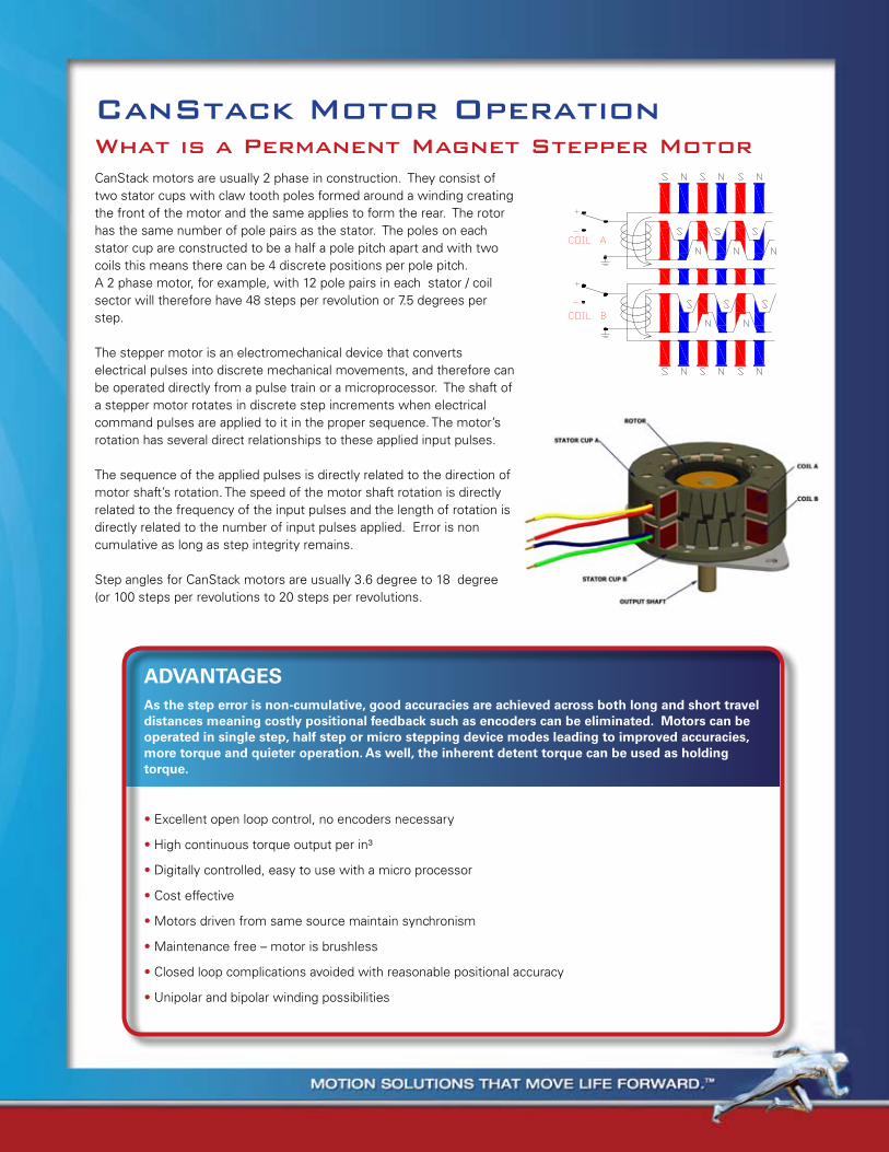
ADVANTAGESAs the step error is non-cumulative, good accuracies are achieved across both long and short travel distances meaning costly positional feedback such as encoders can be eliminated. Motors can be operated in single step, half step or micro stepping device modes leading to improved accuracies, more torque and quieter operation. As well, the inherent detent torque can be used as holding torque.
• Excellent open loop control, no encoders necessary
• High continuous torque output per in³
• Digitally controlled, easy to use with a micro processor
• Cost effective
• Motors driven from same source maintain synchronism
• Maintenance free – motor is brushless
• Closed loop complications avoided with reasonable positional accuracy
• Unipolar and bipolar winding possibilities
CanStack motor operation
CanStack motors are usually 2 phase in construction. They consist of two stator cups with claw tooth poles formed around a winding creating the front of the motor and the same applies to form the rear. The rotor has the same number of pole pairs as the stator. The poles on each stator cup are constructed to be a half a pole pitch apart and with two coils this means there can be 4 discrete positions per pole pitch.A 2 phase motor, for example, with 12 pole pairs in each stator / coil sector will therefore have 48 steps per revolution or 7.5 degrees per step.
The stepper motor is an electromechanical device that converts electrical pulses into discrete mechanical movements, and therefore can be operated directly from a pulse train or a microprocessor. The shaft of a stepper motor rotates in discrete step increments when electrical command pulses are applied to it in the proper sequence. The motor’s rotation has several direct relationships to these applied input pulses.
The sequence of the applied pulses is directly related to the direction of motor shaft’s rotation. The speed of the motor shaft rotation is directly related to the frequency of the input pulses and the length of rotation is directly related to the number of input pulses applied. Error is non cumulative as long as step integrity remains.
Step angles for CanStack motors are usually 3.6 degree to 18 degree (or 100 steps per revolutions to 20 steps per revolutions.
What is a permanent magnet Stepper motor
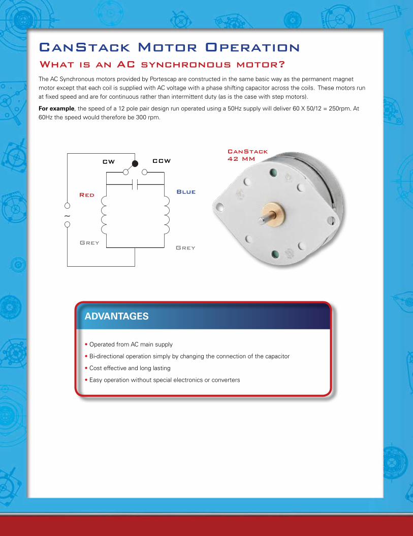
CanStack motor operation
The AC Synchronous motors provided by Portescap are constructed in the same basic way as the permanent magnet motor except that each coil is supplied with AC voltage with a phase shifting capacitor across the coils. These motors run at fixed speed and are for continuous rather than intermittent duty (as is the case with step motors).
For example, the speed of a 12 pole pair design run operated using a 50Hz supply will deliver 60 X 50/12 = 250rpm. At 60Hz the speed would therefore be 300 rpm.
What is an AC synchronous motor?
ADVANTAGES
• Operated from AC main supply
• Bi-directional operation simply by changing the connection of the capacitor
• Cost effective and long lasting
• Easy operation without special electronics or converters
CW
red Blue
GreyGrey
CCW
~
CanStack 42 mm
26 m 048 D 2 B
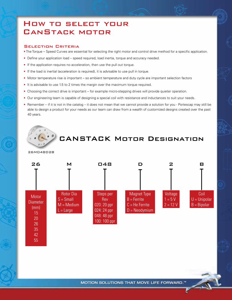
CANSTACK motor Designation
Selection Criteria• The Torque – Speed Curves are essential for selecting the right motor and control drive method for a specific application.
• Define your application load – speed required, load inertia, torque and accuracy needed.
• If the application requires no acceleration, then use the pull out torque.
• If the load is inertial (acceleration is required), it is advisable to use pull in torque.
• Motor temperature rise is important – so ambient temperature and duty cycle are important selection factors
• It is advisable to use 1.5 to 2 times the margin over the maximum torque required.
• Choosing the correct drive is important – for example micro-stepping drives will provide quieter operation.
• Our engineering team is capable of designing a special coil with resistance and inductances to suit your needs.
• Remember – if it is not in the catalog – it does not mean that we cannot provide a solution for you - Portescap may still be able to design a product for your needs as our team can draw from a wealth of customized designs created over the past 40 years.
26 m 048 D 2 B
Steps per Rev
020: 20 ppr024: 24 ppr048: 48 ppr100: 100 ppr
CoilU = UnipolarB = Bipolar
Motor Diameter
(mm)152026354255
Voltage1 = 5 V2 = 12 V
Magnet TypeB = FerriteC = He FerriteD = Neodymium
Rotor DiaS = SmallM = MediumL = Large
How to select your CanStack motor
26M048D2B
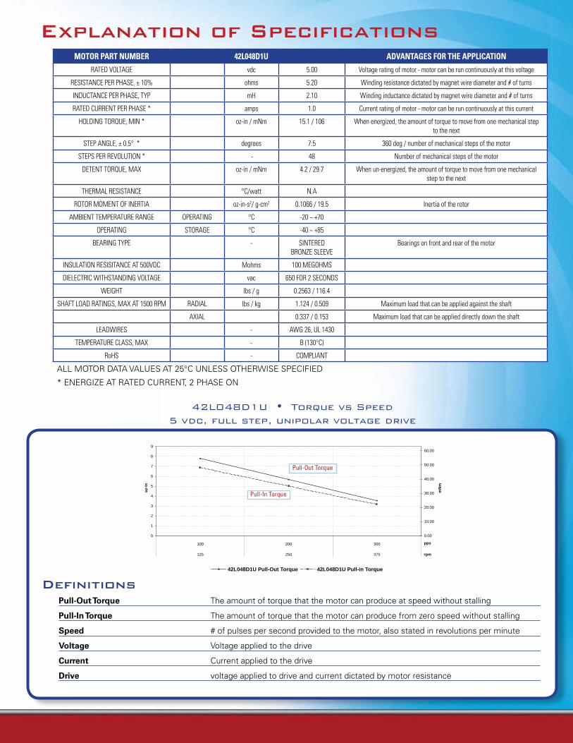
Explanation of SpecificationsMOTOR PART NUMBER 42L048D1U ADVANTAGES FOR THE APPLICATION
RATED VOLTAGE vdc 5.00 Voltage rating of motor - motor can be run continuously at this voltage
RESISTANCE PER PHASE, ± 10% ohms 5.20 Winding resistance dictated by magnet wire diameter and # of turns
INDUCTANCE PER PHASE, TYP mH 2.10 Winding inductance dictated by magnet wire diameter and # of turns
RATED CURRENT PER PHASE * amps 1.0 Current rating of motor - motor can be run continuously at this current
HOLDING TORQUE, MIN * oz-in / mNm 15.1 / 106 When energized, the amount of torque to move from one mechanical step to the next
STEP ANGLE, ± 0.5° * degrees 7.5 360 deg / number of mechanical steps of the motor
STEPS PER REVOLUTION * - 48 Number of mechanical steps of the motor
DETENT TORQUE, MAX oz-in / mNm 4.2 / 29.7 When un-energized, the amount of torque to move from one mechanical step to the next
THERMAL RESISTANCE °C/watt N.A
ROTOR MOMENT OF INERTIA oz-in-s2/ g-cm2 0.1066 / 19.5 Inertia of the rotor
AMBIENT TEMPERATURE RANGE OPERATING °C -20 ~ +70
OPERATING STORAGE °C -40 ~ +85
BEARING TYPE - SINTERED BRONZE SLEEVE
Bearings on front and rear of the motor
INSULATION RESISITANCE AT 500VDC Mohms 100 MEGOHMS
DIELECTRIC WITHSTANDING VOLTAGE vac 650 FOR 2 SECONDS
WEIGHT lbs / g 0.2563 / 116.4
SHAFT LOAD RATINGS, MAX AT 1500 RPM RADIAL lbs / kg 1.124 / 0.509 Maximum load that can be applied against the shaft
AXIAL 0.337 / 0.153 Maximum load that can be applied directly down the shaft
LEADWIRES - AWG 26, UL 1430
TEMPERATURE CLASS, MAX - B (130°C)
RoHS - COMPLIANT
ALL MOTOR DATA VALUES AT 25°C UNLESS OTHERWISE SPECIFIED
* ENERGIZE AT RATED CURRENT, 2 PHASE ON
42L048D1U•TorquevsSpeed5vdc,fullstep,unipolarvoltagedrive
Definitions
Pull-Out Torque The amount of torque that the motor can produce at speed without stalling
Pull-In Torque The amount of torque that the motor can produce from zero speed without stalling
Speed # of pulses per second provided to the motor, also stated in revolutions per minute
Voltage Voltage applied to the drive
Current Current applied to the drive
Drive voltage applied to drive and current dictated by motor resistance
oz-
in
mN
m
42L048D1UTorque vs Speed
5 vdc, full step, unipolar voltage
0
1
2
3
4
5
6
7
8
9
100 200 300
125 250 375
pps
0.00
10.00
20.00
30.00
40.00
50.00
60.00
rpm
42L048D1U Pull-Out Torque 42L048D1U Pull-in Torque
Pull-In Torque
Pull-Out Torque
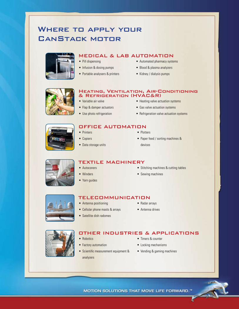
Where to apply yourCanStack motor
TeLeCommUNICATIoNAntenna positioning•
Cellular phone masts & arrays•
Satellite dish radomes•
Radar arrays•
Antenna drives•
meDICAL & LAB AUTomATIoNPill dispensing•
Infusion & dosing pumps•
Portable analysers & printers•
Automated pharmacy systems•
Blood & plasma analyzers•
Kidney / dialysis pumps•
Heating, Ventilation, Air-Conditioning & refrigeration (HVAC&r)
Variable air valve•
Flap & damper actuators•
Use photo refrigeration•
Heating valve actuation systems•
Gas valve actuation systems•
Refrigeration valve actuation systems•
oFFICe AUTomATIoNPrinters•
Copiers•
Data storage units •
Plotters•
Paper feed / sorting machines & •
devices
TeXTILe mACHINerYAutoconers•
Winders•
Yarn guides•
Stitching machines & cutting tables•
Sewing machines•
oTHer INDUSTrIeS & AppLICATIoNSRobotics•
Factory automation•
Scientific measurement equipment & •
analyzers
Timers & counter•
Locking mechanisms•
Vending & gaming machines•
Definitions
Pull-Out Torque The amount of torque that the motor can produce at speed without stalling
Pull-In Torque The amount of torque that the motor can produce from zero speed without stalling
Speed # of pulses per second provided to the motor, also stated in revolutions per minute
Voltage Voltage applied to the drive
Current Current applied to the drive
Drive voltage applied to drive and current dictated by motor resistance
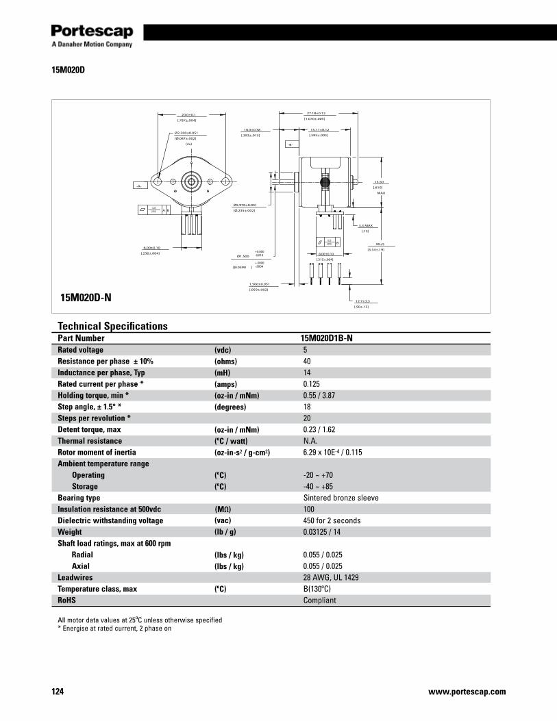
124 www.portescap.com
15M020D
15M020D-N
20.0±0.1
[.787±.004]
Ø2.200±0.051
[Ø.087±.002]
(2x)
27.18±0.12
[1.070±.005]
15.11±0.12
[.595±.005]
10.0±0.38
[.393±.015]
15.50
[.610]
MAX
1.500±0.051
[.059±.002]
Ø1.500
[Ø.0590 ]
Ø5.970±0.051
[Ø.235±.002]
3.3 MAX
[.13]
90±5
[3.54±.19]
12.7±3.3
[.50±.13]
8.00±0.10
[.315±.004]
6.00±0.10
[.236±.004]
0.25[.010] B
0.25[.010] A B
-A-
-B-
+0.000-0.010
+.0000-.0004
Technical SpecificationsPart Number 15M020D1B-NRated voltage 5Resistance per phase ± 10% 40Inductance per phase, Typ 14 Rated current per phase * 0.125Holding torque, min * 0.55 / 3.87 Step angle, ± 1.5° * 18Steps per revolution * 20Detent torque, max 0.23 / 1.62Thermal resistance N.A.Rotor moment of inertia 6.29 x 10E-4 / 0.115Ambient temperature range Operating -20 ~ +70 Storage -40 ~ +85Bearing type Sintered bronze sleeveInsulation resistance at 500vdc 100 Dielectric withstanding voltage 450 for 2 secondsWeight 0.03125 / 14Shaft load ratings, max at 600 rpm Radial 0.055 / 0.025 Axial 0.055 / 0.025Leadwires 28 AWG, UL 1429Temperature class, max B(130ºC)RoHS Compliant
All motor data values at 25ºC unless otherwise specified* Energise at rated current, 2 phase on
(vdc)(ohms)(mH) (amps)(oz-in / mNm) (degrees)
(oz-in / mNm)(ºC / watt)(oz-in-s2 / g-cm2)
(ºC)(ºC)
(ºC)
(vac)(lb / g)
(lbs / kg)(lbs / kg)
(MΩ)
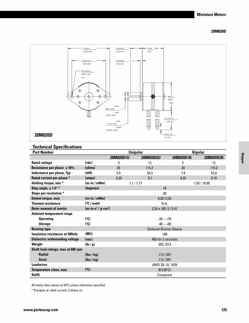
Miniature Motors
125www.portescap.com
Stepper
20M020D
20M020D
31.0±0.2
1.220±.008
25.00±0.13
.984±.005
Ø2.20±0.05
Ø.087±.002
(2x)
16.38 MAX
.645
Ø20.5
Ø.807
MAX
Ø1.50 -0.01
Ø.0590 -.0004
Ø6.00 -0.05
Ø.236 -.002
8.50±0.38
.335±.015
1.50±0.05
.059±.002
127.00±6.35
5.00±.25
6.35±1.50
.25±.06
+.000
+0.00
+.0000
+0.00
Rated voltage Resistance per phase ± 10% Inductance per phase, Typ Rated current per phase * Holding torque, min * Step angle, ± 1.5° * Steps per revolution * Detent torque, max Thermal resistance Rotor moment of inertia Ambient temperature range Operating Storage Bearing type Insulation resistance at 500vdc Dielectric withstanding voltage Weight Shaft load ratings, max at 600 rpm Radial AxialLeadwires Temperature class, max RoHS
All motor data values at 25ºC unless otherwise specified
* Energise at rated current, 2 phase on
Technical SpecificationsPart Number Unipolar Bipolar 20M020D1U 20M020D2U 20M020D1B 20M020D2B 5 12 5 12 20 115.2 20 115.2 3.9 20.3 7.8 52.8 0.25 0.1 0.25 0.10 1.1 / 7.77 1.55 / 10.95 18 20 0.50 /3.53 N.A. 2.24 x 10E-3 / 0.41 -20 ~ +70 -40 ~ +85 Sintered Bronze Sleeve 100 450 for 2 seconds .052 /23.5 .112 /.051 .112 /.051 AWG 28, UL 1429 B(130ºC) Compliant
(vdc)(ohms)(mH) (amps)(oz-in / mNm)
(degrees)
(oz-in / mNm)(ºC / watt)(oz-in-s2 / g-cm2)
(ºC)(ºC)
(ºC)
(vac)(MΩ)
(lb / g)
(lbs / kg)(lbs / kg)
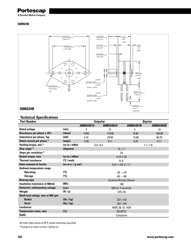
126 www.portescap.com
26M024B
34.90±0.10
1.374±.004
42.82±0.38
1.686±.015
Ø3.30±0.13
Ø.130±.005
(2x)
Ø2.000 -0.005
Ø.0787 -.0002
Ø10.000 -0.051
Ø.3937 -.0020
11.30±0.64
.445±.025
1.52±0.13
.060±.005
0.81±0.05
.032±.002
13.72
.540
MAX
3.40
.134
MAX
Ø26.16
Ø1.030
MAX
190.5±12.7
7.50±.50
12.7±3.3
.50±.13
STRIPPED
+0.000
+.0000
+0.000
+.0000
Rated voltage Resistance per phase ± 10% Inductance per phase, Typ Rated current per phase * Holding torque, min * Step angle * Steps per revolution * Detent torque, max Thermal resistance Rotor moment of inertia Ambient temperature range Operating Storage Bearing type Insulation resistance at 500vdc Dielectric withstanding voltage Weight Shaft load ratings, max at 600 rpm Radial AxialLeadwires Temperature class, max RoHS
All motor data values at 25ºC unless otherwise specified
* Energise at rated current, 2 phase on
Technical SpecificationsPart Number Unipolar Bipolar 26M024B1U 26M024B2U 26M024B1B 26M024B2B 5 12 5 12 19.60 110.00 19.80 108.00 4.10 29.90 13.00 60.70 0.26 0.11 0.25 0.11 0.9 / 6.3 1.1 / 7.8 15 ± 1° 24 0.19 /1.34 N.A. 6.01 x 10E-3 / 1.1 -20 ~ +70 -40 ~ +85 Sintered Bronze Sleeve 100 650 for 2 seconds .075 /34 .337 /.153 .337 /.153 AWG 28, UL 1429 B(130ºC) Compliant
26MO24B
(vdc)(ohms)(mH) (amps)(oz-in / mNm) (degrees)
(oz-in / mNm)(ºC / watt)(oz-in-s2 / g-cm2)
(ºC)(ºC)
(ºC)
(vac)(lb / g)
(lbs / kg)(lbs / kg)
(MΩ)
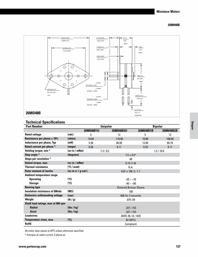
Miniature Motors
127www.portescap.com
Stepper
26M048B
34.90±0.10
1.374±.004
42.82±0.38
1.686±.015
Ø3.30±0.13
Ø.130±.005
(2x)
Ø2.000 -0.005
Ø.0787 -.0002
Ø10.000 -0.051
Ø.3937 -.0020
11.30±0.64
.445±.025
1.52±0.13
.060±.005
0.81±0.05
.032±.002
13.72
.540
MAX
3.40
.134
MAX
Ø26.16
Ø1.030
MAX
190.5±12.7
7.50±.50
12.7±3.3
.50±.13
STRIPPED
+0.000
+.0000
+0.000
+.0000
Rated voltage Resistance per phase ± 10% Inductance per phase, Typ Rated current per phase * Holding torque, min * Step angle * Steps per revolution * Detent torque, max Thermal resistance Rotor moment of inertia Ambient temperature range Operating Storage Bearing type Insulation resistance at 500vdc Dielectric withstanding voltage Weight Shaft load ratings, max at 600 rpm Radial Axial Leadwires Temperature class, max RoHS
All motor data values at 25ºC unless otherwise specified
* Energise at rated current, 2 phase on
Technical SpecificationsPart Number Unipolar Bipolar 26M048B1U 26M048B2U 26M048B1B 26M048B2B 5 12 5 12 19.60 110.00 19.80 108.00 5.30 36.50 13.00 60.70 0.26 0.11 0.25 0.11 1.3 / 9.2 1.5 / 10.6 7.5 ± 0.5° 48 0.19 /1.34 N.A. 6.01 x 10E-3 / 1.1 -20 ~ +70 -40 ~ +85 Sintered Bronze Sleeve 100 650 for 2 seconds .075 /34 .337 /.153 .337 /.153 AWG 28, UL 1429 B(130ºC) Compliant
(vdc)(ohms)(mH) (amps)(oz-in / mNm) (degrees)
(oz-in / mNm)(ºC / watt)(oz-in-s2 / g-cm2)
(ºC)
(ºC)
(ºC)
(vac)(lb / g)
(lbs / kg)(lbs / kg)
26MO48B
(MΩ)
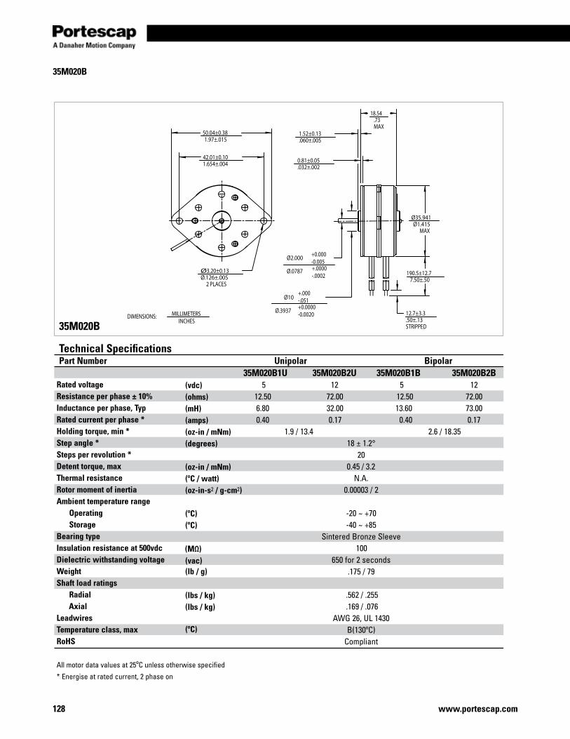
128 www.portescap.com
35M020B
Rated voltage Resistance per phase ± 10% Inductance per phase, Typ Rated current per phase * Holding torque, min * Step angle * Steps per revolution * Detent torque, max Thermal resistance Rotor moment of inertia Ambient temperature range Operating Storage Bearing type Insulation resistance at 500vdc Dielectric withstanding voltage Weight Shaft load ratings Radial AxialLeadwires Temperature class, max RoHS
All motor data values at 25ºC unless otherwise specified
* Energise at rated current, 2 phase on
Technical SpecificationsPart Number Unipolar Bipolar 35M020B1U 35M020B2U 35M020B1B 35M020B2B 5 12 5 12 12.50 72.00 12.50 72.00 6.80 32.00 13.60 73.00 0.40 0.17 0.40 0.17 1.9 / 13.4 2.6 / 18.35 18 ± 1.2° 20 0.45 / 3.2 N.A. 0.00003 / 2 -20 ~ +70 -40 ~ +85 Sintered Bronze Sleeve 100 650 for 2 seconds .175 / 79 .562 / .255 .169 / .076 AWG 26, UL 1430 B(130ºC) Compliant
35M020B
(vdc)(ohms)(mH) (amps)(oz-in / mNm) (degrees)
(oz-in / mNm)(ºC / watt)(oz-in-s2 / g-cm2)
(ºC)(ºC)
(ºC)
(vac)(lb / g)
(lbs / kg)(lbs / kg)
(MΩ)
50.04±0.381.97±.015
42.01±0.101.654±.004
Ø3.20±0.13Ø.126±.005
2 PLACES
Ø35.941Ø1.415
MAX
18.54.73MAX
1.52±0.13.060±.005
0.81±0.05.032±.002
Ø10
Ø.3937
Ø2.000
Ø.0787 190.5±12.77.50±.50
12.7±3.3.50±.13STRIPPED
+0.0000-0.0020
+.000-.051
+0.000-0.005+.0000-.0002
DIMENSIONS: MILLIMETERSINCHES
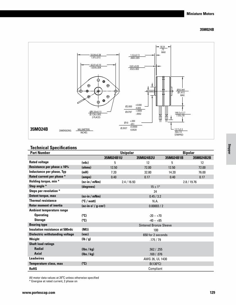
Miniature Motors
129www.portescap.com
Stepper
35M024B
Rated voltage Resistance per phase ± 10% Inductance per phase, Typ Rated current per phase * Holding torque, min * Step angle * Steps per revolution * Detent torque, max Thermal resistance Rotor moment of inertia Ambient temperature range Operating Storage Bearing type Insulation resistance at 500vdc Dielectric withstanding voltage Weight Shaft load ratings Radial AxialLeadwires Temperature class, max
RoHS
All motor data values at 25ºC unless otherwise specified* Energise at rated current, 2 phase on
Technical SpecificationsPart Number Unipolar Bipolar 35M024B1U 35M024B2U 35M024B1B 35M024B2B 5 12 5 12 12.50 72.00 12.50 72.00 7.20 32.80 14.20 76.00 0.40 0.17 0.40 0.17 2.4 / 16.93 2.8 / 19.76 15 ± 1° 24 0.45 / 3.2 N.A. 0.00003 / 2 -20 ~ +70 -40 ~ +85 Sintered Bronze Sleeve 100 650 for 2 seconds .175 / 79 .562 / .255 .169 / .076 AWG 26, UL 1430 B(130ºC) Compliant
(vdc)(ohms)(mH) (amps)(oz-in / mNm) (degrees)
(oz-in / mNm)(ºC / watt)(oz-in-s2 / g-cm2)
(ºC)(ºC)
(ºC)
(vac)(lb / g)
(lbs / kg)(lbs / kg)
35MO24B
(MΩ)
50.04±0.381.97±.015
42.01±0.101.654±.004
Ø3.20±0.13Ø.126±.005
2 PLACES
Ø35.941Ø1.415
MAX
18.54.73MAX
1.52±0.13.060±.005
0.81±0.05.032±.002
Ø10
Ø.3937
Ø2.000
Ø.0787 190.5±12.77.50±.50
12.7±3.3.50±.13STRIPPED
+0.0000-0.0020
+.000-.051
+0.000-0.005+.0000-.0002
DIMENSIONS: MILLIMETERSINCHES
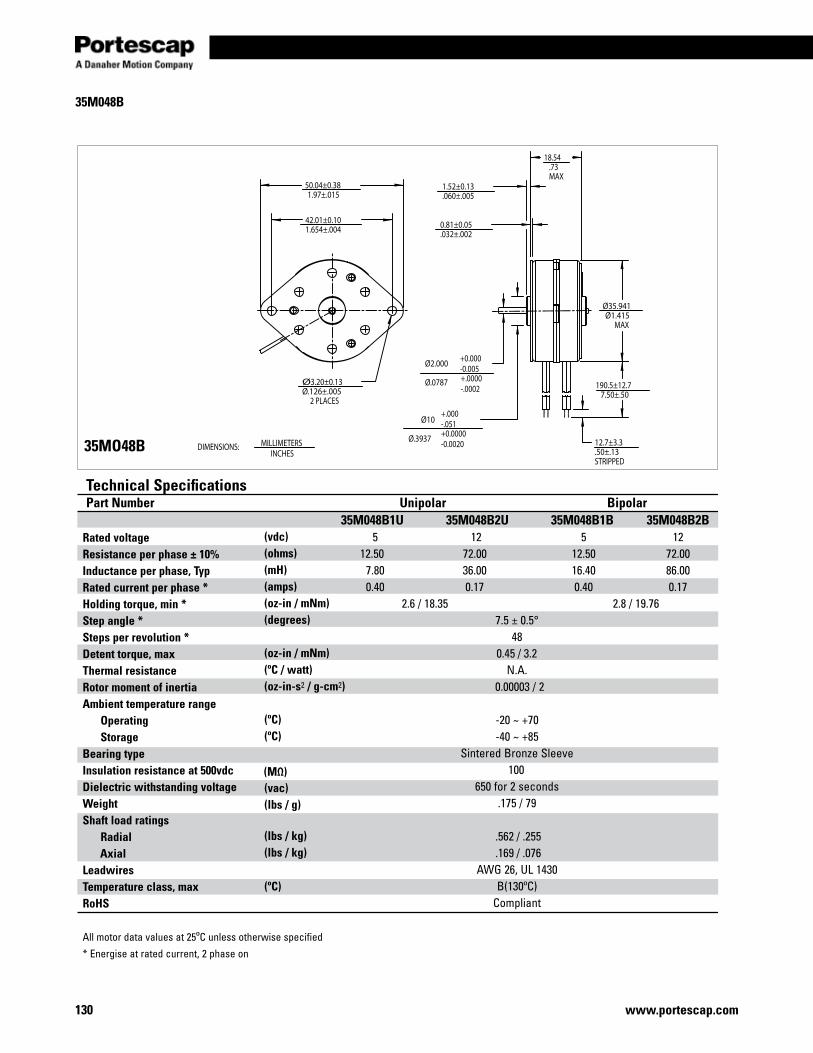
130 www.portescap.com
35M048B
35MO48B
Rated voltage Resistance per phase ± 10% Inductance per phase, Typ Rated current per phase * Holding torque, min * Step angle * Steps per revolution * Detent torque, max Thermal resistance Rotor moment of inertia Ambient temperature range Operating Storage Bearing type Insulation resistance at 500vdc Dielectric withstanding voltage Weight Shaft load ratings Radial AxialLeadwires Temperature class, max RoHS
All motor data values at 25ºC unless otherwise specified
* Energise at rated current, 2 phase on
Technical SpecificationsPart Number Unipolar Bipolar 35M048B1U 35M048B2U 35M048B1B 35M048B2B 5 12 5 12 12.50 72.00 12.50 72.00 7.80 36.00 16.40 86.00 0.40 0.17 0.40 0.17 2.6 / 18.35 2.8 / 19.76 7.5 ± 0.5° 48 0.45 / 3.2 N.A. 0.00003 / 2 -20 ~ +70 -40 ~ +85 Sintered Bronze Sleeve 100 650 for 2 seconds .175 / 79 .562 / .255 .169 / .076 AWG 26, UL 1430 B(130ºC) Compliant
(vdc)(ohms)(mH) (amps)(oz-in / mNm) (degrees)
(oz-in / mNm)(ºC / watt)(oz-in-s2 / g-cm2)
(ºC)(ºC)
(ºC)
(vac)(lbs / g)
(lbs / kg)(lbs / kg)
(MΩ)
50.04±0.381.97±.015
42.01±0.101.654±.004
Ø3.20±0.13Ø.126±.005
2 PLACES
Ø35.941Ø1.415
MAX
18.54.73MAX
1.52±0.13.060±.005
0.81±0.05.032±.002
Ø10
Ø.3937
Ø2.000
Ø.0787 190.5±12.77.50±.50
12.7±3.3.50±.13STRIPPED
+0.0000-0.0020
+.000-.051
+0.000-0.005+.0000-.0002
DIMENSIONS: MILLIMETERSINCHES
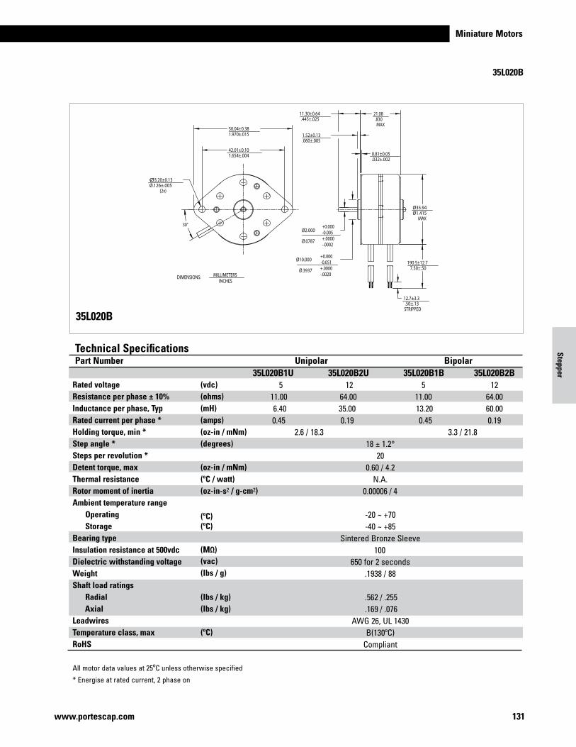
Miniature Motors
131www.portescap.com
Stepper
35L020B
30°
50.04±0.381.970±.015
42.01±0.101.654±.004
Ø3.20±0.13Ø.126±.005
(2x)
Ø35.94Ø1.415
MAX
190.5±12.77.50±.50
12.7±3.3.50±.13STRIPPED
21.08.830MAX
0.81±0.05.032±.002
1.52±0.13.060±.005
11.30±0.64.445±.025
Ø2.000
Ø.0787
Ø10.000
Ø.3937
+0.000-0.005+.0000-.0002
+0.000-0.051+.0000-.0020DIMENSIONS: MILLIMETERS
INCHES
35L020B
Rated voltage Resistance per phase ± 10% Inductance per phase, Typ Rated current per phase * Holding torque, min * Step angle * Steps per revolution * Detent torque, max Thermal resistance Rotor moment of inertia Ambient temperature range Operating Storage Bearing type Insulation resistance at 500vdc Dielectric withstanding voltage Weight Shaft load ratings Radial AxialLeadwires Temperature class, max RoHS
All motor data values at 25ºC unless otherwise specified
* Energise at rated current, 2 phase on
Technical SpecificationsPart Number Unipolar Bipolar 35L020B1U 35L020B2U 35L020B1B 35L020B2B 5 12 5 12 11.00 64.00 11.00 64.00 6.40 35.00 13.20 60.00 0.45 0.19 0.45 0.19 2.6 / 18.3 3.3 / 21.8 18 ± 1.2° 20 0.60 / 4.2 N.A. 0.00006 / 4 -20 ~ +70 -40 ~ +85 Sintered Bronze Sleeve 100 650 for 2 seconds .1938 / 88 .562 / .255 .169 / .076 AWG 26, UL 1430 B(130ºC) Compliant
(vdc)(ohms)(mH) (amps)(oz-in / mNm) (degrees)
(oz-in / mNm)(ºC / watt)(oz-in-s2 / g-cm2)
(ºC)
(ºC)
(ºC)
(vac)(lbs / g)
(lbs / kg)(lbs / kg)
(MΩ)
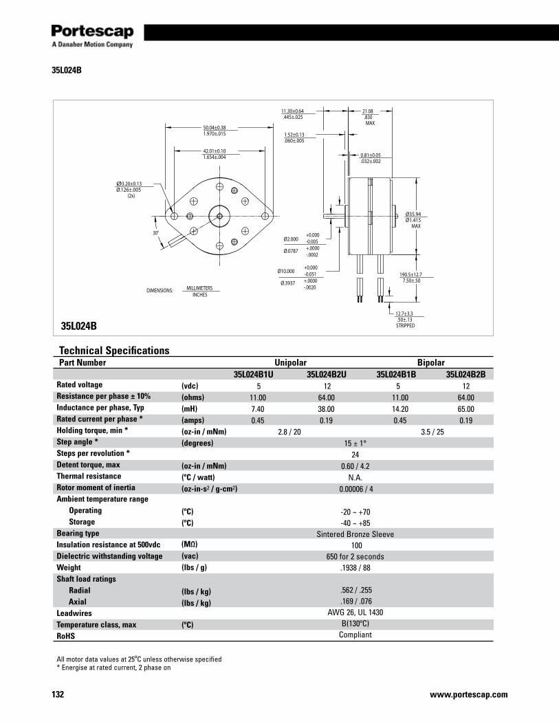
132 www.portescap.com
35L024B
30°
50.04±0.381.970±.015
42.01±0.101.654±.004
Ø3.20±0.13Ø.126±.005
(2x)
Ø35.94Ø1.415
MAX
190.5±12.77.50±.50
12.7±3.3.50±.13STRIPPED
21.08.830MAX
0.81±0.05.032±.002
1.52±0.13.060±.005
11.30±0.64.445±.025
Ø2.000
Ø.0787
Ø10.000
Ø.3937
+0.000-0.005+.0000-.0002
+0.000-0.051+.0000-.0020DIMENSIONS: MILLIMETERS
INCHES
35L024B
Rated voltage Resistance per phase ± 10% Inductance per phase, Typ Rated current per phase * Holding torque, min * Step angle * Steps per revolution * Detent torque, max Thermal resistance Rotor moment of inertia Ambient temperature range Operating Storage Bearing type Insulation resistance at 500vdc Dielectric withstanding voltage Weight Shaft load ratings Radial AxialLeadwires Temperature class, max RoHS
All motor data values at 25ºC unless otherwise specified* Energise at rated current, 2 phase on
Technical SpecificationsPart Number Unipolar Bipolar 35L024B1U 35L024B2U 35L024B1B 35L024B2B 5 12 5 12 11.00 64.00 11.00 64.00 7.40 38.00 14.20 65.00 0.45 0.19 0.45 0.19 2.8 / 20 3.5 / 25 15 ± 1° 24 0.60 / 4.2 N.A. 0.00006 / 4 -20 ~ +70 -40 ~ +85 Sintered Bronze Sleeve 100 650 for 2 seconds .1938 / 88 .562 / .255 .169 / .076 AWG 26, UL 1430 B(130ºC) Compliant
(vdc)(ohms)(mH) (amps)(oz-in / mNm) (degrees)
(oz-in / mNm)(ºC / watt)(oz-in-s2 / g-cm2)
(ºC)
(ºC)
(ºC)
(vac)(lbs / g)
(lbs / kg)(lbs / kg)
(MΩ)
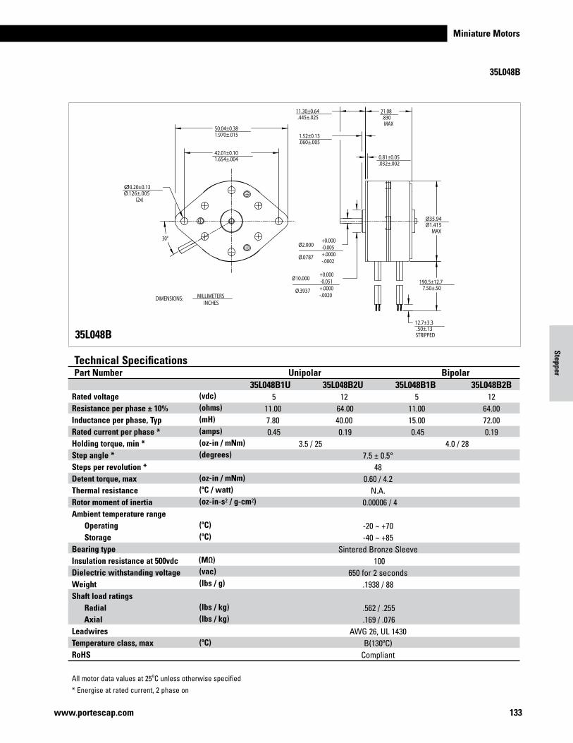
Miniature Motors
133www.portescap.com
Stepper
35L048B
30°
50.04±0.381.970±.015
42.01±0.101.654±.004
Ø3.20±0.13Ø.126±.005
(2x)
Ø35.94Ø1.415
MAX
190.5±12.77.50±.50
12.7±3.3.50±.13STRIPPED
21.08.830MAX
0.81±0.05.032±.002
1.52±0.13.060±.005
11.30±0.64.445±.025
Ø2.000
Ø.0787
Ø10.000
Ø.3937
+0.000-0.005+.0000-.0002
+0.000-0.051+.0000-.0020DIMENSIONS: MILLIMETERS
INCHES
35L048B
Rated voltage Resistance per phase ± 10% Inductance per phase, Typ Rated current per phase * Holding torque, min * Step angle * Steps per revolution * Detent torque, max Thermal resistance Rotor moment of inertia Ambient temperature range Operating Storage Bearing type Insulation resistance at 500vdc Dielectric withstanding voltage Weight Shaft load ratings Radial AxialLeadwires Temperature class, max RoHS
All motor data values at 25ºC unless otherwise specified
* Energise at rated current, 2 phase on
Technical SpecificationsPart Number Unipolar Bipolar 35L048B1U 35L048B2U 35L048B1B 35L048B2B 5 12 5 12 11.00 64.00 11.00 64.00 7.80 40.00 15.00 72.00 0.45 0.19 0.45 0.19 3.5 / 25 4.0 / 28 7.5 ± 0.5° 48 0.60 / 4.2 N.A. 0.00006 / 4 -20 ~ +70 -40 ~ +85 Sintered Bronze Sleeve 100 650 for 2 seconds .1938 / 88 .562 / .255 .169 / .076 AWG 26, UL 1430 B(130ºC) Compliant
(vdc)(ohms)(mH) (amps)(oz-in / mNm) (degrees)
(oz-in / mNm)(ºC / watt)(oz-in-s2 / g-cm2)
(ºC)
(ºC)
(ºC)
(vac)(lbs / g)
(lbs / kg)(lbs / kg)
(MΩ)
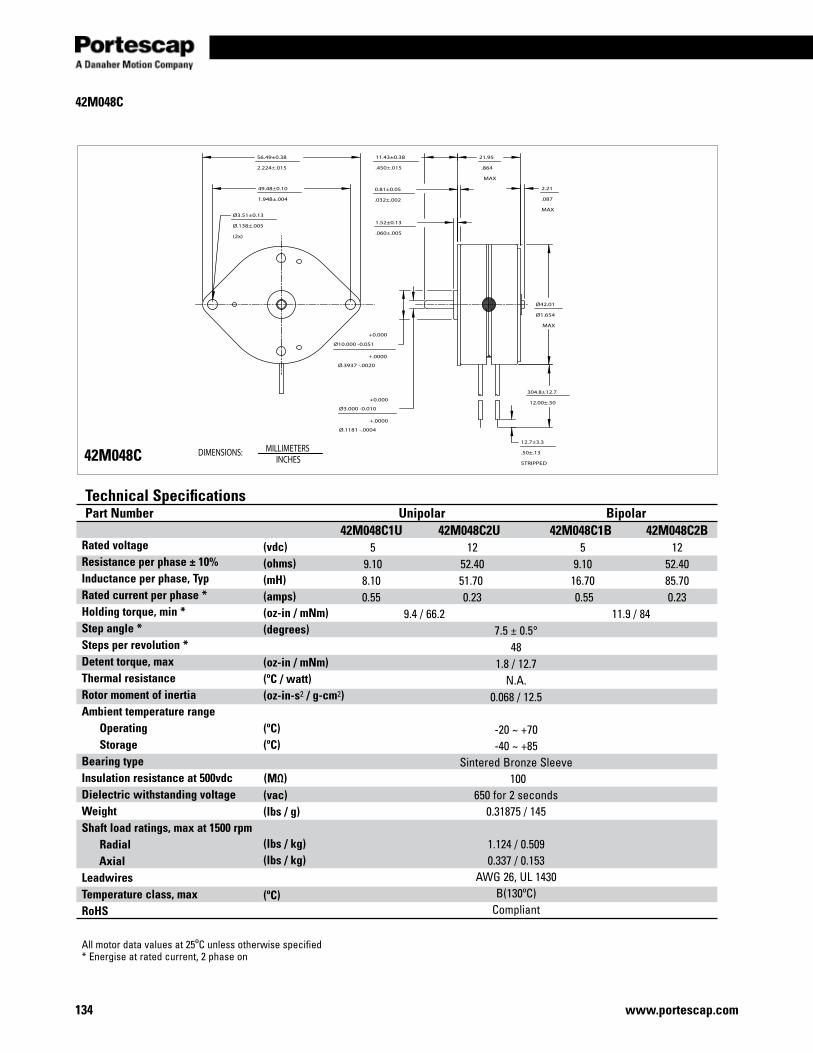
134 www.portescap.com
42M048C
42M048C
49.48±0.10
1.948±.004
Ø3.51±0.13
Ø.138±.005
(2x)
11.43±0.38
.450±.015
1.52±0.13
.060±.005
0.81±0.05
.032±.002
Ø42.01
Ø1.654
MAX
Ø10.000 -0.051
Ø.3937 -.0020
Ø3.000 -0.010
Ø.1181 -.0004
56.49±0.38
2.224±.015
304.8±12.7
12.00±.50
12.7±3.3
.50±.13
STRIPPED
21.95
.864
MAX
2.21
.087
MAX
+.0000
+.0000
+0.000
+0.000
Rated voltage Resistance per phase ± 10% Inductance per phase, Typ Rated current per phase * Holding torque, min * Step angle * Steps per revolution * Detent torque, max Thermal resistance Rotor moment of inertia Ambient temperature range Operating Storage Bearing type Insulation resistance at 500vdc Dielectric withstanding voltage Weight Shaft load ratings, max at 1500 rpm Radial AxialLeadwires Temperature class, max RoHS
All motor data values at 25ºC unless otherwise specified* Energise at rated current, 2 phase on
Technical SpecificationsPart Number Unipolar Bipolar 42M048C1U 42M048C2U 42M048C1B 42M048C2B 5 12 5 12 9.10 52.40 9.10 52.40 8.10 51.70 16.70 85.70 0.55 0.23 0.55 0.23 9.4 / 66.2 11.9 / 84 7.5 ± 0.5° 48 1.8 / 12.7 N.A. 0.068 / 12.5 -20 ~ +70 -40 ~ +85 Sintered Bronze Sleeve 100 650 for 2 seconds 0.31875 / 145 1.124 / 0.509 0.337 / 0.153 AWG 26, UL 1430 B(130ºC) Compliant
(vdc)(ohms)(mH) (amps)(oz-in / mNm) (degrees)
(oz-in / mNm)(ºC / watt)(oz-in-s2 / g-cm2)
(ºC)(ºC)
(ºC)
(vac)(lbs / g)
(lbs / kg)(lbs / kg)
(MΩ)
DIMENSIONS: MILLIMETERSINCHES
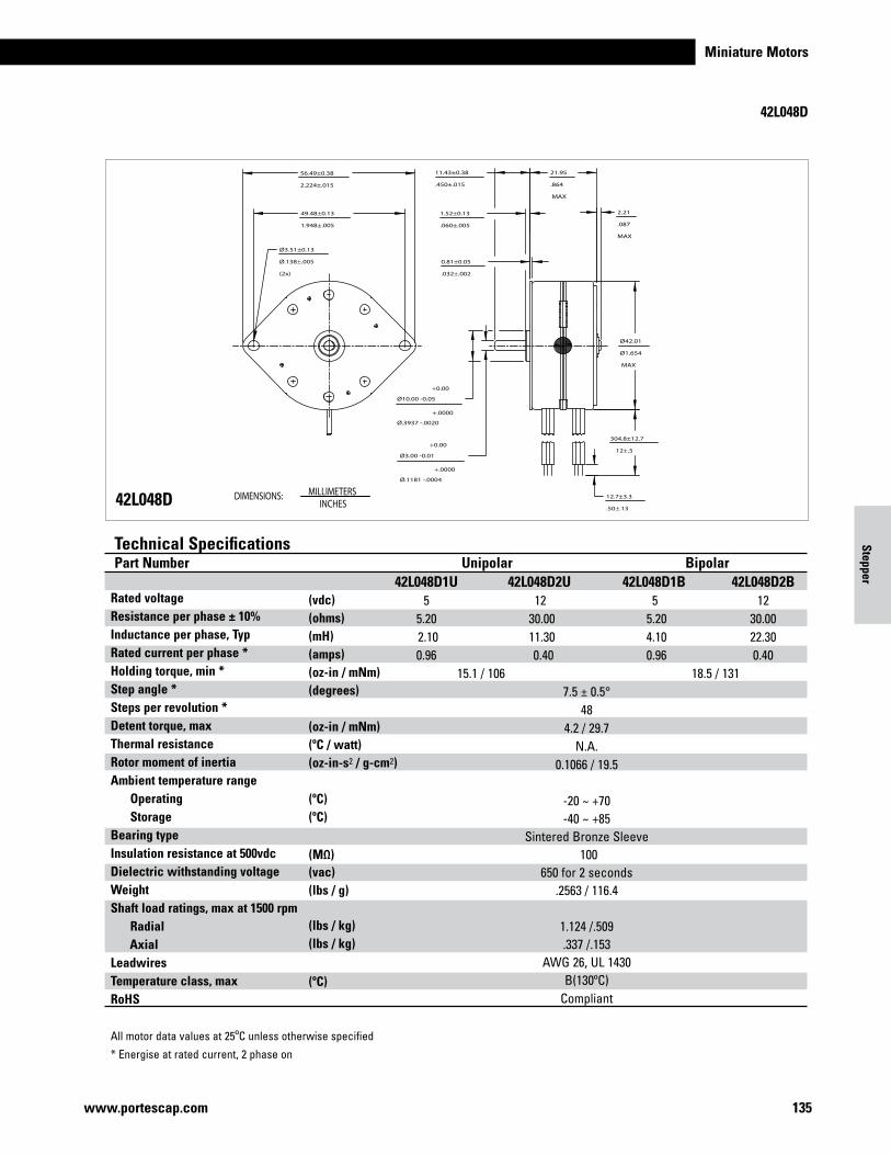
Miniature Motors
135www.portescap.com
42L048D
21.95
.864
MAX
11.43±0.38
.450±.015
1.52±0.13
.060±.005
Ø42.01
Ø1.654
MAX
Ø3.51±0.13
Ø.138±.005
(2x)
12.7±3.3
.50±.13
304.8±12.7
12±.5
49.48±0.13
1.948±.005
Ø10.00 -0.05
Ø.3937 -.0020
Ø3.00 -0.01
Ø.1181 -.0004
0.81±0.05
.032±.002
56.49±0.38
2.224±.015
2.21
.087
MAX
+.0000
+0.00
+.0000
+0.00
42L048D
Rated voltage Resistance per phase ± 10% Inductance per phase, Typ Rated current per phase * Holding torque, min * Step angle * Steps per revolution * Detent torque, max Thermal resistance Rotor moment of inertia Ambient temperature range Operating Storage Bearing type Insulation resistance at 500vdc Dielectric withstanding voltage Weight Shaft load ratings, max at 1500 rpm Radial AxialLeadwires Temperature class, max RoHS
All motor data values at 25ºC unless otherwise specified
* Energise at rated current, 2 phase on
Technical SpecificationsPart Number Unipolar Bipolar 42L048D1U 42L048D2U 42L048D1B 42L048D2B 5 12 5 12 5.20 30.00 5.20 30.00 2.10 11.30 4.10 22.30 0.96 0.40 0.96 0.40 15.1 / 106 18.5 / 131 7.5 ± 0.5° 48 4.2 / 29.7 N.A. 0.1066 / 19.5 -20 ~ +70 -40 ~ +85 Sintered Bronze Sleeve 100 650 for 2 seconds .2563 / 116.4 1.124 /.509 .337 /.153 AWG 26, UL 1430 B(130ºC) Compliant
(vdc)(ohms)(mH) (amps)(oz-in / mNm) (degrees)
(oz-in / mNm)(ºC / watt)(oz-in-s2 / g-cm2)
(ºC)(ºC)
(ºC)
(vac)(lbs / g)
(lbs / kg)(lbs / kg)
(MΩ)
DIMENSIONS: MILLIMETERSINCHES
Stepper
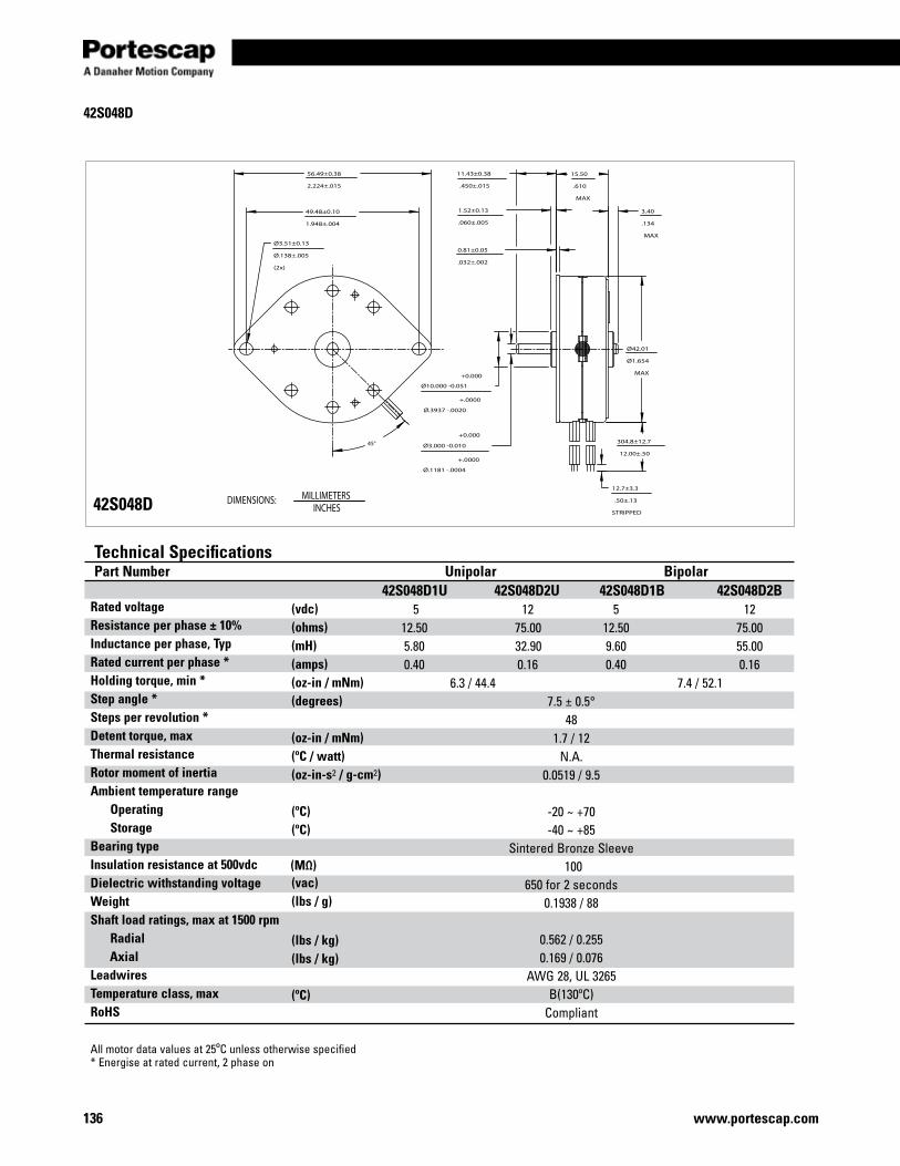
www.portescap.com136
42S048D
42S048D
11.43±0.38
.450±.015
1.52±0.13
.060±.005
0.81±0.05
.032±.002
Ø42.01
Ø1.654
MAX
Ø10.000 -0.051
Ø.3937 -.0020
Ø3.000 -0.010
Ø.1181 -.0004
49.48±0.10
1.948±.004
Ø3.51±0.13
Ø.138±.005
(2x)
56.49±0.38
2.224±.015
45° 304.8±12.7
12.00±.50
12.7±3.3
.50±.13
STRIPPED
15.50
.610
MAX
3.40
.134
MAX
+0.000
+0.000
+.0000
+.0000
Rated voltage Resistance per phase ± 10% Inductance per phase, Typ Rated current per phase * Holding torque, min * Step angle * Steps per revolution * Detent torque, max Thermal resistance Rotor moment of inertia Ambient temperature range Operating Storage Bearing type Insulation resistance at 500vdc Dielectric withstanding voltage Weight Shaft load ratings, max at 1500 rpm Radial AxialLeadwires Temperature class, max RoHS
All motor data values at 25ºC unless otherwise specified* Energise at rated current, 2 phase on
Technical SpecificationsPart Number Unipolar Bipolar 42S048D1U 42S048D2U 42S048D1B 42S048D2B 5 12 5 12 12.50 75.00 12.50 75.00 5.80 32.90 9.60 55.00 0.40 0.16 0.40 0.16 6.3 / 44.4 7.4 / 52.1 7.5 ± 0.5° 48 1.7 / 12 N.A. 0.0519 / 9.5 -20 ~ +70 -40 ~ +85 Sintered Bronze Sleeve 100 650 for 2 seconds 0.1938 / 88 0.562 / 0.255 0.169 / 0.076 AWG 28, UL 3265 B(130ºC) Compliant
(vdc)(ohms)(mH) (amps)(oz-in / mNm) (degrees)
(oz-in / mNm)(ºC / watt)(oz-in-s2 / g-cm2)
(ºC)(ºC)
(ºC)
(vac)(lbs / g)
(lbs / kg)(lbs / kg)
(MΩ)
DIMENSIONS: MILLIMETERSINCHES
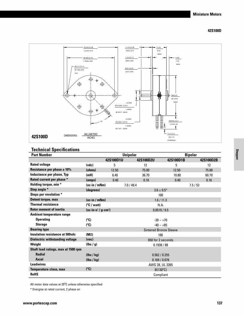
Miniature Motors
137www.portescap.com
Stepper
42S100D
42S100D
11.43±0.38
.450±.015
1.52±0.13
.060±.005
0.81±0.05
.032±.002
Ø42.01
Ø1.654
MAX
Ø10.000 -0.051
Ø.3937 -.0020
Ø3.000 -0.010
Ø.1181 -.0004
49.48±0.10
1.948±.004
Ø3.51±0.13
Ø.138±.005
(2x)
56.49±0.38
2.224±.015
45° 304.8±12.7
12.00±.50
12.7±3.3
.50±.13
STRIPPED
15.50
.610
MAX
3.40
.134
MAX
+0.000
+0.000
+.0000
+.0000
Rated voltage Resistance per phase ± 10% Inductance per phase, Typ Rated current per phase * Holding torque, min * Step angle * Steps per revolution * Detent torque, max Thermal resistance Rotor moment of inertia Ambient temperature range Operating Storage Bearing type Insulation resistance at 500vdc Dielectric withstanding voltage Weight Shaft load ratings, max at 1500 rpm Radial AxialLeadwires Temperature class, max RoHS
All motor data values at 25ºC unless otherwise specified
* Energise at rated current, 2 phase on
Technical SpecificationsPart Number Unipolar Bipolar 42S100D1U 42S100D2U 42S100D1B 42S100D2B 5 12 5 12 12.50 75.00 12.50 75.00 6.40 36.70 10.80 60.70 0.40 0.16 0.40 0.16 7.0 / 49.4 7.5 / 53 3.6 ± 0.5° 100 1.6 / 11.3 N.A. 0.0519 / 9.5 -20 ~ +70 -40 ~ +85 Sintered Bronze Sleeve 100 650 for 2 seconds 0.1938 / 88 0.562 / 0.255 0.169 / 0.076 AWG 28, UL 3265 B(130ºC) Compliant
(vdc)(ohms)(mH) (amps)(oz-in / mNm) (degrees)
(oz-in / mNm)(ºC / watt)(oz-in-s2 / g-cm2)
(ºC)(ºC)
(ºC)
(vac)(lbs / g)
(lbs / kg)(lbs / kg)
(MΩ)
DIMENSIONS: MILLIMETERSINCHES
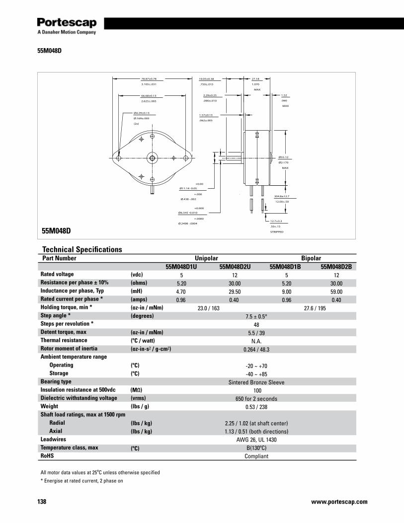
www.portescap.com138
55M048D
55M048D
78.87±0.78
3.105±.031
66.68±0.13
2.625±.005
Ø55.12
Ø2.170
MAX
19.05±0.38
.750±.015
27.18
1.070
MAX
1.52
.060
MAX
1.57±0.13
.062±.005
2.29±0.25
.090±.010
Ø4.29±0.13
Ø.169±.005
(2x)
Ø11.14 -0.05
Ø.438 -.002304.8±12.7
12.00±.50
12.7±3.3
.50±.13
STRIPPED
Ø6.345 -0.010
Ø.2498 -.0004
+0.00
+.000
+0.000
+.0000
Rated voltage Resistance per phase ± 10% Inductance per phase, Typ Rated current per phase * Holding torque, min * Step angle * Steps per revolution * Detent torque, max Thermal resistance Rotor moment of inertia Ambient temperature range Operating Storage Bearing type Insulation resistance at 500vdc Dielectric withstanding voltage Weight Shaft load ratings, max at 1500 rpm Radial AxialLeadwires Temperature class, max RoHS
All motor data values at 25ºC unless otherwise specified
* Energise at rated current, 2 phase on
Technical SpecificationsPart Number Unipolar Bipolar 55M048D1U 55M048D2U 55M048D1B 55M048D2B 5 12 5 12 5.20 30.00 5.20 30.00 4.70 29.50 9.00 59.00 0.96 0.40 0.96 0.40 23.0 / 163 27.6 / 195 7.5 ± 0.5° 48 5.5 / 39 N.A. 0.264 / 48.3 -20 ~ +70 -40 ~ +85 Sintered Bronze Sleeve 100 650 for 2 seconds 0.53 / 238 2.25 / 1.02 (at shaft center) 1.13 / 0.51 (both directions) AWG 26, UL 1430 B(130ºC) Compliant
(vdc)(ohms)(mH) (amps)(oz-in / mNm) (degrees)
(oz-in / mNm)(ºC / watt)(oz-in-s2 / g-cm2)
(ºC)(ºC)
(ºC)
(vrms)(lbs / g)
(lbs / kg)(lbs / kg)
(MΩ)
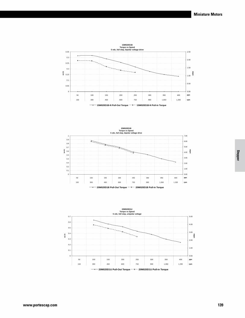
Miniature Motors
139www.portescap.com
Stepper
15M020D1BTorque vs Speed
5 vdc, full step, bipolar voltage drive
0
0.05
0.1
0.15
0.2
0.25
0.3
0.35
50 100 150 200 250 300 350 400
150 300 450 600 750 900 1,050 1,200
pps
oz-
in
0.00
0.50
1.00
1.50
2.00
2.50
rpm
mN
m
15M020D1B-N Pull-Out Torque 15M020D1B-N Pull-in Torque
oz-
in
mN
m
20M020D1UTorque vs Speed
5 vdc, full step, unipolar voltage
0
0.1
0.2
0.3
0.4
0.5
0.6
0.7
50 100 150 200 250 300 350 400
150 300 450 600 750 900 1,050 1,200
pps
0.00
1.00
2.00
3.00
4.00
5.00
rpm
20M020D1U Pull-Out Torque 20M020D1U Pull-in Torque
oz-
in
mN
m
20M020D1BTorque vs Speed
5 vdc, full step, bipolar voltage drive
0
0.1
0.2
0.3
0.4
0.5
0.6
0.7
0.8
0.9
1
50 100 150 200 250 300 350 400
150 300 450 600 750 900 1,050 1,200
pps
0.00
1.00
2.00
3.00
4.00
5.00
6.00
7.00
rpm
20M020D1B Pull-Out Torque 20M020D1B Pull-in Torque
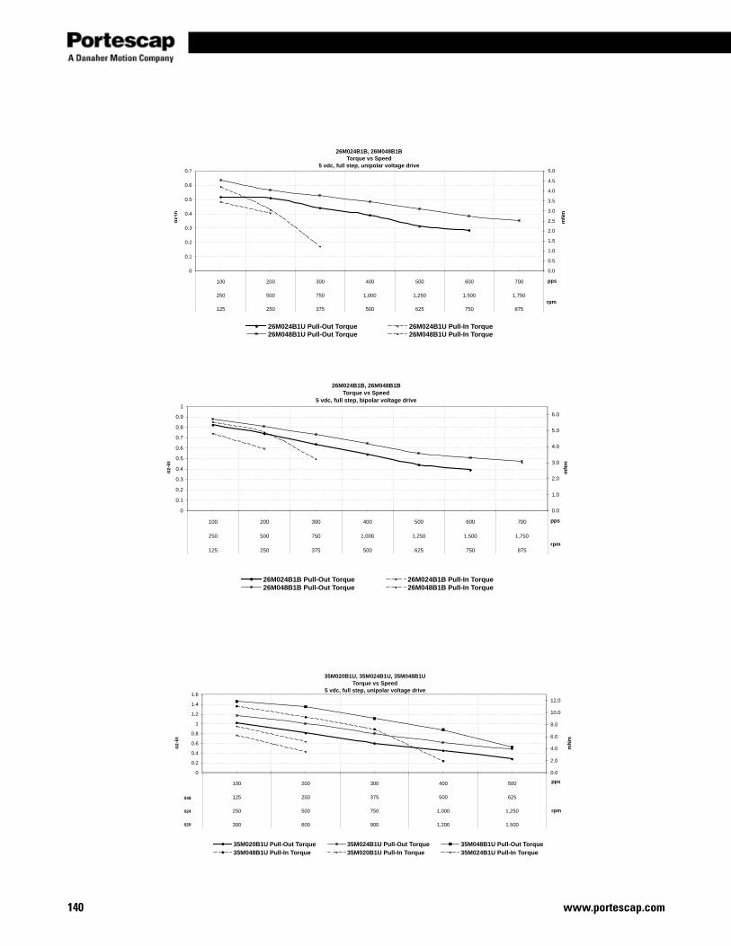
www.portescap.com140
oz-
in
mN
m
26M024B1B, 26M048B1BTorque vs Speed
5 vdc, full step, unipolar voltage drive
0
0.1
0.2
0.3
0.4
0.5
0.6
0.7
100 200 300 400 500 600 700
250 500 750 1,000 1,250 1,500 1,750
125 250 375 500 625 750 875
pps
0.0
0.5
1.0
1.5
2.0
2.5
3.0
3.5
4.0
4.5
5.0
rpm
26M024B1U Pull-Out Torque 26M024B1U Pull-In Torque26M048B1U Pull-Out Torque 26M048B1U Pull-In Torque
oz-
in
mN
m
26M024B1B Pull-Out Torque 26M024B1B Pull-In Torque26M048B1B Pull-Out Torque 26M048B1B Pull-In Torque
26M024B1B, 26M048B1BTorque vs Speed
5 vdc, full step, bipolar voltage drive
0
0.1
0.2
0.3
0.4
0.5
0.6
0.7
0.8
0.9
1
100 200 300 400 500 600 700
250 500 750 1,000 1,250 1,500 1,750
125 250 375 500 625 750 875
pps
0.0
1.0
2.0
3.0
4.0
5.0
6.0
rpm
oz-
in
mN
m
35M020B1U, 35M024B1U, 35M048B1UTorque vs Speed
5 vdc, full step, unipolar voltage drive
0
0.2
0.4
0.6
0.8
1
1.2
1.4
1.6
100 200 300 400 500
125 250 375 500 625
250 500 750 1,000 1,250
300 600 900 1,200 1,500
pps
0.0
2.0
4.0
6.0
8.0
10.0
12.0
rpm
35M020B1U Pull-Out Torque 35M024B1U Pull-Out Torque 35M048B1U Pull-Out Torque35M048B1U Pull-In Torque 35M020B1U Pull-In Torque 35M024B1U Pull-In Torque
048
024
020
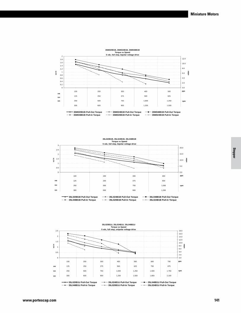
Miniature Motors
141www.portescap.com
Stepper
oz-
in
mN
m
35M020B1B, 35M024B1B, 35M048B1BTorque vs Speed
5 vdc, full step, bipolar voltage drive
0
0.2
0.4
0.6
0.8
1
1.2
1.4
1.6
1.8
2
100 200 300 400 500
125 250 375 500 625
250 500 750 1,000 1,250
300 600 900 1,200 1,500
pps
0.0
2.0
4.0
6.0
8.0
10.0
12.0
rpm
35M020B1B Pull-Out Torque 35M024B1B Pull-Out Torque 35M048B1B Pull-Out Torque35M048B1B Pull-In Torque 35M020B1B Pull-In Torque 35M024B1B Pull-In Torque
048
024
020
oz-
in
mN
m
35L020B1B Pull-Out Torque 35L024B1B Pull-Out Torque 35L048B1B Pull-Out Torque35L048B1B Pull-In Torque 35L020B1B Pull-In Torque 35L024B1B Pull-In Torque
35L020B1B, 35L024B1B, 35L048B1BTorque vs Speed
5 vdc, full step, bipolar voltage drive
0
0.5
1
1.5
2
2.5
3
100 200 300 400
125 250 375 500
250 500 750 1,000
300 600 900 1,200
pps
0.0
5.0
10.0
15.0
20.0
rpm
020
048
024
oz-
in
mN
m
35L020B1U, 35L024B1U, 35L048B1UTorque vs Speed
5 vdc, full step, unipolar voltage drive
0
0.5
1
1.5
2
2.5
100 200 300 400 500 600 700
125 250 375 500 625 750 875
250 500 750 1,000 1,250 1,500 1,750
300 600 900 1,200 1,500 1,800 2,100
pps
0.0
2.0
4.0
6.0
8.0
10.0
12.0
14.0
16.0
18.0
rpm
35L020B1U Pull-Out Torque 35L024B1U Pull-Out Torque 35L048B1U Pull-Out Torque35L048B1U Pull-In Torque 35L020B1U Pull-In Torque 35L024B1U Pull-In Torque
048
024
020
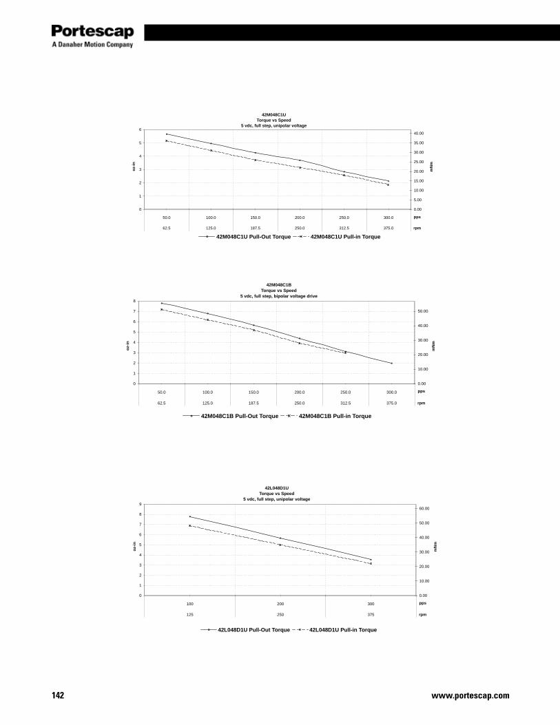
www.portescap.com142
oz-
in
mN
m
42M048C1UTorque vs Speed
5 vdc, full step, unipolar voltage
0
1
2
3
4
5
6
50.0 100.0 150.0 200.0 250.0 300.0
62.5 125.0 187.5 250.0 312.5 375.0
pps
0.00
5.00
10.00
15.00
20.00
25.00
30.00
35.00
40.00
rpm
42M048C1U Pull-Out Torque 42M048C1U Pull-in Torque
oz-
in
mN
m
42M048C1BTorque vs Speed
5 vdc, full step, bipolar voltage drive
0
1
2
3
4
5
6
7
8
50.0 100.0 150.0 200.0 250.0 300.0
62.5 125.0 187.5 250.0 312.5 375.0
pps
0.00
10.00
20.00
30.00
40.00
50.00
rpm
42M048C1B Pull-Out Torque 42M048C1B Pull-in Torque
oz-
in
mN
m
42L048D1UTorque vs Speed
5 vdc, full step, unipolar voltage
0
1
2
3
4
5
6
7
8
9
100 200 300
125 250 375
pps
0.00
10.00
20.00
30.00
40.00
50.00
60.00
rpm
42L048D1U Pull-Out Torque 42L048D1U Pull-in Torque

Miniature Motors
143www.portescap.com
Stepper
oz-
in
mN
m
42L048D1BTorque vs Speed
5 vdc, full step, bipolar voltage drive
0
2
4
6
8
10
12
14
100 200 300 400
125 250 375 500
pps
0.00
10.00
20.00
30.00
40.00
50.00
60.00
70.00
80.00
90.00
rpm
42L048D1B Pull-Out Torque 42L048D1B Pull-in Torque
oz-
in
mN
m
42S048D1B, 42S100D1BTorque vs Speed
5 vdc, full step, bipolar voltage drive
0
1
2
3
4
5
6
7
100 200 300 400
125 250 375 500
60 120 180 240
pps
0.0
5.0
10.0
15.0
20.0
25.0
30.0
35.0
40.0
45.0
50.0
rpm
42S048D1B Pull-Out Torque 42S048D1B Pull-In Torque 42S100D1B Pull-Out Torque 42S100D1B Pull-In Torque
oz-
in
mN
m
42S048D1U, 42S100D1UTorque vs Speed
5 vdc, full step, unipolar voltage
0
1
2
3
4
5
6
100 200 300 400
125 250 375 500
60 120 180 240
pps
0.0
5.0
10.0
15.0
20.0
25.0
30.0
35.0
40.0
rpm
42S048D1U Pull-Out Torque 42S048D1U Pull-In Torque 42S100D1U Pull-Out Torque 42S100D1U Pull-In Torque
048
100
048
100
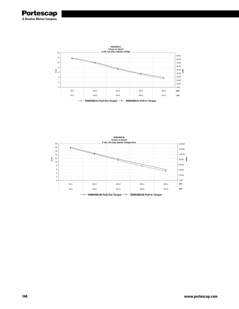
www.portescap.com144
oz-
in
mN
m
55M048D1UTorque vs Speed
5 vdc, full step, unipolar voltage
0
2
4
6
8
10
12
14
50.0 100.0 150.0 200.0 250.0
62.5 125.0 187.5 250.0 312.5
pps
0.00
10.00
20.00
30.00
40.00
50.00
60.00
70.00
80.00
90.00
rpm
55M048D1U Pull-Out Torque 55M048D1U Pull-in Torque
oz-
in
mN
m
55M048D1BTorque vs Speed
5 vdc, full step, bipolar voltage drive
0
2
4
6
8
10
12
14
16
18
20
50.0 100.0 150.0 200.0 250.0
62.5 125.0 187.5 250.0 312.5
pps
0.00
20.00
40.00
60.00
80.00
100.00
120.00
140.00
rpm
55M048D1B Pull-Out Torque 55M048D1B Pull-in Torque

Miniature Motors
145www.portescap.com
Stepper
Notes
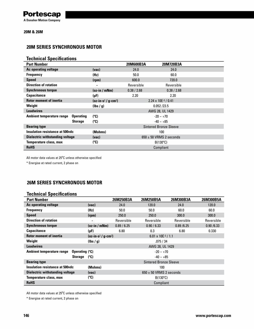
www.portescap.com146
20M & 26M
20M SERIES SYNCHRONOUS MOTOR
Ac operating voltage Frequency Speed Direction of rotation Synchronous torque Capacitance Rotor moment of inertia Weight Leadwires Ambient temperature range Operating Storage Bearing type Insulation resistance at 500vdc Dielectric withstanding voltage Temperature class, max RoHS
All motor data values at 25ºC unless otherwise specified
* Energise at rated current, 2 phase on
Technical SpecificationsPart Number 20M600B3A 20M720B3A 24.0 24.0 50.0 60.0 600.0 720.0 - Reversible Reversible 0.38 / 2.68 0.38 / 2.68 2.20 2.20 2.24 x 10E-3 / 0.41 0.052 /23.5 AWG 28, UL 1429 -20 ~ +70 -40 ~ +85 Sintered Bronze Sleeve
100 650 ± 50 VRMS 2 seconds B(130ºC) Compliant
Ac operating voltage Frequency Speed Direction of rotation Synchronous torque Capacitance Rotor moment of inertia Weight Leadwires Ambient temperature range Operating Storage Bearing type Insulation resistance at 500vdc Dielectric withstanding voltage Temperature class, max RoHS
All motor data values at 25ºC unless otherwise specified
* Energise at rated current, 2 phase on
26M SERIES SYNCHRONOUS MOTOR
Technical SpecificationsPart Number 26M250B3A 26M250B5A 26M300B3A 26M300B5A 24.0 120.0 24.0 120.0 50.0 50.0 60.0 60.0 250.0 250.0 300.0 300.0 Reversible Reversible Reversible Reversible 0.89 / 6.25 0.90 / 6.33 0.89 /6.25 0.90 /6.33 6.80 0.3 6.80 0.330 6.01 x 10E-3 / 1.1 .075 / 34 AWG 28, UL 1429 -20 ~ +70 -40 ~ +85 Sintered Bronze Sleeve 100 650 ± 50 VRMS 2 seconds B(130ºC) Compliant
(vac)(Hz)(rpm) -(oz-in / mNm) (μF)(oz-in-s2 / g-cm2)(lbs / g)
(ºC)(ºC)
(ºC)
(Mohms)(vac)
(vac)(Hz)(rpm) -(oz-in / mNm) (μF)(oz-in-s2 / g-cm2)(lbs / g)
(ºC)
(ºC)
(ºC)
(Mohms)(vac)
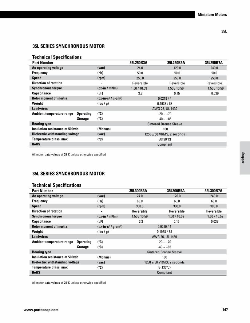
Miniature Motors
147www.portescap.com
Stepper
Ac operating voltage Frequency Speed Direction of rotation Synchronous torque Capacitance Rotor moment of inertia Weight Leadwires Ambient temperature range Operating Storage Bearing type Insulation resistance at 500vdc Dielectric withstanding voltage Temperature class, max RoHS
All motor data values at 25ºC unless otherwise specified
35L
35L SERIES SYNCHRONOUS MOTOR
35L SERIES SYNCHRONOUS MOTOR
Technical SpecificationsPart Number 35L250B3A 35L250B5A 35L250B7A 24.0 120.0 240.0 50.0 50.0 50.0 250.0 250.0 250.0 Reversible Reversible Reversible 1.50 / 10.59 1.50 / 10.59 1.50 / 10.59 3.3 0.15 0.039 0.0219 / 4 0.1938 / 88 AWG 26, UL 1430 -20 ~ +70 -40 ~ +85 Sintered Bronze Sleeve 100 1250 ± 50 VRMS, 2 seconds B(130ºC) Compliant
Technical SpecificationsPart Number 35L300B3A 35L300B5A 35L300B7A 24.0 120.0 240.0 60.0 60.0 60.0 300.0 300.0 300.0 Reversible Reversible Reversible 1.50 / 10.59 1.50 / 10.59 1.50 / 10.59 3.3 0.15 0.039 0.0219 / 4 0.1938 / 88 AWG 26, UL 1430 -20 ~ +70 -40 ~ +85 Sintered Bronze Sleeve 100 1250 ± 50 VRMS, 2 seconds B(130ºC) Compliant
(vac)(Hz)(rpm) -(oz-in / mNm) (μF)(oz-in-s2 / g-cm2)(lbs / g)
(ºC)
(ºC)
(ºC)
(Mohms)(vac)
(vac)(Hz)(rpm) -(oz-in / mNm) (μF)(oz-in-s2 / g-cm2)(lbs / g)
(ºC)
(ºC)
(ºC)
(Mohms)(vac)
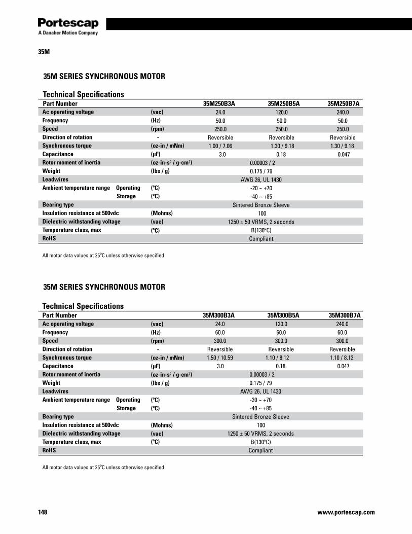
www.portescap.com148
35M
Ac operating voltage Frequency Speed Direction of rotation Synchronous torque Capacitance Rotor moment of inertia Weight Leadwires Ambient temperature range Operating Storage Bearing type Insulation resistance at 500vdc Dielectric withstanding voltage Temperature class, max RoHS
All motor data values at 25ºC unless otherwise specified
35M SERIES SYNCHRONOUS MOTOR
35M SERIES SYNCHRONOUS MOTOR
Technical SpecificationsPart Number 35M250B3A 35M250B5A 35M250B7A 24.0 120.0 240.0 50.0 50.0 50.0 250.0 250.0 250.0 Reversible Reversible Reversible 1.00 / 7.06 1.30 / 9.18 1.30 / 9.18 3.0 0.18 0.047 0.00003 / 2 0.175 / 79 AWG 26, UL 1430 -20 ~ +70 -40 ~ +85 Sintered Bronze Sleeve 100 1250 ± 50 VRMS, 2 seconds B(130ºC) Compliant
Technical SpecificationsPart Number 35M300B3A 35M300B5A 35M300B7A 24.0 120.0 240.0 60.0 60.0 60.0 300.0 300.0 300.0 Reversible Reversible Reversible 1.50 / 10.59 1.10 / 8.12 1.10 / 8.12 3.0 0.18 0.047 0.00003 / 2 0.175 / 79 AWG 26, UL 1430 -20 ~ +70 -40 ~ +85 Sintered Bronze Sleeve 100 1250 ± 50 VRMS, 2 seconds B(130ºC) Compliant
(vac)(Hz)(rpm) -(oz-in / mNm) (μF)(oz-in-s2 / g-cm2)(lbs / g)
(ºC)(ºC)
(ºC)
(Mohms)(vac)
(vac)(Hz)(rpm) -(oz-in / mNm) (μF)(oz-in-s2 / g-cm2)(lbs / g)
(ºC)(ºC)
(ºC)
(Mohms)(vac)

Miniature Motors
149www.portescap.com
Stepper
42M
Ac operating voltage Frequency Speed Direction of rotation Synchronous torque Capacitance Rotor moment of inertia Weight Leadwires Ambient temperature range Operating Storage Bearing type Insulation resistance at 500vdc Dielectric withstanding voltage Temperature class, max RoHS
All motor data values at 25ºC unless otherwise specified
42M SERIES SYNCHRONOUS MOTOR
42M SERIES SYNCHRONOUS MOTOR
Technical SpecificationsPart Number 42M250C3A 42M250C5A 42M250C7A 24.0 120.0 230.0 50.0 50.0 50.0 250.0 250.0 250.0 Reversible Reversible Reversible 5.05 / 35.66 5.78 / 40.82 5.47 / 38.63 6.8 0.33 0.100 0.068 / 12.5 0.31875 / 145 AWG 24, UL 1015 -20 ~ +70 -40 ~ +85 Sintered Bronze Sleeve 100 1250 ± 50 VRMS, 2 seconds B(130ºC) Compliant
Technical SpecificationsPart Number 42M300C3A 42M300C5A 42M300C7A 24.0 120.0 230.0 60.0 60.0 60.0 300.0 300.0 300.0 Reversible Reversible Reversible 5.05 / 35.66 5.78 / 40.82 5.47 / 38.63 6.8 0.33 0.082 0.068 / 12.5 0.31875 / 145 AWG 24, UL 1015 -20 ~ +70 -40 ~ +85 Sintered Bronze Sleeve 100 1250 ± 50 VRMS, 2 seconds B(130ºC) Compliant
(vac)(Hz)(rpm) -(oz-in / mNm) (μF)(oz-in-s2 / g-cm2)(lbs / g)
(ºC)(ºC)
(ºC)
(Mohms)(vac)
(vac)(Hz)(rpm) -(oz-in / mNm) (μF)(oz-in-s2 / g-cm2)(lbs / g)
(ºC)(ºC)
(ºC)
(Mohms)(vac)
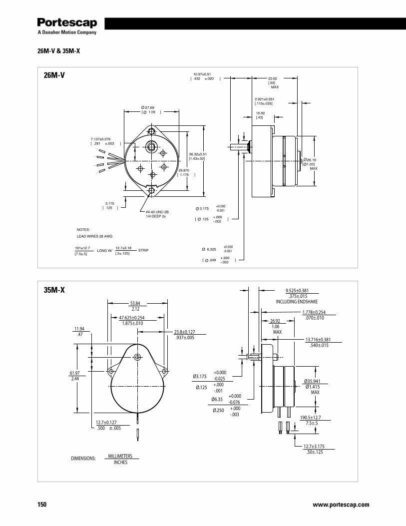
www.portescap.com150
26M-V & 35M-X
26M-V
35M-X
13.716±0.381.540±.015
53.842.12
47.625±0.2541.875±.010
61.972.44
12.7±0.127.500 ±.005
11.94.47 23.8±0.127
.937±.005
26.921.06MAX
1.778±0.254.070±.010
9.525±0.381.375±.015
INCLUDING ENDSHAKE
Ø3.175
Ø.125
Ø6.35
Ø.250
Ø35.941Ø1.415
MAX
12.7±3.175.50±.125
190.5±12.77.5±.5
+0.000-0.025+.000-.001
+0.000-0.076+.000-.003
DIMENSIONS: MILLIMETERSINCHES
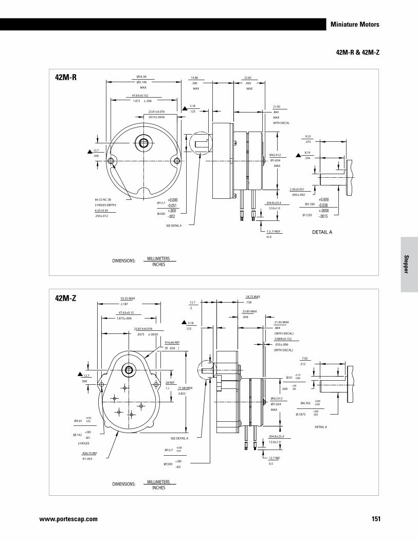
Miniature Motors
151www.portescap.com
Stepper
42M-R & 42M-Z
Ø54.36
Ø2.140
MAX
47.63±0.152
1.875 ±.006
#6-32 NC-2B
2 HOLES-DEPTH:
6.35±0.30
.250±.012
Ø12.7
Ø.500
14.86
.585
MAX
3.18
.125
23.85
.939
MAX
21.95
.864
MAX
WITH DECAL
23.81±0.076
.9375±.0030
Ø42.012
Ø1.654
MAX
2.36±0.051
.093±.002
8.74
.344
9.53
.375
Ø3.180
Ø.1250
12.7
.500
304.8±25.4
12.0±1.0
12.7 REF
0.5
SEE DETAIL A
+0.000-0.038+.0000-.0015
DETAIL A
+0.000-0.051+.000-.002
55.55 MAX
2.187
47.63±0.15
1.875±.006
23.813±0.076
.9375 ±.0030
12.7
.500
Ø3.61
Ø
2 HOLES
.142+.003
-.001
R26.75 REF
R 1.053
28 REF
1.1
R16.66 REF
[R ].656
Ø12.7
Ø .500+.000
-.002
3.18
.125
18.75 MAX
.738
21.95 MAX
.864
(WITH DECAL)
23.85 MAX
.939
0.889±0.152
.035±.006
(WITH DECAL)
Ø42.012
Ø1.654
MAX
71.68 MAX
2.822
7.92
.312
Ø4.763
Ø.1875
304.8±25.4
12.0±1.0
12.7 REF
0.5
Ø.51
.020
12.7
.5
+0.000-0.051
+0.076-0.025
+0.000-0.008
+.0000-.0003
DETAIL A
SEE DETAIL A
+0.127-0.000
+.005-.000
42M-R
42M-Z
DIMENSIONS: MILLIMETERSINCHES
DIMENSIONS: MILLIMETERSINCHES
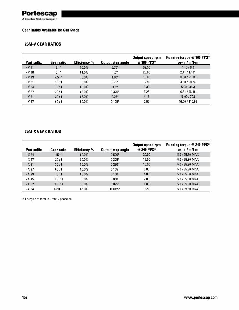
www.portescap.com152
Gear Ratios Available for Can Stack
26M-V GEAR RATIOS
35M-X GEAR RATIOS
Part suffix- V 11- V 16- V 19- V 21- V 24- V 27- V 31- V 37
Part suffix- X 24- X 27- X 31- X 37- X 39- X 45- X 52- X 64
Gear ratio 2 : 1 5 : 1
7.5 : 1 10 : 1 15 : 1 20 : 1 30 : 1 60 : 1
Gear ratio 15 : 1 20 : 1 30 : 1 60 : 1 75 : 1
150 : 1 300 : 1
1350 : 1
Efficiency %90.0%81.0%73.0%73.0%66.0%66.0%66.0%59.0%
Efficiency %80.0%80.0%80.0%80.0%80.0%70.0%70.0%65.0%
Output step angle3.75°1.5°1.00°0.75°0.5°
0.375°0.25°0.125°
Output step angle0.500°0.375°0.250°0.125°0.100°0.050°0.025°0.0055°
Output speed rpm @ 100 PPS*
62.5025.0016.6612.508.336.254.172.09
Output speed rpm @ 240 PPS*
20.0015.0010.005.004.002.001.000.22
Running torque @ 100 PPS* oz-in / mN-m
1.16 / 8.92.41 / 17.013.00 / 21.084.00 / 28.245.00 / 35.36.64 / 46.8810.00 / 70.6
16.00 / 112.96
Running torque @ 240 PPS* oz-in / mN-m5.0 / 35.30 MAX5.0 / 35.30 MAX5.0 / 35.30 MAX5.0 / 35.30 MAX5.0 / 35.30 MAX5.0 / 35.30 MAX5.0 / 35.30 MAX5.0 / 35.30 MAX
* Energise at rated current, 2 phase on
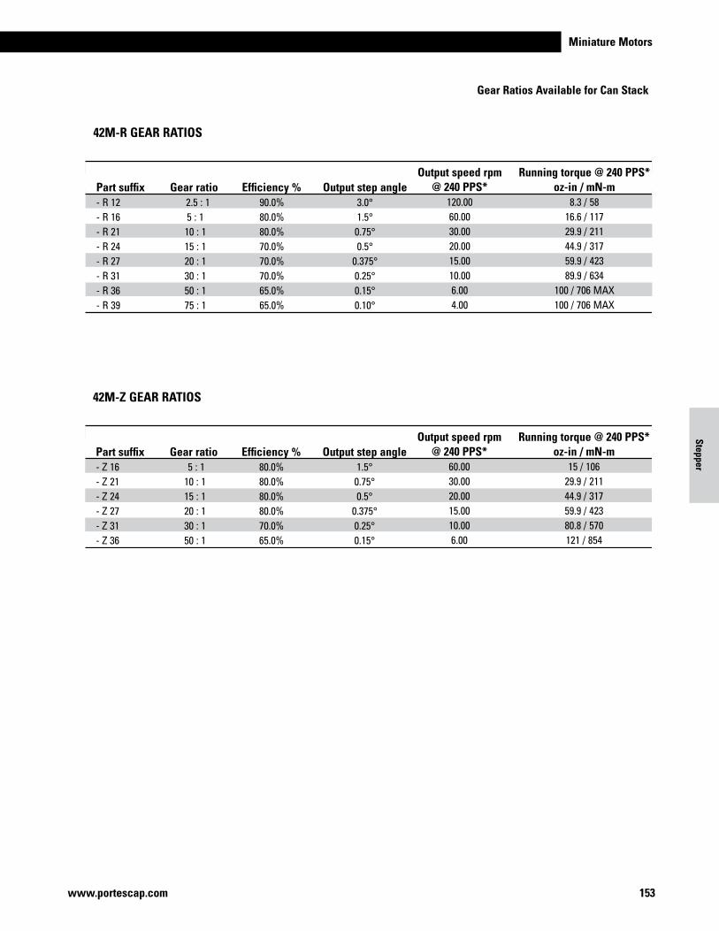
Miniature Motors
153www.portescap.com
Stepper
42M-Z GEAR RATIOS
Part suffix- Z 16- Z 21- Z 24- Z 27- Z 31- Z 36
Gear ratio 5 : 1 10 : 1 15 : 1 20 : 1 30 : 1 50 : 1
Efficiency %80.0%80.0%80.0%80.0%70.0%65.0%
Output step angle1.5°0.75°0.5°
0.375°0.25°0.15°
Output speed rpm @ 240 PPS*
60.0030.0020.0015.0010.006.00
Running torque @ 240 PPS* oz-in / mN-m
15 / 10629.9 / 21144.9 / 31759.9 / 42380.8 / 570121 / 854
Gear Ratios Available for Can Stack
42M-R GEAR RATIOS
Part suffix- R 12- R 16- R 21- R 24- R 27- R 31- R 36- R 39
Gear ratio 2.5 : 1
5 : 1 10 : 1 15 : 1 20 : 1 30 : 1 50 : 1 75 : 1
Efficiency %90.0%80.0%80.0%70.0%70.0%70.0%65.0%65.0%
Output step angle3.0° 1.5° 0.75° 0.5°
0.375° 0.25° 0.15° 0.10°
Output speed rpm @ 240 PPS*
120.00 60.00 30.00 20.00 15.00 10.00 6.004.00
Running torque @ 240 PPS* oz-in / mN-m
8.3 / 58 16.6 / 117 29.9 / 211 44.9 / 317 59.9 / 423 89.9 / 634
100 / 706 MAX 100 / 706 MAX

www.portescap.com154
Notes
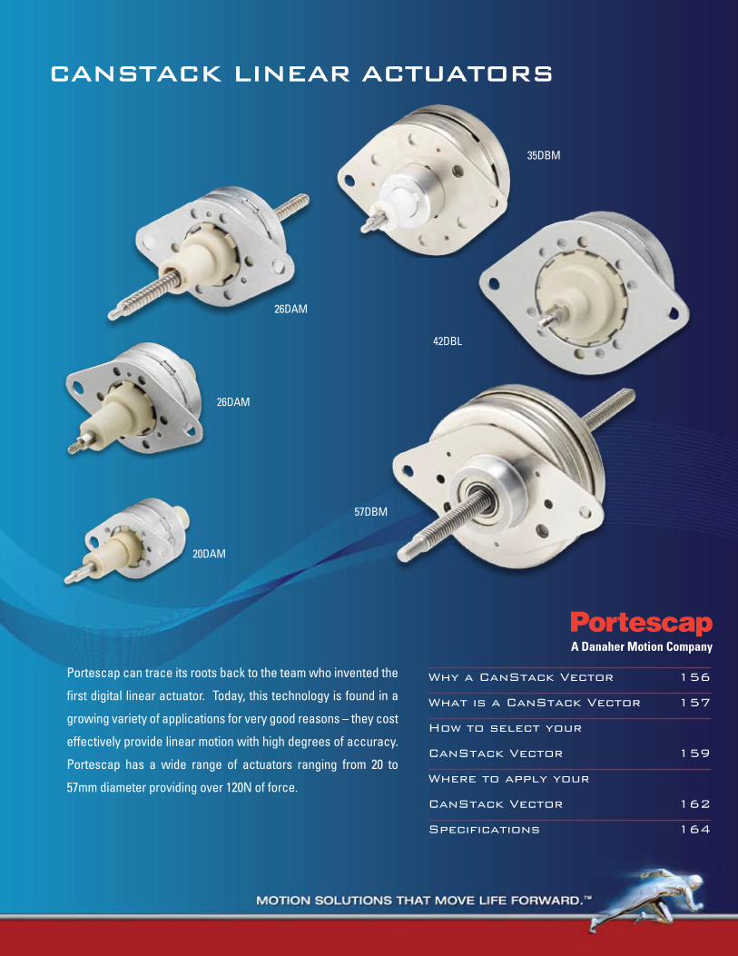
20DAM
26DAM
CanStaCk Linear aCtuatorS
Why a CanStack Vector 156
What is a CanStack Vector 157
How to select your
CanStack Vector 159
Where to apply your
CanStack Vector 162
Specifications 164
Portescap can trace its roots back to the team who invented the
first digital linear actuator. Today, this technology is found in a
growing variety of applications for very good reasons – they cost
effectively provide linear motion with high degrees of accuracy.
Portescap has a wide range of actuators ranging from 20 to
57mm diameter providing over 120N of force.
26DAM
35DBM
42DBL
57DBM
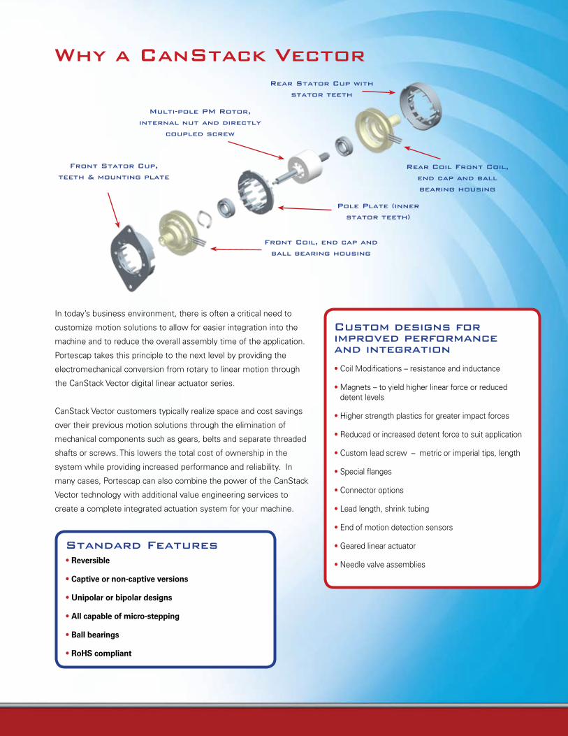
Standard Features• Reversible
• Captive or non-captive versions
• Unipolar or bipolar designs
• All capable of micro-stepping
• Ball bearings
• RoHS compliant
Why a CanStack Vector
Front Stator Cup,
teeth & mounting plate
Multi-pole PM rotor,
internal nut and directly
coupled screw
rear Stator Cup with
stator teeth
Front Coil, end cap and
ball bearing housing
Pole Plate (inner
stator teeth)
rear Coil Front Coil,
end cap and ball
bearing housing
Custom designs for improved performance and integration
• Coil Modifications – resistance and inductance
• Magnets – to yield higher linear force or reduced detent levels
• Higher strength plastics for greater impact forces
• Reduced or increased detent force to suit application
• Custom lead screw – metric or imperial tips, length
• Special flanges
• Connector options
• Lead length, shrink tubing
• End of motion detection sensors
• Geared linear actuator
• Needle valve assemblies
In today’s business environment, there is often a critical need to
customize motion solutions to allow for easier integration into the
machine and to reduce the overall assembly time of the application.
Portescap takes this principle to the next level by providing the
electromechanical conversion from rotary to linear motion through
the CanStack Vector digital linear actuator series.
CanStack Vector customers typically realize space and cost savings
over their previous motion solutions through the elimination of
mechanical components such as gears, belts and separate threaded
shafts or screws. This lowers the total cost of ownership in the
system while providing increased performance and reliability. In
many cases, Portescap can also combine the power of the CanStack
Vector technology with additional value engineering services to
create a complete integrated actuation system for your machine.
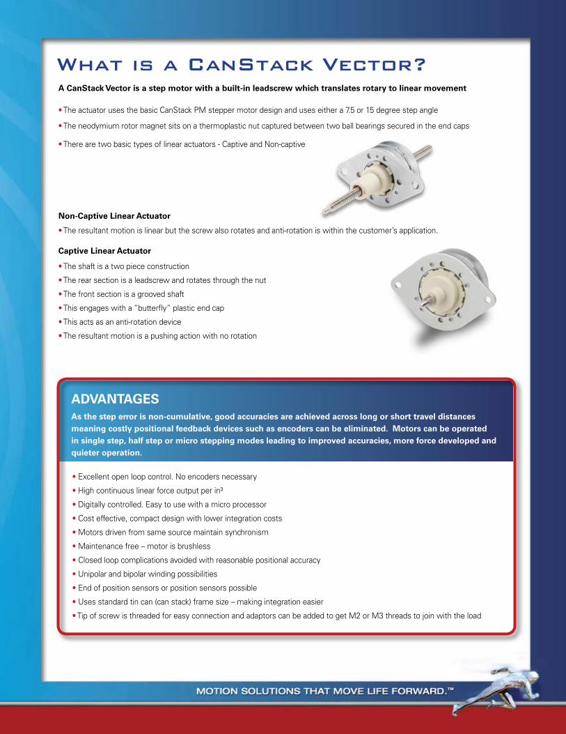
What is a CanStack Vector?A CanStack Vector is a step motor with a built-in leadscrew which translates rotary to linear movement
Non-Captive Linear Actuator
Captive Linear Actuator
• The actuator uses the basic CanStack PM stepper motor design and uses either a 7.5 or 15 degree step angle
• The neodymium rotor magnet sits on a thermoplastic nut captured between two ball bearings secured in the end caps
• There are two basic types of linear actuators - Captive and Non-captive
• The resultant motion is linear but the screw also rotates and anti-rotation is within the customer’s application.
• The shaft is a two piece construction
• The rear section is a leadscrew and rotates through the nut
• The front section is a grooved shaft
• This engages with a “butterfly” plastic end cap
• This acts as an anti-rotation device
• The resultant motion is a pushing action with no rotation
ADVANTAGESAs the step error is non-cumulative, good accuracies are achieved across long or short travel distances meaning costly positional feedback devices such as encoders can be eliminated. Motors can be operated in single step, half step or micro stepping modes leading to improved accuracies, more force developed and quieter operation.
• Excellent open loop control. No encoders necessary
• High continuous linear force output per in³
• Digitally controlled. Easy to use with a micro processor
• Cost effective, compact design with lower integration costs
• Motors driven from same source maintain synchronism
• Maintenance free – motor is brushless
• Closed loop complications avoided with reasonable positional accuracy
• Unipolar and bipolar winding possibilities
• End of position sensors or position sensors possible
• Uses standard tin can (can stack) frame size – making integration easier
• Tip of screw is threaded for easy connection and adaptors can be added to get M2 or M3 threads to join with the load
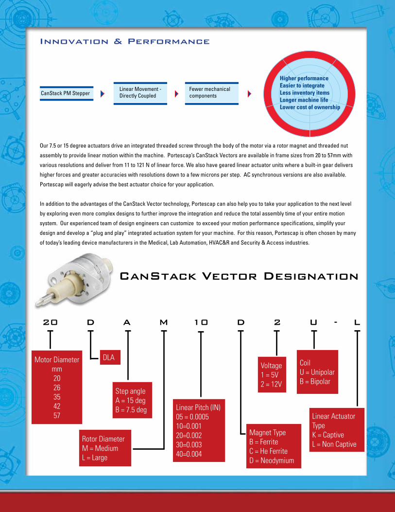
Our 7.5 or 15 degree actuators drive an integrated threaded screw through the body of the motor via a rotor magnet and threaded nut
assembly to provide linear motion within the machine. Portescap’s CanStack Vectors are available in frame sizes from 20 to 57mm with
various resolutions and deliver from 11 to 121 N of linear force. We also have geared linear actuator units where a built-in gear delivers
higher forces and greater accuracies with resolutions down to a few microns per step. AC synchronous versions are also available.
Portescap will eagerly advise the best actuator choice for your application.
In addition to the advantages of the CanStack Vector technology, Portescap can also help you to take your application to the next level
by exploring even more complex designs to further improve the integration and reduce the total assembly time of your entire motion
system. Our experienced team of design engineers can customize to exceed your motion performance specifications, simplify your
design and develop a “plug and play” integrated actuation system for your machine. For this reason, Portescap is often chosen by many
of today’s leading device manufacturers in the Medical, Lab Automation, HVAC&R and Security & Access industries.
innovation & Performance
CanStack Vector Designation
20 D a M 10 D 2 u - L
Step angleA = 15 degB = 7.5 deg
Rotor DiameterM = MediumL = Large
DLAVoltage1 = 5V2 = 12V
CoilU = UnipolarB = Bipolar
Linear Actuator TypeK = Captive L = Non Captive
Motor Diametermm 2026354257
Magnet TypeB = FerriteC = He FerriteD = Neodymium
Linear Pitch (IN)05 = 0.000510=0.00120=0.00230=0.00340=0.004
CanStack PM StepperLinear Movement - Directly Coupled
Fewer mechanical components
Higher performanceEasier to integrateLess inventory itemsLonger machine lifeLower cost of ownership
How to select your Linear actuator

Resistance/Windings (Ohms)BipOlaR & UnipOlaR
Portescap finds its place among an esteemed worldwide family of motion control experts.
How to select your Linear actuator
• Linear force – speed curves are the key to selecting the right motor and control drive method for a specific application.
• Define your application load – speed required, load inertia and force required, and accuracy needed.
• If the application requires no acceleration, then use the pull out force.
• If the load is inertial, acceleration is required, it is advisable to use pull in force.
• Use a 1.5 to 2 times margin over the maximum torque required.
• Leave some distance at either end of travel to avoid impact damage at the maximum travel or stroke. The force on the shaft, when fully extended, has to be supported by the number of threads in contact with the nut. This can be a limiting factor.
• Choosing the correct drive is important. For example micro-stepping drives will provide quieter operation. Like all steppers – a linear actuator will deliver force dependent on the drive – L/R , Chopper, 24 or 36V
• Remember – if it is not in the catalog – it does not mean that we cannot provide a solution - Portescap may still be able to provide you what you want as our team can draw from a wealth of customized designs created over the past 20 years of linear actuator designs.
seRies linear travelper step(mm/in)
maximum Force
(n / oz)
min. holding Force(Un-energized)
(n / oz)
dc Operating
Voltage5 Vdc 12 Vdc
20DAM-K&-L 0.0254 / .0010 30/108 55.6/200 5 or 12 20 115.2
0.0508 / .0020 20.9/75 11.1/40 5 or 12 20 115.2
0.1018/.0040 11.1/40 2.8/10 5 or 12 20 115.2
26DBM-K & -L 0.0127 / .0005 16.7 / 60 55.6 / 200 5 or 12 14.6 84
0.0254 / .0010 13.3 / 48 13.9 / 50 5 or 12 14.6 84
0.0508 / .0020 8.9 / 32 2.8 / 10 5 or 12 14.6 84
26DAM-K&-L 0.0254 / .0010 33.4 / 120 55.6 / 200 5 or 12 14.6 84
0.0508 / .0020 25 / 90 19.5 / 70 5 or 12 14.6 84
0.1018/.0040 14.5 / 52 8.3 / 30 5 or 12 14.6 84
35DBM-K & -L 0.0254 / .0010 20.9 / 75 11.1 / 40 5 or 12 10 58
0.0508 / .0020 15.3 / 55 2.8 / 10 5 or 12 10 58
0.0762 / .0030 8.3 / 30 1.4 / 5 5 or 12 10 58
42DBL-K & -L 0.0254 / .0010 100.0 / 360 111.2 / 400 5 or 12 5 28.8
0.0508 / .0020 72.3 / 260 83.4 / 300 5 or 12 5 28.8
0.1016 / .0040 50.0 / 180 19.5 / 70 5 or 12 5 28.8
57DBM -L 0.0254 / .0010 124.6 / 448 88/ 320 5 or 12 4.3 25
0.0508 / .0020 102.4/ 368 71/256 5 or 12 4.3 25
Resistance/Windings (Ohms) Bipolar & Unipolar
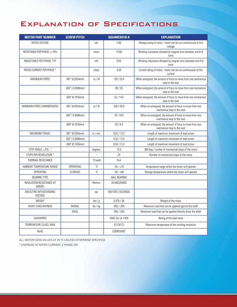
explanation of Specifications
mOtOR paRt nUmBeR scReW pitch 26damXXd1B-K eXplanatiOn
RATED VOLTAGE vdc 5.00 Voltage rating of motor - motor can be run continuously at this voltage
RESISTANCE PER PHASE, ± 10% ohms 14.60 Winding resistance dictated by magnet wire diameter and # of turns
INDUCTANCE PER PHASE, TYP mH 6.50 Winding inductance dictated by magnet wire diameter and # of turns
RATED CURRENT PER PHASE * amps 0.34 Current rating of motor - motor can be run continuously at this current
MAXIMUM FORCE .001" (0.0254mm) oz / N 120 / 33.4 When energized, the amount of force to move from one mechanical step to the next
.002" ( 0.0508mm) 90 / 25 When energized, the amount of force to move from one mechanical step to the next
.004" (0.1016mm) 52 / 14.5 When energized, the amount of force to move from one mechanical step to the next
MINIMUM FORCE (UNENERGIZED) .001" (0.0254mm) oz / N 200 / 55.6 When un-energized, the amount of force to move from one mechanical step to the next
.002" ( 0.0508mm) 70 / 19.5 When un-energized, the amount of force to move from one mechanical step to the next
.004" (0.1016mm) 30 / 8.3 When un-energized, the amount of force to move from one mechanical step to the next
MAXIMUM TRAVEL .001" (0.0254mm) in / mm 0.52 / 13.2 Length of maximum movement of lead screw
.002" ( 0.0508mm) 0.52 / 13.2 Length of maximum movement of lead screw
.004" (0.1016mm) 0.52 / 13.2 Length of maximum movement of lead screw
STEP ANGLE, ± 5% * degrees 15.0 360 deg / number of mechanical steps of the motor
STEPS PER REVOLUTION * - 24 Number of mechanical steps of the motor
THERMAL RESISTANCE ºC/watt N.A
AMBIENT TEMPERATURE RANGE OPERATING ºC -20 ~ +70 Temperature range which the motor will operate
OPERATING STORAGE ºC -40 ~ +85 Storage temperature where the motor will operate
BEARING TYPE - BALL BEARING
INSULATION RESISITANCE AT 500VDC
Mohms 20 MEGOHMS
DIELECTRIC WITHSTANDING VOLTAGE
vac 650 FOR 2 SECONDS
WEIGHT lbs / g 0.075 / 34 Weight of the motor
SHAFT LOAD RATINGS RADIAL lbs / kg .055 / .025 Maximum load that can be applied against the shaft
AXIAL .055 / .025 Maximum load that can be applied directly down the shaft
LEADWIRES AWG 28, UL 1429 Rating of the lead wires
TEMPERATURE CLASS, MAX B (130°C) Maximum temperature of the winding insulation
RoHS COMPLIANT
ALL MOTOR DATA VALUES AT 25 ºC UNLESS OTHERWISE SPECIFIED
* ENERGISE AT RATED CURRENT, 2 PHASE ON
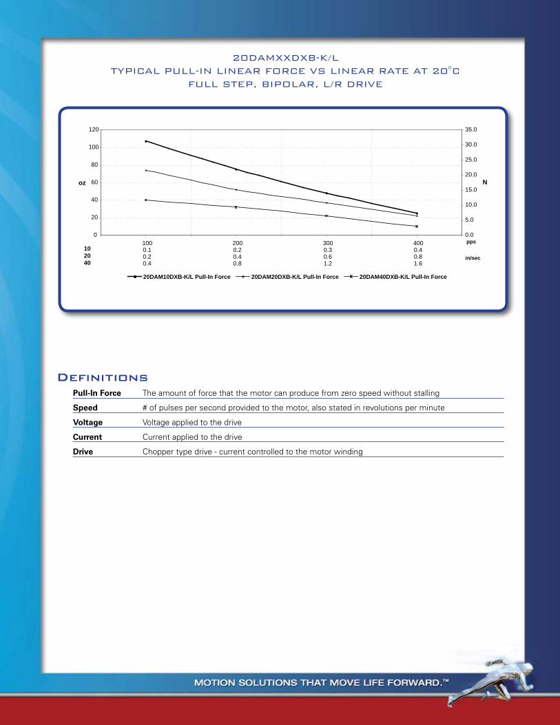
0
20
40
60
80
100
120
1000.10.20.4
2000.20.40.8
3000.30.61.2
4000.40.81.6
pps
oz
0.0
5.0
10.0
15.0
20.0
25.0
30.0
35.0
in/sec
N
20DAM10DXB-K/L Pull-In Force 20DAM20DXB-K/L Pull-In Force 20DAM40DXB-K/L Pull-In Force
402010
20DAMXXDXB-K/LTYPICAL PULL-IN LINEAR FORCE VS LINEAR RATE AT 20°C
FULL STEP, BIPOLAR, L/R DRIVE
Definitions
Pull-In Force The amount of force that the motor can produce from zero speed without stalling
Speed # of pulses per second provided to the motor, also stated in revolutions per minute
Voltage Voltage applied to the drive
Current Current applied to the drive
Drive Chopper type drive - current controlled to the motor winding
mOtOR paRt nUmBeR scReW pitch 26damXXd1B-K eXplanatiOn
RATED VOLTAGE vdc 5.00 Voltage rating of motor - motor can be run continuously at this voltage
RESISTANCE PER PHASE, ± 10% ohms 14.60 Winding resistance dictated by magnet wire diameter and # of turns
INDUCTANCE PER PHASE, TYP mH 6.50 Winding inductance dictated by magnet wire diameter and # of turns
RATED CURRENT PER PHASE * amps 0.34 Current rating of motor - motor can be run continuously at this current
MAXIMUM FORCE .001" (0.0254mm) oz / N 120 / 33.4 When energized, the amount of force to move from one mechanical step to the next
.002" ( 0.0508mm) 90 / 25 When energized, the amount of force to move from one mechanical step to the next
.004" (0.1016mm) 52 / 14.5 When energized, the amount of force to move from one mechanical step to the next
MINIMUM FORCE (UNENERGIZED) .001" (0.0254mm) oz / N 200 / 55.6 When un-energized, the amount of force to move from one mechanical step to the next
.002" ( 0.0508mm) 70 / 19.5 When un-energized, the amount of force to move from one mechanical step to the next
.004" (0.1016mm) 30 / 8.3 When un-energized, the amount of force to move from one mechanical step to the next
MAXIMUM TRAVEL .001" (0.0254mm) in / mm 0.52 / 13.2 Length of maximum movement of lead screw
.002" ( 0.0508mm) 0.52 / 13.2 Length of maximum movement of lead screw
.004" (0.1016mm) 0.52 / 13.2 Length of maximum movement of lead screw
STEP ANGLE, ± 5% * degrees 15.0 360 deg / number of mechanical steps of the motor
STEPS PER REVOLUTION * - 24 Number of mechanical steps of the motor
THERMAL RESISTANCE ºC/watt N.A
AMBIENT TEMPERATURE RANGE OPERATING ºC -20 ~ +70 Temperature range which the motor will operate
OPERATING STORAGE ºC -40 ~ +85 Storage temperature where the motor will operate
BEARING TYPE - BALL BEARING
INSULATION RESISITANCE AT 500VDC
Mohms 20 MEGOHMS
DIELECTRIC WITHSTANDING VOLTAGE
vac 650 FOR 2 SECONDS
WEIGHT lbs / g 0.075 / 34 Weight of the motor
SHAFT LOAD RATINGS RADIAL lbs / kg .055 / .025 Maximum load that can be applied against the shaft
AXIAL .055 / .025 Maximum load that can be applied directly down the shaft
LEADWIRES AWG 28, UL 1429 Rating of the lead wires
TEMPERATURE CLASS, MAX B (130°C) Maximum temperature of the winding insulation
RoHS COMPLIANT
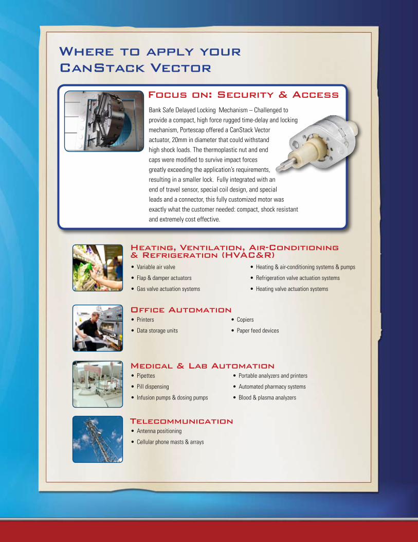
Heating, Ventilation, air-Conditioning & refrigeration (HVaC&r)
Variable air valve•
Flap & damper actuators•
Gas valve actuation systems•
Heating & air-conditioning systems & pumps•
Refrigeration valve actuation systems•
Heating valve actuation systems•
Where to apply your CanStack Vector
Office AutomationPrinters•
Data storage units•
Copiers•
Paper feed devices•
Medical & Lab automationPipettes•
Pill dispensing•
Infusion pumps & dosing pumps•
Portable analyzers and printers•
Automated pharmacy systems•
Blood & plasma analyzers•
telecommunicationAntenna positioning•
Cellular phone masts & arrays•
Focus on: Security & accessBank Safe Delayed Locking Mechanism – Challenged to provide a compact, high force rugged time-delay and locking mechanism, Portescap offered a CanStack Vector actuator, 20mm in diameter that could withstand high shock loads. The thermoplastic nut and end caps were modified to survive impact forces greatly exceeding the application’s requirements, resulting in a smaller lock. Fully integrated with an end of travel sensor, special coil design, and special leads and a connector, this fully customized motor was exactly what the customer needed: compact, shock resistant and extremely cost effective.

Miniature Motors
163www.portescap.com
Stepper
Notes

www.portescap.com164
Ø20.50 MAX
[Ø.807 MAX]
Ø7.92±0.13
[Ø.312±.005]
Ø3.43 REF
[Ø.135 REF]
76.20±0.64
[3.000±.025]
2X Ø3.66±0.05
[Ø.144±.002]
33.32±0.51
[1.312±.020]
26.19±0.13
[1.031±.005]
Ø7.92±0.13
[Ø.312±.005]
Ø9.63±0.13
[Ø.379±.005]
15.76±0.20
[.620±.008]
4.58±0.20
[.180±.008]
25.60 MAX
[1.008 MAX]
15.13±0.15
[.595±.006]
0.80±0.13
[.031±.005]
3.81±0.13
[.150±.005]
304.8±10.0 LONG
[12±1]
#2-56 UNC-2A(OTHER UNIFIED
AND METRICTHREADS
AVAILABLE)
NOTES : 1. SHAFT AXIAL BACKLASH : 0.15/[.006] MAX.
20DAM-L
ALL MOTOR DATA VALUES AT 20ºC UNLESS OTHERWISE SPECIFIED* ENERGISE AT RATED CURRENT, 2 PHASE ON, L/R Drive
20DAM-L
Motor Part Number Rated voltage vdc Resistance per phase, ± 10% ohms Inductance per phase, typ mH Rated current per phase * amps Maximum force .001" (0.0254mm) oz / N .002" ( 0.0508mm) .004" (0.1016mm)Minimum holding .001" (0.0254mm) oz / N force (unenergized) .002" ( 0.0508mm) .004" (0.1016mm)Maximum travel .001" (0.0254mm) in / mm .002" ( 0.0508mm) .004" (0.1016mm)Step angle, ± 1º * degrees Steps per revolution * Thermal resistance ºC/watt Ambient temperature range Operating ºC Storage ºC Bearing type Insulation resisitance at 500vdc Mohms Dielectric withstanding voltage vac Weight lbs / g Leadwires Temperature class, max RoHS
20DAMXXD1B-L 20DAMXXD2B-L 5.00 12.00 20.00 115.20 7.20 40.80 0.25 0.10 110 / 30.6 75 / 20.9 40 / 11.1 200 / 55.6 40 / 11.1 10 / 2.8 1.97 / 50.0 1.97 / 50.0 1.97 / 50.0 15.00 24 N.A. -20 ~ +70 -40 ~ +85 Ball bearing 20 megohms 650 for 2 seconds 0.055 / 25 AWG28, UL 1429 B (130°C) COMPLIANT
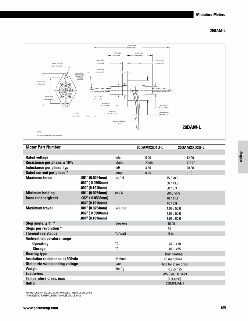
Miniature Motors
165www.portescap.com
Ø20.50 MAX
[Ø.807 MAX]
Ø7.92±0.13
[Ø.312±.005]
Ø3.43 REF
[Ø.135 REF]
76.20±0.64
[3.000±.025]
2X Ø3.66±0.05
[Ø.144±.002]
33.32±0.51
[1.312±.020]
26.19±0.13
[1.031±.005]
Ø7.92±0.13
[Ø.312±.005]
Ø9.63±0.13
[Ø.379±.005]
15.76±0.20
[.620±.008]
4.58±0.20
[.180±.008]
25.60 MAX
[1.008 MAX]
15.13±0.15
[.595±.006]
0.80±0.13
[.031±.005]
3.81±0.13
[.150±.005]
304.8±10.0 LONG
[12±1]
#2-56 UNC-2A(OTHER UNIFIED
AND METRICTHREADS
AVAILABLE)
NOTES : 1. SHAFT AXIAL BACKLASH : 0.15/[.006] MAX.
20DAM-L
ALL MOTOR DATA VALUES AT 20ºC UNLESS OTHERWISE SPECIFIED* ENERGISE AT RATED CURRENT, 2 PHASE ON , L/R Drive
20DAM-L
Motor Part Number Rated voltage vdc Resistance per phase, ± 10% ohms Inductance per phase, typ mH Rated current per phase * amps Maximum force .001" (0.0254mm) oz / N .002" ( 0.0508mm) .004" (0.1016mm)Minimum holding .001" (0.0254mm) oz / N force (unenergized) .002" ( 0.0508mm) .004" (0.1016mm)Maximum travel .001" (0.0254mm) in / mm .002" ( 0.0508mm) .004" (0.1016mm)Step angle, ± 1º * degrees Steps per revolution * Thermal resistance ºC/watt Ambient temperature range Operating ºC Storage ºC Bearing type Insulation resisitance at 500vdc Mohms Dielectric withstanding voltage vac Weight lbs / g Leadwires Temperature class, max RoHS
Motor Part Number Rated voltage vdc Resistance per phase, ± 10% ohms Inductance per phase, typ mH Rated current per phase * amps Maximum force .001" (0.0254mm) oz / N .002" ( 0.0508mm) .004" (0.1016mm)Minimum holding .001" (0.0254mm) oz / N force (unenergized) .002" ( 0.0508mm) .004" (0.1016mm)Maximum travel .001" (0.0254mm) in / mm .002" ( 0.0508mm) .004" (0.1016mm)Step angle, ± 1º * degrees Steps per revolution * Thermal resistance ºC/watt Ambient temperature range Operating ºC Storage ºC Bearing type Insulation resisitance at 500vdc Mohms Dielectric withstanding voltage vac Weight lbs / g Leadwires Temperature class, max RoHS
20DAMXXD1B-L 20DAMXXD2B-L 5.00 12.00 20.00 115.20 7.20 40.80 0.25 0.10 110 / 30.6 75 / 20.9 40 / 11.1 200 / 55.6 40 / 11.1 10 / 2.8 1.97 / 50.0 1.97 / 50.0 1.97 / 50.0 15.00 24 N.A. -20 ~ +70 -40 ~ +85 Ball bearing 20 megohms 650 for 2 seconds 0.055 / 25 AWG28, UL 1429 B (130°C) COMPLIANT
20DAMXXD1U-L 20DAMXXD2U-L 5.00 12.00 20.00 115.20 3.80 20.30 0.25 0.10 75 / 20.9 50 / 13.9 30 / 8.3 200 / 55.6 40 / 11.1 10 / 2.8 1.97 / 50.0 1.97 / 50.0 1.97 / 50.0 15.00 24 N.A. -20 ~ +70 -40 ~ +85 Ball bearing 20 megohms 650 for 2 seconds 0.055 / 25 AWG28, UL 1429 B (130°C) COMPLIANT
Stepper
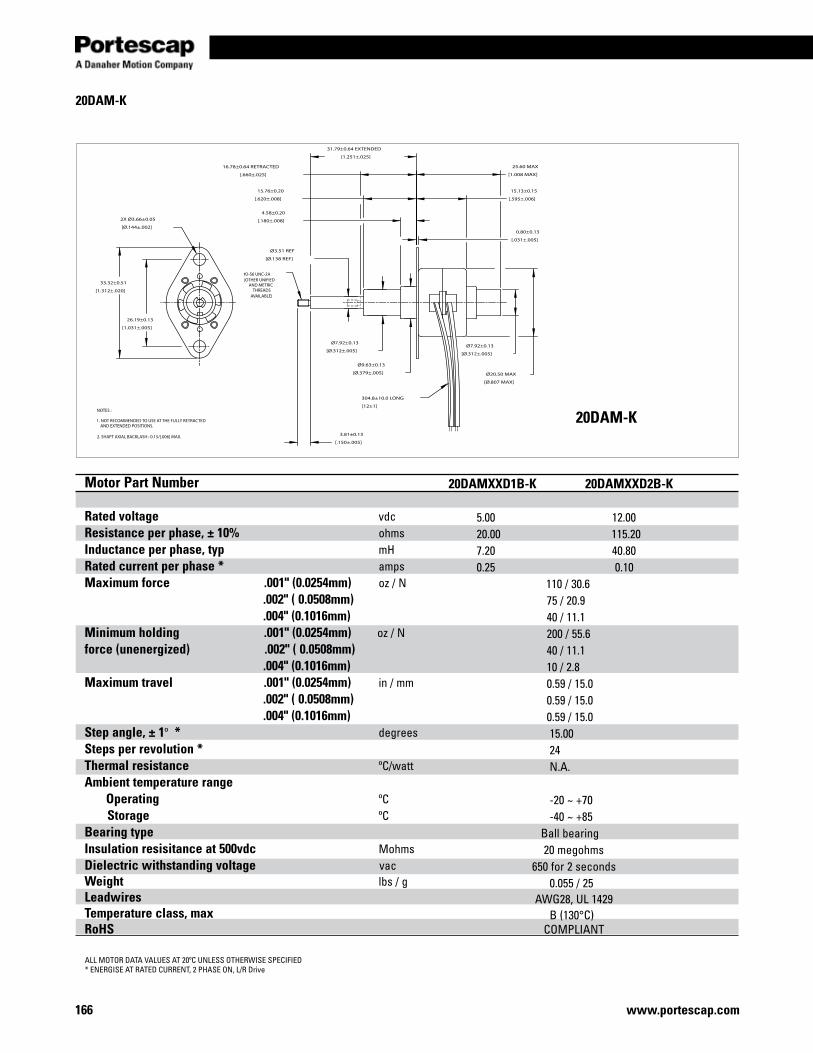
www.portescap.com166
3.81±0.13
[.150±.005]
0.80±0.13
[.031±.005]
15.13±0.15
[.595±.006]
25.60 MAX
[1.008 MAX]
Ø7.92±0.13
[Ø.312±.005]
Ø20.50 MAX
[Ø.807 MAX]
4.58±0.20
[.180±.008]
15.76±0.20
[.620±.008]
Ø9.63±0.13
[Ø.379±.005]
Ø7.92±0.13
[Ø.312±.005]
26.19±0.13
[1.031±.005]
33.32±0.51
[1.312±.020]
2X Ø3.66±0.05
[Ø.144±.002]
16.78±0.64 RETRACTED
[.660±.025]
31.79±0.64 EXTENDED
[1.251±.025]
Ø3.51 REF
[Ø.138 REF]
304.8±10.0 LONG
[12±1]
#2-56 UNC-2A(OTHER UNIFIED
AND METRICTHREADS
AVAILABLE)
NOTES : 1. NOT RECOMMENDED TO USE AT THE FULLY RETRACTED AND EXTENDED POSITIONS. 2. SHAFT AXIAL BACKLASH : 0.15/[.006] MAX.
20DAM-K
ALL MOTOR DATA VALUES AT 20ºC UNLESS OTHERWISE SPECIFIED* ENERGISE AT RATED CURRENT, 2 PHASE ON, L/R Drive
20DAM-K
Motor Part Number Rated voltage vdc Resistance per phase, ± 10% ohms Inductance per phase, typ mH Rated current per phase * amps Maximum force .001" (0.0254mm) oz / N .002" ( 0.0508mm) .004" (0.1016mm)Minimum holding .001" (0.0254mm) oz / N force (unenergized) .002" ( 0.0508mm) .004" (0.1016mm)Maximum travel .001" (0.0254mm) in / mm .002" ( 0.0508mm) .004" (0.1016mm)Step angle, ± 1º * degrees Steps per revolution * Thermal resistance ºC/watt Ambient temperature range Operating ºC Storage ºC Bearing type Insulation resisitance at 500vdc Mohms Dielectric withstanding voltage vac Weight lbs / g Leadwires Temperature class, max RoHS
20DAMXXD1B-K 20DAMXXD2B-K 5.00 12.00 20.00 115.20 7.20 40.80 0.25 0.10 110 / 30.6 75 / 20.9 40 / 11.1 200 / 55.6 40 / 11.1 10 / 2.8 0.59 / 15.0 0.59 / 15.0 0.59 / 15.0 15.00 24 N.A. -20 ~ +70 -40 ~ +85 Ball bearing 20 megohms 650 for 2 seconds 0.055 / 25 AWG28, UL 1429 B (130°C) COMPLIANT
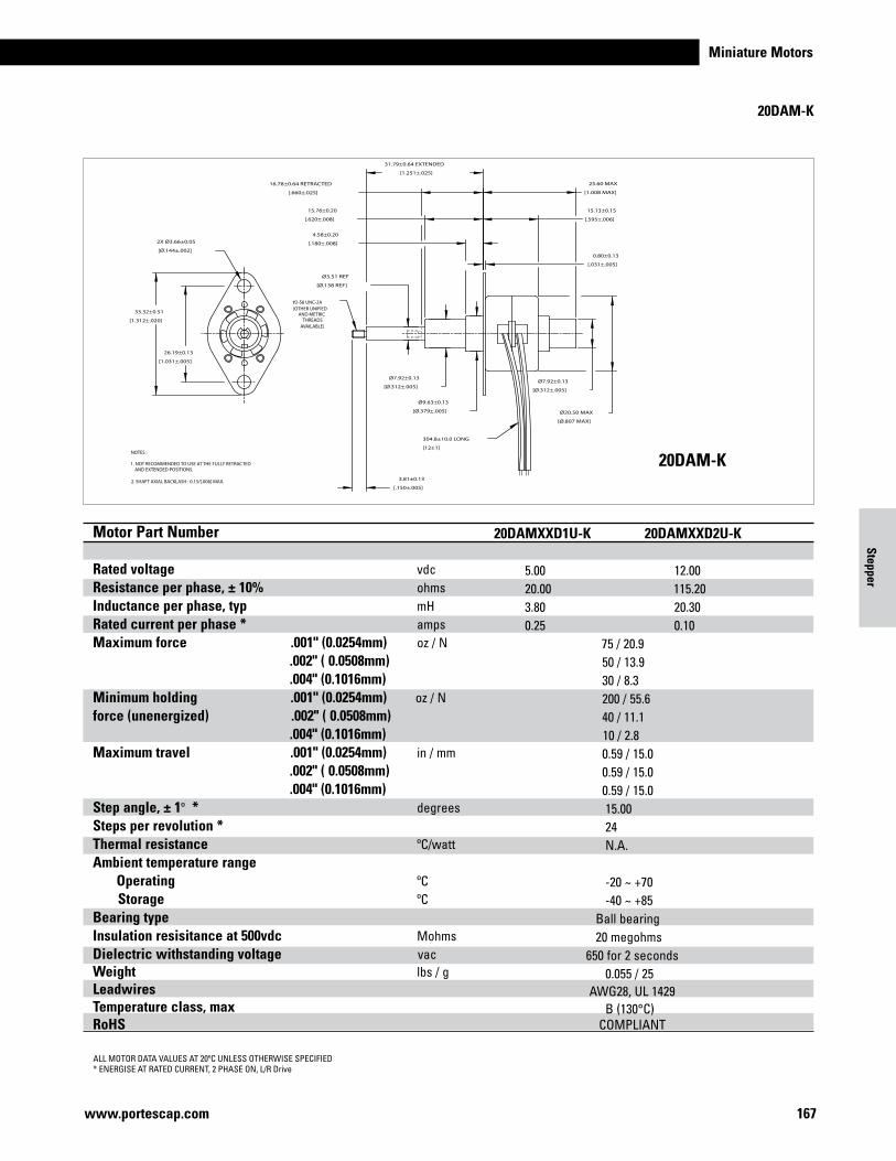
Miniature Motors
167www.portescap.com
3.81±0.13
[.150±.005]
0.80±0.13
[.031±.005]
15.13±0.15
[.595±.006]
25.60 MAX
[1.008 MAX]
Ø7.92±0.13
[Ø.312±.005]
Ø20.50 MAX
[Ø.807 MAX]
4.58±0.20
[.180±.008]
15.76±0.20
[.620±.008]
Ø9.63±0.13
[Ø.379±.005]
Ø7.92±0.13
[Ø.312±.005]
26.19±0.13
[1.031±.005]
33.32±0.51
[1.312±.020]
2X Ø3.66±0.05
[Ø.144±.002]
16.78±0.64 RETRACTED
[.660±.025]
31.79±0.64 EXTENDED
[1.251±.025]
Ø3.51 REF
[Ø.138 REF]
304.8±10.0 LONG
[12±1]
#2-56 UNC-2A(OTHER UNIFIED
AND METRICTHREADS
AVAILABLE)
NOTES : 1. NOT RECOMMENDED TO USE AT THE FULLY RETRACTED AND EXTENDED POSITIONS. 2. SHAFT AXIAL BACKLASH : 0.15/[.006] MAX.
20DAM-K
ALL MOTOR DATA VALUES AT 20ºC UNLESS OTHERWISE SPECIFIED* ENERGISE AT RATED CURRENT, 2 PHASE ON, L/R Drive
20DAM-K
Motor Part Number Rated voltage vdc Resistance per phase, ± 10% ohms Inductance per phase, typ mH Rated current per phase * amps Maximum force .001" (0.0254mm) oz / N .002" ( 0.0508mm) .004" (0.1016mm)Minimum holding .001" (0.0254mm) oz / N force (unenergized) .002" ( 0.0508mm) .004" (0.1016mm)Maximum travel .001" (0.0254mm) in / mm .002" ( 0.0508mm) .004" (0.1016mm)Step angle, ± 1º * degrees Steps per revolution * Thermal resistance ºC/watt Ambient temperature range Operating ºC Storage ºC Bearing type Insulation resisitance at 500vdc Mohms Dielectric withstanding voltage vac Weight lbs / g Leadwires Temperature class, max RoHS
Motor Part Number Rated voltage vdc Resistance per phase, ± 10% ohms Inductance per phase, typ mH Rated current per phase * amps Maximum force .001" (0.0254mm) oz / N .002" ( 0.0508mm) .004" (0.1016mm)Minimum holding .001" (0.0254mm) oz / N force (unenergized) .002" ( 0.0508mm) .004" (0.1016mm)Maximum travel .001" (0.0254mm) in / mm .002" ( 0.0508mm) .004" (0.1016mm)Step angle, ± 1º * degrees Steps per revolution * Thermal resistance ºC/watt Ambient temperature range Operating ºC Storage ºC Bearing type Insulation resisitance at 500vdc Mohms Dielectric withstanding voltage vac Weight lbs / g Leadwires Temperature class, max RoHS
20DAMXXD1B-K 20DAMXXD2B-K 5.00 12.00 20.00 115.20 7.20 40.80 0.25 0.10 110 / 30.6 75 / 20.9 40 / 11.1 200 / 55.6 40 / 11.1 10 / 2.8 0.59 / 15.0 0.59 / 15.0 0.59 / 15.0 15.00 24 N.A. -20 ~ +70 -40 ~ +85 Ball bearing 20 megohms 650 for 2 seconds 0.055 / 25 AWG28, UL 1429 B (130°C) COMPLIANT
20DAMXXD1U-K 20DAMXXD2U-K 5.00 12.00 20.00 115.20 3.80 20.30 0.25 0.10 75 / 20.9 50 / 13.9 30 / 8.3 200 / 55.6 40 / 11.1 10 / 2.8 0.59 / 15.0 0.59 / 15.0 0.59 / 15.0 15.00 24 N.A. -20 ~ +70 -40 ~ +85 Ball bearing 20 megohms 650 for 2 seconds 0.055 / 25 AWG28, UL 1429 B (130°C) COMPLIANT
Stepper
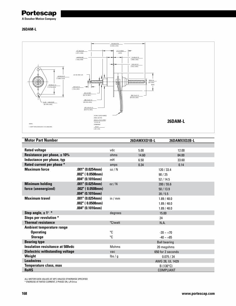
www.portescap.com168
42.82±0.51
[1.686±.020]
34.90±0.13
[1.374±.005]
0.81±0.13
[.032±.005]
12.40±0.15
[.488±.006]
21.31 MAX
[.839]
4.27±0.20
[.168±.008]
15.18±0.20
[.597±.008]
Ø8.13±0.13
[Ø.320±.005]
Ø26.16
[Ø1.030]
MAX
Ø12.03±0.13
[Ø.474±.005]
Ø8.13±0.13
[Ø.320±.005]2x Ø 3.66±0.05
[Ø.144±.002]
76.20±0.76
[3.000±.030]
Ø3.43 REF.
[Ø.135 REF.]
3.81±0.13
[.150±.005]
4 OR 6 LEAD WIRES
AWG 28 PVC
304.8 ±10.0 LONG
[12.0±.4]
STRIPPED
10 ±1
[.40 ±.04]
#2-56 UNC-2A
NOTES : 1. SHAFT AXIAL BACKLASH : 0.15/[.006] MAX.
26DAM-L
ALL MOTOR DATA VALUES AT 20ºC UNLESS OTHERWISE SPECIFIED* ENERGISE AT RATED CURRENT, 2 PHASE ON, L/R Drive
26DAM-L
Motor Part Number Rated voltage vdc Resistance per phase, ± 10% ohms Inductance per phase, typ mH Rated current per phase * amps Maximum force .001" (0.0254mm) oz / N .002" ( 0.0508mm) .004" (0.1016mm)Minimum holding .001" (0.0254mm) oz / N force (unenergized) .002" ( 0.0508mm) .004" (0.1016mm)Maximum travel .001" (0.0254mm) in / mm .002" ( 0.0508mm) .004" (0.1016mm)Step angle, ± 1º * degrees Steps per revolution * Thermal resistance ºC/watt Ambient temperature range Operating ºC Storage ºC Bearing type Insulation resisitance at 500vdc Mohms Dielectric withstanding voltage vac Weight lbs / g Leadwires Temperature class, max RoHS
26DAMXXD1B-L 26DAMXXD2B-L 5.00 12.00 14.60 84.00 6.50 33.60 0.34 0.14 120 / 33.4 90 / 25 52 / 14.5 200 / 55.6 50 / 13.9 20 / 5.5 1.89 / 48.0 1.89 / 48.0 1.89 / 48.0 15.00 24 N.A. -20 ~ +70 -40 ~ +85 Ball bearing 20 megohms 650 for 2 seconds 0.075 / 34 AWG 28, UL 1429 B (130°C) COMPLIANT
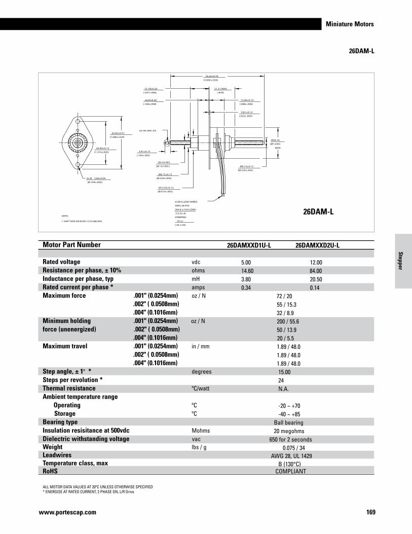
Miniature Motors
169www.portescap.com
42.82±0.51
[1.686±.020]
34.90±0.13
[1.374±.005]
0.81±0.13
[.032±.005]
12.40±0.15
[.488±.006]
21.31 MAX
[.839]
4.27±0.20
[.168±.008]
15.18±0.20
[.597±.008]
Ø8.13±0.13
[Ø.320±.005]
Ø26.16
[Ø1.030]
MAX
Ø12.03±0.13
[Ø.474±.005]
Ø8.13±0.13
[Ø.320±.005]2x Ø 3.66±0.05
[Ø.144±.002]
76.20±0.76
[3.000±.030]
Ø3.43 REF.
[Ø.135 REF.]
3.81±0.13
[.150±.005]
4 OR 6 LEAD WIRES
AWG 28 PVC
304.8 ±10.0 LONG
[12.0±.4]
STRIPPED
10 ±1
[.40 ±.04]
#2-56 UNC-2A
NOTES : 1. SHAFT AXIAL BACKLASH : 0.15/[.006] MAX.
26DAM-L
ALL MOTOR DATA VALUES AT 20ºC UNLESS OTHERWISE SPECIFIED* ENERGISE AT RATED CURRENT, 2 PHASE ON, L/R Drive
26DAM-L
Motor Part Number Rated voltage vdc Resistance per phase, ± 10% ohms Inductance per phase, typ mH Rated current per phase * amps Maximum force .001" (0.0254mm) oz / N .002" ( 0.0508mm) .004" (0.1016mm)Minimum holding .001" (0.0254mm) oz / N force (unenergized) .002" ( 0.0508mm) .004" (0.1016mm)Maximum travel .001" (0.0254mm) in / mm .002" ( 0.0508mm) .004" (0.1016mm)Step angle, ± 1º * degrees Steps per revolution * Thermal resistance ºC/watt Ambient temperature range Operating ºC Storage ºC Bearing type Insulation resisitance at 500vdc Mohms Dielectric withstanding voltage vac Weight lbs / g Leadwires Temperature class, max RoHS
Motor Part Number Rated voltage vdc Resistance per phase, ± 10% ohms Inductance per phase, typ mH Rated current per phase * amps Maximum force .001" (0.0254mm) oz / N .002" ( 0.0508mm) .004" (0.1016mm)Minimum holding .001" (0.0254mm) oz / N force (unenergized) .002" ( 0.0508mm) .004" (0.1016mm)Maximum travel .001" (0.0254mm) in / mm .002" ( 0.0508mm) .004" (0.1016mm)Step angle, ± 1º * degrees Steps per revolution * Thermal resistance ºC/watt Ambient temperature range Operating ºC Storage ºC Bearing type Insulation resisitance at 500vdc Mohms Dielectric withstanding voltage vac Weight lbs / g Leadwires Temperature class, max RoHS
26DAMXXD1B-L 26DAMXXD2B-L 5.00 12.00 14.60 84.00 6.50 33.60 0.34 0.14 120 / 33.4 90 / 25 52 / 14.5 200 / 55.6 50 / 13.9 20 / 5.5 1.89 / 48.0 1.89 / 48.0 1.89 / 48.0 15.00 24 N.A. -20 ~ +70 -40 ~ +85 Ball bearing 20 megohms 650 for 2 seconds 0.075 / 34 AWG 28, UL 1429 B (130°C) COMPLIANT
26DAMXXD1U-L 26DAMXXD2U-L 5.00 12.00 14.60 84.00 3.80 20.50 0.34 0.14 72 / 20 55 / 15.3 32 / 8.9 200 / 55.6 50 / 13.9 20 / 5.5 1.89 / 48.0 1.89 / 48.0 1.89 / 48.0 15.00 24 N.A. -20 ~ +70 -40 ~ +85 Ball bearing 20 megohms 650 for 2 seconds 0.075 / 34 AWG 28, UL 1429 B (130°C) COMPLIANT
Stepper

www.portescap.com170
42.82±0.51
[1.686±.020]
34.90±0.13
[1.374±.005]
0.81±0.13
[.032±.005]
12.40±0.15
[.488±.006]
4.27±0.20
[.168±.008]
16.99±0.64
[.669±.025]
RETRACTED
30.20±0.64
[1.189±.025]
EXTENDED
Ø8.13±0.13
[Ø.320±.005]
Ø26.16
[Ø1.030]
MAX
Ø12.03±0.13
[Ø.474±.005]
Ø8.13±0.13
[Ø.320±.005]
Ø3.51 REF.
[Ø.138] REF.
Ø3.66±0.05
[Ø.144±.002]
(2x)
3.81±0.13
[.150±.005]
4 OR 6 LEAD WIRES
AWG 28 PVC
304.8 ±10.0 LONG
[12 ±.4]
STRIPPED
10 ±1
[.40±.04]
#2-56 UNC-2A
NOTES : 1. NOT RECOMMENDED TO USE AT THE FULLY RETRACTED AND EXTENDED POSITIONS. 2. SHAFT AXIAL BACKLASH : 0.15/[.006] MAX.
26DAM-K
ALL MOTOR DATA VALUES AT 20ºC UNLESS OTHERWISE SPECIFIED* ENERGISE AT RATED CURRENT, 2 PHASE ON, L/R Drive
26DAM-K
Motor Part Number Rated voltage vdc Resistance per phase, ± 10% ohms Inductance per phase, typ mH Rated current per phase * amps Maximum force .001" (0.0254mm) oz / N .002" ( 0.0508mm) .004" (0.1016mm)Minimum holding .001" (0.0254mm) oz / N force (unenergized) .002" ( 0.0508mm) .004" (0.1016mm)Maximum travel .001" (0.0254mm) in / mm .002" ( 0.0508mm) .004" (0.1016mm)Step angle, ± 1º * degrees Steps per revolution * Thermal resistance ºC/watt Ambient temperature range Operating ºC Storage ºC Bearing type Insulation resisitance at 500vdc Mohms Dielectric withstanding voltage vac Weight lbs / g Leadwires Temperature class, max RoHS
26DAMXXD1B-K 26DAMXXD2B-K 5.00 12.00 14.60 84.00 6.50 33.60 0.34 0.14 120 / 33.4 90 / 25 52 / 14.5 200 / 55.6 50 / 13.9 20 / 5.5 0.52 / 13.2 0.52 / 13.2 0.52 / 13.2 15.00 24 N.A. -20 ~ +70 -40 ~ +85 Ball bearing 20 megohms 650 for 2 seconds 0.075 / 34 AWG 28, UL 1429 B (130°C) COMPLIANT
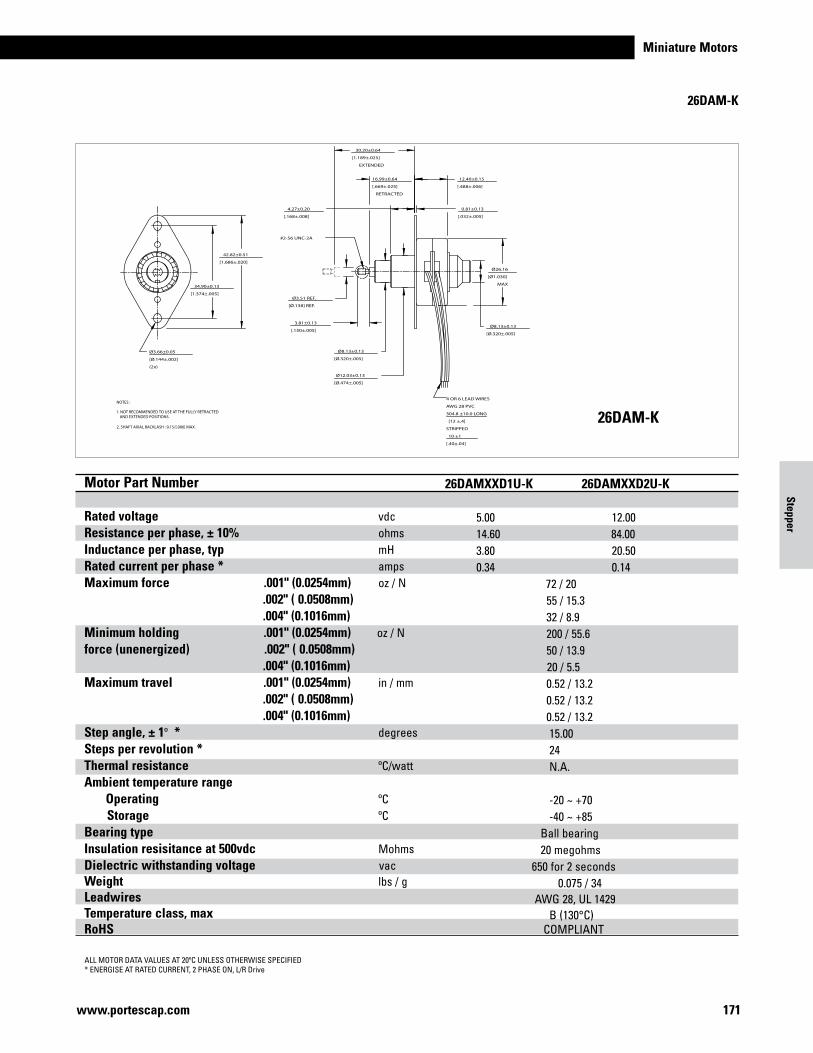
Miniature Motors
171www.portescap.com
42.82±0.51
[1.686±.020]
34.90±0.13
[1.374±.005]
0.81±0.13
[.032±.005]
12.40±0.15
[.488±.006]
4.27±0.20
[.168±.008]
16.99±0.64
[.669±.025]
RETRACTED
30.20±0.64
[1.189±.025]
EXTENDED
Ø8.13±0.13
[Ø.320±.005]
Ø26.16
[Ø1.030]
MAX
Ø12.03±0.13
[Ø.474±.005]
Ø8.13±0.13
[Ø.320±.005]
Ø3.51 REF.
[Ø.138] REF.
Ø3.66±0.05
[Ø.144±.002]
(2x)
3.81±0.13
[.150±.005]
4 OR 6 LEAD WIRES
AWG 28 PVC
304.8 ±10.0 LONG
[12 ±.4]
STRIPPED
10 ±1
[.40±.04]
#2-56 UNC-2A
NOTES : 1. NOT RECOMMENDED TO USE AT THE FULLY RETRACTED AND EXTENDED POSITIONS. 2. SHAFT AXIAL BACKLASH : 0.15/[.006] MAX.
26DAM-K
ALL MOTOR DATA VALUES AT 20ºC UNLESS OTHERWISE SPECIFIED* ENERGISE AT RATED CURRENT, 2 PHASE ON, L/R Drive
26DAM-K
Motor Part Number Rated voltage vdc Resistance per phase, ± 10% ohms Inductance per phase, typ mH Rated current per phase * amps Maximum force .001" (0.0254mm) oz / N .002" ( 0.0508mm) .004" (0.1016mm)Minimum holding .001" (0.0254mm) oz / N force (unenergized) .002" ( 0.0508mm) .004" (0.1016mm)Maximum travel .001" (0.0254mm) in / mm .002" ( 0.0508mm) .004" (0.1016mm)Step angle, ± 1º * degrees Steps per revolution * Thermal resistance ºC/watt Ambient temperature range Operating ºC Storage ºC Bearing type Insulation resisitance at 500vdc Mohms Dielectric withstanding voltage vac Weight lbs / g Leadwires Temperature class, max RoHS
Motor Part Number Rated voltage vdc Resistance per phase, ± 10% ohms Inductance per phase, typ mH Rated current per phase * amps Maximum force .001" (0.0254mm) oz / N .002" ( 0.0508mm) .004" (0.1016mm)Minimum holding .001" (0.0254mm) oz / N force (unenergized) .002" ( 0.0508mm) .004" (0.1016mm)Maximum travel .001" (0.0254mm) in / mm .002" ( 0.0508mm) .004" (0.1016mm)Step angle, ± 1º * degrees Steps per revolution * Thermal resistance ºC/watt Ambient temperature range Operating ºC Storage ºC Bearing type Insulation resisitance at 500vdc Mohms Dielectric withstanding voltage vac Weight lbs / g Leadwires Temperature class, max RoHS
26DAMXXD1B-K 26DAMXXD2B-K 5.00 12.00 14.60 84.00 6.50 33.60 0.34 0.14 120 / 33.4 90 / 25 52 / 14.5 200 / 55.6 50 / 13.9 20 / 5.5 0.52 / 13.2 0.52 / 13.2 0.52 / 13.2 15.00 24 N.A. -20 ~ +70 -40 ~ +85 Ball bearing 20 megohms 650 for 2 seconds 0.075 / 34 AWG 28, UL 1429 B (130°C) COMPLIANT
26DAMXXD1U-K 26DAMXXD2U-K 5.00 12.00 14.60 84.00 3.80 20.50 0.34 0.14 72 / 20 55 / 15.3 32 / 8.9 200 / 55.6 50 / 13.9 20 / 5.5 0.52 / 13.2 0.52 / 13.2 0.52 / 13.2 15.00 24 N.A. -20 ~ +70 -40 ~ +85 Ball bearing 20 megohms 650 for 2 seconds 0.075 / 34 AWG 28, UL 1429 B (130°C) COMPLIANT
Stepper

www.portescap.com172
42.82±0.51
1.686±.020
34.90±0.13
1.374±.005
0.81±0.13
.032±.005
12.40±0.15
.488±.006
21.31
.839
MAX9.58±0.20
.377±.008
15.18±0.20
.597±.008
Ø8.13±0.13
Ø.320±.005
Ø26.16
Ø1.030
MAX
Ø12.03±0.13
Ø.474±.005
Ø8.13±0.13
Ø.320±.005
Ø3.43 REF
Ø.135 REF
Ø3.30±0.05
Ø.130±.002
(2x)
3.81±0.13
.150±.005
76.20±0.76
3.000±.030
NOTES : 1. SHAFT AXIAL BACKLASH : 0.15/.006 MAX.
#2-56 UNC-2A(OTHER UNIFIEDAND METRIC THREADSAVAILABLE)
304.8±25.4
12±1
LONG
26DBM-L
ALL MOTOR DATA VALUES AT 20ºC UNLESS OTHERWISE SPECIFIED* ENERGISE AT RATED CURRENT, 2 PHASE ON, L/R Drive
26DBM-L
Motor Part Number Rated voltage vdc Resistance per phase, ± 10% ohms Inductance per phase, typ mH Rated current per phase * amps Maximum force .0005" (0.0127mm) oz / N .001" (0.0254mm) .002" (0.0508mm)Minimum holding .0005" (0.0127mm) oz / N force (unenergized) .001" (0.0254mm) .002" (0.0508mm)Maximum travel .0005" (0.0127mm) in / mm .001" (0.0254mm) .002" (0.0508mm)Step angle, ± 0.5º * degrees Steps per revolution * Thermal resistance ºC/watt Ambient temperature range Operating ºC Storage ºC Bearing type Insulation resisitance at 500vdc Mohms Dielectric withstanding voltage vac Weight lbs / g Leadwires Temperature class, max RoHS
26DBMXXD1B-L 26DBMXXD2B-L 5.00 12.00 14.60 84.00 8.80 46.30 0.34 0.14 128 / 35.6 104 / 28.9 69 / 19.2 200 / 55.6 50 / 13.9 20 / 5.5 1.89 / 48.0 1.89 / 48.0 1.89 / 48.0 7.5 48 N.A. -20 ~ +70 -40 ~ +85 Ball bearing 20 megohms 650 for 2 seconds 0.075 / 34 AWG 28, UL 1429 B (130°C) COMPLIANT
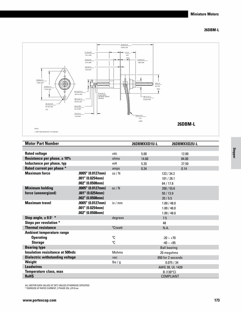
Miniature Motors
173www.portescap.com
42.82±0.51
1.686±.020
34.90±0.13
1.374±.005
0.81±0.13
.032±.005
12.40±0.15
.488±.006
21.31
.839
MAX9.58±0.20
.377±.008
15.18±0.20
.597±.008
Ø8.13±0.13
Ø.320±.005
Ø26.16
Ø1.030
MAX
Ø12.03±0.13
Ø.474±.005
Ø8.13±0.13
Ø.320±.005
Ø3.43 REF
Ø.135 REF
Ø3.30±0.05
Ø.130±.002
(2x)
3.81±0.13
.150±.005
76.20±0.76
3.000±.030
NOTES : 1. SHAFT AXIAL BACKLASH : 0.15/.006 MAX.
#2-56 UNC-2A(OTHER UNIFIEDAND METRIC THREADSAVAILABLE)
304.8±25.4
12±1
LONG
26DBM-L
ALL MOTOR DATA VALUES AT 20ºC UNLESS OTHERWISE SPECIFIED* ENERGISE AT RATED CURRENT, 2 PHASE ON, L/R Drive
26DBM-L
Motor Part Number Rated voltage vdc Resistance per phase, ± 10% ohms Inductance per phase, typ mH Rated current per phase * amps Maximum force .0005" (0.0127mm) oz / N .001" (0.0254mm) .002" (0.0508mm)Minimum holding .0005" (0.0127mm) oz / N force (unenergized) .001" (0.0254mm) .002" (0.0508mm)Maximum travel .0005" (0.0127mm) in / mm .001" (0.0254mm) .002" (0.0508mm)Step angle, ± 0.5º * degrees Steps per revolution * Thermal resistance ºC/watt Ambient temperature range Operating ºC Storage ºC Bearing type Insulation resisitance at 500vdc Mohms Dielectric withstanding voltage vac Weight lbs / g Leadwires Temperature class, max RoHS
Motor Part Number Rated voltage vdc Resistance per phase, ± 10% ohms Inductance per phase, typ mH Rated current per phase * amps Maximum force .0005" (0.0127mm) oz / N .001" (0.0254mm) .002" (0.0508mm)Minimum holding .0005" (0.0127mm) oz / N force (unenergized) .001" (0.0254mm) .002" (0.0508mm)Maximum travel .0005" (0.0127mm) in / mm .001" (0.0254mm) .002" (0.0508mm)Step angle, ± 0.5º * degrees Steps per revolution * Thermal resistance ºC/watt Ambient temperature range Operating ºC Storage ºC Bearing type Insulation resisitance at 500vdc Mohms Dielectric withstanding voltage vac Weight lbs / g Leadwires Temperature class, max RoHS
26DBMXXD1B-L 26DBMXXD2B-L 5.00 12.00 14.60 84.00 8.80 46.30 0.34 0.14 128 / 35.6 104 / 28.9 69 / 19.2 200 / 55.6 50 / 13.9 20 / 5.5 1.89 / 48.0 1.89 / 48.0 1.89 / 48.0 7.5 48 N.A. -20 ~ +70 -40 ~ +85 Ball bearing 20 megohms 650 for 2 seconds 0.075 / 34 AWG 28, UL 1429 B (130°C) COMPLIANT
26DBMXXD1U-L 26DBMXXD2U-L 5.00 12.00 14.60 84.00 5.20 27.50 0.34 0.14 123 / 34.2 101 / 28.1 64 / 17.8 200 / 55.6 50 / 13.9 20 / 5.5 1.89 / 48.0 1.89 / 48.0 1.89 / 48.0 7.5 48 N.A. -20 ~ +70 -40 ~ +85 Ball bearing 20 megohms 650 for 2 seconds 0.075 / 34 AWG 28, UL 1429 B (130°C) COMPLIANT
Stepper

www.portescap.com174
42.82±0.51
1.686±.020
34.90±0.13
1.374±.005
0.81±0.13
.032±.005
12.40±0.15
.488±.006
21.31
.839
MAX
9.58±0.20
.377±.008
15.18±0.20
.597±.008
30.20±0.64
1.189±.025
EXTENDED
16.99±0.64
.669±.025
RETRACTED
Ø8.13±0.13
Ø.320±.005
Ø26.16
Ø1.030
MAX
Ø12.03±0.13
Ø.474±.005
Ø8.13±0.13
Ø.320±.005
Ø3.51 REF
Ø.138 REF
Ø3.30±0.05
Ø.130±.002
(2x)
3.81±0.13
.150±.005
NOTES : 1. NOT RECOMMENDED TO USE AT THE FULLY RETRACTED AND EXTENDED POSITIONS. 2. SHAFT AXIAL BACKLASH : 0.15/.006 MAX.
#2-56 UNC-2A(OTHER UNIFIEDAND METRIC THREADSAVAILABLE)
304.8±25.4
12±1
LONG
26DBM-K
ALL MOTOR DATA VALUES AT 20ºC UNLESS OTHERWISE SPECIFIED* ENERGISE AT RATED CURRENT, 2 PHASE ON, L/R Drive
26DBM-K
Motor Part Number Rated voltage vdc Resistance per phase, ± 10% ohms Inductance per phase, typ mH Rated current per phase * amps Maximum force .0005" (0.0127mm) oz / N .001" (0.0254mm) .002" (0.0508mm)Minimum holding .0005" (0.0127mm) oz / N force (unenergized) .001" (0.0254mm) .002" (0.0508mm)Maximum travel .0005" (0.0127mm) in / mm .001" (0.0254mm) .002" (0.0508mm)Step angle, ± 0.5º * degrees Steps per revolution * Thermal resistance ºC/watt Ambient temperature range Operating ºC Storage ºC Bearing type Insulation resisitance at 500vdc Mohms Dielectric withstanding voltage vac Weight lbs / g Leadwires Temperature class, max RoHS
26DBMXXD1B-K 26DBMXXD2B-K 5.00 12.00 14.60 84.00 8.80 46.30 0.34 0.14 128 / 35.6 104 / 28.9 69 / 19.2 200 / 55.6 50 / 13.9 20 / 5.5 0.52 / 13.2 0.52 / 13.2 0.52 / 13.2 7.5 48 N.A. -20 ~ +70 -40 ~ +85 Ball bearing 20 megohms 650 for 2 seconds 0.075 / 34 AWG 28, UL 1429 B (130°C) COMPLIANT
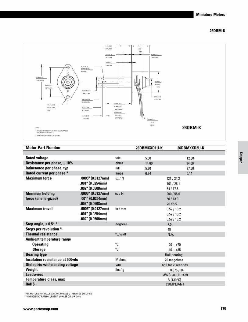
Miniature Motors
175www.portescap.com
42.82±0.51
1.686±.020
34.90±0.13
1.374±.005
0.81±0.13
.032±.005
12.40±0.15
.488±.006
21.31
.839
MAX
9.58±0.20
.377±.008
15.18±0.20
.597±.008
30.20±0.64
1.189±.025
EXTENDED
16.99±0.64
.669±.025
RETRACTED
Ø8.13±0.13
Ø.320±.005
Ø26.16
Ø1.030
MAX
Ø12.03±0.13
Ø.474±.005
Ø8.13±0.13
Ø.320±.005
Ø3.51 REF
Ø.138 REF
Ø3.30±0.05
Ø.130±.002
(2x)
3.81±0.13
.150±.005
NOTES : 1. NOT RECOMMENDED TO USE AT THE FULLY RETRACTED AND EXTENDED POSITIONS. 2. SHAFT AXIAL BACKLASH : 0.15/.006 MAX.
#2-56 UNC-2A(OTHER UNIFIEDAND METRIC THREADSAVAILABLE)
304.8±25.4
12±1
LONG
26DBM-K
ALL MOTOR DATA VALUES AT 20ºC UNLESS OTHERWISE SPECIFIED* ENERGISE AT RATED CURRENT, 2 PHASE ON, L/R Drive
26DBM-K
Motor Part Number Rated voltage vdc Resistance per phase, ± 10% ohms Inductance per phase, typ mH Rated current per phase * amps Maximum force .0005" (0.0127mm) oz / N .001" (0.0254mm) .002" (0.0508mm)Minimum holding .0005" (0.0127mm) oz / N force (unenergized) .001" (0.0254mm) .002" (0.0508mm)Maximum travel .0005" (0.0127mm) in / mm .001" (0.0254mm) .002" (0.0508mm)Step angle, ± 0.5º * degrees Steps per revolution * Thermal resistance ºC/watt Ambient temperature range Operating ºC Storage ºC Bearing type Insulation resisitance at 500vdc Mohms Dielectric withstanding voltage vac Weight lbs / g Leadwires Temperature class, max RoHS
Motor Part Number Rated voltage vdc Resistance per phase, ± 10% ohms Inductance per phase, typ mH Rated current per phase * amps Maximum force .0005" (0.0127mm) oz / N .001" (0.0254mm) .002" (0.0508mm)Minimum holding .0005" (0.0127mm) oz / N force (unenergized) .001" (0.0254mm) .002" (0.0508mm)Maximum travel .0005" (0.0127mm) in / mm .001" (0.0254mm) .002" (0.0508mm)Step angle, ± 0.5º * degrees Steps per revolution * Thermal resistance ºC/watt Ambient temperature range Operating ºC Storage ºC Bearing type Insulation resisitance at 500vdc Mohms Dielectric withstanding voltage vac Weight lbs / g Leadwires Temperature class, max RoHS
26DBMXXD1B-K 26DBMXXD2B-K 5.00 12.00 14.60 84.00 8.80 46.30 0.34 0.14 128 / 35.6 104 / 28.9 69 / 19.2 200 / 55.6 50 / 13.9 20 / 5.5 0.52 / 13.2 0.52 / 13.2 0.52 / 13.2 7.5 48 N.A. -20 ~ +70 -40 ~ +85 Ball bearing 20 megohms 650 for 2 seconds 0.075 / 34 AWG 28, UL 1429 B (130°C) COMPLIANT
26DBMXXD1U-K 26DBMXXD2U-K 5.00 12.00 14.60 84.00 5.20 27.50 0.34 0.14 123 / 34.2 101 / 28.1 64 / 17.8 200 / 55.6 50 / 13.9 20 / 5.5 0.52 / 13.2 0.52 / 13.2 0.52 / 13.2 7.5 48 N.A. -20 ~ +70 -40 ~ +85 Ball bearing 20 megohms 650 for 2 seconds 0.075 / 34 AWG 28, UL 1429 B (130°C) COMPLIANT
Stepper
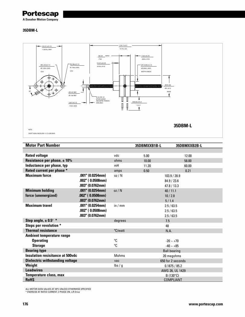
www.portescap.com176
18.54 MAX
.730
7.62±0.25
.300±.010
10.41±0.25
.410±.010Ø14.99±0.13
Ø.590±.005
BOTH ENDS
304.8±25.4
12±1
Ø3.20±0.13
Ø.126±.005
(2x)
30°
42.01±0.10
1.654±.004
Ø35.94
Ø1.415
MAX
120.7±0.5
4.75±.02
3.81±0.13
.150±.005
Ø3.45 REF
Ø.136 REF
R3.96±0.13
R.156±.005
(2x)
#2-56 UNC-2A(OTHER UNIFIEDAND METRIC THREADSAVAILABLE)
NOTE : SHAFT AXIAL BACKLASH : 0.15/.006 MAX.
35DBM-L
ALL MOTOR DATA VALUES AT 20ºC UNLESS OTHERWISE SPECIFIED* ENERGISE AT RATED CURRENT, 2 PHASE ON, L/R Drive
35DBM-L
Motor Part Number Rated voltage vdc Resistance per phase, ± 10% ohms Inductance per phase, typ mH Rated current per phase * amps Maximum force .001" (0.0254mm) oz / N .002" ( 0.0508mm) .003" (0.0762mm)Minimum holding .001" (0.0254mm) oz / N force (unenergized) .002" ( 0.0508mm) .003" (0.0762mm)Maximum travel .001" (0.0254mm) in / mm .002" ( 0.0508mm) .003" (0.0762mm)Step angle, ± 0.5º * degrees Steps per revolution * Thermal resistance ºC/watt Ambient temperature range Operating ºC Storage ºC Bearing type Insulation resisitance at 500vdc Mohms Dielectric withstanding voltage vac Weight lbs / g Leadwires Temperature class, max RoHS
35DBMXXB1B-L 35DBMXXB2B-L 5.00 12.00 10.00 58.00 11.20 60.00 0.50 0.21 103.9 / 28.9 84.9 / 23.6 47.8 / 13.3 40 / 11.1 10 / 2.8 5 / 1.4 2.5 / 63.5 2.5 / 63.5 2.5 / 63.5 7.5 48 N.A. -20 ~ +70 -40 ~ +85 Ball bearing 20 megohms 650 for 2 seconds 0.1875 / 85.2 AWG 26, UL 1429 B (130°C) COMPLIANT
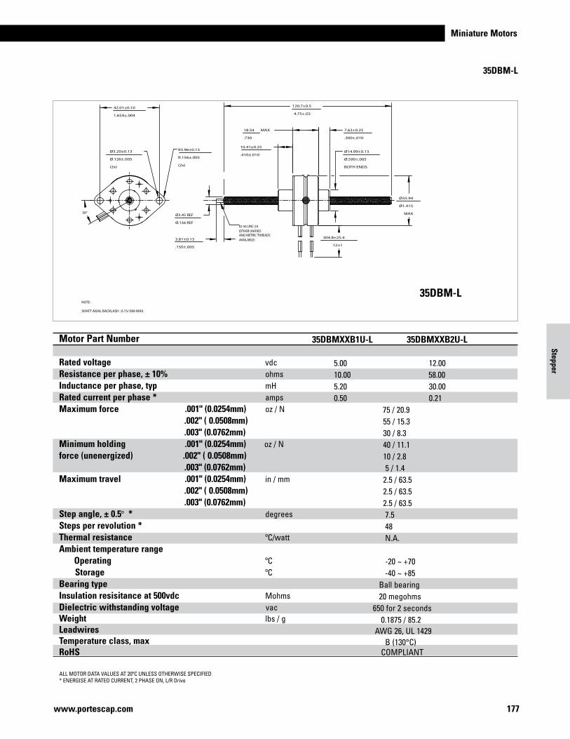
Miniature Motors
177www.portescap.com
18.54 MAX
.730
7.62±0.25
.300±.010
10.41±0.25
.410±.010Ø14.99±0.13
Ø.590±.005
BOTH ENDS
304.8±25.4
12±1
Ø3.20±0.13
Ø.126±.005
(2x)
30°
42.01±0.10
1.654±.004
Ø35.94
Ø1.415
MAX
120.7±0.5
4.75±.02
3.81±0.13
.150±.005
Ø3.45 REF
Ø.136 REF
R3.96±0.13
R.156±.005
(2x)
#2-56 UNC-2A(OTHER UNIFIEDAND METRIC THREADSAVAILABLE)
NOTE : SHAFT AXIAL BACKLASH : 0.15/.006 MAX.
35DBM-L
ALL MOTOR DATA VALUES AT 20ºC UNLESS OTHERWISE SPECIFIED* ENERGISE AT RATED CURRENT, 2 PHASE ON, L/R Drive
35DBM-L
Motor Part Number Rated voltage vdc Resistance per phase, ± 10% ohms Inductance per phase, typ mH Rated current per phase * amps Maximum force .001" (0.0254mm) oz / N .002" ( 0.0508mm) .003" (0.0762mm)Minimum holding .001" (0.0254mm) oz / N force (unenergized) .002" ( 0.0508mm) .003" (0.0762mm)Maximum travel .001" (0.0254mm) in / mm .002" ( 0.0508mm) .003" (0.0762mm)Step angle, ± 0.5º * degrees Steps per revolution * Thermal resistance ºC/watt Ambient temperature range Operating ºC Storage ºC Bearing type Insulation resisitance at 500vdc Mohms Dielectric withstanding voltage vac Weight lbs / g Leadwires Temperature class, max RoHS
Motor Part Number Rated voltage vdc Resistance per phase, ± 10% ohms Inductance per phase, typ mH Rated current per phase * amps Maximum force .001" (0.0254mm) oz / N .002" ( 0.0508mm) .003" (0.0762mm)Minimum holding .001" (0.0254mm) oz / N force (unenergized) .002" ( 0.0508mm) .003" (0.0762mm)Maximum travel .001" (0.0254mm) in / mm .002" ( 0.0508mm) .003" (0.0762mm)Step angle, ± 0.5º * degrees Steps per revolution * Thermal resistance ºC/watt Ambient temperature range Operating ºC Storage ºC Bearing type Insulation resisitance at 500vdc Mohms Dielectric withstanding voltage vac Weight lbs / g Leadwires Temperature class, max RoHS
35DBMXXB1B-L 35DBMXXB2B-L 5.00 12.00 10.00 58.00 11.20 60.00 0.50 0.21 103.9 / 28.9 84.9 / 23.6 47.8 / 13.3 40 / 11.1 10 / 2.8 5 / 1.4 2.5 / 63.5 2.5 / 63.5 2.5 / 63.5 7.5 48 N.A. -20 ~ +70 -40 ~ +85 Ball bearing 20 megohms 650 for 2 seconds 0.1875 / 85.2 AWG 26, UL 1429 B (130°C) COMPLIANT
35DBMXXB1U-L 35DBMXXB2U-L 5.00 12.00 10.00 58.00 5.20 30.00 0.50 0.21 75 / 20.9 55 / 15.3 30 / 8.3 40 / 11.1 10 / 2.8 5 / 1.4 2.5 / 63.5 2.5 / 63.5 2.5 / 63.5 7.5 48 N.A. -20 ~ +70 -40 ~ +85 Ball bearing 20 megohms 650 for 2 seconds 0.1875 / 85.2 AWG 26, UL 1429 B (130°C) COMPLIANT
Stepper

www.portescap.com178
18.54
.730
MAX
Ø14.99±0.13
Ø.590±.005
BOTH ENDS
304.8±25.4
12±1
Ø3.20±0.13
Ø.126±.005
(2x)
30°
42.01±0.10
1.654±.004
Ø35.94
Ø1.415
MAX
7.62±0.25
.300±.010
BOTH ENDS
17.42±0.30
.686±.012
36.75±0.71
1.447±.028
EXTENDED
18.85±0.71
.742±.028
RETRACTED
19.05±0.25
.750±.010
3.81±0.13
.150±.005
Ø7.85±0.13
Ø.309±.005
BOTH ENDS
Ø3.51 REF
Ø.138 REFR3.96±0.13
R.156±.005
(2x)
#2-56 UNC-2A(OTHER UNIFIEDAND METRIC THREADSAVAILABLE)
NOTES : 1. NOT RECOMMENDED TO USE AT THE FULLY RETRACTED AND EXTENDED POSITIONS. 2. SHAFT AXIAL BACKLASH : 0.15/.006 MAX.
35DBM-K
ALL MOTOR DATA VALUES AT 20ºC UNLESS OTHERWISE SPECIFIED* ENERGISE AT RATED CURRENT, 2 PHASE ON, L/R Drive
35DBM-K
Motor Part Number Rated voltage vdc Resistance per phase, ± 10% ohms Inductance per phase, typ mH Rated current per phase * amps Maximum force .001" (0.0254mm) oz / N .002" ( 0.0508mm) .003" (0.0762mm)Minimum holding .001" (0.0254mm) oz / N force (unenergized) .002" ( 0.0508mm) .003" (0.0762mm)Maximum travel .001" (0.0254mm) in / mm .002" ( 0.0508mm) .003" (0.0762mm)Step angle, ± 0.5º * degrees Steps per revolution * Thermal resistance ºC/watt Ambient temperature range Operating ºC Storage ºC Bearing type Insulation resisitance at 500vdc Mohms Dielectric withstanding voltage vac Weight lbs / g Leadwires Temperature class, max RoHS
35DBMXXB1B-K 35DBMXXB2B-K 5.00 12.00 10.00 58.00 11.20 60.00 0.50 0.21 103.9 / 28.9 84.9 / 23.6 47.8 / 13.3 40 / 11.1 10 / 2.8 5 / 1.4 0.705 / 17.9 0.705 / 17.9 0.705 / 17.9 7.5 48 N.A. -20 ~ +70 -40 ~ +85 Ball bearing 20 megohms 650 for 2 seconds 0.1875 / 85.2 AWG 26, UL 1429 B (130°C) COMPLIANT
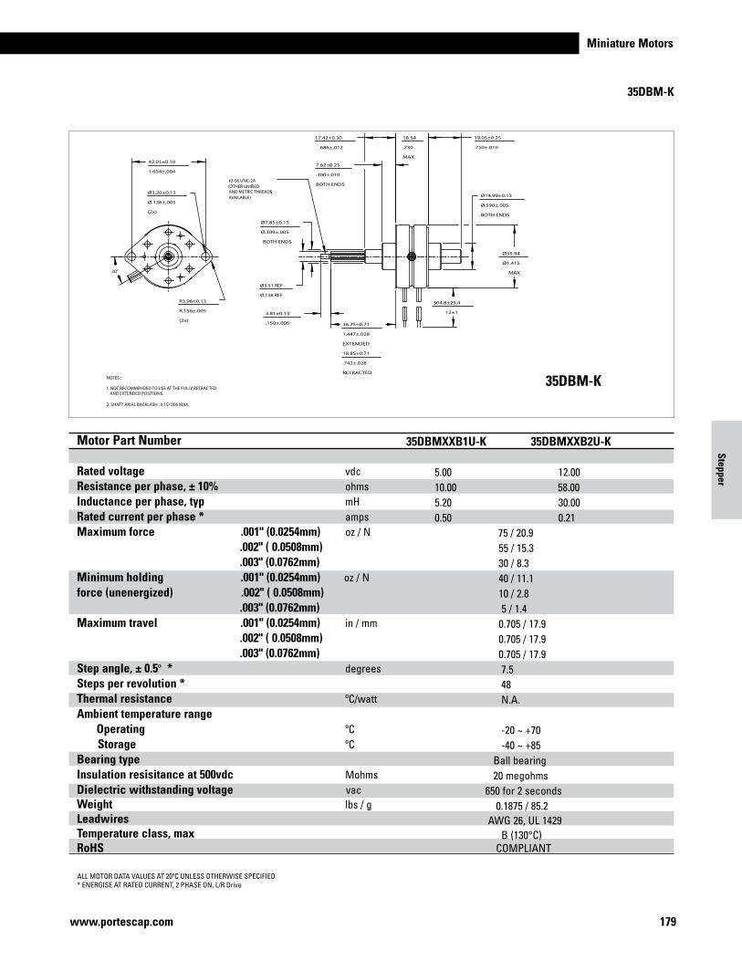
Miniature Motors
179www.portescap.com
18.54
.730
MAX
Ø14.99±0.13
Ø.590±.005
BOTH ENDS
304.8±25.4
12±1
Ø3.20±0.13
Ø.126±.005
(2x)
30°
42.01±0.10
1.654±.004
Ø35.94
Ø1.415
MAX
7.62±0.25
.300±.010
BOTH ENDS
17.42±0.30
.686±.012
36.75±0.71
1.447±.028
EXTENDED
18.85±0.71
.742±.028
RETRACTED
19.05±0.25
.750±.010
3.81±0.13
.150±.005
Ø7.85±0.13
Ø.309±.005
BOTH ENDS
Ø3.51 REF
Ø.138 REFR3.96±0.13
R.156±.005
(2x)
#2-56 UNC-2A(OTHER UNIFIEDAND METRIC THREADSAVAILABLE)
NOTES : 1. NOT RECOMMENDED TO USE AT THE FULLY RETRACTED AND EXTENDED POSITIONS. 2. SHAFT AXIAL BACKLASH : 0.15/.006 MAX.
35DBM-K
ALL MOTOR DATA VALUES AT 20ºC UNLESS OTHERWISE SPECIFIED* ENERGISE AT RATED CURRENT, 2 PHASE ON, L/R Drive
35DBM-K
Motor Part Number Rated voltage vdc Resistance per phase, ± 10% ohms Inductance per phase, typ mH Rated current per phase * amps Maximum force .001" (0.0254mm) oz / N .002" ( 0.0508mm) .003" (0.0762mm)Minimum holding .001" (0.0254mm) oz / N force (unenergized) .002" ( 0.0508mm) .003" (0.0762mm)Maximum travel .001" (0.0254mm) in / mm .002" ( 0.0508mm) .003" (0.0762mm)Step angle, ± 0.5º * degrees Steps per revolution * Thermal resistance ºC/watt Ambient temperature range Operating ºC Storage ºC Bearing type Insulation resisitance at 500vdc Mohms Dielectric withstanding voltage vac Weight lbs / g Leadwires Temperature class, max RoHS
Motor Part Number Rated voltage vdc Resistance per phase, ± 10% ohms Inductance per phase, typ mH Rated current per phase * amps Maximum force .001" (0.0254mm) oz / N .002" ( 0.0508mm) .003" (0.0762mm)Minimum holding .001" (0.0254mm) oz / N force (unenergized) .002" ( 0.0508mm) .003" (0.0762mm)Maximum travel .001" (0.0254mm) in / mm .002" ( 0.0508mm) .003" (0.0762mm)Step angle, ± 0.5º * degrees Steps per revolution * Thermal resistance ºC/watt Ambient temperature range Operating ºC Storage ºC Bearing type Insulation resisitance at 500vdc Mohms Dielectric withstanding voltage vac Weight lbs / g Leadwires Temperature class, max RoHS
35DBMXXB1U-K 35DBMXXB2U-K 5.00 12.00 10.00 58.00 5.20 30.00 0.50 0.21 75 / 20.9 55 / 15.3 30 / 8.3 40 / 11.1 10 / 2.8 5 / 1.4 0.705 / 17.9 0.705 / 17.9 0.705 / 17.9 7.5 48 N.A. -20 ~ +70 -40 ~ +85 Ball bearing 20 megohms 650 for 2 seconds 0.1875 / 85.2 AWG 26, UL 1429 B (130°C) COMPLIANT
Stepper
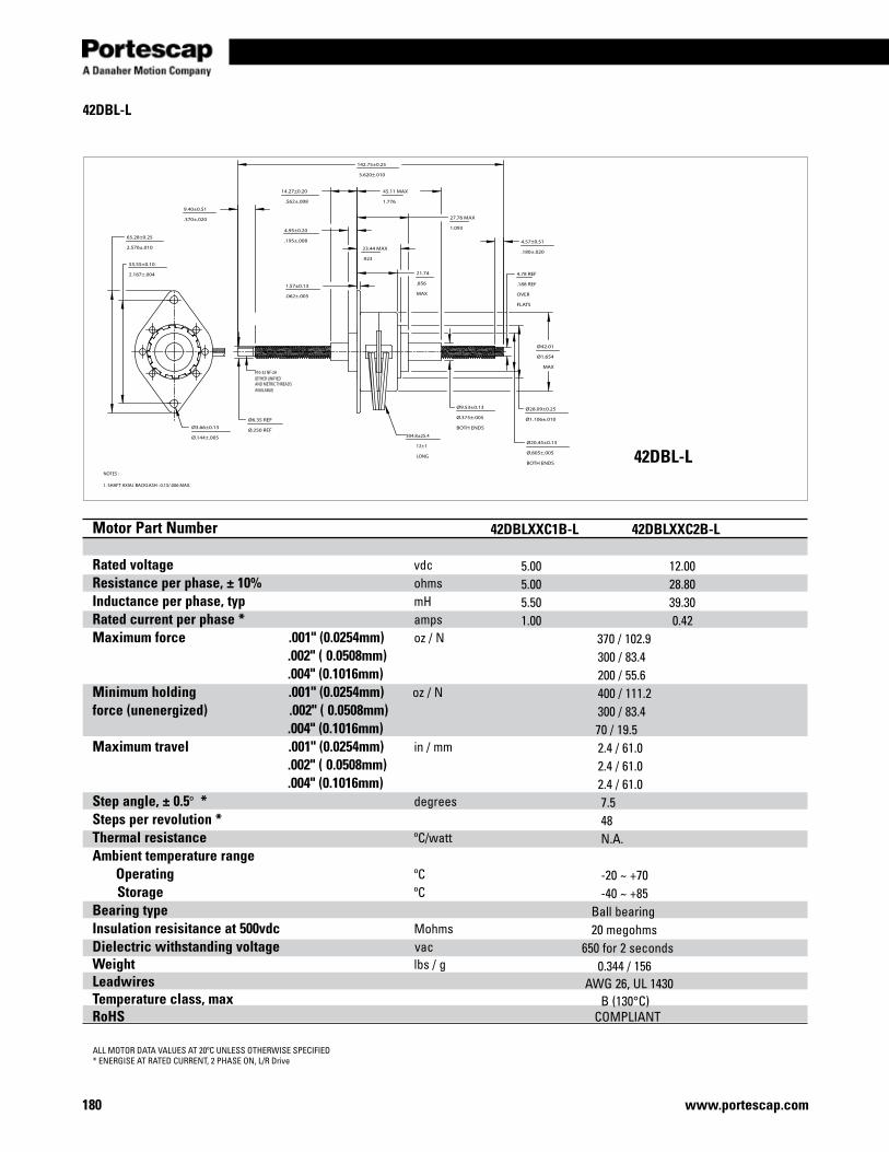
www.portescap.com180
45.11 MAX
1.776
27.76 MAX
1.093
23.44 MAX
.923
21.74
.856
MAX
4.95±0.20
.195±.008
14.27±0.20
.562±.008
Ø42.01
Ø1.654
MAX
Ø28.09±0.25
Ø1.106±.010
Ø20.45±0.13
Ø.805±.005
BOTH ENDS
Ø9.53±0.13
Ø.375±.005
BOTH ENDS
65.28±0.25
2.570±.010
55.55±0.10
2.187±.004
1.57±0.13
.062±.005
Ø3.66±0.13
Ø.144±.005
142.75±0.25
5.620±.010
9.40±0.51
.370±.020
4.57±0.51
.180±.020
4.78 REF
.188 REF
OVER
FLATS
Ø6.35 REF
Ø.250 REF
#10-32 NF-2A(OTHER UNIFIEDAND METRIC THREADSAVAILABLE)
NOTES : 1. SHAFT AXIAL BACKLASH : 0.15/.006 MAX.
304.8±25.4
12±1
LONG
42DBL-L
ALL MOTOR DATA VALUES AT 20ºC UNLESS OTHERWISE SPECIFIED* ENERGISE AT RATED CURRENT, 2 PHASE ON, L/R Drive
42DBL-L
Motor Part Number Rated voltage vdc Resistance per phase, ± 10% ohms Inductance per phase, typ mH Rated current per phase * amps Maximum force .001" (0.0254mm) oz / N .002" ( 0.0508mm) .004" (0.1016mm)Minimum holding .001" (0.0254mm) oz / N force (unenergized) .002" ( 0.0508mm) .004" (0.1016mm)Maximum travel .001" (0.0254mm) in / mm .002" ( 0.0508mm) .004" (0.1016mm)Step angle, ± 0.5º * degrees Steps per revolution * Thermal resistance ºC/watt Ambient temperature range Operating ºC Storage ºC Bearing type Insulation resisitance at 500vdc Mohms Dielectric withstanding voltage vac Weight lbs / g Leadwires Temperature class, max RoHS
42DBLXXC1B-L 42DBLXXC2B-L 5.00 12.00 5.00 28.80 5.50 39.30 1.00 0.42 370 / 102.9 300 / 83.4 200 / 55.6 400 / 111.2 300 / 83.4 70 / 19.5 2.4 / 61.0 2.4 / 61.0 2.4 / 61.0 7.5 48 N.A. -20 ~ +70 -40 ~ +85 Ball bearing 20 megohms 650 for 2 seconds 0.344 / 156 AWG 26, UL 1430 B (130°C) COMPLIANT
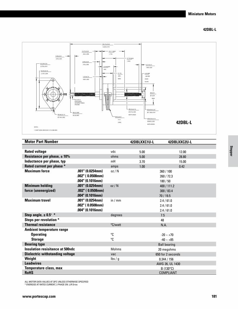
Miniature Motors
181www.portescap.com
45.11 MAX
1.776
27.76 MAX
1.093
23.44 MAX
.923
21.74
.856
MAX
4.95±0.20
.195±.008
14.27±0.20
.562±.008
Ø42.01
Ø1.654
MAX
Ø28.09±0.25
Ø1.106±.010
Ø20.45±0.13
Ø.805±.005
BOTH ENDS
Ø9.53±0.13
Ø.375±.005
BOTH ENDS
65.28±0.25
2.570±.010
55.55±0.10
2.187±.004
1.57±0.13
.062±.005
Ø3.66±0.13
Ø.144±.005
142.75±0.25
5.620±.010
9.40±0.51
.370±.020
4.57±0.51
.180±.020
4.78 REF
.188 REF
OVER
FLATS
Ø6.35 REF
Ø.250 REF
#10-32 NF-2A(OTHER UNIFIEDAND METRIC THREADSAVAILABLE)
NOTES : 1. SHAFT AXIAL BACKLASH : 0.15/.006 MAX.
304.8±25.4
12±1
LONG
42DBL-L
ALL MOTOR DATA VALUES AT 20ºC UNLESS OTHERWISE SPECIFIED* ENERGISE AT RATED CURRENT, 2 PHASE ON. L/R Drive
42DBL-L
Motor Part Number Rated voltage vdc Resistance per phase, ± 10% ohms Inductance per phase, typ mH Rated current per phase * amps Maximum force .001" (0.0254mm) oz / N .002" ( 0.0508mm) .004" (0.1016mm)Minimum holding .001" (0.0254mm) oz / N force (unenergized) .002" ( 0.0508mm) .004" (0.1016mm)Maximum travel .001" (0.0254mm) in / mm .002" ( 0.0508mm) .004" (0.1016mm)Step angle, ± 0.5º * degrees Steps per revolution * Thermal resistance ºC/watt Ambient temperature range Operating ºC Storage ºC Bearing type Insulation resisitance at 500vdc Mohms Dielectric withstanding voltage vac Weight lbs / g Leadwires Temperature class, max RoHS
Motor Part Number Rated voltage vdc Resistance per phase, ± 10% ohms Inductance per phase, typ mH Rated current per phase * amps Maximum force .001" (0.0254mm) oz / N .002" ( 0.0508mm) .004" (0.1016mm)Minimum holding .001" (0.0254mm) oz / N force (unenergized) .002" ( 0.0508mm) .004" (0.1016mm)Maximum travel .001" (0.0254mm) in / mm .002" ( 0.0508mm) .004" (0.1016mm)Step angle, ± 0.5º * degrees Steps per revolution * Thermal resistance ºC/watt Ambient temperature range Operating ºC Storage ºC Bearing type Insulation resisitance at 500vdc Mohms Dielectric withstanding voltage vac Weight lbs / g Leadwires Temperature class, max RoHS
42DBLXXC1B-L 42DBLXXC2B-L 5.00 12.00 5.00 28.80 5.50 39.30 1.00 0.42 370 / 102.9 300 / 83.4 200 / 55.6 400 / 111.2 300 / 83.4 70 / 19.5 2.4 / 61.0 2.4 / 61.0 2.4 / 61.0 7.5 48 N.A. -20 ~ +70 -40 ~ +85 Ball bearing 20 megohms 650 for 2 seconds 0.344 / 156 AWG 26, UL 1430 B (130°C) COMPLIANT
42DBLXXC1U-L 42DBLXXC2U-L 5.00 12.00 5.00 28.80 3.70 15.00 1.00 0.42 360 / 100 260 / 72.3 180 / 50 400 / 111.2 300 / 83.4 70 / 19.5 2.4 / 61.0 2.4 / 61.0 2.4 / 61.0 7.5 48 N.A. -20 ~ +70 -40 ~ +85 Ball bearing 20 megohms 650 for 2 seconds 0.344 / 156 AWG 26, UL 1430 B (130°C) COMPLIANT
Stepper
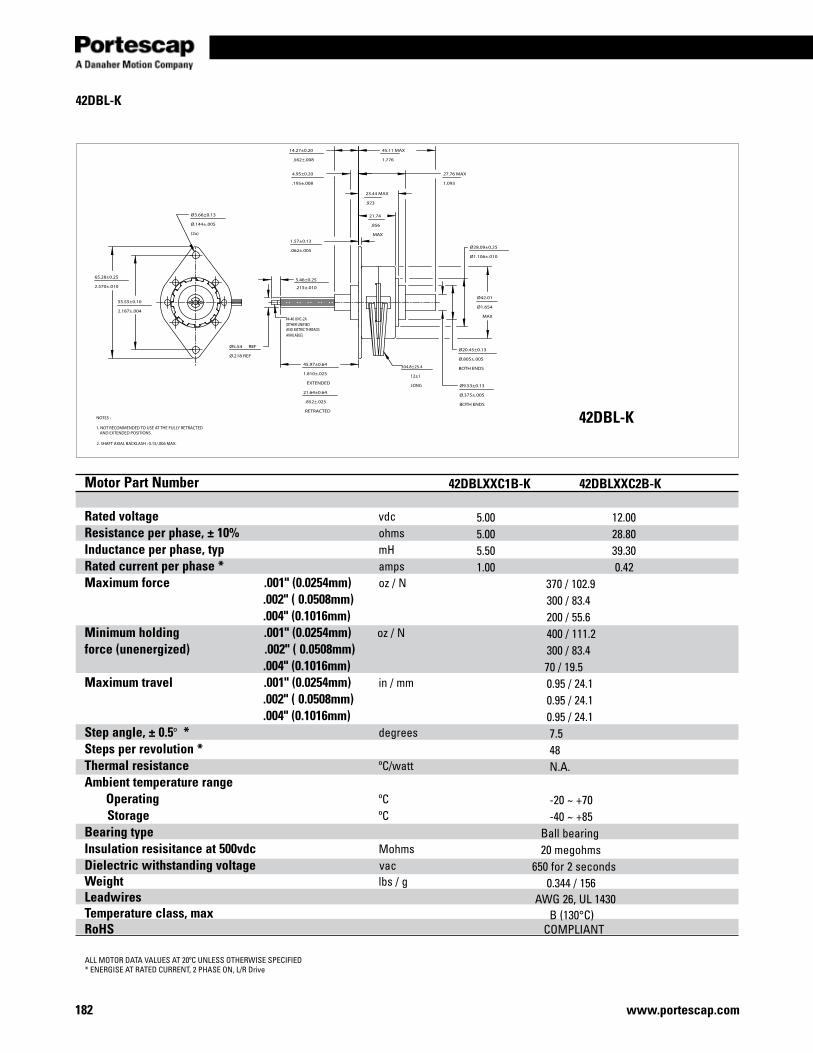
www.portescap.com182
45.11 MAX
1.776
27.76 MAX
1.093
23.44 MAX
.923
21.74
.856
MAX
4.95±0.20
.195±.008
14.27±0.20
.562±.008
45.97±0.64
1.810±.025
EXTENDED
21.64±0.64
.852±.025
RETRACTED
Ø42.01
Ø1.654
MAX
Ø28.09±0.25
Ø1.106±.010
Ø20.45±0.13
Ø.805±.005
BOTH ENDS
Ø9.53±0.13
Ø.375±.005
BOTH ENDS
55.55±0.10
2.187±.004
Ø3.66±0.13
Ø.144±.005
(2x)
Ø5.54 REF
Ø.218 REF
1.57±0.13
.062±.005
65.28±0.25
2.570±.0105.46±0.25
.215±.010
#4-40 UNC-2A(OTHER UNIFIEDAND METRIC THREADSAVAILABLE)
NOTES : 1. NOT RECOMMENDED TO USE AT THE FULLY RETRACTED AND EXTENDED POSITIONS. 2. SHAFT AXIAL BACKLASH : 0.15/.006 MAX.
304.8±25.4
12±1
LONG
42DBL-K
ALL MOTOR DATA VALUES AT 20ºC UNLESS OTHERWISE SPECIFIED* ENERGISE AT RATED CURRENT, 2 PHASE ON, L/R Drive
42DBL-K
Motor Part Number Rated voltage vdc Resistance per phase, ± 10% ohms Inductance per phase, typ mH Rated current per phase * amps Maximum force .001" (0.0254mm) oz / N .002" ( 0.0508mm) .004" (0.1016mm)Minimum holding .001" (0.0254mm) oz / N force (unenergized) .002" ( 0.0508mm) .004" (0.1016mm)Maximum travel .001" (0.0254mm) in / mm .002" ( 0.0508mm) .004" (0.1016mm)Step angle, ± 0.5º * degrees Steps per revolution * Thermal resistance ºC/watt Ambient temperature range Operating ºC Storage ºC Bearing type Insulation resisitance at 500vdc Mohms Dielectric withstanding voltage vac Weight lbs / g Leadwires Temperature class, max RoHS
42DBLXXC1B-K 42DBLXXC2B-K 5.00 12.00 5.00 28.80 5.50 39.30 1.00 0.42 370 / 102.9 300 / 83.4 200 / 55.6 400 / 111.2 300 / 83.4 70 / 19.5 0.95 / 24.1 0.95 / 24.1 0.95 / 24.1 7.5 48 N.A. -20 ~ +70 -40 ~ +85 Ball bearing 20 megohms 650 for 2 seconds 0.344 / 156 AWG 26, UL 1430 B (130°C) COMPLIANT
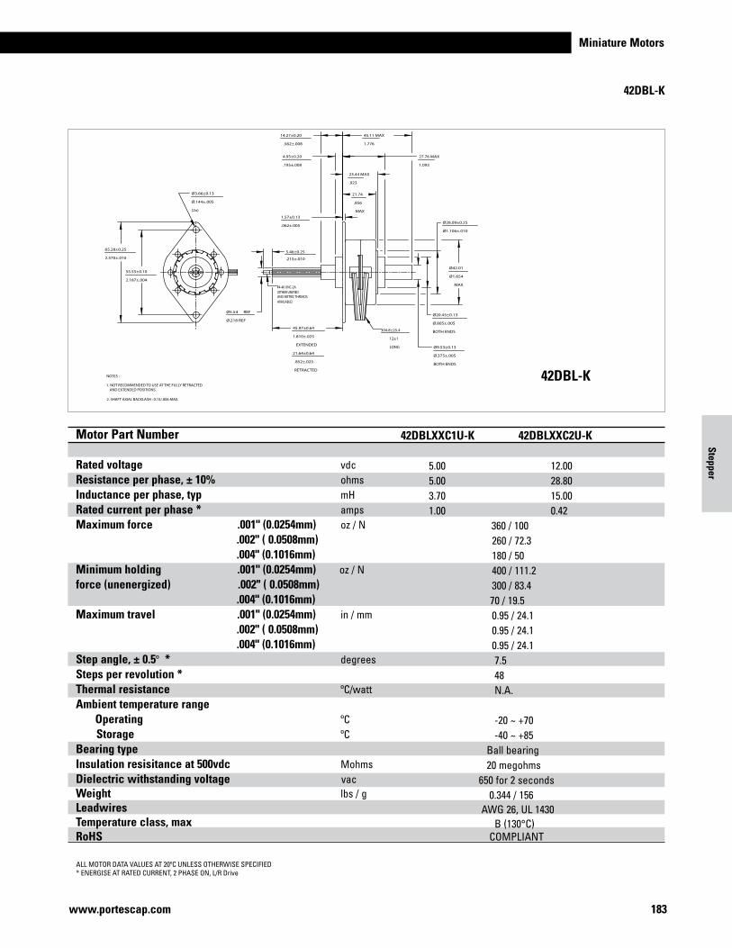
Miniature Motors
183www.portescap.com
45.11 MAX
1.776
27.76 MAX
1.093
23.44 MAX
.923
21.74
.856
MAX
4.95±0.20
.195±.008
14.27±0.20
.562±.008
45.97±0.64
1.810±.025
EXTENDED
21.64±0.64
.852±.025
RETRACTED
Ø42.01
Ø1.654
MAX
Ø28.09±0.25
Ø1.106±.010
Ø20.45±0.13
Ø.805±.005
BOTH ENDS
Ø9.53±0.13
Ø.375±.005
BOTH ENDS
55.55±0.10
2.187±.004
Ø3.66±0.13
Ø.144±.005
(2x)
Ø5.54 REF
Ø.218 REF
1.57±0.13
.062±.005
65.28±0.25
2.570±.0105.46±0.25
.215±.010
#4-40 UNC-2A(OTHER UNIFIEDAND METRIC THREADSAVAILABLE)
NOTES : 1. NOT RECOMMENDED TO USE AT THE FULLY RETRACTED AND EXTENDED POSITIONS. 2. SHAFT AXIAL BACKLASH : 0.15/.006 MAX.
304.8±25.4
12±1
LONG
42DBL-K
ALL MOTOR DATA VALUES AT 20ºC UNLESS OTHERWISE SPECIFIED* ENERGISE AT RATED CURRENT, 2 PHASE ON, L/R Drive
42DBL-K
Motor Part Number Rated voltage vdc Resistance per phase, ± 10% ohms Inductance per phase, typ mH Rated current per phase * amps Maximum force .001" (0.0254mm) oz / N .002" ( 0.0508mm) .004" (0.1016mm)Minimum holding .001" (0.0254mm) oz / N force (unenergized) .002" ( 0.0508mm) .004" (0.1016mm)Maximum travel .001" (0.0254mm) in / mm .002" ( 0.0508mm) .004" (0.1016mm)Step angle, ± 0.5º * degrees Steps per revolution * Thermal resistance ºC/watt Ambient temperature range Operating ºC Storage ºC Bearing type Insulation resisitance at 500vdc Mohms Dielectric withstanding voltage vac Weight lbs / g Leadwires Temperature class, max RoHS
Motor Part Number Rated voltage vdc Resistance per phase, ± 10% ohms Inductance per phase, typ mH Rated current per phase * amps Maximum force .001" (0.0254mm) oz / N .002" ( 0.0508mm) .004" (0.1016mm)Minimum holding .001" (0.0254mm) oz / N force (unenergized) .002" ( 0.0508mm) .004" (0.1016mm)Maximum travel .001" (0.0254mm) in / mm .002" ( 0.0508mm) .004" (0.1016mm)Step angle, ± 0.5º * degrees Steps per revolution * Thermal resistance ºC/watt Ambient temperature range Operating ºC Storage ºC Bearing type Insulation resisitance at 500vdc Mohms Dielectric withstanding voltage vac Weight lbs / g Leadwires Temperature class, max RoHS
42DBLXXC1B-K 42DBLXXC2B-K 5.00 12.00 5.00 28.80 5.50 39.30 1.00 0.42 370 / 102.9 300 / 83.4 200 / 55.6 400 / 111.2 300 / 83.4 70 / 19.5 0.95 / 24.1 0.95 / 24.1 0.95 / 24.1 7.5 48 N.A. -20 ~ +70 -40 ~ +85 Ball bearing 20 megohms 650 for 2 seconds 0.344 / 156 AWG 26, UL 1430 B (130°C) COMPLIANT
42DBLXXC1U-K 42DBLXXC2U-K 5.00 12.00 5.00 28.80 3.70 15.00 1.00 0.42 360 / 100 260 / 72.3 180 / 50 400 / 111.2 300 / 83.4 70 / 19.5 0.95 / 24.1 0.95 / 24.1 0.95 / 24.1 7.5 48 N.A. -20 ~ +70 -40 ~ +85 Ball bearing 20 megohms 650 for 2 seconds 0.344 / 156 AWG 26, UL 1430 B (130°C) COMPLIANT
Stepper
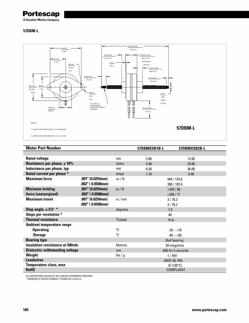
www.portescap.com184
142.75±0.25
5.62±.0166.675
2.625
33.325
1.312
Ø57.94
Ø2.281
MAX
44.45
1.750
Ø24.26
Ø.955
R6.35
R.25
(2x)
9.40±0.51
.37±.02
24.56±0.254
.967±.010
(WITHOUT
DECAL)
7.94±0.38
.315±.015
1.57
.06211.91±0.38
.469±.015
4.57±0.51
.18±0.02
4.78
.188
OVER
FLATS
Ø4.30
Ø.169
(2x)
317.5±12.7
12.5±.5
#10-32 NF-2A(OTHER UNIFIEDAND METRIC THREADSAVAILABLE)
NOTES :
1. SHAFT AXIAL BACKLASH : 0.15/.006 MAX.
2. UNSPECIFIED TOLERANCES : ±0.13/±.005
57DBM-L
ALL MOTOR DATA VALUES AT 20ºC UNLESS OTHERWISE SPECIFIED* ENERGISE AT RATED CURRENT, 2 PHASE ON, L/R Drive
57DBM-L
Motor Part Number Rated voltage vdc Resistance per phase, ± 10% ohms Inductance per phase, typ mH Rated current per phase * amps Maximum force .001" (0.0254mm) oz / N .002" ( 0.0508mm)Minimum holding .001" (0.0254mm) oz / N force (unenergized) .002" ( 0.0508mm)Maximum travel .001" (0.0254mm) in / mm .002" ( 0.0508mm)Step angle, ± 0.5º * degrees Steps per revolution * Thermal resistance ºC/watt Ambient temperature range Operating ºC Storage ºC Bearing type Insulation resisitance at 500vdc Mohms Dielectric withstanding voltage vac Weight lbs / g Leadwires Temperature class, max RoHS
57DBMXXB1B-L 57DBMXXB2B-L 5.00 12.00 4.30 25.00 6.30 36.00 1.16 0.48 448 / 124.6 368 / 102.4 >320 / 88 >256 / 71 3 / 76.2 3 / 76.2 7.5 48 N.A. -20 ~ +70 -40 ~ +85 Ball bearing 20 megohms 650 for 5 seconds 1 / 454 AWG 26, MIL B (130°C) COMPLIANT
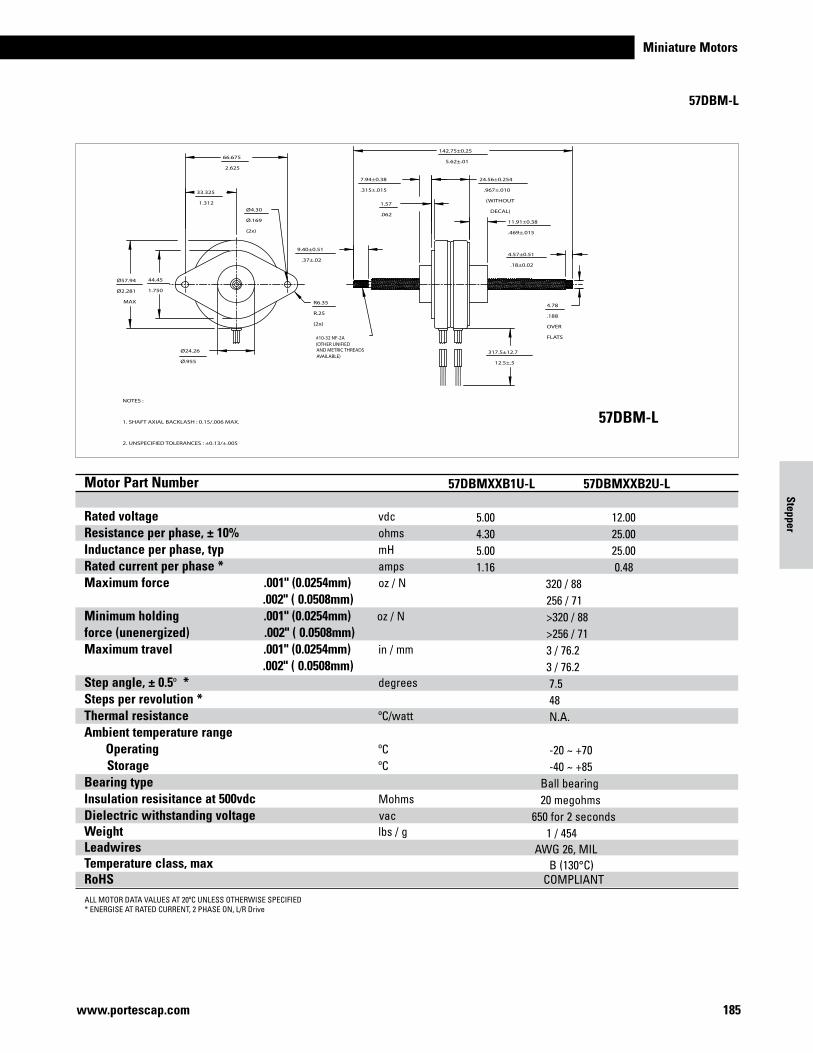
Miniature Motors
185www.portescap.com
142.75±0.25
5.62±.0166.675
2.625
33.325
1.312
Ø57.94
Ø2.281
MAX
44.45
1.750
Ø24.26
Ø.955
R6.35
R.25
(2x)
9.40±0.51
.37±.02
24.56±0.254
.967±.010
(WITHOUT
DECAL)
7.94±0.38
.315±.015
1.57
.06211.91±0.38
.469±.015
4.57±0.51
.18±0.02
4.78
.188
OVER
FLATS
Ø4.30
Ø.169
(2x)
317.5±12.7
12.5±.5
#10-32 NF-2A(OTHER UNIFIEDAND METRIC THREADSAVAILABLE)
NOTES :
1. SHAFT AXIAL BACKLASH : 0.15/.006 MAX.
2. UNSPECIFIED TOLERANCES : ±0.13/±.005
57DBM-L
ALL MOTOR DATA VALUES AT 20ºC UNLESS OTHERWISE SPECIFIED* ENERGISE AT RATED CURRENT, 2 PHASE ON, L/R Drive
57DBM-L
Motor Part Number Rated voltage vdc Resistance per phase, ± 10% ohms Inductance per phase, typ mH Rated current per phase * amps Maximum force .001" (0.0254mm) oz / N .002" ( 0.0508mm)Minimum holding .001" (0.0254mm) oz / N force (unenergized) .002" ( 0.0508mm)Maximum travel .001" (0.0254mm) in / mm .002" ( 0.0508mm)Step angle, ± 0.5º * degrees Steps per revolution * Thermal resistance ºC/watt Ambient temperature range Operating ºC Storage ºC Bearing type Insulation resisitance at 500vdc Mohms Dielectric withstanding voltage vac Weight lbs / g Leadwires Temperature class, max RoHS
Motor Part Number Rated voltage vdc Resistance per phase, ± 10% ohms Inductance per phase, typ mH Rated current per phase * amps Maximum force .001" (0.0254mm) oz / N .002" ( 0.0508mm)Minimum holding .001" (0.0254mm) oz / N force (unenergized) .002" ( 0.0508mm)Maximum travel .001" (0.0254mm) in / mm .002" ( 0.0508mm)Step angle, ± 0.5º * degrees Steps per revolution * Thermal resistance ºC/watt Ambient temperature range Operating ºC Storage ºC Bearing type Insulation resisitance at 500vdc Mohms Dielectric withstanding voltage vac Weight lbs / g Leadwires Temperature class, max RoHS
57DBMXXB1B-L 57DBMXXB2B-L 5.00 12.00 4.30 25.00 6.30 36.00 1.16 0.48 448 / 124.6 368 / 102.4 >320 / 88 >256 / 71 3 / 76.2 3 / 76.2 7.5 48 N.A. -20 ~ +70 -40 ~ +85 Ball bearing 20 megohms 650 for 5 seconds 1 / 454 AWG 26, MIL B (130°C) COMPLIANT
57DBMXXB1U-L 57DBMXXB2U-L 5.00 12.00 4.30 25.00 5.00 25.00 1.16 0.48 320 / 88 256 / 71 >320 / 88 >256 / 71 3 / 76.2 3 / 76.2 7.5 48 N.A. -20 ~ +70 -40 ~ +85 Ball bearing 20 megohms 650 for 2 seconds 1 / 454 AWG 26, MIL B (130°C) COMPLIANT
Stepper
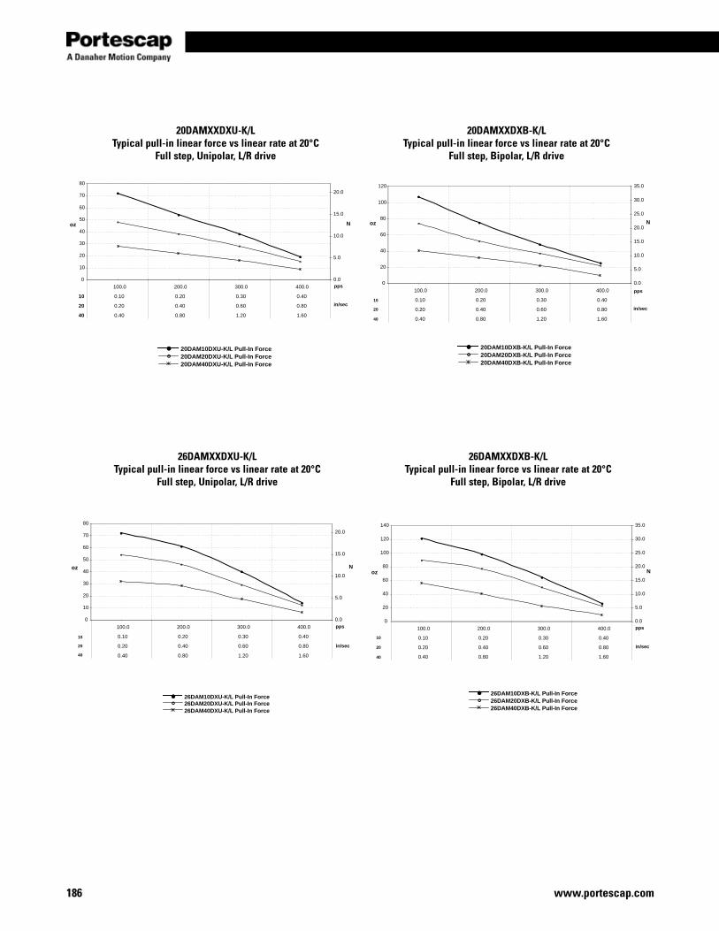
www.portescap.com186
oz N
pps
in/sec
0
10
20
30
40
50
60
70
80
100.0 200.0 300.0 400.0
0.10 0.20 0.30 0.40
0.20 0.40 0.60 0.80
0.40
10
20
40 0.80 1.20 1.60
0.0
5.0
10.0
15.0
20.0
20DAM10DXU-K/L Pull-In Force20DAM20DXU-K/L Pull-In Force20DAM40DXU-K/L Pull-In Force
oz N
pps
in/sec
20DAM10DXB-K/L Pull-In Force20DAM20DXB-K/L Pull-In Force20DAM40DXB-K/L Pull-In Force
0
20
40
60
80
100
120
100.0 200.0 300.0 400.0
0.10 0.20 0.30 0.40
0.20 0.40 0.60 0.80
0.40 0.80 1.20 1.60
0.0
5.0
10.0
15.0
20.0
25.0
30.0
35.0
40
20
10
20DAMXXDXU-K/LTypical pull-in linear force vs linear rate at 20°C
Full step, Unipolar, L/R drive
20DAMXXDXB-K/LTypical pull-in linear force vs linear rate at 20°C
Full step, Bipolar, L/R drive
oz N
pps
in/sec
0
10
20
30
40
50
60
70
80
100.0 200.0 300.0 400.0
0.10 0.20 0.30 0.40
0.20 0.40 0.60 0.80
0.40 0.80 1.20 1.60
0.0
5.0
10.0
15.0
20.0
26DAM10DXU-K/L Pull-In Force26DAM20DXU-K/L Pull-In Force26DAM40DXU-K/L Pull-In Force
10
20
40
oz N
pps
in/sec
0
20
40
60
80
100
120
140
100.0 200.0 300.0 400.0
0.10 0.20 0.30 0.40
0.20 0.40 0.60 0.80
0.40 0.80 1.20 1.60
0.0
5.0
10.0
15.0
20.0
25.0
30.0
35.0
26DAM10DXB-K/L Pull-In Force26DAM20DXB-K/L Pull-In Force26DAM40DXB-K/L Pull-In Force
40
20
10
26DAMXXDXU-K/LTypical pull-in linear force vs linear rate at 20°C
Full step, Unipolar, L/R drive
26DAMXXDXB-K/LTypical pull-in linear force vs linear rate at 20°C
Full step, Bipolar, L/R drive
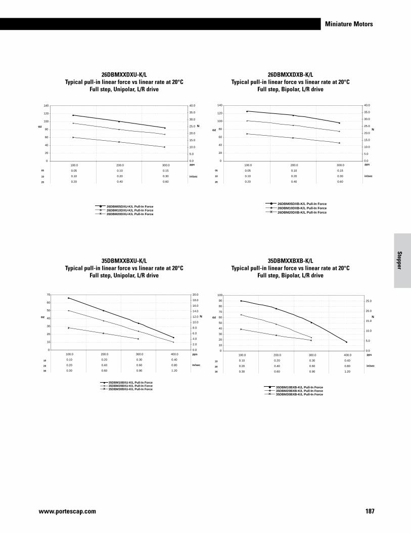
Miniature Motors
187www.portescap.com
Stepper
oz N
pps
in/sec
0
20
40
60
80
100
120
140
100.0 200.0 300.0
0.05 0.10 0.15
0.10 0.20 0.30
0.20 0.40 0.60
0.0
5.0
10.0
15.0
20.0
25.0
30.0
35.0
40.0
26DBM05DXU-K/L Pull-In Force26DBM10DXU-K/L Pull-In Force26DBM20DXU-K/L Pull-In Force
10
20
05
oz N
pps
in/sec
0
20
40
60
80
100
120
140
100.0 200.0 300.0
0.05 0.10 0.15
0.10 0.20 0.30
0.20 0.40 0.60
0.0
5.0
10.0
15.0
20.0
25.0
30.0
35.0
40.0
26DBM05DXB-K/L Pull-In Force26DBM10DXB-K/L Pull-In Force26DBM20DXB-K/L Pull-In Force
05
10
20
26DBMXXDXU-K/LTypical pull-in linear force vs linear rate at 20°C
Full step, Unipolar, L/R drive
26DBMXXDXB-K/LTypical pull-in linear force vs linear rate at 20°C
Full step, Bipolar, L/R drive
oz N
0
10
20
30
40
50
60
70
100.0 200.0 300.0 400.0
0.10 0.20 0.30 0.40
0.20 0.40 0.60 0.80
0.30 0.60 0.90 1.20
pps
0.0
2.0
4.0
6.0
8.0
10.0
12.0
14.0
16.0
18.0
20.0
in/sec
35DBM10BXU-K/L Pull-In Force35DBM20BXU-K/L Pull-In Force35DBM30BXU-K/L Pull-In Force
20
10
30
oz N
pps
in/sec20
10
30
35DBM10BXB-K/L Pull-In Force35DBM20BXB-K/L Pull-In Force35DBM30BXB-K/L Pull-In Force
0
10
20
30
40
50
60
70
80
90
100
100.0 200.0 300.0 400.0
0.10 0.20 0.30 0.40
0.20 0.40 0.60 0.80
0.30 0.60 0.90 1.20
0.0
5.0
10.0
15.0
20.0
25.0
35DBMXXBXU-K/LTypical pull-in linear force vs linear rate at 20°C
Full step, Unipolar, L/R drive
35DBMXXBXB-K/LTypical pull-in linear force vs linear rate at 20°C
Full step, Bipolar, L/R drive
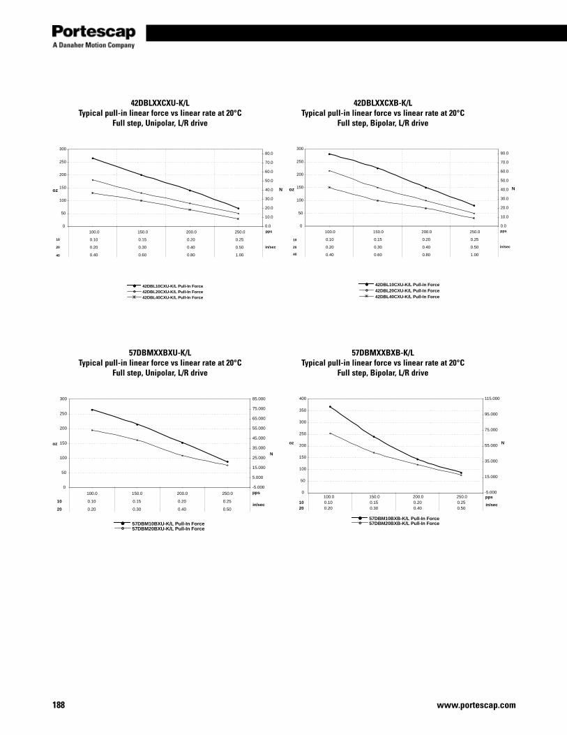
www.portescap.com188
0
50
100
150
200
250
300
100.0 150.0 200.0 250.0
0.10 0.15 0.20 0.25
0.20 0.30 0.40 0.50
0.40 0.60 0.80 1.00
pps
oz
0.0
10.0
20.0
30.0
40.0
50.0
60.0
70.0
80.0
in/sec
N
42DBL10CXU-K/L Pull-In Force42DBL20CXU-K/L Pull-In Force42DBL40CXU-K/L Pull-In Force
40
20
10
oz
pps
in/sec
N
42DBL10CXU-K/L Pull-In Force42DBL20CXU-K/L Pull-In Force42DBL40CXU-K/L Pull-In Force
0
50
100
150
200
250
300
100.0 150.0 200.0 250.0
0.10 0.15 0.20 0.25
0.20 0.30 0.40 0.50
0.40 0.60 0.80 1.00
0.0
10.0
20.0
30.0
40.0
50.0
60.0
70.0
80.0
10
20
40
42DBLXXCXU-K/LTypical pull-in linear force vs linear rate at 20°C
Full step, Unipolar, L/R drive
42DBLXXCXB-K/LTypical pull-in linear force vs linear rate at 20°C
Full step, Bipolar, L/R drive
0
50
100
150
200
250
300
100.0 150.0 200.0 250.0
0.10 0.15 0.20 0.25
0.20
10
20 0.30 0.40 0.50
pps
oz
-5.000
5.000
15.000
25.000
35.000
45.000
55.000
65.000
75.000
85.000
N
in/sec
57DBM10BXU-K/L Pull-In Force57DBM20BXU-K/L Pull-In Force
oz N
0
50
100
150
200
250
300
350
400
100.0 150.0 200.0 250.00.10 0.15 0.20 0.250.20
1020 0.30 0.40 0.50
pps-5.000
15.000
35.000
55.000
75.000
95.000
115.000
in/sec
57DBM10BXB-K/L Pull-In Force57DBM20BXB-K/L Pull-In Force
57DBMXXBXU-K/LTypical pull-in linear force vs linear rate at 20°C
Full step, Unipolar, L/R drive
57DBMXXBXB-K/LTypical pull-in linear force vs linear rate at 20°C
Full step, Bipolar, L/R drive
Miniature Motors
189www.portescap.com
Stepper
Notes

190
Notes
www.portescap.com
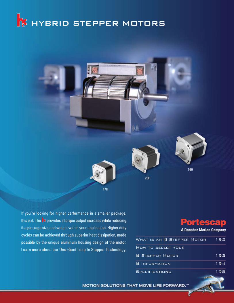
17H
23H
34H
hybrid stepper motors
What is an h3 Stepper Motor 192
How to select your
h3 Stepper Motor 193
h3 Information 194
Specifications 198
If you’re looking for higher performance in a smaller package,
this is it. The provides a torque output increase while reducing
the package size and weight within your application. Higher duty
cycles can be achieved through superior heat dissipation, made
possible by the unique aluminum housing design of the motor.
Learn more about our One Giant Leap In Stepper Technology.
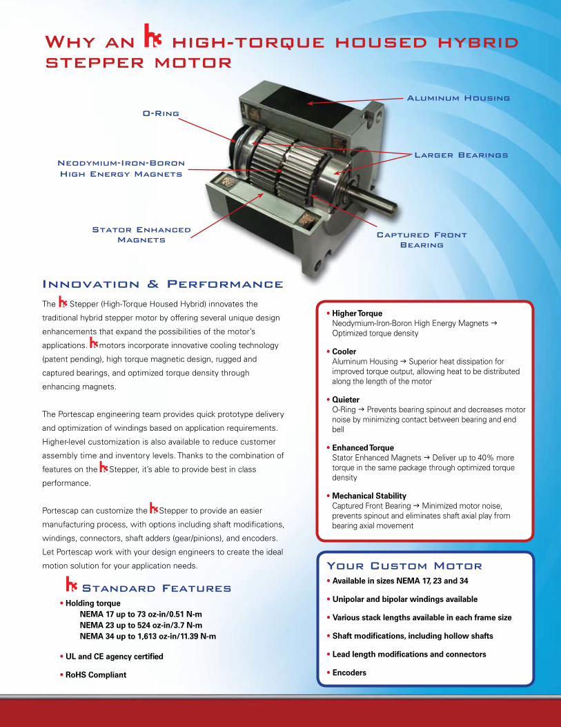
Why an high-torque housed hybrid stepper motor
Neodymium-iron-boron high energy magnets
Aluminum housing
Larger bearings
o-ring
stator enhanced magnets Captured Front
bearing
• Higher Torque Neodymium-Iron-Boron High Energy Magnets g Optimized torque density
• Cooler Aluminum Housing g Superior heat dissipation for improved torque output, allowing heat to be distributed along the length of the motor
• Quieter O-Ring g Prevents bearing spinout and decreases motor noise by minimizing contact between bearing and end bell
• Enhanced Torque Stator Enhanced Magnets g Deliver up to 40% more torque in the same package through optimized torque density
• Mechanical Stability Captured Front Bearing g Minimized motor noise, prevents spinout and eliminates shaft axial play from bearing axial movement
The Stepper (High-Torque Housed Hybrid) innovates the
traditional hybrid stepper motor by offering several unique design
enhancements that expand the possibilities of the motor’s
applications. motors incorporate innovative cooling technology
(patent pending), high torque magnetic design, rugged and
captured bearings, and optimized torque density through
enhancing magnets.
The Portescap engineering team provides quick prototype delivery
and optimization of windings based on application requirements.
Higher-level customization is also available to reduce customer
assembly time and inventory levels. Thanks to the combination of
features on the Stepper, it’s able to provide best in class
performance.
Portescap can customize the Stepper to provide an easier
manufacturing process, with options including shaft modifications,
windings, connectors, shaft adders (gear/pinions), and encoders.
Let Portescap work with your design engineers to create the ideal
motion solution for your application needs.
innovation & performance
your Custom motor• Available in sizes NEMA 17, 23 and 34
• Unipolar and bipolar windings available
• Various stack lengths available in each frame size
• Shaft modifications, including hollow shafts
• Lead length modifications and connectors
• Encoders
standard Features• Holding torque NEMA 17 up to 73 oz-in/0.51 N-m NEMA 23 up to 524 oz-in/3.7 N-m NEMA 34 up to 1,613 oz-in/11.39 N-m
• UL and CE agency certified
• RoHS Compliant
17 h 0 18 d 10 b
H = Hybrid Stepper Motor
Frame size
Rated Current Per Phase05 = .5 A, 10 = 1.0 A, 15 = 1.5 A, 20 = 2.0 A 30 = 3.0 A, 50 = 5.0 A
B = Bipolar CoilU = Unipolar Coil
Motor Lengths (see drawing) 0 = Short Stack 1 = 1 Stack2 = 2 Stack3 = 3 Stack
D = Neodymium Rotor Magnet
E = Enhanced18 = 1.8˚ Per StepWith 2 Phases Energized
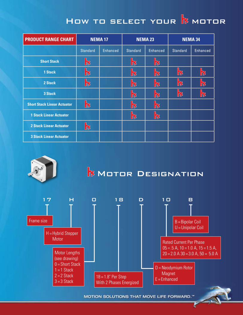
how to select your motor
PRODUCT RANGE CHART NEMA 17 NEMA 23 NEMA 34
Standard Enhanced Standard Enhanced Standard Enhanced
Short Stack
1 Stack
2 Stack
3 Stack
Short Stack Linear Actuator
1 Stack Linear Actuator
2 Stack Linear Actuator
3 Stack Linear Actuator
motor designation
17 h 0 18 d 10 b
H = Hybrid Stepper Motor
Frame size
Rated Current Per Phase05 = .5 A, 10 = 1.0 A, 15 = 1.5 A, 20 = 2.0 A 30 = 3.0 A, 50 = 5.0 A
B = Bipolar CoilU = Unipolar Coil
Motor Lengths (see drawing) 0 = Short Stack 1 = 1 Stack2 = 2 Stack3 = 3 Stack
D = Neodymium Rotor Magnet
E = Enhanced18 = 1.8˚ Per StepWith 2 Phases Energized
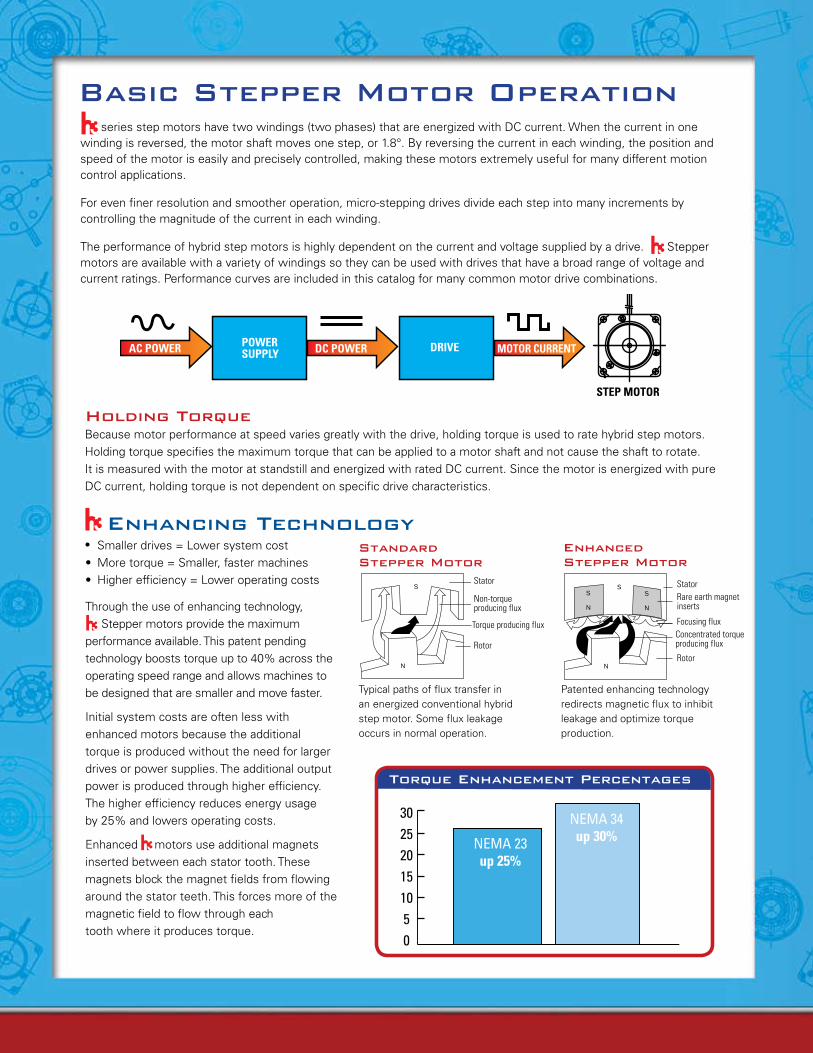
basic stepper motor operation
Portescap finds its place among an esteemed worldwide family of motion control experts.
series step motors have two windings (two phases) that are energized with DC current. When the current in one winding is reversed, the motor shaft moves one step, or 1.8°. By reversing the current in each winding, the position and speed of the motor is easily and precisely controlled, making these motors extremely useful for many different motion control applications.
For even finer resolution and smoother operation, micro-stepping drives divide each step into many increments by controlling the magnitude of the current in each winding.
The performance of hybrid step motors is highly dependent on the current and voltage supplied by a drive. Stepper motors are available with a variety of windings so they can be used with drives that have a broad range of voltage and current ratings. Performance curves are included in this catalog for many common motor drive combinations.
AC POWER POWERSUPPLY DC POWER DRIVE MOTOR CURRENT
STEP MOTOR
• Smaller drives = Lower system cost • Moretorque=Smaller,fastermachines• Higherefficiency=Loweroperatingcosts
Through the use of enhancing technology, Stepper motors provide the maximum performance available. This patent pending technology boosts torque up to 40% across the operating speed range and allows machines to be designed that are smaller and move faster.
Initial system costs are often less with enhanced motors because the additional torque is produced without the need for larger drives or power supplies. The additional output power is produced through higher efficiency. The higher efficiency reduces energy usage by 25% and lowers operating costs.
Enhanced motors use additional magnets inserted between each stator tooth. These magnets block the magnet fields from flowing around the stator teeth. This forces more of the magnetic field to flow through each tooth where it produces torque.
S
N
S
N
S
N
S
N
standard stepper motor
Stator
Non-torqueproducing flux
Rotor
Typical paths of flux transfer in an energized conventional hybrid step motor. Some flux leakage occurs in normal operation.
S
N
S
N
S
N
S
N
enhanced stepper motor
StatorRare earth magnet inserts
Focusing fluxConcentrated torque producing flux
Rotor
Patented enhancing technology redirects magnetic flux to inhibit leakage and optimize torque production.
enhancing technology
Torque producing flux
torque enhancement percentages
NEMA 23 up 25%
302520151050
NEMA 34 up 30%
holding torqueBecause motor performance at speed varies greatly with the drive, holding torque is used to rate hybrid step motors. Holding torque specifies the maximum torque that can be applied to a motor shaft and not cause the shaft to rotate. It is measured with the motor at standstill and energized with rated DC current. Since the motor is energized with pure DC current, holding torque is not dependent on specific drive characteristics.
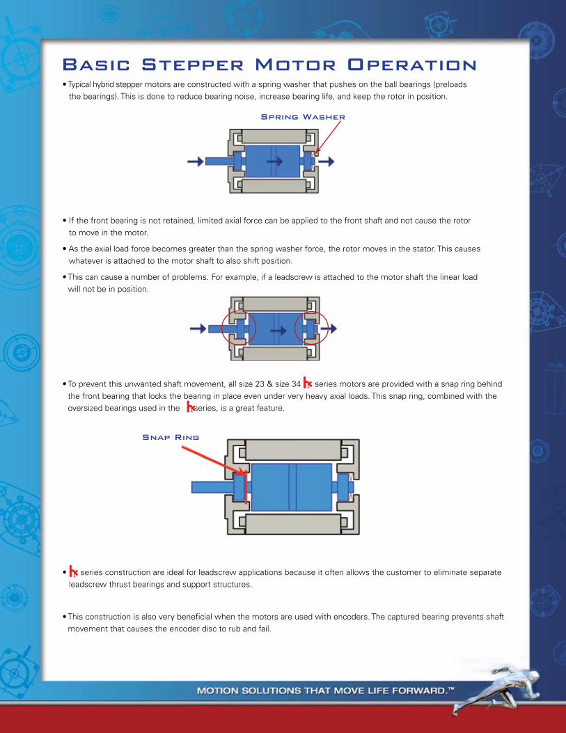
basic stepper motor operationbasic stepper motor operation•Typicalhybridsteppermotorsareconstructedwithaspringwasherthatpushesontheballbearings(preloads
the bearings). This is done to reduce bearing noise, increase bearing life, and keep the rotor in position.
spring Washer
•Topreventthisunwantedshaftmovement,allsize23&size34seriesmotorsareprovidedwithasnapringbehindthe front bearing that locks the bearing in place even under very heavy axial loads. This snap ring, combined with the oversized bearings used in the series, is a great feature.
snap ring
•seriesconstructionareidealforleadscrewapplicationsbecauseitoftenallowsthecustomertoeliminateseparateleadscrew thrust bearings and support structures.
•Thisconstructionisalsoverybeneficialwhenthemotorsareusedwithencoders.Thecapturedbearingpreventsshaftmovement that causes the encoder disc to rub and fail.
•Ifthefrontbearingisnotretained,limitedaxialforcecanbeappliedtothefrontshaftandnotcausetherotor to move in the motor.
•Astheaxialloadforcebecomesgreaterthanthespringwasherforce,therotormovesinthestator.Thiscauseswhatever is attached to the motor shaft to also shift position.
•Thiscancauseanumberofproblems.Forexample,ifaleadscrewisattachedtothemotorshaftthelinearload will not be in position.
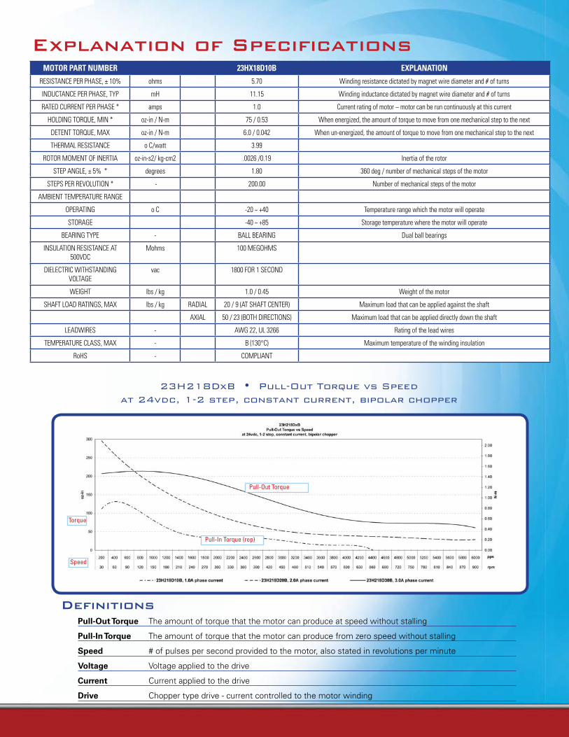
explanation of specificationsMOTOR PART NUMBER 23HX18D10B EXPLANATiON
RESISTANCE PER PHASE, ± 10% ohms 5.70 Winding resistance dictated by magnet wire diameter and # of turns
INDUCTANCE PER PHASE, TYP mH 11.15 Winding inductance dictated by magnet wire diameter and # of turns
RATED CURRENT PER PHASE * amps 1.0 Current rating of motor – motor can be run continuously at this current
HOLDING TORQUE, MIN * oz-in / N-m 75 / 0.53 When energized, the amount of torque to move from one mechanical step to the next
DETENT TORQUE, MAX oz-in / N-m 6.0 / 0.042 When un-energized, the amount of torque to move from one mechanical step to the next
THERMAL RESISTANCE o C/watt 3.99
ROTOR MOMENT OF INERTIA oz-in-s2/ kg-cm2 .0026 /0.19 Inertia of the rotor
STEP ANGLE, ± 5% * degrees 1.80 360 deg / number of mechanical steps of the motor
STEPS PER REVOLUTION * - 200.00 Number of mechanical steps of the motor
AMBIENT TEMPERATURE RANGE
OPERATING o C -20 ~ +40 Temperature range which the motor will operate
STORAGE -40 ~ +85 Storage temperature where the motor will operate
BEARING TYPE - BALL BEARING Dual ball bearings
INSULATION RESISTANCE AT 500VDC
Mohms 100 MEGOHMS
DIELECTRIC WITHSTANDING VOLTAGE
vac 1800 FOR 1 SECOND
WEIGHT lbs / kg 1.0 / 0.45 Weight of the motor
SHAFT LOAD RATINGS, MAX lbs / kg RADIAL 20 / 9 (AT SHAFT CENTER) Maximum load that can be applied against the shaft
AXIAL 50 / 23 (BOTH DIRECTIONS) Maximum load that can be applied directly down the shaft
LEADWIRES - AWG 22, UL 3266 Rating of the lead wires
TEMPERATURE CLASS, MAX - B (130°C) Maximum temperature of the winding insulation
RoHS - COMPLIANT
Definitions
Pull-Out Torque The amount of torque that the motor can produce at speed without stalling
Pull-In Torque The amount of torque that the motor can produce from zero speed without stalling
Speed # of pulses per second provided to the motor, also stated in revolutions per minute
Voltage Voltage applied to the drive
Current Current applied to the drive
Drive Chopper type drive - current controlled to the motor winding
23H218DxB•Pull-OutTorquevsSpeedat24vdc,1-2step,constantcurrent,bipolarchopper
Torque
Speed
Pull-In Torque (rep)
Pull-Out Torque
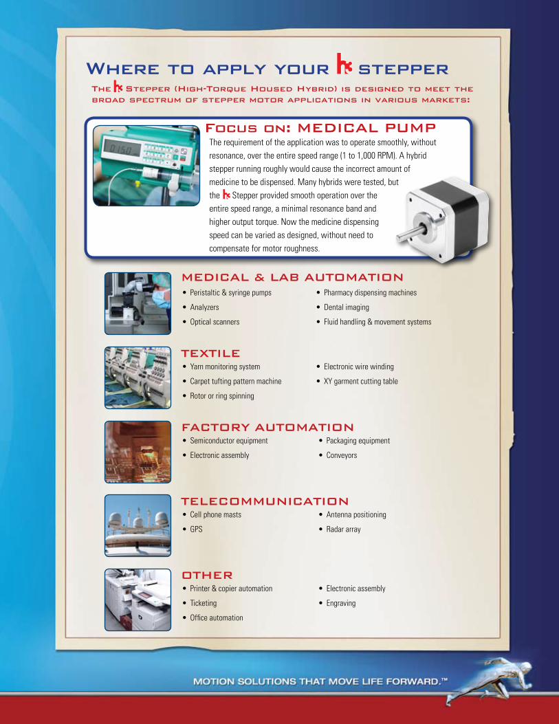
mediCAL & LAb AutomAtioNPeristaltic & syringe pumps•
Analyzers•
Optical scanners•
Pharmacy dispensing machines•
Dental imaging•
Fluid handling & movement systems•
Where to apply your stepperthe stepper (high-torque housed hybrid) is designed to meet the broad spectrum of stepper motor applications in various markets:
teXtiLeYarn monitoring system•
Carpet tufting pattern machine•
Rotor or ring spinning•
Electronic wire winding•
XY garment cutting table•
FACtory AutomAtioNSemiconductor equipment•
Electronic assembly•
Packaging equipment•
Conveyors•
teLeCommuNiCAtioNCell phone masts•
GPS•
Antenna positioning•
Radar array•
otherPrinter & copier automation•
Ticketing•
Office automation•
Electronic assembly•
Engraving•
Focus on: mediCAL pumpThe requirement of the application was to operate smoothly, without resonance, over the entire speed range (1 to 1,000 RPM). A hybrid stepper running roughly would cause the incorrect amount of medicine to be dispensed. Many hybrids were tested, but the Stepper provided smooth operation over the entire speed range, a minimal resonance band and higher output torque. Now the medicine dispensing speed can be varied as designed, without need to compensate for motor roughness.
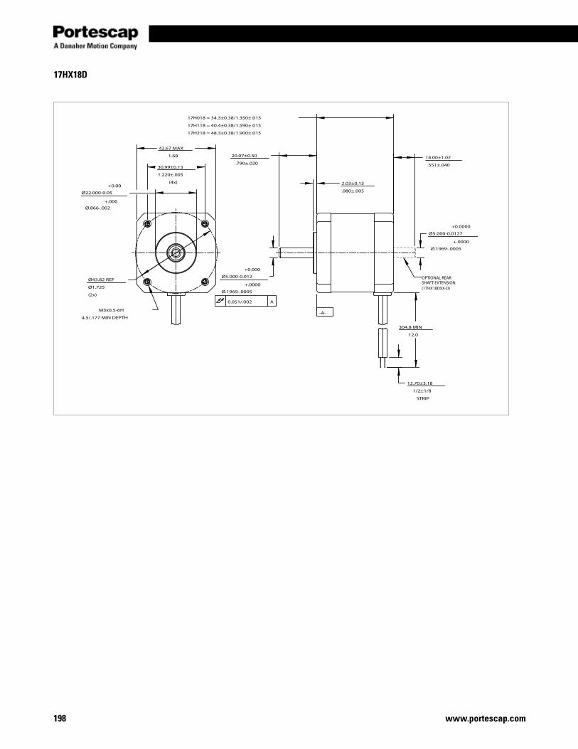
www.portescap.com198
42.67 MAX
1.68
30.99±0.13
1.220±.005
(4x)
Ø22.000-0.05
Ø.866-.002
Ø43.82 REF
Ø1.725
(2x)
M3x0.5-6H
4.5/.177 MIN DEPTH
17H018 = 34.3±0.38/1.350±.015
17H118 = 40.4±0.38/1.590±.015
17H218 = 48.3±0.38/1.900±.015
14.00±1.02
.551±.040
2.03±0.13
.080±.005
20.07±0.50
.790±.020
Ø5.000-0.012
Ø.1969-.0005
Ø5.000-0.0127
Ø.1969-.0005
304.8 MIN
12.0
12.70±3.18
1/2±1/8
STRIP
0.051/.002 A
-A-
+.000
+0.00
OPTIONAL REARSHAFT EXTENSION(17HX18DXX-D)
+0.0000
+.0000
+0.000
+.0000
17HX18D
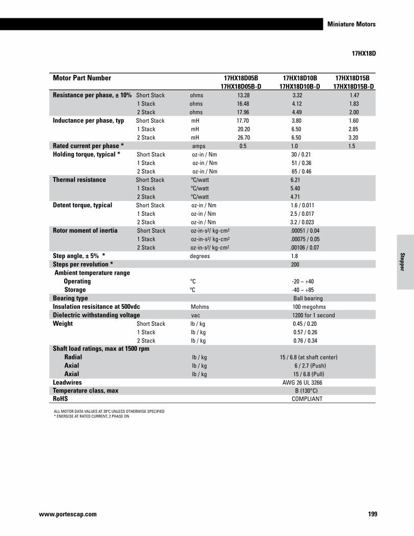
Miniature Motors
199www.portescap.com
Motor Part Number 17HX18D05B 17HX18D10B 17HX18D15B 17HX18D05B-D 17HX18D10B-D 17HX18D15B-DResistance per phase, ± 10% Short Stack ohms 13.28 3.32 1.47 1 Stack ohms 16.48 4.12 1.83 2 Stack ohms 17.96 4.49 2.00Inductance per phase, typ Short Stack mH 17.70 3.80 1.60 1 Stack mH 20.20 6.50 2.85 2 Stack mH 26.70 6.50 3.20 Rated current per phase * amps 0.5 1.0 1.5Holding torque, typical * Short Stack oz-in / Nm 30 / 0.21 1 Stack oz-in / Nm 51 / 0.36 2 Stack oz-in / Nm 65 / 0.46Thermal resistance Short Stack ºC/watt 6.21 1 Stack ºC/watt 5.40 2 Stack ºC/watt 4.71Detent torque, typical Short Stack oz-in / Nm 1.6 / 0.011 1 Stack oz-in / Nm 2.5 / 0.017 2 Stack oz-in / Nm 3.2 / 0.023Rotor moment of inertia Short Stack oz-in-s2/ kg-cm2 .00051 / 0.04 1 Stack oz-in-s2/ kg-cm2 .00075 / 0.05 2 Stack oz-in-s2/ kg-cm2 .00106 / 0.07Step angle, ± 5% * degrees 1.8 Steps per revolution * 200 Ambient temperature range Operating ºC -20 ~ +40 Storage ºC -40 ~ +85 Bearing type Ball bearing Insulation resisitance at 500vdc Mohms 100 megohmsDielectric withstanding voltage vac 1200 for 1 secondWeight Short Stack lb / kg 0.45 / 0.20 1 Stack lb / kg 0.57 / 0.26 2 Stack lb / kg 0.76 / 0.34Shaft load ratings, max at 1500 rpm Radial lb / kg 15 / 6.8 (at shaft center) Axial lb / kg 6 / 2.7 (Push) Axial lb / kg 15 / 6.8 (Pull)Leadwires AWG 26 UL 3266Temperature class, max B (130°C)RoHS COMPLIANT
17HX18D
ALL MOTOR DATA VALUES AT 20ºC UNLESS OTHERWISE SPECIFIED* ENERGISE AT RATED CURRENT, 2 PHASE ON
Stepper
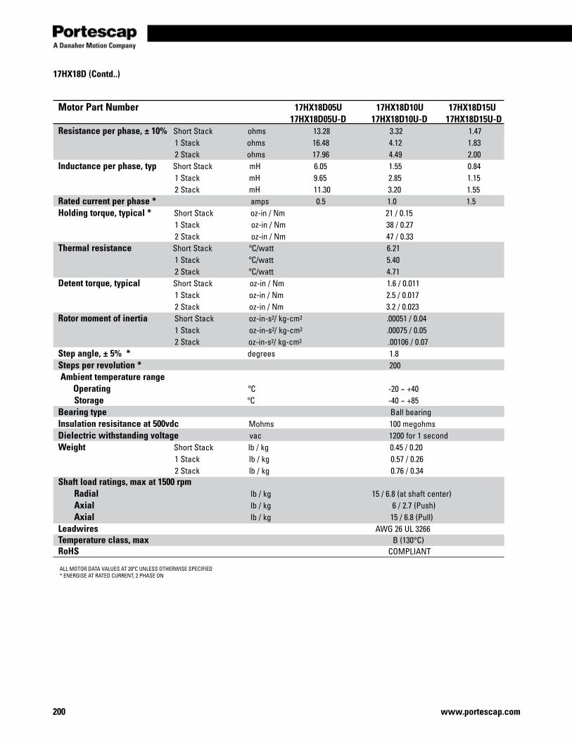
www.portescap.com200
17HX18D (Contd..)
ALL MOTOR DATA VALUES AT 20ºC UNLESS OTHERWISE SPECIFIED* ENERGISE AT RATED CURRENT, 2 PHASE ON
Motor Part Number 17HX18D05U 17HX18D10U 17HX18D15U 17HX18D05U-D 17HX18D10U-D 17HX18D15U-DResistance per phase, ± 10% Short Stack ohms 13.28 3.32 1.47 1 Stack ohms 16.48 4.12 1.83 2 Stack ohms 17.96 4.49 2.00Inductance per phase, typ Short Stack mH 6.05 1.55 0.84 1 Stack mH 9.65 2.85 1.15 2 Stack mH 11.30 3.20 1.55 Rated current per phase * amps 0.5 1.0 1.5Holding torque, typical * Short Stack oz-in / Nm 21 / 0.15 1 Stack oz-in / Nm 38 / 0.27 2 Stack oz-in / Nm 47 / 0.33Thermal resistance Short Stack ºC/watt 6.21 1 Stack ºC/watt 5.40 2 Stack ºC/watt 4.71Detent torque, typical Short Stack oz-in / Nm 1.6 / 0.011 1 Stack oz-in / Nm 2.5 / 0.017 2 Stack oz-in / Nm 3.2 / 0.023Rotor moment of inertia Short Stack oz-in-s2/ kg-cm2 .00051 / 0.04 1 Stack oz-in-s2/ kg-cm2 .00075 / 0.05 2 Stack oz-in-s2/ kg-cm2 .00106 / 0.07Step angle, ± 5% * degrees 1.8 Steps per revolution * 200 Ambient temperature range Operating ºC -20 ~ +40 Storage ºC -40 ~ +85 Bearing type Ball bearing Insulation resisitance at 500vdc Mohms 100 megohmsDielectric withstanding voltage vac 1200 for 1 secondWeight Short Stack lb / kg 0.45 / 0.20 1 Stack lb / kg 0.57 / 0.26 2 Stack lb / kg 0.76 / 0.34Shaft load ratings, max at 1500 rpm Radial lb / kg 15 / 6.8 (at shaft center) Axial lb / kg 6 / 2.7 (Push) Axial lb / kg 15 / 6.8 (Pull)Leadwires AWG 26 UL 3266Temperature class, max B (130°C)RoHS COMPLIANT
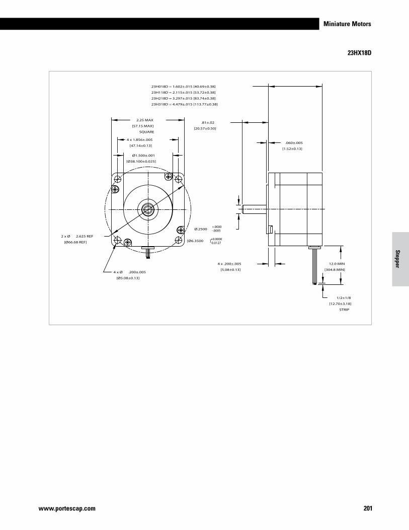
Miniature Motors
201www.portescap.com
Motor Part Number 17HX18D05U 17HX18D10U 17HX18D15U 17HX18D05U-D 17HX18D10U-D 17HX18D15U-DResistance per phase, ± 10% Short Stack ohms 13.28 3.32 1.47 1 Stack ohms 16.48 4.12 1.83 2 Stack ohms 17.96 4.49 2.00Inductance per phase, typ Short Stack mH 6.05 1.55 0.84 1 Stack mH 9.65 2.85 1.15 2 Stack mH 11.30 3.20 1.55 Rated current per phase * amps 0.5 1.0 1.5Holding torque, typical * Short Stack oz-in / Nm 21 / 0.15 1 Stack oz-in / Nm 38 / 0.27 2 Stack oz-in / Nm 47 / 0.33Thermal resistance Short Stack ºC/watt 6.21 1 Stack ºC/watt 5.40 2 Stack ºC/watt 4.71Detent torque, typical Short Stack oz-in / Nm 1.6 / 0.011 1 Stack oz-in / Nm 2.5 / 0.017 2 Stack oz-in / Nm 3.2 / 0.023Rotor moment of inertia Short Stack oz-in-s2/ kg-cm2 .00051 / 0.04 1 Stack oz-in-s2/ kg-cm2 .00075 / 0.05 2 Stack oz-in-s2/ kg-cm2 .00106 / 0.07Step angle, ± 5% * degrees 1.8 Steps per revolution * 200 Ambient temperature range Operating ºC -20 ~ +40 Storage ºC -40 ~ +85 Bearing type Ball bearing Insulation resisitance at 500vdc Mohms 100 megohmsDielectric withstanding voltage vac 1200 for 1 secondWeight Short Stack lb / kg 0.45 / 0.20 1 Stack lb / kg 0.57 / 0.26 2 Stack lb / kg 0.76 / 0.34Shaft load ratings, max at 1500 rpm Radial lb / kg 15 / 6.8 (at shaft center) Axial lb / kg 6 / 2.7 (Push) Axial lb / kg 15 / 6.8 (Pull)Leadwires AWG 26 UL 3266Temperature class, max B (130°C)RoHS COMPLIANT
23HX18D
2.25 MAX
[57.15 MAX]
SQUARE
4 x 1.856±.005
[47.14±0.13]
Ø1.500±.001
[Ø38.100±0.025]
4 x Ø .200±.005
[Ø5.08±0.13]
2 x Ø 2.625 REF
[Ø66.68 REF]
.81±.02
[20.57±0.50]
23H018D = 1.602±.015 [40.69±0.38]
23H118D = 2.115±.015 [53.72±0.38]
23H218D = 3.297±.015 [83.74±0.38]
23H318D = 4.479±.015 [113.77±0.38]
.060±.005
[1.52±0.13]
Ø.2500
[Ø6.3500 ]
4 x .200±.005
[5.08±0.13]
12.0 MIN
[304.8 MIN]
1/2±1/8
[12.70±3.18]
STRIP
+.0000-.0005
+0.0000-0.0127
Stepper

www.portescap.com202
23HX18D
ALL MOTOR DATA VALUES AT 25ºC UNLESS OTHERWISE SPECIFIED* ENERGISE AT RATED CURRENT, 2 PHASE ON
Motor Part Number 23HX18D10B 23HX18D20B 23HX18D30BRated voltage Short Stack vdc 5.70 2.86 1.89 1 Stack vdc 6.84 3.42 2.28 2 Stack vdc 8.50 4.26 2.82 3 Stack vdc 10.75 5.38 3.57Resistance per phase, ± 10% Short Stack ohms 5.70 1.43 0.63 1 Stack ohms 6.84 1.71 0.76 2 Stack ohms 8.50 2.13 0.94 3 Stack ohms 10.75 2.69 1.19Inductance per phase, typ Short Stack mH 11.15 2.66 1.21 1 Stack mH 25.56 6.10 2.78 2 Stack mH 34.28 8.33 3.92 3 Stack mH 43.52 13.35 4.99Rated current per phase * amps 1.0 2.0 3.0Holding torque, typical * Short Stack oz-in / Nm 75 / 0.53 1 Stack oz-in / Nm 180 / 1.27 2 Stack oz-in / Nm 330 / 2.33 3 Stack oz-in / Nm 400 / 2.82Detent torque, typical Short Stack oz-in / Nm 6.0 / 0.042 1 Stack oz-in / Nm 9.0 / 0.064 2 Stack oz-in / Nm 15.0 / 0.106 3 Stack oz-in / Nm 18.0 / 0.127Thermal resistance Short Stack ºC/watt 3.99 1 Stack ºC/watt 3.57 2 Stack ºC/watt 2.62 3 Stack ºC/watt 1.58Rotor moment of inertia Short Stack oz-in-s2/ kg-cm2 .0026 / 0.19 1 Stack oz-in-s2/ kg-cm2 .0035 / 0.24 2 Stack oz-in-s2/ kg-cm2 .0068 / 0.48 3 Stack oz-in-s2/ kg-cm2 .0102 / 0.72Step angle, ± 5% * degrees 1.8 Steps per revolution * 200 Ambient temperature range Operating ºC -20 ~ +40 Storage ºC -40 ~ +85 Bearing type Ball bearing Insulation resisitance at 500vdc Mohms 100 megohmsDielectric withstanding voltage vac 1200 for 1 secondWeight Short Stack lb / kg 1.0 / 0.45 1 Stack lb / kg 1.4 / 0.64 2 Stack lb / kg 2.4 / 1.09 3 Stack lb / kg 3.4 / 1.55Shaft load ratings, max at 1500 rpm Radial lb / kg 20 / 9 (at shaft center) Axial lb / kg 50 / 23 (Both directions)Leadwires AWG 22 UL 3266Temperature class, max B (130°C)RoHS COMPLIANT
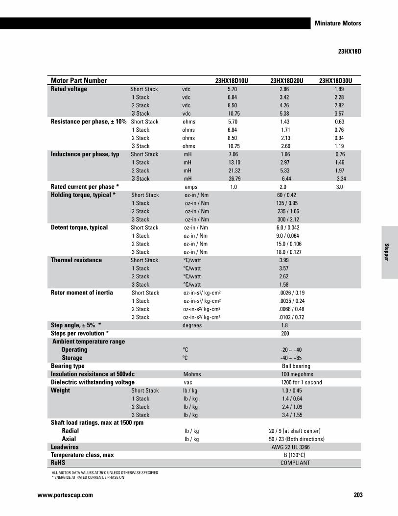
Miniature Motors
203www.portescap.com
23HX18D
Motor Part Number 23HX18D10B 23HX18D20B 23HX18D30BRated voltage Short Stack vdc 5.70 2.86 1.89 1 Stack vdc 6.84 3.42 2.28 2 Stack vdc 8.50 4.26 2.82 3 Stack vdc 10.75 5.38 3.57Resistance per phase, ± 10% Short Stack ohms 5.70 1.43 0.63 1 Stack ohms 6.84 1.71 0.76 2 Stack ohms 8.50 2.13 0.94 3 Stack ohms 10.75 2.69 1.19Inductance per phase, typ Short Stack mH 11.15 2.66 1.21 1 Stack mH 25.56 6.10 2.78 2 Stack mH 34.28 8.33 3.92 3 Stack mH 43.52 13.35 4.99Rated current per phase * amps 1.0 2.0 3.0Holding torque, typical * Short Stack oz-in / Nm 75 / 0.53 1 Stack oz-in / Nm 180 / 1.27 2 Stack oz-in / Nm 330 / 2.33 3 Stack oz-in / Nm 400 / 2.82Detent torque, typical Short Stack oz-in / Nm 6.0 / 0.042 1 Stack oz-in / Nm 9.0 / 0.064 2 Stack oz-in / Nm 15.0 / 0.106 3 Stack oz-in / Nm 18.0 / 0.127Thermal resistance Short Stack ºC/watt 3.99 1 Stack ºC/watt 3.57 2 Stack ºC/watt 2.62 3 Stack ºC/watt 1.58Rotor moment of inertia Short Stack oz-in-s2/ kg-cm2 .0026 / 0.19 1 Stack oz-in-s2/ kg-cm2 .0035 / 0.24 2 Stack oz-in-s2/ kg-cm2 .0068 / 0.48 3 Stack oz-in-s2/ kg-cm2 .0102 / 0.72Step angle, ± 5% * degrees 1.8 Steps per revolution * 200 Ambient temperature range Operating ºC -20 ~ +40 Storage ºC -40 ~ +85 Bearing type Ball bearing Insulation resisitance at 500vdc Mohms 100 megohmsDielectric withstanding voltage vac 1200 for 1 secondWeight Short Stack lb / kg 1.0 / 0.45 1 Stack lb / kg 1.4 / 0.64 2 Stack lb / kg 2.4 / 1.09 3 Stack lb / kg 3.4 / 1.55Shaft load ratings, max at 1500 rpm Radial lb / kg 20 / 9 (at shaft center) Axial lb / kg 50 / 23 (Both directions)Leadwires AWG 22 UL 3266Temperature class, max B (130°C)RoHS COMPLIANT
ALL MOTOR DATA VALUES AT 25ºC UNLESS OTHERWISE SPECIFIED* ENERGISE AT RATED CURRENT, 2 PHASE ON
Motor Part Number 23HX18D10U 23HX18D20U 23HX18D30URated voltage Short Stack vdc 5.70 2.86 1.89 1 Stack vdc 6.84 3.42 2.28 2 Stack vdc 8.50 4.26 2.82 3 Stack vdc 10.75 5.38 3.57Resistance per phase, ± 10% Short Stack ohms 5.70 1.43 0.63 1 Stack ohms 6.84 1.71 0.76 2 Stack ohms 8.50 2.13 0.94 3 Stack ohms 10.75 2.69 1.19Inductance per phase, typ Short Stack mH 7.06 1.66 0.76 1 Stack mH 13.10 2.97 1.46 2 Stack mH 21.32 5.33 1.97 3 Stack mH 26.79 6.44 3.34Rated current per phase * amps 1.0 2.0 3.0Holding torque, typical * Short Stack oz-in / Nm 60 / 0.42 1 Stack oz-in / Nm 135 / 0.95 2 Stack oz-in / Nm 235 / 1.66 3 Stack oz-in / Nm 300 / 2.12Detent torque, typical Short Stack oz-in / Nm 6.0 / 0.042 1 Stack oz-in / Nm 9.0 / 0.064 2 Stack oz-in / Nm 15.0 / 0.106 3 Stack oz-in / Nm 18.0 / 0.127Thermal resistance Short Stack ºC/watt 3.99 1 Stack ºC/watt 3.57 2 Stack ºC/watt 2.62 3 Stack ºC/watt 1.58Rotor moment of inertia Short Stack oz-in-s2/ kg-cm2 .0026 / 0.19 1 Stack oz-in-s2/ kg-cm2 .0035 / 0.24 2 Stack oz-in-s2/ kg-cm2 .0068 / 0.48 3 Stack oz-in-s2/ kg-cm2 .0102 / 0.72Step angle, ± 5% * degrees 1.8 Steps per revolution * 200 Ambient temperature range Operating ºC -20 ~ +40 Storage ºC -40 ~ +85 Bearing type Ball bearing Insulation resisitance at 500vdc Mohms 100 megohmsDielectric withstanding voltage vac 1200 for 1 secondWeight Short Stack lb / kg 1.0 / 0.45 1 Stack lb / kg 1.4 / 0.64 2 Stack lb / kg 2.4 / 1.09 3 Stack lb / kg 3.4 / 1.55Shaft load ratings, max at 1500 rpm Radial lb / kg 20 / 9 (at shaft center) Axial lb / kg 50 / 23 (Both directions)Leadwires AWG 22 UL 3266Temperature class, max B (130°C)RoHS COMPLIANT
Stepper
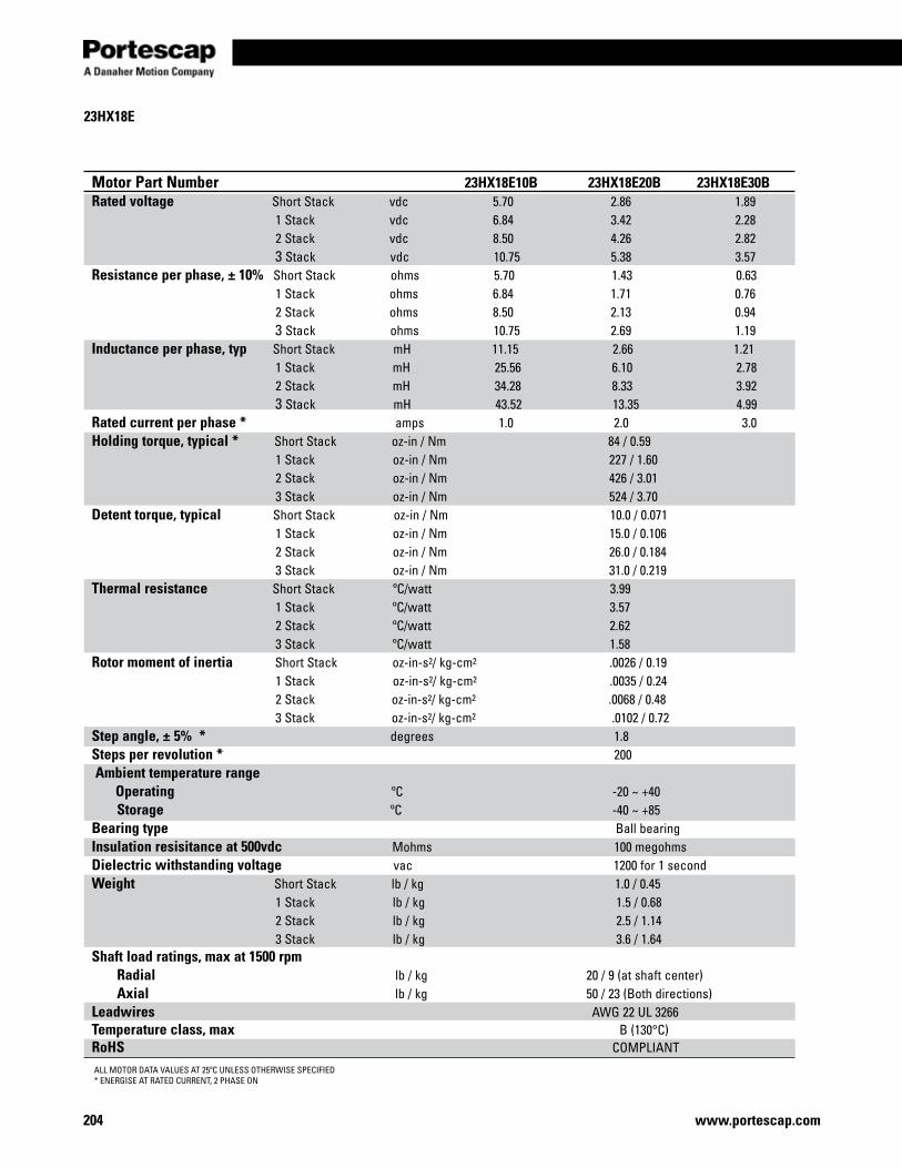
www.portescap.com204
23HX18E
ALL MOTOR DATA VALUES AT 25ºC UNLESS OTHERWISE SPECIFIED* ENERGISE AT RATED CURRENT, 2 PHASE ON
Motor Part Number 23HX18E10B 23HX18E20B 23HX18E30BRated voltage Short Stack vdc 5.70 2.86 1.89 1 Stack vdc 6.84 3.42 2.28 2 Stack vdc 8.50 4.26 2.82 3 Stack vdc 10.75 5.38 3.57Resistance per phase, ± 10% Short Stack ohms 5.70 1.43 0.63 1 Stack ohms 6.84 1.71 0.76 2 Stack ohms 8.50 2.13 0.94 3 Stack ohms 10.75 2.69 1.19Inductance per phase, typ Short Stack mH 11.15 2.66 1.21 1 Stack mH 25.56 6.10 2.78 2 Stack mH 34.28 8.33 3.92 3 Stack mH 43.52 13.35 4.99Rated current per phase * amps 1.0 2.0 3.0Holding torque, typical * Short Stack oz-in / Nm 84 / 0.59 1 Stack oz-in / Nm 227 / 1.60 2 Stack oz-in / Nm 426 / 3.01 3 Stack oz-in / Nm 524 / 3.70Detent torque, typical Short Stack oz-in / Nm 10.0 / 0.071 1 Stack oz-in / Nm 15.0 / 0.106 2 Stack oz-in / Nm 26.0 / 0.184 3 Stack oz-in / Nm 31.0 / 0.219Thermal resistance Short Stack ºC/watt 3.99 1 Stack ºC/watt 3.57 2 Stack ºC/watt 2.62 3 Stack ºC/watt 1.58Rotor moment of inertia Short Stack oz-in-s2/ kg-cm2 .0026 / 0.19 1 Stack oz-in-s2/ kg-cm2 .0035 / 0.24 2 Stack oz-in-s2/ kg-cm2 .0068 / 0.48 3 Stack oz-in-s2/ kg-cm2 .0102 / 0.72Step angle, ± 5% * degrees 1.8 Steps per revolution * 200 Ambient temperature range Operating ºC -20 ~ +40 Storage ºC -40 ~ +85 Bearing type Ball bearing Insulation resisitance at 500vdc Mohms 100 megohmsDielectric withstanding voltage vac 1200 for 1 secondWeight Short Stack lb / kg 1.0 / 0.45 1 Stack lb / kg 1.5 / 0.68 2 Stack lb / kg 2.5 / 1.14 3 Stack lb / kg 3.6 / 1.64Shaft load ratings, max at 1500 rpm Radial lb / kg 20 / 9 (at shaft center) Axial lb / kg 50 / 23 (Both directions)Leadwires AWG 22 UL 3266Temperature class, max B (130°C)RoHS COMPLIANT
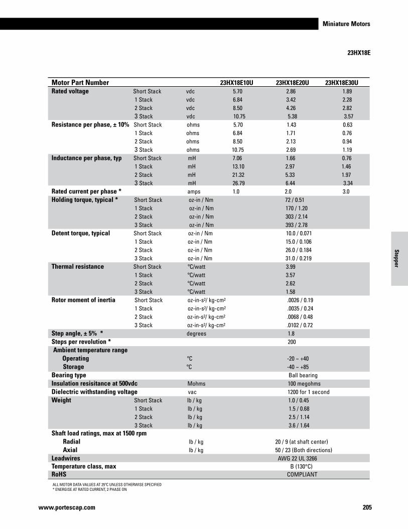
Miniature Motors
205www.portescap.com
Motor Part Number 23HX18E10B 23HX18E20B 23HX18E30BRated voltage Short Stack vdc 5.70 2.86 1.89 1 Stack vdc 6.84 3.42 2.28 2 Stack vdc 8.50 4.26 2.82 3 Stack vdc 10.75 5.38 3.57Resistance per phase, ± 10% Short Stack ohms 5.70 1.43 0.63 1 Stack ohms 6.84 1.71 0.76 2 Stack ohms 8.50 2.13 0.94 3 Stack ohms 10.75 2.69 1.19Inductance per phase, typ Short Stack mH 11.15 2.66 1.21 1 Stack mH 25.56 6.10 2.78 2 Stack mH 34.28 8.33 3.92 3 Stack mH 43.52 13.35 4.99Rated current per phase * amps 1.0 2.0 3.0Holding torque, typical * Short Stack oz-in / Nm 84 / 0.59 1 Stack oz-in / Nm 227 / 1.60 2 Stack oz-in / Nm 426 / 3.01 3 Stack oz-in / Nm 524 / 3.70Detent torque, typical Short Stack oz-in / Nm 10.0 / 0.071 1 Stack oz-in / Nm 15.0 / 0.106 2 Stack oz-in / Nm 26.0 / 0.184 3 Stack oz-in / Nm 31.0 / 0.219Thermal resistance Short Stack ºC/watt 3.99 1 Stack ºC/watt 3.57 2 Stack ºC/watt 2.62 3 Stack ºC/watt 1.58Rotor moment of inertia Short Stack oz-in-s2/ kg-cm2 .0026 / 0.19 1 Stack oz-in-s2/ kg-cm2 .0035 / 0.24 2 Stack oz-in-s2/ kg-cm2 .0068 / 0.48 3 Stack oz-in-s2/ kg-cm2 .0102 / 0.72Step angle, ± 5% * degrees 1.8 Steps per revolution * 200 Ambient temperature range Operating ºC -20 ~ +40 Storage ºC -40 ~ +85 Bearing type Ball bearing Insulation resisitance at 500vdc Mohms 100 megohmsDielectric withstanding voltage vac 1200 for 1 secondWeight Short Stack lb / kg 1.0 / 0.45 1 Stack lb / kg 1.5 / 0.68 2 Stack lb / kg 2.5 / 1.14 3 Stack lb / kg 3.6 / 1.64Shaft load ratings, max at 1500 rpm Radial lb / kg 20 / 9 (at shaft center) Axial lb / kg 50 / 23 (Both directions)Leadwires AWG 22 UL 3266Temperature class, max B (130°C)RoHS COMPLIANT
23HX18E
ALL MOTOR DATA VALUES AT 25ºC UNLESS OTHERWISE SPECIFIED* ENERGISE AT RATED CURRENT, 2 PHASE ON
Motor Part Number 23HX18E10U 23HX18E20U 23HX18E30URated voltage Short Stack vdc 5.70 2.86 1.89 1 Stack vdc 6.84 3.42 2.28 2 Stack vdc 8.50 4.26 2.82 3 Stack vdc 10.75 5.38 3.57Resistance per phase, ± 10% Short Stack ohms 5.70 1.43 0.63 1 Stack ohms 6.84 1.71 0.76 2 Stack ohms 8.50 2.13 0.94 3 Stack ohms 10.75 2.69 1.19Inductance per phase, typ Short Stack mH 7.06 1.66 0.76 1 Stack mH 13.10 2.97 1.46 2 Stack mH 21.32 5.33 1.97 3 Stack mH 26.79 6.44 3.34Rated current per phase * amps 1.0 2.0 3.0Holding torque, typical * Short Stack oz-in / Nm 72 / 0.51 1 Stack oz-in / Nm 170 / 1.20 2 Stack oz-in / Nm 303 / 2.14 3 Stack oz-in / Nm 393 / 2.78Detent torque, typical Short Stack oz-in / Nm 10.0 / 0.071 1 Stack oz-in / Nm 15.0 / 0.106 2 Stack oz-in / Nm 26.0 / 0.184 3 Stack oz-in / Nm 31.0 / 0.219Thermal resistance Short Stack ºC/watt 3.99 1 Stack ºC/watt 3.57 2 Stack ºC/watt 2.62 3 Stack ºC/watt 1.58Rotor moment of inertia Short Stack oz-in-s2/ kg-cm2 .0026 / 0.19 1 Stack oz-in-s2/ kg-cm2 .0035 / 0.24 2 Stack oz-in-s2/ kg-cm2 .0068 / 0.48 3 Stack oz-in-s2/ kg-cm2 .0102 / 0.72Step angle, ± 5% * degrees 1.8 Steps per revolution * 200 Ambient temperature range Operating ºC -20 ~ +40 Storage ºC -40 ~ +85 Bearing type Ball bearing Insulation resisitance at 500vdc Mohms 100 megohmsDielectric withstanding voltage vac 1200 for 1 secondWeight Short Stack lb / kg 1.0 / 0.45 1 Stack lb / kg 1.5 / 0.68 2 Stack lb / kg 2.5 / 1.14 3 Stack lb / kg 3.6 / 1.64Shaft load ratings, max at 1500 rpm Radial lb / kg 20 / 9 (at shaft center) Axial lb / kg 50 / 23 (Both directions)Leadwires AWG 22 UL 3266Temperature class, max B (130°C)RoHS COMPLIANT
Stepper
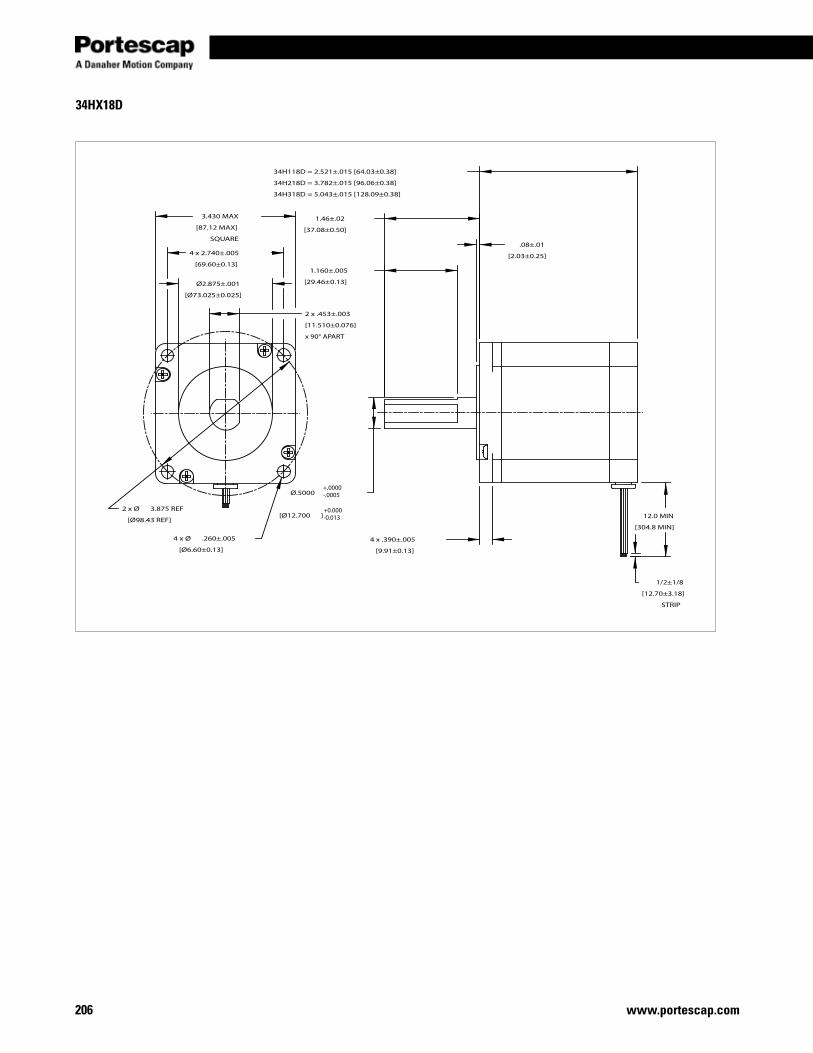
www.portescap.com206
34HX18D
3.430 MAX
[87.12 MAX]
SQUARE
4 x 2.740±.005
[69.60±0.13]
Ø2.875±.001
[Ø73.025±0.025]
4 x Ø .260±.005
[Ø6.60±0.13]
2 x Ø 3.875 REF
[Ø98.43 REF]
34H118D = 2.521±.015 [64.03±0.38]
34H218D = 3.782±.015 [96.06±0.38]
34H318D = 5.043±.015 [128.09±0.38]
.08±.01
[2.03±0.25]
4 x .390±.005
[9.91±0.13]
12.0 MIN
[304.8 MIN]
1/2±1/8
[12.70±3.18]
STRIP
1.46±.02
[37.08±0.50]
Ø.5000
[Ø12.700 ]
1.160±.005
[29.46±0.13]
2 x .453±.003
[11.510±0.076]
x 90° APART
+.0000-.0005
+0.000-0.013
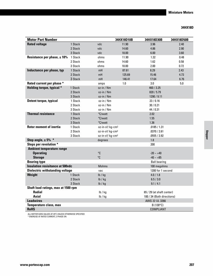
Miniature Motors
207www.portescap.com
ALL MOTOR DATA VALUES AT 25ºC UNLESS OTHERWISE SPECIFIED* ENERGISE AT RATED CURRENT, 2 PHASE ON
Motor Part Number 34HX18D10B 34HX18D30B 34HX18D50BRated voltage 1 Stack vdc 11.90 3.96 2.40 2 Stack vdc 14.60 4.86 2.90 3 Stack vdc 18.00 6.00 3.60Resistance per phase, ± 10% 1 Stack ohms 11.90 1.32 0.48 2 Stack ohms 14.60 1.62 0.58 3 Stack ohms 18.00 2.00 0.72Inductance per phase, typ 1 Stack mH 87.61 8.29 2.43 2 Stack mH 125.69 15.46 4.73 3 Stack mH 146.41 17.64 6.76Rated current per phase * amps 1.0 3.0 5.0Holding torque, typical * 1 Stack oz-in / Nm 460 / 3.25 2 Stack oz-in / Nm 820 / 5.79 3 Stack oz-in / Nm 1290 / 9.11Detent torque, typical 1 Stack oz-in / Nm 23 / 0.16 2 Stack oz-in / Nm 30 / 0.21 3 Stack oz-in / Nm 44 / 0.31Thermal resistance 1 Stack ºC/watt 2.02 2 Stack ºC/watt 1.55 3 Stack ºC/watt 1.36Rotor moment of inertia 1 Stack oz-in-s2/ kg-cm2 .0185 / 1.31 2 Stack oz-in-s2/ kg-cm2 .0370 / 2.61 3 Stack oz-in-s2/ kg-cm2 .0555 / 3.92Step angle, ± 5% * degrees 1.8 Steps per revolution * 200 Ambient temperature range Operating ºC -20 ~ +40 Storage ºC -40 ~ +85 Bearing type Ball bearing Insulation resisitance at 500vdc Mohms 100 megohmsDielectric withstanding voltage vac 1200 for 1 secondWeight 1 Stack lb / kg 4.0 / 1.8 2 Stack lb / kg 6.5 / 3.0 3 Stack lb / kg 9.1 / 4.1Shaft load ratings, max at 1500 rpm Radial lb / kg 65 / 29 (at shaft center) Axial lb / kg 100 / 34 (Both directions)Leadwires AWG 22 UL 3266Temperature class, max B (130°C)RoHS COMPLIANT
34HX18D
Stepper
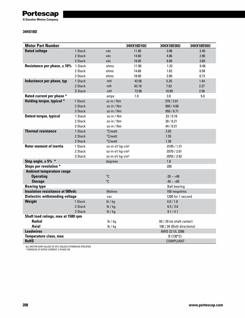
www.portescap.com208
34HX18D
ALL MOTOR DATA VALUES AT 25ºC UNLESS OTHERWISE SPECIFIED* ENERGISE AT RATED CURRENT, 2 PHASE ON
Motor Part Number 34HX18D10U 34HX18D30U 34HX18D50URated voltage 1 Stack vdc 11.90 3.96 2.40 2 Stack vdc 14.60 4.86 2.90 3 Stack vdc 18.00 6.00 3.60Resistance per phase, ± 10% 1 Stack ohms 11.90 1.32 0.48 2 Stack ohms 14.60 1.62 0.58 3 Stack ohms 18.00 2.00 0.72Inductance per phase, typ 1 Stack mH 43.56 5.20 1.44 2 Stack mH 63.18 7.62 2.27 3 Stack mH 73.96 10.89 2.56Rated current per phase * amps 1.0 3.0 5.0Holding torque, typical * 1 Stack oz-in / Nm 370 / 2.61 2 Stack oz-in / Nm 660 / 4.66 3 Stack oz-in / Nm 950 / 6.71Detent torque, typical 1 Stack oz-in / Nm 23 / 0.16 2 Stack oz-in / Nm 30 / 0.21 3 Stack oz-in / Nm 44 / 0.31Thermal resistance 1 Stack ºC/watt 2.02 2 Stack ºC/watt 1.55 3 Stack ºC/watt 1.36Rotor moment of inertia 1 Stack oz-in-s2/ kg-cm2 .0185 / 1.31 2 Stack oz-in-s2/ kg-cm2 .0370 / 2.61 3 Stack oz-in-s2/ kg-cm2 .0555 / 3.92Step angle, ± 5% * degrees 1.8 Steps per revolution * 200 Ambient temperature range Operating ºC -20 ~ +40 Storage ºC -40 ~ +85 Bearing type Ball bearing Insulation resisitance at 500vdc Mohms 100 megohmsDielectric withstanding voltage vac 1200 for 1 secondWeight 1 Stack lb / kg 4.0 / 1.8 2 Stack lb / kg 6.5 / 3.0 3 Stack lb / kg 9.1 / 4.1Shaft load ratings, max at 1500 rpm Radial lb / kg 65 / 29 (at shaft center) Axial lb / kg 100 / 34 (Both directions)Leadwires AWG 22 UL 3266Temperature class, max B (130°C)RoHS COMPLIANT
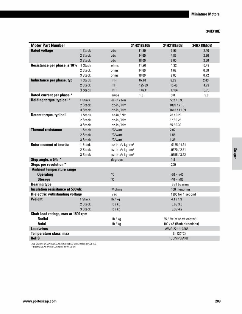
Miniature Motors
209www.portescap.com
34HX18E
Motor Part Number 34HX18D10U 34HX18D30U 34HX18D50URated voltage 1 Stack vdc 11.90 3.96 2.40 2 Stack vdc 14.60 4.86 2.90 3 Stack vdc 18.00 6.00 3.60Resistance per phase, ± 10% 1 Stack ohms 11.90 1.32 0.48 2 Stack ohms 14.60 1.62 0.58 3 Stack ohms 18.00 2.00 0.72Inductance per phase, typ 1 Stack mH 43.56 5.20 1.44 2 Stack mH 63.18 7.62 2.27 3 Stack mH 73.96 10.89 2.56Rated current per phase * amps 1.0 3.0 5.0Holding torque, typical * 1 Stack oz-in / Nm 370 / 2.61 2 Stack oz-in / Nm 660 / 4.66 3 Stack oz-in / Nm 950 / 6.71Detent torque, typical 1 Stack oz-in / Nm 23 / 0.16 2 Stack oz-in / Nm 30 / 0.21 3 Stack oz-in / Nm 44 / 0.31Thermal resistance 1 Stack ºC/watt 2.02 2 Stack ºC/watt 1.55 3 Stack ºC/watt 1.36Rotor moment of inertia 1 Stack oz-in-s2/ kg-cm2 .0185 / 1.31 2 Stack oz-in-s2/ kg-cm2 .0370 / 2.61 3 Stack oz-in-s2/ kg-cm2 .0555 / 3.92Step angle, ± 5% * degrees 1.8 Steps per revolution * 200 Ambient temperature range Operating ºC -20 ~ +40 Storage ºC -40 ~ +85 Bearing type Ball bearing Insulation resisitance at 500vdc Mohms 100 megohmsDielectric withstanding voltage vac 1200 for 1 secondWeight 1 Stack lb / kg 4.0 / 1.8 2 Stack lb / kg 6.5 / 3.0 3 Stack lb / kg 9.1 / 4.1Shaft load ratings, max at 1500 rpm Radial lb / kg 65 / 29 (at shaft center) Axial lb / kg 100 / 34 (Both directions)Leadwires AWG 22 UL 3266Temperature class, max B (130°C)RoHS COMPLIANT
ALL MOTOR DATA VALUES AT 25ºC UNLESS OTHERWISE SPECIFIED* ENERGISE AT RATED CURRENT, 2 PHASE ON
Motor Part Number 34HX18E10B 34HX18E30B 34HX18E50BRated voltage 1 Stack vdc 11.90 3.96 2.40 2 Stack vdc 14.60 4.86 2.90 3 Stack vdc 18.00 6.00 3.60Resistance per phase, ± 10% 1 Stack ohms 11.90 1.32 0.48 2 Stack ohms 14.60 1.62 0.58 3 Stack ohms 18.00 2.00 0.72Inductance per phase, typ 1 Stack mH 87.61 8.29 2.43 2 Stack mH 125.69 15.46 4.73 3 Stack mH 146.41 17.64 6.76Rated current per phase * amps 1.0 3.0 5.0Holding torque, typical * 1 Stack oz-in / Nm 552 / 3.90 2 Stack oz-in / Nm 1009 / 7.13 3 Stack oz-in / Nm 1613 / 11.39Detent torque, typical 1 Stack oz-in / Nm 28 / 0.20 2 Stack oz-in / Nm 37 / 0.26 3 Stack oz-in / Nm 55 / 0.39Thermal resistance 1 Stack ºC/watt 2.02 2 Stack ºC/watt 1.55 3 Stack ºC/watt 1.36Rotor moment of inertia 1 Stack oz-in-s2/ kg-cm2 .0185 / 1.31 2 Stack oz-in-s2/ kg-cm2 .0370 / 2.61 3 Stack oz-in-s2/ kg-cm2 .0555 / 3.92Step angle, ± 5% * degrees 1.8 Steps per revolution * 200 Ambient temperature range Operating ºC -20 ~ +40 Storage ºC -40 ~ +85 Bearing type Ball bearing Insulation resisitance at 500vdc Mohms 100 megohmsDielectric withstanding voltage vac 1200 for 1 secondWeight 1 Stack lb / kg 4.1 / 1.9 2 Stack lb / kg 6.6 / 3.0 3 Stack lb / kg 9.3 / 4.2Shaft load ratings, max at 1500 rpm Radial lb / kg 65 / 29 (at shaft center) Axial lb / kg 100 / 45 (Both directions)Leadwires AWG 22 UL 3266Temperature class, max B (130°C)RoHS COMPLIANT
Stepper
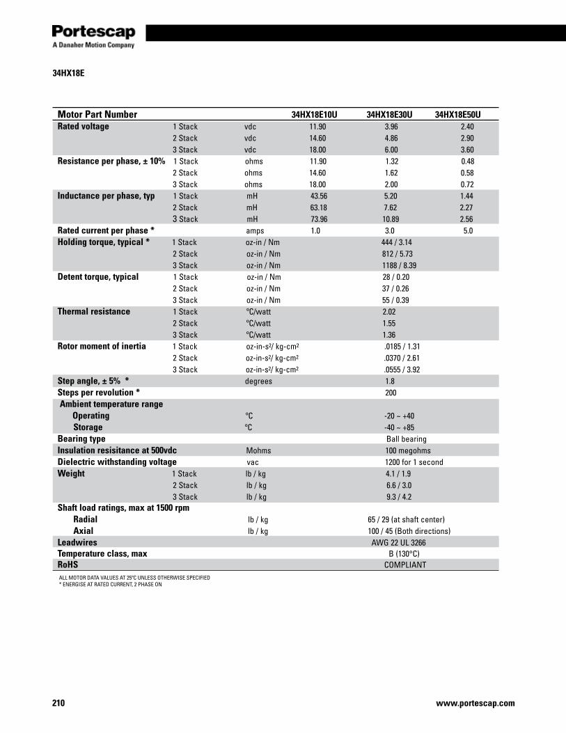
www.portescap.com210
34HX18E
ALL MOTOR DATA VALUES AT 25ºC UNLESS OTHERWISE SPECIFIED* ENERGISE AT RATED CURRENT, 2 PHASE ON
Motor Part Number 34HX18E10U 34HX18E30U 34HX18E50URated voltage 1 Stack vdc 11.90 3.96 2.40 2 Stack vdc 14.60 4.86 2.90 3 Stack vdc 18.00 6.00 3.60Resistance per phase, ± 10% 1 Stack ohms 11.90 1.32 0.48 2 Stack ohms 14.60 1.62 0.58 3 Stack ohms 18.00 2.00 0.72Inductance per phase, typ 1 Stack mH 43.56 5.20 1.44 2 Stack mH 63.18 7.62 2.27 3 Stack mH 73.96 10.89 2.56Rated current per phase * amps 1.0 3.0 5.0Holding torque, typical * 1 Stack oz-in / Nm 444 / 3.14 2 Stack oz-in / Nm 812 / 5.73 3 Stack oz-in / Nm 1188 / 8.39Detent torque, typical 1 Stack oz-in / Nm 28 / 0.20 2 Stack oz-in / Nm 37 / 0.26 3 Stack oz-in / Nm 55 / 0.39Thermal resistance 1 Stack ºC/watt 2.02 2 Stack ºC/watt 1.55 3 Stack ºC/watt 1.36Rotor moment of inertia 1 Stack oz-in-s2/ kg-cm2 .0185 / 1.31 2 Stack oz-in-s2/ kg-cm2 .0370 / 2.61 3 Stack oz-in-s2/ kg-cm2 .0555 / 3.92Step angle, ± 5% * degrees 1.8 Steps per revolution * 200 Ambient temperature range Operating ºC -20 ~ +40 Storage ºC -40 ~ +85 Bearing type Ball bearing Insulation resisitance at 500vdc Mohms 100 megohmsDielectric withstanding voltage vac 1200 for 1 secondWeight 1 Stack lb / kg 4.1 / 1.9 2 Stack lb / kg 6.6 / 3.0 3 Stack lb / kg 9.3 / 4.2Shaft load ratings, max at 1500 rpm Radial lb / kg 65 / 29 (at shaft center) Axial lb / kg 100 / 45 (Both directions)Leadwires AWG 22 UL 3266Temperature class, max B (130°C)RoHS COMPLIANT
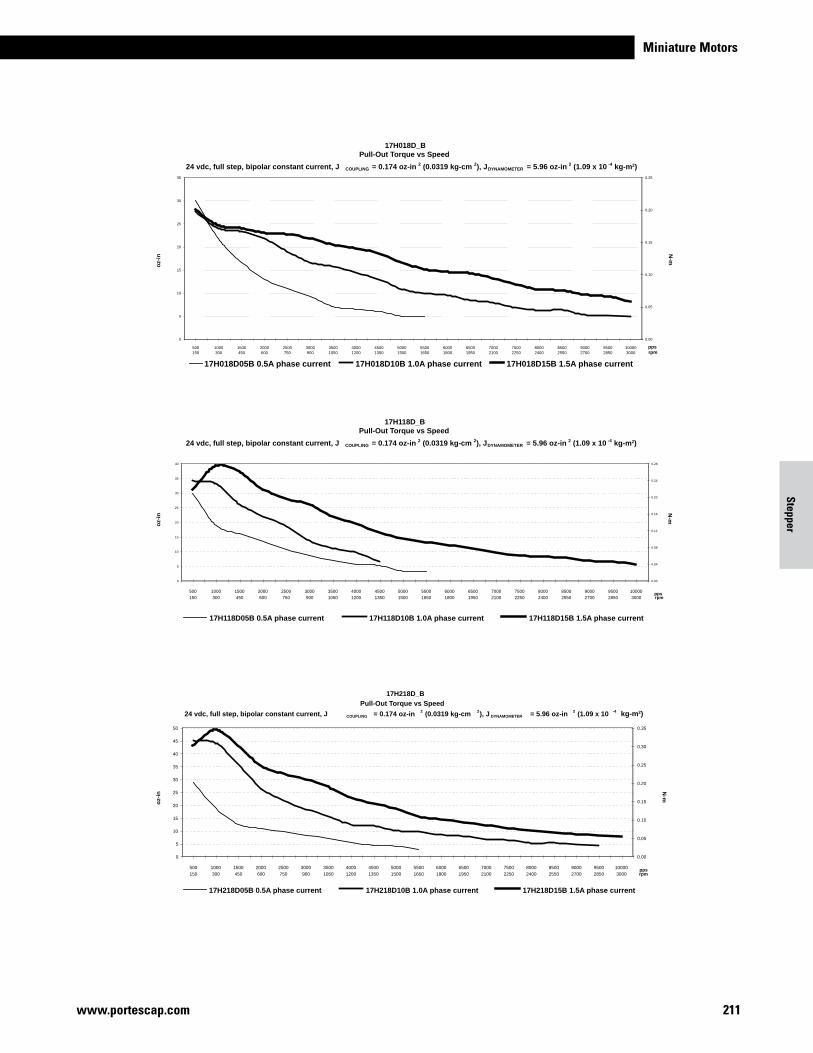
Miniature Motors
211www.portescap.com
oz-
in
N-m
17H018D_BPull-Out Torque vs Speed
24 vdc, full step, bipolar constant current, J COUPLING = 0.174 oz-in 2 (0.0319 kg-cm 2), JDYNAMOMETER = 5.96 oz-in 2 (1.09 x 10 -4 kg-m2)
0
5
10
15
20
25
30
35
500150
1000300
1500450
2000600
2500750
3000900
35001050
40001200
45001350
50001500
55001650
60001800
65001950
70002100
75002250
80002400
85002550
90002700
95002850
100003000
pps
0.00
0.05
0.10
0.15
0.20
0.25
rpm
17H018D05B 0.5A phase current 17H018D10B 1.0A phase current 17H018D15B 1.5A phase current
oz-
in
N-m
17H118D_BPull-Out Torque vs Speed
24 vdc, full step, bipolar constant current, J COUPLING = 0.174 oz-in 2 (0.0319 kg-cm 2), JDYNAMOMETER = 5.96 oz-in 2 (1.09 x 10 -4 kg-m2)
0
5
10
15
20
25
30
35
40
500
150
1000
300
1500
450
2000
600
2500
750
3000
900
3500
1050
4000
1200
4500
1350
5000
1500
5500
1650
6000
1800
6500
1950
7000
2100
7500
2250
8000
2400
8500
2550
9000
2700
9500
2850
10000
3000pps
0.00
0.04
0.08
0.12
0.16
0.20
0.24
0.28
rpm
17H118D05B 0.5A phase current 17H118D10B 1.0A phase current 17H118D15B 1.5A phase current
oz-
in
N-m
17H218D_B
Pull-Out Torque vs Speed
24 vdc, full step, bipolar constant current, J COUPLING = 0.174 oz-in 2 (0.0319 kg-cm 2), J DYNAMOMETER = 5.96 oz-in 2 (1.09 x 10 -4
0
5
10
15
20
25
30
35
40
45
50
500
150
1000
300
1500
450
2000
600
2500
750
3000
900
3500
1050
4000
1200
4500
1350
5000
1500
5500
1650
6000
1800
6500
1950
7000
2100
7500
2250
8000
2400
8500
2550
9000
2700
9500
2850
10000
3000pps
0.00
0.05
0.10
0.15
0.20
0.25
0.30
0.35
rpm
17H218D05B 0.5A phase current 17H218D10B 1.0A phase current 17H218D15B 1.5A phase current
kg-m2)
Motor Part Number 34HX18E10U 34HX18E30U 34HX18E50URated voltage 1 Stack vdc 11.90 3.96 2.40 2 Stack vdc 14.60 4.86 2.90 3 Stack vdc 18.00 6.00 3.60Resistance per phase, ± 10% 1 Stack ohms 11.90 1.32 0.48 2 Stack ohms 14.60 1.62 0.58 3 Stack ohms 18.00 2.00 0.72Inductance per phase, typ 1 Stack mH 43.56 5.20 1.44 2 Stack mH 63.18 7.62 2.27 3 Stack mH 73.96 10.89 2.56Rated current per phase * amps 1.0 3.0 5.0Holding torque, typical * 1 Stack oz-in / Nm 444 / 3.14 2 Stack oz-in / Nm 812 / 5.73 3 Stack oz-in / Nm 1188 / 8.39Detent torque, typical 1 Stack oz-in / Nm 28 / 0.20 2 Stack oz-in / Nm 37 / 0.26 3 Stack oz-in / Nm 55 / 0.39Thermal resistance 1 Stack ºC/watt 2.02 2 Stack ºC/watt 1.55 3 Stack ºC/watt 1.36Rotor moment of inertia 1 Stack oz-in-s2/ kg-cm2 .0185 / 1.31 2 Stack oz-in-s2/ kg-cm2 .0370 / 2.61 3 Stack oz-in-s2/ kg-cm2 .0555 / 3.92Step angle, ± 5% * degrees 1.8 Steps per revolution * 200 Ambient temperature range Operating ºC -20 ~ +40 Storage ºC -40 ~ +85 Bearing type Ball bearing Insulation resisitance at 500vdc Mohms 100 megohmsDielectric withstanding voltage vac 1200 for 1 secondWeight 1 Stack lb / kg 4.1 / 1.9 2 Stack lb / kg 6.6 / 3.0 3 Stack lb / kg 9.3 / 4.2Shaft load ratings, max at 1500 rpm Radial lb / kg 65 / 29 (at shaft center) Axial lb / kg 100 / 45 (Both directions)Leadwires AWG 22 UL 3266Temperature class, max B (130°C)RoHS COMPLIANT
Stepper
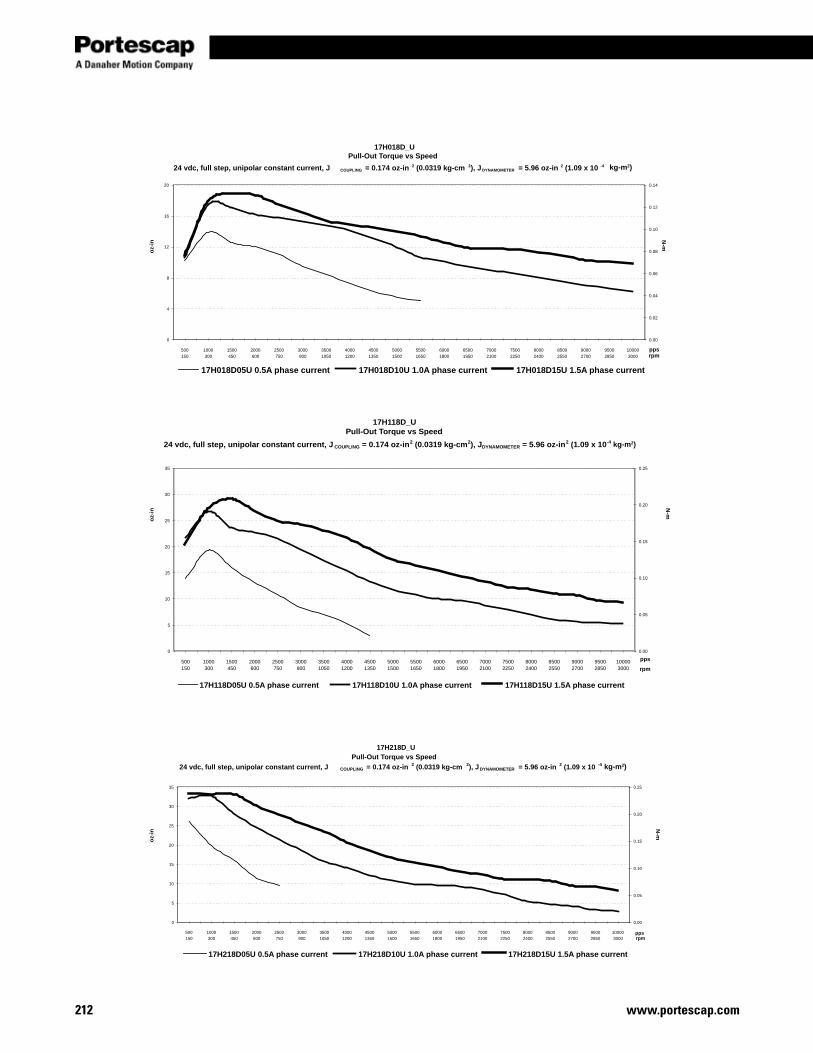
www.portescap.com212
oz-
inN
-m
kg-m2)
17H018D_UPull-Out Torque vs Speed
24 vdc, full step, unipolar constant current, J COUPLING = 0.174 oz-in 2 (0.0319 kg-cm 2), JDYNAMOMETER = 5.96 oz-in 2 (1.09 x 10 -4
0
4
8
12
16
20
500
150
1000
300
1500
450
2000
600
2500
750
3000
900
3500
1050
4000
1200
4500
1350
5000
1500
5500
1650
6000
1800
6500
1950
7000
2100
7500
2250
8000
2400
8500
2550
9000
2700
9500
2850
10000
3000
pps
0.00
0.02
0.04
0.06
0.08
0.10
0.12
0.14
rpm
17H018D05U 0.5A phase current 17H018D10U 1.0A phase current 17H018D15U 1.5A phase current
oz-
inN
-m
kg-m2)
17H118D_UPull-Out Torque vs Speed
24 vdc, full step, unipolar constant current, J COUPLING = 0.174 oz-in2 (0.0319 kg-cm2), JDYNAMOMETER = 5.96 oz-in2 (1.09 x 10⁻⁴
0
5
10
15
20
25
30
35
500150
1000300
1500450
2000600
2500750
3000900
35001050
40001200
45001350
50001500
55001650
60001800
65001950
70002100
75002250
80002400
85002550
90002700
95002850
100003000
pps
0.00
0.05
0.10
0.15
0.20
0.25
rpm
17H118D05U 0.5A phase current 17H118D10U 1.0A phase current 17H118D15U 1.5A phase current
oz-
inN
-m
kg-m2)
17H218D_UPull-Out Torque vs Speed
24 vdc, full step, unipolar constant current, J COUPLING = 0.174 oz-in 2 (0.0319 kg-cm 2), J DYNAMOMETER = 5.96 oz-in 2 (1.09 x 10 -4
0
5
10
15
20
25
30
35
500
150
1000
300
1500
450
2000
600
2500
750
3000
900
3500
1050
4000
1200
4500
1350
5000
1500
5500
1650
6000
1800
6500
1950
7000
2100
7500
2250
8000
2400
8500
2550
9000
2700
9500
2850
10000
3000pps
0.00
0.05
0.10
0.15
0.20
0.25
rpm
17H218D05U 0.5A phase current 17H218D10U 1.0A phase current 17H218D15U 1.5A phase current
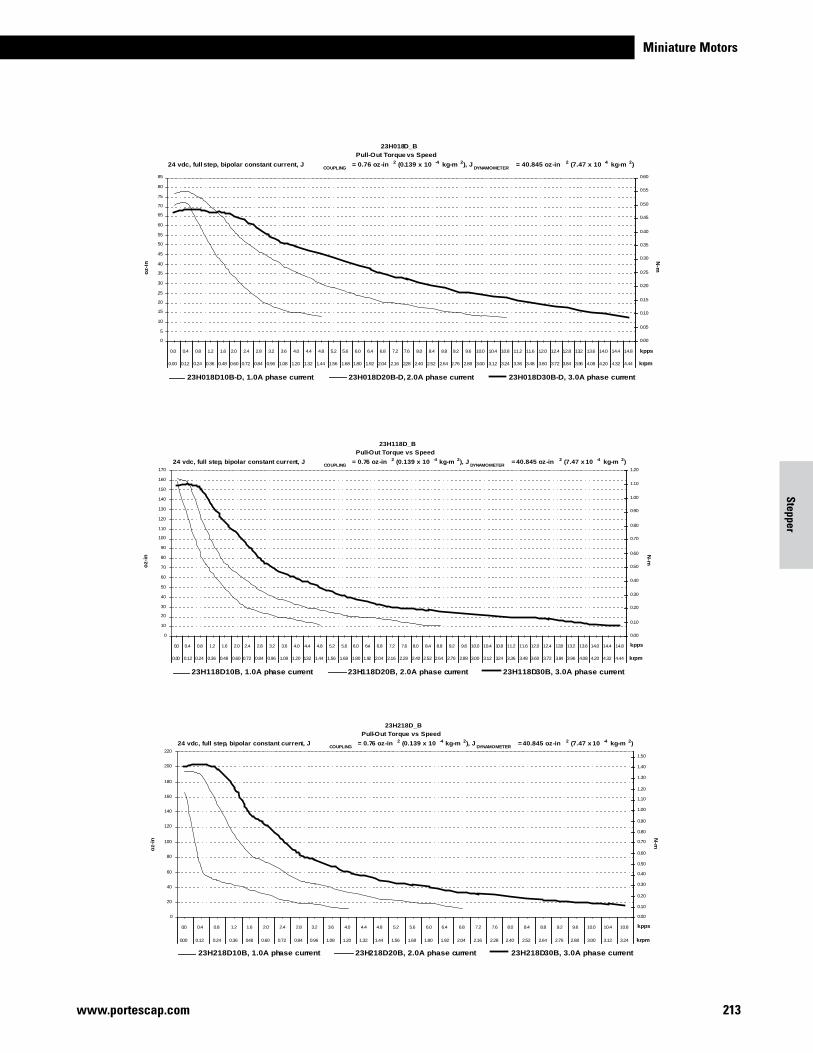
Miniature Motors
213www.portescap.com
Stepper
oz-
inN
-m
23H218D_B
Pull-Out Torque vs Speed
24 vdc, full step, bipolar constant current, JCOUPLING
= 0.76 oz-in 2 (0.139 x 10 -4 kg-m 2), JDYNAMOMETER
= 40.845 oz-in 2 (7.47 x 10 -4 kg-m 2)
0
20
40
60
80
100
120
140
160
180
200
220
0.0 0.4 0.8 1.2 1.6 2.0 2.4 2.8 3.2 3.6 4.0 4.4 4.8 5.2 5.6 6.0 6.4 6.8 7.2 7.6 8.0 8.4 8.8 9.2 9.6 10.0 10.4 10.8
0.00 0.12 0.24 0.36 0.48 0.60 0.72 0.84 0.96 1.08 1.20 1.32 1.44 1.56 1.68 1.80 1.92 2.04 2.16 2.28 2.40 2.52 2.64 2.76 2.88 3.00 3.12 3.24
kpps
0.00
0.10
0.20
0.30
0.40
0.50
0.60
0.70
0.80
0.90
1.00
1.10
1.20
1.30
1.40
1.50
krpm
23H218D10B, 1.0A phase current 23H218D20B, 2.0A phase current 23H218D30B, 3.0A phase current
oz-
in
N-m
23H018D_B
Pull-Out Torque vs Speed
24 vdc, full step, bipolar constant current, JCOUPLING
= 0.76 oz-in 2 (0.139 x 10 -4 kg-m 2), JDYNAMOMETER
= 40.845 oz-in 2 (7.47 x 10 -4 kg-m 2)
0
5
10
15
20
25
30
35
40
45
50
55
60
65
70
75
80
85
0.0 0.4 0.8 1.2 1.6 2.0 2.4 2.8 3.2 3.6 4.0 4.4 4.8 5.2 5.6 6.0 6.4 6.8 7.2 7.6 8.0 8.4 8.8 9.2 9.6 10.0 10.4 10.8 11.2 11.6 12.0 12.4 12.8 13.2 13.6 14.0 14.4 14.8
0.00 0.12 0.24 0.36 0.48 0.60 0.72 0.84 0.96 1.08 1.20 1.32 1.44 1.56 1.68 1.80 1.92 2.04 2.16 2.28 2.40 2.52 2.64 2.76 2.88 3.00 3.12 3.24 3.36 3.48 3.60 3.72 3.84 3.96 4.08 4.20 4.32 4.44
kpps
0.00
0.05
0.10
0.15
0.20
0.25
0.30
0.35
0.40
0.45
0.50
0.55
0.60
krpm
23H018D10B-D, 1.0A phase current 23H018D20B-D, 2.0A phase current 23H018D30B-D, 3.0A phase current
oz-
in
N-m
23H118D_B
Pull-Out Torque vs Speed
24 vdc, full step, bipolar constant current, JCOUPLING
= 0.76 oz-in 2 (0.139 x 10 -4 kg-m 2), JDYNAMOMETER
= 40.845 oz-in 2 (7.47 x 10 -4 kg-m 2)
0
10
20
30
40
50
60
70
80
90
100
110
120
130
140
150
160
170
0.0 0.4 0.8 1.2 1.6 2.0 2.4 2.8 3.2 3.6 4.0 4.4 4.8 5.2 5.6 6.0 6.4 6.8 7.2 7.6 8.0 8.4 8.8 9.2 9.6 10.0 10.4 10.8 11.2 11.6 12.0 12.4 12.8 13.2 13.6 14.0 14.4 14.8
0.00 0.12 0.24 0.36 0.48 0.60 0.72 0.84 0.96 1.08 1.20 1.32 1.44 1.56 1.68 1.80 1.92 2.04 2.16 2.28 2.40 2.52 2.64 2.76 2.88 3.00 3.12 3.24 3.36 3.48 3.60 3.72 3.84 3.96 4.08 4.20 4.32 4.44
kpps
0.00
0.10
0.20
0.30
0.40
0.50
0.60
0.70
0.80
0.90
1.00
1.10
1.20
krpm
23H118D10B, 1.0A phase current 23H118D20B, 2.0A phase current 23H118D30B, 3.0A phase current
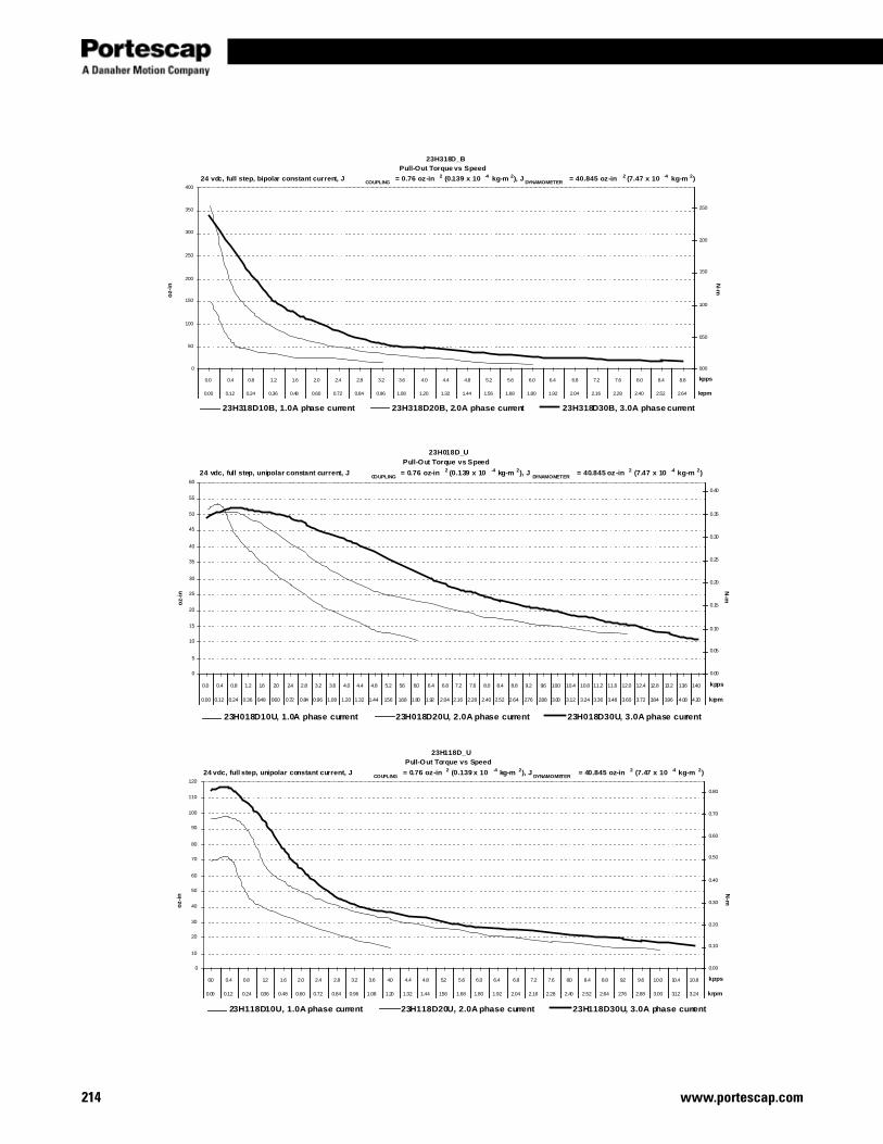
www.portescap.com214
oz-
inN
-m23H318D_B
Pull-Out Torque vs Speed
24 vdc, full step, bipolar constant current, JCOUPLING
= 0.76 oz-in 2 (0.139 x 10 -4 kg-m 2), JDYNAMOMETER
= 40.845 oz-in 2 (7.47 x 10 -4 kg-m 2)
0
50
100
150
200
250
300
350
400
0.0 0.4 0.8 1.2 1.6 2.0 2.4 2.8 3.2 3.6 4.0 4.4 4.8 5.2 5.6 6.0 6.4 6.8 7.2 7.6 8.0 8.4 8.8
0.00 0.12 0.24 0.36 0.48 0.60 0.72 0.84 0.96 1.08 1.20 1.32 1.44 1.56 1.68 1.80 1.92 2.04 2.16 2.28 2.40 2.52 2.64
kpps
0.00
0.50
1.00
1.50
2.00
2.50
krpm
23H318D10B, 1.0A phase current 23H318D20B, 2.0A phase current 23H318D30B, 3.0A phase current
oz-
in
N-m
23H018D_U
Pull-Out Torque vs Speed
24 vdc, full step, unipolar constant current, JCOUPLING
= 0.76 oz-in 2 (0.139 x 10 -4 kg-m 2), JDYNAMOMETER
= 40.845 oz-in 2 (7.47 x 10 -4 kg-m 2)
0
5
10
15
20
25
30
35
40
45
50
55
60
0.0 0.4 0.8 1.2 1.6 2.0 2.4 2.8 3.2 3.6 4.0 4.4 4.8 5.2 5.6 6.0 6.4 6.8 7.2 7.6 8.0 8.4 8.8 9.2 9.6 10.0 10.4 10.8 11.2 11.6 12.0 12.4 12.8 13.2 13.6 14.0
0.00 0.12 0.24 0.36 0.48 0.60 0.72 0.84 0.96 1.08 1.20 1.32 1.44 1.56 1.68 1.80 1.92 2.04 2.16 2.28 2.40 2.52 2.64 2.76 2.88 3.00 3.12 3.24 3.36 3.48 3.60 3.72 3.84 3.96 4.08 4.20
kpps
0.00
0.05
0.10
0.15
0.20
0.25
0.30
0.35
0.40
krpm
23H018D10U, 1.0A phase current 23H018D20U, 2.0A phase current 23H018D30U, 3.0A phase current
oz-
in
N-m
23H118D_U
Pull-Out Torque vs Speed
24 vdc, full step, unipolar constant current, JCOUPLING
= 0.76 oz-in 2 (0.139 x 10 -4 kg-m 2), JDYNAMOMETER
= 40.845 oz-in 2 (7.47 x 10 -4 kg-m 2)
0
10
20
30
40
50
60
70
80
90
100
110
120
0.0 0.4 0.8 1.2 1.6 2.0 2.4 2.8 3.2 3.6 4.0 4.4 4.8 5.2 5.6 6.0 6.4 6.8 7.2 7.6 8.0 8.4 8.8 9.2 9.6 10.0 10.4 10.8
0.00 0.12 0.24 0.36 0.48 0.60 0.72 0.84 0.96 1.08 1.20 1.32 1.44 1.56 1.68 1.80 1.92 2.04 2.16 2.28 2.40 2.52 2.64 2.76 2.88 3.00 3.12 3.24
kpps
0.00
0.10
0.20
0.30
0.40
0.50
0.60
0.70
0.80
krpm
23H118D10U, 1.0A phase current 23H118D20U, 2.0A phase current 23H118D30U, 3.0A phase current
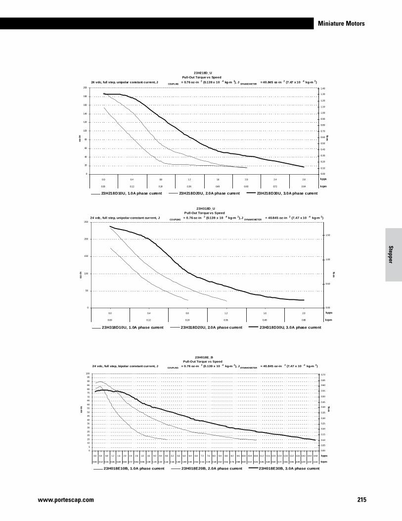
Miniature Motors
215www.portescap.com
Stepper
oz-
in
N-m
23H218D_U
Pull-Out Torque vs Speed
24 vdc, full step, unipolar constant current, JCOUPLING
= 0.76 oz-in 2 (0.139 x 10 -4 kg-m 2), JDYNAMOMETER
= 40.845 oz-in 2 (7.47 x 10 -4 kg-m 2)
0
20
40
60
80
100
120
140
160
180
200
0.0 0.4 0.8 1.2 1.6 2.0 2.4 2.8
0.00 0.12 0.24 0.36 0.48 0.60 0.72 0.84
kpps
0.00
0.10
0.20
0.30
0.40
0.50
0.60
0.70
0.80
0.90
1.00
1.10
1.20
1.30
1.40
krpm
23H218D10U, 1.0A phase current 23H218D20U, 2.0A phase current 23H218D30U, 3.0A phase current
oz-
in
N-m
23H318D_U
Pull-Out Torque vs Speed
24 vdc, full step, unipolar constant current, JCOUPLING
= 0.76 oz-in 2 (0.139 x 10 -4 kg-m 2), JDYNAMOMETER
= 40.845 oz-in 2 (7.47 x 10 -4 kg-m 2)
0
50
100
150
200
250
0.0 0.4 0.8 1.2 1.6 2.0
0.00 0.12 0.24 0.36 0.48 0.60
kpps
0.00
0.50
1.00
1.50
krpm
23H318D10U, 1.0A phase current 23H318D20U, 2.0A phase current 23H318D30U, 3.0A phase current
oz-
in
N-m
23H018E_B
Pull-Out Torque vs Speed
24 vdc, full step, bipolar constant current, JCOUPLING
= 0.76 oz-in 2 (0.139 x 10 -4 kg-m 2), JDYNAMOMETER
= 40.845 oz-in 2 (7.47 x 10 -4 kg-m 2)
0
5
10
15
20
25
30
35
40
45
50
55
60
65
70
75
80
85
90
95
100
0.0 0.4 0.8 1.2 1.6 2.0 2.4 2.8 3.2 3.6 4.0 4.4 4.8 5.2 5.6 6.0 6.4 6.8 7.2 7.6 8.0 8.4 8.8 9.2 9.6 10.0 10.4 10.8 11.2 11.6 12.0 12.4 12.8 13.2 13.6 14.0 14.4 14.8
0.00 0.12 0.24 0.36 0.48 0.60 0.72 0.84 0.96 1.08 1.20 1.32 1.44 1.56 1.68 1.80 1.92 2.04 2.16 2.28 2.40 2.52 2.64 2.76 2.88 3.00 3.12 3.24 3.36 3.48 3.60 3.72 3.84 3.96 4.08 4.20 4.32 4.44
kpps
0.00
0.05
0.10
0.15
0.20
0.25
0.30
0.35
0.40
0.45
0.50
0.55
0.60
0.65
0.70
krpm
23H018E10B, 1.0A phase current 23H018E20B, 2.0A phase current 23H018E30B, 3.0A phase current
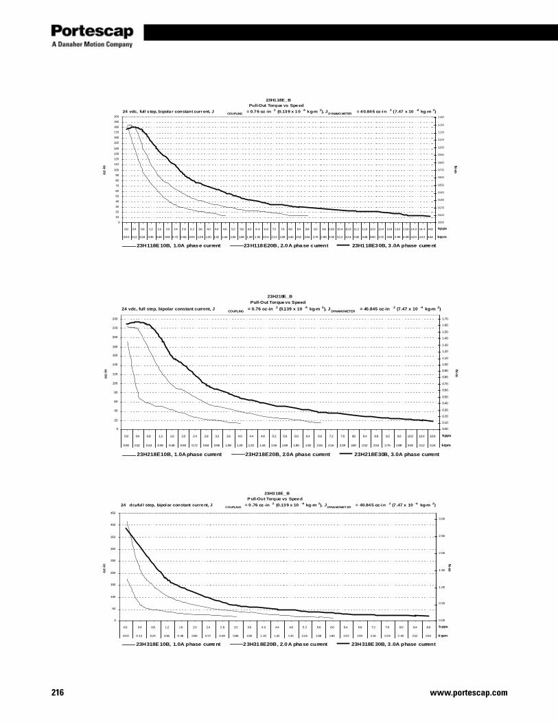
www.portescap.com216
oz-
inN
-m23H118E_B
Pull-Out Torque vs Speed
24 vdc, full s tep, bipolar constant curr ent, JCOUPLING
= 0.76 oz -in 2 (0.139 x 10 -4 kg-m 2), JDYNAMO METER
= 40.845 oz-in 2 (7.47 x 10 -4 kg-m 2)
0
10
20
30
40
50
60
70
80
90
100
110
120
130
140
150
160
170
180
190
200
0.0 0.4 0.8 1.2 1.6 2.0 2.4 2.8 3.2 3.6 4.0 4.4 4.8 5.2 5.6 6.0 6.4 6.8 7.2 7.6 8.0 8.4 8.8 9.2 9.6 10.0 10.4 10.8 11.2 11.6 12.0 12.4 12.8 13.2 13.6 14.0 14.4 14.8
0.00 0.12 0.24 0.36 0.48 0.60 0.72 0.84 0.96 1.08 1.20 1.32 1.44 1.56 1.68 1.80 1.92 2.04 2.16 2.28 2.40 2.52 2.64 2.76 2.88 3.00 3.12 3.24 3.36 3.48 3.60 3.72 3.84 3.96 4.08 4.20 4.32 4.44
kpps
0.00
0.10
0.20
0.30
0.40
0.50
0.60
0.70
0.80
0.90
1.00
1.10
1.20
1.30
1.40
krpm
23H118E 10B, 1.0A phase current 23H118E20B, 2.0A phase current 23H118E30B, 3 .0A phase current
oz-
inN
-m
23H218E_B
Pull-Out Torque vs Speed
24 vdc, full step, bipolar constant current, JCOUPLING
= 0.76 oz-in 2 (0.139 x 10 -4 kg-m 2), JDYNAMOMETER
= 40.845 oz-in 2 (7.47 x 10 -4 kg-m 2)
0
20
40
60
80
100
120
140
160
180
200
220
240
0.0 0.4 0.8 1.2 1.6 2.0 2.4 2.8 3.2 3.6 4.0 4.4 4.8 5.2 5.6 6.0 6.4 6.8 7.2 7.6 8.0 8.4 8.8 9.2 9.6 10.0 10.4 10.8
0.00 0.12 0.24 0.36 0.48 0.60 0.72 0.84 0.96 1.08 1.20 1.32 1.44 1.56 1.68 1.80 1.92 2.04 2.16 2.28 2.40 2.52 2.64 2.76 2.88 3.00 3.12 3.24
kpps
0.00
0.10
0.20
0.30
0.40
0.50
0.60
0.70
0.80
0.90
1.00
1.10
1.20
1.30
1.40
1.50
1.60
1.70
krpm
23H218E10B, 1.0A phase current 23H218E20B, 2.0A phase current 23H218E30B, 3.0A phase current
oz-
inN
-m
23H318E_B
P ull-Out Torque vs Speed
24 vdc, ful l step, bipolar constant current, JCOUPLING
= 0 .76 oz -in 2 (0.139 x 10 -4 kg-m 2), JDYNAMOMET ER
= 40.845 oz-in 2 (7 .47 x 10 -4 kg-m 2)
0
50
100
150
200
250
300
350
400
450
0.0 0.4 0.8 1.2 1.6 2.0 2.4 2.8 3.2 3.6 4.0 4.4 4.8 5.2 5.6 6.0 6.4 6.8 7.2 7.6 8.0 8.4 8.8
0.00 0.12 0.24 0.36 0.48 0.60 0.72 0.84 0.96 1.08 1.20 1.32 1.44 1.56 1.68 1.80 1.92 2.04 2.16 2.28 2.40 2.52 2.64
kpps
0.00
0.50
1.00
1.50
2.00
2.50
3.00
krpm
23H318E 10B, 1.0A phase current 23H318E20B, 2.0A phase current 23H318E 30B, 3 .0A phase current
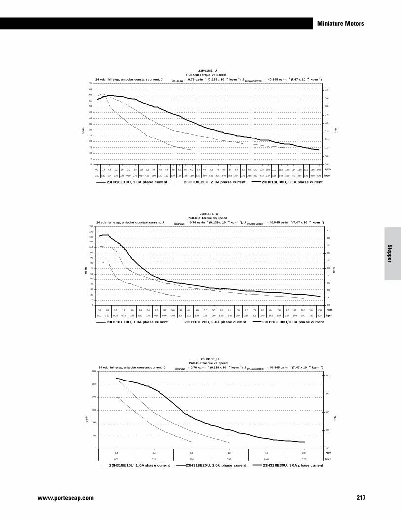
Miniature Motors
217www.portescap.com
Stepper
oz-
in
N-m
23H018 E_U
Pull-Out Torque vs Speed
24 vdc, full step, unipolar constant current, JCOUPLING
= 0.76 oz-in 2 (0 .139 x 10 -4 kg-m 2), JDYNAMOMETER
= 40.845 oz-in 2 (7.47 x 10 -4 kg-m 2)
0
5
10
15
20
25
30
35
40
45
50
55
60
65
70
0.0 0.4 0.8 1.2 1.6 2.0 2.4 2.8 3.2 3.6 4.0 4.4 4.8 5.2 5.6 6.0 6.4 6.8 7.2 7.6 8.0 8.4 8.8 9.2 9.6 10.0 10.4 10.8 11.2 11.6 12.0 12.4 12.8 13.2 13.6 14.0
0.00 0.12 0.24 0.36 0.48 0.60 0.72 0.84 0.96 1.08 1.20 1.32 1.44 1.56 1.68 1.80 1.92 2.04 2.16 2.28 2.40 2.52 2.64 2.76 2.88 3.00 3.12 3.24 3.36 3.48 3.60 3.72 3.84 3.96 4.08 4.20
kpps
0.00
0.05
0.10
0.15
0.20
0.25
0.30
0.35
0.40
0.45
krpm
23H018E10U, 1.0A phase current 23H018E20U, 2 .0A phase current 23H018E30U, 3.0A phase current
oz-
in
N-m
2 3H118E_U
P ull-Out Torque vs Speed
24 vdc, full s tep, unipolar constant current, JCOUPLING
= 0.76 oz -in 2 (0 .139 x 10 -4 kg-m 2), JDYNAMO METER
= 40.845 oz-in 2 (7.47 x 10 -4 kg-m 2)
0
10
20
30
40
50
60
70
80
90
100
110
120
130
140
150
0.0 0.4 0.8 1.2 1.6 2.0 2.4 2.8 3.2 3.6 4.0 4.4 4.8 5.2 5.6 6.0 6.4 6.8 7.2 7.6 8.0 8.4 8.8 9.2 9.6 10.0 10.4 10.8
0.00 0.12 0.24 0.36 0.48 0.60 0.72 0.84 0.96 1.08 1.20 1.32 1.44 1.56 1.68 1.80 1.92 2.04 2.16 2.28 2.40 2.52 2.64 2.76 2.88 3.00 3.12 3.24
kpps
0.00
0.10
0.20
0.30
0.40
0.50
0.60
0.70
0.80
0.90
1.00
krpm
23H118E10U, 1.0A phase current 23H118E20U, 2 .0A phase current 23H118E 30U, 3 .0A phase current
oz-
in
N-m
23H318E_U
Pull-Out Tor que vs Speed
24 vdc , full step, unipolar constant current, JCOUPLING
= 0.76 oz-in 2 (0.139 x 10 -4 kg-m 2), JDYNAMOMETER
= 40 .845 oz -in 2 (7 .47 x 10 -4 kg-m 2)
0
50
100
150
200
250
300
0.0 0.4 0.8 1.2 1.6 2.0
0.00 0.12 0.24 0.36 0.48 0.60
kpps
0.00
0.50
1.00
1.50
2.00
krpm
23H318E 10U, 1.0A phase current 23H318E20U, 2.0A phase current 23H318E30U, 3.0A phase current
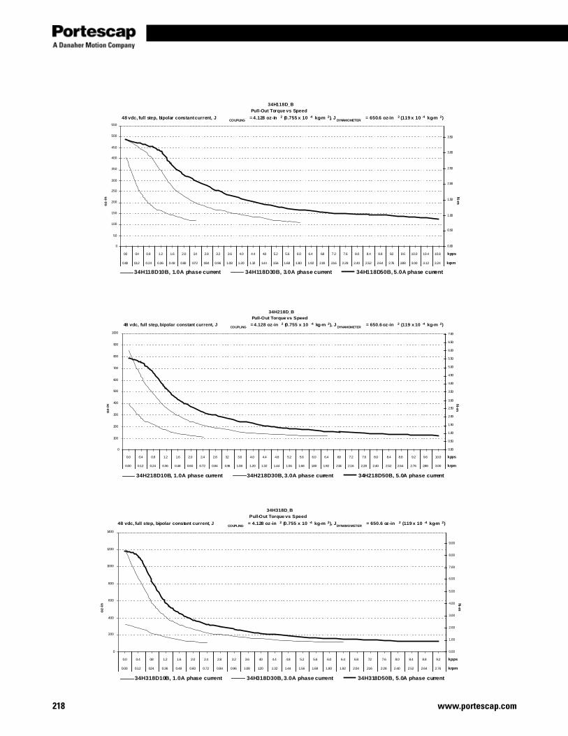
www.portescap.com218
oz-
inN
-m
34H118D_BPull-Out Torque vs Speed
48 vdc, full step, bipolar constant current, JCOUPLING
= 4.128 oz-in 2 (0.755 x 10 -4 kg-m 2), JDYNAMOMETER
= 650.6 oz-in 2 (119 x 10 -4 kg-m 2)
0
50
100
150
200
250
300
350
400
450
500
550
0.0 0.4 0.8 1.2 1.6 2.0 2.4 2.8 3.2 3.6 4.0 4.4 4.8 5.2 5.6 6.0 6.4 6.8 7.2 7.6 8.0 8.4 8.8 9.2 9.6 10.0 10.4 10.8
0.00 0.12 0.24 0.36 0.48 0.60 0.72 0.84 0.96 1.08 1.20 1.32 1.44 1.56 1.68 1.80 1.92 2.04 2.16 2.28 2.40 2.52 2.64 2.76 2.88 3.00 3.12 3.24
kpps
0.00
0.50
1.00
1.50
2.00
2.50
3.00
3.50
krpm
34H118D10B, 1.0A phase current 34H118D30B, 3.0A phase current 34H118D50B, 5.0A phase current
oz-
inN
-m
34H218D_BPull-Out Torque vs Speed
48 vdc, full step, bipolar constant current, JCOUPLING
= 4.128 oz-in 2 (0.755 x 10 -4 kg-m 2), JDYNAMOMETER
= 650.6 oz-in 2 (119 x 10 -4 kg-m 2)
0
100
200
300
400
500
600
700
800
900
1000
0.0 0.4 0.8 1.2 1.6 2.0 2.4 2.8 3.2 3.6 4.0 4.4 4.8 5.2 5.6 6.0 6.4 6.8 7.2 7.6 8.0 8.4 8.8 9.2 9.6 10.0
0.00 0.12 0.24 0.36 0.48 0.60 0.72 0.84 0.96 1.08 1.20 1.32 1.44 1.56 1.68 1.80 1.92 2.04 2.16 2.28 2.40 2.52 2.64 2.76 2.88 3.00
kpps
0.00
0.50
1.00
1.50
2.00
2.50
3.00
3.50
4.00
4.50
5.00
5.50
6.00
6.50
7.00
krpm
34H218D10B, 1.0A phase current 34H218D30B, 3.0A phase current 34H218D50B, 5.0A phase current
oz-
in
N-m
34H318D_BPull-Out Torque vs Speed
48 vdc, full step, bipolar constant current, JCOUPLING
= 4.128 oz-in 2 (0.755 x 10 -4 kg-m 2), JDYNAMOMETER
= 650.6 oz-in 2 (119 x 10 -4 kg-m 2)
0
200
400
600
800
1000
1200
1400
0.0 0.4 0.8 1.2 1.6 2.0 2.4 2.8 3.2 3.6 4.0 4.4 4.8 5.2 5.6 6.0 6.4 6.8 7.2 7.6 8.0 8.4 8.8 9.2
0.00 0.12 0.24 0.36 0.48 0.60 0.72 0.84 0.96 1.08 1.20 1.32 1.44 1.56 1.68 1.80 1.92 2.04 2.16 2.28 2.40 2.52 2.64 2.76
kpps
0.00
1.00
2.00
3.00
4.00
5.00
6.00
7.00
8.00
9.00
krpm
34H318D10B, 1.0A phase current 34H318D30B, 3.0A phase current 34H318D50B, 5.0A phase current
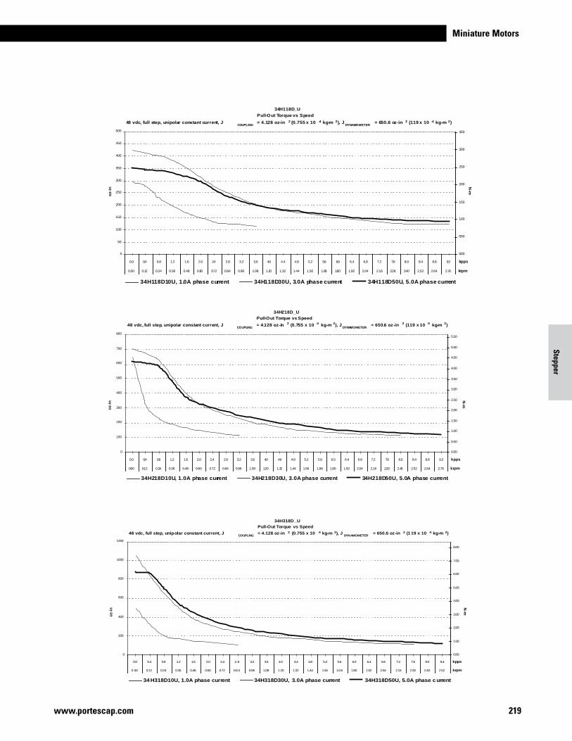
Miniature Motors
219www.portescap.com
Stepper
oz-
in
N-m
34H118D_UPull-Out Torque vs Speed
48 vdc, full step, unipolar constant current, JCOUPLING
= 4.128 oz-in 2 (0.755 x 10 -4 kg-m 2), JDYNAMOMETER
= 650.6 oz-in 2 (119 x 10 -4 kg-m 2)
0
50
100
150
200
250
300
350
400
450
500
0.0 0.4 0.8 1.2 1.6 2.0 2.4 2.8 3.2 3.6 4.0 4.4 4.8 5.2 5.6 6.0 6.4 6.8 7.2 7.6 8.0 8.4 8.8 9.2
0.00 0.12 0.24 0.36 0.48 0.60 0.72 0.84 0.96 1.08 1.20 1.32 1.44 1.56 1.68 1.80 1.92 2.04 2.16 2.28 2.40 2.52 2.64 2.76
kpps
0.00
0.50
1.00
1.50
2.00
2.50
3.00
3.50
krpm
34H118D10U, 1.0A phase current 34H118D30U, 3.0A phase current 34H118D50U, 5.0A phase current
oz-
inN
-m
34H218D_UPull-Out Torque vs Speed
48 vdc, full step, unipolar constant current, JCOUPLING
= 4.128 oz-in 2 (0.755 x 10 -4 kg-m 2), JDYNAMOMETER
= 650.6 oz-in 2 (119 x 10 -4 kg-m 2)
0
100
200
300
400
500
600
700
800
0.0 0.4 0.8 1.2 1.6 2.0 2.4 2.8 3.2 3.6 4.0 4.4 4.8 5.2 5.6 6.0 6.4 6.8 7.2 7.6 8.0 8.4 8.8 9.2
0.00 0.12 0.24 0.36 0.48 0.60 0.72 0.84 0.96 1.08 1.20 1.32 1.44 1.56 1.68 1.80 1.92 2.04 2.16 2.28 2.40 2.52 2.64 2.76
kpps
0.00
0.50
1.00
1.50
2.00
2.50
3.00
3.50
4.00
4.50
5.00
5.50
krpm
34H218D10U, 1.0A phase current 34H218D30U, 3.0A phase current 34H218D50U, 5.0A phase current
oz-
inN
-m
34H318D_UPull-Out Torque vs Speed
48 vdc, full step, unipolar constant current, JCOUPLING
= 4.128 oz-in 2 (0.755 x 10 -4 kg-m 2), JDYNAMOMETER
= 650.6 oz-in 2 (1 19 x 10 -4 kg-m 2)
0
200
400
600
800
1000
1200
0.0 0.4 0.8 1.2 1.6 2.0 2.4 2.8 3.2 3.6 4.0 4.4 4.8 5.2 5.6 6.0 6.4 6.8 7.2 7.6 8.0 8.4
0.00 0.12 0.24 0.36 0.48 0.60 0.72 0.84 0.96 1.08 1.20 1.32 1.44 1.56 1.68 1.80 1.92 2.04 2.16 2.28 2.40 2.52
kpps
0.00
1.00
2.00
3.00
4.00
5.00
6.00
7.00
8.00
krpm
34 H318D10U, 1.0A phase current 34H318D30U, 3.0A phase current 34H318D50U, 5.0A phase c urrent
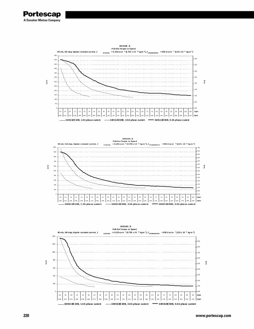
www.portescap.com220
oz-
in
N-m
34H118E_B
Pull-Out Torque vs Speed
48 vdc, full step, bipolar constant current, JCOUPLING
= 4.128 oz-in 2 (0.755 x 10 -4 kg-m 2), JDYNAMOMETER
= 650.6 oz-in 2 (119 x 10 -4 kg-m 2)
0
50
100
150
200
250
300
350
400
450
500
550
600
0.0 0.4 0.8 1.2 1.6 2.0 2.4 2.8 3.2 3.6 4.0 4.4 4.8 5.2 5.6 6.0 6.4 6.8 7.2 7.6 8.0 8.4 8.8 9.2 9.6 10.0 10.4 10.8
0.00 0.12 0.24 0.36 0.48 0.60 0.72 0.84 0.96 1.08 1.20 1.32 1.44 1.56 1.68 1.80 1.92 2.04 2.16 2.28 2.40 2.52 2.64 2.76 2.88 3.00 3.12 3.24
kpps
0.00
0.50
1.00
1.50
2.00
2.50
3.00
3.50
4.00
krpm
34H118E10B, 1.0A phase current 34H118E30B, 3.0A phase current 34H118E50B, 5.0A phase current
oz-
inN
-m
34H218E_B
Pull-Out Torque vs Speed
48 vdc, full step, bipolar constant current, JCOUPLING
= 4.128 oz-in 2 (0.755 x 10 -4 kg-m 2), JDYNAMOMETER
= 650 .6 oz-in 2 (119 x 10 -4 kg-m 2)
0
100
200
300
400
500
600
700
800
900
1000
0.0 0.4 0.8 1.2 1.6 2.0 2.4 2.8 3.2 3.6 4.0 4.4 4.8 5.2 5.6 6.0 6.4 6.8 7.2 7.6 8.0 8.4 8.8 9.2 9.6 10.0
0.00 0.12 0.24 0.36 0.48 0.60 0.72 0.84 0.96 1.08 1.20 1.32 1.44 1.56 1.68 1.80 1.92 2.04 2.16 2.28 2.40 2.52 2.64 2.76 2.88 3.00
kpps
0.00
0.50
1.00
1.50
2.00
2.50
3.00
3.50
4.00
4.50
5.00
5.50
6.00
6.50
7.00
krpm
34H218E10B, 1 .0A phase current 34H218E30B, 3.0A phase current 34H218E50B, 5.0A phase current
N-m
oz-
in
34H318E_BPull-Out Torque vs Speed
48 vdc, full step, bipolar constant current, JCOUPLING
= 4.128 oz-in 2 (0.755 x 10 -4 kg-m 2), JDYNAMOMETER
= 650.6 oz-in 2 (119 x 10 -4 kg-m 2)
0
200
400
600
800
1000
1200
1400
0.0 0.4 0.8 1.2 1.6 2.0 2.4 2.8 3.2 3.6 4.0 4.4 4.8 5.2 5.6 6.0 6.4 6.8 7.2 7.6 8.0 8.4 8.8 9.2
0.00 0.12 0.24 0.36 0.48 0.60 0.72 0.84 0.96 1.08 1.20 1.32 1.44 1.56 1.68 1.80 1.92 2.04 2.16 2.28 2.40 2.52 2.64 2.76
kpps
0.00
1.00
2.00
3.00
4.00
5.00
6.00
7.00
8.00
9.00
krpm
34H318E10B, 1.0A phase current 34H318E30B, 3.0A phase current 34H318E50B, 5.0A phase current

Miniature Motors
221www.portescap.com
Stepper
oz-
in
N-m
34H318E_UPull-Out Torque vs Speed
48 vdc, full step, unipolar constant current, JCOUPLING
= 4.128 oz-in 2 (0.755 x 10 -4 kg-m 2), JDYNAMOMETER
= 650.6 oz-in 2 (119 x 10 -4 kg-m 2)
0
200
400
600
800
1000
1200
1400
0.0 0.4 0.8 1.2 1.6 2.0 2.4 2.8 3.2 3.6 4.0 4.4 4.8 5.2 5.6 6.0 6.4 6.8 7.2 7.6 8.0 8.4
0.00 0.12 0.24 0.36 0.48 0.60 0.72 0.84 0.96 1.08 1.20 1.32 1.44 1.56 1.68 1.80 1.92 2.04 2.16 2.28 2.40 2.52
kpps
0.00
1.00
2.00
3.00
4.00
5.00
6.00
7.00
8.00
9.00
krpm
34H318E10U, 1.0A phase current 34H318E30U, 3.0A phase current 34H318E50U, 5.0A phase current
34H118E_U
Pull-Out Torque vs Speed
48 vdc, full step, unipolar constant current, JCOUPLING
= 4.128 oz-in 2 (0.755 x 10 -4 kg-m 2), JDYNAMOMETER
= 650.6 oz-in 2 (119 x 10 -4 kg-m 2)
0
50
100
150
200
250
300
350
400
450
500
0.0 0.4 0.8 1.2 1.6 2.0 2.4 2.8 3.2 3.6 4.0 4.4 4.8 5.2 5.6 6.0 6.4 6.8 7.2 7.6 8.0 8.4 8.8 9.2
0.00 0.12 0.24 0.36 0.48 0.60 0.72 0.84 0.96 1.08 1.20 1.32 1.44 1.56 1.68 1.80 1.92 2.04 2.16 2.28 2.40 2.52 2.64 2.76
kpps
oz-
in
0.00
0.50
1.00
1.50
2.00
2.50
3.00
3.50
krpm
N-m
34H118E10U, 1.0A phase current 34H118E30U, 3.0A phase current 34H118E50U, 5.0A phase current
oz-
in
N-m
34H218E_UPull-Out Torque vs Speed
48 vdc, full step, unipolar constant current, JCOUPLING
= 4.128 oz-in 2 (0.755 x 10 -4 kg-m 2), JDYNAMOMETER
= 650.6 oz -in 2 (119 x 10 -4 kg-m 2)
0
100
200
300
400
500
600
700
800
900
0.0 0.4 0.8 1.2 1.6 2.0 2.4 2.8 3.2 3.6 4.0 4.4 4.8 5.2 5.6 6.0 6.4 6.8 7.2 7.6 8.0 8.4 8.8 9.2
0.00 0.12 0.24 0.36 0.48 0.60 0.72 0.84 0.96 1.08 1.20 1.32 1.44 1.56 1.68 1.80 1.92 2.04 2.16 2.28 2.40 2.52 2.64 2.76
kpps
0.00
0.50
1.00
1.50
2.00
2.50
3.00
3.50
4.00
4.50
5.00
5.50
6.00
krpm
34H218E10U, 1.0A phase current 34H218E30U, 3.0A phase current 34H218E50U, 5.0A phase current

222
Notes
www.portescap.com
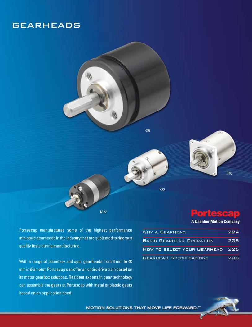
GEARHEADS
Why a Gearhead 224
Basic Gearhead Operation 225
How to select your Gearhead 226
Gearhead Specifications 228
Portescap manufactures some of the highest performance
miniature gearheads in the industry that are subjected to rigorous
quality tests during manufacturing.
With a range of planetary and spur gearheads from 8 mm to 40
mm in diameter, Portescap can offer an entire drive train based on
its motor gearbox solutions. Resident experts in gear technology
can assemble the gears at Portescap with metal or plastic gears
based on an application need.
M22
R32
R16
R40
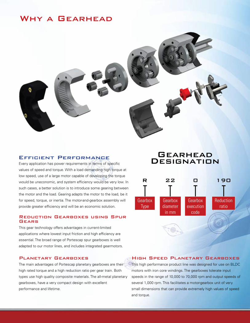
Why a Gearhead
Every application has power requirements in terms of specific
values of speed and torque. With a load demanding high torque at
low speed, use of a large motor capable of developing the torque
would be uneconomic, and system efficiency would be very low. In
such cases, a better solution is to introduce some gearing between
the motor and the load. Gearing adapts the motor to the load, be it
for speed, torque, or inertia. The motor-and-gearbox assembly will
provide greater efficiency and will be an economic solution.
Reduction Gearboxes using Spur GearsThis gear technology offers advantages in current-limited
applications where lowest input friction and high efficiency are
essential. The broad range of Portescap spur gearboxes is well
adapted to our motor lines, and includes integrated gearmotors.
Planetary GearboxesThe main advantages of Portescap planetary gearboxes are their
high rated torque and a high reduction ratio per gear train. Both
types use high quality composite materials. The all-metal planetary
gearboxes, have a very compact design with excellent
performance and lifetime.
Efficient Performance Gearhead Designation
R 22 0 190
Gearbox Type
Reduction ratio
Gearbox diameter
in mm
Gearbox execution
code
High Speed Planetary GearboxesThis high performance product line was designed for use on BLDC
motors with iron core windings. The gearboxes tolerate input
speeds in the range of 10,000 to 70,000 rpm and output speeds of
several 1,000 rpm. This facilitates a motor-gearbox unit of very
small dimensions that can provide extremely high values of speed
and torque.
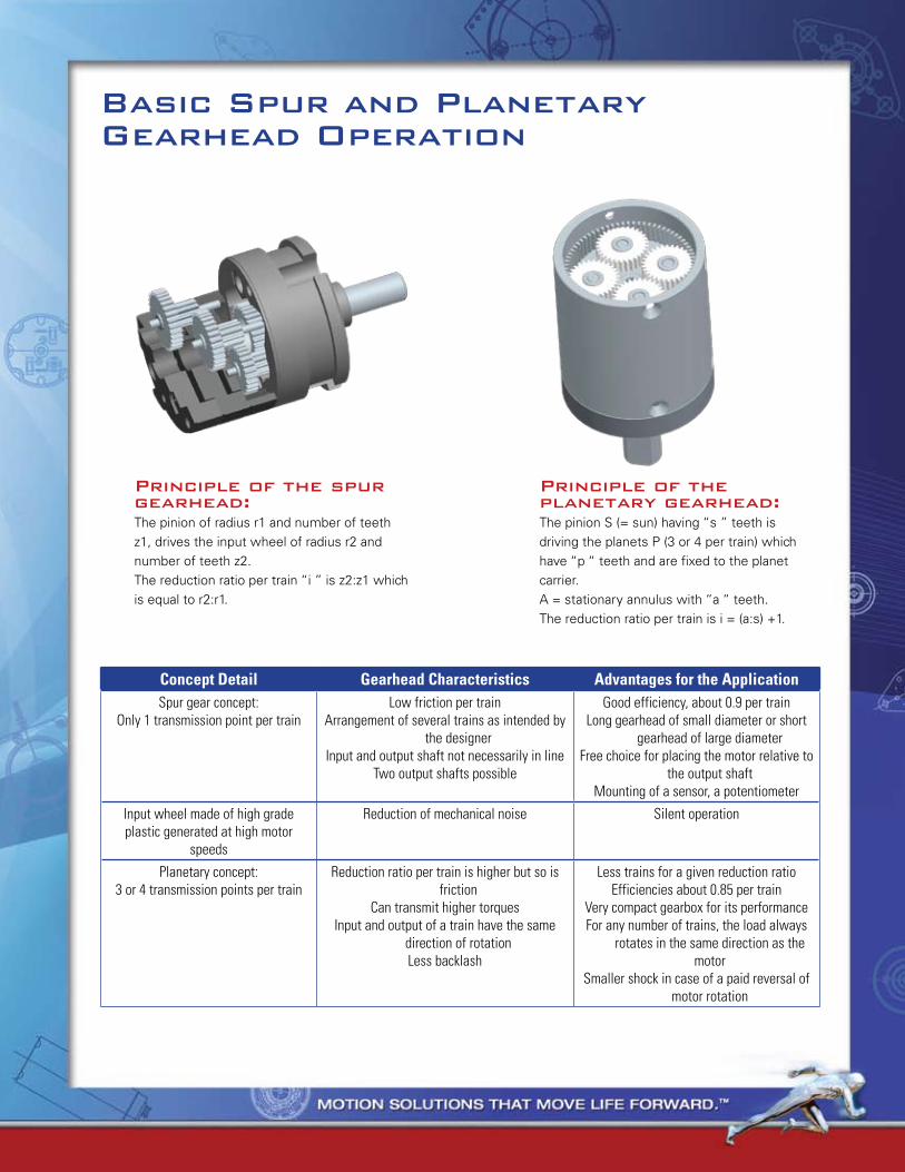
Gearhead Designation
R 22 0 190
Gearbox Type
Reduction ratio
Gearbox diameter
in mm
Gearbox execution
code
Basic Spur and PlanetaryGearhead Operation
Concept Detail Gearhead Characteristics Advantages for the ApplicationSpur gear concept:
Only 1 transmission point per trainLow friction per train
Arrangement of several trains as intended by the designer
Input and output shaft not necessarily in lineTwo output shafts possible
Good efficiency, about 0.9 per trainLong gearhead of small diameter or short
gearhead of large diameterFree choice for placing the motor relative to
the output shaftMounting of a sensor, a potentiometer
Input wheel made of high grade plastic generated at high motor
speeds
Reduction of mechanical noise Silent operation
Planetary concept:3 or 4 transmission points per train
Reduction ratio per train is higher but so is friction
Can transmit higher torques Input and output of a train have the same
direction of rotationLess backlash
Less trains for a given reduction ratioEfficiencies about 0.85 per train
Very compact gearbox for its performance For any number of trains, the load always
rotates in the same direction as the motor
Smaller shock in case of a paid reversal of motor rotation
Principle of the spur gearhead:The pinion of radius r1 and number of teeth z1, drives the input wheel of radius r2 and number of teeth z2.The reduction ratio per train “i ” is z2:z1 which is equal to r2:r1.
Principle of the planetary gearhead:The pinion S (= sun) having “s ” teeth is driving the planets P (3 or 4 per train) which have “p “ teeth and are fixed to the planet carrier.A = stationary annulus with “a “ teeth.The reduction ratio per train is i = (a:s) +1.
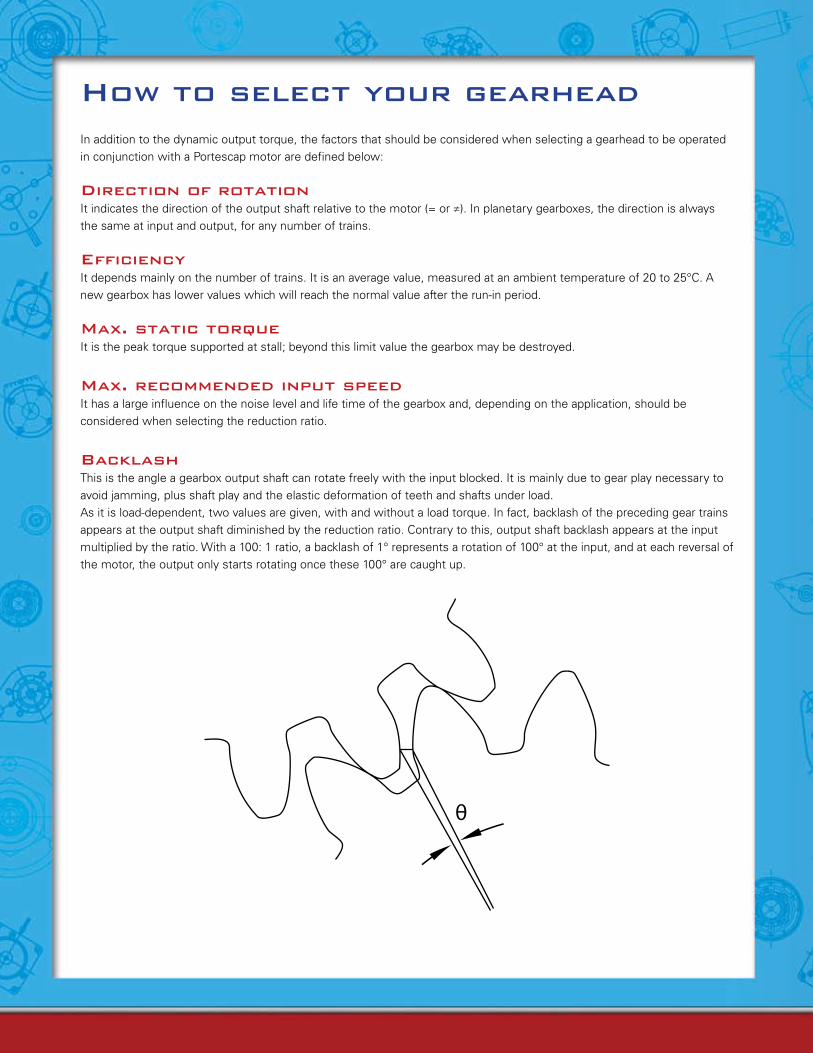
How to select your gearheadIn addition to the dynamic output torque, the factors that should be considered when selecting a gearhead to be operated in conjunction with a Portescap motor are defined below:
Direction of rotationIt indicates the direction of the output shaft relative to the motor (= or ≠). In planetary gearboxes, the direction is always the same at input and output, for any number of trains.
EfficiencyIt depends mainly on the number of trains. It is an average value, measured at an ambient temperature of 20 to 25°C. A new gearbox has lower values which will reach the normal value after the run-in period.
Max. static torqueIt is the peak torque supported at stall; beyond this limit value the gearbox may be destroyed.
Max. recommended input speedIt has a large influence on the noise level and life time of the gearbox and, depending on the application, should be considered when selecting the reduction ratio.
BacklashThis is the angle a gearbox output shaft can rotate freely with the input blocked. It is mainly due to gear play necessary to avoid jamming, plus shaft play and the elastic deformation of teeth and shafts under load.As it is load-dependent, two values are given, with and without a load torque. In fact, backlash of the preceding gear trains appears at the output shaft diminished by the reduction ratio. Contrary to this, output shaft backlash appears at the input multiplied by the ratio. With a 100: 1 ratio, a backlash of 1° represents a rotation of 100° at the input, and at each reversal of the motor, the output only starts rotating once these 100° are caught up.
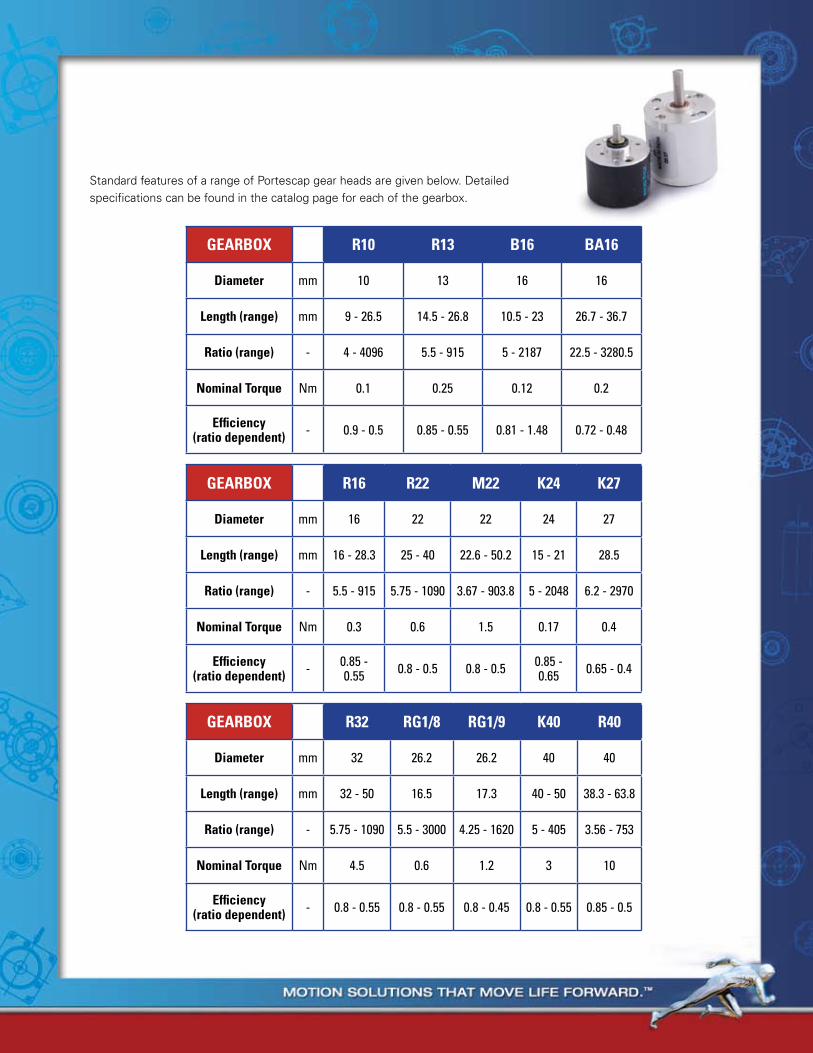
How to select your gearhead
PRODUCT RANGE CHART
GEARBOX R16 R22 M22 K24 K27
Diameter mm 16 22 22 24 27
Length (range) mm 16 - 28.3 25 - 40 22.6 - 50.2 15 - 21 28.5
Ratio (range) - 5.5 - 915 5.75 - 1090 3.67 - 903.8 5 - 2048 6.2 - 2970
Nominal Torque Nm 0.3 0.6 1.5 0.17 0.4
Efficiency(ratio dependent) - 0.85 -
0.55 0.8 - 0.5 0.8 - 0.5 0.85 - 0.65 0.65 - 0.4
GEARBOX R32 RG1/8 RG1/9 K40 R40
Diameter mm 32 26.2 26.2 40 40
Length (range) mm 32 - 50 16.5 17.3 40 - 50 38.3 - 63.8
Ratio (range) - 5.75 - 1090 5.5 - 3000 4.25 - 1620 5 - 405 3.56 - 753
Nominal Torque Nm 4.5 0.6 1.2 3 10
Efficiency(ratio dependent) - 0.8 - 0.55 0.8 - 0.55 0.8 - 0.45 0.8 - 0.55 0.85 - 0.5
GEARBOX R10 R13 B16 BA16
Diameter mm 10 13 16 16
Length (range) mm 9 - 26.5 14.5 - 26.8 10.5 - 23 26.7 - 36.7
Ratio (range) - 4 - 4096 5.5 - 915 5 - 2187 22.5 - 3280.5
Nominal Torque Nm 0.1 0.25 0.12 0.2
Efficiency(ratio dependent) - 0.9 - 0.5 0.85 - 0.55 0.81 - 1.48 0.72 - 0.48
Standard features of a range of Portescap gear heads are given below. Detailed specifications can be found in the catalog page for each of the gearbox.
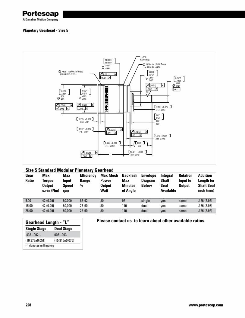
228 www.portescap.com
Size 5 Standard Modular Planetary GearheadGear Max Max Efficiency Max Mech Backlash Envelope Integral Rotation AdditionRatio Torque Input Range Power Max Diagram Shaft Input to Length for Output Speed % Output Minutes Below Seal Output Shaft Seal oz-in (Nm) rpm Watt of Angle Available inch (mm)
5.00 42 (0.29) 80,000 85-92 80 95 single yes same .156 (3.96)15.00 42 (0.29) 80,000 75-90 80 110 dual yes same .156 (3.96)25.00 42 (0.29) 80,000 75-90 80 110 dual yes same .156 (3.96)
Gearhead Length - “L”Single Stage Dual Stage.432±.002 . 603±.003
(10.973±0.051) (15.316±0.076)(-) denotes millimeters
Please contact us to learn about other available ratios
Planetary Gearhead - Size 5
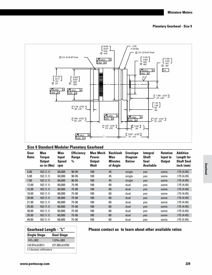
Miniature Motors
229www.portescap.com
Please contact us to learn about other available ratios
Size 9 Standard Modular Planetary GearheadGear Max Max Efficiency Max Mech Backlash Envelope Integral Rotation AdditionRatio Torque Input Range Power Max Diagram Shaft Input to Length for Output Speed % Output Minutes Below Seal Output Shaft Seal oz-in (Nm) rpm Watt of Angle Available inch (mm)
4.00 162 (1.1) 60,000 90-95 180 45 single yes same .175 (4.45)5.00 162 (1.1) 60,000 90-95 180 45 single yes same .175 (4.45)7.00 162 (1.1) 60,000 90-95 180 45 single yes same .175 (4.45)12.00 162 (1.1) 60,000 75-90 180 60 dual yes same .175 (4.45)15.00 162 (1.1) 60,000 75-90 180 60 dual yes same .175 (4.45)16.00 162 (1.1) 60,000 75-90 180 60 dual yes same .175 (4.45)20.00 162 (1.1) 60,000 75-90 180 60 dual yes same .175 (4.45)21.00 162 (1.1) 60,000 75-90 180 60 dual yes same .175 (4.45)25.00 162 (1.1) 60,000 75-90 180 60 dual yes same .175 (4.45)28.00 162 (1.1) 60,000 75-90 180 60 dual yes same .175 (4.45)35.00 162 (1.1) 60,000 75-90 180 60 dual yes same .175 (4.45)49.00 162 (1.1) 60,000 75-90 180 60 dual yes same .175 (4.45)
Gearhead Length - “L”Single Stage Dual Stage.747±.002 . 1.074±.003
(18.974±0.051) (27.305±0.076)(-) denotes millimeters
Gearhead
Planetary Gearhead - Size 9
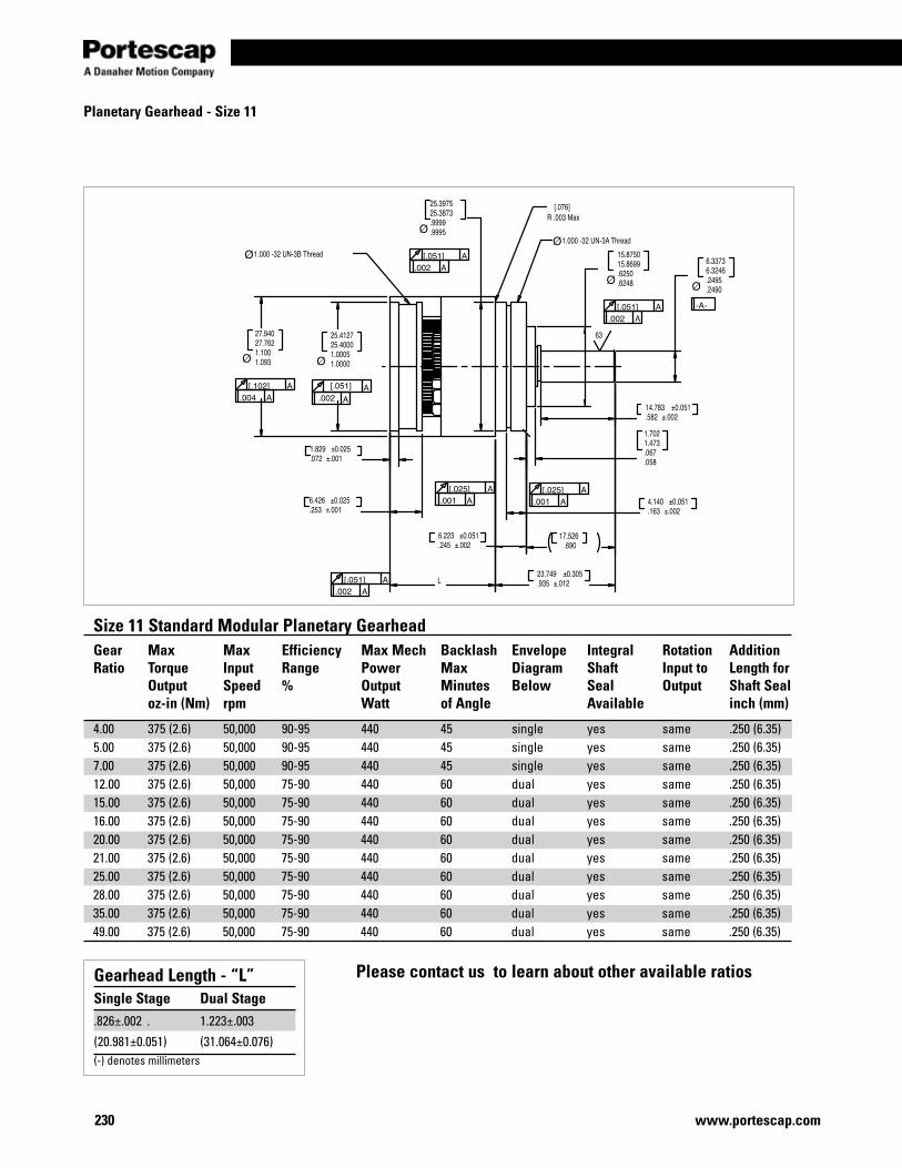
230 www.portescap.com
Planetary Gearhead - Size 11
Gearhead Length - “L”Single Stage Dual Stage.826±.002 . 1.223±.003
(20.981±0.051) (31.064±0.076)(-) denotes millimeters
Size 11 Standard Modular Planetary GearheadGear Max Max Efficiency Max Mech Backlash Envelope Integral Rotation AdditionRatio Torque Input Range Power Max Diagram Shaft Input to Length for Output Speed % Output Minutes Below Seal Output Shaft Seal oz-in (Nm) rpm Watt of Angle Available inch (mm)
4.00 375 (2.6) 50,000 90-95 440 45 single yes same .250 (6.35)5.00 375 (2.6) 50,000 90-95 440 45 single yes same .250 (6.35)7.00 375 (2.6) 50,000 90-95 440 45 single yes same .250 (6.35)12.00 375 (2.6) 50,000 75-90 440 60 dual yes same .250 (6.35)15.00 375 (2.6) 50,000 75-90 440 60 dual yes same .250 (6.35)16.00 375 (2.6) 50,000 75-90 440 60 dual yes same .250 (6.35)20.00 375 (2.6) 50,000 75-90 440 60 dual yes same .250 (6.35)21.00 375 (2.6) 50,000 75-90 440 60 dual yes same .250 (6.35)25.00 375 (2.6) 50,000 75-90 440 60 dual yes same .250 (6.35)28.00 375 (2.6) 50,000 75-90 440 60 dual yes same .250 (6.35)35.00 375 (2.6) 50,000 75-90 440 60 dual yes same .250 (6.35)49.00 375 (2.6) 50,000 75-90 440 60 dual yes same .250 (6.35)
Please contact us to learn about other available ratios
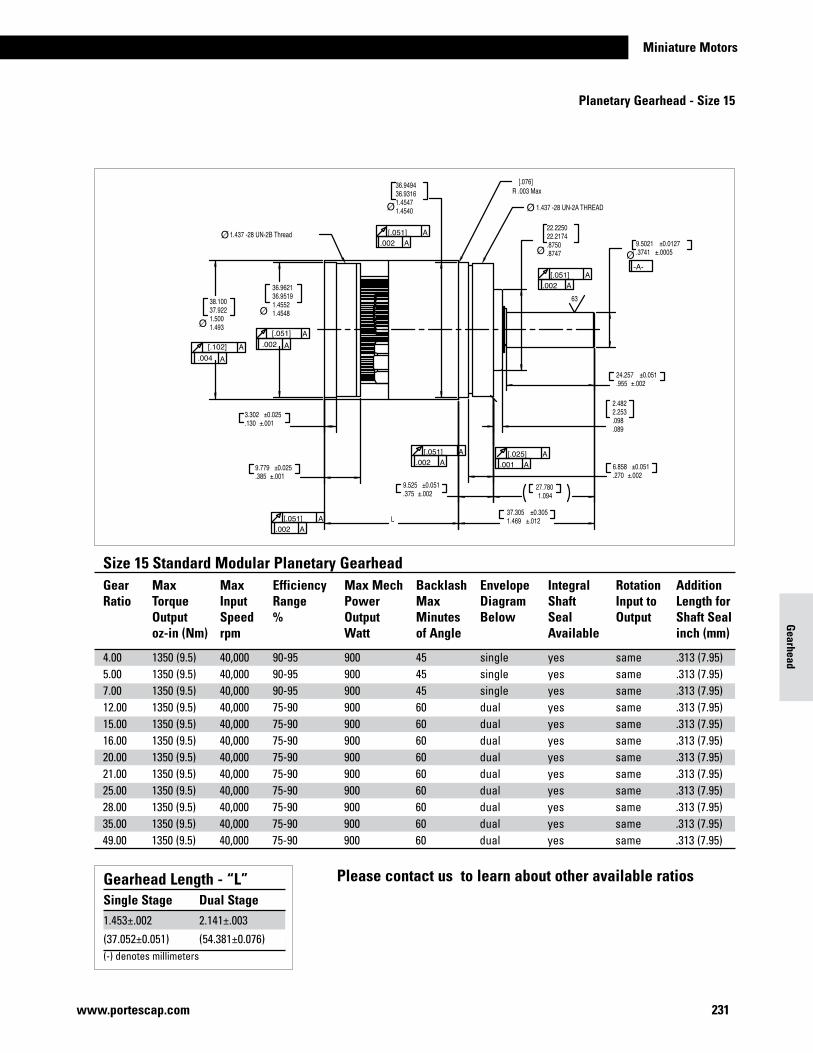
Miniature Motors
231www.portescap.com
Size 15 Standard Modular Planetary GearheadGear Max Max Efficiency Max Mech Backlash Envelope Integral Rotation AdditionRatio Torque Input Range Power Max Diagram Shaft Input to Length for Output Speed % Output Minutes Below Seal Output Shaft Seal oz-in (Nm) rpm Watt of Angle Available inch (mm)
4.00 1350 (9.5) 40,000 90-95 900 45 single yes same .313 (7.95)5.00 1350 (9.5) 40,000 90-95 900 45 single yes same .313 (7.95)7.00 1350 (9.5) 40,000 90-95 900 45 single yes same .313 (7.95)12.00 1350 (9.5) 40,000 75-90 900 60 dual yes same .313 (7.95)15.00 1350 (9.5) 40,000 75-90 900 60 dual yes same .313 (7.95)16.00 1350 (9.5) 40,000 75-90 900 60 dual yes same .313 (7.95)20.00 1350 (9.5) 40,000 75-90 900 60 dual yes same .313 (7.95)21.00 1350 (9.5) 40,000 75-90 900 60 dual yes same .313 (7.95)25.00 1350 (9.5) 40,000 75-90 900 60 dual yes same .313 (7.95)28.00 1350 (9.5) 40,000 75-90 900 60 dual yes same .313 (7.95)35.00 1350 (9.5) 40,000 75-90 900 60 dual yes same .313 (7.95)49.00 1350 (9.5) 40,000 75-90 900 60 dual yes same .313 (7.95)
Gearhead Length - “L”Single Stage Dual Stage1.453±.002 2.141±.003
(37.052±0.051) (54.381±0.076)(-) denotes millimeters
Gearhead
Planetary Gearhead - Size 15
Please contact us to learn about other available ratios
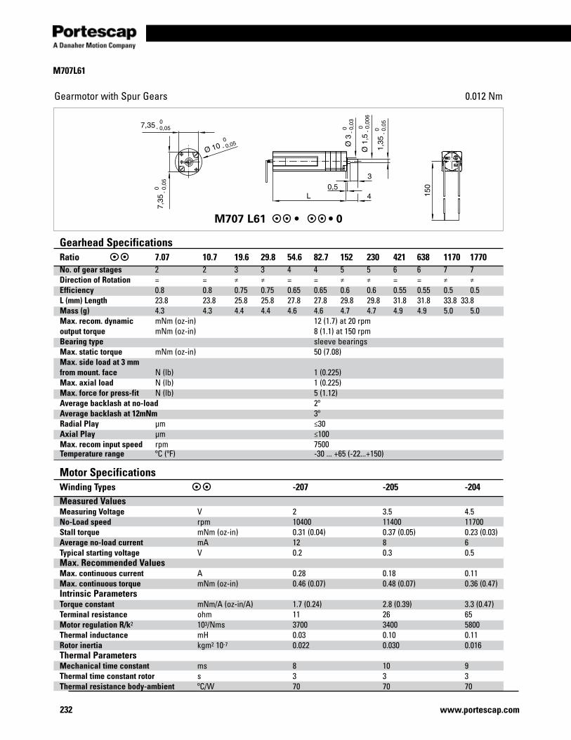
232 www.portescap.com
Gearmotor with Spur Gears 0.012 Nm
M707 L61 • • 0
M707L61
Gearhead SpecificationsRatio 7.07 10.7 19.6 29.8 54.6 82.7 152 230 421 638 1170 1770No. of gear stages 2 2 3 3 4 4 5 5 6 6 7 7Direction of Rotation = = ≠ ≠ = = ≠ ≠ = = ≠ ≠Efficiency 0.8 0.8 0.75 0.75 0.65 0.65 0.6 0.6 0.55 0.55 0.5 0.5L (mm) Length 23.8 23.8 25.8 25.8 27.8 27.8 29.8 29.8 31.8 31.8 33.8 33.8Mass (g) 4.3 4.3 4.4 4.4 4.6 4.6 4.7 4.7 4.9 4.9 5.0 5.0Max. recom. dynamic mNm (oz-in) 12 (1.7) at 20 rpmoutput torque mNm (oz-in) 8 (1.1) at 150 rpm Bearing type sleeve bearings Max. static torque mNm (oz-in) 50 (7.08) Max. side load at 3 mm from mount. face N (lb) 1 (0.225) Max. axial load N (lb) 1 (0.225) Max. force for press-fit N (lb) 5 (1.12) Average backlash at no-load 2º Average backlash at 12mNm 3º Radial Play µm ≤30 Axial Play µm ≤100 Max. recom input speed rpm 7500 Temperature range ºC (ºF) -30 ... +65 (-22...+150)
Motor SpecificationsWinding Types -207 -205 -204Measured Values Measuring Voltage V 2 3.5 4.5No-Load speed rpm 10400 11400 11700Stall torque mNm (oz-in) 0.31 (0.04) 0.37 (0.05) 0.23 (0.03)Average no-load current mA 12 8 6Typical starting voltage V 0.2 0.3 0.5Max. Recommended Values Max. continuous current A 0.28 0.18 0.11Max. continuous torque mNm (oz-in) 0.46 (0.07) 0.48 (0.07) 0.36 (0.47)Intrinsic Parameters Torque constant mNm/A (oz-in/A) 1.7 (0.24) 2.8 (0.39) 3.3 (0.47)Terminal resistance ohm 11 26 65Motor regulation R/k2 103/Nms 3700 3400 5800Thermal inductance mH 0.03 0.10 0.11Rotor inertia kgm2 10-7 0.022 0.030 0.016Thermal Parameters Mechanical time constant ms 8 10 9Thermal time constant rotor s 3 3 3Thermal resistance body-ambient ºC/W 70 70 70
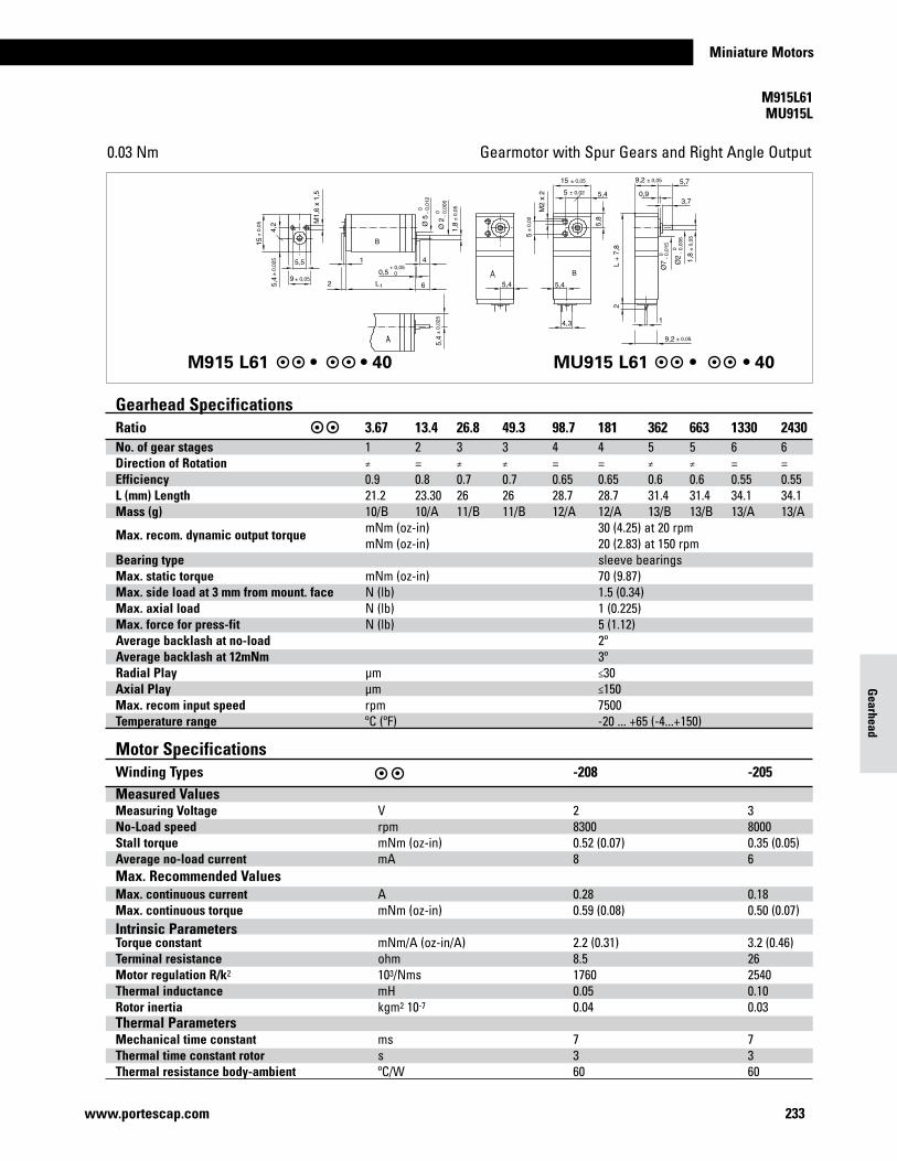
Miniature Motors
233www.portescap.com
Gearmotor with Spur Gears and Right Angle Output0.03 Nm
M915 L61 • • 40 MU915 L61 • • 40
Gearhead SpecificationsRatio 3.67 13.4 26.8 49.3 98.7 181 362 663 1330 2430No. of gear stages 1 2 3 3 4 4 5 5 6 6Direction of Rotation ≠ = ≠ ≠ = = ≠ ≠ = =Efficiency 0.9 0.8 0.7 0.7 0.65 0.65 0.6 0.6 0.55 0.55L (mm) Length 21.2 23.30 26 26 28.7 28.7 31.4 31.4 34.1 34.1Mass (g) 10/B 10/A 11/B 11/B 12/A 12/A 13/B 13/B 13/A 13/A
Max. recom. dynamic output torque mNm (oz-in) 30 (4.25) at 20 rpm mNm (oz-in) 20 (2.83) at 150 rpm Bearing type sleeve bearings Max. static torque mNm (oz-in) 70 (9.87) Max. side load at 3 mm from mount. face N (lb) 1.5 (0.34) Max. axial load N (lb) 1 (0.225) Max. force for press-fit N (lb) 5 (1.12) Average backlash at no-load 2º Average backlash at 12mNm 3º Radial Play µm ≤30 Axial Play µm ≤150 Max. recom input speed rpm 7500 Temperature range ºC (ºF) -20 ... +65 (-4...+150)
Gearhead
M915L61 MU915L
Gearhead SpecificationsRatio 7.07 10.7 19.6 29.8 54.6 82.7 152 230 421 638 1170 1770No. of gear stages 2 2 3 3 4 4 5 5 6 6 7 7Direction of Rotation = = ≠ ≠ = = ≠ ≠ = = ≠ ≠Efficiency 0.8 0.8 0.75 0.75 0.65 0.65 0.6 0.6 0.55 0.55 0.5 0.5L (mm) Length 23.8 23.8 25.8 25.8 27.8 27.8 29.8 29.8 31.8 31.8 33.8 33.8Mass (g) 4.3 4.3 4.4 4.4 4.6 4.6 4.7 4.7 4.9 4.9 5.0 5.0Max. recom. dynamic mNm (oz-in) 12 (1.7) at 20 rpmoutput torque mNm (oz-in) 8 (1.1) at 150 rpm Bearing type sleeve bearings Max. static torque mNm (oz-in) 50 (7.08) Max. side load at 3 mm from mount. face N (lb) 1 (0.225) Max. axial load N (lb) 1 (0.225) Max. force for press-fit N (lb) 5 (1.12) Average backlash at no-load 2º Average backlash at 12mNm 3º Radial Play µm ≤30 Axial Play µm ≤100 Max. recom input speed rpm 7500 Temperature range ºC (ºF) -30 ... +65 (-22...+150)
Motor SpecificationsWinding Types -207 -205 -204Measured Values Measuring Voltage V 2 3.5 4.5No-Load speed rpm 10400 11400 11700Stall torque mNm (oz-in) 0.31 (0.04) 0.37 (0.05) 0.23 (0.03)Average no-load current mA 12 8 6Typical starting voltage V 0.2 0.3 0.5Max. Recommended Values Max. continuous current A 0.28 0.18 0.11Max. continuous torque mNm (oz-in) 0.46 (0.07) 0.48 (0.07) 0.36 (0.47)Intrinsic Parameters Torque constant mNm/A (oz-in/A) 1.7 (0.24) 2.8 (0.39) 3.3 (0.47)Terminal resistance ohm 11 26 65Motor regulation R/k2 103/Nms 3700 3400 5800Thermal inductance mH 0.03 0.10 0.11Rotor inertia kgm2 10-7 0.022 0.030 0.016Thermal Parameters Mechanical time constant ms 8 10 9Thermal time constant rotor s 3 3 3Thermal resistance body-ambient ºC/W 70 70 70
Motor SpecificationsWinding Types -208 -205 Measured Values Measuring Voltage V 2 3No-Load speed rpm 8300 8000Stall torque mNm (oz-in) 0.52 (0.07) 0.35 (0.05)Average no-load current mA 8 6Max. Recommended Values Max. continuous current A 0.28 0.18 Max. continuous torque mNm (oz-in) 0.59 (0.08) 0.50 (0.07) Intrinsic Parameters Torque constant mNm/A (oz-in/A) 2.2 (0.31) 3.2 (0.46) Terminal resistance ohm 8.5 26 Motor regulation R/k2 103/Nms 1760 2540 Thermal inductance mH 0.05 0.10 Rotor inertia kgm2 10-7 0.04 0.03 Thermal Parameters Mechanical time constant ms 7 7 Thermal time constant rotor s 3 3 Thermal resistance body-ambient ºC/W 60 60
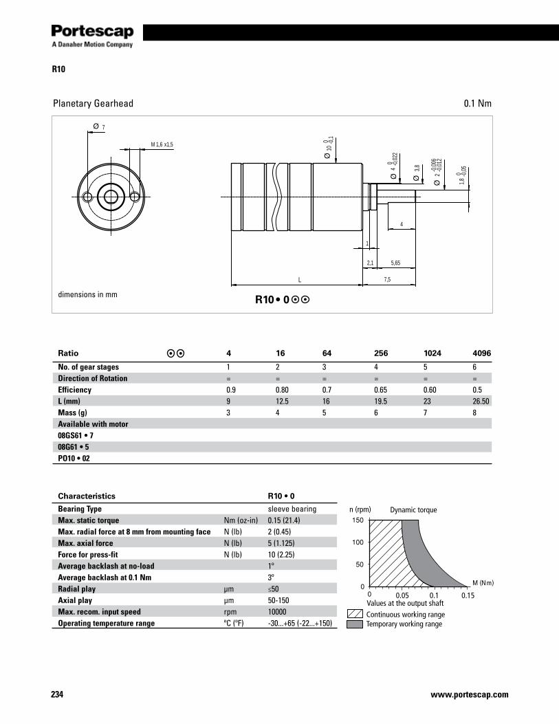
234 www.portescap.com
R10
Planetary Gearhead 0.1 Nm
2,1
1,8
0 -0,0
5
5,65
4
7,5L
1,6M x1,5
1
7
2-0
,006
-0,0
12
3,8
10 0 -0
,1
4 0 -0
,022
dimensions in mm R10 • 0
Ratio 4 16 64 256 1024 4096
No. of gear stages 1 2 3 4 5 6Direction of Rotation = = = = = =Efficiency 0.9 0.80 0.7 0.65 0.60 0.5L (mm) 9 12.5 16 19.5 23 26.50Mass (g) 3 4 5 6 7 8Available with motor 08GS61 • 7 08G61 • 5 PO10 • 02
Characteristics R10 • 0
Bearing Type sleeve bearing Max. static torque Nm (oz-in) 0.15 (21.4) Max. radial force at 8 mm from mounting face N (lb) 2 (0.45) Max. axial force N (lb) 5 (1.125) Force for press-fit N (lb) 10 (2.25) Average backlash at no-load 1º Average backlash at 0.1 Nm 3º Radial play µm ≤50 Axial play µm 50-150 Max. recom. input speed rpm 10000 Operating temperature range ºC (ºF) -30...+65 (-22...+150)
M (Nm)
n (rpm) Dynamic torque
Continuous working rangeTemporary working range
Values at the output shaft0.05 0.1 0.15
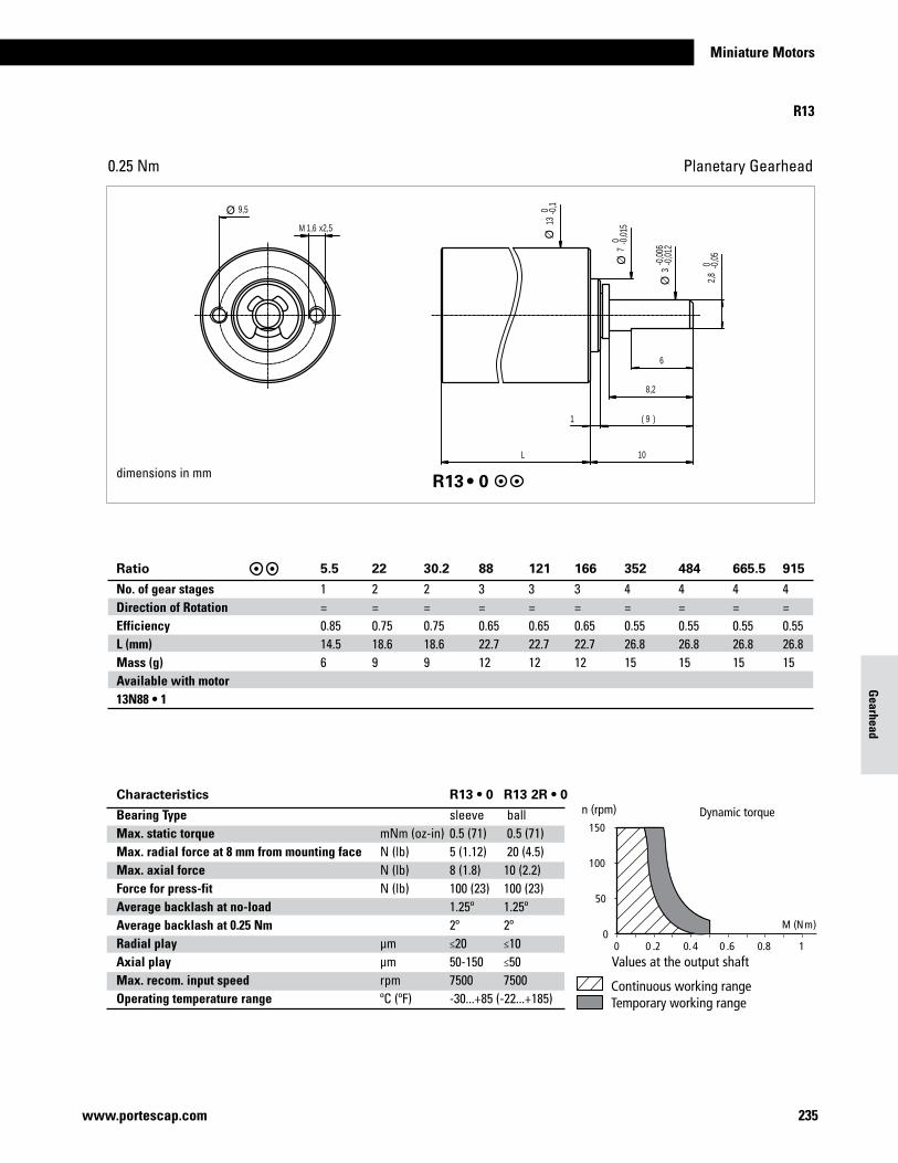
235www.portescap.com
Miniature Motors
Gearhead
Planetary Gearhead0.25 Nm
1,6M x2,5
2,8
0 -0,0
5
6
8,2
9( )1
10L
9,5
3-0
,006
-0,0
127 0 -0
,015
13 0 -0
,1
R13 • 0
Ratio 5.5 22 30.2 88 121 166 352 484 665.5 915
No. of gear stages 1 2 2 3 3 3 4 4 4 4Direction of Rotation = = = = = = = = = =Efficiency 0.85 0.75 0.75 0.65 0.65 0.65 0.55 0.55 0.55 0.55L (mm) 14.5 18.6 18.6 22.7 22.7 22.7 26.8 26.8 26.8 26.8Mass (g) 6 9 9 12 12 12 15 15 15 15Available with motor13N88 • 1
Characteristics R13 • 0 R13 2R • 0
Bearing Type sleeve ballMax. static torque mNm (oz-in) 0.5 (71) 0.5 (71)Max. radial force at 8 mm from mounting face N (lb) 5 (1.12) 20 (4.5)Max. axial force N (lb) 8 (1.8) 10 (2.2)Force for press-fit N (lb) 100 (23) 100 (23)Average backlash at no-load 1.25º 1.25ºAverage backlash at 0.25 Nm 2º 2ºRadial play µm ≤20 ≤10Axial play µm 50-150 ≤50Max. recom. input speed rpm 7500 7500Operating temperature range ºC (ºF) -30...+85 (-22...+185)
Continuous working rangeTemporary working range
Values at the output shaft
Dynamic torquen (rpm)150
100
50
00 0 .2 0.4 0 .6 0.8 1
M (Nm)
dimensions in mm
R13
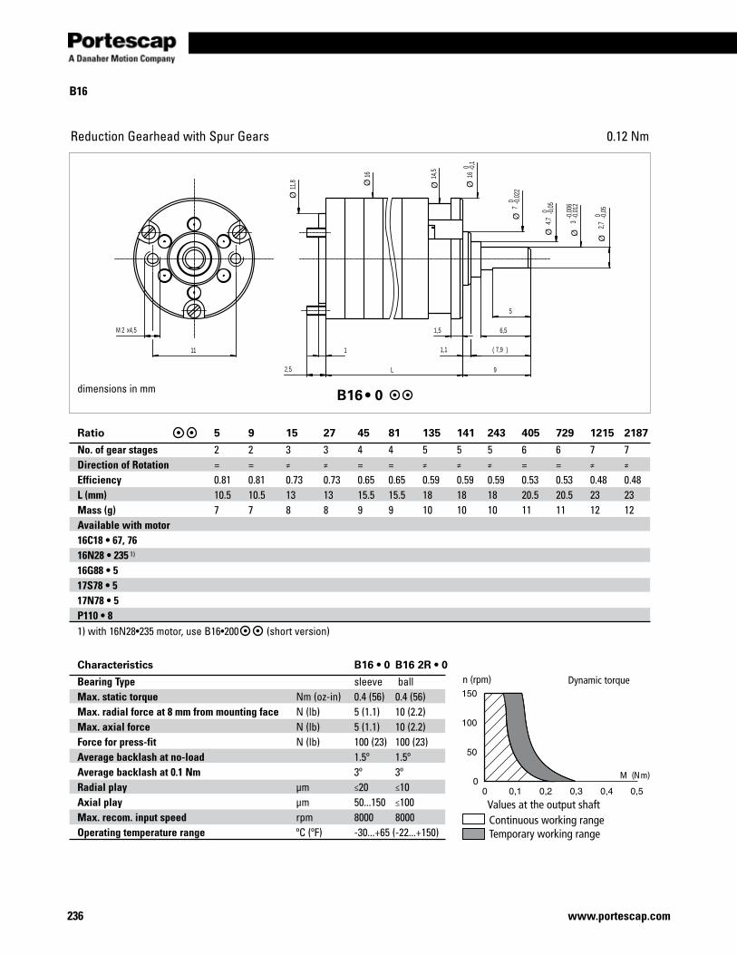
236 www.portescap.com
B16
Reduction Gearhead with Spur Gears 0.12 Nm
6,5
2,7
0 -0,0
5
1
5
2M x4,5
11
1,5
92,5 L
1,1 7,9( )
4,7
0 -0,0
5
16 0 -0
,1
11,8
16 14,5
3-0
,006
-0,0
127 0 -0
,022
dimensions in mm B16 • 0
Ratio 5 9 15 27 45 81 135 141 243 405 729 1215 2187
No. of gear stages 2 2 3 3 4 4 5 5 5 6 6 7 7Direction of Rotation = = ≠ ≠ = = ≠ ≠ ≠ = = ≠ ≠
Efficiency 0.81 0.81 0.73 0.73 0.65 0.65 0.59 0.59 0.59 0.53 0.53 0.48 0.48L (mm) 10.5 10.5 13 13 15.5 15.5 18 18 18 20.5 20.5 23 23Mass (g) 7 7 8 8 9 9 10 10 10 11 11 12 12Available with motor 16C18 • 67, 76 16N28 • 235 1) 16G88 • 5 17S78 • 5 17N78 • 5 P110 • 8 1) with 16N28•235 motor, use B16•200 (short version)
Characteristics B16 • 0 B16 2R • 0
Bearing Type sleeve ballMax. static torque Nm (oz-in) 0.4 (56) 0.4 (56)Max. radial force at 8 mm from mounting face N (lb) 5 (1.1) 10 (2.2)Max. axial force N (lb) 5 (1.1) 10 (2.2)Force for press-fit N (lb) 100 (23) 100 (23)Average backlash at no-load 1.5º 1.5ºAverage backlash at 0.1 Nm 3º 3ºRadial play µm ≤20 ≤10Axial play µm 50...150 ≤100Max. recom. input speed rpm 8000 8000Operating temperature range ºC (ºF) -30...+65 (-22...+150)
M (Nm)
Continuous working rangeTemporary working range
Values at the output shaft
Dynamic torquen (rpm)
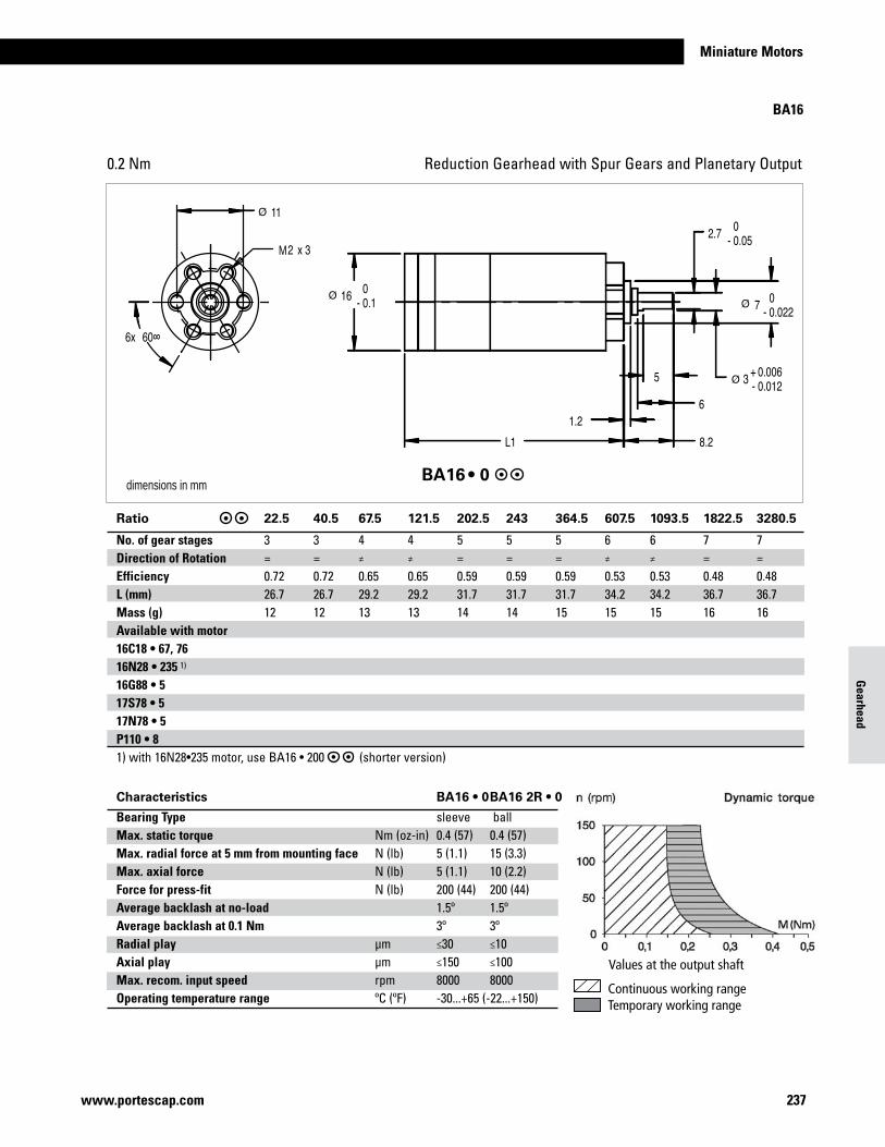
237www.portescap.com
Miniature Motors
Gearhead
Reduction Gearhead with Spur Gears and Planetary Output0.2 Nm
M
dimensions in mmBA16 • 0
Characteristics BA16 • 0 BA16 2R • 0
Bearing Type sleeve ballMax. static torque Nm (oz-in) 0.4 (57) 0.4 (57)Max. radial force at 5 mm from mounting face N (lb) 5 (1.1) 15 (3.3)Max. axial force N (lb) 5 (1.1) 10 (2.2)Force for press-fit N (lb) 200 (44) 200 (44)Average backlash at no-load 1.5º 1.5ºAverage backlash at 0.1 Nm 3º 3ºRadial play µm ≤30 ≤10Axial play µm ≤150 ≤100Max. recom. input speed rpm 8000 8000Operating temperature range ºC (ºF) -30...+65 (-22...+150)
BA16
Ratio 22.5 40.5 67.5 121.5 202.5 243 364.5 607.5 1093.5 1822.5 3280.5
No. of gear stages 3 3 4 4 5 5 5 6 6 7 7Direction of Rotation = = ≠ ≠ = = = ≠ ≠ = =Efficiency 0.72 0.72 0.65 0.65 0.59 0.59 0.59 0.53 0.53 0.48 0.48L (mm) 26.7 26.7 29.2 29.2 31.7 31.7 31.7 34.2 34.2 36.7 36.7Mass (g) 12 12 13 13 14 14 15 15 15 16 16Available with motor 16C18 • 67, 76 16N28 • 235 1) 16G88 • 5 17S78 • 5 17N78 • 5 P110 • 8 1) with 16N28•235 motor, use BA16 • 200 (shorter version)
Continuous working rangeTemporary working range
Values at the output shaft
Dynamic torquen (rpm)150
100
50
00 0 .2 0.4 0 .6 0.8 1
M (Nm)
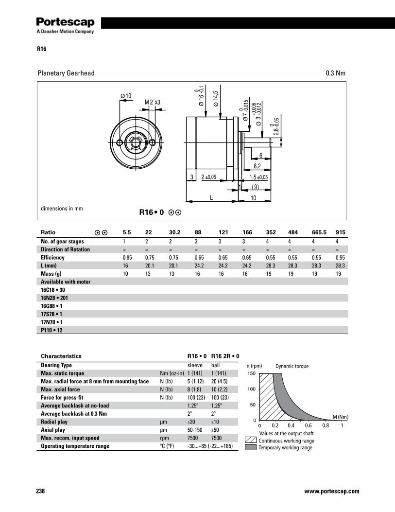
238 www.portescap.com
R16
Planetary Gearhead 0.3 Nm
dimensions in mm
Ratio 5.5 22 30.2 88 121 166 352 484 665.5 915
No. of gear stages 1 2 2 3 3 3 4 4 4 4Direction of Rotation = = = = = = = = = =Efficiency 0.85 0.75 0.75 0.65 0.65 0.65 0.55 0.55 0.55 0.55L (mm) 16 20.1 20.1 24.2 24.2 24.2 28.3 28.3 28.3 28.3Mass (g) 10 13 13 16 16 16 19 19 19 19Available with motor 16C18 • 30 16N28 • 201 16G88 • 1 17S78 • 1 17N78 • 1 P110 • 12
Characteristics R16 • 0 R16 2R • 0
Bearing Type sleeve ballMax. static torque Nm (oz-in) 1 (141) 1 (141)Max. radial force at 8 mm from mounting face N (lb) 5 (1.12) 20 (4.5)Max. axial force N (lb) 8 (1.8) 10 (2.2)Force for press-fit N (lb) 100 (23) 100 (23)Average backlash at no-load 1.25º 1.25ºAverage backlash at 0.3 Nm 2º 2ºRadial play µm ≤20 ≤10Axial play µm 50-150 ≤50Max. recom. input speed rpm 7500 7500Operating temperature range ºC (ºF) -30...+85 (-22...+185)
Continuous working rangeTemporary working range
Values at the output shaft
n (rpm)
M (Nm)
Dynamic torque
0.2 0.4 0.6 0.8 1
R16 • 0
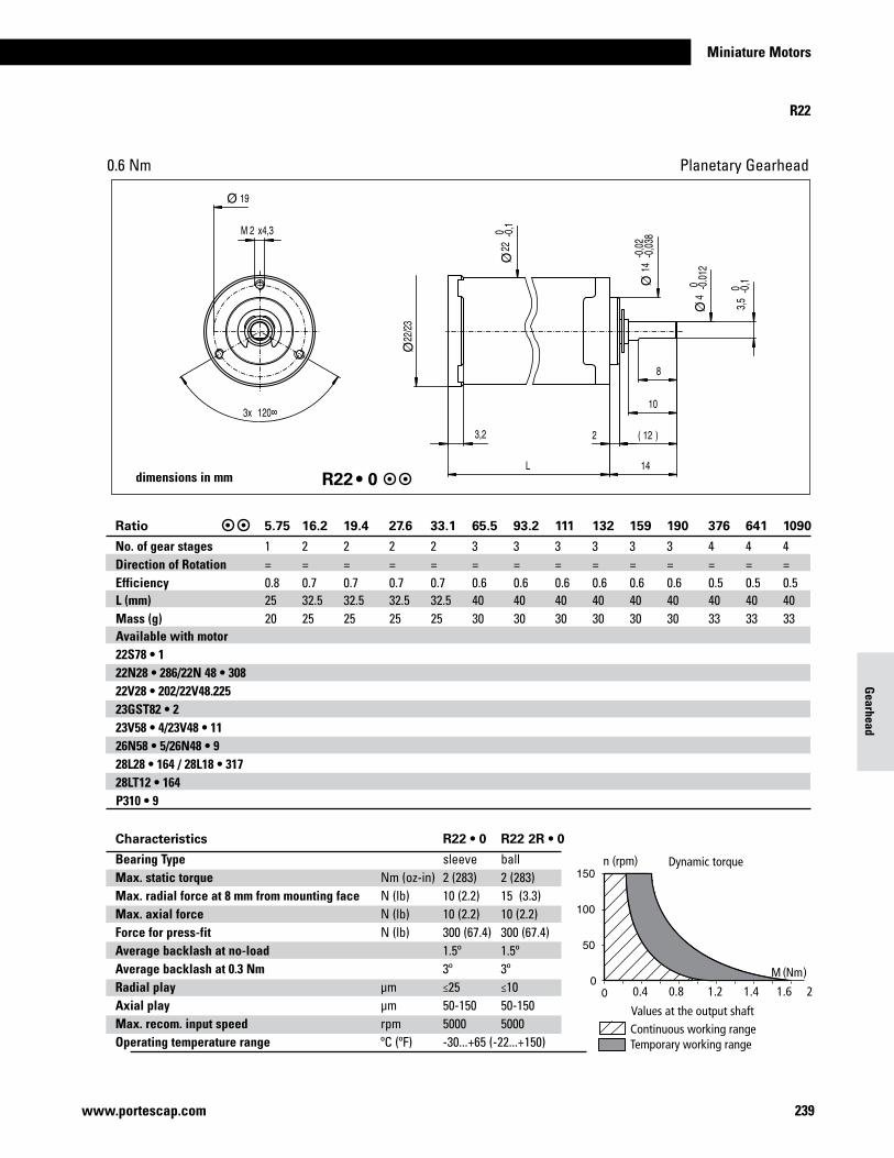
239www.portescap.com
Miniature Motors
Gearhead
Planetary Gearhead0.6 Nm
R22 • 0
Characteristics R22 • 0 R22 2R • 0
Bearing Type sleeve ballMax. static torque Nm (oz-in) 2 (283) 2 (283)Max. radial force at 8 mm from mounting face N (lb) 10 (2.2) 15 (3.3)Max. axial force N (lb) 10 (2.2) 10 (2.2)Force for press-fit N (lb) 300 (67.4) 300 (67.4)Average backlash at no-load 1.5º 1.5ºAverage backlash at 0.3 Nm 3º 3ºRadial play µm ≤25 ≤10Axial play µm 50-150 50-150Max. recom. input speed rpm 5000 5000Operating temperature range ºC (ºF) -30...+65 (-22...+150)
Ratio 5.75 16.2 19.4 27.6 33.1 65.5 93.2 111 132 159 190 376 641 1090
No. of gear stages 1 2 2 2 2 3 3 3 3 3 3 4 4 4Direction of Rotation = = = = = = = = = = = = = =Efficiency 0.8 0.7 0.7 0.7 0.7 0.6 0.6 0.6 0.6 0.6 0.6 0.5 0.5 0.5L (mm) 25 32.5 32.5 32.5 32.5 40 40 40 40 40 40 40 40 40Mass (g) 20 25 25 25 25 30 30 30 30 30 30 33 33 33Available with motor 22S78 • 1 22N28 • 286/22N 48 • 308 22V28 • 202/22V48.225 23GST82 • 2 23V58 • 4/23V48 • 11 26N58 • 5/26N48 • 9 28L28 • 164 / 28L18 • 317 28LT12 • 164 P310 • 9
n (rpm) Dynamic torque
M (Nm)
Continuous working rangeTemporary working range
Values at the output shaft
0.4 0.8 1.2 1.4 1.6 2
R22
dimensions in mm
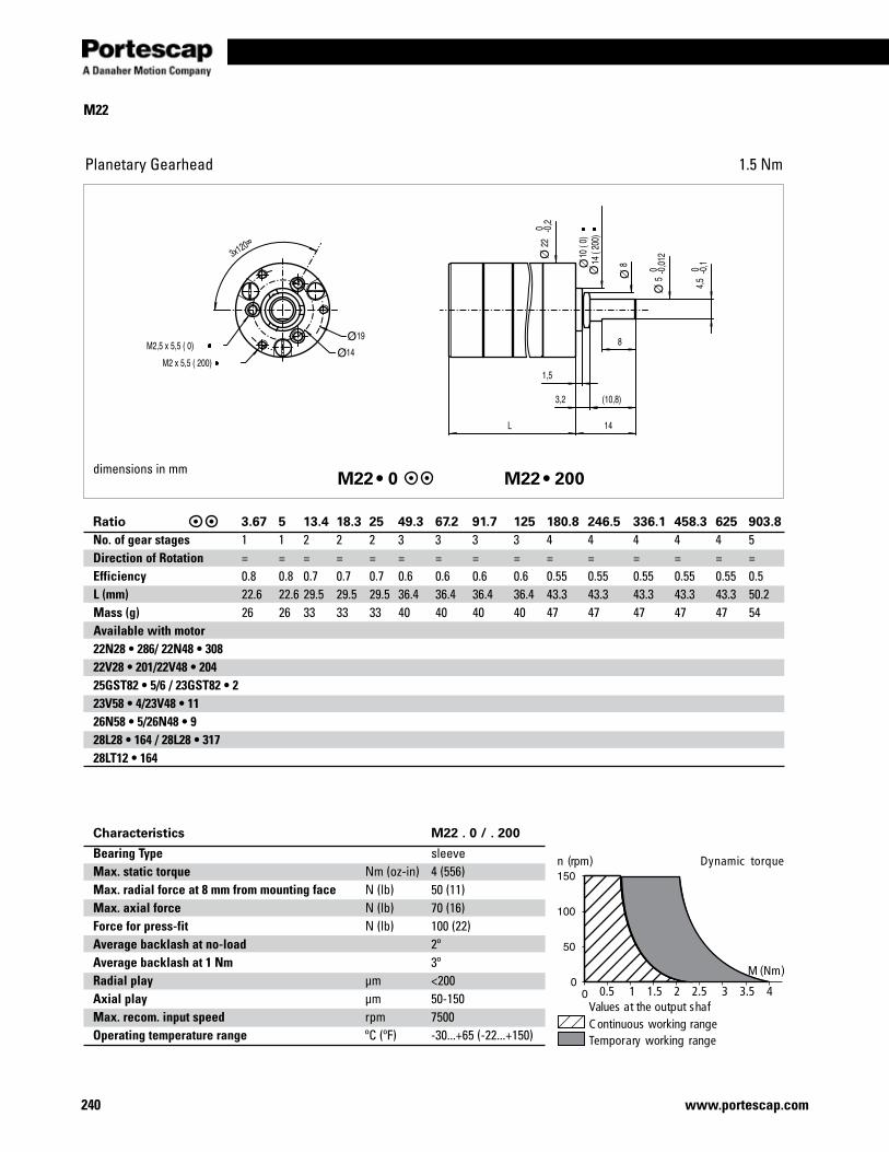
240 www.portescap.com
M22
Planetary Gearhead 1.5 Nm
dimensions in mm M22 • 0 M22 • 200
M (Nm)
Temporary working rangeC ontinuous working rangeValues at the output shaf
n (rpm) Dynamic torque
0.5 1 1.5 2 2.5 3 3.5 4
Characteristics M22 . 0 / . 200
Bearing Type sleeve Max. static torque Nm (oz-in) 4 (556)Max. radial force at 8 mm from mounting face N (lb) 50 (11) Max. axial force N (lb) 70 (16)Force for press-fit N (lb) 100 (22)Average backlash at no-load 2ºAverage backlash at 1 Nm 3ºRadial play µm <200Axial play µm 50-150Max. recom. input speed rpm 7500Operating temperature range ºC (ºF) -30...+65 (-22...+150)
Ratio 3.67 5 13.4 18.3 25 49.3 67.2 91.7 125 180.8 246.5 336.1 458.3 625 903.8No. of gear stages 1 1 2 2 2 3 3 3 3 4 4 4 4 4 5Direction of Rotation = = = = = = = = = = = = = = =Efficiency 0.8 0.8 0.7 0.7 0.7 0.6 0.6 0.6 0.6 0.55 0.55 0.55 0.55 0.55 0.5L (mm) 22.6 22.6 29.5 29.5 29.5 36.4 36.4 36.4 36.4 43.3 43.3 43.3 43.3 43.3 50.2Mass (g) 26 26 33 33 33 40 40 40 40 47 47 47 47 47 54Available with motor 22N28 • 286/ 22N48 • 308 22V28 • 201/22V48 • 204 25GST82 • 5/6 / 23GST82 • 2 23V58 • 4/23V48 • 11 26N58 • 5/26N48 • 9 28L28 • 164 / 28L28 • 317 28LT12 • 164
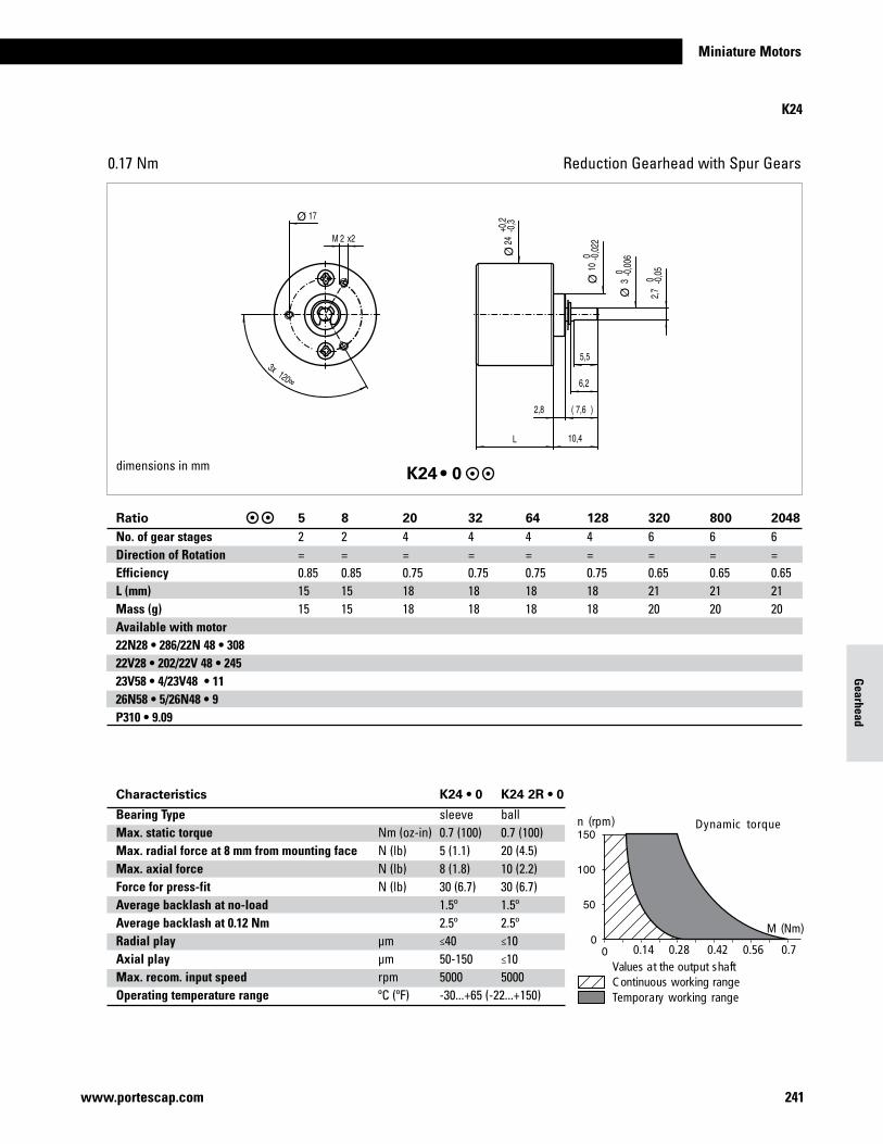
241www.portescap.com
Miniature Motors
Gearhead
Reduction Gearhead with Spur Gears0.17 Nm
K24 • 0
Characteristics K24 • 0 K24 2R • 0
Bearing Type sleeve ballMax. static torque Nm (oz-in) 0.7 (100) 0.7 (100)Max. radial force at 8 mm from mounting face N (lb) 5 (1.1) 20 (4.5)Max. axial force N (lb) 8 (1.8) 10 (2.2)Force for press-fit N (lb) 30 (6.7) 30 (6.7)Average backlash at no-load 1.5º 1.5ºAverage backlash at 0.12 Nm 2.5º 2.5ºRadial play µm ≤40 ≤10Axial play µm 50-150 ≤10Max. recom. input speed rpm 5000 5000Operating temperature range ºC (ºF) -30...+65 (-22...+150)
M (Nm)
n (rpm) Dynamic torque
Temporary working rangeC ontinuous working rangeValues at the output shaft
0.14 0.28 0.42 0.56 0.7
dimensions in mm
Ratio 5 8 20 32 64 128 320 800 2048No. of gear stages 2 2 4 4 4 4 6 6 6Direction of Rotation = = = = = = = = =Efficiency 0.85 0.85 0.75 0.75 0.75 0.75 0.65 0.65 0.65L (mm) 15 15 18 18 18 18 21 21 21Mass (g) 15 15 18 18 18 18 20 20 20Available with motor 22N28 • 286/22N 48 • 308 22V28 • 202/22V 48 • 245 23V58 • 4/23V48 • 11 26N58 • 5/26N48 • 9 P310 • 9.09
K24
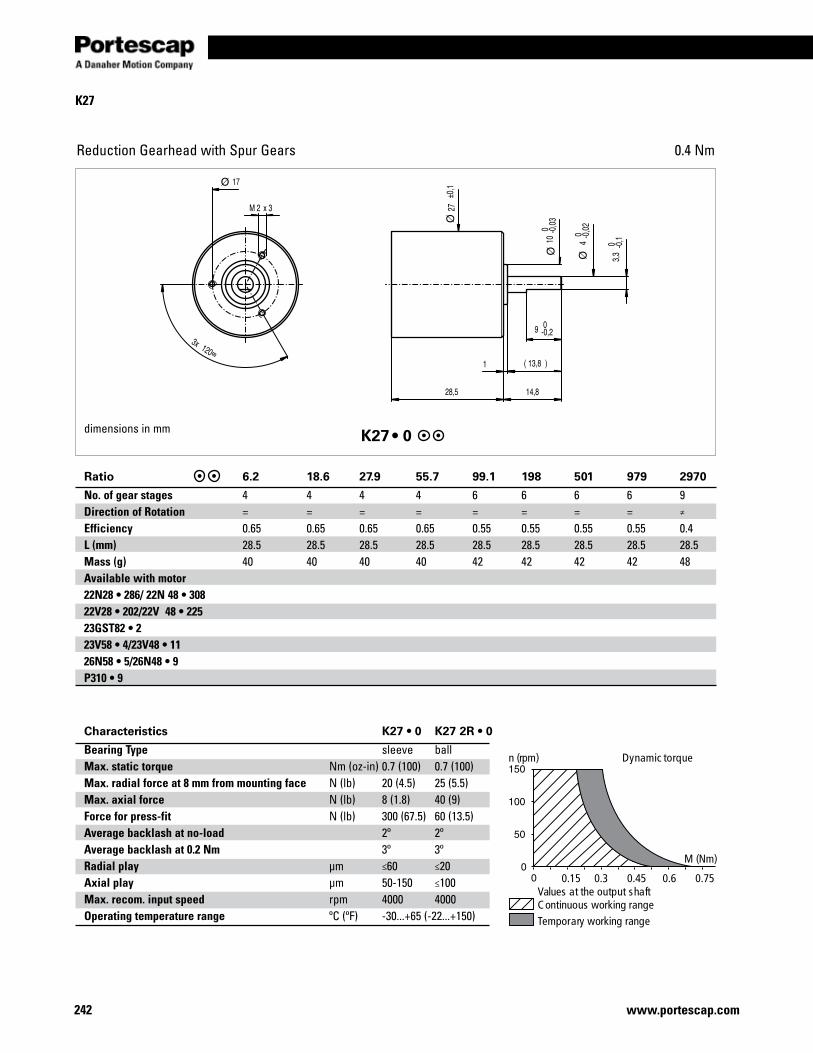
242 www.portescap.com
Reduction Gearhead with Spur Gears 0.4 Nm
dimensions in mm K27 • 0
Characteristics K27 • 0 K27 2R • 0
Bearing Type sleeve ballMax. static torque Nm (oz-in) 0.7 (100) 0.7 (100)Max. radial force at 8 mm from mounting face N (lb) 20 (4.5) 25 (5.5)Max. axial force N (lb) 8 (1.8) 40 (9)Force for press-fit N (lb) 300 (67.5) 60 (13.5)Average backlash at no-load 2º 2ºAverage backlash at 0.2 Nm 3º 3ºRadial play µm ≤60 ≤20Axial play µm 50-150 ≤100Max. recom. input speed rpm 4000 4000Operating temperature range ºC (ºF) -30...+65 (-22...+150)
M (Nm)
Temporary working rangeC ontinuous working rangeValues at the output shaft
n (rpm) Dynamic torque
0.15 0.3 0.45 0.6 0.75
K27
Ratio 6.2 18.6 27.9 55.7 99.1 198 501 979 2970
No. of gear stages 4 4 4 4 6 6 6 6 9Direction of Rotation = = = = = = = = ≠
Efficiency 0.65 0.65 0.65 0.65 0.55 0.55 0.55 0.55 0.4L (mm) 28.5 28.5 28.5 28.5 28.5 28.5 28.5 28.5 28.5Mass (g) 40 40 40 40 42 42 42 42 48Available with motor 22N28 • 286/ 22N 48 • 308 22V28 • 202/22V 48 • 225 23GST82 • 2 23V58 • 4/23V48 • 11 26N58 • 5/26N48 • 9 P310 • 9
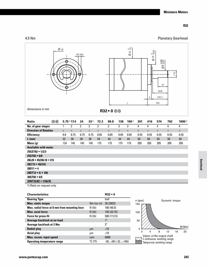
243www.portescap.com
Miniature Motors
Gearhead
Planetary Gearhead4.5 Nm
3M x5,5
L
10
15,25
16,5( )
20,5
70,
1
4
-0,0
08-0
,017
32 0 -0
,1
26
20 0 -0
,021
8
dimensions in mm R32 • 0
Characteristics R32 • 0
Bearing Type ball Max. static torque Nm (oz-in) 20 (2832) Max. radial force at 8 mm from mounting face N (lb) 180 (40.5) Max. axial force N (lb) 150 (33.75) Force for press-fit N (lb) 500 (112.5) Average backlash at no-load 1º Average backlash at 3 Nm 2º Radial play µm ≤10 Axial play µm ≤10 Max. recom. input speed rpm 6000 Operating temperature range ºC (ºF) -30...+85 (-22...+185)
M (Nm)
Temporary working rangeC ontinuous working rangeValues at the output shaft
n (rpm) Dynamic torque
R32
Ratio 5.75 1) 17.4 24 33 1) 72.3 99.8 138 190 1) 301 416 574 792 1090 1)
No. of gear stages 1 2 2 2 3 3 3 3 4 4 4 4 4Direction of Rotation = = = = = = = = = = = = =Efficiency 0.8 0.75 0.75 0.75 0.65 0.65 0.65 0.65 0.55 0.55 0.55 0.55 0.55L (mm) 32 38 38 38 44 44 44 44 50 50 50 50 50Mass (g) 124 145 145 145 175 175 175 175 205 205 205 205 205Available with motor 25GST82 • 1/2/3 25GT82 • 6/8 28L28 • 49/28L18 • 315 28LT12 • 49/316 28D11 • 4 28DT12 • 4/ • 106 30GT82 • 4/5 35NT32/82 • 1/50/351) Ratio on request only
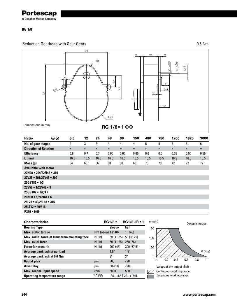
244 www.portescap.com
RG 1/8
Reduction Gearhead with Spur Gears 0.6 Nm
RG 1/8 • 1
Ratio 5.5 12 24 48 96 150 480 750 1200 1920 3000
No. of gear stages 2 3 3 4 4 4 5 5 6 6 6Direction of Rotation = ≠ ≠ = = = ≠ ≠ = = =Efficiency 0.8 0.7 0.7 0.65 0.65 0.65 0.6 0.6 0.55 0.55 0.55L (mm) 16.5 16.5 16.5 16.5 16.5 16.5 16.5 16.5 16.5 16.5 16.5Mass (g) 64 66 66 68 68 68 70 70 72 72 72Available with motor 22N28 • 204/22N48 • 310 22V28 • 201/22V48 • 204 23GST82 • 1/3 23V58 • 1/23V48 • 9 25GST82 • 1/2/4 / 26N58 • 1/26N48 • 6 28L28 • 49/28L18 • 315 28LT12 • 49/316 P310 • 9.09
Continuous working rangeTemporary working range
Values at the output shaft
Dynamic torquen (rpm)
M (Nm)
0.2 0.4 0.6 0.8 1
dimensions in mm
Characteristics RG1/8 • 1 RG1/8 2R • 1
Bearing Type sleeve ballMax. static torque Nm (oz-in) 1 (140) 1 (140)Max. radial force at 8 mm from mounting face N (lb) 50 (11.25) 50 (33.75)Max. axial force N (lb) 50 (11.25) 250 (56)Force for press-fit N (lb) 200 (45) 300 (67.51)Average backlash at no-load 1.5º 1.5ºAverage backlash at 0.6 Nm 3º 3ºRadial play µm ≤60 ≤20Axial play µm 50-250 ≤200Max. recom. input speed rpm 5000 5000Operating temperature range ºC (ºF) -30...+65 (-22...+150)
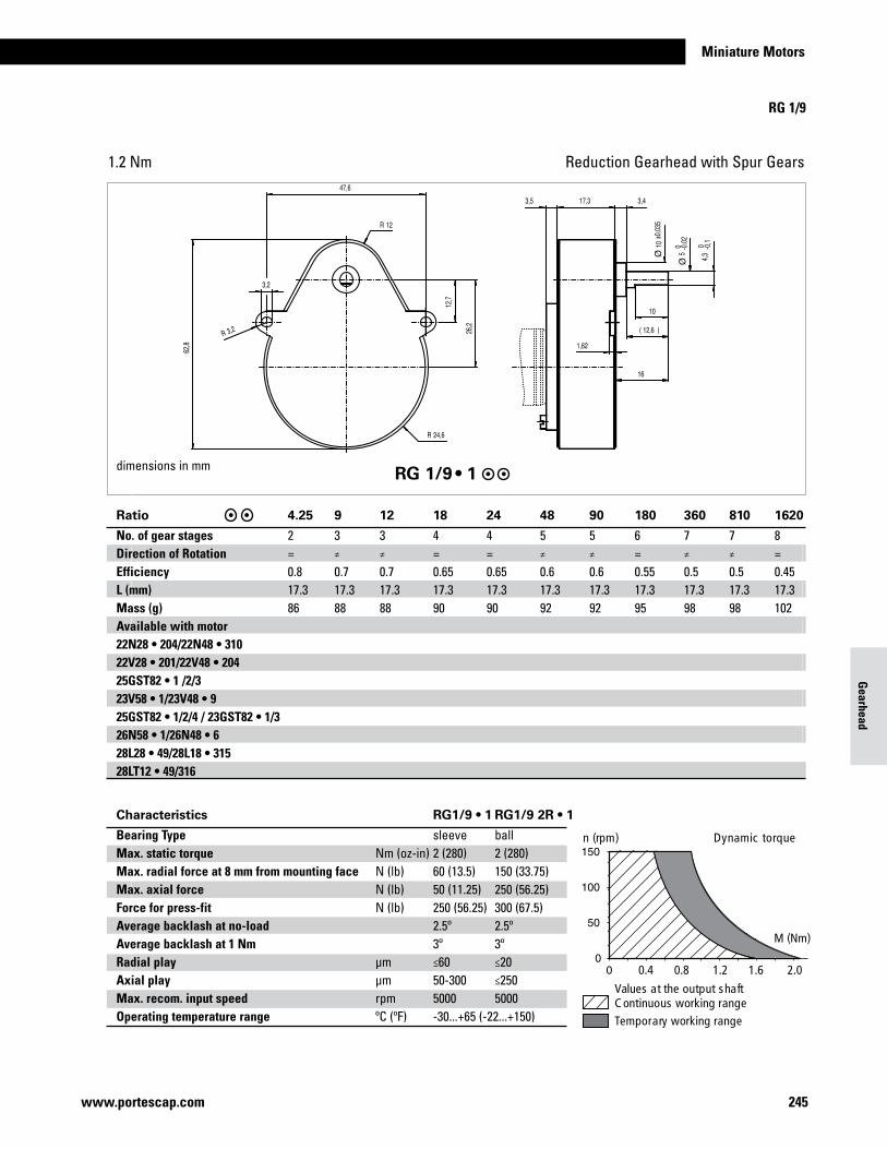
245www.portescap.com
Miniature Motors
Gearhead
Ratio 5.5 12 24 48 96 150 480 750 1200 1920 3000
No. of gear stages 2 3 3 4 4 4 5 5 6 6 6Direction of Rotation = ≠ ≠ = = = ≠ ≠ = = =Efficiency 0.8 0.7 0.7 0.65 0.65 0.65 0.6 0.6 0.55 0.55 0.55L (mm) 16.5 16.5 16.5 16.5 16.5 16.5 16.5 16.5 16.5 16.5 16.5Mass (g) 64 66 66 68 68 68 70 70 72 72 72Available with motor 22N28 • 204/22N48 • 310 22V28 • 201/22V48 • 204 23GST82 • 1/3 23V58 • 1/23V48 • 9 25GST82 • 1/2/4 / 26N58 • 1/26N48 • 6 28L28 • 49/28L18 • 315 28LT12 • 49/316 P310 • 9.09
RG 1/9
Reduction Gearhead with Spur Gears1.2 Nm
dimensions in mm RG 1/9 • 1
Characteristics RG1/9 • 1 RG1/9 2R • 1
Bearing Type sleeve ballMax. static torque Nm (oz-in) 2 (280) 2 (280)Max. radial force at 8 mm from mounting face N (lb) 60 (13.5) 150 (33.75)Max. axial force N (lb) 50 (11.25) 250 (56.25)Force for press-fit N (lb) 250 (56.25) 300 (67.5)Average backlash at no-load 2.5º 2.5ºAverage backlash at 1 Nm 3º 3ºRadial play µm ≤60 ≤20Axial play µm 50-300 ≤250Max. recom. input speed rpm 5000 5000Operating temperature range ºC (ºF) -30...+65 (-22...+150)
M (Nm)
Temporary working rangeC ontinuous working rangeValues at the output shaft
n (rpm) Dynamic torque
0.4 0.8 1.2 1.6 2.0
Ratio 4.25 9 12 18 24 48 90 180 360 810 1620
No. of gear stages 2 3 3 4 4 5 5 6 7 7 8Direction of Rotation = ≠ ≠ = = ≠ ≠ = ≠ ≠ =Efficiency 0.8 0.7 0.7 0.65 0.65 0.6 0.6 0.55 0.5 0.5 0.45L (mm) 17.3 17.3 17.3 17.3 17.3 17.3 17.3 17.3 17.3 17.3 17.3Mass (g) 86 88 88 90 90 92 92 95 98 98 102Available with motor 22N28 • 204/22N48 • 310 22V28 • 201/22V48 • 204 25GST82 • 1 /2/3 23V58 • 1/23V48 • 9 25GST82 • 1/2/4 / 23GST82 • 1/3 26N58 • 1/26N48 • 6 28L28 • 49/28L18 • 315 28LT12 • 49/316
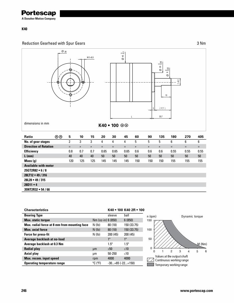
246 www.portescap.com
K40
Reduction Gearhead with Spur Gears 3 Nm
K40 • 100
Ratio 5 10 15 20 30 45 60 90 135 180 270 405No. of gear stages 2 3 3 4 4 4 5 5 5 6 6 6Direction of Rotation = ≠ ≠ = = = ≠ ≠ ≠ = = =Efficiency 0.8 0.7 0.7 0.65 0.65 0.65 0.6 0.6 0.6 0.55 0.55 0.55L (mm) 40 40 40 50 50 50 50 50 50 50 50 50Mass (g) 120 125 125 145 145 145 150 150 150 155 155 155Available with motor 25GT2R82 • 6 / 8 28LT12 • 49 / 316 28L28 • 49 / 315 28D11 • 4 35NT2R32 • 54 / 66
Characteristics K40 • 100 K40 2R • 100
Bearing Type sleeve ballMax. static torque Nm (oz-in) 6 (850) 6 (850)Max. radial force at 8 mm from mounting face N (lb) 80 (18) 150 (33.75)Max. axial force N (lb) 80 (18) 150 (33.75)Force for press-fit N (lb) 200 (45) 200 (45)Average backlash at no-load 1º 1ºAverage backlash at 0.3 Nm 1.5º 1.5ºRadial play µm ≤50 ≤10Axial play µm 50-250 ≤10Max. recom. input speed rpm 4000 4000Operating temperature range ºC (ºF) -30...+65 (-22...+150)
M (Nm)
Temporary working rangeContinuous working rangeValues at the output shaft
n (rpm) Dynamic torque
dimensions in mm
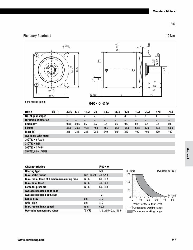
247www.portescap.com
Miniature Motors
Gearhead
R40
Planetary Gearhead 10 Nm
L
dimensions in mm R40 • 0
Ratio 3.56 5.6 15.2 24 54.2 85.3 134 193 303 478 753No. of gear stages 1 1 2 2 3 3 3 4 4 4 4Direction of Rotation = = = = = = = = = = =Efficiency 0.85 0.85 0.7 0.7 0.6 0.6 0.6 0.5 0.5 0.5 0.5L (mm) 38.3 38.3 46,8 46.8 55.3 55.3 55.3 63.8 63.8 63.8 63.8Mass (g) 245 245 285 285 340 340 340 400 400 400 400Available with motor 25GT82 • 1 / 2 / 4 28DT12 • 1/98 30GT82 • 4 / • 5 35NT32/82 • 1/50/69
M (Nm)
Temporary working rangeC ontinuous working rangeValues at the output shaft
n (rpm) Dynamic torque
Characteristics R40 • 0
Bearing Type ballMax. static torque Nm (oz-in) 40 (5700)Max. radial force at 8 mm from mounting face N (lb) 600 (135)Max. axial force N (lb) 400 (90)Force for press-fit N (lb) 600 (135)Average backlash at no-load 1ºAverage backlash at 0.3 Nm 1.3ºRadial play µm ≤10Axial play µm ≤10Max. recom. input speed rpm 6000Operating temperature range ºC (ºF) -30...+85 (-22...+185)

248 www.portescap.com
Notes
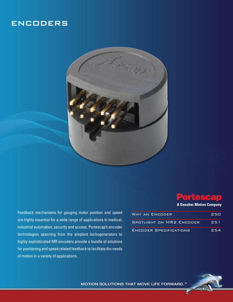
EncodErs
Why an Encoder 250
Spotlight on MR2 Encoder 251
Encoder Specifications 254
Feedback mechanisms for gauging motor position and speed
are highly essential for a wide range of applications in medical,
industrial automation, security and access. Portescap’s encoder
technologies spanning from the simplest tachogenerators to
highly sophisticated MR encoders provide a bundle of solutions
for positioning and speed related feedback to facilitate the needs
of motion in a variety of applications.
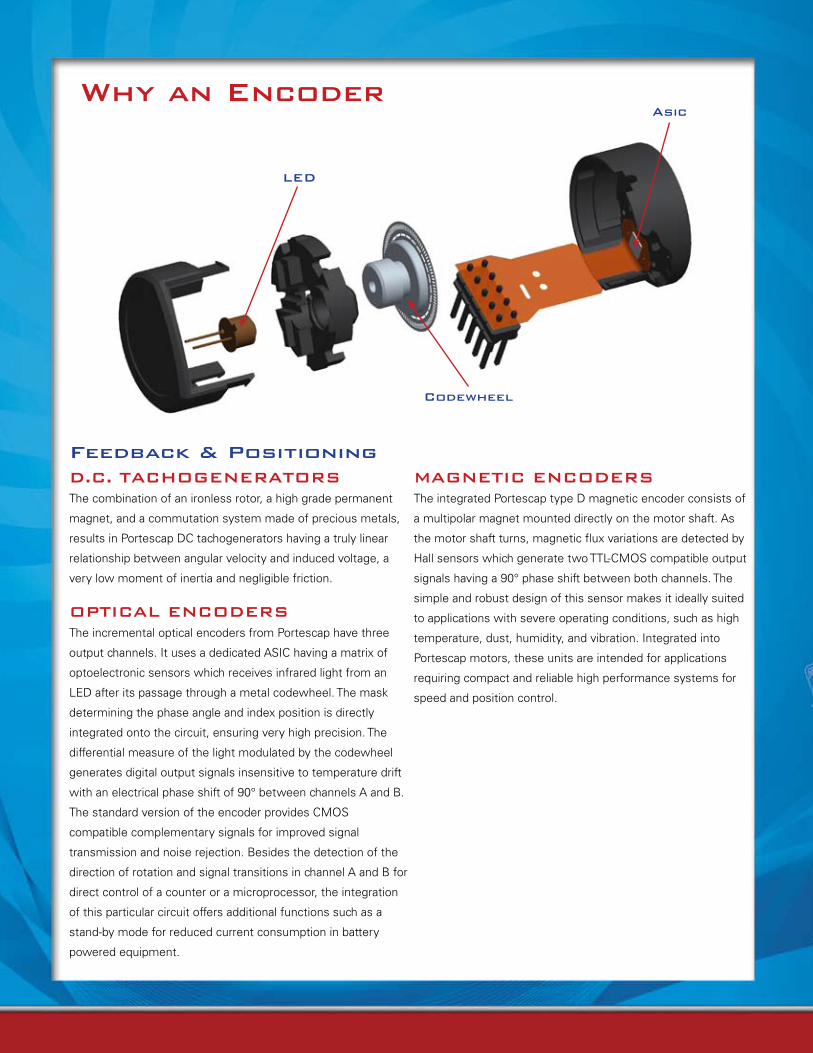
Why an Encoder
LEd
codewheel
Asic
d.c. TAcHoGEnErATorsThe combination of an ironless rotor, a high grade permanent
magnet, and a commutation system made of precious metals,
results in Portescap DC tachogenerators having a truly linear
relationship between angular velocity and induced voltage, a
very low moment of inertia and negligible friction.
oPTIcAL EncodErsThe incremental optical encoders from Portescap have three
output channels. It uses a dedicated ASIC having a matrix of
optoelectronic sensors which receives infrared light from an
LED after its passage through a metal codewheel. The mask
determining the phase angle and index position is directly
integrated onto the circuit, ensuring very high precision. The
differential measure of the light modulated by the codewheel
generates digital output signals insensitive to temperature drift
with an electrical phase shift of 90° between channels A and B.
The standard version of the encoder provides CMOS
compatible complementary signals for improved signal
transmission and noise rejection. Besides the detection of the
direction of rotation and signal transitions in channel A and B for
direct control of a counter or a microprocessor, the integration
of this particular circuit offers additional functions such as a
stand-by mode for reduced current consumption in battery
powered equipment.
Feedback & PositioningMAGnETIc EncodErsThe integrated Portescap type D magnetic encoder consists of
a multipolar magnet mounted directly on the motor shaft. As
the motor shaft turns, magnetic flux variations are detected by
Hall sensors which generate two TTL-CMOS compatible output
signals having a 90° phase shift between both channels. The
simple and robust design of this sensor makes it ideally suited
to applications with severe operating conditions, such as high
temperature, dust, humidity, and vibration. Integrated into
Portescap motors, these units are intended for applications
requiring compact and reliable high performance systems for
speed and position control.
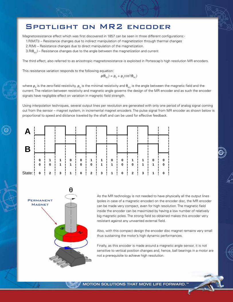
Why an Encoder spotlight on Mr2 encoderMagnetoresistance effect which was first discovered in 1857 can be seen in three different configurations:- 1.R(M(T)) – Resistance changes due to indirect manipulation of magnetization through thermal changes 2.R(M) – Resistance changes due to direct manipulation of the magnetization. 3.R(θM,I) – Resistance changes due to the angle between the magnetization and current
The third effect, also referred to as anisotropic magnetoresistance is exploited in Portescap’s high resolution MR encoders.
This resistance variation responds to the following equation:ρ(θM,I) = ρ0 + ρ∆cos2(θM,I)
where ρ0 is the zero-field resistivity, ρ∆ is the minimal resistivity and θM,I is the angle between the magnetic field and the current. The relation between resistivity and magnetic angle governs the design of the MR encoder and as such the encoder signals have negligible effect on variation in magnetic field strength.
Using interpolation techniques, several output lines per revolution are generated with only one period of analog signal coming out from the sensor – magnet system, in incremental magnet encoders. The pulse signal from MR encoder as shown below is proportional to speed and distance traveled by the shaft and can be used for effective feedback.
32 3 1 1 00 20 2 3 1 0State:
01
00
10
11
01
00
10
11
01
00
10
11
A
B00
PermanentMagnet
As the MR technology is not needed to have physically all the output lines (poles in case of a magnetic encoder) on the encoder disc, the MR encoder can be made very compact, even for high resolution. The magnetic field inside the encoder can be maximized by having a low number of relatively big magnetic poles. The strong field so obtained makes this encoder very resistant against any unwanted external field.
Also, with this compact design the encoder disc magnet remains very small thus sustaining the motor’s high dynamic performances.
Finally, as this encoder is made around a magnetic angle sensor, it is not sensitive to vertical position changes and, hence, ball bearings in a motor are not a prerequisite to achieve high resolution.
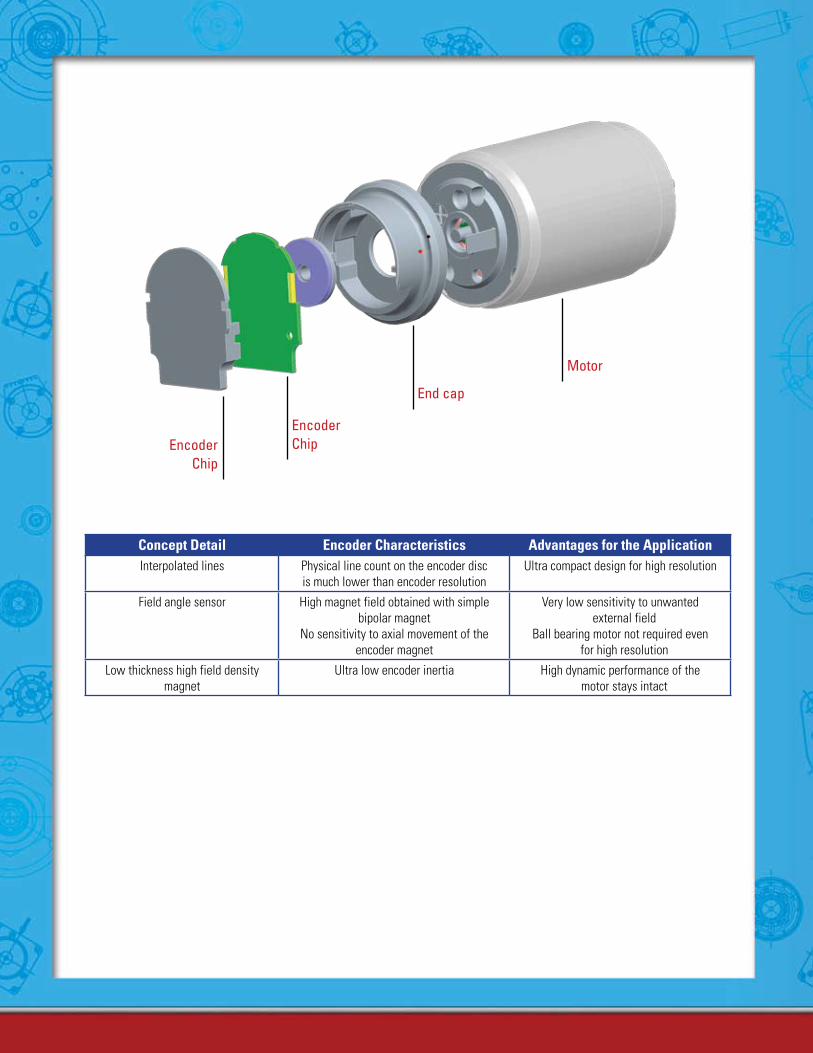
Concept Detail Encoder Characteristics Advantages for the ApplicationInterpolated lines Physical line count on the encoder disc
is much lower than encoder resolutionUltra compact design for high resolution
Field angle sensor High magnet field obtained with simplebipolar magnet
No sensitivity to axial movement of theencoder magnet
Very low sensitivity to unwanted external field
Ball bearing motor not required even for high resolution
Low thickness high field density magnet
Ultra low encoder inertia High dynamic performance of the motor stays intact
EncoderChip
End cap
Motor
EncoderChip
253www.portescap.com
Miniature Motors
Notes
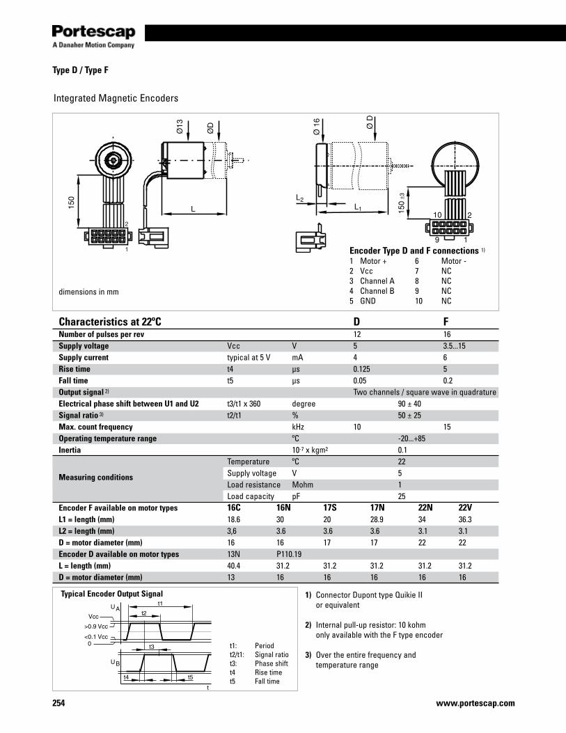
254 www.portescap.com
Type D / Type F
Integrated Magnetic Encoders
dimensions in mm
Characteristics at 22ºC D FNumber of pulses per rev 12 16 Supply voltage Vcc V 5 3.5...15Supply current typical at 5 V mA 4 6Rise time t4 µs 0.125 5Fall time t5 µs 0.05 0.2Output signal 2) Two channels / square wave in quadratureElectrical phase shift between U1 and U2 t3/t1 x 360 degree 90 ± 40Signal ratio 3) t2/t1 % 50 ± 25Max. count frequency kHz 10 15Operating temperature range ºC -20...+85Inertia 10-7 x kgm2 0.1
Measuring conditions
Temperature ºC 22 Supply voltage V 5 Load resistance Mohm 1 Load capacity pF 25Encoder F available on motor types 16C 16N 17S 17N 22N 22VL1 = length (mm) 18.6 30 20 28.9 34 36.3L2 = length (mm) 3,6 3.6 3.6 3.6 3.1 3.1D = motor diameter (mm) 16 16 17 17 22 22Encoder D available on motor types 13N P110.19 L = length (mm) 40.4 31.2 31.2 31.2 31.2 31.2 D = motor diameter (mm) 13 16 16 16 16 16
1) Connector Dupont type Quikie II or equivalent
2) Internal pull-up resistor: 10 kohm only available with the F type encoder
3) Over the entire frequency and temperature range
Typical Encoder Output Signal
t1: Periodt2/t1: Signal ratiot3: Phase shiftt4 Rise timet5 Fall time
Encoder Type D and F connections 1)
1 Motor + 6 Motor -2 Vcc 7 NC3 Channel A 8 NC4 Channel B 9 NC5 GND 10 NC
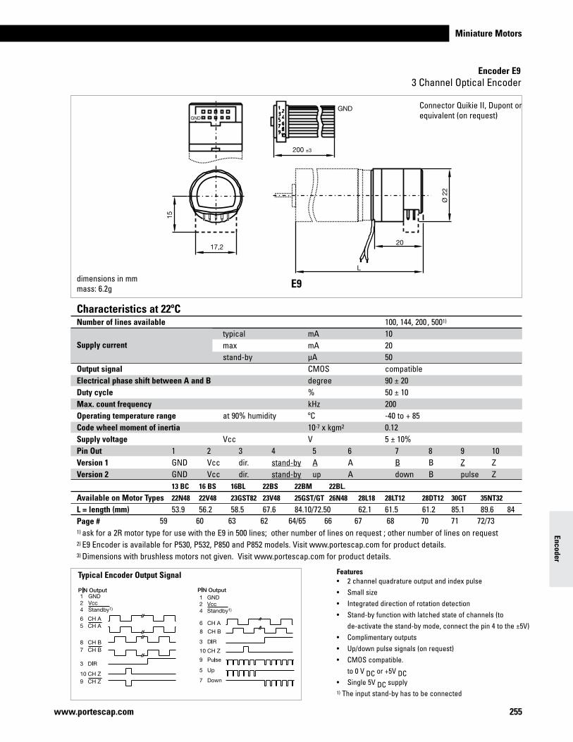
Miniature Motors
Encoder E9
255www.portescap.com
3 Channel Optical Encoder
dimensions in mmmass: 6.2g E9
Features• 2channelquadratureoutputandindexpulse• Smallsize• Integrateddirectionofrotationdetection• Stand-byfunctionwithlatchedstateofchannels(to de-activate the stand-by mode, connect the pin 4 to the ±5V)• Complimentaryoutputs• Up/downpulsesignals(onrequest)• CMOScompatible. to 0 V DC or +5V DC• Single5VDC supply1) The input stand-by has to be connected
Typical Encoder Output Signal
Connector Quikie II, Dupont or equivalent(onrequest)
Encoder
Characteristics at 22ºC Number of lines available 100, 144, 200 , 5001)
Supply current typical mA 10
max mA 20 stand-by µA 50 Output signal CMOS compatible Electrical phase shift between A and B degree 90 ± 20 Duty cycle % 50 ± 10 Max. count frequency kHz 200 Operating temperature range at 90% humidity ºC -40 to + 85 Code wheel moment of inertia 10-7 x kgm2 0.12 Supply voltage Vcc V 5 ± 10% Pin Out 1 2 3 4 5 6 7 8 9 10 Version 1 GND Vcc dir. stand-by A A B B Z Z Version 2 GND Vcc dir. stand-by up A down B pulse Z 13 BC 16 BS 16BL 22BS 22BM 22BL.
Available on Motor Types 22N48 22V48 23GST82 23V48 25GST/GT 26N48 28L18 28LT12 28DT12 30GT 35NT32
L = length (mm) 53.9 56.2 58.5 67.6 84.10/72.50 62.1 61.5 61.2 85.1 89.6 84Page # 1) ask for a 2R motor type for use with the E9 in 500 lines; other number of lines on request ; other number of lines on request2) E9 Encoder is available for P530, P532, P850 and P852 models. Visit www.portescap.com for product details. 3) Dimensions with brushless motors not given. Visit www.portescap.com for product details.
59 60 63 62 64/65 66 67 68 70 71 72/73
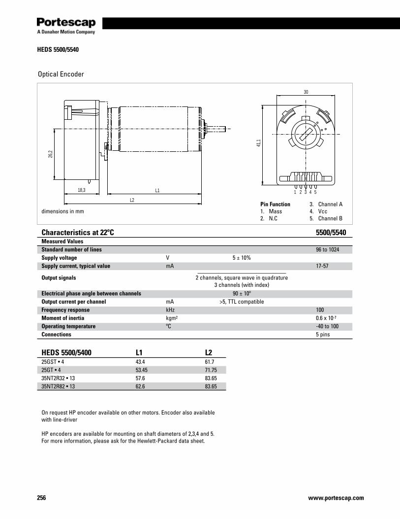
256 www.portescap.com
HEDS 5500/5540
Optical Encoder
1 2 3 4 5
26,2
30
41,1
L118,3
L2
dimensions in mmPin Function1. Mass2. N.C
3. Channel A4. Vcc5. Channel B
Characteristics at 22ºC 5500/5540Measured ValuesStandard number of lines 96 to 1024Supply voltage V 5 ± 10% Supply current, typical value mA 17-57
Output signals 2 channels, square wave in quadrature 3channels(withindex)Electrical phase angle between channels 90 ± 10º Output current per channel mA >5, TTL compatible Frequency response kHz 100Moment of inertia kgm2 0.6 x 10⁻⁷
Operating temperature ºC -40 to 100Connections 5 pins
HEDS 5500/5400 L1 L2 25GST•4 43.4 61.725GT•4 53.45 71.7535NT2R32•13 57.6 83.6535NT2R82•13 62.6 83.65
On request HP encoder available on other motors. Encoder also available with line-driver
HP encoders are available for mounting on shaft diameters of 2,3,4 and 5. For more information, please ask for the Hewlett-Packard data sheet.
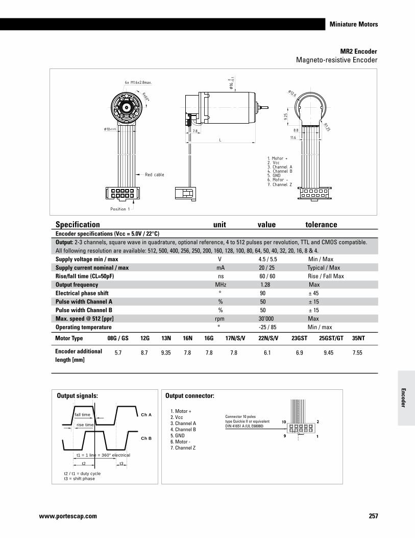
Miniature Motors
257www.portescap.com
Encoder
Magneto-resistive Encoder
Specification unit value tolerance Encoder specifications (Vcc = 5.0V / 22°C) Output: 2-3 channels, square wave in quadrature, optional reference, 4 to 512 pulses per revolution, TTL and CMOS compatible.All following resolution are available: 512, 500, 400, 256, 250, 200, 160, 128, 100, 80, 64, 50, 40, 32, 20, 16, 8 & 4. Supply voltage min / max V 4.5 / 5.5 Min / Max Supply current nominal / max mA 20 / 25 Typical / Max Rise/fall time (CL=50pF) ns 60 / 60 Rise / Fall Max Output frequency MHz 1.28 MaxElectrical phase shift ° 90 ± 45 Pulse width Channel A % 50 ± 15Pulse width Channel B % 50 ± 15Max. speed @ 512 [ppr] rpm 30’000 MaxOperating temperature ° -25 / 85 Min / max
08G / GS 12G 13N 16N 16G 17N/S/V 22N/S/V 23GST 25GST/GT 35NT
5.7 8.7 9.35 7.8 7.8 7.8 6.1 6.9 9.45 7.55
Motor Type
Encoder additional length [mm]
MR2 Encoder
Output signals:
t1 = 1 line = 360° electrical
t2 t3
t2 / t1 = duty cycle t3 = shift phase
Ch A
Ch B
fall time
rise time
Output connector:
1. Motor +2. Vcc3. Channel A4. Channel B5. GND6. Motor -7. Channel Z
Connector 10 polestype Quickie II or equivalentDIN 41651 A (UL E68080)

258 www.portescap.com
Notes
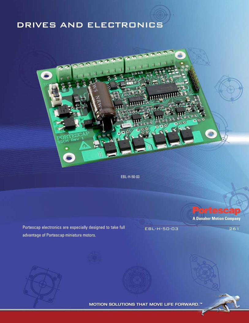
EBL-H-50-03
DRIVES AND ELECTRONICS
EBL-H-50-03 261
Portescap electronics are especially designed to take full
advantage of Portescap miniature motors.

260 www.portescap.com
Notes
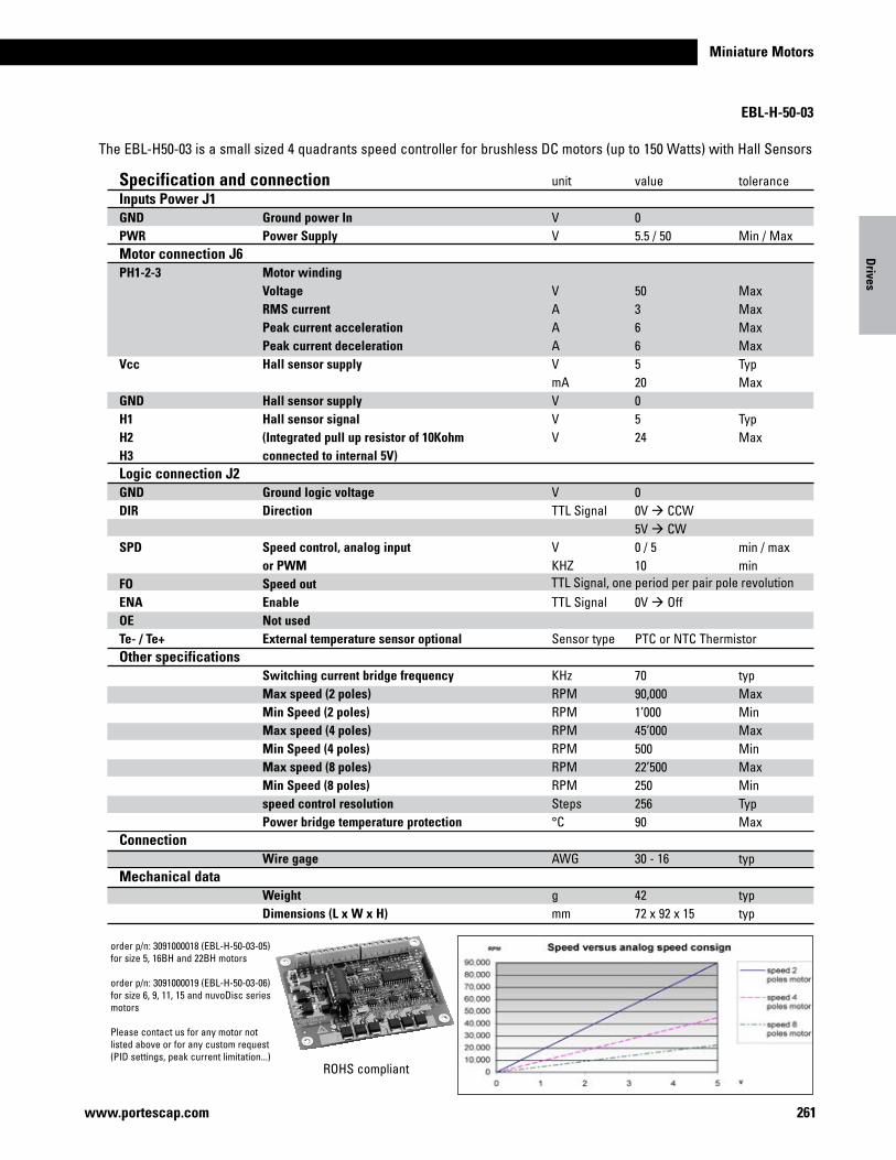
Miniature Motors
261www.portescap.com
Drives
EBL-H-50-03
The EBL-H50-03 is a small sized 4 quadrants speed controller for brushless DC motors (up to 150 Watts) with Hall Sensors
ROHS compliant
order p/n: 3091000018 (EBL-H-50-03-05) for size 5, 16BH and 22BH motors
order p/n: 3091000019 (EBL-H-50-03-06) for size 6, 9, 11, 15 and nuvoDisc series motors
Please contact us for any motor not listed above or for any custom request (PID settings, peak current limitation...)
Ground power InPower Supply
Motor windingVoltageRMS currentPeak current accelerationPeak current decelerationHall sensor supply
Hall sensor supplyHall sensor signal(Integrated pull up resistor of 10Kohm connected to internal 5V)
Ground logic voltageDirection
Speed control, analog input or PWMSpeed outEnableNot usedExternal temperature sensor optional
Switching current bridge frequencyMax speed (2 poles)Min Speed (2 poles)Max speed (4 poles)Min Speed (4 poles)Max speed (8 poles)Min Speed (8 poles)speed control resolutionPower bridge temperature protection
Wire gage
WeightDimensions (L x W x H)
Specification and connectionInputs Power J1GNDPWR Motor connection J6PH1-2-3
Vcc
GNDH1H2H3 Logic connection J2GNDDIR
SPD
FOENAOETe- / Te+Other specifications
Connection
Mechanical data
unit
VV
VAAAVmAVVV
VTTL Signal
VKHZ
TTL Signal
Sensor type
KHzRPMRPMRPMRPMRPMRPMSteps°C
AWG
gmm
value
05.5 / 50
503665200524
00V à CCW5V à CW0 / 510
0V à Off
PTC or NTC Thermistor
7090,000 1’00045’00050022’50025025690
30 - 16
4272 x 92 x 15
tolerance
Min / Max
MaxMaxMaxMaxTypMax
TypMax
min / maxmin
typMaxMinMaxMinMaxMinTypMax
typ
typtyp
TTL Signal, one period per pair pole revolution

262www.portescap.com
Miniature Motors
Notes
EnginEErs appEndix
Engineers appendix 264
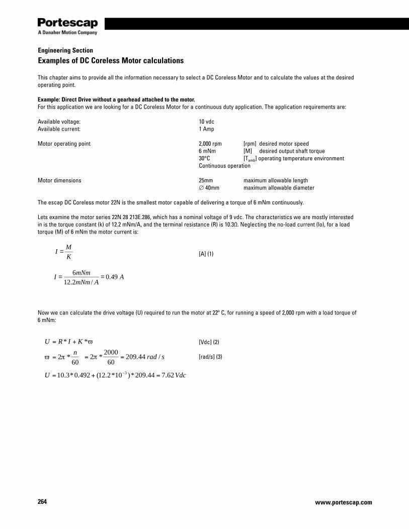
264
Engineering Section
www.portescap.com
Examples of DC Coreless Motor calculations
This chapter aims to provide all the information necessary to select a DC Coreless Motor and to calculate the values at the desired operating point.
Example: Direct Drive without a gearhead attached to the motor.For this application we are looking for a DC Coreless Motor for a continuous duty application. The application requirements are:
Available voltage: 10 vdcAvailable current: 1 Amp
Motor operating point 2,000 rpm [rpm] desired motor speed 6 mNm [M] desired output shaft torque 30°C [Tamb] operating temperature environment Continuous operation
Motor dimensions 25mm maximum allowable length ∅ 40mm maximum allowable diameter The escap DC Coreless motor 22N is the smallest motor capable of delivering a torque of 6 mNm continuously.
Lets examine the motor series 22N 28 213E.286, which has a nominal voltage of 9 vdc. The characteristics we are mostly interested in is the torque constant (k) of 12.2 mNm/A, and the terminal resistance (R) is 10.3Ω. Neglecting the no-load current (lo), for a load torque (M) of 6 mNm the motor current is: [A] (1)
Now we can calculate the drive voltage (U) required to run the motor at 22º C, for running a speed of 2,000 rpm with a load torque of 6 mNm:
[Vdc] (2) [rad/s] (3)
K
MI =
AAmNm
mNmI 49.0
/2.126
==
srad /44.20960
2000*2 == π
60*2
nπϖ =
VdcU 62.744.209*)10*2.12(492.0*3.10 3 =+= −
ϖ** KIRU +=
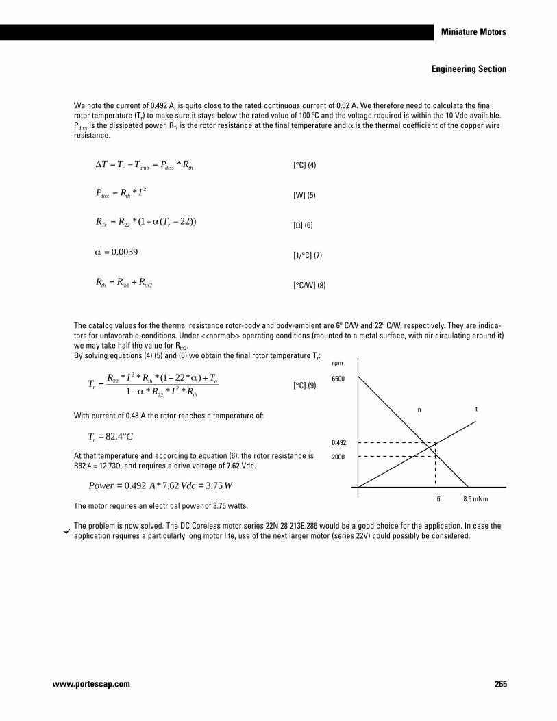
265
Miniature Motors
Engineering Section
www.portescap.com
We note the current of 0.492 A, is quite close to the rated continuous current of 0.62 A. We therefore need to calculate the final rotor temperature (Tr) to make sure it stays below the rated value of 100 ºC and the voltage required is within the 10 Vdc available. Pdiss is the dissipated power, RTr is the rotor resistance at the final temperature and α is the thermal coefficient of the copper wire resistance.
[°C] (4)
[W] (5)
[Ω] (6)
[1/°C] (7) [°C/W] (8)
The catalog values for the thermal resistance rotor-body and body-ambient are 6º C/W and 22º C/W, respectively. They are indica-tors for unfavorable conditions. Under <<normal>> operating conditions (mounted to a metal surface, with air circulating around it) we may take half the value for Rth2.By solving equations (4) (5) and (6) we obtain the final rotor temperature Tr: [°C] (9)
With current of 0.48 A the rotor reaches a temperature of:
At that temperature and according to equation (6), the rotor resistance is R82.4 = 12.73Ω, and requires a drive voltage of 7.62 Vdc.
The motor requires an electrical power of 3.75 watts.
The problem is now solved. The DC Coreless motor series 22N 28 213E.286 would be a good choice for the application. In case the application requires a particularly long motor life, use of the next larger motor (series 22V) could possibly be considered.
thdissambr RPTTT *=−=Δ
2* IRP thdiss =
))22(1(*22 −+= rTr TRR α
0039.0=α
21 ththth RRR +=
rpm
6500
0.492
2000
6 8.5 mNm
n t
th
athr RIR
TRIRT
***1
)*221(***2
22
222
α
α
−
+−=
CTr °= 4.82
WVdcAPower 75.362.7*492.0 ==
266
Engineering Section
www.portescap.com
Examples of DC Coreless Gearmotor calculationExample: Direct Drive with a gearhead attached to the motor.
For this application we are looking for a DC Coreless Motor & Gearhead for a continuous duty application. The application requirements are:
Available voltage: 15 vdcAvailable current: 1.5 Amp
Motor operating point 30 rpm [rpm] desired motor speed 500 mNm [M] desired output shaft torque 22°C [Tamb] operating temperature environment Continuous operation
Motor dimensions 80mm maximum allowable length ∅ 25mm maximum allowable diameter The gearhead specification page for the R22 shows this torque can be achieved with this planetary gearhead. When choosing the reduction ratio we should keep in mind the recommended maximum input speed of the R22 gearhead should remain below 5,000 rpm in order to assure low wear and low audible noise.
[-] (10)
The catalog indicates the closest ratio to the desired one calculated above is 111:1, the efficiency for this ratio is 0.6 (or 60%). We may now calculate the motor speed (nm) and the reflected torque (Mm) on the motor shaft. [mNm] (11)
[rpm] (12)
The motor table shows the 22V28 series motor can deliver torque of 7.5 mNm continuously. The 22V28 series motor is available as a standard combination with the planetary gearhead R22. After choosing a voltage winding we can calculate the motor current and voltage the same way as in the previous example.
The motor having a load torque value (M) of 7.5 mNm is required to be driven at a speed of 3,330 rpm. The ambient temperature (Tamb) is 22º. The available voltage in the application is 12 vdc.
Lets examine the motor series 22V 28 213E.202, which has a nominal voltage of 12 vdc. The characteristics we are mostly interested in are the torque constant (k) of 14.9 mNm/A, and the terminal resistance is 11.9Ω. Neglecting the no-load current (lo), for a torque load of 7.51 mNm the motor current is:
[A]
η*iM
M m =
mNmNmmNm
M m 51.710*51.76.0*111
500 3 === −
rpminn chm 330,3111*30* ===
chnn
i max≤
rpmrpm
rpmi 7.166
30
5000=≤
AAmNm
mNmkM
I 50.0/9.14
51.7===
267
Miniature Motors
www.portescap.com
Engineering section
Now we can calculate the drive voltage required to run the motor at 22º C, for a desired speed of 3,300 rpm with a load torque of 7.5 mNm:
[[Vdc]
[rad/s]
We note the current of the motor under load is 0.50, which is quite close to the rated continuous current of 0.58 A. We therefore calculate the final rotor temperature (Tf) to make sure it stays below the rated value of 100º C and the voltage required is within the 12 Vdc available. Pdiss is the dissipated power, RTr is the rotor resistance at the final temperature and α is the thermal coefficient of the copper wire resistance.
[°C] [W]
[Ω]
[1/°C] [°C/W]
The catalog values for the thermal resistance rotor-body and body-ambient are 6º C/W and 22º C/W, respectively. They are indicators for unfavorable conditions. Under <<normal>> operating conditions (mounted to a metal surface and with air circulating around it) we may take half the value for Rth2.By solving equations (4), (5) and (6) we obtain the final rotor temperature Tr:
With a current of 0.50 A the rotor reaches a temperature of
At that temperature and according to equation (6), the rotor resistance is R85 = 14.82Ω, and we need a drive voltage of 12.60 Vdc.
The motor requires an electrical power of 6.3 watts.
The problem is now solved. The gearmotor series 22V28 213E.202 R22 0 111 would be a good choice for the application. In case the application requires a particularly long motor life, use of the next larger motor (type 23V) could possibly also be considered.
VdcU 15.1172.348*)10*9.14(50.0*9.11 3 =+= −
72.34860330,3
*260
*2 === ππϖn
ϖ** KIRU +=
RPTTT dissambr *=−=Δ
2* IRP thdiss =
))22(1(*22 −+= rTr TRR α
0039.0=α
21 ththth RRR +=
th
athr RIR
TRIRT
***1
)*221(***2
22
222
α
α
−
+−= °=
−+−
= 8517*50.0*9.11*0039.01
22)0039.0*221(*17*50.0*9.112
2
CTr °= 85
WVdcAPower 3.660.12*50.0 ==
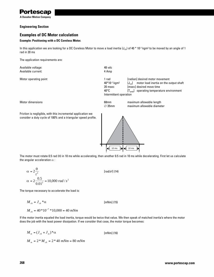
268
Engineering Section
www.portescap.com
Examples of DC Motor calculationExample: Positioning with a DC Coreless Motor.
In this application we are looking for a DC Coreless Motor to move a load inertia (Jch) of 40 * 10-7 kgm2 to be moved by an angle of 1 rad in 20 ms
The application requirements are:
Available voltage: 48 vdcAvailable current: 4 Amp
Motor operating point 1 rad [radian] desired motor movement 40*10-7 kgm2 [Jch] motor load inertia on the output shaft 20 msec [msec] desired move time 40°C [Tamb] operating temperature environment Intermittent operation
Motor dimensions 68mm maximum allowable length ∅ 35mm maximum allowable diameter Friction is negligible, with this incremental application we consider a duty cycle of 100% and a triangular speed profile.
The motor must rotate 0.5 rad (θ) in 10 ms while accelerating, then another 0.5 rad in 10 ms while decelerating. First let us calculate the angular acceleration α :
[rad/s2] (14)
The torque necessary to accelerate the load is:
[mNm] (15)
If the motor inertia equaled the load inertia, torque would be twice that value. We then speak of matched inertia’s where the motor does the job with the least power dissipation. If we consider that case, the motor torque becomes:
[mNm] (16)
22t
θα =
22 /000,10
01.0
5.02 srad==α
10 ms 10 ms
α*chch JM =
mNmM ch 40000,10*10*40 7 == −
α*)( mchm JJM +=
mNmmNmMM chm 8040*2*2 ===
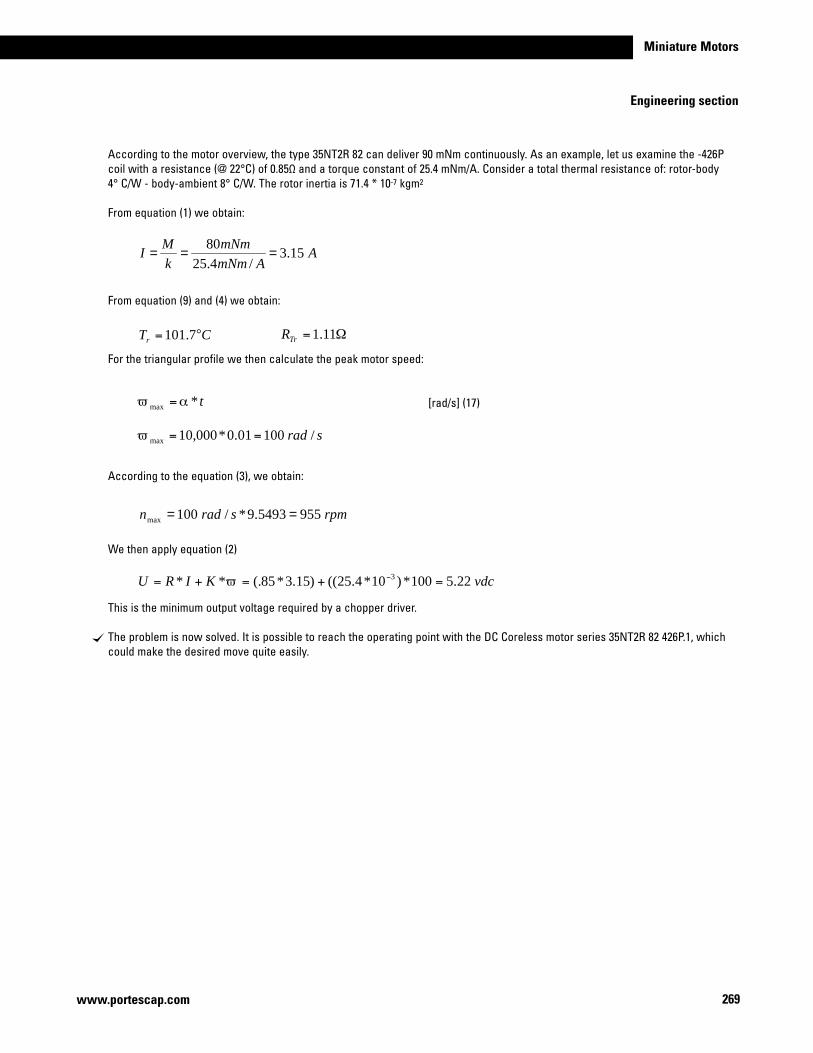
269
Miniature Motors
www.portescap.com
Engineering section
According to the motor overview, the type 35NT2R 82 can deliver 90 mNm continuously. As an example, let us examine the -426P coil with a resistance (@ 22°C) of 0.85Ω and a torque constant of 25.4 mNm/A. Consider a total thermal resistance of: rotor-body 4° C/W - body-ambient 8° C/W. The rotor inertia is 71.4 * 10-7 kgm2
From equation (1) we obtain:
From equation (9) and (4) we obtain:
For the triangular profile we then calculate the peak motor speed:
[rad/s] (17)
According to the equation (3), we obtain:
We then apply equation (2)
This is the minimum output voltage required by a chopper driver.
The problem is now solved. It is possible to reach the operating point with the DC Coreless motor series 35NT2R 82 426P.1, which could make the desired move quite easily.
AAmNm
mNmkM
I 15.3/4.25
80===
CTr °= 7.101 Ω= 11.1TrR
t*max αϖ =
srad /10001.0*000,10max ==ϖ
rpmsradn 9555493.9*/100max ==
vdcKIRU 22.5100*)10*4.25(()15.3*85(.** 3 =+=+= −ϖ
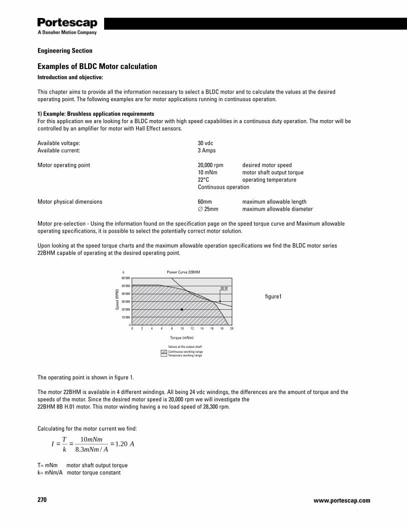
270
Engineering Section
www.portescap.com
Examples of BLDC Motor calculationIntroduction and objective:
This chapter aims to provide all the information necessary to select a BLDC motor and to calculate the values at the desired operating point. The following examples are for motor applications running in continuous operation.
1) Example: Brushless application requirementsFor this application we are looking for a BLDC motor with high speed capabilities in a continuous duty operation. The motor will be controlled by an amplifier for motor with Hall Effect sensors.
Available voltage: 30 vdcAvailable current: 3 Amps
Motor operating point 20,000 rpm desired motor speed 10 mNm motor shaft output torque 22°C operating temperature Continuous operation
Motor physical dimensions 60mm maximum allowable length ∅ 25mm maximum allowable diameter Motor pre-selection - Using the information found on the specification page on the speed torque curve and Maximum allowable operating specifications, it is possible to select the potentially correct motor solution.
Upon looking at the speed torque charts and the maximum allowable operation specifications we find the BLDC motor series 22BHM capable of operating at the desired operating point.
The operating point is shown in figure 1.
The motor 22BHM is available in 4 different windings. All being 24 vdc windings, the differences are the amount of torque and the speeds of the motor. Since the desired motor speed is 20,000 rpm we will investigate the 22BHM 8B H.01 motor. This motor winding having a no load speed of 28,300 rpm.
Calculating for the motor current we find:
T= mNm motor shaft output torquek= mNm/A motor torque constant
10'000
00 2 4 6 8 10 12 14 16 18 20
20'000
30'000
40'000
50'000
60'000
50 W
Power Curve 22BHM
Torque (mNm)
Values at the output shaftContinuous working rangeTemporary working range
Spee
d (R
PM)
n
AAmNm
mNm
k
TI 20.1
/3.8
10===
figure1
271
Miniature Motors
www.portescap.com
Engineering section
The supply current of the system in question is 3 amps and therefore there should be no difficulties.
Calculating the voltage required to run the motor at 20,000 rpm follows the formula:
The problem is now solved. Since the voltage required is less than the available voltage, it is possible to reach the operating point with the BLDC slotless motor series 22BHM 8B H.01, which could do the job quite easily.
The amplifier able to accomplish this is the EBL-50-H-03, which has:•Speedcontrolviahallsensors•Voltageinputsfrom5.5–50vdc•Maximumcontinuouscurrent3Amps
Mechanical power at the motor shaft:
T= mNm motor shaft output torquen= rpm Motor shaft speed
Motor efficiency (ignoring core losses):
U = vdc motor voltageI = Amp Motor current
ϖ*TPmech =
wattmNmPmech 94.2039.2094*10 ==
%5.842.1*65.20
94.20*
====IU
P
P
P mech
elec
mechη
vdcU 65.2039.2094*10*3.8*20.1*99.0 3 == −
sradn
/39.209460000,20
*260
*2 === ππϖ
ϖ** kIRU +=
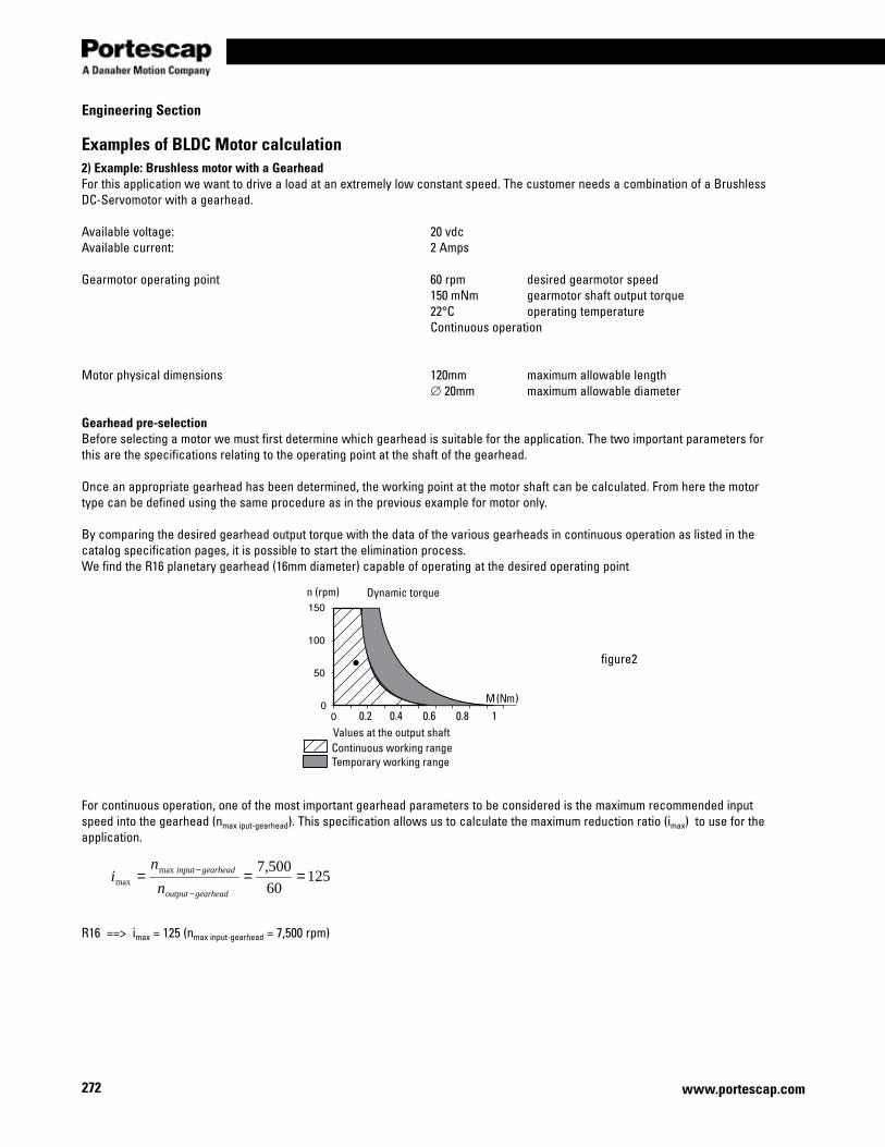
272
Engineering Section
www.portescap.com
Examples of BLDC Motor calculation2) Example: Brushless motor with a GearheadFor this application we want to drive a load at an extremely low constant speed. The customer needs a combination of a Brushless DC-Servomotor with a gearhead.
Available voltage: 20 vdcAvailable current: 2 Amps
Gearmotor operating point 60 rpm desired gearmotor speed 150 mNm gearmotor shaft output torque 22°C operating temperature Continuous operation
Motor physical dimensions 120mm maximum allowable length ∅ 20mm maximum allowable diameter Gearhead pre-selectionBefore selecting a motor we must first determine which gearhead is suitable for the application. The two important parameters for this are the specifications relating to the operating point at the shaft of the gearhead.
Once an appropriate gearhead has been determined, the working point at the motor shaft can be calculated. From here the motor type can be defined using the same procedure as in the previous example for motor only.
By comparing the desired gearhead output torque with the data of the various gearheads in continuous operation as listed in the catalog specification pages, it is possible to start the elimination process. We find the R16 planetary gearhead (16mm diameter) capable of operating at the desired operating point
For continuous operation, one of the most important gearhead parameters to be considered is the maximum recommended input speed into the gearhead (nmax iput-gearhead). This specification allows us to calculate the maximum reduction ratio (imax) to use for the application.
R16 ==> imax = 125 (nmax input-gearhead = 7,500 rpm)
Continuous working rangeTemporary working range
Values at the output shaft
n (rpm)
M (Nm)
Dynamic torque
0.2 0.4 0.6 0.8 1
12560
500,7maxmax ===
−
−
gearheadoutput
gearheadinput
n
ni
figure2
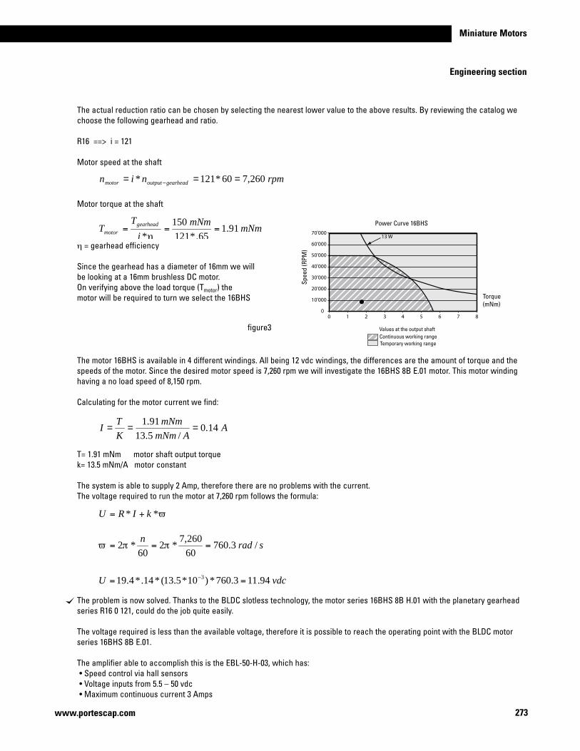
273
Miniature Motors
www.portescap.com
Engineering section
The actual reduction ratio can be chosen by selecting the nearest lower value to the above results. By reviewing the catalog we choose the following gearhead and ratio.
R16 ==> i = 121
Motor speed at the shaft
Motor torque at the shaft
η = gearhead efficiency
Since the gearhead has a diameter of 16mm we will be looking at a 16mm brushless DC motor.On verifying above the load torque (Tmotor) the motor will be required to turn we select the 16BHS
The motor 16BHS is available in 4 different windings. All being 12 vdc windings, the differences are the amount of torque and the speeds of the motor. Since the desired motor speed is 7,260 rpm we will investigate the 16BHS 8B E.01 motor. This motor winding having a no load speed of 8,150 rpm.
Calculating for the motor current we find:
T= 1.91 mNm motor shaft output torquek= 13.5 mNm/A motor constant
The system is able to supply 2 Amp, therefore there are no problems with the current.The voltage required to run the motor at 7,260 rpm follows the formula:
The problem is now solved. Thanks to the BLDC slotless technology, the motor series 16BHS 8B H.01 with the planetary gearhead series R16 0 121, could do the job quite easily.
The voltage required is less than the available voltage, therefore it is possible to reach the operating point with the BLDC motor series 16BHS 8B E.01.
The amplifier able to accomplish this is the EBL-50-H-03, which has:•Speedcontrolviahallsensors•Voltageinputsfrom5.5–50vdc•Maximumcontinuouscurrent3Amps
rpmnin gearheadoutputmotor 260,760*121* === −
mNmmNm
i
TT gearhead
motor 91.165.*121
150
*===
η
ϖ** kIRU +=
vdcU 94.113.760*)10*5.13(*14.*4.19 3 == −
sradn
/3.76060
260,7*2
60*2 === ππϖ
AAmNm
mNm
K
TI 14.0
/5.13
91.1===
Spee
d (R
PM)
13 W
0 1 2 3 4 5 6 7 80
10'000
20'000
30'000
40'000
50'000
60'000
70'000
Values at the output shaft
Torque (mNm)
Power Curve 16BHS
Continuous working rangeTemporary working range
figure3
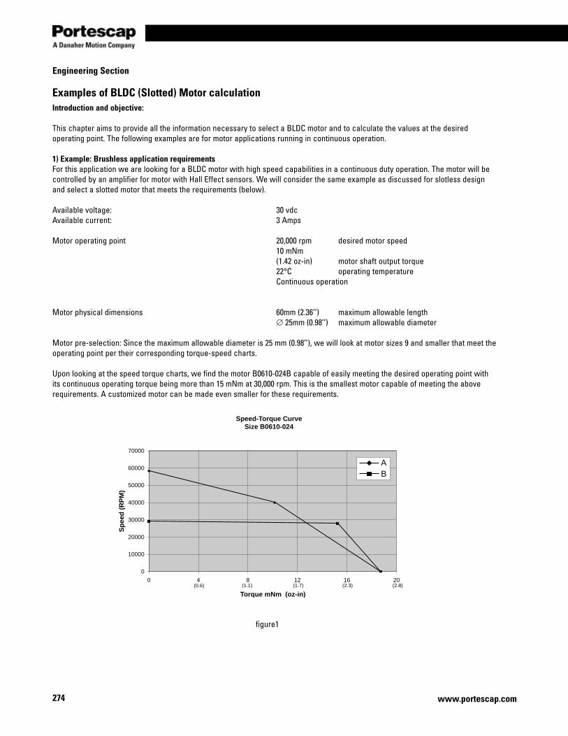
274
Engineering Section
www.portescap.com
Examples of BLDC (Slotted) Motor calculationIntroduction and objective:
This chapter aims to provide all the information necessary to select a BLDC motor and to calculate the values at the desired operating point. The following examples are for motor applications running in continuous operation.
1) Example: Brushless application requirementsFor this application we are looking for a BLDC motor with high speed capabilities in a continuous duty operation. The motor will be controlled by an amplifier for motor with Hall Effect sensors. We will consider the same example as discussed for slotless design and select a slotted motor that meets the requirements (below).
Available voltage: 30 vdcAvailable current: 3 Amps
Motor operating point 20,000 rpm desired motor speed 10 mNm (1.42 oz-in) motor shaft output torque 22°C operating temperature Continuous operation
Motor physical dimensions 60mm (2.36’’) maximum allowable length ∅ 25mm (0.98’’) maximum allowable diameter Motor pre-selection: Since the maximum allowable diameter is 25 mm (0.98’’), we will look at motor sizes 9 and smaller that meet the operating point per their corresponding torque-speed charts.
Upon looking at the speed torque charts, we find the motor B0610-024B capable of easily meeting the desired operating point with its continuous operating torque being more than 15 mNm at 30,000 rpm. This is the smallest motor capable of meeting the above requirements. A customized motor can be made even smaller for these requirements.
Speed-Torque CurveSize B0610-024
0
10000
20000
30000
40000
50000
60000
70000
0 4 8 12 16 20
Torque mNm (oz-in)
Sp
eed
(R
PM
)
AB
(0.6) (1.1) (1.7) (2.3) (2.8)
figure1
275
Miniature Motors
www.portescap.com
Engineering section
The motor B0610-024 is available in 2 different windings. Both being 24 VDC windings, the differences are the amount of torque and the speeds of the motor. Since the desired motor speed is 20,000 rpm we will investigate the B0610-024B motor having a no load speed of 29,197 rpm.
Calculating for the motor current we find:
T= mNm motor shaft output torquek= mNm/A motor torque constant
The supply current of the system in question is 3 amps and therefore there should be no difficulties.
Calculating the voltage required to run the motor at 20,000 rpm follows the formula:
The problem is now solved. Since the voltage required is less than the available voltage, it is possible to reach the operating point with the BLDC slotted motor B0610-024B, which could do the job quite easily.
Mechanical power at the motor shaft:
T= mNm motor shaft output torquen= rpm Motor shaft speed
Motor efficiency (ignoring core losses):
U = vdc motor voltageI = Amp Motor current
vdcU 43.1839.2094*10*84.728.1*57.1 3 =+= −
sradn
/39.209460000,20
*260
*2 === ππϖ
ϖ** kIRU +=
ϖ*TPmech =
WattsmNmPmech 94.2039.2094*10 ==
%8.8828.1*43.18
94.20
*====
IU
P
P
P mech
elec
mechη
AAmNm
mNm
k
TI 28.1
/84.7
10===
276
Engineering Section
www.portescap.com
Examples of BLDC Motor calculation2) Example: Brushless motor with a GearheadFor this application we want to drive a load at a low constant speed. The customer needs a combination of a Brushless DC-Servomotor with a gearhead.
Available voltage: 50 vdcAvailable current: 1 Amp
Gearmotor operating point 2500 rpm desired gearmotor speed 40 mNm gearmotor shaft output torque 10.5 Watts output power at the gearhead 22°C operating temperature Continuous operation
Motor physical dimensions 70mm maximum allowable length ∅ 15mm maximum allowable diameter Gearhead pre-selectionBefore selecting a motor we must first determine which gearhead is suitable for the application. The two important parameters for this are the specifications relating to the operating point at the shaft of the gearhead.
Once an appropriate gearhead has been determined, the working point at the motor shaft can be calculated. From here the motor type can be defined using the same procedure as in the previous example for motor only.
By comparing the desired gearhead output torque and envelope requirements with the data of the various gearheads in continuous operation as listed in the catalog specification pages, it is possible to start the elimination process. We find the Size 5 planetary gearhead (12.7 mm diameter) capable of operating at the desired operating point
For continuous operation, one of the most important gearhead parameters to be considered is the maximum recommended input speed into the gearhead (nmax input-gearhead). This specification allows us to calculate the maximum reduction ratio (imax) to use for the application.
Size 5 Gearhead ==> imax = 32 (nmax input-gearhead = 80,000 rpm)
The actual reduction ratio can be chosen by selecting the nearest lower value to the above results. By reviewing the catalog we choose the following gearhead and ratio.
R16 ==> i = 25
Motor speed at the shaft
Motor torque at the shaft
322500
80000maxmax ===
−
−
gearheadoutput
gearheadinput
n
ni
rpmnin gearheadoutputmotor 500,622500*25* === −
mNmmNm
i
TT gearhead
motor 94.1825.*25
40
*===
η
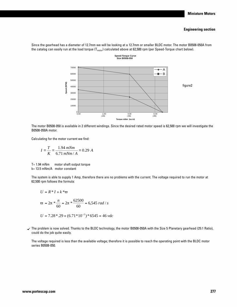
277
Miniature Motors
www.portescap.com
Engineering section
Since the gearhead has a diameter of 12.7mm we will be looking at a 12.7mm or smaller BLDC motor. The motor B0508-050A from the catalog can easily run at the load torque (Tmotor) calculated above at 62,500 rpm (per Speed-Torque chart below).
The motor B0508-050 is available in 2 different windings. Since the desired rated motor speed is 62,500 rpm we will investigate the B0508-050A motor.
Calculating for the motor current we find:
T= 1.94 mNm motor shaft output torquek= 13.5 mNm/A motor constant
The system is able to supply 1 Amp, therefore there are no problems with the current. The voltage required to run the motor at 62,500 rpm follows the formula:
The problem is now solved. Thanks to the BLDC technology, the motor B0508-050A with the Size 5 Planetary gearhead (25:1 Ratio), could do the job quite easily.
The voltage required is less than the available voltage; therefore it is possible to reach the operating point with the BLDC motor series B0508-050.
ϖ** kIRU +=
vdcU 466545*)10*71.6(29.*28.7 3 =+= −
sradn
/545,660
62500*2
60*2 === ππϖ
AAmNm
mNm
KT
I 29.0/71.6
94.1===
Speed-Torque CurveSize B0508-050
0
10000
20000
30000
40000
50000
60000
70000
6.004.00.2.000.00
Torque mNm (oz-in)
Sp
eed
(R
PM
)
AB
)058.()665.()382.(
figure2
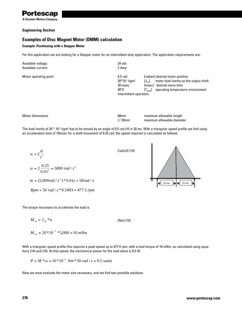
278
Engineering Section
www.portescap.com
Examples of Disc Magnet Motor (DMM) calculationExample: Positioning with a Stepper Motor
For this application we are looking for a Stepper motor for an intermittent duty application. The application requirements are:
Available voltage: 24 vdcAvailable current: 2 Amp
Motor operating point 0.5 rad [radian] desired motor position 20*10-7 kgm2 [Jch] motor load inertia on the output shaft 20 msec [msec] desired move time 40°C [Tamb] operating temperature environment Intermittent operation
Motor dimensions 68mm maximum allowable length ∅ 35mm maximum allowable diameter The load inertia of 20 * 10-7 kgm2 has to be moved by an angle of 0.5 rad (θ) in 20 ms. With a triangular speed profile we find using an acceleration time of 10msec for a shaft movement of 0.25 rad, the speed required is calculated as follows:
[rad/s2] (14)
The torque necessary to accelerate the load is:
[Nm] (15)
With a triangular speed profile this requires a peak speed up to 477.5 rpm, with a load torque of 10 mNm, as calculated using equa-tions (14) and (15). At that speed, the mechanical power for the load alone is 0.5 W.
Now we must evaluate the motor size necessary, and we find two possible solutions.
10 ms 10 ms
wattssradNmMP 5.0/50*10*10* 3 === −ω
α*chch JM =
mNmM ch 10000,5*10*20 7 == −
22t
θα =
22
/500001.0
25.02 srad==α
sradssrad /5001.0*)/000,5( 2 ==ϖ
rpmsradRpm 5.4775493.9*/50 ==
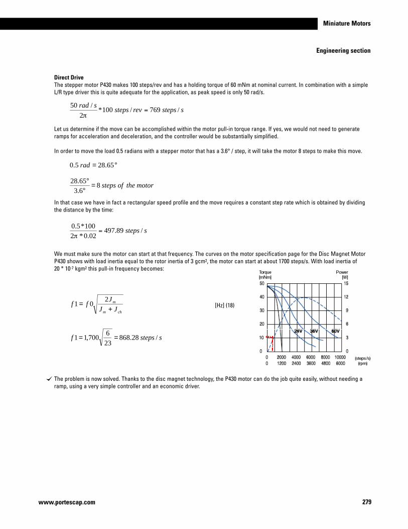
279
Miniature Motors
www.portescap.com
Engineering section
Direct DriveThe stepper motor P430 makes 100 steps/rev and has a holding torque of 60 mNm at nominal current. In combination with a simple L/R type driver this is quite adequate for the application, as peak speed is only 50 rad/s.
Let us determine if the move can be accomplished within the motor pull-in torque range. If yes, we would not need to generate ramps for acceleration and deceleration, and the controller would be substantially simplified.
In order to move the load 0.5 radians with a stepper motor that has a 3.6° / step, it will take the motor 8 steps to make this move.
In that case we have in fact a rectangular speed profile and the move requires a constant step rate which is obtained by dividing the distance by the time:
We must make sure the motor can start at that frequency. The curves on the motor specification page for the Disc Magnet Motor P430 shows with load inertia equal to the rotor inertia of 3 gcm2, the motor can start at about 1700 steps/s. With load inertia of 20 * 10-7 kgm2 this pull-in frequency becomes:
[Hz] (18)
The problem is now solved. Thanks to the disc magnet technology, the P430 motor can do the job quite easily, without needing a ramp, using a very simple controller and an economic driver.
°= 65.285.0 rad
motortheofsteps86.365.28
=°°
chm
m
JJJ
ff+
=2
01
sstepsf /28.868236
700,11 ==
sstepsrevstepssrad
/769/100*2
/50=
π
ssteps /89.49702.0*2
100*5.0=
π
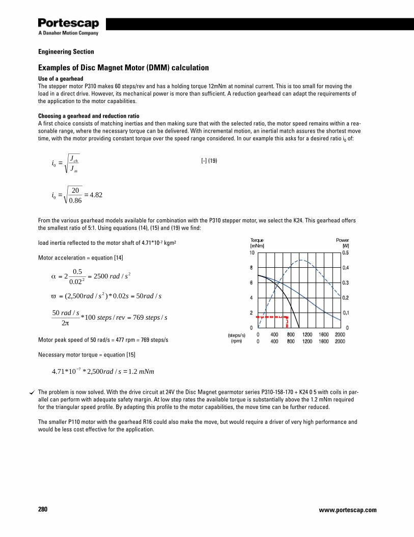
280
Engineering Section
www.portescap.com
Examples of Disc Magnet Motor (DMM) calculationUse of a gearheadThe stepper motor P310 makes 60 steps/rev and has a holding torque 12mNm at nominal current. This is too small for moving the load in a direct drive. However, its mechanical power is more than sufficient. A reduction gearhead can adapt the requirements of the application to the motor capabilities.
Choosing a gearhead and reduction ratioA first choice consists of matching inertias and then making sure that with the selected ratio, the motor speed remains within a rea-sonable range, where the necessary torque can be delivered. With incremental motion, an inertial match assures the shortest move time, with the motor providing constant torque over the speed range considered. In our example this asks for a desired ratio i0 of:
[-] (19)
From the various gearhead models available for combination with the P310 stepper motor, we select the K24. This gearhead offers the smallest ratio of 5:1. Using equations (14), (15) and (19) we find:
load inertia reflected to the motor shaft of 4.71*10-7 kgm2
Motor acceleration = equation [14]
Motor peak speed of 50 rad/s = 477 rpm = 769 steps/s
Necessary motor torque = equation [15]
The problem is now solved. With the drive circuit at 24V the Disc Magnet gearmotor series P310-158-170 + K24 0 5 with coils in par-allel can perform with adequate safety margin. At low step rates the available torque is substantially above the 1.2 mNm required for the triangular speed profile. By adapting this profile to the motor capabilities, the move time can be further reduced.
The smaller P110 motor with the gearhead R16 could also make the move, but would require a driver of very high performance and would be less cost effective for the application.
22
/250002.0
5.02 srad==α
sradssrad /5002.0*)/500,2( 2 ==ϖ
sstepsrevstepssrad
/769/100*2
/50=
π
m
ch
JJ
i =0
82.486.0
200 ==i
mNmsrad 2.1/500,2*10*71.4 7 =−
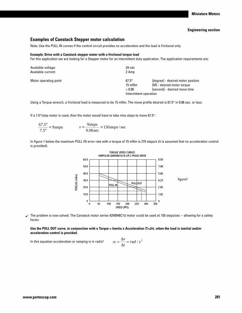
281
Miniature Motors
www.portescap.com
Engineering section
Examples of Canstack Stepper motor calculationNote: Use the PULL IN curves if the control circuit provides no acceleration and the load is frictional only.
Example: Drive with a Canstack stepper motor with a frictional torque loadFor this application we are looking for a Stepper motor for an intermittent duty application. The application requirements are:
Available voltage: 24 vdcAvailable current: 2 Amp
Motor operating point 67.5° [degree] - desired motor position 15 mNm [M] - desired motor torque < 0.06 [second] - desired move time Intermittent operation
Using a Torque wrench, a frictional load is measured to be 15 mNm. The move profile desired is 67.5° in 0.06 sec. or less.
If a 7.5°/step motor is used, then the motor would have to take nine steps to move 67.5°.
In figure 1 below the maximum PULL IN error rate with a torque of 15 mNm is 275 steps/s (it is assumed that no acceleration control is provided).
Theproblemisnowsolved.TheCanstackmotorseries42M048C1Umotorcouldbeusedat150steps/sec–allowingforasafetyfactor.
Use the PULL OUT curve, in conjunction with a Torque = Inertia x Acceleration (T=Jπ), when the load is inertial and/or acceleration control is provided.
In this equation acceleration or ramping is in rad/s2
steps95.75.67
=°°
sec/150sec06.0
9steps
stepsv ==
2/ sradt
v=
Δ
Δ=α
figure1
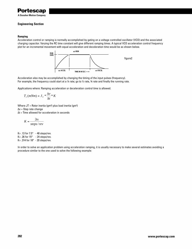
282
Engineering Section
www.portescap.com
RampingAcceleration control or ramping is normally accomplished by gating on a voltage controlled oscillator (VCO) and the associated charging capacitor. Varying the RC time constant will give different ramping times. A typical VCO acceleration control frequency plot for an incremental movement with equal acceleration and deceleration time would be as shown below.
Acceleration also may be accomplished by changing the timing of the input pulses (frequency).For example, the frequency could start at a ¼ rate; go to ½ rate, ¾ rate and finally the running rate.
Applications where: Ramping acceleration or deceleration control time is allowed.
Where JT = Rotor inertia (gm2) plus load inertia (gm2)Δv = Step rate changeΔt = Time allowed for acceleration in seconds
K= .13 for 7.5° - 48 steps/rev.K= .26 for 15° - 24 steps/rev.K= .314 for 18° - 20 steps/rev.
In order to solve an application problem using acceleration ramping, it is usually necessary to make several estimates avoiding a procedure similar to the one used to solve the following example:
Kt
vJmNmTJ **)( T Δ
Δ=
revstepsK
/2α
=
figure2
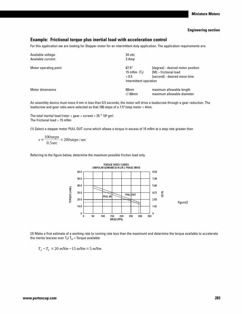
283
Miniature Motors
www.portescap.com
Engineering section
Example: Frictional torque plus inertial load with acceleration controlFor this application we are looking for Stepper motor for an intermittent duty application. The application requirements are:
Available voltage: 24 vdcAvailable current: 3 Amp
Motor operating point 67.5° [degree] - desired motor position 15 mNm (Tf) [M]–frictionalload < 0.5 [second] - desired move time Intermittent operation
Motor dimensions 60mm maximum allowable length ∅ 60mm maximum allowable diameter
An assembly device must move 4 mm in less than 0.5 seconds; the motor will drive a leadscrew through a gear reduction. The leadscrew and gear ratio were selected so that 100 steps of a 7.5°/step motor = 4mm.
The total inertial load (rotor + gear + screw) = 25 * 104 gm2. The frictional load = 15 mNm
(1) Select a stepper motor PULL OUT curve which allows a torque in excess of 15 mNm at a step rate greater than
Referring to the figure below, determine the maximum possible friction load only.
(2) Make a first estimate of a working rate (a running rate less than the maximum) and determine the torque available to accelerate the inertia (excess over TF) TA = Torque available
sec/200sec5.0
100steps
stepsv ==
mNmmNmmNmTT FA 51520 =−=−
figure3
284
Engineering Section
www.portescap.com
(3) Using a 60% safety margin 5 mNm * 0.6 = 3 mNm Calculate Δt to accelerate. (refer to figure 2)
From the equation:
To accelerate Δt = 0.027 sec (note: the same amount of time is allowed to decelerate the load)
(4) The number of steps used to accelerate and decelerate
< OR >
(5) The time to move at the run rate NT=Totalsteps/revolution–Steptomakethedesiredmove.
(6) The total time to move is as follows:
The problem is now solved. The Canstack stepper motor series 42M048C1U is the first estimate. This motor can be moved slower if more of a safety factor is desired.
Kt
vJmNmTJ **)( T Δ
Δ=
027.0**T =
Δ=Δ
jT
KvJt
mNmTJ 3027.0
13.0*250*10*25 4
==
2**2
tv
NN DA Δ=+
tvNN DA Δ=+ * steps7027.0*250 ==
937100 =−=TN
sec37.0125125
93
+=
+=Δ
DA
Trun NN
Nt
totaldecelaccelrun tttt =Δ+Δ+Δ
sec42.0027.0027.037.0 =++
285
Miniature Motors
www.portescap.com
Engineering section
Example: No ramping acceleration or deceleration control is allowed.Even though no acceleration time is provided, the stepper can lag a maximum of two steps or 180° electrical degrees. If the motor goes from zero steps/sec to v steps/sec the lag time Δt would be
The torque equation for no acceleration or deceleration is:
Where : JT = Rotor inertia (gm2) + load inertia (gm2) = 25*104 gm2
Example: Friction plus Inertia – No acceleration ramping. For this application we are looking for Stepper motor for a continuous duty application. The application requirements are: A tape capstan is to be driven by a stepper motor.
Motor operating point 15.3 mNm (Tf) [M]–frictionalload 10*104 (JL) [gm2]–loadinertia continuous operation
The capstan must rotate in 7.5° increments at a rate of 200 steps/sec.
Since a torque greater than 15.3 mNm at 200 steps/sec is required, consider the CanStack stepper motor series 42M048C1U. (refer to figure 4)
The total inertia= motor rotor inertia + load inertia
sec2==Δ
vt
Kv
JmNmtorqueT TJ *2
*)(2
=
250sec/ == ratestepsv
13.048
2
/
2===
ππ
revstepK
LRT JJJ +=
244 )10*1010*5.12( gm+=
2410*5.13 gm=
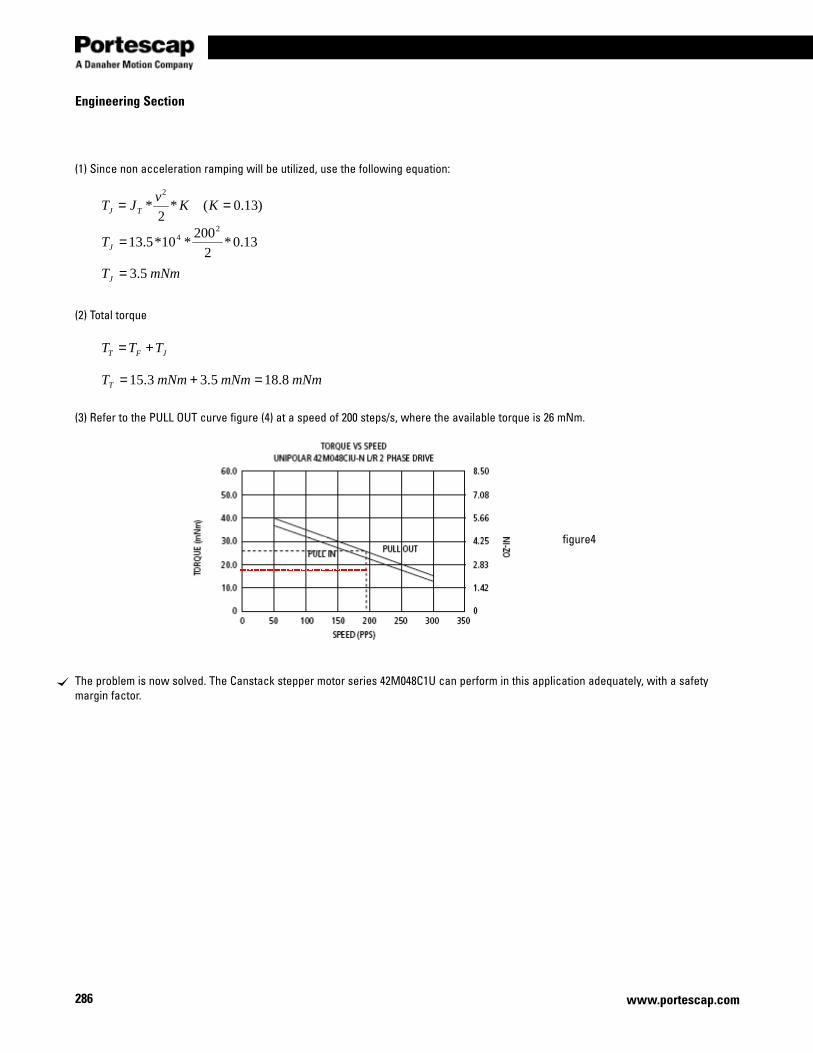
286
Engineering Section
www.portescap.com
(1) Since non acceleration ramping will be utilized, use the following equation:
(2) Total torque
(3) Refer to the PULL OUT curve figure (4) at a speed of 200 steps/s, where the available torque is 26 mNm.
The problem is now solved. The Canstack stepper motor series 42M048C1U can perform in this application adequately, with a safety margin factor.
)13.0(*2
*2
== KKv
JT TJ
13.0*2
200*10*5.13
24=JT
mNmTJ 5.3=
JFT TTT +=
mNmmNmmNmTT 8.185.33.15 =+=
figure4

287
Miniature Motors
www.portescap.com
Notes

288 www.portescap.com
Notes

289
Miniature Motors
www.portescap.com
Notes

290 www.portescap.com
Notes

© 2009, Portescap, A Danaher Motion Company. All rights reserved. Information and specifications subject to change at any time. All trademarks are property of their respective owners. Lit code: 0123
Global Presence
North AmericaPortescap (Headquarters)110 Westtown RoadWest Chester, Pennsylvania 19382-4978Tel.: +1 (610) 235-5499Fax: +1 (610) [email protected]
EuropePortescapRue Jardiniere 157, Case PostaleCH 2301 La Chaux-de-FondsSwitzerlandTel.: +41 (0)32 925 61 11Fax: +41 (0)32 925 65 [email protected]
AsiaPortescap Singapore Pte. Ltd.Block 3015 A Ubi Road 1#07-08 Kampong Ubi Industrial EstateSingapore 408705Tel.: +65 6747 4888Fax: +65 6743 [email protected]
IndiaPortescapUnit 2, SDF-1, SEEPZ-SEZAndheri East, Mumbai 400 096, IndiaTel.: +91 22 2829 4130 / 4131Fax: +91 22 [email protected]
JapanDanaher Motion Japan2F, Tokyu REIT Building2-7-1 Hatchobori Chuo-kuTokyo 104-0032 JapanTel.: +81 3 6222 1051Fax: +81 3 6222 [email protected]
China Danaher Motion China5th Floor, No.280-6, Linhong RoadChangning District Shanghai, P.R.China 200335Tel.: +86 21 61289814 Fax: +86 21 [email protected]
ChinaDanaher Motion ChinaRM2205, Scitech Tower22 Jianguomenwai StreetBeijing, China 100004 Tel.: +86 10 65150260Fax: +86 10 [email protected]
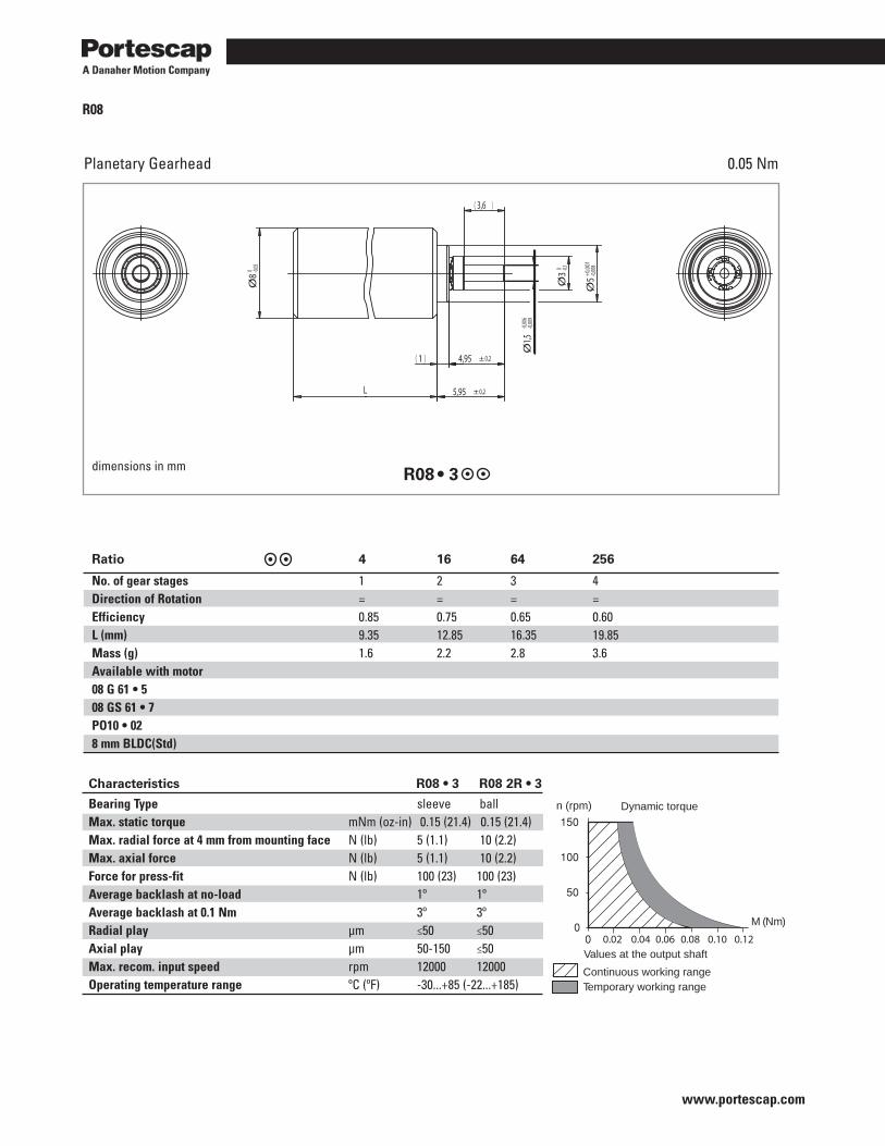
www.portescap.com
R08
Planetary Gearhead 0.05 Nm
dimensions in mm R08 • 3
Ratio 4 16 64 256
No. of gear stages 1 2 3 4 Direction of Rotation = = = = Efficiency 0.85 0.75 0.65 0.60 L (mm) 9.35 12.85 16.35 19.85 Mass (g) 1.6 2.2 2.8 3.6 Available with motor 08 G 61 • 5 08 GS 61 • 7 PO10 • 028 mm BLDC(Std)
M (Nm)
n (rpm) Dynamic torque
Continuous working rangeTemporary working range
Values at the output shaft0.040.02 0.06 0.08 0.10 0.12
Ø8 0 -0,
05
( )1 4,95 ± 0,2
Ø3 0 -0,
1
( )3,6
Ø5+0
,001
-0,00
8
Ø1,5
-0,00
6-0,
009
5,95 ± 0,2L
Characteristics R08 • 3 R08 2R • 3
Bearing Type sleeve ballMax. static torque mNm (oz-in) 0.15 (21.4) 0.15 (21.4)Max. radial force at 4 mm from mounting face N (lb) 5 (1.1) 10 (2.2)Max. axial force N (lb) 5 (1.1) 10 (2.2)Force for press-fit N (lb) 100 (23) 100 (23)Average backlash at no-load 1º 1ºAverage backlash at 0.1 Nm 3º 3ºRadial play µm ≤50 ≤50Axial play µm 50-150 ≤50Max. recom. input speed rpm 12000 12000Operating temperature range ºC (ºF) -30...+85 (-22...+185)