Embed Size (px)
Citation preview
— FREEL ANCE 2016
Freelance DCSProduct Catalog

2
— Table of contents
004 – 005 Introduction
006 – 009 System architecture
010 – 060 The controllers AC 900F, AC 800F, AC 700F
061 Power Supplies for AC 900F, AC 700F and S700 I/O
062 – 131 I/Os: S700, S800, S900
132 – 135 Fieldbus network components and PROFIBUS configuration for S700
136 – 145 Freelance Operations
146 – 159 Freelance Engineering
160 – 161 Media and documentation
162 – 165 Add-ons, extensions, and service
166 – 167 References
168 – 171 Index
—01—01
—02
—03
—01—02
—04
—06
—03
—05
—07—08—09—10—11—12
3
—01
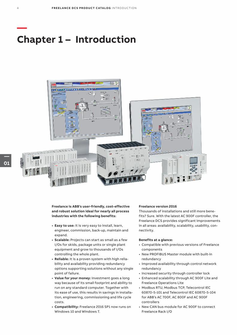
—Chapter 1 – Introduction
Freelance is ABB’s user-friendly, cost-effective and robust solution ideal for nearly all process industries with the following benefits:
• Easy to use: It is very easy to install, learn, engineer, commission, back-up, maintain and expand.
• Scalable: Projects can start as small as a few I/Os for skids, package units or single plant equipment and grow to thousands of I/Os controlling the whole plant.
• Reliable: It is a proven system with high relia-bility and availability providing redundancy options supporting solutions without any single point of failure.
• Value for your money: Investment goes a long way because of its small footprint and ability to run on any standard computer. Together with its ease of use, this results in savings in installa-tion, engineering, commissioning and life cycle costs.
• Compatibility: Freelance 2016 SP1 now runs on Windows 10 and Windows 7.
Freelance version 2016Thousands of installations and still more bene-fits? Sure. With the latest AC 900F controller, the Freelance DCS provides significant improvements in all areas: availability, scalability, usability, con-nectivity.
Benefits at a glance:• Compatible with previous versions of Freelance
components• New PROFIBUS Master module with built-in
redundancy• Improved availability through control network
redundancy• Increased security through controller lock• Enhanced scalability through AC 900F Lite and
Freelance Operations Lite• Modbus RTU, Modbus TCP, Telecontrol IEC
60870-5-101 and Telecontrol IEC 60870-5-104 for ABB’s AC 700F, AC 800F and AC 900F controllers
• New CAN bus module for AC 900F to connect Freelance Rack I/O
4 F R E E L A N CE D C S PRO D U C T C ATA LO G I NTR O D U C TI O N
—01
—Easy to useFreelance can be installed on any standard com-puter and in just a few minutes. A Quickstart Tu-torial is available, which allows users to learn at their own pace with detailed instructional videos. It takes less than a week to learn since there is just one engineering tool. Pre-engineered, ready-to-use displays make engineering much easier compared to other control systems or PLC/SCADA combinations. Additionally, a system-wide project database makes archiving or backup very easy to perform. There is also multiple language support.
The Freelance control system combines user-friendly engineering with an open, modern sys-tem architecture. This means: • Only one tool for engineering, commissioning
and diagnostics• Fieldbus management completely integrated
into control system engineering• Time and cost savings in engineering, commis-
sioning, testing, service and maintenance• Assembly close to the field: reduction of field
wiring and space requirements• Freelance has a convenient cross-reference
feature allowing variables and tags to be found easily in any editor right up to the graphic display. This makes troubleshooting and debugging easier, resulting in faster project execution.
Pre-configured components for the operator level. The engineering of the Freelance operator level is straightforward. The pre-configured visu-alization components include:• Faceplates• Module diagnostics• Extended troubleshooting capabilities• Automatically generated SFC displays• Automatically generated system communication• Event list, alarm line and message log files• Trend displays with long-term archiving• These components can be used straight out of
the box, eliminating time-consuming manual configuration.
—ReliableFreelance is a well-proven technology that has been around for more than 20 years and is installed in thousands of installations globally since its origination in Germany.
High availabilityThe technology has proven its worth in industrial use over several years and meets the toughest requirements regarding availability. The hardware can be structured redundantly at all levels. This includes the redundant fieldbus modules, redun-dant fieldbus lines as well as network and control-ler redundancy.
Regulatory complianceWith a view to meeting the requirements of regulatory authorities such as the American FDA (Food and Drug Administration) or the EFSA (European Food Safety Authority), Freelance provides a series of features that facilitate the validation procedure. Examples include:• Encrypted log and trend data• Audit trail functions• Access rights and user administration
(security lock)
—ScalableFreelance can be easily scaled up from a small sys-tem of a few I/Os to a large system of up to thou-sands of I/Os. Expansion can be done with mini-mal engineering effort. All controller types can be used in combination in a single system. They are suitable both for installation in the control room and for use in junction boxes directly in the field. • The AC 700F controller has a small footprint
that supports PROFIBUS. It can support up to eight direct I/O modules.
• The AC 800F controller can be equipped with up to four fieldbus modules of type serial, PROFIBUS, FF HSE or Freelance CAN bus. Optionally, AC 800F supports redundancy.
• The AC 900F controller also supports PROFIBUS and Freelance CAN bus and truly extends the hardware portfolio of the Freelance distributed control system. The AC 900F modular controller offers expanded flexibility via a pluggable SD card, more Ethernet ports, redundancy options for high availability and power enough for around 1,500 I/Os per controller. A Lite version is available, optimized for smaller applications.
The new lite version of Freelance Operations also provides for enhanced scalability of the system on the operator level.
—Value for your moneyThe big advantage of Freelance is the savings it provides in project engineering.
The easy-to-use features and use of only one tool for configuration of graphics, controllers and field devices allows engineering and commissioning time to be reduced, resulting in faster start-ups.
Freelance has a small footprint (comparable to a PLC), which means less space requirement for cabinets. Since the system uses intelligent peer-to-peer architecture, there is no need for expen-sive server PCs.
In fact, Freelance can run on any standard com-puter with minimum specifications. It is installed in just a few minutes.
5I NTR O D U C TI O N F R E E L A N CE D C S PRO D U C T C ATA LO G
—02
—Chapter 2 – System architecture
007 2.1 Operator level
007 2.2 Engineering tool
007 2.3 Process level
008 – 009 2.4 System communication
008 2.4.1 Control network
009 2.4.2 OPC
009 2.4.3 Advanced application programming DMS-API
009 2.4.4 Technical details of the control network
6 F R E E L A N CE D C S PRO D U C T C ATA LO G S Y S TEM A R CH ITEC T U R E
—02
—2.1 Operator level
The Freelance Operations station is a software that runs on a simple PC-environment under Microsoft Windows. It installs in five minutes. Freelance Operations supports dual-monitor operation, which offers the benefit to stay continuously tuned with essential information like the alarm list, while inspecting at the same time for example the progress of a sequential function chart, trend archives, or the system display with extended diagnostics. In a plant, several Freelance Operator Workplaces can work seamlessly together.
The extended automation functionality of ABB’s System 800xA can be utilized for Freelance as well by utilizing the “800xA for Freelance” con-nectivity package. This way you can concentrate several Freelance systems under one common operator console in parallel to the existing operator stations.
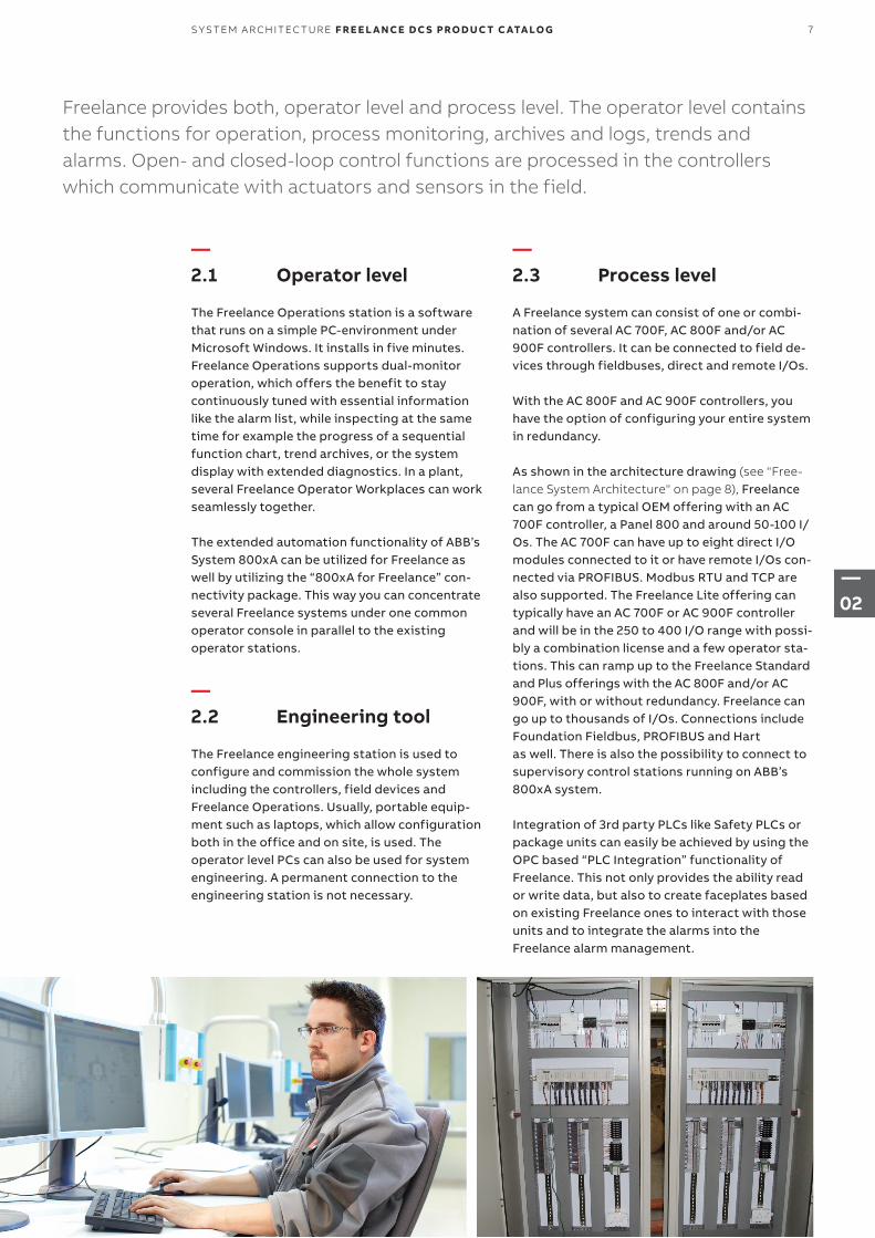
—2.2 Engineering tool
The Freelance engineering station is used to configure and commission the whole system including the controllers, field devices and Freelance Operations. Usually, portable equip-ment such as laptops, which allow configuration both in the office and on site, is used. The operator level PCs can also be used for system engineering. A permanent connection to the engineering station is not necessary.
—2.3 Process level
A Freelance system can consist of one or combi-nation of several AC 700F, AC 800F and/or AC 900F controllers. It can be connected to field de-vices through fieldbuses, direct and remote I/Os.
With the AC 800F and AC 900F controllers, you have the option of configuring your entire system in redundancy.
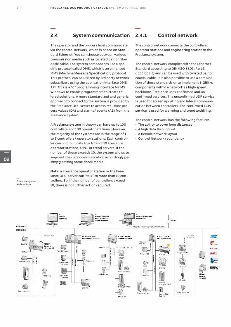
As shown in the architecture drawing (see "Free-lance System Architecture" on page 8), Freelance can go from a typical OEM offering with an AC 700F controller, a Panel 800 and around 50-100 I/Os. The AC 700F can have up to eight direct I/O modules connected to it or have remote I/Os con-nected via PROFIBUS. Modbus RTU and TCP are also supported. The Freelance Lite offering can typically have an AC 700F or AC 900F controller and will be in the 250 to 400 I/O range with possi-bly a combination license and a few operator sta-tions. This can ramp up to the Freelance Standard and Plus offerings with the AC 800F and/or AC 900F, with or without redundancy. Freelance can go up to thousands of I/Os. Connections include Foundation Fieldbus, PROFIBUS and Hart as well. There is also the possibility to connect to supervisory control stations running on ABB’s 800xA system.
Integration of 3rd party PLCs like Safety PLCs or package units can easily be achieved by using the OPC based “PLC Integration” functionality of Freelance. This not only provides the ability read or write data, but also to create faceplates based on existing Freelance ones to interact with those units and to integrate the alarms into the Freelance alarm management.
Freelance provides both, operator level and process level. The operator level contains the functions for operation, process monitoring, archives and logs, trends and alarms. Open- and closed-loop control functions are processed in the controllers which communicate with actuators and sensors in the field.
7S Y S TEM A R CH ITEC T U R E F R E E L A N CE D C S PRO D U C T C ATA LO G
—02
—2.4 System communication
The operator and the process level communicate via the control network, which is based on Stan-dard Ethernet. You can choose between various transmission media such as twisted pair or fiber optic cable. The system components use a spe-cific protocol called DMS, which is an enhanced MMS (Machine Message Specification) protocol. This protocol can be utilized by 3rd party network subscribers using the application interface DMS- API. This is a “C” programming interface for MS Windows to enable programmers to create tai-lored solutions. A more standardized and generic approach to connect to the system is provided by the Freelance OPC server to access real-time pro-cess values (DA) and alarms/ events (AE) from the Freelance System.
A Freelance system in theory can have up to 100 controllers and 100 operator stations. However the majority of the systems are in the range of 1 to 5 controllers/ operator stations. Each control-ler can communicate to a total of 10 Freelance operator stations, OPC- or trend servers. If the number of those exceeds 10, the system allows to segment the data communication accordingly per simply setting some check marks.
Note: a Freelance operator station or the Free-lance OPC-server can “talk” to more than 10 con-trollers. So, if the number of controllers exceed 10, there is no further action required.
—2.4.1 Control network
The control network connects the controllers, operator stations and engineering station in the Freelance system.
The control network complies with the Ethernet Standard according to DIN/ISO 8802, Part 3 (IEEE 802.3) and can be used with twisted pair or coaxial cable. It is also possible to use a combina-tion of these standards or to implement 1-GBit/s components within a network as high-speed backbone. Freelance uses confirmed and un- confirmed services. The unconfirmed UDP service is used for screen updating and lateral communi-cation between controllers. The confirmed TCP/IP service is used for alarming and trend archiving.
The control network has the following features:• The ability to cover long distances• A high data throughput• A flexible network layout• Control Network redundancy
—Freelance system Architecture
8 F R E E L A N CE D C S PRO D U C T C ATA LO G S Y S TEM A R CH ITEC T U R E
—02
—2.4.2 OPC
Freelance provides an OPC gateway (server), which allows OPC clients to access data and alarms from the Freelance controllers. The OPC server also allows access to the DPV1 parameters and user parameters of PROFIBUS and HART devices. In the case of HART devices, this is only possible if they are connected to an S900 remote I/O unit. For Freelance version 8.2 and higher, the parameters of FOUNDATION Fieldbus devices can also be accessed. It is possible to limit access to this data at the OPC gateway such that an OPC client cannot see certain tags and variables at all, can only read other tags and variables, or has both read and write access to certain tags and variables.
Freelance Operations has a built-in OPC client, which permits you to access data from external OPC servers. Using this, for example, data from third-party controllers with OPC support can be integrated into a custom graphic in Freelance Operations. Since Version 9.2, when using Free- lance Operations PLC Integration, also Faceplate creation and Alarm & Events are supported.
As several OPC gateways can be used in the Freelance system, server redundancy can be established using OPC clients that support this function. The Freelance Engineering software supports this with the redundant OPC gateway configuration.
The trend server option provides a special OPC gateway that is used by the operator stations for user-defined trend displays. Access to the trend server is fixed to “read only”, and all trend vari-ables are automatically available. There is one trend server per Freelance system.
—2.4.3 Advanced application programming DMS-API
The DMS Application Programming Interface pro-vides C programmers with a Windows interface through which they can access internal Freelance communications services. This enables them to create their own Windows applications that can read online data from the Freelance system and create values.
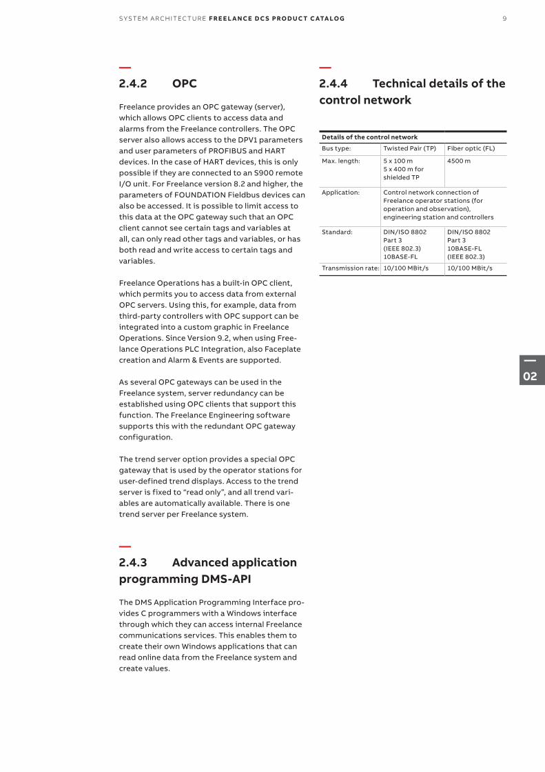
—2.4.4 Technical details of the control network
Details of the control network
Bus type: Twisted Pair (TP) Fiber optic (FL)
Max. length: 5 x 100 m 5 x 400 m for shielded TP
4500 m
Application: Control network connection of Freelance operator stations (for operation and observation), engineering station and controllers
Standard: DIN/ISO 8802 Part 3 (IEEE 802.3) 10BASE-FL
DIN/ISO 8802 Part 3 10BASE-FL (IEEE 802.3)
Transmission rate: 10/100 MBit/s 10/100 MBit/s
9S Y S TEM A R CH ITEC T U R E F R E E L A N CE D C S PRO D U C T C ATA LO G
—Chapter 3 – Controllers
012 3.1 Overview
013 3.2 Functions
014 – 028 3.3 The controller AC 900F
014 3.3.1 Hardware and certificates
017 3.3.2 AC 900F redundancy concept
018 3.3.3 Central processing unit PM 902F, standard
020 3.3.4 Central processing unit PM 901F, lite
022 3.3.5 PROFIBUS Communication Interfaces
024 3.3.6 CAN Communication Interface
027 3.3.7 Accessories
029 – 053 3.4 The controller AC 800F
030 3.4.1 Hardware and certificates
034 3.4.2 AC 800F redundancy concept
036 3.4.3 AC 800F, pre-assembled stations
036 3.4.4 AC 800F, base unit PM 803F
038 3.4.5 Power supply
042 3.4.6 Ethernet interface
044 3.4.7 Fieldbus interface modules
10 F R E E L A N CE D C S PRO D U C T C ATA LO G CO NTR O L L ER S
—03
050 3.4.8 Coated and G3 compliant hardware
051 3.4.9 Accessories
054 – 060 3.5 The controller AC 700F
054 3.5.1 Hardware and certificates
056 3.5.2 Central processing unit PM 783F
058 3.5.3 PROFIBUS module CI 773F
058 3.5.4 CPU terminal base TB 711F
060 3.5.5 Accessories for CPU module
11CO NTR O L L ER S F R E E L A N CE D C S PRO D U C T C ATA LO G
—03
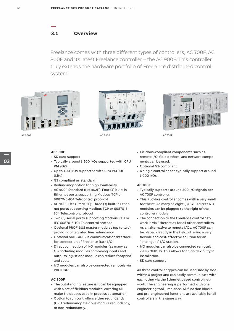
—3.1 Overview
Freelance comes with three different types of controllers, AC 700F, AC 800F and its latest Freelance controller – the AC 900F. This controller truly extends the hardware portfolio of Freelance distributed control system.
AC 900F AC 800F AC 700F
AC 900F• SD card support• Typically around 1,500 I/Os supported with CPU
PM 902F• Up to 400 I/Os supported with CPU PM 901F
(Lite)• G3 compliant as standard• Redundancy option for high availability• AC 900F Standard (PM 902F): Four (4) built-in
Ethernet ports supporting Modbus TCP or 60870-5-104 Telecontrol protocol
• AC 900F Lite (PM 901F): Three (3) built-in Ether-net ports supporting Modbus TCP or 60870-5-104 Telecontrol protocol
• Two (2) serial ports supporting Modbus RTU or IEC 60870-5-101 Telecontrol protocol
• Optional PROFIBUS master modules (up to two) providing integrated line redundancy
• Optional one CAN Bus communication interface for connection of Freelance Rack I/O
• Direct connection of I/O modules (as many as 10), including modules combining inputs and outputs in just one module can reduce footprint and costs.
• I/O modules can also be connected remotely via PROFIBUS
AC 800F• The outstanding feature is it can be equipped
with a set of fieldbus modules, covering all major fieldbuses used in process automation.
• Option to run controllers either redundantly (CPU redundancy, fieldbus module redundancy) or non-redundantly.
• Fieldbus-compliant components such as remote I/O, field devices, and network compo-nents can be used.
• Optional G3-compliant• A single controller can typically support around
1,000 I/Os
AC 700F• Typically supports around 300 I/O signals per
AC 700F controller. • This PLC-like controller comes with a very small
footprint. As many as eight (8) S700 direct I/O modules can be plugged to the right of the controller module.
• The connection to the Freelance control net-work is via Ethernet as for all other controllers. As an alternative to remote I/Os, AC 700F can be placed directly in the field, offering a very flexible and cost-effective solution for an “intelligent” I/O station.
• I/O modules can also be connected remotely via PROFIBUS. This allows for high flexibility in installation.
• SD card support
All three controller types can be used side by side within a project and can easily communicate with each other via the Ethernet based control net-work. The engineering is performed with one engineering tool, Freelance. All function blocks and pre-engineered functions are available for all controllers in the same way.
12 F R E E L A N CE D C S PRO D U C T C ATA LO G CO NTR O L L ER S
—03
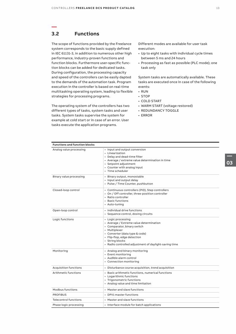
Functions and function blocks
Analog value processing • Input and output conversion • Linearization • Delay and dead-time filter• Average / extreme value determination in time• Setpoint adjustment• Counter with analog input• Time scheduler
Binary value processing • Binary output, monostable • Input and output delay• Pulse / Time Counter, pushbutton
Closed-loop control • Continuous controllers (PID), Step controllers• On / Off controller, three-position controller• Ratio controller• Basic functions• Auto-tuning
Open-loop control • Individual drive functions• Sequence control, dosing circuits
Logic functions • Logic processing• Average / Extreme value determination• Comparator, binary switch• Multiplexer• Converter (data type & code)• Flip-flop, edge detection • String blocks• Radio controlled adjustment of daylight-saving time
Monitoring • Analog and binary monitoring• Event monitoring• Audible alarm control• Connection monitoring
Acquisition functions • Disturbance course acquisition, trend acquisition
Arithmetic functions • Basic arithmetic functions, numerical functions• Logarithmic functions• Trigonometric functions• Analog value and time limitation
Modbus functions • Master and slave functions
PROFIBUS • DPV1 master functions
Telecontrol functions • Master and slave functions
Phase logic processing • Interface module for batch applications
—3.2 Functions
The scope of functions provided by the Freelance system corresponds to the basic supply defined in IEC 61131-3, in addition to numerous other high performance, industry-proven functions and function blocks. Furthermore user-specific func-tion blocks can be added for dedicated tasks. During configuration, the processing capacity and speed of the controllers can be easily dapted to the demands of the automation task. Program execution in the controller is based on real-time multitasking operating system, leading to flexible strategies for processing programs.
The operating system of the controllers has two different types of tasks, system tasks and user tasks. System tasks supervise the system for example at cold start or in case of an error. User tasks execute the application programs.
Different modes are available for user task execution:• Up to eight tasks with individual cycle times
between 5 ms and 24 hours• Processing as fast as possible (PLC mode); one
task only
System tasks are automatically available. These tasks are executed once in case of the following events:• RUN• STOP• COLD START• WARM START (voltage restored)• REDUNDANCY TOGGLE• ERROR
13CO NTR O L L ER S F R E E L A N CE D C S PRO D U C T C ATA LO G
—03
—3.3 The controller AC 900F
—3.3.1 Hardware and certificates
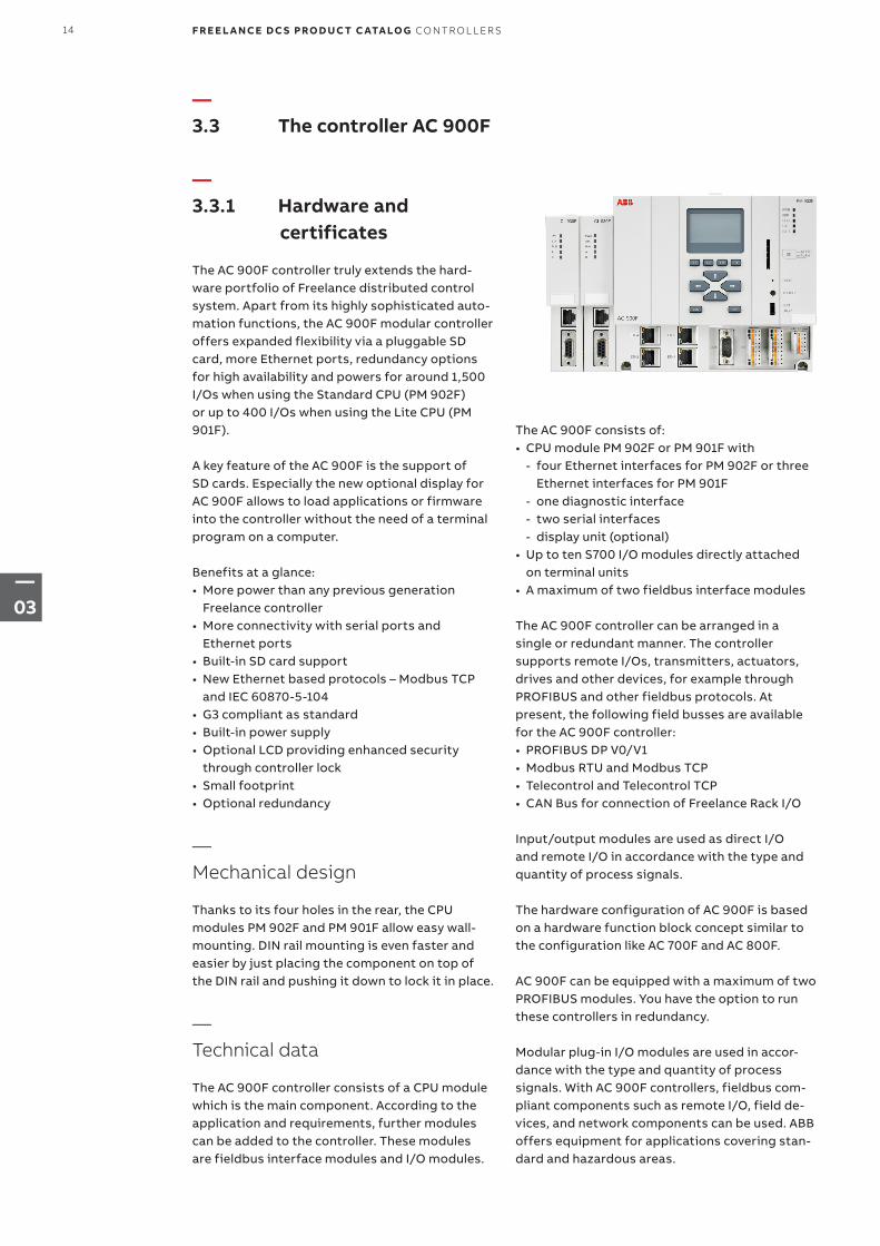
The AC 900F controller truly extends the hard-ware portfolio of Freelance distributed control system. Apart from its highly sophisticated auto-mation functions, the AC 900F modular controller offers expanded flexibility via a pluggable SD card, more Ethernet ports, redundancy options for high availability and powers for around 1,500 I/Os when using the Standard CPU (PM 902F) or up to 400 I/Os when using the Lite CPU (PM 901F).
A key feature of the AC 900F is the support of SD cards. Especially the new optional display for AC 900F allows to load applications or firmware into the controller without the need of a terminal program on a computer.
Benefits at a glance:• More power than any previous generation
Freelance controller • More connectivity with serial ports and
Ethernet ports• Built-in SD card support • New Ethernet based protocols – Modbus TCP
and IEC 60870-5-104 • G3 compliant as standard• Built-in power supply• Optional LCD providing enhanced security
through controller lock• Small footprint• Optional redundancy
—Mechanical design
Thanks to its four holes in the rear, the CPU modules PM 902F and PM 901F allow easy wall-mounting. DIN rail mounting is even faster and easier by just placing the component on top of the DIN rail and pushing it down to lock it in place.
—Technical data
The AC 900F controller consists of a CPU module which is the main component. According to the application and requirements, further modules can be added to the controller. These modules are fieldbus interface modules and I/O modules.
The AC 900F consists of:• CPU module PM 902F or PM 901F with
- four Ethernet interfaces for PM 902F or three Ethernet interfaces for PM 901F
- one diagnostic interface - two serial interfaces - display unit (optional)
• Up to ten S700 I/O modules directly attached on terminal units
• A maximum of two fieldbus interface modules
The AC 900F controller can be arranged in a single or redundant manner. The controller supports remote I/Os, transmitters, actuators, drives and other devices, for example through PROFIBUS and other fieldbus protocols. At present, the following field busses are available for the AC 900F controller:• PROFIBUS DP V0/V1• Modbus RTU and Modbus TCP• Telecontrol and Telecontrol TCP• CAN Bus for connection of Freelance Rack I/O
Input/output modules are used as direct I/O and remote I/O in accordance with the type and quantity of process signals.
The hardware configuration of AC 900F is based on a hardware function block concept similar to the configuration like AC 700F and AC 800F.
AC 900F can be equipped with a maximum of two PROFIBUS modules. You have the option to run these controllers in redundancy.
Modular plug-in I/O modules are used in accor-dance with the type and quantity of process signals. With AC 900F controllers, fieldbus com-pliant components such as remote I/O, field de-vices, and network components can be used. ABB offers equipment for applications covering stan-dard and hazardous areas.
14 F R E E L A N CE D C S PRO D U C T C ATA LO G CO NTR O L L ER S
—03
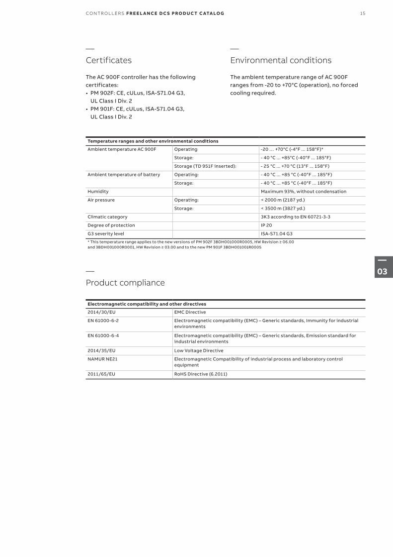
Temperature ranges and other environmental conditions
Ambient temperature AC 900F Operating -20 … +70°C (-4°F ... 158°F)*
Storage: - 40 °C ... +85°C (-40°F ... 185°F)
Storage (TD 951F inserted): - 25 °C ... +70 °C (13°F ... 158°F)
Ambient temperature of battery Operating: - 40 °C ... +85 °C (-40°F ... 185°F)
Storage: - 40 °C ... +85 °C (-40°F ... 185°F)
Humidity Maximum 93%, without condensation
Air pressure Operating: < 2000 m (2187 yd.)
Storage: < 3500 m (3827 yd.)
Climatic category 3K3 according to EN 60721-3-3
Degree of protection IP 20
G3 severity level ISA-S71.04 G3
* This temperature range applies to the new versions of PM 902F 3BDH001000R0005, HW Revision ≥ 06.00 and 3BDH001000R0001, HW Revision ≥ 03.00 and to the new PM 901F 3BDH001001R0005
Electromagnetic compatibility and other directives
2014/30/EU EMC Directive
EN 61000-6-2 Electromagnetic compatibility (EMC) – Generic standards, Immunity for industrial environments
EN 61000-6-4 Electromagnetic compatibility (EMC) – Generic standards, Emission standard for industrial environments
2014/35/EU Low Voltage Directive
NAMUR NE21 Electromagnetic Compatibility of industrial process and laboratory control equipment
2011/65/EU RoHS Directive (6.2011)
—Certificates
The AC 900F controller has the following certificates: • PM 902F: CE, cULus, ISA-S71.04 G3,
UL Class I Div. 2• PM 901F: CE, cULus, ISA-S71.04 G3,
UL Class I Div. 2
—Product compliance
—Environmental conditions
The ambient temperature range of AC 900F ranges from -20 to +70°C (operation), no forced cooling required.
15CO NTR O L L ER S F R E E L A N CE D C S PRO D U C T C ATA LO G
—03
—Power dissipation for the calculation of cooling systems
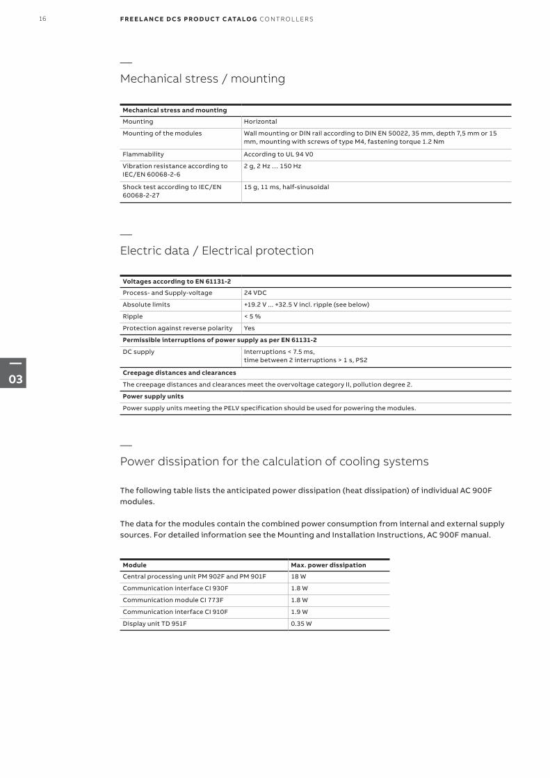
Mechanical stress and mounting
Mounting Horizontal
Mounting of the modules Wall mounting or DIN rail according to DIN EN 50022, 35 mm, depth 7,5 mm or 15 mm, mounting with screws of type M4, fastening torque 1.2 Nm
Flammability According to UL 94 V0
Vibration resistance according to IEC/EN 60068-2-6
2 g, 2 Hz … 150 Hz
Shock test according to IEC/EN 60068-2-27
15 g, 11 ms, half-sinusoidal
Module Max. power dissipation
Central processing unit PM 902F and PM 901F 18 W
Communication interface CI 930F 1.8 W
Communication module CI 773F 1.8 W
Communication interface CI 910F 1.9 W
Display unit TD 951F 0.35 W
Voltages according to EN 61131-2
Process- and Supply-voltage 24 VDC
Absolute limits +19.2 V ... +32.5 V incl. ripple (see below)
Ripple < 5 %
Protection against reverse polarity Yes
Permissible interruptions of power supply as per EN 61131-2
DC supply Interruptions < 7.5 ms, time between 2 interruptions > 1 s, PS2
Creepage distances and clearances
The creepage distances and clearances meet the overvoltage category II, pollution degree 2.
Power supply units
Power supply units meeting the PELV specification should be used for powering the modules.
The following table lists the anticipated power dissipation (heat dissipation) of individual AC 900F modules.
The data for the modules contain the combined power consumption from internal and external supply sources. For detailed information see the Mounting and Installation Instructions, AC 900F manual.
—Mechanical stress / mounting
—Electric data / Electrical protection
16 F R E E L A N CE D C S PRO D U C T C ATA LO G CO NTR O L L ER S
—03
—3.3.2 AC 900F redundancy concept
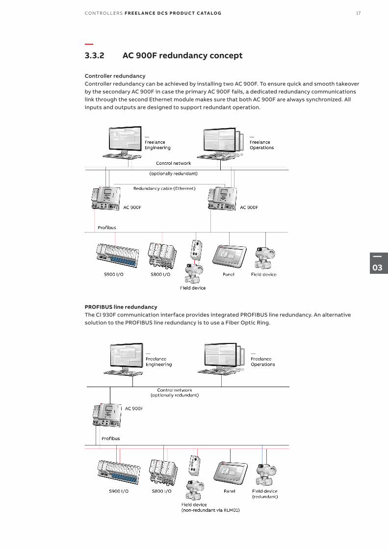
Controller redundancy Controller redundancy can be achieved by installing two AC 900F. To ensure quick and smooth takeover by the secondary AC 900F in case the primary AC 900F fails, a dedicated redundancy communications link through the second Ethernet module makes sure that both AC 900F are always synchronized. All inputs and outputs are designed to support redundant operation.
PROFIBUS line redundancy The CI 930F communication interface provides integrated PROFIBUS line redundancy. An alternative solution to the PROFIBUS line redundancy is to use a Fiber Optic Ring.
17CO NTR O L L ER S F R E E L A N CE D C S PRO D U C T C ATA LO G
—03
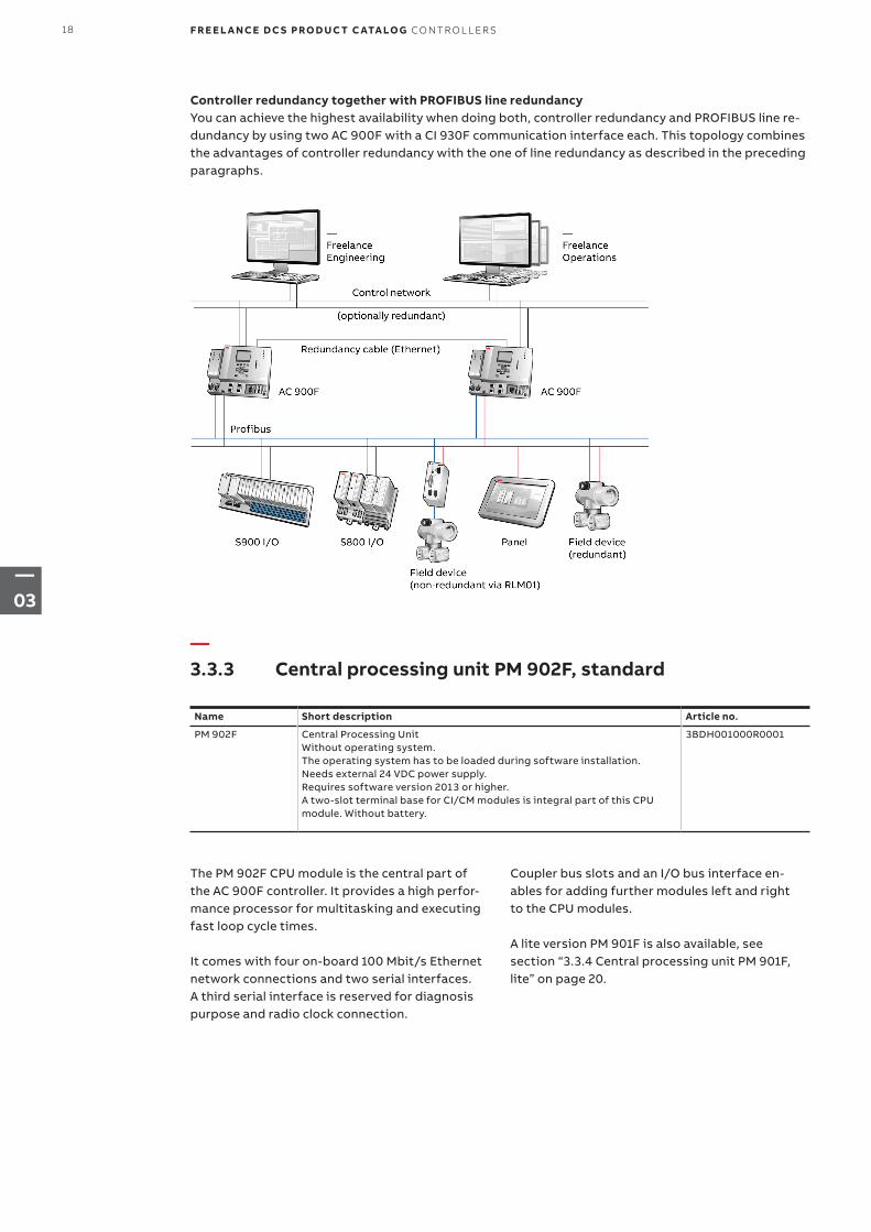
Controller redundancy together with PROFIBUS line redundancy You can achieve the highest availability when doing both, controller redundancy and PROFIBUS line re-dundancy by using two AC 900F with a CI 930F communication interface each. This topology combines the advantages of controller redundancy with the one of line redundancy as described in the preceding paragraphs.
The PM 902F CPU module is the central part of the AC 900F controller. It provides a high perfor-mance processor for multitasking and executing fast loop cycle times.
It comes with four on-board 100 Mbit/s Ethernet network connections and two serial interfaces. A third serial interface is reserved for diagnosis purpose and radio clock connection.
Name Short description Article no.
PM 902F Central Processing UnitWithout operating system. The operating system has to be loaded during software installation.Needs external 24 VDC power supply.Requires software version 2013 or higher.A two-slot terminal base for CI/CM modules is integral part of this CPU module. Without battery.
3BDH001000R0001
Coupler bus slots and an I/O bus interface en-ables for adding further modules left and right to the CPU modules. A lite version PM 901F is also available, see section “3.3.4 Central processing unit PM 901F, lite” on page 20.
—3.3.3 Central processing unit PM 902F, standard
18 F R E E L A N CE D C S PRO D U C T C ATA LO G CO NTR O L L ER S
—03
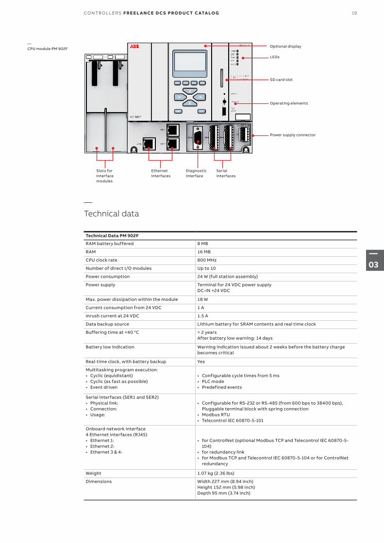
—CPU module PM 902F
Technical Data PM 902F
RAM battery buffered 8 MB
RAM 16 MB
CPU clock rate 800 MHz
Number of direct I/O modules Up to 10
Power consumption 24 W (full station assembly)
Power supply Terminal for 24 VDC power supplyDC-IN +24 VDC
Max. power dissipation within the module 18 W
Current consumption from 24 VDC 1 A
Inrush current at 24 VDC 1.5 A
Data backup source Lithium battery for SRAM contents and real time clock
Buffering time at +40 °C > 2 yearsAfter battery low warning: 14 days
Battery low indication Warning indication issued about 2 weeks before the battery charge becomes critical
Real-time clock, with battery backup Yes
Multitasking program execution: • Cyclic (equidistant) • Cyclic (as fast as possible)• Event driven
• Configurable cycle times from 5 ms• PLC mode• Predefined events
Serial interfaces (SER1 and SER2)• Physical link:• Connection:• Usage:
• Configurable for RS-232 or RS-485 (from 600 bps to 38400 bps), Pluggable terminal block with spring connection
• Modbus RTU• Telecontrol IEC 60870-5-101
Onboard network interface 4 Ethernet interfaces (RJ45)• Ethernet 1:• Ethernet 2:• Ethernet 3 & 4:
• for ControlNet (optional Modbus TCP and Telecontrol IEC 60870-5-104)
• for redundancy link• for Modbus TCP and Telecontrol IEC 60870-5-104 or for ControlNet
redundancy
Weight 1.07 kg (2.36 lbs)
Dimensions Width 227 mm (8.94 inch)Height 152 mm (5.98 inch)Depth 95 mm (3.74 inch)
—Technical data
Optional display
LEDs
SD card slot
Operating elements
Power supply connector
Slots for interface modules
Ethernet interfaces
Diagnostic interface
Serial interfaces
19CO NTR O L L ER S F R E E L A N CE D C S PRO D U C T C ATA LO G
—03
—3.3.4 Central processing unit PM 901F, lite
Name Short description Article no.
PM 901F Central Processing UnitWithout operating system. The operating system has to be loaded during software installation.Needs external 24 VDC power supply.Requires software version 2016 or higher.A two-slot terminal base for CI/CM modules is integral part of this CPU module. Without battery.
3BDH001001R0001
A CPU module is the central part of the AC 900F controller. It provides a high performance proces-sor for multitasking and executing fast loop cycle times.
It comes with three on-board 100 Mbit/s Ethernet network connections and two serial interfaces. A third serial interface is reserved for diagnosis purpose and radio clock connection.
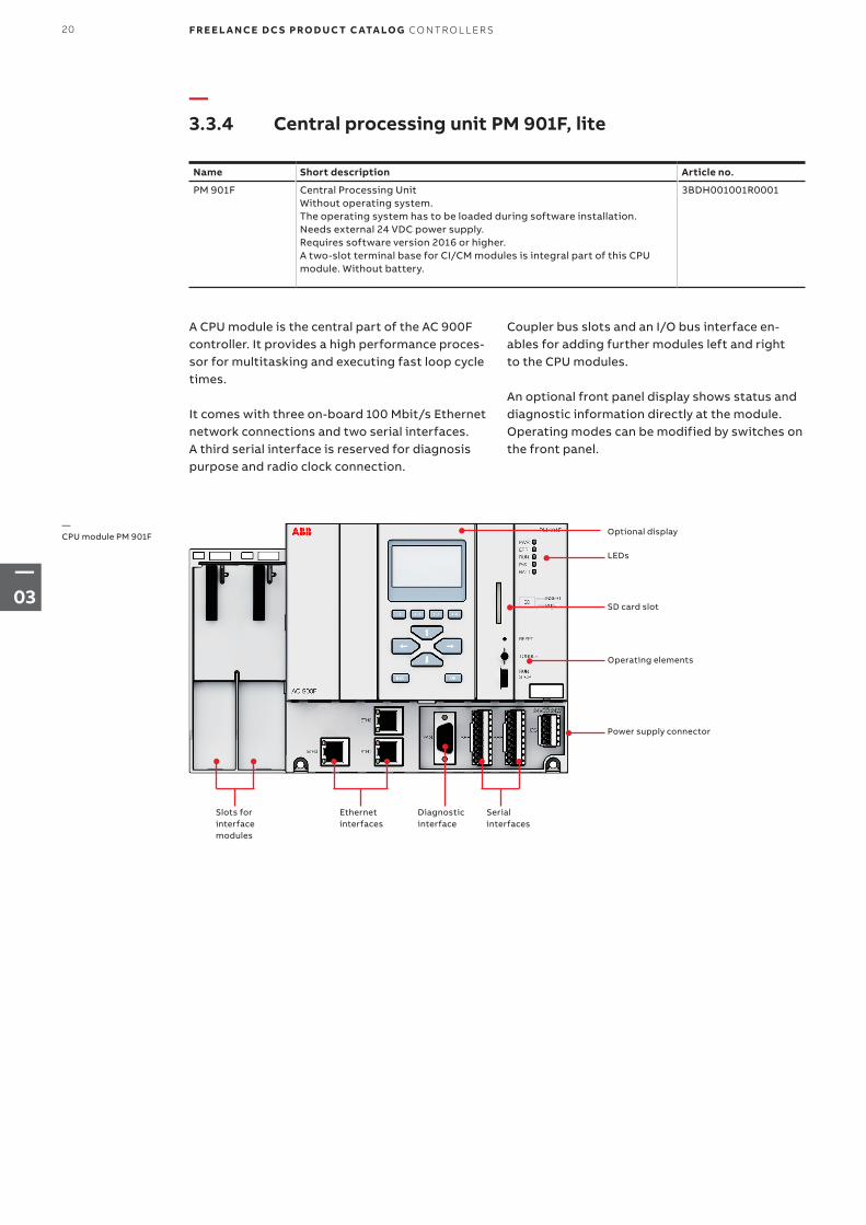
—CPU module PM 901F Optional display
LEDs
SD card slot
Operating elements
Power supply connector
Slots for interface modules
Ethernet interfaces
Diagnostic interface
Serial interfaces
Coupler bus slots and an I/O bus interface en-ables for adding further modules left and right to the CPU modules.
An optional front panel display shows status and diagnostic information directly at the module. Operating modes can be modified by switches on the front panel.
20 F R E E L A N CE D C S PRO D U C T C ATA LO G CO NTR O L L ER S
—03
—Technical data
Technical Data PM 901F
RAM battery buffered 3 MB
RAM 16 MB
CPU clock rate 400 MHz
Number of direct I/O modules Up to 10
Power consumption 24 W (full station assembly)
Power supply Terminal for 24 VDC power supplyDC-IN +24 VDC
Max. power dissipation within the module 18 W
Current consumption from 24 VDC 1 A
Inrush current at 24 VDC 1.5 A
Data backup source Lithium battery for SRAM contents and real time clock
Buffering time at +40 °C > 2 yearsAfter battery low warning: 14 days
Battery low indication Warning indication issued about 2 weeks before the battery charge becomes critical
Real-time clock, with battery backup Yes
Multitasking program execution: • Cyclic (equidistant) • Cyclic (as fast as possible)• Event driven
• Configurable cycle times from 5 ms• PLC mode• Predefined events
Serial interfaces (SER1 and SER2)• Physical link:• Connection:• Usage:
• Configurable for RS-232 or RS-485 (from 600 bps to 38400 bps), Pluggable terminal block with spring connection
• Modbus RTU• Telecontrol IEC 60870-5-101
Onboard network interface 3 Ethernet interfaces (RJ45)• Ethernet 1:• Ethernet 2:• Ethernet 3:
• for ControlNet (optional Modbus TCP and Telecontrol IEC 60870-5-104)
• for redundancy link• for Modbus TCP and Telecontrol IEC 60870-5-104 or for ControlNet
redundancy
Weight 1.07 kg (2.36 lbs)
Dimensions Width 227 mm (8.94 inch)Height 152 mm (5.98 inch)Depth 95 mm (3.74 inch)
21CO NTR O L L ER S F R E E L A N CE D C S PRO D U C T C ATA LO G
—03
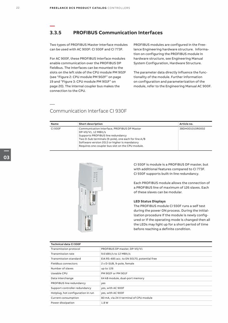
—3.3.5 PROFIBUS Communication Interfaces
—Communication Interface CI 930F
Name Short description Article no.
CI 930F Communication Interface, PROFIBUS DP MasterDP-V0/V1, 12 MBit/sSupports PROFIBUS line redundancyTwo D-Sub terminals (9-pole), one each for line A/BSoftware version 2013 or higher is mandatoryRequires one coupler bus slot on the CPU module.
3BDH001010R0002
Two types of PROFIBUS Master interface modules can be used with AC 900F: CI 930F and CI 773F.
For AC 900F, these PROFIBUS interface modules enable communication over the PROFIBUS DP fieldbus. The interfaces can be mounted to the slots on the left side of the CPU module PM 902F (see “Figure 2: CPU module PM 902F” on page 19 and “Figure 3: CPU module PM 901F” on page 20). The internal coupler bus makes the connection to the CPU.
CI 930F is module is a PROFIBUS DP master, but with additional features compared to CI 773F. CI 930F supports built-in line redundancy.
Each PROFIBUS module allows the connection of a PROFIBUS line of maximum of 126 slaves. Each of these slaves can be modular.
LED Status DisplaysThe PROFIBUS module CI 930F runs a self test during the power ON process. During the initial-ization procedure if the module is newly config-ured or if the operating mode is changed then all the LEDs may light up for a short period of time before reaching a definite condition.
PROFIBUS modules are configured in the Free-lance Engineering hardware structure. Informa-tion on configuring the PROFIBUS module in hardware structure, see Engineering Manual System Configuration, Hardware Structure.
The parameter data directly influence the func-tionality of the module. Further information on configuration and parameterization of the module, refer to the Engineering Manual AC 900F.
Technical data CI 930F
Transmission protocol PROFIBUS DP master, DP-V0/V1
Transmission rate 9.6 kBit/s to 12 MBit/s
Transmission standard EIA RS-485 acc. to EN 50170, potential free
Fieldbus connectors 2 x D-SUB, 9-pole, female
Number of slaves up to 126
Useable CPU PM 902F or PM 901F
Data interchange 64 kB module, dual-port memory
PROFIBUS line redundancy yes
Support controller redundancy yes, with AC 900F
Hotplug, hot configuration in run yes, with AC 900F
Current consumption 80 mA, via 24 V terminal of CPU module
Power dissipation 1.8 W
22 F R E E L A N CE D C S PRO D U C T C ATA LO G CO NTR O L L ER S
—03
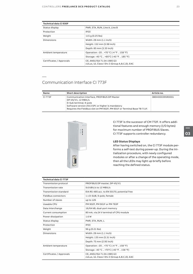
—Communication Interface CI 773F
Name Short description Article no.
CI 773F Communication Interface, PROFIBUS DP MasterDP-V0/V1, 12 MBit/sD-Sub terminal, 9-poleSoftware version 2013 SP1 or higher is mandatoryRequires the Fieldbus slot on PM 902F, PM 901F or Terminal Base TB 711F.
3BDH000395R0001
CI 773F is the sucessor of CM 772F. It offers addi-tional features and enough memory (I/O bytes) for maximum number of PROFIBUS Slaves. CI 773F supports controller redundancy.
LED Status DisplaysAfter having switched on, the CI 773F module per-forms a self-test during power-up. During the ini-tialization procedure, with newly configured modules or after a change of the operating mode, then all the LEDs may light up briefly before reaching the defined status.
Technical data CI 773F
Transmission protocol PROFIBUS DP master, DP-V0/V1
Transmission rate 9.6 kBit/s to 12 MBit/s
Transmission standard EIA RS-485 acc. to EN 50170, potential free
Fieldbus connectors 1 x D-SUB, 9-pole, female
Number of slaves up to 126
Useable CPU PM 902F, PM 901F or PM 783F
Data interchange 16/64 kB, dual-port memory
Current consumption 80 mA, via 24 V terminal of CPU module
Power dissipation 1.6 W
Status display PWR, STA, RUN, L
Protection IP20
Weight 96 g (0.21 lbs)
Dimensions Width: 28 mm (1.1 inch)
Height: 135 mm (5.31 inch)
Depth: 75 mm (2.95 inch)
Ambient temperature Operation: -20 .. +70 °C (-4 °F .. 158 °F)
Storage: -40 °C .. +70°C (-40 °F .. 158 °F)
Certificates / Approvals CE, ANSI/ISA 71.04-1985 G3 cULus, UL Class I Div 2 (Group A,B,C,D), EAC
Technical data CI 930F
Status display PWR, STA, RUN, Line A, Line B
Protection IP20
Weight 115 g (0.25 lbs)
Dimensions Width: 28 mm (1.1 inch)
Height: 152 mm (5.98 inch)
Depth: 85 mm (3.35 inch)
Ambient temperature Operation: -20 .. +70 °C (-4 °F .. 158 °F)
Storage: -40 °C .. +85°C (-40 °F .. 185 °F)
Certificates / Approvals CE, ANSI/ISA 71.04-1985 G3cULus, UL Class I Div 2 (Group A,B,C,D), EAC
23CO NTR O L L ER S F R E E L A N CE D C S PRO D U C T C ATA LO G
—03
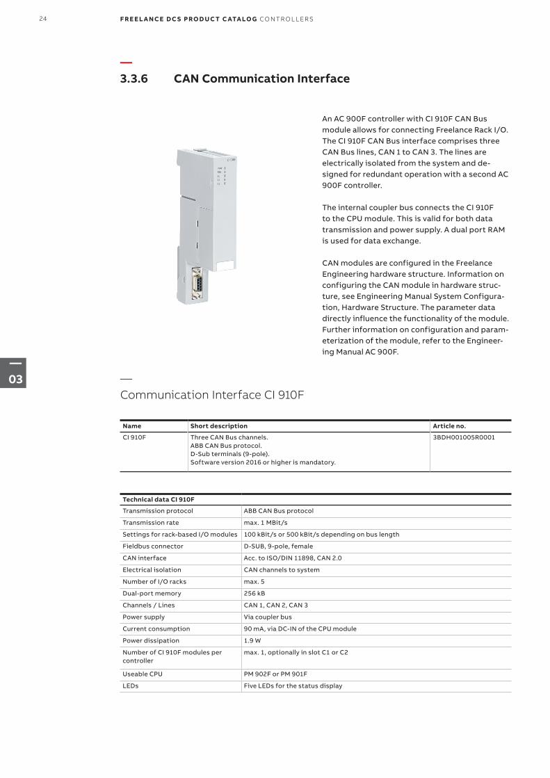
—3.3.6 CAN Communication Interface
—Communication Interface CI 910F
Name Short description Article no.
CI 910F Three CAN Bus channels.ABB CAN Bus protocol.D-Sub terminals (9-pole).Software version 2016 or higher is mandatory.
3BDH001005R0001
An AC 900F controller with CI 910F CAN Bus module allows for connecting Freelance Rack I/O. The CI 910F CAN Bus interface comprises three CAN Bus lines, CAN 1 to CAN 3. The lines are electrically isolated from the system and de-signed for redundant operation with a second AC 900F controller. The internal coupler bus connects the CI 910F to the CPU module. This is valid for both data transmission and power supply. A dual port RAM is used for data exchange.
CAN modules are configured in the Freelance Engineering hardware structure. Information on configuring the CAN module in hardware struc-ture, see Engineering Manual System Configura-tion, Hardware Structure. The parameter data directly influence the functionality of the module. Further information on configuration and param-eterization of the module, refer to the Engineer-ing Manual AC 900F.
Technical data CI 910F
Transmission protocol ABB CAN Bus protocol
Transmission rate max. 1 MBit/s
Settings for rack-based I/O modules 100 kBit/s or 500 kBit/s depending on bus length
Fieldbus connector D-SUB, 9-pole, female
CAN interface Acc. to ISO/DIN 11898, CAN 2.0
Electrical isolation CAN channels to system
Number of I/O racks max. 5
Dual-port memory 256 kB
Channels / Lines CAN 1, CAN 2, CAN 3
Power supply Via coupler bus
Current consumption 90 mA, via DC-IN of the CPU module
Power dissipation 1.9 W
Number of CI 910F modules per controller
max. 1, optionally in slot C1 or C2
Useable CPU PM 902F or PM 901F
LEDs Five LEDs for the status display
24 F R E E L A N CE D C S PRO D U C T C ATA LO G CO NTR O L L ER S
—03
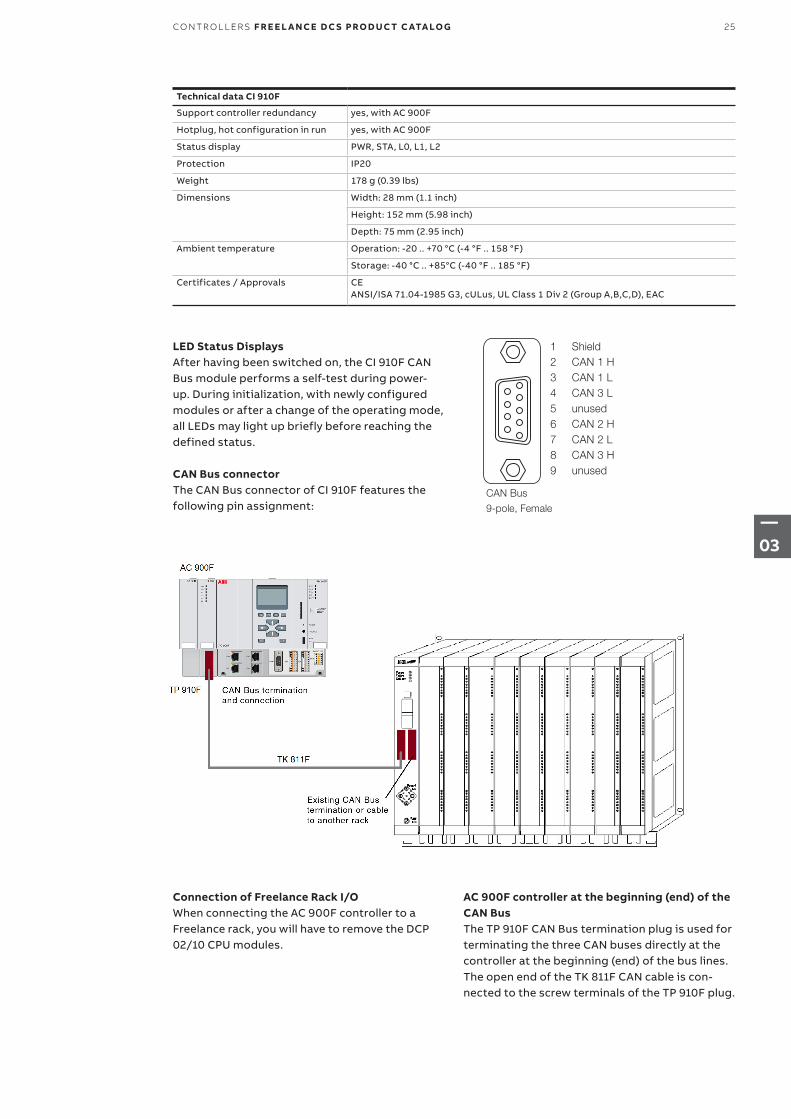
LED Status DisplaysAfter having been switched on, the CI 910F CAN Bus module performs a self-test during power- up. During initialization, with newly configured modules or after a change of the operating mode, all LEDs may light up briefly before reaching the defined status.
CAN Bus connectorThe CAN Bus connector of CI 910F features the following pin assignment:
1 Shield2 CAN 1 H3 CAN 1 L4 CAN 3 L5 unused6 CAN 2 H7 CAN 2 L8 CAN 3 H9 unused
CAN Bus
9-pole, Female
Connection of Freelance Rack I/OWhen connecting the AC 900F controller to a Freelance rack, you will have to remove the DCP 02/10 CPU modules.
AC 900F controller at the beginning (end) of the CAN BusThe TP 910F CAN Bus termination plug is used for terminating the three CAN buses directly at the controller at the beginning (end) of the bus lines. The open end of the TK 811F CAN cable is con-nected to the screw terminals of the TP 910F plug.
Technical data CI 910F
Support controller redundancy yes, with AC 900F
Hotplug, hot configuration in run yes, with AC 900F
Status display PWR, STA, L0, L1, L2
Protection IP20
Weight 178 g (0.39 lbs)
Dimensions Width: 28 mm (1.1 inch)
Height: 152 mm (5.98 inch)
Depth: 75 mm (2.95 inch)
Ambient temperature Operation: -20 .. +70 °C (-4 °F .. 158 °F)
Storage: -40 °C .. +85°C (-40 °F .. 185 °F)
Certificates / Approvals CEANSI/ISA 71.04-1985 G3, cULus, UL Class 1 Div 2 (Group A,B,C,D), EAC
25CO NTR O L L ER S F R E E L A N CE D C S PRO D U C T C ATA LO G
—03
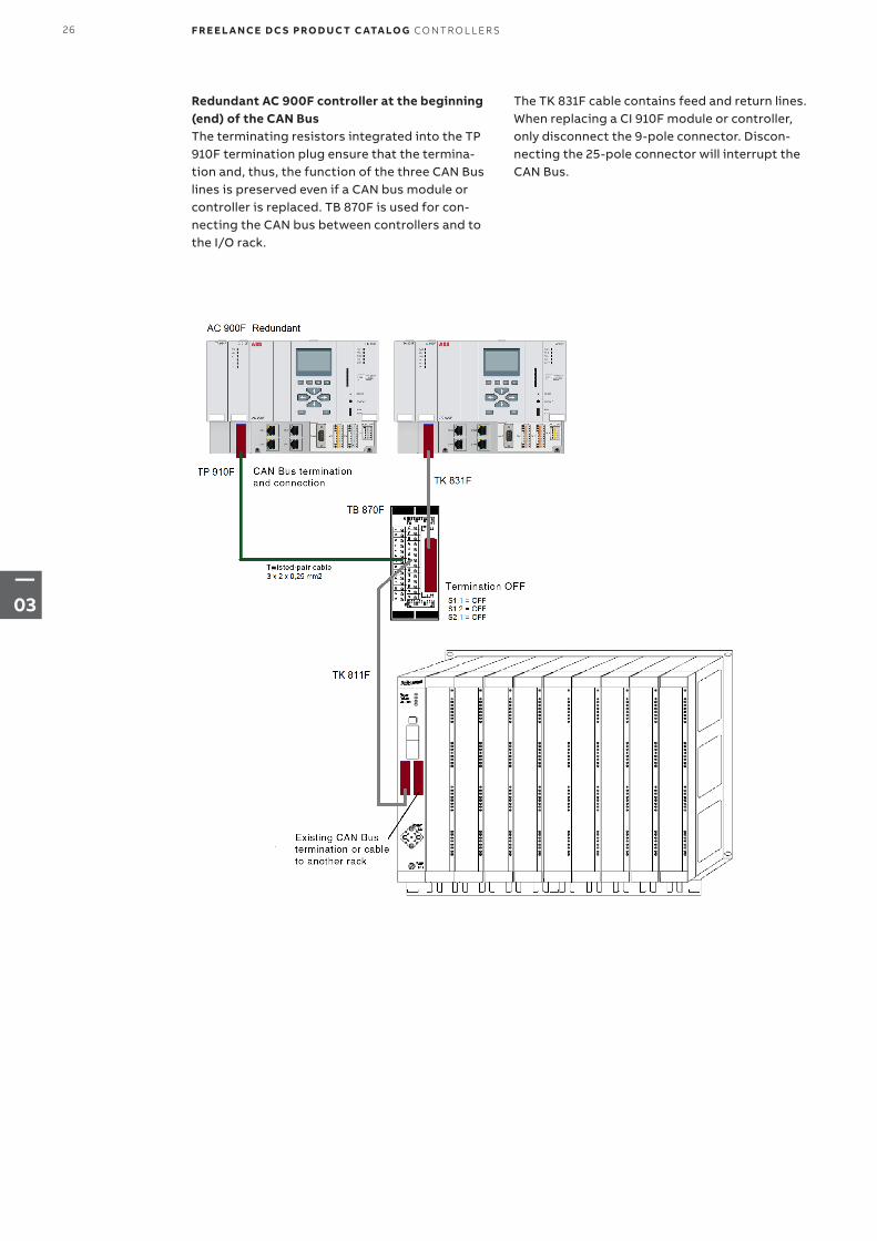
Redundant AC 900F controller at the beginning (end) of the CAN BusThe terminating resistors integrated into the TP 910F termination plug ensure that the termina-tion and, thus, the function of the three CAN Bus lines is preserved even if a CAN bus module or controller is replaced. TB 870F is used for con-necting the CAN bus between controllers and to the I/O rack.
The TK 831F cable contains feed and return lines. When replacing a CI 910F module or controller, only disconnect the 9-pole connector. Discon-necting the 25-pole connector will interrupt the CAN Bus.
26 F R E E L A N CE D C S PRO D U C T C ATA LO G CO NTR O L L ER S
—03
—3.3.7 Accessories
—TD 951F Display Unit
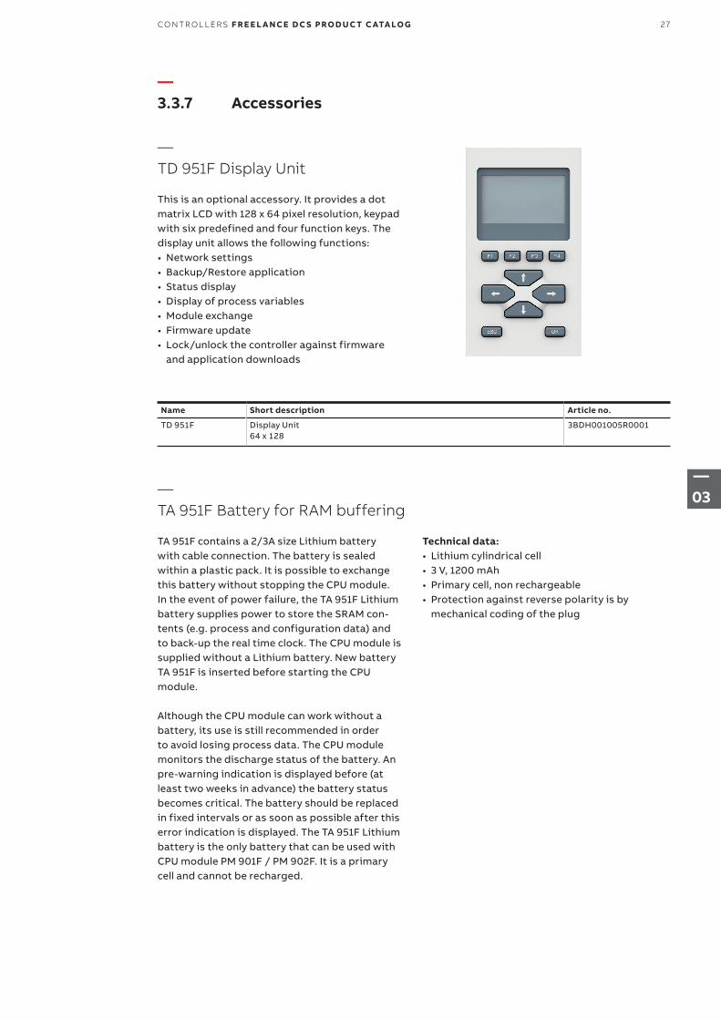
This is an optional accessory. It provides a dot matrix LCD with 128 x 64 pixel resolution, keypad with six predefined and four function keys. The display unit allows the following functions:• Network settings• Backup/Restore application• Status display• Display of process variables• Module exchange• Firmware update• Lock/unlock the controller against firmware
and application downloads
—TA 951F Battery for RAM buffering
TA 951F contains a 2/3A size Lithium battery with cable connection. The battery is sealed within a plastic pack. It is possible to exchange this battery without stopping the CPU module. In the event of power failure, the TA 951F Lithium battery supplies power to store the SRAM con-tents (e.g. process and configuration data) and to back-up the real time clock. The CPU module is supplied without a Lithium battery. New battery TA 951F is inserted before starting the CPU module.
Although the CPU module can work without a battery, its use is still recommended in order to avoid losing process data. The CPU module monitors the discharge status of the battery. An pre-warning indication is displayed before (at least two weeks in advance) the battery status becomes critical. The battery should be replaced in fixed intervals or as soon as possible after this error indication is displayed. The TA 951F Lithium battery is the only battery that can be used with CPU module PM 901F / PM 902F. It is a primary cell and cannot be recharged.
Name Short description Article no.
TD 951F Display Unit64 x 128
3BDH001005R0001
Technical data:• Lithium cylindrical cell• 3 V, 1200 mAh• Primary cell, non rechargeable• Protection against reverse polarity is by
mechanical coding of the plug
27CO NTR O L L ER S F R E E L A N CE D C S PRO D U C T C ATA LO G
—03
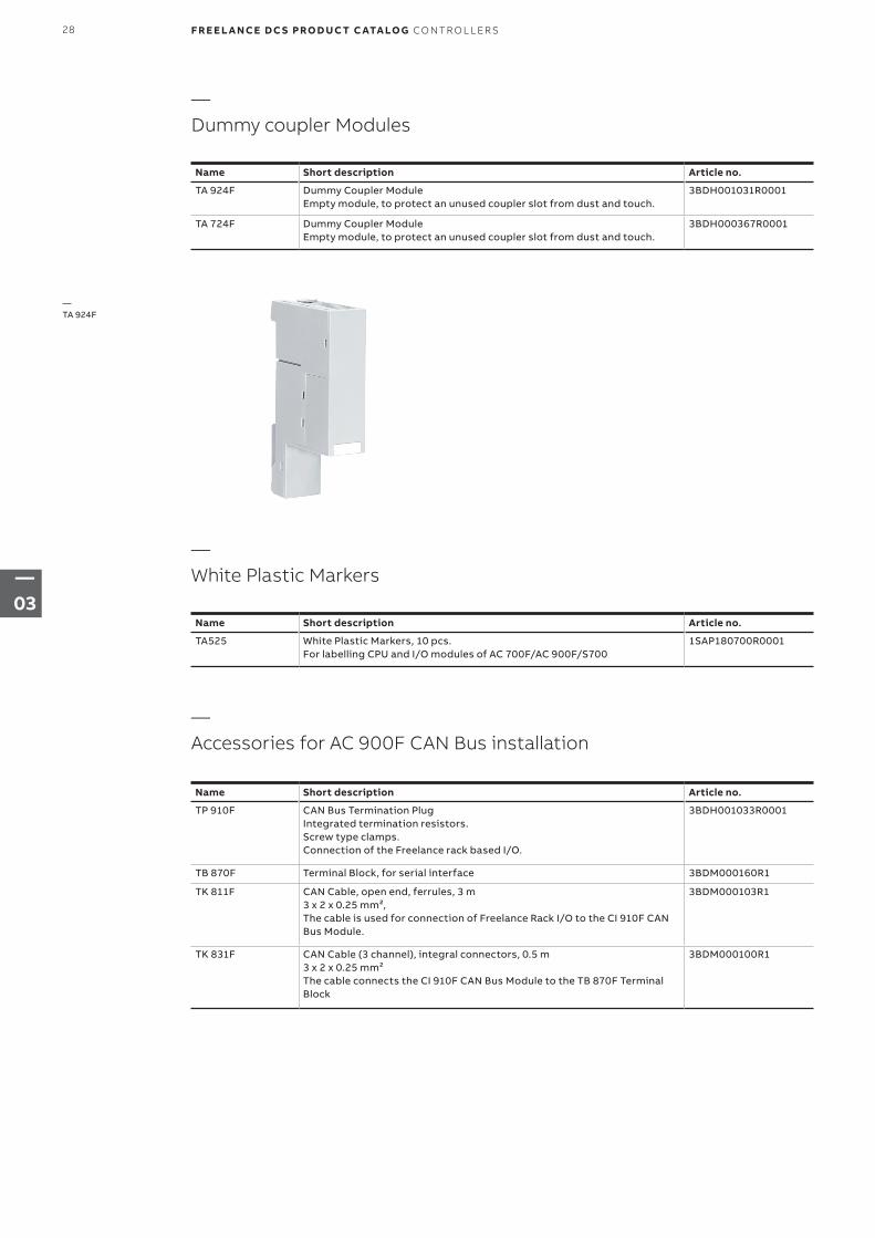
—TA 924F
Name Short description Article no.
TA 924F Dummy Coupler ModuleEmpty module, to protect an unused coupler slot from dust and touch.
3BDH001031R0001
TA 724F Dummy Coupler ModuleEmpty module, to protect an unused coupler slot from dust and touch.
3BDH000367R0001
Name Short description Article no.
TP 910F CAN Bus Termination PlugIntegrated termination resistors.Screw type clamps.Connection of the Freelance rack based I/O.
3BDH001033R0001
TB 870F Terminal Block, for serial interface 3BDM000160R1
TK 811F CAN Cable, open end, ferrules, 3 m3 x 2 x 0.25 mm²,The cable is used for connection of Freelance Rack I/O to the CI 910F CAN Bus Module.
3BDM000103R1
TK 831F CAN Cable (3 channel), integral connectors, 0.5 m3 x 2 x 0.25 mm²The cable connects the CI 910F CAN Bus Module to the TB 870F Terminal Block
3BDM000100R1
—Dummy coupler Modules
—White Plastic Markers
—Accessories for AC 900F CAN Bus installation
Name Short description Article no.
TA525 White Plastic Markers, 10 pcs.For labelling CPU and I/O modules of AC 700F/AC 900F/S700
1SAP180700R0001
28 F R E E L A N CE D C S PRO D U C T C ATA LO G CO NTR O L L ER S
—03
1. GSD = Device Master Data, abbreviation for the German term “Gerätestammdaten”. A GSD is the device database file (also called device data sheet)2. DTM = Device Driver based on FDT technolog3. CFF= Capabilities File4. DD= Device Description
—3.4 The controller AC 800F
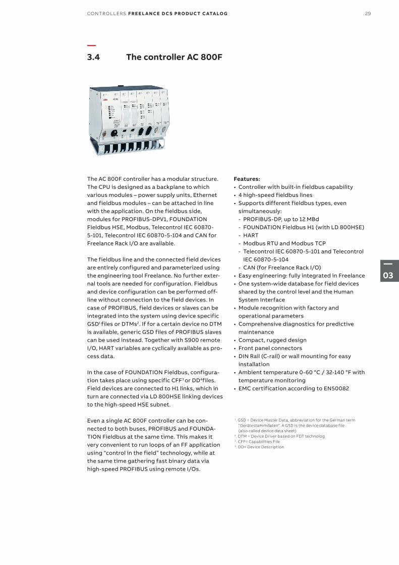
The AC 800F controller has a modular structure. The CPU is designed as a backplane to which various modules – power supply units, Ethernet and fieldbus modules – can be attached in line with the application. On the fieldbus side, modules for PROFIBUS-DPV1, FOUNDATION Fieldbus HSE, Modbus, Telecontrol IEC 60870- 5-101, Telecontrol IEC 60870-5-104 and CAN for Freelance Rack I/O are available.
The fieldbus line and the connected field devices are entirely configured and parameterized using the engineering tool Freelance. No further exter-nal tools are needed for configuration. Fieldbus and device configuration can be performed off-line without connection to the field devices. In case of PROFIBUS, field devices or slaves can be integrated into the system using device specific GSD1 files or DTMs2. If for a certain device no DTM is available, generic GSD files of PROFIBUS slaves can be used instead. Together with S900 remote I/O, HART variables are cyclically available as pro-cess data.
In the case of FOUNDATION Fieldbus, configura-tion takes place using specific CFF3 or DD4files. Field devices are connected to H1 links, which in turn are connected via LD 800HSE linking de vices to the high-speed HSE subnet.
Even a single AC 800F controller can be con-nected to both buses, PROFIBUS and FOUNDA-TION Fieldbus at the same time. This makes it very convenient to run loops of an FF application using “control in the field” technology, while at the same time gathering fast binary data via high-speed PROFIBUS using remote I/Os.
Features:• Controller with built-in fieldbus capability• 4 high-speed fieldbus lines• Supports different fieldbus types, even
simultaneously: - PROFIBUS-DP, up to 12 MBd - FOUNDATION Fieldbus H1 (with LD 800HSE) - HART - Modbus RTU and Modbus TCP - Telecontrol IEC 60870-5-101 and Telecontrol
IEC 60870-5-104 - CAN (for Freelance Rack I/O)
• Easy engineering: fully integrated in Freelance• One system-wide database for field devices
shared by the control level and the Human System Interface
• Module recognition with factory and operational parameters
• Comprehensive diagnostics for predictive maintenance
• Compact, rugged design• Front panel connectors• DIN Rail (C-rail) or wall mounting for easy
installation• Ambient temperature 0-60 °C / 32-140 °F with
temperature monitoring• EMC certification according to EN50082
29CO NTR O L L ER S F R E E L A N CE D C S PRO D U C T C ATA LO G
—03
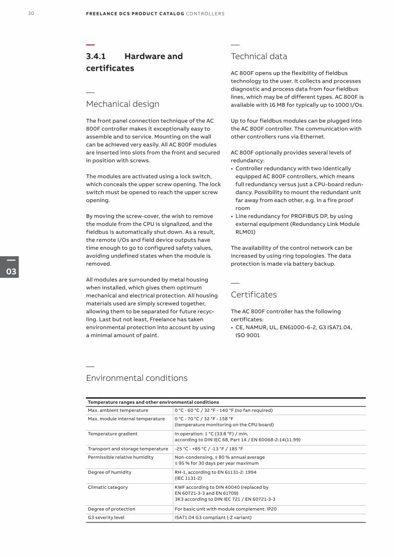
—3.4.1 Hardware and certificates
—Mechanical design
The front panel connection technique of the AC 800F controller makes it exceptionally easy to assemble and to service. Mounting on the wall can be achieved very easily. All AC 800F modules are inserted into slots from the front and secured in position with screws.
The modules are activated using a lock switch, which conceals the upper screw opening. The lock switch must be opened to reach the upper screw opening.
By moving the screw-cover, the wish to remove the module from the CPU is signalized, and the fieldbus is automatically shut down. As a result, the remote I/Os and field device outputs have time enough to go to configured safety values, avoiding undefined states when the module is removed.
All modules are surrounded by metal housing when installed, which gives them optimum mechanical and electrical protection. All housing materials used are simply screwed together, allowing them to be separated for future recyc-ling. Last but not least, Freelance has taken environmental protection into account by using a minimal amount of paint.
—Technical data
AC 800F opens up the flexibility of fieldbus technology to the user. It collects and processes diagnostic and process data from four fieldbus lines, which may be of different types. AC 800F is available with 16 MB for typically up to 1000 I/Os.
Up to four fieldbus modules can be plugged into the AC 800F controller. The communication with other controllers runs via Ethernet.
AC 800F optionally provides several levels of redundancy:• Controller redundancy with two identically
equipped AC 800F controllers, which means full redundancy versus just a CPU-board redun-dancy. Possibility to mount the redundant unit far away from each other, e.g. in a fire proof room
• Line redundancy for PROFIBUS DP, by using external equipment (Redundancy Link Module RLM01)
The availability of the control network can be increased by using ring topologies. The data protection is made via battery backup.
—Certificates
The AC 800F controller has the following certificates:• CE, NAMUR, UL, EN61000-6-2, G3 ISA71.04,
ISO 9001
Temperature ranges and other environmental conditions
Max. ambient temperature 0 °C - 60 °C / 32 °F - 140 °F (no fan required)
Max. module internal temperature 0 °C - 70 °C / 32 °F - 158 °F(temperature monitoring on the CPU board)
Temperature gradient In operation: 1 °C (33.8 °F) / min, according to DIN IEC 68, Part 14 / EN 60068-2-14(11.99)
Transport and storage temperature -25 °C - +85 °C / -13 °F / 185 °F
Permissible relative humidity Non-condensing, ≤ 80 % annual average ≤ 95 % for 30 days per year maximum
Degree of humidity RH-1, according to EN 61131-2: 1994 (IEC 1131-2)
Climatic category KWF according to DIN 40040 (replaced by EN 60721-3-3 and EN 61709) 3K3 according to DIN IEC 721 / EN 60721-3-3
Degree of protection For basic unit with module complement: IP20
G3 severity level ISA71.04 G3 compliant (-Z variant)
—Environmental conditions
30 F R E E L A N CE D C S PRO D U C T C ATA LO G CO NTR O L L ER S
—03
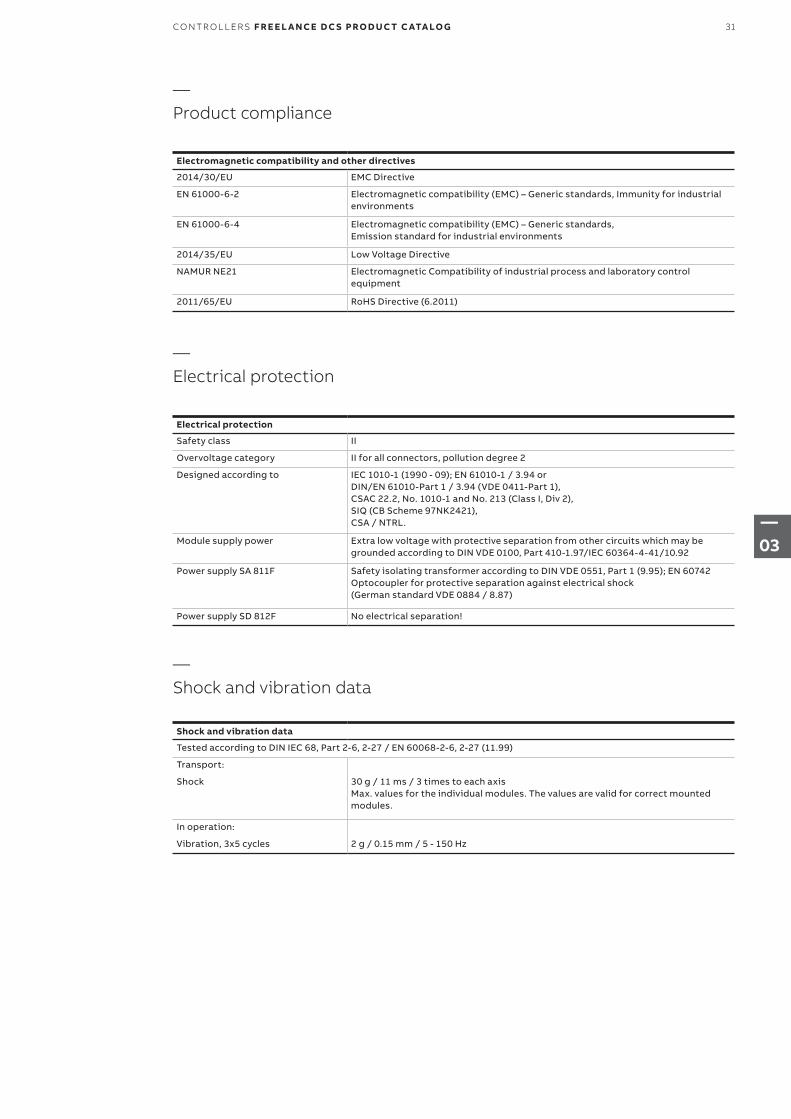
Electromagnetic compatibility and other directives
2014/30/EU EMC Directive
EN 61000-6-2 Electromagnetic compatibility (EMC) – Generic standards, Immunity for industrial environments
EN 61000-6-4 Electromagnetic compatibility (EMC) – Generic standards, Emission standard for industrial environments
2014/35/EU Low Voltage Directive
NAMUR NE21 Electromagnetic Compatibility of industrial process and laboratory control equipment
2011/65/EU RoHS Directive (6.2011)
Electrical protection
Safety class II
Overvoltage category II for all connectors, pollution degree 2
Designed according to IEC 1010-1 (1990 - 09); EN 61010-1 / 3.94 or DIN/EN 61010-Part 1 / 3.94 (VDE 0411-Part 1), CSAC 22.2, No. 1010-1 and No. 213 (Class I, Div 2), SIQ (CB Scheme 97NK2421), CSA / NTRL.
Module supply power Extra low voltage with protective separation from other circuits which may be grounded according to DIN VDE 0100, Part 410-1.97/IEC 60364-4-41/10.92
Power supply SA 811F Safety isolating transformer according to DIN VDE 0551, Part 1 (9.95); EN 60742 Optocoupler for protective separation against electrical shock (German standard VDE 0884 / 8.87)
Power supply SD 812F No electrical separation!
—Product compliance
—Electrical protection
Shock and vibration data
Tested according to DIN IEC 68, Part 2-6, 2-27 / EN 60068-2-6, 2-27 (11.99)
Transport:
Shock 30 g / 11 ms / 3 times to each axis Max. values for the individual modules. The values are valid for correct mounted modules.
In operation:
Vibration, 3x5 cycles 2 g / 0.15 mm / 5 - 150 Hz
—Shock and vibration data
31CO NTR O L L ER S F R E E L A N CE D C S PRO D U C T C ATA LO G
—03
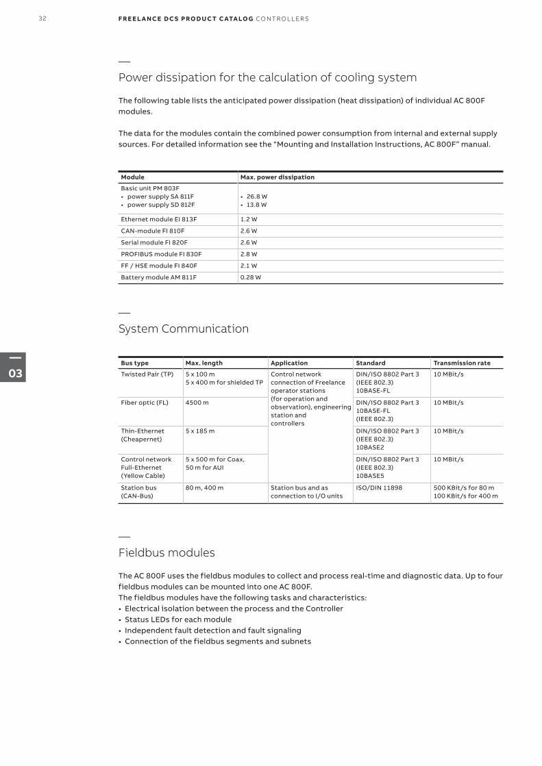
—System Communication
—Power dissipation for the calculation of cooling system
The following table lists the anticipated power dissipation (heat dissipation) of individual AC 800F modules.
The data for the modules contain the combined power consumption from internal and external supply sources. For detailed information see the “Mounting and Installation Instructions, AC 800F” manual.
—Fieldbus modules
The AC 800F uses the fieldbus modules to collect and process real-time and diagnostic data. Up to four fieldbus modules can be mounted into one AC 800F.The fieldbus modules have the following tasks and characteristics:• Electrical isolation between the process and the Controller• Status LEDs for each module• Independent fault detection and fault signaling• Connection of the fieldbus segments and subnets
Module Max. power dissipation
Basic unit PM 803F• power supply SA 811F• power supply SD 812F
• 26.8 W• 13.8 W
Ethernet module EI 813F 1.2 W
CAN-module FI 810F 2.6 W
Serial module FI 820F 2.6 W
PROFIBUS module FI 830F 2.8 W
FF / HSE module FI 840F 2.1 W
Battery module AM 811F 0.28 W
Bus type Max. length Application Standard Transmission rate
Twisted Pair (TP) 5 x 100 m 5 x 400 m for shielded TP
Control network connection of Freelance operator stations (for operation and observation), engineering station and controllers
DIN/ISO 8802 Part 3 (IEEE 802.3) 10BASE-FL
10 MBit/s
Fiber optic (FL) 4500 m DIN/ISO 8802 Part 3 10BASE-FL (IEEE 802.3)
10 MBit/s
Thin-Ethernet (Cheapernet)
5 x 185 m DIN/ISO 8802 Part 3 (IEEE 802.3) 10BASE2
10 MBit/s
Control network Full-Ethernet (Yellow Cable)
5 x 500 m for Coax, 50 m for AUI
DIN/ISO 8802 Part 3 (IEEE 802.3) 10BASE5
10 MBit/s
Station bus (CAN-Bus)
80 m, 400 m Station bus and as connection to I/O units
ISO/DIN 11898 500 KBit/s for 80 m 100 KBit/s for 400 m
32 F R E E L A N CE D C S PRO D U C T C ATA LO G CO NTR O L L ER S
—03
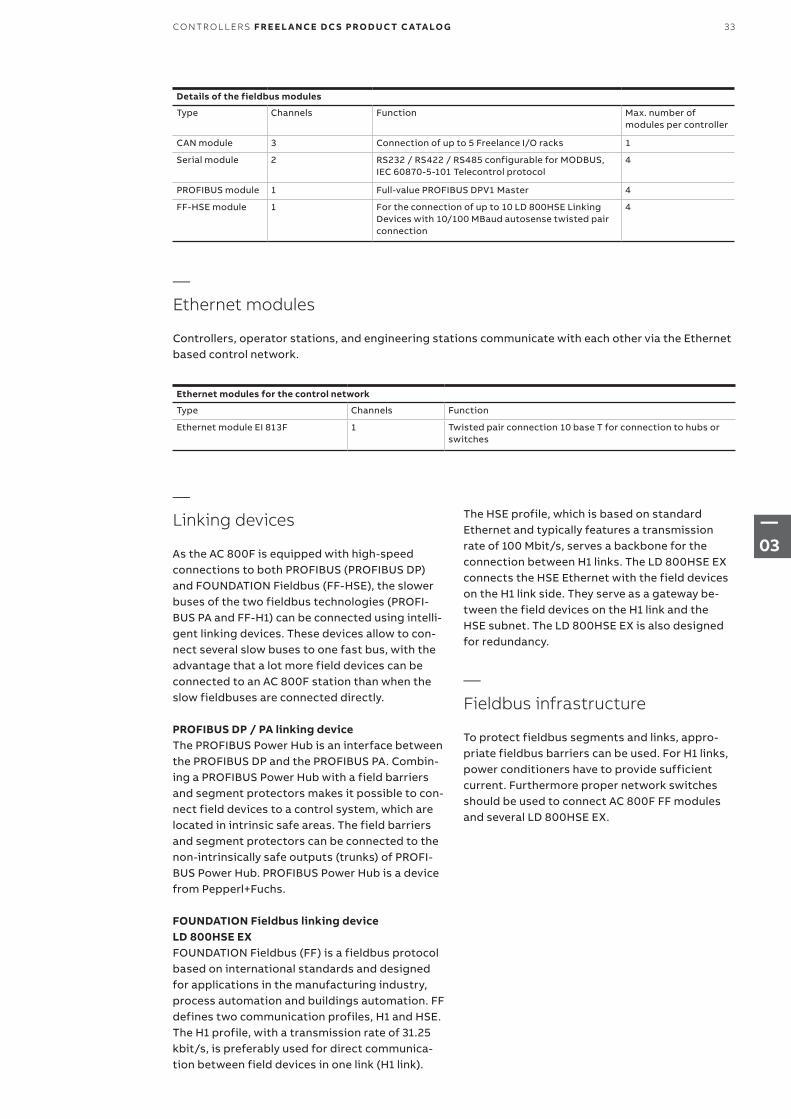
Details of the fieldbus modules
Type Channels Function Max. number of modules per controller
CAN module 3 Connection of up to 5 Freelance I/O racks 1
Serial module 2 RS232 / RS422 / RS485 configurable for MODBUS, IEC 60870-5-101 Telecontrol protocol
4
PROFIBUS module 1 Full-value PROFIBUS DPV1 Master 4
FF-HSE module 1 For the connection of up to 10 LD 800HSE Linking Devices with 10/100 MBaud autosense twisted pair connection
4
Ethernet modules for the control network
Type Channels Function
Ethernet module EI 813F 1 Twisted pair connection 10 base T for connection to hubs or switches
—Ethernet modules
Controllers, operator stations, and engineering stations communicate with each other via the Ethernet based control network.
—Linking devices
As the AC 800F is equipped with high-speed connections to both PROFIBUS (PROFIBUS DP) and FOUNDATION Fieldbus (FF-HSE), the slower buses of the two fieldbus technologies (PROFI-BUS PA and FF-H1) can be connected using intelli-gent linking devices. These devices allow to con-nect several slow buses to one fast bus, with the advantage that a lot more field devices can be connected to an AC 800F station than when the slow fieldbuses are connected directly.
PROFIBUS DP / PA linking deviceThe PROFIBUS Power Hub is an interface between the PROFIBUS DP and the PROFIBUS PA. Combin-ing a PROFIBUS Power Hub with a field barriers and segment protectors makes it possible to con-nect field devices to a control system, which are located in intrinsic safe areas. The field barriers and segment protectors can be connected to the non-intrinsically safe outputs (trunks) of PROFI-BUS Power Hub. PROFIBUS Power Hub is a device from Pepperl+Fuchs.
FOUNDATION Fieldbus linking device LD 800HSE EXFOUNDATION Fieldbus (FF) is a fieldbus protocol based on international standards and designed for applications in the manufacturing industry, process automation and buildings automation. FF defines two communication profiles, H1 and HSE. The H1 profile, with a transmission rate of 31.25 kbit/s, is preferably used for direct communica-tion between field devices in one link (H1 link).
The HSE profile, which is based on standard Ethernet and typically features a transmission rate of 100 Mbit/s, serves a backbone for the connection between H1 links. The LD 800HSE EX connects the HSE Ethernet with the field devices on the H1 link side. They serve as a gateway be-tween the field devices on the H1 link and the HSE subnet. The LD 800HSE EX is also designed for redundancy.
—Fieldbus infrastructure
To protect fieldbus segments and links, appro-priate fieldbus barriers can be used. For H1 links, power conditioners have to provide sufficient current. Furthermore proper network switches should be used to connect AC 800F FF modules and several LD 800HSE EX.
33CO NTR O L L ER S F R E E L A N CE D C S PRO D U C T C ATA LO G
—03
—3.4.2 AC 800F redundancy concept
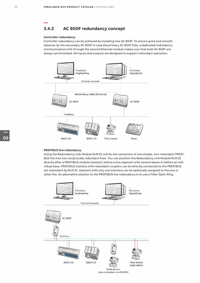
Controller redundancy Controller redundancy can be achieved by installing two AC 800F. To ensure quick and smooth takeover by the secondary AC 800F in case the primary AC 800F fails, a dedicated redundancy communications link through the second Ethernet module makes sure that both AC 800F are always synchronized. All inputs and outputs are designed to support redundant operation.
PROFIBUS line redundancy Using the Redundancy Link Module RLM 01 will do the conversion of one simple, non-redundant PROFI-BUS line into two reciprocally redundant lines. You can position the Redundancy Link Module RLM 01 directly after a PROFIBUS module (master), before a bus segment with several slaves or before an indi-vidual slave. PROFIBUS stations with redundant couplers can be directly connected to the PROFIBUS set redundant by RLM 01. Stations with only one interface can be optionally assigned to the one or other line. An alternative solution to the PROFIBUS line redundancy is to use a Fiber Optic Ring.
34 F R E E L A N CE D C S PRO D U C T C ATA LO G CO NTR O L L ER S
—03
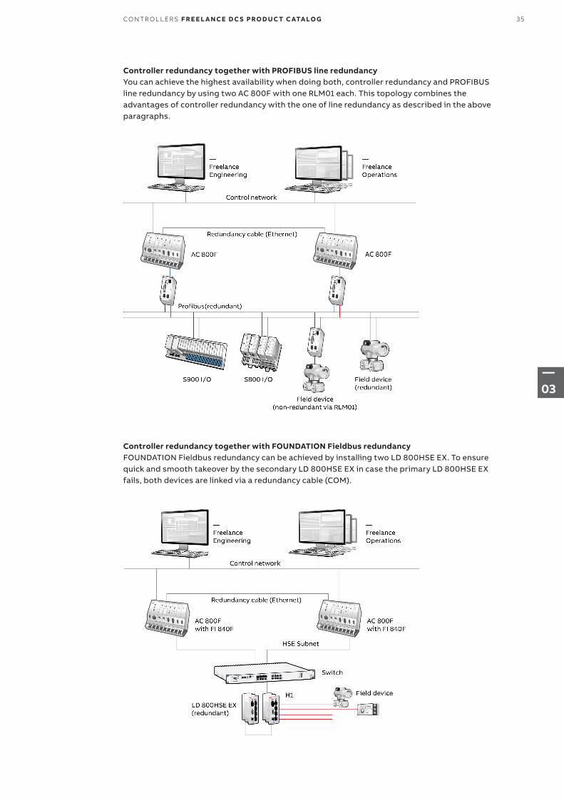
Controller redundancy together with PROFIBUS line redundancy You can achieve the highest availability when doing both, controller redundancy and PROFIBUS line redundancy by using two AC 800F with one RLM01 each. This topology combines the advantages of controller redundancy with the one of line redundancy as described in the above paragraphs.
Controller redundancy together with FOUNDATION Fieldbus redundancyFOUNDATION Fieldbus redundancy can be achieved by installing two LD 800HSE EX. To ensure quick and smooth takeover by the secondary LD 800HSE EX in case the primary LD 800HSE EX fails, both devices are linked via a redundancy cable (COM).
35CO NTR O L L ER S F R E E L A N CE D C S PRO D U C T C ATA LO G
—03
—3.4.3 AC 800F redundancy concept
—3.4.4 AC 800F, base unit PM 803F
Name Short description Article no.
AC 800F – 16 MB, 115 / 230 VAC
• With Ethernet 10BaseT, PROFIBUS module and Base Unit PM 803F
Incl. standard system test, battery SB 808F, mains cable TK 807F (open end). Slot assignment: P = SA 811F, E1 = EI 813F, F3 = FI 830F, E2, F1, F2, F4 = Front panel. Compliant to UL by using mains cable TK 809F (3BDM000212R1). Freelance V7.1SP2a or higher is mandatory.
3BDH000103R1
AC 800F – 16 MB, prepared for redundancy, 24 VDC
• With Ethernet 10BaseT, PROFIBUS module and Base Unit PM 803F
Incl. standard system test, 2 batteries SB 808F, 2 mains cable TK 802F (open end). Slot assignment: P = SD 812F, E1, E2 = EI 813F, F3 = FI 830F, F1, F2, F4 = Front panel. Freelance V7.1SP2a or higher is mandatory.
3BDH000133R1
Name Short description Article no.
PM 803F Base Unit 16 MB, battery-buffered RAMWithout operating system. The operating system has to be loaded during software installation. With special Contact Ledge RW 855F. Freelance V7.1PS2a or higher is mandatory.
3BDH000530R1
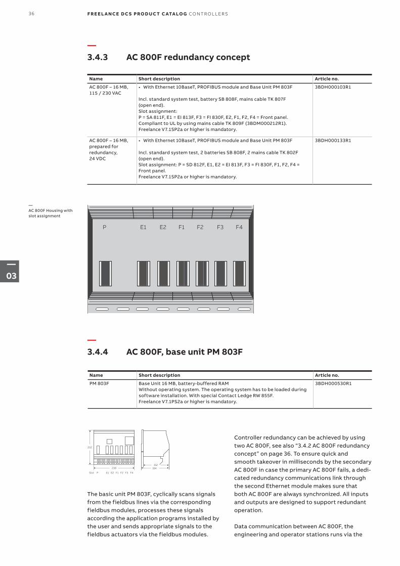
P E1 E2 F1 F2 F3 F4
—AC 800F Housing with slot assignment
239
F4F3F2F1E2E1P Slot
202
152164
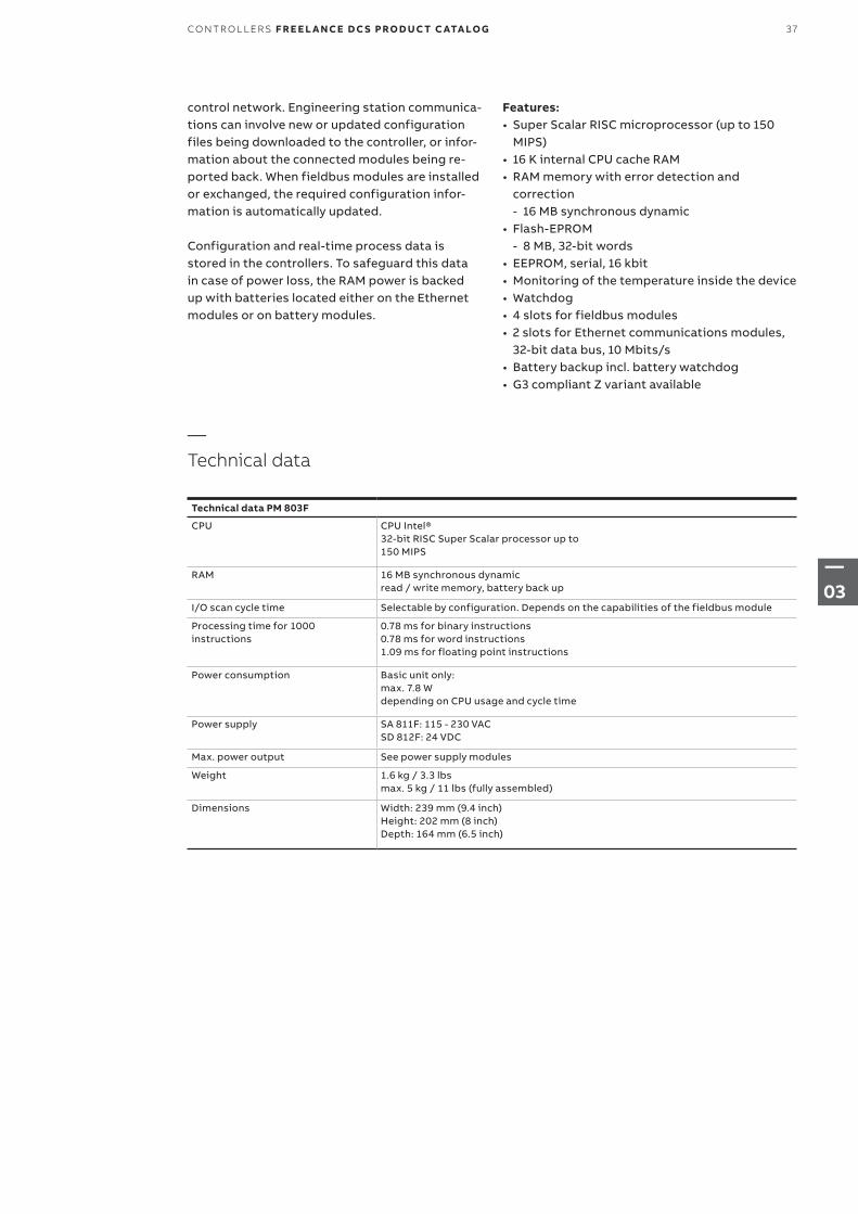
The basic unit PM 803F, cyclically scans signals from the fieldbus lines via the corresponding fieldbus modules, processes these signals according the application programs installed by the user and sends appropriate signals to the fieldbus actuators via the fieldbus modules.
Controller redundancy can be achieved by using two AC 800F, see also “3.4.2 AC 800F redundancy concept” on page 36. To ensure quick and smooth takeover in milliseconds by the secondary AC 800F in case the primary AC 800F fails, a dedi-cated redundancy communications link through the second Ethernet module makes sure that both AC 800F are always synchronized. All inputs and outputs are designed to support redundant operation.
Data communication between AC 800F, the engineering and operator stations runs via the
36 F R E E L A N CE D C S PRO D U C T C ATA LO G CO NTR O L L ER S
—03
control network. Engineering station communica-tions can involve new or updated configuration files being downloaded to the controller, or infor-mation about the connected modules being re-ported back. When fieldbus modules are installed or exchanged, the required configuration infor-mation is automatically updated.
Configuration and real-time process data is stored in the controllers. To safeguard this data in case of power loss, the RAM power is backed up with batteries located either on the Ethernet modules or on battery modules.
Features:• Super Scalar RISC microprocessor (up to 150
MIPS)• 16 K internal CPU cache RAM• RAM memory with error detection and
correction - 16 MB synchronous dynamic
• Flash-EPROM - 8 MB, 32-bit words
• EEPROM, serial, 16 kbit• Monitoring of the temperature inside the device• Watchdog• 4 slots for fieldbus modules• 2 slots for Ethernet communications modules,
32-bit data bus, 10 Mbits/s• Battery backup incl. battery watchdog • G3 compliant Z variant available
Technical data PM 803F
CPU CPU Intel® 32-bit RISC Super Scalar processor up to 150 MIPS
RAM 16 MB synchronous dynamic read / write memory, battery back up
I/O scan cycle time Selectable by configuration. Depends on the capabilities of the fieldbus module
Processing time for 1000 instructions
0.78 ms for binary instructions0.78 ms for word instructions1.09 ms for floating point instructions
Power consumption Basic unit only: max. 7.8 W depending on CPU usage and cycle time
Power supply SA 811F: 115 - 230 VAC SD 812F: 24 VDC
Max. power output See power supply modules
Weight 1.6 kg / 3.3 lbs max. 5 kg / 11 lbs (fully assembled)
Dimensions Width: 239 mm (9.4 inch) Height: 202 mm (8 inch) Depth: 164 mm (6.5 inch)
—Technical data
37CO NTR O L L ER S F R E E L A N CE D C S PRO D U C T C ATA LO G
—03
—3.4.5 Power supply
—Ethernet modules
Name Short description Article no.
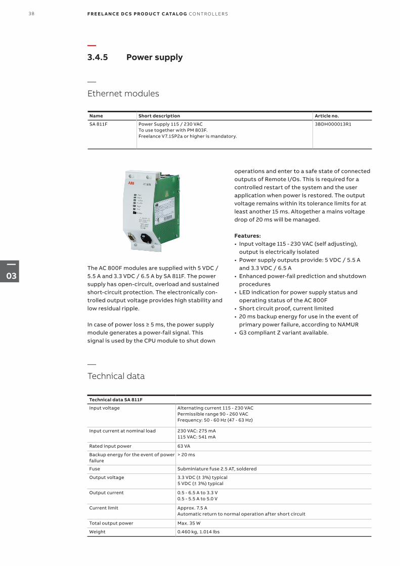
SA 811F Power Supply 115 / 230 VACTo use together with PM 803F. Freelance V7.1SP2a or higher is mandatory.
3BDH000013R1
The AC 800F modules are supplied with 5 VDC / 5.5 A and 3.3 VDC / 6.5 A by SA 811F. The power supply has open-circuit, overload and sustained short-circuit protection. The electronically con-trolled output voltage provides high stability and low residual ripple.
In case of power loss ≥ 5 ms, the power supply module generates a power-fail signal. This signal is used by the CPU module to shut down
operations and enter to a safe state of connected out puts of Remote I/Os. This is required for a controlled restart of the system and the user application when power is restored. The output voltage remains within its tolerance limits for at least another 15 ms. Altogether a mains voltage drop of 20 ms will be managed.
Features:• Input voltage 115 - 230 VAC (self adjusting),
output is electrically isolated• Power supply outputs provide: 5 VDC / 5.5 A
and 3.3 VDC / 6.5 A• Enhanced power-fail prediction and shutdown
procedures• LED indication for power supply status and
operating status of the AC 800F• Short circuit proof, current limited• 20 ms backup energy for use in the event of
primary power failure, according to NAMUR• G3 compliant Z variant available.
Technical data SA 811F
Input voltage Alternating current 115 - 230 VAC Permissible range 90 - 260 VAC Frequency: 50 - 60 Hz (47 - 63 Hz)
Input current at nominal load 230 VAC: 275 mA 115 VAC: 541 mA
Rated input power 63 VA
Backup energy for the event of power failure
> 20 ms
Fuse Subminiature fuse 2.5 AT, soldered
Output voltage 3.3 VDC (± 3%) typical 5 VDC (± 3%) typical
Output current 0.5 - 6.5 A to 3.3 V 0.5 - 5.5 A to 5.0 V
Current limit Approx. 7.5 A Automatic return to normal operation after short circuit
Total output power Max. 35 W
Weight 0.460 kg, 1.014 lbs
—Technical data
38 F R E E L A N CE D C S PRO D U C T C ATA LO G CO NTR O L L ER S
—03

Control Description
Run/Stop switch Internal supply voltage is available
Toggle Prim/Sec For redundancy. Toggles between primary and secondary AC 800F (operational on primary AC 800F only, and only if a secondary AC 800F is available)
Reset Reset button press and hold > 4 s for coldstart
Control Description
Power supply One connector for 115 - 230 VAC input
Diag For diagnostics and optional radio-controlled clock 9-pin male connector
—Operator controls
—Front panel connections
LED Status Description
Power Internal supply voltage is available
Failure Off Normal status
Orange Self test
Flashing orange Overtemperature occurred during operation
Red Hardware failure of the basic unit
Flashing red Software failure of the system
Run/Stop Green Processing active
Flashing green Process was stopped and is now started again
Red Processing inactive
Flashing red Process was active and is stopped now
Orange Self test
Off Software initialization
Prim/Sec In case of redundancy please see the LEDs description in the manual “Mounting and Installation Instruction AC 800F”. For non-redundancy the states are:
Orange Self test
Off Normal status
—LED displays
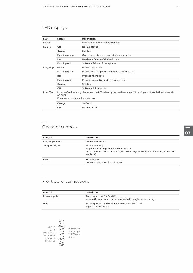
GND 5 n.c. 4 TxD output 3 RxD input 2 Output 1
+5 V/100 mA
9 Not used!8 CTS input7 RTS output6 n.c.
39CO NTR O L L ER S F R E E L A N CE D C S PRO D U C T C ATA LO G
—03
—SD 812F
Name Short description Article no.
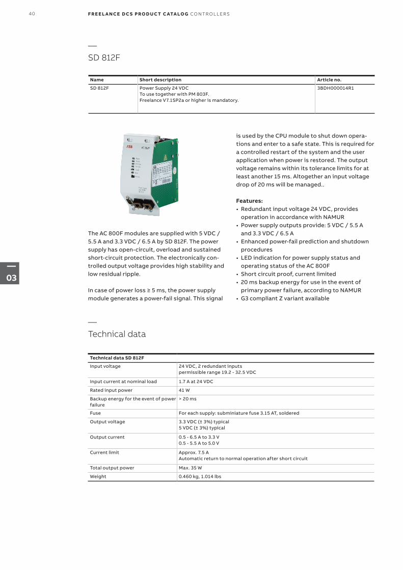
SD 812F Power Supply 24 VDCTo use together with PM 803F. Freelance V7.1SP2a or higher is mandatory.
3BDH000014R1
The AC 800F modules are supplied with 5 VDC / 5.5 A and 3.3 VDC / 6.5 A by SD 812F. The power supply has open-circuit, overload and sustained short-circuit protection. The electronically con-trolled output voltage provides high stability and low residual ripple.
In case of power loss ≥ 5 ms, the power supply module generates a power-fail signal. This signal
is used by the CPU module to shut down opera-tions and enter to a safe state. This is required for a controlled restart of the system and the user application when power is restored. The output voltage remains within its tolerance limits for at least another 15 ms. Altogether an input voltage drop of 20 ms will be managed..
Features:• Redundant input voltage 24 VDC, provides
operation in accordance with NAMUR • Power supply outputs provide: 5 VDC / 5.5 A
and 3.3 VDC / 6.5 A• Enhanced power-fail prediction and shutdown
procedures• LED indication for power supply status and
operating status of the AC 800F• Short circuit proof, current limited• 20 ms backup energy for use in the event of
primary power failure, according to NAMUR• G3 compliant Z variant available
Technical data SD 812F
Input voltage 24 VDC, 2 redundant inputs permissible range 19.2 - 32.5 VDC
Input current at nominal load 1.7 A at 24 VDC
Rated input power 41 W
Backup energy for the event of power failure
> 20 ms
Fuse For each supply: subminiature fuse 3.15 AT, soldered
Output voltage 3.3 VDC (± 3%) typical 5 VDC (± 3%) typical
Output current 0.5 - 6.5 A to 3.3 V 0.5 - 5.5 A to 5.0 V
Current limit Approx. 7.5 A Automatic return to normal operation after short circuit
Total output power Max. 35 W
Weight 0.460 kg, 1.014 lbs
—Technical data
40 F R E E L A N CE D C S PRO D U C T C ATA LO G CO NTR O L L ER S
—03
Control Description
Run/Stop switch Connected to LED
Toggle Prim/Sec For redundancy. Toggles between primary and secondary AC 800F (operational on primary AC 800F only, and only if a secondary AC 800F is available)
Reset Reset button press and hold > 4 s for coldstart
Control Description
Power supply Two connectors for 24 VDC, automatic input selection when used with single power supply
Diag For diagnostics and optional radio-controlled clock 9-pin male connector
—Operator controls
—Front panel connections
LED Status Description
Power Internal supply voltage is available
Failure Off Normal status
Orange Self test
Flashing orange Overtemperature occurred during operation
Red Hardware failure of the basic unit
Flashing red Software failure of the system
Run/Stop Green Processing active
Flashing green Process was stopped and is now started again
Red Processing inactive
Flashing red Process was active and is stopped now
Orange Self test
Off Software initialization
Prim/Sec In case of redundancy please see the LEDs description in the manual “Mounting and Installation Instruction AC 800F”. For non-redundancy the states are:
Orange Self test
Off Normal status
—LED displays
GND 5 n.c. 4 TxD output 3 RxD input 2 Output 1
+5 V/100 mA
9 Not used!8 CTS input7 RTS output6 n.c.
41CO NTR O L L ER S F R E E L A N CE D C S PRO D U C T C ATA LO G
—03
—3.4.6 Ethernet interface
—EI 813F, 10BaseT
Name Short description Article no.
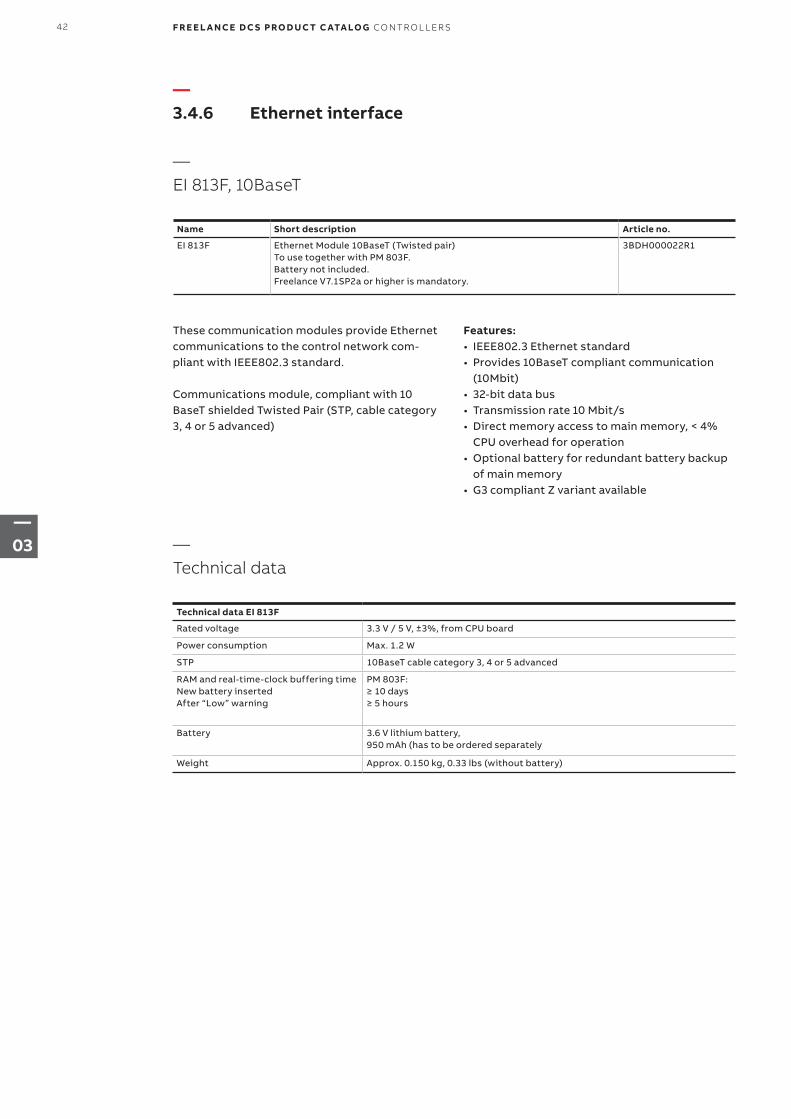
EI 813F Ethernet Module 10BaseT (Twisted pair)To use together with PM 803F. Battery not included. Freelance V7.1SP2a or higher is mandatory.
3BDH000022R1
These communication modules provide Ethernet communications to the control network com- pliant with IEEE802.3 standard.
Communications module, compliant with 10 BaseT shielded Twisted Pair (STP, cable category 3, 4 or 5 advanced)
Features:• IEEE802.3 Ethernet standard• Provides 10BaseT compliant communication
(10Mbit) • 32-bit data bus• Transmission rate 10 Mbit/s• Direct memory access to main memory, < 4%
CPU overhead for operation• Optional battery for redundant battery backup
of main memory• G3 compliant Z variant available
Technical data EI 813F
Rated voltage 3.3 V / 5 V, ±3%, from CPU board
Power consumption Max. 1.2 W
STP 10BaseT cable category 3, 4 or 5 advanced
RAM and real-time-clock buffering time New battery inserted After “Low” warning
PM 803F: ≥ 10 days ≥ 5 hours
Battery 3.6 V lithium battery, 950 mAh (has to be ordered separately
Weight Approx. 0.150 kg, 0.33 lbs (without battery)
—Technical data
42 F R E E L A N CE D C S PRO D U C T C ATA LO G CO NTR O L L ER S
—03
Control Description
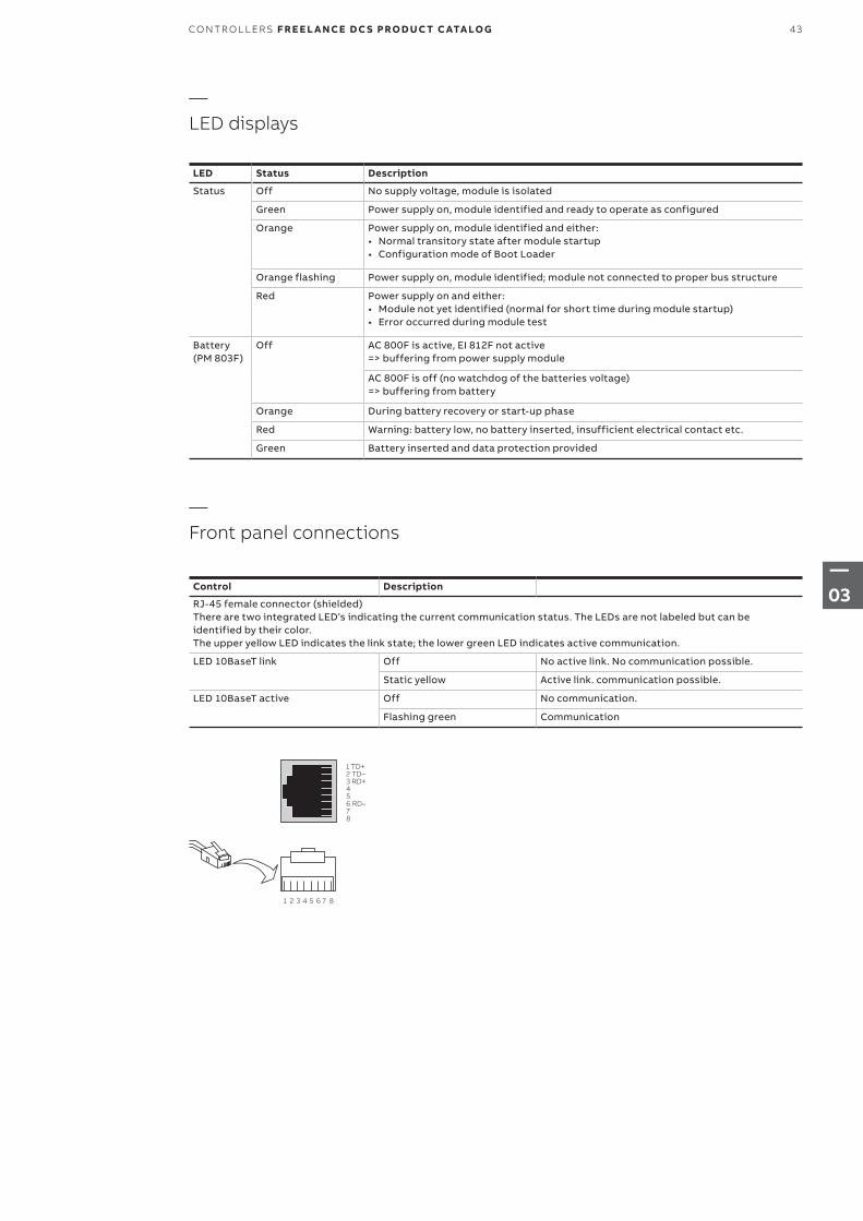
RJ-45 female connector (shielded) There are two integrated LED’s indicating the current communication status. The LEDs are not labeled but can be identified by their color. The upper yellow LED indicates the link state; the lower green LED indicates active communication.
LED 10BaseT link Off No active link. No communication possible.
Static yellow Active link. communication possible.
LED 10BaseT active Off No communication.
Flashing green Communication
—Front panel connections
LED Status Description
Status Off No supply voltage, module is isolated
Green Power supply on, module identified and ready to operate as configured
Orange Power supply on, module identified and either:• Normal transitory state after module startup• Configuration mode of Boot Loader
Orange flashing Power supply on, module identified; module not connected to proper bus structure
Red Power supply on and either:• Module not yet identified (normal for short time during module startup)• Error occurred during module test
Battery (PM 803F)
Off AC 800F is active, EI 812F not active => buffering from power supply module
AC 800F is off (no watchdog of the batteries voltage) => buffering from battery
Orange During battery recovery or start-up phase
Red Warning: battery low, no battery inserted, insufficient electrical contact etc.
Green Battery inserted and data protection provided
—LED displays
1 TD+2 TD–3 RD+456 RD–78
1 2 3 4 5 6 7 8
43CO NTR O L L ER S F R E E L A N CE D C S PRO D U C T C ATA LO G
—03
—3.4.7 Fieldbus interface modules
—CAN-3 module FI 810
Name Short description Article no.
FI 810F Fieldbus Module, CAN (triple channel) for rack I/OTo use together with PM 803F.
3BDH000030R1
The FI 810F module provides connectivity to the Freelance rack I/O - up to 5 racks can be con-nected. It provides functionality according CAN 2.0 specification and supports baud rates up 1 MBd. All interfaces are electrically isolated and support redundant operation in conjunction with a second AC 800F.
Only one FI 810F module may be plugged per AC 800F. The slot of the FI 810F module has to be F1
Features:• 3-channel CAN modules• Transmission rate: up to 1 MBd• Module can be removed or inserted during
operation • Redundant operation, with redundant AC 800F• G3 compliant Z variant available
Technical data FI 810F
Rated voltage 5 V, ± 3% from basic unit
Power consumption 1.6 W - 2.6 W, appending from communication
Channel supply:• Raged voltage• Power consump.• per channel
• 5 V, ± 10%• 0.15 W, when idling• 0.30 W, during communication
Weight Approx. 0.145 kg, 0.32 lbs
—Technical data
LED Status Description
Status Off No supply power, module is isolated
Green Module is active and working properly
Orange Module has been identified by AC 800F, but has not yet been activated
Red Module powered up, but not yet identified, or an error has occurred
RxD0 Green Receive data on channel 0
TxD0 Green Transmit data on channel 0
RxD1 Green Receive data on channel 1
TxD1 Green Transmit data on channel 1
RxD2 Green Receive data on channel 2
TxD2 Green Transmit data on channel 2
—LED displays
44 F R E E L A N CE D C S PRO D U C T C ATA LO G CO NTR O L L ER S
—03
Name Short description Article no.
FI 820F Fieldbus Module, Serial (dual channel)To use together with PM 803F.
3BDH000031R1
The FI 820F module provides connectivity to a variety of serial fieldbuses and serial protocols. Standard protocol is MODBUS
By using different connection cables the physical interface can easily be selected: RS485 (half duplex), RS422 (full duplex) or RS232. All inter-faces are electrically isolated and support redun-dant operation in conjunction with a second AC 800F.
Features:• Provides 2 serial interfaces• Transmission rates up to 38.4 kBd configurable• Physical interfaces RS485, RS422, RS232
selectable• Electrical isolation• Module can be removed or inserted during
operation • Redundant operation, with redundant AC 800F• G3 compliant Z variant available
Technical data FI 820F
Rated voltage 5 V, ± 3% from basic unit
Power consumption 1.6 W - 2.6 W, appending from communication
Channel supply:• Raged voltage• Power consump.• per channel
• 5 V, ± 10%• 0.15 W, when idling• 0.30 W, during communication
Output voltage for termination (Vcc_Term)• Rated voltage• Max. output current
• 5 V, ± 10%• 20 mA
Weight Approx. 0.145 kg, 0.32 lbs
—Technical data
Front panel connections
CAN 3 9-pin female connector
—Front panel connections
—Serial module FI 820F
n.c. 1 CAN 0 H 2 CAN 0 L 3 CAN 2 L 4 n.c. 5
6 CAN 1 H7 CAN 1 L8 CAN 2 H9 n.c.
45CO NTR O L L ER S F R E E L A N CE D C S PRO D U C T C ATA LO G
—03
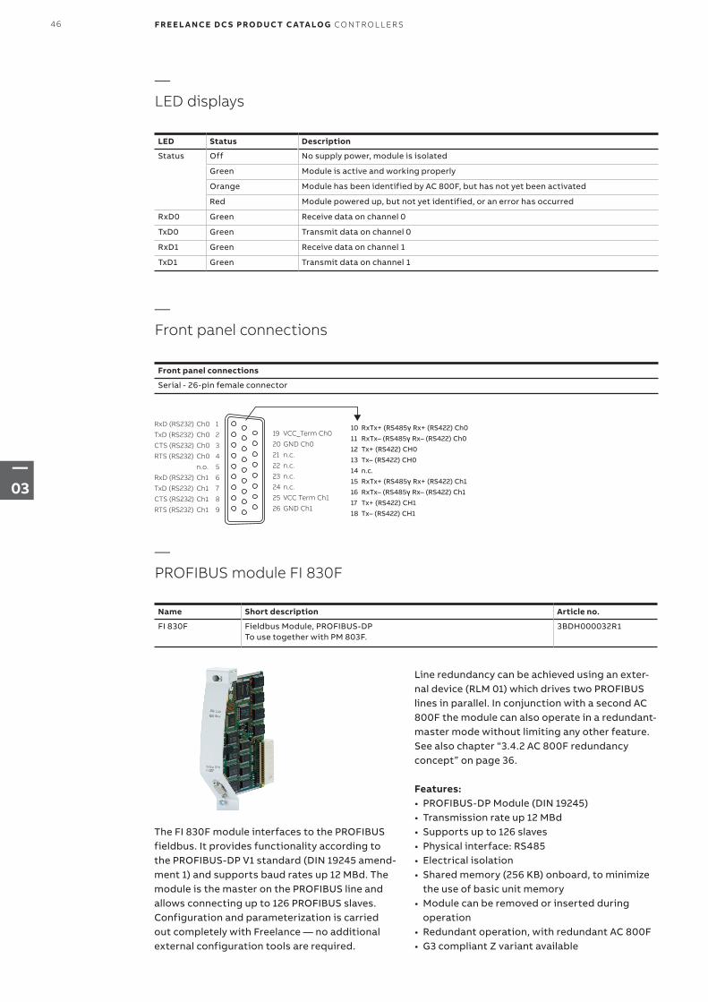
LED Status Description
Status Off No supply power, module is isolated
Green Module is active and working properly
Orange Module has been identified by AC 800F, but has not yet been activated
Red Module powered up, but not yet identified, or an error has occurred
RxD0 Green Receive data on channel 0
TxD0 Green Transmit data on channel 0
RxD1 Green Receive data on channel 1
TxD1 Green Transmit data on channel 1
—LED displays
Name Short description Article no.
FI 830F Fieldbus Module, PROFIBUS-DPTo use together with PM 803F.
3BDH000032R1
Front panel connections
Serial - 26-pin female connector
—Front panel connections
—PROFIBUS module FI 830F
The FI 830F module interfaces to the PROFIBUS fieldbus. It provides functionality according to the PROFIBUS-DP V1 standard (DIN 19245 amend-ment 1) and supports baud rates up 12 MBd. The module is the master on the PROFIBUS line and allows connecting up to 126 PROFIBUS slaves. Configuration and parameterization is carried out completely with Freelance — no additional external configuration tools are required.
Line redundancy can be achieved using an exter-nal device (RLM 01) which drives two PROFIBUS lines in parallel. In conjunction with a second AC 800F the module can also operate in a redundant-master mode without limiting any other feature. See also chapter “3.4.2 AC 800F redundancy concept” on page 36.
Features:• PROFIBUS-DP Module (DIN 19245)• Transmission rate up 12 MBd • Supports up to 126 slaves• Physical interface: RS485• Electrical isolation• Shared memory (256 KB) onboard, to minimize
the use of basic unit memory• Module can be removed or inserted during
operation • Redundant operation, with redundant AC 800F• G3 compliant Z variant available
RxD (RS232) Ch0 1
TxD (RS232) Ch0 2
CTS (RS232) Ch0 3
RTS (RS232) Ch0 4
n.o. 5
RxD (RS232) Ch1 6
TxD (RS232) Ch1 7
CTS (RS232) Ch1 8
RTS (RS232) Ch1 9
19 VCC_Term Ch0
20 GND Ch0
21 n.c.
22 n.c.
23 n.c.
24 n.c.
25 VCC Term Ch1
26 GND Ch1
10 RxTx+ (RS485γ Rx+ (RS422) Ch011 RxTx– (RS485γ Rx– (RS422) Ch012 Tx+ (RS422) CH013 Tx– (RS422) CH014 n.c.15 RxTx+ (RS485γ Rx+ (RS422) Ch116 RxTx– (RS485γ Rx– (RS422) Ch117 Tx+ (RS422) CH118 Tx– (RS422) CH1
46 F R E E L A N CE D C S PRO D U C T C ATA LO G CO NTR O L L ER S
—03
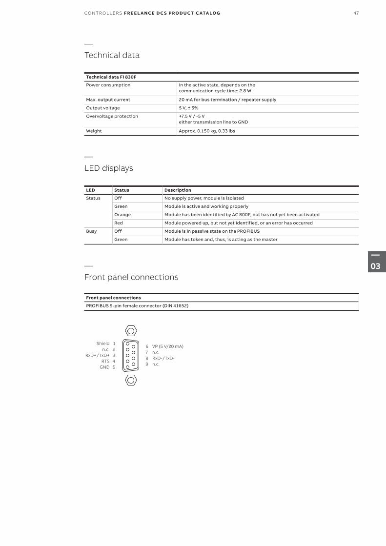
LED Status Description
Status Off No supply power, module is isolated
Green Module is active and working properly
Orange Module has been identified by AC 800F, but has not yet been activated
Red Module powered up, but not yet identified, or an error has occurred
Busy Off Module is in passive state on the PROFIBUS
Green Module has token and, thus, is acting as the master
—LED displays
Shield 1 n.c. 2 RxD+/TxD+ 3 RTS 4 GND 5
6 VP (5 V/20 mA)7 n.c.8 RxD-/TxD-9 n.c.
Technical data FI 830F
Power consumption In the active state, depends on the communi cation cycle time: 2.8 W
Max. output current 20 mA for bus termination / repeater supply
Output voltage 5 V, ± 5%
Overvoltage protection +7.5 V / -5 V either transmission line to GND
Weight Approx. 0.150 kg, 0.33 lbs
Front panel connections
PROFIBUS 9-pin female connector (DIN 41652)
—Technical data
—Front panel connections
47CO NTR O L L ER S F R E E L A N CE D C S PRO D U C T C ATA LO G
—03
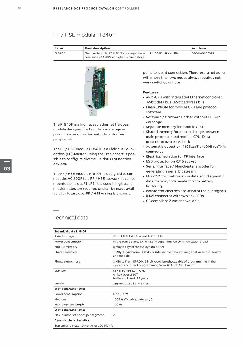
point-to-point connection. Therefore a networks with more than two nodes always requires net-work switches or hubs.
Features:• ARM-CPU with integrated Ethernet controller,
32-bit data bus, 32-bit address bus• Flash EPROM for module CPU and protocol
software • Software / firmware update without EPROM
exchange• Separate memory for module CPU• Shared memory for data exchange between
main processor and module CPU. Data protection by parity check
• Automatic detection if 10BaseT or 100BaseTX is connected
• Electrical isolation for TP interface• ESD protector on RJ45 socket• Serial interface / Manchester encoder for
generating a serial bit stream• EEPROM for configuration data and diagnostic
data memory independent from battery buffering
• Isolator for electrical isolation of the bus signals• RJ45 connector with two link LEDs• G3 compliant Z variant available
Technical data FI 840F
Rated voltage 5 V ± 3 % 3.3 V ± 3 % and 2.5 V ± 5 %
Power consumption In the active state, 1.4 W - 2.1 W depending on communications load
Module memory 8 MBytes synchronous dynamic RAM
Shared memory 1 MByte synchronous static RAM used for data exchange between CPU board and module
Firmware memory 2 MByte Flash EPROM, 32-bit word length, capable of programming in the system and direct programming from AC 800F CPU board
EEPROM Serial 16 kbit EEPROM, write cycles ≥ 107 buffering time ≥ 10 years
Weight Approx. 0.150 kg, 0.33 lbs
Static characteristics
Power consumption Max. 2.1 W
Medium 100BaseTx cable, category 5
Max. segment length 100 m
Static characteristics
Max. number of nodes per segment 2
Dynamic characteristics
Transmission rate 10 Mbit/s or 100 Mbit/s
—Technical data
Name Short description Article no.
FI 840F Fieldbus Module, FF HSE. To use together with PM 803F. UL certified. Freelance V7.1SP2a or higher is mandatory.
3BDH000033R1
The FI 840F is a high speed ethernet fieldbus module designed for fast data exchange in production engineering with decentralized peripherals.
The FF / HSE module FI 840F is a Fieldbus Foun-dation-(FF)-Master. Using the Freelance it is pos-sible to configure diverse Fieldbus Foundation devices.
The FF / HSE module FI 840F is designed to con-nect the AC 800F to a FF / HSE network. It can be mounted on slots F1...F4. It is used if high trans-mission rates are required or shall be made avail-able for future use. FF / HSE wiring is always a
—FF / HSE module FI 840F
48 F R E E L A N CE D C S PRO D U C T C ATA LO G CO NTR O L L ER S
—03
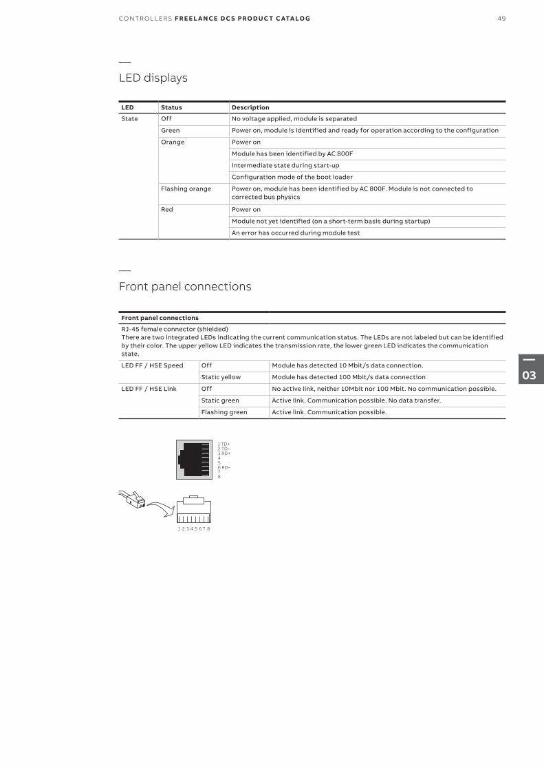
LED Status Description
State Off No voltage applied, module is separated
Green Power on, module is identified and ready for operation according to the configuration
Orange Power on
Module has been identified by AC 800F
Intermediate state during start-up
Configuration mode of the boot loader
Flashing orange Power on, module has been identified by AC 800F. Module is not connected to corrected bus physics
Red Power on
Module not yet identified (on a short-term basis during startup)
An error has occurred during module test
Front panel connections
RJ-45 female connector (shielded)There are two integrated LEDs indicating the current communication status. The LEDs are not labeled but can be identified by their color. The upper yellow LED indicates the transmission rate, the lower green LED indicates the communication state.
LED FF / HSE Speed Off Module has detected 10 Mbit/s data connection.
Static yellow Module has detected 100 Mbit/s data connection
LED FF / HSE Link Off No active link, neither 10Mbit nor 100 Mbit. No communi cation possible.
Static green Active link. Communication possible. No data transfer.
Flashing green Active link. Communication possible.
—Front panel connections
—LED displays
1 TD+2 TD–3 RD+456 RD–78
1 2 3 4 5 6 7 8
49CO NTR O L L ER S F R E E L A N CE D C S PRO D U C T C ATA LO G
—03
—3.4.8 Coated and G3 compliant hardware
Name Short description Article no.
PM 803F-Z Base Unit 16 MB, battery-buffered RAM Coated and G3 compliant version. Without operating system. The operating system has to be loadedduring software installation.With special Contact Ledge RW 855F.Software V7.1SP2a or higher is mandatory.
3BDH000530Z1
Name Short description Article no.
EI 813F-Z Ethernet Module 10BaseT (Twisted pair)Coated and G3 compliant version. To use together with PM 803F-Z. Battery not included. Software V7.1SP2a or higher is mandatory.
3BDH000022Z1
Name Short description Article no.
SA 811F-Z Power Supply 115/230 VAC
Coated and G3 compliant version. To use together with PM 803F-Z. Software V7.1SP2a or higher is mandatory.
3BDH000013Z1
SD 812F-Z Power Supply 24 VDC
Coated and G3 compliant version. To use together with PM 803F-Z. Software V7.1SP2a or higher is mandatory
3BDH000014Z1
G3 compliant components are protected with a special coating against corrosive gases. The following Freelance ISA71.04 G3 compliant components can be ordered under the same con-ditions as any ordinary Freelance component. G3 compliance for AC 800F requires exclusively use of –Z components. AM 810F-Z serves for closing unused slots and the behind system plug.
G3 compliant components are identified by “Z“ added to the module name, for example AC 800F-Z-4 MB.
—Base units
—Power supplies
—Ethernet interface module
50 F R E E L A N CE D C S PRO D U C T C ATA LO G CO NTR O L L ER S
—03
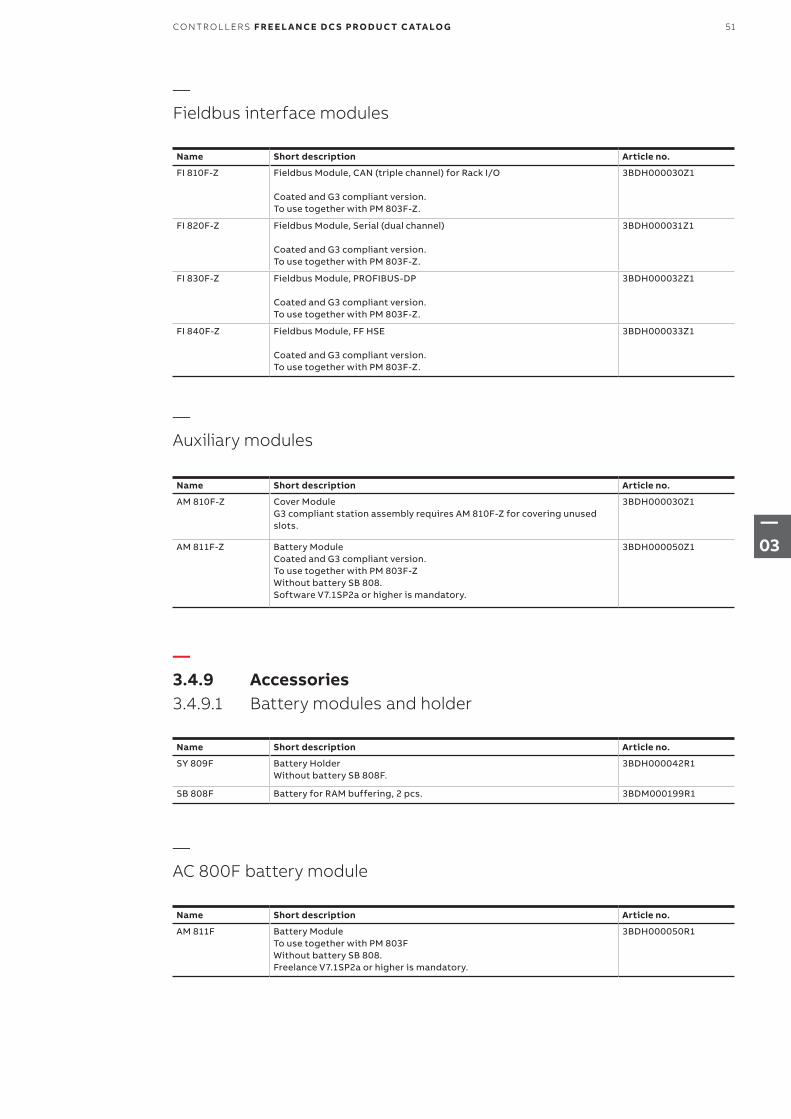
—3.4.9 Accessories3.4.9.1 Battery modules and holder
Name Short description Article no.
AM 810F-Z Cover Module G3 compliant station assembly requires AM 810F-Z for covering unused slots.
3BDH000030Z1
AM 811F-Z Battery Module Coated and G3 compliant version.To use together with PM 803F-ZWithout battery SB 808.Software V7.1SP2a or higher is mandatory.
3BDH000050Z1
Name Short description Article no.
SY 809F Battery HolderWithout battery SB 808F.
3BDH000042R1
SB 808F Battery for RAM buffering, 2 pcs. 3BDM000199R1
Name Short description Article no.
FI 810F-Z Fieldbus Module, CAN (triple channel) for Rack I/O Coated and G3 compliant version. To use together with PM 803F-Z.
3BDH000030Z1
FI 820F-Z Fieldbus Module, Serial (dual channel) Coated and G3 compliant version. To use together with PM 803F-Z.
3BDH000031Z1
FI 830F-Z Fieldbus Module, PROFIBUS-DP Coated and G3 compliant version. To use together with PM 803F-Z.
3BDH000032Z1
FI 840F-Z Fieldbus Module, FF HSE Coated and G3 compliant version. To use together with PM 803F-Z.
3BDH000033Z1
—Auxiliary modules
—Fieldbus interface modules
Name Short description Article no.
AM 811F Battery ModuleTo use together with PM 803F Without battery SB 808. Freelance V7.1SP2a or higher is mandatory.
3BDH000050R1
—AC 800F battery module
51CO NTR O L L ER S F R E E L A N CE D C S PRO D U C T C ATA LO G
—03
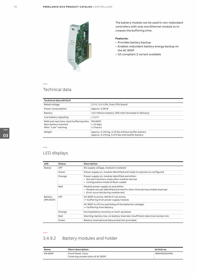
The battery module can be used in non-redundant controllers with only one Ethernet module to in-creases the buffering time.
Features:• Provides battery backup• Enables redundant battery energy backup on
the AC 800F• G3 compliant Z variant available
Technical data AM 811F
Rated voltage 3.3 V / 5 V ±3%, from CPU board
Power consumption Approx. 0.28 W
Battery 3.6 V lithium battery, 950 mAh (included in delivery)
Low battery signaling ≤ 3.2 V
RAM and real-time-clock buffering time New battery inserted After “Low“ warning
PM 803F: ≥ 10 days ≥ 5 hours
Weight Approx. 0.150 kg, 0.33 lbs without buffer battery Approx. 0.170 kg, 0.375 lbs with buffer battery
—Technical data
LED Status Description
Status Off No supply voltage, module is isolated
Green Power supply on, module identified and ready to operate as configured
Orange Power supply on, module identified and either:• Normal transitory state after module startup• Configuration mode of Boot Loader
Red Module power supply on and either:• Module not yet identified (normal for short time during module startup)• Error occurred during module test
Battery (PM 803F)
Off AC 800F is active, AM 811F not active => buffering from power supply module
AC 800F is off (no watchdog of the batteries voltage): => buffering from Battery.
Orange During battery recovery or start-up phase
Red Warning: battery low, no battery inserted, insufficient electrical contact etc.
Green Battery inserted and data protection provided.
—LED displays
—3.4.9.2 Battery modules and holder
Name Short description Article no.
AM 895F Front Panel, 4 pcsCovering unused slots of AC 800F.
3BDH000044R1
52 F R E E L A N CE D C S PRO D U C T C ATA LO G CO NTR O L L ER S
—03
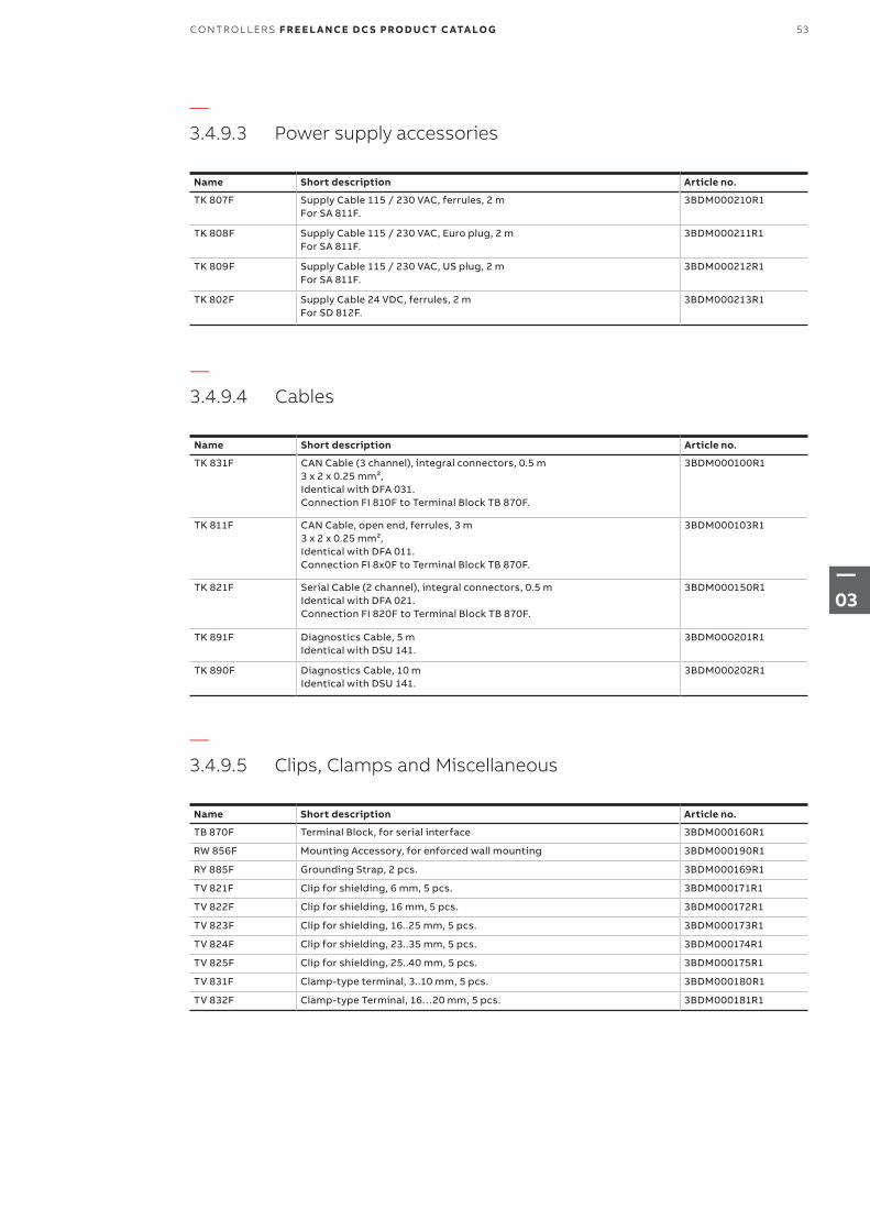
—3.4.9.3 Power supply accessories
—3.4.9.4 Cables
—3.4.9.5 Clips, Clamps and Miscellaneous
Name Short description Article no.
TK 807F Supply Cable 115 / 230 VAC, ferrules, 2 mFor SA 811F.
3BDM000210R1
TK 808F Supply Cable 115 / 230 VAC, Euro plug, 2 mFor SA 811F.
3BDM000211R1
TK 809F Supply Cable 115 / 230 VAC, US plug, 2 mFor SA 811F.
3BDM000212R1
TK 802F Supply Cable 24 VDC, ferrules, 2 mFor SD 812F.
3BDM000213R1
Name Short description Article no.
TK 831F CAN Cable (3 channel), integral connectors, 0.5 m3 x 2 x 0.25 mm², Identical with DFA 031. Connection FI 810F to Terminal Block TB 870F.
3BDM000100R1
TK 811F CAN Cable, open end, ferrules, 3 m3 x 2 x 0.25 mm², Identical with DFA 011. Connection FI 8x0F to Terminal Block TB 870F.
3BDM000103R1
TK 821F Serial Cable (2 channel), integral connectors, 0.5 mIdentical with DFA 021. Connection FI 820F to Terminal Block TB 870F.
3BDM000150R1
TK 891F Diagnostics Cable, 5 mIdentical with DSU 141.
3BDM000201R1
TK 890F Diagnostics Cable, 10 mIdentical with DSU 141.
3BDM000202R1
Name Short description Article no.
TB 870F Terminal Block, for serial interface 3BDM000160R1
RW 856F Mounting Accessory, for enforced wall mounting 3BDM000190R1
RY 885F Grounding Strap, 2 pcs. 3BDM000169R1
TV 821F Clip for shielding, 6 mm, 5 pcs. 3BDM000171R1
TV 822F Clip for shielding, 16 mm, 5 pcs. 3BDM000172R1
TV 823F Clip for shielding, 16..25 mm, 5 pcs. 3BDM000173R1
TV 824F Clip for shielding, 23..35 mm, 5 pcs. 3BDM000174R1
TV 825F Clip for shielding, 25..40 mm, 5 pcs. 3BDM000175R1
TV 831F Clamp-type terminal, 3..10 mm, 5 pcs. 3BDM000180R1
TV 832F Clamp-type Terminal, 16…20 mm, 5 pcs. 3BDM000181R1
53CO NTR O L L ER S F R E E L A N CE D C S PRO D U C T C ATA LO G
—03
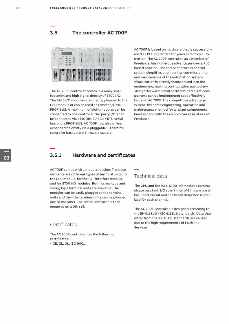
—3.5 The controller AC 700F
—3.5.1 Hardware and certificates
The AC 700F controller comes in a really small footprint and high signal density of S700 I/O. The S700 I/O modules are directly plugged to the CPU module or can be used as remote I/O via PROFIBUS. A maximum of eight modules can be connected to one controller. 3rd party I/O‘s can be connected via a MODBUS ASCII / RTU serial bus or via PROFIBUS. AC 700F now also offers expanded flexibility via a pluggable SD card for controller backup and firmware update.
AC 700F comes with a modular design. The base elements are different types of terminal units, for the CPU module, for the FBP interface module, and for S700 I/O modules. Both, screw type and spring type terminal units are available. The modules can be easily plugged to the terminal units and then the terminal units can be plugged one to the other. The entire controller is then mounted on a DIN rail.
— Certificates
The AC 700F controller has the following certificates:• CE, GL, UL, ISO 9001.
AC 700F is based on hardware that is successfully used as PLC in practice for years in factory auto-mation. The AC 700F controller, as a member of Freelance, has numerous advantages over a PLC based solution: The compact process control system simplifies engineering, commissioning, and maintenance of the automation system. Visualization is directly incorporated into the engineering, making configuration particularly straightforward. Small or distributed plant com-ponents can be implemented cost effectively by using AC 700F. The competitive advantage is clear: the same engineering, operation and maintenance method for all plant components hand in hand with the well-known ease of use of Freelance.
—
Technical data
The CPU and the local S700 I/O modules commu-nicate very fast. I/O scan times of 2 ms are possi-ble. Short circuit and line break detection is real-ized for each channel.
The AC 700F controller is designed according to the EN 61131-2 / IEC 61131-2 standards. Data that differ from the IEC 61131 standards are caused due to the high requirements of Maritime Services.
54 F R E E L A N CE D C S PRO D U C T C ATA LO G CO NTR O L L ER S
—03
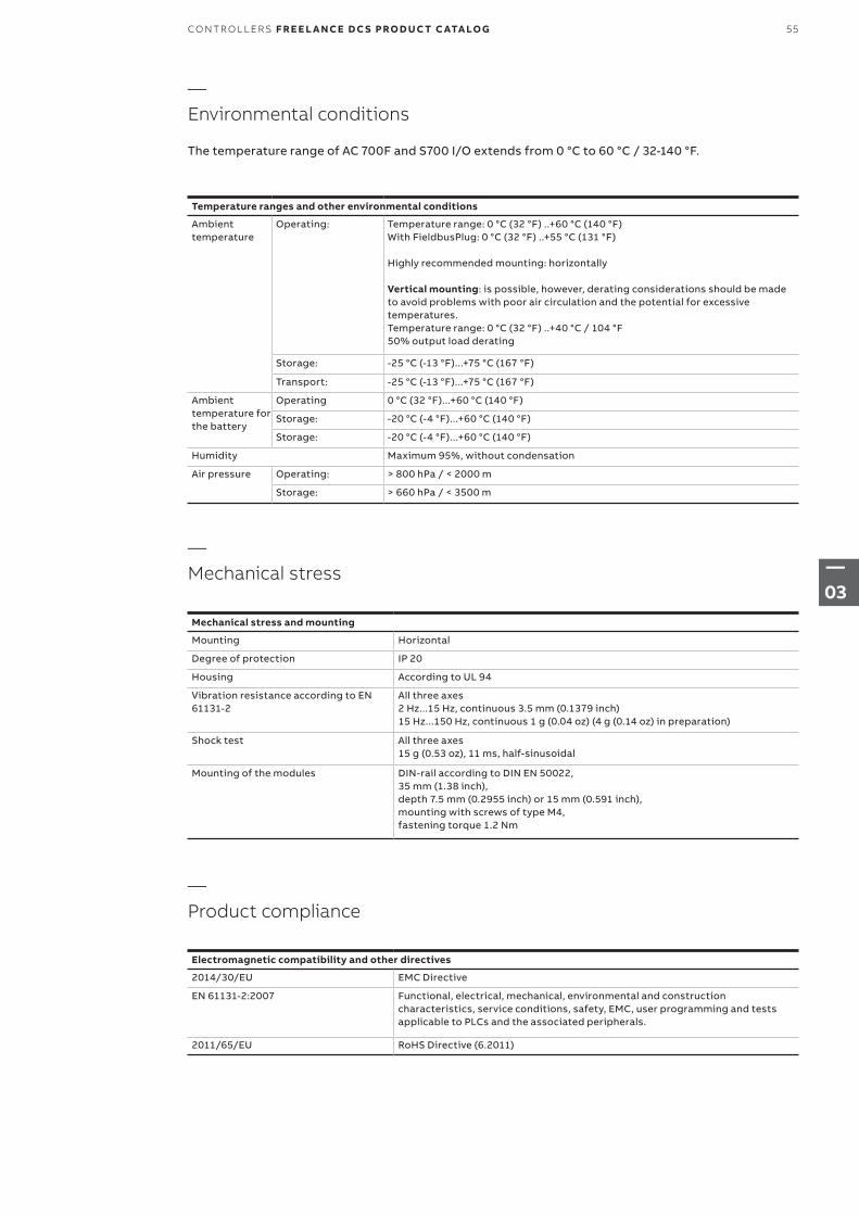
—
Environmental conditions
The temperature range of AC 700F and S700 I/O extends from 0 °C to 60 °C / 32-140 °F.
—
Mechanical stress
—
Product compliance
Temperature ranges and other environmental conditions
Ambient temperature
Operating: Temperature range: 0 °C (32 °F) ..+60 °C (140 °F) With FieldbusPlug: 0 °C (32 °F) ..+55 °C (131 °F) Highly recommended mounting: horizontally Vertical mounting: is possible, however, derating considerations should be made to avoid problems with poor air circulation and the potential for excessive temperatures. Temperature range: 0 °C (32 °F) ..+40 °C / 104 °F 50% output load derating
Storage: -25 °C (-13 °F)...+75 °C (167 °F)
Transport: -25 °C (-13 °F)...+75 °C (167 °F)
Ambient temperature for the battery
Operating 0 °C (32 °F)...+60 °C (140 °F)
Storage: -20 °C (-4 °F)...+60 °C (140 °F)
Storage: -20 °C (-4 °F)...+60 °C (140 °F)
Humidity Maximum 95%, without condensation
Air pressure Operating: > 800 hPa / < 2000 m
Storage: > 660 hPa / < 3500 m
Mechanical stress and mounting
Mounting Horizontal
Degree of protection IP 20
Housing According to UL 94
Vibration resistance according to EN 61131-2
All three axes 2 Hz...15 Hz, continuous 3.5 mm (0.1379 inch) 15 Hz...150 Hz, continuous 1 g (0.04 oz) (4 g (0.14 oz) in preparation)
Shock test All three axes 15 g (0.53 oz), 11 ms, half-sinusoidal
Mounting of the modules DIN-rail according to DIN EN 50022, 35 mm (1.38 inch), depth 7.5 mm (0.2955 inch) or 15 mm (0.591 inch), mounting with screws of type M4, fastening torque 1.2 Nm
Electromagnetic compatibility and other directives
2014/30/EU EMC Directive
EN 61131-2:2007 Functional, electrical, mechanical, environmental and construction characteristics, service conditions, safety, EMC, user programming and tests applicable to PLCs and the associated peripherals.
2011/65/EU RoHS Directive (6.2011)
55CO NTR O L L ER S F R E E L A N CE D C S PRO D U C T C ATA LO G
—03
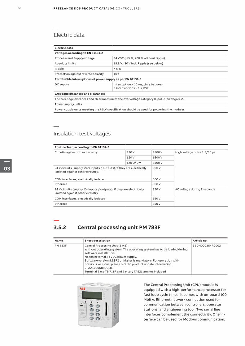
—
Electric data
—
Insulation test voltages
Electric data
Voltages according to EN 61131-2
Process- and Supply-voltage 24 VDC (-15 %, +20 % without ripple)
Absolute limits 19.2 V...30 V incl. Ripple (see below)
Ripple < 5 %
Protection against reverse polarity 10 s
Permissible interruptions of power supply as per EN 61131-2
DC supply Interruption < 10 ms, time between 2 interruptions > 1 s, PS2
Creepage distances and clearances
The creepage distances and clearances meet the overvoltage category II, pollution degree 2.
Power supply units
Power supply units meeting the PELV specification should be used for powering the modules.
Routine Test, according to EN 61131-2
Circuits against other circuitry 230 V 2500 V High voltage pulse 1.2/50 μs
120 V 1500 V
120-240 V 2500 V
24 V circuits (supply, 24 V inputs / outputs), if they are electrically isolated against other circuitry.
500 V
COM interfaces, electrically isolated 500 V
Ethernet 500 V
24 V circuits (supply, 24 inputs / outputs), if they are electrically isolated against other circuitry
350 V AC voltage during 2 seconds
COM interfaces, electrically isolated 350 V
Ethernet 350 V
—3.5.2 Central processing unit PM 783F
Name Short description Article no.
PM 783F Central Processing Unit (2 MB)Without operating system. The operating system has to be loaded during software installation. Needs external 24 VDC power supply.Software version 9.2SP2 or higher is mandatory. For operation withprevious versions, please refer to product update information2PAA102068R0018.Terminal Base TB 711F and Battery TA521 are not included
3BDH000364R0002
The Central Processing Unit (CPU) module is equipped with a high-performance processor for fast loop cycle times. It comes with on-board 100 Mbit/s Ethernet network connection used for communication between controllers, operator stations, and engineering tool. Two serial line interfaces complement the connectivity. One in-terface can be used for Modbus communication,
56 F R E E L A N CE D C S PRO D U C T C ATA LO G CO NTR O L L ER S
—03
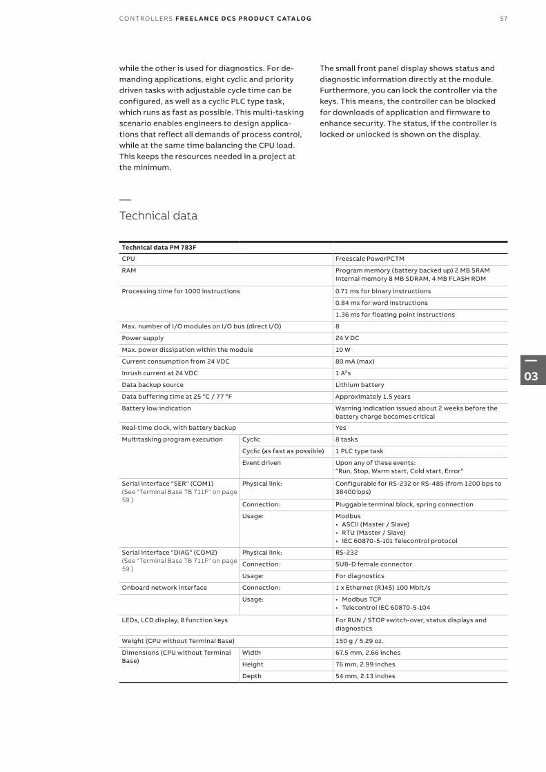
while the other is used for diagnostics. For de-manding applications, eight cyclic and priority driven tasks with adjustable cycle time can be configured, as well as a cyclic PLC type task, which runs as fast as possible. This multi-tasking scenario enables engineers to design applica-tions that reflect all demands of process control, while at the same time balancing the CPU load. This keeps the resources needed in a project at the minimum.
Technical data PM 783F
CPU Freescale PowerPCTM
RAM Program memory (battery backed up) 2 MB SRAM Internal memory 8 MB SDRAM, 4 MB FLASH ROM
Processing time for 1000 instructions 0.71 ms for binary instructions
0.84 ms for word instructions
1.36 ms for floating point instructions
Max. number of I/O modules on I/O bus (direct I/O) 8
Power supply 24 V DC
Max. power dissipation within the module 10 W
Current consumption from 24 VDC 80 mA (max)
Inrush current at 24 VDC 1 A²s
Data backup source Lithium battery
Data buffering time at 25 °C / 77 °F Approximately 1.5 years
Battery low indication Warning indication issued about 2 weeks before the battery charge becomes critical
Real-time clock, with battery backup Yes
Multitasking program execution Cyclic 8 tasks
Cyclic (as fast as possible) 1 PLC type task
Event driven Upon any of these events: “Run, Stop, Warm start, Cold start, Error“
Serial interface “SER“ (COM1) (See "Terminal Base TB 711F" on page 59 )
Physical link: Configurable for RS-232 or RS-485 (from 1200 bps to 38400 bps)
Connection: Pluggable terminal block, spring connection
Usage: Modbus• ASCII (Master / Slave)• RTU (Master / Slave)• IEC 60870-5-101 Telecontrol protocol
Serial interface “DIAG“ (COM2) (See "Terminal Base TB 711F" on page 59 )
Physical link: RS-232
Connection: SUB-D female connector
Usage: For diagnostics
Onboard network interface Connection: 1 x Ethernet (RJ45) 100 Mbit/s
Usage: • Modbus TCP • Telecontrol IEC 60870-5-104
LEDs, LCD display, 8 function keys For RUN / STOP switch-over, status displays and diagnostics
Weight (CPU without Terminal Base) 150 g / 5.29 oz.
Dimensions (CPU without Terminal Base)
Width 67.5 mm, 2.66 inches
Height 76 mm, 2.99 inches
Depth 54 mm, 2.13 inches
—Technical data
The small front panel display shows status and diagnostic information directly at the module. Furthermore, you can lock the controller via the keys. This means, the controller can be blocked for downloads of application and firmware to enhance security. The status, if the controller is locked or unlocked is shown on the display.
57CO NTR O L L ER S F R E E L A N CE D C S PRO D U C T C ATA LO G
—03
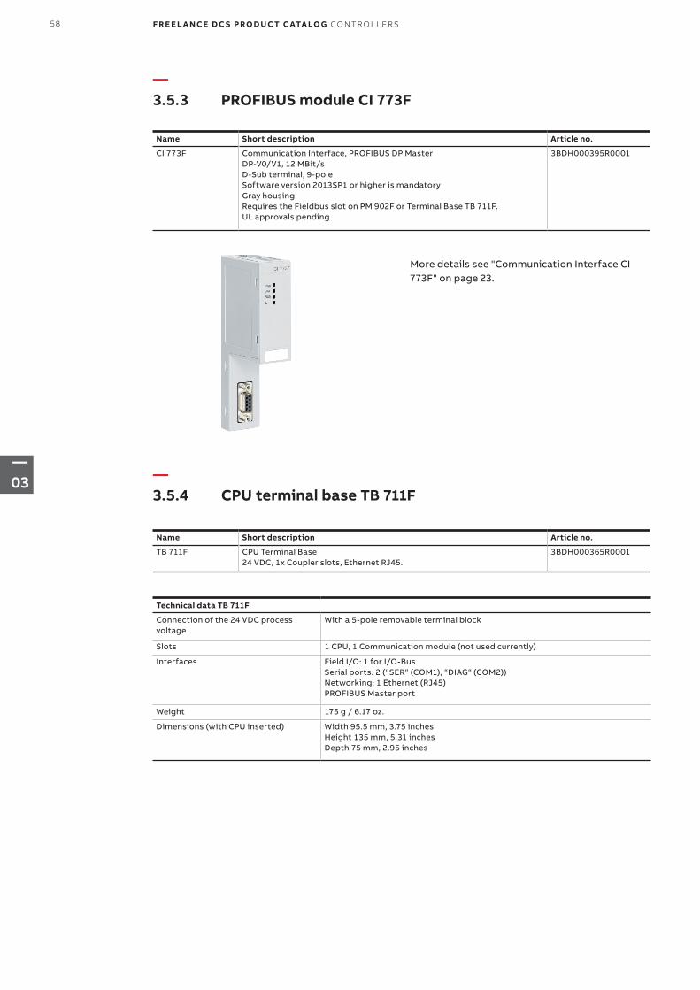
—3.5.3 PROFIBUS module CI 773F
—3.5.4 CPU terminal base TB 711F
Name Short description Article no.
CI 773F Communication Interface, PROFIBUS DP MasterDP-V0/V1, 12 MBit/sD-Sub terminal, 9-poleSoftware version 2013SP1 or higher is mandatoryGray housingRequires the Fieldbus slot on PM 902F or Terminal Base TB 711F.UL approvals pending
3BDH000395R0001
Name Short description Article no.
TB 711F CPU Terminal Base24 VDC, 1x Coupler slots, Ethernet RJ45.
3BDH000365R0001
Technical data TB 711F
Connection of the 24 VDC process voltage
With a 5-pole removable terminal block
Slots 1 CPU, 1 Communication module (not used currently)
Interfaces Field I/O: 1 for I/O-Bus Serial ports: 2 (“SER“ (COM1), “DIAG“ (COM2)) Networking: 1 Ethernet (RJ45)PROFIBUS Master port
Weight 175 g / 6.17 oz.
Dimensions (with CPU inserted) Width 95.5 mm, 3.75 inches Height 135 mm, 5.31 inches Depth 75 mm, 2.95 inches
More details see "Communication Interface CI 773F" on page 23.
58 F R E E L A N CE D C S PRO D U C T C ATA LO G CO NTR O L L ER S
—03
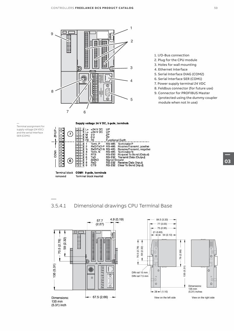
— 3.5.4.1 Dimensional drawings CPU Terminal Base
1. I/O-Bus connection2. Plug for the CPU module3. Holes for wall mounting4. Ethernet interface5. Serial Interface DIAG (COM2)6. Serial interface SER (COM1)7. Power supply terminal 24 VDC8. Feldbus connector (for future use)9. Connector for PROFIBUS Master (protected using the dummy coupler module when not in use)
DC
-IN
10W
ET
HE
RN
ET
FBP
SE
RD
IAG
1
2
3
4
5
7
6
8
9
L+
L-
M
M
FE
1
2
3
4
5
67
8
9
—Terminal assignment for supply voltage (24 VDC) and the serial interface SER (COM1)
28
21 (0.83)54 (2.13)
75 (2.95)
59
(2
.32
)
70
.5 (
2.7
8)
13
5 (5
.31)
76
(2
.99
)
View on the left side View on the right side
77 (3.03)
84.5 (3.33)
DIN rail 15 mmDIN rail 7.5 mm
135 mm(5.31) inches
Dimensions:
(1.10)
59CO NTR O L L ER S F R E E L A N CE D C S PRO D U C T C ATA LO G
—03
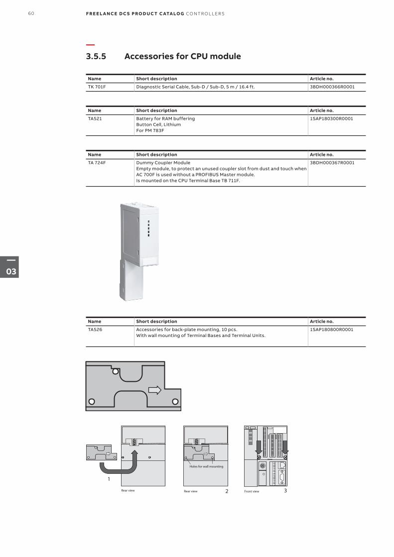
—3.5.5 Accessories for CPU module
Name Short description Article no.
TK 701F Diagnostic Serial Cable, Sub-D / Sub-D, 5 m / 16.4 ft. 3BDH000366R0001
Name Short description Article no.
TA521 Battery for RAM buffering Button Cell, LithiumFor PM 783F
1SAP180300R0001
Name Short description Article no.
TA526 Accessories for back-plate mounting, 10 pcs.With wall mounting of Terminal Bases and Terminal Units.
1SAP180800R0001
Name Short description Article no.
TA 724F Dummy Coupler ModuleEmpty module, to protect an unused coupler slot from dust and touch when AC 700F is used without a PROFIBUS Master module. Is mounted on the CPU Terminal Base TB 711F.
3BDH000367R0001
3Front view
1
Rear view 2Rear view
Holes for wall mounting
60 F R E E L A N CE D C S PRO D U C T C ATA LO G CO NTR O L L ER S
—03
Name Output current Article no.
SD831* 3 A 3BSC610064R1
SD832* 5 A 3BSC610065R1
SD833* 10 A 3BSC610066R1
SD834* 20 A 3BSC610067R1
CP-C.1 24/5.0 5 A 1SVR360563R1001
CP-C.1 24/10.0 10 A 1SVR360663R1001
*See also chapter 5.3.4 S800 Power supplies
—Chapter 4 – Power supplies for AC 900F, AC 700F and S700 I/O
The following power supplies are compatible with AC 900F, AC 700F and S700 I/O. They can be used to provide 24 V DC to CPU moduls, I/O modules and field devices. Accessories, such as voter-, redundancy- and messaging modules, enable the setup of a redundant power supply and its monitoring.
Alternatively, Power Supplies that supports the technical requirement described in the M&I manual can be used.
Further information on power supplies can be found in the related product documentation.
61P OW ER SU PPL I E S FO R AC 9 0 0 F, AC 70 0 F A N D S 70 0 I/O F R E E L A N CE D C S PRO D U C T C ATA LO G
—04
—Chapter 5 – I/Os
064 5.1 Introduction to I/Os for Freelance
065 – 110 5.2 S700 I/O
066 5.2.1 S700 I/O modules
066 5.2.2 Fieldbus interface module CI 741F
068 5.2.3 Digital I/O Modules
086 5.2.4 Analog I/O Modules
102 5.2.5 Digital / analog I/O modulee
106 5.2.6 S700 I/O terminal units
111 5.2.7 S 700 I/O Accessories
111 – 119 5.3 S800 Remote I/O
112 5.3.1 Communication
113 5.3.2 S800 I/O modules
118 5.3.3 S800L modules
121 5.3.4 Power supplies
121 5.3.5 S800 I/O user documentation
122 – 119 5.4 S900 Remote I/O
122 5.4.1 Introduction to S900 I/O system
123 5.4.2 Redundant termination unit TU921S/B/N
62 F R E E L A N CE D C S PRO D U C T C ATA LO G I/OS: S 70 0, S 8 0 0, S9 0 0
—05
—Chapter 5 – I/Os
123 5.4.3 Power supply SA920S/B/N
124 5.4.4 Digital I/O modules
125 5.4.5 Analog I/O modules
129 5.4.6 Field housing
130 5.4.7 Accessories for S900
131 5.4.8 Software
63I/OS: S 70 0, S 8 0 0, S9 0 0 F R E E L A N CE D C S PRO D U C T C ATA LO G
—05
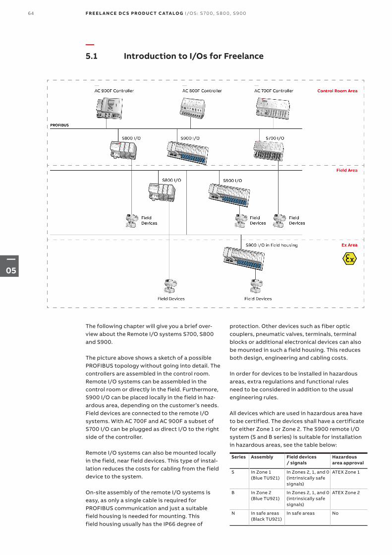
—5.1 Introduction to I/Os for Freelance
The following chapter will give you a brief over-view about the Remote I/O systems S700, S800 and S900.
The picture above shows a sketch of a possible PROFIBUS topology without going into detail. The controllers are assembled in the control room. Remote I/O systems can be assembled in the control room or directly in the field. Furthermore, S900 I/O can be placed locally in the field in haz-ardous area, depending on the customer’s needs. Field devices are connected to the remote I/O systems. With AC 700F and AC 900F a subset of S700 I/O can be plugged as direct I/O to the right side of the controller.
Remote I/O systems can also be mounted locally in the field, near field devices. This type of instal-lation reduces the costs for cabling from the field device to the system.
On-site assembly of the remote I/O systems is easy, as only a single cable is required for PROFIBUS communication and just a suitable field housing is needed for mounting. This field housing usually has the IP66 degree of
protection. Other devices such as fiber optic couplers, pneumatic valves, terminals, terminal blocks or additional electronical devices can also be mounted in such a field housing. This reduces both design, engineering and cabling costs.
In order for devices to be installed in hazardous areas, extra regulations and functional rules need to be considered in addition to the usual engineering rules.
All devices which are used in hazardous area have to be certified. The devices shall have a certificate for either Zone 1 or Zone 2. The S900 remote I/O system (S and B series) is suitable for installation in hazardous areas, see the table below:
Series Assembly Field devices / signals
Hazardous area approval
S In Zone 1 (Blue TU921)
In Zones 2, 1, and 0 (intrinsically safe signals)
ATEX Zone 1
B In Zone 2 (Blue TU921)
In Zones 2, 1, and 0 (intrinsically safe signals)
ATEX Zone 2
N In safe areas (Black TU921)
In safe areas No
64 F R E E L A N CE D C S PRO D U C T C ATA LO G I/OS: S 70 0, S 8 0 0, S9 0 0
—05
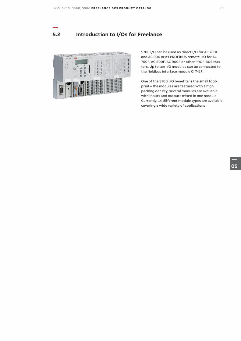
—5.2 Introduction to I/Os for Freelance
S700 I/O can be used as direct I/O for AC 700F and AC 900 or as PROFIBUS remote I/O for AC 700F, AC 800F, AC 900F or other PROFIBUS Mas-ters. Up to ten I/O modules can be connected to the fieldbus interface module CI 741F.
One of the S700 I/O benefits is the small foot-print – the modules are featured with a high packing density, several modules are available with inputs and outputs mixed in one module. Currently, 14 different module types are available covering a wide variety of applications
65I/OS: S 70 0, S 8 0 0, S9 0 0 F R E E L A N CE D C S PRO D U C T C ATA LO G
—05
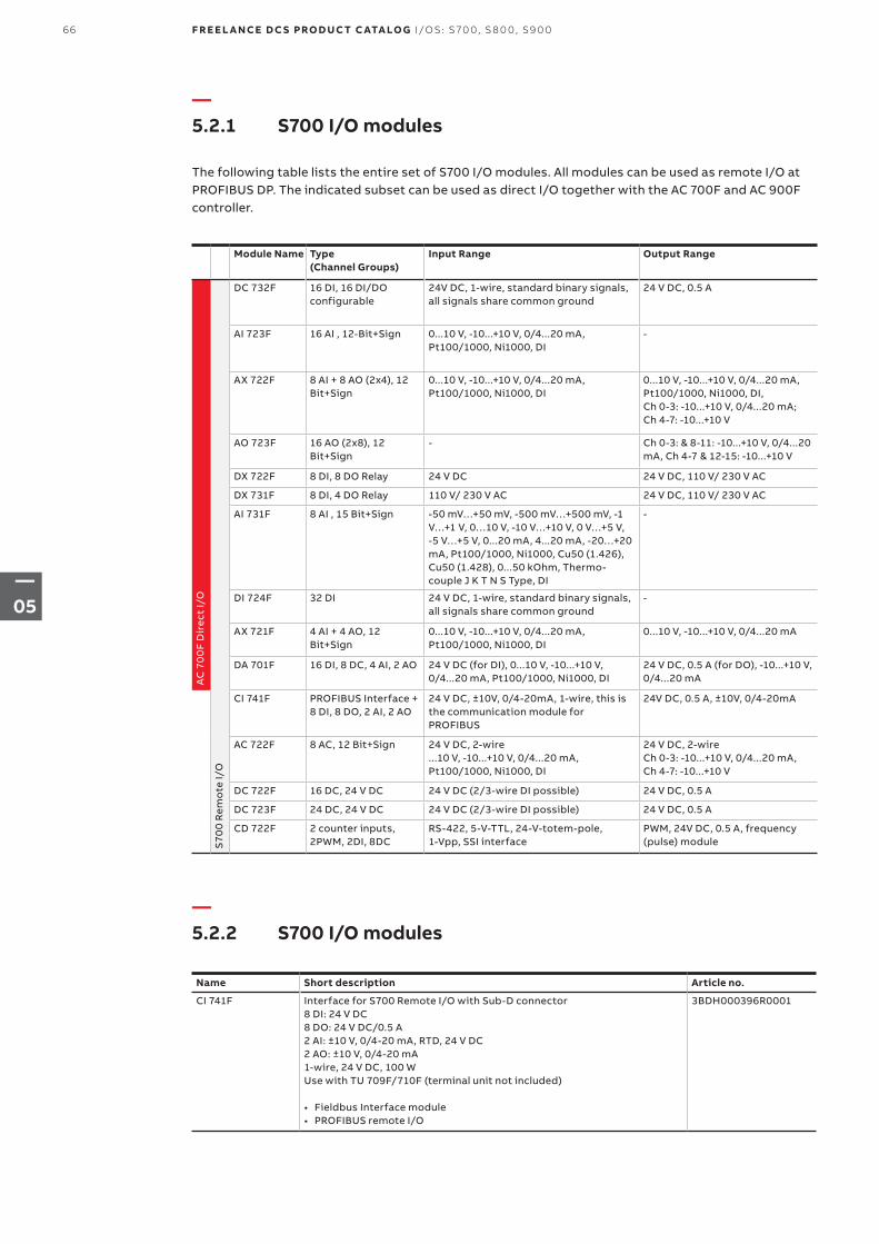
—5.2.1 S700 I/O modules
—5.2.2 S700 I/O modules
The following table lists the entire set of S700 I/O modules. All modules can be used as remote I/O at PROFIBUS DP. The indicated subset can be used as direct I/O together with the AC 700F and AC 900F controller.
Module Name Type (Channel Groups)
Input Range Output Range
AC
70
0F
Dir
ect
I/O
S70
0 R
emo
te I/
O
DC 732F 16 DI, 16 DI/DO configurable
24V DC, 1-wire, standard binary signals, all signals share common ground
24 V DC, 0.5 A
AI 723F 16 AI , 12-Bit+Sign 0...10 V, -10...+10 V, 0/4...20 mA, Pt100/1000, Ni1000, DI
-
AX 722F 8 AI + 8 AO (2x4), 12 Bit+Sign
0...10 V, -10...+10 V, 0/4...20 mA, Pt100/1000, Ni1000, DI
0...10 V, -10...+10 V, 0/4...20 mA, Pt100/1000, Ni1000, DI, Ch 0-3: -10...+10 V, 0/4...20 mA; Ch 4-7: -10...+10 V
AO 723F 16 AO (2x8), 12 Bit+Sign
- Ch 0-3: & 8-11: -10...+10 V, 0/4...20 mA, Ch 4-7 & 12-15: -10...+10 V
DX 722F 8 DI, 8 DO Relay 24 V DC 24 V DC, 110 V/ 230 V AC
DX 731F 8 DI, 4 DO Relay 110 V/ 230 V AC 24 V DC, 110 V/ 230 V AC
AI 731F 8 AI , 15 Bit+Sign -50 mV…+50 mV, -500 mV…+500 mV, -1 V…+1 V, 0…10 V, -10 V…+10 V, 0 V…+5 V, -5 V…+5 V, 0...20 mA, 4...20 mA, -20…+20 mA, Pt100/1000, Ni1000, Cu50 (1.426), Cu50 (1.428), 0...50 kOhm, Thermo-couple J K T N S Type, DI
-
DI 724F 32 DI 24 V DC, 1-wire, standard binary signals, all signals share common ground
-
AX 721F 4 AI + 4 AO, 12 Bit+Sign
0...10 V, -10...+10 V, 0/4...20 mA, Pt100/1000, Ni1000, DI
0...10 V, -10...+10 V, 0/4...20 mA
DA 701F 16 DI, 8 DC, 4 AI, 2 AO 24 V DC (for DI), 0...10 V, -10...+10 V, 0/4...20 mA, Pt100/1000, Ni1000, DI
24 V DC, 0.5 A (for DO), -10...+10 V, 0/4...20 mA
CI 741F PROFIBUS Interface + 8 DI, 8 DO, 2 AI, 2 AO
24 V DC, ±10V, 0/4-20mA, 1-wire, this is the communication module for PROFIBUS
24V DC, 0.5 A, ±10V, 0/4-20mA
AC 722F 8 AC, 12 Bit+Sign 24 V DC, 2-wire...10 V, -10...+10 V, 0/4...20 mA, Pt100/1000, Ni1000, DI
24 V DC, 2-wireCh 0-3: -10...+10 V, 0/4...20 mA, Ch 4-7: -10...+10 V
DC 722F 16 DC, 24 V DC 24 V DC (2/3-wire DI possible) 24 V DC, 0.5 A
DC 723F 24 DC, 24 V DC 24 V DC (2/3-wire DI possible) 24 V DC, 0.5 A
CD 722F 2 counter inputs, 2PWM, 2DI, 8DC
RS-422, 5-V-TTL, 24-V-totem-pole, 1-Vpp, SSI interface
PWM, 24V DC, 0.5 A, frequency (pulse) module
Name Short description Article no.
CI 741F Interface for S700 Remote I/O with Sub-D connector8 DI: 24 V DC8 DO: 24 V DC/0.5 A2 AI: ±10 V, 0/4-20 mA, RTD, 24 V DC2 AO: ±10 V, 0/4-20 mA1-wire, 24 V DC, 100 WUse with TU 709F/710F (terminal unit not included)
• Fieldbus Interface module• PROFIBUS remote I/O
3BDH000396R0001
66 F R E E L A N CE D C S PRO D U C T C ATA LO G I/OS: S 70 0, S 8 0 0, S9 0 0
—05
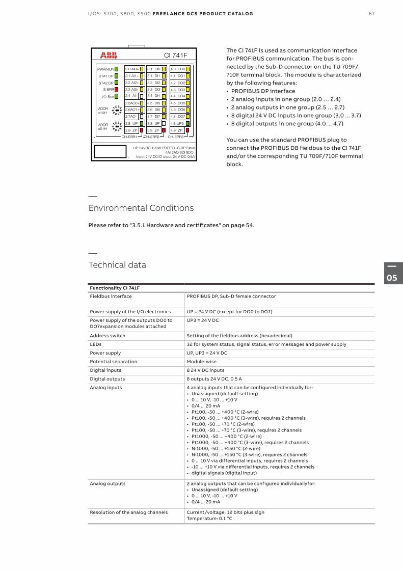
The CI 741F is used as communication interface for PROFIBUS communication. The bus is con-nected by the Sub-D connector on the TU 709F/ 710F terminal block. The module is characterized by the following features: • PROFIBUS DP interface• 2 analog inputs in one group (2.0 … 2.4)• 2 analog outputs in one group (2.5 … 2.7)• 8 digital 24 V DC inputs in one group (3.0 ... 3.7)• 8 digital outputs in one group (4.0 ... 4.7)
You can use the standard PROFIBUS plug to connect the PROFIBUS DB fieldbus to the CI 741F and/or the corresponding TU 709F/710F terminal block.
CI 741F
UP 24VDC 100W PROFIBUS DP Slave4AI 2AO 8DI 8DO
Input 24V DC/O utput 24 V DC 0.5A
PWR/RUN
STA1 DP
CH-ERR2 CH-ERR3
3.1 DI0
3.1 DI1
3.2 DI2
3.3 DI3
3.4 DI4
3.5 DI5
3.6 DI6
3.7 DI7
3.8 UP
3.9 ZP
4.0 DO0
4.1 DO1
4.2 DO2
4.3 DO3
4.4 DO4
4.5 DO5
4.6 DO6
4.7 DO7
4.8 UP3
4.9 ZP
ADDR
ADDR
x10H
x01H
STA2 DP
S-ERR
I/O-Bus
CH-ERR1
2.0 AI0+
2.1 AI1+
2.2 AI2+
2.3 AI3+
2.4 AI-
2.5AO0+
2.6AO1+
2.7AO-
2.8 UP
2.9 ZP
—Environmental Conditions
Please refer to "3.5.1 Hardware and certificates" on page 54.
—Technical data
Functionality CI 741F
Fieldbus interface PROFIBUS DP, Sub-D female connector
Power supply of the I/O electronics UP = 24 V DC (except for DO0 to DO7)
Power supply of the outputs DO0 to DO7expansion modules attached
UP3 = 24 V DC
Address switch Setting of the fieldbus address (hexadecimal)
LEDs 32 for system status, signal status, error messages and power supply
Power supply UP, UP3 = 24 V DC
Potential separation Module-wise
Digital inputs 8 24 V DC inputs
Digital outputs 8 outputs 24 V DC, 0.5 A
Analog inputs 4 analog inputs that can be configured individually for:• Unassigned (default setting)• 0 ... 10 V, -10 ... +10 V• 0/4 ... 20 mA• Pt100, -50 ... +400 °C (2-wire)• Pt100, -50 ... +400 °C (3-wire), requires 2 channels• Pt100, -50 ... +70 °C (2-wire)• Pt100, -50 ... +70 °C (3-wire), requires 2 channels• Pt1000, -50 ... +400 °C (2-wire)• Pt1000, -50 ... +400 °C (3-wire), requires 2 channels• Ni1000, -50 ... +150 °C (2-wire)• Ni1000, -50 ... +150 °C (3-wire), requires 2 channels• 0 ... 10 V via differential inputs, requires 2 channels• -10 ... +10 V via differential inputs, requires 2 channels• digital signals (digital input)
Analog outputs 2 analog outputs that can be configured individuallyfor:• Unassigned (default setting)• 0 ... 10 V, -10 ... +10 V• 0/4 ... 20 mA
Resolution of the analog channels Current/voltage: 12 bits plus sign Temperature: 0.1 °C
67I/OS: S 70 0, S 8 0 0, S9 0 0 F R E E L A N CE D C S PRO D U C T C ATA LO G
—05
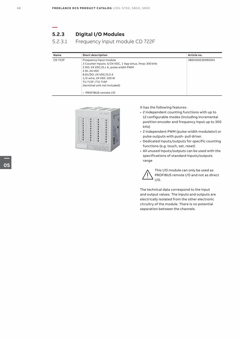
—5.2.3 Digital I/O Modules5.2.3.1 Frequency input module CD 722F
Name Short description Article no.
CD 722F Frequency input module2 Counter Inputs: 5/24 VDC, 1 Vpp sinus, fmax 300 kHz2 DO: 24 VDC/0,1 A, pulse width PWM2 DI: 24 VDC8 DI/DO: 24 VDC/0,5 A1/2-wire, 24 VDC 100 WTU 715F /TU 716F (terminal unit not included)
• PROFIBUS remote I/O
3BDH000393R0001
It has the following features:• 2 independent counting functions with up to
12 configurable modes (including incremental position encoder and frequency input up to 300 kHz)
• 2 independent PWM (pulse-width modulator) or pulse outputs with push- pull driver.
• Dedicated inputs/outputs for specific counting functions (e.g. touch, set, reset)
• All unused inputs/outputs can be used with the specifications of standard inputs/outputs range
This I/O module can only be used as PROFIBUS remote I/O and not as direct I/O.
The technical data correspond to the input and output values. The inputs and outputs are electrically isolated from the other electronic circuitry of the module. There is no potential separation between the channels.
68 F R E E L A N CE D C S PRO D U C T C ATA LO G I/OS: S 70 0, S 8 0 0, S9 0 0
—05
—Technical data
The technical data correspond to the input and output values. The inputs and outputs are electrically isolated from the other electronic circuitry of the module. There is no potential separation between the channels.
Functionality CD 722F
Digital inputs/outputs 24 V DC, dedicated inputs/outputs can be used for specific counting functions:
Catch/touch operation, counter value stored in separate variable on external event (rising or falling edge)
Set input to preset counter register with predefined value
Set input to reset counter register
End value output; the output is set when predefined value is reached
Reference point initialization (RPI) input for incremental encoder initialization
All unused inputs/outputs can be used with the specification of standard input/output range.
High-speed counter/encoder integrated, 2 counters (hardware interface with +24 V DC, +5 V DC, differential and 1 Vpp sinus input) with up to 12 configurable operation modes:
32 bits one counter mode
16 bits two counter mode
Incremental position encoder
Absolute SSI encoder
Time frequency meter
Frequency input up to 300 kHz
PWM/pulse outputs 2 pulse-width-modulators or pulse outputs
Output specification
Push-pull output: 24 V DC, 100 mA max.
Current limitation (thermal and over current)
PWM specification
Frequency from 1 Hz to 100 kHz
Value from 0 to 100 %
Pulse specification
Frequency from 1 Hz to 15 kHz
Pulse emission from 1 to 65535 pulses
Number of pulses emitted indicator (0 to 100 %)
Frequency specification
Frequency output = 100 kHz when duty cycle set to 50 %
Power supply for encoders Two 5 V power supplies, max. 100mA
LEDs For system displays, indicating signal statuses, errors and power supply
Internal power supply Via I/O Bus
External power supply Via the terminals UP(process voltage 24 V DC) and ZP (0 V DC)
69I/OS: S 70 0, S 8 0 0, S9 0 0 F R E E L A N CE D C S PRO D U C T C ATA LO G
—05
Technical Data CD 722F
Connection Terminals 1.8,2.8,3.8 and 4.8 for UP (+24 V DC) and 1.9, 2.9, 3.9 and 4.9 for ZP (0V)
Protection against reversed voltage Yes
Rated protection fuse on UP 10 A fast
Rated value 24 V DC
Max. ripple 5 %
Current consumption
From UP 0.07 A + max. 0.008 A per input + max. 0.5 A per output + 0.01 A for A, B and Z inputs
Via I/O Bus Approx. 5 mA
Inrush current from UP (at power up) 0.04 A²s
Electrical isolation Yes, per module
Max. power dissipation within the module
6 W (outputs not loaded)
Dimensions (without the Terminal Unit) 67.5 x 76 x 54 mm / 2.66 x 2.99 x 2.13 inches width x height x depth
Weight 125 g/ 4.41 oz.
Mounting position Horizontal or vertical with limitations (output load per group 50 % at 40°C (104°F))
Cooling The natural convection cooling must not be hindered by cable ducts or other parts in the mounting cabinet.
Technical data for the digital inputs/outputs if used as standard inputs
Number of channels per module 2 + 8 configurable digital inputs/outputs
Reference potential for all inputs Terminals 1.9…4.9 (Minus pole of the supply voltage, signal name ZP)
Electrical isolation From the rest of the module
Indication of the input signals 1 yellow LED per channel, the LED is ON when the input signal is high (signal1)
Input type acc. to EN 61131-2 Type 1
Input delay (0->1 or 1->0) Typically 8 ms, configurable from 0.1…32 ms
Input signal voltage 24 V DC
• Signal 0• Undefined signal • Signal 1
• -3 V...+5 V• > +5 V...< +15 V• +15 V...+30 V
Ripple with signal 0 Within -3 V...+5 V*
Ripple with signal 1 Within +15 V...+30 V
Input current per channel
• Input voltage +24 V• Input voltage +5 V• Input voltage +15 V• Input voltage +30 V
• Typically 5 mA• > 1 mA• > 5 mA• < 8 mA
Max. cable length Shielded 1000 m (3280.83 ft)
Unshielded 600 m (1968.50 ft)
* Due to the direct connection to the output, the demagnetizing varistor is also effective at the input. This is why the difference between UPx and the input signal may not exceed the clamp voltage of the varistor. The varistor limits the voltage to approx. 36 V. Following this, the input voltage must range from -12 V to +30 V when UPx = 24 V and from -6 V to +30 V when UPx = 30 V.
70 F R E E L A N CE D C S PRO D U C T C ATA LO G I/OS: S 70 0, S 8 0 0, S9 0 0
—05
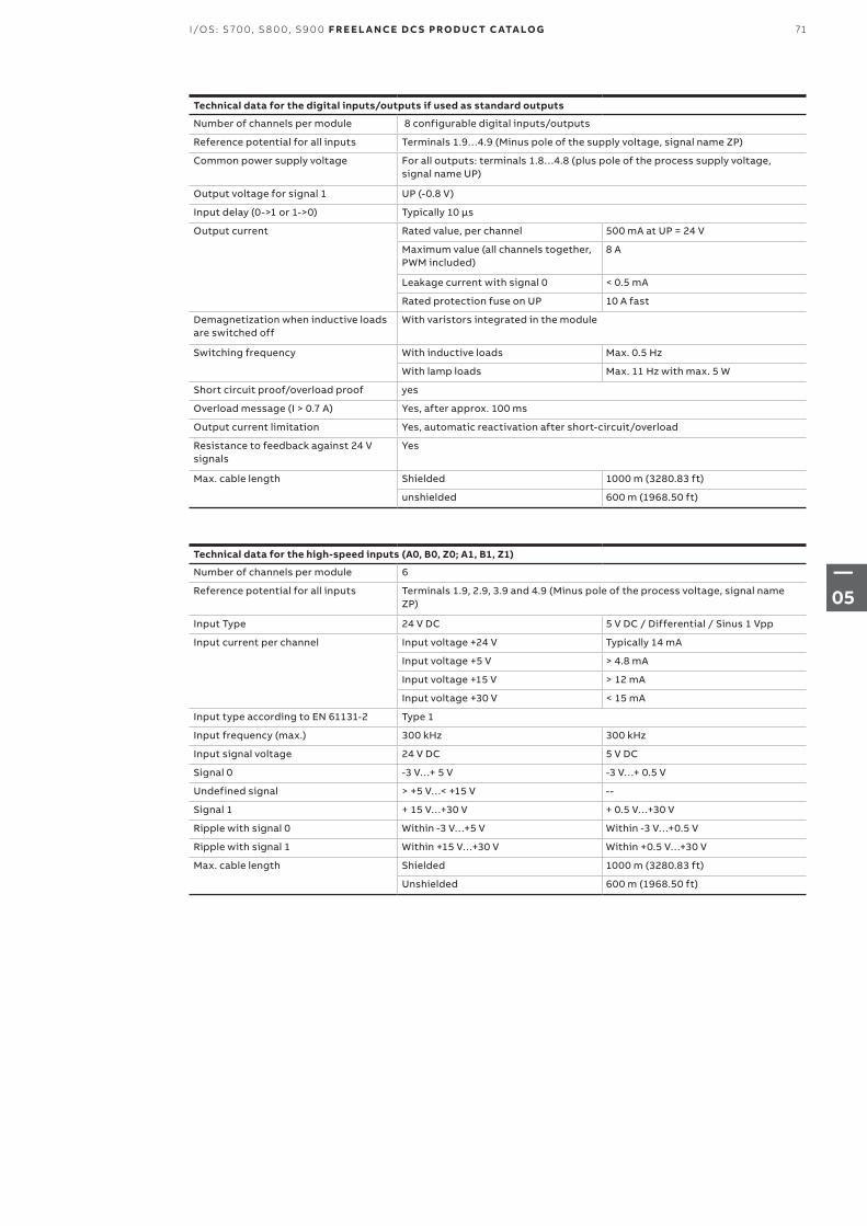
Technical data for the digital inputs/outputs if used as standard outputs
Number of channels per module 8 configurable digital inputs/outputs
Reference potential for all inputs Terminals 1.9…4.9 (Minus pole of the supply voltage, signal name ZP)
Common power supply voltage For all outputs: terminals 1.8…4.8 (plus pole of the process supply voltage, signal name UP)
Output voltage for signal 1 UP (-0.8 V)
Input delay (0->1 or 1->0) Typically 10 µs
Output current Rated value, per channel 500 mA at UP = 24 V
Maximum value (all channels together, PWM included)
8 A
Leakage current with signal 0 < 0.5 mA
Rated protection fuse on UP 10 A fast
Demagnetization when inductive loads are switched off
With varistors integrated in the module
Switching frequency With inductive loads Max. 0.5 Hz
With lamp loads Max. 11 Hz with max. 5 W
Short circuit proof/overload proof yes
Overload message (I > 0.7 A) Yes, after approx. 100 ms
Output current limitation Yes, automatic reactivation after short-circuit/overload
Resistance to feedback against 24 V signals
Yes
Max. cable length Shielded 1000 m (3280.83 ft)
unshielded 600 m (1968.50 ft)
Technical data for the high-speed inputs (A0, B0, Z0; A1, B1, Z1)
Number of channels per module 6
Reference potential for all inputs Terminals 1.9, 2.9, 3.9 and 4.9 (Minus pole of the process voltage, signal name ZP)
Input Type 24 V DC 5 V DC / Differential / Sinus 1 Vpp
Input current per channel Input voltage +24 V Typically 14 mA
Input voltage +5 V > 4.8 mA
Input voltage +15 V > 12 mA
Input voltage +30 V < 15 mA
Input type according to EN 61131-2 Type 1
Input frequency (max.) 300 kHz 300 kHz
Input signal voltage 24 V DC 5 V DC
Signal 0 -3 V…+ 5 V -3 V…+ 0.5 V
Undefined signal > +5 V…< +15 V --
Signal 1 + 15 V…+30 V + 0.5 V…+30 V
Ripple with signal 0 Within -3 V…+5 V Within -3 V…+0.5 V
Ripple with signal 1 Within +15 V…+30 V Within +0.5 V…+30 V
Max. cable length Shielded 1000 m (3280.83 ft)
Unshielded 600 m (1968.50 ft)
71I/OS: S 70 0, S 8 0 0, S9 0 0 F R E E L A N CE D C S PRO D U C T C ATA LO G
—05
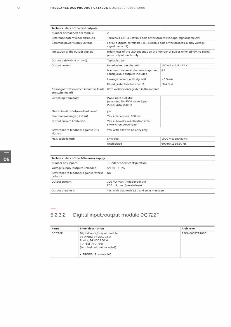
Technical data of the fast outputs
Number of channels per module 2
Reference potential for all inputs Terminals 1.9…4.9 (Minus pole of the process voltage, signal name ZP)
Common power supply voltage For all outputs: terminals 1.8…4.8 (plus pole of the process supply voltage, signal name UP)
Indication of the output signals Brightness of the LED depends on the number of pulses emitted (0% to 100%) – pulse output mode only
Output delay (0->1 or 1->0) Typically 1 µs
Output current Rated value, per channel 100 mA at UP = 24 V
Maximum value (all channels together, configurable outputs included)
8 A
Leakage current with signal 0 < 0.5 mA
Rated protection fuse on UP 10 A fast
De-magnetization when inductive loads are switched off
With varistors integrated in the module
Switching frequency PWM: upto 100 kHz (min. step for PWM value: 2 µs)Pulse: upto 15 k Hz
Short circuit proof/overload proof yes
Overload message (I > 0.7A) Yes, after approx. 100 ms
Output current limitation Yes, automatic reactivation after short-circuit/overload
Resistance to feedback against 24 V signals
Yes, with positive polarity only
Max. cable length Shielded 1000 m (3280.83 ft)
Unshielded 600 m (1968.50 ft)
Technical data of the 5-V-sensor supply
Number of supplies 2, independent configuration
Voltage supply (outputs unloaded) 5 V DC +/- 5%
Resistance to feedback against reverse polarity
No
Output current 100 mA max. (independently)200 mA max. (parallel use)
Output diagnosis Yes, with diagnosis LED and error message
—5.2.3.2 Digital input/output module DC 722F
Name Short description Article no.
DC 722F Digital input/output module16 DI/DO: 24 VDC/0.5 A2-wire, 24 VDC 200 WTU 715F /TU 716F (terminal unit not included)
• PROFIBUS remote I/O
3BDH000372R0001
72 F R E E L A N CE D C S PRO D U C T C ATA LO G I/OS: S 70 0, S 8 0 0, S9 0 0
—05
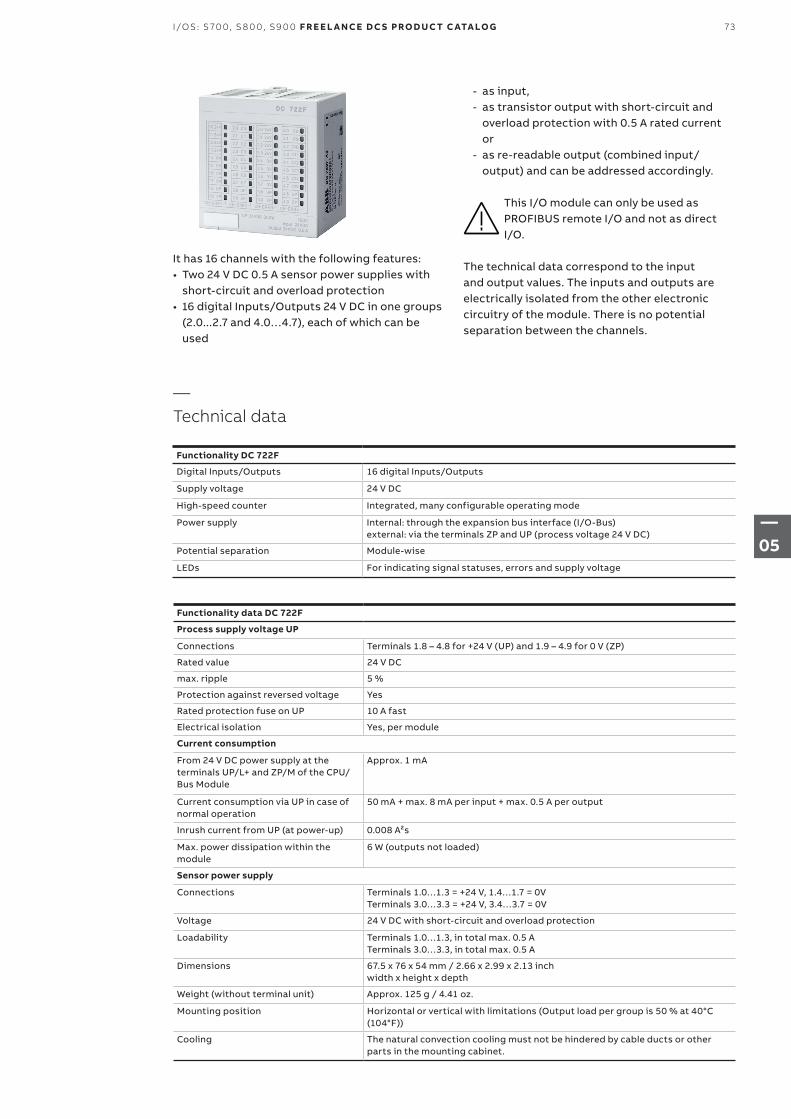
It has 16 channels with the following features:• Two 24 V DC 0.5 A sensor power supplies with
short-circuit and overload protection• 16 digital Inputs/Outputs 24 V DC in one groups
(2.0...2.7 and 4.0…4.7), each of which can be used
—Technical data
Functionality DC 722F
Digital Inputs/Outputs 16 digital Inputs/Outputs
Supply voltage 24 V DC
High-speed counter Integrated, many configurable operating mode
Power supply Internal: through the expansion bus interface (I/O-Bus) external: via the terminals ZP and UP (process voltage 24 V DC)
Potential separation Module-wise
LEDs For indicating signal statuses, errors and supply voltage
Functionality data DC 722F
Process supply voltage UP
Connections Terminals 1.8 – 4.8 for +24 V (UP) and 1.9 – 4.9 for 0 V (ZP)
Rated value 24 V DC
max. ripple 5 %
Protection against reversed voltage Yes
Rated protection fuse on UP 10 A fast
Electrical isolation Yes, per module
Current consumption
From 24 V DC power supply at the terminals UP/L+ and ZP/M of the CPU/Bus Module
Approx. 1 mA
Current consumption via UP in case of normal operation
50 mA + max. 8 mA per input + max. 0.5 A per output
Inrush current from UP (at power-up) 0.008 A²s
Max. power dissipation within the module
6 W (outputs not loaded)
Sensor power supply
Connections Terminals 1.0…1.3 = +24 V, 1.4…1.7 = 0V Terminals 3.0…3.3 = +24 V, 3.4…3.7 = 0V
Voltage 24 V DC with short-circuit and overload protection
Loadability Terminals 1.0…1.3, in total max. 0.5 A Terminals 3.0…3.3, in total max. 0.5 A
Dimensions 67.5 x 76 x 54 mm / 2.66 x 2.99 x 2.13 inch width x height x depth
Weight (without terminal unit) Approx. 125 g / 4.41 oz.
Mounting position Horizontal or vertical with limitations (Output load per group is 50 % at 40°C (104°F))
Cooling The natural convection cooling must not be hindered by cable ducts or other parts in the mounting cabinet.
- as input, - as transistor output with short-circuit and
overload protection with 0.5 A rated current or
- as re-readable output (combined input/ output) and can be addressed accordingly.
This I/O module can only be used as PROFIBUS remote I/O and not as direct I/O.
The technical data correspond to the input and output values. The inputs and outputs are electrically isolated from the other electronic circuitry of the module. There is no potential separation between the channels.
73I/OS: S 70 0, S 8 0 0, S9 0 0 F R E E L A N CE D C S PRO D U C T C ATA LO G
—05
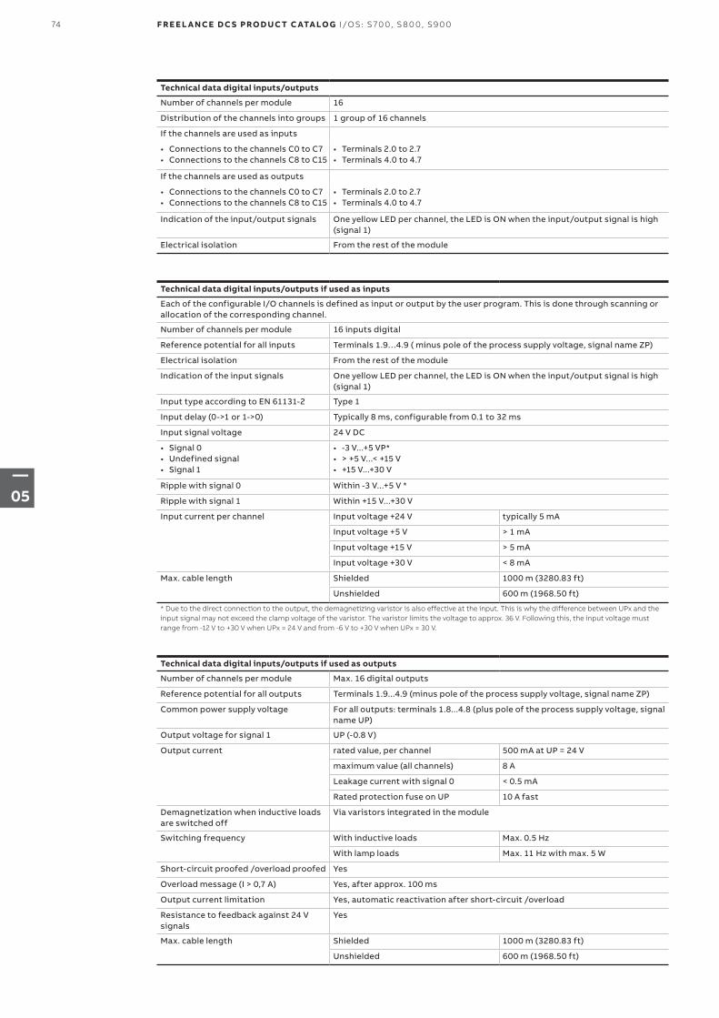
Technical data digital inputs/outputs
Number of channels per module 16
Distribution of the channels into groups 1 group of 16 channels
If the channels are used as inputs
• Connections to the channels C0 to C7• Connections to the channels C8 to C15
• Terminals 2.0 to 2.7• Terminals 4.0 to 4.7
If the channels are used as outputs
• Connections to the channels C0 to C7• Connections to the channels C8 to C15
• Terminals 2.0 to 2.7• Terminals 4.0 to 4.7
Indication of the input/output signals One yellow LED per channel, the LED is ON when the input/output signal is high (signal 1)
Electrical isolation From the rest of the module
Technical data digital inputs/outputs if used as outputs
Number of channels per module Max. 16 digital outputs
Reference potential for all outputs Terminals 1.9...4.9 (minus pole of the process supply voltage, signal name ZP)
Common power supply voltage For all outputs: terminals 1.8...4.8 (plus pole of the process supply voltage, signal name UP)
Output voltage for signal 1 UP (-0.8 V)
Output current rated value, per channel 500 mA at UP = 24 V
maximum value (all channels) 8 A
Leakage current with signal 0 < 0.5 mA
Rated protection fuse on UP 10 A fast
Demagnetization when inductive loads are switched off
Via varistors integrated in the module
Switching frequency With inductive loads Max. 0.5 Hz
With lamp loads Max. 11 Hz with max. 5 W
Short-circuit proofed /overload proofed Yes
Overload message (I > 0,7 A) Yes, after approx. 100 ms
Output current limitation Yes, automatic reactivation after short-circuit /overload
Resistance to feedback against 24 V signals
Yes
Max. cable length Shielded 1000 m (3280.83 ft)
Unshielded 600 m (1968.50 ft)
Technical data digital inputs/outputs if used as inputs
Each of the configurable I/O channels is defined as input or output by the user program. This is done through scanning or allocation of the corresponding channel.
Number of channels per module 16 inputs digital
Reference potential for all inputs Terminals 1.9…4.9 ( minus pole of the process supply voltage, signal name ZP)
Electrical isolation From the rest of the module
Indication of the input signals One yellow LED per channel, the LED is ON when the input/output signal is high (signal 1)
Input type according to EN 61131-2 Type 1
Input delay (0->1 or 1->0) Typically 8 ms, configurable from 0.1 to 32 ms
Input signal voltage 24 V DC
• Signal 0• Undefined signal • Signal 1
• -3 V...+5 VP*• > +5 V...< +15 V• +15 V...+30 V
Ripple with signal 0 Within -3 V...+5 V *
Ripple with signal 1 Within +15 V...+30 V
Input current per channel Input voltage +24 V typically 5 mA
Input voltage +5 V > 1 mA
Input voltage +15 V > 5 mA
Input voltage +30 V < 8 mA
Max. cable length Shielded 1000 m (3280.83 ft)
Unshielded 600 m (1968.50 ft)
* Due to the direct connection to the output, the demagnetizing varistor is also effective at the input. This is why the difference between UPx and the input signal may not exceed the clamp voltage of the varistor. The varistor limits the voltage to approx. 36 V. Following this, the input voltage must range from -12 V to +30 V when UPx = 24 V and from -6 V to +30 V when UPx = 30 V.
74 F R E E L A N CE D C S PRO D U C T C ATA LO G I/OS: S 70 0, S 8 0 0, S9 0 0
—05
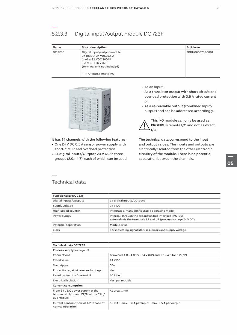
—5.2.3.3 Digital input/output module DC 723F
Name Short description Article no.
DC 723F Digital input/output module24 DI/DO: 24 VDC/0.5 A1-wire, 24 VDC 300 WTU 715F /TU 716F (terminal unit not included)
• PROFIBUS remote I/O
3BDH000373R0001
It has 24 channels with the following features:• One 24 V DC 0.5 A sensor power supply with
short-circuit and overload protection• 24 digital Inputs/Outputs 24 V DC in three
groups (2.0…4.7), each of which can be used
- As an input, - As a transistor output with short-circuit and
overload protection with 0.5 A rated current or
- As a re-readable output (combined input/ output) and can be addressed accordingly.
This I/O module can only be used as PROFIBUS remote I/O and not as direct I/O.
The technical data correspond to the input and output values. The inputs and outputs are electrically isolated from the other electronic circuitry of the module. There is no potential separation between the channels.
—Technical data
Functionality DC 723F
Digital Inputs/Outputs 24 digital Inputs/Outputs
Supply voltage 24 V DC
High-speed counter Integrated, many configurable operating mode
Power supply Internal: through the expansion bus interface (I/O-Bus)external: via the terminals ZP and UP (process voltage 24 V DC)
Potential separation Module-wise
LEDs For indicating signal statuses, errors and supply voltage
Technical data DC 723F
Process supply voltage UP
Connections Terminals 1.8 – 4.8 for +24 V (UP) and 1.9 – 4.9 for 0 V (ZP)
Rated value 24 V DC
Max. ripple 5 %
Protection against reversed voltage Yes
Rated protection fuse on UP 10 A fast
Electrical isolation Yes, per module
Current consumption
From 24 V DC power supply at the terminals UP/L+ and ZP/M of the CPU/Bus Module
Approx. 1 mA
Current consumption via UP in case of normal operation
50 mA + max. 8 mA per input + max. 0.5 A per output
75I/OS: S 70 0, S 8 0 0, S9 0 0 F R E E L A N CE D C S PRO D U C T C ATA LO G
—05
Technical data DC 723F
Current consumption
Inrush current from UP (at power-up) 0.008 A²s
Max. power dissipation within the module
6 W (outputs not loaded)
Sensor power supply
Connections Terminals 1.0…1.3 = +24 V, 1.4…1.7 = 0V
Voltage 24 V DC with short-circuit and overload protection
Loadability Terminals 1.0…1.3, in total max. 0.5 A
Dimensions 67.5 x 76 x 54 mm / 2.66 x 2.99 x 2.13 inch (width x height x depth)
Weight (without terminal unit) Approx. 125 g / 4.41 oz.
Mounting position Horizontal or vertical with limitations (Output load per group is 50 % at 40°C (104°F))
Cooling The natural convection cooling must not be hindered by cable ducts or other parts in the mounting cabinet.
Technical data digital inputs/outputs
Number of channels per module 24
Distribution of the channels into groups 1 group of 24 channels
If the channels are used as inputs
• Connections to the channels C0 to C7• Connections to the channels C8 to C15• Connections to the channels C16 to
C23
• Terminals 2.0 to 2.7• Terminals 3.0 to 3.7• Terminals 4.0 to 4.7
If the channels are used as outputs
• Connections to the channels C0 to C7• Connections to the channels C8 to C15• Connections to the channels C16 to
C23
• Terminals 2.0 to 2.7• Terminals 3.0 to 3.7• Terminals 4.0 to 4.7
Indication of the input/output signals One yellow LED per channel, the LED is ON when the input/output signal is high (signal 1)
Electrical isolation From the rest of the module
Technical data digital inputs/outputs if used as inputs
Each of the configurable I/O channels is defined as input or output by the user program. This is done through scanning or allocation of the corresponding channel.
Number of channels per module 24 inputs digital
Reference potential for all inputs Terminals 1.9…4.9 ( minus pole of the process supply voltage, signal name ZP)
Electrical isolation From the rest of the module
Indication of the input signals One yellow LED per channel, the LED is ON when the input/output signal is high (signal 1)
Input type according to EN 61131-2 Type 1
Input delay (0->1 or 1->0) Typically 8 ms, configurable from 0.1 to 32 ms
Input signal voltage 24 V DC
• Signal 0• Undefined signal • Signal 1
• -3 V...+5 VP*• +5 V...+15 V• +15 V...+30 V
Ripple with signal 0 Within -3 V...+5 V*
Ripple with signal 1 Within +15 V...+30 V
Input current per channel Input voltage +24 V typically 5 mA
Input voltage +5 V > 1 mA
Input voltage +15 V > 5 mA
Input voltage +30 V < 8 mA
Max. cable length Shielded 1000 m (3280.83 ft)
Unshielded 600 m (1968.50 ft)
* Due to the direct connection to the output, the demagnetizing varistor is also effective at the input. This is why the difference between UPx and the input signal may not exceed the clamp voltage of the varistor. The varistor limits the voltage to approx. 36 V. Following this, the input voltage must range from -12 V to +30 V when UPx = 24 V and from -6 V to +30 V when UPx = 30 V.
76 F R E E L A N CE D C S PRO D U C T C ATA LO G I/OS: S 70 0, S 8 0 0, S9 0 0
—05
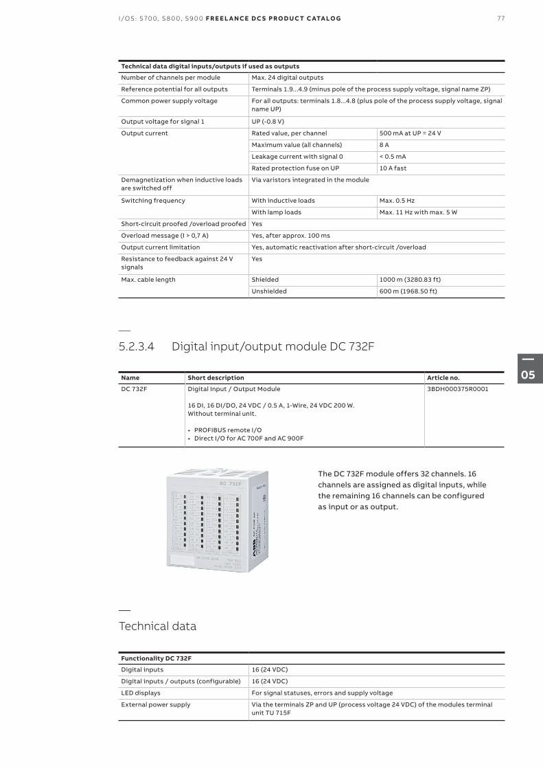
Technical data digital inputs/outputs if used as outputs
Number of channels per module Max. 24 digital outputs
Reference potential for all outputs Terminals 1.9...4.9 (minus pole of the process supply voltage, signal name ZP)
Common power supply voltage For all outputs: terminals 1.8...4.8 (plus pole of the process supply voltage, signal name UP)
Output voltage for signal 1 UP (-0.8 V)
Output current Rated value, per channel 500 mA at UP = 24 V
Maximum value (all channels) 8 A
Leakage current with signal 0 < 0.5 mA
Rated protection fuse on UP 10 A fast
Demagnetization when inductive loads are switched off
Via varistors integrated in the module
Switching frequency With inductive loads Max. 0.5 Hz
With lamp loads Max. 11 Hz with max. 5 W
Short-circuit proofed /overload proofed Yes
Overload message (I > 0,7 A) Yes, after approx. 100 ms
Output current limitation Yes, automatic reactivation after short-circuit /overload
Resistance to feedback against 24 V signals
Yes
Max. cable length Shielded 1000 m (3280.83 ft)
Unshielded 600 m (1968.50 ft)
—5.2.3.4 Digital input/output module DC 732F
Name Short description Article no.
DC 732F Digital Input / Output Module 16 DI, 16 DI/DO, 24 VDC / 0.5 A, 1-Wire, 24 VDC 200 W. Without terminal unit.
• PROFIBUS remote I/O• Direct I/O for AC 700F and AC 900F
3BDH000375R0001
The DC 732F module offers 32 channels. 16 channels are assigned as digital inputs, while the remaining 16 channels can be configured as input or as output.
—Technical data
Functionality DC 732F
Digital inputs 16 (24 VDC)
Digital inputs / outputs (configurable) 16 (24 VDC)
LED displays For signal statuses, errors and supply voltage
External power supply Via the terminals ZP and UP (process voltage 24 VDC) of the modules terminal unit TU 715F
77I/OS: S 70 0, S 8 0 0, S9 0 0 F R E E L A N CE D C S PRO D U C T C ATA LO G
—05
Technical data DC 732F
Process supply voltage UP
Connections Terminals 1.8 - 4.8 for +24 V (UP) and 1.9 - 4.9 for 0 V (ZP)
Rated value 24 VDC
Max. ripple 5%
Protection against reversed voltage Yes
Rated protection fuse on UP 10 A fast
Electrical isolation Yes, per module
Current consumption
Internal (via I/O-Bus) ca. 5 mA at 3.3 VDC
Current consumption from UP at normal operation/with outputs
50 mA + max. 8 mA per input + max. 0.5 A per output
Inrush current from UP (at power up) 0.007 A²s
Max. power dissipation within the module
6 W (outputs unloaded)
Sensor power supply
Dimensions (without Terminal Unit) 67.5 x 76 x 54 mm / 2.66 x 2.99 x 2.13 inch (width x height x depth)
Weight (without Terminal Unit) Approx. 125 g / 4.41 Oz.
Cooling The natural convection cooling must not be hindered by cable ducts or other parts in the mounting cabinet.
Technical data of the configurable digital inputs / outputs DC 732F
Each of the configurable I/O channels can be wired as input or output by the user.
Number of channels per module 16 inputs / outputs (with transistors)
Distribution of the channels into groups 1 group of 16 channels
If the channels are used as inputs
• Channels I16...I23• Channels I24...I31
• Terminals 3.0...3.7• Terminals 4.0...4.7
If the channels are used as outputs
• Channels O16...O23• Channels O24...O31
• Terminals 3.0...3.7• Terminals 4.0...4.7
Indication of the input / output signals One yellow LED per channel, the LED is ON when the input / output signal is high (signal 1)
Electrical isolation From the rest of the module
Technical data of the digital inputs DC 732F
Number of channels per module 16
Distribution of the channels into groups 1 group of 16 channels
Terminals of the channels I0 to I7 1.0 to 1.7
Terminals of the channels I8 to I15 2.0 to 2.7
Reference potential for all inputs Terminals 1.9...4.9 (minus pole of the process supply voltage, signal name ZP)
Electrical isolation From the rest of the module (I/O-Bus)
Indication of the input signals One yellow LED per channel, the LED is ON when the input signal is high (signal 1)
Input type acc. to EN 61131-2 Type 1
Input delay (0->1 or 1->0) Typ. 8 ms, configurable from 0.1 to 32 ms
Input signal voltage 24 VDC
• Signal 0• Undefined signal• Signal 1
• -3 V...+5 V• > +5 V...< +15 V• +15 V...+30 V
Ripple with signal 0 Within -3 V...+5 V
Ripple with signal 1 Within +15 V...+30 V
Input current per channel
• Input voltage +24 V• Input voltage +5 V• Input voltage +15 V• Input voltage +30 V
• Typ. 5 mA• > 1 mA• > 5 mA• < 8 mA
Max. cable length Shielded 1000 m / 3280 ft.
Unshielded 600 m / 1968 ft.
78 F R E E L A N CE D C S PRO D U C T C ATA LO G I/OS: S 70 0, S 8 0 0, S9 0 0
—05
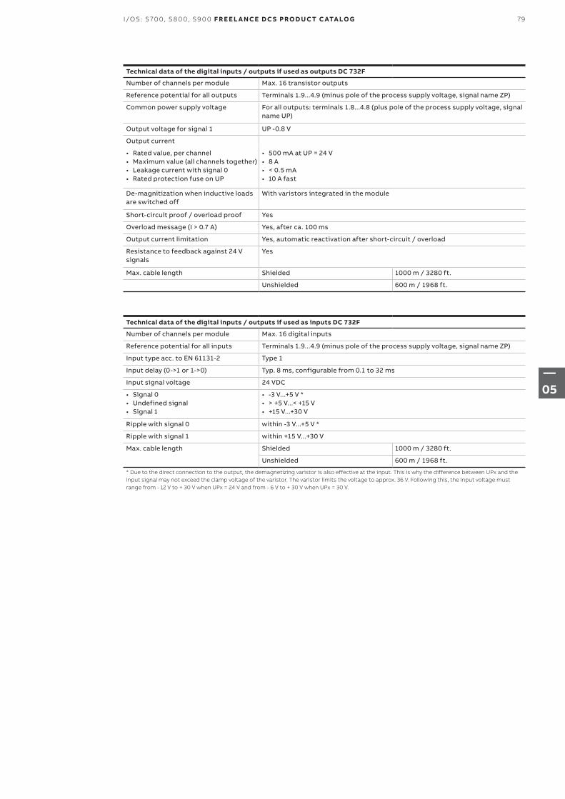
Technical data of the digital inputs / outputs if used as outputs DC 732F
Number of channels per module Max. 16 transistor outputs
Reference potential for all outputs Terminals 1.9...4.9 (minus pole of the process supply voltage, signal name ZP)
Common power supply voltage For all outputs: terminals 1.8...4.8 (plus pole of the process supply voltage, signal name UP)
Output voltage for signal 1 UP -0.8 V
Output current
• Rated value, per channel• Maximum value (all channels together)• Leakage current with signal 0• Rated protection fuse on UP
• 500 mA at UP = 24 V• 8 A• < 0.5 mA• 10 A fast
De-magnitization when inductive loads are switched off
With varistors integrated in the module
Short-circuit proof / overload proof Yes
Overload message (I > 0.7 A) Yes, after ca. 100 ms
Output current limitation Yes, automatic reactivation after short-circuit / overload
Resistance to feedback against 24 V signals
Yes
Max. cable length Shielded 1000 m / 3280 ft.
Unshielded 600 m / 1968 ft.
Technical data of the digital inputs / outputs if used as inputs DC 732F
Number of channels per module Max. 16 digital inputs
Reference potential for all inputs Terminals 1.9...4.9 (minus pole of the process supply voltage, signal name ZP)
Input type acc. to EN 61131-2 Type 1
Input delay (0->1 or 1->0) Typ. 8 ms, configurable from 0.1 to 32 ms
Input signal voltage 24 VDC
• Signal 0• Undefined signal• Signal 1
• -3 V...+5 V *• > +5 V...< +15 V• +15 V...+30 V
Ripple with signal 0 within -3 V...+5 V *
Ripple with signal 1 within +15 V...+30 V
Max. cable length Shielded 1000 m / 3280 ft.
Unshielded 600 m / 1968 ft.
* Due to the direct connection to the output, the demagnetizing varistor is also effective at the input. This is why the difference between UPx and the input signal may not exceed the clamp voltage of the varistor. The varistor limits the voltage to approx. 36 V. Following this, the input voltage must range from - 12 V to + 30 V when UPx = 24 V and from - 6 V to + 30 V when UPx = 30 V.
79I/OS: S 70 0, S 8 0 0, S9 0 0 F R E E L A N CE D C S PRO D U C T C ATA LO G
—05
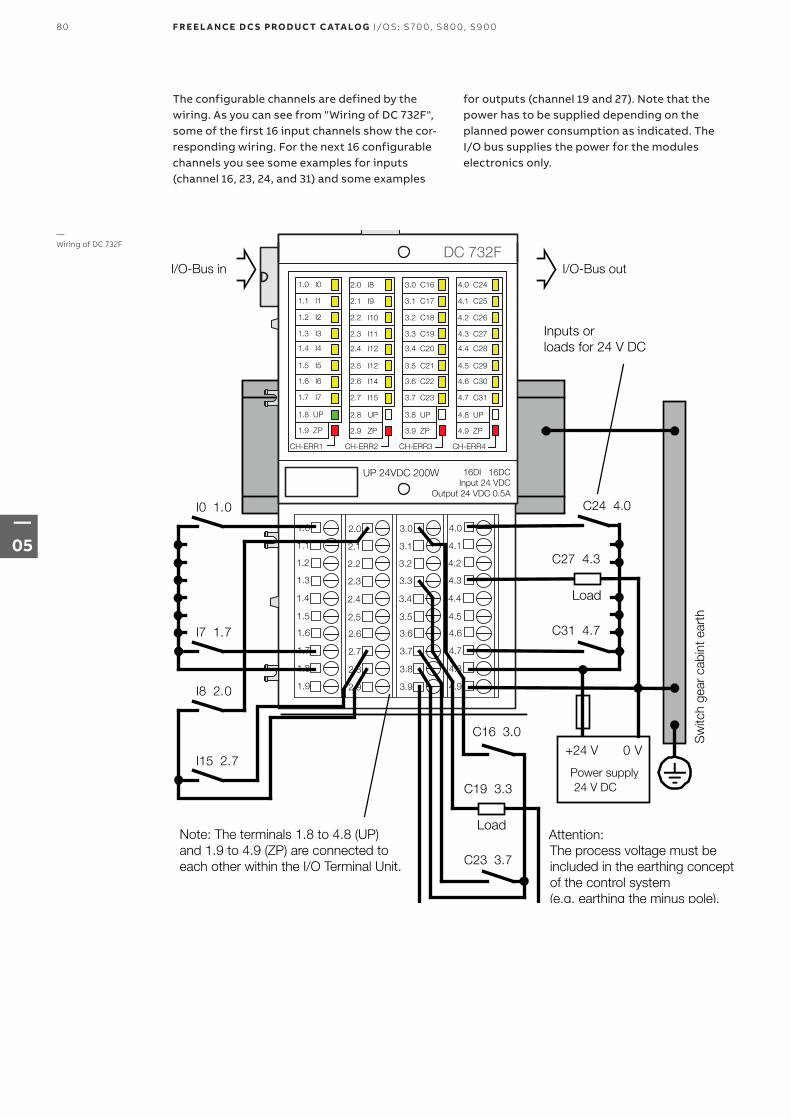
1.0
1.1
1.2
1.3
1.4
1.5
1.6
1.7
1.8
1.9
3.0
3.1
3.2
3.3
3.4
3.5
3.6
3.7
3.8
3.9
2.0
2.1
2.2
2.3
2.4
2.5
2.6
2.7
2.8
2.9
4.0
4.1
4.2
4.3
4.4
4.5
4.6
4.7
4.8
4.9
DC 732F
UP 24VDC 200W 16DI 16DCInput 24 VDC
Output 24 VDC 0.5A
CH-ERR1 CH-ERR2 CH-ERR3 CH-ERR4
1.0 I0
1.1 I1
1.2 I2
1.3 I3
1.4 I4
1.5 I5
1.6 I6
1.7 I7
1.8 UP
1.9 ZP
2.0 I8
2.1 I9
2.2 I10
2.3 I11
2.4 I12
2.5 I12
2.6 I14
2.7 I15
2.8 UP
2.9 ZP
3.0 C16
3.1 C17
3.2 C18
3.3 C19
3.4 C20
3.5 C21
3.6 C22
3.7 C23
3.8 UP
3.9 ZP
4.0 C24
4.1 C25
4.2 C26
4.3 C27
4.4 C28
4.5 C29
4.6 C30
4.7 C31
4.8 UP
4.9 ZP
I0 1.0
I7 1.7
C24 4.0
Sw
itch
gear
cab
int e
arth
Attention:
I/O-Bus in I/O-Bus out
Power supply
+24 V 0 V
I8 2.0
I15 2.7
C27 4.3
C31 4.7
C16 3.0
C19 3.3
C23 3.7
24 V DC
The process voltage must beincluded in the earthing conceptof the control system(e.g. earthing the minus pole).
Note: The terminals 1.8 to 4.8 (UP)and 1.9 to 4.9 (ZP) are connected toeach other within the I/O Terminal Unit.
Inputs orloads for 24 V DC
Load
Load
The configurable channels are defined by the wiring. As you can see from "Wiring of DC 732F", some of the first 16 input channels show the cor-responding wiring. For the next 16 configurable channels you see some examples for inputs (channel 16, 23, 24, and 31) and some examples
for outputs (channel 19 and 27). Note that the power has to be supplied depending on the planned power consumption as indicated. The I/O bus supplies the power for the modules electronics only.
—Wiring of DC 732F
80 F R E E L A N CE D C S PRO D U C T C ATA LO G I/OS: S 70 0, S 8 0 0, S9 0 0
—05
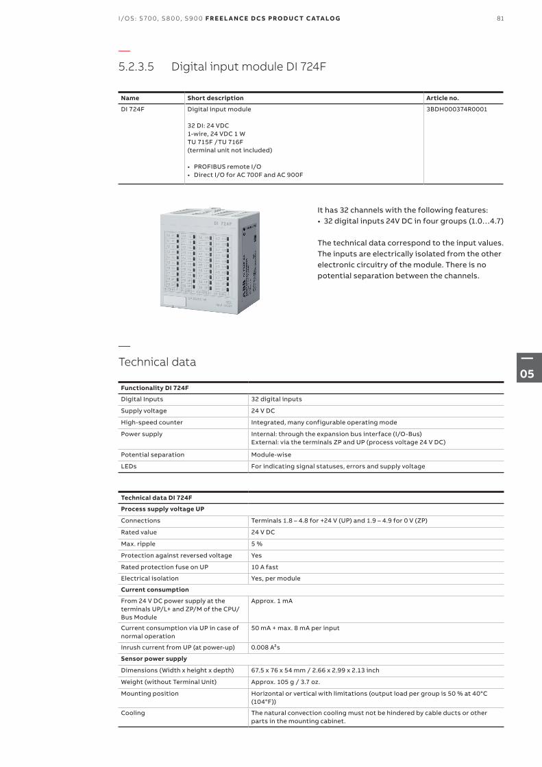
—5.2.3.5 Digital input module DI 724F
Name Short description Article no.
DI 724F Digital input module
32 DI: 24 VDC1-wire, 24 VDC 1 WTU 715F /TU 716F (terminal unit not included)
• PROFIBUS remote I/O• Direct I/O for AC 700F and AC 900F
3BDH000374R0001
It has 32 channels with the following features:• 32 digital inputs 24V DC in four groups (1.0…4.7)
The technical data correspond to the input values. The inputs are electrically isolated from the other electronic circuitry of the module. There is no potential separation between the channels.
—Technical data
Functionality DI 724F
Digital Inputs 32 digital inputs
Supply voltage 24 V DC
High-speed counter Integrated, many configurable operating mode
Power supply Internal: through the expansion bus interface (I/O-Bus)External: via the terminals ZP and UP (process voltage 24 V DC)
Potential separation Module-wise
LEDs For indicating signal statuses, errors and supply voltage
Technical data DI 724F
Process supply voltage UP
Connections Terminals 1.8 – 4.8 for +24 V (UP) and 1.9 – 4.9 for 0 V (ZP)
Rated value 24 V DC
Max. ripple 5 %
Protection against reversed voltage Yes
Rated protection fuse on UP 10 A fast
Electrical isolation Yes, per module
Current consumption
From 24 V DC power supply at the terminals UP/L+ and ZP/M of the CPU/Bus Module
Approx. 1 mA
Current consumption via UP in case of normal operation
50 mA + max. 8 mA per input
Inrush current from UP (at power-up) 0.008 A²s
Sensor power supply
Dimensions (Width x height x depth) 67.5 x 76 x 54 mm / 2.66 x 2.99 x 2.13 inch
Weight (without Terminal Unit) Approx. 105 g / 3.7 oz.
Mounting position Horizontal or vertical with limitations (output load per group is 50 % at 40°C (104°F))
Cooling The natural convection cooling must not be hindered by cable ducts or other parts in the mounting cabinet.
81I/OS: S 70 0, S 8 0 0, S9 0 0 F R E E L A N CE D C S PRO D U C T C ATA LO G
—05
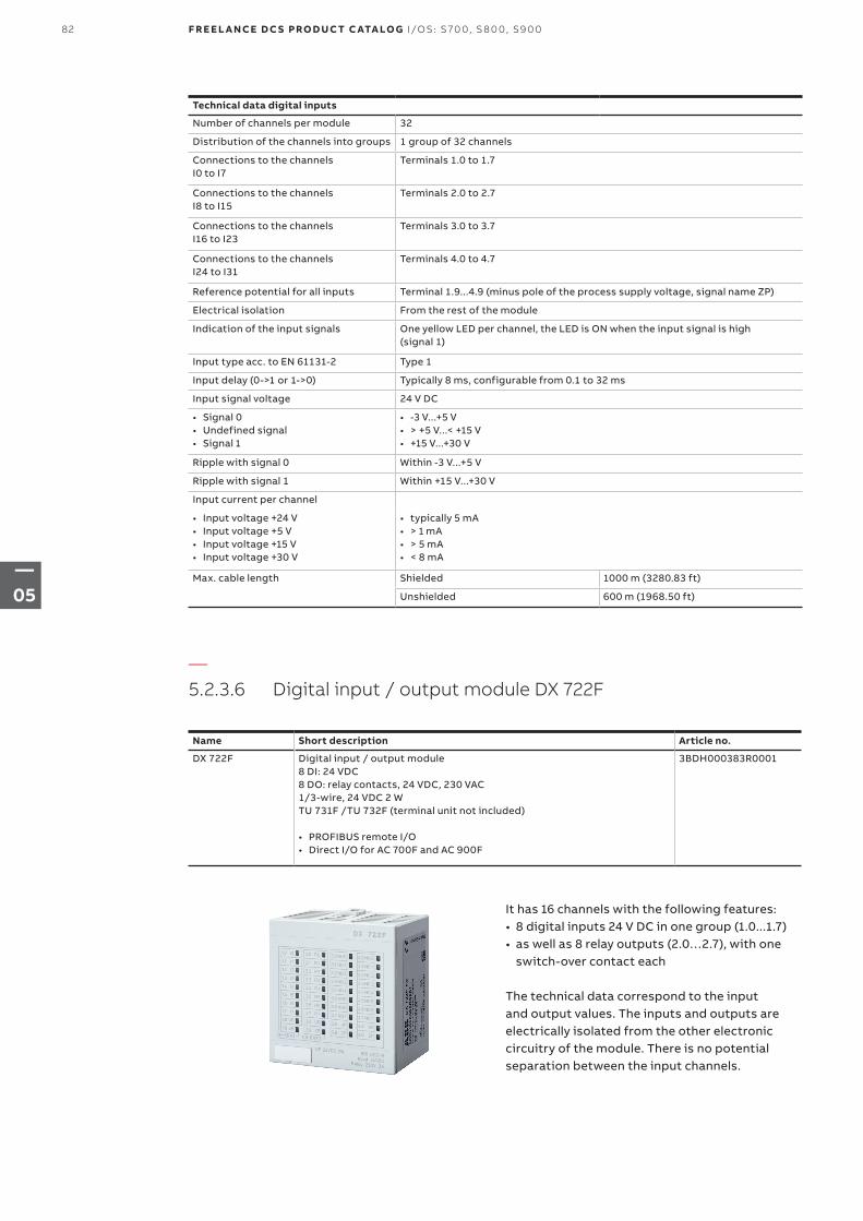
Technical data digital inputs
Number of channels per module 32
Distribution of the channels into groups 1 group of 32 channels
Connections to the channels I0 to I7
Terminals 1.0 to 1.7
Connections to the channels I8 to I15
Terminals 2.0 to 2.7
Connections to the channels I16 to I23
Terminals 3.0 to 3.7
Connections to the channels I24 to I31
Terminals 4.0 to 4.7
Reference potential for all inputs Terminal 1.9...4.9 (minus pole of the process supply voltage, signal name ZP)
Electrical isolation From the rest of the module
Indication of the input signals One yellow LED per channel, the LED is ON when the input signal is high (signal 1)
Input type acc. to EN 61131-2 Type 1
Input delay (0->1 or 1->0) Typically 8 ms, configurable from 0.1 to 32 ms
Input signal voltage 24 V DC
• Signal 0• Undefined signal • Signal 1
• -3 V...+5 V• > +5 V...< +15 V• +15 V...+30 V
Ripple with signal 0 Within -3 V...+5 V
Ripple with signal 1 Within +15 V...+30 V
Input current per channel
• Input voltage +24 V• Input voltage +5 V• Input voltage +15 V• Input voltage +30 V
• typically 5 mA• > 1 mA• > 5 mA• < 8 mA
Max. cable length Shielded 1000 m (3280.83 ft)
Unshielded 600 m (1968.50 ft)
—5.2.3.6 Digital input / output module DX 722F
Name Short description Article no.
DX 722F Digital input / output module 8 DI: 24 VDC8 DO: relay contacts, 24 VDC, 230 VAC1/3-wire, 24 VDC 2 WTU 731F /TU 732F (terminal unit not included)
• PROFIBUS remote I/O• Direct I/O for AC 700F and AC 900F
3BDH000383R0001
It has 16 channels with the following features:• 8 digital inputs 24 V DC in one group (1.0...1.7)• as well as 8 relay outputs (2.0…2.7), with one
switch-over contact each
The technical data correspond to the input and output values. The inputs and outputs are electrically isolated from the other electronic circuitry of the module. There is no potential separation between the input channels.
82 F R E E L A N CE D C S PRO D U C T C ATA LO G I/OS: S 70 0, S 8 0 0, S9 0 0
—05
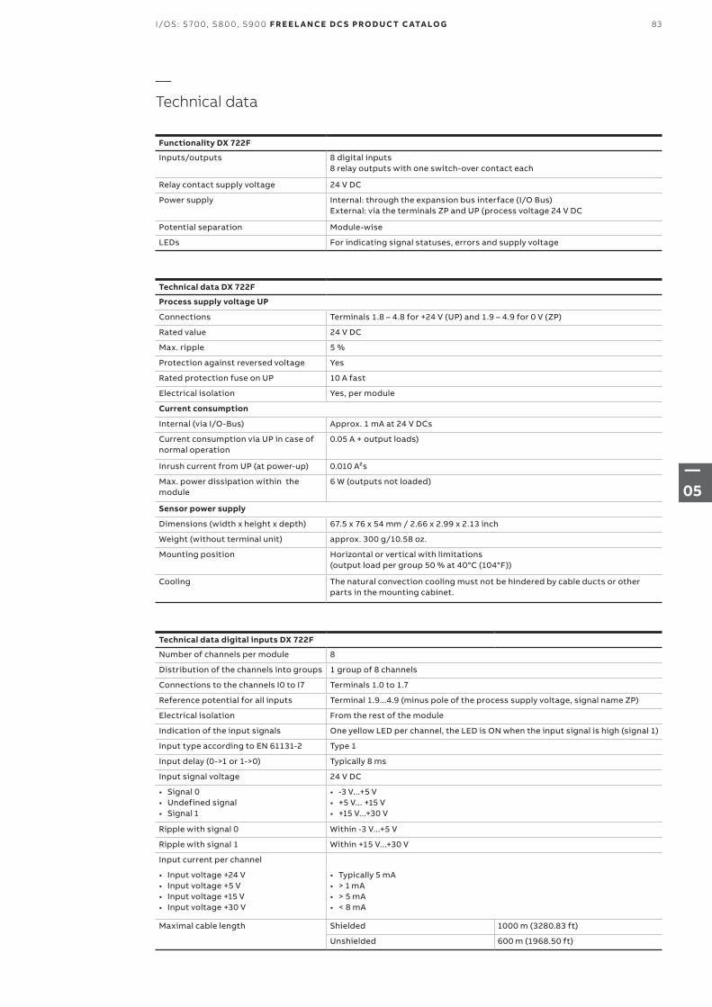
Technical data digital inputs DX 722F
Number of channels per module 8
Distribution of the channels into groups 1 group of 8 channels
Connections to the channels I0 to I7 Terminals 1.0 to 1.7
Reference potential for all inputs Terminal 1.9...4.9 (minus pole of the process supply voltage, signal name ZP)
Electrical isolation From the rest of the module
Indication of the input signals One yellow LED per channel, the LED is ON when the input signal is high (signal 1)
Input type according to EN 61131-2 Type 1
Input delay (0->1 or 1->0) Typically 8 ms
Input signal voltage 24 V DC
• Signal 0• Undefined signal • Signal 1
• -3 V...+5 V• +5 V... +15 V• +15 V...+30 V
Ripple with signal 0 Within -3 V...+5 V
Ripple with signal 1 Within +15 V...+30 V
Input current per channel
• Input voltage +24 V• Input voltage +5 V• Input voltage +15 V• Input voltage +30 V
• Typically 5 mA• > 1 mA• > 5 mA• < 8 mA
Maximal cable length Shielded 1000 m (3280.83 ft)
Unshielded 600 m (1968.50 ft)
Technical data DX 722F
Process supply voltage UP
Connections Terminals 1.8 – 4.8 for +24 V (UP) and 1.9 – 4.9 for 0 V (ZP)
Rated value 24 V DC
Max. ripple 5 %
Protection against reversed voltage Yes
Rated protection fuse on UP 10 A fast
Electrical isolation Yes, per module
Current consumption
Internal (via I/O-Bus) Approx. 1 mA at 24 V DCs
Current consumption via UP in case of normal operation
0.05 A + output loads)
Inrush current from UP (at power-up) 0.010 A²s
Max. power dissipation within the module
6 W (outputs not loaded)
Sensor power supply
Dimensions (width x height x depth) 67.5 x 76 x 54 mm / 2.66 x 2.99 x 2.13 inch
Weight (without terminal unit) approx. 300 g/10.58 oz.
Mounting position Horizontal or vertical with limitations (output load per group 50 % at 40°C (104°F))
Cooling The natural convection cooling must not be hindered by cable ducts or other parts in the mounting cabinet.
—Technical data
Functionality DX 722F
Inputs/outputs 8 digital inputs8 relay outputs with one switch-over contact each
Relay contact supply voltage 24 V DC
Power supply Internal: through the expansion bus interface (I/O Bus)External: via the terminals ZP and UP (process voltage 24 V DC
Potential separation Module-wise
LEDs For indicating signal statuses, errors and supply voltage
83I/OS: S 70 0, S 8 0 0, S9 0 0 F R E E L A N CE D C S PRO D U C T C ATA LO G
—05
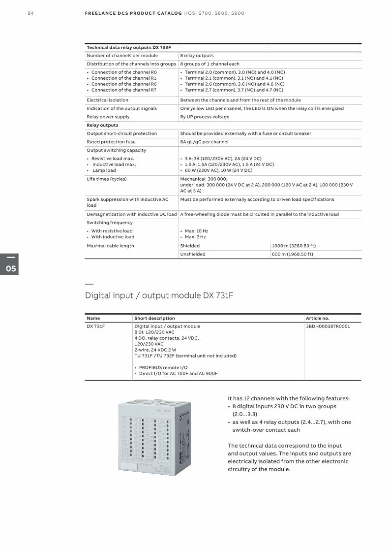
Technical data relay outputs DX 722F
Number of channels per module 8 relay outputs
Distribution of the channels into groups 8 groups of 1 channel each
• Connection of the channel R0• Connection of the channel R1• Connection of the channel R6• Connection of the channel R7
• Terminal 2.0 (common), 3.0 (NO) and 4.0 (NC)• Terminal 2.1 (common), 3.1 (NO) and 4.1 (NC)• Terminal 2.6 (common), 3.6 (NO) and 4.6 (NC)• Terminal 2.7 (common), 3.7 (NO) and 4.7 (NC)
Electrical isolation Between the channels and from the rest of the module
Indication of the output signals One yellow LED per channel, the LED is ON when the relay coil is energized
Relay power supply By UP process voltage
Relay outputs
Output short-circuit protection Should be provided externally with a fuse or circuit breaker
Rated protection fuse 6A gL/gG per channel
Output switching capacity
• Resistive load max.• Inductive load max.• Lamp load
• 3 A; 3A (120/230V AC), 2A (24 V DC)• 1.5 A; 1.5A (120/230V AC), 1.5 A (24 V DC)• 60 W (230V AC), 10 W (24 V DC)
Life times (cycles) Mechanical: 300 000;under load: 300 000 (24 V DC at 2 A), 200 000 (120 V AC at 2 A), 100 000 (230 V AC at 3 A)
Spark suppression with inductive AC load
Must be performed externally according to driven load specifications
Demagnetization with inductive DC load A free-wheeling diode must be circuited in parallel to the inductive load
Switching frequency
• With resistive load• With inductive load
• Max. 10 Hz• Max. 2 Hz
Maximal cable length Shielded 1000 m (3280.83 ft)
Unshielded 600 m (1968.50 ft)
Name Short description Article no.
DX 731F Digital input / output module8 DI: 120/230 VAC4 DO: relay contacts, 24 VDC, 120/230 VAC2-wire, 24 VDC 2 WTU 731F /TU 732F (terminal unit not included)
• PROFIBUS remote I/O• Direct I/O for AC 700F and AC 900F
3BDH000387R0001
It has 12 channels with the following features:• 8 digital inputs 230 V DC in two groups
(2.0...3.3)• as well as 4 relay outputs (2.4...2.7), with one
switch-over contact each
The technical data correspond to the input and output values. The inputs and outputs are electrically isolated from the other electronic circuitry of the module.
—Digital input / output module DX 731F
84 F R E E L A N CE D C S PRO D U C T C ATA LO G I/OS: S 70 0, S 8 0 0, S9 0 0
—05
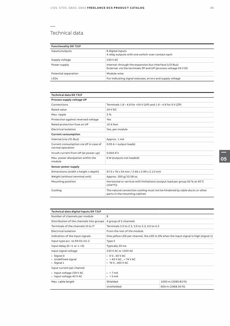
Technical data digital inputs DX 731F
Number of channels per module 8
Distribution of the channels into groups 4 group of 2 channels
Terminals of the channels I0 to I7 Terminals 2.0 to 2.3, 3.0 to 3.3, 4.0 to 4.3
Electrical isolation From the rest of the module
Indication of the input signals One yellow LED per channel, the LED is ON when the input signal is high (signal 1)
Input type acc. to EN 61131-2 Type 2
Input delay (0->1 or 1->0) Typically 20 ms
Input signal voltage 230 V AC or 120V AC
• Signal 0• Undefined signal • Signal 1
• 0 V...40 V AC• > 40 V AC...< 74 V AC• 74 V...265 V AC
Input current per channel
• Input voltage 159 V AC• Input voltage 40 V AC
• > 7 mA• < 5 mA
Max. cable length Shielded 1000 m (3280.83 ft)
Unshielded 600 m (1968.50 ft)
Technical data DX 731F
Process supply voltage UP
Connections Terminals 1.8 – 4.8 for +24 V (UP) and 1.9 – 4.9 for 0 V (ZP)
Rated value 24 V DC
Max. ripple 5 %
Protection against reversed voltage Yes
Rated protection fuse on UP 10 A fast
Electrical isolation Yes, per module
Current consumption
Internal (via I/O-Bus) Approx. 1 mA
Current consumption via UP in case of normal operation
0.05 A + output loads)
Inrush current from UP (at power-up) 0.004 A²s
Max. power dissipation within the module
6 W (outputs not loaded)
Sensor power supply
Dimensions (width x height x depth) 67.5 x 76 x 54 mm / 2.66 x 2.99 x 2.13 inch
Weight (without terminal unit) Approx. 300 g/10.58 oz.
Mounting position Horizontal or vertical with limitations (output load per group 50 % at 40°C (104°F))
Cooling The natural convection cooling must not be hindered by cable ducts or other parts in the mounting cabinet.
—Technical data
Functionality DX 731F
Inputs/outputs 8 digital inputs4 relay outputs with one switch-over contact each
Supply voltage 230 V AC
Power supply Internal: through the expansion bus interface (I/O Bus)External: via the terminals ZP and UP (process voltage 24 V DC
Potential separation Module-wise
LEDs For indicating signal statuses, errors and supply voltage
85I/OS: S 70 0, S 8 0 0, S9 0 0 F R E E L A N CE D C S PRO D U C T C ATA LO G
—05
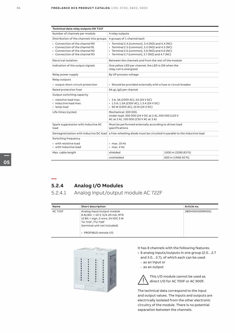
It has 8 channels with the following features:• 8 analog inputs/outputs in one group (2.0…2.7
and 3.0…3.7), of which each can be used - as an input or - as an output
This I/O module cannot be used as direct I/O for AC 700F or AC 900F.
The technical data correspond to the input and output values. The inputs and outputs are electrically isolated from the other electronic circuitry of the module. There is no potential separation between the channels.
—5.2.4 Analog I/O Modules5.2.4.1 Analog input/output module AC 722F
Name Short description Article no.
AC 722F Analog input/output module8 AI/AO: +-10 V, 0/4-20 mA, RTD12 Bit + sign, 2-wire, 24 VDC 5 WTU 715F /TU 716F (terminal unit not included)
• PROFIBUS remote I/O
3BDH000369R0001
Technical data relay outputs DX 731F
Number of channels per module 4 relay outputs
Distribution of the channels into groups 4 groups of 1 channel each
• Connection of the channel R0• Connection of the channel R1• Connection of the channel R2• Connection of the channel R3
• Terminal 2.4 (common), 3.4 (NO) and 4.4 (NC)• Terminal 2.5 (common), 3.5 (NO) and 4.5 (NC)• Terminal 2.6 (common), 3.6 (NO) and 4.6 (NC)• Terminal 2.7 (common), 3.7 (NO) and 4.7 (NC)
Electrical isolation Between the channels and from the rest of the module
Indication of the output signals One yellow LED per channel, the LED is ON when therelay coil is energized
Relay power supply By UP process voltage
Relay outputs
• output short-circuit protection • Should be provided externally with a fuse or circuit breaker
Rated protection fuse 6A gL/gG per channel
Output switching capacity
• resistive load max.• inductive load max.• lamp load
• 3 A; 3A (230V AC), 2A (24 V DC)• 1.5 A; 1.5A (230V AC), 1.5 A (24 V DC)• 60 W (230V AC), 10 W (24 V DC)
Life times (cycles) Mechanical: 300 000;Under load: 300 000 (24 V DC at 2 A), 200 000 (120 VAC at 2 A), 100 000 (230 V AC at 3 A)
Spark suppression with inductive AC load
Must be performed externally according to driven loadspecifications
Demagnetization with inductive DC load a free-wheeling diode must be circuited in parallel to the inductive load
Switching frequency
• with resistive load• with inductive load
• max. 10 Hz• max. 2 Hz
Max. cable length shielded 1000 m (3280.83 ft)
unshielded 600 m (1968.50 ft)
86 F R E E L A N CE D C S PRO D U C T C ATA LO G I/OS: S 70 0, S 8 0 0, S9 0 0
—05
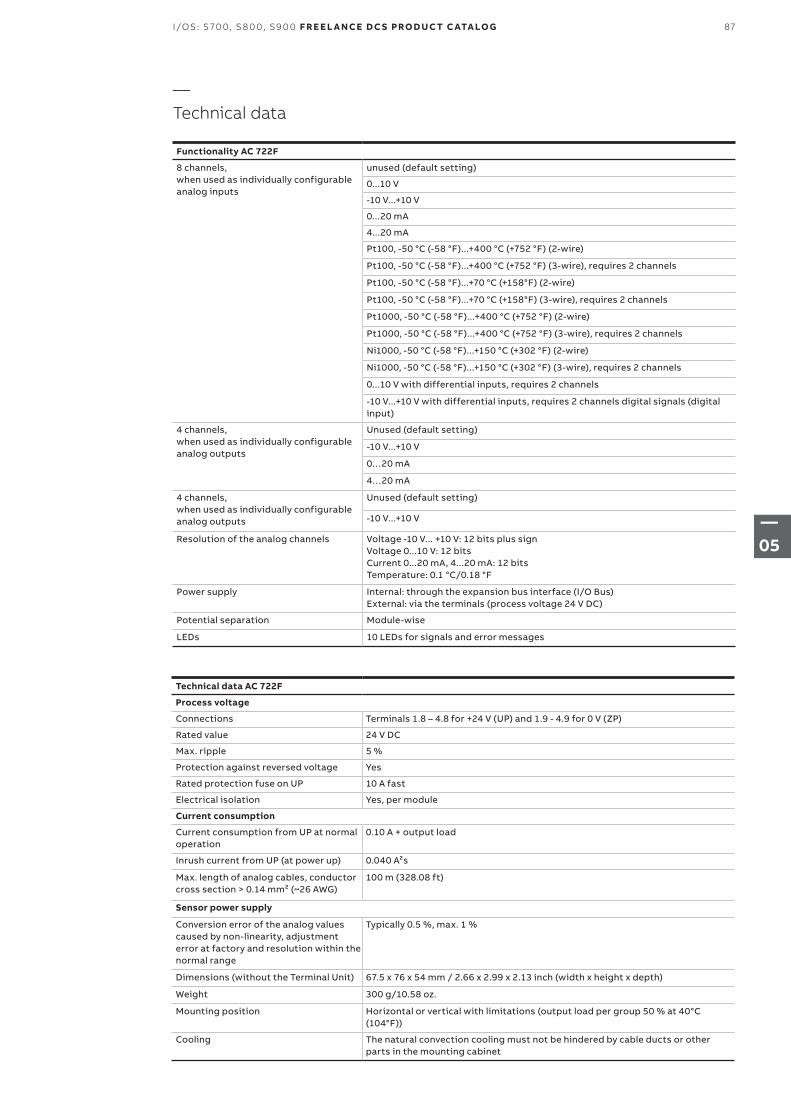
—Technical data
Functionality AC 722F
8 channels, when used as individually configurable analog inputs
unused (default setting)
0...10 V
-10 V...+10 V
0...20 mA
4...20 mA
Pt100, -50 °C (-58 °F)...+400 °C (+752 °F) (2-wire)
Pt100, -50 °C (-58 °F)...+400 °C (+752 °F) (3-wire), requires 2 channels
Pt100, -50 °C (-58 °F)...+70 °C (+158°F) (2-wire)
Pt100, -50 °C (-58 °F)...+70 °C (+158°F) (3-wire), requires 2 channels
Pt1000, -50 °C (-58 °F)...+400 °C (+752 °F) (2-wire)
Pt1000, -50 °C (-58 °F)...+400 °C (+752 °F) (3-wire), requires 2 channels
Ni1000, -50 °C (-58 °F)...+150 °C (+302 °F) (2-wire)
Ni1000, -50 °C (-58 °F)...+150 °C (+302 °F) (3-wire), requires 2 channels
0...10 V with differential inputs, requires 2 channels
-10 V...+10 V with differential inputs, requires 2 channels digital signals (digital input)
4 channels, when used as individually configurable analog outputs
Unused (default setting)
-10 V...+10 V
0…20 mA
4…20 mA
4 channels, when used as individually configurable analog outputs
Unused (default setting)
-10 V...+10 V
Resolution of the analog channels Voltage -10 V... +10 V: 12 bits plus sign Voltage 0...10 V: 12 bitsCurrent 0...20 mA, 4...20 mA: 12 bitsTemperature: 0.1 °C/0.18 °F
Power supply Internal: through the expansion bus interface (I/O Bus)External: via the terminals (process voltage 24 V DC)
Potential separation Module-wise
LEDs 10 LEDs for signals and error messages
Technical data AC 722F
Process voltage
Connections Terminals 1.8 – 4.8 for +24 V (UP) and 1.9 - 4.9 for 0 V (ZP)
Rated value 24 V DC
Max. ripple 5 %
Protection against reversed voltage Yes
Rated protection fuse on UP 10 A fast
Electrical isolation Yes, per module
Current consumption
Current consumption from UP at normal operation
0.10 A + output load
Inrush current from UP (at power up) 0.040 A²s
Max. length of analog cables, conductor cross section > 0.14 mm² (~26 AWG)
100 m (328.08 ft)
Sensor power supply
Conversion error of the analog values caused by non-linearity, adjustment error at factory and resolution within the normal range
Typically 0.5 %, max. 1 %
Dimensions (without the Terminal Unit) 67.5 x 76 x 54 mm / 2.66 x 2.99 x 2.13 inch (width x height x depth)
Weight 300 g/10.58 oz.
Mounting position Horizontal or vertical with limitations (output load per group 50 % at 40°C (104°F))
Cooling The natural convection cooling must not be hindered by cable ducts or other parts in the mounting cabinet
87I/OS: S 70 0, S 8 0 0, S9 0 0 F R E E L A N CE D C S PRO D U C T C ATA LO G
—05
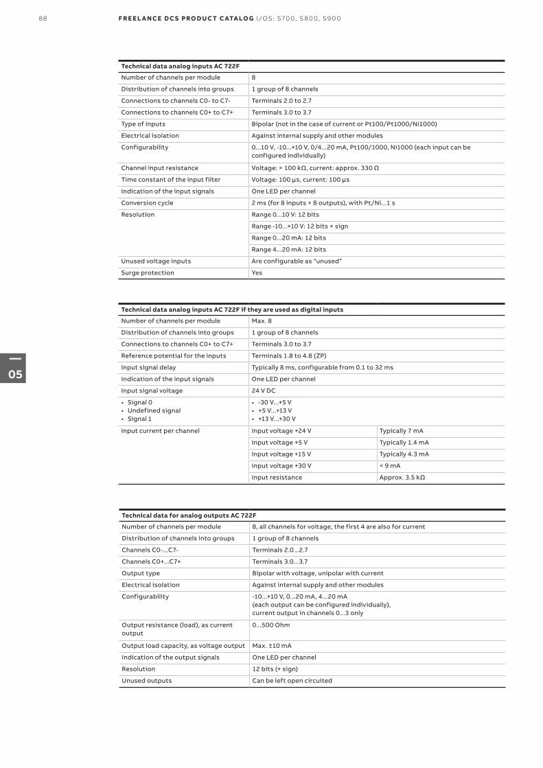
Technical data analog inputs AC 722F
Number of channels per module 8
Distribution of channels into groups 1 group of 8 channels
Connections to channels C0- to C7- Terminals 2.0 to 2.7
Connections to channels C0+ to C7+ Terminals 3.0 to 3.7
Type of Inputs Bipolar (not in the case of current or Pt100/Pt1000/Ni1000)
Electrical isolation Against internal supply and other modules
Configurability 0...10 V, -10...+10 V, 0/4...20 mA, Pt100/1000, Ni1000 (each input can be configured individually)
Channel input resistance Voltage: > 100 kΩ, current: approx. 330 Ω
Time constant of the input filter Voltage: 100 µs, current: 100 µs
Indication of the input signals One LED per channel
Conversion cycle 2 ms (for 8 inputs + 8 outputs), with Pt/Ni...1 s
Resolution Range 0...10 V: 12 bits
Range -10...+10 V: 12 bits + sign
Range 0...20 mA: 12 bits
Range 4...20 mA: 12 bits
Unused voltage inputs Are configurable as “unused”
Surge protection Yes
Technical data analog inputs AC 722F if they are used as digital inputs
Number of channels per module Max. 8
Distribution of channels into groups 1 group of 8 channels
Connections to channels C0+ to C7+ Terminals 3.0 to 3.7
Reference potential for the inputs Terminals 1.8 to 4.8 (ZP)
Input signal delay Typically 8 ms, configurable from 0.1 to 32 ms
Indication of the input signals One LED per channel
Input signal voltage 24 V DC
• Signal 0• Undefined signal• Signal 1
• -30 V...+5 V• +5 V...+13 V• +13 V...+30 V
Input current per channel Input voltage +24 V Typically 7 mA
Input voltage +5 V Typically 1.4 mA
Input voltage +15 V Typically 4.3 mA
Input voltage +30 V < 9 mA
Input resistance Approx. 3.5 kΩ
Technical data for analog outputs AC 722F
Number of channels per module 8, all channels for voltage, the first 4 are also for current
Distribution of channels into groups 1 group of 8 channels
Channels C0-...C7- Terminals 2.0...2.7
Channels C0+...C7+ Terminals 3.0...3.7
Output type Bipolar with voltage, unipolar with current
Electrical isolation Against internal supply and other modules
Configurability -10...+10 V, 0...20 mA, 4...20 mA (each output can be configured individually), current output in channels 0...3 only
Output resistance (load), as current output
0...500 Ohm
Output load capacity, as voltage output Max. ±10 mA
Indication of the output signals One LED per channel
Resolution 12 bits (+ sign)
Unused outputs Can be left open circuited
88 F R E E L A N CE D C S PRO D U C T C ATA LO G I/OS: S 70 0, S 8 0 0, S9 0 0
—05
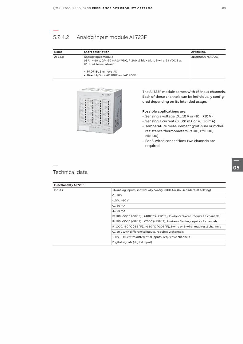
—5.2.4.2 Analog input module AI 723F
Name Short description Article no.
AI 723F Analog input module16 AI: +-10 V, 0/4-20 mA 24 VDC, Pt100 12 bit + Sign, 2-wire, 24 VDC 5 W. Without terminal unit.
• PROFIBUS remote I/O• Direct I/O for AC 700F and AC 900F
3BDH000376R0001
The AI 723F module comes with 16 input channels. Each of these channels can be individually config-ured depending on its intended usage.
Possible applications are:• Sensing a voltage (0…10 V or -10…+10 V)• Sensing a current (0…20 mA or 4…20 mA)• Temperature measurement (platinum or nickel
resistance thermometers Pt100, Pt1000, Ni1000)
• For 3-wired connections two channels are required
—Technical data
Functionality AI 723F
Inputs 16 analog inputs, individually configurable for Unused (default setting)
0...10 V
-10 V...+10 V
0...20 mA
4...20 mA
Pt100, -50 °C (-58 °F)...+400 °C (+752 °F), 2-wire or 3-wire, requires 2 channels
Pt100, -50 °C (-58 °F)...+70 °C (+158 °F), 2-wire or 3-wire, requires 2 channels
Ni1000, -50 °C (-58 °F)...+150 °C (+302 °F), 2-wire or 3-wire, requires 2 channels
0...10 V with differential inputs, requires 2 channels
-10 V...+10 V with differential inputs, requires 2 channels
Digital signals (digital input)
89I/OS: S 70 0, S 8 0 0, S9 0 0 F R E E L A N CE D C S PRO D U C T C ATA LO G
—05
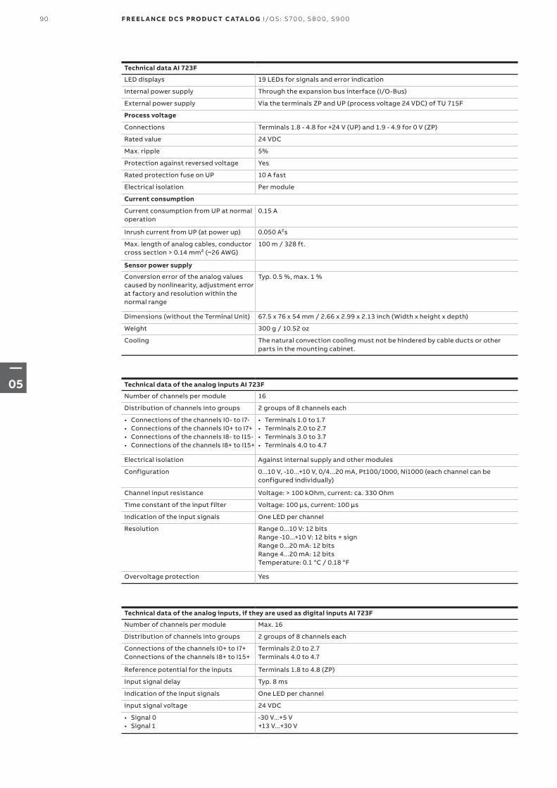
Technical data of the analog inputs AI 723F
Number of channels per module 16
Distribution of channels into groups 2 groups of 8 channels each
• Connections of the channels I0- to I7-• Connections of the channels I0+ to I7+• Connections of the channels I8- to I15-• Connections of the channels I8+ to I15+
• Terminals 1.0 to 1.7• Terminals 2.0 to 2.7• Terminals 3.0 to 3.7• Terminals 4.0 to 4.7
Electrical isolation Against internal supply and other modules
Configuration 0...10 V, -10...+10 V, 0/4...20 mA, Pt100/1000, Ni1000 (each channel can be configured individually)
Channel input resistance Voltage: > 100 kOhm, current: ca. 330 Ohm
Time constant of the input filter Voltage: 100 μs, current: 100 μs
Indication of the input signals One LED per channel
Resolution Range 0...10 V: 12 bitsRange -10...+10 V: 12 bits + signRange 0...20 mA: 12 bitsRange 4...20 mA: 12 bitsTemperature: 0.1 °C / 0.18 °F
Overvoltage protection Yes
Technical data of the analog inputs, if they are used as digital inputs AI 723F
Number of channels per module Max. 16
Distribution of channels into groups 2 groups of 8 channels each
Connections of the channels I0+ to I7+ Connections of the channels I8+ to I15+
Terminals 2.0 to 2.7 Terminals 4.0 to 4.7
Reference potential for the inputs Terminals 1.8 to 4.8 (ZP)
Input signal delay Typ. 8 ms
Indication of the input signals One LED per channel
Input signal voltage 24 VDC
• Signal 0• Signal 1
-30 V...+5 V+13 V...+30 V
Technical data AI 723F
LED displays 19 LEDs for signals and error indication
Internal power supply Through the expansion bus interface (I/O-Bus)
External power supply Via the terminals ZP and UP (process voltage 24 VDC) of TU 715F
Process voltage
Connections Terminals 1.8 - 4.8 for +24 V (UP) and 1.9 - 4.9 for 0 V (ZP)
Rated value 24 VDC
Max. ripple 5%
Protection against reversed voltage Yes
Rated protection fuse on UP 10 A fast
Electrical isolation Per module
Current consumption
Current consumption from UP at normal operation
0.15 A
Inrush current from UP (at power up) 0.050 A²s
Max. length of analog cables, conductor cross section > 0.14 mm² (~26 AWG)
100 m / 328 ft.
Sensor power supply
Conversion error of the analog values caused by nonlinearity, adjustment error at factory and resolution within the normal range
Typ. 0.5 %, max. 1 %
Dimensions (without the Terminal Unit) 67.5 x 76 x 54 mm / 2.66 x 2.99 x 2.13 inch (Width x height x depth)
Weight 300 g / 10.52 oz
Cooling The natural convection cooling must not be hindered by cable ducts or other parts in the mounting cabinet.
90 F R E E L A N CE D C S PRO D U C T C ATA LO G I/OS: S 70 0, S 8 0 0, S9 0 0
—05
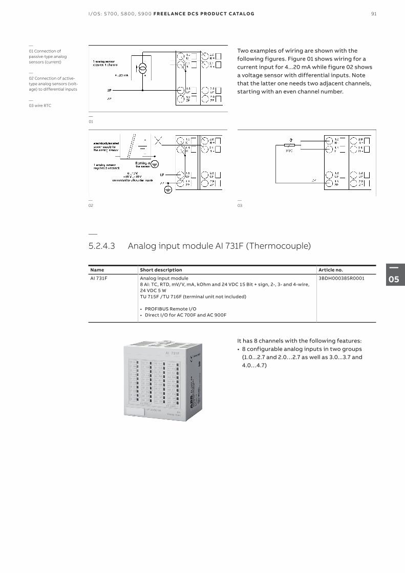
Two examples of wiring are shown with the following figures. Figure 01 shows wiring for a current input for 4...20 mA while figure 02 shows a voltage sensor with differential inputs. Note that the latter one needs two adjacent channels, starting with an even channel number.
—01 Connection of passive-type analog sensors (current)
—02 Connection of active-type analog sensors (volt-age) to differential inputs
—03 wire RTC
—01
—02
—03
—5.2.4.3 Analog input module AI 731F (Thermocouple)
Name Short description Article no.
AI 731F Analog input module8 AI: TC, RTD, mV/V, mA, kOhm and 24 VDC 15 Bit + sign, 2-, 3- and 4-wire, 24 VDC 5 WTU 715F /TU 716F (terminal unit not included)
• PROFIBUS Remote I/O• Direct I/O for AC 700F and AC 900F
3BDH000385R0001
It has 8 channels with the following features:• 8 configurable analog inputs in two groups
(1.0...2.7 and 2.0…2.7 as well as 3.0...3.7 and 4.0…4.7)
91I/OS: S 70 0, S 8 0 0, S9 0 0 F R E E L A N CE D C S PRO D U C T C ATA LO G
—05
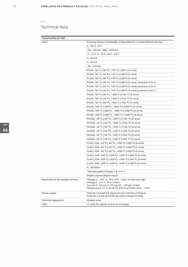
—Technical data
Functionality AI 731F
Input 8 analog inputs, individually configurable for: unused (default setting)
0…5V, 0...10 V
-50…+50 mV, -500…+500 mV
-1…+1 V, -5…+5 V, -10 V...+10 V
0...20 mA
4...20 mA
-20…+20 mA
Pt100, -50 °C (-58 °F)...+70 °C (+158°F) (2-wire)
Pt100, -50 °C (-58 °F)...+70 °C (+158°F) (3-wire)
Pt100, -50 °C (-58 °F)...+70 °C (+158°F) (4-wire)
Pt100, -50 °C (-58 °F)...+70 °C (+158°F) (2-wire), resolution 0.01 K
Pt100, -50 °C (-58 °F)...+70 °C (+158°F) (3-wire),resolution 0.01 K
Pt100, -50 °C (-58 °F)...+70 °C (+158°F) (4-wire),resolution 0.01 K
Pt100, -50 °C (-58 °F)...+400 °C (+752 °F) (2-wire)
Pt100, -50 °C (-58 °F)...+400 °C (+752 °F) (3-wire)
Pt100, -50 °C (-58 °F)...+400 °C (+752 °F) (4-wire)
Pt100, -200 °C (-328°F)...+850 °C (+1562°F) (2-wire)
Pt100, -200 °C (-328°F)... +850 °C (+1562°F) (3-wire)
Pt100, -200 °C (-328°F)... +850 °C (+1562°F) (4-wire)
Pt1000, -50 °C (-58 °F)...+400 °C (+752 °F) (2-wire)
Pt1000, -50 °C (-58 °F)...+400 °C (+752 °F) (3-wire)
Pt1000, -50 °C (-58 °F)...+400 °C (+752 °F) (4-wire)
Ni1000, -50 °C (-58 °F)...+150 °C (+302 °F) (2-wire)
Ni1000, -50 °C (-58 °F)...+150 °C (+302 °F) (3-wire)
Ni1000, -50 °C (-58 °F)...+150 °C (+302 °F) (4-wire)
Cu50 1.426, -50 °C (-58 °F)...+200 °C (+392°F) (2-wire)
Cu50 1.426, -50 °C (-58 °F)...+200 °C (+392°F) (3-wire)
Cu50 1.426, -50 °C (-58 °F)...+200 °C (+392°F) (4-wire)
Cu50 1.428, -200 °C (-328°F)...+200 °C (+392°F) (2-wire)
Cu50 1.428, -200 °C (-328°F)...+200 °C (+392°F) (3-wire)
Cu50 1.428, -200 °C (-328°F)...+200 °C (+392°F) (4-wire)
0…50 kOhm
Thermocouples of types J, K, T, N, S
Digital signals (digital input)
Resolution of the analog channels Voltage -1…+1V, -5…+5V,-10 V... +10 V: 15 bits plus signVoltage 0…5 V, 0...10 V: 15 bitsCurrent 0...20 mA, 4...20 mA,-20…+20 mA: 15 bitsTemperature: 0.1 °C (0.18 °F), 0.01°C at Pt100 -50°C…+70°C
Power supply Internal: through the expansion bus interface (I/O Bus)External: via the terminals (process voltage 24 V DC)
Potential separation Module-wise
LEDs 11 LEDs for signals and error messages
92 F R E E L A N CE D C S PRO D U C T C ATA LO G I/OS: S 70 0, S 8 0 0, S9 0 0
—05
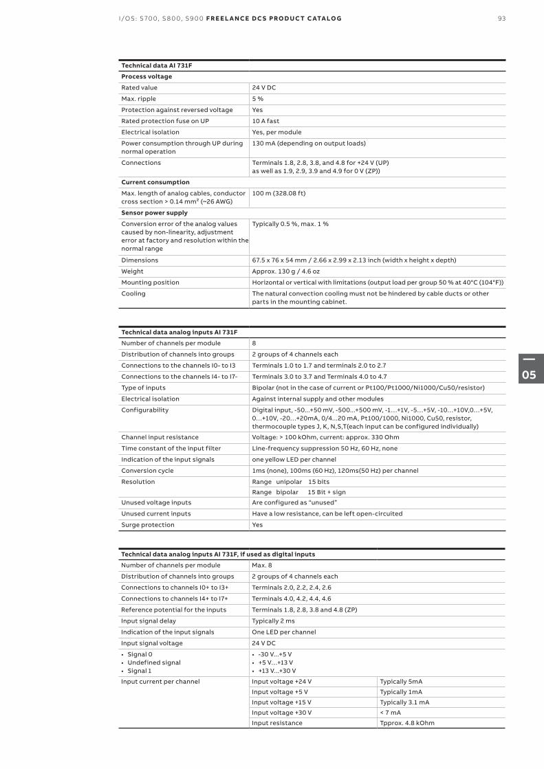
Technical data AI 731F
Process voltage
Rated value 24 V DC
Max. ripple 5 %
Protection against reversed voltage Yes
Rated protection fuse on UP 10 A fast
Electrical isolation Yes, per module
Power consumption through UP during normal operation
130 mA (depending on output loads)
Connections Terminals 1.8, 2.8, 3.8, and 4.8 for +24 V (UP) as well as 1.9, 2.9, 3.9 and 4.9 for 0 V (ZP))
Current consumption
Max. length of analog cables, conductor cross section > 0.14 mm² (~26 AWG)
100 m (328.08 ft)
Sensor power supply
Conversion error of the analog values caused by non-linearity, adjustment error at factory and resolution within the normal range
Typically 0.5 %, max. 1 %
Dimensions 67.5 x 76 x 54 mm / 2.66 x 2.99 x 2.13 inch (width x height x depth)
Weight Approx. 130 g / 4.6 oz
Mounting position Horizontal or vertical with limitations (output load per group 50 % at 40°C (104°F))
Cooling The natural convection cooling must not be hindered by cable ducts or other parts in the mounting cabinet.
Technical data analog inputs AI 731F
Number of channels per module 8
Distribution of channels into groups 2 groups of 4 channels each
Connections to the channels I0- to I3 Terminals 1.0 to 1.7 and terminals 2.0 to 2.7
Connections to the channels I4- to I7- Terminals 3.0 to 3.7 and Terminals 4.0 to 4.7
Type of inputs Bipolar (not in the case of current or Pt100/Pt1000/Ni1000/Cu50/resistor)
Electrical isolation Against internal supply and other modules
Configurability Digital input, -50...+50 mV, -500...+500 mV, -1…+1V, -5…+5V, -10…+10V,0…+5V, 0…+10V, -20…+20mA, 0/4...20 mA, Pt100/1000, Ni1000, Cu50, resistor, thermocouple types J, K, N,S,T(each input can be configured individually)
Channel input resistance Voltage: > 100 kOhm, current: approx. 330 Ohm
Time constant of the input filter Line-frequency suppression 50 Hz, 60 Hz, none
Indication of the input signals one yellow LED per channel
Conversion cycle 1ms (none), 100ms (60 Hz), 120ms(50 Hz) per channel
Resolution Range unipolar 15 bits
Range bipolar 15 Bit + sign
Unused voltage inputs Are configured as “unused”
Unused current inputs Have a low resistance, can be left open-circuited
Surge protection Yes
Technical data analog inputs AI 731F, if used as digital inputs
Number of channels per module Max. 8
Distribution of channels into groups 2 groups of 4 channels each
Connections to channels I0+ to I3+ Terminals 2.0, 2.2, 2.4, 2.6
Connections to channels I4+ to I7+ Terminals 4.0, 4.2, 4.4, 4.6
Reference potential for the inputs Terminals 1.8, 2.8, 3.8 and 4.8 (ZP)
Input signal delay Typically 2 ms
Indication of the input signals One LED per channel
Input signal voltage 24 V DC
• Signal 0• Undefined signal• Signal 1
• -30 V...+5 V• +5 V…+13 V• +13 V...+30 V
Input current per channel Input voltage +24 V Typically 5mA
Input voltage +5 V Typically 1mA
Input voltage +15 V Typically 3.1 mA
Input voltage +30 V < 7 mA
Input resistance Tpprox. 4.8 kOhm
93I/OS: S 70 0, S 8 0 0, S9 0 0 F R E E L A N CE D C S PRO D U C T C ATA LO G
—05
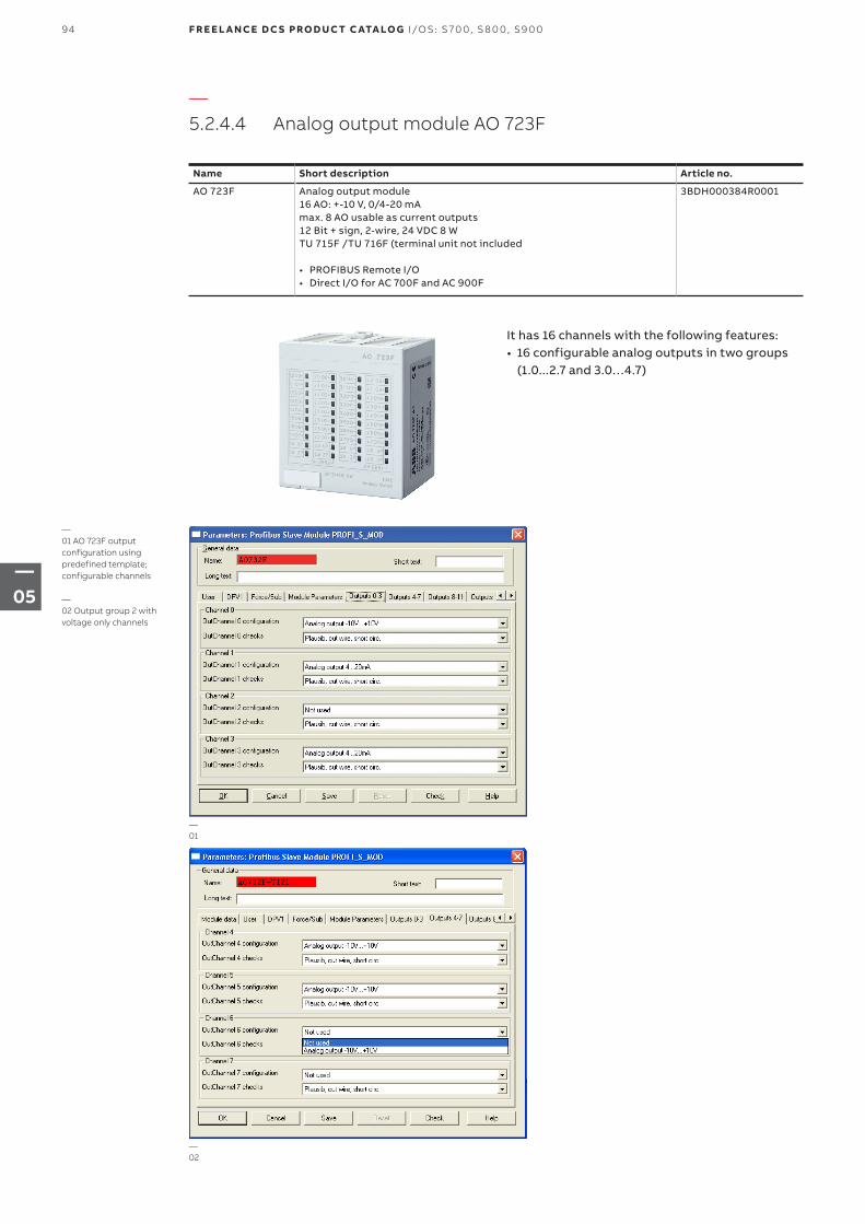
—5.2.4.4 Analog output module AO 723F
Name Short description Article no.
AO 723F Analog output module16 AO: +-10 V, 0/4-20 mAmax. 8 AO usable as current outputs12 Bit + sign, 2-wire, 24 VDC 8 WTU 715F /TU 716F (terminal unit not included
• PROFIBUS Remote I/O• Direct I/O for AC 700F and AC 900F
3BDH000384R0001
It has 16 channels with the following features:• 16 configurable analog outputs in two groups
(1.0...2.7 and 3.0…4.7)
—01 AO 723F output configuration using predefined template; configurable channels
—02 Output group 2 with voltage only channels
—01
—02
94 F R E E L A N CE D C S PRO D U C T C ATA LO G I/OS: S 70 0, S 8 0 0, S9 0 0
—05
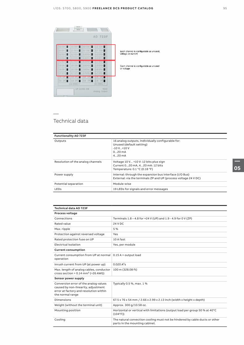
—Technical data
Functionality AO 723F
Outputs 16 analog outputs, individually configurable for:Unused (default setting)-10 V...+10 V0...20 mA4...20 mA
Resolution of the analog channels Voltage 10 V... +10 V: 12 bits plus signCurrent 0...20 mA, 4...20 mA: 12 bitsTemperature: 0.1 °C (0.18 °F)
Power supply Internal: through the expansion bus interface (I/O Bus)External: via the terminals ZP and UP (process voltage 24 V DC)
Potential separation Module-wise
LEDs 19 LEDs for signals and error messages
Technical data AO 723F
Process voltage
Connections Terminals 1.8 – 4.8 for +24 V (UP) and 1.9 - 4.9 for 0 V (ZP)
Rated value 24 V DC
Max. ripple 5 %
Protection against reversed voltage Yes
Rated protection fuse on UP 10 A fast
Electrical isolation Yes, per module
Current consumption
Current consumption from UP at normal operation
0.15 A + output load
Inrush current from UP (at power up) 0.020 A²s
Max. length of analog cables, conductor cross section > 0.14 mm² (~26 AWG)
100 m (328.08 ft)
Sensor power supply
Conversion error of the analog values caused by non-linearity, adjustment error at factory and resolution within the normal range
Typically 0.5 %, max. 1 %
Dimensions 67.5 x 76 x 54 mm / 2.66 x 2.99 x 2.13 inch (width x height x depth)
Weight (without the terminal unit) Approx. 300 g/10.58 oz.
Mounting position Horizontal or vertical with limitations (output load per group 50 % at 40°C (104°F))
Cooling The natural convection cooling must not be hindered by cable ducts or other parts in the mounting cabinet.
95I/OS: S 70 0, S 8 0 0, S9 0 0 F R E E L A N CE D C S PRO D U C T C ATA LO G
—05
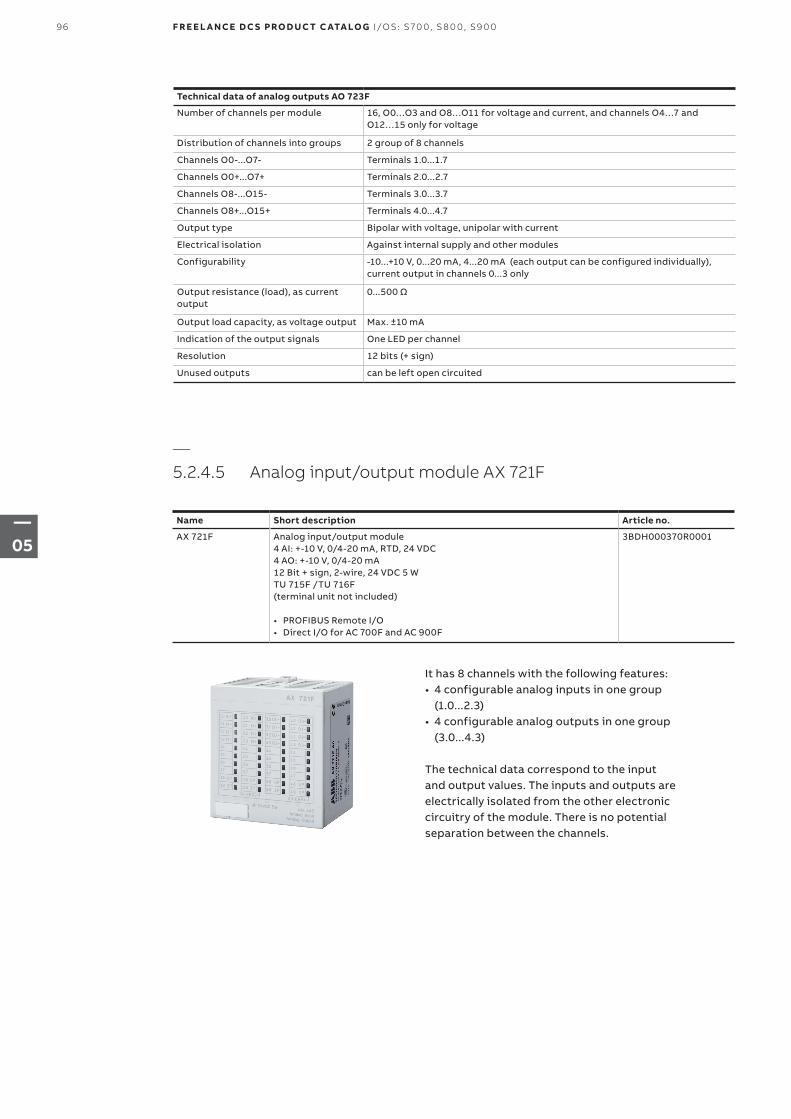
Technical data of analog outputs AO 723F
Number of channels per module 16, O0…O3 and O8…O11 for voltage and current, and channels O4…7 and O12…15 only for voltage
Distribution of channels into groups 2 group of 8 channels
Channels O0-...O7- Terminals 1.0...1.7
Channels O0+...O7+ Terminals 2.0...2.7
Channels O8-...O15- Terminals 3.0...3.7
Channels O8+...O15+ Terminals 4.0...4.7
Output type Bipolar with voltage, unipolar with current
Electrical isolation Against internal supply and other modules
Configurability -10...+10 V, 0...20 mA, 4...20 mA (each output can be configured individually), current output in channels 0...3 only
Output resistance (load), as current output
0...500 Ω
Output load capacity, as voltage output Max. ±10 mA
Indication of the output signals One LED per channel
Resolution 12 bits (+ sign)
Unused outputs can be left open circuited
—5.2.4.5 Analog input/output module AX 721F
Name Short description Article no.
AX 721F Analog input/output module4 AI: +-10 V, 0/4-20 mA, RTD, 24 VDC4 AO: +-10 V, 0/4-20 mA12 Bit + sign, 2-wire, 24 VDC 5 WTU 715F /TU 716F (terminal unit not included)
• PROFIBUS Remote I/O• Direct I/O for AC 700F and AC 900F
3BDH000370R0001
It has 8 channels with the following features:• 4 configurable analog inputs in one group
(1.0...2.3)• 4 configurable analog outputs in one group
(3.0...4.3)
The technical data correspond to the input and output values. The inputs and outputs are electrically isolated from the other electronic circuitry of the module. There is no potential separation between the channels.
96 F R E E L A N CE D C S PRO D U C T C ATA LO G I/OS: S 70 0, S 8 0 0, S9 0 0
—05
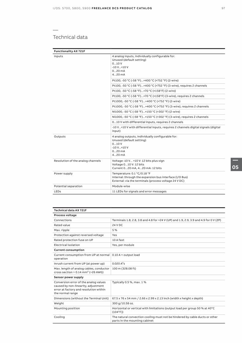
—Technical data
Functionality AX 721F
Inputs 4 analog inputs, individually configurable for: Unused (default setting)0...10 V-10 V...+10 V0...20 mA4...20 mA
Pt100, -50 °C (-58 °F)...+400 °C (+752 °F) (2-wire)
Pt100, -50 °C (-58 °F)...+400 °C (+752 °F) (3-wire), requires 2 channels
Pt100, -50 °C (-58 °F)...+70 °C (+158°F) (2-wire)
Pt100, -50 °C (-58 °F)...+70 °C (+158°F) (3-wire), requires 2 channels
Pt1000, -50 °C (-58 °F)...+400 °C (+752 °F) (2-wire)
Pt1000, -50 °C (-58 °F)...+400 °C (+752 °F) (3-wire), requires 2 channels
Ni1000, -50 °C (-58 °F)...+150 °C (+302 °F) (2-wire)
Ni1000, -50 °C (-58 °F)...+150 °C (+302 °F) (3-wire), requires 2 channels
0...10 V with differential inputs, requires 2 channels
-10 V...+10 V with differential inputs, requires 2 channels digital signals (digital input)
Outputs 4 analog outputs, individually configurable for:Unused (default setting)0...10 V-10 V...+10 V0...20 mA4...20 mA
Resolution of the analog channels Voltage -10 V... +10 V: 12 bits plus sign Voltage 0...10 V: 12 bitsCurrent 0...20 mA, 4...20 mA: 12 bits
Power supply Temperature: 0.1 °C/0.18 °FInternal: through the expansion bus interface (I/O Bus)External: via the terminals (process voltage 24 V DC)
Potential separation Module-wise
LEDs 11 LEDs for signals and error messages
Technical data AX 721F
Process voltage
Connections Terminals 1.8, 2.8, 3.8 and 4.8 for +24 V (UP) and 1.9, 2.9, 3.9 and 4.9 for 0 V (ZP)
Rated value 24 V DC
Max. ripple 5 %
Protection against reversed voltage Yes
Rated protection fuse on UP 10 A fast
Electrical isolation Yes, per module
Current consumption
Current consumption from UP at normal operation
0.10 A + output load
Inrush current from UP (at power up) 0.020 A²s
Max. length of analog cables, conductor cross section > 0.14 mm² (~26 AWG)
100 m (328.08 ft)
Sensor power supply
Conversion error of the analog values caused by non-linearity, adjustment error at factory and resolution within the normal range
Typically 0.5 %, max. 1 %
Dimensions (without the Terminal Unit) 67.5 x 76 x 54 mm / 2.66 x 2.99 x 2.13 inch (width x height x depth)
Weight 300 g/10.58 oz.
Mounting position Horizontal or vertical with limitations (output load per group 50 % at 40°C (104°F))
Cooling The natural convection cooling must not be hindered by cable ducts or other parts in the mounting cabinet
97I/OS: S 70 0, S 8 0 0, S9 0 0 F R E E L A N CE D C S PRO D U C T C ATA LO G
—05
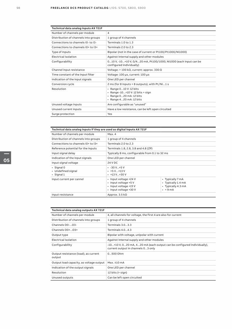
Technical data analog inputs AX 721F
Number of channels per module 4
Distribution of channels into groups 1 group of 4 channels
Connections to channels I0- to I3- Terminals 1.0 to 1.3
Connections to channels I0+ to I3+ Terminals 2.0 to 2.3
Type of Inputs Bipolar (not in the case of current or Pt100/Pt1000/Ni1000)
Electrical isolation Against internal supply and other modules
Configurability 0...10 V, -10...+10 V, 0/4...20 mA, Pt100/1000, Ni1000 (each input can be configured individually)
Channel input resistance Voltage: > 100 kΩ, current: approx. 330 Ω
Time constant of the input filter Voltage: 100 µs, current: 100 µs
Indication of the input signals One LED per channel
Conversion cycle 2 ms (for 8 inputs + 8 outputs), with Pt/Ni...1 s
Resolution • Range 0...10 V: 12 bits• Range -10...+10 V: 12 bits + sign• Range 0...20 mA: 12 bits• Range 4...20 mA: 12 bits
Unused voltage inputs Are configurable as “unused”
Unused current inputs Have a low resistance, can be left open circuited
Surge protection Yes
Technical data analog inputs if they are used as digital inputs AX 721F
Number of channels per module Max. 4
Distribution of channels into groups 1 group of 4 channels
Connections to channels I0+ to I3+ Terminals 2.0 to 2.3
Reference potential for the inputs Terminals 1.8, 2.8, 3.8 and 4.8 (ZP)
Input signal delay Typically 8 ms, configurable from 0.1 to 32 ms
Indication of the input signals One LED per channel
Input signal voltage 24 V DC
• Signal 0• Undefined signal• Signal 1
• -30 V...+5 V• +5 V…+13 V• +13 V...+30 V
Input current per cannel • Input voltage +24 V• Input voltage +5 V• Input voltage +15 V• Input voltage +30 V
• Typically 7 mA• Typically 1.4 mA• Typically 4.3 mA• < 9 mA
Input resistance Approx. 3.5 kΩ
Technical data analog outputs AX 721F
Number of channels per module 4, all channels for voltage, the first 4 are also for current
Distribution of channels into groups 1 group of 4 channels
Channels O0-...O3- Terminals 3.0...3.3
Channels O0+...O3+ Terminals 4.0...4.3
Output type Bipolar with voltage, unipolar with current
Electrical isolation Against internal supply and other modules
Configurability -10...+10 V, 0...20 mA, 4...20 mA (each output can be configured individually), current output in channels 0...3 only
Output resistance (load), as current output
0...500 Ohm
Output load capacity, as voltage output Max. ±10 mA
Indication of the output signals One LED per channel
Resolution 12 bits (+ sign)
Unused outputs Can be left open circuited
98 F R E E L A N CE D C S PRO D U C T C ATA LO G I/OS: S 70 0, S 8 0 0, S9 0 0
—05
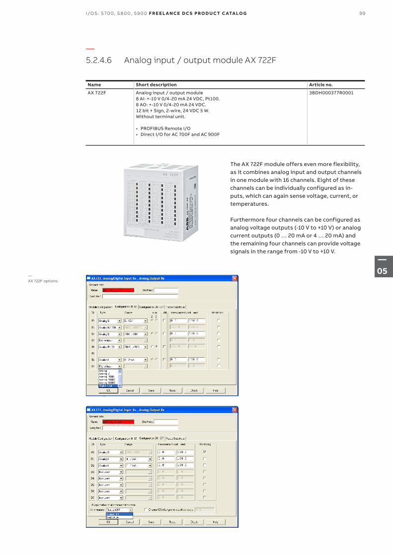
—5.2.4.6 Analog input / output module AX 722F
Name Short description Article no.
AX 722F Analog input / output module8 AI: +-10 V 0/4-20 mA 24 VDC, Pt100. 8 AO: +-10 V 0/4-20 mA 24 VDC. 12 bit + Sign, 2-wire, 24 VDC 5 W. Without terminal unit.
• PROFIBUS Remote I/O• Direct I/O for AC 700F and AC 900F
3BDH000377R0001
The AX 722F module offers even more flexibility, as it combines analog input and output channels in one module with 16 channels. Eight of these channels can be individually configured as in-puts, which can again sense voltage, current, or temperatures.
Furthermore four channels can be configured as analog voltage outputs (-10 V to +10 V) or analog current outputs (0 … 20 mA or 4 … 20 mA) and the remaining four channels can provide voltage signals in the range from -10 V to +10 V.
—AX 722F options
99I/OS: S 70 0, S 8 0 0, S9 0 0 F R E E L A N CE D C S PRO D U C T C ATA LO G
—05
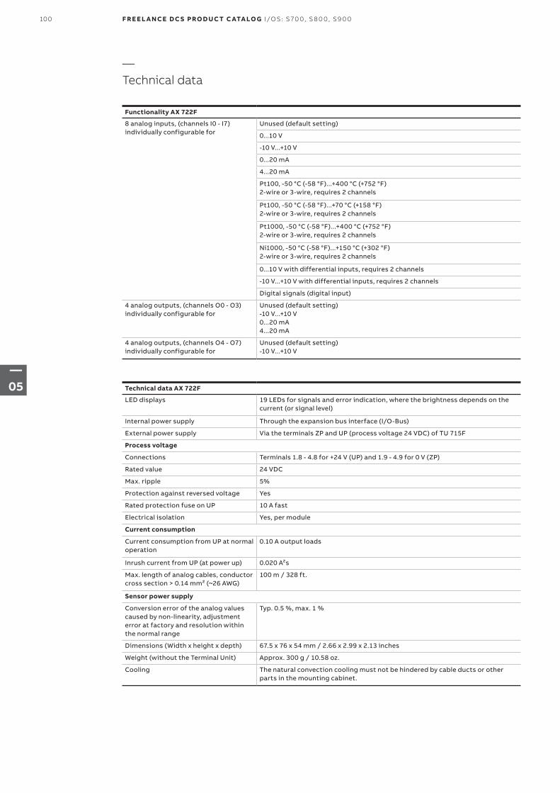
—Technical data
Functionality AX 722F
8 analog inputs, (channels I0 - I7) individually configurable for
Unused (default setting)
0...10 V
-10 V...+10 V
0...20 mA
4...20 mA
Pt100, -50 °C (-58 °F)...+400 °C (+752 °F) 2-wire or 3-wire, requires 2 channels
Pt100, -50 °C (-58 °F)...+70 °C (+158 °F) 2-wire or 3-wire, requires 2 channels
Pt1000, -50 °C (-58 °F)...+400 °C (+752 °F) 2-wire or 3-wire, requires 2 channels
Ni1000, -50 °C (-58 °F)...+150 °C (+302 °F) 2-wire or 3-wire, requires 2 channels
0...10 V with differential inputs, requires 2 channels
-10 V...+10 V with differential inputs, requires 2 channels
Digital signals (digital input)
4 analog outputs, (channels O0 - O3) individually configurable for
Unused (default setting)-10 V...+10 V0...20 mA4...20 mA
4 analog outputs, (channels O4 - O7) individually configurable for
Unused (default setting)-10 V...+10 V
Technical data AX 722F
LED displays 19 LEDs for signals and error indication, where the brightness depends on the current (or signal level)
Internal power supply Through the expansion bus interface (I/O-Bus)
External power supply Via the terminals ZP and UP (process voltage 24 VDC) of TU 715F
Process voltage
Connections Terminals 1.8 - 4.8 for +24 V (UP) and 1.9 - 4.9 for 0 V (ZP)
Rated value 24 VDC
Max. ripple 5%
Protection against reversed voltage Yes
Rated protection fuse on UP 10 A fast
Electrical isolation Yes, per module
Current consumption
Current consumption from UP at normal operation
0.10 A output loads
Inrush current from UP (at power up) 0.020 A²s
Max. length of analog cables, conductor cross section > 0.14 mm² (~26 AWG)
100 m / 328 ft.
Sensor power supply
Conversion error of the analog values caused by non-linearity, adjustment error at factory and resolution within the normal range
Typ. 0.5 %, max. 1 %
Dimensions (Width x height x depth) 67.5 x 76 x 54 mm / 2.66 x 2.99 x 2.13 inches
Weight (without the Terminal Unit) Approx. 300 g / 10.58 oz.
Cooling The natural convection cooling must not be hindered by cable ducts or other parts in the mounting cabinet.
100 F R E E L A N CE D C S PRO D U C T C ATA LO G I/OS: S 70 0, S 8 0 0, S9 0 0
—05
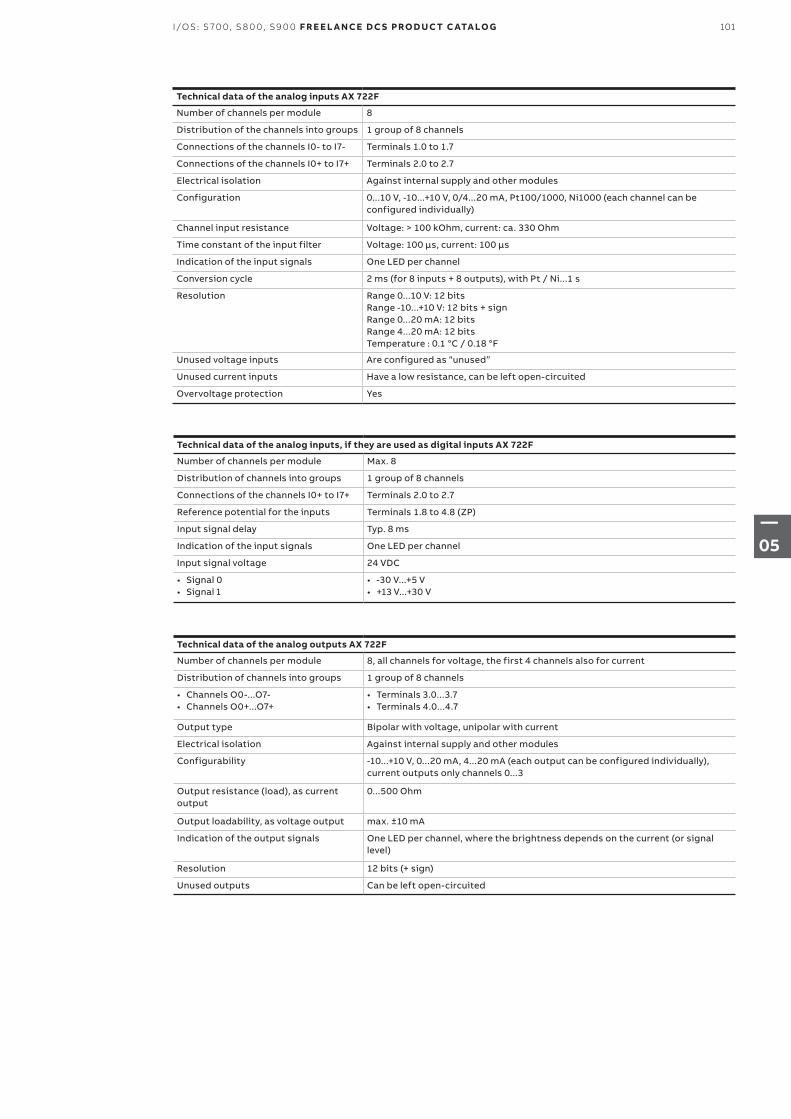
Technical data of the analog inputs AX 722F
Number of channels per module 8
Distribution of the channels into groups 1 group of 8 channels
Connections of the channels I0- to I7- Terminals 1.0 to 1.7
Connections of the channels I0+ to I7+ Terminals 2.0 to 2.7
Electrical isolation Against internal supply and other modules
Configuration 0...10 V, -10...+10 V, 0/4...20 mA, Pt100/1000, Ni1000 (each channel can be configured individually)
Channel input resistance Voltage: > 100 kOhm, current: ca. 330 Ohm
Time constant of the input filter Voltage: 100 μs, current: 100 μs
Indication of the input signals One LED per channel
Conversion cycle 2 ms (for 8 inputs + 8 outputs), with Pt / Ni...1 s
Resolution Range 0...10 V: 12 bitsRange -10...+10 V: 12 bits + signRange 0...20 mA: 12 bitsRange 4...20 mA: 12 bitsTemperature : 0.1 °C / 0.18 °F
Unused voltage inputs Are configured as “unused”
Unused current inputs Have a low resistance, can be left open-circuited
Overvoltage protection Yes
Technical data of the analog outputs AX 722F
Number of channels per module 8, all channels for voltage, the first 4 channels also for current
Distribution of channels into groups 1 group of 8 channels
• Channels O0-...O7-• Channels O0+...O7+
• Terminals 3.0...3.7• Terminals 4.0...4.7
Output type Bipolar with voltage, unipolar with current
Electrical isolation Against internal supply and other modules
Configurability -10...+10 V, 0...20 mA, 4...20 mA (each output can be configured individually), current outputs only channels 0...3
Output resistance (load), as current output
0...500 Ohm
Output loadability, as voltage output max. ±10 mA
Indication of the output signals One LED per channel, where the brightness depends on the current (or signal level)
Resolution 12 bits (+ sign)
Unused outputs Can be left open-circuited
Technical data of the analog inputs, if they are used as digital inputs AX 722F
Number of channels per module Max. 8
Distribution of channels into groups 1 group of 8 channels
Connections of the channels I0+ to I7+ Terminals 2.0 to 2.7
Reference potential for the inputs Terminals 1.8 to 4.8 (ZP)
Input signal delay Typ. 8 ms
Indication of the input signals One LED per channel
Input signal voltage 24 VDC
• Signal 0• Signal 1
• -30 V...+5 V• +13 V...+30 V
101I/OS: S 70 0, S 8 0 0, S9 0 0 F R E E L A N CE D C S PRO D U C T C ATA LO G
—05
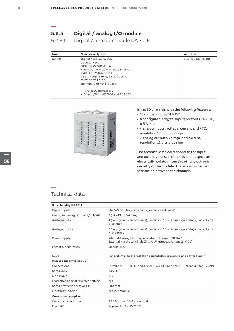
It has 30 channels with the following features:• 16 digital inputs, 24 V DC• 8 configurable digital inputs/outputs 24 V DC,
0.5 A max.• 4 analog inputs, voltage, current and RTD,
resolution 12 bits plus sign• 2 analog outputs, voltage and current,
resolution 12 bits plus sign The technical data correspond to the input and output values. The inputs and outputs are electrically isolated from the other electronic circuitry of the module. There is no potential separation between the channels.
—5.2.5 Digital / analog I/O module5.2.5.1 Digital / analog module DA 701F
Name Short description Article no.
DA 701F Digital / analog module16 DI: 24 VDC8 DI/DO: 24 VDC/0.5 A4 AI: +-10 V 0/4-20 mA, RTD , 24 VDC2 AO: +-10 V, 0/4-20 mA12 Bit + sign, 1-wire, 24 VDC 200 WTU 715F /TU 716F(terminal unit not included)
• PROFIBUS Remote I/O• Direct I/O for AC 700F and AC 900F
3BDH000371R0001
—Technical data
Functionality DA 701F
Digital Inputs 16 (24 V DC; delay time configurable via software)
Configurable digital inputs/outputs 8 (24 V DC, 0.5 A max)
Analog inputs 4 (configurable via software), resolution 12 bits plus sign, voltage, current and RTD input
Analog outputs 2 (configurable via software), resolution 12 bits plus sign, voltage, current and RTD output
Power supply Internal: through the expansion bus interface (I/O-Bus)External: via the terminals ZP and UP (process voltage 24 V DC)
Potential separation Module-wise
LEDs For system displays, indicating signal statuses, errors and power supply
Process supply voltage UP
Connections Terminals 1.8, 2.8, 3.8 and 4.8 for +24 V (UP) and 1.9, 2.9, 3.9 and 4.9 for 0 V (ZP)
Rated value 24 V DC
Max. ripple 5 %
Protection against reversed voltage Yes
Rated protection fuse on UP 10 A fast
Electrical isolation Yes, per module
Current consumption
Current consumption 0.07 A + max. 0.5 A per output
From UP Approx. 1 mA at 24 V DC
102 F R E E L A N CE D C S PRO D U C T C ATA LO G I/OS: S 70 0, S 8 0 0, S9 0 0
—05
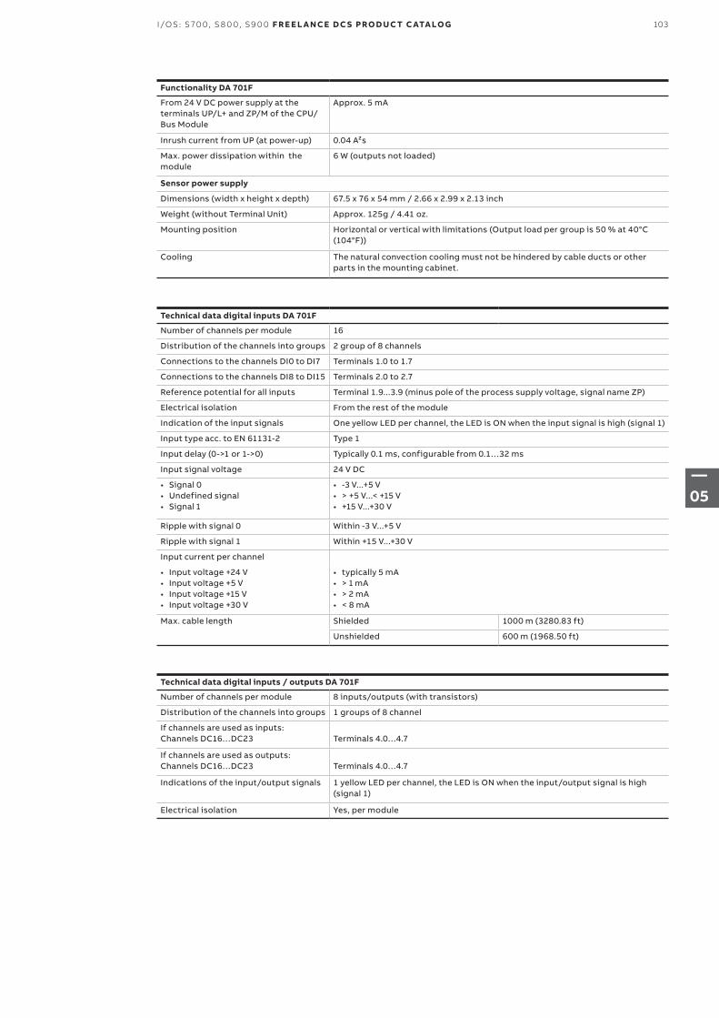
Functionality DA 701F
From 24 V DC power supply at the terminals UP/L+ and ZP/M of the CPU/Bus Module
Approx. 5 mA
Inrush current from UP (at power-up) 0.04 A²s
Max. power dissipation within the module
6 W (outputs not loaded)
Sensor power supply
Dimensions (width x height x depth) 67.5 x 76 x 54 mm / 2.66 x 2.99 x 2.13 inch
Weight (without Terminal Unit) Approx. 125g / 4.41 oz.
Mounting position Horizontal or vertical with limitations (Output load per group is 50 % at 40°C (104°F))
Cooling The natural convection cooling must not be hindered by cable ducts or other parts in the mounting cabinet.
Technical data digital inputs / outputs DA 701F
Number of channels per module 8 inputs/outputs (with transistors)
Distribution of the channels into groups 1 groups of 8 channel
If channels are used as inputs:Channels DC16…DC23 Terminals 4.0…4.7
If channels are used as outputs:Channels DC16…DC23 Terminals 4.0…4.7
Indications of the input/output signals 1 yellow LED per channel, the LED is ON when the input/output signal is high (signal 1)
Electrical isolation Yes, per module
Technical data digital inputs DA 701F
Number of channels per module 16
Distribution of the channels into groups 2 group of 8 channels
Connections to the channels DI0 to DI7 Terminals 1.0 to 1.7
Connections to the channels DI8 to DI15 Terminals 2.0 to 2.7
Reference potential for all inputs Terminal 1.9...3.9 (minus pole of the process supply voltage, signal name ZP)
Electrical isolation From the rest of the module
Indication of the input signals One yellow LED per channel, the LED is ON when the input signal is high (signal 1)
Input type acc. to EN 61131-2 Type 1
Input delay (0->1 or 1->0) Typically 0.1 ms, configurable from 0.1…32 ms
Input signal voltage 24 V DC
• Signal 0• Undefined signal • Signal 1
• -3 V...+5 V• > +5 V...< +15 V• +15 V...+30 V
Ripple with signal 0 Within -3 V...+5 V
Ripple with signal 1 Within +15 V...+30 V
Input current per channel
• Input voltage +24 V• Input voltage +5 V• Input voltage +15 V• Input voltage +30 V
• typically 5 mA• > 1 mA• > 2 mA• < 8 mA
Max. cable length Shielded 1000 m (3280.83 ft)
Unshielded 600 m (1968.50 ft)
103I/OS: S 70 0, S 8 0 0, S9 0 0 F R E E L A N CE D C S PRO D U C T C ATA LO G
—05
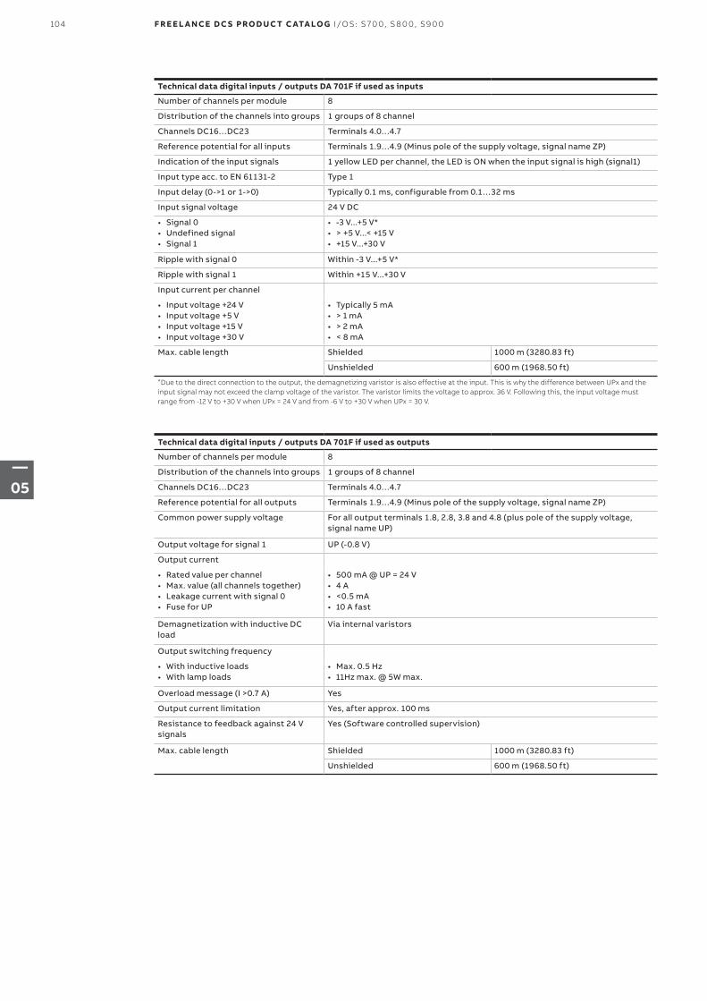
Technical data digital inputs / outputs DA 701F if used as outputs
Number of channels per module 8
Distribution of the channels into groups 1 groups of 8 channel
Channels DC16…DC23 Terminals 4.0…4.7
Reference potential for all outputs Terminals 1.9…4.9 (Minus pole of the supply voltage, signal name ZP)
Common power supply voltage For all output terminals 1.8, 2.8, 3.8 and 4.8 (plus pole of the supply voltage, signal name UP)
Output voltage for signal 1 UP (-0.8 V)
Output current
• Rated value per channel• Max. value (all channels together)• Leakage current with signal 0• Fuse for UP
• 500 mA @ UP = 24 V• 4 A• <0.5 mA• 10 A fast
Demagnetization with inductive DC load
Via internal varistors
Output switching frequency
• With inductive loads• With lamp loads
• Max. 0.5 Hz• 11Hz max. @ 5W max.
Overload message (I >0.7 A) Yes
Output current limitation Yes, after approx. 100 ms
Resistance to feedback against 24 V signals
Yes (Software controlled supervision)
Max. cable length Shielded 1000 m (3280.83 ft)
Unshielded 600 m (1968.50 ft)
Technical data digital inputs / outputs DA 701F if used as inputs
Number of channels per module 8
Distribution of the channels into groups 1 groups of 8 channel
Channels DC16…DC23 Terminals 4.0…4.7
Reference potential for all inputs Terminals 1.9…4.9 (Minus pole of the supply voltage, signal name ZP)
Indication of the input signals 1 yellow LED per channel, the LED is ON when the input signal is high (signal1)
Input type acc. to EN 61131-2 Type 1
Input delay (0->1 or 1->0) Typically 0.1 ms, configurable from 0.1…32 ms
Input signal voltage 24 V DC
• Signal 0• Undefined signal• Signal 1
• -3 V...+5 V*• > +5 V...< +15 V• +15 V...+30 V
Ripple with signal 0 Within -3 V...+5 V*
Ripple with signal 1 Within +15 V...+30 V
Input current per channel
• Input voltage +24 V• Input voltage +5 V• Input voltage +15 V• Input voltage +30 V
• Typically 5 mA• > 1 mA• > 2 mA• < 8 mA
Max. cable length Shielded 1000 m (3280.83 ft)
Unshielded 600 m (1968.50 ft)
*Due to the direct connection to the output, the demagnetizing varistor is also effective at the input. This is why the difference between UPx and the input signal may not exceed the clamp voltage of the varistor. The varistor limits the voltage to approx. 36 V. Following this, the input voltage must range from -12 V to +30 V when UPx = 24 V and from -6 V to +30 V when UPx = 30 V.
104 F R E E L A N CE D C S PRO D U C T C ATA LO G I/OS: S 70 0, S 8 0 0, S9 0 0
—05
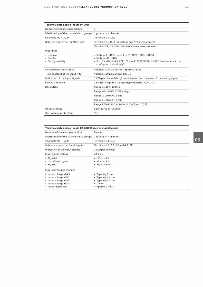
Technical data analog inputs DA 701F
Number of channels per module 4
Distribution of the channels into groups 1 groups of 4 channel
Channels AI0+…AI3+ Terminals 3.0…3.3
Reference potential for AI0+…AI3+ Terminals 3.4 (AI-) for voltage and RTD measurement
Terminal 1.9, 2.9, 3.9 and 4.9 for current measurement
Input type
• Unipolar• Bipolar• Configurability
• Voltage 0…10 V, current or Pt100/Pt1000/Ni1000• Voltaqe -10…+10V• 0…10 V, -10…+10 V, 0/4…20 mA, Pt1000/1000, Ni1000 (each input can be
configured individually)
Channel input resistance Voltage: >100 kΩ, current: approx. 330 Ω
Time constant of the input filter Voltage: 100 µs, current: 100 µs
Indication of the input signals 1 LED per channel (brightness depends on the value of the analog signal)
Conversion cycle 1 ms (for 4 inputs + 2 outputs); with RTDs Pt/Ni… 1s
Resolution Range 0…10 V: 12 Bits
Range -10…+10 V: 12 Bits +sign
Range 0…20 mA: 12 Bits
Range 4…20 mA: 12 Bits
Range RTD (Pt100, Pt1000, Ni1000): 0.1°C (°F)
Unused inputs Configured as ‘unused’
Overvoltage protection Yes
Technical data analog inputs DA 701F if used as digital inputs
Number of channels per module Max. 4
Distribution of the channels into groups 1 groups of 4 channel
Channels AI0+…AI3+ Terminals 3.0…3.3
Reference potential for all inputs Terminals 1.9, 2.9, 3.9 and 4.9 (ZP)
Indication of the input signals 1 LED per channel
Input signal voltage 24 V DC
• Signal 0• Undefined signal• Signal 1
• -30 V...+5 V• +5 V...+13 V• +13 V...+30 V
Input current per channel
• Input voltage +24 V• Input voltage +5 V• Input voltage +15 V• Input voltage +30 V• Input resistance
• Typically 7 mA• Typically 1.4 mA• Typically 3.7 mA• < 9 mA• Approx. 3.5 kΩ
105I/OS: S 70 0, S 8 0 0, S9 0 0 F R E E L A N CE D C S PRO D U C T C ATA LO G
—05
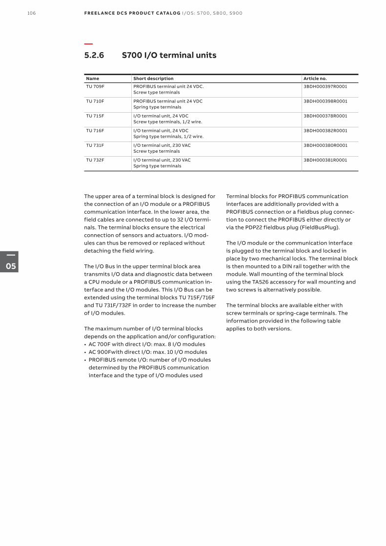
The upper area of a terminal block is designed for the connection of an I/O module or a PROFIBUS communication interface. In the lower area, the field cables are connected to up to 32 I/O termi-nals. The terminal blocks ensure the electrical connection of sensors and actuators. I/O mod-ules can thus be removed or replaced without detaching the field wiring.
The I/O Bus in the upper terminal block area transmits I/O data and diagnostic data between a CPU module or a PROFIBUS communication in-terface and the I/O modules. This I/O Bus can be extended using the terminal blocks TU 715F/716F and TU 731F/732F in order to increase the number of I/O modules.
The maximum number of I/O terminal blocks depends on the application and/or configuration:• AC 700F with direct I/O: max. 8 I/O modules• AC 900Fwith direct I/O: max. 10 I/O modules• PROFIBUS remote I/O: number of I/O modules
determined by the PROFIBUS communication interface and the type of I/O modules used
—5.2.6 S700 I/O terminal units
Name Short description Article no.
TU 709F PROFIBUS terminal unit 24 VDC. Screw type terminals
3BDH000397R0001
TU 710F PROFIBUS terminal unit 24 VDC Spring type terminals
3BDH000398R0001
TU 715F I/O terminal unit, 24 VDCScrew type terminals, 1/2 wire.
3BDH000378R0001
TU 716F I/O terminal unit, 24 VDCSpring type terminals, 1/2 wire.
3BDH000382R0001
TU 731F I/O terminal unit, 230 VACScrew type terminals
3BDH000380R0001
TU 732F I/O terminal unit, 230 VACSpring type terminals
3BDH000381R0001
Terminal blocks for PROFIBUS communication interfaces are additionally provided with a PROFIBUS connection or a fieldbus plug connec-tion to connect the PROFIBUS either directly or via the PDP22 fieldbus plug (FieldBusPlug).
The I/O module or the communication interface is plugged to the terminal block and locked in place by two mechanical locks. The terminal block is then mounted to a DIN rail together with the module. Wall mounting of the terminal block using the TA526 accessory for wall mounting and two screws is alternatively possible.
The terminal blocks are available either with screw terminals or spring-cage terminals. The information provided in the following table applies to both versions.
106 F R E E L A N CE D C S PRO D U C T C ATA LO G I/OS: S 70 0, S 8 0 0, S9 0 0
—05
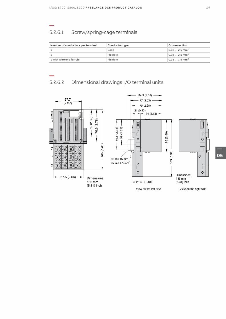
—5.2.6.2 Dimensional drawings I/O terminal units
—5.2.6.1 Screw/spring-cage terminals
Number of conductors per terminal Conductor type Cross-section
1 Solid 0.08 … 2.5 mm²
1 Flexible 0.08 … 2.5 mm²
1 with wire end ferrule Flexible 0.25 … 1.5 mm²
107I/OS: S 70 0, S 8 0 0, S9 0 0 F R E E L A N CE D C S PRO D U C T C ATA LO G
—05
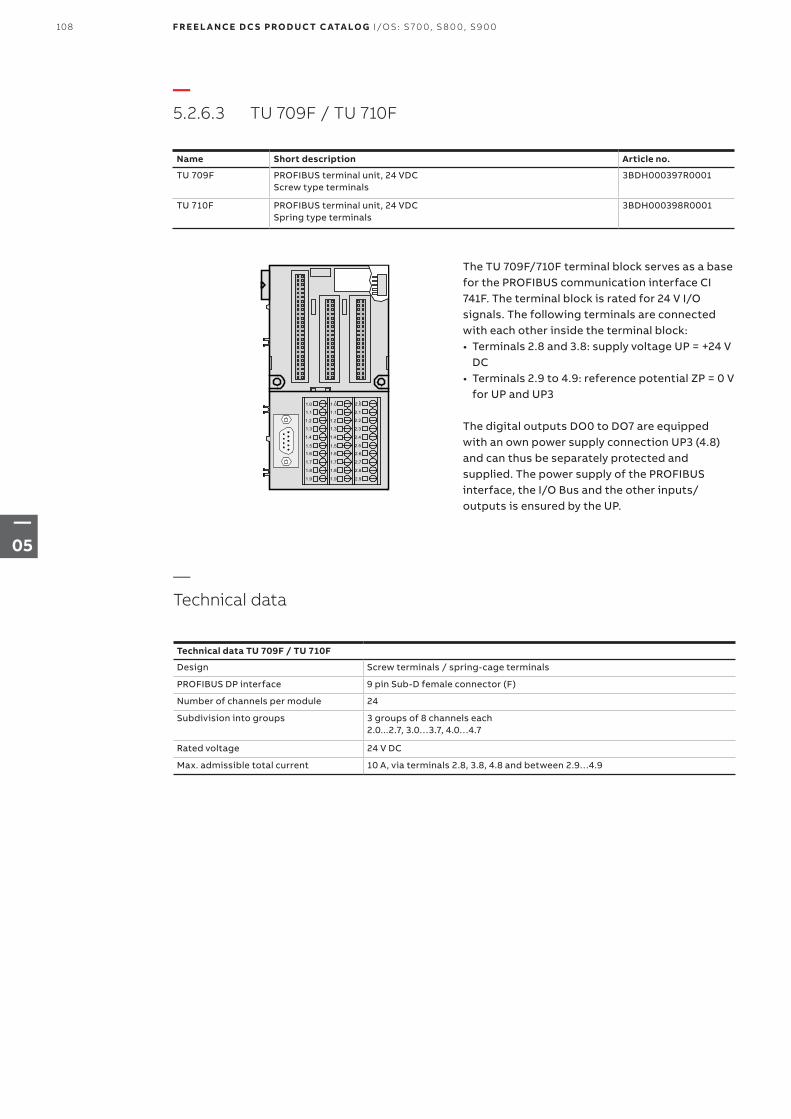
—5.2.6.3 TU 709F / TU 710F
1.0
1.1
1.2
1.3
1.4
1.5
1.6
1.7
1.8
1.9
2.0
2.1
2.2
2.3
2.4
2.5
2.6
2.7
2.8
2.9
1.0
1.1
1.2
1.3
1.4
1.5
1.6
1.7
1.8
1.9
Name Short description Article no.
TU 709F PROFIBUS terminal unit, 24 VDCScrew type terminals
3BDH000397R0001
TU 710F PROFIBUS terminal unit, 24 VDCSpring type terminals
3BDH000398R0001
The TU 709F/710F terminal block serves as a base for the PROFIBUS communication interface CI 741F. The terminal block is rated for 24 V I/O signals. The following terminals are connected with each other inside the terminal block:• Terminals 2.8 and 3.8: supply voltage UP = +24 V
DC• Terminals 2.9 to 4.9: reference potential ZP = 0 V
for UP and UP3
The digital outputs DO0 to DO7 are equipped with an own power supply connection UP3 (4.8) and can thus be separately protected and supplied. The power supply of the PROFIBUS interface, the I/O Bus and the other inputs/ outputs is ensured by the UP.
—Technical data
Technical data TU 709F / TU 710F
Design Screw terminals / spring-cage terminals
PROFIBUS DP interface 9 pin Sub-D female connector (F)
Number of channels per module 24
Subdivision into groups 3 groups of 8 channels each 2.0...2.7, 3.0…3.7, 4.0…4.7
Rated voltage 24 V DC
Max. admissible total current 10 A, via terminals 2.8, 3.8, 4.8 and between 2.9…4.9
108 F R E E L A N CE D C S PRO D U C T C ATA LO G I/OS: S 70 0, S 8 0 0, S9 0 0
—05
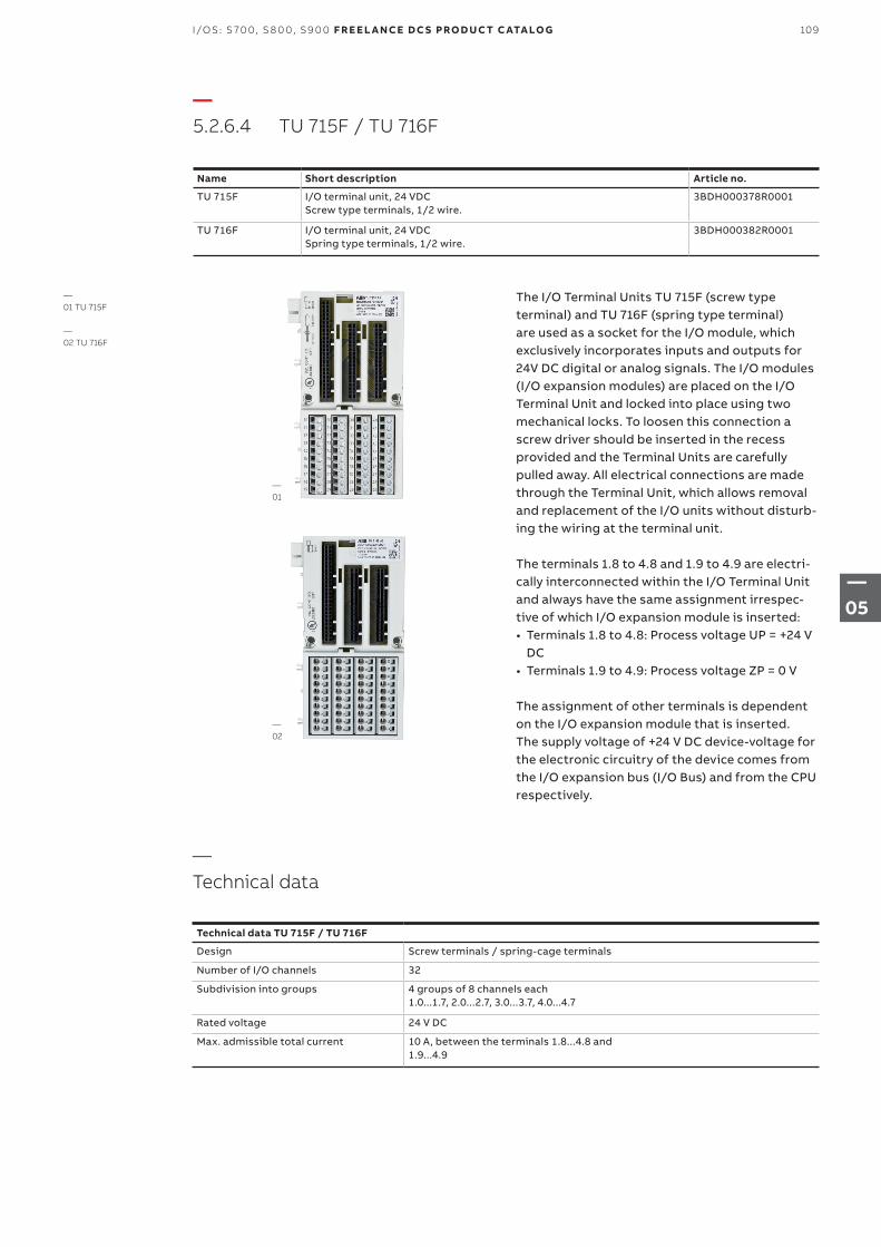
—Technical data
Technical data TU 715F / TU 716F
Design Screw terminals / spring-cage terminals
Number of I/O channels 32
Subdivision into groups 4 groups of 8 channels each 1.0...1.7, 2.0...2.7, 3.0...3.7, 4.0...4.7
Rated voltage 24 V DC
Max. admissible total current 10 A, between the terminals 1.8...4.8 and1.9...4.9
—5.2.6.4 TU 715F / TU 716F
Name Short description Article no.
TU 715F I/O terminal unit, 24 VDCScrew type terminals, 1/2 wire.
3BDH000378R0001
TU 716F I/O terminal unit, 24 VDCSpring type terminals, 1/2 wire.
3BDH000382R0001
The I/O Terminal Units TU 715F (screw type terminal) and TU 716F (spring type terminal) are used as a socket for the I/O module, which exclusively incorporates inputs and outputs for 24V DC digital or analog signals. The I/O modules (I/O expansion modules) are placed on the I/O Terminal Unit and locked into place using two mechanical locks. To loosen this connection a screw driver should be inserted in the recess provided and the Terminal Units are carefully pulled away. All electrical connections are made through the Terminal Unit, which allows removal and replacement of the I/O units without disturb-ing the wiring at the terminal unit. The terminals 1.8 to 4.8 and 1.9 to 4.9 are electri-cally interconnected within the I/O Terminal Unit and always have the same assignment irrespec-tive of which I/O expansion module is inserted:• Terminals 1.8 to 4.8: Process voltage UP = +24 V
DC • Terminals 1.9 to 4.9: Process voltage ZP = 0 V
The assignment of other terminals is dependent on the I/O expansion module that is inserted.The supply voltage of +24 V DC device-voltage for the electronic circuitry of the device comes from the I/O expansion bus (I/O Bus) and from the CPU respectively.
—01 TU 715F
—02 TU 716F
—01
—02
109I/OS: S 70 0, S 8 0 0, S9 0 0 F R E E L A N CE D C S PRO D U C T C ATA LO G
—05
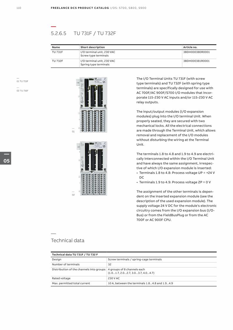
—Technical data
Technical data TU 731F / TU 732 F
Design Screw terminals / spring-cage terminals
Number of terminals 32
Distribution of the channels into groups 4 groups of 8 channels each (1.0...1.7, 2.0...2.7, 3.0...3.7, 4.0...4.7)
Rated voltage 230 V AC
Max. permitted total current 10 A, between the terminals 1.8...4.8 and 1.9...4.9
—5.2.6.5 TU 731F / TU 732F
Name Short description Article no.
TU 731F I/O terminal unit, 230 VACScrew type terminals
3BDH000380R0001
TU 732F I/O terminal unit, 230 VACSpring type terminals
3BDH000381R0001
The I/O Terminal Units TU 731F (with screw type terminals) and TU 732F (with spring type terminals) are specifically designed for use with AC 700F/AC 900F/S700 I/O modules that incor-porate 115-230 V AC inputs and/or 115-230 V AC relay outputs.
The input/output modules (I/O expansion modules) plug into the I/O terminal Unit. When properly seated, they are secured with two mechanical locks. All the electrical connections are made through the Terminal Unit, which allows removal and replacement of the I/O modules without disturbing the wiring at the Terminal Unit.
The terminals 1.8 to 4.8 and 1.9 to 4.9 are electri-cally interconnected within the I/O Terminal Unit and have always the same assignment, irrespec-tive of which I/O expansion module is inserted:• Terminals 1.8 to 4.8: Process voltage UP = +24 V
DC• Terminals 1.9 to 4.9: Process voltage ZP = 0 V
The assignment of the other terminals is depen-dent on the inserted expansion module (see thedescription of the used expansion module). The supply voltage 24 V DC for the module‘s electronic circuitry comes from the I/O expansion bus (I/O-Bus) or from the FieldBusPlug or from the AC 700F or AC 900F CPU.
—01 TU 715F
—02 TU 716F
—01
—02
110 F R E E L A N CE D C S PRO D U C T C ATA LO G I/OS: S 70 0, S 8 0 0, S9 0 0
—05
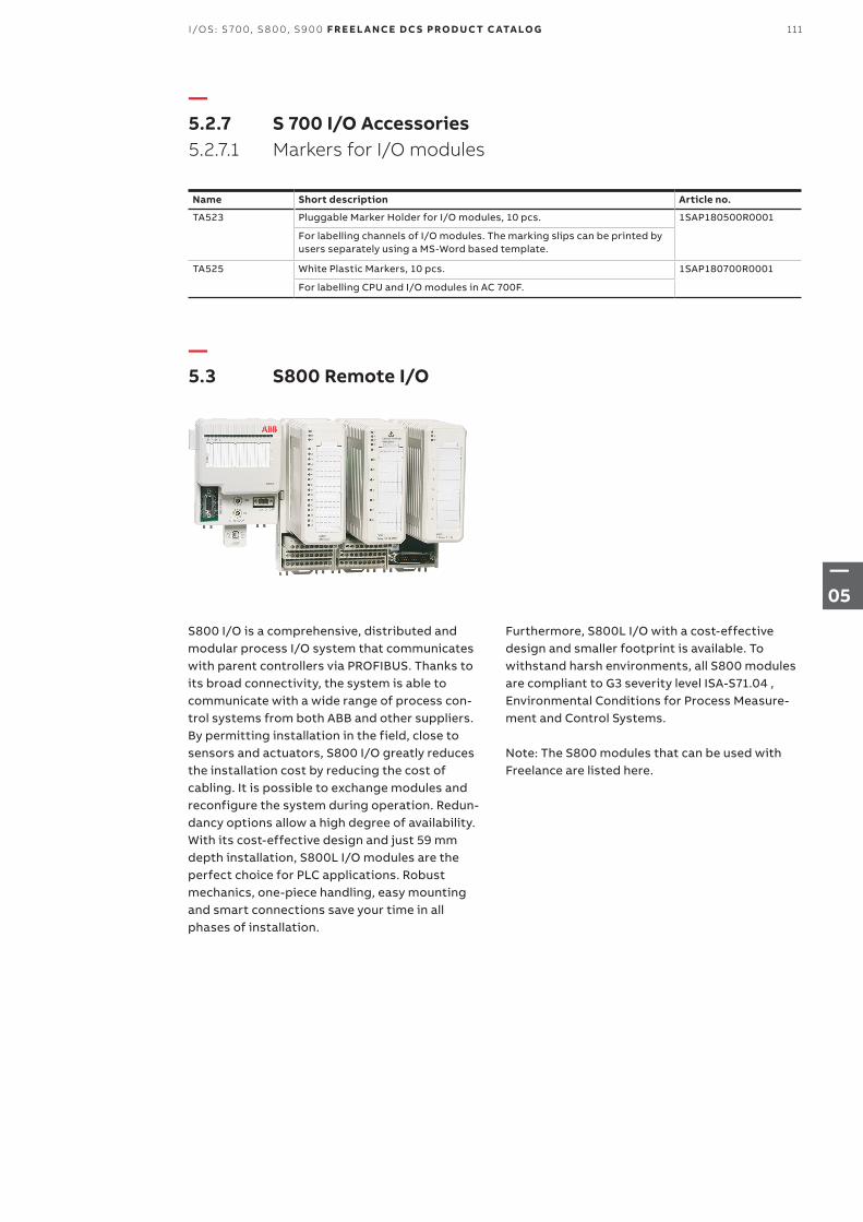
—5.2.7 S 700 I/O Accessories 5.2.7.1 Markers for I/O modules
Name Short description Article no.
TA523 Pluggable Marker Holder for I/O modules, 10 pcs. 1SAP180500R0001
For labelling channels of I/O modules. The marking slips can be printed by users separately using a MS-Word based template.
TA525 White Plastic Markers, 10 pcs. 1SAP180700R0001
For labelling CPU and I/O modules in AC 700F.
—5.3 S800 Remote I/O
S800 I/O is a comprehensive, distributed and modular process I/O system that communicates with parent controllers via PROFIBUS. Thanks to its broad connectivity, the system is able to communicate with a wide range of process con-trol systems from both ABB and other suppliers. By permitting installation in the field, close to sensors and actuators, S800 I/O greatly reduces the installation cost by reducing the cost of cabling. It is possible to exchange modules and reconfigure the system during operation. Redun-dancy options allow a high degree of availability.With its cost-effective design and just 59 mm depth installation, S800L I/O modules are the perfect choice for PLC applications. Robust mechanics, one-piece handling, easy mounting and smart connections save your time in all phases of installation.
Furthermore, S800L I/O with a cost-effective design and smaller footprint is available. To withstand harsh environments, all S800 modules are compliant to G3 severity level ISA-S71.04 , Environmental Conditions for Process Measure-ment and Control Systems.
Note: The S800 modules that can be used with Freelance are listed here.
111I/OS: S 70 0, S 8 0 0, S9 0 0 F R E E L A N CE D C S PRO D U C T C ATA LO G
—05
—5.3.1 Communication 5.3.1.1 Field communication interfaces
Name Short description Article no.
CI801 PROFIBUS DP-V1 Communication Interface 3BSE022366R1
Including: 1x Power Supply Connector 1x TB807 ModuleBus Terminator The basic system software loaded in CI801 does not support the following I/O modules: DI830, DI831, DI885, AI880A, DI880 and DO880.
CI801 Engineering kit
SW 1.2 3BSE038540R1300
Including: 1x CD with GSD file, Memory Maps and Release Note. 1x Reference Manual Memory Maps for CI801.
CI840A PROFIBUS DP-V1 Communication Interface. For 1+1 redundant operation. 3BSE041882R1
Two CI840A and one TU847 or one TU846 must be ordered. The basic system software loaded in CI840 does not support the following I/O modules: DI830, DI831, DI885, AI880A, DI880, DO880 and ABB Drives.
CI840 Engineering kit
SW 4.0 3BSE031694R4000
Including: 1x CD with GSD file, Memory Maps and Release Notes. 1x Reference Manual Memory Maps for CI840.
TU846 Module Termination Unit, MTU, for 1+1 CI840. Support for redundant I/O 3BSE022460R1
Vertical mounting of modules. Including: 1x Power Supply Connector 2x TB807 ModuleBus Terminator.
TU847 Module Termination Unit for 1+1 CI840. Support for non-redundant I/O 3BSE022462R1
Vertical mounting of modules. Including: 1x Power Supply Connector 1x TB807 ModuleBus Terminator.
Front label set FCI / AC 70 / TB 3BSC970089R1
Sheet with 12 labels. For CI810, CI820, CI830, and TB820.
Label set, item design
FCI / AC 70 / TB 3BSC970091R1
Sheet with 40 labels. For CI810, CI820, CI830, and TB820.
Mounting kit For vertical mounting of CI801, CI840 and TB840 on a vertical DIN rail 3BSE040749R1
Mounting profile 1800
2 DIN rails and 1 cable duct 3BSE049768R1
DIN rail length : 1650mm + 210mm (65”) + (8.3”)
Al-profile Al-profile with DIN Rail and Cable Duct, mounting 465 mm (19”) 3BSE022255R1
DIN rail length 429mm (16,9”)
Al-profile Al-profile with DIN Rail and Cable Duct for RM550, mounting 592 mm (24”) 3BSE022256R1
DIN rail length 556mm (21,9”)
112 F R E E L A N CE D C S PRO D U C T C ATA LO G I/OS: S 70 0, S 8 0 0, S9 0 0
—05
—5.3.1.2 Upgrade kit and tool cables
Upgrading of CI801 or CI840A to latest software version are available for download from ABB Library/SolutionsBank. Item TK212A is cable connecting a PC to CI840A for download of software. CI801 requires items TK212A and FS801K01 for download of software
Name Short description Article no.
TK212A Tool cable 3BSC630197R1
RJ45 (male) to Dsub-9 (female), length 3 m. RJ45 8P8C plug (with shell). Cable : UL2464 26 AWG x 8C.
FS801K01 Service adapter kit 3BSE038407R1
Including: 1x Service adapter FS801 1x cable TK802 For connection of CI801 to PC. A cable TK812 is also needed.
—5.3.2 S800 I/O modules 5.3.2.1 S800 I/O Analog input modules
Name Short description Article no.
AI810 Analog Input, 1x8 channels 3BSE008516R1
0(4)…20 mA, 0…10 V, 12 bit, single ended, 0.1%, Rated isolation 50 V. Use Module Termination Unit TU810, TU812, TU814, TU830, TU833, TU835, TU838.
AI815 Analog Input, 1x8 channels, HART 3BSE052604R1
0(4)..20mA, 0(1)..5V, 12bit, single ended, 0.1%, Rated isolation 50V. Current limited transmitter power distribution. Use Module Termination Unit TU810, TU812, TU814, TU830, TU833, TU835 or TU838.
AI820 Analog Input, 4x1 channel 3BSE008544R1
+-20 mA, 0(4)..20 mA, +-10 V, +-5 V, 0(1)..5 V, diff., 5 0V CMV, 14 bit +sign. Rin(curr)250 Ohm, Rated isolation 50 V. Use Module Termination Unit TU810, TU812, TU814, TU830, TU833.
AI825 Analog Input, 4x1 channel, galvanically isolated 3BSE036456R1
-20..20 mA, 0(4)..20 mA, -10…10 V, 0(2)…10 V, Galvanically isolated channels. 14 bit+sign, 0.1%, Rated isolation 250 V. Use Module Termination Unit TU811, TU813, TU831.
AI830A Analog Input, 1x8 channels RTD 3BSE040662R1
Pt100, Ni100/120, Cu10, R, Rated isolation 50 V. Use Module Termination Unit TU810, TU812, TU814, TU830, TU833.
AI835A Analog Input, 8 channels, Thermocouple / mV 3BSE051306R1
Rated isolation 50 V. Use Module Termination Unit TU810, TU812, TU814, TU830, TU833.
AI843 Analog Input, Redundant or Single 1x8 channels, Thermocouple / mV 3BSE028925R1
Rated isolation 50 V. Use Modules Termination Unit TU830, TU833, TU842, TU843.
AI845 Analog Input, redundant or single, 1x8 channels HART 3BSE023675R1
0(4)…20 mA, 0(1)…5 V, 12 bit, single ended, 0.1%, Rated isolation 50 V. Current limited transmitter power distribution. Advanced on-board diagnostics. Use Module Termination Unit TU810, TU812, TU814, TU830, TU833, TU835, TU838, TU844, TU845.
AI890 Analog Input, 1x8 channels with Intrinsic Safety Interface 3BSC690071R1
(4)..20 mA single ended 0.1%. Rated isolation 50 V. Use Module Termination Unit TU890 or TU891
113I/OS: S 70 0, S 8 0 0, S9 0 0 F R E E L A N CE D C S PRO D U C T C ATA LO G
—05
—5.3.2.2 S800 I/O Analog output modules
Name Short description Article no.
AI893 Analog Input 8 channels, temperature measuring. Intrinsic Safety Interface, G3 compliant
3BSC690141R1
For TC and RTD sensors. Rated isolation 50 V. Protection class G3. Use Module Termination Unit TU890 or TU891.
AI895 Analog Input, 1x8 channels with Intrinsic Safety and HART, G3 compliant. 3BSC690086R1
4..20 mA single ended 0,1%. Rated isolation 50 V. Protection class G3. Use Module Termination Unit TU890 or TU891.
Name Short description Article no.
AO810V2 Analog Output, 1x8 channels, 0(4)..20 mA 3BSE038415R1
0(4)…20 mA, 14 bit RLmax 500/850 Ohm, Rated isolation 50 V. Use module Termination Unit TU810, TU812, TU814, TU830 or TU833.
AO815 Analog Output, 1x8 channels, HART 3BSE052605R1
4..20mA, 12bit, 0.1%, RLmax 750 ohm, Rated isol. 50V. Use Module Termination Unit TU810, TU812, TU814, TU830 or TU833.
AO820 Analog Output, 4x1 channel 3BSE008546R1
+-20 mA, 0(4)..20 mA, +-10 V, 12 bit+sign. Indiv. isolation channels. RL max 500 Ohm, Rated isolation 50 V. Use Module Termination Unit TU810, TU812, TU814, TU830, TU833.
AO845A Analog Output, redundant or single, 1x8 channels, HART 3BSE045584R1
4…20 mA, 12 bit, 0.1%, RLmax 750 ohm, Rated isolation 50 V. Advanced on-board diagnostics. Use Module Termination Unit TU810, TU812, TU814, TU830, TU833, TU842, TU843.
AO890 Analog Output, 1x8 channels with Intrinsic Safety Interface 3BSC690072R1
0 (4)..20 mA 0,1%. RL max 750 Ohm Rated isolation 50 V. Use Module Termination Unit TU890 or TU891.
AO895 Analog Output 1x8 channels with Intrinsic Safety and HART. G3 compliant 3BSC690087R1
4..20 mA 0,1%. RL max 750 Ohm Rated isolation 50 V. Protection class G3. Use Module Termination Unit TU890 or TU891.
114 F R E E L A N CE D C S PRO D U C T C ATA LO G I/OS: S 70 0, S 8 0 0, S9 0 0
—05
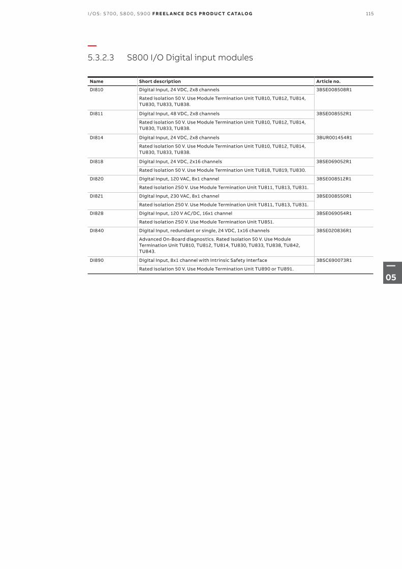
—5.3.2.3 S800 I/O Digital input modules
Name Short description Article no.
DI810 Digital Input, 24 VDC, 2x8 channels 3BSE008508R1
Rated isolation 50 V. Use Module Termination Unit TU810, TU812, TU814, TU830, TU833, TU838.
DI811 Digital Input, 48 VDC, 2x8 channels 3BSE008552R1
Rated isolation 50 V. Use Module Termination Unit TU810, TU812, TU814, TU830, TU833, TU838.
DI814 Digital Input, 24 VDC, 2x8 channels 3BUR001454R1
Rated isolation 50 V. Use Module Termination Unit TU810, TU812, TU814, TU830, TU833, TU838.
DI818 Digital Input, 24 VDC, 2x16 channels 3BSE069052R1
Rated isolation 50 V. Use Module Termination Unit TU818, TU819, TU830.
DI820 Digital Input, 120 VAC, 8x1 channel 3BSE008512R1
Rated isolation 250 V. Use Module Termination Unit TU811, TU813, TU831.
DI821 Digital Input, 230 VAC, 8x1 channel 3BSE008550R1
Rated isolation 250 V. Use Module Termination Unit TU811, TU813, TU831.
DI828 Digital Input, 120 V AC/DC, 16x1 channel 3BSE069054R1
Rated isolation 250 V. Use Module Termination Unit TU851.
DI840 Digital Input, redundant or single, 24 VDC, 1x16 channels 3BSE020836R1
Advanced On-Board diagnostics. Rated isolation 50 V. Use Module Termination Unit TU810, TU812, TU814, TU830, TU833, TU838, TU842, TU843.
DI890 Digital Input, 8x1 channel with Intrinsic Safety Interface 3BSC690073R1
Rated isolation 50 V. Use Module Termination Unit TU890 or TU891.
115I/OS: S 70 0, S 8 0 0, S9 0 0 F R E E L A N CE D C S PRO D U C T C ATA LO G
—05
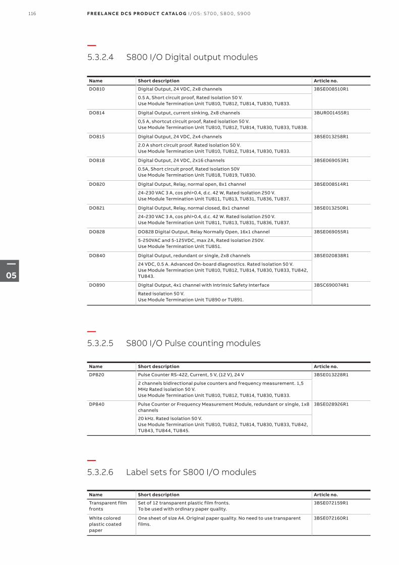
—5.3.2.4 S800 I/O Digital output modules
—5.3.2.5 S800 I/O Pulse counting modules
—5.3.2.6 Label sets for S800 I/O modules
Name Short description Article no.
DO810 Digital Output, 24 VDC, 2x8 channels 3BSE008510R1
0.5 A, Short circuit proof, Rated isolation 50 V. Use Module Termination Unit TU810, TU812, TU814, TU830, TU833.
DO814 Digital Output, current sinking, 2x8 channels 3BUR001455R1
0,5 A, shortcut circuit proof, Rated isolation 50 V. Use Module Termination Unit TU810, TU812, TU814, TU830, TU833, TU838.
DO815 Digital Output, 24 VDC, 2x4 channels 3BSE013258R1
2.0 A short circuit proof. Rated isolation 50 V. Use Module Termination Unit TU810, TU812, TU814, TU830, TU833.
DO818 Digital Output, 24 VDC, 2x16 channels 3BSE069053R1
0.5A, Short circuit proof, Rated isolation 50VUse Module Termination Unit TU818, TU819, TU830.
DO820 Digital Output, Relay, normal open, 8x1 channel 3BSE008514R1
24-230 VAC 3 A, cos phi>0.4, d.c. 42 W, Rated isolation 250 V. Use Module Termination Unit TU811, TU813, TU831, TU836, TU837.
DO821 Digital Output, Relay, normal closed, 8x1 channel 3BSE013250R1
24-230 VAC 3 A, cos phi>0.4, d.c. 42 W. Rated isolation 250 V. Use Module Termination Unit TU811, TU813, TU831, TU836, TU837.
DO828 DO828 Digital Output, Relay Normally Open, 16x1 channel 3BSE069055R1
5-250VAC and 5-125VDC, max 2A, Rated isolation 250V. Use Module Termination Unit TU851.
DO840 Digital Output, redundant or single, 2x8 channels 3BSE020838R1
24 VDC, 0.5 A. Advanced On-board diagnostics. Rated isolation 50 V. Use Module Termination Unit TU810, TU812, TU814, TU830, TU833, TU842, TU843.
DO890 Digital Output, 4x1 channel with Intrinsic Safety Interface 3BSC690074R1
Rated isolation 50 V. Use Module Termination Unit TU890 or TU891.
Name Short description Article no.
DP820 Pulse Counter RS-422, Current, 5 V, (12 V), 24 V 3BSE013228R1
2 channels bidirectional pulse counters and frequency measurement. 1,5 MHz Rated isolation 50 V. Use Module Termination Unit TU810, TU812, TU814, TU830, TU833.
DP840 Pulse Counter or Frequency Measurement Module, redundant or single, 1x8 channels
3BSE028926R1
20 kHz. Rated isolation 50 V. Use Module Termination Unit TU810, TU812, TU814, TU830, TU833, TU842, TU843, TU844, TU845.
Name Short description Article no.
Transparent film fronts
Set of 12 transparent plastic film fronts.To be used with ordinary paper quality.
3BSE072159R1
White colored plastic coated paper
One sheet of size A4. Original paper quality. No need to use transparent films.
3BSE072160R1
116 F R E E L A N CE D C S PRO D U C T C ATA LO G I/OS: S 70 0, S 8 0 0, S9 0 0
—05
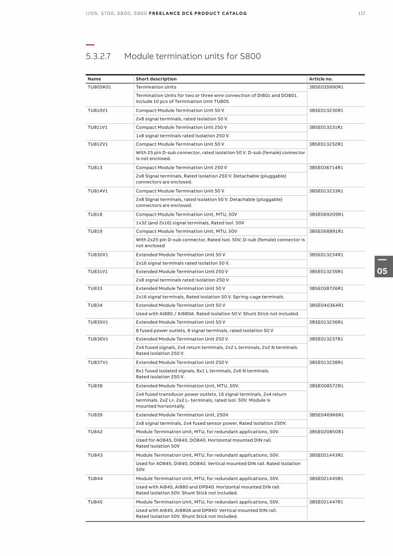
—5.3.2.7 Module termination units for S800
Name Short description Article no.
TU805K01 Termination Units 3BSE035990R1
Termination Units for two or three wire connection of DI801 and DO801. Include 10 pcs of Termination Unit TU805.
TU810V1 Compact Module Termination Unit 50 V 3BSE013230R1
2x8 signal terminals, rated isolation 50 V.
TU811V1 Compact Module Termination Unit 250 V 3BSE013231R1
1x8 signal terminals rated isolation 250 V.
TU812V1 Compact Module Termination Unit 50 V 3BSE013232R1
With 25 pin D-sub connector, rated isolation 50 V. D-sub (female) connector is not enclosed.
TU813 Compact Module Termination Unit 250 V 3BSE036714R1
2x8 Signal terminals, Rated isolation 250 V. Detachable (pluggable) connectors are enclosed.
TU814V1 Compact Module Termination Unit 50 V 3BSE013233R1
2x8 Signal terminals, rated isolation 50 V. Detachable (pluggable) connectors are enclosed.
TU818 Compact Module Termination Unit, MTU, 50V 3BSE069209R1
1x32 (and 2x16) signal terminals, Rated isol. 50V
TU819 Compact Module Termination Unit, MTU, 50V 3BSE068891R1
With 2x25 pin D-sub connector, Rated isol. 50V, D-sub (female) connector is not enclosed
TU830V1 Extended Module Termination Unit 50 V 3BSE013234R1
2x16 signal terminals rated isolation 50 V.
TU831V1 Extended Module Termination Unit 250 V 3BSE013235R1
2x8 signal terminals rated isolation 250 V.
TU833 Extended Module Termination Unit 50 V 3BSE038726R1
2x16 signal terminals, Rated isolation 50 V. Spring-cage terminals.
TU834 Extended Module Termination Unit 50 V 3BSE040364R1
Used with AI880 / AI880A. Rated isolation 50 V. Shunt Stick not included.
TU835V1 Extended Module Termination Unit 50 V 3BSE013236R1
8 fused power outlets, 8 signal terminals, rated isolation 50 V
TU836V1 Extended Module Termination Unit 250 V 3BSE013237R1
2x4 fused signals, 2x4 return terminals, 2x2 L terminals, 2x2 N terminals. Rated isolation 250 V.
TU837V1 Extended Module Termination Unit 250 V 3BSE013238R1
8x1 fused isolated signals, 8x1 L terminals, 2x6 N terminals. Rated isolation 250 V.
TU838 Extended Module Termination Unit, MTU, 50V. 3BSE008572R1
2x4 fused transducer power outlets, 16 signal terminals, 2x4 returnterminals, 2x2 L+, 2x2 L- terminals, rated isol. 50V. Module ismounted horizontally.
TU839 Extended Module Termination Unit, 250V 3BSE046966R1
2x8 signal terminals, 2x4 fused sensor power, Rated isolation 250V.
TU842 Module Termination Unit, MTU, for redundant applications, 50V. 3BSE020850R1
Used for AO845, DI840, DO840. Horizontal mounted DIN rail.Rated isolation 50V
TU843 Module Termination Unit, MTU, for redundant applications, 50V. 3BSE021443R1
Used for AO845, DI840, DO840. Vertical mounted DIN rail. Rated isolation 50V.
TU844 Module Termination Unit, MTU, for redundant applications, 50V. 3BSE021445R1
Used with AI845, AI880 and DP840. Horizontal mounted DIN rail.Rated isolation 50V. Shunt Stick not included.
TU845 Module Termination Unit, MTU, for redundant applications, 50V. 3BSE021447R1
Used with AI845, AI880A and DP840. Vertical mounted DIN rail.Rated isolation 50V. Shunt Stick not included.
117I/OS: S 70 0, S 8 0 0, S9 0 0 F R E E L A N CE D C S PRO D U C T C ATA LO G
—05
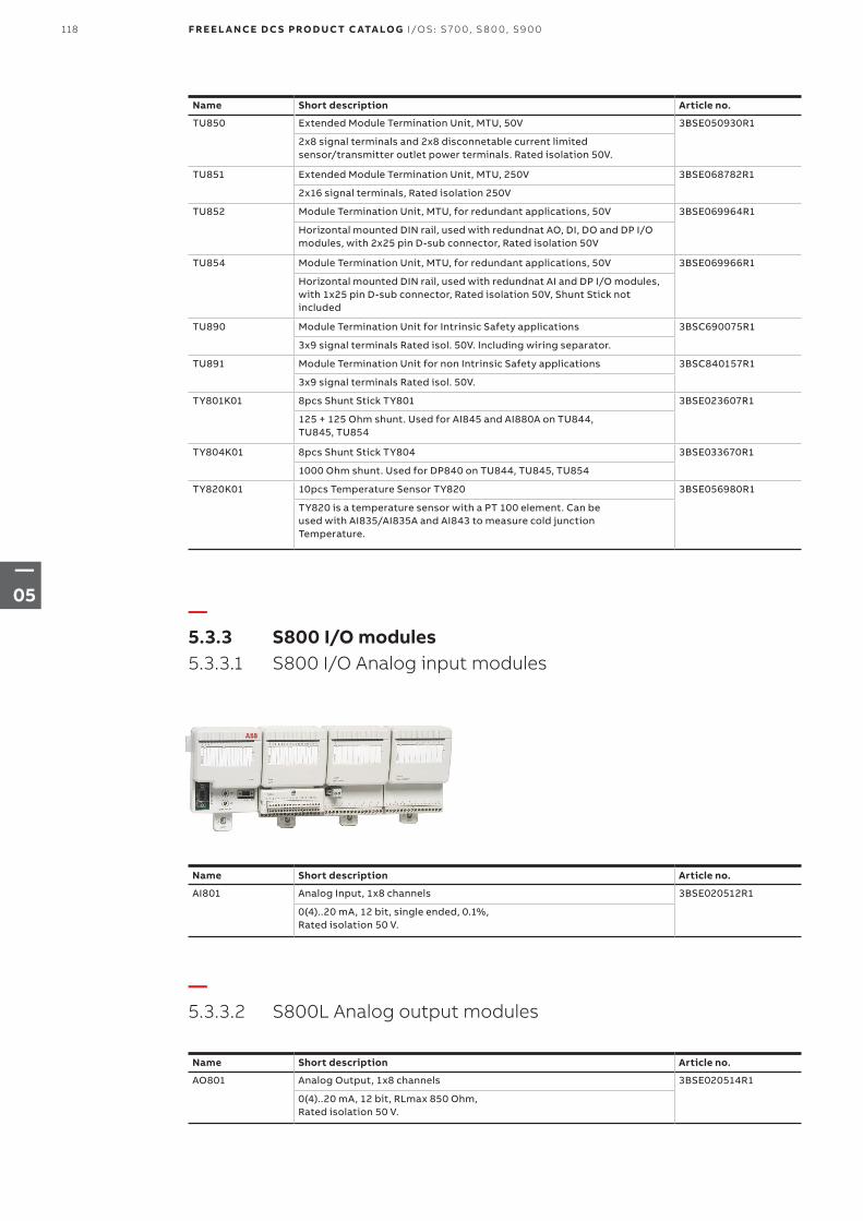
Name Short description Article no.
TU850 Extended Module Termination Unit, MTU, 50V 3BSE050930R1
2x8 signal terminals and 2x8 disconnetable current limitedsensor/transmitter outlet power terminals. Rated isolation 50V.
TU851 Extended Module Termination Unit, MTU, 250V 3BSE068782R1
2x16 signal terminals, Rated isolation 250V
TU852 Module Termination Unit, MTU, for redundant applications, 50V 3BSE069964R1
Horizontal mounted DIN rail, used with redundnat AO, DI, DO and DP I/O modules, with 2x25 pin D-sub connector, Rated isolation 50V
TU854 Module Termination Unit, MTU, for redundant applications, 50V 3BSE069966R1
Horizontal mounted DIN rail, used with redundnat AI and DP I/O modules, with 1x25 pin D-sub connector, Rated isolation 50V, Shunt Stick not included
TU890 Module Termination Unit for Intrinsic Safety applications 3BSC690075R1
3x9 signal terminals Rated isol. 50V. Including wiring separator.
TU891 Module Termination Unit for non Intrinsic Safety applications 3BSC840157R1
3x9 signal terminals Rated isol. 50V.
TY801K01 8pcs Shunt Stick TY801 3BSE023607R1
125 + 125 Ohm shunt. Used for AI845 and AI880A on TU844,TU845, TU854
TY804K01 8pcs Shunt Stick TY804 3BSE033670R1
1000 Ohm shunt. Used for DP840 on TU844, TU845, TU854
TY820K01 10pcs Temperature Sensor TY820 3BSE056980R1
TY820 is a temperature sensor with a PT 100 element. Can beused with AI835/AI835A and AI843 to measure cold junctionTemperature.
Name Short description Article no.
AI801 Analog Input, 1x8 channels 3BSE020512R1
0(4)..20 mA, 12 bit, single ended, 0.1%, Rated isolation 50 V.
Name Short description Article no.
AO801 Analog Output, 1x8 channels 3BSE020514R1
0(4)..20 mA, 12 bit, RLmax 850 Ohm, Rated isolation 50 V.
—5.3.3 S800 I/O modules 5.3.3.1 S800 I/O Analog input modules
—5.3.3.2 S800L Analog output modules
118 F R E E L A N CE D C S PRO D U C T C ATA LO G I/OS: S 70 0, S 8 0 0, S9 0 0
—05
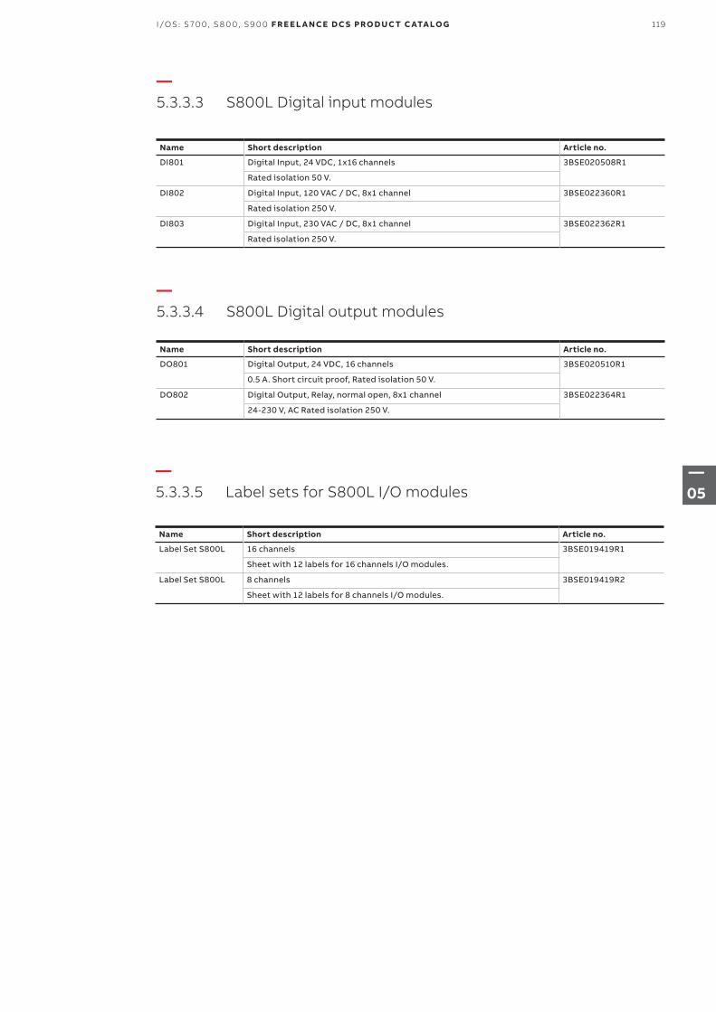
—5.3.3.3 S800L Digital input modules
—5.3.3.4 S800L Digital output modules
Name Short description Article no.
DI801 Digital Input, 24 VDC, 1x16 channels 3BSE020508R1
Rated isolation 50 V.
DI802 Digital Input, 120 VAC / DC, 8x1 channel 3BSE022360R1
Rated isolation 250 V.
DI803 Digital Input, 230 VAC / DC, 8x1 channel 3BSE022362R1
Rated isolation 250 V.
Name Short description Article no.
DO801 Digital Output, 24 VDC, 16 channels 3BSE020510R1
0.5 A. Short circuit proof, Rated isolation 50 V.
DO802 Digital Output, Relay, normal open, 8x1 channel 3BSE022364R1
24-230 V, AC Rated isolation 250 V.
—5.3.3.5 Label sets for S800L I/O modules
Name Short description Article no.
Label Set S800L 16 channels 3BSE019419R1
Sheet with 12 labels for 16 channels I/O modules.
Label Set S800L 8 channels 3BSE019419R2
Sheet with 12 labels for 8 channels I/O modules.
119I/OS: S 70 0, S 8 0 0, S9 0 0 F R E E L A N CE D C S PRO D U C T C ATA LO G
—05
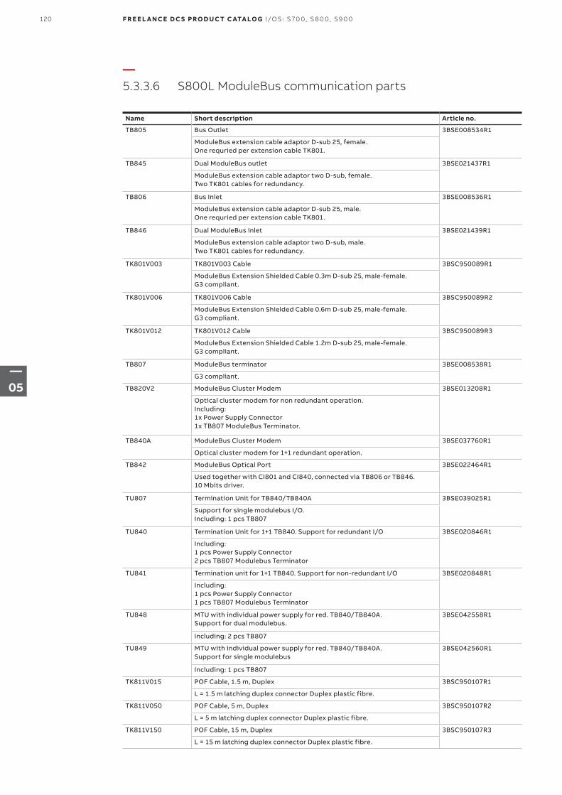
—5.3.3.6 S800L ModuleBus communication parts
Name Short description Article no.
TB805 Bus Outlet 3BSE008534R1
ModuleBus extension cable adaptor D-sub 25, female. One requried per extension cable TK801.
TB845 Dual ModuleBus outlet 3BSE021437R1
ModuleBus extension cable adaptor two D-sub, female. Two TK801 cables for redundancy.
TB806 Bus Inlet 3BSE008536R1
ModuleBus extension cable adaptor D-sub 25, male. One requried per extension cable TK801.
TB846 Dual ModuleBus inlet 3BSE021439R1
ModuleBus extension cable adaptor two D-sub, male. Two TK801 cables for redundancy.
TK801V003 TK801V003 Cable 3BSC950089R1
ModuleBus Extension Shielded Cable 0.3m D-sub 25, male-female. G3 compliant.
TK801V006 TK801V006 Cable 3BSC950089R2
ModuleBus Extension Shielded Cable 0.6m D-sub 25, male-female. G3 compliant.
TK801V012 TK801V012 Cable 3BSC950089R3
ModuleBus Extension Shielded Cable 1.2m D-sub 25, male-female. G3 compliant.
TB807 ModuleBus terminator 3BSE008538R1
G3 compliant.
TB820V2 ModuleBus Cluster Modem 3BSE013208R1
Optical cluster modem for non redundant operation. Including: 1x Power Supply Connector 1x TB807 ModuleBus Terminator.
TB840A ModuleBus Cluster Modem 3BSE037760R1
Optical cluster modem for 1+1 redundant operation.
TB842 ModuleBus Optical Port 3BSE022464R1
Used together with CI801 and CI840, connected via TB806 or TB846. 10 Mbits driver.
TU807 Termination Unit for TB840/TB840A 3BSE039025R1
Support for single modulebus I/O. Including: 1 pcs TB807
TU840 Termination Unit for 1+1 TB840. Support for redundant I/O 3BSE020846R1
Including:1 pcs Power Supply Connector2 pcs TB807 Modulebus Terminator
TU841 Termination unit for 1+1 TB840. Support for non-redundant I/O 3BSE020848R1
Including:1 pcs Power Supply Connector1 pcs TB807 Modulebus Terminator
TU848 MTU with individual power supply for red. TB840/TB840A.Support for dual modulebus.
3BSE042558R1
Including: 2 pcs TB807
TU849 MTU with individual power supply for red. TB840/TB840A.Support for single modulebus
3BSE042560R1
Including: 1 pcs TB807
TK811V015 POF Cable, 1.5 m, Duplex 3BSC950107R1
L = 1.5 m latching duplex connector Duplex plastic fibre.
TK811V050 POF Cable, 5 m, Duplex 3BSC950107R2
L = 5 m latching duplex connector Duplex plastic fibre.
TK811V150 POF Cable, 15 m, Duplex 3BSC950107R3
L = 15 m latching duplex connector Duplex plastic fibre.
120 F R E E L A N CE D C S PRO D U C T C ATA LO G I/OS: S 70 0, S 8 0 0, S9 0 0
—05
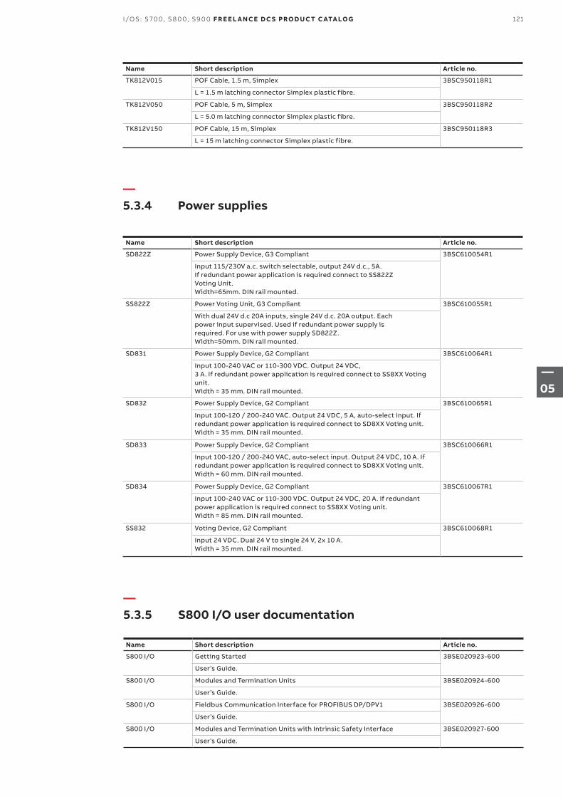
Name Short description Article no.
TK812V015 POF Cable, 1.5 m, Simplex 3BSC950118R1
L = 1.5 m latching connector Simplex plastic fibre.
TK812V050 POF Cable, 5 m, Simplex 3BSC950118R2
L = 5.0 m latching connector Simplex plastic fibre.
TK812V150 POF Cable, 15 m, Simplex 3BSC950118R3
L = 15 m latching connector Simplex plastic fibre.
Name Short description Article no.
SD822Z Power Supply Device, G3 Compliant 3BSC610054R1
Input 115/230V a.c. switch selectable, output 24V d.c., 5A.If redundant power application is required connect to SS822ZVoting Unit.Width=65mm. DIN rail mounted.
SS822Z Power Voting Unit, G3 Compliant 3BSC610055R1
With dual 24V d.c 20A inputs, single 24V d.c. 20A output. Eachpower input supervised. Used if redundant power supply isrequired. For use with power supply SD822Z.Width=50mm. DIN rail mounted.
SD831 Power Supply Device, G2 Compliant 3BSC610064R1
Input 100-240 VAC or 110-300 VDC. Output 24 VDC, 3 A. If redundant power application is required connect to SS8XX Voting unit. Width = 35 mm. DIN rail mounted.
SD832 Power Supply Device, G2 Compliant 3BSC610065R1
Input 100-120 / 200-240 VAC. Output 24 VDC, 5 A, auto-select input. If redundant power application is required connect to SD8XX Voting unit. Width = 35 mm. DIN rail mounted.
SD833 Power Supply Device, G2 Compliant 3BSC610066R1
Input 100-120 / 200-240 VAC, auto-select input. Output 24 VDC, 10 A. If redundant power application is required connect to SD8XX Voting unit. Width = 60 mm. DIN rail mounted.
SD834 Power Supply Device, G2 Compliant 3BSC610067R1
Input 100-240 VAC or 110-300 VDC. Output 24 VDC, 20 A. If redundant power application is required connect to SS8XX Voting unit. Width = 85 mm. DIN rail mounted.
SS832 Voting Device, G2 Compliant 3BSC610068R1
Input 24 VDC. Dual 24 V to single 24 V, 2x 10 A. Width = 35 mm. DIN rail mounted.
—5.3.4 Power supplies
Name Short description Article no.
S800 I/O Getting Started 3BSE020923-600
User’s Guide.
S800 I/O Modules and Termination Units 3BSE020924-600
User’s Guide.
S800 I/O Fieldbus Communication Interface for PROFIBUS DP/DPV1 3BSE020926-600
User’s Guide.
S800 I/O Modules and Termination Units with Intrinsic Safety Interface 3BSE020927-600
User’s Guide.
—5.3.5 S800 I/O user documentation
121I/OS: S 70 0, S 8 0 0, S9 0 0 F R E E L A N CE D C S PRO D U C T C ATA LO G
—05
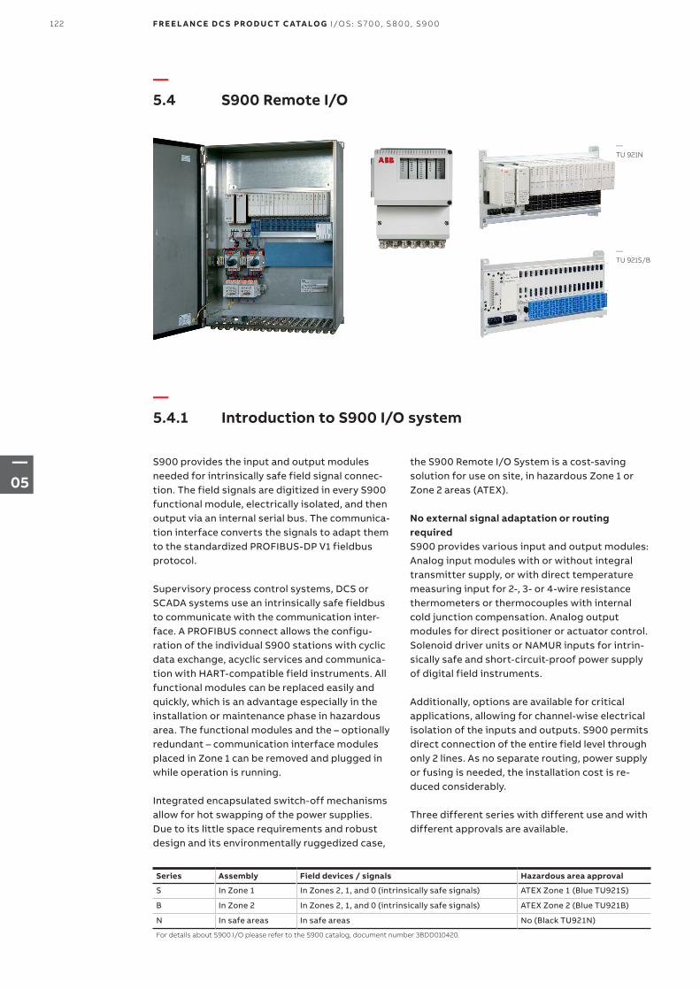
—5.4.1 Introduction to S900 I/O system
—5.4 S900 Remote I/O
S900 provides the input and output modules needed for intrinsically safe field signal connec-tion. The field signals are digitized in every S900 functional module, electrically isolated, and then output via an internal serial bus. The communica-tion interface converts the signals to adapt them to the standardized PROFIBUS-DP V1 fieldbus protocol.
Supervisory process control systems, DCS or SCADA systems use an intrinsically safe fieldbus to communicate with the communication inter-face. A PROFIBUS connect allows the configu-ration of the individual S900 stations with cyclic data exchange, acyclic services and communica-tion with HART-compatible field instruments. All functional modules can be replaced easily and quickly, which is an advantage especially in the installation or maintenance phase in hazardous area. The functional modules and the – optionally redundant – communication interface modules placed in Zone 1 can be removed and plugged in while operation is running.
Integrated encapsulated switch-off mechanisms allow for hot swapping of the power supplies. Due to its little space requirements and robust design and its environmentally ruggedized case,
the S900 Remote I/O System is a cost-saving solution for use on site, in hazardous Zone 1 or Zone 2 areas (ATEX).
No external signal adaptation or routing requiredS900 provides various input and output modules: Analog input modules with or without integral transmitter supply, or with direct temperature measuring input for 2-, 3- or 4-wire resistance thermometers or thermocouples with internal cold junction compensation. Analog output modules for direct positioner or actuator control. Solenoid driver units or NAMUR inputs for intrin-sically safe and short-circuit-proof power supply of digital field instruments.
Additionally, options are available for critical applications, allowing for channel-wise electrical isolation of the inputs and outputs. S900 permits direct connection of the entire field level through only 2 lines. As no separate routing, power supply or fusing is needed, the installation cost is re-duced considerably.
Three different series with different use and with different approvals are available.
Series Assembly Field devices / signals Hazardous area approval
S In Zone 1 In Zones 2, 1, and 0 (intrinsically safe signals) ATEX Zone 1 (Blue TU921S)
B In Zone 2 In Zones 2, 1, and 0 (intrinsically safe signals) ATEX Zone 2 (Blue TU921B)
N In safe areas In safe areas No (Black TU921N)
For details about S900 I/O please refer to the S900 catalog, document number 3BDD010420.
—TU 921N
—TU 921S/B
122 F R E E L A N CE D C S PRO D U C T C ATA LO G I/OS: S 70 0, S 8 0 0, S9 0 0
—05
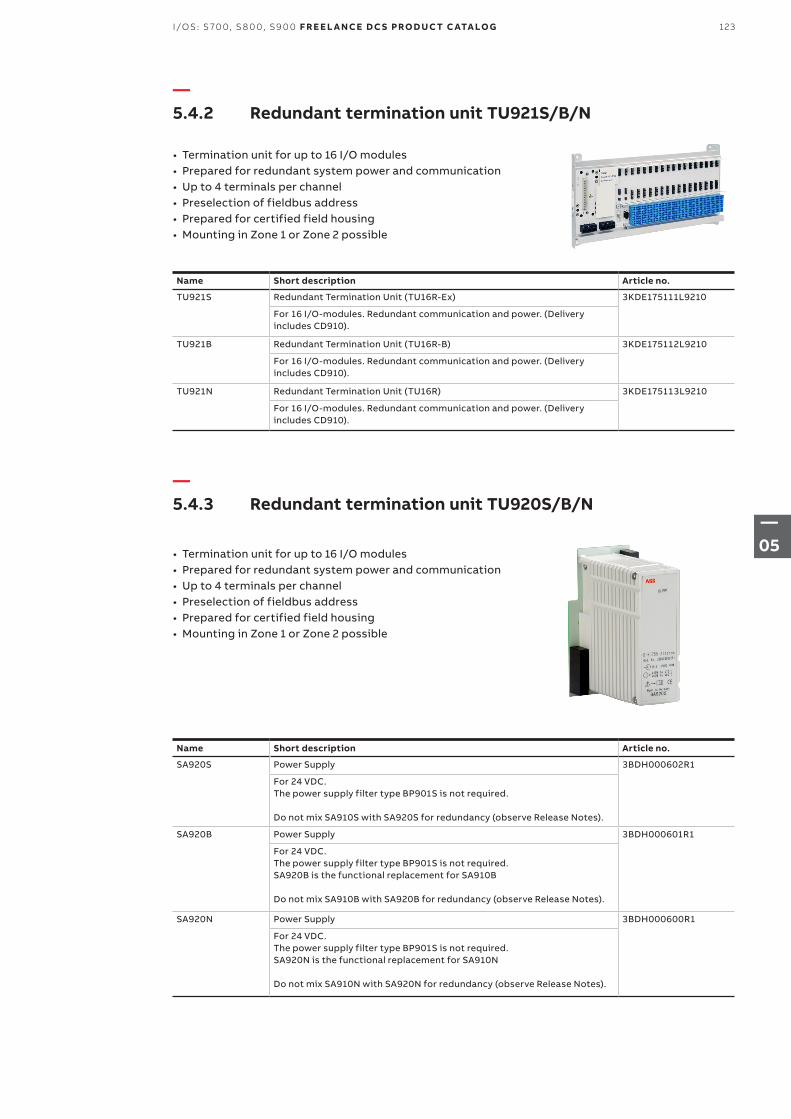
—5.4.2 Redundant termination unit TU921S/B/N
—5.4.3 Redundant termination unit TU920S/B/N
• Termination unit for up to 16 I/O modules• Prepared for redundant system power and communication• Up to 4 terminals per channel• Preselection of fieldbus address• Prepared for certified field housing• Mounting in Zone 1 or Zone 2 possible
• Termination unit for up to 16 I/O modules• Prepared for redundant system power and communication• Up to 4 terminals per channel• Preselection of fieldbus address• Prepared for certified field housing• Mounting in Zone 1 or Zone 2 possible
Name Short description Article no.
TU921S Redundant Termination Unit (TU16R-Ex) 3KDE175111L9210
For 16 I/O-modules. Redundant communication and power. (Delivery includes CD910).
TU921B Redundant Termination Unit (TU16R-B) 3KDE175112L9210
For 16 I/O-modules. Redundant communication and power. (Delivery includes CD910).
TU921N Redundant Termination Unit (TU16R) 3KDE175113L9210
For 16 I/O-modules. Redundant communication and power. (Delivery includes CD910).
Name Short description Article no.
SA920S Power Supply 3BDH000602R1
For 24 VDC. The power supply filter type BP901S is not required.
Do not mix SA910S with SA920S for redundancy (observe Release Notes).
SA920B Power Supply 3BDH000601R1
For 24 VDC. The power supply filter type BP901S is not required. SA920B is the functional replacement for SA910B Do not mix SA910B with SA920B for redundancy (observe Release Notes).
SA920N Power Supply 3BDH000600R1
For 24 VDC. The power supply filter type BP901S is not required. SA920N is the functional replacement for SA910N Do not mix SA910N with SA920N for redundancy (observe Release Notes).
123I/OS: S 70 0, S 8 0 0, S9 0 0 F R E E L A N CE D C S PRO D U C T C ATA LO G
—05
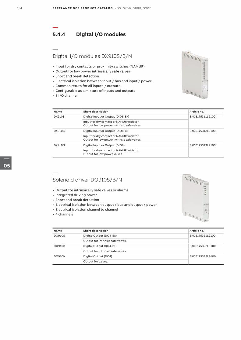
—5.4.4 Digital I/O modules
—Digital I/O modules DX910S/B/N
• Input for dry contacts or proximity switches (NAMUR)• Output for low power intrinsically safe valves• Short and break detection• Electrical isolation between input / bus and input / power• Common return for all inputs / outputs• Configurable as a mixture of inputs and outputs• 8 I/O channel
—Solenoid driver DO910S/B/N
• Output for intrinsically safe valves or alarms• Integrated driving power• Short and break detection• Electrical isolation between output / bus and output / power• Electrical isolation channel to channel• 4 channels
Name Short description Article no.
DX910S Digital Input or Output (DIO8-Ex) 3KDE175311L9100
Input for dry contact or NAMUR initiator. Output for low power intrinsic safe valves.
DX910B Digital Input or Output (DIO8-B) 3KDE175312L9100
Input for dry contact or NAMUR initiator. Output for low power intrinsic safe valves.
DX910N Digital Input or Output (DIO8) 3KDE175313L9100
Input for dry contact or NAMUR initiator. Output for low power valves.
Name Short description Article no.
DO910S Digital Output (DO4-Ex) 3KDE175321L9100
Output for intrinsic safe valves.
DO910B Digital Output (DO4-B) 3KDE175322L9100
Output for intrinsic safe valves.
DO910N Digital Output (DO4) 3KDE175323L9100
Output for valves.
124 F R E E L A N CE D C S PRO D U C T C ATA LO G I/OS: S 70 0, S 8 0 0, S9 0 0
—05
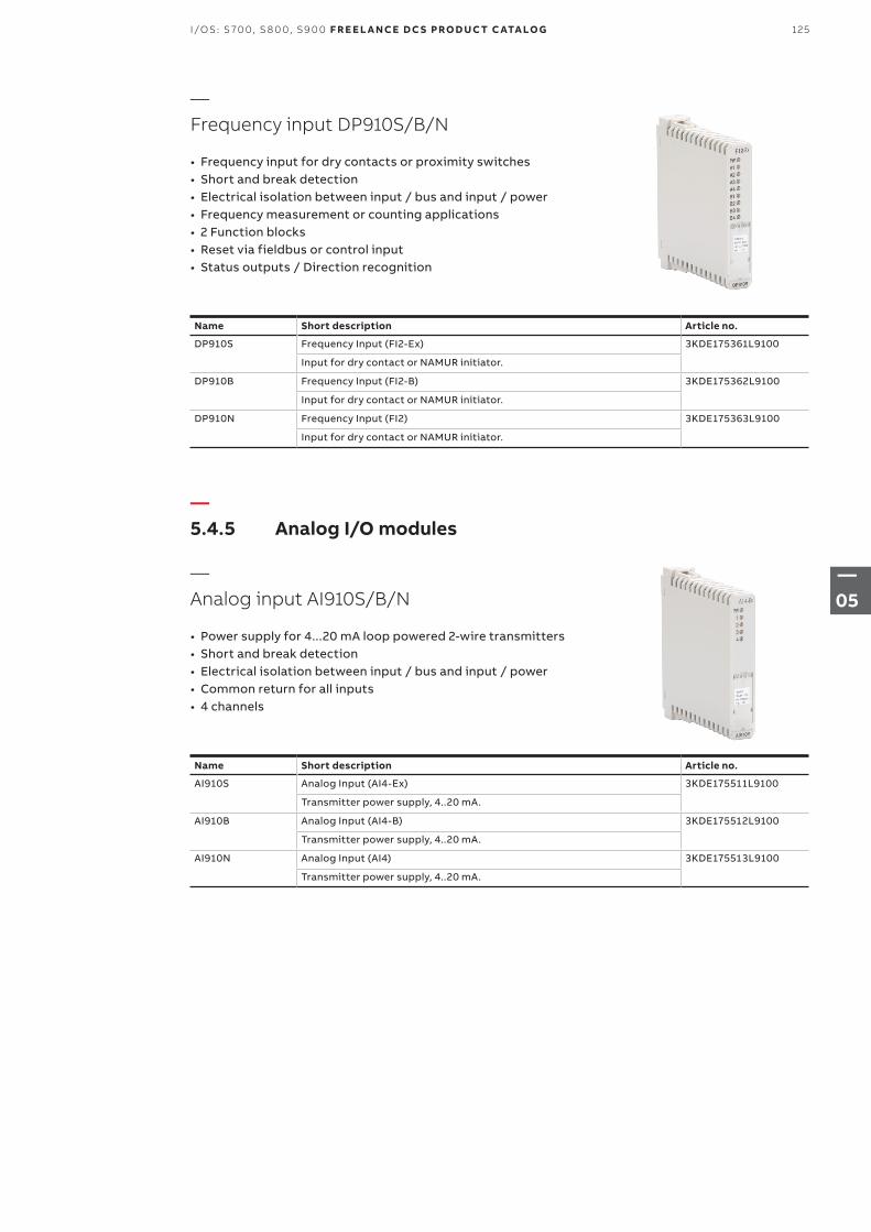
—5.4.5 Analog I/O modules
—Analog input AI910S/B/N
• Power supply for 4...20 mA loop powered 2-wire transmitters• Short and break detection• Electrical isolation between input / bus and input / power• Common return for all inputs• 4 channels
—Frequency input DP910S/B/N
• Frequency input for dry contacts or proximity switches• Short and break detection• Electrical isolation between input / bus and input / power• Frequency measurement or counting applications• 2 Function blocks• Reset via fieldbus or control input• Status outputs / Direction recognition
Name Short description Article no.
DP910S Frequency Input (FI2-Ex) 3KDE175361L9100
Input for dry contact or NAMUR initiator.
DP910B Frequency Input (FI2-B) 3KDE175362L9100
Input for dry contact or NAMUR initiator.
DP910N Frequency Input (FI2) 3KDE175363L9100
Input for dry contact or NAMUR initiator.
Name Short description Article no.
AI910S Analog Input (AI4-Ex) 3KDE175511L9100
Transmitter power supply, 4..20 mA.
AI910B Analog Input (AI4-B) 3KDE175512L9100
Transmitter power supply, 4..20 mA.
AI910N Analog Input (AI4) 3KDE175513L9100
Transmitter power supply, 4..20 mA.
125I/OS: S 70 0, S 8 0 0, S9 0 0 F R E E L A N CE D C S PRO D U C T C ATA LO G
—05
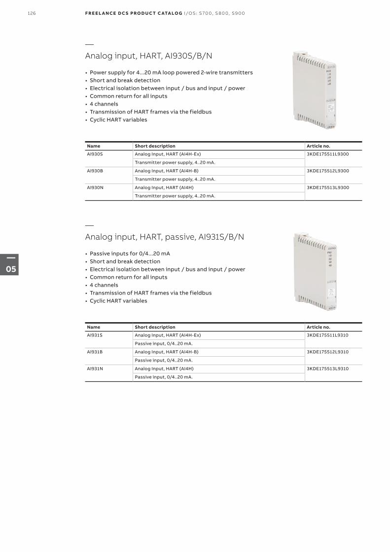
—Analog input, HART, AI930S/B/N
• Power supply for 4...20 mA loop powered 2-wire transmitters• Short and break detection• Electrical isolation between input / bus and input / power• Common return for all inputs• 4 channels• Transmission of HART frames via the fieldbus• Cyclic HART variables
—Analog input, HART, passive, AI931S/B/N
• Passive inputs for 0/4...20 mA• Short and break detection• Electrical isolation between input / bus and input / power• Common return for all inputs• 4 channels• Transmission of HART frames via the fieldbus• Cyclic HART variables
Name Short description Article no.
AI930S Analog Input, HART (AI4H-Ex) 3KDE175511L9300
Transmitter power supply, 4..20 mA.
AI930B Analog Input, HART (AI4H-B) 3KDE175512L9300
Transmitter power supply, 4..20 mA.
AI930N Analog Input, HART (AI4H) 3KDE175513L9300
Transmitter power supply, 4..20 mA.
Name Short description Article no.
AI931S Analog Input, HART (AI4H-Ex) 3KDE175511L9310
Passive input, 0/4..20 mA.
AI931B Analog Input, HART (AI4H-B) 3KDE175512L9310
Passive input, 0/4..20 mA.
AI931N Analog Input, HART (AI4H) 3KDE175513L9310
Passive input, 0/4..20 mA.
126 F R E E L A N CE D C S PRO D U C T C ATA LO G I/OS: S 70 0, S 8 0 0, S9 0 0
—05
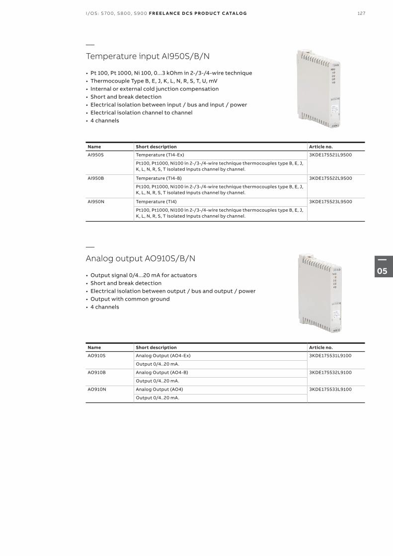
—Temperature input AI950S/B/N
• Pt 100, Pt 1000, Ni 100, 0...3 kOhm in 2-/3-/4-wire technique• Thermocouple Type B, E, J, K, L, N, R, S, T, U, mV• Internal or external cold junction compensation• Short and break detection• Electrical isolation between input / bus and input / power• Electrical isolation channel to channel• 4 channels
—Analog output AO910S/B/N
• Output signal 0/4...20 mA for actuators• Short and break detection• Electrical isolation between output / bus and output / power• Output with common ground• 4 channels
Name Short description Article no.
AI950S Temperature (TI4-Ex) 3KDE175521L9500
Pt100, Pt1000, Ni100 in 2-/3-/4-wire technique thermocouples type B, E, J, K, L, N, R, S, T isolated inputs channel by channel.
AI950B Temperature (TI4-B) 3KDE175522L9500
Pt100, Pt1000, Ni100 in 2-/3-/4-wire technique thermocouples type B, E, J, K, L, N, R, S, T isolated inputs channel by channel.
AI950N Temperature (TI4) 3KDE175523L9500
Pt100, Pt1000, Ni100 in 2-/3-/4-wire technique thermocouples type B, E, J, K, L, N, R, S, T isolated inputs channel by channel.
Name Short description Article no.
AO910S Analog Output (AO4-Ex) 3KDE175531L9100
Output 0/4..20 mA.
AO910B Analog Output (AO4-B) 3KDE175532L9100
Output 0/4..20 mA.
AO910N Analog Output (AO4) 3KDE175533L9100
Output 0/4..20 mA.
127I/OS: S 70 0, S 8 0 0, S9 0 0 F R E E L A N CE D C S PRO D U C T C ATA LO G
—05
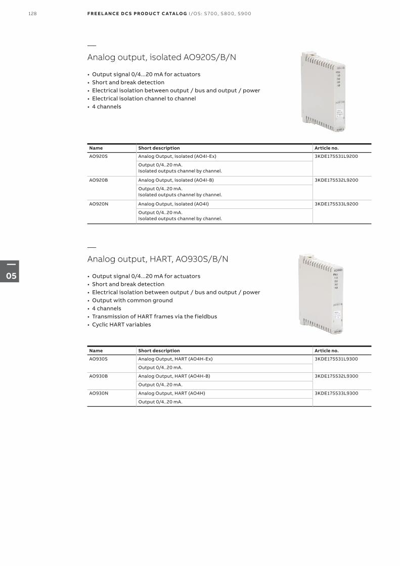
—Analog output, isolated AO920S/B/N
• Output signal 0/4...20 mA for actuators• Short and break detection• Electrical isolation between output / bus and output / power• Electrical isolation channel to channel• 4 channels
—Analog output, HART, AO930S/B/N
• Output signal 0/4...20 mA for actuators• Short and break detection• Electrical isolation between output / bus and output / power• Output with common ground• 4 channels• Transmission of HART frames via the fieldbus• Cyclic HART variables
Name Short description Article no.
AO920S Analog Output, isolated (AO4I-Ex) 3KDE175531L9200
Output 0/4..20 mA. Isolated outputs channel by channel.
AO920B Analog Output, isolated (AO4I-B) 3KDE175532L9200
Output 0/4..20 mA. Isolated outputs channel by channel.
AO920N Analog Output, isolated (AO4I) 3KDE175533L9200
Output 0/4..20 mA. Isolated outputs channel by channel.
Name Short description Article no.
AO930S Analog Output, HART (AO4H-Ex) 3KDE175531L9300
Output 0/4..20 mA.
AO930B Analog Output, HART (AO4H-B) 3KDE175532L9300
Output 0/4..20 mA.
AO930N Analog Output, HART (AO4H) 3KDE175533L9300
Output 0/4..20 mA.
128 F R E E L A N CE D C S PRO D U C T C ATA LO G I/OS: S 70 0, S 8 0 0, S9 0 0
—05
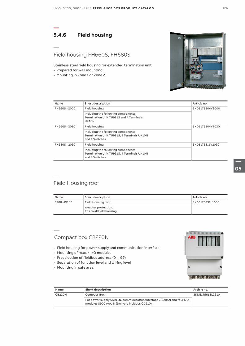
—5.4.6 Field housing
—Field housing FH660S, FH680S
Stainless steel field housing for extended termination unit• Prepared for wall mounting• Mounting in Zone 1 or Zone 2
—Compact box CB220N
• Field housing for power supply and communication interface• Mounting of max. 4 I/O modules• Preselection of fieldbus address (0 ... 99)• Separation of function level and wiring level• Mounting in safe area
—Field Housing roof
Name Short description Article no.
FH660S - 2000 Field housing 3KDE175804V2000
Including the following components: Termination Unit TU921S and 4 TerminalsUK10N
FH660S - 2020 Field housing 3KDE175804V2020
Including the following components: Termination Unit TU921S, 4 Terminals UK10Nand 2 Switches
FH680S - 2020 Field housing 3KDE175811V2020
Including the following components: Termination Unit TU921S, 4 Terminals UK10Nand 2 Switches
Name Short description Article no.
S900 - BI100 Field Housing roof 3KDE175831L1000
Weather protection. Fits to all field housing.
Name Short description Article no.
CB220N Compact-Box 3KDE175613L2210
For power supply SA911N, communication interface CI920AN and four I/O modules S900 type N (Delivery includes CD910).
129I/OS: S 70 0, S 8 0 0, S9 0 0 F R E E L A N CE D C S PRO D U C T C ATA LO G
—05
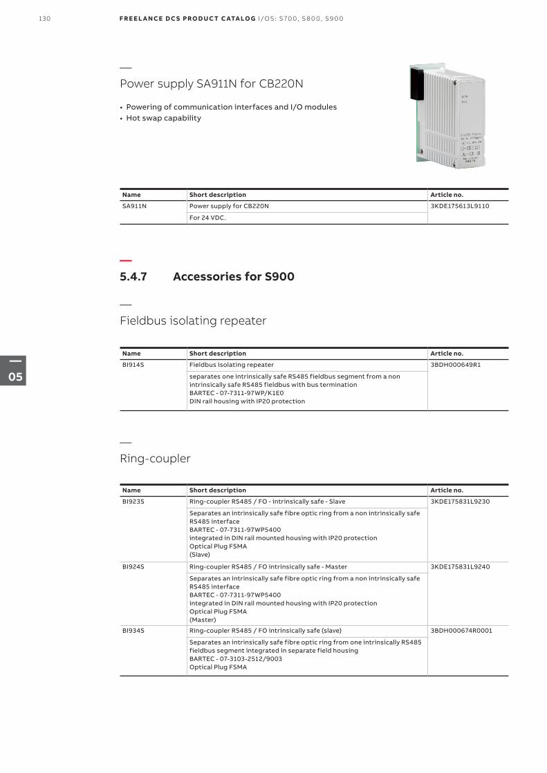
—Power supply SA911N for CB220N
• Powering of communication interfaces and I/O modules• Hot swap capability
Name Short description Article no.
SA911N Power supply for CB220N 3KDE175613L9110
For 24 VDC.
—5.4.7 Accessories for S900
—Fieldbus isolating repeater
Name Short description Article no.
BI914S Fieldbus isolating repeater 3BDH000649R1
separates one intrinsically safe RS485 fieldbus segment from a non intrinsically safe RS485 fieldbus with bus terminationBARTEC - 07-7311-97WP/K1E0DIN rail housing with IP20 protection
—Ring-coupler
Name Short description Article no.
BI923S Ring-coupler RS485 / FO - intrinsically safe - Slave 3KDE175831L9230
Separates an intrinsically safe fibre optic ring from a non intrinsically safe RS485 interfaceBARTEC - 07-7311-97WP5400integrated in DIN rail mounted housing with IP20 protectionOptical Plug FSMA(Slave)
BI924S Ring-coupler RS485 / FO intrinsically safe - Master 3KDE175831L9240
Separates an intrinsically safe fibre optic ring from a non intrinsically safe RS485 interfaceBARTEC - 07-7311-97WP5400integrated in DIN rail mounted housing with IP20 protectionOptical Plug FSMA(Master)
BI934S Ring-coupler RS485 / FO intrinsically safe (slave) 3BDH000674R0001
Separates an intrinsically safe fibre optic ring from one intrinsically RS485 fieldbus segment integrated in separate field housingBARTEC - 07-3103-2512/9003Optical Plug FSMA
130 F R E E L A N CE D C S PRO D U C T C ATA LO G I/OS: S 70 0, S 8 0 0, S9 0 0
—05
—Additional accessories
Name Short description Article no.
IP920 Module housing 3KDE175831L9200
IP20 protection for empty slots on the termination unit. For use in S900 S, B, and N systems.
IL910 Insert labels 3KDE175839L9101
380 pcs.
BP914S Intrinsically safe PROFIBUS-DP connector for CI920AS and CI920AB
D-SUB Connector (color blue) for operating the intrinsically safePROFIBUS-DP with CI920AS and CI920AB(Siemens 6ES7972-0DA60-0XA0)
3BSE067082R1
—5.4.8 Software
Name Short description Article no.
CD910 Additional Software 3KDE175839L9100
CD ROM incl. S900 Documentation, Certificates, GSD (file)ABB DTM S900 DP and Software ToolsCD ROM will be delivered with all TU921 and CB220 deliveries
131I/OS: S 70 0, S 8 0 0, S9 0 0 F R E E L A N CE D C S PRO D U C T C ATA LO G
—05
—Chapter 6 – Fieldbus network components and PROFIBUS configuration for S700
133 6.1 PROFIBUS DP configuration for S700
134 6.2 PROFIBUS network components
135 6.3 FOUNDATION Fieldbus network components
132 F R E E L A N CE D C S PRO D U C T C ATA LO G F I EL D B US N E T WO R K CO M P O N ENTS
—06
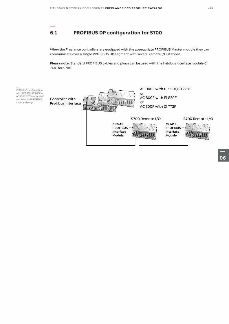
—6.1 PROFIBUS DP configuration for S700
When the Freelance controllers are equipped with the appropriate PROFIBUS Master module they can communicate over a single PROFIBUS DP segment with several remote I/O stations.
Please note: Standard PROFIBUS cables and plugs can be used with the fieldbus interface module CI 741F for S700.
—PROFIBUS configuration with AC 900F, AC 800F or AC 700F, S700 remote I/O and standard PROFIBUS cable and plugs
133FI EL D B US N E T WO R K CO M P O N ENTS F R E E L A N CE D C S PRO D U C T C ATA LO G
—06
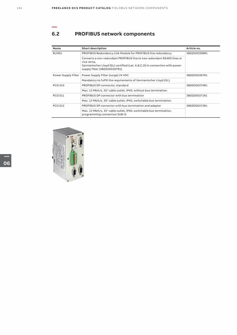
—6.2 PROFIBUS network components
Name Short description Article no.
RLM01 PROFIBUS Redundancy Link Module for PROFIBUS line redundancy 3BDZ000398R1
Converts a non-redundant PROFIBUS line to two redundant RS485 lines or vice versa. Germanischer Lloyd (GL) certified (cat. A,B,C,D) in connection with power supply filter (3BDZ000397R1).
Power Supply Filter Power Supply Filter (surge) 24 VDC 3BDZ000397R1
Mandatory to fulfill the requirements of Germanischer Lloyd (GL).
PCO 010 PROFIBUS DP connector, standard 3BDZ000370R1
Max. 12 Mbit/s, 35° cable outlet, IP40, without bus termination.
PCO 011 PROFIBUS DP connector with bus termination 3BDZ000371R1
Max. 12 Mbit/s, 35° cable outlet, IP40, switchable bus termination.
PCO 012 PROFIBUS DP connector with bus termination and adapter 3BDZ000372R1
Max. 12 Mbit/s, 35° cable outlet, IP40, switchable bus termination, programming connection SUB-D.
134 F R E E L A N CE D C S PRO D U C T C ATA LO G F I EL D B US N E T WO R K CO M P O N ENTS
—06
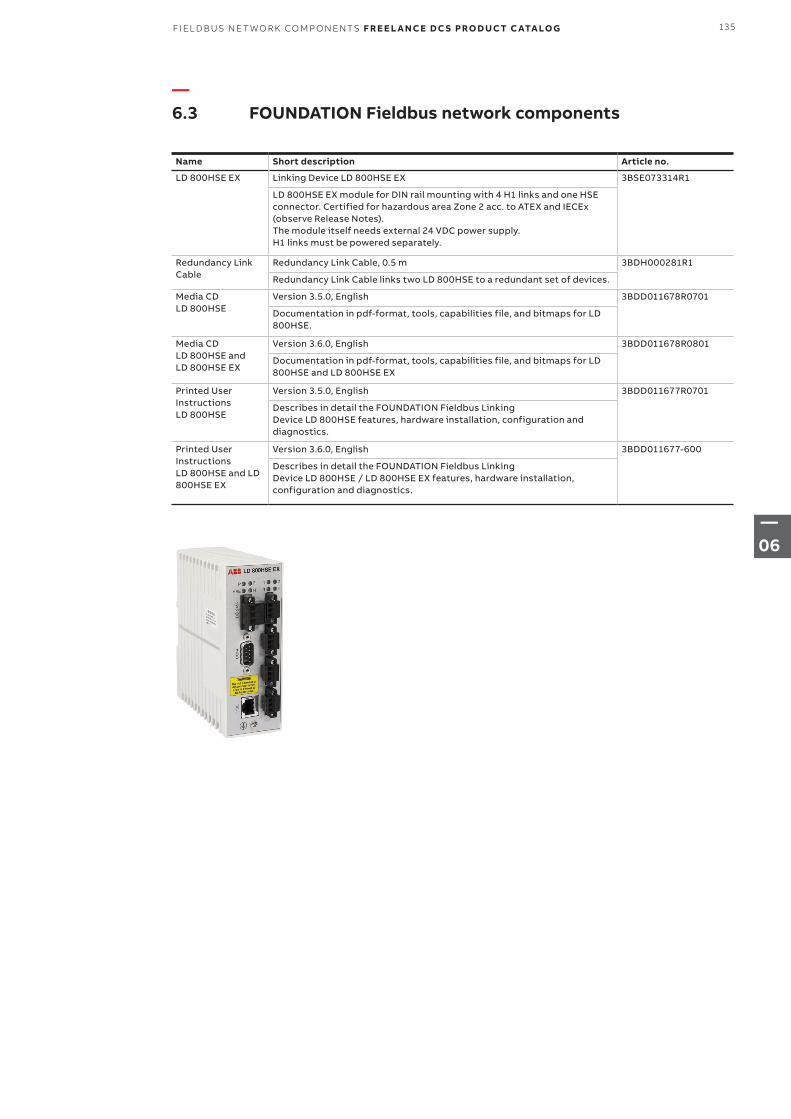
—6.3 FOUNDATION Fieldbus network components
Name Short description Article no.
LD 800HSE EX Linking Device LD 800HSE EX 3BSE073314R1
LD 800HSE EX module for DIN rail mounting with 4 H1 links and one HSE connector. Certified for hazardous area Zone 2 acc. to ATEX and IECEx (observe Release Notes). The module itself needs external 24 VDC power supply. H1 links must be powered separately.
Redundancy Link Cable
Redundancy Link Cable, 0.5 m 3BDH000281R1
Redundancy Link Cable links two LD 800HSE to a redundant set of devices.
Media CD LD 800HSE
Version 3.5.0, English 3BDD011678R0701
Documentation in pdf-format, tools, capabilities file, and bitmaps for LD 800HSE.
Media CD LD 800HSE and LD 800HSE EX
Version 3.6.0, English 3BDD011678R0801
Documentation in pdf-format, tools, capabilities file, and bitmaps for LD 800HSE and LD 800HSE EX
Printed User Instructions LD 800HSE
Version 3.5.0, English 3BDD011677R0701
Describes in detail the FOUNDATION Fieldbus Linking Device LD 800HSE features, hardware installation, configuration and diagnostics.
Printed User Instructions LD 800HSE and LD 800HSE EX
Version 3.6.0, English 3BDD011677-600
Describes in detail the FOUNDATION Fieldbus Linking Device LD 800HSE / LD 800HSE EX features, hardware installation, configuration and diagnostics.
135FI EL D B US N E T WO R K CO M P O N ENTS F R E E L A N CE D C S PRO D U C T C ATA LO G
—06
—Chapter 7 – Freelance Operations
137 – 140 7.1 Overview
141 – 142 7.2 Messages & operator hints
143 7.3 Automation Sentinel
143 7.4 Freelance Software languages
143 7.5 Freelance Operations license
144 7.6 Connectivity
144 7.7 Freelance Operations options
144 7.8 Freelance Operations hardkeys
136 F R E E L A N CE D C S PRO D U C T C ATA LO G FR EEL A N CE O PER ATI O NS
—07
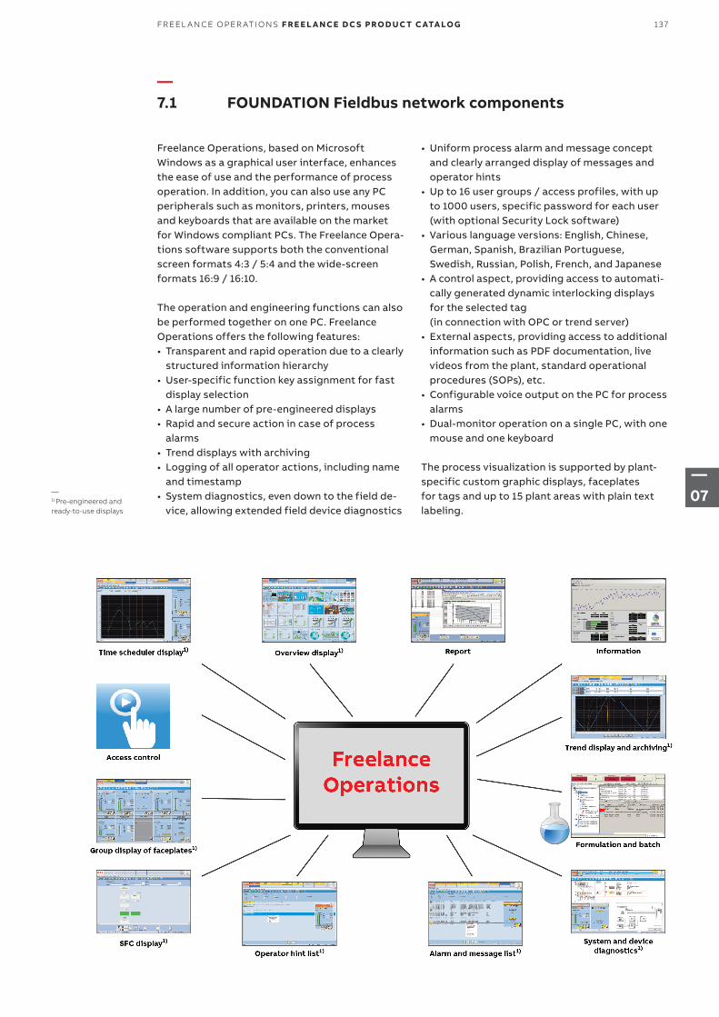
—7.1 FOUNDATION Fieldbus network components
Freelance Operations, based on Microsoft Windows as a graphical user interface, enhances the ease of use and the performance of process operation. In addition, you can also use any PC peripherals such as monitors, printers, mouses and keyboards that are available on the market for Windows compliant PCs. The Freelance Opera-tions software supports both the conventional screen formats 4:3 / 5:4 and the wide-screen formats 16:9 / 16:10.
The operation and engineering functions can also be performed together on one PC. Freelance Operations offers the following features:• Transparent and rapid operation due to a clearly
structured information hierarchy• User-specific function key assignment for fast
display selection• A large number of pre-engineered displays• Rapid and secure action in case of process
alarms• Trend displays with archiving• Logging of all operator actions, including name
and timestamp• System diagnostics, even down to the field de-
vice, allowing extended field device diagnostics
• Uniform process alarm and message concept and clearly arranged display of messages and operator hints
• Up to 16 user groups / access profiles, with up to 1000 users, specific password for each user (with optional Security Lock software)
• Various language versions: English, Chinese, German, Spanish, Brazilian Portuguese, Swedish, Russian, Polish, French, and Japanese
• A control aspect, providing access to automati-cally generated dynamic interlocking displays for the selected tag (in connection with OPC or trend server)
• External aspects, providing access to additional information such as PDF documentation, live videos from the plant, standard operational procedures (SOPs), etc.
• Configurable voice output on the PC for process alarms
• Dual-monitor operation on a single PC, with one mouse and one keyboard
The process visualization is supported by plant-specific custom graphic displays, faceplates for tags and up to 15 plant areas with plain text labeling.
—1) Pre-engineered and ready-to-use displays
137FR EEL A N CE O PER ATI O NS F R E E L A N CE D C S PRO D U C T C ATA LO G
—07
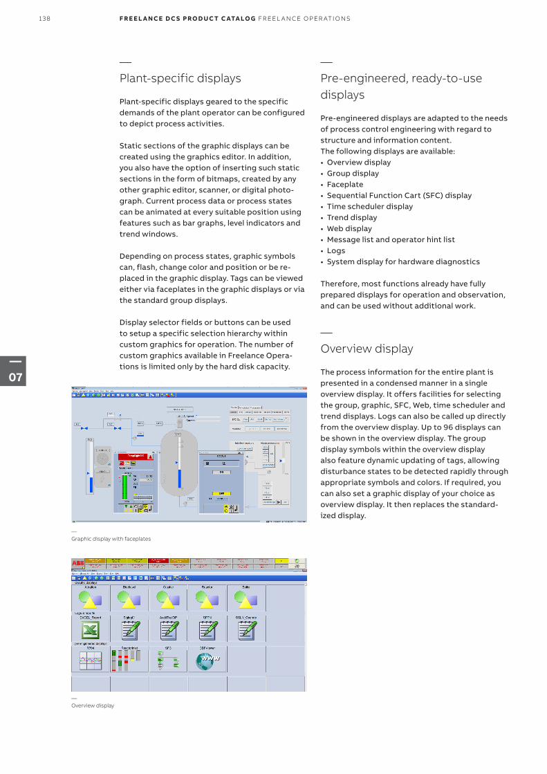
—Plant-specific displays
Plant-specific displays geared to the specific demands of the plant operator can be configured to depict process activities.
Static sections of the graphic displays can be created using the graphics editor. In addition, you also have the option of inserting such static sections in the form of bitmaps, created by any other graphic editor, scanner, or digital photo-graph. Current process data or process states can be animated at every suitable position using features such as bar graphs, level indicators and trend windows.
Depending on process states, graphic symbols can, flash, change color and position or be re-placed in the graphic display. Tags can be viewed either via faceplates in the graphic displays or via the standard group displays.
Display selector fields or buttons can be used to setup a specific selection hierarchy within custom graphics for operation. The number of custom graphics available in Freelance Opera-tions is limited only by the hard disk capacity.
—Pre-engineered, ready-to-use displays
Pre-engineered displays are adapted to the needs of process control engineering with regard to structure and information content.The following displays are available:• Overview display• Group display• Faceplate• Sequential Function Cart (SFC) display• Time scheduler display• Trend display• Web display• Message list and operator hint list• Logs• System display for hardware diagnostics
Therefore, most functions already have fully prepared displays for operation and observation, and can be used without additional work.
—Overview display
The process information for the entire plant is presented in a condensed manner in a single overview display. It offers facilities for selecting the group, graphic, SFC, Web, time scheduler and trend displays. Logs can also be called up directly from the overview display. Up to 96 displays can be shown in the overview display. The group display symbols within the overview display also feature dynamic updating of tags, allowing disturbance states to be detected rapidly through appropriate symbols and colors. If required, you can also set a graphic display of your choice as overview display. It then replaces the standard-ized display.
—Graphic display with faceplates
—Overview display
138 F R E E L A N CE D C S PRO D U C T C ATA LO G FR EEL A N CE O PER ATI O NS
—07
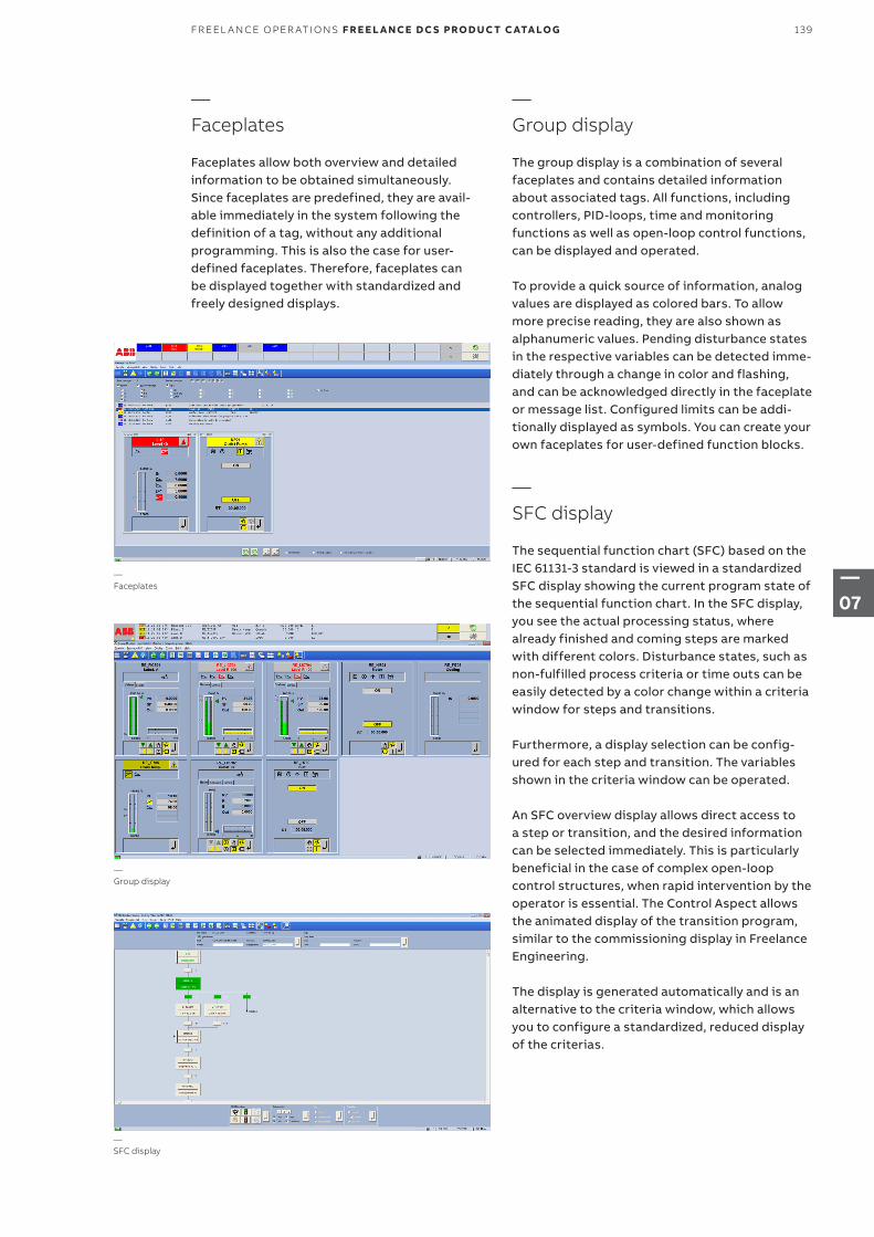
—Faceplates
Faceplates allow both overview and detailed information to be obtained simultaneously. Since faceplates are predefined, they are avail-able immediately in the system following the definition of a tag, without any additional programming. This is also the case for user-defined faceplates. Therefore, faceplates can be displayed together with standardized and freely designed displays.
—Group display
The group display is a combination of several faceplates and contains detailed information about associated tags. All functions, including controllers, PID-loops, time and monitoring functions as well as open-loop control functions, can be displayed and operated.
To provide a quick source of information, analog values are displayed as colored bars. To allow more precise reading, they are also shown as alphanumeric values. Pending disturbance states in the respective variables can be detected imme-diately through a change in color and flashing, and can be acknowledged directly in the faceplate or message list. Configured limits can be addi-tionally displayed as symbols. You can create your own faceplates for user-defined function blocks.
—SFC display
The sequential function chart (SFC) based on the IEC 61131-3 standard is viewed in a standardized SFC display showing the current program state of the sequential function chart. In the SFC display, you see the actual processing status, where already finished and coming steps are marked with different colors. Disturbance states, such as non-fulfilled process criteria or time outs can be easily detected by a color change within a criteria window for steps and transitions.
Furthermore, a display selection can be config-ured for each step and transition. The variables shown in the criteria window can be operated.
An SFC overview display allows direct access to a step or transition, and the desired information can be selected immediately. This is particularly beneficial in the case of complex open-loop control structures, when rapid intervention by the operator is essential. The Control Aspect allows the animated display of the transition program, similar to the commissioning display in Freelance Engineering.
The display is generated automatically and is an alternative to the criteria window, which allows you to configure a standardized, reduced display of the criterias.
—SFC display
—Faceplates
—Group display
139FR EEL A N CE O PER ATI O NS F R E E L A N CE D C S PRO D U C T C ATA LO G
—07
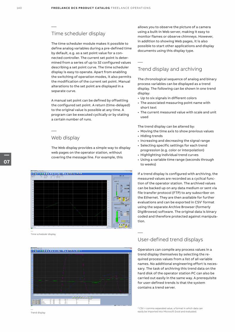
—Time scheduler display
The time scheduler module makes it possible to define analog variables during a pre-defined time by default, e.g. as a set point value for a con-nected controller. The current set point is deter-mined from a series of up to 32 configured values describing a set point curve. The time scheduler display is easy to operate. Apart from enabling the switching of operation modes, it also permits the modification of the current set point. Manual alterations to the set point are displayed in a separate curve.
A manual set point can be defined by offsetting the configured set point. A return (time-delayed) to the original value is possible at any time. A program can be executed cyclically or by stating a certain number of runs.
—Web display
The Web display provides a simple way to display web pages on the operator station, without covering the message line. For example, this
—Time scheduler display
—Trend display
allows you to observe the picture of a camera using a built-in Web server, making it easy to monitor flames or observe chimneys. However, in addition to showing Web pages, it is also possible to start other applications and display documents using this display type.
—Trend display and archiving
The chronological sequence of analog and binary process variables can be displayed as a trend display. The following can be shown in one trend display:• Up to six signals in different colors• The associated measuring point name with
short text• The current measured value with scale and unit
used
The trend display can be altered by:• Moving the time axis to show previous values• Hiding trends• Increasing and decreasing the signal range• Selecting specific settings for each trend
progression (e.g. color or interpolation)• Highlighting individual trend curves• Using a variable time range (seconds through
to weeks)
If a trend display is configured with archiving, the measured values are recorded as a cyclical func-tion of the operator station. The archived values can be backed up on any data medium or sent via file transfer protocol (FTP) to any subscriber on the Ethernet. They are then available for further evaluations and can be exported in CSV1 format using the separate Archive Browser (formerly DigiBrowse) software. The original data is binary coded and therefore protected against manipula-tion.
—User-defined trend displays
Operators can compile any process values in a trend display themselves by selecting the re-quired process values from a list of all variable names. No additional engineering effort is neces-sary. The task of archiving this trend data on the hard disk of the operator station PC can also be carried out easily in the same way. A prerequisite for user-defined trends is that the system contains a trend server.
1) CSV = comma separated value, a format in which data can easily be imported into Microsoft Excel and evaluated.
140 F R E E L A N CE D C S PRO D U C T C ATA LO G FR EEL A N CE O PER ATI O NS
—07
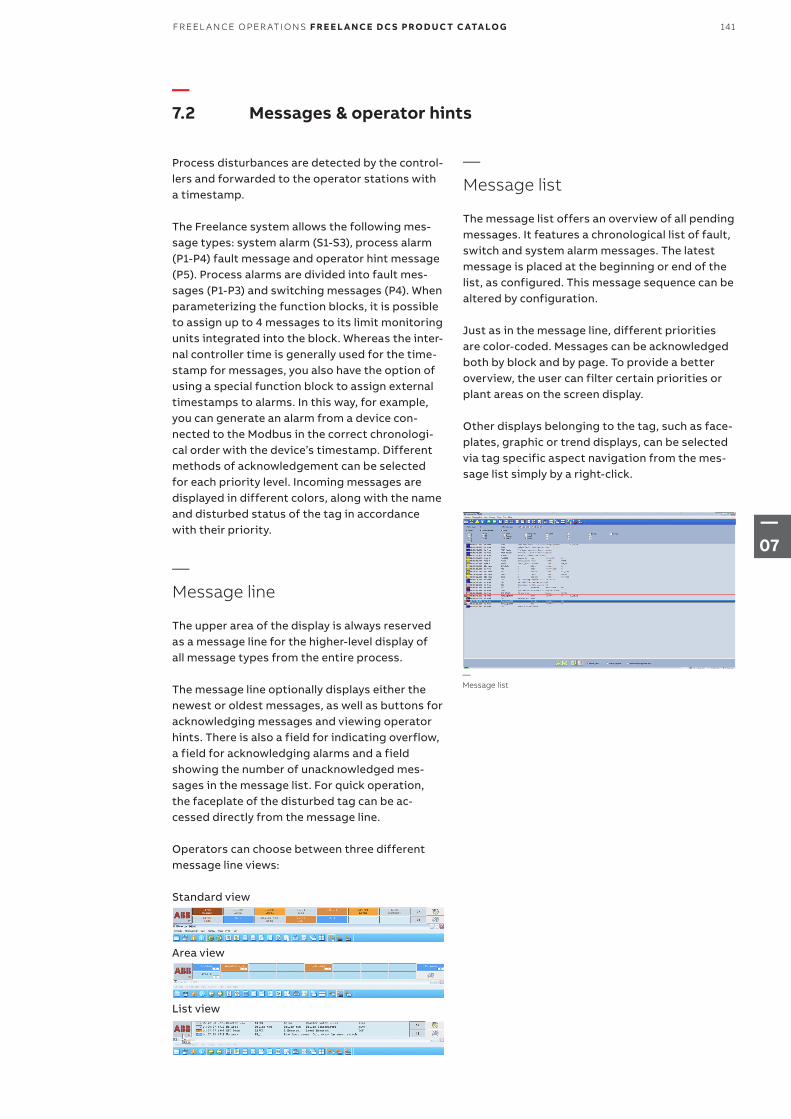
—Message list
—7.2 Messages & operator hints
Process disturbances are detected by the control-lers and forwarded to the operator stations with a timestamp.
The Freelance system allows the following mes-sage types: system alarm (S1-S3), process alarm (P1-P4) fault message and operator hint message (P5). Process alarms are divided into fault mes-sages (P1-P3) and switching messages (P4). When parameterizing the function blocks, it is possible to assign up to 4 messages to its limit monitoring units integrated into the block. Whereas the inter-nal controller time is generally used for the time-stamp for messages, you also have the option of using a special function block to assign external timestamps to alarms. In this way, for example, you can generate an alarm from a device con-nected to the Modbus in the correct chronologi-cal order with the device’s timestamp. Different methods of acknowledgement can be selected for each priority level. Incoming messages are displayed in different colors, along with the name and disturbed status of the tag in accordance with their priority.
—Message line
The upper area of the display is always reserved as a message line for the higher-level display of all message types from the entire process.
The message line optionally displays either the newest or oldest messages, as well as buttons for acknowledging messages and viewing operator hints. There is also a field for indicating overflow, a field for acknowledging alarms and a field showing the number of unacknowledged mes-sages in the message list. For quick operation, the faceplate of the disturbed tag can be ac-cessed directly from the message line.
Operators can choose between three different message line views:
Standard view
Area view
List view
—Message list
The message list offers an overview of all pending messages. It features a chronological list of fault, switch and system alarm messages. The latest message is placed at the beginning or end of the list, as configured. This message sequence can be altered by configuration.
Just as in the message line, different priorities are color-coded. Messages can be acknowledged both by block and by page. To provide a better overview, the user can filter certain priorities or plant areas on the screen display.
Other displays belonging to the tag, such as face-plates, graphic or trend displays, can be selected via tag specific aspect navigation from the mes-sage list simply by a right-click.
141FR EEL A N CE O PER ATI O NS F R E E L A N CE D C S PRO D U C T C ATA LO G
—07
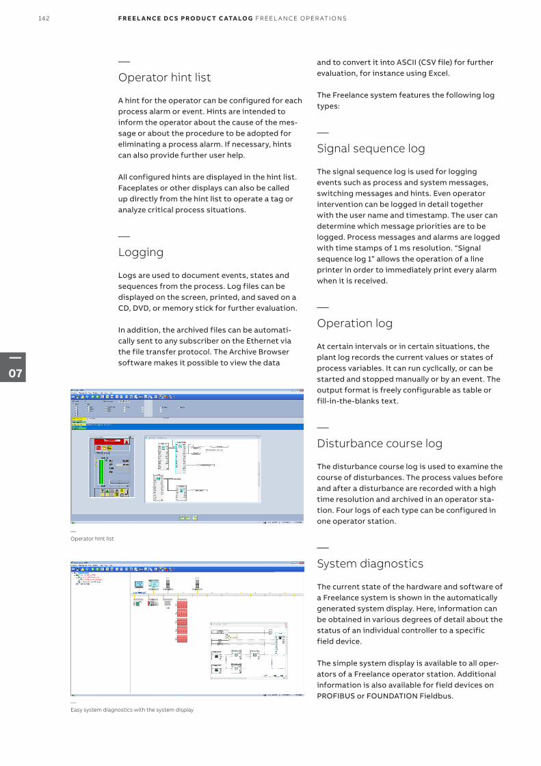
—Operator hint list
A hint for the operator can be configured for each process alarm or event. Hints are intended to inform the operator about the cause of the mes-sage or about the procedure to be adopted for eliminating a process alarm. If necessary, hints can also provide further user help.
All configured hints are displayed in the hint list. Faceplates or other displays can also be called up directly from the hint list to operate a tag or analyze critical process situations.
—Logging
Logs are used to document events, states and sequences from the process. Log files can be displayed on the screen, printed, and saved on a CD, DVD, or memory stick for further evaluation.
In addition, the archived files can be automati-cally sent to any subscriber on the Ethernet via the file transfer protocol. The Archive Browser software makes it possible to view the data
and to convert it into ASCII (CSV file) for further evaluation, for instance using Excel.
The Freelance system features the following log types:
—Signal sequence log
The signal sequence log is used for logging events such as process and system messages, switching messages and hints. Even operator intervention can be logged in detail together with the user name and timestamp. The user can determine which message priorities are to be logged. Process messages and alarms are logged with time stamps of 1 ms resolution. “Signal sequence log 1” allows the operation of a line printer in order to immediately print every alarm when it is received.
—Operation log
At certain intervals or in certain situations, the plant log records the current values or states of process variables. It can run cyclically, or can be started and stopped manually or by an event. The output format is freely configurable as table or fill-in-the-blanks text.
—Disturbance course log
The disturbance course log is used to examine the course of disturbances. The process values before and after a disturbance are recorded with a high time resolution and archived in an operator sta-tion. Four logs of each type can be configured in one operator station.
—System diagnostics
The current state of the hardware and software of a Freelance system is shown in the automatically generated system display. Here, information can be obtained in various degrees of detail about the status of an individual controller to a specific field device.
The simple system display is available to all oper-ators of a Freelance operator station. Additional information is also available for field devices on PROFIBUS or FOUNDATION Fieldbus.
—Operator hint list
—Easy system diagnostics with the system display
142 F R E E L A N CE D C S PRO D U C T C ATA LO G FR EEL A N CE O PER ATI O NS
—07
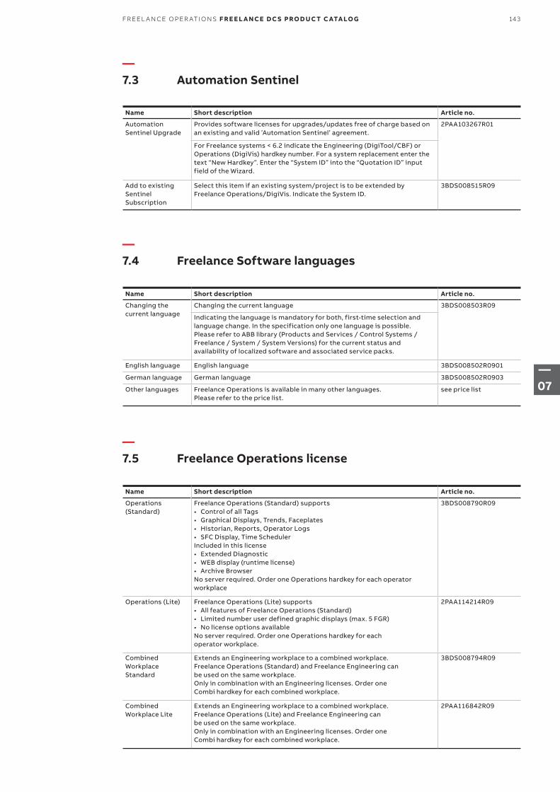
—7.3 Automation Sentinel
—7.4 Freelance Software languages
—7.5 Freelance Operations license
Name Short description Article no.
Automation Sentinel Upgrade
Provides software licenses for upgrades/updates free of charge based on an existing and valid ’Automation Sentinel’ agreement.
2PAA103267R01
For Freelance systems < 6.2 indicate the Engineering (DigiTool/CBF) or Operations (DigiVis) hardkey number. For a system replacement enter the text “New Hardkey”. Enter the “System ID” into the “Quotation ID” input field of the Wizard.
Add to existing Sentinel Subscription
Select this item if an existing system/project is to be extended by Freelance Operations/DigiVis. Indicate the System ID.
3BDS008515R09
Name Short description Article no.
Changing the current language
Changing the current language 3BDS008503R09
Indicating the language is mandatory for both, first-time selection and language change. In the specification only one language is possible.Please refer to ABB library (Products and Services / Control Systems / Freelance / System / System Versions) for the current status and availability of localized software and associated service packs.
English language English language 3BDS008502R0901
German language German language 3BDS008502R0903
Other languages Freelance Operations is available in many other languages. Please refer to the price list.
see price list
Name Short description Article no.
Operations (Standard)
Freelance Operations (Standard) supports• Control of all Tags• Graphical Displays, Trends, Faceplates• Historian, Reports, Operator Logs• SFC Display, Time SchedulerIncluded in this license• Extended Diagnostic• WEB display (runtime license)• Archive BrowserNo server required. Order one Operations hardkey for each operator workplace
3BDS008790R09
Operations (Lite) Freelance Operations (Lite) supports• All features of Freelance Operations (Standard)• Limited number user defined graphic displays (max. 5 FGR)• No license options availableNo server required. Order one Operations hardkey for eachoperator workplace.
2PAA114214R09
Combined Workplace Standard
Extends an Engineering workplace to a combined workplace.Freelance Operations (Standard) and Freelance Engineering canbe used on the same workplace.Only in combination with an Engineering licenses. Order oneCombi hardkey for each combined workplace.
3BDS008794R09
Combined Workplace Lite
Extends an Engineering workplace to a combined workplace.Freelance Operations (Lite) and Freelance Engineering canbe used on the same workplace.Only in combination with an Engineering licenses. Order oneCombi hardkey for each combined workplace.
2PAA116842R09
143FR EEL A N CE O PER ATI O NS F R E E L A N CE D C S PRO D U C T C ATA LO G
—07
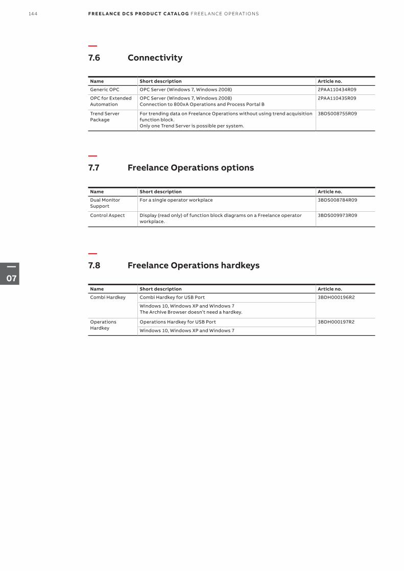
—7.6 Connectivity
—7.7 Freelance Operations options
—7.8 Freelance Operations hardkeys
Name Short description Article no.
Generic OPC OPC Server (Windows 7, Windows 2008) 2PAA110434R09
OPC for Extended Automation
OPC Server (Windows 7, Windows 2008)Connection to 800xA Operations and Process Portal B
2PAA110435R09
Trend Server Package
For trending data on Freelance Operations without using trend acquisition function block.Only one Trend Server is possible per system.
3BDS008755R09
Name Short description Article no.
Dual Monitor Support
For a single operator workplace 3BDS008784R09
Control Aspect Display (read only) of function block diagrams on a Freelance operator workplace.
3BDS009973R09
Name Short description Article no.
Combi Hardkey Combi Hardkey for USB Port 3BDH000196R2
Windows 10, Windows XP and Windows 7The Archive Browser doesn’t need a hardkey.
Operations Hardkey
Operations Hardkey for USB Port 3BDH000197R2
Windows 10, Windows XP and Windows 7
144 F R E E L A N CE D C S PRO D U C T C ATA LO G FR EEL A N CE O PER ATI O NS
—07

145FR EEL A N CE O PER ATI O NS F R E E L A N CE D C S PRO D U C T C ATA LO G
—07
—Chapter 8 – Freelance Engineering
147 – 148 8.1 Overview
149 – 153 8.2 Configuration of functions
149 8.2.1 IEC 61131-3
151 8.2.2 Other Functions
152 8.2.3 Fieldbus and field device configuration
154 – 155 8.3 Commissioning
155 8.3.1 Commissioning the fieldbus lines
156 8.4 Freelance Software languages
156 8.5 Freelance Engineering license
156 8.6 Freelance Engineering hardkeys
157 – 158 8.7 Control - Software license
157 8.7.1 Base License
157 8.7.2 Additional basic I/Os
158 8.7.3 Controller license options
158 8.7.4 Batch
146 F R E E L A N CE D C S PRO D U C T C ATA LO G FR EEL A N CE EN G I N EER I N G
—08
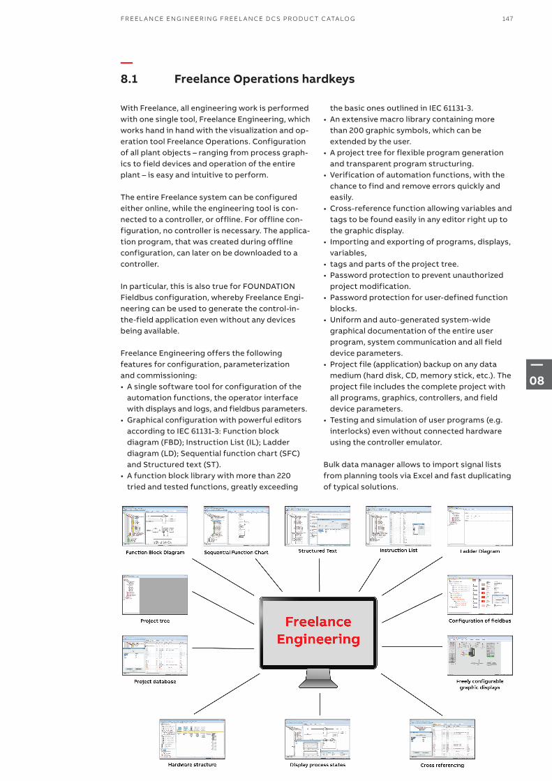
—8.1 Freelance Operations hardkeys
With Freelance, all engineering work is performed with one single tool, Freelance Engineering, which works hand in hand with the visualization and op-eration tool Freelance Operations. Configuration of all plant objects – ranging from process graph-ics to field devices and operation of the entire plant – is easy and intuitive to perform.
The entire Freelance system can be configured either online, while the engineering tool is con-nected to a controller, or offline. For offline con-figuration, no controller is necessary. The applica-tion program, that was created during offline configuration, can later on be downloaded to a controller.
In particular, this is also true for FOUNDATION Fieldbus configuration, whereby Freelance Engi-neering can be used to generate the control-in-the-field application even without any devices being available.
Freelance Engineering offers the following features for configuration, parameterization and commissioning:• A single software tool for configuration of the
automation functions, the operator interface with displays and logs, and fieldbus parameters.
• Graphical configuration with powerful editors according to IEC 61131-3: Function block diagram (FBD); Instruction List (IL); Ladder diagram (LD); Sequential function chart (SFC) and Structured text (ST).
• A function block library with more than 220 tried and tested functions, greatly exceeding
the basic ones outlined in IEC 61131-3.• An extensive macro library containing more
than 200 graphic symbols, which can be extended by the user.
• A project tree for flexible program generation and transparent program structuring.
• Verification of automation functions, with the chance to find and remove errors quickly and easily.
• Cross-reference function allowing variables and tags to be found easily in any editor right up to the graphic display.
• Importing and exporting of programs, displays, variables,
• tags and parts of the project tree.• Password protection to prevent unauthorized
project modification.• Password protection for user-defined function
blocks.• Uniform and auto-generated system-wide
graphical documentation of the entire user program, system communication and all field device parameters.
• Project file (application) backup on any data medium (hard disk, CD, memory stick, etc.). The project file includes the complete project with all programs, graphics, controllers, and field device parameters.
• Testing and simulation of user programs (e.g. interlocks) even without connected hardware using the controller emulator.
Bulk data manager allows to import signal lists from planning tools via Excel and fast duplicating of typical solutions.
147FR EEL A N CE EN G IN EER I N G FR EEL A N CE D C S PR O D U C T C ATA LO G
—08
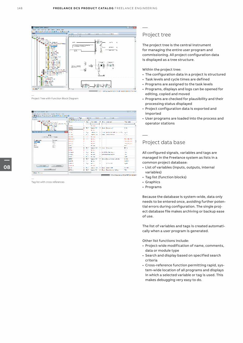
—Project tree
The project tree is the central instrument for managing the entire user program and commissioning. All project configu ration data is displayed as a tree structure.
Within the project tree:• The configuration data in a project is structured• Task levels and cycle times are defined• Programs are assigned to the task levels• Programs, displays and logs can be opened for
editing, copied and moved• Programs are checked for plausibility and their
processing status displayed• Project configuration data is exported and
imported• User programs are loaded into the process and
operator stations
—Project data base
All configured signals, variables and tags are managed in the Freelance system as lists in a common project database:• List of variables (inputs, outputs, internal
variables)• Tag list (function blocks)• Graphics• Programs
Because the database is system-wide, data only needs to be entered once, avoiding further poten-tial errors during configuration. The single proj-ect database file makes archiving or backup ease of use.
The list of variables and tags is created automati-cally when a user program is generated.
Other list functions include:• Project-wide modification of name, comments,
data or module type• Search and display based on specified search
criteria• Cross-reference function permitting rapid, sys-
tem-wide location of all programs and displays in which a selected variable or tag is used. This makes debugging very easy to do.
—Project Tree with Function Block Diagram
—Tag list with cross references
148 F R E E L A N CE D C S PRO D U C T C ATA LO G FR EEL A N CE EN G I N EER I N G
—08
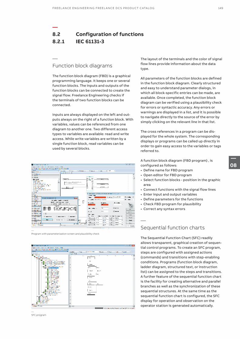
—Function block diagrams
The function block diagram (FBD) is a graphical programming language. It keeps one or several function blocks. The inputs and outputs of the function blocks can be connected to create the signal flow. Freelance Engineering checks if the terminals of two function blocks can be connected.
Inputs are always displayed on the left and out-puts always on the right of a function block. With variables, values can be referenced from one diagram to another one. Two different access types to variables are available: read and write access. While write variables are written by a single function block, read variables can be used by several blocks.
—Program with parameterization screen and plausibility check
—SFC program
—8.2 Configuration of functions 8.2.1 IEC 61131-3
The layout of the terminals and the color of signal flow lines provide information about the data type.
All parameters of the function blocks are defined in the function block diagram. Clearly structured and easy to understand parameter dialogs, in which all block-specific entries can be made, are available. Once completed, the function block diagram can be verified using a plausibility check for errors or syntactic accuracy. Any errors or warnings are displayed in a list, and it is possible to navigate directly to the source of the error by simply clicking on the relevant line in that list.
The cross references in a program can be dis-played for the whole system. The corresponding displays or programs can be called up directly in order to gain easy access to the variables or tags referred to.
A function block diagram (FBD program) , is configured as follows:• Define name for FBD program• Open editor for FBD program• Select function blocks - position in the graphic
area• Connect functions with the signal flow lines• Enter input and output variables• Define parameters for the functions• Check FBD program for plausibility• Correct any syntax errors
—Sequential function charts
The Sequential Function Chart (SFC) readily allows transparent, graphical creation of sequen-tial control programs. To create an SFC program, steps are configured with assigned actions (commands) and transitions with step-enabling conditions. Programs (function block diagram, ladder diagram, structured text, or instruction list) can be assigned to the steps and transitions. A further feature of the sequential function chart is the facility for creating alternative and parallel branches as well as the synchronization of these sequential structures. At the same time as the sequential function chart is configured, the SFC display for operation and observation on the operator station is generated automatically.
149FR EEL A N CE EN G IN EER I N G FR EEL A N CE D C S PR O D U C T C ATA LO G
—08
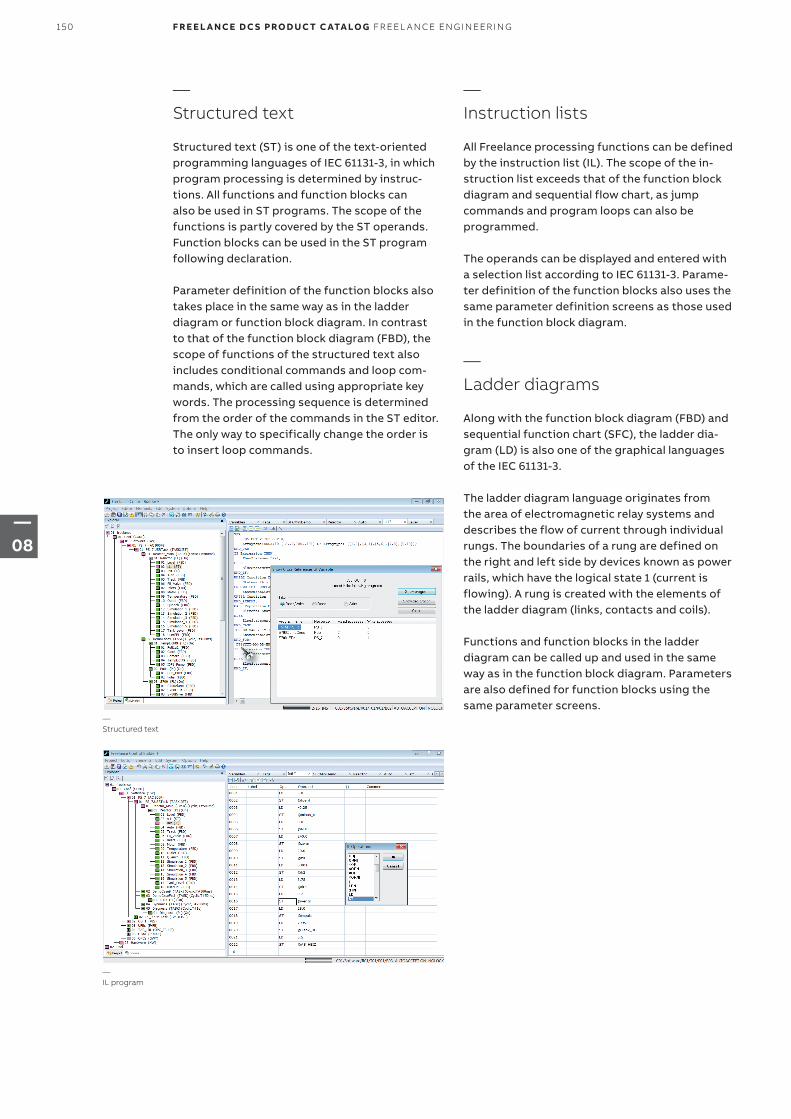
—Structured text
Structured text (ST) is one of the text-oriented programming languages of IEC 61131-3, in which program processing is determined by instruc-tions. All functions and function blocks can also be used in ST programs. The scope of the functions is partly covered by the ST operands. Function blocks can be used in the ST program following declaration.
Parameter definition of the function blocks also takes place in the same way as in the ladder diagram or function block diagram. In contrast to that of the function block diagram (FBD), the scope of functions of the structured text also includes conditional commands and loop com-mands, which are called using appropriate key words. The processing sequence is determined from the order of the commands in the ST editor. The only way to specifically change the order is to insert loop commands.
—Instruction lists
All Freelance processing functions can be defined by the instruction list (IL). The scope of the in-struction list exceeds that of the function block diagram and sequential flow chart, as jump commands and program loops can also be programmed. The operands can be displayed and entered with a selection list according to IEC 61131-3. Parame-ter definition of the function blocks also uses the same parameter definition screens as those used in the function block diagram.
—Ladder diagrams
Along with the function block diagram (FBD) and sequential function chart (SFC), the ladder dia-gram (LD) is also one of the graphical languages of the IEC 61131-3.
The ladder diagram language originates from the area of electromagnetic relay systems and describes the flow of current through individual rungs. The boundaries of a rung are defined on the right and left side by devices known as power rails, which have the logical state 1 (current is flowing). A rung is created with the elements of the ladder diagram (links, contacts and coils).
Functions and function blocks in the ladder diagram can be called up and used in the same way as in the function block diagram. Parameters are also defined for function blocks using the same parameter screens.
—Structured text
—IL program
150 F R E E L A N CE D C S PRO D U C T C ATA LO G FR EEL A N CE EN G I N EER I N G
—08
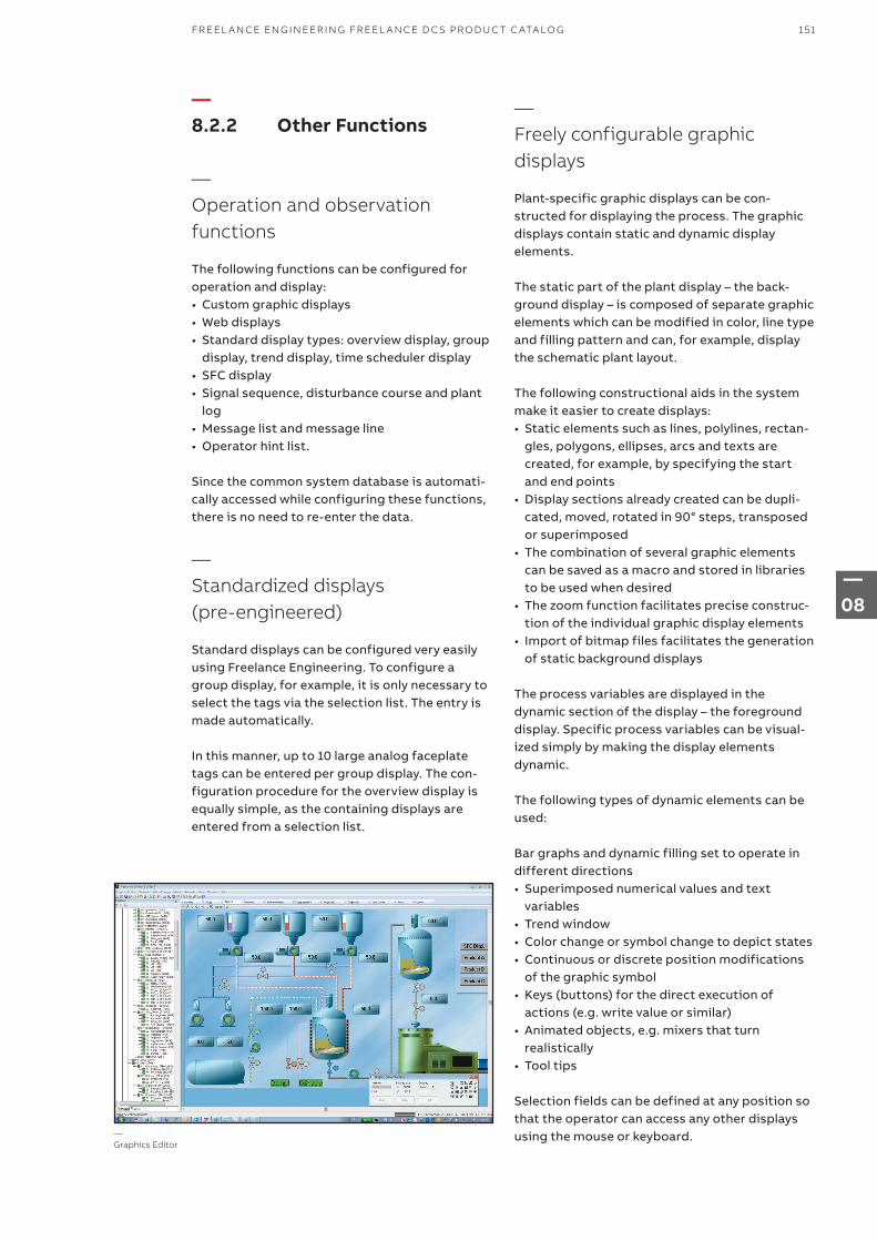
—Graphics Editor
—8.2.2 Other Functions
—Operation and observation functions
The following functions can be configured for operation and display:• Custom graphic displays• Web displays• Standard display types: overview display, group
display, trend display, time scheduler display• SFC display• Signal sequence, disturbance course and plant
log• Message list and message line• Operator hint list.
Since the common system database is automati-cally accessed while configuring these functions, there is no need to re-enter the data.
—Standardized displays (pre-engineered)
Standard displays can be configured very easily using Freelance Engineering. To configure a group display, for example, it is only necessary to select the tags via the selection list. The entry is made automatically.
In this manner, up to 10 large analog faceplate tags can be entered per group display. The con-figuration procedure for the overview display is equally simple, as the containing displays are entered from a selection list.
—Freely configurable graphic displays
Plant-specific graphic displays can be con-structed for displaying the process. The graphic displays contain static and dynamic display elements. The static part of the plant display – the back-ground display – is composed of separate graphic elements which can be modified in color, line type and filling pattern and can, for example, display the schematic plant layout.
The following constructional aids in the system make it easier to create displays:• Static elements such as lines, polylines, rectan-
gles, polygons, ellipses, arcs and texts are created, for example, by specifying the start and end points
• Display sections already created can be dupli-cated, moved, rotated in 90° steps, transposed or superimposed
• The combination of several graphic elements can be saved as a macro and stored in libraries to be used when desired
• The zoom function facilitates precise construc-tion of the individual graphic display elements
• Import of bitmap files facilitates the generation of static background displays
The process variables are displayed in the dynamic section of the display – the foreground display. Specific process variables can be visual-ized simply by making the display elements dynamic.
The following types of dynamic elements can be used:
Bar graphs and dynamic filling set to operate in different directions• Superimposed numerical values and text
variables• Trend window• Color change or symbol change to depict states• Continuous or discrete position modifications
of the graphic symbol• Keys (buttons) for the direct execution of
actions (e.g. write value or similar)• Animated objects, e.g. mixers that turn
realistically• Tool tips
Selection fields can be defined at any position so that the operator can access any other displays using the mouse or keyboard.
151FR EEL A N CE EN G IN EER I N G FR EEL A N CE D C S PR O D U C T C ATA LO G
—08
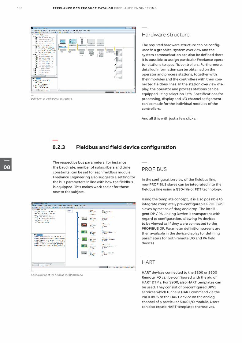
—Hardware structure
The required hardware structure can be config-ured in a graphical system overview and the system communication can also be defined there. It is possible to assign particular Freelance opera-tor stations to specific controllers. Furthermore, detailed information can be obtained on the operator and process stations, together with their modules and the controllers with their con-nected fieldbus lines. In the station overview dis-play, the operator and process stations can be equipped using selection lists. Specifications for processing, display and I/O channel assignment can be made for the individual modules of the controllers.
And all this with just a few clicks.
—Definition of the hardware structure
—8.2.3 Fieldbus and field device configuration
The respective bus parameters, for instance the baud rate, number of subscribers and time constants, can be set for each fieldbus module. Freelance Engineering also suggests a setting for the bus parameters in line with how the fieldbus is equipped. This makes work easier for those new to the subject.
—PROFIBUS
In the configuration view of the fieldbus line, new PROFIBUS slaves can be integrated into the fieldbus line using a GSD-file or FDT technology.
Using the template concept, it is also possible to integrate completely pre-configurable PROFIBUS slaves by means of drag and drop. The intelli- gent DP / PA Linking Device is transparent with regard to configuration, allowing PA devices to be viewed as if they were connected to the PROFIBUS DP. Parameter definition screens are then available in the device display for defining parameters for both remote I/O and PA field devices.
—HART
HART devices connected to the S800 or S900 Remote I/O can be configured with the aid of HART DTMs. For S900, also HART templates can be used. They consist of preconfigured DPV1 services which tunnel a HART command via the PROFIBUS to the HART device on the analog channel of a particular S900 I/O module. Users can also create HART templates themselves.
—Configuration of the fieldbus line (PROFIBUS)
152 F R E E L A N CE D C S PRO D U C T C ATA LO G FR EEL A N CE EN G I N EER I N G
—08
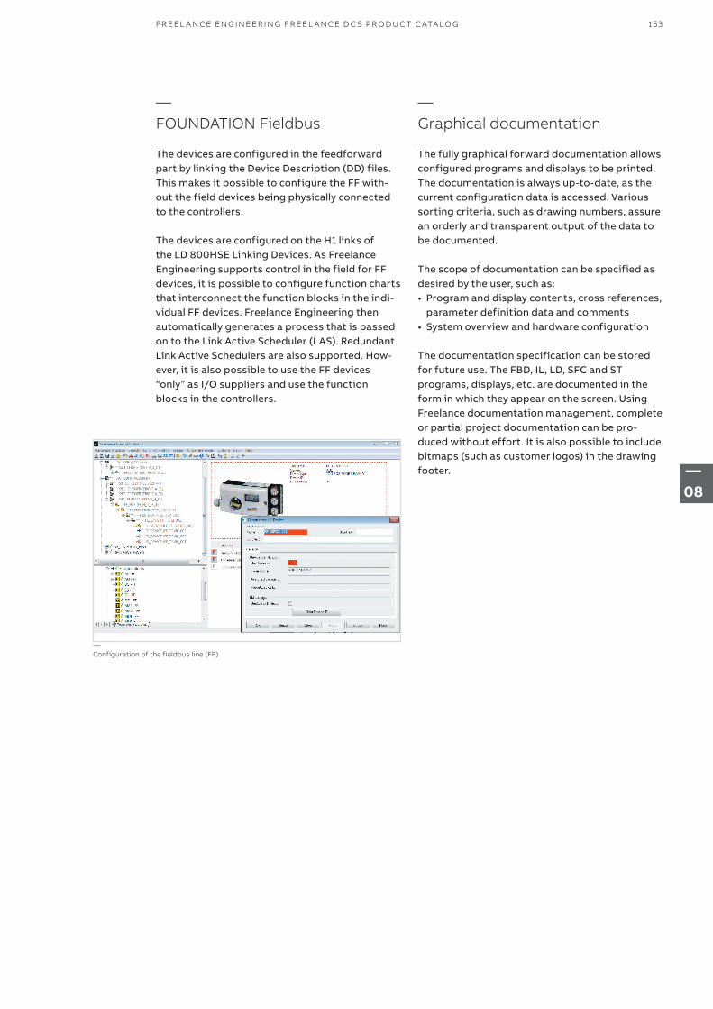
—FOUNDATION Fieldbus
The devices are configured in the feedforward part by linking the Device Description (DD) files. This makes it possible to configure the FF with-out the field devices being physically connected to the controllers.
The devices are configured on the H1 links of the LD 800HSE Linking Devices. As Freelance Engineering supports control in the field for FF devices, it is possible to configure function charts that interconnect the function blocks in the indi-vidual FF devices. Freelance Engineering then automatically generates a process that is passed on to the Link Active Scheduler (LAS). Redundant Link Active Schedulers are also supported. How-ever, it is also possible to use the FF devices “only” as I/O suppliers and use the function blocks in the controllers.
—Configuration of the fieldbus line (FF)
—Graphical documentation
The fully graphical forward documentation allows configured programs and displays to be printed. The documentation is always up-to-date, as the current configuration data is accessed. Various sorting criteria, such as drawing numbers, assure an orderly and transparent output of the data to be documented.
The scope of documentation can be specified as desired by the user, such as:• Program and display contents, cross references,
parameter definition data and comments• System overview and hardware configuration
The documentation specification can be stored for future use. The FBD, IL, LD, SFC and ST programs, displays, etc. are documented in the form in which they appear on the screen. Using Freelance documentation management, complete or partial project documentation can be pro-duced without effort. It is also possible to include bitmaps (such as customer logos) in the drawing footer.
153FR EEL A N CE EN G IN EER I N G FR EEL A N CE D C S PR O D U C T C ATA LO G
—08
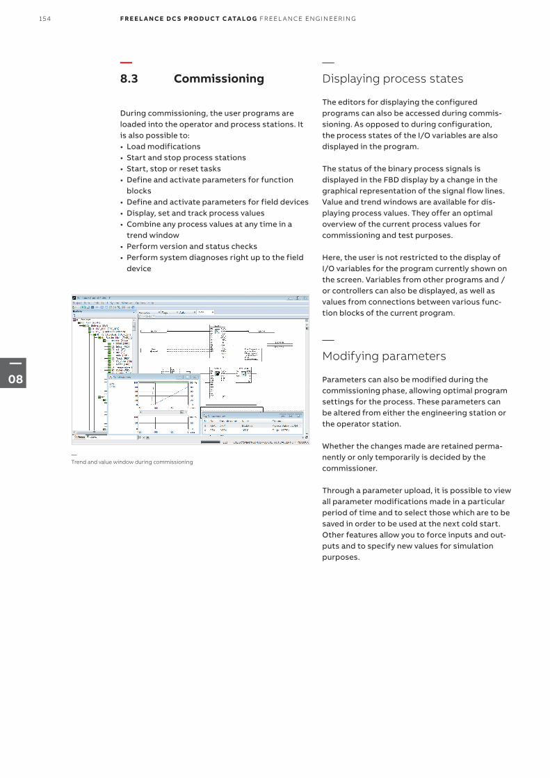
—8.3 Commissioning
During commissioning, the user programs are loaded into the operator and process stations. It is also possible to:• Load modifications• Start and stop process stations• Start, stop or reset tasks• Define and activate parameters for function
blocks• Define and activate parameters for field devices• Display, set and track process values• Combine any process values at any time in a
trend window• Perform version and status checks• Perform system diagnoses right up to the field
device
—Displaying process states
The editors for displaying the configured programs can also be accessed during commis-sioning. As opposed to during configuration, the process states of the I/O variables are also displayed in the program. The status of the binary process signals is displayed in the FBD display by a change in the graphical representation of the signal flow lines.Value and trend windows are available for dis-playing process values. They offer an optimal overview of the current process values for commissioning and test purposes.
Here, the user is not restricted to the display of I/O variables for the program currently shown on the screen. Variables from other programs and / or controllers can also be displayed, as well as values from connections between various func-tion blocks of the current program.
—Modifying parameters
Parameters can also be modified during the commissioning phase, allowing optimal program settings for the process. These parameters can be altered from either the engineering station or the operator station. Whether the changes made are retained perma-nently or only temporarily is decided by the commissioner.
Through a parameter upload, it is possible to view all parameter modifications made in a particular period of time and to select those which are to be saved in order to be used at the next cold start.Other features allow you to force inputs and out-puts and to specify new values for simulation purposes.
—Trend and value window during commissioning
154 F R E E L A N CE D C S PRO D U C T C ATA LO G FR EEL A N CE EN G I N EER I N G
—08
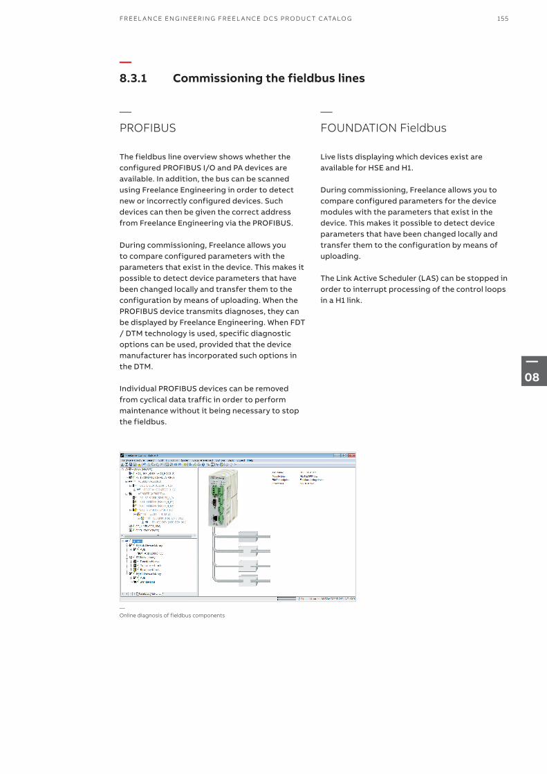
—Online diagnosis of fieldbus components
—8.3.1 Commissioning the fieldbus lines
—PROFIBUS
The fieldbus line overview shows whether the configured PROFIBUS I/O and PA devices are available. In addition, the bus can be scanned using Freelance Engineering in order to detect new or incorrectly configured devices. Such devices can then be given the correct address from Freelance Engineering via the PROFIBUS.
During commissioning, Freelance allows you to compare configured parameters with the parameters that exist in the device. This makes it possible to detect device parameters that have been changed locally and transfer them to the configuration by means of uploading. When the PROFIBUS device transmits diagnoses, they can be displayed by Freelance Engineering. When FDT / DTM technology is used, specific diagnostic options can be used, provided that the device manufacturer has incorporated such options in the DTM.
Individual PROFIBUS devices can be removed from cyclical data traffic in order to perform maintenance without it being necessary to stop the fieldbus.
—FOUNDATION Fieldbus
Live lists displaying which devices exist are available for HSE and H1.
During commissioning, Freelance allows you to compare configured parameters for the device modules with the parameters that exist in the device. This makes it possible to detect device parameters that have been changed locally and transfer them to the configuration by means of uploading.
The Link Active Scheduler (LAS) can be stopped in order to interrupt processing of the control loops in a H1 link.
155FR EEL A N CE EN G IN EER I N G FR EEL A N CE D C S PR O D U C T C ATA LO G
—08

—8.4 Freelance Software languages
—8.5 Freelance Engineering license
—8.6 Freelance Engineering hardkeys
Name Short description Article no.
Changing the current language
Changing the current language 3BDS008503R09
Indicate the Engineering hardkey number and the new language. Setup CD and the user documentation in the chosen language are to order additionally.
Available languages The Freelance Software is available in various languages. For article numbers see the price list.
see price list
Name Short description Article no.
Engineering Hardkey for USB
Windows 10, Windows XP and Windows 7 3BDH000198R2
Name Short description Article no.
Engineering (Standard)
Software License Order one Engineering hardkey for each engineering workplace
3BDS008510R09
Freelance Engineering (Standard) supports• 16 Character Tag Names• User Defined Function Blocks (runtime license)• OPC Function Block Classes (runtime license) Included in this license• WEB Display Configuration
Engineering (Professional)
Software License Order one Engineering hardkey for each engineering workplace
3BDS008520R09
Freelance Engineering (Professional) supportsAll features of Freelance Engineering (Standard)Security LockUser Defined Function Blocks (developer license)OPC Function Block Classes (developer license)FDT TechnologyDTM Device DriverPlease check the list of DTMs which are approved by ABB for usewith Freelance Engineering in version 2016.
Engineering license for one workplace supporting the following controllers:• AC 900F, AC 800F, AC 700F• DCP 02/10, DFC 01/02
For engineering at least one setup CD, one license (Standard or Professional), one hardkey and a language selection are required.
156 F R E E L A N CE D C S PRO D U C T C ATA LO G FR EEL A N CE EN G I N EER I N G
—08
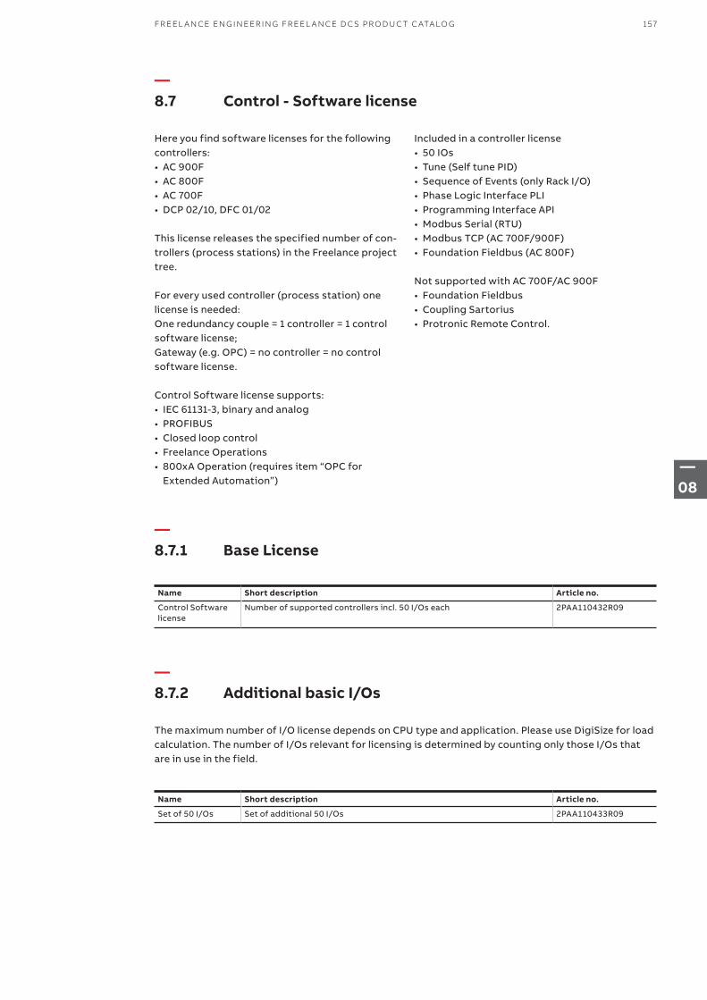
—8.7.1 Base License
—8.7.2 Additional basic I/Os
—8.7 Control - Software license
Name Short description Article no.
Control Software license
Number of supported controllers incl. 50 I/Os each 2PAA110432R09
Name Short description Article no.
Set of 50 I/Os Set of additional 50 I/Os 2PAA110433R09
The maximum number of I/O license depends on CPU type and application. Please use DigiSize for load calculation. The number of I/Os relevant for licensing is determined by counting only those I/Os that are in use in the field.
Here you find software licenses for the following controllers:• AC 900F• AC 800F• AC 700F• DCP 02/10, DFC 01/02
This license releases the specified number of con-trollers (process stations) in the Freelance project tree.
For every used controller (process station) one license is needed:One redundancy couple = 1 controller = 1 control software license;Gateway (e.g. OPC) = no controller = no control software license.
Control Software license supports: • IEC 61131-3, binary and analog• PROFIBUS• Closed loop control• Freelance Operations• 800xA Operation (requires item “OPC for
Extended Automation”)
Included in a controller license• 50 IOs• Tune (Self tune PID)• Sequence of Events (only Rack I/O)• Phase Logic Interface PLI• Programming Interface API• Modbus Serial (RTU)• Modbus TCP (AC 700F/900F)• Foundation Fieldbus (AC 800F)
Not supported with AC 700F/AC 900F• Foundation Fieldbus• Coupling Sartorius• Protronic Remote Control.
157FR EEL A N CE EN G IN EER I N G FR EEL A N CE D C S PR O D U C T C ATA LO G
—08
—8.7.3 Controller license options
—8.7.4 Batch
Name Short description Article no.
TeleControl Support for IEC 60870-5-101 and -104 3BDS008758R09
Check whether the implemented subset of functionality meets yourrequirements. IEC 60870-5-104 is currently not released with DCP02/10 and DFC 01/02.
Name Short description Article no.
Freelance Formulation 1.1
Essential Recipe Manager 2PAA110436R09
This license includes a license for the Freelance Formulation batch application.
Freelance Batch Interface to Freelance Batch 2PAA110437R09
Batch for Extended Automation
Interface to 800xA Batch
Please refer to Extended Automation 800xA price list for the batch application (license).
2PAA110438R09
Additional option to Control Software Basic. This option must be ordered for every controller, where you want to use it.
Interfaces to Batch applications. The Batch application has to be ordered separately.
158 F R E E L A N CE D C S PRO D U C T C ATA LO G FR EEL A N CE EN G I N EER I N G
—08

159FR EEL A N CE EN G IN EER I N G FR EEL A N CE D C S PR O D U C T C ATA LO G
—08
—Chapter 9 – Media and documentation
161 9.1 Product box
161 9.2 Software CD
161 9.3 Formulation Software 1.1
161 9.4 Documentation CD
160 F R E E L A N CE D C S PRO D U C T C ATA LO G M ED I A A N D D O C U M ENTATI O N
—09
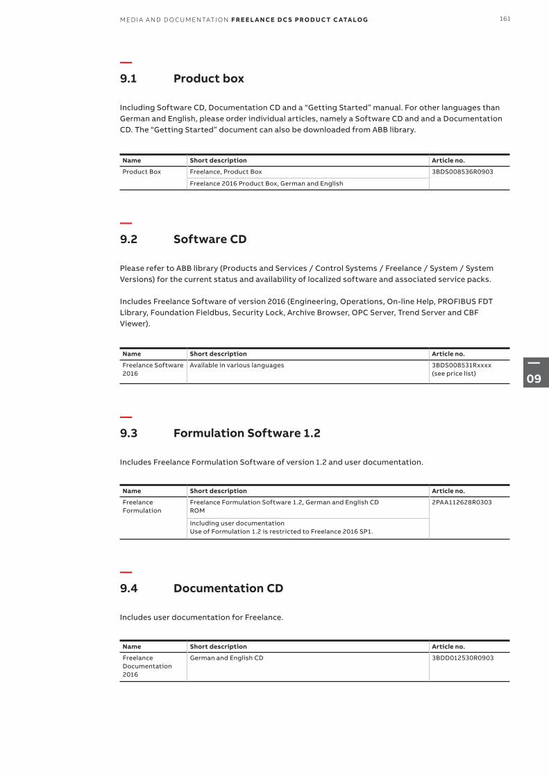
—9.1 Product box
—9.3 Formulation Software 1.2
—9.4 Documentation CD
—9.2 Software CD
Including Software CD, Documentation CD and a “Getting Started” manual. For other languages than German and English, please order individual articles, namely a Software CD and and a Documentation CD. The “Getting Started” document can also be downloaded from ABB library.
Includes Freelance Formulation Software of version 1.2 and user documentation.
Includes user documentation for Freelance.
Please refer to ABB library (Products and Services / Control Systems / Freelance / System / System Versions) for the current status and availability of localized software and associated service packs.
Includes Freelance Software of version 2016 (Engineering, Operations, On-line Help, PROFIBUS FDT Library, Foundation Fieldbus, Security Lock, Archive Browser, OPC Server, Trend Server and CBF Viewer).
Name Short description Article no.
Product Box Freelance, Product Box 3BDS008536R0903
Freelance 2016 Product Box, German and English
Name Short description Article no.
Freelance Formulation
Freelance Formulation Software 1.2, German and English CDROM
2PAA112628R0303
Including user documentationUse of Formulation 1.2 is restricted to Freelance 2016 SP1.
Name Short description Article no.
Freelance Documentation 2016
German and English CD 3BDD012530R0903
Name Short description Article no.
Freelance Software 2016
Available in various languages 3BDS008531Rxxxx (see price list)
161M ED I A A N D D O C U M ENTATI O N F R E E L A N CE D C S PRO D U C T C ATA LO G
—09
—Chapter 10 – Add-ons, extensions, and service
163 10.1 Add-ons, extensions, and service
164 10.2 Asset Management
164 10.3 System Integration
165 10.4 Training
165 10.5 Repair Services
162 F R E E L A N CE D C S PRO D U C T C ATA LO G A D D - O NS , E X TENSI O NS , A N D SER V I CE
—10
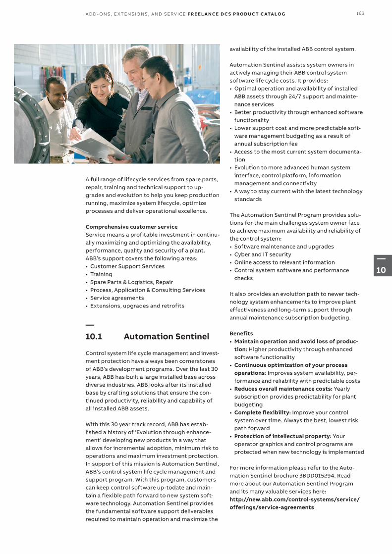
A full range of lifecycle services from spare parts, repair, training and technical support to up-grades and evolution to help you keep production running, maximize system lifecycle, optimize processes and deliver operational excellence.
Comprehensive customer serviceService means a profitable investment in continu-ally maximizing and optimizing the availability, performance, quality and security of a plant. ABB’s support covers the following areas:• Customer Support Services• Training• Spare Parts & Logistics, Repair• Process, Application & Consulting Services• Service agreements• Extensions, upgrades and retrofits
—10.1 Automation Sentinel
Control system life cycle management and invest-ment protection have always been cornerstones of ABB’s development programs. Over the last 30 years, ABB has built a large installed base across diverse industries. ABB looks after its installed base by crafting solutions that ensure the con-tinued productivity, reliability and capability of all installed ABB assets.
With this 30 year track record, ABB has estab-lished a history of ‘Evolution through enhance-ment’ developing new products in a way that allows for incremental adoption, minimum risk to operations and maximum investment protection. In support of this mission is Automation Sentinel, ABB’s control system life cycle management and support program. With this program, customers can keep control software up-todate and main-tain a flexible path forward to new system soft-ware technology. Automation Sentinel provides the fundamental software support deliverables required to maintain operation and maximize the
availability of the installed ABB control system.
Automation Sentinel assists system owners in actively managing their ABB control system software life cycle costs. It provides:• Optimal operation and availability of installed
ABB assets through 24/7 support and mainte-nance services
• Better productivity through enhanced software functionality
• Lower support cost and more predictable soft-ware management budgeting as a result of annual subscription fee
• Access to the most current system documenta-tion
• Evolution to more advanced human system interface, control platform, information management and connectivity
• A way to stay current with the latest technology standards
The Automation Sentinel Program provides solu-tions for the main challenges system owner face to achieve maximum availability and reliability of the control system:• Software maintenance and upgrades• Cyber and IT security• Online access to relevant information• Control system software and performance
checks
It also provides an evolution path to newer tech-nology system enhancements to improve plant effectiveness and long-term support through annual maintenance subscription budgeting.
Benefits• Maintain operation and avoid loss of produc-
tion: Higher productivity through enhanced software functionality
• Continuous optimization of your process operations: Improves system availability, per-formance and reliability with predictable costs
• Reduces overall maintenance costs: Yearly subscription provides predictability for plant budgeting
• Complete flexibility: Improve your control system over time. Always the best, lowest risk path forward
• Protection of intellectual property: Your operator graphics and control programs are protected when new technology is implemented
For more information please refer to the Auto-mation Sentinel brochure 3BDD015294. Read more about our Automation Sentinel Program and its many valuable services here: http://new.abb.com/control-systems/service/offerings/service-agreements
163A D D - O NS , E X TENSI O NS , A N D SER V I CE F R E E L A N CE D C S PRO D U C T C ATA LO G
—10

—10.2 Asset Management
If you want to keep your production plant up and running in the long term, you need information about the availability and degree of wear and tear of your equipment. All of the information neces-sary for this is available; integrated and included in the basic software package of the Freelance control system. As a result, several customers have been able to avoid making investments that appeared essential but were in fact unnecessary. Freelance allows the use of modern asset man-agement methods for more efficient mainte-nance and optimization – helping for instance to make optimum use of plant capacity.
—10.3 System Integration
Our instrumentation and control specialists, or our certified partners in system integration, will be happy to assist you in planning and implemen-ting your automation project. ABB Automation‘s staff can also work with you to plan and imple-ment the installation of a Freelance system in your plant.
Under this arrangement, the ABB Automation Engineering Department will compile the specific project documentation for you. This can include functional diagrams, circuit diagrams, configura-tion documentation, and operating documenta-tion including system descriptions and instruc-tions for operation, modes of operation and plant maintenance.
At many sites, ABB Automation has its own com-missioning engineers who work together with planning engineers, process instructors and operators to commission your plant, optimize it, perform a test run and hand over the system to the operator.
164 F R E E L A N CE D C S PRO D U C T C ATA LO G A D D - O NS , E X TENSI O NS , A N D SER V I CE
—10

—10.4 Training
To make sure your operators are fully knowledge-able in the operation of the Freelance distributed control system, we offer a range of technical training courses.
In addition, we offer a computer-based training program for Freelance on a multimedia DVD. This will provide you with the basic knowledge you need for configuration, therefore allowing you to start using the system very quickly and efficiently.
—10.5 Repair Services
ABB repair and troubleshooting support services are available throughout the life cycles of the plant and its process control systems.
—We repair and return your unique unit
Our repair network provides repairs that meet original equipment specifications. Our world-class turnaround time for repairs is typically less than two weeks. We include a repair report in every return shipment.
Please contact us for more information about our Repair Services or visit our web page: www.abb.com/freelance. You find the information under “Services”.
165A D D - O NS , E X TENSI O NS , A N D SER V I CE F R E E L A N CE D C S PRO D U C T C ATA LO G
—10
—Chapter 11 – References
166 F R E E L A N CE D C S PRO D U C T C ATA LO G R EFER EN CE S
—11
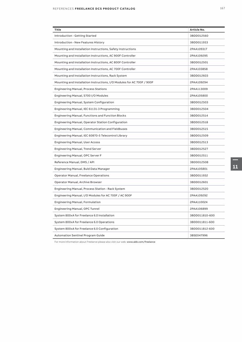
Title Article No.
Introduction - Getting Started 3BDD012560
Introduction - New Features History 3BDD011933
Mounting and Installation Instructions, Safety Instructions 2PAA109317
Mounting and Installation Instructions, AC 900F Controller 2PAA109295
Mounting and Installation Instructions, AC 800F Controller 3BDD012501
Mounting and Installation Instructions, AC 700F Controller 2PAA103858
Mounting and Installation Instructions, Rack System 3BDD012603
Mounting and Installation Instructions, I/O Modules for AC 700F / 900F 2PAA109294
Engineering Manual, Process Stations 2PAA113009
Engineering Manual, S700 I/O Modules 2PAA105800
Engineering Manual, System Configuration 3BDD012503
Engineering Manual, IEC 61131-3 Programming 3BDD012504
Engineering Manual, Functions and Function Blocks 3BDD012514
Engineering Manual, Operator Station Configuration 3BDD012518
Engineering Manual, Communication and Fieldbuses 3BDD012515
Engineering Manual, IEC 60870-5 Telecontrol Library 3BDD012509
Engineering Manual, User Access 3BDD012513
Engineering Manual, Trend Server 3BDD012527
Engineering Manual, OPC Server F 3BDD012511
Reference Manual, DMS / API 3BDD012508
Engineering Manual, Buld Data Manager 2PAA105801
Operator Manual, Freelance Operations 3BDD011932
Operator Manual, Archive Browser 3BDD012601
Engineering Manual, Process Station - Rack System 3BDD012520
Engineering Manual, I/O Modules for AC 700F / AC 900F 2PAA109292
Engineering Manual, Formulation 2PAA110024
Engineering Manual, OPC Tunnel 2PAA106899
System 800xA for Freelance 6.0 Installation 3BDD011810-600
System 800xA for Freelance 6.0 Operations 3BDD011811-600
System 800xA for Freelance 6.0 Configuration 3BDD011812-600
Automation Sentinel Program Guide 3BSE047996
For more information about Freelance please also visit our web: www.abb.com/freelance
167R EFER EN CE S F R E E L A N CE D C S PRO D U C T C ATA LO G
—11
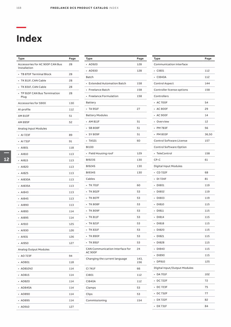
—Index
Type Page
Accessories for AC 900F CAN Bus installation
28
• TB 870F Terminal Block 28
• TK 811F, CAN Cable 28
• TK 831F, CAN Cable 28
• TP 910F CAN Bus Termination Plug
28
Accessories for S900 130
Al-profile 112
AM 810F 51
AM 895F 52
Analog Input Modules
• AI 723F 89
• AI 731F 91
• AI801 118
• AI810 113
• AI815 113
• AI820 113
• AI825 113
• AI830A 113
• AI835A 113
• AI843 113
• AI845 113
• AI890 113
• AI893 114
• AI895 114
• AI910 125
• AI930 126
• AI931 126
• AI950 127
Analog Output Modules
• AO 723F 94
• AO801 118
• AO810V2 114
• AO815 114
• AO820 114
• AO845A 114
• AO890 114
• AO895 114
• AO910 127
Type Page
• AO920 128
• AO930 128
Batch
• Extended Automation Batch 158
• Freelance Batch 158
• Freelance Formulation 158
Battery
• TA 951F 27
Battery Modules
• AM 811F 51
• SB 808F 51
• SY 809F 51
• TA521 60
BI100
• Field Housing roof 129
BI923S 130
BI924S 130
BI934S 130
Cables
• TK 701F 60
• TK 802F 53
• TK 807F 53
• TK 808F 53
• TK 809F 53
• TK 811F 53
• TK 821F 53
• TK 831F 53
• TK 890F 53
• TK 891F 53
CAN Communication Interface for AC 900F
24
Changing the current language 143, 156
CI 741F 66
CI801 112
CI840A 112
Clamps 53
Clips 53
Commissioning 154
Type Page
Communication Interface
• CI801 112
• CI840A 112
Control Aspect 144
Controller license options 158
Controllers
• AC 700F 54
• AC 800F 29
• AC 900F 14
• Overview 12
• PM 783F 56
• PM 803F 36,50
Control Software License 157
Control Software Option
• TeleControl 158
CP-C 61
Digital Input Modules
• CD 722F 68
• DI 724F 81
• DI801 119
• DI802 119
• DI803 119
• DI810 115
• DI811 115
• DI814 115
• DI818 115
• DI820 115
• DI821 115
• DI828 115
• DI840 115
• DI890 115
• DP910 125
Digital Input/Output Modules
• DA 701F 102
• DC 722F 72
• DC 723F 75
• DC 732F 77
• DX 722F 82
• DX 731F 84
168 F R E E L A N CE D C S PRO D U C T C ATA LO G IN D E X
—12
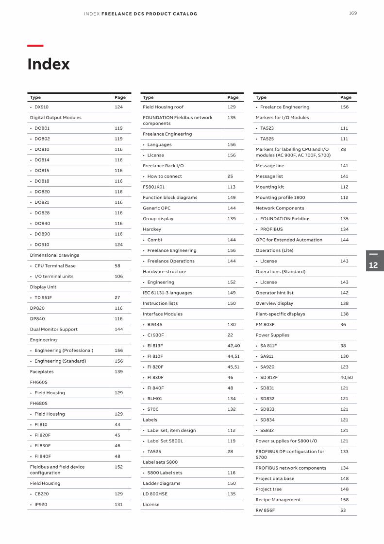
—Index
Type Page
• DX910 124
Digital Output Modules
• DO801 119
• DO802 119
• DO810 116
• DO814 116
• DO815 116
• DO818 116
• DO820 116
• DO821 116
• DO828 116
• DO840 116
• DO890 116
• DO910 124
Dimensional drawings
• CPU Terminal Base 58
• I/O terminal units 106
Display Unit
• TD 951F 27
DP820 116
DP840 116
Dual Monitor Support 144
Engineering
• Engineering (Professional) 156
• Engineering (Standard) 156
Faceplates 139
FH660S
• Field Housing 129
FH680S
• Field Housing 129
• FI 810 44
• FI 820F 45
• FI 830F 46
• FI 840F 48
Fieldbus and field device configuration
152
Field Housing
• CB220 129
• IP920 131
Type Page
Field Housing roof 129
FOUNDATION Fieldbus network components
135
Freelance Engineering
• Languages 156
• License 156
Freelance Rack I/O
• How to connect 25
FS801K01 113
Function block diagrams 149
Generic OPC 144
Group display 139
Hardkey
• Combi 144
• Freelance Engineering 156
• Freelance Operations 144
Hardware structure
• Engineering 152
IEC 61131-3 languages 149
Instruction lists 150
Interface Modules
• BI914S 130
• CI 930F 22
• EI 813F 42,40
• FI 810F 44,51
• FI 820F 45,51
• FI 830F 46
• FI 840F 48
• RLM01 134
• S700 132
Labels
• Label set, item design 112
• Label Set S800L 119
• TA525 28
Label sets S800
• S800 Label sets 116
Ladder diagrams 150
LD 800HSE 135
License
Type Page
• Freelance Engineering 156
Markers for I/O Modules
• TA523 111
• TA525 111
Markers for labelling CPU and I/O modules (AC 900F, AC 700F, S700)
28
Message line 141
Message list 141
Mounting kit 112
Mounting profile 1800 112
Network Components
• FOUNDATION Fieldbus 135
• PROFIBUS 134
OPC for Extended Automation 144
Operations (Lite)
• License 143
Operations (Standard)
• License 143
Operator hint list 142
Overview display 138
Plant-specific displays 138
PM 803F 36
Power Supplies
• SA 811F 38
• SA911 130
• SA920 123
• SD 812F 40,50
• SD831 121
• SD832 121
• SD833 121
• SD834 121
• SS832 121
Power supplies for S800 I/O 121
PROFIBUS DP configuration for S700
133
PROFIBUS network components 134
Project data base 148
Project tree 148
Recipe Management 158
RW 856F 53
169I N D E X F R E E L A N CE D C S PRO D U C T C ATA LO G
—12
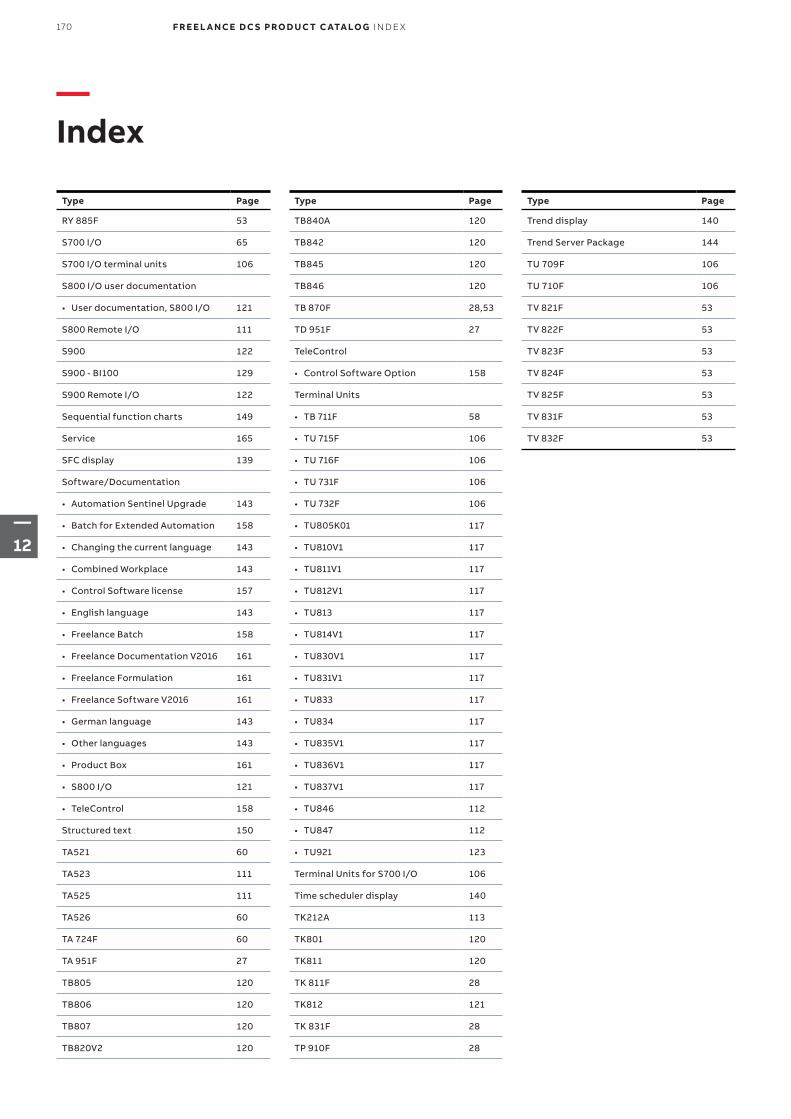
Type Page
RY 885F 53
S700 I/O 65
S700 I/O terminal units 106
S800 I/O user documentation
• User documentation, S800 I/O 121
S800 Remote I/O 111
S900 122
S900 - BI100 129
S900 Remote I/O 122
Sequential function charts 149
Service 165
SFC display 139
Software/Documentation
• Automation Sentinel Upgrade 143
• Batch for Extended Automation 158
• Changing the current language 143
• Combined Workplace 143
• Control Software license 157
• English language 143
• Freelance Batch 158
• Freelance Documentation V2016 161
• Freelance Formulation 161
• Freelance Software V2016 161
• German language 143
• Other languages 143
• Product Box 161
• S800 I/O 121
• TeleControl 158
Structured text 150
TA521 60
TA523 111
TA525 111
TA526 60
TA 724F 60
TA 951F 27
TB805 120
TB806 120
TB807 120
TB820V2 120
Type Page
TB840A 120
TB842 120
TB845 120
TB846 120
TB 870F 28,53
TD 951F 27
TeleControl
• Control Software Option 158
Terminal Units
• TB 711F 58
• TU 715F 106
• TU 716F 106
• TU 731F 106
• TU 732F 106
• TU805K01 117
• TU810V1 117
• TU811V1 117
• TU812V1 117
• TU813 117
• TU814V1 117
• TU830V1 117
• TU831V1 117
• TU833 117
• TU834 117
• TU835V1 117
• TU836V1 117
• TU837V1 117
• TU846 112
• TU847 112
• TU921 123
Terminal Units for S700 I/O 106
Time scheduler display 140
TK212A 113
TK801 120
TK811 120
TK 811F 28
TK812 121
TK 831F 28
TP 910F 28
Type Page
Trend display 140
Trend Server Package 144
TU 709F 106
TU 710F 106
TV 821F 53
TV 822F 53
TV 823F 53
TV 824F 53
TV 825F 53
TV 831F 53
TV 832F 53
—Index
170 F R E E L A N CE D C S PRO D U C T C ATA LO G IN D E X
—12

171I N D E X F R E E L A N CE D C S PRO D U C T C ATA LO G
—12

3BD
D0
1518
8 e
n F
—ABB ABControl Technologiesabb.com/freelanceabb.com/controlsystems
—We reserve the right to make technical changes to the products or modify the contents of this document without prior notice. With regard to purchase orders, the agreed particulars shall prevail. ABB does not assume any responsibility for any errors or incomplete information in this document.
We reserve all rights to this document and the items and images it contains. The reproduction, disclosure to third parties or the use of the content of this document –including parts thereof – are prohibited without ABB’s prior written permission.
Copyright© 2018 ABBAll rights reserved


