Embed Size (px)
Citation preview
DCS: AH-64D
Quick Start Manual
DCS: AH-64D
2
TABLE OF CONTENTS
INSTALLATION AND LAUNCH ................................... 14
Game Problems ...................................................................................... 14
Useful Links ............................................................................................ 14
CONFIGURE YOUR GAME .......................................... 15
AIRCRAFT HISTORY .................................................. 20
The Key West Agreement ......................................................................... 20
Advanced Attack Helicopter Program .......................................................... 21
AH-64A .................................................................................................. 21
AH-64D ................................................................................................. 22
AIRCRAFT OVERVIEW ............................................... 23
Cockpit .................................................................................................. 23
Fuselage ................................................................................................ 23
Engines ................................................................................................. 23
Digital Engine Computer and Hydromechanical Unit ................................ 24
Starter System .................................................................................. 24
Fire Protection System ....................................................................... 25
Auxiliary Power Unit (APU) .................................................................. 25
Drivetrain .............................................................................................. 25
Rotors ................................................................................................... 26
Flight Controls ........................................................................................ 26
Back-Up Control System (BUCS) .......................................................... 27
DCS: AH-64D
3
Landing Gear .................................................................................... 27
Fuel System ........................................................................................... 28
Fuel Transfer Subsystem .................................................................... 28
Nitrogen Inerting Unit (NIU) ................................................................ 28
Electrical System .................................................................................... 28
Hydraulic System .................................................................................... 29
Integrated Pressurized Air System (IPAS) ................................................... 29
Anti-Ice System ...................................................................................... 30
Environmental Control System (ECS) ......................................................... 30
Lighting System ...................................................................................... 31
Avionics ................................................................................................. 31
Communications System ..................................................................... 32
Identification System ......................................................................... 32
Navigation and Position Systems .......................................................... 32
Sensor and Sighting Systems .................................................................... 33
AH-64D ARMAMENTS ................................................ 35
M139 Area Weapon System ...................................................................... 35
Aerial Rocket Sub-system ......................................................................... 36
Longbow Hellfire Modular Missile System .................................................... 39
COCKPIT OVERVIEW................................................. 41
Pilot Seat ............................................................................................... 41
Pilot’s Cockpit, Forward ...................................................................... 41
Pilot’s Cockpit, Left Console ................................................................. 49
Pilot’s Cockpit, Left Auxiliary Console .................................................... 56
Pilot’s Cockpit, Lower Console .............................................................. 57
Pilot’s Cockpit, CMWS Control Panel ..................................................... 59
DCS: AH-64D
4
Pilot’s Cockpit, Right Console ............................................................... 60
Pilot’s Cockpit, HOCAS (Hands-On Collective And Stick) .......................... 62
Copilot-Gunner Seat ................................................................................ 67
CPG Cockpit, Forward ......................................................................... 67
CPG Cockpit, Left Console and Left Auxiliary Console .............................. 76
CPG Cockpit, Right Console ................................................................. 78
CPG Cockpit, HOCAS (Hands-On Collective And Stick) ............................. 79
Integrated Helmet And Display Sighting System (IHADSS) ............................ 81
Flight Symbology ............................................................................... 81
Weapon Symbology ........................................................................... 88
Multi-purpose Displays ............................................................................. 89
Variable Action Button (VAB) Functions ................................................. 90
Autopaging ....................................................................................... 93
Cursor Use ........................................................................................ 93
Single DP Operation ........................................................................... 94
Menu Page ........................................................................................ 94
Aircraft, Engine (ENG) Page ................................................................ 94
Aircraft, Engine Page, System (SYS) Page ............................................. 99
Aircraft, Flight (FLT) Page ................................................................. 101
Aircraft, Flight Page, Set (SET) Format ............................................... 104
Aircraft, FUEL Page .......................................................................... 105
Aircraft, Performance (PERF) Page ..................................................... 109
Aircraft, Performance Page, Weight (WT) Format .................................. 110
Aircraft, Utility (UTIL) Page ............................................................... 112
Mission, Tactical Situation Display (TSD) Page ..................................... 114
Mission, TSD Page, Pan Sub-Page ...................................................... 116
Mission, TSD Page, Show Menu .......................................................... 117
DCS: AH-64D
5
Mission, TSD Page, Show Menu, SA Sub-Menu ..................................... 119
Mission, TSD Page, Show Menu, THRT SHOW Sub-Menu ........................ 120
Mission, TSD Page, Show Menu, COORD SHOW Sub-Menu ..................... 122
Mission, TSD Page, Coordinates (COORD) Sub-Page ............................. 123
Mission, TSD Page, Waypoints/Hazards (WPTHZ) Sub-Page ................... 124
Mission, TSD Page, Control Measures (CTRLM) Sub-Page ....................... 125
Mission, TSD Page, Line Sub-Page ...................................................... 125
Mission, TSD Page, Area Sub-Page ..................................................... 126
Mission, TSD Page, Shot Sub-Page ..................................................... 126
Mission, TSD Page, Fuel/Ammo/Rocket/Missile (FARM) Sub-Page ............ 126
Mission, TSD Page, Utility (UTIL) Sub-Page ......................................... 126
Mission, TSD Page, Battle Area Management (BAM) Sub-Page ................ 128
Mission, TSD Page, Map Sub-Page ...................................................... 134
Mission, TSD Page, Route (RTE) Sub-Page........................................... 138
Mission, TSD Page, Route Menu (RTM) Sub-Page .................................. 140
Mission, TSD Page, Point Sub-Page .................................................... 141
Mission, TSD Page, Abbreviation (ABR) Sub-Page ................................. 142
Mission, TSD Page, Instruments (INST) Sub-Page ................................ 143
Mission, TSD Page, INST Sub-Page, Utility (UTIL) Sub-Page ................... 144
Mission, Weapon (WPN) Page ............................................................ 145
Mission, WPN Page, Missile Channel (CHAN) Sub-Page .......................... 153
Mission, WPN Page, Code Sub-Page .................................................... 155
Mission, WPN Page, Code Sub-Page, Frequency (FREQ) Sub-Page ........... 156
Mission, WPN Page, Utility (UTIL) Sub-Page ......................................... 156
Mission, WPN Page, UTIL Sub-Page, Load Sub-Page .............................. 159
Mission, Fire Control Radar (FCR) Page ............................................... 160
DCS: AH-64D
6
Mission, FCR Page, Utility (UTIL) Sub-Page .......................................... 160
Mission, Aircraft Survivability Equipment (ASE) Page ............................ 161
Mission, ASE Page, Utility (UTIL) Sub-Page .......................................... 162
Communications, Communications (COM) Page .................................... 163
Communications, COM Page, Preset Directory (PRESET DIR) Sub-Page.... 164
Communications, COM Page, Modem Sub-Page .................................... 164
Communications, COM Page, Net Sub-Page ......................................... 164
Communications, COM Page, Member Directory (MBR DIR) Sub-Page...... 164
Communications, COM Page, Originator ID (ORIG ID) Sub-Page ............. 164
Communications, COM Page, Originator Directory (ORIG DIR) Sub-Page .. 164
Communications, COM Page, Manual (MAN) Sub-Page .......................... 165
Communications, Improved Data Modem (IDM) Page ............................ 166
Communications, Transponder (XPNDR) Page ...................................... 166
Communications, UHF Radio (UHF) Page ............................................. 166
Communications, UHF Page, Word-Of-the-Day (WOD) Sub-Page ............ 166
Communications, UHF Page, Freq Management Training (FMT) Sub-Page . 167
Communications, UHF Page, Settings (SET) Sub-Page ........................... 167
Communications, FM Radio (FM) Page ................................................ 167
Communications, FM Page, ECCM Remote Fill (ERF) Sub-Page ............... 167
Communications, FM Page, Settings (SET) Sub-Page ............................ 167
Communications, HF Radio (HF) Page ................................................. 167
Communications, HF Page, Self-Address Sub-Page ............................... 167
Communications, HF Page, Settings (SET) Sub-Page ............................. 167
Communications, HF Page, Zeroize (ZERO) Sub-Page ........................... 168
Communications, HF Page, Presets Sub-Page ....................................... 168
Communications, HF Page, Nets Sub-Page .......................................... 168
DCS: AH-64D
7
Communications, HF Page, Call Address Sub-Page ................................ 168
Communications, COM Page, Message Receive (MSG REC) Sub-Page ...... 168
Communications, MSG REC Page, ATHS Sub-Page ................................ 168
Communications, COM Page, Message Send (MSG SEND) Sub-Page ........ 168
Communications, Send Page, Text Sub-Page ....................................... 168
Communications, Send Page, Current Mission Sub-Page ........................ 169
Video (VID) Page ............................................................................. 170
Video Cassette Recorder (VCR) Page .................................................. 171
System, Data Management System (DMS) Page ................................... 172
System, DMS page, Warning/Caution/Advisory (WCA) Sub-Page ............ 173
System, DMS Page, Data Transfer Unit (DTU) Sub-Page ........................ 174
System, DMS Page, Fault Sub-Page .................................................... 175
System, DMS Page, Initiated BIT (IBIT) Sub-Page ................................ 176
System, DMS Page, Shutdown Sub-Page ............................................. 179
System, DMS Page, Versions (VERS) Sub-Page .................................... 180
System, DMS Page, Utility (UTIL) Sub-Page ......................................... 181
Enhanced Up-Front Display ..................................................................... 182
Preset Menu .................................................................................... 184
Keyboard Unit ....................................................................................... 185
MPD Data Entry ............................................................................... 185
KU Arithmetic and Notetaking ............................................................ 186
NAVIGATION .......................................................... 187
Points .................................................................................................. 188
Adding a Point ................................................................................. 191
Editing a Point ................................................................................. 197
DCS: AH-64D
8
Deleting a Point ............................................................................... 200
Storing a Point ................................................................................ 201
Transmitting a Point ......................................................................... 204
Navigating to a Point ........................................................................ 205
Routes ................................................................................................. 209
Creating a Route Using the Mission Editor ........................................... 210
Creating a Route Using the Route (RTE) Page ...................................... 211
Editing a Route Using the Route (RTE) Page ........................................ 213
Selecting a Route Using the Route Menu (RTM) Page ............................ 216
Deleting a Route Using the Route Menu (RTM) Page ............................. 217
Radio Navigation in Low-Visiblity Conditions .............................................. 218
Tuning and Navigating to a Non-Directional Beacon (NDB) ..................... 218
Holding Over a Non-Directional Beacon (NDB) ..................................... 222
Instrument Approaches Using a Non-Directional Beacon (NDB) .............. 227
COMMUNICATIONS ................................................. 230
Radios ................................................................................................. 230
Using Voice Radios ................................................................................ 231
Cyclic and Floor Controls ................................................................... 232
Tuning Voice Radios Using EUFD ............................................................. 233
EUFD Controls ................................................................................. 233
EUFD Preset Tuning ......................................................................... 233
Tuning Voice Radios Using an MPD .......................................................... 234
MPD Controls .................................................................................. 234
MPD Manual Tuning ......................................................................... 234
MPD Preset Tuning ........................................................................... 236
Transponder (IFF) ................................................................................. 237
DCS: AH-64D
9
Setting Transponder Codes ............................................................... 237
Improved Data Modem (IDM) ................................................................. 237
AIRCRAFT PROCEDURES ......................................... 239
Cold Start ............................................................................................ 239
Interior Checks ................................................................................ 239
Before Starting APU ......................................................................... 240
Starting APU ................................................................................... 241
After Starting APU ........................................................................... 241
Data Management System (DMS) Sweep ............................................ 241
IHADSS Boresight ............................................................................ 245
Before Starting Engines .................................................................... 246
Starting Engines .............................................................................. 246
Before Taxi ..................................................................................... 247
Taxi and Takeoff ................................................................................... 248
Ground Taxi .................................................................................... 248
Before Takeoff ................................................................................. 248
Hovering Flight ................................................................................ 250
Types of Takeoffs ............................................................................ 251
Approach and Landing ........................................................................... 254
Before Landing Check ....................................................................... 254
Types of Approaches ........................................................................ 254
After Landing Check ......................................................................... 256
Shutdown ............................................................................................ 256
SENSORS AND SIGHTS ........................................... 257
Helmet Mounted Display (HMD) ............................................................... 258
DCS: AH-64D
10
Pilot Night Vision System (PNVS) ............................................................. 261
Target Acquisition Designation Sight (TADS) ............................................. 262
Weapon Symbology ......................................................................... 263
Linear Motion Compensator (LMC) ...................................................... 266
Multi-Target Tracker (MTT) ............................................................... 267
Laser Range Finder and Designator (LRFD) .......................................... 267
Laser Spot Tracker (LST) .................................................................. 267
Fire Control Radar (FCR) ........................................................................ 267
Radio Frequency Interferometer (RFI) ...................................................... 267
COMBAT EMPLOYMENT ........................................... 268
General ............................................................................................... 268
Attack Helicopter Employment ................................................................ 269
Team Maneuvering .......................................................................... 269
Terrain Flight Modes ......................................................................... 271
Weapon Delivery Techniques ............................................................. 273
Area Weapon System (AWS) ................................................................... 274
Gun engagement in NORM mode using TADS ....................................... 274
Gun engagement in NORM mode using HMD ........................................ 277
Gun engagement in FIXED mode using HMD ........................................ 279
Aerial Rocket Sub-system (ARS) .............................................................. 282
Rocket engagement in COOP mode using TADS (Direct Fire) .................. 286
Rocket engagement in COOP mode using TADS (Indirect Fire) ............... 291
Rocket engagement using HMD (Hover Fire) ........................................ 293
Rocket engagement using HMD (Running/Diving Fire) ........................... 296
Longbow Hellfire Modular Missile System (LBHMMS) ................................... 299
Laser-guided Hellfire engagement (LOBL) ........................................... 301
Laser-guided Hellfire engagement (LOAL-DIR) ..................................... 303
DCS: AH-64D
11
Laser-guided Hellfire engagement (LOAL-LO or LOAL-HI) ...................... 306
Laser-guided Hellfire engagement (Rapid Fire) ..................................... 310
Laser-guided Hellfire engagement (Ripple Fire) .................................... 313
Laser-guided Hellfire engagement (Remote Fire) .................................. 313
Aircraft Survivability Equipment (ASE) ..................................................... 319
Radar Signal Detecting Set................................................................ 320
Laser Signal Detecting Set ................................................................ 321
Common Missile Warning System ....................................................... 321
Radar Jammer ................................................................................. 322
Chaff Dispenser ............................................................................... 322
Flare Dispensers .............................................................................. 324
“GEORGE” AI .......................................................... 325
AH-64D AI Controls Structure ................................................................. 325
AH-64D AI Helper Controls ................................................................ 327
AH-64D AI Helper Commands ............................................................ 327
Player-as-CPG George Commands ...................................................... 328
Player-as-PLT George Commands ....................................................... 332
Additional Features .......................................................................... 336
APPENDICES .......................................................... 338
Appendix A Abbreviated Cockpit Procedures .............................................. 338
Add a Point on the TSD ..................................................................... 338
Edit a Point on the TSD ..................................................................... 338
Delete a Point from the TSD .............................................................. 339
Store a Point on the TSD .................................................................. 339
DCS: AH-64D
12
Select a Point for Direct-To Navigation ................................................ 341
Add a Point to the Current Route ....................................................... 341
Delete a Point from the Current Route ................................................ 342
Select a New Route .......................................................................... 342
Delete a Route ................................................................................ 342
Tune the ADF to a Manual Frequency .................................................. 343
Tune the ADF to an NDB Preset ......................................................... 343
Edit an NDB Preset .......................................................................... 343
Select an Acquisition source .............................................................. 344
Engage a Target with 30mm Area Weapon System ............................... 344
Engage a Target with 2.75-inch Unguided Rockets ................................ 345
Engage a Target with AGM-114K Laser-Guided Hellfire Missile ................ 345
Engage a Target with AGM-114L Radar-Guided Hellfire Missile ............... 346
Perform Post-Engagement Procedures ................................................ 346
Appendix B Abbreviation Page – Point/Symbol Tables ................................. 347
Appendix C Calculation and Conversion Formulas ....................................... 360

DCS: AH-64D
13
HEALTH WARNING! Please read before using this computer game or allowing your children to use it.
A very small proportion of people may experience a seizure or loss of
consciousness when exposed to certain visual images, including flashing lights or
that can occur in computer games. This may happen even with people who have
no medical history of seizures, epilepsy, or “photosensitive epileptic seizures”
while playing computer games.
These seizures have a variety of symptoms, including light-headedness, dizziness,
disorientation, blurred vision, eye or face twitching, loss of consciousness or
awareness.
Immediately stop playing and consult your doctor if you or your children
experience any of the above symptoms.
The risk of seizures can be reduced if the following precautions are taken - this
advice applies generally when playing computer games.
Do not play when you are drowsy or tired.
Play in a well-lit room.
Rest for at least 10 minutes per hour when playing.
DCS: AH-64D
14
INSTALLATION AND LAUNCH You will need to be logged into Windows with Administrator rights to install DCS
World and the DCS: AH-64D module.
After purchasing DCS: AH-64D from our e-Shop, start DCS World. Select the
Module Manager icon at the top of the Main Menu. Upon selection, your AH-64 will
automatically install.
The AH-64D module operates within the DCS World PC simulation. When you run
DCS World, you in turn launch DCS: AH-64D. A map of the Caucasus region, the
Su-25T Frogfoot attack aircraft, and TF-51 training aircraft are also included for
free.
After clicking the DCS World icon on your desktop, the DCS World Main Menu
screen opens. From the Main Menu, you can read DCS news, change your
wallpaper by selecting the AH-64D icon at the bottom of the screen, or select any
of the options along the right side of the screen. To get started quickly, you can
select Instant Action and play any of the missions listed for the AH-64D.
GAME PROBLEMS
If you encounter a problem, particularly with controls, we suggest you back up
and then delete the Saved Games\DCS\Config folder within your user directory,
which is created by DCS on your operating system drive at first launch. Restart
the game and this folder will be rebuilt automatically with default settings,
including all the controller input profiles.
If problems persist, we suggest consulting our online technical support forums.
USEFUL LINKS
• DCS Homepage
• DCS: AH-64D Forum
• DCS Wiki
DCS: AH-64D
15
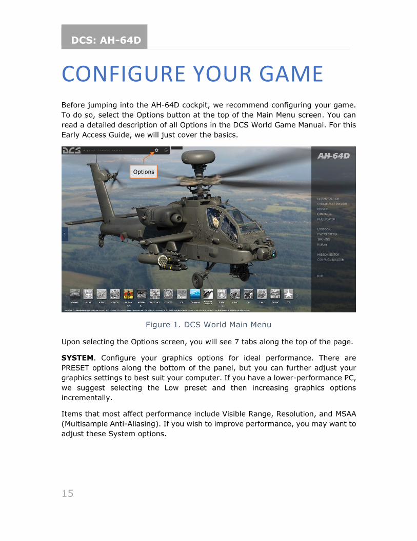
CONFIGURE YOUR GAME Before jumping into the AH-64D cockpit, we recommend configuring your game.
To do so, select the Options button at the top of the Main Menu screen. You can
read a detailed description of all Options in the DCS World Game Manual. For this
Early Access Guide, we will just cover the basics.
Figure 1. DCS World Main Menu
Upon selecting the Options screen, you will see 7 tabs along the top of the page.
SYSTEM. Configure your graphics options for ideal performance. There are
PRESET options along the bottom of the panel, but you can further adjust your
graphics settings to best suit your computer. If you have a lower-performance PC,
we suggest selecting the Low preset and then increasing graphics options
incrementally.
Items that most affect performance include Visible Range, Resolution, and MSAA
(Multisample Anti-Aliasing). If you wish to improve performance, you may want to
adjust these System options.
Options
DCS: AH-64D
16
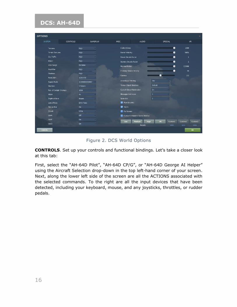
Figure 2. DCS World Options
CONTROLS. Set up your controls and functional bindings. Let’s take a closer look
at this tab:
First, select the “AH-64D Pilot”, “AH-64D CP/G”, or “AH-64D George AI Helper”
using the Aircraft Selection drop-down in the top left-hand corner of your screen.
Next, along the lower left side of the screen are all the ACTIONS associated with
the selected commands. To the right are all the input devices that have been
detected, including your keyboard, mouse, and any joysticks, throttles, or rudder
pedals.
DCS: AH-64D
17
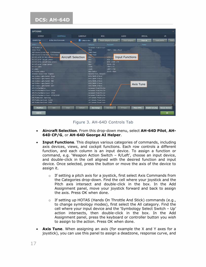
Figure 3. AH-64D Controls Tab
• Aircraft Selection. From this drop-down menu, select AH-64D Pilot, AH-64D CP/G, or AH-64D George AI Helper.
• Input Functions. This displays various categories of commands, including
axis devices, views, and cockpit functions. Each row controls a different function, and each column is an input device. To assign a function or
command, e.g. ‘Weapon Action Switch – R/Left’, choose an input device, and double-click in the cell aligned with the desired function and input device. Once selected, press the button or move the axis of the device to
assign it.
o If setting a pitch axis for a joystick, first select Axis Commands from the Categories drop-down. Find the cell where your joystick and the
Pitch axis intersect and double-click in the box. In the Add Assignment panel, move your joystick forward and back to assign the axis. Press OK when done.
o If setting up HOTAS (Hands On Throttle And Stick) commands (e.g., to change symbology modes), first select the All category. Find the cell where your input device and the ‘Symbology Select Switch – Up’
action intersects, then double-click in the box. In the Add Assignment panel, press the keyboard or controller button you wish to assign to the action. Press OK when done.
• Axis Tune. When assigning an axis (for example the X and Y axes for a joystick), you can use this panel to assign a deadzone, response curve, and
Aircraft Selection Input Functions
Axis Tune
DCS: AH-64D
18
other tuning. This can be very useful if you find the aircraft too sensitive to control. The most common and useful functions to adjust are Deadzone,
Response Curve, Saturation Y, and Invert.
GAMEPLAY. This tab primarily allows you to adjust the game to be as realistic or
as casual as you’d like. Choose from many difficulty settings like labels, tooltips,
unlimited fuel/weapons, etc. Turning the aircraft’s Mirrors “Off” can help improve
performance.
MISC. These are additional settings to alter your game experience.
AUDIO. Use this tab to adjust the audio levels of the game. You also have the
option to turn on and off different audio effects.
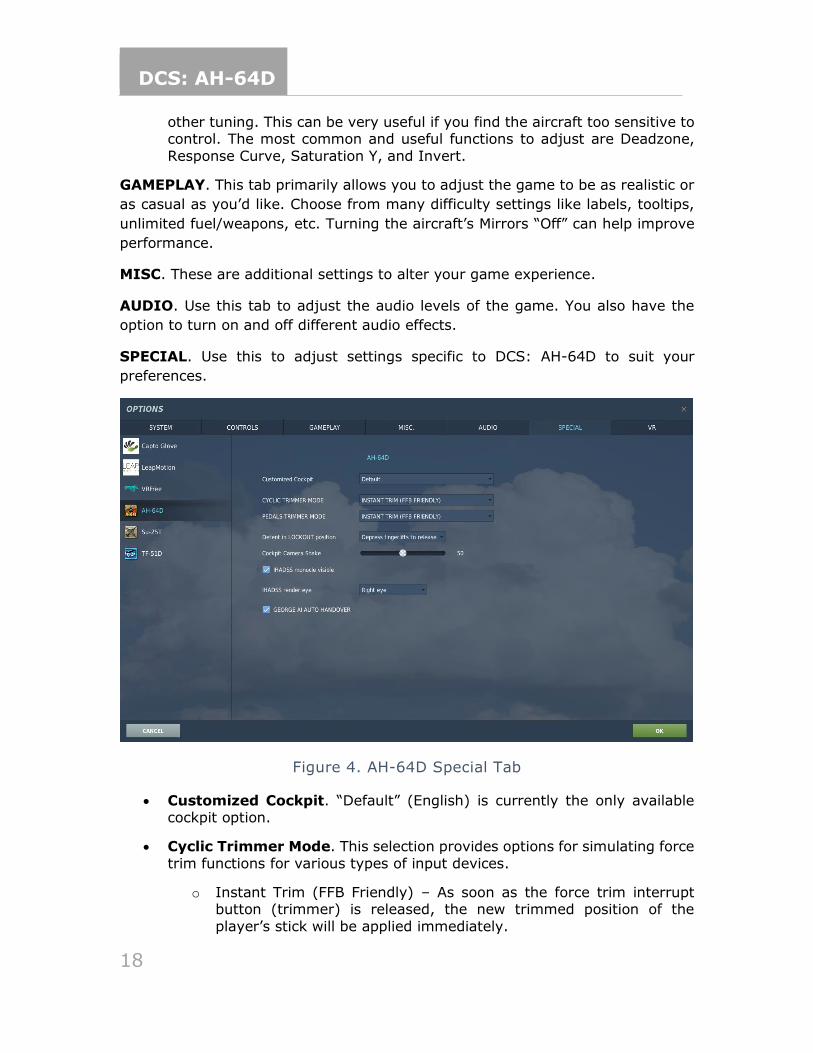
SPECIAL. Use this to adjust settings specific to DCS: AH-64D to suit your
preferences.
Figure 4. AH-64D Special Tab
• Customized Cockpit. “Default” (English) is currently the only available cockpit option.
• Cyclic Trimmer Mode. This selection provides options for simulating force
trim functions for various types of input devices.
o Instant Trim (FFB Friendly) – As soon as the force trim interrupt button (trimmer) is released, the new trimmed position of the
player’s stick will be applied immediately.
DCS: AH-64D
19
o Central Position Trimmer Mode – After the force trim interrupt button (trimmer) is released, the new trimmed position of the player’s stick
will only be applied after the stick is returned to neutral position.
o Joystick Without Springs and FFB – This option is used for joysticks lacking any spring resistance or Force-Feedback (FFB).
• Pedals Trimmer Mode. This selection provides the same trimming options as the Cyclic Trimmer Mode but applied to player pedal devices.
• Detent in LOCKOUT position.
o Automatically Jump Over – This option will move the engine quadrant power levers past the FLY position and into LOCKOUT without any detents applied. Recommended for player throttles equipped with
physical detents.
o Depress Fingerlifts to Release Locks – This option will move the engine quadrant power levers past the FLY position and into
LOCKOUT only when the Power Lever Finger Lift detent commands are used. Recommended for player throttles that lack physical detents.
• Cockpit Camera Shake. Adjusts the intensity of physics applied to moveable cockpit elements.
• IHADSS monocle visible. When enabled, a “ghost HDU” outline around
the IHADSS symbology will be displayed to simulate the physical obstruction of the HDU monocle. When disabled, only the IHADSS symbology itself will be displayed.
• IHADSS render eye. Selects between rendering the IHADSS symbology in either the left or right VR eyepiece, or both eyepieces simultaneously.
• George AI Auto-Handover. When enabled, when the player switches
position to the front (CPG) seat, George AI will automatically take control of the helicopter flight controls. If disabled, the player will still retain flight control of the helicopter when switching between seats, and will need to
command George AI when to take the flight controls.
VR. The VR tab allows you to enable support for VR headsets. When using VR, be
particularly aware of the Pixel Density setting, as it can have a dramatic effect on
game performance.
(N/I). This denotes a system or function of the DCS: AH-64D within this manual
that is not implemented.
DCS: AH-64D
20
AIRCRAFT HISTORY The AH-64D is the second generation of the AH-64 line, which began with the
Advanced Aerial Fire Support System program in 1963, culminating in the AH-64A
in 1983. The AH-64D design was completed in 1997, centered around the AN/APG-
78 fire control radar.
THE KEY WEST AGREEMENT
In 1948, James V. Forrestal, the first US Secretary of Defense (SecD), drafted the
Key West Agreement, which codified the separation of air assets between the Army
and the newly founded US Air Force. In particular, it limited Army Aviation to
employing fixed-wing aircraft below 2,500 pounds weight and helicopters below
4,000 pounds. It was believed that the Air Force would provide for the close air
support (CAS) role with a new generation of modern multirole fighter aircraft.
In 1960, President Kennedy’s SecD, Robert S. McNamara, revisited this agreement
by starting the Army Tactical Mobility Requirements Board. The Board and its
chairman, Lt. Gen. Hamilton H. Howze, recommended that Army Aviation be
greatly expanded to include a well-developed attack role, among many others.
McNamara followed the board’s recommendation, which produced an immediate
rebuke from Air Force generals, insistent that fighters were the only effective CAS
platforms.
Army leadership was eager to demonstrate otherwise, having noted the success
of armed UH-1 Hueys. To that end, in 1963, the Army founded the Advanced Aerial
Fire Support System (AAFSS), to design a purpose-built attack helicopter, rather
than an armed variant of a utility helicopter. In 1964, the request for proposals
(RFP) was announced, and in 1968, Lockheed won the competition with its
proposal for the AH-56A Cheyenne, a close air support gunship.
In the late 1960s, the US military’s strategic concern shifted to the large numbers
of tanks that Warsaw Pact countries could employ in a European ground war. Thus,
aircraft development priority changed from close air support to the anti-tank role.
In response to this shift, the US Air Force founded the A-X program (which would
eventually result in the A-10A “Warthog”), and in 1972, the Army canceled
development of the AH-56 in favor of a program to develop a more capable anti-
tank platform.
DCS: AH-64D
21
ADVANCED ATTACK HELICOPTER PROGRAM
The Army’s project to build an anti-tank helicopter was called the Advanced Attack
Helicopter (AAH) program, and it was aimed at designing a capable replacement
for the AH-1 Cobra, the Army’s light attack helicopter of the period.
The AAH RFP was announced in November 1972, specifying that the helicopter
should have the same General Electric T700 engine as the successful UH-60
Blackhawk, and should be armed with a 30mm cannon and sixteen anti-tank TOW
missiles. Later, as the separately developed AGM-114 Hellfire missile neared
completion, the RFP was altered, and the TOW missiles were swapped out with a
requirement to carry sixteen Hellfires.
Bell, Boeing, Vertol/Grumman, Hughes, Lockheed, and Sikorsky all submitted
proposals for the AAH program, and in July of 1973, the Department of Defense
chose thew Hughes Model 77 and the Bell Model 409 to be built and compete for
the contract. A few months later, the Army designated the AAH program as one of
its “Big Five” top priority projects, reflecting the importance of developing a
capable anti-tank helicopter.
The Bell Model 409, designated the YAH-63, first flew on September 30, 1975, and
the Hughes Model 77 (designated YAH-64) first flew only a day later. After a series
of trials, the Army decided to move ahead with the YAH-64, citing its increased
survivability over the YAH-63 stemming from the YAH-64’s four-blade main rotor
and tailwheel landing gear configuration.
AH-64A
The YAH-64 then entered pre-production, per Phase Two of the AAH program. In
Phase Two, the YAH-64 airframe was integrated with the weapons and sensor
platforms it would employ, in particular, the AGM-114, which would be the
cornerstone anti-tank missile for the helicopter. During pre-production, the aircraft
was re-designated the AH-64A.
The AH-64A was equipped with a revolutionary new targeting system, called the
Target Acquisition Designation Sight (TADS). It was designed to allow aircrews to
acquire targets and steer the 30mm cannon using a helmet-mounted sight.
Combined with the Pilot Night Vision System (PNVS), the helmet-mounted display
made the AH-64A a lethal all-weather attack vehicle.
Following pre-production, in 1981, three AH-64As were delivered to the Army for
Operational Test II. The engines were upgraded to the newer T700-GE-701, with
a shaft horsepower of 1,690 hp.
DCS: AH-64D
22
In 1982, the Army approved the AH-64A for full-scale production, and in 1983,
the first production AH-64A rolled off the line at Hughes’s production facility in
Mesa, Arizona. In January 1984, the Army took delivery of its first production AH-
64A, and in March 1986, began training its first operational AH-64A unit, the 7th
Battalion, 17th Cavalry Brigade, in Ft. Hood, Texas.
The AH-64A first saw combat in 1989 as part of Operation Just Cause, the US
invasion of Panama.
In all, over one thousand AH-64As were produced, most of which have since been
upgraded to the D model. The variant served until July 2012, when the last A
model was taken out of service for upgrades.
AH-64D
Following Operation Desert Storm, McDonnell-Douglas (which had since acquired
Hughes) proposed the AH-64B upgrade, which would incorporate a modernized
cockpit and fire control system as well as new rotor blades. The program was
approved and funded by Congress but was canceled merely a year later in favor
of the AH-64D proposal, which promised a much more ambitious upgrade to the
aircraft.
The AH-64D incorporated upgraded engines and a longer fuselage to house an
entirely new suite of sensors. Most notable was the addition of the AN/APG-78 fire
control radar, mounted above the main rotor, making D models immediately
identifiable. In addition, the TADS and PNVS were replaced with the Arrowhead
system, consisting of the Integrated Helmet and Display Sighting System
(IHADSS), second-generation long wave targeting FLIR and DTV targeting
cameras, a pilotage FLIR, and an integrated target tracking system.
The first prototype D model was flown in April of 1992, and by 1995, testing had
concluded, and full-scale production began. The first AH-64D was delivered to the
Army on March 31, 1997.
Since August 1997, Boeing has produced AH-64Ds domestically for the United
States and for foreign partners. AgustaWestland produces AH-64Ds for the United
Kingdom. Along with the US and UK, the AH-64D operates as part of the armies
of the United Arab Emirates, Singapore, Saudi Arabia, the Netherlands, Kuwait,
Japan, Israel, Greece, and Egypt.
Along with building new D models, the Army also awarded McDonnell-Douglas a
$1.9 billion contract to upgrade existing AH-64As to Ds. Starting in August of 1997,
Boeing has since upgraded all US A models to Ds. In all, 2400 AH-64s have been
produced since 1975, over a thousand of them AH-64Ds.
DCS: AH-64D
23
AIRCRAFT OVERVIEW The Boeing AH-64D is a two-person day/night all-weather attack helicopter
developed originally by Hughes Aircraft Company for the US Army. The helicopter
was originally designed for the anti-tank role, employing primarily the AGM-114
Hellfire and Hydra-70 2.75-inc rockets. Its design incorporates significant
survivability and redundancy after lessons learned in Vietnam.
COCKPIT
The AH-64D has two cockpits in tandem. The aft cockpit is for the pilot (PLT), and
the forward cockpit is for the copilot/gunner (CPG). Flight controls and weapons
controls are installed for both crewmembers, but some targeting, and employment
controls are only installed in the CPG position.
Both cockpit seatbacks are protected with ballistic shielding, and an additional
ballistic shield sits between the two cockpits.
Both cockpit canopies consist of two heated glass windshield and five acrylic side
panels. The canopies open upward and to the side for ingress and egress, and
latch for flight. Improper latching is detected and annunciated by the onboard
avionics.
For emergency egress, both cockpits include a canopy jettison system. Jettison
handles are installed for the pilot and CPG, as well as an exterior jettison handle
for rescue personnel. The jettison system consists of a detonating cord that ejects
four of the acrylic side panels for crew egress.
FUSELAGE
The AH-64D fuselage is armored, with 2,500 pounds of ballistic shielding designed
to sustain hits from projectiles up to 23mm in caliber. The fuselage includes three
integral fire/overheat detectors: one adjacent the main transmission, and one on
each firewall louver door (where engine exhaust is routed).
ENGINES
The AH-64D is powered by two General Electric T700-GE-701C turboshaft engines,
each generating 1,940 shaft horsepower. The engines are front drive and
DCS: AH-64D
24
regulated by a Digital Electronic Control (DEC) and Hydro-Mechanical Unit (HMU)
integral with each engine.
Each engine consists of a cold section, hot section, power turbine section, and
accessory section. The cold section consists of an inlet particle separator for dust
and sand protection, six-stage compressor, variable inlet guide vanes (IGVs), and
variable stator vanes. The DEC is mounted to the cold section. The hot section
consists of the annular combustor, nozzle assembly and gas generator turbine.
The power turbine section consists of two turbine stages and the exhaust frame.
The accessory section includes the HMU, fuel boost pump, oil system, and Air
Turbine Starter system. Each engine has a nose-mounted reduction gearbox that
powers the main transmission.
Digital Engine Computer and Hydromechanical Unit
The DEC and HMU work together to manage each engine, setting power based on
the position of the power levers and collective handles. The power lever position
is mechanically transmitted to the HMU via a power available spindle (PAS), and
the collective position mechanically via a load demand spindle (LDS). During
normal operation, the HMU controls fuel flow to the combustor according to the
PAS and LDS. The HMU also schedules the inlet guide vanes, controls the anti-ice
and start bleed valve, and regulates discharge air pressure and NG (gas generator
RPM). The HMU includes an automatic NG overspeed cut-off that will flame out the
engine to prevent an engine overspeed.
The DEC coordinates automatic torque load-sharing between the two engines,
monitors NP (power turbine RPM), and limits turbine gas temperature (TGT). Like
the HMU’s automatic NG overspeed cut-off, the DEC has an automatic NP overspeed
cut-off. The DEC is normally powered by the engine’s alternator but can use
aircraft power as a backup. The DEC for each engine can be disabled by placing
the engine’s power lever into the “lock-out” position momentarily.
The DEC has a contingency power feature that automatically activates during
single-engine operations. If an engine flames out, the DEC increases the TGT
limiter of the remaining engine automatically.
During high-torque maneuvers (e.g., left pedal turns with no change in collective
position), the DEC’s maximum torque rate attenuator (MTRA) will automatically
reduce fuel flow to assist in preventing an over torque.
Starter System
The starter system consists of a pneumatic starter valve, an ignition system with
two igniter plugs, and the DEC. Pneumatic pressure for engine start can be
DCS: AH-64D
25
supplied by the Auxiliary Power Unit (APU), Aircraft Ground Power Unit (AGPU), or
a running engine (cross-bleed start).
During engine start, the DEC will monitor engine parameters and automatically
abort the start if an imminent hot start is detected.
Fire Protection System
Engine fire detection is provided by two optical flame detectors in each engine,
and two in the APU. Two nitrogen fire bottles provide fire suppression. The bottles,
labeled PRI (primary) and RES (reserve), can be discharged into either engine or
the APU.
Auxiliary Power Unit (APU)
The APU is a self-contained gas generator that can power the accessory section of
the main transmission to generate electric and hydraulic power, as well as
pressurized air, without the need for engine power. The APU is primarily used to
start the engines without requiring external ground power sources but can be used
as an emergency or auxiliary source of electric or hydraulic power.
The APU draws fuel from the aft fuel cell only and consumes approximately 175
pounds per hour when active.
The APU is automatically monitored by an Electronic Control Unit (ECU), which
detects overspeed and overcurrent anomalies, as well as abnormal oil pressure.
The ECU will automatically shut down the APU when an anomaly is detected. The
ECU also controls the power takeoff (PTO) clutch engagement to the accessory
section of the main transmission.
DRIVETRAIN
The main rotor drive system consists of the main rotor drive shaft, main rotor
transmission, three-stage reduction gearing, and dual independent integral oil
systems. The main transmission receives power from two nose gearbox inputs,
one mounted on each turboshaft engine. The main transmission is used to drive
the main rotor.
The tail rotor drive system consists of the tail rotor drive shaft, intermediate
gearbox, and tail rotor gearbox. The tail rotor drive shaft consists of four sections
within the tail boom. The sections are connected with flexible couplings and
mounted with hanger bearings to accommodate aerodynamic and maneuvering
loads from the tail boom. The intermediate gearbox is at the base of the vertical
stabilizer, and the tail rotor gearbox is at the base of the tail rotor static mast.
Both gearboxes reduce the transmission RPM and change the angle of the drive.
DCS: AH-64D
26
The main and tail rotor drive shafts are designed to carry torque loads only. Each
of these shafts pass through and rotate within a static mast. The main rotor static
mast carries all vertical and bending loads, and the tail rotor static mast absorbs
all tail rotor loads. This allows the aircraft to perform aggressive or aerobatic
maneuvers while minimizing stresses to the drive train system
ROTORS
The AH-64D has a four-blade main rotor for lift and translation, and a four-blade
tail rotor for anti-torque and directional control.
The four-blade main rotor is fully articulated, with each blade able to flap, feather,
lead, and lag independently. Mechanical droop stops limit blade droop.
The four-blade tail rotor is semi-rigid of a teetering design.
FLIGHT CONTROLS
AH-64D flight controls are hydromechanical, consisting of mechanical linkages
between the flight controls and control surfaces, augmented by transmission-
driven hydraulic power. The flight controls are conventional and consist of a cyclic,
collective, and anti-torque pedals.
The cyclic is mechanically connected to a swashplate on the rotor mast that tilts
the main rotor. The collective is mechanically connected to the LDS and directly
controls rotor blade pitch. The anti-torque pedals control tail rotor blade pitch.
Hydraulic augmentation is provided by the Stability and Control Augmentation
System (SCAS), which consists of hydraulic actuators controlled by the Flight
Management Computer (FMC). The FMC provides rate damping to smooth flight
control inputs and command augmentation. It also provides limited attitude and
altitude hold capability for hands-off flying. The command augmentation system
provides consistent control feel across the full range of helicopter airspeeds. The
SCAS also provides automatic turn coordination for turns above 40 knots airspeed.
The AH-64D has an articulating horizontal stabilator controlled by an electric
actuator. The horizontal stabilator improves pitch angle control and improves over-
the-nose visibility at low airspeeds. In automatic mode, the FMC schedules the
horizontal stabilator position according to collective position, airspeed, and pitch
rate. In nap of the earth (NOE)/approach mode, the horizontal stabilator is driven
to the 25° trailing edge down position when below 80 knots, to further improve
over-the-nose visibility. In manual mode, the pilot controls trim position with a
switch on the collective.
DCS: AH-64D
27
To ease pilot workload, a trim feel system is provided for the cyclic. The trim feel
system consists of lateral and longitudinal force trim springs, and magnetic
solenoids that engage and disengage the force trim. A button on the cyclic
disengages the trim feel system, allowing the cyclic to move freely without
resistance. When re-engaged, the force trim springs hold the cyclic in its current
position and provide an increasing force gradient as the cyclic is deflected away
from this center point.
Back-Up Control System (BUCS)
Normally, the pilot and CPG flight controls are mechanically linked. The mechanical
linkages are protected by shear pins and mis-track sensors to prevent a control
jam or severance from affecting both sets of flight controls.
If the flight controls are decoupled by the shear pin, or a mis-track is otherwise
sensed, the Back-Up Control System is automatically activated. The BUCS is a
single-channel, four-axis, non-redundant electric fly-by-wire (FBW) system. The
FBW system is designed to replicate the feel of the hydromechanical controls but
does not replicate SCAS functionality.
BUCS can only be active for the pilot or the CPG station. Either the pilot or the
CPG can transfer BUCS control to their station if necessary, depending on the
nature and location of the jam or severance within the flight controls.
Landing Gear
The AH-64D has two trailing-link main landing gear (MLG) wheels and a lockable,
free-castoring tailwheel. The MLG consists of left and right wheels and tires with
integral disc brakes, mounted on separate nitrogen-oil shock struts.
Each anti-torque pedal is connected to a hydraulic disc brake on the corresponding
MLG wheel. Each MLG brake is connected to its own master cylinder, which
provides hydraulic pressure to the braking system. The pilot and CPG anti-torque
pedals, when pressed downwards, actuate the hydraulic brake system for the
corresponding wheel. A parking brake valve maintains brake pressure when closed.
The tailwheel is free-castoring in the full 360° of motion. A spring-loaded tailwheel
lock can be hydraulically actuated to hold the tailwheel in position. The tailwheel
lock is activated from the collective flight grips or the tail wheel lock pushbuttons.
Both mail landing gear shock struts have a one-time capability to absorb loads
from a high-stress impact. Shear rings and rupture discs on each strut, when
activated by a hard landing, start a controlled collapse of the strut to reduce crash
loads on the airframe.
DCS: AH-64D
28
FUEL SYSTEM
The AH-64D includes two internal self-sealing, crash-resistant fuel cells. The
forward fuel cell holds up to 156 gallons, and the aft fuel cell holds up to 220
gallons. Fuel is normally balanced between the two cells automatically by the
avionics.
A 230-gallon external fuel tank can be mounted on each of the four stub wing
pylons. An Internal Auxiliary Fuel System (IAFS) can be installed into the
ammunition bay, storing either 98 or 129 gallons at the expense of ammunition
capacity.
Fuel Transfer Subsystem
Fuel is transferred between the forward and aft cells using pneumatic pressure.
Transfer is normally automatic but can be manually controlled by the aircrew.
Fuel transfer from the IAFS or external tanks is one-way only. Transfer from the
external tanks to the internal cells is pneumatic, and an electric fuel pump
transfers fuel from the IAFS to the internal cells.
Normally, the forward cell feeds engine 1 and the aft cell feeds engine 2. The
aircrew can control crossfeed modes, where both engines feed from one fuel cell,
as necessary in abnormal circumstances.
An electric boost pump is used to provide motive flow from the aft cell only during
engine start. This boost pump can also be manually selected on during an
emergency. The APU has its own electric boost pump that also draws from the aft
cell.
Nitrogen Inerting Unit (NIU)
The fuel cells are inerted using nitrogen to reduce the risk of fire. The NIU is
completely self-contained and automatic. It uses aircraft power and pressurized
air and generates an inerted mix containing around 99% nitrogen. This inerted
gas is used to pressurize the internal cells. It is also routed to the IAFS during fuel
transfer.
ELECTRICAL SYSTEM
Electrical aircraft power is managed by the Electrical Power Management System
(EPMS). The EPMS is a fully redundant and automatic power system consisting of
a distributor for battery, AC, and DC power.
DCS: AH-64D
29
The battery is a 24-volt, 15-amp fiber nickel-cadmium (FNC) design. It can provide
power for normal flight loads for up to 12 minutes, assuming at least an 80%
charge.
AC power is provided by two brushless, air-cooled generators. Each generator
outputs 45 kVA three-phase four-wire power at 115 or 200 volts and 400 Hz. Each
generator has its own Generator Control Unit (GCU). A single generator is capable
of handling full flight loads without shedding. The generators are mounted to the
transmission accessory gearbox.
DC power is provided by two Transformer-Rectifier Units (TRUs), each providing
28 volts and 350 amps of DC power. Like the generators, a single TRU can provide
sufficient power for full flight loads without shedding.
An external power receptacle can provide DC and AC power for all systems from
an AGPU.
Power is distributed by four AC busses, four DC busses, four battery busses, and
a battery hot bus. See the Appendices (TODO) for an electrical distribution diagram.
Each bus and power consumer is protected by a resettable circuit breaker.
HYDRAULIC SYSTEM
The AH-64D has two independent hydraulic systems, labeled primary and utility.
The primary system exclusively powers the hydraulic flight control system via the
FMC. It’s powered by the main transmission and has a total capacity of six pints
with a one-pint reservoir.
The utility system is a secondary source of hydraulic power for the flight controls
(bypassing the FMC), and powers all other hydraulic systems: rotor brake, area
weapon turret drive, ammunition handling system, APU start motor, tailwheel
unlock actuator, and external stores elevation actuators. The utility system is also
powered by the main transmission. Because of the higher loads placed on the
utility system, it has a higher-volume manifold and larger reservoir.
The utility system also charges a 3,000-psi hydraulic accumulator. The hydraulic
accumulator is used to provide hydraulic damping during gun fire, hydraulic power
to the rotor brake and APU starter, and can be used to temporarily power the flight
controls via the utility system in an emergency.
INTEGRATED PRESSURIZED AIR SYSTEM (IPAS)
The IPAS provides pressurized air to aircraft pneumatic systems. Bleed air is drawn
from two ports: a high-pressure port is exclusively used to pressurize the hydraulic
DCS: AH-64D
30
systems, and a low-pressure port is used by all other consumers. Low-pressure
air is used by the engine air turbine starters, fuel boost and transfer pumps, anti-
ice system, ice detection probe, nitrogen inerting unit, vapor cycle cooling system,
and environmental control system.
IPAS bleed air can be provided by one or both engines, the APU, or an external
source such as an AGPU.
ANTI-ICE SYSTEM
Ice detection is provided by an aspirating ice detect probe, powered by pneumatic
air from the IPAS. The ice detect probe activates whenever free air temperature
drops to 5 °C or below. When the anti-ice system is in AUTO mode, detection of
ice will automatically command activation of all anti-ice systems.
Ice protection is provided by electric pitot and air data system (ADS) sensor heat,
pneumatic engine inlet anti-ice, electric sensor aperture anti-ice, and electrically
heated canopies.
The canopies also include crewmember-controllable windshield wipers and a defog
system powered by the IPAS.
ENVIRONMENTAL CONTROL SYSTEM (ECS)
The ECS provides crewmember comfort through ventilation, heating, and air
conditioning. Ventilation is provided by pilot and CPG gaspers, which can be
opened to admit outside air into the cockpit. The ECS also powers ventilation fans
that provide forced air exchange between the cockpits and for avionics cooling.
Heating is provided by regulated bleed air from the IPAS.
Air conditioning is provided from two independent vapor cycle cooling systems.
One system provides cooled air for the pilot and aft sections of each Extended
Forward Avionics Bay (EFAB); the other system provides cooled air for the CPG,
the TADS & PNVS turrets, and the forward sections of each EFAB. A digital control
unit (DCU) manages the flow of cooled air.
In the event of a cockpit cooling failure, the DCU will automatically open an
interconnect valve between the two cockpits. The ventilation fans in the failed
cockpit will stop, and the functional cockpit’s ventilation fans will force cooled air
into both cockpits.
DCS: AH-64D
31
LIGHTING SYSTEM
The AH-64D has interior and exterior lighting. Exterior lighting consists of
formation lights, navigation lights, anti-collision lights, and a steerable search and
landing light. Inspection and maintenance lights are also installed throughout the
fuselage.
Interior lighting consists of primary and secondary/emergency lighting. The
primary lighting is the light plates for switch labels, display bezels, and the keypad.
Secondary/emergency lighting is a set of floodlights that illuminate different
sections of the cockpit.
The standby instruments in the pilot cockpit have their own independent lighting.
Each crewmember has a dimmable utility light that can be aimed around the
cockpit.
AVIONICS
AH-64D avionics subsystems communicate across four redundant multiplex (MUX)
bus channels at 1 Mbps. Each bus channel consists of a primary and secondary
bus. Channel 1 is used for controls and displays, communications and transponder
equipment, and aircraft systems. Channel 2 is used by the Aircraft Survivability
Equipment (ASE), Data Transfer Unit (DTU), flight controls, and navigation
systems. Channel 3 is used by the sighting, sensors, and weapons systems.
Channel 4 is used exclusively by the Fire Control Radar (FCR) and Radio Frequency
Interferometer (RFI).
Avionics systems are controlled in both cockpits by Multi-Purpose Displays (MPDs),
two per cockpit. Each MPD has six variable-action buttons (VAB) per side. The
buttons of the top row are labeled (left to right) T1–T6, the bottom row B1–B6,
and the left and right columns are labeled (top to bottom) L1–L6 and R1–R6,
respectively. Button B1 always returns the crewmember to the main menu. Each
MPD also has six fixed-action buttons (FAB) that allow immediate access to the
FCR, WPN, TSD, A/C, COM and VID pages; and a "favorites" button that allows
quick access of up to three frequently used MPD pages.
With external power connected and both throttles in the OFF position, the MPDs
will enter a “screen saver” mode after five minutes of inactivity. Pressing any MPD
button will re-activate all MPDs.
DCS: AH-64D
32
Communications System
The communications system includes an intercom for crewmember communication,
an ARC-186(V) VHF AM radio, an ARC-164(V) UHF AM radio, two ARC-201D VHF
FM radios, and an ARC-220 HF radio.
The VHF AM radio can receive between 108 and 115.975 MHz and transmit/receive
between 116 and 151.975 MHz.
The UHF radio can transmit and receive between 225 and 399.975 MHz. It has a
dedicated guard receiver always tuned to 243 MHz. The radio is capable of HAVE
QUICK and HAVE QUICK II frequency hopping as an electronic counter-
countermeasures (ECCM) technique.
The two VHF FM radios can transmit and receive between 30 and 87.975 MHz. The
radios support SINCGARS combat nets and Fire Support (FS) protocols. The FM1
radio can be augmented by an improved FM amplifier capable of providing up to
40 watts of transmit power.
The HF radio can transmit and receive between 2 and 29.9999 MHz.
A KY-58 is installed to provide voice message encryption for the UHF radio, and a
KY-100 provides voice and data encryption for the HF radio.
All radios are connected to the battery bus and can be used prior to engine start.
The AH-64D includes an MD-1295A Improved Data Modem (IDM) that can transmit
and receive TACFIRE (Tactical Fire Direction System) and Longbow AFAPD (Air
Force Applications Program Development) messages over any radio. It can also
utilize either FM radio for Fire Support artillery messages.
Identification System
The AH-64D includes an APX-118(V) transponder, capable of responding to
interrogations in Mode 1, Mode 3/A, and Mode C formats. The APX-118(V) can also
reply to encrypted Mode 4 interrogations.
Navigation and Position Systems
The AH-64D’s navigation system consists of two embedded GPS Inertial Navigation
Systems (EGI), the Doppler Radar Velocity Sensor (DRVS), Air Data System (ADS),
radar altimeter, automatic direction finder (ADF), High Integrated Air Data
Computer (HIADC), and flight management computer (FMC). Each EGI consists of
a five-channel encrypted GPS receiver that provides position updates to a ring
laser gyro (RLG) inertial navigation unit (INU). The two EGIs are labeled INU1 and
DCS: AH-64D
33
INU2, and the navigation system will select between them automatically as
primary and backup.
In addition, the AH-64D has an AN/ASN-157 Doppler Radar Velocity Sensor
(DRVS), which uses Doppler radar to determine aircraft groundspeed. This figure
is used as a velocity-aiding source for the EGI.
The Air Data System (ADS) consists of two independent air data subsystems: the
Flight Management Computer (FMC) and the Helicopter Air Data System (HADS).
The HADS is comprised of the High Integrated Air Data Computer (HIADC) and
two Airspeed And Direction Sensor (AADS) probes. The AADS probes sense
airspeed magnitude, direction, and free airstream temperature. The HIADC uses
this data, along with ambient and pitot pressure sensors, to compute air mass
related data. The FMC computes pressure altitude, pitot airspeed, and density
altitude related information. The FMC receives longitudinal and lateral true air
speeds, static temperature, and non-filtered true air speeds from the HIADC.
The AN/APN-209 Radar Altimeter provides height above ground level (AGL) to the
navigation system. The APN-209 uses a downward-facing radar to determine AGL
altitude.
The AN/ARN-149 Automatic Direction Finder (ADF) provides audio and radio
direction-finding capability for transmissions between 100 and 2199.5 kHz.
SENSOR AND SIGHTING SYSTEMS
The primary sensor and sighting system for the AH-64 is the Integrated Helmet
and Display Sighting System (IHADSS). The IHADSS consists of the Helmet
Display Unit (HDU), a small, collimated display placed in front of the crewmember’s
right eye (on a rotatable arm); the Sensor Surveying Units (SSU), a series of
sensors in the cockpit that determine crewmember head position and line-of-sight;
the Boresight Reticle Units (BRU), which establishes sensor boresight; and avionics
systems that can slave sensor and weapon systems to the IHADSS line of sight.
The IHADSS displays sensor, targeting, and aircraft information in the
crewmember’s line-of-sight, helping the crewmembers to locate and track targets
and maintain situational awareness. The HDU symbology format changes
depending on its display mode, which is controlled by the crew. The display is also
capable of overlaying calibrated video data from Forward-Looking Infrared (FLIR)
or Day Television (DTV) sensors, augmenting the crewmembers’ view of terrain,
obstructions, and vehicles at night or in inclement weather.
FLIR data comes from the AN/AAQ-11 Pilot Night Vision System (PNVS), which
provides day- and night-capable infrared capability.
DCS: AH-64D
34
The AN/ASQ-170 Target Acquisition Designation Sight (TADS) is an integrated
target acquisition and tracking system for the AH-64D. It consists of both FLIR and
Day TV (DTV) video systems, a laser rangefinder/designator (LRF/D), and a laser
spot tracker (LST). This gives TADS the ability to locate, track, and laser designate
targets day and night, and in inclement weather conditions.
Unique to the D model is the AN/APG-78 Fire Control Radar (FCR) and Radio
Frequency Interferometer (RFI). The APG-78 is an air-to-ground and air-to-air
radar with the capability to locate and independently track up to 128 surface
targets. The radar is mounted atop the main rotor mast, allowing the helicopter to
remain masked while scanning for targets. It has a scan capability of ±90° in
azimuth and +23-12° in elevation.
Along with the IHADSS and TADS, the APG-78 can be used as a source of targeting
data for the 30mm Area Weapon System, Hydra 2.75-inch rockets and AGM-114
Hellfire missiles.
The APG-78 also has limited air-to-air self-defense capability in conjunction with
the AGM-114.
DCS: AH-64D
35
AH-64D ARMAMENTS The AH-64D was designed primarily to employ the Longbow Hellfire Modular
Missile System (LBHMMS), along with its Area Weapon System and Aerial Rocket
Subsystem. It has four hardpoints, two mounted to each stub wing. Each hardpoint
is capable of articulating between +4° to -15° in elevation.
M139 AREA WEAPON SYSTEM
The Area Weapon System (AWS) consists of an M230 30mm automatic chain-
driven gun mounted on the underside of the helicopter between the two main
landing gear, its turret, controls, and the ammunition handling system. The
weapon is mounted on a hydraulically steered turret that can be slaved to either
the TADS line-of-sight or IHADSS line-of-sight, or fixed to a forward-firing position.
The M230 has a magazine of 1200 rounds and fires up to 625 rounds per minute.
When the Internal Auxiliary Fuel System (IAFS) is installed, magazine size is
reduced to 300 rounds. The turret can steer up to 86° in azimuth. It can elevate
up to 11° or depress down to 60°.
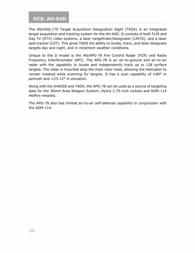
Figure 5 M230 Area Weapon System
The M230 fires 30x113 millimeter link-less, tracer-less ammunition, consisting of
either M789 High Explosive Dual Purpose (HEDP) rounds for tactical operations or
M788 Target Practice rounds for non-combat use. The M789 has a light armor
penetrating capability as well as a bursting fragmentation effect for anti-material
and anti-personnel use.
DCS: AH-64D
36
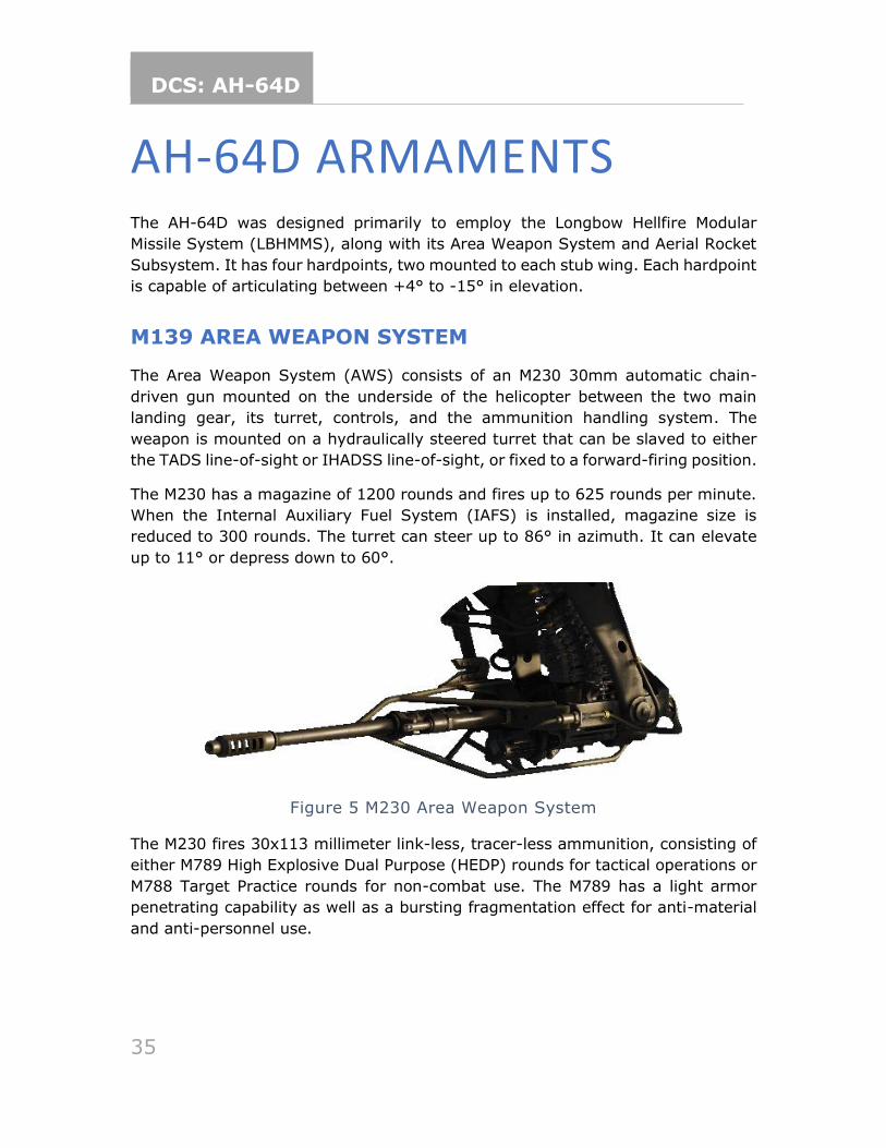
Figure 6. M789 HEDP (left) and M788 TP (right) 30mm ammunition
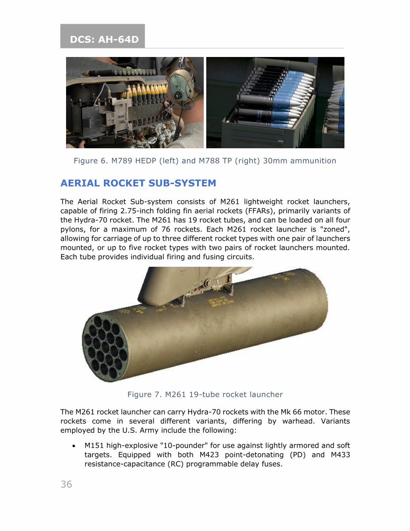
AERIAL ROCKET SUB-SYSTEM
The Aerial Rocket Sub-system consists of M261 lightweight rocket launchers,
capable of firing 2.75-inch folding fin aerial rockets (FFARs), primarily variants of
the Hydra-70 rocket. The M261 has 19 rocket tubes, and can be loaded on all four
pylons, for a maximum of 76 rockets. Each M261 rocket launcher is "zoned",
allowing for carriage of up to three different rocket types with one pair of launchers
mounted, or up to five rocket types with two pairs of rocket launchers mounted.
Each tube provides individual firing and fusing circuits.
Figure 7. M261 19-tube rocket launcher
The M261 rocket launcher can carry Hydra-70 rockets with the Mk 66 motor. These
rockets come in several different variants, differing by warhead. Variants
employed by the U.S. Army include the following:
• M151 high-explosive "10-pounder" for use against lightly armored and soft
targets. Equipped with both M423 point-detonating (PD) and M433
resistance-capacitance (RC) programmable delay fuses.
DCS: AH-64D
37
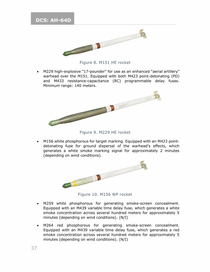
Figure 8. M151 HE rocket
• M229 high-explosive "17-pounder" for use as an enhanced “aerial artillery”
warhead over the M151. Equipped with both M423 point-detonating (PD)
and M433 resistance-capacitance (RC) programmable delay fuses.
Minimum range: 140 meters.
Figure 9. M229 HE rocket
• M156 white phosphorous for target marking. Equipped with an M423 point-
detonating fuse for ground dispersal of the warhead’s effects, which
generates a white smoke marking signal for approximately 2 minutes
(depending on wind conditions).
Figure 10. M156 WP rocket
• M259 white phosphorous for generating smoke-screen concealment.
Equipped with an M439 variable time delay fuse, which generates a white
smoke concentration across several hundred meters for approximately 5
minutes (depending on wind conditions). (N/I)
• M264 red phosphorous for generating smoke-screen concealment.
Equipped with an M439 variable time delay fuse, which generates a red
smoke concentration across several hundred meters for approximately 5
minutes (depending on wind conditions). (N/I)
DCS: AH-64D
38
• M261 multi-purpose submunition (MPSM) with 9 submunitions for use
against lightly- to medium-armored vehicles and soft targets. Equipped
with an M439 variable time delay fuse for an airburst just prior to the target.
Minimum range 1,000 meters.
Coming later in EA
Figure 11. M261 MPSM rocket
• M255A1 flechette with 1,179 60-grain hardened steel flechettes for use
against soft targets or personnel. Equipped with an M439 variable time
delay fuse for an airburst just prior to the target. Minimum range 800
meters; Effective range 1 to 3 kilometers.
Coming later in EA
Figure 12. M255A1 Flechette rocket
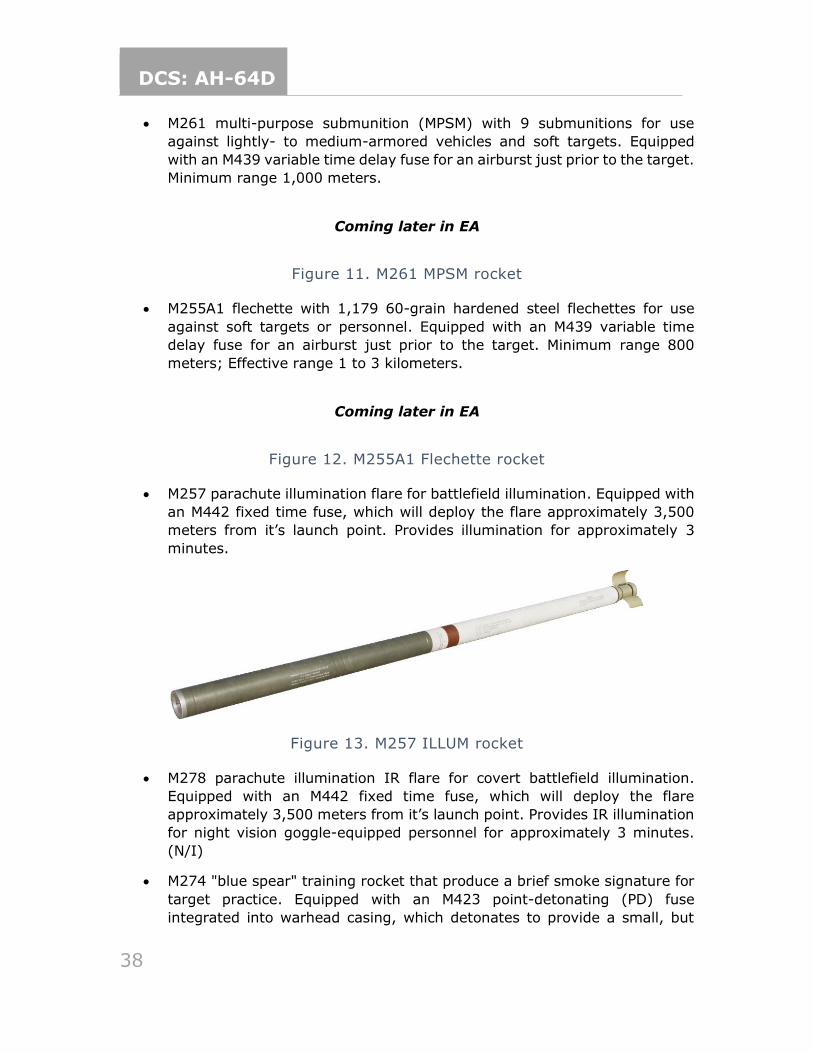
• M257 parachute illumination flare for battlefield illumination. Equipped with
an M442 fixed time fuse, which will deploy the flare approximately 3,500
meters from it’s launch point. Provides illumination for approximately 3
minutes.
Figure 13. M257 ILLUM rocket
• M278 parachute illumination IR flare for covert battlefield illumination.
Equipped with an M442 fixed time fuse, which will deploy the flare
approximately 3,500 meters from it’s launch point. Provides IR illumination
for night vision goggle-equipped personnel for approximately 3 minutes.
(N/I)
• M274 "blue spear" training rocket that produce a brief smoke signature for
target practice. Equipped with an M423 point-detonating (PD) fuse
integrated into warhead casing, which detonates to provide a small, but
DCS: AH-64D
39
noticeable flash and smoke signature for impact spotting. Ballistic match to
the M151 HE rocket to provide identical targeting and engagement training
for aircrews. (N/I)
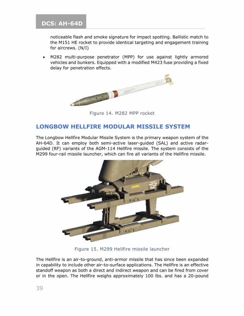
• M282 multi-purpose penetrator (MPP) for use against lightly armored
vehicles and bunkers. Equipped with a modified M423 fuse providing a fixed
delay for penetration effects.
Figure 14. M282 MPP rocket
LONGBOW HELLFIRE MODULAR MISSILE SYSTEM
The Longbow Hellfire Modular Missile System is the primary weapon system of the
AH-64D. It can employ both semi-active laser-guided (SAL) and active radar-
guided (RF) variants of the AGM-114 Hellfire missile. The system consists of the
M299 four-rail missile launcher, which can fire all variants of the Hellfire missile.
Figure 15. M299 Hellfire missile launcher
The Hellfire is an air-to-ground, anti-armor missile that has since been expanded
in capability to include other air-to-surface applications. The Hellfire is an effective
standoff weapon as both a direct and indirect weapon and can be fired from cover
or in the open. The Hellfire weighs approximately 100 lbs. and has a 20-pound
DCS: AH-64D
40
high-explosive anti-tank (HEAT) warhead, which includes a tandem shaped-charge
for defeating reactive armor.
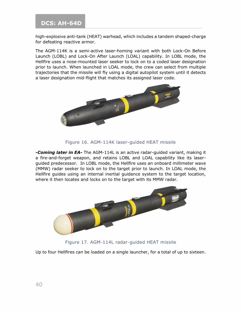
The AGM-114K is a semi-active laser-homing variant with both Lock-On Before
Launch (LOBL) and Lock-On After Launch (LOAL) capability. In LOBL mode, the
Hellfire uses a nose-mounted laser seeker to lock on to a coded laser designation
prior to launch. When launched in LOAL mode, the crew can select from multiple
trajectories that the missile will fly using a digital autopilot system until it detects
a laser designation mid-flight that matches its assigned laser code.
Figure 16. AGM-114K laser-guided HEAT missile
-Coming later in EA- The AGM-114L is an active radar-guided variant, making it
a fire-and-forget weapon, and retains LOBL and LOAL capability like its laser-
guided predecessor. In LOBL mode, the Hellfire uses an onboard millimeter wave
(MMW) radar seeker to lock on to the target prior to launch. In LOAL mode, the
Hellfire guides using an internal inertial guidance system to the target location,
where it then locates and locks on to the target with its MMW radar.
Figure 17. AGM-114L radar-guided HEAT missile
Up to four Hellfires can be loaded on a single launcher, for a total of up to sixteen.
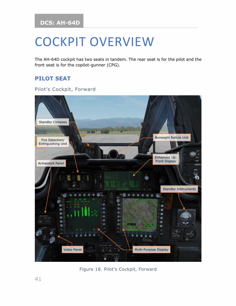
DCS: AH-64D
41
COCKPIT OVERVIEW The AH-64D cockpit has two seats in tandem. The rear seat is for the pilot and the
front seat is for the copilot-gunner (CPG).
PILOT SEAT
Pilot’s Cockpit, Forward
Figure 18. Pilot’s Cockpit, Forward
Fire Detection/ Extinguishing Unit
Enhanced Up-Front Display
Video Panel
Armament Panel
Multi-Purpose Display
Standby Instruments
Boresight Reticle Unit
Standby Compass
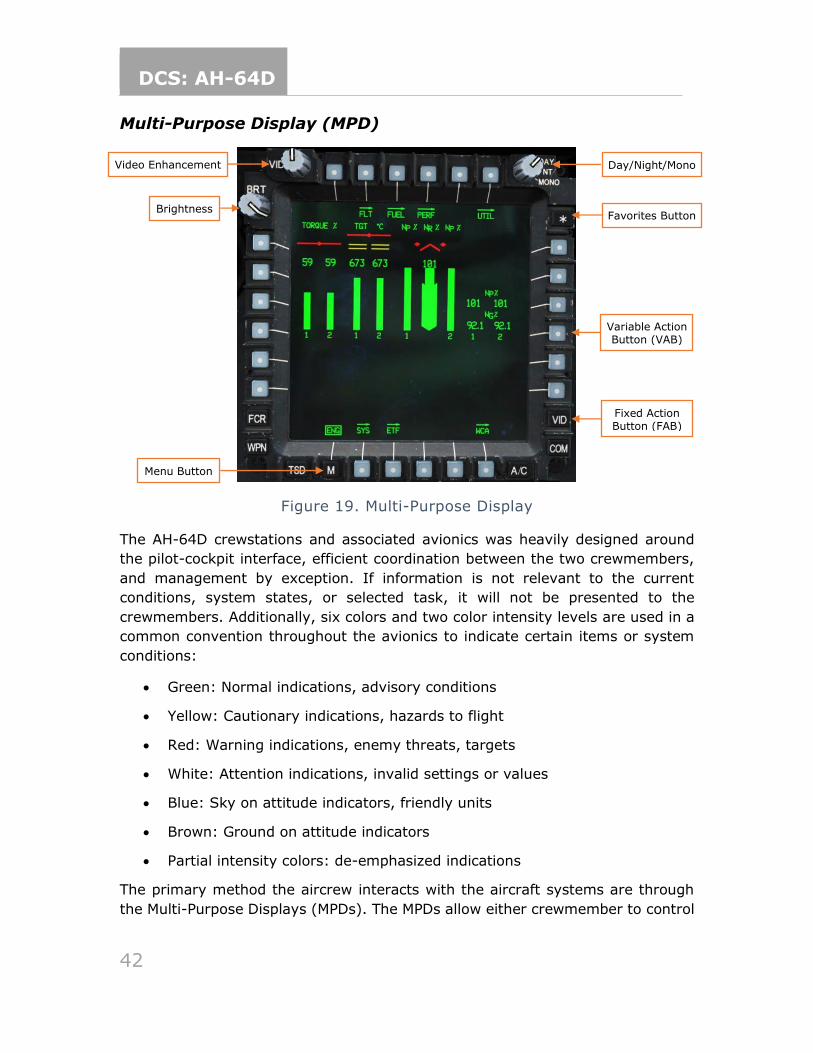
DCS: AH-64D
42
Multi-Purpose Display (MPD)
Figure 19. Multi-Purpose Display
The AH-64D crewstations and associated avionics was heavily designed around
the pilot-cockpit interface, efficient coordination between the two crewmembers,
and management by exception. If information is not relevant to the current
conditions, system states, or selected task, it will not be presented to the
crewmembers. Additionally, six colors and two color intensity levels are used in a
common convention throughout the avionics to indicate certain items or system
conditions:
• Green: Normal indications, advisory conditions
• Yellow: Cautionary indications, hazards to flight
• Red: Warning indications, enemy threats, targets
• White: Attention indications, invalid settings or values
• Blue: Sky on attitude indicators, friendly units
• Brown: Ground on attitude indicators
• Partial intensity colors: de-emphasized indications
The primary method the aircrew interacts with the aircraft systems are through
the Multi-Purpose Displays (MPDs). The MPDs allow either crewmember to control
Video Enhancement
Brightness
Variable Action Button (VAB)
Day/Night/Mono
Fixed Action Button (FAB)
Menu Button
Favorites Button
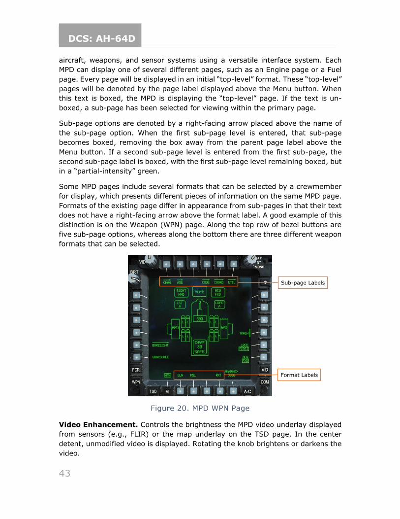
DCS: AH-64D
43
aircraft, weapons, and sensor systems using a versatile interface system. Each
MPD can display one of several different pages, such as an Engine page or a Fuel
page. Every page will be displayed in an initial “top-level” format. These “top-level”
pages will be denoted by the page label displayed above the Menu button. When
this text is boxed, the MPD is displaying the “top-level” page. If the text is un-
boxed, a sub-page has been selected for viewing within the primary page.
Sub-page options are denoted by a right-facing arrow placed above the name of
the sub-page option. When the first sub-page level is entered, that sub-page
becomes boxed, removing the box away from the parent page label above the
Menu button. If a second sub-page level is entered from the first sub-page, the
second sub-page label is boxed, with the first sub-page level remaining boxed, but
in a “partial-intensity” green.
Some MPD pages include several formats that can be selected by a crewmember
for display, which presents different pieces of information on the same MPD page.
Formats of the existing page differ in appearance from sub-pages in that their text
does not have a right-facing arrow above the format label. A good example of this
distinction is on the Weapon (WPN) page. Along the top row of bezel buttons are
five sub-page options, whereas along the bottom there are three different weapon
formats that can be selected.
Figure 20. MPD WPN Page
Video Enhancement. Controls the brightness the MPD video underlay displayed
from sensors (e.g., FLIR) or the map underlay on the TSD page. In the center
detent, unmodified video is displayed. Rotating the knob brightens or darkens the
video.
Format Labels
Sub-page Labels
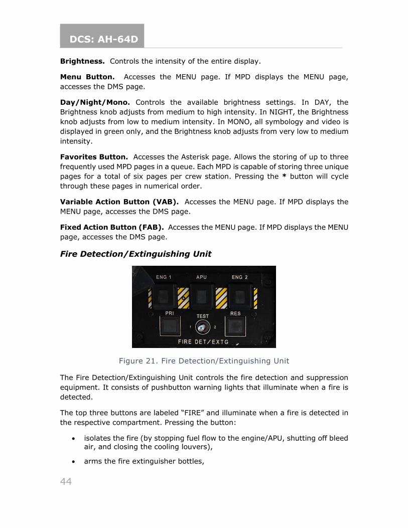
DCS: AH-64D
44
Brightness. Controls the intensity of the entire display.
Menu Button. Accesses the MENU page. If MPD displays the MENU page,
accesses the DMS page.
Day/Night/Mono. Controls the available brightness settings. In DAY, the
Brightness knob adjusts from medium to high intensity. In NIGHT, the Brightness
knob adjusts from low to medium intensity. In MONO, all symbology and video is
displayed in green only, and the Brightness knob adjusts from very low to medium
intensity.
Favorites Button. Accesses the Asterisk page. Allows the storing of up to three
frequently used MPD pages in a queue. Each MPD is capable of storing three unique
pages for a total of six pages per crew station. Pressing the * button will cycle
through these pages in numerical order.
Variable Action Button (VAB). Accesses the MENU page. If MPD displays the
MENU page, accesses the DMS page.
Fixed Action Button (FAB). Accesses the MENU page. If MPD displays the MENU
page, accesses the DMS page.
Fire Detection/Extinguishing Unit
Figure 21. Fire Detection/Extinguishing Unit
The Fire Detection/Extinguishing Unit controls the fire detection and suppression
equipment. It consists of pushbutton warning lights that illuminate when a fire is
detected.
The top three buttons are labeled “FIRE” and illuminate when a fire is detected in
the respective compartment. Pressing the button:
• isolates the fire (by stopping fuel flow to the engine/APU, shutting off bleed
air, and closing the cooling louvers),
• arms the fire extinguisher bottles,
DCS: AH-64D
45
• and acknowledges the master warning and voice warning message.
ENG 1 FIRE. Illuminates when a fire is detected in the #1 engine.
ENG 2 FIRE. Illuminates when a fire is detected in the #2 engine.
APU FIRE. Illuminates when an APU fire is detected.
The bottom two buttons are labeled “DISCH” and illuminate when the respective
extinguisher bottle is armed and has not yet been discharged. The bottles are
armed only when one of the FIRE pushbuttons has been pressed.
PRI. Illuminates when the primary extinguisher bottle is armed and available.
Pressing the button discharges the bottle.
RES. Illuminates when the reserve extinguisher bottle is armed and available.
Pressing the button discharges the bottle.
Finally, the TEST switch is used to test the extinguisher system. Placing the switch
in either the “1” or “2” position tests that respective half of the fire detection circuit
for both engines and the APU, as well as the aft deck overheat sensors and voice
message warning.
TEST 1. Tests one half of the fire detection circuit. A successful test is indicated
when all three FIRE pushbuttons are illuminated.
TEST 2. Tests the other half of the fire detection circuit. A successful test is
indicated when all three FIRE pushbuttons and both DISCH pushbuttons are
illuminated.
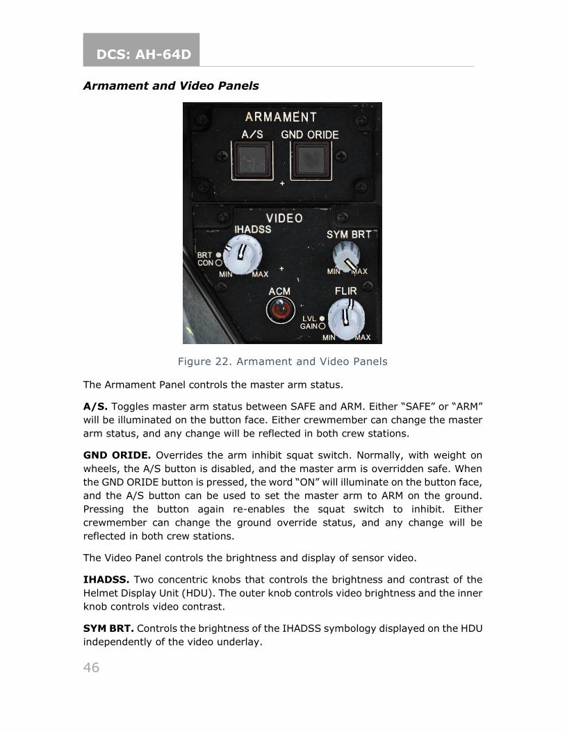
DCS: AH-64D
46
Armament and Video Panels
Figure 22. Armament and Video Panels
The Armament Panel controls the master arm status.
A/S. Toggles master arm status between SAFE and ARM. Either “SAFE” or “ARM”
will be illuminated on the button face. Either crewmember can change the master
arm status, and any change will be reflected in both crew stations.
GND ORIDE. Overrides the arm inhibit squat switch. Normally, with weight on
wheels, the A/S button is disabled, and the master arm is overridden safe. When
the GND ORIDE button is pressed, the word “ON” will illuminate on the button face,
and the A/S button can be used to set the master arm to ARM on the ground.
Pressing the button again re-enables the squat switch to inhibit. Either
crewmember can change the ground override status, and any change will be
reflected in both crew stations.
The Video Panel controls the brightness and display of sensor video.
IHADSS. Two concentric knobs that controls the brightness and contrast of the
Helmet Display Unit (HDU). The outer knob controls video brightness and the inner
knob controls video contrast.
SYM BRT. Controls the brightness of the IHADSS symbology displayed on the HDU
independently of the video underlay.
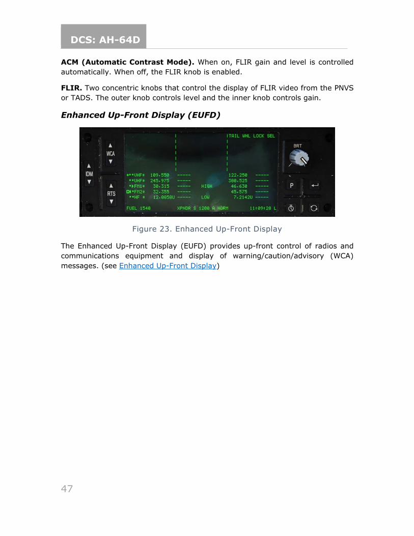
DCS: AH-64D
47
ACM (Automatic Contrast Mode). When on, FLIR gain and level is controlled
automatically. When off, the FLIR knob is enabled.
FLIR. Two concentric knobs that control the display of FLIR video from the PNVS
or TADS. The outer knob controls level and the inner knob controls gain.
Enhanced Up-Front Display (EUFD)
Figure 23. Enhanced Up-Front Display
The Enhanced Up-Front Display (EUFD) provides up-front control of radios and
communications equipment and display of warning/caution/advisory (WCA)
messages. (see Enhanced Up-Front Display)
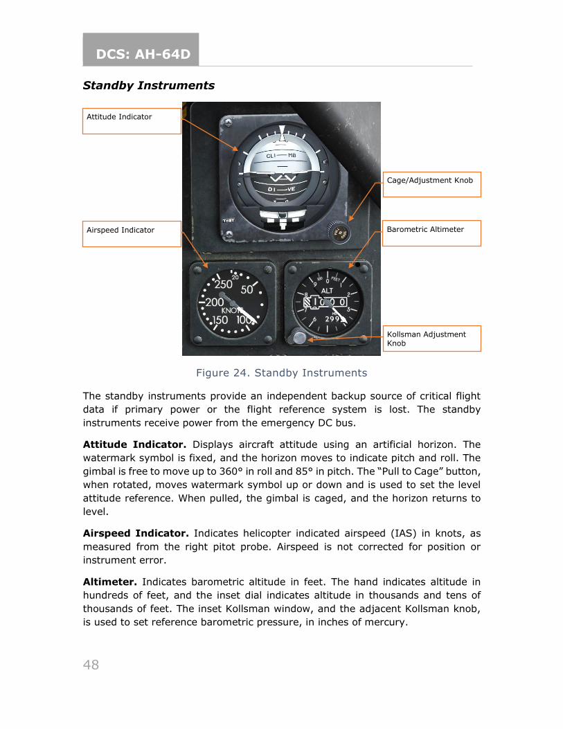
DCS: AH-64D
48
Standby Instruments
Figure 24. Standby Instruments
The standby instruments provide an independent backup source of critical flight
data if primary power or the flight reference system is lost. The standby
instruments receive power from the emergency DC bus.
Attitude Indicator. Displays aircraft attitude using an artificial horizon. The
watermark symbol is fixed, and the horizon moves to indicate pitch and roll. The
gimbal is free to move up to 360° in roll and 85° in pitch. The “Pull to Cage” button,
when rotated, moves watermark symbol up or down and is used to set the level
attitude reference. When pulled, the gimbal is caged, and the horizon returns to
level.
Airspeed Indicator. Indicates helicopter indicated airspeed (IAS) in knots, as
measured from the right pitot probe. Airspeed is not corrected for position or
instrument error.
Altimeter. Indicates barometric altitude in feet. The hand indicates altitude in
hundreds of feet, and the inset dial indicates altitude in thousands and tens of
thousands of feet. The inset Kollsman window, and the adjacent Kollsman knob,
is used to set reference barometric pressure, in inches of mercury.
Attitude Indicator
Barometric Altimeter Airspeed Indicator
Cage/Adjustment Knob
Kollsman Adjustment Knob
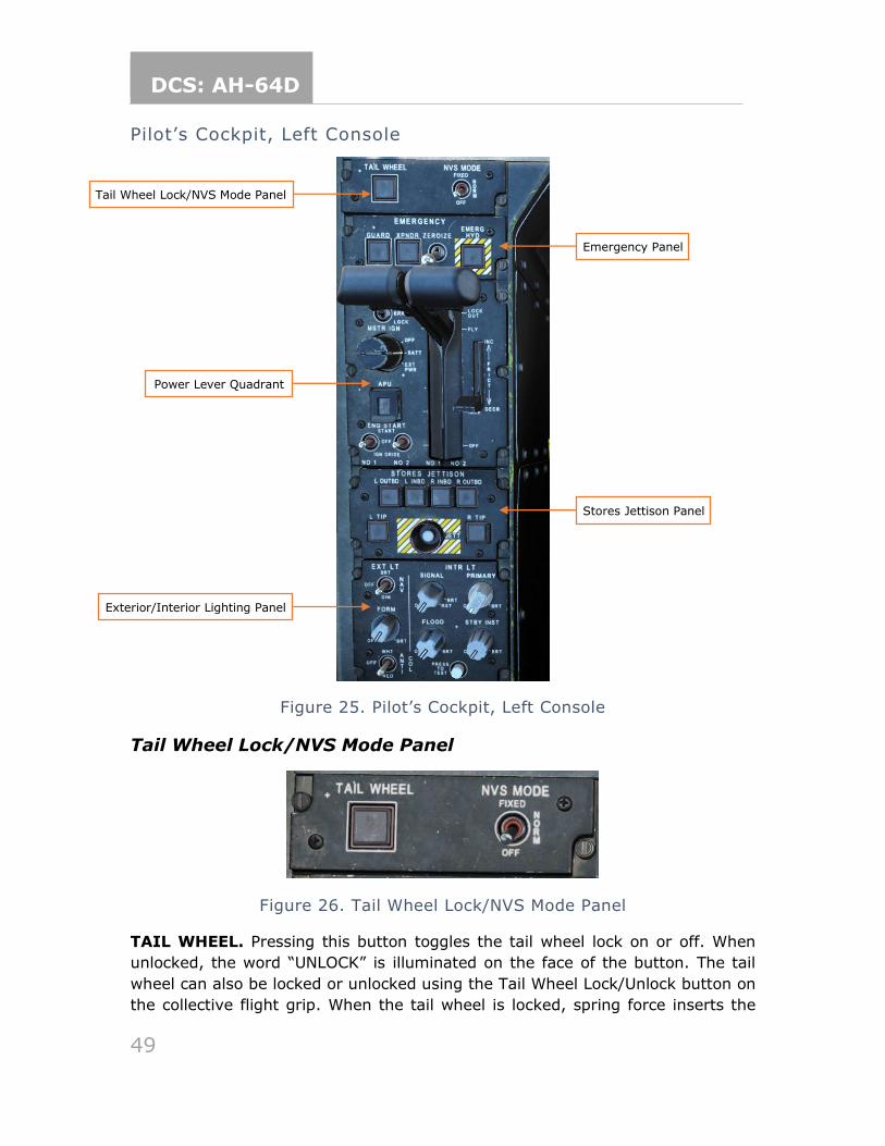
DCS: AH-64D
49
Pilot’s Cockpit, Left Console
Figure 25. Pilot’s Cockpit, Left Console
Tail Wheel Lock/NVS Mode Panel
Figure 26. Tail Wheel Lock/NVS Mode Panel
TAIL WHEEL. Pressing this button toggles the tail wheel lock on or off. When
unlocked, the word “UNLOCK” is illuminated on the face of the button. The tail
wheel can also be locked or unlocked using the Tail Wheel Lock/Unlock button on
the collective flight grip. When the tail wheel is locked, spring force inserts the
Power Lever Quadrant
Exterior/Interior Lighting Panel
Stores Jettison Panel
Tail Wheel Lock/NVS Mode Panel
Emergency Panel
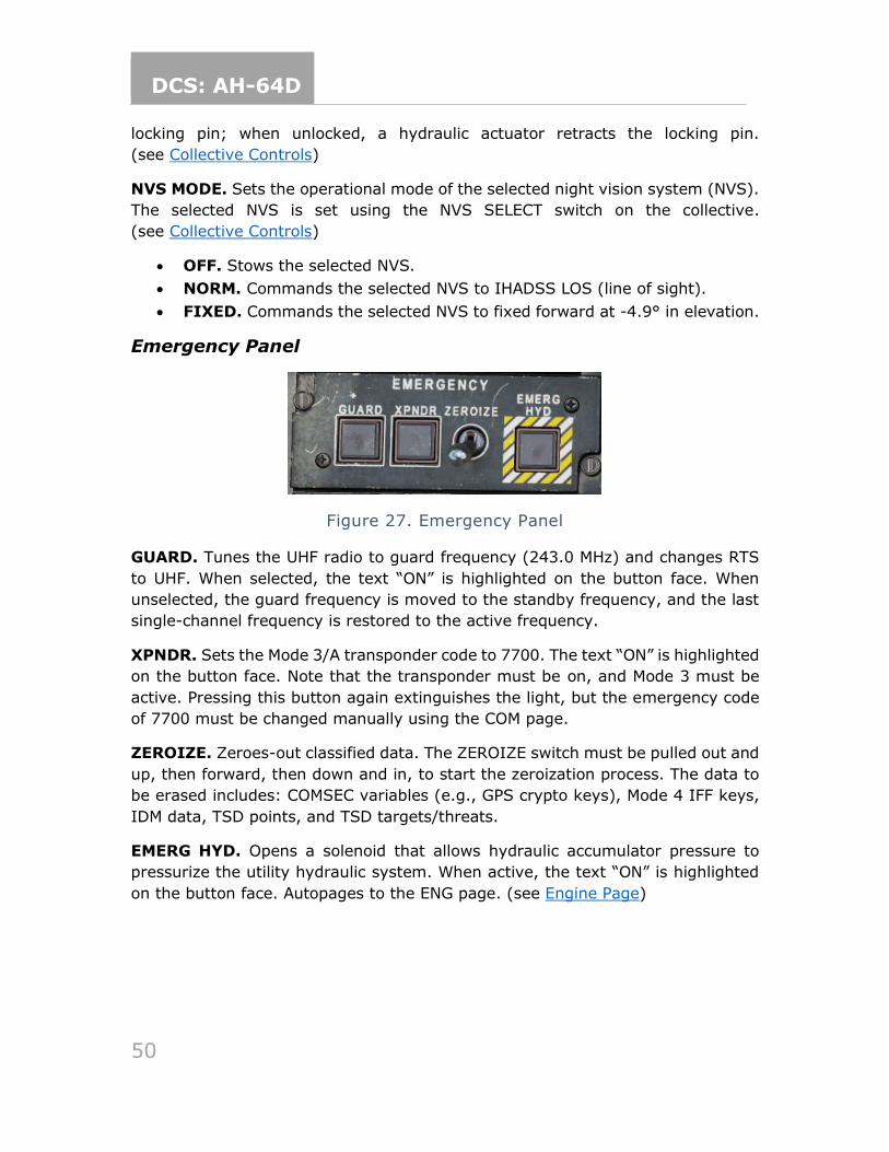
DCS: AH-64D
50
locking pin; when unlocked, a hydraulic actuator retracts the locking pin.
(see Collective Controls)
NVS MODE. Sets the operational mode of the selected night vision system (NVS).
The selected NVS is set using the NVS SELECT switch on the collective.
(see Collective Controls)
• OFF. Stows the selected NVS.
• NORM. Commands the selected NVS to IHADSS LOS (line of sight).
• FIXED. Commands the selected NVS to fixed forward at -4.9° in elevation.
Emergency Panel
Figure 27. Emergency Panel
GUARD. Tunes the UHF radio to guard frequency (243.0 MHz) and changes RTS
to UHF. When selected, the text “ON” is highlighted on the button face. When
unselected, the guard frequency is moved to the standby frequency, and the last
single-channel frequency is restored to the active frequency.
XPNDR. Sets the Mode 3/A transponder code to 7700. The text “ON” is highlighted
on the button face. Note that the transponder must be on, and Mode 3 must be
active. Pressing this button again extinguishes the light, but the emergency code
of 7700 must be changed manually using the COM page.
ZEROIZE. Zeroes-out classified data. The ZEROIZE switch must be pulled out and
up, then forward, then down and in, to start the zeroization process. The data to
be erased includes: COMSEC variables (e.g., GPS crypto keys), Mode 4 IFF keys,
IDM data, TSD points, and TSD targets/threats.
EMERG HYD. Opens a solenoid that allows hydraulic accumulator pressure to
pressurize the utility hydraulic system. When active, the text “ON” is highlighted
on the button face. Autopages to the ENG page. (see Engine Page)
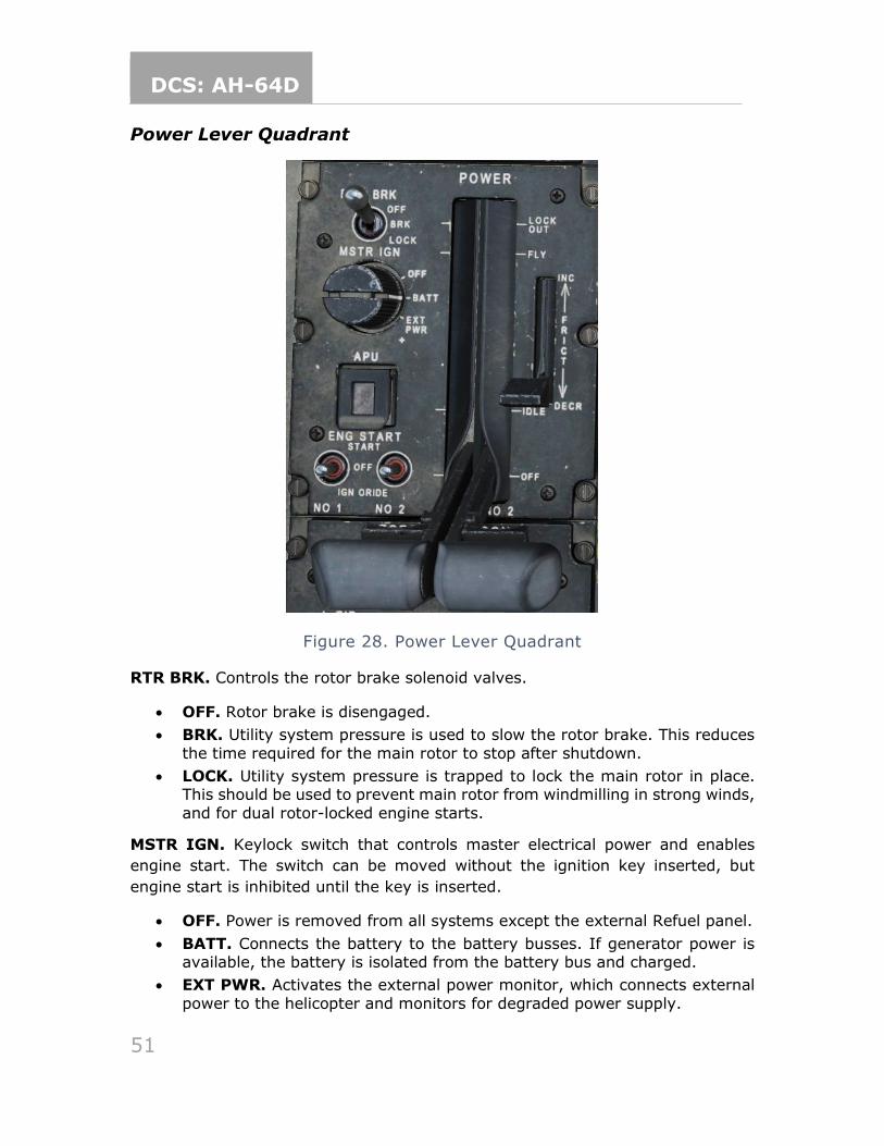
DCS: AH-64D
51
Power Lever Quadrant
Figure 28. Power Lever Quadrant
RTR BRK. Controls the rotor brake solenoid valves.
• OFF. Rotor brake is disengaged.
• BRK. Utility system pressure is used to slow the rotor brake. This reduces
the time required for the main rotor to stop after shutdown.
• LOCK. Utility system pressure is trapped to lock the main rotor in place. This should be used to prevent main rotor from windmilling in strong winds,
and for dual rotor-locked engine starts.
MSTR IGN. Keylock switch that controls master electrical power and enables
engine start. The switch can be moved without the ignition key inserted, but
engine start is inhibited until the key is inserted.
• OFF. Power is removed from all systems except the external Refuel panel.
• BATT. Connects the battery to the battery busses. If generator power is available, the battery is isolated from the battery bus and charged.
• EXT PWR. Activates the external power monitor, which connects external
power to the helicopter and monitors for degraded power supply.
DCS: AH-64D
52
POWER. Two power levers, one for each engine. Each lever includes four primary
positions (OFF, IDLE, FLY, and LOCK OUT), an intermediate range between IDLE
and FLY, and detents to prevent inadvertently moving the power levers aft to OFF
or forward to LOCK OUT.
• OFF. Inhibits fuel to the engine, shutting it down if the engine is running.
Also used to abort engine starts.
• IDLE. Sets ground idle RPM. Used during engine start sequence.
• FLY. Sets rotor RPM (Nr) to 101%, Nr is controlled automatically by the load
demand spindle.
• LOCK OUT. Disables the turbine gas temperature limiting system by
locking out the DEC, allowing for manual control of engine RPM. After moving the power lever to LOCK OUT, it should immediately be returned to an intermediate position between IDLE and FLY. The pilot can then control
engine RPM directly using the power lever.
FRICT. Throttle friction control knob.
APU. APU starter pushbutton. Pressing this button initiates automatic APU start
and illuminates the text “ON” on the button face. The ECU will automatically shut
down the APU if it senses an abnormal indication, or if the pilot presses the APU
button again.
ENG START. These switches initiate the automatic engine start process for either
engine. The ignition key must be in the MSTR IGN keylock to actuate these
switches.
• OFF. Engine starting system is inactive.
• START. Momentarily positioning ENG START switch to this position initiates
automatic engine start; switch is spring-loaded back to OFF. The engine is pneumatically motored by the Air Turbine Starter, and the ignition system
is energized. Starter cutout is automatic when the engine achieves 52% Ng.
• IGN ORIDE. Motors the engine with the ignition system off. Used to reduce TGT after an aborted engine start. Must be returned to OFF to cease
motoring the engine.
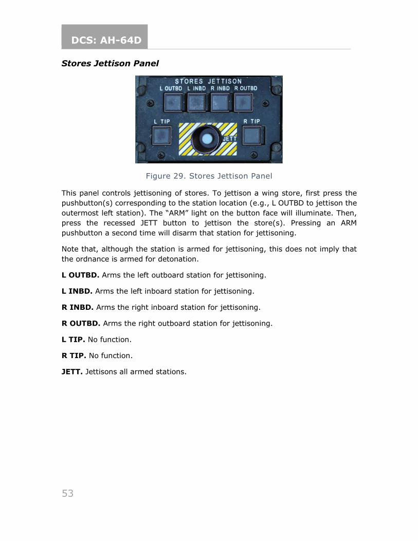
DCS: AH-64D
53
Stores Jettison Panel
Figure 29. Stores Jettison Panel
This panel controls jettisoning of stores. To jettison a wing store, first press the
pushbutton(s) corresponding to the station location (e.g., L OUTBD to jettison the
outermost left station). The “ARM” light on the button face will illuminate. Then,
press the recessed JETT button to jettison the store(s). Pressing an ARM
pushbutton a second time will disarm that station for jettisoning.
Note that, although the station is armed for jettisoning, this does not imply that
the ordnance is armed for detonation.
L OUTBD. Arms the left outboard station for jettisoning.
L INBD. Arms the left inboard station for jettisoning.
R INBD. Arms the right inboard station for jettisoning.
R OUTBD. Arms the right outboard station for jettisoning.
L TIP. No function.
R TIP. No function.
JETT. Jettisons all armed stations.
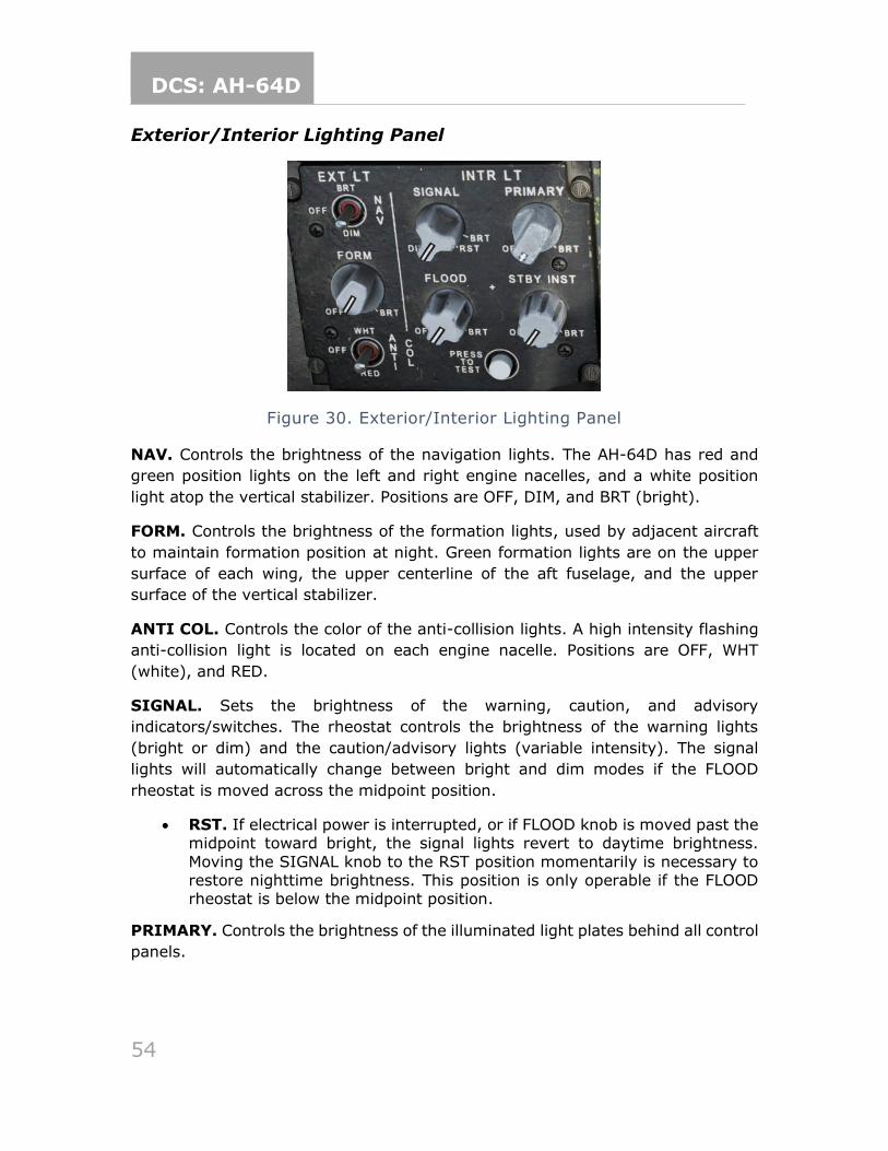
DCS: AH-64D
54
Exterior/Interior Lighting Panel
Figure 30. Exterior/Interior Lighting Panel
NAV. Controls the brightness of the navigation lights. The AH-64D has red and
green position lights on the left and right engine nacelles, and a white position
light atop the vertical stabilizer. Positions are OFF, DIM, and BRT (bright).
FORM. Controls the brightness of the formation lights, used by adjacent aircraft
to maintain formation position at night. Green formation lights are on the upper
surface of each wing, the upper centerline of the aft fuselage, and the upper
surface of the vertical stabilizer.
ANTI COL. Controls the color of the anti-collision lights. A high intensity flashing
anti-collision light is located on each engine nacelle. Positions are OFF, WHT
(white), and RED.
SIGNAL. Sets the brightness of the warning, caution, and advisory
indicators/switches. The rheostat controls the brightness of the warning lights
(bright or dim) and the caution/advisory lights (variable intensity). The signal
lights will automatically change between bright and dim modes if the FLOOD
rheostat is moved across the midpoint position.
• RST. If electrical power is interrupted, or if FLOOD knob is moved past the midpoint toward bright, the signal lights revert to daytime brightness.
Moving the SIGNAL knob to the RST position momentarily is necessary to restore nighttime brightness. This position is only operable if the FLOOD rheostat is below the midpoint position.
PRIMARY. Controls the brightness of the illuminated light plates behind all control
panels.
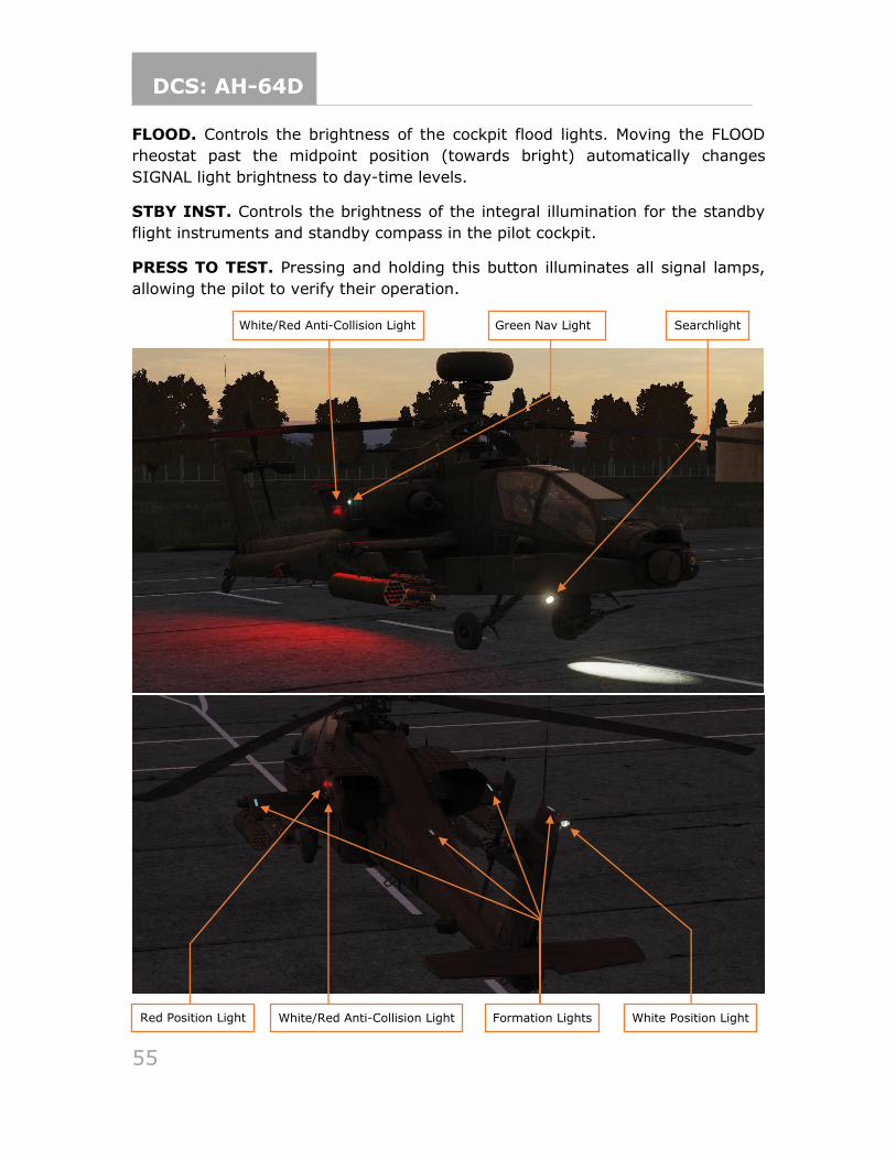
DCS: AH-64D
55
FLOOD. Controls the brightness of the cockpit flood lights. Moving the FLOOD
rheostat past the midpoint position (towards bright) automatically changes
SIGNAL light brightness to day-time levels.
STBY INST. Controls the brightness of the integral illumination for the standby
flight instruments and standby compass in the pilot cockpit.
PRESS TO TEST. Pressing and holding this button illuminates all signal lamps,
allowing the pilot to verify their operation.
White/Red Anti-Collision Light Green Nav Light Searchlight
Red Position Light White/Red Anti-Collision Light White Position Light Formation Lights
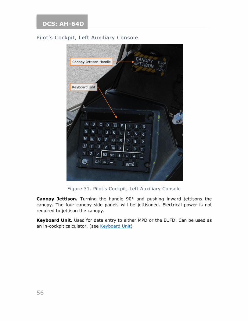
DCS: AH-64D
56
Pilot’s Cockpit, Left Auxiliary Console
Figure 31. Pilot’s Cockpit, Left Auxiliary Console
Canopy Jettison. Turning the handle 90° and pushing inward jettisons the
canopy. The four canopy side panels will be jettisoned. Electrical power is not
required to jettison the canopy.
Keyboard Unit. Used for data entry to either MPD or the EUFD. Can be used as
an in-cockpit calculator. (see Keyboard Unit)
Canopy Jettison Handle
Keyboard Unit
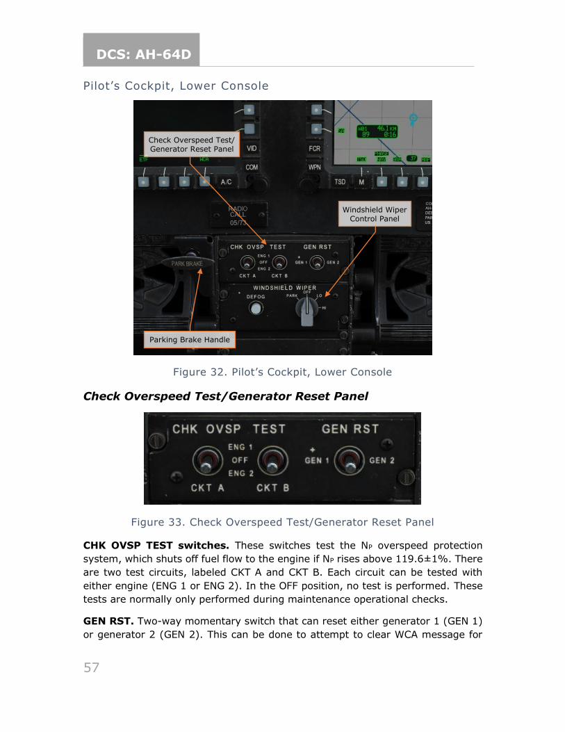
DCS: AH-64D
57
Pilot’s Cockpit, Lower Console
Figure 32. Pilot’s Cockpit, Lower Console
Check Overspeed Test/Generator Reset Panel
Figure 33. Check Overspeed Test/Generator Reset Panel
CHK OVSP TEST switches. These switches test the NP overspeed protection
system, which shuts off fuel flow to the engine if NP rises above 119.6±1%. There
are two test circuits, labeled CKT A and CKT B. Each circuit can be tested with
either engine (ENG 1 or ENG 2). In the OFF position, no test is performed. These
tests are normally only performed during maintenance operational checks.
GEN RST. Two-way momentary switch that can reset either generator 1 (GEN 1)
or generator 2 (GEN 2). This can be done to attempt to clear WCA message for
Windshield Wiper Control Panel
Check Overspeed Test/ Generator Reset Panel
Parking Brake Handle
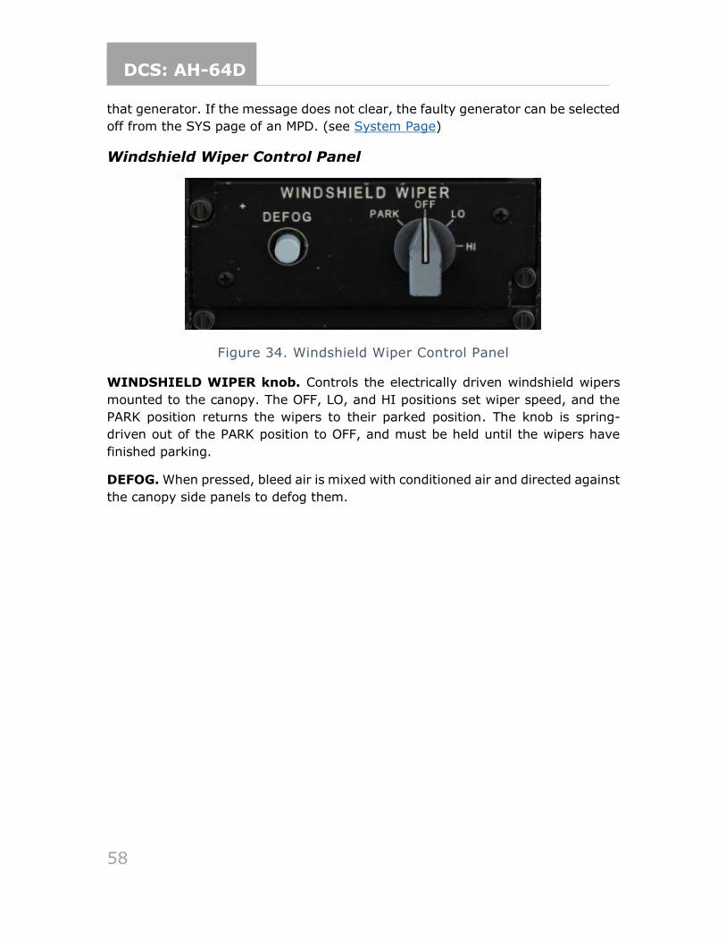
DCS: AH-64D
58
that generator. If the message does not clear, the faulty generator can be selected
off from the SYS page of an MPD. (see System Page)
Windshield Wiper Control Panel
Figure 34. Windshield Wiper Control Panel
WINDSHIELD WIPER knob. Controls the electrically driven windshield wipers
mounted to the canopy. The OFF, LO, and HI positions set wiper speed, and the
PARK position returns the wipers to their parked position. The knob is spring-
driven out of the PARK position to OFF, and must be held until the wipers have
finished parking.
DEFOG. When pressed, bleed air is mixed with conditioned air and directed against
the canopy side panels to defog them.
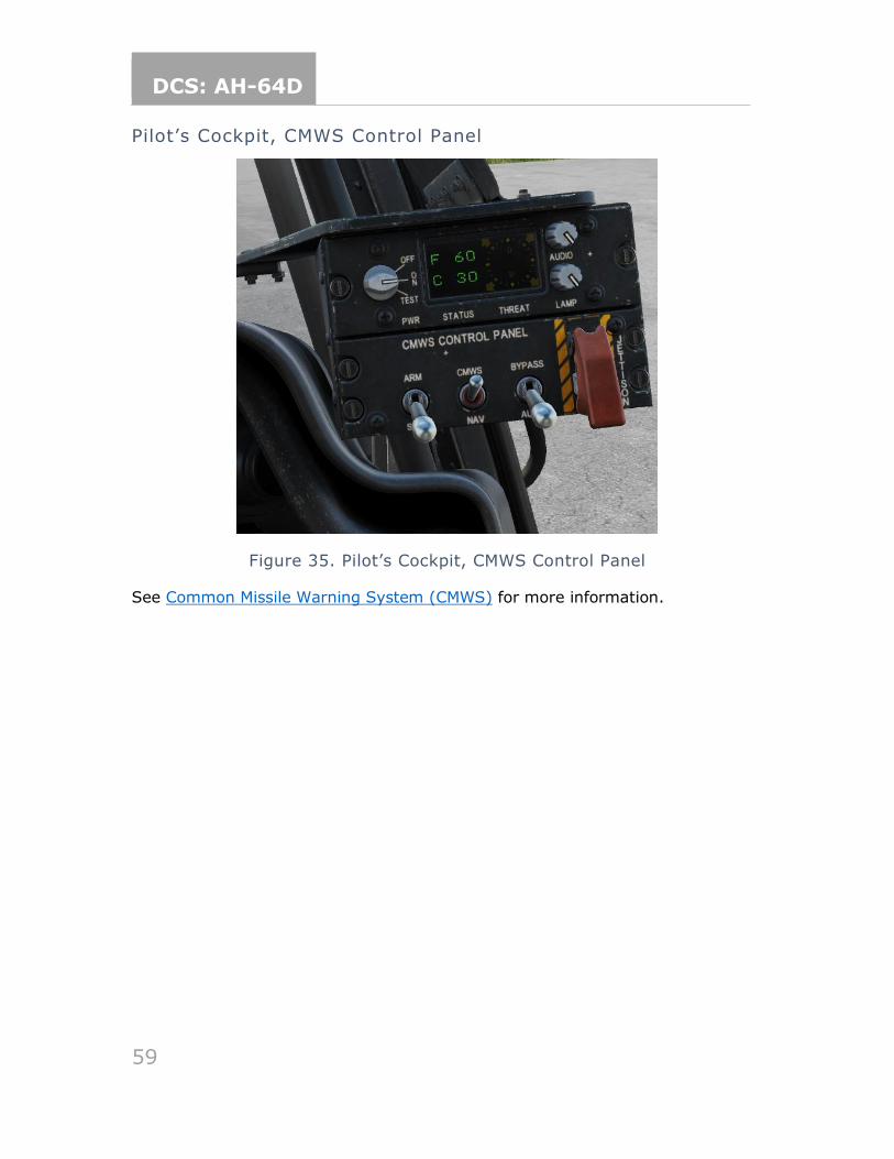
DCS: AH-64D
59
Pilot’s Cockpit, CMWS Control Panel
Figure 35. Pilot’s Cockpit, CMWS Control Panel
See Common Missile Warning System (CMWS) for more information.
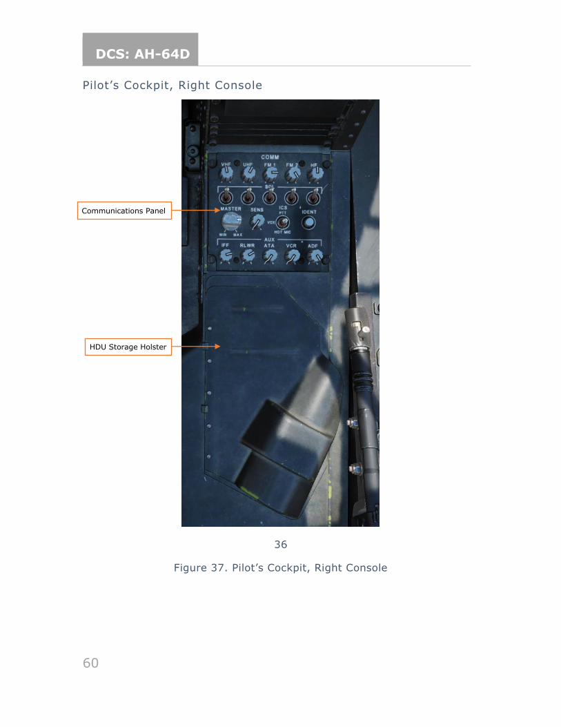
DCS: AH-64D
60
Pilot’s Cockpit, Right Console
36
Figure 37. Pilot’s Cockpit, Right Console
Communications Panel
HDU Storage Holster
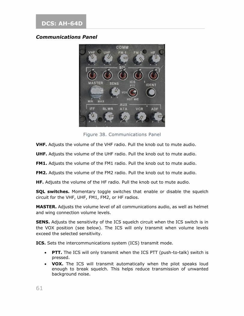
DCS: AH-64D
61
Communications Panel
Figure 38. Communications Panel
VHF. Adjusts the volume of the VHF radio. Pull the knob out to mute audio.
UHF. Adjusts the volume of the UHF radio. Pull the knob out to mute audio.
FM1. Adjusts the volume of the FM1 radio. Pull the knob out to mute audio.
FM2. Adjusts the volume of the FM2 radio. Pull the knob out to mute audio.
HF. Adjusts the volume of the HF radio. Pull the knob out to mute audio.
SQL switches. Momentary toggle switches that enable or disable the squelch
circuit for the VHF, UHF, FM1, FM2, or HF radios.
MASTER. Adjusts the volume level of all communications audio, as well as helmet
and wing connection volume levels.
SENS. Adjusts the sensitivity of the ICS squelch circuit when the ICS switch is in
the VOX position (see below). The ICS will only transmit when volume levels
exceed the selected sensitivity.
ICS. Sets the intercommunications system (ICS) transmit mode.
• PTT. The ICS will only transmit when the ICS PTT (push-to-talk) switch is pressed.
• VOX. The ICS will transmit automatically when the pilot speaks loud enough to break squelch. This helps reduce transmission of unwanted background noise.
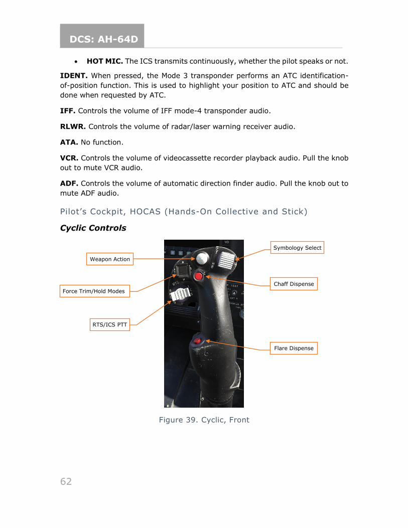
DCS: AH-64D
62
• HOT MIC. The ICS transmits continuously, whether the pilot speaks or not.
IDENT. When pressed, the Mode 3 transponder performs an ATC identification-
of-position function. This is used to highlight your position to ATC and should be
done when requested by ATC.
IFF. Controls the volume of IFF mode-4 transponder audio.
RLWR. Controls the volume of radar/laser warning receiver audio.
ATA. No function.
VCR. Controls the volume of videocassette recorder playback audio. Pull the knob
out to mute VCR audio.
ADF. Controls the volume of automatic direction finder audio. Pull the knob out to
mute ADF audio.
Pilot’s Cockpit, HOCAS (Hands-On Collective and Stick)
Cyclic Controls
Figure 39. Cyclic, Front
Symbology Select
Weapon Action
Chaff Dispense
Flare Dispense
Force Trim/Hold Modes
RTS/ICS PTT
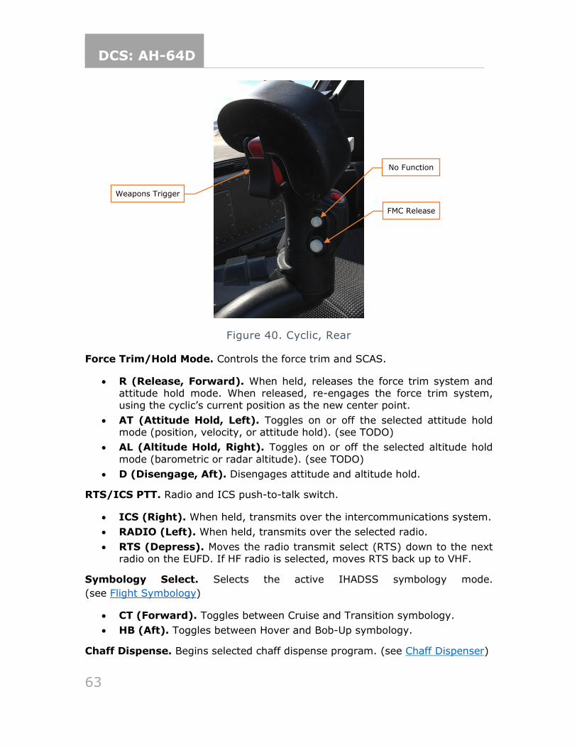
DCS: AH-64D
63
Figure 40. Cyclic, Rear
Force Trim/Hold Mode. Controls the force trim and SCAS.
• R (Release, Forward). When held, releases the force trim system and attitude hold mode. When released, re-engages the force trim system, using the cyclic’s current position as the new center point.
• AT (Attitude Hold, Left). Toggles on or off the selected attitude hold mode (position, velocity, or attitude hold). (see TODO)
• AL (Altitude Hold, Right). Toggles on or off the selected altitude hold
mode (barometric or radar altitude). (see TODO)
• D (Disengage, Aft). Disengages attitude and altitude hold.
RTS/ICS PTT. Radio and ICS push-to-talk switch.
• ICS (Right). When held, transmits over the intercommunications system.
• RADIO (Left). When held, transmits over the selected radio.
• RTS (Depress). Moves the radio transmit select (RTS) down to the next radio on the EUFD. If HF radio is selected, moves RTS back up to VHF.
Symbology Select. Selects the active IHADSS symbology mode.
(see Flight Symbology)
• CT (Forward). Toggles between Cruise and Transition symbology.
• HB (Aft). Toggles between Hover and Bob-Up symbology.
Chaff Dispense. Begins selected chaff dispense program. (see Chaff Dispenser)
Weapons Trigger
No Function
FMC Release
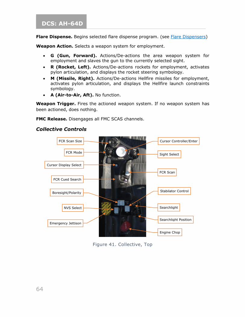
DCS: AH-64D
64
Flare Dispense. Begins selected flare dispense program. (see Flare Dispensers)
Weapon Action. Selects a weapon system for employment.
• G (Gun, Forward). Actions/De-actions the area weapon system for employment and slaves the gun to the currently selected sight.
• R (Rocket, Left). Actions/De-actions rockets for employment, activates
pylon articulation, and displays the rocket steering symbology.
• M (Missile, Right). Actions/De-actions Hellfire missiles for employment, activates pylon articulation, and displays the Hellfire launch constraints
symbology.
• A (Air-to-Air, Aft). No function.
Weapon Trigger. Fires the actioned weapon system. If no weapon system has
been actioned, does nothing.
FMC Release. Disengages all FMC SCAS channels.
Collective Controls
Figure 41. Collective, Top
FCR Mode
FCR Scan Size
Cursor Display Select
FCR Scan
FCR Cued Search
Cursor Controller/Enter
Sight Select
Engine Chop
Searchlight Position
Searchlight
Stabilator Control Boresight/Polarity
NVS Select
Emergency Jettison
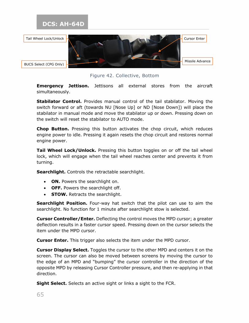
DCS: AH-64D
65
Figure 42. Collective, Bottom
Emergency Jettison. Jettisons all external stores from the aircraft
simultaneously.
Stabilator Control. Provides manual control of the tail stabilator. Moving the
switch forward or aft (towards NU [Nose Up] or ND [Nose Down]) will place the
stabilator in manual mode and move the stabilator up or down. Pressing down on
the switch will reset the stabilator to AUTO mode.
Chop Button. Pressing this button activates the chop circuit, which reduces
engine power to idle. Pressing it again resets the chop circuit and restores normal
engine power.
Tail Wheel Lock/Unlock. Pressing this button toggles on or off the tail wheel
lock, which will engage when the tail wheel reaches center and prevents it from
turning.
Searchlight. Controls the retractable searchlight.
• ON. Powers the searchlight on.
• OFF. Powers the searchlight off.
• STOW. Retracts the searchlight.
Searchlight Position. Four-way hat switch that the pilot can use to aim the
searchlight. No function for 1 minute after searchlight stow is selected.
Cursor Controller/Enter. Deflecting the control moves the MPD cursor; a greater
deflection results in a faster cursor speed. Pressing down on the cursor selects the
item under the MPD cursor.
Cursor Enter. This trigger also selects the item under the MPD cursor.
Cursor Display Select. Toggles the cursor to the other MPD and centers it on the
screen. The cursor can also be moved between screens by moving the cursor to
the edge of an MPD and “bumping” the cursor controller in the direction of the
opposite MPD by releasing Cursor Controller pressure, and then re-applying in that
direction.
Sight Select. Selects an active sight or links a sight to the FCR.
Tail Wheel Lock/Unlock
BUCS Select (CPG Only)
Missile Advance
Cursor Enter
DCS: AH-64D
66
• HMD (Forward). The IHADSS is selected as the active sight. IHADSS line of sight (LOS) is used for weapons targeting.
• FCR (Left). The FCR is selected as the active sight. FCR Next-to-Shoot (NTS) is used for weapons targeting.
• TADS (Right). No function for pilot’s collective.
• LINK (Aft). Slaves TADS LOS to FCR Next-To-Shoot (NTS). If the CPG’s active sight is TADS and the pilot commands LINK, the CPG’s active sight will become HMD.
Boresight/Polarity.
• PLRT. Toggles FLIR image polarity (black-hot or white-hot).
• B/S. No function.
NVS Select. Selects the image source for the night vision system, TADS or PNVS.
When the pilot selects one NVS source, the other source is automatically assigned
to the CPG.
FCR Mode. Selects an FCR mode. No function if FCR is not the active sight.
• GTM (Forward). Selects Ground Targeting Mode.
• RMAP (Right). Selects Radar Map Mode Re-selection toggles raw radar video underlay.
• ATM (Aft). Selects Air Targeting Mode.
• TPM (Left). Selects Terrain Profiles Mode.
FCR Scan Size. Selects FCR field of view (FOV).
• W (Right). Selects Wide FOV. Scans 90° arc.
• M (Aft). Selects Medium FOV. Scans 45° arc.
• N (Left). Selects Narrow FOV. Scans 30° arc.
• Z (Forward). Selects Zoom FOV. Scans 15° arc.
FCR Scan. Activates or deactivates the FCR transmitter. No function if FCR is not
the active sight and the master arm isn't in ARM.
• S-SCAN (forward). Performs a single scanburst.
• C-SCAN (aft). Activates or deactivates continuous scanburst.
FCR Cued Search. Rapidly orients the FCR antenna towards an emitter detected
by the RFI. Scans in the direction of the emitter and attempts to correlate the
location of the emitter in the GTM, ATM, or RMAP targeting modes. No function if
FCR is not the active sight and the master arm isn't in ARM.
Missile Advance. Manually steps the next Hellfire missile for launch. No function
unless the missile mode is Manual.
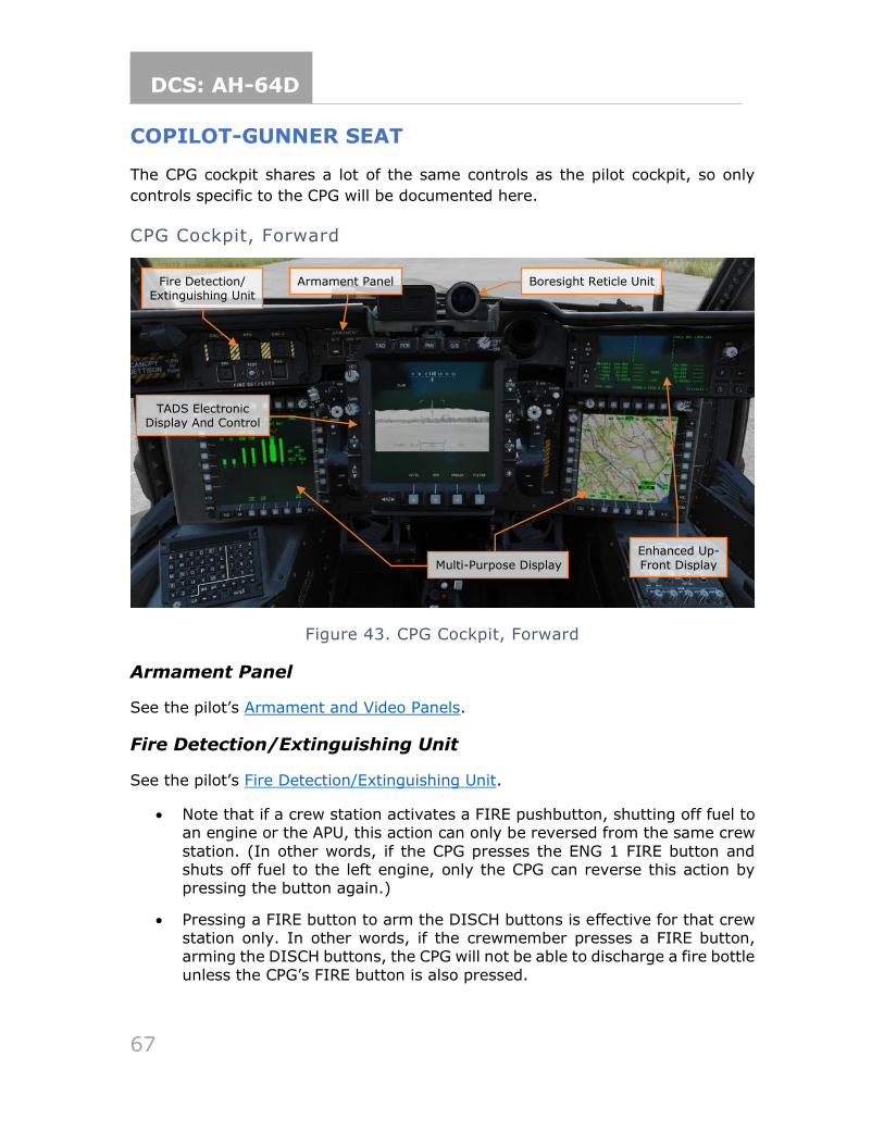
DCS: AH-64D
67
COPILOT-GUNNER SEAT
The CPG cockpit shares a lot of the same controls as the pilot cockpit, so only
controls specific to the CPG will be documented here.
CPG Cockpit, Forward
Figure 43. CPG Cockpit, Forward
Armament Panel
See the pilot’s Armament and Video Panels.
Fire Detection/Extinguishing Unit
See the pilot’s Fire Detection/Extinguishing Unit.
• Note that if a crew station activates a FIRE pushbutton, shutting off fuel to an engine or the APU, this action can only be reversed from the same crew
station. (In other words, if the CPG presses the ENG 1 FIRE button and shuts off fuel to the left engine, only the CPG can reverse this action by pressing the button again.)
• Pressing a FIRE button to arm the DISCH buttons is effective for that crew station only. In other words, if the crewmember presses a FIRE button, arming the DISCH buttons, the CPG will not be able to discharge a fire bottle
unless the CPG’s FIRE button is also pressed.
Armament Panel Fire Detection/ Extinguishing Unit
Enhanced Up-
Front Display Multi-Purpose Display
Boresight Reticle Unit
TADS Electronic Display And Control
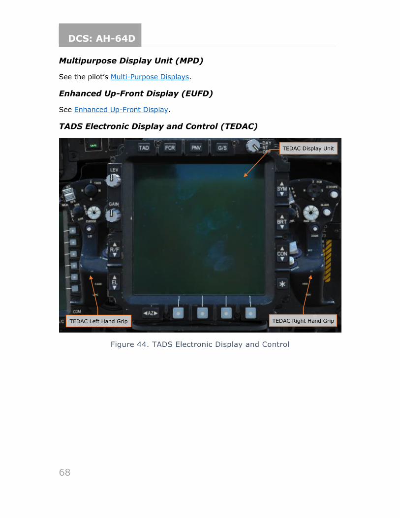
DCS: AH-64D
68
Multipurpose Display Unit (MPD)
See the pilot’s Multi-Purpose Displays.
Enhanced Up-Front Display (EUFD)
See Enhanced Up-Front Display.
TADS Electronic Display and Control (TEDAC)
Figure 44. TADS Electronic Display and Control
TEDAC Left Hand Grip
TEDAC Display Unit
TEDAC Right Hand Grip
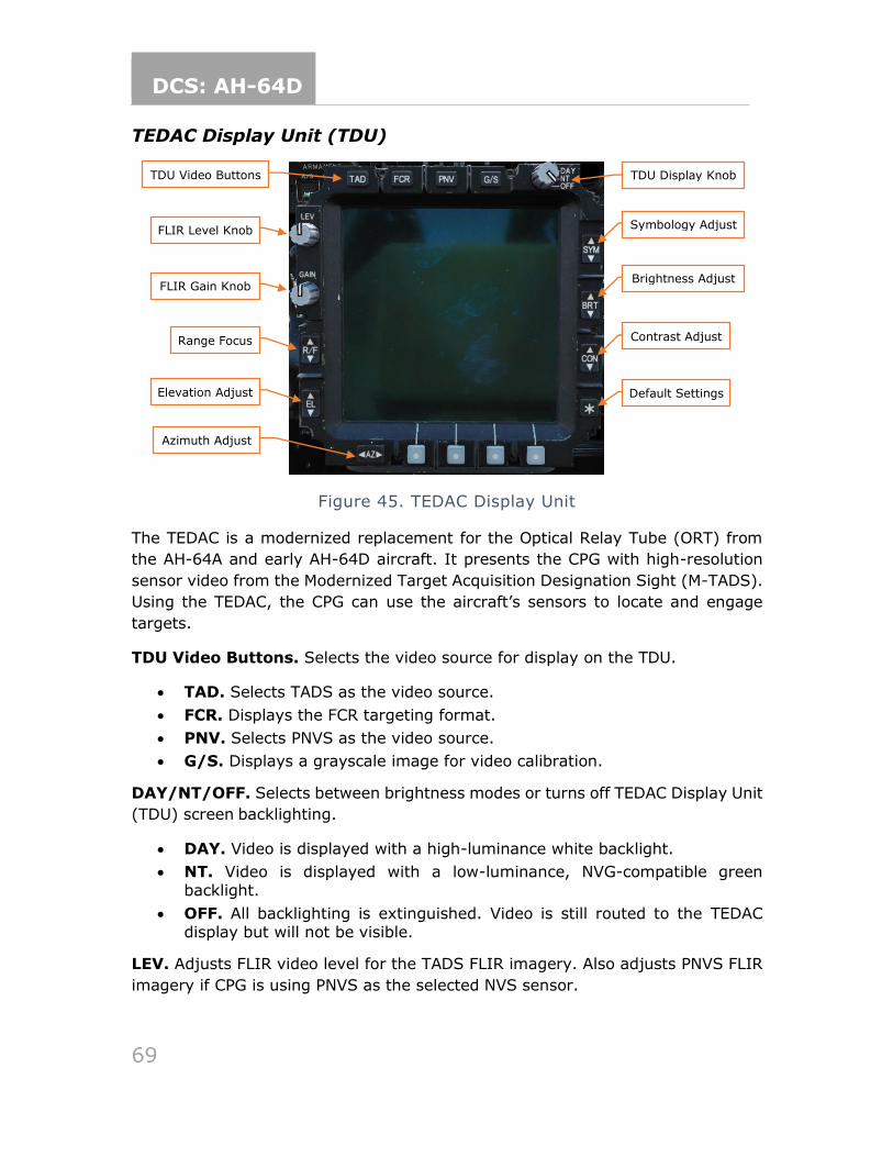
DCS: AH-64D
69
TEDAC Display Unit (TDU)
Figure 45. TEDAC Display Unit
The TEDAC is a modernized replacement for the Optical Relay Tube (ORT) from
the AH-64A and early AH-64D aircraft. It presents the CPG with high-resolution
sensor video from the Modernized Target Acquisition Designation Sight (M-TADS).
Using the TEDAC, the CPG can use the aircraft’s sensors to locate and engage
targets.
TDU Video Buttons. Selects the video source for display on the TDU.
• TAD. Selects TADS as the video source.
• FCR. Displays the FCR targeting format.
• PNV. Selects PNVS as the video source.
• G/S. Displays a grayscale image for video calibration.
DAY/NT/OFF. Selects between brightness modes or turns off TEDAC Display Unit
(TDU) screen backlighting.
• DAY. Video is displayed with a high-luminance white backlight.
• NT. Video is displayed with a low-luminance, NVG-compatible green backlight.
• OFF. All backlighting is extinguished. Video is still routed to the TEDAC display but will not be visible.
LEV. Adjusts FLIR video level for the TADS FLIR imagery. Also adjusts PNVS FLIR
imagery if CPG is using PNVS as the selected NVS sensor.
TDU Video Buttons TDU Display Knob
Symbology Adjust
Brightness Adjust
Contrast Adjust
Default Settings
FLIR Level Knob
FLIR Gain Knob
Range Focus
Elevation Adjust
Azimuth Adjust
DCS: AH-64D
70
GAIN. Adjusts FLIR video gain for the TADS FLIR imagery. Also adjusts PNVS FLIR
imagery if CPG is using PNVS as the selected NVS sensor.
R/F. Adjusts focal distance (range/focus) for DTV or FLIR video. Minimum focal
distance is 500 meters for the FLIR in NFOV or MFOV (narrow or medium field of
view). Minimum focal distance is 1,500 meters for the DTV in NFOV.
EL. Used to adjust TADS drift in elevation when the AZ/EL enable button is selected.
AZ. Used to adjust TADS drift in azimuth when the AZ/EL enable button is selected.
SYM. Sets symbology brightness of the CPG HDU when HMD is the active sight,
from black to white. Sets symbology brightness of TADS LOS crosshairs and IAT
gates of the TADS video when TADS is the active sight. A momentary press steps
brightness up or down once; a short press commands a slow continuous change;
and a long press commands a fast continuous change.
BRT. Adjusts the image or grayscale intensity of the CPG HDU when HMD is the
active sight, or the TDU when the TADS is the active sight. A momentary press
steps brightness up or down once; a short press commands a slow continuous
change; and a long press commands a fast continuous change.
CON. Adjusts the image or grayscale contrast of the CPG HDU when HMD is the
active sight, or the TDU when the TADS is the active sight. A momentary press
steps brightness up or down once; a short press commands a slow continuous
change; and a long press commands a fast continuous change.
* (asterisk) button. Resets brightness and contrast of the CPG HDU or TDU to
default setting. The day/night setting determines whether a bright or dim default
is used.
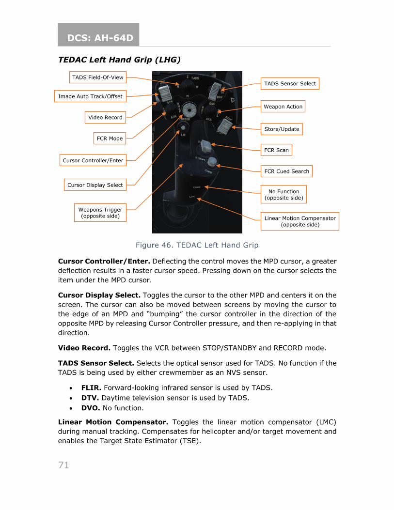
DCS: AH-64D
71
TEDAC Left Hand Grip (LHG)
Figure 46. TEDAC Left Hand Grip
Cursor Controller/Enter. Deflecting the control moves the MPD cursor, a greater
deflection results in a faster cursor speed. Pressing down on the cursor selects the
item under the MPD cursor.
Cursor Display Select. Toggles the cursor to the other MPD and centers it on the
screen. The cursor can also be moved between screens by moving the cursor to
the edge of an MPD and “bumping” the cursor controller in the direction of the
opposite MPD by releasing Cursor Controller pressure, and then re-applying in that
direction.
Video Record. Toggles the VCR between STOP/STANDBY and RECORD mode.
TADS Sensor Select. Selects the optical sensor used for TADS. No function if the
TADS is being used by either crewmember as an NVS sensor.
• FLIR. Forward-looking infrared sensor is used by TADS.
• DTV. Daytime television sensor is used by TADS.
• DVO. No function.
Linear Motion Compensator. Toggles the linear motion compensator (LMC)
during manual tracking. Compensates for helicopter and/or target movement and
enables the Target State Estimator (TSE).
Linear Motion Compensator
(opposite side)
No Function (opposite side)
TADS Field-Of-View
Image Auto Track/Offset
Video Record
FCR Mode
Cursor Controller/Enter
Cursor Display Select
Weapons Trigger (opposite side)
FCR Cued Search
FCR Scan
Store/Update
Weapon Action
TADS Sensor Select
DCS: AH-64D
72
Store/Update. Stores position information or performs position updates.
• STORE (forward). Stores selected sensor LOS as a point.
• UPDT (aft). Performs a flyover or TADS position update. (see TODO)
TADS Field-Of-View. Selects TADS field of view (FOV).
• W (right). Selects Wide FOV. No zoom; for navigation and target detection.
• M (aft). Selects Medium FOV. Optical zoom; for target detection and acquisition. Not available when DTV is in use.
• N (left). Selects Narrow FOV. Optical zoom; for identification and targeting.
• Z (forward). Selects Zoom FOV. Electronic zoom for targeting.
Image Auto Track/Offset. Initiates and controls image auto tracking and offset
tracking.
• IAT (forward), short. Enables image-auto track and establishes the object under the cursor as the primary track.
• IAT (forward), long. Activates manual sizing of the tracking gates.
• OFS (aft). When offset tracking, returns TADS LOS to the primary track. When not offset tracking, deletes the current track (primary or secondary).
FCR Mode. Selects an FCR mode. No function if FCR is not the active sight.
• GTM (forward). Selects Ground Targeting Mode.
• RMAP (right). Selects Radar Map Mode. Re-selection toggles raw radar
video underlay.
• ATM (aft). Selects Air Targeting Mode.
• TPM (left). Selects Terrain Profiles Mode.
FCR Scan. If the selected sight is the FCR and the master arm is in ARM or TADS
with the FCR linked, activates or deactivates the FCR transmitter. Otherwise, no
function.
• S-SCAN (forward). Performs a single scanburst.
• C-SCAN (aft). Activates or deactivates continuous scanburst.
FCR Cued Search. Rapidly orients the FCR antenna towards a threat emitter
detected by the RFI. Scans in the direction of the emitter and attempts to correlate
the location of the emitter in the GTM, ATM, or RMAP targeting modes. No function
if FCR is not the active sight and the master arm isn't in ARM.
Weapon Action. Selects a weapon system for employment.
• G (Gun, forward). Actions/De-actions the Area Weapon System for employment and slaves the gun to the currently selected sight.
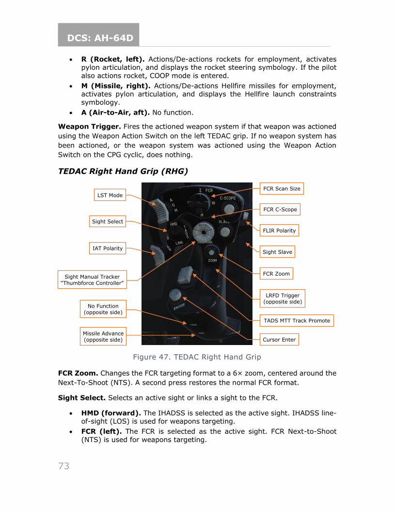
DCS: AH-64D
73
• R (Rocket, left). Actions/De-actions rockets for employment, activates pylon articulation, and displays the rocket steering symbology. If the pilot
also actions rocket, COOP mode is entered.
• M (Missile, right). Actions/De-actions Hellfire missiles for employment, activates pylon articulation, and displays the Hellfire launch constraints
symbology.
• A (Air-to-Air, aft). No function.
Weapon Trigger. Fires the actioned weapon system if that weapon was actioned
using the Weapon Action Switch on the left TEDAC grip. If no weapon system has
been actioned, or the weapon system was actioned using the Weapon Action
Switch on the CPG cyclic, does nothing.
TEDAC Right Hand Grip (RHG)
Figure 47. TEDAC Right Hand Grip
FCR Zoom. Changes the FCR targeting format to a 6× zoom, centered around the
Next-To-Shoot (NTS). A second press restores the normal FCR format.
Sight Select. Selects an active sight or links a sight to the FCR.
• HMD (forward). The IHADSS is selected as the active sight. IHADSS line-of-sight (LOS) is used for weapons targeting.
• FCR (left). The FCR is selected as the active sight. FCR Next-to-Shoot
(NTS) is used for weapons targeting.
Missile Advance (opposite side)
LST Mode
Sight Manual Tracker “Thumbforce Controller”
Sight Select
IAT Polarity
No Function (opposite side)
FCR Scan Size
FCR C-Scope
FLIR Polarity
Sight Slave
FCR Zoom
LRFD Trigger (opposite side)
TADS MTT Track Promote
Cursor Enter
DCS: AH-64D
74
• TADS (right). The TADS is selected as the active sight. TADS line-of-sight (LOS) is used for weapons targeting.
• LINK (aft). When TADS is the active sight, slaves FCR centerline to TADS LOS. When FCR is the active sight, slaves TADS LOS to FCR Next-To-Shoot (NTS). If the pilot’s active sight is FCR and the CPG commands LINK, the
pilot’s active sight will become HMD.
Sight Slave. Toggles the FCR or TADS tracking mode between Slave and Manual
(de-slaved). When in Slave, FCR or TADS LOS is slaved to target acquisition LOS.
When in Manual, FCR antenna angle or TADS LOS is controlled by the sight manual
tracker.
Sight Manual Tracker. Slews FCR antenna angle or TADS LOS when TADS LOS
when Slave is not enabled (tracking mode is Manual).
TADS MTT Track Promote. Cycles between TADS multi-target tracker (MTT)
primary and secondary IAT tracks.
• Forward. Steps to the next TADS track and promotes it to primary.
• Aft. Steps to the previous TADS track and promotes it to primary.
FLIR Polarity. Toggles FLIR image polarity (black-hot or white-hot).
IAT Polarity. Selects polarity for the image auto tracker.
• W (White, forward). Bright objects are tracked by the IAT.
• A (Auto, mid). IAT automatically chooses tracker polarity.
• B (Black, aft). Dark objects are tracked by the IAT.
LST Mode. Sets the laser spot tracker (LST) mode.
• A (Automatic, forward). Enables the LST and commands the TADS to begin a 4-bar scan centered around the current target LOS.
• O (Off, mid). LST is disabled.
• M (Manual, aft). Enables the LST and sets TADS tracking mode to Manual.
LRFD Trigger. Activates the laser rangefinder.
• First detent. LRFD determines target range.
• Second detent. LRFD determines target range and designates target for
laser guidance.
FCR Scan Size. Selects FCR field of view (FOV).
• W (right). Selects Wide FOV. Scans 90° arc.
• M (aft). Selects Medium FOV. Scans 45° arc.
• N (left). Selects Narrow FOV. Scans 30° arc.
• Z (forward). Selects Zoom FOV. Scans 15° arc.

DCS: AH-64D
75
FCR C-Scope. Toggles the FCR C-scope (azimuth over elevation) display within
the HMD and TADS symbology.
Missile Advance. Manually steps the next Hellfire missile for launch. No function
unless the missile mode is Manual.
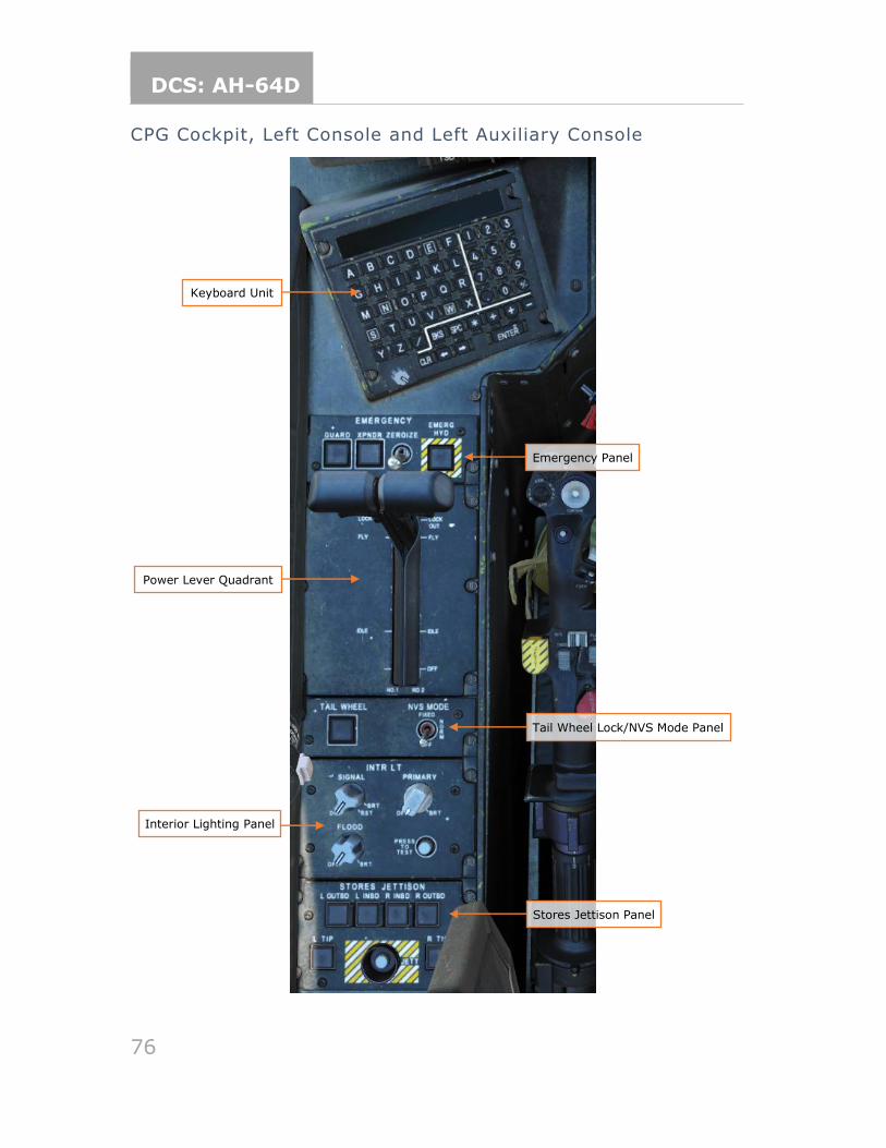
DCS: AH-64D
76
CPG Cockpit, Left Console and Left Auxiliary Console
Power Lever Quadrant
Interior Lighting Panel
Stores Jettison Panel
Tail Wheel Lock/NVS Mode Panel
Emergency Panel
Keyboard Unit
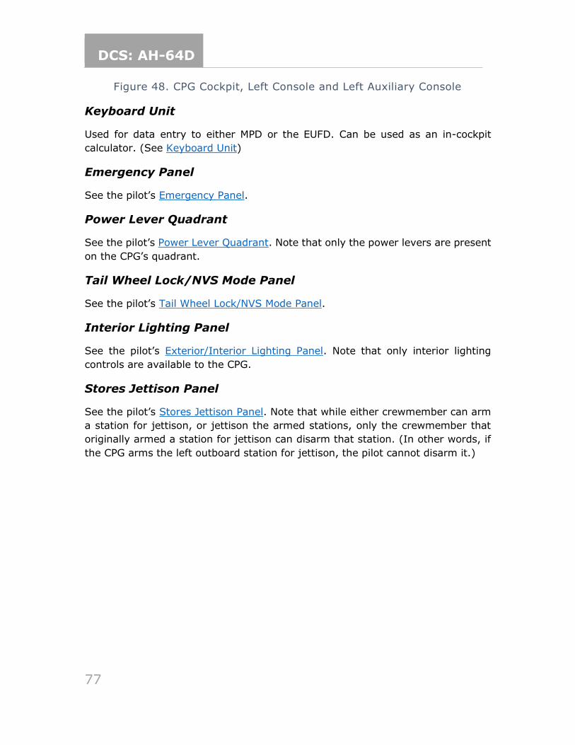
DCS: AH-64D
77
Figure 48. CPG Cockpit, Left Console and Left Auxiliary Console
Keyboard Unit
Used for data entry to either MPD or the EUFD. Can be used as an in-cockpit
calculator. (See Keyboard Unit)
Emergency Panel
See the pilot’s Emergency Panel.
Power Lever Quadrant
See the pilot’s Power Lever Quadrant. Note that only the power levers are present
on the CPG’s quadrant.
Tail Wheel Lock/NVS Mode Panel
See the pilot’s Tail Wheel Lock/NVS Mode Panel.
Interior Lighting Panel
See the pilot’s Exterior/Interior Lighting Panel. Note that only interior lighting
controls are available to the CPG.
Stores Jettison Panel
See the pilot’s Stores Jettison Panel. Note that while either crewmember can arm
a station for jettison, or jettison the armed stations, only the crewmember that
originally armed a station for jettison can disarm that station. (In other words, if
the CPG arms the left outboard station for jettison, the pilot cannot disarm it.)
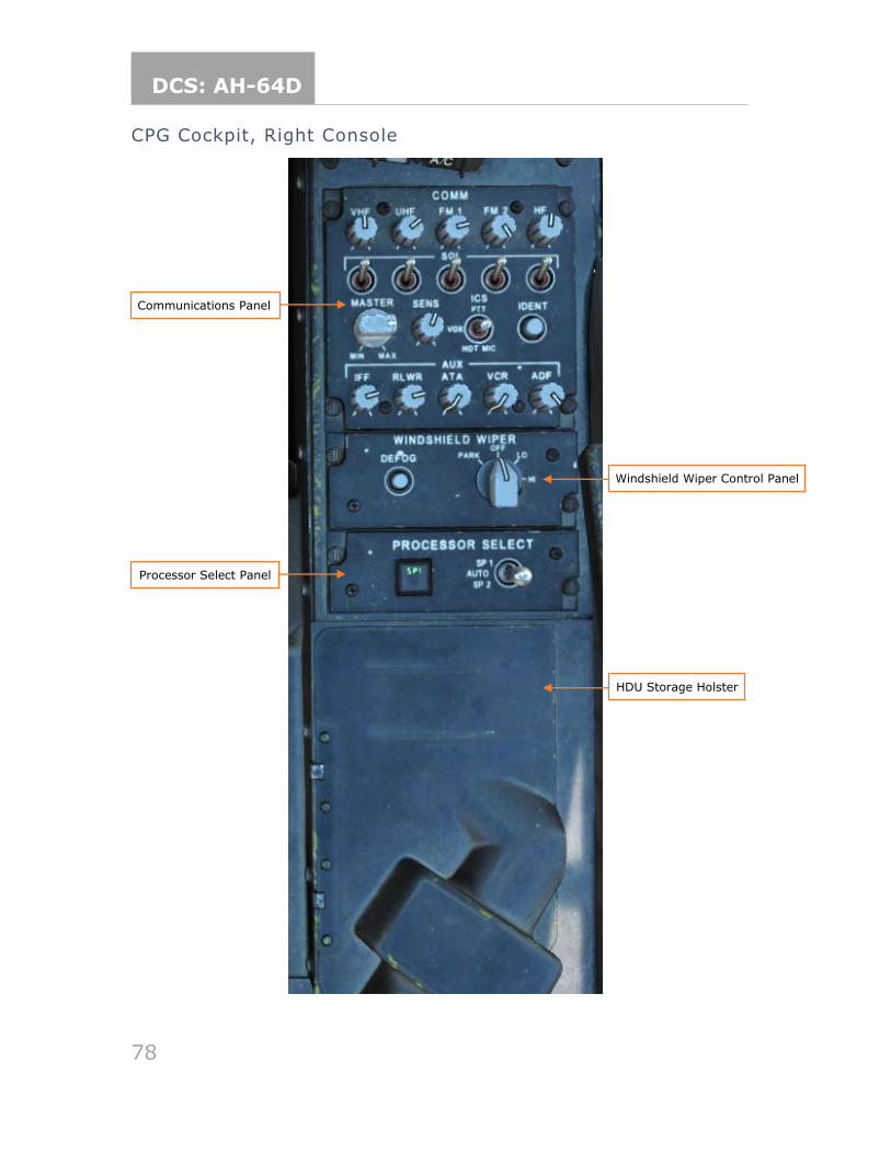
DCS: AH-64D
78
CPG Cockpit, Right Console
Communications Panel
Processor Select Panel
HDU Storage Holster
Windshield Wiper Control Panel
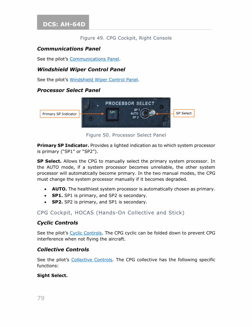
DCS: AH-64D
79
Figure 49. CPG Cockpit, Right Console
Communications Panel
See the pilot’s Communications Panel.
Windshield Wiper Control Panel
See the pilot’s Windshield Wiper Control Panel.
Processor Select Panel
Figure 50. Processor Select Panel
Primary SP Indicator. Provides a lighted indication as to which system processor
is primary (“SP1” or “SP2”).
SP Select. Allows the CPG to manually select the primary system processor. In
the AUTO mode, if a system processor becomes unreliable, the other system
processor will automatically become primary. In the two manual modes, the CPG
must change the system processor manually if it becomes degraded.
• AUTO. The healthiest system processor is automatically chosen as primary.
• SP1. SP1 is primary, and SP2 is secondary.
• SP2. SP2 is primary, and SP1 is secondary.
CPG Cockpit, HOCAS (Hands-On Collective and Stick)
Cyclic Controls
See the pilot’s Cyclic Controls. The CPG cyclic can be folded down to prevent CPG
interference when not flying the aircraft.
Collective Controls
See the pilot’s Collective Controls. The CPG collective has the following specific
functions:
Sight Select.
Primary SP Indicator SP Select
DCS: AH-64D
80
• TADS (Right). Selects TADS as the active sight. TADS line of sight is used for weapons targeting.
• LINK (Aft). When TADS is the active sight, slaves FCR centerline to TADS LOS. When FCR is the active sight, slaves TADS LOS to FCR Next-To-Shoot (NTS). If the pilot’s active sight is FCR and the CPG commands LINK, the
pilot’s active sight will become HMD.
FCR Scan. If the selected sight is the FCR, or TADS with the FCR linked, activates
or deactivates the FCR transmitter. Otherwise, no function.
• S-SCAN (forward). Performs a single scanburst.
• C-SCAN (aft). Activates or deactivates continuous scanburst.
BUCS Select. Manually switches the Back-Up Control System (BUCS) control
priority to the CPG cockpit controls (non-reversible).
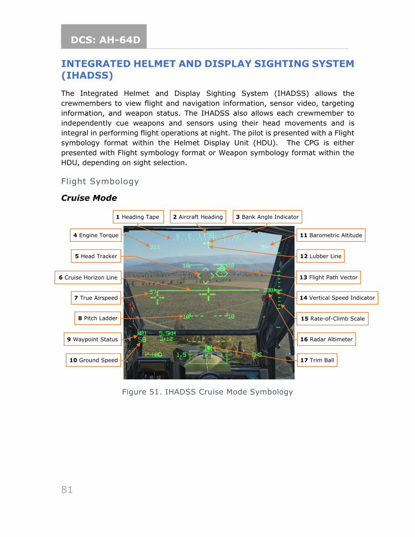
DCS: AH-64D
81
INTEGRATED HELMET AND DISPLAY SIGHTING SYSTEM
(IHADSS)
The Integrated Helmet and Display Sighting System (IHADSS) allows the
crewmembers to view flight and navigation information, sensor video, targeting
information, and weapon status. The IHADSS also allows each crewmember to
independently cue weapons and sensors using their head movements and is
integral in performing flight operations at night. The pilot is presented with a Flight
symbology format within the Helmet Display Unit (HDU). The CPG is either
presented with Flight symbology format or Weapon symbology format within the
HDU, depending on sight selection.
Flight Symbology
Cruise Mode
Figure 51. IHADSS Cruise Mode Symbology
16 Radar Altimeter
14 Vertical Speed Indicator
15 Rate-of-Climb Scale
11 Barometric Altitude
12 Lubber Line
13 Flight Path Vector 6 Cruise Horizon Line
8 Pitch Ladder
4 Engine Torque
5 Head Tracker
1 Heading Tape 3 Bank Angle Indicator 2 Aircraft Heading
7 True Airspeed
9 Waypoint Status
17 Trim Ball 10 Ground Speed
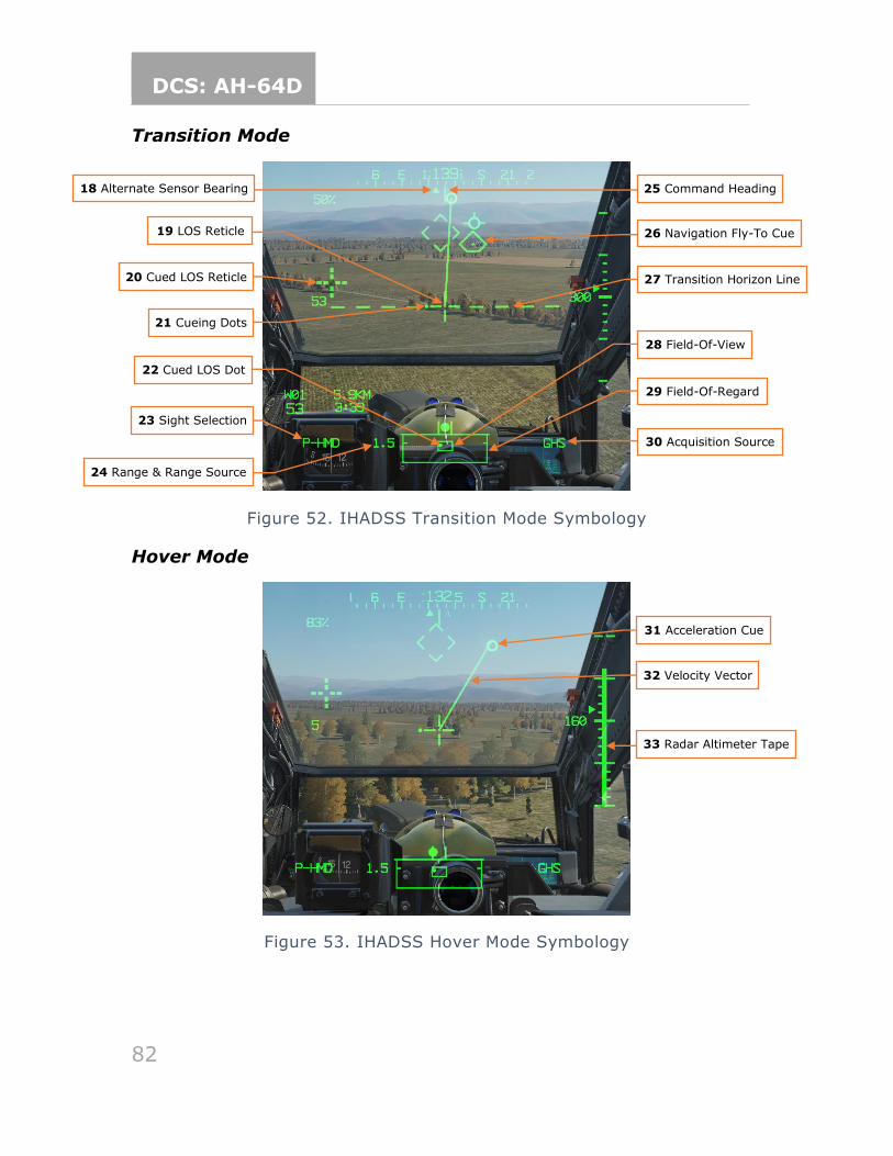
DCS: AH-64D
82
Transition Mode
Figure 52. IHADSS Transition Mode Symbology
Hover Mode
Figure 53. IHADSS Hover Mode Symbology
29 Field-Of-Regard
21 Cueing Dots
20 Cued LOS Reticle
22 Cued LOS Dot
27 Transition Horizon Line
25 Command Heading
26 Navigation Fly-To Cue 19 LOS Reticle
28 Field-Of-View
30 Acquisition Source
31 Acceleration Cue
32 Velocity Vector
23 Sight Selection
24 Range & Range Source
18 Alternate Sensor Bearing
33 Radar Altimeter Tape
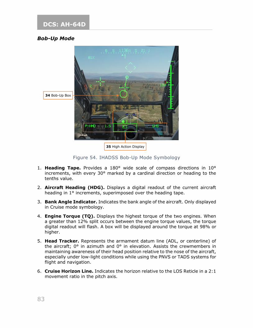
DCS: AH-64D
83
Bob-Up Mode
Figure 54. IHADSS Bob-Up Mode Symbology
1. Heading Tape. Provides a 180° wide scale of compass directions in 10° increments, with every 30° marked by a cardinal direction or heading to the
tenths value.
2. Aircraft Heading (HDG). Displays a digital readout of the current aircraft
heading in 1° increments, superimposed over the heading tape.
3. Bank Angle Indicator. Indicates the bank angle of the aircraft. Only displayed in Cruise mode symbology.
4. Engine Torque (TQ). Displays the highest torque of the two engines. When a greater than 12% split occurs between the engine torque values, the torque digital readout will flash. A box will be displayed around the torque at 98% or
higher.
5. Head Tracker. Represents the armament datum line (ADL, or centerline) of the aircraft; 0° in azimuth and 0° in elevation. Assists the crewmembers in
maintaining awareness of their head position relative to the nose of the aircraft, especially under low-light conditions while using the PNVS or TADS systems for flight and navigation.
6. Cruise Horizon Line. Indicates the horizon relative to the LOS Reticle in a 2:1 movement ratio in the pitch axis.
34 Bob-Up Box
35 High Action Display
DCS: AH-64D
84
7. True Airspeed (TAS). Indicates the true airspeed of the aircraft in 1 knot increments, from 0 to 210 knots. The true airspeed is boxed when the airspeed
exceeds VNE. When Attitude Hold is engaged, a rounded “status window” box is displayed around the TAS digital readout.
8. Pitch Ladder. Indicates aircraft pitch angles in 10° increments, up to a
maximum of 30°. Only displayed in Cruise mode symbology.
9. Waypoint Status. Displays the name of the current point selected for navigation, its distance in kilometers or nautical miles, current ground speed,
and estimated time to arrival (ETE). The ETE is based on the aircraft’s current ground speed, and is presented in HH:MM format when the ETE is ≥5 minutes, or M:SS format when ETE is <5 minutes. The ETE is not displayed when ground
speed is <15 knots or ETE is >10 hours. The distance remaining is not displayed if there is no active destination point.
10. Ground Speed (GS). Indicates the speed across the ground in 1 knot
increments. Ground speed is not displayed unless the primary INU is aligned.
11. Barometric Altitude (MSL). Barometric altitude of the aircraft, from -2,300 feet up to 20,000 feet in increments of 10 feet. Only displayed in Cruise mode
symbology.
12. Lubber Line. The lubber line is aligned to the centerline of the aircraft and serves as a reference for both the aircraft heading and Cruise mode symbology
bank angle indicator.
13. Flight Path Vector (FPV). The flight path vector (FPV) represents the point towards which the helicopter is flying. It is a 3D representation of the aircraft’s
velocity. The FPV will disappear when the 3D velocity magnitude is <5 knots ground speed, or when weight-on-wheels.
14. Vertical Speed Indicator (VSI). The vertical speed indicator moves up and
down the rate-of-climb scale to indicate vertical speed. The VSI becomes saturated at the ±1000 fpm tick marks of the rate-of-climb scale.
15. Rate-of-Climb Scale. The rate of climb indicator scale presents 100 fpm rate
of climb tick marks to ±500 fpm, and then displays 1000 fpm tick marks. When the rate-of-climb exceeds ±1000 fpm, a digital readout in 100 fpm sensitivity is displayed adjacent to the rate-of-climb minimum or maximum tick marks.
16. Radar Altimeter (AGL). Aircraft altitude above ground level from 0 to 1,428 feet, displayed in increments of 1 foot up 50 feet in altitude, and increments of 10 feet between 50 feet and 1,428 feet in altitude. The radar altimeter digital
readout will be removed when above 1,428 feet. When Altitude Hold is engaged, a rounded “status window” box is displayed around the radar altimeter digital readout.
17. Skid/Slip Indicator (Trim Ball). Indicates the amount of side acceleration and when the aircraft is in coordinated flight (“aerodynamic trim” or “in trim”).
DCS: AH-64D
85
18. Alternate Sensor Bearing. Indicates the azimuth of the opposite crewmember’s selected HMD or TADS LOS. The alternate sensor bearing is not
displayed to a crewmember when the other crewmember’s selected sight is FCR.
19. Line-Of-Sight (LOS) Reticle. Indicates the line-of-sight of the selected sight.
It is used as a reference for the Head Tracker, Horizon Line, Velocity Vector, Acceleration Cue, and Bob-Up Box. It is also used as an aiming crosshair for weapons employment. The LOS reticle flashes when the crewmember’s LOS is
invalid, the selected NVS sensor is at its slew limit, or if the gun is actioned and the gun system has failed and is no longer following the crewmember’s helmet. The LOS reticle is bolded when in Cruise mode.
20. Cued Line-Of-Sight (LOS) Reticle. Indicates the location of the selected acquisition source to the crewmember. If CUEING (R1) is deselected on the pilot’s WPN UTIL page, this symbol is not visible.
21. Cueing Dots. Indicates the quadrant direction of the selected acquisition source to cue the crewmember’s LOS to the cued LOS reticle. The dots are removed when the cued LOS reticle is with 4° of that quadrant relative to the
LOS reticle. All four dots flash when “IHADSS B/S REQUIRED” message is present within the Sight Status field of the High Action Display, indicating the crewmember needs to boresight their IHADSS. If CUEING (R1) is deselected
on the pilot’s WPN UTIL page, this symbol is not visible.
22. Cued Line-Of-Sight (LOS) Dot. Indicates the relative azimuth and elevation of the selected acquisition source within the field-of-regard box.
23. Sight Selection. Displays the crewmember’s selected sight. Available sight selections for the pilot are HMD or FCR. Available sight selections for the CPG are HMD, FCR, or TADS.
24. Range and Range Source. Displays the range source in use and the current range in tenths of kilometers or meters (laser only). Available range sources include:
a. Default range: 1.5 km for the pilot; 3.0 km for the CPG
b. Manual range: 100-50,000 meters (displayed as M0.1 to M50.0)
c. Auto range: 0.1 km to 50 km (displayed as A0.1 to A50.0)
d. Navigation range: 0.1 to 32 km (displayed as N0.1 to N32.0)
e. Radar range: 0.1 to 9.9 km (displayed as R0.1 to R9.9)
f. Laser range: 500 to 9999 meters (displayed as 500 to 9999)
25. Command/Bob-Up Heading. Command heading chevron indicates the heading to the Navigation Fly-To Cue. When operating in Bob-Up it represents the heading of the aircraft at the time Bob-Up mode was entered.
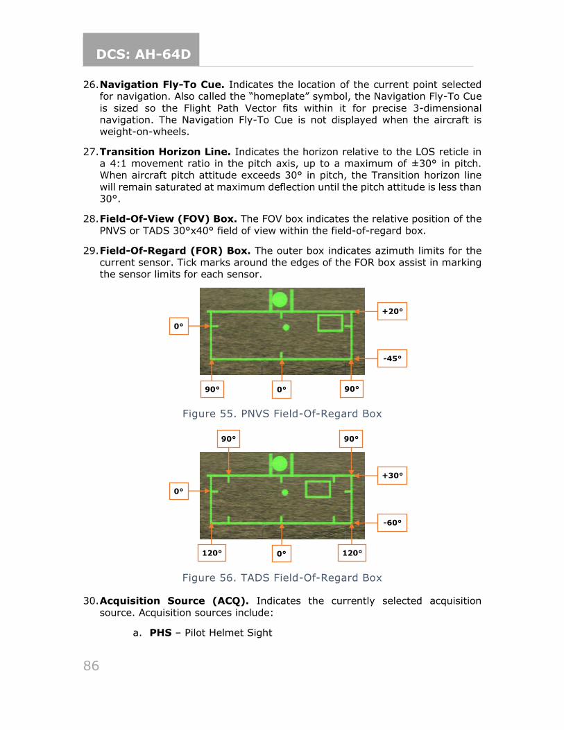
DCS: AH-64D
86
26. Navigation Fly-To Cue. Indicates the location of the current point selected for navigation. Also called the “homeplate” symbol, the Navigation Fly-To Cue
is sized so the Flight Path Vector fits within it for precise 3-dimensional navigation. The Navigation Fly-To Cue is not displayed when the aircraft is weight-on-wheels.
27. Transition Horizon Line. Indicates the horizon relative to the LOS reticle in a 4:1 movement ratio in the pitch axis, up to a maximum of ±30° in pitch. When aircraft pitch attitude exceeds 30° in pitch, the Transition horizon line
will remain saturated at maximum deflection until the pitch attitude is less than 30°.
28. Field-Of-View (FOV) Box. The FOV box indicates the relative position of the
PNVS or TADS 30°x40° field of view within the field-of-regard box.
29. Field-Of-Regard (FOR) Box. The outer box indicates azimuth limits for the current sensor. Tick marks around the edges of the FOR box assist in marking
the sensor limits for each sensor.
Figure 55. PNVS Field-Of-Regard Box
Figure 56. TADS Field-Of-Regard Box
30. Acquisition Source (ACQ). Indicates the currently selected acquisition
source. Acquisition sources include:
a. PHS – Pilot Helmet Sight
+20°
-45°
0°
0° 90° 90°
+30°
-60°
0°
0° 120° 120°
90° 90°
DCS: AH-64D
87
b. GHS – Gunner Helmet Sight
c. SKR – Tracking missile seeker
d. RFI – Radio Frequency Interferometer
e. FCR – Fire Control Radar
f. FXD – Fixed forward (aircraft centerline; 0° in azimuth/elevation)
g. W##, H##, C##, T## – (## is the number of the stored Waypoint, Hazard, Control Measure or Target/Threat)
h. TRN – Cursor-selected terrain location on the TSD
31. Acceleration Cue. The acceleration cue indicates magnitude and direction of the aircraft’s acceleration. The velocity vector will always seek the center of the acceleration cue. The acceleration cue can be thought of as a
representation of the cyclic, as displacing the cyclic will displace the acceleration cue.
When in Hover or Bob-Up symbology modes, the origin of the acceleration cue
is from the outer end of the velocity vector when the vector is less than maximum scale (not “saturated”). When the velocity vector is saturated beyond the maximum scale, the acceleration cue will originate from the center
of the LOS reticle.
32. Velocity Vector (VV). The velocity vector indicates the 2D direction and magnitude of travel of the helicopter across the ground. The center of the LOS
represents a point approximating the mast. In Hover mode symbology, the velocity vector will reach maximum saturation at 6 knots ground speed, and in Transition mode symbology at 60 knots ground speed.
33. Radar Altimeter (AGL) Analog Tape. Presents tick marks every 10 feet to an altitude of 50 feet, and tick marks every 50 feet to an altitude of 200 feet. When the aircraft has exceeded 200 feet AGL, the radar altitude tape will
disappear. The radar altimeter tape will not be displayed again until the aircraft descends below 180 feet AGL.
34. Bob-Up Box. Represents a 12 square-foot box anchored to the position it was
on the ground at the time Bob-Up mode was entered. This is termed “dropping a Bob-Up box”. The box will remain in this position until the crew changes symbology modes. When the Bob-Up box has reached the edge of the display
(“saturated”), the aircraft has travelled 40 feet.
35. High Action Display (HAD). The High Action Displays displayed in both Flight and Weapons symbology. The HAD provides prioritized sight and weapon
status messages to the crew for targeting and weapons employment. See Target Acquisition Designation Sight for more information.
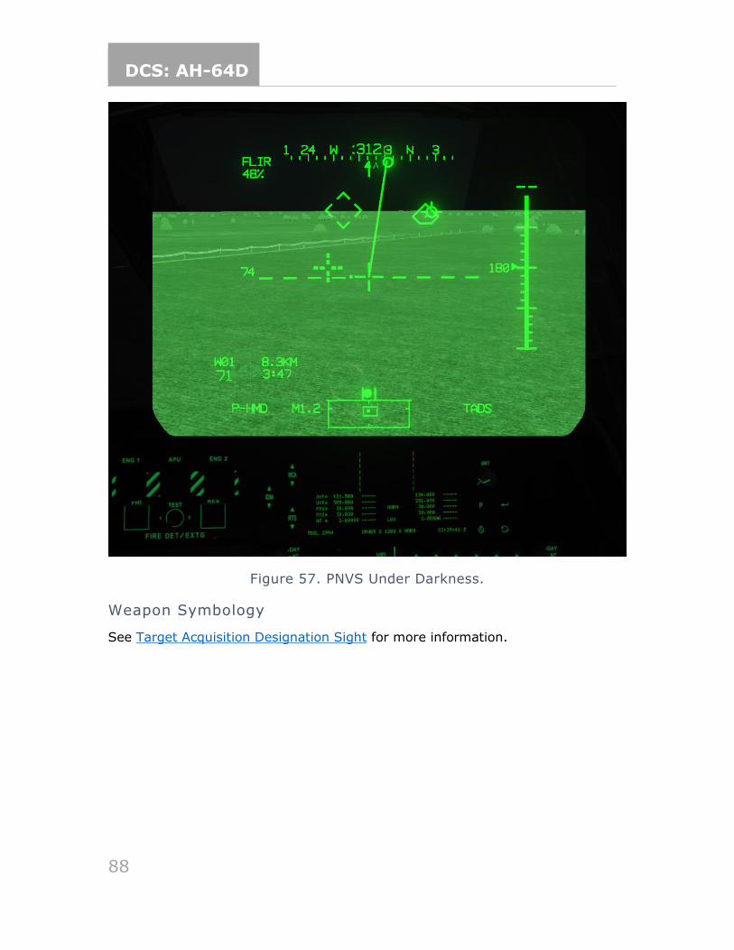
DCS: AH-64D
88
Figure 57. PNVS Under Darkness.
Weapon Symbology
See Target Acquisition Designation Sight for more information.
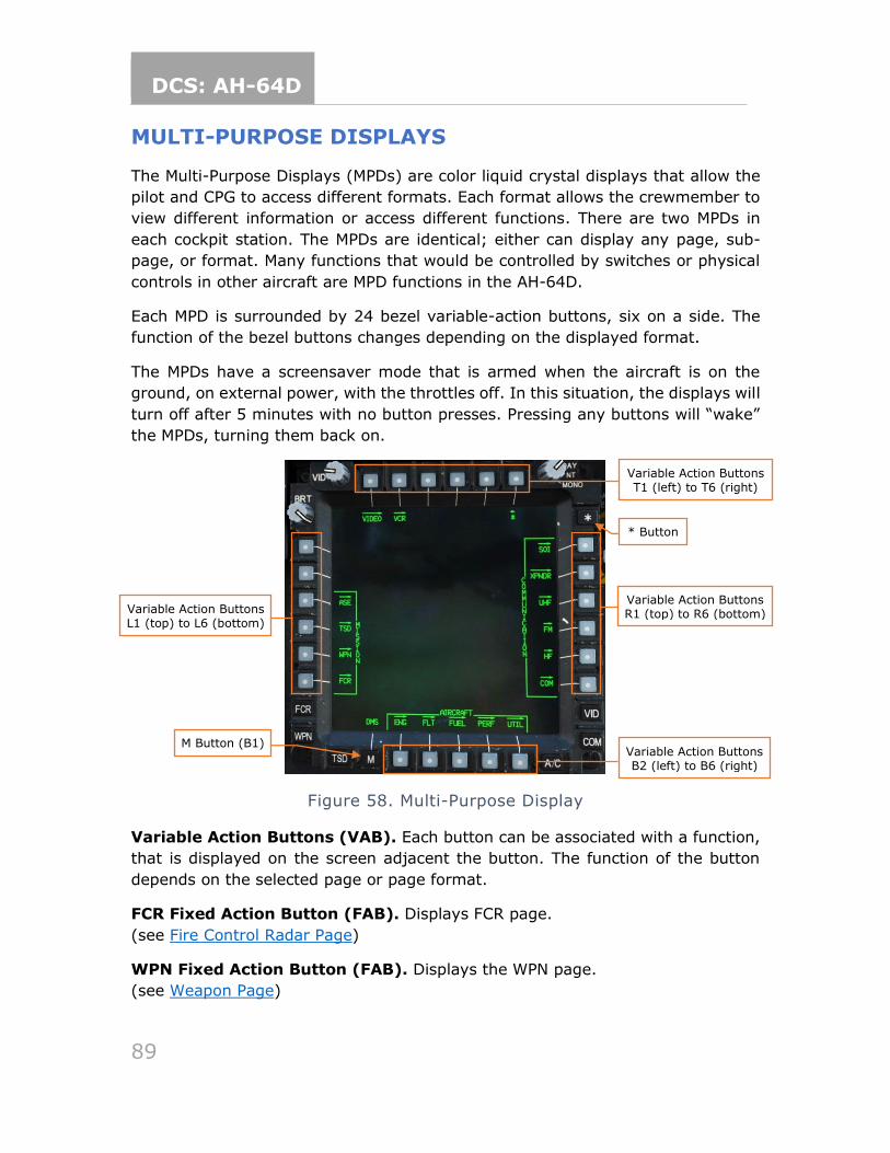
DCS: AH-64D
89
MULTI-PURPOSE DISPLAYS
The Multi-Purpose Displays (MPDs) are color liquid crystal displays that allow the
pilot and CPG to access different formats. Each format allows the crewmember to
view different information or access different functions. There are two MPDs in
each cockpit station. The MPDs are identical; either can display any page, sub-
page, or format. Many functions that would be controlled by switches or physical
controls in other aircraft are MPD functions in the AH-64D.
Each MPD is surrounded by 24 bezel variable-action buttons, six on a side. The
function of the bezel buttons changes depending on the displayed format.
The MPDs have a screensaver mode that is armed when the aircraft is on the
ground, on external power, with the throttles off. In this situation, the displays will
turn off after 5 minutes with no button presses. Pressing any buttons will “wake”
the MPDs, turning them back on.
Figure 58. Multi-Purpose Display
Variable Action Buttons (VAB). Each button can be associated with a function,
that is displayed on the screen adjacent the button. The function of the button
depends on the selected page or page format.
FCR Fixed Action Button (FAB). Displays FCR page.
(see Fire Control Radar Page)
WPN Fixed Action Button (FAB). Displays the WPN page.
(see Weapon Page)
Variable Action Buttons L1 (top) to L6 (bottom)
Variable Action Buttons T1 (left) to T6 (right)
Variable Action Buttons R1 (top) to R6 (bottom)
M Button (B1)
* Button
Variable Action Buttons B2 (left) to B6 (right)
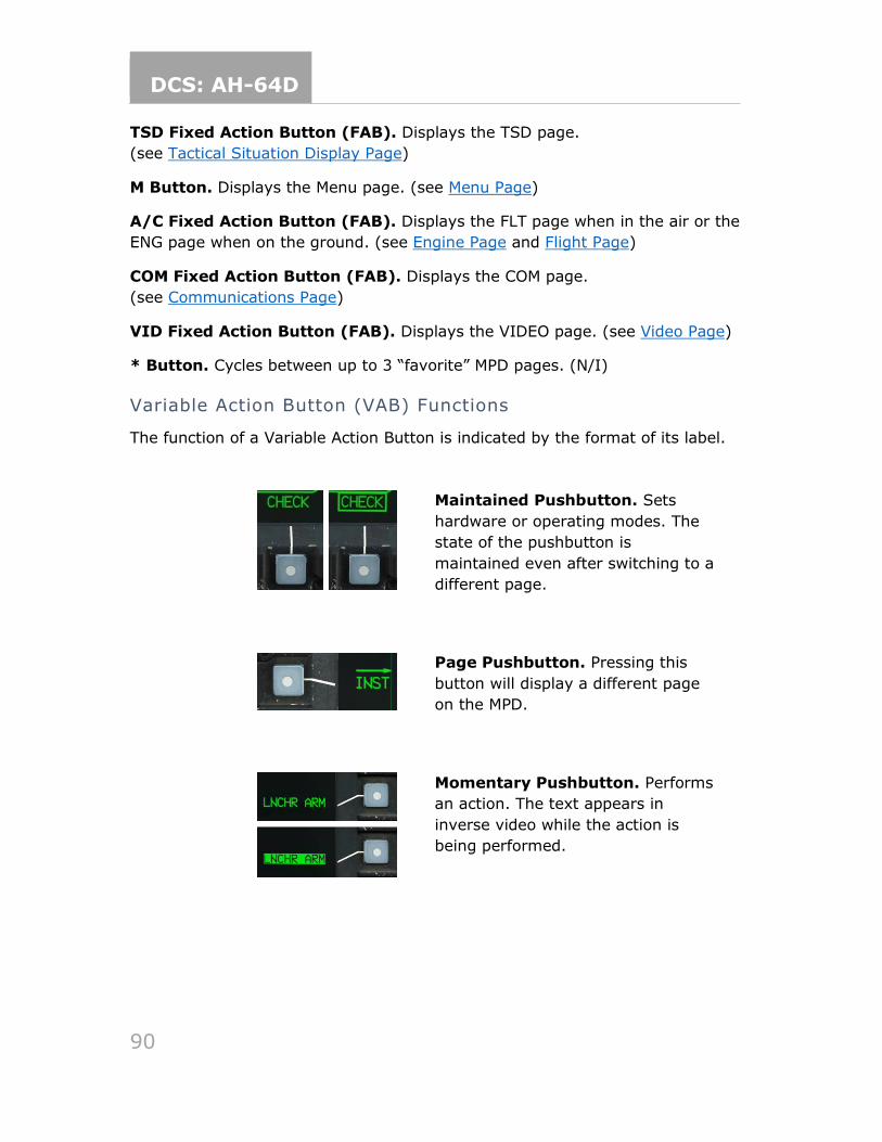
DCS: AH-64D
90
TSD Fixed Action Button (FAB). Displays the TSD page.
(see Tactical Situation Display Page)
M Button. Displays the Menu page. (see Menu Page)
A/C Fixed Action Button (FAB). Displays the FLT page when in the air or the
ENG page when on the ground. (see Engine Page and Flight Page)
COM Fixed Action Button (FAB). Displays the COM page.
(see Communications Page)
VID Fixed Action Button (FAB). Displays the VIDEO page. (see Video Page)
* Button. Cycles between up to 3 “favorite” MPD pages. (N/I)
Variable Action Button (VAB) Functions
The function of a Variable Action Button is indicated by the format of its label.
Maintained Pushbutton. Sets
hardware or operating modes. The
state of the pushbutton is
maintained even after switching to a
different page.
Page Pushbutton. Pressing this
button will display a different page
on the MPD.
Momentary Pushbutton. Performs
an action. The text appears in
inverse video while the action is
being performed.
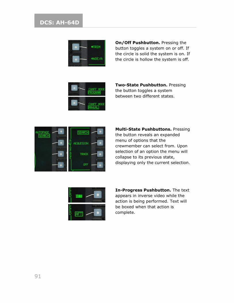
DCS: AH-64D
91
On/Off Pushbutton. Pressing the
button toggles a system on or off. If
the circle is solid the system is on. If
the circle is hollow the system is off.
Two-State Pushbutton. Pressing
the button toggles a system
between two different states.
Multi-State Pushbuttons. Pressing
the button reveals an expanded
menu of options that the
crewmember can select from. Upon
selection of an option the menu will
collapse to its previous state,
displaying only the current selection.
In-Progress Pushbutton. The text
appears in inverse video while the
action is being performed. Text will
be boxed when that action is
complete.
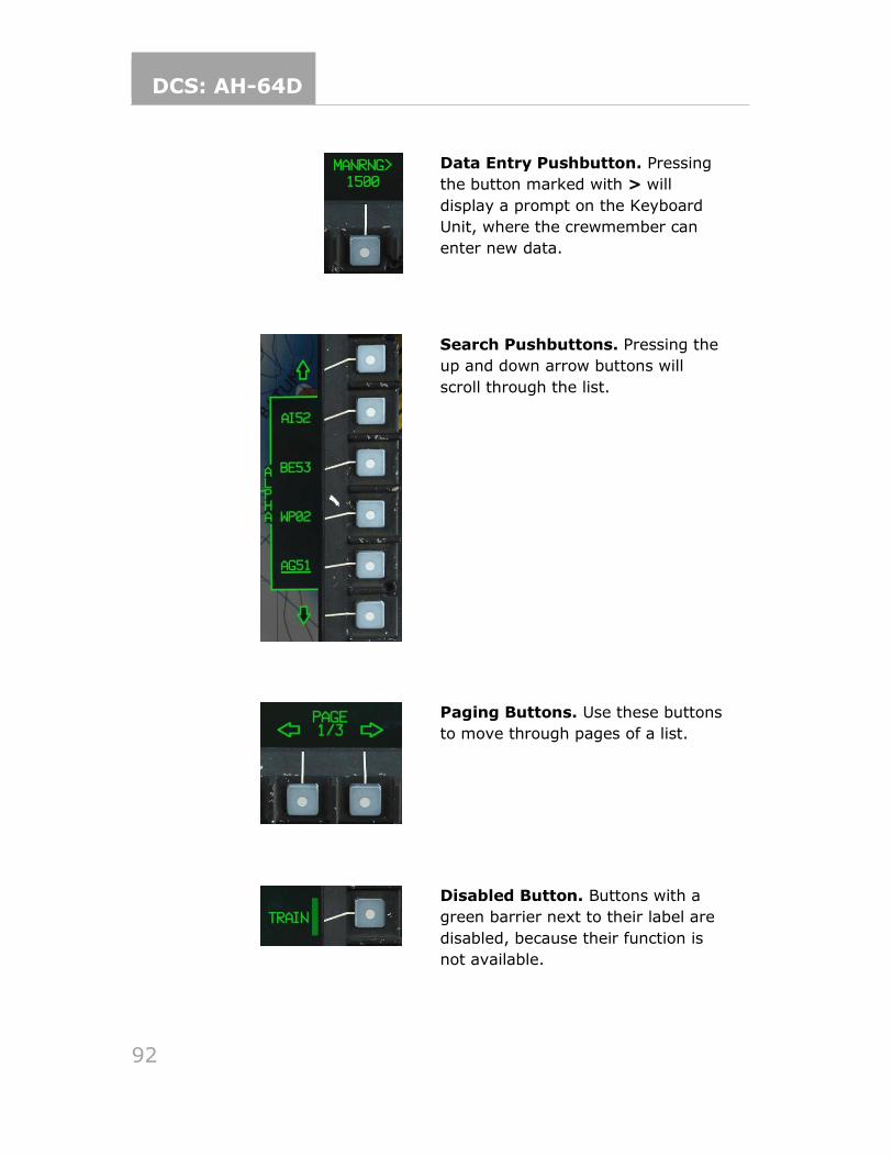
DCS: AH-64D
92
Data Entry Pushbutton. Pressing
the button marked with > will
display a prompt on the Keyboard
Unit, where the crewmember can
enter new data.
Search Pushbuttons. Pressing the
up and down arrow buttons will
scroll through the list.
Paging Buttons. Use these buttons
to move through pages of a list.
Disabled Button. Buttons with a
green barrier next to their label are
disabled, because their function is
not available.

DCS: AH-64D
93
TODO Failed Command. Buttons with a
white triangle next to their label
indicate that a command was
attempted and failed, and the
crewmember has the option to retry.
Missing/Invalid Data. Button
labels displayed in white with a
question mark indicate data that is
invalid or missing.
Autopaging
Some pages will present automatically when certain events occur; this is called
autopaging. The threshold for ASE autopaging can be set independently in each
cockpit. ENG autopaging can be disabled in the CPG cockpit only.
• The ENG page will display when a new warning message appears.
• The ENG page will display if the EMER HYD switch is activated.
• The ENG page will display when an engine starter is engaged.
• The TSD page will display when the RLWR or RFI detects radar or laser
energy exceeding the set threshold.
• The FCR page will display when the sight select is set to FCR.
• Depressing (Z-axis) on the Symbol Select Switch on the cyclic will select
the FLT page.
Cursor Use
The Cursor Control Switch on the collective is used to slew the cursor on the active
MPD. The cursor can be moved to the opposite display using the Cursor Display
Select Switch, or by moving the cursor to the edge of one display and “bumping”
the cursor controller in the direction of the opposite MPD by releasing Cursor
Controller pressure, and then re-applying in that direction.
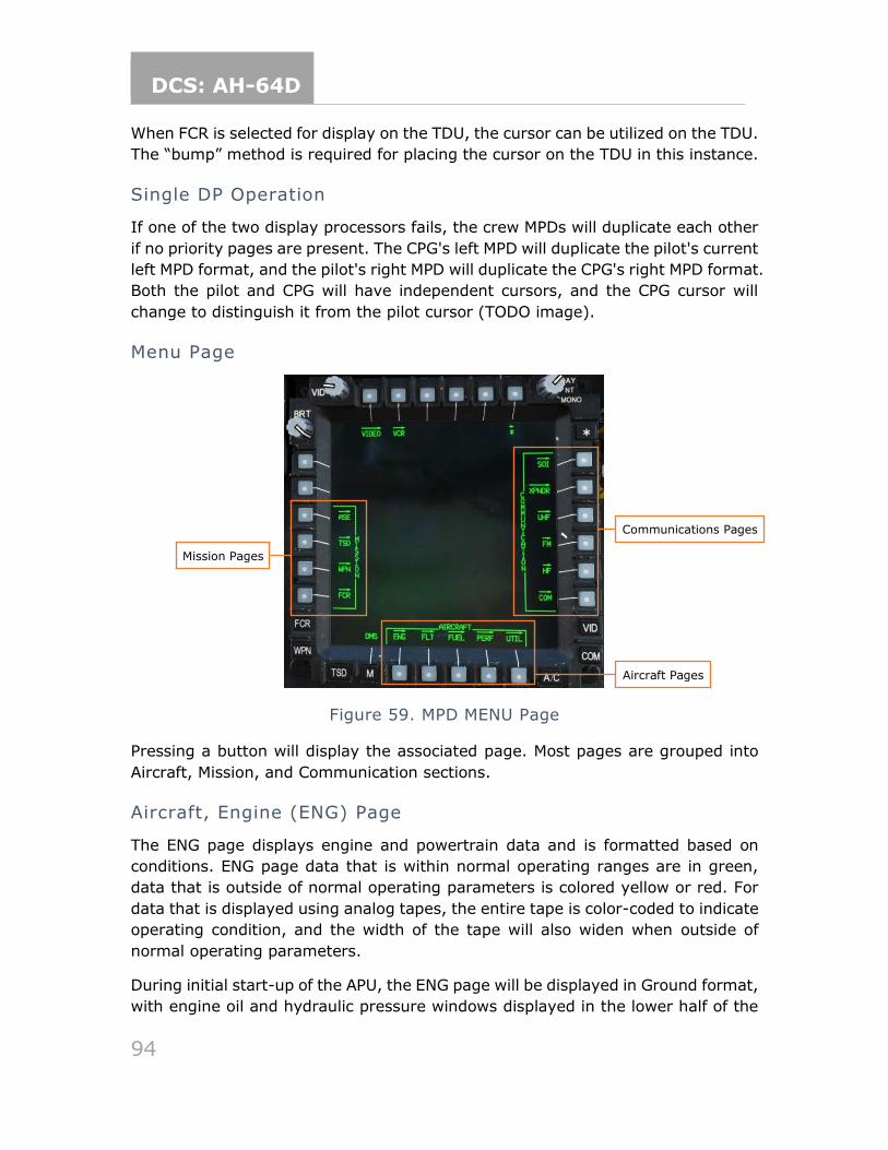
DCS: AH-64D
94
When FCR is selected for display on the TDU, the cursor can be utilized on the TDU.
The “bump” method is required for placing the cursor on the TDU in this instance.
Single DP Operation
If one of the two display processors fails, the crew MPDs will duplicate each other
if no priority pages are present. The CPG's left MPD will duplicate the pilot's current
left MPD format, and the pilot's right MPD will duplicate the CPG's right MPD format.
Both the pilot and CPG will have independent cursors, and the CPG cursor will
change to distinguish it from the pilot cursor (TODO image).
Menu Page
Figure 59. MPD MENU Page
Pressing a button will display the associated page. Most pages are grouped into
Aircraft, Mission, and Communication sections.
Aircraft, Engine (ENG) Page
The ENG page displays engine and powertrain data and is formatted based on
conditions. ENG page data that is within normal operating ranges are in green,
data that is outside of normal operating parameters is colored yellow or red. For
data that is displayed using analog tapes, the entire tape is color-coded to indicate
operating condition, and the width of the tape will also widen when outside of
normal operating parameters.
During initial start-up of the APU, the ENG page will be displayed in Ground format,
with engine oil and hydraulic pressure windows displayed in the lower half of the
Mission Pages
Communications Pages
Aircraft Pages
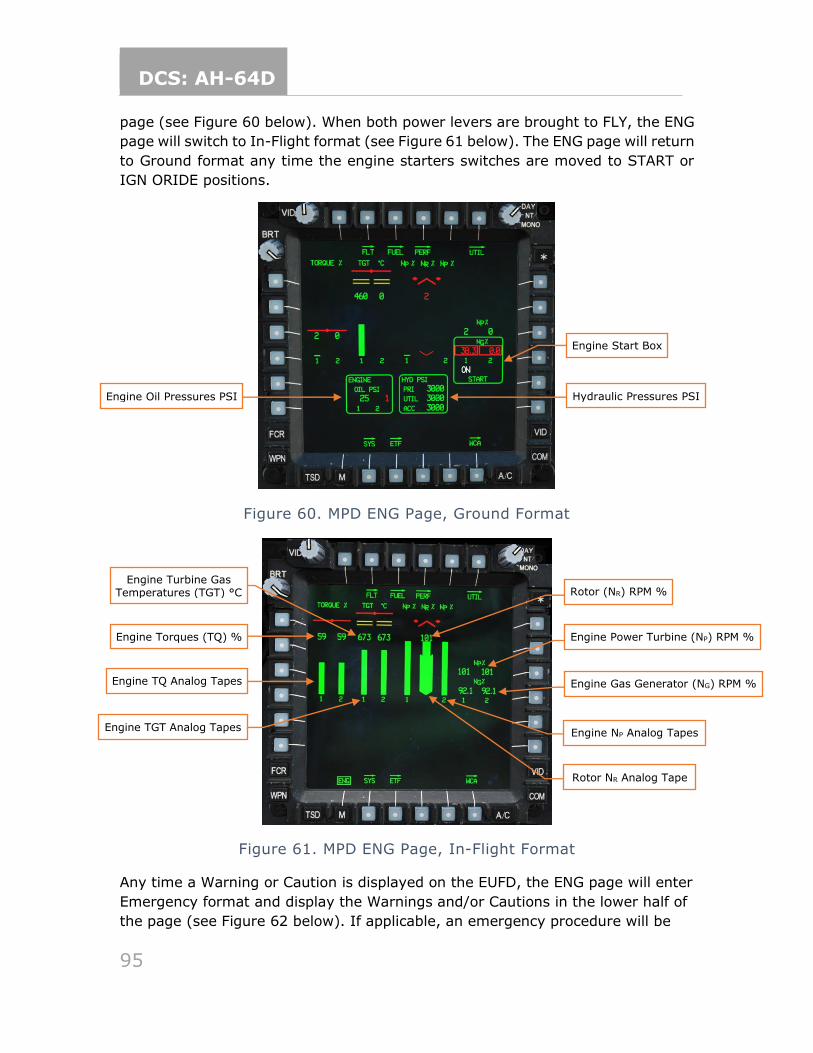
DCS: AH-64D
95
page (see Figure 60 below). When both power levers are brought to FLY, the ENG
page will switch to In-Flight format (see Figure 61 below). The ENG page will return
to Ground format any time the engine starters switches are moved to START or
IGN ORIDE positions.
Figure 60. MPD ENG Page, Ground Format
Figure 61. MPD ENG Page, In-Flight Format
Any time a Warning or Caution is displayed on the EUFD, the ENG page will enter
Emergency format and display the Warnings and/or Cautions in the lower half of
the page (see Figure 62 below). If applicable, an emergency procedure will be
Engine Turbine Gas Temperatures (TGT) °C Rotor (NR) RPM %
Hydraulic Pressures PSI Pressures
Engine Torques (TQ) % Engine Power Turbine (NP) RPM %
Engine Gas Generator (NG) RPM %
Engine NP Analog Tapes
Rotor NR Analog Tape
Engine TGT Analog Tapes
Engine TQ Analog Tapes
Engine Oil Pressures PSI
Engine Start Box
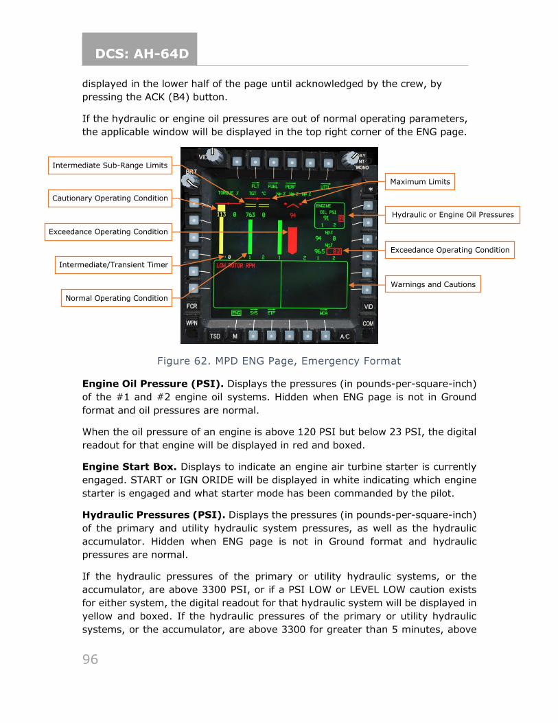
DCS: AH-64D
96
displayed in the lower half of the page until acknowledged by the crew, by
pressing the ACK (B4) button.
If the hydraulic or engine oil pressures are out of normal operating parameters,
the applicable window will be displayed in the top right corner of the ENG page.
Figure 62. MPD ENG Page, Emergency Format
Engine Oil Pressure (PSI). Displays the pressures (in pounds-per-square-inch)
of the #1 and #2 engine oil systems. Hidden when ENG page is not in Ground
format and oil pressures are normal.
When the oil pressure of an engine is above 120 PSI but below 23 PSI, the digital
readout for that engine will be displayed in red and boxed.
Engine Start Box. Displays to indicate an engine air turbine starter is currently
engaged. START or IGN ORIDE will be displayed in white indicating which engine
starter is engaged and what starter mode has been commanded by the pilot.
Hydraulic Pressures (PSI). Displays the pressures (in pounds-per-square-inch)
of the primary and utility hydraulic system pressures, as well as the hydraulic
accumulator. Hidden when ENG page is not in Ground format and hydraulic
pressures are normal.
If the hydraulic pressures of the primary or utility hydraulic systems, or the
accumulator, are above 3300 PSI, or if a PSI LOW or LEVEL LOW caution exists
for either system, the digital readout for that hydraulic system will be displayed in
yellow and boxed. If the hydraulic pressures of the primary or utility hydraulic
systems, or the accumulator, are above 3300 for greater than 5 minutes, above
Warnings and Cautions
Hydraulic or Engine Oil Pressures
Exceedance Operating Condition
Exceedance Operating Condition
Maximum Limits
Cautionary Operating Condition
Intermediate/Transient Timer
Intermediate Sub-Range Limits
Normal Operating Condition
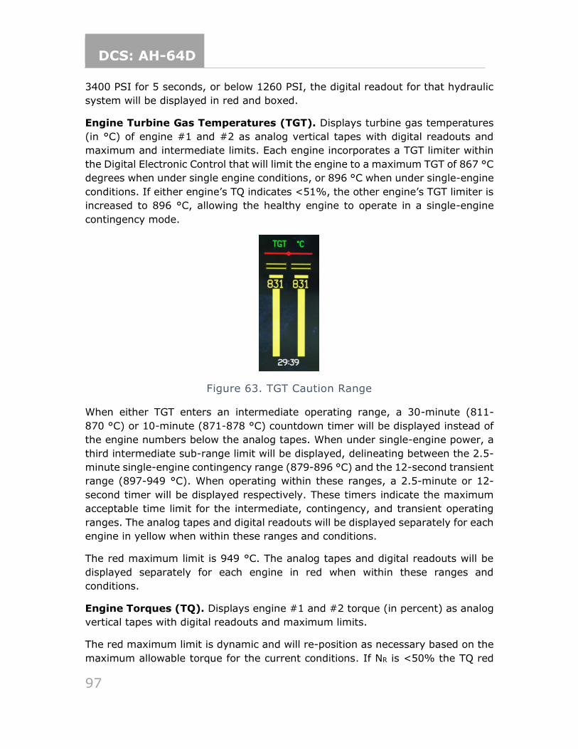
DCS: AH-64D
97
3400 PSI for 5 seconds, or below 1260 PSI, the digital readout for that hydraulic
system will be displayed in red and boxed.
Engine Turbine Gas Temperatures (TGT). Displays turbine gas temperatures
(in °C) of engine #1 and #2 as analog vertical tapes with digital readouts and
maximum and intermediate limits. Each engine incorporates a TGT limiter within
the Digital Electronic Control that will limit the engine to a maximum TGT of 867 °C
degrees when under single engine conditions, or 896 °C when under single-engine
conditions. If either engine’s TQ indicates <51%, the other engine’s TGT limiter is
increased to 896 °C, allowing the healthy engine to operate in a single-engine
contingency mode.
Figure 63. TGT Caution Range
When either TGT enters an intermediate operating range, a 30-minute (811-
870 °C) or 10-minute (871-878 °C) countdown timer will be displayed instead of
the engine numbers below the analog tapes. When under single-engine power, a
third intermediate sub-range limit will be displayed, delineating between the 2.5-
minute single-engine contingency range (879-896 °C) and the 12-second transient
range (897-949 °C). When operating within these ranges, a 2.5-minute or 12-
second timer will be displayed respectively. These timers indicate the maximum
acceptable time limit for the intermediate, contingency, and transient operating
ranges. The analog tapes and digital readouts will be displayed separately for each
engine in yellow when within these ranges and conditions.
The red maximum limit is 949 °C. The analog tapes and digital readouts will be
displayed separately for each engine in red when within these ranges and
conditions.
Engine Torques (TQ). Displays engine #1 and #2 torque (in percent) as analog
vertical tapes with digital readouts and maximum limits.
The red maximum limit is dynamic and will re-position as necessary based on the
maximum allowable torque for the current conditions. If NR is <50% the TQ red
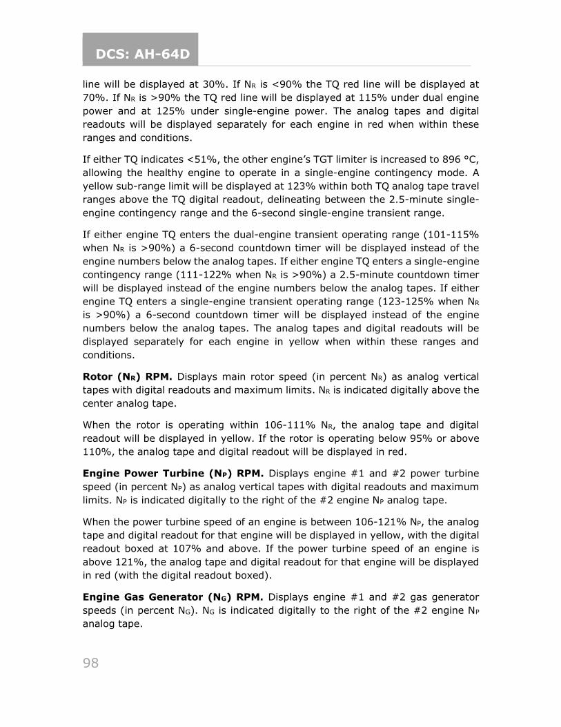
DCS: AH-64D
98
line will be displayed at 30%. If NR is <90% the TQ red line will be displayed at
70%. If NR is >90% the TQ red line will be displayed at 115% under dual engine
power and at 125% under single-engine power. The analog tapes and digital
readouts will be displayed separately for each engine in red when within these
ranges and conditions.
If either TQ indicates <51%, the other engine’s TGT limiter is increased to 896 °C,
allowing the healthy engine to operate in a single-engine contingency mode. A
yellow sub-range limit will be displayed at 123% within both TQ analog tape travel
ranges above the TQ digital readout, delineating between the 2.5-minute single-
engine contingency range and the 6-second single-engine transient range.
If either engine TQ enters the dual-engine transient operating range (101-115%
when NR is >90%) a 6-second countdown timer will be displayed instead of the
engine numbers below the analog tapes. If either engine TQ enters a single-engine
contingency range (111-122% when NR is >90%) a 2.5-minute countdown timer
will be displayed instead of the engine numbers below the analog tapes. If either
engine TQ enters a single-engine transient operating range (123-125% when NR
is >90%) a 6-second countdown timer will be displayed instead of the engine
numbers below the analog tapes. The analog tapes and digital readouts will be
displayed separately for each engine in yellow when within these ranges and
conditions.
Rotor (NR) RPM. Displays main rotor speed (in percent NR) as analog vertical
tapes with digital readouts and maximum limits. NR is indicated digitally above the
center analog tape.
When the rotor is operating within 106-111% NR, the analog tape and digital
readout will be displayed in yellow. If the rotor is operating below 95% or above
110%, the analog tape and digital readout will be displayed in red.
Engine Power Turbine (NP) RPM. Displays engine #1 and #2 power turbine
speed (in percent NP) as analog vertical tapes with digital readouts and maximum
limits. NP is indicated digitally to the right of the #2 engine NP analog tape.
When the power turbine speed of an engine is between 106-121% NP, the analog
tape and digital readout for that engine will be displayed in yellow, with the digital
readout boxed at 107% and above. If the power turbine speed of an engine is
above 121%, the analog tape and digital readout for that engine will be displayed
in red (with the digital readout boxed).
Engine Gas Generator (NG) RPM. Displays engine #1 and #2 gas generator
speeds (in percent NG). NG is indicated digitally to the right of the #2 engine NP
analog tape.
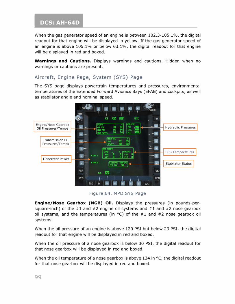
DCS: AH-64D
99
When the gas generator speed of an engine is between 102.3-105.1%, the digital
readout for that engine will be displayed in yellow. If the gas generator speed of
an engine is above 105.1% or below 63.1%, the digital readout for that engine
will be displayed in red and boxed.
Warnings and Cautions. Displays warnings and cautions. Hidden when no
warnings or cautions are present.
Aircraft, Engine Page, System (SYS) Page
The SYS page displays powertrain temperatures and pressures, environmental
temperatures of the Extended Forward Avionics Bays (EFAB) and cockpits, as well
as stabilator angle and nominal speed.
Figure 64. MPD SYS Page
Engine/Nose Gearbox (NGB) Oil. Displays the pressures (in pounds-per-
square-inch) of the #1 and #2 engine oil systems and #1 and #2 nose gearbox
oil systems, and the temperatures (in °C) of the #1 and #2 nose gearbox oil
systems.
When the oil pressure of an engine is above 120 PSI but below 23 PSI, the digital
readout for that engine will be displayed in red and boxed.
When the oil pressure of a nose gearbox is below 30 PSI, the digital readout for
that nose gearbox will be displayed in red and boxed.
When the oil temperature of a nose gearbox is above 134 in °C, the digital readout
for that nose gearbox will be displayed in red and boxed.
Generator Power
Engine/Nose Gearbox Oil Pressures/Temps
Transmission Oil Pressures/Temps
Hydraulic Pressures Pressures
ECS Temperatures
Stabilator Status
DCS: AH-64D
100
Transmission (XMSN) Oil. Displays the pressures (in pounds-per-square-inch)
and temperatures (in °C) of the #1 and #2 transmission oil systems.
When the oil pressure of a transmission oil system is below 30 PSI, the digital
readout for that transmission system will be displayed in red and boxed.
When the oil temperature of a transmission oil system above 134 in °C, the digital
readout for that transmission system will be displayed in red and boxed.
Generator (GEN) Power. Toggles Generator #1 or #2 off. Generators must be
reset in the pilot crewstation to be toggled back on.
(see pilot’s Check Overspeed Test/Generator Reset Panel)
Hydraulic Pressures. Displays the pressures (in pounds-per-square-inch) of the
primary and utility hydraulic system pressures, as well as the hydraulic
accumulator.
If the hydraulic pressures of the primary or utility hydraulic systems, or the
accumulator, are above 3300 PSI, or if a PSI LOW or LEVEL LOW caution exists
for either system, the digital readout for that hydraulic system will be displayed in
yellow and boxed. If the hydraulic pressures of the primary or utility hydraulic
systems, or the accumulator, are above 3300 for greater than 5 minutes, above
3400 PSI for 5 seconds, or below 1260 PSI, the digital readout for that hydraulic
system will be displayed in red and boxed.
ECS Temperatures. Displays the environmental temperatures inside the forward
and aft sections of each Extended Forward Avionics Bay (EFAB) and each cockpit.
Stabilator Status. Displays the current stabilator angle and nominal airspeed
restriction. The angle is referenced to the trailing edge of the stabilator and
displays a range of 10° UP to -35° DN. When stabilator is in manual mode, the
angle and nominal airspeed values are displayed in white. If the stabilator is
detected as failed, the nominal airspeed value will be displayed in yellow. If the
position of the stabilator is unknown, the angle indication will be displayed as a
white “?” and the nominal airspeed will be displayed in red as the true airspeed
equivalent of 90 knots IAS.
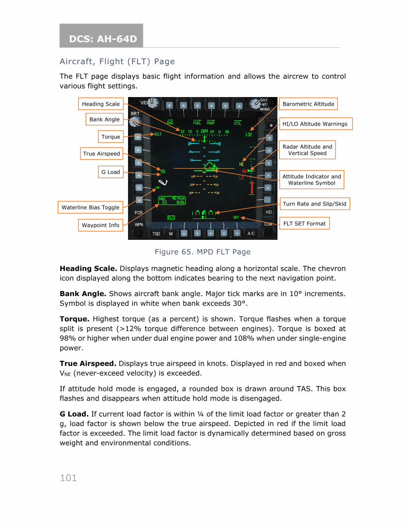
DCS: AH-64D
101
Aircraft, Flight (FLT) Page
The FLT page displays basic flight information and allows the aircrew to control
various flight settings.
Figure 65. MPD FLT Page
Heading Scale. Displays magnetic heading along a horizontal scale. The chevron
icon displayed along the bottom indicates bearing to the next navigation point.
Bank Angle. Shows aircraft bank angle. Major tick marks are in 10° increments.
Symbol is displayed in white when bank exceeds 30°.
Torque. Highest torque (as a percent) is shown. Torque flashes when a torque
split is present (>12% torque difference between engines). Torque is boxed at
98% or higher when under dual engine power and 108% when under single-engine
power.
True Airspeed. Displays true airspeed in knots. Displayed in red and boxed when
VNE (never-exceed velocity) is exceeded.
If attitude hold mode is engaged, a rounded box is drawn around TAS. This box
flashes and disappears when attitude hold mode is disengaged.
G Load. If current load factor is within ¼ of the limit load factor or greater than 2
g, load factor is shown below the true airspeed. Depicted in red if the limit load
factor is exceeded. The limit load factor is dynamically determined based on gross
weight and environmental conditions.
Heading Scale
Bank Angle
Torque
True Airspeed
Waterline Bias Toggle
Waypoint Info
Turn Rate and Slip/Skid
FLT SET Format
Attitude Indicator and Waterline Symbol
Radar Altitude and Vertical Speed
Barometric Altitude
HI/LO Altitude Warnings
G Load
DCS: AH-64D
102
Waterline Bias Toggle. Toggles on or off the waterline bias. “BIAS” is displayed
below “-W-” when bias is applied.
Waypoint Data. Displays navigational information in two lines. Line one displays
the name of the selected destination (W## for waypoints, H## for hazards, C##
for control measures, or T## for targets/threats) and the distance remaining. Line
two displays ground speed and time remaining.
Barometric Altitude. Displays barometric altitude in feet. If barometric data is
not present or invalid, displays inertial altitude. When inertial altitude is shown, it
will be depicted in white with the text “INRTL” underneath.
Radar Altitude. Radar altitude in feet is displayed on the right side of the vertical
scale and shown digitally at the center of the scale. The graphical scale has tick
marks for 10-foot intervals between 0 and 50 feet, and 100-foot intervals to 200
feet. If radar altitude exceeds 1428 feet, the scale is not shown.
If a low-altitude alert height is set and the aircraft is below that height, the word
“LO” is displayed in red, and both the analog tape and digital radar altimeter are
shown in red. If a high-altitude alert height is set and the aircraft is above that
height, the word “HI” is displayed in yellow, and the digital radar altimeter is shown
in yellow.
Vertical Speed. Rate of climb or descent (in feet per minute) is shown on the left
side of the vertical scale. Tick marks for every 100 feet per minute to ±500 fpm,
and then another tick mark is drawn at ±1000 fpm. If aircraft vertical speed
exceeds 1000 fpm, vertical speed is shown digitally in white at the top or bottom
of the scale.
Attitude Indicator. Indicates aircraft pitch and roll. Pitch ladders are drawn in
10° increments to ±90°. Positive (sky) pitch is displayed in cyan and negative
(ground) pitch is displayed in brown. The solid brown horizon line indicates 0°
pitch.
Waterline Symbol. The waterline symbol indicates nose position and is a central
reference for the pitch ladder. The symbol can be biased (adjusted upward or
downward from its normal position) by using the FLT SET page (see Figure 67
below). When the waterline is biased, it appears filled in rather than hollow.
Turn Rate. The top scale of this symbol indicates aircraft rate of turn. Rate of turn
is shown as a solid square. Three “doghouses” indicate level (no turn) and standard
rate turns to the left or right.
Slip/Skid. The bottom scale of this symbol indicates horizontal acceleration.
Horizontal acceleration is shown as a deflection of the oval from the center position.
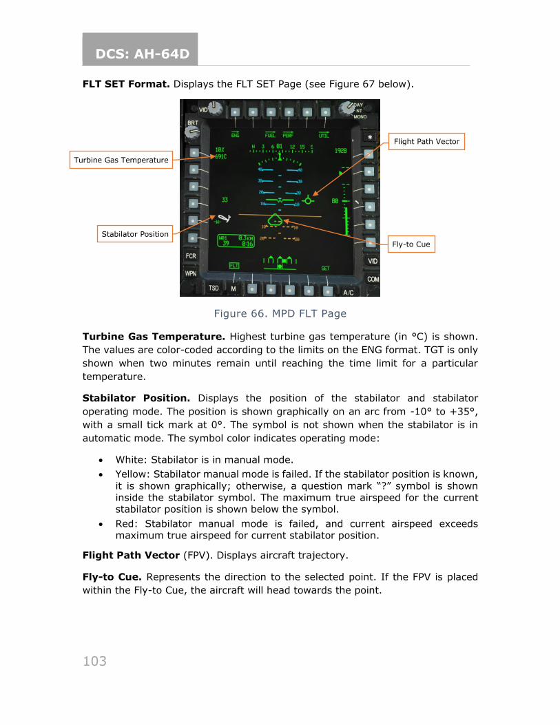
DCS: AH-64D
103
FLT SET Format. Displays the FLT SET Page (see Figure 67 below).
Figure 66. MPD FLT Page
Turbine Gas Temperature. Highest turbine gas temperature (in °C) is shown.
The values are color-coded according to the limits on the ENG format. TGT is only
shown when two minutes remain until reaching the time limit for a particular
temperature.
Stabilator Position. Displays the position of the stabilator and stabilator
operating mode. The position is shown graphically on an arc from -10° to +35°,
with a small tick mark at 0°. The symbol is not shown when the stabilator is in
automatic mode. The symbol color indicates operating mode:
• White: Stabilator is in manual mode.
• Yellow: Stabilator manual mode is failed. If the stabilator position is known,
it is shown graphically; otherwise, a question mark “?” symbol is shown inside the stabilator symbol. The maximum true airspeed for the current stabilator position is shown below the symbol.
• Red: Stabilator manual mode is failed, and current airspeed exceeds maximum true airspeed for current stabilator position.
Flight Path Vector (FPV). Displays aircraft trajectory.
Fly-to Cue. Represents the direction to the selected point. If the FPV is placed
within the Fly-to Cue, the aircraft will head towards the point.
Turbine Gas Temperature
Flight Path Vector
Fly-to Cue
Stabilator Position
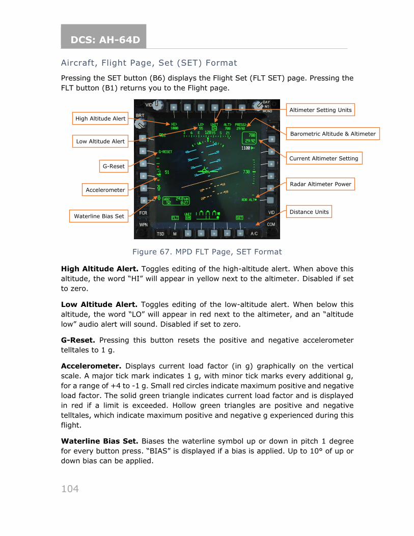
DCS: AH-64D
104
Aircraft, Flight Page, Set (SET) Format
Pressing the SET button (B6) displays the Flight Set (FLT SET) page. Pressing the
FLT button (B1) returns you to the Flight page.
Figure 67. MPD FLT Page, SET Format
High Altitude Alert. Toggles editing of the high-altitude alert. When above this
altitude, the word “HI” will appear in yellow next to the altimeter. Disabled if set
to zero.
Low Altitude Alert. Toggles editing of the low-altitude alert. When below this
altitude, the word “LO” will appear in red next to the altimeter, and an “altitude
low” audio alert will sound. Disabled if set to zero.
G-Reset. Pressing this button resets the positive and negative accelerometer
telltales to 1 g.
Accelerometer. Displays current load factor (in g) graphically on the vertical
scale. A major tick mark indicates 1 g, with minor tick marks every additional g,
for a range of +4 to -1 g. Small red circles indicate maximum positive and negative
load factor. The solid green triangle indicates current load factor and is displayed
in red if a limit is exceeded. Hollow green triangles are positive and negative
telltales, which indicate maximum positive and negative g experienced during this
flight.
Waterline Bias Set. Biases the waterline symbol up or down in pitch 1 degree
for every button press. “BIAS” is displayed if a bias is applied. Up to 10° of up or
down bias can be applied.
High Altitude Alert
Low Altitude Alert
G-Reset
Accelerometer
Waterline Bias Set
Altimeter Setting Units
Barometric Altitude & Altimeter
Current Altimeter Setting
Radar Altimeter Power
Distance Units
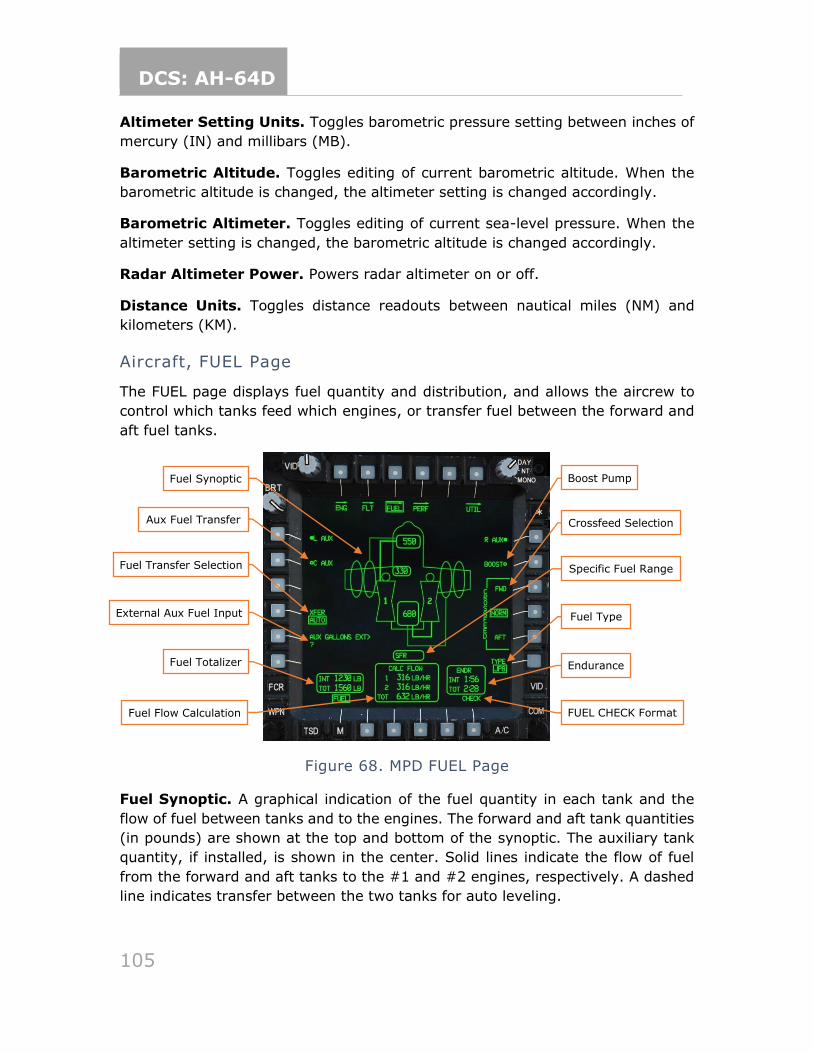
DCS: AH-64D
105
Altimeter Setting Units. Toggles barometric pressure setting between inches of
mercury (IN) and millibars (MB).
Barometric Altitude. Toggles editing of current barometric altitude. When the
barometric altitude is changed, the altimeter setting is changed accordingly.
Barometric Altimeter. Toggles editing of current sea-level pressure. When the
altimeter setting is changed, the barometric altitude is changed accordingly.
Radar Altimeter Power. Powers radar altimeter on or off.
Distance Units. Toggles distance readouts between nautical miles (NM) and
kilometers (KM).
Aircraft, FUEL Page
The FUEL page displays fuel quantity and distribution, and allows the aircrew to
control which tanks feed which engines, or transfer fuel between the forward and
aft fuel tanks.
Figure 68. MPD FUEL Page
Fuel Synoptic. A graphical indication of the fuel quantity in each tank and the
flow of fuel between tanks and to the engines. The forward and aft tank quantities
(in pounds) are shown at the top and bottom of the synoptic. The auxiliary tank
quantity, if installed, is shown in the center. Solid lines indicate the flow of fuel
from the forward and aft tanks to the #1 and #2 engines, respectively. A dashed
line indicates transfer between the two tanks for auto leveling.
Fuel Synoptic
Aux Fuel Transfer
Fuel Transfer Selection
External Aux Fuel Input
Fuel Totalizer
Boost Pump
Crossfeed Selection
Specific Fuel Range
Fuel Type
Endurance
FUEL CHECK Format Fuel Flow Calculation
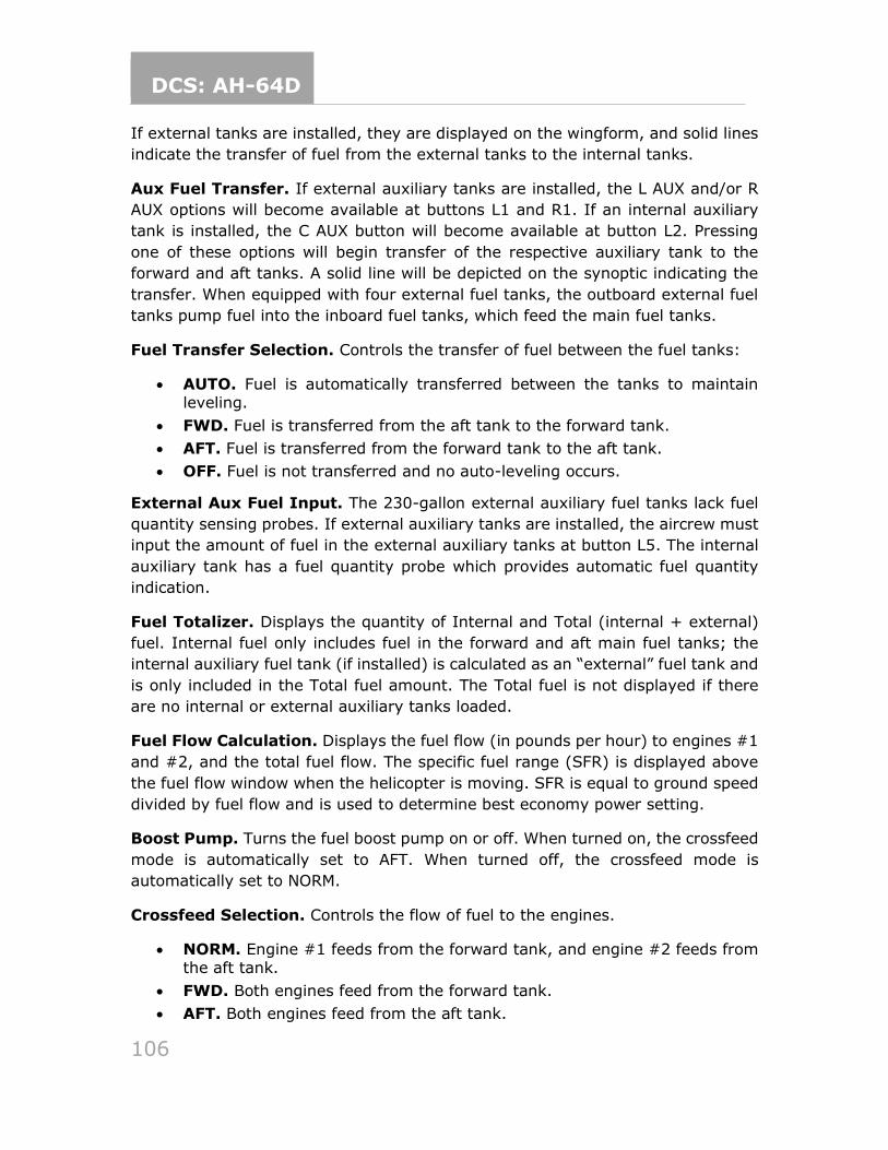
DCS: AH-64D
106
If external tanks are installed, they are displayed on the wingform, and solid lines
indicate the transfer of fuel from the external tanks to the internal tanks.
Aux Fuel Transfer. If external auxiliary tanks are installed, the L AUX and/or R
AUX options will become available at buttons L1 and R1. If an internal auxiliary
tank is installed, the C AUX button will become available at button L2. Pressing
one of these options will begin transfer of the respective auxiliary tank to the
forward and aft tanks. A solid line will be depicted on the synoptic indicating the
transfer. When equipped with four external fuel tanks, the outboard external fuel
tanks pump fuel into the inboard fuel tanks, which feed the main fuel tanks.
Fuel Transfer Selection. Controls the transfer of fuel between the fuel tanks:
• AUTO. Fuel is automatically transferred between the tanks to maintain leveling.
• FWD. Fuel is transferred from the aft tank to the forward tank.
• AFT. Fuel is transferred from the forward tank to the aft tank.
• OFF. Fuel is not transferred and no auto-leveling occurs.
External Aux Fuel Input. The 230-gallon external auxiliary fuel tanks lack fuel
quantity sensing probes. If external auxiliary tanks are installed, the aircrew must
input the amount of fuel in the external auxiliary tanks at button L5. The internal
auxiliary tank has a fuel quantity probe which provides automatic fuel quantity
indication.
Fuel Totalizer. Displays the quantity of Internal and Total (internal + external)
fuel. Internal fuel only includes fuel in the forward and aft main fuel tanks; the
internal auxiliary fuel tank (if installed) is calculated as an “external” fuel tank and
is only included in the Total fuel amount. The Total fuel is not displayed if there
are no internal or external auxiliary tanks loaded.
Fuel Flow Calculation. Displays the fuel flow (in pounds per hour) to engines #1
and #2, and the total fuel flow. The specific fuel range (SFR) is displayed above
the fuel flow window when the helicopter is moving. SFR is equal to ground speed
divided by fuel flow and is used to determine best economy power setting.
Boost Pump. Turns the fuel boost pump on or off. When turned on, the crossfeed
mode is automatically set to AFT. When turned off, the crossfeed mode is
automatically set to NORM.
Crossfeed Selection. Controls the flow of fuel to the engines.
• NORM. Engine #1 feeds from the forward tank, and engine #2 feeds from the aft tank.
• FWD. Both engines feed from the forward tank.
• AFT. Both engines feed from the aft tank.
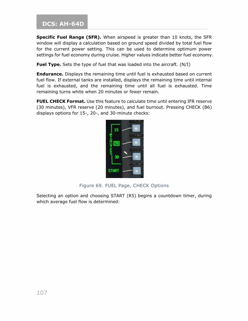
DCS: AH-64D
107
Specific Fuel Range (SFR). When airspeed is greater than 10 knots, the SFR
window will display a calculation based on ground speed divided by total fuel flow
for the current power setting. This can be used to determine optimum power
settings for fuel economy during cruise. Higher values indicate better fuel economy.
Fuel Type. Sets the type of fuel that was loaded into the aircraft. (N/I)
Endurance. Displays the remaining time until fuel is exhausted based on current
fuel flow. If external tanks are installed, displays the remaining time until internal
fuel is exhausted, and the remaining time until all fuel is exhausted. Time
remaining turns white when 20 minutes or fewer remain.
FUEL CHECK Format. Use this feature to calculate time until entering IFR reserve
(30 minutes), VFR reserve (20 minutes), and fuel burnout. Pressing CHECK (B6)
displays options for 15-, 20-, and 30-minute checks:
Figure 69. FUEL Page, CHECK Options
Selecting an option and choosing START (R5) begins a countdown timer, during
which average fuel flow is determined:
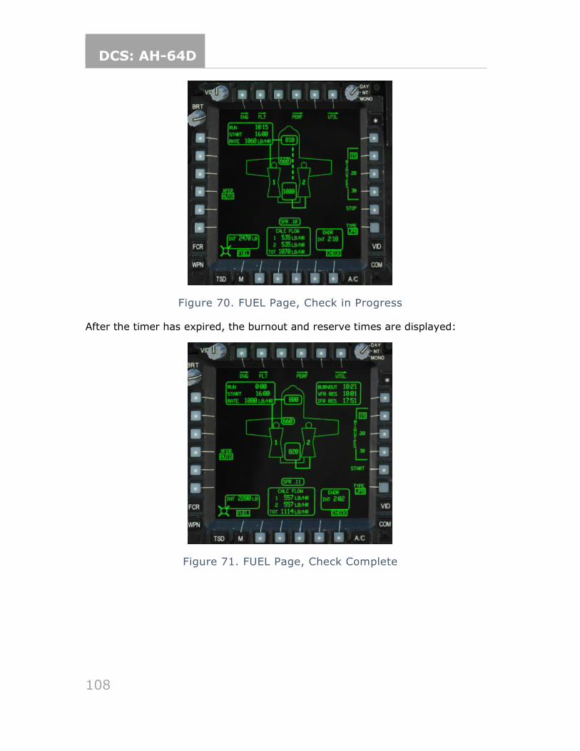
DCS: AH-64D
108
Figure 70. FUEL Page, Check in Progress
After the timer has expired, the burnout and reserve times are displayed:
Figure 71. FUEL Page, Check Complete
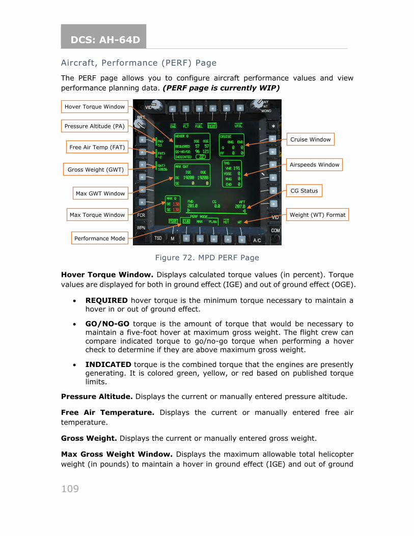
DCS: AH-64D
109
Aircraft, Performance (PERF) Page
The PERF page allows you to configure aircraft performance values and view
performance planning data. (PERF page is currently WIP)
Figure 72. MPD PERF Page
Hover Torque Window. Displays calculated torque values (in percent). Torque
values are displayed for both in ground effect (IGE) and out of ground effect (OGE).
• REQUIRED hover torque is the minimum torque necessary to maintain a
hover in or out of ground effect.
• GO/NO-GO torque is the amount of torque that would be necessary to maintain a five-foot hover at maximum gross weight. The flight crew can
compare indicated torque to go/no-go torque when performing a hover check to determine if they are above maximum gross weight.
• INDICATED torque is the combined torque that the engines are presently generating. It is colored green, yellow, or red based on published torque limits.
Pressure Altitude. Displays the current or manually entered pressure altitude.
Free Air Temperature. Displays the current or manually entered free air
temperature.
Gross Weight. Displays the current or manually entered gross weight.
Max Gross Weight Window. Displays the maximum allowable total helicopter
weight (in pounds) to maintain a hover in ground effect (IGE) and out of ground
Hover Torque Window
Pressure Altitude (PA)
Gross Weight (GWT)
Max GWT Window
Max Torque Window
Cruise Window
Airspeeds Window
CG Status
Weight (WT) Format
Performance Mode
Free Air Temp (FAT)
DCS: AH-64D
110
effect (OGE), for dual-engine (DE) and single-engine (SE) operations. Values are
displayed in yellow when they are exceeded by current helicopter weight.
Max Torque Window. Displays maximum torque available for normal operations
(in percent).
• DE. Displays 30-minute maximum dual-engine torque. Value is displayed
in yellow if above 100% and red if above 115%.
• SE. Displays 2.5-minute maximum single-engine torque. Value is displayed in yellow if above 110% and red if above 125%.
Performance Mode. Sets the conditions for the performance calculations.
• CUR. Calculate performance using current conditions. When selected, the
PA, FAT, and GWT values cannot be modified. In CUR mode, the current anti-ice setting (on or off) is used for calculations.
• MAX. Performance calculations are made using the values entered for PA,
FAT, and GWT.
• PLAN. Performance calculations are made using the values loaded from the DTU.
Cruise Window. Displays calculated cruise performance for maximum range
(RNG) and maximum endurance (END).
• Q. Maximum-range or maximum-endurance torque value (in percent).
• FF. Maximum-range or maximum-endurance fuel flow value (in pounds per hour).
Airspeeds Window. Displays performance-related speeds in knots true airspeed
(KTAS):
• VNE. Never-exceed speed.
• VSSE. Safe single-engine speed. This is the minimum speed that should be maintained during single-engine operations.
• RNG. Maximum-range cruising speed.
• END. Maximum-endurance cruising speed.
CG Status. Displays the forward and aft center of gravity limits and the current
center of gravity (in inches) digitally and graphically.
Weight Format. Displays the Weight Data Entry format (see Figure 73 below).
Aircraft, Performance Page, Weight (WT) Format
The Weight format allows you to enter the weight of personnel and equipment
onboard the aircraft for performance and limitations calculation. Press any of the
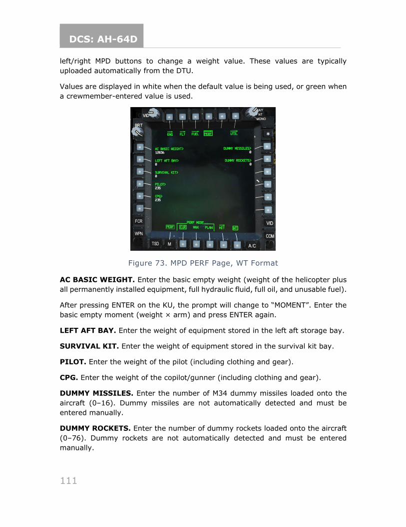
DCS: AH-64D
111
left/right MPD buttons to change a weight value. These values are typically
uploaded automatically from the DTU.
Values are displayed in white when the default value is being used, or green when
a crewmember-entered value is used.
Figure 73. MPD PERF Page, WT Format
AC BASIC WEIGHT. Enter the basic empty weight (weight of the helicopter plus
all permanently installed equipment, full hydraulic fluid, full oil, and unusable fuel).
After pressing ENTER on the KU, the prompt will change to “MOMENT”. Enter the
basic empty moment (weight × arm) and press ENTER again.
LEFT AFT BAY. Enter the weight of equipment stored in the left aft storage bay.
SURVIVAL KIT. Enter the weight of equipment stored in the survival kit bay.
PILOT. Enter the weight of the pilot (including clothing and gear).
CPG. Enter the weight of the copilot/gunner (including clothing and gear).
DUMMY MISSILES. Enter the number of M34 dummy missiles loaded onto the
aircraft (0–16). Dummy missiles are not automatically detected and must be
entered manually.
DUMMY ROCKETS. Enter the number of dummy rockets loaded onto the aircraft
(0–76). Dummy rockets are not automatically detected and must be entered
manually.
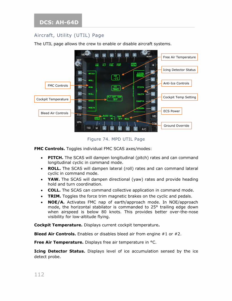
DCS: AH-64D
112
Aircraft, Utility (UTIL) Page
The UTIL page allows the crew to enable or disable aircraft systems.
Figure 74. MPD UTIL Page
FMC Controls. Toggles individual FMC SCAS axes/modes:
• PITCH. The SCAS will dampen longitudinal (pitch) rates and can command longitudinal cyclic in command mode.
• ROLL. The SCAS will dampen lateral (roll) rates and can command lateral
cyclic in command mode.
• YAW. The SCAS will dampen directional (yaw) rates and provide heading hold and turn coordination.
• COLL. The SCAS can command collective application in command mode.
• TRIM. Toggles the force trim magnetic brakes on the cyclic and pedals.
• NOE/A. Activates FMC nap of earth/approach mode. In NOE/approach
mode, the horizontal stabilator is commanded to 25° trailing edge down when airspeed is below 80 knots. This provides better over-the-nose visibility for low-altitude flying.
Cockpit Temperature. Displays current cockpit temperature.
Bleed Air Controls. Enables or disables bleed air from engine #1 or #2.
Free Air Temperature. Displays free air temperature in °C.
Icing Detector Status. Displays level of ice accumulation sensed by the ice
detect probe.
Bleed Air Controls
Free Air Temperature
Icing Detector Status
FMC Controls
Cockpit Temperature Cockpit Temp Setting
ECS Power
Ground Override
Anti-Ice Controls
DCS: AH-64D
113
Anti-Ice Controls. Sets anti-ice system mode and turns on or off anti-ice
equipment.
• SYSTEM. Sets anti-ice system mode. When in AUTO mode, anti-ice system controls are enabled automatically when ice is detected by the ice detect probe. When ice is no longer detected, they can be disabled manually by
the aircrew. (They are not disabled automatically.) In MANUAL mode, the aircrew must enable and disable the anti-icing systems manually depending on the presence of ice.
• PITOT. Enables or disables electrical pitot and air data sensor (ADS) heat.
• INLET. Enables or disables bleed air heat for the engine and inlet fairings, and electrical heating for nose gearbox fairings.
• CANOPY. Enables or disables the electrical heating elements in embedded in the middle forward windshields for the pilot and CPG stations.
• SENSOR. Enables or disables the electrical heating of the turret shrouds,
boresight, and sensor windows for the TADS/PNVS. Automatically disabled and “barriered” while on the ground, unless GND (B6) is selected.
Cockpit Temperature Setting. Sets the desired crew station temperature using
the KU. Each crewmember can set their own temperature.
ECS Power. Powers the ECS on or off. When powered off, the ECS will not regulate
cockpit or EFAB temperature.
Ground Override. When weight-on-wheels, overrides the inhibit that prevents
the TADS/PNVS anti-ice from activating, and removes the barrier from SENSOR
(B6).
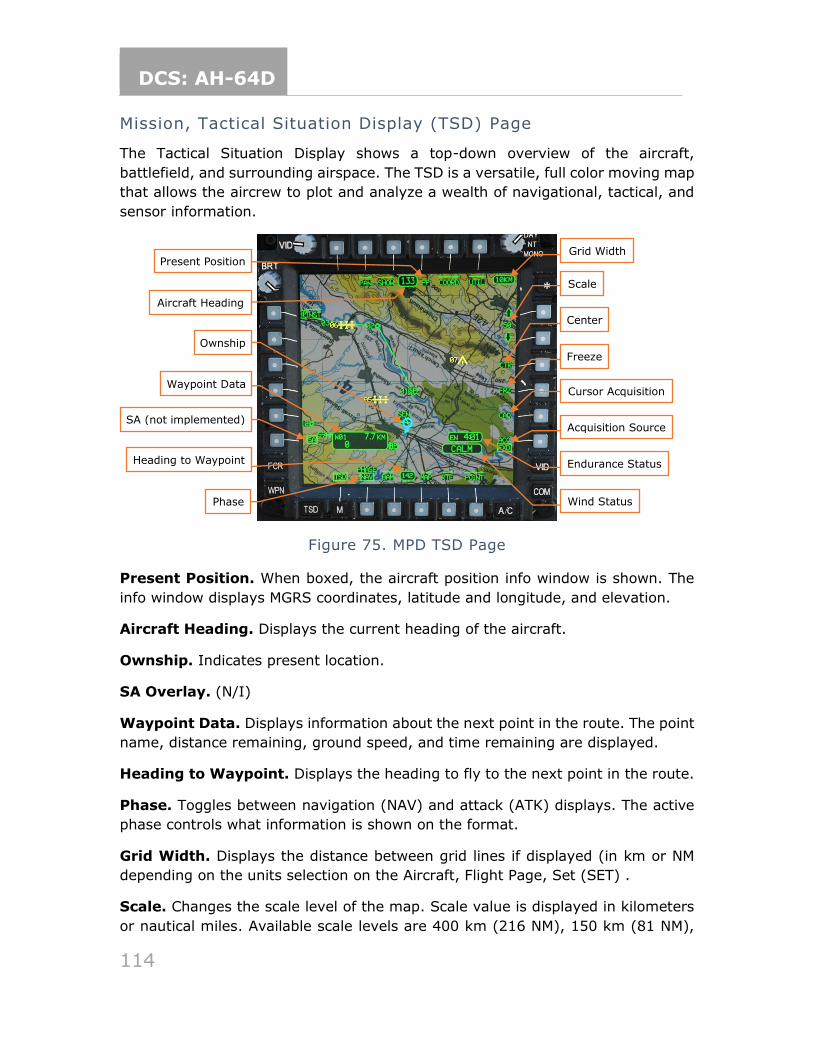
DCS: AH-64D
114
Mission, Tactical Situation Display (TSD) Page
The Tactical Situation Display shows a top-down overview of the aircraft,
battlefield, and surrounding airspace. The TSD is a versatile, full color moving map
that allows the aircrew to plot and analyze a wealth of navigational, tactical, and
sensor information.
Figure 75. MPD TSD Page
Present Position. When boxed, the aircraft position info window is shown. The
info window displays MGRS coordinates, latitude and longitude, and elevation.
Aircraft Heading. Displays the current heading of the aircraft.
Ownship. Indicates present location.
SA Overlay. (N/I)
Waypoint Data. Displays information about the next point in the route. The point
name, distance remaining, ground speed, and time remaining are displayed.
Heading to Waypoint. Displays the heading to fly to the next point in the route.
Phase. Toggles between navigation (NAV) and attack (ATK) displays. The active
phase controls what information is shown on the format.
Grid Width. Displays the distance between grid lines if displayed (in km or NM
depending on the units selection on the Aircraft, Flight Page, Set (SET) .
Scale. Changes the scale level of the map. Scale value is displayed in kilometers
or nautical miles. Available scale levels are 400 km (216 NM), 150 km (81 NM),
Scale
Center
Cursor Acquisition
Acquisition Source
Endurance Status
Ownship
Waypoint Data
SA (not implemented)
Phase
Aircraft Heading
Heading to Waypoint
Wind Status
Present Position
Freeze
Grid Width
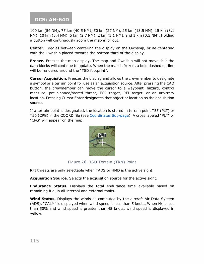
DCS: AH-64D
115
100 km (54 NM), 75 km (40.5 NM), 50 km (27 NM), 25 km (13.5 NM), 15 km (8.1
NM), 10 km (5.4 NM), 5 km (2.7 NM), 2 km (1.1 NM), and 1 km (0.5 NM). Holding
a button will continuously zoom the map in or out.
Center. Toggles between centering the display on the Ownship, or de-centering
with the Ownship placed towards the bottom third of the display.
Freeze. Freezes the map display. The map and Ownship will not move, but the
data blocks will continue to update. When the map is frozen, a bold dashed outline
will be rendered around the “TSD footprint”.
Cursor Acquisition. Freezes the display and allows the crewmember to designate
a symbol or a terrain point for use as an acquisition source. After pressing the CAQ
button, the crewmember can move the cursor to a waypoint, hazard, control
measure, pre-planned/stored threat, FCR target, RFI target, or an arbitrary
location. Pressing Cursor Enter designates that object or location as the acquisition
source.
If a terrain point is designated, the location is stored in terrain point T55 (PLT) or
T56 (CPG) in the COORD file (see Coordinates Sub-page). A cross labeled “PLT” or
“CPG” will appear on the map.
Figure 76. TSD Terrain (TRN) Point
RFI threats are only selectable when TADS or HMD is the active sight.
Acquisition Source. Selects the acquisition source for the active sight.
Endurance Status. Displays the total endurance time available based on
remaining fuel in all internal and external tanks.
Wind Status. Displays the winds as computed by the aircraft Air Data System
(ADS). “CALM” is displayed when wind speed is less than 5 knots. When NR is less
than 50% and wind speed is greater than 45 knots, wind speed is displayed in
yellow.
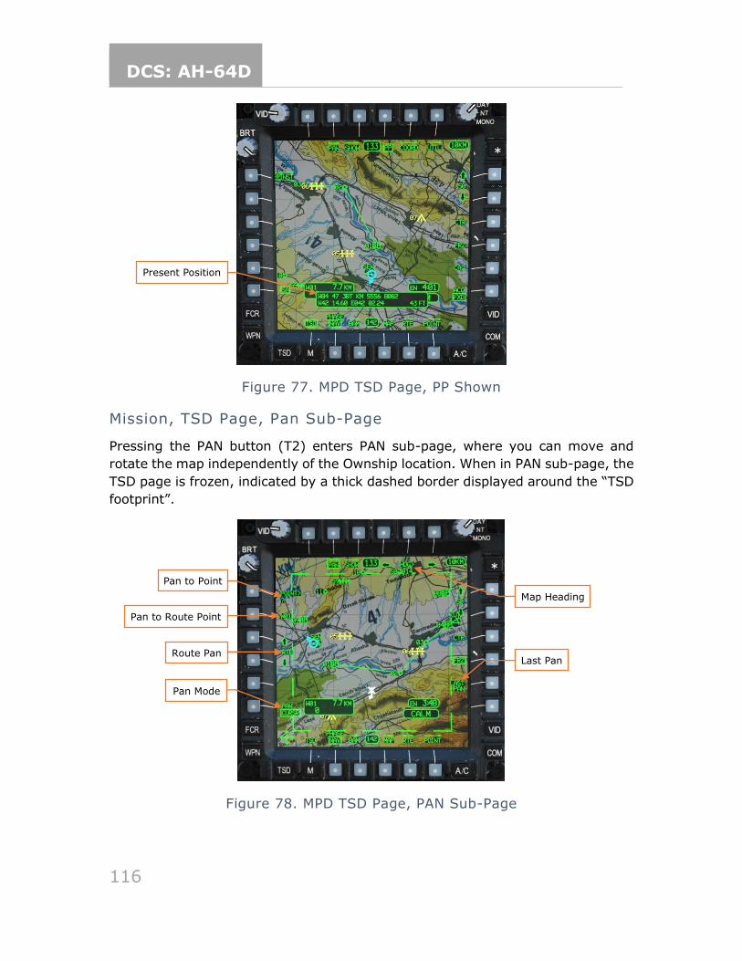
DCS: AH-64D
116
Figure 77. MPD TSD Page, PP Shown
Mission, TSD Page, Pan Sub-Page
Pressing the PAN button (T2) enters PAN sub-page, where you can move and
rotate the map independently of the Ownship location. When in PAN sub-page, the
TSD page is frozen, indicated by a thick dashed border displayed around the “TSD
footprint”.
Figure 78. MPD TSD Page, PAN Sub-Page
Present Position
Map Heading
Pan to Point
Route Pan
Pan Mode
Last Pan
Pan to Route Point
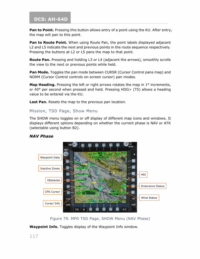
DCS: AH-64D
117
Pan to Point. Pressing this button allows entry of a point using the KU. After entry,
the map will pan to this point.
Pan to Route Point. When using Route Pan, the point labels displayed adjacent
L2 and L5 indicate the next and previous points in the route sequence respectively.
Pressing the buttons at L2 or L5 pans the map to that point.
Route Pan. Pressing and holding L3 or L4 (adjacent the arrows), smoothly scrolls
the view to the next or previous points while held.
Pan Mode. Toggles the pan mode between CURSR (Cursor Control pans map) and
NORM (Cursor Control controls on-screen cursor) pan modes.
Map Heading. Pressing the left or right arrows rotates the map in 1° increments,
or 40° per second when pressed and held. Pressing HDG> (T5) allows a heading
value to be entered via the KU.
Last Pan. Resets the map to the previous pan location.
Mission, TSD Page, Show Menu
The SHOW menu toggles on or off display of different map icons and windows. It
displays different options depending on whether the current phase is NAV or ATK
(selectable using button B2).
NAV Phase
Figure 79. MPD TSD Page, SHOW Menu (NAV Phase)
Waypoint Info. Toggles display of the Waypoint Info window.
Waypoint Data
Obstacles
Cursor Info
Inactive Zones
CPG Cursor
HSI
Endurance Status
Wind Status
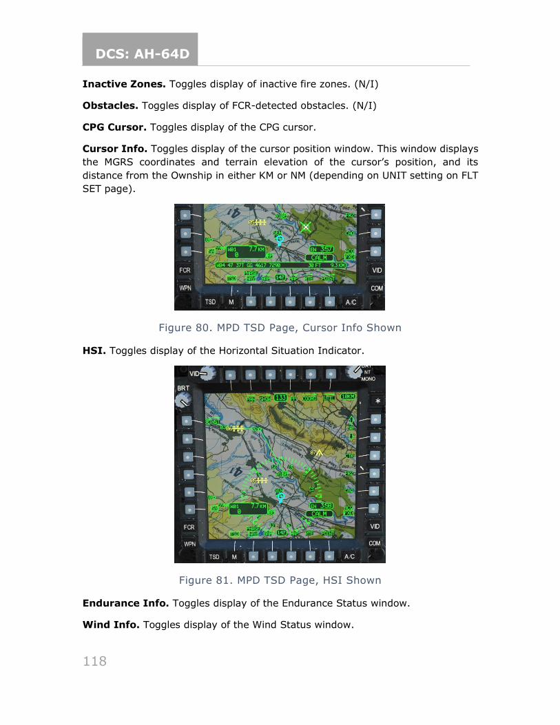
DCS: AH-64D
118
Inactive Zones. Toggles display of inactive fire zones. (N/I)
Obstacles. Toggles display of FCR-detected obstacles. (N/I)
CPG Cursor. Toggles display of the CPG cursor.
Cursor Info. Toggles display of the cursor position window. This window displays
the MGRS coordinates and terrain elevation of the cursor’s position, and its
distance from the Ownship in either KM or NM (depending on UNIT setting on FLT
SET page).
Figure 80. MPD TSD Page, Cursor Info Shown
HSI. Toggles display of the Horizontal Situation Indicator.
Figure 81. MPD TSD Page, HSI Shown
Endurance Info. Toggles display of the Endurance Status window.
Wind Info. Toggles display of the Wind Status window.
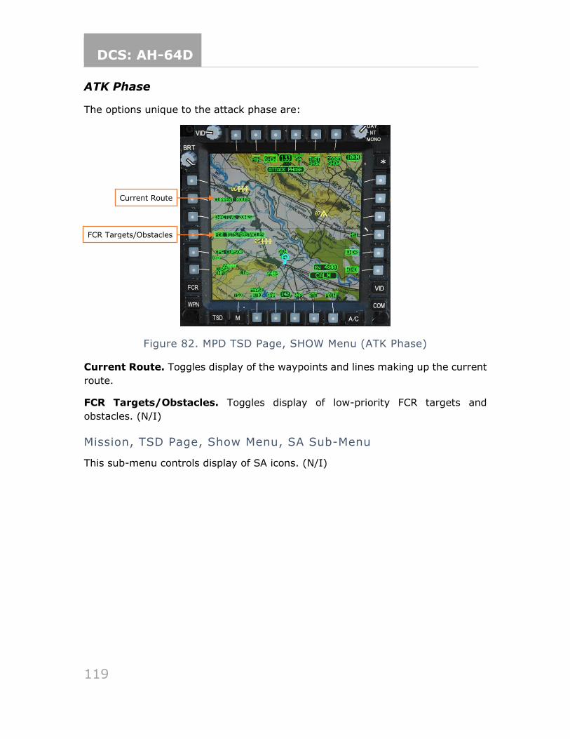
DCS: AH-64D
119
ATK Phase
The options unique to the attack phase are:
Figure 82. MPD TSD Page, SHOW Menu (ATK Phase)
Current Route. Toggles display of the waypoints and lines making up the current
route.
FCR Targets/Obstacles. Toggles display of low-priority FCR targets and
obstacles. (N/I)
Mission, TSD Page, Show Menu, SA Sub-Menu
This sub-menu controls display of SA icons. (N/I)
Current Route
FCR Targets/Obstacles
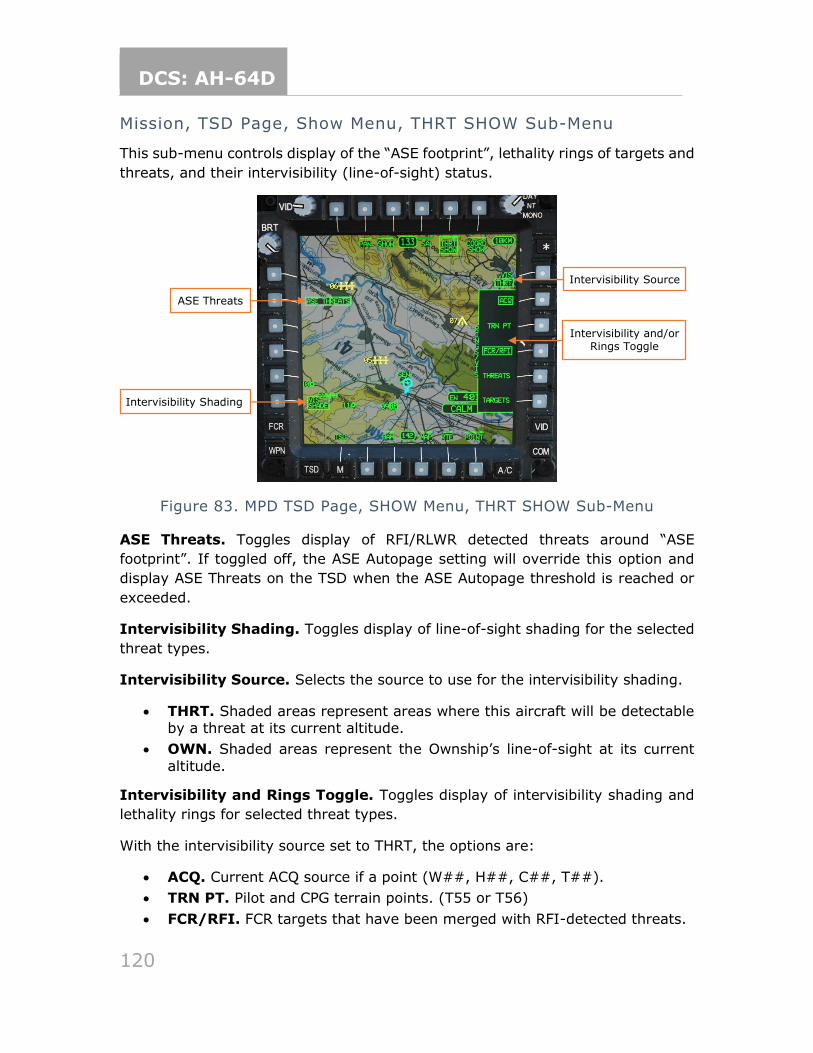
DCS: AH-64D
120
Mission, TSD Page, Show Menu, THRT SHOW Sub-Menu
This sub-menu controls display of the “ASE footprint”, lethality rings of targets and
threats, and their intervisibility (line-of-sight) status.
Figure 83. MPD TSD Page, SHOW Menu, THRT SHOW Sub-Menu
ASE Threats. Toggles display of RFI/RLWR detected threats around “ASE
footprint”. If toggled off, the ASE Autopage setting will override this option and
display ASE Threats on the TSD when the ASE Autopage threshold is reached or
exceeded.
Intervisibility Shading. Toggles display of line-of-sight shading for the selected
threat types.
Intervisibility Source. Selects the source to use for the intervisibility shading.
• THRT. Shaded areas represent areas where this aircraft will be detectable by a threat at its current altitude.
• OWN. Shaded areas represent the Ownship’s line-of-sight at its current
altitude.
Intervisibility and Rings Toggle. Toggles display of intervisibility shading and
lethality rings for selected threat types.
With the intervisibility source set to THRT, the options are:
• ACQ. Current ACQ source if a point (W##, H##, C##, T##).
• TRN PT. Pilot and CPG terrain points. (T55 or T56)
• FCR/RFI. FCR targets that have been merged with RFI-detected threats.
Intervisibility and/or Rings Toggle
ASE Threats
Intervisibility Shading
Intervisibility Source
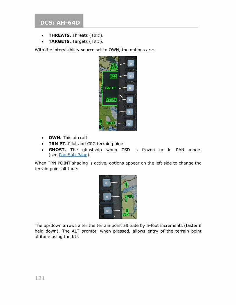
DCS: AH-64D
121
• THREATS. Threats (T##).
• TARGETS. Targets (T##).
With the intervisibility source set to OWN, the options are:
• OWN. This aircraft.
• TRN PT. Pilot and CPG terrain points.
• GHOST. The ghostship when TSD is frozen or in PAN mode.
(see Pan Sub-Page)
When TRN POINT shading is active, options appear on the left side to change the
terrain point altitude:
The up/down arrows alter the terrain point altitude by 5-foot increments (faster if
held down). The ALT prompt, when pressed, allows entry of the terrain point
altitude using the KU.
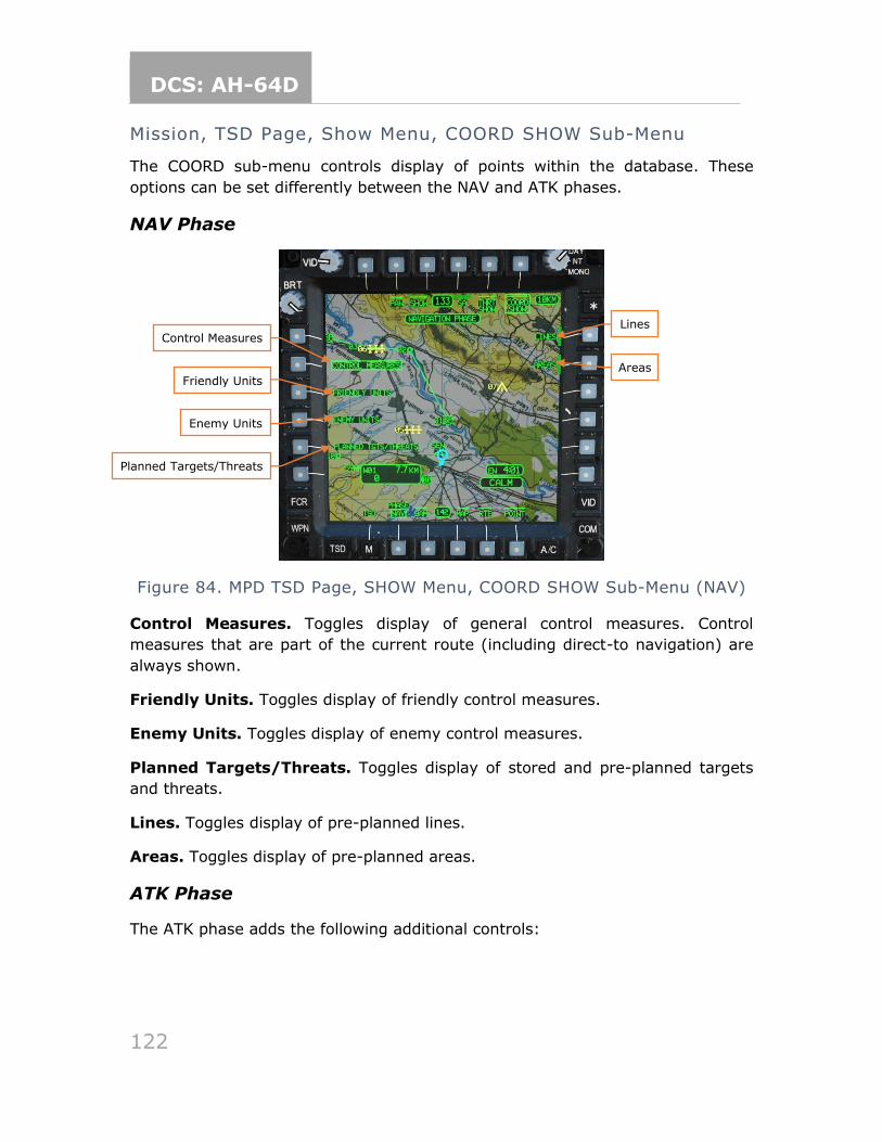
DCS: AH-64D
122
Mission, TSD Page, Show Menu, COORD SHOW Sub-Menu
The COORD sub-menu controls display of points within the database. These
options can be set differently between the NAV and ATK phases.
NAV Phase
Figure 84. MPD TSD Page, SHOW Menu, COORD SHOW Sub-Menu (NAV)
Control Measures. Toggles display of general control measures. Control
measures that are part of the current route (including direct-to navigation) are
always shown.
Friendly Units. Toggles display of friendly control measures.
Enemy Units. Toggles display of enemy control measures.
Planned Targets/Threats. Toggles display of stored and pre-planned targets
and threats.
Lines. Toggles display of pre-planned lines.
Areas. Toggles display of pre-planned areas.
ATK Phase
The ATK phase adds the following additional controls:
Control Measures
Friendly Units
Enemy Units
Planned Targets/Threats
Lines
Areas
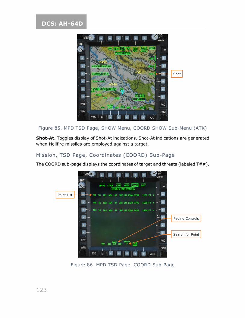
DCS: AH-64D
123
Figure 85. MPD TSD Page, SHOW Menu, COORD SHOW Sub-Menu (ATK)
Shot-At. Toggles display of Shot-At indications. Shot-At indications are generated
when Hellfire missiles are employed against a target.
Mission, TSD Page, Coordinates (COORD) Sub-Page
The COORD sub-page displays the coordinates of target and threats (labeled T##).
Figure 86. MPD TSD Page, COORD Sub-Page
Search for Point
Paging Controls
Shot
Point List
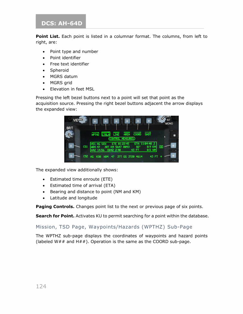
DCS: AH-64D
124
Point List. Each point is listed in a columnar format. The columns, from left to
right, are:
• Point type and number
• Point identifier
• Free text identifier
• Spheroid
• MGRS datum
• MGRS grid
• Elevation in feet MSL
Pressing the left bezel buttons next to a point will set that point as the
acquisition source. Pressing the right bezel buttons adjacent the arrow displays
the expanded view:
The expanded view additionally shows:
• Estimated time enroute (ETE)
• Estimated time of arrival (ETA)
• Bearing and distance to point (NM and KM)
• Latitude and longitude
Paging Controls. Changes point list to the next or previous page of six points.
Search for Point. Activates KU to permit searching for a point within the database.
Mission, TSD Page, Waypoints/Hazards (WPTHZ) Sub-Page
The WPTHZ sub-page displays the coordinates of waypoints and hazard points
(labeled W## and H##). Operation is the same as the COORD sub-page.
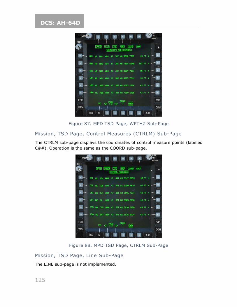
DCS: AH-64D
125
Figure 87. MPD TSD Page, WPTHZ Sub-Page
Mission, TSD Page, Control Measures (CTRLM) Sub-Page
The CTRLM sub-page displays the coordinates of control measure points (labeled
C##). Operation is the same as the COORD sub-page.
Figure 88. MPD TSD Page, CTRLM Sub-Page
Mission, TSD Page, Line Sub-Page
The LINE sub-page is not implemented.
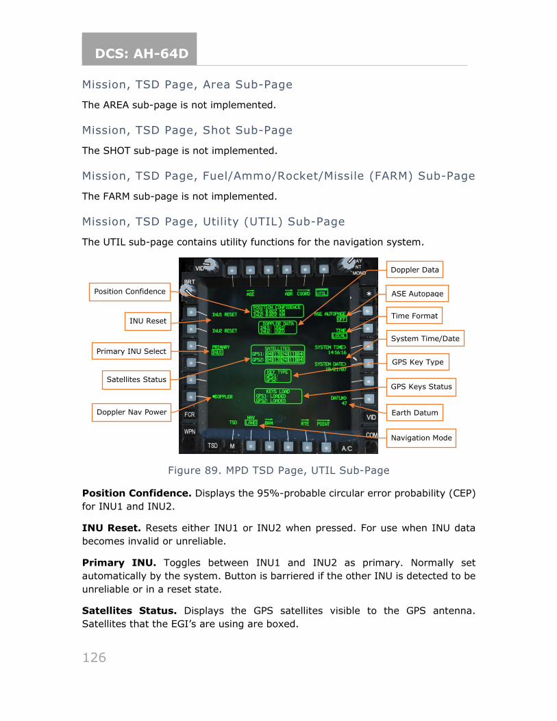
DCS: AH-64D
126
Mission, TSD Page, Area Sub-Page
The AREA sub-page is not implemented.
Mission, TSD Page, Shot Sub-Page
The SHOT sub-page is not implemented.
Mission, TSD Page, Fuel/Ammo/Rocket/Missile (FARM) Sub-Page
The FARM sub-page is not implemented.
Mission, TSD Page, Utility (UTIL) Sub-Page
The UTIL sub-page contains utility functions for the navigation system.
Figure 89. MPD TSD Page, UTIL Sub-Page
Position Confidence. Displays the 95%-probable circular error probability (CEP)
for INU1 and INU2.
INU Reset. Resets either INU1 or INU2 when pressed. For use when INU data
becomes invalid or unreliable.
Primary INU. Toggles between INU1 and INU2 as primary. Normally set
automatically by the system. Button is barriered if the other INU is detected to be
unreliable or in a reset state.
Satellites Status. Displays the GPS satellites visible to the GPS antenna.
Satellites that the EGI’s are using are boxed.
Position Confidence
Doppler Data
INU Reset
GPS Keys Status
Primary INU Select
Satellites Status
GPS Key Type
ASE Autopage
System Time/Date
Time Format
Earth Datum Doppler Nav Power
Navigation Mode
DCS: AH-64D
127
Doppler Nav Power. Toggles power to the Doppler navigation system.
Doppler Data. Displays the Doppler-aiding status of each INU:
• USED. INU is using Doppler-aided navigation.
• REJECTED. INU is not using Doppler-aided navigation.
• MEMORY. Doppler-aided navigation is in dead-reckoning mode.
ASE Autopage. Selects the threat level that will result in an Autopage to the TSD
format:
• SEARCH. ASE will autopage when a search radar is detected.
• ACQUISITION. ASE will autopage when a radar acquisition is detected.
• TRACK. ASE will autopage when a tracking radar is detected.
• OFF. ASE will not autopage.
Time Format. Toggles between LOCAL and UTC (ZULU) time.
System Time. Allows the aircrew to change the system time using the KU.
System Date. Allows the aircrew to change the system date using the KU.
GPS Key Type. Displays the type of GPS keys loaded into each GPS receiver.
• GUV. A Group Unique Variable (GUV) key encryption key has been loaded.
• (blank). A Crypto-Variable Weekly (CVW) key production key has been loaded.
GPS Keys Status. Displays the state of the GPS key load for each receiver:
• LOADED. CVW key was loaded.
• VALID. TODO
• VERIFIED. TODO
• INCORRECT. GPS key is incorrect for current date.
• CORRUPT LOAD. GPS key data is corrupt.
• NONE. No GPS key has been loaded, or the key was erased.
• ERASE FAIL. The GPS key could not be zeroized.
Earth Datum. Allows the aircrew to set the geodetic system used for navigation.
The default is “47”, meaning WGS-84. The aircrew can set another datum by ABR
page ID or enter “D” to return to the default datum.
Navigation Mode. Toggles between LAND and SEA. During start-up, this mode
will control the method of EGI alignment. In flight, this mode changes the
weighting of the Doppler velocity data to provide the best navigational accuracy.
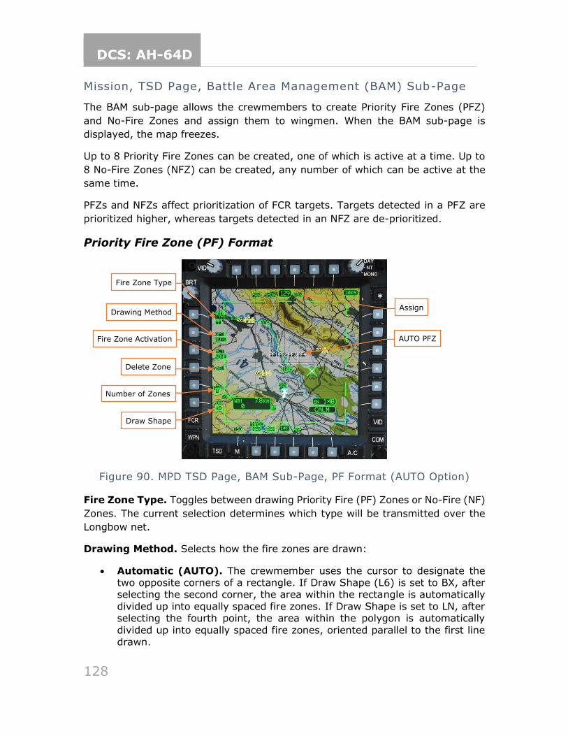
DCS: AH-64D
128
Mission, TSD Page, Battle Area Management (BAM) Sub-Page
The BAM sub-page allows the crewmembers to create Priority Fire Zones (PFZ)
and No-Fire Zones and assign them to wingmen. When the BAM sub-page is
displayed, the map freezes.
Up to 8 Priority Fire Zones can be created, one of which is active at a time. Up to
8 No-Fire Zones (NFZ) can be created, any number of which can be active at the
same time.
PFZs and NFZs affect prioritization of FCR targets. Targets detected in a PFZ are
prioritized higher, whereas targets detected in an NFZ are de-prioritized.
Priority Fire Zone (PF) Format
Figure 90. MPD TSD Page, BAM Sub-Page, PF Format (AUTO Option)
Fire Zone Type. Toggles between drawing Priority Fire (PF) Zones or No-Fire (NF)
Zones. The current selection determines which type will be transmitted over the
Longbow net.
Drawing Method. Selects how the fire zones are drawn:
• Automatic (AUTO). The crewmember uses the cursor to designate the two opposite corners of a rectangle. If Draw Shape (L6) is set to BX, after selecting the second corner, the area within the rectangle is automatically
divided up into equally spaced fire zones. If Draw Shape is set to LN, after selecting the fourth point, the area within the polygon is automatically
divided up into equally spaced fire zones, oriented parallel to the first line drawn.
Fire Zone Type
Assign
Fire Zone Activation
Draw Shape
Number of Zones
Delete Zone
Drawing Method
AUTO PFZ
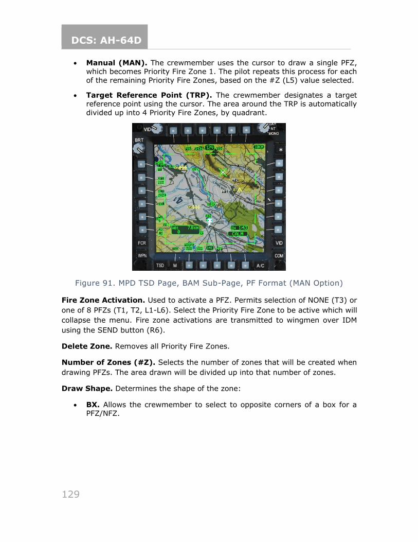
DCS: AH-64D
129
• Manual (MAN). The crewmember uses the cursor to draw a single PFZ, which becomes Priority Fire Zone 1. The pilot repeats this process for each
of the remaining Priority Fire Zones, based on the #Z (L5) value selected.
• Target Reference Point (TRP). The crewmember designates a target reference point using the cursor. The area around the TRP is automatically
divided up into 4 Priority Fire Zones, by quadrant.
Figure 91. MPD TSD Page, BAM Sub-Page, PF Format (MAN Option)
Fire Zone Activation. Used to activate a PFZ. Permits selection of NONE (T3) or
one of 8 PFZs (T1, T2, L1-L6). Select the Priority Fire Zone to be active which will
collapse the menu. Fire zone activations are transmitted to wingmen over IDM
using the SEND button (R6).
Delete Zone. Removes all Priority Fire Zones.
Number of Zones (#Z). Selects the number of zones that will be created when
drawing PFZs. The area drawn will be divided up into that number of zones.
Draw Shape. Determines the shape of the zone:
• BX. Allows the crewmember to select to opposite corners of a box for a PFZ/NFZ.
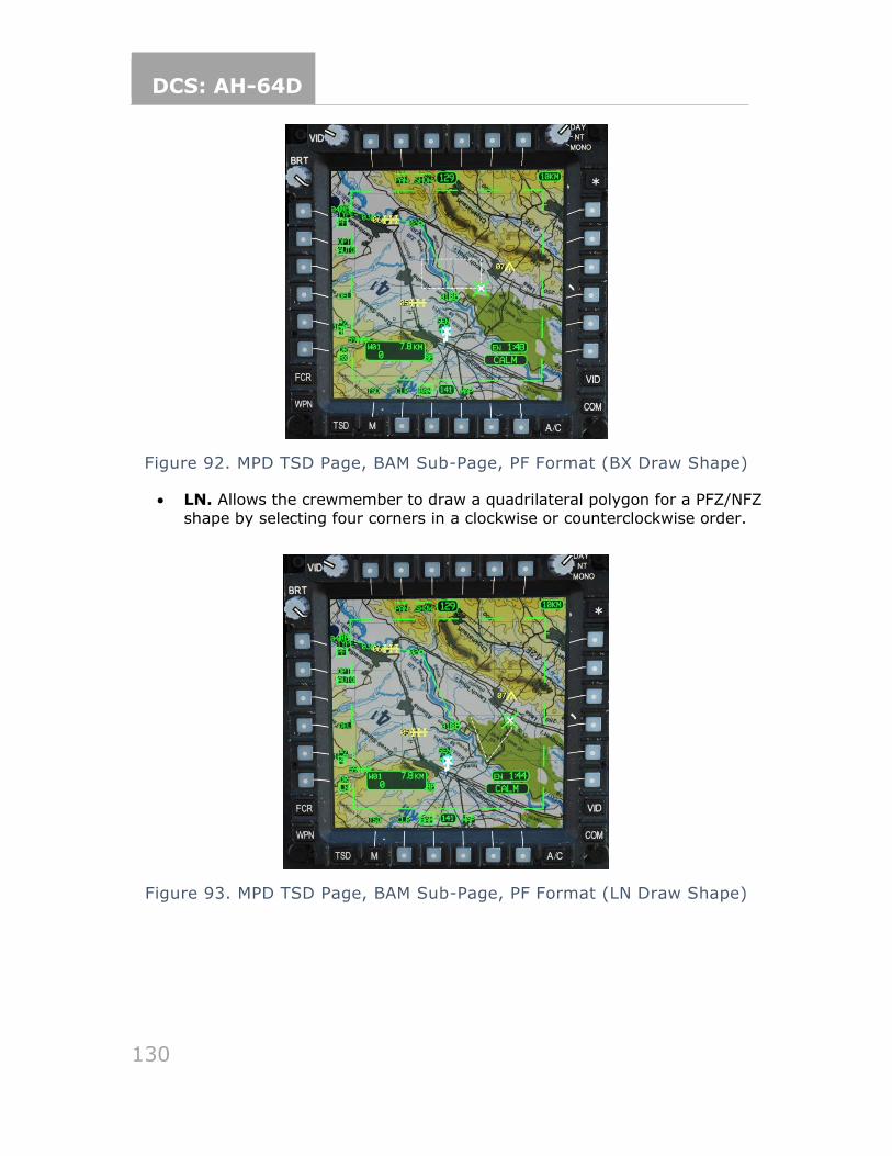
DCS: AH-64D
130
Figure 92. MPD TSD Page, BAM Sub-Page, PF Format (BX Draw Shape)
• LN. Allows the crewmember to draw a quadrilateral polygon for a PFZ/NFZ
shape by selecting four corners in a clockwise or counterclockwise order.
Figure 93. MPD TSD Page, BAM Sub-Page, PF Format (LN Draw Shape)
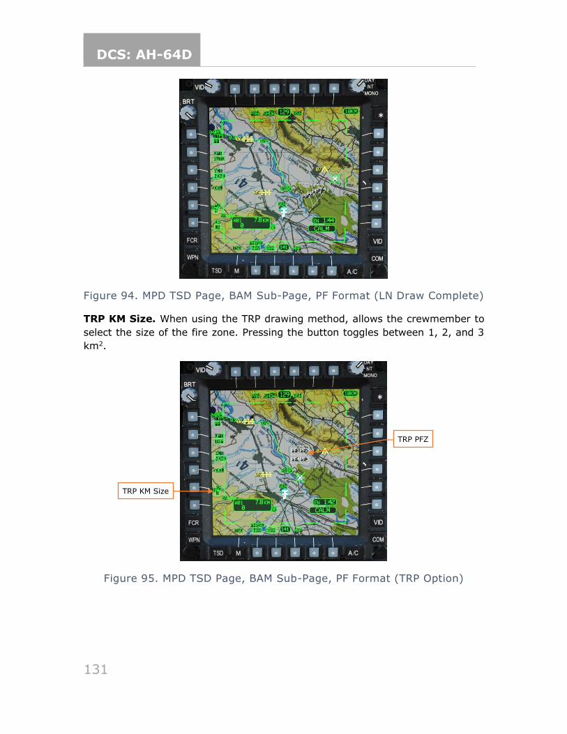
DCS: AH-64D
131
Figure 94. MPD TSD Page, BAM Sub-Page, PF Format (LN Draw Complete)
TRP KM Size. When using the TRP drawing method, allows the crewmember to
select the size of the fire zone. Pressing the button toggles between 1, 2, and 3
km2.
Figure 95. MPD TSD Page, BAM Sub-Page, PF Format (TRP Option)
TRP KM Size
TRP PFZ
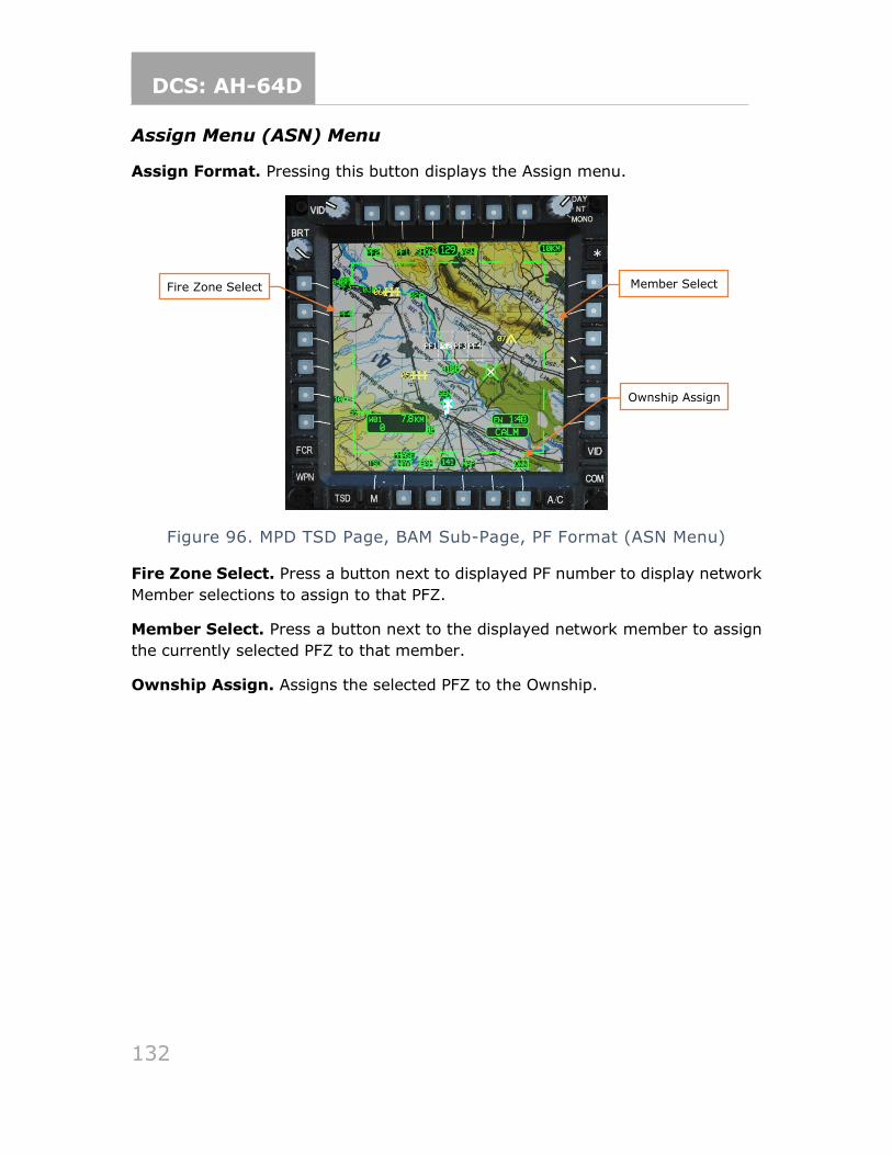
DCS: AH-64D
132
Assign Menu (ASN) Menu
Assign Format. Pressing this button displays the Assign menu.
Figure 96. MPD TSD Page, BAM Sub-Page, PF Format (ASN Menu)
Fire Zone Select. Press a button next to displayed PF number to display network
Member selections to assign to that PFZ.
Member Select. Press a button next to the displayed network member to assign
the currently selected PFZ to that member.
Ownship Assign. Assigns the selected PFZ to the Ownship.
Ownship Assign
Fire Zone Select Member Select
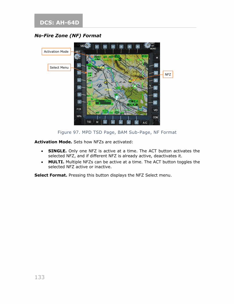
DCS: AH-64D
133
No-Fire Zone (NF) Format
Figure 97. MPD TSD Page, BAM Sub-Page, NF Format
Activation Mode. Sets how NFZs are activated:
• SINGLE. Only one NFZ is active at a time. The ACT button activates the
selected NFZ, and if different NFZ is already active, deactivates it.
• MULTI. Multiple NFZs can be active at a time. The ACT button toggles the selected NFZ active or inactive.
Select Format. Pressing this button displays the NFZ Select menu.
Activation Mode
Select Menu
NFZ
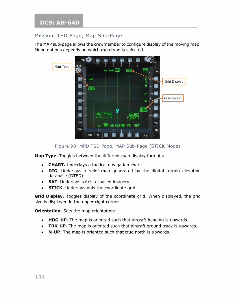
DCS: AH-64D
134
Mission, TSD Page, Map Sub-Page
The MAP sub-page allows the crewmember to configure display of the moving map.
Menu options depends on which map type is selected.
Figure 98. MPD TSD Page, MAP Sub-Page (STICK Mode)
Map Type. Toggles between the different map display formats:
• CHART. Underlays a tactical navigation chart.
• DIG. Underlays a relief map generated by the digital terrain elevation
database (DTED).
• SAT. Underlays satellite-based imagery.
• STICK. Underlays only the coordinate grid.
Grid Display. Toggles display of the coordinate grid. When displayed, the grid
size is displayed in the upper right corner.
Orientation. Sets the map orientation:
• HDG-UP. The map is oriented such that aircraft heading is upwards.
• TRK-UP. The map is oriented such that aircraft ground track is upwards.
• N-UP. The map is oriented such that true north is upwards.
Map Type
Orientation
Grid Display
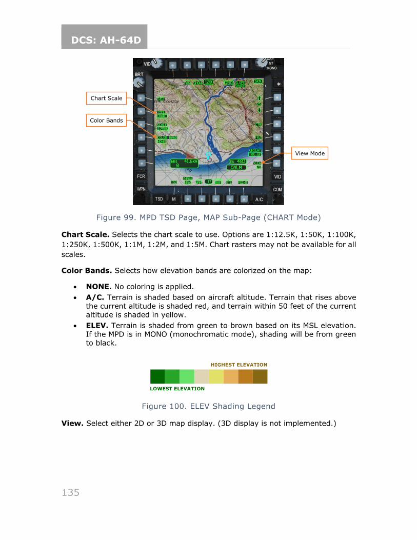
DCS: AH-64D
135
Figure 99. MPD TSD Page, MAP Sub-Page (CHART Mode)
Chart Scale. Selects the chart scale to use. Options are 1:12.5K, 1:50K, 1:100K,
1:250K, 1:500K, 1:1M, 1:2M, and 1:5M. Chart rasters may not be available for all
scales.
Color Bands. Selects how elevation bands are colorized on the map:
• NONE. No coloring is applied.
• A/C. Terrain is shaded based on aircraft altitude. Terrain that rises above
the current altitude is shaded red, and terrain within 50 feet of the current altitude is shaded in yellow.
• ELEV. Terrain is shaded from green to brown based on its MSL elevation.
If the MPD is in MONO (monochromatic mode), shading will be from green to black.
Figure 100. ELEV Shading Legend
View. Select either 2D or 3D map display. (3D display is not implemented.)
LOWEST ELEVATION
HIGHEST ELEVATION
Chart Scale
Color Bands
View Mode
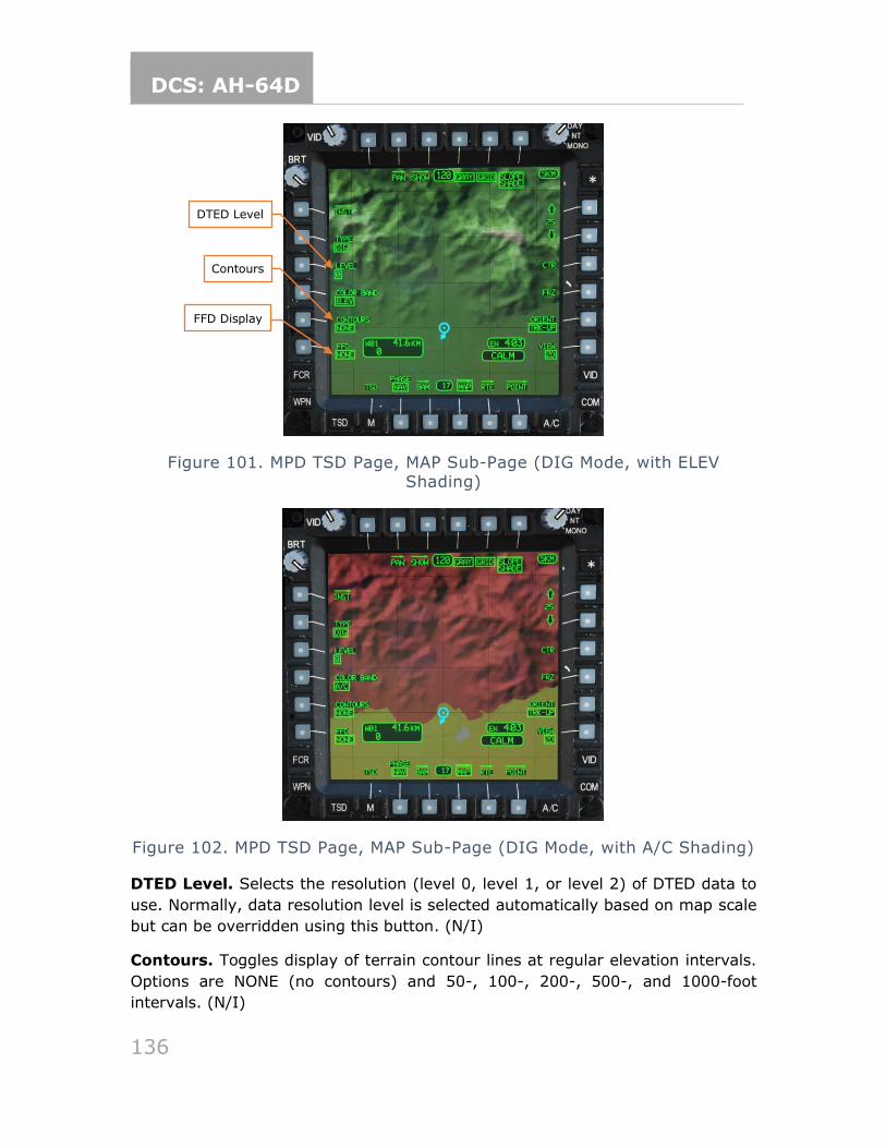
DCS: AH-64D
136
Figure 101. MPD TSD Page, MAP Sub-Page (DIG Mode, with ELEV Shading)
Figure 102. MPD TSD Page, MAP Sub-Page (DIG Mode, with A/C Shading)
DTED Level. Selects the resolution (level 0, level 1, or level 2) of DTED data to
use. Normally, data resolution level is selected automatically based on map scale
but can be overridden using this button. (N/I)
Contours. Toggles display of terrain contour lines at regular elevation intervals.
Options are NONE (no contours) and 50-, 100-, 200-, 500-, and 1000-foot
intervals. (N/I)
DTED Level
Contours
FFD Display
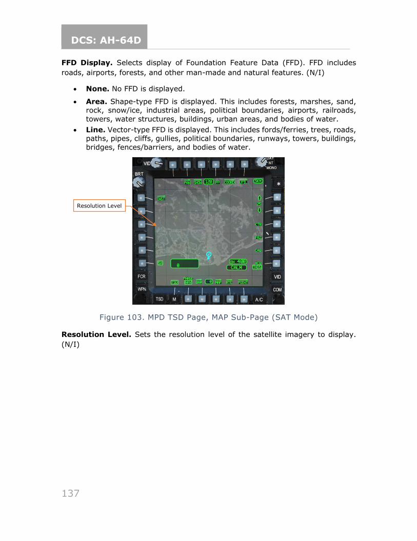
DCS: AH-64D
137
FFD Display. Selects display of Foundation Feature Data (FFD). FFD includes
roads, airports, forests, and other man-made and natural features. (N/I)
• None. No FFD is displayed.
• Area. Shape-type FFD is displayed. This includes forests, marshes, sand, rock, snow/ice, industrial areas, political boundaries, airports, railroads,
towers, water structures, buildings, urban areas, and bodies of water.
• Line. Vector-type FFD is displayed. This includes fords/ferries, trees, roads, paths, pipes, cliffs, gullies, political boundaries, runways, towers, buildings,
bridges, fences/barriers, and bodies of water.
Figure 103. MPD TSD Page, MAP Sub-Page (SAT Mode)
Resolution Level. Sets the resolution level of the satellite imagery to display.
(N/I)
Resolution Level
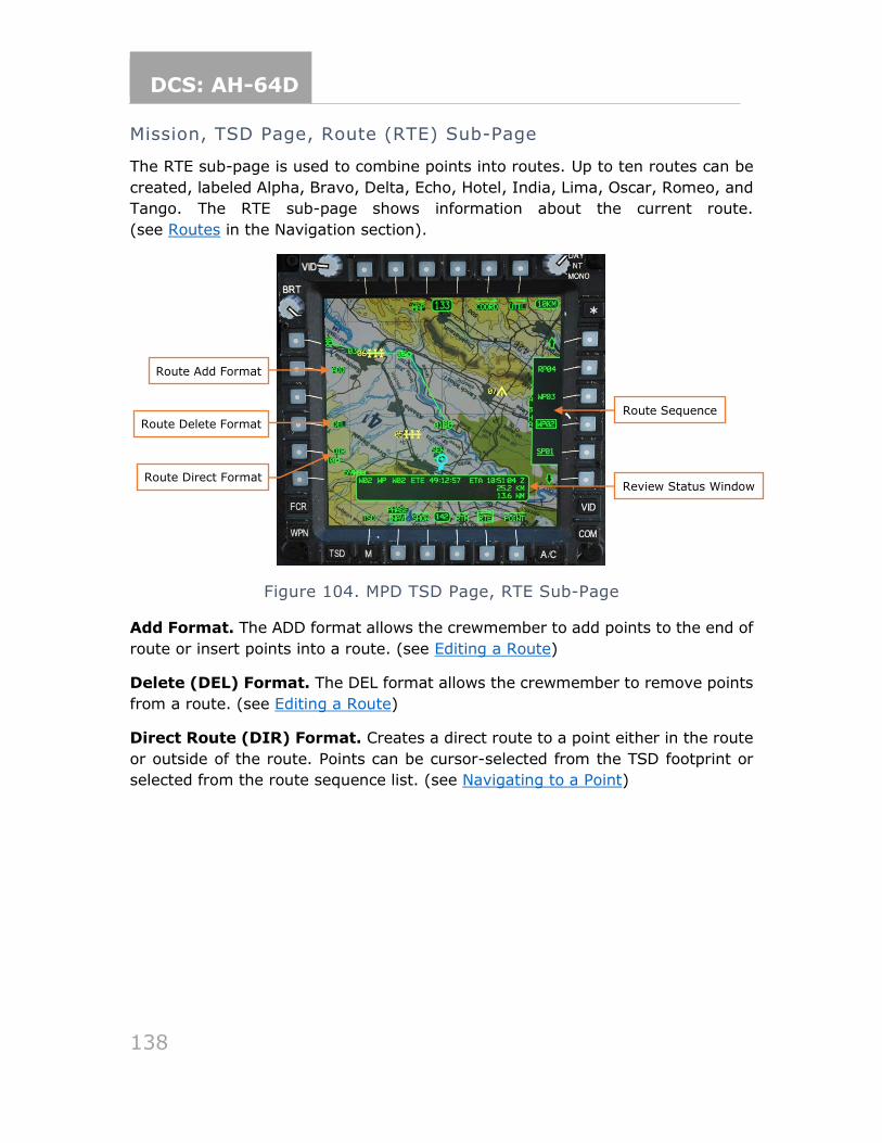
DCS: AH-64D
138
Mission, TSD Page, Route (RTE) Sub-Page
The RTE sub-page is used to combine points into routes. Up to ten routes can be
created, labeled Alpha, Bravo, Delta, Echo, Hotel, India, Lima, Oscar, Romeo, and
Tango. The RTE sub-page shows information about the current route.
(see Routes in the Navigation section).
Figure 104. MPD TSD Page, RTE Sub-Page
Add Format. The ADD format allows the crewmember to add points to the end of
route or insert points into a route. (see Editing a Route)
Delete (DEL) Format. The DEL format allows the crewmember to remove points
from a route. (see Editing a Route)
Direct Route (DIR) Format. Creates a direct route to a point either in the route
or outside of the route. Points can be cursor-selected from the TSD footprint or
selected from the route sequence list. (see Navigating to a Point)
Route Delete Format
Route Direct Format
Route Add Format
Route Sequence
Review Status Window
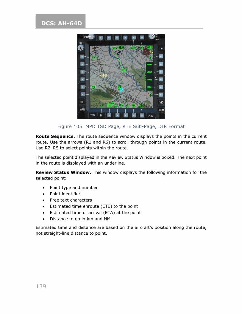
DCS: AH-64D
139
Figure 105. MPD TSD Page, RTE Sub-Page, DIR Format
Route Sequence. The route sequence window displays the points in the current
route. Use the arrows (R1 and R6) to scroll through points in the current route.
Use R2–R5 to select points within the route.
The selected point displayed in the Review Status Window is boxed. The next point
in the route is displayed with an underline.
Review Status Window. This window displays the following information for the
selected point:
• Point type and number
• Point identifier
• Free text characters
• Estimated time enroute (ETE) to the point
• Estimated time of arrival (ETA) at the point
• Distance to go in km and NM
Estimated time and distance are based on the aircraft’s position along the route,
not straight-line distance to point.
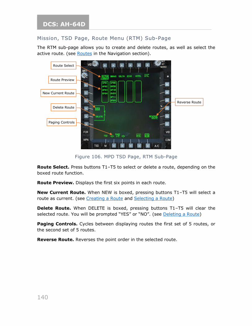
DCS: AH-64D
140
Mission, TSD Page, Route Menu (RTM) Sub-Page
The RTM sub-page allows you to create and delete routes, as well as select the
active route. (see Routes in the Navigation section).
Figure 106. MPD TSD Page, RTM Sub-Page
Route Select. Press buttons T1–T5 to select or delete a route, depending on the
boxed route function.
Route Preview. Displays the first six points in each route.
New Current Route. When NEW is boxed, pressing buttons T1–T5 will select a
route as current. (see Creating a Route and Selecting a Route)
Delete Route. When DELETE is boxed, pressing buttons T1–T5 will clear the
selected route. You will be prompted “YES” or “NO”. (see Deleting a Route)
Paging Controls. Cycles between displaying routes the first set of 5 routes, or
the second set of 5 routes.
Reverse Route. Reverses the point order in the selected route.
Route Select
Reverse Route
Route Preview
Delete Route
Paging Controls
New Current Route
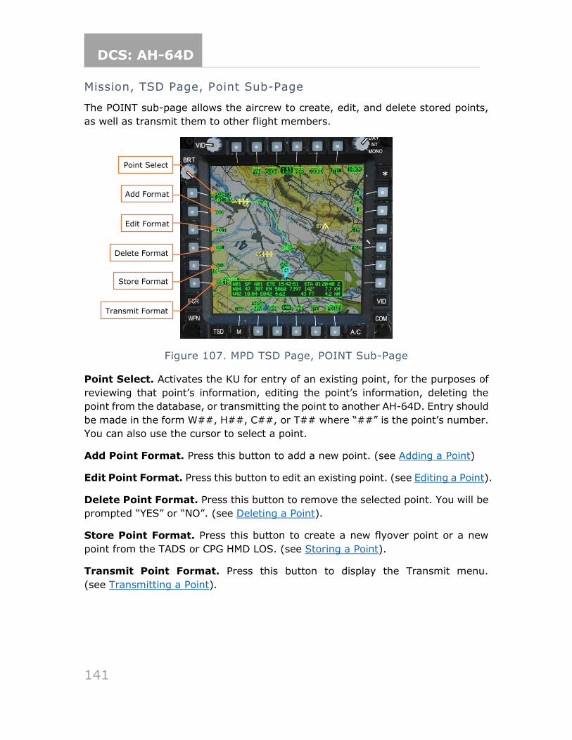
DCS: AH-64D
141
Mission, TSD Page, Point Sub-Page
The POINT sub-page allows the aircrew to create, edit, and delete stored points,
as well as transmit them to other flight members.
Figure 107. MPD TSD Page, POINT Sub-Page
Point Select. Activates the KU for entry of an existing point, for the purposes of
reviewing that point’s information, editing the point’s information, deleting the
point from the database, or transmitting the point to another AH-64D. Entry should
be made in the form W##, H##, C##, or T## where “##” is the point’s number.
You can also use the cursor to select a point.
Add Point Format. Press this button to add a new point. (see Adding a Point)
Edit Point Format. Press this button to edit an existing point. (see Editing a Point).
Delete Point Format. Press this button to remove the selected point. You will be
prompted “YES” or “NO”. (see Deleting a Point).
Store Point Format. Press this button to create a new flyover point or a new
point from the TADS or CPG HMD LOS. (see Storing a Point).
Transmit Point Format. Press this button to display the Transmit menu.
(see Transmitting a Point).
Point Select
Add Format
Edit Format
Delete Format
Store Format
Transmit Format
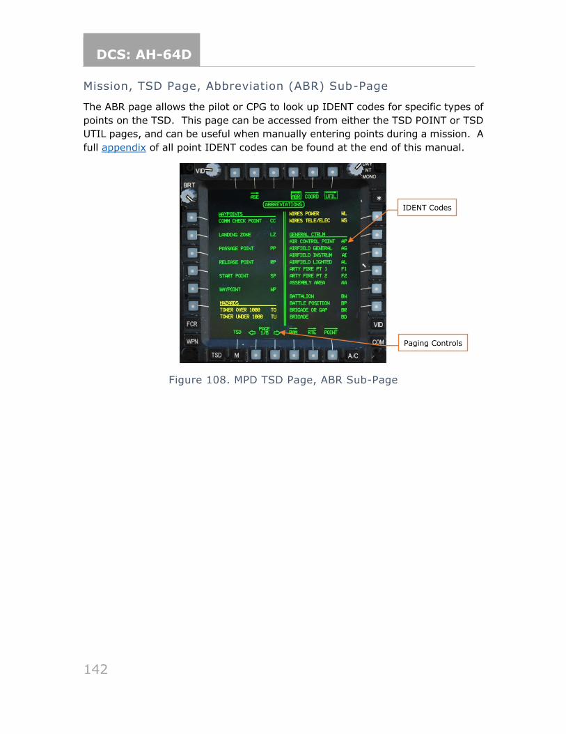
DCS: AH-64D
142
Mission, TSD Page, Abbreviation (ABR) Sub-Page
The ABR page allows the pilot or CPG to look up IDENT codes for specific types of
points on the TSD. This page can be accessed from either the TSD POINT or TSD
UTIL pages, and can be useful when manually entering points during a mission. A
full appendix of all point IDENT codes can be found at the end of this manual.
Figure 108. MPD TSD Page, ABR Sub-Page
IDENT Codes
Paging Controls
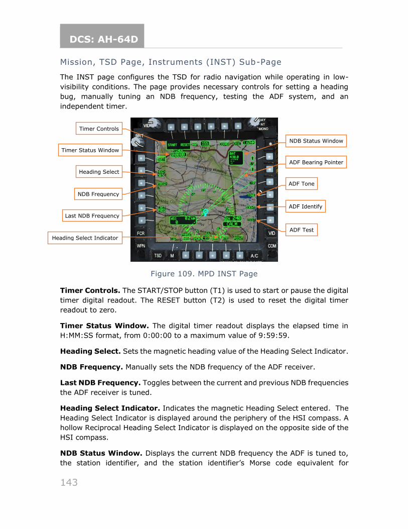
DCS: AH-64D
143
Mission, TSD Page, Instruments (INST) Sub-Page
The INST page configures the TSD for radio navigation while operating in low-
visibility conditions. The page provides necessary controls for setting a heading
bug, manually tuning an NDB frequency, testing the ADF system, and an
independent timer.
Figure 109. MPD INST Page
Timer Controls. The START/STOP button (T1) is used to start or pause the digital
timer digital readout. The RESET button (T2) is used to reset the digital timer
readout to zero.
Timer Status Window. The digital timer readout displays the elapsed time in
H:MM:SS format, from 0:00:00 to a maximum value of 9:59:59.
Heading Select. Sets the magnetic heading value of the Heading Select Indicator.
NDB Frequency. Manually sets the NDB frequency of the ADF receiver.
Last NDB Frequency. Toggles between the current and previous NDB frequencies
the ADF receiver is tuned.
Heading Select Indicator. Indicates the magnetic Heading Select entered. The
Heading Select Indicator is displayed around the periphery of the HSI compass. A
hollow Reciprocal Heading Select Indicator is displayed on the opposite side of the
HSI compass.
NDB Status Window. Displays the current NDB frequency the ADF is tuned to,
the station identifier, and the station identifier’s Morse code equivalent for
Timer Controls
NDB Status Window
Timer Status Window
Heading Select
NDB Frequency
Last NDB Frequency
ADF Bearing Pointer
ADF Tone
ADF Test
ADF Identify
Heading Select Indicator
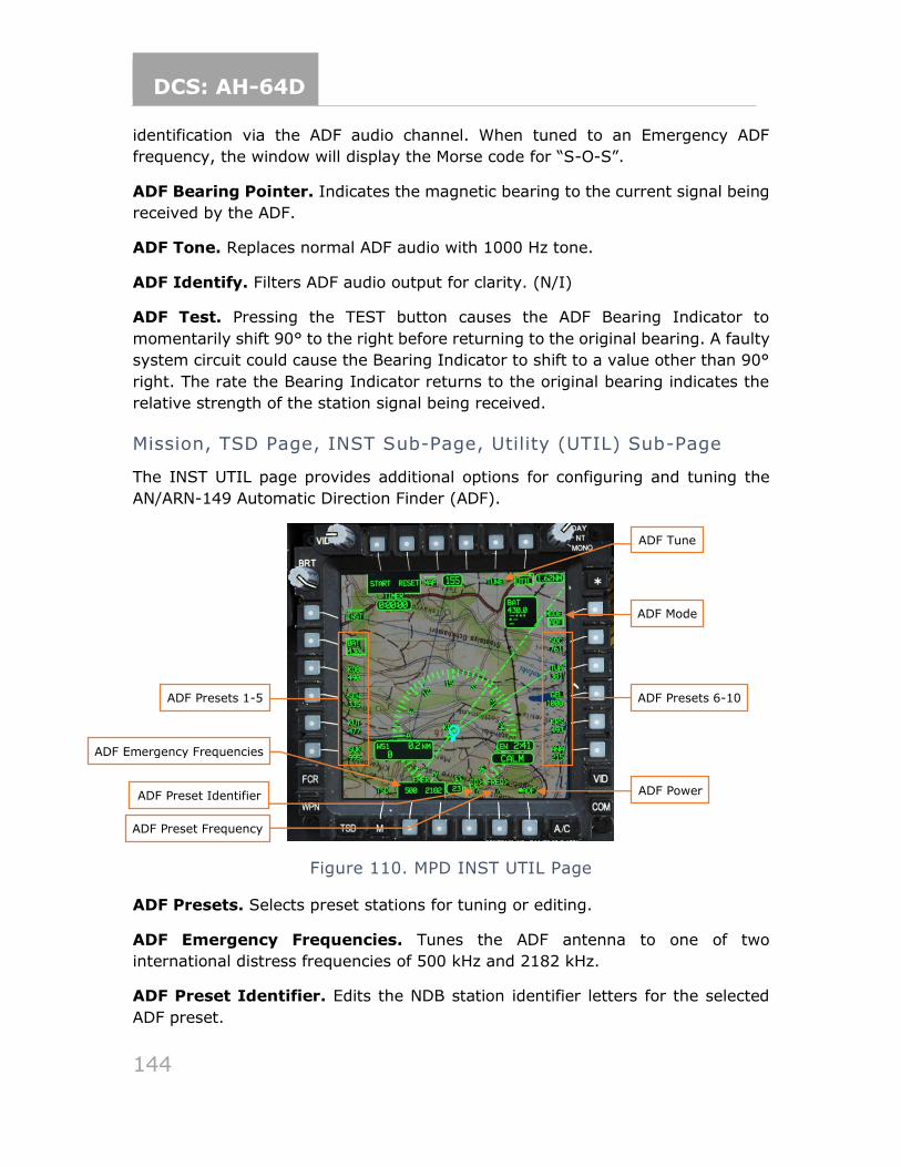
DCS: AH-64D
144
identification via the ADF audio channel. When tuned to an Emergency ADF
frequency, the window will display the Morse code for “S-O-S”.
ADF Bearing Pointer. Indicates the magnetic bearing to the current signal being
received by the ADF.
ADF Tone. Replaces normal ADF audio with 1000 Hz tone.
ADF Identify. Filters ADF audio output for clarity. (N/I)
ADF Test. Pressing the TEST button causes the ADF Bearing Indicator to
momentarily shift 90° to the right before returning to the original bearing. A faulty
system circuit could cause the Bearing Indicator to shift to a value other than 90°
right. The rate the Bearing Indicator returns to the original bearing indicates the
relative strength of the station signal being received.
Mission, TSD Page, INST Sub-Page, Utility (UTIL) Sub-Page
The INST UTIL page provides additional options for configuring and tuning the
AN/ARN-149 Automatic Direction Finder (ADF).
Figure 110. MPD INST UTIL Page
ADF Presets. Selects preset stations for tuning or editing.
ADF Emergency Frequencies. Tunes the ADF antenna to one of two
international distress frequencies of 500 kHz and 2182 kHz.
ADF Preset Identifier. Edits the NDB station identifier letters for the selected
ADF preset.
ADF Emergency Frequencies
ADF Tune
ADF Mode
ADF Power
ADF Presets 1-5
ADF Preset Identifier
ADF Preset Frequency
ADF Presets 6-10
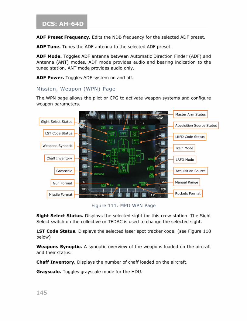
DCS: AH-64D
145
ADF Preset Frequency. Edits the NDB frequency for the selected ADF preset.
ADF Tune. Tunes the ADF antenna to the selected ADF preset.
ADF Mode. Toggles ADF antenna between Automatic Direction Finder (ADF) and
Antenna (ANT) modes. ADF mode provides audio and bearing indication to the
tuned station. ANT mode provides audio only.
ADF Power. Toggles ADF system on and off.
Mission, Weapon (WPN) Page
The WPN page allows the pilot or CPG to activate weapon systems and configure
weapon parameters.
Figure 111. MPD WPN Page
Sight Select Status. Displays the selected sight for this crew station. The Sight
Select switch on the collective or TEDAC is used to change the selected sight.
LST Code Status. Displays the selected laser spot tracker code. (see Figure 118
below)
Weapons Synoptic. A synoptic overview of the weapons loaded on the aircraft
and their status.
Chaff Inventory. Displays the number of chaff loaded on the aircraft.
Grayscale. Toggles grayscale mode for the HDU.
Sight Select Status
Master Arm Status
LST Code Status
Weapons Synoptic
Grayscale
Gun Format
Missile Format
Acquisition Source Status
LRFD Code Status
LRFD Mode
Acquisition Source
Manual Range
Rockets Format
Chaff Inventory
Train Mode
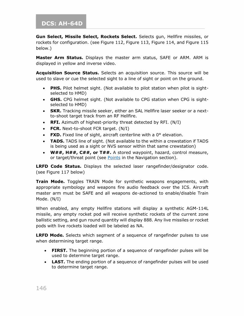
DCS: AH-64D
146
Gun Select, Missile Select, Rockets Select. Selects gun, Hellfire missiles, or
rockets for configuration. (see Figure 112, Figure 113, Figure 114, and Figure 115
below.)
Master Arm Status. Displays the master arm status, SAFE or ARM. ARM is
displayed in yellow and inverse video.
Acquisition Source Status. Selects an acquisition source. This source will be
used to slave or cue the selected sight to a line of sight or point on the ground.
• PHS. Pilot helmet sight. (Not available to pilot station when pilot is sight-selected to HMD)
• GHS. CPG helmet sight. (Not available to CPG station when CPG is sight-
selected to HMD)
• SKR. Tracking missile seeker, either an SAL Hellfire laser seeker or a next-to-shoot target track from an RF Hellfire.
• RFI. Azimuth of highest-priority threat detected by RFI. (N/I)
• FCR. Next-to-shoot FCR target. (N/I)
• FXD. Fixed line of sight, aircraft centerline with a 0° elevation.
• TADS. TADS line of sight. (Not available to the within a crewstation if TADS is being used as a sight or NVS sensor within that same crewstation)
• W##, H##, C##, or T##. A stored waypoint, hazard, control measure,
or target/threat point (see Points in the Navigation section).
LRFD Code Status. Displays the selected laser rangefinder/designator code.
(see Figure 117 below)
Train Mode. Toggles TRAIN Mode for synthetic weapons engagements, with
appropriate symbology and weapons fire audio feedback over the ICS. Aircraft
master arm must be SAFE and all weapons de-actioned to enable/disable Train
Mode. (N/I)
When enabled, any empty Hellfire stations will display a synthetic AGM-114L
missile, any empty rocket pod will receive synthetic rockets of the current zone
ballistic setting, and gun round quantity will display 888. Any live missiles or rocket
pods with live rockets loaded will be labeled as NA.
LRFD Mode. Selects which segment of a sequence of rangefinder pulses to use
when determining target range.
• FIRST. The beginning portion of a sequence of rangefinder pulses will be used to determine target range.
• LAST. The ending portion of a sequence of rangefinder pulses will be used to determine target range.
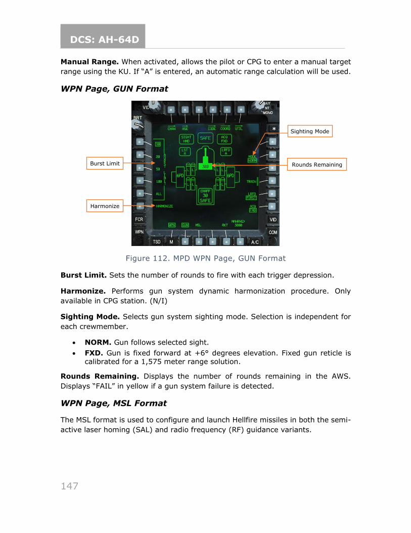
DCS: AH-64D
147
Manual Range. When activated, allows the pilot or CPG to enter a manual target
range using the KU. If “A” is entered, an automatic range calculation will be used.
WPN Page, GUN Format
Figure 112. MPD WPN Page, GUN Format
Burst Limit. Sets the number of rounds to fire with each trigger depression.
Harmonize. Performs gun system dynamic harmonization procedure. Only
available in CPG station. (N/I)
Sighting Mode. Selects gun system sighting mode. Selection is independent for
each crewmember.
• NORM. Gun follows selected sight.
• FXD. Gun is fixed forward at +6° degrees elevation. Fixed gun reticle is calibrated for a 1,575 meter range solution.
Rounds Remaining. Displays the number of rounds remaining in the AWS.
Displays “FAIL” in yellow if a gun system failure is detected.
WPN Page, MSL Format
The MSL format is used to configure and launch Hellfire missiles in both the semi-
active laser homing (SAL) and radio frequency (RF) guidance variants.
Sighting Mode
Harmonize
Burst Limit Rounds Remaining
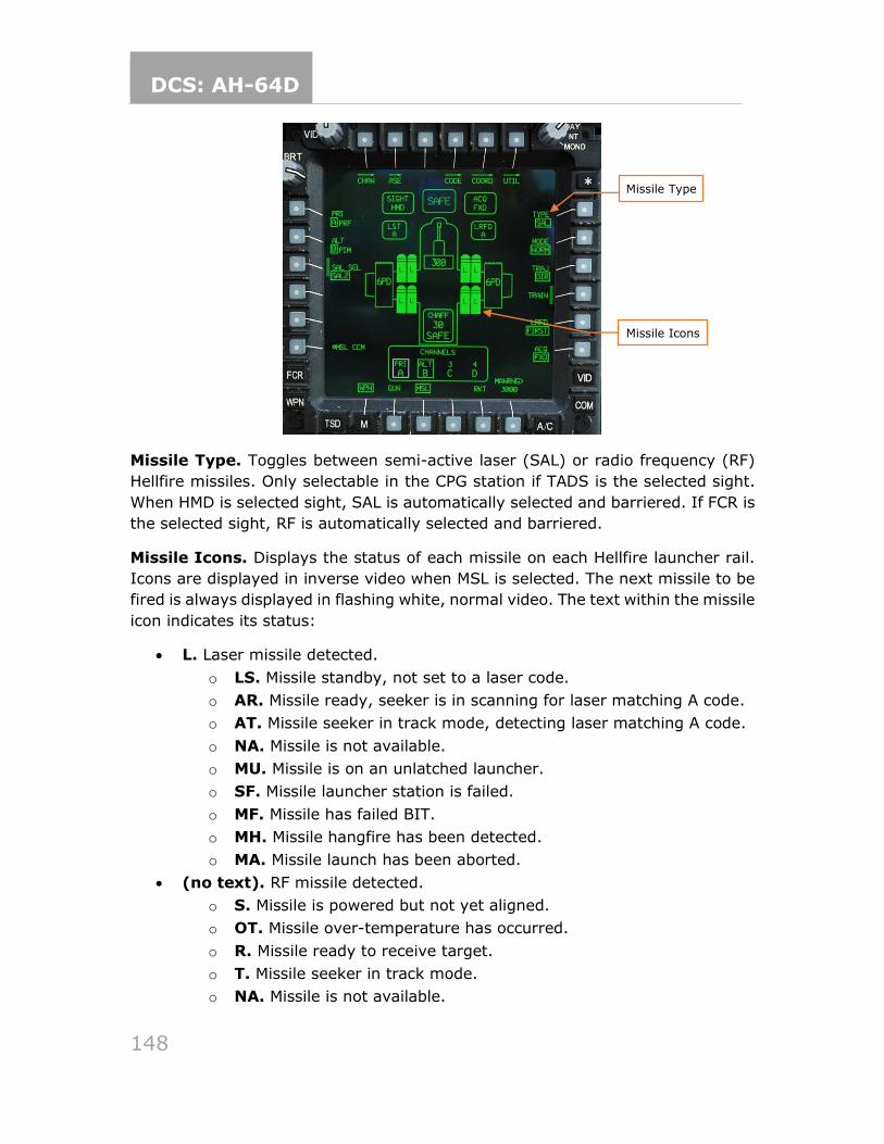
DCS: AH-64D
148
Missile Type. Toggles between semi-active laser (SAL) or radio frequency (RF)
Hellfire missiles. Only selectable in the CPG station if TADS is the selected sight.
When HMD is selected sight, SAL is automatically selected and barriered. If FCR is
the selected sight, RF is automatically selected and barriered.
Missile Icons. Displays the status of each missile on each Hellfire launcher rail.
Icons are displayed in inverse video when MSL is selected. The next missile to be
fired is always displayed in flashing white, normal video. The text within the missile
icon indicates its status:
• L. Laser missile detected.
o LS. Missile standby, not set to a laser code.
o AR. Missile ready, seeker is in scanning for laser matching A code.
o AT. Missile seeker in track mode, detecting laser matching A code.
o NA. Missile is not available.
o MU. Missile is on an unlatched launcher.
o SF. Missile launcher station is failed.
o MF. Missile has failed BIT.
o MH. Missile hangfire has been detected.
o MA. Missile launch has been aborted.
• (no text). RF missile detected.
o S. Missile is powered but not yet aligned.
o OT. Missile over-temperature has occurred.
o R. Missile ready to receive target.
o T. Missile seeker in track mode.
o NA. Missile is not available.
Missile Type
Missile Icons
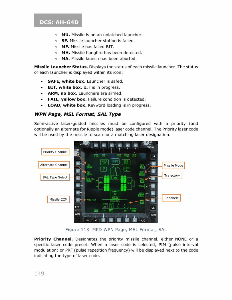
DCS: AH-64D
149
o MU. Missile is on an unlatched launcher.
o SF. Missile launcher station is failed.
o MF. Missile has failed BIT.
o MH. Missile hangfire has been detected.
o MA. Missile launch has been aborted.
Missile Launcher Status. Displays the status of each missile launcher. The status
of each launcher is displayed within its icon:
• SAFE, white box. Launcher is safed.
• BIT, white box. BIT is in progress.
• ARM, no box. Launchers are armed.
• FAIL, yellow box. Failure condition is detected.
• LOAD, white box. Keyword loading is in progress.
WPN Page, MSL Format, SAL Type
Semi-active laser-guided missiles must be configured with a priority (and
optionally an alternate for Ripple mode) laser code channel. The Priority laser code
will be used by the missile to scan for a matching laser designation.
Figure 113. MPD WPN Page, MSL Format, SAL
Priority Channel. Designates the priority missile channel, either NONE or a
specific laser code preset. When a laser code is selected, PIM (pulse interval
modulation) or PRF (pulse repetition frequency) will be displayed next to the code
indicating the type of laser code.
Priority Channel
Alternate Channel
SAL Type Select
Missile CCM
Trajectory
Channels
Missile Mode
DCS: AH-64D
150
Alternate Channel. Designates the alternate missile channel, either NONE or a
specific laser code preset. The alternate missile channel cannot be chosen until a
priority missile channel is chosen.
SAL Type Select. Selects the type of SAL missile to fire.
• SAL 1. Selects Hellfire I missiles for firing. Hellfire I missiles are only
capable of tracking PRF codes.
• SAL 2. Selects Hellfire II missiles for firing. Hellfire II missiles can track both PRF and PIM codes.
• AUTO. Automatically selects Hellfire I or II missiles. If a PIM code is set, only Hellfire II missiles will be selected. If a PRF code is set, Hellfire II
missiles will be prioritized over Hellfire I missiles.
SAL Seeker Deice. Manually deices the missile seeker head in preparation for
launch. Jettisons the missile’s deice cover. (N/I)
Missile CCM. Enables SAL missile counter-countermeasures. (N/I)
Missile Mode. Selects which laser channel will be used for multiple launches, and
how missiles are managed.
• NORM. All selected missiles will be guided using the priority laser channel.
• RIPL. Selected missiles will be guided alternately between the priority and
alternate laser channel for each successive launch.
• MAN. A single missile will be launched and guided using the priority laser channel. The Manual Advance button on the collective or TEDAC must be
used to ready the next missile between launches.
Trajectory. Selects the post-launch LOAL missile trajectory.
• DIR. Missile will fly directly to the target with minimal loft. Requires aircraft
to have direct line-of-sight to the target free of obstacles.
• LO. Missile will fly a low-altitude loft to the target.
• HI. Missile will fly a high-altitude loft to the target.
Channels. Displays which laser codes have been assigned to which missile
channels. (see Missile Channel Sub-page)
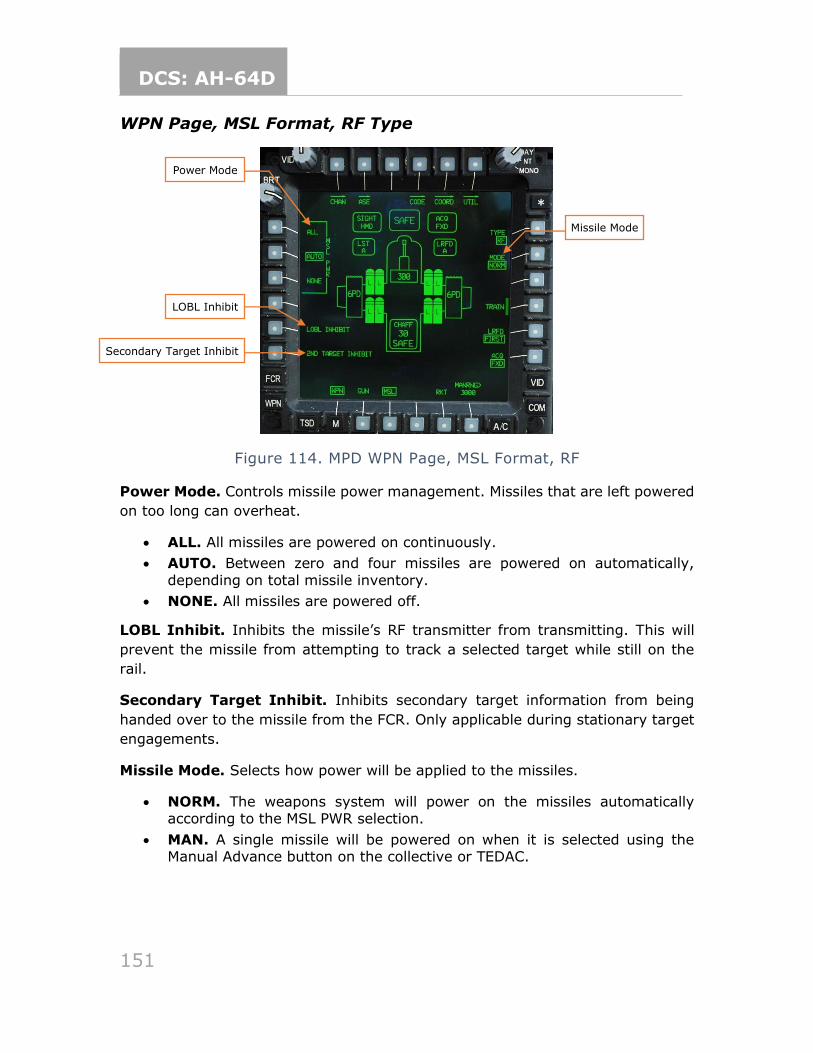
DCS: AH-64D
151
WPN Page, MSL Format, RF Type
Figure 114. MPD WPN Page, MSL Format, RF
Power Mode. Controls missile power management. Missiles that are left powered
on too long can overheat.
• ALL. All missiles are powered on continuously.
• AUTO. Between zero and four missiles are powered on automatically,
depending on total missile inventory.
• NONE. All missiles are powered off.
LOBL Inhibit. Inhibits the missile’s RF transmitter from transmitting. This will
prevent the missile from attempting to track a selected target while still on the
rail.
Secondary Target Inhibit. Inhibits secondary target information from being
handed over to the missile from the FCR. Only applicable during stationary target
engagements.
Missile Mode. Selects how power will be applied to the missiles.
• NORM. The weapons system will power on the missiles automatically according to the MSL PWR selection.
• MAN. A single missile will be powered on when it is selected using the Manual Advance button on the collective or TEDAC.
Power Mode
LOBL Inhibit
Secondary Target Inhibit
Missile Mode
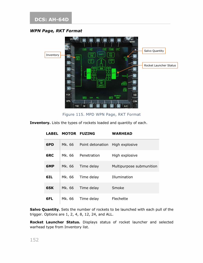
DCS: AH-64D
152
WPN Page, RKT Format
Figure 115. MPD WPN Page, RKT Format
Inventory. Lists the types of rockets loaded and quantity of each.
LABEL MOTOR FUZING WARHEAD
6PD Mk. 66 Point detonation High explosive
6RC Mk. 66 Penetration High explosive
6MP Mk. 66 Time delay Multipurpose submunition
6IL Mk. 66 Time delay Illumination
6SK Mk. 66 Time delay Smoke
6FL Mk. 66 Time delay Flechette
Salvo Quantity. Sets the number of rockets to be launched with each pull of the
trigger. Options are 1, 2, 4, 8, 12, 24, and ALL.
Rocket Launcher Status. Displays status of rocket launcher and selected
warhead type from Inventory list.
Inventory
Rocket Launcher Status
Salvo Quantity
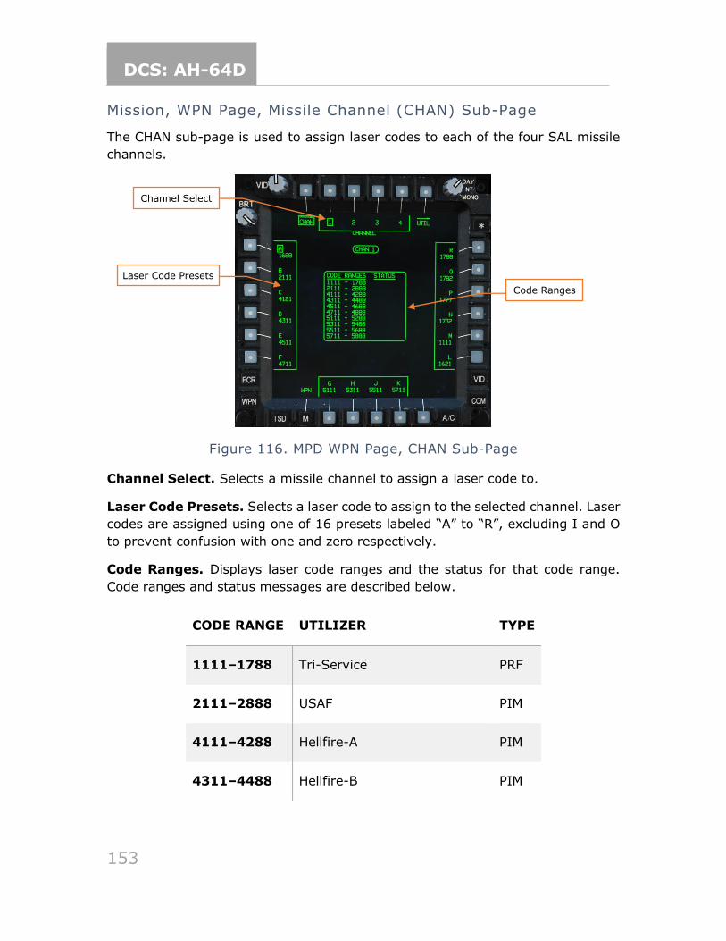
DCS: AH-64D
153
Mission, WPN Page, Missile Channel (CHAN) Sub-Page
The CHAN sub-page is used to assign laser codes to each of the four SAL missile
channels.
Figure 116. MPD WPN Page, CHAN Sub-Page
Channel Select. Selects a missile channel to assign a laser code to.
Laser Code Presets. Selects a laser code to assign to the selected channel. Laser
codes are assigned using one of 16 presets labeled “A” to “R”, excluding I and O
to prevent confusion with one and zero respectively.
Code Ranges. Displays laser code ranges and the status for that code range.
Code ranges and status messages are described below.
CODE RANGE UTILIZER TYPE
1111–1788 Tri-Service PRF
2111–2888 USAF PIM
4111–4288 Hellfire-A PIM
4311–4488 Hellfire-B PIM
Laser Code Presets
Channel Select
Code Ranges
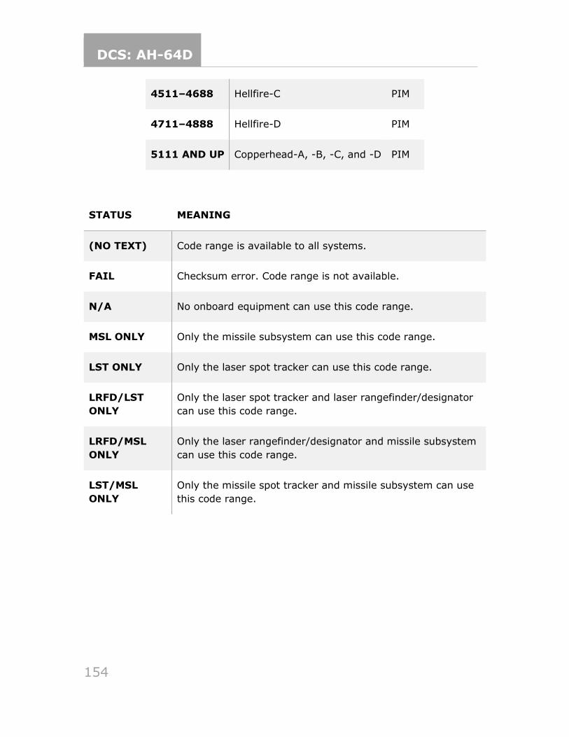
DCS: AH-64D
154
4511–4688 Hellfire-C PIM
4711–4888 Hellfire-D PIM
5111 AND UP Copperhead-A, -B, -C, and -D PIM
STATUS MEANING
(NO TEXT) Code range is available to all systems.
FAIL Checksum error. Code range is not available.
N/A No onboard equipment can use this code range.
MSL ONLY Only the missile subsystem can use this code range.
LST ONLY Only the laser spot tracker can use this code range.
LRFD/LST
ONLY
Only the laser spot tracker and laser rangefinder/designator
can use this code range.
LRFD/MSL
ONLY
Only the laser rangefinder/designator and missile subsystem
can use this code range.
LST/MSL
ONLY
Only the missile spot tracker and missile subsystem can use
this code range.
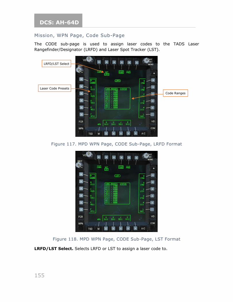
DCS: AH-64D
155
Mission, WPN Page, Code Sub-Page
The CODE sub-page is used to assign laser codes to the TADS Laser
Rangefinder/Designator (LRFD) and Laser Spot Tracker (LST).
Figure 117. MPD WPN Page, CODE Sub-Page, LRFD Format
Figure 118. MPD WPN Page, CODE Sub-Page, LST Format
LRFD/LST Select. Selects LRFD or LST to assign a laser code to.
LRFD/LST Select
Laser Code Presets
Code Ranges
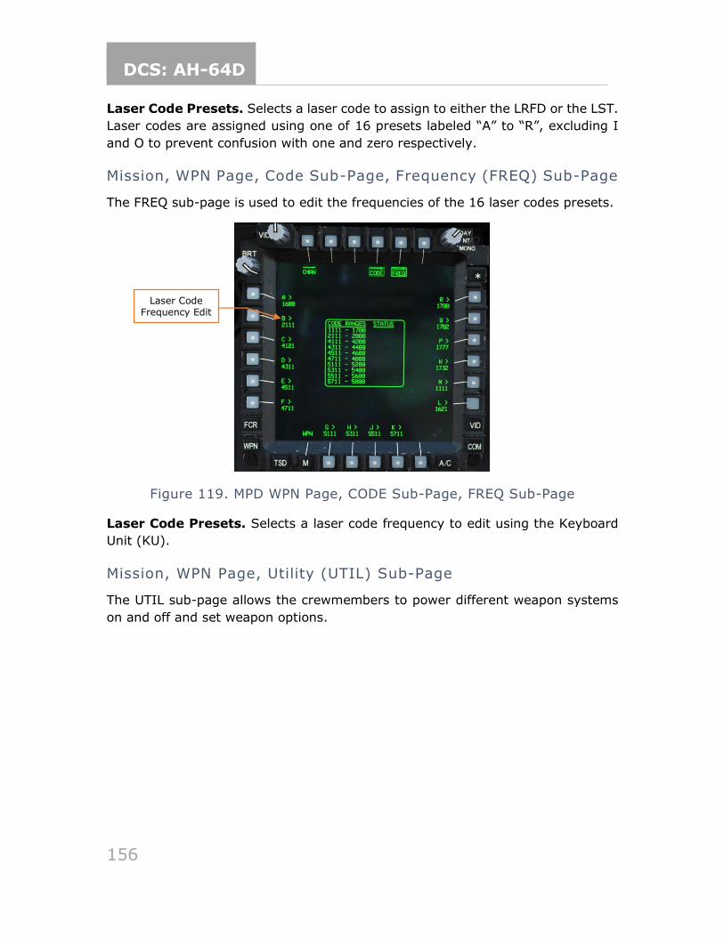
DCS: AH-64D
156
Laser Code Presets. Selects a laser code to assign to either the LRFD or the LST.
Laser codes are assigned using one of 16 presets labeled “A” to “R”, excluding I
and O to prevent confusion with one and zero respectively.
Mission, WPN Page, Code Sub-Page, Frequency (FREQ) Sub-Page
The FREQ sub-page is used to edit the frequencies of the 16 laser codes presets.
Figure 119. MPD WPN Page, CODE Sub-Page, FREQ Sub-Page
Laser Code Presets. Selects a laser code frequency to edit using the Keyboard
Unit (KU).
Mission, WPN Page, Utility (UTIL) Sub-Page
The UTIL sub-page allows the crewmembers to power different weapon systems
on and off and set weapon options.
Laser Code Frequency Edit
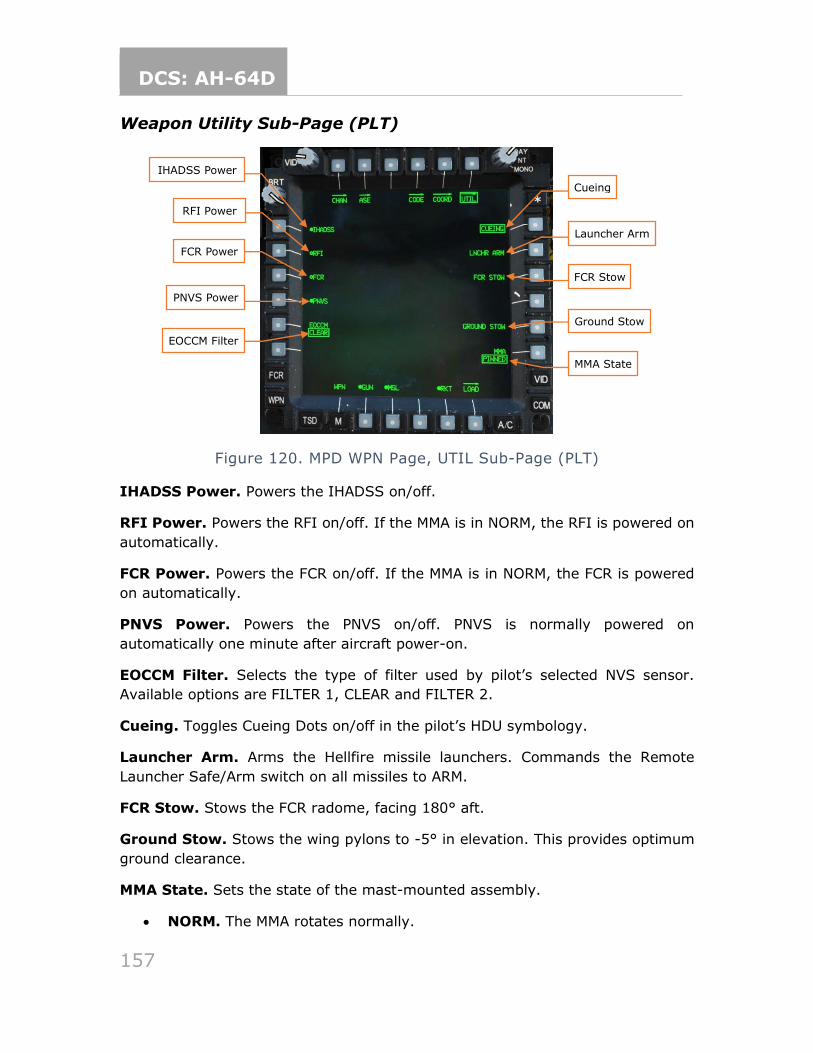
DCS: AH-64D
157
Weapon Utility Sub-Page (PLT)
Figure 120. MPD WPN Page, UTIL Sub-Page (PLT)
IHADSS Power. Powers the IHADSS on/off.
RFI Power. Powers the RFI on/off. If the MMA is in NORM, the RFI is powered on
automatically.
FCR Power. Powers the FCR on/off. If the MMA is in NORM, the FCR is powered
on automatically.
PNVS Power. Powers the PNVS on/off. PNVS is normally powered on
automatically one minute after aircraft power-on.
EOCCM Filter. Selects the type of filter used by pilot’s selected NVS sensor.
Available options are FILTER 1, CLEAR and FILTER 2.
Cueing. Toggles Cueing Dots on/off in the pilot’s HDU symbology.
Launcher Arm. Arms the Hellfire missile launchers. Commands the Remote
Launcher Safe/Arm switch on all missiles to ARM.
FCR Stow. Stows the FCR radome, facing 180° aft.
Ground Stow. Stows the wing pylons to -5° in elevation. This provides optimum
ground clearance.
MMA State. Sets the state of the mast-mounted assembly.
• NORM. The MMA rotates normally.
Cueing
PNVS Power
EOCCM Filter
IHADSS Power
Launcher Arm
RFI Power
FCR Power
FCR Stow
Ground Stow
MMA State
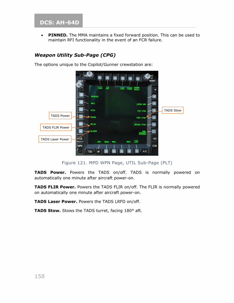
DCS: AH-64D
158
• PINNED. The MMA maintains a fixed forward position. This can be used to maintain RFI functionality in the event of an FCR failure.
Weapon Utility Sub-Page (CPG)
The options unique to the Copilot/Gunner crewstation are:
Figure 121. MPD WPN Page, UTIL Sub-Page (PLT)
TADS Power. Powers the TADS on/off. TADS is normally powered on
automatically one minute after aircraft power-on.
TADS FLIR Power. Powers the TADS FLIR on/off. The FLIR is normally powered
on automatically one minute after aircraft power-on.
TADS Laser Power. Powers the TADS LRFD on/off.
TADS Stow. Stows the TADS turret, facing 180° aft.
TADS Stow
TADS Power
TADS FLIR Power
TADS Laser Power
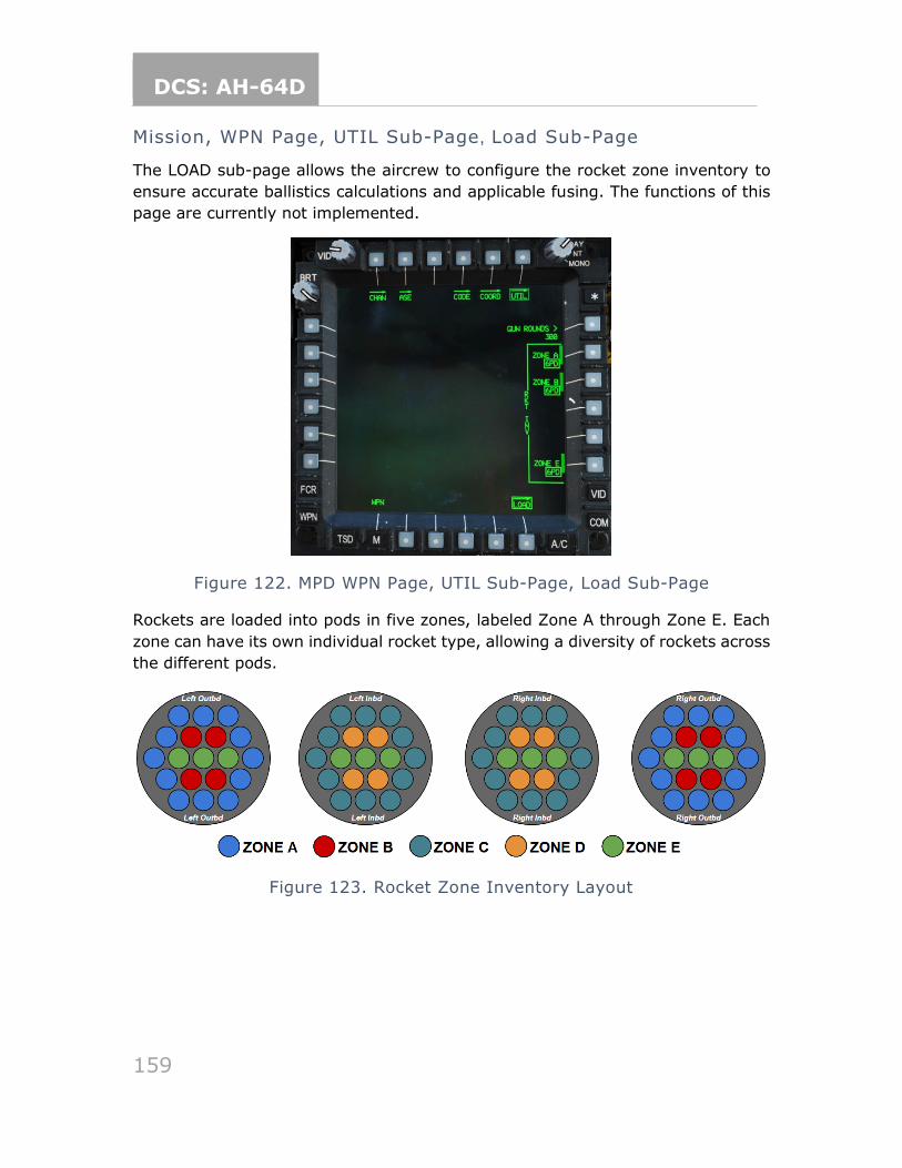
DCS: AH-64D
159
Mission, WPN Page, UTIL Sub-Page, Load Sub-Page
The LOAD sub-page allows the aircrew to configure the rocket zone inventory to
ensure accurate ballistics calculations and applicable fusing. The functions of this
page are currently not implemented.
Figure 122. MPD WPN Page, UTIL Sub-Page, Load Sub-Page
Rockets are loaded into pods in five zones, labeled Zone A through Zone E. Each
zone can have its own individual rocket type, allowing a diversity of rockets across
the different pods.
Figure 123. Rocket Zone Inventory Layout

DCS: AH-64D
160
Mission, Fire Control Radar (FCR) Page
The FCR page is not implemented.
Mission, FCR Page, Utility (UTIL) Sub-Page
The FCR UTIL sub-page is not implemented.
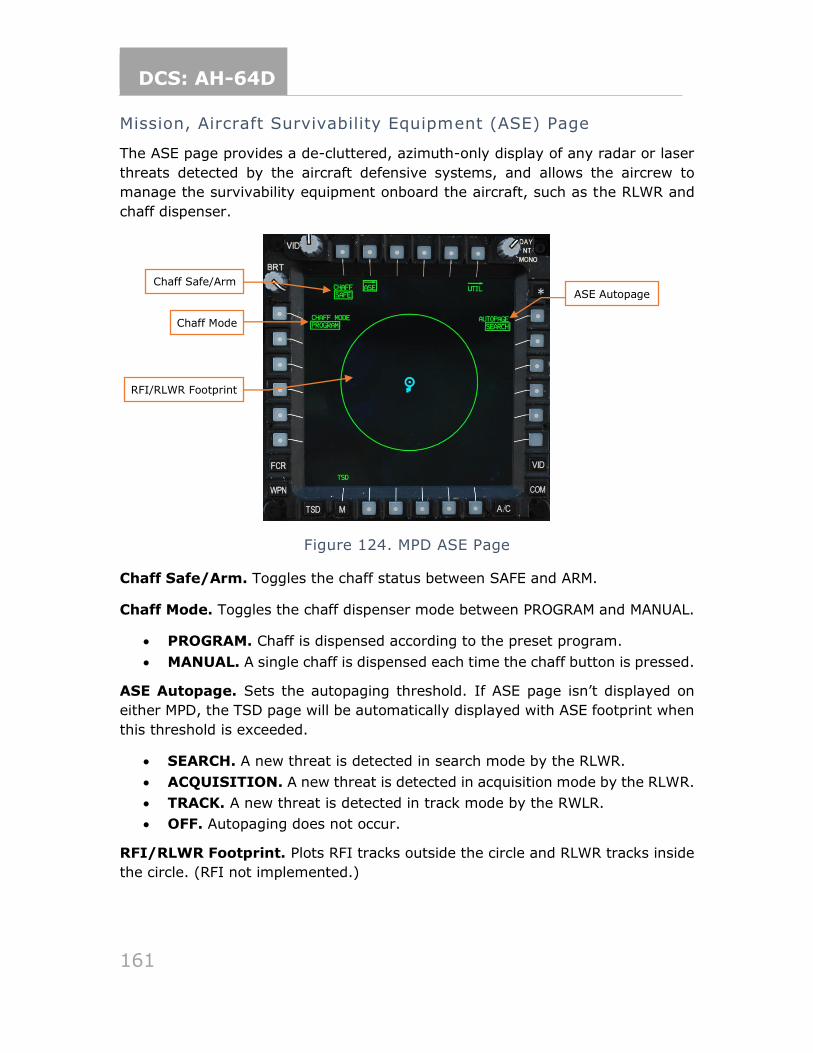
DCS: AH-64D
161
Mission, Aircraft Survivability Equipment (ASE) Page
The ASE page provides a de-cluttered, azimuth-only display of any radar or laser
threats detected by the aircraft defensive systems, and allows the aircrew to
manage the survivability equipment onboard the aircraft, such as the RLWR and
chaff dispenser.
Figure 124. MPD ASE Page
Chaff Safe/Arm. Toggles the chaff status between SAFE and ARM.
Chaff Mode. Toggles the chaff dispenser mode between PROGRAM and MANUAL.
• PROGRAM. Chaff is dispensed according to the preset program.
• MANUAL. A single chaff is dispensed each time the chaff button is pressed.
ASE Autopage. Sets the autopaging threshold. If ASE page isn’t displayed on
either MPD, the TSD page will be automatically displayed with ASE footprint when
this threshold is exceeded.
• SEARCH. A new threat is detected in search mode by the RLWR.
• ACQUISITION. A new threat is detected in acquisition mode by the RLWR.
• TRACK. A new threat is detected in track mode by the RWLR.
• OFF. Autopaging does not occur.
RFI/RLWR Footprint. Plots RFI tracks outside the circle and RLWR tracks inside
the circle. (RFI not implemented.)
Chaff Safe/Arm
Chaff Mode
RFI/RLWR Footprint
ASE Autopage
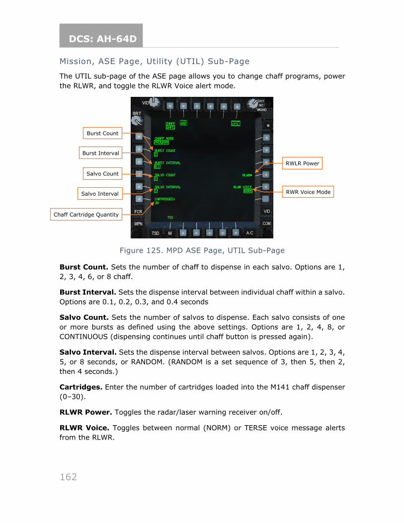
DCS: AH-64D
162
Mission, ASE Page, Utility (UTIL) Sub-Page
The UTIL sub-page of the ASE page allows you to change chaff programs, power
the RLWR, and toggle the RLWR Voice alert mode.
Figure 125. MPD ASE Page, UTIL Sub-Page
Burst Count. Sets the number of chaff to dispense in each salvo. Options are 1,
2, 3, 4, 6, or 8 chaff.
Burst Interval. Sets the dispense interval between individual chaff within a salvo.
Options are 0.1, 0.2, 0.3, and 0.4 seconds
Salvo Count. Sets the number of salvos to dispense. Each salvo consists of one
or more bursts as defined using the above settings. Options are 1, 2, 4, 8, or
CONTINUOUS (dispensing continues until chaff button is pressed again).
Salvo Interval. Sets the dispense interval between salvos. Options are 1, 2, 3, 4,
5, or 8 seconds, or RANDOM. (RANDOM is a set sequence of 3, then 5, then 2,
then 4 seconds.)
Cartridges. Enter the number of cartridges loaded into the M141 chaff dispenser
(0–30).
RLWR Power. Toggles the radar/laser warning receiver on/off.
RLWR Voice. Toggles between normal (NORM) or TERSE voice message alerts
from the RLWR.
RWLR Power
RWR Voice Mode
Chaff Cartridge Quantity
Salvo Interval
Salvo Count
Burst Interval
Burst Count
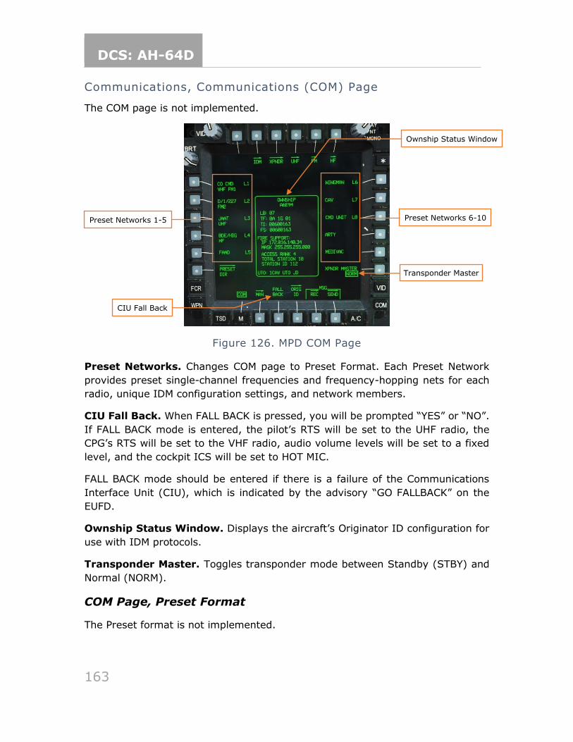
DCS: AH-64D
163
Communications, Communications (COM) Page
The COM page is not implemented.
Figure 126. MPD COM Page
Preset Networks. Changes COM page to Preset Format. Each Preset Network
provides preset single-channel frequencies and frequency-hopping nets for each
radio, unique IDM configuration settings, and network members.
CIU Fall Back. When FALL BACK is pressed, you will be prompted “YES” or “NO”.
If FALL BACK mode is entered, the pilot’s RTS will be set to the UHF radio, the
CPG’s RTS will be set to the VHF radio, audio volume levels will be set to a fixed
level, and the cockpit ICS will be set to HOT MIC.
FALL BACK mode should be entered if there is a failure of the Communications
Interface Unit (CIU), which is indicated by the advisory “GO FALLBACK” on the
EUFD.
Ownship Status Window. Displays the aircraft’s Originator ID configuration for
use with IDM protocols.
Transponder Master. Toggles transponder mode between Standby (STBY) and
Normal (NORM).
COM Page, Preset Format
The Preset format is not implemented.
Preset Networks 1-5
CIU Fall Back
Preset Networks 6-10
Transponder Master
Ownship Status Window
DCS: AH-64D
164
COM Page, Preset Tune Format
The Preset Tune format is not implemented.
Communications, COM Page, Preset Directory (PRESET DIR) Sub-
Page
The PRESET DIR sub-page is not implemented.
Communications, COM Page, Modem Sub-Page
The MODEM sub-page is not implemented.
Communications, COM Page, Net Sub-Page
The NET sub-page is not implemented.
Communications, COM Page, Member Directory (MBR DIR) Sub-
Page
The MBR DIR sub-page is not implemented.
Communications, COM Page, Originator ID (ORIG ID) Sub-Page
The ORIG ID sub-page is not implemented.
Communications, COM Page, Originator Directory (ORIG DIR)
Sub-Page
The ORIG DIR sub-page is not implemented.
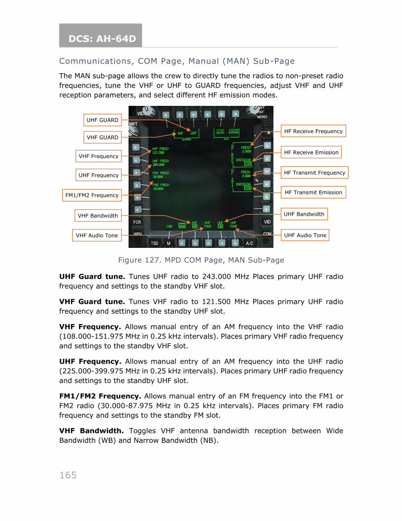
DCS: AH-64D
165
Communications, COM Page, Manual (MAN) Sub-Page
The MAN sub-page allows the crew to directly tune the radios to non-preset radio
frequencies, tune the VHF or UHF to GUARD frequencies, adjust VHF and UHF
reception parameters, and select different HF emission modes.
Figure 127. MPD COM Page, MAN Sub-Page
UHF Guard tune. Tunes UHF radio to 243.000 MHz Places primary UHF radio
frequency and settings to the standby VHF slot.
VHF Guard tune. Tunes VHF radio to 121.500 MHz Places primary UHF radio
frequency and settings to the standby UHF slot.
VHF Frequency. Allows manual entry of an AM frequency into the VHF radio
(108.000-151.975 MHz in 0.25 kHz intervals). Places primary VHF radio frequency
and settings to the standby VHF slot.
UHF Frequency. Allows manual entry of an AM frequency into the UHF radio
(225.000-399.975 MHz in 0.25 kHz intervals). Places primary UHF radio frequency
and settings to the standby UHF slot.
FM1/FM2 Frequency. Allows manual entry of an FM frequency into the FM1 or
FM2 radio (30.000-87.975 MHz in 0.25 kHz intervals). Places primary FM radio
frequency and settings to the standby FM slot.
VHF Bandwidth. Toggles VHF antenna bandwidth reception between Wide
Bandwidth (WB) and Narrow Bandwidth (NB).
VHF Frequency
UHF GUARD
VHF GUARD
UHF Frequency
FM1/FM2 Frequency
VHF Bandwidth
VHF Audio Tone
UHF Bandwidth
UHF Audio Tone
HF Receive Frequency
HF Receive Emission
HF Transmit Frequency
HF Transmit Emission
DCS: AH-64D
166
VHF Tone. Generates an audio tone over the VHF audio channel for 5 seconds for
setting volume and performing maintenance.
HF Receive Frequency. Allows manual entry of a shortwave receive frequency
into the HF radio (2.0000-29.9999 MHz in 0.1 kHz intervals).
HF Receive Emission. Sets HF emission mode for reception. Setting this option
will automatically set the XMIT emission mode to the same setting.
• LSB. Selects Lower Side-Band for HF reception.
• USB. Selects Upper Side-Band for HF reception.
• CW. Selects Continuous Wave for HF reception.
• AME. Selects Amplitude Modulation Equivalent for HF reception.
HF Transmit Frequency. Allows manual entry of a shortwave transmit frequency
into the HF radio (2.0000-29.9999 MHz in 0.1 kHz intervals).
HF Receive Emission. Selects HF emission mode for transmission.
• LSB. Selects Lower Side-Band for HF transmission.
• USB. Selects Upper Side-Band for HF transmission.
• CW. Selects Continuous Wave for HF transmission.
• AME. Selects Amplitude Modulation Equivalent for HF transmission.
UHF Bandwidth. Toggles UHF antenna bandwidth reception between Wide
Bandwidth (WB) and Narrow Bandwidth (NB).
UHF Tone. Generates an audio tone over the UHF audio channel for 5 seconds for
setting volume and performing maintenance.
Communications, Improved Data Modem (IDM) Page
The IDM page is not implemented.
Communications, Transponder (XPNDR) Page
The XPNDR page is not implemented.
Communications, UHF Radio (UHF) Page
The UHF page is not implemented.
Communications, UHF Page, Word-Of-the-Day (WOD) Sub-Page
The UHF Word-Of-the-Day (WOD) sub-page is not implemented.
DCS: AH-64D
167
Communications, UHF Page, Freq Management Training (FMT)
Sub-Page
The UHF FMT sub-page is not implemented.
Communications, UHF Page, Settings (SET) Sub-Page
The UHF SET sub-page is not implemented.
Communications, FM Radio (FM) Page
The FM page is not implemented.
Communications, FM Page, ECCM Remote Fill (ERF) Sub-Page
The FM ERF sub-page is not implemented.
Communications, FM Page, Settings (SET) Sub-Page
The FM SET sub-page is not implemented.
Communications, HF Radio (HF) Page
The HF page is not implemented.
HF Page, Manual Format
The HF page, Manual format is not implemented.
HF Page, Preset Format
The HF page, Preset format is not implemented.
HF Page, ALE Format
The HF page, ALE format is not implemented.
HF Page, ECCM Format
The HF page, ECCM format is not implemented.
Communications, HF Page, Self-Address Sub-Page
The HF SELF-ADDRESS sub-page is not implemented.
Communications, HF Page, Settings (SET) Sub-Page
The HF SET sub-page is not implemented.
DCS: AH-64D
168
Communications, HF Page, Zeroize (ZERO) Sub-Page
The HF ZERO sub-page is not implemented.
Communications, HF Page, Presets Sub-Page
The HF PRESETS sub-page is not implemented.
Communications, HF Page, Nets Sub-Page
The HF Nets sub-page is not implemented.
Communications, HF Page, Call Address Sub-Page
The HF CALL ADDRESS sub-page is not implemented.
Communications, COM Page, Message Receive (MSG REC) Sub-
Page
The MSG REC sub-page is not implemented.
MSG REC Page, IDM Format
The MSG REC page, IDM format is not implemented.
MSG REC Page, HF Format
The MSG REC page, HF format is not implemented.
Communications, MSG REC Page, ATHS Sub-Page
This is placeholder text.
Communications, COM Page, Message Send (MSG SEND) Sub-
Page
The MSG SEND sub-page is not implemented.
Communications, Send Page, Text Sub-Page
The TEXT sub-page is not implemented.
TEXT Sub-Page, IDM Free Format
The TEXT sub-page, IDM FREE format is not implemented.
TEXT Sub-Page, IDM MPS Format
The TEXT sub-page, IDM MPS format is not implemented.
DCS: AH-64D
169
TEXT Sub-Page, HF Free Format
The TEXT sub-page, HF FREE format is not implemented.
TEXT Sub-Page, HF MPS Format
The TEXT sub-page, HF MPS format is not implemented.
Communications, Send Page, Current Mission Sub-Page
The CURRENT MISSION sub-page is not implemented.
CURRENT MISSION Sub-Page, Route Format
The TEXT sub-page, HF MPS format is not implemented.
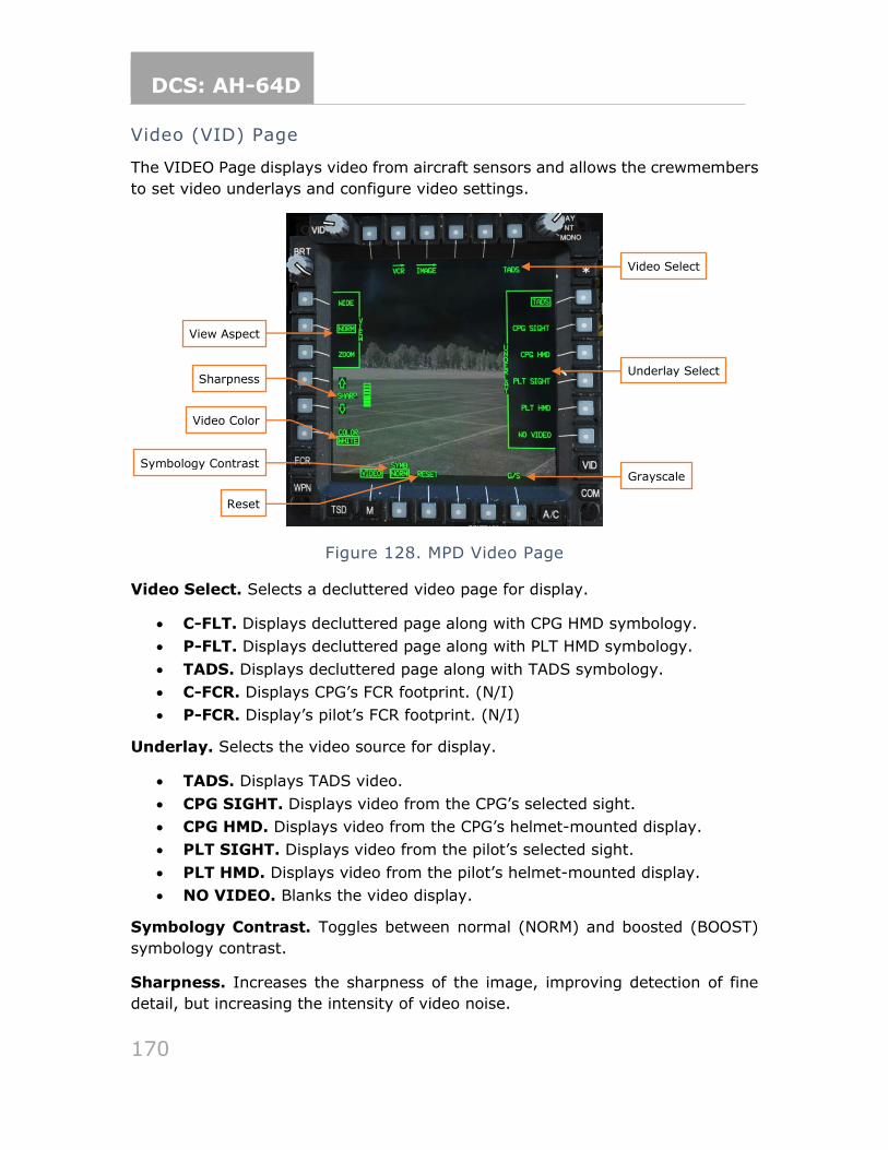
DCS: AH-64D
170
Video (VID) Page
The VIDEO Page displays video from aircraft sensors and allows the crewmembers
to set video underlays and configure video settings.
Figure 128. MPD Video Page
Video Select. Selects a decluttered video page for display.
• C-FLT. Displays decluttered page along with CPG HMD symbology.
• P-FLT. Displays decluttered page along with PLT HMD symbology.
• TADS. Displays decluttered page along with TADS symbology.
• C-FCR. Displays CPG’s FCR footprint. (N/I)
• P-FCR. Display’s pilot’s FCR footprint. (N/I)
Underlay. Selects the video source for display.
• TADS. Displays TADS video.
• CPG SIGHT. Displays video from the CPG’s selected sight.
• CPG HMD. Displays video from the CPG’s helmet-mounted display.
• PLT SIGHT. Displays video from the pilot’s selected sight.
• PLT HMD. Displays video from the pilot’s helmet-mounted display.
• NO VIDEO. Blanks the video display.
Symbology Contrast. Toggles between normal (NORM) and boosted (BOOST)
symbology contrast.
Sharpness. Increases the sharpness of the image, improving detection of fine
detail, but increasing the intensity of video noise.
View Aspect
Video Select
Video Color
Sharpness
Symbology Contrast
Reset
Underlay Select
Grayscale
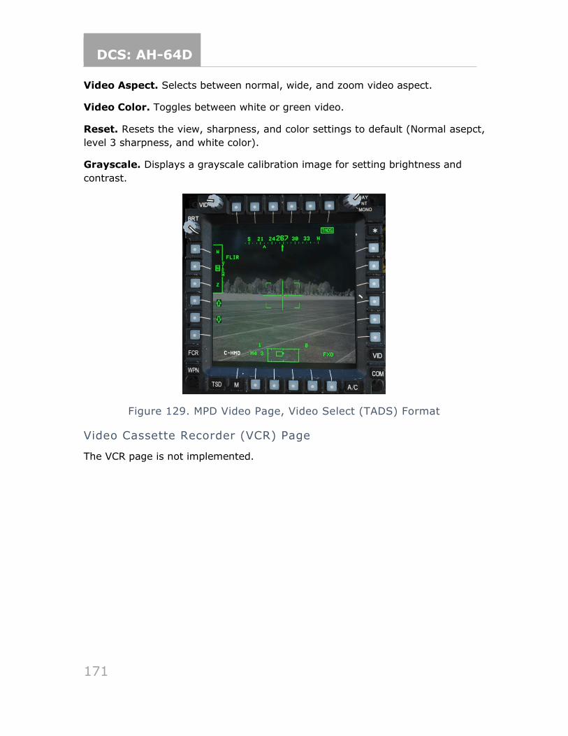
DCS: AH-64D
171
Video Aspect. Selects between normal, wide, and zoom video aspect.
Video Color. Toggles between white or green video.
Reset. Resets the view, sharpness, and color settings to default (Normal asepct,
level 3 sharpness, and white color).
Grayscale. Displays a grayscale calibration image for setting brightness and
contrast.
Figure 129. MPD Video Page, Video Select (TADS) Format
Video Cassette Recorder (VCR) Page
The VCR page is not implemented.
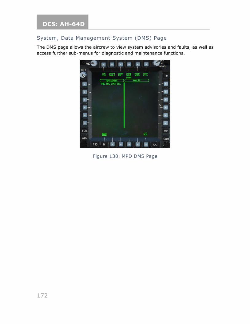
DCS: AH-64D
172
System, Data Management System (DMS) Page
The DMS page allows the aircrew to view system advisories and faults, as well as
access further sub-menus for diagnostic and maintenance functions.
Figure 130. MPD DMS Page
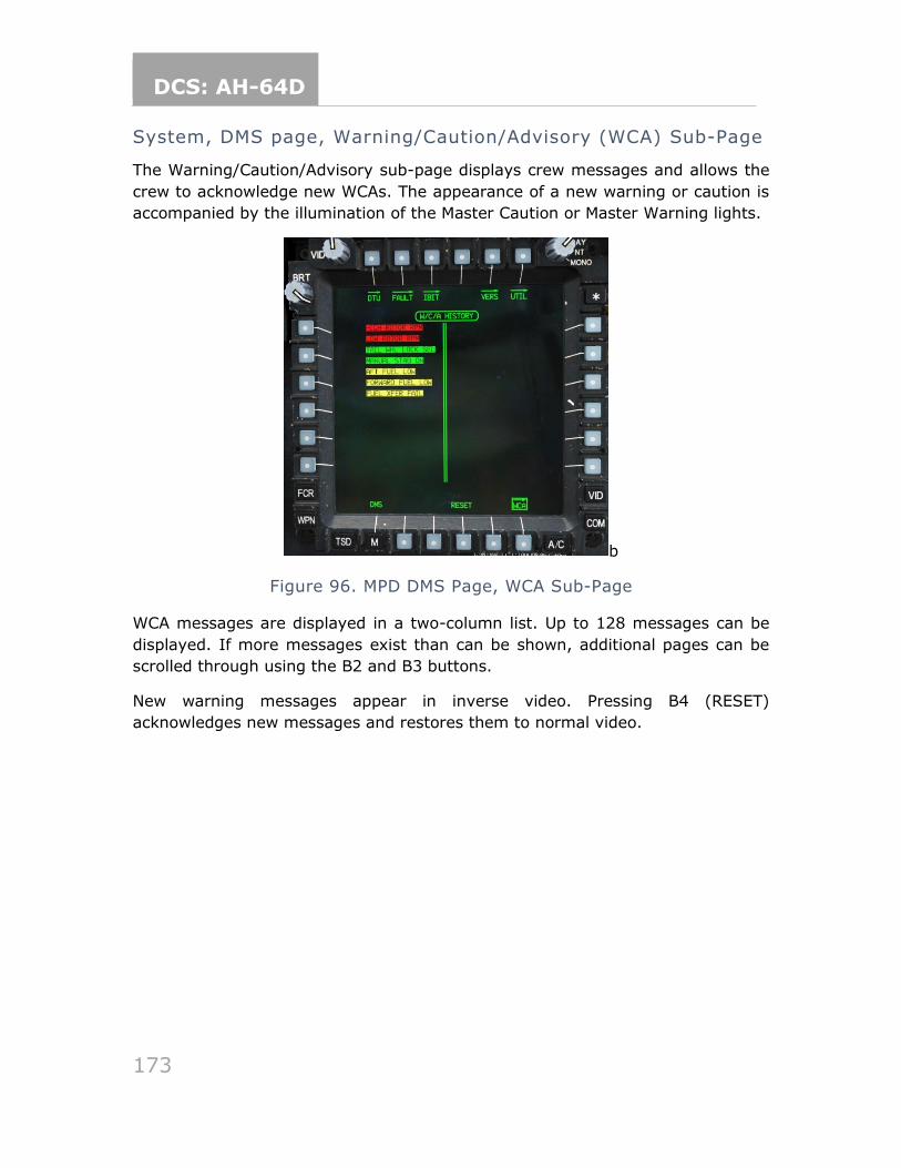
DCS: AH-64D
173
System, DMS page, Warning/Caution/Advisory (WCA) Sub-Page
The Warning/Caution/Advisory sub-page displays crew messages and allows the
crew to acknowledge new WCAs. The appearance of a new warning or caution is
accompanied by the illumination of the Master Caution or Master Warning lights.
b
Figure 96. MPD DMS Page, WCA Sub-Page
WCA messages are displayed in a two-column list. Up to 128 messages can be
displayed. If more messages exist than can be shown, additional pages can be
scrolled through using the B2 and B3 buttons.
New warning messages appear in inverse video. Pressing B4 (RESET)
acknowledges new messages and restores them to normal video.
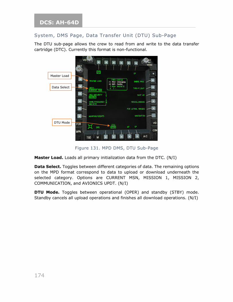
DCS: AH-64D
174
System, DMS Page, Data Transfer Unit (DTU) Sub-Page
The DTU sub-page allows the crew to read from and write to the data transfer
cartridge (DTC). Currently this format is non-functional.
Figure 131. MPD DMS, DTU Sub-Page
Master Load. Loads all primary initialization data from the DTC. (N/I)
Data Select. Toggles between different categories of data. The remaining options
on the MPD format correspond to data to upload or download underneath the
selected category. Options are CURRENT MSN, MISSION 1, MISSION 2,
COMMUNICATION, and AVIONICS UPDT. (N/I)
DTU Mode. Toggles between operational (OPER) and standby (STBY) mode.
Standby cancels all upload operations and finishes all download operations. (N/I)
Master Load
Data Select
DTU Mode
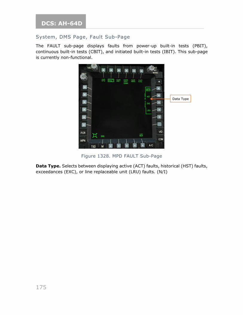
DCS: AH-64D
175
System, DMS Page, Fault Sub-Page
The FAULT sub-page displays faults from power-up built-in tests (PBIT),
continuous built-in tests (CBIT), and initiated built-in tests (IBIT). This sub-page
is currently non-functional.
Figure 1328. MPD FAULT Sub-Page
Data Type. Selects between displaying active (ACT) faults, historical (HST) faults,
exceedances (EXC), or line replaceable unit (LRU) faults. (N/I)
Data Type
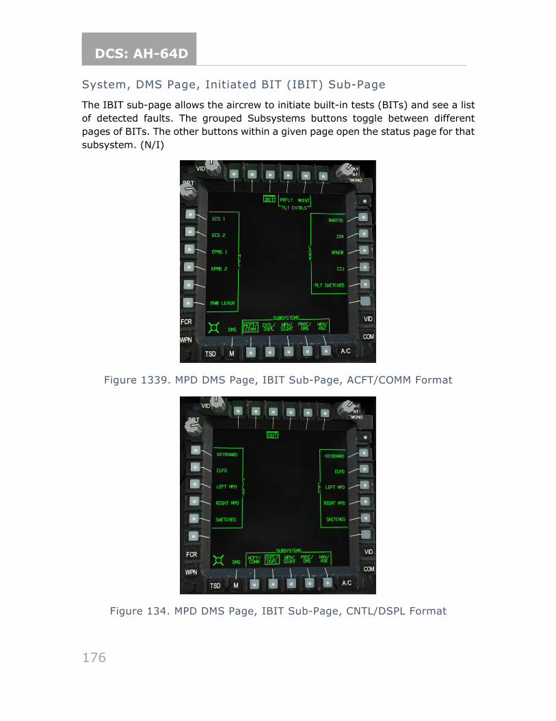
DCS: AH-64D
176
System, DMS Page, Initiated BIT (IBIT) Sub-Page
The IBIT sub-page allows the aircrew to initiate built-in tests (BITs) and see a list
of detected faults. The grouped Subsystems buttons toggle between different
pages of BITs. The other buttons within a given page open the status page for that
subsystem. (N/I)
Figure 1339. MPD DMS Page, IBIT Sub-Page, ACFT/COMM Format
Figure 134. MPD DMS Page, IBIT Sub-Page, CNTL/DSPL Format
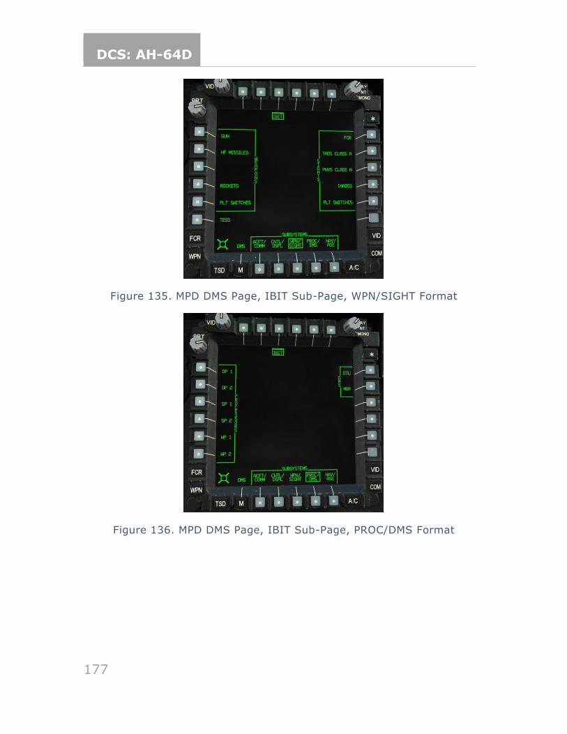
DCS: AH-64D
177
Figure 135. MPD DMS Page, IBIT Sub-Page, WPN/SIGHT Format
Figure 136. MPD DMS Page, IBIT Sub-Page, PROC/DMS Format
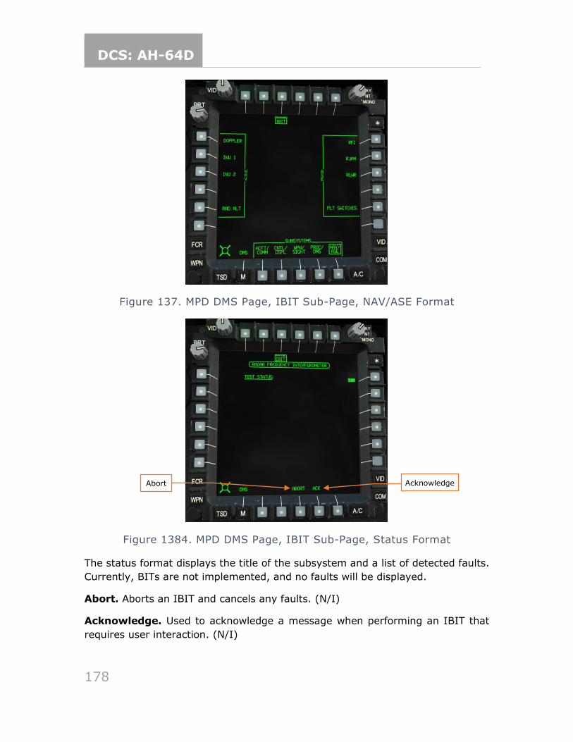
DCS: AH-64D
178
Figure 137. MPD DMS Page, IBIT Sub-Page, NAV/ASE Format
Figure 1384. MPD DMS Page, IBIT Sub-Page, Status Format
The status format displays the title of the subsystem and a list of detected faults.
Currently, BITs are not implemented, and no faults will be displayed.
Abort. Aborts an IBIT and cancels any faults. (N/I)
Acknowledge. Used to acknowledge a message when performing an IBIT that
requires user interaction. (N/I)
Abort Acknowledge
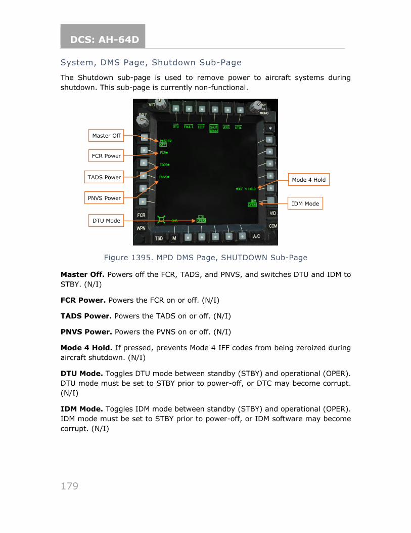
DCS: AH-64D
179
System, DMS Page, Shutdown Sub-Page
The Shutdown sub-page is used to remove power to aircraft systems during
shutdown. This sub-page is currently non-functional.
Figure 1395. MPD DMS Page, SHUTDOWN Sub-Page
Master Off. Powers off the FCR, TADS, and PNVS, and switches DTU and IDM to
STBY. (N/I)
FCR Power. Powers the FCR on or off. (N/I)
TADS Power. Powers the TADS on or off. (N/I)
PNVS Power. Powers the PVNS on or off. (N/I)
Mode 4 Hold. If pressed, prevents Mode 4 IFF codes from being zeroized during
aircraft shutdown. (N/I)
DTU Mode. Toggles DTU mode between standby (STBY) and operational (OPER).
DTU mode must be set to STBY prior to power-off, or DTC may become corrupt.
(N/I)
IDM Mode. Toggles IDM mode between standby (STBY) and operational (OPER).
IDM mode must be set to STBY prior to power-off, or IDM software may become
corrupt. (N/I)
IDM Mode
DTU Mode
Master Off
Mode 4 Hold
FCR Power
TADS Power
PNVS Power
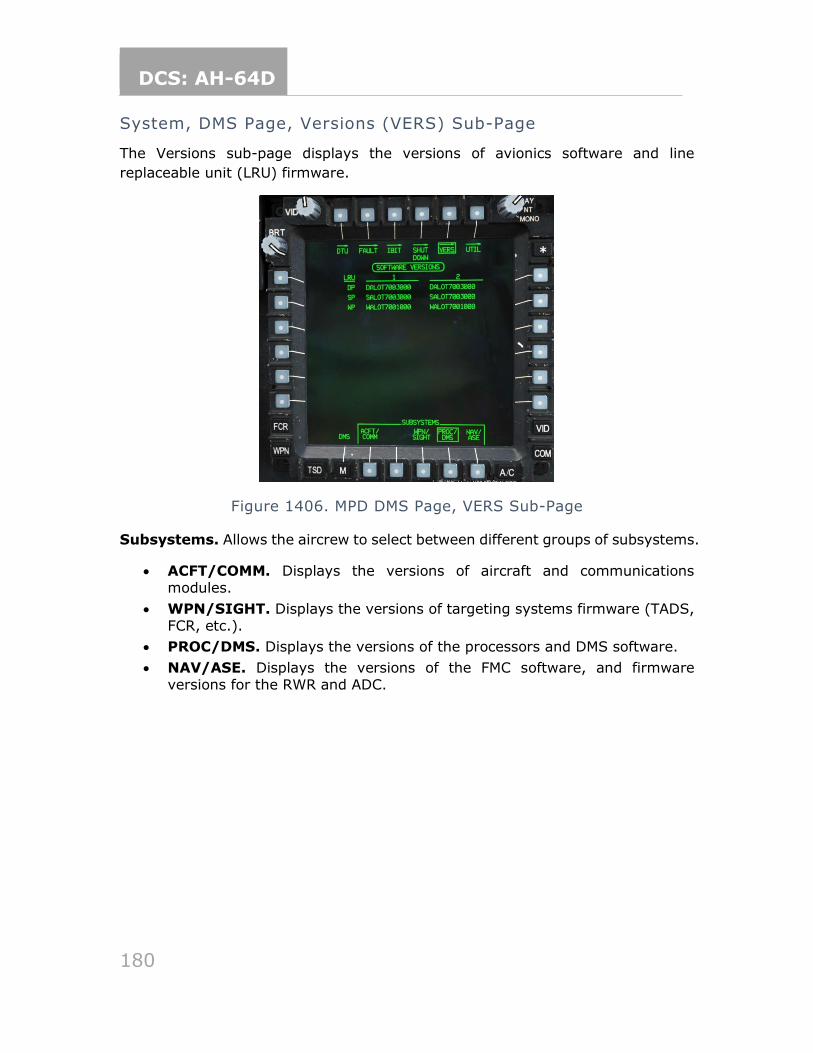
DCS: AH-64D
180
System, DMS Page, Versions (VERS) Sub-Page
The Versions sub-page displays the versions of avionics software and line
replaceable unit (LRU) firmware.
Figure 1406. MPD DMS Page, VERS Sub-Page
Subsystems. Allows the aircrew to select between different groups of subsystems.
• ACFT/COMM. Displays the versions of aircraft and communications modules.
• WPN/SIGHT. Displays the versions of targeting systems firmware (TADS, FCR, etc.).
• PROC/DMS. Displays the versions of the processors and DMS software.
• NAV/ASE. Displays the versions of the FMC software, and firmware versions for the RWR and ADC.
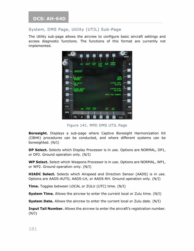
DCS: AH-64D
181
System, DMS Page, Utility (UTIL) Sub-Page
The Utility sub-page allows the aircrew to configure basic aircraft settings and
access diagnostic functions. The functions of this format are currently not
implemented.
Figure 141. MPD DMS UTIL Page
Boresight. Displays a sub-page where Captive Boresight Harmonization Kit
(CBHK) procedures can be conducted, and where different systems can be
boresighted. (N/I)
DP Select. Selects which Display Processor is in use. Options are NORMAL, DP1,
or DP2. Ground operation only. (N/I)
WP Select. Select which Weapons Processor is in use. Options are NORMAL, WP1,
or WP2. Ground operation only. (N/I)
HIADC Select. Selects which Airspeed and Direction Sensor (AADS) is in use.
Options are AADS-AUTO, AADS-LH, or AADS-RH. Ground operation only. (N/I)
Time. Toggles between LOCAL or ZULU (UTC) time. (N/I)
System Time. Allows the aircrew to enter the current local or Zulu time. (N/I)
System Date. Allows the aircrew to enter the current local or Zulu date. (N/I)
Input Tail Number. Allows the aircrew to enter the aircraft’s registration number.
(N/I)
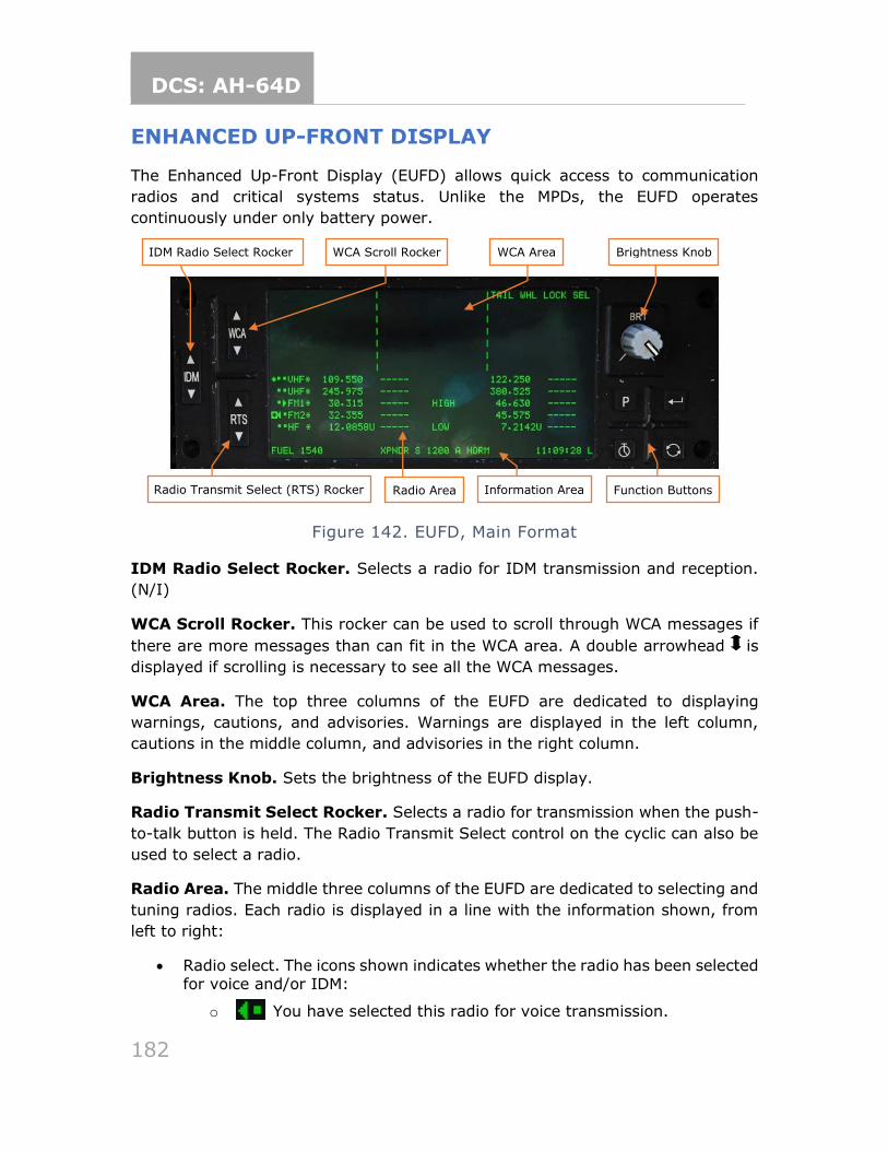
DCS: AH-64D
182
ENHANCED UP-FRONT DISPLAY
The Enhanced Up-Front Display (EUFD) allows quick access to communication
radios and critical systems status. Unlike the MPDs, the EUFD operates
continuously under only battery power.
Figure 142. EUFD, Main Format
IDM Radio Select Rocker. Selects a radio for IDM transmission and reception.
(N/I)
WCA Scroll Rocker. This rocker can be used to scroll through WCA messages if
there are more messages than can fit in the WCA area. A double arrowhead is
displayed if scrolling is necessary to see all the WCA messages.
WCA Area. The top three columns of the EUFD are dedicated to displaying
warnings, cautions, and advisories. Warnings are displayed in the left column,
cautions in the middle column, and advisories in the right column.
Brightness Knob. Sets the brightness of the EUFD display.
Radio Transmit Select Rocker. Selects a radio for transmission when the push-
to-talk button is held. The Radio Transmit Select control on the cyclic can also be
used to select a radio.
Radio Area. The middle three columns of the EUFD are dedicated to selecting and
tuning radios. Each radio is displayed in a line with the information shown, from
left to right:
• Radio select. The icons shown indicates whether the radio has been selected for voice and/or IDM:
o You have selected this radio for voice transmission.
IDM Radio Select Rocker WCA Scroll Rocker WCA Area Brightness Knob
Radio Transmit Select (RTS) Rocker Radio Area Information Area Function Buttons
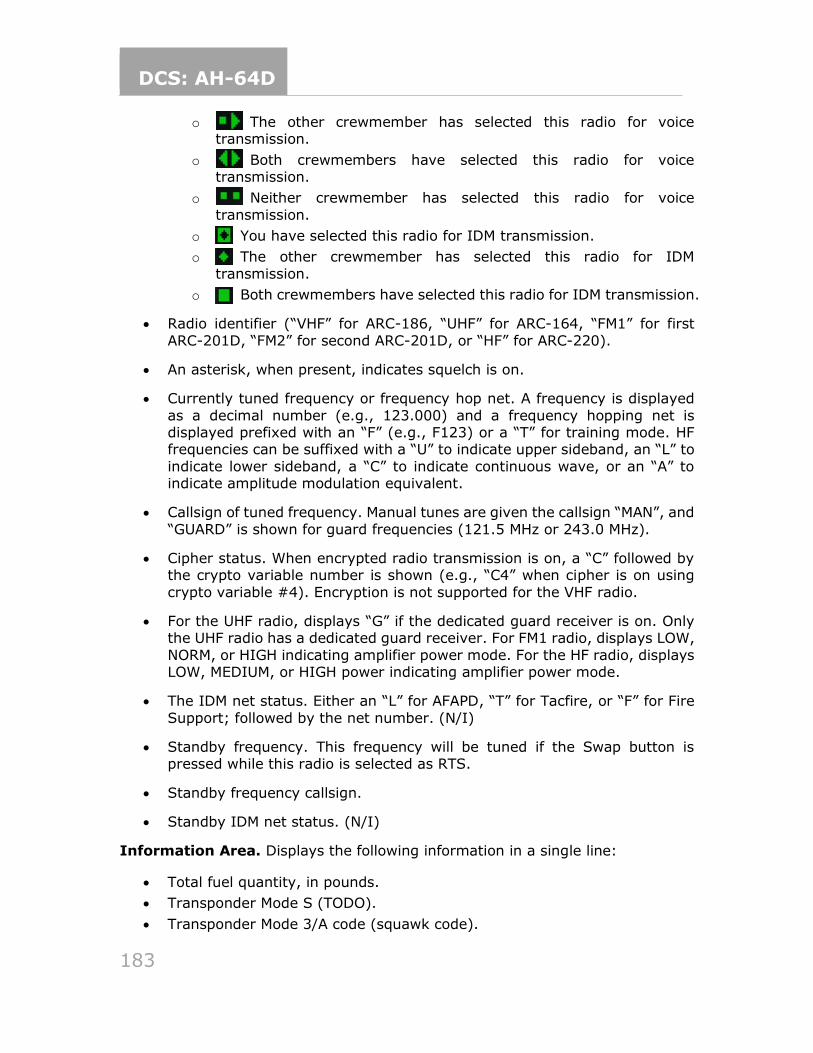
DCS: AH-64D
183
o The other crewmember has selected this radio for voice transmission.
o Both crewmembers have selected this radio for voice transmission.
o Neither crewmember has selected this radio for voice
transmission.
o You have selected this radio for IDM transmission.
o The other crewmember has selected this radio for IDM
transmission.
o Both crewmembers have selected this radio for IDM transmission.
• Radio identifier (“VHF” for ARC-186, “UHF” for ARC-164, “FM1” for first
ARC-201D, “FM2” for second ARC-201D, or “HF” for ARC-220).
• An asterisk, when present, indicates squelch is on.
• Currently tuned frequency or frequency hop net. A frequency is displayed
as a decimal number (e.g., 123.000) and a frequency hopping net is displayed prefixed with an “F” (e.g., F123) or a “T” for training mode. HF frequencies can be suffixed with a “U” to indicate upper sideband, an “L” to
indicate lower sideband, a “C” to indicate continuous wave, or an “A” to indicate amplitude modulation equivalent.
• Callsign of tuned frequency. Manual tunes are given the callsign “MAN”, and
“GUARD” is shown for guard frequencies (121.5 MHz or 243.0 MHz).
• Cipher status. When encrypted radio transmission is on, a “C” followed by the crypto variable number is shown (e.g., “C4” when cipher is on using
crypto variable #4). Encryption is not supported for the VHF radio.
• For the UHF radio, displays “G” if the dedicated guard receiver is on. Only the UHF radio has a dedicated guard receiver. For FM1 radio, displays LOW,
NORM, or HIGH indicating amplifier power mode. For the HF radio, displays LOW, MEDIUM, or HIGH power indicating amplifier power mode.
• The IDM net status. Either an “L” for AFAPD, “T” for Tacfire, or “F” for Fire
Support; followed by the net number. (N/I)
• Standby frequency. This frequency will be tuned if the Swap button is pressed while this radio is selected as RTS.
• Standby frequency callsign.
• Standby IDM net status. (N/I)
Information Area. Displays the following information in a single line:
• Total fuel quantity, in pounds.
• Transponder Mode S (TODO).
• Transponder Mode 3/A code (squawk code).
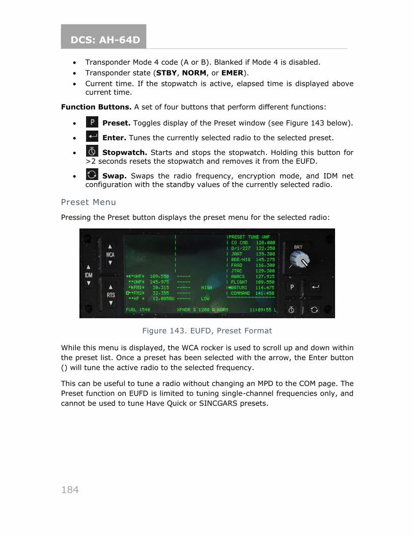
DCS: AH-64D
184
• Transponder Mode 4 code (A or B). Blanked if Mode 4 is disabled.
• Transponder state (STBY, NORM, or EMER).
• Current time. If the stopwatch is active, elapsed time is displayed above current time.
Function Buttons. A set of four buttons that perform different functions:
• Preset. Toggles display of the Preset window (see Figure 143 below).
• Enter. Tunes the currently selected radio to the selected preset.
• Stopwatch. Starts and stops the stopwatch. Holding this button for
>2 seconds resets the stopwatch and removes it from the EUFD.
• Swap. Swaps the radio frequency, encryption mode, and IDM net configuration with the standby values of the currently selected radio.
Preset Menu
Pressing the Preset button displays the preset menu for the selected radio:
Figure 143. EUFD, Preset Format
While this menu is displayed, the WCA rocker is used to scroll up and down within
the preset list. Once a preset has been selected with the arrow, the Enter button
() will tune the active radio to the selected frequency.
This can be useful to tune a radio without changing an MPD to the COM page. The
Preset function on EUFD is limited to tuning single-channel frequencies only, and
cannot be used to tune Have Quick or SINCGARS presets.
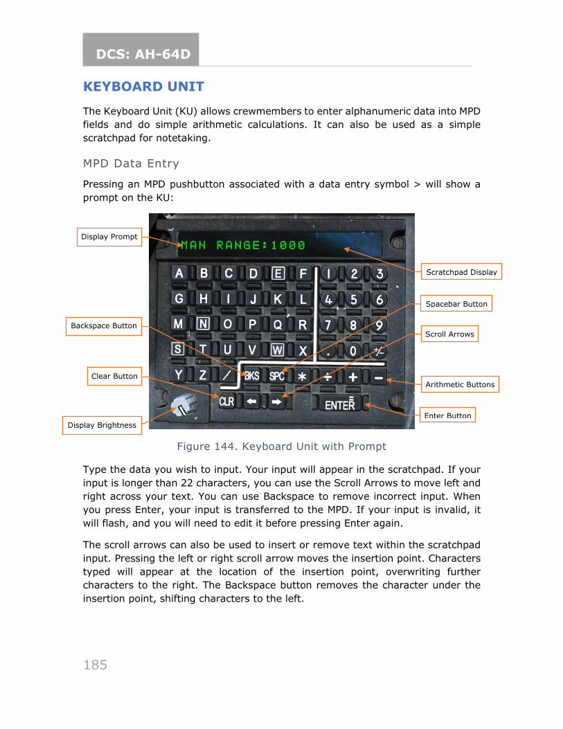
DCS: AH-64D
185
KEYBOARD UNIT
The Keyboard Unit (KU) allows crewmembers to enter alphanumeric data into MPD
fields and do simple arithmetic calculations. It can also be used as a simple
scratchpad for notetaking.
MPD Data Entry
Pressing an MPD pushbutton associated with a data entry symbol > will show a
prompt on the KU:
Figure 144. Keyboard Unit with Prompt
Type the data you wish to input. Your input will appear in the scratchpad. If your
input is longer than 22 characters, you can use the Scroll Arrows to move left and
right across your text. You can use Backspace to remove incorrect input. When
you press Enter, your input is transferred to the MPD. If your input is invalid, it
will flash, and you will need to edit it before pressing Enter again.
The scroll arrows can also be used to insert or remove text within the scratchpad
input. Pressing the left or right scroll arrow moves the insertion point. Characters
typed will appear at the location of the insertion point, overwriting further
characters to the right. The Backspace button removes the character under the
insertion point, shifting characters to the left.
Scratchpad Display
Display Prompt
Backspace Button
Arithmetic Buttons
Enter Button
Display Brightness
Clear Button
Scroll Arrows
Spacebar Button
DCS: AH-64D
186
KU Arithmetic and Notetaking
When a prompt is not displayed, you can use the KU to perform simple arithmetic
operations or store temporary notes.
To perform basic arithmetic, enter a number, followed by either the * (multiply),
÷ (divide), + (add), or - (subtract) keys. Enter another number and press Enter
(equals). The result will display on the scratchpad.
You can also enter freeform data into the scratchpad. It will remain in the
scratchpad until cleared (with the CLR button).
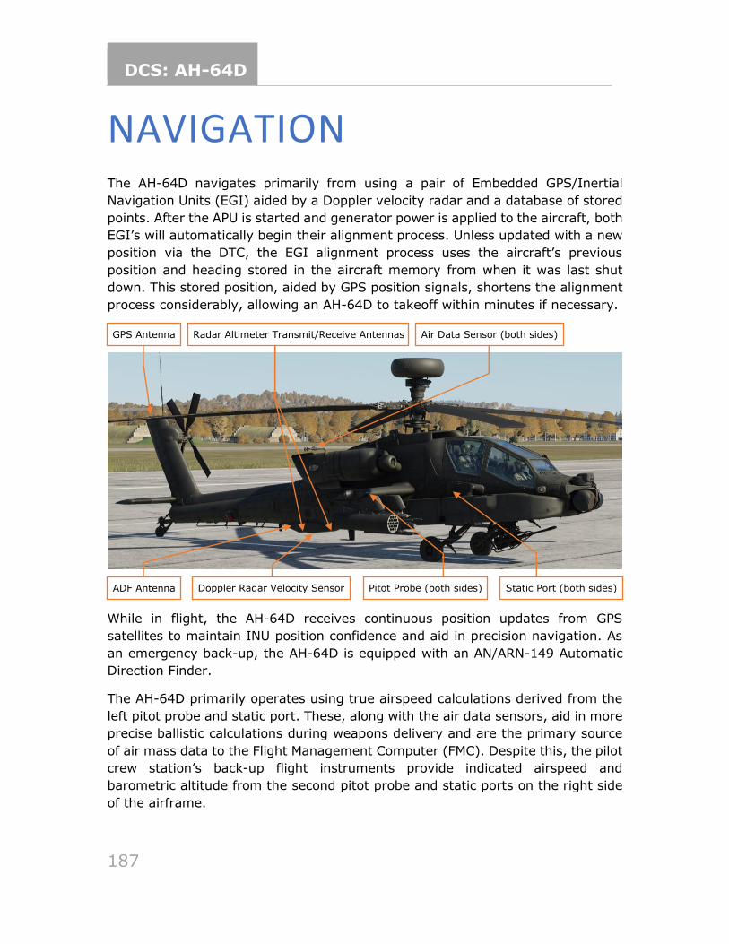
DCS: AH-64D
187
NAVIGATION The AH-64D navigates primarily from using a pair of Embedded GPS/Inertial
Navigation Units (EGI) aided by a Doppler velocity radar and a database of stored
points. After the APU is started and generator power is applied to the aircraft, both
EGI’s will automatically begin their alignment process. Unless updated with a new
position via the DTC, the EGI alignment process uses the aircraft’s previous
position and heading stored in the aircraft memory from when it was last shut
down. This stored position, aided by GPS position signals, shortens the alignment
process considerably, allowing an AH-64D to takeoff within minutes if necessary.
While in flight, the AH-64D receives continuous position updates from GPS
satellites to maintain INU position confidence and aid in precision navigation. As
an emergency back-up, the AH-64D is equipped with an AN/ARN-149 Automatic
Direction Finder.
The AH-64D primarily operates using true airspeed calculations derived from the
left pitot probe and static port. These, along with the air data sensors, aid in more
precise ballistic calculations during weapons delivery and are the primary source
of air mass data to the Flight Management Computer (FMC). Despite this, the pilot
crew station’s back-up flight instruments provide indicated airspeed and
barometric altitude from the second pitot probe and static ports on the right side
of the airframe.
GPS Antenna Air Data Sensor (both sides)
ADF Antenna
Radar Altimeter Transmit/Receive Antennas
Doppler Radar Velocity Sensor Static Port (both sides) Pitot Probe (both sides)
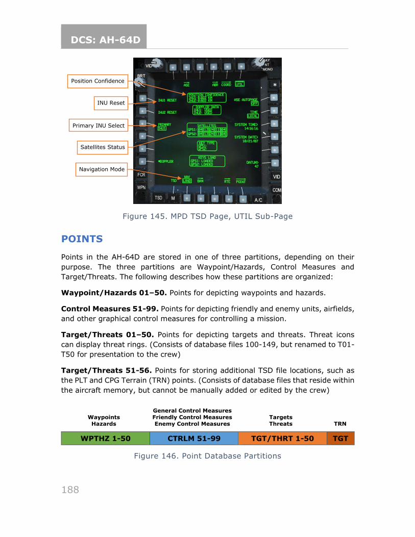
DCS: AH-64D
188
Figure 145. MPD TSD Page, UTIL Sub-Page
POINTS
Points in the AH-64D are stored in one of three partitions, depending on their
purpose. The three partitions are Waypoint/Hazards, Control Measures and
Target/Threats. The following describes how these partitions are organized:
Waypoint/Hazards 01–50. Points for depicting waypoints and hazards.
Control Measures 51-99. Points for depicting friendly and enemy units, airfields,
and other graphical control measures for controlling a mission.
Target/Threats 01–50. Points for depicting targets and threats. Threat icons
can display threat rings. (Consists of database files 100-149, but renamed to T01-
T50 for presentation to the crew)
Target/Threats 51-56. Points for storing additional TSD file locations, such as
the PLT and CPG Terrain (TRN) points. (Consists of database files that reside within
the aircraft memory, but cannot be manually added or edited by the crew)
WPTHZ 1-50 CTRLM 51-99 TGT/THRT 1-50 TGT
Figure 146. Point Database Partitions
General Control Measures Friendly Control Measures Enemy Control Measures
Waypoints
Hazards
Targets Threats
TRN
Position Confidence
Primary INU Select
INU Reset
Navigation Mode
Satellites Status
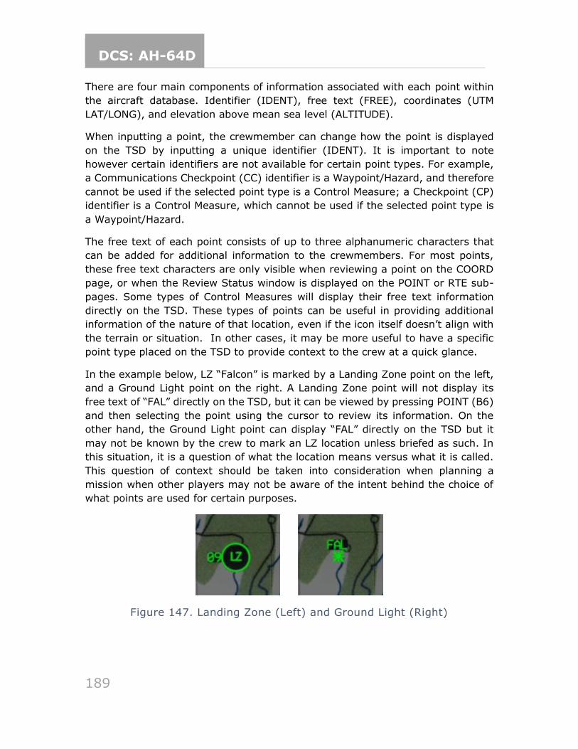
DCS: AH-64D
189
There are four main components of information associated with each point within
the aircraft database. Identifier (IDENT), free text (FREE), coordinates (UTM
LAT/LONG), and elevation above mean sea level (ALTITUDE).
When inputting a point, the crewmember can change how the point is displayed
on the TSD by inputting a unique identifier (IDENT). It is important to note
however certain identifiers are not available for certain point types. For example,
a Communications Checkpoint (CC) identifier is a Waypoint/Hazard, and therefore
cannot be used if the selected point type is a Control Measure; a Checkpoint (CP)
identifier is a Control Measure, which cannot be used if the selected point type is
a Waypoint/Hazard.
The free text of each point consists of up to three alphanumeric characters that
can be added for additional information to the crewmembers. For most points,
these free text characters are only visible when reviewing a point on the COORD
page, or when the Review Status window is displayed on the POINT or RTE sub-
pages. Some types of Control Measures will display their free text information
directly on the TSD. These types of points can be useful in providing additional
information of the nature of that location, even if the icon itself doesn’t align with
the terrain or situation. In other cases, it may be more useful to have a specific
point type placed on the TSD to provide context to the crew at a quick glance.
In the example below, LZ “Falcon” is marked by a Landing Zone point on the left,
and a Ground Light point on the right. A Landing Zone point will not display its
free text of “FAL” directly on the TSD, but it can be viewed by pressing POINT (B6)
and then selecting the point using the cursor to review its information. On the
other hand, the Ground Light point can display “FAL” directly on the TSD but it
may not be known by the crew to mark an LZ location unless briefed as such. In
this situation, it is a question of what the location means versus what it is called.
This question of context should be taken into consideration when planning a
mission when other players may not be aware of the intent behind the choice of
what points are used for certain purposes.
Figure 147. Landing Zone (Left) and Ground Light (Right)
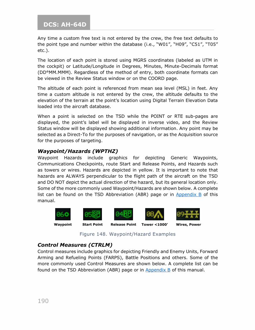
DCS: AH-64D
190
Any time a custom free text is not entered by the crew, the free text defaults to
the point type and number within the database (i.e., “W01”, “H09”, “C51”, “T05”
etc.).
The location of each point is stored using MGRS coordinates (labeled as UTM in
the cockpit) or Latitude/Longitude in Degrees, Minutes, Minute-Decimals format
(DD°MM.MMM). Regardless of the method of entry, both coordinate formats can
be viewed in the Review Status window or on the COORD page.
The altitude of each point is referenced from mean sea level (MSL) in feet. Any
time a custom altitude is not entered by the crew, the altitude defaults to the
elevation of the terrain at the point’s location using Digital Terrain Elevation Data
loaded into the aircraft database.
When a point is selected on the TSD while the POINT or RTE sub-pages are
displayed, the point’s label will be displayed in inverse video, and the Review
Status window will be displayed showing additional information. Any point may be
selected as a Direct-To for the purposes of navigation, or as the Acquisition source
for the purposes of targeting.
Waypoint/Hazards (WPTHZ)
Waypoint Hazards include graphics for depicting Generic Waypoints,
Communications Checkpoints, route Start and Release Points, and Hazards such
as towers or wires. Hazards are depicted in yellow. It is important to note that
hazards are ALWAYS perpendicular to the flight path of the aircraft on the TSD
and DO NOT depict the actual direction of the hazard, but its general location only.
Some of the more commonly used Waypoint/Hazards are shown below. A complete
list can be found on the TSD Abbreviation (ABR) page or in Appendix B of this
manual.
Figure 148. Waypoint/Hazard Examples
Control Measures (CTRLM)
Control measures include graphics for depicting Friendly and Enemy Units, Forward
Arming and Refueling Points (FARPS), Battle Positions and others. Some of the
more commonly used Control Measures are shown below. A complete list can be
found on the TSD Abbreviation (ABR) page or in Appendix B of this manual.
Waypoint Start Point Release Point Tower <1000’ Wires, Power
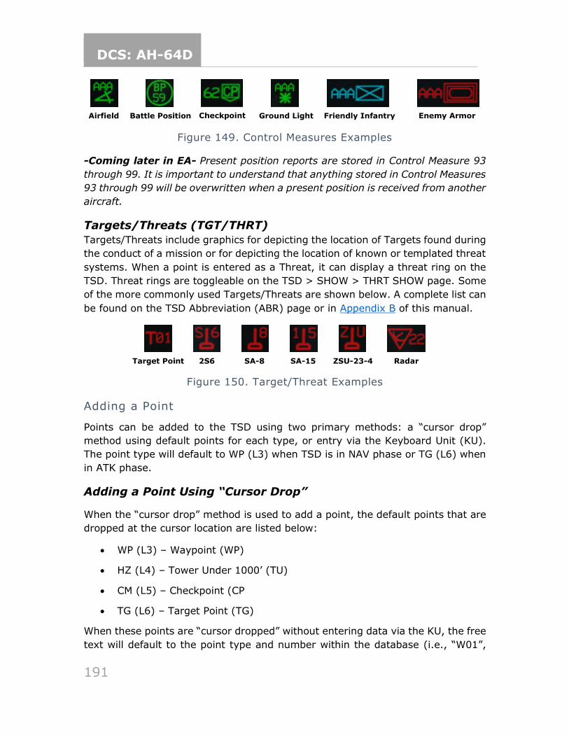
DCS: AH-64D
191
Figure 149. Control Measures Examples
-Coming later in EA- Present position reports are stored in Control Measure 93
through 99. It is important to understand that anything stored in Control Measures
93 through 99 will be overwritten when a present position is received from another
aircraft.
Targets/Threats (TGT/THRT)
Targets/Threats include graphics for depicting the location of Targets found during
the conduct of a mission or for depicting the location of known or templated threat
systems. When a point is entered as a Threat, it can display a threat ring on the
TSD. Threat rings are toggleable on the TSD > SHOW > THRT SHOW page. Some
of the more commonly used Targets/Threats are shown below. A complete list can
be found on the TSD Abbreviation (ABR) page or in Appendix B of this manual.
Figure 150. Target/Threat Examples
Adding a Point
Points can be added to the TSD using two primary methods: a “cursor drop”
method using default points for each type, or entry via the Keyboard Unit (KU).
The point type will default to WP (L3) when TSD is in NAV phase or TG (L6) when
in ATK phase.
Adding a Point Using “Cursor Drop”
When the “cursor drop” method is used to add a point, the default points that are
dropped at the cursor location are listed below:
• WP (L3) – Waypoint (WP)
• HZ (L4) – Tower Under 1000’ (TU)
• CM (L5) – Checkpoint (CP
• TG (L6) – Target Point (TG)
When these points are “cursor dropped” without entering data via the KU, the free
text will default to the point type and number within the database (i.e., “W01”,
Airfield Genera
l
Battle Position Checkpoint Ground Light Friendly Infantry Enemy Armor
Target Point 2S6 SA-8 SA-15 ZSU-23-4 Radar
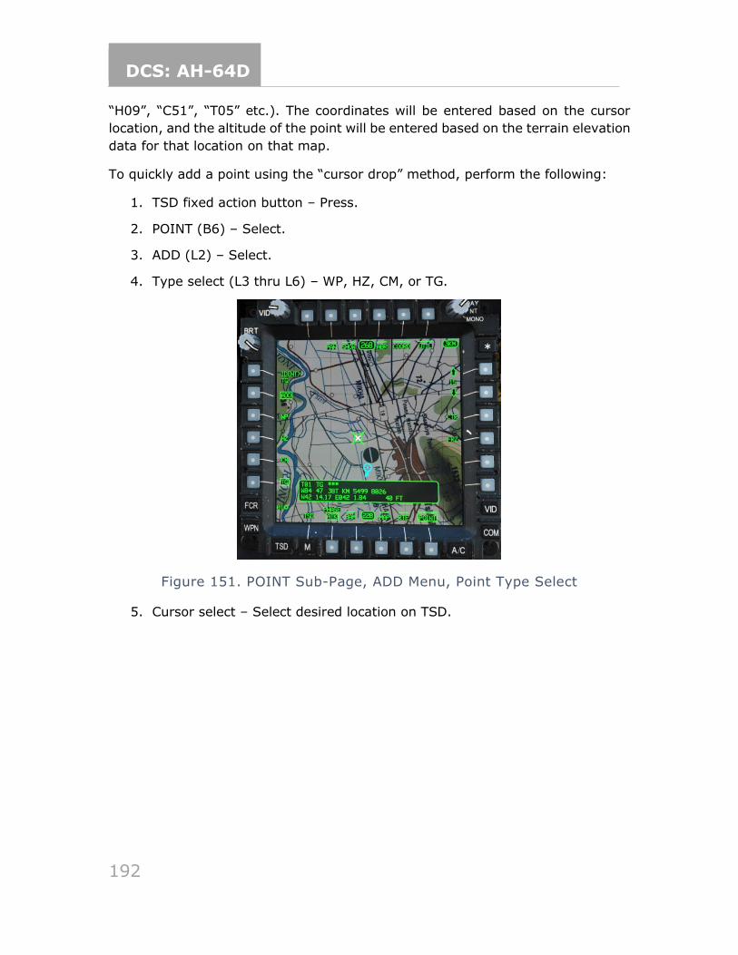
DCS: AH-64D
192
“H09”, “C51”, “T05” etc.). The coordinates will be entered based on the cursor
location, and the altitude of the point will be entered based on the terrain elevation
data for that location on that map.
To quickly add a point using the “cursor drop” method, perform the following:
1. TSD fixed action button – Press.
2. POINT (B6) – Select.
3. ADD (L2) – Select.
4. Type select (L3 thru L6) – WP, HZ, CM, or TG.
Figure 151. POINT Sub-Page, ADD Menu, Point Type Select
5. Cursor select – Select desired location on TSD.
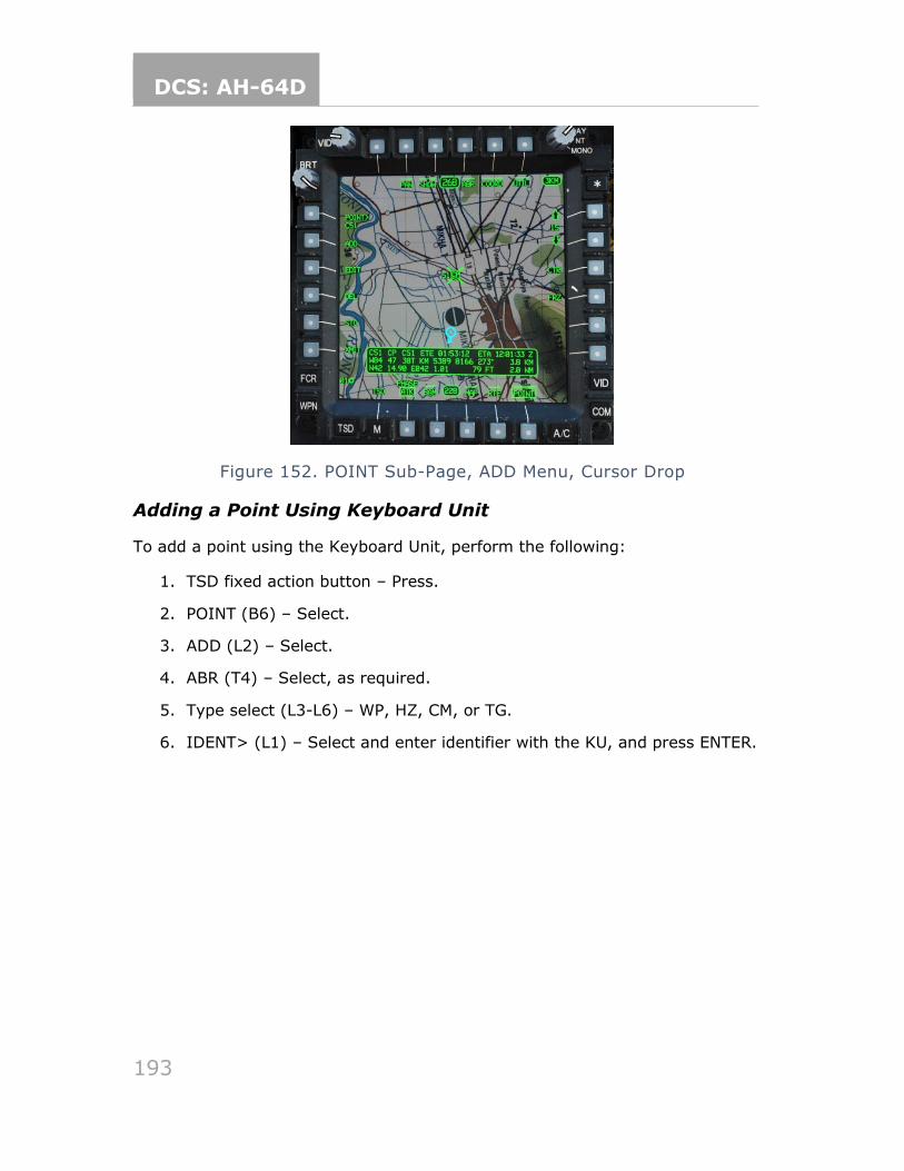
DCS: AH-64D
193
Figure 152. POINT Sub-Page, ADD Menu, Cursor Drop
Adding a Point Using Keyboard Unit
To add a point using the Keyboard Unit, perform the following:
1. TSD fixed action button – Press.
2. POINT (B6) – Select.
3. ADD (L2) – Select.
4. ABR (T4) – Select, as required.
5. Type select (L3-L6) – WP, HZ, CM, or TG.
6. IDENT> (L1) – Select and enter identifier with the KU, and press ENTER.
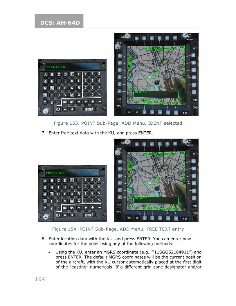
DCS: AH-64D
194
Figure 153. POINT Sub-Page, ADD Menu, IDENT selected
7. Enter free text data with the KU, and press ENTER.
Figure 154. POINT Sub-Page, ADD Menu, FREE TEXT entry
8. Enter location data with the KU, and press ENTER. You can enter new coordinates for the point using any of the following methods:
• Using the KU, enter an MGRS coordinate (e.g., “11SGQ52184911”) and press ENTER. The default MGRS coordinates will be the current position of the aircraft, with the KU cursor automatically placed at the first digit
of the “easting” numericals. If a different grid zone designator and/or
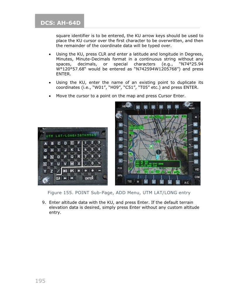
DCS: AH-64D
195
square identifier is to be entered, the KU arrow keys should be used to place the KU cursor over the first character to be overwritten, and then
the remainder of the coordinate data will be typed over.
• Using the KU, press CLR and enter a latitude and longitude in Degrees, Minutes, Minute-Decimals format in a continuous string without any
spaces, decimals, or special characters (e.g., “N74°25.94 W°120°57.68“ would be entered as “N742594W1205768”) and press ENTER.
• Using the KU, enter the name of an existing point to duplicate its coordinates (i.e., “W01”, “H09”, “C51”, “T05” etc.) and press ENTER.
• Move the cursor to a point on the map and press Cursor Enter.
Figure 155. POINT Sub-Page, ADD Menu, UTM LAT/LONG entry
9. Enter altitude data with the KU, and press Enter. If the default terrain elevation data is desired, simply press Enter without any custom altitude
entry.
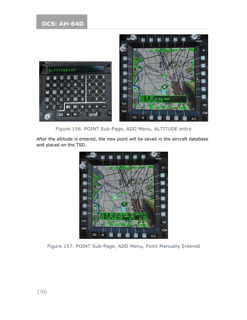
DCS: AH-64D
196
Figure 156. POINT Sub-Page, ADD Menu, ALTITUDE entry
After the altitude is entered, the new point will be saved in the aircraft database
and placed on the TSD.
Figure 157. POINT Sub-Page, ADD Menu, Point Manually Entered
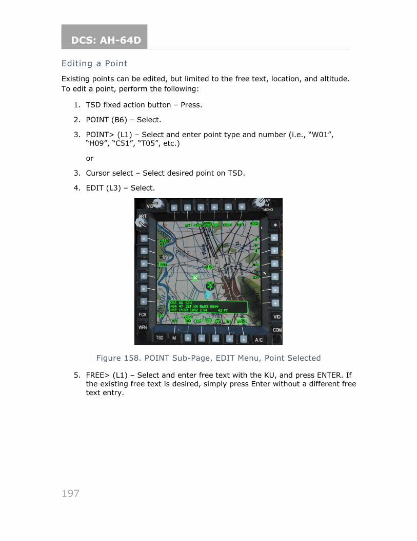
DCS: AH-64D
197
Editing a Point
Existing points can be edited, but limited to the free text, location, and altitude.
To edit a point, perform the following:
1. TSD fixed action button – Press.
2. POINT (B6) – Select.
3. POINT> (L1) – Select and enter point type and number (i.e., “W01”, “H09”, “C51”, “T05”, etc.)
or
3. Cursor select – Select desired point on TSD.
4. EDIT (L3) – Select.
Figure 158. POINT Sub-Page, EDIT Menu, Point Selected
5. FREE> (L1) – Select and enter free text with the KU, and press ENTER. If the existing free text is desired, simply press Enter without a different free
text entry.
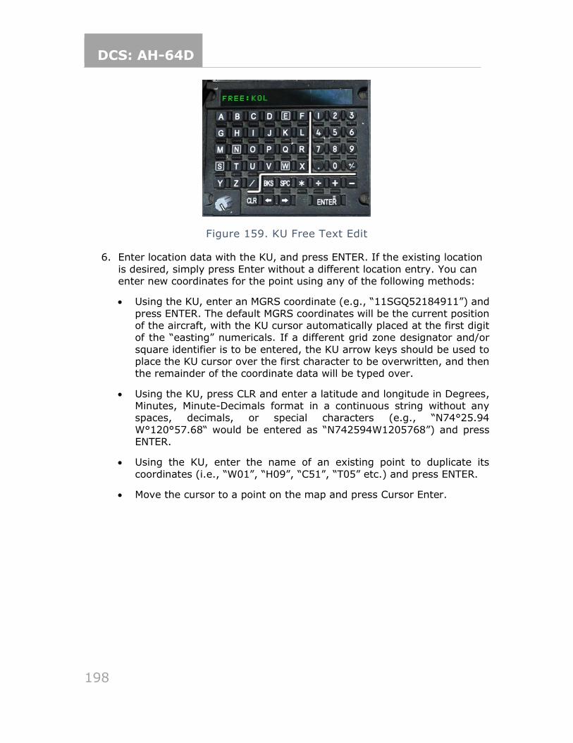
DCS: AH-64D
198
Figure 159. KU Free Text Edit
6. Enter location data with the KU, and press ENTER. If the existing location
is desired, simply press Enter without a different location entry. You can enter new coordinates for the point using any of the following methods:
• Using the KU, enter an MGRS coordinate (e.g., “11SGQ52184911”) and
press ENTER. The default MGRS coordinates will be the current position of the aircraft, with the KU cursor automatically placed at the first digit of the “easting” numericals. If a different grid zone designator and/or
square identifier is to be entered, the KU arrow keys should be used to place the KU cursor over the first character to be overwritten, and then the remainder of the coordinate data will be typed over.
• Using the KU, press CLR and enter a latitude and longitude in Degrees, Minutes, Minute-Decimals format in a continuous string without any spaces, decimals, or special characters (e.g., “N74°25.94
W°120°57.68“ would be entered as “N742594W1205768”) and press ENTER.
• Using the KU, enter the name of an existing point to duplicate its
coordinates (i.e., “W01”, “H09”, “C51”, “T05” etc.) and press ENTER.
• Move the cursor to a point on the map and press Cursor Enter.
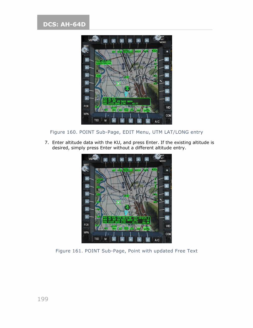
DCS: AH-64D
199
Figure 160. POINT Sub-Page, EDIT Menu, UTM LAT/LONG entry
7. Enter altitude data with the KU, and press Enter. If the existing altitude is
desired, simply press Enter without a different altitude entry.
Figure 161. POINT Sub-Page, Point with updated Free Text
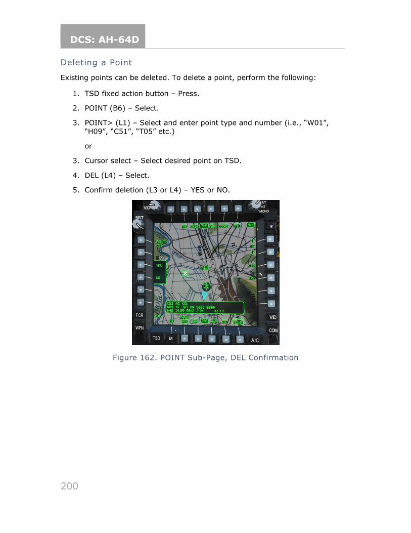
DCS: AH-64D
200
Deleting a Point
Existing points can be deleted. To delete a point, perform the following:
1. TSD fixed action button – Press.
2. POINT (B6) – Select.
3. POINT> (L1) – Select and enter point type and number (i.e., “W01”,
“H09”, “C51”, “T05” etc.)
or
3. Cursor select – Select desired point on TSD.
4. DEL (L4) – Select.
5. Confirm deletion (L3 or L4) – YES or NO.
Figure 162. POINT Sub-Page, DEL Confirmation
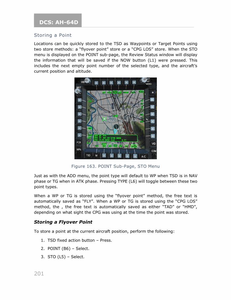
DCS: AH-64D
201
Storing a Point
Locations can be quickly stored to the TSD as Waypoints or Target Points using
two store methods: a “flyover point” store or a “CPG LOS” store. When the STO
menu is displayed on the POINT sub-page, the Review Status window will display
the information that will be saved if the NOW button (L1) were pressed. This
includes the next empty point number of the selected type, and the aircraft’s
current position and altitude.
Figure 163. POINT Sub-Page, STO Menu
Just as with the ADD menu, the point type will default to WP when TSD is in NAV
phase or TG when in ATK phase. Pressing TYPE (L6) will toggle between these two
point types.
When a WP or TG is stored using the “flyover point” method, the free text is
automatically saved as “FLY”. When a WP or TG is stored using the “CPG LOS”
method, the , the free text is automatically saved as either “TAD” or “HMD”,
depending on what sight the CPG was using at the time the point was stored.
Storing a Flyover Point
To store a point at the current aircraft position, perform the following:
1. TSD fixed action button – Press.
2. POINT (B6) – Select.
3. STO (L5) – Select.
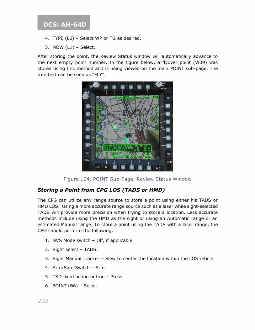
DCS: AH-64D
202
4. TYPE (L6) – Select WP or TG as desired.
5. NOW (L1) – Select.
After storing the point, the Review Status window will automatically advance to
the next empty point number. In the figure below, a flyover point (W09) was
stored using this method and is being viewed on the main POINT sub-page. The
free text can be seen as “FLY”.
Figure 164. POINT Sub-Page, Review Status Window
Storing a Point from CPG LOS (TADS or HMD)
The CPG can utilize any range source to store a point using either his TADS or
HMD LOS. Using a more accurate range source such as a laser while sight-selected
TADS will provide more precision when trying to store a location. Less accurate
methods include using the HMD as the sight or using an Automatic range or an
estimated Manual range. To store a point using the TADS with a laser range, the
CPG should perform the following:
1. NVS Mode switch – Off, if applicable.
2. Sight select – TADS.
3. Sight Manual Tracker – Slew to center the location within the LOS reticle.
4. Arm/Safe Switch – Arm.
5. TSD fixed action button – Press.
6. POINT (B6) – Select.
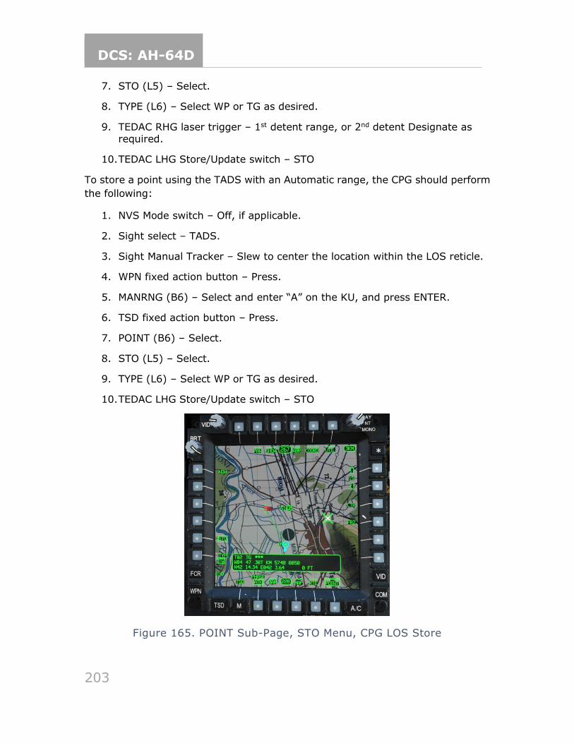
DCS: AH-64D
203
7. STO (L5) – Select.
8. TYPE (L6) – Select WP or TG as desired.
9. TEDAC RHG laser trigger – 1st detent range, or 2nd detent Designate as required.
10. TEDAC LHG Store/Update switch – STO
To store a point using the TADS with an Automatic range, the CPG should perform
the following:
1. NVS Mode switch – Off, if applicable.
2. Sight select – TADS.
3. Sight Manual Tracker – Slew to center the location within the LOS reticle.
4. WPN fixed action button – Press.
5. MANRNG (B6) – Select and enter “A” on the KU, and press ENTER.
6. TSD fixed action button – Press.
7. POINT (B6) – Select.
8. STO (L5) – Select.
9. TYPE (L6) – Select WP or TG as desired.
10. TEDAC LHG Store/Update switch – STO
Figure 165. POINT Sub-Page, STO Menu, CPG LOS Store
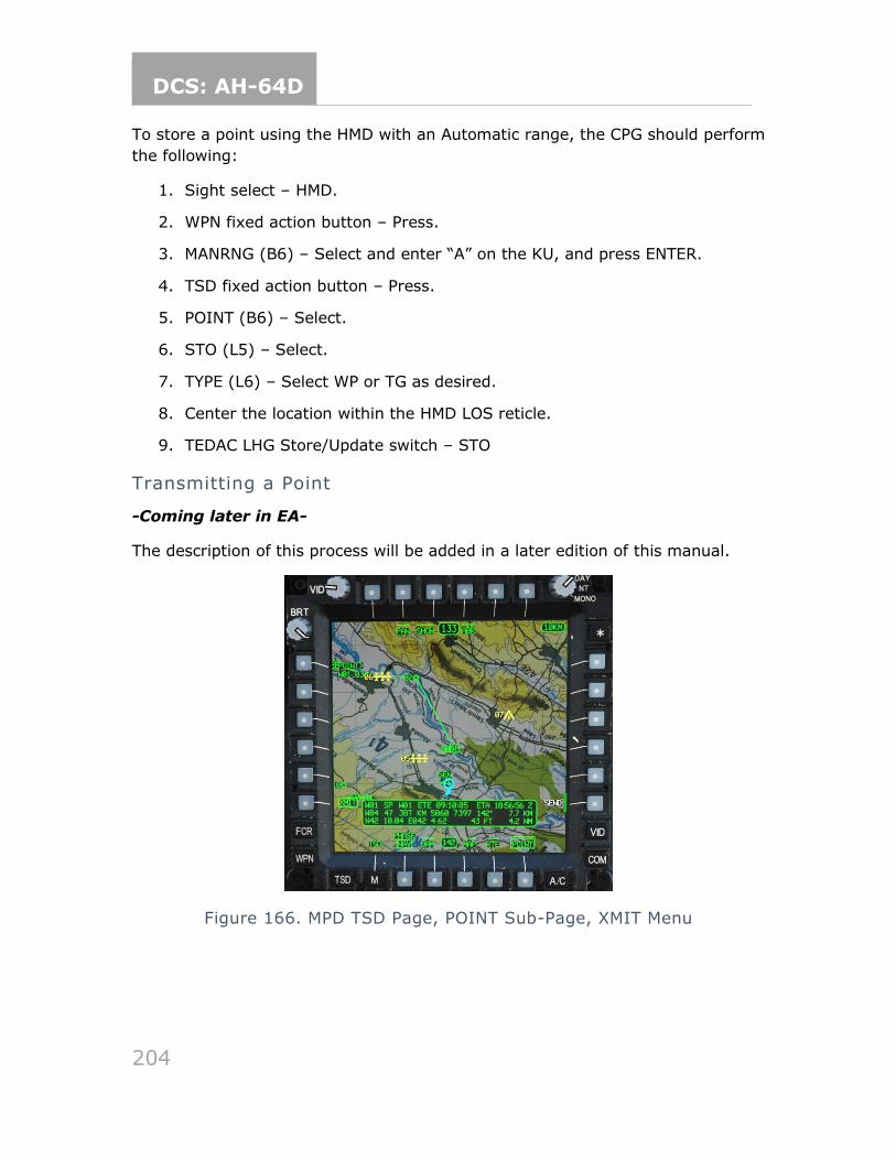
DCS: AH-64D
204
To store a point using the HMD with an Automatic range, the CPG should perform
the following:
1. Sight select – HMD.
2. WPN fixed action button – Press.
3. MANRNG (B6) – Select and enter “A” on the KU, and press ENTER.
4. TSD fixed action button – Press.
5. POINT (B6) – Select.
6. STO (L5) – Select.
7. TYPE (L6) – Select WP or TG as desired.
8. Center the location within the HMD LOS reticle.
9. TEDAC LHG Store/Update switch – STO
Transmitting a Point
-Coming later in EA-
The description of this process will be added in a later edition of this manual.
Figure 166. MPD TSD Page, POINT Sub-Page, XMIT Menu
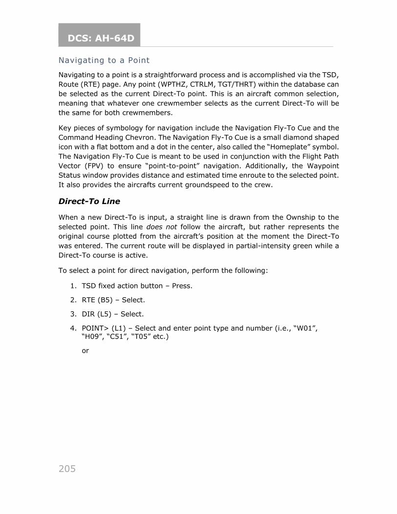
DCS: AH-64D
205
Navigating to a Point
Navigating to a point is a straightforward process and is accomplished via the TSD,
Route (RTE) page. Any point (WPTHZ, CTRLM, TGT/THRT) within the database can
be selected as the current Direct-To point. This is an aircraft common selection,
meaning that whatever one crewmember selects as the current Direct-To will be
the same for both crewmembers.
Key pieces of symbology for navigation include the Navigation Fly-To Cue and the
Command Heading Chevron. The Navigation Fly-To Cue is a small diamond shaped
icon with a flat bottom and a dot in the center, also called the “Homeplate” symbol.
The Navigation Fly-To Cue is meant to be used in conjunction with the Flight Path
Vector (FPV) to ensure “point-to-point” navigation. Additionally, the Waypoint
Status window provides distance and estimated time enroute to the selected point.
It also provides the aircrafts current groundspeed to the crew.
Direct-To Line
When a new Direct-To is input, a straight line is drawn from the Ownship to the
selected point. This line does not follow the aircraft, but rather represents the
original course plotted from the aircraft’s position at the moment the Direct-To
was entered. The current route will be displayed in partial-intensity green while a
Direct-To course is active.
To select a point for direct navigation, perform the following:
1. TSD fixed action button – Press.
2. RTE (B5) – Select.
3. DIR (L5) – Select.
4. POINT> (L1) – Select and enter point type and number (i.e., “W01”, “H09”, “C51”, “T05” etc.)
or
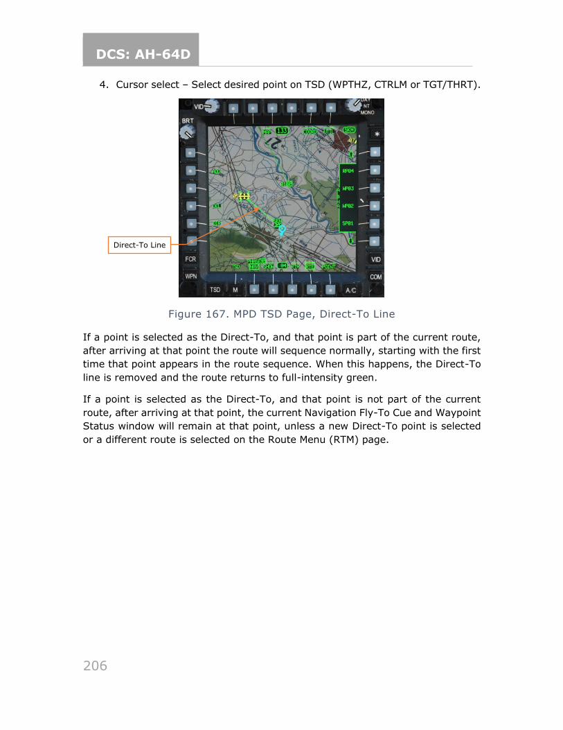
DCS: AH-64D
206
4. Cursor select – Select desired point on TSD (WPTHZ, CTRLM or TGT/THRT).
Figure 167. MPD TSD Page, Direct-To Line
If a point is selected as the Direct-To, and that point is part of the current route,
after arriving at that point the route will sequence normally, starting with the first
time that point appears in the route sequence. When this happens, the Direct-To
line is removed and the route returns to full-intensity green.
If a point is selected as the Direct-To, and that point is not part of the current
route, after arriving at that point, the current Navigation Fly-To Cue and Waypoint
Status window will remain at that point, unless a new Direct-To point is selected
or a different route is selected on the Route Menu (RTM) page.
Direct-To Line
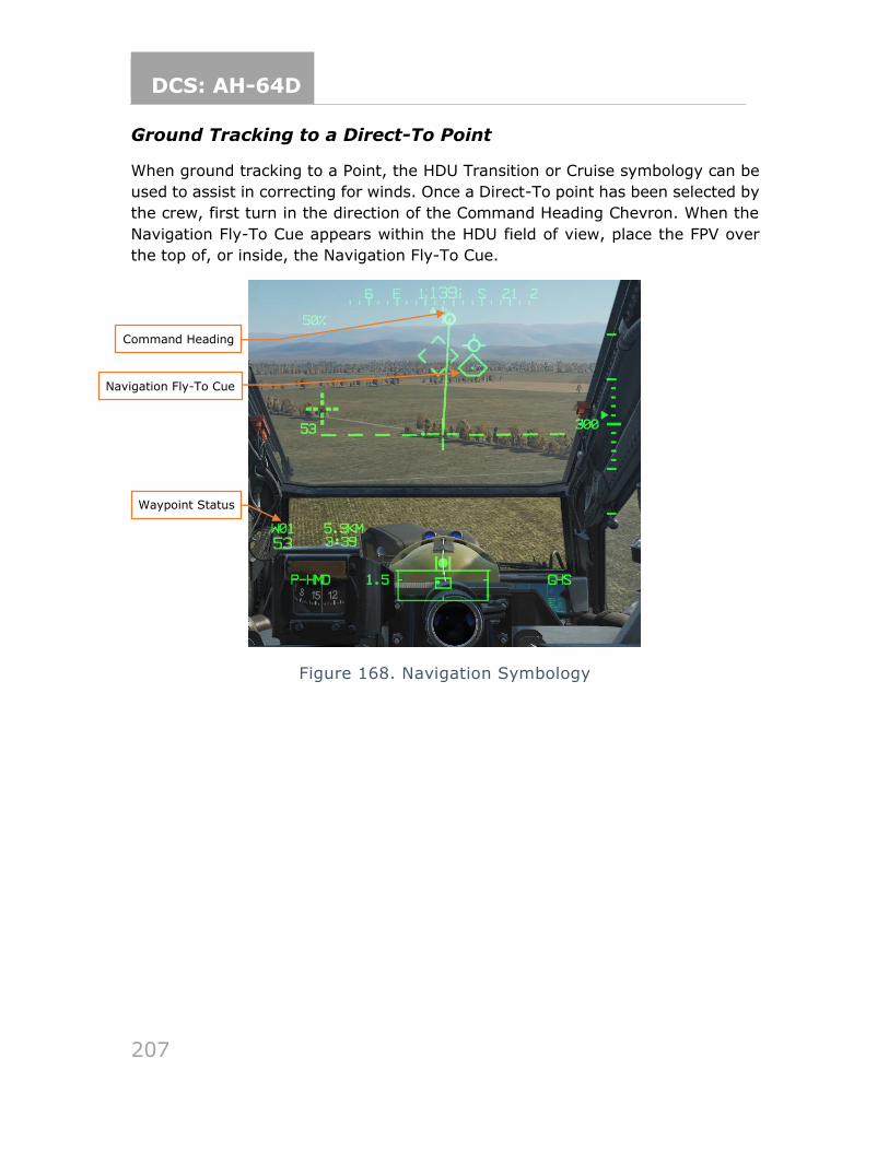
DCS: AH-64D
207
Ground Tracking to a Direct-To Point
When ground tracking to a Point, the HDU Transition or Cruise symbology can be
used to assist in correcting for winds. Once a Direct-To point has been selected by
the crew, first turn in the direction of the Command Heading Chevron. When the
Navigation Fly-To Cue appears within the HDU field of view, place the FPV over
the top of, or inside, the Navigation Fly-To Cue.
Figure 168. Navigation Symbology
Command Heading
Navigation Fly-To Cue
Waypoint Status
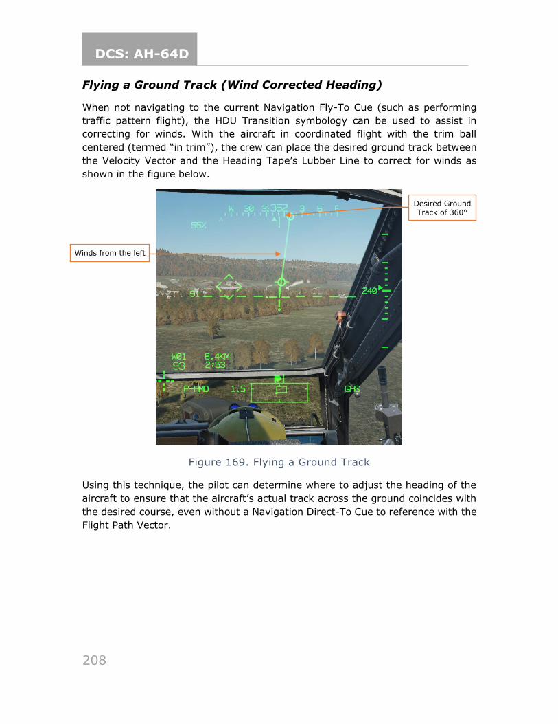
DCS: AH-64D
208
Flying a Ground Track (Wind Corrected Heading)
When not navigating to the current Navigation Fly-To Cue (such as performing
traffic pattern flight), the HDU Transition symbology can be used to assist in
correcting for winds. With the aircraft in coordinated flight with the trim ball
centered (termed “in trim”), the crew can place the desired ground track between
the Velocity Vector and the Heading Tape’s Lubber Line to correct for winds as
shown in the figure below.
Figure 169. Flying a Ground Track
Using this technique, the pilot can determine where to adjust the heading of the
aircraft to ensure that the aircraft’s actual track across the ground coincides with
the desired course, even without a Navigation Direct-To Cue to reference with the
Flight Path Vector.
Desired Ground Track of 360°
Winds from the left
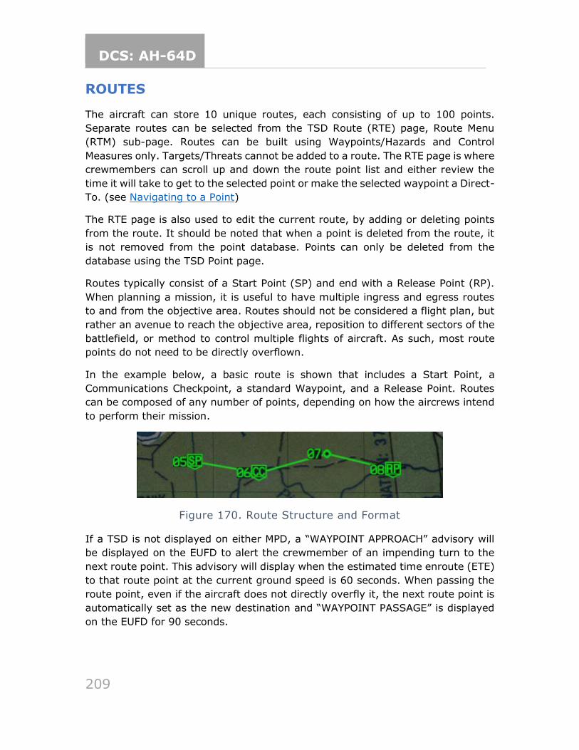
DCS: AH-64D
209
ROUTES
The aircraft can store 10 unique routes, each consisting of up to 100 points.
Separate routes can be selected from the TSD Route (RTE) page, Route Menu
(RTM) sub-page. Routes can be built using Waypoints/Hazards and Control
Measures only. Targets/Threats cannot be added to a route. The RTE page is where
crewmembers can scroll up and down the route point list and either review the
time it will take to get to the selected point or make the selected waypoint a Direct-
To. (see Navigating to a Point)
The RTE page is also used to edit the current route, by adding or deleting points
from the route. It should be noted that when a point is deleted from the route, it
is not removed from the point database. Points can only be deleted from the
database using the TSD Point page.
Routes typically consist of a Start Point (SP) and end with a Release Point (RP).
When planning a mission, it is useful to have multiple ingress and egress routes
to and from the objective area. Routes should not be considered a flight plan, but
rather an avenue to reach the objective area, reposition to different sectors of the
battlefield, or method to control multiple flights of aircraft. As such, most route
points do not need to be directly overflown.
In the example below, a basic route is shown that includes a Start Point, a
Communications Checkpoint, a standard Waypoint, and a Release Point. Routes
can be composed of any number of points, depending on how the aircrews intend
to perform their mission.
Figure 170. Route Structure and Format
If a TSD is not displayed on either MPD, a “WAYPOINT APPROACH” advisory will
be displayed on the EUFD to alert the crewmember of an impending turn to the
next route point. This advisory will display when the estimated time enroute (ETE)
to that route point at the current ground speed is 60 seconds. When passing the
route point, even if the aircraft does not directly overfly it, the next route point is
automatically set as the new destination and “WAYPOINT PASSAGE” is displayed
on the EUFD for 90 seconds.
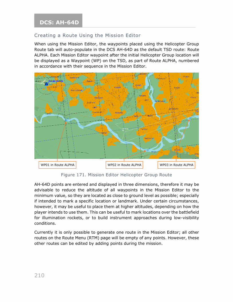
DCS: AH-64D
210
Creating a Route Using the Mission Editor
When using the Mission Editor, the waypoints placed using the Helicopter Group
Route tab will auto-populate in the DCS AH-64D as the default TSD route: Route
ALPHA. Each Mission Editor waypoint after the initial Helicopter Group location will
be displayed as a Waypoint (WP) on the TSD, as part of Route ALPHA, numbered
in accordance with their sequence in the Mission Editor.
Figure 171. Mission Editor Helicopter Group Route
AH-64D points are entered and displayed in three dimensions, therefore it may be
advisable to reduce the altitude of all waypoints in the Mission Editor to the
minimum value, so they are located as close to ground level as possible; especially
if intended to mark a specific location or landmark. Under certain circumstances,
however, it may be useful to place them at higher altitudes, depending on how the
player intends to use them. This can be useful to mark locations over the battlefield
for illumination rockets, or to build instrument approaches during low-visibility
conditions.
Currently it is only possible to generate one route in the Mission Editor; all other
routes on the Route Menu (RTM) page will be empty of any points. However, these
other routes can be edited by adding points during the mission.
WP01 in Route ALPHA WP02 in Route ALPHA WP03 in Route ALPHA
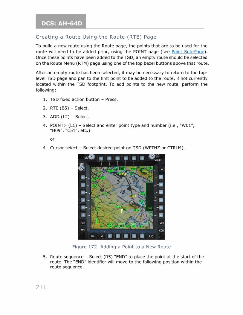
DCS: AH-64D
211
Creating a Route Using the Route (RTE) Page
To build a new route using the Route page, the points that are to be used for the
route will need to be added prior, using the POINT page (see Point Sub-Page).
Once these points have been added to the TSD, an empty route should be selected
on the Route Menu (RTM) page using one of the top bezel buttons above that route.
After an empty route has been selected, it may be necessary to return to the top-
level TSD page and pan to the first point to be added to the route, if not currently
located within the TSD footprint. To add points to the new route, perform the
following:
1. TSD fixed action button – Press.
2. RTE (B5) – Select.
3. ADD (L2) – Select.
4. POINT> (L1) – Select and enter point type and number (i.e., “W01”, “H09”, “C51”, etc.)
or
4. Cursor select – Select desired point on TSD (WPTHZ or CTRLM).
Figure 172. Adding a Point to a New Route
5. Route sequence – Select (R5) “END” to place the point at the start of the
route. The “END” identifier will move to the following position within the route sequence.
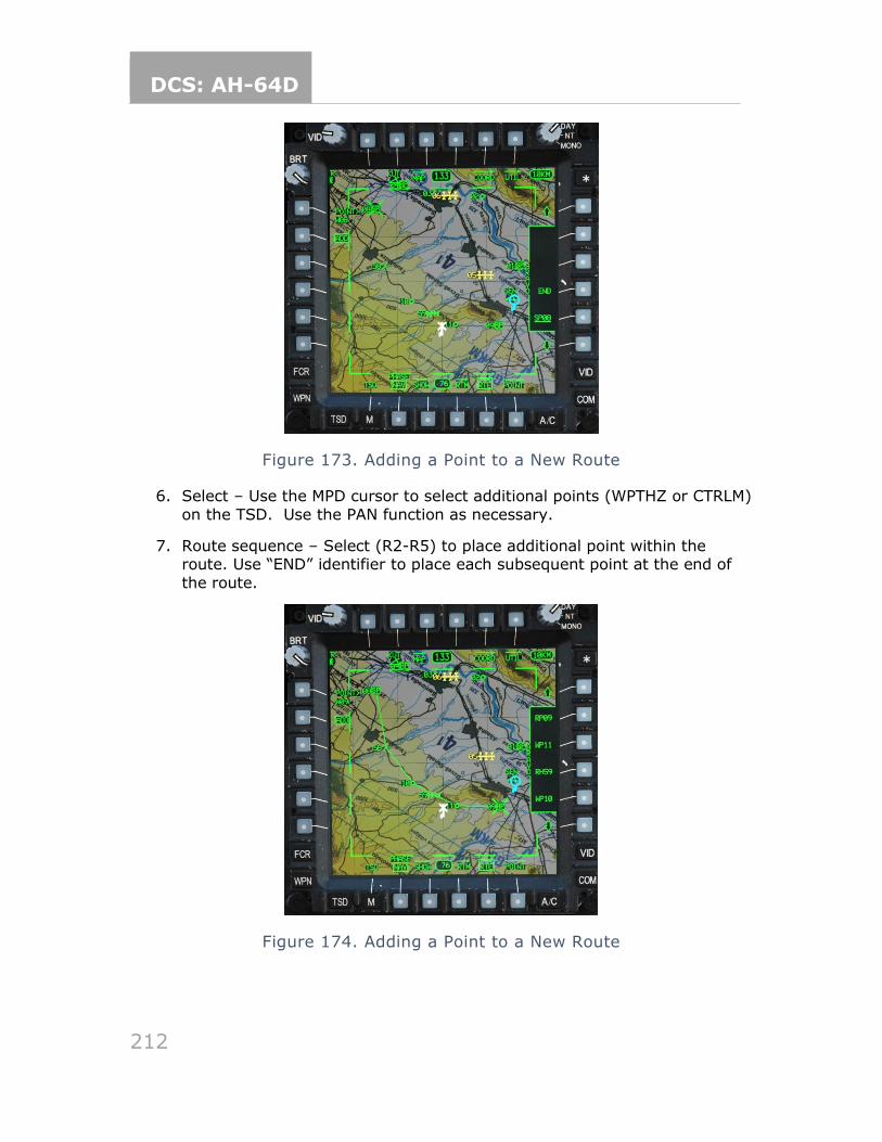
DCS: AH-64D
212
Figure 173. Adding a Point to a New Route
6. Select – Use the MPD cursor to select additional points (WPTHZ or CTRLM)
on the TSD. Use the PAN function as necessary.
7. Route sequence – Select (R2-R5) to place additional point within the route. Use “END” identifier to place each subsequent point at the end of
the route.
Figure 174. Adding a Point to a New Route
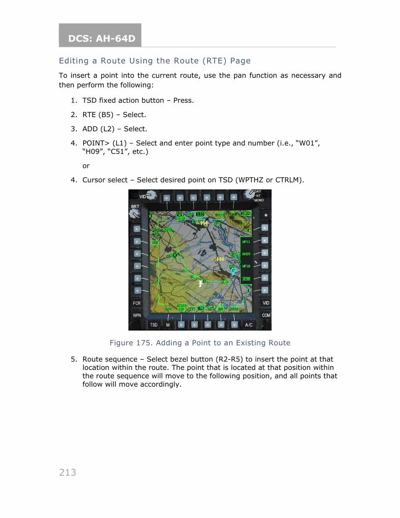
DCS: AH-64D
213
Editing a Route Using the Route (RTE) Page
To insert a point into the current route, use the pan function as necessary and
then perform the following:
1. TSD fixed action button – Press.
2. RTE (B5) – Select.
3. ADD (L2) – Select.
4. POINT> (L1) – Select and enter point type and number (i.e., “W01”,
“H09”, “C51”, etc.)
or
4. Cursor select – Select desired point on TSD (WPTHZ or CTRLM).
Figure 175. Adding a Point to an Existing Route
5. Route sequence – Select bezel button (R2-R5) to insert the point at that location within the route. The point that is located at that position within
the route sequence will move to the following position, and all points that follow will move accordingly.
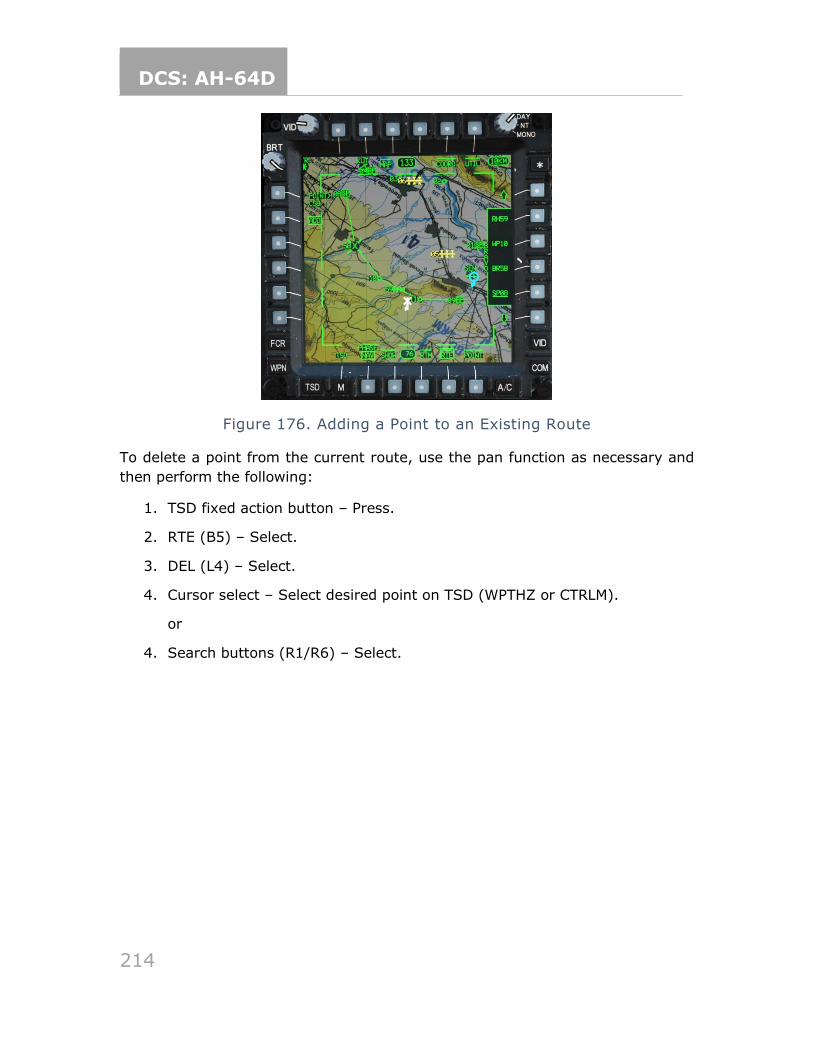
DCS: AH-64D
214
Figure 176. Adding a Point to an Existing Route
To delete a point from the current route, use the pan function as necessary and
then perform the following:
1. TSD fixed action button – Press.
2. RTE (B5) – Select.
3. DEL (L4) – Select.
4. Cursor select – Select desired point on TSD (WPTHZ or CTRLM).
or
4. Search buttons (R1/R6) – Select.
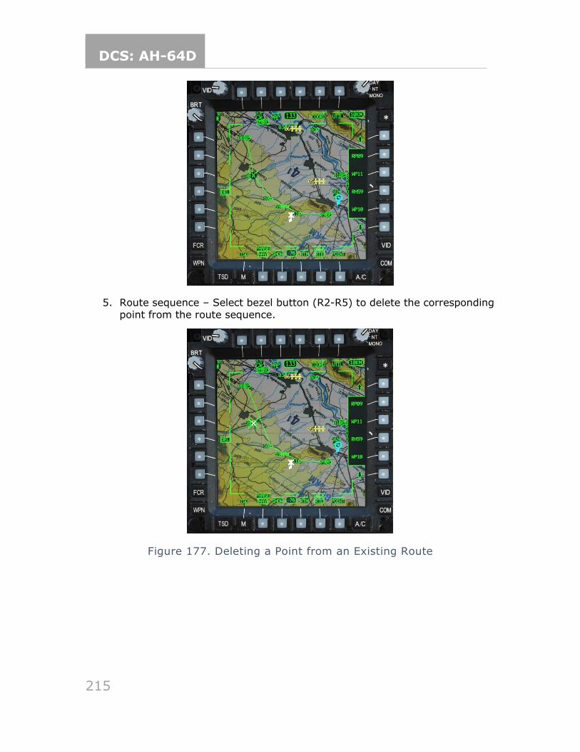
DCS: AH-64D
215
5. Route sequence – Select bezel button (R2-R5) to delete the corresponding point from the route sequence.
Figure 177. Deleting a Point from an Existing Route
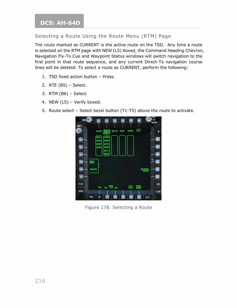
DCS: AH-64D
216
Selecting a Route Using the Route Menu (RTM) Page
The route marked as CURRENT is the active route on the TSD. Any time a route
is selected on the RTM page with NEW (L5) boxed, the Command Heading Chevron,
Navigation Fly-To Cue and Waypoint Status windows will switch navigation to the
first point in that route sequence, and any current Direct-To navigation course
lines will be deleted. To select a route as CURRENT, perform the following:
1. TSD fixed action button – Press.
2. RTE (B5) – Select.
3. RTM (B6) – Select.
4. NEW (L5) – Verify boxed.
5. Route select – Select bezel button (T1-T5) above the route to activate.
Figure 178. Selecting a Route
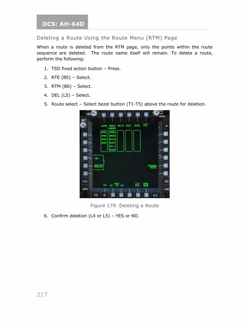
DCS: AH-64D
217
Deleting a Route Using the Route Menu (RTM) Page
When a route is deleted from the RTM page, only the points within the route
sequence are deleted. The route name itself will remain. To delete a route,
perform the following:
1. TSD fixed action button – Press.
2. RTE (B5) – Select.
3. RTM (B6) – Select.
4. DEL (L5) – Select.
5. Route select – Select bezel button (T1-T5) above the route for deletion.
Figure 179. Deleting a Route
6. Confirm deletion (L4 or L5) – YES or NO.
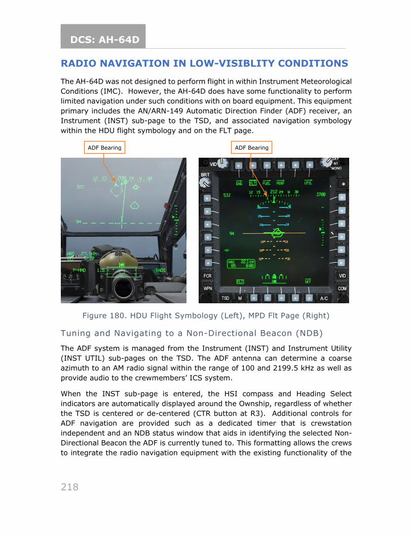
DCS: AH-64D
218
RADIO NAVIGATION IN LOW-VISIBLITY CONDITIONS
The AH-64D was not designed to perform flight in within Instrument Meteorological
Conditions (IMC). However, the AH-64D does have some functionality to perform
limited navigation under such conditions with on board equipment. This equipment
primary includes the AN/ARN-149 Automatic Direction Finder (ADF) receiver, an
Instrument (INST) sub-page to the TSD, and associated navigation symbology
within the HDU flight symbology and on the FLT page.
Figure 180. HDU Flight Symbology (Left), MPD Flt Page (Right)
Tuning and Navigating to a Non-Directional Beacon (NDB)
The ADF system is managed from the Instrument (INST) and Instrument Utility
(INST UTIL) sub-pages on the TSD. The ADF antenna can determine a coarse
azimuth to an AM radio signal within the range of 100 and 2199.5 kHz as well as
provide audio to the crewmembers’ ICS system.
When the INST sub-page is entered, the HSI compass and Heading Select
indicators are automatically displayed around the Ownship, regardless of whether
the TSD is centered or de-centered (CTR button at R3). Additional controls for
ADF navigation are provided such as a dedicated timer that is crewstation
independent and an NDB status window that aids in identifying the selected Non-
Directional Beacon the ADF is currently tuned to. This formatting allows the crews
to integrate the radio navigation equipment with the existing functionality of the
ADF Bearing ADF Bearing
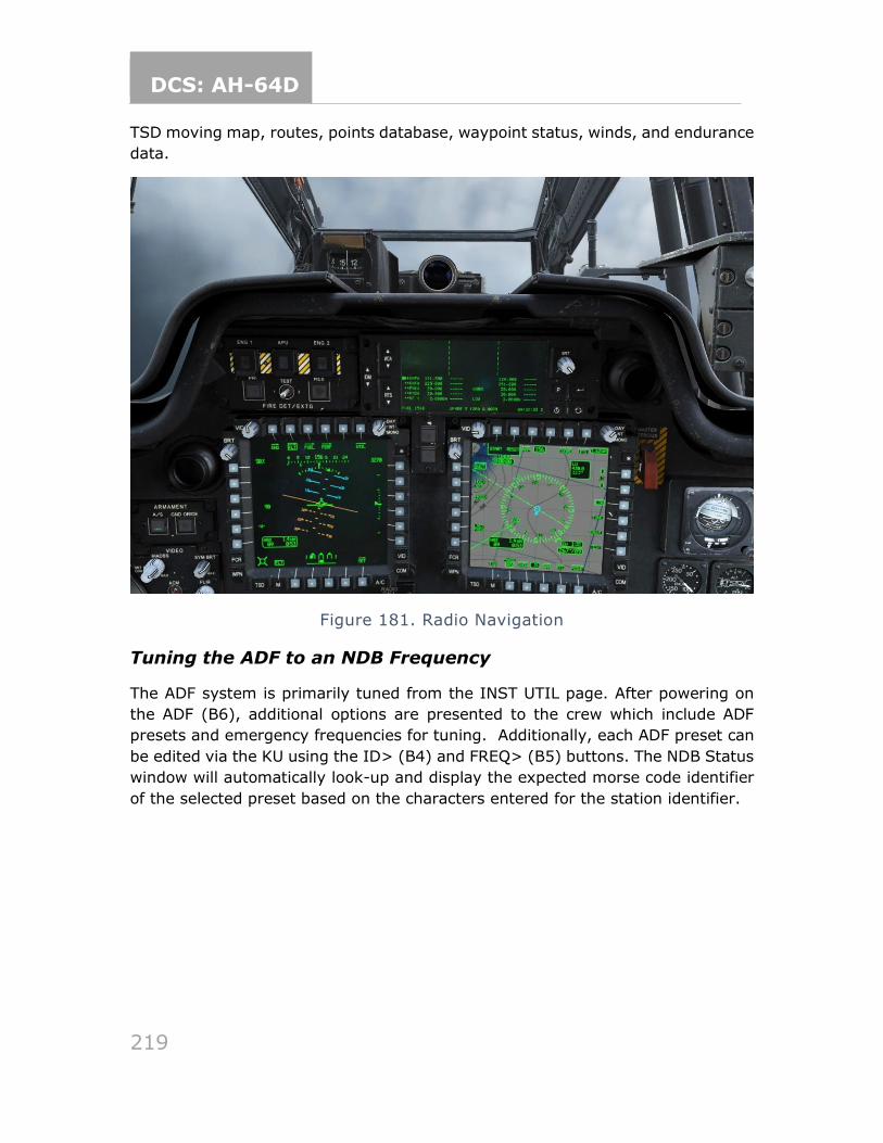
DCS: AH-64D
219
TSD moving map, routes, points database, waypoint status, winds, and endurance
data.
Figure 181. Radio Navigation
Tuning the ADF to an NDB Frequency
The ADF system is primarily tuned from the INST UTIL page. After powering on
the ADF (B6), additional options are presented to the crew which include ADF
presets and emergency frequencies for tuning. Additionally, each ADF preset can
be edited via the KU using the ID> (B4) and FREQ> (B5) buttons. The NDB Status
window will automatically look-up and display the expected morse code identifier
of the selected preset based on the characters entered for the station identifier.
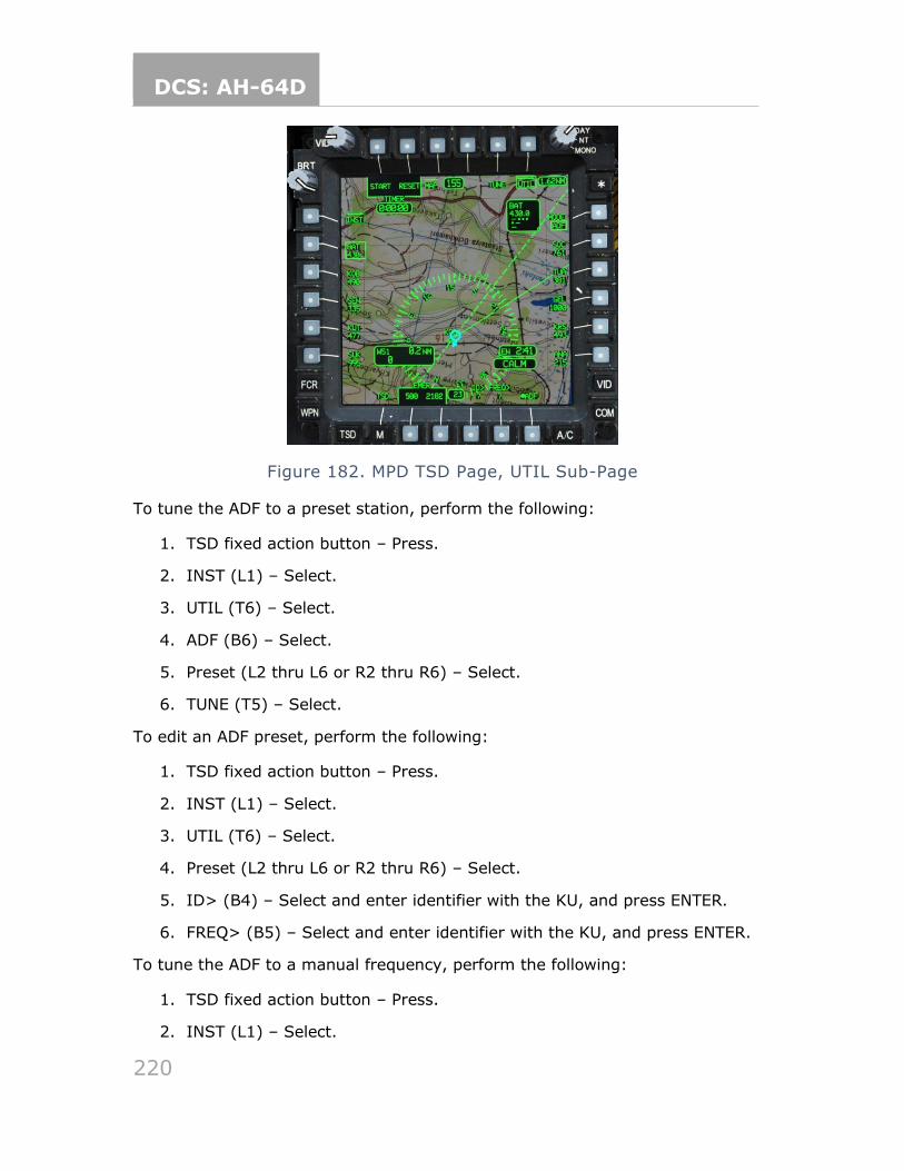
DCS: AH-64D
220
Figure 182. MPD TSD Page, UTIL Sub-Page
To tune the ADF to a preset station, perform the following:
1. TSD fixed action button – Press.
2. INST (L1) – Select.
3. UTIL (T6) – Select.
4. ADF (B6) – Select.
5. Preset (L2 thru L6 or R2 thru R6) – Select.
6. TUNE (T5) – Select.
To edit an ADF preset, perform the following:
1. TSD fixed action button – Press.
2. INST (L1) – Select.
3. UTIL (T6) – Select.
4. Preset (L2 thru L6 or R2 thru R6) – Select.
5. ID> (B4) – Select and enter identifier with the KU, and press ENTER.
6. FREQ> (B5) – Select and enter identifier with the KU, and press ENTER.
To tune the ADF to a manual frequency, perform the following:
1. TSD fixed action button – Press.
2. INST (L1) – Select.
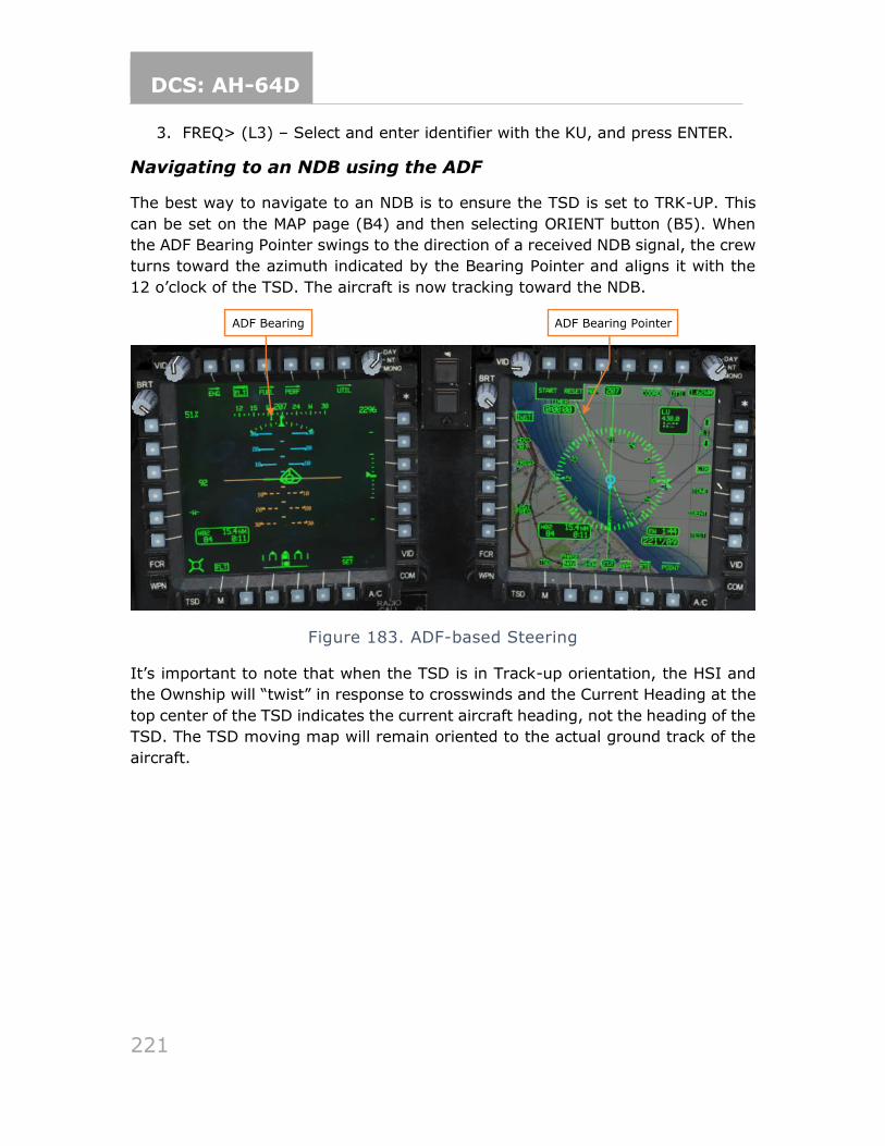
DCS: AH-64D
221
3. FREQ> (L3) – Select and enter identifier with the KU, and press ENTER.
Navigating to an NDB using the ADF
The best way to navigate to an NDB is to ensure the TSD is set to TRK-UP. This
can be set on the MAP page (B4) and then selecting ORIENT button (B5). When
the ADF Bearing Pointer swings to the direction of a received NDB signal, the crew
turns toward the azimuth indicated by the Bearing Pointer and aligns it with the
12 o’clock of the TSD. The aircraft is now tracking toward the NDB.
Figure 183. ADF-based Steering
It’s important to note that when the TSD is in Track-up orientation, the HSI and
the Ownship will “twist” in response to crosswinds and the Current Heading at the
top center of the TSD indicates the current aircraft heading, not the heading of the
TSD. The TSD moving map will remain oriented to the actual ground track of the
aircraft.
ADF Bearing ADF Bearing Pointer
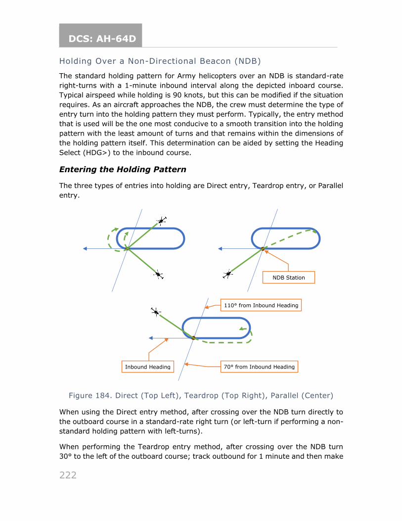
DCS: AH-64D
222
Holding Over a Non-Directional Beacon (NDB)
The standard holding pattern for Army helicopters over an NDB is standard-rate
right-turns with a 1-minute inbound interval along the depicted inboard course.
Typical airspeed while holding is 90 knots, but this can be modified if the situation
requires. As an aircraft approaches the NDB, the crew must determine the type of
entry turn into the holding pattern they must perform. Typically, the entry method
that is used will be the one most conducive to a smooth transition into the holding
pattern with the least amount of turns and that remains within the dimensions of
the holding pattern itself. This determination can be aided by setting the Heading
Select (HDG>) to the inbound course.
Entering the Holding Pattern
The three types of entries into holding are Direct entry, Teardrop entry, or Parallel
entry.
Figure 184. Direct (Top Left), Teardrop (Top Right), Parallel (Center)
When using the Direct entry method, after crossing over the NDB turn directly to
the outboard course in a standard-rate right turn (or left-turn if performing a non-
standard holding pattern with left-turns).
When performing the Teardrop entry method, after crossing over the NDB turn
30° to the left of the outboard course; track outbound for 1 minute and then make
Inbound Heading
NDB Station
110° from Inbound Heading
70° from Inbound Heading
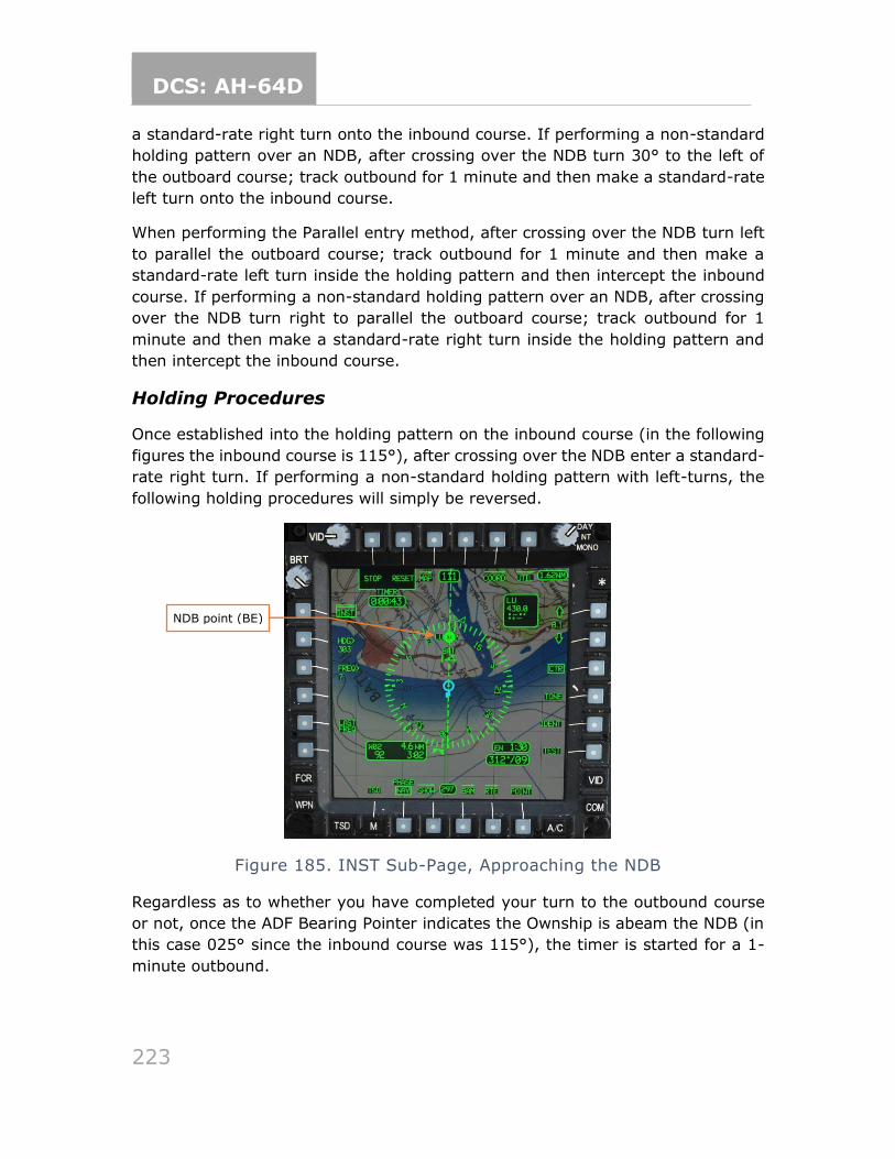
DCS: AH-64D
223
a standard-rate right turn onto the inbound course. If performing a non-standard
holding pattern over an NDB, after crossing over the NDB turn 30° to the left of
the outboard course; track outbound for 1 minute and then make a standard-rate
left turn onto the inbound course.
When performing the Parallel entry method, after crossing over the NDB turn left
to parallel the outboard course; track outbound for 1 minute and then make a
standard-rate left turn inside the holding pattern and then intercept the inbound
course. If performing a non-standard holding pattern over an NDB, after crossing
over the NDB turn right to parallel the outboard course; track outbound for 1
minute and then make a standard-rate right turn inside the holding pattern and
then intercept the inbound course.
Holding Procedures
Once established into the holding pattern on the inbound course (in the following
figures the inbound course is 115°), after crossing over the NDB enter a standard-
rate right turn. If performing a non-standard holding pattern with left-turns, the
following holding procedures will simply be reversed.
Figure 185. INST Sub-Page, Approaching the NDB
Regardless as to whether you have completed your turn to the outbound course
or not, once the ADF Bearing Pointer indicates the Ownship is abeam the NDB (in
this case 025° since the inbound course was 115°), the timer is started for a 1-
minute outbound.
NDB point (BE)
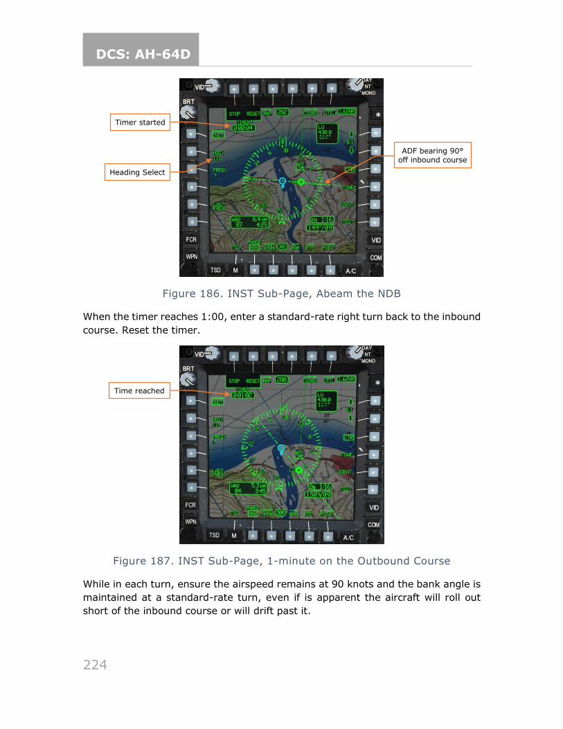
DCS: AH-64D
224
Figure 186. INST Sub-Page, Abeam the NDB
When the timer reaches 1:00, enter a standard-rate right turn back to the inbound
course. Reset the timer.
Figure 187. INST Sub-Page, 1-minute on the Outbound Course
While in each turn, ensure the airspeed remains at 90 knots and the bank angle is
maintained at a standard-rate turn, even if is apparent the aircraft will roll out
short of the inbound course or will drift past it.
Heading Select
ADF bearing 90° off inbound course
Timer started
Time reached
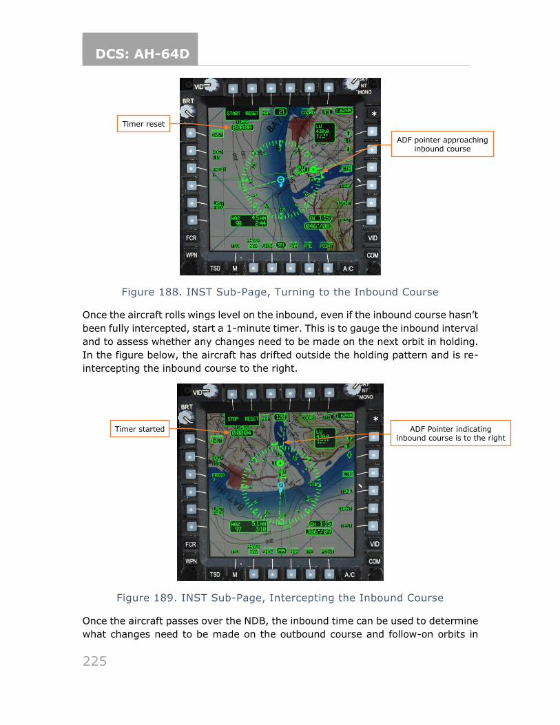
DCS: AH-64D
225
Figure 188. INST Sub-Page, Turning to the Inbound Course
Once the aircraft rolls wings level on the inbound, even if the inbound course hasn’t
been fully intercepted, start a 1-minute timer. This is to gauge the inbound interval
and to assess whether any changes need to be made on the next orbit in holding.
In the figure below, the aircraft has drifted outside the holding pattern and is re-
intercepting the inbound course to the right.
Figure 189. INST Sub-Page, Intercepting the Inbound Course
Once the aircraft passes over the NDB, the inbound time can be used to determine
what changes need to be made on the outbound course and follow-on orbits in
Timer reset
ADF pointer approaching inbound course
Timer started ADF Pointer indicating inbound course is to the right
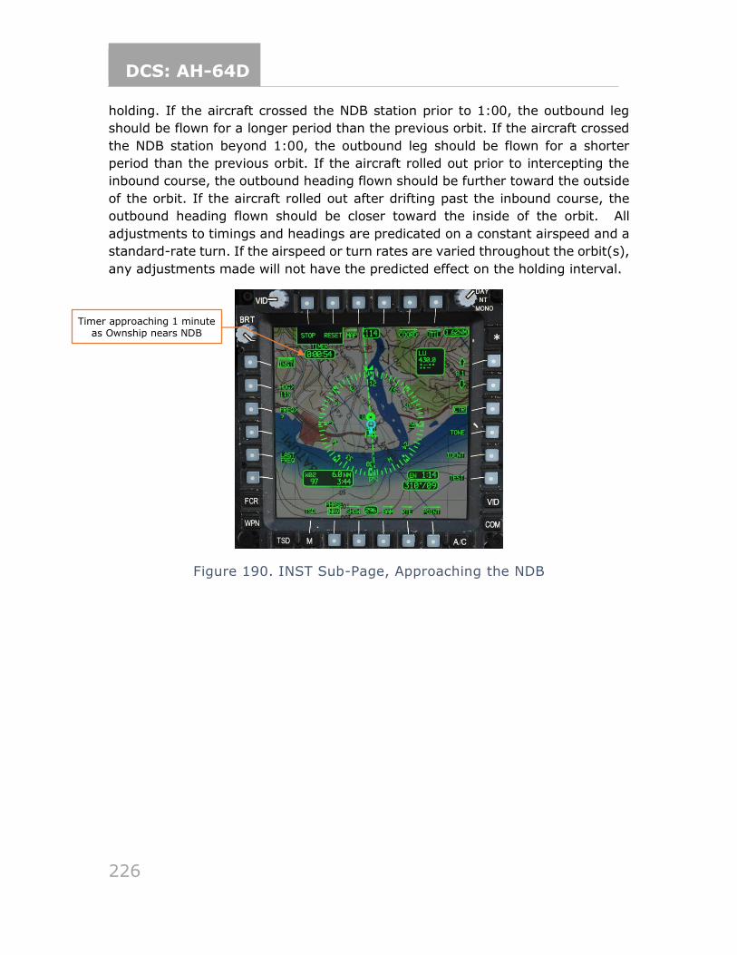
DCS: AH-64D
226
holding. If the aircraft crossed the NDB station prior to 1:00, the outbound leg
should be flown for a longer period than the previous orbit. If the aircraft crossed
the NDB station beyond 1:00, the outbound leg should be flown for a shorter
period than the previous orbit. If the aircraft rolled out prior to intercepting the
inbound course, the outbound heading flown should be further toward the outside
of the orbit. If the aircraft rolled out after drifting past the inbound course, the
outbound heading flown should be closer toward the inside of the orbit. All
adjustments to timings and headings are predicated on a constant airspeed and a
standard-rate turn. If the airspeed or turn rates are varied throughout the orbit(s),
any adjustments made will not have the predicted effect on the holding interval.
Figure 190. INST Sub-Page, Approaching the NDB
Timer approaching 1 minute as Ownship nears NDB
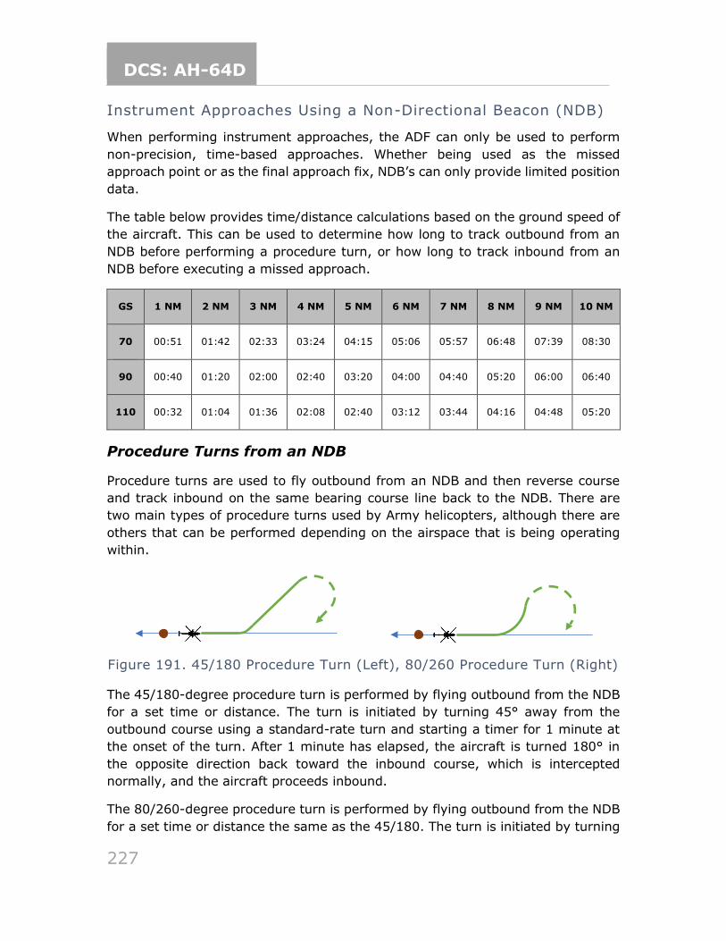
DCS: AH-64D
227
Instrument Approaches Using a Non-Directional Beacon (NDB)
When performing instrument approaches, the ADF can only be used to perform
non-precision, time-based approaches. Whether being used as the missed
approach point or as the final approach fix, NDB’s can only provide limited position
data.
The table below provides time/distance calculations based on the ground speed of
the aircraft. This can be used to determine how long to track outbound from an
NDB before performing a procedure turn, or how long to track inbound from an
NDB before executing a missed approach.
GS 1 NM 2 NM 3 NM 4 NM 5 NM 6 NM 7 NM 8 NM 9 NM 10 NM
70 00:51 01:42 02:33 03:24 04:15 05:06 05:57 06:48 07:39 08:30
90 00:40 01:20 02:00 02:40 03:20 04:00 04:40 05:20 06:00 06:40
110 00:32 01:04 01:36 02:08 02:40 03:12 03:44 04:16 04:48 05:20
Procedure Turns from an NDB
Procedure turns are used to fly outbound from an NDB and then reverse course
and track inbound on the same bearing course line back to the NDB. There are
two main types of procedure turns used by Army helicopters, although there are
others that can be performed depending on the airspace that is being operating
within.
Figure 191. 45/180 Procedure Turn (Left), 80/260 Procedure Turn (Right)
The 45/180-degree procedure turn is performed by flying outbound from the NDB
for a set time or distance. The turn is initiated by turning 45° away from the
outbound course using a standard-rate turn and starting a timer for 1 minute at
the onset of the turn. After 1 minute has elapsed, the aircraft is turned 180° in
the opposite direction back toward the inbound course, which is intercepted
normally, and the aircraft proceeds inbound.
The 80/260-degree procedure turn is performed by flying outbound from the NDB
for a set time or distance the same as the 45/180. The turn is initiated by turning
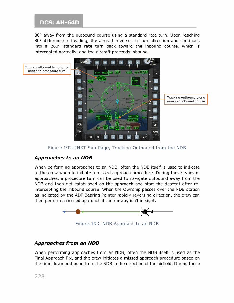
DCS: AH-64D
228
80° away from the outbound course using a standard-rate turn. Upon reaching
80° difference in heading, the aircraft reverses its turn direction and continues
into a 260° standard rate turn back toward the inbound course, which is
intercepted normally, and the aircraft proceeds inbound.
Figure 192. INST Sub-Page, Tracking Outbound from the NDB
Approaches to an NDB
When performing approaches to an NDB, often the NDB itself is used to indicate
to the crew when to initiate a missed approach procedure. During these types of
approaches, a procedure turn can be used to navigate outbound away from the
NDB and then get established on the approach and start the descent after re-
intercepting the inbound course. When the Ownship passes over the NDB station
as indicated by the ADF Bearing Pointer rapidly reversing direction, the crew can
then perform a missed approach if the runway isn’t in sight.
Figure 193. NDB Approach to an NDB
Approaches from an NDB
When performing approaches from an NDB, often the NDB itself is used as the
Final Approach Fix, and the crew initiates a missed approach procedure based on
the time flown outbound from the NDB in the direction of the airfield. During these
Timing outbound leg prior to initiating procedure turn
Tracking outbound along
reversed inbound course
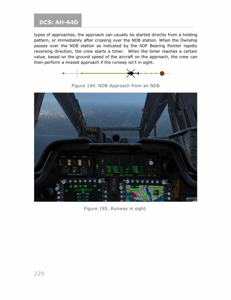
DCS: AH-64D
229
types of approaches, the approach can usually be started directly from a holding
pattern, or immediately after crossing over the NDB station. When the Ownship
passes over the NDB station as indicated by the ADF Bearing Pointer rapidly
reversing direction, the crew starts a timer. When the timer reaches a certain
value, based on the ground speed of the aircraft on the approach, the crew can
then perform a missed approach if the runway isn’t in sight.
Figure 194. NDB Approach from an NDB
Figure 195. Runway in sight.
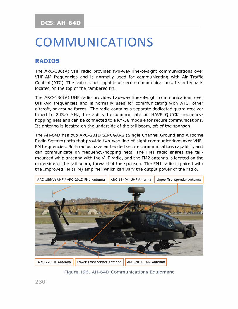
DCS: AH-64D
230
COMMUNICATIONS RADIOS
The ARC-186(V) VHF radio provides two-way line-of-sight communications over
VHF-AM frequencies and is normally used for communicating with Air Traffic
Control (ATC). The radio is not capable of secure communications. Its antenna is
located on the top of the cambered fin.
The ARC-186(V) UHF radio provides two-way line-of-sight communications over
UHF-AM frequencies and is normally used for communicating with ATC, other
aircraft, or ground forces. The radio contains a separate dedicated guard receiver
tuned to 243.0 MHz, the ability to communicate on HAVE QUICK frequency-
hopping nets and can be connected to a KY-58 module for secure communications.
Its antenna is located on the underside of the tail boom, aft of the sponson.
The AH-64D has two ARC-201D SINCGARS (Single Channel Ground and Airborne
Radio System) sets that provide two-way line-of-sight communications over VHF-
FM frequencies. Both radios have embedded secure communications capability and
can communicate on frequency-hopping nets. The FM1 radio shares the tail-
mounted whip antenna with the VHF radio, and the FM2 antenna is located on the
underside of the tail boom, forward of the sponson. The FM1 radio is paired with
the Improved FM (IFM) amplifier which can vary the output power of the radio.
Figure 196. AH-64D Communications Equipment
ARC-220 HF Antenna ARC-201D FM2 Antenna
ARC-186(V) VHF / ARC-201D FM1 Antenna Antenna
ARC-164(V) UHF Antenna Upper Transponder Antenna
Lower Transponder Antenna
DCS: AH-64D
231
The AH-64D is equipped with an ARC-220 HF radio for two-way, non-line-of-sight
(NLOS) and over-the-horizon (OTH) communications over shortwave frequencies.
The radio has an embedded modem for sending and receiving data transmissions,
can operate using frequency-hopping nets, and can be connected to a KY-100
module for secure communications capability. The ARC-220 is also capable of
communications using Automatic Link Establishment (ALE) multi-channel nets to
decrease crew workload and increase communications reliability. The HF radio
utilizes a near-vertical incidence skywave (NVIS) type antenna which runs along
the right side of the tail boom. The radio is paired with a dedicated amplifier which
can vary the output power of the radio.
USING VOICE RADIOS
The aircraft radios are operated by cyclic controls, the EUFD and the MPD COM
pages. A communications panel is also present in each crewstation and allows
crews to adjust the volume of each individual radio, toggle radio squelch on or off,
and adjust their microphone settings.
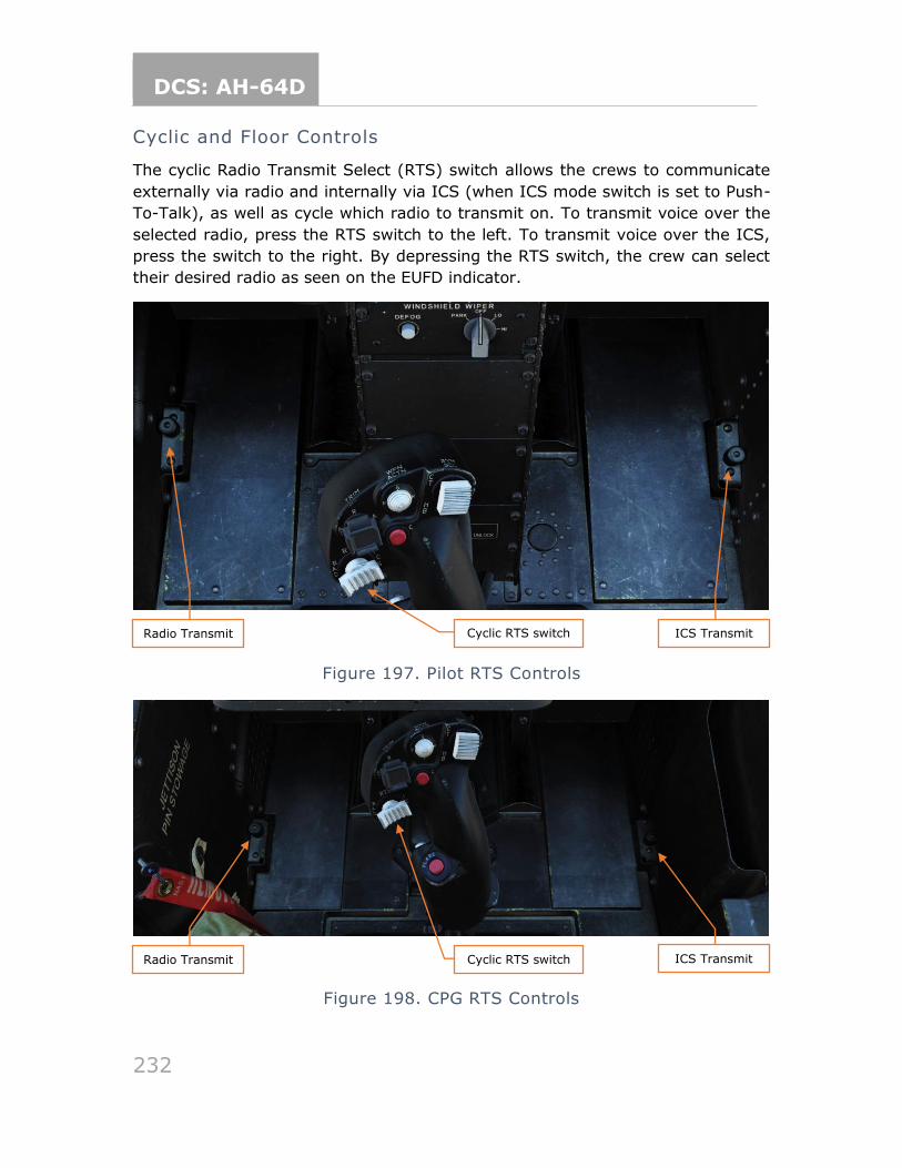
DCS: AH-64D
232
Cyclic and Floor Controls
The cyclic Radio Transmit Select (RTS) switch allows the crews to communicate
externally via radio and internally via ICS (when ICS mode switch is set to Push-
To-Talk), as well as cycle which radio to transmit on. To transmit voice over the
selected radio, press the RTS switch to the left. To transmit voice over the ICS,
press the switch to the right. By depressing the RTS switch, the crew can select
their desired radio as seen on the EUFD indicator.
Figure 197. Pilot RTS Controls
Figure 198. CPG RTS Controls
Radio Transmit ICS Transmit Cyclic RTS switch
Radio Transmit ICS Transmit Cyclic RTS switch
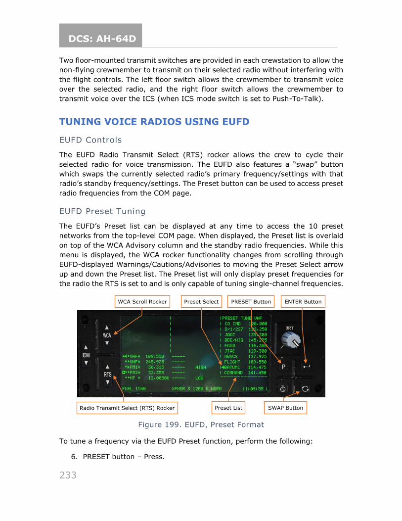
DCS: AH-64D
233
Two floor-mounted transmit switches are provided in each crewstation to allow the
non-flying crewmember to transmit on their selected radio without interfering with
the flight controls. The left floor switch allows the crewmember to transmit voice
over the selected radio, and the right floor switch allows the crewmember to
transmit voice over the ICS (when ICS mode switch is set to Push-To-Talk).
TUNING VOICE RADIOS USING EUFD
EUFD Controls
The EUFD Radio Transmit Select (RTS) rocker allows the crew to cycle their
selected radio for voice transmission. The EUFD also features a “swap” button
which swaps the currently selected radio’s primary frequency/settings with that
radio’s standby frequency/settings. The Preset button can be used to access preset
radio frequencies from the COM page.
EUFD Preset Tuning
The EUFD’s Preset list can be displayed at any time to access the 10 preset
networks from the top-level COM page. When displayed, the Preset list is overlaid
on top of the WCA Advisory column and the standby radio frequencies. While this
menu is displayed, the WCA rocker functionality changes from scrolling through
EUFD-displayed Warnings/Cautions/Advisories to moving the Preset Select arrow
up and down the Preset list. The Preset list will only display preset frequencies for
the radio the RTS is set to and is only capable of tuning single-channel frequencies.
Figure 199. EUFD, Preset Format
To tune a frequency via the EUFD Preset function, perform the following:
6. PRESET button – Press.
Preset List SWAP Button
PRESET Button WCA Scroll Rocker
Radio Transmit Select (RTS) Rocker
ENTER Button Preset Select
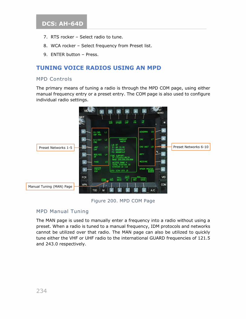
DCS: AH-64D
234
7. RTS rocker – Select radio to tune.
8. WCA rocker – Select frequency from Preset list.
9. ENTER button – Press.
TUNING VOICE RADIOS USING AN MPD
MPD Controls
The primary means of tuning a radio is through the MPD COM page, using either
manual frequency entry or a preset entry. The COM page is also used to configure
individual radio settings.
Figure 200. MPD COM Page
MPD Manual Tuning
The MAN page is used to manually enter a frequency into a radio without using a
preset. When a radio is tuned to a manual frequency, IDM protocols and networks
cannot be utilized over that radio. The MAN page can also be utilized to quickly
tune either the VHF or UHF radio to the international GUARD frequencies of 121.5
and 243.0 respectively.
Preset Networks 1-5
Manual Tuning (MAN) Page
Preset Networks 6-10
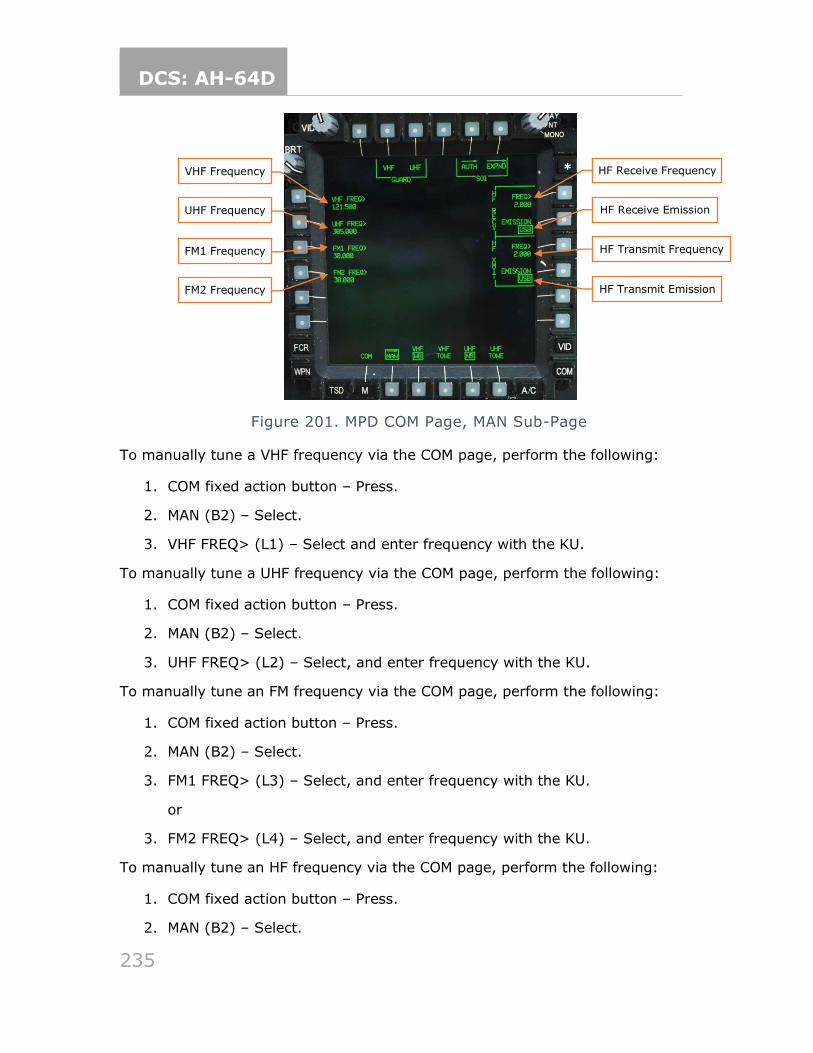
DCS: AH-64D
235
Figure 201. MPD COM Page, MAN Sub-Page
To manually tune a VHF frequency via the COM page, perform the following:
1. COM fixed action button – Press.
2. MAN (B2) – Select.
3. VHF FREQ> (L1) – Select and enter frequency with the KU.
To manually tune a UHF frequency via the COM page, perform the following:
1. COM fixed action button – Press.
2. MAN (B2) – Select.
3. UHF FREQ> (L2) – Select, and enter frequency with the KU.
To manually tune an FM frequency via the COM page, perform the following:
1. COM fixed action button – Press.
2. MAN (B2) – Select.
3. FM1 FREQ> (L3) – Select, and enter frequency with the KU.
or
3. FM2 FREQ> (L4) – Select, and enter frequency with the KU.
To manually tune an HF frequency via the COM page, perform the following:
1. COM fixed action button – Press.
2. MAN (B2) – Select.
VHF Frequency
UHF Frequency
FM1 Frequency
FM2 Frequency
HF Receive Frequency
HF Receive Emission
HF Transmit Frequency
HF Transmit Emission
DCS: AH-64D
236
3. HF RECV FREQ> (R1) – Select, and enter frequency with the KU.
4. HF RECV EMISSION (R2) – Select and set appropriately.
5. HF XMIT FREQ> (R3) – Select, and enter frequency with the KU.
6. HF XMIT EMISSION (R4) – Select and set appropriately.
MPD Preset Tuning
-Coming later in EA-
A total of 60 Preset Networks are available to the crew and are usually built during
pre-mission planning. The top-level COM page displays 10 Preset Nets (also
selected during pre-mission planning and loaded via the DTC). The additional
remaining 50 Preset Networks are found in the Preset Directory and can replace
the top-level COM page Preset Networks.
Each Preset Network can contain the following:
• 8-character preset name which is displayed on the COM page
• 5-character callsign which is displayed on the EUFD
• VHF single-channel frequency
• UHF HAVE QUICK frequency-hopping net
• UHF single-channel frequency
• FM1 SINCGARS frequency-hopping net
• FM1 single-channel frequency
• FM2 SINCGARS frequency-hopping net
• FM2 single-channel frequency
• HF ECCM frequency-hopping net
• HF ALE multi-channel net
• HF Preset single-channel frequency
• HF Manual single-channel frequency
• IDM Protocol
• Net members and associated address information
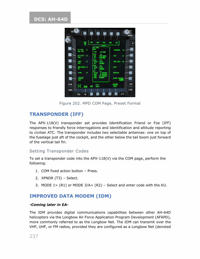
DCS: AH-64D
237
Figure 202. MPD COM Page, Preset Format
TRANSPONDER (IFF)
The APX-118(V) transponder set provides Identification Friend or Foe (IFF)
responses to friendly force interrogations and identification and altitude reporting
to civilian ATC. The transponder includes two selectable antennas: one on top of
the fuselage just aft of the cockpit, and the other below the tail boom just forward
of the vertical tail fin.
Setting Transponder Codes
To set a transponder code into the APX-118(V) via the COM page, perform the
following:
1. COM fixed action button – Press.
2. XPNDR (T3) – Select.
3. MODE 1> (R1) or MODE 3/A> (R2) – Select and enter code with the KU.
IMPROVED DATA MODEM (IDM)
-Coming later in EA-
The IDM provides digital communications capabilities between other AH-64D
helicopters via the Longbow Air Force Application Program Development (AFAPD),
more commonly referred to as the Longbow Net. The IDM can transmit over the
VHF, UHF, or FM radios, provided they are configured as a Longbow Net (denoted
DCS: AH-64D
238
by an L in the EUFD) and the crew has selected that radio using the IDM rocker on
the EUFD.
The IDM allows other AH-64D helicopters to individually transmit points, routes,
FCR targets, text messages, files, or the entire DTC mission database.
DCS: AH-64D
239
AIRCRAFT PROCEDURES COLD START
The following procedures are to be completed after pre-flight. Since there is a large
amount of commonality between crewstations, checks are combined to save space.
Checks specific to the Pilot crewstation will be denoted by (PLT) and checks
specific to the CPG crewstation will be denoted by (CPG). Where checks are
common, they will be denoted by (PLT/CPG).
Interior Checks
Upon entering the crewstation, check the following:
• (PLT/CPG) Canopy door, check then as desired (open or intermediate position).
Check the following along the left side of the crewstation, beginning in the back
left corner:
• (PLT) EXT LT/INTR LT panel – Set NAV lights to BRT, ANTI-COL OFF and
PRIMARY to BRT.
• (CPG) INTR LT panel – Set PRIMARY to BRT.
• (PLT/CPG) Power levers – OFF.
• (PLT) ENG START switches – OFF.
• (PLT) RTR BRK switch – OFF.
• (PLT/CPG) NVS MODE switch – OFF.
On the front panel, beginning on the left side check:
• (PLT/CPG) KU brightness knob – As desired.
• (PLT) VIDEO panel – Check and position knobs to 12 o’clock position.
• (PLT/CPG) MPD and EUFD brightness knobs – As desired.
• (PLT) CMWS Control Indicator PWR switch – OFF.
DCS: AH-64D
240
• (PLT) CMWS Control Panel – Set Switches as follows:
o CMWS/NAV – CMWS.
o BYPASS/AUTO – AUTO.
o JETTISON – Off (cover closed).
• (CPG) TEDAC Right Handgrip LT switch - OFF
• (PLT) PARK BRAKE – Set, handle out.
• (PLT) Standby flight instruments – Check:
o Attitude indicator – Caged.
Check the following along the right side of the crewstation:
• (PLT/CPG) COMM panel switches – As desired.
• (PLT/CPG) HDU – Check and adjust as required.
Before Starting APU
Once the interior checks are complete:
• (PLT) MSTR IGN switch – BATT.
• (PLT) Searchlight – As required.
• (PLT) TAIL WHEEL button – Locked, UNLOCKED light is off.
• (PLT/CPG) EMERG HYD button – Verify pushbutton ON light is off.
• (PLT) EXT LT/INTR LT panel – PRESS-TO-TEST button illuminates all signal lights – Check.
• (CPG) INTR LT panel – PRESS-TO-TEST button illuminates all signal lights – Check.
• (PLT/CPG) MSTR WARN, MSTR CAUT, and EUFD – Check.
• FIRE DET/EXTG panel TEST switch – Test as follows:
o (PLT) Position 1: - MSTR WARN, ENG 1, APU and ENG 2 FIRE buttons are illuminated, an AFT DECK FIRE warning is displayed on
the EUFD and voice warning system is activated.
o (CPG) Position 2: - MSTR WARN, ENG 1, APU and ENG 2 FIRE and DISCH buttons are illuminated, an AFT DECK FIRE warning is
displayed on the EUFD and voice warning system is activated.
DCS: AH-64D
241
Starting APU
With the Interior and Before Starting APU checks complete, it is now time to start
the APU. During extended APU operations, monitor the XMSN OIL temperature on
the ENG SYS page. Do not exceed operations for greater than 5 minutes at a XMSN
OIL temperature of 120° to 130° C. If the temperature exceeds 130° C, shut the
APU down and allow the XMSN OIL temperature to cool for 30 minutes.
• (PLT) APU – Start as follows:
o APU button – Press and release.
o EUFD – Observe for “APU START”, “APU POWER ON” and “ACCUM OIL PRESS LO” advisories.
After Starting APU
Now that the APU has been started, perform the following:
• (PLT/CPG) Canopy door, check then as desired (open or intermediate position).
• (PLT/CPG) DTU page – Select load.
• (PLT/CPG) Menu page – Systems configuration – Perform DMS sweep.
Data Management System (DMS) Sweep
The Data Management System (DMS) sweep is meant to pre-configure aircraft
pages for use during flight. While conducting the DMS sweep, it is important to be
consistent. As an example technique, the sweep of any specific page begins at the
top of the MPD and moves clockwise to the right, along the bottom and finishing
on the left of the MPD. Other techniques may be used based on crewmember
preferences or specific mission requirements.
Perform the DMS sweep as follows:
• (PLT/CPG) ‘M’ (B1) button – Press.
o ASE (L3) – Select.
▪ UTIL (T6) – Select.
▪ RLWR VOICE (R5) – Set as desired.
▪ Chaff settings (L2-L5) – Set as desired.
▪ CHAFF mode (L1) – Set as desired.
▪ UTIL (T6) – Deselect.
DCS: AH-64D
242
o AUTOPAGE (R1) – Set as desired.
• (PLT/CPG) TSD Button – Press.
o SHOW (T3) – Select and configure NAV SHOW options.
▪ PHASE (B2) – Select ATK and configure ATK phase SHOW options.
▪ THRT SHOW (T5) – Select and configure THRT SHOW options.
▪ COORD SHOW (T6) – Select and configure ATK phase COORD SHOW options.
▪ PHASE (B2) – Select NAV and configure NAV phase COORD SHOW options.
▪ SHOW (T3) – Deselect.
o UTIL (T6) – Select.
▪ TIME (R2) – Set Zulu/Local as desired.
▪ SYSTEM TIME> (R3) – Update Local time if necessary.
▪ UTIL (T6) – Deselect.
o SCALE (R1 & R2) – Set as desired.
o CTR (R3) – Set as desired.
o RTE (B5) – Select.
▪ DIR (L5) – Set to desired point.
▪ RTE (B5) – Deselect.
o MAP (B4) – Select.
▪ GRID (T5) – Set as desired.
▪ ORIENT (R5) – Set as desired.
▪ COLOR BAND (L4) – Set as desired.
▪ SCALE (L3) – Set as desired.
▪ TYPE (L2) – Set as desired.
▪ MAP (B4) – Deselect.
o INST (L1) – Select.
▪ UTIL (T6) – Select.
▪ ADF (B6) – Turn on ADF.
DCS: AH-64D
243
▪ Configure ADF as desired.
▪ UTIL (T6) – Deselect.
▪ INST (L1) – Deselect.
• (PLT/CPG) WPN Button – Press.
o GRAYSCALE (L6) – Select and optimize.
o BORESIGHT (B5) – Select and perform IHADSS boresight.
o BORESIGHT (B5) – Deselect.
o GUN (B2) – Select.
▪ Set desired BURST LIMIT L1 thru L5 and MODE on R2.
o MSL (B3) – Select.
▪ CODE (T4) – Select.
▪ SET (T2) – Select LRFD and set as desired.
▪ SET (T2) – Select LST and set as desired.
▪ SET (T2) – Deselect.
o Set/Verify PRI (L1) matches the LRFD.
o Set/Verity ALT (L2) matches the LST.
o RKT (B5) – Select.
o INVENTORY (L1 thru L5) – Select as desired.
o QTY (R1) – Set as desired.
o RKT (B5) – Deselect.
o ACQ (R6) – Set as desired, FS select SLAVE for cueing dots.
o MANRNG> (B6) – Set as desired or enter ‘A’ for Auto-Range.
• (PLT/CPG) A/C Button – Press.
o FLT (T2) – Select.
▪ SET (B6) – Select.
▪ HI> (T1) – Set as desired.
▪ LO> (T3) – Set as desired.
▪ UNIT (T4) – Set as desired.
DCS: AH-64D
244
▪ ALT> (T5) – Set airfield elevation if known.
or
▪ PRES> (T6) – Set altimeter if known.
▪ UNIT (B2) – Set as desired.
▪ SET (B6) – Deselect.
o FUEL (T3) – Select.
▪ CHECK (B6) – Select.
▪ Set timer as desired on R2 thru R4.
▪ CHECK (B6) – Deselect.
o PERF (T4) – Select.
▪ WT (B6) – Select.
▪ AC BASIC WEIGHT> (L1) – Verify/Update.
▪ LEFT AFT BAY> (L2) – Verify/Update.
▪ SURVIVAL KIT BAY> (L3) – Verify/Update.
▪ PILOT> (L4) – Verify/Update.
▪ CPG> (L5) – Verify/Update.
▪ WT (B6) – Deselect.
o Verify PERF page with Performance Planning Card (PPC) and ensure aircraft is within CG (Center-of-Gravity) limits.
o UTIL (T6) – Select.
o SYSTEM (R1) – Set as desired.
▪ Set ANTI-ICE as desired on R3 thru R6.
• (PLT/CPG) COM Button – Press.
WILL BE UPDATED LATER IN EA
o MAN (B2) – Select.
▪ VHF FREQ> (L1), UHF FREQ> (L2), FM1 FREQ> (L3), and FM2
FREQ> (L4) – Set as desired.
Once all pages have been configured/updated as desired, set MPD page selections
as desired. A common technique is to use the left MPD as the “working” MPD, while
the TSD is permanently displayed on the right.
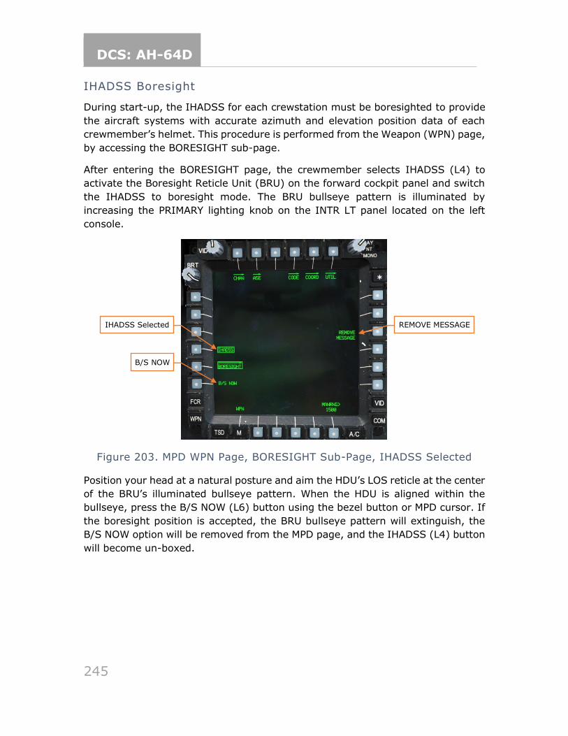
DCS: AH-64D
245
IHADSS Boresight
During start-up, the IHADSS for each crewstation must be boresighted to provide
the aircraft systems with accurate azimuth and elevation position data of each
crewmember’s helmet. This procedure is performed from the Weapon (WPN) page,
by accessing the BORESIGHT sub-page.
After entering the BORESIGHT page, the crewmember selects IHADSS (L4) to
activate the Boresight Reticle Unit (BRU) on the forward cockpit panel and switch
the IHADSS to boresight mode. The BRU bullseye pattern is illuminated by
increasing the PRIMARY lighting knob on the INTR LT panel located on the left
console.
Figure 203. MPD WPN Page, BORESIGHT Sub-Page, IHADSS Selected
Position your head at a natural posture and aim the HDU’s LOS reticle at the center
of the BRU’s illuminated bullseye pattern. When the HDU is aligned within the
bullseye, press the B/S NOW (L6) button using the bezel button or MPD cursor. If
the boresight position is accepted, the BRU bullseye pattern will extinguish, the
B/S NOW option will be removed from the MPD page, and the IHADSS (L4) button
will become un-boxed.
IHADSS Selected
B/S NOW
REMOVE MESSAGE
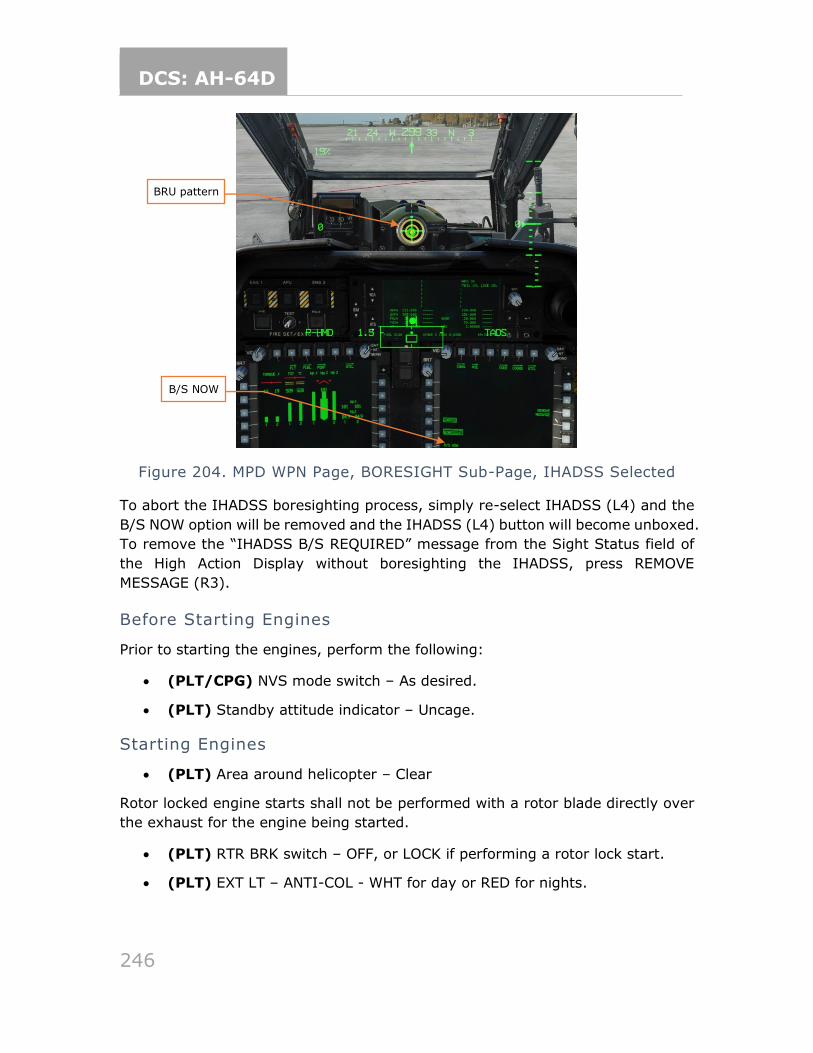
DCS: AH-64D
246
Figure 204. MPD WPN Page, BORESIGHT Sub-Page, IHADSS Selected
To abort the IHADSS boresighting process, simply re-select IHADSS (L4) and the
B/S NOW option will be removed and the IHADSS (L4) button will become unboxed.
To remove the “IHADSS B/S REQUIRED” message from the Sight Status field of
the High Action Display without boresighting the IHADSS, press REMOVE
MESSAGE (R3).
Before Starting Engines
Prior to starting the engines, perform the following:
• (PLT/CPG) NVS mode switch – As desired.
• (PLT) Standby attitude indicator – Uncage.
Starting Engines
• (PLT) Area around helicopter – Clear
Rotor locked engine starts shall not be performed with a rotor blade directly over
the exhaust for the engine being started.
• (PLT) RTR BRK switch – OFF, or LOCK if performing a rotor lock start.
• (PLT) EXT LT – ANTI-COL - WHT for day or RED for nights.
BRU pattern
B/S NOW
DCS: AH-64D
247
During the start if the TGT appears it will exceed 851°C prior to NG idle speed of
63%; if TGT, NP and ENG OIL PSI do not increase within 45 seconds after moving
power lever to idle; or if the ENG 1 or 2 START advisory is removed prior to
attaining 52% NG, abort the start by taking the power lever to OFF.
While starting the engines, select an ENG and an ENG SYS page to monitor aircraft
indications and perform the following:
• (PLT) First engine – Start as follows:
o ENG START switch – START, observe ENG # START advisory on the EUFD and START box displayed on the ENG page.
Prior to advancing the power lever to IDLE, verify TGT is less than 80° C.
o Power lever – IDLE, at first indication of Ng increase.
o ENG OIL PSI – Monitor.
o TGT – Monitor.
o NG – Monitor.
o MSTR WARN, MSTR CAUT, and EUFD – Monitor.
• (PLT) Second Engine – Repeat the steps above.
• (PLT) RTR BRK switch – OFF.
Prior to advancing the power levers to FLY, confirm that both ENG 1 and 2 OIL PSI
readouts are less than 70 PSI and the NGB TEMP readouts are above 20° C.
• (PLT) POWER levers – Advance both POWER levers smoothly to FLY and ensure that both torque indications increase simultaneously.
• (PLT) NP and NR – Verify 101%.
• (PLT) MSTR WARN, MSTR CAUT, and EUFD – Monitor.
• (PLT) APU – Off.
Before Taxi
Prior to initiating ground taxi, perform the following:
• (PLT) EXT LT panel – Verify NAV lights to BRT, set ANTI-COL - WHT for day or RED for night.
• (PLT/CPG) Searchlight – As required.
• (PLT) PARKING BRAKE – Released, handle in.
• (PLT) TAIL WHEEL button – UNLOCK as desired, verify unlocked, light on.
DCS: AH-64D
248
TAXI AND TAKEOFF
Ground Taxi
After requesting permission from ATC to taxi, select transition symbology. Press
and hold the force trim release interrupted. Increase collective to 27% to 30% TQ
or as required depending on aircraft gross weight and surface conditions. Apply
forward cyclic until the acceleration cue is at the tip of the LOS reticle, then release
the force trim switch. Apply additional collective as required to initiate movement.
Interrupt the force trim as necessary and maintain the acceleration cue at the tip
of the LOS reticle with fore/aft cyclic. Maintain approximately 5 to 6 knots ground
speed, or speed appropriate for the surface conditions. You can also reference the
waypoint status window for ground speed.
Prior to initiating a turn, ensure the TAIL WHEEL UNLOCKED push-button light is
illuminated. Apply pedal in the direction of turn and maintain a constant rate of
turn with pressure/counter pressure on the pedals. Apply cyclic in the direction of
the turn to maintain a level horizon line.
To stop the helicopter, first lock and verify the TAIL WHEEL UNLOCKED push-
button light is not illuminated, then apply aft cyclic to center the acceleration cue
in the center of the LOS. Select hover symbology to determine fore/aft drift more
accurately. Reference the trim ball and maintain the trim ball centered with
left/right cyclic. When the aircraft has stopped, neutralize the flight controls, and
reduce the collective.
During ground taxi, perform the following:
• (PLT/CPG) Wheel brakes – Check in both crew stations by applying a slight
amount of pressure against the toe brakes.
• (PLT) ENG page – Check, NP/NR 101%, all indications green.
• (PLT) FLT page – Check and set/update altimeter.
• (PLT) Pilot standby instruments – Check and set/update altimeter.
Before Takeoff
Perform the following prior to picking up to a hover:
• (PLT/CPG) Weapons Subsystem – Check the following:
o A/S button – SAFE.
o GND ORIDE button – Off.
o Weapons not actioned – Verify in the High Action Display (HAD).
DCS: AH-64D
249
• (PLT/CPG) TAIL WHEEL button – Locked, UNLOCKED light is off.
• (PLT) PARK BRAKE – Released, handle in or as desired.
• (PLT/CPG) Systems – Check as follows:
o FUEL page options – Verify:
▪ XFER – AUTO.
▪ XFEED – NORM.
▪ BOOST – OFF.
▪ CHECK page – select page and start a 15-minute fuel check.
▪ CHECK page – De-select.
o Fuel quantity – Check and verify enough fuel for the mission to be flown.
o EUFD – Check clear of Warnings and Cautions.
o Engine and flight instruments – Check:
▪ NP/NR 101%, all indications green.
▪ Update altimeter as required on FLT page and pilot’s standby altimeter.
o ASE – As required.
o Avionics – As desired.
▪ Transponder – NORM, or as desired and squawking appropriate codes.
▪ COMM – As desired, verify in EUFD.
▪ NAV – Update navigation direct or select desired route.
Prior to performing the hover power check, ensure an ENG page and PERF page
are displayed.
o Hover Power Check – Perform.
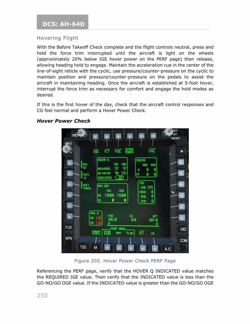
DCS: AH-64D
250
Hovering Flight
With the Before Takeoff Check complete and the flight controls neutral, press and
hold the force trim interrupted until the aircraft is light on the wheels
(approximately 20% below IGE hover power on the PERF page) then release,
allowing heading hold to engage. Maintain the acceleration cue in the center of the
line-of-sight reticle with the cyclic, use pressure/counter-pressure on the cyclic to
maintain position and pressure/counter-pressure on the pedals to assist the
aircraft in maintaining heading. Once the aircraft is established at 5-foot hover,
interrupt the force trim as necessary for comfort and engage the hold modes as
desired.
If this is the first hover of the day, check that the aircraft control responses and
CG feel normal and perform a Hover Power Check.
Hover Power Check
Figure 205. Hover Power Check PERF Page
Referencing the PERF page, verify that the HOVER Q INDICATED value matches
the REQUIRED IGE value. Then verify that the INDICATED value is less than the
GO-NO/GO OGE value. If the INDICATED value is greater than the GO-NO/GO OGE
DCS: AH-64D
251
value, the aircraft does not have enough power to perform the following
maneuvers that require OGE power:
• Approach to an OGE hover
• Masking/Unmasking
• NOE flight
For every 200 lbs of Gross Weight (GWT) lost, a 1% TQ reduction can be applied.
Use this rule to determine how much fuel or ammo to remove from the aircraft in
order to enable out of ground effect flight possible.
Types of Takeoffs
The purpose of the takeoff is to transition from the hover to forward flight, with
the implied task being the aircrew remains outside of the heigh-velocity avoid
region of the aircraft. Operations within the avoid region guarantee a forced
landing due to engine failure with some degree of aircraft damage. Operations
outside of the avoid region provide an opportunity to potentially maintain flight
under single-engine conditions or permit a force landing with little to no damage
to the aircraft.
There are four types of Visual Meteorological Conditions (VMC) takeoffs performed
by US Army AH-64D aircrews:
• VMC Takeoff
• VMC Level Acceleration Takeoff is performed when surface conditions and
obstacles permit and involves accelerating the aircraft through velocity safe single engine (VSSE) airspeed prior to initiating a climb. This type of takeoff is meant to reduce the risks of operating inside the avoid region should an
engine fail.
• VMC Minimum Power Takeoff from the ground/hover is performed when surface conditions are not suitable for a rolling takeoff. During training, the
piot is limited to only IGE hover power when performing this type of takeoff.
• Rolling Takeoff is performed when the aircraft is IGE power limited, and
surface conditions are suitable for a rolling takeoff. During training, the pilot is limited to 10% below hover power when performing this type of takeoff.
The preferred takeoff for the AH-64D is the VMC Level Acceleration Takeoff.
DCS: AH-64D
252
VMC Takeoff
From a hover, begin by selecting Transition symbology, then press and hold the
force trim release button and apply forward cyclic for a 90-knot climb attitude
(wings level) while increasing the collective >10% above hover power or as
necessary to establish the desired climb. Release the force trim upon establishing
a 90-knot attitude and trim as necessary to maintain a level VSI until through
VSSE. Maintain ground track alignment with the pedals and center the trim ball
into coordinated flight (termed “in-trim”) once clear of all obstacles or 50 feet,
whichever occurs first. Maintain the FPV (Flight Path Vector) above any obstacles
to assist in ensuring obstacle clearance. When above VSSE adjust the collective to
establish >500 fpm (feet-per-minute) rate of climb or as desired.
VMC Level Acceleration Takeoff
From a hover, begin by selecting Transition symbology, then press and hold the
force trim release button and apply forward cyclic for a 90-knot attitude (wings
level) while increasing the collective approximately 10% above hover power or as
necessary to maintain altitude and accelerate the aircraft. Release the force trim
upon establishing a 90-knot attitude and trim as necessary to maintain a level VSI
until through VSSE. Maintain ground track alignment with the pedals and center
the trim ball into coordinated flight once clear of all obstacles or 50 feet, whichever
occurs first. Continue adjusting the controls as necessary to achieve 50 knots by
the time an altitude of 50 feet ALG is reached or as required to clear obstacles.
Maintain the FPV above any obstacles to assist in ensuring obstacle clearance.
Once clear of obstacles adjust for a 70-knot attitude and >500 fpm rate of climb
or as desired.
VMC Minimum Power Takeoff
To simulate operating in a power limited environment, complete this maneuver
using only hover power.
From a hover, begin by selection Transition symbology, then press and hold the
force trim release interrupted. Slowly and smoothly apply forward cyclic to begin
accelerating the aircraft. Maintain the velocity vector straight up and down the 12
o’clock post of the LOS reticle with the pedals. As the aircraft approaches ETL a
slight loss of altitude may occur. Ground contact is permissible, but not
recommended. Adjust the collective to maintain hover power, as increasing rotor
efficiency will cause the torque to decrease. Interrupt the force trim as necessary
to maintain a level VSI. Continue to apply forward cyclic for a level VSI while
accelerating to achieve 50 knots. Use the pedals to center the trim ball into
coordinated flight commensurate with the obstacles. Avoid pitch attitudes more
than 10 degrees below the horizon to avoid ground contact with the rotor system.
DCS: AH-64D
253
As the aircraft approaches 50 knots, adjust for a 70-knot attitude to initiate a climb.
Ensure the FPV is above the obstacles. Once clear of the obstacles adjust for a
>500 fpm rate of climb or as desired.
Rolling Takeoff
To simulate operating in a power limited environment, begin by completing a 5-
foot hover power check and note the torque. If the result of this hover power check
was 71%, subtract 10% from this value to determine the ‘simulated power limit’
to be used during the maneuver, in this example 61%. Land the aircraft and using
an ENG SYS page, set the stabilator to zero using the collective flight grip to reduce
drag.
From the ground, begin by selecting Transition symbology, then press and hold
the force trim interrupted while increasing the collective to 30% torque. Continue
increasing the collective to the simulated power limit while simultaneously
applying forward cyclic for a 90-knot attitude (wings level), then release the force
trim. Interrupt the force trim as necessary to maintain a level attitude. Do not
allow the nose to drop below wings level until after liftoff to prevent ground contact
with the gun. Maintain the velocity vector straight up and down the 12 o’clock post
of the LOS reticle with the pedals. As the aircraft lifts off, continue to apply forward
cyclic for a level VSI while accelerating to achieve 50 knots. Use the pedals to
center the trim ball into coordinated flight commensurate with the obstacles. Avoid
pitch attitudes more than 10 degrees below the horizon to avoid ground contact
with the rotor system. As the aircraft approaches 50 knots, adjust for a 70-knot
attitude to initiate a climb. Ensure the FPV is above the obstacles. Once clear of
the obstacles adjust for a >500 fpm rate of climb or as desired. The maneuver is
terminated when a positive rate of climb has been established, the aircraft is clear
of obstacles and at or near max endurance/rate-of-climb or desired airspeed.
Return the stabilator to auto mode by depressing the stabilator switch.
If performing this maneuver in a power limited environment (high/hot/heavy), it
is recommended the pilot use 5% below the maximum dual engine torque available
to avoid potentially drooping the rotor.
DCS: AH-64D
254
APPROACH AND LANDING
Before Landing Check
Before landing perform the following:
• (PLT/CPG) Weapons Subsystem – Check the following:
o A/S button – SAFE.
o GND ORIDE button – Off.
o Weapons not actioned – Verify in the High Action Display (HAD).
• (PLT/CPG) ASE – As required.
• (PLT/CPG) TAIL WHEEL button – Locked, UNLOCKED light is off.
• (PLT) PARK BRAKE – Released, handle in or as desired.
Types of Approaches
There are two main approach types: The Visual Meteorological Conditions (VMC)
Approach to a Hover/Ground and the Rolling Landing. When performing a VMC
Approach, key considerations are:
• Size of the landing area. Is the area large enough for the aircraft to land and depart from? If there are multiple aircraft landing to the area, is it large enough for all the aircraft to land and depart from?
• Suitability of the landing surface. Is it an improved landing area? Soft dirt/mud? Snow or Dust which may result in white/brownout conditions?
• Barriers or obstacles in/around the landing area. Are there trees,
rocks, fences, wires, holes?
• Approach and takeoff direction. Are they the same? Or is the approach made in one direction and the takeoff made in another?
• Termination point. Perform the approach to the last one-third of the useable landing area, especially if multiple aircraft are landing.
• Winds. A landing into the wind is preferred, but if it is not possible,
increase the power required during the approach.
• Power available. Evaluate both IGE and OGE power required against maximum torque available.
If the aircraft is power limited, and the surface area is suitable, then a rolling
landing should be considered, and the aircraft should be kept above ETL or Velocity
Safe Dual Engine (VSDE), or if single engine, above Velocity Safe Single Engine
(VSSE).
DCS: AH-64D
255
VMC Approach to a Hover
From an altitude and airspeed that affords the best observation of the landing area,
place the LOS reticle on the intended point of landing. Press and hold the force
trim interrupted and reduce the collective approximately 20% below cruise torque.
Place the acceleration cue at the 40 knot ground speed position and adjust the
collective for a 500 fpm or desired rate or descent. Maintain the FPV slightly above
the intended point of landing to prevent “under-arcing” the approach. Control the
flight path vector vertically with the collective and horizontally with the left/right
cyclic. Maintain the acceleration cue behind the tip of the velocity vector to ensure
a smooth, consistent deceleration while maintaining a 500 fpm or desired rate of
descent. Prior to descending below the obstacles or 50 feet, keep the trim ball
centered. Once below the obstacles or below 50 feet, use the pedals to align the
nose with the landing direction. The decision to abort the approach should be made
prior to descending below the obstacles. When the velocity vector is within the
LOS reticle, select Hover symbology and terminate to a 5-foot stationary hover.
Engage the hold modes as desired to assist in maintaining the hover.
Rolling Landing
From an altitude and airspeed that affords the best observation of the landing area,
place the LOS reticle on the intended point of landing. Press and hold the force
trim release interrupted and reduce the collective approximately 20% below cruise
torque. Place the acceleration cue at the 40 knot ground speed position and adjust
the collective for a 300 to 500 fpm or desired rate of descent. Maintain the FPV
slightly above the intended point of landing to prevent “under-arcing” the approach.
Plan to touch down in the first 1/3rd of the useable landing area. Control the flight
path vector vertically with the collective and horizontally with the left/right cyclic.
Maintain the acceleration cue behind the tip of the velocity vector to ensure a
smooth, consistent deceleration while maintaining a 300 to 500 fpm or desired
rate of descent. Prior to descending below the obstacles or 50 feet, keep the trim
ball centered. Once below the obstacles or below 50 feet, use the pedals to align
the nose with the landing direction. Maintain the velocity vector straight up and
down the 12 o’clock post of the LOS reticle with the pedals and lateral cyclic.
Maintain at or above ETL or VSDE until touch down, or if single engine maintain at
or above VSSE until 30 feet. Once the aircraft touches down reduce the collective
slightly to settle the aircraft, then increase the collective to 30% dual engine (60%
single engine) or more prior to applying aft cyclic to aerodynamically brake the
aircraft. Maintain heading with the pedals and a level attitude with lateral cyclic.
When the velocity vector is within the LOS reticle, select Hover symbology and
maintain the acceleration cue in the center of the LOS reticle. Neutralize the flight
controls and reduce the collective after the aircraft has stopped. It is permissible
to utilize the toe brakes to assist in stopping the aircraft.
DCS: AH-64D
256
After Landing Check
After landing, perform the following:
• (PLT/CPG) TAIL WHEEL button – As desired.
• (PLT) Exterior lights – As required.
• (PLT/CPG) Avionics – Transponder to STBY.
SHUTDOWN
Once established in parking, perform the following:
• (PLT) APU – Start as follows:
o APU button – Press ON.
o EUFD – Observe for APU START, APU POWER ON and ACCUM OIL PRESS LO.
• (PLT) TAIL WHEEL button – Locked, UNLOCKED light is off.
• (PLT) PARK BRAKE – Set, handle out.
Prior to retarding the power levers to IDLE verify the APU ON advisory is displayed
on the EUFD.
• (PLT) Power levers – IDLE, start 2-minute timer on EUFD.
• (PLT) Standby attitude indicator – Cage.
• (PLT) CMWS Control Indicator PWR switch – OFF.
• (PLT/CPG) NVS MODE switch – OFF.
• (PLT/CPG) ACM switch – OFF.
• (PLT) Power levers – OFF, after 2 minutes has elapsed.
• (PLT) RTR BRK switch – BRK, when NR is less than 50%.
• (PLT) Stabilator – Manually set to 0° using the ENG SYS page.
• (PLT) Search Light – OFF.
• (PLT) RTR BRK switch – OFF after rotor has stopped.
• (PLT) EXT LT/INTR LT panel switches – OFF.
• (CPG) INTR LT panel switches – OFF.
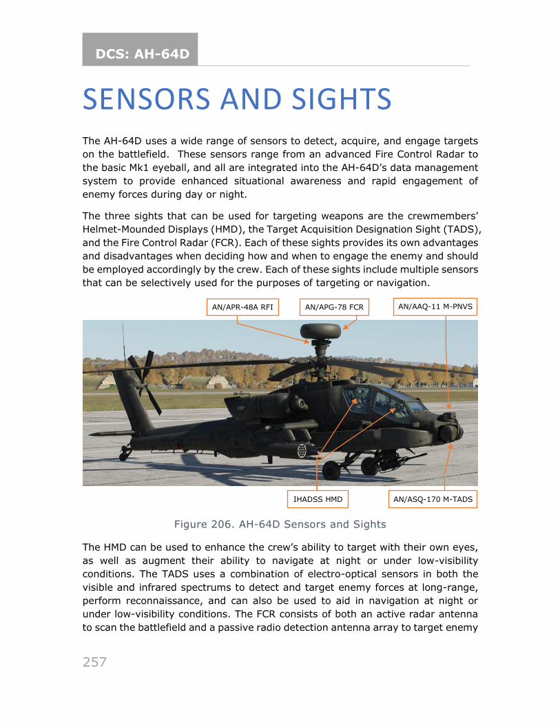
DCS: AH-64D
257
SENSORS AND SIGHTS The AH-64D uses a wide range of sensors to detect, acquire, and engage targets
on the battlefield. These sensors range from an advanced Fire Control Radar to
the basic Mk1 eyeball, and all are integrated into the AH-64D’s data management
system to provide enhanced situational awareness and rapid engagement of
enemy forces during day or night.
The three sights that can be used for targeting weapons are the crewmembers’
Helmet-Mounded Displays (HMD), the Target Acquisition Designation Sight (TADS),
and the Fire Control Radar (FCR). Each of these sights provides its own advantages
and disadvantages when deciding how and when to engage the enemy and should
be employed accordingly by the crew. Each of these sights include multiple sensors
that can be selectively used for the purposes of targeting or navigation.
Figure 206. AH-64D Sensors and Sights
The HMD can be used to enhance the crew’s ability to target with their own eyes,
as well as augment their ability to navigate at night or under low-visibility
conditions. The TADS uses a combination of electro-optical sensors in both the
visible and infrared spectrums to detect and target enemy forces at long-range,
perform reconnaissance, and can also be used to aid in navigation at night or
under low-visibility conditions. The FCR consists of both an active radar antenna
to scan the battlefield and a passive radio detection antenna array to target enemy
IHADSS HMD AN/ASQ-170 M-TADS
AN/APR-48A RFI AN/AAQ-11 M-PNVS AN/APG-78 FCR
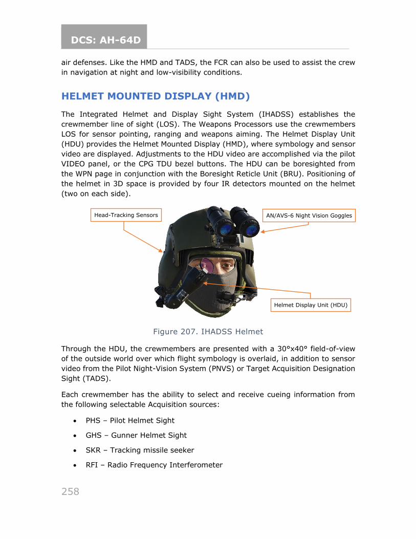
DCS: AH-64D
258
air defenses. Like the HMD and TADS, the FCR can also be used to assist the crew
in navigation at night and low-visibility conditions.
HELMET MOUNTED DISPLAY (HMD)
The Integrated Helmet and Display Sight System (IHADSS) establishes the
crewmember line of sight (LOS). The Weapons Processors use the crewmembers
LOS for sensor pointing, ranging and weapons aiming. The Helmet Display Unit
(HDU) provides the Helmet Mounted Display (HMD), where symbology and sensor
video are displayed. Adjustments to the HDU video are accomplished via the pilot
VIDEO panel, or the CPG TDU bezel buttons. The HDU can be boresighted from
the WPN page in conjunction with the Boresight Reticle Unit (BRU). Positioning of
the helmet in 3D space is provided by four IR detectors mounted on the helmet
(two on each side).
Figure 207. IHADSS Helmet
Through the HDU, the crewmembers are presented with a 30°x40° field-of-view
of the outside world over which flight symbology is overlaid, in addition to sensor
video from the Pilot Night-Vision System (PNVS) or Target Acquisition Designation
Sight (TADS).
Each crewmember has the ability to select and receive cueing information from
the following selectable Acquisition sources:
• PHS – Pilot Helmet Sight
• GHS – Gunner Helmet Sight
• SKR – Tracking missile seeker
• RFI – Radio Frequency Interferometer
Helmet Display Unit (HDU)
Head-Tracking Sensors AN/AVS-6 Night Vision Goggles
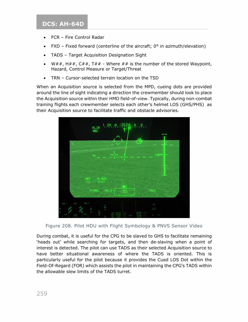
DCS: AH-64D
259
• FCR – Fire Control Radar
• FXD – Fixed forward (centerline of the aircraft; 0° in azimuth/elevation)
• TADS – Target Acquisition Designation Sight
• W##, H##, C##, T## - Where ## is the number of the stored Waypoint, Hazard, Control Measure or Target/Threat
• TRN – Cursor-selected terrain location on the TSD
When an Acquisition source is selected from the MPD, cueing dots are provided
around the line of sight indicating a direction the crewmember should look to place
the Acquisition source within their HMD field-of-view. Typically, during non-combat
training flights each crewmember selects each other’s helmet LOS (GHS/PHS) as
their Acquisition source to facilitate traffic and obstacle advisories.
Figure 208. Pilot HDU with Flight Symbology & PNVS Sensor Video
During combat, it is useful for the CPG to be slaved to GHS to facilitate remaining
‘heads out’ while searching for targets, and then de-slaving when a point of
interest is detected. The pilot can use TADS as their selected Acquisition source to
have better situational awareness of where the TADS is oriented. This is
particularly useful for the pilot because it provides the Cued LOS Dot within the
Field-Of-Regard (FOR) which assists the pilot in maintaining the CPG’s TADS within
the allowable slew limits of the TADS turret.
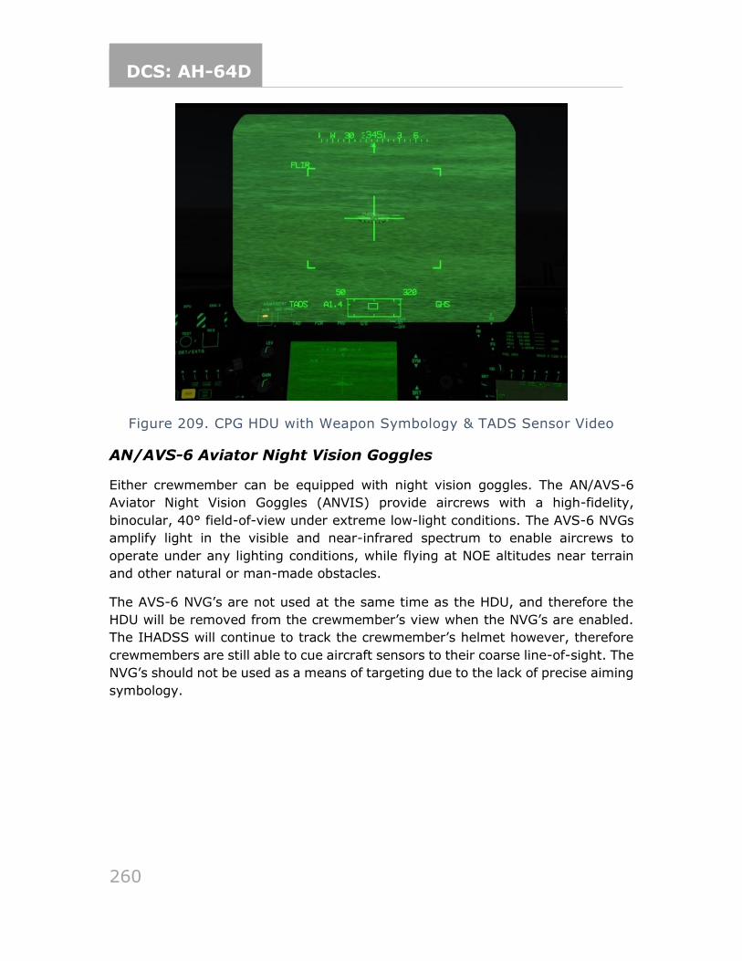
DCS: AH-64D
260
Figure 209. CPG HDU with Weapon Symbology & TADS Sensor Video
AN/AVS-6 Aviator Night Vision Goggles
Either crewmember can be equipped with night vision goggles. The AN/AVS-6
Aviator Night Vision Goggles (ANVIS) provide aircrews with a high-fidelity,
binocular, 40° field-of-view under extreme low-light conditions. The AVS-6 NVGs
amplify light in the visible and near-infrared spectrum to enable aircrews to
operate under any lighting conditions, while flying at NOE altitudes near terrain
and other natural or man-made obstacles.
The AVS-6 NVG’s are not used at the same time as the HDU, and therefore the
HDU will be removed from the crewmember’s view when the NVG’s are enabled.
The IHADSS will continue to track the crewmember’s helmet however, therefore
crewmembers are still able to cue aircraft sensors to their coarse line-of-sight. The
NVG’s should not be used as a means of targeting due to the lack of precise aiming
symbology.
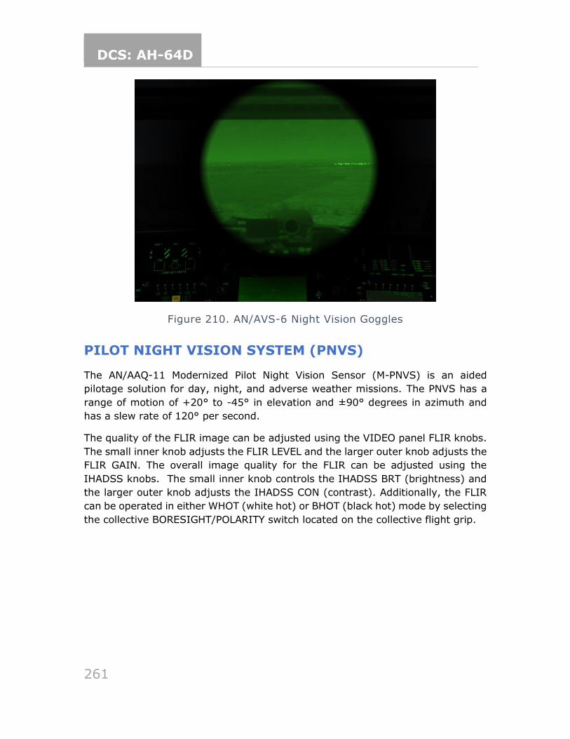
DCS: AH-64D
261
Figure 210. AN/AVS-6 Night Vision Goggles
PILOT NIGHT VISION SYSTEM (PNVS)
The AN/AAQ-11 Modernized Pilot Night Vision Sensor (M-PNVS) is an aided
pilotage solution for day, night, and adverse weather missions. The PNVS has a
range of motion of +20° to -45° in elevation and ±90° degrees in azimuth and
has a slew rate of 120° per second.
The quality of the FLIR image can be adjusted using the VIDEO panel FLIR knobs.
The small inner knob adjusts the FLIR LEVEL and the larger outer knob adjusts the
FLIR GAIN. The overall image quality for the FLIR can be adjusted using the
IHADSS knobs. The small inner knob controls the IHADSS BRT (brightness) and
the larger outer knob adjusts the IHADSS CON (contrast). Additionally, the FLIR
can be operated in either WHOT (white hot) or BHOT (black hot) mode by selecting
the collective BORESIGHT/POLARITY switch located on the collective flight grip.
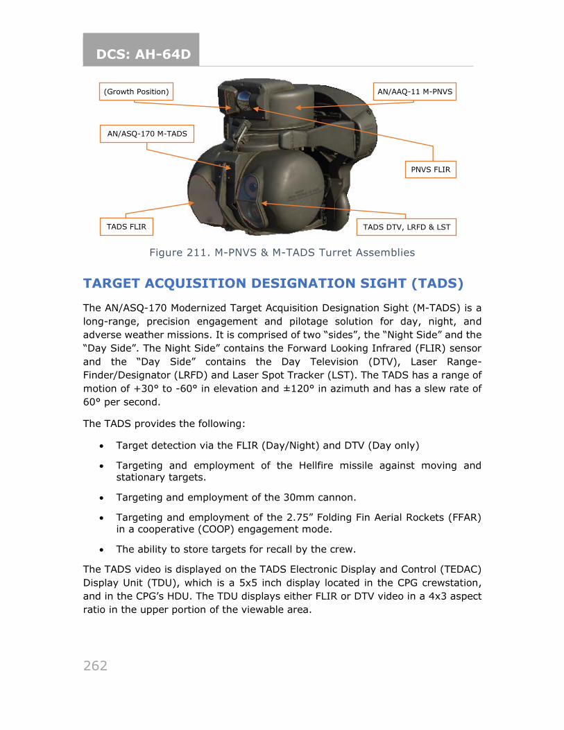
DCS: AH-64D
262
Figure 211. M-PNVS & M-TADS Turret Assemblies
TARGET ACQUISITION DESIGNATION SIGHT (TADS)
The AN/ASQ-170 Modernized Target Acquisition Designation Sight (M-TADS) is a
long-range, precision engagement and pilotage solution for day, night, and
adverse weather missions. It is comprised of two “sides”, the “Night Side” and the
“Day Side”. The Night Side” contains the Forward Looking Infrared (FLIR) sensor
and the “Day Side” contains the Day Television (DTV), Laser Range-
Finder/Designator (LRFD) and Laser Spot Tracker (LST). The TADS has a range of
motion of +30° to -60° in elevation and ±120° in azimuth and has a slew rate of
60° per second.
The TADS provides the following:
• Target detection via the FLIR (Day/Night) and DTV (Day only)
• Targeting and employment of the Hellfire missile against moving and stationary targets.
• Targeting and employment of the 30mm cannon.
• Targeting and employment of the 2.75” Folding Fin Aerial Rockets (FFAR) in a cooperative (COOP) engagement mode.
• The ability to store targets for recall by the crew.
The TADS video is displayed on the TADS Electronic Display and Control (TEDAC)
Display Unit (TDU), which is a 5x5 inch display located in the CPG crewstation,
and in the CPG’s HDU. The TDU displays either FLIR or DTV video in a 4x3 aspect
ratio in the upper portion of the viewable area.
AN/ASQ-170 M-TADS
AN/AAQ-11 M-PNVS
TADS FLIR TADS DTV, LRFD & LST
PNVS FLIR
(Growth Position)
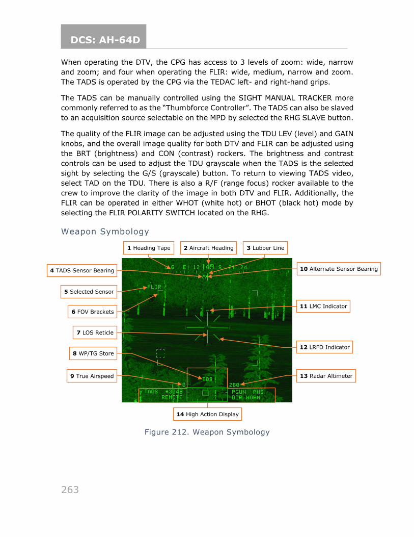
DCS: AH-64D
263
When operating the DTV, the CPG has access to 3 levels of zoom: wide, narrow
and zoom; and four when operating the FLIR: wide, medium, narrow and zoom.
The TADS is operated by the CPG via the TEDAC left- and right-hand grips.
The TADS can be manually controlled using the SIGHT MANUAL TRACKER more
commonly referred to as the “Thumbforce Controller”. The TADS can also be slaved
to an acquisition source selectable on the MPD by selected the RHG SLAVE button.
The quality of the FLIR image can be adjusted using the TDU LEV (level) and GAIN
knobs, and the overall image quality for both DTV and FLIR can be adjusted using
the BRT (brightness) and CON (contrast) rockers. The brightness and contrast
controls can be used to adjust the TDU grayscale when the TADS is the selected
sight by selecting the G/S (grayscale) button. To return to viewing TADS video,
select TAD on the TDU. There is also a R/F (range focus) rocker available to the
crew to improve the clarity of the image in both DTV and FLIR. Additionally, the
FLIR can be operated in either WHOT (white hot) or BHOT (black hot) mode by
selecting the FLIR POLARITY SWITCH located on the RHG.
Weapon Symbology
Figure 212. Weapon Symbology
1 Heading Tape 3 Lubber Line 2 Aircraft Heading
4 TADS Sensor Bearing 10 Alternate Sensor Bearing
5 Selected Sensor
6 FOV Brackets
7 LOS Reticle
8 WP/TG Store
11 LMC Indicator
12 LRFD Indicator
9 True Airspeed 13 Radar Altimeter
14 High Action Display
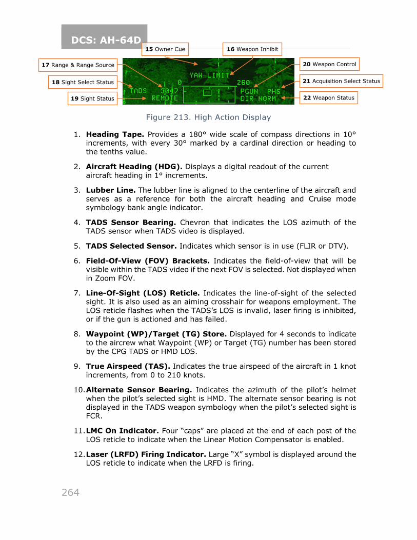
DCS: AH-64D
264
Figure 213. High Action Display
1. Heading Tape. Provides a 180° wide scale of compass directions in 10° increments, with every 30° marked by a cardinal direction or heading to
the tenths value.
2. Aircraft Heading (HDG). Displays a digital readout of the current
aircraft heading in 1° increments.
3. Lubber Line. The lubber line is aligned to the centerline of the aircraft and serves as a reference for both the aircraft heading and Cruise mode
symbology bank angle indicator.
4. TADS Sensor Bearing. Chevron that indicates the LOS azimuth of the TADS sensor when TADS video is displayed.
5. TADS Selected Sensor. Indicates which sensor is in use (FLIR or DTV).
6. Field-Of-View (FOV) Brackets. Indicates the field-of-view that will be visible within the TADS video if the next FOV is selected. Not displayed when
in Zoom FOV.
7. Line-Of-Sight (LOS) Reticle. Indicates the line-of-sight of the selected sight. It is also used as an aiming crosshair for weapons employment. The
LOS reticle flashes when the TADS’s LOS is invalid, laser firing is inhibited, or if the gun is actioned and has failed.
8. Waypoint (WP)/Target (TG) Store. Displayed for 4 seconds to indicate
to the aircrew what Waypoint (WP) or Target (TG) number has been stored by the CPG TADS or HMD LOS.
9. True Airspeed (TAS). Indicates the true airspeed of the aircraft in 1 knot
increments, from 0 to 210 knots.
10. Alternate Sensor Bearing. Indicates the azimuth of the pilot’s helmet when the pilot’s selected sight is HMD. The alternate sensor bearing is not
displayed in the TADS weapon symbology when the pilot’s selected sight is FCR.
11. LMC On Indicator. Four “caps” are placed at the end of each post of the
LOS reticle to indicate when the Linear Motion Compensator is enabled.
12. Laser (LRFD) Firing Indicator. Large “X” symbol is displayed around the LOS reticle to indicate when the LRFD is firing.
17 Range & Range Source
18 Sight Select Status
20 Weapon Control
21 Acquisition Select Status
15 Owner Cue 16 Weapon Inhibit
19 Sight Status 22 Weapon Status
DCS: AH-64D
265
13. Radar Altimeter (AGL). Aircraft altitude above ground level from 0 to 1,428 feet, displayed in increments of 1 foot up 50 feet in altitude, and
increments of 10 feet between 50 feet and 1,428 feet in altitude. The radar altimeter digital readout will be removed when above 1,428 feet.
14. High Action Display (HAD). The High Action Displayis displayed in both
Flight and Weapons symbology. The HAD provides prioritized sight and weapon status messages to the crew for targeting and weapons employment.
15. Owner Cue. During single DP operations, “PLT FORMAT” or “CPG FORMAT” will flash for 3 seconds within the HMD whenever the ownership of the video source changes, or when entering or exiting single DP operations.
16. Weapon Inhibit. Displays safety or performance inhibit indications based on the currently actioned weapon within the crewstation. Also displays W## or T## messages for 4 seconds in the CPG HMD or TADS symbology when
a WP or TG is stored using the CPG’s LOS.
17. Range and Range Source. Displays the range source in use and the current range in tenths of kilometers or meters (laser only). Available range
sources include:
a. Default range: 1.5 km for the pilot; 3.0 km for the CPG
b. Manual range: 100-50,000 meters (displayed as M0.1 to M50.0)
c. Auto range: 0.1 km to 50 km (displayed as A0.1 to A50.0)
d. Navigation range: 0.1 to 32 km (displayed as N0.1 to N32.0)
e. Radar range: 0.1 to 9.9 km (displayed as R0.1 to R9.9)
f. Laser range: 500 to 9999 meters (displayed as 500 to 9999)
18. Sight Select Status. Indicates the sight currently selected within the crewstation. Sight selection statuses include:
a. P-HMD: Pilot’s selected sight is HMD.
b. P-FCR: Pilot’s selected sight is FCR.
c. P-FCRL: Pilot’s selected sight is FCR. TADS has been linked.
d. C-HMD: CPG’s selected sight is HMD.
e. C-FCR: CPG’s selected sight is FCR.
f. C-FCRL: CPG’s selected sight is FCR. TADS has been linked.
g. TADS: CPG’s selected sight is TADS.
h. TADSL: CPG’s selected sight is TADS. FCR has been linked.
DCS: AH-64D
266
19. Sight Status. Displays status messages of aircraft sights and weapon status messages of laser-guided Hellfires launched in Remote Fire mode.
20. Weapon Control. Indicates the currently actioned weapon within the opposite crewstation. Weapon Control indications include:
a. PGUN – Pilot’s actioned weapon is gun.
b. PRKT – Pilot’s actioned weapon is rockets.
c. PMSL – Pilot’s actioned weapon is missiles.
d. CGUN – CPG’s actioned weapon is gun.
e. CRKT – CPG’s actioned weapon is rockets.
f. CMSL – CPG’s actioned weapon is missiles.
g. COOP – Pilot’s actioned weapon is rockets; CPG has actioned rockets
on the left TEDAC grip in cooperative rockets mode.
21. Acquisition Select Status (ACQ). Indicates the acquisition source currently selected within the crewstation. Acquisition sources include:
a. PHS – Pilot Helmet Sight
b. GHS – Gunner Helmet Sight
c. SKR – Tracking missile seeker
d. RFI – Radio Frequency Interferometer
e. FCR – Fire Control Radar
f. FXD – Fixed forward (centerline of the aircraft; 0° in
azimuth/elevation)
g. W##, H##, C##, T## – (## is the number of the stored Waypoint, Hazard, Control Measure or Target/Threat)
h. TRN – Cursor-selected terrain location on the TSD
22. Weapon Status. Displays status messages of the currently actioned weapon within the crewstation.
Linear Motion Compensator (LMC)
The M-TADS features Linear Motion Compensator (LMC) which is used to aid in
tracking. It compensates for helicopter movement and/or target movement and is
meant to reduce CPG workload. The LMC provides target state estimation in the
form of lead angle calculations when the CPG is using the TADS for targeting for
gun or rocket engagements against moving targets.
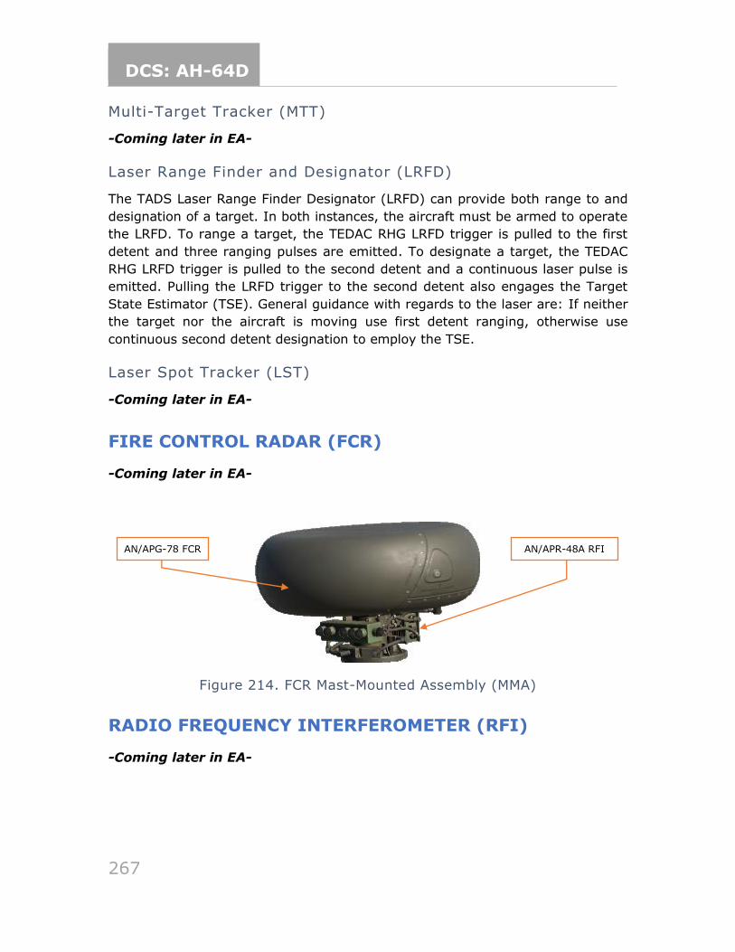
DCS: AH-64D
267
Multi-Target Tracker (MTT)
-Coming later in EA-
Laser Range Finder and Designator (LRFD)
The TADS Laser Range Finder Designator (LRFD) can provide both range to and
designation of a target. In both instances, the aircraft must be armed to operate
the LRFD. To range a target, the TEDAC RHG LRFD trigger is pulled to the first
detent and three ranging pulses are emitted. To designate a target, the TEDAC
RHG LRFD trigger is pulled to the second detent and a continuous laser pulse is
emitted. Pulling the LRFD trigger to the second detent also engages the Target
State Estimator (TSE). General guidance with regards to the laser are: If neither
the target nor the aircraft is moving use first detent ranging, otherwise use
continuous second detent designation to employ the TSE.
Laser Spot Tracker (LST)
-Coming later in EA-
FIRE CONTROL RADAR (FCR)
-Coming later in EA-
Figure 214. FCR Mast-Mounted Assembly (MMA)
RADIO FREQUENCY INTERFEROMETER (RFI)
-Coming later in EA-
AN/APR-48A RFI AN/APG-78 FCR
DCS: AH-64D
268
COMBAT EMPLOYMENT GENERAL
Pre-mission planning is the single most important part of any successful combat
mission. Crews evaluate the terrain and threat and then plan the mission routes,
altitudes and weapons load based on their analysis. Routes, pre-planned targets
and other graphical control measures to enhance situational awareness are loaded
into the aircraft via the DTU and displayed on the TSD.
Routes and altitudes should be selected to maximize survivability and reduce the
probability of detection by threat weapon systems. The TSD can further enhance
situational awareness of potential threat blind spots by using color banding
(enabled from the MAP page). Selecting an appropriate map type and scale on the
TSD can also enhance situational awareness. Configuring the SHOW options on
the TSD is also important in ensuring critical information is present on the TSD for
crews to reference.
On departure or when approaching the Forward Edge of Battle Area (FEBA), crews
should conduct WAIL-RM checks and ensure the aircraft is ready to engage. The
following should be considered:
1. Weapons – Confirm Master Arm and weapon settings are as desired.
2. ASE – Arm on the ASE page and CMWS control panel.
3. IFF (N/I) – Identification Friend-or-Foe systems are set appropriately.
4. Lights – Off (or set Formation lighting as appropriate).
5. Recorder (N/I) – Configure and set appropriately.
6. MPDs – Select TSD NAV/ATK phase and pages as desired.
Once beyond the Forward Line of Own Troops (FLOT), the CPG is continuously
searching, acquiring, identifying, lasing, and storing targets or points of interest
using the TADS. The PLT can store targets or waypoints using the fly-over method,
but for obvious reasons this is the least preferred way of storing a target in the
aircraft.
During enroute phases of flight, the CPG is the crewmember primarily responsible
for updating the aircraft’s routing and/or direct-to navigation. The CPG is also
typically responsible for tuning appropriate radio frequencies, communicating with
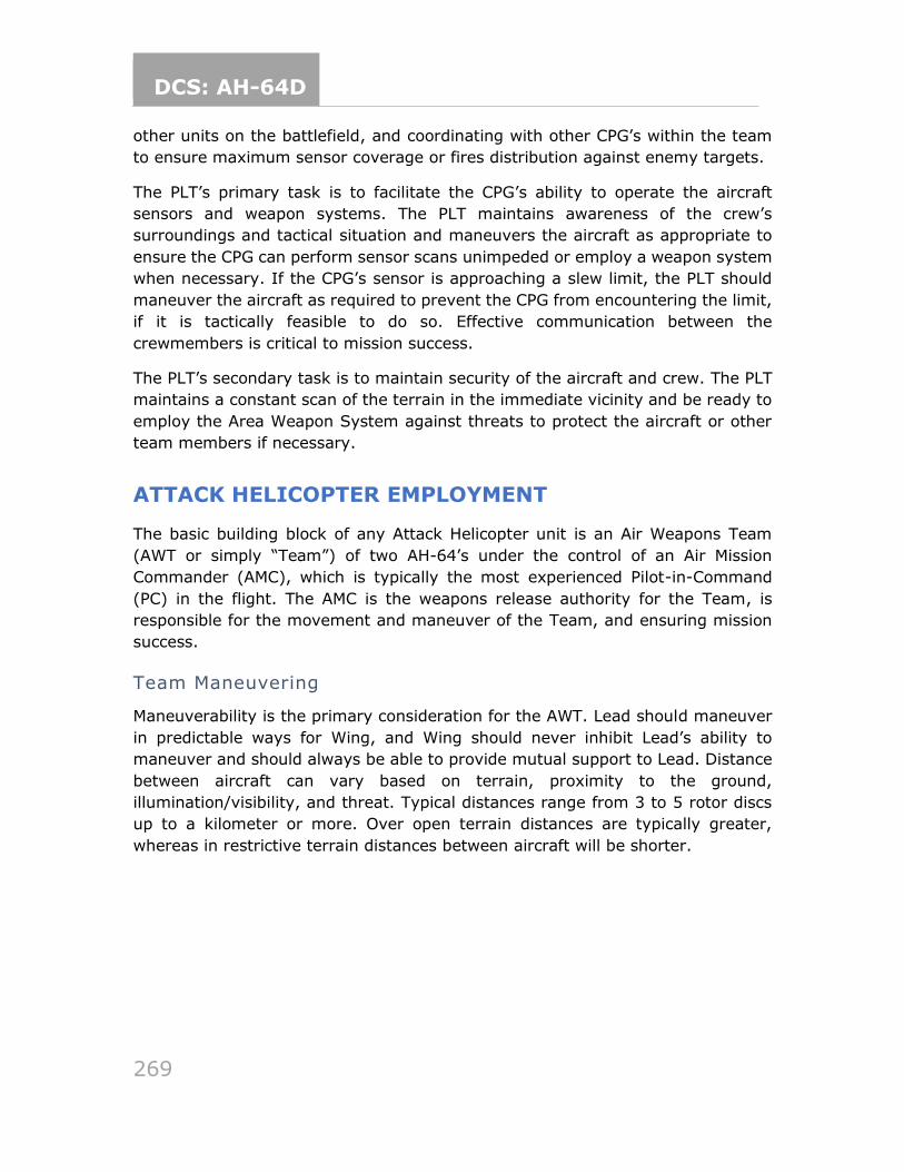
DCS: AH-64D
269
other units on the battlefield, and coordinating with other CPG’s within the team
to ensure maximum sensor coverage or fires distribution against enemy targets.
The PLT’s primary task is to facilitate the CPG’s ability to operate the aircraft
sensors and weapon systems. The PLT maintains awareness of the crew’s
surroundings and tactical situation and maneuvers the aircraft as appropriate to
ensure the CPG can perform sensor scans unimpeded or employ a weapon system
when necessary. If the CPG’s sensor is approaching a slew limit, the PLT should
maneuver the aircraft as required to prevent the CPG from encountering the limit,
if it is tactically feasible to do so. Effective communication between the
crewmembers is critical to mission success.
The PLT’s secondary task is to maintain security of the aircraft and crew. The PLT
maintains a constant scan of the terrain in the immediate vicinity and be ready to
employ the Area Weapon System against threats to protect the aircraft or other
team members if necessary.
ATTACK HELICOPTER EMPLOYMENT
The basic building block of any Attack Helicopter unit is an Air Weapons Team
(AWT or simply “Team”) of two AH-64’s under the control of an Air Mission
Commander (AMC), which is typically the most experienced Pilot-in-Command
(PC) in the flight. The AMC is the weapons release authority for the Team, is
responsible for the movement and maneuver of the Team, and ensuring mission
success.
Team Maneuvering
Maneuverability is the primary consideration for the AWT. Lead should maneuver
in predictable ways for Wing, and Wing should never inhibit Lead’s ability to
maneuver and should always be able to provide mutual support to Lead. Distance
between aircraft can vary based on terrain, proximity to the ground,
illumination/visibility, and threat. Typical distances range from 3 to 5 rotor discs
up to a kilometer or more. Over open terrain distances are typically greater,
whereas in restrictive terrain distances between aircraft will be shorter.
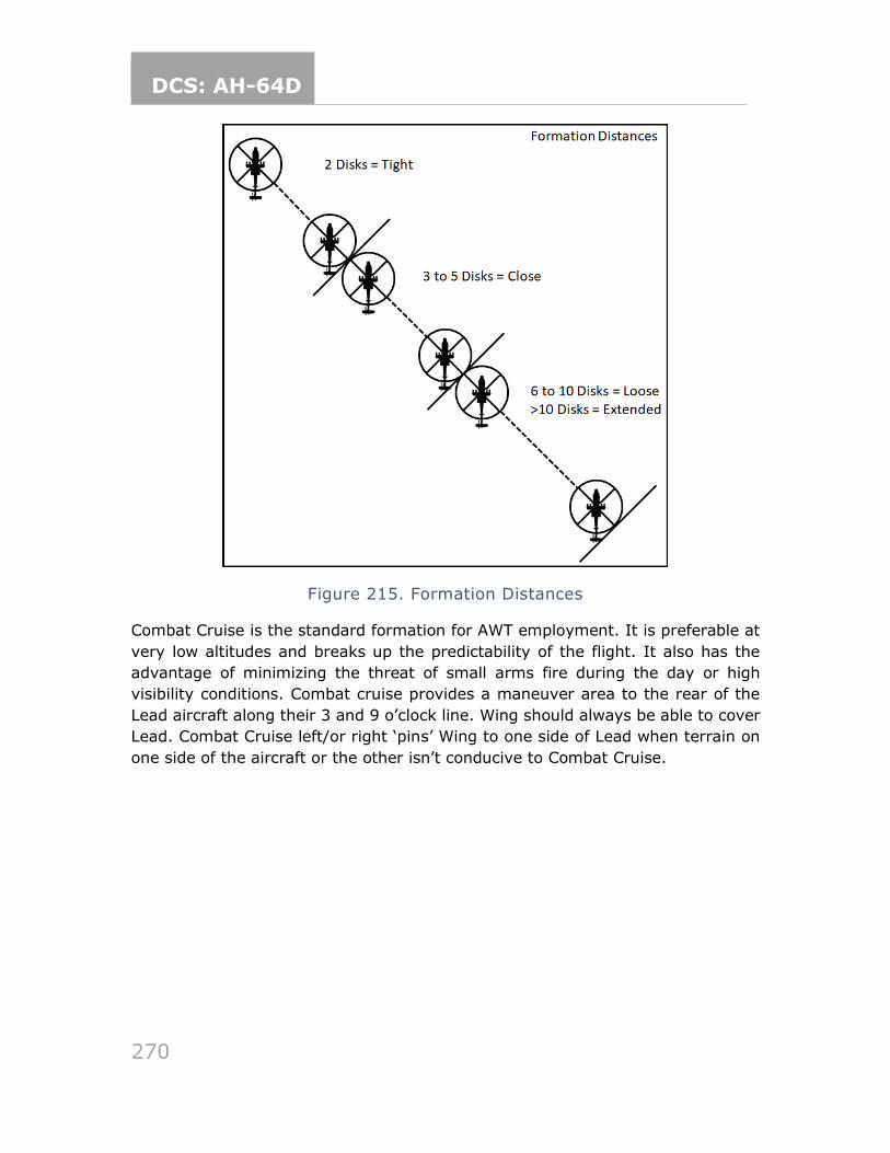
DCS: AH-64D
270
Figure 215. Formation Distances
Combat Cruise is the standard formation for AWT employment. It is preferable at
very low altitudes and breaks up the predictability of the flight. It also has the
advantage of minimizing the threat of small arms fire during the day or high
visibility conditions. Combat cruise provides a maneuver area to the rear of the
Lead aircraft along their 3 and 9 o’clock line. Wing should always be able to cover
Lead. Combat Cruise left/or right ‘pins’ Wing to one side of Lead when terrain on
one side of the aircraft or the other isn’t conducive to Combat Cruise.
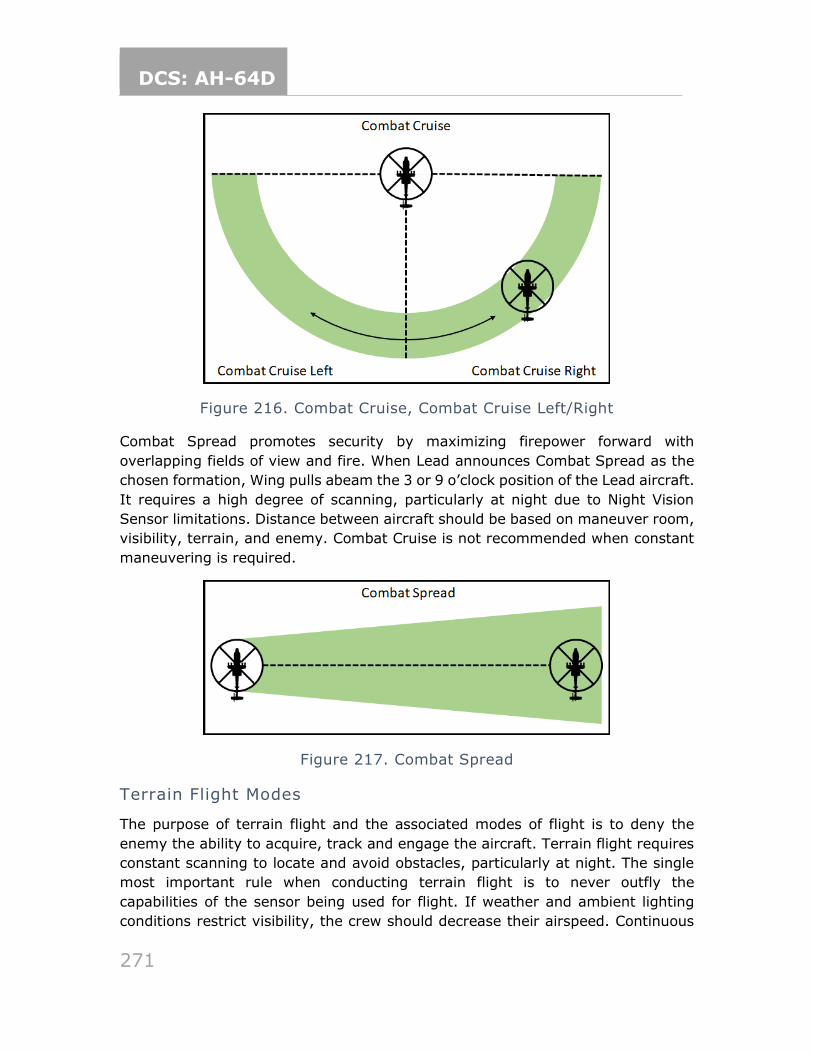
DCS: AH-64D
271
Figure 216. Combat Cruise, Combat Cruise Left/Right
Combat Spread promotes security by maximizing firepower forward with
overlapping fields of view and fire. When Lead announces Combat Spread as the
chosen formation, Wing pulls abeam the 3 or 9 o’clock position of the Lead aircraft.
It requires a high degree of scanning, particularly at night due to Night Vision
Sensor limitations. Distance between aircraft should be based on maneuver room,
visibility, terrain, and enemy. Combat Cruise is not recommended when constant
maneuvering is required.
Figure 217. Combat Spread
Terrain Flight Modes
The purpose of terrain flight and the associated modes of flight is to deny the
enemy the ability to acquire, track and engage the aircraft. Terrain flight requires
constant scanning to locate and avoid obstacles, particularly at night. The single
most important rule when conducting terrain flight is to never outfly the
capabilities of the sensor being used for flight. If weather and ambient lighting
conditions restrict visibility, the crew should decrease their airspeed. Continuous
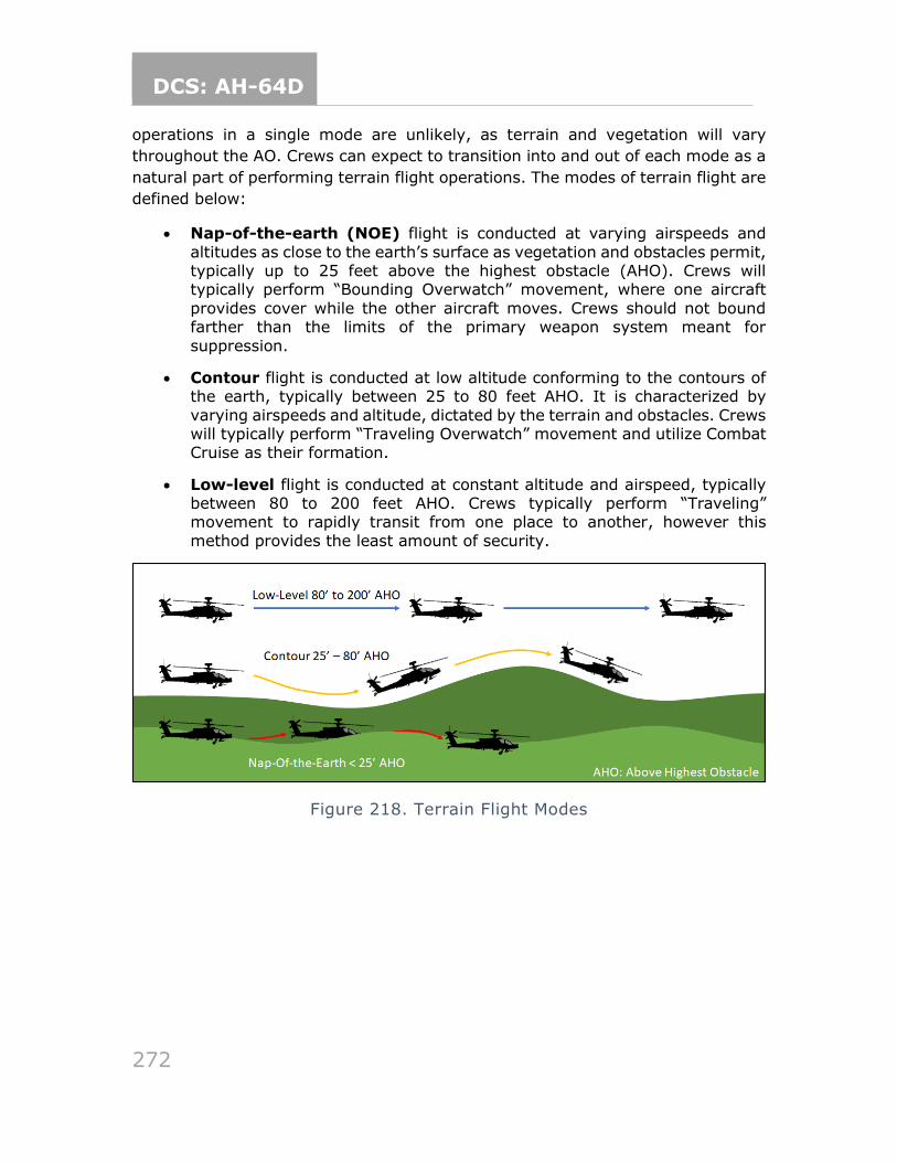
DCS: AH-64D
272
operations in a single mode are unlikely, as terrain and vegetation will vary
throughout the AO. Crews can expect to transition into and out of each mode as a
natural part of performing terrain flight operations. The modes of terrain flight are
defined below:
• Nap-of-the-earth (NOE) flight is conducted at varying airspeeds and
altitudes as close to the earth’s surface as vegetation and obstacles permit, typically up to 25 feet above the highest obstacle (AHO). Crews will typically perform “Bounding Overwatch” movement, where one aircraft
provides cover while the other aircraft moves. Crews should not bound farther than the limits of the primary weapon system meant for
suppression.
• Contour flight is conducted at low altitude conforming to the contours of the earth, typically between 25 to 80 feet AHO. It is characterized by
varying airspeeds and altitude, dictated by the terrain and obstacles. Crews will typically perform “Traveling Overwatch” movement and utilize Combat Cruise as their formation.
• Low-level flight is conducted at constant altitude and airspeed, typically between 80 to 200 feet AHO. Crews typically perform “Traveling” movement to rapidly transit from one place to another, however this
method provides the least amount of security.
Figure 218. Terrain Flight Modes
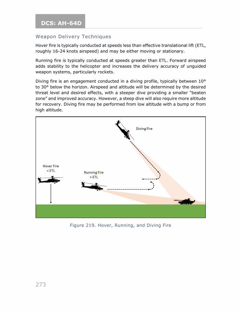
DCS: AH-64D
273
Weapon Delivery Techniques
Hover fire is typically conducted at speeds less than effective translational lift (ETL,
roughly 16-24 knots airspeed) and may be either moving or stationary.
Running fire is typically conducted at speeds greater than ETL. Forward airspeed
adds stability to the helicopter and increases the delivery accuracy of unguided
weapon systems, particularly rockets.
Diving fire is an engagement conducted in a diving profile, typically between 10°
to 30° below the horizon. Airspeed and altitude will be determined by the desired
threat level and desired effects, with a steeper dive providing a smaller “beaten
zone” and improved accuracy. However, a steep dive will also require more altitude
for recovery. Diving fire may be performed from low altitude with a bump or from
high altitude.
Figure 219. Hover, Running, and Diving Fire
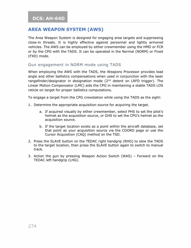
DCS: AH-64D
274
AREA WEAPON SYSTEM (AWS)
The Area Weapon System is designed for engaging area targets and suppressing
close-in threats. It is highly effective against personnel and lightly armored
vehicles. The AWS can be employed by either crewmember using the HMD or FCR
or by the CPG with the TADS. It can be operated in the Normal (NORM) or Fixed
(FXD) mode.
Gun engagement in NORM mode using TADS
When employing the AWS with the TADS, the Weapons Processor provides lead
angle and other ballistics compensations when used in conjunction with the laser
rangefinder/designator in designation mode (2nd detent on LRFD trigger). The
Linear Motion Compensator (LMC) aids the CPG in maintaining a stable TADS LOS
reticle on target for proper ballistics computations.
To engage a target from the CPG crewstation while using the TADS as the sight:
1. Determine the appropriate acquisition source for acquiring the target.
a. If acquired visually by either crewmember, select PHS to set the pilot’s helmet as the acquisition source, or GHS to set the CPG’s helmet as the
acquisition source.
b. If the target location exists as a point within the aircraft database, set that point as your acquisition source via the COORD page or use the
Cursor Acquisition (CAQ) method on the TSD.
2. Press the SLAVE button on the TEDAC right handgrip (RHG) to slew the TADS to the target location, then press the SLAVE button again to switch to manual
track.
3. Action the gun by pressing Weapon Action Switch (WAS) – Forward on the TEDAC left handgrip (LHG).
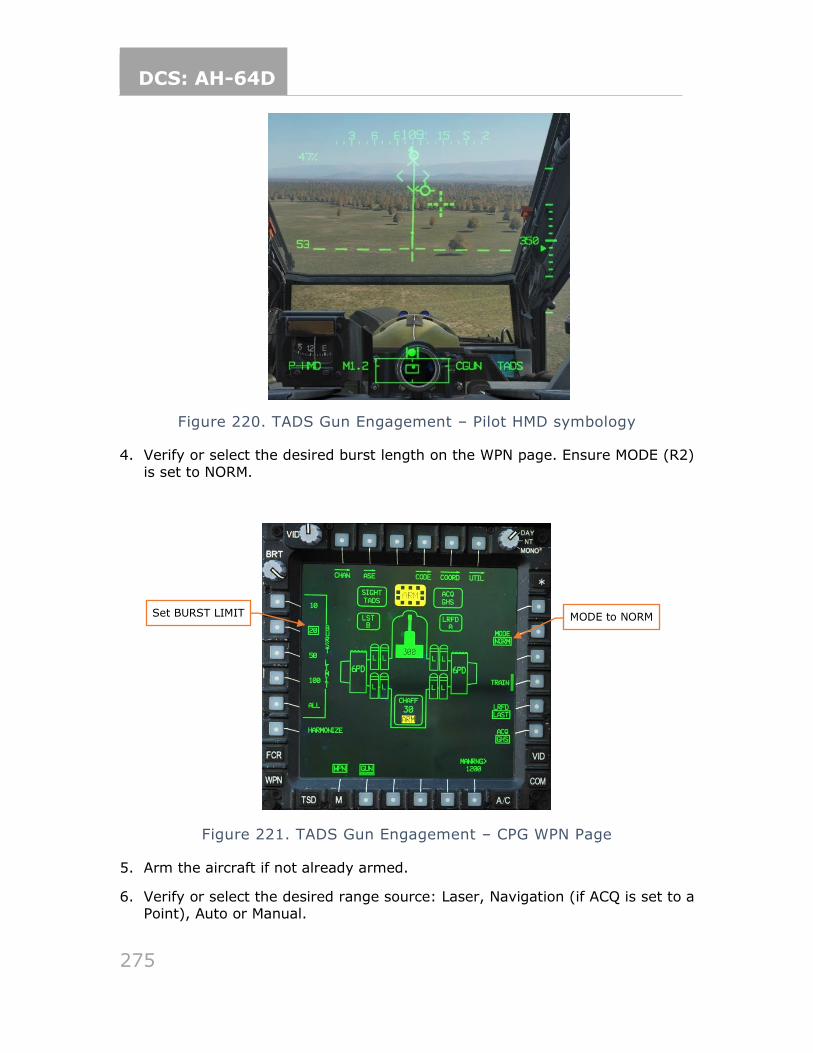
DCS: AH-64D
275
Figure 220. TADS Gun Engagement – Pilot HMD symbology
4. Verify or select the desired burst length on the WPN page. Ensure MODE (R2)
is set to NORM.
Figure 221. TADS Gun Engagement – CPG WPN Page
5. Arm the aircraft if not already armed.
6. Verify or select the desired range source: Laser, Navigation (if ACQ is set to a Point), Auto or Manual.
Set BURST LIMIT MODE to NORM
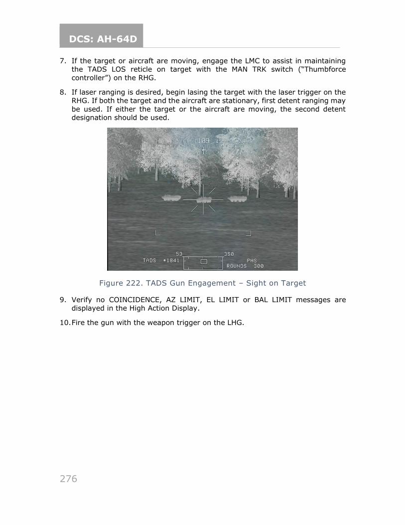
DCS: AH-64D
276
7. If the target or aircraft are moving, engage the LMC to assist in maintaining the TADS LOS reticle on target with the MAN TRK switch (“Thumbforce
controller”) on the RHG.
8. If laser ranging is desired, begin lasing the target with the laser trigger on the RHG. If both the target and the aircraft are stationary, first detent ranging may
be used. If either the target or the aircraft are moving, the second detent designation should be used.
Figure 222. TADS Gun Engagement – Sight on Target
9. Verify no COINCIDENCE, AZ LIMIT, EL LIMIT or BAL LIMIT messages are displayed in the High Action Display.
10. Fire the gun with the weapon trigger on the LHG.
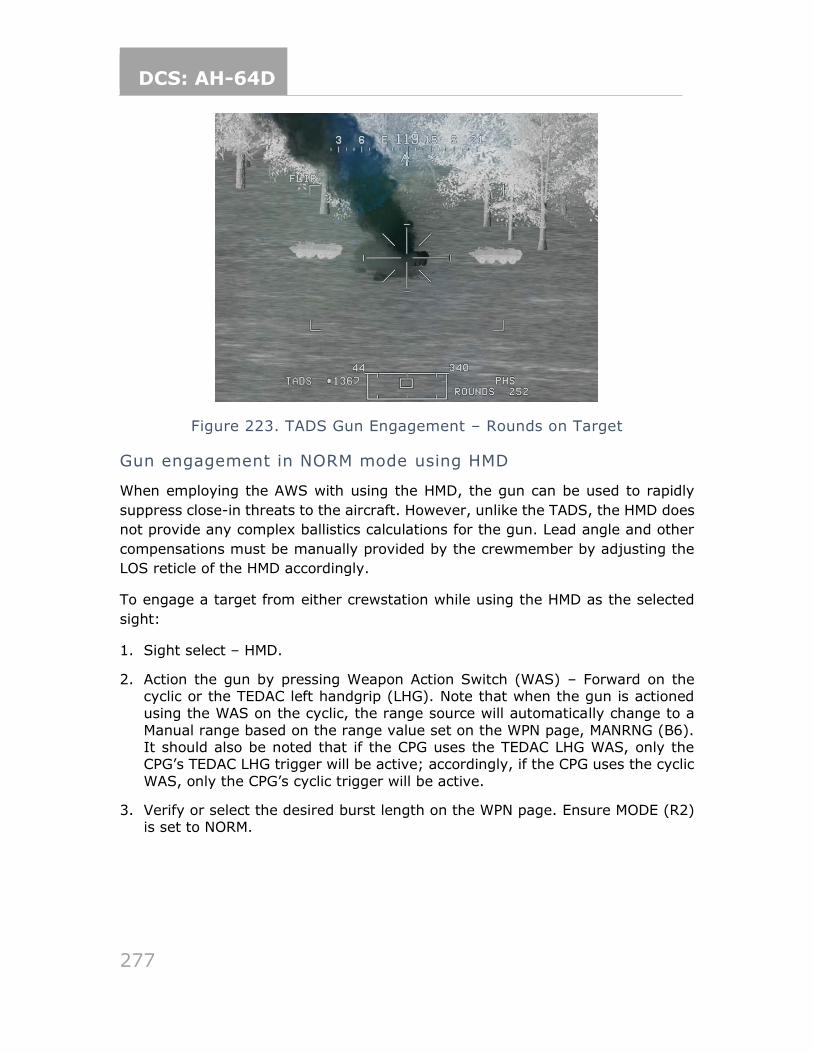
DCS: AH-64D
277
Figure 223. TADS Gun Engagement – Rounds on Target
Gun engagement in NORM mode using HMD
When employing the AWS with using the HMD, the gun can be used to rapidly
suppress close-in threats to the aircraft. However, unlike the TADS, the HMD does
not provide any complex ballistics calculations for the gun. Lead angle and other
compensations must be manually provided by the crewmember by adjusting the
LOS reticle of the HMD accordingly.
To engage a target from either crewstation while using the HMD as the selected
sight:
1. Sight select – HMD.
2. Action the gun by pressing Weapon Action Switch (WAS) – Forward on the cyclic or the TEDAC left handgrip (LHG). Note that when the gun is actioned using the WAS on the cyclic, the range source will automatically change to a
Manual range based on the range value set on the WPN page, MANRNG (B6). It should also be noted that if the CPG uses the TEDAC LHG WAS, only the CPG’s TEDAC LHG trigger will be active; accordingly, if the CPG uses the cyclic
WAS, only the CPG’s cyclic trigger will be active.
3. Verify or select the desired burst length on the WPN page. Ensure MODE (R2) is set to NORM.
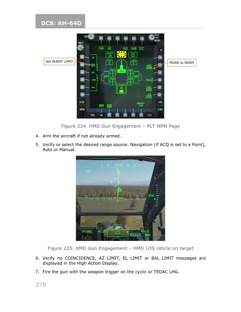
DCS: AH-64D
278
Figure 224. HMD Gun Engagement – PLT WPN Page
4. Arm the aircraft if not already armed.
5. Verify or select the desired range source: Navigation (if ACQ is set to a Point), Auto or Manual.
Figure 225. HMD Gun Engagement – HMD LOS reticle on target
6. Verify no COINCIDENCE, AZ LIMIT, EL LIMIT or BAL LIMIT messages are
displayed in the High Action Display.
7. Fire the gun with the weapon trigger on the cyclic or TEDAC LHG.
Set BURST LIMIT MODE to NORM
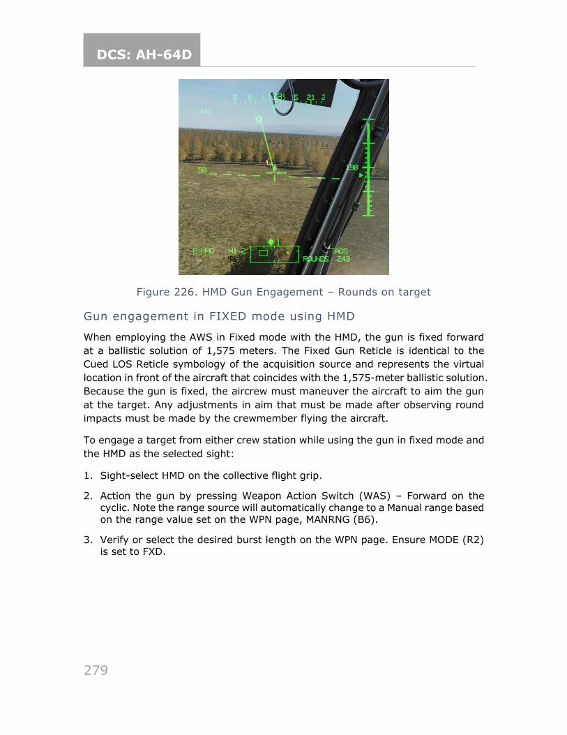
DCS: AH-64D
279
Figure 226. HMD Gun Engagement – Rounds on target
Gun engagement in FIXED mode using HMD
When employing the AWS in Fixed mode with the HMD, the gun is fixed forward
at a ballistic solution of 1,575 meters. The Fixed Gun Reticle is identical to the
Cued LOS Reticle symbology of the acquisition source and represents the virtual
location in front of the aircraft that coincides with the 1,575-meter ballistic solution.
Because the gun is fixed, the aircrew must maneuver the aircraft to aim the gun
at the target. Any adjustments in aim that must be made after observing round
impacts must be made by the crewmember flying the aircraft.
To engage a target from either crew station while using the gun in fixed mode and
the HMD as the selected sight:
1. Sight-select HMD on the collective flight grip.
2. Action the gun by pressing Weapon Action Switch (WAS) – Forward on the cyclic. Note the range source will automatically change to a Manual range based on the range value set on the WPN page, MANRNG (B6).
3. Verify or select the desired burst length on the WPN page. Ensure MODE (R2) is set to FXD.
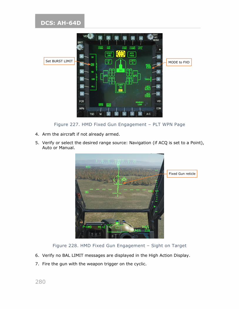
DCS: AH-64D
280
Figure 227. HMD Fixed Gun Engagement – PLT WPN Page
4. Arm the aircraft if not already armed.
5. Verify or select the desired range source: Navigation (if ACQ is set to a Point), Auto or Manual.
Figure 228. HMD Fixed Gun Engagement – Sight on Target
6. Verify no BAL LIMIT messages are displayed in the High Action Display.
7. Fire the gun with the weapon trigger on the cyclic.
Set BURST LIMIT MODE to FXD
Fixed Gun reticle
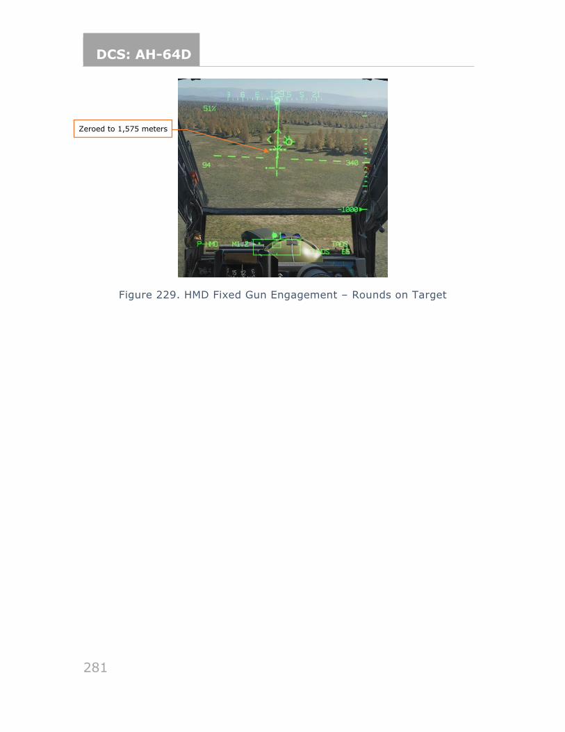
DCS: AH-64D
281
Figure 229. HMD Fixed Gun Engagement – Rounds on Target
Zeroed to 1,575 meters
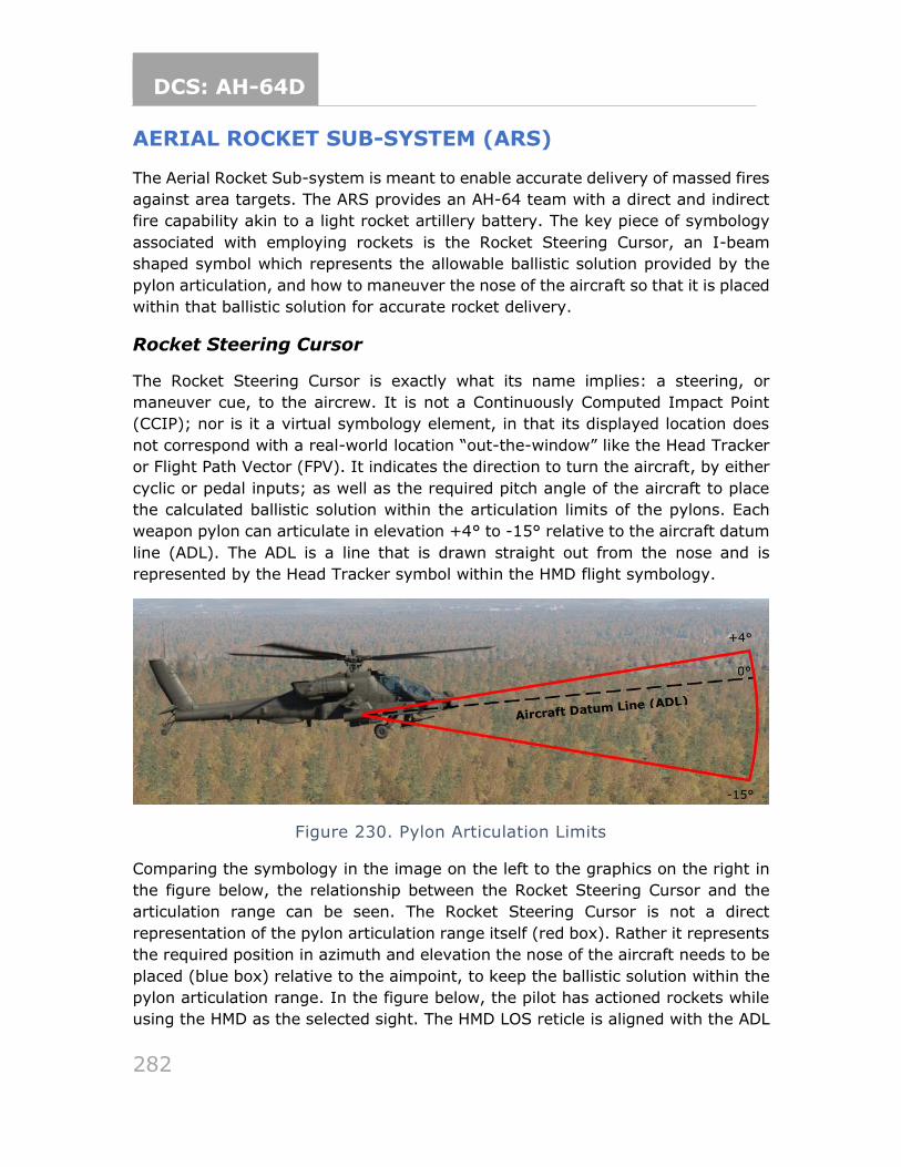
DCS: AH-64D
282
AERIAL ROCKET SUB-SYSTEM (ARS)
The Aerial Rocket Sub-system is meant to enable accurate delivery of massed fires
against area targets. The ARS provides an AH-64 team with a direct and indirect
fire capability akin to a light rocket artillery battery. The key piece of symbology
associated with employing rockets is the Rocket Steering Cursor, an I-beam
shaped symbol which represents the allowable ballistic solution provided by the
pylon articulation, and how to maneuver the nose of the aircraft so that it is placed
within that ballistic solution for accurate rocket delivery.
Rocket Steering Cursor
The Rocket Steering Cursor is exactly what its name implies: a steering, or
maneuver cue, to the aircrew. It is not a Continuously Computed Impact Point
(CCIP); nor is it a virtual symbology element, in that its displayed location does
not correspond with a real-world location “out-the-window” like the Head Tracker
or Flight Path Vector (FPV). It indicates the direction to turn the aircraft, by either
cyclic or pedal inputs; as well as the required pitch angle of the aircraft to place
the calculated ballistic solution within the articulation limits of the pylons. Each
weapon pylon can articulate in elevation +4° to -15° relative to the aircraft datum
line (ADL). The ADL is a line that is drawn straight out from the nose and is
represented by the Head Tracker symbol within the HMD flight symbology.
Figure 230. Pylon Articulation Limits
Comparing the symbology in the image on the left to the graphics on the right in
the figure below, the relationship between the Rocket Steering Cursor and the
articulation range can be seen. The Rocket Steering Cursor is not a direct
representation of the pylon articulation range itself (red box). Rather it represents
the required position in azimuth and elevation the nose of the aircraft needs to be
placed (blue box) relative to the aimpoint, to keep the ballistic solution within the
pylon articulation range. In the figure below, the pilot has actioned rockets while
using the HMD as the selected sight. The HMD LOS reticle is aligned with the ADL
-15°
+4°
0°
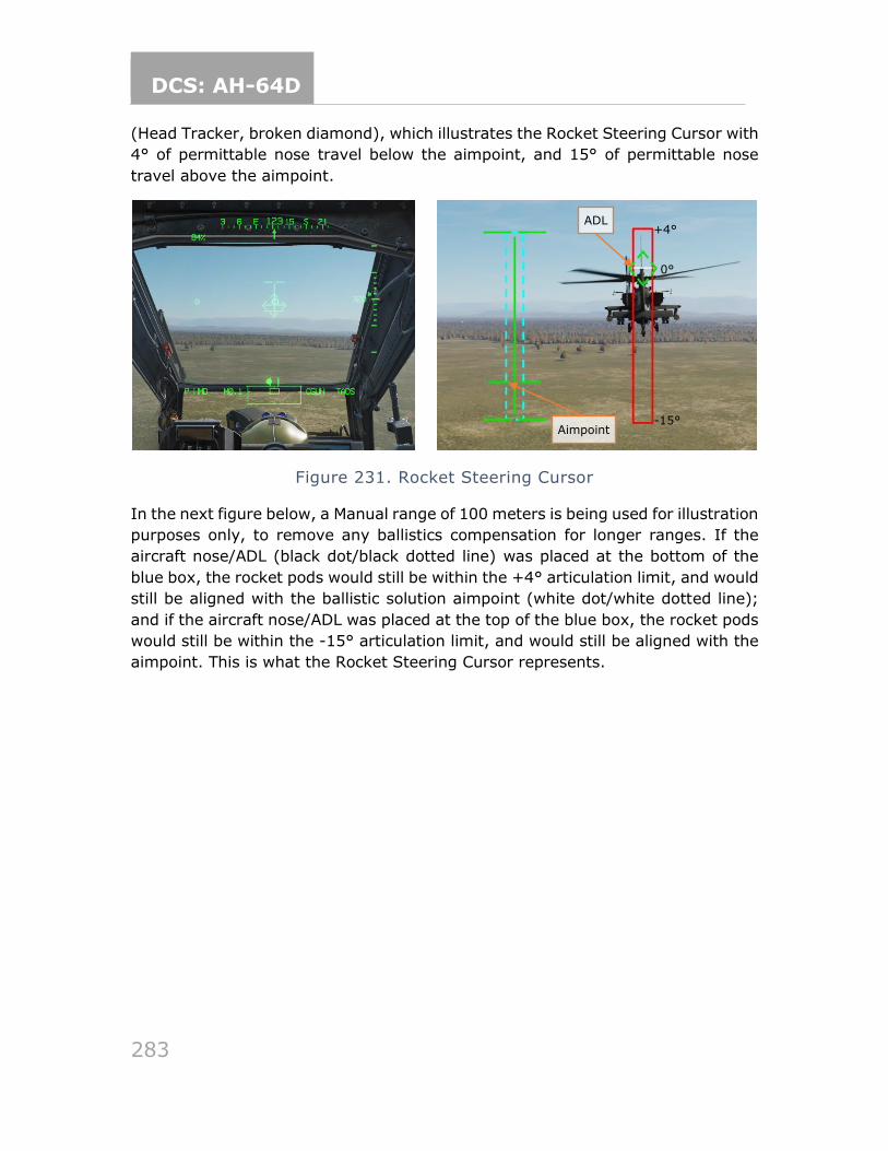
DCS: AH-64D
283
(Head Tracker, broken diamond), which illustrates the Rocket Steering Cursor with
4° of permittable nose travel below the aimpoint, and 15° of permittable nose
travel above the aimpoint.
Figure 231. Rocket Steering Cursor
In the next figure below, a Manual range of 100 meters is being used for illustration
purposes only, to remove any ballistics compensation for longer ranges. If the
aircraft nose/ADL (black dot/black dotted line) was placed at the bottom of the
blue box, the rocket pods would still be within the +4° articulation limit, and would
still be aligned with the ballistic solution aimpoint (white dot/white dotted line);
and if the aircraft nose/ADL was placed at the top of the blue box, the rocket pods
would still be within the -15° articulation limit, and would still be aligned with the
aimpoint. This is what the Rocket Steering Cursor represents.
+4°
-15°
0°
ADL
Aimpoint
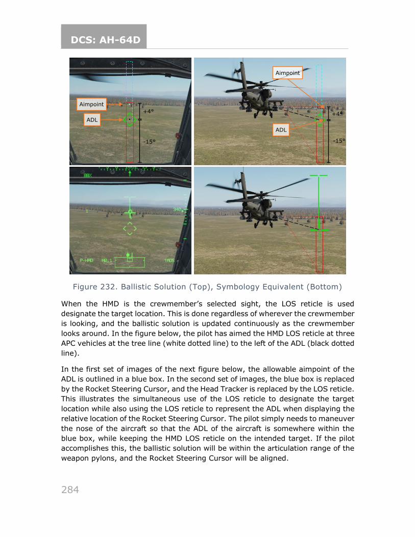
DCS: AH-64D
284
Figure 232. Ballistic Solution (Top), Symbology Equivalent (Bottom)
When the HMD is the crewmember’s selected sight, the LOS reticle is used
designate the target location. This is done regardless of wherever the crewmember
is looking, and the ballistic solution is updated continuously as the crewmember
looks around. In the figure below, the pilot has aimed the HMD LOS reticle at three
APC vehicles at the tree line (white dotted line) to the left of the ADL (black dotted
line).
In the first set of images of the next figure below, the allowable aimpoint of the
ADL is outlined in a blue box. In the second set of images, the blue box is replaced
by the Rocket Steering Cursor, and the Head Tracker is replaced by the LOS reticle.
This illustrates the simultaneous use of the LOS reticle to designate the target
location while also using the LOS reticle to represent the ADL when displaying the
relative location of the Rocket Steering Cursor. The pilot simply needs to maneuver
the nose of the aircraft so that the ADL of the aircraft is somewhere within the
blue box, while keeping the HMD LOS reticle on the intended target. If the pilot
accomplishes this, the ballistic solution will be within the articulation range of the
weapon pylons, and the Rocket Steering Cursor will be aligned.
ADL
Aimpoint
+4°
-15°
ADL
Aimpoint
+4°
-15°
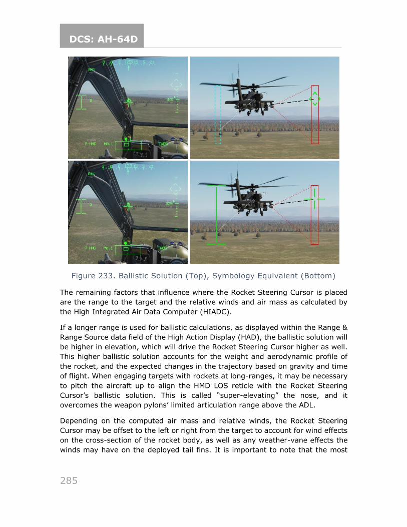
DCS: AH-64D
285
Figure 233. Ballistic Solution (Top), Symbology Equivalent (Bottom)
The remaining factors that influence where the Rocket Steering Cursor is placed
are the range to the target and the relative winds and air mass as calculated by
the High Integrated Air Data Computer (HIADC).
If a longer range is used for ballistic calculations, as displayed within the Range &
Range Source data field of the High Action Display (HAD), the ballistic solution will
be higher in elevation, which will drive the Rocket Steering Cursor higher as well.
This higher ballistic solution accounts for the weight and aerodynamic profile of
the rocket, and the expected changes in the trajectory based on gravity and time
of flight. When engaging targets with rockets at long-ranges, it may be necessary
to pitch the aircraft up to align the HMD LOS reticle with the Rocket Steering
Cursor’s ballistic solution. This is called “super-elevating” the nose, and it
overcomes the weapon pylons’ limited articulation range above the ADL.
Depending on the computed air mass and relative winds, the Rocket Steering
Cursor may be offset to the left or right from the target to account for wind effects
on the cross-section of the rocket body, as well as any weather-vane effects the
winds may have on the deployed tail fins. It is important to note that the most
DCS: AH-64D
286
accurate rocket employment with forward airspeed results when the aircraft is
kept within coordinated flight with the trim ball centered.
Despite each crewmember having the capability to independently employ rockets
from either crew station, the most accurate method of employing unguided rockets
from the AH-64 is using the Cooperative engagement mode. This mode allows the
pilot and CPG to work in unison by allowing the CPG to perform the targeting for
the ballistic solution while the pilot focuses on flying the aircraft to align the nose
within the Rocket Steering Cursor. This mode leverages the stability of the TADS
as a sight and allows the crew to generate an accurate ballistic solution at much
further ranges than what would be possible with a conventional CCIP.
For the pilot, the primary distinction of COOP mode is that the Rocket Steering
Cursor is not affected by head movement. The CPG’s TADS LOS reticle and range
source drives the ballistic solution, which therefore determine where the Rocket
Steering Cursor is displayed within the pilot’s HMD symbology. A common practice
by the pilot is to set the TADS as the acquisition source to provide increased
situational awareness of where the TADS is pointing relative to the nose of the
aircraft.
To enter this mode, the CPG must action rockets using the Weapon Action Switch
(WAS) on the TEDAC left handgrip (LHG) while the pilot actions rockets using the
WAS on the cyclic as normal. Both crewmembers will be presented with “COOP” in
the Weapon Control field of the HAD. When COOP mode is entered, the WPN page
becomes common for each crewmember, and the current settings on the CPG’s
WPN page, RKT format will override the pilot’s settings. However, once in COOP
mode, either crewmember can change the rocket selection in the INVENTORY (L1-
L5) or the QTY (R1) as necessary. Either crewmember can fire the rockets using
their respective weapon triggers (TEDAC weapon trigger for the CPG, cyclic
weapon trigger for the pilot), but this is normally left to the pilot.
When using Cooperative mode, the aircrew may elect to employ rockets with the
Direct Fire method or the Indirect Fire method. Direct Fire allows the aircrew to
observe the target area and make immediate adjustments, but this requires the
aircraft to remain exposed to enemy detection and weapons fire. Indirect Fire
allows the aircrew to remain behind cover and fire rocket salvos over a mask onto
a target location stored in the aircraft database, but direct observation of the
target area and corrections are more difficult. Indirect Fire is typically only used
for large area suppression.
Rocket engagement in COOP mode using TADS (Direct Fire)
To engage a target with Direct Fire rockets in Cooperative mode, using the TADS
as the sight:
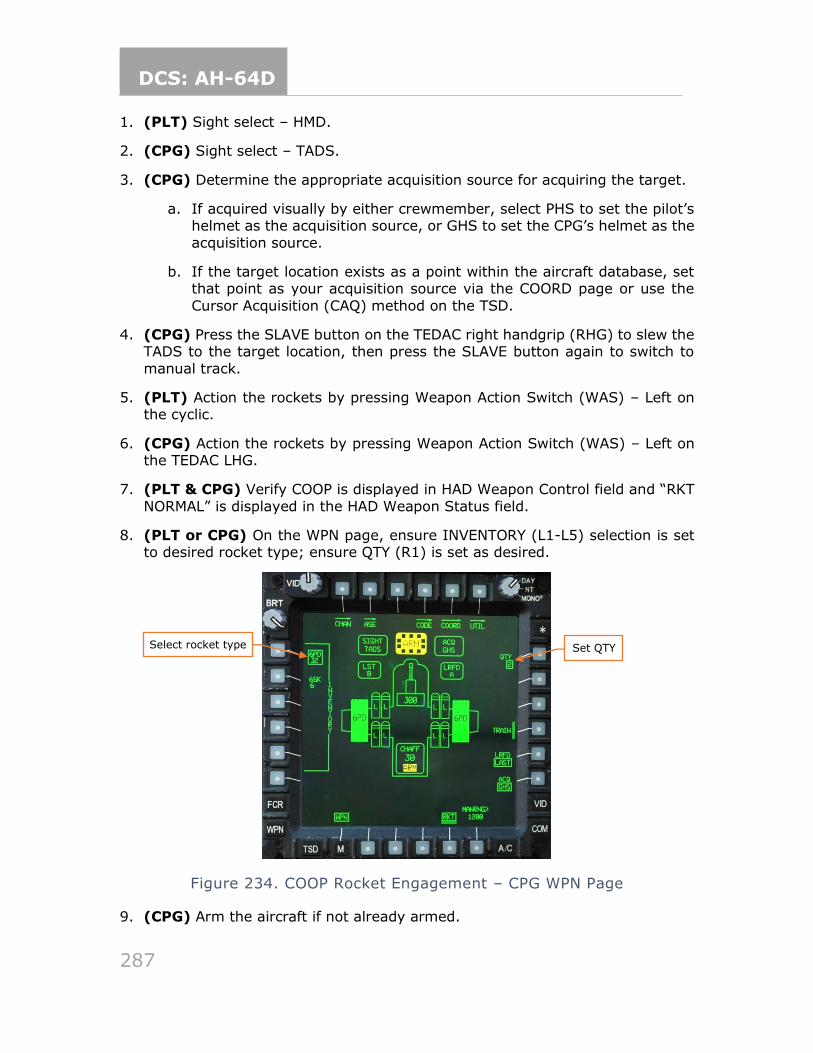
DCS: AH-64D
287
1. (PLT) Sight select – HMD.
2. (CPG) Sight select – TADS.
3. (CPG) Determine the appropriate acquisition source for acquiring the target.
a. If acquired visually by either crewmember, select PHS to set the pilot’s helmet as the acquisition source, or GHS to set the CPG’s helmet as the
acquisition source.
b. If the target location exists as a point within the aircraft database, set that point as your acquisition source via the COORD page or use the
Cursor Acquisition (CAQ) method on the TSD.
4. (CPG) Press the SLAVE button on the TEDAC right handgrip (RHG) to slew the TADS to the target location, then press the SLAVE button again to switch to
manual track.
5. (PLT) Action the rockets by pressing Weapon Action Switch (WAS) – Left on the cyclic.
6. (CPG) Action the rockets by pressing Weapon Action Switch (WAS) – Left on the TEDAC LHG.
7. (PLT & CPG) Verify COOP is displayed in HAD Weapon Control field and “RKT
NORMAL” is displayed in the HAD Weapon Status field.
8. (PLT or CPG) On the WPN page, ensure INVENTORY (L1-L5) selection is set to desired rocket type; ensure QTY (R1) is set as desired.
Figure 234. COOP Rocket Engagement – CPG WPN Page
9. (CPG) Arm the aircraft if not already armed.
Select rocket type Set QTY
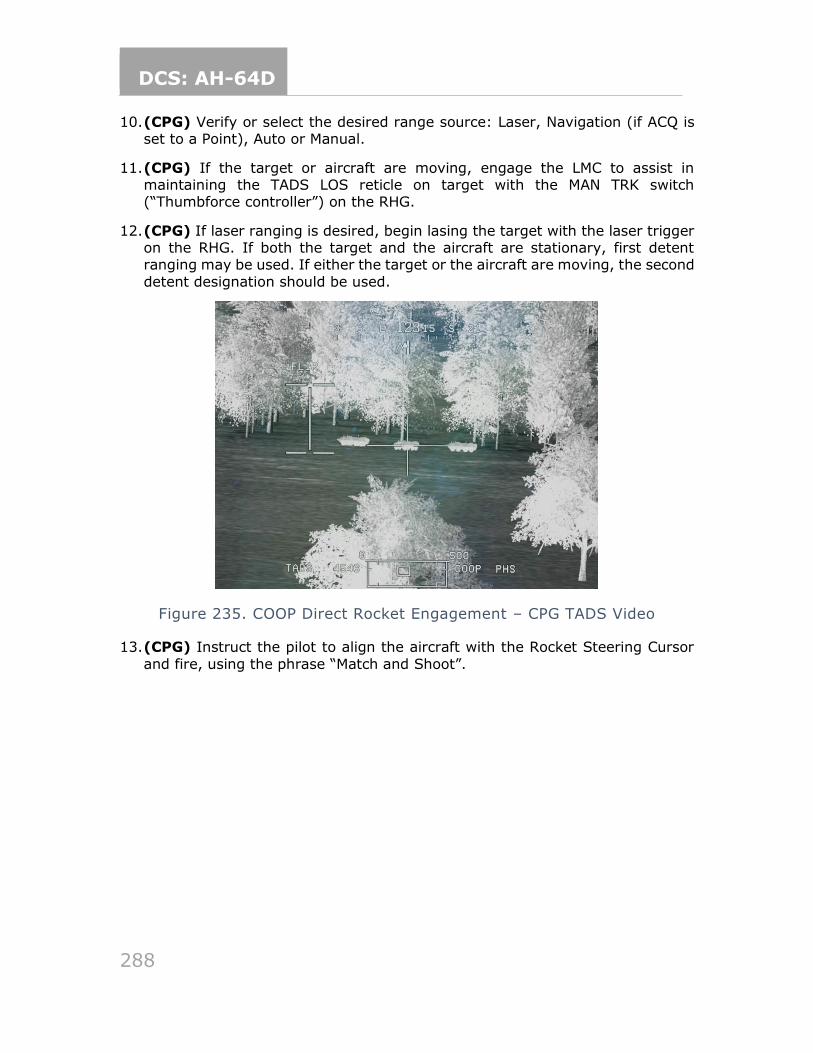
DCS: AH-64D
288
10. (CPG) Verify or select the desired range source: Laser, Navigation (if ACQ is set to a Point), Auto or Manual.
11. (CPG) If the target or aircraft are moving, engage the LMC to assist in maintaining the TADS LOS reticle on target with the MAN TRK switch (“Thumbforce controller”) on the RHG.
12. (CPG) If laser ranging is desired, begin lasing the target with the laser trigger on the RHG. If both the target and the aircraft are stationary, first detent ranging may be used. If either the target or the aircraft are moving, the second
detent designation should be used.
Figure 235. COOP Direct Rocket Engagement – CPG TADS Video
13. (CPG) Instruct the pilot to align the aircraft with the Rocket Steering Cursor
and fire, using the phrase “Match and Shoot”.
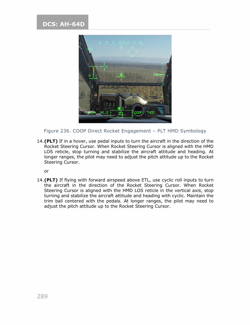
DCS: AH-64D
289
Figure 236. COOP Direct Rocket Engagement – PLT HMD Symbology
14. (PLT) If in a hover, use pedal inputs to turn the aircraft in the direction of the
Rocket Steering Cursor. When Rocket Steering Cursor is aligned with the HMD LOS reticle, stop turning and stabilize the aircraft attitude and heading. At longer ranges, the pilot may need to adjust the pitch attitude up to the Rocket
Steering Cursor.
or
14. (PLT) If flying with forward airspeed above ETL, use cyclic roll inputs to turn
the aircraft in the direction of the Rocket Steering Cursor. When Rocket Steering Cursor is aligned with the HMD LOS reticle in the vertical axis, stop turning and stabilize the aircraft attitude and heading with cyclic. Maintain the
trim ball centered with the pedals. At longer ranges, the pilot may need to adjust the pitch attitude up to the Rocket Steering Cursor.
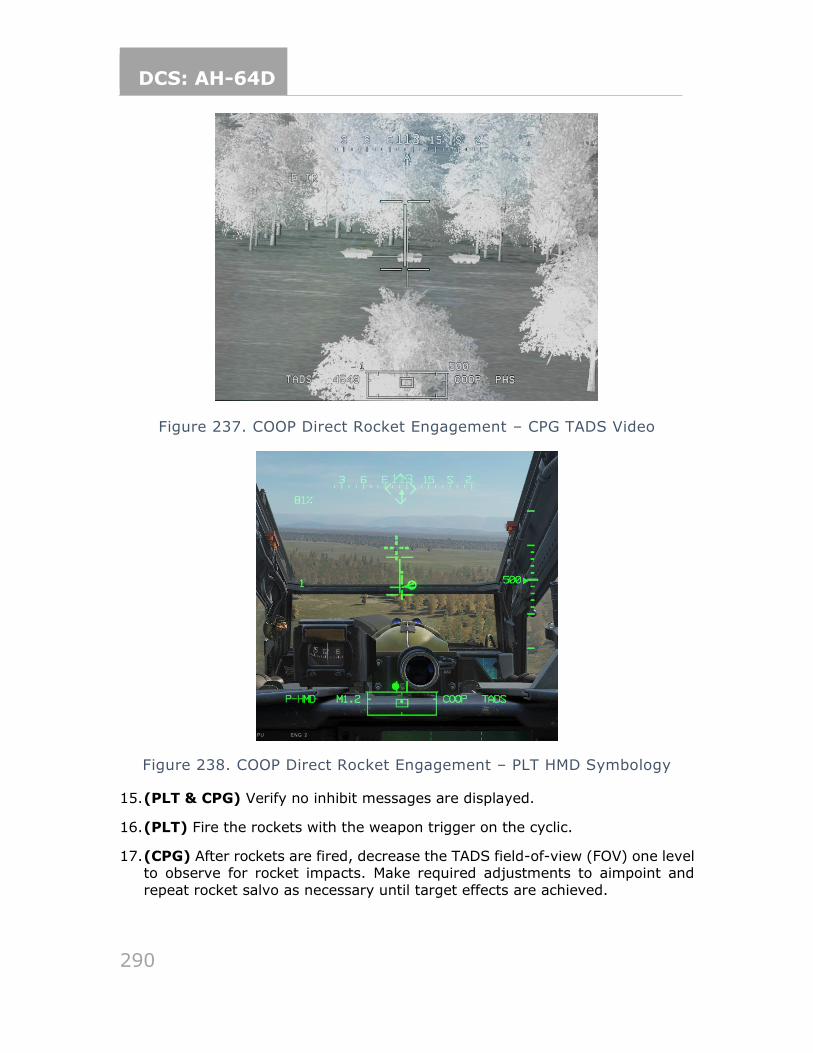
DCS: AH-64D
290
Figure 237. COOP Direct Rocket Engagement – CPG TADS Video
Figure 238. COOP Direct Rocket Engagement – PLT HMD Symbology
15. (PLT & CPG) Verify no inhibit messages are displayed.
16. (PLT) Fire the rockets with the weapon trigger on the cyclic.
17. (CPG) After rockets are fired, decrease the TADS field-of-view (FOV) one level to observe for rocket impacts. Make required adjustments to aimpoint and
repeat rocket salvo as necessary until target effects are achieved.
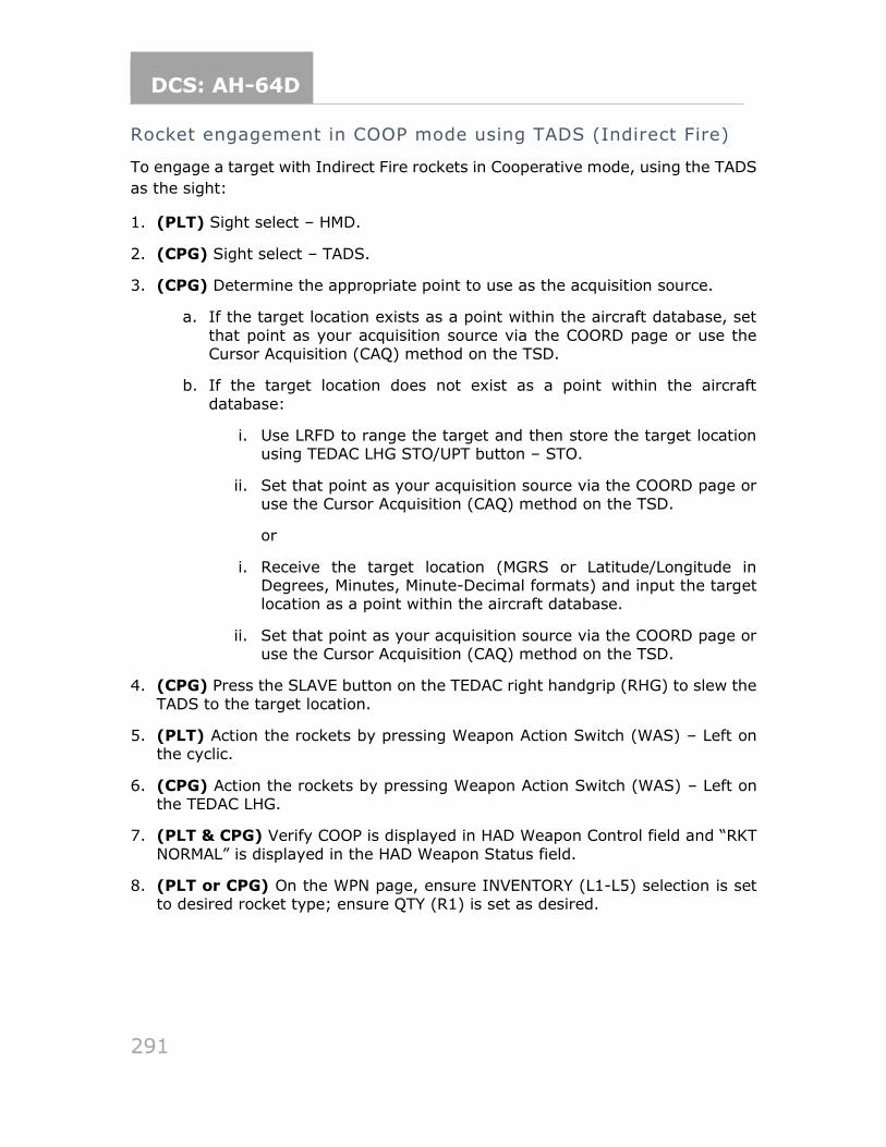
DCS: AH-64D
291
Rocket engagement in COOP mode using TADS (Indirect Fire)
To engage a target with Indirect Fire rockets in Cooperative mode, using the TADS
as the sight:
1. (PLT) Sight select – HMD.
2. (CPG) Sight select – TADS.
3. (CPG) Determine the appropriate point to use as the acquisition source.
a. If the target location exists as a point within the aircraft database, set
that point as your acquisition source via the COORD page or use the Cursor Acquisition (CAQ) method on the TSD.
b. If the target location does not exist as a point within the aircraft
database:
i. Use LRFD to range the target and then store the target location using TEDAC LHG STO/UPT button – STO.
ii. Set that point as your acquisition source via the COORD page or use the Cursor Acquisition (CAQ) method on the TSD.
or
i. Receive the target location (MGRS or Latitude/Longitude in Degrees, Minutes, Minute-Decimal formats) and input the target location as a point within the aircraft database.
ii. Set that point as your acquisition source via the COORD page or use the Cursor Acquisition (CAQ) method on the TSD.
4. (CPG) Press the SLAVE button on the TEDAC right handgrip (RHG) to slew the
TADS to the target location.
5. (PLT) Action the rockets by pressing Weapon Action Switch (WAS) – Left on the cyclic.
6. (CPG) Action the rockets by pressing Weapon Action Switch (WAS) – Left on the TEDAC LHG.
7. (PLT & CPG) Verify COOP is displayed in HAD Weapon Control field and “RKT
NORMAL” is displayed in the HAD Weapon Status field.
8. (PLT or CPG) On the WPN page, ensure INVENTORY (L1-L5) selection is set to desired rocket type; ensure QTY (R1) is set as desired.
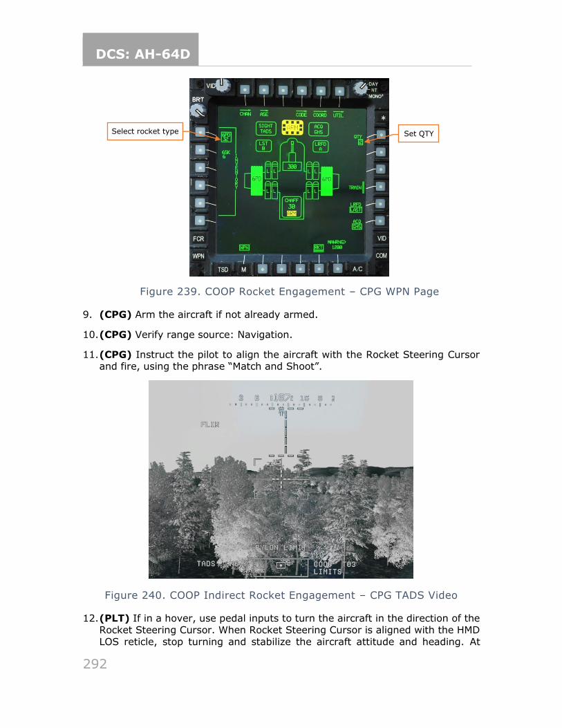
DCS: AH-64D
292
Figure 239. COOP Rocket Engagement – CPG WPN Page
9. (CPG) Arm the aircraft if not already armed.
10. (CPG) Verify range source: Navigation.
11. (CPG) Instruct the pilot to align the aircraft with the Rocket Steering Cursor and fire, using the phrase “Match and Shoot”.
Figure 240. COOP Indirect Rocket Engagement – CPG TADS Video
12. (PLT) If in a hover, use pedal inputs to turn the aircraft in the direction of the Rocket Steering Cursor. When Rocket Steering Cursor is aligned with the HMD
LOS reticle, stop turning and stabilize the aircraft attitude and heading. At
Select rocket type Set QTY
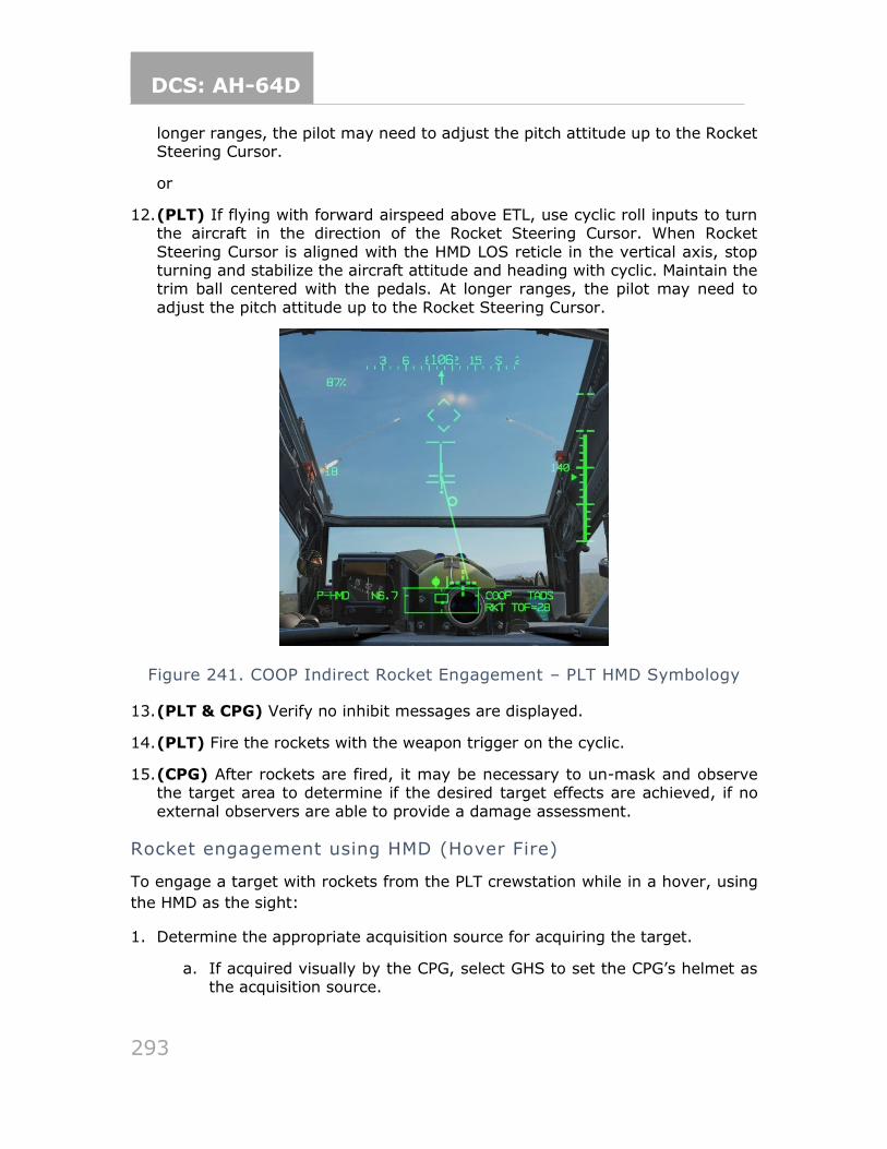
DCS: AH-64D
293
longer ranges, the pilot may need to adjust the pitch attitude up to the Rocket Steering Cursor.
or
12. (PLT) If flying with forward airspeed above ETL, use cyclic roll inputs to turn the aircraft in the direction of the Rocket Steering Cursor. When Rocket
Steering Cursor is aligned with the HMD LOS reticle in the vertical axis, stop turning and stabilize the aircraft attitude and heading with cyclic. Maintain the trim ball centered with the pedals. At longer ranges, the pilot may need to
adjust the pitch attitude up to the Rocket Steering Cursor.
Figure 241. COOP Indirect Rocket Engagement – PLT HMD Symbology
13. (PLT & CPG) Verify no inhibit messages are displayed.
14. (PLT) Fire the rockets with the weapon trigger on the cyclic.
15. (CPG) After rockets are fired, it may be necessary to un-mask and observe the target area to determine if the desired target effects are achieved, if no
external observers are able to provide a damage assessment.
Rocket engagement using HMD (Hover Fire)
To engage a target with rockets from the PLT crewstation while in a hover, using
the HMD as the sight:
1. Determine the appropriate acquisition source for acquiring the target.
a. If acquired visually by the CPG, select GHS to set the CPG’s helmet as the acquisition source.
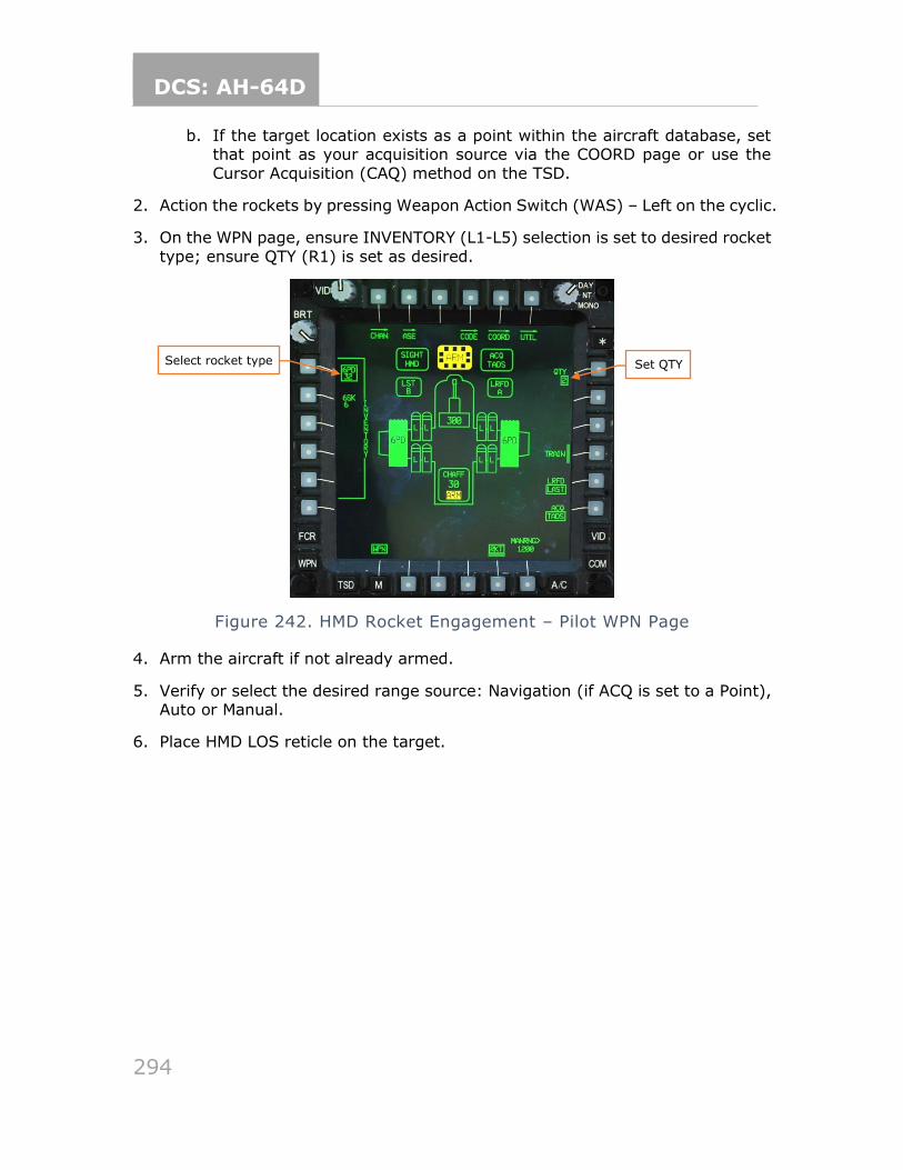
DCS: AH-64D
294
b. If the target location exists as a point within the aircraft database, set that point as your acquisition source via the COORD page or use the
Cursor Acquisition (CAQ) method on the TSD.
2. Action the rockets by pressing Weapon Action Switch (WAS) – Left on the cyclic.
3. On the WPN page, ensure INVENTORY (L1-L5) selection is set to desired rocket
type; ensure QTY (R1) is set as desired.
Figure 242. HMD Rocket Engagement – Pilot WPN Page
4. Arm the aircraft if not already armed.
5. Verify or select the desired range source: Navigation (if ACQ is set to a Point), Auto or Manual.
6. Place HMD LOS reticle on the target.
Select rocket type Set QTY
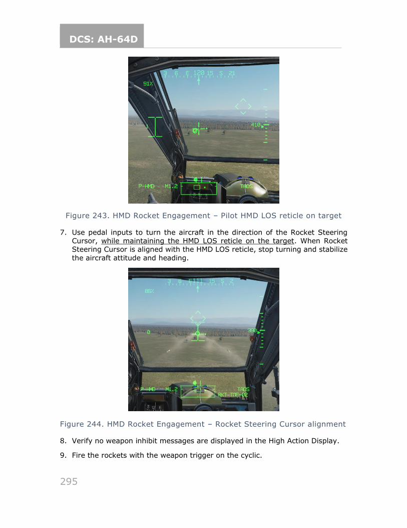
DCS: AH-64D
295
Figure 243. HMD Rocket Engagement – Pilot HMD LOS reticle on target
7. Use pedal inputs to turn the aircraft in the direction of the Rocket Steering Cursor, while maintaining the HMD LOS reticle on the target. When Rocket Steering Cursor is aligned with the HMD LOS reticle, stop turning and stabilize
the aircraft attitude and heading.
Figure 244. HMD Rocket Engagement – Rocket Steering Cursor alignment
8. Verify no weapon inhibit messages are displayed in the High Action Display.
9. Fire the rockets with the weapon trigger on the cyclic.
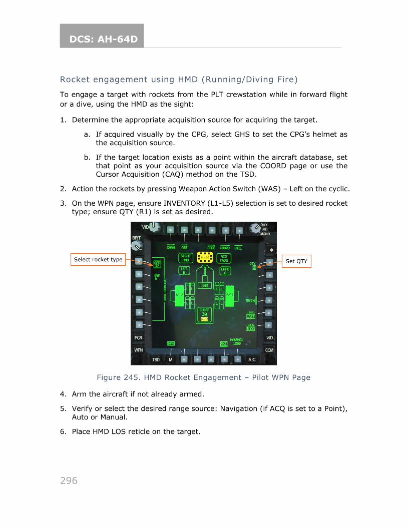
DCS: AH-64D
296
Rocket engagement using HMD (Running/Diving Fire)
To engage a target with rockets from the PLT crewstation while in forward flight
or a dive, using the HMD as the sight:
1. Determine the appropriate acquisition source for acquiring the target.
a. If acquired visually by the CPG, select GHS to set the CPG’s helmet as the acquisition source.
b. If the target location exists as a point within the aircraft database, set that point as your acquisition source via the COORD page or use the Cursor Acquisition (CAQ) method on the TSD.
2. Action the rockets by pressing Weapon Action Switch (WAS) – Left on the cyclic.
3. On the WPN page, ensure INVENTORY (L1-L5) selection is set to desired rocket type; ensure QTY (R1) is set as desired.
Figure 245. HMD Rocket Engagement – Pilot WPN Page
4. Arm the aircraft if not already armed.
5. Verify or select the desired range source: Navigation (if ACQ is set to a Point),
Auto or Manual.
6. Place HMD LOS reticle on the target.
Select rocket type Set QTY
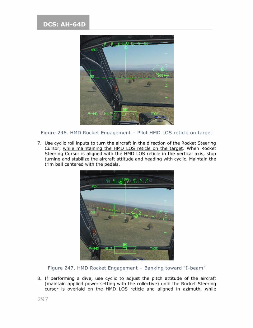
DCS: AH-64D
297
Figure 246. HMD Rocket Engagement – Pilot HMD LOS reticle on target
7. Use cyclic roll inputs to turn the aircraft in the direction of the Rocket Steering Cursor, while maintaining the HMD LOS reticle on the target. When Rocket Steering Cursor is aligned with the HMD LOS reticle in the vertical axis, stop
turning and stabilize the aircraft attitude and heading with cyclic. Maintain the trim ball centered with the pedals.
Figure 247. HMD Rocket Engagement – Banking toward “I-beam”
8. If performing a dive, use cyclic to adjust the pitch attitude of the aircraft
(maintain applied power setting with the collective) until the Rocket Steering cursor is overlaid on the HMD LOS reticle and aligned in azimuth, while
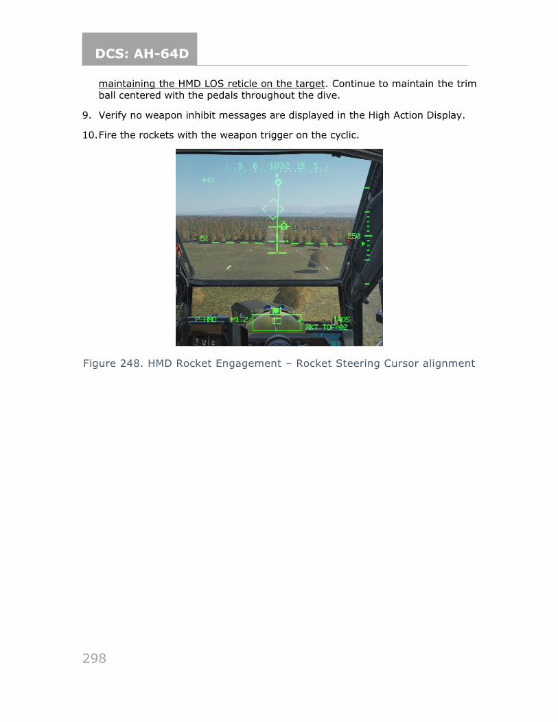
DCS: AH-64D
298
maintaining the HMD LOS reticle on the target. Continue to maintain the trim ball centered with the pedals throughout the dive.
9. Verify no weapon inhibit messages are displayed in the High Action Display.
10. Fire the rockets with the weapon trigger on the cyclic.
Figure 248. HMD Rocket Engagement – Rocket Steering Cursor alignment
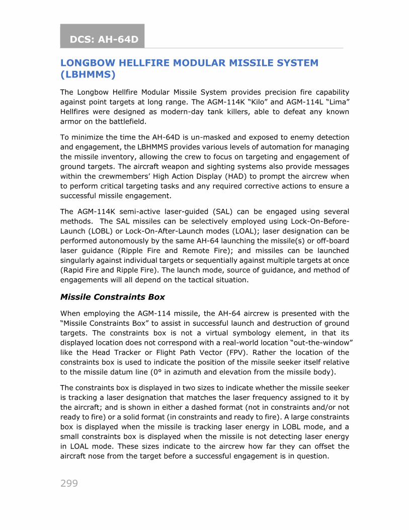
DCS: AH-64D
299
LONGBOW HELLFIRE MODULAR MISSILE SYSTEM
(LBHMMS)
The Longbow Hellfire Modular Missile System provides precision fire capability
against point targets at long range. The AGM-114K “Kilo” and AGM-114L “Lima”
Hellfires were designed as modern-day tank killers, able to defeat any known
armor on the battlefield.
To minimize the time the AH-64D is un-masked and exposed to enemy detection
and engagement, the LBHMMS provides various levels of automation for managing
the missile inventory, allowing the crew to focus on targeting and engagement of
ground targets. The aircraft weapon and sighting systems also provide messages
within the crewmembers’ High Action Display (HAD) to prompt the aircrew when
to perform critical targeting tasks and any required corrective actions to ensure a
successful missile engagement.
The AGM-114K semi-active laser-guided (SAL) can be engaged using several
methods. The SAL missiles can be selectively employed using Lock-On-Before-
Launch (LOBL) or Lock-On-After-Launch modes (LOAL); laser designation can be
performed autonomously by the same AH-64 launching the missile(s) or off-board
laser guidance (Ripple Fire and Remote Fire); and missiles can be launched
singularly against individual targets or sequentially against multiple targets at once
(Rapid Fire and Ripple Fire). The launch mode, source of guidance, and method of
engagements will all depend on the tactical situation.
Missile Constraints Box
When employing the AGM-114 missile, the AH-64 aircrew is presented with the
“Missile Constraints Box” to assist in successful launch and destruction of ground
targets. The constraints box is not a virtual symbology element, in that its
displayed location does not correspond with a real-world location “out-the-window”
like the Head Tracker or Flight Path Vector (FPV). Rather the location of the
constraints box is used to indicate the position of the missile seeker itself relative
to the missile datum line (0° in azimuth and elevation from the missile body).
The constraints box is displayed in two sizes to indicate whether the missile seeker
is tracking a laser designation that matches the laser frequency assigned to it by
the aircraft; and is shown in either a dashed format (not in constraints and/or not
ready to fire) or a solid format (in constraints and ready to fire). A large constraints
box is displayed when the missile is tracking laser energy in LOBL mode, and a
small constraints box is displayed when the missile is not detecting laser energy
in LOAL mode. These sizes indicate to the aircrew how far they can offset the
aircraft nose from the target before a successful engagement is in question.
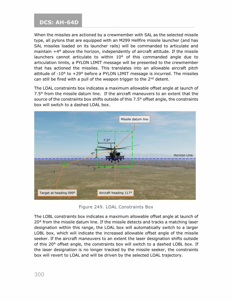
DCS: AH-64D
300
When the missiles are actioned by a crewmember with SAL as the selected missile
type, all pylons that are equipped with an M299 Hellfire missile launcher (and has
SAL missiles loaded on its launcher rails) will be commanded to articulate and
maintain +4° above the horizon, independently of aircraft attitude. If the missile
launchers cannot articulate to within 10° of this commanded angle due to
articulation limits, a PYLON LIMIT message will be presented to the crewmember
that has actioned the missiles. This translates into an allowable aircraft pitch
attitude of -10° to +29° before a PYLON LIMIT message is incurred. The missiles
can still be fired with a pull of the weapon trigger to the 2nd detent.
The LOAL constraints box indicates a maximum allowable offset angle at launch of
7.5° from the missile datum line. If the aircraft maneuvers to an extent that the
source of the constraints box shifts outside of this 7.5° offset angle, the constraints
box will switch to a dashed LOAL box.
Figure 249. LOAL Constraints Box
The LOBL constraints box indicates a maximum allowable offset angle at launch of
20° from the missile datum line. If the missile detects and tracks a matching laser
designation within this range, the LOAL box will automatically switch to a larger
LOBL box, which will indicate the increased allowable offset angle of the missile
seeker. If the aircraft maneuvers to an extent the laser designation shifts outside
of this 20° offset angle, the constraints box will switch to a dashed LOBL box. If
the laser designation is no longer tracked by the missile seeker, the constraints
box will revert to LOAL and will be driven by the selected LOAL trajectory.
4°
7.5°
Target at heading 099° Aircraft heading 117°
Horizon Line
Missile datum line

DCS: AH-64D
301
Figure 250. LOBL Constraints Box
When intending to engage targets with laser-guided Hellfire missiles, the most
important step is verifying the Priority missile channel is set to the same laser code
as the TADS LRFD. If these do not match, the CPG will receive a “REMOTE”
message in the Sight Status field of the High Action Display, to indicate the
requirement for an off-board laser designation source (see Remote Fire). It is
worth noting that if the pilot intends to employ laser-guided Hellfire missiles from
the backseat, the “REMOTE” message will not be displayed due to the fact the pilot
always requires a laser designation provided by another source, whether that be
his/her own CPG or another asset on the battlefield.
Laser-guided Hellfire engagement (LOBL)
To engage a target with a Hellfire missile in LOBL mode from the CPG crewstation,
while using the TADS as the sight to provide autonomous designation:
1. (CPG) Determine the appropriate acquisition source for acquiring the target.
a. If acquired visually by either crewmember, select PHS to set the pilot’s helmet as the acquisition source, or GHS to set the CPG’s helmet as the acquisition source.
b. If the target location exists as a point within the aircraft database, set that point as your acquisition source via the COORD page or use the Cursor Acquisition (CAQ) method on the TSD.
4°
20°
Target at heading 099° Aircraft heading 117°
Missile datum line
Horizon Line
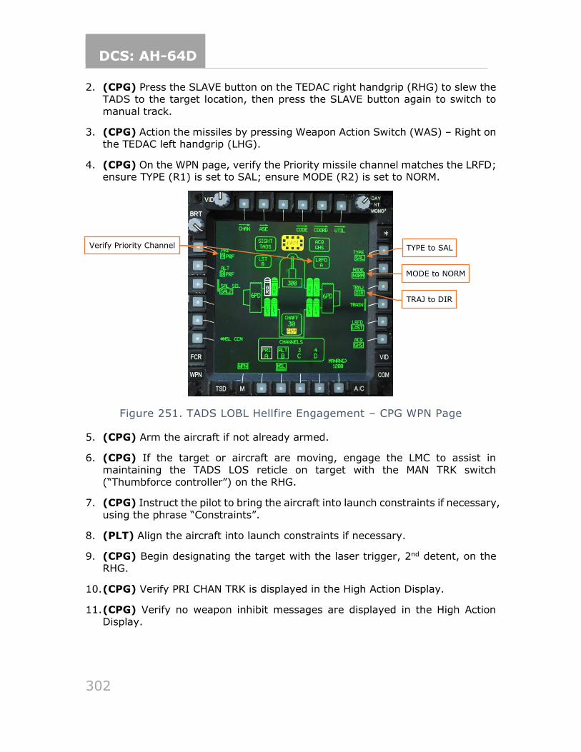
DCS: AH-64D
302
2. (CPG) Press the SLAVE button on the TEDAC right handgrip (RHG) to slew the TADS to the target location, then press the SLAVE button again to switch to
manual track.
3. (CPG) Action the missiles by pressing Weapon Action Switch (WAS) – Right on the TEDAC left handgrip (LHG).
4. (CPG) On the WPN page, verify the Priority missile channel matches the LRFD; ensure TYPE (R1) is set to SAL; ensure MODE (R2) is set to NORM.
Figure 251. TADS LOBL Hellfire Engagement – CPG WPN Page
5. (CPG) Arm the aircraft if not already armed.
6. (CPG) If the target or aircraft are moving, engage the LMC to assist in maintaining the TADS LOS reticle on target with the MAN TRK switch
(“Thumbforce controller”) on the RHG.
7. (CPG) Instruct the pilot to bring the aircraft into launch constraints if necessary, using the phrase “Constraints”.
8. (PLT) Align the aircraft into launch constraints if necessary.
9. (CPG) Begin designating the target with the laser trigger, 2nd detent, on the RHG.
10. (CPG) Verify PRI CHAN TRK is displayed in the High Action Display.
11. (CPG) Verify no weapon inhibit messages are displayed in the High Action Display.
TYPE to SAL Verify Priority Channel
TRAJ to DIR
MODE to NORM
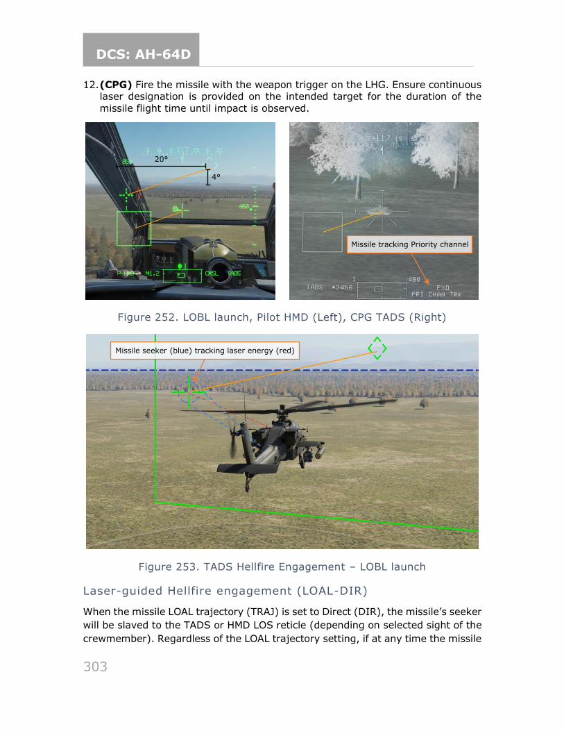
DCS: AH-64D
303
12. (CPG) Fire the missile with the weapon trigger on the LHG. Ensure continuous laser designation is provided on the intended target for the duration of the
missile flight time until impact is observed.
Figure 252. LOBL launch, Pilot HMD (Left), CPG TADS (Right)
Figure 253. TADS Hellfire Engagement – LOBL launch
Laser-guided Hellfire engagement (LOAL-DIR)
When the missile LOAL trajectory (TRAJ) is set to Direct (DIR), the missile’s seeker
will be slaved to the TADS or HMD LOS reticle (depending on selected sight of the
crewmember). Regardless of the LOAL trajectory setting, if at any time the missile
20°
4°
Missile tracking Priority channel
Missile seeker (blue) tracking laser energy (red)
DCS: AH-64D
304
detects a matching laser designation, the seeker will begin tracking the laser
designation, the missile will switch to LOBL mode, and the missile constraints box
will switch to the larger LOBL format. At this point, the missile will ignore the LOAL
trajectory setting and will operate as LOBL. If the laser designation is no longer
tracked by the missile seeker, the constraints box will revert to LOAL and will be
driven by the selected LOAL trajectory.
The purpose of LOAL is to fire the missile and then provide laser guidance after
weapons release. When conducting an autonomous missile engagement (laser
designation provided by launching aircraft), the most common reason for firing a
missile in LOAL-Direct instead of LOBL is backscatter. Backscatter can exist when
an obscurant is between the aircraft and target, and/or the angle between the
TADS LOS reticle and missile seeker differ by greater than 2°. When this 2°
difference is detected by the aircraft, a “BACKSCATTER” message will be presented
to the CPG, which will prevent the missile from being launched, regardless of which
weapon trigger detent is used. The gunner should cease lasing, which will cage
the missile seeker back to the TADS LOS and attempt to lase again. If backscatter
cannot be overcome, the CPG should fire the missile using LOAL-Direct and then
begin laser designation after the missile has successfully launched.
To engage a target with a Hellfire missile in LOAL-DIR mode from the CPG
crewstation, while using the TADS as the sight to provide autonomous designation:
1. (CPG) Determine the appropriate acquisition source for acquiring the target.
a. If acquired visually by either crewmember, select PHS to set the pilot’s
helmet as the acquisition source, or GHS to set the CPG’s helmet as the acquisition source.
b. If the target location exists as a point within the aircraft database, set
that point as your acquisition source via the COORD page or use the Cursor Acquisition (CAQ) method on the TSD.
2. (CPG) Press the SLAVE button on the TEDAC right handgrip (RHG) to slew the
TADS to the target location, then press the SLAVE button again to switch to manual track.
3. (CPG) Action the missiles by pressing Weapon Action Switch (WAS) – Right on
the TEDAC left handgrip (LHG).
4. (CPG) On the WPN page, verify the Priority missile channel matches the LRFD; ensure TYPE (R1) is set to SAL; ensure MODE (R2) is set to NORM; ensure
TRAJ (R3) is set to DIR.
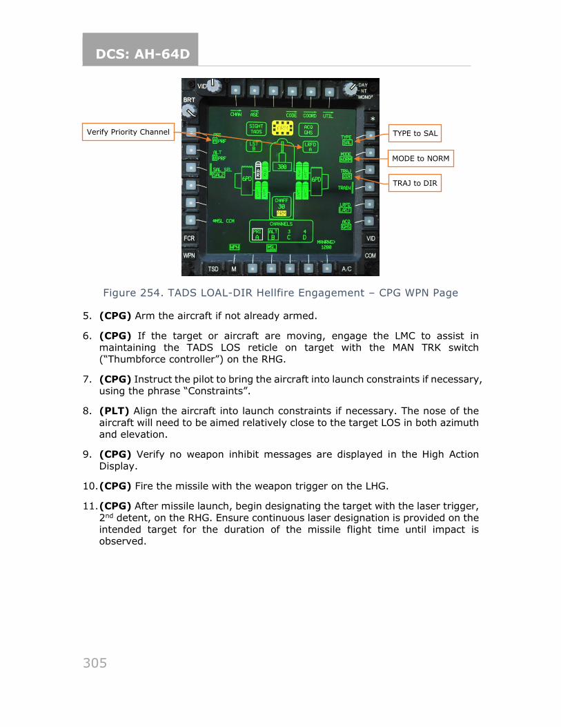
DCS: AH-64D
305
Figure 254. TADS LOAL-DIR Hellfire Engagement – CPG WPN Page
5. (CPG) Arm the aircraft if not already armed.
6. (CPG) If the target or aircraft are moving, engage the LMC to assist in maintaining the TADS LOS reticle on target with the MAN TRK switch (“Thumbforce controller”) on the RHG.
7. (CPG) Instruct the pilot to bring the aircraft into launch constraints if necessary, using the phrase “Constraints”.
8. (PLT) Align the aircraft into launch constraints if necessary. The nose of the
aircraft will need to be aimed relatively close to the target LOS in both azimuth and elevation.
9. (CPG) Verify no weapon inhibit messages are displayed in the High Action
Display.
10. (CPG) Fire the missile with the weapon trigger on the LHG.
11. (CPG) After missile launch, begin designating the target with the laser trigger,
2nd detent, on the RHG. Ensure continuous laser designation is provided on the intended target for the duration of the missile flight time until impact is observed.
TYPE to SAL
TRAJ to DIR
MODE to NORM
Verify Priority Channel
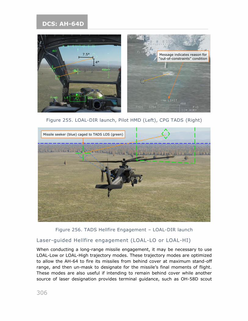
DCS: AH-64D
306
Figure 255. LOAL-DIR launch, Pilot HMD (Left), CPG TADS (Right)
Figure 256. TADS Hellfire Engagement – LOAL-DIR launch
Laser-guided Hellfire engagement (LOAL-LO or LOAL-HI)
When conducting a long-range missile engagement, it may be necessary to use
LOAL-Low or LOAL-High trajectory modes. These trajectory modes are optimized
to allow the AH-64 to fire its missiles from behind cover at maximum stand-off
range, and then un-mask to designate for the missile’s final moments of flight.
These modes are also useful if intending to remain behind cover while another
source of laser designation provides terminal guidance, such as OH-58D scout
Missile seeker (blue) caged to TADS LOS (green)
Message indicates reason for “out-of-constraints” condition
7.5°
4°
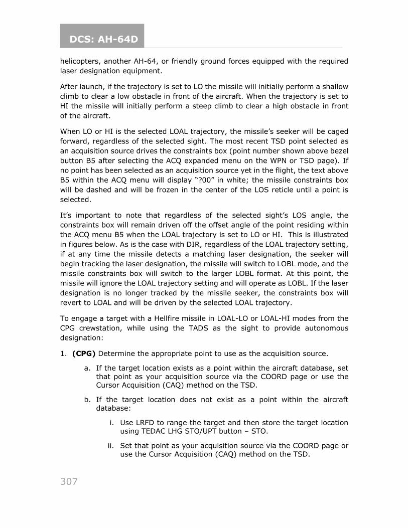
DCS: AH-64D
307
helicopters, another AH-64, or friendly ground forces equipped with the required
laser designation equipment.
After launch, if the trajectory is set to LO the missile will initially perform a shallow
climb to clear a low obstacle in front of the aircraft. When the trajectory is set to
HI the missile will initially perform a steep climb to clear a high obstacle in front
of the aircraft.
When LO or HI is the selected LOAL trajectory, the missile’s seeker will be caged
forward, regardless of the selected sight. The most recent TSD point selected as
an acquisition source drives the constraints box (point number shown above bezel
button B5 after selecting the ACQ expanded menu on the WPN or TSD page). If
no point has been selected as an acquisition source yet in the flight, the text above
B5 within the ACQ menu will display “?00” in white; the missile constraints box
will be dashed and will be frozen in the center of the LOS reticle until a point is
selected.
It’s important to note that regardless of the selected sight’s LOS angle, the
constraints box will remain driven off the offset angle of the point residing within
the ACQ menu B5 when the LOAL trajectory is set to LO or HI. This is illustrated
in figures below. As is the case with DIR, regardless of the LOAL trajectory setting,
if at any time the missile detects a matching laser designation, the seeker will
begin tracking the laser designation, the missile will switch to LOBL mode, and the
missile constraints box will switch to the larger LOBL format. At this point, the
missile will ignore the LOAL trajectory setting and will operate as LOBL. If the laser
designation is no longer tracked by the missile seeker, the constraints box will
revert to LOAL and will be driven by the selected LOAL trajectory.
To engage a target with a Hellfire missile in LOAL-LO or LOAL-HI modes from the
CPG crewstation, while using the TADS as the sight to provide autonomous
designation:
1. (CPG) Determine the appropriate point to use as the acquisition source.
a. If the target location exists as a point within the aircraft database, set
that point as your acquisition source via the COORD page or use the Cursor Acquisition (CAQ) method on the TSD.
b. If the target location does not exist as a point within the aircraft
database:
i. Use LRFD to range the target and then store the target location using TEDAC LHG STO/UPT button – STO.
ii. Set that point as your acquisition source via the COORD page or use the Cursor Acquisition (CAQ) method on the TSD.
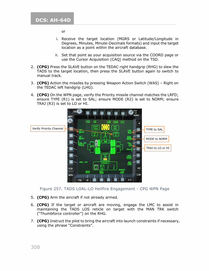
DCS: AH-64D
308
or
i. Receive the target location (MGRS or Latitude/Longitude in
Degrees, Minutes, Minute-Decimals formats) and input the target location as a point within the aircraft database.
ii. Set that point as your acquisition source via the COORD page or
use the Cursor Acquisition (CAQ) method on the TSD.
2. (CPG) Press the SLAVE button on the TEDAC right handgrip (RHG) to slew the TADS to the target location, then press the SLAVE button again to switch to
manual track.
3. (CPG) Action the missiles by pressing Weapon Action Switch (WAS) – Right on the TEDAC left handgrip (LHG).
4. (CPG) On the WPN page, verify the Priority missile channel matches the LRFD; ensure TYPE (R1) is set to SAL; ensure MODE (R2) is set to NORM; ensure TRAJ (R3) is set to LO or HI.
Figure 257. TADS LOAL-LO Hellfire Engagement - CPG WPN Page
5. (CPG) Arm the aircraft if not already armed.
6. (CPG) If the target or aircraft are moving, engage the LMC to assist in
maintaining the TADS LOS reticle on target with the MAN TRK switch (“Thumbforce controller”) on the RHG.
7. (CPG) Instruct the pilot to bring the aircraft into launch constraints if necessary,
using the phrase “Constraints”.
TYPE to SAL
TRAJ to LO or HI
MODE to NORM
Verify Priority Channel
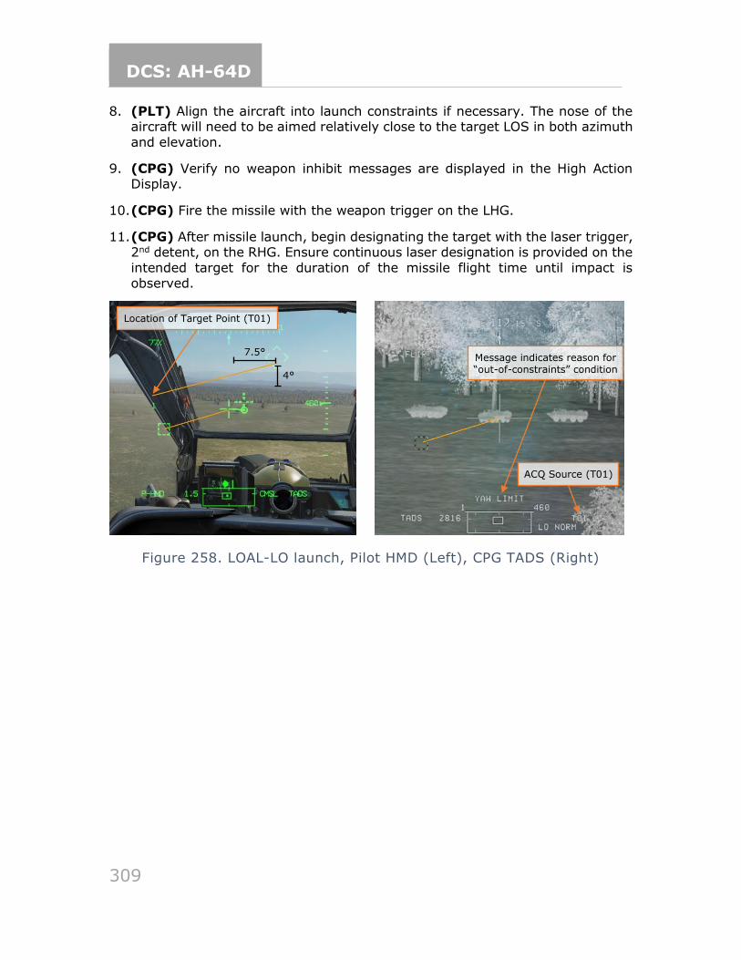
DCS: AH-64D
309
8. (PLT) Align the aircraft into launch constraints if necessary. The nose of the aircraft will need to be aimed relatively close to the target LOS in both azimuth
and elevation.
9. (CPG) Verify no weapon inhibit messages are displayed in the High Action Display.
10. (CPG) Fire the missile with the weapon trigger on the LHG.
11. (CPG) After missile launch, begin designating the target with the laser trigger, 2nd detent, on the RHG. Ensure continuous laser designation is provided on the
intended target for the duration of the missile flight time until impact is observed.
Figure 258. LOAL-LO launch, Pilot HMD (Left), CPG TADS (Right)
Location of Target Point (T01)
Message indicates reason for “out-of-constraints” condition
ACQ Source (T01)
7.5°
4°
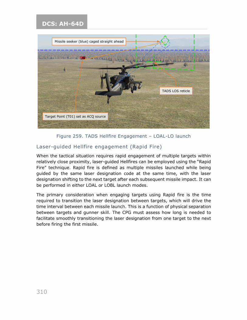
DCS: AH-64D
310
Figure 259. TADS Hellfire Engagement – LOAL-LO launch
Laser-guided Hellfire engagement (Rapid Fire)
When the tactical situation requires rapid engagement of multiple targets within
relatively close proximity, laser-guided Hellfires can be employed using the “Rapid
Fire” technique. Rapid fire is defined as multiple missiles launched while being
guided by the same laser designation code at the same time, with the laser
designation shifting to the next target after each subsequent missile impact. It can
be performed in either LOAL or LOBL launch modes.
The primary consideration when engaging targets using Rapid fire is the time
required to transition the laser designation between targets, which will drive the
time interval between each missile launch. This is a function of physical separation
between targets and gunner skill. The CPG must assess how long is needed to
facilitate smoothly transitioning the laser designation from one target to the next
before firing the first missile.
Missile seeker (blue) caged straight ahead
TADS LOS reticle
Target Point (T01) set as ACQ source
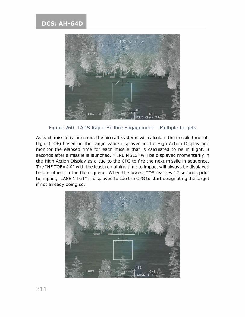
DCS: AH-64D
311
Figure 260. TADS Rapid Hellfire Engagement – Multiple targets
As each missile is launched, the aircraft systems will calculate the missile time-of-
flight (TOF) based on the range value displayed in the High Action Display and
monitor the elapsed time for each missile that is calculated to be in flight. 8
seconds after a missile is launched, “FIRE MSLS” will be displayed momentarily in
the High Action Display as a cue to the CPG to fire the next missile in sequence.
The “HF TOF=##” with the least remaining time to impact will always be displayed
before others in the flight queue. When the lowest TOF reaches 12 seconds prior
to impact, “LASE 1 TGT” is displayed to cue the CPG to start designating the target
if not already doing so.
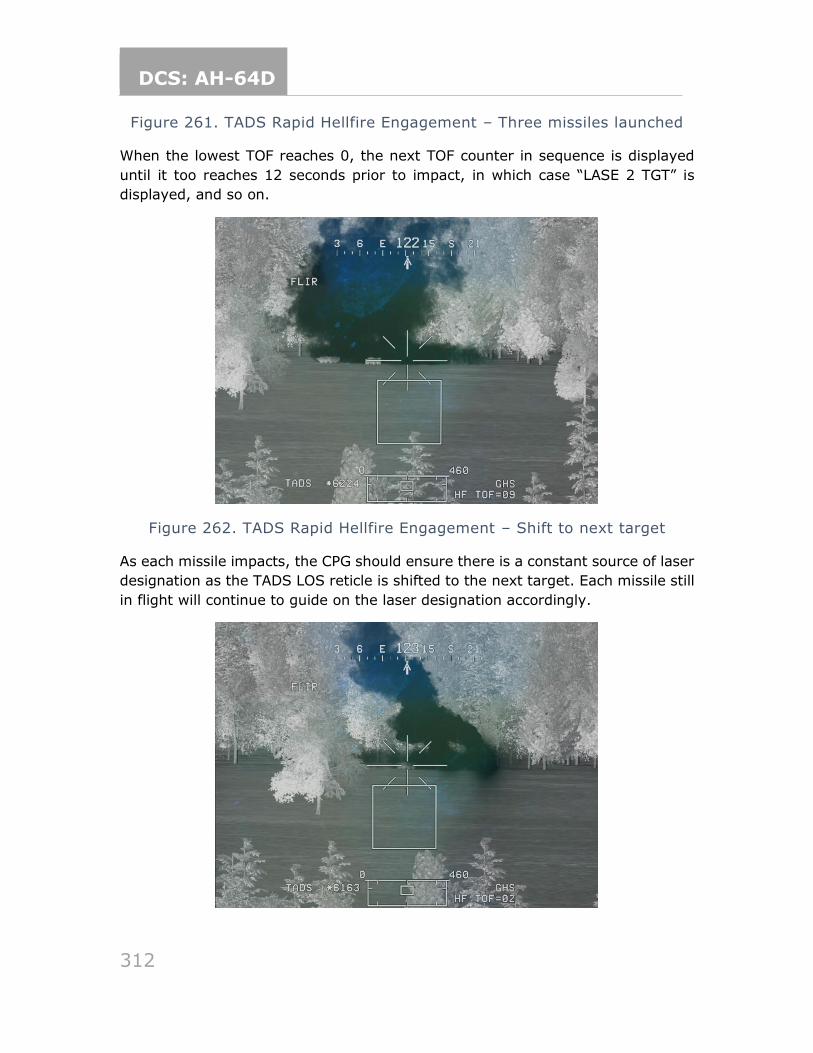
DCS: AH-64D
312
Figure 261. TADS Rapid Hellfire Engagement – Three missiles launched
When the lowest TOF reaches 0, the next TOF counter in sequence is displayed
until it too reaches 12 seconds prior to impact, in which case “LASE 2 TGT” is
displayed, and so on.
Figure 262. TADS Rapid Hellfire Engagement – Shift to next target
As each missile impacts, the CPG should ensure there is a constant source of laser
designation as the TADS LOS reticle is shifted to the next target. Each missile still
in flight will continue to guide on the laser designation accordingly.
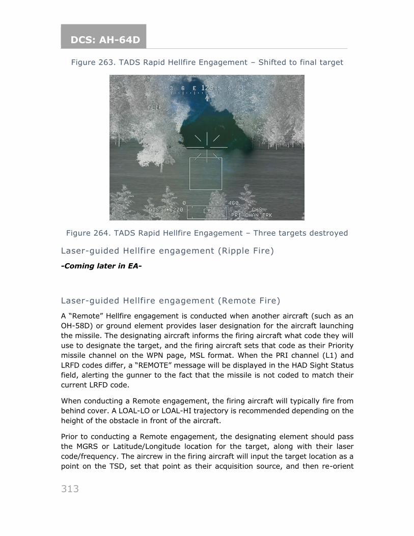
DCS: AH-64D
313
Figure 263. TADS Rapid Hellfire Engagement – Shifted to final target
Figure 264. TADS Rapid Hellfire Engagement – Three targets destroyed
Laser-guided Hellfire engagement (Ripple Fire)
-Coming later in EA-
Laser-guided Hellfire engagement (Remote Fire)
A “Remote” Hellfire engagement is conducted when another aircraft (such as an
OH-58D) or ground element provides laser designation for the aircraft launching
the missile. The designating aircraft informs the firing aircraft what code they will
use to designate the target, and the firing aircraft sets that code as their Priority
missile channel on the WPN page, MSL format. When the PRI channel (L1) and
LRFD codes differ, a “REMOTE” message will be displayed in the HAD Sight Status
field, alerting the gunner to the fact that the missile is not coded to match their
current LRFD code.
When conducting a Remote engagement, the firing aircraft will typically fire from
behind cover. A LOAL-LO or LOAL-HI trajectory is recommended depending on the
height of the obstacle in front of the aircraft.
Prior to conducting a Remote engagement, the designating element should pass
the MGRS or Latitude/Longitude location for the target, along with their laser
code/frequency. The aircrew in the firing aircraft will input the target location as a
point on the TSD, set that point as their acquisition source, and then re-orient
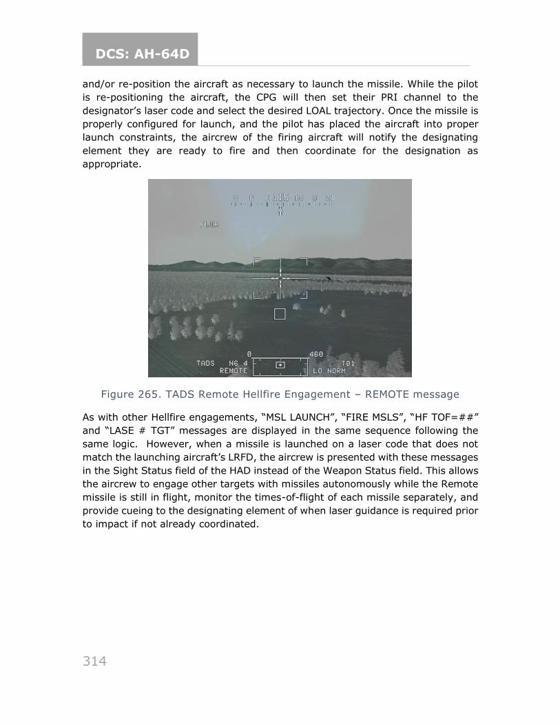
DCS: AH-64D
314
and/or re-position the aircraft as necessary to launch the missile. While the pilot
is re-positioning the aircraft, the CPG will then set their PRI channel to the
designator’s laser code and select the desired LOAL trajectory. Once the missile is
properly configured for launch, and the pilot has placed the aircraft into proper
launch constraints, the aircrew of the firing aircraft will notify the designating
element they are ready to fire and then coordinate for the designation as
appropriate.
Figure 265. TADS Remote Hellfire Engagement – REMOTE message
As with other Hellfire engagements, “MSL LAUNCH”, “FIRE MSLS”, “HF TOF=##”
and “LASE # TGT” messages are displayed in the same sequence following the
same logic. However, when a missile is launched on a laser code that does not
match the launching aircraft’s LRFD, the aircrew is presented with these messages
in the Sight Status field of the HAD instead of the Weapon Status field. This allows
the aircrew to engage other targets with missiles autonomously while the Remote
missile is still in flight, monitor the times-of-flight of each missile separately, and
provide cueing to the designating element of when laser guidance is required prior
to impact if not already coordinated.
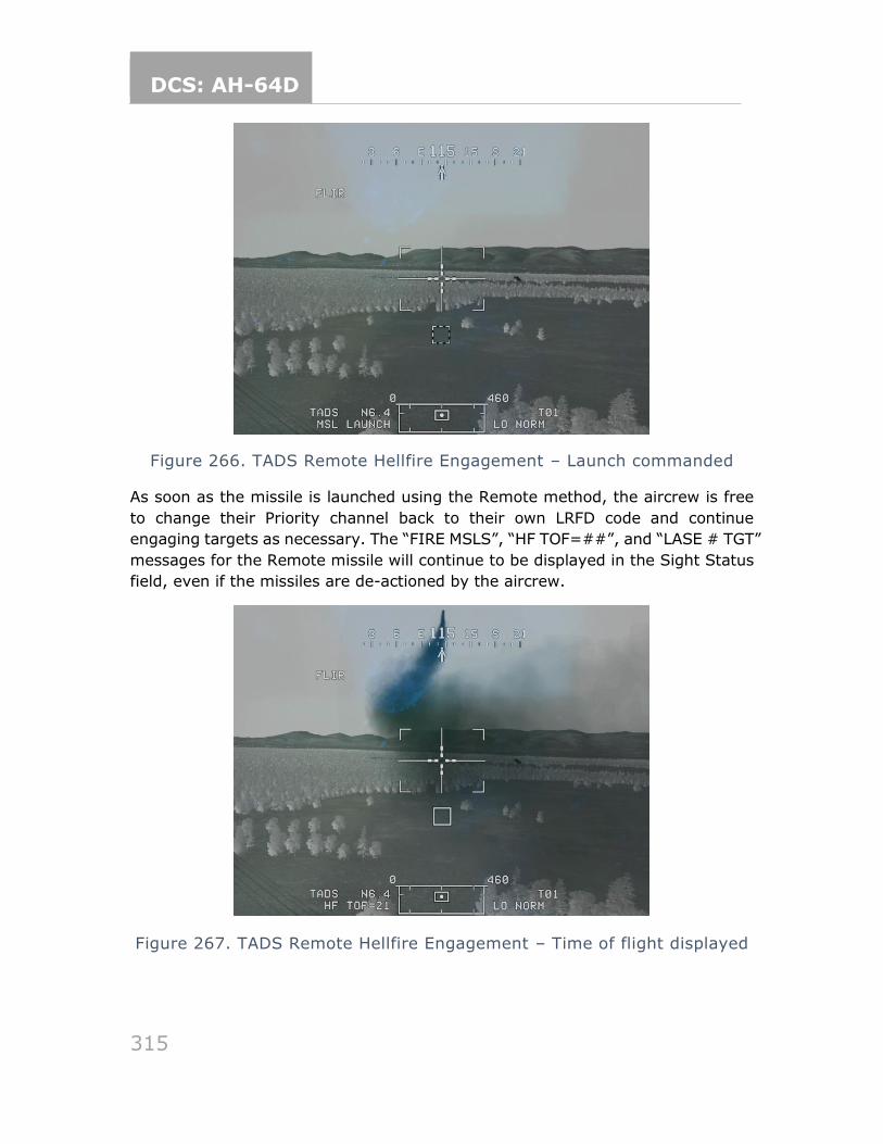
DCS: AH-64D
315
Figure 266. TADS Remote Hellfire Engagement – Launch commanded
As soon as the missile is launched using the Remote method, the aircrew is free
to change their Priority channel back to their own LRFD code and continue
engaging targets as necessary. The “FIRE MSLS”, “HF TOF=##”, and “LASE # TGT”
messages for the Remote missile will continue to be displayed in the Sight Status
field, even if the missiles are de-actioned by the aircrew.
Figure 267. TADS Remote Hellfire Engagement – Time of flight displayed
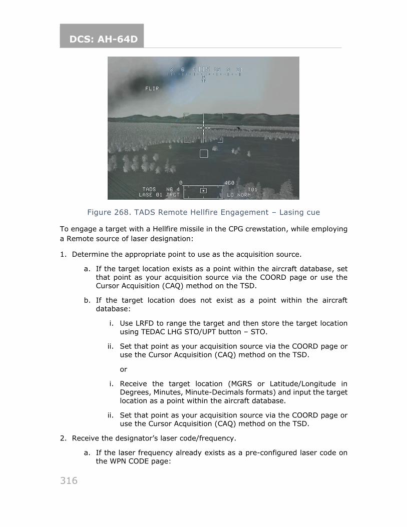
DCS: AH-64D
316
Figure 268. TADS Remote Hellfire Engagement – Lasing cue
To engage a target with a Hellfire missile in the CPG crewstation, while employing
a Remote source of laser designation:
1. Determine the appropriate point to use as the acquisition source.
a. If the target location exists as a point within the aircraft database, set
that point as your acquisition source via the COORD page or use the Cursor Acquisition (CAQ) method on the TSD.
b. If the target location does not exist as a point within the aircraft
database:
i. Use LRFD to range the target and then store the target location
using TEDAC LHG STO/UPT button – STO.
ii. Set that point as your acquisition source via the COORD page or use the Cursor Acquisition (CAQ) method on the TSD.
or
i. Receive the target location (MGRS or Latitude/Longitude in Degrees, Minutes, Minute-Decimals formats) and input the target
location as a point within the aircraft database.
ii. Set that point as your acquisition source via the COORD page or use the Cursor Acquisition (CAQ) method on the TSD.
2. Receive the designator’s laser code/frequency.
a. If the laser frequency already exists as a pre-configured laser code on the WPN CODE page:
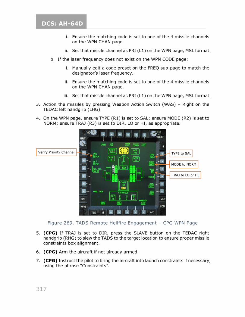
DCS: AH-64D
317
i. Ensure the matching code is set to one of the 4 missile channels on the WPN CHAN page.
ii. Set that missile channel as PRI (L1) on the WPN page, MSL format.
b. If the laser frequency does not exist on the WPN CODE page:
i. Manually edit a code preset on the FREQ sub-page to match the
designator’s laser frequency.
ii. Ensure the matching code is set to one of the 4 missile channels on the WPN CHAN page.
iii. Set that missile channel as PRI (L1) on the WPN page, MSL format.
3. Action the missiles by pressing Weapon Action Switch (WAS) – Right on the TEDAC left handgrip (LHG).
4. On the WPN page, ensure TYPE (R1) is set to SAL; ensure MODE (R2) is set to NORM; ensure TRAJ (R3) is set to DIR, LO or HI, as appropriate.
Figure 269. TADS Remote Hellfire Engagement – CPG WPN Page
5. (CPG) If TRAJ is set to DIR, press the SLAVE button on the TEDAC right handgrip (RHG) to slew the TADS to the target location to ensure proper missile constraints box alignment.
6. (CPG) Arm the aircraft if not already armed.
7. (CPG) Instruct the pilot to bring the aircraft into launch constraints if necessary, using the phrase “Constraints”.
TYPE to SAL
TRAJ to LO or HI
MODE to NORM
Verify Priority Channel
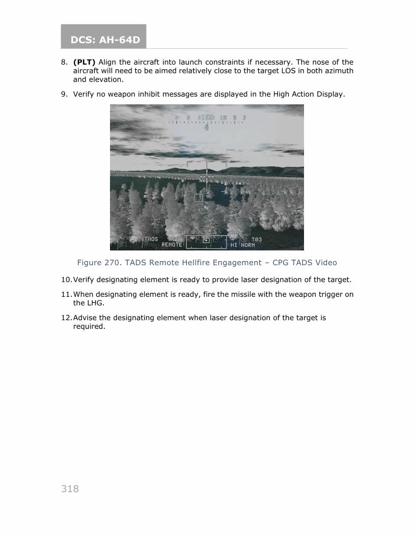
DCS: AH-64D
318
8. (PLT) Align the aircraft into launch constraints if necessary. The nose of the aircraft will need to be aimed relatively close to the target LOS in both azimuth
and elevation.
9. Verify no weapon inhibit messages are displayed in the High Action Display.
Figure 270. TADS Remote Hellfire Engagement – CPG TADS Video
10. Verify designating element is ready to provide laser designation of the target.
11. When designating element is ready, fire the missile with the weapon trigger on the LHG.
12. Advise the designating element when laser designation of the target is required.
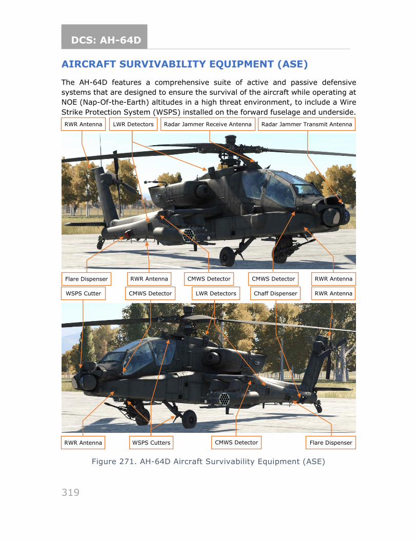
DCS: AH-64D
319
AIRCRAFT SURVIVABILITY EQUIPMENT (ASE)
The AH-64D features a comprehensive suite of active and passive defensive
systems that are designed to ensure the survival of the aircraft while operating at
NOE (Nap-Of-the-Earth) altitudes in a high threat environment, to include a Wire
Strike Protection System (WSPS) installed on the forward fuselage and underside.
Figure 271. AH-64D Aircraft Survivability Equipment (ASE)
CMWS Detector
Radar Jammer Transmit Antenna Antenna
RWR Antenna
Radar Jammer Receive Antenna Antenna
LWR Detectors
CMWS Detector
RWR Antenna
Flare Dispenser RWR Antenna
CMWS Detector RWR Antenna
LWR Detectors CMWS Detector RWR Antenna
Flare Dispenser
Chaff Dispenser
WSPS Cutters
WSPS Cutter
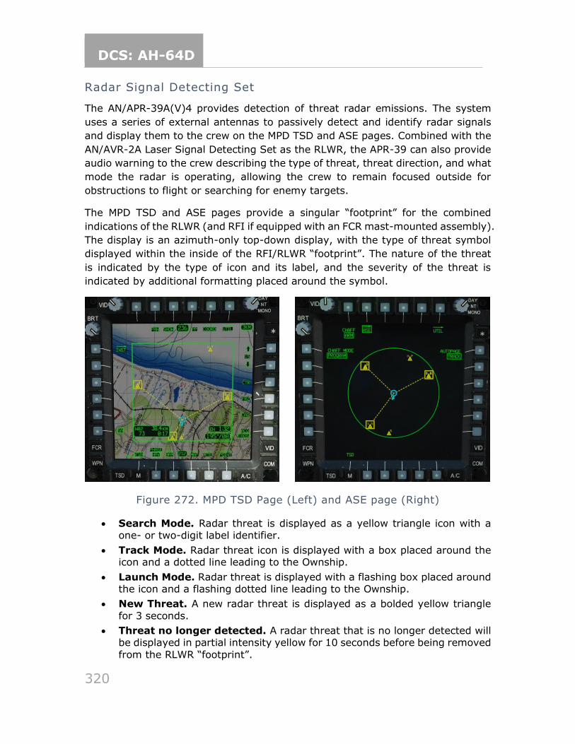
DCS: AH-64D
320
Radar Signal Detecting Set
The AN/APR-39A(V)4 provides detection of threat radar emissions. The system
uses a series of external antennas to passively detect and identify radar signals
and display them to the crew on the MPD TSD and ASE pages. Combined with the
AN/AVR-2A Laser Signal Detecting Set as the RLWR, the APR-39 can also provide
audio warning to the crew describing the type of threat, threat direction, and what
mode the radar is operating, allowing the crew to remain focused outside for
obstructions to flight or searching for enemy targets.
The MPD TSD and ASE pages provide a singular “footprint” for the combined
indications of the RLWR (and RFI if equipped with an FCR mast-mounted assembly).
The display is an azimuth-only top-down display, with the type of threat symbol
displayed within the inside of the RFI/RLWR “footprint”. The nature of the threat
is indicated by the type of icon and its label, and the severity of the threat is
indicated by additional formatting placed around the symbol.
Figure 272. MPD TSD Page (Left) and ASE page (Right)
• Search Mode. Radar threat is displayed as a yellow triangle icon with a one- or two-digit label identifier.
• Track Mode. Radar threat icon is displayed with a box placed around the icon and a dotted line leading to the Ownship.
• Launch Mode. Radar threat is displayed with a flashing box placed around the icon and a flashing dotted line leading to the Ownship.
• New Threat. A new radar threat is displayed as a bolded yellow triangle
for 3 seconds.
• Threat no longer detected. A radar threat that is no longer detected will be displayed in partial intensity yellow for 10 seconds before being removed
from the RLWR “footprint”.
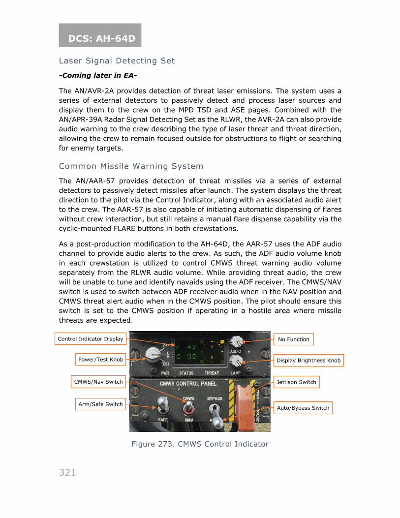
DCS: AH-64D
321
Laser Signal Detecting Set
-Coming later in EA-
The AN/AVR-2A provides detection of threat laser emissions. The system uses a
series of external detectors to passively detect and process laser sources and
display them to the crew on the MPD TSD and ASE pages. Combined with the
AN/APR-39A Radar Signal Detecting Set as the RLWR, the AVR-2A can also provide
audio warning to the crew describing the type of laser threat and threat direction,
allowing the crew to remain focused outside for obstructions to flight or searching
for enemy targets.
Common Missile Warning System
The AN/AAR-57 provides detection of threat missiles via a series of external
detectors to passively detect missiles after launch. The system displays the threat
direction to the pilot via the Control Indicator, along with an associated audio alert
to the crew. The AAR-57 is also capable of initiating automatic dispensing of flares
without crew interaction, but still retains a manual flare dispense capability via the
cyclic-mounted FLARE buttons in both crewstations.
As a post-production modification to the AH-64D, the AAR-57 uses the ADF audio
channel to provide audio alerts to the crew. As such, the ADF audio volume knob
in each crewstation is utilized to control CMWS threat warning audio volume
separately from the RLWR audio volume. While providing threat audio, the crew
will be unable to tune and identify navaids using the ADF receiver. The CMWS/NAV
switch is used to switch between ADF receiver audio when in the NAV position and
CMWS threat alert audio when in the CMWS position. The pilot should ensure this
switch is set to the CMWS position if operating in a hostile area where missile
threats are expected.
Figure 273. CMWS Control Indicator
Control Indicator Display
Power/Test Knob
CMWS/Nav Switch
Arm/Safe Switch
No Function
Display Brightness Knob
Jettison Switch
Auto/Bypass Switch
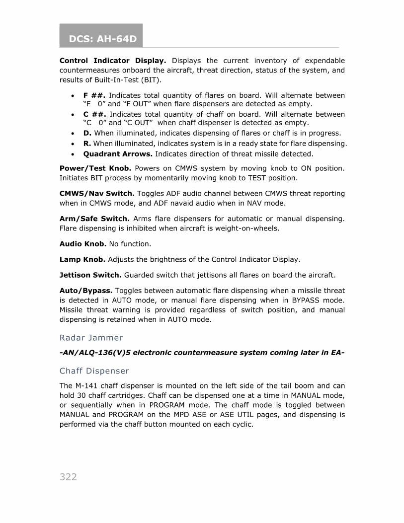
DCS: AH-64D
322
Control Indicator Display. Displays the current inventory of expendable
countermeasures onboard the aircraft, threat direction, status of the system, and
results of Built-In-Test (BIT).
• F ##. Indicates total quantity of flares on board. Will alternate between “F 0” and “F OUT” when flare dispensers are detected as empty.
• C ##. Indicates total quantity of chaff on board. Will alternate between “C 0” and “C OUT” when chaff dispenser is detected as empty.
• D. When illuminated, indicates dispensing of flares or chaff is in progress.
• R. When illuminated, indicates system is in a ready state for flare dispensing.
• Quadrant Arrows. Indicates direction of threat missile detected.
Power/Test Knob. Powers on CMWS system by moving knob to ON position.
Initiates BIT process by momentarily moving knob to TEST position.
CMWS/Nav Switch. Toggles ADF audio channel between CMWS threat reporting
when in CMWS mode, and ADF navaid audio when in NAV mode.
Arm/Safe Switch. Arms flare dispensers for automatic or manual dispensing.
Flare dispensing is inhibited when aircraft is weight-on-wheels.
Audio Knob. No function.
Lamp Knob. Adjusts the brightness of the Control Indicator Display.
Jettison Switch. Guarded switch that jettisons all flares on board the aircraft.
Auto/Bypass. Toggles between automatic flare dispensing when a missile threat
is detected in AUTO mode, or manual flare dispensing when in BYPASS mode.
Missile threat warning is provided regardless of switch position, and manual
dispensing is retained when in AUTO mode.
Radar Jammer
-AN/ALQ-136(V)5 electronic countermeasure system coming later in EA-
Chaff Dispenser
The M-141 chaff dispenser is mounted on the left side of the tail boom and can
hold 30 chaff cartridges. Chaff can be dispensed one at a time in MANUAL mode,
or sequentially when in PROGRAM mode. The chaff mode is toggled between
MANUAL and PROGRAM on the MPD ASE or ASE UTIL pages, and dispensing is
performed via the chaff button mounted on each cyclic.
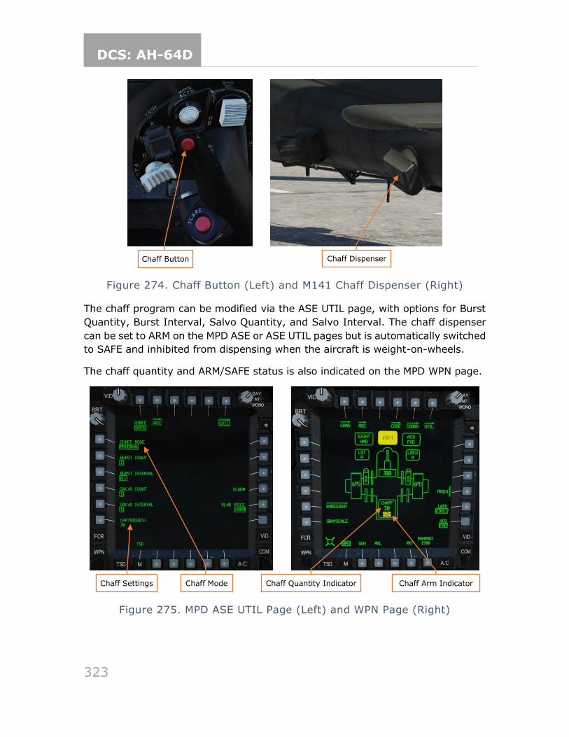
DCS: AH-64D
323
Figure 274. Chaff Button (Left) and M141 Chaff Dispenser (Right)
The chaff program can be modified via the ASE UTIL page, with options for Burst
Quantity, Burst Interval, Salvo Quantity, and Salvo Interval. The chaff dispenser
can be set to ARM on the MPD ASE or ASE UTIL pages but is automatically switched
to SAFE and inhibited from dispensing when the aircraft is weight-on-wheels.
The chaff quantity and ARM/SAFE status is also indicated on the MPD WPN page.
Figure 275. MPD ASE UTIL Page (Left) and WPN Page (Right)
Chaff Button
Chaff Settings Chaff Mode
Chaff Dispenser DispenserButto
Chaff Quantity Indicator Chaff Arm Indicator
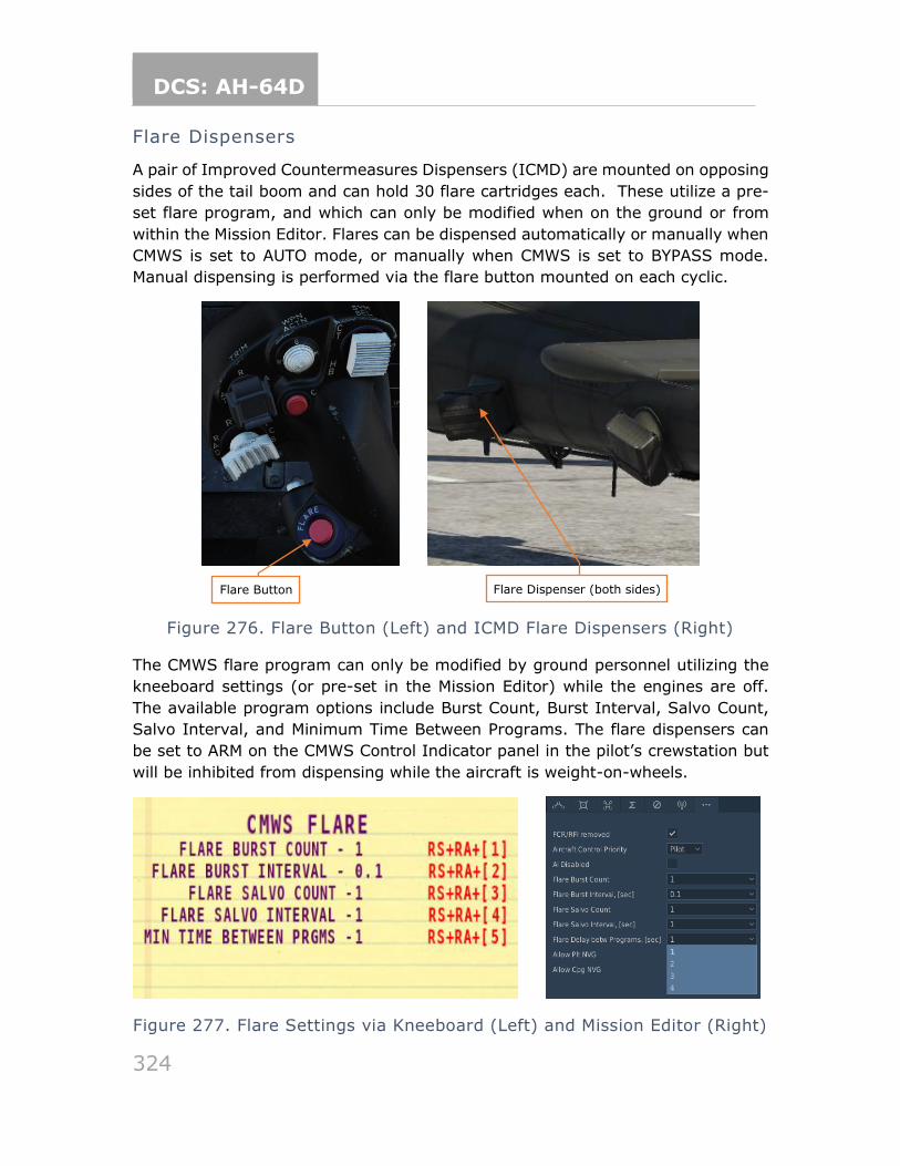
DCS: AH-64D
324
Flare Dispensers
A pair of Improved Countermeasures Dispensers (ICMD) are mounted on opposing
sides of the tail boom and can hold 30 flare cartridges each. These utilize a pre-
set flare program, and which can only be modified when on the ground or from
within the Mission Editor. Flares can be dispensed automatically or manually when
CMWS is set to AUTO mode, or manually when CMWS is set to BYPASS mode.
Manual dispensing is performed via the flare button mounted on each cyclic.
Figure 276. Flare Button (Left) and ICMD Flare Dispensers (Right)
The CMWS flare program can only be modified by ground personnel utilizing the
kneeboard settings (or pre-set in the Mission Editor) while the engines are off.
The available program options include Burst Count, Burst Interval, Salvo Count,
Salvo Interval, and Minimum Time Between Programs. The flare dispensers can
be set to ARM on the CMWS Control Indicator panel in the pilot’s crewstation but
will be inhibited from dispensing while the aircraft is weight-on-wheels.
Figure 277. Flare Settings via Kneeboard (Left) and Mission Editor (Right)
Flare Button Flare Dispenser (both sides)
DCS: AH-64D
325
“GEORGE” AI The AH-64D is crewed by two crewmembers: a Pilot (PLT) and a Copilot/Gunner
(CPG). The DCS: AH-64D module supports multicrew capability, where two players
can occupy the two seats in a multiplayer session for cooperative play. To
accommodate a single-player experience, we have created George, a virtual
crewmember that allows single-player pilots to control mission-critical items in the
cockpit that the player is not occupying. George was designed to mimic the real-
life procedures used by AH-64D crew members. It enables single-players to
coordinate and control AI actions.
George can be controlled by a four-way hat on your HOTAS or using joystick
buttons. The Early Access version of George will continue to be refined, and have
new features added.
AH-64D AI CONTROLS STRUCTURE
The George control bindings are divided into two areas: Under the AH-64D Pilot
aircraft selection, the AH-64D George AI Helper input functions category
contains bindings that show the helper interface, as well as “quick action” bindings
for giving George basic orders (e.g., “Consent To Fire”).
Under the AH-64D George AI Helper aircraft selection, you can set controls to
navigate the George AI Helper Interface. You will likely want to bind these controls
to a four-way hat on your joystick. The controls you bind to the AI Interface can
be dual-bound to commands under the AH-64D Pilot module — for example, the
four-way hat on your joystick can be bound to Sight Select Switch controls under
AH-64D Pilot, and to the George AI Helper Interface under AH-64D George AI
Helper. Now your four-way hat will function normally as a Sight Selection control
but can also be used to issue commands from the AI Helper Interface.
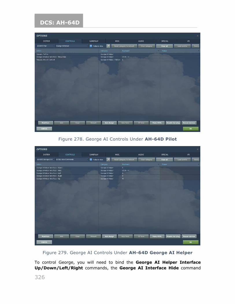
DCS: AH-64D
326
Figure 278. George AI Controls Under AH-64D Pilot
Figure 279. George AI Controls Under AH-64D George AI Helper
To control George, you will need to bind the George AI Helper Interface
Up/Down/Left/Right commands, the George AI Interface Hide command
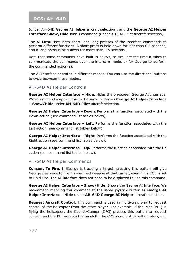
DCS: AH-64D
327
(under AH-64D George AI Helper aircraft selection), and the George AI Helper
Interface Show/Hide Menu command (under AH-64D Pilot aircraft selection).
The AI Menu uses both short- and long-presses of the interface commands to perform different functions. A short press is held down for less than 0.5 seconds, and a long press is held down for more than 0.5 seconds.
Note that some commands have built-in delays, to simulate the time it takes to
communicate the commands over the intercom mode, or for George to perform
the commanded action(s).
The AI Interface operates in different modes. You can use the directional buttons
to cycle between these modes.
AH-64D AI Helper Controls
George AI Helper Interface – Hide. Hides the on-screen George AI Interface.
We recommend mapping this to the same button as George AI Helper Interface
– Show/Hide under AH-64D Pilot aircraft selection.
George AI Helper Interface – Down. Performs the function associated with the
Down action (see command list tables below).
George AI Helper Interface – Left. Performs the function associated with the
Left action (see command list tables below).
George AI Helper Interface – Right. Performs the function associated with the
Right action (see command list tables below).
George AI Helper Interface – Up. Performs the function associated with the Up
action (see command list tables below).
AH-64D AI Helper Commands
Consent To Fire. If George is tracking a target, pressing this button will give
George clearance to fire his assigned weapon at that target, even if his ROE is set
to Hold Fire. The AI Interface does not need to be displayed to use this command.
George AI Helper Interface – Show/Hide. Shows the George AI Interface. We
recommend mapping this command to the same joystick button as George AI
Helper Interface – Hide under AH-64D George AI Helper aircraft selection.
Request Aircraft Control. This command is used in multi-crew play to request
control of the helicopter from the other player. For example, if the Pilot (PLT) is
flying the helicopter, the Copilot/Gunner (CPG) presses this button to request
control, and the PLT accepts the handoff. The CPG’s cyclic stick will un-stow, and
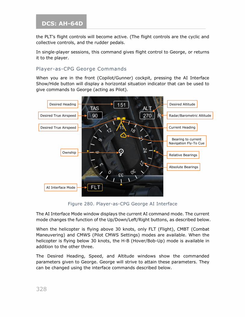
DCS: AH-64D
328
the PLT’s flight controls will become active. (The flight controls are the cyclic and
collective controls, and the rudder pedals.
In single-player sessions, this command gives flight control to George, or returns
it to the player.
Player-as-CPG George Commands
When you are in the front (Copilot/Gunner) cockpit, pressing the AI Interface
Show/Hide button will display a horizontal situation indicator that can be used to
give commands to George (acting as Pilot).
Figure 280. Player-as-CPG George AI Interface
The AI Interface Mode window displays the current AI command mode. The current
mode changes the function of the Up/Down/Left/Right buttons, as described below.
When the helicopter is flying above 30 knots, only FLT (Flight), CMBT (Combat
Maneuvering) and CMWS (Pilot CMWS Settings) modes are available. When the
helicopter is flying below 30 knots, the H-B (Hover/Bob-Up) mode is available in
addition to the other three.
The Desired Heading, Speed, and Altitude windows show the commanded
parameters given to George. George will strive to attain these parameters. They
can be changed using the interface commands described below.
Desired Heading
Desired True Airspeed
AI Interface Mode
Desired True Airspeed
Current Heading
Bearing to current
Navigation Fly-To Cue
Radar/Barometric Altitude
Relative Bearings
Absolute Bearings
Ownship
Desired Altitude
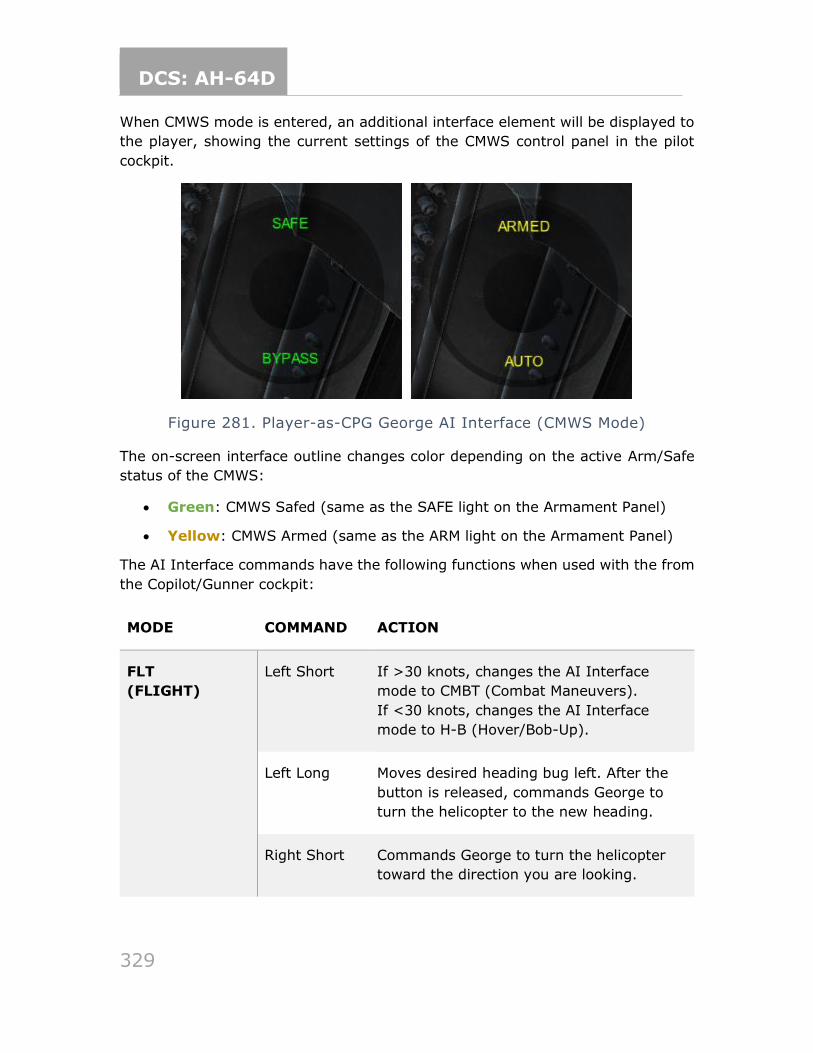
DCS: AH-64D
329
When CMWS mode is entered, an additional interface element will be displayed to
the player, showing the current settings of the CMWS control panel in the pilot
cockpit.
Figure 281. Player-as-CPG George AI Interface (CMWS Mode)
The on-screen interface outline changes color depending on the active Arm/Safe
status of the CMWS:
• Green: CMWS Safed (same as the SAFE light on the Armament Panel)
• Yellow: CMWS Armed (same as the ARM light on the Armament Panel)
The AI Interface commands have the following functions when used with the from
the Copilot/Gunner cockpit:
MODE COMMAND ACTION
FLT
(FLIGHT)
Left Short If >30 knots, changes the AI Interface
mode to CMBT (Combat Maneuvers).
If <30 knots, changes the AI Interface
mode to H-B (Hover/Bob-Up).
Left Long Moves desired heading bug left. After the
button is released, commands George to
turn the helicopter to the new heading.
Right Short Commands George to turn the helicopter
toward the direction you are looking.
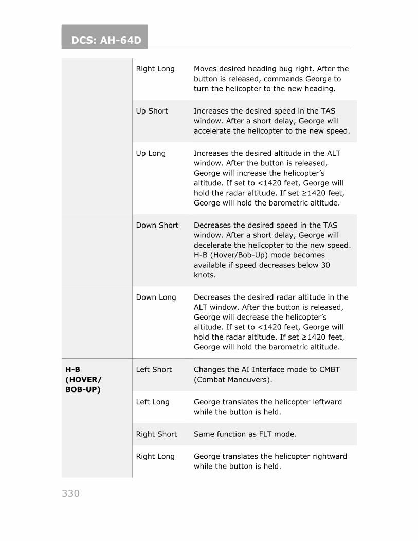
DCS: AH-64D
330
Right Long Moves desired heading bug right. After the
button is released, commands George to
turn the helicopter to the new heading.
Up Short Increases the desired speed in the TAS
window. After a short delay, George will
accelerate the helicopter to the new speed.
Up Long Increases the desired altitude in the ALT
window. After the button is released,
George will increase the helicopter’s
altitude. If set to <1420 feet, George will
hold the radar altitude. If set ≥1420 feet,
George will hold the barometric altitude.
Down Short Decreases the desired speed in the TAS
window. After a short delay, George will
decelerate the helicopter to the new speed.
H-B (Hover/Bob-Up) mode becomes
available if speed decreases below 30
knots.
Down Long Decreases the desired radar altitude in the
ALT window. After the button is released,
George will decrease the helicopter’s
altitude. If set to <1420 feet, George will
hold the radar altitude. If set ≥1420 feet,
George will hold the barometric altitude.
H-B
(HOVER/
BOB-UP)
Left Short Changes the AI Interface mode to CMBT
(Combat Maneuvers).
Left Long George translates the helicopter leftward
while the button is held.
Right Short Same function as FLT mode.
Right Long George translates the helicopter rightward
while the button is held.
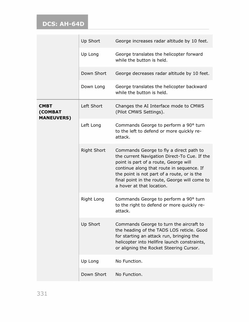
DCS: AH-64D
331
Up Short George increases radar altitude by 10 feet.
Up Long George translates the helicopter forward
while the button is held.
Down Short George decreases radar altitude by 10 feet.
Down Long George translates the helicopter backward
while the button is held.
CMBT
(COMBAT
MANEUVERS)
Left Short Changes the AI Interface mode to CMWS
(Pilot CMWS Settings).
Left Long Commands George to perform a 90° turn
to the left to defend or more quickly re-
attack.
Right Short Commands George to fly a direct path to
the current Navigation Direct-To Cue. If the
point is part of a route, George will
continue along that route in sequence. If
the point is not part of a route, or is the
final point in the route, George will come to
a hover at that location.
Right Long Commands George to perform a 90° turn
to the right to defend or more quickly re-
attack.
Up Short Commands George to turn the aircraft to
the heading of the TADS LOS reticle. Good
for starting an attack run, bringing the
helicopter into Hellfire launch constraints,
or aligning the Rocket Steering Cursor.
Up Long No Function.
Down Short No Function.
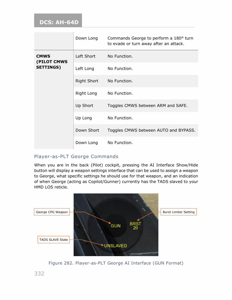
DCS: AH-64D
332
Down Long Commands George to perform a 180° turn
to evade or turn away after an attack.
CMWS
(PILOT CMWS
SETTINGS)
Left Short No Function.
Left Long No Function.
Right Short No Function.
Right Long No Function.
Up Short Toggles CMWS between ARM and SAFE.
Up Long No Function.
Down Short Toggles CMWS between AUTO and BYPASS.
Down Long No Function.
Player-as-PLT George Commands
When you are in the back (Pilot) cockpit, pressing the AI Interface Show/Hide
button will display a weapon settings interface that can be used to assign a weapon
to George, what specific settings he should use for that weapon, and an indication
of when George (acting as Copilot/Gunner) currently has the TADS slaved to your
HMD LOS reticle.
Figure 282. Player-as-PLT George AI Interface (GUN Format)
George CPG Weapon
TADS SLAVE State
Burst Limiter Setting
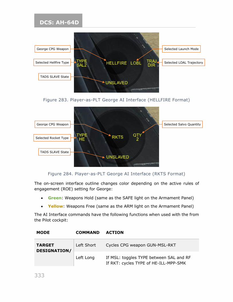
DCS: AH-64D
333
Figure 283. Player-as-PLT George AI Interface (HELLFIRE Format)
Figure 284. Player-as-PLT George AI Interface (RKTS Format)
The on-screen interface outline changes color depending on the active rules of
engagement (ROE) setting for George:
• Green: Weapons Hold (same as the SAFE light on the Armament Panel)
• Yellow: Weapons Free (same as the ARM light on the Armament Panel)
The AI Interface commands have the following functions when used with the from
the Pilot cockpit:
MODE COMMAND ACTION
TARGET
DESIGNATION/
Left Short Cycles CPG weapon GUN-MSL-RKT
Left Long If MSL: toggles TYPE between SAL and RF
If RKT: cycles TYPE of HE-ILL-MPP-SMK
Selected Hellfire Type
George CPG Weapon
Selected LOAL Trajectory
TADS SLAVE State
Selected Launch Mode
Selected Rocket Type
George CPG Weapon
TADS SLAVE State
Selected Salvo Quantity
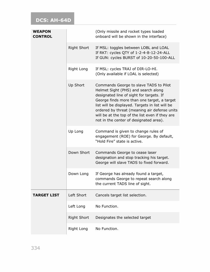
DCS: AH-64D
334
WEAPON
CONTROL
(Only missile and rocket types loaded
onboard will be shown in the interface)
Right Short If MSL: toggles between LOBL and LOAL
If RKT: cycles QTY of 1-2-4-8-12-24-ALL
If GUN: cycles BURST of 10-20-50-100-ALL
Right Long If MSL: cycles TRAJ of DIR-LO-HI.
(Only available if LOAL is selected)
Up Short Commands George to slave TADS to Pilot
Helmet Sight (PHS) and search along
designated line of sight for targets. If
George finds more than one target, a target
list will be displayed. Targets in list will be
ordered by threat (meaning air defense units
will be at the top of the list even if they are
not in the center of designated area).
Up Long Command is given to change rules of
engagement (ROE) for George. By default,
“Hold Fire” state is active.
Down Short Commands George to cease laser
designation and stop tracking his target.
George will slave TADS to fixed forward.
Down Long If George has already found a target,
commands George to repeat search along
the current TADS line of sight.
TARGET LIST Left Short Cancels target list selection.
Left Long No Function.
Right Short Designates the selected target
Right Long No Function.
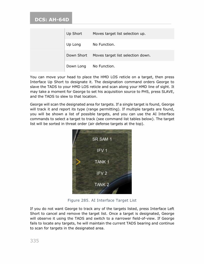
DCS: AH-64D
335
Up Short Moves target list selection up.
Up Long No Function.
Down Short Moves target list selection down.
Down Long No Function.
You can move your head to place the HMD LOS reticle on a target, then press
Interface Up Short to designate it. The designation command orders George to
slave the TADS to your HMD LOS reticle and scan along your HMD line of sight. It
may take a moment for George to set his acquisition source to PHS, press SLAVE,
and the TADS to slew to that location.
George will scan the designated area for targets. If a single target is found, George
will track it and report its type (range permitting). If multiple targets are found,
you will be shown a list of possible targets, and you can use the AI Interface
commands to select a target to track (see command list tables below). The target
list will be sorted in threat order (air defense targets at the top).
Figure 285. AI Interface Target List
If you do not want George to track any of the targets listed, press Interface Left
Short to cancel and remove the target list. Once a target is designated, George
will observe it using the TADS and switch to a narrower field-of-view. If George
fails to locate any targets, he will maintain the current TADS bearing and continue
to scan for targets in the designated area.
DCS: AH-64D
336
To employ Hellfire missiles against George’s tracked target, you must fly the
helicopter to align the Hellfire missile constraints box as described in the Longbow
Hellfire Modular Missile System section (see Missile Constraints Box in the Combat
Employment section). Once the helicopter is within missile launch constraints,
George will act according to the current ROE:
• If ROE is yellow (Weapons Free), George will launch and guide a Hellfire missile as soon as launch parameters are met.
• If ROE is green (Weapons Hold), George will wait for your consent to fire the missile. Consent is given with the Consent To Fire command binding.
Once the Hellfire either hits the target, George will stop designating the target and
switch to a wider field-of-view in the TADS.
Additional Features
George has some other features that are always available:
• During a cold start, George will close his cockpit canopy when you close yours, or after the APU is powered on, whichever comes first.
Some other important notes about George:
• George will not ground taxi. When you are in the Copilot/Gunner seat, you can order George to takeoff by increasing the Desired Altitude above zero,
or order him to land by decreasing the Desired Altitude to zero. Once airborne, you can use the FLT and H-B modes to order George to fly, hover, or translate in any direction. This can be useful to hover taxi around a FARP
or airfield or maneuver the aircraft within a battle position.
• George currently communicates via on-screen text messages only. George will acknowledge commands, flight directions, weapon assignments, and
when he can’t perform a requested order. Voiceovers and reactions will be added in a later update.
• When you are in the Pilot seat, and George is tracking a target, he will automatically laser designate the tracked target if required for the current weapon and engagement type.
• George is not immortal. If you die, George cannot assume your position.
You can adjust the flight controls handover behavior by going to the Options →
Special tab → AH-64D panel, and toggling the checkbox labeled GEORGE AI AUTO
HANDOVER (checked by default). When checked, George will take over the flight
controls whenever you switch from the Pilot position to the CPG position. It will
attempt to maintain your current flight parameters. When unchecked, you
continue to have the flight controls from the Copilot/Gunner position.
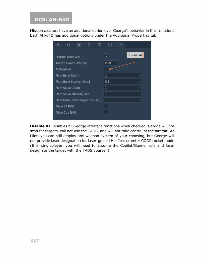
DCS: AH-64D
337
Mission creators have an additional option over George’s behavior in their missions.
Each AH-64D has additional options under the Additional Properties tab.
Disable AI. Disables all George interface functions when checked. George will not
scan for targets, will not use the TADS, and will not take control of the aircraft. As
Pilot, you can still employ any weapon system of your choosing, but George will
not provide laser designation for laser-guided Hellfires or enter COOP rocket mode
(If in singleplayer, you will need to assume the Copilot/Gunner role and laser
designate the target with the TADS yourself).
Disable AI
DCS: AH-64D
338
APPENDICES APPENDIX A ABBREVIATED COCKPIT PROCEDURES
Add a Point on the TSD
To quickly add a point using the “cursor drop” method, perform the following:
1. TSD fixed action button – Press.
2. POINT (B6) – Select.
3. ADD (L2) – Select.
4. Type select (L3 thru L6) – WP, HZ, CM, or TG.
5. Cursor select – Select desired location on TSD.
To add a point using the Keyboard Unit, perform the following:
1. TSD fixed action button – Press.
2. POINT (B6) – Select.
3. ADD (L2) – Select.
4. ABR (T4) – Select, as required.
5. Type select (L3 thru L6) – WP, HZ, CM, or TG.
6. IDENT> (L1) – Select and enter identifier with the KU, and press ENTER.
7. Enter free text data with the KU, and press ENTER.
8. Enter location data with the KU, and press ENTER.
9. Enter altitude data with the KU, and press Enter.
Edit a Point on the TSD
To edit a point, perform the following:
1. TSD fixed action button – Press.
2. POINT (B6) – Select.
DCS: AH-64D
339
3. POINT> (L1) – Select and enter point type and number (i.e., “W01”, “H09”, “C51”, “T05”, etc.)
or
3. Cursor select – Select desired point on TSD.
4. EDIT (L3) – Select.
5. FREE> (L1) – Select and enter free text with the KU, and press ENTER. If the existing free text is desired, simply press Enter without a different free text entry.
6. Enter location data with the KU, and press ENTER. If the existing location is desired, simply press Enter without a different location entry.
7. Enter altitude data with the KU, and press Enter. If the existing altitude is
desired, simply press Enter without a different altitude entry.
Delete a Point from the TSD
To delete a point, perform the following:
1. TSD fixed action button – Press.
2. POINT (B6) – Select.
3. POINT> (L1) – Select and enter point type and number (i.e., “W01”, “H09”, “C51”, “T05” etc.)
or
3. Cursor select – Select desired point on TSD.
4. DEL (L4) – Select.
5. Confirm deletion (L3 or L4) – YES or NO.
Store a Point on the TSD
To store a point at the current aircraft position, perform the following:
1. TSD fixed action button – Press.
2. POINT (B6) – Select.
3. STO (L5) – Select.
4. TYPE (L6) – Select WP or TG as desired.
DCS: AH-64D
340
5. NOW (L1) – Select.
To store a point using the TADS with a laser range, the CPG should perform the
following:
1. NVS Mode switch – Off, if applicable.
2. Sight select – TADS.
3. Sight Manual Tracker – Slew to center the location within the LOS reticle.
4. Arm/Safe Switch – Arm.
5. TSD fixed action button – Press.
6. POINT (B6) – Select.
7. STO (L5) – Select.
8. TYPE (L6) – Select WP or TG as desired.
9. TEDAC RHG laser trigger – 1st detent range, or 2nd detent Designate as required.
10. TEDAC LHG Store/Update switch – STO
To store a point using the TADS with an Automatic range, the CPG should perform
the following:
1. NVS Mode switch – Off, if applicable.
2. Sight select – TADS.
3. Sight Manual Tracker – Slew to center the location within the LOS reticle.
4. WPN fixed action button – Press.
5. MANRNG (B6) – Select and enter “A” on the KU, and press ENTER.
6. TSD fixed action button – Press.
7. POINT (B6) – Select.
8. STO (L5) – Select.
9. TYPE (L6) – Select WP or TG as desired.
10. TEDAC LHG Store/Update switch – STO
To store a point using the HMD with an Automatic range, the CPG should perform
the following:
1. Sight select – HMD.
2. WPN fixed action button – Press.
DCS: AH-64D
341
3. MANRNG (B6) – Select and enter “A” on the KU, and press ENTER.
4. TSD fixed action button – Press.
5. POINT (B6) – Select.
6. STO (L5) – Select.
7. TYPE (L6) – Select WP or TG as desired.
8. Center the location within the HMD LOS reticle.
9. TEDAC LHG Store/Update switch – STO
Select a Point for Direct-To Navigation
To select a point for direct navigation, perform the following:
1. TSD fixed action button – Press.
2. RTE (B5) – Select.
3. DIR (L5) – Select.
4. POINT> (L1) – Select and enter point type and number (i.e., “W01”, “H09”, “C51”, etc.)
or
4. Cursor select – Select desired point on TSD (WPTHZ, CTRLM or TGT/THRT).
Add a Point to the Current Route
To insert a point into the current route, use the pan function as necessary and
then perform the following:
1. TSD fixed action button – Press.
2. RTE (B5) – Select.
3. ADD (L2) – Select.
4. POINT> (L1) – Select and enter point type and number (i.e., “W01”, “H09”, “C51”, etc.)
or
4. Cursor select – Select desired point on TSD (WPTHZ or CTRLM).
DCS: AH-64D
342
5. Route sequence – Select bezel button (R2-R5) to insert the point at that location within the route.
Delete a Point from the Current Route
To delete a point from the current route, use the pan function as necessary and
then perform the following:
1. TSD fixed action button – Press.
2. RTE (B5) – Select.
3. DEL (L4) – Select.
4. Cursor select – Select desired point on TSD (WPTHZ or CTRLM).
or
4. Search buttons (R1/R6) – Select.
5. Route sequence – Select bezel button (R2-R5) to delete the corresponding
point from the route sequence.
Select a New Route
To select a route as CURRENT, perform the following:
1. TSD fixed action button – Press.
2. RTE (B5) – Select.
3. RTM (B6) – Select.
4. NEW (L5) – Verify boxed.
5. Route select – Select bezel button (T1-T5) above the route to activate.
Delete a Route
To delete a route, perform the following:
1. TSD fixed action button – Press.
2. RTE (B5) – Select.
3. RTM (B6) – Select.
DCS: AH-64D
343
4. DEL (L5) – Select.
5. Route select – Select bezel button (T1-T5) above the route for deletion.
6. Confirm deletion (L4 or L5) – YES or NO.
Tune the ADF to a Manual Frequency
To tune the ADF to a manual frequency, perform the following:
1. TSD fixed action button – Press.
2. INST (L1) – Select.
3. FREQ> (L3) – Select and enter identifier with the KU, and press ENTER.
Tune the ADF to an NDB Preset
To tune the ADF to a preset station, perform the following:
1. TSD fixed action button – Press.
2. INST (L1) – Select.
3. UTIL (T6) – Select.
4. ADF (B6) – Select.
5. Preset (L2 thru L6 or R2 thru R6) – Select.
6. TUNE (T5) – Select.
Edit an NDB Preset
To edit an ADF preset, perform the following:
1. TSD fixed action button – Press.
2. INST (L1) – Select.
3. UTIL (T6) – Select.
4. Preset (L2 thru L6 or R2 thru R6) – Select.
5. ID> (B4) – Select and enter identifier with the KU, and press ENTER.
6. FREQ> (B5) – Select and enter identifier with the KU, and press ENTER.
DCS: AH-64D
344
Select an Acquisition source
To select an acquisition source from the ACQ expanded menu, perform the
following:
1. TSD or WPN fixed action button – Press.
2. ACQ (R6) – Select.
3. ACQ select - Select desired ACQ source from expanded menu options.
To select an existing point as an acquisition source directly from the TSD,
perform the following:
1. TSD fixed action button – Press.
2. CAQ (R5) – Select.
3. Cursor select – Select desired point on TSD.
To select an existing point as an acquisition source from the database, perform
the following:
1. TSD or WPN fixed action button – Press.
2. COORD (T5) – Select.
3. WPTHZ (T1) or CTRLM (T2) – Select if necessary.
4. Use paging controls (B2/B3) – Select.
or
4. SRCH> (B4) – Select and enter data with KU.
5. Point select – Use the left bezel button (L1-L6) to select a point.
Engage a Target with 30mm Area Weapon System
To engage a target with the 30mm Area Weapon System (AWS) perform the
following:
1. Sight select – TADS, HMD or FCR as desired or verify in HAD Sight Select
Status field.
2. Weapon – Weapon Action Switch (WAS) – Forward to GUN.
3. Arm/Safe button – ARM (Performed by crewmember not on the controls).
DCS: AH-64D
345
4. Range – Set as desired or verify in the HAD Range/Range Source field.
5. Messages – Verify no inhibit messages are displayed. Verify “ROUNDS
####” is displayed in the HAD Weapon Status field.
Engage a Target with 2.75-inch Unguided Rockets
To engage a target with independent (HMD/FCR) rockets perform the following:
1. Sight select – HMD or FCR as desired or verify in HAD Sight Select Status
field.
2. Weapon – Weapon Action Switch (WAS) – Left to RKT.
3. Arm/Safe button – ARM (Performed by crewmember not on the controls).
4. Range – Set as desired or verify in the HAD Range/Range Source field.
5. Messages – Verify no inhibit messages are displayed. Verify “RKT NORMAL” is displayed in the HAD Weapon Status field.
To engage a target with cooperative (COOP) rockets perform the following:
1. (PLT) Sight select – HMD.
2. (CPG) Sight select – TADS.
3. (PLT) Weapon – Cyclic Weapon Action Switch (WAS) – Left to RKT.
4. (CPG) Weapon – TEDAC LHG Weapon Action Switch (WAS) – Left to RKT.
5. Arm/Safe button – ARM (Performed by crewmember not on the controls).
6. (CPG) Range – Set as desired or verify in the HAD Range/Range Source field.
7. (PLT & CPG) Messages – Verify no inhibit messages are displayed. Verify COOP is displayed in HAD Weapon Control field and “RKT NORMAL” is displayed in the HAD Weapon Status field.
Engage a Target with AGM-114K Laser-Guided Hellfire Missile
To engage a target with a laser-guided Hellfire perform the following:
1. (CPG) Sight select – TADS.
2. (CPG) Weapon – Weapon Action Switch (WAS) – Right to MSL.
DCS: AH-64D
346
3. Arm/Safe button – ARM (Performed by crewmember not on the controls).
4. (CPG) Range – Set as desired or verify in the HAD Range/Range Source
field.
5. (CPG) Messages – Verify no inhibits are displayed. Verify trajectory and mode is displayed as desired in HAD Weapon Status field.
6. (Optional, if launching LOBL) Designate – Squeeze TEDAC RHG laser trigger, 2nd detent.
7. (Optional, if launching LOBL) Messages (CPG) – Verify no inhibits are
displayed. Verify “PRI CHAN TRK” is displayed in the HAD Weapon Status field if launching LOBL.
Engage a Target with AGM-114L Radar-Guided Hellfire Missile
-Coming later in EA-
Perform Post-Engagement Procedures
Following an engagement, the crewmember should:
1. Ensure finger is off the weapon trigger.
2. Ensure weapon is de-actioned.
3. Arm/Safe button – SAFE, as required (Performed by crewmember not on the controls).
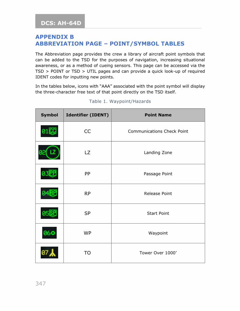
DCS: AH-64D
347
APPENDIX B
ABBREVIATION PAGE – POINT/SYMBOL TABLES
The Abbreviation page provides the crew a library of aircraft point symbols that
can be added to the TSD for the purposes of navigation, increasing situational
awareness, or as a method of cueing sensors. This page can be accessed via the
TSD > POINT or TSD > UTIL pages and can provide a quick look-up of required
IDENT codes for inputting new points.
In the tables below, icons with “AAA” associated with the point symbol will display
the three-character free text of that point directly on the TSD itself.
Table 1. Waypoint/Hazards
Symbol Identifier (IDENT) Point Name
CC Communications Check Point
LZ Landing Zone
PP Passage Point
RP Release Point
SP Start Point
WP Waypoint
TO Tower Over 1000’
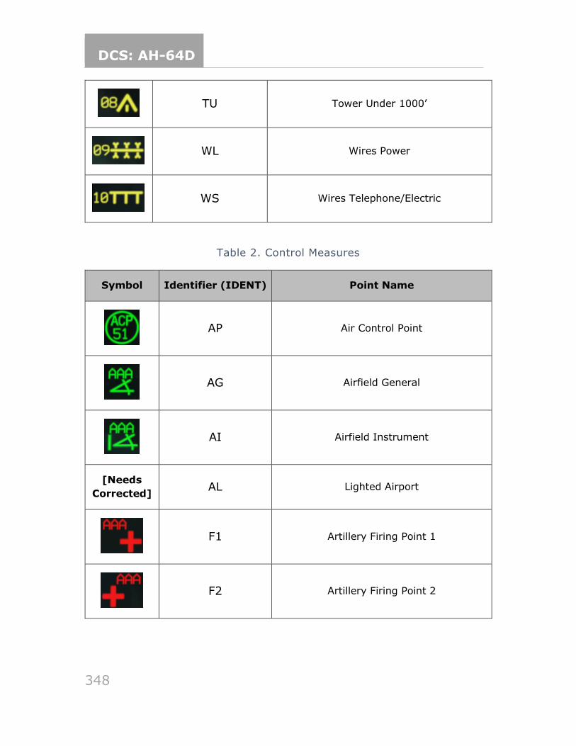
DCS: AH-64D
348
TU Tower Under 1000’
WL Wires Power
WS Wires Telephone/Electric
Table 2. Control Measures
Symbol Identifier (IDENT) Point Name
AP Air Control Point
AG Airfield General
AI Airfield Instrument
[Needs
Corrected] AL Lighted Airport
F1 Artillery Firing Point 1
F2 Artillery Firing Point 2
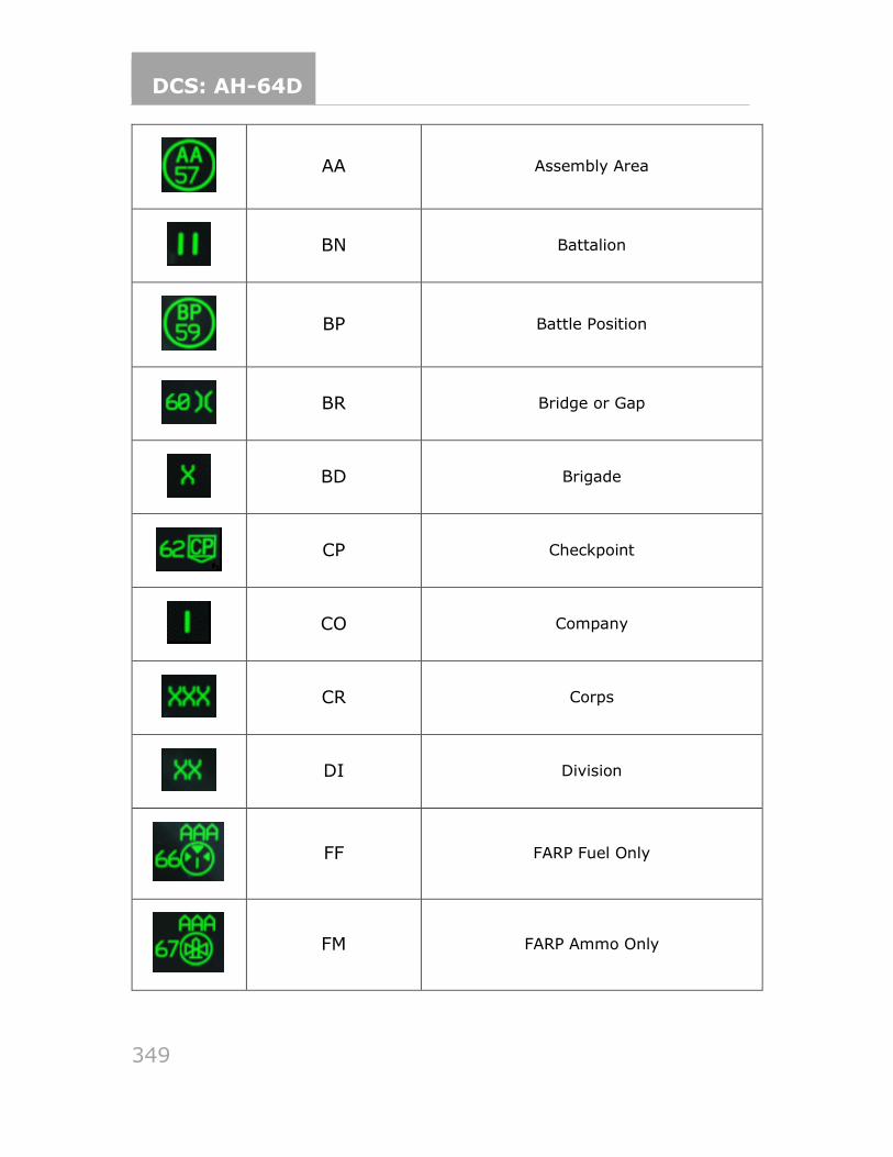
DCS: AH-64D
349
AA Assembly Area
BN Battalion
BP Battle Position
BR Bridge or Gap
BD Brigade
CP Checkpoint
CO Company
CR Corps
DI Division
FF FARP Fuel Only
FM FARP Ammo Only
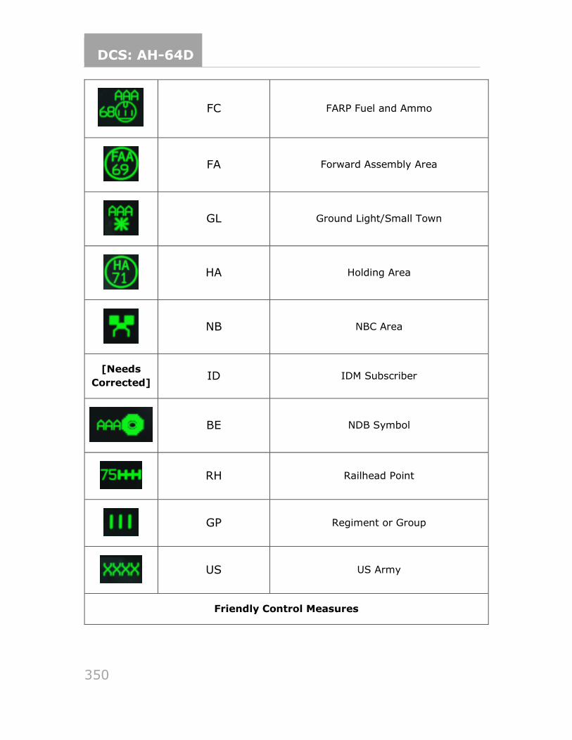
DCS: AH-64D
350
FC FARP Fuel and Ammo
FA Forward Assembly Area
GL Ground Light/Small Town
HA Holding Area
NB NBC Area
[Needs
Corrected] ID IDM Subscriber
BE NDB Symbol
RH Railhead Point
GP Regiment or Group
US US Army
Friendly Control Measures
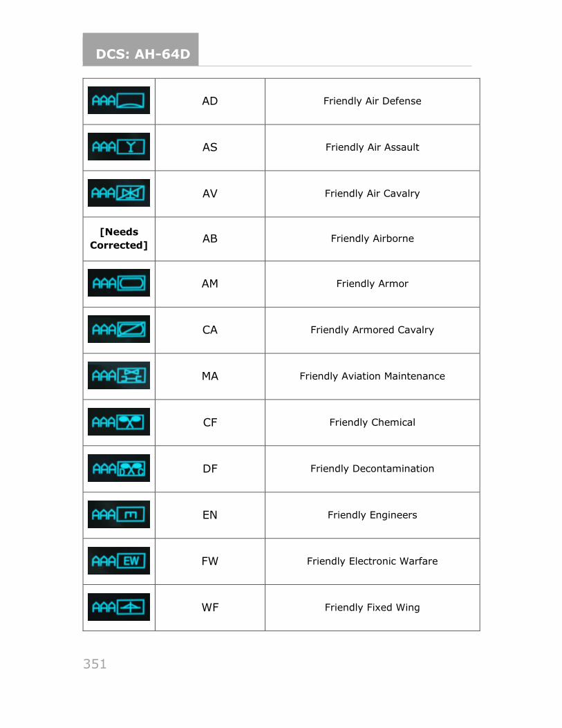
DCS: AH-64D
351
AD Friendly Air Defense
AS Friendly Air Assault
AV Friendly Air Cavalry
[Needs
Corrected] AB Friendly Airborne
AM Friendly Armor
CA Friendly Armored Cavalry
MA Friendly Aviation Maintenance
CF Friendly Chemical
DF Friendly Decontamination
EN Friendly Engineers
FW Friendly Electronic Warfare
WF Friendly Fixed Wing
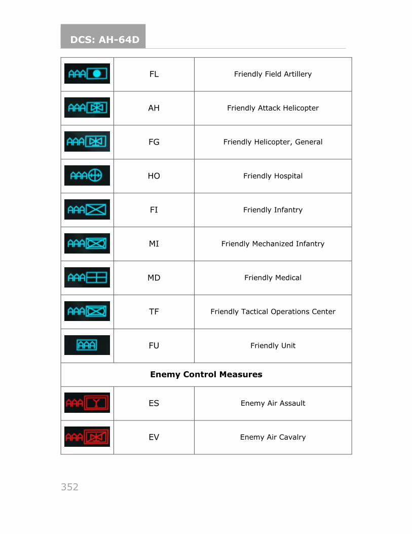
DCS: AH-64D
352
FL Friendly Field Artillery
AH Friendly Attack Helicopter
FG Friendly Helicopter, General
HO Friendly Hospital
FI Friendly Infantry
MI Friendly Mechanized Infantry
MD Friendly Medical
TF Friendly Tactical Operations Center
FU Friendly Unit
Enemy Control Measures
ES Enemy Air Assault
EV Enemy Air Cavalry
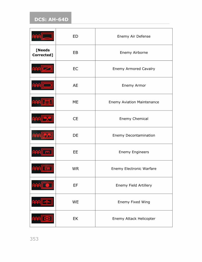
DCS: AH-64D
353
ED Enemy Air Defense
[Needs
Corrected] EB Enemy Airborne
EC Enemy Armored Cavalry
AE Enemy Armor
ME Enemy Aviation Maintenance
CE Enemy Chemical
DE Enemy Decontamination
EE Enemy Engineers
WR Enemy Electronic Warfare
EF Enemy Field Artillery
WE Enemy Fixed Wing
EK Enemy Attack Helicopter
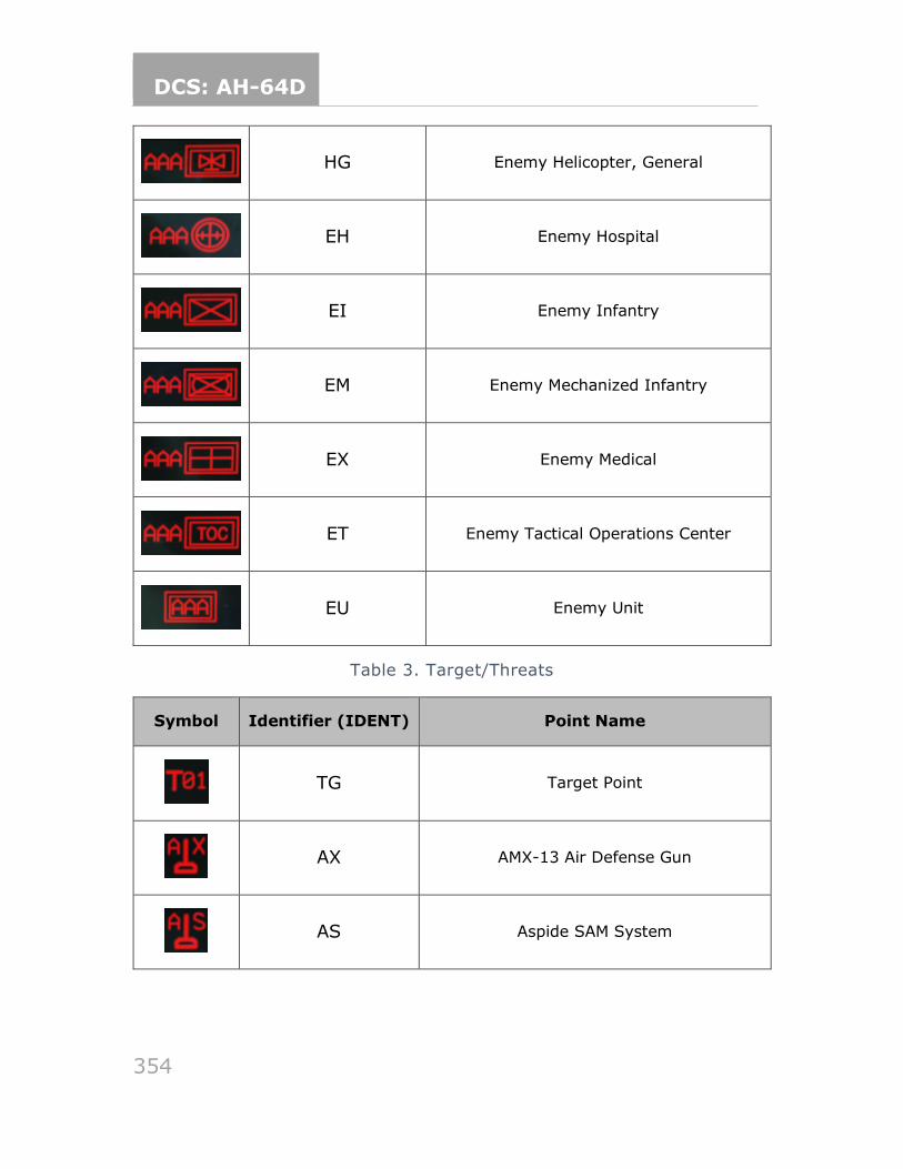
DCS: AH-64D
354
HG Enemy Helicopter, General
EH Enemy Hospital
EI Enemy Infantry
EM Enemy Mechanized Infantry
EX Enemy Medical
ET Enemy Tactical Operations Center
EU Enemy Unit
Table 3. Target/Threats
Symbol Identifier (IDENT) Point Name
TG Target Point
AX AMX-13 Air Defense Gun
AS Aspide SAM System
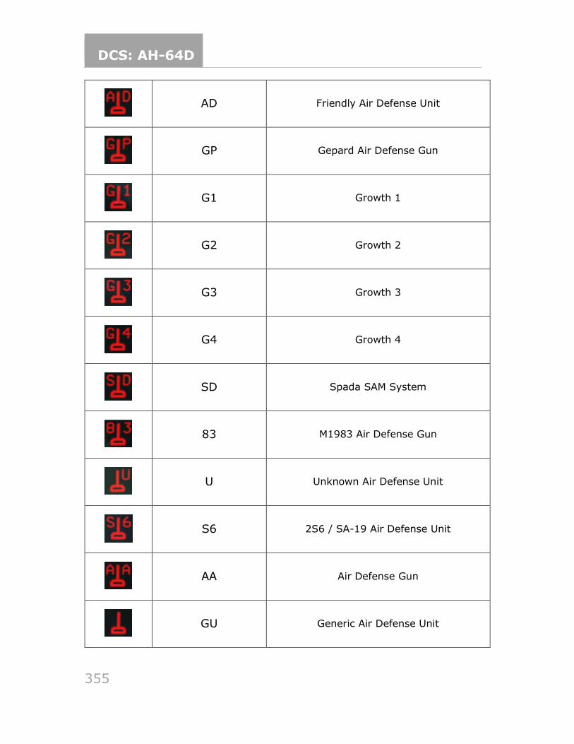
DCS: AH-64D
355
AD Friendly Air Defense Unit
GP Gepard Air Defense Gun
G1 Growth 1
G2 Growth 2
G3 Growth 3
G4 Growth 4
SD Spada SAM System
83 M1983 Air Defense Gun
U Unknown Air Defense Unit
S6 2S6 / SA-19 Air Defense Unit
AA Air Defense Gun
GU Generic Air Defense Unit
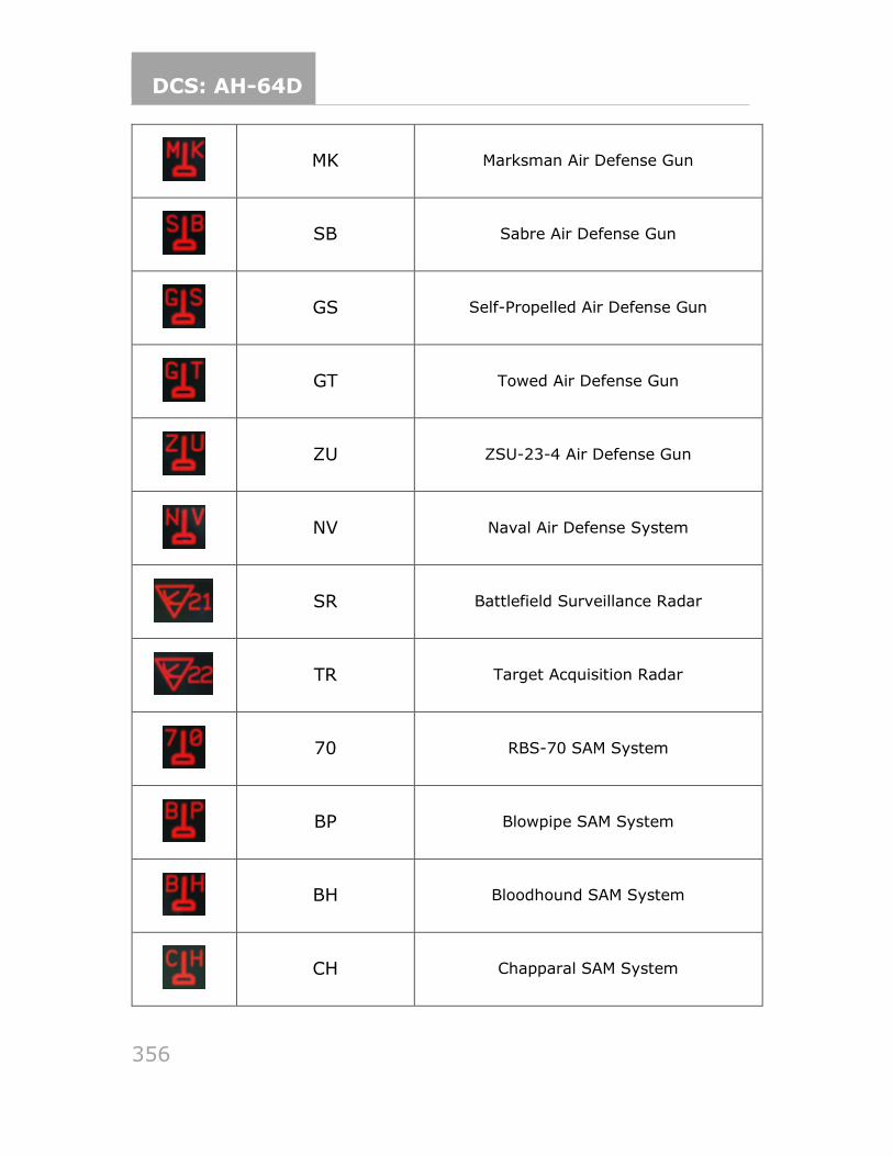
DCS: AH-64D
356
MK Marksman Air Defense Gun
SB Sabre Air Defense Gun
GS Self-Propelled Air Defense Gun
GT Towed Air Defense Gun
ZU ZSU-23-4 Air Defense Gun
NV Naval Air Defense System
SR Battlefield Surveillance Radar
TR Target Acquisition Radar
70 RBS-70 SAM System
BP Blowpipe SAM System
BH Bloodhound SAM System
CH Chapparal SAM System
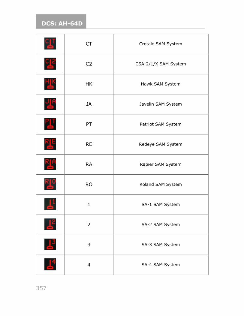
DCS: AH-64D
357
CT Crotale SAM System
C2 CSA-2/1/X SAM System
HK Hawk SAM System
JA Javelin SAM System
PT Patriot SAM System
RE Redeye SAM System
RA Rapier SAM System
RO Roland SAM System
1 SA-1 SAM System
2 SA-2 SAM System
3 SA-3 SAM System
4 SA-4 SAM System
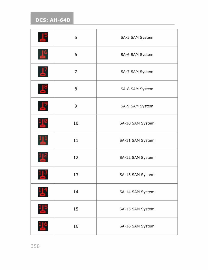
DCS: AH-64D
358
5 SA-5 SAM System
6 SA-6 SAM System
7 SA-7 SAM System
8 SA-8 SAM System
9 SA-9 SAM System
10 SA-10 SAM System
11 SA-11 SAM System
12 SA-12 SAM System
13 SA-13 SAM System
14 SA-14 SAM System
15 SA-15 SAM System
16 SA-16 SAM System
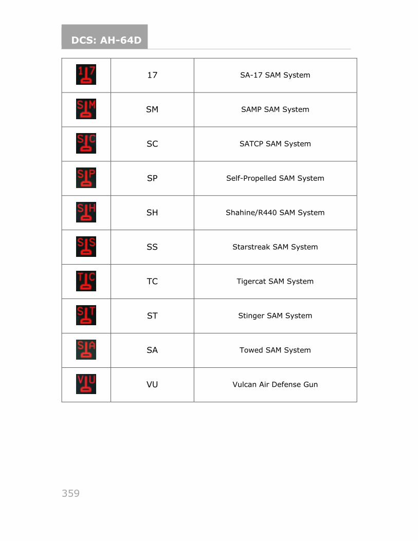
DCS: AH-64D
359
17 SA-17 SAM System
SM SAMP SAM System
SC SATCP SAM System
SP Self-Propelled SAM System
SH Shahine/R440 SAM System
SS Starstreak SAM System
TC Tigercat SAM System
ST Stinger SAM System
SA Towed SAM System
VU Vulcan Air Defense Gun
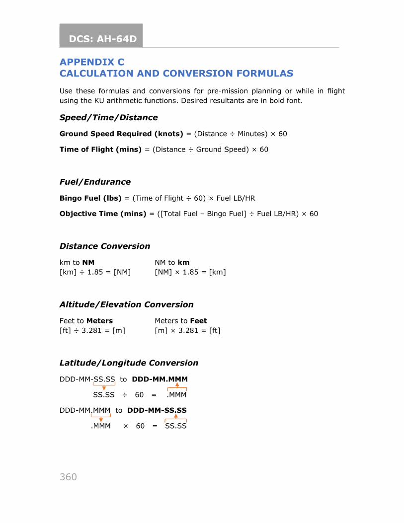
DCS: AH-64D
360
APPENDIX C
CALCULATION AND CONVERSION FORMULAS
Use these formulas and conversions for pre-mission planning or while in flight
using the KU arithmetic functions. Desired resultants are in bold font.
Speed/Time/Distance
Ground Speed Required (knots) = (Distance ÷ Minutes) × 60
Time of Flight (mins) = (Distance ÷ Ground Speed) × 60
Fuel/Endurance
Bingo Fuel (lbs) = (Time of Flight ÷ 60) × Fuel LB/HR
Objective Time (mins) = ([Total Fuel – Bingo Fuel] ÷ Fuel LB/HR) × 60
Distance Conversion
km to NM NM to km
[km] ÷ 1.85 = [NM] [NM] × 1.85 = [km]
Altitude/Elevation Conversion
Feet to Meters Meters to Feet
[ft] ÷ 3.281 = [m] [m] × 3.281 = [ft]
Latitude/Longitude Conversion
DDD-MM-SS.SS to DDD-MM.MMM
SS.SS ÷ 60 = .MMM
DDD-MM.MMM to DDD-MM-SS.SS
.MMM × 60 = SS.SS

DCS: AH-64D
361
Good hunting!
The Eagle Dynamics SA team
EAGLE DYNAMICS SA © 2022