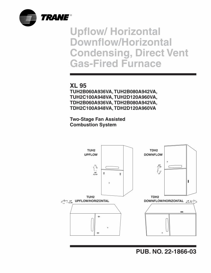
Upflow/ Horizontal Downflow/HorizontalCondensing, Direct Vent Gas-Fired Furnace
PUB. NO. 22-1866-03
XL 95TUH2B060A936VA, TUH2B080A942VA, TUH2C100A948VA, TUH2D120A960VA, TDH2B060A936VA, TDH2B080A942VA, TDH2C100A948VA, TDH2D120A960VA
Two-Stage Fan Assisted Combustion System
TDH2DOWNFLOW
DOWNFLOW/HORIZONTAL
TUH2UPFLOW
TUH2UPFLOW/HORIZONTAL
TDH2

© 2012 Trane All Rights Reserved 2 22-1866-03
GeneralFeatures
NATURAL GAS MODELSCentral Heating furnace designs are certified to ANSI Z21.47 / CSA 2.3 for both natural and L.P. gas. Limit setting and rating data were established and approved under standard rating condi-tions using American National Stan-dards Institute standards.
SAFE OPERATIONThe Integrated System Control has solid state devices, which continuously monitor for presence of flame, when the system is in the heating mode of operation. Dual solenoid combination gas valve and regulator provide extra safety.
QUICK HEATINGDurable, cycle tested, heavy gauge alu-minized steel heat exchanger quickly transfers heat to provide warm condi-tioned air to the structure. Low energy power vent blower, to increase effi-ciency and provide a positive discharge of gas fumes to the outside.
BURNERSMultiport Inshot burners will give years of quiet and efficient service. All models can be converted to L.P. gas without changing burners.
INTEGRATED SYSTEM CONTROLExclusively designed operational pro-gram provides total control of furnace limit sensors, blowers, gas valve, flame control and includes self diagnostics for ease of service. Also contains connec-tion points for E.A.C./humidifier.
AIR DELIVERYThe four speed, direct drive blower motor, has sufficient airflow for most heating and cooling requirements, will switch from heating to cooling speeds on demand from room thermostat. The blower door safety switch will prevent or terminate furnace operation when the blower door is removed.
SECONDARY HEAT EXCHANGERThe XL 95 has a special type 29-4C™stainless steel secondary heat exchanger to reclaim heat from flue gases which would normally be lost instead.
STYLINGHeavy gauge steel and “wrap-around” cabinet construction is used in the cabinet with baked-on enamel finish for strength and beauty. The heat exchang-er section of the cabinet is completely lined with foil faced fiberglass insulation. This results in quiet and efficient opera-tion due to the excellent acoustical and insulating qualities of fiberglass. Built-in bottom pan and alternate bottom, left or right side return air connection provision.
FEATURES AND GENERAL OPERATIONThe XL 95 High Efficiency Gas Furnac-es employ a Silicon Nitride Hot Surface Ignition system, which eliminates the waste of a constant burning pilot. The integrated system control lights the main burners upon a demand for heat from the room thermostat. Complete front service access.
a. Low energy power venter
b. Vent proving pressure switch.
Features and Benefits
UH2-PSC Standard Equipment
•Direct drive, 4-speed motor•120VoltSiliconNitrideIgniter•Variablespeedinduceddraftblower•Direct/Non-Directventoption•PVCventing-1or2pipeoption•Fused24voltcontrolcircuit•Manualresetburnersafetyswitches•Powersupply115/1/60•Convertibletohorizontalonleftside•2-stagegasvalve• Accessoryhook-upcapability–
Hum and EAC
• Integratedsolidstatecontrolwithself-diagnostics
•Heavygaugealuminizedsteelheatex-changer
• Type 29-4C™ stainless steel second-ary heat exchanger
•Multi-portIn-shotburners•Quietinduceddraftblower•LitePort™extendedsystemdiagnostics•Storedfaultcodehistoryinmicroproces-
sor noncoital memory• Cleanable high velocity filters (upflow
only)•Hingedblowerdoor*•Perfectfitdoorlatches*•Insulatedblowerdoor*•Gasketedblowerdoor*•Completefrontserviceaccess•Left/rightgasconnection•Adjustablefanofftimes•OptionalL.Pconversionkit•Selectable cool ing fan of f de-
lay eliminates need for BAY24X045 time delay kit
• Singlewiretwinning
• Optional extended warranties
*(Upflowonly)
22-1866-03 3
Contents
General Features 2Features and Benefits 2
XL 95 Standard Equipment 2XL95OptionalEquipment 4
General Data 5TUH2B060A936VA 5TUH2B080A942VA 5TUH2C100A948VA 5TUH2D120A960VA 6TDH2B060A936VA 6TDH2B080A942VA 6TDH2C100A948VA 6TDH2D120A960VA 7
Performance Data 8Electrical Data 10Field Wiring 14Twinning Field Wiring 15Dimensions 16
4 22-1866-03
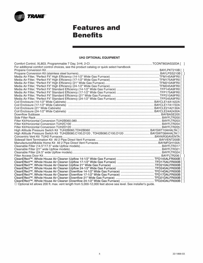
Features and Benefits
UH2 OPTIONAL EQUIPMENT
Comfort Control, XL803, Programmable 7 Day, 3-Ht, 2-Cl ...........................................................................TCONT803AS32DA[ ]For additional comfort control choices, see the product catalog or quick select handbookPropane Conversion Kit ........................................................................................................................................ BAYLPKT210B[]PropaneConversionKit(stainlesssteelburners).................................................................................................. BAYLPSS210B[]MediaAirFilter,“PerfectFit”HighEfficiency(14-1/2"WideGasFurnace) ........................................................... TFM145A9FR0[]MediaAirFilter,“PerfectFit”HighEfficiency(17-1/2"WideGasFurnace) ........................................................... TFM175A9FR0[]MediaAirFilter,“PerfectFit”HighEfficiency(21"WideGasFurnace) ................................................................. TFM210A9FR0[]MediaAirFilter,“PerfectFit”HighEfficiency(24-1/2"WideGasFurnace) ........................................................... TFM245A9FR0[]MediaAirFilter,“PerfectFit”StandardEfficiency(14-1/2"WideGasFurnace) ....................................................TFP145A9FR0[]MediaAirFilter,“PerfectFit”StandardEfficiency(17-1/2"WideGasFurnace) ....................................................TFP175A9FR0[]MediaAirFilter,“PerfectFit”StandardEfficiency(21"WideGasFurnace) ...........................................................TFP210A9FR0[]MediaAirFilter,“PerfectFit”StandardEfficiency(24-1/2"WideGasFurnace) ....................................................TFP245A9FR0[]CoilEnclosure(14-1/2"WideCabinets) ......................................................................................................... BAYCLE14A1422A[]CoilEnclosure(17-1/2"WideCabinets) ....................................................................................................... BAYCLE17A1722A[]CoilEnclosure(21"WideCabinets) .............................................................................................................. BAYCLE21A2130A[]CoilEnclosure(24-1/2"WideCabinets) ....................................................................................................... BAYCLE24A2430A[]Downflow Subbase ................................................................................................................................................. BAYBASE205[]Side Filter Rack ....................................................................................................................................................... BAYFLTR200[]FilterKit/HorizontalConversionTUH2B060,080...................................................................................................... BAYFLTR203[]FilterKit/HorizontalConversionTUH2C100 ............................................................................................................ BAYFLTR204[]FilterKit/HorizontalConversionTUH2D120 ............................................................................................................ BAYFLTR205[]HighAltitudePressureSwitchKitTUH2B060,TDH2B060 ....................................................................... BAYSWT10AHALTA1[]HighAltitudePressureSwitchKitTUH2B080,C100,D120,TDH2B080,C100,D120 ............................... BAYSWT08AHALTA1[]ConcentricVentKitTUH2Furnaces ...............................................................................................................BAYAIR30AVENTA[]Sidewall Vent Termination Kit All 2 Pipe Direct Vent Furnaces ............................................................................BAYVENT200B[]Manufactured/Mobile Home Kit All 2 Pipe Direct Vent Furnaces ........................................................................BAYMFGH100A[]CleanableFilter(14.5"/17.5"wideUpflowmodels) .................................................................................................. BAYFLTR317[]CleanableFilter(21"wideUpflowmodels) .............................................................................................................. BAYFLTR321[]CleanableFilter(24.5"wideUpflowmodels) ........................................................................................................... BAYFLTR324[]Filter Access Door Kit ............................................................................................................................................. BAYFLTR206[ ]CleanEffect™,WholeHouseAirCleaner(Upflow14-1/2"WideGasFurnace) ............................................. TFD145ALFR000B []CleanEffect™,WholeHouseAirCleaner(Upflow17-1/2"WideGasFurnace) .............................................TFD175ALFR000B [] CleanEffect™,WholeHouseAirCleaner(Upflow21"WideGasFurnace) ...................................................TFD210ALFR000B [] CleanEffect™,WholeHouseAirCleaner(Upflow24-1/2"WideGasFurnace) .............................................TFD245ALFR000B [] CleanEffect™,WholeHouseAirCleaner(Downflow14-1/2"WideGasFurnace) ........................................ TFD14DALFR000B [] CleanEffect™,WholeHouseAirCleaner(Downflow17-1/2"WideGasFurnace) ........................................ TFD17DALFR000B [] CleanEffect™,WholeHouseAirCleaner(Downflow21"WideGasFurnace) .............................................. TFD21DALFR000B [] CleanEffect™,WholeHouseAirCleaner(Downflow24-1/2"WideGasFurnace) ........................................ TFD24DALFR000B [] 1 Optionalkitallows200ft.max.ventlengthfrom5,000-12,000feetabovesealevel.Seeinstaller'sguide.
22-1866-03 5
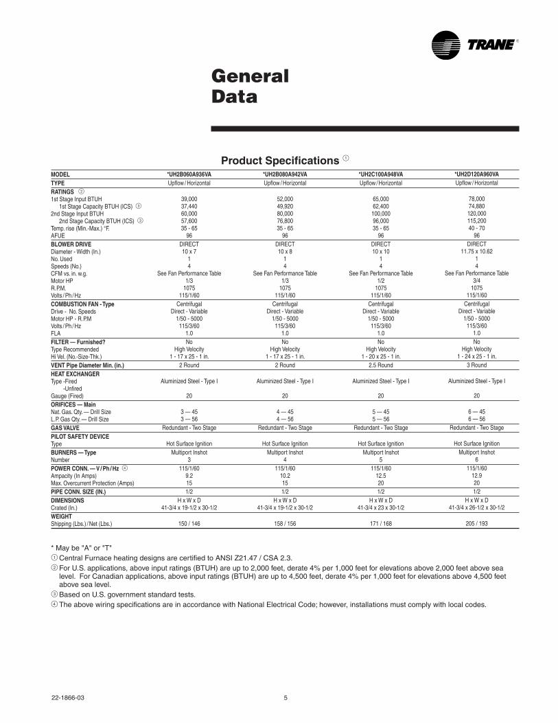
General Data
Product Specifications 1MODELTYPERATINGS 21st Stage Input BTUH 1st Stage Capacity BTUH (ICS) 32nd Stage Input BTUH 2nd Stage Capacity BTUH (ICS) 3Temp. rise (Min.-Max.) °F.AFUEBLOWER DRIVEDiameter - Width (In.)No. UsedSpeeds (No.)CFM vs. in. w.g.Motor HPR.P.M.Volts / Ph / HzCOMBUSTION FAN - TypeDrive - No. SpeedsMotor HP - R.P.MVolts / Ph / HzFLAFILTER — Furnished?Type RecommendedHi Vel. (No.-Size-Thk.)VENT Pipe Diameter Min. (in.)HEAT EXCHANGERType -Fired -UnfiredGauge (Fired)ORIFICES — MainNat. Gas. Qty. — Drill SizeL.P. Gas Qty. — Drill SizeGAS VALVEPILOT SAFETY DEVICETypeBURNERS — TypeNumberPOWER CONN. — V / Ph / Hz 4Ampacity (In Amps)Max. Overcurrent Protection (Amps)PIPE CONN. SIZE (IN.)DIMENSIONSCrated (In.)WEIGHTShipping (Lbs.) / Net (Lbs.)
*UH2B060A936VAUpflow / Horizontal
39,00037,44060,00057,60035 - 65
96DIRECT10 x 7
14
See Fan Performance Table1/3
1075115/1/60
CentrifugalDirect - Variable
1/50 - 5000115/3/60
1.0No
High Velocity1 - 17 x 25 - 1 in.
2 Round
Aluminized Steel - Type I
20
3 — 453 — 56
Redundant - Two Stage
Hot Surface IgnitionMultiport Inshot
3115/1/60
9.2151/2
H x W x D41-3/4 x 19-1/2 x 30-1/2
150 / 146
*UH2B080A942VAUpflow / Horizontal
52,00049,92080,00076,80035 - 65
96DIRECT10 x 8
14
See Fan Performance Table1/3
1075115/1/60
CentrifugalDirect - Variable
1/50 - 5000115/3/60
1.0No
High Velocity1 - 17 x 25 - 1 in.
2 Round
Aluminized Steel - Type I
20
4 — 454 — 56
Redundant - Two Stage
Hot Surface IgnitionMultiport Inshot
4115/1/60
10.2151/2
H x W x D41-3/4 x 19-1/2 x 30-1/2
158 / 156
*UH2C100A948VAUpflow / Horizontal
65,00062,400100,00096,00035 - 65
96DIRECT10 x 10
14
See Fan Performance Table1/2
1075115/1/60
CentrifugalDirect - Variable
1/50 - 5000115/3/60
1.0No
High Velocity1 - 20 x 25 - 1 in.
2.5 Round
Aluminized Steel - Type I
20
5 — 455 — 56
Redundant - Two Stage
Hot Surface IgnitionMultiport Inshot
5115/1/60
12.5201/2
H x W x D41-3/4 x 23 x 30-1/2
171 / 168
*Maybe"A"or"T"1 Central Furnace heating designs are certified to ANSI Z21.47 / CSA 2.3.2ForU.S.applications,aboveinputratings(BTUH)areupto2,000feet,derate4%per1,000feetforelevationsabove2,000feetabovesea
level.ForCanadianapplications,aboveinputratings(BTUH)areupto4,500feet,derate4%per1,000feetforelevationsabove4,500feetabove sea level.
3BasedonU.S.governmentstandardtests.4 The above wiring specifications are in accordance with National Electrical Code; however, installations must comply with local codes.
*UH2D120A960VAUpflow / Horizontal
78,00074,880120,000115,20040 - 70
96DIRECT
11.75 x 10.6214
See Fan Performance Table3/4
1075115/1/60
CentrifugalDirect - Variable
1/50 - 5000115/3/60
1.0No
High Velocity1 - 24 x 25 - 1 in.
3 Round
Aluminized Steel - Type I
20
6 — 456 — 56
Redundant - Two Stage
Hot Surface IgnitionMultiport Inshot
6115/1/60
12.9201/2
H x W x D41-3/4 x 26-1/2 x 30-1/2
205 / 193
6 22-1866-03
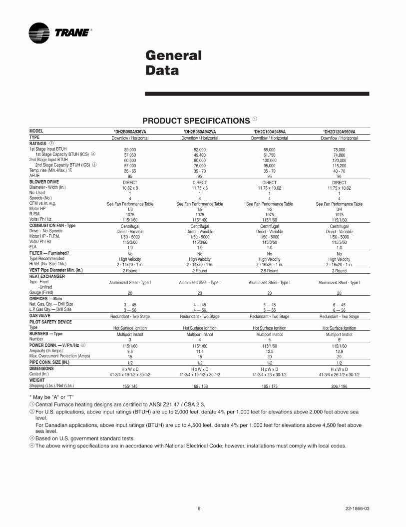
General Data
PRODUCT SPECIFICATIONS 1MODELTYPERATINGS 21st Stage Input BTUH 1st Stage Capacity BTUH (ICS) 32nd Stage Input BTUH 2nd Stage Capacity BTUH (ICS) 3Temp. rise (Min.-Max.) °F.AFUEBLOWER DRIVEDiameter - Width (In.)No. UsedSpeeds (No.)CFM vs. in. w.g.Motor HPR.P.M.Volts / Ph / HzCOMBUSTION FAN - TypeDrive - No. SpeedsMotor HP - R.P.M.Volts / Ph / HzFLAFILTER — Furnished?Type RecommendedHi Vel. (No.-Size-Thk.)VENT Pipe Diameter Min. (in.)HEAT EXCHANGERType -Fired -UnfiredGauge (Fired)ORIFICES — MainNat. Gas. Qty. — Drill SizeL.P. Gas Qty. — Drill SizeGAS VALVEPILOT SAFETY DEVICETypeBURNERS — TypeNumberPOWER CONN. — V / Ph / Hz 4Ampacity (In Amps)Max. Overcurrent Protection (Amps)PIPE CONN. SIZE (IN.)DIMENSIONSCrated (In.)WEIGHTShipping (Lbs.) / Net (Lbs.)
*Maybe"A"or"T"1 Central Furnace heating designs are certified to ANSI Z21.47 / CSA 2.3.2ForU.S.applications,aboveinputratings(BTUH)areupto2,000feet,derate4%per1,000feetforelevationsabove2,000feetabovesea
level. ForCanadianapplications,aboveinputratings(BTUH)areupto4,500feet,derate4%per1,000feetforelevationsabove4,500feetabove
sea level.3BasedonU.S.governmentstandardtests.4 The above wiring specifications are in accordance with National Electrical Code; however, installations must comply with local codes.
*DH2C100A948VADownflow / Horizontal
65,00061,750100,00095,00035 - 70
95DIRECT
11.75 x 10.6214
See Fan Performance Table1/2
1075115/1/60
CentrifugalDirect - Variable
1/50 - 5000115/3/60
1.0No
High Velocity2 - 16x20 - 1 in.
2.5 Round
Aluminized Steel - Type I
20
5 — 455 — 56
Redundant - Two Stage
Hot Surface IgnitionMultiport Inshot
5115/1/60
12.5201/2
H x W x D41-3/4 x 23 x 30-1/2
185 / 175
*DH2B080A942VADownflow / Horizontal
52,00049,40080,00076,00035 - 70
95DIRECT11.75 x 8
14
See Fan Performance Table1/2
1075115/1/60
CentrifugalDirect - Variable
1/50 - 5000115/3/60
1.0No
High Velocity2 - 14x20 - 1 in.
2 Round
Aluminized Steel - Type I
20
4 — 454 — 56
Redundant - Two Stage
Hot Surface IgnitionMultiport Inshot
4115/1/60
11.4151/2
H x W x D41-3/4 x 19-1/2 x 30-1/2
168 / 158
*DH2B060A936VADownflow / Horizontal
39,00037,05060,00057,00035 - 65
95DIRECT10.62 x 8
14
See Fan Performance Table1/3
1075115/1/60
CentrifugalDirect - Variable
1/50 - 5000115/3/60
1.0No
High Velocity2 - 14x20 - 1 in.
2 Round
Aluminized Steel - Type I
20
3 — 453 — 56
Redundant - Two Stage
Hot Surface IgnitionMultiport Inshot
3115/1/60
9.8151/2
H x W x D41-3/4 x 19-1/2 x 30-1/2
155/ 145
*DH2D120A960VADownflow / Horizontal
78,00074,880120,000115,20040 - 70
96DIRECT
11.75 x 10.6214
See Fan Performance Table3/4
1075115/1/60
CentrifugalDirect - Variable
1/50 - 5000115/3/60
1.0No
High Velocity2 - 16x20 - 1 in.
3 Round
Aluminized Steel - Type I
20
6 — 456 — 56
Redundant - Two Stage
Hot Surface IgnitionMultiport Inshot
6115/1/60
12.9201/2
H x W x D41-3/4 x 26-1/2 x 30-1/2
206 / 196
22-1866-03 7
Performance Data
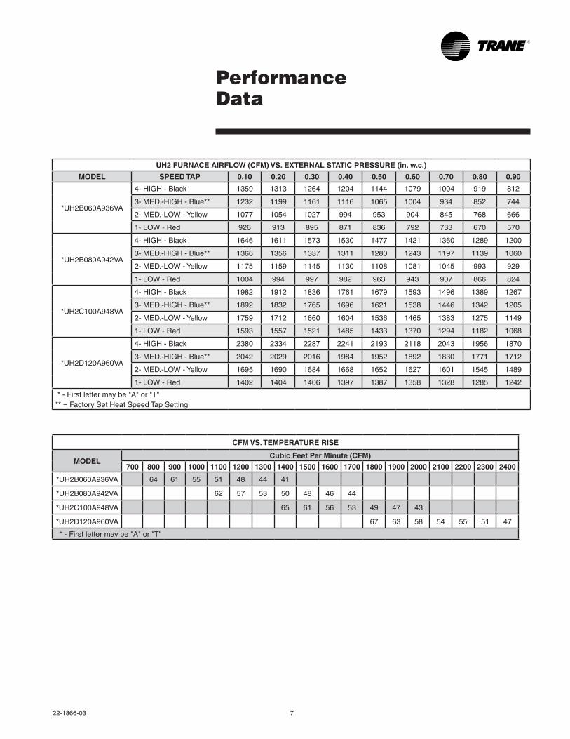
CFM VS. TEMPERATURE RISE
MODELCubic Feet Per Minute (CFM)
700 800 900 1000 1100 1200 1300 1400 1500 1600 1700 1800 1900 2000 2100 2200 2300 2400
*UH2B060A936VA 64 61 55 51 48 44 41
*UH2B080A942VA 62 57 53 50 48 46 44
*UH2C100A948VA 65 61 56 53 49 47 43
*UH2D120A960VA 67 63 58 54 55 51 47
*-Firstlettermaybe"A"or"T"
UH2 FURNACE AIRFLOW (CFM) VS. EXTERNAL STATIC PRESSURE (in. w.c.)
MODEL SPEED TAP 0.10 0.20 0.30 0.40 0.50 0.60 0.70 0.80 0.90
*UH2B060A936VA
4- HIGH - Black 1359 1313 1264 1204 1144 1079 1004 919 812
3-MED.-HIGH-Blue** 1232 1199 1161 1116 1065 1004 934 852 744
2-MED.-LOW-Yellow 1077 1054 1027 994 953 904 845 768 666
1-LOW-Red 926 913 895 871 836 792 733 670 570
*UH2B080A942VA
4- HIGH - Black 1646 1611 1573 1530 1477 1421 1360 1289 1200
3-MED.-HIGH-Blue** 1366 1356 1337 1311 1280 1243 1197 1139 1060
2-MED.-LOW-Yellow 1175 1159 1145 1130 1108 1081 1045 993 929
1-LOW-Red 1004 994 997 982 963 943 907 866 824
*UH2C100A948VA
4- HIGH - Black 1982 1912 1836 1761 1679 1593 1496 1389 1267
3-MED.-HIGH-Blue** 1892 1832 1765 1696 1621 1538 1446 1342 1205
2-MED.-LOW-Yellow 1759 1712 1660 1604 1536 1465 1383 1275 1149
1-LOW-Red 1593 1557 1521 1485 1433 1370 1294 1182 1068
*UH2D120A960VA
4- HIGH - Black 2380 2334 2287 2241 2193 2118 2043 1956 1870
3-MED.-HIGH-Blue** 2042 2029 2016 1984 1952 1892 1830 1771 1712
2-MED.-LOW-Yellow 1695 1690 1684 1668 1652 1627 1601 1545 1489
1-LOW-Red 1402 1404 1406 1397 1387 1358 1328 1285 1242
*-Firstlettermaybe"A"or"T"**=FactorySetHeatSpeedTapSetting
8 22-1866-03
Performance Data
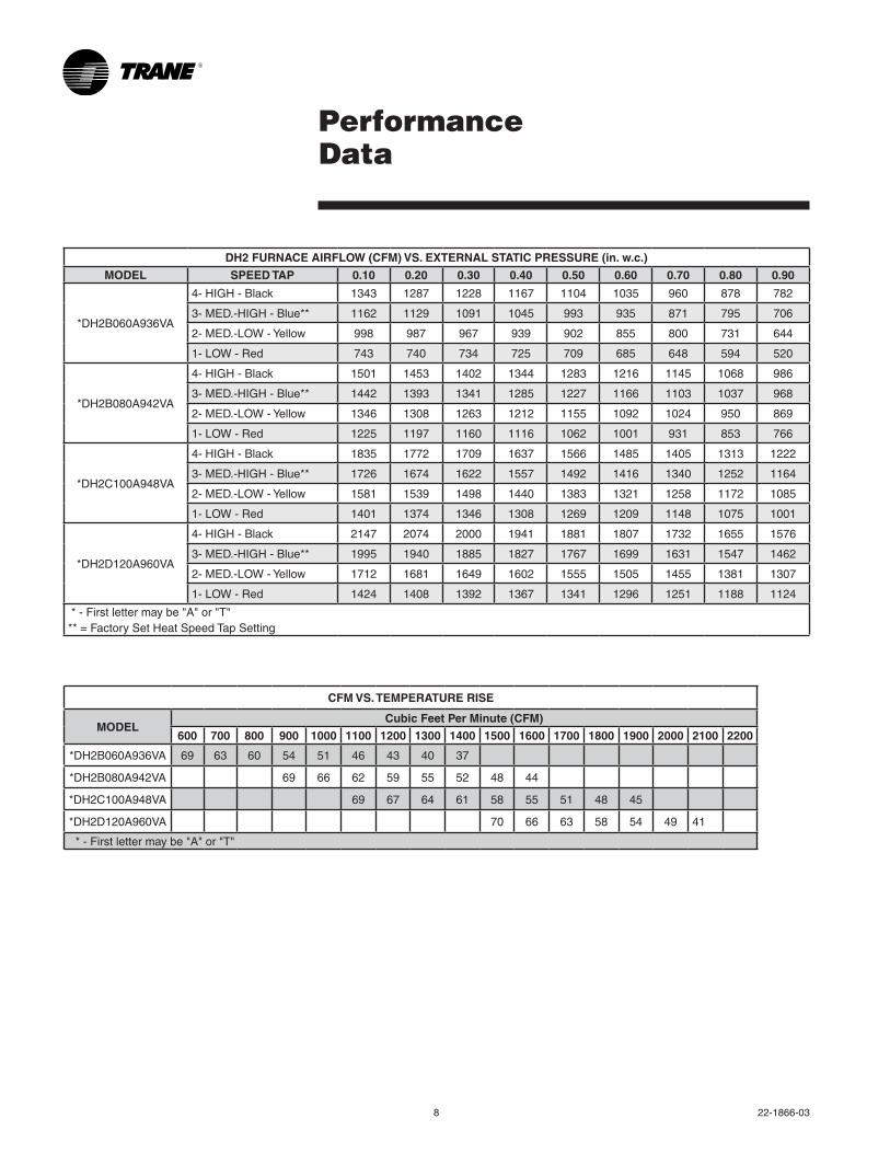
CFM VS. TEMPERATURE RISE
MODELCubic Feet Per Minute (CFM)
600 700 800 900 1000 1100 1200 1300 1400 1500 1600 1700 1800 1900 2000 2100 2200
*DH2B060A936VA 69 63 60 54 51 46 43 40 37
*DH2B080A942VA 69 66 62 59 55 52 48 44
*DH2C100A948VA 69 67 64 61 58 55 51 48 45
*DH2D120A960VA 70 66 63 58 54 49 41
*-Firstlettermaybe"A"or"T"
DH2 FURNACE AIRFLOW (CFM) VS. EXTERNAL STATIC PRESSURE (in. w.c.)
MODEL SPEED TAP 0.10 0.20 0.30 0.40 0.50 0.60 0.70 0.80 0.90
*DH2B060A936VA
4- HIGH - Black 1343 1287 1228 1167 1104 1035 960 878 782
3-MED.-HIGH-Blue** 1162 1129 1091 1045 993 935 871 795 706
2-MED.-LOW-Yellow 998 987 967 939 902 855 800 731 644
1-LOW-Red 743 740 734 725 709 685 648 594 520
*DH2B080A942VA
4- HIGH - Black 1501 1453 1402 1344 1283 1216 1145 1068 986
3-MED.-HIGH-Blue** 1442 1393 1341 1285 1227 1166 1103 1037 968
2-MED.-LOW-Yellow 1346 1308 1263 1212 1155 1092 1024 950 869
1-LOW-Red 1225 1197 1160 1116 1062 1001 931 853 766
*DH2C100A948VA
4- HIGH - Black 1835 1772 1709 1637 1566 1485 1405 1313 1222
3-MED.-HIGH-Blue** 1726 1674 1622 1557 1492 1416 1340 1252 1164
2-MED.-LOW-Yellow 1581 1539 1498 1440 1383 1321 1258 1172 1085
1-LOW-Red 1401 1374 1346 1308 1269 1209 1148 1075 1001
*DH2D120A960VA
4- HIGH - Black 2147 2074 2000 1941 1881 1807 1732 1655 1576
3-MED.-HIGH-Blue** 1995 1940 1885 1827 1767 1699 1631 1547 1462
2-MED.-LOW-Yellow 1712 1681 1649 1602 1555 1505 1455 1381 1307
1-LOW-Red 1424 1408 1392 1367 1341 1296 1251 1188 1124
*-Firstlettermaybe"A"or"T"**=FactorySetHeatSpeedTapSetting

22-1866-03 9
Electrical Data
(continued on next page)
*UH2 Wiring Diagram
From Dwg. D344563
10 22-1866-03
Electrical Data
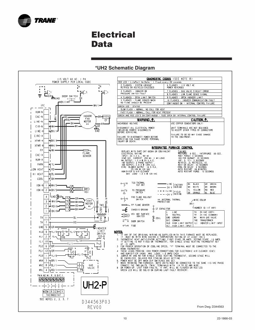
*UH2 Schematic Diagram
From Dwg. D344563
22-1866-03 11
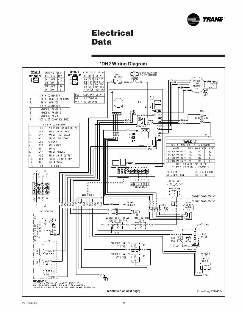
Electrical Data
(continued on next page)
*DH2 Wiring Diagram
From Dwg. D344564

12 22-1866-03
Electrical Data
*DH2 Schematic Diagram
From Dwg. D344564
22-1866-03 13
Field Wiring
SEE NOTE 6
From Dwg. 21B342024 Rev. 0
2 STAGE FURNACE
TWIN
SEE NOTE 7
B/CB/C TO 115 V 1 PH.,60 HZ., POWERSUPPLY PERLOCAL CODES
HUM SEENOTE 5
EAC SEENOTE 5
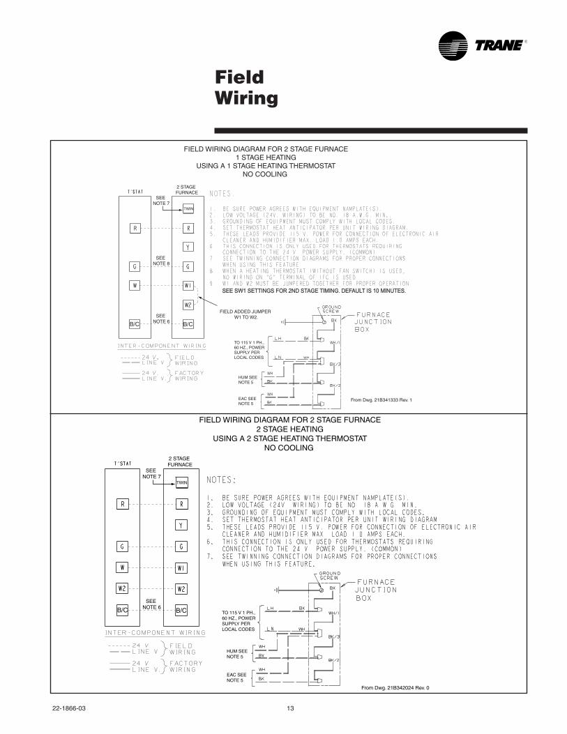
FIELD WIRING DIAGRAM FOR 2 STAGE FURNACE2 STAGE HEATING
USING A 2 STAGE HEATING THERMOSTATNO COOLING
SEE NOTE 6
From Dwg. 21B341333 Rev. 1
2 STAGE FURNACE
TWIN
SEE NOTE 7
FIELD ADDED JUMPER W1 TO W2.
SEE NOTE 8
B/C B/C
TO 115 V 1 PH.,60 HZ., POWERSUPPLY PERLOCAL CODES
HUM SEENOTE 5
EAC SEENOTE 5
FIELD WIRING DIAGRAM FOR 2 STAGE FURNACE1 STAGE HEATING
USING A 1 STAGE HEATING THERMOSTATNO COOLING
SEE SW1 SETTINGS FOR 2ND STAGE TIMING. DEFAULT IS 10 MINUTES.
14 22-1866-03
Twinning Field Wiring
TWIN TWIN
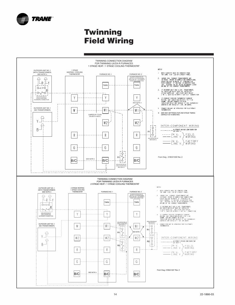
TWINNING CONNECTION DIAGRAMFOR TWINNING UX/DX-R FURNACES
2 STAGE HEAT / 1 STAGE COOLING THERMOSTAT
2 STAGE HEATING1 STAGE COOLING
THERMOSTAT FURNACE NO. 1 FURNACE NO. 2
BLOWER OPERATION OF UNIT NO. 2 IS SYNCRONIZEDWITH UNIT NO. 1 VIA SIGNALS
FROM TWIN CONNECTION.
SEE NOTE 4
OUTDOOR UNIT NO. 1(NO TRANSFORMER)
OUTDOOR UNIT NO. 1(WITH TRANSFORMER)
SEE NOTE 3
RC
ISOLATION RELAY(FIELD SUPPLIED)
ALTERNATE CONNECTION
R2
R2
SEE NOTE 5
ISOLATION RELAY(FIELD SUPPLIED)
SEE NOTE 4
ISOLATION RELAYSEE NOTE 4
R1R1
B/C B/C B/CFrom Dwg. 21B341337 Rev. 2
TWIN TWIN
TWINNING CONNECTION DIAGRAMFOR TWINNING UX/DX-R FURNACES
1 STAGE HEAT / 1 STAGE COOLING THERMOSTAT
1 STAGEHEATING / COOLING
THERMOSTAT FURNACE NO. 1 FURNACE NO. 2
BLOWER OPERATION OF UNIT NO. 2 IS SYNCRONIZEDWITH UNIT NO. 1 VIA SIGNALS
FROM TWIN CONNECTION.
SEE NOTE 4
OUTDOOR UNIT NO. 1(NO TRANSFORMER)
OUTDOOR UNIT NO. 1(WITH TRANSFORMER)
SEE NOTE 3
RC
ISOLATION RELAY(FIELD SUPPLIED)
ALTERNATE CONNECTION
R1
R1
SEE NOTE 5
ISOLATION RELAY(FIELD SUPPLIED)
SEE NOTE 4
ISOLATION RELAYSEE NOTE 4
JUMPER W1 TO W2ON BOTH UNITS.
B/CB/CB/CFrom Dwg. 21B341336 Rev. 2
6. SEE SW1 SETTINGS FOR 2ND STAGE TIMING. DEFAULT IS 10 MINUTES.
22-1866-03 15
From
Dw
g. C
3418
84
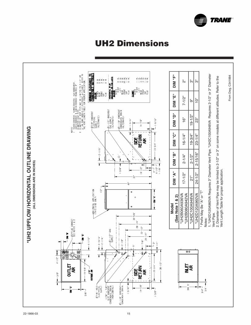
UH2 Dimensions
*UH
2 U
PF
LO
W / H
OR
IZO
NTA
L O
UT
LIN
E D
RA
WIN
G(A
LL
DIM
EN
SIO
NS
AR
E IN
INC
HE
S)
Mo
del
(See
No
te 1
& 2
)D
IM "
A"
DIM
"B
"D
IM "
C"
DIM
"D
"D
IM "
E"
DIM
"F
"
*UH
2B06
0A93
6VA
*U
H2B
080A
942V
A17
-1/2
"2-
1/4"
16-1
/4"
16"
7-1/
2"2"
*UH
2C10
0A94
8VA
21"
2-1/
2"19
-3/4
"19
-1/2
"9"
3"*U
H2D
120A
960V
A24
-1/2
"2-
15/1
6"23
-1/4
"23
"10
"3"
*P
refix
May
Be
"A"
or"
T"
Not
es:
1.*
UH
2D12
0A96
0VA
Req
uire
s3"
Dia
met
erV
entP
ipe.
*U
H2C
100A
948V
AR
equi
res
2-1/
2"o
r3"
Dia
met
er
Ven
t Pip
e.2.
Dia
met
ero
fVen
tPip
em
ayb
elim
ited
to2
-1/2
"or
3"
ons
ome
mod
els
atd
iffer
enta
ltitu
des.
Ref
erto
the
Ven
t Len
gth
Tabl
e fo
r pr
oper
app
licat
ion.
16 22-1866-03
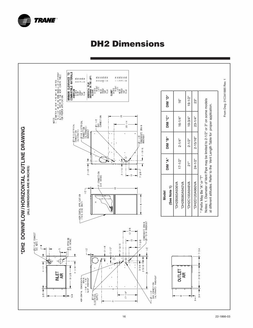
DH2 Dimensions
From
Dw
g. 2
1C34
1885
Rev
. 1
*DH
2 D
OW
NF
LO
W / H
OR
IZO
NTA
L O
UT
LIN
E D
RA
WIN
G(A
LL
DIM
EN
SIO
NS
AR
E IN
INC
HE
S)
Mo
del
(See
No
te 1
)D
IM "
A"
DIM
"B
"D
IM "
C"
DIM
"D
"
*DH
2B06
0A93
6VA
*DH
2B08
0A94
2VA
17-1
/2"
2-1/
4"16
-1/4
"16
"
*DH
2C10
0A94
8VA
21"
2-1/
2"19
-3/4
"19
-1/2
"
*DH
2D12
0A96
0VA
24-1
/2"
2-15
/16"
23-1
/4"
23"
*P
refix
May
Be
"A"
or"
T"
Not
es:1
.Dia
met
ero
fVen
tPip
em
ayb
elim
ited
to2
-1/2
"or
3"
ons
ome
mod
els
at d
iffer
ent a
ltitu
des.
Ref
er to
the
Ven
t Len
gth
Tabl
e fo
r p
rope
r ap
plic
atio
n.

22-1866-03 17

Trane has a policy of continuous product and product data improvement and it reserves the right to change design and specifications without notice.
Trane6200 Troup HighwayTyler, TX 75707www.trane.com
LiteratureOrderNumber 22-1866-03
File Number 22-1866-03
Supersedes 22-1866-02
Date 09/12
Recommended