Embed Size (px)
Citation preview
WTW online measurement technique
Flow-thru installations for sensors
Technical Information
ba75393e05 08/2006
NoteAll dimensions are quoted in mm.
NoteFurther information and technical data of the products is given in the operating manuals on the enclosed CD-ROM and on the Internet under www.WTW.com.

2 ba75393e05 08/2006
Copyright © Weilheim 2006, WTW GmbHReprinting - even as excerpts - is only allowed with the explicit written authorization of WTW GmbH, Weilheim.Printed in Germany.
Contents
Contents
1 Measuring in pipes and containers . . . . . . . . . . . . . . . . . . 5
2 D 700/N flow-thru vessel . . . . . . . . . . . . . . . . . . . . . . . . . . 8
3 D 300/pH flow-thru vessel . . . . . . . . . . . . . . . . . . . . . . . . . 9
4 D 530 flow-thru vessel . . . . . . . . . . . . . . . . . . . . . . . . . . . 10
5 DMS/N flow-thru measurement vessel . . . . . . . . . . . . . . 11
6 EBST 700-DU/N flow-thru armature . . . . . . . . . . . . . . . . 12
7 EBS 700-DU/N installation set . . . . . . . . . . . . . . . . . . . . . 14
8 D 702/N flow-thru vessel . . . . . . . . . . . . . . . . . . . . . . . . . 15
9 ESS 700 VA/N welding socket . . . . . . . . . . . . . . . . . . . . . 16
10 ESS 700 VA/10 welding socket . . . . . . . . . . . . . . . . . . . . 17
11 WA 700/2 retractable armature . . . . . . . . . . . . . . . . . . . . 18
12 WA 700/10 retractable armature . . . . . . . . . . . . . . . . . . . 19
13 ESS-WA 700/... welding socket . . . . . . . . . . . . . . . . . . . . 20
14 VIS-Flow-thru measuring cell . . . . . . . . . . . . . . . . . . . . . . 21
15 Selection table for sensor-specific adapters . . . . . . . . . . 22
3ba75393e05 08/2006

Contents
4 ba75393e05 08/2006
IQ SENSOR NET - Technische Informationen Measuring in pipes and containers
5ba75393e05 08/2006
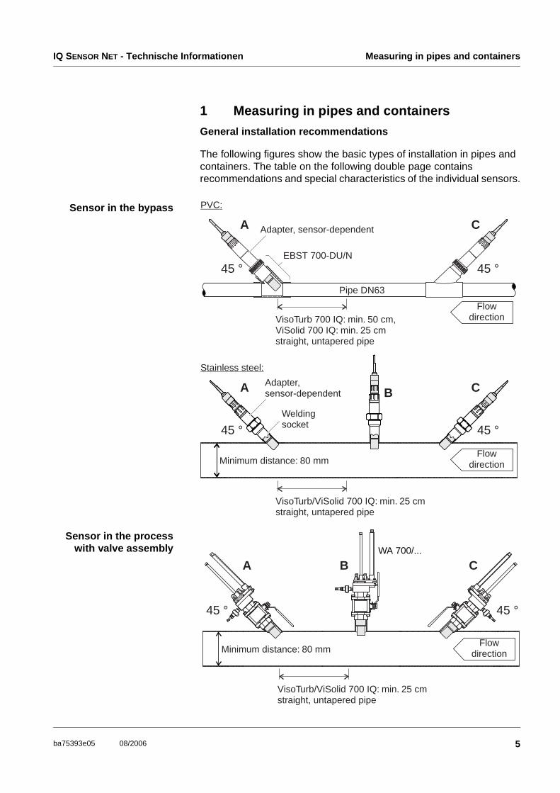
1 Measuring in pipes and containers
General installation recommendations
The following figures show the basic types of installation in pipes and containers. The table on the following double page contains recommendations and special characteristics of the individual sensors.
Sensor in the bypass
Sensor in the processwith valve assembly
VisoTurb 700 IQ: min. 50 cm,ViSolid 700 IQ: min. 25 cmstraight, untapered pipe
VisoTurb/ViSolid 700 IQ: min. 25 cmstraight, untapered pipe
Flowdirection
Flowdirection
A
A
45 °
45 °
EBST 700-DU/N
Adapter, sensor-dependent
Adapter,sensor-dependent
Weldingsocket
PVC:
Stainless steel:
Pipe DN63
45 °
45 °
C
C
Minimum distance: 80 mm
B
FlowdirectionMinimum distance: 80 mm
A
45 ° 45 °
B C
VisoTurb/ViSolid 700 IQ: min. 25 cmstraight, untapered pipe
WA 700/...
Measu
ring
in p
ipes an
d co
ntain
ersIQ
SE
NS
OR
NE
T - Tech
nical in
form
ation
6ba75393e05
08/2006
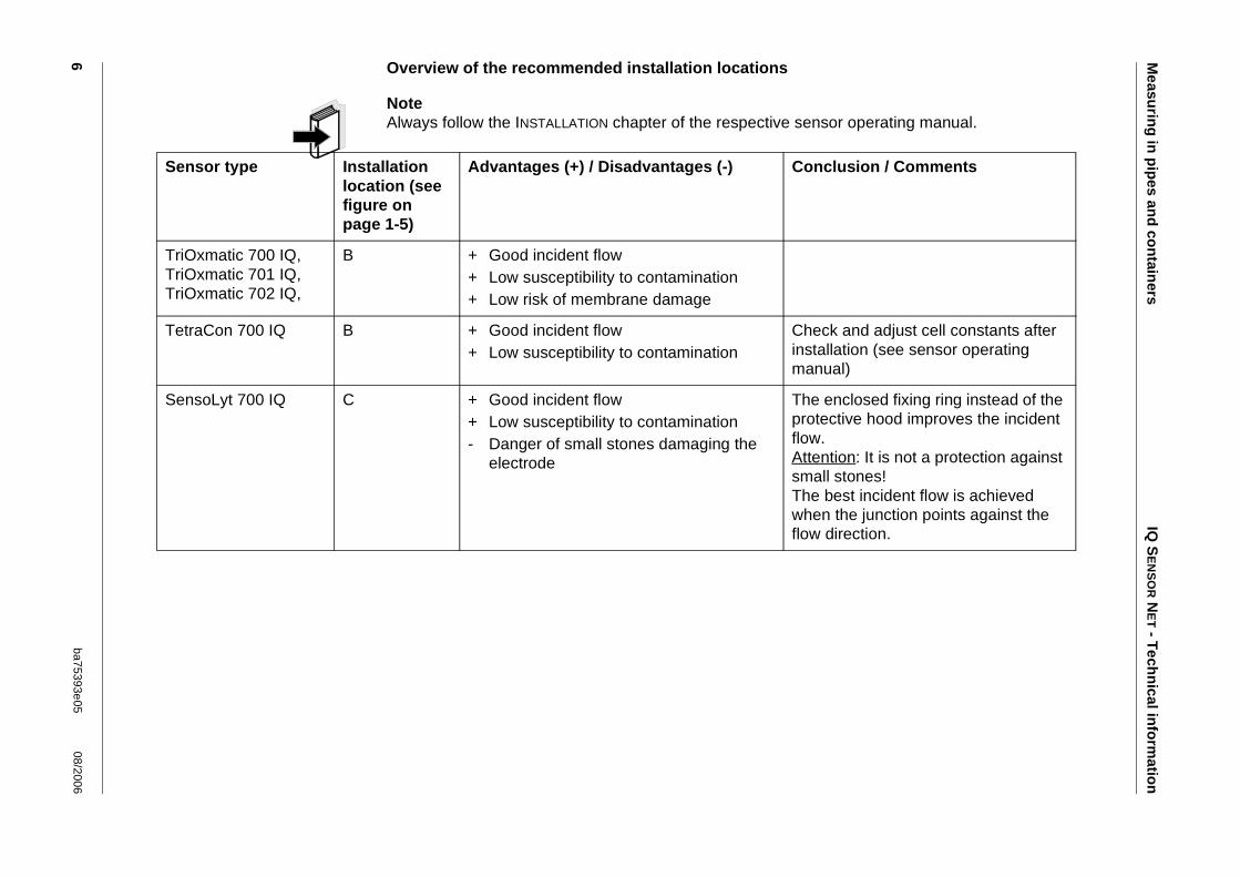
Overview of the recommended installation locations
NoteAlways follow the INSTALLATION chapter of the respective sensor operating manual.
Sensor type Installation location (see figure on page 1-5)
Advantages (+) / Disadvantages (-) Conclusion / Comments
TriOxmatic 700 IQ,TriOxmatic 701 IQ,TriOxmatic 702 IQ,
B + Good incident flow+ Low susceptibility to contamination+ Low risk of membrane damage
TetraCon 700 IQ B + Good incident flow+ Low susceptibility to contamination
Check and adjust cell constants after installation (see sensor operating manual)
SensoLyt 700 IQ C + Good incident flow+ Low susceptibility to contamination- Danger of small stones damaging the
electrode
The enclosed fixing ring instead of the protective hood improves the incident flow.Attention: It is not a protection against small stones!The best incident flow is achieved when the junction points against the flow direction.
IQS
EN
SO
RN
ET - T
echn
ical info
rmatio
nM
easurin
g in
pip
es and
con
tainers7
ba75393e0508/2006
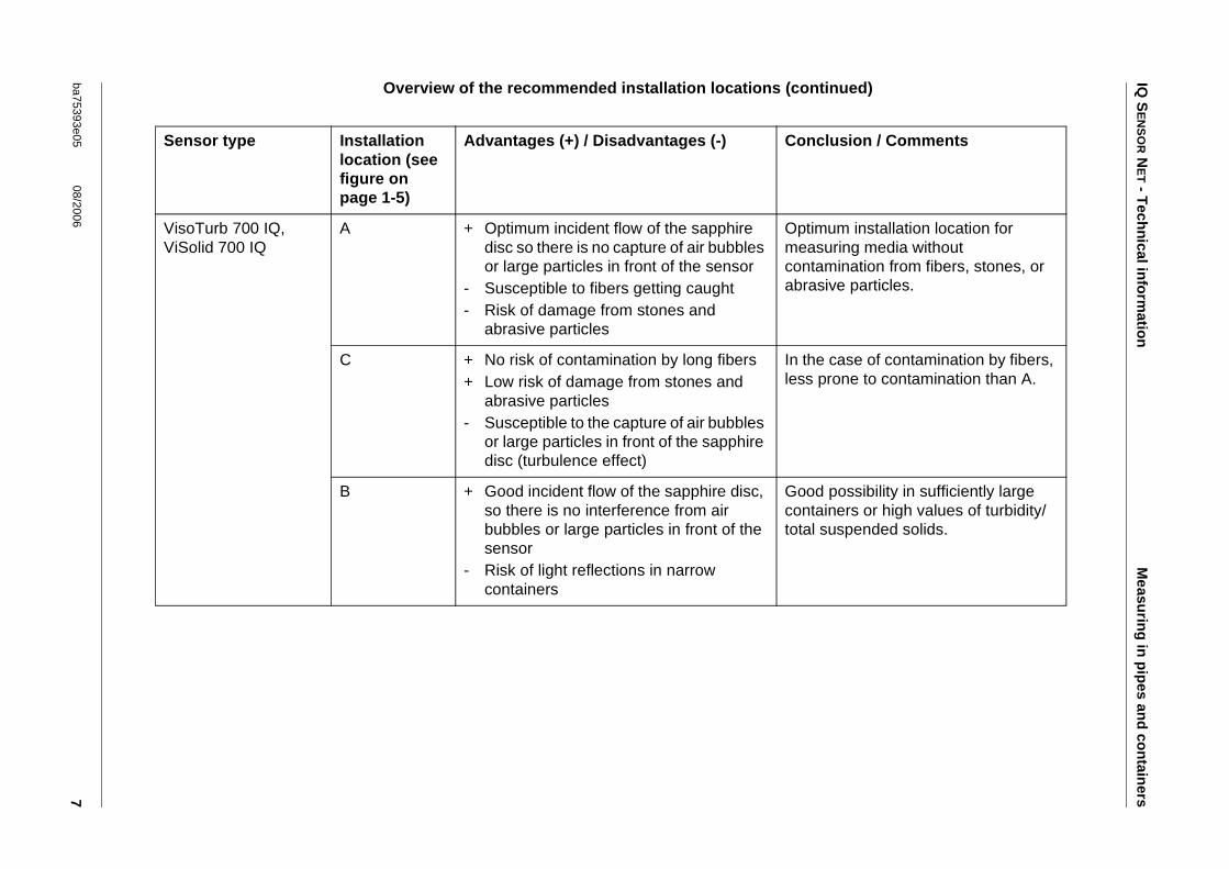
Overview of the recommended installation locations (continued)
Sensor type Installation location (see figure on page 1-5)
Advantages (+) / Disadvantages (-) Conclusion / Comments
VisoTurb 700 IQ, ViSolid 700 IQ
A + Optimum incident flow of the sapphire disc so there is no capture of air bubbles or large particles in front of the sensor
- Susceptible to fibers getting caught- Risk of damage from stones and
abrasive particles
Optimum installation location for measuring media without contamination from fibers, stones, or abrasive particles.
C + No risk of contamination by long fibers+ Low risk of damage from stones and
abrasive particles- Susceptible to the capture of air bubbles
or large particles in front of the sapphire disc (turbulence effect)
In the case of contamination by fibers, less prone to contamination than A.
B + Good incident flow of the sapphire disc, so there is no interference from air bubbles or large particles in front of the sensor
- Risk of light reflections in narrow containers
Good possibility in sufficiently large containers or high values of turbidity/total suspended solids.
D 700/N flow-thru vessel IQ SENSOR NET - Technische Informationen
8 ba75393e05 08/2006
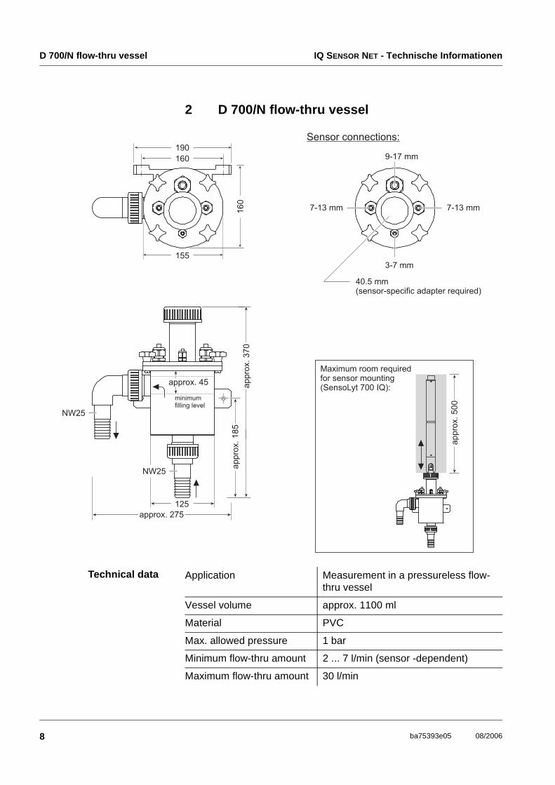
2 D 700/N flow-thru vessel
Technical data Application Measurement in a pressureless flow-thru vessel
Vessel volume approx. 1100 ml
Material PVC
Max. allowed pressure 1 bar
Minimum flow-thru amount 2 ... 7 l/min (sensor -dependent)
Maximum flow-thru amount 30 l/min
IQ SENSOR NET - Technische Informationen D 300/pH flow-thru vessel
9ba75393e05 08/2006
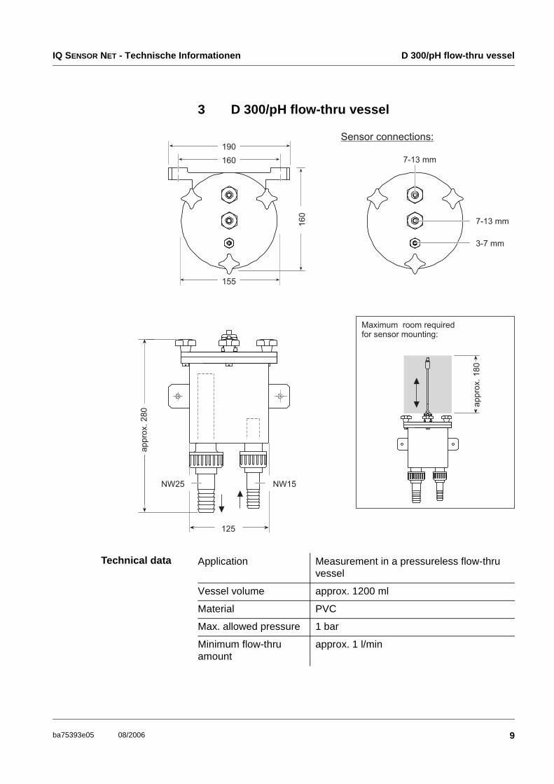
3 D 300/pH flow-thru vessel
Technical data Application Measurement in a pressureless flow-thru vessel
Vessel volume approx. 1200 ml
Material PVC
Max. allowed pressure 1 bar
Minimum flow-thru amount
approx. 1 l/min
D 530 flow-thru vessel IQ SENSOR NET - Technische Informationen
10 ba75393e05 08/2006
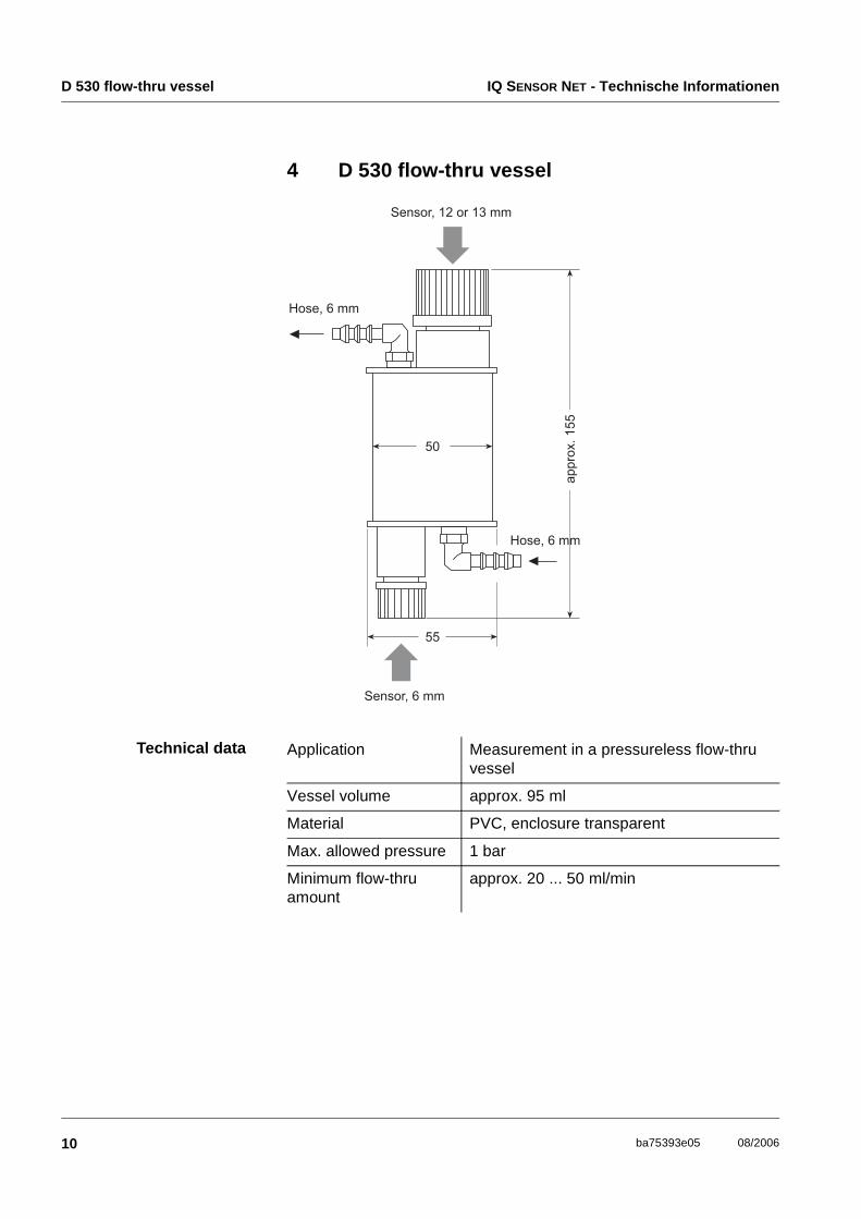
4 D 530 flow-thru vessel
Technical data Application Measurement in a pressureless flow-thru vessel
Vessel volume approx. 95 ml
Material PVC, enclosure transparent
Max. allowed pressure 1 bar
Minimum flow-thru amount
approx. 20 ... 50 ml/min
IQ SENSOR NET - Technische Informationen DMS/N flow-thru measurement vessel
11ba75393e05 08/2006
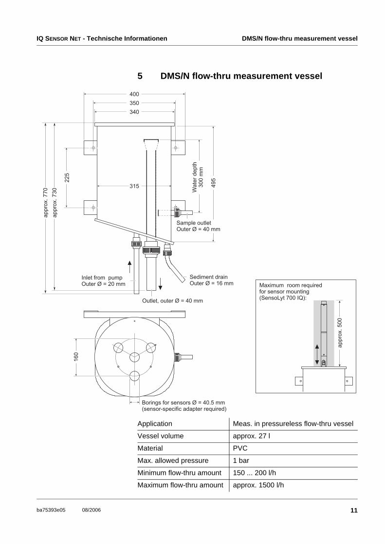
5 DMS/N flow-thru measurement vessel
Application Meas. in pressureless flow-thru vessel
Vessel volume approx. 27 l
Material PVC
Max. allowed pressure 1 bar
Minimum flow-thru amount 150 ... 200 l/h
Maximum flow-thru amount approx. 1500 l/h
EBST 700-DU/N flow-thru armature IQ SENSOR NET - Technische Informationen
12 ba75393e05 08/2006
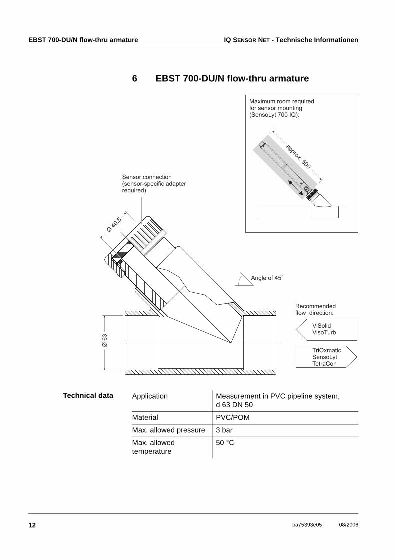
6 EBST 700-DU/N flow-thru armature
Technical data Application Measurement in PVC pipeline system, d 63 DN 50
Material PVC/POM
Max. allowed pressure 3 bar
Max. allowed temperature
50 °C
IQ SENSOR NET - Technische Informationen EBST 700-DU/N flow-thru armature
13ba75393e05 08/2006
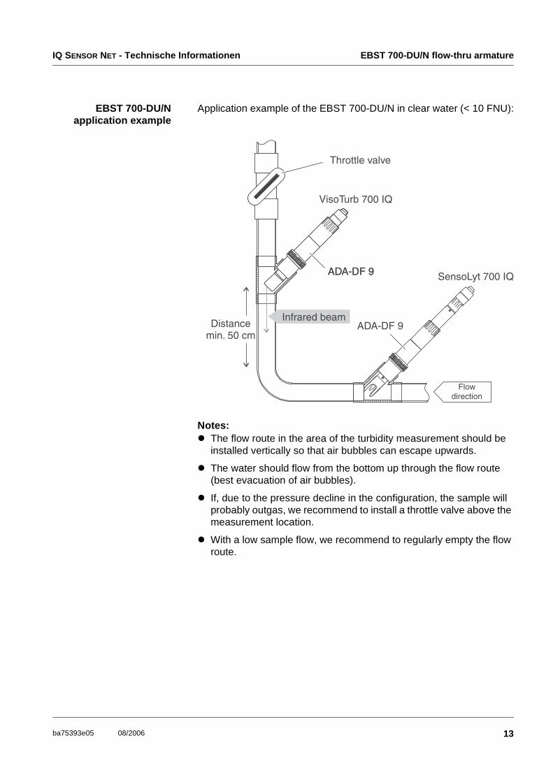
EBST 700-DU/Napplication example
Application example of the EBST 700-DU/N in clear water (< 10 FNU):
Notes:The flow route in the area of the turbidity measurement should be installed vertically so that air bubbles can escape upwards.
The water should flow from the bottom up through the flow route (best evacuation of air bubbles).
If, due to the pressure decline in the configuration, the sample will probably outgas, we recommend to install a throttle valve above the measurement location.
With a low sample flow, we recommend to regularly empty the flow route.
EBS 700-DU/N installation set IQ SENSOR NET - Technische Informationen
14 ba75393e05 08/2006
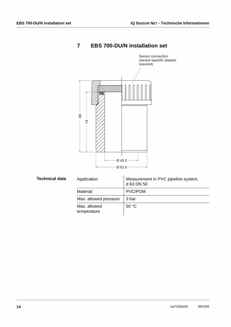
7 EBS 700-DU/N installation set
Technical data Application Measurement in PVC pipeline system, d 63 DN 50
Material PVC/POM
Max. allowed pressure 3 bar
Max. allowed temperature
50 °C
IQ SENSOR NET - Technische Informationen D 702/N flow-thru vessel
15ba75393e05 08/2006
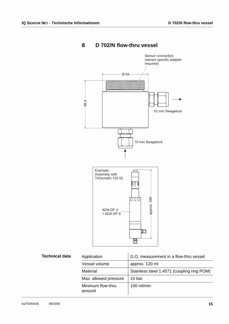
8 D 702/N flow-thru vessel
Technical data Application D.O. measurement in a flow-thru vessel
Vessel volume approx. 120 ml
Material Stainless steel 1.4571 (coupling ring POM)
Max. allowed pressure 10 bar
Minimum flow-thru amount
100 ml/min
ESS 700 VA/N welding socket IQ SENSOR NET - Technische Informationen
16 ba75393e05 08/2006
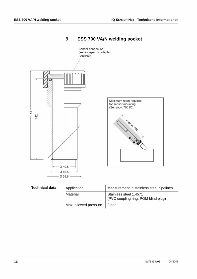
9 ESS 700 VA/N welding socket
Technical data Application Measurement in stainless steel pipelines
Material Stainless steel 1.4571(PVC coupling ring, POM blind plug)
Max. allowed pressure 3 bar
IQ SENSOR NET - Technische Informationen ESS 700 VA/10 welding socket
17ba75393e05 08/2006
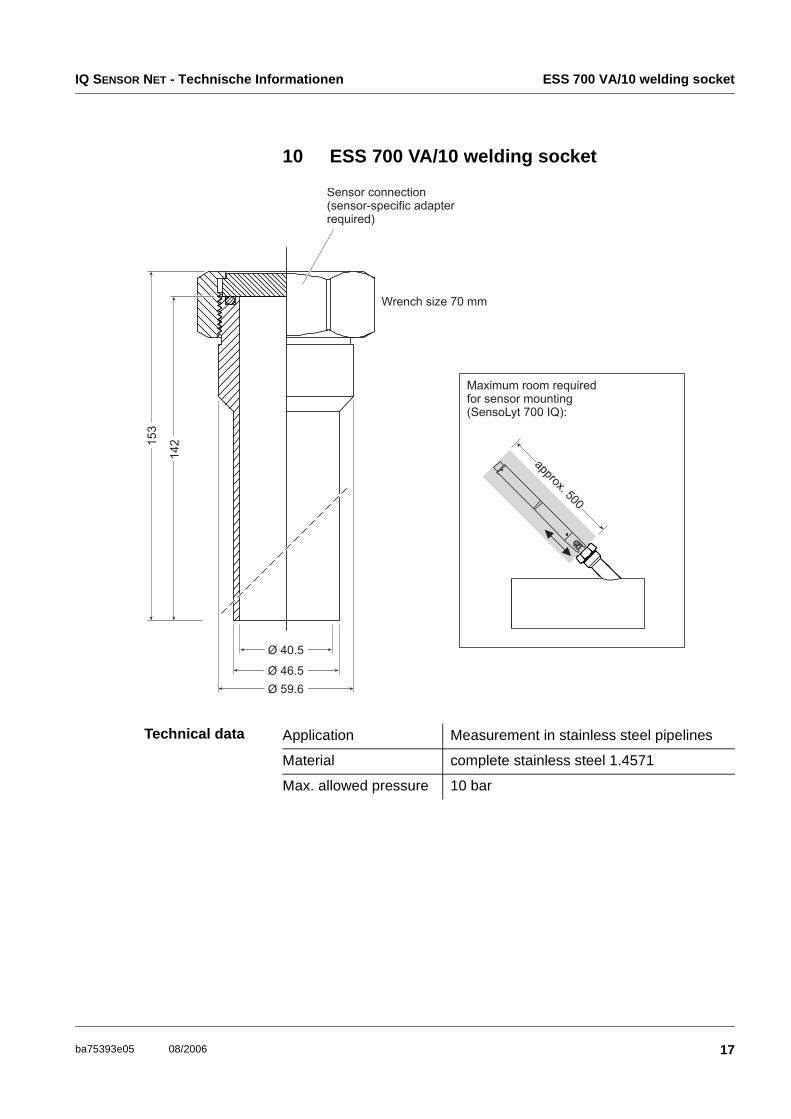
10 ESS 700 VA/10 welding socket
Technical data Application Measurement in stainless steel pipelines
Material complete stainless steel 1.4571
Max. allowed pressure 10 bar
WA 700/2 retractable armature IQ SENSOR NET - Technische Informationen
18 ba75393e05 08/2006
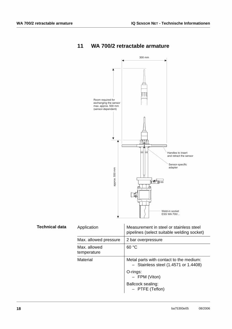
11 WA 700/2 retractable armature
Technical data Application Measurement in steel or stainless steel pipelines (select suitable welding socket)
Max. allowed pressure 2 bar overpressure
Max. allowed temperature
60 °C
Material Metal parts with contact to the medium: – Stainless steel (1.4571 or 1.4408)
O-rings: – FPM (Viton)
Ballcock sealing: – PTFE (Teflon)
IQ SENSOR NET - Technische Informationen WA 700/10 retractable armature
19ba75393e05 08/2006
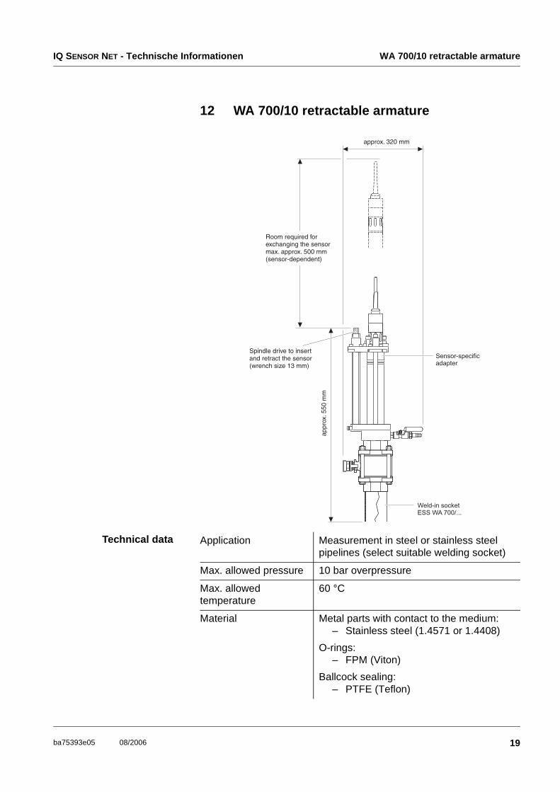
12 WA 700/10 retractable armature
Technical data Application Measurement in steel or stainless steel pipelines (select suitable welding socket)
Max. allowed pressure 10 bar overpressure
Max. allowed temperature
60 °C
Material Metal parts with contact to the medium: – Stainless steel (1.4571 or 1.4408)
O-rings: – FPM (Viton)
Ballcock sealing: – PTFE (Teflon)
ESS-WA 700/... welding socket IQ SENSOR NET - Technische Informationen
20 ba75393e05 08/2006
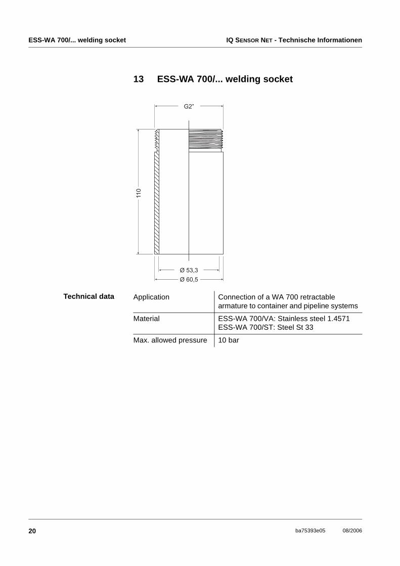
13 ESS-WA 700/... welding socket
Technical data
Ø 53,3
Ø 60,5
G2”
11
0
Application Connection of a WA 700 retractable armature to container and pipeline systems
Material ESS-WA 700/VA: Stainless steel 1.4571ESS-WA 700/ST: Steel St 33
Max. allowed pressure 10 bar
IQ SENSOR NET - Technische Informationen VIS-Flow-thru measuring cell
21ba75393e05 08/2006
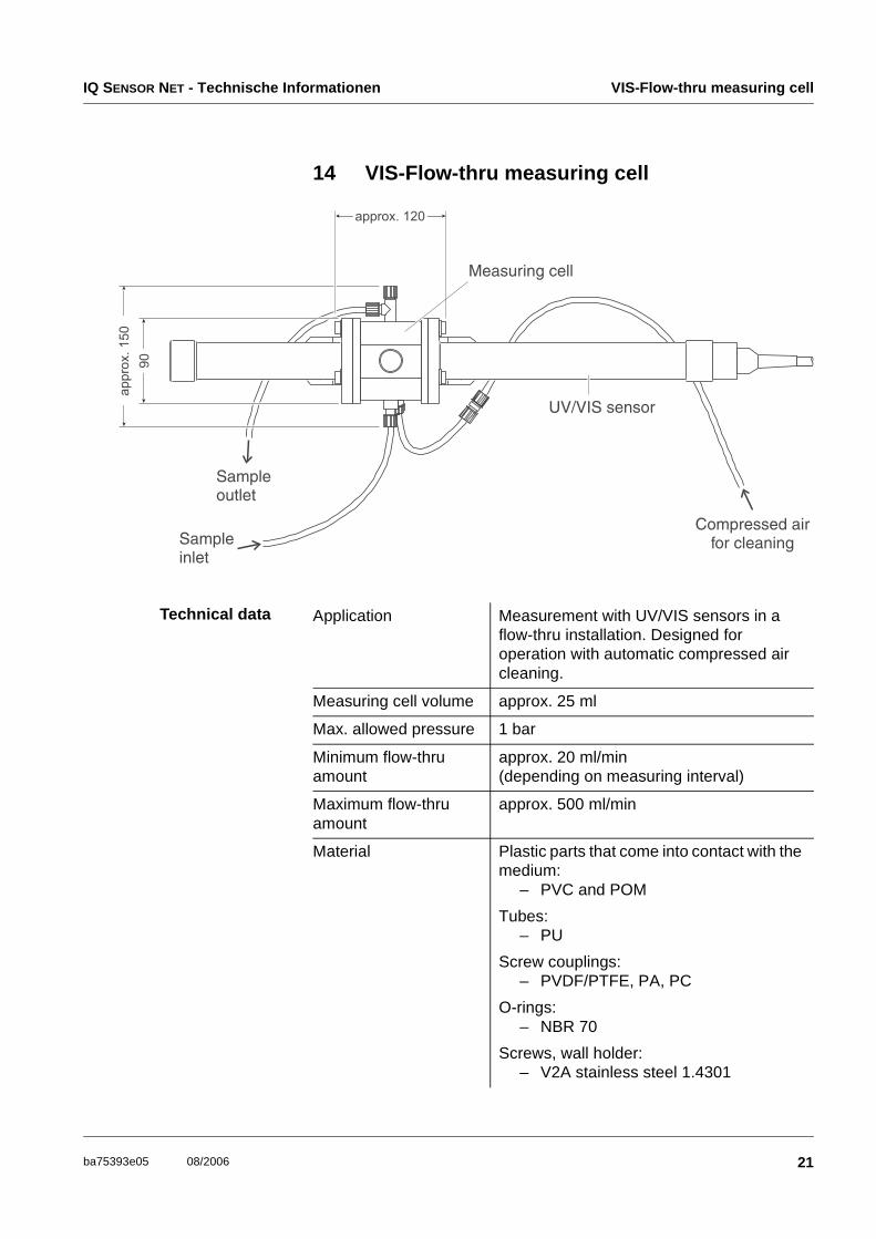
14 VIS-Flow-thru measuring cell
Technical data Application Measurement with UV/VIS sensors in a flow-thru installation. Designed for operation with automatic compressed air cleaning.
Measuring cell volume approx. 25 ml
Max. allowed pressure 1 bar
Minimum flow-thru amount
approx. 20 ml/min (depending on measuring interval)
Maximum flow-thru amount
approx. 500 ml/min
Material Plastic parts that come into contact with the medium:
– PVC and POM
Tubes: – PU
Screw couplings: – PVDF/PTFE, PA, PC
O-rings: – NBR 70
Screws, wall holder: – V2A stainless steel 1.4301
Selection table for sensor-specific adapters IQ SENSOR NET - Technische Informationen
22 ba75393e05 08/2006
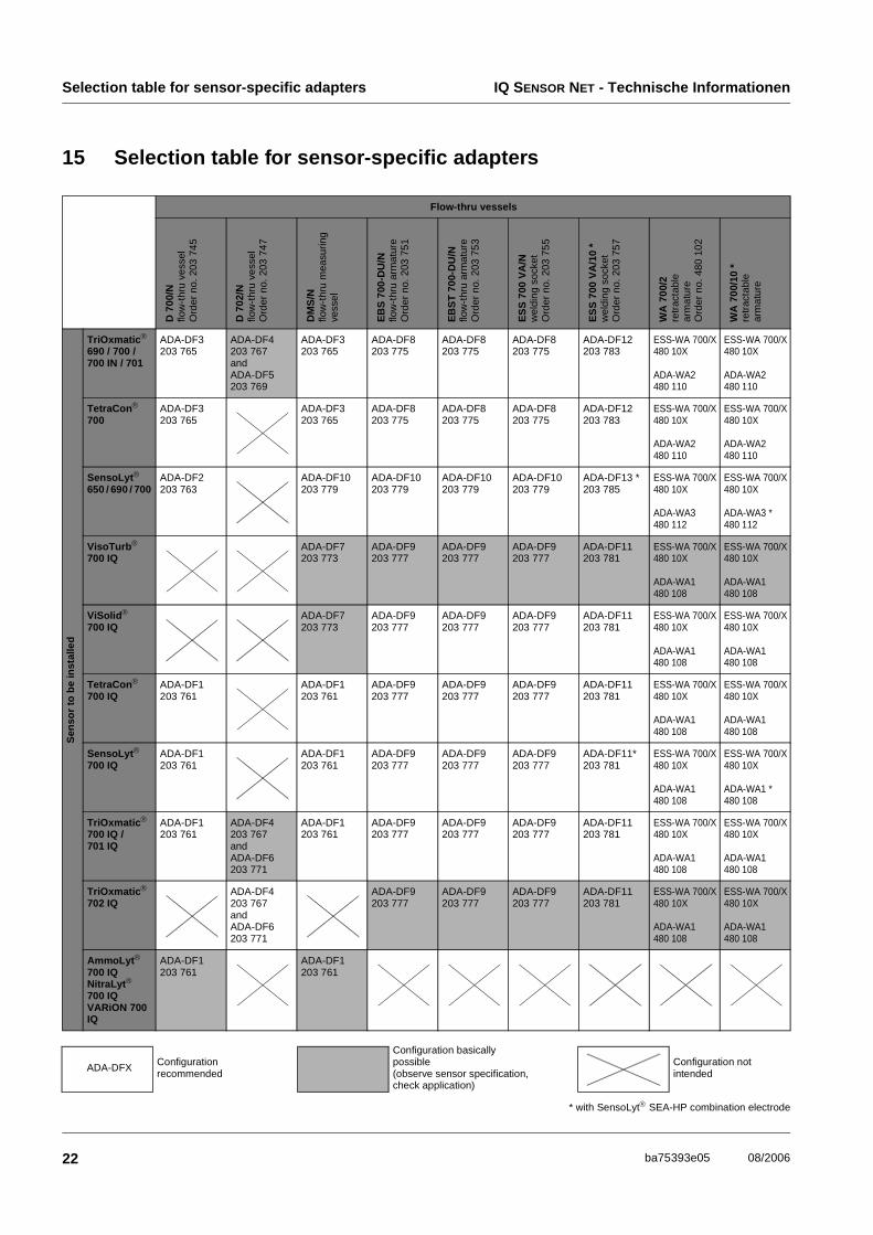
15 Selection table for sensor-specific adapters
Flow-thru vessels
TriOxmatic
690 / 700 /700 IN / 701
ADA-DF3203 765
ADA-DF4203 767and ADA-DF5203 769
ADA-DF3203 765
ADA-DF8203 775
ADA-DF8203 775
ADA-DF8203 775
ADA-DF12203 783
ESS-WA 700/X480 10X
ADA-WA2480 110
ESS-WA 700/X480 10X
ADA-WA2480 110
TetraCon
700ADA-DF3203 765
ADA-DF3203 765
ADA-DF8203 775
ADA-DF8203 775
ADA-DF8203 775
ADA-DF12203 783
ESS-WA 700/X480 10X
ADA-WA2480 110
ESS-WA 700/X480 10X
ADA-WA2480 110
SensoLyt
650 / 690 / 700 ADA-DF2203 763
ADA-DF10203 779
ADA-DF10203 779
ADA-DF10203 779
ADA-DF10203 779
ADA-DF13 *203 785
ESS-WA 700/X480 10X
ADA-WA3480 112
ESS-WA 700/X480 10X
ADA-WA3 *480 112
VisoTurb
700 IQADA-DF7203 773
ADA-DF9203 777
ADA-DF9203 777
ADA-DF9203 777
ADA-DF11203 781
ESS-WA 700/X480 10X
ADA-WA1480 108
ESS-WA 700/X480 10X
ADA-WA1480 108
ViSolid
700 IQADA-DF7203 773
ADA-DF9203 777
ADA-DF9203 777
ADA-DF9203 777
ADA-DF11203 781
ESS-WA 700/X480 10X
ADA-WA1480 108
ESS-WA 700/X480 10X
ADA-WA1480 108
TetraCon
700 IQADA-DF1203 761
ADA-DF1203 761
ADA-DF9203 777
ADA-DF9203 777
ADA-DF9203 777
ADA-DF11203 781
ESS-WA 700/X480 10X
ADA-WA1480 108
ESS-WA 700/X480 10X
ADA-WA1480 108
SensoLyt
700 IQADA-DF1203 761
ADA-DF1203 761
ADA-DF9203 777
ADA-DF9203 777
ADA-DF9203 777
ADA-DF11*203 781
ESS-WA 700/X480 10X
ADA-WA1480 108
ESS-WA 700/X480 10X
ADA-WA1 *480 108
TriOxmatic
700 IQ / 701 IQ
ADA-DF1203 761
ADA-DF4203 767and ADA-DF6203 771
ADA-DF1203 761
ADA-DF9203 777
ADA-DF9203 777
ADA-DF9203 777
ADA-DF11203 781
ESS-WA 700/X480 10X
ADA-WA1480 108
ESS-WA 700/X480 10X
ADA-WA1480 108
TriOxmatic
702 IQADA-DF4203 767and ADA-DF6203 771
ADA-DF9203 777
ADA-DF9203 777
ADA-DF9203 777
ADA-DF11203 781
ESS-WA 700/X480 10X
ADA-WA1480 108
ESS-WA 700/X480 10X
ADA-WA1480 108
AmmoLyt
700 IQNitraLyt
700 IQVARiON 700 IQ
ADA-DF1203 761
ADA-DF1203 761
D 7
00/N
flow
-thr
u ve
ssel
Ord
er n
o. 2
03 7
45
D 7
02/N
flow
-thr
u ve
ssel
Ord
er n
o. 2
03 7
47
DM
S/N
flow
-thr
u m
easu
ring
vess
el
EB
S 7
00-D
U/N
flow
-thr
u ar
mat
ure
Ord
er n
o. 2
03 7
51
EB
ST
700
-DU
/Nflo
w-t
hru
arm
atur
eO
rder
no.
203
753
ES
S 7
00 V
A/N
wel
ding
soc
ket
Ord
er n
o. 2
03 7
55
ES
S 7
00 V
A/1
0 *
wel
ding
soc
ket
Ord
er n
o. 2
03 7
57
WA
700
/2re
trac
tabl
e ar
mat
ure
Ord
er n
o. 4
80 1
02
WA
700
/10
*re
trac
tabl
e ar
mat
ure
Sen
sor
to b
e in
stal
led
ADA-DFX Configurationrecommended
Configuration basically possible(observe sensor specification, check application)
Configuration not intended
* with SensoLyt SEA-HP combination electrode