Embed Size (px)
Citation preview


Table of contents. 1. General description of MAGNA-LON................................................................................................. 3 2. Installation .......................................................................................................................................... 4 3. SNVT Details...................................................................................................................................... 5 4. SCPT / UCPT Details......................................................................................................................... 6 5. Application example........................................................................................................................... 7 6. PumpController Functional-Block Details .......................................................................................... 9 7. Node object ...................................................................................................................................... 32 8. Manufacture specific variables ........................................................................................................ 34 9. Device resource files........................................................................................................................ 35
Grundfos A/S, DK-8850 Bjerringbro, Denmark
Page 2 of 35

1. General description of MAGNA-LON The LON-interface add on module for GRUNDFOS MAGNATM (MAGNA-LON) will connect a GRUNDFOS MAGNATM pump to a LON network. Via MAGNA-LON it is possible to control the pump and get pump status.
MAGNA LONpump status
LON
control data
Figure 1
MAGNA-LON is designed using a 3150 neuron chip, an FTT10 transceiver and a 32 Kbyte Flash memory, which makes updating of software possible. The pump profile in this document is compliant with version 1.0 of “Pump Controller Object”, from LonMark organization. The MAGNA-LON module has been developed according to LonMark Application Layer Interoperability Guidelines 3.3. MAGNA-LON uses self documentation strings, which means an installation-tool can access the relevant information over the network, otherwise MAGNALON.XIF can be found on the same disk as this document.
Grundfos A/S, DK-8850 Bjerringbro, Denmark
Page 3 of 35

2. Installation When MAGNA-LON is delivered it is already configured. This means that when it is powered up the application program will start. The Flash memory will contain Firmware version 7.0, and application code. Furthermore the communication parameters will be present in the EEPROM memory of the neuron-chips. The customer will need to install the network and make the required bindings. MAGNA-LON can be installed on a network in two different ways. 1. MAGNA-LON can be installed by pushing the SERVICE pin, which will cause the neuron-chip to transmit a unique 48 bit ID code to the network. 2. The unique ID code can also be found on the label situated on the side of the MAGNA-LON interface. The bar code is in Code 39 format. An additional label with the same unique code is supplied with the MAGNA-LON interface. This label can be attached to the building installation plan. MAGNA has a yellow service LED that indicates various states of the interface. When is delivered it should only flash for a moment and then remain off. For further information see Echelon documentation.
Grundfos A/S, DK-8850 Bjerringbro, Denmark
Page 4 of 35

3. SNVT Details
NV #
Name Recv HrtBt
SNVT Type SNVT Index
Class Description
1 nviPumpSetpoint No SNVT_switch 95 RAM Pump setpoint for normal operation 2 nviPumpOpMode No SNVT_hvac_mode 108 RAM Requested pump operating mode 6 nviPumpOvdStop No SNVT_switch 95 RAM Pump override stop command 7 nviOvdSpeed No SNVT_lev_percent 81 RAM Override setpoint for speed 8 nviOvdPress No SNVT_press 30 RAM Override setpoint for pressure
10 nviRemotePress Yes SNVT_press 30 RAM Remote differential pressure senor input 11 nviRemoteFlow Yes SNVT_flow_p 161 RAM Remote flow sensor input
3 nvoPumpCapacity Yes SNVT_lev_percent 81 RAM Pump capacity as percent of maximum 4 nvoEffOpMode Yes SNVT_hvac_mode 108 RAM Effective operating mode 5 nvoControlMode Yes SNVT_dev_c_mode 162 RAM Effective device control mode 13 nvoPumpStatus Yes SNVT_dev_status 173 RAM Pump status diagnostic information 14 nvoPressure No SNVT_press 30 RAM Pump pressure 15 nvoFlow No SNVT_flow_p 161 RAM Pump flow 16 nvoSpeed No SNVT_rpm 102 RAM Pump speed 17 nvoPumpOverride No SNVT_switch 95 RAM Pump override active 18 nvoRuntime No SNVT_time_hour 124 RAM Runtime in hours 19 nvoPumpFault No SNVT_dev_fault 174 RAM Fault states of the pump 21 nvoFluidTemp No SNVT_temp_p 105 RAM Fluid temperature 22 nvoPower No SNVT_power 27 RAM Electrical power consumption in watts 24 nvoEnergyConsum No SNVT_elec_kwh 13 RAM Total energy consumption of the pump
SNVT number is according to SFPTpumpController
Grundfos A/S, DK-8850 Bjerringbro, Denmark
Page 5 of 35

4. SCPT / UCPT Details
SCPT Name NV Name
Type or SNVT
SCPT Index
Associated NVs Description
SCPTmaxSendTime nciSndHrtBt
SNVT_time_sec(107)
49 nv3, nv4, nv5, nv13 Maximum period of time that expires before the functional block will automatically update NVs
SCPTpumpCharacteristic nroPumpChar
(structure)
233 Entire Functional Block Maximum flow, maximum pressure and maximum speed for the pump, defines the pump characteristics.
SCPTlocation nciLocation
SNVT_str_asc(36)
17 Entire Functional Block Used to provide physical location of the device
SCPTmaxRcvTime nciRcvHrtBt
SNVT_time_sec(107)
48 nv10, nv11 Maximum period of time that will expires before the functional block resets to default values, and start using
internal flow, pressure or speed feedback.
SCPTdeviceControlMode nciControlMode
SNVT_dec_c_mode(162)
238 Entire Functional Block Control Mode for normal operation
SCPTminRemotePressureSetpoint nciRemMinPress SNVT_press(30)
239 nv10 Remote pressure-sensor minimum value
SCPTmaxRemotePressureSetpoint nciRemMaxPress SNVT_press(30)
240 nv10 Remote pressure-sensor maximum value
SCPTminRemoteFlowSetpoint nciRemMinFlow
SNVT_flow_p (161)
241 nv11 Remote flow-sensor minimum value
SCPTmaxRemoteFlowSetpoint nciRemMaxFlow
SNVT_flow_p (161)
242 nv11 Remote flow-sensor maximum value
UCPT_Ti nciTi
SNVT_time_sec(107)
nv10, nv11 Integral time for PI regulator
UCPT_Ts nciTs
SNVT_time_sec(107)
nv10, nv11 sample time for PI regulator
UCPT_Kp nciKp
SNVT_multiplier (82)
nv10, nv11 Gain for PI regulator
Grundfos A/S, DK-8850 Bjerringbro, Denmark
Page 6 of 35
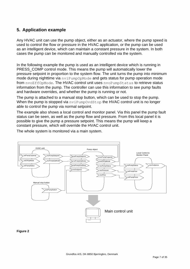
5. Application example Any HVAC unit can use the pump object, either as an actuator, where the pump speed is used to control the flow or pressure in the HVAC application, or the pump can be used as an intelligent device, which can maintain a constant pressure in the system. In both cases the pump can be monitored and manually controlled via the system. In the following example the pump is used as an intelligent device which is running in PRESS_COMP control mode. This means the pump will automatically lower the pressure setpoint in proportion to the system flow. The unit turns the pump into minimum mode during nighttime via nviPumpOpMode and gets status for pump operation mode from nvoEffOpMode. The HVAC control unit uses nvoPumpStatus to retrieve status information from the pump. The controller can use this information to see pump faults and hardware overrides, and whether the pump is running or not. The pump is attached to a manual stop button, which can be used to stop the pump. When the pump is stopped via nviPumpOvdStop the HVAC control unit is no longer able to control the pump via normal setpoint. The example also shows a local control and monitor panel. Via this panel the pump fault status can be seen, as well as the pump flow and pressure. From this local panel it is possible to give the pump a pressure setpoint. This means the pump will keep a constant pressure, which will override the HVAC control unit. The whole system is monitored via a main system.
nvoPumpSetpoint
nvoPumpOpMode
nviPumpCapacity
nviEffOpMode
nviPumpStatus
HVAC-unit
nvoPumpSwitch
Manual stop button
nviPumpStatus nvoOvdpress
nviPumpFlow
nviPumpPress
Local Control &Monitor Panel
nviPumpSetpoint
Pump object
nviPumpOpMode
nviPumpOvdStop
nviOvdpress
nvoPumpCapacity
nvoEffOpMode
nvoPumpStatus
nvoPressure
nvoFlow
Main control unit
Figure 2
Grundfos A/S, DK-8850 Bjerringbro, Denmark
Page 7 of 35

The Pump Controller profile includes input network variables to manually override the operation of the pump. A valid value on any one of these input variables sets the pump into the override mode. The pump will not return to normal setpoint control until all manual override inputs are invalid. The priority of the various override inputs can be seen in Figure 3
Figure 3
Grundfos A/S, DK-8850 Bjerringbro, Denmark
Page 8 of 35

6. PumpController Functional-Block Details
Configuration nc49 nciSndHrtBt
nciControlMode
nc17 nciLocation
nv1 SNVT_switch nviPumpSetpoint
nv2 SNVT_hvac_modenviPumpOpMode
nv3 SNVT_lev_percent nvoPumpCapacity
nv4 SNVT_hvac_mode nvoEffOpMode
nv5 SNVT_dev_c_mode nvoControlMode
nv13 SNVT_dev_status nvoPumpStatus nv6 SNVT_switch
nviPumpOvdStop
nv7 SNVT_lev_percentnviOvdSpeed nv14
SNVT_press nvoPressure
nv15SNVT_flow_p nvoFlow
nv16 SNVT_rpm nvoSpeed
nv18SNVT_time_hour nvoRuntime
nv19SNVT_dev_fault nvoPumpFault
nv20SNVT_tempnvoFluid-
nv24SNVT_elec_kwh nvoEnergyConsum
nv17 SNVT_switch nvoPumpOverride
nv21 SNVT_temp_p nvoFluidTemp
nv22SNVT_power nvoPower
nv8 SNVT_press nviOvdPress
nv10 SNVT_press nviRemotePress
nv11 SNVT_flow_p nviRemoteFlow
nroPumpCharnc233 nciRcvHrtBtnc48 nciRemMinPressnc239
nciRemMaxPressnc240nciRemMinFlownc241nciRemMaxFlownc242
nc238
Figure 4
Grundfos A/S, DK-8850 Bjerringbro, Denmark
Page 9 of 35
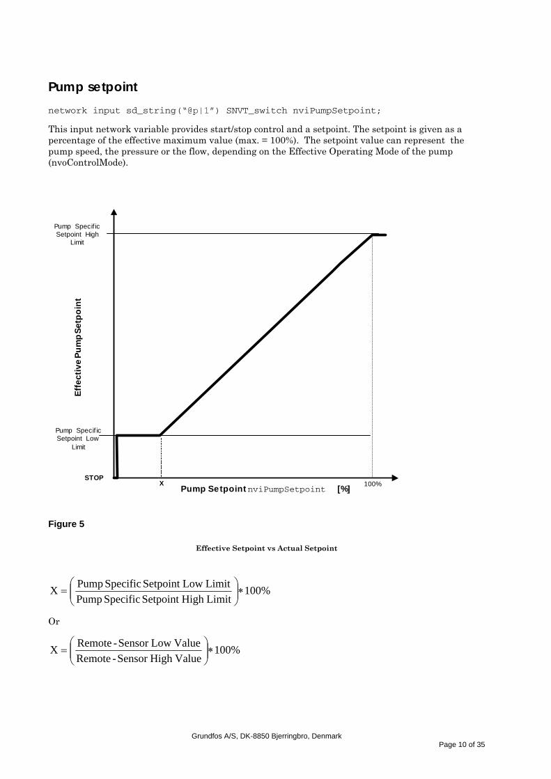
Pump setpoint
network input sd_string(“@p|1”) SNVT_switch nviPumpSetpoint;
This input network variable provides start/stop control and a setpoint. The setpoint is given as a percentage of the effective maximum value (max. = 100%). The setpoint value can represent the pump speed, the pressure or the flow, depending on the Effective Operating Mode of the pump (nvoControlMode).
Pump Specif icSetpoint High
Limit
Pump Specif icSetpoint Low
Limit
100%STOP
Pump Setpoint nviPumpSetpoint [%]
Effe
ctiv
e Pu
mp
Setp
oint
X
Figure 5
Effective Setpoint vs Actual Setpoint
%100LimitHigh Setpoint Specific PumpLimit LowSetpoint Specific PumpX ∗⎟⎟
⎠
⎞⎜⎜⎝
⎛=
Or
%100ValueHigh Sensor -RemoteValue LowSensor -RemoteX ∗⎟⎟
⎠
⎞⎜⎜⎝
⎛=
Grundfos A/S, DK-8850 Bjerringbro, Denmark
Page 10 of 35

When using an external sensor, X can be calculated from the sensor range values.
The pump specific setpoint limits and the calculation of X for the different MAGNA pump types when not using an external sensor can be seen in the table below:
Pump type Setpoint Low Limit
Setpoint High Limit
Calculated “X” in regulated mode
(DCM_PRESS_CONST or
DCM_PRESS_COMP)
Calculated “X” in unregulated mode
(DCM_SPEED_CONST)
MAGNA 32-120
1 m ≈ 10 kPa 10 m ≈ 100 kPa
10 % 30 %
MAGNA 40-120
1 m ≈ 10 kPa 10 m ≈ 100 kPa
10 % 30 %
MAGNA 50-60 1 m ≈ 10 kPa 5 m ≈ 50 kPa 20 % 45 %
MAGNA 65-60 1 m ≈ 10 kPa 5 m ≈ 50 kPa 20 % 45 %
MAGNA 50-120
1 m ≈ 10 kPa 10 m ≈ 100 kPa
10 % 30 %
MAGNA 65-120
1 m ≈ 10 kPa 10 m ≈ 100 kPa
10 % 30 %
For example, if the setpoint limits (control mode DCM_PRESS_CONST or DCM_PRESS_COMP) are 10 kPa and 100 kPa, “X” can be calculated to be 10 %. This means that a setpoint value from 1% to 10% provides a setpoint of 10 kPa (0% stops the pump). 11% up to 100% provides a setpoint of 11 kPa up to 100 kPa.
The values of X for the unregulated mode are approximated values. A value of e.g. 30 % means that the lower speed limit of the pump is approx. 30 % of the value of the maximum speed.
The setpoint cannot be set in the control mode DCM_PRESS_AUTO. Control mode DCM_FLOW_CONST requires an external flow sensor.
Valid range
Please refer to the description of nvoControlMode for a detailed explanation of the different control modes that can be specified by the configuration property, nciControlMode.
State Value Equivalent percent Requested speed
0 n/a n/a STOP 1 0 0% STOP 1 1 to 200 0.5 to 100.0% 0.5 to 100.0% 1 201 to 255 100.0% 100.0%
Grundfos A/S, DK-8850 Bjerringbro, Denmark
Page 11 of 35

Default Value
Default value is 50%, and pump is running, however the pump will poll this network variable at startup (if bound), to ensure correct startup value.
Grundfos A/S, DK-8850 Bjerringbro, Denmark
Page 12 of 35

Requested pump operating mode
network input sd_string(“@p|2”) SNVT_hvac_mode nviPumpOpMode;
This input network variable is typically used by a supervisory controller to override the pump controller operating mode. If a mode is requested that is not supported by the unit, the unit will treat it as an invalid value (treated as HVAC_NUL).
When the mode is HVAC_AUTO, the network-variable input, nviPumpSetpoint, defines the working setpoint of the pump. When the mode is HVAC_MRNG_WRMUP or HVACPRE_COOL, the pump operates at maximum capacity.
For energy saving at night, in the summer, or under low-load conditions, the mode HVAC_ECONOMY or HVAC_NIGHT_PURGE may be used. The pump operates in this mode at minimum capacity.
Valid range
Value Identifier Notes
0 HVAC_AUTO Normal operation: nviPumpSetpoint defines the effective setpoint
2 HVAC_MRNG_WRMUP Morning warm-up: maximum-capacity mode
4 HVAC_NIGHT_PURGE Night purge: minimum-capacity mode
5 HVAC_PRE_COOL Morning cool-down: maximum-capacity mode
6 HVAC_OFF The pump cannot be controlled from the network, but will continue to monitor its outputs.
13 HVAC_ECONOMY Energy saving: minimum-capacity mode
-1 (0xFF) HVAC_NUL Invalid value
Default Value Default value is HVAC_AUTO. This value will be adopted at power-up.
Grundfos A/S, DK-8850 Bjerringbro, Denmark
Page 13 of 35

Pump capacity
network output sd_string(“@p|3”) SNVT_lev_percent nvoPumpCapacity;
This output network variable provides the actual pump capacity as a percentage of the effective maximum-setpoint value (pump specific setpoint high limit). A value of more than 100% means that the pump is providing a value that is higher than the highest possible setpoint.
Valid range
-163.840% .. 163.830% (0.005% or 50 ppm). The value 0x7FFF represents invalid data.
When transmitted
This value is transmitted immediately when its value has changed significantly. Additionally, this network variable will also be transmitted as a heartbeat output on a regular basis as specified by the Maximum Send Time <nciSndHrtBt> configuration property.
Effective operating mode
network output sd_string(“@p|4”) SNVT_hvac_mode nvoEffOpMode;
This output network variable provides the actual pump operating mode. The value of this network variable is the same as the value of the Requested Operating Mode (nviPumpOpMode) except when a different mode is selected by a local input on the pump, this could be STOP / MAX from push buttons or external STOP, in this case, the value will reflect this by setting the output to HVAC_OFF, and nvoPumpStatus.pump_ctrl.local_control (“Locally controlled pump”) will be set (“1”).
Valid range
Value Identifier Notes
0 HVAC_AUTO Normal operation: nviPumpSetpoint defines the effective setpoint
2 HVAC_MRNG_WRMUP Morning warm-up: maximum-capacity mode
4 HVAC_NIGHT_PURGE Night purge: minimum-capacity mode
5 HVAC_PRE_COOL Morning cool-down: maximum-capacity mode
6 HVAC_OFF The pump cannot be controlled from the network, but will continue to monitor its outputs.
13 HVAC_ECONOMY Energy saving: minimum-capacity mode
-1 (0xFF) HVAC_NUL Invalid value
When transmitted
Grundfos A/S, DK-8850 Bjerringbro, Denmark
Page 14 of 35

This value is transmitted immediately when its value has changed. Additionally, this network variable will also be transmitted as a heartbeat output on a regular basis as specified by the Maximum Send Time nciSndHrtBt configuration property.
Grundfos A/S, DK-8850 Bjerringbro, Denmark
Page 15 of 35

Effective device control mode
network output sd_string(“@p|5”) SNVT_dev_c_mode nvoControlMode;
This output network variable provides the actual control mode of the pump. The actual control mode is determined by nciControlMode, nviOvdSpeed, nviOvdPress, nviRemotePress or nviRemoteFlow.
Valid range
Control mode
DCM_SPEED_CONST(0)Pump is running in the constant-speed mode
The setpoint of the pump will be interpreted as setpoint for the pump speed.
The setpoint value is a percentage of the maximum speed of the pump.
DCM_PRESS_CONST (1)Pump is running in the constant-pressure mode
The setpoint of the pump will be interpreted as setpoint for the pressure. The controller inside the pump will change the pump speed so that the pressure is constant. The controlled pressure can be the pump pressure or can come from an external pressure sensor.The setpoint value is a percentage of the maximum possible constant-pressure setpoint of the pump, or it is a percentage of the maximum remote pressure-sensor value.
DCM_PRESS_COMP (2)Pump is running in the compensated-pressure mode
The setpoint of the pump will be interpreted as basic setpoint for the compensated-pressure mode (the black dot in the drawing). The controller inside the pump will automatically lower the actual-pressure setpoint dependent on the flow (flow compensation-the dashed line in the drawing).The setpoint value is a percentage of the maximum possible compensated-pressure setpoint of the pump.
DCM_FLOW_CONST (3) *)Pump is running in the constant-flow mode
The setpoint of the pump will be interpreted as setpoint for the pump flow.The controller inside the pump will change the pump speed so that the flow will be constant. The controlled flow can be the flow through the pump or the flow signal can come from an external sensor.The setpoint value is a percentage of the maximum possible constant-flow setpoint of the pump, or it is a percentage of the maximum remote flow-sensor value.
DCM_PRESS_AUTO (7)pump is running in the automatic pressure-control mode
In this mode, the setpoint has no effect, except for starting and stopping the pump. The actual pressure setpoint of the pump is chosen and optimized automatically by the pump to suit the needs of the installation in the most effective wayThe only effect of the setpoint input is to start and stop the pump.
Description
Flow
Pressure
Flow
Pressure
Flow
Pressure
Flow
Pressure
F l o w
Pressure
T h e s e tp o in t isa u to m a t ic a lly o p t im iz e d
*)only valid with flow sensor input
When transmitted
This value is transmitted immediately when its value has changed. Additionally, this network variable will also be transmitted as a heartbeat output on a regular basis as specified by the Maximum Send Time nciSndHrtBt configuration property.
Grundfos A/S, DK-8850 Bjerringbro, Denmark
Page 16 of 35

Pump override stop command
network input sd_string(“@p|6”) SNVT_switch nviPumpOvdStop;
This input network variable provides a manual override function to stop the pump, typically from a supervisory device. The value “OVDSTOP” stops the pump and has priority over the value of the Pump Setpoint nviPumpSetpoint and the two override setpoints nviOvdSpeed and nviOvdPress.
The manual override status of the pump controller is indicated in the output network variable nvoPumpOverride.
Valid range
State Value Equivalent Percent Requested Operation
0 n/a n/a NORMAL 1 0 n/a NORMAL 1 1 to 255 n/a OVDSTOP
0xFF n/a n/a invalid (NORMAL) Default value is 0xFF (invalid value) in the state field. The value will be adopted at power-up.
Override setpoint for speed
network input sd_string(“@p|7”) SNVT_lev_percent nviOvdSpeed;
This input network variable provides an override request and a speed setpoint, typically from a supervisory device. This speed setpoint is given as a percentage of the maximum speed of the pump. When a valid value is received and the Pump Override Stop Command is not active, the present pump setpoint (nviPumpSetpoint or nviOvdPress) will be overridden and the pump will be controlled to the given speed setpoint. The pump then works in the DCM_SPEED_CONST mode.
Invalid values of all override setpoint inputs (nviOvdSpeed and nviOvdPress) and a normal status of the Pump Override Stop Command (nviPumpOvdStop) will set the pump back into the NORMAL mode. The manual override status of the pump controller is indicated in the nvoPumpOverride network variable. The control flow can be seen from Figure 3.
Valid range
-163.840% .. 163.830% (0.005% or 50 ppm). The value 0x7FFF represents invalid data that must be interpreted as “no override requested”.
A negative value will be interpreted as 0%, and the nvoPumpStatus.pump_ctrl.setpt_out_of_range(“Setpoint out of range”) will be set(“1”).
AValue of more than 100% will be interpreted as 100%, and the nvoPumpStatus.pump_ctrl.setpt_out_of_range(“Setpoint out of range”) will be set(“1”).
Default value
Grundfos A/S, DK-8850 Bjerringbro, Denmark
Page 17 of 35

Default value is 0x7FFF (invalid value). The value will be adopted at power-up.
Override setpoint for pressure
network input sd_string(“@p|8”) SNVT_press nviOvdPress;
This input network variable provides an override request and a pressure setpoint, typically from a supervisory device. When a valid value is received and the Pump Override Stop Command is not active, the current pump setpoint (nviPumpSetpoint or nviOvdSpeed) will be overridden and the pump will be controlled to the given pressure setpoint. The pump then works in the DCM_PRESS_CONST mode.
Invalid values of all override setpoint inputs (nviOvdSpeed or nviOvdPress) and a normal status of the Pump Override Stop Command nviPumpOvdStop will set the pump back into the NORMAL mode. The manual override status of the pump controller is indicated in the nvoPumpOverride network variable. The control flow can be seen from Figure 3.
Valid range
-3,276.8 .. 3,276.7 kiloPascals (0.1 kPa). The value 0x7FFF represents invalid data that must be interpreted as “no override requested”.
A value below the Manufacturer-defined Setpoint Low–Limit will be saturated to this value, and the the nvoPumpStatus.pump_ctrl.setpt_out_of_range(“Setpoint out of range”) will be set(“1”).
A value above the Manufacturer-defined Setpoint High–Limit will be saturated to this value, and the the nvoPumpStatus.pump_ctrl.setpt_out_of_range(“Setpoint out of range”) will be set(“1”).
Default value
Default value is 0x7FFF (invalid value). The value will be adopted at power-up.
Grundfos A/S, DK-8850 Bjerringbro, Denmark
Page 18 of 35

Remote Pressure Sensor Input
network input sd_string(“@p|10”) SNVT_press nviRemotePress;
The nviRemotePress network variable allows the use of a remote differential pressure sensor on the network as the feedback signal to the pump controller.
A valid value on the nviRemotePress network variable will disable the internal feedback signal of the pump controller and activate the remote sensor operating mode - forcing the pump to run in the constant pressure control mode. This is indicated by the nvoPumpStatus.pump_ctrl.remote_press (“remote pressure sensor”) being set (“1”).
The nvoPumpCapacity output variable will indicate the value of the pressure signal from the sensor as a percentage of its maximum value. This makes it possible to compare the sensor value with the nviPumpSetpoint value.
The nvoPressure output variable always indicates the differential pressure across the pump flanges measured or estimated by the pump controller. This may help in analyzing the behavior of the system.
When using nviRemotePress, the pressure setpoint is given by nviPumpSetpoint. The ranging of both the setpoint and the feedback is given by the configuration properties: Remote Minimum and Maximum Pressure sensor Value (nciRemMinPress and nciRemMaxPress). These values are used in place of the manufacturer-defined setpoint limits.
If the nviRemotePress variable receives an invalid value or if the heartbeat (specified by nciRcvHrtBt) is missing, remote control is deactivated, and the pump controller will return to the control mode defined by nciControlMode.
Any valid value in the manual override inputs will take priority over the remote sensor control, and the pump controller will use the internal feedback signals.
Pump Setpoint<nviPumpSetpoint>
Pumpcontroller Pump
Remotepressure
Scale
<nvoPumpPressure><nvoPumpFlow><nvoPumpSpeed>
Absolute sensor FbRelative sensor Fb
<nvoPumpCapacity>
+
-
e Hydronicsystem
Remotepressuresensor
Valid Range -3,276.8 .. 3,276.7 kilo Pascal (0.1 kPa). The value 0x7FFF represents invalid data and can be interpreted as “not connected”.
Default value Default value is 0x7FFF (invalid value). The value will be adopted at power-up and in case of not receiving an update within the specified receive heartbeat time.
Grundfos A/S, DK-8850 Bjerringbro, Denmark
Page 19 of 35
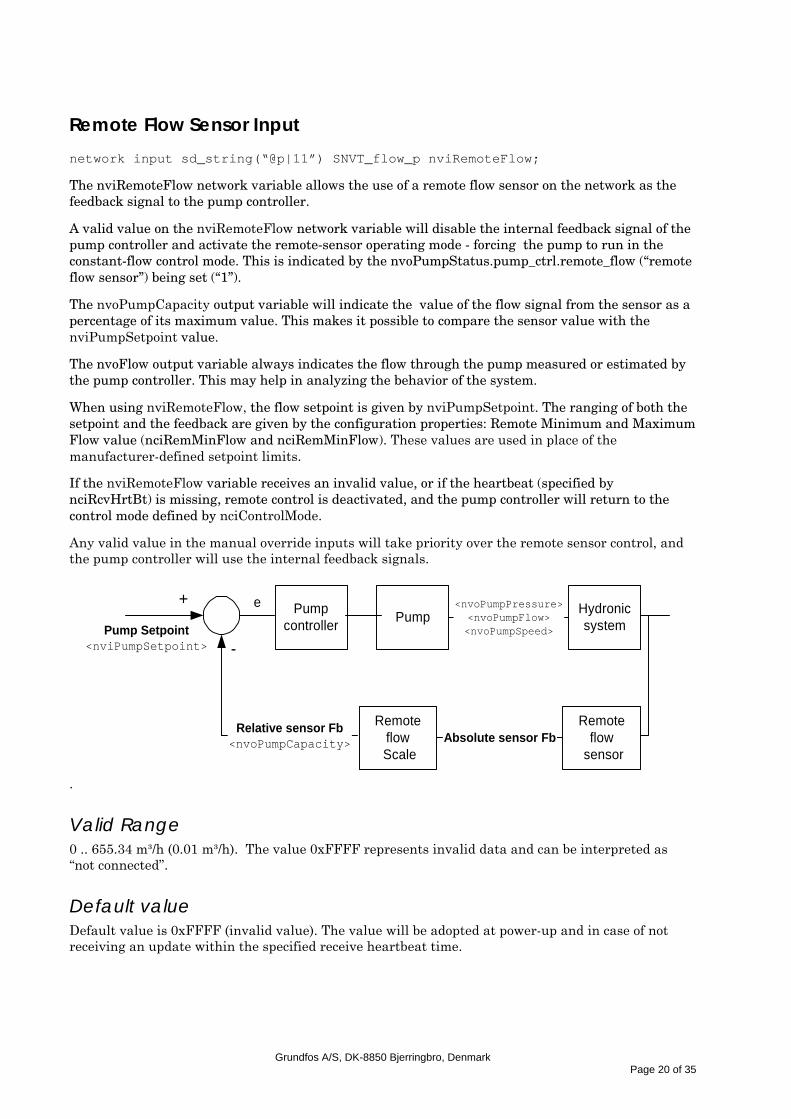
Remote Flow Sensor Input
network input sd_string(“@p|11”) SNVT_flow_p nviRemoteFlow;
The nviRemoteFlow network variable allows the use of a remote flow sensor on the network as the feedback signal to the pump controller.
A valid value on the nviRemoteFlow network variable will disable the internal feedback signal of the pump controller and activate the remote-sensor operating mode - forcing the pump to run in the constant-flow control mode. This is indicated by the nvoPumpStatus.pump_ctrl.remote_flow (“remote flow sensor”) being set (“1”).
The nvoPumpCapacity output variable will indicate the value of the flow signal from the sensor as a percentage of its maximum value. This makes it possible to compare the sensor value with the nviPumpSetpoint value.
The nvoFlow output variable always indicates the flow through the pump measured or estimated by the pump controller. This may help in analyzing the behavior of the system.
When using nviRemoteFlow, the flow setpoint is given by nviPumpSetpoint. The ranging of both the setpoint and the feedback are given by the configuration properties: Remote Minimum and Maximum Flow value (nciRemMinFlow and nciRemMinFlow). These values are used in place of the manufacturer-defined setpoint limits.
If the nviRemoteFlow variable receives an invalid value, or if the heartbeat (specified by nciRcvHrtBt) is missing, remote control is deactivated, and the pump controller will return to the control mode defined by nciControlMode.
Any valid value in the manual override inputs will take priority over the remote sensor control, and the pump controller will use the internal feedback signals.
Pump Setpoint<nviPumpSetpoint>
Pumpcontroller Pump
Remoteflow
Scale
<nvoPumpPressure><nvoPumpFlow><nvoPumpSpeed>
Absolute sensor FbRelative sensor Fb
<nvoPumpCapacity>
+
-
e Hydronicsystem
Remoteflow
sensor
.
Valid Range 0 .. 655.34 m³/h (0.01 m³/h). The value 0xFFFF represents invalid data and can be interpreted as “not connected”.
Default value Default value is 0xFFFF (invalid value). The value will be adopted at power-up and in case of not receiving an update within the specified receive heartbeat time.
Grundfos A/S, DK-8850 Bjerringbro, Denmark
Page 20 of 35

Pump status diagnostic information network output sd_string(“@p|13”) SNVT_dev_status nvoPumpStatus;
This output network variable provides detailed diagnostic information on the status of the pump controller.
Valid range
The valid range of SNVT_dev_status.pump_ctrl, excluding “reserved” fields:
Bit name Desciption
dev_type.pump_ctrl.device_fault (see nvoPumpFault for detailed information).
dev_type.pump_ctrl.supply_fault No electrical power, no fluid in pump, etc. –
see nvoPumpFault for detailed information.
dev_type.pump_ctrl.speed_low The pump is running at the lowest possible speed, therefore the requested performance is not possible.
dev_type.pump_ctrl.speed_high The pump is running at the highest possible speed, therefore the requested performance is not possible.
dev_type.pump_ctrl.setpt_out_of_range This bit is set if any of the manual override variables are out of range.
dev_type.pump_ctrl.local_control Hardware override (push buttons, external STOP or R100).
dev_type.pump_ctrl.running The pump is running.
dev_type.pump_ctrl.remote_press The pump is using network pressure sensor.
dev_type.pump_ctrl.remote_flow The pump is using network flow sensor.
dev_type.pump_ctrl.remote_temp Not supported for MAGNA-LON.
When transmitted
This value is transmitted immediately when its state has changed. Additionally, this network variable will also be transmitted as a heartbeat output on a regular basis as specified by the Maximum Send Time nciSndHrtBt configuration property.
Grundfos A/S, DK-8850 Bjerringbro, Denmark
Page 21 of 35

Pump pressure
network output sd_string(“@p|14”) SNVT_press nvoPressure;
This optional output network variable provides the pressure between the pump flanges as estimated or measured by the pump controller.
Valid range
-3,276.8 .. 3,276.7 kilo Pascal (0.1 kPa). The value 0x7FFF represents invalid data.
When transmitted
This value is transmitted immediately when its value has changed more than 2 KPa.
Pump flow
network output sd_string(“@p|15”) SNVT_flow_p nvoFlow;
This optional output network variable provides the flow through the pump as estimated or measured by the pump controller.
Valid range
0 .. 655,34 m³/h (0,01 m³/h The value 0xFFFF represents invalid data).
When transmitted
This value is transmitted immediately when its value has changed more than 0.3 m^3/h.
Pump speed
network output sd_string(“@p|16”) SNVT_rpm nvoSpeed;
This optional output network variable provides the speed of the pump.
Valid range
0 .. 65,534 revolutions/minute (1 RPM). The value 0xFFFF represents invalid data.
When transmitted
This value is transmitted immediately when its value has changed more than 107 rpm .
Grundfos A/S, DK-8850 Bjerringbro, Denmark
Page 22 of 35

Pump override active
network output sd_string(“@p|17”) SNVT_switch nvoPumpOverride
This optional output network variable provides the manual override status of the pump. The variable has the value “OVERRIDE”, if the pump setpoint has been overridden via one of the variables: nviOvdSpeed or nviOvdPress.
Valid range
State Value Equivalent percent Override status0 0 0 Normal1 200 100 OVERRIDE
0xFF n/a n/a invalid value
When transmitted
This value is transmitted immediately when its value has changed.
Runtime
network output sd_string(“@p|18”) SNVT_time_hour nvoRuntime;
This output network variable provides the total running time for the pump in hours. After 65535 hours the counter starts again from zero (0).
Valid range
The valid range is 0 .. 65535 hours (1 hour), ( 2730 days or 7.67 years).
When transmitted
This value is transmitted immediately when its value has changed.
Grundfos A/S, DK-8850 Bjerringbro, Denmark
Page 23 of 35
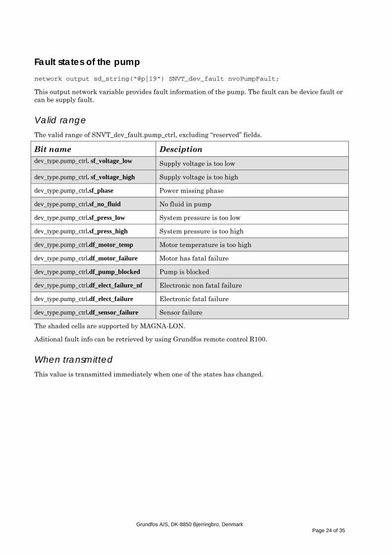
Fault states of the pump
network output sd_string(“@p|19”) SNVT_dev_fault nvoPumpFault;
This output network variable provides fault information of the pump. The fault can be device fault or can be supply fault.
Valid range
The valid range of SNVT_dev_fault.pump_ctrl, excluding “reserved” fields.
Bit name Desciption dev_type.pump_ctrl. sf_voltage_low Supply voltage is too low
dev_type.pump_ctrl. sf_voltage_high Supply voltage is too high
dev_type.pump_ctrl.sf_phase Power missing phase
dev_type.pump_ctrl.sf_no_fluid No fluid in pump
dev_type.pump_ctrl.sf_press_low System pressure is too low
dev_type.pump_ctrl.sf_press_high System pressure is too high
dev_type.pump_ctrl.df_motor_temp Motor temperature is too high
dev_type.pump_ctrl.df_motor_failure Motor has fatal failure
dev_type.pump_ctrl.df_pump_blocked Pump is blocked
dev_type.pump_ctrl.df_elect_failure_nf Electronic non fatal failure
dev_type.pump_ctrl.df_elect_failure Electronic fatal failure
dev_type.pump_ctrl.df_sensor_failure Sensor failure
The shaded cells are supported by MAGNA-LON.
Aditional fault info can be retrieved by using Grundfos remote control R100.
When transmitted
This value is transmitted immediately when one of the states has changed.
Grundfos A/S, DK-8850 Bjerringbro, Denmark
Page 24 of 35
Fluid temperature
network output sd_string(“@p|21”) SNVT_temp_p nvoFluidTemp;
This optional output network variable provides the temperature of the fluid in the pump.
Valid range
-273.17 .. +327.66 degrees C (0.01 degrees C). The value 0x7FFF represents invalid data.
When transmitted
This value is transmitted immediately when its value has changed more than 1 °C.
Power consumption in watts
network output sd_string(“@p|22”) SNVT_power nvoPower;
This optional output network variable provides the actual power being consumed by the pump.
Valid range
0 .. 6,553.5 Watts (0.1 W). The value 0xFFFF represents invalid data.
When transmitted
This value is transmitted immediately when its value has changed more than 2 W.
Energy consumption
network output sd_string(“@p|24”) SNVT_elec_kwh nvoEnergyConsum;
This optional output network variable provides the energy consumption of the pump from the beginning of its life. After 65,535 kWh the counter resets to 0 kWh.
Valid range
0 .. 65,535 kilo watt hour (1 kWh).
When transmitted
This value is transmitted immediately when its value has changed.
Grundfos A/S, DK-8850 Bjerringbro, Denmark
Page 25 of 35

Send heartbeat
network input config sd_string(“&2,i.j.k,0\x80,49”) SNVT_time_sec nciSndHrtBt;
This input configuration property sets the maximum period of time that expires before the functional block will automatically update the following network variables:
nv3, nvoPumpCapacity
nv4, nvoEffOpMode
nv5, nvoControlMode
nv13, nvoPumpStatus
Valid range
The valid range is 0.0 to 6,553.4 sec (0.1 sec)
A value of 6,553.5 is invalid and will disable the automatic update mechanism.
A value of zero (0) will be used for the internal timer in the case where the configured value is 6,553.5 seconds (0xFFFF). The value of zero (0) disables the Send Heartbeat mechanism.
Typical default value
The typical default value is 0.0 (no automatic update)
SCPT reference
SCPTmaxSendTime (49)
Location label
network input config sd_string(“&1,p,0\x80,17”) SNVT_str_asc nciLocation;
This configuration property can be used to provide the location of the functional block (or device).
Valid range
Any NULL terminated ASCII string of 31 bytes total length (including NULL).
Typical default value
The default value is an ASCII string containing all zeros ("\0").
SCPT reference SCPT_location (17)
Grundfos A/S, DK-8850 Bjerringbro, Denmark
Page 26 of 35

Receive Heartbeat
network input config sd_string(“&2,i.j.k,0\x80,48”) SNVT_time_sec nciSndHrtBt;
This input configuration property sets the maximum period of time that can elapse before the functional block will automatically use the default values for the following network variables:
nv10, nviRemotePress
nv11, nviRemoteFlow
Valid range
The valid range is 0.0 to 6,553.4 sec (0.1 sec)
A value of 6,553.5 is invalid and will disable the automatic update mechanism.
A value of zero (0) will be used for the internal timer in the case where the configured value is 6,553.5 seconds (0xFFFF). The value of zero (0) disables the Receive Heartbeat mechanism.
Typical default value
The typical default value is 0.0 (no automatic update)
SCPT reference
SCPTmaxRcvTime (48)
Control mode for normal operation
network input config sd_string(“&1,p,0\x80,238”) SNVT_dev_c_mode nciControlMode
This configuration property defines the device control mode to be used for the normal operating mode when a remote network pressure or flow sensor is not bound to the controller and the internal speed, pressure or flow feedback signal is used by the controller.
Refer to Effective Device Control Mode (nvoEffControlMode) for details of the control modes.
Valid range
The valid range is the same as that of nvoEffControlMode.
Typical default value The default control mode for a pump is DCM_PRESS_COMP (value=2).
SCPT reference
SCPTdeviceControlMode (238)
Grundfos A/S, DK-8850 Bjerringbro, Denmark
Page 27 of 35
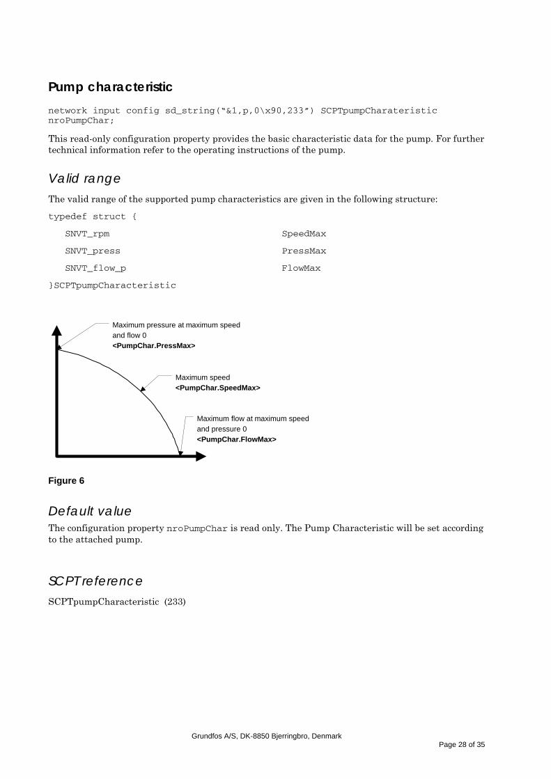
Pump characteristic
network input config sd_string(“&1,p,0\x90,233”) SCPTpumpCharateristic nroPumpChar;
This read-only configuration property provides the basic characteristic data for the pump. For further technical information refer to the operating instructions of the pump.
Valid range
The valid range of the supported pump characteristics are given in the following structure:
typedef struct {
SNVT_rpm SpeedMax
SNVT_press PressMax
SNVT_flow_p FlowMax
}SCPTpumpCharacteristic
Maximum pressure at maximum speedand flow 0<PumpChar.PressMax>
Maximum flow at maximum speedand pressure 0<PumpChar.FlowMax>
Maximum speed<PumpChar.SpeedMax>
Figure 6
Default value The configuration property nroPumpChar is read only. The Pump Characteristic will be set according to the attached pump.
SCPT reference
SCPTpumpCharacteristic (233)
Grundfos A/S, DK-8850 Bjerringbro, Denmark
Page 28 of 35

Remote Pressure-Sensor Minimum Value
network input config sd_string(“&2,i,0\x80,239”) SNVT_press nciRemMinPress;
This input configuration property provides the minimum value for ranging the remote pressure sensor. Together with nciRemMaxPress, these range values replace the normal setpoint limits when the remote sensor is used. See Remote Pressure-Sensor Input (nviRemotePress).
Valid range
-3,276.8 .. 3,276.7 kiloPascal (0.1 kPa). The value 0x7FFF represents invalid data.
Default value nciRemMinPress = 0x7FFF (invalid)
SCPT reference
SCPTminRemotePressureSetpoint (239)
Remote Pressure-Sensor Maximum Value
network input config sd_string(“&2,i,0\x80,240”) SNVT_press nciRemMaxPress;
This input configuration property provides the minimum value for ranging the remote pressure sensor. Together with nciRemMinPress, these range values replace the normal setpoint limits when the remote sensor is used. See Remote Pressure-Sensor Input (nviRemotePress).
Valid range
-3,276.8 .. 3,276.7 kiloPascal (0.1 kPa). The value 0x7FFF represents invalid data.
Default value nciRemMinPress = 0x7FFF (invalid)
SCPT reference
SCPTmaxRemotePressureSetpoint (240)
Grundfos A/S, DK-8850 Bjerringbro, Denmark
Page 29 of 35
Remote Flow-Sensor Minimum Value
network input config sd_string(“&2,i,0\x80,241”) SNVT_flow_p nciRemMinFlow;
This input configuration property provides the minimum value for ranging the remote flow sensor. Together with nciRemMaxFlow, these range values replace the normal setpoint limits when the remote sensor is used. See Remote Flow-Sensor Input (nviRemoteFlow).
Valid range
0 .. 655,34 m³/h (0,01 m³/h The value 0xFFFF represents invalid data).
Default value nciRemMinFlow = 0xFFFF (invalid)
SCPT reference
SCPTminRemoteFlowSetpoint (241)
Remote Flow-Sensor Maximum Value
network input config sd_string(“&2,i,0\x80,242”) SNVT_flow_p nciRemMaxFlow;
This input configuration property provides the maximum value for ranging the remote flow sensor. Together with nciRemMinFlow, these range values replace the normal setpoint limits when the remote sensor is used. See Remote Flow-Sensor Input (nviRemoteFlow).
Valid range
0 .. 655,34 m³/h (0,01 m³/h The value 0xFFFF represents invalid data).
Default value nciRemMaxFlow = 0xFFFF (invalid)
SCPT reference
SCPTmaxRemoteFlowSetpoint (242)
Grundfos A/S, DK-8850 Bjerringbro, Denmark
Page 30 of 35

Kp
network input config sd_string(“&2,i.j.k,0\x80,6”) SNVT_multiplier nciKp
This input configuration property defines the value of Kp in the PI regulator, used when an external flow or pressure sensor is connected.
Valid range
0 .. 25,4 (0.1 ). The value 0xFFFF represents invalid data.
Typical default value Default value is 0xFFFF (invalid value). The value will be adopted at power-up.
UCPT reference
UCPT_Kp (6)
Ti
network input config sd_string(“&2,i.j.k,0\x80,4”) SNVT_time_sec nciTi
This input configuration property defines the value of Ti in the PI regulator, used when an external flow or pressure sensor is connected.
Valid range The valid range is 0.0 to 6,553.4 sec (0.1 sec). The value 0xFFFF represents invalid data
Typical default value Default value is 0xFFFF (invalid value). The value will be adopted at power-up.
UCPT reference
UCPT_Ti (4)
Ts
network input config sd_string(“&2,i.j.k,0\x80,5”) SNVT_time_sec nciTs
This input configuration property defines the value of Ts in the PI regulator, used when an external flow or pressure sensor is connected.
Valid range The valid range is 0.0 to 6,553.4 sec (0.1 sec). The value 0xFFFF represents invalid data
Typical default value Default value is 0xFFFF (invalid value). The value will be adopted at power-up.
Grundfos A/S, DK-8850 Bjerringbro, Denmark
Page 31 of 35
UCPT reference
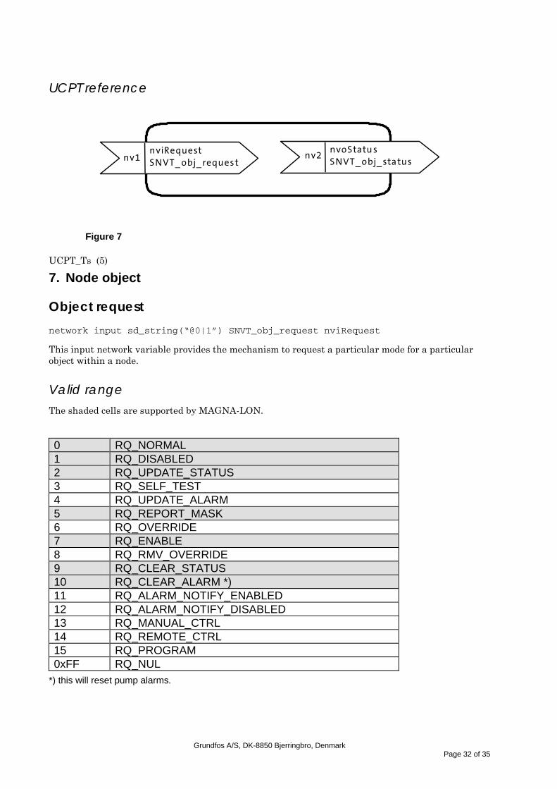
nv1 SNVT_obj_request nviRequest nv2
SNVT_obj_status nvoStatu s
Figure 7
UCPT_Ts (5)
7. Node object Object request
network input sd_string(“@0|1”) SNVT_obj_request nviRequest
This input network variable provides the mechanism to request a particular mode for a particular object within a node.
Valid range
The shaded cells are supported by MAGNA-LON.
0 RQ_NORMAL 1 RQ_DISABLED 2 RQ_UPDATE_STATUS 3 RQ_SELF_TEST 4 RQ_UPDATE_ALARM 5 RQ_REPORT_MASK 6 RQ_OVERRIDE 7 RQ_ENABLE 8 RQ_RMV_OVERRIDE 9 RQ_CLEAR_STATUS 10 RQ_CLEAR_ALARM *) 11 RQ_ALARM_NOTIFY_ENABLED 12 RQ_ALARM_NOTIFY_DISABLED 13 RQ_MANUAL_CTRL 14 RQ_REMOTE_CTRL 15 RQ_PROGRAM 0xFF RQ_NUL
*) this will reset pump alarms.
Grundfos A/S, DK-8850 Bjerringbro, Denmark
Page 32 of 35
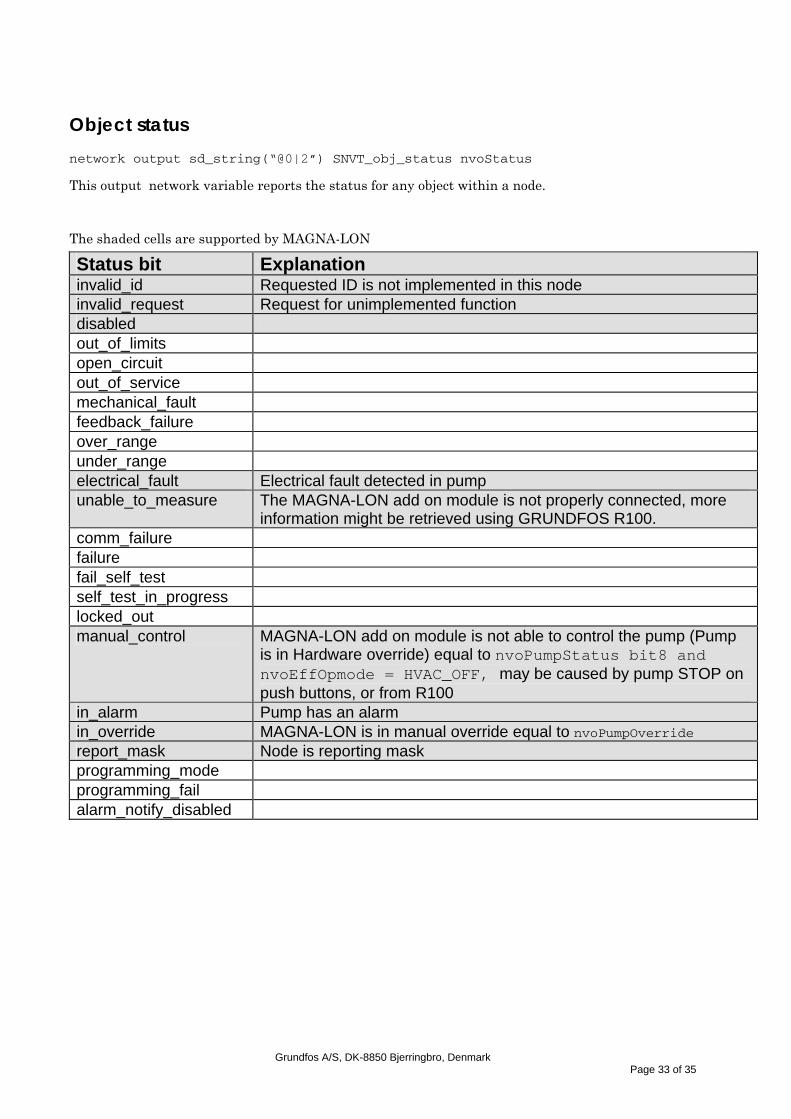
Object status
network output sd_string(“@0|2”) SNVT_obj_status nvoStatus
This output network variable reports the status for any object within a node.
The shaded cells are supported by MAGNA-LON
Status bit Explanation invalid_id Requested ID is not implemented in this node invalid_request Request for unimplemented function disabled out_of_limits open_circuit out_of_service mechanical_fault feedback_failure over_range under_range electrical_fault Electrical fault detected in pump unable_to_measure The MAGNA-LON add on module is not properly connected, more
information might be retrieved using GRUNDFOS R100. comm_failure failure fail_self_test self_test_in_progress locked_out manual_control MAGNA-LON add on module is not able to control the pump (Pump
is in Hardware override) equal to nvoPumpStatus bit8 and nvoEffOpmode = HVAC_OFF, may be caused by pump STOP on push buttons, or from R100
in_alarm Pump has an alarm in_override MAGNA-LON is in manual override equal to nvoPumpOverride report_mask Node is reporting mask programming_mode programming_fail alarm_notify_disabled
Grundfos A/S, DK-8850 Bjerringbro, Denmark
Page 33 of 35

8. Manufacture specific variables
Grundfos command
network input UNVT_GF_cmd nviGrundfosCmd
This manufacturer specific input network variable provides the mechanism to request a particular information string from Grundfos products. This string contains information about node software version and date, which can be used when downloading new software to the node. The result from this command can be seen in nvoGrundfosInfo.
Valid range 0 GF_NO_CMD no command 1 GF_PRODUCT_VER product version 2 GF_PRODUCT_INFO product_info 3 GF_SOFTWARE_VERSION the current software version 4 GF_SOFTWARE_DATE software date 5 GF_SOFTWARE_DEVELOPERS Initials for software developers Grundfos info
network output SNVT_str_asc nvoGrundfosInfo
This manufacturer specific output network variable provides the mechanism to get a information string from Grundfos products. This string contains information about node software version and date, which can be used when downloading new software to the node. This string is the result from nviGrundfosCmd.
Valid range
Any NULL terminated ASCII string of 31 bytes total length.
Grundfos A/S, DK-8850 Bjerringbro, Denmark
Page 34 of 35
9. Device resource files MAGNA-LON contains UNVTs and UCPT’s (User Network Variable Types), therefore Grundfos is supplying DRF (Device Resource Files). If the DRFs are used, the right formatting and type-definition will be achieved. The DRFs can be found on the same disk as this document. The files can be installed by copying the files to e.g. C:\LONWORKS\TYPES\USER\GRUNDFOS\ then use the program ldrfcat.exe to add the files. For further information about how to install DRFs please look in Echelon documentation. The following UNVTs and UCPTs are supported in the DRfiles: UNVT_dev_c_mode UNVT_flow_p UNVT_ManufSetLim UNVT_PumpChar UNVT_GF_cmd UCPT_Kp UCPT_Ts UCPT_Ti
Grundfos A/S, DK-8850 Bjerringbro, Denmark
Page 35 of 35

DenmarkGRUNDFOS DK A/S Poul Due Jensens Vej 7A DK-8850 Bjerringbro Tlf.: +45-87 50 50 50 Telefax: +45-87 50 51 51 E-mail: [email protected]/DK
ArgentinaBombas GRUNDFOS de Argentina S.A.Ruta Panamericana km. 37.500 Lote 34A1619 - GarinPcia. de Buenos AiresPhone: +54-3327 414 444Telefax: +54-3327 411 111
AustraliaGRUNDFOS Pumps Pty. Ltd. P.O. Box 2040 Regency Park South Australia 5942 Phone: +61-8-8461-4611 Telefax: +61-8-8340 0155
AustriaGRUNDFOS Pumpen Vertrieb Ges.m.b.H.Grundfosstraße 2 A-5082 Grödig/Salzburg Tel.: +43-6246-883-0 Telefax: +43-6246-883-30
BelgiumN.V. GRUNDFOS Bellux S.A. Boomsesteenweg 81-83 B-2630 Aartselaar Tél.: +32-3-870 7300 Télécopie: +32-3-870 7301
BrazilGRUNDFOS do Brasil Ltda.Rua Tomazina 106CEP 83325 - 040Pinhais - PRPhone: +55-41 668 3555Telefax: +55-41 668 3554
CanadaGRUNDFOS Canada Inc. 2941 Brighton Road Oakville, Ontario L6H 6C9 Phone: +1-905 829 9533 Telefax: +1-905 829 9512
ChinaGRUNDFOS Pumps (Shanghai) Co. Ltd.22 Floor, Xin Hua Lian Building755-775 Huai Hai Rd, (M)Shanghai 200020PRCPhone: +86-512-67 61 11 80Telefax: +86-512-67 61 81 67
Czech RepublicGRUNDFOS s.r.o.Cajkovského 21779 00 OlomoucPhone: +420-585-716 111Telefax: +420-585-438 906
FinlandOY GRUNDFOS Pumput AB Mestarintie 11 PiispankyläFIN-01730 Vantaa (Helsinki) Phone: +358-9 878 9150 Telefax: +358-9 878 91550
FrancePompes GRUNDFOS Distribution S.A. Parc d’Activités de Chesnes 57, rue de Malacombe F-38290 St. Quentin Fallavier (Lyon) Tél.: +33-4 74 82 15 15 Télécopie: +33-4 74 94 10 51
GermanyGRUNDFOS GMBHSchlüterstr. 3340699 ErkrathTel.: +49-(0) 211 929 69-0 Telefax: +49-(0) 211 929 69-3799e-mail: [email protected] in Deutschland:e-mail: [email protected]
GreeceGRUNDFOS Hellas A.E.B.E. 20th km. Athinon-Markopoulou Av. P.O. Box 71 GR-19002 Peania Phone: +0030-210-66 83 400 Telefax: +0030-210-66 46 273
Hong KongGRUNDFOS Pumps (Hong Kong) Ltd. Unit 1, Ground floor Siu Wai Industrial Centre 29-33 Wing Hong Street & 68 King Lam Street, Cheung Sha Wan Kowloon Phone: +852-27861706/27861741 Telefax: +852-27858664
HungaryGRUNDFOS Hungária Kft.Park u. 8H-2045 Törökbálint, Phone: +36-23 511 110Telefax: +36-23 511 111
IndiaGRUNDFOS Pumps India Private LimitedFlat A, Ground Floor61/62 Chamiers AptmtChamiers RoadChennai 600 028Phone: +91-44 432 3487Telefax: +91-44 432 3489
IndonesiaPT GRUNDFOS Pompa Jl. Rawa Sumur III, Blok III/CC-1 Kawasan Industri, Pulogadung Jakarta 13930 Phone: +62-21-460 6909 Telefax: +62-21-460 6910/460 6901
IrelandGRUNDFOS (Ireland) Ltd. Unit 34, Stillorgan Industrial Park Blackrock County Dublin Phone: +353-1-2954926 Telefax: +353-1-2954739
ItalyGRUNDFOS Pompe Italia S.r.l. Via Gran Sasso 4I-20060 Truccazzano (Milano)Tel.: +39-02-95838112 Telefax: +39-02-95309290/95838461
JapanGRUNDFOS Pumps K.K.1-2-3, Shin MiyakodaHamamatsu CityShizuoka pref. 431-21Phone: +81-53-428 4760Telefax: +81-53-484 1014
KoreaGRUNDFOS Pumps Korea Ltd.6th Floor, Aju Building 679-5 Yeoksam-dong, Kangnam-ku, 135-916Seoul Korea Phone: +82-2-5317 600Telefax: +82-2-5633 725
MalaysiaGRUNDFOS Pumps Sdn. Bhd.7 Jalan Peguam U1/25Glenmarie Industrial Park40150 Shah AlamSelangor Phone: +60-3-5569 2922Telefax: +60-3-5569 2866
MexicoBombas GRUNDFOS de Mexico S.A. de C.V. Boulevard TLC No. 15Parque Industrial Stiva AeropuertoApodaca, N.L. 66600Mexico Phone: +52-81-8144 4000 Telefax: +52-81-8144 4010
NetherlandsGRUNDFOS Nederland B.V. Postbus 104 NL-1380 AC Weesp Tel.: +31-294-492 211 Telefax: +31-294-492244/492299
New ZealandGRUNDFOS Pumps NZ Ltd.17 Beatrice Tinsley CrescentNorth Harbour Industrial EstateAlbany, AucklandPhone: +64-9-415 3240Telefax: +64-9-415 3250
NorwayGRUNDFOS Pumper A/S Strømsveien 344 Postboks 235, Leirdal N-1011 Oslo Tlf.: +47-22 90 47 00 Telefax: +47-22 32 21 50
PolandGRUNDFOS Pompy Sp. z o.o. ul. Klonowa 23Baranowo k. PoznaniaPL-62-081 PrzezmierowoPhone: +48-61-650 13 00Telefax: +48-61-650 13 50
PortugalBombas GRUNDFOS Portugal, S.A. Rua Calvet de Magalhães, 241Apartado 1079P-2770-153 Paço de ArcosTel.: +351-21-440 76 00Telefax: +351-21-440 76 90
RussiaOOO GRUNDFOSShkolnaya 39RUS-109544 MoscowPhone: +7-095 564 88 00, +7-095 737 30 00Telefax: +7-095 564 88 11, +7-095 737 75 36e-mail: [email protected]
SingaporeGRUNDFOS (Singapore) Pte. Ltd. 24 Tuas West Road Jurong Town Singapore 638381 Phone: +65-6865 1222 Telefax: +65-6861 8402
SpainBombas GRUNDFOS España S.A. Camino de la Fuentecilla, s/n E-28110 Algete (Madrid) Tel.: +34-91-848 8800 Telefax: +34-91-628 0465
SwedenGRUNDFOS AB Box 63, Angeredsvinkeln 9 S-424 22 Angered Tel.: +46-771-32 23 00 Telefax: +46-31 331 94 60
SwitzerlandGRUNDFOS Pumpen AG Bruggacherstrasse 10 CH-8117 Fällanden/ZH Tel.: +41-1-806 8111 Telefax: +41-1-806 8115
TaiwanGRUNDFOS Pumps (Taiwan) Ltd. 14, Min-Yu Road Tunglo Industrial Park Tunglo, Miao-Li County Taiwan, R.O.C. Phone: +886-37-98 05 57Telefax: +886-37-98 05 70
ThailandGRUNDFOS (Thailand) Ltd. 947/168 Moo 12, Bangna-Trad Rd., K.M. 3,Bangna, PhrakanongBangkok 10260 Phone: +66-2-744 1785 ... 91Telefax: +66-2-744 1775 ... 6
TurkeyGRUNDFOS POMPA SAN. ve TIC. LTD. STIBulgurlu Caddesi no. 32 TR-81190 Üsküdar IstanbulPhone: +90 - 216-4280 306Telefax: +90 - 216-3279 988
United Arab EmiratesGRUNDFOS Gulf DistributionP.O. Box 16768Jebel Ali Free ZoneDubaiPhone: +971-4- 8815 166Telefax: +971-4-8815 136
United KingdomGRUNDFOS Pumps Ltd. Grovebury Road Leighton Buzzard/Beds. LU7 8TL Phone: +44-1525-850000 Telefax: +44-1525-850011
U.S.A.GRUNDFOS Pumps Corporation 17100 West 118th TerraceOlathe, Kansas 66061Phone: +1-913-227-3400 Telefax: +1-913-227-3500
Addresses revised 12.08.2004

www.grundfos.com
Being responsible is our foundationThinking ahead makes it possible
Innovation is the essence
60 15 26 0904 GBRepl. 60 15 26 1103