Embed Size (px)
Citation preview

日本語
ENG
LISH
取扱説明書 / Instruction Manual
LONWORKS®インタフェースカード
LONWORKS® Interface Card "OPC-LNW"
Fuji Electric Co., Ltd. INR-SI47-1705-JE

Copyright © 2013 Fuji Electric Co., Ltd. All rights reserved. No part of this publication may be reproduced or copied without prior written permission from Fuji Electric Co., Ltd.
LONWORKS, LonTalk, and LonMaker are registered trademarks of Echelon Corporation in the United States. All other product and company names mentioned in this manual are trademarks or registered trademarks of their respective holders.
The information contained herein is subject to change without prior notice for improvement.
この取扱説明書の著作権は,富士電機株式会社にあります。この取扱説明書の一部または全部を無断で複製・転
載することはお断りします。
LONWORKS, LonTalk, および LonMaker は,米国 Echelon の登録商標です。本書に掲載されているその他の会社名
や製品名は,一般に各社の商標または登録商標です。
この説明書の内容は将来予告なしに変更することがあります。

日本語
日本語版


1
日本語
まえがき
LONWORKS インタフェースカード「OPC-LNW」をお買上げいただきましてありがとうございます。
このインタフェースカードを当社インバータに取付けることで,各種の LONWORKS 機器から, LONWORKS のパラメー
タを使って運転指令・速度指令や運転状況のモニタ, そしてインバータの設定の変更・参照を行うことができま
す。またインバータの全機能コードの変更・参照が可能となります。
この取扱説明書にはインバータに関する取扱い方の記載はありませんので,ご使用の前には,この説明書とイン
バータ本体の取扱説明書をお読みになって取扱い方を理解し,正しくご使用ください。間違った取扱いは,正常
な運転を妨げ,寿命の低下や故障の原因になります。
取扱説明書はご使用後も大切に保管してください。
関連資料
OPC-LNW に関連する資料を以下に示します。目的に応じてご利用ください。
・ RS-485 通信ユーザーズマニュアル
・ インバータの取扱説明書
資料は随時改訂していますので,ご使用の際には最新版の資料を入手してください。
この取扱説明書に記載している図,端子の有無,機能コード,アラームコード等は対象インバータによって異な
る場合があります。
本書の構成
本書の構成は,以下のとおりです。
第 1章 特徴 LONWORKS インタフェースカードの主な特徴を説明します。
第 2章 製品の確認 開梱時に行う点検や製品の運搬および保管の注意事項,インタフェースカードの外観および XIF ファイル, 専用
プラグインの入手方法について説明します。
第 3章 各部の機能 サービスボタンおよび LED インジケータについて説明します。
第 4章 取付けと取外し 取付け手順,取付け上の注意事項などについて説明します。
第 5章 配線 本インタフェースカードの基本接続図,端子台配置,LONWORKS ケーブルの仕様および配線方法について説明しま
す。
第 6章 必要なインバータ機能コード設定 LONWORKS から運転指令および周波数指令を行うために必要なインバータ機能コードの設定について説明します。
その他に, 関連するインバータ機能コードについても説明します。
第 7章 オブジェクトの詳細 本インタフェースカードがサポートしているオブジェクトと, そのネットワーク変数(NV)および構成プロパティ
(CP)について説明します。
第 8章 LONWORKS 通信異常時の動作 LONWORKS 通信異常時の動作の詳細について説明します。
第 9章 トラブルシューティング インバータが指示どおり動作しない場合やアラーム状態になった場合に行うトラブルシューティングについて
説明します。
第 10 章 仕様 一般仕様および通信仕様について記載しています。

2
アイコンについて
本書では以下のアイコンを使用しています。
この表示を無視して誤った取扱いをすると,本製品が本来持つ性能を発揮できなかったり,その操作や
設定が事故につながることになります。
本製品の操作や設定の際,知っておくと便利な参考事項を示しています。
参照先を示します。
目次
まえがき .................................. 1 本書の構成 .................................. 1
第 1 章 特徴 ................................ 3 第 2章 製品の確認 .......................... 3 第 3章 各部の機能 .......................... 4
3.1 サービスボタン....................... 4 3.2 LED.................................. 4 3.3 端子台............................... 4 3.4 バーコードシール..................... 4
第 4章 取付けと取外し ...................... 5 4.1 インタフェースカードの取付け......... 5 4.2 インタフェースカードの取外し......... 6
第 5章 配線 ................................ 7 5.1 基本接続図........................... 7 5.2 端子台の配線......................... 7 5.3 インバータへの配線................... 9
第 6章 必要なインバータ機能コード設定 ..... 10
第 7章 オブジェクトの詳細................. 12 7.1 概要 ............................... 12 7.2 ノードオブジェクト ................. 12 7.3 VSD オブジェクト概要................ 14 7.4 VSD 入力ネットワーク変数............ 20 7.5 VSD 出力ネットワーク変数............ 24 7.6 インバータ機能コードの読出しおよび
書込み方法 ........................ 29 7.7 VSD オブジェクトの構成プロパティ(CP) 32
第 8章 LONWORKS 通信異常時の動作 .......... 34 8.1 LONWORKS 通信異常時の動作設定....... 34
第 9章 トラブルシューティング............. 35 第 10章 仕様.............................. 36
10.1 一般仕様 .......................... 36 10.2 通信仕様 .......................... 36

3
日本語
第 1 章 特徴
LONWORKS インタフェースカードの特徴を以下に示します。
- 通信速度 : 78Kbps
- プロファイル : Variable Speed Motor Drive functional profile Ver1.1 準拠
- 通信トポロジー : フリートポロジー(バス型, スター型, ループ型, 混合型)
- ネットワーク変数 : 総数 62 個
- インバータが持つ全機能コードを読み書き可能
重要:本インタフェースカードをコミッションした後は, 必ずインバータの電源を再起動するか,
ネットワーク管理ツール(例:LonMaker)から Reset を行ってください。これを行うまで, 本イン
タフェースカードの NVおよび CP の変更がインバータに反映されません。
第 2 章 製品の確認
次の項目を確認してください。
(1) LONWORKS インタフェースカードが入っていることを確認してください。
(2) カード上の部品の破損,凹み,反りなど輸送時での破損がないことを確認してください。
(3) カード上に形式「OPC-LNW」が印刷されていることを確認してください。(図 2-1)
(4) カード上にバーコードシールが貼付けてあることを確認してください(図 2-2)。また貼付け前のバーコード
シールが製品に 1枚同梱されていることを確認してください。
製品にご不審な点や不具合などございましたら,お買上げ店または 寄りの弊社営業所までご連絡ください。
・対象インバータおよび ROM バージョンについては、インバータのユーザーズマニュアルを確認して
ください。
・本カードには XIF ファイル, リソースファイルは付属していません。
上記のファイルは次の Web サイトにてダウンロード可能です。(会員登録が必要(無料))
技術情報ページ https://felib.fujielectric.co.jp/download/
・ネットワーク管理ツールは付属していません。別途、ご手配ください。管理ツールには Echelon 社
の LonMaker を推奨します。
・バーコードにはニューロンIDを記載してあります。バーコード規格は CODE-39 フォーマットです。
図 2-1 カード表面 図 2-2 カード裏面
LED (状態表示 インジケータ)
LONWORKS 端子台 CN1サービスボタン
形式
バーコードシール (ニューロン ID)

4
第 3 章 各部の機能
3.1 サービスボタン
ネットワークへコミッション時に本ボタンを押下します。押すとニューロン IDがネットワークへ出力されます。
インバータ機能コード o30 を 1 に設定することで, サービスボタンを押すのと同様の動作が可能です。
この方法ですとタッチパネルから操作ができるため, インバータのカバーを取り外す必要もなく安全で
便利です。
サービスボタンを押す時は, インバータの高圧部に触れないように十分に注意してください。インバータ機能
コード o30 を 1にすることでも同等の動作が行えます。安全ですので, こちらを推奨いたします。
感電のおそれあり
3.2 LED
本インタフェースカードの状態を示します。インジケータ LED は次の 4種類あります。
表 3-1 LED の状態
名称 色 内容 備考
POWER 緑 正常 ―
緑点滅 電源投入時の自己診断および初期化中 約 0.5s 間実施
赤点滅 LONWORKS 通信異常 インバータに er5 発生*1
赤 ハードウェア異常
(インタフェースカード取付け不良または故障) インバータに er4 発生
COMM 緑 LONWORKS 通信イベント発生 *2 ケーブル未接続状態でも出力NV値の変化が発生するとLED が点灯します。
WINK 緑点滅 WINK メッセージ受信 6 回点滅
SERVICE 緑 サービスボタン押下状態 ―
緑点滅 未構成状態 未コミッション状態等
消灯 構成済状態 コミッション済状態等
*1 er5 を無視するように設定することも可能です。第 8 章「8.1 LONWORKS 通信異常時の動作設定」を参照し
てください。
*2 電源 ON 後, 本インタフェースカードのイニシャルが完了した時点で, ネットワークにインバータの 新情報
を伝えるため,本インタフェースカードの持つ全ての出力ネットワーク変数を出力するイベントが発生します。
このイベントは, ケーブルの接続有無や, バインドおよびコミッション有無に関わらず発生しますので, そ
のような時でも COMM LED は点灯します。なお, このイベントによって出力ネットワーク変数が値を出力する
までの時間を, VSD オブジェクトの UCPT_SendDelayAfterDevRdy で調整することが可能です。
UCPT_SendDelayAfterDevRdy についての詳細は,第 7 章「7.3(3)構成プロパティ(CP)の説明」を参照し
てください。
3.3 端子台
LONWORKS 通信用端子台とアース端子台があります。
配線方法については,第 5章「配線」を参照してください。
3.4 バーコードシール
インタフェースカードに実装されているニューロンチップのニューロン ID が番号とバーコードで表記してありま
す。バーコード規格は CODE-39 フォーマットです。また,ネットワーク図面等に貼付け用として未使用のバーコ
ードシールを 1枚同梱しております。

5
日本語
第 4 章 取付けと取外し
取付け・配線は電源を遮断して 10 分以上経過してから行ってください。更に LED モニタおよびチャージラン
プの消灯を確認し,テスターなどを使用して主回路端子 P(+)-N(-)間の直流中間回路電圧が安全な値(DC+25V
以下)に下がっていることを確認してから行ってください。
感電のおそれあり
・ 外部あるいは内部部品が損傷・脱落している製品を使用しないでください。
火災,事故,けがのおそれあり
・ 糸くず,紙,木くず,ほこり,金属くずなどの異物がインバータやインタフェースカード内に侵入するのを防止してください。
火災,事故のおそれあり
・ 製品の取付け,取外し時に不適切な作業を行うと,製品が破損するおそれがあります。
故障のおそれあり
4.1 インタフェースカードの取付け
インバータ本体の主回路端子および制御回路端子の配線は,インタフェースカードを取り付ける前に
行ってください。
(1) インバータ本体のカバーを取り外し,制御プリント基板を露出してください。インタフェースカードは,イ
ンバータ本体のオプション接続ポートに取付け可能です。
インタフェースカードの接続ポートについては、インバータのユーザーズマニュアルを確認してくだ
さい。
インバータ取扱説明書の「配線」を参照してカバーを取り外してください。
(2) インタフェースカードの裏面(図 2-2)の CN1 を,インバータ本体の制御プリント基板の接続ポートへ差し
込み,付属ねじで固定してください。(図 4-2)
インタフェースカードの取付け位置決め部(図 4-1)がツメ(図 4-1 の①)にセットされ,CN1(図
4-1 の②)が確実に差し込まれていることを確認してください。図 4-2 は取付け完了を示します。
(3) インタフェースカードの配線を行います。
配線方法については,第 5章「配線」を参照してください。
(4) インバータ本体のカバーを元に戻してください。
インバータ取扱説明書の「配線」を参照してカバーを取り付けてください。

6
① インタフェースカードをツメに引っ掛けるよう
にしながらインバータ本体へ位置決めする。
② コネクタ CN1 をインバータ本体へ挿入する。
注: 先にコネクタ側を挿入した場合,挿入が不十分で
接触不良となる可能性があります。
図 4-1 インタフェースカードの取付け(FRENIC-HVAC の A-port への取付け時)
図 4-2 取付け完了(FRENIC-HVAC の A-port への取付け時)
4.2 インタフェースカードの取外し
インタフェースカードを取り外す際は,ねじ 2ヶ所を外し,取外し用つまみ(図 4-2)を引っぱって取り外してください。
①
②
付属ねじで固定
ツメ
取外し用つまみ

7
日本語
第 5 章 配線
5.1 基本接続図
L1/R U
V
W
L2/S
L3/T
インバータ
OPC-LNW
NET_A
SHELDLont通信ケーブル
TERM1
Motor
G
M
1
2
3 NET_B
G G
LON トランス
LON トランシーバ
CPU
* インタフェースカードを取り付けると,zG に接続されます。
図 5-1 基本接続図
5.2 端子台の配線
(1) LONWORKS ケーブルは LONMARK 推奨のシールド付きツイストペアケーブルを使用してください。
推奨ケーブルは,昭和電線製 形式 LW161S です。
配線に関する詳細は Echelon 社発行の「FT3120/FT3150 Smart Transceiver Data Book」を参照してく
ださい。Echelon 社の Web サイトから無料でダウンロード可能です。
URL: https://www.echelon.com/support/documentation/manuals/transceivers/005-0139-01D.pdf

8
(2) LONWORKS 端子台コネクタ(TERM1)の配線
着脱可能な 3ピン端子台を使用しています(図 5-2)。端子台のピン配置は表 5-1 のとおりです。
適合する端子台コネクタはフェニックスコンタクト製 MVSTBR2.5/3-ST-5.08 です。
3 2 1
電線 約 7mm
図 5-2 LONWORKS 端子台コネクタと推奨被覆むきサイズ
表 5-1 端子台のピン配置
端子番号 端子名称 説明
1 SD 通信シールド
2 NET A 通信線
3 NET B 通信線
端子台のねじサイズおよび推奨締め付けトルクについては以下を参照してください。
ねじサイズ M3
締め付けトルク 0.5~0.6 [N・m]
通信線は無極性で, ケーブルの 2線がそれぞれ NET A と NET B に接続してあれば通信可能です。
どちらが NET A, NET B でも通信に問題はありません。また, 他のノードとの間で配線がクロスし
ていても問題はありません。
(3) 終端抵抗について
フリートポロジー接続の場合, 1 セグメントあたり 1個の終端抵抗が必要となります。
終端抵抗は本製品に付属していません。別途抵抗をご用意ください。推奨は Echelon 製 TP/FT-10
Channel Terminator Model No.44100 です。自作される場合は, 下記の RC 回路をご使用ください。
R
C1
C2
+
+
NET A
NET B
図 5-3 終端抵抗の回路図
R : 52.3Ω±1%, 1/8W
C1, C2 : 100uF, 50V(min)耐圧

9
日本語
5.3 インバータへの配線
LONWORKS ケーブルの配線は,主回路の配線とは可能な限り離して配線してください。ノイズによる誤
動作の要因となります。
配線は,制御プリント基板上を極力這わないように配線してください。誤動作の原因になることがあ
ります。
* LONWORKS インタフェースカードの配線は,インバータ本体の 制御端子台上部と表面カバーの間を通してください。
FRENIC-HVAC 7.5kW の例
FRENIC-HVAC 22kW の例
図 5-4 配線例

10
第 6 章 必要なインバータ機能コード設定
LONWORKS から運転指令, 周波数指令および nviXcmd_1~5 の指令を行うにあたり, インバータの機能コードの設
定が必要です。表 6-1 に一覧を示します。
また, 特定の NV を有効にするために必要なインバータ機能コード設定を表 6-2, その他関連するインバータ機能
コードを表 6-3 に示します。
インバータ機能コードの詳細については, インバータのユーザーズマニュアルおよび「RS-485 通信ユ
ーザーズマニュアル(MHT271)」の第 5章「機能コードとデータフォーマット」を参照してください。
下記のインバータ機能コードの設定をしなくても LONWORKS 通信自体は可能です。下表の設定は
LONWORKS のコミッションの前に行っても, 後に行ってもどちらでもかまいません。
重要 本インタフェースカードをコミッションした後は, 必ずインバータの電源を再起動するか,
ネットワーク管理ツールから Reset を行ってください。(Online にするだけでは正常に動作しませ
ん)。これを行うまで, 本インタフェースカードの NV, CP がインバータに反映されません。
表 6-1 LONWORKS から運転・周波数指令・nviXcmd1~5 を有効にするために必須な機能コード設定
機能コード 説明 工場出荷値 設定変更値 備考
y98 LONWORKS からの運転・周波数指令 0 3 UCPT_LinkFunc を設定することでも同様
y99 ローダからの運転・周波数指令 0 0 工場出荷値から変更不要
E01~E09 X1~X9 端子の機能選択 対象のインバータによって異なります。
下記以外に設定
24, 1024([LE]選択)
35, 1035([LOC]選択)
- [LE]選択時でも物理的端子を ONすれば問題なし。
- [LOC]選択時でも物理的端子を OFF すれば問題なし。
E98 FWD 端子の機能選択 98 98 工場出荷値から変更不要
下記の特定の NV を有効にするためには, 表 6-1 以外に表 6-2 の変更も行ってください。
表 6-2 特定の NV を有効にするために必要な機能コード設定
有効とする NV 機能コード 説明 工場出荷値 設定変更値
nviAOcmd F31, F35 FM1, FM2 または FMA, FMP 端子機能選択
0, 0 10 (ユニバーサル AO)
nviDOcmd_Y1, Y2 E20, E21 Y1, Y2 端子機能選択 0, 1 27 (ユニバーサル DO)
ネットワーク変数(NV)の詳細につきましては, 表 7-4「VSD オブジェクトの変数説明」を参照してく
ださい。
機能コードとインバータ汎用入力端子の数は対象のインバータによって異なります。

11
日本語
その他関連する機能コードを表 6-3 に示します。
表 6-3 その他関連機能コード
機能コード 説明 工場出荷値 設定範囲 備考
o27*1 LONWORKS 通信異常発生時の動作選択 0 0~15 UCPT_CblLossMode でも設定
可能。
o28*1 LONWORKS 通信異常発生時の動作タイマー
0.0s 0.0s~60.0s UCPT_CblLossTimer でも設定
可能。
o30 サービスボタン同等機能 0 0~255 o30=1 以上でサービスボタン押下状態となります。 o30 変更後, 自動的に 0クリアされます。
W90 LONWORKS インタフェースカードソフトバージョン
インタフェースカードによる
-(モニタ専用) 10 進 4 桁表示 例: Ver1.42の場合0142と表示されます。
W95 インタフェースカード-インバータ間通信エラー回数
0 -(モニタ専用)
W96 インタフェースカード-インバータ間通信エラー内容 (伝送エラーのみ*2)
0 -(モニタ専用) 後に発生した通信エラーの内容。エラーコードは富士汎用インバータプロトコルと同様。*3
*1 o27, o28 についての詳細は第 8章「8.1 LONWORKS 通信異常時の動作設定」を参照してください。
*2 伝送エラー以外の論理エラーについては, VSD オブジェクトの nv34 nvoAccessErrCode に反映されます。コ
ード内容詳細に関しては第 7章「7.6 (2)インバータ機能コードの書込み」を参照してください。
*3 エラーコード詳細については,「RS-485 通信ユーザーズマニュアル(MHT271)」の第 4章「4.3 通信エラー」
を参照してください。

12
第 7 章 オブジェクトの詳細
7.1 概要
本インタフェースカードはノードオブジェクトと Variable Speed Motor Drive オブジェクト(以下, VSD オブジ
ェクト)の 2つをサポートしています。以降にそれぞれのオブジェクトについて説明します。
7.2 ノードオブジェクト
(1) ノードオブジェクト概要
本インタフェースカードのシステム的な処理を行います。(通常, ユーザおよびインテグレータが意識的に使
用する必要はありません。)
Node Object #0
nv2 nvoStatus SNVT_obj_status nv1 nviRequest
SNVT_obj_request
nv8 nvoFileDirectory SNVT_adress
図 7-1 ノードオブジェクト外観
(2) ネットワーク変数(NV)一覧
表 7-1 に変数の一覧を示します。
表 7-1 ノードオブジェクトの変数一覧
Index 名称 変数型 説明
nv1 nviRequest SNVT_obj_request 各 Object に対して,個々のモード設定を行う。 サポートする Request: - RQ_NORMAL(0) - RQ_ENABLED(7) - RQ_DISABLED(1) - RQ_UPDATE_STATUS(2) - RQ_REPORT_MASK(5) - RQ_CLEAR_ALARM(10)
nv2 nvoStatus SNVT_obj_status 各 object の状態をモニタする。 サポートする Status: - object_id - invalid_id - invalid_request - disabled - in_alarm - report_mask
nv8 nvoFileDirectory SNVT_address Configuration file が入っている Directory のスタートアドレスを示す。

13
日本語
(3) ネットワーク変数詳細説明
i) nviRequest
表 7-2 に nviRequest の各モードに対する応答一覧を示します。
表 7-2 nviRequest の応答一覧
Request ノードオブジェクトの応答 VSD オブジェクトの応答
RQ_NORMAL(0) - object と NV を通常モード(イネーブル)にする
- nvoStatus を更新し出力
- object と NV を通常モード(イネーブル)にする
- nvoStatus を更新し出力
RQ_ENABLE(7) 同上 同上
RQ_DISABLE(1) - 運転中ならば,モータ停止
- Node Object はイネーブルのまま
- nvoStatus を更新し出力
- 運転中ならば,モータ停止
- VSD Object は無効となる。NV の入力は無視,出力は送信禁止
- nvoStatus を更新し出力
RQ_UPDATE_STATUS(2) - nvoStatus を更新し出力 - nvoStatus を更新し出力
RQ_REPORT_MASK(5) - サポートしている機能を 1として応答
- nvoStatus を更新し出力
- サポートしている機能を 1として応答
RQ_CLEAR_ALARM(10) - アラームリセット
- nvoStatus を更新し出力
- アラームリセット
- nvoStatus を更新し出力
上記以外の Request - Invalid request 応答
- nvoStatus を更新し出力
- Invalid request 応答
- nvoStatus を更新し出力
上記以外の objectID - Invalid request 応答
- nvoStatus を更新し出力
- Invalid request 応答
- nvoStatus を更新し出力
ii) nvoStatus
表 7-3 にサポートする Status の説明を示します。
表 7-3 nvoStatus 一覧
Status 説明
object_id リクエスト時に指定した Object ID を返す。
invalid_id 不正な Object ID に対して Request があった場合に 1となる。
invalid_request Invalid request 応答時に 1 となる。
disabled VSD object が Disable 状態である時に 1 となる。
in_alarm インバータがアラーム中あるいはアラーム未解除時に 1 となる。
report_mask サポートする Status を 1 とする。
(4) 構成プロパティ(CP)
ノードオブジェクト用の CPはサポートしていません。

14
7.3 VSD オブジェクト概要
(1) VSD オブジェクト概要
インバータの制御・状態のモニタを行います。図中の変数名の末尾に書かれている( )内は, その変数に連動
して変化するインバータ機能コードを示しています。
( )内に示したインバータ機能コードの詳細につきましては, 「RS-485 通信ユーザーズマニュアル
(MHT271)」の第 5章「機能コードとデータフォーマット」を参照してください。
VSD object #1
nv1 nviDrvSpeedStpt (mandatory)
nv4 nvoDrvSpeed (mandatory)
FUJI original NVs
nv3 nvoDrvCurnt (M11)
nv5 nvoDrvVolt (M12)
nv6 nvoDrvPwr (M10)
nv7 nvoDrvRunHours (Z40)
…
nv2 nviDrvSpeedScale
nv9 nviFreqCmd (S05) nv23 nvoDrvStatus (M14)
nv24 nvoOutputFreq (M09)
nv25 nvoDrvTorque (M07)
nv26 nvoDrvEnergy (W81)
nv27 nvoDrvOpeHours (W70)
nv28 nvoOpeTm_1 (W67)
nv29 nvoOpeTm_2 (W68)
nv30 nvoDCbusCapacity (W75)
nv31 nvoDrvTemp_1 (M61)
nv32 nvoDrvTemp_2 (M62)
nv33 nvoReadParamVal
nv34 nvoAccessErrCode
nv35 nvoAIVal_1 (M49)
nv36 nvoAIVal_2 (M50)
nv37 nvoAIVal_3 (M54)
nv38 nvoPIDFb (M72)
nv13 nviAOcmd (S12)
nv10 nviReadParamCode
nv11 nviWriteParaCode
nv12 nviWriteParamVal
nv15
nv14 nviDOcmd_Y1 (S07)
nv17 nviXcmd_1 (S06)
nv21 nviXcmd_5 (S06)
nv16 nviFWDcmd (S06)
nv22 nv1AlarmReset (S14)
Configuration Properties (24 個)
nv39 nvoYstatus_1 (M15)
nv43 nvoYstatus_5 (M15)
…
nv44 nvoXstatus_1 (M13)
nv48 nvoXstatus_5 (M13)
…
nv50 nvoAlarm (M16)
nv55 nvoAlarmCurrent (X21)
nv53 nvoAlarmFreq_1 (M31)
nv54 nvoAlarmFreq_2 (M35)
nv51 NvoAlarmLog (M17, M18, M19)
nv52 nvoAlarmOpCmd (M39)
nv57 nvoAlarmOpTime (M42)
nv58 nvoAlarmPower (X35)
nv59 nvoAlarmTorque (M33)
nv56 nvoAlarmVolt (M38)
nv49 nvoInAlarm (bit)
nviOpeCmd (S06) nv8
図 7-2 VSD オブジェクト概観

15
日本語
(2) ネットワーク変数(NV)の説明
表 7-4 に変数の説明を示します。なお表中の機能コードの欄は, 該当のネットワーク変数と連動して変化す
るインバータ機能コードを示しています。
表 7-4 VSD オブジェクトの変数説明
Index 名称 変数型 説明 機能 コード
参照 ページ
nv1 nviDrvSpeedStpt SNVT_switch 起動・停止指令/簡易速度指令(SCPT_nomFreq の周波数を 100%とする。)
- 20
nv2 nviDrvSpeedScale SNVT_lev_percent 簡易速度指令用の調整ゲイン。(本値が負の値の場合は逆転方向となる)
- 20
nv3 nvoDrvCurnt SNVT_amp 出力電流値(実効値)モニタ。0.1A 刻み。 M11 -
nv4 nvoDrvSpeed SNVT_lev_percent 速度モニタ。SCPTnomFreq の周波数を100%とする。
- 24
nv5 nvoDrvVolt SNVT_volt 出力電圧値(実効値)モニタ。0.1V 刻み。 M12 -
nv6 nvoDrvPwr SNVT_power_kilo 出力電力値モニタ。0.1kW 刻み。 M10 -
nv7 nvoDrvRunHours SNVT_time_hour 累積モータ運転時間。(機械系の寿命診断) Z40 -
nv8 nviOpeCmd SNVT_state 運転操作指令(正転・逆転指令,汎用入力端子への指令)。インバータ通信専用機能コード S06 と同じ。
S06 21
nv9 nviFreqCmd SNVT_freq_hz 周波数指令。0.1Hz 刻み。 S05 21
nv10 nviReadParamCode SNVT_count インバータの任意の機能コード読出し。読出しを行う機能コードを指定。読出し値は nv33 に出力。
- 21, 29
nv11 nviWriteParaCode SNVT_count インバータの任意の機能コードへの書込み。書込みを行う機能コードを指定。
- 22, 31
nv12 nviWriteParamVal SNVT_count インバータの任意の機能コードへの書込み。nv11 で指定した機能コードへの書込みデータ。書込み結果は nv34 に出力。
- 22, 31
nv13 nviAOcmd SNVT_lev_percent インバータのアナログ出力に任意の出力を指定。インバータ通信専用機能コードS12 と同じ。
S12 22, 10
nv14 nviDOcmd_Y1 SNVT_switch インバータの汎用出力端子の Y1 端子ON/OFF。1 で ON。(機能コード E20=27 (ユニバーサル Do)に設定要)
S07 22, 10
nv15 nviDOcmd_Y2 SNVT_switch インバータの汎用出力端子の Y2 端子
ON/OFF。1 で ON。(機能コード E21=27
(ユニバーサル Do)に設定要)
S07 22, 10
nv16 nviFWDcmd SNVT_switch インバータの汎用入力端子 FWD への指令(S06 の XF 信号)。機能コード E98 で機能選択可。初期状態では正転指令。
S06 23, 10
nv17 nviXcmd_1 SNVT_switch インバータの汎用入力端子 X1 への指令(S06 の X1 信号)。 機能コード E01 で機能選択可。
S06 23, 10
nv18 nviXcmd_2 SNVT_switch インバータの汎用入力端子 X2 への指令(S06 の X2 信号)。 機能コード E02 で機能選択可。
S06 23, 10
nv19 nviXcmd_3 SNVT_switch インバータの汎用入力端子 X3 への指令(S06 の X3 信号)。 機能コード E03 で機能選択可。
S06 23, 10
nv20 nviXcmd_4 SNVT_switch インバータの汎用入力端子 X4 への指令(S06 の X4 信号)。 機能コード E04 で機能選択可。
S06 23, 10

16
Index 名称 変数型 説明 機能 コード
参照 ページ
nv21 nviXcmd_5 SNVT_switch インバータの汎用入力端子 X5 への指令(S06 の X5 信号)。 機能コード E05 で機能選択可。
S06 23, 10
nv22 nviAlarmReset SNVT_switch TRUE でアラームリセット。
アラームリセット後,自動的に False
となる。
S14 23
nv23 nvoDrvStatus SNVT_state 運転状態モニタ。インバータ通信専用機能コード M14 と同じ。
M14 24
nv24 nvoOutputFreq SNVT_freq_hz 出力周波数モニタ。0.1Hz 刻み。 M09 -
nv25 nvoDrvTorque SNVT_lev_percent 出力トルクモニタ。定格トルクを 100%とする。0.005%刻み。
M07 -
nv26 nvoDrvEnergy SNVT_elec _kwh 積算インバータ消費電力モニタ。 W81 -
nv27 nvoDrvOpeHours SNVT_time_hour インバータ電源稼働時間モニタ。 (インバータの寿命診断)
W70 -
nv28 nvoOpeTm_1 SNVT_time_hour プリント基板上の電界コンデンサの累積運転時間。(制御回路の寿命診断)
W67 -
nv29 nvoOpeTm_2 SNVT_time_hour 冷却ファン累積運転時間。 W68 -
nv30 nvoDCbusCapacity SNVT_lev_percent 主回路コンデンサ容量。出荷状態を 100%とする。
W75 -
nv31 nvoDrvTemp_1 SNVT_temp インバータ内気温度。1刻み。 M61 -
nv32 nvoDrvTemp_2 SNVT_temp 冷却フィン温度。1刻み。 M62 -
nv33 nvoReadParamVal SNVT_count 読出し機能コードのデータ。フォーマットは 7.6 項参照。
- 24, 29
nv34 nvoAccessErrCode UNVT_ErrCode (1byteHex × 3)
機能コード書き込み後のエラーコードと
アクセスした機能コード。
nv11, nv12 による機能コードアクセス時のみ更新し,LON 上に出力する。
- 25, 31
nv35 nvoAIval_1 SNVT_lev_percent 12 端子の入力電圧。 (10V で 100%,0V で 0%)
M49 25
nv36 nvoAIval_2 SNVT_lev_percent C1 端子の入力電流。 (20mA で 100%,4mA または 0mA で 0%)
M50 25
nv37 nvoAIval_3 SNVT_lev_percent V2 端子の入力電圧。 (10V で 100%,0V で 0%)
M54 25
nv38 nvoPIDFb SNVT_lev_percent PID フィードバック値モニタ。(%値) M72 26
nv39 nvoYstatus_1 SNVT_switch 汎用出力端子 Y1 の状態。E20 で機能選択。 M15 26
nv40 nvoYstatus_2 SNVT_switch 汎用出力端子 Y2 の状態。E21 で機能選択。 M15 26
nv41 nvoYstatus_3 SNVT_switch 汎用出力端子 Y3 の状態。E22 で機能選択。 M15 26
nv42 nvoYstatus_4 SNVT_switch 未使用 - -
nv43 nvoYstatus_5 SNVT_switch 汎用リレー出力端子 Y5A/C の状態。E24 で機能選択。
M15 26
nv44 nvoXstatus_1 SNVT_switch 汎用入力端子 X1 指令の状態。機能コードE01=25(ユニバーサル DI)時は物理的 X1端子の ON/OFF 状態を出力する。
M13 26
nv45 nvoXstatus_2 SNVT_switch 汎用入力端子 X2 指令の状態。機能コードE02=25(ユニバーサル DI)時は物理的 X2端子の ON/OFF 状態を出力する。
M13 26

17
日本語
Index 名称 変数型 説明 機能 コード
参照 ページ
nv46 nvoXstatus_3 SNVT_switch 汎用入力端子 X3 指令の状態。機能コードE03=25(ユニバーサル DI)時は物理的 X3端子の ON/OFF 状態を出力する。
M13 26
nv47 nvoXstatus_4 SNVT_switch 汎用入力端子 X4 指令の状態。機能コードE04=25(ユニバーサル DI)時は物理的 X4端子の ON/OFF 状態を出力する。
M13 26
nv48 nvoXstatus_5 SNVT_switch 汎用入力端子 X5 指令の状態。機能コードE05=25(ユニバーサル DI)時は物理的のX5 端子の ON/OFF 状態を出力する。
M13 26
nv49 nvoInAlarm SNVT_switch インバータアラーム中あるいはアラーム解除前に ON。
M14 -
nv50 nvoAlarm UNVT_alarm_cod (1byte decimal)
発生中あるいは直前に発生した 新のアラームコード。
M16 27
nv51 nvoAlarmLog UNVT_alarm_log (1byte dec×3)
過去 3回分のアラームコード履歴。 1 回前, 2 回前, 3 回前 の順
M17 M18 M19
28
nv52 nvoAlarmOpCmd SNVT_state アラーム発生時の運転操作指令(S06)状態。
M39 -
nv53 nvoAlarmFreq_1 SNVT_freq_hz 新のアラーム発生時の周波数指令。0.1Hz 刻み。
M31 -
nv54 nvoAlarmFreq_2 SNVT_freq_hz 新のアラーム発生時の出力周波数。0.1Hz 刻み。
M35 -
nv55 nvoAlarmCurrent SNVT_amp 新のアラーム発生時の出力電流。0.1A刻み。
X21 -
nv56 nvoAlarmVolt SNVT_volt 新のアラーム発生時の出力電圧。0.1V刻み。
M38 -
nv57 nvoAlarmOpTime SNVT_time_hour 新のアラーム発生時の累積稼動時間。 M42 -
nv58 nvoAlarmPower SNVT_power_kilo 新のアラーム発生時の消費電力。0.1kW刻み。
X35 -
nv59 nvoAlarmTorque SNVT_lev_percent 新のアラーム発生時の出力トルク。定格トルクを 100%とする。0.005%刻み。
M33 -
1 つの出力 NV から枝分かれで, 本インタフェースカードの 2つ以上の入力 NV にバインドさせる場
合(エイリアスを使用したファンアウト接続), タイミングによっては, どちらか一方の入力を取り
こぼす可能性がありますので, 原則としてそのようなバインドをするのは避けてください。どうし
ても必要な場合は, バインドのメッセージングサービスを Repeated にする等を行い, 取りこぼし
がないように個別にご調整ください。

18
(3) 構成プロパティ(CP)の説明
表 7-5 に CP の説明を示します。 なお表中の機能コードの欄は, 該当の構成プロパティに対応しているイン
バータ機能コードを示しています。これらの機能コードを変更することでも, CP の値は変更可能です。
CP の説明の補足資料として, 必要に応じインバータユーザーズマニュアルの「機能コード」を参照して
ください。
表 7-5 VSD オブジェクトの CP の説明
名称 分解能 説明 初期値 機能 コード
参照 ページ
SCPT_maxSetpoint 0.005% 高周波数。SCPT_nomFreq を 100%とする。
100.000% (60Hz)
F03 -
SCPT_minSetpoint 0.005% 下限周波数。SCPT_nomFreq を 100%とする。
0.000% F16 -
SCPT_maxSendTime 0.1s ハートビート送信間隔。対象の NV は, データの変化の有無に関わらず, この時間間隔でデータを出力し続ける。0.0s で無効化。
0.0s - 32
SCPT_nomRPM 1r/min %値速度指令の 100%値。単位 r/min。本CP を変更すると, SCPT_nomFreq の値が自動的に対応する値に書き換わります。
1800r/min - -
SCPT_nomFreq 0.1Hz %値速度指令の 100%値。単位 Hz。本値がすべての%速度指令の 100%値となる。
60.0Hz - 20
SCPT_rampUpTm 0.1s 0 速から 高周波数までの加速時間。 20.0s F07 -
SCPT_rampDownTm 0.1s 高周波数から 0速までの減速時間 20.0s F08 -
(UCPT_rampUpTm2) - 使用しません。 - - -
(UCPT_rampDownTm2) - 使用しません。 - - -
SCPT_defScale 0.005% nviDrvSpeedScale のデフォルト値 100.000% - -
SCPT_maxRcvTime 0.1s ハートビート受信間隔。対象の NV に, この時間データ受信がない場合, 断線と見なす。0.0s で無効化。
0.0s
32
SCPT_minDeltaLevel 0.5% 出力 NV の送信 小変化率。対象の NV はこの変化率以上で値が変化したと見なしデータ出力する。0.0%で無効化。
0.0% 33
SCPT_minSendTime 0.1s 出力NVの 小送信間隔。対象のNVは, データ出力後この時間が経過するまで, データが変化しても出力しない。0.0s で無効化。
0.5s 33
UCPT_BaseFreq 0.1Hz インバータのベース周波数(モータ 1専用)。
50.0Hz F04 -
(UCPT_JogFreq) - 使用しません。 - - -
UCPT_JumpFreq 0.1Hz×4 個 4 個のインバータ機能コードの集合体。「ジャンプ周波数 1, 2, 3, ジャンプ幅」の順。
0.0Hz, 0.0Hz, 0.0Hz, 3.0Hz
C01,C02,C03,C04
-
UCPT_LinkFunc 1 LONWORKS からの運転操作指令,速度指令を有効/無効切替え。y98 と同じ。y98=3で運転 and 速度指令が有効となる。
0
y98 10
UCPT_multStepFreq1 0.01Hz 多段周波数 1の周波数を設定。多段周波数指令は, 汎用入力端子(X 端子, FWD端子)の機能選択 E01~E05, E98 にて選択し, 該当の入力端子の ON/OFF にて行う。
0.00Hz C05 -

19
日本語
名称 分解能 説明 初期値 機能 コード
参照 ページ
UCPT_PIDsettings 0.001, 0.1s, 0.01s, 0.1s
PID の設定の集合体。 「Pゲイン, I 時間, D 時間, フィードバックフィルタ時間」の順。
0.100, 0.0s, 0.00s, 0.5s
J03, J04, J05, J06 *1
-
UCPT_StartFreq 0.1Hz 始動周波数。 0.5Hz F23 -
UCPT_StopFreq 0.1Hz 停止周波数。 0.2Hz F25 -
(UCPT_TorqLimit) - 使用しません。 - - -
UCPT_CblLossMode 1 LONWORKS 断線発生時の動作選択。 インバータ機能コード o27 と同じ。
0 o27 34
UCPT_CblLossTimer 0.1s LONWORKS 断線による er5アラーム発生の動作タイマー。インバータ機能コードo28 と同じ。
0.0s o28 34
UCPT_FlyingStart Mode
1 モータ空転時の引き込みモード選択。 引き込み時の周波数はインバータ機能コード H17 で設定。
0(不動作) H09 -
UCPT_momentaryPwr LossMode
1 瞬時停電再始動時動作選択。インバータ機能コード F14 と同じ。
1 F14 -
UCPT_AutoRestart 1 トリップ状態時の自動アラームリセット回数。インバータ機能コード H04 と同じ。リセット間隔は機能コード H05 で設定する。
0 H04 -
UCPT_SendDelay AfterDevRdy
0.1s インタフェースカードの電源確立後あるいはネットワーク管理ツールからのReset コマンド受信から,この時間の経過を待ってから出力 NVはデータ出力を開始する。ネットワーク全体のデータ伝送開始時間を厳密に管理したい場合に使用。0.0s 設定時は本インタフェースカードのイニシャル処理が終了し次第, NV を出力する。*2
0.0s ― -
*1 本機能コードについては対象のインバータによって異なります。インバータの PID 機能に関する詳細は,
インバータユーザーズマニュアルの「Jコード」および「PID 制御部」を参照してください。
*2 本インタフェースカードのイニシャル処理時間は約0.5sです。従って0.5s未満の時間を設定しても, 約
0.5s 経過しないと出力 NVからデータ出力はありません。なお, 本インタフェースカードの電源確立後は,
ネットワークにインバータの 新値を反映するため, 全ての出力 NV を出力します。
コミッション直後にネットワーク管理ツールでモニタされる CP は, 一旦は必ずデフォルト値でモ
ニタされるため, インバータの機能コード設定値と必ずしも一致していません。これは見かけ上だ
けの現象で, 実際の動作はインバータの機能コードに従います。CPのモニタ値をインバータと一致
させるためには, ネットワーク管理ツールにて, CP 値の同期(LonMaker の場合 : ReSync CPs)を
実施し, デバイスの CP 値をアップロードしてください。
タッチパネルから CP に対応している機能コードを変更した場合, ネットワーク管理ツールでモニ
タされる CP の値は自動的に更新されませんのでご注意ください。ただし, これは見かけ上だけの
動作で, 実際には問題なくインバータに CP の変更は反映されています。CP のモニタ値を更新する
には, ネットワーク管理ツールにて, CP 値の同期(LonMaker の場合: ReSync CPs)を実施し, デ
バイスの CP 値をアップロードする必要があります。
ネットワーク管理ツール上から CP を設定した時点で(同じ値でも OK),本インタフェースカードの
全ての出力 NVが, その時点での 新データを出力します。ネットワーク上の NVが 新値で更新さ
れるためご活用ください。OFFLINE から ONLINE にした時も同様に全ての出力 NVを出力します。

20
7.4 VSD 入力ネットワーク変数
(1) nv1 nviDrvSpeedStpt
LONWORKS からインバータの運転, 停止指令と周波数指令を行います。
変数型:SNVT_switch
表 7-6 nviDrvSpeedStpt の動作
state value 動作
0 NA 運転指令 OFF
1 0.0(%) 0 速運転(トルク発生なし)
1 0.5~100.0(%) 0.5 ~ 100.0%周波数で運転
-1 (0xFF) NA 無効
デフォルト値 : state=-1, value=0
周波数指令値は, nviDrvSpeedStpt.value, nviDrvSpeedScale および SCPT_nomFreq を用い下式により決定
します。
周波数指令(Hz) = nviDrvSpeedStpt.value(%) × nviDrvSpeedScale(%) × SCPT_nomFreq(Hz)
上式の 3 項の内 1 個でも入力される毎に再計算し, 運転中停止中にかかわらず周波数指令を上書き変更し
ます。ただし, state=0xFF 時は入力があっても周波数指令を再計算しません。
周波数指令には, このネットワーク変数と nv9 nviFreqcmd とがあります。周波数指令はこれら
2つのうち, どちらか 後に設定された方がインバータに反映されます。(後書き優先)
LONWORKS からインバータの運転, 停止指令および周波数指令を行えるようにするためには,下記
の設定が必要です。
構成プロパティ UCPT_LinkFunc=3 またはインバータ機能コード y98=3
影響を受けるネットワーク帯域調整 CP : SCPT_maxRcvTime
(2) nv2 nviDrvSpeedScale
回転方向と周波数指令を調整するために使用します。
変数型: SNVT_lev_percent
データ範囲: -163.840% ~ 163.830% (0.005%刻み)
163.835%(無効値)の場合は入力を無視し, 前回値のまま動作します。
デフォルト値: SCPT_defScale の設定値
影響を受けるネットワーク帯域調整 CP: SCPT_maxRcvTime

21
日本語
(3) nv8 nviOpecmd
インバータの正転, 逆転, 汎用入力端子 X1~X9, FWD 端子, REV 端子の設定を行えます。本変数はインバ
ータ通信専用機能コード S06 と同一フォーマットです。
bit15 bit14 bit13 bit12 bit11 bit10 bit9 bit8 bit7 bit6 bit5 bit4 bit3 bit2 bit1 bit0
ALM RST
REV端子
FWD 端子
- - X9 X8 X7 X6 X5 X4 X3 X2 X1 REV FWD
FWD, REV : 正転, 逆転指令
X1~X9 : インバータ汎用入力端子指令 X1~X9
FWD, REV 端子 : インバータ汎用入力端子指令 FWD 端子, REV 端子
ALMRST : ON→OFF でアラームリセット
変数型: SNVT_state
デフォルト値: 0000000000000000(2 進数)
影響を受けるネットワーク帯域調整 CP: SCPT_maxRcvTime
インバータ汎用入力端子指令 X1~X9 の数は対象のインバータによって異なります。
このネットワーク変数による入力をインバータに反映させるためには下記の設定が必要です。
構成プロパティ UCPT_LinkFunc=2 or 3 あるいは インバータ機能コード y98=2 or 3
(4) nv9 nviFreqcmd
周波数指令を 0.1Hz 単位で入力します。
変数型: SNVT_freq_hz
データ範囲: 0.0 ~ 6553.5 Hz (インバータとしての動作範囲 0.0~400.0Hz)
デフォルト値: 0.0Hz
影響を受けるネットワーク帯域調整 CP: SCPT_maxRcvTime
周波数指令には, このネットワーク変数と nv1 nviDrvSpeedStpt とがあります。周波数指令はこ
れら 2つのうち, どちらか 後に設定された方がインバータに反映されます。(後書き優先)
LONWORKS からの周波数指令をインバータに反映させるためには下記の設定が必要です。
構成プロパティ UCPT_LinkFunc=1 or 3 あるいは インバータ機能コード y98=1 or 3
(5) nv10 nviReadParamCode
インバータ機能コード読出し用変数。読出しするインバータ機能コードを指定します。機能コードの読出
しデータは nv33 nvoReadParamVal に出力されます。
機能コードの読出し方法詳細については, 第 7章「7.6 (1)インバータ機能コードの読出し」を参照
してください。
変数型: SNVT_count
データ範囲: 0000 ~ FFFF(16 進数)
デフォルト値: 0000(16 進数)
影響を受けるネットワーク帯域調整 CP: なし

22
(6) nv11 nviWriteParaCode, nv12 nviWriteParamVal
インバータ機能コード書込み用変数。nv11 で機能コードを指定し, nv12 に書込み値を入力します。機能コ
ード書込みの成否については書込み後, nv34 nvoAccessErrCode で確認できます。
機能コードの書込み方法詳細については, 第 7 章「7.6 (2)インバータ機能コードの書込み」を参照
してください。
変数型: SNVT_count
データ範囲: 0000 ~ FFFF(16 進数)
デフォルト値: 0000(16 進数)
影響を受けるネットワーク帯域調整 CP: なし
(7) nv13 nviAOcmd
インバータのアナログ出力端子(FM端子)に本ネットワーク変数値を出力します (ユニバーサル AO)。
FM1 端子に出力の場合 0~11V あるいは 4mA~20mA, FM2 端子に出力の場合 0~11V あるいは 0mA~20mA,FMA
端子に出力の場合 0~11V あるいは 4mA~20mA, FMP 端子に出力の場合, 所定の周波数の方形波パルスを出
力します。これにより, 物理的なアナログ出力端子 1ch を持つアナログ出力機器として使用することが可
能です。
FM1 端子および FM2 端子の詳細については, インバータユーザーズマニュアルの「制御回路端子の配
線」および「機能コードの概要」の F31, F35 の項を参照してください。
変数型: SNVT_lev_percent
データ範囲: -163.840% ~ 163.830% (インバータとしての有効範囲 0.000%~110.000%)
163.835%(無効値)の場合は入力を無視し, 前回値のまま動作します。
デフォルト値: 0.000%
影響を受けるネットワーク帯域調整 CP: SCPT_maxRcvTime
このネットワーク変数を有効にするためには下記の設定が必要です。
FM1 端子あるいは FMA 端子に出力の場合 : インバータ機能コード F31=10, FM2 端子あるいは FMP
端子に出力の場合: F35=10
FM1 端子, FM2 端子あるいは FMA 端子, FMP 端子の両方とも有効にすることも可能ですが, 両端子と
もそれぞれ同一のアナログレベルを出力することになります。
(8) nv14 nviDOcmd_Y1, nv15 nviDOcmd_Y2
インバータのディジタル出力端子 Y1 端子および Y2 端子に本ネットワーク変数の ON/OFF 値を出力します
(ユニバーサル DO)。これにより, 物理的な Y 端子を 大 2bit ディジタル出力機器として使用することが
可能です。
Y 端子の詳細については, インバータユーザーズマニュアルの「制御回路端子の配線」および「機能コ
ードの概要」の E20, E21 の項を参照してください。
変数型: SNVT_switch
データ範囲: value…0.0~100.0%, state…1, 0, -1
デフォルト値: value…0.0%, state…0
影響を受けるネットワーク帯域調整 CP: SCPT_maxRcvTime
nviDOcmd_Y1, Y2 を bit 列データとして使用しないでください。LONWORKS 通信では, 複数の変数
が完全に同時に出力されることはあり得ないため, インバータに反映するタイミングでbit列デ
ータの取りこぼしが発生し, 全く意図しないデータとなる場合があります。bit 列データとして
扱う場合は, 機能コード読出しにより S07 を読出してください。
このネットワーク変数による入力をインバータに反映させるためには下記の設定が必要です。
Y1 端子の場合: インバータ機能コード E20=27, Y2 端子の場合: E21=27

23
日本語
(9) nv16 nviFWDcmd
インバータの汎用入力端子 FWD 端子の ON/OFF を設定します。FWD 端子の機能選択はインバータ機能コード
E98 で行います。FWD 端子の機能選択はインバータの工場出荷値では「正転指令」となっています。
インバータ機能コード E98 についての詳細は, インバータユーザーズマニュアルの「機能コード」を
参照してください。
変数型: SNVT_switch
データ範囲: value…0.0~100.0%, state…1, 0, -1
デフォルト値: value…0.0%, state…0
影響を受けるネットワーク帯域調整 CP: SCPT_maxRcvTime
FWD 端子の機能選択を「逆転指令」とする場合は, REV 端子の機能選択を「逆転指令」以外に設
定する必要があります。REV 端子の機能選択はインバータ機能コード E99 で行います。
このネットワーク変数による運転指令は, nviDrvSpeedStpt による運転指令とは独立したもので
あるため, いずれかの運転指令が ON ならばモータは運転中となります。従ってモータを停止さ
せるためには, 両方の変数による運転指令を共に OFF する必要があります。
このネットワーク変数による入力をインバータに反映させるためには下記の設定が必要です。
構成プロパティ UCPT_LinkFunc=2 or 3 あるいは インバータ機能コード y98=2 or 3
(10) nv17~21 nviXcmd_1 ~ nviXcmd_5
インバータの汎用入力端子 X1 端子~X5 端子の ON/OFF を設定します。各端子の機能選択は E01~E05 で行
います。
インバータ機能コードE01~E05についての詳細は, インバータユーザーズマニュアルの「機能コード」
を参照してください。
変数型: SNVT_switch
データ範囲: value…0.0~100.0%, state…1, 0, -1
デフォルト値: value…0.0%, state…0
影響を受けるネットワーク帯域調整 CP: SCPT_maxRcvTime
nviXcmd_1~5 を bit 列データ(例: 多段速指令)として使用しないでください。LONWORKS 通信
では, 複数の変数が完全に同時に入力されることはあり得ないため, インバータに反映するタイ
ミングで bit 列データの取りこぼしが発生し, 全く意図しない指令となる場合があります。bit
列データとして扱う場合は, nv8 nviOpeCmd を使用してください。
汎用入力端子の機能選択によっては, LONWORKS からの ON/OFF 指令が設定に関わらず無視されてし
まうものもあります。また実際の端子台からの指令が無条件で反映されてしまうものもあります。
それらの詳細については, 「RS-485 通信ユーザーズマニュアル(MHT271)」の第 5章「5.1.2[3] 運
転操作指令データ」を参照してください。
これらのネットワーク変数による入力をインバータに反映させるためには下記の設定が必要です。
構成プロパティ UCPT_LinkFunc=2 or 3 あるいは インバータ機能コード y98=2 or 3
(11) nv22 nviAlarmReset
ON を入力するとインバータのアラーム発生後のトリップ状態を解除します。ON時にアラーム要因がなくな
っていないとトリップ状態の解除はできません。入力後, 自動的に OFF に戻ります。
変数型: SNVT_switch
データ範囲: value…0.0~100.0%, state…1, 0, -1
デフォルト値: value…0.0%, state…0
影響を受けるネットワーク帯域調整 CP: なし

24
7.5 VSD 出力ネットワーク変数
ここでは, 補足説明が必要な主要な VSD 出力ネットワーク変数について説明します。ここに説明のない変数に
関しては, 「7.3 VSD オブジェクト概要」をご覧ください。
(1) nv4 nvoDrvSpeed
出力周波数を基準周波数 SCPT_nomFreq の%値で出力します。
変数型: SNVT_lev_percent
データ範囲: -163.840% ~ 163.830% (0.005%刻み)
影響を受けるネットワーク帯域調整 CP: SCPT_maxSendTime, SCPT_minSendTime, SCPT_minDeltaLevel
出力タイミング
データ変化時, SCPT_maxSendTime 設定時間(設定時のみ), SCPT_minSendTime 設定時間(設定時のみ),
SCPT_minDeltaLevel 設定幅変化時(設定時のみ)
(2) nv23 nvoDrvStatus
インバータの現在の状態を出力します。本変数はインバータ通信専用機能コード M14 と同一フォーマット
です。
bit15 bit14 bit13 bit12 bit11 bit10 bit9 bit8 bit7 bit6 bit5 bit4 bit3 bit2 bit1 bit0
BUSY - - RL ALM DEC ACC IL VL - NUV BRK INT EXT REV FWD
FWD, REV : 正転中, 逆転中 IL : 電流制限中
EXT : 直流制動中(または予備励磁中) ACC : 加速中
INT : インバータ遮断 DEC : 減速中
BRK : 制動中 ALM : 一括アラーム
NUV : 直流中間確立(0で不足電圧) RL : 通信有効
VL : 電圧制限中 BUSY : 機能コード書込み中
変数型: SNVT_state
影響を受けるネットワーク帯域調整 CP: SCPT_maxSendTime, SCPT_minSendTime
出力タイミング
データ変化時, SCPT_maxSendTime 設定時間(設定時のみ), SCPT_minSendTime 設定時間(設定時のみ)
(3) nv33 nvoReadParamVal
インバータ機能コード読出し用変数。nv10 nviReadParamCode で指定した機能コードの値を出力します。
機能コードの読出し方法詳細については,「7.6 (1)インバータ機能コードの読出し」を参照してくだ
さい。
変数型: SNVT_count
データ範囲: 0000 ~ FFFF(16 進数)
影響を受けるネットワーク帯域調整 CP: SCPT_maxSendTime
出力タイミング
nv10 nviReadParamCode 入力時, SCPT_maxSendTime 設定時間(設定時のみ)
このネットワーク変数の出力タイミングは, 値の変化の有無に関わらず, nv10 nviReadParamCode
入力後です。

25
日本語
(4) nv34 nvoAccessErrCode
nv11 nviWriteParaCode, nv12 nviWriteParamVal によるインバータ機能コード書込み完了時に, 「書込み
エラーコード(1byte)+対象のインバータ機能コード(2byte)」の値を出力します。なお, 正常書込み完了
の場合はエラーコード 00h となります。
エラーコードについては「7.6 (2)インバータ機能コードの書込み」の表 7-10 を参照してください。
変数型:UNVT_ErrCode (3byte)
1byte 1byte 1byte
エラーコード エラー対象の
機能コードの種別エラー対象の
機能コードの番号
※LonMaker 上ではこの変数は「エラーコード(10 進), 機能コード種別(10 進), 機能コード番号(10 進)」
の形で見えます。
本ネットワーク変数のフォーマット詳細および機能コードの書込み方法詳細については,「7.6 (2)
インバータ機能コードの書込み」を参照してください。
データ範囲: 00, 00, 00 ~ FF, FF, FF (16 進数)
影響を受けるネットワーク帯域調整 CP: なし
出力タイミング: nv12 nviWriteParamVal 入力後
(5) nv35~37 nvoAIVal_1 ~ nvoAIVal_3
インバータのアナログ入力端子(12, C1 および V2 端子)に入力されている電気的アナログ信号レベルを
それぞれ%値で出力します。端子とネットワーク変数の関連は下記の表 7-7 のとおりです。
表 7-7 nvoAIVal_1~3 とインバータアナログ入力端子との対応
ネットワーク変数 アナログ端子 アナログ信号レベル
nvoAIVal_1 12 端子 0 ~ 100% = 0 ~ 10 V
nvoAIVal_2 C1 端子 0 ~ 100% = 4~20mA または 0~20mA
nvoAIVal_3 V2 端子 0 ~ 100% = 0 ~ 10 V
12 端子, C1 端子および V2 端子の詳細については, インバータユーザーズマニュアルの「制御回路端子
の配線」を参照してください。
変数型: SNVT_lev_percent
データ範囲: 0.000% ~ 100.000% (0.005%刻み)
影響を受けるネットワーク帯域調整 CP: SCPT_maxSendTime, SCPT_minSendTime, SCPT_minDeltaLevel
出力タイミング
データ変化時, SCPT_maxSendTime 設定時間(設定時のみ), SCPT_minSendTime 設定時間(設定時のみ),
SCPT_minDeltaLevel 設定幅変化時(設定時のみ)
各アナログ入力のバイアスおよびゲイン設定は無視されます。つまり, アナログ入力端子に 0V(0mA
または 4mA)が入力されている時に 本ネットワーク変数が 0%となり, 10V(20mA)が入力されている
時に 変数が 100%となるという関係がバイアス, ゲイン設定に関わらず常時成立します。

26
(6) nv38 nvoPIDFb アナログ入力端子(12, C1 および V2 端子)の機能選択に「PID フィードバック値」を選択した端子において,
その端子に入力されたアナログ信号レベルを PID フィードバック値として%値で出力します。
このネットワーク変数を利用するためには, インバータの PID 機能を有効にする必要があります。イン
バータの PID 機能に関する詳細については,「インバータユーザーズマニュアルの「Jコード」および「PID
制御部」を参照してください。
変数型: SNVT_lev_percent
データ範囲: 0.0% ~ 163.830% (0.005%刻み)
影響を受けるネットワーク帯域調整 CP: SCPT_maxSendTime, SCPT_minSendTime, SCPT_minDeltaLevel
出力タイミング
データ変化時, SCPT_maxSendTime 設定時間(設定時のみ), SCPT_minSendTime 設定時間(設定時のみ),
SCPT_minDeltaLevel 設定幅変化時(設定時のみ)
このネットワーク変数は, アナログ入力ゲイン設定にて値が調整可能です。関連するインバータ機
能コードは C32, C34, C37, C39, C42 および C44 です。
(7) nv39, nv40, nv41, nv43 nvoYstatus_1, nvoYstatus_2, nvoYstatus_3, nvoYstatus_5
インバータの汎用出力端子 Y1, Y2, Y3 およびリレー出力端子 Y5A/C の ON/OFF 状態を出力します。各出力
端子の機能選択はそれぞれインバータ機能コード E20, E21, E22 および E24 で行います。
インバータ機能コード E20, E21, E22 および E24 についての詳細は, インバータユーザーズマニュア
ルの「機能コード」を参照してください。
変数型: SNVT_switch
データ範囲: value…0.0, 100.0%, state…1, 0
影響を受けるネットワーク帯域調整 CP: SCPT_maxSendTime, SCPT_minSendTime
出力タイミング
データ変化時, SCPT_maxSendTime 設定時間(設定時のみ), SCPT_minSendTime 設定時間(設定時のみ)
nv42 nvoYstatus_4 はネットワーク変数としては存在しますが, インバータが Y4 端子をサポート
していないため機能しません。
(8) nv44~48 nvoXstatus_1 ~ nvoXstatus_5
インバータ汎用入力端子X1~X9端子に対する指令がインバータに反映されているかをON/OFFで出力します。
インバータ機能コード y98 もしくは UCPT_LinkFunc を 0とすることにより, 物理的な X端子による
指令の反映状況をモニタすることが可能です。もちろん nviXcmd_1~5 による指令の反映状況のモ
ニタも可能です。 詳細については, 「RS-485 通信ユーザーズマニュアル(MHT271)」の第 5章「5.1.2
[3]運転操作指令データ」を参照してください。
変数型: SNVT_switch
データ範囲: value…0.0, 100.0%, state…1, 0
影響を受けるネットワーク帯域調整 CP: SCPT_maxSendTime, SCPT_minSendTime
出力タイミング
データ変化時, SCPT_maxSendTime 設定時間(設定時のみ), SCPT_minSendTime 設定時間(設定時のみ)
汎用入力端子の機能選択を「ユニバーサル DI」(E01~E05=25)にすることで, 物理的な X 端子の
ON/OFF 状態を LONWORKS 上に出力できるようになります。 これによりインバータの物理的 X端子を
大 5bit のディジタル入力機器として使用することができます。
汎用入力端子の機能選択によっては, LONWORKS からの ON/OFF 指令が設定に関わらず無視されてし
まうものもあります。また 物理的な端子台からの指令が無条件で反映されてしまうものもありま
す。それらの詳細については, 「RS-485 通信ユーザーズマニュアル(MHT271)」の第 5章「5.1.2 [3]
運転操作指令データ」を参照してください。

27
日本語
(9) nv50 nvoAlarm
現在発生中あるいは 新のアラームの内容を表 7-8 に示すアラームコードで出力します。
変数型:UNVT_alarm_cod (1byte 10 進数表示)
データ範囲 : 0 ~ 255
影響を受けるネットワーク帯域調整 CP : SCPT_minSendTime
出力タイミング
データ変化時, SCPT_minSendTime 設定時間(設定時のみ)
表 7-8 アラームコード一覧
アラーム
コード 内容
アラーム
コード 内容
0 アラームなし --- 23 モータ 1過負荷 0l1
1 過電流(加速中) 0c1 24 モータ 2過負荷 0l2
2 過電流(減速中) 0c2 44 モータ 3過負荷 0l3
3 過電流(一定速中) 0c3 45 モータ 4過負荷 0l4
5 地絡 ef 25 インバータ過負荷 0lu
6 過電圧(加速中) 0u1 27 過速度保護 0s
7 過電圧(減速中) 0u2 28 PG 断線 pg
8 過電圧
(一定速中または停止中)
0u3 29 NTC サーミスタ断線 nrb
10 不足電圧 lu 31 メモリエラー er1
11 入力欠相 lIn 32 タッチパネル通信エラー er2
12 電源周波数異常 fre 33 CPU エラー er3
13 AC ヒューズ断 acf 34 通信カードエラー er4
14 ヒューズ断 fus 35 通信エラー er5
15 DC ヒューズ断 dcf 36 運転動作エラー er6
16 充電回路異常 pbf 37 チューニングエラー er7
17 冷却フィン過熱 0h1
18 外部アラーム 0h2
38
53
RS-485 通信エラー
(通信ポート 1)
(通信ポート 2)
er8
erp
19 インバータ内過熱 0h3 39 A/D コンバータ異常 er9
20 モータ保護
(PTC/NTC サーミスタ)
0h4 42 脱調検出 erd
22 制動抵抗器過熱 dbh 46 出力欠相 0pl

28
表 7-8 アラームコード一覧(続き)
アラーム
コード
M16~M19
内容
アラーム
コード
M16~M19
内容
47 速度不一致
(速度偏差過大)
ere
50 磁極センサエラー erc
51 不足電圧時
データセーブエラー
erf
91
92
93
フィードバック異常検出外部
PID1
PID2
PID3
pua
pub
puc
52 位置偏差過大 d0 250 バッテリ不足 lob
54 ハードウェアエラー erh 251 日時情報喪失 dtl
56 位置制御エラー ero 252 強制運転 fod
57 イネーブル回路異常 ecf 253 パスワード保護 lok
58 電流入力断線検出 cof 254 模擬故障 err
59 制動トランジスタ故障 dba
65 カスタマイズロジック異常 ecl
66 PID 制御 1フィードバック異常検出 pu1
67 PID 制御 2フィードバック異常検出 pu2
68 USB 通信エラー eru
81 渇水保護 pdr
82 高頻度運転保護 roc
83 大水量保護 pol
84 噛み込み防止保護 rlo
85 フィルタ目詰まり異常 fol
(10) nv51 nvoAlarmLog
過去 3回分のアラーム履歴をアラームコードで出力します。
変数型: UNVT_alarm_log (10 進 1byte × 3)
1byte 1byte 1byte
1 回前アラーム (10 進数)
2 回前アラーム
(10 進数) 3 回前アラーム
(10 進数)
※LonMaker 上ではこの変数は「1 回前アラームコード, 2 回前アラームコード, 3 回前アラームコード」
の形で見えます。
データ範囲: 0, 0, 0 ~ 255, 255, 255
影響を受けるネットワーク帯域調整 CP: SCPT_minSendTime
出力タイミング
データ変化時, SCPT_minSendTime 設定時間(設定時のみ)

29
日本語
7.6 インバータ機能コードの読出しおよび書込み方法
(1) インバータ機能コードの読出し
nv10 nviReadParamCode および nv33 nvoReadParamVal を使用します。以下に手順を説明します。
1. nv10 nviReadParamCode に読出しを行うインバータ機能コードを下記の 16bit フォーマットに従って入
力します。これによりインバータ機能コードの読出し処理が開始されます。
例: H30 の場合
H ⇒ 種別コード 08
30 ⇒ 1E(16 進表記) 081E (16 進数) ( ⇒ 2078 (10 進数) )
bit15 bit14 bit13 bit12 bit11 bit10 bit9 bit8 bit7 bit6 bit5 bit4 bit3 bit2 bit1 bit0
インバータ機能コード種別 インバータ機能コード番号
インバータ機能コード種別 : 機能コードの種別。(F, E, C・・・等)。下の表 7-9 を参照。
インバータ機能コード番号 : 機能コード種別に続く番号。E98 ならば 98 がそれに当たる。
2. インバータ機能コードを入力後, nv33 nvoReadParamVal に値が出力され, 読出し処理を終了します。値
は機能コードごとのフォーマットに従っています。
インバータ機能コードのそれぞれのフォーマットについては, 「RS-485 通信ユーザーズマニュアル
(MHT271)」の第 5章「5.2 データフォーマット」を参照してください。
存在しないインバータ機能コードを入力した場合は, nv33 nvoReadParamVal に0が出力されま
す。
インバータ機能コードの読出し処理中に更に読出し要求が割り込んだ場合は, 割り込んだ方の
読出し要求が無視されます。本インタフェースカードでは, 事前に読出し処理中かどうかを識別
するための出力ネットワーク変数をサポートしていません。従って, 機能コード読出しを高い頻
度で使用される場合は nv10 nviReadParamCode および nv33 nvoReadParamVal の入力および出力
状態をモニタし, 一連の読出し処理が完了したことを確認した上で次の読出し要求を行うよう
なシステム設計とすることを推奨いたします。
表 7-9 機能コード種別
種別 種別コード 機能コード名称 種別 種別コード 機能コード名称
S 2 02h 指令・機能データ W1 23 17h モニタデータ 3
M 3 03h モニタデータ W2 24 18h モニタデータ 4
F 4 04h 基本機能 W3 25 19h モニタデータ 5
E 5 05h 端子機能 X1 26 1Ah アラーム 3
C 6 06h 制御機能 X2 27 1Bh アラーム 4
P 7 07h モータ 1 パラメータ Z1 28 1Ch アラーム 5
H 8 08h ハイレベル機能 K 29 1Dh タッチパネル機能
A 9 09h モータ 2 パラメータ T 30 1Eh 時計タイマ機能
o 10 0Ah オプション機能 E1 31 1Fh 端子機能 1
L 11 0Bh 昇降機用 H1 32 20h ハイパフォーマンス機能 1
r 12 0Ch モータ 4 パラメータ o1 33 21h オプション機能 1
U 13 0Dh ソフトリレー1 U1 34 22h ソフトリレー2

30
表 7-9 機能コード種別(続き)
種別 種別コード 機能コード名称 種別 種別コード 機能コード名称
J 14 0Eh アプリケーション 1 M1 35 23h モニタデータ 1
Y 15 0Fh リンク機能 J1 36 24h アプリケーション機能
W 16 10h モニタデータ 2 J2 37 25h アプリケーション機能
X 17 11h アラーム 1 J3 38 26h アプリケーション機能
Z 18 12h アラーム 2 J4 39 27h アプリケーション機能
b 19 13h モータ 3 パラメータ J5 40 28h アプリケーション機能
d 20 14h アプリケーション 2 J6 41 29h アプリケーション機能
d1 42 2Ah アプリケーション機能
例:F26 の場合 F ⇒ 種別コード 04
26 ⇒ 1A(16 進表記) "041a "
例) インバータ機能コード F23 始動周波数を読出しする場合。(読出し値 0.5Hz)
1. nv10 nviReadParamCode: 417(hex) を入力。(機能コードの種別:F⇒04h, 番号:23⇒17h)
2. nv33 nvoReadParamVal: 5 が出力。(フォーマットが 0.1Hz 刻みにより 5は 0.5Hz を意味します)

31
日本語
(2) インバータ機能コードの書込み
nv11 nviWriteParaCode, nv12 nviWriteParamVal および nv34 nvoAccessErrCode を使用します。以下に手
順を説明します。
1. nv11 nviWriteParaCode に書込みを行うインバータ機能コードを入力します。フォーマットは読出し時
と同一です。
2. nv12 nviWriteParamVal に書込みする値を入力します。これによりインバータ機能コードの書込み処理
が開始されます。書込みフォーマットは読出し時と同一です。
インバータ機能コードのそれぞれのフォーマットについては,「RS-485 通信ユーザーズマニュアル
(MHT271)」の第 5章「5.2 データフォーマット」を参照してください。
3. 書込み値を入力後, nv34 nvoAccessErrCode に書込み結果が出力され, 書込み処理を終了します。nv34
nvoAccessErrCode のフォーマットは下記のとおりです。
1byte 1byte 1byte
エラーコード エラー対象の
機能コードの種別エラー対象の
機能コードの番号
※LonMaker 上ではこの変数は「エラーコード(10 進), 機能コード種別(10 進), 機能コード番号(10 進)」
の形で見えます。
機能コードの種別については読出し処理と同一です。表 7-9 を参照してください。
表 7-10 エラーコード表
エラーコード 内容
00h (0) 正常
01h (1) リンク優先エラー
02h (2) 存在しない機能コードに対し書込み
03h (3) 書込み不許可機能コードに対し書込み
06h (6) 運転中変更不可機能コードに対し運転中に書込み
07h (7) 端子入力中変更不可機能コードに対し, 端子入力中に書込み
08h (8) データ範囲外エラー
09h (9) パスワード保護中書込みエラー
0Fh (15) 機能コード書込み中エラー
インバータ機能コードの書込み処理中に更に書込み要求が割り込んだ場合は, 割り込んだ方の要
求に対する応答として nv34 nvoAccessErrCode のエラーコード 0Fh(機能コード書込み中エラー)が
即座に出力され, その後本来の書込み要求に対する応答が出力されます。
例)インバータ機能コード H13 瞬停再始動待ち時間に 9.5s を書込みする場合
1. nv11 nviWriteParaCode : 80D(hex) を入力。(機能コードの種別:H⇒08h, 番号:13⇒0Dh)
2. nv12 nviWriteParamVal : 95 を入力。(フォーマットが 0.1s 刻みにより 95 は 9.5s を意味します)
3. nv34 nvoAccessErrCode に書込み結果が出力される。
正常書込みの場合 : 0, 8, 13 (エラーコード:0, 機能コード種別:H, 番号:13)
範囲外書込みの場合: 8, 8, 13 (エラーコード:8, 機能コード種別:H, 番号:13)

32
7.7 VSD オブジェクトの構成プロパティ(CP)
ここでは, 補足説明が必要な主要な VSD 構成プロパティ(以下, CP)について説明します。ここに説明のない
CPに関しては,「7.3 VSD オブジェクト概要」をご覧ください。
(1) SCPT_maxRcvTime
受信ハートビート。 対象の入力 NV(表 7-11)の受信ハートビート時間を一括で設定します。前回データ受
信時から, この設定値の時間経過までにデータ受信がない場合に LONWORKS 通信異常と判断します。0.0s
の時は, 受信が無くても断線とはなりません。
LONWORKS 断線に関する設定や動作については, 第 8章「8.1 LONWORKS 通信異常時の動作設定」を参照
してください。
データ範囲: 0.0s ~ 6553.4s (0.1s 刻み)
初期値: 0.0s (断線無視)
データ範囲を越える設定値 6553.5s を書き込んだ場合,この値が表示されますが,内部値の書換え
は行われず,その前に書き込まれたデータを保持します。
表 7-11 SCPT_maxRcvTime 対象の NV
Index 名称
nv1 nviDrvSpeedStpt
nv2 nviDrvSpeedScale
nv8 nviOpeCmd
nv9 nviFreqCmd
nv13 nviAOCmd
nv14, nv15 nviDOcmd_Y1, Y2
nv16 nviFWDcmd
nv17~21 nviXcmd_1~5
(2) SCPT_maxSendTime
送信ハートビート。 対象の出力 NV(表 7-12)の定周期出力時間の設定を行います。この設定を行うことで,
内部モニタ値が一定周期で更新されます。0.0s の時は, 定周期出力を行いません。
データ範囲: 0.0s ~ 6553.4s (0.1s 刻み)
初期値: 0.0s (定周期出力なし)
表 7-12 SCPT_maxSendTime 対象の NV
Index 名称 Index 名称
nv3 nvoDrvCurnt nv32 nvoDrvTemp_2
nv4 nvoDrvSpeed nv33 nvoReadParamVal
nv5 nvoDrvVolt nv35 nvoAiVal_1
nv6 nvoDrvPwr nv36 nvoAiVal_2
nv23 nvoOpeStatus nv37 nvoAiVal_3
nv24 nvoOutputFreq nv38 nvoPIDFb
nv25 nvoDrvTorque nv39~43 nvoYstatus_1~5
nv26 nvoDrvEnergy nv44~48 nvoXstatus_1~5
nv31 nvoDrvTemp_1

33
日本語
(3) SCPT_minSendTime
低送信間隔。対象の出力 NV(表 7-13)の出力禁止時間を設定します。この時間内では, 出力 NV の値に変
化があったとしても, 時間経過まで出力を行いません。0.0s の時は, この出力禁止時間を設けません。
データ範囲: 0.0s ~ 6553.4s (0.1s 刻み)
初期値: 0.0s (無効)
表 7-13 SCPT_minSendTime 対象の NV
Index 名称
下記の出力 NV を除くすべての出力 NV が対象
nv33 nvoReadParamVal
nv34 nvoAccessErrCode
(4) SCPT_minDeltaLevel
送信 小変化率。 対象の出力 NV(表 7-14)の変化検出幅を設定します。検出幅以上のデータ変化が発生す
ると, NV は値に変化があったと見なし出力を行います。なお, 検出幅は対象 NV それぞれの 100%値に対す
る割合(%値)で設定します。表 7-14 にそれぞれの NV の 100%値をあわせて示します。本 CPも 0.0%時に無
効となります。
データ範囲: 0.0% ~ 200.0% (0.5%刻み)
初期値: 0.0% (無効)
表 7-14 SCPT_maxSendTime 対象の NV
Index 名称 変数の単位 100%値
nv3 nvoDrvCurnt A インバータ定格電流値
nv4 nvoDrvSpeed % 100%
nv5 nvoDrvVolt V ベース電圧。インバータ機能コードF05 の設定値。AVR フリー時(F05=0 時)は 200V/400V
nv6 nvoDrvPwr kW インバータ容量値
nv24 nvoOutputFreq Hz SCPT_nomFreq 設定値
nv25 nvoDrvTorque % 100%
nv30 nvoDCbusCapacity % 100%
nv31 nvoDrvTemp_1 100%
nv32 nvoDrvTemp_2 100%
nv35 nvoAIVal_1 % 100%
nv36 nvoAIVal_2 % 100%
nv37 nvoAIVal_3 % 100%
nv38 nvoPIDFb % 100%

34
第 8 章 LONWORKS 通信異常時の動作
8.1 LONWORKS 通信異常時の動作設定
受信ハートビート SCPT_maxRcvTime を設定している場合, 設定した時間内に対象の入力 NV にデータ受信がない
と, 本インタフェースカードは LONWORKS 通信異常(タイムアウト)と見なし, 設定によってはインバータは er5ト
リップとなります。通信異常検出後の動作は次の CPまたはインバータ機能コードで設定します。
- UCPT_CblLossMode (インバータ機能コード o27 と同じ)
- UCPT_CblLossTimer(インバータ機能コード o28 と同じ)
LONWORKS 通信異常の監視対象となる入力 NVについては, 第 7章「7.7 (1)SCPT_maxRcvTime」の表 7-11 を参
照してください。
受信ハートビート SCPT_maxRcvTime を設定している場合でも, 一度もデータを入力されていない NVに
対しては, 時間内にデータ入力がなくても LONWORKS 通信異常とは見なされません。データを入力され
て初めて NVがタイムアウト監視対象となります。
(1) UCPT_CblLossMode 通信異常検出時の動作モードを選択します。(表 8-1)。なお, インバータ機能コード o27 でも全く同じ設定
が可能で, いずれかを設定すると一方も連動して変更されます。
表 8-1 UCPT_CblLossMode の動作選択
SCPT_maxRcvTime UCPT_
CblLossMode(o27) UCPT_
CblLossTimer(o28)異常発生時の動作説明
0s - - タイムアウト無視。LED の異常表示なし。
NV は Timeout 前の状態を保持。
0,4 ~ 9 - タイムアウト後,即時フリーラン停止し, er5トリップ
1 Delay 時間 タイムアウト後,o28 で設定した時間経過後,フリーラン停止し er5 トリップ。
2 Delay 時間 タイムアウト後,o28 で設定した時間内にデータ入力
がなければフリーラン停止し,er5 トリップ。
データ入力があれば,通信異常を無視。
3,13 ~ 15 - 通信異常を無視して現在の動作を継続(er5 トリップ
なし)。 NV はタイムアウト前の状態を保持。
LED は軽故障表示(POWER LED 赤点滅)。
10 - タイムアウト後,即時減速停止し,停止後 er5トリップ。
11 Delay 時間 タイムアウト後,o28 で設定した時間経過後,減速停止し,停止後 er5トリップ。
0s 以外
(タイムアウト時間
を設定)
12 Delay 時間 タイムアウト後,o28 で設定した時間内にデータ入力
がなければ減速停止し,停止後 er5 トリップ。
データ入力があれば,通信異常を無視。
UCPT_CblLossMode=3 など, 設定によっては LONWORKS 通信異常があっても er5 とならない場合があ
ります。 er5とならない場合でも, 通信異常があれば, インタフェースカード上の LED は LONWORKS
通信異常表示(POWER LED 赤点滅)します。
仮にネットワークが, 本インタフェースカードの NVだけバインドしたものであった場合(ターンアラ
ウンド接続), LONWORKS のケーブルを外しても通信は成立するため, 通信異常にはなりません。
(2) UCPT_CblLossTimer 通信異常検出時の動作タイマーです。 UCPT_CblLossMode の設定により, タイマーの意味合いが変わります。
上表を参照してください。なお, インバータ機能コード o28 でも全く同じ設定が可能で, いずれかを設定す
ると一方も連動して変更されます。

35
日本語
第 9 章 トラブルシューティング
本インタフェースカードに何らかのトラブルが発生した場合は,下記に従ってトラブルシューティングを行ってく
ださい。
No 現象 原因
1 インタフェースカードの LED が全く点灯しない
• インバータの電源が ON していない。
• インタフェースカードが正しく取付けられていない。
• インタフェースカードの故障。
2 er4アラームが解除できない (POWER LED が赤点灯)
• インタフェースカードが正しく取付けられていない。
• インタフェースカードの故障。
3 er5アラームが解除できない, あるいは, POWER LED が赤点滅してしまう
• ケーブルが正しく配線されていない。
• 受信ハートビートで設定した時間内に入力 NV にデータを入力していない。
4 コミッションできない • 異なる製品の XIF ファイルを使用している。または, XIF ファイルのバージョンが 新でない。
• ケーブルが正しく配線されていない
• アース接続していない。(ノイズによる通信不可能状態)
5 コミッション後, NV, CP に値を入力しても, インバータに反映されない。
• コミッション後に, インバータの電源再起動あるいは, ネットワーク設定ツールから Reset をしていない。
• ネットワークがオフラインあるいはディセーブルになっている。
6 出力 NV がモニタできない。 • SCPT_maxSendTime > SCPT_minSendTimeの関係が成り立っていない。
• SCPT_minDeltaLevelに大きすぎる値が設定されていて, 値が変化したと見なされていない。
• UCPT_SendDelayAfterDevRdy 設定時間による待ち時間中である。
• ネットワークがオフラインあるいはディセーブルになっている。
7 運転指令あるいは周波数指令がインバータ反映されない
• y98 あるいは, UCPT_LinkFunc が 3 に設定されていない。
• インバータの機能コードで優先順位が高い運転指令・速度指令が有効になっている。(y99, [LE]端子, [LOC]端子)
• コミッション後に, インバータの電源再起動あるいは, ネットワーク設定ツールから Reset をしていない。
• ネットワークがオフラインあるいはディセーブルになっている。
8 nviXcmd_1~5, nviFWDcmdを ONしても, インバータに反映されない。
• y98 あるいは, UCPT_LinkFunc が 2 あるいは,3 に設定されていない。
• X 端子, FWD 端子の機能選択を, LONWORKS から不可能なものに設定した。
9 nviDOcmd_Y1, Y2 を ON あるいは, nviAOcmd に値を入力してもインバータ端子に出力されない。
• Y 端子, FM1 端子および FM2 端子あるいは FMA 端子および FMP端子の機能選択がそれぞれユニバーサルDO, ユニバーサルAOに設定されていない。
10 LONWORKS ケーブルが未接続なのに, COMM LED が点灯する。
• 正常動作です。問題ありません。
11 速度指令は反映されたが,実際の回転速度が指令とは異なっている
• インバータユーザーズマニュアルの「モータの異常動作」を参照してください。

36
第 10 章 仕様
10.1 一般仕様
記載の無い項目については,インバータ本体の仕様に準じます。
項目 仕様
製品形式 OPC-LNW
動作周囲温度 -10~+50 (インバータ本体の周囲温度)
動作周囲湿度 5~95%RH (結露しないこと)
外形寸法 98×40mm
対応インバータ 対象インバータおよび ROMバージョンをインバータのユーザーズマニュアルにて確認
10.2 通信仕様
項目 仕様
通信速度 78kbps
通信用 IC FT3120 スマートトランシーバ
通信トランシーバ TP/FT-10 (フリートポロジー)
通信プロトコル LonTalk プロトコル準拠
ネットワーク変数(NV) 62 個(不動作 NV 含む)
コンフィギュレーション プロパティ(CP)
28 個(不動作 CP 含む)
準拠プロファイル Variable Speed Motor Drive functional Profile Version1.1 準拠

ENG
LISH
English Version


1
ENG
LISH
Preface Thank you for purchasing our LONWORKS Interface Card "OPC-LNW." Installing this card on your inverter makes it possible from other LONWORKS devices in the network to issue run and speed commands and monitor the inverter running status, using LONWORKS parameters. It also enables modification and monitoring of the inverter configuration as well as writing to and reading from the inverter's function codes. This instruction manual does not contain inverter handling instructions. Read through this instruction manual in conjunction with the inverter Instruction Manual and be familiar with proper handling and operation of this product. Improper handling might result in incorrect operation, a short life, or even a failure of this product.
Keep this manual in a safe place. Related Publications Listed below are the other materials related to the use of the LONWORKS interface card. Read them in conjunction with this manual as necessary.
• RS-485 Communication User's Manual • Inverter instruction Manual The materials are subject to change without notice. Be sure to obtain the latest editions for use. A figure, existence of a terminal, a function code, an alarm code, etc. which have been written in this manual may change with object inverters.
How this manual is organized This manual is made up of chapters 1 through 10.
Chapter 1 Features Gives an overview of the main features of the LONWORKS interface card.
Chapter 2 Acceptance Inspection Lists points to be checked upon delivery of the interface card and precautions for transportation and storage of the card. Also this chapter presents the appearance of the card and provides information on how to obtain an XIF file and LNS plug-in.
Chapter 3 Basic Functions Provides instructions on how to use the service button and status indicator LEDs.
Chapter 4 Installation and Removal Provides instructions and precautions for installing the interface card.
Chapter 5 Wiring Provides wiring instructions around the Basic Connection Diagram and the terminal blocks on the interface card and the cable specifications.
Chapter 6 Function Code Settings Required for LONWORKS Communication Describes the inverter's function codes to be set for receiving run and frequency commands via LONWORKS network. It also lists the related function codes.
Chapter 7 Object Details Describes the objects supported by the interface card and their network variables (NV) and configuration properties (CP).
Chapter 8 Inverter Reaction to LONWORKS Communications Errors Describes on how the inverter operates if a LONWORKS communications error occurs.
Chapter 9 Troubleshooting Provides troubleshooting instructions for certain problems, e.g., when the inverter does not operate as ordered or when an alarm condition has been recognized.
Chapter 10 Specifications Lists the general specifications and communications specifications.

2
Icons The following icons are used throughout this manual.
This icon indicates information which, if not heeded, can result in the product not operating to full efficiency, as well as information concerning incorrect operations and settings which can result in accidents.
This icon indicates information that can prove handy when performing certain settings or operations.
This icon indicates a reference to more detailed information.
Table of Contents Preface ............................................................................1 How this manual is organized.................................1 Chapter 1 Features .............................................3 Chapter 2 Acceptance Inspection .......................3 Chapter 3 Basic Functions..................................4
3.1 Service Button..........................................4 3.2 Status Indicator LEDs...............................4 3.3 Terminal Blocks........................................4 3.4 Barcode Label..........................................4
Chapter 4 Installation and Removal ....................5 4.1 Installing the Interface Card .....................5 4.2 Removing the Interface Card ...................6
Chapter 5 Wiring.................................................7 5.1 Basic Connection Diagram.......................7 5.2 Wiring to the Terminal Blocks ...................7 5.3 Wiring to Inverter......................................9
Chapter 6 Function Code Settings Required for LONWORKS Communication...........10
Chapter 7 Object Details...................................12 7.1 Overview................................................12 7.2 Node Object...........................................12 7.3 VSD Object ............................................14 7.4 VSD Object Input Network Variables......22 7.5 VSD Object Output Network Variables ...26 7.6 Reading and Writing from/to Inverter's
Function Codes......................................31 7.7 VSD Object Configuration Properties
(CPs) .....................................................34 Chapter 8 Inverter Reaction to LONWORKS
Communications Errors....................36 8.1 Specifying an Inverter Reaction to
LONWORKS Communications Errors ....36 Chapter 9 Troubleshooting................................37 Chapter 10 Specifications ...................................38
10.1 General Specifications ...........................38 10.2 Communications Specifications..............38

3
ENG
LISH
Chapter 1 Features The LONWORKS interface card has the following features:
- Baud rate : 78 kbps - Profile : Variable Speed Motor Drive Functional Profile Version 1.1 compliant - Network topology : Free topology (Bus, Star, Loop and Hybrid) - Network variables (NVs) : 62 in total - Able to read and write all function codes supported in Inverter
IMPORTANT After commissioning of this card, be sure to restart the inverter or reset it with a LONWORKSintegration tool (e.g., LonMaker). Until it is done, the changes made for network variables (NVs) orconfiguration properties (CPs) will not be validated on the inverter.
Chapter 2 Acceptance Inspection Unpack the package and check that:
(1) A LONWORKS interface card is contained in the package. (2) The interface card has not been damaged during transportation--no defective electronic devices, dents, or
warp. (3) The model name "OPC -LNW" is printed on the interface card. (See Figure 2-1.) (4) A barcode label (representing Neuron ID) is attached to the interface card. Another barcode label (not
attached to the card) comes with the card.
If you suspect the product is not working properly or if you have any questions about your product, contact your Fuji Electric representative.
- Please check the user's manual of an inverter about an object inverter and a ROM version.
-None of an XIF file and resource file comes with the LONWORKS interface card. These files can be downloaded for free (registration required) from our website at: https://felib.fujielectric.co.jp/download/index.htm?site=global&lang=en -A LONWORKS integration tool does not come with the interface card. Get the one separately. The
recommended tool is Echelon LonMaker. - The Neuron ID is printed on the barcode label. The barcode symbology is Code 39.
Figure 2-1 Front of the Interface Card Figure 2-2 Back of the Interface Card
Status indicator LEDs
LONWORKS terminal blockCN1
Service button
Model name
Barcode label (Neuron ID)

4
Chapter 3 Basic Functions 3.1 Service Button
The service button is used to commission the LONWORKS interface card to the network. Pressing the button outputs the Neuron ID to the network.
Setting inverter's function code o30 to "1" is functionally equivalent to the depression of the service button. The function code enables commission from the keypad so as not to require removing the inverter cover, making it safe and convenient.
When pressing the service button, take extra care not to touch the inverter high-voltage section. Setting inverter's function code o30 to "1" is functionally equivalent to the depression of the service button, so using the function code is recommended for safety. Electric shock could occur.
3.2 Status Indicator LEDs
The four status indicator LEDs show the status of the interface card as listed below. Table 3-1 LED Status
Name Color Meaning Note
Lights in green Normal --
Blinks in green Self-diagnostic test running or initialization in progress during powering on sequence
This test takes approx. 0.5 second.
Blinks in red LONWORKS communications error The inverter shows er5. *1 POWER
Lights in red Hardware error (Card not properly installed or card faulty) The inverter shows er4.
COMM Lights in green Occurrence of LONWORKS communications event *2
The change of an output NV value lights this LED even if the cable is not connected.
WINK Blinks in green WINK message received Blinking 6 times.
Lights in green Service button being pressed --
Blinks in green Unconfigured Including uncommissioned state SERVICE
Off Configured Including commissioned state.
*1 Configuration for ignoring er5 is possible. For details, refer to Chapter 8, Section 8.1 "Specifying an Inverter Reaction to LONWORKS Communications Errors."
*2 Upon completion of initialization of the interface card after the power is turned on, an event that outputs all output network variables supported by this card occurs in order to tell the latest inverter information to the network. Since this event occurs independent of the cable connection/disconnection, binding/unbinding, and commissioned/not commissioned, it lights the COMM LED. The delay time from the occurrence of the event to the output of the output network variables can be adjusted with the VSD object, UCPT_SendDelayAfterDevRdy.
For details about UCPT_SendDelayAfterDevRdy, refer to Section 7.3.3 "List of VSD object configuration properties (CPs)."
3.3 Terminal Blocks
The interface card has two terminal blocks: LONWORKS and ground.
For wirings, refer to Chapter 5 "Wiring."
3.4 Barcode Label
The Neuron ID assigned to the Neuron chip mounted on the interface card is printed on the barcode label pasted on the card in both human-readable character string and barcode. The barcode symbology is Code 39. One more barcode label comes with the card for application to a network drawing, etc.

5
ENG
LISH
Chapter 4 Installation and Removal
Turn the power off and wait for at least ten minutes, before starting installation. Further, check that the LED monitor and charge lamp are unlit, and check the DC link circuit voltage between the P (+) and N (-) terminals to be lower than 25 VDC. Otherwise, electric shock could occur.
• Do not use the product that is damaged or lacking parts. Doing so could cause a fire, an accident, or injuries.
• Prevent lint, paper fibers, sawdust, dust, metallic chips, or other foreign materials from getting into the inverter and the interface card.
Otherwise, a fire or an accident might result.
• Incorrect handling in installation/removal jobs could cause a failure. A failure might result.
4.1 Installing the Interface Card
Before mounting the interface card, perform the wiring for the main circuit terminals and control circuit terminals.
(1) Remove the front cover from the inverter and expose the control printed circuit board (control PCB). The interface card can be connected to the option connection ports on the inverter's control PCB.
Check the user's manual of an inverter about the connection port of the interface card.
To remove the front cover, refer to "wiring" in the Inverter Instruction Manual.
(2) Insert connector CN1 on the back of the interface card (Figure 2-2) into the option connection ports on the inverter's control PCB. Then tighten the two screws that come with the card. (Figure 4-2)
Check that the positioning cutout (shown in Figure 4-1) is fitted on the tab ( in Figure 4-1) and connector CN1 is fully inserted ( in Figure 4-1). Figure 4-2 shows the interface card correctly mounted.
(3) Perform wiring on the interface card. For wiring instructions, see Chapter 5.
(4) Put the front cover back into place. To put back the front cover, refer to "wiring" in the Inverter Instruction Manual.

6
Fit the positioning cutout of the interface card over the tab on the inverter to determine the mounting position.
Insert connector CN1 on the interface card into the option connection ports on the inverter's control PCB.
Note: Be sure to follow the order of and . Inserting CN1 first may lead to insufficient insertion, resulting in a contact failure.
Figure 4-1 Mounting the Interface Card (to FRENIC-HVAC A-port)
Figure 4-2 Mounting Completed (on FRENIC-HVAC A-port)
4.2 Removing the Interface Card
Remove the two screws that secure the interface card and pull the release knob (shown Figure 4-2) to take the interface card out of the inverter.
Release knob
Fixed with attached screws
Tab

7
ENG
LISH
Chapter 5 Wiring 5.1 Basic Connection Diagram
L1/R U
V
W
L2/S
L3/T
INVERTER
OPC-LNW
NET_A
SHELDLON communication cable
TERM1
Motor
G
M
1
2
3 NET_B
G G
LON Trance
LON Transceiver
CPU
*Mounting the interface card connects to the grounding zG.
Figure 5-1 Basic Connection Diagram
5.2 Wiring to the Terminal Blocks
(1) Use a shielded twist pair cable recommended by LONMARK for network connection.
The recommended cable is LW161S manufactured by Showa Electric Wire & Cable Co., Ltd.
For details about wiring, refer to the "FT3120/FT3150 Smart Transceiver Data Book" published by Echelon. It can be downloaded for free from our website at:
http://www.echelon.com/support/documentation/manuals/.../005-0139-01d.pdf

8
(2) Wiring to the LONWORKS' terminal block (TERM1) The terminal block uses a pluggable 3-pin connector shown in Figure 5-2. Table 5-1 shows the pin
assignment. The applicable pluggable connector is "MVSTBR2.5/3-ST-5.08" manufactured by Phoenix Contact
Corporation.
3 2 1
Cable wire Approx.7mm
Figure 5-2 Terminal Block and Recommended Strip Length
Table 5-1 Pin Assignment on TERM1
Pin # Pin Assignment Description
1 SD For shielded wire
2 NET A For communication data3 NET B For communication data
The table below lists the terminal screw size and its recommended tightening torque. Terminal screw size M3 Tightening torque 0.5 to 0.6 [N・m]
The network wiring is polarity insensitive. Connecting the two wires of the network cable to NET Aand NET B enables communication, without regard to polarity. Wire crossing between theinterface card and other nodes causes no problem.
(3) Network termination Free topology wiring requires a single terminating resistor per segment.
No terminating resistor comes with the interface card. Prepare resistors separately. The recommended terminating resistor is "TP/FT-10 Channel Terminator Model No.44100" manufactured by Echelon.
R
C1
C2
+
+
NET A
NET B
R: 52.3Ω ±1 %, 1/8W
C1, C2: 100 μF, 50 VDC min. voltage rating
Figure 5-3 LONWORKS Network Termination

9
ENG
LISH
5.3 Wiring to Inverter
Route the wiring of the LONWORKS communications cable as far from the wiring of the main circuitas possible. Otherwise electric noise may cause malfunctions.
Route the wires, taking care not to let them go over the control PCB, malfunctions may occur.
* Pass the wires from the interface card between the
control circuit terminal block and the front cover. In the case of FRENIC-HVAC 7.5 kW
In the case of FRENIC-HVAC 22 kW
Figure 5-4 Wiring Examples

10
Chapter 6 Function Code Settings Required for LONWORKS Communication To enable run, frequency, and nviXcmd_1 to 5 commands via the LONWORKS network, the inverter requires setting function codes listed in Table 6-1.
To enable particular NVs, modify the function codes listed in Table 6-2. To enable other functions, modify them listed in Table 6-3.
For details about function codes, refer to the user's manual of an inverter and RS-485 Communication User's Manual (MEH448), Chapter 5, Section 5.2 "Data Formats."
Function code settings in Tables 6-1 through 6-3 are not essential for LONWORKS communication. Those settings can be made either before or after commissioning of the interface card.
IMPORTANT After commissioning of the interface card, be sure to restart the inverter or reset it with a LONWORKS integration tool (e.g., LonMaker). (The card does not operate normally just by turning it online.) Until itis done, the changes made for network variables (NVs) or configuration properties (CPs) will not bevalidated on the inverter.
Table 6-1 Function Code Settings for Enabling Run, Frequency and nviXcmd1 to 5 Commands via LONWORKS Network
Function code Description Factory default Setting Required Remarks
y98 Run and frequency commands via LONWORKS network
0 3 Setting UCPT_LinkFunc is equivalent to setting y98.
y99 Run and frequency commands via Loader
0 0 No change is required from the factory default.
E01 to E09 Command assignment to terminals [X1] to [X9]
Depends on the target inverter
Except the following.
24, 1024 (LE selected) 35, 1035 (LOC selected)
- Even if LE is selected, turning the physical terminal ON causes no problem.
- Even if LOC is selected, the physical terminal OFF causes no problem.
E98 Command assignment to terminal [FWD]
98 98 No change is required from the factory default.
The number of function codes and inverter's general-purpose input terminals differs depending on the target inverter.
To enable particular NVs listed below, modify the following function codes in addition to the ones listed in Table 6-1.
Table 6-2 Function Codes Required for Enabling nviAOcmd and nviDOcmd_Y1 and Y2
NV to be Enabled Function code Description Factory
default Setting Required
nviAOcmd F31, F35 Analog output to terminals [FM1] and [FM2] or [FMA] and [FMP]
0, 0 10 (Universal AO)
nviDOcmd_Y1, Y2 E20, E21 Signal assignment to terminals [Y1] and [Y2] 0, 1 27 (Universal DO)
For details about network variables (NVs), refer to Table 7-4 "VSD Object Network Variables."
11
ENG
LISH
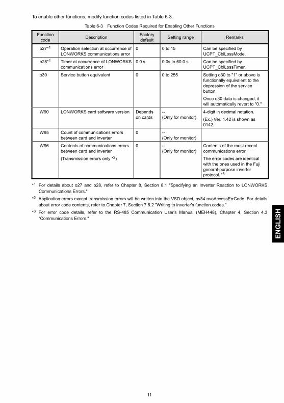
To enable other functions, modify function codes listed in Table 6-3.
Table 6-3 Function Codes Required for Enabling Other Functions
Function code Description Factory
default Setting range Remarks
o27*1 Operation selection at occurrence of LONWORKS communications error
0 0 to 15 Can be specified by UCPT_CblLossMode.
o28*1 Timer at occurrence of LONWORKS communications error
0.0 s 0.0s to 60.0 s Can be specified by UCPT_CblLossTimer.
o30 Service button equivalent 0 0 to 255 Setting o30 to "1" or above is functionally equivalent to the depression of the service button.
Once o30 data is changed, it will automatically revert to "0."
W90 LONWORKS card software version Depends on cards
-- (Only for monitor)
4-digit in decimal notation.
(Ex.) Ver. 1.42 is shown as 0142.
W95 Count of communications errors between card and inverter
0 -- (Only for monitor)
W96 Contents of communications errors between card and inverter
(Transmission errors only *2)
0 -- (Only for monitor)
Contents of the most recent communications error.
The error codes are identical with the ones used in the Fuji general-purpose inverter protocol. *3
*1 For details about o27 and o28, refer to Chapter 8, Section 8.1 "Specifying an Inverter Reaction to LONWORKS Communications Errors."
*2 Application errors except transmission errors will be written into the VSD object, nv34 nvoAccessErrCode. For details about error code contents, refer to Chapter 7, Section 7.6.2 "Writing to inverter's function codes."
*3 For error code details, refer to the RS-485 Communication User's Manual (MEH448), Chapter 4, Section 4.3 "Communications Errors."

12
Chapter 7 Object Details 7.1 Overview
The interface card supports two objects--a node object and Variable Speed Motor Drive object (VSD object). This chapter provides detailed information on these objects.
7.2 Node Object
7.2.1 Node object overview The node object processes the system events in LONWORKS network communication for the interface
card. (Usually any intervention of users or integrators is not required.)
Figure 7-1 illustrates the relationship between a node object and network variables (NVs).
Node Object #0
nv2 nvoStatus SNVT_obj_status nv1 nviRequest
SNVT_obj_request
nv8 nvoFileDirectory SNVT_adress
Figure 7-1 Overview Structure of Node Object
7.2.2 List of node object network variables (NVs) Table 7-1 lists node object network variables supported on the interface card.
Table 7-1 Node Object Network Variables
Index Variable name Variable type Description nv1 nviRequest SNVT_obj_request This variable is used to request a particular mode for an
object. Requests supported: - RQ_NORMAL(0) - RQ_ENABLED(7) - RQ_DISABLED(1) - RQ_UPDATE_STATUS(2) - RQ_REPORT_MASK(5) - RQ_CLEAR_ALARM(10)
nv2 nvoStatus SNVT_obj_status This variable is used to report the status of an object. Statuses supported: - object_id - invalid_id - invalid_request - disabled - in_alarm - report_mask
nv8 nvoFileDirectory SNVT_address This variable is used to provide the starting address of the directory that contains the configuration file.

13
ENG
LISH
7.2.3 NV details (1) nviRequest Table 7-2 lists responses to the request modes of nviRequest.
Table 7-2 Responses to nviRequest
Request Node object response VSD object response
RQ_NORMAL(0) - Enables the node object and NVs to the normal mode.
- Updates nvoStatus and outputs the new object status.
- Enables the VSD object and NVs to the normal mode.
- Updates nvoStatus and outputs the new object status.
RQ_ENABLE(7) Same as above. Same as above.
RQ_DISABLE(1) - Stops the motor if running. - Keeps the node object enabled. - Updates nvoStatus and outputs the
new object status.
- Stops the motor if running. - Disables the VSD object, ignores NV
input, and forbids its output to transmit. - Updates nvoStatus and outputs the
new object status. RQ_UPDATE_STATUS(2) - Updates nvoStatus and outputs the
new object status. - Updates nvoStatus and outputs the
new object status. RQ_REPORT_MASK(5) - Reports supported requests as "1."
- Updates nvoStatus and outputs the new object status.
- Reports supported requests as "1."
RQ_CLEAR_ALARM(10) - Resets alarm. - Updates nvoStatus and outputs the
new object status.
- Resets alarm. - Updates nvoStatus and outputs the
new object status. All other requests - Returns an invalid request
response. - Updates nvoStatus and outputs the
new object status.
- Returns an invalid request response. - Updates nvoStatus and outputs the
new object status.
All other objectIDs - Returns an invalid request response.
- Updates nvoStatus and outputs the new object status.
- Returns an invalid request response. - Updates nvoStatus and outputs the
new object status.
(2) nvoStatus Table 7-3 lists the status network variables supported and their descriptions.
Table 7-3 Status Network Variables Supported
Status Description
object_id Returns the object ID designated by the Request.
invalid_id Turns "1" when Request is issued to an object with invalid ID. invalid_request Turns "1" for an invalid request response.
disabled Turns "1" when the VSD object is disabled.
in_alarm Turns "1" when the inverter is in an alarm state or has not solved an alarm.
report_mask Turns the value of the supported status to "1." 7.2.4 Configuration properties (CPs) Configuration properties are not supported for the node object.

14
7.3 VSD Object
7.3.1 VSD object overview The Variable Speed Motor Drive (VSD) object allows you to control the inverter and monitor its running
status. Figure 7-2 illustrates an overview structure of a VSD object. Letters in parenthesis at the tail of the NV name strings show the names of the inverter's function codes that are involved by the related NVs.
For details about the function codes in parenthesis, refer to the RS-485 Communication User's Manual (MEH448), Chapter 5, "FUNCTION CODES AND DATA FORMATS."
nviDrvSpeedStptnv1
nviDrvSpeedScalenv2
nvoDrvSpeednv4
nvoDrvCurnt (M11)nv3
nvoDrvPwr (M10)nv6
nvoDrvRunHours (W79)nv7
nvoDrvVolt (M12)nv5
nviOpecmd (S06)nv8
nviFreqcmd (S05)nv9
nvoDrvStatus (M14)nv23
nvoOutputFreq (M09)nv24
nvoDrvTorque (M07)nv25
nvoDrvEnergy (W81)nv26
nvoDrvOpeHours(W70)nv27
nvoOpeTm_1 (W76)nv28
nvoOpeTm_2 (W77)nv29
nvoDCbusCapacity (W75)nv30
nvoDrvTemp_1 (M61)nv31
nvoDrvTemp_2 (M62)nv32
nviReadParamCodenv10
nviWriteParaCodenv11
nviWriteParamValnv12
nvoReadParamValnv33
nvoAccessErrCodenv34
nviAOcmd (S12)nv13 nvoAIVal_1 (M49)nv35
nvoAIVal_2 (M50)nv36
nvoAiVal_3 (M54)nv37
nvoPIDFb (M72)nv38
nviDOcmd_Y1 (S07)nv14
nviDOcmd_Y2 (S07)nv15
nvoYstatus_1 (M15)nv39
nvoYstatus_5 (M15)nv43
nvoXstatus_1 (M13)nv44
nvoXstatus_5 (M13)nv48
・・・
・・・
nviFWDcmd (S06)nv16
nviXcmd_1 (S06)nv17
nviXcmd_5 (S06)nv21
・・・
nviAlarmReset (S14)nv22
nvoInAlarm (M14)nv49
nvoAlarm (M16)nv50
nvoAlarmFreq_2 (M35)nv54
nvoAlarmCurrent (X21)nv55
nvoAlarmLog (M17~19)nv51
nvoAlarmOpCmd (M39)nv52
nvoAlarmVolt (M38)nv56
nvoAlarmOpTime (M42)nv57
nvoAlarmFreq_1 (M31)nv53
nvoAlarmPower (X35)nv58
nvoAlarmTorque (M33)nv59
24 Configuration Properties
VSD Object #1
Figure 7-2 Overview Structure of VSD Object

15
ENG
LISH
7.3.2 List of VSD object network variables (NVs) Table 7-4 lists the summary of VSD object network variables (NVs). The function code column in the table
shows their associated inverter's function codes.
Some of the VSD object input and output NVs are detailed in Sections 7.4 and 7.5, respectively.
Table 7-4 VSD Object Network Variables
Index Variable name Variable type Descriptions Function code Refer to:
nv1 nviDrvSpeedStpt SNVT_switch This input provides start/stop commands and a low-resolution speed setpoint. (as a percentage of SCPT_nomFreq)
- p. 22
nv2 nviDrvSpeedScale SNVT_lev_percent This input provides scaling for a low-resolution speed setpoint. (Negative values indicate reverse motor direction.)
- p. 22
nv3 nvoDrvCurnt SNVT_amp This output reports the output current (RMS) with 0.1 A resolution.
M11 -
nv4 nvoDrvSpeed SNVT_lev_percent This output reports the output speed. (as a percentage of SCPT_nomFreq)
- p. 26
nv5 nvoDrvVolt SNVT_volt This output reports the output voltage (RMS) with 0.1 V resolution.
M12 -
nv6 nvoDrvPwr SNVT_power_kilo This output reports the output power with 0.1 kW resolution.
M10 -
nv7 nvoDrvRunHours SNVT_time_hour This output reports the cumulative motor run time. (Diagnostic reference of the mechanical component service life)
Z40 -
nv8 nviOpeCmd SNVT_state This input provides run commands including run forward command, run reverse command, and terminal commands assigned to general-purpose, digital input terminals. Functionally equivalent to function code S06 (dedicated to inverter communication).
S06 p. 23
nv9 nviFreqCmd SNVT_freq_hz This input provides frequency command with 0.1 Hz resolution.
S05 p. 23
nv10 nviReadParamCode SNVT_count This input specifies a target inverter's function code to read out its data to nv33 nvoReadParamVal.
- pp. 23 and 31
nv11 nviWriteParaCode SNVT_count This input specifies a target inverter's function code to write data with nv12 nviWriteParamVal.
- pp. 24 and 32
nv12 nviWriteParamVal SNVT_count This input contains data to write into the inverter's function code specified by nv11 nviWriteParaCode. The write result is output to nv34.
- pp. 24 and 32
nv13 nviAOcmd SNVT_lev_percent This input specifies any output level for the inverter's analog output terminal. Functionally equivalent to function code S12 (dedicated to inverter communication).
S12 pp. 24 and 10
nv14 nviDOcmd_Y1 SNVT_switch This input turns the inverter's digital output terminal [Y1] ON/OFF. If the value is "1," [Y1] is ON. (Setting E20 to "27" (Universal DO) is needed.)
S07 pp. 24 and 10
nv15 nviDOcmd_Y2 SNVT_switch This input turns the inverter's digital output terminal [Y2] ON/OFF. If the value is "1," [Y2] is ON. (Setting E21 to "27" (Universal DO) is needed.)
S07 pp. 24 and 10
nv16 nviFWDcmd SNVT_switch This input turns terminal command FWD (bit XF of S06) ON/OFF, which is assigned to the inverter's digital input terminal [FWD] with function code E98. FWD runs a motor forward by factory default.
S06 pp. 25 and 10

16
Index Variable name Variable type Descriptions Function code Refer to:
nv17 nviXcmd_1 SNVT_switch This input turns a terminal command (bit X1 of S06) ON/OFF, which is assigned to the inverter's digital input terminal [X1] with function code E01.
S06 pp. 25 and 10
nv18 nviXcmd_2 SNVT_switch This input turns a terminal command (bit X2 of S06) ON/OFF, which is assigned to the inverter's digital input terminal [X2] with function code E02.
S06 pp. 25 and 10
nv19 nviXcmd_3 SNVT_switch This input turns a terminal command (bit X3 of S06) ON/OFF, which is assigned to the inverter's digital input terminal [X3] with function code E03.
S06 pp. 25 and 10
nv20 nviXcmd_4 SNVT_switch This input turns a terminal command (bit X4 of S06) ON/OFF, which is assigned to the inverter's digital input terminal [X4] with function code E04.
S06 pp. 25 and 10
nv21 nviXcmd_5 SNVT_switch This input turns a terminal command (bit X5 of S06) ON/OFF, which is assigned to the inverter's digital input terminal [X5] with function code E05.
S06 pp. 25 and 10
nv22 nviAlarmReset SNVT_switch Turning this variable ON (TRUE) clears alarm in the inverter. Once it turns ON, it automatically returns to OFF (False).
S14 p. 25
nv23 nvoDrvStatus SNVT_state This output reports the running status. Functionally equivalent to function code M14 (dedicated to inverter communication).
M14 p. 26
nv24 nvoOutputFreq SNVT_freq_hz This output reports the output frequency with 0.1 Hz resolution.
M09 -
nv25 nvoDrvTorque SNVT_lev_percent This output reports the output torque as a percentage of the rated torque with 0.005% resolution.
M07 -
nv26 nvoDrvEnergy SNVT_elec _kwh This output reports the inverter's cumulative power consumption in watt-hours.
W81 -
nv27 nvoDrvOpeHours SNVT_time_hour This output reports the cumulative inverter run time. (Diagnostic reference data for inverter lifetime)
W70 -
nv28 nvoOpeTm_1 SNVT_time_hour This output reports the cumulative run time of electrolytic capacitors on printed circuit boards.(Diagnostic reference data for service lifetime of the control circuit)
W67 -
nv29 nvoOpeTm_2 SNVT_time_hour This output reports the cumulative run time of the cooling fan.
W68 -
nv30 nvoDCbusCapacity SNVT_lev_percent This output reports the current capacitance of the DC link bus capacitor in %, based on the capacitance when shipped as 100%.
W75 -
nv31 nvoDrvTemp_1 SNVT_temp This output reports the inverter internal temperature with 1°C resolution.
M61 -
nv32 nvoDrvTemp_2 SNVT_temp This output reports the heat sink temperature with 1°C resolution.
M62 -
nv33 nvoReadParamVal SNVT_count This outputs function code data read. For the format, refer to Section 7.6.
- pp. 26 and 31
nv34 nvoAccessErrCode UNVT_ErrCode (1byteHex x 3)
This outputs the error code and accessed function code after completion of writing to inverter's function code. It updates only when accessed to nv11 and nv12 and outputs to LON.
- pp. 27 and 32

17
ENG
LISH
Index Variable name Variable type Descriptions Function code Refer to:
nv35 nvoAIval_1 SNVT_lev_percent This output reports the input voltage at terminal [12]. (100% at 10 V, 0% at 0 V)
M49 p. 27
nv36 nvoAIval_2 SNVT_lev_percent This output reports the input current at terminal [C1]. (100% at 20 mA, 0% at 4 mA or 0 mA)
M50 p. 27
nv37 nvoAIval_3 SNVT_lev_percent This output reports the input voltage at terminal [V2]. (100% at 10 V, 0% at 0 V)
M54 p. 27
nv38 nvoPIDFb SNVT_lev_percent This output reports the PID feedback value (%).
M72 p. 28
nv39 nvoYstatus_1 SNVT_switch This output reports the status of digital output terminal [Y1] whose function is assigned by E20.
M15 p. 28
nv40 nvoYstatus_2 SNVT_switch This output reports the status of digital output terminal [Y2] whose function is assigned by E21.
M15 p. 28
nv41 nvoYstatus_3 SNVT_switch This output reports the status of digital output terminal [Y3] whose function is assigned by E22.
M15 p. 28
nv42 nvoYstatus_4 SNVT_switch Reserved. - - nv43 nvoYstatus_5 SNVT_switch This output reports the status of digital output
terminal [Y5A/C] whose function is specified by E24.
M15 p. 28
nv44 nvoXstatus_1 SNVT_switch This output reports the status of a terminal command assigned to digital input terminal [X1]. When E01 data is "25" (Universal DI), this output reports the ON/OFF state of the physical terminal [X1].
M13 p. 28
nv45 nvoXstatus_2 SNVT_switch This output reports the status of a terminal command assigned to digital input terminal [X2]. When E02 data is "25" (Universal DI), this output reports the ON/OFF state of the physical terminal [X2].
M13 p. 28
nv46 nvoXstatus_3 SNVT_switch This output reports the status of a terminal command assigned to digital input terminal [X3]. When E03 data is "25" (Universal DI), this output reports the ON/OFF state of the physical terminal [X3].
M13 p. 28
nv47 nvoXstatus_4 SNVT_switch This output reports the status of a terminal command assigned to digital input terminal [X4]. When E04 data is "25" (Universal DI), this output reports the ON/OFF state of the physical terminal [X4].
M13 p. 28
nv48 nvoXstatus_5 SNVT_switch This output reports the status of a terminal command assigned to digital input terminal [X5]. When E05 data is "25" (Universal DI), this output reports the ON/OFF state of the physical terminal [X5].
M13 p. 28
nv49 nvoInAlarm SNVT_switch This output remains ON when the inverter is in an alarm state or has not canceled the recent alarm.
M14 -
nv50 nvoAlarm UNVT_alarm_cod(1 byte decimal)
This output reports the code of an alarm that is occurring or has occurred most recently.
M16 p. 29

18
Index Variable name Variable type Descriptions Function code Refer to:
nv51 nvoAlarmLog UNVT_alarm_log (1 byte dec x 3)
This output reports three recent alarm codes in the order of 1st, 2nd, and 3rd recent ones.
M17 M18 M19
p. 30
nv52 nvoAlarmOpCmd SNVT_state The status of run command (S06) at the time of alarm.
M39 -
nv53 nvoAlarmFreq_1 SNVT_freq_hz This output reports the status of a frequency command being executed when the most recent alarm occurred, with 0.1 Hz resolution.
M31 -
nv54 nvoAlarmFreq_2 SNVT_freq_hz This output reports the output frequency being applied when the most recent alarm occurred, with 0.1 Hz resolution.
M35 -
nv55 nvoAlarmCurrent SNVT_amp This output reports the output current being applied when the most recent alarm occurred, with 0.1 A resolution.
X21 -
nv56 nvoAlarmVolt SNVT_volt This output reports the output voltage being applied when the most recent alarm occurred, with 0.1 V resolution.
M38 -
nv57 nvoAlarmOpTime SNVT_time_hour This output reports the inverter's run time being accumulated until the most recent alarm occurred.
M42 -
nv58 nvoAlarmPower SNVT_power_kilo This output reports the inverter's power consumption detected when the most recent alarm occurred, with 0.1 kW resolution.
X35 -
nv59 nvoAlarmTorque SNVT_lev_percent This output reports the inverter's output torque detected when the most recent alarm occurred, as a percentage of the rated torque with 0.005% resolution.
M33 -
Fan-out connection using aliases (branching a single output NV to two or more input NVs on thisinterface card) should be avoided because the interface card may miss-fetch any input NV depending upon the fetch timing. If it cannot be avoided, use the repeated mode for the connection messaging service to prevent miss-fetch of the branched NV aliases.

19
ENG
LISH
7.3.3 List of VSD object configuration properties (CPs) Table 7-5 lists the summary of VSD object configuration properties (CPs). The function code column in the
table shows their associated inverter's function codes. Modifying function code data can change the associated CP value.
Some of these CPs have detailed descriptions in Section 7.7 (see the page given in the table below).
Refer to the user's manual of an inverter, "FUNCTION CODES" for supplementary information on the CPs.
Table 7-5 VSD Object CPs
CP name Unit Description Default Function code
Refer to:
SCPT_maxSetpoint 0.005% Defines the maximum frequency as a percentage of SCPT_nomFreq.
100.000% (60 Hz)
F03 -
SCPT_minSetpoint 0.005% Defines the lower limit of the output frequency as a percentage of SCPT_nomFreq.
0.000% F16 -
SCPT_maxSendTime 0.1 s Sets the heartbeat send interval. The concerned NV continues transmitting data at this time intervals, regardless the data changing. Specifying 0.0 s disables this CP.
0.0 s - p. 33
SCPT_nomRPM 1 r/min Used to enter the nominal speed, 100% of the percent speed command, in r/min. Modifying this CP automatically replaces the value of SCPT_nomFreq.
1800 r/min
- -
SCPT_nomFreq 0.1 Hz Used to enter the nominal frequency, 100% of the percent speed command, in Hz. All percent speed commands refer to this value.
60.0 Hz - p. 22
SCPT_rampUpTm 0.1 s Used to enter the ramp-up time from the zero to maximum speed.
20.0 s F07 -
SCPT_rampDownTm 0.1 s Used to enter the ramp-down time from the maximum to zero speed.
20.0 s F08 -
(UCPT_rampUpTm2) - Reserved. - - - (UCPT_rampDown Tm2)
- Reserved. - - -
SCPT_defScale 0.005% Contains the default value for nviDrvSpeedScale. 100.000%
- -
SCPT_maxRcvTime 0.1 s Sets the heartbeat receive interval. If the concerned NV receives no data within this interval, it interprets the transmission as being broken. Specifying 0.0 s disables this CP.
0.0 s
p. 33
SCPT_minDeltaLevel 0.5% Sets the minimum data change rate for an output NV to start data transmission. If the data change rate exceeds this value, the concerned NV interprets the data as being changed, starting data transmission. Specifying 0.0% disables this CP.
0.0% p. 34
SCPT_minSendTime 0.1 s Sets the minimum pause time for an output NV to start data transmission. Once the concerned NV finishes data transmission, it does not start data transmission until this time has elapsed even if the data change rate exceeds SCPT_minDeltaLevel. Setting 0.0 s disables this CP.
0.5 s p. 34
UCPT_BaseFreq 0.1 Hz Sets the base frequency of the inverter for motor 1. 50.0 Hz F04 - (UCPT_JogFreq) - Reserved. - - -

20
CP name Unit Description Default Function code
Refer to:
UCPT_JumpFreq 0.1 Hz x 4 Contains an ensemble of four inverter's function codes specified in the array order shown below. "Jump frequency 1, 2, 3 and jump frequency band"
0.0 Hz,0.0 Hz,0.0 Hz,3.0 Hz
C01, C02, C03, C04
-
UCPT_LinkFunc 1 Switches run and speed commands between "enable" and "disable" via the LONWORKS network. Functionally equivalent to function code y98. Setting y98 data to "3" enables run and speed commands.
0
y98 p. 10
UCPT_multStepFreq1 0.01 Hz Sets the frequency to be applied when multistep frequency 1 is selected. Multistep frequency: Assigning terminal commands to digital input terminals [X1] to [X5] and [FWD] with E01 to E05 and E98 and turning those terminals ON/OFF can select the multistep frequency.
0.00 Hz C05 -
UCPT_PIDsettings 0.001, 0.1 s, 0.01 s, 0.1 s
Contains an ensemble of four PID parameters specified in the array order shown below. "P gain, I time, D time and feedback filter time constant"
0.100, 0.0 s, 0.00 s, 0.5 s
J03, J04, J05, J06 *1
-
UCPT_StartFreq 0.1 Hz Sets the starting frequency. 0.5 Hz F23 -
UCPT_StopFreq 0.1 Hz Sets the stop frequency. 0.2 Hz F25 - (UCPT_TorqLimit) - Reserved. - - -
UCPT_CblLossMode 1 Specifies an action to follow when a communications line break error occurs on the LONWORKS network. Functionally equivalent to function code o27.
0 o27 p. 35
UCPT_CblLossTimer 0.1 s Sets the timer to determine the issuing timing of er5 alarm triggered by a communications line break on the LONWORKS network. Functionally equivalent to function code o28.
0.0 s o28 p. 35
UCPT_FlyingStart Mode
1 Specifies the auto search for idling motor's speed. In the auto search mode, the frequency can be specified by function code H17.
0 (Disable)
H09 -
UCPT_momentary Pwr LossMode
1 Specifies the restart mode after a momentary power failure. Functionally equivalent to function code F14.
1 F14 -
UCPT_AutoRestart 1 Specifies the number of auto-resetting times for automatically escaping the tripped state. Functionally equivalent to function code H04. H05 specifies the reset interval.
0 H04 -
UCPT_SendDelay AfterDevRdy
0.1 s Specifies the data transmission start delay time for the LONWORKS interface card. The output NV starts data transmission after this delay time has elapsed from when the interface card is powered up or receives a reset command from the LONWORKS integration tool. This CP should be used to strictly manage the starting time of data transmission on the whole network. Specifying 0.0 s makes the NV start data transmission upon completion of initialization of the card. *2
0.0 s ― -
*1 These function codes differ depending on the target inverter. For details about the PID control of the
inverter, refer to the "J codes" and "PID Control Block" given in the Inverter User's Manual.

21
ENG
LISH
*2 This LONWORKS interface card needs approx. 0.5 second for initialization. Therefore, specifying less than 0.5 second cannot start data transmission from the output NV until approx. 0.5 second elapses.
When the interface card is powered up, it transmits all output NVs to validate the latest inverter settings on the LONWORKS network.
Immediately after commissioning, the LONWORKS integration tool temporarily monitors CP default values, so those CP values do not necessarily match the inverter's function code settings. This is,however, only apparent and the inverter runs with its function code settings. To make the monitored CP values match the inverter's settings, use the LONWORKS integration toolto execute the "Synchronize CP" command (e.g., ReSync CPs in LonMaker) and upload the CPvalues of this card.
Modifying CP-associated function codes from the keypad does not automatically update the CP values being monitored by the LONWORKS integration tool. This is, however, only apparent and themodification is validated on the associated CPs without any problems. To update the monitored CP values, use the LONWORKS integration tool to execute the "Synchronize CP" command (e.g., ReSync CPs in LonMaker) and upload the CP values of this card.
The moment the LONWORKS integration tool sets CP values (new or unchanged values), all output NVs implemented on this card output the latest data at that time. Use this feature to update the NVson the network with the latest data. In addition, switching the inverter from offline to online also outputs all output NVs as well.

22
7.4 VSD Object Input Network Variables
(1) nv1 nviDrvSpeedStpt This NV controls the inverter's run/stop and frequency commands via the LONWORKS network.
- Variable type: SNVT_switch
Table 7-6 Operation of nviDrvSpeedStpt
state value Operation
0 NA Run command OFF
1 0.0 (%) Zero speed command (No torque generated) 1 0.5 to 100.0 (%) Run at 0.5 to 100.0% frequency -1 (0xFF) NA Invalid
- Default setting: state = -1, value = 0
The interface card calculates the frequency command value with nviDrvSpeedStpt.value, nviDrvSpeedScale and SCPT_nomFreq.
Frequency command (Hz) = nviDrvSpeedStpt.value (%) x nviDrvSpeedScale (%) x SCPT_nomFreq (Hz)
Each time any one of the three terms in the above equation is entered, the interface card calculates the frequency command again and overwrites the previous value with new one, regardless of whether the inverter is running or on halt. If state = 0xFF, however, no recalculation takes place even with any input.
The frequency command can be specified with this NV and nv9 nviFrecmd. If both of these NVs are specified, the last one takes effect on the inverter (Last command has priority).
To enable the inverter's run/stop and frequency commands via the LONWORKS network, either ofthe following settings is required. UCPT_LinkFunc = 3 or inverter's function code y98 = 3
- CPs for control of the affected network bandwidth: SCPT_maxRcvTime (2) nv2 nviDrvSpeedScale This NV specifies the motor rotational direction and frequency command.
- Variable type: SNVT_lev_percent
- Data setting range: -163.840 to 163.830% (0.005% resolution) If entering 163.835% (invalid), for example, the interface card ignores the entry and the inverter runs with the previous value.
- Default setting: Value specified by SCPT_defScale
- CPs for control of the affected network bandwidth: SCPT_maxRcvTime

23
ENG
LISH
(3) nv8 nviOpecmd This NV specifies the inverter data of run forward/reverse, digital input terminals [X1] to [X9], [FWD] and
[REV]. The command format of this NT is the same as that of function code S06.
bit 15 bit 14 bit 13 bit 12 bit 11 bit 10 bit 9 bit 8 bit 7 bit 6 bit 5 bit 4 bit 3 bit 2 bit 1 bit 0
ALM RST [REV] [FWD] - - X9 X8 X7 X6 X5 X4 X3 X2 X1 REV FWD
FWD, REV: Run forward/reverse commands to the inverter X1 to X9: Terminal command assignment fields for inverter's digital inputs [X1] to [X9] [FWD], [REV]: Run forward/reverse terminal command assignment fields for inverter's digital inputs [FWD] and
[REV] ALMRST: Switching from ON to OFF clears inverter alarms.
- Variable type: SNVT_state
- Default setting: 0000000000000000 (16 bit binary)
- CPs for control of the affected network bandwidth: SCPT_maxRcvTime
The number of inverter's general-purpose input terminals differs depending on the target inverter.
To validate this NV entry on the inverter, any of the following settings is required. UCPT_LinkFunc = 2 or 3, or inverter's function code y98 = 2 or 3
(4) nv9 nviFreqcmd This NV specifies the frequency command in Hz with 0.1 Hz resolution.
- Variable type: SNVT_freq_hz
- Data setting range: 0.0 to 6553.5 Hz (Valid range for inverter: 0.0 to 400.0 Hz)
- Default setting: 0.0 Hz
- CPs for control of the affected network bandwidth: SCPT_maxRcvTime
The frequency command can be specified with this NV and nv1 nviDrvSpeedStpt. If both of these NVs are specified, the last one takes effect on the inverter (Last command has priority). To validate this NV entry on the inverter, any of the following settings is required. UCPT_LinkFunc = 1 or 3, or inverter's function code y98 = 1 or 3
(5) nv10 nviReadParamCode This NV specifies a target inverter's function code to read out its data with nv33 nvoReadParamVal.
For details about readout of function code data, refer to Section 7.6.1 "Reading from inverter's function codes."
- Variable type: SNVT_count
- Data setting range: 0000 to FFFF (hexadecimal)
- Default: 0000 (hexadecimal)
- CPs for control of the affected network bandwidth: None

24
(6) nv11 nviWriteParaCode, nv12 nviWriteParamVal Data contained in nv12 will be written into a function code specified by nv11.
For details about writing data, refer to Section 7.6.2 "Writing to inverter's function codes."
- Variable type: SNVT_count
- Data setting range: 0000 to FFFF (hexadecimal)
- Default setting: 0000 (hexadecimal)
- CPs for control of the affected network bandwidth: None (7) nv13 nviAOcmd This NV outputs its value onto the inverter's analog output terminal [FMA/FMP/FMI] (same as universal
AO).
To terminal [FM1], the NV outputs 0 to 11 VDC or 4 to 20 mADC. To terminal [FM2], the NV outputs 0 to 11 VDC or 0 to 20 mADC. To terminal [FMA], the NV outputs 0 to 11 VDC or 4 to 20 mADC. To terminal [FMP], it outputs a square wave pulse train prescribed by the inverter. For [FMI], it outputs 4 to 20 mADC.
This allows the inverter to work as an analog output device having a single channel, physical analog output.
For details about terminals [FMA] and [FMP] (or [FMI] and [FM2]), refer to the user's manual of an inverter, "Wiring for control circuit terminals" and "Overview of Function Codes," F31 and F35.
- Variable type: SNVT_lev_percent
- Data setting range: -163.840 to 163.830% (Valid range for inverter: 0.000 to 110.000%) Setting 163.835% (invalid), for example, will be ignored so that the inverter runs with the previous value.
- Default setting: 0.000%
- CPs for control of the affected network bandwidth: SCPT_maxRcvTime
To validate this NV entry on the inverter, either of the following settings is required. For [FM1] or [FMA], inverter's function code F31 = 10 For [FM2] or [FMP] (or [FMI]), F35 = 10 It is possible to enable both [FM1] and [FM2] or [FMA] and [FMP], however, both terminals output the same analog level signals.
(8) nv14 nviDOcmd_Y1, nv15 nviDOcmd_Y2 The nv14 or nv15 outputs its ON/OFF value onto inverter's digital output terminal [Y1] or [Y2], respectively
(same as universal DO). This allows the inverter's physical Y terminals to work as a 2-bit (max.) digital output device.
For details about Y terminals, refer to the user's manual of an inverter, "Wiring for control circuit terminals" and "Overview of Function Codes," E20 and E21.
- Variable type: SNVT_switch
- Data setting range: value = 0.0 to 100.0%, state = 1, 0, -1
- Default settings: value = 0.0%, state = 0
- CPs for control of the affected network bandwidth: SCPT_maxRcvTime
Do not use nviDOcmd_Y1 or nviDOcmd_Y2 as a bit array. This is because, in LONWORKS communication, two or more variables are never output concurrently, so the interface card may miss-fetch the bit array at the timing when the data gets validated on the inverter. Accordingly, theinverter could receive it as unexpected data. To handle them as a bit array, read out S07 by the function code readout feature.
To validate this NV entry on the inverter, either of the following settings is required. For [Y1], inverter's function code E20 = 27 For [Y2], E21 = 27

25
ENG
LISH
(9) nv16 nviFWDcmd This NV controls the ON/OFF of inverter's digital input terminal [FWD]. Command assignment to [FWD] is
made with function code E98. The factory default command is "Run forward."
For details about function code E98, refer to the user's manual of an inverter, "FUNCTION CODES."
- Variable type: SNVT_switch
- Data setting range: value = 0.0 to 100.0%, state = 1, 0, -1
- Default setting: value = 0.0%, state = 0
- CPs for control of the affected network bandwidth: SCPT_maxRcvTime
To assign the "Run reverse" command to terminal [FWD], it is necessary to assign a terminalcommand other than "Run reverse" to terminal [REV] using function code E99. The run command issued by this NV is independent of the one issued by nviDrvSpeedStpt, soturning ON either one of those run commands runs the motor. To stop it, therefore, concurrentlyturn OFF both of them issued by the two NVs. To validate this NV entry on the inverter, any of the following settings is required. UCPT_LinkFunc = 2 or 3, or inverter's function code y98 = 2 or 3
(10) nv17 to nv21 nviXcmd_1 to nviXcmd_5 These NVs control the ON/OFF of inverter's digital input terminals [X1] to [X5]. Command assignments to
[X1] to [X5] are made with function codes E01 to E05, respectively.
For details about function codes E01 to E05, refer to the user's manual of an inverter, "FUNCTION CODES."
- Variable type: SNVT_switch
- Data setting range: value = 0.0 to 100.0%, state = 1, 0, -1
- Default settings: value = 0.0%, state = 0
- CPs for control of the affected network bandwidth: SCPT_maxRcvTime
Do not use any of nviXcmd_1 to nviXcmd_5 as a bit array (e.g., multistep speed command). Thisis because, in LONWORKS communication, two or more variables are never input concurrently, so the interface card may miss-fetch the bit array at the timing when the data gets validated on the inverter. Accordingly, the inverter could transmit it as unexpected data. To handle them as a bit array, use nv8 nviOpecmd, instead. Depending on the command assignment to inverter's digital input terminals, some ON/OFFcommands via the LONWORKS network using these NVs may be ignored. On the other hand,some commands entered from the terminal block may be unconditionally validated. For detailsabout these events, refer to the RS-485 Communication User's Manual (MEH448), Chapter 5, Section 5.1.2 [3] "Operation command data." To validate this NV entry on the inverter, any of the following settings is required UCPT_LinkFunc = 2 or 3, or inverter's function code y98 = 2 or 3
(11) nv22 nviAlarmReset Setting the ON value to this NV releases the inverter's trip state. If any alarm factor persists at the entry of
the ON value, the trip state cannot be released. After the entry of the ON value, the NV state automatically reverts to OFF.
- Variable type: SNVT_switch
- Data setting range: value = 0.0 to 100.0%, state = 1, 0, -1
- Default setting: value = 0.0%, state = 0
- CPs for control of the affected network bandwidth: None

26
7.5 VSD Object Output Network Variables
This section describes VSD object output network variables that need supplemental explanations. For variables not found in this section, refer to Section 7.3 "VSD Object."
(1) nv4 nvoDrvSpeed This NV outputs the inverter's output frequency as a percentage of SCPT_nomFreq (Base frequency).
- Variable type: SNVT_lev_percent
- Data setting range: -163.840 to 163.830% (0.005% resolution)
- CPs for control of the affected network bandwidth: SCPT_maxSendTime, SCPT_minSendTime and SCPT_minDeltaLevel
- Output timing: At the time of data change, at intervals specified by SCPT_maxSendTime (if specified), after the time specified by SCPT_minSendTime (if specified), or when the data change rate exceeds the value specified by SCPT_minDeltaLevel (if specified)
(2) nv23 nvoDrvStatus This NV outputs the current inverter status. The format of this NV is the same as that of the inverter's
communication function code M14.
bit 15 bit 14 bit 13 bit 12 bit 11 bit 10 bit 9 bit 8 bit 7 bit 6 bit 5 bit 4 bit 3 bit 2 bit 1 bit 0
BUSY - - RL ALM DEC ACC IL VL - NUV BRK INT EXT REV FWD
FWD, REV : Run forward, Run reverse IL : During output current limiting EXT : During DC-braking (or Pre-exciting) ACC : During acceleration INT : Inverter shutdown DEC : During deceleration BRK : Braking ALM : Alarm relay output NUV : DC link bus voltage established (0: Undervoltage) RL : Communication active VL : Output voltage limiting BUSY : Busy in writing function codes
- Variable type: SNVT_state
- CPs for control of the affected network bandwidth: SCPT_maxSendTime and SCPT_minSendTime
- Output timing: At the time of data change, at intervals specified by SCPT_maxSendTime (if specified), or after the time specified by SCPT_minSendTime (if specified)
(3) nv33 nvoReadParamVal This NV reads out data from the inverter's function code specified by nv10 nviReadParamCode.
For details about readout of function code data, refer to Section 7.6.1 "Reading from inverter's function codes."
- Variable type: SNVT_count
- Data setting range: 0000 to FFFF (hexadecimal)
- CPs for control of the affected network bandwidth: SCPT_maxSendTime
- Output timing: At the input time of nv10 nviReadParamCode or at intervals specified by SCPT_maxSendTime (if specified)
This NV is issued after input of nviReadParamCode, regardless of whether the data has been changed or not.

27
ENG
LISH
(4) nv34 nvoAccessErrCode After completion of writing of inverter's function code data with nv11 nviWriteParaCode and nv12
nviWriteParamVal, this NV outputs a three-byte string "Write error code (1 byte) + Function code accessed (2 bytes)." If the data has been successfully written, the error code value is 00h.
For details about error codes, refer to Table 7-10 in Section 7.6.2 "Writing to inverter's function codes."
- Variable type: UNVT_ErrCode (3 bytes)
1 byte 1 byte 1 byte
Error code Function code group of error
detection target
Function code number of the error
detection target
LonMaker represents this NV data in the format: "Error code (decimal), Function code group(decimal), Function code number (decimal)."
For details about the NV format and function code writing procedure, refer to Section 7.6.2 "Writing to inverter's function codes."
- Data setting range: 00, 00, 00 to FF, FF, FF (hexadecimal)
- CPs for control of the affected network bandwidth: None
- Output timing: After the input time of nv12 nviWriteParamVal
(5) nv35 to nv37 nvoAIVal_1 to nvoAIVal_3 The nv35 to nv37 output the voltage or current input level applied to inverter's analog input terminals [12],
[C1] and [V2] in percentage, respectively. Table 7-7 lists the relationship between terminals and NVs.
Table 7-7 Analog input terminals and NVs
Network variables Analog terminals Analog signal level
nvoAIVal_1 [12] 0 to 100% = 0 to 10 V nvoAIVal_2 [C1] 0 to 100% = 4 to 20 mA or 0 to 20
mA nvoAIVal_3 [V2] 0 to 100% = 0 to 10 V
For details about terminals [12], [C1] and [V2], refer to the "Wiring for control circuit terminals" in the
Inverter User's Manual.
- Variable type: SNVT_lev_percent
- Data setting range: 0.000 to 100.000% (0.005% resolution)
- CPs for control of the affected network bandwidth: SCPT_maxSendTime, SCPT_minSendTime, SCPT_minDeltaLevel
- Output timing: At the time of data change, at intervals specified by SCPT_maxSendTime (if specified), after the time specified by SCPT_minSendTime (if specified), or when the data change rate exceeds the value specified by SCPT_minDeltaLevel (if specified)
The NV ignores bias and gain data for each analog input. On the LONWORKS network, thefollowing relationship is always established regardless of the bias and gain data: When 0 V (0 mA or 4 mA) is applied to an analog input terminal, the NV value is 0%, and when 10 V (or 20 mA), 100%.

28
(6) nv38 nvoPIDFb When the PID feedback value is assigned to any of analog input terminals [12], [C1] and [V2], this NV
outputs the analog signal level applied to that terminal as the PID feedback value in percentage.
To use this NV, it is necessary to enable the inverter's PID control. For details about the PID control of the inverter, refer to the "J codes" and "PID Control Block" given in the Inverter User's Manual.
- Variable type: SNVT_lev_percent
- Data setting range: 0.0 to 163.830% (0.005% resolution)
- CPs for control of the affected network bandwidth: SCPT_maxSendTime, SCPT_minSendTime, SCPT_minDeltaLevel
- Output timing: At the time of data change, at intervals specified by SCPT_maxSendTime (if specified), after the time specified by SCPT_minSendTime (if specified), or when the data change rate exceeds the value specified by SCPT_minDeltaLevel (if specified)
This NV data can be adjusted with analog input gain setting. The related inverter's function codesare C32, C34, C37, C39, C42 and C44.
(7) nv39, nv40, nv41, nv43 nvoYstatus_1, nvoYstatus_2, nvoYstatus_3, nvoYstatus_5 The nv39 to nv41 and nv43 output the ON/OFF status of inverter's digital output terminals [Y1] to [Y3] and
relay contact output terminal [5A/C], respectively. Signal assignments to these terminals are made with function codes E20 to E22 and E24.
For details about function codes E20, E21, E22 and E24, refer to the user's manual of an inverter, "FUNCTION CODES."
- Variable type: SNVT_switch
- Data setting range: value = 0.0, 100.0%, state = 1, 0
- CPs for control of the affected network bandwidth: SCPT_maxSendTime, SCPT_minSendTime
- Output timing: At the time of data change, at intervals specified by SCPT_maxSendTime (if specified) or after the time specified by SCPT_minSendTime (if specified)
Although the nv42 nvoYstatus_4 exists, it does not function since the Inverter does not support terminal [Y4].
(8) nv44 to nv48 nvoXstatus_1 to nvoXstatus_5 The nv44 to nv48 check whether terminal commands applied to inverter's digital input terminals [X1] to [X9]
are validated or not on the inverter, respectively, and outputs it in ON/OFF state.
Setting data "0" to inverter's function code y98 or UCPT_LinkFunc makes it possible to monitorthe validation status of terminal commands applied to physical terminals [Xn], respectively. In thissituation, it is also possible to monitor commands assigned by nviXcmd_1 to nviXcmd_5 as well. For details, refer to the RS-485 Communication User's Manual (MEH448), Chapter 5, Section 5.1.2 [3] "Operation command data."
- Variable type: SNVT_switch
- Data setting range: value = 0.0, 100.0%, state = 1, 0
- CPs for control of the affected network bandwidth: SCPT_maxSendTime, SCPT_minSendTime
- Output timing: At the time of data change, at intervals specified by SCPT_maxSendTime (if specified) or after the time specified by SCPT_minSendTime (if specified)
Assigning "Universal DI" to a digital input terminal (E01 to E05 = 25) makes it possible to output the physical ON/OFF status of terminal [Xn] onto the LONWORKS network. Accordingly, theinverter's physical terminal [Xn] can be used as a digital input device having max. 5 bits.

29
ENG
LISH
Depending on the command assignment to inverter's digital input terminals, some ON/OFF commands via the LONWORKS network using these NVs may be ignored. On the other hand,some commands entered from the terminal block may be unconditionally validated. For detailsabout these events, refer to the RS-485 Communication User's Manual (MEH448), Chapter 5, Section 5.1.2 [3] "Operation command data."
(9) nv50 nvoAlarm This NV outputs the contents of an alarm that is occurring or has recently occurred.
- Variable type: UNVT_alarm_cod (1 byte, decimal)
- Data setting range: 0 to 255
- CPs for control of the affected network bandwidth: SCPT_minSendTime
- Output timing: At the time of data change or after the time specified by SCPT_minSendTime (if specified)
Table 7-8 Alarm Code Table
Alarm codes in
M16 to M19 Description
Alarm codesin
M16 to M19Description
0 (00H) No alarm --- 23 (17H) Overload of motor 1 0l1
1 (01H) Overcurrent (during acceleration)
0c1 24 (18H) Overload of motor 2 0l2
2 (02H) Overcurrent (during deceleration)
0c2 44 (2CH) Overload of motor 3 0l3
3 (03H) Overcurrent (During running at constant speed)
0c3 45 (2DH) Overload of motor 4 0l4
5 (05H) Grounding fault ef 25 (19H) Inverter overload 0lu
6 (06H) Overvoltage (during acceleration)
0u1 27 (1BH) Over speed error 0s
7 (07H) Overvoltage (during deceleration)
0u2 28 (1CH) Wiring break in a PG pg
8 (08H) Overvoltage (during running at constant speed or stopped)
0u3 29 (1DH) Wiring break in a NTC thermistor
nrb
10 (0AH) Undervoltage lu 31 (1FH) Memory error er1
11 (0BH) Input phase loss lIn 32 (20H) Keypad communications error er2
12 (0CH) Power supply frequency error fre 33 (21H) CPU error er3
13 (0DH) AC fuse blown acf 34 (22H) Option communications error er4
14 (0EH) Fuse blown fus 35 (23H) Option error er5
15 (0FH) DC fuse blown dcf 36 (24H) Operation protection er6
16 (10H) Charger circuit fault pbf 37 (25H) Tuning error er7
17 (11H) Heat sink overheat 0h1
18 (12H) External alarm 0h2
38 (26H)
53 (35H)
RS-485 communications error (COM port 1) (COM port 2)
er8
erp
19 (13H) Inverter internal overheat 0h3 39 (27H) A/D converter defection er9
20 (14H) Motor protection (PTC/NTC thermistor)
0h4 42 (29H) Out-of-step detection erd
22 (16H) Braking resistor overheat dbh 46 (2EH) Output phase loss 0pl

30
Table 7-8 Alarm Codes (Continued)
Alarm codes in
M16 to M19 Description
Alarm codesin
M16 to M19Description
47 (2FH) Speed mismatching (Out of speed control)
ere
50 (32H) Magnetic pole sensor error erc
51 (33H) Data save error during undervoltage
erf
91 (5BH) 92 (5CH) 93 (5DH)
Feedback error
Exterior PID1 Exterior PID2 Exterior PID3
pua
pub
puc
52 (34H) Position deviation error d0 250 (FAH) Low battery lob
54 (36H) Hardware error erh 251 (FBH) Time information loss dtl
56 (38H) Position control error ero 252 (FCH) Forced operation fod
57 (39H) Enable circuit error ecf 253 (FDH) Password protection lok
58 (3AH) Current input disconnect detection cof 254 (FE H) Mock alarm err
59 (3BH) DB transistor failure dba
65 (41H) Customizable logic error
ecl
66 (42H) PID1 feedback error pu1
67 (43H) PID2 feedback error pu2
68 (44H) USB communications error eru
81 (51H) Drought protection pdr
82 (52H) Control of maximum starts per hour roc
83 (53H) End of curve protection pol
84 (54H) Anti jam rlo
85 (55H) Filter clogging error fol
(10) nv51 nvoAlarmLog This NV outputs the history of recent 3 alarms.
- Variable type: UNVT_alarm_log (Decimal, 1 byte x 3)
1 byte 1 byte 1 byte
Most recent alarm code (Decimal) 2nd recent alarm code
(Decimal) 3rd recent alarm code
(Decimal)
LonMaker represents this NV data in the format: "Most recent alarm code, 2nd recent alarm code, 3rd recent alarm code."
- Data setting range: 0, 0, 0 to 255, 255, 255
- CPs for control of the affected network bandwidth: SCPT_minSendTime
- Output timing: At the time of data change or after the time specified by SCPT_minSendTime (if specified)

31
ENG
LISH
081E (hexadecimal) = 2078 (decimal)
7.6 Reading and Writing from/to Inverter's Function Codes
7.6.1 Reading from inverter's function codes Use nv10 nviReadParamCode and nv33 nvoReadParamVal. This section summarizes the reading procedure.
(1) Enter the inverter's target function code into nv10 nviReadParamCode in the 16-bit format shown below. This starts the readout process of the inverter's function code.
(Example) Reading H30 from the inverter H: Function code group 08 30: 1E (hexadecimal)
bit 15 bit 14 bit 13 bit 12 bit 11 bit 10 bit 9 bit 8 bit 7 bit 6 bit 5 bit 4 bit 3 bit 2 bit 1 bit 0
Inverter's function code group Function code number
Inverter's function code group: Group of function codes (F, E, C etc.). See Table 7-9 below. Function code number: 2-digit number following the function code group. For example, 98 in E98.
(2) nv33 nvoReadParamVal outputs the data of the function code specified by nv10 nviReadParamCode, then
the readout process terminates. The value is subject to the format of individual function codes.
For details about the data format of individual function codes, refer to the RS-485 Communication User's Manual (MEH448), Chapter 5, Section 5.2 "Data Formats."
Input of a non-existing function code returns "0" to nv33 nvoReadParamVal.
If a running readout process for a function code is interrupted by another readout request, theinterrupting request will be ignored. This interface card does not support any output NV that identifies whether a readout process is already running. To run the read process very frequently,therefore, it is recommended that the software be so designed that it monitors the input/outputstatus of nv10 nviReadParamCode and nv33 nvoReadParamVal, confirms the completion of all the previous processes, and then starts a new readout process.
Table 7-9 Function Code Groups
Classifi- cation
Group number Function code name Classifi-
cationGroup
number Function code name
S 2 02h Command Data W1 23 17h Monitor 3 M 3 03h Monitor Data W2 24 18h Monitor 4 F 4 04h Fundamental Functions W3 25 19h Monitor 5 E 5 05h Extension Terminal Functions X1 26 1Ah Alarm 3 C 6 06h Control Functions X2 27 1Bh Alarm 4 P 7 07h Motor 1 Parameters Z1 28 1Ch Alarm 5 H 8 08h High Performance Functions K 29 1Dh Keypad Panel Function A 9 09h Motor 2 Parameters T 30 1Eh Clock Timer Function o 10 0Ah Optional Functions E1 31 1Fh Extension Terminal Functions 1 L 11 0Bh For elevators H1 32 20h High Performance Function 1 r 12 0Ch Motor 4 Parameters o1 33 21h Optional Functions 1 U 13 0Dh Soft relay 1 U1 34 22h Soft relay 2 J 14 0Eh Application Function 1 M1 35 23h Monitor Data 1 y 15 0Fh Link Functions J1 36 24h Application Function W 16 10h Monitor Data 2 J2 37 25h Application Function X 17 11h Alarm Data 1 J3 38 26h Application Function Z 18 12h Alarm Data 2 J4 39 27h Application Function b 19 13h Motor 3 Parameters J5 40 28h Application Function d 20 14h Application Functions 2 J6 41 29h Application Function d1 42 24Ah Application Function

32
Example: F26 F ⇒ Group number 04 26 ⇒ 1A(16 notation) "041a "
Example: Reading the inverter's function code F23 (Starting frequency) whose value is 0.5 Hz
1) nv10 nviReadParamCode: Enter 417 (hex) to this NV. Function code group = F (04h), Function code number = 23 (17h)
2) nv33 nvoReadParamVal: This NV outputs 5. (5 means 0.5 Hz because of the format with 0.1 Hz resolution)

33
ENG
LISH
7.6.2 Writing to inverter's function codes Use nv11 nviWriteParamCode, nv12 nviWriteParamVal, and nv34 nvoAccessErrCode. This section summarizes the writing procedure.
(1) Enter the inverter's target function code into nv11 nviWriteParamCode. The data entry format is the same as that of the readout on the previous page.
(2) Enter data to be written into the target function code, into nv12 nviWriteParamVal. This starts the writing process of the function code data to the inverter. The data entry format is the same as that of the readout on the previous page.
For details about the data format of individual function codes, refer to the RS-485 Communication User's Manual (MEH448), Chapter 5, Section 5.2 "Data Formats."
(3) nv34 nvoAccessErrCode outputs the result of the writing process, then the writing process terminates. The format of nv34 nvoAccessErrCode is shown below.
1 byte 1 byte 1 byte
Error code Function code group of error
detection target
Function code number of the error
detection target
LonMaker represents this NV data in the format: "Error code (decimal), Function code group (decimal), Function code number (decimal)."
Function code groups are the same as those in the readout process. See Table 7-9. Table 7-10 Error Codes
Error code Description
00h (0) Normal
01h (1) Link priority error 02h (2) Attempted to write data to a non-existing function code 03h (3) Attempted to write data to a write-protected function code
06h (6) Attempted to write data to a function code not allowed to change during running 07h (7) Attempted to write data to a function code not allowed to change when the terminal input is alive. 08h (8) Out of data entry range 09h (9) Attempted to write data to a password-protected function code 0Fh (15) Function code write error
If a writing process for a function code is interrupted by another writing request, error code 0Fh (Function code write error) is immediately issued to nv34 nvoAccessErrCode as a response to theinterrupting request, then the response to the interrupted process will be issued.
Example: Writing 9.5 s to the inverter's function code H13 (Restart Mode after Momentary Power Failure, Restart time)
1)nv11 nviWriteParaCode: Enter 80Dh to this NV. Function code group = H (08h), Function code number = 13 (0Dh)
2)nv12 nviWriteParamVal: Enter 95 to this NV. (95 means 9.5 seconds because of the format with 0.1 s resolution)
3) nv34 nvoAccessErrCode: The written result is returned to this NV as the following strings. - For normal writing: 0, 8, 13 (0: Error code, H: Function code group, 13: Function code number) - For out of range writing: 8, 8, 13(8: Error code, H: Function code group, 13: Function code number)

34
7.7 VSD Object Configuration Properties (CPs)
This section details VSD object configuration properties (CPs) that need supplemental descriptions. For CPs not found in this section, refer to Section 7.3 "VSD Object." (1) SCPT_maxRcvTime Receive heartbeat. This CP specifies the heartbeat receive interval for input NVs listed in Table 7-11 in
block. If no data is received within this interval after the reception of the last data, the interface card interprets the state as a LONWORKS communications error.
Setting the heartbeat time at 0.0 s does not break the connection to the LONWORKS network even if no data is received.
For details about the settings and activities on a LONWORKS connection break, refer to Chapter 8, Section 8.1 "Specifying an Inverter Reaction to LONWORKS Communications Errors."
- Data setting range: 0.0 to 6553.4 s (0.1 s resolution)
- Default setting: 0.0 s (Ignore connection break)
Writing a value (e.g., 6553.5) exceeding the data setting range to this CP displays the value but does not update the internal value, retaining the previously written data.
Table 7-11 NVs with Receive Heartbeat Time Specified by SCPT_maxRcvTime
Index NV name
nv1 nviDrvSpeedStpt
nv2 nviDrvSpeedScale nv8 nviOpeCmd nv9 nviFreqCmd
nv13 nviAOCmd nv14, nv15 nviDOcmd_Y1, Y2 nv16 nviFWDcmd nv17 to nv21 nviXcmd_1 to 5
(2) SCPT_maxSendTime Send heartbeat. This CP specifies the constant updating period for all output NVs listed in Table 7-12 below
in block. Specifying it periodically updates those NVs that include the internal monitor values.
Setting the send heartbeat at 0.0 s does not cause updating.
- Data setting range: 0.0 to 6553.4 s (0.1 s resolution)
- Default setting: 0.0 s (No periodic updating)
Table 7-12 NVs with Send Heartbeat Time Specified by SCPT_maxSendTime
Index NV name Index NV name
nv3 nvoDrvCurnt nv32 nvoDrvTemp_2
nv4 nvoDrvSpeed nv33 nvoReadParamVal nv5 nvoDrvVolt nv35 nvoAiVal_1 nv6 nvoDrvPwr nv36 nvoAiVal_2 nv23 nvoOpeStatus nv37 nvoAiVal_3
nv24 nvoOutputFreq nv38 nvoPIDFb nv25 nvoDrvTorque nv39 to nv43 nvoYstatus_1 to 5 nv26 nvoDrvEnergy nv44 to nv48 nvoXstatus_1 to 5 nv31 nvoDrvTemp_1

35
ENG
LISH
(3) SCPT_minSendTime Minimum pause period for send. This CP specifies the send prohibit time length for all output NVs listed in
Table 7-13 in block. Until this time has elapsed, the interface card does not output any NVs even if the NV value changes within this time length.
Setting this CP at 0.0 s provides no send prohibit time length.
- Data setting range: 0.0 to 6553.4 s (0.1 s resolution)
- Default setting: 0.0 s (Inactive)
Table 7-13 NVs with Minimum Pause Period Specified by SCPT_minSendTime
Index NV name
All output NVs except the following nv33 nvoReadParamVal nv34 nvoAccessErrCode
(4) SCPT_minDeltaLevel Minimum data change rate for send. This CP specifies the hysteresis width or minimum insensitivity band
on data change for individual NVs listed in Table 7-14. If a data change exceeding the band occurs in an NV, the NV can fetch the change in its data and the interface card outputs it.
Specify the band in the ratio (%) to the 100% value of each NV value. Table 7-14 lists the 100% value of each NV.
Setting 0.0% also inactivates this CP.
- Data setting range: 0.0 to 200.0% (0.5% resolution)
- Default setting: 0.0% (Inactive)
Table 7-14 NVs with Minimum Data Change Rate Specified by SCPT_maxSendTime
Index NV name Unit 100% value
nv3 nvoDrvCurnt A Rated output current of the inverter
nv4 nvoDrvSpeed % 100% nv5 nvoDrvVolt V Base voltage. Same as data of inverter's function code
F05. When F05 = 0 (not AVR-controller), 200/400 VAC.
nv6 nvoDrvPwr kW Capacity of the inverter nv24 nvoOutputFreq Hz Value specified by SCPT_nomFreq nv25 nvoDrvTorque % 100%
nv30 nvoDCbusCapacity % 100% nv31 nvoDrvTemp_1 °C 100°C nv32 nvoDrvTemp_2 °C 100°C nv35 nvoAIVal_1 % 100% nv36 nvoAIVal_2 % 100% nv37 nvoAIVal_3 % 100%
nv38 nvoPIDFb % 100%

36
Chapter 8 Inverter Reaction to LONWORKS Communications Errors 8.1 Specifying an Inverter Reaction to LONWORKS Communications Errors If, with the receive heartbeat SCPT_maxRcvTime specified, the target input NV receives no data within the specified heartbeat time, this card interprets it as a LONWORKS communications error (timeout), causing the inverter to trip with er5 depending upon the configuration. The inverter reaction to follow an occurrence of LONWORKS communications errors can be specified with the configuration properties (CPs) or their equivalent inverter's function codes given below.
Configuration properties (CPs) Equivalent inverter's function code UCPT_CblLossMode o27 UCPT_CblLossTimer o28
For details about input network variables (NVs) to be monitored if a LONWORKS communications error
occurs, refer to Table 7-11 in Chapter 7, Section 7.7 "(1) SCPT_maxRcvTime."
Such an input NV that has not received data once could not be a timeout monitor target, so noLONWORKS communications error can be detected even if the receive heartbeat SCPT_maxRcvTime is specified and the input NV receives no data within the specified heartbeat time.
(1) UCPT_CblLossMode As listed in Table 8-1, this CP specifies the inverter reaction mode to select when a communications error is detected. Inverter's function code o27 is functionally equivalent to this CP. Modifying the CP automatically modifies function code o27 data, and vice versa.
Table 8-1 Specifying Inverter Reaction Mode with UCPT_CblLossMode
SCPT_maxRcvTime UCPT_CblLossMode (o27)
UCPT_CblLossTimer(o28) Inverter Reaction to Communications Errors
0s - - Skip out on time-out. No error indication on LEDs. NV continues the current state.
0, 4 to 9 - After time-out, immediately the motor coasts to a stop and issuing "er5".
1 Delay time After time-out, the motor coasts to a stop and issuing "er5" after the time longer than the specified timer (o28) period.
2 Delay time After time-out, when the data does not input during the time specified timer (o28) period, the motor coasts to a stop and issuing "er5". If the data input, the communication error is disvalued.
3, 13 to 15 - The communication error is disvalued and continues the current behavior. (no “er5” is issued.) NV continues the current state. Minor indication on LEDs (flashing red on POWER LEDs).
10 -
After time-out, immediately decelerates it to a stop, and after stopped, issuing "er5".
11 Delay time After time-out, decelerates it to a stop after the time longer than the specified timer (o28) period, and after stopped, issuing "er5".
Other than 0s (Set time-out
time)
12 Delay time After time-out, when the data does not input during the time specified timer (o28) period, decelerates it to a stop, and after stopped, issuing "er5". If the data input, the communication error is disvalued.
Even if a LONWORKS communications error has occurred, the inverter may not display er5 with the configuration including UCPT_CblLossMode = 3. However, the POWER LED on the interface card blinks in red, showing an occurrence of LONWORKS communications errors.
If the network binds only NVs of this card (turnaround connection), the communications link can be established even with the LONWORKS network cable disconnected, so no communications erroroccurs.
(2) UCPT_CblLossTimer This CP specifies the timer to work when a communications error is detected. The timer count object varies with the UCPT_CblLossMode setting as listed in Table 8-1 above. Inverter's function code o28 is functionally equivalent to this CP. Modifying the CP automatically modifies function code o27 data, and vice versa.

37
ENG
LISH
Chapter 9 Troubleshooting If any problem arises with this card, follow the troubleshooting procedures given below.
No. Phenomenon/Symptom Probable Causes
1 None of the LEDs on the interface card would light.
• The inverter is not powered ON. • The card is not properly installed. • The card is faulty.
2 er4 alarm cannot be reset. (The POWER LED lights in red.)
• The card is not properly installed. • The card is faulty.
3 er5 alarm cannot be reset. (The POWER LED flashes in red.)
• Cabling is not properly done. • The target input NV has not received data within the time specified by
the receive heartbeat.
4 No commissioning possible. • An XIF file designed for different products is used or the XIF file version is not latest.
• Cabling is not properly done. • The card is not grounded. (Communication impossible due to noise)
5 Data entered to NVs or CPs after commissioning cannot be validated on the inverter.
• After commissioning of the card, the inverter is not restarted or reset with a LONWORKS integration tool (e.g., LonMaker).
• The network is offline or disabled.
6 Output NV cannot be monitored. • The SCPT_maxSendTime value specified is not greater than the SCPT_minSendTime value specified.
• The SCPT_minDeltaLevel value specified is too large so that the change cannot be recognized.
• The card is in the waiting time specified by UCPT_SendDelayAfterDevRdy.
• The network is offline or disabled.
7 A run or frequency command cannot be validated on the inverter.
• y98 or UCPT_LinkFunc is not set to "3." • Any higher priority run or frequency command is enabled by inverter's
function codes (y99, LE or LOC terminal command). • After commissioning of the card, the inverter is not restarted or reset
with a LONWORKS integration tool (e.g., LonMaker). • The network is offline or disabled.
8 Turning nviXcmd_1 to 5 or nviFWDcmd command ON is not validated on the inverter.
• y98 or UCPT_LinkFunc is not set to "2" or "3." • Terminals [X1] to [X5] and [FWD] are assigned commands not
accessible via the LONWORKS network.
9 Turning nviDOcmd_Y1 or Y2 ON or entering data to nviAOcmd cannot output it to the inverter terminal.
• Universal DO and Universal AO are not assigned to terminals [Y1], [FMI] and [FM2] or [FMA] and [FMP], respectively.
10 The LONWORKS network cable is not connected to the card, but the COMM LED lights.
Normal operation. No problem.
11 The speed command is validated on the inverter, but the actual motor speed is different from the commanded frequency.
Refer to the user's manual of an inverter, "Motor is running abnormally."

38
Chapter 10 Specifications 10.1 General Specifications
For the items not covered in this section, the specifications of the inverter apply.
Item Specifications
Model OPC-LNW
Operating ambient temperature range -10 to +50°C (Temperature around the inverter)
Operating ambient humidity range 5 to 95% RH (There shall be no condensation.)
External dimensions 98 x 40 mm
Applicable inverter Check the user's manual of an inverter about an object inverter and a ROM version.
10.2 Communications Specifications
Item Specifications
Transmission speed 78 kbps
Communication IC FT3120 Smart Transceiver
Transceiver TP/FT-10 (Free topology)
Network protocol LonTalk protocol compliant
Network variables (NVs) 62 (including inactive NVs)
Configuration properties (CPs) 28 (including inactive CPs)
Applicable profile Variable Speed Motor Drive Functional Profile Version 1.1 compliant

MEMO

MEMO
LONWORKS®インタフェースカード / LONWORKS
® Interface Card "OPC-LNW"
取扱説明書 / Instruction Manual First Edition, August 2013
Fuji Electric Co., Ltd.
本書の内容については,万全を期して作成いたしましたが,万一ご不審の点や誤り,記載もれなど,
お気づきの点がありましたら,ご連絡ください。
運用した結果の影響については,上項にかかわらず責任を負いかねますのでご了承ください。
The purpose of this manual is to provide accurate information in the handling, setting up and operating of the LONWORKS
® Interface Card for the inverters for our company. Please feel free to send your comments regarding any errors or omissions you may have found, or any suggestions you may have for generally improving the manual. In no event will Fuji Electric Co., Ltd. be liable for any direct or indirect damages resulting from the application of the information in this manual.

富士電機株式会社
パワエレ機器事業本部 141-0032 東京都品川区大崎一丁目 11 番 2 号
(ゲートシティ大崎イーストタワー)URL http://www.fujielectric.co.jp/
発行 富士電機株式会社 鈴鹿工場
513-8633 三重県鈴鹿市南玉垣町 5520 番地
技術相談窓口 TEL:0120-128-220 FAX:0120-128-230
Fuji Electric Co., Ltd.
Gate City Ohsaki, East Tower, 11-2, Osaki 1-chome, Shinagawa-ku, Tokyo, 141-0032, Japan Phone: +81 3 5435 7283 Fax: +81 3 5435 7425 URL http://www.fujielectric.com/
INR-SI47-1705-JE