Embed Size (px)
Citation preview
PREcast Seismic Structural Systems
PRESSS
Volume 3 - 09
DESIGN GUIDELINESFOR
PRECAST CONCRETE SEISMIC STRUCTURALSYSTEMS
by
John F. Stanton and Suzanne D. Nakaki
The University of Washington and The Nakaki Bashaw Group, Inc.
PRESSS Report No. 01/03-09UW Report No. SM 02-02
February2002
Department of Civil EngineeringUniversity of Washington,
Seattle, WA 98195
Abstract
This report describes the methods that are proposed for designing five seismic structural systemsmade from precast concrete. Those five systems formed the structural framing in the PRESSSPhase III test building that was tested at the University of California at San Diego in August andSeptember 1999. Four of the five systems were based on new structural concepts, and areintended to behave quite differently from the cast-in-place concrete framing systems aroundwhich present codes are written. One of the goals of the test was to provide validation for thosesystems.
The four new systems were:
¯ A precast wall, in which the individual panels are vertically post-tensioned to thefoundation and are designed to rock about their bases under seismic loading. Ductileconnections crossing the vertical joints between panels dissipate energy as they deform inshear.
¯ An unbonded pre-tensioned frame, in which the precast beams are continuous through thejoints and the columns are fabricated in one-story segments. Building drifts areaccommodated by development of a single crack in the beam at the beam-columninterface. The unbonded pre-tensioning remains elastic and closes the crack as soon asthe lateral load is removed.
¯ An unbonded post-tensioned frame, in which the precast columns are continuous throughthe joints and the beams are fabricated in one-bay segments. Building drifts areaccommodated by development of a single crack between the beam and column at theirinterface. The unbonded post-tensioning remains elastic and closes the crack as soon asthe lateral load is removed. Deformed reinforcing bars also cross the interface, but arebonded in their ducts by grouting. They yield altemately in tension and compression and,in so doing, dissipate energy.
¯ A yielding "gap" frame, in which a gap is left between the beam and column over most ofthe beam height, except at the bottom, where a grout pad joins the two. Post-tensioningalong the length of the beam line maintains a permanent clamping force between thebeams and columns. Reinforcing bars cross the gap at the top of the beam and yieldalternately in tension and compression. The concrete at the top of the beam never comesinto contact with the column. The purpose of the system is to reduce the problem ofbeam elongation during cyclic loading.
In addition, a yielding frame, without gaps or pre-stressing, was incorporated in the building inorder to represent existing technology. It was constructed by grouting bars into ducts to connectthe beams to the columns. It develops its moment resistance by tension and compressionyielding of the bars.
The behavior expected of each system is described, and step-by-step design procedures are givenfor the primary components of each system.
Acknowledgements
Funding for this project was provided by the National Science Foundation, PCI and PCMAC.Material assistance for the Five Story Test Building were also provided by:
A.T. Curd Structures, Inc.Bautech, Co.California Field Ironworkers Administrative TrustCharles Pankow Builders, Ltd.Clark PacificCoreslab Structures, LADayton SuperiorDywidag Systems InternationalERICOFlorida Wire and Cable Inc.Fontana SteelGillies TruckingHeaded Reinforcement CorporationHorizon High ReachJVI Inc.L. G. DesignMTS Systems CorporationNielsen Dillingham BuildersNMB Splice SleevePomeroy CorporationPrecision ImageryHansen Spancrete of CaliforniaSumiden WireWhite Cap
The Industrial Advisory Panel gave freely of their time and advice throughout the project, forwhich the authors are deeply indebted. The members were: Mario Bertolini, Robert Clark, NedCleland, Tom D’Arcy, Robert Englekirk, S.K. Ghosh, Jon Grafton, James Iverson, Paul JohN,Robert Konoske, H.S. Lew, Doug Lorah, Paul Mack, Robert Mast, William Michelarya, DougMooradian, John Nanna, Norm Scott, David Seagren, Fattah Shaikh, and Edward Wopschall.
The PRESSS Phase III test building could not have been designed without the efforts ofGraduate Research Assistants Rebecca Hix-Collins and Joe Galusha, and Visiting ResearchEngineer Masahiro Sugata, all of the University of Washington, who conducted the detaileddesign of the building, and Graduate Research Assistants Jim Conley and Stefano Pampanin ofthe University of California, San Diego, who conducted independent dynamic analyses to predictthe performance of the building prior to the test.
Last, sincere thanks are due to Nigel Priestley and Sri Sritharan, both of UC San Diego.Although their primary task was to conduct the test of the PRESSS Phase III test building, theyasked endless difficult questions and kept the design team on its toes.
ii

Table of Contents
Abstract ...............................................................................................................................i
Acknowledgements ...........................................................................................................ii
List of Tables ....................................................................................................................iv
List of Figures .....................................................................................................................v
Chapter 1 Introduction ...................................................................................................1-1
Chapter 2 Development of Earthquake Loads for Design ............................................2-1
Chapter 3 Unbonded Post-tensioned Walls ...................................................................3-1
Chapter 4 Unbonded Pre-tensioned Frames ..................................................................4-1
Chapter 5 Unbonded Post-tensioned Frames ................................................................5-1
Chapter 6 Yielding Frames ............................................................................................6-1
Chapter 7 Yielding Gap Frames ....................................................................................7-1
Chapter 8 Summary and Conclusions ...........................................................................8-1
Chapter 9 References ....................................................................................................9-1
Chapter 10 Definitions ...............................................................................................10-1
Chapter 11 Acronyms .................................................................................................11-1
Chapter 12 Notation ...................................................................................................12-1
Appendix A Listing of PRESSS Phase III Reports
o.o111

Table 2.1
List of Tables.
Over-strength Factors for Deformed Reinforcement and Pre-stressing Strand .......2-12
Figure 1.1Figure 1.2
List of Figures.
PRESSS Test Building Floor Plans ........................................................................1-2Pre-stressed Frames with and without Damping ....................................................1-3
Figure 2.1Figure 2.2aFigure 2.2aFigure 2.3Figure 2.4Figure 2.5
Use of DRS to find Period Corresponding to a Target Displacement ....................2-3Typical Design DRS ...............................................................................................2-4Conversion from ARS to DRS ................................................................................2-4Relationship among At~,sDoF, Veq and I~q ..............................................................2-5Flowchart for Displacement Based Design .............................................................2-8Drift vs. Relative Strength of Resisting Elements ................................................2-13
FigureFigure
3.13.2
Figure 3.3Figure 3.4Figure 3.5Figure 3.6Figure 3.7Figure 3.8Figure 3.9Figure 3.10Figure 3.11
Unbonded Post-Tensioned Split Wall .....................................................................3-1Unbonded Post-tensioned Split Wall - Location of Post-tensioning and ShearConnectors ..............................................................................................................3-2Unbonded Post-tensioned Split Wall - Components ..............................................3-3UFP Shear Connector ............................................................................................3-4Unbonded Post-tensioned Split Wall - Deformed Configuration at Design Drift.. 3-8Unbonded Post-tensioned Split Wall - Locations of Forces at Design Drift ..........3-9Forces on UFP under Inelastic Conditions ...........................................................3-13Critical Stresses and Strains in UFP Material .......................................................3-15Confinement Detail at Base of Wall .....................................................................3-16Wall-to-Floor Connection System used in PRESSS Building ..............................3-18Unbonded Post-Tensioned Split Wall at End of Test ...........................................3-20
FigureFigure
FigureFigureFigure
Figure
Figure
Figure
Figure
4.1 Unbonded Pre-Tensioned Frame without Damping ...............................................4-14.2 Unbonded Pre-Tensioned Frame without Damping - Layout of Elements and
Primary Reinforcement ...........................................................................................4-14.3 Unbonded Pre-Tensioned Frame without Damping - Components ........................4-24.4 Unbonded Pre-Tensioned Frame without Damping - Deformed Configuration ....4-24.5 Unbonded Pre-Tensioned Frame without Damping - Forces on Connection at
Design Drift ............................................................................................................ 4-54.6 Unbonded Pre-Tensioned Frame without Damping - Locations of Forces at Design
Drift .........................................................................................................................4-64.7 Unbonded Pre-Tensioned Frame without Damping- Interior Joint Shear Forces
4-134.8 Unbonded Pre-Tensioned Frame without Damping - Exterior Joint Shear Forces
4-144.9 Unbonded Pre-Tensioned Frame without Damping at End of Test ......................4-16
V

FigureFigure
FigureFigureFigure
Figure
FigureFigureFigure
5.1 Unbonded Post-Tensioned Frame with Damping ...................................................5-15.2 Unbonded Post-Tensioned Frame with Damping - Layout of Elements and Primary
Reinforcement ..............................................................................2 ..........................5-15.3 Unbonded Post-Tensioned Frame with Damping - Components ...........................5-25.4 Unbonded Post-Tensioned Frame with Damping - Deformed Configuration ........5-25.5 Unbonded Post-Tensioned Frame with Damping - Forces on Connection at Design
Drift .........................................................................................................................5-75.6 Unbonded Post-Tensioned Frame with Damping - Locations of Forces at Design
Drift .........................................................................................................................5-75.7 Unbonded Post-Tensioned Frame with Damping - Interior Joint Shear Forces .. 5-185.8 Unbonded Post-Tensioned Frame with Damping - Exterior Joint Shear Forces. 5-195.9 Unbonded Post-Tensioned Frame with Damping at End of Test .........................5-21
Figure 6.1 YieldingFigure 6.2 YieldingFigure 6.3 YieldingFigure 6.4 YieldingFigure 6.5 YieldingFigure 6.6 YieldingFigure 6.7 YieldingFigure 6.8 Yielding
Figure 7.1Figure 7.2Figure 7.3Figure 7.4Figure 7.5Figure 7.6Figure 7.7
Frame.......................................................................................................6-1Frame - Layout of Elements and Primary Reinforcement .......................6-1Frame - Components ................................................................................6-2Frame - Deformed Configuration ............................................................6-2Frame - Forces on Connection .................................................................6-5Frame - Location of Forces at Design Drift .............................................6-6Frame - Exterior Joint, Showing Slipped Bars ......................................6-13Frame - Exterior Joint after the Test ......................................................6-14
Yielding Gap Frame ................................................................................................7-1Yielding Gap Frame - Layout of Elements and Primary Reinforcement ...............7-1Yielding Gap Frame - Components ........................................................................7-2Yielding Gap Frame - Deformed Configuration .....................................................7-2Yielding Gap Frame - Location of Forces at Design Drift .....................................7-5Yielding Gap Frame - Beam Shear Truss Models ..................................................7-8Yielding Gap Frame near End of Test ..................................................................7-11
vi
INTRODUCTION
1.1 Background
PRESSS is an acronym for PREcast Seismic Structural Systems, a program of structuralengineering research into precast concrete building systems suitable for seismic conditions. Thatresearch was conducted jointly by researchers from eight universities, the National Institute forScience and Technology, and the practicing engineering community. The research was fundedjointly by the National Science Foundation and the precast concrete industry. Priestley [1996]provides an overview of the program. The primary goals were:
¯ To develop comprehensive and rational design recommendations needed for broaderacceptance ofprecast concrete construction in different seismic zones.
¯ To develop new materials, concepts and technologies for precast concrete construction indifferent seismic zones.
The program consisted of three phases. In Phase I, fundamental concepts were developed. InPhase II, laboratory tests were conducted on connections and sub-assemblages. In Phase III, acomplete building was designed, using the concepts and connections developed in the earlierphases, and was tested under lateral loading.
This report summarizes the design methods associated with the five seismic framing systemsincorporated in the PRESSS Phase III test building.
That building was 60% full scale, and was two bays long, two bays wide and five stories high.Typical floor plans are shown in Figure 1.1. The building derived its lateral resistance from twoperimeter frames in the north-south direction and from a central spine wall running east-west.The frame on the east side of the building contained two different framing concepts that relied onpre-stressing, while the west one consisted of two non-pre-stressed systems. The wall was post-tensioned to the foundation. Two flooring systems were used; the lower three floors wereconstructed from pre-topped double-tees while the upper two floors used hollow-core with acast-in-place topping.
The precast seismic systems used in the test building possess several novel features [Nakaki et al.1999]. First, they all take advantage of the jointed nature of precast concrete construction byconcentrating the deformations in the connections. By this means the deformations in, andtherefore the damage to, the members themselves is minimized. This approach openspossibilities of true performance-based design by giving the designer tools with which to controlthe level of damage caused by an earthquake. Second, several of the systems re-center after thelateral loading is removed, leading to essentially zero residual drift. These characteristicsconstitute performance that is superior to the life-safety-only requirements of traditional buildingcodes. In particular, they provide the engineer with tools to design for low repair costs and earlyre-use of the building after an earthquake. Last, the systems require the use of no unfamiliar
1-1

technologies, but rely for their functioning on new arrangements of existing materials.should help them to gain acceptance in the construction community.
This
N ~
Double Tee Floor
Hybrid Frame
15’-0"
TCY Gap Frame
Hollowcore Floor
PreTemioned Frame
Actuator Connection Panel
Topped Hollow Core
Actuator Connection Panel ~
Topped Hollow Core
Actuator Connection Panel
TCY Frame
Figure 1.1: PRESSS Test Building Floor Plans(Courtesy Prof Sri Sritharan)
1-2
More detailed information on the design, construction and testing of the PRESSS Phase III testbuilding may be found in the reports listed in Appendix A.
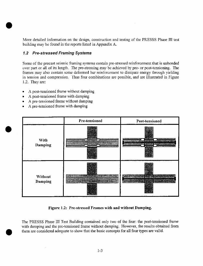
1.2 Pre-stressed Framing Systems
Some of the precast seismic framing systems contain pre-stressed reinforcement that is unbondedover part or all of its length. The pre-stressing may be achieved by pre- or post-tensioning. Theframes may also contain some deformed bar reinforcement to dissipate energy through yieldingin tension and compression. Thus four combinations are possible, and are illustrated in Figure1.2. They are:
¯ A post-tensioned frame without damping¯ A post-tensioned frame with damping¯ A pre-tensioned frame without damping¯ A pre-tensioned frame with damping
WithDamping
WithoutDamping
Pre-tensioned Post-tensioned
Figure 1.2: Pre-stressed Frames with and without Damping.
The PRESSS Phase III Test Building contained only two of the four: the post-tensioned framewith damping and the pre-tensioned frame without damping. However, the results obtained fromthem are considered adequate to show that the basic concepts for all four types are valid.
1-3

Priestley and MacRae [1996] tested several post-tensioned frame connections without damping,and achieved satisfactory results. The post-tensioned system without damping is designed in thesame way as the pre-tensioned system without damping of Chapter 4, except that the crackingmoment does not need to be evaluated since the interface is pre-cracked.
At the time of writing no pre-tensioned frame with damping has been tested. However, itsbehavior is expected to be similar to that of damped post-tensioned precast frame described inChapter 5, and it should be designed according to the principles presented there.
1.3 Format of the Report
This report is divided into five main chapters (Chapters 3-7), each of which describes a singlesystem and is largely autonomous. Each of those chapters presents, for the system that itaddresses, the design concept, the design procedure, important construction issues and a briefdiscussion.
Preceding these main chapters is Chapter 2, which discusses the derivation of earthquake loadsand the appropriate limit states. That information is included because the test building wasdesigned using displacement-based methods, which may be unfamiliar to some designers.
At the end of the report are a list of acronyms, a list of definitions, and a list of symbols. Inaddition, all symbols are defined in any chapter in which they are used.
1.4 Notation
The notation used in this report does not correspond to that used in any single code or standard.While much of it follows ACI notation, differences exist. There are several reasons for thedivergence. First, the material contained herein must be read in conjunction with severaldifferent published documents, all of which use different notation. Second, ACI notation doesnot use a consistent set of subscripts. For example, pre-stressed reinforcement is sometimesindicated by the subscript "p", (as in fpy) and sometimes by the subscript "s" (as in fse). In thisreport, the need to distinguish between pre-stressed and non-pre-stressed reinforcement isparamount, so such anomalies were considered unacceptable.
Inasmuch as possible, the notation adheres to the following principles. Greek symbols representdimensionless coefficients or ratios. Roman symbols represent variables that carry dimensions.Of the latter, stresses are given by lower case letters and forces by upper case letters. Subscripts"p" and "s" refer to pre-stressed and non-pre-stressed steel reinforcement respectively.Subscripts "0" and "des" refer to the zero drift state and the design limit state respectively.
1-4

2 DEVELOPMENT OF EARTHQUAKE LOADS FOR DESIGN
The PRESSS Phase III Test Building was designed using Displacement Based Design [Priestleyand Kowalsky, 2000]. This is a relatively new approach to developing seismic design loads thatprovides a rational alternative to the Force-Based Design procedures that are required by almostevery contemporary code. In the interests of providing a background on "the environment inwhich the design equations presented in the following chapters were developed, this chaptercontains a brief discussion of Force and Displacement Based Design methodologies.
2.1 Force-Based Design
Force Based Design procedures for computing seismic loads are contained in current designcodes, such as the UBC ["Uniform" 1997], the NEHRP provisions [NEHRP, 2000] and the IBC["International", 2000]. The most commonly used approach is the Equivalent Lateral Force(FiLF) procedure, in which the elastic response to the design earthquake ground motion is firstcomputed using assumed values of stiffness, after which it is modified using empirical factors toapproximate the effects of inelastic response. An estimate of the drift under the design loading isobtained by computing the drift of an elastic model of the structure under the design load, thenmodifying that by an empirical factor to account for the influence of inelasticity.
2.2 Displacement-Based Design
2.2.2 Overview
Displacement Based Design (DBD) embodies the philosophy that a structure should be designedto achieve a specified drift during a specified ground motion. The strength of the structure isthen selected by rational means to ensure that this goal is met. The displacement is the keyparameter, and the loads are derived from it. This approach is essentially the reverse of thetraditional Force Based Design (FBD), in which the loads are derived first and an estimate of thedrift is then obtained from the computed loads.
Priestley [2000] has described the Displacement Based Design method in some detail, so only asummary is given here. The method has its origins in the work of Gulkan and Sozen [1974] andShibata and Sozen [1976], but has undergone considerable development since then [Priestley andKowalsky, 2000], and is now incorporated into the SEAOC Recommended Lateral ForceRequirements ["Tentative", 1999] as a viable approach to determining seismic loads.
Two important assumptions underlie it:
First, the response of the structure is dominated by a deformed shape that resembles thefimdamental inelastic mode shape. This is essentially the same assumption as is made in theEquivalent Lateral Force embodiment of existing force-based design. It generally leads to a
2-1

reasonable description of the building and story drifts but, because it excludes higher modeeffects, it cannot be used alone to calculate individual story forces and the correspondingfloor-to-frame connection forces. The inelastic mode shape is defined in the same way as anelastic mode shape, namely the shape that leads to identical distributions of load andresponse. However the inelastic shape is not a mode shape in the sense of an eigenvector to alinear system, because it lacks some of the properties, such as orthogonality, of a true modeshape. The shape also varies with the intensity of the applied toad. In DBD, a shape ischosen that approximates the displaced shape of the inelastic system at the design load.
Second, the peak displacement of an inelastic SDOF system is the same as that of a viscouslydamped elastic system if the two have, at peak drift, the same secant stiffness and energydissipation per cycle.
2.2.3 Notation
AloopArect
Ca
K
LM[M]M*Mcap,totMcap,pMcap,sMcap,tot
Ms ’,des
RS~SaTTeqVdes
VeqVmax
F
= area of hysteresis loop= area of rectangle circumscribing hysteresis loop= vector with elements = 1.0 in DOFs parallel to ground motion and 0.0 elsewhere= ratio of inelastic to elastic drift= specified strength ofpre-stressing tendon material= specified yield strength of pre-stressing tendon material= specified yield strength of deformed reinforcement-- stiffness of SDOF system= secant stiffness of true hysteretic system at maximum displacement= earthquake participating mass= mass of SDOF system= mass matrix-- generalized mass in first mode= total moment capacity= moment capacity provided by pre-stressed reinforcement= moment capacity provided by yielding reinforcement= total moment capacity= effective mass in first mode= resisting moment provided by compression deformed reinforcement at design limit
state= seismic response modification factor= spectral acceleration= spectral displacement-- period of linear elastic SDOF system= period of equivalent viscously-damped linear SDOF system= design base shear= design base shear of equivalent viscously-damped linear system= peak shear experienced during pushover analysis
= earthquake participation factor
2-2

Atar,MDOF =
Atar, SDOF =
Odes =
X =XpLs~s’
~eq~eq,calc
~eq,est
{~)eq}
O)eq
inelastic drift of structure under reduced earthquake load in 1997 UBCelastic drift of structure under reduced earthquake load in 1997 UBCtarget displacement for MDOF systemtarget displacement for SDOF systemdesign interface rotation, consistent with design moment, Mdesover-strength factorover-strength factor for pre-stressed reinforcement in tensionover-strength factor for deformed reinforcement in tensionover-strength factor for deformed reinforcement in compressionviscous dampingviscous damping in equivalent linear systemcalculated viscous damping in equivalent linear systemestimated viscous damping in equivalent linear systemequivalent mode shape, or assumed deformed shapenatural frequency of SDOF systemnatural frequency of equivalent linear SDOF system
2.2.4 Procedure
The core of the DBD method may be explained most easily by considering the simplest case of aviscously damped linear Single Degree-of Freedom (SDOF) system in which the system massand damping are assumed to be known. The objective is to design the system so that it willreach a specified displacement (the design displacement, Atar, SDOF) when subjected to a specifiedground motion. The procedure is illustrated in Figure 2.1.
Atar,SDOF
Displacement Response Spectrum
Period
Figure 2.1: Use of DRS to Find Period Corresponding to a Target Displacement
2-3
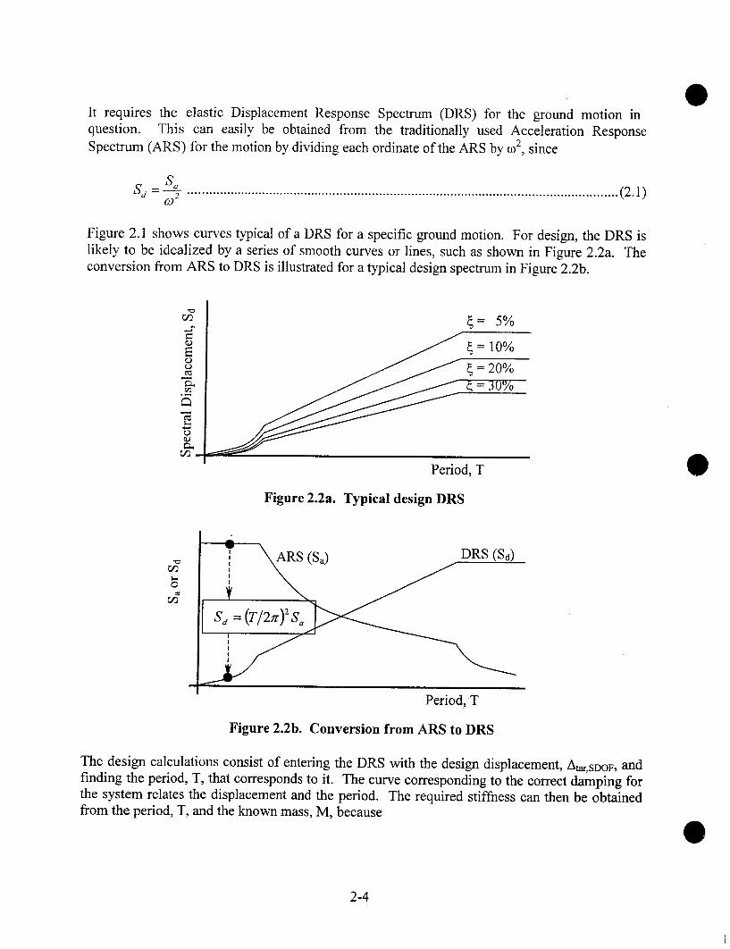
It requires the elastic Displacement Response Spectrum (DRS) for the ground motion inquestion. This can easily be obtained from the traditionally used Acceleration ResponseSpectrum (ARS) for the motion by dividing each ordinate of the ARS by c02, since
_SaSd - co---5- .........................................................................................................................(2.1)
Figure 2.1 shows curves typical of a DRS for a specific ground motion. For design, the DRS islikely to be idealized by a series of smooth curves or lines, such as shown in Figure 2.2a. Theconversion from ARS to DRS is illustrated for a typical design spectrum in Figure 2.2b.
{= 5%
lO%
30%
Period, T
Figure 2.2a. Typical design DRS
i ARS (S,) DRS (Sd)
. = 2 So
Period,
Figure 2.2b. Conversion from ARS to DRS
The design calculations consist of entering the DRS with the design displacement, Atar, SDOF, andfinding the period, T, that corresponds to it. The curve corresponding to the correct damping forthe system relates the displacement and the period. The required stiffness can then be obtainedfrom the period, T, and the known mass, M, because
2-4

K = Moo2 = M ....................................................................................................(2.2)
Once the required stiffness is known, the member sizes can be selected and the design iscomplete.
If the true system is hysteretic, rather than elastic, the procedure must be augmented by a secondstep that relates inelastic and elastic behavior. The (SDOF) hysteretic system is approximated byan equivalent viscously damped one. The two are equivalent in that the stiffness of the elasticsystem is the same as the secant stiffness of the inelastic system at the design drift. The viscousdamping is selected to give the same energy dissipation per cycle as exists in the hystereticsystem at peak drift. The hysteretic energy dissipation per cycle, and therefore the equivalentdamping, is assumed here to be known at the start of the design. (A modification to address thecase in which it is not known is described below). The DRS is entered, as before, with Atar,SDOVto find a period. The resulting period is Teq, the period of the equivalent elastic system that, whencombined with the known damping, will result in the desired Atar,SDOF. The equivalent stiffness,K~q, corresponding to Teq, is then computed from
M( 2rc l~ ..............................................................................................................(2.3)
An elastic system with this stiffness will result in the desired displacement, Atar, SDOF. Therequired strength of the real hysteretic system can be obtained from the equivalent elastic one byreference to Figure 2.3 and Equation 2.4.
DisplacementAtar,SDOF
Figure 2.3 Relationship among Atar,SDOF, Veq and Keq.Veq = KeqAtar,SDOF ........................................................................................................
;..(2.4)
2-5

Since Atar, SDOV was selected by the designer, and is therefore known, Veq can be computeddirectly from Equation 2.4.Once the required strength, Veq, has been computed, the member sizes can be selected and thecomplete load vs. displacement curve can be constructed. The area inside the hysteresis loop isequal to the energy dissipated per cycle, from which the equivalent damping can be computed.For systems with the same properties in each direction, the equivalent damping [Chopra, 1999] isgiven by using Equation 2.5.
~eq -- ¯.................................................................................................................(2.5)gr Arect
where A~oop = area enclosed by the hysteresis loopArm = area of the rectangle circumscribing the hysteresis loop
If ~eq differs from the value assumed at the start of the analysis, the computations must berepeated with the new {eq until convergence is achieved.
If, in addition, the system has more than one Degree of Freedom (DOF), a procedure is neededfor reducing the Multi-Degree-of-Freedom (MDOF) system to an equivalent SDOF one, so thatthe DRS can be used. This is done using classical modal analysis procedures, except that adeformed shape, {~eq}, is assumed for the MDOF hysteretic system and is used in place of thetrue first elastic mode shape. Approximate shapes are suggested by Priestley and Kowalsky[2000]. Use of this equivalent mode shape leads to
L = {¢eq }r[M]{e} .............................................................................................................(2.7)
LF=~- ..........................................................................................................................(2.8)
Mg=--LZ .....................................................................................................................(2.9)M"
/~tar,SDOF = I~,ar,MDOF /1’’ ................................................................................................. (2.10)
where {q~ eq } ---- equivalent mode shape (i.e. shape chosen by the engineer to represent thedeflected shape of the structure at the design drift)
[M] = mass matrix{e} = vector with elements = 1.0 in DOFs parallel to the ground motion and 0.0
elsewhereF = earthquake participation factor
2-6
L = earthquake participating massM* = generalized mass in first modeMeff = effective mass in first mode
The equivalent mode shape, {~eq}, should be normalized so that it has the value 1.0 at thelocation where the target displacement, At~,MDOV is measured in the MDOF system.
After computing the design base shear, Vdes, on the basis of an assumed level of damping, anddesigning the corresponding member sizes and strengths, the true damping supplied by theMDOF hysteretic system must be computed. This may be done by conducting a single-cycle"pushover" analysis on the MDOF system, using imposed lateral displacements distributed in theassumed displaced shape (the equivalent mode shape). The structure should be pushed toAtar,MDOF, reversed to --Atar, MDOF, then taken back to zero displacement. Equation 2.5 can then beused to determine the equivalent damping, for symmetric systems. In Equation 2.5, Aloop isgiven by the energy dissipated by the MDOF system and Arect is given by (4Atar,SOOF*Vmax),
where Vmax is the peak base shear experienced during the pushover analysis.
For hysteretic MDOF systems, the procedure may be broken into nine steps, shown in Figure2.4.
Select the target displacement, At,r, Moor. A possible basis for the choice is the amountof drift-induced damage to the building that is deemed to be tolerable under theintensity of ground motion being considered.
Estimate the equivalent viscous damping of the structure, ~eq, es~ The exact value isnot important at this stage because it will be corrected in subsequent iterations. Thevalue depends on the ductility demand. In the absence of better information, thefollowing starting values may be used as a guide:. 5-8% for undamped unbonded pre-stressed systems, 8-15% for unbonded pre-stressed frames and walls with damping, and15-25% for yielding or yielding gap frames.
Select a deformed shape, {(beq}. The shape should resemble the expected deformedshape of the structure at the design drift. This shape is used as the equivalent modeshape in the analysis that follows.
Compute the Earthquake Participation Factor, F, that converts the roof displacementof the MDOF system to the displacement of the associated SDOF system, usingconventional modal techniques and treating the deformed shape of Step 3 as an elasticmode shape. If the equivalent mode shape is normalized so that the elementcorresponding to the roof displacement is 1.0, and if the MDOF target displacement ismeasured at the roof, the Earthquake Participation Factor, F, is defined by
L = {~eq }r[Ml{e} ...............................................................................................(2.11)
2-7
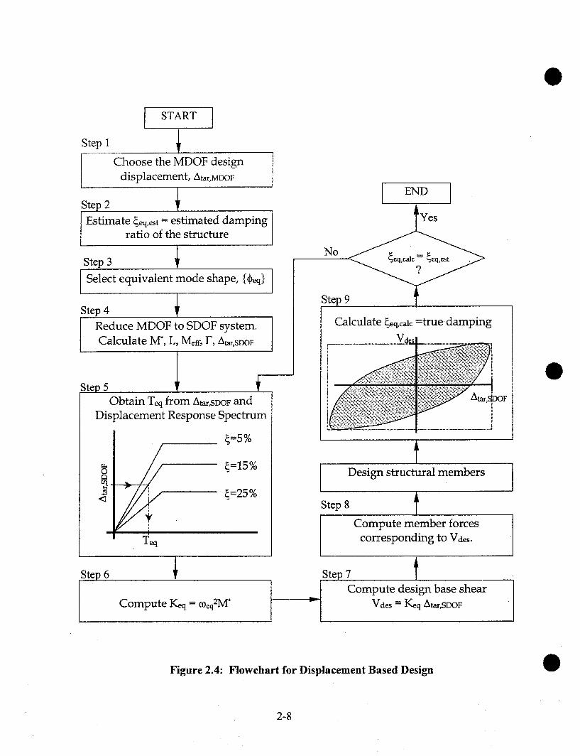
I START
Step 1
Choose the MDOF designdisplacement, Ata~,MDOF
Step 2
IEstimate {eq,est = estimated dampingratio of the structure
Step 3
ISelect equivalent mode shape, {d?eq}
Step 4Reduce MDOF to SDOF system.Calculate M*, L, Meff, 1-’, Atar, SDOF
Step 5 (Obtain Teq from A~,SDOF and
Displacement Response Spectrum
[
Teq
lStep 6
Compute Keq = ~0eq2M*
I ENDI
No
Step
Calculate ~eq, calc =true dampingV
Design structural members
Step 8Compute member forces
corresponding to Va~s.
Step 7Compute design base shear
Vdes = Keq Atar,SDOF
Figure 2.4: Flowchart for Displacement Based Design
2-8
M" = {(b~q}r[Ml{fb~q} .........................................................................................(2.12)
F= --L ...........................................................................................................(2.13)_/14’
The target drift of the SDOF system is thenA ,ar,S~OF = A ,ar.va~OF 11~ ....................................................................................
(2.14)
Compute the Equivalent Period, Teq, necessary to achieve Atar, SDOF during the designearthquake, given the estimated damping, ~eq,est, and the DRS.
Compute the Equivalent Stiffness, Keq, for the SDOF system from the equivalentperiod and the known mass of the structure, by
Keq = 2~r M’. .............................................................................................(2.15)
Compute the Design Base Shear from
Vaes = KeqA,ar,SOOF .............................................................................................(2.16)
Compute the story loads using the distribution defined by the equivalent mode shape.
Analyze the structure under the loads of Step 7, obtain the member forces and designthe members to resist them.
Determine the Energy Dissipated per Cycle (EDC) by the structure from a cyclic push-pull analysis or otherwise, and re-evaluate the equivalent viscous damping. It is givenby
~eq,calc -- 2 Atoop ...............................................................................................(2.17)
If the value of ~eq,calc differs significantly from the previous estimate, ~eq,est, repeat Steps 5-9 withthe new estimate of damping.
2.2.5 Discussion of Displacement Based Design
Displacement Based Design addresses primarily the response in the fundamental mode ofvibration. In almost all two-dimensional systems, this represents the vast majority of thedisplacement. However, local forces, such as floor-to-wall forces in a wall structure, may be
2-9
much larger than those predicted from the basic DBD procedure because of the local effect ofhigher modes. The same is true for the FBD procedure. Consideration of such forces isimportant at least in the design of connections. One approach to estimating the effects of highermodes is given by Eberhard and Sozen [1993]. It is applicable to both FBD and DBD.
One of the consequences of using DBD is that the required strength is related to the availabledamping. Thus, if two systems have identical stiffnesses but different damping characteristics,the one with the smaller damping will require a larger strength if both are to reach the sameprescribed drift. This feature of the DBD procedure reflects the physics of the problem, but isnot taken into account by FBD. As an example, if a pre-stressed frame with damping and a pre-stressed frame without damping are under consideration for a particular building, if DBD is used,and if the same drift limit is imposed for both systems, the design loads will be higher in thesystem without damping.
2.2.6 Comparison of Force and Displacement Based Design Procedures
The Displacement-Based Design procedure is essentially the reverse of that used in Force-BasedDesign. A comparison of the two procedures helps to bring out the differences between them.
The Equivalent Lateral Force (ELF) procedure is perhaps the most commonly used manifestationof FBD. In it, the structural configuration is selected and approximate member sizes areassumed, then the period of the structure is taken either from an eigenvalue analysis of an elasticmodel of the structure or from empirical equations in the code. The elastic response, and inparticular the maximum elastic forces, are found from a simplified acceleration responsespectrum and the computed period. They are applied over the height of the structure accordingto a code-specified distribution that approximates the first mode of vibration but that alsoincludes an empirical allowance for higher mode effects. The design forces, which representinelastic response, are obtained by dividing the elastic forces by an empirical factor, R [e.g.,"Uniform", 1997]. That factor is based purely on the type of system, and not on the individualcharacteristics of the building in question.
The global displacements are estimated by applying the design (i.e. inelastic) forces to an elasticmodel of the structure and computing the displacements. These displacements (As in UBC 1997)have no physical meaning, but are converted to the estimated design displacements, AM, bymultiplying by an empirical factor of Ca ["International" 2000] or 0.7R ["Uniform" 1997].These estimated design displacements are computed without reference to the real dampingavailable, and depend on the validity of the empirical "Equal Displacements Rule" [Veletsos andNewmark, 1960]. Furthermore, the maximum displacement, As, is sensitive to the elasticstiffness of the structure, which in turn depends on the level of cracking assumed in the concrete.Thus the estimated design displacement, AM, also depends on the assumptions that underlie theanalytical model of the structure.
The primary approximations in FBD lie in the assumption that inelastic forces can be obtainedsatisfactorily from the response of an elastic model with a nominal 5% damping, through the useof an empirical modifying factor that is based solely on the type of vertical structure.
2-10
Computation of the displacements rely on the design forces, the properties of the elastic modelof the structure, and the empirical factor that is used to relate elastic and inelastic displacement.That factor relies in part on the validity of the "Equal Displacements Rule".
In DBD, the maximum displacement is selected by the designer, then the required strength of thesystem is computed by assuming that the inelastic system can be represented by an equivalentelastic system with the same secant stiffness and damping. The initial elastic stiffness iscomparatively unimportant for this calculation, because the only design variable that itinfluences is the damping, and its effect on that is small.
The primary approximation in DBD is the assumption that an inelastic system displays the samedisplacement response as does an elastic system with the same secant stiffness and energydissipation per cycle.
DBD relies on none of the empirical modification factors used in FBD. It is therefore better ableto take into account the particular characteristics of the structure in question. It is believed bysome, e.g. [Priestley and Kowalsky 2000], to be the more rational procedure. However this viewis not universally held, e.g. [Chopra and God, 2001].
2.3 Performance Levels and Limit States
For any structure, consideration of several different limit states is desirable. In each, response toa prescribed set of loads is compared against acceptance criteria. For example, response to loadsthat represent those to be expected in an earthquake with a probability of 2% in 50 years mightbe evaluated for the potential for collapse. Or the response to an earthquake with a probability of50% in 50 years might be reviewed for its potential to cause non-structural damage. In makingthese evaluations, both demand and capacity mist be considered. Furthermore, consistentcombinations of load and allowable drift should be developed separately for each limit state.
The determination of these loads, and the factors that reflect the reliability with which they canbe predicted, lies outside the scope of this report. The material contained herein addresses onlythe matter of capacity. The purpose of the report is to provide design methods and equations thatpermit an engineer to establish by calculation the physical characteristics of the five systems thatwere used in the PRESSS Phase III test Building. Selection of the appropriate loads againstwhich to match the computed strengths must be achieved through consensus, and that is theresponsibility of code-writing bodies rather than individual authors. The same is true for otherrelated issues, such as the amount of live load to be taken into account in a seismic analysis ordesign, or minimum design standards to account for other loading types.
In this report, material over-strength factors, ~, are applied to the yield strength of thereinforcement to define the stress in that reinforcement at the strain in question. This isnecessary because, at the strains implicit in the design, considerable strain-hardening may havetaken place. Table 2.1 contains proposed values for material over-strength factors that representapproximately the mean values to be found in the field. Separate values are given for tension
2-11

and compression. These are based on the authors’ observations, so, before being incorporatedinto a design code they should be verified, and modified as necessary, by a comprehensivestatistical study. The associated System States are provided only as a guide. The straincorresponding to a particular System State should be chosen by the designer, in accordance withthe performance level desired for the particular structure.
No over-strength values are given for special items, such as the UFP shear connectors used in thewalls described in Chapter 3. For such items, the designer may choose from many materials, and)~ values should be selected that represent the strain-hardening characteristics of the materialchosen.
Table 2.1: Over-strength Factors for Deformed Reinforcement and Pre-stressing Strand.
SuggestedSystem StateFirst YieldDesignMax. Credible’
strain0.0020.040.08
ASTM A706 bars
1.01.351.5
~S’
1.01.01.0
Pre-stressing strandstrainNA~ NA1
0.0085 1.00.02 1.1
Notes:I In systems that contain pre-stressing but no deformed reinforcement, the values for the
Design System State may be used for the First Yield System State.2 The Maximum Credible state corresponds to the extreme drift required by testing criteria,
such as those of ACI ITG 1.1 ["Acceptance", 1999]
The factors in Table 2.1 are not intended to reflect the fact that the true yield strength ofdeformed reinforcement is often significantly higher than the nominal value of 60 ksi. Thedifference between nominal and true yield strength needs to be taken into account if CapacityDesign is to be implemented successfully. However, for the reasons stated above, thedevelopment o~f safety factors that reflect the true distribution of material strengths, or thataddress other objectives embodied in load and resistance factors in codes, lies outside the scopeof this study. (For example, Section R9.3.1 of ACI 318-99 provides fourdifferent classes ofuncertainty, all of which contribute to the strength reduction factors, ~0, used in that document.The vulnerability of the systems discussed in this report to the uncertainties addressed byACI318-99 may or may not be well represented by the strength reduction factors in that code).
2.4 Drift and Interface Rotation
For all five of the systems described in the report, the rotation at the interface between twoelements plays an important role in the design procedure. That rotation is closely related, but notidentical, to the drift ratio. It must be determined from the drift ratio using the geometry of thesystem in question.
2-12
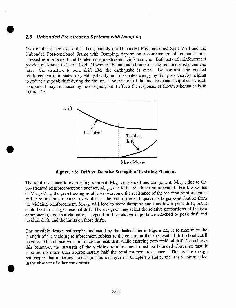
2.5 Unbonded Pre-stressed Systems with Damping
Two of the systems described here, namely the Unbonded Post-tensioned Split Wall and theUnbonded Post-tensioned Frame with Damping, depend on a combination of unbonded pre-stressed reinforcement and bonded non-pre-stressed reinforcement. Both sets of reinforcementprovide resistance to lateral load. However, the unbonded pre-stressing remains elastic and canreturn the structure to zero drift after the earthquake is over. By contrast, the bondedreinforcement is intended to yield cyclically, and dissipates energy by doing so, thereby helpingto reduce the peak drift during the motion. The fraction of the total resistance supplied by eachcomponent may be chosen by the designer, but it affects the response, as shown schematically inFigure. 2.5.
Drift
Peak driftResidualdrift
Mcap,s!Mcap,tot
Figure. 2.5: Drift vs. Relative Strength of Resisting Elements
The total resistance to overturning moment, Mcap, consists of one component, Mew,p, due to thepre-stressed reinforcement and another, Mcap,s, due to the yielding reinforcement. For low valuesof Mcap,s/Mcap, the pre-stressing as able to overcome the resistance of the yielding reinforcementand to return the structure to zero drift at the end of the earthquake. A larger contribution fromthe yielding reinforcement, Mcap,s, will lead to more damping and thus lower peak drift, but itcould lead to a larger residual drift. The designer may select the relative proportions of the twocomponents, and that choice will depend on the relative importance attached to peak drift andresidual drift, and the limits on those drifts.
One possible design philosophy, indicated by the dashed line in Figure 2.5, is to maximize thestrength of the yielding reinforcement subject to the constraint that the residual drift should stillbe zero. This choice will minimize the peak drift while ensuring zero residual drift. To achievethis behavior, the strength of the yielding reinforcement must be bounded above so that itsupplies no more than approximately half the total moment resistance. This is the designphilosophy that underlies the design equations given in Chapters 3 and 5, and it is recommendedin the absence of other constraints.
2-13

2-14

3 UNBONDED POST-TENSIONED SPLITWALLS
3.1 Concept Description
The Unbonded Post-Tensioned Split Wall is illustrated in Figure 3.1. It is composed of two ormore vertical wall panels, separated by vertical joints across which shear sliding occurs duringan earthquake. The wall panels are post-tensioned to the foundation. The bonded reinforcementin the wall panels has been omitted from the figure in the interests of clarity.
Figure 3.1: Unbonded Post-tensioned Split Wall
Each wall panel may be cast as a single element, or as several separate wall elements that aresubsequently joined by rigid connections. Each wall panel is vertically post-tensioned to thefoundation. The tendons may be placed at the edge or at the middle of the panel, but in mostcases placement in the center will prove advantageous, because it induces the least tendonelongation for a given drift ratio.
The wall panels are connected across their vertical joints by shear connectors that dissipateenergy by yielding. While other arrangements for dissipating energy are possible, the discussionin this report is restricted to the system used in the PRESSS Phase Ill test building. Figure 3.2
3-1
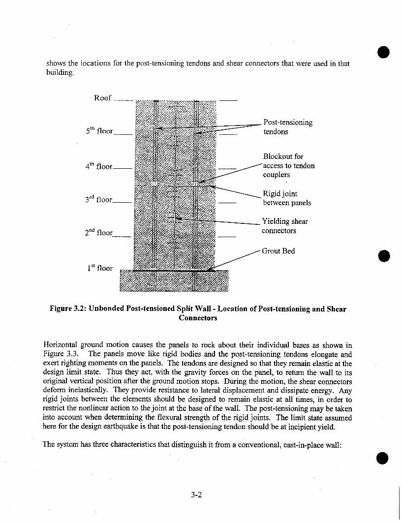
shows the locations for the post-tensioning tendons and shear connectors that were used in thatbuilding.
Roof __
Post-tensioning5th floor__ tendons
4th floor,~Blockout for
to tendoncouplers
floor-~. Rigid joint
between panels
Yielding shear2na floor connectors
1 st floor
Bed
Figure 3.2: Unbonded Post-tensioned Split Wall - Location of Post-tensioning and ShearConnectors
Horizontal ground motion causes the panels to rock about their individual bases as shown inFigure 3.3. The panels move like rigid bodies and the post-tensioning tendons elongate andexert righting moments on the panels. The tendons are designed so that they remain elastic at thedesign limit state. Thus they act, with the gravity forces on the panel, to return the wall to itsoriginal vertical position after the ground motion stops. During the motion, the shear connectorsdeform inelastically. They provide resistance to lateral displacement and dissipate energy. Anyrigid joints between the elements should be designed to remain elastic at all times, in order torestrict the nonlinear action to the joint at the base of the wall. The post-tensioning may be takeninto account when determining the flexural strength of the rigid joints. The limit state assumedhere for the design earthquake is that the post-tensioning tendon should be at incipient yield.
The system has three characteristics that distinguish it from a conventional, cast-in-place wall:
3-2

Essentially rigid body motion of wall panels. The system displaces primarily by rocking ofthe panels and by opening of the joint at the wall base. Displacements caused by bendingand shear deformations of the panels themselves are much smaller than those due to rocking.This behavior leads to much less panel damage than would be expected in a fixed-base wallthat undergoes the same drift.
Panel rocking. The panel properties, and in particular the aspect ratio, are selected so thatthe rigid body motion is rocking rather than sliding. This choice leads to high drift capacity.
Separation of restoring force and damping. The post-tensioning provides an elastic restoringforce while the shear connectors provide damping. This arrangement uses the sameprinciples as are present in the suspension of an automobile, where separate elements areused for springs and shock absorbers. This separation of functions allows the wall to bedesigned to achieve zero residual drift after the ground motion stops.
Shear Post-tensioningconnectors
Grout pad
Figure 3.3: Unbonded Post-tensioned Split Wall - Components
There is no lower bound on the strength of the shear connectors. They could be omittedaltogether, thereby Simplifying construction, but the penalty would be larger peak drifts due tothe low damping. This philosophy is adopted by Kurama et al. [1998], for example, and iscommonly used in (non-pre-stressed) tilt-up panel construction.
Design procedures are given for shear connectors made from U-shaped Flexural Plates (UFPs),shown in Figure 3.4. This connector was originally proposed by Kelly et al. [1972] and isdiscussed further by Schultz and Magana [1996] and Galusha [1999]. Other connector typesmay also be used. However, the wall test [Priestley et al., 1999] that forms the basis for thecomparison of predicted and measured responses contained UFPs.
3-3

Figure 3.4: UFP Shear Connector
The UFP works by rolling like a tank track to accommodate relative shear displacement betweenthe two panels. The bent plate dissipates energy as the different regions of it alternately bendand straighten inelastically. The shear displacement that can be accommodated is limited onlyby the geometry of the system, in particular by the distance by which the weld is held back fromthe bend in the plate.
The rocking behavior of the wall leads to less panel damage than would occur in a conventional,cast-in-place wall, because the wall panels do not deform inelastically. However, some localdistress must be expected at the wall toe about which rocking occurs. Several alternative designapproaches are possible for controlling that damage. The designer should select one that isconsistent with the design objectives for the building and the expected level of drift. The issuesto be considered include:
¯ damage to, and degradation of, concrete and grout¯ buckling of vertical wall reinforcement¯ loss ofpre-stress due to vertical shortening of wall and grout pad¯ horizontal sliding promoted by damaged interface materials
When the wall rocks, the local compressive stresses in the grout and concrete are high enoughthat some inelastic action will occur. By suitable selection of material strengths in accordancewith the principles of capacity design, the designer can control the location of the inelasticaction.
The inelastic action can be forced to occur in the concrete wall panel by using grout that isstronger than the concrete. Then the toe of the wall panel must be confined to prevent
3-4

compression failure of the concrete. The cover concrete, which by definition is not confined, islikely to be lost due to the large strains. However, that damage is expected to be easilyrepairable.
Another alternative is to make the concrete, including any reinforcement, stronger than the grout,thereby forcing the inelastic deformations into the grout bed. In this case, the strength required inthe wall panels can be achieved by using stronger concrete, vertical reinforcement, confinementreinforcement, local armor, or other means. The grout can be made ductile by fiber reinforcing,by placing it in a trough below the wall, as was done in the PRESSS building, or both. Thissecond approach is intended to reduce the damage to the panels at the expense of some groutcrushing. The calculations in this chapter are based on this approach.
In extreme cases, extensive pulverization of the grout could lower the coefficient of friction andlead to premature sliding. However, sliding is controlled by the aspect ratio of the wall panels,as well as by the coefficient of friction, and in many cases sliding will not govern design, even ifthe grout crushes and the friction is consequently lowered.
3.2 Design Assumptions
The following assumptions are made in the development of design equations:
The design forces and drift limits are known. The drift limits are selected to satisfy coderestrictions and user requirements. Forces may be obtained either by Force Based Design orby Displacement Based Design. Interface rotations are obtained from the drift ratio, usingthe geometry of the system.
2. The overall dimensions of the wall are known, having been obtained from architecturalconstraints and preliminary calculations.
3. The wall panels are all the same size and have a constant thickness. Design equations forother arrangements follow the same principles, but are necessarily more complex.
° The shear connectors are treated as rigid-plastic in the interests of simplicity. Designprocedures in which they are modeled as elasto-plastic would lead to the same strength, butslightly lower damping, provided that all connectors yielded prior to the design drift. Suchdesign procedures would necessarily be more complex than those presented here. Oneconsequence of the rigid-plastic modeling is that any relative shear displacements betweenpanels that occur prior to the earthquake have no effect on the seismic behavior. Suchdisplacements might be caused by differential response to pre-stress, settlement or thermaleffects. Such displacements are likely to be small compared with the seismic displacements.
The post-tensioning tendon is at incipient yield at the design drift. If a lower tension stress isdesired in the tendon at the design drift, it should be substituted for fpy in the equations thatfollow.
3-5

Properties of the proposed materials are known.
¯
The principal ones are:strength and stiffness of post-tensioning materialstrength of deformed reinforcementstrength of shear connectorsstrength of concretestrength of grout
3.3 Notation
The sign convention adopted is that forces and deformations are computed as positive quantities,regardless of whether they are tensile or compressive.
Ap
CoCcCdes
Dsc
Epf’gfp,des
fp0fpy
fsc,des =
Fsc,left =
Fsc,net =Fsc,right
herr =huhwkl =lw =
lw,tot =Mcap,panel =
Soap,wall =
Mdes =
nnsc
Ndes
= area of pre-stressing tendon= width of UFP connector plate= compressive reaction on one wall panel at zero drift= compression capacity of one wall panel= compressive reaction on one wall panel at design limit state= bend diameter (measured at mid-thickness of plate) in UFP connector plate= Young’s modulus of pre-stressing tendon material= specified grout strength at 28 days= stress in pre-stressing tendon at the design limit state= stress in pre-stressing tendon, after losses, at zero drift= specified yield strength ofpre-stressing tendon material
stress in UFP connector plate under plastic conditionstotal yield force of all shear connectors in one vertical jointtotal yield force of all shear connectors in joint to left of panelnet vertical force on one panel from all shear connectorstotal yield force of all shear connectors in joint to right of panelheight above foundation of lateral load resultant on wall
= unbonded length of pre-stressing tendon= total height of wall panel (used for self-weight)
uniform stress in Whitney rectangular equivalent stress block divided by f’glength of one wall panel (horizontal dimension in plane of the wall)total length of one wallmoment capacity of one paneltotal moment capacity of wallmoment demand at design limit stateplastic moment strength of one UFP connector
= number of panels per wall= number of shear connectors required per vertical joint= total axial force on one wall panel from gravity plus post-tensioning at zero drift= total axial force on one wall panel from gravity plus post-tensioning at design limit
state
3-6

P0
Pdestsc
twtw,effVdesWsc
W floor
WWpanel
~O,ave
C~des
17,des,ave
?cAlpAfp~o
ApI~sc,des
~sc,max
~SC,U
rio
~des
Odes
KO
PfpoPMOM
13ROC
PUPL
pZRD
= force in pre-stressing tendon at zero drift= force in the pre-stressing tendon at design limit state= plate thickness in UFP connector= thickness of wall panel= thickness of wall panel effective in resisting compressive force= design base shear= shear strength of one UFP shear connector= distributed vertical load on the wall, at base, from all floors= total gravity load from all floors on one wall panel= self-weight of one panel
= distance from the compression face of the member to the center of the compressionforce, divided by the member depth, at zero drift
= average value, over all panels, of= distance from center of compressive reaction to edge of member divided by member
depth, at design limit state= average value, over all panels, of C~a~s= depth of equivalent compressive stress block divided by the neutral axis depth= density of concrete= increase in stress in pre-stressing tendon between zero drift and design drift= increase in stress in pre-stressing tendon between zero drift and design drift when
concrete and grout strengths are infinite= deformation of pre-stressing tendon between zero drift and design drift= strain in the UFP connector plate at the design limit state= maximum permissible strain in UFP connector plate under cyclic loading= strain at maximum stress in the UFP connector plate material= distance from member compression face to neutral axis divided by member depth, at
zero drift= distance from member compression face to neutral axis divided by member depth, at
design limit state= interface rotation at design limit state= ratio of design strength of shear connectors in one joint to the vertical load on one
panel= coefficient of friction= stress ratio to ensure that pre-stressing tendon does not yield at maximum drift= demand/capacity ratio for overturning moment on panel= force ratio to ensure that the panel slides rather than rocks= ratio of uplift force to hold-down force on one panel= parameter ratio controlling the residual drift
3-7

3.4 Design Procedure for Critical Elements
3.4.1 Design of Post-tensioning Tendons and Shear Connectors
The following step-by-step procedure is presented in the form of analysis rather than design,because direct design, without iteration, is not possible for most cases. However, by automatingthe analysis procedure on a spreadsheet or similar computer application, design may beconducted quickly and easily. In the steps that follow, the lateral load is assumed to be acting tothe right. Therefore the right end of the wall is the compression end, and the left end is thetension end. The wall is shown in its deformed shape in Figure 3.5. The locations of the forcesare detailed in Figure 3.6.
Establish Material Properties
Establish properties of materials to be used. These include:¯ grout: strength, stress block coefficient 131, coefficient of friction against concrete¯ concrete: strength, density¯ tendon: Young’s modulus, yield strength¯ connector: cyclic load-displacement relationship
In the absence of better information, the coefficient of friction, ~t, between the grout and the-concrete may be taken as 0.5. Hutchinson et al. [1990] measured a value of 0.6 between precastconcrete and grout under cyclic loading. That value is reduced here to 0.5 to allow for variationswith grout type. Roughening of the surfaces could lead to a higher value, but experimentalevidence would be needed to justify its use in design.
w
Vdes
heft
Vdes ~< p.ENaes
Figure 3.5: Unbonded Post-tensioned Split Wall - Deformed Configuration at Design Drift
3-8
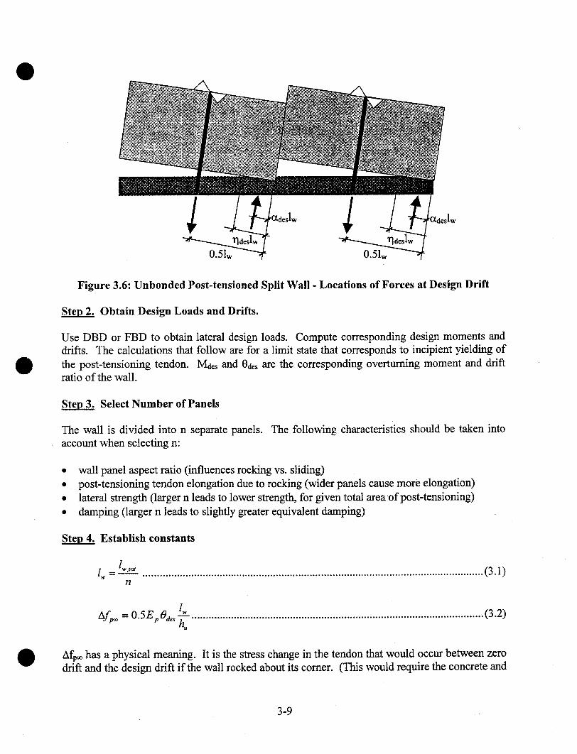
Figure 3.6: Unbonded Post-tensioned Split Wall - Locations of Forces at Design Drift
Ste~ 2. Obtain Design Loads and Drifts.
Use DBD or FBD to obtain lateral design loads. Compute corresponding design moments anddrifts. The calculations that follow are for a limit state that corresponds to incipient yielding ofthe post-tensioning tendon. Mdes and Odes are the corresponding overturning moment and driftratio of the wall.
Ste~ 3. Select Number of Panels
The wall is divided into n separate panels.account when selecting n:
The following characteristics should be taken into
¯ wall panel aspect ratio (influences rocking vs. sliding)¯ post-tensioning tendon elongation due to rocking (wider panels cause more elongation)¯ lateral strength (larger n leads to lower strength, for given total areaof post-tensioning)¯ damping (larger n leads to slightly greater equivalent damping)
Ste~ 4. Establish constants
lw - lw’t°’ ........................................................................................................................(3.1)
n
lw 2Afp~ =0.5EpOa~ ~-- .......................................................................................................(3.)n~
Afp~ has a physical meaning. It is the stress change in the tendon that would occur between zerodrift and the design drift if the wall rocked about its comer. (This would require the concrete and
3-9

grout to be infinitely strong, so in practice it is impossible and the true stress change will besmaller than Afp~. The true stress change is given by Equation 3.18)
Mac, = Vae~.h~ .................................................................................................................(3.3)
Wp~,,~ = l~twhw~"C ............................................................................................................. (3.4)
W = Wpane’ -t- lwWfloor ........................................................................................................ (3.5)
Cc = l~tw.~r (klf’g ) .........................................................................................................(3.6)
Fsc,,~, = F~c,~e~ - <~ri~h, ....................................................................................................(3.7)
In Equation 3.4, tw is the total wall thickness, used here to compute the weight of the panel. InEquation 3.6, tw,efr is the thickness of wall that is effective in resisting compression. Forexample, if the grout strength controls the compression capacity, and the grout bed is narrowerthan the wall, tw,efr should be the width of the grout bed.
Note: Steps 5 - 10 that follow must be repeated with different input values until a combination isachieved that satisfies all the acceptance criteria in Step 10.
Steo 5. Select Reinforcement
Select Ap, fp0, Fsc. Compute Fsc,net, the net vertical force on each panel due to the shearconnectors. For interior panels in a wall with more than two panels, Fsc,net will be zero if verticallines of connector have the same strength, as is assumed here.
Ste~ 6. Establish Conditions Immediately after Lift-off at the Base of the Wall.
Each wall panel lifts off the base gradually. During lift-off, the stresses in the grout and concreteat the interface are initially low enough that behavior is elastic but, as lift-off progresses, thestresses rise and some inelastic behavior occurs. In the conditions addressed in this step, lift-offis assumed to have progressed far enough for the grout to behave inelastically, but the drift ratiois small enough that the tendon stress can still be taken with sufficient accuracy as fp0, the valueat zero drift.
g = Apf, o ......................................................................................................................(3.8)
No = Po + W ...................................................................................................................(3.9)
CO = NO d- Fsc,net ............................................................................................................ (3.10)
3-10

................................................................................................................... (3.11)
r/o = 2 a--m° .....................................................................................................................(3.12)
F~co = ~c .................................: ..............................................................., ....................(3.13)
No
Steo 7. Establish Conditions at Design Load and Drift
Pdes, the force in the tendon at the the design limit state, may be found by iteration. If Pdes isestimated, then axial force equilibrium requires
Nde.~ = Pae.~ + W .............................................................................................................(3.14)
Cde~. = N~. + F.~.~.,,e, .......................................................................................................(3.15)
The location of the compressive force in the concrete and grout bed is ~deshb, where
Ctde~. = 0.5 Cd~s ..............................................................................................................(3.16)
and the neutral axis location is given by ~ldeshb, where
riot, = 2 aae‘ .................................................................................................................(3.17)
Figure 3.6 shows that the elongation of the tendon is
A, : Odeslw(O.5 -- 7]des) ....... ; ........................................................................................... (3.18)
Thus the increase in stress in the tendon is
Ap = Af p~O_ 2rla~s) ......................................................................................(3.19)Afp = Ep’~u
and the total stress is
fp,ae, ={fpo + ASp )~-- fpy ............................................................................................... (3.20)
3-11

A better estimate of Pdes is then given by
P,~, = A~,f p,a,, ...............................................................................................................(3.21)
Equations 3.14 to 3.21 may be solved iteratively until they converge to give the final value ofPdes. Alternatively, those equations may be combined for a direct solution. First Equations 3.19through 3.21 are combined and solved for rides, to give
Ap{fpo + AU )+ V + F.<.,,.,rials = fl~C~ + 2A~,Afw ¯ .....................................................~ ........................(3.22)
This value of rlaes is then substituted in Equations 3.19 through 3.21 to give, after some algebraicmanipulation,
A, f,,o+Af~ 1 ~
Pa,, - A~,f p~ < A~,f p, ........................................................... (3.23)
o.5/ ,Cc
This value of Paes may then be substituted in Equations 3.14- 3.19 to provide values for the otherconstants.
Ste~ 8. Compute Resisting Moments of Wall Panels
M cop,m.., = l>, (C aes (O.5 -crd.~ )+ O.5(F.<.t.s, + Fs<,,,g~,, )) ...................................................... (3.24)
Equation 3.24 gives the resisting moment about the centerline of the panel. The first termrepresents the couple caused by the compressive force under the panel and the tendon force, andthe second, term represents the moment due to the shear connectors. The resisting moments ofall wall panels should be computed separately, because each panel will have its own distinctvalue of otdes. In general, the panel at the tension end of the wall will have a smaller resistingmoment than will the panel at the compression end. In a wall with four or more identical panels,the behavior of the interior panels will be the same.
Ste~ 9. Compute Resisting Moment of Wall
M c,,~,.w,,l~ = Z M ~,~,panet .................................................................................................(3.25)
Step 10. Check Acceptance Criteria
The following dimensionless ratios, P~o~, etc., should be checked to ensure that the designcriteria are met. Each ratio fulfills a function similar to that of a demand/capacity ratio, but itdoes not necessarily represent a ratio of forces.
3-12

M des,OMoM - -- _< 1.0
Mcap, wall
Lo--
overtuming ..............................(3.26)
yield of post-tensioning steel... (3.27)
(n- 1 + 2a°"ve~¢°) < 1.0Pz~ = Xo
n(0.5
uplift of end panel ...................(3.28)
residual drift .............................(3.29)
~ORoC = ~_(0.5--Of0 ave)~ <-- 1,0 sliding vs. rocking ...................(3.30)
where c~0,ave = average across all panels of the value of c~0.
If the acceptance criteria do not satisfy the specified limits, select new values for Ap, fpo andand repeat Steps 5-10.
Equation 3.24 shows that the post-tensioning and the shear connectors both contribute to theresisting moment of the panel. Thus, in general, the greatest strength will be achieved by makingthe connector forces as large as possible. The connector forces are bounded above by the ZeroResidual Drift criterion (Equation 3.29). Maximizing the connector forces will also maximizethe damping.
3.4.2 Design of UFP Shear Connectors
Any ductile shear connector that has the required strength and deformation capacity may be usedto connect the wall panels. The UFP connector is one example and is described here because itwas used in the PRESSS Phase III building test and worked well. It consists of two flatanchorage plates, one embedded in each panel edge, and one plate bent in the shape of a "U" thatis welded to the embedded plates.
gsc
Figure 3.7: Forces on UFP under Inelastic Conditions
3-13

Equations for analysis of the UFP are presented. They may be used for design on a trial anderror basis. Design is unlikely to be direct, because it is a compromise between number ofconnectors, plate dimensions, available plate sizes, radius of bend and material properties. Afree body diagram of the curved part of the bent plate is shown in Figure 3.7. Momentequilibrium requires that
EcD,c : 2M,c ..............................................................................................................(3.31)
where Msc, the plastic moment capacity of the plate, is given by
( b,.ct,.c2 ~M,c = |~|f~.c.ae~. .....................................................................................................(3.32)
and fsc,ae~ = the stress in the plate under plastic conditions, including strain-hardening.
As the straight part of the plate is bent, the strain change in the outer fiber of the UFP caused bythe change in curvature is
%"~e" D~,~ ...................................................................................................................(3.33)
Combining Equations 3.31 - 3.33 leads to
V~.c = ~’~-J[f.c,ae,%,,~,J ................................................................................................(3.34)
The number of shear connectors required per vertical joint, n~c, is given by
n.~.~ V,e .......................................................................................................................(3.35)
In Equation 3.33, the strain ~sc,aes should be limited to a value ~;sc,max that can be imposedcyclically without damage to the plate. The number of cycles depends on the earthquake groundmotion used for the design. In the absence of better information, a strain limit of
%,m~x =--~-- .................................................................................................................(3.36)
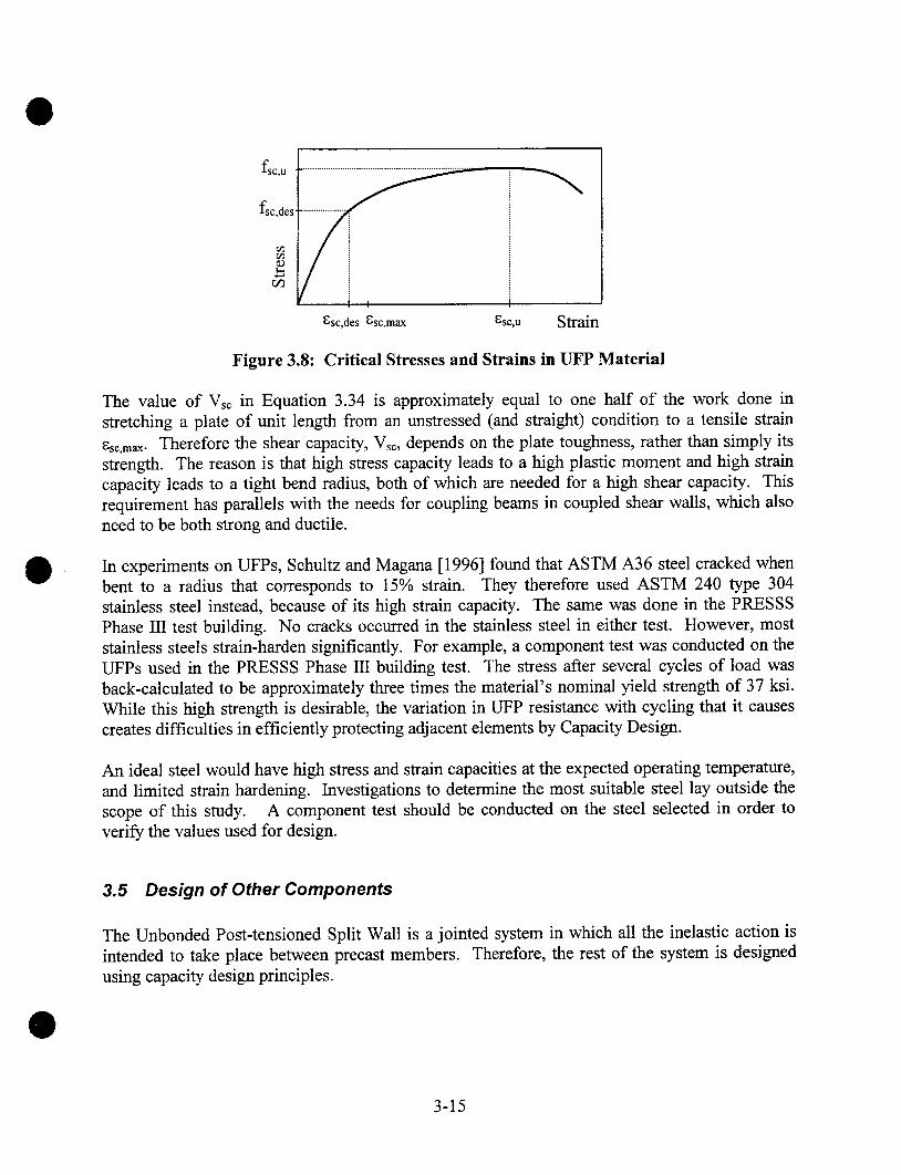
is proposed, where ~sc,u is the strain in the material at maximum stress in a static tension test.The strain change during cyclic loading is the same as the initial strain imposed in forming theplate, because the change in curvature is the same in both cases,fsc,aes is the stress thatcorresponds to ~,a¢~. These strains are illustrated in Figure 3.8.
3-14
fSC,II
~sc,des [;sc,max [;sc,u Strain
Figure 3.8: Critical Stresses and Strains in UFP Material
The value of Vsc in Equation 3.34 is approximately equal to one half of the work done instretching a plate of unit length from an unstressed (and straight) condition to a tensile strain~sc,max. Therefore the shear capacity, Vsc, depends on the plate toughness, rather than simply itsstrength. The reason is that high stress capacity leads to a high plastic moment and high straincapacity leads to a tight bend radius, both of which are needed for a high shear capacity. Thisrequirement has parallels with the needs for coupling beams in coupled shear walls, which alsoneed to be both strong and ductile.
In experiments on UFPs, Schultz and Magana [1996] found that ASTM A36 steel cracked whenbent to a radius that corresponds to 15% strain. They therefore used ASTM 240 type 304stainless steel instead, because of its high strain capacity. The same was done in the PRESSSPhase III test building. No cracks occurred in the stainless steel in either test. However, moststainless steels strain-harden significantly. For example, a component test was conducted on theUFPs used in the PRESSS Phase III building test. The stress after several cycles of load wasback-calculated to be approximately three times the material’s nominal yield strength of 37 ksi.While this high strength is desirable, the variation in UFP resistance with cycling that it causescreates difficulties in efficiently protecting adjacent elements by Capacity Design.
An ideal steel would have high stress and strain capacities at the expected operating temperature,and limited strain hardening. Investigations to determine the most suitable steel lay outside thescope of this study. A component test should be conducted on the steel selected in order toverify the values used for design.
3.5 Design of Other Components
The Unbonded Post-tensioned Split Wall is a jointed system in which all the inelastic action isintended to take place between precast members. Therefore, the rest of the system is designedusing capacity design principles.
3-15

3.5.1 Panel Reinforcement
The bonded reinforcement in the body of the wall panel should be designed to remain elastic.The influence of higher modes of vibration should be taken into account when designing thepanels and any joints between them, because they may cause the effective height of the seismicloading to be smaller than suggested by the loading patterns of either the DBD analysis or theEquivalent Lateral Force procedure of FBD. For a given resistance to overturning moment, thebase shear force will then increase, and local moments and shears within the panel may be largerthan those caused by an approximately triangular load pattern. One method for accounting forhigher mode effects is given by Eberhard and Sozen [1993].
Reinforcement should be supplied to resist the splitting and bursting stresses caused by the post-tensioning anchor. Strut-and-tie modeling is recommended for determining local design forces.
3.5.2 Confinement Reinforcement
Confinement reinforcement should be designed for the wall toes. The amount and distribution ofconfinement reinforcement will depend on the limit state under consideration. Relationshipsbetween the volume of confinement reinforcement and the compressive strength of the confinedconcrete are given by several authors, e,g., [Paulay and Priestley, 1992].
In the PRESSS Phase III building test, the wall toes were confined using a steel channel, whosedepth was equal to the wall width, at each toe. The arrangement is illustrated in Figure 3.9. Theweb of the channel lay in a horizontal plane. At the bottom comers of each panel, verticalreinforcement was welded to the channel to ensure good transmission of compressive stress. Thearea of reinforcement was selected as 2% of the corresponding concrete area, and the steel wasplaced over the outer 25% of each panel. This reinforcement was included in the calculations ofthe compressive capacity of the toe of the wall.
Vertical wallreinforcement
tw
Wall ties -- Grout bed
Steel channel Foundation
Figure 3.9: Confinement Detail at Base of Wall
3-16
Note that the grout in the joint will be considerably stronger than would a cube of the samematerial, because it is thin compared with its lateral dimensions and is thus confined by the wallabove and the foundation below it. Conservatism in designing the wall toes is thus advisable.
3.5.3 Wall-to-Floor Connections
Connections between the wall and floor must be designed. The loads that they carry include theeffects of higher modes of vibration, so these must be included in the calculation of the appliedloads. The contribution of the higher modes to the global overturning moment is small. Howeverthe relative effect of higher modes on individual floor forces is larger and should be accountedfor explicitly. This is true in all structures, including cast-in-place walls, and is not peculiar toprecast wall systems. Guidance for selecting design forces is given by Eberhard and Sozen[1993].
The connections should also take account of any relative displacements between components thatmust be allowed to occur freely. Two main types of displacement exist. First, relative sheardisplacements occur across the interface between the sliding joint between panels, so the slabshould not be attached rigidly to the wall panels close to the joint unless out of plane sheardamage to the slab is acceptable. Some other means of support must be supplied in the region.Second, the center of each wall panel rises as it rocks and creates differential vertical movementsbetween the wall and the perimeter frame. It is worth noting that a cast-in-place wall alsoexperiences a vertical component of motion that is comparable to the one found in a precast wall.
The effects of the differential movements in the two walls are similar, but are usually ignored,perhaps because the damage to the cast-in-place wall itself is so serious that moderate crackingin the floors is viewed as relatively unimportant. Thus any methods used in a conventional cast-in-place structure are also candidates for use in a precast one.
However, measures can be taken to improve the performance of the building by designing theconnections to reduce damage. One possible way of accommodating the sliding sheardisplacements between the panels is to install an edge beam that runs parallel to the wall and toconnect it to the wall only near the centerline of each panel. In the PRESSS Phase III testbuilding, this was achieved by bolting a steel header beam to the wall panels as shownschematically in Figure 3.10, using a single large bolt in each panel. This arrangement allowedrelative rotation between the header and the wall, so the header remained horizontal at all timesand no damage was done when the wall rocked. Shear forces parallel to the wall weretransferred from the floor into the header and thence through the bolts into the wall.
The relative vertical displacements between the wall and the perimeter frame occur because bothelements experience the same rotation, but the wall panels are wider. If the header beam issupported on both the perimeter frame and the wall, it must accommodate the differential verticalmovement between them. In the PRESSS Phase III test building, this was done by introducing ajoint in the header beam, because the building dimensions were such that the wall ended veryclose to the exterior frame and would otherwise have caused significant inelastic bending in theheader beam. In a prototype structure, the likely greater horizontal separation between the wall
3-17

and the perimeter frame would permit some deformation to be accommodated by bending of theheader beam and floor, thereby obviating the need for the elaborate connections used in thePR~SSS Phase III test building.
Wall Panel Precast floorunits
Bolt Header beam
Figure 3.10: Wall-to-Floor Connection System used in PRESSS Building
3.6 Limits on Reinforcement
There is no lower limit on the quantity of post-.tensioning to be used in the wall. In an extremecase of large, heavy, panels and low seismic loading, the self-weight alone may be sufficient toensure re-centering, in which case no post-tensioning would be necessary to resist the lateralloads. However, such designs are likely to be rare.
The maximum permissible quantity of post-tensioning depends on the design objective. If thegoal is to protect the panel against cover spalling, the post-tensioning must be limited so that thestrains in the concrete are low enough to prevent such behavior. If cover spalling is consideredacceptable during a rare, severe, earthquake, because it can be repaired easily, then the designermay use one of several different strategies, all of which are based on increasing the compressivestrength of the toe of the wall. Possibilities include confinement of the wall core, adding verticalreinforcement, etc. Multiple design objectives are also possible. For example, two reasonableobjectives for the same building might be no spalling under a moderate earthquake, but no failureof the core of the wall during a severe earthquake.
3.7 Construction lssues
3.7.1 Transportation Limitations
Transportation and crane limitations should be considered when selecting the wall panel andelement sizes.
3-18
3.7.2 Post-tensioning Materials
Bars and strands are both acceptable forms of post-tensioning. When large tendon elongationsare needed, the greater elongation capacity of strand may prove advantageous. In other cases,the ease of installing and connecting bars may offer greater benefits.
3.7.3 Post-tensioning Duct Alignment
The post-tensioning ducts must be large enough to allow installation of the tendons, and must bestraight. Crooked ducts could impede installation of tendons, risk kinking of the tendons andcause friction during stressing.
3.7.4 Corrosion Protection
Measures must be taken to ensure that the unbonded post-tensioning tendons are protectedagainst corrosion, especially at critical locations, such as anchorages and any couplings.
3.7.5 Grout Confinement
Use of fiber-reinforced grout between the foundation and wall will help to ensure that the groutdoes not escape from the interface when it is highly compressed. This will help to preventdeterioration in performance with cycling. Placing the grout in a pocket in the foundation, suchas shown in Figure 3.9, will provide additional confinement.
3.8 Discussion
The wall in the PRESSS Phase III test building performed very well. It exhibited all the featuresthat it was intended to possess under design loading: zero residual drift, closely predictable peakdrift, and minimal damage. Figure 3.11 a shows that wall after the completion of the test, duringwhich it was displaced to 2.7% drift. The horizontal cracks in the wall were caused by out-of-plane bending, when the building was being tested in the frame direction, and so are not relevantto the in-plane performance.
The total damage caused by in-plane loading can be seen in Figure 3.11 b, which shows the detailof the spalling of the cover concrete at the toe of the wall. The damage is minor in extent andcould be repaired easily. The performance level of the wall would fall into the highest categoryof almost any classification system. The low level of damage is remarkable, especially in thelight of the loading history, which included ground motions 50% larger than those consistentwith the response spectrum for a UBC Zone 4 earthquake.
The design procedures outlined here have not yet been validated by the authors using the datafrom the PRESSS Phase III test. Therefore, they should be used only for trial designs.
3-19
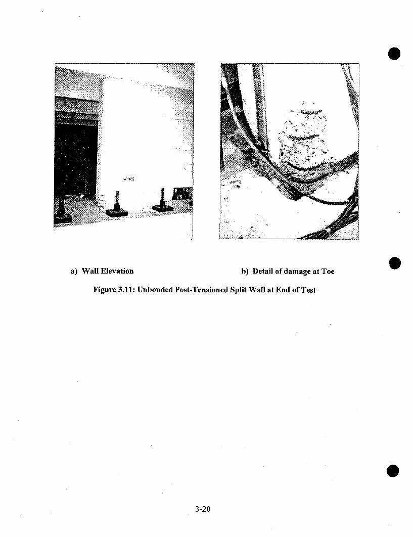
a) Wall Elevation b) Detail of damage at Toe
Figure 3.11: Unbonded Post-Tensioned Split Wall at End of Test
3-20
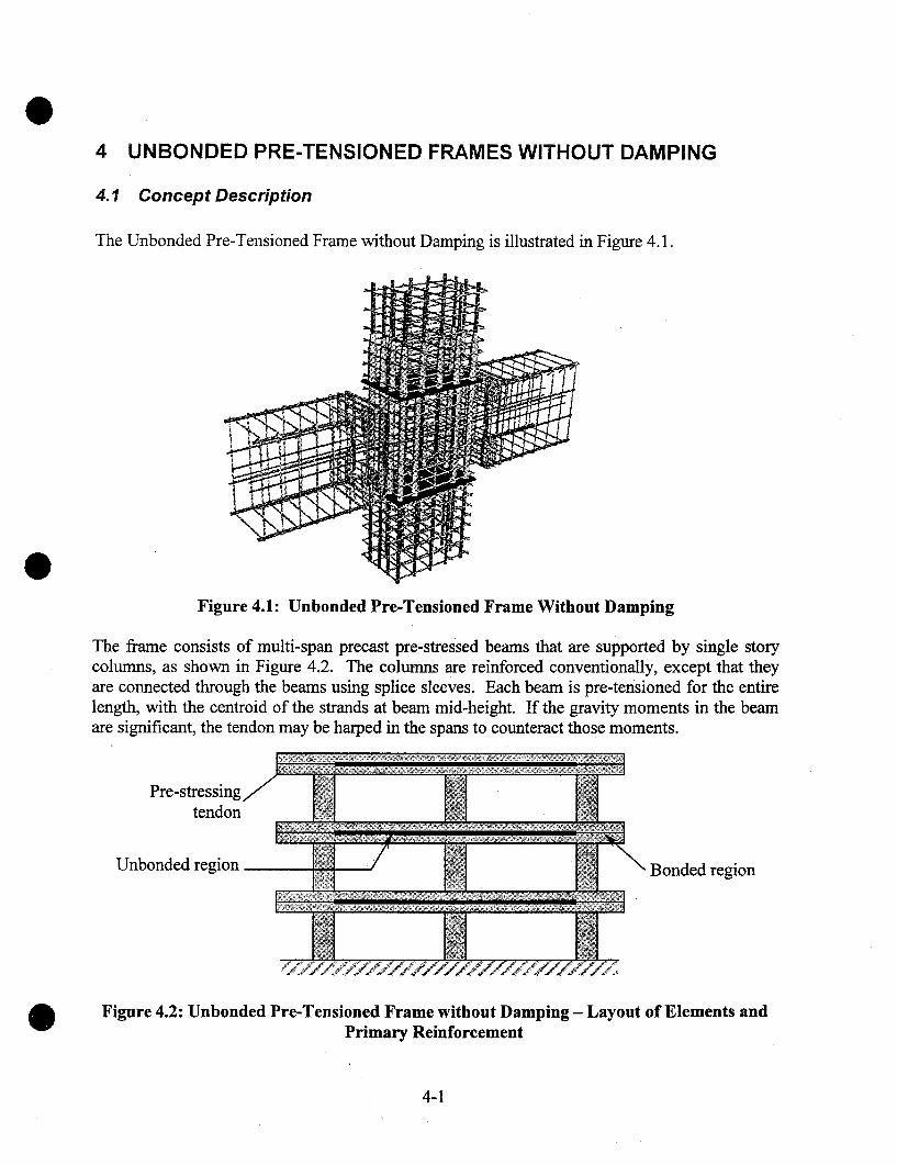
4 UNBONDED PRE-TENSIONED FRAMES WITHOUT DAMPING
4.1 Concept Description
The Unbonded Pre-Tensioned Frame without Damping is illustrated in Figure 4.1.
Figure 4.1: Unbonded Pre-Tensioned Frame Without Damping
The frame consists of multi-span precast pre-stressed beams that are supported by single storycolumns, as shown in Figure 4.2. The columns are reinforced conventionally, except that theyare connected through the beams using splice sleeves. Each beam is pre-tensioned for the entirelength, with the centroid of the strands at beam mid-height. If the gravity moments in the beamare significant, the tendon may be harped in the spans to counteract those moments.
Pre-stressingtendon
Unbonded region Bonded region
Figure 4.2: Unbonded Pre-Tensioned Frame without Damping - Layout of Elements andPrimary Reinforcement
4-1
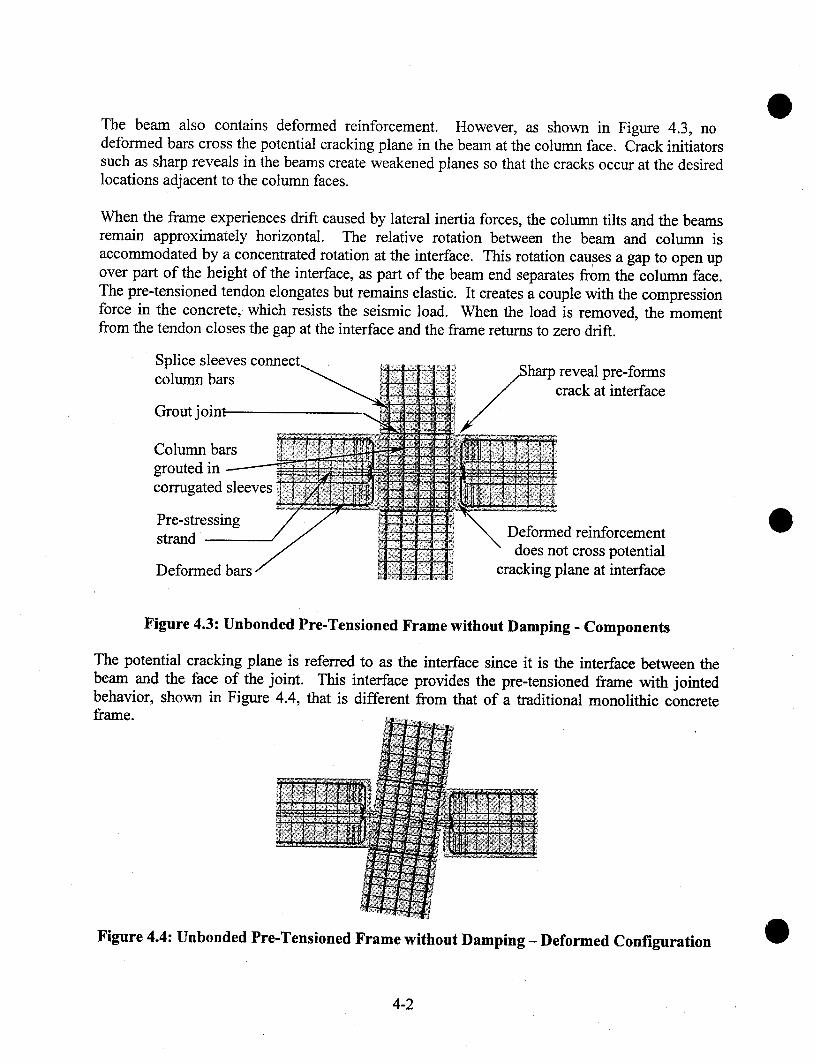
The beam also contains deformed reinforcement. However, as shown in Figure 4.3, nodeformed bars cross the potential cracking plane in the beam at the column face. Crack initiatorssuch as sharp reveals in the beams create weakened planes so that the cracks occur at the desiredlocations adjacent to the column faces.
When the frame experiences drift caused by lateral inertia forces, the column tilts and the beamsremain approximately horizontal. The relative rotation between the beam and column isaccommodated by a concentrated rotation at the interface. This rotation cau,ses a gap to open upover part of the height of the interface, as part of the beam end separates from the column face.The pre-tensioned tendon elongates but remains elastic. It creates a couple with the compressionforce in the concrete, which resists the seismic load. When the load is removed, the momentfrom the tendon closes the gap at the interface and the frame returns to zero drift.
Splice sleevescolumn bars
Grout joint
Column barsgrouted incorrugated sleeves
strand
Deformed bars
harp reveal pre-formscrack at interface
Deformed reinforcementdoes not cross potential
cracking plane at interface
Figure 4.3: Unbonded Pre-Tensioned Frame without Damping - Components
The potential cracking plane is referred to as the interface since it is the interface between thebeam and the face of the joint. This interface provides the pre-tensioned frame with jointedbehavior, shown in Figure 4.4, that is different from that of a traditional monolithic concreteframe.
Figure 4.4: Unbonded Pre-Tensioned Frame without Damping - Deformed Configuration
4-2

The pre-tensioned strands are bonded to the concrete only at the ends of the beam length, asshown in Figure 4.2. In the central region, which must include all interfaces at which jointopening is expected, the strands are debonded by sheathing or other means. Sufficient bondedlength is provided at the beam end to fully anchor the strands. If the seismic framing extends tothe comer column, the beams may need to project beyond the outer face of the column in orderto accommodate the strand development length. Other design alternatives include providing amechanical anchorage to supplement the bond [Shahawy and Cai, 2001] or stopping the seismicframing short of the end bay and using a gravity-only system thereafter.
4.2 Design Assumptions
The following assumptions are made in the development of design equations:
The design forces and drift limits are known. The drift limits are selected to satisfy coderestrictions and user requirements. Forces may be obtained either by Force Based Design orby Displacement Based Design. Interface rotations are obtained from the drift ratio, usingthe geometry of the system.
2. The overall dimensions of the frame members are known, having been obtained fromarchitectural constraints and preliminary calculations.
3. The pre-tensioned beams are of constant cross section and contain pre-stressing that is thesame over the full length. Each bay in the frame is of equal length.
o
Pre-stressing strands are unbonded through all columns that form part of the seismic framing.They are bonded beyond the interior face of the last column in the seismic part of the frame.
At each interface, the centroid of the pre-stressing strands is located at the mid-depth of thebeam section.
The post-tensioning is at incipient yield at the design drift. If a lower tension stress is desiredin the PT at the design drift, it should be substituted for fpy in the equations that follow.
Properties of the proposed materials are known. The principal ones are:¯ strength and stiffness ofpre-tensioning strands¯ strength of concrete
4.3 Notation
The sign convention adopted is that forces and deformations are computed as positive quantities,regardless of whether they are tensile or compressive.
ades = depth of compression stress block at design limit state
4-3

Ap
bductEpf’cfp0
fpufpy
Fc,desUp,deshbhckph
lcldInlphlpuMcap,beamMcrMdesVjoint
Vcol,desV joint
VuVu,D+L
= area of pre-stressing tendon= width of beam= width of pre-stressing duct in joint-- Young’s modulus of pre-stressing tendon material-- specified concrete strength at 28 days-- stress in pre-stressing tendon, after losses, at zero drift= stress in pre-stressing tendon at design limit state= maximum tendon jacking stress minus pre-stress losses= specified strength of pre-stressing tendon material= specified yield strength ofpre-stressing tendon material= modulus of rupture of concrete= force in beam concrete at beam-colunm interface at design limit state-- force in pre-stressing tendon at design limit state= depth of beam= depth of column (in plane of frame)= plastic hinge length factor= total bay dimension between column centerlines= floor-to-floor story height= development length= clear span of beam between column faces= plastic hinge length= unbonded length of pre-stressing tendon tributary to one interface-- beam moment strength at interface at design limit state= cracking moment strength at interface-- moment demand at design limit state= joint shear stress= column shear force at design limit state= joint shear force= nominal shear strength= factored shear demand= factored dead and live load shear demand at interface
(/,des
AlpAfp~
rides
Odes
Cv
= distance from center of compressive reaction to edge of member divided by memberdepth, at design limit statedepth of equivalent compressive stress block divided by neutral axis depthincrease in stress in pre-stressing tendon between zero drift and design driftincrease in. stress in pre-stressing tendon between zero drift and design drift whenconcrete strength is infinitedeformation ofpre-stressing tendon between zero drift and design driftcompression strain in extreme fiber of concretedistance from member compression face to neutral axis divided by member depth, atdesign limit stateinterface rotation at design limit statecoefficient of frictionstrength reduction factor for shear
4-4
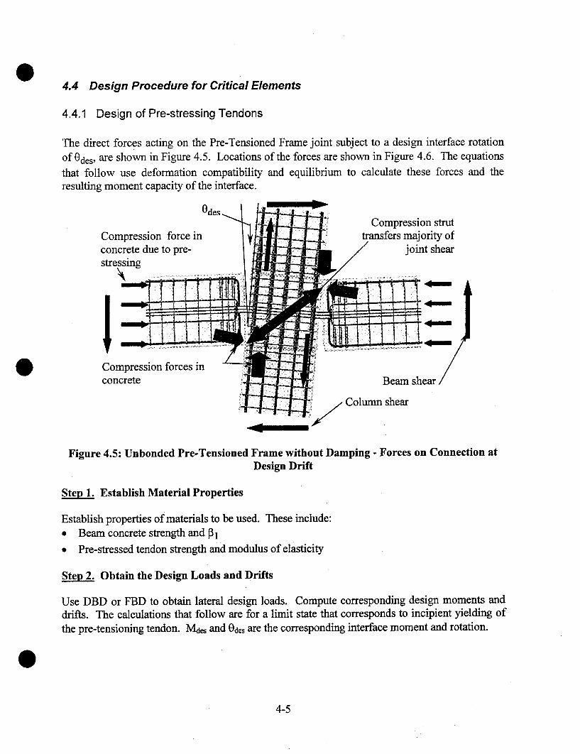
4.4 Design Procedure for Critical Elements
4.4.1 Design of Pre-stressing Tendons
The direct forces acting on the Pre-Tensioned Frame joint subject to a design interface rotationof 0des, are shown in Figure 4.5. Locations of the forces are shown in Figure 4.6. The equationsthat follow use deformation compatibility and equilibrium to calculate these forces and theresulting moment capacity of the interface.
Compression force inconcrete due to pre-stressing
Compression forces inconcrete
Compression struttransfers majority of
joint shear
Beam shear
Column shear
Figure 4.5: Unbondcd Pre-Tensioned Frame without Damping - Forces on Connection atDesign Drift
Establish Material Properties
Establish properties of materials to be used. These include:¯ Beam concrete strength and 131¯ Pre-stressed tendon strength and modulus of elasticity
Ste~ 2. Obtain the Design Loads and Drifts
Use DBD or FBD to obtain lateral design loads. Compute corresponding design moments anddrifts. The calculations that follow are for a limit state that corresponds to incipient yielding ofthe pre-tensioning tendon. Md~s and 0d~s are the corresponding interface moment and rotation.
4-5
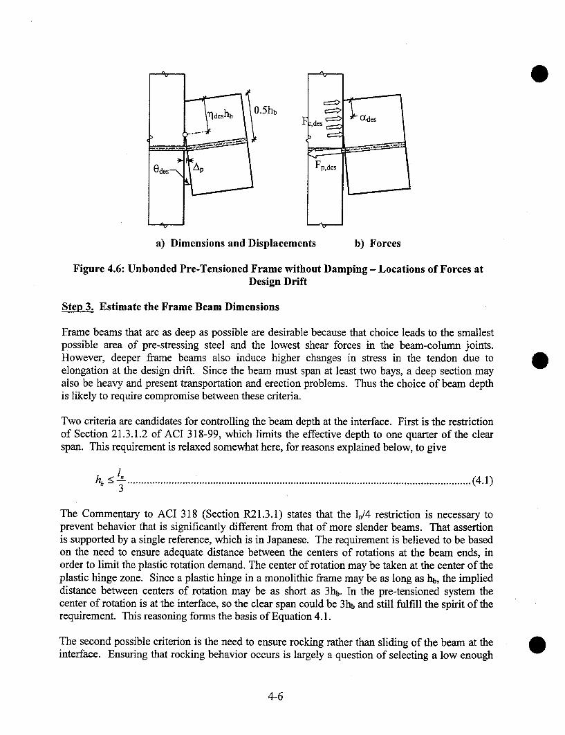
F z, des ~
Fp,des
a) Dimensions and Displacements b) Forces
Figure 4.6: Unbonded Pre-Tensioned Frame without Damping - Locations of Forces atDesign Drift
Ste~ 3. Estimate the Frame Beam Dimensions
Frame beams that are as deep as possible are desirable because that choice leads to the smallestpossible area of pre-stressing steel and the lowest shear forces in the beam-column joints.However, deeper frame beams also induce higher changes in stress in the tendon due toelongation at the design drift. Since the beam must span at least two bays, a deep section mayalso be heavy and present transportation and erection problems. Thus the choice of beam depthis likely to require compromise between these criteria.
Two criteria are candidates for controlling the beam depth at the interface. First is the restrictionof Section 21.3.1.2 of ACI 318-99, which limits the effective depth to one quarter of the clearspan. This requirement is relaxed somewhat here, for reasons explained below, to give
hb -<--. ...........................................................................................................................(4.1)3
The Commentary to ACI 318 (Section R21.3.1) states that the ln/4 restriction is necessary toprevent behavior that is significantly different from that of more slender beams. That assertionis supported by a single reference, which is in Japanese. The requirement is believed to be basedon the need to ensure adequate distance between the centers of rotations at the beam ends, inorder to limit the plastic rotation demand. The center of rotation may be taken at the center of theplastic hinge zone. Since a plastic hinge in a monolithic frame may be as long as hb, the implieddistance between centers of rotation may be as short as 3hb. In the pre-tensioned system thecenter of rotation is at the interface, so the clear span could be 3hb and still fulfill the spirit of therequirement. This reasoning forms the basis of Equation 4.1.
The second possible criterion is the need to ensure rocking rather than sliding of the beam at theinterface. Ensuring that rocking behavior occurs is largely a question of selecting a low enough
4-6
depth-to-span ratio in the beam. A precise upper bound for hn/ln may be obtained by taking intoaccount the shear demand and capacity, as discussed in Section 4.5.2. However, for parametervalues likely in practice, that criterion is unlikely to control, and Equation 4.1 will control themaximum beam depth at the interface.
Note that hb is the depth of the beam at the beam-column interface. If a reveal exists there toguide the crack, its dimensions must be accounted for when evaluating hb.
The beam width should satisfy Section 21.3.1.3 of ACI 318 ["Building", 1999]
bb > 0.3hb .......................................................................................................................(4.2)
ACI 318-99 Section R21.3.1 states that this requirement is based on experience withconventional, non-pre-stressed, cast-in-place frames. Its applicability to precast, pretensionedframes is unclear. It is recommended here that Equation 4.2 be treated as advisory rather thanmandatory. Use of a narrow beam could permit the beam weight to be kept low enough toovercome otherwise difficult erection problems.
Ste~ 4. Establish Constants
hb ......................................................................................................(4.3)Af~ = 0.5E~, Odes l~,~
Afp~ has a physical meaning. It is the stress change in the tendon that would occur between zerodrift and the design drift if the beam rocked about its comer. (This would require the concrete tobe infinitely strong, so in practice it is impossible and the true stress change will be smaller. It isgiven by Equation 4.7)
Step 5. Estimate the Required Tendon Area, Ap
The tendon area, Ap, and initial pre-stressing stress, fpo, may be computed iteratively.
If the design limit state corresponds to incipient yielding of the tendon, an initial estimate of therequired tendon area can be obtained by assuming that the compression force in the beam islocated 0.05hb from the compression face. This assumption leads to a lever arm of 0.45hb and atendon area of
MdesA~, - (0.45hb)f~,y ..........................................................................................................(4.4)
Ste~ 6. Estimate the Neutral Axis Parameter, rides, at Design Drift
The neutral axis location that is consistent with Step 5 can be obtained using Equation 4.5. Theexact value assumed is unimportant, because it will be corrected during the iterative designprocedure.
4-7

0.1~.e.~. =--. ......................................................................................................................(4.5)#l
Steo 7. Calculate the Elongation and Stress in the Pre-stressing Tendon at Odes
The elongation of the pre-stressing steel is related to both the interface rotation demand, 0des, andthe neutral axis depth.
AI~ = 0 aesh~, (0.5 - r/ae~.) ...................................................................................................(4.6)
The corresponding change in stress, as the interface rotation increases from zero to Odes, is
Afp = ~ Ep = Af~ (1 - 2r/a,s) (4.7)
The stress in the tendon must satisfy two conditions. First, at Odes, it must not exceed the yieldstress. Second, at zero interface rotation, it must not exceed fpi, the maximum allowable initialstress, fpi is given by the maximum permissible jacking stress of 0.70fpu minus any losses.These criteria can be met by setting
f,0 = f,, - ~f, ...............................................................................................................(4.8)
~f f,o>_fp,
then f~,0 = f~,i .........................................................................................................................(4.9)
f,,,es = f,0 + afp .......................................................................................................... (4.10)else
f,,.,es= f,,, ....................................................................................................................(4.11)
Steo 8. Calculate the Forces in the Pre-stressing Steel and Concrete at Odes
The force in the pre-stressing tendon is
F,,,~,, = A,,f ,,,,,,, ............................................................................................................(4.~2)
The compression force in the concrete, Fe,des, can be calculated from axial force equilibrium asFc,a,~ = F~,,,~e, ................................................................................................................. (4.13)
4-8

Ste~ 9. Calculate the Locations of the Compression Force and the Neutral Axis
The depth of the Whitney Equivalent stress block (Section 10.2.7 of ACI 318-99) in the concreteis
Fc ,desaa," = (4.14)
0.85f’c bb
The resultant compressive force on the grout is located at ~deshb from the compression face,where
ades ....................................................................................................................(4.15)(Z des : ~2hb
and the neutral axis is located rldeshb from the compression face, where
= ade----~s ...................................................................................................................(4.16)rl des fl~ h~
This value of lqdes is then compared to the previous value, and Steps 7 - 9 are repeated until thecomputed and assumed values of rides converge.
Step 10. Calculate the Moment Strength of the Section at Odes
The moment strength is calculated by taking moments about the centroid of the compressionforce. It is given by
Mcop,~eam = F~,,d~,.h~ (0.5 - c%, ) .......................................................................................(4.17)
This must be equal to or greater than the design moment, soMc,p,b,~ >_ M d,~ ............................................................................................................
(4.18)
If the moment capacity is too small, increase Ap and repeat Steps 6-10.
Step 11. Confine the Compression Area as Needed.
The local stress in the compressed region of the beam can become very large, especially if theinterface rotation or the initial pre-stress force is large. The concrete there is expected to deforminelastically, so it must be protected against crushing and falling out of the joint by confiningreinforcement. In the PRESSS Phase III test building, specially fabricated welded wire fabricwas used for the purpose. Itcan be seen in Figure 4.1.Since the beam end deformation is concentrated in a single crack and because the tendon istmbonded and pre-stressed, plane sections do not remain plane at the end of the beam. Thus theconcrete strains cannot strictly be evaluated from the curvature within a plastic hinge length. No
4-9

completely rational method has yet been proposed for evaluating the strain field in the concreteunder these circumstances.
In lieu of a more precise approach, Priestley and MacRae [1996] recommend an equivalentplastic hinge length equal to 0.041, for an unbonded post-tensioned, connection. However, thisassumed plastic hinge length does not account for the level of pre-stress in the tendon. Toovercome this difficulty, the plastic hinge length is taken here as a function of the compressionzone depth, rldeshb.
lph = kphl]aes hb ..............................................................................................................(4.19)
where, without experimental validation, kph is taken equal to 1.0. This choice is made on thebasis of St Venant’s Principle [St. Venant, 1855], which implies that a local disturbance in stressdies out rapidly at distances greater than the member depth.
The average compression strain over this plastic hinge length is
0 0desV ldes"b , des ............................................................................................... (4.20)lph kp~
If this compression strain exceeds the ultimate strain of the unconfined concrete, spalling shouldbe expected and the compression region should be confined to ensure that the concrete cansustain higher strains without degradation. In addition, if the cover is expected to spall, areduced beam section with dimensions equal to the confined core dimensions should be used inthe above calculations.
4.5 Design of Other Components
4.5.1 Interface Cracking Strength
Section 18.8.3 of ACI 318-99 requires that the design moment strength of the beam must begreater than 1.2 times the cracking strength. The cracking moment is
A~’f~’°lb~(h~)~ ......................................................................................(4.21)Mcr = f" + h~bb ) 6
where fr = modulus of rupture of the concrete = 7.5~1£c
However, the associated Commentary makes clear that this requirement is intended to preventbrittle collapse in gravity systems, and provides conditions under which the requirement need notbe satisfied. If sufficient moment strength exists at mid-span to carry the gravity moments, asdiscussed in Section 4.5.3, cracking at the ends of the statically indeterminate beam will not lead
4-10
to collapse. It is thus recommended that the requirement of Equation 4.21 be treated asadvisory and not mandatory.
4.5.2 Interface Shear Strength
Shear resistance across the interface is provided by shear friction. The normal force creating thatfriction is supplied by the pre-stressing. Since there is no deformed steel reinforcement crossingthe interface, the compression force on the concrete is always equal to the force in the pre-stressing tendon. At zero drift, the requirement of no slip at the interface leads to
Vu D+Lf~0 > ’ ¯ ................................................................................................................(4.22)
At the design drift, the shear friction resistance at the interface is
V, = ¢t A~,f ~,,de,. ............................................................................................................(4.23)
where ~ is the coefficient of friction at the cracked interface. The corresponding shear demandon the interface is determined from equilibrium on the beam.
2 M cap,beam
V, = V,,D+L + ...............................................................................................(4.24)l,
The moment capacity for a beam with a tendon at mid-height is given by Equation 4.17.Combining Equations 4.17, 4.23 and 4.25 leads to
h~, < 1 I V"’D+z ]l, - (0.5 -ade,) ¢v/~-
. ...............................................................................(4.25)Apf p,a,, )
ACI 318-99 permits la = 1.4 for monolithic concrete, which is the relevant condition at theinterface crack. However a value lower than this should be used in order to minimize thepossibility of cyclic slipping and the associated damage to the interface. A value of g = 0.7 isrecommended here, albeit without experimental validation. If, as is likely, Vu,O+L is an order ofmagnitude less than Apfp,dcs, the limit on hb/ln imposed by Equation 4.25 will be less critical thanthat of Equation 4.1.
4.5.3 Beam Flexure
During cyclic frame displacements, the beam end moments may become equal in magnitude andopposite in sign (i.e. both clockwise or both counter-clockwise). Their effect on the mid-spanmoment capacity is then zero, so moment demand at mid-span is the same as that for a simplespan. This observation applies to all types of frame, including cast-in-place concrete andstructural steel moment frames. Reinforcement should be selected accordingly. In particular, the
4-11
connection between the two beams at mid-span should be designed to carry the necessarypositive moment if it is located near mid-span.
4.5.4 Beam Shear
The beam must be designed so that, for all possible load cases, the weakest mechanism is themoment strength at the interface. This requires the beam shear strength to be designed usingCapacity Design principles. The compression force from the post-tensioning tendon in the beamimproves the beam’s shear capacity, and may be taken in to account by using the provisions ofSection 11.3.1 of ACI318-99 and treating the pre-stressing force as an external compression.
4.5.5 Beam Torsion
Torsion at the beam-column interface is resisted almost exclusively by shear stresses in thecracked concrete. While the pre-tensioned tendon carries some shear by dowel action, theamount is uncertain. The torsional stiffness and strength at the interface are therefore muchsmaller than those of the beam itself, so torsional rotation is concentrated at the beam-columninterface. For that reason, torsional loading on the frame beam should be minimized.
4.5.6 Bond and Anchorage
The pre-stressing tendon must be anchored past the last interface so that it is fully developed andcan sustain cyclic loading. If anchorage is achieved by bond alone, the anchored length shouldbe at least the development length required in Section 12.9 of ACI 318-99. In the PRESSSPhase III test building, the ½" dia. strands were bonded over a length of 78" (1.15 times the ldspecified by ACI) and no evidence of strand slip was seen. Mechanical anchorages, such asstrand chucks, may be used to supplement the bond. Use of bond and mechanical anchoragestogether is discussed by Shahawy and Cai [2001].
4.5.7 Column Design
The column should be designed using Capacity Design principles to ensure that the nonlinearaction occurs in the beam at the beam-column interface. Column splices should also be designedusing Capacity Design principles, including consideration of higher mode effects as described inthe UBC ["Uniform", 1997].
4.5.8 Joint Shear
The required joint shear strength should be determined using Capacity Design principles. Thejoint forces on the exterior and interior columns are different, due to both the magnitude ofloading on the joint and the resistance mechanism within the joint.
The magnitude of the joint shear demand is computed here using values for the forces that areconsistent with the strains expected in the members. Those forces differ from the ones used inACI318-99, which are largely empirical, and which do not take into account pre-stressed
4-12
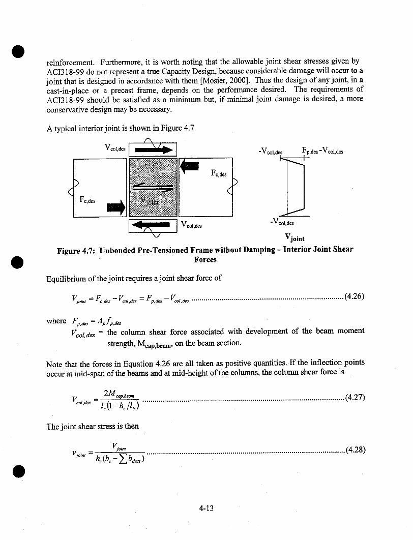
reinforcement. Furthermore, it is worth noting that the allowable joint shear stresses given byACI318-99 do not represent a true Capacity Design, because considerable damage will occur to ajoint that is designed in accordance with them [Mosier, 2000]. Thus the design of any joint, in acast-in-place or a precast frame, depends on the performance desired. The requirements ofACI318-99 should be satisfied as a minimum but, if minimal joint damage is desired, a moreconservative design may be necessary,
A typical interior joint is shown in Figure 4.7.
)Fc,des
Figure 4.7:
-Vcol,des Fp,des -Vcol,des
V joint
Unbonded Pre-Tensioncd Frame without Damping - Interior Joint ShearForces
Equilibrium of the joint requires a joint shear force of
Viol,, = Fc,d,s _ Vco,,des = Fp.de, -- Vco,,de~ ...........................................................................(4.26)
where Fp.a~~ = Apfp,d,~V¢ol, des = the eolurrm shear force associated with development of the beam moment
strength, Meap,beam, on the beam section.
Note that the forces in Equation 4.26 are all taken as positive quantities. If the inflection pointsoccur at mid-span of the beams and at mid-height of the columns, the column shear force is
2M~’.b~" ...................................................................................................(4.27)Voo,, s
The joint shear stress is then
Vjoint
vi°i" = h~ (b~ - ~_,bd,,. )............................................................................................ .....(4.28)
4-13
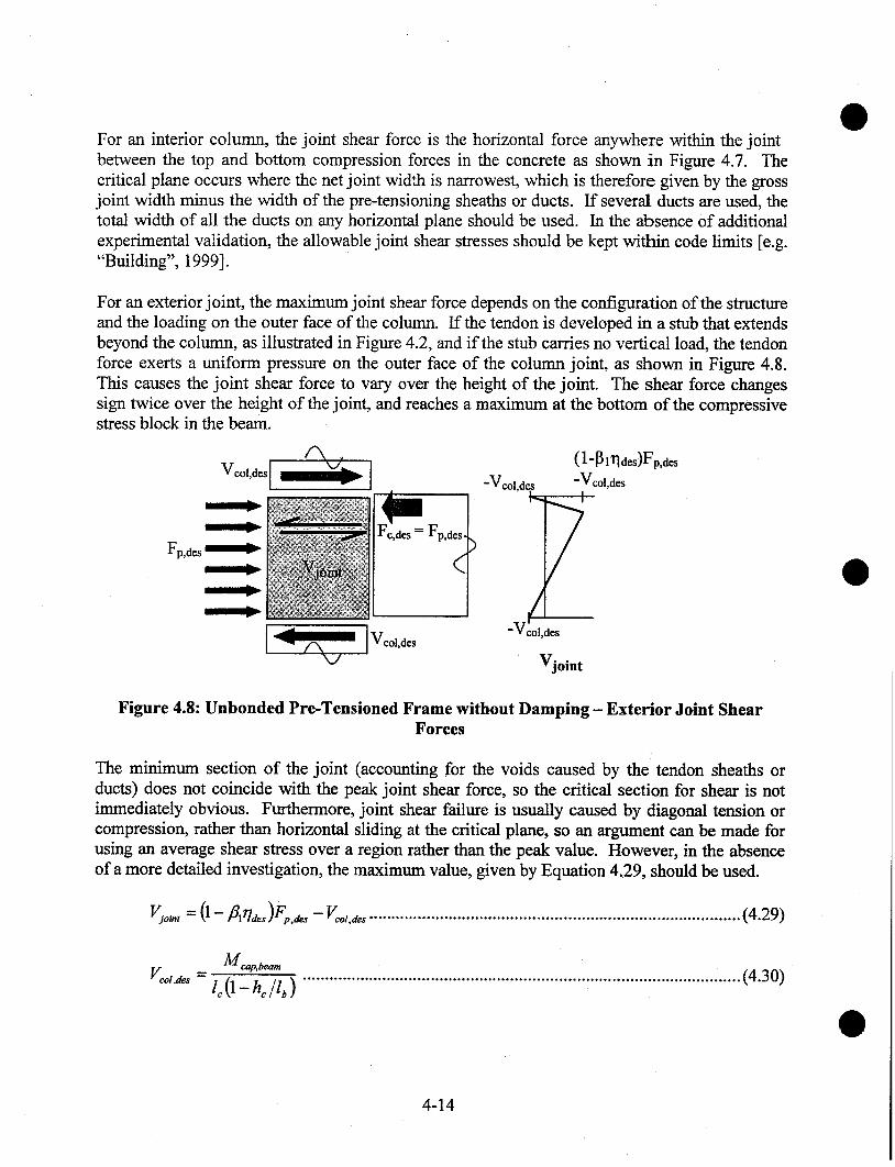
For an interior column, the joint shear force is the horizontal force anywhere within the jointbetween the top and bottom compression forces in the concrete as shown in Figure 4.7. Thecritical plane occurs where the net joint width is narrowest, which is therefore given by the grossjoint width minus the width of the pre-tensioning sheaths or ducts. If several duets are used, thetotal width of all the ducts on any horizontal plane should be used. In the absence of additionalexperimental validation, the allowable joint shear stresses should be kept within code limits [e.g."Building", 1999].
For an exterior joint, the maximum joint shear force depends on the configuration of the structureand the loading on the outer face of the column. If the tendon is developed in a stub that extendsbeyond the column, as illustrated in Figure 4.2, and if the stub carries no vertical load, the tendonforce exerts a uniform pressure on the outer face of the column joint, as shown in Figure 4.8.This causes the joint shear force to vary over the height of the joint. The shear force changessign twice over the height of the joint, and reaches a maximum at the bottom of the compressivestress block in the beam.
(1-~ l~]des)Fp,des
Vc°l’desl’ I~~ ] -Vcol,des -Vcol,des
7Fp,des.
=V d~s
Vjoint
Figure 4.8: Unbonded Pre-Tensioned Frame without Damping - Exterior Joint ShearForces
The minimum section of the joint (accounting for the voids caused by the tendon sheaths orducts) does not coincide with the peak joint shear force, so the critical section for shear is notimmediately obvious. Furthermore, joint shear failure is usually caused by diagonal tension orcompression, rather than horizontal sliding at the critical plane, so an argument can be made forusing an average shear stress over a region rather than the peak value. However, in the absenceof a more detailed investigation, the maximum value, given by Equation 4.29, should be used.
V~.o~, =(1- fllrla~)F~,.a~ -Vco,,a= ....................................................................................(4.29)
Vc°’"~" = l~ 0 - hc lib) ...................................................................................................(4.30)
4-14

The joint shear stress is given by Equation 4.28. In the absence of experimental validation, theallowable joint shear stresses should be kept within code limits [e.g. "Building", 1999].
4.6 Limits on Reinforcement
There is no upper bound to the amount of beam reinforcement that may be used. However, asthe pre-stressing force increases, the lever arm diminishes, so very heavily reinforced beams areunlikely to be economical. In heavily reinforced beams the compressive strain in the concretewill likely exceed the nominal crushing strain of 0.003 in./in, so confinement will be required.
4.7 Construction lssues
4.7.1 Beam Weight
To avoid the use of many beam connections, the beams will likely span at least two bays.Weight may then become a controlling factor in their design.
4.7.2 Erection Tolerances
The system requires accurate placement of the columns, so that the protruding column bars canbe threaded through the vertical ducts in the beam.
4.8 Discussion
The Unbonded Pre-Tensioned Frame without Damping that was tested in the PRESSS Phase IIItest building performed very well. Figure 4.9 shows the frame at the end of the test. The onlyvisible damage was the interface crack and slight crushing of the concrete cover on thecompressive face of the beam, at the beam-column interface. While the crack formed at theinterface as expected, it was not as straight as might have been desired. This occurred becausethe bottom of the reveal was rounded rather than sharp. In addition, a joint shear crack is visible,but it closed as soon as the loading was removed.
The Unbonded Pre-Tensioned Frame without Damping was used at the top two levels of the testbuilding, where the flexural demands, and therefore also the capacities, were smaller than atlower levels in the same frame. However, the drift demands were still substantial, with the roofdrift ratio reaching 4%. The damage to the interface was minimal, no shear slip was observedthere, and there was no evidence of bond failure in the beam stubs.
In a multi-span beam using more than one beam element, the connections between beams at mid-span must resist shear and some moment. They should be rigid, and have no inelastic
4-15

deformation requirement, so many different types are possible.Connection Manual [PCI, 1988].
Examples are given in the PCI
The design procedures outlined here have not yet been validated by the authors using the datafrom the PRESSS Phase III test. Therefore, they should be used only for trial designs.
Figure 4.9: Unbonded Pre-Tensioned Frame without Damping at End of Test
4-16

5 UNBONDED POST-TENSIONED FRAMES WITH DAMPING
5.1 Concept Description
The Unbonded Post-Tensioned Frame with Damping is illustrated in Figure 5.1.
Figure 5.1: Unbonded Post-Tensioned Frame with Damping
The frame consists of multi-story precast columns, spliced as necessary, and single span beamsbetween columns. The arrangement is shown schematically in Figure 5.2. Each beam line ispost-tensioned for the entire length of the frame, at beam mid-height. The post-tensionedtendons are not grouted. Deformed bars are grouted into sleeves at the top and bottom of thebeam, which extend through the column. An unbonded length of the deformed reinforcement atthe interface, shown in Figure 5.3, protects the reinforcement from fracture at high drifts bylimiting the strain in it.
Post-tensioningtendon
(unbonded)
Deformedbars
Post-tensioninganchorage
Figure 5.2: Unbonded Post.Tensioned Frame with Damping - Layout of Elements andPrimary Reinforcement
5-1

Continuity bars(deformed reinforcement)
Debondedlength
Unbonded post-Interface tensioned tendongrout in duct
Figure 5.3: Unbonded Post-Tensioned Frame with Damping - Components
When the frame experiences drift caused by lateral inertia forces, the column tilts and the beamsremain approximately horizontal. The relative rotation between the beam and column isaccommodated by a concentrated rotation at the interface. This rotation causes a gap to open upover part of the height of the interface, as part of the beam end separates from the grout pad. Thepost-tensioning tendon elongates but remains elastic. The continuity bars in the tension regionyield in tension. Each set of reinforcement creates a couple with the compression force in thegrout, and the total moment resists the seismic load. When the load is removed, the momentfrom the post-tensioning tendon tends to close the gap at the interface. The continuity barsshorten and yield in compression, thereby resisting the closure of the gap. The frame can bemade to return to zero drift by ensuring that the moment due to the post-tensioning is greaterthan that due to the continuity bars in compression.
Figure 5.4: Unbonded Post-Tensioned Frame with Damping - Deformed Configuration
5-2

The grout at the interface provides an opportunity to minimize damage to the concrete beamitself. If the grout is designed to be weaker than the concrete in the beam, then the rotation at theinterface is accommodated by local compression of the grout pad. In this case, grout with a high(cyclic) compressive strain capacity must be used. The calculations in this chapter are based onthis approach. Alternatively, the concrete in the beam itself may be designed to be weaker thanthe grout. In this case the rotation at the interface is accommodated by compression of a "plastichinge length" in the concrete. If the concrete strains are higher than the unconfined straincapacity of the concrete used in the beam, then the compression region of the beam must beconfined and a reduced beam section used for the analysis, because the cover will spall.
The total resisting moment is comprised of one component from the pre-stressing tendon andanother from the deformed reinforcement. The fraction of the total resistance supplied by eachcomponent may be chosen by the designer, but the choice affects the response. For a given totalstrength, a higher proportion of deformed reinforcement will lead to more damping and lowerpeak drift, but may lead to larger residual drift, and vice versa.
One possible design philosophy is to maximize the moment strength provided by the deformedreinforcement, subject to the constraint that the residual drift should still be zero. This choicewill minimize the peak drift, while maintaining zero residual drift. This design philosophy isused in the following equations.
The design equations for pre-stressed systems with energy dissipation are more complex thanthose for beams that contain only one type of reinforcement. In the design procedure thatfollows, an iterative approach is taken so that the design steps are transparent and the designobjective is clear.
5.2 Design Assumptions
The following assumptions are made in the development of design equations:
1. The design forces and drifts are known. The drift limits are selected to satisfy coderestrictions and user requirements. Forces may be obtained either by Force Based Design, orby Displacement Based Design. Interface rotations are obtained from the drift ratio, using thegeometry of the system.
2. The overall dimensions of the frame members are known, having been obtained fromarchitectural constraints and preliminary calculations.
3. The beams are of constant cross section and contain post-tensioning that is the same over thefull length. Each bay in the frame is of equal length.
4. The post-tensioning tendon is unbonded through all columns that form part of the seismicframing. It is anchored at the exterior face of the last column in the seismic part of the frame.
5-3

o At each interface, the centroid of the post-tensioning tendon is located at the mid-depth ofthe beam section.
6. The post-tensioning tendon is at incipient yield at the design drift. If a lower tension stress isdesired, it should be substituted for fpy in the equations that follow.
7. Deformed bars are grouted into ducts, with a short unbonded length at the interface. Theducts are grouted through the column. Equal top and bottom reinforcement is used.
8. The grout at the interface is reinforced with fibers to prevent grout degradation and lossunder cyclic loading.
Properties of the proposed materials are known. The principal ones are¯ tendon material strength and modulus of elasticity¯ deformed bar yield and peak strength¯ concrete strength¯ interface grout strength and stress block coefficient [31¯ coefficient of friction, g, between the grout and concrete
The coefficient of friction, g, between the grout and the concrete, may be taken as 0.5 in theabsence of better information. Hutchinson et al. [ 1990] measured a value of 0.6 between precastconcrete and grout under cyclic loading. It is reduced here to 0.5 to allow for variations withgrout type. Experimental evidence would be needed to justify the use of a higher value in design.
5.3 Notation
The sign convention adopted is that forces and deformations are computed as positive quantities,regardless of whether they are tensile or compressive.
ApAsbcbductbgdbEpf’gfp0
fpy
= depth of compression stress block in grout at zero drift= depth of compression stress block in grout at design limit state= area of pre-stressing tendon= area of deformed reinforcement in one face of beam= width column= width ofpre-stressing duct in joint= width of grout pad at beam-column interface= diameter of deformed reinforcing bar= Young’s modulus ofpre-stressing tendon material= specified grout strength at 28 days= stress in pre-stressing tendon, after losses, at zero drift= stress in pre-stressing tendon at design limit state= maximum tendon jacking stress minus pre-stress losses= specified strength of pre-stressing tendon material= specified yield strength ofpre-stressing tendon material
5-4

fs,d~s
fs’,desfsy
Fc,0Fc,desFp,OFp,aesFso
Fs’oFs’,deshehg
lblcInlphlpu
= stress in tension deformed reinforcement= stress in compression deformed reinforcement= specified yield strength of deformed reinforcement= force between beam concrete and grout at beam-column interface at zero drift= force in beam concrete at beam-column interface at design limit state= force in pre-stressing tendon at zero drift= force in pre-stressing tendon at design limit state= force in tension deformed reinforcement at zero drift= force in tension deformed reinforcement at design limit state= force in compression deformed reinforcement at zero drift= force in compression reinforcing steel at design limit state= column depth (in plane of frame)= depth of grout pad at beam-column interface= plastic hinge length factor= total bay dimension between column centerlines= floor-to-floor story height= clear span of beam between column faces= plastic hinge length= unbonded length of unbonded pre-stressing tendon tributary to one interface
lsu =
Mcap,beam =
Mdes =Mp,oMp,aesMs,oMs,desMs’.oMs’,aes
Vjoint
Vcol,desV joint
VnVuVu,D+L
length of unbonded region of deformed reinforcement at each interfacebeam moment strength at interface at design limit statemoment demand at design limit state
= resisting moment provided by pre-stressing tendon at zero drift= resisting moment provided by pre-stressing tendon at design limit state= resisting moment provided by tension deformed reinforcement at zero drift= resisting moment provided by tension deformed reinforcement at design limit state= resisting moment provided by compression deformed reinforcement at zero drift= resisting moment provided by compression deformed reinforcement at design limit
state= joint shear stress= column shear force at design limit state=joint shear force= nominal shear strength= factored shear demand= factored dead and live load shear demand at interface
~des
AlpAfp~
Ap
= distance from compression face of member to center of compression force, divided bymember depth, at zero drift
= distance from center of compressive reaction to edge of member divided by memberdepth, at design limit state
= depth of equivalent compressive stress block divided by neutral axis depth= increase in stress in pre-stressing tendon between zero drift and design drift= increase in stress in pre-stressing tendon between zero drift and design drift when
concrete and grout strengths are infinite= deformation ofpre-stressing tendon between zero drift and design drift
5-5
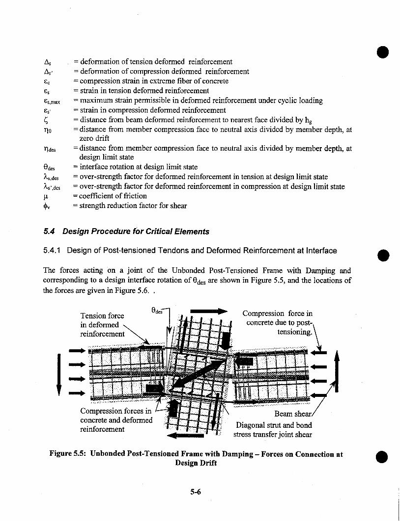
des
Odes
~,s,des
~,s’,des
= deformation of tension deformed reinforcement= deformation of compression deformed reinforcement= compression strain in extreme fiber of concrete= strain in tension deformed reinforcement= maximum strain permissible in deformed reinforcement under cyclic loading= strain in compression deformed reinforcement= distance from beam deformed reinforcement to nearest face divided by hg= distance from member compression face to neutral axis divided by member depth, at
zero drift= distance from member compression face to neutral axis divided by member depth, at
design limit state= interface rotation at design limit state= over-strength factor for deformed reinforcement in tension at design limit state= over-strength factor for deformed reinforcement in compression at design limit state= coefficient of friction= strength reduction factor for shear
5.4 Design Procedure for Critical Elements
5.4.1 Design of Post-tensioned Tendons and Deformed Reinforcement at Interface
The forces acting on a joint of the Unbonded Post-Tensioned Frame with Damping andcorresponding to a design interface rotation of Odes are shown in Figure 5.5, and the locations ofthe forces are given in Figure 5.6..
Tension forcein deformedreinforcement
Compression forces inconcrete and deformedreinforcement
Compression force inconcrete due to post-.
tensioning~[~
Beam
Diagonal strut and bondstress transfer joint shear
Figure 5.5: Unbonded Post-Tensioned Frame with Damping - Forces on Connection atDesign Drift
5-6
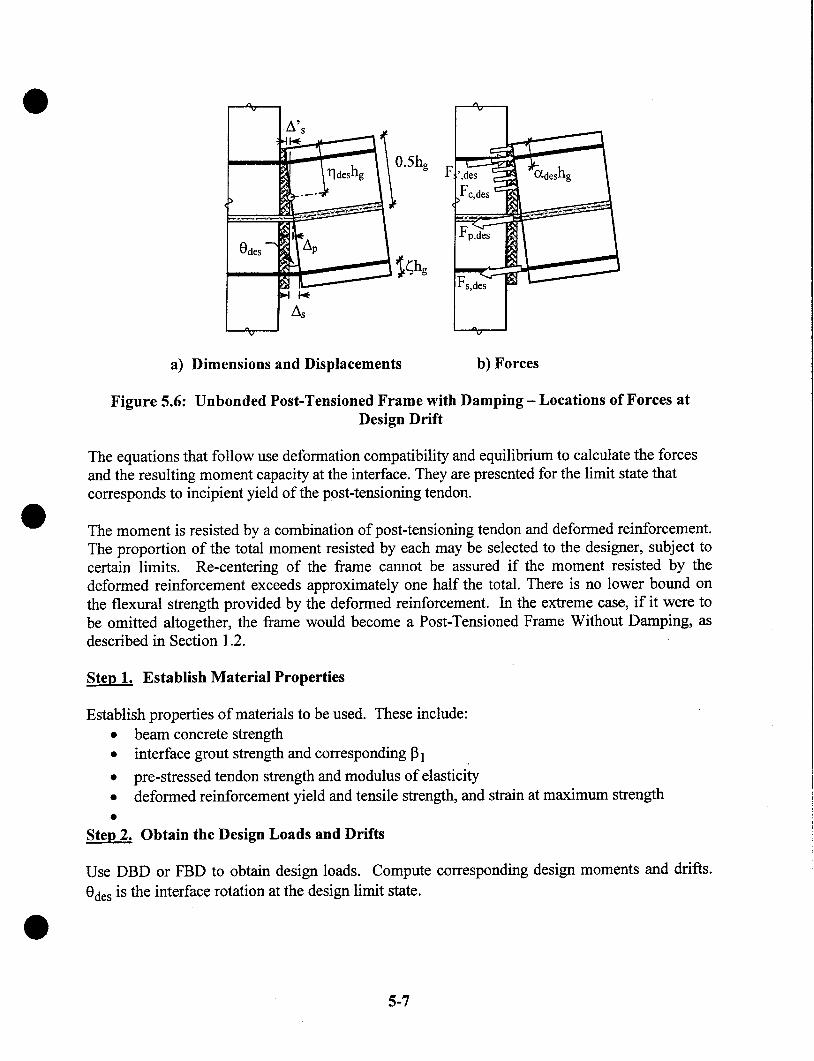
a) Dimensions and Displacements b) Forces
Figure 5.6: Unbonded Post-Tensioned Frame with Damping- Locations of Forces atDesign Drift
The equations that follow use deformation compatibility and equilibrium to calculate the forcesand the resulting moment capacity at the interface. They are presented for the limit state thatcorresponds to incipient yield of the post-tensioning tendon.
The moment is resisted by a combination of post-tensioning tendon and deformed reinforcement.The proportion of the total moment resisted by each may be selected to the designer, subject tocertain limits. Re-centering of the frame cannot be assured if the moment resisted by thedeformed reinforcement exceeds approximately one half the total. There is no lower bound onthe flexural strength provided by the deformed reinforcement. In the extreme case, if it were tobe omitted altogether, the frame would become a Post-Tensioned Frame Without Damping, asdescribed in Section 1.2.
Steo 1. Establish Material Properties
¯
¯
¯
¯
¯
Establish properties of materials to be used. These include:beam concrete strengthinterface grout strength and corresponding 91
pre-stressed tendon strength and modulus of elasticitydeformed reinforcement yield and tensile strength, and strain at maximum strength
Obtain the Design Loads and Drifts
Use DBD or FBD to obtain design loads. Compute corresponding design moments and drifts.Odes is the interface rotation at the design limit state.
5-7
Steo 3. Estimate the Frame Beam Dimensions
Frame beams that are as deep as possible are desirable because that choice leads to the smallestpossible area of pre-stressing tendon and the lowest shear forces in the beam-column joints.However, deeper frame beams also induce higher changes in stress in the tendon due toelongation at the design drift. The beam depth should be chosen with these consequences inmind.
Two criteria are candidates for controlling the beam depth at the interface. First is the restrictionof Section 21.3.1.2 of ACI 318-99, which limits the effective depth to one quarter of the clearspan. This requirement is relaxed somewhat here, for reasons explained below, to give
<loh~ _~ ............................................................................................................................(5.1)
The Commentary to ACI 318 (Section R21.3.1) states that the In/4 restriction is necessary toprevent behavior that is significantly different from that of more slender beams. That assertionis supported by a single reference, which is in Japanese. The requirement is believed to be basedon the need to ensure adequate distance between the centers of rotations at the beam ends, inorder to limit the plastic rotation demand. The center of rotation may be taken at the center of theplastic hinge zone. Since a plastic hinge in a monolithic frame may be as long as hb, the implieddistance between centers of rotation may be as short as 3hb. In the post-tensioned system thecenter of rotation is at the interface, so the clear span could be 3hg and still fulfill the spirit of therequirement. This reasoning forms the basis of Equation 5.1.
The second possible criterion is the need to ensure rocking rather than sliding of the beam at theinterface. Ensuring that rocking behavior occurs is largely a question of selecting a low enoughdepth-to-span ratio in the beam. A precise upper bound for hn/ln may be obtained by taking intoaccount the shear demand and capacity, as discussed in Section 5.5.1. However, for parametervalues likely in practice, the criterion is unlikely to control. In that case Equation 5.1 will controlthe maximum beam depth at the interface.
The beam width should satisfy Section 21.3.1.3 of ACI 318 ["Building", 1999]
b~ > 0.3hb .......................................................................................................................(5.2)
ACI 318-99 Section R21.3.1 states that this requirement is based on experience withconventional, cast-in-place, non-pre-stressed frames. Its applicability to precast, post-tensionedframes is unclear. It is recommended here that Equation 5.2 be treated as advisory rather thanmandatory. Use of a narrow beam could permit the beam weight to be kept low enough toovercome otherwise difficult erection problems.
If the grout at the interface is held back from the face of the beam, the dimensions of the grout,rather than those of the concrete, should be used in the design.
5-8
Establish Constants
ha ......................................................................................................(5.3)A f p~ = O . 5 E p Odesup--I
Afp~ has a physical meaning. It is the stress change in the tendon that would occur between zerodrift and the design drift if the beam rocked about its comer. (This would require the concreteand grout to be infinitely strong, so in practice it is impossible and the tree stress change will besmaller. It is given by Equation 5.12)
Steo 5. Determine the Proportion of Moment Strength to be Provided by Pre-stressing andDeformed Reinforcement, Respectively
In the Unbonded Post-Tensioned Frame with Damping, the two different types of reinforcementfulfill very different functions. Both provide moment strength at the interface, but the pre-stressing provides an elastic restoring force that tends to self-right the frame after the earthquakeis over, whereas the deformed reinforcement provides damping. The criterion for self-righting,which is that the moment resisted by the post-tensioning tendon at zero drift be greater than themoment resisted by the deformed reinforcement, creates an upper bound on the amount ofdeformed reinforcement. Use of this criterion leads to designs in which slightly less than half thetotal moment resistance is supplied by the deformed reinforcement. The exact proportionsdepend on the design interface rotation, the beam span/depth ratio, the allowable jacking stressand the yield strength of the tendon. However, a reasonable initial estimate can be obtained from
Mp,aes ~ 0.55Mae,’ ....................................... , ..................................................................(5.4)
M s,ae.’ = M aes - M p,ae.~ ....................................................................................................(5.5)
In the design equations that follow, the calculations depend on displacement compatibilitybetween the tendon and the surrounding concrete. They are similar to those used whencomputing the strength of a conventional pre-stressed beam by strain compatibility and are thusiterative.
Steo 6. Estimate Required the Tendon Area, Ap
If the design limit state corresponds to incipient yielding of the tendon, an initial estimate of therequired tendon area can be obtained by assuming that the compression force in the beam islocated 0.05hg from the compression face. This assumption leads to a lever arm of 0.45hg and atendon area of
M p,aesAP -- (O.4$hgJf , y
.......................................................................................................... (5.6)
5-9

Ste~ 7. Estimate the Required Area, As, of Deformed Reinforcement
An initial estimate of the required area of deformed reinforcement can be obtained by using thesame assumptions as for Equation 5.6.
Ms,desA, = (0.95_£)hgAs,,~,,f~y ..............................................................................................(5.7)
The value of the material stress factor, )~s,aes, depends on the limit state under consideration, andthe corresponding allowable strain in the deformed reinforcement. Proposed values are given inTable 2.1.
Ste~ 8. Estimate the Neutral Axis Parameter, ~des, at the Design Drift
The neutral axis location that is consistent with Step 7 can be obtained using Equation 5.8. Theexact value assumed is unimportant, because it will be corrected during the iterati~ce designprocedure.
0.117des = --- ...................................................................................................................... (5.8)
Ste~ 9. Calculate the Stress in the Tension Deformed Reinforcement
The strain in the tension deformed reinforcement exceeds the yield strain, and is given by ~s,m~from Table 2.1. The corresponding stress is
f,.des= 2,.d,,f~ ...............................................................................................................(5.9)
Step 10. Calculate the Stress in the Compression Deformed Reinforcement
The compression deformed reinforcement is likely to be at a comparatively small net strain,because the presence of the concrete and grout prevents large compressive strains. However, thebars are also likely to have undergone significant inelastic tension strain in previous cycles, sothe stress cannot be related directly to the instantaneous strain. Thus the stress is taken as
f~,~es = L,~.~f~ ..............................................................................- ...............................(5.10)
where )~s’,des is given in Table 2.1. Its value takes into account the fact that the stress-strain curveis likely to be somewhat rounded by the Bauschinger effect. Thus )~s’,des is less than )~s,des.
Step II. Calculate the Elongation and Stress in the Pre-stressing Tendon at Odes
The elongation of the pre-stressing is related to both the interface rotation demand, Odes, and theneutral axis depth.
5-10

l~ p -~ ~ deshb (O.S --17des) .................................................................................................. (511)
The corresponding change in stress, as the interface rotation increases from zero to Odes, is
Afp = ~ Ep = Af~ (1 .- 2r/aes) ......................................................................................(5.12)
The stress in the tendon must satisfy two separate upper bounds. At the start of the design it isnot clear which will control. First, at Odes, fp0 must not exceed the yield stress. Second, at zerointerface rotation, fp0 must not exceed fpi, the maximum permissible jacking stress of 0.7fouminus any losses. These criteria can be met by setting
f~o = fpy-Afp .............................................................................................................(5.13)
If f ~,o > f pi
then fpo= f~,i .......................................................................................................................(5.14)
f,.~o..-- L0 + AL .......................................................................................................... (5.15)else
f,.,s =f,y .......................................................................................: ............................(5.16)
Step 12. Calculate the Forces in the Deformed Reinforcement, Pre-stressing Tendon andGrout at Odes
The forces in the various reinforcement elements are
F,.~e.. = A, f p.,~s .............................................................................................................(5.17)
F~.,.s -- 4~&~..f~ .........................................................................................................(5.18)
F.,.~..=A.&,,.o.f~ ........................................................................................................(5.19)
The compression force between the grout and the concrete, Fc,des, can be calculated fromequilibrium on the section
F~,.e. -- F.,,e~ + F.,... - F.,..~ ...........................................................................................(5.20)
5-11

Step 13. Calculate the Locations of the Compression Force and the Neutral Axis
The depth of the Whitney Equivalent stress block (Section 10.2.7 of ACI 318-99) in the grout is
Fc,desaae.~ - ¯ .......................................................................................................(5.21)
0.85 f’g bg
The resultant compressive force on the grout is located at c~deshg from the compression face,where
a desCrdes -- 2hg ...................................................................................................................(5.22)
and the neutral axis is located l]deshg from the compression face, where
a desrlde~ =gp,° h~ ..................................................................................................................(5.23)
This value ofrlaes is then compared to the previous value, and Steps 11 - 13 are repeated until thecomputed and assumed values of rides converge.
Step 14. Calculate the Moment Strength of the Section at Odes
The moment strength is calculated by taking the moments about the centroid of the compressionforce provided by the deformed reinforcement and pre-stressing. These are
m r,aes = Fr,aesh g [O.5 - o~ a~s ] .........................................................................................(5.24)
M s,a~, = F,,ae~h g [1- ~ - a d, s ] .......................................................................................(5.25)
M,.,a~s = F,,,,~e, hg[~-aa~s ] ...........................................................................................(5.26)
Then the total moment strength is
Mcap,beam = Mp,des + M.~,a,,. + M~.,,a,,. " (5.27)
This must be equal to or greater than the design moment, so
Mc~,,b~,, > M~ ............................................................................................................(5.28)
If the moment capacity is too small, increase Ap and As and repeat Steps 11-14.
5-12
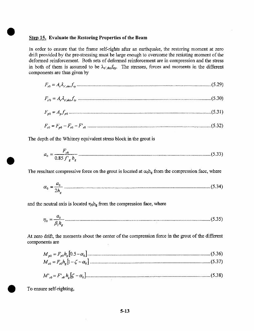
Step 15. Evaluate the Restoring Properties of the Beam
In order to ensure that the frame self-rights after an earthquake, the restoring moment at zerodrift provided by the pre-stressing must be large enough to overcome the resisting moment of thedeformed reinforcement. Both sets of deformed reinforcement are in compression and the stressin both of them is assumed to be 2s’,acsfsy. The stresses, forces and moments in the differentcomponents are thus given by
Eoo = AsAs,,desf~ ............................................................................................................(5.29)
: ...........................................................................................................(5.30)
Fpo = Apfpo ..................................................................................................................(5.31)
Fc0 = Fp0 - F~.o - F’so ...................................................................................................(5.32)
The depth of the Whitney equivalent stress block in the grout is
Fc0a0 ...........................................................................................................(5.33)
0.85 f’g bg
The resultant compressive force on the grout is located at ct0hg from the compression face, where
a0ao = ~. ....................................................................................................................(5.34)2hg
and the neutral axis is located rlohg from the compression face, where
aor/o .....................................................................................................................(5.35)t~lhg
At zero drift, the moments about the center of the compression force in the grout of the differentcomponents are
M po = F~,ohg[O.5-ao] .................................................................................................. (5.36)
Mso = F, ohg[1-~-ao] ................................................................................................(5.37)
M’.~o = F’~.0 hg[("-a0] ................................................................................................... (5.38)
To ensure self-righting,
5-13

Mpo >_ M~o + M’~o ........................................................................................................(5.39)
If Equation 5.39 is not satisfied, select a higher ratio of Mp,des/Mdes and repeat Steps 5-15.
Step 16. Calculate the Elongation and Required Unbonded Length of the DeformedReinforcement
The elongation of the tension deformed reinforcement is related to both the drift demand and theneutral axis depth.
A, = 0 acing (1 - � - qde~) ...............................................................................................(5.40)
where ~hg is the distance from the centroid of the tension deformed reinforcement to the tensionface of the beam. In order to keep the strain in the deformed reinforcement below the maximumusable strain at the design drift, ~s,max, given in Table 2.1, the total unbonded length must satisfy
l~, > A____~__.~ .................................i .................................................................................(5.41)
High cyclic strains can cause growth in the unbonded length. The magnitude of that growthdepends on the confinement provided around the bar and other parameters. For bars grouted intoa pre-formed hole in the concrete, Cheok and Stone [1994] found the growth in debonded lengthto be 5.5db (2.75db at each end of the intentionally debonded length) for a #3 bar. More recenttesting on bars grouted in corrugated steel ducts [Stanton et al. 2000] has shown that, under thosecircumstances, the growth depends on bar strength, grout strength and load history, but is on theorder of 1.0db.
If the estimated debonded length is greater than the true one, the true bar strain will be higherthan the predicted one, and the bars may fracture prematurely. If the estimated debonded lengthis less than the true one, thetrue strain will be lower than predicted and yield of the bars will bedelayed. The consequences are that the bar stress, and therefore the resisting moment, at peakdrift will be slightly lower, as will also be the damping. However, these changes will be verysmall. Because the consequences of predicting too high a growth in the debonded length aremuch more serious than those of a low prediction, the growth in debonded length is assumedhere to be zero.
Step 16. Confine Compression Region as Needed
The local stress in the compressed region of the beam can become very large, especially if theinterface rotation or the initial pre-stress force is large. That stress exists in both the concrete andthe grout. The grout is expected to deform inelastically, but it is protected by fiber reinforcementagainst crushing and falling out of the joint. The concrete in the beam should be protectedagainst crushing in case the grout sustains a stress higher than its cube strength. This is likely tobe the case, because the dimensions of the grout pad provide excellent confinement.
5-14

Since the beam end deformation is concentrated in a single crack and because the tendon isunbonded and pre-stressed, plane sections do not remain plane at the end of the beam. Thus theconcrete strains cannot strictly be evaluated from the curvature within a plastic hinge length. Nocompletely rational method has yet been proposed for evaluating the strain field in the concreteunder these circumstances.
In lieu of a more precise approach, Priestley and MacRae [1996] recommend an equivalentplastic hinge length equal to 0.041n for an unbonded post-tensioned, connection. However, thisassumed plastic hinge length does not account for the level of pre-stress in the tendon. Toovercome this difficulty, the plastic hinge length is taken here as a function of the compressionzone depth, vldeshg.
lph = kphr]aes hg ..............................................................................................................(5.42)
where, without experimental validation, kph is taken equal to 1.0. This choice is made on thebasis of St Venant’s Principle [St. Venant, 1855], which implies that a local disturbance in stressdies out rapidly at distances greater than the member depth.
The average compression strain over this plastic hinge length is
0 d,,(rlae, hb) 0 de., ............................................................................................... (5.43)l p~ k p~
If this compression strain exceeds the ultimate strain of the unconfined concrete, spalling shouldbe expected and the compression region should be confined to ensure that the concrete cansustain higher strains without degradation. In addition, if the cover is expected to spall, areduced beam section with dimensions equal to the confined core dimensions should be used inthe above calculations.
5.5 Design of Other Components
5.5.1 Interface Shear
Shear resistance across the interface is provided by shear friction. The normal force creating thatfriction is supplied by the pre-stressing. Therefore, the shear resistance at the interface is
V, = ,u Fc,d,s ..................................................................................................................(5.44)
The corresponding shear demand on the interface is determined from equilibrium on the beam.
5-15

mu = Vu,D+L q"2 M cap,beam
l,,............................................................................................... (5.45)
5.5.2 Beam Flexure
During cyclic frame displacements, the beam end moments may become equal inmagnitude and opposite in sign (i.e. both clockwise or both counter-clockwise). Their effect onthe mid-span moment capacity is then zero, so moment demand at mid-span is the same as thatfor a simple span. Reinforcement should be selected accordingly. This observation applies to alltypes of frame, including cast-in-place concrete and structural steel moment frames. The post-tensioning may be taken into account in evaluating the gravity load capacity of the beam,provided that it is in place when the load occurs.
5.5.3 Beam Shear
The beam must be designed so that, for all possible load cases, the weakest mechanism is themoment strength at the interface. This requires the beam shear strength to be designed usingCapacity Design principles. The compression force from the post-tensioning tendon in the beamimproves the beam’s shear capacity, and may be taken in to account by using the provisions ofSection 11.3.1 of ACI318-99 and treating the pre-stressing force as an external compression.
5.5.4 Beam Torsion
Torsion at the beam-column interface is resisted by the couple formed by two shear forces, onein the compression region of the concrete and the other in the tension reinforcement, whichresists the shear by dowel action. The torsional stiffness at the interface is much smaller thanthat of the beam itself, so torsional rotation is concentrated at the beam-column interface.Torsional loading on the frame beam should therefore be minimized.
5.5.5 Bond and Anchorage
The post-tensioned tendon should be anchored using mechanical anchors.
The deformed reinforcement is anchored in the grouted sleeves that extend into the beam. Careshould be taken to provide sufficient development length past the end of the debonded region,including sufficient length to transfer the force from the deformed reinforcement in the ducts intothe reinforcement cast directly into the beam. For these purposes, the debonded region includesboth the intentionally debonded region calculated above plus any growth in the debonded regioncaused by cyclic bar yielding. For this calculation, it is not conservative to assume that thegrowth in the debonded length is zero.
5-16
The Unbonded Post-Tensioned Frame with Damping may be constructed by casting thecontinuity bars directly into a cast-in-place slab on a precast beam, rather than grouting them intoducts in the beam. Because the bond of bars in concrete is much less robust than bond of barsgrouted into ducts, cyclic loading will cause a significant penetration of inelastic strain into thebonded region of the bars, and a significant increase in the unbonded length in the beam. Thecomputation of the growth in debonded length should account for the appropriate bondproperties of the bars.
5.5.6 Column Design
The column should be designed using Capacity Design principles to ensure that the nonlinearaction occurs at the beam-column interface. Column splices should also be designed usingCapacity Design principles, including consideration of higher mode effects as described in theUBC ["Uniform", 1997].
5.5.7 Joint Shear
The required joint shear strength should be determined using Capacity Design principles. Thejoint forces on the exterior and interior columns are different, due to both the magnitude ofloading on the joint and the resistance mechanism within the joint.
The magnitude of the joint shear demand is computed here using values for the forces that areconsistent with the strains expected in the members. Those forces may differ from the ones usedin ACI318-99, which are largely empirical. Furthermore, it is worth noting that the allowablejoint shear stresses given by ACI318-99 do not represent a true Capacity Design, becauseconsiderable damage will occur to a joint that is designed in accordance with them [Mosier,2000]. Thus the design of any joint, in a cast-in-place or a precast frame, depends on theperformance desired. The requirements of ACI318-99 should be satisfied as a minimum but, ifminimal joint damage is desired, a more conservative design may be necessary.
A typical interior joint is shown in Figure 5.7. Equilibrium of the joint requires a joint shearforce of
V.ioj., = -F.,ae, - Fc.ae, - F,.,,a.. + Vco,,a., = -F~,,a.. - 2F..a., + V~o,.a,, ................................... (5.46)
where
Wcol,des = the column shear force associated with development of the beam momentstrength, Mcap,beam, on the beam section.
5-17
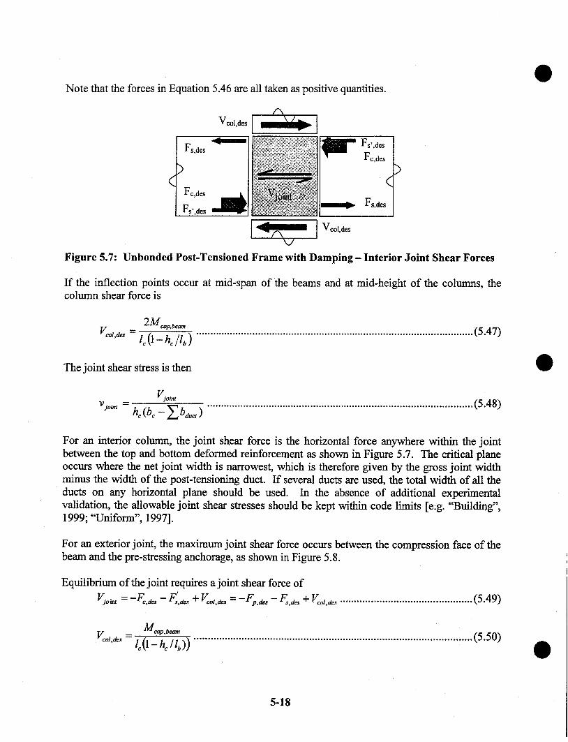
Note that the forces in Equation 5.46 are all taken as positive quantities.
Figure 5.7:
Fs,des
Fs, des ~
Fs’,desFc,des
Unbonded Post-Tensioned Frame with Damping - Interior Joint Shear Forces
If the inflection points occur at mid-span of the beams and at mid-height of the columns, thecolumn shear force is
2 M cap, beamVc°"a~ = lo 0 - h~ /lb ) ................................................................................................... (5.47)
The joint shear stress is then
Vjobnt
v J°~" = h~ (b~ - ~.,ba~, ) ...............................................................................................(5.48)
For an interior column, the joint shear force is the horizontal force anywhere within the joimbetween the top and bottom deformed reinforcement as shown in Figure 5.7. The critical planeoccurs where the net joint width is narrowest, which is therefore given by the gross joint widthminus the width of the post-tensioning duct. If several ducts are used, the total width of all theducts on any horizontal plane should be used. In the absence of additional experimentalvalidation, the allowable joint shear stresses should be kept within code limits [e;g. "Building",1999; "Uniform", 1997].
For an exterior joint, the maximum joint shear force occurs between the compression face of thebeam and the pre-stressing anchorage, as shown in Figure 5.8.
Equilibrium of the joint requires a joint shear force of
V~o~t = -Fc.d~ -- F~.a,s + Vco,.~s = -Fp.a~ - F,.d= + V~o,.a,, .................... ...........................(5.49)
Mcap,t~.nV o,,d = o0-hc/lb)) ...................................................................................................(5.50)
5-18
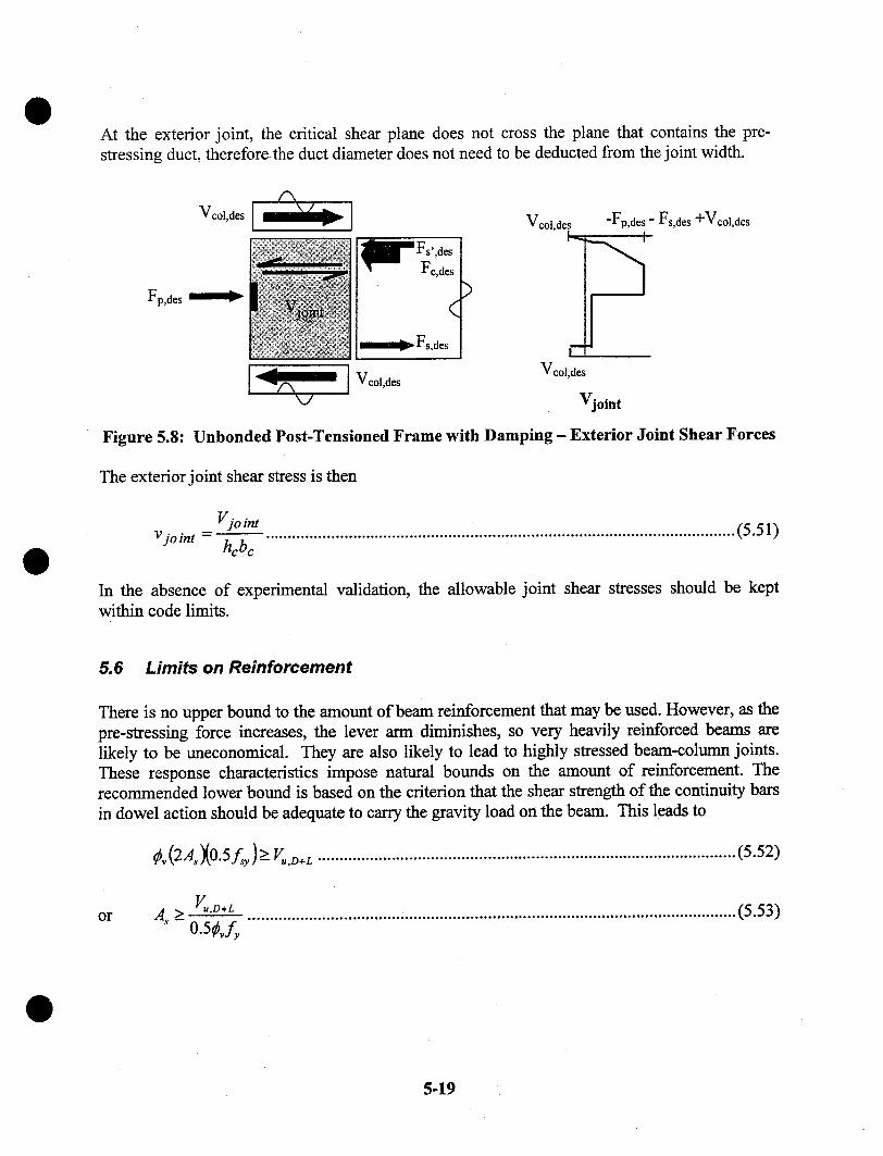
At the exterior joint, the critical shear plane does not cross the plane that contains the pre-stressing duct, therefore~the duct diameter does not need to be deducted from the joint width.
Fp,des ~
Vcol,des
!
Veol,d~
-Fp,des " Fs,des +Vcol,des
Vjoint
Figure 5.8: Unbonded Post-Tensioned Frame with Damping - Exterior Joint Shear Forces
The exterior joint shear stress is then
Vjo int ............................................................................................................(5.51)Vjoint =hcbc
In the absence of experimental validation, the allowable joint shear stresses should be keptwithin code limits.
5.6 Limits on Reinforcement
There is no upper bound to the amount of beam reinforcement that may be used. However, as thepre-stressing force increases, the lever arm diminishes, so very heavily reinforced beams arelikely to be uneconomical. They are also likely to lead to highly stressed beam-column joints.These response characteristics impose natural bounds on the amount of reinforcement. Therecommended lower bound is based on the criterion that the shear strength of the continuity barsin dowel action should be adequate to carry the gravity load on the beam. This leads to
Xo.5y ) >_ ................................................................................................(5.52)
or V",Z~+L ................................................................................................................(5.53)As >- 0.5 vf
5-19
5.7 Construction Issues
The seismic performance of the Post-Tensioned Frame with Damping is sensitive to severalaspects of the constructed system.
5.7.1 Unbonded Deformed Reinforcement Length and Location
The debonded region of the bar must be the correct length, or the bars could fractureprematurely. It must also be located in the beam, ending at the beam-column interface. If itwere to lie in the column, the bond length in the column might be inadequate to developsimultaneously the strength of the bar in tension on one side of the column and in compressionon the other side.
5.7.2 Deformed Reinforcement Grouting
The grouting procedure should be selected and controlled so that the space between the bar andthe duct wall is completely filled with grout. Any voids could have a detrimental effect on thebond of the bars.
5.7.3 Interface Grout
The interface grout should be reinforced with fibers to ensure that it does not degrade throughoutthe anticipated high strains. Research [Cheok and Stone 1994] has shown that 3 pounds of nylonfibers per cubic yard of grout is sufficient to withstand very high rotations .without degradation.
5.8 Discussion
The Unbonded Post-Tensioned Frame with Damping that was tested in the PRESSS Phase IIItest performed very well. Minimal damage was sustained, as shown in Figure 5.9, even after thebuilding had been deformed to 4% roof drift. In particular, the flexural cracking in the beamswas minimal, and no slip was observed at any of the beam-column interfaces. The primarydamage consisted of some joint cracks, which closed when the load was removed, and minorcrushing at the top and bottom of the beams. The latter would have been easily repairable.
The design procedures outlined here have not yet been validated by the authors using the datafrom the PRESSS Phase III test building. Therefore, they should be used only for trial designs.
5-20

Figure 5.9: Unbonded Post-Tensioned Frame with Damping at End of Test
5-21

0
0
0
5-22
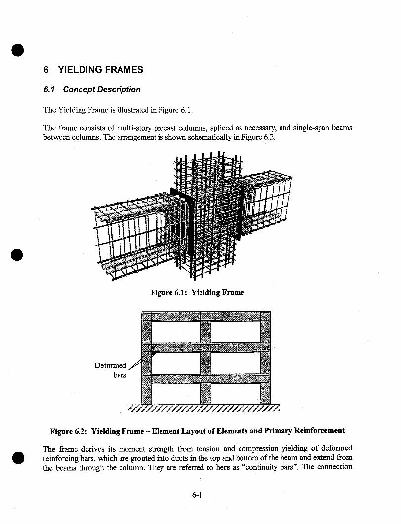
6 YIELDING FRAMES
6.1 Concept Description
The Yielding Frame is illustrated in Figure 6.1.
The frame consists of multi-story precast columns, spliced as necessary, and single-span beamsbetween columns. The arrangement is shown schematically in Figure 6.2.
Figure 6.1: Yielding Frame
Deformedbars
Figure 6.2: Yielding Frame - Element Layout of Elements and Primary Reinforcement
The frame derives its moment strength from tension and compression yielding of deformedreinforcing bars, which are grouted into ducts in the top and bottom of the beam and extend fromthe beams through the column. They are referred to here as "continuity bars". The connection
6-1

resembles, at least functionally, a conventional yielding connection of the type included in thePCI Connection Manual [PCI Committee, 1988]. As shown in Figure 6.3, the deformedreinforcement is unbonded over a short length next to the interface to limit the steel strain andprotect the reinforcing from fracture at high drifts.
Continuity bars(deformedreinforcement)
Interfacegrout
Bars debondedlocally next to the
interface
Figure 6.3: Yielding Frame - Components
The connection may be constructed by loading the bars into the beam, erecting the beam ontemporary corbels, then sliding the bars through the column to their final position. The interfaceand the ducts are then grouted. If the slab is cast in place, or if a thick enough topping is used,the top bars may be embedded directly in it rather than being grouted in ducts in the precastbeam. This construction method leads to the bars being embedded directly in cast-in-placeconcrete in the. beam, but grouted in ducts through the column.
Figure 6.4: Yielding Frame - Deformed Configuration
6-2

During an earthquake, the column sways and most of its rotation is accommodated by a gap thatopens between the beam and column, as shown in Figure 6.4. The bars yield in tension orcompression and thereby provide a resisting moment. The connection dissipates energy duringcyclic loading, but does the frame does not re-center.
The local behavior of the beam near the interface depends on the relative areas of the top andbottom bars, and on the extent to which compression is induced in the beam. If the conditionsare such that an open crack can exist through the whole depth of the grout joint at the interface,the grout risks falling out, and all the shear must be carried by the bars in dowel action. Thelatter leads to the possibility of splitting of the concrete and kinking, and subsequent buckling, ofthe bars.
A full-depth crack is likely if the areas of top and bottom reinforcement are different, because thebeam-column joint is likely to "walk open". This behavior is illustrated assuming that the areaof top steel is the larger of the two. A large negative moment will cause the top steel to yield intension and a crack to open at the top of the beam. When the load is reversed, the tension in thebottom steel will be too small to yield the top steel in compression, so the top crack will remainopen and a bottom crack will also form.
If the areas of top and bottom steel are equal, no driving mechanism exists to open a full-depthcrack. However, no closing mechanism exists either, because the forces in the bars are equal andopposite. The grout then carries no compression and so is unable to carry shear by friction. Theonly way that the grout can be subjected to compression is if the natural elongation of the beam,which occurs because the gap opens at the interface, is restrained by shear in the columns. Thisrestraint has been shown to occur in cast-in-pace frames [e.g. Zerbe and Durrani, 1989], but itdepends on the characteristics of the structure, and not just of the member, so it is different inevery bay and is difficult to evaluate precisely. Furthermore, it is not accounted for inconventional practice. Thus it cannot be regarded as a dependable source of shear friction in theYielding Frame. The lack of a clear mechanism for transferring the beam shear constitutes adrawback for the Yielding Frame.
6.2 Design Assumptions
The following design assumptions are made in the development of design equations:
The design forces and drifts are known. The drift limits are selected to satisfy coderestrictions and user requirements. Forces may be obtained either by Force Based Design orby Displacement Based Design. Interface rotations are obtained from the drift ratio, usingthe geometry of the section.
2. The overall dimensions of the frame members are known, having been obtained fromarchitectural constraints and preliminary calculations.
3. The beams have a constant cross section.
6-3

Equal top and bottom reinforcing is used.
The continuity bars are grouted into ducts through the column and are anchored in the beamseither side.
The continuity bars are debonded for a short length in each beam, adjacent to the beam-column interface to limit the tension strain during an earthquake.
Properties of the proposed materials are known. The principal ones are:¯ strength and stiffness of deformed reinforcement¯ strength, f’e, and stress block coefficient, 131, of the concrete
6.3 Notation
The sign convention adopted is that forces and deformations are computed as positive quantities,regardless of whether they are tensile or compressive.
ad¢s
A~bgdbf~g
fsy
Fe,~lesFs,desFs’,deshb
hg
Inlsu
= depth of compression stress block in grout at design limit state= area of deformed reinforcement in one face of beam= width of beam at beam-column interface= diameter of deformed reinforcing bar= specified grout strength at 28 days= specified yield strength of deformed reinforcement= force in beam concrete at beam-column interface at design limit state= force in tension deformed reinforcement at design limit state= force in compression reinforcing steel at design limit state= depth of beam= column depth (in plane of frame)= depth of grout pad at beam-column interface= total bay dimension between column centerlines= floor-to-floor story height= clear span of beam between column faces= length ofunbonded region of deformed reinforcement at each interface
Mcap,beam = beam moment strength at interface at design limit stateMdesVjoint
Wool,desV joint
VuVu,D+L
O;des
= moment demand at design limit state= joint shear stress= colunm shear force at design limit state= joint shear force= factored shear demand= factored dead and live load shear demand at interface= distance from center of compressive reaction to edge of member divided by member
depth, at design limit state= depth of equivalent compressive stress block divided by neutral axis depth
6-4
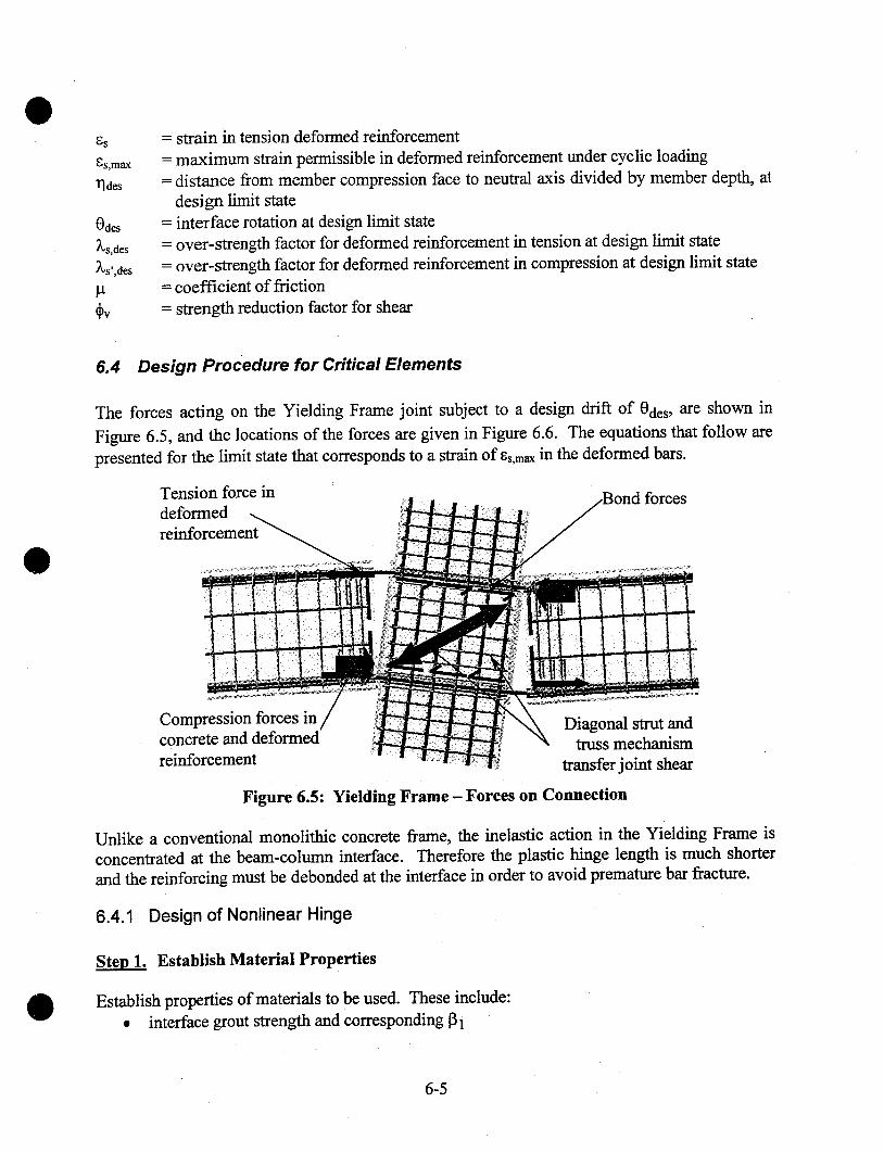
l~des
Odes
~,s,desXs’,des
= strain in tension deformed reinforcement= maximum strain permissible in deformed reinforcement under cyclic loading= distance from member compression face to neutral axis divided by member depth, at
design limit state= interface rotation at design limit state= over-strength factor for deformed reinforcement in tension at design limit state= over-strength factor for deformed reinforcement in compression at design limit state= coefficient of fi’iction= strength reduction factor for shear
6.4 Design Procedure for Critical Elements
The forces acting on the Yielding Frame joint subject to a design drift of Odes, are shown inFigure 6.5, and the locations of the forces are given in Figure 6.6. The equations that follow arepresented for the limit state that corresponds to a strain of ~s,max in the deformed bars.
Tension force indeformedreinforcement
forces
Compression forces inconcrete and deformedreinforcement
Diagonal strut andtruss mechanism
transfer joint shear
Figure 6.5: Yielding Frame - Forces on Connection
Unlike a conventional monolithic concrete frame, the inelastic action in the Yielding Frame isconcentrated at the beam-column interface. Therefore the plastic hinge length is much shorterand the reinforcing must be debonded at the interface in order to avoid premature bar fracture.
6.4.1 Design of Nonlinear Hinge
~ Establish Material Properties
Establish properties of materials to be used. These include:¯ interface grout strength and corresponding 91
6-5
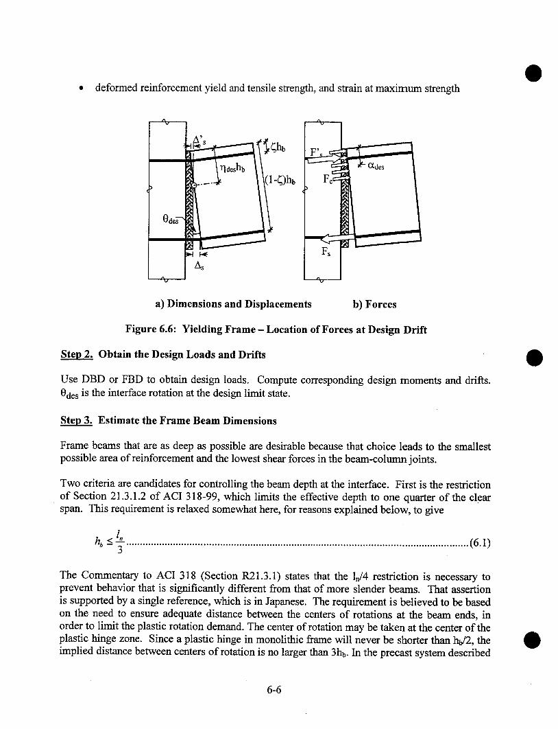
¯ deformed reinforcement yield and tensile strength, and strain at maximum strength
a) Dimensions and Displacements b) Forces
Figure 6.6: Yielding Frame - Location of Forces at Design Drift
Ste~ 2. Obtain the Design Loads and Drifts
Use DBD or FBD to obtain design loads. Compute corresponding design moments and drifts.Odes is the interface rotation at the design limit state.
Ste~ 3. Estimate the Frame Beam Dimensions
Frame beams that are as deep as possible are desirable because that choice leads to the smallestpossible area of reinforcement and the lowest shear forces in the beam-column joints.
Two criteria are candidates for controlling the beam depth at the interface. First is the restrictionof Section 21.3.1.2 of ACI 318-99, which limits the effective depth to one quarter of the clearspan. This requirement is relaxed somewhat here, for reasons explained below, to give
hb -< -f ............................................................................................................................(6.1)
The Commentary to ACI 318 (Section R21.3.1) states that the ln/4 restriction is necessary toprevent behavior that is significantly different from that of more slender beams. That assertionis supported by a single reference, which is in Japanese. The requirement is believed to be basedon the need to ensure adequate distance between the centers of rotations at the beam ends, inorder to limit the plastic rotation demand. The center of rotation may be taken at the center of theplastic hinge zone. Since a plastic hinge in monolithic frame will never be shorter than hb/2, theimplied distance between centers of rotation is no larger than 3hb. In the precast system described
6-6
here the center of rotation is at the interface, so the clear span could then be as short as 3hb andstill fulfill the spirit of the requirement. This reasoning forms the basis of Equation 6.1.
The beam width should satisfy Section 21.3.1.3 of ACI 318 ["Building", 1999]
bb > 0.3hb .......................................................................................................................(6.2)
ACI 318-99 Section R21.3.1 states that this requirement is based on experience withconventional, cast-in-place, non-pre-stressed frames. Its applicability to precast, post-tensionedframes is unclear. It is recommended here that Equation 6.2 be treated as advisory rather thanmandatory. Use of a narrow beam could permit the beam weight to be kept low enough toovercome otherwise difficult erection problems.
Estimate the Required Area of Reinforcement
The top and bottom reinforcement are assumed to have equal areas. End moments caused bygravity loads are addressed in Section 6.5.2.
While direct solution for the required area of reinforcement is possible, iteration provides asimpler approach and is used here. For an initial estimate of the required area of reinforcement,the lever ann is assumed to be the distance between the centroids of the two sets ofreinforcement.
Males ...................................................................................................(6.3)Thus A~ = L,a,,f~h~ 0 - 2~’)
Calculate the Forces in the Reinforcement
The tension reinforcement is expected to undergo significant tension strain, and the stress in it istherefore taken as %s,desfsy. The compression reinforcement is expected to have experiencedsignificant tension strain during previous cycles, so, in returning to a strain close to zero, it willhave also experienced a large compressive change in strain. The stress in it is therefore taken asLs’,desfsy. Values for ~,s,aesfsy. and Ls’,aesfsy are proposed in Table 2.1. The forces on the differentelements are then:
Fs,a,s = As2,,,~,~f ~ ...............................................: ...........................................................(6.4)
F~.,ae~ = As2,.,a,,f ~y ..........................................................................................................(6.5)
Ste~6. Compute the Magnitude and Location of the Compression Force on the Concrete
The compression force between the concrete and grout, Fc,des, can be calculated from axial forceequilibrium as
6-7

Fc,aes = Fs,ae~, - F~,,ae~. .......................................................................................................(6.6)
The depth of the Whitney Equivalent stress block (Section 10.2.7 of ACI 318-99), assumed hereto be controlled by the grout properties, is
FC ,des.......................................................................................................... (6.7)aae~ - 0.85f’g b~,
The resultant compressive force on the concrete is located at ~deshb from the compression face,where
- aae’~ .....................................................................................................................(6.8)
The neutral axis is located at a distance ~ldeshb from the compression face of the beam, where
addsr/d~, = ~. ...................................................................................................................(6.9)
The moment capacity of the beam is given by
Mcap,beam = Fs,deshb 0 -- ~ -- O[’des )-- Fs’,deshb (~ -- I~’des ) .................................................: ..... (6.10)
where ~ = distance from centroid of deformed reinforcement to the nearest face of the concrete,divided by hb.
This must be greater than or equal to the design moment, so
M~,,~,,n.,~ > Ma,s .......................................................................................i ....................(6.11)
If Equation 6.11 is not satisfied, select a new As and repeat Steps 5 - 6 until a satisfactorysolution is reached.
Ste~ 7. Select the Debonded Length for the Continuity Bars
The debonded length of the reinforcing bars must satisfy
l~, >_ 0 ae~hbO-~- rla~) ..............: ................................................................................(6.12)
High cyclic strains can cause growth in the unbonded length. The amount of growth depends onthe confinement provided around the bar and other parameters. For bars grouted into a pre-
6-8

formed hole in the beam, Cheok and Stone [1994] found the growth in debonded length to be5.5db (2.75db at each end of the intentionally debonded length) for a #3 bar. More recent testingon bars grouted in corrugated steel ducts [Stanton et al. 2002] has shown that the growth dependson bar strength, grout strength and load history, but is on the order of 1.0db. The danger inassuming an additional debonded length that is larger than the true one is that the true bar strainswill be higher than the predicted ones, and there is a risk of the bars fracturing prematurely. Thedanger in assuming an additional debonded length that is smaller than the true on is that the barsstrain will be lower than expected. However, because the stress-strain curve is relatively flat atstrains near ~s,max, the resulting error in estimating the stress will be relatively small. Because theconsequences of overestimating the growth in debonded length are much more serious than thoseof underestimating it, the growth in debonded length is assumed here to be zero.
6.5 Design of other Components
The behavior of the Yielding Frame beam is similar that of a monolithic frame beam, except thatthe end rotation is concentrated at the interface rather than being distributed over a finite plastichinge length. Therefore most other features of the system, apart from the shear design of theinterface, can be designed to current code requirements.
6.5.1 Interface Shear Strength
The interface beam shear must be carried largely by dowel action of the grouted bars, unlesssome other explicit mechanism is provided. The compression force across the interface isresisted by a combination of the compression reinforcement and the surrounding concrete.Because the compression reinforcement will have yielded, and is treated as carrying a stress ofLs’,desfsy, the nominal shear friction capacity across the grout is given by
V..sr = ,u.Fc.ae" = ,u(F,.ae" - F,..ae,) ............................................................................... ..(6.13)
The shear demand at the joint is
2M c"~"be"’ . ...............................................................................................(6.14)l.
Therefore the nominal shear strength of the bars in dowel action must satisfy
V. ao,~l >- V~ - V, sr .......................................................................................................(6.15)
Shear resistance through dowel action is not formally accounted for in conventional practice, andACI318-99 contains no provisions for computing it. Its use also raises the possibility of kinkingof the bars if the loading is cyclic. Therefore experimental evidence is needed if it is to be usedin this case. It should be noted that, if more horizontal reinforcement is added to increase the
6-9

shear friction capacity given in Equation 6.13, it will be counterproductive because it will alsoincrease the shear demand by increasing Mcap,beam, as shown by Equation 6.14.
6.5.2 Beam Flexure
During cyclic frame displacements, the beam end moments may become equal in magnitude andopposite in sign (i.e. both clockwise or both counter-clockwise). Their effect on the mid-spanmoment capacity is ~then zero, so moment demand at mid-span is the same as that for a simplespan. Reinforcement should be selected accordingly. This observation applies to all types offrame, including cast-in-place concrete and structural steel moment frames.
6.5.3 Beam Shear
The beam should be designed for shear using principles of Capacity Design, as outlined inSection 21.3.4 of ACI318-99. Placing ties to carry the entire shear in the very end of the beamwill help to reduce the tendency for dowel action of the continuity bars to split the concrete.
6.5.4 Beam Torsion
Torsion in the beam can be resisted only by dowel action of the bars. Therefore any slab systemloading onto the beam should be designed to apply the least possible torsion.
6.5.5 Bond and Anchorage
The deformed reinforcement is anchored in the grouted sleeves that extend into the beam. Careshould be taken to provide sufficient development length past the end of the debonded region,including sufficient length to transfer the force from the deformed bars into the longitudinalreinforcement that is cast into the beam. For these purposes, the debonded region includes boththe intentionally debonded region calculated above plus any growth in the debonded regioncaused by cyclic bar yielding. For this calculation, it is unconservative to assume that the growthin the debonded length is zero. An additional length of 2rib at each end of the intentionallydebonded region is recommended.
The Yielding Frame may be constructed by casting the continuity bars directly into a cast-in-place slab on a precast beam, rather than grouting them into ducts in the beam. Because the bondof bars in concrete is much less robust than bond of bars grouted into ducts, cyclic loading willcause a significant penetration of inelastic strain into the bonded region of the bars, and asignificant increase in the unbonded length in the beam. The development length provisions inChapter 21 of ACI 318-99 should be used.
6.5.6 Column Design
The column should be designed using Capacity Design principles to ensure that nonlinear actionoccurs at the beam-column interface. Column splices should also be designed using Capacity
6-10
Design principles, including consideration["Uniform", 1997].
6.5.7 Joint Shear
of higher mode effects as describedin the UBC
The magnitude of the joint shear demand is computed here using values for the forces that areconsistent with the strains expected in the members. Those forces may differ from the ones usedin ACI318-99, which are largely empirical. Furthermore, it is worth noting that the allowablejoint shear stresses given by ACI318-99 do not represent a true Capacity Design, becauseconsiderable damage will occur to a joint that is designed in accordance with them [Mosier,2000]. Thus the design of any joint, in a cast-in-place or a precast frame, depends on theperformance desired. The requirements of ACI318-99 should be satisfied as a minimum but, ifminimal joint damage is desired, a more conservative design may be necessary.
For an interior joint,
V~.o,,, = 2F,,ae* - Vco,,a," ...................................................................................................(6.16)
Note that the forces in Equation 6.16 are all taken as positive quantities. If the inflection pointsoccur at mid-span of the beams and at mid-height of the columns, the column shear force is
2 M cap, beamVco,,a,,. _ lcO _ hc/lb ) .....................................................................................................(6.17)
The joint shear stress is then
VJ°i" ......................................................................................... ........................(6.18)v~°i" = hcb~
For an exterior joint, the procedures are similar, but Equation 6.16 is replaced byV~o~,’ = F,.a,s - V~ol.a~~ ....................................................................................................(6.19)
and Mc"t"be’~ ...................................................................................................(6.20)-zoO-ho/l )
6.6 Limits on Reinforcement
If the areas of the top and bottom continuity bars are equal, there is no upper limit to the amountof reinforcement used. The recommended lower bound is based on the criterion that the shearstrength of the continuity bars in dowel action should be adequate to carry the gravity load on thebeam. This leads to
6-11
orVu,D+ L
A.,. > 0.5~bvf~ ...............................................................................................................(6.16)
6.7 Construction lssues
6.7.1 Placement of Bars
Some way is needed for placing the bars in the ducts. One possibility is to make the ducts runthe full length of the beam and to place the bars in the ducts before lifting the beam into place.Troughs in the top and bottom of the beam, or access holes to the ducts, can then allow the barsto be moved along the duct by hand.
6.7.2 Debonded Length of Bars
The debonded region of the bar must be the correct length, and must be installed accurately, sothat it occurs at the joint interface. Otherwise the bars could fracture prematurely. Thedebonded region should also be located in the beam. If it were to lie in the column, the bond inthe column might be inadequate to develop simultaneously the strength of the bar in tension onone side of the column and in compression on the other side.
6.7.3 Deformed Reinforcement Grouting
The grouting procedure should be selected and controlled so that the space between the bar andthe duct wall is completely filled with grout. Any voids could have a detrimental effect on thebond of the bars.
6.8 Discussion
Although designers may wish to use corbels to supplement the shear capacity of the connection,this approach is not recommended. First, corbels provide supplementary shear strength only inthe downward direction. Second, when the beam rotates downwards, the center of rotation is atthe front comer of the corbel. The end of the beam then moves upwards relative to the columnface and kinks the bars at the interface. This behavior has been observed in tests and isdetrimental to performance, e.g. [Stanton et al, 1987]. Corrective measures are possible for bothof these behaviors, such as hold-down bolts and dapped beams, e.g. [Palmieri et al., 1996].However the connection then becomes distinctly different from the one considered here anddisplays other undesirable behavior characteristics.
In the PRESSS Phase III building test, some of the continuity bars slipped through the exteriorcolumn, as shown in Figure 6.7. This behavior was most probably the result of imperfectgrouting. The bars had T-heads on their ends in order to provide good tension anchorage. Theyappeared to yield in tension then to push through the column when the load reversed. Bond tests
6-12
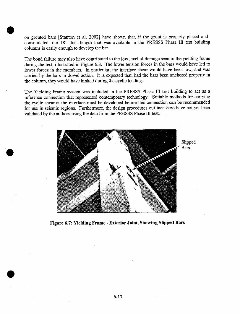
on grouted bars [Stanton et al. 2002] have shown that, if the grout is properly placed andconsolidated, the 18" duct length that was available in the PRESSS Phase III test buildingcolumns is easily enough to develop the bar.
The bond failure may also have contributed to the low level of damage seen in the yielding frameduring the test, illustrated in Figure 6.8. The lower tension forces in the bars would have led tolower forces in the members. In particular, the interface shear would have been low, and wascarried by the bars in dowel action. It is expected that, had the bars been anchored properly inthe column, they would have kinked during the cyclic loading.
The Yielding Frame system was included in the PRESSS Phase III test building to act as areference connection that represented contemporary technology. Suitable methods for carryingthe cyclic shear at the interface must be developed before this connection can be recommendedfor use in seismic regions. Furthermore, the design procedures outlined here have not yet beenvalidated by the authors using the data from the PRESSS Phase 111 test.
Slipped3ars
Figure 6.7: Yielding Frame - Exterior Joint, Showing Slipped Bars
6-13
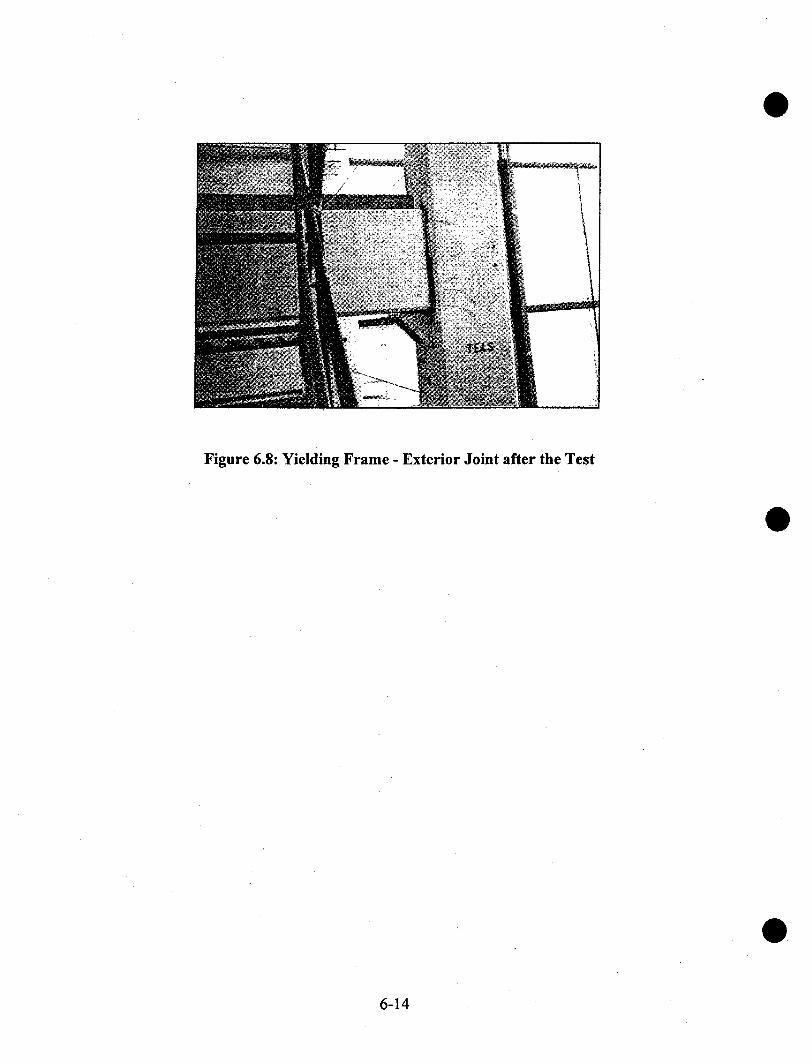
Figure 6.8: Yielding Frame - Exterior Joint after the Test
6-14

7 YIELDING GAP FRAMES
7.1 Concept Description
The Yielding Gap Frame is shown in Figure 7.1. The beam is connected to the column at thebottom by a post-tensioning tendon that passes through, and pre-compresses, a grout pad. At thetop, the connection is made by deformed bars grouted into ducts. The grout pad exists only atthe bottom of the beam, so there is no contact between the two concrete faces at the top of thebeam. The element layout is shown in Figure 7.2 and the reinforcing details are shown in Figure7.3
Figure 7.1: Yielding Gap Frame
Deformedbars in ducts
Post-tensioning
tendon
Gap
Groutpad
Figure 7.2: Yielding Gap Frame -Layout of Elements and Primary Reinforcement
7-1

Continuity bars Continuity barscrossing ga1 at
(remains constant length) .......... (at bottom only)
Figure 7.3: Yielding Gap Frame - Components
Figure 7.4 shows the deformed shape of the joint region caused by earthquake loading. Thecolumn tilts as the building drifts and the connections accommodate the angle change by yieldingof the deformed bars in the top of the beam. The end of the beam rotates about the grout pad,which acts as a hinge. Shear is carded by friction at the grout pad, made possible by thecompression force across it, which is supplied by the post-tensioning. The post-tensioningtendon never elongates and never experiences any change in stress.
Bars yield in compressionas gap closes
~Beam rotates about grout pad.
Tendon does not stretch
Figure 7.4: Yielding Gap Frame - Deformed Configuration
The distinguishing characteristic of the connection is that it overcomes the problems associatedwith the beam elongation that typically occurs under plastic rotation [Zerbe and Durrani, 1989].That beam growth takes place in both precast and cast-in-place concrete frames and constitutes a
7-2

potential problem for precast floors, because loss of seating is a possibility. Although beamgrowth is more easily visualized in a precast system, in which a gap opens between the columnface and the end of the beam, some researchers believe that it is more pronounced in a cast-in-place frame, because there it is caused by the continued opening under cyclic loading of thediagonal shear cracks in the plastic hinge region, [e.g. Fenwick and Megget, 1993].
By forcing the bars at the top of the beam to deform equally in tension on one side of the columnand in compression on the other, the distance between the two beam ends remains unchangedduring column drift. Detailing of the floors is thus much simplified, and there is no risk of losinggravity support for the floors.
The frame does not re-center, so residual drift is a possibility, as it is with conventional cast-in-place concrete moment frames and with steel moment frames.
During the PRESSS Phase III building test, the gap connections performed adequately, but thegrout pads suffered some damage and the concrete at the bottom of the beams spalled. However,the shortcomings were associated with the detailed design of the connection in the test buildingand not with the basic concept. They are discussed in Section 7.8.
7.2 Design Assumptions
The following design assumptions are made in the development of design equations:
o
The design forces and drifts arerestrictions and user requirements.by Displacement Based Design.
known. The drift limits are selected to satisfy codeForces may be obtained either by Force Based Design or
The overall dimensions of the frame members are known, having been obtained fromarchitectural constraints and preliminary calculations.
The beams are of constant cross section. Each bay in the frame is of equal length.
The beam continuity bars are unbonded for a short length in the beam, adjacent to the beam-column interface to prevent high strain concentrations.
The centroids of the grout pad and the post-tensioning tendon are coincident.
Properties of the proposed materials are known. The principal ones are:¯ the strength of the deformed reinforcement¯ the strength and stiffness of the post-tensioning tendon¯ the grout strength¯ the concrete strength
7-3

The coefficient of friction, ~, between the grout and the concrete, may be taken as 0.5.Hutchinson et al. [1991] measured a value of 0.6 between precast concrete and grout undercyclic shear loading. It is reduced here to 0.5 to ensure that no slip occurs. Roughening of thesurfaces could lead to a higher value, but experimental evidence would be needed to justify itsuse in design.
7.3 Notation
The sign convention adopted is that forces and deformations are computed as positive quantities,regardless of whether they are tensile or compressive.
Cgd’db
Fc,desFs,des
Fs’,aeslgapInlsuMdes
= area ofpre-stressing tendon= area of deformed reinforcement in one face of beam= compressive strength of grout pad= depth from top face of beam to centroid of deformed reinforcement= diameter of deformed reinforcing bar= depth from top face of beam to centroid of pre-stressing tendon= stress in pre-stressing tendon, after losses, at zero drift= specified yield strength of deformed reinforcement= force in beam concrete at beam-column interface at design limit state= force in tension deformed reinforcement at design limit state= force in compression reinforcing steel at design limit state= width of gap (in direction parallel to longitudinal axis of beam)= clear span of beam between column faces= length of unbonded region of deformed reinforcement at each interface= moment demand at design limit state= factored dead and live load shear demand at interface
Odes
~,s,des
~’s’,dcs
= deformation of compression deformed reinforcement= maximum strain permissible in deformed reinforcement under cyclic loading= interface rotation at design limit state= over-strength factor for deformed reinforcement in tension at design limit state= over-strength factor for deformed reinforcement in compression at design limit state= coefficient of friction= strength reduction factor for shear
7.4 Design Procedure for Critical Elements
In the Yielding Gap Frame, the bending deformations of the frame occur by tension andcompression yielding of the deformed bars (the "continuity bars") in the top of the beam. Thegrout pad carries the shear force by shear friction, so it must be permanently compressed by thepost-tensioning tendon. Therefore the deformed reinforcement is designed to provide the

required flexural strength, and the post-tensioning tendon is designed to ensure a net pre-compression across the grout pad that is large enough to resist the interface shear by friction.The assumed positive directions of the forces and displacements are shown in Figure 7.5.
%
Odes
mS,
dp
a) Dimensions and Displacements
Fc,des
b) Forces
Figure 7.5: Yielding Gap Frame- Location of Forces at Design Drift
7.4.1 Design of Nonlinear Hinge
Establish the Material Properties
Establish properties of materials to be used. These include:¯ beam concrete strength¯ interface grout strength and corresponding 131¯ pre-stressed tendon strength and modulus of elasticity¯ deformed reinforcement yield and tensile strength, and strain at maximum strength
Ste~2 Select the Gap Size
The gap size depends on the drift to be accommodated. Proper functioning of the connectionrequires that no contact occur between the beam and column faces at top of the interface.Therefore the gap must satisfy
lg,,p > O de~d~, ....................................................................................................................(7.1)
~ Select the Area of Deformed Reinforcement
The continuity bars grouted into the ducts must satisfy
7-5
M des>- (d p - d’)O.5(~,,ae~ + A~,,ae~ )f +~ ................................................................................(7.2)
The average ~,s,des value is used in Equation 7.2 because at one end of the beam the continuitybars will be in tension, whereas at the other they will be in compression. Use of the averagematerial overstrength factor allows the structure to be analyzed assuming the strength of thebeam is the same in negative and positive bending. The value of the material stress factor,depends on the limit state under consideration, and the corresponding allowable strain in the barreinforcement. Suitable values are given in Table 2.1. The value required in Equation 7.2 is theone that corresponds to the design limit state.
Ste~4 Select the Debonded Length for the Bars
The bars must be debonded locally to prevent fracture through excessive strain. The bar may bedebonded locally by wrapping or sleeving. The debonded length should be in the beam, not thecolumn. The total debonded length must satisfy
0 a~tdp -d’)l~, > .......................................................................................................... (7.3)
High cyclic strains can cause growth in the unbonded length. The magnitude of that growthdepends on the confinement provided around the bar and other parameters. For bars grouted intoa pre-formed hole in the concrete, Cheok and Stone [1994] found the growth in debonded lengthto be 5.5db (2.75db at each end of the intentionally debonded length) for a #3 bar. More recenttesting on bars grouted in corrugated steel ducts [Stanton et al. 2002] has shown that, under thosecircumstances, the growth depends on bar strength, grout strength and load history, but is on theorder of 1.0db.
If the estimated debonded length is greater than the true one, the true bar strain will be higherthan the predicted one, and the bars may fracture prematurely. If the estimated debonded lengthis less than the true one, the true strain will be lower than predicted and yield of the bars will bedelayed. The consequences are that the bar stress, and therefore the resisting moment, at peakdrift will be slightly lower, as will also be the damping. However, these changes will be verysmall. Because the consequences of predicting too high a growth in the debonded length aremuch more serious than those of a low prediction, the growth in debonded length is assumedhere to be zero.
Ste~5 Select the Post-tensioned Reinforcement
The force in the post-tensioning tendon must be large enough to resist the compression in thereinforcing bars and still provide sufficient clamping force to resist vertical shear across the groutpad by shear friction. The post-tensioning tendon must satisfy all three of Equations 7.4 - 7.6,each of which addresses a different condition. If the seismic shear adds to the gravity shear, (i.e.the continuity bars are in tension)
7-6

Apf ~o Vu D+L>#v/Z .....+~#,/.d,) ’’’--- tF’a" +Fs’a‘s)-Fsa"‘" , ...........................................................(7.4)
If the seismic and gravity shears oppose each other, and the gravity shear is less than the seismicshear,
If the seismic and gravity shears oppose each other, and the gravity shear is larger than theseismic shear,
Arf ~,o > V~.D+ ~. ( d ~,- #,,!.z ~"-~,,--~= )tF’’a’= + F=,,,~==)+ F=,,~,s ...........................................................(7.6)
where F,.~,, : A~2~..,~,f~, ..........................................................................................................(7.7)
F~,.,~. = A~A~,.u.sf ~ .................................................................................¯ .........................(7.8)
The forces Fs,des and Fs’,aes are positive quantities, regardless of whether they are tensile orcompressive. In most cases, Equation 7.5 will control the tendon design.
The post-tensioning tendon does not elongate during lateral displacement of the frame, so thestress in it may be based on initial stressing conditions and losses. Stress limits are given inSection 18.5.1 of ACI 318-99.
~ Design the Grout Pad
The compressive strength, Cg, of the grout pad must satisfy
C~, >_ A~,f~,o + 2,,d,,A,f,r .................................................................................................(7.9)
Under seismic loading, the grout pad experiences compression that varies from(A~,f~,o - A~,,d,~A,f~y) to (A~,fpo + 2~.d,,A,f~). In addition, the beam end rotates, so the grout padwill be subjected to compression plus bending. In order to minimize the adverse effects of thebending, the pad should be kept small and made of high strength material. It should also be wellconfined both in order to increase its strength and to provide it with some ductility. This may beachieved by suitable reinforcement, for example with fibers. Because the grout pad is a criticalelement, a relatively high dosage of fiber, such as 1% by volume of stainless steel fibers, isrecommended.
7-7
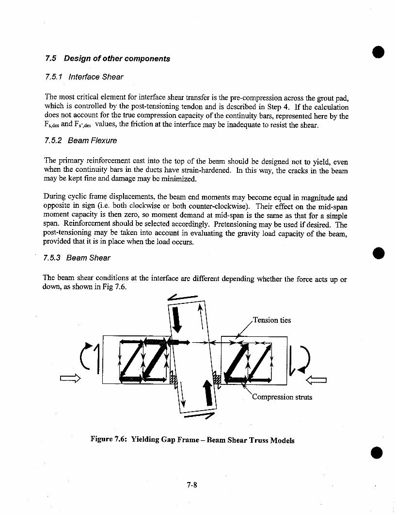
Design of other components
Interface Shear
The most critical element for interface shear transfer is the pre-compression across the grout pad,which is controlled by the post-tensioning tendon and is described in Step 4. If the calculationdoes not account for the true compression capacity of the continuity bars, represented here by theFs,des and Fs’,des values, the friction at the interface may be inadequate to resist the shear.
7. 5.2 Beam Flexure
The primary reinforcement cast into the top of the beam should be designed not to yield, evenwhen the continuity bars in the ducts have strain-hardened. In this way, the cracks in the beammay be kept fine and damage may be minimized.
During cyclic fram.e displacements, the beam end moments may become equal in magnitude andopposite in sign (i.e. both clockwise or both counter-clockwise). Their effect on the mid-spanmoment capacity is then zero, so moment demand at mid-span is the same as that for a simplespan. Reinforcement should be selected accordingly. Pretensioning may be used if desired. Thepost-tensioning may be taken into account in evaluating the gravity load capacity of the beam,provided that it is in place when the load occurs.
7.5.3 Beam Shear
The beam shear conditions at the interface are different depending whether the force acts up ordown, as shown in Fig 7.6.
ties
struts
Figure 7.6: Yielding Gap Frame - Beam Shear Truss Models
7-8
For upward shear, a strut and tie model shows that, at the very end of the beam, a set of stirrupsis needed that will carry the entire shear force. This is so because the shear must be transferredthrough the grout pad and not through the compression bars. For downward shear, the strut startsat the grout pad and propagates diagonally upward into the beam, so the behavior is comparableto that of a cast-in-place beam.
7.5.4 Beam Torsion
The beam-column interface can resist little torsion because the gap there is always open. Thefloor system should therefore be designed so as to minimize the torsional demand on the beam.
7. 5. 5 Bond and Anchorage
The minimum permissible length for the ducts in the beam depends on the transfer of force fromthe duct to the adjacent bar embedded directly in the beam. The maximum available length ofthe ducts is most likely controlled by the method of installation of the bars. They may be loadedinto the duct before the beam is placed, then slid along the duct, through the column, once thebeam is in place on temporary corbels. Sliding the bar requires access to it, which may be gainedby means of a trough or opening in the beam, which is best located near mid-span. The presenceof such a trough may limit the available duct length. The effect of the additional debondedlength described in Step 3 should be taken into account. When computing the anchorage length,the additional debonded length should be assumed to have its maximum probable value. Thismay be taken as 2db at each end of the deliberately debonded region for bars grouted in ducts.
7.5.6 Column Design
Column design, other than the joint region, is conducted using conventional procedures. Thecolumn may be pre-tensioned for handling if desired. If it is, the bending strength provided bythe pre-tensioning should be accounted for. Attention should be paid to the space needed forhorizontal ducts, which may influence the arrangement of longitudinal column bars.
7. 5. 7 Joint Shear
The beam-column joint should be designed by conventional means, but the amount of joint steelmay differ from that required by Section 21.4.4.1 of ACI 318-99. Detailed study of the jointshear behavior of a Yielding Gap frame joint has yet not been conducted. It is likely that thehorizontal pre-compression due to the post-tensioning will improve the joint resistance[Pantazopoulou and Bonacci, 1992], but the fact that all the force is introduced by bar bond,rather than by direct concrete compression, may detract from it. Direct compression loading ofthe joint tends to cause more of the force to be carried by the main diagonal strut, whereas forcesintroduced through bar bond tend to be carried by the truss mechanism that includes the ties[Priestley and Paulay 1992]. Further investigation of the joint shear behavior of this system isdesirable.
7-9
8 SUMMARYAND CONCLUSIONS
8.1 Summary
Guidelines are presented for the structural design of five different precast concrete seismicframing systems. The behavior expected of each system is described, and step-by-stepprocedures are given for establishing the capacities of the primary components of each system.
The five systems were included in the PRESSS Phase III test building, tested at the University ofCalifornia at San Diego in August and September 1999. Those tests were conducted usingpseudo-dynamic loading and a variety of different intensities. The most severe loading wasequivalent to 150% of the Zone 4 design earthquake embodied in the 1997 UBC. Details of thetests are provided by Priestley et al. [1999].
The test building performed very well, maintaining good lateral resistance to a peak roof drift ofapproximately 4% in the frame direction and 3% in the wall direction. Damage was much lessthan would be expected in a comparable conventional reinforced concrete SMR_F structuresubjected to the same loading. In the frame direction, the loading was arranged so that thebuilding did not twist. Therefore the residual drift was the same on both sides of the building. Itwas also very small. It is believed that the self-centering characteristics of the pre-stressed frameprovided most of the benefits. In a prototype structure without the restraint against twisting, thetwo types of frame would likely have displayed different residual drifts. In the wall direction,the residual drift was approximately 0.0006 radians, or approximately 2% of the peak driftduring the testing, and the damage was minimal. From the points of view of alignment, plumb,and structural damage, the building was fully serviceable directly after the test.
8.2 Conclusions
The following conclusions can be drawn from the study:
The three pre-stressed systems (the Unbonded Post-Tensioned Frame with Damping, theUnbonded Pre-tensioned Frame and particularly the Unbonded Post-Tensioned Split Wall)all represent structural systems that can be expected to provide good structural performance.They offer a characteristic that is not available in the framing systems presently recognized inthe 1997 UBC, namely zero residual drift. The choice of conferring this characteristic on thebuilding lies within the control of the designer.
Local debonding near the interface allows the deformed reinforcement to yield and toprovide inelastic deformations, without inflicting significant damage on the surroundingconcrete.
8-1
o
o
The Yielding Frame may be expected to provide good flexural ductility, but it will not on itsown re-center. A further disadvantage is that vertical shear at the bearn-colunm interfacemust be transferred by dowel action. That action risks kinking the main bars and leading totheir premature fracture. This behavior was not observed in the test because the bars lostbond and did not develop large enough forces, but it is likely to occur in the field. Without arational design procedure for the interface shear, and experimental verification of goodresponse, the Yielding Frame cannot be recommended for use.
The Yielding Gap frame incurred some damage, but maintained its load-carrying capabilitythroughout the testing. However, the damage was attributed to a shortcoming in the detaileddesign, rather than any error in the basic concept. Thus, while the Yielding Gap Framecannot be recommended for use now, it merits further development because it has thepotential for eliminating the undesirable effects of beam growth.
Displacement Based Design offers a viable method for determining the required lateralstrength of the structure. It allows the designer to take full advantage of the specialcharacteristics of the systems described here, whereas Force Based Design does not. It alsoallows the designer a means of designing simply and straightforwardly for different levels ofperformance in all structural systems.
8.3 Recommendations
1. A series of detailed design examples should be prepared for each of the systems described inthis report and should be communicated to the design community through workshops orother means.
o
Studies are needed to correlate the design capacities described in this report with design loadsspecified in codes, such as NEHRP [2000], for different performance levels.
Further development and testing should be conducted on the Yielding Gap Frame system. Itshows considerable promise of solving the problems of beam growth due to plastic hingingthat occur in both cast-in-place frames and precast frames without gaps at the joint.
A study should be undertaken to determine the appropriate compressive deformation limitsand confining strategies for concrete reinforced with partially unbonded reinforcement, bothpre-stressed and non-pre-stressed, in which the flexural rotation is concentrated at a singlecrack.
8-2
9 REFERENCES"Building Code Requirements for Reinforced Concrete (ACI 318-99) and Commentary". ACI,
Farmington Hills, MI.Cheok, G.S. and Stone, W.C. (1994). "Performance of 1/3 Scale Model Precast Concrete Beam-
Column Connections Subjected to Cyclic Inelastic Loads - Report No. 4". Report No.NISTIR 5436, NIST, Gaithersburg, MD, June.
Cheok, G.S., Stone, W.C. and Nakaki, S.D. (1996). "Simplified Design Procedure for HybridPrecast Connections". Report No. NISTIR 5765, NIST, Gaithersburg, MD, Feb.
Chopra, A.K. (1999). "Dynamics of Structures: Theory and Applications to EarthquakeEngineering". 2nd ed. Prentice Hall.
Chopra, A.K. and Goel, R.K. (2001). "Direct Displacement-Based Design: Use of Inelastic vs.Elastic Design Spectra. " Earthquake Spectra, 17(1), Feb., pp 47-64.
Eberhard, M.O. and Sozen, M.A.. (1993) "A Behavior-Based Method to Determine Design Shearin Earthquake-Resistant Walls," ASCE. Jo. Struct. Eng., 119(2), Feb., pp. 619-640.
Fenwick, R.C. and Megget, L.M. (1993). "Elongation and Load-Deflection Characteristics ofReinforced Concrete Members Containing Plastic Hinges ". Bulletin of the New ZealandNational Society for Earthquake Engineering, 26(1), Jan, pp. 28-41.
Galusha, J.G. (1999). "Precast, Post-tensioned Concrete Walls Designed-to Rock". MSCEThesis, University of Washington, Seattle, WA, 103 p.
Gulkan, P. and Sozen, M.A. (1974). "Inelastic Response of Reinforced Concrete Structures toEarthquake Motions". ACI Jo., ACI, Detroit, MI. pp. 604-610.
Hutchinson, R.L., Rizkalla, S.H., Lau, M. and Heuvel, S. (1990). "Horizontal Post-tensionedWall Connections for Precast Concrete Load-Beating Shear Wall Panels". PCIJo. 36(6),Nov-Dec, pp. 64-76.
"International Building Code". (2000). International Code Council, Falls Church, VA.Kelly, J.M., Skinner, I., and Heine, A.J. (1972). "Mechanisms of Energy Absorption in Special
Devices for Use in Earthquake Resistant Structures". Bulletin of the New ZealandNational Society for Earthquake Engineering, 5(3), pp..63-68.
Kurama, Y., Pessiki, S., Same, R., Lu, L.-W. and Sheikh, M. (1998). "Analytical Modeling andLateral Load Behavior of Unbonded Post-Tensioned Precast Concrete Walls." ReportNo. EQ-96-02, Lehigh University, Bethlehem, PA.
Meinlaeit, D.F. and Jirsa, J.O., (1977). "The Shear Strength of Reinforced Concrete Beam-Column Joints". CESRL Repot No. 77-1, Dept. of Civil Engineering, University of Texasat Austin, Austin, TX, Jan, 271 p.
Mosier, W.G. "Seismic Assessment of Reinforced Concrete Beam-Column Joints". MSCEThesis, Dept. of Civil Engineering, University of Washington, 2000. 2.18 p.
Nakaki, S.D, Stanton, J.F. and Sritharan, S., (1999). "An Overview of the PR~SSS Five StoryPrecast Test Building". PCIJo., 44(2), Mar.-Apr., pp. 28-39.
"NEHRP Recommended Provisions for Seismic Regulations for New Buildings and OtherStructures: Part I, Provisions (FEMA 368) and Part 11, Commentary (T’EMA 369)".(2000). Building Seismic Safety Council, Washington DC.
Palmieri, L., Saqan, E., French, C. and Kreger, M. (1996). "Ductile Connections for PrecastConcrete Frame Systems,’. Paper No. SP 162-13, Mete A. Sozen Symposium, SP-162,ACI, Farmington Hills, MI, pp. 312-355.
9-1

Pantazopoulou, S. and Bonacci, J. (1992). "Consideration of Questions about Beam-ColumnJoints". ACIStr. Jo., 89(1), Jan.-Feb., pp. 27-36.
Paulay, T. and Priesfley, M.J.N. (1992). "Seismic Design of Reinforced Concrete and MasonryStructures". Wiley.
PCI Committee on Connection Details. (1988). "Manual on Design and Detailing of Connectionsfor Precast and Prestressed Concrete". PCI, Chicago, IL.
Priestley, M.J.N., (1996). "The PRESSS Program - Current Status and Plans for Phase ffI".PCIJo., 41(2), Mar.-Apr., pp. 22-40.
Priestley, M.J.N. (2000) " Performance-Based Seismic Design". State-of-the-Art PlenarySession 2, 12WCEE, Auckland, New Zealand, Jan.
Priestley, M.J.N. and Kowalsky, M.J., (2000) "Displacement-Based Design for Multi-Degree ofFreedom Systems". Bulletin of the New Zealand National Society for EarthquakeEngineering. 33(4), pp. 421-444.
Priestley, M.J.N., Kowalsky, M.J., Ranzo, G. and Benzoni, G. (1996) "PreliminaryDevelopment of Direct Displacement-Based Design for Multi-Degree of FreedomSystems". Proc. SEAOC Annual Conference, Oct.
Priestley, M.J.N., and MacRae, G.A., (1996). "Seismic Tests of Precast Beam-to-Column JointSubassemblages With Unbonded Tendons," PCIJo., 41 (1), Jan.-Feb. pp. 64-81
Priestley, M.J.N, Sritharan, S., Conley, J. and Pampanin, S. (1999) "Preliminary Results formthe PRESSS Five Story Test Building". PCIJo., 46(6), Nov-Dec. pp. 42-67.
Saint Venant, B. (1855). "Memoire des Savants Etrangers". Journal de Mathematique,Liouville, taille 14.
Schultz, A.E. and Magana, R.A. (1996). "Seismic Behavior of Connections in Preeast ConcreteWalls". Paper No. SP 162-12, Mete A. Sozen Symposium, SP-162, ACI, FarmingtonHills, MI, pp. 273-311.
Shahawy, M. and Cai., C.S. (2001). "Enhancement of the Performance of Prestressed ConcreteBridge Girders Using Strand Anchorage". PCI Jo. 46(5), Sept.-Oct., pp. 82-97.
Shibata, A. and Sozen, M:A. (1976). "Substitute-Structure Method for Seismic Design in R/C".ASCEStr. Jo., 102(ST1), Jan., pp. 1-18.
Stanton, J.F., Raynor, D. and Lehman, D.E. (2002). "Bond Characteristics of Reinforcing BarsGrouted in Ducts". Accepted for publication by ACIStr. Jo.
Stanton, J.F., Anderson, R.G., Dolan, C.W. and McCleary, D.E. (1987). "Moment ResistantConnections and Simple Connections". PCIJo. 32(2), Mar.-Apr. pp. 62-74.
Stone, W.C., Cheok, G.S. and Stanton, J.F. (1995). "Beam-Column Connection Subjected toSeismic Loads". ACIStr. Jo., 92(2), Mar.-Apr., pp. 229-249.
"Tentative Guidelines for Performance-Based Engineering" (1999). In Appendix I,Recommended Lateral Force Requirements and Commentary, Structural EngineersAssociation of California, Sacramento, CA.
"Uniform Building Code" (1997). International Conference of Building Officials, Whittier, CA.Veletsos, A.S. and Newmark, N.M. (1960), "Effect of Inelastic Behavior on the Response of
Simple Systems to Earthquake Motions". Proc. 2WCEE, Tokyo and Kyoto, 1960. pp.895~912.
Zerbe, H.E. and Durrani, A.J. (1989). "Seismic Response of Connections in 2-Bay R/C FrameSubassemblies". ASCE, Jo. Str. Eng., 115(11), pp. 2829-2844.
9-2

10 DEFINITIONS
Capacity Design - A design process whereby one group of structural elements is protectedagainst damage by designing it to be stronger than the neighboring elements through whichthe load must be transmitted.
Continuity Bars - Deformed reinforcing bars grouted into ducts or cast into site-cast concretethat provide structural continuity between the ends of a beam and the adjoining framingelements.
Deformed Reinforcement- Deformed reinforcing bars, bar mats, deformed wire, welded plainand deformed wire fabric conforming to the requirements of ACI 318-99.
Design Displacement- Total lateral displacement expected for the Design Basis Earthquake.
Dowel action - Carriage of transverse shear force by a reinforcing bar by means of shear stressesin the bar.
Equivalent Mode Shape - An assumed deformed shape of the structure that is used inDisplacement Based Design in lieu of the true elastic first mode shape.
Essentially Rigid Body Motion - Motion in which the rigid body component is significantlygreater than the deformation component.
Interface - The meeting point of two elements that undergo nonlinear action during seismicloading.
Monolithic Frame - A cast-in-place concrete seismic frame that is reinforced with deformedreinforcement only.
Tendon - Strand or high strength bars that are used for pre-stressing.
Wall Element- Part of a wall that is cast in a single piece.
Wall Panel- Part of a wall, which may be composed of several wall elements, that is designedto exhibit essentially rigid body motion and to undergo shear displacement relative to anyadjacent wall panels.
10-1
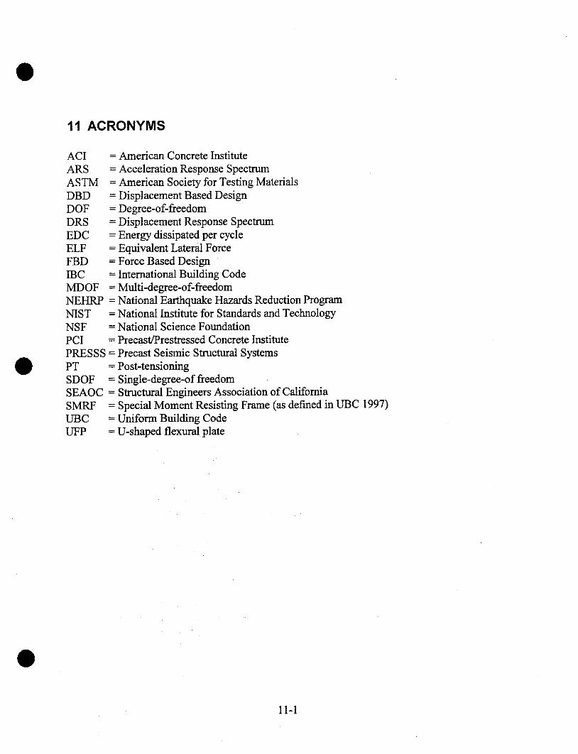
11 ACRONYMS
ACIARSASTM =DBD =DOF =DRS =EDC =ELF =FBD =IBCMDOFNEHRPNISTNSFPCI =PRESSS =PT =SDOF =SEAOC =SMRFUBCUFP
= American Concrete Institute= Acceleration Response Spectrum
American Society for Testing MaterialsDisplacement Based DesignDegree-of-freedomDisplacement Response SpectrumEnergy dissipated per cycleEquivalent Lateral ForceForce Based Design
= International Building Code= Multi-degree-of-freedom= National Earthquake Hazards Reduction Program= National Institute for Standards and Technology= National Science Foundation
Precast/Prestressed Concrete InstitutePrecast Seismic Structural SystemsPost-tensioningSingle-degree-of freedomStructural Engineers Association of California
= Special Moment Resisting Frame (as defined in UBC 1997)= Uniform Building Code= U-shaped flexural plate
11-1
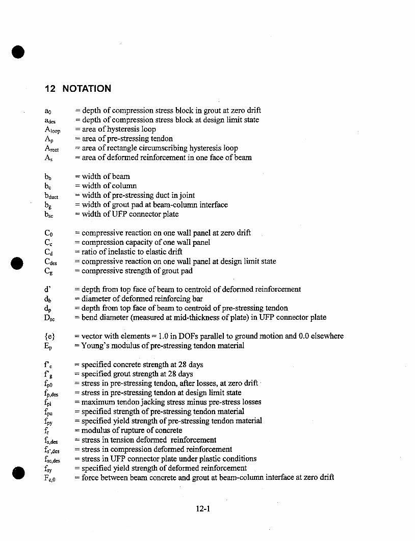
12 NOTATION
-A-loop
ArectAs
depth of compression stress block in grout at zero driftdepth of compression stress block at design limit statearea of hysteresis looparea of pre-stressing tendonarea of rectangle circumscribing hysteresis looparea of deformed reinforcement in one face of beam
bb
bductbgbse
= width of beam= width of column= width ofpre-stressing duct in joint= width of grout pad at beam-column interface= width of UFP connector plate
C0
C~C~CdesCg
= compressive reaction on one wall panel at zero drift= compression capacity of one wall panel= ratio of inelastic to elastic drift= compressive reaction on one wall panel at design limit state= compressive strength of grout pad
dbdpDsc
depth from top face of beam to centroid of deformed reinforcementdiameter of deformed reinforcing bardepth from top face of beam to centroid ofpre-stressing tendonbend diameter (measured at mid-thickness of plate) in UFP connector plate
{e}Ep
= vector with elements = 1.0 in DOFs parallel to ground motion and 0.0 elsewhere= Young’s modulus of pre-stressing tendon material
fp,des
fpifpufpyfrfs,des
fs’,des
fsc,des
Fc,0
specified concrete strength at 28 daysspecified grout strength at 28 daysstress in pre-stressing tendon, after losses, at zero driftstress in pre-stressing tendon at design limit statemaximum tendon jacking stress minus pre-stress lossesspecified strength of pre-stressing tendon materialspecified yield strength ofpre-stressing tendon materialmodulus of rupture of concretestress in tension deformed reinforcementstress in compression deformed reinforcementstress in UFP connector plate under plastic conditionsspecified yield strength of deformed reinforcementforce between beam concrete and grout at beam-colunm interface at zero drift
12-I
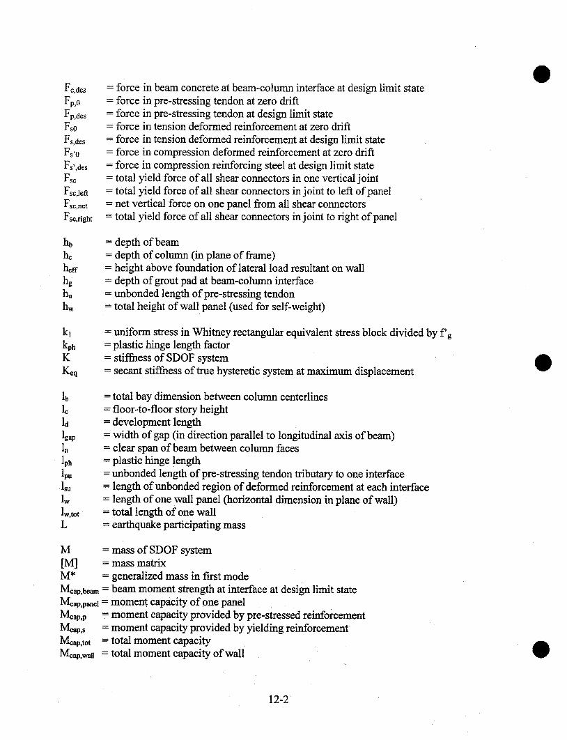
Fp,o
Fp,des
Fso
Fs,desFs’o
Fs’,desFsc
Fse,lett
Fs¢,netFse,right
= force= force= force= force= force= force
in beam concrete at beam-colunm interface at design limit statein pre-stressing tendon at zero driftin pre-stressing tendon at design limit statein tension deformed reinforcement at zero driftin tension deformed reinforcement at design limit statein compression deformed reinforcement at zero drift
= force in compression reinforcing steel at design limit state= total yield force of all shear connectors in one vertical joint= total yield force of all shear connectors in joint to left of panel= net vertical force on one panel from all shear connectors= total yield force of all shear connectors in joint to right of panel
= depth of beam= depth of column (in plane of frame)= height above foundation of lateral load resultant on wall= depth of grout pad at beam-column interface= unbonded length ofpre-stressing tendon= total height of wall panel (used for self-weight)
kl = uniform stress in Whitney rectangular equivalent stress block divided by f’g= plastic hinge length factor= stiffness of SDOF system= secant stiffness of true hysteretic system at maximum displacement
lb
ldlgap
lph
lpu
lwlw,totL
= total bay dimension between column centerlines= floor-to.floor story height= development length= width of gap (in direction parallel to longitudinal axis of beam)= clear span of beam between column faces= plastic hinge length= unbonded length ofpre-stressing tendon tributary to one interface= length of unbonded region of deformed reinforcement at each interface= length of one wall panel (horizontal dimension in plane of wall)= total length of one wall= earthquake participating mass
M = mass of SDOF system[M] = mass matrixM* = generalized mass in first modeMeap.beam = beam moment strength at interface at design limit stateMeap,pa~e~ = moment capacity of one panelMcap,p = moment capacity provided by pre-stressed reinforcementMeap,s = moment capacity provided by yielding reinforcementMeap,tot = total moment capacitylVl~.p,.wn = total moment capacity of wall
12-2
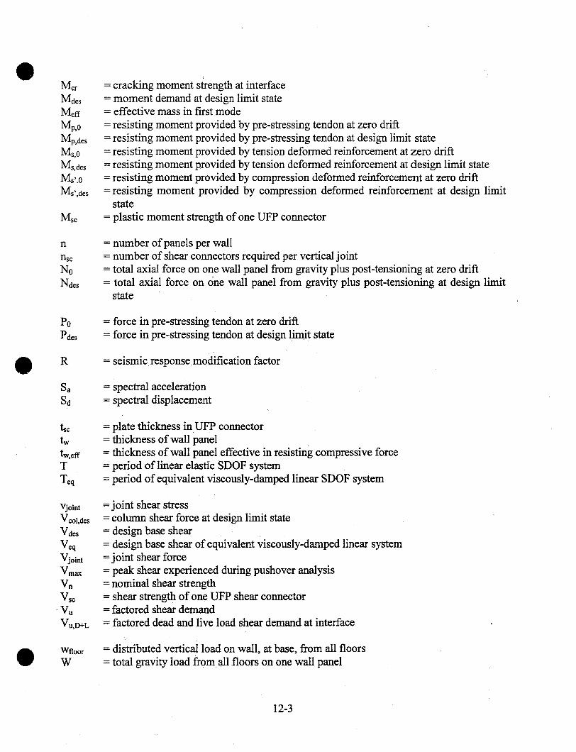
Met
Mdes
Mp,oMp,desMs, oMs,desMs,.OMs’,des
MSC
n
nscNoNdes
PoPdes
R
Sa
Vjoint
Vcol,d~s
VdesVeqV joint
VmaxVnWs~
Vu,D+L
WfloorW
= cracking moment s~rength at interface= moment demand at design limit state= effective mass in first mode= resisting moment provided by pre-stressing tendon at zero drift= resisting moment provided by pre-stressing tendon at design limit state= resisting moment provided by tension deformed reinforcement at zero drift= resisting moment provided by tension deformed reinforcement at design limit state= resisting moment provided by compression deformed reinforcement at zero drift= resisting moment provided by compression deformed reinforcement at design limit
state= plastic moment strength of one UFP connector
= number of panels per wall= number of shear connectors required per vertical joint= total axial force on one wall panel from gravity plus post-tensioning at zero drift= total axial force on One wall panel from gravity plus post-tensioning at design limit
state
= force in pre-stressing tendon at zero drift= force in pre-stressing tendon at design limit state
= seismic response modification factor
= spectral acceleration= spectral displacement
= plate thickness in UFP connector= thickness of wall panel= thickness of wall panel effective in resisting compressive force= period of linear elastic SDOF system= period of equivalent viscously-damped linear SDOF system
= joint shear stress= column shear force at design limit state= design base shear= design base shear of equivalent viscously-damped linear system= joint shear force= peak shear experienced during pushover analysis= nominal shear strength= shear strength of one UFP shear connector= factored shear demand= factored dead and live load shear demand at interface
= distributed vertical load on wall, at base, from all floors= total gravity load from all floors on one wall panel
12-3

W’panel = self-weight of one panel
~0,ave
O~des
~des,ave
= distance from compression face of member to center of compression force, divided bymember depth, at zero drift
= average value, over all panels, of ~0= distance from .center of compressive reaction to edge of member divided by member
depth, at design limit state= average value, over all panels, of O~d~s
= depth of equivalent compressive stress block divided by neutral axis depth
= density of concrete= earthquake participation factor
AlpAfp~
AM
Ap =As =
As =
Atar,MDOF =Atar, SDOF =
= increase in stress in pre-stressing tendon between zero drift and design drift= increase in stress in pre-stressing tendon between zero drift and design drift when
concrete and grout strengths are infinite= inelastic drift of structure under reduced earthquake load in 1997 UBC
deformation ofpre-stressing tendon between zero drift and design driftdeformation of tension deformed reinforcementelastic drift of structure under reduced earthquake load in 1997 UBCdeformation of compression deformed reinforcementtarget displacement for MDOF systemtarget displacement for SDOF system
~s,max
~s’
~sc,des
~sc,max
~sc, u
= compression strain in extreme fiber of concrete= strain in tension deformed reinforcement= maximum strain permissible in deformed reinforcement under cyclic loading= strain in compression deformed reinforcement= strain in UFP connector plate at design limit state= maximum permissible strain in UFP connector plate under cyclic loading= strain at maximum stress in UFP connector plate material
= distance from beam deformed reinforcement to nearest face divided by lab
= distance from member compression face to neutral axis divided by member depth, atzero drift
= distance from member compression face to neutral axis divided by member depth, atdesign limit state
Odes = interface rotation at design limit state
= ratio of design strength of shear connectors in one joint to vertical load on one panel
12-4

~,s)~s,des
~,s’,des
~eq,calc
~eq,est
P~opMOM
pRoc
OUPL
pZRD
Oeq
= over-strength factor= over-strength factor for pre-stressed reinforcement in tension= over-strength factor for deformed reinforcement in tension= over-strength factor for deformed reinforcement in tension at design limit state= over-strength factor for deformed reinforcement in compression= over-strength factor for deformed reinforcement in compression at design limit state
= coefficient of friction
= viscous damping= viscous damping in equivalent linear system= calculated viscous damping in equivalent linear system= estimated viscous damping in equivalent linear system
= stre~ss ratio to ensure that pre-stressing tendon does not yield at maximum drift= demand/capacity ratio for overturning moment on panel= force ratio to ensure that panel slides rather than rocks= ratio of uplift force to hold-down force on one panel= parameter ratio controlling residual drift
= equivalent mode shape, or assumed deformed shape= strength reduction factor for shear
= natural frequency of SDOF system= natural frequency of equivalent linear SDOF system
12-5

Appendix A.
List of planned PRESSS Phase III Reports.
Volume 3-1:Volume 3-2:Volume 3-3:Volume 3-4:Volume 3-5:Volume 3-6:Volume 3-7:Volume 3-8:Volume 3-9:Volume 3-10:
Seismic DesignConstructionTest Procedures and InstrumentationFrame Direction ResponseWall Direction ResponseTest DatabaseResponse PredictionsAnalytical Parameter StudiesDesign GuidelinesSummary Volume
A-1


![Modelling of Unbonded Post-Tensioned Concrete Slabs Under ... · unbonded post-tensioned slabs. The slabs were designed accord-ing to BS 8110-1 [22] and the Concrete Society Technical](https://img.dokumen.tips/doc/110x75/60f7151a886e554e76513f68/modelling-of-unbonded-post-tensioned-concrete-slabs-under-unbonded-post-tensioned.jpg)