Embed Size (px)
Citation preview
- 1 -
A CAST-STEEL FRICTION DAMPER FOR POST-TENSIONED PRECAST CONCRETE FRAME BUILDINGS
Brian G. Morgen Graduate Research Assistant, Structural Systems Laboratory
Department of Civil Engineering and Geological Sciences University of Notre Dame, Notre Dame, Indiana
Yahya C. Kurama, Ph.D., P.E.
Associate Professor Department of Civil Engineering and Geological Sciences
University of Notre Dame, Notre Dame, Indiana
ABSTRACT
This paper describes the development of a new type of friction damper, which utilizes steel castings, to provide supplemental energy dissipation to unbonded post-tensioned precast concrete building moment frame structures in seismic regions. Previous research has shown that these structures have desirable seismic characteristics such as a self-centering capability and an ability to undergo large nonlinear displacements with little damage; however, the lateral displacements during a severe earthquake may be larger than acceptable. In order to reduce the seismic displacement demands, the proposed friction dampers are placed locally at selected beam-to-column joints of a frame structure, and dissipate energy through the displacements that occur as a result of gap opening between the precast beam and column members. This paper describes an experimental program to evaluate the damper performance and to determine the nonlinear behavior of frame subassemblies that use these dampers. Large scale beam-column specimens with and without dampers were tested under reversed cyclic loading with the following varied parameters: damper normal force, friction material, area of beam post-tensioning steel, initial stress of beam post-tensioning steel, and beam depth. The test results show that the dampers can be designed to provide a large amount of supplemental energy dissipation to a frame, while the self-centering capability of the structure is preserved. It is concluded that the use of the proposed friction damper in unbonded post-tensioned precast concrete frames in seismic regions is promising. Analytical investigations of the test specimens indicate that the damper behavior under cyclic loading can be represented using an elastic-perfectly-plastic model. Ultimately, the results will be used to develop seismic analysis/design tools and guidelines for the proposed supplemental energy dissipation system.
- 2 -
INTRODUCTION Precast concrete building structural systems are comprised of prefabricated concrete members
(e.g., beams, columns, wall panels) that are joined or assembled together to create the load resisting system. This construction technique results in cost-effective structures that provide high quality production and rapid erection. However, the use of precast concrete buildings in seismic regions of the United States has been limited due to uncertainty about their performance under earthquakes, as well as an overall lack of a substantial body of research to support precast concrete seismic design and construction practices.1
In the absence of prescriptive seismic design provisions for precast concrete, current model building codes2 require that precast structures emulate the behavior of monolithic cast-in-place reinforced concrete structures unless certain acceptance criteria3 are satisfied through substantial experimental and analytical evidence. These “emulative” precast systems are designed and detailed such that their behavior under lateral loads is similar to the behavior of monolithic cast-in-place reinforced concrete structures.
In recent years, largely through the support of the National Science Foundation (NSF), the National Institute of Standards and Technology (NIST), and the precast/prestressed concrete industry, a significant amount of research has been conducted on the seismic behavior and design of precast concrete structures that do not emulate the behavior of cast-in-place construction.1,4-13 Different from monolithic cast-in-place reinforced concrete structures, the behavior of these “non-emulative” structures under lateral loads is governed by the opening of gaps at the joints between the precast concrete members.
One of the non-emulative precast systems that has successfully emerged from recent research uses unbonded post-tensioning between the precast members to achieve the lateral load resistance needed in seismic regions. These promising types of precast structures have significant economic benefits, construction simplicity and speed, superior quality control, and desirable seismic performance characteristics such as a self-centering capability (i.e., ability to return towards the original undisplaced position upon unloading from a nonlinear displacement) and an ability to undergo large nonlinear lateral displacements or drifts with little structural damage. The greatest setback to the use of these structures in seismic regions is an increase in their lateral displacements as a result of small energy dissipation.1 The research described in this paper focuses on this issue, with the broad objective of improving the seismic behavior of post-tensioned non-emulative precast concrete frame structures by using supplemental passive energy dissipation.
In the last few decades, a substantial amount of research has been conducted on the use of supplemental passive energy dissipation in steel and monolithic cast-in-place reinforced concrete structures.14-15 In comparison, there has been little research on the application of supplemental energy dissipation in non-emulative precast concrete frame construction. In order to reduce the lateral displacement demands during a seismic event, the use of mild steel reinforcement through the precast beam-to-column joints, in addition to the post-tensioning steel, has been investigated5-6,8-10,12 and successfully applied in practice.13 These systems are often referred to as “hybrid” precast frame systems due to the mixed use of mild steel and post-tensioning steel reinforcement. As an alternative, this paper investigates a new type of friction damper that can be used externally at the beam-to-column joints of the frames to dissipate energy during an earthquake. The unique gap opening behavior between the beam and column members of non-emulative precast frames allows for the development of innovative energy dissipation systems. The proposed friction damper takes advantage of these gap opening displacements in post-tensioned precast concrete frame structures, similar to applications in post-tensioned steel frame structures.16
RESEARCH SIGNIFICANCE The supplemental energy dissipation system developed in this research uses friction between
adjacent metallic surfaces caused by relative beam-to-column interface rotation. Large scale experimental studies were conducted on precast beam-column subassemblies with and without prototype friction dampers. Six beam specimens were tested with the following design parameters varied: (1) damper normal force; (2) friction material; (3) area of beam post-tensioning steel; (4) initial stress of beam post-tensioning steel, and (5) beam depth. In addition, isolated damper tests are being conducted to examine the effects of loading rate and slip amplitude on the damper behavior.
- 3 -
To supplement the experimental studies, the nonlinear behavior of friction-damped precast concrete moment frames under earthquake-induced loads is being investigated using analytical models in the DRAIN-2DX17 structural analysis program. Beam-column subassembly analytical models are verified against results from the experimental studies. The effects of a number of structural parameters on the seismic behavior of multistory frames will be investigated, including: (1) frame dimensions; (2) number, location, and slip force of the friction dampers; and (3) amount of post-tensioning in the precast members. Comparisons of precast frames with and without friction dampers will be made against hybrid precast systems that use mild steel reinforcement through the beam-to-column joints and against traditional monolithic cast-in-place reinforced concrete systems. Ultimately, the results will be used to develop performance-based seismic analysis/design tools and guidelines that give engineers the capability to design buildings with predictable and reliable behavior under earthquakes.
EXPERIMENTAL PROGRAM
Prototype Frame Building Since the friction-damped precast concrete structural system presented in this paper is not a
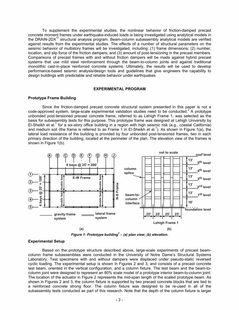
code-approved system, large-scale experimental validation studies need to be conducted.3 A prototype unbonded post-tensioned precast concrete frame, referred to as Lehigh Frame 1, was selected as the basis for subassembly tests for this purpose. This prototype frame was designed at Lehigh University by El-Sheikh et al.7 for a six-story office building in a region with high seismic risk (e.g., coastal California) and medium soil (the frame is referred to as Frame 1 in El-Sheikh et al.7). As shown in Figure 1(a), the lateral load resistance of the building is provided by four unbonded post-tensioned frames, two in each primary direction of the building, located at the perimeter of the plan. The elevation view of the frames is shown in Figure 1(b).
13'
13'
13'
13'
13'
16'
roof level
5th level
4th level
3th level
2rd level
1st level
foundation level
25' 25'25'25'
not to scale
column
splice
(b)
8 bays @ 25' = 200'
4 b
ay
s @
25
' =
10
0'
gravity frame
system
lateral frame
system
do
ub
le t
ee
sd
ou
ble
te
es
do
ub
le t
ee
sd
ou
ble
te
es
E-W Frame
N-S
Fra
me
A B C D E F G H J
(a)
1
2
3
4
5
Lehigh Frame 1
beam-to-
column
interface
Figure 1: Prototype building7 – (a) plan view; (b) elevation.
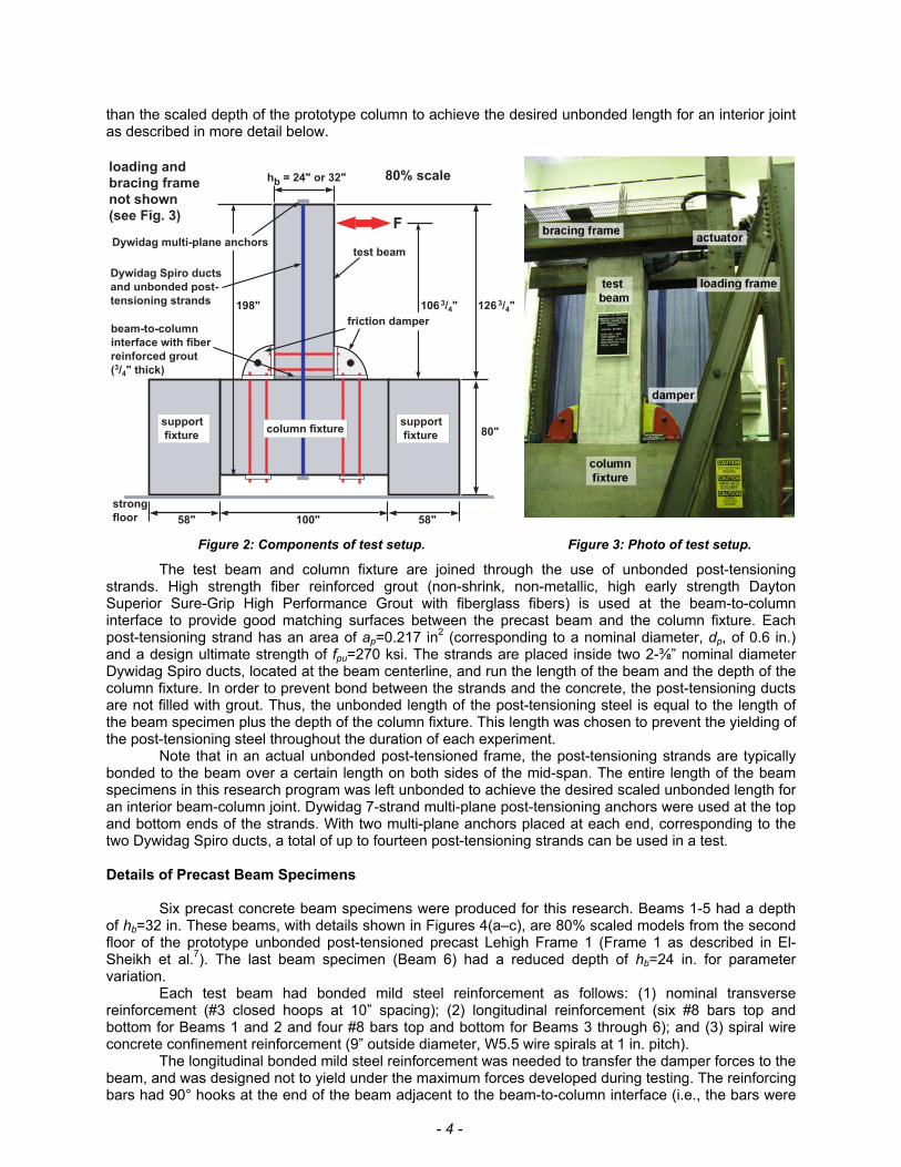
Experimental Setup Based on the prototype structure described above, large-scale experiments of precast beam-
column frame subassemblies were conducted in the University of Notre Dame’s Structural Systems Laboratory. Test specimens with and without dampers were displaced under pseudo-static reversed cyclic loading. The experimental setup is shown in Figures 2 and 3, and consists of a precast concrete test beam, oriented in the vertical configuration, and a column fixture. The test beam and the beam-to-column joint were designed to represent an 80% scale model of a prototype interior beam-to-column joint. The location of the actuator in Figure 2 represents the mid-span length of the scaled prototype beam. As shown in Figures 2 and 3, the column fixture is supported by two precast concrete blocks that are tied to a reinforced concrete strong floor. The column fixture was designed to be re-used in all of the subassembly tests conducted as part of this research. Note that the depth of the column fixture is larger
- 4 -
than the scaled depth of the prototype column to achieve the desired unbonded length for an interior joint as described in more detail below.
hb = 24" or 32"
126 3/4"
80"
58" 58"100"
198"
support
fixture
106 3/4"
F
test beam
Dywidag Spiro ducts
and unbonded post-
tensioning strands
friction damper
column fixture
80% scale
strong
floor
loading and
bracing frame
not shown
(see Fig. 3)
support
fixture
beam-to-column
interface with fiber
reinforced grout
(3/4" thick)
Dywidag multi-plane anchors
Figure 2: Components of test setup. Figure 3: Photo of test setup.
The test beam and column fixture are joined through the use of unbonded post-tensioning strands. High strength fiber reinforced grout (non-shrink, non-metallic, high early strength Dayton Superior Sure-Grip High Performance Grout with fiberglass fibers) is used at the beam-to-column interface to provide good matching surfaces between the precast beam and the column fixture. Each post-tensioning strand has an area of ap=0.217 in2 (corresponding to a nominal diameter, dp, of 0.6 in.) and a design ultimate strength of fpu=270 ksi. The strands are placed inside two 2-⅜” nominal diameter Dywidag Spiro ducts, located at the beam centerline, and run the length of the beam and the depth of the column fixture. In order to prevent bond between the strands and the concrete, the post-tensioning ducts are not filled with grout. Thus, the unbonded length of the post-tensioning steel is equal to the length of the beam specimen plus the depth of the column fixture. This length was chosen to prevent the yielding of the post-tensioning steel throughout the duration of each experiment.
Note that in an actual unbonded post-tensioned frame, the post-tensioning strands are typically bonded to the beam over a certain length on both sides of the mid-span. The entire length of the beam specimens in this research program was left unbonded to achieve the desired scaled unbonded length for an interior beam-column joint. Dywidag 7-strand multi-plane post-tensioning anchors were used at the top and bottom ends of the strands. With two multi-plane anchors placed at each end, corresponding to the two Dywidag Spiro ducts, a total of up to fourteen post-tensioning strands can be used in a test. Details of Precast Beam Specimens
Six precast concrete beam specimens were produced for this research. Beams 1-5 had a depth
of hb=32 in. These beams, with details shown in Figures 4(a–c), are 80% scaled models from the second floor of the prototype unbonded post-tensioned precast Lehigh Frame 1 (Frame 1 as described in El-Sheikh et al.7). The last beam specimen (Beam 6) had a reduced depth of hb=24 in. for parameter variation.
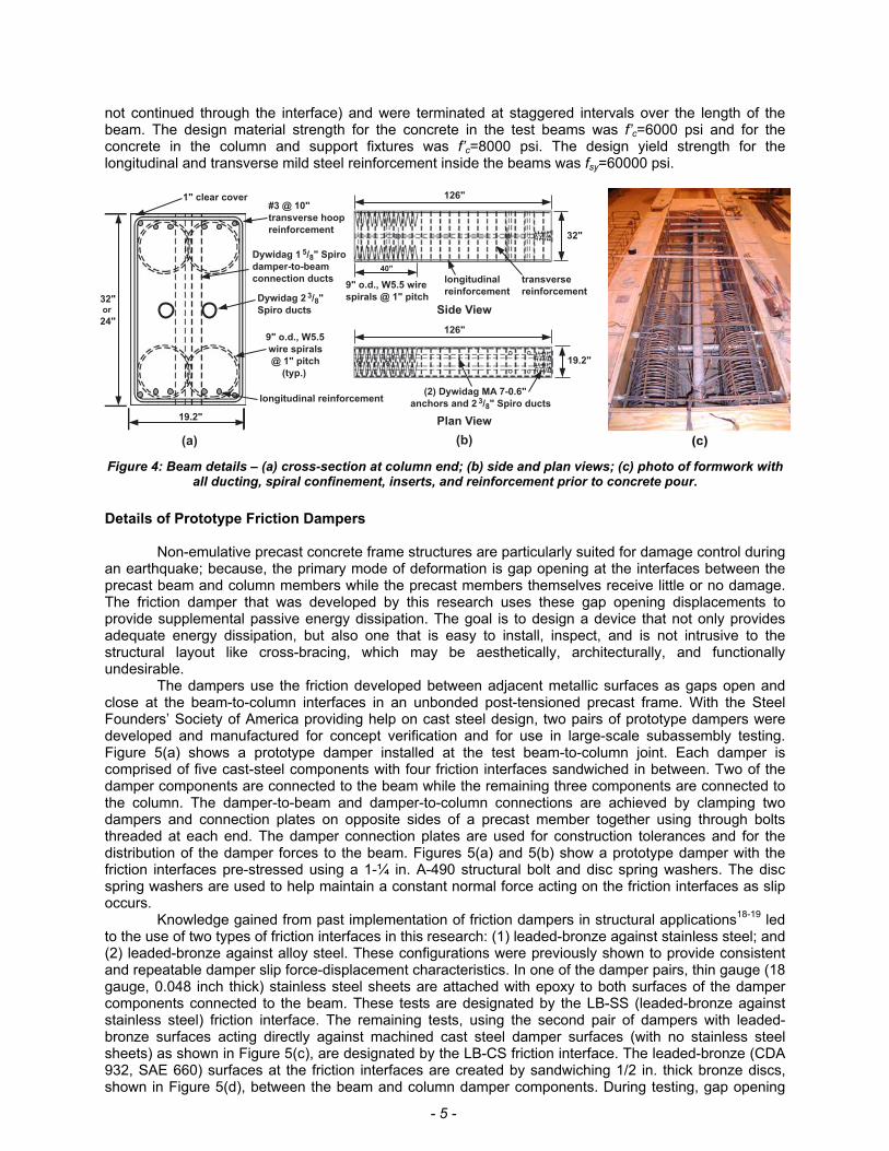
Each test beam had bonded mild steel reinforcement as follows: (1) nominal transverse reinforcement (#3 closed hoops at 10” spacing); (2) longitudinal reinforcement (six #8 bars top and bottom for Beams 1 and 2 and four #8 bars top and bottom for Beams 3 through 6); and (3) spiral wire concrete confinement reinforcement (9” outside diameter, W5.5 wire spirals at 1 in. pitch).
The longitudinal bonded mild steel reinforcement was needed to transfer the damper forces to the beam, and was designed not to yield under the maximum forces developed during testing. The reinforcing bars had 90° hooks at the end of the beam adjacent to the beam-to-column interface (i.e., the bars were
- 5 -
not continued through the interface) and were terminated at staggered intervals over the length of the beam. The design material strength for the concrete in the test beams was f’c=6000 psi and for the concrete in the column and support fixtures was f’c=8000 psi. The design yield strength for the longitudinal and transverse mild steel reinforcement inside the beams was fsy=60000 psi.
19.2"
32" or
24"
9" o.d., W5.5
wire spirals
@ 1" pitch
(typ.)
1" clear cover
(a)
126"
32"
40"
9" o.d., W5.5 wire
spirals @ 1" pitch
Side View
19.2"
(2) Dywidag MA 7-0.6"
anchors and 2 3/8" Spiro ducts
Plan View
126"
(b)
Dywidag 1 5/8" Spiro
damper-to-beam
connection ducts
#3 @ 10"
transverse hoop
reinforcement
longitudinal
reinforcement
transverse
reinforcement
longitudinal reinforcement
Dywidag 2 3/8"
Spiro ducts
Figure 4: Beam details – (a) cross-section at column end; (b) side and plan views; (c) photo of formwork with all ducting, spiral confinement, inserts, and reinforcement prior to concrete pour.
Details of Prototype Friction Dampers
Non-emulative precast concrete frame structures are particularly suited for damage control during
an earthquake; because, the primary mode of deformation is gap opening at the interfaces between the precast beam and column members while the precast members themselves receive little or no damage. The friction damper that was developed by this research uses these gap opening displacements to provide supplemental passive energy dissipation. The goal is to design a device that not only provides adequate energy dissipation, but also one that is easy to install, inspect, and is not intrusive to the structural layout like cross-bracing, which may be aesthetically, architecturally, and functionally undesirable.
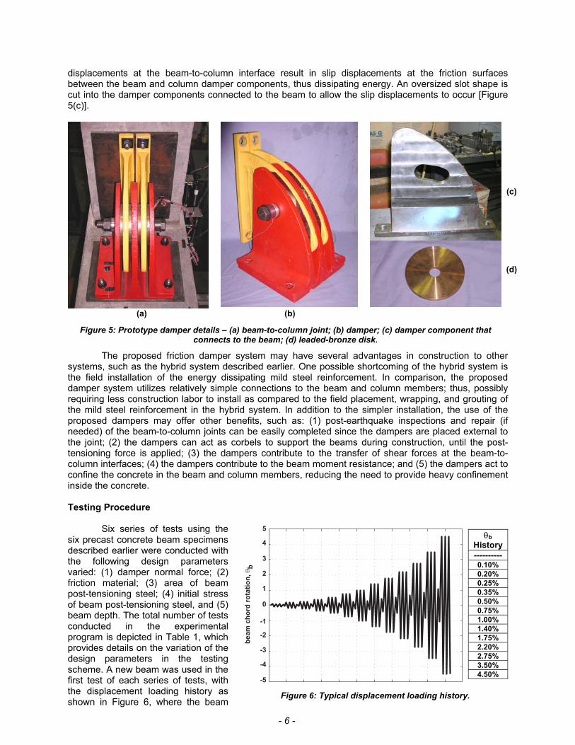
The dampers use the friction developed between adjacent metallic surfaces as gaps open and close at the beam-to-column interfaces in an unbonded post-tensioned precast frame. With the Steel Founders’ Society of America providing help on cast steel design, two pairs of prototype dampers were developed and manufactured for concept verification and for use in large-scale subassembly testing. Figure 5(a) shows a prototype damper installed at the test beam-to-column joint. Each damper is comprised of five cast-steel components with four friction interfaces sandwiched in between. Two of the damper components are connected to the beam while the remaining three components are connected to the column. The damper-to-beam and damper-to-column connections are achieved by clamping two dampers and connection plates on opposite sides of a precast member together using through bolts threaded at each end. The damper connection plates are used for construction tolerances and for the distribution of the damper forces to the beam. Figures 5(a) and 5(b) show a prototype damper with the friction interfaces pre-stressed using a 1-¼ in. A-490 structural bolt and disc spring washers. The disc spring washers are used to help maintain a constant normal force acting on the friction interfaces as slip occurs.
Knowledge gained from past implementation of friction dampers in structural applications18-19 led to the use of two types of friction interfaces in this research: (1) leaded-bronze against stainless steel; and (2) leaded-bronze against alloy steel. These configurations were previously shown to provide consistent and repeatable damper slip force-displacement characteristics. In one of the damper pairs, thin gauge (18 gauge, 0.048 inch thick) stainless steel sheets are attached with epoxy to both surfaces of the damper components connected to the beam. These tests are designated by the LB-SS (leaded-bronze against stainless steel) friction interface. The remaining tests, using the second pair of dampers with leaded-bronze surfaces acting directly against machined cast steel damper surfaces (with no stainless steel sheets) as shown in Figure 5(c), are designated by the LB-CS friction interface. The leaded-bronze (CDA 932, SAE 660) surfaces at the friction interfaces are created by sandwiching 1/2 in. thick bronze discs, shown in Figure 5(d), between the beam and column damper components. During testing, gap opening
- 6 -
displacements at the beam-to-column interface result in slip displacements at the friction surfaces between the beam and column damper components, thus dissipating energy. An oversized slot shape is cut into the damper components connected to the beam to allow the slip displacements to occur [Figure 5(c)].
(c)
(d)
(a) (b) Figure 5: Prototype damper details – (a) beam-to-column joint; (b) damper; (c) damper component that
connects to the beam; (d) leaded-bronze disk.
The proposed friction damper system may have several advantages in construction to other systems, such as the hybrid system described earlier. One possible shortcoming of the hybrid system is the field installation of the energy dissipating mild steel reinforcement. In comparison, the proposed damper system utilizes relatively simple connections to the beam and column members; thus, possibly requiring less construction labor to install as compared to the field placement, wrapping, and grouting of the mild steel reinforcement in the hybrid system. In addition to the simpler installation, the use of the proposed dampers may offer other benefits, such as: (1) post-earthquake inspections and repair (if needed) of the beam-to-column joints can be easily completed since the dampers are placed external to the joint; (2) the dampers can act as corbels to support the beams during construction, until the post-tensioning force is applied; (3) the dampers contribute to the transfer of shear forces at the beam-to-column interfaces; (4) the dampers contribute to the beam moment resistance; and (5) the dampers act to confine the concrete in the beam and column members, reducing the need to provide heavy confinement inside the concrete.
Testing Procedure
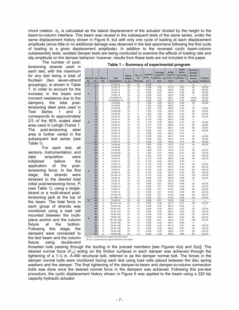
Six series of tests using the
six precast concrete beam specimens described earlier were conducted with the following design parameters varied: (1) damper normal force; (2) friction material; (3) area of beam post-tensioning steel; (4) initial stress of beam post-tensioning steel, and (5) beam depth. The total number of tests conducted in the experimental program is depicted in Table 1, which provides details on the variation of the design parameters in the testing scheme. A new beam was used in the first test of each series of tests, with the displacement loading history as shown in Figure 6, where the beam
5
-4
-3
-2
-1
0
1
2
3
4
-5
be
am
ch
ord
ro
tati
on
, θb
θb History ---------- 0.10% 0.20% 0.25% 0.35% 0.50% 0.75% 1.00% 1.40% 1.75% 2.20% 2.75% 3.50% 4.50%
Figure 6: Typical displacement loading history.
- 7 -
chord rotation, θb, is calculated as the lateral displacement of the actuator divided by the height to the beam-to-column interface. This beam was reused in the subsequent tests of the same series, under the same displacement history shown in Figure 6, but with only one cycle of loading at each displacement amplitude (since little or no additional damage was observed in the test specimens following the first cycle of loading to a given displacement amplitude). In addition to the reversed cyclic beam-column subassembly tests, isolated damper tests are being conducted to examine the effects of loading rate and slip amplitude on the damper behavior; however, results from these tests are not included in this paper.
The number of post-tensioning strands used in each test, with the maximum for any test being a total of fourteen (two seven-strand groupings), is shown in Table 1. In order to account for the increase in the beam end moment resistance due to the dampers, the total post-tensioning steel area used in Test Series 1 and 2 corresponds to approximately 2/3 of the 80% scaled steel area used in Lehigh Frame 1. The post-tensioning steel area is further varied in the subsequent test series (see Table 1).
For each test, all sensors, instrumentation, and data acquisition were initialized before the application of the post-tensioning force. In the first stage, the strands were stressed to the desired total initial post-tensioning force, Pi (see Table 1), using a single-strand or a multi-strand post-tensioning jack at the top of the beam. The total force in each group of strands was monitored using a load cell mounted between the multi-plane anchor and the column fixture at the bottom. Following this stage, the dampers were connected to the test beam and the column fixture using double-end threaded rods passing through the ducting in the precast members [see Figures 4(a) and 5(a)]. The desired normal force (Fdn) acting on the friction surfaces in each damper was achieved through the tightening of a 1-¼ in. A-490 structural bolt, referred to as the damper normal bolt. The forces in the damper normal bolts were monitored during each test using load cells placed between the disc spring washers and the damper. The final tightening of the damper-to-beam and damper-to-column connection bolts was done once the desired normal force in the dampers was achieved. Following this pre-test procedure, the cyclic displacement history shown in Figure 6 was applied to the beam using a 220 kip capacity hydraulic actuator.
Table 1 – Summary of experimental program
Series
No.
Test
No.
Beam
No.
Test
Designation
Beam
Depth,
hb (in.)
No. of
PT
Strands
Total PT
Area, Ap
(in.2)
Average
Initial PT
Stress, fpi
(ksi)
Initial
Total PT
Force, Pi
(kips)
Initial
Beam
Concrete
Stress, fci
(ksi)
Nominal
Damper
Normal
Force,
Fdn (kips)
Friction
Interface*
1 1 1 T1-00-14 32 14 3.038 --- --- --- 0 ---
2 2 T2-40-14 32 14 3.038 0.50 411.5 0.67 40 LB-SS
3 2 T2-20-14 32 14 3.038 0.42 346.2 0.56 20 LB-SS
4 2 T2-00-14 32 14 3.038 0.42 344.8 0.56 60 LB-SS
5 2 T2-60-14 32 14 3.038 0.42 345.3 0.56 0 LB-SS
6 2 T2-00/80-14 32 14 3.038 0.42 346.1 0.56 varies LB-SS
7 2 T2-00|00/60-14 32 14 3.038 0.42 347.3 0.57 varies LB-SS
8 3 T3-40-06 32 6 1.302 0.66 232.2 0.38 40 LB-SS
9 3 T3-00-06 32 6 1.302 0.59 206.0 0.34 0 ---
10 3 T3-20-06 32 6 1.302 0.59 208.0 0.34 20 LB-SS
11 3 T3-40b-06 32 6 1.302 0.59 205.8 0.33 40 LB-SS
12 3 T3-60-06 32 6 1.302 0.59 208.7 0.34 60 LB-SS
13 3 T3-40-10 32 10 2.170 0.52 305.3 0.50 40 LB-SS
14 3 T3-00-10 32 10 2.170 0.50 294.2 0.48 0 ---
15 3 T3-20-10 32 10 2.170 0.49 289.8 0.47 20 LB-SS
16 3 T3-60-10 32 10 2.170 0.49 289.8 0.47 60 LB-SS
17 3 T3-80-10 32 10 2.170 0.50 292.7 0.48 80 LB-SS
18 3 T3-40-14 32 14 3.038 0.57 470.4 0.77 40 LB-SS
19 3 T3-00-14 32 14 3.038 0.56 456.2 0.74 0 ---
20 3 T3-20-14 32 14 3.038 0.55 454.7 0.74 20 LB-SS
21 3 T3-60-14 32 14 3.038 0.55 453.2 0.74 60 LB-SS
22 3 T3-80-14 32 14 3.028 0.56 456.2 0.74 80 LB-SS
23 4 T4-40-06 32 6 1.302 0.56 197.2 0.32 40 LB-CS
24 4 T4-00-06 32 6 1.302 0.38 131.9 0.21 0 ---
25 4 T4-20-06 32 6 1.302 0.37 129.5 0.21 20 LB-CS
26 4 T4-40b-06 32 6 1.302 0.37 128.5 0.21 40 LB-CS
27 4 T4-60-06 32 6 1.302 0.37 129.2 0.21 60 LB-CS
28 4 T4-40-10 32 10 2.170 0.48 280.6 0.46 40 LB-CS
29 4 T4-00-10 32 10 2.170 0.45 262.8 0.43 0 ---
30 4 T4-20-10 32 10 2.170 0.45 262.5 0.43 20 LB-CS
31 4 T4-40b-10 32 10 2.170 0.45 261.8 0.43 40 LB-CS
32 4 T4-60-10 32 10 2.170 0.45 262.2 0.43 60 LB-CS
33 4 T4-80-10 32 10 2.170 0.45 261.8 0.43 80 LB-CS
34 4 T4-100-10 32 10 2.170 0.45 262.8 0.43 100 LB-CS
35 4 T4-40-14 32 14 3.038 0.52 425.9 0.69 40 LB-CS
36 4 T4-00-14 32 14 3.038 0.52 423.3 0.69 0 ---
37 4 T4-20-14 32 14 3.038 0.51 420.3 0.68 20 LB-CS
38 4 T4-40b-14 32 14 3.038 0.51 419.9 0.68 40 LB-CS
39 4 T4-60-14 32 14 3.038 0.51 419.9 0.68 60 LB-CS
40 4 T4-80-14 32 14 3.028 0.51 419.2 0.68 80 LB-CS
41 4 T4-100-14 32 14 3.028 0.51 419.2 0.68 80 LB-CS
42 4 T4-100b-14 32 14 3.038 0.51 418.9 0.68 100 LB-CS
5 43 5 T5-00-14 32 14 3.038 0.51 416.5 0.68 0 ---
44 6 T6-100-14A 24 14 3.038 0.38 307.7 0.67 100 LB-CS
45 6 T6-00-14A 24 14 3.038 0.35 287.4 0.62 0 ---
46 6 T6-20-14A 24 14 3.038 0.35 285.7 0.62 20 LB-CS
47 6 T6-40-14A 24 14 3.038 0.35 285.4 0.62 40 LB-CS
48 6 T6-60-14A 24 14 3.038 0.35 285.4 0.62 60 LB-CS
49 6 T6-80-14A 24 14 3.038 0.35 284.4 0.62 80 LB-CS
50 6 T6-100-14B 24 14 3.038 0.51 420.4 0.91 100 LB-CS
51 6 T6-00-14B 24 14 3.038 0.49 405.7 0.88 0 ---
52 6 T6-20-14B 24 14 3.038 0.49 401.5 0.87 20 LB-CS
53 6 T6-40-14B 24 14 3.038 0.49 400.5 0.87 40 LB-CS
54 6 T6-60-14B 24 14 3.038 0.49 399.4 0.87 60 LB-CS
55 6 T6-80-14B 24 14 3.038 0.49 398.0 0.86 80 LB-CS
* LB-SS = Leaded-Bronze against Stainless Steel
LB-CS = Leaded-Bronze against Machined Cast Steel
2
3
4
6
- 8 -
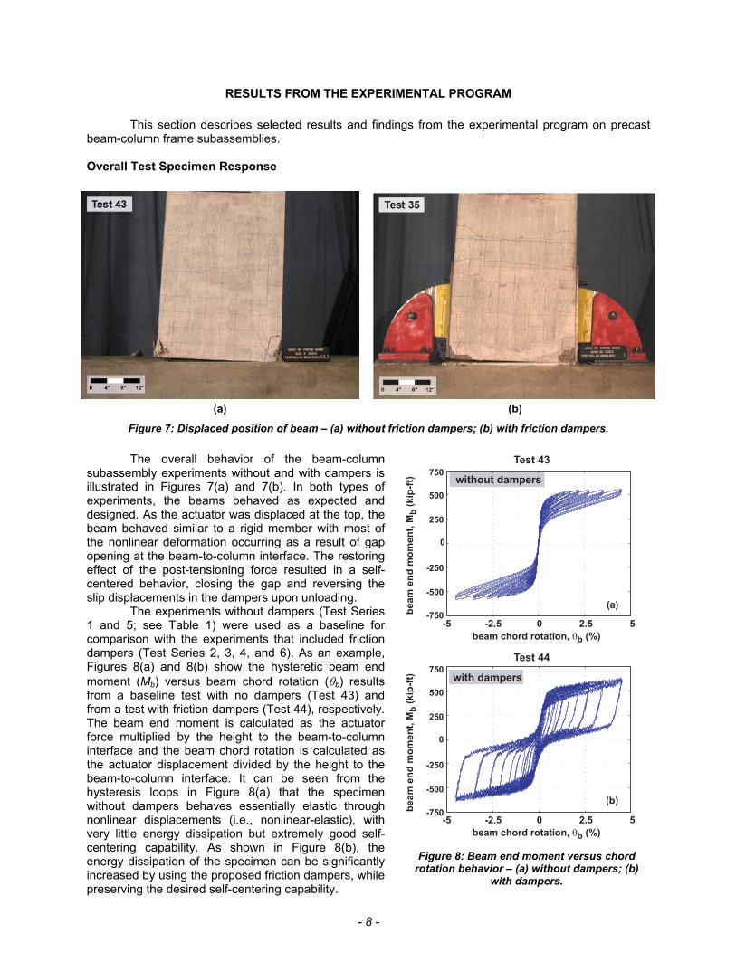
RESULTS FROM THE EXPERIMENTAL PROGRAM This section describes selected results and findings from the experimental program on precast beam-column frame subassemblies. Overall Test Specimen Response
(a) (b)
Figure 7: Displaced position of beam – (a) without friction dampers; (b) with friction dampers. The overall behavior of the beam-column
subassembly experiments without and with dampers is illustrated in Figures 7(a) and 7(b). In both types of experiments, the beams behaved as expected and designed. As the actuator was displaced at the top, the beam behaved similar to a rigid member with most of the nonlinear deformation occurring as a result of gap opening at the beam-to-column interface. The restoring effect of the post-tensioning force resulted in a self-centered behavior, closing the gap and reversing the slip displacements in the dampers upon unloading.
The experiments without dampers (Test Series 1 and 5; see Table 1) were used as a baseline for comparison with the experiments that included friction dampers (Test Series 2, 3, 4, and 6). As an example, Figures 8(a) and 8(b) show the hysteretic beam end moment (Mb) versus beam chord rotation (θb) results from a baseline test with no dampers (Test 43) and from a test with friction dampers (Test 44), respectively. The beam end moment is calculated as the actuator force multiplied by the height to the beam-to-column interface and the beam chord rotation is calculated as the actuator displacement divided by the height to the beam-to-column interface. It can be seen from the hysteresis loops in Figure 8(a) that the specimen without dampers behaves essentially elastic through nonlinear displacements (i.e., nonlinear-elastic), with very little energy dissipation but extremely good self-centering capability. As shown in Figure 8(b), the energy dissipation of the specimen can be significantly increased by using the proposed friction dampers, while preserving the desired self-centering capability.
Test 43
Test 44
beam chord rotation, θb (%)
-5 52.50-2.5
(b)
0
beam
en
d m
om
en
t, M
b (
kip
-ft)
-750
-500
-250
250
500
750with dampers
beam chord rotation, θb (%)
-5 52.50-2.5
0
(a)
beam
en
d m
om
en
t, M
b (
kip
-ft)
-750
-500
-250
250
500
750without dampers
Figure 8: Beam end moment versus chord
rotation behavior – (a) without dampers; (b) with dampers.
- 9 -
Note that the hysteresis loops in Figure 8(b) correspond to a beam with a smaller depth (hb=24 in.) than the beam in Figure 8(a) (hb=32 in.; see Table 1). The results show that the maximum moment resistance of the smaller beam with dampers is larger that the resistance of the deeper beam without dampers. It is concluded that the proposed friction dampers contribute significantly to the beam moment resistance, which may lead to the design of smaller beams in practice.
Damper Normal Force
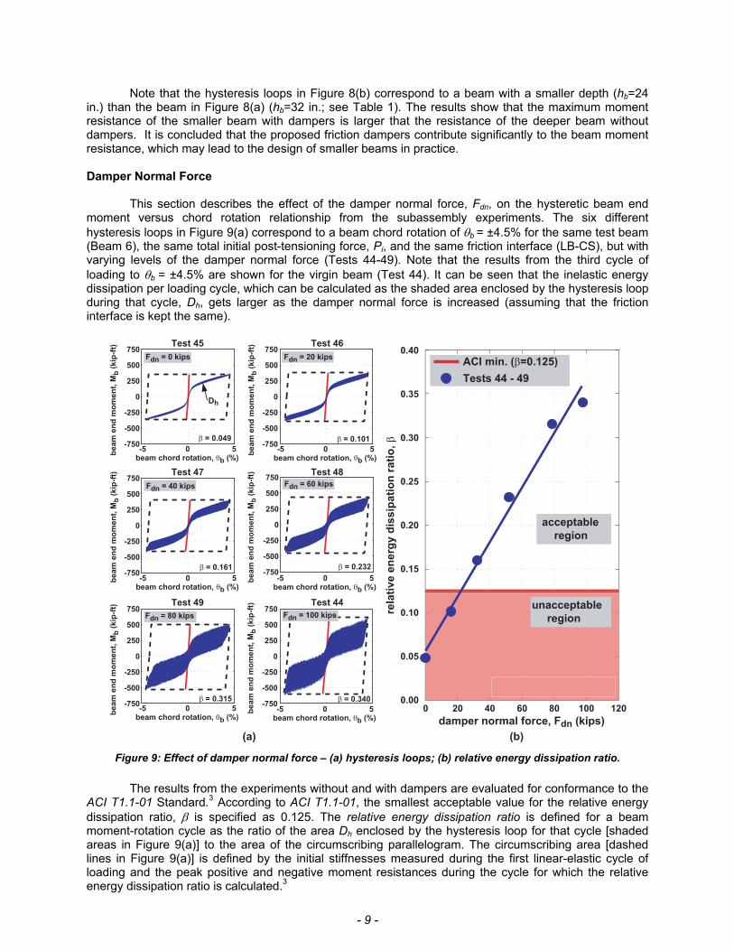
This section describes the effect of the damper normal force, Fdn, on the hysteretic beam end moment versus chord rotation relationship from the subassembly experiments. The six different hysteresis loops in Figure 9(a) correspond to a beam chord rotation of θb = ±4.5% for the same test beam (Beam 6), the same total initial post-tensioning force, Pi, and the same friction interface (LB-CS), but with varying levels of the damper normal force (Tests 44-49). Note that the results from the third cycle of loading to θb = ±4.5% are shown for the virgin beam (Test 44). It can be seen that the inelastic energy dissipation per loading cycle, which can be calculated as the shaded area enclosed by the hysteresis loop during that cycle, Dh, gets larger as the damper normal force is increased (assuming that the friction interface is kept the same).
-750
-500
-250
0
250
500
750
-750
-500
-250
0
250
500
750
-750
-500
-250
0
250
500
750
-750
-500
-250
0
250
500
750
-750
-500
-250
0
250
500
750
-750
-500
-250
0
250
500
750
β = 0.340
β = 0.049
β = 0.101
β = 0.161
β = 0.232
β = 0.315
-5 0 5
Fdn = 0 kips
beam
en
d m
om
en
t, M
b (
kip
-ft)
beam chord rotation, θb (%)-5 0 5
Fdn = 20 kips
beam
en
d m
om
en
t, M
b (
kip
-ft)
beam chord rotation, θb (%)
-5 0 5
Fdn = 40 kips
beam
en
d m
om
en
t, M
b (
kip
-ft)
beam chord rotation, θb (%)-5 0 5
Fdn = 60 kips
beam
en
d m
om
en
t, M
b (
kip
-ft)
beam chord rotation, θb (%)
-5 0 5
Fdn = 80 kips
beam
en
d m
om
en
t, M
b (
kip
-ft)
beam chord rotation, θb (%)-5 0 5
Fdn = 100 kips
beam
en
d m
om
en
t, M
b (
kip
-ft)
beam chord rotation, θb (%)0 20 40 60 80 100 120
unacceptable
region
acceptable
region
ACI min. (β=0.125)
Tests 44 - 49
0.40
0.35
0.30
0.25
0.20
0.15
0.10
0.05
0.00
damper normal force, Fdn (kips)
rela
tive e
nerg
y d
issip
ati
on
rati
o, β
(a) (b)
Dh
Test 45 Test 46
Test 47 Test 48
Test 49 Test 44
Figure 9: Effect of damper normal force – (a) hysteresis loops; (b) relative energy dissipation ratio. The results from the experiments without and with dampers are evaluated for conformance to the
ACI T1.1-01 Standard.3 According to ACI T1.1-01, the smallest acceptable value for the relative energy dissipation ratio, β is specified as 0.125. The relative energy dissipation ratio is defined for a beam moment-rotation cycle as the ratio of the area Dh enclosed by the hysteresis loop for that cycle [shaded areas in Figure 9(a)] to the area of the circumscribing parallelogram. The circumscribing area [dashed lines in Figure 9(a)] is defined by the initial stiffnesses measured during the first linear-elastic cycle of loading and the peak positive and negative moment resistances during the cycle for which the relative energy dissipation ratio is calculated.3
- 10 -
The relative energy dissipation ratio, β, is a measure of the amount of viscous damping in an equivalent linear elastic system that would result in the same amount of energy dissipation as the nonlinear system. The ACI T1.1-01 Standard recommends that if β is smaller than 0.125, there may be inadequate damping for the frame as a whole, and the oscillations of the frame may continue for a considerable time after an earthquake, possibly producing low-cycle fatigue effects and excessive displacements. Figure 9(b) illustrates the effect of the friction dampers on the relative energy dissipation ratio of the specimens from Tests 44 to 49 corresponding to a beam chord rotation of θb=±4.5%. The test specimen with no dampers [Figure 9(a); Fdn=0 kips] shows unacceptable behavior (with β <0.125) while the specimens with damper normal force, Fdn, larger that 40 kips have acceptable behaviors (with β >0.125) and also meet all of the other prescriptive acceptance requirements of ACI T1.1-01.3 Looking at the plot in Figure 9(b), it can be observed that as the damper normal force is increased (i.e., damper slip force increased), the relative energy dissipation ratio increases almost proportionally.
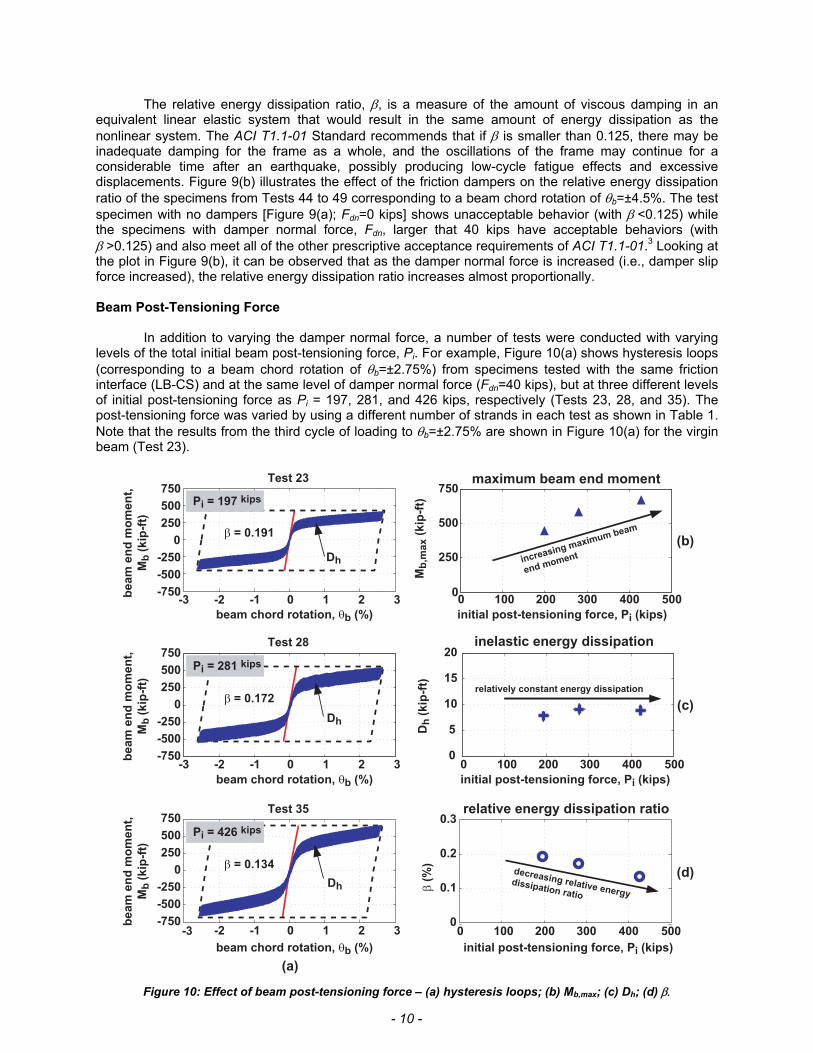
Beam Post-Tensioning Force In addition to varying the damper normal force, a number of tests were conducted with varying levels of the total initial beam post-tensioning force, Pi. For example, Figure 10(a) shows hysteresis loops (corresponding to a beam chord rotation of θb=±2.75%) from specimens tested with the same friction interface (LB-CS) and at the same level of damper normal force (Fdn=40 kips), but at three different levels of initial post-tensioning force as Pi = 197, 281, and 426 kips, respectively (Tests 23, 28, and 35). The post-tensioning force was varied by using a different number of strands in each test as shown in Table 1. Note that the results from the third cycle of loading to θb=±2.75% are shown in Figure 10(a) for the virgin beam (Test 23).
-750
-500
-250
0
250
500
750
0
-750
-500
-250
250
500
750
-750
-500
-250
0
250
500
750
0
5
10
15
20
250
500
750
β = 0.191
-3 -2 -1 0 1 2 3
Pi = 197 kips
beam chord rotation, θb (%)
be
am
en
d m
om
en
t,
Mb
(k
ip-f
t)
β = 0.172
-3 -2 -1 0 1 2 3
Pi = 281 kips
beam chord rotation, θb (%)
β = 0.134
-3 -2 -1 0 1 2 3
Pi = 426 kips
beam chord rotation, θb (%)
(a)
0 100 200 300 400 5000
initial post-tensioning force, Pi (kips)
maximum beam end moment
increasing maximum beam
end moment
Mb
,ma
x (
kip
-ft)
(b)
initial post-tensioning force, Pi (kips)
relative energy dissipation ratio
β (
%)
0
0.1
0.2
0.3
decreasing relative energy
dissipation ratio
(d)
initial post-tensioning force, Pi (kips)
inelastic energy dissipation
Dh
(k
ip-f
t)
relatively constant energy dissipation
(c)
Dh
Dh
Dh
be
am
en
d m
om
en
t,
Mb
(k
ip-f
t)
be
am
en
d m
om
en
t,
Mb
(k
ip-f
t)
Test 23
Test 28
Test 35
0 100 200 300 400 500
0 100 200 300 400 500
Figure 10: Effect of beam post-tensioning force – (a) hysteresis loops; (b) Mb,max; (c) Dh; (d) β.
- 11 -
The first observation from Figure 10(a) is that as the beam post-tensioning force is increased, the
beam maximum end moment, Mb,max (defined as the maximum moment resistance under loading in the positive or negative direction) also increases. This is illustrated in Figure 10(b) for loading in the positive direction; the results in the negative direction are very similar.
Secondly, Figure 10(c) shows that the amount of inelastic energy dissipation [i.e., the shaded area, Dh, under the hysteresis loops in Figure 10(a)] is relatively the same for the three tests. This is due to the fact that the inelastic energy dissipation is directly related to the damper normal force, which was kept constant in the tests.
Thirdly, the relative energy dissipation ratio, β, decreases as the beam post-tensioning force is increased. This observation is plotted in Figure 10(d). The decrease in β as the post-tensioning force is increased occurs because the maximum beam end moment Mb,max increases while Dh stays relatively constant, since the relative energy dissipation ratio is defined as the shaded area under the hysteresis loop (Dh) divided by the circumscribing parallelogram (which is related to Mb,max). Beam Depth
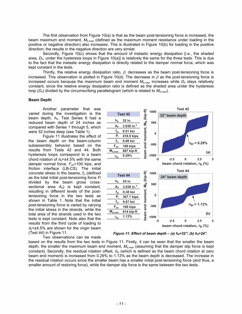
Another parameter that was varied during the investigation is the beam depth, hb. Test Series 6 had a reduced beam depth of 24 inches as compared with Series 1 through 5, which were 32 inches deep (see Table 1).
Figure 11 illustrates the effect of the beam depth on the beam-column subassembly behavior based on the results from Tests 42 and 44. Both hysteresis loops correspond to a beam chord rotation of θb=±4.5% with the same damper normal force, Fdn=100 kips, and friction interface (LB-CS). The initial concrete stress in the beams, fci (defined as the total initial post-tensioning force Pi divided by the beam gross cross-sectional area Ab) is kept constant, resulting in different levels of the post-tensioning force in the two tests as shown in Table 1. Note that the initial post-tensioning force is varied by varying the initial stress in the strands, while the total area of the strands used in the two tests is kept constant. Note also that the results from the third cycle of loading to θb=±4.5% are shown for the virgin beam (Test 44) in Figure 11.
Two observations can be made based on the results from the two tests in Figure 11. Firstly, it can be seen that the smaller the beam depth, the smaller the maximum beam end moment, Mb,max (assuming that the damper slip force is kept constant). Secondly, the residual rotation offset, θbr (which is defined as the beam chord rotation at zero beam end moment) is increased from 0.29% to 1.13% as the beam depth is decreased. The increase in the residual rotation occurs since the smaller beam has a smaller initial post-tensioning force (and thus, a smaller amount of restoring force), while the damper slip force is the same between the two tests.
-5 -2.5 0 2.5 5
-1000
-500
0
500
1000
-5 -2.5 0 2.5 5
-1000
-500
0
500
1000
be
am
en
d m
om
en
t, M
b (
kip
-ft)
be
am
en
d m
om
en
t, M
b (
kip
-ft)
beam chord rotation, θb (%)
beam chord rotation, θb (%)
Test 42
Test 44
(a)
(b)
hb 32 in.
fci 0.68 ksi
Pi 418.9 kips
Fdn 100 kips
Mb,max 887 kip-ft
θbr0.29%
Test 42
θbr = 1.13%
θbr = 0.29%
Test 44
32" beam depth
24" beam depth
3.038 in.2Ap
fpi 0.51 ksi
hb 24 in.
fci 0.67 ksi
Pi 307.7 kips
Fdn 100 kips
Mb,max 614 kip-ft
θbr1.13%
3.038 in.2Ap
fpi 0.38 ksi
Figure 11: Effect of beam depth – (a) hb=32”; (b) hb=24”.
- 12 -
Beam Deterioration
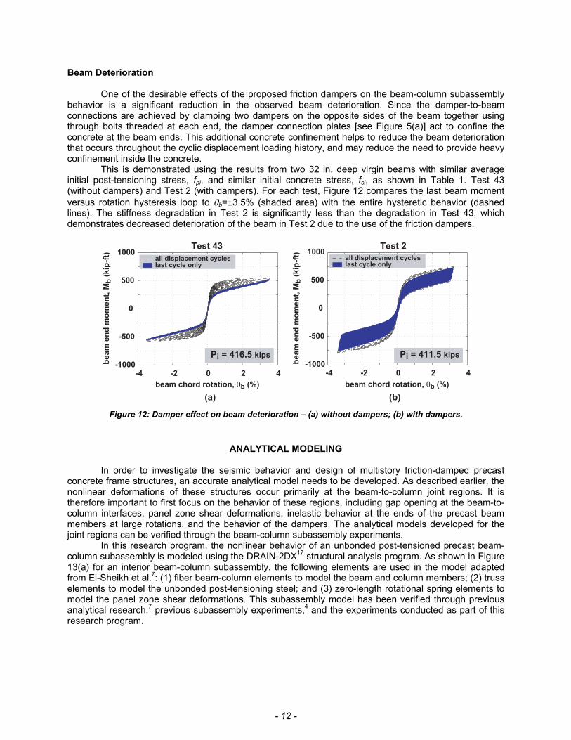
One of the desirable effects of the proposed friction dampers on the beam-column subassembly behavior is a significant reduction in the observed beam deterioration. Since the damper-to-beam connections are achieved by clamping two dampers on the opposite sides of the beam together using through bolts threaded at each end, the damper connection plates [see Figure 5(a)] act to confine the concrete at the beam ends. This additional concrete confinement helps to reduce the beam deterioration that occurs throughout the cyclic displacement loading history, and may reduce the need to provide heavy confinement inside the concrete.
This is demonstrated using the results from two 32 in. deep virgin beams with similar average initial post-tensioning stress, fpi, and similar initial concrete stress, fci, as shown in Table 1. Test 43 (without dampers) and Test 2 (with dampers). For each test, Figure 12 compares the last beam moment versus rotation hysteresis loop to θb=±3.5% (shaded area) with the entire hysteretic behavior (dashed lines). The stiffness degradation in Test 2 is significantly less than the degradation in Test 43, which demonstrates decreased deterioration of the beam in Test 2 due to the use of the friction dampers.
-4 -2 0 2 4 -1000
-500
0
500
1000
beam
en
d m
om
en
t, M
b (
kip
-ft)
beam chord rotation, θb (%)
(b)
all displacement cycleslast cycle only
Test 43
Pi = 416.5 kips
-4 -2 0 2 4 -1000
-500
0
500
1000all displacement cycleslast cycle only
beam chord rotation, θb (%)
(a)
Test 2
Pi = 411.5 kips
beam
en
d m
om
en
t, M
b (
kip
-ft)
Figure 12: Damper effect on beam deterioration – (a) without dampers; (b) with dampers.
ANALYTICAL MODELING
In order to investigate the seismic behavior and design of multistory friction-damped precast
concrete frame structures, an accurate analytical model needs to be developed. As described earlier, the nonlinear deformations of these structures occur primarily at the beam-to-column joint regions. It is therefore important to first focus on the behavior of these regions, including gap opening at the beam-to-column interfaces, panel zone shear deformations, inelastic behavior at the ends of the precast beam members at large rotations, and the behavior of the dampers. The analytical models developed for the joint regions can be verified through the beam-column subassembly experiments.
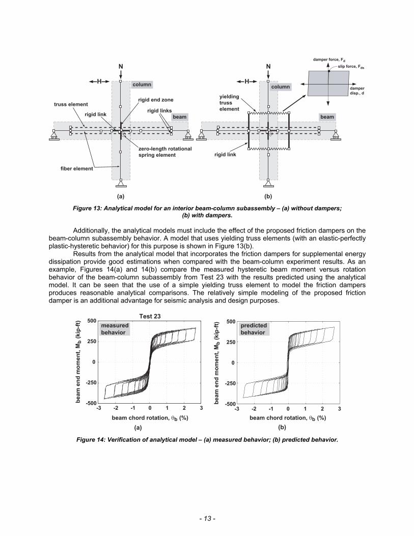
In this research program, the nonlinear behavior of an unbonded post-tensioned precast beam-column subassembly is modeled using the DRAIN-2DX17 structural analysis program. As shown in Figure 13(a) for an interior beam-column subassembly, the following elements are used in the model adapted from El-Sheikh et al.7: (1) fiber beam-column elements to model the beam and column members; (2) truss elements to model the unbonded post-tensioning steel; and (3) zero-length rotational spring elements to model the panel zone shear deformations. This subassembly model has been verified through previous analytical research,7 previous subassembly experiments,4 and the experiments conducted as part of this research program.
- 13 -
(a) (b)
truss element
fiber element
rigid linkrigid links
rigid end zone
zero-length rotational
spring element
H
N
column
beam
yielding
truss
element
H
N
column
beam
rigid link
damper force, Fd
damper
disp., d
slip force, Fds
Figure 13: Analytical model for an interior beam-column subassembly – (a) without dampers; (b) with dampers.
Additionally, the analytical models must include the effect of the proposed friction dampers on the
beam-column subassembly behavior. A model that uses yielding truss elements (with an elastic-perfectly plastic-hysteretic behavior) for this purpose is shown in Figure 13(b).
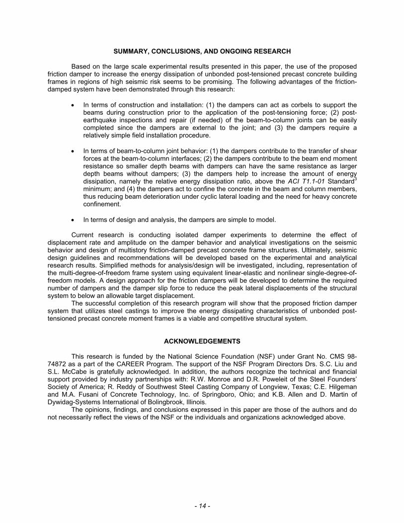
Results from the analytical model that incorporates the friction dampers for supplemental energy dissipation provide good estimations when compared with the beam-column experiment results. As an example, Figures 14(a) and 14(b) compare the measured hysteretic beam moment versus rotation behavior of the beam-column subassembly from Test 23 with the results predicted using the analytical model. It can be seen that the use of a simple yielding truss element to model the friction dampers produces reasonable analytical comparisons. The relatively simple modeling of the proposed friction damper is an additional advantage for seismic analysis and design purposes.
(a) (b)
beam
en
d m
om
en
t, M
b (
kip
-ft)
beam chord rotation, θb (%)
-3 -2 -1 0 1 2 3 -500
-250
0
250
500Test 23
-3 -2 -1 0 1 2 3-500
-250
0
250
500
beam
en
d m
om
en
t, M
b (
kip
-ft)
beam chord rotation, θb (%)
measured
behavior
predicted
behavior
Figure 14: Verification of analytical model – (a) measured behavior; (b) predicted behavior.
- 14 -
SUMMARY, CONCLUSIONS, AND ONGOING RESEARCH
Based on the large scale experimental results presented in this paper, the use of the proposed friction damper to increase the energy dissipation of unbonded post-tensioned precast concrete building frames in regions of high seismic risk seems to be promising. The following advantages of the friction-damped system have been demonstrated through this research:
• In terms of construction and installation: (1) the dampers can act as corbels to support the
beams during construction prior to the application of the post-tensioning force; (2) post-earthquake inspections and repair (if needed) of the beam-to-column joints can be easily completed since the dampers are external to the joint; and (3) the dampers require a relatively simple field installation procedure.
• In terms of beam-to-column joint behavior: (1) the dampers contribute to the transfer of shear
forces at the beam-to-column interfaces; (2) the dampers contribute to the beam end moment resistance so smaller depth beams with dampers can have the same resistance as larger depth beams without dampers; (3) the dampers help to increase the amount of energy dissipation, namely the relative energy dissipation ratio, above the ACI T1.1-01 Standard3 minimum; and (4) the dampers act to confine the concrete in the beam and column members, thus reducing beam deterioration under cyclic lateral loading and the need for heavy concrete confinement.
• In terms of design and analysis, the dampers are simple to model. Current research is conducting isolated damper experiments to determine the effect of
displacement rate and amplitude on the damper behavior and analytical investigations on the seismic behavior and design of multistory friction-damped precast concrete frame structures. Ultimately, seismic design guidelines and recommendations will be developed based on the experimental and analytical research results. Simplified methods for analysis/design will be investigated, including, representation of the multi-degree-of-freedom frame system using equivalent linear-elastic and nonlinear single-degree-of-freedom models. A design approach for the friction dampers will be developed to determine the required number of dampers and the damper slip force to reduce the peak lateral displacements of the structural system to below an allowable target displacement. The successful completion of this research program will show that the proposed friction damper system that utilizes steel castings to improve the energy dissipating characteristics of unbonded post-tensioned precast concrete moment frames is a viable and competitive structural system.
ACKNOWLEDGEMENTS This research is funded by the National Science Foundation (NSF) under Grant No. CMS 98-74872 as a part of the CAREER Program. The support of the NSF Program Directors Drs. S.C. Liu and S.L. McCabe is gratefully acknowledged. In addition, the authors recognize the technical and financial support provided by industry partnerships with: R.W. Monroe and D.R. Poweleit of the Steel Founders’ Society of America; R. Reddy of Southwest Steel Casting Company of Longview, Texas; C.E. Hilgeman and M.A. Fusani of Concrete Technology, Inc. of Springboro, Ohio; and K.B. Allen and D. Martin of Dywidag-Systems International of Bolingbrook, Illinois.
The opinions, findings, and conclusions expressed in this paper are those of the authors and do not necessarily reflect the views of the NSF or the individuals and organizations acknowledged above.
- 15 -
REFERENCES 1. Priestley, M. and Tao, J.R., “Seismic Response of Precast Prestressed Concrete Frames with
Partially Debonded Tendons,” PCI Journal, Precast/Prestressed Concrete Institute, v. 38, No. 1, January-February 1993, pp. 58-67.
2. ACI Committee 318, “Building Code Requirements for Structural Concrete (ACI 318-02) and Commentary (ACI 318R-02),” American Concrete Institute, Farmington Hills, Michigan, 1999.
3. ACI Innovation Task Group 1, “Acceptance Criteria for Moment Frames Based on Structural Testing (ACI T1.1-01) and Commentary (ACI T1.1R-01),” American Concrete Institute, Farmington Hills, Michigan, 2001, 11 pp.
4. Cheok, G. and Lew, H.S., “Model Precast Concrete Beam-to-Column Joints Subject to Cyclic Loading,” PCI Journal, Precast/Prestressed Concrete Institute, v. 38, No. 4, July-August 1993, pp. 80-92.
5. Cheok, G., Stone, W., and Nakaki, S., “Simplified Design Procedure for Hybrid Precast Concrete Connections,” NISTIR 5765, National Institute of Standards and Technology, Gaithersburg, MD, 1996, 81 pp.
6. Stanton, J., Stone, W., and Cheok, G., “A Hybrid Reinforced Precast Frame for Seismic Regions”, PCI Journal, Precast/Prestressed Concrete Institute, v. 42, No. 2, March-April 1997, pp. 20-32.
7. El-Sheikh, M., Sause, R., Pessiki, S., Lu, L.W., and Kurama, Y., “Seismic Analysis, Behavior, and Design of Unbonded Post-Tensioned Precast Moment Frames,” Report No. EQ-97-02, Department of Civil and Environmental Engineering, Lehigh University, Bethlehem, Pennsylvania, November 1997.
8. Stone, W., Cheok, G., and Stanton, J., “Performance of Hybrid Moment-Resisting Precast Beam-Column Concrete Connections Subjected to Cyclic Loading,” ACI Structural Journal, American Concrete Institute, v. 95, No. 5, September-October 1998, pp. 527-539.
9. Nakaki, S.D., Stanton, J.F., and Sritharan, S., “An Overview of the PRESSS Five-Story Precast Test Building,” PCI Journal, Precast/Prestressed Concrete Institute, v. 44, No. 2, March-April 1999, pp. 26-39.
10. Priestley, M., Sritharan, S., Conley, J., and Pampanin, S., “Preliminary Results and Conclusions from the PRESSS Five-Story Precast Concrete Test Building,” PCI Journal, Precast/Prestressed Concrete Institute, v. 44, No. 6, November-December 1999, pp. 42-67.
11. Kurama, Y., “Simplified Seismic Design Approach for Friction-Damped Unbonded Post-Tensioned Precast Concrete Walls”, ACI Structural Journal, American Concrete Institute, v. 98, No. 5, September-October 2001, pp. 705-716.
12. Stanton, J. and Nakaki, S., “Design Guidelines for Precast Concrete Seismic Structural Systems”, Report No. PRESSS-01/03-09, Department of Civil Engineering, University of Washington, Seattle, Washington, February 2002.
13. Englekirk, R.E., “Design-Construction of The Paramount – A 39-Story Precast Prestressed Concrete Apartment Building,” PCI Journal, Precast/Prestressed Concrete Institute, v. 47, No. 4, July-August 2002, pp. 56-71.
14. Soong, T.T. and Dargush, G.F., Passive Energy Dissipation Systems in Structural Engineering, John Wiley & Sons, Inc., New York, N.Y., 1997.
15. Soong, T.T. and Spencer, B.F., “Supplemental Energy Dissipation: State-of-the-Art and State-of-the-Practice,” Engineering Structures, Elsevier Science Ltd., v. 24, 2002, pp. 243-259.
16. Christopoulos, C, Filiatrault, A., Uang, C-M., and Folz, B., “Post-tensioned Energy Dissipating Connections for Moment-Resisting Steel Frames,” Journal of Structural Engineering, American Society of Civil Engineers, v. 128, No. 9, September 2002, pp. 1111-1120.
17. Parkash, V., Powell, G., and Campbell, S., “DRAIN-2DX Base Program Description and User Guide; Version 1.10,” Report No. UCB/SEMM-93/17, Department of Civil Engineering, University of California, Berkeley, California, November 1993.
18. Grigorian, C., Yang, T., and Popov, E., “Slotted Bolted Connection Energy Dissipators,” Earthquake Spectra, Earthquake Engineering Research Institute, v. 9, No. 3, August 1993, pp. 491-504.
19. Way, D., “Friction-Damped Moment Resisting Frames,” Earthquake Spectra, Earthquake Engineering Research Institute, v. 12, No. 3, August 1996, pp. 623-633.
- 16 -
APPENDIX A – NOTATION
Ab = beam gross cross-sectional area ap = area of post-tensioning strand Ap = total beam post-tensioning steel area d = damper displacement dp = diameter of post-tensioning strand Dh = inelastic energy dissipation f'c = design concrete strength fci = initial beam concrete stress fpi = average initial stress in post-tensioning strands fpu = ultimate strength of post-tensioning strands Fd = damper force Fdn = damper normal force Fds = damper slip force fsy = design yield strength of mild reinforcement hb = beam depth LB-CS = leaded-bronze against cast steel LB-SS = leaded-bronze against stainless steel Mb = beam end moment Mb,max = maximum beam end moment P = total beam post-tensioning force Pi = total initial beam post-tensioning force β = relative energy dissipation ratio θb = beam chord rotation θbr = residual beam chord rotation