Embed Size (px)
Citation preview

OMNITERM LPI & LPD Loop Powered Isolators Model C2063B LPI (single) & C2462A LPD (dual) 4-20mA Loop Powered Isolators
Copyright Omniflex ♦ Subject to change without notice Datasheet DSC2063BR06 sheet 1 of 12 http://www.omniflex.com
Features • Isolate any instrument current loop to 1500Vac • Powered by the current loop - no power supply required • Lowest volt drop <3 Volts at 20 mA (2,5V Typical) • Load independent – no field calibration ever required • High 1kohm load capability • High 0.1% Accuracy • High 11.25mm per channel packing density • Reverse polarity and overload protection • Unique internal clamp can protect against open circuit. • Internal 250 ohm resistor for 1-5V input to PLC’s etc. • Easy DIN rail or surface mounting
The OMNITERM LPI and LPD are loop powered isolating current repeaters specifically designed to isolate instrument current loops from circulating ground currents that can cause system inaccuracies, or at worst, instrument failure. Insert in any 4-20mA current loop to isolate the instruments in the loop. The current applied to the input is repeated on the isolated output, and the load present on the output is reflected back to the input. No separate power source is required.
Forming part of OMNIFLEX’s extensive OMNITERM range of signal conditioning and signal isolation products, the OMNITERM LPI and LPD are designed to be DIN rail or surface mounted.
The Omniterm LPI is a single loop isolator in a 22.5mm wide DIN rail mount housing with extensive additional connection features, while the LPD is a dual loop isolator that fits two separate channels into the same 22.5mm width for high density applications.
These second-generation products utilise advanced electronic techniques to achieve high accuracy with minimum loop losses and zero field calibration.
Because of the faithful nature in which threflected back to the input, an open circuit onopen circuit on the input. In cases where this iclamp is provided in the LPI model which, wthat the current loop is not broken if the load unplugging the input terminations of a PLC or R
In many applications there is a need to con5Volts for an RTU, PLC or DCS etc. This because the precision resistor needs to be souindependently without causing loop errors. Tothe LPI version also includes a precision 250connected into the circuit to convert the outmodule.
The LPI and LPD operate over 0-50mA ranglevels to be repeated.
Applications • Isolate instruments in the same current loop
• Prevent ground loops and eliminate loop errors
• Isolate RTU’s, PLC’s, SCADA I/O from the field loop.
• Isolate two-wire transmitter loops from local 24Volts
• Isolate grounded chart recorders from the field loop
• Isolate grounded control valves from the transmitter
• Can be used with two-wire or four-wire transmitters
• Isolate and convert two wire field devices to 1-5V
Mechanical Det
11022.5
D T
ATASHEE
®
e output impedance is the output will cause an s undesirable, an internal hen connected, ensures is disconnected, such as TU.
vert the 4-20mA into 1-is normally inconvenient rced, mounted and wired overcome this obstacle, ohm resistor that can be put into 1-5V within the
e, allowing fault current
ails 75
OMNITERM LPI & LPD Loop Powered Isolators Model C2063B LPI (single) & C2462A LPD (dual) 4-20mA Loop Powered Isolators
Copyright Omniflex ♦ Subject to change without notice Datasheet DSC2063BR06 sheet 2 of 12 http://www.omniflex.com
®
Connection Diagram
4-20m A input 4-20m A outpu t
Input C lam p O utpu t C lam p
C onnect to 0Vfor 1 -5V on O U T
2
1
3
5
4
66v8 6v8
+
- -
+
IN O U T
LP I
250 ohm s8 7
250 ohm sC onnect to 0Vfor 1-5V on IN
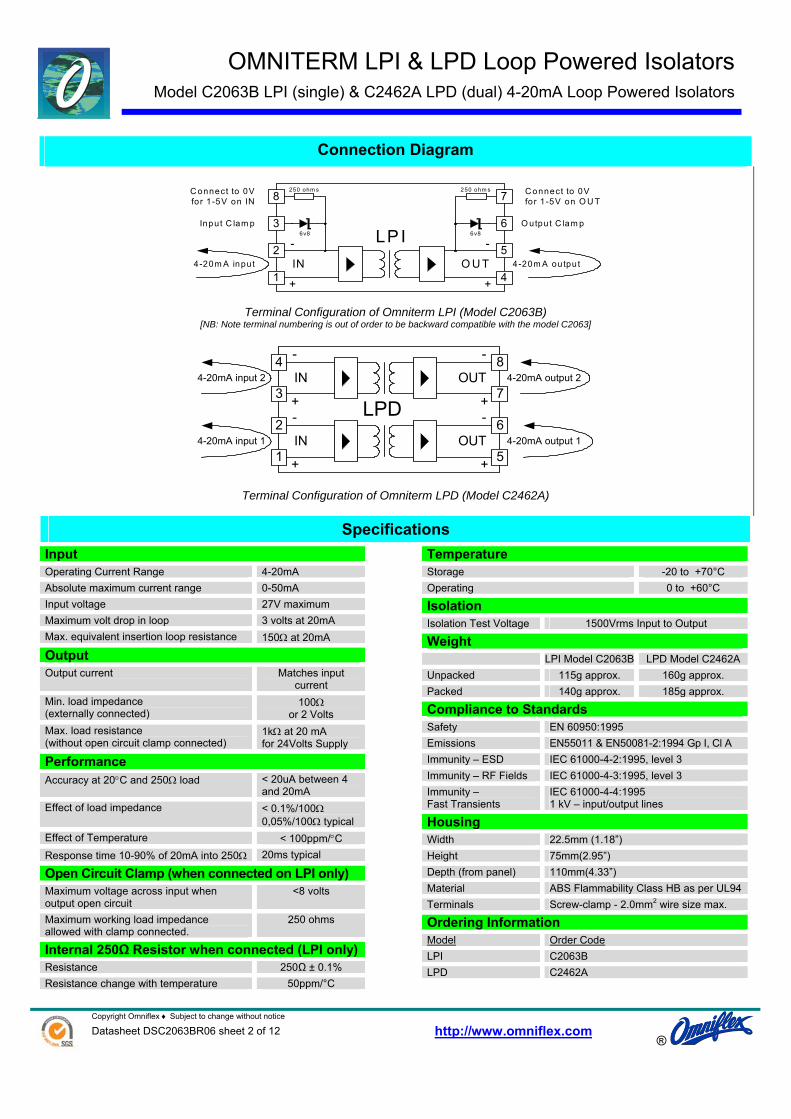
Terminal Configuration of Omniterm LPI (Model C2063B) [NB: Note terminal numbering is out of order to be backward compatible with the model C2063]
2
1
3
6
5
7
+
- -
+
IN OUT
LPD
4 8
4-20mA output 1
+
- -
+
IN OUT
4-20mA input 1
4-20mA input 2 4-20mA output 2
Terminal Configuration of Omniterm LPD (Model C2462A)
Specifications Input Operating Current Range 4-20mA Absolute maximum current range 0-50mA Input voltage 27V maximum Maximum volt drop in loop 3 volts at 20mA Max. equivalent insertion loop resistance 150Ω at 20mA
Output Output current Matches input
current Min. load impedance (externally connected)
100Ω or 2 Volts
Max. load resistance (without open circuit clamp connected)
1kΩ at 20 mA for 24Volts Supply
Performance Accuracy at 20°C and 250Ω load < 20uA between 4
and 20mA Effect of load impedance < 0.1%/100Ω
0,05%/100Ω typical Effect of Temperature < 100ppm/°C Response time 10-90% of 20mA into 250Ω 20ms typical
Open Circuit Clamp (when connected on LPI only) Maximum voltage across input when output open circuit
<8 volts
Maximum working load impedance allowed with clamp connected.
250 ohms
Internal 250Ω Resistor when connected (LPI only) Resistance 250Ω ± 0.1% Resistance change with temperature 50ppm/°C
Temperature Storage -20 to +70°C Operating 0 to +60°C
Isolation Isolation Test Voltage 1500Vrms Input to Output
Weight LPI Model C2063B LPD Model C2462A Unpacked 115g approx. 160g approx. Packed 140g approx. 185g approx.
Compliance to Standards Safety EN 60950:1995 Emissions EN55011 & EN50081-2:1994 Gp I, Cl A Immunity – ESD IEC 61000-4-2:1995, level 3 Immunity – RF Fields IEC 61000-4-3:1995, level 3 Immunity – Fast Transients
IEC 61000-4-4:1995 1 kV – input/output lines
Housing Width 22.5mm (1.18”) Height 75mm(2.95”) Depth (from panel) 110mm(4.33”) Material ABS Flammability Class HB as per UL94 Terminals Screw-clamp - 2.0mm2 wire size max.
Ordering Information Model Order CodeLPI C2063B LPD C2462A

OMNITERM LPI & LPD Loop Powered Isolators Model C2063B LPI (single) & C2462A LPD (dual) 4-20mA Loop Powered Isolators
Copyright Omniflex ♦ Subject to change without notice Datasheet DSC2063BR06 sheet 3 of 12 http://www.omniflex.com
Application Examples
Application 1: Using the LPI to isolate a powered 4-20mA transmitter output from a resistive load
+
-
+
-
Pow ered4-20m AO utput
4-20m A 4-20m A2
1
3
5
4
66v8 6v8
+
- -
+
IN O U T
LP I
250 ohm s8 7
250 ohm s
4-20m AInput
R L
This is the basic circuit for inserting a Loop Powered Isolator (LPI) into a current loop. The LPI can simply be “cut” into any existing current loop to isolate the current transmitter from the load.
NOTE: The “IN” side of the LPI is always connected to the side of the loop supplying the loop power.
The LPI will consume less than 3 Volts of the available loop voltage. This is equivalent to inserting less 150 ohms of additional resistance into the current loop.
To determine the maximum loop resistance that you can tolerate in your cabling, apply the following formula:
150−−= LTMAX RRR
where: RMAX is the maximum resistance in the loop without causing measurement error. RT is the maximum load resistance that the current transmitter can drive. RL is the total resistance of all loads in the loop (excluding the LPI)
For reliable operation over the long term, you should design for less initial cable resistance than this maximum value. This provides a safety factor to account for increase in resistance of terminations and wiring with age/weathering etc.
A sensible value to use for this safety factor would be 100 ohms (equal to 2 Volts at 20mA).
®

OMNITERM LPI & LPD Loop Powered Isolators Model C2063B LPI (single) & C2462A LPD (dual) 4-20mA Loop Powered Isolators
Copyright Omniflex ♦ Subject to change without notice Datasheet DSC2063BR06 sheet 4 of 12 http://www.omniflex.com
®
Application 2: Using the LPI to isolate a field mounted 4-20mA two-wire transmitter from a PLC, RTU or DCS
+24VLoop Powered
Two-wireTransmitter
4-20mA 4-20mA
2
1
3
5
4
66v86v8
+
--
+
INOUT
LPI
250 ohms87
250 ohms
+
-
0V
4-20mAInput
RL
This is the basic circuit for isolating a field-mounted two-wire transmitter from the control circuitry using an LPI. The LPI can simply be “cut” into any existing two-wire current loop to isolate the transmitter from the panel power supply.
NOTE: The “IN” side of the LPI is always connected to the side of the loop supplying the loop power, so in this application the two-wire transmitter is connected to the OUT terminals of the LPI.
Because of the 2mm2 wire size capability of the LPI terminals, the LPI can also act as the field interface terminals, saving you the extra termination and wiring cost. For multiple loops where space is a concern, use the LPD dual module. (See Application 7, 8 and 9)
The LPI will consume less than 3 Volts of the available loop voltage. This is equivalent to inserting less 150 ohms of additional resistance into the current loop.
To determine the maximum loop resistance that you can tolerate in your cabling, apply the following formula:
15002.
)( minmin −−−
= LTS
MAX RVVR
where: RMAX is the maximum resistance in the loop without causing measurement error (in Ohms). VSmin is the minimum voltage of the power supply used to drive the loop (in Volts). VTmin is the minimum voltage required by the two-wire transmitter for operation (in Volts). RL is the total resistance of all loads in the loop (excluding the LPI) (in Ohms)
For reliable operation over the long term, you should design for less initial cable resistance than this maximum value. This provides a safety factor to account for increase in resistance of terminations and wiring with age/weathering etc.
A sensible value to use for this safety factor would be 100 ohms (equal to 2 Volts at 20mA).
OMNITERM LPI & LPD Loop Powered Isolators Model C2063B LPI (single) & C2462A LPD (dual) 4-20mA Loop Powered Isolators
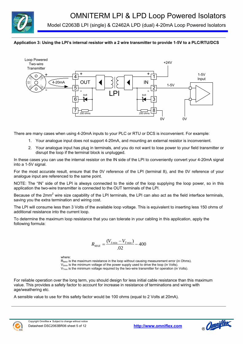
Application 3: Using the LPI’s internal resistor with a 2 wire transmitter to provide 1-5V to a PLC/RTU/DCS
+24VLoop Powered
Two-wireTransmitter
4-20mA1-5V2
1
3
5
4
66v86v8
+
--
+
INOUT
LPI
250 ohms87
250 ohms
+
-
0V
1-5VInput
0V
There are many cases when using 4-20mA inputs to your PLC or RTU or DCS is inconvenient. For example:
1. Your analogue input does not support 4-20mA, and mounting an external resistor is inconvenient.
2. Your analogue input has plug in terminals, and you do not want to lose power to your field transmitter or disrupt the loop if the terminal block is unplugged.
In these cases you can use the internal resistor on the IN side of the LPI to conveniently convert your 4-20mA signal into a 1-5V signal.
For the most accurate result, ensure that the 0V reference of the LPI (terminal 8), and the 0V reference of your analogue input are referenced to the same point.
NOTE: The “IN” side of the LPI is always connected to the side of the loop supplying the loop power, so in this application the two-wire transmitter is connected to the OUT terminals of the LPI.
Because of the 2mm2 wire size capability of the LPI terminals, the LPI can also act as the field interface terminals, saving you the extra termination and wiring cost.
The LPI will consume less than 3 Volts of the available loop voltage. This is equivalent to inserting less 150 ohms of additional resistance into the current loop.
To determine the maximum loop resistance that you can tolerate in your cabling in this application, apply the following formula:
40002.
)( minmin −−
= TSMAX
VVR
where: RMAX is the maximum resistance in the loop without causing measurement error (in Ohms). VSmin is the minimum voltage of the power supply used to drive the loop (in Volts). VTmin is the minimum voltage required by the two-wire transmitter for operation (in Volts).
For reliable operation over the long term, you should design for less initial cable resistance than this maximum value. This provides a safety factor to account for increase in resistance of terminations and wiring with age/weathering etc.
A sensible value to use for this safety factor would be 100 ohms (equal to 2 Volts at 20mA).
®
Copyright Omniflex ♦ Subject to change without notice Datasheet DSC2063BR06 sheet 5 of 12 http://www.omniflex.com

OMNITERM LPI & LPD Loop Powered Isolators Model C2063B LPI (single) & C2462A LPD (dual) 4-20mA Loop Powered Isolators
Copyright Omniflex ♦ Subject to change without notice Datasheet DSC2063BR06 sheet 6 of 12 http://www.omniflex.com
®
Application 4: Using the LPI’s internal resistor with a 4 wire transmitter to provide 1-5V to a PLC/RTU/DCS
1-5V
2
1
3
5
4
66v8 6v8
+
- -
+
IN O U T
LP I
250 ohm s8 7
250 ohm s
0V
1-5VInput
0V+
-4-20m A
There are many cases when using 4-20mA inputs to your PLC or RTU or DCS is inconvenient. For example:
1. Your analogue input does not support 4-20mA, and mounting an external resistor to convert the signal to 1-5V is inconvenient.
2. Your analogue input has plug in terminals, and you do not want to lose power to your field transmitter or disrupt the loop if the terminals are unplugged.
In these cases you can use the internal resistor on the OUT side of the LPI to conveniently convert your 4-20mA signal into a 1-5V signal.
For the most accurate result, ensure that the 0V reference to the LPI (terminal 5), and the 0V reference of your analogue input are referenced to the same point.
NOTE: The “IN” side of the LPI is always connected to the side of the loop supplying the loop power, so in this application the four-wire transmitter is connected to the IN terminals of the LPI.
Because of the 2mm2 wire size capability of the LPI terminals, the LPI can also act as the field interface terminals, saving you the extra termination and wiring cost.
The LPI will consume less than 8 Volts of the available loop voltage. This is equivalent to inserting less than 400 ohms of resistance into the current loop.
To determine the maximum loop resistance that you can tolerate in your cabling in this application, apply the following formula:
400−= TMAX RR
where: RMAX is the maximum resistance in the loop without causing measurement error (in Ohms). RT is the maximum load resistance that the current transmitter can drive (in Ohms).
For reliable operation over the long term, you should design for less initial cable resistance than this maximum value. This provides a safety factor to account for increase in resistance of terminations and wiring with age/weathering etc.
A sensible value to use for this safety factor would be 100 ohms (equal to 2 Volts at 20mA).

OMNITERM LPI & LPD Loop Powered Isolators Model C2063B LPI (single) & C2462A LPD (dual) 4-20mA Loop Powered Isolators
Copyright Omniflex ♦ Subject to change without notice Datasheet DSC2063BR06 sheet 7 of 12 http://www.omniflex.com
®
Application 5: Using the LPI’s internal clamp with a 2 wire transmitter to protect the loop against open circuit.
+24VLoop Powered
Two-wireTransmitter
4-20mA 4-20mA
2
1
3
5
4
66v86v8
+
--
+
INOUT
LPI
250 ohms87
250 ohms
+
-
0V
4-20mAInput
RL
0V
There are cases, when using 4-20mA inputs to your PLC, RTU or DCS, where it is important that the current loop is not disrupted when the analogue input to your PLC or RTU or DCS is unplugged or disconnected.
In these cases you can use the internal clamp of the LPI to protect the loop from open circuit if your PLC or RTU or DCS input is unplugged or disconnected.
This is simply achieved by connecting the input clamp terminal 3 to your 0V reference. If the analogue input to your PLC or RTU or DCS is disconnected, the current will be diverted to 0V through the clamp, saving the current loop from disconnection.
The voltage across the LPI will be clamped to 6.8Volts in this condition – only slightly higher than the normal operating voltage of 1-5 Volts. This higher clamp voltage should be used when calculating maximum allowable loop resistance.
NOTE: The “IN” side of the LPI is always connected to the side of the loop supplying the loop power, so in this application the two-wire transmitter is connected to the OUT terminals of the LPI.
Because of the 2mm2 wire size capability of the LPI terminals, the LPI can also act as the field interface terminals, saving you the extra termination and wiring cost.
To determine the maximum loop resistance of your cabling that you can tolerate in your loop with the clamp in operation, apply the following formula:
50002.
)( minmin −−
= TSMAX
VVR
where: RMAX is the maximum resistance in the loop without causing measurement error (in Ohms). VSmin is the minimum voltage of the power supply used to drive the loop (in Volts). VTmin is the minimum voltage required by the two-wire transmitter for operation (in Volts).
For reliable operation over the long term, you should design for less initial cable resistance than this maximum value. This provides a safety factor to account for increase in resistance of terminations and wiring with age/weathering etc.
A sensible value to use for this safety factor would be 100 ohms (equal to 2 Volts at 20mA).

OMNITERM LPI & LPD Loop Powered Isolators Model C2063B LPI (single) & C2462A LPD (dual) 4-20mA Loop Powered Isolators
Copyright Omniflex ♦ Subject to change without notice Datasheet DSC2063BR06 sheet 8 of 12 http://www.omniflex.com
®
Application 6: Using the LPI’s internal clamp with a 4 wire transmitter to protect the loop against open circuit.
+
-
+
-4-20m A 4-20m A
2
1
3
5
4
66v8 6v8
+
- -
+
IN O U T
LP I
250 ohm s8 7
250 ohm s
4-20m AInput
R L
When using 4-20mA inputs to your PLC, RTU or DCS, there are cases where it is important that the current loop is not disrupted when the analogue input to your PLC or RTU or DCS is unplugged or disconnected.
In these cases you can use the internal clamp of the LPI to protect the loop from open circuit if your PLC or RTU or DCS input is unplugged or disconnected.
In four-wire current transmitter applications this is simply achieved by connecting the output clamp terminal 6 to the current output terminal 4 of the LPI. If the analogue input to your PLC or RTU or DCS is disconnected, the current will be diverted through the clamp, saving the current loop from disconnection.
The voltage across the LPI will be clamped to 6.8Volts in this condition – slightly higher than the normal operating voltage of 1-5 Volts. This higher clamp voltage should be used when calculating maximum allowable loop resistance.
NOTE: The “IN” side of the LPI is always connected to the side of the loop supplying the loop power, so in this application the four-wire transmitter is connected to the IN terminals of the LPI.
Because of the 2mm2 wire size capability of the LPI terminals, the LPI can also act as the field interface terminals, saving you the extra termination and wiring cost.
To determine the maximum loop resistance of your cabling that you can tolerate in your loop with the clamp in operation, apply the following formula:
500−= TMAX RR
where: RMAX is the maximum resistance in the loop without causing measurement error (in Ohms). RT is the maximum load resistance that the current transmitter can drive (in Ohms).
For reliable operation over the long term, you should design for less initial cable resistance than this maximum value. This provides a safety factor to account for increase in resistance of terminations and wiring with age/weathering etc.
A sensible value to use for this safety factor would be 100 ohms (equal to 2 Volts at 20mA).
OMNITERM LPI & LPD Loop Powered Isolators Model C2063B LPI (single) & C2462A LPD (dual) 4-20mA Loop Powered Isolators
Copyright Omniflex ♦ Subject to change without notice Datasheet DSC2063BR06 sheet 9 of 12 http://www.omniflex.com
®
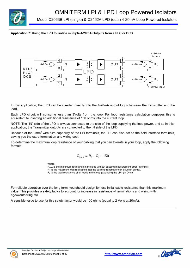
Application 7: Using the LPD to isolate multiple 4-20mA Outputs from a PLC or DCS
R TU /PLC /D C S
+
- -4-20m A
+4-20m A input
4-20m A
+
4-20m A
-
2
1
3
6
5
7
+
- -
+
IN O U T
LPD
4 8
+
- -
+
IN O U T
+
-
4-20m A
4-20m AInputs
R L
R L
In this application, the LPD can be inserted directly into the 4-20mA output loops between the transmitter and the load.
Each LPD circuit will consume less than 3Volts from the loop. For loop resistance calculation purposes this is equivalent to inserting an additional resistance of 150 ohms into the current loop.
NOTE: The “IN” side of the LPD is always connected to the side of the loop supplying the loop power, and so in this application, the Transmitter outputs are connected to the IN side of the LPD.
Because of the 2mm2 wire size capability of the LPI terminals, the LPI can also act as the field interface terminals, saving you the extra termination and wiring cost.
To determine the maximum loop resistance of your cabling that you can tolerate in your loop, apply the following formula:
150−−= LTMAX RRR
where: RMAX is the maximum resistance in the loop without causing measurement error (in ohms). RT is the maximum load resistance that the current transmitter can drive (in ohms). RL is the total resistance of all loads in the loop (excluding the LPI) (in Ohms)
For reliable operation over the long term, you should design for less initial cable resistance than this maximum value. This provides a safety factor to account for increase in resistance of terminations and wiring with age/weathering etc.
A sensible value to use for this safety factor would be 100 ohms (equal to 2 Volts at 20mA).

OMNITERM LPI & LPD Loop Powered Isolators Model C2063B LPI (single) & C2462A LPD (dual) 4-20mA Loop Powered Isolators
Copyright Omniflex ♦ Subject to change without notice Datasheet DSC2063BR06 sheet 10 of 12 http://www.omniflex.com
®
Application 8: Using the LPD to isolate multiple 4-20mA inputs to a PLC or RTU (with passive inputs)
0V
24Vdc
RTU/ PLC+
-
4-20mAPassive inputs
4-20mA
2
1
3
6
5
7
+
--
+
INOUT
LPD
48
+
--
+
INOUT4-20mA
4-20mA+
-4-20mA
+
-+
-
R L
R L
In this application, the LPD can be inserted directly into the 4-20mA input loops between the field mounted two-wire transmitter and the PLC or RTU input.
Each LPD circuit will consume less than 3Volts from the loop. For loop resistance calculation purposes this is equivalent to inserting an additional resistance of 150 ohms into the current loop.
NOTE: The “IN” side of the LPD is always connected to the side of the loop supplying the loop power, and so in this application, the two-wire transmitters are connected to the OUT side of the LPD.
Because of the 2mm2 wire size capability of the LPD terminals, the LPD can also act as the field interface terminals, saving you the extra termination and wiring cost.
To determine the maximum loop resistance of your cabling that you can tolerate in your loop, apply the following formula:
15002.
)( minmin −−−
= LTS
MAX RVVR
where: RMAX is the maximum resistance in the loop without causing measurement error (in Ohms). VSmin is the minimum voltage of the power supply used to drive the loop (in Volts). VTmin is the minimum voltage required by the two-wire transmitter for operation (in Volts). RL is the resistance of the PLC/RTU input (in Ohms)
For reliable operation over the long term, you should design for less initial cable resistance than this maximum value. This provides a safety factor to account for increase in resistance of terminations and wiring with age/weathering etc.
A sensible value to use for this safety factor would be 100 ohms (equal to 2 Volts at 20mA).

OMNITERM LPI & LPD Loop Powered Isolators Model C2063B LPI (single) & C2462A LPD (dual) 4-20mA Loop Powered Isolators
Copyright Omniflex ♦ Subject to change without notice Datasheet DSC2063BR06 sheet 11 of 12 http://www.omniflex.com
®
Application 9: Using the LPD to isolate multiple 4-20mA inputs to a DCS with active (two-wire tx) inputs.
0V
+
-Loop-powered
Two-wire Transmitters
4-20mATwo-wire inputs
4-20mA
2
1
3
6
5
7
+
--
+
INOUT
LPD
48
+
--
+
INOUT4-20mA
4-20mA
+
-4-20mA
+
-+
-
R L
R L
+24V
DCS
In this application, the LPD can be inserted directly into the 4-20mA input loops between the field mounted two-wire transmitter and the DCS input.
Each LPD circuit will consume less than 3Volts from the loop. For loop resistance calculation purposes this is equivalent to inserting an additional resistance of 150 ohms into the current loop.
NOTE: The “IN” side of the LPD is always connected to the side of the loop supplying the loop power, and so in this application, the two-wire transmitters are connected to the OUT side of the LPD.
Because of the 2mm2 wire size capability of the LPD terminals, the LPD can also act as the field interface terminals, saving you the extra termination and wiring cost.
To determine the maximum loop resistance of your cabling that you can tolerate in your loop, apply the following formula:
15002.
)( minmin −−−
= LTS
MAX RVVR
where: RMAX is the maximum resistance in the loop without causing measurement error (in Ohms). VSmin is the minimum voltage of the power supply used to drive the loop (in Volts). VTmin is the minimum voltage required by the two-wire transmitter for operation (in Volts). RL is the resistance of the PLC/RTU input (in Ohms)
For reliable operation over the long term, you should design for less initial cable resistance than this maximum value. This provides a safety factor to account for increase in resistance of terminations and wiring with age/weathering etc.
A sensible value to use for this safety factor would be 100 ohms (equal to 2 Volts at 20mA).

OMNITERM LPI & LPD Loop Powered Isolators Model C2063B LPI (single) & C2462A LPD (dual) 4-20mA Loop Powered Isolators
Copyright Omniflex ♦ Subject to change without notice Datasheet DSC2063BR06 sheet 12 of 12 http://www.omniflex.com
®
Application 10: Dealing with zero loop resistance when using the LPI.
+
-
+
-
Pow ered4-20m AO utput
4-20m A 4-20m A2
1
3
5
4
66v8 6v8
+
- -
+
IN O U T
LP I
250 ohm s8 7
250 ohm s
4-20m AInput
R < 100ohm sL
The LPI is optimised to minimise the effective inserted loop impedance, but does require a minimum of 100 ohms of load impedance, (or 2 volts) on the output to maintain operation.
In some applications, when using four-wire transmitters, the load being driven is lower than this minimum value, and additional load needs to be inserted into the output loop to bring the minimum load up to the required 100 ohms.
One solution for this is to use the internal 250 ohm resistor to provide this additional resistance. When connected as shown in the diagram above, the internal resistor is used in series with the current loop to provide an additional 250 ohms of loop resistance. This brings the LPI back into specification without the need for any additional resistors.
NOTE: The “IN” side of the LPI is always connected to the side of the loop supplying the loop power, so in this application the four-wire transmitter is connected to the IN terminals of the LPI.
Because of the 2mm2 wire size capability of the LPI terminals, the LPI can also act as the field interface terminals, saving you the extra termination and wiring cost.
To determine the maximum loop resistance of your cabling that you can tolerate in your loop with the clamp in operation, apply the following formula:
400−−= LTMAX RRR
where: RMAX is the maximum resistance in the loop without causing measurement error (in Ohms). RT is the maximum load resistance that the current transmitter can drive (in Ohms). RL is the resistance of the connected load (in Ohms)
For reliable operation over the long term, you should design for less initial cable resistance than this maximum value. This provides a safety factor to account for increase in resistance of terminations and wiring with age/weathering etc.
A sensible value to use for this safety factor would be 100 ohms (equal to 2 Volts at 20mA).