Embed Size (px)
Citation preview

NIBE™ VVM 300all IN oNE INdoor uNIt
NIBE VVM 300NIBE VVM 300 is an all in one inddor unit. It consists of a double jacketed pressure vessel, two immersion heaters and intelligent controls. VVM 300 is designed for connection and communica-tion with outdoor heat pump F20XX of 6 kW, 8 kW and 10 kW. For example floating condensation and automatic speed control for optimal performance of the load pumpconnected to the out-door unit.
VVM 300 is equipped with an intelligent control.
the insulation consists of environmenal friendly polyurethane, which is moulded in one piece.
IntellIgent hot water
• VVM300isdesignedforconnectionandcommunicationwithoutdoorheatpumpF20XXof6kW,8kWand10kW.
• Watervolume280litres,ofwhich155litresishottapwater.
• VVM300isequippedwithclimatecontrolledautomaticbypassestomaintainthecorrecttemperaturefortheheatingsystem.
• Uniquecontrolsystemformaximumenergyoptimization.
• Selfregulatingspeedcontrolledchargepump.
• Loadmonitorasstandardforhousefuse.
• Preparedforpoolheating.
• Preparedforcontroloftwoheatingsystems.
2 NIBE VVM 300
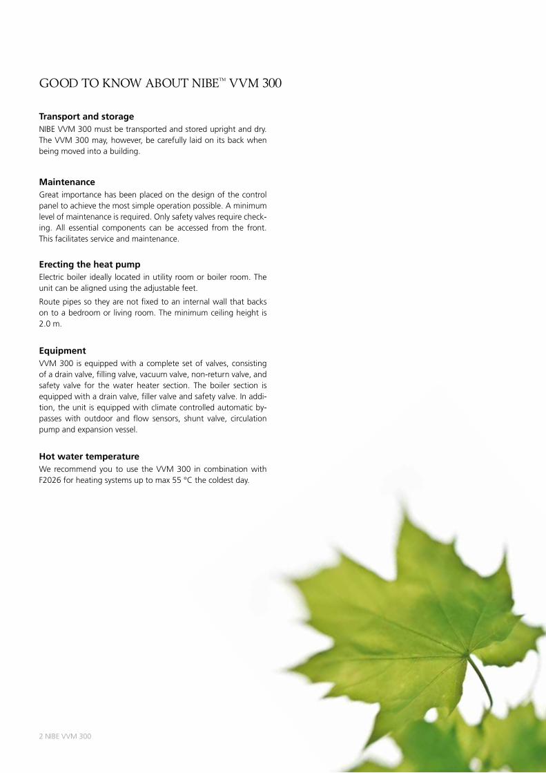
Transport and storageNIBE VVM 300 must be transported and stored upright and dry. the VVM 300 may, however, be carefully laid on its back when being moved into a building.
MaintenanceGreat importance has been placed on the design of the control panel to achieve the most simple operation possible. a minimum level of maintenance is required. only safety valves require check-ing. all essential components can be accessed from the front. this facilitates service and maintenance.
Erecting the heat pumpElectric boiler ideally located in utility room or boiler room. the unit can be aligned using the adjustable feet.
route pipes so they are not fixed to an internal wall that backs on to a bedroom or living room. the minimum ceiling height is 2.0 m.
EquipmentVVM 300 is equipped with a complete set of valves, consisting of a drain valve, filling valve, vacuum valve, non-return valve, and safety valve for the water heater section. the boiler section is equipped with a drain valve, filler valve and safety valve. In addi-tion, the unit is equipped with climate controlled automatic by-passes with outdoor and flow sensors, shunt valve, circulation pump and expansion vessel.
Hot water temperatureWe recommend you to use the VVM 300 in combination with F2026 for heating systems up to max 55 °C the coldest day.
good to know about nIbe™ VVM 300
NIBE VVM 300 3
good to know about nIbe™ VVM 300
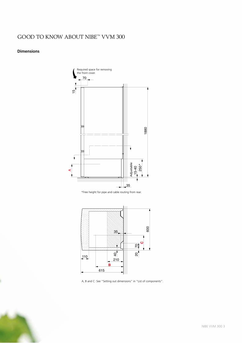
Dimensions
B615
110
70
600
40
C
35
20
A
Stäl
lbar
15-4
0
35
250 60
1880
7015 Elektrisk
matning Ø 25
Utegivare Ø 16
Kommunikationskabel tillF20XX Ø 25 Elektrisk
matning Ø 25Utegivare Ø 16
Modularkabel tillFIGHTER 2020 Ø 25
Emalj
9047
0
520
40
210
235
5533
0
145 155 155 145
required space for removing the front cover.
*Free height for pipe and cable routing from rear.
Adjustable *
a, B and C: See “Setting out dimensions” in “list of components”.
4 NIBE VVM 300
LEK
Art.nr. 611???
2
1 b a r 3
0 4
1
88
43
46
24
17
16
44
19
44
89
62
96
162
8
99
14
Återledn.radiatorer
v.v.
70518071 504974 79
98
85
42
35
83
100
101
23
6
10
67
69
9
7
18
30
38
25
32
102
34
103k.v.
73 4766Framledningradiatorer
4
104
40
61
93
95
52
75
76
12
11
5384
48
45
23
163
good to know about nIbe™ VVM 300
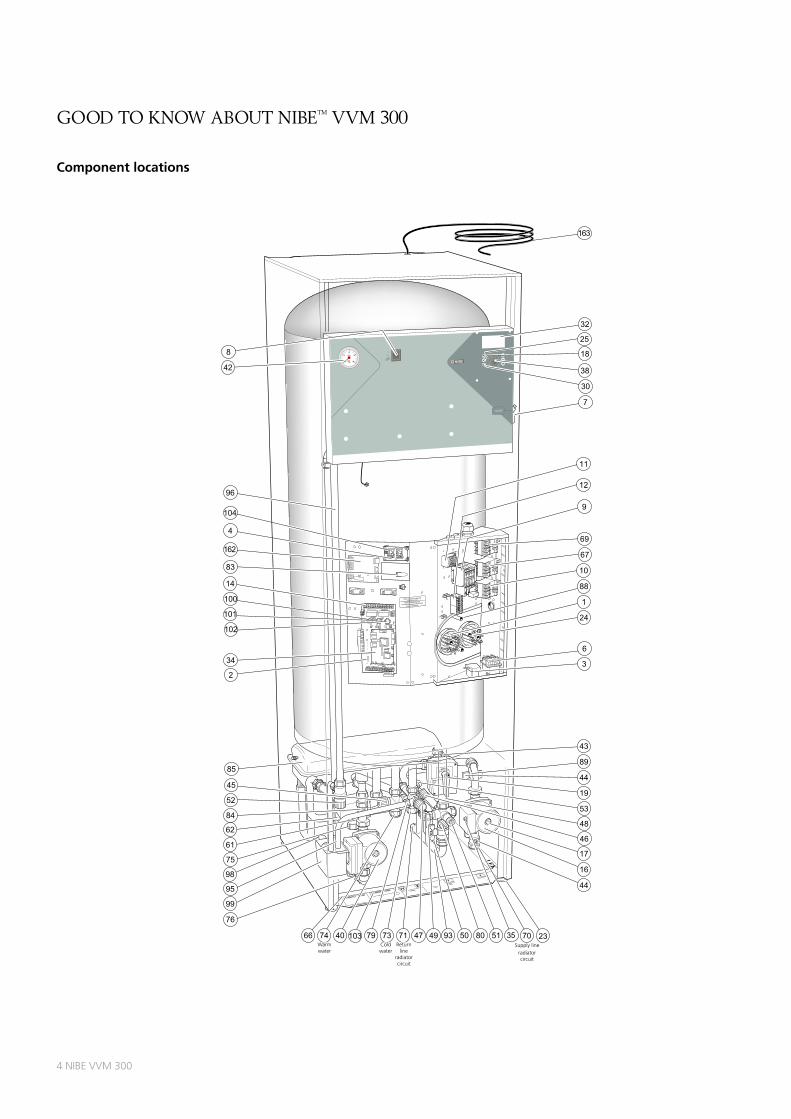
Component locations
Warm water
return line
radiator circuit
Supply lineradiator circuit
Cold water
NIBE VVM 300 5
good to know about nIbe™ VVM 300
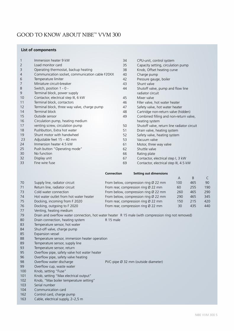
List of components
1 Immersion heater 9 kW2 load monitor card3 operating thermostat, backup heating4 Communication socket, communication cable F20XX6 temperature limiter7 Miniature circuit-breaker8 Switch, position 1 - 0 -9 terminal block, power supply10 Contactor, electrical step III, 6 kW11 terminal block, contactors12 terminal block, three way valve, charge pump14 terminal block15 outside sensor16 Circulation pump, heating medium17 venting screw, circulation pump18 Pushbutton, Extra hot water19 Shunt motor with handwheel 23 adjustable feet 15 – 40 mm24 Immersion heater 4.5 kW25 Push button “operating mode”30 No function 32 display unit33 Fine wire fuse
34 CPu-unit, control system35 Capacity setting, circulation pump38 Knob, offset heating curve40 Charge pump42 Pressure gauge, boiler43 Shunt valve44 Shutoff valve, pump and flow line radiator circuit45 Mixer valve46 Filler valve, hot water heater47 Safety valve, hot water heater48 Cartridge non-return valve (hidden)49 Combined filling and non-return valve, heating system50 Shutoff valve, return line radiator circuit51 drain valve, heating system52 Safety valve, heating system53 Vacuum valve61 Motor, three way valve62 Shuttle valve66 rating plate67 Contactor, electrical step I, 3 kW69 Contactor, electrical step III, 4.5 kW
Connection Setting out dimensions a B C70 Supply line, radiator circuit From below, compression ring Ø 22 mm 100 465 9071 return line, radiator circuit From rear, compression ring Ø 22 mm 60 255 19073 Cold water connection From below, compression ring Ø 22 mm 260 465 29074 Hot water outlet from hot water heater From below, compression ring Ø 22 mm 290 465 34575 docking, incoming from F 2020 From rear, compression ring Ø 22 mm 150 215 42076 docking, outgoing to F 2020 From rear, compression ring Ø 22 mm 30 435 44077 Venting, heating medium79 drain and overflow water connection, hot water heater r 15 male (with compression ring not removed)80 drain connection, heating system r 15 male83 temperature sensor, hot water84 Shut-off valve, charge pump85 Expansion vessel88 temperature sensor, immersion heater operation89 temperature sensor, supply line93 temperature sensor, return95 overflow pipe, safety valve hot water heater96 overflow pipe, safety valve heating98 overflow water discharge PVC-pipe Ø 32 mm (outside diameter)99 overflow cup, waste water100 Knob, setting “Fuse”101 Knob, setting “Max electrical output”102 Knob, “Max boiler temperature setting”103 Serial number104 Communication card162 Control card, charge pump163 Cable, electrical supply, 2–2,5 m
6 NIBE VVM 300
InstallatIon
Inspection of the installationCurrent regulations require the heating installation to be inspect-ed before it is commissioned. the inspection must be carried out by a suitably qualified person and should be documented. the above applies to installations with a closed expansion vessel. If the electric boiler or the expansion vessel is replaced, the instal-lation must be inspected again.
Maximum boiler and radiator volumesthe volume of the expansion vessel (85) is 12 litres and it is pres-surised as standard to 0.5 bar (5 mvp). as a result, the maximum permitted height between the vessel and the highest radiator is 5 metres.
If the standard initial pressure in the pressure vessel is not high enough it can be increased by adding air via the valve in the ex-pansion vessel. the initial pressure of the expansion vessel must be stated in the inspection document. any change in the initial pressure affects the ability of the expansion vessel to handle the expansion of the water.
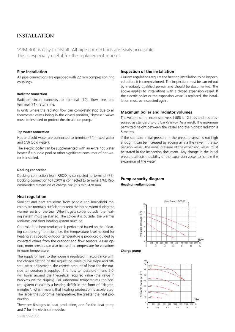
Pump capacity diagramHeating medium pump
Charge pump
Pipe installationall pipe connections are equipped with 22 mm compression ring couplings.
Radiator connection
radiator circuit connects to terminal (70), flow line and terminal (71), return line.
In units where the radiator flow can completely stop due to all thermostat valves being in the closed position, “bypass” valves must be installed to protect the circulation pump.
Tap water connection
Hot and cold water are connected to terminal (74) mixed water and (73) (cold water).
the electric boiler can be supplemented with an extra hot water heater if a bubble pool or other significant consumer of hot wa-ter is installed.
Docking connection
docking connection from F20XX is connected to terminal (75). docking connection to F20XX is connected to terminal (76). rec-ommended dimension of charge circuit is min Ø28 mm.
Heat regulationSunlight and heat emissions from people and household ma-chines are normally sufficient to keep the house warm during the warmer parts of the year. When it gets colder outside, the heat-ing system must be started. the colder it is outside, the warmer radiators and floor heating system must be.
Control of the heat production is performed based on the “float-ing condensing” principle, i.e. the temperature level needed for heating at a specific outdoor temperature is produced guided by collected values from the outdoor and flow sensors. as an op-tion, room sensors can also be used to compensate for variations in room temperature.
the supply of heat to the house is regulated in accordance with the chosen setting of the regulating curve (curve slope and off-set). after adjustment, the correct amount of heat for the out-side temperature is supplied. the flow temperature (menu 2.0) will hover around the theoretical required value (the value in brackets on the display). For subnormal temperatures the con-trol system calculates a heating deficit in the form of “degree-minutes”, which means that heating production is accelerated. the larger the subnormal temperature, the greater the heat pro-duction.
there are 8 stages to heat production, one for the heat pump and 7 for the electrical module.
VVM 300 is easy to install. all pipe connections are easily accessible. this is especially useful for the replacement market.
Pumpkapacitet
Flöde
Till
gäng
ligt t
ryck
, kP
a
Internt tryckfall i panna(inklusive armatur)
Tillgänglig pumpkapacitet(pannans interntryckfall fråndraget)
3
2
1
0 500 1000
0
1500 2000
4
l/h
P
5
6
Interner Druckverlust in der Heizung(einschließlich Armatur)
Zugängliche Pumpenkapazität(interner Heizdruckverlust abgezogen)
3
2
1
kPa
kPa
60
50
40
30
20
10
0
mWs
l/s0,50,40,30,20,10
Höchstmenge:1700 l/h
Höchstmenge:1700 l/h
3
2
1
0 500 1000
0
1500 2000
4
l/h
l/h
l/h
P
5
6
Internal pressure drop in boiler(including fittings)
Available pump capacity(less the internal pressure drop of the boiler)
3
2
1
wg
10
2000
0
20
400
30
600
40
800
50
1000
60
1200
70
1400 1600 1800 2000
50
40
30
20
10
0
m
Flow
l/s0,50,40,30,20,10
l/s0,50,40,30,20,10
Max flow: 1700 l/h Max flow: 1700 l/h
Max flöde: 1700 l/h
l/s0,50,40,30,20,10
Flow, l/h
Ava
ilabl
e pu
mp
capa
city
, kP
a
10
2000
0
20
400
30
600
40
800
50
1000
60
1200
70
1400 1600 1800 2000
Menge
Vor
hand
ener
Dru
ck, k
Pa
10
2000
0
20
400
30
600
40
800
50
1000
60
1200
70
1400 1600 1800 2000
MOS SE F310P
ava
ilabl
e pr
essu
re, k
Pa
Flow
Max flow: 1700 l/h
Flöde
Till
gäng
ligt t
ryck
, kP
a
kPa
l/h
10
2000
0
20
400
30
600
40
800
50
1000
60
1200
70
1400 1600
l/s0,40,30,20,10
100%
70%
30%
90%
50%
10%Flow
ava
ilabl
e pr
essu
re, k
Pa
NIBE VVM 300 7
Electrical connections
Connection
VVM 300 must be installed via an isolator switch with a mini-mum breaking gap of 3 mm. other electrical equipment, except the outdoor sensor and the current sensors, are connected at the factory.
disconnect the electric boiler before insulation testing the house wiring.
Connection must not be carried out without the permission of the electricity supplier and under the supervision of a qualified electrician. the cable entry conduit is dimensioned for cable with a max Ø 19 mm.
the power is controlled via contactors, which are operated by a the control system.
the automatic heating control system, circulation pump (16), charge pump (40) and its cabling, are internally fuse protected with a miniature circuit breaker (7).
InstallatIon
Outside sensor
Install the outside sensor in the shade on a wall facing north or north-west, so it is unaffected by the morning sun. Connect the sensor with a two wire cable.
If a conduit is used it must be sealed to prevent condensation in the sensor capsule. the minimum cable cross section should be 0.4 mm2 up to lengths of 50 metres, for example, EKKX or liYY.
Centralised load control and load monitor
Centralised load control or tariff control achieved by activation of external potential free closing contact.
VVM 300 is equipped with an internal load monitor. the control system must be set for the installation’s main fuse so that the load monitor can work correctly. the supplied current sensor (20) is connected to VVM 300 by a 4 wire cable.
Cable type: unscreened liYY, screened liYCY. Cable area, at least 4 x 0.25 mm2 with cable length up to 50 m.
When the load monitor senses an overcurrent on one of the phases, the immersion heater will step down the output until it can be connected again.
Kommunikationskabel
Elmatning
Arbetsbrytare
Strömkännare
Utegivare
Eventuellt anslutenF20XX
VVM 300
Elmatning
Arbetsbrytare
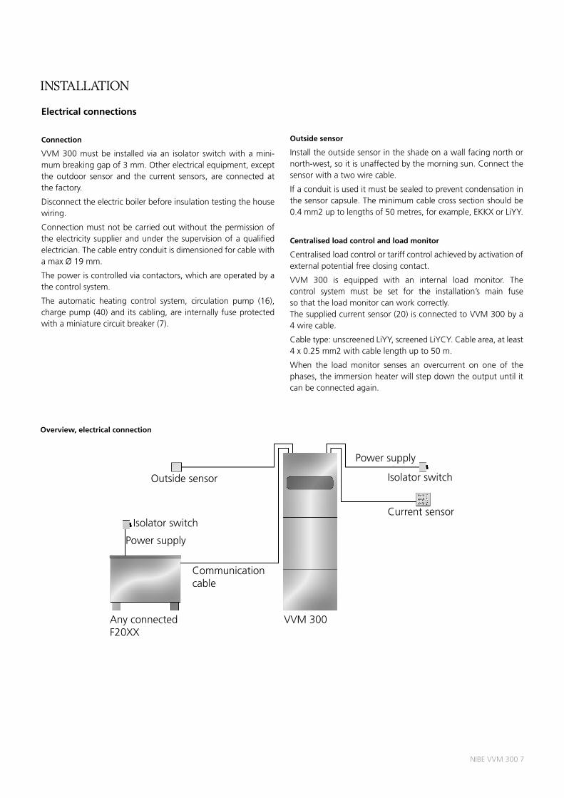
outside sensor
Isolator switch
Power supply
Communication cable
Current sensor
Isolator switch
Power supply
any connected F20XX
VVM 300
Overview, electrical connection
8 NIBE VVM 300
dockIngs
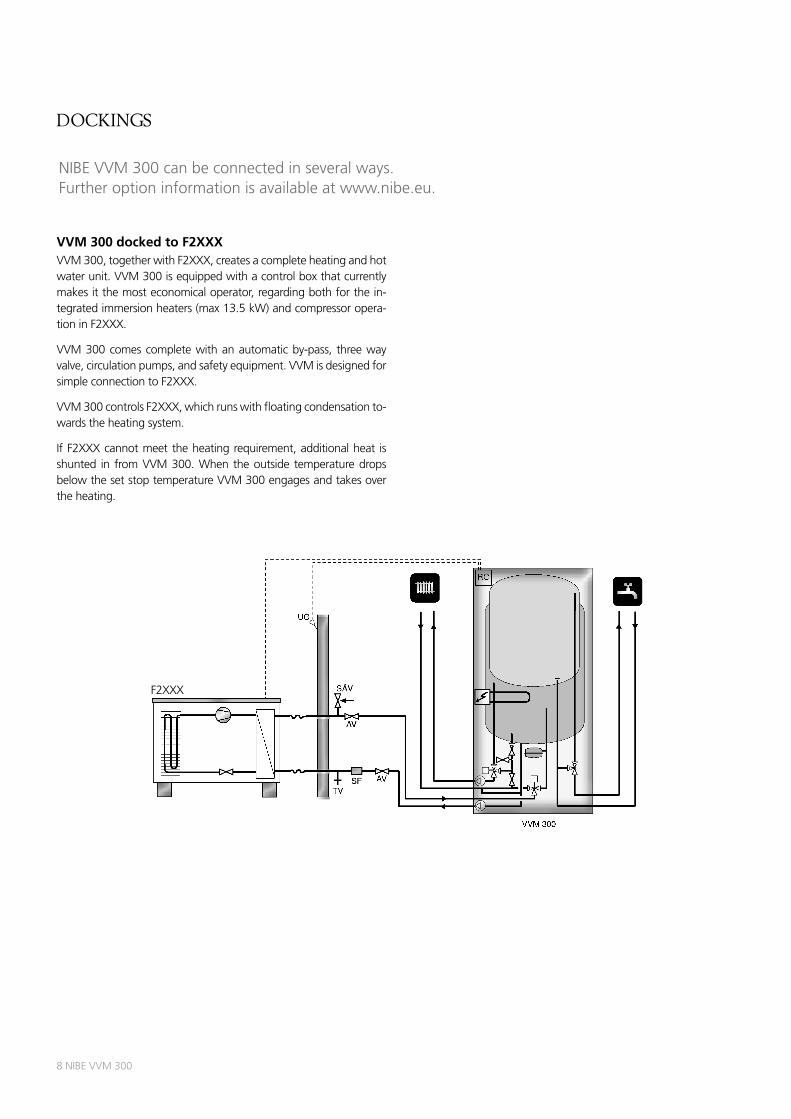
NIBE VVM 300 can be connected in several ways. Further option information is available at www.nibe.eu.
VVM 300 docked to F2XXXVVM 300, together with F2XXX, creates a complete heating and hot water unit. VVM 300 is equipped with a control box that currently makes it the most economical operator, regarding both for the in-tegrated immersion heaters (max 13.5 kW) and compressor opera-tion in F2XXX.
VVM 300 comes complete with an automatic by-pass, three way valve, circulation pumps, and safety equipment. VVM is designed for simple connection to F2XXX.
VVM 300 controls F2XXX, which runs with floating condensation to-wards the heating system.
If F2XXX cannot meet the heating requirement, additional heat is shunted in from VVM 300. When the outside temperature drops below the set stop temperature VVM 300 engages and takes over the heating.
F20XX
VVM 300
AV
AV
SÄV
SF
RC
TV
UG
F20XX
VVM 300
RC
52
63
44
4476
99
15
F2XXX
dockIngs
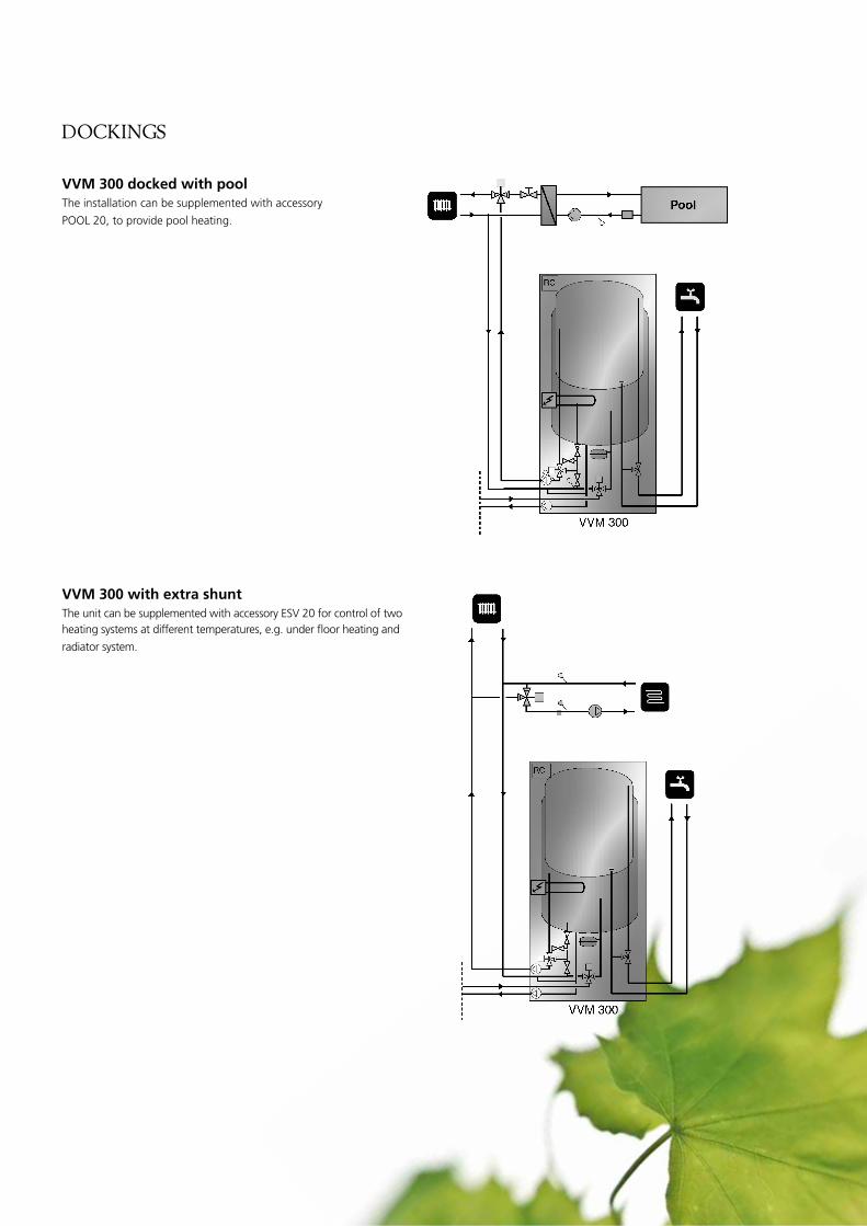
VVM 300 docked with poolthe installation can be supplemented with accessory
Pool 20, to provide pool heating.
VVM 300 with extra shuntthe unit can be supplemented with accessory ESV 20 for control of two heating systems at different temperatures, e.g. under floor heating and
radiator system.
99
95
VVM 300
RC
Pool
95
VVM 300
RC
10 NIBE VVM 300
technIcal specIfIcatIons
supplIed coMponents
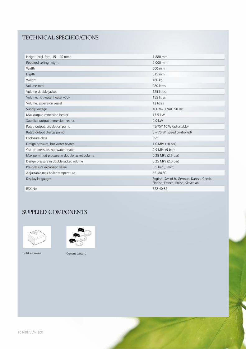
outdoor sensor Current sensors
Height (excl. foot: 15 – 40 mm) 1,880 mm
required ceiling height 2,000 mm
Width 600 mm
depth 615 mm
Weight 160 kg
Volume total 280 litres
Volume double jacket 125 litres
Volume, hot water heater (Cu) 155 litres
Volume, expansion vessel 12 litres
Supply voltage 400 V~ 3 NaC 50 Hz
Max output immersion heater 13.5 kW
Supplied output immersion heater 9.0 kW
rated output, circulation pump 45/75/110 W (adjustable)
rated output charge pump 6 – 70 W (speed controlled)
Enclosure class IP21
design pressure, hot water heater 1.0 MPa (10 bar)
Cut-off pressure, hot water heater 0.9 MPa (9 bar)
Max permitted pressure in double jacket volume 0.25 MPa (2.5 bar)
design pressure in double jacket volume 0.25 MPa (2.5 bar)
Pre-pressure expansion vessel 0.5 bar (5 mvp)
adjustable max boiler temperature 55 -80 °C
display languages English, Swedish, German, danish, Czech, Finnish, French, Polish, Slovenian
rSK No. 622 40 82
LEK
LEK
NIBE AB�
Utetemperatur givare�
Outdoor temperature sensor�
Aussentemperatur fühler�
Artikel 018764
LEK
LEK
LEK
NIBE VVM 300 11
accessorIes
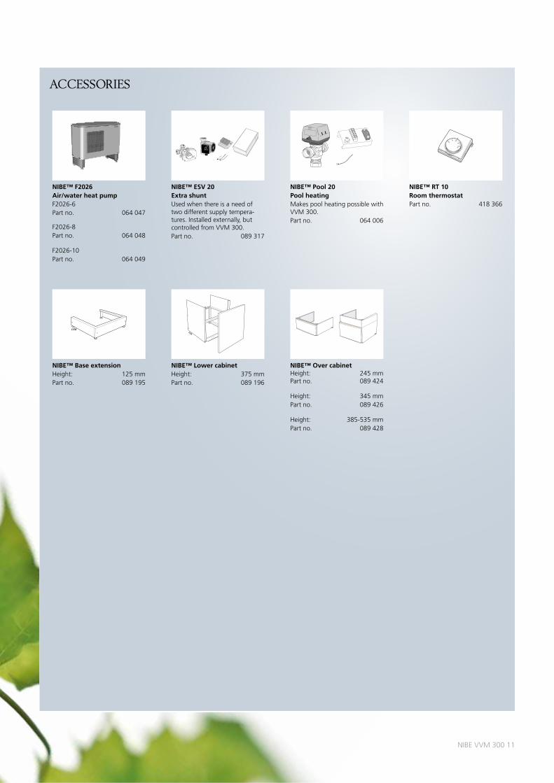
NIBE™ F2026Air/water heat pumpF2026-6Part no. 064 047
F2026-8Part no. 064 048
F2026-10Part no. 064 049
LEK
NIBE™ ESV 20Extra shuntused when there is a need of two different supply tempera-tures. Installed externally, but controlled from VVM 300.Part no. 089 317
HAHN
LEK
LEK
LEK
GR
UN
DFO
ST
ype
UP
S2
5 -
60
13
0P
/N:5
95
26
44
72
30
V-
HE
JSA
N
PC
;00
17
NIB
DK
50
Hz
IP
44
TF
11
0C
lass
H
Ma
x.
10
ba
r
2.5
uF
45
0.2
06
50
.30
90
0.4
0
1m(A
)P,
(W)
LEK
GR
UN
DFO
ST
ype
UP
S2
5 -
60
13
0P
/N:5
95
26
44
72
30
V-
HE
JSA
N
PC
;00
17
NIB
DK
50
Hz
IP
44
TF
11
0C
lass
H
Ma
x.
10
ba
r
2.5
uF
45
0.2
06
50
.30
90
0.4
0
1m(A
)P,
(W)
NIBE™ Pool 20Pool heatingMakes pool heating possible with VVM 300.Part no. 064 006
Plåt med kopplingsplint
VARNING
DATASKYLT 123456SERIENR. 123456
VVKV
LEK
NIBE™ RT 10Room thermostatPart no. 418 366
LEK
10
15 20
2530ϒC
NIBE™ Base extensionHeight: 125 mmPart no. 089 195
LEK
NIBE™ Lower cabinetHeight: 375 mmPart no. 089 196
LEK
NIBE™ Over cabinet Height: 245 mm Part no. 089 424
Height: 345 mmPart no. 089 426
Height: 385-535 mmPart no. 089 428
LEK
LEK

12 NIBE VVM 300
this brochure is a publication from NIBE. all product illustrations, facts and specifications are based on current information at the time of the publication’s approval. NIBE makes reservations for any factual or printing errors in this brochure. Printed by: aM-tryck & reklam. Photos: www.benfoto.se. ©NIBE 2011.
NIBE is ISo-certified: SS-EN ISo 9001:2000SS-EN ISo 14001:2004
6393
97 t
echn
ical
PBd
GB
NIB
E V
VM
300
114
3-1
MILJÖMÄRKT
307–005
NIBE Energy Systems aBBox 14285 21 MarkarydSWEdENtel. +46 433 - 73 000www.nibe.eu