Embed Size (px)
Citation preview

Vol.:(0123456789)
Wireless Personal Communications (2021) 120:2101–2115https://doi.org/10.1007/s11277-021-08550-9
1 3
Massive MIMO Systems for 5G Communications
Sinan A. Khwandah1 · John P. Cosmas4 · Pavlos I. Lazaridis2 · Zaharias D. Zaharis2 · Ioannis P. Chochliouros3
Accepted: 22 April 2021 / Published online: 8 May 2021 © The Author(s) 2021
AbstractMassive MIMO will improve the performance of future 5G systems in terms of data rate and spectral efficiency, while accommodating a large number of users. Furthermore, it allows for 3D beamforming in order to provide more degrees of freedom and increase the number of high-throughput users. Massive MIMO is expected to provide more advan-tages compared to other solutions in terms of energy and spectral efficiency. This will be achieved by focusing the radiation towards the direction of the intended users, thus imple-menting simultaneous transmission to many users while keeping interference low. It can boost the capacity compared to a conventional antenna solution, resulting in a spectral effi-ciency up to 50 times greater than that provided by actual 4G technology. However, to take full advantage of this technology and to overcome the challenges of implementation in a real environment, a complicated radio system is required. The purpose of this work is to present the MIMO technology evolution and challenges in a simple introductory way and investigate potential system enhancements.
Keywords MIMO · Beamforming · Massive MIMO · 3D MIMO
* Sinan A. Khwandah [email protected]
John P. Cosmas [email protected]
Pavlos I. Lazaridis [email protected]
Zaharias D. Zaharis [email protected]
Ioannis P. Chochliouros [email protected]
1 Solent University, Southampton, UK2 University of Huddersfield, Huddersfield, UK3 Hellenic Telecommunications Organization (OTE) S.A, Marousi, Greece4 Brunel University, London, UK

2102 S. A. Khwandah et al.
1 3
1 Introduction
The cellular infrastructure evolution has started from 1G analog systems in the 1980s fol-lowed by 2G digital systems like GSM, where the baseband unit, a digital unit connected to the telecom network, was co-located with the analog radio head unit in a shelter at the base of the antenna tower. Thick low-loss coaxial cables were used to connect these units to the antennas on the top of a tall tower with amplifiers to compensate for the loss of power along the coaxial cables. In recent 3G and 4G systems, distributed networks are used instead of traditional networks in 1G and 2G. In distributed networks, the radio unit, including all transmitting and receiving components with amplifiers, is split from the base-band unit and is placed on the top of the antenna tower. Long running coaxial cables that are lossy at high frequencies are replaced by fiber fronthauls carrying digital data up to the tower. This architecture achieves an important link gain because the radio head is placed next to the antennas. In 4.5G and 5G systems, the baseband processing unit will be central-ized [1]. The remote radio unit will be directly integrated with hundreds of antenna ele-ments, thus forming the massive MIMO scheme (Fig. 1).
The dramatic increase of wireless data traffic across the world puts significant pres-sure on the existing wireless communication systems. The limitation of spectrum avail-ability has directed telecom engineers towards mm-Wave frequencies, which require small radiating elements [2]. This scaling down of the antenna element size perfectly suits the requirement of massive MIMO, and makes these large-scale antenna arrays a promising technology [3]. Furthermore, an increased number of antenna elements leads to a better performance and an improved signal to interference-plus-noise ratio (SINR). In conven-tional MIMO systems, the maximum number of antenna elements used is 8 at the transmit-ter and another 8 elements at the receiver side (8 × 8 MIMO system). However, in massive MIMO and depending on the implemented prototype, for 5G new radio, the supporting BS antennas will be up to 256 and UE antennas will be up to 32 [4]. By increasing the number of elements of the antenna array, significant throughput and coverage improvements in cel-lular networks can be achieved. Moreover, the higher path loss due to high frequencies can be overcome by using multiple antenna elements to combine energy in required directions. This introduces beamforming techniques into MIMO and thus radio energy is concentrated in smaller angular sectors resulting in significant spectral efficiency improvement. With the introduction of massive MIMO, a new promising technique has emerged by additionally
Fig. 1 Antenna array for mm-Wave frequencies and the cellular infrastructure evolution

2103Massive MIMO Systems for 5G Communications
1 3
exploiting the elevation angle. This is called 3D MIMO and it is implemented by deploy-ing antenna elements in both horizontal and vertical dimensions. To achieve 3D MIMO, 3D beamforming must be implemented, allowing in this way the base station to adapt and dynamically control the transmission directions in both azimuth and elevation. This helps improve the system performance and accommodates the increasing capacity demand [5].
In order to identify the requirements and motivations of this advanced MIMO technol-ogy, this tutorial briefly addresses how massive MIMO evolved and why it is necessary for future 5G networks. This will be presented together with the critical technology of massive MIMO antenna arrays for evolving 4G into 5G and the challenges facing its deployment and measurement. Furthermore, practical issues and implementation based on real devices and in different environmental conditions are discussed.
In the following sections, first MIMO basics are introduced and then the advanced aspects are presented and analyzed. These aspects include the importance of beamform-ing, the importance of channel state information feedback, the pattern/polarization antenna array model for massive MIMO systems and finally 3D MIMO.
2 Single User‑MIMO & Multiple User‑MIMO
The simplest implementation of MIMO is the single-user MIMO (SU-MIMO) (release 8), where both the user equipment (UE) and the base station (BS) use multiple antennas. This enables them to support different types of transmission modes depending on channel con-ditions (Fig. 2). There are two distinct cases: transmit diversity where the same data is transmitted by multiple antennas simultaneously to boost SNR, and spatial multiplexing where independent data streams are sent on each antenna to increase capacity [6].
SU-MIMO is used today in LTE networks. The complexity of this scheme is based on the UE receiver because it needs to separate the different received data streams (interfer-ence due to multi stream transmission). For example, knowledge of the channel matrix H (that is a matrix which is made up of channel path coefficients) is not required at the trans-mitter side but it is required at the receiver side to decode the received signals. The receiver develops the channel knowledge by decoding the preamble or pilot data. This requires a lot of computational power to calculate the inverse channel matrix H−1 at the receiver side. However, performing all these calculations is not efficient when the receiver is a mobile device due to battery constrains. In MU-MIMO part of the complexity is moved to the base station, which has more computational power. In this case, a matrix W is applied at the
SU-MIMO
Tx Rx
x1
x2H-1
^ x1
x2^
Rx 1
Rx 2
MU-MIMO
Tx
s1
s2
^ x1
x2^
x1
x2W
h11
h12
h21
h22
r1
r2
h11
h21
h12
h22
=x1
x2
r1
r2
X=H-1R
R=HS^
w11
w21
w12
w22
=h11
h21
h12
h22
=s1
s2
h11
h12
h21
h22
x1
x2
s1
s2
x1
x2
^ ^
X=HS=HWX=(HW)X^
Fig. 2 SU-MIMO vs. MU-MIMO

2104 S. A. Khwandah et al.
1 3
transmitter side and performs a pre-weighting of the data [7]. To compute matrix W, dur-ing the channel coherence time, all the UEs transmit a number of uplink pilots at the same time. All the antennas of the base station receive the transmitted uplink pilots and compute the pre-weighting matrix W. The measured magnitude and phase due to the distance from each user to each element of the antenna array are used to precode the data streams and to distribute data streams to each antenna port. As a result, the receiver does not need to han-dle the multiuser spatial layer separation and each UE receives the data independently from the other UEs with an improved SINR.
3 From MU‑MIMO to Massive MIMO
Given that different SINR requirements are set for different users depending on the appli-cation (e.g., video downloading, internet browsing, texting, etc.), beamforming is vital to the system in order to achieve different SINRs over different users inside the same cell. Utilizing beamforming techniques in mm-Wave wireless communication systems aims to find the optimal path with a minimum loss to reach users and keep interference as low as possible.
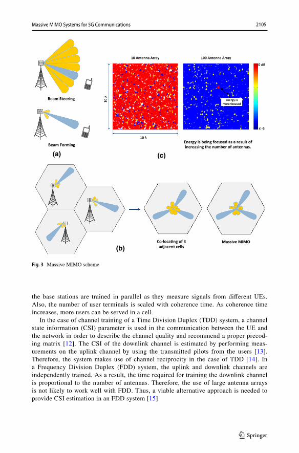
Before proceeding to beamforming, we will introduce beamsteering (Fig. 3a), which is performed by steering the antenna main lobe towards one of a number of predefined directions [8]. To decide which direction has to be used at the transmitter, several methods are applied such as transmitting orthogonal pilot signals on each of the predefined direc-tions. Then, the UE reports back to its serving cell BS on which signal is received with the highest power. Using beamsteering helps to improve signal strength levels in omnidirec-tional antenna cells, because signal strength decreases from the cell center towards the cell edge. By directing all the energy in a particular direction, SINR is significantly improved at the cell edge, moreover, several independent cells operating in the same region can be co-located without any form of co-ordination or cooperation and placed closely together (Fig. 3b). In this case, all the transmit antennas are co-located at the same place using beamsteering to direct the energy in a particular direction. Although co-locating improves the SINR at the cell edge, however, the side lobes are a matter of concern due to potential interference. This requires antennas with significantly reduced side lobes [9].
On the other hand, in beamforming, channel estimation is used. Antenna weighting compensation is applied in real time to form a beam directed towards the user of concern, instead of picking up one of a pre-defined directions as is the case in beamsteering.
In order to achieve beamforming, the number of antennas available at the base station must be at least ten times greater than the number of single antenna UEs located inside the cell [10]. The new structure of this large-scale MIMO (massive MIMO) is close to the case of co-location and enables the transmitters to focus the energy over a very narrow area through beamforming. By increasing the number of antennas, the power is better focused in a narrower beam and therefore at the receiver side, for any user, there is a higher signal level for that user while the other users receive lower signals as shown in Fig. 3c. Beam-forming results in significantly less wasted power in the coverage area. This, in turn, results in less interference and increases the spectral efficiency when using spatial multiplexing. This further helps to achieve important power savings [11].
The time required to estimate the channel (also known as channel training) of the massive MIMO system depends on the number of base station antennas used. The number of pilots received by these antennas is a function of the number of UEs and
2105Massive MIMO Systems for 5G Communications
1 3
the base stations are trained in parallel as they measure signals from different UEs. Also, the number of user terminals is scaled with coherence time. As coherence time increases, more users can be served in a cell.
In the case of channel training of a Time Division Duplex (TDD) system, a channel state information (CSI) parameter is used in the communication between the UE and the network in order to describe the channel quality and recommend a proper precod-ing matrix [12]. The CSI of the downlink channel is estimated by performing meas-urements on the uplink channel by using the transmitted pilots from the users [13]. Therefore, the system makes use of channel reciprocity in the case of TDD [14]. In a Frequency Division Duplex (FDD) system, the uplink and downlink channels are independently trained. As a result, the time required for training the downlink channel is proportional to the number of antennas. Therefore, the use of large antenna arrays is not likely to work well with FDD. Thus, a viable alternative approach is needed to provide CSI estimation in an FDD system [15].
100 Antenna Array10 Antenna Array
10 λ
10 λ
Energy is more focused
0 dB
≤ -5
Co-loca�ng of 3 adjacent cells
Massive MIMO
Beam Forming
Beam Steering
Energy is being focused as a result of increasing the number of antennas.
(a) (c)
(b)
Fig. 3 Massive MIMO scheme
2106 S. A. Khwandah et al.
1 3
4 Scheduling and Feedback for Massive MIMO
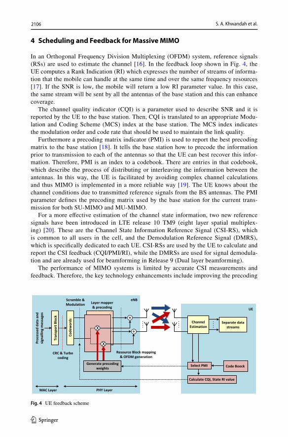
In an Orthogonal Frequency Division Multiplexing (OFDM) system, reference signals (RSs) are used to estimate the channel [16]. In the feedback loop shown in Fig. 4, the UE computes a Rank Indication (RI) which expresses the number of streams of informa-tion that the mobile can handle at the same time and over the same frequency resources [17]. If the SNR is low, the mobile will return a low RI parameter value. In this case, the same stream will be sent by all the antennas of the base station and this can enhance coverage.
The channel quality indicator (CQI) is a parameter used to describe SNR and it is reported by the UE to the base station. Then, CQI is translated to an appropriate Modu-lation and Coding Scheme (MCS) index at the base station. The MCS index indicates the modulation order and code rate that should be used to maintain the link quality.
Furthermore a precoding matrix indicator (PMI) is used to report the best precoding matrix to the base station [18]. It tells the base station how to precode the information prior to transmission to each of the antennas so that the UE can best recover this infor-mation. Therefore, PMI is an index to a codebook. There are entries in that codebook, which describe the process of distributing or interleaving the information between the antennas. In this way, the UE is facilitated by avoiding complex channel calculations and thus MIMO is implemented in a more reliable way [19]. The UE knows about the channel conditions due to transmitted reference signals from the BS antennas. The PMI parameter defines the precoding matrix used by the base station for the current trans-mission for both SU-MIMO and MU-MIMO.
For a more effective estimation of the channel state information, two new reference signals have been introduced in LTE release 10 TM9 (eight layer spatial multiplex-ing) [20]. These are the Channel State Information Reference Signal (CSI-RS), which is common to all users in the cell, and the Demodulation Reference Signal (DMRS), which is specifically dedicated to each UE. CSI-RSs are used by the UE to calculate and report the CSI feedback (CQI/PMI/RI), while the DMRSs are used for signal demodula-tion and are already used for beamforming in Release 9 (Dual layer beamforming).
The performance of MIMO systems is limited by accurate CSI measurements and feedback. Therefore, the key technology enhancements include improving the precoding
Fig. 4 UE feedback scheme

2107Massive MIMO Systems for 5G Communications
1 3
matrix feedback accuracy by employing analog CSI feedback and faster CQI feedback [21]. This will reflect the real channel quality, when CQI is measured on pre-scheduled CSI-RSs.
While scheduling in MU-MIMO is based on assigning a set of channel vectors to the UEs and depends on the accuracy of CSI, it is recommended for massive MIMO to con-sider the two-stage UE scheduling and feedback method (Fig. 5a), where the UEs are grouped into a number of groups and the channel feedback is reported per group. Figure 5b and c show a comparison between the two-stage scheme and other conventional methods, such as full CSI (where the base station collects CSIs of all UEs) and partial CSI feed-back approaches [22]. As shown in these figures, in the partial CSI feedback approach, the amount of feedback is relatively small but the downlink transmission performance is generally lower than that of the full CSI approach. On the other hand, the two-stage scheme results in a lower amount of feedback compared to partial CSI method but achieves a spec-tral efficiency very close to that of the full CSI feedback approach.
5 Massive MIMO Channel Capacity Improvement
The increase in the degrees of freedom, i.e., the flexibility of the base station antenna array to direct the beams when the number of antennas at the base station is much larger than the precoding vectors, is important and it will be considered for the antenna array model for massive MIMO [23]. The use of pattern/polarization antenna array in future massive MIMO system will help improve the spectral efficiency of the system. The
(b) (c)
(a)
Fig. 5 a The two-stage UE scheduling and feedback b Spectral efficiency comparison c Amount of feed-back comparison

2108 S. A. Khwandah et al.
1 3
idea is to benefit from two schemes. The first one is Beam Division Multiple Access (BDMA), which creates a number B of sectors through 3D beamforming instead of a single sector [24], while the second one is the pattern/polarization scheme. A com-bined scheme is called Pattern/Polarization Beam Division Multiple Access (P2BDMA). Figure 6a shows four different types (K = 4) of pattern/polarization antenna elements denoted by the O, △, □, ◇ symbols. The pattern/polarization antenna array is decom-posed into K virtual antenna arrays and each one of them produces a beam distributed in B sectors. If N is the number of UE antennas, then N by K channels can be realized
Sector 1Sector 1 Sector bSector bSector BSector B
K beams with the same angle
of departure (AoD)
K beams with the same angle
of departure (AoD)
Ver�c
al unit
s
Ver�
cal u
nits
1,11,1
1,K1,K
b,1b,1
b,Kb,K
B,1B,1
B,KB,K
Single sector model (B=1)
8 sector model (B=8, 2 ver�cal & 4 horizontal)
beambeam
beambeam beambeambeambeam
BDMA: K=1BDMA: K=1 P2BDMA: K=4 (beam sectoriza�on)
(a)
(b)
Fig. 6 a Pattern/polarization antenna elements for massive MIMO b Downlink spectral efficiency vs. SNR

2109Massive MIMO Systems for 5G Communications
1 3
per sector, and (N, K) symbols can be transmitted at least in the same time/frequency resource.
An increase in the possible polarization patterns in future massive MIMO will result in even more degrees of freedom [23]. This leads to a higher spectral efficiency which in turn improves the channel capacity by exploiting the low correlation characteristics of different pattern/polarization antenna channels. Figure 6b presents four different systems: the first one is a single 120° sector of the conventional three sector system (N = 4). The second is an 8 sector system composed by a single antenna array with vertical polarization only (BDMA: K = 1, N = 1). The third one is an 8 sector system composed by two virtual antenna arrays, one with vertical polarization, and the other with horizontal polarization (BDMA: K = 2, N = 2). Finally, the fourth one is an 8 sector system composed by four vir-tual antenna arrays with different pattern/polarizations from each other (P2BDMA: K = 4, N = 4).
As mentioned earlier, a large number of antenna elements are used in massive MIMO to generate the beam pattern. Due to the increase in the number of antenna elements, there is a concern on the amount of feedback that can cause serious overhead to the system. A proposed solution to this problem is the antenna grouping scheme (AGS). According to this scheme, the CSI is aggregated from groups of antenna elements and it is fed back by the UE.
#1#2
#5#6
#9#10
#13#14
#3#4
#7#8
#11#12
#15#16
G1
G2
G3
G4
Channel
Aggregated channel of G1
Aggregated channel of G2
Aggregated channel of G3
Aggregated channel of G4
Feedback
#1#2
#5#6
#9#10
#13#14
#3#4
#7#8
#11#12
#15#16
Channel
Aggregated channel of the 1st pa�ern
Aggregated channel of the 2nd pa�ern
Aggregated channel of the 3rd pa�ern
Aggregated channel of the 4th pa�ern
FeedbackSelected
Fig. 7 Antenna grouping (left) and pattern/polarization grouping (right)

2110 S. A. Khwandah et al.
1 3
The AGS is shown in Fig. 7, where the UE reports only 4 values by aggregating the CSI from four groups containing 16 antenna elements in total. To increase the func-tionality of this scheme, it is important to determine the assigned groups. For example, antennas that have the same radiation/polarization pattern are grouped and the appro-priate pattern/polarization is selected based on the channel information. In this way, different pattern/polarization schemes can be exploited over the same time/frequency resource [25].
6 3D MIMO
In order to meet the future demands of massive MIMO, a promising technology is 3D MIMO and it aims to solve the fitting problem of a large number of antenna elements (32 for example with a spacing of 0.5 λ) into the limited space available. In a 3D MIMO sys-tem (Fig. 8a), the radiation pattern can be controlled with respect to azimuth and elevation angles by properly modifying the excitation weights of the antenna array elements.
When the elevation is exploited together with the azimuth, a better average-cell and cell-edge performance is obtained compared to the conventional MIMO systems used in 4G-LTE networks [26]. TDD 3D-MIMO uses channel reciprocity and the gain is higher in field trials compared to the traditional 2D-MIMO. However, the above advantages require accurate operation in three dimensions and cause new challenges [27].
In order to support elevation beamforming with FD-MIMO and have a more precise control of the beamforming direction, transceiver units (TXRUs) are introduced to the transmitter to control the amplitude and phase of the excitation weights. However, a large number of TXRUs induces a great overhead of CSI-RS and an excessive CSI-RS resource consumption [28]. This requires high resolution CSI feedback and CSI report-ing mechanism with finer granularity of amplitude and phase to further improve the performance [29, 30]. The performance and feasibility of elevation beamforming for 3D MIMO has been investigated and it has been reported that different schemes (Fig. 8b) are beneficial for 3D MIMO and exhibit different throughput gains, while the best choice depends on the number of TXRUs [31]. Such schemes are the non-precoded scheme, where different CSI-RS ports use the same wide beam, the beamformed scheme, where CSI-RS ports use narrow beams that do not cover the entire cell, and the hybrid scheme, i.e., non-precoded & beamformed CSI.
In order to achieve the expected gain for 3D-MIMO, future systems must avoid mis-matches and comply with legacy systems [32]. Therefore, as far as 3D-MIMO is con-cerned, the specification of the system is still under enhancement and there still exists a large margin for improvement [33, 34].
3D MIMO improves the cell spectrum efficiency so that more users can be scheduled by eNB. As the number of connected users increases, there is a higher demand for refer-ence signals by the users and eNBs to estimate the channel. Therefore, the requirement for reference signal capacity would become higher, or else the actual supportable users would be limited in number [35, 36].
Mobility scenarios were addressed for future MIMO in order to achieve reliable transmission schemes. Moreover, issues concerning beam management enhancement, beam failure recovery and low-latency as well as highly reliable mm-Wave transmission are future research topics for LTE Rel-16 [37, 38].

2111Massive MIMO Systems for 5G Communications
1 3
Fig. 8 a. Azimuth and elevation beamforming b Non-precoded CSI-RS (top) vs. beamformed CSI-RS (bottom) Eleva�on
Beamforming
Azimuth Beamforming
FD-MIMO
FD-MIMO
FD-MIMO
CSI Feedback (PMI,RI, CQI)
+ CSI Feedback (PMI,RI, CQI)CRI (CSI-RS Resource Indicator)
(a)
(b)

2112 S. A. Khwandah et al.
1 3
7 Conclusions
In this paper, we have presented the background and advantages of future massive MIMO systems. The investigation indicates good performance due to the employed methods for the downlink channel such as user grouping and group-based feedback schemes. Furthermore, the adoption of the pattern/polarization antenna array model for massive MIMO shows an increase in the degrees of freedom of MIMO channels and thus an improved channel capacity.
The extension of the current technology into 3D MIMO would upgrade the existing implementation and allow flexible azimuth and elevation radiation patterns. 3GPP has developed specification support for FD-MIMO by enhancing the MIMO relevant refer-ence signal and CSI reporting mechanism. Finally, the uplink beamforming and channel reciprocity utilization at the UE side may be implemented as the number of antennas on UE is growing.
Open Access This article is distributed under the terms of the Creative Commons Attribution 4.0 Interna-tional License (http:// creat iveco mmons. org/ licen ses/ by/4. 0/), which permits unrestricted use, distribution, and reproduction in any medium, provided you give appropriate credit to the original author(s) and the source, provide a link to the Creative Commons license, and indicate if changes were made. The Creative Commons Public Domain Dedication waiver (http:// creat iveco mmons. org/ publi cdoma in/ zero/1. 0/) applies to the data made available in this article, unless otherwise stated.
References
1. Zhang, C., Huang, Y., Sheikh, F., & Wang, Z. (2017). Advanced baseband processing algorithms, circuits, and implementations for 5g communication. IEEE Journal on Emerging and Selected Top-ics in Circuits and Systems, 7(4), 477–490
2. Lin, Z., Du, X., Chen, H., Ai, B., Chen, Z., & Wu, D. (2019). Millimeter-wave propagation mod-eling and measurements for 5g mobile networks. IEEE Wireless Communications, 26(1), 72–77
3. Han, S., et al. (2015). Large-scale antenna systems with hybrid analog and digital beamforming for millimeter wave 5G. IEEE Communications Magazine, 53(1), 186–194
4. CATR. (2016). Discussion on the frame structure design for NR. 3GPP TDocs TSG RAN WG1, Busan, Korea, Tech. Rep. R1–163132, April.
5. Zhang, J., Yu, X., & Letaief, K. B. (2020). Hybrid beamforming for 5G and beyond millimeter-wave systems: A holistic view. IEEE Open Journal of the Communications Society, 1, 77–91
6. Guo, W., Fan, J., Li, G. Y., Yin, Q., & Zhu, X. (2017). Adaptive SU/MU-MIMO scheduling schemes for LTE-A downlink transmission. IET Communications, 11(6), 783–792
7. Clerckx, B., & Oestges, C. (2013). MIMO Wireless Networks: Channels Techniques and Standards for Multi-Antenna, Multi-User and Multi-Cell Systems. Cambridge: Academic Press.
8. Zhou, I., Ramírez, G. A., Montero, L., Blanch, S., Romeu, J., & Jofre, L. (2020). 3D Beamsteering low complexity reconfigurable multilevel antenna. IEEE Antennas and Wireless Propagation Let-ters, 19(6), 1017–1021
9. Han, C., Xiao, L., Chen, Z., & Yuan, T. (2020). Co-located self-neutralized handset antenna pairs with complementary radiation patterns for 5G mimo applications. IEEE Access, 8, 73151–73163
10. National Instruments, "Overview of massive MIMO for NR," 3GPP TDocs TSG RAN WG1, Nan-jing, China, Tech. Rep. R1–164117, May 2016.
11. Zhang, W., Xia, X., Fu, Y., & Bao, X. (2019). Hybrid and full-digital beamforming in mm wave massive MIMO systems: A comparison considering low-resolution ADCs. China Communications, 16(6), 91–102
12. Li, Q., Zhang, A., Liu, P., Li, J., & Li, C. (2020). A Novel CSI feedback approach for massive MIMO Using LSTM-attention CNN. IEEE Access, 8, 7295–7302

2113Massive MIMO Systems for 5G Communications
1 3
13. Luo, C., Ji, J., Wang, Q., Chen, X., & Li, P. (2020). Channel state information prediction for 5G wireless communications: A deep learning approach. IEEE Transactions on Network Science and Engineering, 7(1), 227–236
14. Raeesi, O., Gokceoglu, A., Zou, Y., Björnson, E., & Valkama, M. (2018). Performance analysis of multi-user massive MIMO downlink under channel non-reciprocity and imperfect CSI. IEEE Transactions on Communications, 66(6), 2456–2471
15. Liao, Y., Yao, H., Hua, Y., & Li, C. (2019). CSI Feedback based on deep learning for massive MIMO systems. IEEE Access, 7, 86810–86820
16. Ge, L., Zhang, Y., Chen, G., & Tong, J. (2019). Compression-based LMMSE channel estimation with adaptive sparsity for massive MIMO in 5G systems. IEEE Systems Journal, 13(4), 3847–3857
17. Zheng, F., et al. (2018). An Efficient CSI Feedback Scheme for Dual-Polarized Massive MIMO. IEEE Access, 6, 23420–23430
18. Penttinen, J. T. (2015). The Telecommunications Handbook Engineering Guidelines for Fixed Mobile and Satellite Systems. USA: Wiley.
19. Li, C., & Huang, K. (2019). Dual-codebook precoding selection for LTE-A system. IEEE Systems Journal, 13(1), 110–116
20. Tran, H., et al. (2018). On improvement of channel estimation for the uplink of large scale MU-MIMO using DMRS. IEEE 5G World Forum (5GWF), 294–298.
21. Huawei. (2016). “Motivation for rel-14 work on CSI and CQI enhancements for MIMO,” 3GPP TDocs TSG RAN, Göteborg, Sweden, Tech. Rep. RP-160291, March, 2016.
22. KT. (2016). “Considerations on enhanced user scheduling and feedback for massive MIMO”, 3GPP TDocs TSG RAN WG1, St Julian’s, Malta.
23. KT corp., (2016). "Considerations on antenna array model for massive MIMO,” 3GPP TDocs TSG RAN WG1, Tech. Rep. R1–160967.
24. Sun, C., Gao, X., Jin, S., Matthaiou, M., Ding, Z., & Xiao, C. (2015). Beam division multiple access transmission for massive MIMO communications. IEEE Transactions on Communications, 63(6), 2170–2184
25. KT Corp. (2016). “On the need of antenna grouping schemes for massive MIMO”, 3GPP TDocs TSG RAN WG1, Tech. Rep. R1–160968.
26. Xu, G., et al. (2017). Full dimension MIMO (FD-MIMO): Demonstrating commercial feasibility. IEEE Journal on Selected Areas in Communications, 35(8), 1876–1886
27. Shafin, R., & Liu, L. (2019). Multi-cell multi-user massive FD-MIMO: Downlink precoding and throughput analysis. IEEE Transactions on Wireless Communications, 18(1), 487–502
28. Media Tek. (2018). “Views on REL-16 MIMO enhancements,” 3GPP TDocs TSG RAN, Chennai, India, Tech. Rep. RP-180352, March.
29. Samsung. (2016). “Enhancements on full-dimension (FD) MIMO for LTE”, 3GPP TDocs TSG RAN, Göteborg, Sweden, Tech. Rep. RP-160623, March.
30. Huawei, HiSilicon (2018). “DL MIMO efficiency enhancements for LTE FDD” 3GPP TDocs TSG RAN, Chennai, India, Tech. Rep. RP-180367, March. 2018.
31. Samsung. (2015). “Elevation beamforming/full-dimension (FD) MIMO for LTE”, 3GPP TDocs TSG RAN, Malmö, Sweden, Tech. Rep. RP-150784, June.
32. Samsung, "Mismatched FD-MIMO configuration fields between RAN1 and RRC," 3GPP TDocs TSG RAN WG1, St Julian’s, Malta, Tech. Rep. R1–160520, Feb. 2016.
33. Huawei, HiSilicon, "New WI proposal on SRS enhancements for LTE" 3GPP TDocs TSG RAN WG1, Dubrovnik, Croatia, Tech. Rep. RP-170345, 2017.
34. 3GPP. (2019). “Maintenance of SRS (sounding reference signal) switching between LTE component carriers”, TSG-TSG RAN, Athens, Greece, Tech. Rep. R1–1903266.
35. ZTE, (2015). “Discussion on SRS Enhancements,” 3GPP TDocs TSG RAN, Fukuoka, Japan, Tech. Rep. RP-152983, May.
36. Huawei., HiSilicon., (2018). “Motivation for new WI proposal on DL MIMO efficiency enhancements for LTE TDD,” 3GPP TDocs TSG RAN, Chennai, India, Tech. Rep. RP-180366, March.
37. Huawei, HiSilicon, (2018). “Motivation for new WI proposal on NR MIMO enhancements”, 3GPP TDocs TSG RAN, Chennai, India, Tech. Rep. RP-180387, 2018.

2114 S. A. Khwandah et al.
1 3
38. Apple (2019) “View on Rel-16 MIMO enhancement WI multi-panel design scope”, 3GPP TDocs TSG RAN, Shenzhen, China, Tech. Rep. RP-190236.
Publisher’s Note Springer Nature remains neutral with regard to jurisdictional claims in published maps and institutional affiliations.
Sinan A. Khwandah received a BSc (Hons) degree in Electrical Engi-neering in 2004, a Diploma degree in Computer and Auto-Control in 2005, an MSc degree in Computer and Auto Control in 2009 from Damascus University; an MSc in Wireless Communication Systems in 2011 and a PhD from Brunel University London in 2015.Sinan is a skilled engineer in existing technologies and fulfilled education and experience requirements to be certified in several areas such as Certi-fied Radio Engineer from Telecoms Academy London and Cisco Sys-tems. Throughout his career, his research has been focused on commu-nication and networks. His latest research is concerned with cellular networks including radio planning and system optimisation, manage-ment of heterogeneous networks, MIMO, and network architecture. He is a member of the IEEE and the IET and is a Fellow of the Academy of Higher Education.
John P. Cosmas received the BEng degree in Electronic Engineering in 1978 from Liverpool University and the Ph.D. degree in 1986 from Imperial College, University of London. He is currently a Professor of Multimedia Systems in the College of Engineering, Design and Physi-cal Sciences at Brunel University London. He co-leads the Wireless Networks and Communications Research Centre, is the course director of MSc Advanced Multimedia Design and 3D Technologies and is an associate editor of IEEE Transactions on Broadcasting. He has partici-pated in eleven EU-IST and two EPSRC funded research projects since 1986 and he has led three of these (CISMUNDUS, PLUTO and 3D MURALE). His latest research is concerned with management of het-erogeneous cellular networks, convergence of cellular and ad-hoc net-works, 3D MIMO and efficient Software Defined Networks architectures.
Pavlos I. Lazaridis received the BSc degree in Electrical Engineering from Aristotle University of Thessaloniki, Greece, in 1990, the MSc in Electronics from Université Pierre & Marie Curie, Paris, France in 1992 and the PhD from ENST Paris, in 1996. From 1991 to 1996, he was involved with research on semiconductor lasers and wave propaga-tion for France Télécom and teaching at ENST Paris. In 1997, he became Head of the Antennas and Propagation Laboratory, TDFC2R Metz (Télédiffusion de France/France Télécom Research Center). From 1998 to 2002 he was senior Examiner at the European Patent Office (EPO), Den Haag, The Netherlands. From 2002 to 2014 he was teaching at the ATEI of Thessaloniki, Greece and Brunel University West London. He is currently a Professor in Electronic and Electrical Engineering at the University of Huddersfield, UK.
2115Massive MIMO Systems for 5G Communications
1 3
Zaharias D. Zaharis received the B.Sc. degree in physics, the M.Sc. degree in electronics, the Ph.D. degree, and the Diploma degree in electrical and computer engineering from the Aristotle University of Thessaloniki, Thessaloniki, Greece, in 1987, 1994, 2000, and 2011, respectively. From 2002 to 2013, he was with the administration of the telecommunications network, Aristotle University of Thessaloniki, and since 2013 he has been with the Department of Electrical and Com-puter Engineering of the same university. His current research interests include design and optimization of antennas and microwave circuits, signal processing on smart antennas, development of evolutionary optimization algorithms, and neural networks. Dr. Zaharis is a member of the Technical Chamber of Greece and a senior member of IEEE.
Ioannis P. Chochliouros received the Diploma of Electrical Engineer-ing from Aristotle University of Thessaloniki, Greece in 1984, the Diploma of Advanced Studies (M.Sc.) in Mechanics from Université Pierre et Marie Curie, Paris VI, France in 1990, and the PhD in Phys-ics and Telecommunications from Université Pierre et Marie Curie, Paris VI, France in 1994. He is Experienced Head of Research with a demonstrated history of working in the telecommunications industry. Skilled in LTE, Computer Science, Software Development, Internet Protocol (IP), and Security. He is Head of Research Programs Section at Hellenic Telecommunications Organisation and Head of Research Programs Section since 2005 at O.T.E. S.A. Before, from 2002 to 2005 he was Head of the Technical Regulations Section of the Standardiza-tion Division, Responsible for communication activities with Stand-ardization Bodies (ITU, ETSI, CEN, CENELEC) and Member of the European TCAM Committee at O.T.E. S.A.