Embed Size (px)
Citation preview

The Path Towards 5G:
Massive MIMO
Dr. Emil Björnson
Division of Communication SystemsDepartment of Electrical Engineering (ISY)Linköping University, Linköping, Sweden

Outline
• Introduction
• How to Achieve Higher Spectral Efficiency
• Basic Properties of Massive MIMO
• Massive MIMO Transmission Protocol
• 4 Myths and Misconceptions
• Research Trends and Open Questions
• Summary
2

INTRODUCTION
3

0
5
10
15
20
25
30
2014 2015 2016 2017 2018 2019 2020
Incredible Success of Wireless Communications
• Future Network Traffic Growth• 38% annual data traffic growth• Slightly faster than in the past!
• Exponential increase• Extrapolation: 5x in 5 years
25x in 10 years125x in 15 years
4
410 MB/month/person
3.2 GB/month/person
Source: Ericsson (November 2014)
Exabyte/month
Martin Cooper’s law
The number of voice/data connections has doubled every 2.5 years (+32% per year) since the beginning of wireless
Last 45 years: 1 Million Increase in Wireless Traffic
Two-way radio, FM/AM radio, satellites, cellular, WiFi, etc.
Source: Wikipedia

Evolving Networks for Higher Traffic
• Increase Network Throughput [bit/s/km2]• Consider a given area
• Simple Formula for Network Throughput:Throughputbit/s/km/
= Available spectrumHz
: Cell densityCell/km/
: Spectral efficiencybit/s/Hz/Cell
• Ways to Achieve 1000x Improvement:
5
More spectrum Higher cell density Higher spectral efficiency
Nokia (2011) 10x 10x 10x
SK Telecom (2012) 3x 56x 6x
New regulations,cognitive radio,mmWave bands
Ultra dense,heterogeneousdeployments
Massive MIMO(Topic of this talk)
?x

HIGHER SPECTRAL EFFICIENCYHow to achieve
6

Higher Spectral Efficiency
• Point-to-Point Spectral Efficiency:• Governed by Shannon’s capacity limit:
logA 1 +Received Signal Power
Interference Power + Noise Power [bit/s/Hz/user]
• Cannot do much: 4 bit/s/Hz à 8 bit/s/Hz requires 17 times more power!
• Many Parallel Transmissions: Spatially focused to each desired user
7
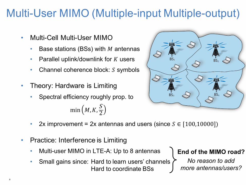
Multi-User MIMO (Multiple-input Multiple-output)
• Multi-Cell Multi-User MIMO• Base stations (BSs) with 𝑀 antennas• Parallel uplink/downlink for 𝐾 users
• Channel coherence block: 𝑆 symbols
• Theory: Hardware is Limiting• Spectral efficiency roughly prop. to
min 𝑀,𝐾, S 2
• 2x improvement = 2x antennas and users (since 𝑆 ∈ [100,10000])
• Practice: Interference is Limiting• Multi-user MIMO in LTE-A: Up to 8 antennas
• Small gains since: Hard to learn users’ channelsHard to coordinate BSs
8
End of the MIMO road?No reason to add
more antennas/users?
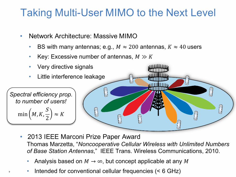
Taking Multi-User MIMO to the Next Level
• Network Architecture: Massive MIMO• BS with many antennas;; e.g., 𝑀 ≈ 200 antennas, 𝐾 ≈ 40 users• Key: Excessive number of antennas, 𝑀 ≫ 𝐾
• Very directive signals• Little interference leakage
• 2013 IEEE Marconi Prize Paper AwardThomas Marzetta, “Noncooperative Cellular Wireless with Unlimited Numbers of Base Station Antennas,” IEEE Trans. Wireless Communications, 2010.
• Analysis based on 𝑀 → ∞, but concept applicable at any 𝑀• Intended for conventional cellular frequencies (< 6 GHz)9
Spectral efficiency prop. to number of users!
min 𝑀,𝐾,S 2 ≈ 𝐾

What is the Key Difference from Today?
• Number of Antennas?• 3G/UMTS: 3 sectors x 20 element-arrays = 60 antennas• 4G/LTE-A: 4-MIMO x 60 = 240 antennas
10
Typical vertical array:10 antennas x 2 polarizationsOnly 1-2 antenna ports
3 sectors, 4 vertical arrays per sectorImage source: gigaom.com
160 antenna elements, LuMaMi testbed, Lund University
No, we already have many antennas!
Massive MIMO CharacteristicsMany small dipoles with transceiver chains
Spatial multiplexing of tens of usersMassive in numbers – not massive in size

Massive MIMO Deployment
• When to Deploy Massive MIMO?• The future will tell, but it can1. Improve wide-area coverage
2. Handle high user densities
• Co-located Deployment• 1D, 2D, or 3D arrays
• Distributed Deployment• Remote radio heads
11
Benefits with Massive MIMOOutdoor users: Handle mobility and provide coverage
Indoor users: No need to put BSs inside buildings

MASSIVE MIMOBasic Properties of
12
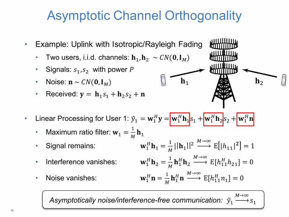
Asymptotic Channel Orthogonality
• Example: Uplink with Isotropic/Rayleigh Fading• Two users, i.i.d. channels: 𝐡Y,𝐡A ~ 𝐶𝑁(𝟎, 𝐈`)• Signals: 𝑠Y,𝑠A with power 𝑃
• Noise: 𝐧 ~ 𝐶𝑁(𝟎, 𝐈`)• Received: 𝐲 = 𝐡Y𝑠Y + 𝐡A𝑠A + 𝐧
• Linear Processing for User 1: 𝑦fY = 𝐰Yh𝐲 = 𝐰Y
h𝐡Y𝑠Y +𝐰Yh𝐡A𝑠A + 𝐰Y
h𝐧
• Maximum ratio filter: 𝐰Y =Y`𝐡Y
• Signal remains: 𝐰Yh𝐡Y =
Y`| 𝐡Y |A
`→j E |ℎYY|𝟐 = 1
• Interference vanishes: 𝐰Yh𝐡A =
Y`𝐡Yh𝐡A
`→j E[ℎYYh ℎAY] = 0
• Noise vanishes: 𝐰Yh𝐧 = Y
`𝐡Yh𝐧
`→j E[ℎYYh 𝑛Y] = 0
13
𝐡Y 𝐡A
Asymptotically noise/interference-free communication: 𝑦fY`→j
𝑠Y
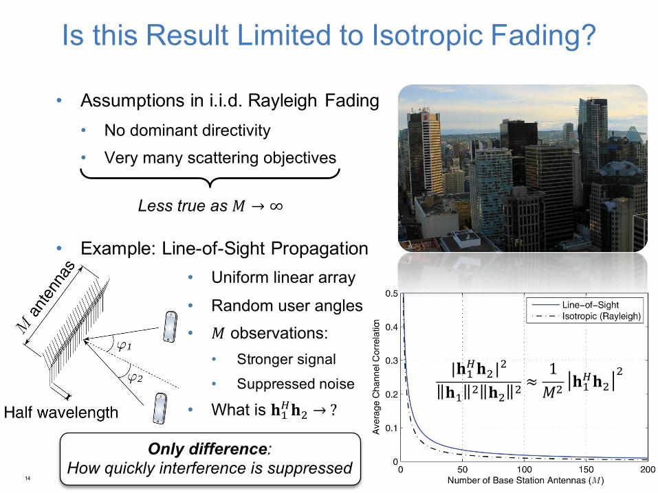
Is this Result Limited to Isotropic Fading?
• Assumptions in i.i.d. Rayleigh Fading• No dominant directivity• Very many scattering objectives
• Example: Line-of-Sight Propagation• Uniform linear array
• Random user angles• 𝑀 observations:
• Stronger signal• Suppressed noise
• What is 𝐡Yh𝐡A → ?
14
Less true as 𝑀 → ∞
Only difference: How quickly interference is suppressed
|𝐡Yh𝐡A|A
𝐡Y A 𝐡A A ≈1𝑀A 𝐡Yh𝐡A
A
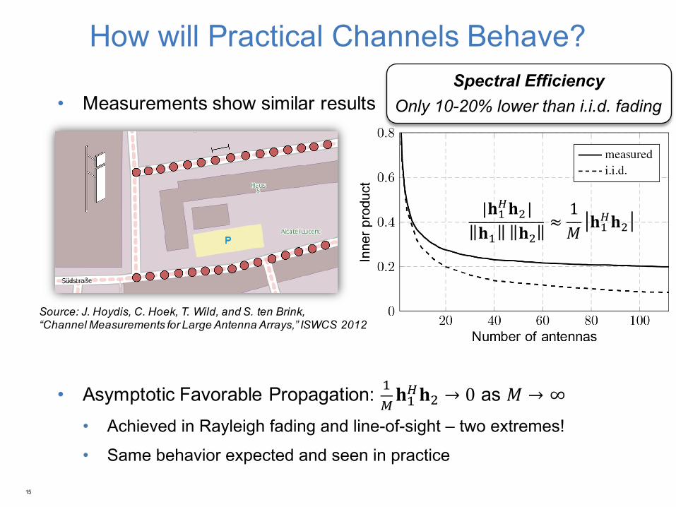
How will Practical Channels Behave?
• Measurements show similar results
• Asymptotic Favorable Propagation: Y`𝐡Yh𝐡A → 0 as 𝑀 → ∞
• Achieved in Rayleigh fading and line-of-sight – two extremes!
• Same behavior expected and seen in practice
15
Source: J. Hoydis, C. Hoek, T. Wild, and S. ten Brink, “Channel Measurements for Large Antenna Arrays,” ISWCS 2012
|𝐡Yh𝐡A|𝐡Y 𝐡A
≈1𝑀 𝐡Yh𝐡A
Spectral EfficiencyOnly 10-20% lower than i.i.d. fading
TRANSMISSION PROTOCOL
16
Massive MIMO
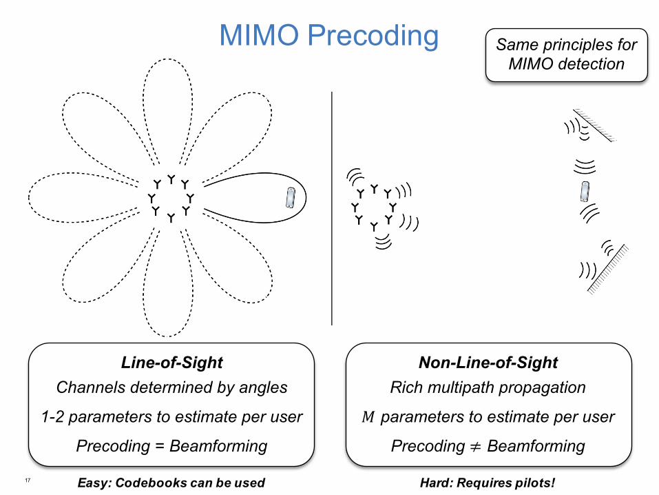
MIMO Precoding
17
Line-of-Sight Channels determined by angles
1-2 parameters to estimate per user
Precoding = Beamforming
Non-Line-of-SightRich multipath propagation
𝑀 parameters to estimate per user
Precoding ≠ Beamforming
Easy: Codebooks can be used Hard: Requires pilots!
Same principles for MIMO detection

Transmission Protocol
• Coherence Blocks• Fixed channel responses• Coherence time: 𝑇r s
• Coherence bandwidth: 𝑊r Hz• Depends on mobility and environment• Block length: 𝑆 = 𝑇r𝑊r symbols• Typically: 𝑆 ∈ [100,10000]
• Time-Division Duplex (TDD)• Switch between downlink and uplink on all frequencies• 𝐵 symbols/block for uplink pilots – to estimate channel responses (𝐵 ≥ 𝐾)• 𝑆 − 𝐵 symbols/block for uplink and/or downlink payload data
18
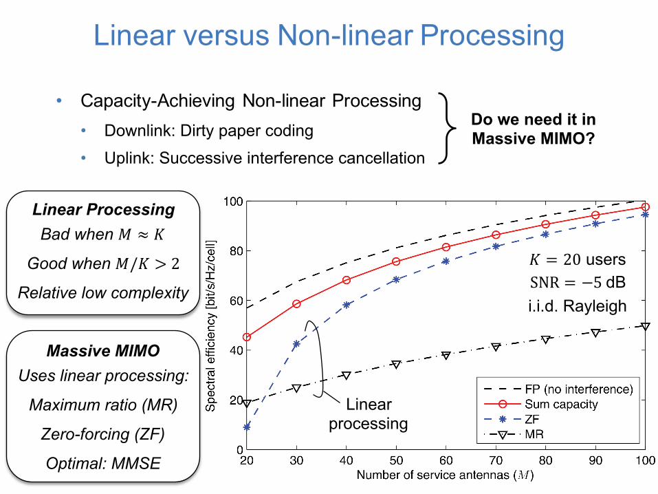
Linear versus Non-linear Processing
• Capacity-Achieving Non-linear Processing• Downlink: Dirty paper coding• Uplink: Successive interference cancellation
19
Do we need it in Massive MIMO?
Linear ProcessingBad when 𝑀 ≈ 𝐾
Good when 𝑀/𝐾 > 2
Relative low complexity
𝐾 = 20 usersSNR = −5 dBi.i.d. Rayleigh
Massive MIMOUses linear processing:
Maximum ratio (MR)
Zero-forcing (ZF)
Optimal: MMSE
Linear processing

Channel Acquisition in Massive MIMO
• BS Needs Channel Responses for Linear Processing• Estimate using uplink pilot symbols• Only 𝐵 pilot symbols available (𝐵 ≤ 𝑆)
• Must use same pilot symbols in different cells• BSs cannot tell some users apart
• Called: Pilot Contamination• Recall: Noise and interference vanish as 𝑀 → ∞• Not interference between users with same pilot!
• Solution: Select how often pilots are reused• Pilot reuse factor 𝛽 ≥ 1
• Users per cell: 𝐾 = |
• Higher 𝛽 à Fewer users per cell,but interferers further away
20 Pilot reuse 𝛽 = 4Pilot reuse 𝛽 = 1 Pilot reuse 𝛽 = 3
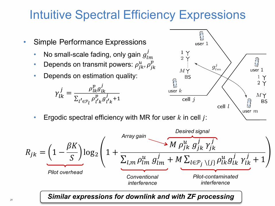
Intuitive Spectral Efficiency Expressions
• Simple Performance Expressions• No small-scale fading, only gain 𝑔
• Depends on transmit powers: 𝜌 , 𝜌
• Depends on estimation quality:
𝛾 =
∑
∈𝒫 Y
• Ergodic spectral efficiency with MR for user 𝑘 in cell 𝑗:
21
Pilot overheadConventional interference
Pilot-contaminated interference
Desired signal
Similar expressions for downlink and with ZF processing
Array gain
𝑅 = 1 −𝛽𝐾𝑆
logA 1 +𝑀 𝜌 𝑔
𝛾
∑ 𝜌 𝑔 +𝑀∑ 𝜌 𝑔
∈𝒫 \ 𝛾
, + 1

How Much can Spectral Efficiency be Improved?
22
Uplink SimulationLTE-like system parametersCoherence block: 𝑆 = 500SNR 5 dB, i.i.d. Rayleigh
ZF and 𝛽 = 3
Observations• Baseline: 2.25 bit/s/Hz/cell (IMT-Advanced)
• Massive MIMO, 𝑀 = 100: x20 gain (𝑀/𝐾 ≈ 6)
• Massive MIMO, 𝑀 = 400: x50 gain (𝑀/𝐾 ≈ 9)
• Per scheduled user: ≈ 2.5 bit/s/Hz

4 MYTHS AND MISCONCEPTIONS
23

Massive MIMO Relies on Asymptotic Results• No! Accurate theory for any 𝑀• Example:
𝑀 = 100, 𝐾 = 30QPSK with ½-LDPC codeTotal: 30 bit/s/Hz
• Reality:Rate expressions reachedat modest codeword lengths
24
Signal Processing Complexity is Overwhelming• Reality: It is higher, but manageable:• Most processing can be parallelized per antenna(e.g., FFTs, channel estimation, precoding/detection of data)
• Not parallelized: Computing ZF/MMSE matrix inversion, but:- Not the main complexity (happens only 1/𝑆 of the time)- Good inversion approximations (diagonal-dominant matrices)
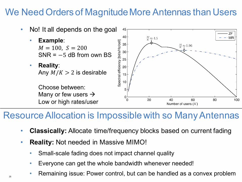
We Need Orders of Magnitude More Antennas than Users
• No! It all depends on the goal• Example:
𝑀 = 100, 𝑆 = 200SNR = −5 dB from own BS
• Reality:Any 𝑀/𝐾 > 2 is desirable
Choose between: Many or few users àLow or high rates/user
25
Resource Allocation is Impossible with so Many Antennas• Classically: Allocate time/frequency blocks based on current fading• Reality: Not needed in Massive MIMO!• Small-scale fading does not impact channel quality• Everyone can get the whole bandwidth whenever needed!• Remaining issue: Power control, but can be handled as a convex problem

RESEARCH TRENDS AND OPEN QUESTIONS
26

Research Trends and Open Questions
• Coexistence with Other Technologies• How to balance traffic load over BS types?• Can it tolerate underlaying (e.g., D2D)?
• Is TDD time synchronization manageable?• Are mmWave frequencies suitable?
• Implementation-Based Hardware and Algorithmic Design• Transceiver hardware is imperfect and affects the system:
• Fact: Massive MIMO tolerates larger hardware impairments• How to utilize this to tailor the transceiver hardware?• Data shuffling is a bottleneck: Develop easily implementable algorithms27

Can Massive MIMO work in FDD mode?
• Frequency-division duplex (FDD) is used in many systems• Different uplink/downlink frequencies à Two-way pilots & feedback needed
28
TDD versus FDDChannel coherence limits both antennas and users in FDD, but only users in TDD
FDD possible with low mobility
Open question
Can we reduce estimation and feedback load?
Yes, under channel sparsity: Exists in line-of-sight, but probably not in general!

SUMMARY
29

Summary
• Massive MIMO: The way to increase spectral efficiency in 5G networks• >20x gain over IMT-Advanced are foreseen• BSs with many small antennas and transceiver chains
• Higher spectral efficiency per cell, not per user• Many potential deployment strategies
• Facts to Remember• Massive MIMO ≠ Massive size: TV sized panels at cellular frequencies• Favorable propagation in most propagation environments
• Resource allocation and processing are simplified, not complicated
• Further Reading• Emil Björnson, Erik G. Larsson, Thomas L. Marzetta, “Massive MIMO: 10 Myths and One Grand Question,” Submitted to IEEE Commun. Magazine.30
QUESTIONS?
Dr. Emil Björnson
Slides and papers available online:http://www.commsys.isy.liu.se/en/staff/emibj29
Would you like to learn more?Come to Stockholm on June 29! I give a tutorial on this topic at IEEE SPAWC 2015!