Embed Size (px)
DESCRIPTION
r an2
Citation preview

J. Michael Pereira and Bradley A. LerchGlenn Research Center, Cleveland, Ohio
Effects of Heat Treatment on the BallisticImpact Properties of Inconel 718 for JetEngine Fan Containment Applications
NASA/TM—2001-209660
July 2001

The NASA STI Program Office . . . in Profile
Since its founding, NASA has been dedicated tothe advancement of aeronautics and spacescience. The NASA Scientific and TechnicalInformation (STI) Program Office plays a key partin helping NASA maintain this important role.
The NASA STI Program Office is operated byLangley Research Center, the Lead Center forNASA’s scientific and technical information. TheNASA STI Program Office provides access to theNASA STI Database, the largest collection ofaeronautical and space science STI in the world.The Program Office is also NASA’s institutionalmechanism for disseminating the results of itsresearch and development activities. These resultsare published by NASA in the NASA STI ReportSeries, which includes the following report types:
• TECHNICAL PUBLICATION. Reports ofcompleted research or a major significantphase of research that present the results ofNASA programs and include extensive dataor theoretical analysis. Includes compilationsof significant scientific and technical data andinformation deemed to be of continuingreference value. NASA’s counterpart of peer-reviewed formal professional papers buthas less stringent limitations on manuscriptlength and extent of graphic presentations.
• TECHNICAL MEMORANDUM. Scientificand technical findings that are preliminary orof specialized interest, e.g., quick releasereports, working papers, and bibliographiesthat contain minimal annotation. Does notcontain extensive analysis.
• CONTRACTOR REPORT. Scientific andtechnical findings by NASA-sponsoredcontractors and grantees.
• CONFERENCE PUBLICATION. Collectedpapers from scientific and technicalconferences, symposia, seminars, or othermeetings sponsored or cosponsored byNASA.
• SPECIAL PUBLICATION. Scientific,technical, or historical information fromNASA programs, projects, and missions,often concerned with subjects havingsubstantial public interest.
• TECHNICAL TRANSLATION. English-language translations of foreign scientificand technical material pertinent to NASA’smission.
Specialized services that complement the STIProgram Office’s diverse offerings includecreating custom thesauri, building customizeddata bases, organizing and publishing researchresults . . . even providing videos.
For more information about the NASA STIProgram Office, see the following:
• Access the NASA STI Program Home Pageat http://www.sti.nasa.gov
• E-mail your question via the Internet [email protected]
• Fax your question to the NASA AccessHelp Desk at 301–621–0134
• Telephone the NASA Access Help Desk at301–621–0390
• Write to: NASA Access Help Desk NASA Center for AeroSpace Information 7121 Standard Drive Hanover, MD 21076

NASA/TM—2001-209660
July 2001
National Aeronautics andSpace Administration
Glenn Research Center
J. Michael Pereira and Bradley A. LerchGlenn Research Center, Cleveland, Ohio
Effects of Heat Treatment on the BallisticImpact Properties of Inconel 718 for JetEngine Fan Containment Applications

Available from
NASA Center for Aerospace Information7121 Standard DriveHanover, MD 21076
National Technical Information Service5285 Port Royal RoadSpringfield, VA 22100
Available electronically at http://gltrs.grc.nasa.gov/GLTRS

1NASA/TM—2001-209660
EFFECTS OF HEAT TREATMENT ON THE BALLISTIC IMPACTPROPERTIES OF INCONEL 718 FOR JET ENGINE FAN
CONTAINMENT APPLICATIONS
J. Michael Pereira and Bradley A. LerchNational Aeronautics and Space Administration
Glenn Research CenterCleveland, Ohio 44135
SUMMARY
The effects of heat treating Inconel 718 on the ballistic impact response and failure mechanisms were studied.Two different annealing conditions and an aged condition were considered. Large differences in the static propertieswere found between the annealed and the aged material, with the annealed condition having lower strength andhardness and greater elongation than the aged. High strain rate tests show similar results. Correspondingly largedifferences were found in the velocity required to penetrate material in the two conditions in impact tests involving12.5 mm diameter, 25.4 mm long cylindrical Ti-6-4 projectiles impacting flat plates at velocities in the range of150 to 300 m/sec. The annealed material was able to absorb over 25 percent more energy than the aged. This is con-trary to results observed for ballistic impact response for higher velocity impacts typically encountered in militaryapplications where it has been shown that there exists a correlation between target hardness and ballistic impactstrength. Metallographic examination of impacted plates showed strong indication of failure due to adiabatic shear.In both materials, localized bands of large shear deformation were apparent and microhardness measurements indi-cated an increase in hardness in these bands compared to the surrounding material. These bands were more localizedin the aged material than in the annealed material. In addition the annealed material underwent significantly greateroverall deformation before failure. The results indicate that lower elongation and reduced strain hardening behaviorlead to a transition from shear to adiabatic shear failure, while high elongation and better strain hardening capabili-ties reduce the tendency for shear to localize and result in an unstable adiabatic shear failure. This supports empiricalcontainment design methods that relate containment thickness to the static toughness.
INTRODUCTION
International aviation regulatory agencies, such as the FAA in the United States, require that aircraft turbine jetengines safely contain fan, compressor, and turbine blades should they be ejected during operation [1]. To achievethis requirement, all commercial turbine jet engines include some type of engine blade containment system. In somecases this consists of a metal ring that is thick enough and strong enough to prevent penetration of a blade. Steel,aluminum, and titanium systems are currently in use. Other systems are more complex, consisting of relatively lightmetal or composite rings, a structure such as honeycomb to provide stiffness, and a series of layers of woven aramidfabric to contain the blade. Fabric systems can substantially reduce the weight [2]. However, for high temperatureapplications, such as around parts of the compressor and the turbine region, or for fans in supersonic applicationswhere conditions are more demanding, it is necessary to use metal containment systems.
While metal systems can be heavy, it is possible to minimize the weight through proper design, material selec-tion and material heat treatment. However, other than by conducting ballistic impact tests, there is currently no reli-able method to predict how a material will perform under impact conditions. Sophisticated computer programs areavailable to simulate impact events, but they rely on accurately modeling the constitutive behavior and deformationand fracture mechanisms that occur. This is still an area of active research and is not yet at a point where accuratepredictions of material behavior can be obtained.
There have been a number of investigations aimed at correlating ballistic impact performance with relativelyeasily measured material properties. A review of some of these studies [3] indicated that hardness measurements ofsteel armor showed surprisingly good correlation with ballistic penetration properties, and that there was also somecorrelation between Charpy impact test values and the ballistic limit, the velocity required for a projectile to pen-etrate a specimen in a particular test configuration. A study by Sangoy et al. [4] concluded that a basic requirementfor ballistic armor is that it has high hardness. An interesting conclusion of this study was that for low hardness

2NASA/TM—2001-209660
steels, where failure occurs as a result of plastic flow in the target, and for high hardness steels, where projectilefracture occurs, there is a strong correlation between the target material hardness and the ballistic limit. However,in the intermediate regime, where the failure is dominated by adiabatic shear, the ballistic limit decreases withhardness.
Impact tests on two titanium alloys [5] found no correlation between the ballistic limit and either fracture tough-ness or Charpy V-notch toughness. This was supported by a study by Burkins and Love [6] in which the effects ofthe annealing temperature on the ballistic limit of Ti-6Al-4V were measured. The results of this study showed thatchanges in annealing temperature affected the tensile strength, yield strength, strain to failure, toughness and Charpyimpact strength. However, there was no clear correlation between any of these properties and the ballistic limit. Itshould be pointed out that the change in static properties due to the annealing was modest.
A number of empirical and analytical models have been developed to predict the ballistic performance of metalsbased on easily measured material and geometric properties [7]. In many of these models [8 and 9] the perforationenergy is proportional to the tensile or yield strength. Corbett and Reid [10] compared a number of empirical modelswith experimental results and found that the onset of adiabatic shearing is a critical factor in determining the impactresistance of plates. Recht [11] reported that catastrophic shear occurs when local temperature gradients offset thestrengthening effects of strain hardening and the slope of the true stress-strain function becomes zero. Under impactconditions involving high strain rates, high strength alloys exhibit unusual behavior in that the rate of work softeningarising from the heat generated in plastic flow is greater than the rate of work hardening so that a catastrophic sheardevelops on a narrow shear plane [12].
Jones et al. [13] used a structural method of analysis formulated using thin plate theory and a rigid-perfectlyplastic yield model to analyze the response of circular plates struck by flat faced cylindrical projectiles. Their modelaccurately predicted the inelastic structural response of plates for relatively heavy projectiles, but they concludedthat the model retained insufficient local detail for failure analysis. A similar analysis was performed by Liu andStronge [14], but their model included the influence of both shear and radial tensile strain on localized failure of theplate. They found that the inclusion of the effects of radial tensile strain yielded more accurate results than thoseobtained with a pure shear failure criterion and for thin plates gave reasonable agreement with experimental resultsof the ballistic limit. The effects of temperature were not included in the model. Li and Jones [15] showed that forthick beams, circular plates, and cylindrical shells subjected to impulsive pressure loading shear ruptures and adia-batic shear failures appear with increasing load and intensity and that there may exist a transition between these twofailure mechanisms that require different material and failure models in analysis and simulation. This analysis pro-duced the critical conditions necessary for the onset of adiabatic shear failures under these loading conditions, butdue to the nature of these conditions, this analysis cannot be applied to the problem being addressed in this study.
Bai and Johnson [16] formulated an analytical model to predict energy absorbed during plugging of a plate by aflat-faced cylinder. This model assumes that only shear strains are present. It incorporates a temperature dependentconstitutive relationship and a critical shear strain at which thermoplastic shear instability occurs. The critical shearstrain is a function of the specific heat of the material, its strain hardening index, and its thermal softening behavior.The model predicts that increases in both the strain hardening index and the critical shear strain increase the amountof energy absorbed in plugging with the critical shear strain being the most influential. The model also predicts thatas the thickness of the plate increases, the energy absorbed per unit thickness begins to level off.
Because of its importance in military applications, much of the ballistic impact work in the literature is relevantto ordnance impact speeds in the vicinity of 1000 m/sec or higher, and typically involve relatively thick targets.There appears to be no static property that correlates well with ballistic impact strength, with the possible exceptionof hardness. Failure modes are highly dependent on the geometry of the target and the projectile and the physicalconstraints of the target. Thin metal plates which are allowed to undergo large structural deformations are morelikely to fail under tension than thick plates which are more likely to fail under shear in a plugging mode [17]. Toevaluate the impact properties of a material for a certain application, it is necessary to conduct experiments underconditions that simulate the use conditions. At impact, velocities that occur in fan containment applications, whichare typically less than 500 m/sec and involve targets that are usually thin relative to the projectile, the failure mecha-nisms are likely to be different from those occurring in high velocity impacts, and the relationship between staticmaterial properties and ballistic impact properties could also be different. Empirically based procedures used forcontainment design currently rate materials according to an approximation of the area under the static stress-straincurve [18]. However, this is just a rule of thumb with a limited range of applicability and the mechanisms behind
3NASA/TM—2001-209660
this relationship are not well understood. Since it is unclear what static properties, if any, are correlated with theballistic limit, and since a good understanding of the failure process is needed to model ballistic failure in contain-ment systems, this study was undertaken. Herein, the failure mechanisms and the relationships between static andballistic impact properties in Inconel 718, at impact velocities pertinent to jet engine blade containment applications,were investigated.
MATERIALS
Three lots of rolled plate material were used in this investigation. Each lot had a unique thickness (1.0, 1.8,2.0 mm), so that thickness effects could be studied. The material was purchased to meet AMS Specification 5596and the composition of each lot, as given by the manufacturer, is shown in Table 1. No major compositional differ-ences were observed among the lots. Inconel 718 has a density of 8.19 gm/cm3 (0.297 lb/in.3) a thermal conductivityof 11.4 W/(m-°C) (79 BTU-in./ft2-hr-°F)) and a specific heat, Cv, of 435 J/Kg °C (0.104 BTU/lb °F) [22].
Heat Treatments
To investigate how mechanical properties affect ballistic properties, it was desirable to vary the mechanicalproperties as much as possible. It has been shown that annealed versus aged In-718 yield vastly differing mechanicalproperties [19]. A small heat treatment study was performed on the 1.8 mm thick material to verify this range ofproperties. Several rectangular, flat tensile specimens, 150 mm in length by 12.7 mm wide were heat treated to oneof several heat treatments shown in Table 2.
The specimens were tested at room temperature in a servohydraulic test machine. They were first run in straincontrol at a strain rate of 0.001/sec. The specimens were loaded up to a strain of 1.9 percent, and then unloaded tozero load. Strain was measured using a 12.7 mm gage length extensometer. These strain measurements allowed anaccurate determination of the elastic modulus and the yield points. A diametral extensometer was also used to mea-sure the transverse strain to enable calculations of Poisson’s ratio. After the unload, the extensometers were removedand the specimen was loaded to failure in stroke control. A loading rate of 0.076 mm/sec was used. Failure strainwas calculated based on a crosshead displacement over a 25.4 mm gage length and was simply the change in lengthdivided by the original length.
The tensile curves are shown in Fig. 1. The data fell into two categories; moderate strength and high strain tofailure (annealed), and high strength with moderate ductility (aged). Based on the results of these tensile tests, thethree conditions A, B and C, shown in Table 3, were chosen for use with the ballistic impact tests. In addition, im-pact test results were compared with those from a previous study [20] on the same material. In the study of Ref. 20,the material was treated as shown by condition D in Table 3. The microstructure of the In-718 plates consisted ofequiaxed grains (Fig. 3) with occasional carbide particles. The average grain sizes were an ASTM 6 for the 1.0 mm,ASTM 4 for the 1.8mm, and ASTM 9 for the 2.0 mm thick materials. The annealed and aged materials of the samethickness had identical grain sizes.
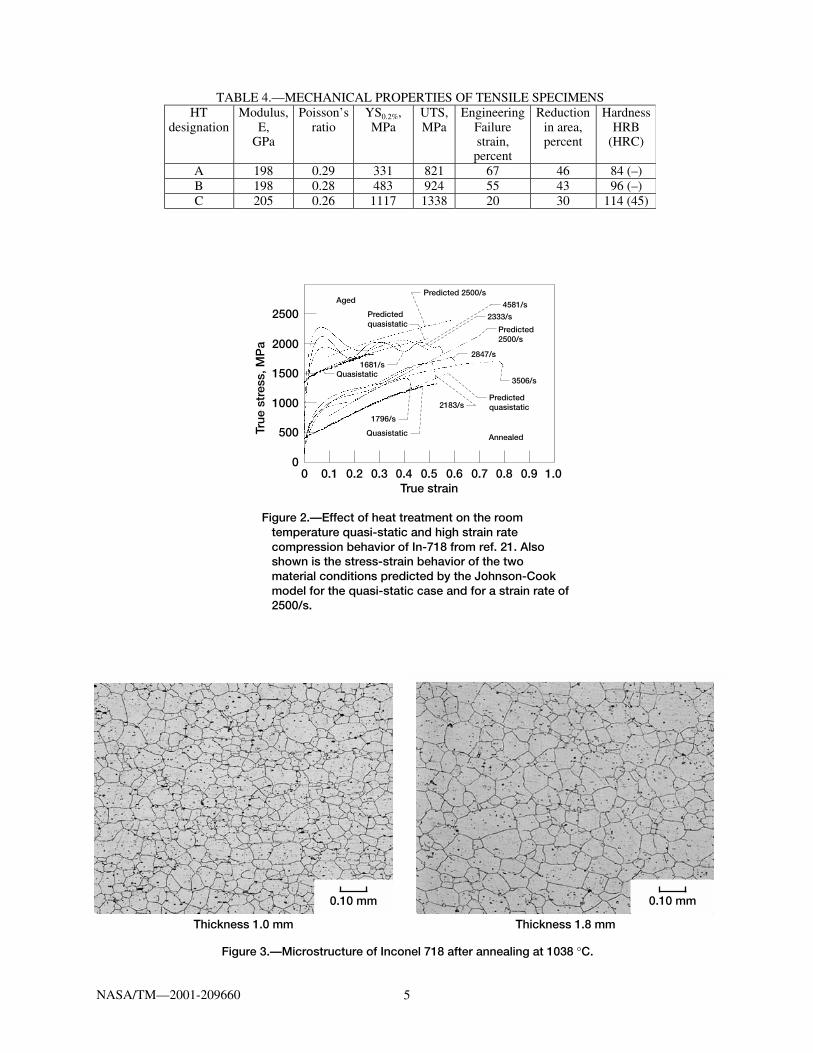
The tensile properties for heat treatments A, B and C are given in Table 4. Note that the 0.2 percent yieldstrength of the aged material is approximately three times that of the annealed, the UTS of the aged is one and a halftimes that of the annealed, while the ductility of the annealed material is substantially greater than the aged material.Note also the large difference in hardness values; the annealed material is softer. These differences in properties aresufficiently large to allow us to assess any possible effects of tensile properties on ballistic impact behavior. In fact,it would be difficult to find a material which exhibited such a wide range of tensile properties without completelyembrittling the alloy and rendering it unsuitable for engineering purposes.
In a separate study, quasi-static and high strain rate compression testing was conducted on In-718 in conditionsA and C [21]. These tests were conducted using a 19 mm diameter split Hopkinson Bar. Specimens were circulardisks with a diameter of 6.35 mm and a thickness of 3.18 mm. Tests were conducted in the strain range of 1600 to5000 /sec. The results of these tests are shown in Fig. 2. Like the quasi-static tensile data there is a marked differ-ence in the response of the material in the two conditions. An important feature is the significantly greater strainhardening behavior of the material in the annealed condition.

4NASA/TM—2001-209660
TABLE 1.—COMPOSITION OF In-718 PLATES (wt. %)Thickness,
mmNi Fe Cr Nb Mo Ti Al Mn Si Ta Co C
1.0 52.8 balance 18.2 5.05 2.98 1.03 0.51 0.22 0.14 <0.05 0.11 0.051.8 52.3 balance 18.2 5.11 3.04 1.05 0.50 0.22 0.14 <0.05 <0.05 0.052.0 52.7 balance 18.4 5.13 3.06 1.00 0.54 0.10 0.08 0.02 0.08 0.04
TABLE 2.—HEAT TREATMENTS USED FOR STATIC TESTINGAnnealing conditions
(1) Annealed at 1037 °C/1h in vacuum + quick cool in argon
(2) Annealed at 954 °C/1h in vacuum + quick cool in argon
(3) Mill-annealed (as-received condition)Aging conditions
Anneal (1) + 718 °C/8h in vacuum, cool at 38 °C/h to 621 °C, hold at 621 °C/8h, quick cool in argon
Anneal (2) + 718 °C/8h in vacuum, cool at 38 °C/h to 621 °C, hold at 621 °C/8h, quick cool in argon
Anneal (1) + 760 °C/6h in vacuum + quick cool in argon
Anneal (2) + 760 °C/6h in vacuum + quick cool in argon
TABLE 3.—ANNEALING AND AGING CONDITIONS CHOSEN FOR IMPACT TESTINGHeat treatment
designationCondition
A Annealed at 1037 °C/1h (vac.) + quick cool
B As received condition (mill-annealed)C A + 718 °C/8h (vac.), cool at 38 °C/h to 621 °C, hold at 621 °C/8h, quick cool
Da B + 718 °C/8h, cool at 38 °C/h to 621 °C, hold at 621 °C/8h, air coolaHeat treatment used with 350×350 mm panels from Ref. [20].
(2) + (4)(1) + (4) (2) + (5)
(2)(1) + (5)
Aged
Annealed
1600
1400
1200
1000
800
600
400
200
–0.1 0 0.1 0.2 0.3Engineering strain
0.4 0.5 0.6 0.7 0.80
Str
ess,
MP
a (3)(1)
(1) Anneal at 1037 °C/1 hr, quick cool(2) Anneal at 954 °C/1 hr, quick cool(3) Mill-annealed(4) Age at 718 °C/8 hr, cool at 38 °C/hr to 621 °C, hold at 621 °C/8 hr(5) Age at 760 °C/6 hr
Figure 1.—Effect of heat treatment on the room temperature tensile behavior of In-718 sheet specimens.
5NASA/TM—2001-209660
Aged
Annealed
4581/s
Predicted 2500/s
Predicted2500/s
Predictedquasistatic
Predictedquasistatic
Quasistatic
Quasistatic
2333/s
2847/s
2183/s
1796/s
3506/s
1681/s
2500
2000
1500
1000
500
0 0.1 0.2 0.3 0.4True strain
0.5 0.6 0.7 1.00
True
str
ess,
MP
a
0.8 0.9
0.10 mm 0.10 mm
Thickness 1.0 mm Thickness 1.8 mm
Figure 3.—Microstructure of Inconel 718 after annealing at 1038 °C.
Figure 2.—Effect of heat treatment on the room temperature quasi-static and high strain rate compression behavior of In-718 from ref. 21. Also shown is the stress-strain behavior of the two material conditions predicted by the Johnson-Cook model for the quasi-static case and for a strain rate of 2500/s.
TABLE 4.—MECHANICAL PROPERTIES OF TENSILE SPECIMENSHT
designationModulus,
E,GPa
Poisson’sratio
YS0.2%,MPa
UTS,MPa
EngineeringFailurestrain,percent
Reductionin area,percent
HardnessHRB
(HRC)
A 198 0.29 331 821 67 46 84 (–)B 198 0.28 483 924 55 43 96 (–)C 205 0.26 1117 1338 20 30 114 (45)

6NASA/TM—2001-209660
The data of Fig. 2 were used to determine the room temperature material constants for the strength componentof the Johnson-Cook model [22] for the In-718 in the two different conditions. The Johnson-Cook model is anempirically based representation of the flow stress defined as
σ = [A + Bεn][1 + C 1n ε·*][1 – T*m] (1)
where s is the flow stress, e is the effective plastic strain, e·* is the effective plastic strain rate, usually normalized toa strain rate of 1.0/s, n is the work hardening exponent and A, B, C and m are constants. T* is defined as
T* = (T – 298)/(Tmelt
– 298) (2)
where T is the temperature in Kelvin and Tmelt is the melting temperature of the material. At room temperatureT* = 0.
For the annealed material, the parameters were determined to be A = 400 MPa, B = 1798 MPa, n = .9143, andC = .0312. For the aged material the parameters were determined to be A = 1350 MPa, B = 1139 MPa, n = .6522and C = .0134. Figure 2 shows the correlation between the Johnson-Cook model with the above constants and thequasi-static tensile data. Also shown is the predicted response from the model at a strain rate of 2500/s.
BALLISTIC IMPACT TESTING
During impact of a containment system by a fan blade large structural deformations occur. To study any rela-tionships that may exist between material properties and impact response relevant to the problem at hand, the targetand projectile dimensions and velocities used in this study were selected to allow relatively large structural deforma-tions while maintaining a controlled experiment. Ballistic impact tests were conducted on specimens of all threethicknesses shown in Table 1. The 1.0 and 1.8 mm impact specimens were treated according to the three conditionsshown in Table 3. The 2.0 mm impact specimens were only tested in the mill annealed condition (Condition B).The impact specimens were 17.8 cm (7 in.) square panels and were centered and clamped over a 15.24 cm (6 in.)square hole in a 1.27 cm (0.5 in.) thick steel plate. Typical impact specimens are shown in Fig. 4. Specimens usedin Ref. 20 were 35.5 cm (14 in.) square panels, centered and clamped over a 30.5 cm (12 in.) square hole in a1.27 cm (0.5 in.) thick steel plate.
The projectile used in the present study and in Ref. 20 was a Ti-6-4 cylinder with a length of 2.54 cm (1 in.)and a diameter of 1.27 cm (0.5 in.). The impacting face was flat with a radius of 0.8 mm (1/32 in.) machined aroundthe perimeter of the impacting surface. The hardness of the projectile was 32 HRC and its mass was in the range of14.05 to 14.20 gm. The projectiles were accelerated toward the specimens at normal incidence using a gas gun witha 1.8 m (6 ft) long, 1.27 cm (0.5 in.) inner diameter barrel shown in Fig. 5. The ballistic limit for each heat treatmentcondition and thickness was determined by conducting a number of impact tests, typically seven, which bracketedas closely as possible the velocity required to penetrate the specimen. The ballistic limit was chosen, somewhatarbitrarily, to be approximately the average of the highest velocity for which no penetration occurred, and thelowest velocity at which penetration occurred. It is estimated that the error in the ballistic limit is within ±6 m/sec(~3 percent). A measure of the extent of the impact damage was made by placing the panel on a surface plate andmeasuring the height of the permanent deformation in the damage zone. The height of the permanent deformationwas either the height of the edge of the hole, if penetration occurred, or the maximum height of the dent if penetra-tion did not occur. This measurement will henceforth be called deflection. Some of the specimens were sectionedand mounted for metallographic examination. In addition, microhardness measurements were made in the largedeformation areas of the specimens. Standard polishing techniques were used for the In-718. However, due to theintense nature of the deformation, a special etching procedure was developed to reveal the deformation withoutburning the surface. The following etching procedure was used: Electrolytically etch at 4V in a solution of10 g CrO3 + 100 ml water. Remove stains by swabbing with Tucker’s reagent. Repeat as needed.

7NASA/TM—2001-209660
Figure 4.—Typical test specimens in the initial, nonperforated and perforated conditions.
Figure 5.—50 caliber gas gun facility.

8NASA/TM—2001-209660
RESULTS
For the initial heat treatment study, the quasi-static stress-strain curves fell into two groups (Fig. 1). The an-nealed material exhibited moderate strength and high elongation while the annealed plus aged material exhibitedhigh strength and moderate elongation. The hardness for these materials was measured to be ~90 HRB for the soft,annealed materials and 45 HRC for the harder, aged materials (C and D). The figure includes the three conditionsused in the subsequent impact tests, as well as the heat treatment condition used in Ref. 20. It should be noted thatthe curve in Fig. 1 designated by “(2) + (4)” was taken from tests on the material from the present study heat treatedin the same way as in Ref. 20. However, it is expected that the material with condition D used in Ref. 20 wouldhave a similar response to this.
TABLE 5.—IMPACT TEST RESULTSSpec. ID Thickness,
mmHeat treatcondition
Rockwellhardness
Deflectionheight, h,
mm
Damagetype
Impactvelocity,
m/secGA70 1.83 Annealed 95 HRB 18.0 Perforated 281GA71 1.83 Annealed 95 HRB 18.0 Perforated 275GA72 1.85 Annealed 95 HRB 17.9 Perforated 273GA73 1.80 Annealed 95 HRB 20.0 Non 258GA74 1.85 Annealed 95 HRB 17.8 Perforated 269GA75 1.80 Aged 45 HRC 10.8 Perforated 258GA76 1.83 Aged 45 HRC 9.4 Perforated 248GA77 1.85 Aged 45 HRC 9.9 Non 226GA78 1.80 Aged 45 HRC 10.9 Non 243GA79 1.83 Aged 45 HRC 9.2 Perforated 245GA60 1.04 Annealed 95 HRB 23.6 Non 190GA61 1.07 Annealed 95 HRB 23.9 Non 192GA63 1.04 Annealed 95 HRB 23.6 Non 193GA64 1.12 Annealed 95 HRB 25.0 Non 198GA62 1.04 Annealed 95 HRB 14.3 Perforated 200GA65 1.04 Aged 45 HRC 8.4 Perforated 187GA66 1.07 Aged 45 HRC 10.3 Perforated 175GA67 1.04 Aged 45 HRC 10.2 Non 167GA68 1.12 Aged 45 HRC 10.4 Non 172GA69 1.09 Aged 45 HRC 9.2 Perforated 166GA87 2.06 Mill Anneal 82 HRB 11.7 Perforated 297GA88 2.06 Mill Anneal 82 HRB 14.8 Non 262GA89 2.06 Mill Anneal 82 HRB 16.5 Non 281GA90 2.03 Mill Anneal 82 HRB 15.5 Perforated 284
TABLE 6.—BALLISTIC LIMIT FOR In 718Heat
treatmentAreal weight,
kg/m2Ballistic limit
velocity,m/sec
Ballistic impactenergy,
JA 8.35 198 277A 14.60 265 497B 8.35 192 260B 14.60 277 543B 16.70 282 562C 8.35 168 198C 14.60 244 420D 8.35 171 206D 14.60 241 409

9NASA/TM—2001-209660
350
300
250
200
150
100181716151413121110987
Areal weight, kg/m2
Imp
act
velo
city
, m/s
ec PenetrationNo penetration
350
300
250
200
150
100181716151413121110987
Areal weight, kg/m2
Imp
act
velo
city
, m/s
ec
PenetrationNo penetration
350
300
250
200
150
100181716151413121110987
Areal weight, kg/m2
Imp
act
velo
city
, m/s
ec
PenetrationNo penetration
Figure 6.—Impact velocity and penetration results forInconel 718 annealed at 1038 °C—Condition A.
Figure 7.—Impact velocity and penetration results forInconel 718 in the as-received condition—Condition B.
Figure 8.—Impact velocity and penetration results for aged Inconel 718—Condition C.
Table 5 lists the velocities and results of the impact tests, as well as a measure of the resulting deflection thatoccurred. Impact test velocities for each of the thickness and heat treatment conditions is shown in Figs. 6 to 8. Theballistic limit for each condition extracted from these data is shown in Table 6, and includes the ballistic limit forheat treatment D, taken from Ref. 20. In this table, areal weight refers to the weight per unit area of the material, orsimply the product of the density and the thickness. This is a relevant measure for fan containment systems since, ingeneral, the overall geometry of the system will be similar, irrespective of the material used. A plot of these data isshown in Fig. 9 and includes the penetration velocity for the 2 mm thick plate in the mill annealed condition (B).For all thicknesses, the annealed material with a lower hardness, moderate strength and higher elongation had supe-rior impact energy absorbing properties compared to the aged material with a higher hardness, higher strength andmoderate elongation. For the 1.0 mm thick specimens there was an average increase of 33 percent in the ballisticimpact energy of the annealed over the aged material. For the 1.8 mm thick material the average increase was25 percent. This is contradictory to results in the literature for high velocity impacts [3 and 4] where it was foundthat high hardness materials exhibited greater impact resistance.
Metallographic examination of the specimens showed that for both sets of heat treating conditions, the impactproduced a circular band of shear deformation extending from the corners of the projectile at the impacted surfaceto the back surface of the plate at an angle of roughly 45° from the plate normal (Fig. 10). There was significantlymore overall deformation in the annealed specimens than the aged specimens as shown by the amount of deflection

10NASA/TM—2001-209660
350
300
250
200
150
100181716151413121110987
Areal weight, kg/m2
Imp
act
velo
city
, m/s
ecCondition
ABCD
AnnealedAged
Figure 9.—Impact velocity and penetration results for Inconel 718 as a function of areal weight and heat treatment.
Figure 10.—Shear deformation pattern in impacted specimen.
in Fig. 11. There was essentially no permanent deformation in the projectiles. Microscopic examination (Fig. 12(a))showed that the annealed specimen exhibited what appeared to be an intense deformation band originating from thecorner of the projectile impact. This band was somewhat ill-defined in structure and extended in width over~10 grains. In nonperforated samples, the band did not reach the back face of the plate. A higher magnification ofthis band (Fig. 12(b)) shows that this was not a true band, but rather a collection of intensely deformed grains,which etched darker than the surrounding grains. The surrounding grains were also heavily deformed, but not tothe extent of those in the band. A microhardness profile was taken across the band. Vicker’s hardness ranged from~260 (100 HRB) in areas far removed from the band (yet still in the deformed region) to a hardness of ~400(41 HRC) in the band itself.
The aged samples had a much finer deformation structure as shown in Fig. 13. Attempts to bring out visibleshear bands were limited. This was partially due to the multitude of fine slip bands in each grain and partially dueto the poor etching characteristics of the aged samples. At areas of intense shear (i.e., projectile impact corners),some evidence of well-defined macroscopic bands was observed, but these were generally short and narrow, oftenconnecting carbide particles. Compared to the apparent bands observed in the annealed material (Fig. 12), thebands in the aged material were much narrower, and often multiple bands could be observed in one grain. Similarmicrohardness profiles were performed with similar results to those in the annealed material. However, the hardnessvalues were higher in all locations due to the fact that the material was originally aged. The hardness ranged from400 (41 HRC) remote from the shear zone to 500 (49 HRC) in the shear zone.
Close examination of the back surface of both the aged and annealed materials revealed shear bands at45° angles to the surface of the plate and at multiple locations near the plug. Shear bands caused a V-notch at thesurface of the plate (Fig. 13). In specimens that were not perforated, cracks were observed emanating from thenotches and propagating along the shear bands. These were the only evidence of cracking in the nonperforatedspecimens. Similar notches and shear bands have been observed in explosively bonded In-718 [23].
DISCUSSION
At high strain rates there is essentially no strain hardening in the aged In-718, as shown by the flat curves inFig.2. This differs from the quasi-static behavior which exhibits a good amount of strain hardening. This behavior isalso different from the annealed material which has a large amount of strain hardening, even at high strain rates. TheJohnson-Cook model was able to reproduce the quasi-static behavior of both material conditions and could predictthe high strain rate data from the annealed material. However, the model was unable to predict the high strain ratedata for the aged material.

11NASA/TM—2001-209660
(a) (b)
(h)(h)
Figure 11.—a) Comparison of overall deformation in aged specimen. b) Annealed specimen. Each specimen was impacted at a velocity slightly below its ballistic limit.

12NASA/TM—2001-209660
(a) 0.5 mm 50.0 �m(b)
20.0 �m(b)0.5 mm(a)
Figure 12.—a) Region of intense shear deformation in annealed specimen. b) Higher magnification shows a collection of intensely deformed grains rather than highly localized shear bands.
Figure 13.—a) Region of intense shear deformation in aged specimen. b) Higher magnification shows highly localized shear bands.
Under the conditions used in this study, annealed In-718 has greater impact resistance than the aged material.The annealed material can absorb more plastic deformation before penetration occurs. This is evident from the de-flection measurements in Table 5 and shown visually in Fig. 11. The large deflections in the annealed specimens, asillustrated in Fig. 4 produced some undesirable features in the experiment. Because of the large deflections, theboundary conditions may have had some effect on the results. Preliminary tests using 15 and 30 cm apertures in theimpact test fixture showed no significant differences in the measured ballistic limit, but the overall deflections couldhave been effected. Also, while the projectile impacted the specimen with normal incidence, failure in the specimenwas not always symmetrical, and often a plug partially separated, forming a flap. This is illustrated in Fig. 4. Whilethis may be an artifact caused by some interaction with the boundaries it is not unusual for this type of behavior tooccur. Woodward [12] noted that in plugging failures several bands are observed to nucleate and propagate indepen-dently, leading to asymmetry in the failure region.
The static toughness, as measured by the area under the stress-strain curve, is greater for the annealed materialthan the aged, as shown in Fig. 1. The improvement in impact resistance of the annealed material is consistent withgeneral guidelines for designing containment systems that correlate larger areas under the static stress-strain curve

13NASA/TM—2001-209660
with enhanced impact properties [18]. However, the improved impact resistance may be more related to the failuremechanisms rather than simply the area under the stress-strain curve. This measurement of toughness is differentfrom a Charpy or KIC fracture toughness, both of which deal with the energy required to propagate a crack. The areaunder the stress-strain curve is more related to the absorption of plastic deformation before failure and may not eveninvolve a crack until the last moments of the tensile test. It should be pointed out that for In-718, Charpy impactresults also showed that the annealed material is tougher than the aged [19]. Thus for In-718, Charpy values appearto correlate with ballistic toughness. However, is not the case for all materials, as illustrated by the results of Burkinsand Love [6] who found no correlation between Charpy impact results and ballistic impact resistance in Ti-6-4.
The hardness of the Ti-6-4 projectile used in the impact tests was intermediate between that of the annealed andthe aged target material. In general, the ballistic limit velocity decreases when the projectile hardness exceeds that ofthe target [24]. Therefore it is possible that these test results underestimate the greater effectiveness of the annealedover the aged material. However, the results are relevant to jet engine containment systems in which the fans aretypically Ti-6-4.
The annealed material appears to better absorb energy by diffusing the macroscopic shear zone over a widerarea (Fig. 12). Whereas Fig. 12 indicates that a diffuse macroshear band is formed, high magnification examinationof this area revealed that bands per se are not formed. Instead, the grains in this area of intense shear are justmore heavily deformed and therefore etch darker than the surrounding grains. This is also indicated by themicrohardness profiles, which revealed a higher hardness in the “band” region, typical of more work hardening(plastic deformation) and agrees with hardness readings taken near shear bands in other materials [25 to 28]. Atleast at low magnification, these apparent bands appear similar to those observed in brass [29 and 30] and copper[30 and 31]. In these cases more homogeneous bands formed under isothermal conditions associated with neckingduring tensile tests. Broad and diffuse bands were also observed in copper under punch-loaded conditions [32].
In contrast, the aged material does show narrow shear bands, thus constricting the later stages of deformationto thin zones, typical of adiabatic shear bands [33]. It has been suggested [25 and 34] that shear localization in-creases with decreasing strain hardening and increasing strength, both of which are exhibited by the aged material.This would explain why the aged material has definite shear band formation and the annealed material does not.Additionally, aged In-718 deforms by the shearing of ordered precipitates [35]. During this process, the precipitatesare reduced in size within the slip plane, as successive dislocations approach and shear the precipitates. Conse-quently, slip within this active plane is easier than on a neighboring inactive slip system. This would encourageshear bands to be narrow. The annealed In-718 does not have ordered precipitates and therefore slip on an existingsystem can only get more difficult due to dislocation tangles (work hardening). The zone of deformation spreads toneighboring, weaker planes forming a broad diffuse band. For adiabatic shear to occur, the amount of softening dueto the local temperature increase must equal the rates of strain and strain rate hardening [36]. Softening can be as-sisted by precipitate shearing. The annealed material shows significantly greater strain hardening behavior underhigh strain rate conditions. Therefore, based on the above discussion, as well as the model of Bai and Johnson [16]discussed in the introduction, one would expect the aged In-718 to have more of a tendency to form adiabatic shearbands than the annealed.
Shear localization can also result from the geometry of the specimen and target and the constraints placed onthem [34]. It can be seen in Fig. 9 that for the mill-annealed material, the increase in penetration velocity slowedas the thickness of the specimen increased. A possible explanation for this is that the greater bending stiffness of thethicker (2 mm) panel constrained the amount of deformation that could take place. This in fact can be seen by thereduction in the deflection measurements in Table 5. This result is consistent with the model of Bai and Johnson[16] which predicts that as the thickness of the plate increases, the energy absorbed per unit thickness begins tolevel off. Metallography revealed no difference in the deformation structure as these specimens also containedbroad, diffuse bands just like the other annealed samples. The thickest material did have a smaller grain size(ASTM 9 compared to an ASTM 6 for the intermediate thickness), but this is not believed to have reduced the slopeof the curve. It is possible that the reduction in the slope of the curve was simply experimental variation since thethick material was from a different study and was added here just for completeness. Examination of additionalthicknesses, especially greater than 2.06 mm, would have helped to clarify whether the slope of the curve continuesto increase with increasing thickness, or if it levels off as suggested in Fig. 9. However, the existing impact facilitywas unable to produce the velocities required to penetrate thicker plates.
Post test analysis of the deformation and fracture behavior of the plates suggest the following scenario. Uponimpact, the flat-bottomed projectile compresses the material underneath it. Simultaneously, the plate is deflected inthe direction of the impact. Bands of intense deformation form at the location of the projectile corners, but for sub-

14NASA/TM—2001-209660
critical velocities do not propagate completely through the thickness. On the back side, shear bands form causingnotches on the surface (Fig. 14). Cracks often form within these bands probably due to the high tensile stresses onthe back surface. Cracking presumably occurs from the front surface as well, but it was never observed in thenonperforated samples. One can assume that if the velocity is high enough to cause cracking on the front surface,the projectile will perforate the plate. Therefore, front side cracking could be used as a critical condition for predict-ing failure in these tests. Since the cracks on the back surface will also propagate, there is a competition between thefront and back side cracks. This often led to a chiseled-shaped fracture surface. Jones et al. [13] observed similarfailure behavior in aluminum alloys when impacted by flat faced cylindrical projectiles, where failure on the proxi-mal surface lead to complete failure across the plate thickness. In contrast, they found that for mild steel, which hasa high adiabatic shear strength [16], impact failure under similar conditions is dominated by material failure on thedistal side.
SUMMARY
Under the conditions used in this study, the softer, annealed Inconel 718 performed significantly better than theharder aged material. This is in contrast to results in the literature for higher velocity impacts, which indicate thatballistic limit increases with hardness. The results presented here suggest that toughness may be a better predictor ofballistic impact resistance for the type of failure mechanism and impact velocity associated with fan containmentevents with Inconel 718. The results indicate that high elongation and better strain hardening capabilities reduce thetendency for shear to localize and result in an unstable adiabatic shear failure. This supports empirical containmentdesign methods that relate containment thickness to the static toughness.
REFERENCES
1. Federal Aviation Regulations Part 33.94. U.S. Federal Aviation Administration.2. Smith, G.T.: Composite Containment Systems for Jet Engine Fan Blades. NASA TM–81675. 1981.3. Wong, A.K. and Connors, M.L.: A Literature Survey on Correlation of Laboratory Tests and the Ballistic Resistance of
Rolled Homogeneous Steel and Aluminum Armors. Army Materials and Mechanics Research Center, Report no.AMMRC SP 72–10, Sept., 1971.
4. Sangoy, L., Meunier, Y. and Pont, G.: Steels for Ballistic Protection. Israel J. Technology, 24, pp. 319–326, 1988.5. Fanning, J.C.L.: Terminal Ballistic Performance of TIMETAL 62S. Eighth World Conference on Titanium. The Institute
of Materials. Birmingham, U.K., 1995.6. Burkins, M. and Love, W.: Effect of Annealing Temperature on the Ballistic Limit Velocity of Ti-6Al-4V ELI plates.
Presented at AeroMat ’96, June 1996, Dayton, OH.7. Corbett, G.G., Reid, S.R. and Johnson, W.: Impact Loading of Plates and Shells by Free-Flying Projectiles:
A Review, Int. J. Impact Engng., Vol. 18(2), pp. 14–1230, 1996.
50.0 �m
Figure 14.—Notches on back surface produced by high tensile stresses and the resulting shear bands.
15NASA/TM—2001-209660
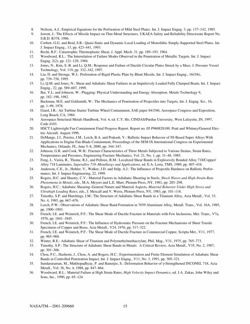
8. Neilson, A.J.: Empirical Equations for the Perforation of Mild Steel Plates. Int. J. Impact Engng. 3, pp. 137–142, 1985.9. Jowett, J.: The Effects of Missile Impact on Thin Metal Structures. UKAEA Safety and Reliability Directorate Report No.
S.R.D. R378, 1986.10. Corbett, G.G. and Reid, S.R.: Quasi-Static and Dynamic Local Loading of Monolithic Simply-Supported Steel Plates. Int.
J. Impact Engng., 13, pp. 423–441, 1993.11. Recht, R.F.: Catastrophic Thermoplastic Shear, J. Appl. Mech. 31, pp. 189–193, 1964.12. Woodward, R.L.: The Interrelation of Failure Modes Observed in the Penetration of Metallic Targets. Int. J. Impact
Engng. 2(2), pp. 121–129, 1984.13. Jones, N., Kim, S.-B. and Li, Q.M.: Response and Failure of Ductile Circular Plates Struck by a Mass. J. Pressure Vessel
Technology, Vol. 119, pp. 332–342, 1997.14. Liu, D. and Stronge, W.J.: Perforation of Rigid-Plastic Plate by Blunt Missile, Int. J. Impact Engng., 16(5/6),
pp. 739–758, 1995.15. Li, Q.M. and Jones, N.: Shear and Adiabatic Shear Failures in an Impulsively Loaded Fully Clamped Beam, Int. J. Impact
Engng., 22, pp. 589–607, 1999.16. Bai, Y.L. and Johnson, W.: Plugging: Physical Understanding and Energy Absorption. Metals Technology 9,
pp. 182–190, 1982.17. Backman, M.E. and Goldsmith, W.: The Mechanics of Penetration of Projectiles into Targets, Int. J. Engng. Sci., 16,
pp. 1–99, 1978.18. Giard, J.R.: Air Turbine Starter Turbine Wheel Containment, SAE paper 841546, Aerospace Congress and Exposition,
Long Beach, CA, 1984.19. Aerospace Structural Metals Handbook, Vol. 4, ed. C.Y. Ho, CINDAS/Purdue University, West Lafayette, IN, 1997,
Code 4103.20. HSCT Lightweight Fan Containment Final Progress Report. Report no. 05 P960828100. Pratt and Whitney/General Elec-
tric Aircraft. August 1996.21. DeMange, J.J., Pereira, J.M., Lerch, B.A. and Prakash, V.: Ballistic Impact Behavior of NI-Based Super Alloys With
Applications to Engine Fan-Blade Containment, Proceedings of the SEM IX International Congress on ExperimentalMechanics, Orlando, FL, June 5–8, 2000, pp. 344–347.
22. Johnson, G.R. and Cook, W.H.: Fracture Characteristics of Three Metals Subjected to Various Strains, Strain Rates,Temperatures and Pressures, Engineering Fracture Mechanics, Vol. 21, No. 1, pp. 31–48, 1985.
23. Feng, J., Vieira, R., Thome, R.J., and Pelloux, R.M.: Localized Shear Bands in Explosively Bonded Alloy 718/Copper/Alloy 718 Laminates, Superalloy 718–Metallurgy and Applications, ed. E.A. Loria, TMS, 1989, pp. 407–416.
24. Anderson, C.E., Jr., Hohler, V., Walker, J.D. and Stilp, A.J.: The Influence of Projectile Hardness on Ballistic Perfor-mance, Int. J. Impact Engineering, 22, 1999.
25. Rogers, H.C. and Shastry, C.V.: Material Factors in Adiabatic Shearing in Steels, Shock Waves and High-Strain-RatePhenomena in Metals, eds., M.A. Meyers and L.E. Murr, Plenum Press, NY, 1981, pp. 285–298.
26. Rogers, H.C.: Adiabatic Shearing–General Nature and Material Aspects, Material Behavior Under High Stress andUltrahigh Loading Rates, eds., J. Mescall and V. Weiss, Plenum Press, NY, 1983, pp. 101–118.
27. Timothy, S.P. and Hutchings, I.M.: The Structure of Adiabatic Shear Bands in a Titanium Alloy, Acta Metall., Vol. 33,No. 4, 1985, pp. 667–676.
28. Leech, P.W.: Observations of Adiabatic Shear Band Formation in 7039 Aluminum Alloy, Metall. Trans., Vol. 16A, 1985,pp. 1900–1903.
29. French, I.E. and Weinrich, P.F.: The Shear Mode of Ductile Fracture in Materials with Few Inclusions, Met. Trans., V7a,1976, pp. 1841–1845.
30. French, I.E. and Weinrich, P.F.: The Influence of Hydrostatic Pressure on the Fracture Mechanisms of Sheet TensileSpecimens of Copper and Brass, Acta Metall., V24, 1976, pp. 317–322.
31. French, I.E. and Weinrich, P.F.: The Shear Mode of Ductile Fracture in Commercial Copper, Scripta Met., V11, 1977,pp. 965–968.
32. Winter, R.E.: Adiabatic Shear of Titanium and Polymethylmethacrylate, Phil. Mag., V31, 1975, pp. 765–773.33. Timothy, S.P.: The Structure of Adiabatic Shear Bands in Metals: A Critical Review, Acta Metall., V35, No. 2, 1987,
pp. 301–306.34. Chou, P.C., Hashemi, J., Chou, A. and Rogers, H.C.: Experimentation and Finite Element Simulation of Adiabatic Shear
Bands in Controlled Penetration Impact, Int. J. Impact Engng., V11, No. 3, 1991, pp. 305–321.35. Sundararaman, M., Mukhopadhyay, P. and Banerjee, S.: Deformation Behavior of γ-Strengthened INCONEL 718, Acta
Metall., Vol. 36, No. 4, 1988, pp. 847–864.36. Woodward, R.L.: Material Failure at High Strain Rates, High Velocity Impact Dynamics, ed. J.A. Zukas, John Wiley and
Sons, Inc., 1990, pp. 65–124.

This publication is available from the NASA Center for AeroSpace Information, 301–621–0390.
REPORT DOCUMENTATION PAGE
2. REPORT DATE
19. SECURITY CLASSIFICATION OF ABSTRACT
18. SECURITY CLASSIFICATION OF THIS PAGE
Public reporting burden for this collection of information is estimated to average 1 hour per response, including the time for reviewing instructions, searching existing data sources,gathering and maintaining the data needed, and completing and reviewing the collection of information. Send comments regarding this burden estimate or any other aspect of thiscollection of information, including suggestions for reducing this burden, to Washington Headquarters Services, Directorate for Information Operations and Reports, 1215 JeffersonDavis Highway, Suite 1204, Arlington, VA 22202-4302, and to the Office of Management and Budget, Paperwork Reduction Project (0704-0188), Washington, DC 20503.
NSN 7540-01-280-5500 Standard Form 298 (Rev. 2-89)Prescribed by ANSI Std. Z39-18298-102
Form Approved
OMB No. 0704-0188
12b. DISTRIBUTION CODE
8. PERFORMING ORGANIZATION REPORT NUMBER
5. FUNDING NUMBERS
3. REPORT TYPE AND DATES COVERED
4. TITLE AND SUBTITLE
6. AUTHOR(S)
7. PERFORMING ORGANIZATION NAME(S) AND ADDRESS(ES)
11. SUPPLEMENTARY NOTES
12a. DISTRIBUTION/AVAILABILITY STATEMENT
13. ABSTRACT (Maximum 200 words)
14. SUBJECT TERMS
17. SECURITY CLASSIFICATION OF REPORT
16. PRICE CODE
15. NUMBER OF PAGES
20. LIMITATION OF ABSTRACT
Unclassified Unclassified
Technical Memorandum
Unclassified
National Aeronautics and Space AdministrationJohn H. Glenn Research Center at Lewis FieldCleveland, Ohio 44135–3191
1. AGENCY USE ONLY (Leave blank)
10. SPONSORING/MONITORING AGENCY REPORT NUMBER
9. SPONSORING/MONITORING AGENCY NAME(S) AND ADDRESS(ES)
National Aeronautics and Space AdministrationWashington, DC 20546–0001
Available electronically at http://gltrs.grc.nasa.gov/GLTRS
July 2001
NASA TM—2001-209660
E–12032
WU–708–24–13–00
21Air transportation and safety; Metallic materials; Structural mechanics;Ballistic impact; Adiabatic shear; Inconel 718; Heat treatment
Unclassified -UnlimitedSubject Categories: 03, 26, and 39 Distribution: Nonstandard
J. Michael Pereira and Bradley A. Lerch
Effects of Heat Treatment on the Ballistic Impact Properties of Inconel 718for Jet Engine Fan Containment Applications
Responsible person, J. Michael Pereira, organization code 5930, 216–433–6738.
The effects of heat treating Inconel 718 on the ballistic impact response and failure mechanisms were studied. Two different annealingconditions and an aged condition were considered. Large differences in the static properties were found between the annealed and theaged material, with the annealed condition having lower strength and hardness and greater elongation than the aged. High strain rate testsshow similar results. Correspondingly large differences were found in the velocity required to penetrate material in the two conditions inimpact tests involving 12.5 mm diameter, 25.4 mm long cylindrical Ti-6-4 projectiles impacting flat plates at velocities in the range of150 to 300 m/sec. The annealed material was able to absorb over 25 percent more energy than the aged. This is contrary to resultsobserved for ballistic impact response for higher velocity impacts typically encountered in military applications where it has been shownthat there exists a correlation between target hardness and ballistic impact strength. Metallographic examination of impacted platesshowed strong indication of failure due to adiabatic shear. In both materials localized bands of large shear deformation were apparent,and microhardness measurements indicated an increase in hardness in these bands compared to the surrounding material. These bandswere more localized in the aged material than in the annealed material. In addition the annealed material underwent significantly greateroverall deformation before failure. The results indicate that lower elongation and reduced strain hardening behavior lead to a transitionfrom shear to adiabatic shear failure, while high elongation and better strain hardening capabilities reduce the tendency for shear tolocalize and result in an unstable adiabatic shear failure. This supports empirical containment design methods that relate containmentthickness to the static toughness.


![Incercari Mecanice de Tractiune[1]](https://img.dokumen.tips/doc/110x75/5571fdd949795991699a1664/incercari-mecanice-de-tractiune1.jpg)