Embed Size (px)
Citation preview

Maher Nadar Computer Vision Final Project 12/06/2106
1
Maher Nadar 12/06/2016
Computer vision Final project
Camera/Pipe orientation extraction using mathematical methods
And EPnP
Abstract
This paper talks about a potential solution that would allow a camera (possibly fixed on a drone)
to retrieve its relative position with respect to a pipe that has been covered by a certain known
and easily observable pattern. Starting with close-up images of the pipe in question, the first step
is to binarize them. A ‘Prewitt’ detector isolates the edges in the resulting image. Next, the borders
of the pipe are localised by use of a ‘Hough Transform, thus segregating the region of interest.
Changing the Region of interest in the original image to HSV and applying a homography (imopen)
with the ‘value’ component of that colour representation returns the black prospect black dots.
After that, the obtained dots are filtered and recognized as the dots of our pattern (the 2D
coordinates of the dots is in hand). Knowing the 3D coordinates, the camera/pipe pose is finally
obtained by use of EPnP algorithm.
INTRODUCTION AND MOTIVATION
In the world of Oil and Gas, there is no doubt that the cost of maintenance of pipelines is remarkably
high. No doubt about it, scanning all the vast stretches of the pipes in usually very harsh
environment conditions to pinpoint the deteriorated areas is a tedious task not willingly taken by
humans.
With the emergence of the drones and their affordability, people are now able to skim through acres
and acres of territory per day with very little effort. Indeed, a drone equipped with the right cameras
is nowadays able to detect moisture, motion behind opaque objects and much more. Having said
that, this study presents a possible way for the drone to know its position with respect to the pipes
while hovering closely to them in case the drone might need to further interact with the pipe it is
facing.

Maher Nadar Computer Vision Final Project 12/06/2106
2
Due to the fact that the intended methodology was to be applied using monocular imaging with
singular frame analysis at a time, the methods that were considered for the presented task were
‘Direct Linear Transformation and Perspective_3_Points.
Direct Linear Transformation (DLT)
In this algorithm, correspondences between 3D and 2D points are represented within a matrix
2nx12, where n is the number of correspondences detected. One has to note here that the 3D
points’ relation to each other is known beforehand (see figure 1).
In the following matrix representation, the P
vector is nothing but the eigenvector of matrix M
corresponding to the smallest eigenvalue.
Assuming that the A matrix containing the camera’s intrinsic parameters is known, and converting
the P vector above into a matrix of 3x4, the transformation matrix enclosing the rotation an
translation can be calculated as such:
Perspective_3_points (P3P)
The simplest form of the PnP methodology is when n=3 (i.e. 3 points correlation). However, 3 points
alone would give us several solutions, which would require a 4th point is usually used in order to
avoid ambiguity.
Problem formulation
P: camera centre of projection; A,B and C: 3D points; u,v and w: 2D projections
X: |PA|; Y: |PB|; Z: |PC|; α: angle BPC; β: angle APC; ϒ: angle APB
p: 2cos α; q: 2cos β; r: 2cos ϒ; a’: |AB|; b’: |BC|; c’: |AC|;
Figure 1: DLT points correspondences
M
Maher Nadar Computer Vision Final Project 12/06/2106
3
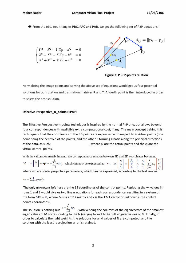
From the obtained triangles PBC, PAC and PAB, we get the following set of P3P equations:
Normalizing the image points and solving the above set of equations would get us four potential
solutions for our rotation and translation matrices R and T. A fourth point is then introduced in order
to select the best solution.
Effective Perspective_n_points (EPnP)
The Effective Perspective-n-points techniques is inspired by the normal PnP one, but allows beyond
four correspondences with negligible extra computational cost, if any. The main concept behind this
technique is that the coordinates of the 3D points are expressed with respect to 4 virtual points (one
point being the centroid of the points, and the other 3 forming a basis along the principal directions
of the data, as such: , where pi are the actual points and the cj are the
virtual control points.
With the calibration matrix in hand, the correspondence relation between 3D and 2D coordinates becomes:
which can now be expressed as
where wi are scalar projective parameters, which can be expressed, according to the last row as
The only unknowns left here are the 12 coordinates of the control points. Replacing the wi values in
rows 1 and 2 would give us two linear equations for each correspondence, resulting in a system of
the form , where M is a 2nx12 matrix and x is the 12x1 vector of unknowns (the control
points coordinates).
The solution is nothing but , with vi being the columns of the eigenvectors of the smallest eigen values of M corresponding to the N (varying from 1 to 4) null singular values of M. Finally, in order to calculate the right weights, the solutions for all 4 values of N are computed, and the solution with the least reprojection error is retained.
Figure 2: P3P 2-points relation

Maher Nadar Computer Vision Final Project 12/06/2106
4
METHODOLOGY
Camera Calibration
The first step to do is surely to calibrate the camera at hand. Using the calibration app figuring inside
the MatLAB program, the camera intrinsic parameters are acquired. 20 pictures of the usual
calibrating checkerboard are taken and inputted in the application. In Figure 3, an example of one of
the images’ automatic pre-processing before calibration is displayed.
At the end of the calibration process, the application displays the 3D re-projection of all the images
in the frame of the camera (displayed in Figure 4), an overall mean error for every image, and,
surely, the camera parameters.
Calibration Results
Focal Length: [1.5245e+03 1.5249e+03]
Principal Point: [614.5443 530.7807]
Thus, the A calibration matrix is
Automatic 2D-3D correspondence acquisition
In this paper, the pose recuperation method that will be used is the Effective Perspective-n-Points
(EPnP). Similarly to the studied techniques mentioned above, correspondences between 3D
coordinates of specific points in the object in question and their 2D projections on the image frame
need to be established before application of the pose retrieval algorithm.
Figure 3: a) original checkerboard image. b) image after processing
Figure 4: calibration re-projection

Maher Nadar Computer Vision Final Project 12/06/2106
5
Due to the fact that the pipes are theoretically expected to display relatively few and unreliable
features (especially if their surface is highly reflective), there is a need to project on the pipe a
pattern that would aid the feature extraction process – projecting this pattern on the pipe is possible
through the use of flexible magnets but it is not within the scope of this paper.
The chosen pattern (Figure 5) would be wrapped around the pipe such that the line formed
by points 1,2 and 3 would be parallel to the axis of the pipe. Naturally, the dimension
between points 3 and 6 would be shortened when the pattern is curled around the round
surface of the pipe. In Figure 6, the chord RQ represents the new dimension. Setting the arc
dimension ‘a’ as 32.8 mm (initial dimension), the chord length would be calculated as such:
where ‘t’ is the angle formed by the arc:
Thus, the new obtained dimension, knowing the pipe radius (55 mm in this case) is 37.7188 mm. 3D coordinates
For simplicity, the world coordinate system where the Z = 0 plane is the plane containing all the projected dots (i.e. the plane whose projection in the cross-sectional cut of the pipe would be the chord RQ in Figure 6). The following are the calculated 3D coordinates, taking point 1 as the origin:
2D coordinates
The main challenge in this paper is to automatically detect the 2D coordinates of the 6 points and to
assign each of them to the correct correspondence point in the world frame. The series of image
processing to do so will be described next.
Figure 5: Proposed Pattern Figure 6: RQ chord length calculation

Maher Nadar Computer Vision Final Project 12/06/2106
6
A series of 8 pictures taken of the pipe with the pattern wrapped around it are considered for this
study. Although all the pictures generate a successful output, the process description will be based
on one example picture out of the set.
Starting with the original close-up image (Figure 7.a), the first step is to perform a binarization. A
‘Prewitt’ detector isolates the edges in the resulting image (Figure 7.b). Next, the borders of the pipe
are localised by use of a ‘Hough Transform’ (Figure 7.c).
Following that, the region of interest, which is the pipe pixels isolation is obtained by extending the
‘hough-lines’ to the edges of the image and setting the pixels outside this region as white (Figure
8.a). The ROI is then transformed into the HSV and an ‘imopen’ morphological operation with a disk
kernel is applied on the ‘V’ matrix of this colour representation. In order to search for prospect black
dots (Figure 8.b). As can be observed, many unwanted black dots are detected on the border of the
ROI. In order to filter them, we calculate the distances between each dot and the 2 lines forming the
border of the ROI and eliminate the ones with a value less than a threshold. Finally, the 6 target dots
are isolated (Figure 8.c).
Figure 7: a) original image b) Binarization + edge detection c) Line detection (Hough Transform)
Figure 8: a) ROI b) black dots detection c) Black dots after filtering

Maher Nadar Computer Vision Final Project 12/06/2106
7
Up to this point, the 6 dots of the pattern are isolated in the image. The next step is to assign each of
them to their corresponding 3D match. In order to do so, the proposed idea is to generate a new
reference frame within the image that would help in distinguishing the dots. A convenient frame
would be the one formed by the bisector of the pipe and with the line orthogonal to it. For even
more convenience, the origin is chosen to be at the edge of the image. In Figure 9.a, the normal
image frame reference is represented as {x,y} in black, whereas the newly chosen frame is
represented as {x’,y’} in red.
The following tables represent the steps taken in order to assign the 6 different detected dots to
their 3D match. In the left most table, the dots coordinates in the image frame are present, but, as
mentioned before, they are still unidentifiable. In the 2nd table, the same dots (in the same order)
have went through a coordinate’s transformation. By comparing these last values to the order of the
dots set in the pattern in Figure 5, the dots coordinates are assigned the right dot numbering. Last
but not least, the coordinates of the numbered dots are taken back to the image frame.
Figure 9: a) New reference frame b) Final dots 2D-3D matching
Figure 10: 2D coordinates correspondences

Maher Nadar Computer Vision Final Project 12/06/2106
8
Pose retrieval through EPnP algorithm
Now that the 2D coordinates, the 3d coordinates and the camera calibration matrix are in hand, the
EPnP function can be used in order to obtain the Rotation Matrix, the translation Matrix and the
position of the dots in the camera reference.
RESULTS AND DISCUSSION
The obtained dots coordinates in the Camera frame seem to be in accordance with the real distance
between the camera and the pipe when the picture was taken.
Displayed herein are the results of two other example pictures to further authenticate the
robustness of the code:

Maher Nadar Computer Vision Final Project 12/06/2106
9
CONCLUSION
In this paper, a technique to estimate the camera to pipe pose has been proposed and successfully
applied to a set of 8 close-up images of the pipe in question along with a chosen pattern used to
better the feature extraction. After a sequence of image processing, the six dots present in the
pattern are isolated and assigned each a number corresponding to their match in 3D. Having the 3D
coordinates (known from the pattern dimensions) and the Camera intrinsics Matrix, the pose of the
points with respect to the camera frame was calculated using the EPnP function in MatLAB.
Limitations and Future Work
Although the algorithm is pretty robust in its correspondence matching and pose estimation from a
given set of images, it is however not able to differentiate whether or not the pattern in the image is
shot in the upright or the flipped side. Indeed, the output of this code is one of the two possible
poses that can be obtained. A possible solution to this issue is to choose a pattern where an extra
dot would be located on the upper or lower side of the pattern.
Another limitation to this algorithm is that the code cannot calculate the camera to pipe pose unless
the dots are detected, which implies that the camera should be relatively close to the pipe in order
to obtain the required results. This could also be solved with a smart choice of pattern. For instance,
the pattern could contain extra dots with different colour (e.g. red) so as to not hinder the black dots
detection algorithm. These extra dots would also be in a bigger size, which would allow detection
from a further distance between camera and pipe. Hence, the red dots would be used for relatively
far positions, and when the camera gets closer, the search for the smaller black dots begins.
END

Maher Nadar Computer Vision Final Project 12/06/2106
10
REFERENCES
V. Lepetit, F. Moreno-Noguer and P. Fua. EPnP: An Accurate O(n) Solution to the PnP
Problem, in International Journal Of Computer Vision, vol. 81, p. 155-166, 2009.
Jensen, Jeppe. "Hough Transform for Straight Lines" (PDF). Retrieved 16
December 2011.
Gao, Xiao-Shan; Hou, Xiao-Rong; Tang, Jianliang; Cheng, Hang-Fei (2003). "Complete
Solution Classification for the Perspective-Three-Point Problem". IEEE Transactions on
Pattern Analysis and Machine Intelligence 25 (8): 930–943
Penny. (2009, 09). Question from Wayne. Retrieved from http://mathcentral.uregina.ca/:
http://mathcentral.uregina.ca/QQ/database/QQ.09.09/h/wayne1.html