Embed Size (px)
Citation preview

Spartan-6 LX9 MicroBoard Tutorial
Creating the AVS6LX9MBHP211 MicroBlaze Hardware Platform
for the Spartan-6 LX9 MicroBoard
Version 13.2.01

Spartan-6 LX9 MicroBoard Tutorial
Page 2 of 24 2
Revision History
Version Description Date 12.4.01 Initial release for EDK 12.4 09 Mar 2011 12.4.02 Fixing broken links 12 Apr 2011 13.2.01 Updating to XPS 13.2 with AXI 19 Jul 2011
Table of Contents Revision History ............................................................................................................................... 2 Table of Contents ............................................................................................................................ 2 Table of Figures ............................................................................................................................... 3 Overview .......................................................................................................................................... 4 Objectives ........................................................................................................................................ 4 Requirements .................................................................................................................................. 5
Software ....................................................................................................................................... 5 Hardware ...................................................................................................................................... 5 Setup ............................................................................................................................................ 5 Recommended Reading .............................................................................................................. 5
Create a MicroBlaze Hardware Platform ......................................................................................... 6 Install the XBD file ........................................................................................................................ 6 Generate the hardware platform .................................................................................................. 7 Modify and Build the Hardware System ..................................................................................... 14 Export to SDK ............................................................................................................................ 22
Getting Help and Support .............................................................................................................. 24
Spartan-6 LX9 MicroBoard Tutorial
Page 3 of 24 3
Table of Figures Figure 1 – Avnet XBD File Repository ............................................................................................. 6 Figure 2 – New Base System Builder Project ................................................................................. 7 Figure 3 – New Project .................................................................................................................... 8 Figure 4 – BSB: Board and System Selection ................................................................................. 9 Figure 5 – Local Memory and Cache Settings .............................................................................. 10 Figure 6 – Peripheral Configuration: Enable Ethernet Interrupt .................................................... 10 Figure 7 – Peripheral Configuration: Configure UART .................................................................. 10 Figure 8 – Peripheral Configuration: Add Timer ............................................................................ 11 Figure 9 – Peripheral Configuration: Configure Timer................................................................... 11 Figure 10 – Peripheral Configuration: Complete ........................................................................... 12 Figure 11 – MicroBlaze Hardware Platform Block Diagram .......................................................... 14 Figure 12 – System Assembly View .............................................................................................. 15 Figure 13 – Configure IP for SPI_FLASH ...................................................................................... 16 Figure 14 – Clock Ratio Changed to 16 ........................................................................................ 16 Figure 15 – Include Second Buffers .............................................................................................. 17 Figure 16 – Enable the Integer Divider .......................................................................................... 18 Figure 17 – Add Watchpoints ........................................................................................................ 19 Figure 18 – Open the Bitgen Options File ..................................................................................... 20 Figure 19 – Verify Design Passed Timing ..................................................................................... 21 Figure 20 – Project Status No Errors ........................................................................................ 21 Figure 21 – Export to SDK ............................................................................................................. 22 Figure 22 – SDK Export Generated Files ...................................................................................... 23

Spartan-6 LX9 MicroBoard Tutorial
Page 4 of 24
Overview Avnet provides several MicroBlaze Hardware Platforms for the Spartan-6 LX9 MicroBoard. This tutorial details step by step how one of these Hardware Platforms was created. The Xilinx Platform Studio (XPS) includes a wizard to easily design an embedded processor hardware platform. The Base System Builder (BSB) wizard is a software tool that helps users quickly build a working hardware platform targeted at a specific development board. Based on the user’s board selection, BSB offers the user a number of options for creating a basic system on that board. These options include processor type, debug interface, cache configuration, memory type and size, and peripheral selection. For each option, functional default values are pre-selected in the GUI. Upon exiting BSB, a hardware specification (MHS) file is created and loaded into the user’s XPS project. The user may then further enhance the design in XPS or continue on to implement the design using the Xilinx implementation tools. The Base System Builder also generates sample applications and linker scripts which can be compiled and run with the hardware on the target development board. The Xilinx Board Description (XBD and XBD2) files define the features and standard peripherals that are available on a particular hardware platform. The XBD file is used by BSB to determine which hardware options are available to a user for a particular board. This tutorial shows how to make use of XPS, BSB, and an XBD2 file to create and use a MicroBlaze soft processor system with AXI interconnect for the Avnet Spartan-6 LX9 MicroBoard.
Objectives This tutorial will demonstrate how to do the following:
• Install a 3rd-party Xilinx Board Description 2 (XBD2) file • Use an IP repository • Define and build a MicroBlaze hardware platform using Base System Builder (BSB) • Customize hardware parameters not accessible through BSB • Export the hardware platform to the Xilinx Software Development Kit (SDK)

Spartan-6 LX9 MicroBoard Tutorial
Page 5 of 24
Requirements The following items are required for proper completion of this tutorial. Software
• Xilinx ISE Embedded Edition software, version 13.2 • Digilent Adept and Xilinx 3rd-party USB Cable driver • Silicon Labs CP2102 USB-to-UART Bridge Driver
Hardware
The hardware setup used by this reference design includes: • Computer with a minimum of 300-900 MB (depending on O/S) to complete an XC6SLX9
design1
• Avnet Spartan-6 LX9 MicroBoard Kit
o Avnet Spartan-6 LX9 MicroBoard o USB Extension cable (if necessary) o USB A-to-MicroB cable
Setup
• Install ISE and EDK software. ISE Embedded Edition or ISE WebPack with the EDK add-on are both valid combinations.
• Install Digilent Adept and Xilinx 3rd-party USB Cable driver (see Spartan-6 LX9 MicroBoard Configuration Guide on the DRC)
Recommended Reading
• Latest documents are at www.em.avnet.com/s6microboard Support Files & Downloads
• The hardware used on the Spartan-6 LX9 MicroBoard is described in detail in Avnet document Xilinx Spartan-6 LX9 Microboard, Rev. B - User Guide.
• The installation and use of the on-board USB JTAG circuit on the Spartan-6 LX9 MicroBoard is described in detail in Avnet document Spartan-6 LX9 MicroBoard Configuration Guide.
• The driver installation for the Silicon Labs CP2102 USB-UART bridge on the Spartan-6 LX9 MicroBoard is described in detail in Avnet document Silicon Labs CP201x USB-to-UART Setup Guide v.1.0.
• For more detailed information about Base System Builder, please refer to the Xilinx document titled Embedded System Tools Reference Manual (est_rm.pdf).
• For details on XBD syntax, please see the chapter on XBD Format in the Xilinx document titled Platform Specification Format Reference Manual (psf_rm.pdf).
• Details on the Spartan-6 FPGA family are included in the following Xilinx documents: o Spartan-6 Family Overview (DS160) o Spartan-6 FPGA Data Sheet (DS162) o Spartan-6 FPGA Configuration User Guide (UG380)
1 Refer to www.xilinx.com/ise/products/memory.htm

Spartan-6 LX9 MicroBoard Tutorial
Page 6 of 24
Create a MicroBlaze Hardware Platform Install the XBD file
This section will describe how to install the XBD files so that they are visible to BSB. XPS supports the concepts of Repositories, but that is a more advanced topic. To simplify, the archive will be installed into the Xilinx installation. This repository is located at <XILINX_EDK>\board. This repository is installed as part of EDK. It is the location for Xilinx XBD files and can be used for 3rd-party boards as well.
The steps to install the XBD files into the Xilinx installed repository are shown below.
1. Download the Avnet XBD archive at www.em.avnet.com/xbd. In the case of the Spartan-6 MicroBoard, the 13.2 XBD2 file should be included as of August 2011. Prior to this, the MicroBoard 13.2 XBD2 is included on the Spartan-6 MicroBoard support page at www.em.avnet.com/s6microboard Support Files & Downloads
2. Open and extract the XBD zip archive to the <XILINX_EDK>\board repository. For example, the default location for 13.2 is C:\Xilinx\13.2\ISE_DS\EDK\board.
3. Unzip the MicroBoard XBD2 into that folder structure under Avnet\ipxact. 4. Verify that the directory structure in the peripheral repository is as follows:
<XILINX_EDK> board Avnet ipxact S6_MicroBoard_v1_0 data
The archive used in this tutorial is shown below. The key file in the archive is S6_MicroBoard.xml, which is dated 19 July 2011 in this example. This MicroBoard repository folder is shown in Figure 2.
Figure 1 – Avnet XBD File Repository

Spartan-6 LX9 MicroBoard Tutorial
Page 7 of 24
Generate the hardware platform
After installing the XBD files, Xilinx Platform Studio’s Base System Builder (BSB) wizard is used to generate a new project for this specific board. BSB accomplishes many things, including:
• Instantiate MicroBlaze processor and peripherals • Create clock synthesis ratios • Create the FPGA pinout and constraints in a UCF • Create the ISE scripts to build the hardware
5. Launch Xilinx Platform Studio (XPS) by selecting Start All Programs Xilinx ISE
Design Suite 13.2 EDK Xilinx Platform Studio 6. Select the radio button for Base System Builder wizard (recommended) then click OK. If
the Create new or open existing project dialog does not come up automatically just select File New Project from the XPS tool bar.
Figure 2 – New Base System Builder Project

Spartan-6 LX9 MicroBoard Tutorial
Page 8 of 24
7. Select a location for your XPS project file (system.xmp) and associated files. You may type in a location or browse to a new or existing directory. Do not choose a directory under the EDK installation directory or a directory with a ‘space’ in the path. Starting in XPS 13.1, AXI-interconnect designs for the MicroBoard are supported. AXI systems require the XBD2 archive format and is the preferred interconnect for MicroBlaze systems. Select the radio button for AXI system. Click OK.
Figure 3 – New Project

Spartan-6 LX9 MicroBoard Tutorial
Page 9 of 24
8. Select Avnet as the Board vendor. If Avnet is not an option, then the XBD files were installed incorrectly. Select Avnet Spartan-6 LX9 MicroBoard for the Board name. Select B for the Board revision (note that the Rev B XBD is valid for Rev A boards as well). The default options for the Reference Clock Frequency, Single MicroBlaze Processor System, and Area Optimization are all unchanged for this example. Click Next>.
Figure 4 – BSB: Board and System Selection

Spartan-6 LX9 MicroBoard Tutorial
Page 10 of 24
9. Change the Processor Frequency to 66 MHz. 10. Change the Local Memory Size to 32 KB. Change the Instruction Cache Size to 4 KB.
Change the Data Cache Size to 4 KB.
Figure 5 – Local Memory and Cache Settings
The Base System Builder wizard uses the XBD file to determine which I/O peripherals are available on the board. All of the available external peripheral controllers (IO Devices) are included by default while none of the internal peripherals are. Adjustments will be made to these selections now.
11. Select the CDCE913_I2C peripheral. Click the < Remove button in the center of the screen to remove this peripheral.
12. Select the Ethernet_MAC peripheral. Check the box for Use Interrupt on the Ethernet_MAC peripheral.
Figure 6 – Peripheral Configuration: Enable Ethernet Interrupt
13. Select the USB_Uart peripheral. Change the Baud Rate to 115200 and check the box for Use Interrupt.
Figure 7 – Peripheral Configuration: Configure UART
Spartan-6 LX9 MicroBoard Tutorial
Page 11 of 24
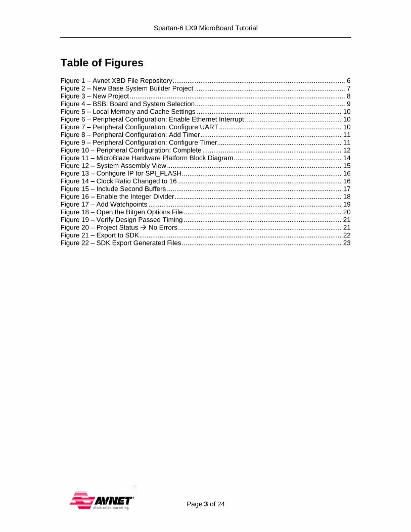
14. Select axi_timer under Internal Peripherals. Click the Add > button.
Figure 8 – Peripheral Configuration: Add Timer
15. Select the axi_timer peripheral and check the Use Interrupt box.
Figure 9 – Peripheral Configuration: Configure Timer

Spartan-6 LX9 MicroBoard Tutorial
Page 12 of 24
16. When complete, the Peripheral selection should look like the figure below. Now click Finish.
Figure 10 – Peripheral Configuration: Complete

Spartan-6 LX9 MicroBoard Tutorial
Page 13 of 24
17. The Base System Builder is done. Take a look at some of the files the BSB has generated. The system.mhs (Microprocessor Hardware Specification) file is the hardware description of our MicroBlaze design. The system.mss (Microprocessor Software Specification) file lists the software drivers for each of our peripherals. A User Constraint File (UCF) is also generated, which contains the FPGA pinout and timing constraints. The fast_runtime.opt file contains the parameters to be used by ISE to implement our design while the download.cmd is an iMPACT script.

Spartan-6 LX9 MicroBoard Tutorial
Page 14 of 24
Modify and Build the Hardware System
The MicroBlaze hardware platform is now generated. Examine the MicroBlaze design. A block diagram of the hardware platform is shown below.
FPGA
JTAG Header
MicroBlazeProcessor Core
GPIOOutput
GPIOInput
LEDsx4
DIPx4
BRAM(32K)
Memory Controller
Microprocessor Debug Module
DLMB Controller
ILMB Controller
32M x 16 LPDDR
PLL@66 MHz
Clock Control
Ethernet MAC
Reset Switch
Reset Control
TimerInterrupt
Cntrlr
400 MHz
I-Cache(4K)
D-Cache(4K)
UART
USB/UART Bridge
SPI Cntrlr
128MbSPI
Flash
66 MHz
AXI4LITEAXI4
AXI Interconnect AXI Interconnect
AXI4
10/100 Ethernet
MAC
Figure 11 – MicroBlaze Hardware Platform Block Diagram

Spartan-6 LX9 MicroBoard Tutorial
Page 15 of 24
The System Assembly View is a graphical representation of the system.mhs specification file. Select the System Assembly View tab near the center of the screen to see this view.
Figure 12 – System Assembly View
Feel free to explore the GUI. Select any of the components in the System Assembly View and right mouse click to see configuration, data sheet and software API options. We will adjust the configuration for three items.

Spartan-6 LX9 MicroBoard Tutorial
Page 16 of 24
18. Right-click on SPI_FLASH and select Configure IP …
Figure 13 – Configure IP for SPI_FLASH
19. Change the Ratio of PLB Clock Frequency To SCK Frequency from 32 to 16. Click OK.
Figure 14 – Clock Ratio Changed to 16

Spartan-6 LX9 MicroBoard Tutorial
Page 17 of 24
20. Configure IP for the ETHERNET_MAC peripheral. Check the two boxes to include the second receiver and transmitter buffers. This improves the performance, but it will consume BRAM. Click OK.
Figure 15 – Include Second Buffers

Spartan-6 LX9 MicroBoard Tutorial
Page 18 of 24
21. Configure IP for the microblaze_0 processor core. Click the Advanced button. In the Instructions tab, check the box for Enable Integer Divider. This adds FPGA logic to the MicroBlaze so that divide calculations are done quickly in hardware rather than in software.
Figure 16 – Enable the Integer Divider

Spartan-6 LX9 MicroBoard Tutorial
Page 19 of 24
22. Switch to the Debug tab. Increase both the Write Address Watchpoints and Read Address Watchpoints to 1. This completes the customizations to the MicroBlaze processor, so click OK to close this dialogue.
Figure 17 – Add Watchpoints

Spartan-6 LX9 MicroBoard Tutorial
Page 20 of 24
The default StartUpClk that XPS assigns in the bitgen.ut file is JTAGCLK. This works fine when creating a PROM file via iMPACT since it auto-corrects the StartUpClk. However, since Master SPI Configuration mode is used for the on-board Flash, it is a good idea to change StartUpClk to CCLK. iMPACT will change this to JTAGCLK when debugging via JTAG. Additionally, the default bitgen.ut file does not specify options for Unused I/Os and the Configuration Rate which means the default options are used during bitstream generation. This can have adverse affects in some projects. Therefore, explicit settings are given for these options at this time.
23. Select the Project tab in the Platform window. Double-click on Bitgen Options File: etc/bitgen.ut.
Figure 18 – Open the Bitgen Options File
24. Edit bitgen.ut to change the StartUpClk to CCLK. Add the following two lines to the file. Save and close the file.
-g UnusedPin:Pullnone -g ConfigRate:26
Once complete, the bitgen.ut file contents appear as follows:
-g TdoPin:PULLNONE -g StartUpClk:CCLK #add other options here. -g UnusedPin:Pullnone -g ConfigRate:26
The design is now ready to be built.
25. Select Hardware Generate Bitstream. This will generate the design netlist, synthesize, and implement the hardware.

Spartan-6 LX9 MicroBoard Tutorial
Page 21 of 24
At this point the hardware design is complete.
26. Click the Design Summary tab. Scroll down to find the Performance Summary. Look for the messages All Constraints Met and All Signals Completely Routed. This can also be done by navigating to the /implementation subdirectory inside the project directory and reviewing the ‘system.par’ (Place and Route Report) file. Also, check the Project Status to verify No Errors. This check should always be performed before continuing on with development
.
Figure 19 – Verify Design Passed Timing
Figure 20 – Project Status No Errors
Spartan-6 LX9 MicroBoard Tutorial
Page 22 of 24
Export to SDK
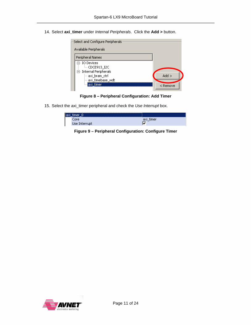
Software capability within XPS was removed in v13.1. The Software Development Kit (SDK) is the required method for creating software designs. The last step of a Hardware Platform design is to export the required hardware files to enable SDK. Once this step is complete, all future application development, hardware download, and debug can be performed entirely within SDK.
27. To export the required hardware files for SDK operation, select Project Export Hardware Design to SDK…
Figure 21 – Export to SDK
28. If simply exporting for later use or to deliver to the software team, select Export Only. Or click Export & Launch SDK if you are ready to use SDK now.
29. Once the Export is complete, you can browse the results in the SDK/SDK_Export directory.

Spartan-6 LX9 MicroBoard Tutorial
Page 23 of 24
Figure 22 – SDK Export Generated Files
The three critical files to continue development are: 1. system.bit 2. system.xml 3. system_bd.bmm
All of the other files are informational. Notice all the IP datasheets included. Also, try clicking on the system.html file to see many details about the hardware platform. A tutorial to introduce you to SDK and how to import these exported files is also available if you would like to continue. Congratulations! You have completed a MicroBlaze Hardware Platform design for the Spartan-6 LX9 MicroBoard.

Spartan-6 LX9 MicroBoard Tutorial
Page 24 of 24
Getting Help and Support Evaluation Kit home page with Documentation and Reference Designs http://em.avnet.com/s6microboard Avnet Spartan-6 LX9 MicroBoard forum: http://community.em.avnet.com/t5/Spartan-6-LX9-MicroBoard/bd-p/Spartan-6LX9MicroBoard
For Xilinx technical support, you may contact your local Avnet/Silica FAE or Xilinx Online Technical Support at www.support.xilinx.com. On this site you will also find the following resources for assistance:
• Software, IP, and Documentation Updates
• Access to Technical Support Web Tools
• Searchable Answer Database with Over 4,000 Solutions
• User Forums
• Training - Select instructor-led classes and recorded e-learning options Contact Avnet Support for any questions regarding the Spartan-6 LX9 MicroBoard reference designs, kit hardware, or if you are interested in designing any of the kit devices into your next design.
• http://www.em.avnet.com/techsupport You can also contact your local Avnet/Silica FAE.