Embed Size (px)
Citation preview
Spartan-6 LX9 MicroBoard Embedded Tutorial
Spartan-6 LX9 MicroBoard Embedded Tutorial
Tutorial 3
Adding Custom IP to an Embedded System
Version 13.1.01
Spartan-6 LX9 MicroBoard Embedded Tutorial
Page 2 of 12
Revision History
Version Description Date
13.1.01 Initial release for EDK 13.1 5/16/2011
Table of Contents
Revision History .............................................................................................................................. 2 Table of Contents ........................................................................................................................... 2 Table of Figures .............................................................................................................................. 2 Overview......................................................................................................................................... 3 Objectives ....................................................................................................................................... 3 Requirements ................................................................................................................................. 4
Software ...................................................................................................................................... 4 Hardware .................................................................................................................................... 4 Recommended Reading ............................................................................................................. 4
I. Creating a Custom AXI IP Using the Wizard .......................................................................... 5 II. Customizing the New Peripheral............................................................................................. 6 III. Adding the Custom Peripheral to the System ..................................................................... 8 IV. Writing Code for the Custom Peripheral ............................................................................. 9 V. Test the Generated System with the Modified Application .................................................... 10 Getting Help and Support ............................................................................................................. 12
Table of Figures
Figure 1 - Hardware Platform ......................................................................................................... 3 Figure 2 - Create Peripheral Wizard ............................................................................................... 5 Figure 3 - Adding IP to AXI Interface .............................................................................................. 7 Figure 4 - XPS Ports View .............................................................................................................. 9
Spartan-6 LX9 MicroBoard Embedded Tutorial
Page 3 of 12
Overview
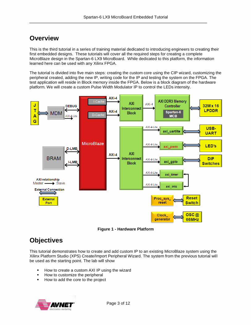
This is the third tutorial in a series of training material dedicated to introducing engineers to creating their first embedded designs. These tutorials will cover all the required steps for creating a complete MicroBlaze design in the Spartan-6 LX9 MicroBoard. While dedicated to this platform, the information learned here can be used with any Xilinx FPGA. The tutorial is divided into five main steps: creating the custom core using the CIP wizard, customizing the peripheral created, adding the new IP, writing code for the IP and testing the system on the FPGA. The test application will reside in Block memory inside the FPGA. Below is a block diagram of the hardware platform. We will create a custom Pulse Width Modulator IP to control the LEDs intensity.
Figure 1 - Hardware Platform
Objectives
This tutorial demonstrates how to create and add custom IP to an existing MicroBlaze system using the Xilinx Platform Studio (XPS) Create/Import Peripheral Wizard. The system from the previous tutorial will be used as the starting point. The lab will show
How to create a custom AXI IP using the wizard How to customize the peripheral How to add the core to the project
Spartan-6 LX9 MicroBoard Embedded Tutorial
Page 4 of 12
Requirements
The following items are required for proper completion of this tutorial. Completion of the Adding EDK IP to an Embedded System Tutorial
Software The following software setup is required to test this reference design:
WindowsXP 32-bit Service Pack 2 Xilinx ISE WebPack with the EDK add-on or ISE Embedded Edition version 13.1 Installed Digilent Adept and Xilinx 3
rd-party USB Cable driver (see Spartan-6 LX9 MicroBoard
Configuration Guide, listed in Recommended Reading, below) Installed Silicon Labs CP210x USB-to-UART Bridge Driver (see Silicon Labs CP210x USB-to-
UART Setup Guide, listed in Recommended Reading, below) Installation of the Spartan-6 LX9 MicroBoard IPXACT files (Available from Avnet:
http://em.avnet.com/s6microboard)
Hardware The hardware setup used by this reference design includes:
Computer with a minimum of 300-900 MB (depending on O/S) to complete an XC6SLX9 design1
Avnet Spartan-6 LX9 MicroBoard Kit o Avnet Spartan-6 LX9 MicroBoard o USB Extension cable (if necessary) o USB A-to-MicroB cable
Recommended Reading Available from Avnet: http://em.avnet.com/s6microboard
The hardware used on the Spartan-6 LX9 MicroBoard is described in detail in Avnet document, Spartan-6 LX9 MicroBoard User Guide.
An overview of the configuration options available on the Spartan-6 LX9 MicroBoard, as well as Digilent driver installation instructions can be found in the Avnet document, Spartan-6 LX9 MicroBoard Configuration Guide.
Instructions on installing the Silicon Labs CP210x USB-to-UART drivers can be found in the Avnet document, Silicon Labs CP210x USB-to-UART Setup Guide.
Available from Xilinx: http://www.xilinx.com/support/documentation/spartan-6.htm Details on the Spartan-6 FPGA family are included in the following Xilinx documents:
o Spartan-6 Family Overview (DS160) o Spartan-6 FPGA Data Sheet (DS162) o Spartan-6 FPGA Configuration User Guide (UG380) o Platform Studio Help (available in tool menu) o Platform Studio SDK Help (available in tool menu) o MicroBlaze Reference Guide v.13.1 (UG081) o Embedded System Tools Reference Manual v.13.1 (UG111)
1 Refer to www.xilinx.com/ise/products/memory.htm
Spartan-6 LX9 MicroBoard Embedded Tutorial
Page 5 of 12
I. Creating a Custom AXI IP Using the Wizard
We will use the Create/Import Peripheral (CIP) wizard in XPS to create a new custom IP for the existing system. The custom IP will consist of a Pulse Width Modulator (PWM) controlled using a software mapped register. If this tutorial is your starting point, you can download the EDK_Tutorial_02 solution from the Avnet DRC: http://em.avnet.com/s6microboard
1) Start Project Navigator and open the EDK_Tutorial project.
2) Double-click on the mb_system.xmp module to open the system in XPS.
3) Go to Hardware > Create or Import Peripheral… Click on Next.
4) Make sure that Create templates for a new peripheral is selected then click Next.
5) Select To an XPS project. Click on Next.
6) Enter the name for the new peripheral, axi_pwm, and then click Next.
7) Select AXI4-Lite: Simpler, non-burst control register style interface. Click Next.
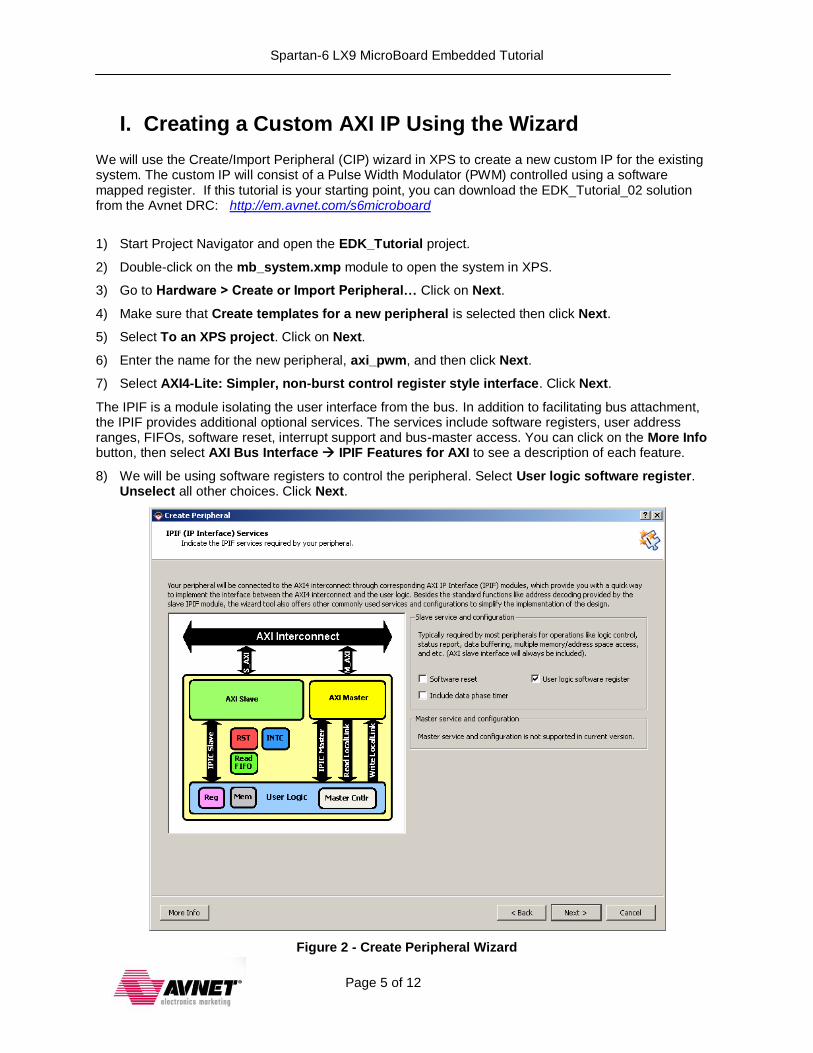
The IPIF is a module isolating the user interface from the bus. In addition to facilitating bus attachment, the IPIF provides additional optional services. The services include software registers, user address ranges, FIFOs, software reset, interrupt support and bus-master access. You can click on the More Info button, then select AXI Bus Interface IPIF Features for AXI to see a description of each feature.
8) We will be using software registers to control the peripheral. Select User logic software register. Unselect all other choices. Click Next.
Figure 2 - Create Peripheral Wizard
Spartan-6 LX9 MicroBoard Embedded Tutorial
Page 6 of 12
9) We will use one 32-bit wide register to communicate with the PWM hardware. Though only twelve bits will be used to select the pulse duty cycle. Select 1 for the number of registers. Click on Next.
10) The IP Interconnect (IPIC) uses a set of signals between the user logic and the AXI bus. We will use
the default signals already selected. Click on Next.
11) Bus Functional Models can be generated to accelerate the IP verification. This tutorial does not cover the BFM simulation of the peripheral. Click on Next.
12) The wizard can also generate custom drivers for the peripheral and an ISE project. We will be using
XPS and writing our own code to test the peripheral. Click on Next.
13) Click on Finish to create the peripheral.
II. Customizing the New Peripheral
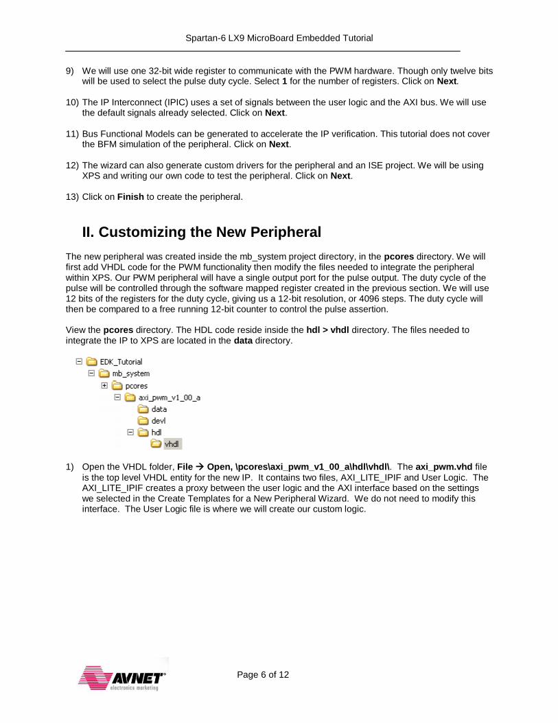
The new peripheral was created inside the mb_system project directory, in the pcores directory. We will first add VHDL code for the PWM functionality then modify the files needed to integrate the peripheral within XPS. Our PWM peripheral will have a single output port for the pulse output. The duty cycle of the pulse will be controlled through the software mapped register created in the previous section. We will use 12 bits of the registers for the duty cycle, giving us a 12-bit resolution, or 4096 steps. The duty cycle will then be compared to a free running 12-bit counter to control the pulse assertion. View the pcores directory. The HDL code reside inside the hdl > vhdl directory. The files needed to integrate the IP to XPS are located in the data directory.
1) Open the VHDL folder, File Open, \pcores\axi_pwm_v1_00_a\hdl\vhdl\. The axi_pwm.vhd file
is the top level VHDL entity for the new IP. It contains two files, AXI_LITE_IPIF and User Logic. The AXI_LITE_IPIF creates a proxy between the user logic and the AXI interface based on the settings we selected in the Create Templates for a New Peripheral Wizard. We do not need to modify this interface. The User Logic file is where we will create our custom logic.
Spartan-6 LX9 MicroBoard Embedded Tutorial
Page 7 of 12
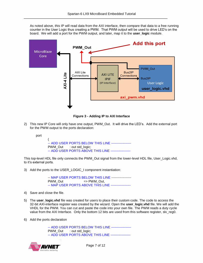
As noted above, this IP will read data from the AXI interface, then compare that data to a free running counter in the User Logic thus creating a PWM. That PWM output will be used to drive LED’s on the board. We will add a port for the PWM output, and later, map it to the user_logic module.
Figure 3 - Adding IP to AXI Interface
2) This new IP Core will only have one output, PWM_Out. It will drive the LED’s. Add the external port for the PWM output to the ports declaration:
port
( -- ADD USER PORTS BELOW THIS LINE ------------------
PWM_Out : out std_logic; -- ADD USER PORTS ABOVE THIS LINE ------------------
This top-level HDL file only connects the PWM_Out signal from the lower-level HDL file, User_Logic.vhd, to it’s external ports.
3) Add the ports to the USER_LOGIC_I component instantiation:
-- MAP USER PORTS BELOW THIS LINE ------------------
PWM_Out => PWM_Out, -- MAP USER PORTS ABOVE THIS LINE ------------------
4) Save and close the file.
5) The user_logic.vhd file was created for users to place their custom code. The code to access the
32-bit AXI-interface register was created by the wizard. Open the user_logic.vhd file. We will add the VHDL for the PWM. You can cut and paste the code into your own file. The PWM reads a duty cycle value from the AXI Interface. Only the bottom 12 bits are used from this software register, slv_reg0.
6) Add the ports declaration
-- ADD USER PORTS BELOW THIS LINE ------------------ PWM_Out : out std_logic; -- ADD USER PORTS ABOVE THIS LINE ------------------
Spartan-6 LX9 MicroBoard Embedded Tutorial
Page 8 of 12
7) Add user signals declaration
--USER signal declarations added here, as needed for user logic signal duty_cycle : std_logic_vector (11 downto 0); signal fcount : std_logic_vector (11 downto 0);
8) Add the user HDL code after the begin statement. The user_logic template already contains code to
read and write the register.
--USER logic implementation added here -- Duty cycle is controlled by the software controlled register duty_cycle <= slv_reg0(11 downto 0); -- 12-bit rollover counter counter : process (Bus2IP_Clk) begin if (Bus2IP_Clk'event and Bus2IP_Clk = '1') then if Bus2IP_Resetn = '0' then fcount <= (others => '0'); else fcount <= fcount + 1; end if; end if; end process counter; -- Enable the output for the duty cycle selected PWM_Out <= '1' when (fcount < duty_cycle) else '0';
9) Save and Close the file.
10) The new external port needs to be added to the definition file for the peripheral in order to be used in
XPS. Open the axi_pwm_v1_00_a\data directory and open the file axi_pwm_v2_1_0.mpd.
11) Add the PWM_Out port
## Ports
PORT PWM_Out = "", DIR = O
12) Save and close the file.
13) Rescan the user IP directories. Project > Rescan User Repositories.
14) The new core will now be available.
III. Adding the Custom Peripheral to the System
We will add and connect the new custom IP to the existing system following the same instructions as in the previous lab. We will remove the GPIO peripheral for the LEDs and connect the PWM peripheral to the LEDs.
1) In XPS, click on the IP Catalog tab in the Project Information Area.
2) Expand the Project Local Pcores/USER list to view the custom IP.
3) Select AXI_PWM then drag and drop it to the System Assembly View window. Click OK.
Spartan-6 LX9 MicroBoard Embedded Tutorial
Page 9 of 12
4) Click OK to connect this IP to MicroBlaze.
5) Click on the Addresses tab to view the address range for the new IP.
6) Delete the GPIO peripheral instance for the LEDs. In the System Assemble View, right-click on
the LEDS_4Bit instance and select Delete Instance. Select Delete instance but do not remove the nets. Click OK.
7) Click on the Ports tab. Expand axi_pwm_0 from the list. It will show the connections available for
the peripheral.
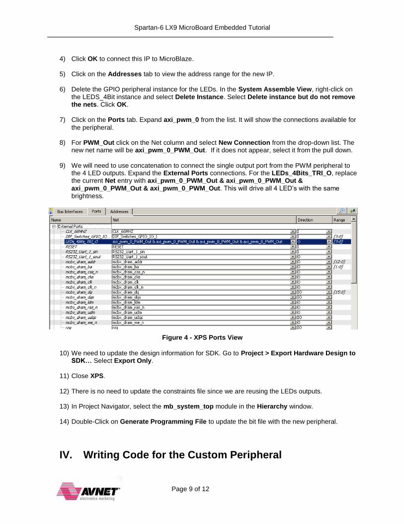
8) For PWM_Out click on the Net column and select New Connection from the drop-down list. The new net name will be axi_pwm_0_PWM_Out. If it does not appear, select it from the pull down.
9) We will need to use concatenation to connect the single output port from the PWM peripheral to
the 4 LED outputs. Expand the External Ports connections. For the LEDs_4Bits_TRI_O, replace the current Net entry with axi_pwm_0_PWM_Out & axi_pwm_0_PWM_Out & axi_pwm_0_PWM_Out & axi_pwm_0_PWM_Out. This will drive all 4 LED’s with the same brightness.
Figure 4 - XPS Ports View
10) We need to update the design information for SDK. Go to Project > Export Hardware Design to SDK… Select Export Only.
11) Close XPS.
12) There is no need to update the constraints file since we are reusing the LEDs outputs.
13) In Project Navigator, select the mb_system_top module in the Hierarchy window.
14) Double-Click on Generate Programming File to update the bit file with the new peripheral.
IV. Writing Code for the Custom Peripheral
Spartan-6 LX9 MicroBoard Embedded Tutorial
Page 10 of 12
To test the new peripheral we will add code to the Tutorial_Test project created with Platform Studio SDK. We will make use of the DIP switches to control the pulse duty cycle. The 4 DIP switches will be used to select the 4 most significant bits of the duty cycle. We will lose some precision but still be able to test the peripheral.
1) Start Xilinx SDK and select the Workspace from EDK_Tutorial.
2) SDK will detect that the hardware system has changed. Click Yes to update the hardware
platform and BSP.
a. If SDK does not auto-detect the new hardware, right-click on the hardware platform project and select Change Hardware Platform Specification. Browse to the XML file and click OK.
The applications will not compile since we removed the GPIO peripheral which was used for the LEDs.
The duty cycle is controlled with a software register. From the address map defined in the user_logic code, the register is located at BaseAddress + 0x0.
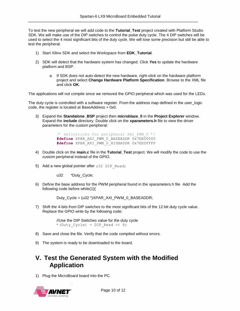
3) Expand the Standalone_BSP project then microblaze_0 in the Project Explorer window.
Expand the include directory. Double click on the xparameters.h file to view the driver parameters for the custom peripheral:
/* Definitions for peripheral AXI_PWM_0 */
#define XPAR_AXI_PWM_0_BASEADDR 0x7EE00000
#define XPAR_AXI_PWM_0_HIGHADDR 0x7EE0FFFF
4) Double click on the main.c file in the Tutorial_Test project. We will modify the code to use the
custom peripheral instead of the GPIO.
5) Add a new global pointer after u32 DIP_Read;
u32 *Duty_Cycle;
6) Define the base address for the PWM peripheral found in the xparameters.h file Add the
following code before while(1){
Duty_Cycle = (u32 *)XPAR_AXI_PWM_0_BASEADDR;
7) Shift the 4-bits from DIP switches to the most significant bits of the 12-bit duty cycle value. Replace the GPIO write by the following code:
//Use the DIP Switches value for the duty cycle *(Duty_Cycle) = DIP_Read << 8;
8) Save and close the file. Verify that the code compiled without errors.
9) The system is ready to be downloaded to the board.
V. Test the Generated System with the Modified Application
1) Plug the MicroBoard board into the PC.

Spartan-6 LX9 MicroBoard Embedded Tutorial
Page 11 of 12
2) Plug the MicroUSB / USB UART cable between the MicroBoard and the PC.
3) In SDK, click on the Program FPGA icon
o For the Bitstream, browse to the EDK_Tutorial directory and select mb_system_top.bit
o For the BMM File, browse to the EDK_Tutorial directory and select edkBmmFile_bd.bmm
4) Click on Program.
5) In the SDK Project Explorer View, right-click on the Tutorial_Test project and select Run As >
Launch on Hardware. NOTE: You may see errors and warnings for testperiph.c. You can ignore these as they are for the peripheral_test application. We are not using this application.
6) Carefully modify the DIP switches positions to change the intensity of the LEDs.
7) Close SDK.

Spartan-6 LX9 MicroBoard Embedded Tutorial
Page 12 of 12
Getting Help and Support
Evaluation Kit home page with Documentation and Reference Designs http://em.avnet.com/s6microboard Avnet Spartan-6 LX9 MicroBoard forum: http://community.em.avnet.com/t5/Spartan-6-LX9-MicroBoard/bd-p/Spartan-6LX9MicroBoard
For Xilinx technical support, you may contact your local Avnet/Silica FAE or Xilinx Online Technical Support at www.support.xilinx.com. On this site you will also find the following resources for assistance:
Software, IP, and Documentation Updates
Access to Technical Support Web Tools
Searchable Answer Database with Over 4,000 Solutions
User Forums
Training - Select instructor-led classes and recorded e-learning options Contact Avnet Support for any questions regarding the Spartan-6 LX9 MicroBoard reference designs, kit hardware, or if you are interested in designing any of the kit devices into your next design.
http://www.em.avnet.com/techsupport You can also contact your local Avnet/Silica FAE.


