Embed Size (px)
Citation preview

Page 31
Previous RRI at Vijayawada commissioned in 1976, was due for replacement. As certain flexibilities werenot available in previous RRI (such as Reception on PF 1 to PF 7 from IIIrd KB Line To KCC jn , Dispatchfrom PF 8,9,10 on Up line to KCC Jn, Reception from SC on PF 8, 9, 10), Yard re-modelling was also proposedinvolving 28 Point Insertion & 23 dismantlings. New RRI work was sanctioned in the year 1998-99. Revisedcost stood at Rs.52.54 Crore (Engineering: 23.40 Cr, S & T: 23.22 Cr , Elec. (Trd.): 3.51 Cr, Elec. (Genl): 2.41Cr).
Indoor work was awarded to M/s.Siemens Ltd., Mumbai in 2004. Approx 553 KMs of cable was laid and apower ring was established connecting all the 8 signal goompties to ensure un-interrupted power supply. BothIndoor & out-door works were ready by 2012. Railway Board’s condonation for gradients was received inJanuary 2015. Commissioner of Railway Safety (CRS) sanction was obtained in June, 2015.
1.0 Signaling Enhancements :
(*) Further addition was replacements of 2 more Cabins – F, G (294 routes).
Usually RRI of this size with Yard remodeling was taken up with NI periods ranging from 11 to 16 days. Butby preponing 12 point insertions & 5 dismantlings to Pre-NI period , Non-Interlocking period was broughtdown to barest minimum of 3 (three) days. N.I Proposal was cleared by COM/SCRly , General Manager,SCRly in February, 2016. Member Traffic approved proposal in May, 2016 . Optg dept notified List of Trainscancelled /Diverted/rescheduled for this work
2.0 Getting ready for N.I.& Colour codes :D –day for NI was set as 21st, 22nd and 23rd September, 2016 (3 days) with 8 (eight) hours and 16(sixteen)
hours traffic block on 2nd and 3rd days of NI. Field officers & supervisors were clearly advised to keep onlybarest minimum for N.I .
Elaborate planning was made involving Division and Head quarters for synchronizing blocks of Engineeringand Traffic and addressing various inter-departmental issues in-time bound fashion, during weekly ReviewMeetings held at HODs level. Every eventuality was flagged & addressed. Pre NI, NI programmes weremeticulously drawn by the Field Officers and implemented without any deviation and every day meetings wereheld to sort out inter-departmental issues.
Since majority of staff were mobilized only 3 days before NI, Core team of BZA were advised to makechange-over as simple as possible by using colour codes of Green (for removals) and insertion with RED.
Commissioning of Route Relay Interlocking (RRI)Vijayawada/SCR
- A Success Story- Sri Ch.Mohan, IRSSE, CSTE/Con/SCRly
Functions(Routes)
Previous RRI
New RRI
Main signals 106 186
Calling On signals 59 183
Shunt signals 259 335
Slots to other cabins 10 32
Total 434 736

Page 32
Gyandeep - Anniversary Issue ‘16
2.1 Testing before N.I :New Cables were Tested & “No change” Track circuits were Transferred beforehand.The Control tables were tested by 3 (three) independent teams, thus establishing a trouble free indoorwiring andSplit blocks were taken for testing existing points from the New RRI and restored back to the Old RRI(to test route setting operation from the new RRI). This ensured that the indoor and out-door circuitswere matching.
Thus Predominant portion of work was done before N.I, leaving only barest minimum for N.I
3.0 Mobilisation of staff at Site for NI & logistics :Enlisting the support of all the wings of S&T Dept , Engineering, Electrical , an army of about 700 staff
were assembled for the Mega event at RRI, Vijayawada. Staff and Officers were provided with accommodation,food and transport using Imprest Cash as per Railway Board’s order No.2012/Sig/SF/2(Policy), dated 09-04-2012. OEM Engineers of Data-loggers, integrated power supply, Siemens Design Team were made availablethrough-out, for smooth working. The Contractors deployed their resources at the Peak. Wireless Communicationarrangements were made duly defining separate channels for Testing of points, track circuits and signals.
4.0 Team formation & On the spot Training for NI :Four JAG officers were assigned with a team of Jr.Scale /Sr. Scale officers and supervisory resources and
specific zone was allotted to each. Drawing of each zone were handed over with colour codes for disconnection& connection. Staff were assigned tasks relevant to their skill-level. Training sessions were conducted 3 daysbefore N.I, through videos and taken to the site for on the spot orientation.
S&T had 27 (twenty seven) Activity Centers with about 284 staff & 28 Officers deployed. Reserve force ofESMs was kept in stand by throughout to rush at short notice to required spots.
5.0 DURING N.I. :NI signals were erected to enable running of trains during N.I and Staff were counseled to ensure integrity of
cable terminations marked with RED labels “NI signals do not disturb”. A control room was set up to workround the clock to monitor, guide, augment resources as per need. Display boards were used to notify Task &duty list to all staff and yard lay out changes on day to day basis. Helmets and Orange jackets were madecompulsory to ensure their Safety as Engg & Traction works were in progress with heavy machines & TowerCar
As the Weather in Vijayawada during all the 3 days of NI was bad with cyclonic depression over Bay ofBengal, all the staff and supervisors were provided with Rain coats and umbrellas.
The motivation of staff and supervisors were kept high by periodical visits by CSTE/C, CSE, and regularupdates on over-all situation through SMS and monitored at site by CSE, CSTE/Con, CSTE. An androidapplication was used to monitor all tasks at 27 activity centres. Against the permitted NI of 72 hours, only 62hours were availed (less by 10 hrs) and against the permitted block of 16 hours on the 2nd day, only 15 hours(less by 1 hr) was taken, Advance forecast was given to plan traffic . These measures were appreciated by COM
With the support given by CSTE, COM and General Manager, SCRly, all PHODs, DRM/BZA & Teammembers fully committed to make a Grand Success “, the work of RRI, Vijayawada was commissionedsuccessfully and smoothly on 23rd September, 2016 at 22.30 hrs. before time.

Page 33
Gyandeep - Anniversary Issue ‘16
6.0 At a glance view of New RRI/BZA.
7.0 Conclusion :-Thus the fear of executing Non Interlocking (NI) at Major RRIs was eliminated duly establishing that the
S&T Department can smoothly and successfully ensure commissioning of Major RRIs by meticulously planning,dedication, motivation & Inter-departmental Co-ordination. A documentary is also under preparation whichwill be supplied to all the Training Institutes, soon. Trainees from IRISET and Zonal Training Center, MLYwere also involved in this work for Educational purposes.
The “Core Team” was lead by Sri Ch.P.R.Vittal, Dy.CSTE/C/BZA, Sri CSS.Subramanyam, DSTE/C/BZA,Sri K.Narsi Reddy, ASTE/C/BZA & Sri D.V.Satyanarayana, ASTE/C/BZA and were supported by all others atSite. Thus, SCRly has successfully completed a Major RRI work at Vijayawada, which was a long pendingwork. GM in a special convened meeting lauded the efforts of S&T/Con. Organisation for the meticulousplanning & execution of NI work of RRI/BZA.
8.0 Comparison of NI duration of RRI/BZA with Other major RRI works:
Routes 1030 (including
F, G cabins)
Points 169
Track ckts 203
Signals 185
Slots 100
S&T goomties 8
Automatic section 5km (on three lines)
Automatic signaling Goompties
3
MSDAC Axle Counters
10 DP’s
SSDAC Axle Counters
10 Sections
UAC axle counters 2 sections
Cabins Replacement Added with this work
2 cabins - G , F Cabins
Alterations at Other cabins
3
Point Removals 23
Point Insertions 28
Glued Joints 191
Description BZA CNB BTI Khurda Road Nagpur JHS ADI NDLS
No. Of Routes
1030(736+ 208 F
Cabin+86 G Cabin)
547 -- 638 533 401 659 1278
No. Of Roads 20 11 18 14 19
No. Of Points 169 98 100 124 111 172 211
No. Of Track Ckts 203 100 177 144 205 279
No. Of Signals 185 100 140 120 162 178 101+53+154
Pre NI (Days) 12 20 26 18 12 30
NI (Days) 3 3 10 16 5 3 11
Page 34
Gyandeep - Anniversary Issue ‘16
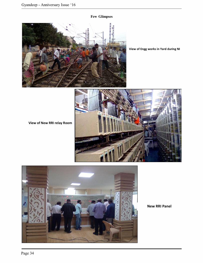
Few Glimpses
View of Engg works in Yard during NI
View of New RRI relay Room
New RRI Panel

Page 35
Earthing for Lighting Protection
Shri P.Venkata Ramana, Senior Professor Signal/IRISET
The Perimeter RingEarth (PRE) or Ring Earthare required for safetycritical installations such asElectronic InterlockingSystems for providingprotection from lightning.RDSO typical bonding &earthing arrangement isavailable for provision ofPerimeter Ring Earth for
Electronic Interlocking installations. But it neitherprovides guidelines for its design nor provides methodto check its effectiveness. More ever, the arrangementis typical but not specific. Specific designs will varyfor different installations especially where buildingsare different in shapes and sizes, varying soilresistivities from place to place and varying flashdensity of lightning from region to region.
The Perimeter Ring Earth is the earth-terminationsystem. Earth- termination system is the continuationof the air-termination system and down conductors. Itdischarges the lightning current to the earth,establishes equipotential bonding between the downconductors and controls the potential in the vicinityof the building walls.
The Perimeter Ring Earth is essentially a type BEarth as per IEC / EN 62305 standards. Earthingsystem based on Perimeter Ring Earth requires designfor a specific installation and requires properinstallation practices. This article provides an insightinto design and installation of Perimeter Ring Earthand its effectiveness as per IEC/EN 62305 standards.
The topic is dealt in four sections.(i) Calculation for requirement of number of
Earth Electrodes in a Perimeter Ring Earth -illustrates the criteria for sufficiency of earth electrodesprovided in a Ring Earth for the measured soilresistivity, level of class of lightning protection andarea of the building.
(ii) Selection of Earth Electrodes - lists variousmaterials available for earth electrodes and theminimum dimensions required for the earth electrodes.
(iii) Soil Resistivity - discusses various parametersof soil resistivity and measurement of soil resistivity
by Wenner method.
(iv) Norms and Precautions - discusses the normsand precautions to be followed in installation ofPerimeter Ring Earth.
The definitions of technical terms are given at theend.
I. CALCULATION FOR REQUIREMENT OFNUMBER OF EARTH ELECTRODES IN APERIMETER EARTH
Type B Earth electrodes are ring earth electrodesencircling the object to be protected.
The total length of Earth electrodes provided inPerimeter Ring Earth depends upon 3 parameters (i)total area of building to be protected from lightning(ii) class of lightning protection being provided ClassI or II or III or IV (iii) Mean Soil Resistivity in thevicinity of the building.
Criteria for effective lightning protection is thatthe mean radius, r of the area encircled by a perimeter
ring earth must be not less than the specified minimumlength, l1.
To determine the mean radius r, the area underconsideration is transferred into an equivalent circulararea and the radius is determined as shown in abovefigures.
Where r = Mean radius, A = Area of the buildingbeing protected
r =