Embed Size (px)
DESCRIPTION
Technical information on motor control centers
Citation preview
Publication 2100-CA001F-EN-P – August 2008 Copyright ©2008 Rockwell Automation, Inc. All Rights Reserved. Printed in USA.Supersedes Publication 2100-CA001E-EN-P – August 2007
MOTOR CONTROL CENTERSCATALOG
• CENTERLINE® 2100 Motor Control Centers
CENTERLINE®, CenterONE®, ControlLogix®, DeviceLogix™, IntelliCENTER®, PowerFlex®, Product Selection Toolbox™, Rockwell Automation®,
RSView®, SMC™, SMC™ 3, SMC™ Dialog Plus, SMC™ Flex, Powermonitor™, ArcShield™, Allen-Bradley® are trademarks of Rockwell Automation, Inc.
Trademarks not belonging to Rockwell Automation are property of their respective companies.
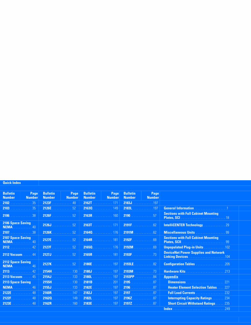
Quick Index
Bulletin Number
PageNumber
Bulletin Number
PageNumber
Bulletin Number
PageNumber
Bulletin Number
PageNumber
2102. . . . . . . . . . . . . . 35 2123F . . . . . . . . . . . . .48 2162T . . . . . . . . . . . . 171 2183J . . . . . . . . . . . . . 1972103. . . . . . . . . . . . . . 35 2126E . . . . . . . . . . . . .52 2163Q . . . . . . . . . . . . 149 2183L . . . . . . . . . . . . . 197 General Information . . . . . . . . . . . . . . . . . . . .1
2106. . . . . . . . . . . . . . 38 2126F . . . . . . . . . . . . .52 2163R . . . . . . . . . . . . 160 2190 . . . . . . . . . . . . . . 57 Sections with Full Cabinet Mounting Plates, SCI . . . . . . . . . . . . . . . . . . . . . . . . . . . 18
2106 Space Saving NEMA. . . . . . . . . . . . 40 2126J . . . . . . . . . . . . .52 2163T . . . . . . . . . . . . 171 2191F . . . . . . . . . . . . . 62 IntelliCENTER Technology. . . . . . . . . . . . . . 29
2107. . . . . . . . . . . . . . 38 2126K . . . . . . . . . . . . .52 2164Q . . . . . . . . . . . . 176 2191M . . . . . . . . . . . . 62 Miscellaneous Units . . . . . . . . . . . . . . . . . . 992107 Space Saving NEMA. . . . . . . . . . . . 40 2127E . . . . . . . . . . . . .52 2164R . . . . . . . . . . . . 181 2192F . . . . . . . . . . . . . 69 Sections with Full Cabinet Mounting
Plates, SCII . . . . . . . . . . . . . . . . . . . . . . . . . . . 992112. . . . . . . . . . . . . . 42 2127F . . . . . . . . . . . . .52 2165Q . . . . . . . . . . . . 176 2192M . . . . . . . . . . . . 69 Unpopulated Plug-in Units . . . . . . . . . . . . .102
2112 Vacuum . . . . . . 44 2127J . . . . . . . . . . . . .52 2165R . . . . . . . . . . . . 181 2193F . . . . . . . . . . . . . 73 DeviceNet Power Supplies and Network Linking Devices. . . . . . . . . . . . . . . . . . . . . . .104
2112 Space Saving NEMA. . . . . . . . . . . . 46 2127K . . . . . . . . . . . . .52 2180E . . . . . . . . . . . . 197 2193LE . . . . . . . . . . . . 82 Configuration Tables . . . . . . . . . . . . . . . . . .205
2113. . . . . . . . . . . . . . 42 2154H. . . . . . . . . . . . .130 2180J . . . . . . . . . . . . 197 2193M . . . . . . . . . . . . 73 Hardware Kits . . . . . . . . . . . . . . . . . . . . . . . .2132113 Vacuum . . . . . . 45 2154J . . . . . . . . . . . . .133 2180L . . . . . . . . . . . . 197 2193PP . . . . . . . . . . . 84 Appendix2113 Space Saving 2155H. . . . . . . . . . . . .130 2181B . . . . . . . . . . . . 201 2195 . . . . . . . . . . . . . . 87 Dimensions . . . . . . . . . . . . . . . . . . . . . . . 221NEMA. . . . . . . . . . . . 46 2155J . . . . . . . . . . . . .133 2182E . . . . . . . . . . . . 197 2196 . . . . . . . . . . . . . . 87 Heater Element Selection Tables . . . . 2272122E . . . . . . . . . . . . 48 2160R . . . . . . . . . . . . .147 2182J . . . . . . . . . . . . 197 2197 . . . . . . . . . . . . . . 87 Full Load Currents . . . . . . . . . . . . . . . . . 2322122F. . . . . . . . . . . . . 48 2162Q. . . . . . . . . . . . .149 2182L . . . . . . . . . . . . 197 2196Z . . . . . . . . . . . . . 87 Interrupting Capacity Ratings . . . . . . . 2342123E . . . . . . . . . . . . 48 2162R . . . . . . . . . . . . .160 2183E . . . . . . . . . . . . 197 2197Z . . . . . . . . . . . . . 87 Short Circuit Withstand Ratings . . . . . 235
Index . . . . . . . . . . . . . . . . . . . . . . . . . . . . . . . .249
i
1
2
3
4
5
6
7
8
9
10
11
12
13
14
15
16
17
18
19
201521
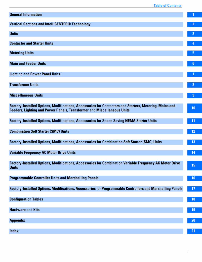
Table of Contents
General Information
Vertical Sections and IntelliCENTER® Technology
Units
Contactor and Starter Units
Metering Units
Main and Feeder Units
Lighting and Power Panel Units
Transformer Units
Miscellaneous Units
Factory-Installed Options, Modifications, Accessories for Contactors and Starters, Metering, Mains and Feeders, Lighting and Power Panels, Transformer and Miscellaneous Units
Factory-Installed Options, Modifications, Accessories for Space Saving NEMA Starter Units
Combination Soft Starter (SMC) Units
Factory-Installed Options, Modifications, Accessories for Combination Soft Starter (SMC) Units
Variable Frequency AC Motor Drive Units
Factory-Installed Options, Modifications, Accessories for Combination Variable Frequency AC Motor Drive Units
Programmable Controller Units and Marshalling Panels
Factory-Installed Options, Modifications, Accessories for Programmable Controllers and Marshalling Panels
Configuration Tables
Hardware and Kits
Appendix
Index
ive
anels
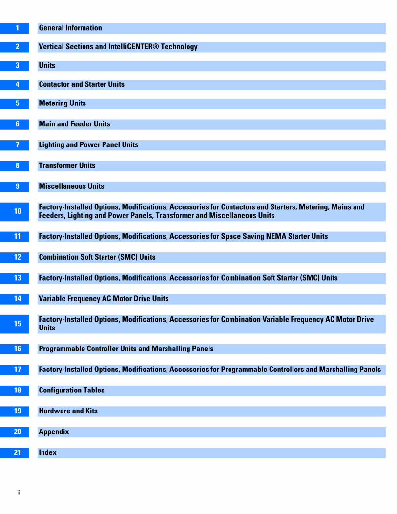
1 General Information
2 Vertical Sections and IntelliCENTER® Technology
3 Units
4 Contactor and Starter Units
5 Metering Units
6 Main and Feeder Units
7 Lighting and Power Panel Units
8 Transformer Units
9 Miscellaneous Units
10 Factory-Installed Options, Modifications, Accessories for Contactors and Starters, Metering, Mains andFeeders, Lighting and Power Panels, Transformer and Miscellaneous Units
11 Factory-Installed Options, Modifications, Accessories for Space Saving NEMA Starter Units
12 Combination Soft Starter (SMC) Units
13 Factory-Installed Options, Modifications, Accessories for Combination Soft Starter (SMC) Units
14 Variable Frequency AC Motor Drive Units
15 Factory-Installed Options, Modifications, Accessories for Combination Variable Frequency AC Motor DrUnits
16 Programmable Controller Units and Marshalling Panels
17 Factory-Installed Options, Modifications, Accessories for Programmable Controllers and Marshalling P
18 Configuration Tables
19 Hardware and Kits
20 Appendix1521 Index
ii
1
2
3
5
General Information
Publication OverviewPublication 2100-CA001x-EN-P is a catalog used for CENTERLINE® 2100 Motor Control Centers (MCCs).
Other Resource Publications for CENTERLINE 2100 Motor Control Centers
1
Contact your local Rockwell Automation sales representative, Allen-Bradley distributor or visit www.rockwellautomation.com/literature.
CENTERLINE 2100 MCC ApplicationsCENTERLINE 2100 MCCs are suitable for use on 3-phase, 3-wire or 4-wire, Wye connected power systems, rated 600 V or less, 50 or 60 hertz, which have a solidly grounded neutral. CENTERLINE 2100 MCCs may also be used on other power system configurations, however, some units and options may not be available. Refer to Appendix page 247 for additional information.
Service and Storage ConditionsCENTERLINE 2100 MCCs conform to NEMA standard ICS 1-1993 for service and storage conditions. All MCCs should have an ambient operating temperature above 0oC but shall not exceed 40oC with up to 95% non-condensing humidity. If the equipment is stored, the ambient temperature shall be above -30oC but shall not exceed 65oC. In addition, MCCs have an altitude class of 2km. The altitude class of 2 km designates equipment for installation where the altitude does not exceed 2000 meters (6600 feet). For installation above 2000 meters, Contact your local Rockwell Automation Sales Office for derating requirements.
UL/cUL/CSA MarkingCENTERLINE 2100 MCCs are listed by Underwriters Laboratories, Inc. (file number E49289) as complying with Standard Safety UL 845 (UL) and either listed by Underwriters Laboratories, Inc. or certified by Canadian Standards Association (CSA) as complying with standard C22-2, No. 254-05 (cUL or CSA). CENTERLINE 2100 MCCs also meet the requirements in Mexican standard for MCCs, NMXJ-353-ANCE-2006. The MCC product, sections and units will therefore carry the respective marking unless otherwise indicated in the footnotes on the various pages in this publication.
ISO 9001 CertificationThe facilities that develop and manufacture CENTERLINE 2100 MCCs are located in Milwaukee and Richland Center, Wisconsin, Cambridge, Ontario, Canada, Tecate, Mexico and Guadalupe, Mexico. All facilities have been certified to be in conformance to the requirements of Quality Management System ISO 9001. These facilities presently are certified by Det Norske Veritas to ISO 9001: 2000, certificate number CERT-9379-2004-AQ-HOU ANAB, effective May 30, 2007.
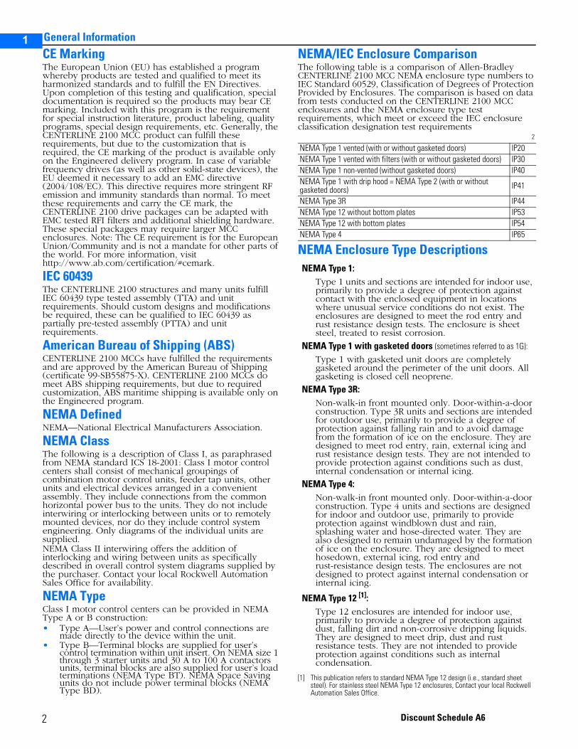
CENTERLINE® 2100 Motor Control Center with IntelliCENTER Technology
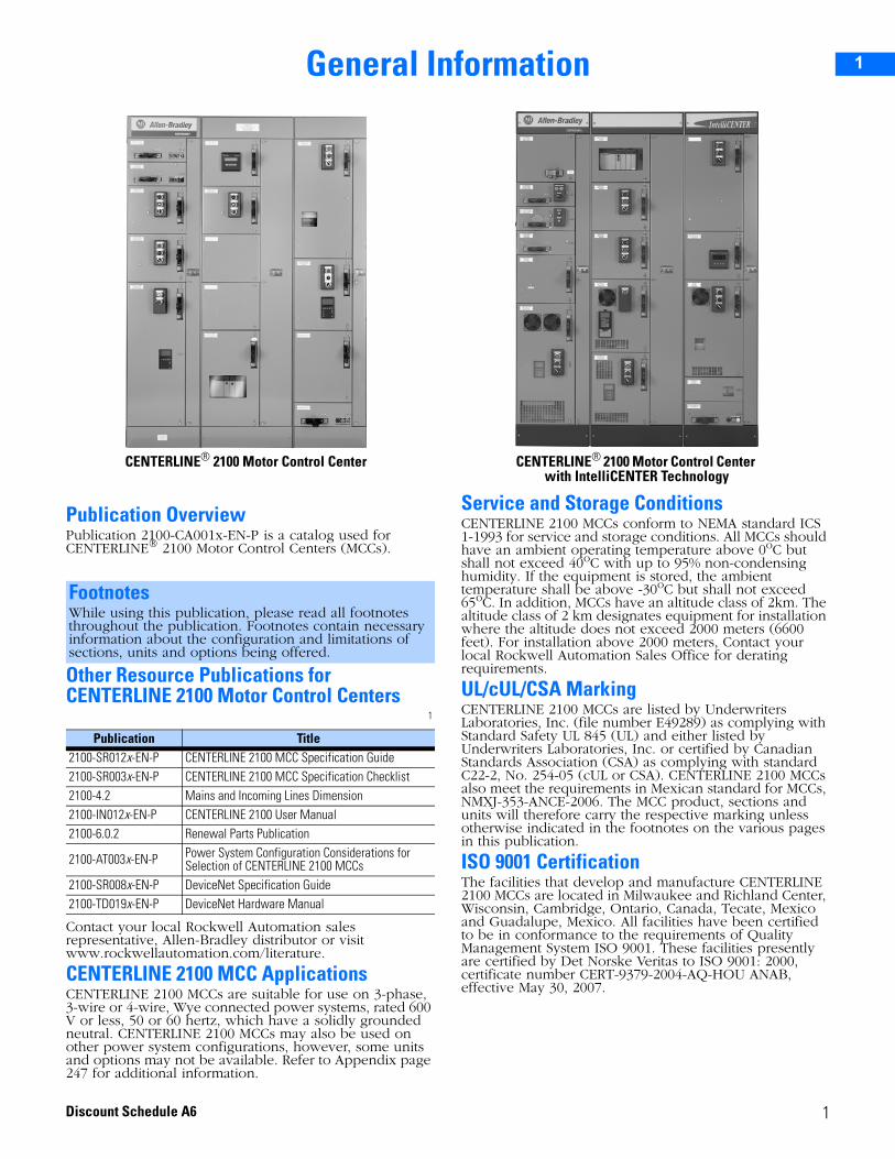
CENTERLINE® 2100 Motor Control Center
FootnotesWhile using this publication, please read all footnotes throughout the publication. Footnotes contain necessary information about the configuration and limitations of sections, units and options being offered.
Publication Title2100-SR012x-EN-P CENTERLINE 2100 MCC Specification Guide2100-SR003x-EN-P CENTERLINE 2100 MCC Specification Checklist2100-4.2 Mains and Incoming Lines Dimension2100-IN012x-EN-P CENTERLINE 2100 User Manual2100-6.0.2 Renewal Parts Publication
2100-AT003x-EN-P Power System Configuration Considerations for Selection of CENTERLINE 2100 MCCs
2100-SR008x-EN-P DeviceNet Specification Guide2100-TD019x-EN-P DeviceNet Hardware Manual
1Discount Schedule A6
1
2
3
5
General Information
CE MarkingThe European Union (EU) has established a program whereby products are tested and qualified to meet its harmonized standards and to fulfill the EN Directives. Upon completion of this testing and qualification, special documentation is required so the products may bear CE marking. Included with this program is the requirement for special instruction literature, product labeling, quality programs, special design requirements, etc. Generally, the CENTERLINE 2100 MCC product can fulfill these requirements, but due to the customization that is required, the CE marking of the product is available only on the Engineered delivery program. In case of variable frequency drives (as well as other solid-state devices), the EU deemed it necessary to add an EMC directive (2004/108/EC). This directive requires more stringent RF emission and immunity standards than normal. To meet these requirements and carry the CE mark, the CENTERLINE 2100 drive packages can be adapted with EMC tested RFI filters and additional shielding hardware. These special packages may require larger MCC enclosures. Note: The CE requirement is for the European Union/Community and is not a mandate for other parts of the world. For more information, visit http://www.ab.com/certification/#cemark.
IEC 60439The CENTERLINE 2100 structures and many units fulfill IEC 60439 type tested assembly (TTA) and unit requirements. Should custom designs and modifications be required, these can be qualified to IEC 60439 as partially pre-tested assembly (PTTA) and unit requirements.
American Bureau of Shipping (ABS)CENTERLINE 2100 MCCs have fulfilled the requirements and are approved by the American Bureau of Shipping (certificate 99-SB55875-X). CENTERLINE 2100 MCCs do meet ABS shipping requirements, but due to required customization, ABS maritime shipping is available only on the Engineered program.
NEMA DefinedNEMA—National Electrical Manufacturers Association.
NEMA ClassThe following is a description of Class I, as paraphrased from NEMA standard ICS 18-2001: Class I motor control centers shall consist of mechanical groupings of combination motor control units, feeder tap units, other units and electrical devices arranged in a convenient assembly. They include connections from the common horizontal power bus to the units. They do not include interwiring or interlocking between units or to remotely mounted devices, nor do they include control system engineering. Only diagrams of the individual units are supplied.NEMA Class II interwiring offers the addition of interlocking and wiring between units as specifically described in overall control system diagrams supplied by the purchaser. Contact your local Rockwell Automation Sales Office for availability.
NEMA TypeClass I motor control centers can be provided in NEMA Type A or B construction:• Type A—User’s power and control connections are
made directly to the device within the unit.• Type B—Terminal blocks are supplied for user’s
control termination within unit insert. On NEMA size 1 through 3 starter units and 30 A to 100 A contactors units, terminal blocks are also supplied for user’s load terminations (NEMA Type BT). NEMA Space Saving units do not include power terminal blocks (NEMA Type BD).
NEMA/IEC Enclosure ComparisonThe following table is a comparison of Allen-Bradley CENTERLINE 2100 MCC NEMA enclosure type numbers to IEC Standard 60529, Classification of Degrees of Protection Provided by Enclosures. The comparison is based on data from tests conducted on the CENTERLINE 2100 MCC enclosures and the NEMA enclosure type test requirements, which meet or exceed the IEC enclosure classification designation test requirements
2
NEMA Enclosure Type Descriptions
NEMA Type 1 vented (with or without gasketed doors) IP20NEMA Type 1 vented with filters (with or without gasketed doors) IP30NEMA Type 1 non-vented (without gasketed doors) IP40NEMA Type 1 with drip hood = NEMA Type 2 (with or without gasketed doors) IP41
NEMA Type 3R IP44NEMA Type 12 without bottom plates IP53NEMA Type 12 with bottom plates IP54NEMA Type 4 IP65
NEMA Type 1:Type 1 units and sections are intended for indoor use, primarily to provide a degree of protection against contact with the enclosed equipment in locations where unusual service conditions do not exist. The enclosures are designed to meet the rod entry and rust resistance design tests. The enclosure is sheet steel, treated to resist corrosion.
NEMA Type 1 with gasketed doors (sometimes referred to as 1G):
Type 1 with gasketed unit doors are completely gasketed around the perimeter of the unit doors. All gasketing is closed cell neoprene.
NEMA Type 3R:Non-walk-in front mounted only. Door-within-a-door construction. Type 3R units and sections are intended for outdoor use, primarily to provide a degree of protection against falling rain and to avoid damage from the formation of ice on the enclosure. They are designed to meet rod entry, rain, external icing and rust resistance design tests. They are not intended to provide protection against conditions such as dust, internal condensation or internal icing.
NEMA Type 4:Non-walk-in front mounted only. Door-within-a-door construction. Type 4 units and sections are designed for indoor and outdoor use, primarily to provide protection against windblown dust and rain, splashing water and hose-directed water. They are also designed to remain undamaged by the formation of ice on the enclosure. They are designed to meet hosedown, external icing, rod entry and rust-resistance design tests. The enclosures are not designed to protect against internal condensation or internal icing.
NEMA Type 12 [1]:
[1] This publication refers to standard NEMA Type 12 design (i.e., standard sheet steel). For stainless steel NEMA Type 12 enclosures, Contact your local Rockwell Automation Sales Office.
Type 12 enclosures are intended for indoor use, primarily to provide a degree of protection against dust, falling dirt and non-corrosive dripping liquids. They are designed to meet drip, dust and rust resistance tests. They are not intended to provide protection against conditions such as internal condensation.
2 Discount Schedule A6
1
2
3
5
General Information
Delivery ProgramsCENTERLINE 2100 MCC products are available on several quick delivery programs and limited to equipment described in this publication.
Delivery Time will be based on the equipment with the longest lead time. Quicker delivery is possible when equipment is separated and ordered according to the delivery category. For example, if an order has one engineered plug-in unit and the remaining units and sections are SC-II - order the engineered unit as a separate item. The SC-II units and sections will ship on the SC-II delivery program and only the engineered unit will have a longer delivery time.
Delivery Program IndicationsDelivery programs are indicated in the right column on all pages. PE delivery program is indicated by shaded cells.
3
Seismic ApplicationsCENTERLINE 2100 MCCs meet the requirements for Uniform Building Code (UBC) Zone 4 seismic applications and comply with IBC 2000 & 2006 seismic criteria. See Appendix page 246 for more information.
DeviceNet™ ProductsLook for DeviceNet capable devices throughout this publication to find units and options that are DeviceNet ready to use in CENTERLINE 2100 MCCs with IntelliCENTER technology. The components used in these units are DeviceNet compatible and ODVA certified. Also, the installation conforms to the rules and guidelines of The Planning and Installation Manual for DeviceNet.IntelliCENTER technology (power supply unit, built-in cabling system, unit cables, etc.) is UL and cUL listed and meets the requirements of a Class 1 power limited circuit (in Canada, Class 1 extra-low-voltage power circuit). Per NEC, this circuit is supplied from a source that has a rated output of not more than 30 Volts and 1000 Volt-Amperes. The power supply unit has an 8A, 24V output and the DeviceNet cabling is rated 8A, 600V. See NEC Article 725 for more detailed information.
Type 2 ProtectionShort circuit coordination is defined in IEC 60947-4-1.Type 2 protection (also referred to as Type 2 coordination) is obtainable when the fuses are specified and sized according to publication 100-2.8, Certified Type 2 Short Circuit Coordination with Allen-Bradley Motor Starters. Only Type 1 coordination is available, other than on specified fuses and circuit breaker units.
Motor ApplicationsThe Motor Control Center Business has made engineering evaluations for the protective device (circuit breaker or fuse) selection, sizing and setting range based on the protection rules/requirements and motor criteria as stipulated in NEC, NEMA and UL standards (e.g., motor full load currents [FLCs], X/R ratios, lock rotor currents, nominal utilization voltages, etc.). Should the motor application have criteria that deviate from those stated in the aforementioned standards, higher FLC and/or motor inrush currents (greater than 1300% of the nominal FLC) may be experienced (e.g., special motors, non-standard NEMA motors, energy efficient motors, Design E motors, IEC Type N motors, etc.). To address these cases, consult publications 2100-TD001x-EN-P and 2100-TD002x-EN-P (for circuit breaker applications), publication 2100-TD003x-EN-P (for power fuse applications) and the NEC for selection guidance. For further assistance or information, contact your local Rockwell Automation Sales Office.
DocumentationFor assembled motor control centers, the customer is supplied with a copy of the motor control center layout and specification (Form 385) and publication 2100-IN012x-EN-P, CENTERLINE 2100 Motor Control Centers User Manual. Publication 2100-IN040x-EN-P, Receiving, Handling and Storing Motor Control Centers, is attached to the outside packaging of each shipping block. Information on bus torquing is located on the inside of each vertical wireway door. Documentation for individual units consists of a copy of the unit wiring diagram and installation instructions. Field termination and torquing requirements for units are included on the unit wiring diagrams. This documentation may be located in a centralized wiring diagram holder or other location depending on configuration. Manuals for SMC units, AC drive units, PLC units, etc. are included in a centralized location in each MCC containing these products.
SC and PE:Products indicating SC or PE delivery provide SC-I and PE-I delivery. When options are added or specified for a section, time of delivery is determined by the longest lead time.
SC-I:This program offers stock-supported, individual plug-in units as well as vertical sections with field installed plug-in units. This program applies to all plug-in units and vertical sections unless they are labeled SC-II. The SC-I program provides the quickest delivery.
SC-II:This program offers stock-supported vertical sections, with factory-installed units for a completely assembled MCC. This is either SC or SC-II. Units specifically labeled SC-II must be factory installed and are not for plug-in installation in the field.
PE-I and PE-II:Shading indicates equipment that is offered on the PE-I or PE-II program. These programs offer a broad range of pre-engineered units and sections and a slightly longer lead time than our SC programs. While PE-I units are available for plug-in installation in the field, units specifically labeled PE-II must be factory installed.
Engineered:Equipment or modifications not available on the above delivery programs may be available on the Engineered program. This program offers the complete line of assembled motor control equipment, custom wired for the customer’s needs. Additionally, a wide range of special control and bus options are offered, making this our most versatile delivery program. Contact your local Rockwell Automation Sales Office or Allen-Bradley distributor for more information.
Catalog NumberWiring Type B—Class 1
NEMA Type 1 and Type 1 w/ gasketDeliveryProgram
2112B-FA_-__ SC2112BB-GA_-__ PE-II
3Discount Schedule A6
General Information1
2
3
5
Up to three electronic documentation CDs can be also be provided at no additional cost for each MCC. The CD contains the following:• Equipment list (elevation, layout specification)
drawings• One-line diagrams (if requested)• Unit wiring diagrams• Spare parts list• User and installation manuals for Rockwell
Automation products, supplied in the specific motor control center
• Test reportingFor other documentation, refer to publication 2100-CA003x-EN-E, Low Voltage Motor Control Centers Documentation Catalog. For more information, contact your local Rockwell Automation Sales Office.
Post Shipment Support
General Terms and Conditions of SaleA copy of the general terms and conditions of sale for CENTERLINE 2100 Motor Control Centers can be obtained at www.rockwellautomation.com/termsofsale.
• Field Service• Repair & Modifications• Code 10 Authorization
• Field Complaints• Technical Issues• Warranty Issues
• Domestic and International Renewal Parts Order Services
CENTERLINE 2100 MCC:Email: [email protected]: 1-414-382-4045Phone: 1-440-646-5800Select Options 2, 5, 4 for Allen-Bradley Brand Products, Motor Control Centers, Hardware Support
CENTERLINE 2100 MCCs with IntelliCENTER technology:Email: [email protected]: 1-414-382-0505Phone: 1-440-646-5800Select Options 2, 5, 3 for Allen-Bradley Brand Products, Motor Control Centers, IntelliCENTER Support
4 Discount Schedule A6
General Information
1
2
3
5
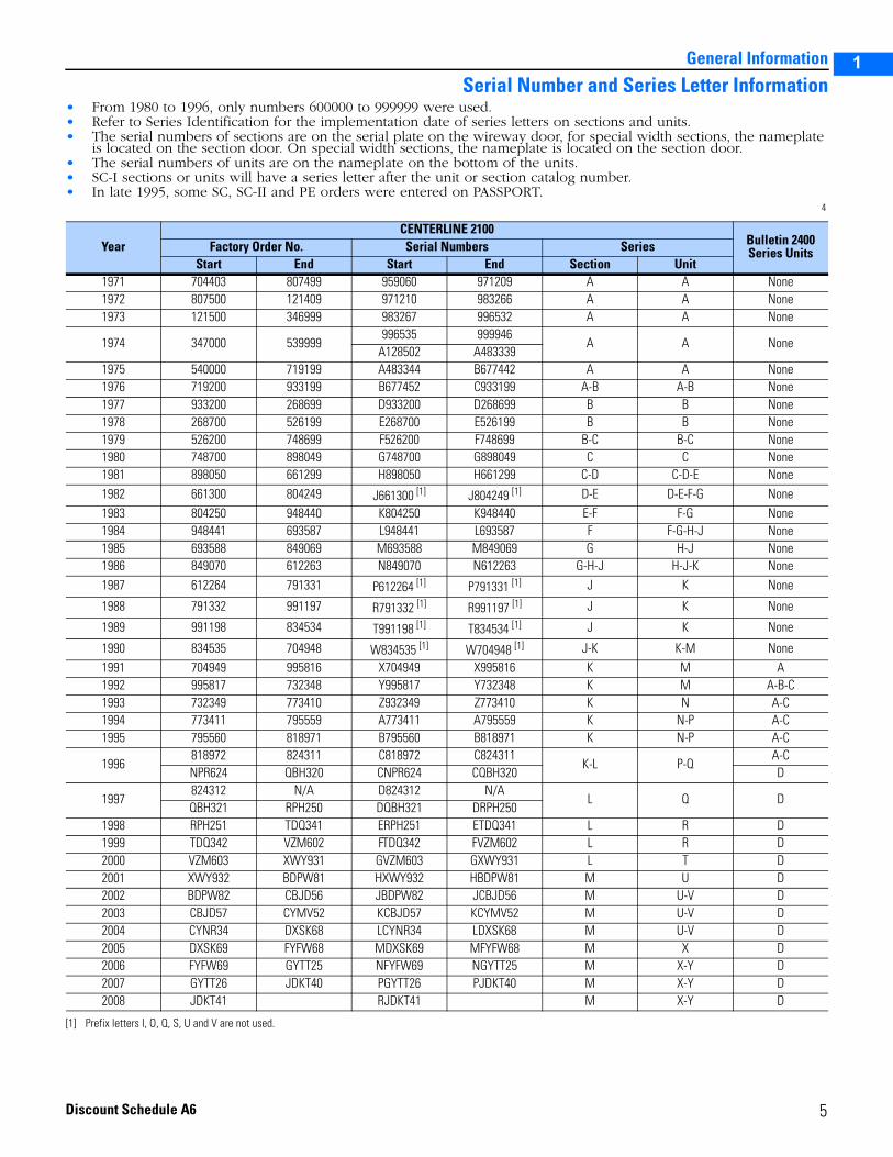
Serial Number and Series Letter Information• From 1980 to 1996, only numbers 600000 to 999999 were used.• Refer to Series Identification for the implementation date of series letters on sections and units.• The serial numbers of sections are on the serial plate on the wireway door, for special width sections, the nameplate
is located on the section door. On special width sections, the nameplate is located on the section door.• The serial numbers of units are on the nameplate on the bottom of the units.• SC-I sections or units will have a series letter after the unit or section catalog number.• In late 1995, some SC, SC-II and PE orders were entered on PASSPORT.
4
YearCENTERLINE 2100
Bulletin 2400 Series UnitsFactory Order No. Serial Numbers Series
Start End Start End Section Unit1971 704403 807499 959060 971209 A A None1972 807500 121409 971210 983266 A A None1973 121500 346999 983267 996532 A A None
1974 347000 539999996535 999946
A A NoneA128502 A483339
1975 540000 719199 A483344 B677442 A A None1976 719200 933199 B677452 C933199 A-B A-B None1977 933200 268699 D933200 D268699 B B None1978 268700 526199 E268700 E526199 B B None1979 526200 748699 F526200 F748699 B-C B-C None1980 748700 898049 G748700 G898049 C C None1981 898050 661299 H898050 H661299 C-D C-D-E None1982 661300 804249 J661300 [1]
[1] Prefix letters I, O, Q, S, U and V are not used.
J804249 [1] D-E D-E-F-G None1983 804250 948440 K804250 K948440 E-F F-G None1984 948441 693587 L948441 L693587 F F-G-H-J None1985 693588 849069 M693588 M849069 G H-J None1986 849070 612263 N849070 N612263 G-H-J H-J-K None1987 612264 791331 P612264 [1] P791331 [1] J K None
1988 791332 991197 R791332 [1] R991197 [1] J K None
1989 991198 834534 T991198 [1] T834534 [1] J K None
1990 834535 704948 W834535 [1] W704948 [1] J-K K-M None1991 704949 995816 X704949 X995816 K M A1992 995817 732348 Y995817 Y732348 K M A-B-C1993 732349 773410 Z932349 Z773410 K N A-C1994 773411 795559 A773411 A795559 K N-P A-C1995 795560 818971 B795560 B818971 K N-P A-C
1996818972 824311 C818972 C824311
K-L P-QA-C
NPR624 QBH320 CNPR624 CQBH320 D
1997824312 N/A D824312 N/A
L Q DQBH321 RPH250 DQBH321 DRPH250
1998 RPH251 TDQ341 ERPH251 ETDQ341 L R D1999 TDQ342 VZM602 FTDQ342 FVZM602 L R D2000 VZM603 XWY931 GVZM603 GXWY931 L T D2001 XWY932 BDPW81 HXWY932 HBDPW81 M U D2002 BDPW82 CBJD56 JBDPW82 JCBJD56 M U-V D2003 CBJD57 CYMV52 KCBJD57 KCYMV52 M U-V D2004 CYNR34 DXSK68 LCYNR34 LDXSK68 M U-V D2005 DXSK69 FYFW68 MDXSK69 MFYFW68 M X D2006 FYFW69 GYTT25 NFYFW69 NGYTT25 M X-Y D2007 GYTT26 JDKT40 PGYTT26 PJDKT40 M X-Y D2008 JDKT41 RJDKT41 M X-Y D
5Discount Schedule A6
1
2
3
5
General Information
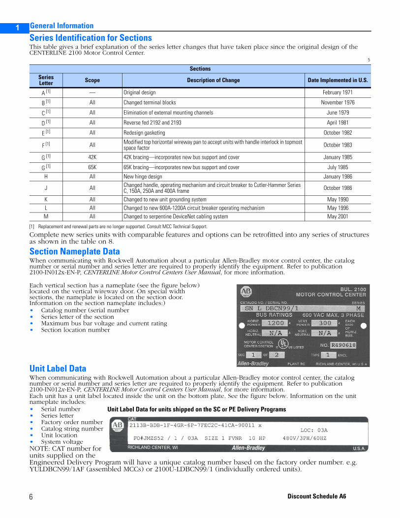
Series Identification for SectionsThis table gives a brief explanation of the series letter changes that have taken place since the original design of the CENTERLINE 2100 Motor Control Center.
5
Complete new series units with comparable features and options can be retrofitted into any series of structures as shown in the table on 8.
Section Nameplate DataWhen communicating with Rockwell Automation about a particular Allen-Bradley motor control center, the catalog number or serial number and series letter are required to properly identify the equipment. Refer to publication 2100-IN012x-EN-P, CENTERLINE Motor Control Centers User Manual, for more information.
Each vertical section has a nameplate (see the figure below) located on the vertical wireway door. On special width sections, the nameplate is located on the section door. Information on the section nameplate includes:)• Catalog number (serial number• Series letter of the section• Maximum bus bar voltage and current rating• Section location number
Unit Label DataWhen communicating with Rockwell Automation about a particular Allen-Bradley motor control center, the catalog number or serial number and series letter are required to properly identify the equipment. Refer to publication 2100-IN012x-EN-P, CENTERLINE Motor Control Centers User Manual, for more information.Each unit has a unit label located inside the unit on the bottom plate. See the figure below. Information on the unit nameplate includes:• Serial number• Series letter• Factory order number• Catalog string number• Unit location• System voltageNOTE: CAT number for units supplied on the Engineered Delivery Program will have a unique catalog number based on the factory order number. e.g. YULDBCN99/1AF (assembled MCCs) or 2100U-LDBCN99/1 (individually ordered units).
SectionsSeriesLetter Scope Description of Change Date Implemented in U.S.
A [1]
[1] Replacement and renewal parts are no longer supported. Consult MCC Technical Support.
— Original design February 1971
B [1] All Changed terminal blocks November 1976
C [1] All Elimination of external mounting channels June 1979
D [1] All Reverse fed 2192 and 2193 April 1981
E [1] All Redesign gasketing October 1982
F [1] All Modified top horizontal wireway pan to accept units with handle interlock in topmost space factor October 1983
G [1] 42K 42K bracing—incorporates new bus support and cover January 1985
G [1] 65K 65K bracing—incorporates new bus support and cover July 1985
H All New hinge design January 1986
J All Changed handle, operating mechanism and circuit breaker to Cutler-Hammer Series C, 150A, 250A and 400A frame October 1986
K All Changed to new unit grounding system May 1990L All Changed to new 600A-1200A circuit breaker operating mechanism May 1996M All Changed to serpentine DeviceNet cabling system May 2001
Unit Label Data for units shipped on the SC or PE Delivery Programs
6 Discount Schedule A6
General Information
1
2
3
5
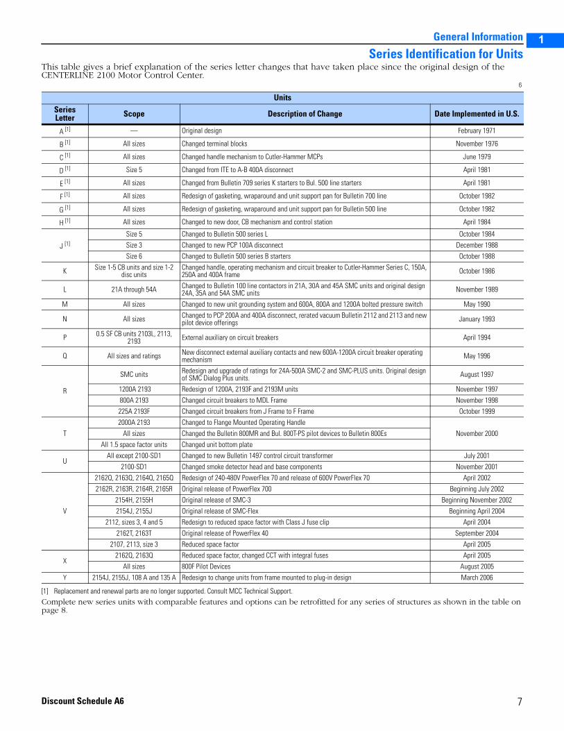
Series Identification for UnitsThis table gives a brief explanation of the series letter changes that have taken place since the original design of the CENTERLINE 2100 Motor Control Center.
6
Complete new series units with comparable features and options can be retrofitted for any series of structures as shown in the table on page 8.
UnitsSeriesLetter Scope Description of Change Date Implemented in U.S.
A [1]
[1] Replacement and renewal parts are no longer supported. Consult MCC Technical Support.
— Original design February 1971
B [1] All sizes Changed terminal blocks November 1976
C [1] All sizes Changed handle mechanism to Cutler-Hammer MCPs June 1979
D [1] Size 5 Changed from ITE to A-B 400A disconnect April 1981
E [1] All sizes Changed from Bulletin 709 series K starters to Bul. 500 line starters April 1981
F [1] All sizes Redesign of gasketing, wraparound and unit support pan for Bulletin 700 line October 1982
G [1] All sizes Redesign of gasketing, wraparound and unit support pan for Bulletin 500 line October 1982
H [1] All sizes Changed to new door, CB mechanism and control station April 1984
J [1]
Size 5 Changed to Bulletin 500 series L October 1984
Size 3 Changed to new PCP 100A disconnect December 1988
Size 6 Changed to Bulletin 500 series B starters October 1988
K Size 1-5 CB units and size 1-2 disc units
Changed handle, operating mechanism and circuit breaker to Cutler-Hammer Series C, 150A, 250A and 400A frame October 1986
L 21A through 54A Changed to Bulletin 100 line contactors in 21A, 30A and 45A SMC units and original design 24A, 35A and 54A SMC units November 1989
M All sizes Changed to new unit grounding system and 600A, 800A and 1200A bolted pressure switch May 1990
N All sizes Changed to PCP 200A and 400A disconnect, rerated vacuum Bulletin 2112 and 2113 and new pilot device offerings January 1993
P 0.5 SF CB units 2103L, 2113, 2193 External auxiliary on circuit breakers April 1994
Q All sizes and ratings New disconnect external auxiliary contacts and new 600A-1200A circuit breaker operating mechanism May 1996
R
SMC units Redesign and upgrade of ratings for 24A-500A SMC-2 and SMC-PLUS units. Original design of SMC Dialog Plus units. August 1997
1200A 2193 Redesign of 1200A, 2193F and 2193M units November 1997
800A 2193 Changed circuit breakers to MDL Frame November 1998
225A 2193F Changed circuit breakers from J Frame to F Frame October 1999
T
2000A 2193 Changed to Flange Mounted Operating Handle
November 2000All sizes Changed the Bulletin 800MR and Bul. 800T-PS pilot devices to Bulletin 800Es
All 1.5 space factor units Changed unit bottom plate
UAll except 2100-SD1 Changed to new Bulletin 1497 control circuit transformer July 2001
2100-SD1 Changed smoke detector head and base components November 2001
V
2162Q, 2163Q, 2164Q, 2165Q Redesign of 240-480V PowerFlex 70 and release of 600V PowerFlex 70 April 2002
2162R, 2163R, 2164R, 2165R Original release of PowerFlex 700 Beginning July 2002
2154H, 2155H Original release of SMC-3 Beginning November 2002
2154J, 2155J Original release of SMC-Flex Beginning April 2004
2112, sizes 3, 4 and 5 Redesign to reduced space factor with Class J fuse clip April 2004
2162T, 2163T Original release of PowerFlex 40 September 2004
2107, 2113, size 3 Reduced space factor April 2005
X2162Q, 2163Q Reduced space factor, changed CCT with integral fuses April 2005
All sizes 800F Pilot Devices August 2005Y 2154J, 2155J, 108 A and 135 A Redesign to change units from frame mounted to plug-in design March 2006
7
Discount Schedule A6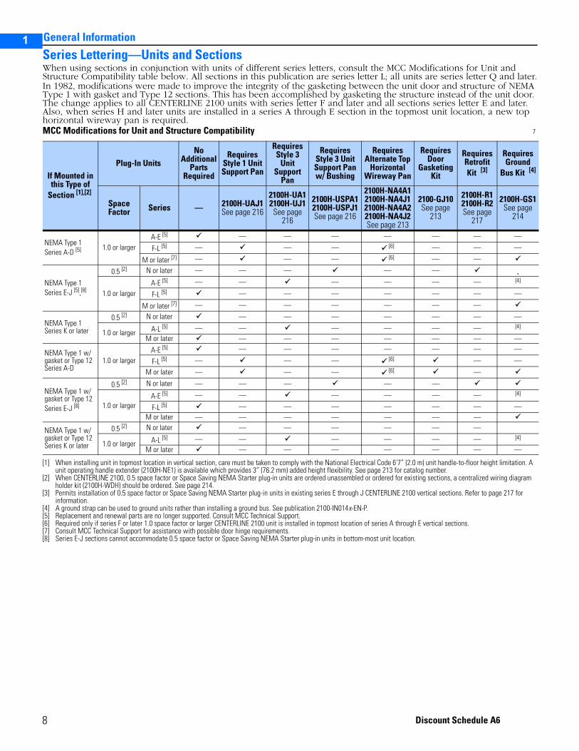
1
2
3
5
General Information
Series Lettering—Units and SectionsWhen using sections in conjunction with units of different series letters, consult the MCC Modifications for Unit and Structure Compatibility table below. All sections in this publication are series letter L; all units are series letter Q and later.In 1982, modifications were made to improve the integrity of the gasketing between the unit door and structure of NEMA Type 1 with gasket and Type 12 sections. This has been accomplished by gasketing the structure instead of the unit door. The change applies to all CENTERLINE 2100 units with series letter F and later and all sections series letter E and later. Also, when series H and later units are installed in a series A through E section in the topmost unit location, a new top horizontal wireway pan is required.MCC Modifications for Unit and Structure Compatibility 7
If Mounted in this Type of
Section [1],[2]
[1] When installing unit in topmost location in vertical section, care must be taken to comply with the National Electrical Code 6'7” (2.0 m) unit handle-to-floor height limitation. A unit operating handle extender (2100H-NE1) is available which provides 3” (76.2 mm) added height flexibility. See page 213 for catalog number.
[2] When CENTERLINE 2100, 0.5 space factor or Space Saving NEMA Starter plug-in units are ordered unassembled or ordered for existing sections, a centralized wiring diagram holder kit (2100H-WDH) should be ordered. See page 214.
Plug-In UnitsNo
Additional Parts
Required
Requires Style 1 Unit Support Pan
Requires Style 3
Unit Support
Pan
RequiresStyle 3 Unit Support Panw/ Bushing
RequiresAlternate Top
Horizontal Wireway Pan
Requires Door
Gasketing Kit
Requires RetrofitKit [3]
[3] Permits installation of 0.5 space factor or Space Saving NEMA Starter plug-in units in existing series E through J CENTERLINE 2100 vertical sections. Refer to page 217 for information.
Requires Ground
Bus Kit [4]
[4] A ground strap can be used to ground units rather than installing a ground bus. See publication 2100-IN014x-EN-P.
Space Factor Series — 2100H-UAJ1
See page 216
2100H-UA12100H-UJ1
See page 216
2100H-USPA12100H-USPJ1See page 216
2100H-NA4A12100H-NA4J12100H-NA4A22100H-NA4J2See page 213
2100-GJ10See page
213
2100H-R12100H-R2See page
217
2100H-GS1See page
214
NEMA Type 1Series A-D [5]
[5] Replacement and renewal parts are no longer supported. Consult MCC Technical Support.
1.0 or largerA-E [5] — — — — — — —
F-L [5] — — — [6]
[6] Required only if series F or later 1.0 space factor or larger CENTERLINE 2100 unit is installed in topmost location of series A through E vertical sections.
— — —
M or later [7]
[7] Consult MCC Technical Support for assistance with possible door hinge requirements.
— — — [6] — —
NEMA Type 1Series E-J [5],[8]
[8] Series E-J sections cannot accommodate 0.5 space factor or Space Saving NEMA Starter plug-in units in bottom-most unit location.
0.5 [2] N or later — — — — — ¸
1.0 or largerA-E [5] — — — — — — [4]
F-L [5] — — — — — — —
M or later [7] — — — — — — —
NEMA Type 1Series K or later
0.5 [2] N or later — — — — — — —
1.0 or larger A-L [5] — — — — — — [4]
M or later — — — — — — —
NEMA Type 1 w/gasket or Type 12Series A-D
1.0 or largerA-E [5] — — — — — — —
F-L [5] — — — [6] — —
M or later — — — [6] —
NEMA Type 1 w/gasket or Type 12Series E-J [8]
0.5 [2] N or later — — — — —
1.0 or largerA-E [5] — — — — — — [4]
F-L [5] — — — — — — —M or later — — — — — — —
NEMA Type 1 w/gasket or Type 12Series K or later
0.5 [2] N or later — — — — — —
1.0 or larger A-L [5] — — — — — — [4]
M or later — — — — — — —
8
Discount Schedule A6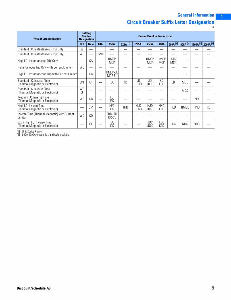
General Information
1
2
3
5
Circuit Breaker Suffix Letter Designation8
Type of Circuit Breaker
Catalog Number
DesignationCircuit Breaker Frame Type
Old New 63A 150A 225A [1]
[1] Unit Series R only.
225A 250A 400A 600A [2]
[2] 600A-2000A electronic trip circuit breakers.
800A [2] 1200A [2] 2000A [2]
Standard I.C. Instantaneous Trip Only W — — — — — — — — — —Standard I.C. Instantaneous Trip Only WG — GMCP — — — — — — — — —
High I.C. Instantaneous Trip Only — CA — HMCPMCP — — HMCP
MCPHMCPMCP
HMCPMCP — — —
Instantaneous Trip Only with Current Limiter WC — — — — — — — — — — —
High I.C. Instantaneous Trip with Current Limiter — CC — HMCP-ELMCP-EL — — — — — — — —
Standard I.C. Inverse Time (Thermal Magnetic or Electronic) WT CT — FDB FD JD
JD3DJD
JD3DKDK3D LD MDL — —
Standard I.C. Inverse Time (Thermal Magnetic or Electronic)
WT, CF — — — — — — — — MDS — —
Medium I.C. Inverse Time (Thermal Magnetic or Electronic) WB CB — FD
I3C — — — — — — ND —
High I.C. Inverse Time(Thermal Magnetic or Electronic) — CM — HFD
I6C HFD HJDJD6D
HJDJD6D
HKDK6D HLD HMDL HND RD
Inverse Time (Thermal Magnetic) with Current Limiter WD CD — FDB-LFD
I3C-CL — — — — — — — —
Extra High I.C. Inverse Time (Thermal Magnetic or Electronic) — CX — FDC
I0C — — JDCJD0D
KDCK0D LDC NDC NDC —
9
Discount Schedule A6
1
2
3
5
General Information
10
2
3
5
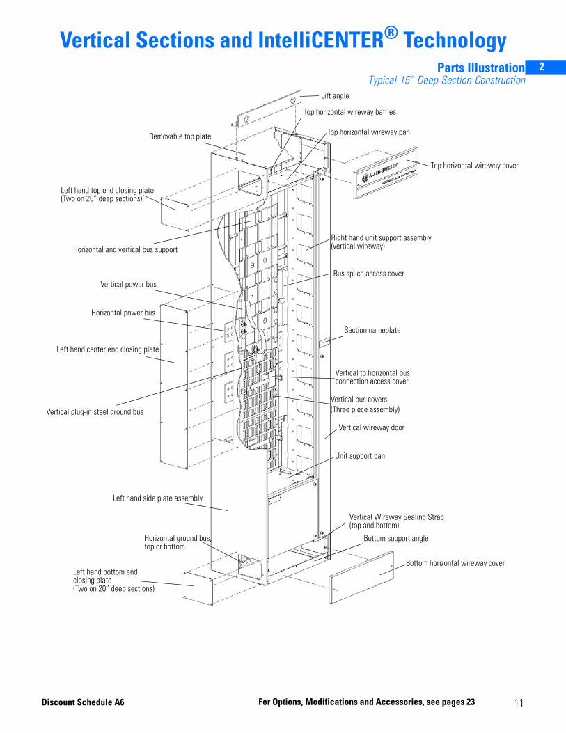
Vertical Sections and IntelliCENTER® TechnologyParts Illustration
Typical 15” Deep Section ConstructionLift angle
Top horizontal wireway baffles
Top horizontal wireway pan
Top horizontal wireway cover
Right hand unit support assembly (vertical wireway)
Bus splice access cover
Section nameplate
Vertical to horizontal bus connection access cover
Vertical bus covers(Three piece assembly)
Vertical wireway door
Unit support pan
Vertical Wireway Sealing Strap (top and bottom)
Bottom support angle
Bottom horizontal wireway coverLeft hand bottom end closing plate (Two on 20” deep sections)
Horizontal ground bus, top or bottom
Left hand side plate assembly
Vertical plug-in steel ground bus
Left hand center end closing plate
Horizontal power bus
Vertical power bus
Horizontal and vertical bus support
Left hand top end closing plate(Two on 20” deep sections)
Removable top plate
11For Options, Modifications and Accessories, see pages 23Discount Schedule A6
2
3
5
Vertical Sections and IntelliCENTER® Technology
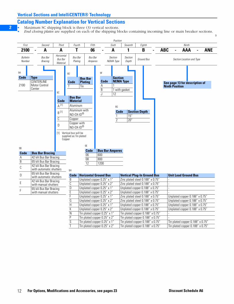
Catalog Number Explanation for Vertical Sections• Maximum SC shipping block is three (3) vertical sections.• End closing plates are supplied on each of the shipping blocks containing incoming line or main breaker sections.
9
Position
First Second Third Fourth Fifth Sixth Seventh Eighth Ninth
2100 - A A T 06 - A 1 B - ABC - AAA - ANEBulletin Number
Bus Bar Bracing
Horizontal Bus Bar Material
Bus Bar Plating
Bus Bar Amperes
Section NEMA Type
Section Depth
Ground Bus Section Location and Type
9A
Code Type
2100CENTERLINE Motor Control Center
9B
Code Bus Bar BracingA 42 kA Bus Bar BracingB 65 kA Bus Bar Bracing
C 42 kA Bus Bar Bracing with automatic shutters
D 65 kA Bus Bar Bracing with automatic shutters
E 42 kA Bus Bar Bracing with manual shutters
F 65 kA Bus Bar Bracing with manual shutters
9D
CodeBus Bar Plating
T Tin
9C
CodeBus Bar Material
A [1]
[1] Vertical bus will be supplied as Tin plated Copper
Aluminum
B [1] Aluminum with NO-OX-ID®
C Copper
DCopper with NO-OX-ID®
9G
Code Section Depth1 15”2 20”
9F
CodeSection NEMA Type
A 1B 1 with gasketJ 12
9E
Code Bus Bar Amperes06 60008 80012 1200
9H
Code Horizontal Ground Bus Vertical Plug-In Ground Bus Unit Load Ground BusB Unplated copper 0.25” x 1” Zinc plated steel 0.188” x 0.75” -C Unplated copper 0.25” x 2” Zinc plated steel 0.188” x 0.75” -D Unplated copper 0.25” x 1” Unplated copper 0.188” x 0.75” -E Unplated copper 0.25” x 2” Unplated copper 0.188” x 0.75” -F Unplated copper 0.25” x 1” Zinc plated steel 0.188” x 0.75” Unplated copper 0.188” x 0.75”G Unplated copper 0.25” x 2” Zinc plated steel 0.188” x 0.75” Unplated copper 0.188” x 0.75”H Unplated copper 0.25” x 1” Unplated copper 0.188” x 0.75” Unplated copper 0.188” x 0.75”K Unplated copper 0.25” x 2” Unplated copper 0.188” x 0.75” Unplated copper 0.188” x 0.75”N Tin plated copper 0.25” x 1” Tin plated copper 0.188” x 0.75” -P Tin plated copper 0.25” x 2” Tin plated copper 0.188” x 0.75” -S Tin plated copper 0.25” x 1” Tin plated copper 0.188” x 0.75” Tin plated copper 0.188” x 0.75”T Tin plated copper 0.25” x 2” Tin plated copper 0.188” x 0.75” Tin plated copper 0.188” x 0.75”
See page 13 for description of Ninth Position
12 For Options, Mod
ificatio ns and Acc essories, see pages 23 Discount Schedule A6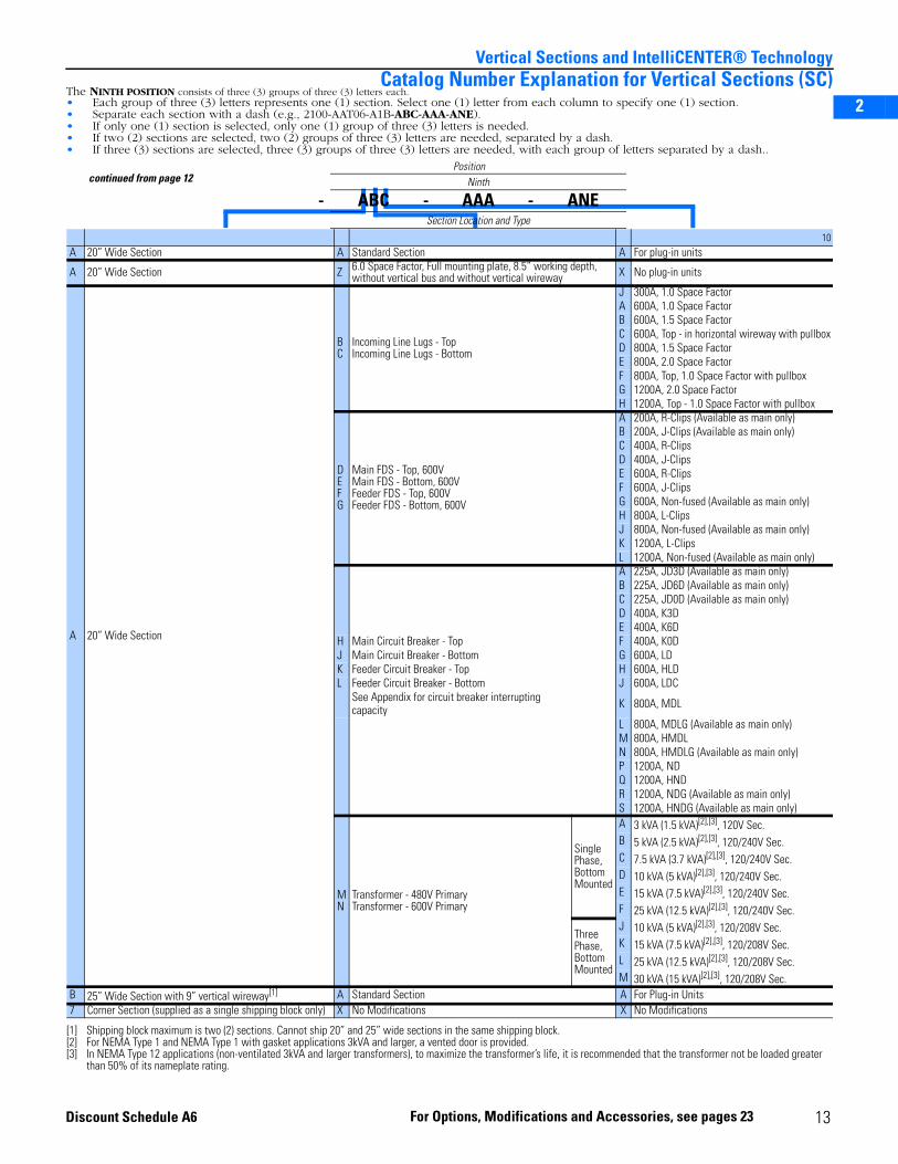
2
3
5
Vertical Sections and IntelliCENTER® TechnologyCatalog Number Explanation for Vertical Sections (SC)
The NINTH POSITION consists of three (3) groups of three (3) letters each.• Each group of three (3) letters represents one (1) section. Select one (1) letter from each column to specify one (1) section.• Separate each section with a dash (e.g., 2100-AAT06-A1B-ABC-AAA-ANE).• If only one (1) section is selected, only one (1) group of three (3) letters is needed.• If two (2) sections are selected, two (2) groups of three (3) letters are needed, separated by a dash.• If three (3) sections are selected, three (3) groups of three (3) letters are needed, with each group of letters separated by a dash..
10 A 20” Wide Section A Standard Section A For plug-in units
A 20” Wide Section Z 6.0 Space Factor, Full mounting plate, 8.5” working depth, without vertical bus and without vertical wireway X No plug-in units
A 20” Wide Section
BC
Incoming Line Lugs - TopIncoming Line Lugs - Bottom
J 300A, 1.0 Space FactorA 600A, 1.0 Space FactorB 600A, 1.5 Space FactorC 600A, Top - in horizontal wireway with pullboxD 800A, 1.5 Space FactorE 800A, 2.0 Space FactorF 800A, Top, 1.0 Space Factor with pullboxG 1200A, 2.0 Space FactorH 1200A, Top - 1.0 Space Factor with pullbox
DEFG
Main FDS - Top, 600VMain FDS - Bottom, 600VFeeder FDS - Top, 600VFeeder FDS - Bottom, 600V
A 200A, R-Clips (Available as main only)B 200A, J-Clips (Available as main only)C 400A, R-ClipsD 400A, J-ClipsE 600A, R-ClipsF 600A, J-ClipsG 600A, Non-fused (Available as main only)H 800A, L-ClipsJ 800A, Non-fused (Available as main only)K 1200A, L-ClipsL 1200A, Non-fused (Available as main only)A 225A, JD3D (Available as main only)B 225A, JD6D (Available as main only)C 225A, JD0D (Available as main only)D 400A, K3DE 400A, K6D
H Main Circuit Breaker - Top F 400A, K0DJ Main Circuit Breaker - Bottom G 600A, LDK Feeder Circuit Breaker - Top H 600A, HLDL Feeder Circuit Breaker - Bottom J 600A, LDC
See Appendix for circuit breaker interrupting capacity K 800A, MDL
L 800A, MDLG (Available as main only)M 800A, HMDLN 800A, HMDLG (Available as main only)P 1200A, NDQ 1200A, HNDR 1200A, NDG (Available as main only)S 1200A, HNDG (Available as main only)
MN
Transformer - 480V PrimaryTransformer - 600V Primary
Single Phase, Bottom Mounted
A 3 kVA (1.5 kVA)[2],[3], 120V Sec.
[2] For NEMA Type 1 and NEMA Type 1 with gasket applications 3kVA and larger, a vented door is provided.[3] In NEMA Type 12 applications (non-ventilated 3kVA and larger transformers), to maximize the transformer’s life, it is recommended that the transformer not be loaded greater
than 50% of its nameplate rating.
B 5 kVA (2.5 kVA)[2],[3], 120/240V Sec.C 7.5 kVA (3.7 kVA)[2],[3], 120/240V Sec.D 10 kVA (5 kVA)[2],[3], 120/240V Sec.E 15 kVA (7.5 kVA)[2],[3], 120/240V Sec.F 25 kVA (12.5 kVA)[2],[3], 120/240V Sec.
Three Phase, Bottom Mounted
J 10 kVA (5 kVA)[2],[3], 120/208V Sec.K 15 kVA (7.5 kVA)[2],[3], 120/208V Sec.L 25 kVA (12.5 kVA)[2],[3], 120/208V Sec.M 30 kVA (15 kVA)[2],[3], 120/208V Sec.
B 25” Wide Section with 9” vertical wireway[1]
[1] Shipping block maximum is two (2) sections. Cannot ship 20” and 25” wide sections in the same shipping block.
A Standard Section A For Plug-in Units7 Corner Section (supplied as a single shipping block only) X No Modifications X No Modifications
continued from page 12Position
Ninth
- ABC - AAA - ANESection Location and Type
13For Options, Modifications and Accessories, see pages 23Discount Schedule A6

2
3
5
Vertical Sections and IntelliCENTER® Technology
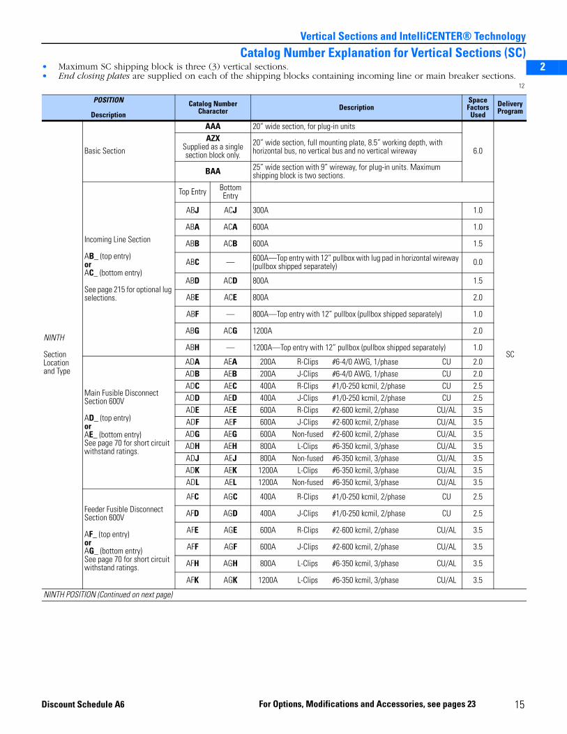
Catalog Number Explanation for Vertical Sections (SC)• Maximum SC shipping block is three (3) vertical sections.• End closing plates are supplied on each of the shipping blocks containing incoming line or main breaker sections.
11
POSITION
Description
CatalogNumber
CharacterDescription Delivery
Program
SECOND
Bus Bar Bracing
A 42kA bus bar bracing
SC
B 65kA bus bar bracingC 42kA bus bar bracing with automatic shuttersD 65kA bus bar bracing with automatic shuttersE 42kA bus bar bracing with manual shuttersF 65kA bus bar bracing with manual shutters
THIRD, FOURTH and FIFTH
Bus BarMaterial and Plating
AT06 600A aluminum bus with tin plating [1]
[1] Vertical bus will be supplied as Tin plated copper
BT06 600A aluminum bus with tin plating and NO-OX-ID [1]
CT06 600A copper bus with tin platingCT08 800A copper bus with tin platingCT12 1200A copper bus with tin platingDT06 600A copper bus with tin plating and NO-OX-IDDT08 800A copper bus with tin plating and NO-OX-IDDT12 1200A copper bus with tin plating and NO-OX-ID
SIXTH
NEMA Enclosure Type
A NEMA Type 1B NEMA Type 1 with gasketJ NEMA Type 12
SEVENTH
Section Depth
1 15” cabinet depth
2 20” cabinet depth
EIGHTH
Ground Bus
(Horizontal ground bus is mounted at the bottom of vertical section.)
BUnplated copper horizontal ground bus and vertical plug-in steel ground bus
0.25” × 1”C 0.25” × 2”D
Unplated copper horizontal ground bus and vertical plug-in unplated copper ground bus 0.25” × 1”
E 0.25” × 2”
F Unplated copper horizontal ground bus, unit load ground bus and vertical plug-in steel ground bus. If required, select unit load ground connectors on plug-in units. See page 116.
0.25” × 1”
G 0.25” × 2”
H Unplated copper horizontal ground bus, unit load ground bus and vertical plug-in unplated copper ground bus. If required, select unit load ground connectors on plug-in units. See page 116.
0.25” × 1”
K 0.25” × 2”
N Tin plated copper horizontal ground bus and vertical plug-in tin plated copper ground bus. Select tin-plated unit ground stabs on all plug-in units. See page 116.
0.25” × 1”
P 0.25” × 2”
S Tin plated copper horizontal ground bus, tin plated copper unit load ground bus and vertical plug-in tin plated copper ground bus. Select tin plated unit ground stabs on all plug-in units. See page 116. If required, select unit load ground connectors on plug-in units. See page 116.
0.25” × 1”
T 0.25” × 2”
NINTH POSITION (On next page)
14 For Options, Modifications and Accessories, see pages 23 Discount Schedule A6
2
3
5
Vertical Sections and IntelliCENTER® Technology
Catalog Number Explanation for Vertical Sections (SC)• Maximum SC shipping block is three (3) vertical sections.• End closing plates are supplied on each of the shipping blocks containing incoming line or main breaker sections.
12
POSITION
DescriptionCatalog Number
Character DescriptionSpaceFactors
UsedDelivery Program
NINTH
Section Location and Type
Basic Section
AAA 20” wide section, for plug-in units
6.0
SC
AZXSupplied as a single section block only.
20” wide section, full mounting plate, 8.5” working depth, with horizontal bus, no vertical bus and no vertical wireway
BAA 25” wide section with 9” wireway, for plug-in units. Maximum shipping block is two sections.
Incoming Line Section
AB_ (top entry)orAC_ (bottom entry)
See page 215 for optional lug selections.
Top Entry Bottom Entry
ABJ ACJ 300A 1.0
ABA ACA 600A 1.0
ABB ACB 600A 1.5
ABC — 600A—Top entry with 12” pullbox with lug pad in horizontal wireway (pullbox shipped separately) 0.0
ABD ACD 800A 1.5
ABE ACE 800A 2.0
ABF — 800A—Top entry with 12” pullbox (pullbox shipped separately) 1.0
ABG ACG 1200A 2.0
ABH — 1200A—Top entry with 12” pullbox (pullbox shipped separately) 1.0
Main Fusible DisconnectSection 600V
AD_ (top entry)orAE_ (bottom entry)See page 70 for short circuit withstand ratings.
ADA AEA 200A R-Clips #6-4/0 AWG, 1/phase CU 2.0ADB AEB 200A J-Clips #6-4/0 AWG, 1/phase CU 2.0ADC AEC 400A R-Clips #1/0-250 kcmil, 2/phase CU 2.5ADD AED 400A J-Clips #1/0-250 kcmil, 2/phase CU 2.5ADE AEE 600A R-Clips #2-600 kcmil, 2/phase CU/AL 3.5ADF AEF 600A J-Clips #2-600 kcmil, 2/phase CU/AL 3.5ADG AEG 600A Non-fused #2-600 kcmil, 2/phase CU/AL 3.5ADH AEH 800A L-Clips #6-350 kcmil, 3/phase CU/AL 3.5ADJ AEJ 800A Non-fused #6-350 kcmil, 3/phase CU/AL 3.5ADK AEK 1200A L-Clips #6-350 kcmil, 3/phase CU/AL 3.5ADL AEL 1200A Non-fused #6-350 kcmil, 3/phase CU/AL 3.5
Feeder Fusible Disconnect Section 600V
AF_ (top entry)orAG_ (bottom entry)See page 70 for short circuit withstand ratings.
AFC AGC 400A R-Clips #1/0-250 kcmil, 2/phase CU 2.5
AFD AGD 400A J-Clips #1/0-250 kcmil, 2/phase CU 2.5
AFE AGE 600A R-Clips #2-600 kcmil, 2/phase CU/AL 3.5
AFF AGF 600A J-Clips #2-600 kcmil, 2/phase CU/AL 3.5
AFH AGH 800A L-Clips #6-350 kcmil, 3/phase CU/AL 3.5
AFK AGK 1200A L-Clips #6-350 kcmil, 3/phase CU/AL 3.5
NINTH POSITION (Continued on next page)
15For Options, Modifications and Accessories, see pages 23Discount Schedule A6
2
3
5
Vertical Sections and IntelliCENTER® Technology
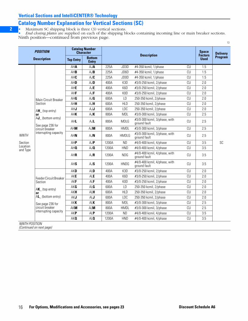
Catalog Number Explanation for Vertical Sections (SC)• Maximum SC shipping block is three (3) vertical sections.• End closing plates are supplied on each of the shipping blocks containing incoming line or main breaker sections.Ninth position—continued from previous page.
13
POSITION
Description
Catalog NumberCharacter
DescriptionSpaceFactors
UsedDeliveryProgram
Top Entry Bottom Entry
NINTH
Section Location and Type
Main Circuit Breaker Section
AH_ (top entry)orAJ_ (bottom entry)
See page 236 for circuit breaker interrupting capacity
AHA AJA 225A JD3D #4-350 kcmil, 1/phase CU 1.5
SC
AHB AJB 225A JD6D #4-350 kcmil, 1/phase CU 1.5AHC AJC 225A JD0D #4-350 kcmil, 1/phase CU 1.5AHD AJD 400A K3D #3/0-250 kcmil, 2/phase CU 2.0AHE AJE 400A K6D #3/0-250 kcmil, 2/phase CU 2.0AHF AJF 400A K0D #3/0-250 kcmil, 2/phase CU 2.0AHG AJG 600A LD 250-350 kcmil, 2/phase CU 2.0AHH AJH 600A HLD 250-350 kcmil, 2/phase CU 2.0AHJ AJJ 600A LDC 250-350 kcmil, 2/phase CU 2.0AHK AJK 800A MDL #3/0-300 kcmil, 3/phase CU 2.5
AHL AJL 800A MDLG #3/0-300 kcmil, 3/phase, with ground fault CU 2.5
AHM AJM 800A HMDL #3/0-300 kcmil, 3/phase CU 2.5
AHN AJN 800A HMDLG #3/0-300 kcmil, 3/phase, with ground fault CU 2.5
AHP AJP 1200A ND #4/0-400 kcmil, 4/phase CU 3.5AHQ AJQ 1200A HND #4/0-400 kcmil, 4/phase CU 3.5
AHR AJR 1200A NDG #4/0-400 kcmil, 4/phase, with ground fault CU 3.5
AHS AJS 1200A HNDG #4/0-400 kcmil, 4/phase, with ground fault CU 3.5
Feeder Circuit Breaker Section
AK_ (top entry)orAL_ (bottom entry)
See page 236 for circuit breaker interrupting capacity
AKD ALD 400A K3D #3/0-250 kcmil, 2/phase CU 2.0AKE ALE 400A K6D #3/0-250 kcmil, 2/phase CU 2.0AKF ALF 400A K0D #3/0-250 kcmil, 2/phase CU 2.0AKG ALG 600A LD 250-350 kcmil, 2/phase CU 2.0AKH ALH 600A HLD 250-350 kcmil, 2/phase CU 2.0AKJ ALJ 600A LDC 250-350 kcmil, 2/phase CU 2.0AKK ALK 800A MDL #3/0-300 kcmil, 3/phase CU 2.5AKM ALM 800A HMDL #3/0-300 kcmil, 3/phase CU 2.5AKP ALP 1200A ND #4/0-400 kcmil, 4/phase CU 3.5AKQ ALQ 1200A HND #4/0-400 kcmil, 4/phase CU 3.5
NINTH POSITION(Continued on next page)
16 For Options, Modifications and Accessories, see pages 23 Discount Schedule A6
2
3
5
Vertical Sections and IntelliCENTER® Technology
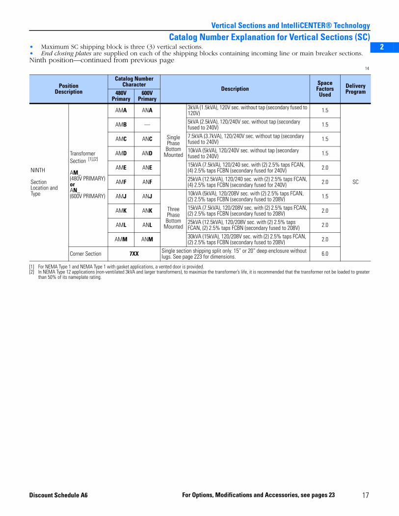
Catalog Number Explanation for Vertical Sections (SC)• Maximum SC shipping block is three (3) vertical sections.• End closing plates are supplied on each of the shipping blocks containing incoming line or main breaker sections.Ninth position—continued from previous page
14
PositionDescription
Catalog NumberCharacter
DescriptionSpaceFactors
UsedDelivery Program480V
Primary600V
Primary
NINTH
SectionLocation and Type
Transformer Section [1],[2]
AM_(480V PRIMARY)orAN_(600V PRIMARY)
[1] For NEMA Type 1 and NEMA Type 1 with gasket applications, a vented door is provided.[2] In NEMA Type 12 applications (non-ventilated 3kVA and larger transformers), to maximize the transformer’s life, it is recommended that the transformer not be loaded to greater
than 50% of its nameplate rating.
AMA ANA
Single Phase
Bottom Mounted
3kVA (1.5kVA), 120V sec. without tap (secondary fused to 120V) 1.5
SC
AMB — 5kVA (2.5kVA), 120/240V sec. without tap (secondary fused to 240V) 1.5
AMC ANC 7.5kVA (3.7kVA), 120/240V sec. without tap (secondary fused to 240V) 1.5
AMD AND 10kVA (5kVA), 120/240V sec. without tap (secondary fused to 240V) 1.5
AME ANE 15kVA (7.5kVA), 120/240 sec. with (2) 2.5% taps FCAN, (4) 2.5% taps FCBN (secondary fused for 240V) 2.0
AMF ANF 25kVA (12.5kVA), 120/240 sec. with (2) 2.5% taps FCAN, (4) 2.5% taps FCBN (secondary fused for 240V) 2.0
AMJ ANJ
Three Phase
Bottom Mounted
10kVA (5kVA), 120/208V sec. with (2) 2.5% taps FCAN, (2) 2.5% taps FCBN (secondary fused to 208V) 1.5
AMK ANK 15kVA (7.5kVA), 120/208V sec. with (2) 2.5% taps FCAN, (2) 2.5% taps FCBN (secondary fused to 208V) 2.0
AML ANL 25kVA (12.5kVA), 120/208V sec. with (2) 2.5% taps FCAN, (2) 2.5% taps FCBN (secondary fused to 208V) 2.0
AMM ANM 30kVA (15kVA), 120/208V sec. with (2) 2.5% taps FCAN, (2) 2.5% taps FCBN (secondary fused to 208V) 2.0
Corner Section 7XX Single section shipping split only. 15” or 20” deep enclosure without lugs. See page 223 for dimensions. 6.0
17For Options, Modifications and Accessories, see pages 23Discount Schedule A6

2
3
5
Vertical Sections and IntelliCENTER® Technology
Vertical Sections (SC) (Without Vertical Wireway)• Maximum SC shipping block is one (1) vertical section.• End closing plates are supplied.• Splice kits are not included.• Enclosures without horizontal bus are UL listed under the UL Standard for Safety UL 508 unless otherwise indicated.
15
Description Working Depth(Inches)
Section NEMA Type 1 NEMA Type 12DeliveryProgramDepth
(Inches)Width
(Inches) Catalog Number Catalog Number
VerticalSection
Includes full six (6.0) space factor door and mounting plate.No verticalwireway.
8.5(with horizontal bus)
15
20 2100-EKC1_1D-_ _ [1]
[1] The catalog numbers listed are not complete:• Select ground bus option B, C, N, or D from table on 14 (only horizontal ground bus is supplied; e.g., 2100-EKC1B).• Select bus bar bracing, A or B, from table on 14 (horizontal bus is provided in vertical section; e.g., 2100-EKC1B1D-A).• Select bus bar material and plating from table on 14 (e.g., 2100-EKC1B1D-AAT06).
2100-EJC1_1D-_ _ [1]
SC
25 2100-EKC1_2D-_ _ [1] 2100-EJC1_2D-_ _ [1]
30 2100-EKC1_3D-_ _ [1] 2100-EJC1_3D-_ _ [1]
35 2100-EKC1_4D-_ _ [1] 2100-EJC1_4D-_ _ [1]
20
20 2100-EKC2_1D-_ _ [1] 2100-EJC2_1D-_ _ [1]
25 2100-EKC2_2D-_ _ [1] 2100-EJC2_2D-_ _ [1]
30 2100-EKC2_3D-_ _ [1] 2100-EJC2_3D-_ _ [1]
35 2100-EKC2_4D-_ _ [1] 2100-EJC2_4D-_ _ [1]
11.5 (with horizontal bus)
[2]
[2] Horizontal bus is 5” deeper than standard.
20
20 2100-EKC2_1A-_ _ [1] 2100-EJC2_1A-_ _ [1]
25 2100-EKC2_2A-_ _ [1] 2100-EJC2_2A-_ _ [1]
30 2100-EKC2_3A-_ _ [1] 2100-EJC2_3A-_ _ [1]
35 2100-EKC2_4A-_ _ [1] 2100-EJC2_4A-_ _ [1]
14(with horizontal bus)
[2]20
20 2100-EKC2_1B-_ _ [1] 2100-EJC2_1B-_ _ [1]
25 2100-EKC2_2B-_ _ [1] 2100-EJC2_2B-_ _ [1]
30 2100-EKC2_3B-_ _ [1] 2100-EJC2_3B-_ _ [1]
35 2100-EKC2_4B-_ _ [1] 2100-EJC2_4B-_ _ [1]
11.5 (without horizontal bus) 15
20 2100-EKC1_1A [3]
[3] The catalog numbers listed are not complete. Select ground bus option B, C, N, or P from table on 14 (only horizontal ground bus is supplied; e.g., 2100-EKC1B1A).
2100-EJC1_1A [3]
25 2100-EKC1_2A [3] 2100-EJC1_2A [3]
30 2100-EKC1_3A [3] 2100-EJC1_3A [3]
35 2100-EKC1_4A [3] 2100-EJC1_4A [3]
40 [4]
[4] 40” wide vertical section is a two-door section with a 3-point latch.
2100-EKC1_5A [3] 2100-EJC1_5A [3]
14
(without horizontal bus) 15
20 2100-EKC1_1B [3] 2100-EJC1_1B [3]
25 2100-EKC1_2B [3] 2100-EJC1_2B [3]
30 2100-EKC1_3B [3] 2100-EJC1_3B [3]
35 2100-EKC1_4B [3] 2100-EJC1_4B [3]
40 [4] 2100-EKC1_5B [3] 2100-EJC1_5B [3]
19 (without horizontal
bus)20
20 2100-EKC2_1C [3] 2100-EJC2_1C [3]
25 2100-EKC2_2C [3] 2100-EJC2_2C [3]
30 2100-EKC2_3C [3] 2100-EJC2_3C [3]
35 2100-EKC2_4C [3] 2100-EJC2_4C [3]
40 [4] 2100-EKC2_5C [3] 2100-EJC2_5C [3]
18 For Options, Modifications and Accessories, see pages 23 Discount Schedule A6
2
3
5
Vertical Sections and IntelliCENTER® Technology
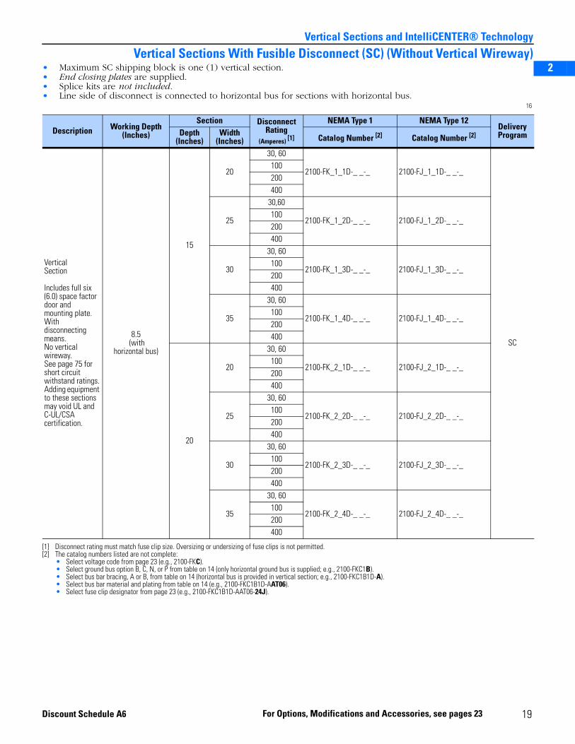
Vertical Sections With Fusible Disconnect (SC) (Without Vertical Wireway)• Maximum SC shipping block is one (1) vertical section.• End closing plates are supplied.• Splice kits are not included.• Line side of disconnect is connected to horizontal bus for sections with horizontal bus.
16
Description Working Depth(Inches)
Section Disconnect Rating
(Amperes) [1]
[1] Disconnect rating must match fuse clip size. Oversizing or undersizing of fuse clips is not permitted.
NEMA Type 1 NEMA Type 12Delivery ProgramDepth
(Inches)Width
(Inches) Catalog Number [2]
[2] The catalog numbers listed are not complete:• Select voltage code from page 23 (e.g., 2100-FKC).• Select ground bus option B, C, N, or P from table on 14 (only horizontal ground bus is supplied; e.g., 2100-FKC1B).• Select bus bar bracing, A or B, from table on 14 (horizontal bus is provided in vertical section; e.g., 2100-FKC1B1D-A).• Select bus bar material and plating from table on 14 (e.g., 2100-FKC1B1D-AAT06).• Select fuse clip designator from page 23 (e.g., 2100-FKC1B1D-AAT06-24J).
Catalog Number [2]
VerticalSection
Includes full six (6.0) space factor door andmounting plate. With disconnecting means.No vertical wireway.See page 75 for short circuit withstand ratings.Adding equipment to these sections may void UL and C-UL/CSA certification.
8.5 (with
horizontal bus)
15
20
30, 60
2100-FK_1_1D-_ _-_ 2100-FJ_1_1D-_ _-_
SC
100200400
25
30,60
2100-FK_1_2D-_ _-_ 2100-FJ_1_2D-_ _-_100200400
30
30, 60
2100-FK_1_3D-_ _-_ 2100-FJ_1_3D-_ _-_100200400
35
30, 60
2100-FK_1_4D-_ _-_ 2100-FJ_1_4D-_ _-_100200400
20
20
30, 60
2100-FK_2_1D-_ _-_ 2100-FJ_2_1D-_ _-_100200400
25
30, 60
2100-FK_2_2D-_ _-_ 2100-FJ_2_2D-_ _-_100200400
30
30, 60
2100-FK_2_3D-_ _-_ 2100-FJ_2_3D-_ _-_100200400
35
30, 60
2100-FK_2_4D-_ _-_ 2100-FJ_2_4D-_ _-_100200400
19 Discount Schedule A6 For Options, Modifications and Accessories, see pages 23
2
3
5
Vertical Sections and IntelliCENTER® Technology
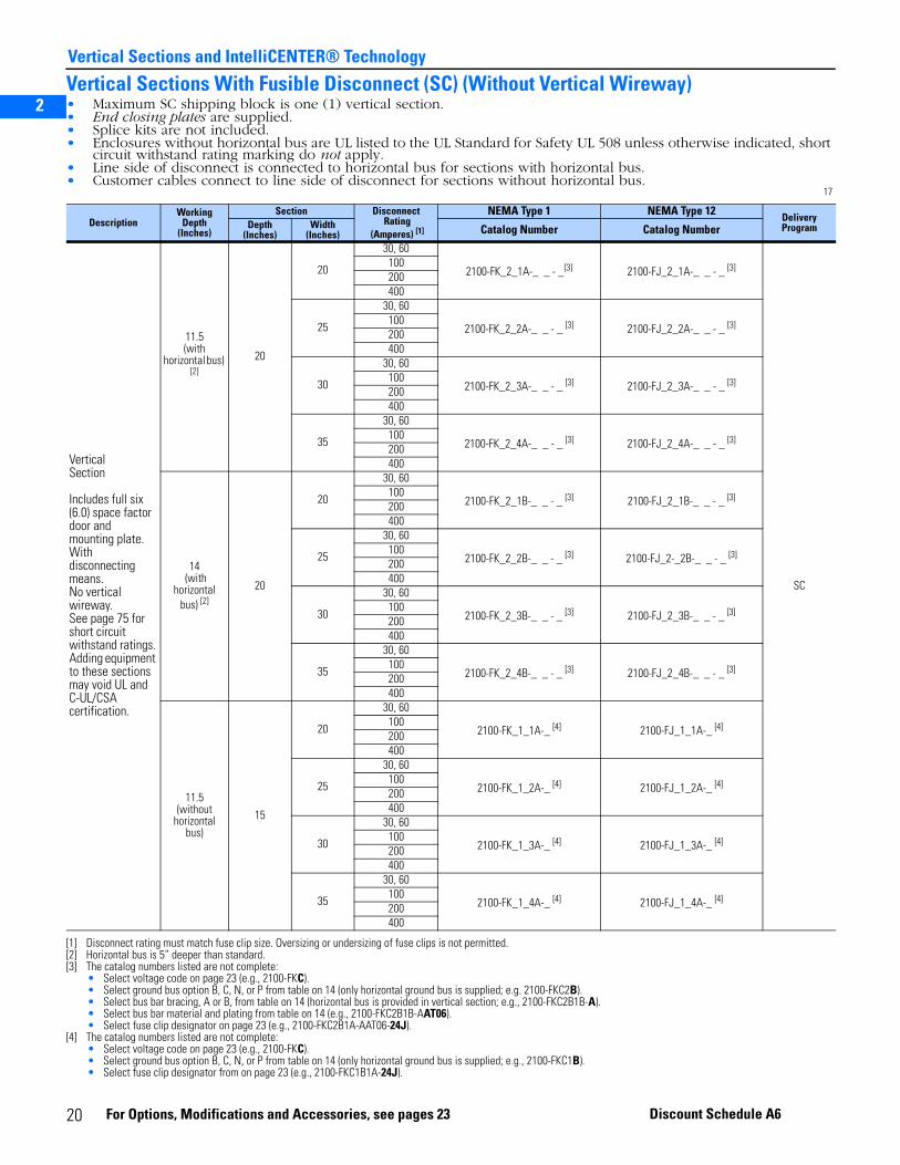
Vertical Sections With Fusible Disconnect (SC) (Without Vertical Wireway)• Maximum SC shipping block is one (1) vertical section.• End closing plates are supplied.• Splice kits are not included.• Enclosures without horizontal bus are UL listed to the UL Standard for Safety UL 508 unless otherwise indicated, short
circuit withstand rating marking do not apply.• Line side of disconnect is connected to horizontal bus for sections with horizontal bus.• Customer cables connect to line side of disconnect for sections without horizontal bus.
17
DescriptionWorking
Depth(Inches)
Section Disconnect Rating
(Amperes) [1]
[1] Disconnect rating must match fuse clip size. Oversizing or undersizing of fuse clips is not permitted.
NEMA Type 1 NEMA Type 12 DeliveryProgramDepth
(Inches)Width
(Inches) Catalog Number Catalog Number
VerticalSection
Includes full six (6.0) space factor door and mounting plate. With disconnecting means.No vertical wireway.See page 75 for short circuit withstand ratings.Adding equipment to these sections may void UL and C-UL/CSA certification.
11.5(with
horizontal bus) [2]
[2] Horizontal bus is 5” deeper than standard.
20
20
30, 60
2100-FK_2_1A-_ _ - _[3]
[3] The catalog numbers listed are not complete:• Select voltage code on page 23 (e.g., 2100-FKC).• Select ground bus option B, C, N, or P from table on 14 (only horizontal ground bus is supplied; e.g. 2100-FKC2B). • Select bus bar bracing, A or B, from table on 14 (horizontal bus is provided in vertical section; e.g., 2100-FKC2B1B-A).• Select bus bar material and plating from table on 14 (e.g., 2100-FKC2B1B-AAT06).• Select fuse clip designator on page 23 (e.g., 2100-FKC2B1A-AAT06-24J).
2100-FJ_2_1A-_ _ - _ [3]
SC
100200400
25
30, 60
2100-FK_2_2A-_ _ - _ [3] 2100-FJ_2_2A-_ _ - _ [3]100200400
30
30, 60
2100-FK_2_3A-_ _ - _ [3] 2100-FJ_2_3A-_ _ - _ [3]100200400
35
30, 60
2100-FK_2_4A-_ _ - _ [3] 2100-FJ_2_4A-_ _ - _ [3]100200400
14 (with
horizontalbus) [2]
20
20
30, 60
2100-FK_2_1B-_ _ - _ [3] 2100-FJ_2_1B-_ _ - _ [3]100200400
25
30, 60
2100-FK_2_2B-_ _ - _ [3] 2100-FJ_2-_2B-_ _ - _ [3]100200400
30
30, 60
2100-FK_2_3B-_ _ - _ [3] 2100-FJ_2_3B-_ _ - _ [3]100200400
35
30, 60
2100-FK_2_4B-_ _ - _ [3] 2100-FJ_2_4B-_ _ - _ [3]100200400
11.5 (without
horizontalbus)
15
20
30, 60
2100-FK_1_1A-_ [4]
[4] The catalog numbers listed are not complete:• Select voltage code on page 23 (e.g., 2100-FKC).• Select ground bus option B, C, N, or P from table on 14 (only horizontal ground bus is supplied; e.g., 2100-FKC1B). • Select fuse clip designator from on page 23 (e.g., 2100-FKC1B1A-24J).
2100-FJ_1_1A-_ [4]100200400
25
30, 60
2100-FK_1_2A-_ [4] 2100-FJ_1_2A-_ [4]100200400
30
30, 60
2100-FK_1_3A-_ [4] 2100-FJ_1_3A-_ [4]100200400
35
30, 60
2100-FK_1_4A-_ [4] 2100-FJ_1_4A-_ [4]100200400
20 Discount Schedule A6For Options, Modifications and Accessories, see pages 23
2
3
5
Vertical Sections and IntelliCENTER® Technology
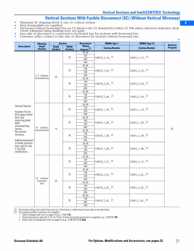
Vertical Sections With Fusible Disconnect (SC) (Without Vertical Wireway)• Maximum SC shipping block is one (1) vertical section.• End closing plates are supplied.• Enclosures without horizontal bus are UL listed to the UL Standard for Safety UL 508 unless otherwise indicated, short
circuit withstand rating marking does not apply.• Line side of disconnect is connected to horizontal bus for sections with horizontal bus.• Customer cables connect to line side of disconnect for sections without horizontal bus.
18
DescriptionWorking
Depth(Inches)
Section Disconnect Rating
(Amperes) [1]
[1] Disconnect rating must match fuse clip size. Oversizing or undersizing of fuse clips is not permitted.
NEMA Type 1 NEMA Type 12DeliveryProgramDepth
(Inches)Width
(Inches) Catalog Number Catalog Number
Vertical Section
Includes full six (6.0) space factor door and mounting plate. With disconnecting means.No vertical wireway.
Adding equipment to these sections may void UL and C-UL/CSA certification.
11.5 (without horizontal bus) 20
20
30, 60
2100-FK_2_1A-_ [2]
[2] The catalog numbers listed are not complete:• Select voltage code from on page 23 (e.g., 2100-FKC).• Select ground bus option B, C, N, or P from 14 (only horizontal ground bus is supplied; e.g., 2100-FKC1B). • Select fuse clip designator from on page 23 (e.g., 2100-FKC1B1B-24J).
2100-FJ_2_1A-_ [2]
SC
100200400
25
30, 60
2100-FK_2_2A-_ [2] 2100-FJ_2_2A-_ [2]100200400
30
30, 60
2100-FK_2_3A-_ [2] 2100-FJ_2_3A-_ [2]100200400
35
30, 60
2100-FK_2_4A-_ [2] 2100-FJ_2_4A-_ [2]100200400
14 (without horizontal bus) 15
20
30, 60
2100-FK_1_1B-_ [2] 2100-FJ_1_1B-_ [2]100200400
25
30, 60
2100-FK_1_2B-_ [2] 2100-FJ_1_2B-_ [2]100200400
30
30, 60
2100-FK_1_3B-_ [2] 2100-FJ_1_3B-_ [2]100200400
35
30, 60
2100-FK_1_4B-_ [2] 2100-FJ_1_4B-_ [2]100200400
19 (without horizontal
bus)20
20
30, 60
2100-FK_2_1C-_ [2] 2100-FJ_2_1C-_ [2]100200400
25
30, 60
2100-FK_2_2C-_ [2] 2100-FJ_2_2C-_ [2]100200400
30
30, 60
2100-FK_2_3C-_ [2] 2100-FJ_2_3C-_ [2]100200400
35
30, 60
2100-FK_2_4C-_ [2] 2100-FJ_2_4C-_ [2]100200400
21For Options, Modifications and Accessories, see pages 23Discount Schedule A6
2
3
5
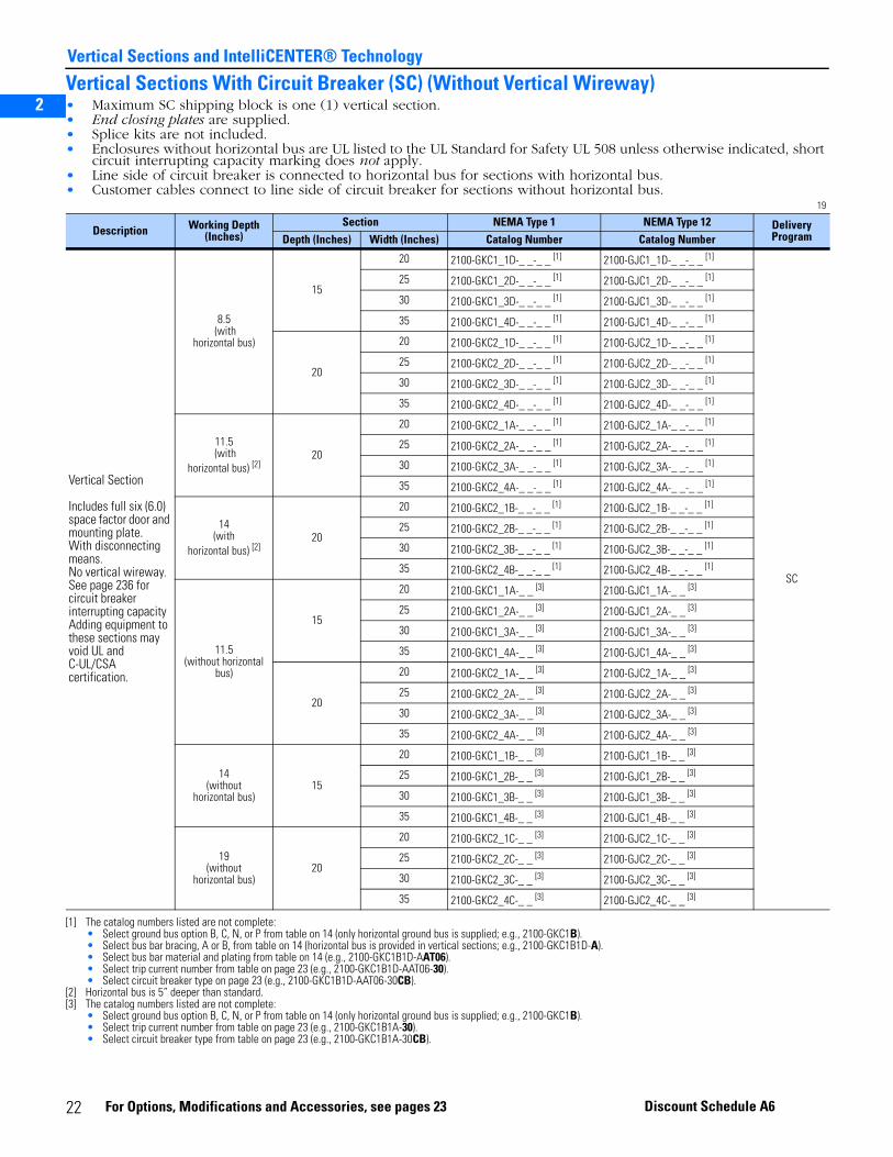
Vertical Sections and IntelliCENTER® Technology
Vertical Sections With Circuit Breaker (SC) (Without Vertical Wireway)• Maximum SC shipping block is one (1) vertical section.• End closing plates are supplied.• Splice kits are not included.• Enclosures without horizontal bus are UL listed to the UL Standard for Safety UL 508 unless otherwise indicated, short
circuit interrupting capacity marking does not apply.• Line side of circuit breaker is connected to horizontal bus for sections with horizontal bus.• Customer cables connect to line side of circuit breaker for sections without horizontal bus.
19
Description Working Depth (Inches)
Section NEMA Type 1 NEMA Type 12 Delivery ProgramDepth (Inches) Width (Inches) Catalog Number Catalog Number
Vertical Section
Includes full six (6.0) space factor door and mounting plate. With disconnecting means.No vertical wireway. See page 236 for circuit breaker interrupting capacityAdding equipment to these sections may void UL and C-UL/CSA certification.
8.5 (with
horizontal bus)
15
20 2100-GKC1_1D-_ _-_ _ [1]
[1] The catalog numbers listed are not complete:• Select ground bus option B, C, N, or P from table on 14 (only horizontal ground bus is supplied; e.g., 2100-GKC1B). • Select bus bar bracing, A or B, from table on 14 (horizontal bus is provided in vertical sections; e.g., 2100-GKC1B1D-A). • Select bus bar material and plating from table on 14 (e.g., 2100-GKC1B1D-AAT06).• Select trip current number from table on page 23 (e.g., 2100-GKC1B1D-AAT06-30).• Select circuit breaker type on page 23 (e.g., 2100-GKC1B1D-AAT06-30CB).
2100-GJC1_1D-_ _-_ _ [1]
SC
25 2100-GKC1_2D-_ _-_ _ [1] 2100-GJC1_2D-_ _-_ _ [1]
30 2100-GKC1_3D-_ _-_ _ [1] 2100-GJC1_3D-_ _-_ _ [1]
35 2100-GKC1_4D-_ _-_ _ [1] 2100-GJC1_4D-_ _-_ _ [1]
20
20 2100-GKC2_1D-_ _-_ _ [1] 2100-GJC2_1D-_ _-_ _ [1]
25 2100-GKC2_2D-_ _-_ _ [1] 2100-GJC2_2D-_ _-_ _ [1]
30 2100-GKC2_3D-_ _-_ _ [1] 2100-GJC2_3D-_ _-_ _ [1]
35 2100-GKC2_4D-_ _-_ _ [1] 2100-GJC2_4D-_ _-_ _ [1]
11.5 (with
horizontal bus) [2]
[2] Horizontal bus is 5” deeper than standard.
20
20 2100-GKC2_1A-_ _-_ _ [1] 2100-GJC2_1A-_ _-_ _ [1]
25 2100-GKC2_2A-_ _-_ _ [1] 2100-GJC2_2A-_ _-_ _ [1]
30 2100-GKC2_3A-_ _-_ _ [1] 2100-GJC2_3A-_ _-_ _ [1]
35 2100-GKC2_4A-_ _-_ _ [1] 2100-GJC2_4A-_ _-_ _ [1]
14(with
horizontal bus) [2]20
20 2100-GKC2_1B-_ _-_ _ [1] 2100-GJC2_1B-_ _-_ _ [1]
25 2100-GKC2_2B-_ _-_ _ [1] 2100-GJC2_2B-_ _-_ _ [1]
30 2100-GKC2_3B-_ _-_ _ [1] 2100-GJC2_3B-_ _-_ _ [1]
35 2100-GKC2_4B-_ _-_ _ [1] 2100-GJC2_4B-_ _-_ _ [1]
11.5(without horizontal
bus)
15
20 2100-GKC1_1A-_ _ [3]
[3] The catalog numbers listed are not complete:• Select ground bus option B, C, N, or P from table on 14 (only horizontal ground bus is supplied; e.g., 2100-GKC1B). • Select trip current number from table on page 23 (e.g., 2100-GKC1B1A-30).• Select circuit breaker type from table on page 23 (e.g., 2100-GKC1B1A-30CB).
2100-GJC1_1A-_ _ [3]
25 2100-GKC1_2A-_ _ [3] 2100-GJC1_2A-_ _ [3]
30 2100-GKC1_3A-_ _ [3] 2100-GJC1_3A-_ _ [3]
35 2100-GKC1_4A-_ _ [3] 2100-GJC1_4A-_ _ [3]
20
20 2100-GKC2_1A-_ _ [3] 2100-GJC2_1A-_ _ [3]
25 2100-GKC2_2A-_ _ [3] 2100-GJC2_2A-_ _ [3]
30 2100-GKC2_3A-_ _ [3] 2100-GJC2_3A-_ _ [3]
35 2100-GKC2_4A-_ _ [3] 2100-GJC2_4A-_ _ [3]
14(without
horizontal bus)15
20 2100-GKC1_1B-_ _ [3] 2100-GJC1_1B-_ _ [3]
25 2100-GKC1_2B-_ _ [3] 2100-GJC1_2B-_ _ [3]
30 2100-GKC1_3B-_ _ [3] 2100-GJC1_3B-_ _ [3]
35 2100-GKC1_4B-_ _ [3] 2100-GJC1_4B-_ _ [3]
19(without
horizontal bus)20
20 2100-GKC2_1C-_ _ [3] 2100-GJC2_1C-_ _ [3]
25 2100-GKC2_2C-_ _ [3] 2100-GJC2_2C-_ _ [3]
30 2100-GKC2_3C-_ _ [3] 2100-GJC2_3C-_ _ [3]
35 2100-GKC2_4C-_ _ [3] 2100-GJC2_4C-_ _ [3]
22 For Options, Modifications and Accessories, see pages 23 Discount Schedule A6
2
3
5
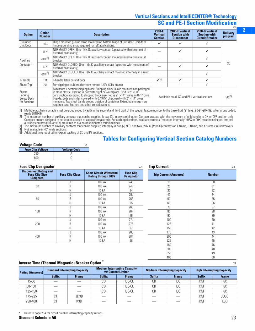
Vertical Sections and IntelliCENTER® TechnologySC and PE-I Section Modification
20
Tables for Configuring Vertical Section Catalog Numbers
Inverse Time (Thermal Magnetic) Breaker Option * 24
Option Option Number Description
2100-E Vertical Section
2100-F Vertical Section with Disconnect
2100-G Vertical Section with
Circuit BreakerDelivery program
Grounded Unit Door -79GD Hinge mounted ground strap mounted on bottom hinge of unit door. Unit door
hinge grounding strap required for IEC applications.
SCAuxiliary Contacts [1]
[1] Multiple auxiliary contacts must be group coded by adding the second and third digit of the special feature number to the base digit “9” (e.g., 90-91-98X-99, when group coded, reads 9018X9).
-98 [2]
[2] The maximum number of auxiliary contacts that can be supplied is two (2), in any combination. Contacts actuate with the movement of unit handle to ON or OFF position only. Contacts are not designed to actuate as a result of a circuit breaker trip. For such applications, auxiliary contacts “mounted internally” (98X or 99X) must be selected. Internal auxiliary contacts (98X or 99X) are wired to a 3-point unmounted terminal block.
NORMALLY OPEN: One (1) N.O. auxiliary contact (operated with movement of external handle only) —
-98X [3]
[3] The maximum number of auxiliary contacts that can be supplied internally is two (2) N.O. and two (2) N.C. (form C) contacts on F-frame, J-frame, and K-frame circuit breakers.
NORMALLY OPEN: One (1) N.O. auxiliary contact mounted internally in circuit breaker — —
-99 [2] NORMALLY CLOSED: One (1) N.C. auxiliary contact (operates with movement of external handle only) —
-99X [3] NORMALLY CLOSED: One (1) N.C. auxiliary contact mounted internally in circuit breaker — —
T-Handle -111 T-handle latch on unit door [4]
[4] Not available in 40” wide sections.
Shunt Trip -754 For tripping circuit breaker from remote 120V, 60Hz source — —
Export Packing Below Deck for Sections
—
Maximum 1-section shipping block. Shipping block is skid mounted and packaged in clear plastic. Packing is not watertight or waterproof. Skid is 2” × 8” construction according to shipping block size. Top is 2” × 4” frame with 1” pine boards. Ends and sides covered with 0.4375” chipboard with 2” × 4” cross members. Two steel bands around outside of container. Extended storage may require space heaters and other considerations.
Available on all SC and PE-I vertical sections. SC [5]
[5] Additional time required for export packing of SC and PE sections.
Voltage Code 21
Fuse Clip Voltage Voltage Code250 A600 C
Fuse Clip Designator 22 Trip Current 23
Disconnect Rating andFuse Clip Size
(Amperes)Fuse Clip Class Short Circuit Withstand
Rating through 600VFuse Clip
Designator Trip Current (Amperes) Number
30J 100 kA 24J 15 30R 100 kA 24R 20 31H 10 kA 24 30 32
60J 100 kA 25J 40 34R 100 kA 25R 50 35H 10 kA 25 60 36
100J 100 kA 26J 70 37R 100 kA 26R 80 38H 10 kA 26 90 39
200J 100 kA 27J 100 40R 100 kA 27R 125 41H 10 kA 27 150 42
400J 100 kA 28J 175 43R 100 kA 28R 200 44H 10 kA 28 225 45
250 46300 48350 49400 50
Rating (Amperes)Standard Interrupting Capacity Medium Interrupting Capacity
w/ Current Limiter Medium Interrupting Capacity High Interrupting Capacity
Suffix Frame Suffix Frame Suffix Frame Suffix Frame15-50 — — CD I3C-CL CB I3C CM I6C60-100 — — CD I3C-CL CB I3C CM I6C
125-150 — — CD I3C-CL CB I3C CM I6C175-225 CT JD3D — — — — CM JD6D250-400 CT K3D — — — — CM K6D
* Refer to page 234 for circuit breaker interrupting capacity ratings.Discount Schedule A6
23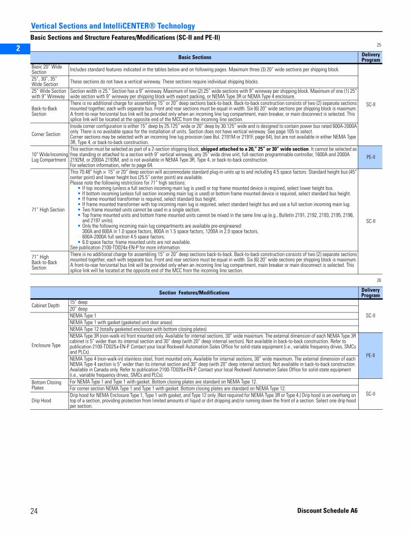
2
3
5
Vertical Sections and IntelliCENTER® Technology
Basic Sections and Structure Features/Modifications (SC-II and PE-II)25
26
Basic Sections DeliveryProgram
Basic 20” Wide Section Includes standard features indicated in the tables below and on following pages. Maximum three (3) 20” wide sections per shipping block.
SC-II
25”, 30”, 35”Wide Section These sections do not have a vertical wireway. These sections require individual shipping blocks.
25” Wide Section with 9” Wireway
Section width is 25.” Section has a 9” wireway. Maximum of two (2) 25” wide sections with 9” wireway per shipping block. Maximum of one (1) 25” wide section with 9” wireway per shipping block with export packing, or NEMA Type 3R or NEMA Type 4 enclosure.
Back-to-Back Section
There is no additional charge for assembling 15” or 20” deep sections back-to-back. Back-to-back construction consists of two (2) separate sections mounted together, each with separate bus. Front and rear sections must be equal in width. Six (6) 20” wide sections per shipping block is maximum. A front-to-rear horizontal bus link will be provided only when an incoming line lug compartment, main breaker, or main disconnect is selected. This splice link will be located at the opposite end of the MCC from the incoming line section.
Corner Section
Inside corner configuration is either 15” deep by 25.125” wide or 20” deep by 30.125” wide and is designed to contain power bus rated 600A-2000A only. There is no available space for the installation of units. Section does not have vertical wireway. See page 105 to select. Corner sections may be selected with an incoming line lug provision (see Bul. 2191M or 2191F, page 64), but are not available in either NEMA Type 3R, Type 4, or back-to-back construction.
10” Wide Incoming Lug Compartment
This section must be selected as part of a 2-section shipping block, shipped attached to a 20,” 25” or 30” wide section. It cannot be selected as free standing or attached to a section with 9” vertical wireway, any 35” wide drive unit, full-section programmable controller, 1600A and 2000A 2192M, or 2000A 2193M, and is not available in NEMA Type 3R, Type 4, or back-to-back construction. For selection information, refer to page 64.
PE-II
71” High Section
This 70.48” high × 15” or 20” deep section will accommodate standard plug-in units up to and including 4.5 space factors. Standard height bus (45” center point) and lower height bus (25.5” center point) are available.Please note the following restrictions for 71” high sections:
• If top incoming (unless a full section incoming main lug is used) or top frame mounted device is required, select lower height bus.• If bottom incoming (unless full section incoming main lug is used) or bottom frame mounted device is required, select standard bus height.• If frame mounted transformer is required, select standard bus height.• If frame mounted transformer with top incoming main lug is required, select standard height bus and use a full section incoming main lug.• Two frame mounted units cannot be used in a single section.• Top frame mounted units and bottom frame mounted units cannot be mixed in the same line up (e.g., Bulletin 2191, 2192, 2193, 2195, 2196,
and 2197 units).• Only the following incoming main lug compartments are available pre-engineered:
300A and 600A in 1.0 space factors, 800A in 1.5 space factors, 1200A in 2.0 space factors, 600A-2000A full section 4.5 space factors.
• 6.0 space factor, frame mounted units are not available.See publication 2100-TD024x-EN-P for more information.
SC-II
71” High Back-to-Back Section
There is no additional charge for assembling 15” or 20” deep sections back-to-back. Back-to-back construction consists of two (2) separate sections mounted together, each with separate bus. Front and rear sections must be equal in width. Six (6) 20” wide sections per shipping block is maximum. A front-to-rear horizontal bus link will be provided only when an incoming line lug compartment, main breaker or main disconnect is selected. This splice link will be located at the opposite end of the MCC from the incoming line section.
Section Features/Modifications DeliveryProgram
Cabinet Depth15” deep
SC-II20” deep
Enclosure Type
NEMA Type 1NEMA Type 1 with gasket (gasketed unit door areas)NEMA Type 12 (totally gasketed enclosure with bottom closing plates)NEMA Type 3R (non-walk-in) front mounted only. Available for internal sections, 30” wide maximum. The external dimension of each NEMA Type 3R cabinet is 5” wider than its internal section and 30” deep (with 20” deep internal section). Not available in back-to-back construction. Refer to publication 2100-TD025x-EN-P. Contact your local Rockwell Automation Sales Office for solid-state equipment (i.e., variable frequency drives, SMCs and PLCs).
PE-IINEMA Type 4 (non-walk-in) stainless steel, front mounted only. Available for internal sections, 30” wide maximum. The external dimension of each NEMA Type 4 section is 5” wider than its internal section and 30” deep (with 20” deep internal section). Not available in back-to-back construction. Available in Canada only. Refer to publication 2100-TD026x-EN-P. Contact your local Rockwell Automation Sales Office for solid-state equipment (i.e., variable frequency drives, SMCs and PLCs).
Bottom Closing Plates
For NEMA Type 1 and Type 1 with gasket. Bottom closing plates are standard on NEMA Type 12.
SC-IIFor corner section NEMA Type 1 and Type 1 with gasket. Bottom closing plates are standard on NEMA Type 12.
Drip HoodDrip hood for NEMA Enclosure Type 1, Type 1 with gasket, and Type 12 only. (Not required for NEMA Type 3R or Type 4.) Drip hood is an overhang on top of a section, providing protection from limited amounts of liquid or dirt dripping and/or running down the front of a section. Select one drip hood per section.
24 Discount Schedule A6

2
3
5
Vertical Sections and IntelliCENTER® Technology
Basic Sections and Structure Features/Modifications (SC-II and PE-II)27
28
29
Section Features/Modifications, continued DeliveryProgram
Power Bus Rating and Material[1]
(For 3-phase, 3-wire systems)
Aluminum with tin plating [1]
[1] Vertical bus will be supplied as tin plated copper
0.125” × 4” 600A
SC-II
0.188” × 4” 800A
Copper with tin plating
0.125” × 3” 600A0.125” × 4” 800A0.250” × 4” 1200A0.500” × 4” 1600A0.625” × 4” 2000A
Copper with silver plating
0.125” × 3” 600A
PE-II0.125” × 4” 800A0.250” × 4” 1200A0.500” × 4” 1600A0.625” × 4” 2000A
Section Features/Modifications Half-Rated Neutral
Full-Rated Neutral
Main Power Bus Rating
DeliveryProgram
Power Bus Rating and Material with Neutral Bus [1]
(For 3-phase,4-wire systems)
Neutral bus mounts above or below main power bus.
[1] When used with main incoming line (Bulletin 2191M), Main Switch (Bulletin 2192M) and Main Circuit Breaker (Bulletin 2193M) requires the selection of incoming neutral option (88HN or 88FN). Refer to Appendix, page 247, for neutral bus configuration information. Refer to page 117 for incoming neutral option selection.
Aluminum with tin plating [2]
[2] Vertical bus will be supplied as tin plated copper
0.125” x 4” 0.125” × 4” 600A
PE-II
0.125” x 4” 0.188” × 4” 800A
Copper with tin plating
0.125” × 3” 0.125” × 3” 600A0.125” × 3” 0.125” × 4” 800A0.125” x 4” 0.250” × 4” 1200A0.188” x 4” 0.500” × 4” 1600A0.250” x 4” 0.625” × 4” 2000A
Copper with silver plating
0.125” × 3” 0.125” × 3” 600A0.125” × 3” 0.125” × 4” 800A0.125” x 4” 0.250” × 4” 1200A0.188” x 4” 0.500” × 4” 1600A0.250” x 4” 0.625” × 4” 2000A
Section Features/Modifications DeliveryProgram
Vertical Bus Rating [1]
[1] Plating of horizontal bus and vertical bus must be the same.
300A tin plated copper vertical bus—0.75” O.D., 0.625” I.D. tubeSC-II
600A tin plated copper vertical bus—0.75” O.D. rod300A silver plated vertical bus—0.75” O.D., 0.625” I.D. tube
PE-II
600A silver plated vertical bus—0.75” O.D. rod
Vertical Neutral Bus [2]
Requires 25” wide section with 9” wireway
[2] Requires horizontal neutral bus. See Power Bus Rating and Material with Neutral Bus in table above.
Tin plated copper bus. Mounted in and insulated from 9” vertical wireway. Mechanically connected to horizontal neutral bus. Isolated from the rest of vertical wireway with barriers. To be used for connecting neutral loads or can be used for control voltages that require a connection to the neutral.
Rated 200A (0.1875” × 0.75”). For connection of control power neutral.Rated 300A (0.25” × 1”). For connection of neutral loads.
Rated 600A (0.25” × 1” qty. 2). For connection of neutral loads.
Neutral Connection Plate [3]
[3] A neutral connection plate can be used only in sections with a vertical wireway. Not available in sections with 6.0 space factor frame mounted units.Not available in top of section with frame mounted unit mounted at top of section.Not available in bottom of section with frame mounted unit mounted at bottom of section.
0.25” × 2” × 12” copper tin plated bus plate with #6-250 kcmil lug (280A capacity). Insulated from and mounted to either top or bottom horizontal wireway. SC-II
0.25” × 2” × 12” copper tin plated bus plate with #6-250 kcmil lug (280A capacity). Insulated from and mounted to either top or bottom horizontal wireway. Cable connection provided to horizontal neutral bus. [2]
PE-II0.25” x 2” x 12” copper silver plated bus plate with #6-250 kcmil lug (280A capacity). Insulated from and mounted to either top or bottom horizontal wireway.0.25” x 2” x 12” copper silver plated bus plate with #6-250 kcmil lug (280A capacity). Insulated from and mounted to either top or bottom horizontal wireway. Cable connection provided to horizontal neutral bus. [2]
25Discount Schedule A6
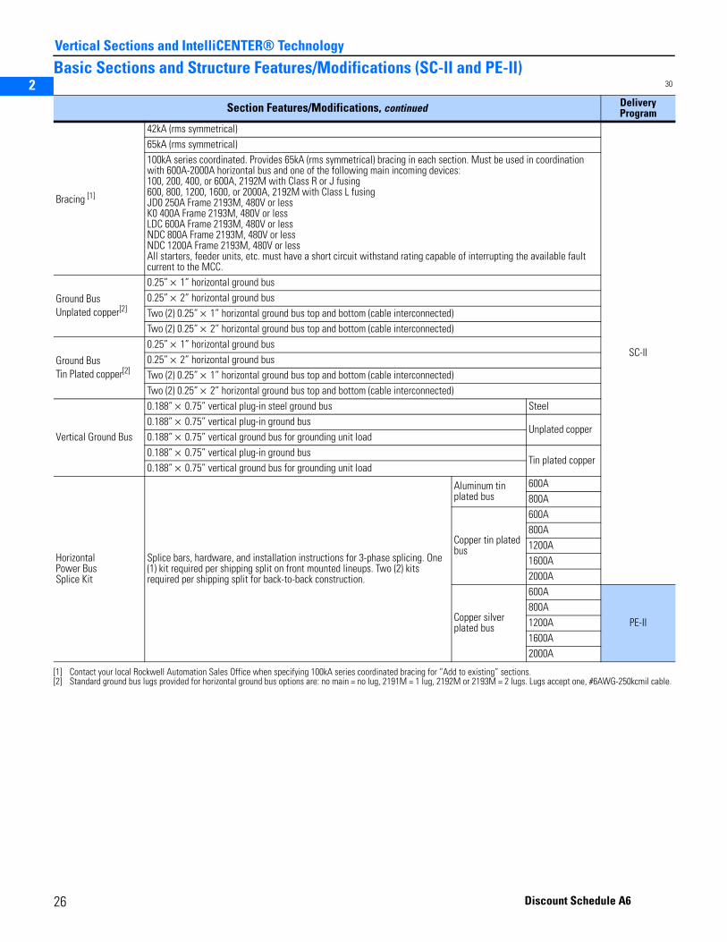
2
3
5
Vertical Sections and IntelliCENTER® Technology
Basic Sections and Structure Features/Modifications (SC-II and PE-II)30
Section Features/Modifications, continued DeliveryProgram
Bracing [1]
[1] Contact your local Rockwell Automation Sales Office when specifying 100kA series coordinated bracing for “Add to existing” sections.
42kA (rms symmetrical)
SC-II
65kA (rms symmetrical)100kA series coordinated. Provides 65kA (rms symmetrical) bracing in each section. Must be used in coordination with 600A-2000A horizontal bus and one of the following main incoming devices:100, 200, 400, or 600A, 2192M with Class R or J fusing600, 800, 1200, 1600, or 2000A, 2192M with Class L fusingJD0 250A Frame 2193M, 480V or less K0 400A Frame 2193M, 480V or lessLDC 600A Frame 2193M, 480V or lessNDC 800A Frame 2193M, 480V or lessNDC 1200A Frame 2193M, 480V or lessAll starters, feeder units, etc. must have a short circuit withstand rating capable of interrupting the available fault current to the MCC.
Ground BusUnplated copper[2]
[2] Standard ground bus lugs provided for horizontal ground bus options are: no main = no lug, 2191M = 1 lug, 2192M or 2193M = 2 lugs. Lugs accept one, #6AWG-250kcmil cable.
0.25” × 1” horizontal ground bus0.25” × 2” horizontal ground busTwo (2) 0.25” × 1” horizontal ground bus top and bottom (cable interconnected)Two (2) 0.25” × 2” horizontal ground bus top and bottom (cable interconnected)
Ground BusTin Plated copper[2]
0.25” × 1” horizontal ground bus0.25” × 2” horizontal ground busTwo (2) 0.25” × 1” horizontal ground bus top and bottom (cable interconnected)Two (2) 0.25” × 2” horizontal ground bus top and bottom (cable interconnected)
Vertical Ground Bus
0.188” × 0.75” vertical plug-in steel ground bus Steel0.188” × 0.75” vertical plug-in ground bus
Unplated copper0.188” × 0.75” vertical ground bus for grounding unit load0.188” × 0.75” vertical plug-in ground bus
Tin plated copper0.188” × 0.75” vertical ground bus for grounding unit load
HorizontalPower BusSplice Kit
Splice bars, hardware, and installation instructions for 3-phase splicing. One (1) kit required per shipping split on front mounted lineups. Two (2) kits required per shipping split for back-to-back construction.
Aluminum tin plated bus
600A800A
Copper tin plated bus
600A800A1200A1600A2000A
Copper silver plated bus
600A
PE-II800A1200A1600A2000A
26 Discount Schedule A6
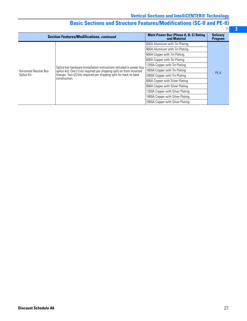
2
3
5
Vertical Sections and IntelliCENTER® Technology
Basic Sections and Structure Features/Modifications (SC-II and PE-II)31
Section Features/Modifications, continued Main Power Bus (Phase A, B, C) Rating and Material
DeliveryProgram
Horizontal Neutral Bus Splice Kit
Splice bar hardware (installation instructions included in power bus splice kit). One (1) kit required per shipping split on front mounted lineups. Two (2) kits required per shipping split for back-to-back construction.
600A Aluminum with Tin Plating
PE-II
800A Aluminum with Tin Plating600A Copper with Tin Plating800A Copper with Tin Plating1200A Copper with Tin Plating1600A Copper with Tin Plating2000A Copper with Tin Plating600A Copper with Silver Plating800A Copper with Silver Plating1200A Copper with Silver Plating1600A Copper with Silver Plating2000A Copper with Silver Plating
27Discount Schedule A6
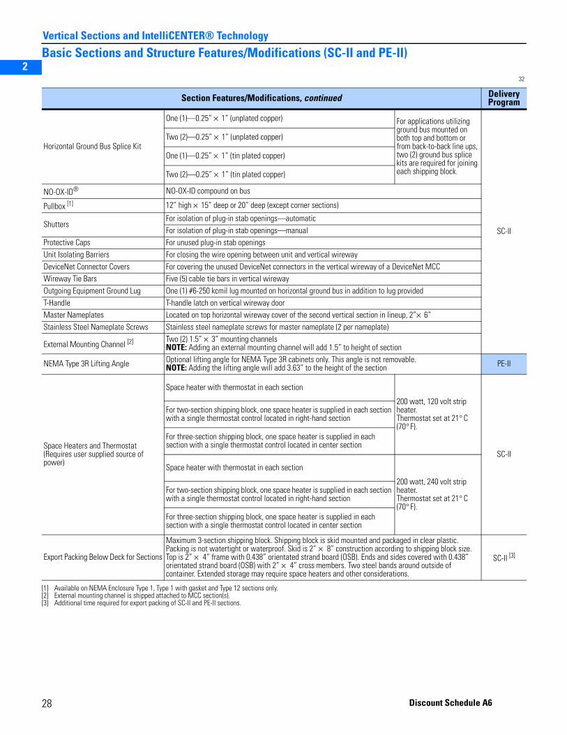
2
3
5
Vertical Sections and IntelliCENTER® Technology
Basic Sections and Structure Features/Modifications (SC-II and PE-II)
32
Section Features/Modifications, continued DeliveryProgram
Horizontal Ground Bus Splice Kit
One (1)—0.25” × 1” (unplated copper) For applications utilizing ground bus mounted on both top and bottom or from back-to-back line ups, two (2) ground bus splice kits are required for joining each shipping block.
SC-II
Two (2)—0.25” × 1” (unplated copper)
One (1)—0.25” × 1” (tin plated copper)
Two (2)—0.25” × 1” (tin plated copper)
NO-OX-ID® NO-OX-ID compound on bus
Pullbox [1]
[1] Available on NEMA Enclosure Type 1, Type 1 with gasket and Type 12 sections only.
12” high × 15” deep or 20” deep (except corner sections)
ShuttersFor isolation of plug-in stab openings—automaticFor isolation of plug-in stab openings—manual
Protective Caps For unused plug-in stab openingsUnit Isolating Barriers For closing the wire opening between unit and vertical wirewayDeviceNet Connector Covers For covering the unused DeviceNet connectors in the vertical wireway of a DeviceNet MCCWireway Tie Bars Five (5) cable tie bars in vertical wirewayOutgoing Equipment Ground Lug One (1) #6-250 kcmil lug mounted on horizontal ground bus in addition to lug providedT-Handle T-handle latch on vertical wireway doorMaster Nameplates Located on top horizontal wireway cover of the second vertical section in lineup, 2”× 6”Stainless Steel Nameplate Screws Stainless steel nameplate screws for master nameplate (2 per nameplate)
External Mounting Channel [2]
[2] External mounting channel is shipped attached to MCC section(s).
Two (2) 1.5” × 3” mounting channelsNOTE: Adding an external mounting channel will add 1.5” to height of section
NEMA Type 3R Lifting Angle Optional lifting angle for NEMA Type 3R cabinets only. This angle is not removable.NOTE: Adding the lifting angle will add 3.63” to the height of the section PE-II
Space Heaters and Thermostat(Requires user supplied source of power)
Space heater with thermostat in each section
200 watt, 120 volt strip heater.Thermostat set at 21° C (70° F).
SC-II
For two-section shipping block, one space heater is supplied in each section with a single thermostat control located in right-hand section
For three-section shipping block, one space heater is supplied in each section with a single thermostat control located in center section
Space heater with thermostat in each section
200 watt, 240 volt strip heater.Thermostat set at 21° C (70° F).
For two-section shipping block, one space heater is supplied in each section with a single thermostat control located in right-hand section
For three-section shipping block, one space heater is supplied in each section with a single thermostat control located in center section
Export Packing Below Deck for Sections
Maximum 3-section shipping block. Shipping block is skid mounted and packaged in clear plastic. Packing is not watertight or waterproof. Skid is 2” × 8” construction according to shipping block size. Top is 2” × 4” frame with 0.438” orientated strand board (OSB). Ends and sides covered with 0.438” orientated strand board (OSB) with 2” × 4” cross members. Two steel bands around outside of container. Extended storage may require space heaters and other considerations.
SC-II [3]
[3] Additional time required for export packing of SC-II and PE-II sections.
28 Discount Schedule A6
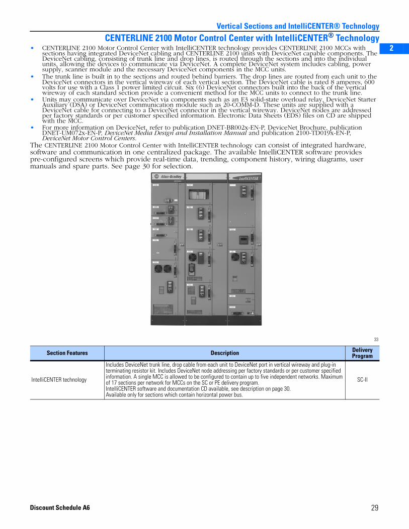
2
3
5
Vertical Sections and IntelliCENTER® Technology
CENTERLINE 2100 Motor Control Center with IntelliCENTER® Technology• CENTERLINE 2100 Motor Control Center with IntelliCENTER technology provides CENTERLINE 2100 MCCs with
sections having integrated DeviceNet cabling and CENTERLINE 2100 units with DeviceNet capable components. The DeviceNet cabling, consisting of trunk line and drop lines, is routed through the sections and into the individual units, allowing the devices to communicate via DeviceNet. A complete DeviceNet system includes cabling, power supply, scanner module and the necessary DeviceNet components in the MCC units.
• The trunk line is built in to the sections and routed behind barriers. The drop lines are routed from each unit to the DeviceNet connectors in the vertical wireway of each vertical section. The DeviceNet cable is rated 8 amperes, 600 volts for use with a Class 1 power limited circuit. Six (6) DeviceNet connectors built into the back of the vertical wireway of each standard section provide a convenient method for the MCC units to connect to the trunk line.
• Units may communicate over DeviceNet via components such as an E3 solid-state overload relay, DeviceNet Starter Auxiliary (DSA) or DeviceNet communication module such as 20-COMM-D. These units are supplied with a DeviceNet cable for connecting to a DeviceNet connector in the vertical wireway. DeviceNet nodes are addressed per factory standards or per customer specified information. Electronic Data Sheets (EDS) files on CD are shipped with the MCC.
• For more information on DeviceNet, refer to publication DNET-BR002x-EN-P, DeviceNet Brochure, publication DNET-UM072x-EN-P, DeviceNet Media Design and Installation Manual and publication 2100-TD019x-EN-P, DeviceNet Motor Control Centers.
The CENTERLINE 2100 Motor Control Center with IntelliCENTER technology can consist of integrated hardware, software and communication in one centralized package. The available IntelliCENTER software provides pre-configured screens which provide real-time data, trending, component history, wiring diagrams, user manuals and spare parts. See page 30 for selection.
33
Section Features Description Delivery Program
IntelliCENTER technology
Includes DeviceNet trunk line, drop cable from each unit to DeviceNet port in vertical wireway and plug-in terminating resistor kit. Includes DeviceNet node addressing per factory standards or per customer specified information. A single MCC is allowed to be configured to contain up to five independent networks. Maximum of 17 sections per network for MCCs on the SC or PE delivery program.IntelliCENTER software and documentation CD available, see description on page 30.Available only for sections which contain horizontal power bus.
SC-II
29Discount Schedule A6
2
3
5
Vertical Sections and IntelliCENTER® Technology
IntelliCENTER SoftwareNOTE: All IntelliCENTER software is copyright protected and for installation on one personal computer only.
34
Minimum PC Requirements for running IntelliCENTER Software:• Operating System: Windows 2000 SP4 or XP (English/Western European Versions)• Processor: Pentium IV processor, 1.4 GHz minimum *
• Video Resolution: 1024 x 768 resolution with true color (24 bit or better)• CD-ROM drive: 4X (16X recommended)• Hard Disk space: 600 MB free disk space• Mouse: Microsoft compatible• RAM: 256 MB—Windows 2000 SP4 or XP (512 MB recommended)Equipment Necessary for Connection of a Computer via DeviceNet, ControlNet or Ethernet:DeviceNet• Laptop computer: 1784-PCD DeviceNet PC interface card and 1784-PCD1 cable• Desktop computer: 1784-PCIDS• RS-232 interface (reduced performance): 1770-KFD DeviceNet interface module
NOTE: 2100H-ICPC120 patch cable is necessary for connecting interface (laptop, desktop, RS-232) to IntelliCENTER MCC wireway
ControlNet• Laptop computer: 1784-PCC ControlNet PC interface card and 1784-C1 cable• Desktop computer: 1784-PCIC ControlNet PC interface card and 1786-TPR ControlNet tap
NOTE: Consult publication CNET-IN002x-EN-P, ControlNet Coax Media Planning and Installation Guide, for configuration and installation of ControlNet cable
Ethernet• Laptop or desktop computer: consult local computer support personnel for Ethernet interface requirementsRecommended Additional Software• RSNetWorx for DeviceNet—used for configuring DeviceNet nodes, saving parameters, and communicating to all
types of DeviceNet components (sensors, non-Allen-Bradley products and other products not found in MCCs)• RSNetWorx for ControlNet—used for configuring ControlNet devices including ControlNet to DeviceNet bridge
Description Delivery Program
IntelliCENTER [1]
Full Version
Catalog Number:2101A-INTLCNTR
[1] Must be ordered separately from MCC.
The IntelliCENTER software replicates the MCC lineup on a computer screen, complete with nameplates and indicators on each door to show status (on, off, warning, fault, communication failure). Graphical views of individual MCC units display device data allowing users to quickly view critical amperes, time-to-trip, trip cause, ground fault amperes and on/off status. Each screen is preconfigured to show the parameters typically of greatest interest, and users easily can customize parameters. Many screens feature trending graphs and analog dials. The software also provides spare parts information, AutoCAD documentation and event logging. Requires Documentation CD; see below.
SC
The IntelliCENTER software also contains ActiveX controls. This allows key views of the software to be displayed inside Human Machine Interfaces (HMIs) such as RSView.
Documentation CD [1][2]
Catalog Number:2101A-INTLDOC
[2] For MCCs ordered prior to September 1, 2006, please contact your local Rockwell Automation Sales Office for availability.
The Documentation CD is the second component of the IntelliCENTER software. The CD contains data files specific to a particular MCC. This information includes unit nameplates, unit details, wiring diagrams, user manuals, spare parts and other details.
Per MCC lineup
Per unit
IntelliCENTER [1]
ActiveX Only Version
Catalog Number:2101A-INTLCNTR-X
The IntelliCENTER ActiveX Only Version software contains only the ActiveX controls necessary to include the IntelliCENTER views (elevation, monitor, electronic documentation, CAD diagrams, event log and spreadsheet) within an HMI. Note: At least one copy of IntelliCENTER Full Version is required to perform maintenance tasks such as moving units, adding units and changing units in the IntelliCENTER software.
* The IntelliCENTER software is a monitoring/communication software package requiring a very large amount of processor speed to function efficiently and quickly. The processor speeds listed will allow the software to function correctly. However, for speed and efficiency, it is recommended to use the fastest Pentium IV class (or better) processor available.
30 Discount Schedule A6
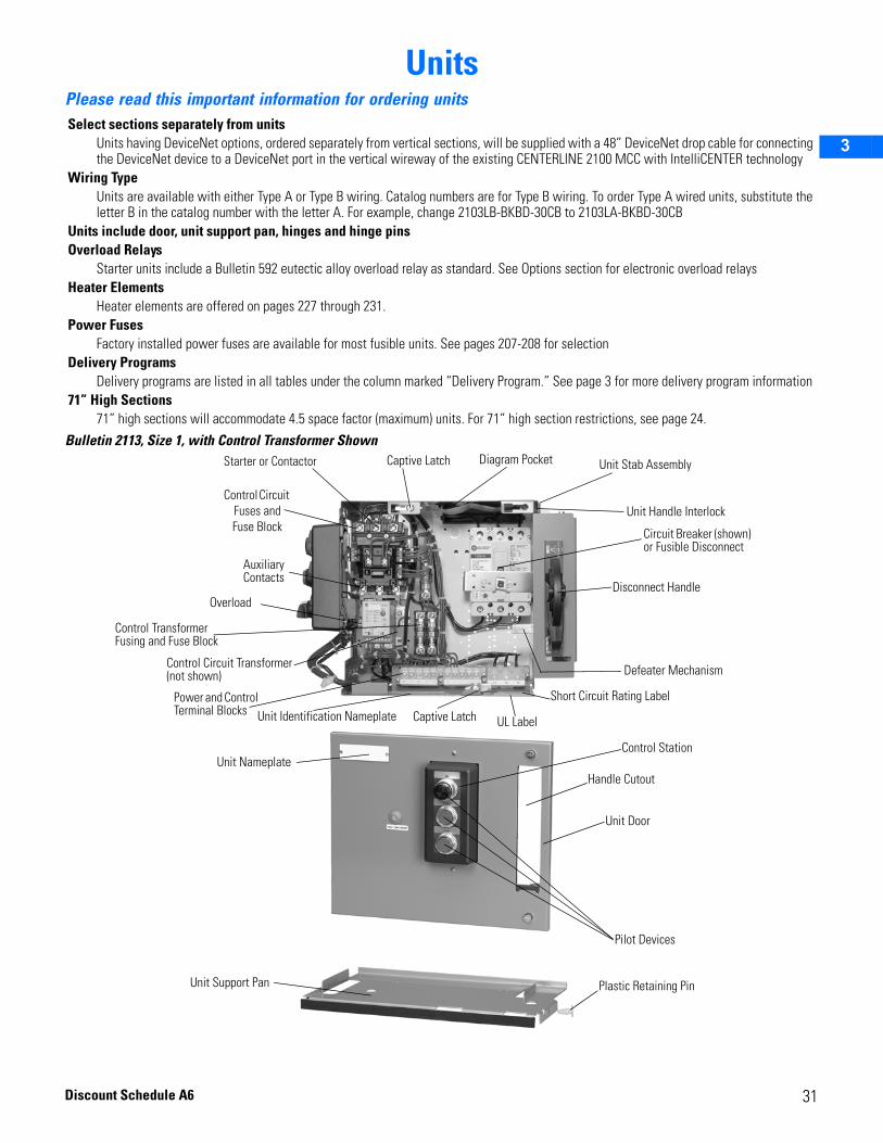
2
3
UnitsPlease read this important information for ordering units
Bulletin 2113, Size 1, with Control Transformer Shown
Select sections separately from unitsUnits having DeviceNet options, ordered separately from vertical sections, will be supplied with a 48” DeviceNet drop cable for connecting the DeviceNet device to a DeviceNet port in the vertical wireway of the existing CENTERLINE 2100 MCC with IntelliCENTER technology
Wiring TypeUnits are available with either Type A or Type B wiring. Catalog numbers are for Type B wiring. To order Type A wired units, substitute the letter B in the catalog number with the letter A. For example, change 2103LB-BKBD-30CB to 2103LA-BKBD-30CB
Units include door, unit support pan, hinges and hinge pinsOverload Relays
Starter units include a Bulletin 592 eutectic alloy overload relay as standard. See Options section for electronic overload relaysHeater Elements
Heater elements are offered on pages 227 through 231.Power Fuses
Factory installed power fuses are available for most fusible units. See pages 207-208 for selectionDelivery Programs
Delivery programs are listed in all tables under the column marked “Delivery Program.” See page 3 for more delivery program information71” High Sections
71” high sections will accommodate 4.5 space factor (maximum) units. For 71” high section restrictions, see page 24.
Unit Stab Assembly
Unit Handle Interlock
Circuit Breaker (shown) or Fusible Disconnect
Disconnect Handle
Unit Identification Nameplate
Diagram PocketStarter or Contactor
Control Circuit Fuses and Fuse Block
Auxiliary Contacts
Control Transformer Fusing and Fuse Block
Control Circuit Transformer (not shown)
Power and Control Terminal Blocks
Short Circuit Rating Label
UL LabelCaptive Latch
Control Station
Pilot Devices
Unit Support Pan
Overload
Handle Cutout
Unit Door
Unit Nameplate
Defeater Mechanism
Captive Latch
Plastic Retaining Pin
31Discount Schedule A6

32
2
3
Units
Discount Schedule A6

2
3
4
5
Contactor and Starter UnitsBulletin 2102L and 2103L Combination Full-Voltage Lighting Contactor Units (FVLC) . . . . . . . . . . . . . . . . 35These combination lighting contactor units are supplied with an Allen-Bradley 500L AC contactor and either a fusible disconnect or circuit breaker. They are rated 30A through 300A. Each unit is provided as a NEMA Class I, Type B-T unit with terminals mounted in the unit for connection to remote devices.
Bulletin 2106 and 2107Combination Full Voltage Reversing Starter Units (FVR) . . . . . . . . . . . . . . . . . . 38 These combination full voltage reversing starter units are supplied with an Allen-Bradley Bulletin 505 reversing starter and either a fusible disconnect or a circuit breaker. The Bulletin 2106 and 2107 starters are rated for NEMA sizes 1 through 5 and are mechanically and electrically interlocked to avoid both contactors being closed simultaneously. Each unit is provided as a NEMA Class I, Type B-T unit with terminals mounted in the unit for connection to remote devices. Full voltage reversing starter units are available with a eutectic alloy, E1 Plus or E3 Plus electronic overload relay.
Bulletin 2106 and 2107 Space Saving NEMA Combination Full Voltage Reversing Starter Units (FVR) . . . . . . . . . . . . . . . . . . 40These combination full voltage reversing starter units offer a space saving alternative while utilizing an Allen-Bradley Bulletin 300 reversing starter and either a fused disconnect or a circuit breaker. The Bulletin 2106 Space Saving NEMA reversing starters are rated for NEMA Size 1 applications and the Bulletin 2107 Space Saving NEMA reversing starters are rated for NEMA Size 1-3 applications. The contactors are mechanically and electrically interlocked to avoid both contactors being closed simultaneously. Each unit is provided as a NEMA Class I, Type B-D unit with terminals mounted in the unit for connections to remote devices. These full voltage reversing units are available with E1 Plus or E3 Plus electronic overload relays.
Bulletin 2112, 2112 Vacuum, 2113, and 2113 VacuumCombination Full Voltage Non-Reversing Starter Units (FVNR) . . . . . . . . . . . . 42 These combination full voltage non-reversing starter units are supplied with an Allen-Bradley Bulletin 509 starter (starter units with vacuum contactors use Allen-Bradley Bulletin 1102C contactors) and either a fusible disconnect or a circuit breaker. The full voltage non-reversing starters are rated for NEMA sizes 1 through 6 (starter units with vacuum contactors are rated 200A, 400A, or 600A). Each unit is provided as a NEMA Class I, Type B-T unit, with terminals mounted in the unit for connection to remote devices. Full voltage non-reversing starter units are available with a eutectic alloy, E1 Plus or E3 electronic overload relay.
For more details on Bulletin 500 contactors and starters, see publication 500-BR010x-EN-P, NEMA Power Components, and publication A116-CA001x-EN-P Allen-Bradley Industrial Controls Catalog. For more details on Bulletin 300 starters, see publication 300-SG001x-EN-P, Bulletin 300 Starters Selection Guide. For more details on Bulletin 1102C vacuum contactors, see publication 500-SG005x-EN-P, Bulletin 512V, 513V, 1102C, 1109, 1232V, 1233V Selection Guide.
33For Options, Modifications and Accessories, see pages 107-123Discount Schedule A6
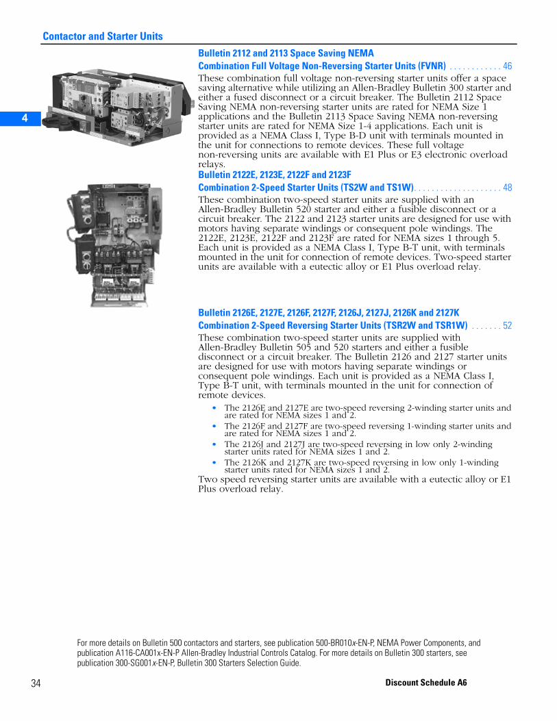
Contactor and Starter Units
3
2
3
4
5
Bulletin 2112 and 2113 Space Saving NEMA Combination Full Voltage Non-Reversing Starter Units (FVNR) . . . . . . . . . . . . 46 These combination full voltage non-reversing starter units offer a space saving alternative while utilizing an Allen-Bradley Bulletin 300 starter and either a fused disconnect or a circuit breaker. The Bulletin 2112 Space Saving NEMA non-reversing starter units are rated for NEMA Size 1 applications and the Bulletin 2113 Space Saving NEMA non-reversing starter units are rated for NEMA Size 1-4 applications. Each unit is provided as a NEMA Class I, Type B-D unit with terminals mounted in the unit for connections to remote devices. These full voltage non-reversing units are available with E1 Plus or E3 electronic overload relays.Bulletin 2122E, 2123E, 2122F and 2123F Combination 2-Speed Starter Units (TS2W and TS1W). . . . . . . . . . . . . . . . . . . . 48 These combination two-speed starter units are supplied with an Allen-Bradley Bulletin 520 starter and either a fusible disconnect or a circuit breaker. The 2122 and 2123 starter units are designed for use with motors having separate windings or consequent pole windings. The 2122E, 2123E, 2122F and 2123F are rated for NEMA sizes 1 through 5. Each unit is provided as a NEMA Class I, Type B-T unit, with terminals mounted in the unit for connection of remote devices. Two-speed starter units are available with a eutectic alloy or E1 Plus overload relay.
Bulletin 2126E, 2127E, 2126F, 2127F, 2126J, 2127J, 2126K and 2127K Combination 2-Speed Reversing Starter Units (TSR2W and TSR1W) . . . . . . . 52 These combination two-speed starter units are supplied with Allen-Bradley Bulletin 505 and 520 starters and either a fusible disconnect or a circuit breaker. The Bulletin 2126 and 2127 starter units are designed for use with motors having separate windings or consequent pole windings. Each unit is provided as a NEMA Class I, Type B-T unit, with terminals mounted in the unit for connection of remote devices.
• The 2126E and 2127E are two-speed reversing 2-winding starter units and are rated for NEMA sizes 1 and 2.
• The 2126F and 2127F are two-speed reversing 1-winding starter units and are rated for NEMA sizes 1 and 2.
• The 2126J and 2127J are two-speed reversing in low only 2-winding starter units rated for NEMA sizes 1 and 2.
• The 2126K and 2127K are two-speed reversing in low only 1-winding starter units rated for NEMA sizes 1 and 2.
Two speed reversing starter units are available with a eutectic alloy or E1 Plus overload relay.
For more details on Bulletin 500 contactors and starters, see publication 500-BR010x-EN-P, NEMA Power Components, and publication A116-CA001x-EN-P Allen-Bradley Industrial Controls Catalog. For more details on Bulletin 300 starters, see publication 300-SG001x-EN-P, Bulletin 300 Starters Selection Guide.
4 Discount Schedule A6
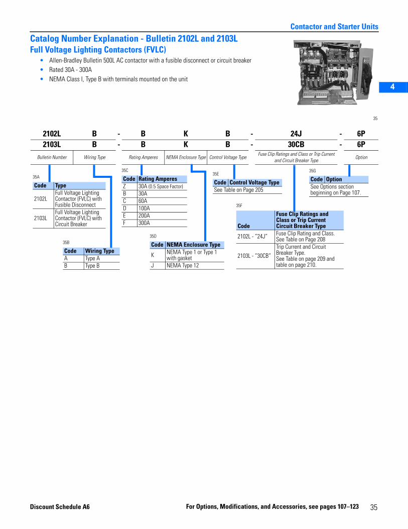
2
3
4
5
Contactor and Starter Units
Catalog Number Explanation - Bulletin 2102L and 2103LFull Voltage Lighting Contactors (FVLC)
• Allen-Bradley Bulletin 500L AC contactor with a fusible disconnect or circuit breaker• Rated 30A - 300A• NEMA Class I, Type B with terminals mounted on the unit
35
2102L B - B K B - 24J - 6P2103L B - B K B - 30CB - 6P
Bulletin Number Wiring Type Rating Amperes NEMA Enclosure Type Control Voltage TypeFuse Clip Ratings and Class or Trip Current
and Circuit Breaker TypeOption
35A
Code Type
2102LFull Voltage Lighting Contactor (FVLC) with Fusible Disconnect
2103LFull Voltage Lighting Contactor (FVLC) with Circuit Breaker
35C
Code Rating AmperesZ 30A (0.5 Space Factor)B 30AC 60AD 100AE 200AF 300A
35B
Code Wiring TypeA Type AB Type B
35D
Code NEMA Enclosure Type
K NEMA Type 1 or Type 1 with gasket
J NEMA Type 12
35E
Code Control Voltage TypeSee Table on Page 205
35F
Code
Fuse Clip Ratings and Class or Trip Current Circuit Breaker Type
2102L - “24J” Fuse Clip Rating and Class. See Table on Page 208
2103L - “30CB”Trip Current and Circuit Breaker Type. See Table on page 209 and table on page 210.
35G
Code OptionSee Options section beginning on Page 107.
Discount S
chedule A6 For Opti ons, Mod ifications, and Accessories 35, see pages 107–123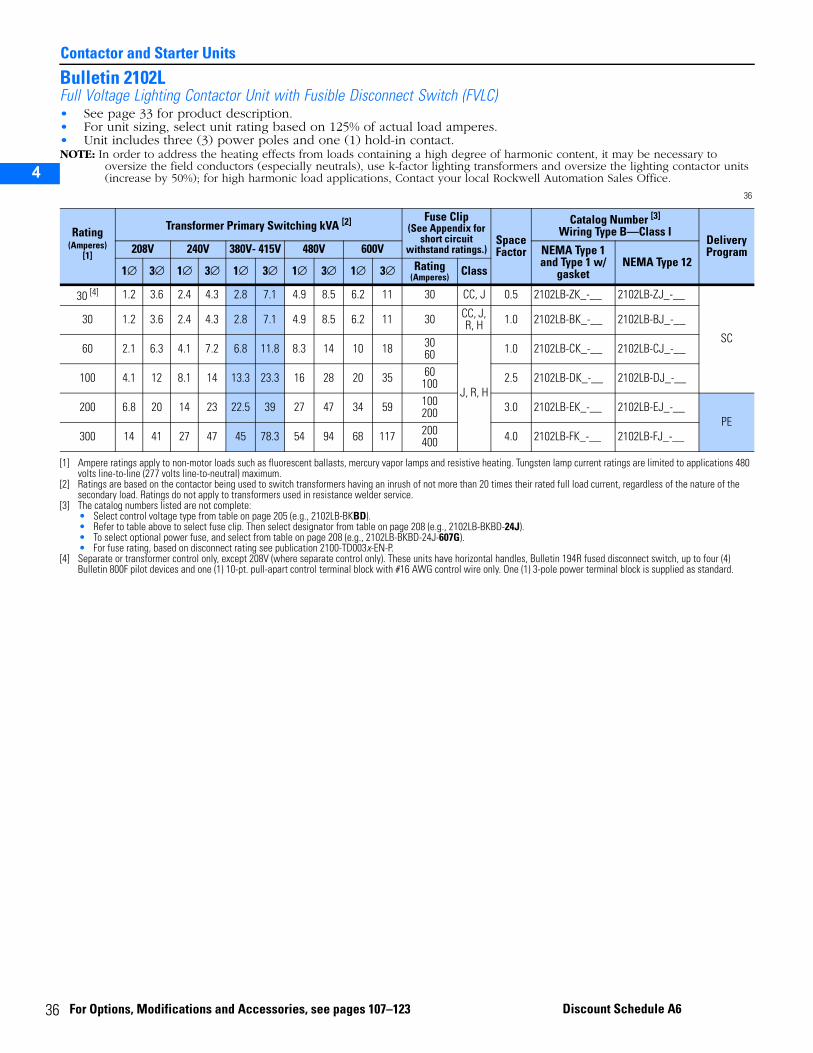
3
Contactor and Starter Units
2
3
4
5
Bulletin 2102LFull Voltage Lighting Contactor Unit with Fusible Disconnect Switch (FVLC)• See page 33 for product description.• For unit sizing, select unit rating based on 125% of actual load amperes.• Unit includes three (3) power poles and one (1) hold-in contact.NOTE: In order to address the heating effects from loads containing a high degree of harmonic content, it may be necessary to
oversize the field conductors (especially neutrals), use k-factor lighting transformers and oversize the lighting contactor units (increase by 50%); for high harmonic load applications, Contact your local Rockwell Automation Sales Office.
36
Rating(Amperes)
[1]
[1] Ampere ratings apply to non-motor loads such as fluorescent ballasts, mercury vapor lamps and resistive heating. Tungsten lamp current ratings are limited to applications 480 volts line-to-line (277 volts line-to-neutral) maximum.
Transformer Primary Switching kVA [2]
[2] Ratings are based on the contactor being used to switch transformers having an inrush of not more than 20 times their rated full load current, regardless of the nature of the secondary load. Ratings do not apply to transformers used in resistance welder service.
Fuse Clip(See Appendix for
short circuit withstand ratings.)
SpaceFactor
Catalog Number [3]
Wiring Type B—Class I
[3] The catalog numbers listed are not complete:• Select control voltage type from table on page 205 (e.g., 2102LB-BKBD).• Refer to table above to select fuse clip. Then select designator from table on page 208 (e.g., 2102LB-BKBD-24J).• To select optional power fuse, and select from table on page 208 (e.g., 2102LB-BKBD-24J-607G).• For fuse rating, based on disconnect rating see publication 2100-TD003x-EN-P.
DeliveryProgram208V 240V 380V- 415V 480V 600V NEMA Type 1
and Type 1 w/ gasket
NEMA Type 121∅ 3∅ 1∅ 3∅ 1∅ 3∅ 1∅ 3∅ 1∅ 3∅ Rating
(Amperes) Class
30 [4]
[4] Separate or transformer control only, except 208V (where separate control only). These units have horizontal handles, Bulletin 194R fused disconnect switch, up to four (4) Bulletin 800F pilot devices and one (1) 10-pt. pull-apart control terminal block with #16 AWG control wire only. One (1) 3-pole power terminal block is supplied as standard.
1.2 3.6 2.4 4.3 2.8 7.1 4.9 8.5 6.2 11 30 CC, J 0.5 2102LB-ZK_-__ 2102LB-ZJ_-__
SC
30 1.2 3.6 2.4 4.3 2.8 7.1 4.9 8.5 6.2 11 30 CC, J, R, H 1.0 2102LB-BK_-__ 2102LB-BJ_-__
60 2.1 6.3 4.1 7.2 6.8 11.8 8.3 14 10 18 3060
J, R, H
1.0 2102LB-CK_-__ 2102LB-CJ_-__
100 4.1 12 8.1 14 13.3 23.3 16 28 20 35 60100 2.5 2102LB-DK_-__ 2102LB-DJ_-__
200 6.8 20 14 23 22.5 39 27 47 34 59 100200 3.0 2102LB-EK_-__ 2102LB-EJ_-__
PE300 14 41 27 47 45 78.3 54 94 68 117 200
400 4.0 2102LB-FK_-__ 2102LB-FJ_-__
6 For Options, Modifications and Accessories, see pages 107–123 Discount Schedule A6
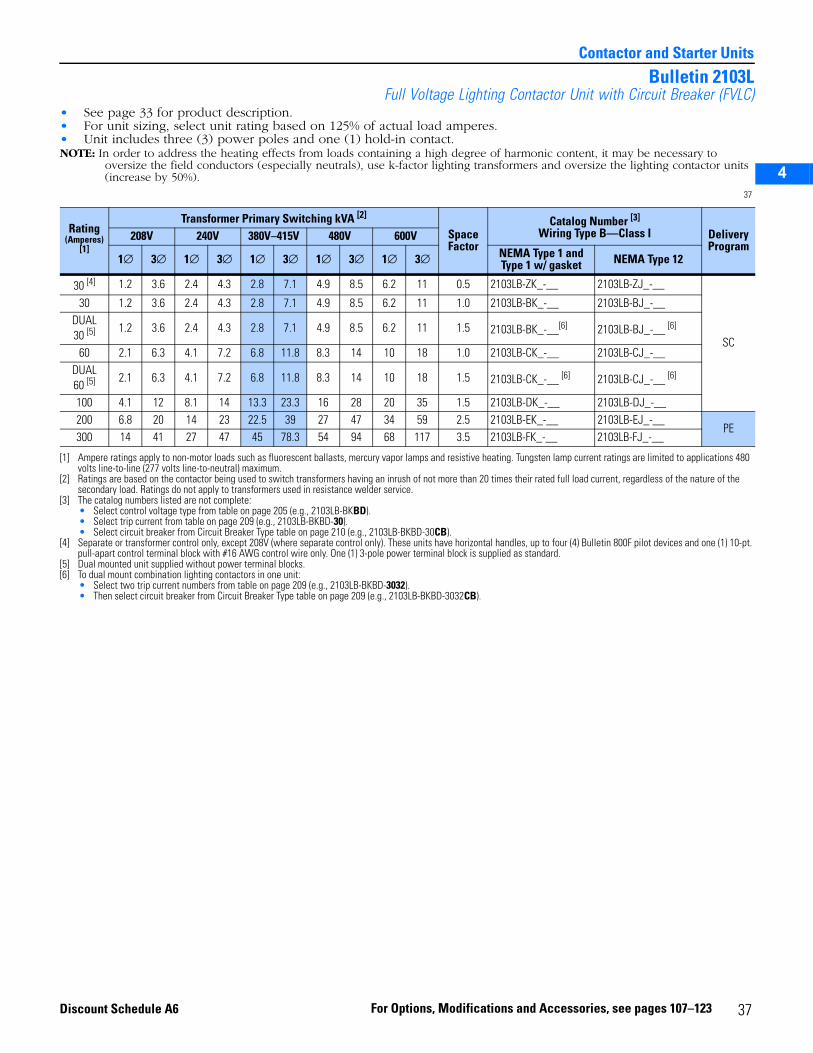
2
3
4
5
Contactor and Starter Units
Bulletin 2103LFull Voltage Lighting Contactor Unit with Circuit Breaker (FVLC)
• See page 33 for product description.• For unit sizing, select unit rating based on 125% of actual load amperes.• Unit includes three (3) power poles and one (1) hold-in contact.NOTE: In order to address the heating effects from loads containing a high degree of harmonic content, it may be necessary to
oversize the field conductors (especially neutrals), use k-factor lighting transformers and oversize the lighting contactor units (increase by 50%).
37
Rating(Amperes)
[1]
[1] Ampere ratings apply to non-motor loads such as fluorescent ballasts, mercury vapor lamps and resistive heating. Tungsten lamp current ratings are limited to applications 480 volts line-to-line (277 volts line-to-neutral) maximum.
Transformer Primary Switching kVA [2]
[2] Ratings are based on the contactor being used to switch transformers having an inrush of not more than 20 times their rated full load current, regardless of the nature of the secondary load. Ratings do not apply to transformers used in resistance welder service.
SpaceFactor
Catalog Number [3]
Wiring Type B—Class I
[3] The catalog numbers listed are not complete:• Select control voltage type from table on page 205 (e.g., 2103LB-BKBD).• Select trip current from table on page 209 (e.g., 2103LB-BKBD-30).• Select circuit breaker from Circuit Breaker Type table on page 210 (e.g., 2103LB-BKBD-30CB).
DeliveryProgram
208V 240V 380V–415V 480V 600V
1∅ 3∅ 1∅ 3∅ 1∅ 3∅ 1∅ 3∅ 1∅ 3∅ NEMA Type 1 and Type 1 w/ gasket NEMA Type 12
30 [4]
[4] Separate or transformer control only, except 208V (where separate control only). These units have horizontal handles, up to four (4) Bulletin 800F pilot devices and one (1) 10-pt. pull-apart control terminal block with #16 AWG control wire only. One (1) 3-pole power terminal block is supplied as standard.
1.2 3.6 2.4 4.3 2.8 7.1 4.9 8.5 6.2 11 0.5 2103LB-ZK_-__ 2103LB-ZJ_-__
SC
30 1.2 3.6 2.4 4.3 2.8 7.1 4.9 8.5 6.2 11 1.0 2103LB-BK_-__ 2103LB-BJ_-__DUAL30 [5]
[5] Dual mounted unit supplied without power terminal blocks.
1.2 3.6 2.4 4.3 2.8 7.1 4.9 8.5 6.2 11 1.5 2103LB-BK_-__[6]
[6] To dual mount combination lighting contactors in one unit:• Select two trip current numbers from table on page 209 (e.g., 2103LB-BKBD-3032).• Then select circuit breaker from Circuit Breaker Type table on page 209 (e.g., 2103LB-BKBD-3032CB).
2103LB-BJ_-__ [6]
60 2.1 6.3 4.1 7.2 6.8 11.8 8.3 14 10 18 1.0 2103LB-CK_-__ 2103LB-CJ_-__DUAL60 [5] 2.1 6.3 4.1 7.2 6.8 11.8 8.3 14 10 18 1.5 2103LB-CK_-__ [6] 2103LB-CJ_-__ [6]
100 4.1 12 8.1 14 13.3 23.3 16 28 20 35 1.5 2103LB-DK_-__ 2103LB-DJ_-__200 6.8 20 14 23 22.5 39 27 47 34 59 2.5 2103LB-EK_-__ 2103LB-EJ_-__
PE300 14 41 27 47 45 78.3 54 94 68 117 3.5 2103LB-FK_-__ 2103LB-FJ_-__
37For Options, Modifications and Accessories, see pages 107–123Discount Schedule A6
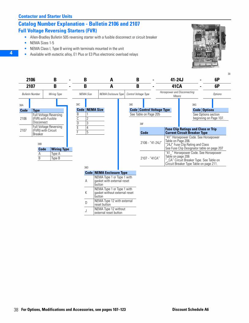
3
Contactor and Starter Units
2
3
4
5
Catalog Number Explanation - Bulletin 2106 and 2107Full Voltage Reversing Starters (FVR)
• Allen-Bradley Bulletin 505 reversing starter with a fusible disconnect or circuit breaker• NEMA Sizes 1-5• NEMA Class I, Type B wiring with terminals mounted in the unit • Available with eutectic alloy, E1 Plus or E3 Plus electronic overload relays
38
2106 B - B A B - 41-24J - 6P2107 B - B A B - 41CA - 6P
Bulletin Number Wiring Type NEMA Size NEMA Enclosure Type Control Voltage TypeHorsepower and Disconnecting
MeansOptions
38A
Code Type
2106Full Voltage Reversing (FVR) with Fusible Disconnect
2107Full Voltage Reversing (FVR)) with Circuit Breaker
38C
Code NEMA SizeB 1C 2D 3E 4F 5
38B
Code Wiring TypeA Type AB Type B
38D
Code NEMA Enclosure Type
ANEMA Type 1 or Type 1 with gasket with external reset button
KNEMA Type 1 or Type 1 with gasket without external reset button
D NEMA Type 12 with external reset button
J NEMA Type 12 without external reset button
38E
Code Control Voltage TypeSee Table on Page 205
38F
CodeFuse Clip Ratings and Class or Trip Current Circuit Breaker Type
2106 - “41-24J”“41” Horsepower Code. See Horsepower Table on Page 206.“24J” Fuse Clip Rating and Class See Fuse Clip Designator table on page 207
2107 - “41CA”“41_” Horsepower Code. See Horsepower Table on page 206“_CA” Circuit Breaker Type. See Table on Circuit Breaker Type Table on page 211.
38G
Code OptionsSee Options section beginning on Page 107.
8 For Optio
ns, Modifications and Acce ssories, see pages 107–123 Discount S chedule A6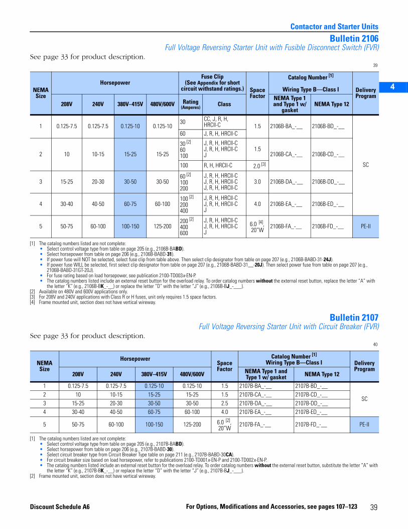
2
3
4
5
Contactor and Starter Units
Bulletin 2106Full Voltage Reversing Starter Unit with Fusible Disconnect Switch (FVR)
See page 33 for product description.39
Bulletin 2107Full Voltage Reversing Starter Unit with Circuit Breaker (FVR)
See page 33 for product description.40
NEMASize
HorsepowerFuse Clip
(See Appendix for short circuit withstand ratings.) Space
Factor
Catalog Number [1]
Wiring Type B—Class I
[1] The catalog numbers listed are not complete: • Select control voltage type from table on page 205 (e.g., 2106B-BABD).• Select horsepower from table on page 206 (e.g., 2106B-BABD-31).• If power fuse will NOT be selected, select fuse clip from table above. Then select clip designator from table on page 207 (e.g., 2106B-BABD-31-24J).• If power fuse WILL be selected, first select clip designator from table on page 207 (e.g., 2106B-BABD-31__-20J). Then select power fuse from table on page 207 (e.g.,
2106B-BABD-31GT-20J).• For fuse rating based on load horsepower, see publication 2100-TD003x-EN-P.• The catalog numbers listed include an external reset button for the overload relay. To order catalog numbers without the external reset button, replace the letter “A” with
the letter “K” (e.g., 2106B-BK_-__) or replace the letter “D” with the letter “J” (e.g., 2106B-BJ_-___).
Delivery Program
208V 240V 380V–415V 480V/600V Rating(Amperes) Class
NEMA Type 1 and Type 1 w/
gasketNEMA Type 12
1 0.125-7.5 0.125-7.5 0.125-10 0.125-1030 CC, J, R, H,
HRCII-C 1.5 2106B-BA_-__ 2106B-BD_-__
SC
60 J, R, H, HRCII-C
2 10 10-15 15-25 15-25
30 [2]
60100
[2] Available on 480V and 600V applications only.
J, R, H, HRCII-CJ, R, H, HRCII-CJ
1.52106B-CA_-__ 2106B-CD_-__
100 R, H, HRCII-C 2.0 [3]
[3] For 208V and 240V applications with Class R or H fuses, unit only requires 1.5 space factors.
3 15-25 20-30 30-50 30-5060 [2]
100200
J, R, H, HRCII-CJ, R, H, HRCII-CJ, R, H, HRCII-C
3.0 2106B-DA_-__ 2106B-DD_-__
4 30-40 40-50 60-75 60-100100 [2]
200400
J, R, H, HRCII-CJ, R, H, HRCII-CJ
4.0 2106B-EA_-__ 2106B-ED_-__
5 50-75 60-100 100-150 125-200200 [2]
400600
J, R, H, HRCII-CJ, R, H, HRCII-CJ
6.0 [4], 20”W
[4] Frame mounted unit, section does not have vertical wireway.
2106B-FA_-__ 2106B-FD_-__ PE-II
NEMA Size
HorsepowerSpaceFactor
Catalog Number [1]
Wiring Type B—Class I
[1] The catalog numbers listed are not complete:• Select control voltage type from table on page 205 (e.g., 2107B-BABD).• Select horsepower from table on page 206 (e.g., 2107B-BABD-30).• Select circuit breaker type from Circuit Breaker Type table on page 211 (e.g., 2107B-BABD-30CA).• For circuit breaker size based on load horsepower, refer to publications 2100-TD001x-EN-P and 2100-TD002x-EN-P.• The catalog numbers listed include an external reset button for the overload relay. To order catalog numbers without the external reset button, substitute the letter “A” with
the letter “K” (e.g., 2107B-BK_-__) or replace the letter “D” with the letter “J” (e.g., 2107B-BJ_-___).
DeliveryProgram
208V 240V 380V–415V 480V/600V NEMA Type 1 and Type 1 w/ gasket NEMA Type 12
1 0.125-7.5 0.125-7.5 0.125-10 0.125-10 1.5 2107B-BA_-__ 2107B-BD_-__
SC2 10 10-15 15-25 15-25 1.5 2107B-CA_-__ 2107B-CD_-__3 15-25 20-30 30-50 30-50 2.5 2107B-DA_-__ 2107B-DD_-__4 30-40 40-50 60-75 60-100 4.0 2107B-EA_-__ 2107B-ED_-__
5 50-75 60-100 100-150 125-200 6.0 [2], 20”W
[2] Frame mounted unit, section does not have vertical wireway.
2107B-FA_-__ 2107B-FD_-__ PE-II
39For Options, Modifications and Accessories, see pages 107–123Discount Schedule A6
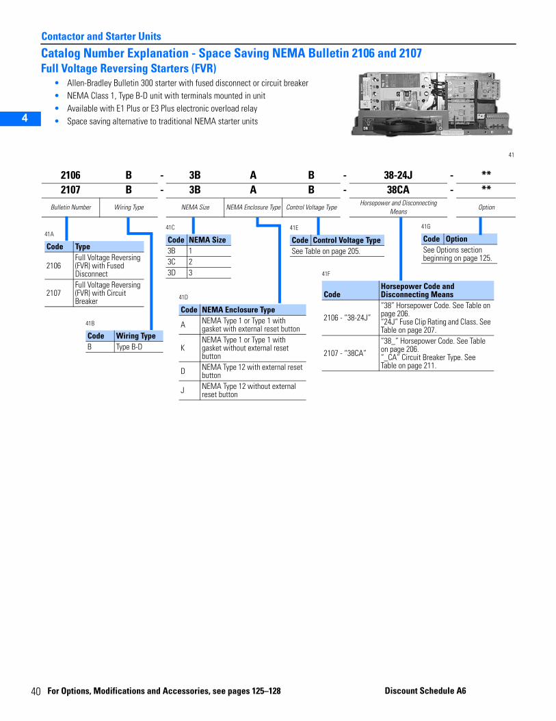
4
Contactor and Starter Units
2
3
4
5
Catalog Number Explanation - Space Saving NEMA Bulletin 2106 and 2107Full Voltage Reversing Starters (FVR)
• Allen-Bradley Bulletin 300 starter with fused disconnect or circuit breaker• NEMA Class 1, Type B-D unit with terminals mounted in unit• Available with E1 Plus or E3 Plus electronic overload relay• Space saving alternative to traditional NEMA starter units
41
2106 B - 3B A B - 38-24J - **2107 B - 3B A B - 38CA - **
Bulletin Number Wiring Type NEMA Size NEMA Enclosure Type Control Voltage TypeHorsepower and Disconnecting
MeansOption
41A
Code Type
2106Full Voltage Reversing (FVR) with Fused Disconnect
2107Full Voltage Reversing (FVR) with Circuit Breaker
41C
Code NEMA Size3B 13C 23D 3
41B
Code Wiring TypeB Type B-D
41D
Code NEMA Enclosure Type
A NEMA Type 1 or Type 1 with gasket with external reset button
KNEMA Type 1 or Type 1 with gasket without external reset button
D NEMA Type 12 with external reset button
J NEMA Type 12 without external reset button
41E
Code Control Voltage TypeSee Table on page 205.
41F
CodeHorsepower Code and Disconnecting Means
2106 - “38-24J”“38” Horsepower Code. See Table on page 206. “24J” Fuse Clip Rating and Class. See Table on page 207.
2107 - “38CA”“38_” Horsepower Code. See Table on page 206. “_CA” Circuit Breaker Type. See Table on page 211.
41G
Code OptionSee Options section beginning on page 125.
0
For Optio ns, Modifications and Ac cessories, see pages 125–128 Discoun t Schedule A6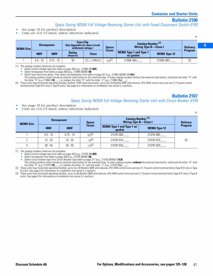
2
3
4
5
Contactor and Starter Units
Bulletin 2106Space Saving NEMA Full Voltage Reversing Starter Unit with Fused Disconnect Switch (FVR)
• See page 33 for product description.• Units are cUL US listed, unless otherwise indicated.
42
Bulletin 2107Space Saving NEMA Full Voltage Reversing Starter Unit with Circuit Breaker (FVR)
• See page 33 for product description.• Units are cUL US listed, unless otherwise indicated.
43
NEMA SizeHorsepower
Fuse Clip(See Appendix for short circuit
withstand ratings.) SpaceFactor
Catalog Number [1]
Wiring Type B—Class I
[1] The catalog numbers listed are not complete:• Select control voltage type from table on page 205 (e.g., 2106B-3BABD).• Select horsepower from table on page 206 (e.g., 2106B-3BABD-38).• Select fuse class from above. Then select clip designator from table on page 207 (e.g., 2106B-3BABD-38-24J).
The catalog numbers listed include an external reset button for the overload relay. To order catalog numbers without the external reset button, substitute the letter “A” with the letter “K” (e.g. 2106B-3BK_-__) or replace the letter “D” with the letter “J” (e.g., 2106B-3BJ_-__)
DeliveryProgram
480V 600V Rating(Amperes) Class NEMA Type 1 and Type 1
w/ gasket NEMA Type 12
1 0.5 - 10 0.75 - 10 30 CC, J, HRCII-C 0.5[2]
[2] These units have horizontal operating handles, Bulletin 194R fused disconnect, up to four (4) Bulletin 800F pilot devices, #16 AWG control wire and one (1) 10-point control terminal block (Type B-D only in Type B units). See page 8 or information on installation into series E-J sections.
2106B-3BA_-__ 2106B-3BD_-__ SC
NEMA SizeHorsepower
SpaceFactor
Catalog Number [1]
Wiring Type B—Class I
[1] The catalog numbers listed are not complete:• Select control voltage type from table on page 205 (e.g., 2107B-3BABD).• Select horsepower from table on page 206 (e.g., 2107B-3BABD-38).• Select circuit breaker type from Circuit Breaker Type table on page 211 (e.g., 2107B-3BABD-38CA).
The catalog numbers listed include an external reset button for the overload relay. To order catalog numbers without the external reset button, substitute the letter “A” with the letter “K” (e.g. 2107B-3BK_-__) or replace the letter “D” with the letter “J” (e.g., 2107B-3BJ_-__).
DeliveryProgram
480V 600V NEMA Type 1 and Type 1 w/ gasket NEMA Type 12
1 0.5 - 10 0.75 - 10 0.5[2]
[2] These units have horizontal operating handles, up to four (4) Bulletin 800F pilot devices, #16 AWG control wire and one (1) 10-point control terminal block (Type B-D only in Type B units). See page 8 for information on installation into series E-J sections.
2107B-3BA_-__ 2107B-3BD_-__
SC2 15 - 25 15 - 25 1.0[3]
[3] These units have horizontal operating handles, up to six (6) Bulletin 800F pilot devices, #16 AWG control wire and one (1) 10-point control terminal block (Type B-D only in Type B units). See page 8 for information on installation into series E-J sections.
2107B-3CA_-__ 2107B-3CD_-__
3 30 - 50 30 - 50 1.5[3] 2107B-3DA_-__ 2107B-3DD_-__
41For Options, Modifications and Accessories, see pages 125–128Discount Schedule A6
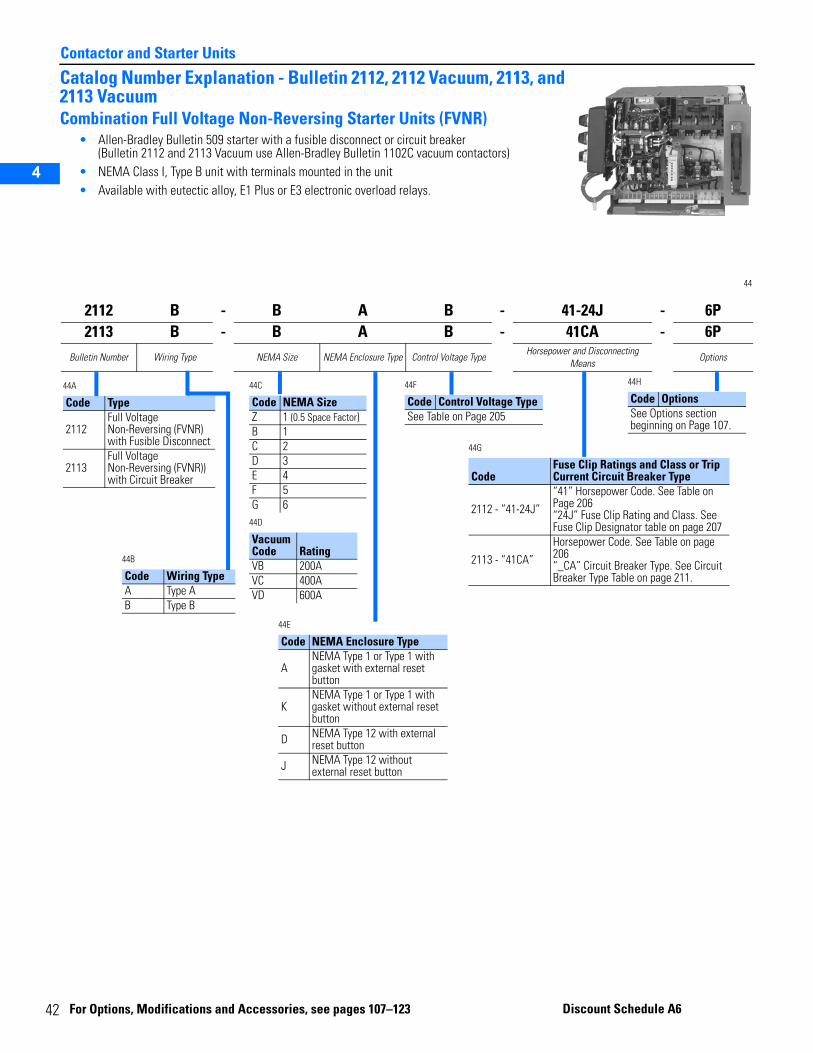
4
Contactor and Starter Units
2
3
4
5
Catalog Number Explanation - Bulletin 2112, 2112 Vacuum, 2113, and 2113 VacuumCombination Full Voltage Non-Reversing Starter Units (FVNR)
• Allen-Bradley Bulletin 509 starter with a fusible disconnect or circuit breaker(Bulletin 2112 and 2113 Vacuum use Allen-Bradley Bulletin 1102C vacuum contactors)
• NEMA Class I, Type B unit with terminals mounted in the unit • Available with eutectic alloy, E1 Plus or E3 electronic overload relays.
44
2112 B - B A B - 41-24J - 6P2113 B - B A B - 41CA - 6P
Bulletin Number Wiring Type NEMA Size NEMA Enclosure Type Control Voltage TypeHorsepower and Disconnecting
MeansOptions
44A
Code Type
2112Full Voltage Non-Reversing (FVNR) with Fusible Disconnect
2113Full Voltage Non-Reversing (FVNR)) with Circuit Breaker
44C
44D
Code NEMA SizeZ 1 (0.5 Space Factor)B 1C 2D 3E 4F 5G 6
Vacuum Code RatingVB 200AVC 400AVD 600A
44B
Code Wiring TypeA Type AB Type B
44E
Code NEMA Enclosure Type
ANEMA Type 1 or Type 1 with gasket with external reset button
KNEMA Type 1 or Type 1 with gasket without external reset button
D NEMA Type 12 with external reset button
J NEMA Type 12 without external reset button
44F
Code Control Voltage TypeSee Table on Page 205
44G
CodeFuse Clip Ratings and Class or Trip Current Circuit Breaker Type
2112 - “41-24J”“41” Horsepower Code. See Table on Page 206“24J” Fuse Clip Rating and Class. See Fuse Clip Designator table on page 207
2113 - “41CA”Horsepower Code. See Table on page 206 “_CA” Circuit Breaker Type. See Circuit Breaker Type Table on page 211.
44H
Code OptionsSee Options section beginning on Page 107.
2 For Opti
ons, Modifications and Acces sories, see pages 107– 123 Discount S chedule A6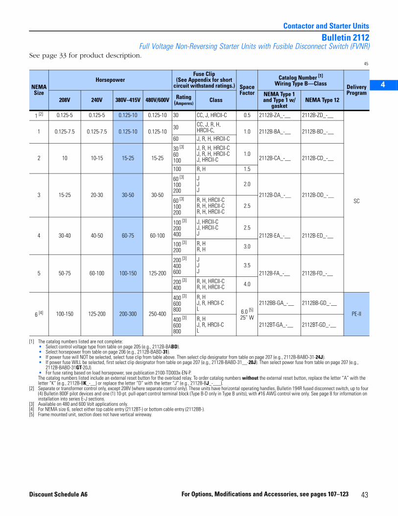
2
3
4
5
Contactor and Starter Units
Bulletin 2112Full Voltage Non-Reversing Starter Units with Fusible Disconnect Switch (FVNR)
See page 33 for product description.45
NEMASize
HorsepowerFuse Clip
(See Appendix for short circuit withstand ratings.) Space
Factor
Catalog Number [1]
Wiring Type B—Class
[1] The catalog numbers listed are not complete:• Select control voltage type from table on page 205 (e.g., 2112B-BABD).• Select horsepower from table on page 206 (e.g., 2112B-BABD-31).• If power fuse will NOT be selected, select fuse clip from table above. Then select clip designator from table on page 207 (e.g., 2112B-BABD-31-24J).• If power fuse WILL be selected, first select clip designator from table on page 207 (e.g., 2112B-BABD-31__-20J). Then select power fuse from table on page 207 (e.g.,
2112B-BABD-31GT-20J).• For fuse rating based on load horsepower, see publication 2100-TD003x-EN-P.The catalog numbers listed include an external reset button for the overload relay. To order catalog numbers without the external reset button, replace the letter “A” with the letter “K” (e.g., 2112B-BK_-__) or replace the letter “D” with the letter “J” (e.g., 2112B-BJ_-___).
DeliveryProgram
208V 240V 380V–415V 480V/600V Rating(Amperes)
ClassNEMA Type 1 and Type 1 w/
gasketNEMA Type 12
1 [2]
[2] Separate or transformer control only, except 208V (where separate control only). These units have horizontal operating handles, Bulletin 194R fused disconnect switch, up to four (4) Bulletin 800F pilot devices and one (1) 10-pt. pull-apart control terminal block (Type B-D only in Type B units), with #16 AWG control wire only. See page 8 for information on installation into series E-J sections.
0.125-5 0.125-5 0.125-10 0.125-10 30 CC, J, HRCII-C 0.5 2112B-ZA_-__ 2112B-ZD_-__
SC
1 0.125-7.5 0.125-7.5 0.125-10 0.125-1030 CC, J, R, H,
HRCII-C, 1.0 2112B-BA_-__ 2112B-BD_-__60 J, R, H, HRCII-C
2 10 10-15 15-25 15-25
30 [3]
60100
[3] Available on 480 and 600 Volt applications only.
J, R, H, HRCII-CJ, R, H, HRCII-CJ, HRCII-C
1.02112B-CA_-__ 2112B-CD_-__
100 R, H 1.5
3 15-25 20-30 30-50 30-50
60 [3]
100200
JJJ
2.0
2112B-DA_-__ 2112B-DD_-__60 [3]
100200
R, H, HRCII-CR, H, HRCII-CR, H, HRCII-C
2.5
4 30-40 40-50 60-75 60-100
100 [3]
200400
J, HRCII-CJ, HRCII-CJ
2.52112B-EA_-__ 2112B-ED_-__
100 [3]
200R, HR, H 3.0
5 50-75 60-100 100-150 125-200
200 [3]
400600
JJJ
3.52112B-FA_-__ 2112B-FD_-__
200 [3]
400R, H, HRCII-CR, H, HRCII-C 4.0
6 [4]
[4] For NEMA size 6, select either top cable entry (2112BT-) or bottom cable entry (2112BB-).
100-150 125-200 200-300 250-400
400 [3]
600800
R, HJ, R, HRCII-CL 6.0 [5]
25” W
[5] Frame mounted unit, section does not have vertical wireway.
2112BB-GA_-__ 2112BB-GD_-__
PE-II400 [3]
600800
R, HJ, R, HRCII-CL
2112BT-GA_-__ 2112BT-GD_-__
43For Options, Modifications and Accessories, see pages 107–123Discount Schedule A6
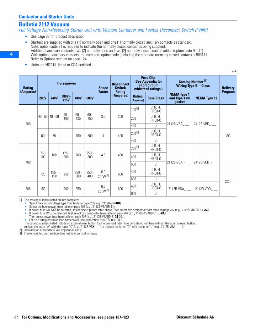
4
Contactor and Starter Units
2
3
4
5
Bulletin 2112 VacuumFull Voltage Non-Reversing Starter Unit with Vacuum Contactor and Fusible Disconnect Switch (FVNR)
• See page 33 for product description.• Starters are supplied with one (1) normally open and one (1) normally closed auxiliary contacts as standard.
Note: option code 91 is required to indicate the normally closed contact is being supplied.Additional auxiliary contacts (two [2] normally open and two [2] normally closed) can be added (option code 90011)With optional auxiliary contacts, the complete option code (including the standard normally closed contact) is 900111.Refer to Options section on page 124.
• Units are NOT UL listed or CSA certified45A
Rating (Amperes)
HorsepowerSpace Factor
Disconnect Switch Rating
(Amperes)
Fuse Clip(See Appendix for
short circuit withstand ratings.)
Catalog Number [1]
Wiring Type B—Class
[1] The catalog numbers listed are not complete:• Select the control voltage type from table on page 205 (e.g., 2112B-VBABD).• Select the horsepower from table on page 206 (e.g., 2112B-VBABD-51).• If power fuse will NOT be selected, select fuse clip from table above. Then select clip designator from table on page 207 (e.g., 2112B-VBABD-51-26J).• If power fuse WILL be selected, first select clip designator from table on page 207 (e.g., 2112B-VBABD-51__-20J).
Then select power fuse from table on page 207 (e.g., 2112B-VBABD-51GT-20J).• For fuse rating based on load horsepower, see publication 2100-TD003x-EN-P.The catalog numbers listed include an external reset button for the overload relay. To order catalog numbers without the external reset button,replace the letter “A” with the letter “K” (e.g., 2112B-VBK_-__) or replace the letter “D” with the letter “J” (e.g., 2112B-VBJ_-___).
DeliveryProgram
208V 240V 380V–415V 480V 600V Rating
(Amperes)Fuse Class
NEMA Type 1 and Type 1 w/
gasketNEMA Type 12
200
40 - 50 40 - 60 60 - 100
60 - 125
60 - 150 3.5 200
100[2]
[2] Available on 480 and 600 Volt applications only.
J, R, H, HRCII-C
2112B-VBA_-__ 2112B-VBD_-__
SC
200 J, R, H, HRCII-C
400 J
60 75 - 150 200 4 400 200[2] J, R, H, HRCII-C
400 J
400
75 - 100 100 125 -
200 200 250 - 300 4.5 400
200[2] J, R, H, HRCII-C
2112B-VCA_-__ 2112B-VCD_-__400 J, R, H,
HRCII-C600 J
125 125 - 150 250 250 -
300350 - 400
6.0 20”W[3]
[3] Frame mounted unit, section does not have vertical wireway.
600400 J, R, H,
HRCII-C
SC-II600 J
600 150 - 300 350 -6.0
20”W[3] 600400 J, R, H,
HRCII-C 2112B-VDA_-__ 2112B-VDD_-__600 J
4 For Options, Modifications and Accessories, see pages 107–123 Discount Schedule A6
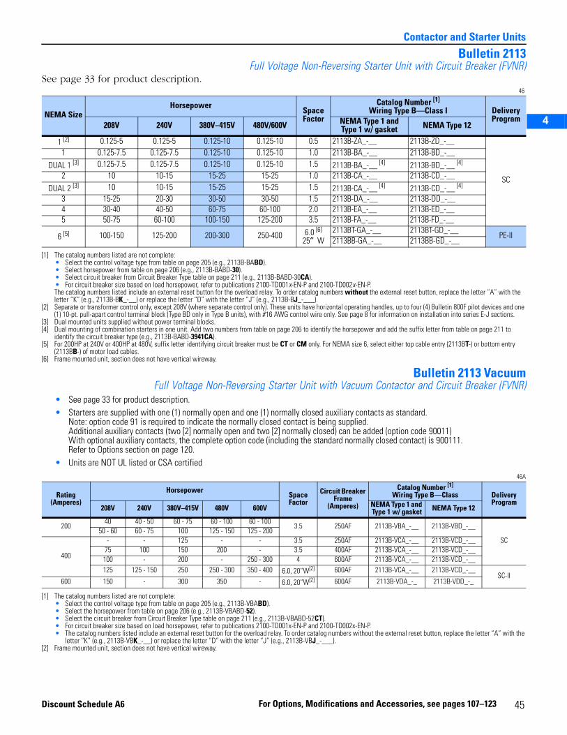
2
3
4
5
Contactor and Starter Units
Bulletin 2113Full Voltage Non-Reversing Starter Unit with Circuit Breaker (FVNR)
See page 33 for product description.46
Bulletin 2113 VacuumFull Voltage Non-Reversing Starter Unit with Vacuum Contactor and Circuit Breaker (FVNR)
• See page 33 for product description.• Starters are supplied with one (1) normally open and one (1) normally closed auxiliary contacts as standard.
Note: option code 91 is required to indicate the normally closed contact is being supplied.Additional auxiliary contacts (two [2] normally open and two [2] normally closed) can be added (option code 90011)With optional auxiliary contacts, the complete option code (including the standard normally closed contact) is 900111.Refer to Options section on page 120.
• Units are NOT UL listed or CSA certified46A
NEMA SizeHorsepower
SpaceFactor
Catalog Number [1]
Wiring Type B—Class I
[1] The catalog numbers listed are not complete:• Select the control voltage type from table on page 205 (e.g., 2113B-BABD).• Select horsepower from table on page 206 (e.g., 2113B-BABD-30).• Select circuit breaker from Circuit Breaker Type table on page 211 (e.g., 2113B-BABD-30CA).• For circuit breaker size based on load horsepower, refer to publications 2100-TD001x-EN-P and 2100-TD002x-EN-P.The catalog numbers listed include an external reset button for the overload relay. To order catalog numbers without the external reset button, replace the letter “A” with the letter “K” (e.g., 2113B-BK_-__) or replace the letter “D” with the letter “J” (e.g., 2113B-BJ_-___).
Delivery Program
208V 240V 380V–415V 480V/600V NEMA Type 1 and Type 1 w/ gasket NEMA Type 12
1 [2]
[2] Separate or transformer control only, except 208V (where separate control only). These units have horizontal operating handles, up to four (4) Bulletin 800F pilot devices and one (1) 10-pt. pull-apart control terminal block (Type BD only in Type B units), with #16 AWG control wire only. See page 8 for information on installation into series E-J sections.
0.125-5 0.125-5 0.125-10 0.125-10 0.5 2113B-ZA_-__ 2113B-ZD_-__
SC
1 0.125-7.5 0.125-7.5 0.125-10 0.125-10 1.0 2113B-BA_-__ 2113B-BD_-__
DUAL 1 [3]
[3] Dual mounted units supplied without power terminal blocks.
0.125-7.5 0.125-7.5 0.125-10 0.125-10 1.5 2113B-BA_-__ [4]
[4] Dual mounting of combination starters in one unit. Add two numbers from table on page 206 to identify the horsepower and add the suffix letter from table on page 211 to identify the circuit breaker type (e.g., 2113B-BABD-3941CA).
2113B-BD_-__ [4]
2 10 10-15 15-25 15-25 1.0 2113B-CA_-__ 2113B-CD_-__
DUAL 2 [3] 10 10-15 15-25 15-25 1.5 2113B-CA_-__ [4] 2113B-CD_-__ [4]
3 15-25 20-30 30-50 30-50 1.5 2113B-DA_-__ 2113B-DD_-__4 30-40 40-50 60-75 60-100 2.0 2113B-EA_-__ 2113B-ED_-__5 50-75 60-100 100-150 125-200 3.5 2113B-FA_-__ 2113B-FD_-__
6 [5]
[5] For 200HP at 240V or 400HP at 480V, suffix letter identifying circuit breaker must be CT or CM only. For NEMA size 6, select either top cable entry (2113BT-) or bottom entry (2113BB-) of motor load cables.
100-150 125-200 200-300 250-400 6.0 [6]
25″ W
[6] Frame mounted unit, section does not have vertical wireway.
2113BT-GA_-__ 2113BT-GD_-__PE-II
2113BB-GA_-__ 2113BB-GD_-__
Rating (Amperes)
HorsepowerSpace Factor
Circuit Breaker Frame
(Amperes)
Catalog Number [1]
Wiring Type B—Class
[1] The catalog numbers listed are not complete:• Select the control voltage type from table on page 205 (e.g., 2113B-VBABD).• Select the horsepower from table on page 206 (e.g., 2113B-VBABD-52).• Select the circuit breaker from Circuit Breaker Type table on page 211 (e.g., 2113B-VBABD-52CT).• For circuit breaker size based on load horsepower, refer to publications 2100-TD001x-EN-P and 2100-TD002x-EN-P.• The catalog numbers listed include an external reset button for the overload relay. To order catalog numbers without the external reset button, replace the letter “A” with the
letter “K” (e.g., 2113B-VBK_-__) or replace the letter “D” with the letter “J” (e.g., 2113B-VBJ_-___).
DeliveryProgram
208V 240V 380V–415V 480V 600V NEMA Type 1 and Type 1 w/ gasket NEMA Type 12
20040 40 - 50 60 - 75 60 - 100 60 - 100
3.5 250AF 2113B-VBA_-__ 2113B-VBD_-__
SC50 - 60 60 - 75 100 125 - 150 125 - 200
400
- - 125 - - 3.5 250AF 2113B-VCA_-__ 2113B-VCD_-__75 100 150 200 - 3.5 400AF 2113B-VCA_-__ 2113B-VCD_-__
100 - 200 - 250 - 300 4 600AF 2113B-VCA_-__ 2113B-VCD_-__125 125 - 150 250 250 - 300 350 - 400 6.0, 20”W[2]
[2] Frame mounted unit, section does not have vertical wireway.
600AF 2113B-VCA_-__ 2113B-VCD_-__SC-II
600 150 - 300 350 - 6.0, 20”W[2] 600AF 2113B-VDA_-_ 2113B-VDD_-_
45For Options, Modifications and Accessories, see pages 107–123Discount Schedule A6
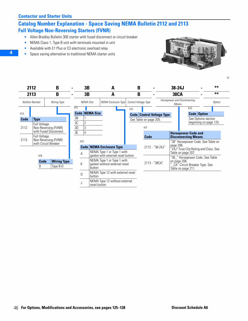
4
Contactor and Starter Units
2
3
4
5
Catalog Number Explanation - Space Saving NEMA Bulletin 2112 and 2113Full Voltage Non-Reversing Starters (FVNR)
• Allen-Bradley Bulletin 300 starter with fused disconnect or circuit breaker• NEMA Class 1, Type B unit with terminals mounted in unit• Available with E1 Plus or E3 electronic overload relay• Space saving alternative to traditional NEMA starter units
47
2112 B - 3B A B - 38-24J - **2113 B - 3B A B - 38CA - **
Bulletin Number Wiring Type NEMA Size NEMA Enclosure Type Control Voltage TypeHorsepower and Disconnecting
MeansOption
47A
Code Type
2112Full Voltage Non-Reversing (FVNR) with Fused Disconnect
2113Full Voltage Non-Reversing (FVNR) with Circuit Breaker
47C
Code NEMA Size3B 13C 23D 33E 4
47B
Code Wiring TypeB Type B-D
47D
Code NEMA Enclosure Type
A NEMA Type 1 or Type 1 with gasket with external reset button
KNEMA Type 1 or Type 1 with gasket without external reset button
D NEMA Type 12 with external reset button
J NEMA Type 12 without external reset button
47E
Code Control Voltage TypeSee Table on page 205.
47F
CodeHorsepower Code and Disconnecting Means
2112 - “38-24J”“38” Horsepower Code. See Table on page 206. “24J” Fuse Clip Rating and Class. See Table on page 207.
2113 - “38CA”“38_” Horsepower Code. See Table on page 206. “_CA” Circuit Breaker Type. See Table on page 211.
47G
Code OptionSee Options section beginning on page 125.
6
For Optio ns, Modifications and Ac cessories, see pages 125–128 Discoun t Schedule A6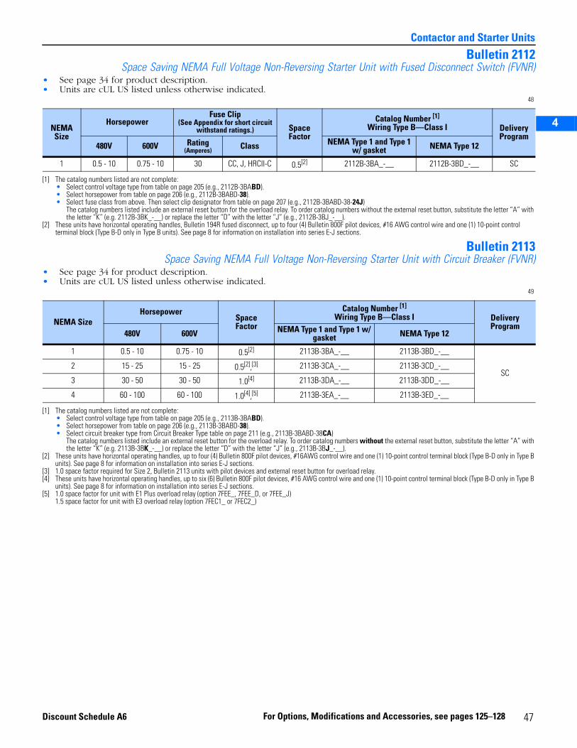
2
3
4
5
Contactor and Starter Units
Bulletin 2112Space Saving NEMA Full Voltage Non-Reversing Starter Unit with Fused Disconnect Switch (FVNR)
• See page 34 for product description.• Units are cUL US listed unless otherwise indicated.
48
Bulletin 2113Space Saving NEMA Full Voltage Non-Reversing Starter Unit with Circuit Breaker (FVNR)
• See page 34 for product description.• Units are cUL US listed unless otherwise indicated.
49
NEMA Size
HorsepowerFuse Clip
(See Appendix for short circuit withstand ratings.) Space
Factor
Catalog Number [1]
Wiring Type B—Class I
[1] The catalog numbers listed are not complete:• Select control voltage type from table on page 205 (e.g., 2112B-3BABD).• Select horsepower from table on page 206 (e.g., 2112B-3BABD-38).• Select fuse class from above. Then select clip designator from table on page 207 (e.g., 2112B-3BABD-38-24J)
The catalog numbers listed include an external reset button for the overload relay. To order catalog numbers without the external reset button, substitute the letter “A” with the letter “K” (e.g. 2112B-3BK_-__) or replace the letter “D” with the letter “J” (e.g., 2112B-3BJ_-__).
DeliveryProgram
480V 600V Rating(Amperes) Class NEMA Type 1 and Type 1
w/ gasket NEMA Type 12
1 0.5 - 10 0.75 - 10 30 CC, J, HRCII-C 0.5[2]
[2] These units have horizontal operating handles, Bulletin 194R fused disconnect, up to four (4) Bulletin 800F pilot devices, #16 AWG control wire and one (1) 10-point control terminal block (Type B-D only in Type B units). See page 8 for information on installation into series E-J sections.
2112B-3BA_-__ 2112B-3BD_-__ SC
NEMA SizeHorsepower
SpaceFactor
Catalog Number [1]
Wiring Type B—Class I
[1] The catalog numbers listed are not complete:• Select control voltage type from table on page 205 (e.g., 2113B-3BABD).• Select horsepower from table on page 206 (e.g., 2113B-3BABD-38).• Select circuit breaker type from Circuit Breaker Type table on page 211 (e.g., 2113B-3BABD-38CA)
The catalog numbers listed include an external reset button for the overload relay. To order catalog numbers without the external reset button, substitute the letter “A” with the letter “K” (e.g. 2113B-3BK_-__) or replace the letter “D” with the letter “J” (e.g., 2113B-3BJ_-__).
DeliveryProgram
480V 600V NEMA Type 1 and Type 1 w/ gasket NEMA Type 12
1 0.5 - 10 0.75 - 10 0.5[2]
[2] These units have horizontal operating handles, up to four (4) Bulletin 800F pilot devices, #16AWG control wire and one (1) 10-point control terminal block (Type B-D only in Type B units). See page 8 for information on installation into series E-J sections.
2113B-3BA_-__ 2113B-3BD_-__
SC2 15 - 25 15 - 25 0.5[2],[3]
[3] 1.0 space factor required for Size 2, Bulletin 2113 units with pilot devices and external reset button for overload relay.
2113B-3CA_-__ 2113B-3CD_-__
3 30 - 50 30 - 50 1.0[4]
[4] These units have horizontal operating handles, up to six (6) Bulletin 800F pilot devices, #16 AWG control wire and one (1) 10-point control terminal block (Type B-D only in Type B units). See page 8 for information on installation into series E-J sections.
2113B-3DA_-__ 2113B-3DD_-__
4 60 - 100 60 - 100 1.0[4],[5]
[5] 1.0 space factor for unit with E1 Plus overload relay (option 7FEE_, 7FEE_D, or 7FEE_J)1.5 space factor for unit with E3 overload relay (option 7FEC1_ or 7FEC2_)
2113B-3EA_-__ 2113B-3ED_-__
47For Options, Modifications and Accessories, see pages 125–128Discount Schedule A6
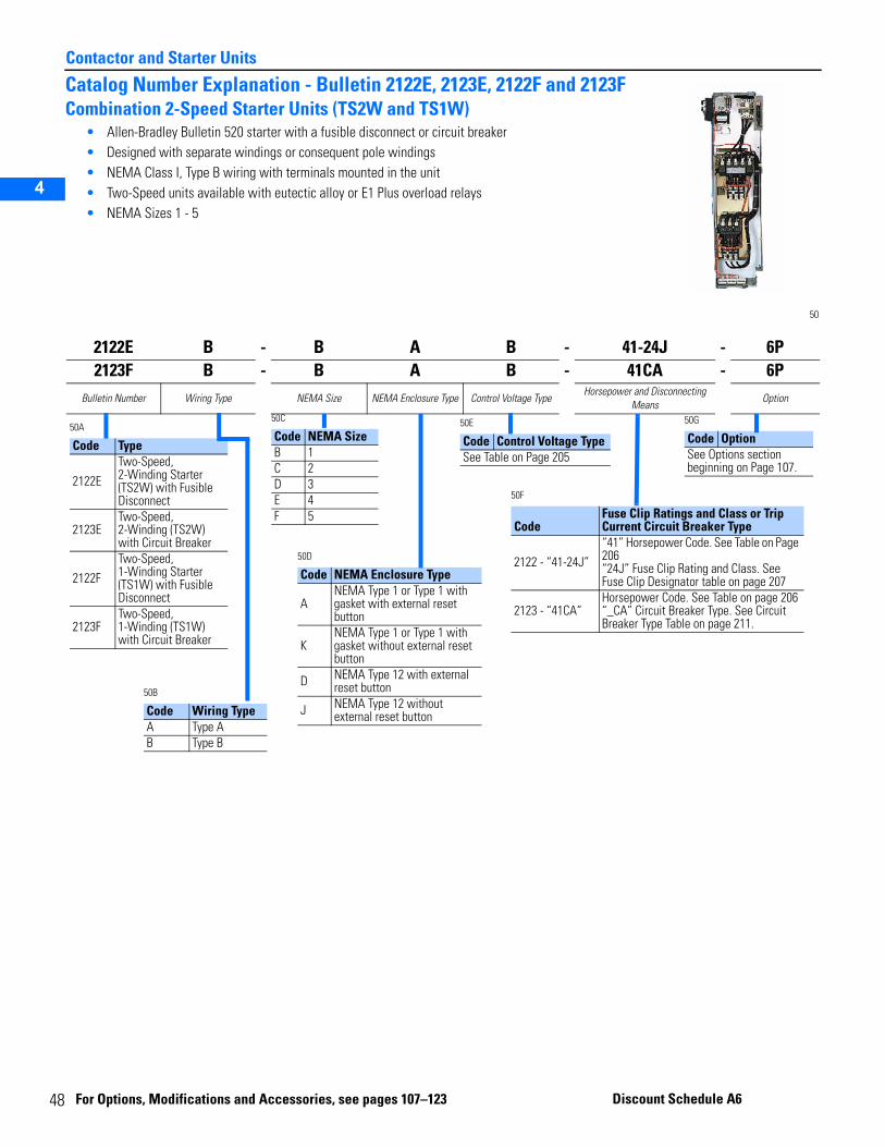
4
Contactor and Starter Units
2
3
4
5
Catalog Number Explanation - Bulletin 2122E, 2123E, 2122F and 2123FCombination 2-Speed Starter Units (TS2W and TS1W)
• Allen-Bradley Bulletin 520 starter with a fusible disconnect or circuit breaker• Designed with separate windings or consequent pole windings• NEMA Class I, Type B wiring with terminals mounted in the unit • Two-Speed units available with eutectic alloy or E1 Plus overload relays• NEMA Sizes 1 - 5
50
2122E B - B A B - 41-24J - 6P2123F B - B A B - 41CA - 6P
Bulletin Number Wiring Type NEMA Size NEMA Enclosure Type Control Voltage TypeHorsepower and Disconnecting
MeansOption
50A
Code Type
2122E
Two-Speed, 2-Winding Starter (TS2W) with Fusible Disconnect
2123ETwo-Speed, 2-Winding (TS2W) with Circuit Breaker
2122FTwo-Speed, 1-Winding Starter (TS1W) with Fusible Disconnect
2123FTwo-Speed, 1-Winding (TS1W) with Circuit Breaker
50C
Code NEMA SizeB 1C 2D 3E 4F 5
50B
Code Wiring TypeA Type AB Type B
50D
Code NEMA Enclosure Type
ANEMA Type 1 or Type 1 with gasket with external reset button
KNEMA Type 1 or Type 1 with gasket without external reset button
D NEMA Type 12 with external reset button
J NEMA Type 12 without external reset button
50E
Code Control Voltage TypeSee Table on Page 205
50F
CodeFuse Clip Ratings and Class or Trip Current Circuit Breaker Type
2122 - “41-24J”“41” Horsepower Code. See Table on Page 206 “24J” Fuse Clip Rating and Class. See Fuse Clip Designator table on page 207
2123 - “41CA”Horsepower Code. See Table on page 206 “_CA” Circuit Breaker Type. See Circuit Breaker Type Table on page 211.
50G
Code OptionSee Options section beginning on Page 107.
8 For Option
s, Modifications and Acce ssories, see pages 107–123 Discount S chedule A6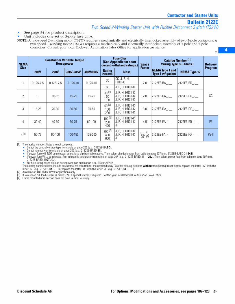
2
3
4
5
Contactor and Starter Units
Bulletin 2122ETwo Speed 2-Winding Starter Unit with Fusible Disconnect Switch (TS2W)
• See page 34 for product description.• Unit includes one set of 3-pole fuse clips.NOTE: A two-speed 2-winding motor (TS2W) requires a mechanically and electrically interlocked assembly of two 3-pole contactors. A
two-speed 1-winding motor (TS1W) requires a mechanically and electrically interlocked assembly of 3-pole and 5-pole contactors. Consult your local Rockwell Automation Sales Office for application assistance.
51
NEMASize
Constant or Variable TorqueHorsepower
Fuse Clip(See Appendix for short
circuit withstand ratings.) SpaceFactor
Catalog Number [1]
Wiring Type B—Class I
[1] The catalog numbers listed are not complete: • Select the control voltage type from table on page 205 (e.g., 2122EB-BABD).• Select horsepower from table on page 206 (e.g., 2122EB-BABD-31).• If power fuse will NOT be selected, select fuse clip from table above. Then select clip designator from table on page 207 (e.g., 2122EB-BABD-31-24J).• If power fuse WILL be selected, first select clip designator from table on page 207 (e.g., 2122EB-BABD-31__-20J). Then select power fuse from table on page 207 (e.g.,
2122EB-BABD-31GT-20J).• For fuse rating based on load horsepower, see publication 2100-TD003x-EN-P.The catalog numbers listed include an external reset button for the overload relay. To order catalog numbers without the external reset button, replace the letter “A” with the letter “K” (e.g., 2122EB-BK_-__) or replace the letter “D” with the letter “J” (e.g., 2122EB-BJ_-___).
DeliveryProgram
208V 240V 380V–415V 480V/600V Rating(Amperes) Class NEMA Type 1 and
Type 1 w/ gasket NEMA Type 12
1 0.125-7.5 0.125- 7.5 0.125-10 0.125-1030 CC, J, R, H,
HRCII-C 2.0 2122EB-BA_-__ 2122EB-BD_-__
SC
60 J, R, H, HRCII-C
2 10 10-15 15-25 15-2530 [2]
60100
[2] Available on 480 and 600 Volt applications only.
J, R, H, HRCII-CJ, R, H, HRCII-CJ, R, H, HRCII-C
2.0 2122EB-CA_-__ 2122EB-CD_-__
3 15-25 20-30 30-50 30-5060 [2]
100200
J, R, H, HRCII-CJ, R, H, HRCII-CJ, R, H, HRCII-C
3.0 2122EB-DA_-__ 2122EB-DD_-__
4 30-40 40-50 60-75 60-100100 [2]
200400
J, R, H, HRCII-CJ, R, H, HRCII-CJ
4.5 2122EB-EA_-__ 2122EB-ED_-__ PE
5 [3]
[3] If low speed full load current is below 77A, a special starter is required. Contact your local Rockwell Automation Sales Office.
50-75 60-100 100-150 125-200200 [2]
400600
J, R, H, HRCII-CJ, R, H, HRCII-CJ
6.0 [4], 20” W
[4] Frame mounted unit, section does not have vertical wireway.
2122EB-FA_-__ 2122EB-FD_-__ PE-II
49For Options, Modifications and Accessories, see pages 107–123Discount Schedule A6
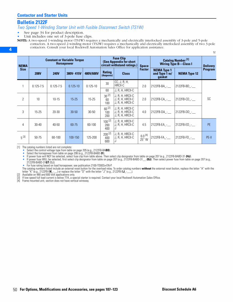
5
Contactor and Starter Units
2
3
4
5
Bulletin 2122FTwo Speed 1-Winding Starter Unit with Fusible Disconnect Switch (TS1W)• See page 34 for product description.• Unit includes one set of 3-pole fuse clips.NOTE: A two-speed 1-winding motor (TS1W) requires a mechanically and electrically interlocked assembly of 3-pole and 5-pole
contactors. A two-speed 2-winding motor (TS2W) requires a mechanically and electrically interlocked assembly of two 3-pole contactors. Consult your local Rockwell Automation Sales Office for application assistance.
52
NEMA Size
Constant or Variable TorqueHorsepower
Fuse Clip(See Appendix for short
circuit withstand ratings.) SpaceFactor
Catalog Number [1]
Wiring Type B—Class I
[1] The catalog numbers listed are not complete: • Select the control voltage type from table on page 205 (e.g., 2122FB-BABD).• Select the horsepower from table on page 206 (e.g., 2122FB-BABD-31).• If power fuse will NOT be selected, select fuse clip from table above. Then select clip designator from table on page 207 (e.g., 2122FB-BABD-31-24J).• If power fuse WILL be selected, first select clip designator from table on page 207 (e.g., 2122FB-BABD-31__-20J). Then select power fuse from table on page 207 (e.g.,
2122FB-BABD-31GT-20J).• For fuse rating based on load horsepower, see publication 2100-TD003x-EN-P.The catalog numbers listed include an external reset button for the overload relay. To order catalog numbers without the external reset button, replace the letter “A” with the letter “K” (e.g., 2122FB-BK_-__) or replace the letter “D” with the letter “J” (e.g., 2122FB-BJ_-___).
Delivery Program
208V 240V 380V- 415V 480V/600V Rating(Amperes) Class
NEMA Type 1 and Type 1 w/
gasketNEMA Type 12
1 0.125-7.5 0.125-7.5 0.125-10 0.125-1030 CC, J, R, H,
HRCII-C 2.0 2122FB-BA_-__ 2122FB-BD_-__
SC
60 J, R, H, HRCII-C
2 10 10-15 15-25 15-2530 [2]
60100
[2] Available on 480 and 600 Volt applications only.
J, R, H, HRCII-CJ, R, H, HRCII-CJ, R, H, HRCII-C
2.0 2122FB-CA_-__ 2122FB-CD_-__
3 15-25 20-30 30-50 30-5060 [2]
100200
J, R, H, HRCII-CJ, R, H, HRCII-CJ, R, H, HRCII-C
4.0 2122FB-DA_-__ 2122FB-DD_-__
4 30-40 40-50 60-75 60-100100 [2]
200400
J, R, H, HRCII-CJ, R, H, HRCII-CJ
4.5 2122FB-EA_-__ 2122FB-ED_-__ PE
5 [3]
[3] If low speed full load current is below 77A, a special starter is required. Contact your local Rockwell Automation Sales Office.
50-75 60-100 100-150 125-200200 [2]
400600
J, R, H, HRCII-CJ, R, H, HRCII-CJ
6.0 [4]
25” W
[4] Frame mounted unit, section does not have vertical wireway.
2122FB-FA_-__ 2122FB-FD_-__ PE-II
0 For Options, Modifications and Accessories, see pages 107–123 Discount Schedule A6
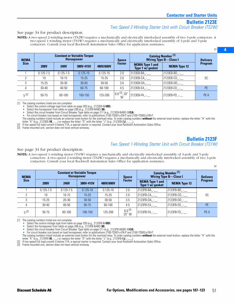
2
3
4
5
Contactor and Starter Units
Bulletin 2123ETwo Speed 2-Winding Starter Unit with Circuit Breaker (TS2W)
See page 34 for product description.NOTE: A two-speed 2-winding motor (TS2W) requires a mechanically and electrically interlocked assembly of two 3-pole contactors. A
two-speed 1-winding motor (TS1W) requires a mechanically and electrically interlocked assembly of 3-pole and 5-pole contactors. Consult your local Rockwell Automation Sales Office for application assistance.
53
Bulletin 2123FTwo Speed 1-Winding Starter Unit with Circuit Breaker (TS1W)
See page 34 for product description.NOTE: A two-speed 1-winding motor (TS1W) requires a mechanically and electrically interlocked assembly of 3-pole and 5-pole
contactors. A two-speed 2-winding motor (TS2W) requires a mechanically and electrically interlocked assembly of two 3-pole contactors. Consult your local Rockwell Automation Sales Office for application assistance.
54
NEMA Size
Constant or Variable TorqueHorsepower Space
Factor
Catalog Number [1]
Wiring Type B—Class I
[1] The catalog numbers listed are not complete:• Select the control voltage type from table on page 205 (e.g., 2123EB-BABD).• Select the horsepower from table on page 206 (e.g., 2123EB-BABD-30).• Select the circuit breaker from Circuit Breaker Type table on page 211 (e.g., 2123EB-BABD-30CA).• For circuit breaker size based on load horsepower, refer to publications 2100-TD001x-EN-P and 2100-TD002x-EN-P.The catalog numbers listed include an external reset button for the overload relay. To order catalog numbers without the external reset button, replace the letter “A” with the letter “K” (e.g., 2123EB-BK_-__) or replace the letter “D” with the letter “J” (e.g., 2123EB-BJ_-___).
DeliveryProgram
208V 240V 380V-415V 480V/600V NEMA Type 1 and Type 1 w/ gasket NEMA Type 12
1 0.125-7.5 0.125-7.5 0.125-10 0.125-10 2.0 2123EB-BA_-__ 2123EB-BD_-__SC2 10 10-15 15-25 15-25 2.0 2123EB-CA_-__ 2123EB-CD_-__
3 15-25 20-30 30-50 30-50 3.0 2123EB-DA_-__ 2123EB-DD_-__4 30-40 40-50 60-75 60-100 4.5 2123EB-EA_-__ 2123EB-ED_-__ PE
5 [2]
[2] If low speed full load current is below 77A, a special starter is required. Contact your local Rockwell Automation Sales Office.
50-75 60-100 100-150 125-200 6.0 [3], 20” W
[3] Frame mounted unit, section does not have vertical wireway.
2123EB-FA_-__ 2123EB-FD_-__ PE-II
NEMASize
Constant or Variable TorqueHorsepower Space
Factor
Catalog Number [1]
Wiring Type B—Class I
[1] The catalog numbers listed are not complete:• Select the control voltage type from table on page 205 (e.g., 2123FB-BABD).• Select the horsepower from table on page 206 (e.g., 2123FB-BABD-30).• Select the circuit breaker from Circuit Breaker Type table on page 211 (e.g., 2123FB-BABD-30CA).• For circuit breaker size based on load horsepower, refer to publications 2100-TD001x-EN-P and 2100-TD002x-EN-P.The catalog numbers listed include an external reset button for the overload relay. To order catalog numbers without the external reset button, replace the letter “A” with the letter “K” (e.g., 2123FB-BK_-__) or replace the letter “D” with the letter “J” (e.g., 2123FB-BJ_-___).
Delivery Program
208V 240V 380V-415V 480V/600V NEMA Type 1 and Type 1 w/ gasket NEMA Type 12
1 0.125-7.5 0.125-7.5 0.125-10 0.125-10 2.0 2123FB-BA_-__ 2123FB-BD_-__SC2 10 10-15 15-25 15-25 2.0 2123FB-CA_-__ 2123FB-CD_-__
3 15-25 20-30 30-50 30-50 3.5 2123FB-DA_-__ 2123FB-DD_-__4 30-40 40-50 60-75 60-100 4.5 2123FB-EA_-__ 2123FB-ED_-__ PE
5 [2]
[2] If low speed full load current is below 77A, a special starter is required. Contact your local Rockwell Automation Sales Office.
50-75 60-100 100-150 125-200 6.0 [3]
25” W
[3] Frame mounted unit, section does not have vertical wireway.
2123FB-FA_-__ 2123FB-FD_-__ PE-II
51For Options, Modifications and Accessories, see pages 107–123Discount Schedule A6Discount Schedule A6
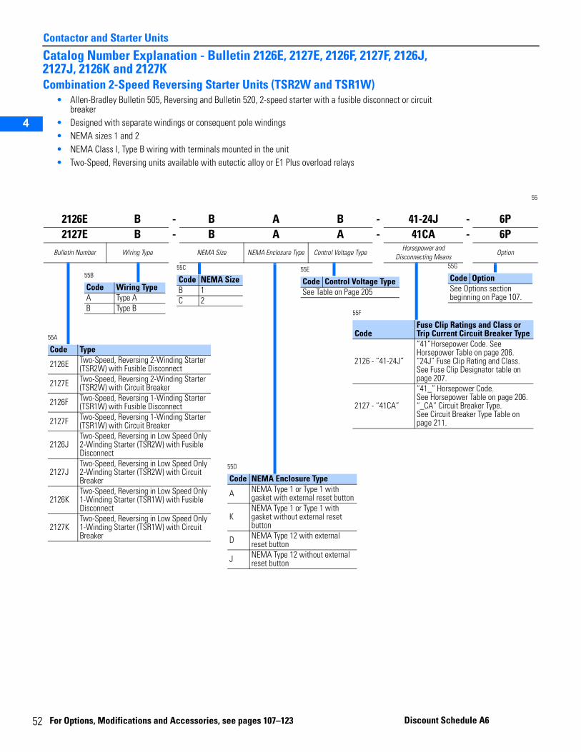
5
Contactor and Starter Units
2
3
4
5
Catalog Number Explanation - Bulletin 2126E, 2127E, 2126F, 2127F, 2126J, 2127J, 2126K and 2127KCombination 2-Speed Reversing Starter Units (TSR2W and TSR1W)
• Allen-Bradley Bulletin 505, Reversing and Bulletin 520, 2-speed starter with a fusible disconnect or circuit breaker
• Designed with separate windings or consequent pole windings• NEMA sizes 1 and 2• NEMA Class I, Type B wiring with terminals mounted in the unit • Two-Speed, Reversing units available with eutectic alloy or E1 Plus overload relays
55
2126E B - B A B - 41-24J - 6P2127E B - B A A - 41CA - 6P
Bulletin Number Wiring Type NEMA Size NEMA Enclosure Type Control Voltage TypeHorsepower and
Disconnecting MeansOption
55A
Code Type
2126E Two-Speed, Reversing 2-Winding Starter (TSR2W) with Fusible Disconnect
2127E Two-Speed, Reversing 2-Winding Starter (TSR2W) with Circuit Breaker
2126F Two-Speed, Reversing 1-Winding Starter (TSR1W) with Fusible Disconnect
2127F Two-Speed, Reversing 1-Winding Starter (TSR1W) with Circuit Breaker
2126JTwo-Speed, Reversing in Low Speed Only 2-Winding Starter (TSR2W) with Fusible Disconnect
2127JTwo-Speed, Reversing in Low Speed Only 2-Winding Starter (TSR2W) with Circuit Breaker
2126KTwo-Speed, Reversing in Low Speed Only 1-Winding Starter (TSR1W) with Fusible Disconnect
2127KTwo-Speed, Reversing in Low Speed Only 1-Winding Starter (TSR1W) with Circuit Breaker
55C
Code NEMA SizeB 1C 2
55B
Code Wiring TypeA Type AB Type B
55D
Code NEMA Enclosure Type
A NEMA Type 1 or Type 1 with gasket with external reset button
KNEMA Type 1 or Type 1 with gasket without external reset button
D NEMA Type 12 with external reset button
J NEMA Type 12 without external reset button
55E
Code Control Voltage TypeSee Table on Page 205
55F
CodeFuse Clip Ratings and Class or Trip Current Circuit Breaker Type
2126 - “41-24J”
“41”Horsepower Code. See Horsepower Table on page 206.“24J” Fuse Clip Rating and Class. See Fuse Clip Designator table on page 207.
2127 - “41CA”
“41_” Horsepower Code.See Horsepower Table on page 206.“_CA” Circuit Breaker Type. See Circuit Breaker Type Table on page 211.
55G
Code OptionSee Options section beginning on Page 107.
2
For Opt ions, Modifications and Accessories, see pages 107–123 Discount Schedule A6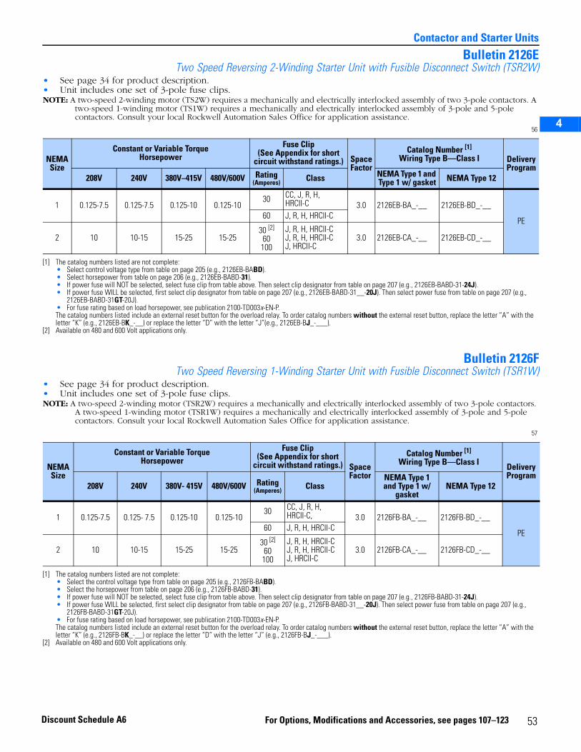
2
3
4
5
Contactor and Starter Units
Bulletin 2126ETwo Speed Reversing 2-Winding Starter Unit with Fusible Disconnect Switch (TSR2W)
• See page 34 for product description.• Unit includes one set of 3-pole fuse clips.NOTE: A two-speed 2-winding motor (TS2W) requires a mechanically and electrically interlocked assembly of two 3-pole contactors. A
two-speed 1-winding motor (TS1W) requires a mechanically and electrically interlocked assembly of 3-pole and 5-pole contactors. Consult your local Rockwell Automation Sales Office for application assistance.
56
Bulletin 2126FTwo Speed Reversing 1-Winding Starter Unit with Fusible Disconnect Switch (TSR1W)
• See page 34 for product description.• Unit includes one set of 3-pole fuse clips.NOTE: A two-speed 2-winding motor (TSR2W) requires a mechanically and electrically interlocked assembly of two 3-pole contactors.
A two-speed 1-winding motor (TSR1W) requires a mechanically and electrically interlocked assembly of 3-pole and 5-pole contactors. Consult your local Rockwell Automation Sales Office for application assistance.
57
NEMA Size
Constant or Variable TorqueHorsepower
Fuse Clip(See Appendix for short
circuit withstand ratings.) SpaceFactor
Catalog Number [1]
Wiring Type B—Class I
[1] The catalog numbers listed are not complete: • Select control voltage type from table on page 205 (e.g., 2126EB-BABD).• Select horsepower from table on page 206 (e.g., 2126EB-BABD-31).• If power fuse will NOT be selected, select fuse clip from table above. Then select clip designator from table on page 207 (e.g., 2126EB-BABD-31-24J).• If power fuse WILL be selected, first select clip designator from table on page 207 (e.g., 2126EB-BABD-31__-20J). Then select power fuse from table on page 207 (e.g.,
2126EB-BABD-31GT-20J).• For fuse rating based on load horsepower, see publication 2100-TD003x-EN-P.The catalog numbers listed include an external reset button for the overload relay. To order catalog numbers without the external reset button, replace the letter “A” with the letter “K” (e.g., 2126EB-BK_-__) or replace the letter “D” with the letter “J”(e.g., 2126EB-BJ_-___).
Delivery Program
208V 240V 380V–415V 480V/600V Rating(Amperes) Class NEMA Type 1 and
Type 1 w/ gasket NEMA Type 12
1 0.125-7.5 0.125-7.5 0.125-10 0.125-1030 CC, J, R, H,
HRCII-C 3.0 2126EB-BA_-__ 2126EB-BD_-__
PE60 J, R, H, HRCII-C
2 10 10-15 15-25 15-2530 [2]
60100
[2] Available on 480 and 600 Volt applications only.
J, R, H, HRCII-CJ, R, H, HRCII-CJ, HRCII-C
3.0 2126EB-CA_-__ 2126EB-CD_-__
NEMASize
Constant or Variable TorqueHorsepower
Fuse Clip(See Appendix for short
circuit withstand ratings.) SpaceFactor
Catalog Number [1]
Wiring Type B—Class I
[1] The catalog numbers listed are not complete:• Select the control voltage type from table on page 205 (e.g., 2126FB-BABD).• Select the horsepower from table on page 206 (e.g., 2126FB-BABD-31).• If power fuse will NOT be selected, select fuse clip from table above. Then select clip designator from table on page 207 (e.g., 2126FB-BABD-31-24J).• If power fuse WILL be selected, first select clip designator from table on page 207 (e.g., 2126FB-BABD-31__-20J). Then select power fuse from table on page 207 (e.g.,
2126FB-BABD-31GT-20J).• For fuse rating based on load horsepower, see publication 2100-TD003x-EN-P.The catalog numbers listed include an external reset button for the overload relay. To order catalog numbers without the external reset button, replace the letter “A” with the letter “K” (e.g., 2126FB-BK_-__) or replace the letter “D” with the letter “J” (e.g., 2126FB-BJ_-___).
DeliveryProgram
208V 240V 380V- 415V 480V/600V Rating(Amperes) Class
NEMA Type 1 and Type 1 w/
gasketNEMA Type 12
1 0.125-7.5 0.125- 7.5 0.125-10 0.125-1030 CC, J, R, H,
HRCII-C, 3.0 2126FB-BA_-__ 2126FB-BD_-__
PE60 J, R, H, HRCII-C
2 10 10-15 15-25 15-2530 [2]
60100
[2] Available on 480 and 600 Volt applications only.
J, R, H, HRCII-CJ, R, H, HRCII-CJ, HRCII-C
3.0 2126FB-CA_-__ 2126FB-CD_-__
53For Options, Modifications and Accessories, see pages 107–123Discount Schedule A6
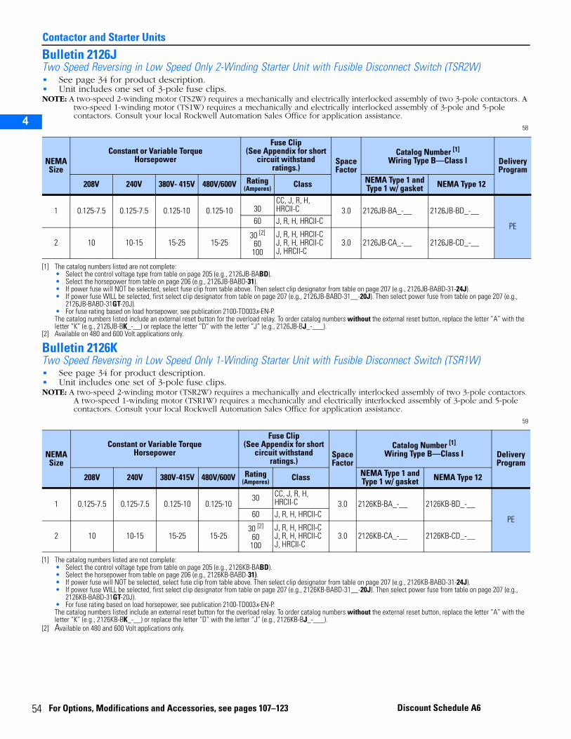
5
Contactor and Starter Units
2
3
4
5
Bulletin 2126JTwo Speed Reversing in Low Speed Only 2-Winding Starter Unit with Fusible Disconnect Switch (TSR2W)• See page 34 for product description.• Unit includes one set of 3-pole fuse clips.NOTE: A two-speed 2-winding motor (TS2W) requires a mechanically and electrically interlocked assembly of two 3-pole contactors. A
two-speed 1-winding motor (TS1W) requires a mechanically and electrically interlocked assembly of 3-pole and 5-pole contactors. Consult your local Rockwell Automation Sales Office for application assistance.
58
Bulletin 2126KTwo Speed Reversing in Low Speed Only 1-Winding Starter Unit with Fusible Disconnect Switch (TSR1W)• See page 34 for product description.• Unit includes one set of 3-pole fuse clips.NOTE: A two-speed 2-winding motor (TSR2W) requires a mechanically and electrically interlocked assembly of two 3-pole contactors.
A two-speed 1-winding motor (TSR1W) requires a mechanically and electrically interlocked assembly of 3-pole and 5-pole contactors. Consult your local Rockwell Automation Sales Office for application assistance.
59
NEMA Size
Constant or Variable TorqueHorsepower
Fuse Clip(See Appendix for short
circuit withstand ratings.)
SpaceFactor
Catalog Number [1]
Wiring Type B—Class I
[1] The catalog numbers listed are not complete: • Select the control voltage type from table on page 205 (e.g., 2126JB-BABD).• Select the horsepower from table on page 206 (e.g., 2126JB-BABD-31).• If power fuse will NOT be selected, select fuse clip from table above. Then select clip designator from table on page 207 (e.g., 2126JB-BABD-31-24J).• If power fuse WILL be selected, first select clip designator from table on page 207 (e.g., 2126JB-BABD-31__-20J). Then select power fuse from table on page 207 (e.g.,
2126JB-BABD-31GT-20J).• For fuse rating based on load horsepower, see publication 2100-TD003x-EN-P.The catalog numbers listed include an external reset button for the overload relay. To order catalog numbers without the external reset button, replace the letter “A” with the letter “K” (e.g., 2126JB-BK_-__) or replace the letter “D” with the letter “J” (e.g., 2126JB-BJ_-___).
Delivery Program
208V 240V 380V- 415V 480V/600V Rating(Amperes) Class NEMA Type 1 and
Type 1 w/ gasket NEMA Type 12
1 0.125-7.5 0.125-7.5 0.125-10 0.125-10 30CC, J, R, H,HRCII-C 3.0 2126JB-BA_-__ 2126JB-BD_-__
PE60 J, R, H, HRCII-C
2 10 10-15 15-25 15-2530 [2]
60100
[2] Available on 480 and 600 Volt applications only.
J, R, H, HRCII-CJ, R, H, HRCII-CJ, HRCII-C
3.0 2126JB-CA_-__ 2126JB-CD_-__
NEMA Size
Constant or Variable TorqueHorsepower
Fuse Clip(See Appendix for short
circuit withstand ratings.)
Space Factor
Catalog Number [1]
Wiring Type B—Class I
[1] The catalog numbers listed are not complete: • Select the control voltage type from table on page 205 (e.g., 2126KB-BABD).• Select the horsepower from table on page 206 (e.g., 2126KB-BABD-31).• If power fuse will NOT be selected, select fuse clip from table above. Then select clip designator from table on page 207 (e.g., 2126KB-BABD-31-24J).• If power fuse WILL be selected, first select clip designator from table on page 207 (e.g., 2126KB-BABD-31__-20J). Then select power fuse from table on page 207 (e.g.,
2126KB-BABD-31GT-20J).• For fuse rating based on load horsepower, see publication 2100-TD003x-EN-P.The catalog numbers listed include an external reset button for the overload relay. To order catalog numbers without the external reset button, replace the letter “A” with the letter “K” (e.g., 2126KB-BK_-__) or replace the letter “D” with the letter “J” (e.g., 2126KB-BJ_-___).
Delivery Program
208V 240V 380V-415V 480V/600V Rating(Amperes) Class NEMA Type 1 and
Type 1 w/ gasket NEMA Type 12
1 0.125-7.5 0.125-7.5 0.125-10 0.125-1030 CC, J, R, H,
HRCII-C 3.0 2126KB-BA_-__ 2126KB-BD_-__
PE60 J, R, H, HRCII-C
2 10 10-15 15-25 15-2530 [2]
60100
[2] Available on 480 and 600 Volt applications only.
J, R, H, HRCII-CJ, R, H, HRCII-CJ, HRCII-C
3.0 2126KB-CA_-__ 2126KB-CD_-__
4 For Options, Modifications and Accessories, see pages 107–123 Discount Schedule A6
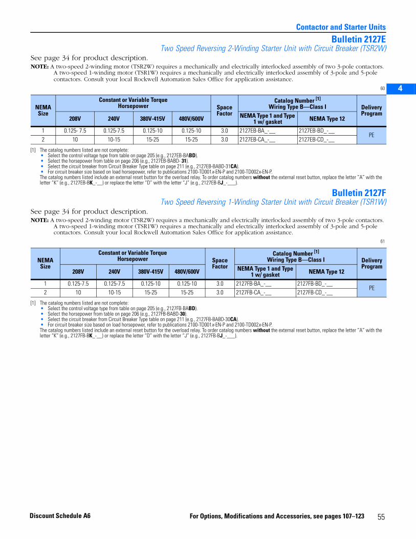
2
3
4
5
Contactor and Starter Units
Bulletin 2127ETwo Speed Reversing 2-Winding Starter Unit with Circuit Breaker (TSR2W)
See page 34 for product description.NOTE: A two-speed 2-winding motor (TSR2W) requires a mechanically and electrically interlocked assembly of two 3-pole contactors.
A two-speed 1-winding motor (TSR1W) requires a mechanically and electrically interlocked assembly of 3-pole and 5-pole contactors. Consult your local Rockwell Automation Sales Office for application assistance.
60
Bulletin 2127FTwo Speed Reversing 1-Winding Starter Unit with Circuit Breaker (TSR1W)
See page 34 for product description.NOTE: A two-speed 2-winding motor (TSR2W) requires a mechanically and electrically interlocked assembly of two 3-pole contactors.
A two-speed 1-winding motor (TSR1W) requires a mechanically and electrically interlocked assembly of 3-pole and 5-pole contactors. Consult your local Rockwell Automation Sales Office for application assistance.
61
NEMASize
Constant or Variable TorqueHorsepower Space
Factor
Catalog Number [1]
Wiring Type B—Class I
[1] The catalog numbers listed are not complete:• Select the control voltage type from table on page 205 (e.g., 2127EB-BABD).• Select the horsepower from table on page 206 (e.g., 2127EB-BABD- 31).• Select the circuit breaker from Circuit Breaker Type table on page 211 (e.g., 2127EB-BABD-31CA).• For circuit breaker size based on load horsepower, refer to publications 2100-TD001x-EN-P and 2100-TD002x-EN-P.The catalog numbers listed include an external reset button for the overload relay. To order catalog numbers without the external reset button, replace the letter “A” with the letter “K” (e.g., 2127EB-BK_-__) or replace the letter “D” with the letter “J” (e.g., 2127EB-BJ_-___).
DeliveryProgram
208V 240V 380V-415V 480V/600V NEMA Type 1 and Type 1 w/ gasket NEMA Type 12
1 0.125- 7.5 0.125-7.5 0.125-10 0.125-10 3.0 2127EB-BA_-__ 2127EB-BD_-__PE
2 10 10-15 15-25 15-25 3.0 2127EB-CA_-__ 2127EB-CD_-__
NEMA Size
Constant or Variable TorqueHorsepower Space
Factor
Catalog Number [1]
Wiring Type B—Class I
[1] The catalog numbers listed are not complete:• Select the control voltage type from table on page 205 (e.g., 2127FB-BABD).• Select the horsepower from table on page 206 (e.g., 2127FB-BABD-30).• Select the circuit breaker from Circuit Breaker Type table on page 211 (e.g., 2127FB-BABD-30CA).• For circuit breaker size based on load horsepower, refer to publications 2100-TD001x-EN-P and 2100-TD002x-EN-P.The catalog numbers listed include an external reset button for the overload relay. To order catalog numbers without the external reset button, replace the letter “A” with the letter “K” (e.g., 2127FB-BK_-__) or replace the letter “D” with the letter “J” (e.g., 2127FB-BJ_-___).
Delivery Program
208V 240V 380V-415V 480V/600V NEMA Type 1 and Type 1 w/ gasket NEMA Type 12
1 0.125-7.5 0.125-7.5 0.125-10 0.125-10 3.0 2127FB-BA_-__ 2127FB-BD_-__PE
2 10 10-15 15-25 15-25 3.0 2127FB-CA_-__ 2127FB-CD_-__
55For Options, Modifications and Accessories, see pages 107–123Discount Schedule A6
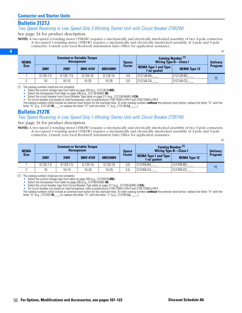
5
Contactor and Starter Units
2
3
4
5
Bulletin 2127JTwo Speed Reversing in Low Speed Only 2-Winding Starter Unit with Circuit Breaker (TSR2W)See page 34 for product description.NOTE: A two-speed 2-winding motor (TSR2W) requires a mechanically and electrically interlocked assembly of two 3-pole contactors.
A two-speed 1-winding motor (TSR1W) requires a mechanically and electrically interlocked assembly of 3-pole and 5-pole contactors. Consult your local Rockwell Automation Sales Office for application assistance.
62
Bulletin 2127KTwo Speed Reversing in Low Speed Only 1-Winding Starter Unit with Circuit Breaker (TSR1W)See page 34 for product description.NOTE: A two-speed 2-winding motor (TSR2W) requires a mechanically and electrically interlocked assembly of two 3-pole contactors.
A two-speed 1-winding motor (TSR1W) requires a mechanically and electrically interlocked assembly of 3-pole and 5-pole contactors. Consult your local Rockwell Automation Sales Office for application assistance.
63
NEMA Size
Constant or Variable TorqueHorsepower Space
Factor
Catalog Number [1]
Wiring Type B—Class I
[1] The catalog numbers listed are not complete:• Select the control voltage type from table on page 205 (e.g., 2127JB-BABD).• Select the horsepower from table on page 206 (e.g., 2127JB-BABD-30).• Select the circuit breaker from Circuit Breaker Type table on page 211 (e.g., 2127JB-BABD-30CA).• For circuit breaker size based on load horsepower, refer to publications 2100-TD001x-EN-P and 2100-TD002x-EN-P.The catalog numbers listed include an external reset button for the overload relay. To order catalog numbers without the external reset button, replace the letter “A” with the letter “K” (e.g., 2127JB-BK_-__) or replace the letter “D” with the letter “J” (e.g., 2127JB-BJ_-___).
Delivery Program
208V 240V 380V-415V 480V/600V NEMA Type 1 and Type 1 w/ gasket NEMA Type 12
1 0.125-7.5 0.125- 7.5 0.125-10 0.125-10 3.0 2127JB-BA_-__ 2127JB-BD_-__PE
2 10 10-15 15-25 15-25 3.0 2127JB-CA_-__ 2127JB-CD_-__
NEMA Size
Constant or Variable TorqueHorsepower Space
Factor
Catalog Number [1]
Wiring Type B—Class I
[1] The catalog numbers listed are not complete:• Select the control voltage type from table on page 205 (e.g., 2127KB-BABD).• Select the horsepower from table on page 206 (e.g., 2127KB-BABD-30).• Select the circuit breaker type from Circuit Breaker Type table on page 211 (e.g., 2127KB-BABD-30CA).• For circuit breaker size based on load horsepower, refer to publications 2100-TD001x-EN-P and 2100-TD002x-EN-P.The catalog numbers listed include an external reset button for the overload relay. To order catalog numbers without the external reset button, replace the letter “A” with the letter “K” (e.g., 2127KB-BK_-__) or replace the letter “D” with the letter “J” (e.g., 2127KB-BJ_-___).
Delivery Program
208V 240V 380V-415V 480V/600V NEMA Type 1 and Type 1 w/ gasket NEMA Type 12
1 0.125-7.5 0.125-7.5 0.125-10 0.125-10 3.0 2127KB-BA_-__ 2127KB-BD_-__PE
2 10 10-15 15-25 15-25 3.0 2127KB-CA_-__ 2127KB-CD_-__
6 For Options, Modifications and Accessories, see pages 107–123 Discount Schedule A6
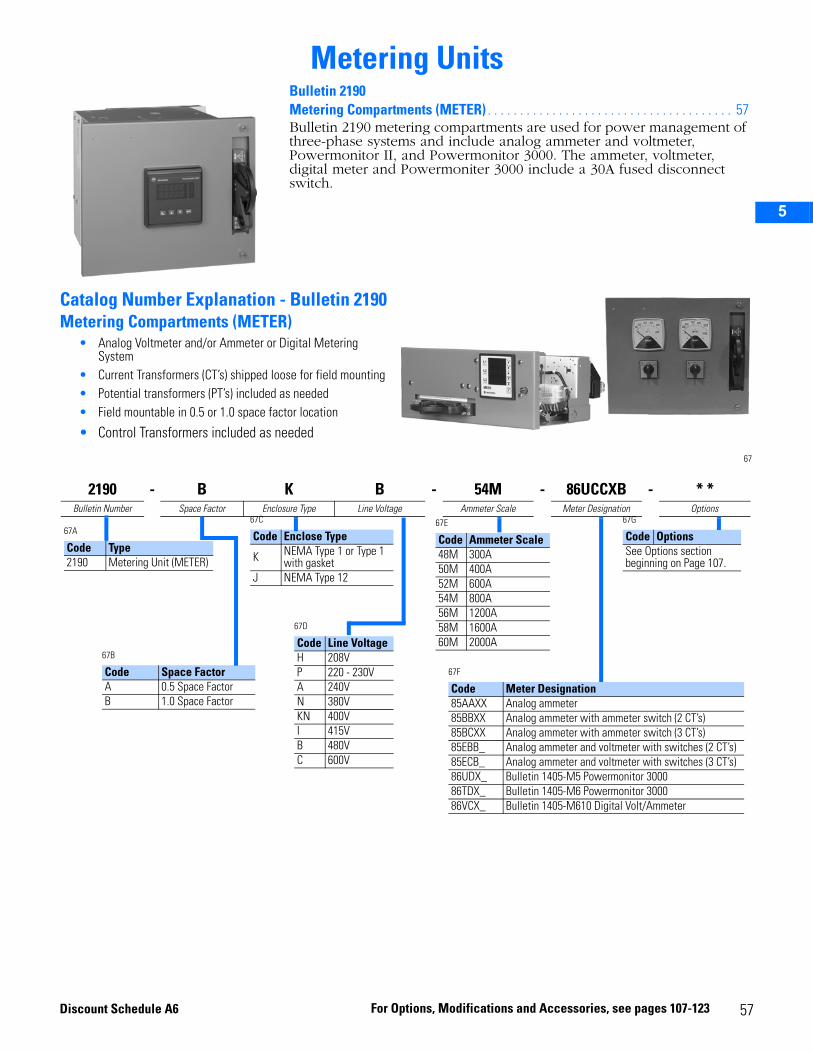
2
3
4
5
Metering Units
Catalog Number Explanation - Bulletin 2190Metering Compartments (METER)
• Analog Voltmeter and/or Ammeter or Digital Metering System
• Current Transformers (CT’s) shipped loose for field mounting• Potential transformers (PT’s) included as needed• Field mountable in 0.5 or 1.0 space factor location
• Control Transformers included as needed
67
Bulletin 2190 Metering Compartments (METER) . . . . . . . . . . . . . . . . . . . . . . . . . . . . . . . . . . . . . . 57Bulletin 2190 metering compartments are used for power management of three-phase systems and include analog ammeter and voltmeter, Powermonitor II, and Powermonitor 3000. The ammeter, voltmeter, digital meter and Powermoniter 3000 include a 30A fused disconnect switch.
2190 - B K B - 54M - 86UCCXB - * *Bulletin Number Space Factor Enclosure Type Line Voltage Ammeter Scale Meter Designation Options
67A
Code Type2190 Metering Unit (METER)
67C
Code Enclose Type
K NEMA Type 1 or Type 1 with gasket
J NEMA Type 12
67B
Code Space FactorA 0.5 Space FactorB 1.0 Space Factor
67D
Code Line VoltageH 208VP 220 - 230VA 240VN 380VKN 400VI 415VB 480VC 600V
67E
Code Ammeter Scale48M 300A50M 400A52M 600A54M 800A56M 1200A58M 1600A60M 2000A
67F
Code Meter Designation85AAXX Analog ammeter85BBXX Analog ammeter with ammeter switch (2 CT’s)85BCXX Analog ammeter with ammeter switch (3 CT’s)85EBB_ Analog ammeter and voltmeter with switches (2 CT’s)85ECB_ Analog ammeter and voltmeter with switches (3 CT’s)86UDX_ Bulletin 1405-M5 Powermonitor 300086TDX_ Bulletin 1405-M6 Powermonitor 300086VCX_ Bulletin 1405-M610 Digital Volt/Ammeter
67G
Code OptionsSee Options section beginning on Page 107.
Disco
unt Schedule A6 For Option s, Modifications and Accessories, 57see pages 107-123
5
Metering Units
2
3
4
5
Bulletin 2190Metering Compartments (METER)See page 57 for product description.
Ammeter:
Panel type (not switchboard type) with 5A movement, 3.5” scale, 102° deflection, and 2% of full scale accuracy.
Voltmeter:
Phase-to-phase voltage measurement only. Panel type (not switchboard type) with 120V movement, 3.5” scale, 102° deflection, and 2% of full scale accuracy.
Powermonitor 3000, Bulletin 1404-M5:
1404-DM highly visible LED display. The monitor can display 64 real-time parameters, including current (Ia, Ib, Ic, In, I3) avg, ±0.2% full-scale accuracy, voltage (Van, Vbn, Vcn, Vab, Vbc, Vca ±0.2% full-scale accuracy), current, and voltage imbalance. There are four (4) forms of power (real, reactive, apparent, and true, ±0.4% full-scale accuracy), kWh, KVARh, kVAHnet, true RMS to the 45th harmonic, frequency (±0.05%), and power factor (±0.4%). The Powermonitor 3000 includes min./max, event logs, trend log (up to 45,867 data points), and distortion analysis with THD, crest factor (I, V), and distortion power factor. Every Powermonitor 3000 includes RS-485 communications as standard and has options for RS-232, DeviceNet, and Remote I/O. Also included are two form-C relays. The 1404-M5 can be flash upgraded to M6, and M8 PM3000 master modules. See your local Rockwell Automation representative for details.
Powermonitor 3000, Bulletin 1404-M6:
Same functionality as the Bulletin 1404-M5 except for the addition of harmonic analysis with TIF, Crest Factor, IEEE 519, and % THD and multiple channel and cycle oscillographic recordings. In addition, the same communication platforms are available.
Digital Volt/Ammeter, Bulletin 1405-M610:
The 1405-M610 measures and displays line-neutral and line-line voltages and the instantaneous, 15 minute averaged peak values of the measured phase currents are displayed sequentially. The features of the M610 include a 3-line display simultaneously showing all 3 phases, peak value storage and display, automatic sequencing of displayed parameters. The M610 also includes 35 pre-programmed standard current transformer ratios. A disconnect and current transformers are included in all 2190 metering units.
8 For Options, Modifications and Accessories, see pages 107-123 Discount Schedule A6
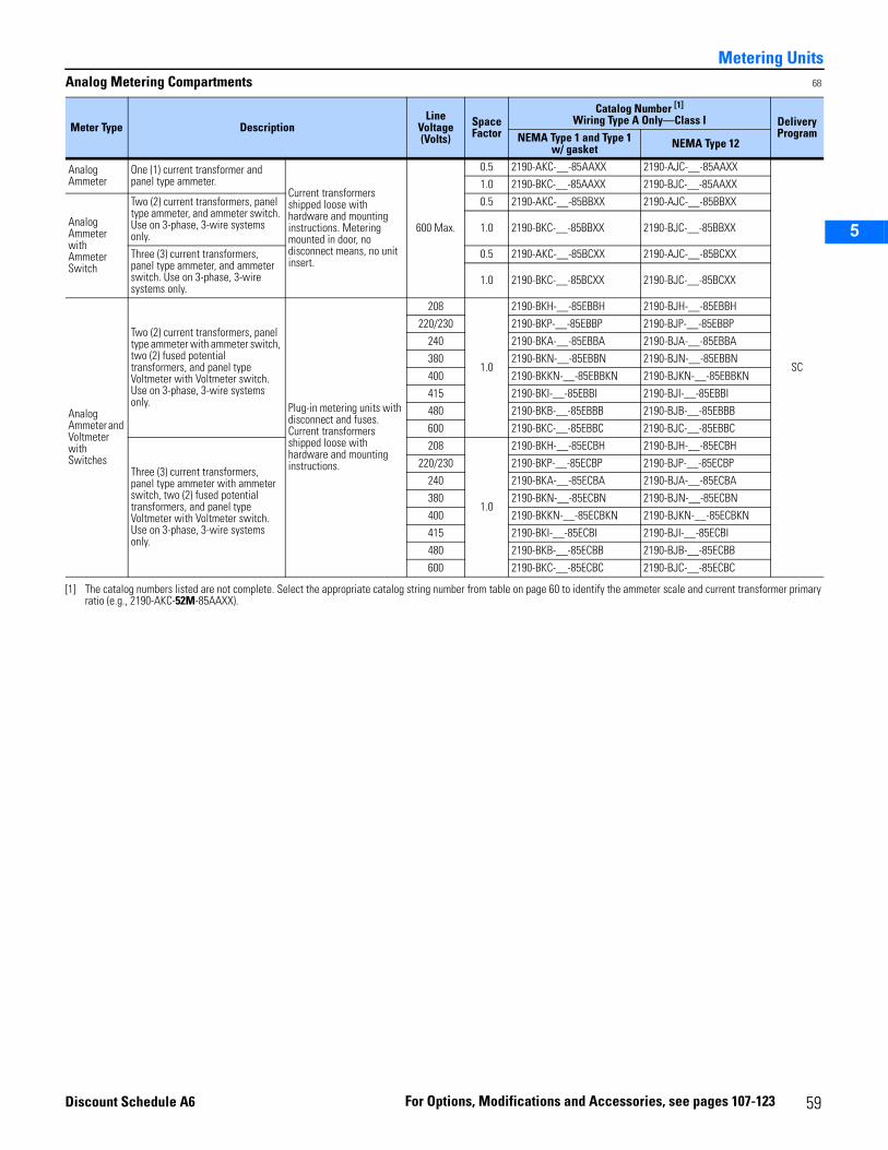
2
3
4
5
Metering UnitsAnalog Metering Compartments 68
Meter Type DescriptionLine
Voltage (Volts)
Space Factor
Catalog Number [1]
Wiring Type A Only—Class I
[1] The catalog numbers listed are not complete. Select the appropriate catalog string number from table on page 60 to identify the ammeter scale and current transformer primary ratio (e.g., 2190-AKC-52M-85AAXX).
Delivery ProgramNEMA Type 1 and Type 1
w/ gasket NEMA Type 12
Analog Ammeter
One (1) current transformer and panel type ammeter.
Current transformers shipped loose with hardware and mounting instructions. Metering mounted in door, no disconnect means, no unit insert.
600 Max.
0.5 2190-AKC-__-85AAXX 2190-AJC-__-85AAXX
SC
1.0 2190-BKC-__-85AAXX 2190-BJC-__-85AAXX
Analog Ammeter with Ammeter Switch
Two (2) current transformers, panel type ammeter, and ammeter switch. Use on 3-phase, 3-wire systems only.
0.5 2190-AKC-__-85BBXX 2190-AJC-__-85BBXX
1.0 2190-BKC-__-85BBXX 2190-BJC-__-85BBXX
Three (3) current transformers, panel type ammeter, and ammeter switch. Use on 3-phase, 3-wire systems only.
0.5 2190-AKC-__-85BCXX 2190-AJC-__-85BCXX
1.0 2190-BKC-__-85BCXX 2190-BJC-__-85BCXX
Analog Ammeter and Voltmeter with Switches
Two (2) current transformers, panel type ammeter with ammeter switch, two (2) fused potential transformers, and panel type Voltmeter with Voltmeter switch. Use on 3-phase, 3-wire systems only. Plug-in metering units with
disconnect and fuses. Current transformers shipped loose with hardware and mounting instructions.
208
1.0
2190-BKH-__-85EBBH 2190-BJH-__-85EBBH
220/230 2190-BKP-__-85EBBP 2190-BJP-__-85EBBP
240 2190-BKA-__-85EBBA 2190-BJA-__-85EBBA
380 2190-BKN-__-85EBBN 2190-BJN-__-85EBBN
400 2190-BKKN-__-85EBBKN 2190-BJKN-__-85EBBKN
415 2190-BKI-__-85EBBI 2190-BJI-__-85EBBI
480 2190-BKB-__-85EBBB 2190-BJB-__-85EBBB
600 2190-BKC-__-85EBBC 2190-BJC-__-85EBBC
Three (3) current transformers, panel type ammeter with ammeter switch, two (2) fused potential transformers, and panel type Voltmeter with Voltmeter switch. Use on 3-phase, 3-wire systems only.
208
1.0
2190-BKH-__-85ECBH 2190-BJH-__-85ECBH
220/230 2190-BKP-__-85ECBP 2190-BJP-__-85ECBP
240 2190-BKA-__-85ECBA 2190-BJA-__-85ECBA
380 2190-BKN-__-85ECBN 2190-BJN-__-85ECBN
400 2190-BKKN-__-85ECBKN 2190-BJKN-__-85ECBKN
415 2190-BKI-__-85ECBI 2190-BJI-__-85ECBI
480 2190-BKB-__-85ECBB 2190-BJB-__-85ECBB
600 2190-BKC-__-85ECBC 2190-BJC-__-85ECBC
59For Options, Modifications and Accessories, see pages 107-123Discount Schedule A6
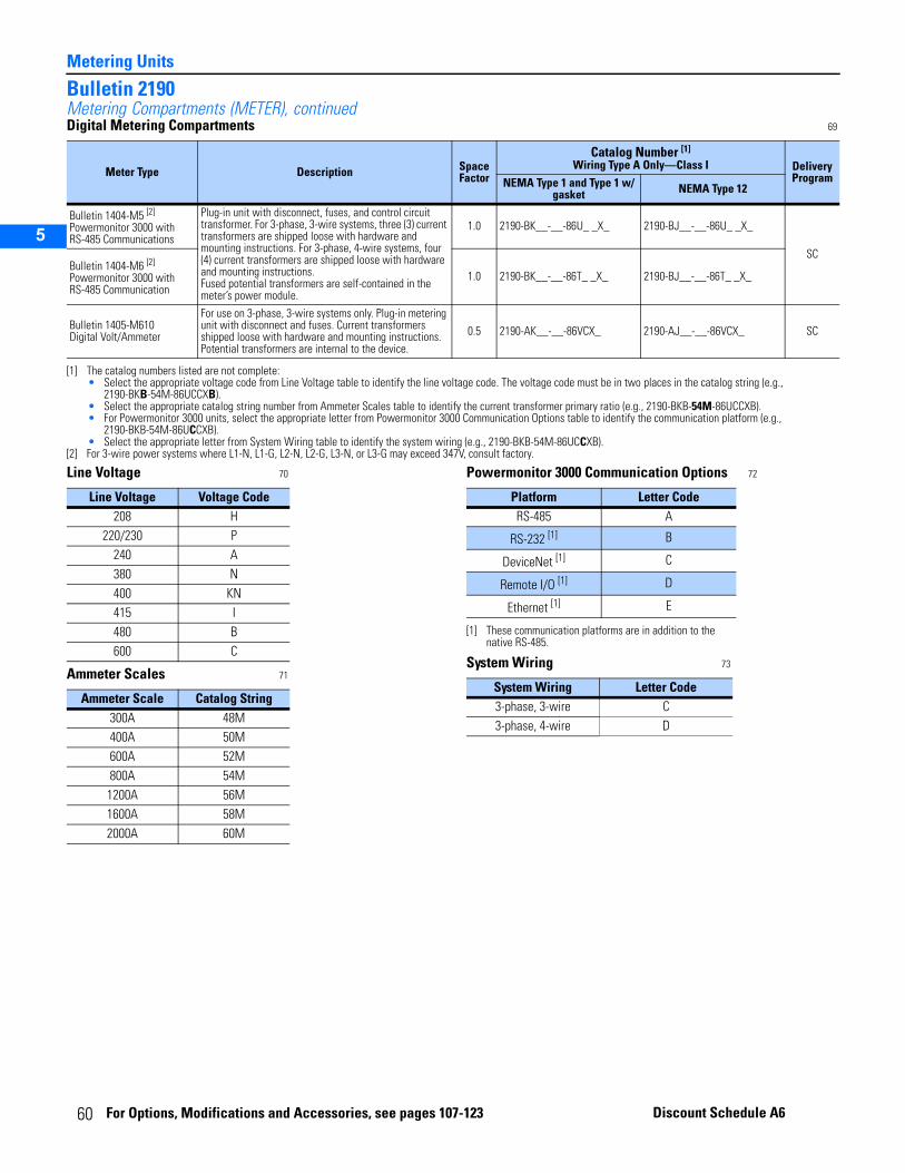
Metering Units
2
3
4
5
Bulletin 2190Metering Compartments (METER), continuedDigital Metering Compartments 69
Line Voltage 70
Ammeter Scales 71
Powermonitor 3000 Communication Options 72
System Wiring 73
Meter Type Description Space Factor
Catalog Number [1]
Wiring Type A Only—Class I
[1] The catalog numbers listed are not complete:• Select the appropriate voltage code from Line Voltage table to identify the line voltage code. The voltage code must be in two places in the catalog string (e.g.,
2190-BKB-54M-86UCCXB).• Select the appropriate catalog string number from Ammeter Scales table to identify the current transformer primary ratio (e.g., 2190-BKB-54M-86UCCXB).• For Powermonitor 3000 units, select the appropriate letter from Powermonitor 3000 Communication Options table to identify the communication platform (e.g.,
2190-BKB-54M-86UCCXB).• Select the appropriate letter from System Wiring table to identify the system wiring (e.g., 2190-BKB-54M-86UCCXB).
Delivery ProgramNEMA Type 1 and Type 1 w/
gasket NEMA Type 12
Bulletin 1404-M5 [2] Powermonitor 3000 with RS-485 Communications
[2] For 3-wire power systems where L1-N, L1-G, L2-N, L2-G, L3-N, or L3-G may exceed 347V, consult factory.
Plug-in unit with disconnect, fuses, and control circuit transformer. For 3-phase, 3-wire systems, three (3) current transformers are shipped loose with hardware and mounting instructions. For 3-phase, 4-wire systems, four (4) current transformers are shipped loose with hardware and mounting instructions. Fused potential transformers are self-contained in the meter’s power module.
1.0 2190-BK__-__-86U_ _X_ 2190-BJ__-__-86U_ _X_
SCBulletin 1404-M6 [2] Powermonitor 3000 with RS-485 Communication
1.0 2190-BK__-__-86T_ _X_ 2190-BJ__-__-86T_ _X_
Bulletin 1405-M610Digital Volt/Ammeter
For use on 3-phase, 3-wire systems only. Plug-in metering unit with disconnect and fuses. Current transformers shipped loose with hardware and mounting instructions. Potential transformers are internal to the device.
0.5 2190-AK__-__-86VCX_ 2190-AJ__-__-86VCX_ SC
Line Voltage Voltage Code208 H
220/230 P240 A380 N400 KN415 I480 B600 C
Ammeter Scale Catalog String300A 48M400A 50M600A 52M800A 54M
1200A 56M1600A 58M2000A 60M
Platform Letter CodeRS-485 A
RS-232 [1]
[1] These communication platforms are in addition to the native RS-485.
B
DeviceNet [1] C
Remote I/O [1] D
Ethernet [1] E
System Wiring Letter Code3-phase, 3-wire C3-phase, 4-wire D
60 For Options, Modifications and Accessories, see pages 107-123 Discount Schedule A6
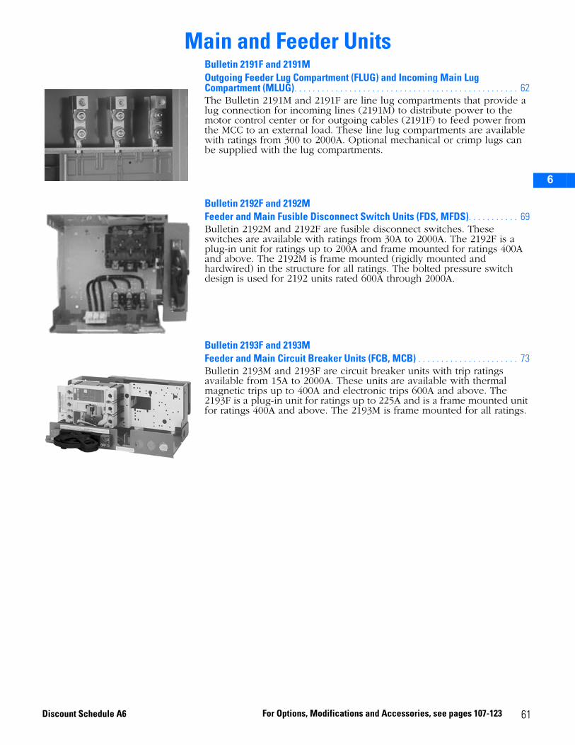
2
3
5
6
Main and Feeder UnitsBulletin 2191F and 2191M Outgoing Feeder Lug Compartment (FLUG) and Incoming Main Lug Compartment (MLUG). . . . . . . . . . . . . . . . . . . . . . . . . . . . . . . . . . . . . . . . . . . . . . . . . 62The Bulletin 2191M and 2191F are line lug compartments that provide a lug connection for incoming lines (2191M) to distribute power to the motor control center or for outgoing cables (2191F) to feed power from the MCC to an external load. These line lug compartments are available with ratings from 300 to 2000A. Optional mechanical or crimp lugs can be supplied with the lug compartments.
Bulletin 2192F and 2192MFeeder and Main Fusible Disconnect Switch Units (FDS, MFDS). . . . . . . . . . . 69Bulletin 2192M and 2192F are fusible disconnect switches. These switches are available with ratings from 30A to 2000A. The 2192F is a plug-in unit for ratings up to 200A and frame mounted for ratings 400A and above. The 2192M is frame mounted (rigidly mounted and hardwired) in the structure for all ratings. The bolted pressure switch design is used for 2192 units rated 600A through 2000A.
Bulletin 2193F and 2193MFeeder and Main Circuit Breaker Units (FCB, MCB) . . . . . . . . . . . . . . . . . . . . . . 73Bulletin 2193M and 2193F are circuit breaker units with trip ratings available from 15A to 2000A. These units are available with thermal magnetic trips up to 400A and electronic trips 600A and above. The 2193F is a plug-in unit for ratings up to 225A and is a frame mounted unit for ratings 400A and above. The 2193M is frame mounted for all ratings.
61For Options, Modifications and Accessories, see pages 107-123Discount Schedule A6
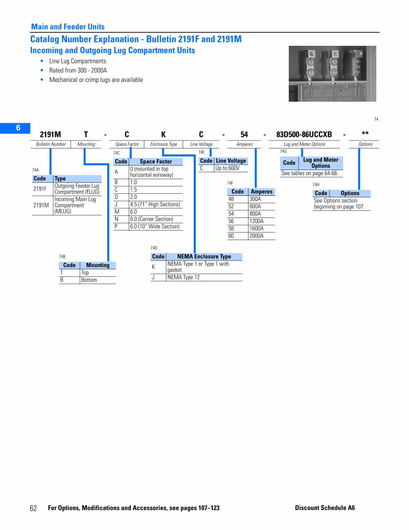
2
3
5
6
Main and Feeder Units
Catalog Number Explanation - Bulletin 2191F and 2191MIncoming and Outgoing Lug Compartment Units
• Line Lug Compartments• Rated from 300 - 2000A• Mechanical or crimp lugs are available
74
2191M T - C K C - 54 - 83D500-86UCCXB - **Bulletin Number Mounting Space Factor Enclosure Type Line Voltage Amperes Lug and Meter Options Options
74A
Code Type
2191F Outgoing Feeder Lug Compartment (FLUG)
2191MIncoming Main Lug Compartment (MLUG)
74C
Code Space Factor
A 0 (mounted in top horizontal wireway)
B 1.0C 1.5D 2.0J 4.5 (71” High Sections)M 6.0N 6.0 (Corner Section)P 6.0 (10” Wide Section)
74B
Code MountingT TopB Bottom
74D
Code NEMA Enclosure Type
K NEMA Type 1 or Type 1 with gasket
J NEMA Type 12
74E
Code Line VoltageC Up to 600V
74F
Code Amperes48 300A52 600A54 800A56 1200A58 1600A60 2000A
74G
Code Lug and Meter Options
See tables on page 64-66.
74H
Code OptionsSee Options section beginning on page 107.
62 Fo
r Options, Modificat ions and Acce ssories, see page s 107–123 Disc ount Schedule A6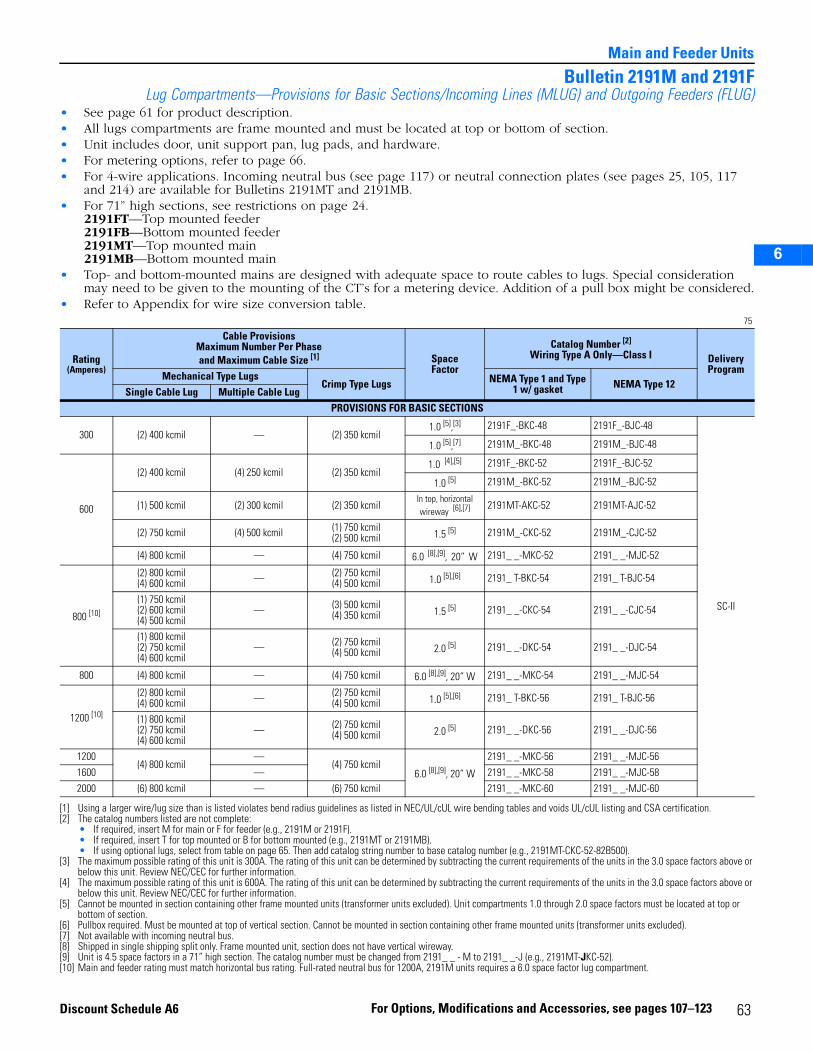
2
3
5
6
Main and Feeder Units
Bulletin 2191M and 2191FLug Compartments—Provisions for Basic Sections/Incoming Lines (MLUG) and Outgoing Feeders (FLUG)
• See page 61 for product description.• All lugs compartments are frame mounted and must be located at top or bottom of section.• Unit includes door, unit support pan, lug pads, and hardware.• For metering options, refer to page 66.• For 4-wire applications. Incoming neutral bus (see page 117) or neutral connection plates (see pages 25, 105, 117
and 214) are available for Bulletins 2191MT and 2191MB.• For 71” high sections, see restrictions on page 24.
2191FT—Top mounted feeder2191FB—Bottom mounted feeder2191MT—Top mounted main2191MB—Bottom mounted main
• Top- and bottom-mounted mains are designed with adequate space to route cables to lugs. Special consideration may need to be given to the mounting of the CT’s for a metering device. Addition of a pull box might be considered.
• Refer to Appendix for wire size conversion table.75
Rating (Amperes)
Cable ProvisionsMaximum Number Per Phaseand Maximum Cable Size [1]
[1] Using a larger wire/lug size than is listed violates bend radius guidelines as listed in NEC/UL/cUL wire bending tables and voids UL/cUL listing and CSA certification.
SpaceFactor
Catalog Number [2]
Wiring Type A Only—Class I
[2] The catalog numbers listed are not complete:• If required, insert M for main or F for feeder (e.g., 2191M or 2191F).• If required, insert T for top mounted or B for bottom mounted (e.g., 2191MT or 2191MB).• If using optional lugs, select from table on page 65. Then add catalog string number to base catalog number (e.g., 2191MT-CKC-52-82B500).
Delivery Program
Mechanical Type LugsCrimp Type Lugs NEMA Type 1 and Type
1 w/ gasket NEMA Type 12Single Cable Lug Multiple Cable Lug
PROVISIONS FOR BASIC SECTIONS
300 (2) 400 kcmil — (2) 350 kcmil1.0 [5],[3]
[3] The maximum possible rating of this unit is 300A. The rating of this unit can be determined by subtracting the current requirements of the units in the 3.0 space factors above or below this unit. Review NEC/CEC for further information.
2191F_-BKC-48 2191F_-BJC-48
SC-II
1.0 [5],[7] 2191M_-BKC-48 2191M_-BJC-48
600
(2) 400 kcmil (4) 250 kcmil (2) 350 kcmil1.0 [4],[5]
[4] The maximum possible rating of this unit is 600A. The rating of this unit can be determined by subtracting the current requirements of the units in the 3.0 space factors above or below this unit. Review NEC/CEC for further information.
[5] Cannot be mounted in section containing other frame mounted units (transformer units excluded). Unit compartments 1.0 through 2.0 space factors must be located at top or bottom of section.
2191F_-BKC-52 2191F_-BJC-52
1.0 [5] 2191M_-BKC-52 2191M_-BJC-52
(1) 500 kcmil (2) 300 kcmil (2) 350 kcmilIn top, horizontal wireway [6],[7]
[6] Pullbox required. Must be mounted at top of vertical section. Cannot be mounted in section containing other frame mounted units (transformer units excluded).[7] Not available with incoming neutral bus.
2191MT-AKC-52 2191MT-AJC-52
(2) 750 kcmil (4) 500 kcmil (1) 750 kcmil(2) 500 kcmil 1.5 [5] 2191M_-CKC-52 2191M_-CJC-52
(4) 800 kcmil — (4) 750 kcmil 6.0 [8],[9], 20” W
[8] Shipped in single shipping split only. Frame mounted unit, section does not have vertical wireway.[9] Unit is 4.5 space factors in a 71” high section. The catalog number must be changed from 2191_ _ - M to 2191_ _-J (e.g., 2191MT-JKC-52).
2191_ _-MKC-52 2191_ _-MJC-52
800 [10]
[10] Main and feeder rating must match horizontal bus rating. Full-rated neutral bus for 1200A, 2191M units requires a 6.0 space factor lug compartment.
(2) 800 kcmil(4) 600 kcmil — (2) 750 kcmil
(4) 500 kcmil 1.0 [5],[6] 2191_ T-BKC-54 2191_ T-BJC-54
(1) 750 kcmil(2) 600 kcmil(4) 500 kcmil
— (3) 500 kcmil(4) 350 kcmil 1.5 [5] 2191_ _-CKC-54 2191_ _-CJC-54
(1) 800 kcmil(2) 750 kcmil(4) 600 kcmil
— (2) 750 kcmil(4) 500 kcmil 2.0 [5] 2191_ _-DKC-54 2191_ _-DJC-54
800 (4) 800 kcmil — (4) 750 kcmil 6.0 [8],[9], 20” W 2191_ _-MKC-54 2191_ _-MJC-54
1200 [10]
(2) 800 kcmil(4) 600 kcmil — (2) 750 kcmil
(4) 500 kcmil 1.0 [5],[6] 2191_ T-BKC-56 2191_ T-BJC-56
(1) 800 kcmil(2) 750 kcmil(4) 600 kcmil
— (2) 750 kcmil(4) 500 kcmil 2.0 [5] 2191_ _-DKC-56 2191_ _-DJC-56
1200(4) 800 kcmil
—(4) 750 kcmil
6.0 [8],[9], 20” W
2191_ _-MKC-56 2191_ _-MJC-56
1600 — 2191_ _-MKC-58 2191_ _-MJC-58
2000 (6) 800 kcmil — (6) 750 kcmil 2191_ _-MKC-60 2191_ _-MJC-60
63For Options, Modifications and Accessories, see pages 107–123Discount Schedule A6
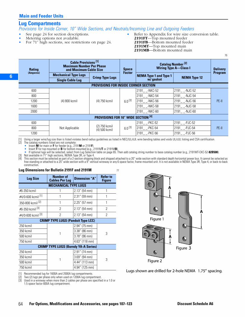
Main and Feeder Units
2
3
5
6
Lug CompartmentsProvisions for Inside Corner, 10” Wide Sections, and Neutrals/Incoming Line and Outgoing Feeders• See page 24 for section descriptions.• Metering options not available.• For 71” high sections, see restrictions on page 24.
• Refer to Appendix for wire size conversion table.2191FT—Top mounted feeder2191FB—Bottom mounted feeder2191MT—Top mounted main2191MB—Bottom mounted main
76
Lug Dimensions for Bulletin 2191F and 2191M 77
Rating(Amperes)
Cable Provisions [1]
Maximum Number Per Phaseand Maximum Cable Size Space
Factor
Catalog Number [2]
Wiring Type A—Class I Delivery Program
Mechanical Type LugsCrimp Type Lugs NEMA Type 1 and Type 1
w/ gasket NEMA Type 12Single Cable Lug
PROVISIONS FOR INSIDE CORNER SECTION600
(4) 800 kcmil (4) 750 kcmil 6.0 [3]
2191_ _-NKC-52 2191_ _-NJC-52
PE-II800 2191_ _-NKC-54 2191_ _-NJC-54
1200 2191_ _-NKC-56 2191_ _-NJC-561600 2191_ _-NKC-58 2191_ _-NJC-582000 2191_ _-NKC-60 2191_ _-NJC-60
PROVISIONS FOR 10” WIDE SECTION [4]
600Not Applicable (2) 750 kcmil
(4) 500 kcmil 6.0 [3]2191_ _-PKC-52 2191_ _-PJC-52
PE-II800 2191_ _-PKC-54 2191_ _-PJC-541200 2191_ _-PKC-56 2191_ _-PJC-56
[1] Using a larger wire/lug size than is listed violates bend radius guidelines as listed in NEC/UL/cUL wire bending tables and voids UL/cUL listing and CSA certification.[2] The catalog numbers listed are not complete:
• Insert M for main or F for feeder (e.g., 2191M or 2191F).• Insert T for top mounted or B for bottom mounted (e.g., 2191MT or 2191MB).• If optional lugs will be selected, select from Lug Selection table on page 65. Then add catalog string number to base catalog number (e.g., 2191MT-CKC-52-82B500).
[3] Not available in 71” high sections, NEMA Type 3R, or Type 4.[4] This section must be selected as part of a 2-section shipping block and shipped attached to a 20” wide section with standard depth horizontal power bus. It cannot be selected as
free standing or attached to a 25" wide section with a 9” vertical wireway or any 6 space factor, frame-mounted unit. It is not available in NEMA Type 3R, Type 4, or back-to-back construction.
Lug Size Number of Cables Per Lug Dimension “A” Refer to
FigureMECHANICAL TYPE LUGS
#6-350 kcmil 1 2.13” (54 mm) 1
#4/0-600 kcmil [1]
[1] Recommended lug for 1600A and 2000A lug compartments.
1 2.31” (59 mm) 1
350-800 kcmil [2]
[2] Two (2) lugs per phase only when used on 1200A lug compartment.
1 2.25” (57 mm) 1
#6-350 kcmil [3]
[3] Used in a wireway when more than 2 cables per phase are specified in a 1.0 or 1.5 space factor 600A lug compartment.
2 2.13” (54 mm) 2
#4/0-600 kcmil [3] 2 2.13” (54 mm) 2
CRIMP TYPE LUGS (Panduit Type LCC)250 kcmil
1
2.94” (75 mm)
3350 kcmil 3.38” (86 mm)500 kcmil 3.78” (96 mm)750 kcmil 4.63” (118 mm)
CRIMP TYPE LUGS (Burndy YA-A Series)250 kcmil
1
2.91” (74 mm)
3350 kcmil 3.69” (94 mm)500 kcmil 4.44” (113 mm)750 kcmil 4.94” (125 mm)
64 For Options, Modifications and Accessories, see pages 107–123 Discount Schedule A6
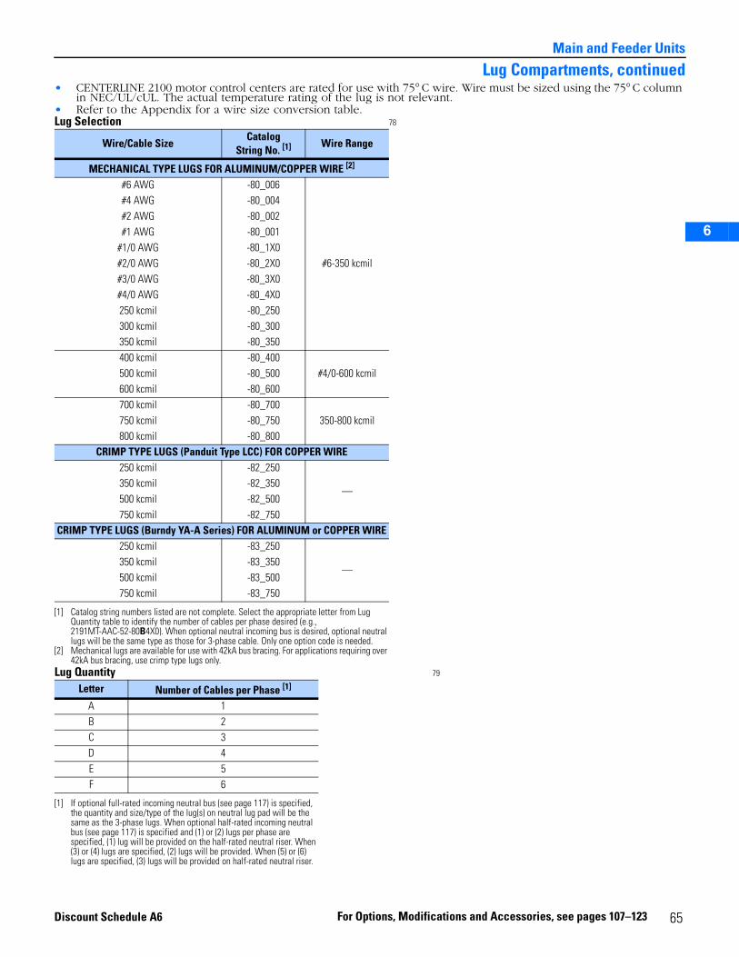
2
3
5
6
Main and Feeder Units
Lug Compartments, continued• CENTERLINE 2100 motor control centers are rated for use with 75° C wire. Wire must be sized using the 75° C column
in NEC/UL/cUL. The actual temperature rating of the lug is not relevant.• Refer to the Appendix for a wire size conversion table.Lug Selection 78
Lug Quantity 79
Wire/Cable SizeCatalog
String No. [1]
[1] Catalog string numbers listed are not complete. Select the appropriate letter from Lug Quantity table to identify the number of cables per phase desired (e.g., 2191MT-AAC-52-80B4X0). When optional neutral incoming bus is desired, optional neutral lugs will be the same type as those for 3-phase cable. Only one option code is needed.
Wire Range
MECHANICAL TYPE LUGS FOR ALUMINUM/COPPER WIRE [2]
[2] Mechanical lugs are available for use with 42kA bus bracing. For applications requiring over 42kA bus bracing, use crimp type lugs only.
#6 AWG -80_006
#6-350 kcmil
#4 AWG -80_004#2 AWG -80_002#1 AWG -80_001
#1/0 AWG -80_1X0#2/0 AWG -80_2X0#3/0 AWG -80_3X0#4/0 AWG -80_4X0250 kcmil -80_250300 kcmil -80_300350 kcmil -80_350400 kcmil -80_400
#4/0-600 kcmil500 kcmil -80_500600 kcmil -80_600700 kcmil -80_700
350-800 kcmil750 kcmil -80_750800 kcmil -80_800
CRIMP TYPE LUGS (Panduit Type LCC) FOR COPPER WIRE250 kcmil -82_250
—350 kcmil -82_350500 kcmil -82_500750 kcmil -82_750
CRIMP TYPE LUGS (Burndy YA-A Series) FOR ALUMINUM or COPPER WIRE250 kcmil -83_250
—350 kcmil -83_350500 kcmil -83_500750 kcmil -83_750
Letter Number of Cables per Phase [1]
[1] If optional full-rated incoming neutral bus (see page 117) is specified, the quantity and size/type of the lug(s) on neutral lug pad will be the same as the 3-phase lugs. When optional half-rated incoming neutral bus (see page 117) is specified and (1) or (2) lugs per phase are specified, (1) lug will be provided on the half-rated neutral riser. When (3) or (4) lugs are specified, (2) lugs will be provided. When (5) or (6) lugs are specified, (3) lugs will be provided on half-rated neutral riser.
A 1B 2C 3D 4E 5F 6
65For Options, Modifications and Accessories, see pages 107–123Discount Schedule A6
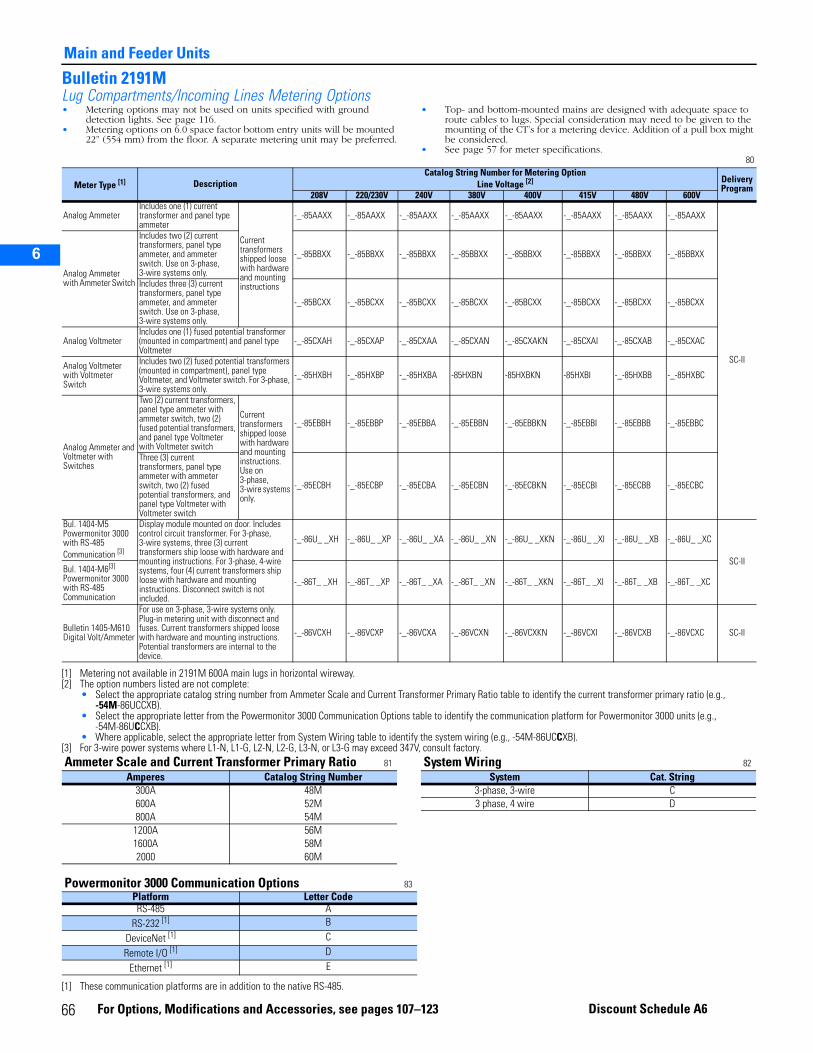
Main and Feeder Units
2
3
5
6
Bulletin 2191MLug Compartments/Incoming Lines Metering Options• Metering options may not be used on units specified with ground
detection lights. See page 116.• Metering options on 6.0 space factor bottom entry units will be mounted
22” (554 mm) from the floor. A separate metering unit may be preferred.
• Top- and bottom-mounted mains are designed with adequate space to route cables to lugs. Special consideration may need to be given to the mounting of the CT’s for a metering device. Addition of a pull box might be considered.
• See page 57 for meter specifications. 80
Meter Type [1] DescriptionCatalog String Number for Metering Option
Line Voltage [2] DeliveryProgram
208V 220/230V 240V 380V 400V 415V 480V 600V
Analog Ammeter Includes one (1) current transformer and panel type ammeter
Current transformers shipped loose with hardware and mounting instructions
-_-85AAXX -_-85AAXX -_-85AAXX -_-85AAXX -_-85AAXX -_-85AAXX -_-85AAXX -_-85AAXX
SC-II
Analog Ammeter with Ammeter Switch
Includes two (2) current transformers, panel type ammeter, and ammeter switch. Use on 3-phase, 3-wire systems only.
-_-85BBXX -_-85BBXX -_-85BBXX -_-85BBXX -_-85BBXX -_-85BBXX -_-85BBXX -_-85BBXX
Includes three (3) current transformers, panel type ammeter, and ammeter switch. Use on 3-phase, 3-wire systems only.
-_-85BCXX -_-85BCXX -_-85BCXX -_-85BCXX -_-85BCXX -_-85BCXX -_-85BCXX -_-85BCXX
Analog VoltmeterIncludes one (1) fused potential transformer (mounted in compartment) and panel type Voltmeter
-_-85CXAH -_-85CXAP -_-85CXAA -_-85CXAN -_-85CXAKN -_-85CXAI -_-85CXAB -_-85CXAC
Analog Voltmeter with Voltmeter Switch
Includes two (2) fused potential transformers (mounted in compartment), panel type Voltmeter, and Voltmeter switch. For 3-phase, 3-wire systems only.
-_-85HXBH -_-85HXBP -_-85HXBA -85HXBN -85HXBKN -85HXBI -_-85HXBB -_-85HXBC
Analog Ammeter and Voltmeter with Switches
Two (2) current transformers, panel type ammeter with ammeter switch, two (2) fused potential transformers, and panel type Voltmeter with Voltmeter switch
Current transformers shipped loose with hardware and mounting instructions. Use on 3-phase,3-wire systems only.
-_-85EBBH -_-85EBBP -_-85EBBA -_-85EBBN -_-85EBBKN -_-85EBBI -_-85EBBB -_-85EBBC
Three (3) current transformers, panel type ammeter with ammeter switch, two (2) fused potential transformers, and panel type Voltmeter with Voltmeter switch
-_-85ECBH -_-85ECBP -_-85ECBA -_-85ECBN -_-85ECBKN -_-85ECBI -_-85ECBB -_-85ECBC
Bul. 1404-M5 Powermonitor 3000 with RS-485 Communication [3]
Display module mounted on door. Includes control circuit transformer. For 3-phase, 3-wire systems, three (3) current transformers ship loose with hardware and mounting instructions. For 3-phase, 4-wire systems, four (4) current transformers ship loose with hardware and mounting instructions. Disconnect switch is not included.
-_-86U_ _XH -_-86U_ _XP -_-86U_ _XA -_-86U_ _XN -_-86U_ _XKN -_-86U_ _XI -_-86U_ _XB -_-86U_ _XC
SC-IIBul. 1404-M6[3]
Powermonitor 3000 with RS-485 Communication
-_-86T_ _XH -_-86T_ _XP -_-86T_ _XA -_-86T_ _XN -_-86T_ _XKN -_-86T_ _XI -_-86T_ _XB -_-86T_ _XC
Bulletin 1405-M610Digital Volt/Ammeter
For use on 3-phase, 3-wire systems only. Plug-in metering unit with disconnect and fuses. Current transformers shipped loose with hardware and mounting instructions. Potential transformers are internal to the device.
-_-86VCXH -_-86VCXP -_-86VCXA -_-86VCXN -_-86VCXKN -_-86VCXI -_-86VCXB -_-86VCXC SC-II
[1] Metering not available in 2191M 600A main lugs in horizontal wireway.[2] The option numbers listed are not complete:
• Select the appropriate catalog string number from Ammeter Scale and Current Transformer Primary Ratio table to identify the current transformer primary ratio (e.g., -54M-86UCCXB).
• Select the appropriate letter from the Powermonitor 3000 Communication Options table to identify the communication platform for Powermonitor 3000 units (e.g., -54M-86UCCXB).
• Where applicable, select the appropriate letter from System Wiring table to identify the system wiring (e.g., -54M-86UCCXB).[3] For 3-wire power systems where L1-N, L1-G, L2-N, L2-G, L3-N, or L3-G may exceed 347V, consult factory.Ammeter Scale and Current Transformer Primary Ratio 81 System Wiring 82
Amperes Catalog String Number System Cat. String300A 48M 3-phase, 3-wire C600A 52M 3 phase, 4 wire D800A 54M
1200A 56M1600A 58M2000 60M
Powermonitor 3000 Communication Options 83 Platform Letter CodeRS-485 A
RS-232 [1]
[1] These communication platforms are in addition to the native RS-485.
B
DeviceNet [1] C
Remote I/O [1] D
Ethernet [1] E
66 For Options, Modifications and Accessories, see pages 107–123 Discount Schedule A6
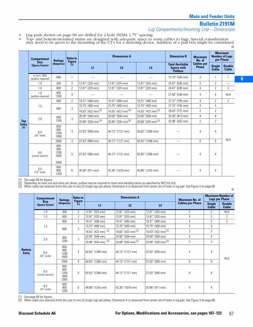
2
3
5
6
Main and Feeder Units
Bulletin 2191MLug Compartments/Incoming Line—Dimensions
• Lug pads shown on page 68 are drilled for 2-hole NEMA 1.75” spacing.• Top- and bottom-mounted mains are designed with adequate space to route cables to lugs. Special consideration
may need to be given to the mounting of the CT’s for a metering device. Addition of a pull box might be considered.84
85
Compartment Size
(Space Factor)
Ratings(Amperes)
Refer to Figure
[1]
[1] See page 68 for figures.
Dimensions A Dimension B Maximum No. of
Cables per Phase
Maximum Number of Lugs
per Phase
L1 L2 L3Total Available
Space with Pullbox
Single Cable
Double Cable
Top Entry
[2]
[2] Depending on wire size and wires per phase, pullbox may be required to meet wire bending radius as specified by NEC/UL/cUL.
In horiz. WW(pullbox required) 600 1 — — — 13.19” (335 mm) 2 1 1
1.0 300 2 12.81” (325 mm) 12.81” (325 mm) 12.81” (325 mm) 24.81” (630 mm) 2 2 —1.0 600 2 12.81” (325 mm) 12.81” (325 mm) 12.81” (325 mm) 24.81” (630 mm) 4 2 2
1.0(pullbox required)
8001200 3 — — — 21.56” (548 mm) 4 4 N/A
1.5
600 2 19.31” (490 mm) 19.31” (490 mm) 19.31” (490 mm) 31.31” (795 mm) 4 2 2
800 315.75” (400 mm) 15.75” (400 mm) 15.75” (400 mm) 27.75” (705 mm) 4 4
N/A
16.63” (422 mm) [3]
[3] When cable size selected limits the user to two (2) single lugs per phase, Dimension A is measured from center set of holes in lug pad. See Figure 3 on page 68.
16.63” (422 mm) [3] 16.63” (422 mm) [3] 28.63” (727 mm) 2 2
2.0 8001200 3
20.00” (508 mm) 20.00” (508 mm) 20.00” (508 mm) 32.00” (813 mm) 4 4
20.88” (530 mm) [3] 20.88” (530 mm) [3] 20.88” (530 mm) [3] 32.88” (835 mm) 2 2
6.0(20” wide)
60080012001600
4 37.63” (956 mm) 44.13” (1121 mm) 50.63” (1286 mm) — 4 4
2000 4 37.63” (956 mm) 44.13” (1121 mm) 50.63” (1286 mm) — 6 6
6.0(corner section)
60080012001600
2000
5 37.63” (956 mm) 44.13” (1121 mm) 50.63” (1286 mm) — 4 4
6.0(10” wide)
6008001200
6 35.88” (911 mm) 42.38” (1076 mm) 48.88” (1242 mm) — 4 4
Compartment Size
(Space Factor)
Ratings(Amperes)
Refer to Figure
[1]
[1] See page 68 for figures.
Dimensions AMaximum No. of Cables per Phase
Maximum Number of Lugs per Phase
L1 L2 L3 Single Cable
Double Cable
BottomEntry
1.0 300 2 12.81” (325 mm) 12.81” (325 mm) 12.81” (325 mm) 2 2 N/A1.0 600 2 12.81” (325 mm) 12.81” (325 mm) 12.81” (325 mm) 4 2 2
1.5
600 2 19.31” (490 mm) 19.31” (490 mm) 19.31” (490 mm) 4 2 2
800 315.75” (400 mm) 15.75” (400 mm) 15.75” (400 mm) 4 4
N/A
16.63” (422 mm) [2]
[2] When cable size selected limits the user to two (2) single lugs per phase, Dimension A is measured from center set of holes in lug pad. See Figure 3 on page 68.
16.63” (422 mm) [2] 16.63” (422 mm) [2] 2 2
2.0 8001200 3
20.00” (508 mm) 20.00” (508 mm) 20.00” (508 mm) 4 4
20.88” (530 mm) [2] 20.88” (530 mm) [2] 20.88” (530 mm) [2] 2 2
6.0(20” wide)
600800
12001600
4 50.63” (1286 mm) 44.13” (1121 mm) 37.63” (956 mm) 4 4
2000 4 50.63” (1286 mm) 44.13” (1121 mm) 37.63” (956 mm) 6 6
6.0(corner section)
600800
120016002000
5 50.63” (1286 mm) 44.13” (1121 mm) 37.63” (956 mm) 4 4
6.0(10” wide)
600800
12006 48.88” (1242 mm) 42.38” (1076 mm) 35.88” (911 mm) 4 4
67For Options, Modifications and Accessories, see pages 107–123Discount Schedule A6

2
3
5
6
Main and Feeder Units
Bulletin 2191MLug Compartments/Incoming Line—DimensionsDimensions for drawings are provided on page 67.
NOTE: All lug pads shown accept NEMA standard 2-hole lugs 1.75” on center using .5” hardware.
"B"
FIGURE 1
"B"
"A"
FIGURE 2
FIGURE 5
"A"(L3)
"A"(L2)
"A"(L1)
FIGURE 6
"A"(L1)
"A"(L3)
"A"(L2)
"B"
"A""A1"
FIGURE 3
"A"(L3)
"A"(L2)
"A"(L1)
FIGURE 4
Phase A vertical bus on top incoming 2.0 space factors and Phase C vertical bus on bottom incoming 2.0 space factors are not required or supplied
68 For Options, Modifications and Accessories, see pages 107–123 Discount Schedule A6
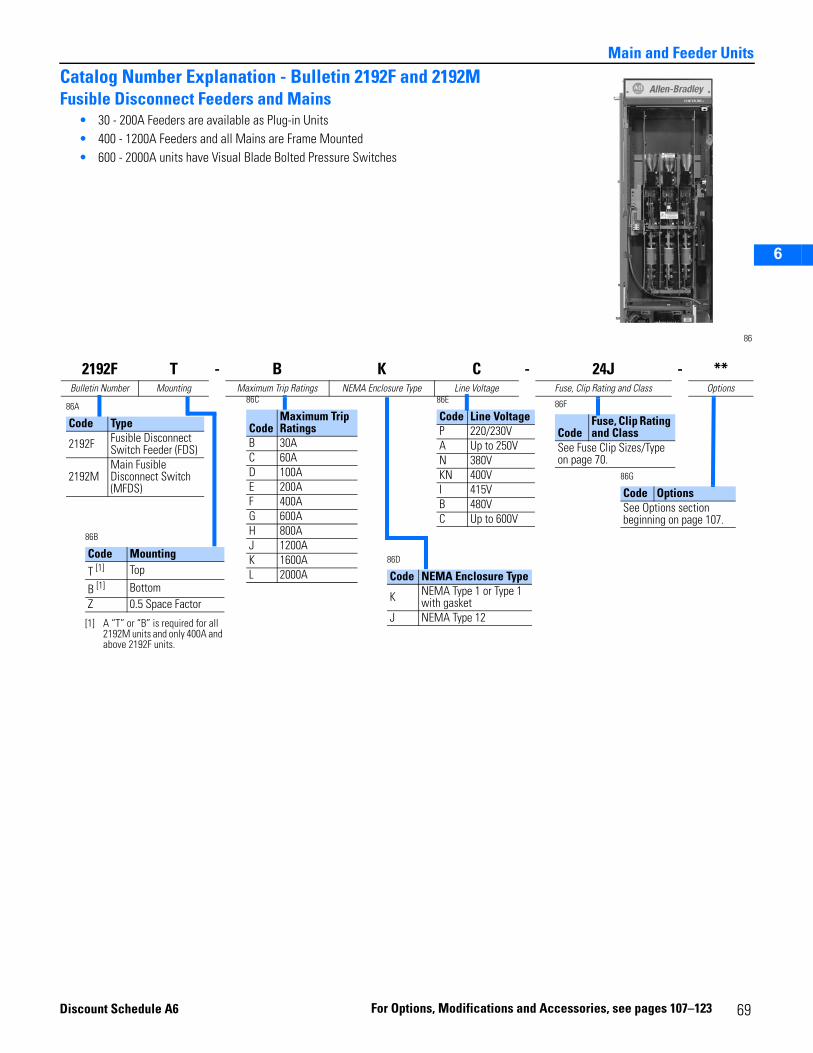
2
3
5
6
Main and Feeder Units
Catalog Number Explanation - Bulletin 2192F and 2192MFusible Disconnect Feeders and Mains
• 30 - 200A Feeders are available as Plug-in Units• 400 - 1200A Feeders and all Mains are Frame Mounted• 600 - 2000A units have Visual Blade Bolted Pressure Switches
86
2192F T - B K C - 24J - **Bulletin Number Mounting Maximum Trip Ratings NEMA Enclosure Type Line Voltage Fuse, Clip Rating and Class Options
86A
Code Type
2192F Fusible Disconnect Switch Feeder (FDS)
2192MMain Fusible Disconnect Switch (MFDS)
86C
CodeMaximum Trip Ratings
B 30AC 60AD 100AE 200AF 400AG 600AH 800AJ 1200AK 1600AL 2000A
86B
Code MountingT [1]
[1] A “T” or “B” is required for all 2192M units and only 400A and above 2192F units.
Top
B [1] Bottom Z 0.5 Space Factor
86D
Code NEMA Enclosure Type
K NEMA Type 1 or Type 1 with gasket
J NEMA Type 12
86E
Code Line VoltageP 220/230VA Up to 250VN 380VKN 400VI 415VB 480VC Up to 600V
86F
CodeFuse, Clip Rating and Class
See Fuse Clip Sizes/Type on page 70.
86G
Code OptionsSee Options section beginning on page 107.
Dis
count Schedule A6 F or Option s, Modifications and A ccessories, 69 see pages 107–123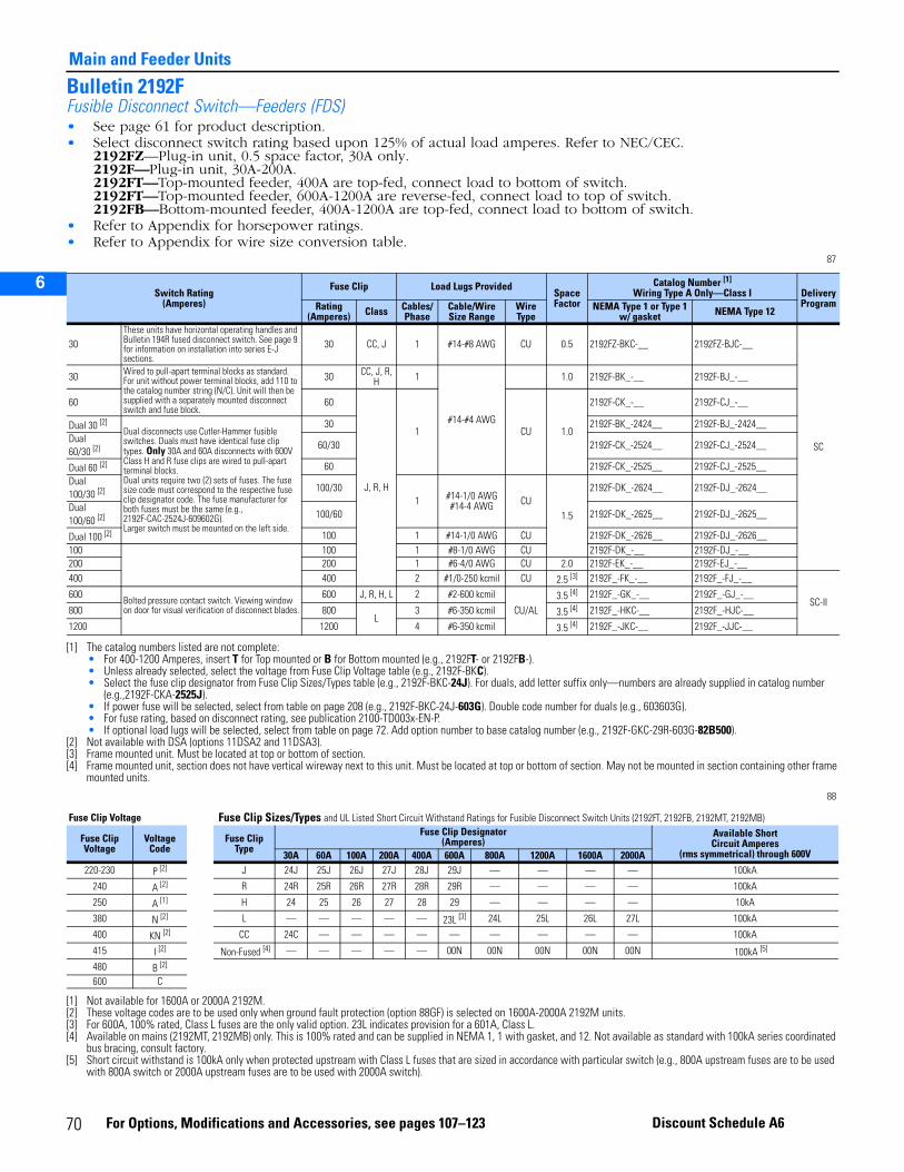
2
3
5
6
Main and Feeder Units
Bulletin 2192FFusible Disconnect Switch—Feeders (FDS)• See page 61 for product description.• Select disconnect switch rating based upon 125% of actual load amperes. Refer to NEC/CEC.
2192FZ—Plug-in unit, 0.5 space factor, 30A only.2192F—Plug-in unit, 30A-200A.2192FT—Top-mounted feeder, 400A are top-fed, connect load to bottom of switch. 2192FT—Top-mounted feeder, 600A-1200A are reverse-fed, connect load to top of switch.2192FB—Bottom-mounted feeder, 400A-1200A are top-fed, connect load to bottom of switch.
• Refer to Appendix for horsepower ratings.• Refer to Appendix for wire size conversion table.
87
88
Switch Rating(Amperes)
Fuse Clip Load Lugs ProvidedSpaceFactor
Catalog Number [1]
Wiring Type A Only—Class I
[1] The catalog numbers listed are not complete:• For 400-1200 Amperes, insert T for Top mounted or B for Bottom mounted (e.g., 2192FT- or 2192FB-).• Unless already selected, select the voltage from Fuse Clip Voltage table (e.g., 2192F-BKC).• Select the fuse clip designator from Fuse Clip Sizes/Types table (e.g., 2192F-BKC-24J). For duals, add letter suffix only—numbers are already supplied in catalog number
(e.g.,2192F-CKA-2525J).• If power fuse will be selected, select from table on page 208 (e.g., 2192F-BKC-24J-603G). Double code number for duals (e.g., 603603G).• For fuse rating, based on disconnect rating, see publication 2100-TD003x-EN-P.• If optional load lugs will be selected, select from table on page 72. Add option number to base catalog number (e.g., 2192F-GKC-29R-603G-82B500).
Delivery ProgramRating
(Amperes) Class Cables/Phase
Cable/Wire Size Range
Wire Type
NEMA Type 1 or Type 1 w/ gasket NEMA Type 12
30These units have horizontal operating handles and Bulletin 194R fused disconnect switch. See page 9 for information on installation into series E-J sections.
30 CC, J 1 #14-#8 AWG CU 0.5 2192FZ-BKC-__ 2192FZ-BJC-__
SC
30 Wired to pull-apart terminal blocks as standard. For unit without power terminal blocks, add 110 to the catalog number string (N/C). Unit will then be supplied with a separately mounted disconnect switch and fuse block.
30 CC, J, R, H 1
#14-#4 AWG
1.0 2192F-BK_-__ 2192F-BJ_-__
60 60
J, R, H
1 CU 1.0
2192F-CK_-__ 2192F-CJ_-__
Dual 30 [2]
[2] Not available with DSA (options 11DSA2 and 11DSA3).
Dual disconnects use Cutler-Hammer fusible switches. Duals must have identical fuse clip types. Only 30A and 60A disconnects with 600V Class H and R fuse clips are wired to pull-apart terminal blocks.Dual units require two (2) sets of fuses. The fuse size code must correspond to the respective fuse clip designator code. The fuse manufacturer for both fuses must be the same (e.g., 2192F-CAC-2524J-609602G).Larger switch must be mounted on the left side.
30 2192F-BK_-2424__ 2192F-BJ_-2424__Dual 60/30 [2] 60/30 2192F-CK_-2524__ 2192F-CJ_-2524__
Dual 60 [2] 60 2192F-CK_-2525__ 2192F-CJ_-2525__Dual 100/30 [2] 100/30
1 #14-1/0 AWG #14-4 AWG CU
1.5
2192F-DK_-2624__ 2192F-DJ_-2624__
Dual 100/60 [2] 100/60 2192F-DK_-2625__ 2192F-DJ_-2625__
Dual 100 [2] 100 1 #14-1/0 AWG CU 2192F-DK_-2626__ 2192F-DJ_-2626__100 100 1 #8-1/0 AWG CU 2192F-DK_-__ 2192F-DJ_-__200 200 1 #6-4/0 AWG CU 2.0 2192F-EK_-__ 2192F-EJ_-__400 400 2 #1/0-250 kcmil CU 2.5 [3]
[3] Frame mounted unit. Must be located at top or bottom of section.
2192F_-FK_-__ 2192F_-FJ_-__
SC-II600
Bolted pressure contact switch. Viewing window on door for visual verification of disconnect blades.
600 J, R, H, L 2 #2-600 kcmil
CU/AL3.5 [4]
[4] Frame mounted unit, section does not have vertical wireway next to this unit. Must be located at top or bottom of section. May not be mounted in section containing other frame mounted units.
2192F_-GK_-__ 2192F_-GJ_-__
800 800L
3 #6-350 kcmil 3.5 [4] 2192F_-HKC-__ 2192F_-HJC-__
1200 1200 4 #6-350 kcmil 3.5 [4] 2192F_-JKC-__ 2192F_-JJC-__
Fuse Clip Voltage Fuse Clip Sizes/Types and UL Listed Short Circuit Withstand Ratings for Fusible Disconnect Switch Units (2192FT, 2192FB, 2192MT, 2192MB)
Fuse ClipVoltage
VoltageCode
Fuse Clip Type
Fuse Clip Designator(Amperes)
Available ShortCircuit Amperes
(rms symmetrical) through 600V30A 60A 100A 200A 400A 600A 800A 1200A 1600A 2000A220-230 P [2] J 24J 25J 26J 27J 28J 29J — — — — 100kA
240 A [2] R 24R 25R 26R 27R 28R 29R — — — — 100kA
250 A [1]
[1] Not available for 1600A or 2000A 2192M.
H 24 25 26 27 28 29 — — — — 10kA
380 N [2]
[2] These voltage codes are to be used only when ground fault protection (option 88GF) is selected on 1600A-2000A 2192M units.
L — — — — — 23L [3]
[3] For 600A, 100% rated, Class L fuses are the only valid option. 23L indicates provision for a 601A, Class L.
24L 25L 26L 27L 100kA
400 KN [2] CC 24C — — — — — — — — — 100kA
415 I [2] Non-Fused [4]
[4] Available on mains (2192MT, 2192MB) only. This is 100% rated and can be supplied in NEMA 1, 1 with gasket, and 12. Not available as standard with 100kA series coordinated bus bracing, consult factory.
— — — — — 00N 00N 00N 00N 00N 100kA [5]
[5] Short circuit withstand is 100kA only when protected upstream with Class L fuses that are sized in accordance with particular switch (e.g., 800A upstream fuses are to be used with 800A switch or 2000A upstream fuses are to be used with 2000A switch).
480 B [2]
600 C
70 For Options, Modifications and Accessories, see pages 107–123 Discount Schedule A6
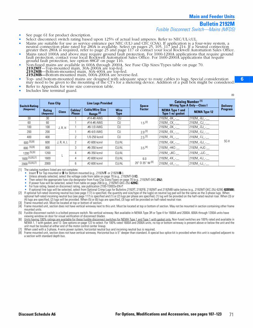
2
3
5
6
Main and Feeder Units
Bulletin 2192MFusible Disconnect Switch—Mains (MFDS)
• See page 61 for product description.• Select disconnect switch rating based upon 125% of actual load amperes. Refer to NEC/UL/cUL.• Mains are suitable for use as service entrance per NEC (UL) and CEC (CSA). If application is a four-wire system, a
neutral connection plate rated for 280A is available. Select on pages 25, 105, 117 and 214. If a Neutral connection greater then 280A is required, refer to page 25 and page 117 or contact your local Rockwell Automation Sales Office.
• Mains rated 1000A and above may require ground fault protection. For 1000-1200A applications that require ground fault protection, contact your local Rockwell Automation Sales Office. For 1600-2000A applications that require ground fault protection, see option 88GF on page 116.
• Non-fused mains are available in 600A through 2000A. See Fuse Clip Sizes/Types table on page 70. 2192MT—Top-mounted main, 30A-2000A are top-fed.2192MB—Bottom-mounted main, 30A-400A are top-fed.2192MB—Bottom-mounted main, 600A-2000A are reverse-fed.
• Top- and bottom-mounted mains are designed with adequate space to route cables to lugs. Special consideration may need to be given to the mounting of the CT’s for a metering device. Addition of a pull box might be considered.
• Refer to Appendix for wire size conversion table.• Includes line terminal guard.
89
Switch Rating (Amperes)
Fuse Clip Line Lugs ProvidedSpaceFactor
Catalog Number [1]
Wiring Type A Only—Class I
[1] The catalog numbers listed are not complete:• Insert T for Top mounted or B for Bottom mounted (e.g., 2192MT- or 2192MB-).• Unless already selected, select the voltage code from table on page 70 (e.g., 2192MT-GKC).• Then select the appropriate fuse clip designator from Fuse Clip Sizes/Types on page 70 (e.g., 2192MT-GKC-29J).• If power fuse will be selected, select from table on page 208 (e.g., 2192MT-GKC-29J-629G).• For fuse rating, based on disconnect rating, see publication 2100-TD003x-EN-P.• If optional line lugs will be selected, select from Optional Crimp Lugs for Bulletins 2192FT, 2192FB, 2192MT and 2192MB table below (e.g., 2192MT-GKC-29J-629G-82B500).
Delivery ProgramRating
(Amperes) Class Cables/Phase
Cable/Wire Size Range [2]
[2] If optional full-rated incoming neutral bus (see page 117) is specified, the quantity and size/type of the lug(s) on neutral lug pad will be the same as the 3-phase lugs. When optional half-rated incoming neutral bus (see page 117) is specified and (1) or (2) lugs per phase are specified, (1) lug will be provided on the half-rated neutral riser. When (3) or (4) lugs are specified, (2) lugs will be provided. When (5) or (6) lugs are specified, (3) lugs will be provided on half-rated neutral riser.
WireType
NEMA Type 1 and Type 1 w/ gasket NEMA Type 12
30 30
J, R, H
1 #14-#8 AWG CU1.5 [3]
[3] Frame mounted unit. Must be located at top or bottom of section.
2192M_-BK_-__ 2192M_-BJ_-__
SC-II
60 60 1 #14-#6 AWG CU 2192M_-CK_-__ 2192M_-CJ_-__100 100 1 #8-1/0 AWG CU 2192M_-DK_-__ 2192M_-DJ_-__200 200 1 #6-4/0 AWG CU 2.0 [3] 2192M_-EK_-__ 2192M_-EJ_-__
400 400 2 1/0-250 kcmil CU 2.5 [3] 2192M_-FK_-__ 2192M_-FJ_-__
600 [5],[6] 600 J, R, H, L 2 #2-600 kcmil CU/AL
3.5 [4]
[4] Frame mounted unit, section does not have vertical wireway next to this unit. Must be located at top or bottom of section. May not be mounted in section containing other frame mounted units.
2192M_-GK_-__ 2192M_-GJ_-__
800 [5],[6]
[5] Fusible disconnect switch is a bolted pressure switch. No vertical wireway. Not available in NEMA Type 3R or Type 4 for 1600A and 2000A. 600A through 1200A units have viewing window on door for visual verification of disconnect blades.
[6] Units having 100% ratings are available for these fusible disconnect switches for NEMA Type 1 and Type 1 with gasket only. Non-fused switches are 100% rated and available in NEMA 1, 1 with gasket, and 12. See options on page 122 to select. For 100% rated 1600A and 2000A units, no top or bottom wireway is present above or below the unit and the unit must be located at either end of the motor control center lineup.
800
L
3 #6-350 kcmil CU/AL 2192M_-HKC-__ 2192M_-HJC-__
1200 [5],[6] 1200 4 #6-350 kcmil CU/AL 2192M_-JKC-__ 2192M_-JJC-__
1600 [5],[6],[7]
[7] When used with a 3-phase, 4-wire power system, horizontal neutral bus and incoming neutral bus is required.
1600 4 #2-600 kcmil CU/AL 6.020” D 35” W [8]
[8] Frame mounted unit, section does not have vertical wireway. Horizontal bus is 5” deeper than standard. A special bus splice kit is provided when this unit is supplied adjacent to a section with standard depth bus.
2192M_-KK_-__ 2192M_-KJ_-__
2000 [5],[6],[7] 2000 6 #2-600 kcmil CU/AL 2192M_-LK_-__ 2192M_-LJ_-__
71For Options, Modifications and Accessories, see pages 107–123Discount Schedule A6

2
3
5
6
Main and Feeder Units
Optional Crimp Lugs for Bulletins 2192FT, 2192FB, 2192MT and 2192MB 90Switch Size Type of Lug Cables/ Phase
Cable/Wire Size or Range Wire Type
OptionNumber [1]
[1] If optional full-rated incoming neutral bus (see page 117) is specified, the quantity and size/type of the lug(s) on neutral lug pad will be the same as the 3-phase lugs. When optional half-rated incoming neutral bus (see page 117) is specified and (1) or (2) lugs per phase are specified, (1) lug will be provided on the half-rated neutral riser. When (3) or (4) lugs are specified, (2) lugs will be provided. When (5) or (6) lugs are specified, (3) lugs will be provided on half-rated neutral riser.
2192FT2192FB
2192MT2192MB
200A Mechanical Only 1 #6-250 kcmil CU 81A250
400A
Panduit Type LCC2 250 kcmil CU 82B250 [2],[3]
1 500 kcmil CU 82A500 [2],[3],[4]
[2] For top entry of incoming cables only.[3] Disconnect supplied with lug pad assembly, reference page 215 for additional lugs.[4] Requires pullbox. Select on page 28.
Burndy YA-A Series2 250 kcmil CU/AL 83B250 [2],[3]
1 500 kcmil CU/AL 83A500 [2],[3],[4]
600APanduit Type LCC 2
500 kcmil
CU 82B500 [3] [3]
Burndy YA-A Series 2 CU/AL 83B500 [3] [3]
800APanduit Type LCC 3 CU 82C500 [3] [3]
Burndy YA-A Series 3 CU/AL 83C500 [3] [3]
1200APanduit Type LCC 4 CU 82D500 [3] [3]
Burndy YA-A Series 4 CU/AL 83D500 [3] [3]
1600APanduit Type LCC 5 CU 82E500 [3]
Burndy YA-A Series 5 CU/AL 83E500 [3]
2000APanduit Type LCC 6 CU 82F500 [3]
Burndy YA-A Series 6 CU/AL 83F500 [3]
72 For Options, Modifications and Accessories, see pages 107–123 Discount Schedule A6
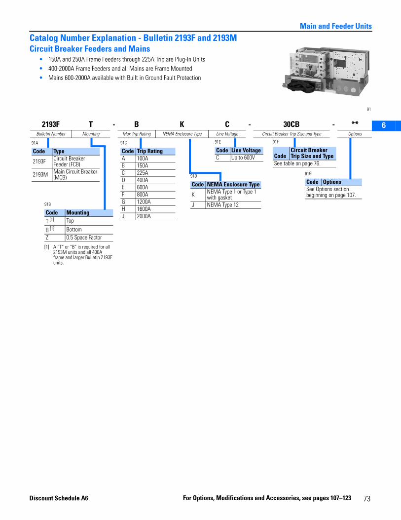
2
3
5
6
Main and Feeder Units
Catalog Number Explanation - Bulletin 2193F and 2193MCircuit Breaker Feeders and Mains
• 150A and 250A Frame Feeders through 225A Trip are Plug-In Units• 400-2000A Frame Feeders and all Mains are Frame Mounted• Mains 600-2000A available with Built in Ground Fault Protection
91
2193F T - B K C - 30CB - **Bulletin Number Mounting Max Trip Rating NEMA Enclosure Type Line Voltage Circuit Breaker Trip Size and Type Options
91A
Code Type
2193F Circuit Breaker Feeder (FCB)
2193M Main Circuit Breaker (MCB)
91C
Code Trip RatingA 100AB 150AC 225AD 400AE 600AF 800AG 1200AH 1600AJ 2000A
91B
Code MountingT [1]
[1] A “T” or “B” is required for all 2193M units and all 400A frame and larger Bulletin 2193F units.
Top
B [1] Bottom Z 0.5 Space Factor
91D
Code NEMA Enclosure Type
K NEMA Type 1 or Type 1 with gasket
J NEMA Type 12
91E
Code Line VoltageC Up to 600V
91F
CodeCircuit Breaker Trip Size and Type
See table on page 76.
91G
Code OptionsSee Options section beginning on page 107.
Disc
ount Schedule A6 F or Option s, Modifications and A ccessories 73, see pages 107–123
2
3
5
6
Main and Feeder Units
Bulletin 2193F3-Pole Feeder Circuit Breaker (FCB)• See page 61 for product description.• See Appendix for circuit breaker characteristics.• Continuous current rating based on 40° C ambient.• Select circuit breaker frame and trip size based upon 125% of actual load amperes. Refer to NEC/CEC. Contact your
local Rockwell Automation Sales Office if 100% rated circuit breakers are required.• Two (2) circuit breakers with trip current up to 150 A can be dual mounted in one plug-in unit for I3C, I6C, and I0C
150A frames. I3C frame circuit breakers with current limiters also can be dual mounted but are limited to a 100A trip maximum on each circuit breaker. To specify dual mounted units, add two numbers from table on page 76 to base catalog number (e.g., 2193F-AJC-3031CB). Half space factor units cannot be dual-mounted.2193F—Plug-in unit, 15A-225A.2193FZ—Plug-in unit, 0.5 space factor, 15A-225A.2193FT—Top-mounted feeder, 400A are top-fed, connect load to bottom of switch.2193FT—Top-mounted feeder, 600A-1200A are reverse-fed, connect load to top of switch.2193FB—Bottom-mounted feeder, 400A-1200A are top-fed, connect load to bottom of switch.
92
FrameRange of Available
Trips (Amperes)
Interrupting Capacity Ratings(rms symmetrical amperes)
SpaceFactor
Catalog Number [1]
Wiring Type A Only—Class I
[1] The catalog numbers listed are not complete:• Select the trip current from table on page 76 (e.g., 2193F-AKC-40CB).• If optional load lugs will be selected, select from table on page 76 (e.g., 2193F-AKC-40CB-80A350).
Delivery ProgramRating
(Amperes) Type 208V240V
380V400V415V480V
600V NEMA Type 1 and Type 1 w/ gasket NEMA Type 12
150 [2]
[2] Non-interchangeable trip breakers.
I3C15-100
65k 35k 18k
0.5 [3]
[3] These units have horizontal operating handles.
2193FZ-AKC-_CB 2193FZ-AJC-_CB
SC
I6C 100k 65k 25k 2193FZ-AKC-_CM 2193FZ-AJC-_CM
I0C 15-50
100k 100k 35k 2193FZ-AKC-_CX 2193FZ-AJC-_CX60-100
I3C-CL15-50
100k 100k 100k 2193FZ-AKC-_CD 2193FZ-AJC-_CD60-100
I3C
125-150
65k 35k 18k 2193FZ-BKC-_CB 2193FZ-BJC-_CBI6C 100k 65k 25k 2193FZ-BKC-_CM 2193FZ-BJC-_CMI0C 100k 100k 35k 2193FZ-BKC-_CX 2193FZ-BJC-_CX
I3C-CL 100k 100k 100k 2193FZ-BKC-_CD 2193FZ-BJC-_CDI3C
15-10065k 35k 18k
1.0
2193F-AKC-_CB 2193F-AJC-_CBI6C 100k 65k 25k 2193F-AKC-_CM 2193F-AJC-_CM
I0C 15-50
100k 100k 35k 2193F-AKC-_CX 2193F-AJC-_CX60-100
I3C-CL15-50
100k 100k 100k 1.0 [4]
[4] When supplied with DSA (options 11DSA2 and 11DSA3), requires 1.5 space factor.
2193F-AKC-_CD 2193F-AJC-_CD60-100 1.5
I3C
125-150 [5]
[5] When selecting a dual circuit breaker unit with one circuit breaker with 125A or 150A trip and the other circuit breaker with 15-100 A trip, use catalog number configuration 2193F-B_C-____ (e.g., 2193F-BKC-4130CB).
65k 35k 18k1.0
2193F-BKC-_CB 2193F-BJC-_CBI6C 100k 65k 25k 2193F-BKC-_CM 2193F-BJC-_CMI0C 100k 100k 35k 2193F-BKC-_CX 2193F-BJC-_CX
I3C-CL 100k 100k 100k 1.5 2193F-BKC-_CD 2193F-BJC-_CD
74 For Options, Modifications and Accessories, see pages 107–123 Discount Schedule A6
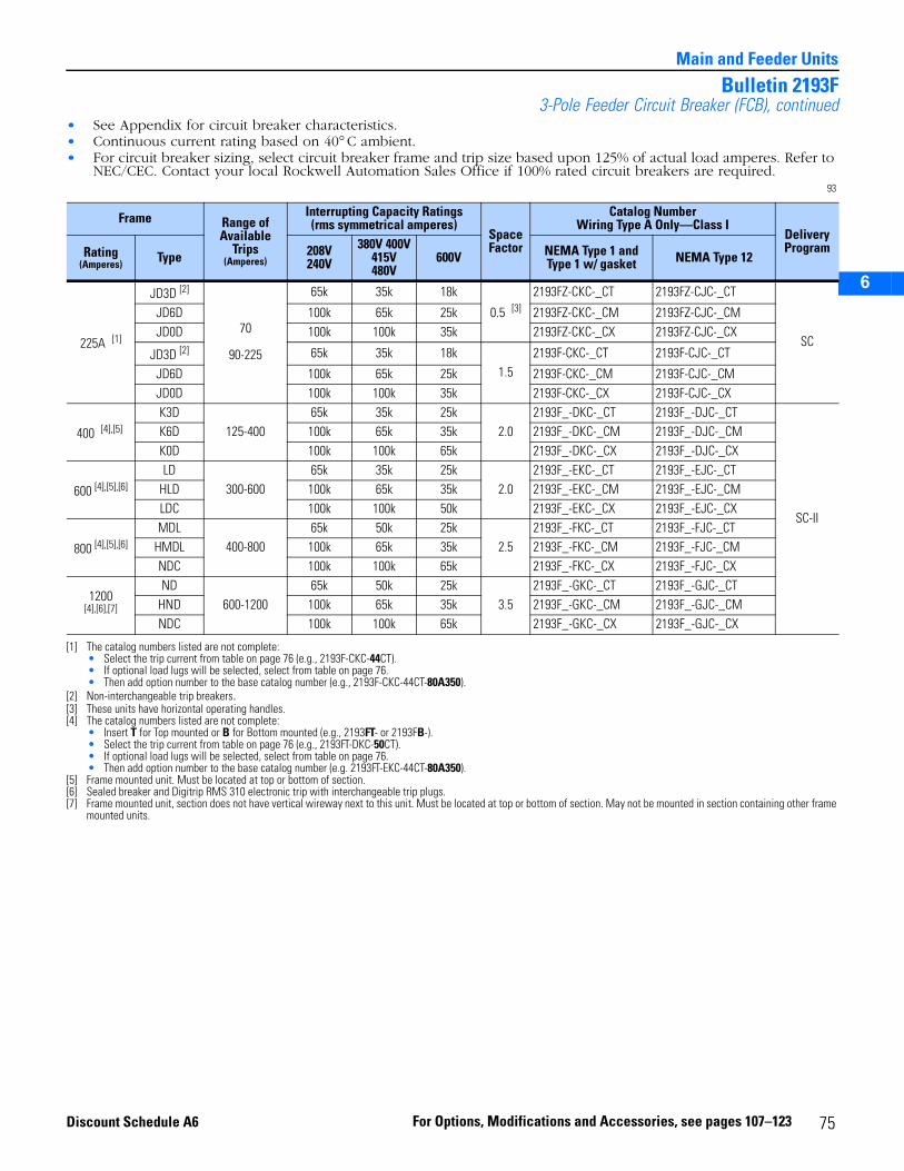
2
3
5
6
Main and Feeder Units
Bulletin 2193F3-Pole Feeder Circuit Breaker (FCB), continued
• See Appendix for circuit breaker characteristics.• Continuous current rating based on 40° C ambient.• For circuit breaker sizing, select circuit breaker frame and trip size based upon 125% of actual load amperes. Refer to
NEC/CEC. Contact your local Rockwell Automation Sales Office if 100% rated circuit breakers are required.93
Frame Range of Available
Trips(Amperes)
Interrupting Capacity Ratings(rms symmetrical amperes)
SpaceFactor
Catalog NumberWiring Type A Only—Class I
Delivery ProgramRating
(Amperes) Type 208V240V
380V 400V415V480V
600V NEMA Type 1 and Type 1 w/ gasket NEMA Type 12
225A [1]
[1] The catalog numbers listed are not complete:• Select the trip current from table on page 76 (e.g., 2193F-CKC-44CT).• If optional load lugs will be selected, select from table on page 76.• Then add option number to the base catalog number (e.g., 2193F-CKC-44CT-80A350).
JD3D [2]
[2] Non-interchangeable trip breakers.
70
90-225
65k 35k 18k
0.5 [3]
[3] These units have horizontal operating handles.
2193FZ-CKC-_CT 2193FZ-CJC-_CT
SC
JD6D 100k 65k 25k 2193FZ-CKC-_CM 2193FZ-CJC-_CMJD0D 100k 100k 35k 2193FZ-CKC-_CX 2193FZ-CJC-_CX
JD3D [2] 65k 35k 18k1.5
2193F-CKC-_CT 2193F-CJC-_CT
JD6D 100k 65k 25k 2193F-CKC-_CM 2193F-CJC-_CMJD0D 100k 100k 35k 2193F-CKC-_CX 2193F-CJC-_CX
400 [4],[5]
[4] The catalog numbers listed are not complete:• Insert T for Top mounted or B for Bottom mounted (e.g., 2193FT- or 2193FB-).• Select the trip current from table on page 76 (e.g., 2193FT-DKC-50CT).• If optional load lugs will be selected, select from table on page 76.• Then add option number to the base catalog number (e.g. 2193FT-EKC-44CT-80A350).
[5] Frame mounted unit. Must be located at top or bottom of section.
K3D125-400
65k 35k 25k2.0
2193F_-DKC-_CT 2193F_-DJC-_CT
SC-II
K6D 100k 65k 35k 2193F_-DKC-_CM 2193F_-DJC-_CMK0D 100k 100k 65k 2193F_-DKC-_CX 2193F_-DJC-_CX
600 [4],[5],[6]
[6] Sealed breaker and Digitrip RMS 310 electronic trip with interchangeable trip plugs.
LD300-600
65k 35k 25k2.0
2193F_-EKC-_CT 2193F_-EJC-_CTHLD 100k 65k 35k 2193F_-EKC-_CM 2193F_-EJC-_CMLDC 100k 100k 50k 2193F_-EKC-_CX 2193F_-EJC-_CX
800 [4],[5],[6]MDL
400-80065k 50k 25k
2.52193F_-FKC-_CT 2193F_-FJC-_CT
HMDL 100k 65k 35k 2193F_-FKC-_CM 2193F_-FJC-_CMNDC 100k 100k 65k 2193F_-FKC-_CX 2193F_-FJC-_CX
1200[4],[6],[7]
[7] Frame mounted unit, section does not have vertical wireway next to this unit. Must be located at top or bottom of section. May not be mounted in section containing other frame mounted units.
ND600-1200
65k 50k 25k3.5
2193F_-GKC-_CT 2193F_-GJC-_CTHND 100k 65k 35k 2193F_-GKC-_CM 2193F_-GJC-_CMNDC 100k 100k 65k 2193F_-GKC-_CX 2193F_-GJC-_CX
75For Options, Modifications and Accessories, see pages 107–123Discount Schedule A6
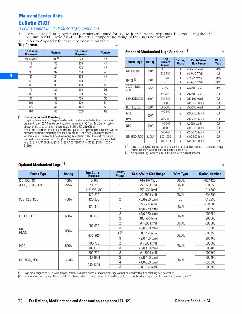
Main and Feeder Units
2
3
5
6
Bulletin 2193F3-Pole Feeder Circuit Breaker (FCB), continued• CENTERLINE 2100 motor control centers are rated for use with 75° C wires. Wire must be sized using the 75° C
column in NEC Table 310-16. The actual temperature rating of the lug is not relevant.• Refer to Appendix for wire size conversion table.Trip Current 94
Trip Current(Amperes) Number Trip Current
(Amperes) Number
(No breaker) 00 [1]
[1] Provision for Field MountingSingle or dual mounted plug-in feeder units may be selected without the circuit breaker in the 150A frame size only. Add the number 00 from Trip Current table above to the base catalog number (e.g., 2193F-AKC-3500CB or 2193F-BKC-4100CB). Mounting hardware, space, and operating mechanism will be provided for future mounting of circuit breaker(s). For a single mounted feeder without circuit breaker but field mounting selected instead, the unit cost is $310. For dual mounted units, add the $310 for any field mounting provisions selected (e.g., 2193F-AKC-00CM is $310; 2193F-AKC-3900CM is $1380; $310 + 1070 = $1380).
175 43
15 30 200 4420 31 225 4530 32 250 4640 34 300 4850 35 350 4960 36 400 5070 37 500 5180 38 600 5290 39 700 53
100 40 800 54125 41 1000 55150 42 1200 56
Standard Mechanical Lugs Supplied [1] 95
[1] Lugs are designed for use with breaker frame. Standard crimp or mechanical lugs cannot be used without special lug pad assembly.
Frame Type RatingTrip
Current (Amperes)
Cables/Phase
Cable/WireSize Range
WireType
I3C, I6C, I0C 150A15-100 1 #14-#1/0 AWG CU/AL
CU125-150 1 #4-#4/0 AWG
I3C-CL [2]
[2] No optional lugs available for I3C frame with current limiters.
150A15-70 1 #14-#2 AWG CU/AL
80-150 1 #1-#4/0 AWG CU/ALJD3D, JD6D, JD0D 225A 70-225 1 #4-350 kcmil CU/AL
K3D, K6D, K0D 400A125-225 1 #3-350 kcmil CU250-350 1 250-500 kcmil CU
400 2 #3/0-250 kcmil CULD, HLD, LDC 600A 300-600 2 250-350 kcmil CU
MDL800A
400-600 2 #2/0-500 kcmil CU
HMDL 700-800 3 #3/0-300 kcmil CU
NDC 800A400-700 2 #2-500 kcmil CU
800 3 #3/0-500 kcmil CU
ND, HND, NDC 1200A600-700 2 #2/0-500 kcmil CU
800-1000 3 #3/0-500 kcmil CU1100-1200 4 #4/0-400 kcmil CU
Optional Mechanical Lugs [1] 96
Frame Type Rating Trip Current(Amperes)
Cables/ Phase Cable/Wire Size Range Wire Type Option Number
I3C, I6C, I0C 150A 15-100 1 #4-#4/0 AWG CU/AL -80A4X0JD3D, JD6D, JD0D 225A 70-225 1 #4-350 kcmil CU/AL -80A350
K3D, K6D, K0D 400A
125-225, 400 1 250-500 kcmil CU -81A500125-225 1 #3-350 kcmil CU/AL -80A350125-350 2 #3/0-250 kcmil CU -81B250
125-4001 250-500 kcmil
CU/AL-80A500
2 #3/0-250 kcmil -80B250
LD, HLD, LDC 600A 300-6002 #3/0-350 kcmil
CU/AL-80B350
2 400-500 kcmil -80B500
MDLHMDL 800A
400-6002 #1-500 kcmil CU/AL -80B5003 #3/0-300 kcmil CU -81C300
400- 800 2 [2] 500-750 kcmilCU/AL
-80B7503 #3/0-400 kcmil -80C400
NDC 800A400-700 2 #1-500 kcmil
CU/AL-80B500
400-800 3 #3/0-400 kcmil -80C400
ND, HND, NDC 1200A
600-700 2 #1-500 kcmil
CU/AL
-80B500600-1000 3 #3/0-400 kcmil -80C400
600-12004 #4/0-500 kcmil -80D5003 500-750 kcmil -80C750
[1] Lugs are designed for use with breaker frame. Standard crimp or mechanical lugs cannot be used without special lug pad assembly.[2] Requires top entry and pullbox for 600-750 kcmil cables in order to meet UL and NEC/UL/cUL wire bending requirements. Select pullbox on page 28.
76 For Options, Modifications and Accessories, see pages 107–123 Discount Schedule A6

2
3
5
6
Main and Feeder Units
Bulletin 2193M3-Pole Main Circuit Breaker (MCB)
• See page 61 for product description.• See Appendix for circuit breaker characteristics.• Select circuit breaker frame and trip size based upon 125% of actual load amperes. Continuous current rating based
on 40° C ambient. Refer to NEC/CEC.• Mains are suitable for use as service entrance per NEC (UL) and CEC (CSA). If application is a four-wire system, a
neutral plate rated for 280A is available, refer to page 25, 105, 117 and 214. If a neutral greater then 280A is required, see page 25 or 117 or contact your local Rockwell Automation Sales Office. Mains rated 1000A and above may require ground fault protection. Refer to NEC/UL/cUL.
• Main Breakers supplied with internal ground fault protection (Breaker Code CTG, CMG or CXG) are supplied with a neutral CT for use on a 3 Phase, 4 Wire, Solidly Grounded “WYE” System. Circuit breakers with internal ground fault protection are not designed for use on a Delta System, Ungrounded “WYE” System or Impedance Grounded “WYE” System.
• Mains units are frame mounted. They must be located at the top or bottom of the section.2193MT—Top-mounted main, 150A-2000A are top-fed.2193MB—Bottom-mounted main, 150A-400A are top-fed.2193MB—Bottom-mounted main, 600A-2000A are reverse-fed.
• Top- and bottom-mounted mains are designed with adequate space to route cables to lugs. Special consideration may need to be given to the mounting of the CT’s for a metering device. Addition of a pull box might be considered.
• Includes line terminal guard for JD, K, L, M, N, and R frame circuit breaker units.97
Frame Range of Available
Trips (Amperes)
Interrupting Capacity Ratings
(rms symmetrical amperes) SpaceFactor
Catalog Number [1]
Wiring Type A Only—Class I
[1] The catalog numbers listed are not complete:• Insert T for top mounted or B for bottom mounted (e.g., 2193MT- or 2193MB-).• Select trip current from table on page 79 (e.g., 2193MB-AKC-40CB).• If optional line lugs will be selected, select from Optional Mechanical and Crimp Lugs tables on page 80.• Then add option number to base catalog number (e.g., 2193MB-AKC-40CB-80A4X0).
Delivery Program
Rating (Ampere) Type 208V/240V 380V/400V
415V/480V 600V NEMA Type 1 and Type 1 w/ gasket NEMA Type 12
150A[2]
I3C15-100
65k 35k 18k
1.5
2193M_-AKC-_CB 2193M_-AJC-_CB
SC-II
I6C 100k 65k 25k 2193M_-AKC-_CM 2193M_-AJC-_CM
I0C 15-50
100k 100k 35k 2193M_-AKC-_CX 2193M_-AJC-_CX60-100
I3C-CL15-50
100k 100k 100k 2193M_-AKC-_CD 2193M_-AJC-_CD60-100
I3C
125-150
65k 35k 18k 2193M_-BKC-_CB 2193M_-BJC-_CBI6C 100k 65k 25k 2193M_-BKC-_CM 2193M_-BJC-_CMI0C 100k 100k 35k 2193M_-BKC-_CX 2193M_-BJC-_CXI3C-CL 100k 100k 100k 2193M_-BKC-_CD 2193M_-BJC-_CD
225AJD3D [2]
[2] Non-interchangeable trip breakers.
70, 90-225
65k 35k 18k 2193M_-CKC-_CT 2193M_-CJC-_CT
JD6D 100k 65k 25k 2193M_-CKC-_CM 2193M_-CJC-_CMJD0D 100k 100k 35k 2193M_-CKC-_CX 2193M_-CJC-_CX
400AK3D
125- 40065k 35k 25k
2.0
2193M_-DKC-_CT 2193M_-DJC-_CTK6D 100k 65k 35k 2193M_-DKC-_CM 2193M_-DJC-_CMK0D 100k 100k 65k 2193M_-DKC-_CX 2193M_-DJC-_CX
600A
LD [3]
[3] Units having 100% rating are available for these circuit breakers for NEMA Type 1 and Type 1 with gasket only. See options on page 122 to select.
300-600 [4]
[4] Sealed breaker and Digitrip RMS 310 electronic trip with interchangeable trip plugs.
65k 35k 25k 2193M_-EKC-_CT 2193M_-EJC-_CT
LDG [3],[5]
[5] Ground fault protection system is suited for solidly grounded system. Ground fault trip range is adjustable from 0.2 to 1 times the trip current rating of the circuit breaker rating plug. Time delay setting can be adjusted from 0.05 to 0.5 seconds. Neutral current transformer shipped loose except when option 88HN or 88FN is specified.
65k 35k 25k 2193M_-EKC-_CTG 2193M_-EJC-_CTG
HLD [3] 100k 65k 35k 2193M_-EKC-_CM 2193M_-EJC-_CM
HLDG [3],[5] 100k 65k 35k 2193M_-EKC-_CMG 2193M_-EJC-_CMG
LDC [3] 100k 100k 50k 2193M_-EKC-_CX 2193M_-EJC-_CX
LDCG [3],[5] 100k 100k 50k 2193M_-EKC-_CXG 2193M_-EJC-_CXG
LD HI-MAG [6]
[6] NOT UL listed. Internal auxiliary contacts (98X, 99X) are not available on this breaker. Unit supplied with molded case switch with fixed high magnetic trip. Requires upstream current limiting branch protection. See molded case switch markings for proper selection of this protection. Ratings listed are the maximum fault currents that can be applied to the devices.
600 65k 35k 25k 2193M_-EKC-52CN 2193M_-EJC-52CN
77For Options, Modifications and Accessories, see pages 107–123Discount Schedule A6
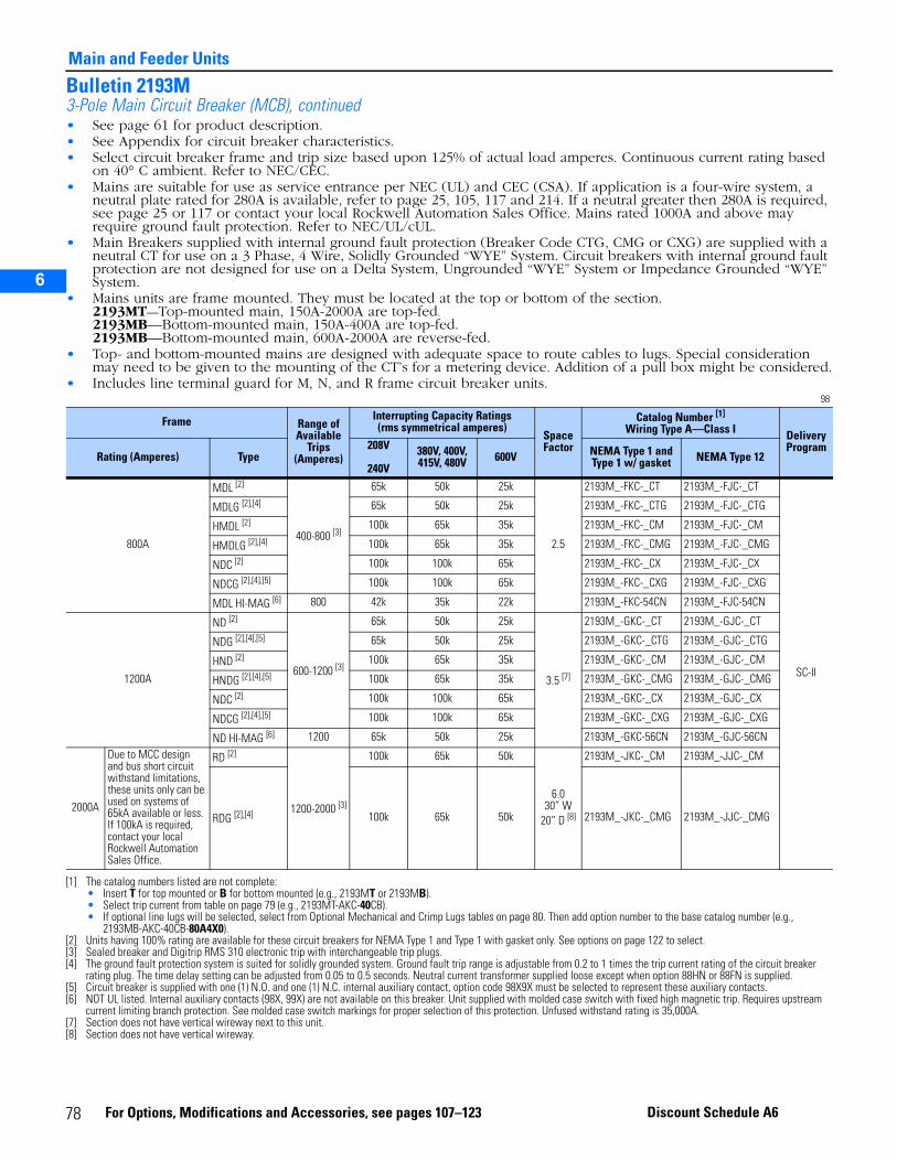
2
3
5
6
Main and Feeder Units
Bulletin 2193M3-Pole Main Circuit Breaker (MCB), continued• See page 61 for product description.• See Appendix for circuit breaker characteristics.• Select circuit breaker frame and trip size based upon 125% of actual load amperes. Continuous current rating based
on 40° C ambient. Refer to NEC/CEC.• Mains are suitable for use as service entrance per NEC (UL) and CEC (CSA). If application is a four-wire system, a
neutral plate rated for 280A is available, refer to page 25, 105, 117 and 214. If a neutral greater then 280A is required, see page 25 or 117 or contact your local Rockwell Automation Sales Office. Mains rated 1000A and above may require ground fault protection. Refer to NEC/UL/cUL.
• Main Breakers supplied with internal ground fault protection (Breaker Code CTG, CMG or CXG) are supplied with a neutral CT for use on a 3 Phase, 4 Wire, Solidly Grounded “WYE” System. Circuit breakers with internal ground fault protection are not designed for use on a Delta System, Ungrounded “WYE” System or Impedance Grounded “WYE” System.
• Mains units are frame mounted. They must be located at the top or bottom of the section.2193MT—Top-mounted main, 150A-2000A are top-fed.2193MB—Bottom-mounted main, 150A-400A are top-fed.2193MB—Bottom-mounted main, 600A-2000A are reverse-fed.
• Top- and bottom-mounted mains are designed with adequate space to route cables to lugs. Special consideration may need to be given to the mounting of the CT’s for a metering device. Addition of a pull box might be considered.
• Includes line terminal guard for M, N, and R frame circuit breaker units. 98
Frame Range of Available
Trips (Amperes)
Interrupting Capacity Ratings(rms symmetrical amperes)
SpaceFactor
Catalog Number [1]
Wiring Type A—Class I
[1] The catalog numbers listed are not complete:• Insert T for top mounted or B for bottom mounted (e.g., 2193MT or 2193MB).• Select trip current from table on page 79 (e.g., 2193MT-AKC-40CB).• If optional line lugs will be selected, select from Optional Mechanical and Crimp Lugs tables on page 80. Then add option number to the base catalog number (e.g.,
2193MB-AKC-40CB-80A4X0).
Delivery Program
Rating (Amperes) Type208V
240V380V, 400V, 415V, 480V 600V NEMA Type 1 and
Type 1 w/ gasket NEMA Type 12
800A
MDL [2]
[2] Units having 100% rating are available for these circuit breakers for NEMA Type 1 and Type 1 with gasket only. See options on page 122 to select.
400-800 [3]
[3] Sealed breaker and Digitrip RMS 310 electronic trip with interchangeable trip plugs.
65k 50k 25k
2.5
2193M_-FKC-_CT 2193M_-FJC-_CT
SC-II
MDLG [2],[4]
[4] The ground fault protection system is suited for solidly grounded system. Ground fault trip range is adjustable from 0.2 to 1 times the trip current rating of the circuit breaker rating plug. The time delay setting can be adjusted from 0.05 to 0.5 seconds. Neutral current transformer supplied loose except when option 88HN or 88FN is supplied.
65k 50k 25k 2193M_-FKC-_CTG 2193M_-FJC-_CTG
HMDL [2] 100k 65k 35k 2193M_-FKC-_CM 2193M_-FJC-_CM
HMDLG [2],[4] 100k 65k 35k 2193M_-FKC-_CMG 2193M_-FJC-_CMG
NDC [2] 100k 100k 65k 2193M_-FKC-_CX 2193M_-FJC-_CX
NDCG [2],[4],[5]
[5] Circuit breaker is supplied with one (1) N.O. and one (1) N.C. internal auxiliary contact, option code 98X9X must be selected to represent these auxiliary contacts.
100k 100k 65k 2193M_-FKC-_CXG 2193M_-FJC-_CXG
MDL HI-MAG [6]
[6] NOT UL listed. Internal auxiliary contacts (98X, 99X) are not available on this breaker. Unit supplied with molded case switch with fixed high magnetic trip. Requires upstream current limiting branch protection. See molded case switch markings for proper selection of this protection. Unfused withstand rating is 35,000A.
800 42k 35k 22k 2193M_-FKC-54CN 2193M_-FJC-54CN
1200A
ND [2]
600-1200 [3]
65k 50k 25k
3.5 [7]
[7] Section does not have vertical wireway next to this unit.
2193M_-GKC-_CT 2193M_-GJC-_CT
NDG [2],[4],[5] 65k 50k 25k 2193M_-GKC-_CTG 2193M_-GJC-_CTG
HND [2] 100k 65k 35k 2193M_-GKC-_CM 2193M_-GJC-_CM
HNDG [2],[4],[5] 100k 65k 35k 2193M_-GKC-_CMG 2193M_-GJC-_CMG
NDC [2] 100k 100k 65k 2193M_-GKC-_CX 2193M_-GJC-_CX
NDCG [2],[4],[5] 100k 100k 65k 2193M_-GKC-_CXG 2193M_-GJC-_CXG
ND HI-MAG [6] 1200 65k 50k 25k 2193M_-GKC-56CN 2193M_-GJC-56CN
2000A
Due to MCC design and bus short circuit withstand limitations, these units only can be used on systems of 65kA available or less. If 100kA is required, contact your local Rockwell Automation Sales Office.
RD [2]
1200-2000 [3]
100k 65k 50k
6.030” W
20” D [8]
[8] Section does not have vertical wireway.
2193M_-JKC-_CM 2193M_-JJC-_CM
RDG [2],[4] 100k 65k 50k 2193M_-JKC-_CMG 2193M_-JJC-_CMG
78 For Options, Modifications and Accessories, see pages 107–123 Discount Schedule A6
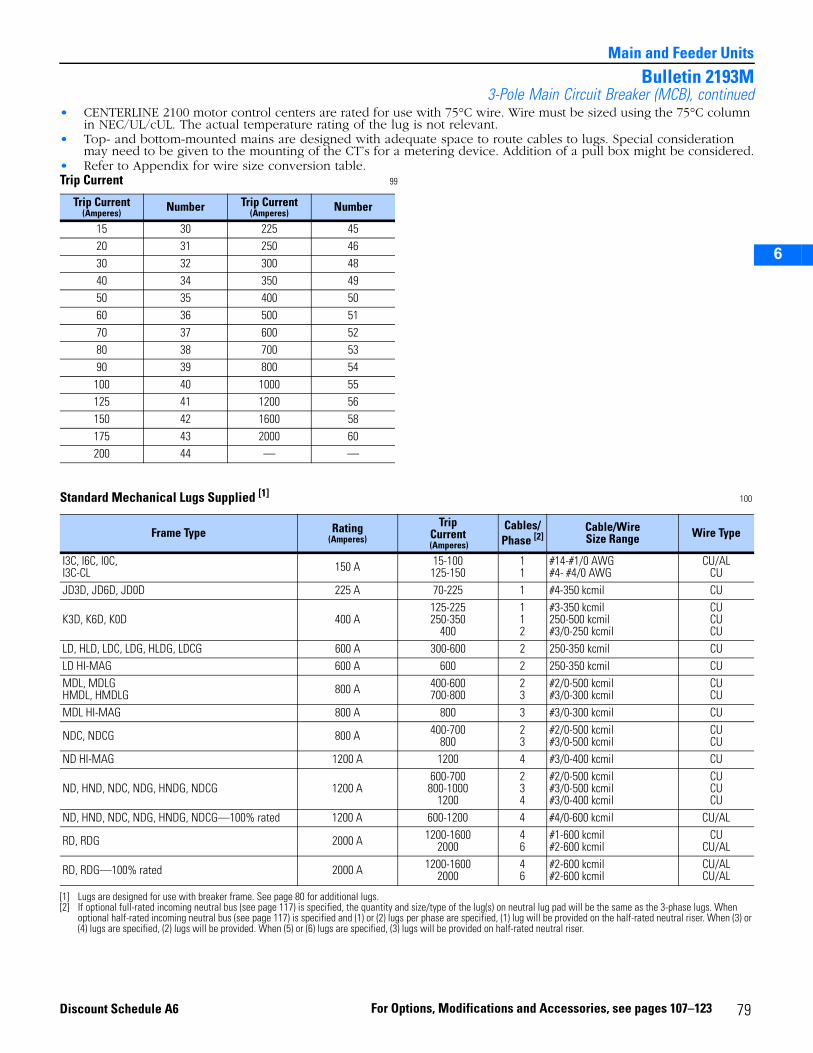
2
3
5
6
Main and Feeder Units
Bulletin 2193M3-Pole Main Circuit Breaker (MCB), continued
• CENTERLINE 2100 motor control centers are rated for use with 75°C wire. Wire must be sized using the 75°C column in NEC/UL/cUL. The actual temperature rating of the lug is not relevant.
• Top- and bottom-mounted mains are designed with adequate space to route cables to lugs. Special consideration may need to be given to the mounting of the CT’s for a metering device. Addition of a pull box might be considered.
• Refer to Appendix for wire size conversion table.Trip Current 99
Trip Current(Amperes) Number Trip Current
(Amperes) Number
15 30 225 4520 31 250 4630 32 300 4840 34 350 4950 35 400 5060 36 500 5170 37 600 5280 38 700 5390 39 800 54100 40 1000 55125 41 1200 56150 42 1600 58175 43 2000 60200 44 — —
Standard Mechanical Lugs Supplied [1] 100
[1] Lugs are designed for use with breaker frame. See page 80 for additional lugs.
Frame Type Rating(Amperes)
TripCurrent
(Amperes)
Cables/Phase [2]
[2] If optional full-rated incoming neutral bus (see page 117) is specified, the quantity and size/type of the lug(s) on neutral lug pad will be the same as the 3-phase lugs. When optional half-rated incoming neutral bus (see page 117) is specified and (1) or (2) lugs per phase are specified, (1) lug will be provided on the half-rated neutral riser. When (3) or (4) lugs are specified, (2) lugs will be provided. When (5) or (6) lugs are specified, (3) lugs will be provided on half-rated neutral riser.
Cable/Wire Size Range Wire Type
I3C, I6C, I0C,I3C-CL 150 A 15-100
125-15011
#14-#1/0 AWG#4- #4/0 AWG
CU/ALCU
JD3D, JD6D, JD0D 225 A 70-225 1 #4-350 kcmil CU
K3D, K6D, K0D 400 A125-225250-350
400
112
#3-350 kcmil250-500 kcmil#3/0-250 kcmil
CUCUCU
LD, HLD, LDC, LDG, HLDG, LDCG 600 A 300-600 2 250-350 kcmil CULD HI-MAG 600 A 600 2 250-350 kcmil CUMDL, MDLGHMDL, HMDLG 800 A 400-600
700-80023
#2/0-500 kcmil#3/0-300 kcmil
CUCU
MDL HI-MAG 800 A 800 3 #3/0-300 kcmil CU
NDC, NDCG 800 A 400-700800
23
#2/0-500 kcmil#3/0-500 kcmil
CUCU
ND HI-MAG 1200 A 1200 4 #3/0-400 kcmil CU
ND, HND, NDC, NDG, HNDG, NDCG 1200 A600-700800-1000
1200
234
#2/0-500 kcmil#3/0-500 kcmil#3/0-400 kcmil
CUCUCU
ND, HND, NDC, NDG, HNDG, NDCG—100% rated 1200 A 600-1200 4 #4/0-600 kcmil CU/AL
RD, RDG 2000 A 1200-16002000
46
#1-600 kcmil#2-600 kcmil
CUCU/AL
RD, RDG—100% rated 2000 A 1200-16002000
46
#2-600 kcmil#2-600 kcmil
CU/ALCU/AL
79For Options, Modifications and Accessories, see pages 107–123Discount Schedule A6
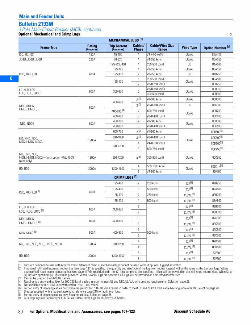
2
3
5
6
Main and Feeder Units
Bulletin 2193M3-Pole Main Circuit Breaker (MCB), continuedOptional Mechanical and Crimp Lugs 101
MECHANICAL LUGS [1]
[1] Lugs are designed for use with breaker frame. Standard crimp or mechanical lugs cannot be used without optional lug pad assembly.
Frame Type Rating(Amperes)
Trip Current (Amperes)
Cables/ Phase
Cable/Wire Size Range Wire Type Option Number [2]
[2] If optional full-rated incoming neutral bus (see page 117) is specified, the quantity and size/type of the lug(s) on neutral lug pad will be the same as the 3-phase lugs. When optional half-rated incoming neutral bus (see page 117) is specified and (1) or (2) lugs per phase are specified, (1) lug will be provided on the half-rated neutral riser. When (3) or (4) lugs are specified, (2) lugs will be provided. When (5) or (6) lugs are specified, (3) lugs will be provided on half-rated neutral riser.
I3C, I6C, I0C 150A 15-100 1 #4-#4/0 AWG CU/AL 80A4X0
JD3D, JD6D, JD0D 225A 70-225 1 #4-350 kcmil CU/AL 80A350
K3D, K6D, K0D 400A
125-225, 400 1 250-500 kcmil CU 81A500
125-225 1 #3-350 kcmil CU/AL 80A350
125-350 2 #3-250 kcmil CU 81B250
125-4001 250-500 kcmil
CU/AL80A500
2 #3/0-250 kcmil 80B250
LD, HLD, LDCLDG, HLDG, LDCG 600A 300-600 2
#3/0-350 kcmilCU/AL
80B350
400-500 kcmil 80B500
MDL, MDLGHMDL, HMDLG 800A
400-6002 [3]
[3] Cannot be used on the HI-MAG frames.
#1-500 kcmil CU/AL 80B500
3 [3] #3/0-300 kcmil CU 81C300
400-800 [4]
[4] Requires top entry and pullbox for 600-750 kcmil cables in order to meet UL and NEC/UL/cUL wire bending requirements. Select on page 28.
2 500-750 kcmilCU/AL
80B750
400-800 3 #3/0-400 kcmil 80C400
NDC, NDCG 800A400-700 2 #1-500 kcmil
CU/AL80B500
400-800 3 #3/0-400 kcmil 80C400
ND, HND, NDC,NDG, HNDG, NDCG 1200A
600-700 2 [3] #1-500 kcmil
CU/AL
80B500[5]
600-1000 3 [3] #3/0-400 kcmil 80C400[5]
600-12004 #4/0-500 kcmil 80D500[5]
3 500-750 kcmil 80C750[5]
[5] Not available with 2193M units with option -755 (100% rated)
ND, HND, NDC,NDG, HNDG, NDCG—(with option -755, 100% rated only)
1200A 600-1200 3 [6]
[6] For top entry of incoming cables only. Requires pullbox for 750-800 kcmil cables in order to meet UL and NEC/UL/cUL cable bending requirements. Select on page 28.
350-800 kcmil CU/AL 80C800
RD, RDG 2000A 1200-16004 500-1000 kcmil
CU/AL80D01K[5]
6 #2-600 kcmil 80F600
CRIMP LUGS [7]
[7] Breaker supplied with a lug pad assembly, reference page 215 for additional lugs.
K3D, K6D, K0D [8]
[8] For top entry of incoming cables only. Requires pullbox. Select on page 28.
400A
125-400 2 250 kcmil CU [9]
[9] CU crimp lugs are Panduit type LCC Series. CU/AL crimp lugs are Burndy YA-A Series.
82B250
125-400 1 500 kcmil CU [9] 82A500
125-400 2 250 kcmil CU/AL [9] 83B250
125-400 1 500 kcmil CU/AL [9] 83A500
LD, HLD, LDCLDG, HLDG, LDCG [8] 600A 300-600
2
500 kcmil
CU [9] 82B500
2 CU/AL [9] 83B500
MDL, MDLGHMDL, HMDLG [8] 800A 400-800
3 CU [9] 82C500
3 CU/AL [9] 83C500
NDC, NDCG [8] 800A 400-8003 CU [9] 82C500
3 CU/AL [9] 83C500
ND, HND, NDC, NDG, HNDG, NDCG 1200A 600-12004 CU [9] 82D500
4 CU/AL [9] 83D500
RD, RDG 2000A 1200-20006 CU [9] 82F500
6 CU/AL [9] 83F500
80 For Options, Modifications and Accessories, see pages 107–123 Discount Schedule A6
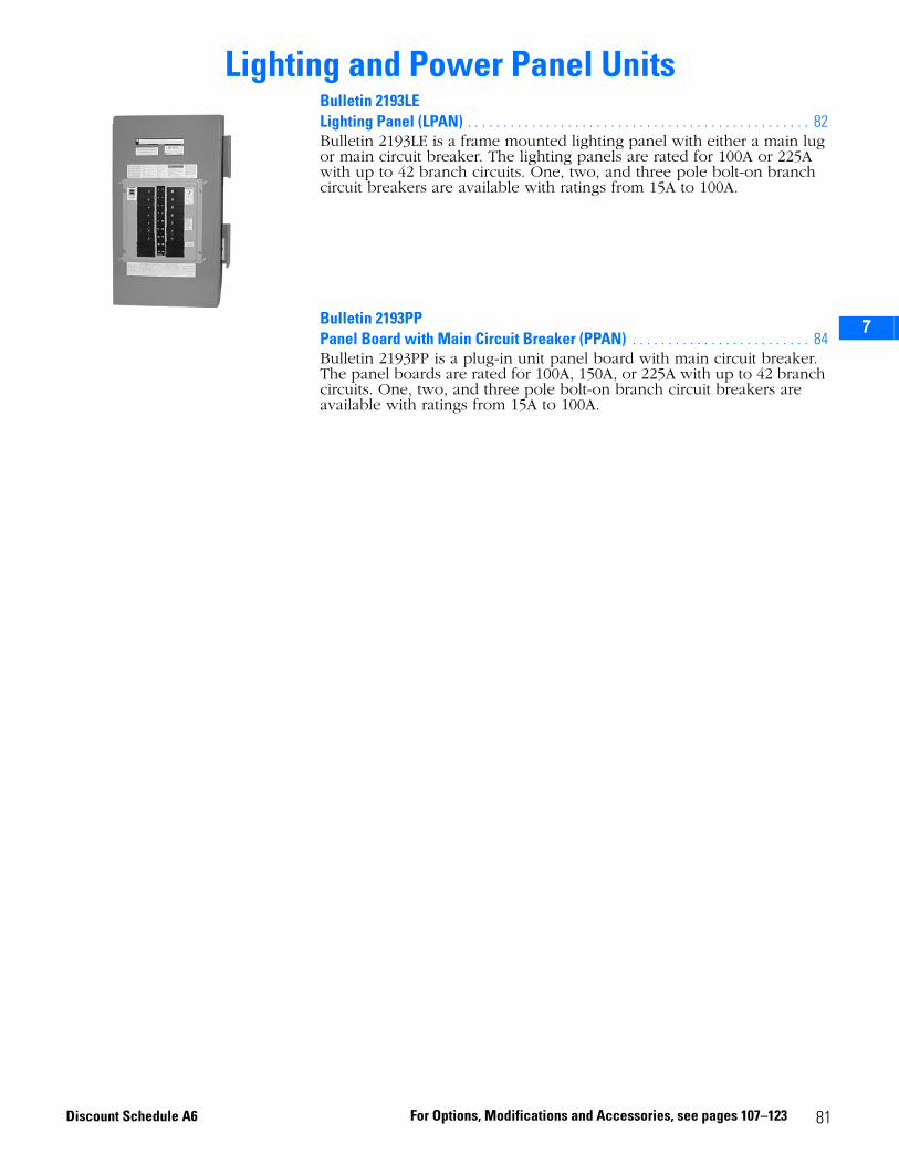
2
3
5
6
7
Lighting and Power Panel UnitsBulletin 2193LE Lighting Panel (LPAN) . . . . . . . . . . . . . . . . . . . . . . . . . . . . . . . . . . . . . . . . . . . . . . . . 82Bulletin 2193LE is a frame mounted lighting panel with either a main lug or main circuit breaker. The lighting panels are rated for 100A or 225A with up to 42 branch circuits. One, two, and three pole bolt-on branch circuit breakers are available with ratings from 15A to 100A.
Bulletin 2193PPPanel Board with Main Circuit Breaker (PPAN) . . . . . . . . . . . . . . . . . . . . . . . . . 84Bulletin 2193PP is a plug-in unit panel board with main circuit breaker. The panel boards are rated for 100A, 150A, or 225A with up to 42 branch circuits. One, two, and three pole bolt-on branch circuit breakers are available with ratings from 15A to 100A.
81For Options, Modifications and Accessories, see pages 107–123Discount Schedule A6
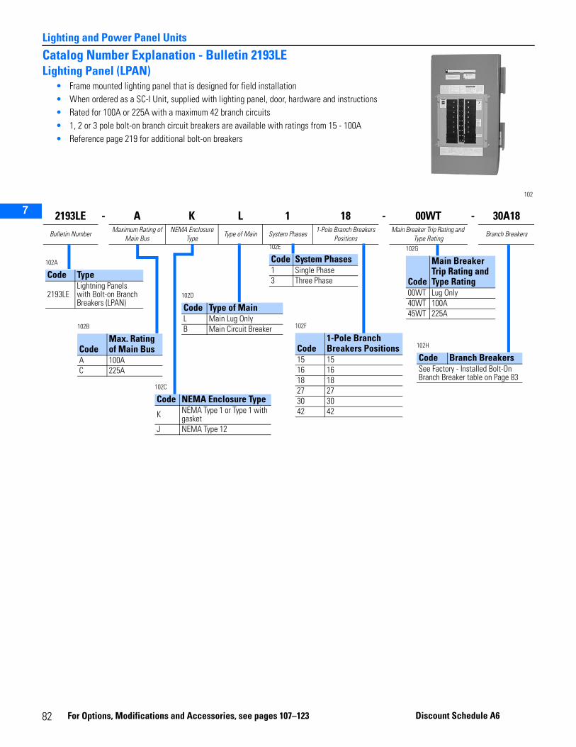
Lighting and Power Panel Units
2
3
5
6
7
Catalog Number Explanation - Bulletin 2193LELighting Panel (LPAN)
• Frame mounted lighting panel that is designed for field installation• When ordered as a SC-I Unit, supplied with lighting panel, door, hardware and instructions• Rated for 100A or 225A with a maximum 42 branch circuits• 1, 2 or 3 pole bolt-on branch circuit breakers are available with ratings from 15 - 100A• Reference page 219 for additional bolt-on breakers
102
2193LE - A K L 1 18 - 00WT - 30A18Bulletin Number
Maximum Rating of Main Bus
NEMA Enclosure Type
Type of Main System Phases1-Pole Branch Breakers
PositionsMain Breaker Trip Rating and
Type RatingBranch Breakers
102A
Code Type
2193LELightning Panels with Bolt-on Branch Breakers (LPAN)
102C
Code NEMA Enclosure Type
K NEMA Type 1 or Type 1 with gasket
J NEMA Type 12
102B
CodeMax. Rating of Main Bus
A 100AC 225A
102D
Code Type of MainL Main Lug OnlyB Main Circuit Breaker
102E
Code System Phases1 Single Phase3 Three Phase
102F
Code1-Pole Branch Breakers Positions
15 1516 1618 1827 2730 3042 42
102G
Code
Main Breaker Trip Rating and Type Rating
00WT Lug Only40WT 100A45WT 225A
102H
Code Branch BreakersSee Factory - Installed Bolt-On Branch Breaker table on Page 83
82 F
or Options, Modifica tions a nd Accessories, see pa ges 10 7–123 Discount Schedule A6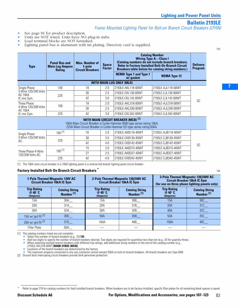
2
3
5
6
7
Lighting and Power Panel Units
Bulletin 2193LEFrame Mounted Lighting Panel for Bolt-on Branch Circuit Breakers (LPAN)
• See page 81 for product description.• Units are NOT wired. Units have NO plug-in stabs.• Load terminal blocks are NOT furnished.• Lighting panel bus is aluminum with tin plating. Directory card is supplied.
103
Factory-Installed Bolt-On Branch Circuit Breakers * 104
TypePanel Bus and
Main Lug AmpereRating
Max. Number of 1-pole
Circuit BreakersSpace Factor
Catalog NumberWiring Type A—Class I
(Catalog numbers do not include branch breakers. Refer to Factory-Installed Bolt-On Branch Circuit
Breakers table below for catalog string numbers.)Delivery Program
NEMA Type 1 and Type 1 w/ gasket NEMA Type 12
WITH MAIN LUG ONLY (MLO)Single Phase 3-Wire 120/240 Volts AC 10kAIC rms Sym.
100 18 2.0 2193LE-AKL118-00WT 2193LE-AJL118-00WT
SC225
30 2.5 2193LE-CKL130-00WT 2193LE-CJL130-00WT42 3.0 2193LE-CKL142-00WT 2193LE-CJL142-00WT
Three Phase4-Wire 120/208 Volts AC 10kAIC rms Sym.
10018 2.0 2193LE-AKL318-00WT 2193LE-AJL318-00WT30 2.5 2193LE-AKL330-00WT 2193LE-AJL330-00WT
225 42 3.0 2193LE-CKL342-00WT 2193LE-CJL342-00WT
WITH MAIN CIRCUIT BREAKER (MCB) [1]
100A Main Circuit Breaker is Cutler-Hammer BAB type series rating 10kA. 225A Main Circuit Breaker is Cutler-Hammer ED type series rating 65kA.
[1] The 100A main circuit breaker in a 100A lighting panel is a reverse-fed branch lighting panel circuit breaker.
Single Phase 3-Wire 120/240 Volts AC.
100 [1] 16 2.0 2193LE-AKB116-40WT 2193LE-AJB116-40WT
SC225
30 3.5 2193LE-CKB130-45WT 2193LE-CJB130-45WT42 4.0 2193LE-CKB142-45WT 2193LE-CJB142-45WT
Three Phase 4-Wire 120/208 Volts AC.
100 [1] 15 2.0 2193LE-AKB315-40WT 2193LE-AJB315-40WT27 2.5 2193LE-AKB327-40WT 2193LE-AJB327-40WT
225 42 4.0 2193LE-CKB342-45WT 2193LE-CJB342-45WT
1-Pole Thermal Magnetic 120V ACCircuit Breaker 10kA IC Sym
2-Pole Thermal Magnetic 120/240V ACCircuit Breaker 10kA IC Sym
3-Pole Thermal Magnetic 120/240V ACCircuit Breaker 10kA IC Sym
(for use on three phase lighting panels only)Trip Rating
@ 40° C(Amperes)
Catalog StringNumber [1]
[1] The catalog numbers listed are not complete:• Select the number of branch breakers (e.g., 32A18).• Add two digits to specify the number of branch breakers desired. Two digits are required for quantities less than ten (e.g., 03 for quantity three).• When selecting multiple branch breakers with different trip ratings, add additional string numbers to the end of the catalog number (e.g.,
2193LE-AKL318-00WT-30A08-31B02-30C02).• Locations of the branch breakers are determined by the factory.• The maximum amperes connected to any one connector cannot exceed 200A on bolt-on branch breakers. All branch breakers are Type BAB.
Trip Rating @ 40° C(Amperes)
Catalog StringNumber [1]
Trip Rating @ 40° C(Amperes)
Catalog StringNumber [1]
15A 30A__ 15A 30B__ 15A 30C__20A 31A__ 20A 31B__ 20A 31C__30A 32A__ 30A 32B__ 30A 32C__
15A w/ grd flt [2]
[2] Ground fault interrupting circuit breakers provide 5mA personnel protection.
30D__ 50A 35B__ 50A 35C__
20A w/ grd flt [2] 31D__ 100A 40B__ 100A 40C__
Filler Plate 00A__ — — — —
* Refer to page 219 for catalog numbers for field installed branch breakers. When breakers are to be factory-installed, specify filler plates for all remaining blank spaces in panel.
83For Options, Modifications and Accessories, see pages 107–123Discount Schedule A6
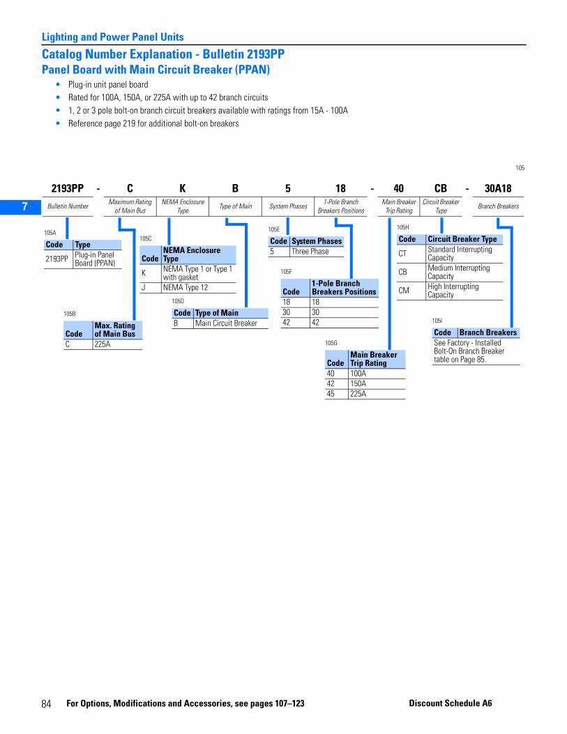
Lighting and Power Panel Units
2
3
5
6
7
Catalog Number Explanation - Bulletin 2193PPPanel Board with Main Circuit Breaker (PPAN)
• Plug-in unit panel board• Rated for 100A, 150A, or 225A with up to 42 branch circuits• 1, 2 or 3 pole bolt-on branch circuit breakers available with ratings from 15A - 100A• Reference page 219 for additional bolt-on breakers
105
2193PP - C K B 5 18 - 40 CB - 30A18Bulletin Number
Maximum Rating of Main Bus
NEMA Enclosure Type
Type of Main System Phases1-Pole Branch
Breakers PositionsMain Breaker
Trip RatingCircuit Breaker
TypeBranch Breakers
105A
Code Type
2193PP Plug-in Panel Board (PPAN)
105C
CodeNEMA Enclosure Type
K NEMA Type 1 or Type 1 with gasket
J NEMA Type 12
105B
CodeMax. Rating of Main Bus
C 225A
105D
Code Type of MainB Main Circuit Breaker
105E
Code System Phases5 Three Phase
105F
Code1-Pole Branch Breakers Positions
18 1830 3042 42
105G
CodeMain Breaker Trip Rating
40 100A42 150A45 225A
105I
Code Branch BreakersSee Factory - Installed Bolt-On Branch Breaker table on Page 85.
105H
Code Circuit Breaker Type
CT Standard Interrupting Capacity
CB Medium Interrupting Capacity
CM High Interrupting Capacity
84
For Options, Modi fications and Accessories, see pag es 107–123 Discount Schedule A6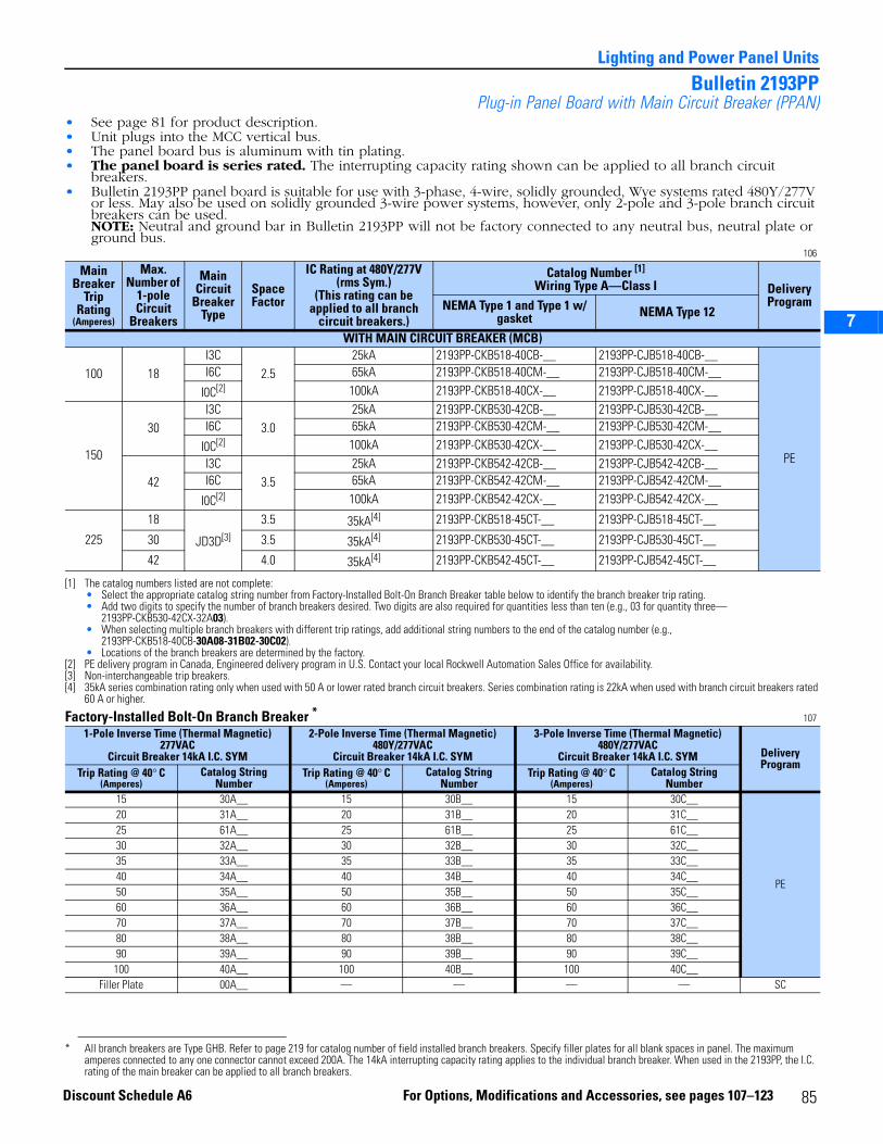
2
3
5
6
7
Lighting and Power Panel Units
Bulletin 2193PPPlug-in Panel Board with Main Circuit Breaker (PPAN)
• See page 81 for product description.• Unit plugs into the MCC vertical bus.• The panel board bus is aluminum with tin plating.• The panel board is series rated. The interrupting capacity rating shown can be applied to all branch circuit
breakers.• Bulletin 2193PP panel board is suitable for use with 3-phase, 4-wire, solidly grounded, Wye systems rated 480Y/277V
or less. May also be used on solidly grounded 3-wire power systems, however, only 2-pole and 3-pole branch circuit breakers can be used.NOTE: Neutral and ground bar in Bulletin 2193PP will not be factory connected to any neutral bus, neutral plate or ground bus.
106
Factory-Installed Bolt-On Branch Breaker * 107
Main Breaker
Trip Rating
(Amperes)
Max.Number of
1-poleCircuit
Breakers
MainCircuit
Breaker Type
Space Factor
IC Rating at 480Y/277V (rms Sym.)
(This rating can be applied to all branch
circuit breakers.)
Catalog Number [1]
Wiring Type A—Class I
[1] The catalog numbers listed are not complete:• Select the appropriate catalog string number from Factory-Installed Bolt-On Branch Breaker table below to identify the branch breaker trip rating.• Add two digits to specify the number of branch breakers desired. Two digits are also required for quantities less than ten (e.g., 03 for quantity three—
2193PP-CKB530-42CX-32A03).• When selecting multiple branch breakers with different trip ratings, add additional string numbers to the end of the catalog number (e.g.,
2193PP-CKB518-40CB-30A08-31B02-30C02).• Locations of the branch breakers are determined by the factory.
Delivery ProgramNEMA Type 1 and Type 1 w/
gasket NEMA Type 12
WITH MAIN CIRCUIT BREAKER (MCB)
100 18I3C
2.525kA 2193PP-CKB518-40CB-__ 2193PP-CJB518-40CB-__
PE
I6C 65kA 2193PP-CKB518-40CM-__ 2193PP-CJB518-40CM-__
I0C[2]
[2] PE delivery program in Canada, Engineered delivery program in U.S. Contact your local Rockwell Automation Sales Office for availability.
100kA 2193PP-CKB518-40CX-__ 2193PP-CJB518-40CX-__
150
30I3C
3.025kA 2193PP-CKB530-42CB-__ 2193PP-CJB530-42CB-__
I6C 65kA 2193PP-CKB530-42CM-__ 2193PP-CJB530-42CM-__
I0C[2] 100kA 2193PP-CKB530-42CX-__ 2193PP-CJB530-42CX-__
42I3C
3.525kA 2193PP-CKB542-42CB-__ 2193PP-CJB542-42CB-__
I6C 65kA 2193PP-CKB542-42CM-__ 2193PP-CJB542-42CM-__
I0C[2] 100kA 2193PP-CKB542-42CX-__ 2193PP-CJB542-42CX-__
225
18
JD3D[3]
[3] Non-interchangeable trip breakers.
3.5 35kA[4]
[4] 35kA series combination rating only when used with 50 A or lower rated branch circuit breakers. Series combination rating is 22kA when used with branch circuit breakers rated 60 A or higher.
2193PP-CKB518-45CT-__ 2193PP-CJB518-45CT-__
30 3.5 35kA[4] 2193PP-CKB530-45CT-__ 2193PP-CJB530-45CT-__
42 4.0 35kA[4] 2193PP-CKB542-45CT-__ 2193PP-CJB542-45CT-__
1-Pole Inverse Time (Thermal Magnetic) 277VAC
Circuit Breaker 14kA I.C. SYM
2-Pole Inverse Time (Thermal Magnetic) 480Y/277VAC
Circuit Breaker 14kA I.C. SYM
3-Pole Inverse Time (Thermal Magnetic) 480Y/277VAC
Circuit Breaker 14kA I.C. SYM Delivery Program
Trip Rating @ 40° C(Amperes)
Catalog StringNumber
Trip Rating @ 40° C(Amperes)
Catalog StringNumber
Trip Rating @ 40° C(Amperes)
Catalog StringNumber
15 30A__ 15 30B__ 15 30C__
PE
20 31A__ 20 31B__ 20 31C__25 61A__ 25 61B__ 25 61C__30 32A__ 30 32B__ 30 32C__35 33A__ 35 33B__ 35 33C__40 34A__ 40 34B__ 40 34C__50 35A__ 50 35B__ 50 35C__60 36A__ 60 36B__ 60 36C__70 37A__ 70 37B__ 70 37C__80 38A__ 80 38B__ 80 38C__90 39A__ 90 39B__ 90 39C__100 40A__ 100 40B__ 100 40C__
Filler Plate 00A__ — — — — SC
* All branch breakers are Type GHB. Refer to page 219 for catalog number of field installed branch breakers. Specify filler plates for all blank spaces in panel. The maximum amperes connected to any one connector cannot exceed 200A. The 14kA interrupting capacity rating applies to the individual branch breaker. When used in the 2193PP, the I.C. rating of the main breaker can be applied to all branch breakers.
85For Options, Modifications and Accessories, see pages 107–123Discount Schedule A6

Lighting and Power Panel Units
2
3
5
6
7
86
2
3
5
6
7
8
Transformer UnitsBulletin 2195, 2196, 2197Control and Lighting Transformers (XFMR) . . . . . . . . . . . . . . . . . . . . . . . . . . . . . . 88Bulletins 2195, 2196, and 2197 are control and lighting transformer units. The transformer units are available with ratings from 0.5 kVA through 50 kVA for single-phase and 10 kVA through 45 kVA for three-phase. Secondary fuses are provided with each transformer unit. Factory installed primary fusing is optional on the 2196 transformer unit.
87For Options, Modifications and Accessories, see pages 107-123Discount Schedule A6
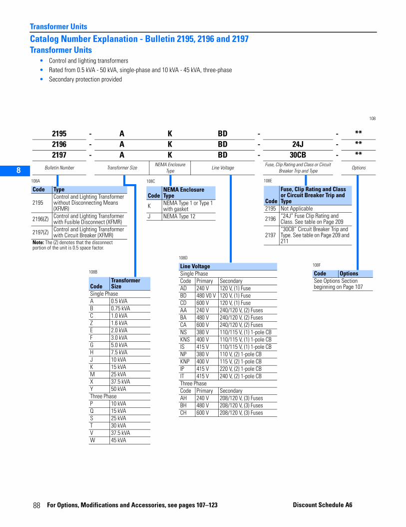
Transformer Units
2
3
5
6
7
8
Catalog Number Explanation - Bulletin 2195, 2196 and 2197Transformer Units
• Control and lighting transformers• Rated from 0.5 kVA - 50 kVA, single-phase and 10 kVA - 45 kVA, three-phase• Secondary protection provided
108
2195 - A K BD - - **2196 - A K BD - 24J - **2197 - A K BD - 30CB - **
Bulletin Number Transformer SizeNEMA Enclosure
TypeLine Voltage
Fuse, Clip Rating and Class or Circuit Breaker Trip and Type
Options
108D
Line VoltageSingle PhaseCode Primary SecondaryAD 240 V 120 V, (1) FuseBD 480 V0 V 120 V, (1) FuseCD 600 V 120 V, (1) FuseAA 240 V 240/120 V, (2) FusesBA 480 V 240/120 V, (2) FusesCA 600 V 240/120 V, (2) FusesNS 380 V 110/115 V, (1) 1-pole CBKNS 400 V 110/115 V, (1) 1-pole CBIS 415 V 110/115 V, (1) 1-pole CBNP 380 V 110 V, (2) 1-pole CBKNP 400 V 115 V, (2) 1-pole CBIP 415 V 220 V, (2) 1-pole CBIT 415 V 240 V, (2) 1-pole CBThree PhaseCode Primary SecondaryAH 240 V 208/120 V, (3) FusesBH 480 V 208/120 V, (3) FusesCH 600 V 208/120 V, (3) Fuses
108E
Code
Fuse, Clip Rating and Class or Circuit Breaker Trip and Type
2195 Not Applicable
2196 “24J” Fuse Clip Rating and Class. See table on Page 209
2197“30CB” Circuit Breaker Trip and Type. See table on Page 209 and 211
108F
Code OptionsSee Options Section beginning on Page 107
108C
CodeNEMA Enclosure Type
K NEMA Type 1 or Type 1 with gasket
J NEMA Type 12
108B
CodeTransformer Size
Single PhaseA 0.5 kVAB 0.75 kVAC 1.0 kVAZ 1.6 kVAE 2.0 kVAF 3.0 kVAG 5.0 kVAH 7.5 kVAJ 10 kVAK 15 kVAM 25 kVAX 37.5 kVAY 50 kVAThree PhaseP 10 kVAQ 15 kVAS 25 kVAT 30 kVAV 37.5 kVAW 45 kVA
108A
Code Type
2195Control and Lighting Transformer without Disconnecting Means (XFMR)
2196(Z) Control and Lighting Transformer with Fusible Disconnect (XFMR)
2197(Z) Control and Lighting Transformer with Circuit Breaker (XFMR)
Note: The (Z) denotes that the disconnect portion of the unit is 0.5 space factor.
88 For Options, M
odifications and Acc essories, se e pages 107–123 Disco unt Schedule A6
2
3
5
6
7
8
Transformer Units
Bulletin 2195Control and Lighting Transformer Unit without Disconnecting Means (XFMR)
See 87 for product description.NOTE: Do not mount transformer units below drive units. Heat from transformer units may cause drive to trip.NOTE: In order to address the heating effects from loads containing a high degree of harmonic content, it may
be necessary to oversize the field conductors (especially neutrals), use k-factor lighting transformers, and oversize the lighting contactor units (increase by 50%). Contact your local Rockwell Automation Sales Office.
NOTE: Tap arrangement for 15-50kVA single phase transformers is (2) 2-1/2% Taps FCAN, (4) 2-1/2% Taps FCBN. Tap arrangements for 10-45 kVA three phase transformers is (2) 2-1/ 2% Taps FCBN.
NOTE: Transformers have Class 180°C insulation, 80° C rise.For 71” high sections, see restrictions on page 24.
109
RatingkVA [1]
[1] In NEMA Type 12 applications (non-ventilated 3kVA and larger transformers), to maximize the transformer’s life, it is recommended that the transformer not be loaded to greater than 50% of its nameplate rating. Number in parentheses indicates approximate derated rating. However, in many applications, NEMA Type 1 with gasket design (vented and filtered doors) may be sufficient.
Recommended Primary Protection (Amperes)
Space Factor
Catalog Number [2]
Wiring Type A—Class I
[2] The catalog numbers listed are not complete. Select the primary voltage code from table on page 205 to identify the transformer primary voltage desired (e.g., 2195-FKBD).
Delivery Program
240 V 480 V 600 VNEMA Type 1 and Type
1 w/ gasket[3]
[3] For ratings 3kVA and larger, vented door is provided.
NEMA Type 1 with filters and Type 1 w/ gasket and filters [4]
[4] For ratings 3kVA and larger, vented and filtered door is provided. 3kVA and larger are available on NEMA Type 12 structures but unit still will be NEMA Type 1/1G with gasket and filters. See page 114 for option -16A.
NEMA Type 12 [1]
SINGLE PHASE—120 Volt secondary with one (1) secondary fuse0.5
15 1515
1.02195-AK_D — 2195-AJ_D
[5]
[5] 240 V and 480 V are SC in U.S. and Canada. 600 V is PE in U.S. and SC in Canada.
0.75 2195-BK_D — 2195-BJ_D1 1.5 2195-CK_D — 2195-CJ_D
1.62.0
2195-ZK_D — 2195-ZJ_D2 2195-EK_D — 2195-EJ_D
3 (1.5) 1.5 [6]
[6] Frame mounted unit. Must be located at bottom of section.
2195-FK_D 2195-FK_D-16A 2195-FJ_D[7]
[7] 240 V and 480 V are SC-II in U.S. and Canada. 600 V is PE-II in U.S. and SC-II in Canada.
5 (2.5) — — 1.5 [6] 2195-GK_D 2195-GK_D-16A 2195-GJ_D
SINGLE PHASE—120/240 Volt secondary with two (2) secondary fusesTransformer secondary wired and protected for 240 V phase to phase/120 V phase to center tap neutral.
5 (2.5) 30 15 —
1.5 [6]2195-GK_A 2195-GK_A-16A 2195-GJ_A
[7]
7.5 (3.7) 40 20 20 2195-HK_A 2195-HK_A-16A 2195-HJ_A10 (5) 50 30 20 2195-JK_A 2195-JK_A-16A 2195-JJ_A
15 (7.5) 70 40 302.0 [8]
[8] Frame mounted unit, section does not have vertical wireway next to this unit. Must be located at bottom of section.
2195-KK_A 2195-KK_A-16A 2195-KJ_A25 (12.5) 125 70 60 2195-MK_A 2195-MK_A-16A 2195-MJ_A
37.5 (18.5) 200 100 70 2.0 20” D [8]
2195-XK_A 2195-XK_A-16A 2195-XJ_A50 (25) 300 150 100 2195-YK_A 2195-YK_A-16A 2195-YJ_A
THREE PHASE—120/208 Volt secondary with three (3) secondary fuses Transformer secondary wired and protected for 208 V phase to phase/120 V phase to WYE neutral.
10 (5) — 20 15
2.0 [8]
2195-PK_H 2195-PK_H-16A 2195-PJ_H
[7]
15 (7.5) — 20 15 2195-QK_H 2195-QK_H-16A 2195-QJ_H25 (12.5) — 40 30 2195-SK_H 2195-SK_H-16A 2195-SJ_H30 (15) — 50 40 2195-TK_H 2195-TK_H-16A 2195-TJ_H
37.5 (18.5) — 60 50 2.0 20” D [8]
2195-VK_H 2195-VK_H-16A 2195-VJ_H45 (22.5) — 70 60 2195-WK_H 2195-WK_H-16A 2195-WJ_H
89For Options, Modifications and Accessories, see pages 107–123Discount Schedule A6
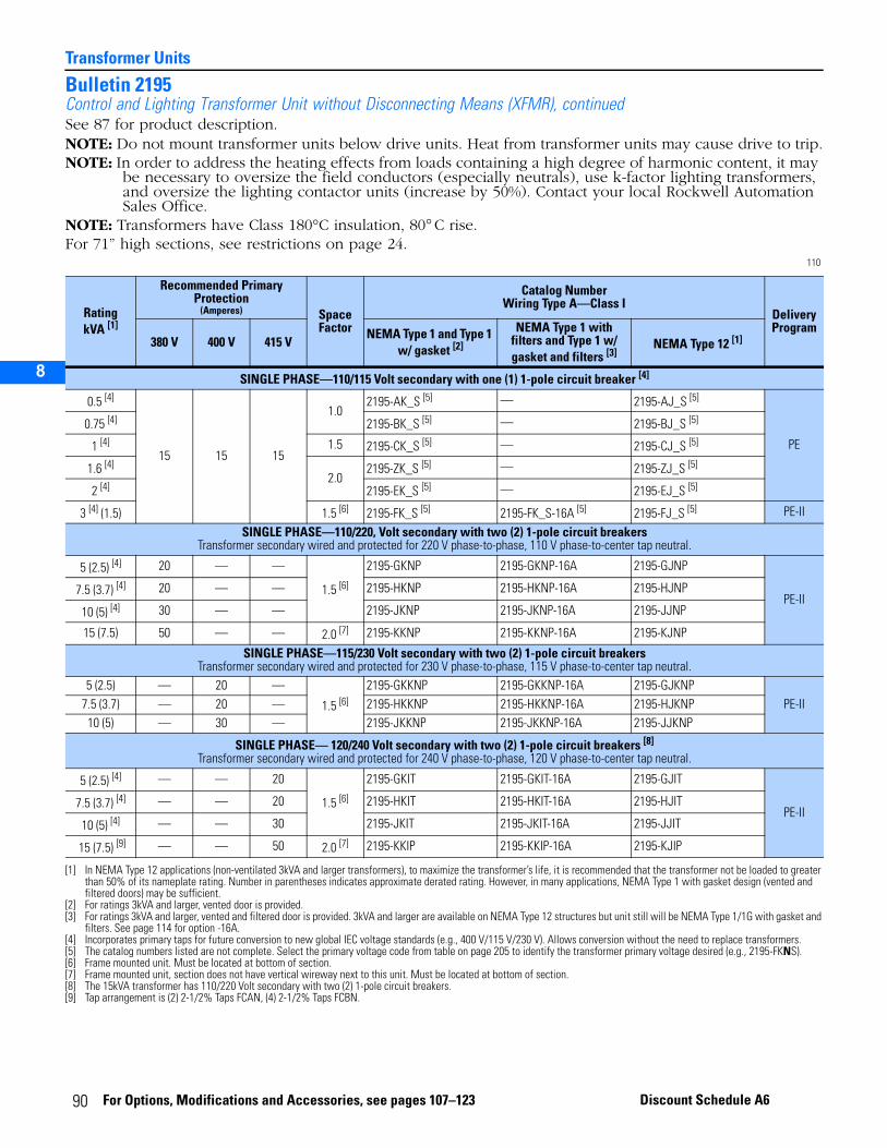
Transformer Units
2
3
5
6
7
8
Bulletin 2195Control and Lighting Transformer Unit without Disconnecting Means (XFMR), continuedSee 87 for product description.NOTE: Do not mount transformer units below drive units. Heat from transformer units may cause drive to trip.NOTE: In order to address the heating effects from loads containing a high degree of harmonic content, it may
be necessary to oversize the field conductors (especially neutrals), use k-factor lighting transformers, and oversize the lighting contactor units (increase by 50%). Contact your local Rockwell Automation Sales Office.
NOTE: Transformers have Class 180°C insulation, 80° C rise.For 71” high sections, see restrictions on page 24.
110
RatingkVA [1]
[1] In NEMA Type 12 applications (non-ventilated 3kVA and larger transformers), to maximize the transformer’s life, it is recommended that the transformer not be loaded to greater than 50% of its nameplate rating. Number in parentheses indicates approximate derated rating. However, in many applications, NEMA Type 1 with gasket design (vented and filtered doors) may be sufficient.
Recommended Primary Protection
(Amperes) Space Factor
Catalog Number Wiring Type A—Class I
Delivery Program
380 V 400 V 415 VNEMA Type 1 and Type 1
w/ gasket [2]
[2] For ratings 3kVA and larger, vented door is provided.
NEMA Type 1 with filters and Type 1 w/ gasket and filters [3]
[3] For ratings 3kVA and larger, vented and filtered door is provided. 3kVA and larger are available on NEMA Type 12 structures but unit still will be NEMA Type 1/1G with gasket and filters. See page 114 for option -16A.
NEMA Type 12 [1]
SINGLE PHASE—110/115 Volt secondary with one (1) 1-pole circuit breaker [4]
[4] Incorporates primary taps for future conversion to new global IEC voltage standards (e.g., 400 V/115 V/230 V). Allows conversion without the need to replace transformers.
0.5 [4]
15 15 15
1.02195-AK_S [5]
[5] The catalog numbers listed are not complete. Select the primary voltage code from table on page 205 to identify the transformer primary voltage desired (e.g., 2195-FKNS).
— 2195-AJ_S [5]
PE
0.75 [4] 2195-BK_S [5] — 2195-BJ_S [5]
1 [4] 1.5 2195-CK_S [5] — 2195-CJ_S [5]
1.6 [4]2.0
2195-ZK_S [5] — 2195-ZJ_S [5]
2 [4] 2195-EK_S [5] — 2195-EJ_S [5]
3 [4] (1.5) 1.5 [6]
[6] Frame mounted unit. Must be located at bottom of section.
2195-FK_S [5] 2195-FK_S-16A [5] 2195-FJ_S [5] PE-II
SINGLE PHASE—110/220, Volt secondary with two (2) 1-pole circuit breakersTransformer secondary wired and protected for 220 V phase-to-phase, 110 V phase-to-center tap neutral.
5 (2.5) [4] 20 — —
1.5 [6]
2195-GKNP 2195-GKNP-16A 2195-GJNP
PE-II7.5 (3.7) [4] 20 — — 2195-HKNP 2195-HKNP-16A 2195-HJNP
10 (5) [4] 30 — — 2195-JKNP 2195-JKNP-16A 2195-JJNP
15 (7.5) 50 — — 2.0 [7]
[7] Frame mounted unit, section does not have vertical wireway next to this unit. Must be located at bottom of section.
2195-KKNP 2195-KKNP-16A 2195-KJNP
SINGLE PHASE—115/230 Volt secondary with two (2) 1-pole circuit breakersTransformer secondary wired and protected for 230 V phase-to-phase, 115 V phase-to-center tap neutral.
5 (2.5) — 20 —
1.5 [6]2195-GKKNP 2195-GKKNP-16A 2195-GJKNP
PE-II7.5 (3.7) — 20 — 2195-HKKNP 2195-HKKNP-16A 2195-HJKNP10 (5) — 30 — 2195-JKKNP 2195-JKKNP-16A 2195-JJKNP
SINGLE PHASE— 120/240 Volt secondary with two (2) 1-pole circuit breakers [8]
Transformer secondary wired and protected for 240 V phase-to-phase, 120 V phase-to-center tap neutral.
[8] The 15kVA transformer has 110/220 Volt secondary with two (2) 1-pole circuit breakers.
5 (2.5) [4] — — 20
1.5 [6]
2195-GKIT 2195-GKIT-16A 2195-GJIT
PE-II7.5 (3.7) [4] — — 20 2195-HKIT 2195-HKIT-16A 2195-HJIT
10 (5) [4] — — 30 2195-JKIT 2195-JKIT-16A 2195-JJIT
15 (7.5) [9]
[9] Tap arrangement is (2) 2-1/2% Taps FCAN, (4) 2-1/2% Taps FCBN.
— — 50 2.0 [7] 2195-KKIP 2195-KKIP-16A 2195-KJIP
90 For Options, Modifications and Accessories, see pages 107–123 Discount Schedule A6
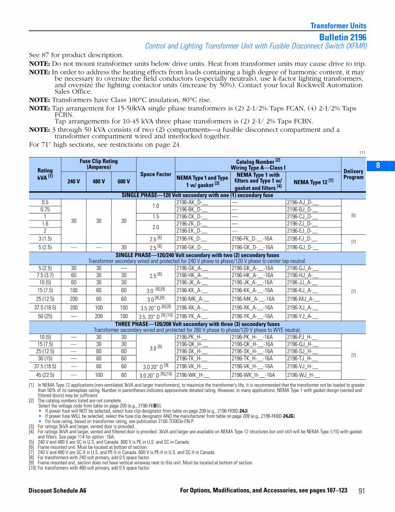
2
3
5
6
7
8
Transformer Units
Bulletin 2196Control and Lighting Transformer Unit with Fusible Disconnect Switch (XFMR)
See 87 for product description.NOTE: Do not mount transformer units below drive units. Heat from transformer units may cause drive to trip.NOTE: In order to address the heating effects from loads containing a high degree of harmonic content, it may
be necessary to oversize the field conductors (especially neutrals), use k-factor lighting transformers, and oversize the lighting contactor units (increase by 50%). Contact your local Rockwell Automation Sales Office.
NOTE: Transformers have Class 180°C insulation, 80°C rise.NOTE: Tap arrangement for 15-50kVA single phase transformers is (2) 2-1/2% Taps FCAN, (4) 2-1/2% Taps
FCBN. Tap arrangements for 10-45 kVA three phase transformers is (2) 2-1/ 2% Taps FCBN.
NOTE: 3 through 50 kVA consists of two (2) compartments—a fusible disconnect compartment and a transformer compartment wired and interlocked together.
For 71” high sections, see restrictions on page 24.
111
RatingkVA [1]
[1] In NEMA Type 12 applications (non-ventilated 3kVA and larger transformers), to maximize the transformer’s life, it is recommended that the transformer not be loaded to greater than 50% of its nameplate rating. Number in parentheses indicates approximate derated rating. However, in many applications, NEMA Type 1 with gasket design (vented and filtered doors) may be sufficient.
Fuse Clip Rating(Amperes)
Space Factor
Catalog Number [2]
Wiring Type A—Class I
[2] The catalog numbers listed are not complete.Select the voltage code from table on page 205 (e.g., 2196-FKBD).• If power fuse will NOT be selected, select fuse clip designator from table on page 209 (e.g., 2196-FKBD-24J).• If power fuse WILL be selected, select the fuse clip designator AND the manufacturer from table on page 209 (e.g., 2196-FKBD-24JG).• For fuse rating, based on transformer rating, see publication 2100-TD003x-EN-P.
Delivery Program
240 V 480 V 600 VNEMA Type 1 and Type
1 w/ gasket [3]
[3] For ratings 3kVA and larger, vented door is provided.
NEMA Type 1 with filters and Type 1 w/ gasket and filters [4]
[4] For ratings 3kVA and larger, vented and filtered door is provided. 3kVA and larger are available on NEMA Type 12 structures but unit still will be NEMA Type 1/1G with gasket and filters. See page 114 for option -16A.
NEMA Type 12 [1]
SINGLE PHASE—120 Volt secondary with one (1) secondary fuse 0.5
30 30 30
1.02196-AK_D-__ — 2196-AJ_D-__
[5]
[5] 240 V and 480 V are SC in U.S. and Canada. 600 V is PE in U.S. and SC in Canada.
0.75 2196-BK_D-__ — 2196-BJ_D-__1 1.5 2196-CK_D-__ — 2196-CJ_D-__
1.62.0
2196-ZK_D-__ — 2196-ZJ_D-__2 2196-EK_D-__ — 2196-EJ_D-__
3 (1.5) 2.5 [6]
[6] Frame mounted unit. Must be located at bottom of section.
2196-FK_D-__ 2196-FK_D-__-16A 2196-FJ_D-__ [7]5 (2.5) — — 30 2.5 [6] 2196-GK_D-__ 2196-GK_D-__-16A 2196-GJ_D-__
SINGLE PHASE—120/240 Volt secondary with two (2) secondary fusesTransformer secondary wired and protected for 240 V phase to phase/120 V phase to center tap neutral.
5 (2.5) 30 30 —2.5 [6]
2196-GK_A-__ 2196-GK_A-__-16A 2196-GJ_A-__
[7]
[7] 240 V and 480 V are SC-II in U.S. and PE-II in Canada. 600 V is PE-II in U.S. and SC-II in Canada.
7.5 (3.7) 60 30 30 2196-HK_A-__ 2196-HK_A-__-16A 2196-HJ_A-__10 (5) 60 30 30 2196-JK_A-__ 2196-JK_A-__-16A 2196-JJ_A-__
15 (7.5) 100 60 60 3.0 [8],[9]
[8] For transformers with 240 volt primary, add 0.5 space factor.[9] Frame mounted unit, section does not have vertical wireway next to this unit. Must be located at bottom of section.
2196-KK_A-__ 2196-KK_A-__-16A 2196-KJ_A-__25 (12.5) 200 60 60 3.0 [8],[9] 2196-MK_A-__ 2196-MK_A-__-16A 2196-MJ_A-__
37.5 (18.5) 200 100 100 3.5 20” D [8],[9] 2196-XK_A-__ 2196-XK_A-__-16A 2196-XJ_A-__50 (25) — 200 100 3.5, 20” D [9],[10] 2196-YK_A-__ 2196-YK_A-__-16A 2196-YJ_A-__
THREE PHASE—120/208 Volt secondary with three (3) secondary fusesTransformer secondary wired and protected for 280 V phase to phase/120 V phase to WYE neutral.
10 (5) — 30 30
3.0 [9]
2196-PK_H-__ 2196-PK_H-__-16A 2196-PJ_H-__
[7]
15 (7.5) — 30 30 2196-QK_H-__ 2196-QK_H-__-16A 2196-QJ_H-__25 (12.5) — 60 60 2196-SK_H-__ 2196-SK_H-__-16A 2196-SJ_H-__30 (15) — 60 60 2196-TK_H-__ 2196-TK_H-__-16A 2196-TJ_H-__
37.5 (18.5) — 60 60 3.0 20” D [9] 2196-VK_H-__ 2196-VK_H-__-16A 2196-VJ_H-__45 (22.5) — 100 60 3.0 20” D [9],[10]
[10] For transformers with 480 volt primary, add 0.5 space factor.
2196-WK_H-__ 2196-WK_H-__-16A 2196-WJ_H-__
91For Options, Modifications, and Accessories, see pages 107–123Discount Schedule A6
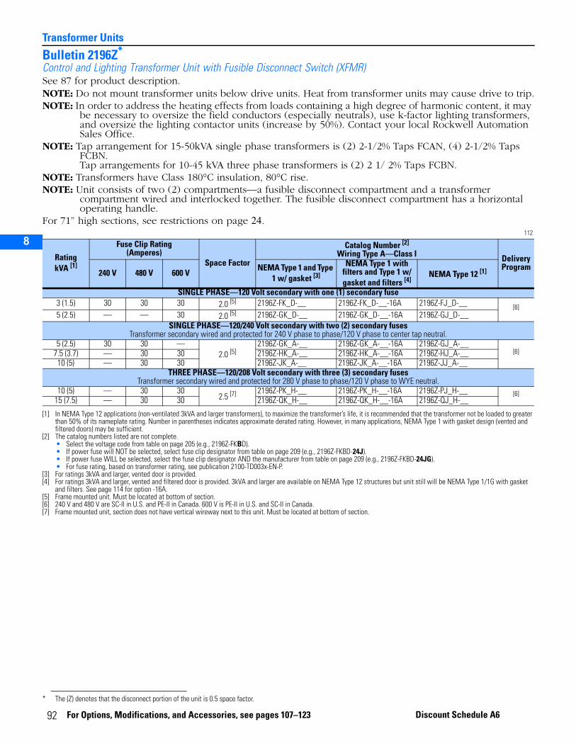
Transformer Units
2
3
5
6
7
8
Bulletin 2196Z*
Control and Lighting Transformer Unit with Fusible Disconnect Switch (XFMR)See 87 for product description.NOTE: Do not mount transformer units below drive units. Heat from transformer units may cause drive to trip.NOTE: In order to address the heating effects from loads containing a high degree of harmonic content, it may
be necessary to oversize the field conductors (especially neutrals), use k-factor lighting transformers, and oversize the lighting contactor units (increase by 50%). Contact your local Rockwell Automation Sales Office.
NOTE: Tap arrangement for 15-50kVA single phase transformers is (2) 2-1/2% Taps FCAN, (4) 2-1/2% Taps FCBN. Tap arrangements for 10-45 kVA three phase transformers is (2) 2 1/ 2% Taps FCBN.
NOTE: Transformers have Class 180°C insulation, 80°C rise.NOTE: Unit consists of two (2) compartments—a fusible disconnect compartment and a transformer
compartment wired and interlocked together. The fusible disconnect compartment has a horizontal operating handle.
For 71” high sections, see restrictions on page 24.112
* The (Z) denotes that the disconnect portion of the unit is 0.5 space factor.
RatingkVA [1]
[1] In NEMA Type 12 applications (non-ventilated 3kVA and larger transformers), to maximize the transformer’s life, it is recommended that the transformer not be loaded to greater than 50% of its nameplate rating. Number in parentheses indicates approximate derated rating. However, in many applications, NEMA Type 1 with gasket design (vented and filtered doors) may be sufficient.
Fuse Clip Rating(Amperes)
Space Factor
Catalog Number [2]
Wiring Type A—Class I
[2] The catalog numbers listed are not complete.• Select the voltage code from table on page 205 (e.g., 2196Z-FKBD).• If power fuse will NOT be selected, select fuse clip designator from table on page 209 (e.g., 2196Z-FKBD-24J).• If power fuse WILL be selected, select the fuse clip designator AND the manufacturer from table on page 209 (e.g., 2196Z-FKBD-24JG).• For fuse rating, based on transformer rating, see publication 2100-TD003x-EN-P.
Delivery Program
240 V 480 V 600 VNEMA Type 1 and Type
1 w/ gasket [3]
[3] For ratings 3kVA and larger, vented door is provided.
NEMA Type 1 with filters and Type 1 w/ gasket and filters [4]
[4] For ratings 3kVA and larger, vented and filtered door is provided. 3kVA and larger are available on NEMA Type 12 structures but unit still will be NEMA Type 1/1G with gasket and filters. See page 114 for option -16A.
NEMA Type 12 [1]
SINGLE PHASE—120 Volt secondary with one (1) secondary fuse 3 (1.5) 30 30 30 2.0 [5]
[5] Frame mounted unit. Must be located at bottom of section.
2196Z-FK_D-__ 2196Z-FK_D-__-16A 2196Z-FJ_D-__ [6]5 (2.5) — — 30 2.0 [5] 2196Z-GK_D-__ 2196Z-GK_D-__-16A 2196Z-GJ_D-__
SINGLE PHASE—120/240 Volt secondary with two (2) secondary fuses Transformer secondary wired and protected for 240 V phase to phase/120 V phase to center tap neutral.
5 (2.5) 30 30 —2.0 [5]
2196Z-GK_A-__ 2196Z-GK_A-__-16A 2196Z-GJ_A-__[6]
[6] 240 V and 480 V are SC-II in U.S. and PE-II in Canada. 600 V is PE-II in U.S. and SC-II in Canada.
7.5 (3.7) — 30 30 2196Z-HK_A-__ 2196Z-HK_A-__-16A 2196Z-HJ_A-__10 (5) — 30 30 2196Z-JK_A-__ 2196Z-JK_A-__-16A 2196Z-JJ_A-__
THREE PHASE—120/208 Volt secondary with three (3) secondary fusesTransformer secondary wired and protected for 280 V phase to phase/120 V phase to WYE neutral.
10 (5) — 30 302.5 [7]
[7] Frame mounted unit, section does not have vertical wireway next to this unit. Must be located at bottom of section.
2196Z-PK_H-__ 2196Z-PK_H-__-16A 2196Z-PJ_H-__ [6]15 (7.5) — 30 30 2196Z-QK_H-__ 2196Z-QK_H-__-16A 2196Z-QJ_H-__
92 For Options, Modifications, and Accessories, see pages 107–123 Discount Schedule A6
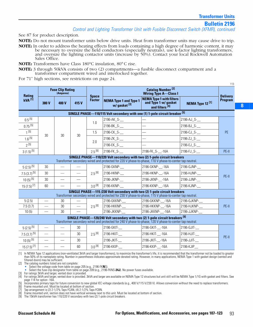
2
3
5
6
7
8
Transformer Units
Bulletin 2196Control and Lighting Transformer Unit with Fusible Disconnect Switch (XFMR), continued
See 87 for product description.NOTE: Do not mount transformer units below drive units. Heat from transformer units may cause drive to trip.NOTE: In order to address the heating effects from loads containing a high degree of harmonic content, it may
be necessary to oversize the field conductors (especially neutrals), use k-factor lighting transformers, and oversize the lighting contactor units (increase by 50%). Contact your local Rockwell Automation Sales Office.
NOTE: Transformers have Class 180°C insulation, 80° C rise.NOTE: 3 through 50kVA consists of two (2) compartments—a fusible disconnect compartment and a
transformer compartment wired and interlocked together.For 71” high sections, see restrictions on page 24.
113
RatingkVA [1]
[1] In NEMA Type 12 applications (non-ventilated 3kVA and larger transformers), to maximize the transformer’s life, it is recommended that the transformer not be loaded to greater than 50% of its nameplate rating. Number in parentheses indicates approximate derated rating. However, in many applications, NEMA Type 1 with gasket design (vented and filtered doors) may be sufficient.
Fuse Clip Rating (Amperes)
Space Factor
Catalog Number [2]
Wiring Type A—Class I
[2] The catalog numbers listed are not complete:• Select the voltage code from table on page 205 (e.g., 2196-FKNS).• Select the fuse clip designator from table on page 209 (e.g., 2196-FKNS-24J). No power fuses available.
Delivery Program
380 V 400 V 415 VNEMA Type 1 and Type 1
w/ gasket [3]
[3] For ratings 3kVA and larger, vented door is provided.
NEMA Type 1 with filters and Type 1 w/ gasket
and filters [4]
[4] For ratings 3kVA and larger, vented door is provided. 3kVA and larger are available on NEMA Type 12 structures but unit still will be NEMA Type 1/1G with gasket and filters. See page 114 for option -16A.
NEMA Type 12 [1]
SINGLE PHASE—110/115 Volt secondary with one (1) 1-pole circuit breaker [5]
[5] Incorporates primary taps for future conversion to new global IEC voltage standards (e.g., 400 V/115 V/230 V). Allows conversion without the need to replace transformers.
0.5 [5]
30 30 30
1.02196-AK_S-__ — 2196-AJ_S-__
PE
0.75 [5] 2196-BK_S-__ — 2196-BJ_S-__
1 [5] 1.5 2196-CK_S-__ — 2196-CJ_S-__
1.6 [5]2.0
2196-ZK_S-__ — 2196-ZJ_S-__
2 [5] 2196-EK_S-__ — 2196-EJ_S-__
3 (1.5) [5] 2.5 [6]
[6] Frame mounted unit. Must be located at bottom of section.
2196-FK_S-__ 2196-FK_S-__-16A 2196-FJ_S-__ PE-II
SINGLE PHASE—110/220 Volt secondary with two (2) 1-pole circuit breakers Transformer secondary wired and protected for 220 V phase-to-phase, 110 V phase-to-center tap neutral.
5 (2.5) [5] 30 — —
2.5 [6]
2196-GKNP-__ 2196-GKNP-__-16A 2196-GJNP-__
PE-II7.5 (3.7) [5] 30 — — 2196-HKNP-__ 2196-HKNP-__-16A 2196-HJNP-__
10 (5) [5] 30 — — 2196-JKNP-__ 2196-JKNP-__-16A 2196-JJNP-__
15 (7.5) [7]
[7] Tap arrangement is (2) 2-1/2% Taps FCAN, (4) 2-1/2% Taps FCBN.
60 — — 3.0 [8]
[8] Frame mounted unit, section does not have vertical wireway next to this unit. Must be located at bottom of section.
2196-KKNP-__ 2196-KKNP-__-16A 2196-KJNP-__
SINGLE PHASE—115 /230 Volt secondary with two (2) 1-pole circuit breakersTransformer secondary wired and protected for 230 V phase-to-phase, 115 V phase-to-center tap neutral.
5 (2.5) — 30 —
2.5 [6]2196-GKKNP-__ 2196-GKKNP-__-16A 2196-GJKNP-__
PE-II7.5 (3.7) — 30 — 2196-HKKNP-__ 2196-HKKNP-__-16A 2196-HJKNP-__10 (5) — 30 — 2196-JKKNP-__ 2196-JKKNP-__-16A 2196-JJKNP-__
SINGLE PHASE—120/240 Volt secondary with two (2) 1-pole circuit breakers [9]
Transformer secondary wired and protected for 240 V phase-to-phase, 120 V phase-to-center tap neutral.
[9] The 15kVA transformer has 110/220 V secondary with two (2) 1-pole circuit breakers.
5 (2.5) [5] — — 30
2.5 [6]
2196-GKIT-__ 2196-GKIT-__-16A 2196-GJIT-__
PE-II7.5 (3.7) [5] — — 30 2196-HKIT-__ 2196-HKIT-__-16A 2196-HJIT-__
10 (5) [5] — — 30 2196-JKIT-__ 2196-JKIT-__-16A 2196-JJIT-__
15 (7.5) [7] — — 60 3.0 [8] 2196-KKIP-__ 2196-KKIP-__-16A 2196-KJIP__
93For Options, Modifications, and Accessories, see pages 107–123Discount Schedule A6
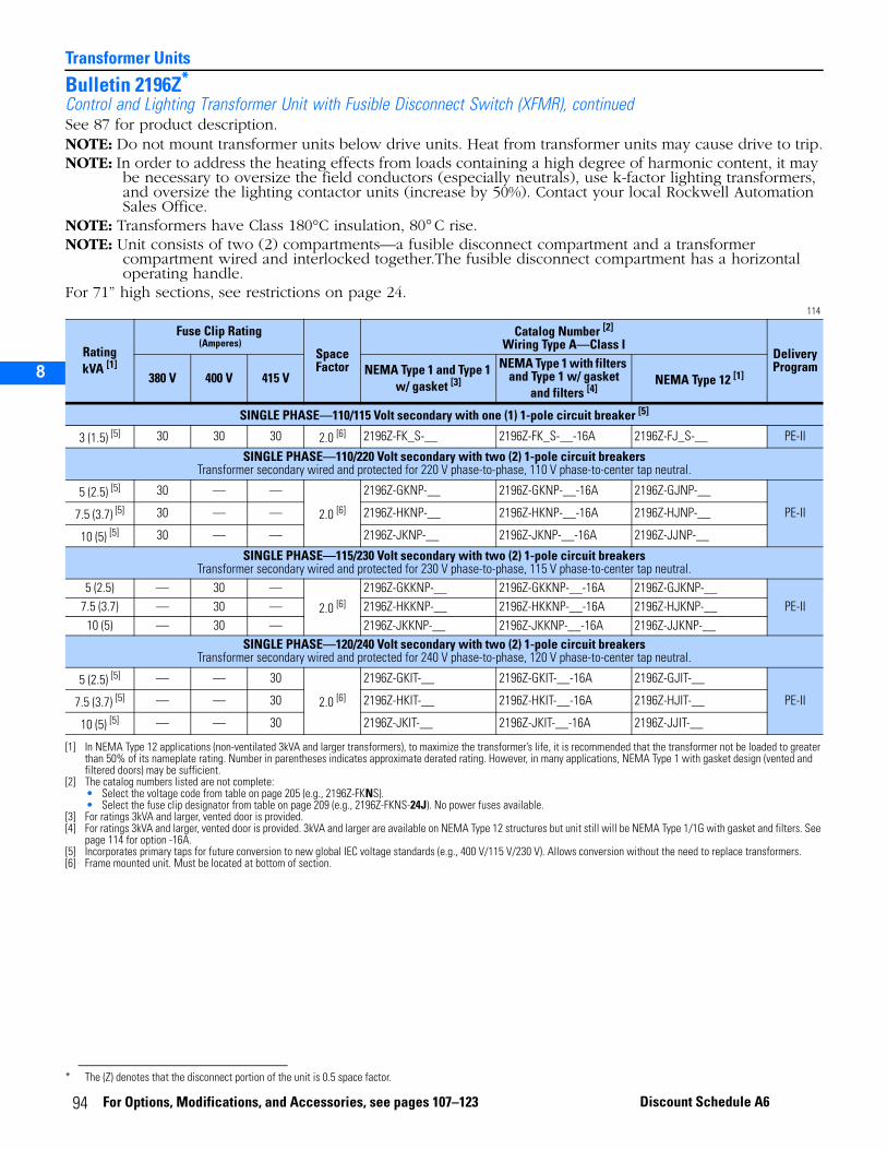
Transformer Units
2
3
5
6
7
8
Bulletin 2196Z*
Control and Lighting Transformer Unit with Fusible Disconnect Switch (XFMR), continuedSee 87 for product description.NOTE: Do not mount transformer units below drive units. Heat from transformer units may cause drive to trip.NOTE: In order to address the heating effects from loads containing a high degree of harmonic content, it may
be necessary to oversize the field conductors (especially neutrals), use k-factor lighting transformers, and oversize the lighting contactor units (increase by 50%). Contact your local Rockwell Automation Sales Office.
NOTE: Transformers have Class 180°C insulation, 80° C rise.NOTE: Unit consists of two (2) compartments—a fusible disconnect compartment and a transformer
compartment wired and interlocked together.The fusible disconnect compartment has a horizontal operating handle.
For 71” high sections, see restrictions on page 24.114
* The (Z) denotes that the disconnect portion of the unit is 0.5 space factor.
RatingkVA [1]
[1] In NEMA Type 12 applications (non-ventilated 3kVA and larger transformers), to maximize the transformer’s life, it is recommended that the transformer not be loaded to greater than 50% of its nameplate rating. Number in parentheses indicates approximate derated rating. However, in many applications, NEMA Type 1 with gasket design (vented and filtered doors) may be sufficient.
Fuse Clip Rating (Amperes)
Space Factor
Catalog Number [2]
Wiring Type A—Class I
[2] The catalog numbers listed are not complete:• Select the voltage code from table on page 205 (e.g., 2196Z-FKNS).• Select the fuse clip designator from table on page 209 (e.g., 2196Z-FKNS-24J). No power fuses available.
Delivery Program
380 V 400 V 415 VNEMA Type 1 and Type 1
w/ gasket [3]
[3] For ratings 3kVA and larger, vented door is provided.
NEMA Type 1 with filters and Type 1 w/ gasket
and filters [4]
[4] For ratings 3kVA and larger, vented door is provided. 3kVA and larger are available on NEMA Type 12 structures but unit still will be NEMA Type 1/1G with gasket and filters. See page 114 for option -16A.
NEMA Type 12 [1]
SINGLE PHASE—110/115 Volt secondary with one (1) 1-pole circuit breaker [5]
[5] Incorporates primary taps for future conversion to new global IEC voltage standards (e.g., 400 V/115 V/230 V). Allows conversion without the need to replace transformers.
3 (1.5) [5] 30 30 30 2.0 [6]
[6] Frame mounted unit. Must be located at bottom of section.
2196Z-FK_S-__ 2196Z-FK_S-__-16A 2196Z-FJ_S-__ PE-II
SINGLE PHASE—110/220 Volt secondary with two (2) 1-pole circuit breakers Transformer secondary wired and protected for 220 V phase-to-phase, 110 V phase-to-center tap neutral.
5 (2.5) [5] 30 — —
2.0 [6]
2196Z-GKNP-__ 2196Z-GKNP-__-16A 2196Z-GJNP-__
PE-II7.5 (3.7) [5] 30 — — 2196Z-HKNP-__ 2196Z-HKNP-__-16A 2196Z-HJNP-__
10 (5) [5] 30 — — 2196Z-JKNP-__ 2196Z-JKNP-__-16A 2196Z-JJNP-__
SINGLE PHASE—115/230 Volt secondary with two (2) 1-pole circuit breakers Transformer secondary wired and protected for 230 V phase-to-phase, 115 V phase-to-center tap neutral.
5 (2.5) — 30 —
2.0 [6]2196Z-GKKNP-__ 2196Z-GKKNP-__-16A 2196Z-GJKNP-__
PE-II7.5 (3.7) — 30 — 2196Z-HKKNP-__ 2196Z-HKKNP-__-16A 2196Z-HJKNP-__10 (5) — 30 — 2196Z-JKKNP-__ 2196Z-JKKNP-__-16A 2196Z-JJKNP-__
SINGLE PHASE—120/240 Volt secondary with two (2) 1-pole circuit breakers Transformer secondary wired and protected for 240 V phase-to-phase, 120 V phase-to-center tap neutral.
5 (2.5) [5] — — 30
2.0 [6]
2196Z-GKIT-__ 2196Z-GKIT-__-16A 2196Z-GJIT-__
PE-II7.5 (3.7) [5] — — 30 2196Z-HKIT-__ 2196Z-HKIT-__-16A 2196Z-HJIT-__
10 (5) [5] — — 30 2196Z-JKIT-__ 2196Z-JKIT-__-16A 2196Z-JJIT-__
94 For Options, Modifications, and Accessories, see pages 107–123 Discount Schedule A6
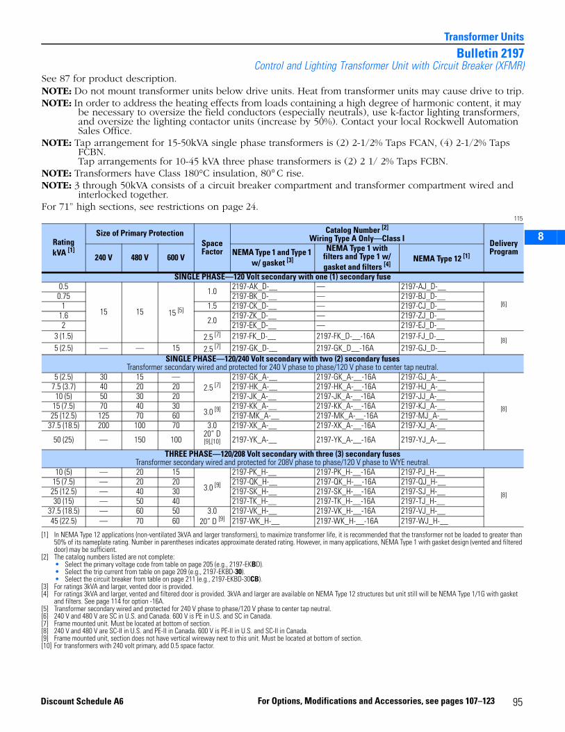
2
3
5
6
7
8
Transformer Units
Bulletin 2197Control and Lighting Transformer Unit with Circuit Breaker (XFMR)
See 87 for product description.NOTE: Do not mount transformer units below drive units. Heat from transformer units may cause drive to trip.NOTE: In order to address the heating effects from loads containing a high degree of harmonic content, it may
be necessary to oversize the field conductors (especially neutrals), use k-factor lighting transformers, and oversize the lighting contactor units (increase by 50%). Contact your local Rockwell Automation Sales Office.
NOTE: Tap arrangement for 15-50kVA single phase transformers is (2) 2-1/2% Taps FCAN, (4) 2-1/2% Taps FCBN. Tap arrangements for 10-45 kVA three phase transformers is (2) 2 1/ 2% Taps FCBN.
NOTE: Transformers have Class 180°C insulation, 80° C rise.NOTE: 3 through 50kVA consists of a circuit breaker compartment and transformer compartment wired and
interlocked together.For 71” high sections, see restrictions on page 24.
115
RatingkVA [1]
[1] In NEMA Type 12 applications (non-ventilated 3kVA and larger transformers), to maximize transformer life, it is recommended that the transformer not be loaded to greater than 50% of its nameplate rating. Number in parentheses indicates approximate derated rating. However, in many applications, NEMA Type 1 with gasket design (vented and filtered door) may be sufficient.
Size of Primary ProtectionSpace Factor
Catalog Number [2]
Wiring Type A Only—Class I
[2] The catalog numbers listed are not complete:• Select the primary voltage code from table on page 205 (e.g., 2197-EKBD).• Select the trip current from table on page 209 (e.g., 2197-EKBD-30).• Select the circuit breaker from table on page 211 (e.g., 2197-EKBD-30CB).
Delivery Program
240 V 480 V 600 VNEMA Type 1 and Type 1
w/ gasket [3]
[3] For ratings 3kVA and larger, vented door is provided.
NEMA Type 1 with filters and Type 1 w/ gasket and filters [4]
[4] For ratings 3kVA and larger, vented and filtered door is provided. 3kVA and larger are available on NEMA Type 12 structures but unit still will be NEMA Type 1/1G with gasket and filters. See page 114 for option -16A.
NEMA Type 12 [1]
SINGLE PHASE—120 Volt secondary with one (1) secondary fuse0.5
15 15 15 [5]
[5] Transformer secondary wired and protected for 240 V phase to phase/120 V phase to center tap neutral.
1.0 2197-AK_D-__ — 2197-AJ_D-__
[6]
[6] 240 V and 480 V are SC in U.S. and Canada. 600 V is PE in U.S. and SC in Canada.
0.75 2197-BK_D-__ — 2197-BJ_D-__1 1.5 2197-CK_D-__ — 2197-CJ_D-__
1.6 2.0 2197-ZK_D-__ — 2197-ZJ_D-__2 2197-EK_D-__ — 2197-EJ_D-__
3 (1.5) 2.5 [7]
[7] Frame mounted unit. Must be located at bottom of section.
2197-FK_D-__ 2197-FK_D-__-16A 2197-FJ_D-__ [8]5 (2.5) — — 15 2.5 [7] 2197-GK_D-__ 2197-GK_D__-16A 2197-GJ_D-__
SINGLE PHASE—120/240 Volt secondary with two (2) secondary fusesTransformer secondary wired and protected for 240 V phase to phase/120 V phase to center tap neutral.
5 (2.5) 30 15 —2.5 [7]
2197-GK_A-__ 2197-GK_A-__-16A 2197-GJ_A-__
[8]
[8] 240 V and 480 V are SC-II in U.S. and PE-II in Canada. 600 V is PE-II in U.S. and SC-II in Canada.
7.5 (3.7) 40 20 20 2197-HK_A-__ 2197-HK_A-__-16A 2197-HJ_A-__10 (5) 50 30 20 2197-JK_A-__ 2197-JK_A-__-16A 2197-JJ_A-__
15 (7.5) 70 40 303.0 [9]
[9] Frame mounted unit, section does not have vertical wireway next to this unit. Must be located at bottom of section.
2197-KK_A-__ 2197-KK_A-__-16A 2197-KJ_A-__25 (12.5) 125 70 60 2197-MK_A-__ 2197-MK_A-__-16A 2197-MJ_A-__
37.5 (18.5) 200 100 70 3.0 20” D [9],[10]
[10] For transformers with 240 volt primary, add 0.5 space factor.
2197-XK_A-__ 2197-XK_A-__-16A 2197-XJ_A-__
50 (25) — 150 100 2197-YK_A-__ 2197-YK_A-__-16A 2197-YJ_A-__
THREE PHASE—120/208 Volt secondary with three (3) secondary fusesTransformer secondary wired and protected for 208V phase to phase/120 V phase to WYE neutral.
10 (5) — 20 15
3.0 [9]
2197-PK_H-__ 2197-PK_H-__-16A 2197-PJ_H-__
[8]
15 (7.5) — 20 20 2197-QK_H-__ 2197-QK_H-__-16A 2197-QJ_H-__25 (12.5) — 40 30 2197-SK_H-__ 2197-SK_H-__-16A 2197-SJ_H-__30 (15) — 50 40 2197-TK_H-__ 2197-TK_H-__-16A 2197-TJ_H-__
37.5 (18.5) — 60 50 3.0 20” D [9]
2197-VK_H-__ 2197-VK_H-__-16A 2197-VJ_H-__45 (22.5) — 70 60 2197-WK_H-__ 2197-WK_H-__-16A 2197-WJ_H-__
95For Options, Modifications and Accessories, see pages 107–123Discount Schedule A6
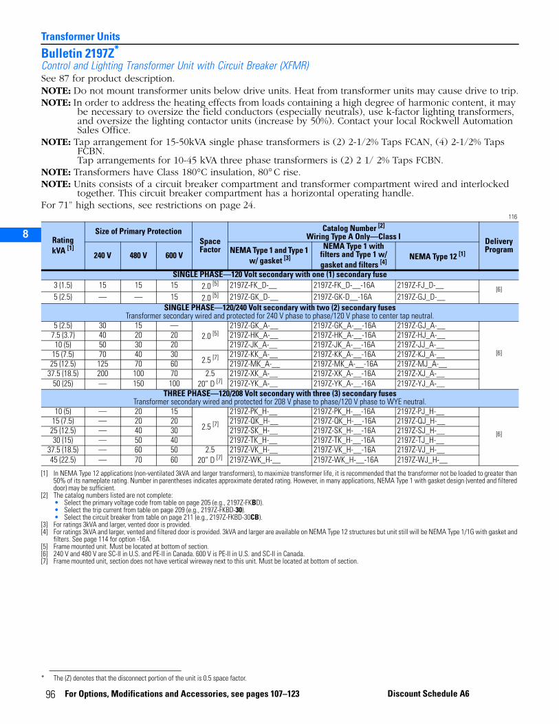
Transformer Units
2
3
5
6
7
8
Bulletin 2197Z*
Control and Lighting Transformer Unit with Circuit Breaker (XFMR)See 87 for product description.NOTE: Do not mount transformer units below drive units. Heat from transformer units may cause drive to trip.NOTE: In order to address the heating effects from loads containing a high degree of harmonic content, it may
be necessary to oversize the field conductors (especially neutrals), use k-factor lighting transformers, and oversize the lighting contactor units (increase by 50%). Contact your local Rockwell Automation Sales Office.
NOTE: Tap arrangement for 15-50kVA single phase transformers is (2) 2-1/2% Taps FCAN, (4) 2-1/2% Taps FCBN. Tap arrangements for 10-45 kVA three phase transformers is (2) 2 1/ 2% Taps FCBN.
NOTE: Transformers have Class 180°C insulation, 80° C rise.NOTE: Units consists of a circuit breaker compartment and transformer compartment wired and interlocked
together. This circuit breaker compartment has a horizontal operating handle.For 71” high sections, see restrictions on page 24.
116
* The (Z) denotes that the disconnect portion of the unit is 0.5 space factor.
RatingkVA [1]
[1] In NEMA Type 12 applications (non-ventilated 3kVA and larger transformers), to maximize transformer life, it is recommended that the transformer not be loaded to greater than 50% of its nameplate rating. Number in parentheses indicates approximate derated rating. However, in many applications, NEMA Type 1 with gasket design (vented and filtered door) may be sufficient.
Size of Primary ProtectionSpaceFactor
Catalog Number [2]
Wiring Type A Only—Class I
[2] The catalog numbers listed are not complete:• Select the primary voltage code from table on page 205 (e.g., 2197Z-FKBD).• Select the trip current from table on page 209 (e.g., 2197Z-FKBD-30).• Select the circuit breaker from table on page 211 (e.g., 2197Z-FKBD-30CB).
Delivery Program
240 V 480 V 600 VNEMA Type 1 and Type 1
w/ gasket [3]
[3] For ratings 3kVA and larger, vented door is provided.
NEMA Type 1 with filters and Type 1 w/ gasket and filters [4]
[4] For ratings 3kVA and larger, vented and filtered door is provided. 3kVA and larger are available on NEMA Type 12 structures but unit still will be NEMA Type 1/1G with gasket and filters. See page 114 for option -16A.
NEMA Type 12 [1]
SINGLE PHASE—120 Volt secondary with one (1) secondary fuse3 (1.5) 15 15 15 2.0 [5]
[5] Frame mounted unit. Must be located at bottom of section.
2197Z-FK_D-__ 2197Z-FK_D-__-16A 2197Z-FJ_D-__ [6]5 (2.5) — — 15 2.0 [5] 2197Z-GK_D-__ 2197Z-GK-D__-16A 2197Z-GJ_D-__
SINGLE PHASE—120/240 Volt secondary with two (2) secondary fusesTransformer secondary wired and protected for 240 V phase to phase/120 V phase to center tap neutral.
5 (2.5) 30 15 —2.0 [5]
2197Z-GK_A-__ 2197Z-GK_A-__-16A 2197Z-GJ_A-__
[6]
[6] 240 V and 480 V are SC-II in U.S. and PE-II in Canada. 600 V is PE-II in U.S. and SC-II in Canada.
7.5 (3.7) 40 20 20 2197Z-HK_A-__ 2197Z-HK_A-__-16A 2197Z-HJ_A-__10 (5) 50 30 20 2197Z-JK_A-__ 2197Z-JK_A-__-16A 2197Z-JJ_A-__
15 (7.5) 70 40 302.5 [7]
[7] Frame mounted unit, section does not have vertical wireway next to this unit. Must be located at bottom of section.
2197Z-KK_A-__ 2197Z-KK_A-__-16A 2197Z-KJ_A-__25 (12.5) 125 70 60 2197Z-MK_A-__ 2197Z-MK_A-__-16A 2197Z-MJ_A-__
37.5 (18.5) 200 100 70 2.5 20” D [7]
2197Z-XK_A-__ 2197Z-XK_A-__-16A 2197Z-XJ_A-__50 (25) — 150 100 2197Z-YK_A-__ 2197Z-YK_A-__-16A 2197Z-YJ_A-__
THREE PHASE—120/208 Volt secondary with three (3) secondary fusesTransformer secondary wired and protected for 208 V phase to phase/120 V phase to WYE neutral.
10 (5) — 20 15
2.5 [7]
2197Z-PK_H-__ 2197Z-PK_H-__-16A 2197Z-PJ_H-__
[6]
15 (7.5) — 20 20 2197Z-QK_H-__ 2197Z-QK_H-__-16A 2197Z-QJ_H-__25 (12.5) — 40 30 2197Z-SK_H-__ 2197Z-SK_H-__-16A 2197Z-SJ_H-__30 (15) — 50 40 2197Z-TK_H-__ 2197Z-TK_H-__-16A 2197Z-TJ_H-__
37.5 (18.5) — 60 50 2.5 20” D [7]
2197Z-VK_H-__ 2197Z-VK_H-__-16A 2197Z-VJ_H-__45 (22.5) — 70 60 2197Z-WK_H-__ 2197Z-WK_H-__-16A 2197Z-WJ_H-__
96 For Options, Modifications and Accessories, see pages 107–123 Discount Schedule A6
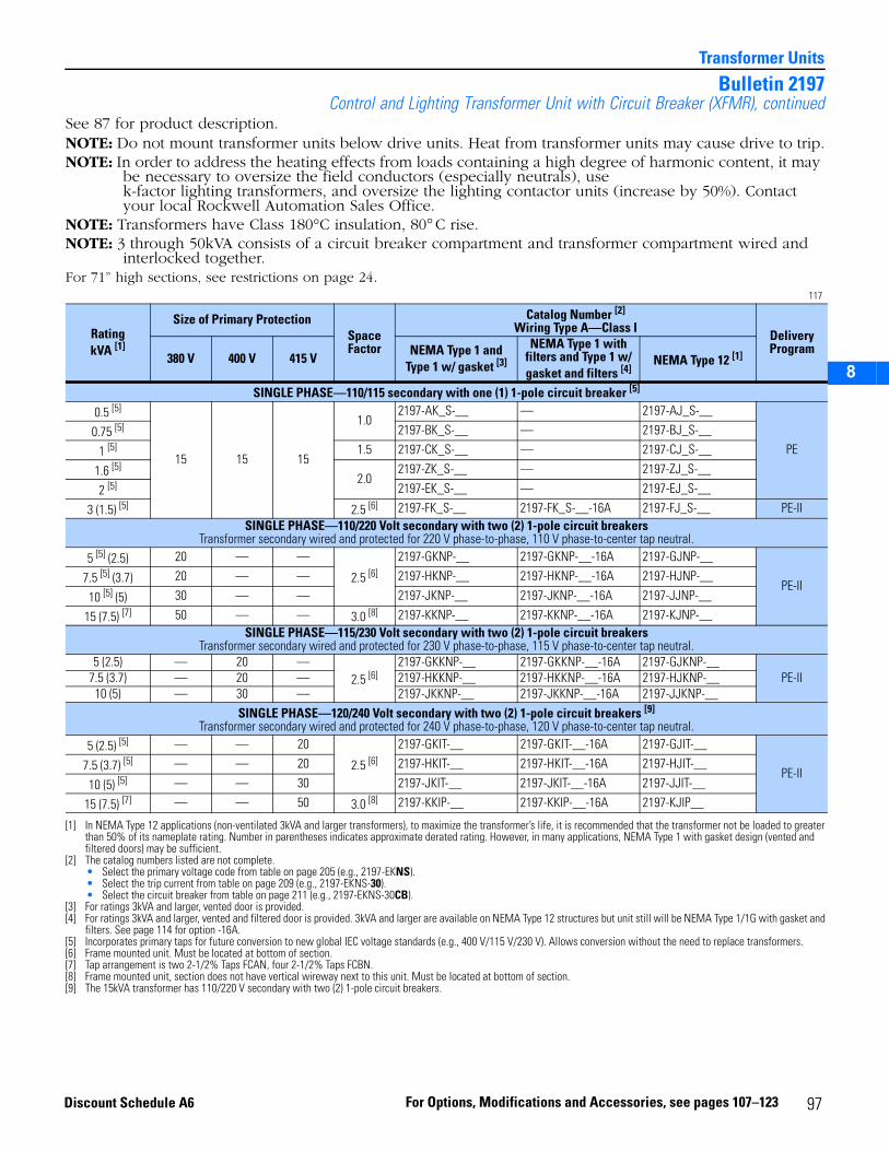
2
3
5
6
7
8
Transformer Units
Bulletin 2197Control and Lighting Transformer Unit with Circuit Breaker (XFMR), continued
See 87 for product description.NOTE: Do not mount transformer units below drive units. Heat from transformer units may cause drive to trip.NOTE: In order to address the heating effects from loads containing a high degree of harmonic content, it may
be necessary to oversize the field conductors (especially neutrals), use k-factor lighting transformers, and oversize the lighting contactor units (increase by 50%). Contact your local Rockwell Automation Sales Office.
NOTE: Transformers have Class 180°C insulation, 80° C rise.NOTE: 3 through 50kVA consists of a circuit breaker compartment and transformer compartment wired and
interlocked together.For 71” high sections, see restrictions on page 24.
117
RatingkVA [1]
[1] In NEMA Type 12 applications (non-ventilated 3kVA and larger transformers), to maximize the transformer’s life, it is recommended that the transformer not be loaded to greater than 50% of its nameplate rating. Number in parentheses indicates approximate derated rating. However, in many applications, NEMA Type 1 with gasket design (vented and filtered doors) may be sufficient.
Size of Primary ProtectionSpace Factor
Catalog Number [2]
Wiring Type A—Class I
[2] The catalog numbers listed are not complete.• Select the primary voltage code from table on page 205 (e.g., 2197-EKNS).• Select the trip current from table on page 209 (e.g., 2197-EKNS-30).• Select the circuit breaker from table on page 211 (e.g., 2197-EKNS-30CB).
Delivery Program
380 V 400 V 415 VNEMA Type 1 and
Type 1 w/ gasket [3]
[3] For ratings 3kVA and larger, vented door is provided.
NEMA Type 1 with filters and Type 1 w/ gasket and filters [4]
[4] For ratings 3kVA and larger, vented and filtered door is provided. 3kVA and larger are available on NEMA Type 12 structures but unit still will be NEMA Type 1/1G with gasket and filters. See page 114 for option -16A.
NEMA Type 12 [1]
SINGLE PHASE—110/115 secondary with one (1) 1-pole circuit breaker [5]
[5] Incorporates primary taps for future conversion to new global IEC voltage standards (e.g., 400 V/115 V/230 V). Allows conversion without the need to replace transformers.
0.5 [5]
15 15 15
1.02197-AK_S-__ — 2197-AJ_S-__
PE0.75 [5] 2197-BK_S-__ — 2197-BJ_S-__
1 [5] 1.5 2197-CK_S-__ — 2197-CJ_S-__
1.6 [5]2.0
2197-ZK_S-__ — 2197-ZJ_S-__
2 [5] 2197-EK_S-__ — 2197-EJ_S-__
3 (1.5) [5] 2.5 [6]
[6] Frame mounted unit. Must be located at bottom of section.
2197-FK_S-__ 2197-FK_S-__-16A 2197-FJ_S-__ PE-IISINGLE PHASE—110/220 Volt secondary with two (2) 1-pole circuit breakers
Transformer secondary wired and protected for 220 V phase-to-phase, 110 V phase-to-center tap neutral.5 [5] (2.5) 20 — —
2.5 [6]
2197-GKNP-__ 2197-GKNP-__-16A 2197-GJNP-__
PE-II7.5 [5] (3.7) 20 — — 2197-HKNP-__ 2197-HKNP-__-16A 2197-HJNP-__
10 [5] (5) 30 — — 2197-JKNP-__ 2197-JKNP-__-16A 2197-JJNP-__
15 (7.5) [7]
[7] Tap arrangement is two 2-1/2% Taps FCAN, four 2-1/2% Taps FCBN.
50 — — 3.0 [8]
[8] Frame mounted unit, section does not have vertical wireway next to this unit. Must be located at bottom of section.
2197-KKNP-__ 2197-KKNP-__-16A 2197-KJNP-__SINGLE PHASE—115/230 Volt secondary with two (2) 1-pole circuit breakers
Transformer secondary wired and protected for 230 V phase-to-phase, 115 V phase-to-center tap neutral.5 (2.5) — 20 —
2.5 [6]2197-GKKNP-__ 2197-GKKNP-__-16A 2197-GJKNP-__
PE-II7.5 (3.7) — 20 — 2197-HKKNP-__ 2197-HKKNP-__-16A 2197-HJKNP-__10 (5) — 30 — 2197-JKKNP-__ 2197-JKKNP-__-16A 2197-JJKNP-__
SINGLE PHASE—120/240 Volt secondary with two (2) 1-pole circuit breakers [9] Transformer secondary wired and protected for 240 V phase-to-phase, 120 V phase-to-center tap neutral.
[9] The 15kVA transformer has 110/220 V secondary with two (2) 1-pole circuit breakers.
5 (2.5) [5] — — 20
2.5 [6]
2197-GKIT-__ 2197-GKIT-__-16A 2197-GJIT-__
PE-II7.5 (3.7) [5] — — 20 2197-HKIT-__ 2197-HKIT-__-16A 2197-HJIT-__
10 (5) [5] — — 30 2197-JKIT-__ 2197-JKIT-__-16A 2197-JJIT-__
15 (7.5) [7] — — 50 3.0 [8] 2197-KKIP-__ 2197-KKIP-__-16A 2197-KJIP__
97For Options, Modifications and Accessories, see pages 107–123Discount Schedule A6
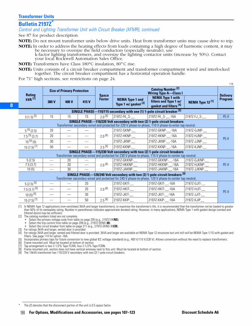
Transformer Units
2
3
5
6
7
8
Bulletin 2197Z*
Control and Lighting Transformer Unit with Circuit Breaker (XFMR), continuedSee 87 for product description.NOTE: Do not mount transformer units below drive units. Heat from transformer units may cause drive to trip.NOTE: In order to address the heating effects from loads containing a high degree of harmonic content, it may
be necessary to oversize the field conductors (especially neutrals), use k-factor lighting transformers, and oversize the lighting contactor units (increase by 50%). Contact your local Rockwell Automation Sales Office.
NOTE: Transformers have Class 180°C insulation, 80° C rise.NOTE: Units consists of a circuit breaker compartment and transformer compartment wired and interlocked
together. The circuit breaker compartment has a horizontal operation handle.For 71” high sections, see restrictions on page 24.
118
* The (Z) denotes that the disconnect portion of the unit is 0.5 space factor.
RatingkVA [1]
[1] In NEMA Type 12 applications (non-ventilated 3kVA and larger transformers), to maximize the transformer’s life, it is recommended that the transformer not be loaded to greater than 50% of its nameplate rating. Number in parentheses indicates approximate derated rating. However, in many applications, NEMA Type 1 with gasket design (vented and filtered doors) may be sufficient.
Size of Primary ProtectionSpaceFactor
Catalog Number [2]
Wiring Type A—Class I
[2] The catalog numbers listed are not complete.• Select the primary voltage code from table on page 205 (e.g., 2197Z-EKNS).• Select the trip current from table on page 209 (e.g., 2197Z-EKNS-30).• Select the circuit breaker from table on page 211 (e.g., 2197Z-EKNS-30CB).
Delivery Program
380 V 400 V 415 VNEMA Type 1 and
Type 1 w/ gasket [3]
[3] For ratings 3kVA and larger, vented door is provided.
NEMA Type 1 with filters and Type 1 w/ gasket and filters [4]
[4] For ratings 3kVA and larger, vented and filtered door is provided. 3kVA and larger are available on NEMA Type 12 structures but unit still will be NEMA Type 1/1G with gasket and filters. See page 114 for option -16A.
NEMA Type 12 [1]
SINGLE PHASE—110/115 secondary with one (1) 1-pole circuit breaker [5]
[5] Incorporates primary taps for future conversion to new global IEC voltage standards (e.g., 400 V/115 V/230 V). Allows conversion without the need to replace transformers.
3 (1.5) [5] 15 15 15 2.0 [6]
[6] Frame mounted unit. Must be located at bottom of section.
2197Z-FK_S-__ 2197Z-FK_S-__-16A 2197Z-FJ_S-__ PE-IISINGLE PHASE—110/220 Volt secondary with two (2) 1-pole circuit breakers
Transformer secondary wired and protected for 220 V phase-to-phase, 110 V phase-to-enter tap neutral.5 [5] (2.5) 20 — —
2.0 [6]
2197Z-GKNP-__ 2197Z-GKNP-__-16A 2197Z-GJNP-__
PE-II7.5 [5] (3.7) 20 — — 2197Z-HKNP-__ 2197Z-HKNP-__-16A 2197Z-HJNP-__
10 [5] (5) 30 — — 2197Z-JKNP-__ 2197Z-JKNP-__-16A 2197Z-JJNP-__
15 (7.5) [7]
[7] Tap arrangement is two 2-1/2% Taps FCAN, four 2-1/2% Taps FCBN.
50 — — 2.5 [8]
[8] Frame mounted unit, section does not have vertical wireway next to this unit. Must be located at bottom of section.
2197Z-KKNP-__ 2197Z-KKNP-__-16A 2197Z-KJNP-__SINGLE PHASE—115/230 Volt secondary with two (2) 1-pole circuit breakers
Transformer secondary wired and protected for 230 V phase-to-phase, 115 V phase-to-center tap neutral. 5 (2.5) — 20 —
2.0 [6]2197Z-GKKNP-__ 2197Z-GKKNP-__-16A 2197Z-GJKNP-__
PE-II7.5 (3.7) — 20 — 2197Z-HKKNP-__ 2197Z-HKKNP-__-16A 2197Z-HJKNP-__10 (5) — 30 — 2197Z-JAKNP-__ 2197Z-JAKNP-__-16A 2197Z-JJKNP-__
SINGLE PHASE—120/240 Volt secondary with two (2) 1-pole circuit breakers [9] Transformer secondary wired and protected for 240 V phase-to-phase, 120 V phase-to-center tap neutral.
[9] The 15kVA transformer has 110/220 V secondary with two (2) 1-pole circuit breakers.
5 (2.5) [5] — — 20
2.0 [6]
2197Z-GKIT-__ 2197Z-GKIT-__-16A 2197Z-GJIT-__
PE-II7.5 (3.7) [5] — — 20 2197Z-HKIT-__ 2197Z-HKIT-__-16A 2197Z-HJIT-__
10 (5) [5] — — 30 2197Z-JKIT-__ 2197Z-JKIT-__-16A 2197Z-JJIT-__
15 (7.5) [7] — — 50 2.5 [8] 2197Z-KKIP-__ 2197Z-KKIP-__-16A 2197Z-KJIP__
98 For Options, Modifications and Accessories, see pages 107–123 Discount Schedule A6

1
2
3
9
12
13
17
18
1520
Miscellaneous UnitsCatalog Number Explanation - Full Section Mounting Plates 119
Full Section Blank Mounting Plate with No Disconnecting Means, with or without Horizontal Power Bus
2100 - E K C 1 X 1 B - - 120 - **Full Section Blank Mounting Plate with Fusible Disconnect Switch, with or without Horizontal Power Bus
2100 - F K C 1 X 1 B - 24J - 120 - **Full Section Blank Mounting Plate with Circuit Breaker, with or without Horizontal Power Bus
2100 - G K C 1 X 1 B - 32CB - 120 - **Bulletin Number
Disconnecting Means
NEMA Type Voltage Unit Depth Placeholder Unit WidthMounting Plate Depth
Fuse Clip or Circuit Breaker
Horizontal Power Bus
Options
119A
Code Type2100
119B
Code Disconnecting MeansE No disconnecting meansF With fusible disconnectG With circuit breaker
119D
Code VoltageA Up to 250VC Up to 600V
119C
Code NEMA Enclosure TypeK NEMA Type 1 or Type 1
with gasketJ NEMA Type 12 119I
CodeFuse Clip or Circuit Breaker
2100F and 2100G only
See page 100 for fuse clip rating or circuit breaker
119K
Code OptionSee available Options on page 23.
119G
Code Unit Width1 20” wide2 25” wide3 30” wide4 35” wide5 40” wide
119H
Code Mounting Plate DepthB 14” DeepC 19” DeepD 8.5” Deep
119E
Code Unit Depth1 15” Deep2 20” Deep
119J
CodeHorizontal Power Bus
Blank Provided with horizontal power bus
120 No horizontal power bus is provided
119F
Code PlaceholderX is a placeholder
For Options, M
o difications and Accessories , see page 99s 107-123 Discount Schedule A6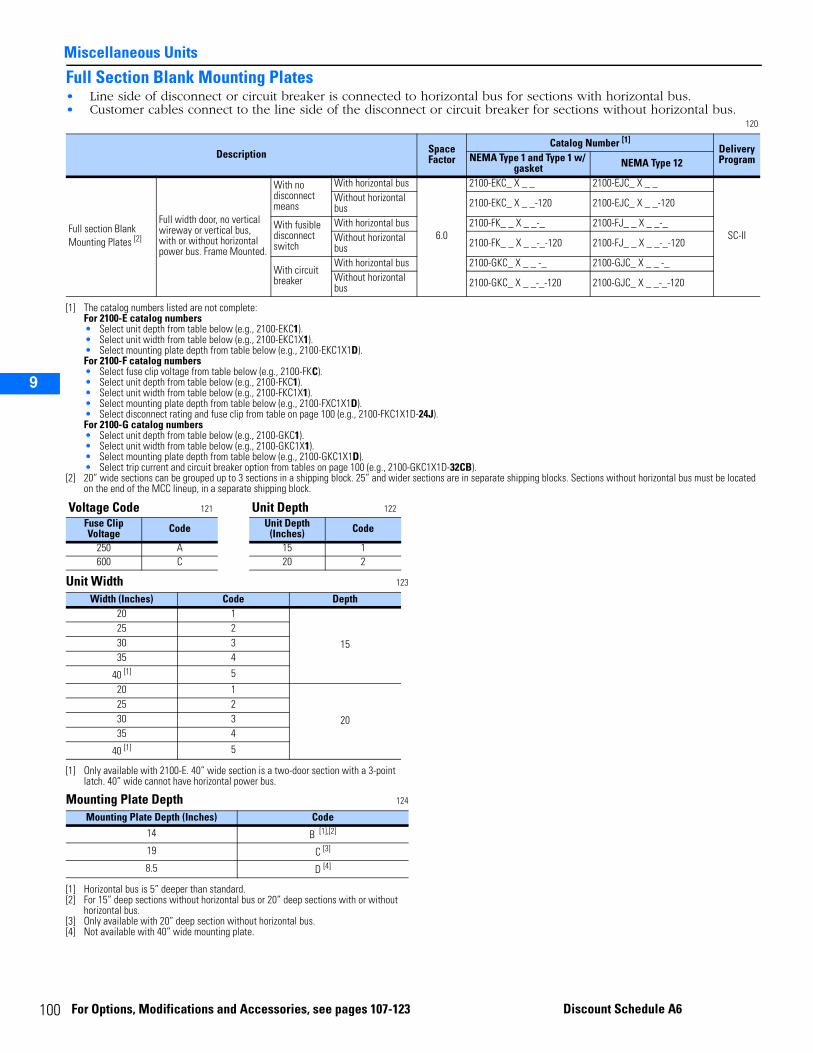
10
Miscellaneous Units1
2
3
9
12
13
17
18
1520
Full Section Blank Mounting Plates• Line side of disconnect or circuit breaker is connected to horizontal bus for sections with horizontal bus.• Customer cables connect to the line side of the disconnect or circuit breaker for sections without horizontal bus.
120
Unit Width 123
Mounting Plate Depth 124
Description Space Factor
Catalog Number [1]
[1] The catalog numbers listed are not complete:For 2100-E catalog numbers• Select unit depth from table below (e.g., 2100-EKC1).• Select unit width from table below (e.g., 2100-EKC1X1).• Select mounting plate depth from table below (e.g., 2100-EKC1X1D).For 2100-F catalog numbers• Select fuse clip voltage from table below (e.g., 2100-FKC).• Select unit depth from table below (e.g., 2100-FKC1).• Select unit width from table below (e.g., 2100-FKC1X1).• Select mounting plate depth from table below (e.g., 2100-FXC1X1D).• Select disconnect rating and fuse clip from table on page 100 (e.g., 2100-FKC1X1D-24J).For 2100-G catalog numbers• Select unit depth from table below (e.g., 2100-GKC1).• Select unit width from table below (e.g., 2100-GKC1X1).• Select mounting plate depth from table below (e.g., 2100-GKC1X1D).• Select trip current and circuit breaker option from tables on page 100 (e.g., 2100-GKC1X1D-32CB).
Delivery ProgramNEMA Type 1 and Type 1 w/
gasket NEMA Type 12
Full section Blank Mounting Plates [2]
[2] 20” wide sections can be grouped up to 3 sections in a shipping block. 25” and wider sections are in separate shipping blocks. Sections without horizontal bus must be located on the end of the MCC lineup, in a separate shipping block.
Full width door, no vertical wireway or vertical bus, with or without horizontal power bus. Frame Mounted.
With no disconnect means
With horizontal bus
6.0
2100-EKC_ X _ _ 2100-EJC_ X _ _
SC-II
Without horizontal bus 2100-EKC_ X _ _-120 2100-EJC_ X _ _-120
With fusible disconnect switch
With horizontal bus 2100-FK_ _ X _ _-_ 2100-FJ_ _ X _ _-_Without horizontal bus 2100-FK_ _ X _ _-_-120 2100-FJ_ _ X _ _-_-120
With circuit breaker
With horizontal bus 2100-GKC_ X _ _ -_ 2100-GJC_ X _ _ -_Without horizontal bus 2100-GKC_ X _ _-_-120 2100-GJC_ X _ _-_-120
Voltage Code 121 Unit Depth 122
Fuse Clip Voltage Code Unit Depth
(Inches) Code
250 A 15 1600 C 20 2
Width (Inches) Code Depth20 1
15
25 230 335 4
40 [1]
[1] Only available with 2100-E. 40” wide section is a two-door section with a 3-point latch. 40” wide cannot have horizontal power bus.
5
20 1
20
25 230 335 4
40 [1] 5
Mounting Plate Depth (Inches) Code14 B [1],[2]
[1] Horizontal bus is 5” deeper than standard.[2] For 15” deep sections without horizontal bus or 20” deep sections with or without
horizontal bus.
19 C [3]
[3] Only available with 20” deep section without horizontal bus.
8.5 D [4]
[4] Not available with 40” wide mounting plate.
0 For Options, Modifications and Accessories, see pages 107-123
Discount Schedule A6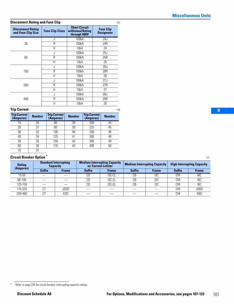
Miscellaneous Units
1
2
3
9
12
13
17
18
1520
Disconnect Rating and Fuse Clip 125
Trip Current 126
Circuit Breaker Option * 127
Disconnect Rating and Fuse Clip Size Fuse Clip Class
Short Circuit withstand Rating
through 600VFuse Clip
Designator
30J 100kA 24JR 100kA 24RH 10kA 24
60J 100kA 25JR 100kA 25RH 10kA 25
100J 100kA 26JR 100kA 26RH 10kA 26
200J 100kA 27JR 100kA 27RH 10kA 27
400J 100kA 28JR 100kA 28RH 10kA 28
Trip Current (Amperes) Number Trip Current
(Amperes) Number Trip Current (Amperes) Number
15 30 80 38 200 4420 31 90 39 225 4530 32 100 40 250 4640 34 125 41 300 4850 35 150 42 350 4960 36 175 43 400 5070 37
Rating (Amperes)
Standard Interrupting Capacity
Medium Interrupting Capacity w/ Current Limiter Medium Interrupting Capacity High Interrupting Capacity
Suffix Frame Suffix Frame Suffix Frame Suffix Frame15-50 — — CD I3C-CL CB I3C CM I6C60-100 — — CD I3C-CL CB I3C CM I6C
125-150 — — CD I3C-CL CB I3C CM I6C175-225 CT JD3D — — — — CM JD6D250-400 CT K3D — — — — CM K6D
* Refer to page 234 for circuit breaker interrupting capacity ratings.
101For Options, Modifications and Accessories, see pages 107-123
Discount Schedule A6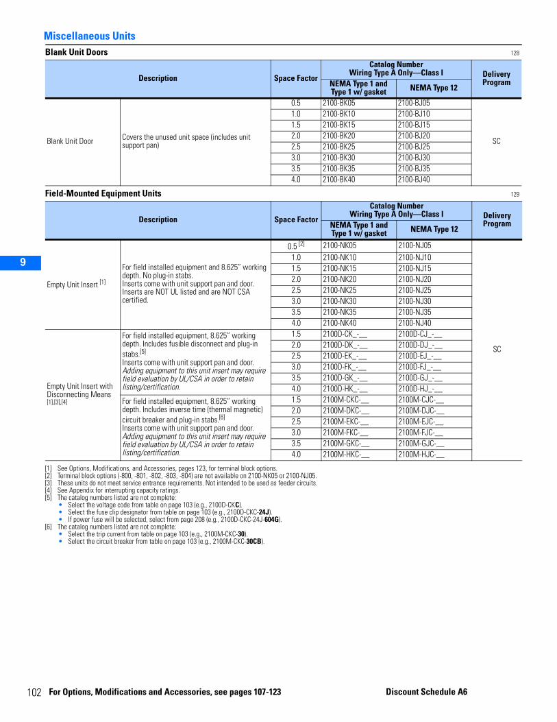
10
Miscellaneous Units1
2
3
9
12
13
17
18
1520
Blank Unit Doors 128
Field-Mounted Equipment Units 129
Description Space Factor
Catalog NumberWiring Type A Only—Class I Delivery
ProgramNEMA Type 1 and Type 1 w/ gasket NEMA Type 12
Blank Unit Door Covers the unused unit space (includes unit support pan)
0.5 2100-BK05 2100-BJ05
SC
1.0 2100-BK10 2100-BJ101.5 2100-BK15 2100-BJ152.0 2100-BK20 2100-BJ202.5 2100-BK25 2100-BJ253.0 2100-BK30 2100-BJ303.5 2100-BK35 2100-BJ354.0 2100-BK40 2100-BJ40
Description Space Factor
Catalog NumberWiring Type A Only—Class I Delivery
ProgramNEMA Type 1 and Type 1 w/ gasket NEMA Type 12
Empty Unit Insert [1]
[1] See Options, Modifications, and Accessories, pages 123, for terminal block options.
For field installed equipment and 8.625” working depth. No plug-in stabs.Inserts come with unit support pan and door.Inserts are NOT UL listed and are NOT CSA certified.
0.5 [2]
[2] Terminal block options (-800, -801, -802, -803, -804) are not available on 2100-NK05 or 2100-NJ05.
2100-NK05 2100-NJ05
SC
1.0 2100-NK10 2100-NJ101.5 2100-NK15 2100-NJ152.0 2100-NK20 2100-NJ202.5 2100-NK25 2100-NJ253.0 2100-NK30 2100-NJ303.5 2100-NK35 2100-NJ354.0 2100-NK40 2100-NJ40
Empty Unit Insert with Disconnecting Means [1],[3],[4]
[3] These units do not meet service entrance requirements. Not intended to be used as feeder circuits.[4] See Appendix for interrupting capacity ratings.
For field installed equipment, 8.625” working depth. Includes fusible disconnect and plug-in stabs.[5]
Inserts come with unit support pan and door.Adding equipment to this unit insert may require field evaluation by UL/CSA in order to retain listing/certification.
[5] The catalog numbers listed are not complete:• Select the voltage code from table on page 103 (e.g., 2100D-CKC).• Select the fuse clip designator from table on page 103 (e.g., 2100D-CKC-24J).• If power fuse will be selected, select from page 208 (e.g., 2100D-CKC-24J-604G).
1.5 2100D-CK_-__ 2100D-CJ_-__2.0 2100D-DK_-__ 2100D-DJ_-__2.5 2100D-EK_-__ 2100D-EJ_-__3.0 2100D-FK_-__ 2100D-FJ_-__3.5 2100D-GK_-__ 2100D-GJ_-__4.0 2100D-HK_-__ 2100D-HJ_-__
For field installed equipment, 8.625” working depth. Includes inverse time (thermal magnetic) circuit breaker and plug-in stabs.[6]
Inserts come with unit support pan and door.Adding equipment to this unit insert may require field evaluation by UL/CSA in order to retain listing/certification.
[6] The catalog numbers listed are not complete:• Select the trip current from table on page 103 (e.g., 2100M-CKC-30).• Select the circuit breaker from table on page 103 (e.g., 2100M-CKC-30CB).
1.5 2100M-CKC-__ 2100M-CJC-__2.0 2100M-DKC-__ 2100M-DJC-__2.5 2100M-EKC-__ 2100M-EJC-__3.0 2100M-FKC-__ 2100M-FJC-__3.5 2100M-GKC-__ 2100M-GJC-__4.0 2100M-HKC-__ 2100M-HJC-__
2 For Options, Modifications and Accessories, see pages 107-123
Discount Schedule A6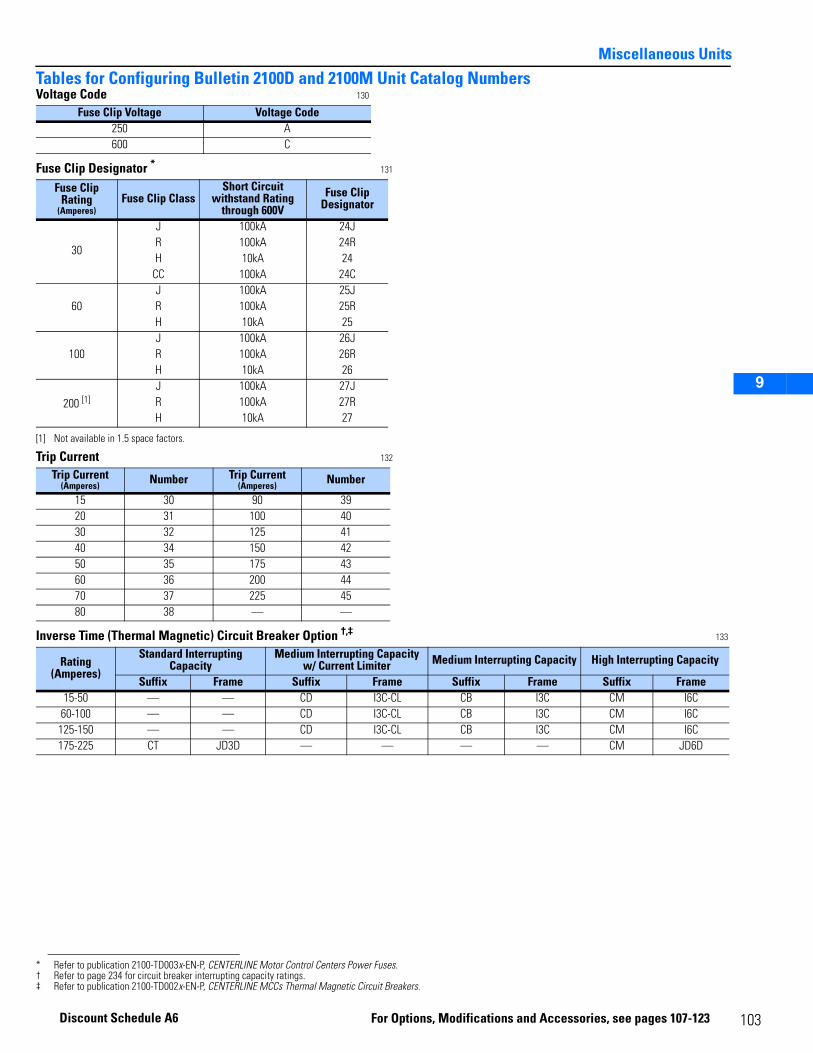
Miscellaneous Units
1
2
3
9
12
13
17
18
1520
Tables for Configuring Bulletin 2100D and 2100M Unit Catalog NumbersVoltage Code 130
Fuse Clip Designator * 131
Trip Current 132
Inverse Time (Thermal Magnetic) Circuit Breaker Option †,‡ 133
Fuse Clip Voltage Voltage Code250 A600 C
Fuse Clip Rating
(Amperes)Fuse Clip Class
Short Circuit withstand Rating
through 600VFuse Clip
Designator
30
J 100kA 24JR 100kA 24RH 10kA 24
CC 100kA 24C
60J 100kA 25JR 100kA 25RH 10kA 25
100J 100kA 26JR 100kA 26RH 10kA 26
200 [1]
[1] Not available in 1.5 space factors.
J 100kA 27JR 100kA 27RH 10kA 27
* Refer to publication 2100-TD003x-EN-P, CENTERLINE Motor Control Centers Power Fuses.
Trip Current(Amperes) Number Trip Current
(Amperes) Number
15 30 90 39 20 31 100 4030 32 125 4140 34 150 4250 35 175 4360 36 200 4470 37 225 4580 38 — —
Rating (Amperes)
Standard Interrupting Capacity
Medium Interrupting Capacity w/ Current Limiter Medium Interrupting Capacity High Interrupting Capacity
Suffix Frame Suffix Frame Suffix Frame Suffix Frame15-50 — — CD I3C-CL CB I3C CM I6C
60-100 — — CD I3C-CL CB I3C CM I6C125-150 — — CD I3C-CL CB I3C CM I6C175-225 CT JD3D — — — — CM JD6D
† Refer to page 234 for circuit breaker interrupting capacity ratings.‡ Refer to publication 2100-TD002x-EN-P, CENTERLINE MCCs Thermal Magnetic Circuit Breakers.
103For Options, Modifications and Accessories, see pages 107-123
Discount Schedule A6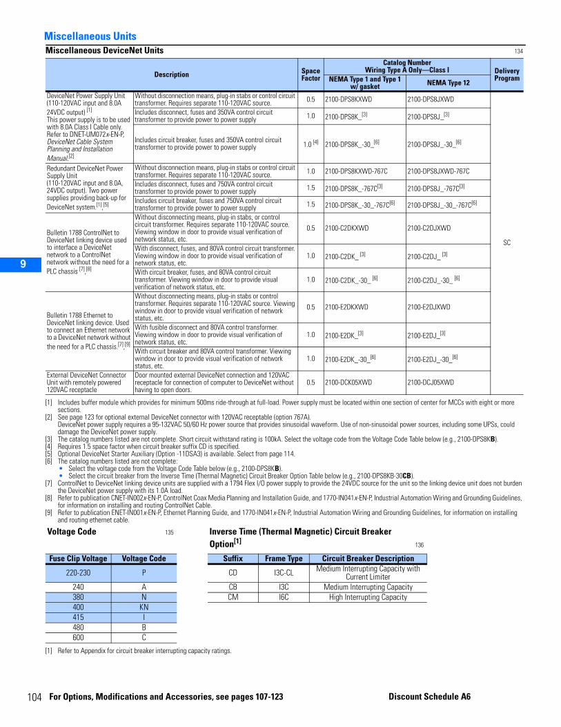
10
1
2
3
9
12
13
17
18
1520
4
Miscellaneous UnitsMiscellaneous DeviceNet Units 134
Description Space Factor
Catalog NumberWiring Type A Only—Class I Delivery
ProgramNEMA Type 1 and Type 1 w/ gasket NEMA Type 12
DeviceNet Power Supply Unit (110-120VAC input and 8.0A 24VDC output) [1]
This power supply is to be used with 8.0A Class I Cable only. Refer to DNET-UM072x-EN-P, DeviceNet Cable System Planning and Installation Manual.[2]
[1] Includes buffer module which provides for minimum 500ms ride-through at full-load. Power supply must be located within one section of center for MCCs with eight or more sections.
[2] See page 123 for optional external DeviceNet connector with 120VAC receptable (option 767A). DeviceNet power supply requires a 95-132VAC 50/60 Hz power source that provides sinusoidal waveform. Use of non-sinusoidal power sources, including some UPSs, could damage the DeviceNet power supply.
Without disconnection means, plug-in stabs or control circuit transformer. Requires separate 110-120VAC source. 0.5 2100-DPS8KXWD 2100-DPS8JXWD
SC
Includes disconnect, fuses and 350VA control circuit transformer to provide power to power supply 1.0 2100-DPS8K_[3]
[3] The catalog numbers listed are not complete. Short circuit withstand rating is 100kA. Select the voltage code from the Voltage Code Table below (e.g., 2100-DPS8KB).
2100-DPS8J_[3]
Includes circuit breaker, fuses and 350VA control circuit transformer to provide power to power supply 1.0 [4]
[4] Requires 1.5 space factor when circuit breaker suffix CD is specified.
2100-DPS8K_-30_[6] 2100-DPS8J_-30_[6]
Redundant DeviceNet Power Supply Unit(110-120VAC input and 8.0A, 24VDC output). Two power supplies providing back-up for DeviceNet system.[1],[5]
[5] Optional DeviceNet Starter Auxiliary (Option -11DSA3) is available. Select from page 114.
Without disconnection means, plug-in stabs or control circuit transformer. Requires separate 110-120VAC source. 1.0 2100-DPS8KXWD-767C 2100-DPS8JXWD-767C
Includes disconnect, fuses and 750VA control circuit transformer to provide power to power supply 1.5 2100-DPS8K_-767C[3] 2100-DPS8J_-767C[3]
Includes circuit breaker, fuses and 750VA control circuit transformer to provide power to power supply 1.5 2100-DPS8K_-30_-767C[6]
[6] The catalog numbers listed are not complete:• Select the voltage code from the Voltage Code Table below (e.g., 2100-DPS8KB).• Select the circuit breaker from the Inverse Time (Thermal Magnetic) Circuit Breaker Option Table below (e.g., 2100-DPS8KB-30CB).
2100-DPS8J_-30_-767C[6]
Bulletin 1788 ControlNet to DeviceNet linking device used to interface a DeviceNet network to a ControlNet network without the need for a PLC chassis [7],[8]
[7] ControlNet to DeviceNet linking device units are supplied with a 1794 Flex I/O power supply to provide the 24VDC source for the unit so the linking device unit does not burden the DeviceNet power supply with its 1.0A load.
[8] Refer to publication CNET-IN002x-EN-P, ControlNet Coax Media Planning and Installation Guide, and 1770-IN041x-EN-P, Industrial Automation Wiring and Grounding Guidelines, for information on installing and routing ControlNet Cable.
Without disconnecting means, plug-in stabs, or control circuit transformer. Requires separate 110-120VAC source. Viewing window in door to provide visual verification of network status, etc.
0.5 2100-C2DKXWD 2100-C2DJXWD
With disconnect, fuses, and 80VA control circuit transformer. Viewing window in door to provide visual verification of network status, etc.
1.0 2100-C2DK_ [3] 2100-C2DJ_ [3]
With circuit breaker, fuses, and 80VA control circuit transformer. Viewing window in door to provide visual verification of network status, etc.
1.0 2100-C2DK_-30_ [6] 2100-C2DJ_-30_ [6]
Bulletin 1788 Ethernet to DeviceNet linking device. Used to connect an Ethernet network to a DeviceNet network without the need for a PLC chassis.[7],[9]
[9] Refer to publication ENET-IN001x-EN-P, Ethernet Planning Guide, and 1770-IN041x-EN-P, Industrial Automation Wiring and Grounding Guidelines, for information on installing and routing ethernet cable.
Without disconnecting means, plug-in stabs or control transformer. Requires separate 110-120VAC source. Viewing window in door to provide visual verification of network status, etc.
0.5 2100-E2DKXWD 2100-E2DJXWD
With fusible disconnect and 80VA control transformer. Viewing window in door to provide visual verification of network status, etc.
1.0 2100-E2DK_[3] 2100-E2DJ_[3]
With circuit breaker and 80VA control transformer. Viewing window in door to provide visual verification of network status, etc.
1.0 2100-E2DK_-30_[6] 2100-E2DJ_-30_[6]
External DeviceNet Connector Unit with remotely powered 120VAC receptacle
Door mounted external DeviceNet connection and 120VAC receptacle for connection of computer to DeviceNet without having to open doors.
0.5 2100-DCK05XWD 2100-DCJ05XWD
Voltage Code 135 Inverse Time (Thermal Magnetic) Circuit Breaker Option[1] 136
[1] Refer to Appendix for circuit breaker interrupting capacity ratings.
Fuse Clip Voltage Voltage Code Suffix Frame Type Circuit Breaker Description
220-230 P CD I3C-CL Medium Interrupting Capacity with Current Limiter
240 A CB I3C Medium Interrupting Capacity380 N CM I6C High Interrupting Capacity400 KN415 I480 B600 C
For Options, Modifications and Accessories, see pages 107-123 Discount Schedule A6
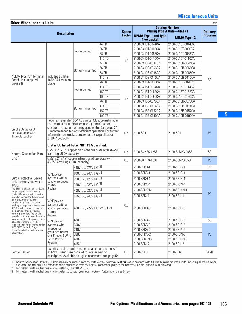
Miscellaneous Units
1
2
3
9
12
13
17
18
1520
Other Miscellaneous Units 137
Description Space Factor
Catalog NumberWiring Type A Only—Class I Delivery
ProgramNEMA Type 1 and Type 1 w/ gasket NEMA Type 12
NEMA Type “C” Terminal Board Unit (supplied unwired)
Includes Bulletin 1492-CA1 terminal blocks
Top- mounted
44 TB
1.0
2100-CK10T-0044CA 2100-CJ10T-0044CA
SC
66 TB 2100-CK10T-0066CA 2100-CJ10T-0066CA88 TB 2100-CK10T-0088CA 2100-CJ10T-0088CA110 TB 2100-CK10T-0110CA 2100-CJ10T-0110CA
Bottom- mounted
44 TB 2100-CK10B-0044CA 2100-CJ10B-0044CA66 TB 2100-CK10B-0066CA 2100-CJ10B-0066CA88 TB 2100-CK10B-0088CA 2100-CJ10B-0088CA110 TB 2100-CK10B-0110CA 2100-CJ10B-0110CA
Top- mounted
76 TB
1.5
2100-CK15T-0076CA 2100-CJ15T-0076CA114 TB 2100-CK15T-0114CA 2100-CJ15T-0114CA152 TB 2100-CK15T-0152CA 2100-CJ15T-0152CA190 TB 2100-CK15T-0190CA 2100-CJ15T-0190CA
Bottom- mounted
76 TB 2100-CK15B-0076CA 2100-CJ15B-0076CA114 TB 2100-CK15B-0114CA 2100-CJ15B-0114CA152 TB 2100-CK15B-0152CA 2100-CJ15B-0152CA190 TB 2100-CK15B-0190CA 2100-CJ15B-0190CA
Smoke Detector Unit(not available with T-handle latches)
Requires separate 120V AC source. Must be installed in bottom of section. Provides one (1) form C contact closure. The use of bottom closing plates (see page 24) is recommended for most efficient operation. For further information on smoke detector unit, see publication 2100-IN046x-EN-P.
Unit is UL listed but is NOT CSA certified.
0.5 2100-SD1 2100-SD1 PE
Neutral Connection Plate Unit [1]
[1] Neutral Connection Plate 0.5 SF Unit can only be used in sections with vertical wireway. Not for use in sections with full width frame mounted units, including all mains.When horizontal neutral bus is selected the cable connection from the neutral connection plate to the horizontal neutral plate is NOT provided.
0.25” x 2” x 12” copper tin plated bus plate with #6-250 kcmil lug (280A capacity) 0.5 2100-BKNPC-05SF 2100-BJNPC-05SF SC
0.25” x 2” x 12” copper silver plated bus plate with #6-250 kcmil lug (280A capacity) 0.5 2100-BKNPS-05SF 2100-BJNPS-05SF PE
Surge Protective Device Unit (formerly known as TVSS)The SPD consists of an IslaGuard surge suppression system by Control Concepts, with circuitry provided to monitor the status of all protection modes. Unit consists of a fused disconnect feeding a surge protective device (SPD) rated to provide a minimum of 160kA per phase of surge current protection. The unit is provided with one green light as a status indicator. (Response time is 0.5nS) SPD meets UL 1449 requirements. Refer to publication 2100-TD023x-EN-P, Surge Protective Device Unit for more information.
WYE power systems with a solidly grounded neutral 3-wire
480V L-L, 277V L-G [2]
[2] For systems with neutral bus (4-wire systems), use 2100-SP_B-3
0.5
2100-SPKB-1 2100-SPJB-1 SC
600V L-L, 346V L-G [3]
[3] For systems with neutral bus (4-wire systems), contact your local Rockwell Automation Sales Office.
2100-SPKC-1 2100-SPJC-1
PE
208V L-L, 120V L-G [3] 2100-SPKH-1 2100-SPJH-1
380V L-L, 220V L-G [3] 2100-SPKN-1 2100-SPJN-1
400V L-L, 230V L-G [3] 2100-SPKKN-1 2100-SPJKN-1
415V L-L, 240V L-G [3] 2100-SPKI-1 2100-SPJI-1WYE power systems with a solidly grounded neutral, 4-wire
480V L-L, 277V L-G, 277V L-N 2100-SPKB-3 2100-SPJB-3
WYE power systems with impedence grounded neutral or 3 Phase, 3 Wire Delta Power Systems
480V 2100-SPKB-2 2100-SPJB-2 SC600V 2100-SPKC-2 2100-SPJC-2
PE240V 2100-SPKA-2 2100-SPJA-2380V 2100-SPKN-2 2100-SPJN-2400V 2100-SPKKN-2 2100-SPJKN-2415V 2100-SPKI-2 2100-SPJI-2
Corner SectionUse this catalog number to select a corner section with an MCC lineup. See page 24 for corner section description. Available as lug compartment, see page 64.
6.0 2100-CS60 2100-CS60 SC-II
105For Options, Modifications and Accessories, see pages 107-123
Discount Schedule A6
10
Miscellaneous Units1
2
3
9
12
13
17
18
1520
6
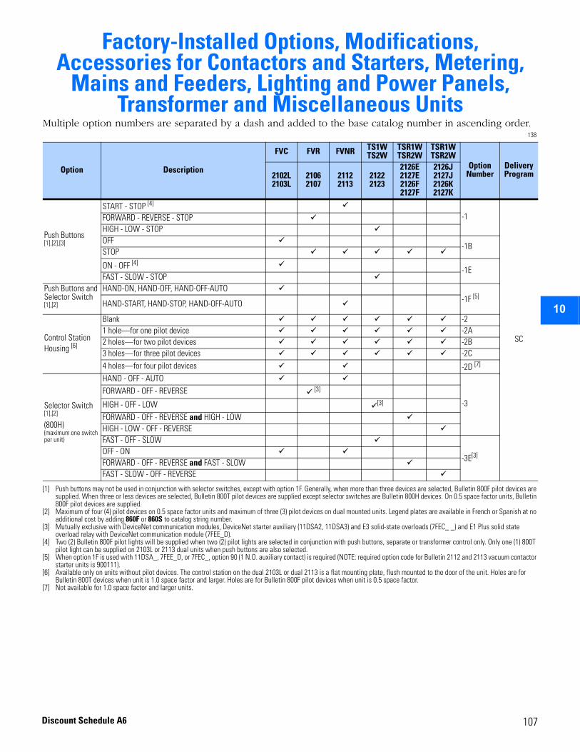
2
3
4
5
6
7
8
9
10
11
12
13
14
15
16
17
Factory-Installed Options, Modifications, Accessories for Contactors and Starters, Metering,
Mains and Feeders, Lighting and Power Panels, Transformer and Miscellaneous Units
Multiple option numbers are separated by a dash and added to the base catalog number in ascending order.138
Option Description
FVC FVR FVNR TS1WTS2W
TSR1WTSR2W
TSR1WTSR2W
OptionNumber
Delivery Program2102L
2103L21062107
21122113
21222123
2126E2127E2126F2127F
2126J2127J2126K2127K
Push Buttons [1],[2],[3]
[1] Push buttons may not be used in conjunction with selector switches, except with option 1F. Generally, when more than three devices are selected, Bulletin 800F pilot devices are supplied. When three or less devices are selected, Bulletin 800T pilot devices are supplied except selector switches are Bulletin 800H devices. On 0.5 space factor units, Bulletin 800F pilot devices are supplied.
[2] Maximum of four (4) pilot devices on 0.5 space factor units and maximum of three (3) pilot devices on dual mounted units. Legend plates are available in French or Spanish at no additional cost by adding 860F or 860S to catalog string number.
[3] Mutually exclusive with DeviceNet communication modules, DeviceNet starter auxiliary (11DSA2, 11DSA3) and E3 solid-state overloads (7FEC_ _) and E1 Plus solid state overload relay with DeviceNet communication module (7FEE_D).
START - STOP [4]
[4] Two (2) Bulletin 800F pilot lights will be supplied when two (2) pilot lights are selected in conjunction with push buttons, separate or transformer control only. Only one (1) 800T pilot light can be supplied on 2103L or 2113 dual units when push buttons are also selected.
-1
SC
FORWARD - REVERSE - STOP HIGH - LOW - STOPOFF
-1B STOP
ON - OFF [4]-1E
FAST - SLOW - STOPPush Buttons and Selector Switch [1],[2]
HAND-ON, HAND-OFF, HAND-OFF-AUTO-1F [5]
[5] When option 1F is used with 11DSA_, 7FEE_D, or 7FEC_, option 90 (1 N.O. auxiliary contact) is required (NOTE: required option code for Bulletin 2112 and 2113 vacuum contactor starter units is 900111).
HAND-START, HAND-STOP, HAND-OFF-AUTO
Control Station Housing [6]
[6] Available only on units without pilot devices. The control station on the dual 2103L or dual 2113 is a flat mounting plate, flush mounted to the door of the unit. Holes are for Bulletin 800T devices when unit is 1.0 space factor and larger. Holes are for Bulletin 800F pilot devices when unit is 0.5 space factor.
Blank -21 hole—for one pilot device -2A2 holes—for two pilot devices -2B3 holes—for three pilot devices -2C4 holes—for four pilot devices -2D [7]
[7] Not available for 1.0 space factor and larger units.
Selector Switch [1],[2]
(800H)(maximum one switch per unit)
HAND - OFF - AUTO
-3FORWARD - OFF - REVERSE [3]
HIGH - OFF - LOW [3] FORWARD - OFF - REVERSE and HIGH - LOWHIGH - LOW - OFF - REVERSEFAST - OFF - SLOW
-3E[3]OFF - ON FORWARD - OFF - REVERSE and FAST - SLOWFAST - SLOW - OFF - REVERSE
107Discount Schedule A6
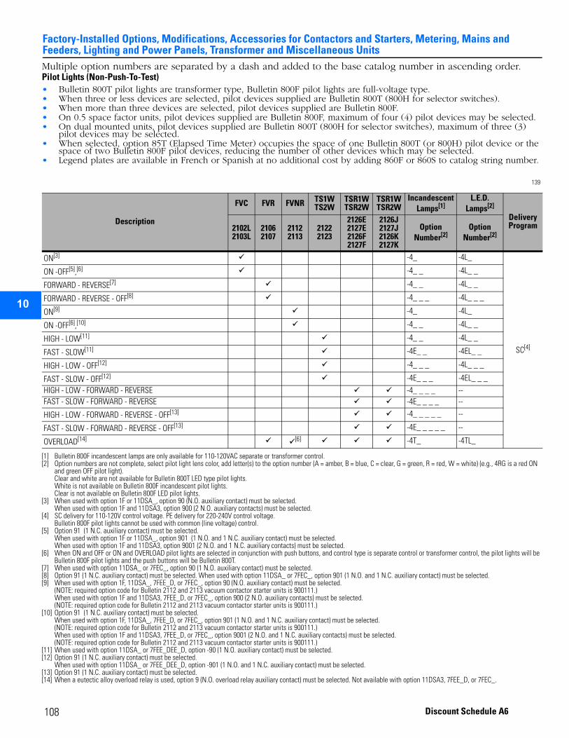
Factory-Installed Options, Modifications, Accessories for Contactors and Starters, Metering, Mains and Feeders, Lighting and Power Panels, Transformer and Miscellaneous Units
2
3
4
5
9
10
11
12
13
14
15
16
17
108
Multiple option numbers are separated by a dash and added to the base catalog number in ascending order.Pilot Lights (Non-Push-To-Test)• Bulletin 800T pilot lights are transformer type, Bulletin 800F pilot lights are full-voltage type.• When three or less devices are selected, pilot devices supplied are Bulletin 800T (800H for selector switches). • When more than three devices are selected, pilot devices supplied are Bulletin 800F. • On 0.5 space factor units, pilot devices supplied are Bulletin 800F, maximum of four (4) pilot devices may be selected. • On dual mounted units, pilot devices supplied are Bulletin 800T (800H for selector switches), maximum of three (3)
pilot devices may be selected. • When selected, option 85T (Elapsed Time Meter) occupies the space of one Bulletin 800T (or 800H) pilot device or the
space of two Bulletin 800F pilot devices, reducing the number of other devices which may be selected. • Legend plates are available in French or Spanish at no additional cost by adding 860F or 860S to catalog string number.
139
Description
FVC FVR FVNR TS1W TS2W
TSR1W TSR2W
TSR1WTSR2W
Incandescent Lamps[1]
[1] Bulletin 800F incandescent lamps are only available for 110-120VAC separate or transformer control.
L.E.D. Lamps[2]
Delivery Program2102L
2103L2106 2107
2112 2113
2122 2123
2126E 2127E 2126F 2127F
2126J 2127J 2126K 2127K
Option Number[2]
[2] Option numbers are not complete, select pilot light lens color, add letter(s) to the option number (A = amber, B = blue, C = clear, G = green, R = red, W = white) (e.g., 4RG is a red ON and green OFF pilot light). Clear and white are not available for Bulletin 800T LED type pilot lights. White is not available on Bulletin 800F incandescent pilot lights. Clear is not available on Bulletin 800F LED pilot lights.
Option Number[2]
ON[3]
[3] When used with option 1F or 11DSA_, option 90 (N.O. auxiliary contact) must be selected. When used with option 1F and 11DSA3, option 900 (2 N.O. auxiliary contacts) must be selected.
-4_ -4L_
SC[4]
[4] SC delivery for 110-120V control voltage. PE delivery for 220-240V control voltage. Bulletin 800F pilot lights cannot be used with common (line voltage) control.
ON -OFF[5],[6]
[5] Option 91 (1 N.C. auxiliary contact) must be selected. When used with option 1F or 11DSA_, option 901 (1 N.O. and 1 N.C. auxiliary contact) must be selected. When used with option 1F and 11DSA3, option 9001 (2 N.O. and 1 N.C. auxiliary contacts) must be selected.
[6] When ON and OFF or ON and OVERLOAD pilot lights are selected in conjunction with push buttons, and control type is separate control or transformer control, the pilot lights will be Bulletin 800F pilot lights and the push buttons will be Bulletin 800T.
-4_ _ -4L_ _
FORWARD - REVERSE[7]
[7] When used with option 11DSA_ or 7FEC_, option 90 (1 N.O. auxiliary contact) must be selected.
-4_ _ -4L_ _
FORWARD - REVERSE - OFF[8]
[8] Option 91 (1 N.C. auxiliary contact) must be selected. When used with option 11DSA_ or 7FEC_, option 901 (1 N.O. and 1 N.C. auxiliary contact) must be selected.
-4_ _ _ -4L_ _ _
ON[9]
[9] When used with option 1F, 11DSA_, 7FEE_D, or 7FEC_, option 90 (N.O. auxiliary contact) must be selected.(NOTE: required option code for Bulletin 2112 and 2113 vacuum contactor starter units is 900111.)When used with option 1F and 11DSA3, 7FEE_D, or 7FEC_, option 900 (2 N.O. auxiliary contacts) must be selected. (NOTE: required option code for Bulletin 2112 and 2113 vacuum contactor starter units is 900111.)
-4_ -4L_
ON -OFF[6],[10]
[10] Option 91 (1 N.C. auxiliary contact) must be selected. When used with option 1F, 11DSA_, 7FEE_D, or 7FEC_, option 901 (1 N.O. and 1 N.C. auxiliary contact) must be selected.(NOTE: required option code for Bulletin 2112 and 2113 vacuum contactor starter units is 900111.) When used with option 1F and 11DSA3, 7FEE_D, or 7FEC_, option 9001 (2 N.O. and 1 N.C. auxiliary contacts) must be selected. (NOTE: required option code for Bulletin 2112 and 2113 vacuum contactor starter units is 900111.)
-4_ _ -4L_ _
HIGH - LOW[11]
[11] When used with option 11DSA_ or 7FEE_DEE_D, option -90 (1 N.O. auxiliary contact) must be selected.
-4_ _ -4L_ _
FAST - SLOW[11] -4E_ _ -4EL_ _
HIGH - LOW - OFF[12]
[12] Option 91 (1 N.C. auxiliary contact) must be selected. When used with option 11DSA_ or 7FEE_DEE_D, option -901 (1 N.O. and 1 N.C. auxiliary contact) must be selected.
-4_ _ _ -4L_ _ _
FAST - SLOW - OFF[12] -4E_ _ _ -4EL_ _ _HIGH - LOW - FORWARD - REVERSE -4_ _ _ _ --FAST - SLOW - FORWARD - REVERSE -4E_ _ _ _ --
HIGH - LOW - FORWARD - REVERSE - OFF[13]
[13] Option 91 (1 N.C. auxiliary contact) must be selected.
-4_ _ _ _ _ --
FAST - SLOW - FORWARD - REVERSE - OFF[13] -4E_ _ _ _ _ --
OVERLOAD[14]
[14] When a eutectic alloy overload relay is used, option 9 (N.O. overload relay auxiliary contact) must be selected. Not available with option 11DSA3, 7FEE_D, or 7FEC_.
[6] -4T_ -4TL_
Discount Schedule A6
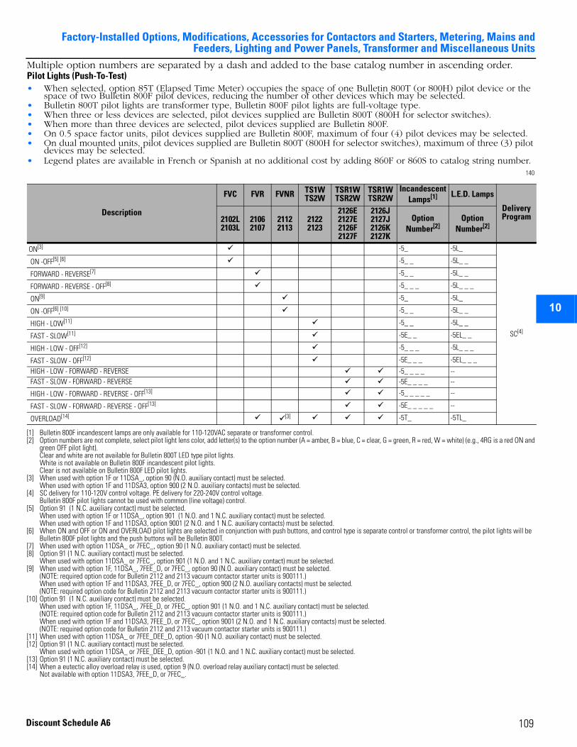
Factory-Installed Options, Modifications, Accessories for Contactors and Starters, Metering, Mains andFeeders, Lighting and Power Panels, Transformer and Miscellaneous Units
2
3
4
5
6
7
8
9
10
11
12
13
14
15
16
17
Multiple option numbers are separated by a dash and added to the base catalog number in ascending order.Pilot Lights (Push-To-Test)• When selected, option 85T (Elapsed Time Meter) occupies the space of one Bulletin 800T (or 800H) pilot device or the
space of two Bulletin 800F pilot devices, reducing the number of other devices which may be selected. • Bulletin 800T pilot lights are transformer type, Bulletin 800F pilot lights are full-voltage type.• When three or less devices are selected, pilot devices supplied are Bulletin 800T (800H for selector switches). • When more than three devices are selected, pilot devices supplied are Bulletin 800F. • On 0.5 space factor units, pilot devices supplied are Bulletin 800F, maximum of four (4) pilot devices may be selected. • On dual mounted units, pilot devices supplied are Bulletin 800T (800H for selector switches), maximum of three (3) pilot
devices may be selected. • Legend plates are available in French or Spanish at no additional cost by adding 860F or 860S to catalog string number.
140
Description
FVC FVR FVNR TS1W TS2W
TSR1W TSR2W
TSR1WTSR2W
Incandescent Lamps[1]
[1] Bulletin 800F incandescent lamps are only available for 110-120VAC separate or transformer control.
L.E.D. Lamps
Delivery Program2102L
2103L2106 2107
2112 2113
2122 2123
2126E 2127E 2126F 2127F
2126J 2127J 2126K 2127K
Option Number[2]
[2] Option numbers are not complete, select pilot light lens color, add letter(s) to the option number (A = amber, B = blue, C = clear, G = green, R = red, W = white) (e.g., 4RG is a red ON and green OFF pilot light). Clear and white are not available for Bulletin 800T LED type pilot lights. White is not available on Bulletin 800F incandescent pilot lights. Clear is not available on Bulletin 800F LED pilot lights.
Option Number[2]
ON[3]
[3] When used with option 1F or 11DSA_, option 90 (N.O. auxiliary contact) must be selected. When used with option 1F and 11DSA3, option 900 (2 N.O. auxiliary contacts) must be selected.
-5_ -5L_
SC[4]
[4] SC delivery for 110-120V control voltage. PE delivery for 220-240V control voltage. Bulletin 800F pilot lights cannot be used with common (line voltage) control.
ON -OFF[5],[6]
[5] Option 91 (1 N.C. auxiliary contact) must be selected. When used with option 1F or 11DSA_, option 901 (1 N.O. and 1 N.C. auxiliary contact) must be selected. When used with option 1F and 11DSA3, option 9001 (2 N.O. and 1 N.C. auxiliary contacts) must be selected.
[6] When ON and OFF or ON and OVERLOAD pilot lights are selected in conjunction with push buttons, and control type is separate control or transformer control, the pilot lights will be Bulletin 800F pilot lights and the push buttons will be Bulletin 800T.
-5_ _ -5L_ _
FORWARD - REVERSE[7]
[7] When used with option 11DSA_ or 7FEC_, option 90 (1 N.O. auxiliary contact) must be selected.
-5_ _ -5L_ _
FORWARD - REVERSE - OFF[8]
[8] Option 91 (1 N.C. auxiliary contact) must be selected. When used with option 11DSA_ or 7FEC_, option 901 (1 N.O. and 1 N.C. auxiliary contact) must be selected.
-5_ _ _ -5L_ _ _
ON[9]
[9] When used with option 1F, 11DSA_, 7FEE_D, or 7FEC_, option 90 (N.O. auxiliary contact) must be selected. (NOTE: required option code for Bulletin 2112 and 2113 vacuum contactor starter units is 900111.)When used with option 1F and 11DSA3, 7FEE_D, or 7FEC_, option 900 (2 N.O. auxiliary contacts) must be selected. (NOTE: required option code for Bulletin 2112 and 2113 vacuum contactor starter units is 900111.)
-5_ -5L_
ON -OFF[6],[10]
[10] Option 91 (1 N.C. auxiliary contact) must be selected. When used with option 1F, 11DSA_, 7FEE_D, or 7FEC_, option 901 (1 N.O. and 1 N.C. auxiliary contact) must be selected. (NOTE: required option code for Bulletin 2112 and 2113 vacuum contactor starter units is 900111.) When used with option 1F and 11DSA3, 7FEE_D, or 7FEC_, option 9001 (2 N.O. and 1 N.C. auxiliary contacts) must be selected. (NOTE: required option code for Bulletin 2112 and 2113 vacuum contactor starter units is 900111.)
-5_ _ -5L_ _
HIGH - LOW[11]
[11] When used with option 11DSA_ or 7FEE_DEE_D, option -90 (1 N.O. auxiliary contact) must be selected.
-5_ _ -5L_ _
FAST - SLOW[11] -5E_ _ -5EL_ _
HIGH - LOW - OFF[12]
[12] Option 91 (1 N.C. auxiliary contact) must be selected. When used with option 11DSA_ or 7FEE_DEE_D, option -901 (1 N.O. and 1 N.C. auxiliary contact) must be selected.
-5_ _ _ -5L_ _ _
FAST - SLOW - OFF[12] -5E_ _ _ -5EL_ _ _
HIGH - LOW - FORWARD - REVERSE -5_ _ _ _ -- FAST - SLOW - FORWARD - REVERSE -5E_ _ _ _ --
HIGH - LOW - FORWARD - REVERSE - OFF[13]
[13] Option 91 (1 N.C. auxiliary contact) must be selected.
-5_ _ _ _ _ --
FAST - SLOW - FORWARD - REVERSE - OFF[13] -5E_ _ _ _ _ --
OVERLOAD[14]
[14] When a eutectic alloy overload relay is used, option 9 (N.O. overload relay auxiliary contact) must be selected. Not available with option 11DSA3, 7FEE_D, or 7FEC_.
[3] -5T_ -5TL_
109Discount Schedule A6
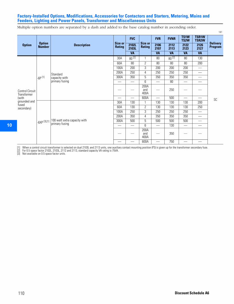
Factory-Installed Options, Modifications, Accessories for Contactors and Starters, Metering, Mains and Feeders, Lighting and Power Panels, Transformer and Miscellaneous Units
2
3
4
5
9
10
11
12
13
14
15
16
17
Multiple option numbers are separated by a dash and added to the base catalog number in ascending order.141
Option OptionNumber Description Size or
Rating
FVCSize or Rating
FVR FVNR TS1W TS2W
TSR1WTSR2W
Delivery Program2102L
2103L21062107
21122113
21222123
21262127
VA VA VA VA VA
Control Circuit Transformer (with grounded and fused secondary)
-6P [1]
[1] When a control circuit transformer is selected on dual 2103L and 2113 units, one auxiliary contact mounting position (P3) is given up for the transformer secondary fuse.
Standardcapacity withprimary fusing
30A 80 [2]
[2] For 0.5 space factor 2102L, 2103L, 2112 and 2113, standard capacity VA rating is 75VA.
1 80 80 [2] 80 130
SC
60A 80 2 80 80 80 200100A 200 3 200 200 200 —200A 250 4 250 250 250 —300A 350 5 350 350 350 —— — 6 — 80 — —
— —200A and
400A— 250 — —
— — 600A — 500 — —
-6XP [3],[1]
[3] Not available on 0.5 space factor units.
100 watt extra capacity withprimary fusing
30A 130 1 130 130 130 20060A 130 2 130 130 130 250100A 250 3 250 250 250 —200A 350 4 350 350 350 —300A 500 5 500 500 500 —— — 6 — 130 — —
— —200A and
400A— 350 — —
— — 600A — 750 — —
110 Discount Schedule A6
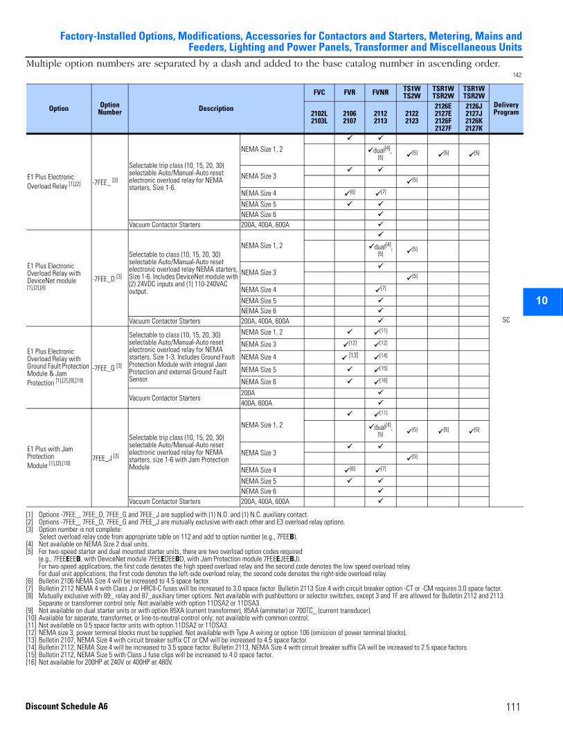
Factory-Installed Options, Modifications, Accessories for Contactors and Starters, Metering, Mains andFeeders, Lighting and Power Panels, Transformer and Miscellaneous Units
2
3
4
5
6
7
8
9
10
11
12
13
14
15
16
17
111
Multiple option numbers are separated by a dash and added to the base catalog number in ascending order. 142
Option OptionNumber Description
FVC FVR FVNR TS1WTS2W
TSR1WTSR2W
TSR1WTSR2W
Delivery Program2102L
2103L21062107
21122113
21222123
2126E2127E2126F2127F
2126J2127J2126K2127K
E1 Plus Electronic Overload Relay [1],[2]
[1] Options -7FEE_, 7FEE_D, 7FEE_G and 7FEE_J are supplied with (1) N.O. and (1) N.C. auxiliary contact.[2] Options -7FEE_, 7FEE_D, 7FEE_G and 7FEE_J are mutually exclusive with each other and E3 overload relay options.
-7FEE_ [3]
[3] Option number is not complete:Select overload relay code from appropriate table on 112 and add to option number (e.g., 7FEEB).
Selectable trip class (10, 15, 20, 30) selectable Auto/Manual-Auto reset electronic overload relay for NEMA starters, Size 1-6.
NEMA Size 1, 2
SC
dual[4], [5]
[4] Not available on NEMA Size 2 dual units.
[5]
[5] For two-speed starter and dual mounted starter units, there are two overload option codes required (e.g., 7FEEEEEB, with DeviceNet module 7FEEEDEEBD, with Jam Protection module 7FEEEJEEBJ).For two-speed applications, the first code denotes the high speed overload relay and the second code denotes the low speed overload relay.For dual unit applications, the first code denotes the left-side overload relay, the second code denotes the right-side overload relay.
[5] [5]
NEMA Size 3 [5]
NEMA Size 4 [6]
[6] Bulletin 2106 NEMA Size 4 will be increased to 4.5 space factor.
[7]
[7] Bulletin 2112 NEMA 4 with Class J or HRCII-C fuses will be increased to 3.0 space factor. Bulletin 2113 Size 4 with circuit breaker option -CT or -CM requires 3.0 space factor.
NEMA Size 5 NEMA Size 6
Vacuum Contactor Starters 200A, 400A, 600A
E1 Plus Electronic Overload Relay with DeviceNet module [1],[2],[8]
[8] Mutually exclusive with 89_ relay and 87_auxiliary timer options. Not available with pushbuttons or selector switches, except 3 and 1F are allowed for Bulletin 2112 and 2113. Separate or transformer control only. Not available with option 11DSA2 or 11DSA3.
-7FEE_D [3]
Selectable to class (10, 15, 20, 30) selectable Auto/Manual-Auto reset electronic overload relay NEMA starters, Size 1-6. Includes DeviceNet module with (2) 24VDC inputs and (1) 110-240VAC output.
NEMA Size 1, 2 dual[4], [5]
[5]
NEMA Size 3 [5]
NEMA Size 4 [7]
NEMA Size 5 NEMA Size 6
Vacuum Contactor Starters 200A, 400A, 600A
E1 Plus Electronic Overload Relay with Ground Fault Protection Module & Jam Protection [1],[2],[9],[10]
[9] Not available on dual starter units or with option 85XA (current transformer), 85AA (ammeter) or 700TC_ (current transducer).[10] Available for separate, transformer, or line-to-neutral control only; not available with common control.
-7FEE_G [3]
Selectable to class (10, 15, 20, 30) selectable Auto/Manual-Auto reset electronic overload relay for NEMA starters, Size 1-3. Includes Ground Fault Protection Module with integral Jam Protection and external Ground Fault Sensor.
NEMA Size 1, 2 [11]
[11] Not available on 0.5 space factor units with option 11DSA2 or 11DSA3.
NEMA Size 3 [12]
[12] NEMA size 3, power terminal blocks must be supplied. Not available with Type A wiring or option 106 (omission of power terminal blocks).
[12]
NEMA Size 4 [13]
[13] Bulletin 2107, NEMA Size 4 with circuit breaker suffix CT or CM will be increased to 4.5 space factor.
[14]
[14] Bulletin 2112, NEMA Size 4 will be increased to 3.5 space factor. Bulletin 2113, NEMA Size 4 with circuit breaker suffix CA will be increased to 2.5 space factors.
NEMA Size 5 [15]
[15] Bulletin 2112, NEMA Size 5 with Class J fuse clips will be increased to 4.0 space factor.
NEMA Size 6 [16]
[16] Not available for 200HP at 240V or 400HP at 480V.
Vacuum Contactor Starters200A400A, 600A
E1 Plus with Jam Protection Module [1],[2],[10]
7FEE_J [3]
Selectable trip class (10, 15, 20, 30) selectable Auto/Manual-Auto reset electronic overload relay for NEMA starters, size 1-6 with Jam Protection Module
NEMA Size 1, 2
[11]
dual[4], [5]
[5] [5] [5]
NEMA Size 3 [5]
NEMA Size 4 [6] [7]
NEMA Size 5 NEMA Size 6
Vacuum Contactor Starters 200A, 400A, 600A
Discount Schedule A6
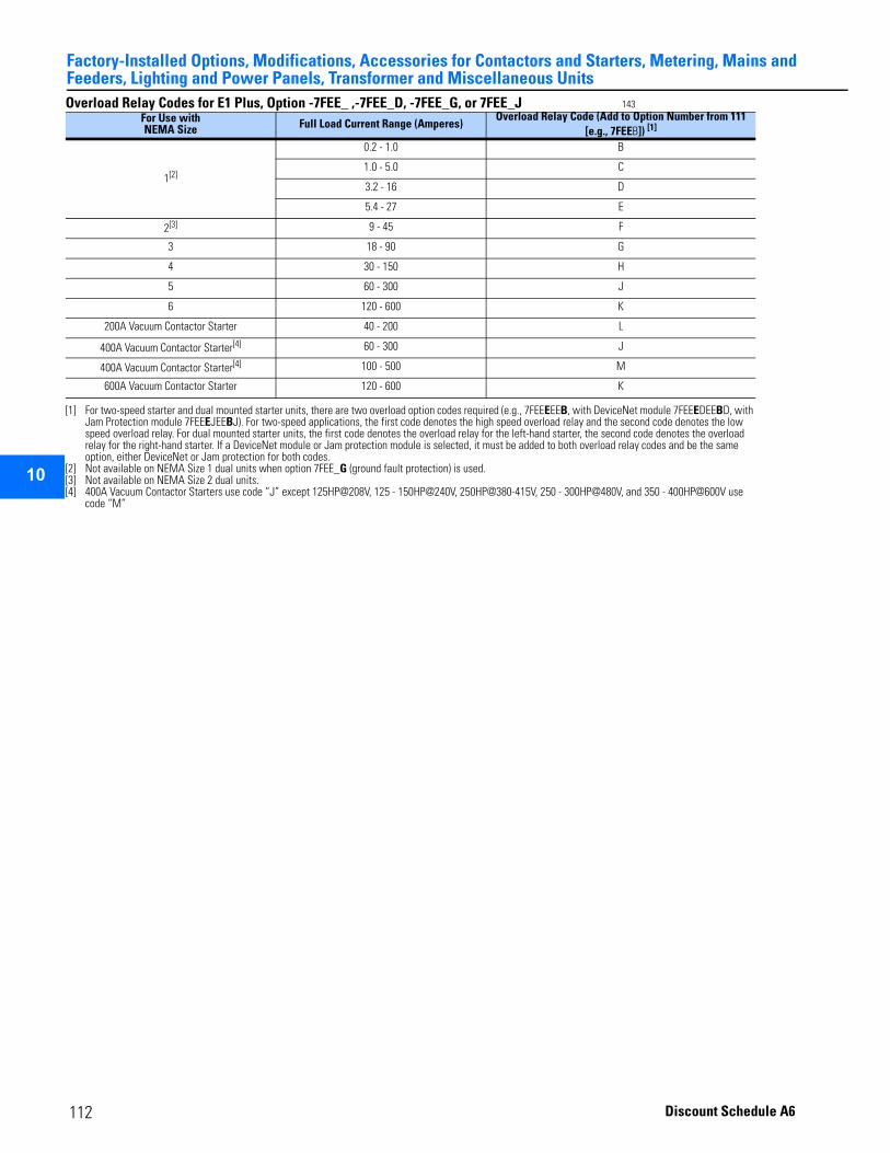
Factory-Installed Options, Modifications, Accessories for Contactors and Starters, Metering, Mains and Feeders, Lighting and Power Panels, Transformer and Miscellaneous Units
2
3
4
5
9
10
11
12
13
14
15
16
17
Overload Relay Codes for E1 Plus, Option -7FEE_ ,-7FEE_D, -7FEE_G, or 7FEE_J 143 For Use with NEMA Size Full Load Current Range (Amperes)
Overload Relay Code (Add to Option Number from 111 [e.g., 7FEEB]) [1]
[1] For two-speed starter and dual mounted starter units, there are two overload option codes required (e.g., 7FEEEEEB, with DeviceNet module 7FEEEDEEBD, with Jam Protection module 7FEEEJEEBJ). For two-speed applications, the first code denotes the high speed overload relay and the second code denotes the low speed overload relay. For dual mounted starter units, the first code denotes the overload relay for the left-hand starter, the second code denotes the overload relay for the right-hand starter. If a DeviceNet module or Jam protection module is selected, it must be added to both overload relay codes and be the same option, either DeviceNet or Jam protection for both codes.
1[2]
[2] Not available on NEMA Size 1 dual units when option 7FEE_G (ground fault protection) is used.
0.2 - 1.0 B
1.0 - 5.0 C
3.2 - 16 D
5.4 - 27 E
2[3]
[3] Not available on NEMA Size 2 dual units.
9 - 45 F
3 18 - 90 G
4 30 - 150 H
5 60 - 300 J
6 120 - 600 K
200A Vacuum Contactor Starter 40 - 200 L
400A Vacuum Contactor Starter[4]
[4] 400A Vacuum Contactor Starters use code “J” except 125HP@208V, 125 - 150HP@240V, 250HP@380-415V, 250 - 300HP@480V, and 350 - 400HP@600V use code “M”
60 - 300 J
400A Vacuum Contactor Starter[4] 100 - 500 M
600A Vacuum Contactor Starter 120 - 600 K
112 Discount Schedule A6
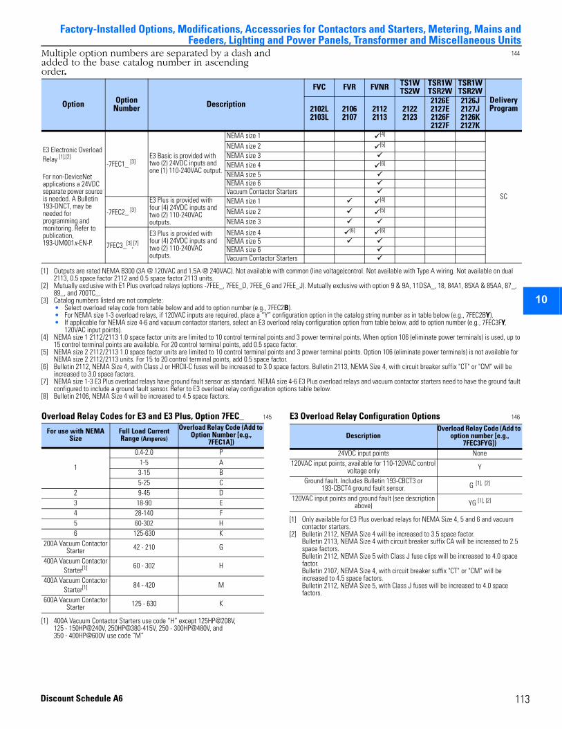
2
3
4
5
6
7
8
9
10
11
12
13
14
15
16
17
Factory-Installed Options, Modifications, Accessories for Contactors and Starters, Metering, Mains and
Feeders, Lighting and Power Panels, Transformer and Miscellaneous UnitsMultiple option numbers are separated by a dash and added to the base catalog number in ascending order.
144
Overload Relay Codes for E3 and E3 Plus, Option 7FEC_ 145 E3 Overload Relay Configuration Options 146
Option OptionNumber Description
FVC FVR FVNR TS1WTS2W
TSR1WTSR2W
TSR1WTSR2W
Delivery Program2102L
2103L21062107
21122113
21222123
2126E2127E2126F2127F
2126J2127J2126K2127K
E3 Electronic Overload Relay [1],[2]
For non-DeviceNet applications a 24VDC separate power source is needed. A Bulletin 193-DNCT, may be needed for programming and monitoring. Refer to publication, 193-UM001x-EN-P.
-7FEC1_ [3]E3 Basic is provided with two (2) 24VDC inputs and one (1) 110-240VAC output.
NEMA size 1 [4]
SC
NEMA size 2 [5]
NEMA size 3 NEMA size 4 [6]
NEMA size 5 NEMA size 6Vacuum Contactor Starters
-7FEC2_ [3]
E3 Plus is provided with four (4) 24VDC inputs and two (2) 110-240VAC outputs.
NEMA size 1 [4]
NEMA size 2 [5]
NEMA size 3
7FEC3_[3],[7]
E3 Plus is provided with four (4) 24VDC inputs and two (2) 110-240VAC outputs.
NEMA size 4 [8] [6]
NEMA size 5 NEMA size 6 Vacuum Contactor Starters
[1] Outputs are rated NEMA B300 (3A @ 120VAC and 1.5A @ 240VAC). Not available with common (line voltage)control. Not available with Type A wiring. Not available on dual 2113, 0.5 space factor 2112 and 0.5 space factor 2113 units.
[2] Mutually exclusive with E1 Plus overload relays (options -7FEE_, 7FEE_D, 7FEE_G and 7FEE_J). Mutually exclusive with option 9 & 9A, 11DSA_, 18, 84A1, 85XA & 85AA, 87_, 89_, and 700TC_.
[3] Catalog numbers listed are not complete:• Select overload relay code from table below and add to option number (e.g., 7FEC2B).• For NEMA size 1-3 overload relays, if 120VAC inputs are required, place a “Y” configuration option in the catalog string number as in table below (e.g., 7FEC2BY).• If applicable for NEMA size 4-6 and vacuum contactor starters, select an E3 overload relay configuration option from table below, add to option number (e.g., 7FEC3FY,
120VAC input points).[4] NEMA size 1 2112/2113 1.0 space factor units are limited to 10 control terminal points and 3 power terminal points. When option 106 (eliminate power terminals) is used, up to
15 control terminal points are available. For 20 control terminal points, add 0.5 space factor.[5] NEMA size 2 2112/2113 1.0 space factor units are limited to 10 control terminal points and 3 power terminal points. Option 106 (eliminate power terminals) is not available for
NEMA size 2 2112/2113 units. For 15 to 20 control terminal points, add 0.5 space factor.[6] Bulletin 2112, NEMA Size 4, with Class J or HRCII-C fuses will be increased to 3.0 space factors. Bulletin 2113, NEMA Size 4, with circuit breaker suffix "CT" or "CM" will be
increased to 3.0 space factors.[7] NEMA size 1-3 E3 Plus overload relays have ground fault sensor as standard. NEMA size 4-6 E3 Plus overload relays and vacuum contactor starters need to have the ground fault
configured to include a ground fault sensor. Refer to E3 overload relay configuration options table below.[8] Bulletin 2106, NEMA Size 4 will be increased to 4.5 space factors.
For use with NEMA Size
Full Load Current Range (Amperes)
Overload Relay Code (Add to Option Number [e.g.,
7FEC1A])
1
0.4-2.0 P1-5 A
3-15 B5-25 C
2 9-45 D3 18-90 E4 28-140 F5 60-302 H6 125-630 K
200A Vacuum Contactor Starter 42 - 210 G
400A Vacuum Contactor Starter[1]
[1] 400A Vacuum Contactor Starters use code “H” except 125HP@208V, 125 - 150HP@240V, 250HP@380-415V, 250 - 300HP@480V, and 350 - 400HP@600V use code “M”
60 - 302 H
400A Vacuum Contactor Starter[1] 84 - 420 M
600A Vacuum Contactor Starter 125 - 630 K
DescriptionOverload Relay Code (Add to
option number [e.g., 7FEC3FYG])
24VDC input points None120VAC input points, available for 110-120VAC control
voltage only Y
Ground fault. Includes Bulletin 193-CBCT3 or 193-CBCT4 ground fault sensor. G [1], [2]
[1] Only available for E3 Plus overload relays for NEMA Size 4, 5 and 6 and vacuum contactor starters.
[2] Bulletin 2112, NEMA Size 4 will be increased to 3.5 space factor.Bulletin 2113, NEMA Size 4 with circuit breaker suffix CA will be increased to 2.5 space factors.Bulletin 2112, NEMA Size 5 with Class J fuse clips will be increased to 4.0 space factor.Bulletin 2107, NEMA Size 4, with circuit breaker suffix "CT" or "CM" will be increased to 4.5 space factors.Bulletin 2112, NEMA Size 5, with Class J fuses will be increased to 4.0 space factors.
120VAC input points and ground fault (see description above) YG [1], [2]
113Discount Schedule A6
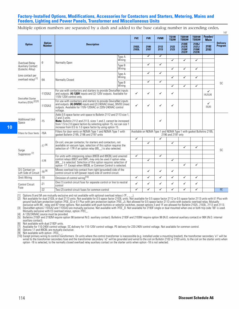
Factory-Installed Options, Modifications, Accessories for Contactors and Starters, Metering, Mains and Feeders, Lighting and Power Panels, Transformer and Miscellaneous Units
2
3
4
5
9
10
11
12
13
14
15
16
17
Multiple option numbers are separated by a dash and added to the base catalog number in ascending order.147
Option OptionNumber Description
FVC FVR FVNR TS1WTS2W
TSR1WTSR2W
TSR1WTSR2W
Feeder/Main
Delivery Program2102L
2103L21062107
21122113
21222123
2126E2127E2126F2127F
2126J2127J2126K2127K
21922193
Overload Relay Auxiliary Contact (Eutectic Alloy)
(one contact per overload relay) [1]
[1] Options 9 and 9A are mutually exclusive and not available with optional overload relays (-7F_ _ _).
-9 Normally Open
Type A Wiring
SC
Type B Wiring
-9A Normally Closed
Type A Wiring
Type B Wiring
DeviceNet Starter Auxiliary (DSA) [2],[3]
[2] Not available for dual 2103L or dual 2113 units. Not available for 0.5 space factor 2103L units. Not available for 0.5 space factor 2112 or 0.5 space factor 2113 units with E1 Plus with ground fault/jam protection (option 7FEE_G) or E1 Plus with jam protection (option 7FEE_J). Not allowed for 0.5 space factor 2113 units with eutectic overload relay. Mutually exclusive with 89_ relay and 87 timer options. Not available with push buttons or selector switches, except options 3 and 1F are allowed for Bulletin 2102L, 2103L, 2112 and 2113.
[3] DeviceNet options 11DSA2 and 11DSA3 are mutually exclusive. Not available with 7FEE_D. Not available for 2193F single or dual mounted when one or both trip code ‘00’ is used. Mutually exclusive with E3 overload relays, option 7FEC_.
-11DSA2For use with contactors and starters to provide DeviceNet inputs and outputs. (4) 120V inputs and (2) 120V outputs. Available for 110V-120V control only.
[4],[5],[6]
[4] A 120/240VAC source must be provided.[5] Bulletins 2192F and 2192M require option 98 (external N.O. auxiliary contact). Bulletins 2193F and 2193M require option 98 (N.O. external auxiliary contact) or 98X (N.O. internal
auxiliary contact).[6] Not available with dual 2192F units.
-11DSA3
For use with contactors and starters to provide DeviceNet inputs and outputs. (4) 24VDC inputs and (2) 240VAC (max), 30VDC (max) outputs. Available for 110V-120VAC or 220V-240VAC control voltage.
[5],[6]
Additional Unit Space -15
Adds 0.5 space factor unit space to Bulletin 2112 and 2113 size 1, 2 and 3 units.Note: Bulletin 2112 and 2113, sizes 1 and 2, cannot be increased from 1.5 to 2.0 space factors by selecting option 15, nor can size 1 increase from 0.5 to 1.0 space factor by using option 15.
SC
Filters for Door Vents -16A Filters for door vents on NEMA Type 1 and NEMA Type 1 with gasket Bulletin 2195, 2196 and 2197 units
Available on NEMA Type 1 and NEMA Type 1 with gasket Bulletins 2195, 2196 and 2197 only
Surge Suppressor [7]
[7] Available for 110-240V control voltage. SC delivery for 110-120V control voltage. PE delivery for 220-240V control voltage. Not available for common control.
-17 [8]
[8] Options 17 and 89CBL are mutually exclusive.
On coil, one per contactor, for starters and contactors, not available on vacuum type, selection of this option requires the selection of -17R if an option relay (89__) is also selected.
-17R
For units with interposing relays (89CB and 89CBL) and unwired control relays (89CF and 89P), may only be used if option relay (89__) is selected. Selection of this option requires selection of option -17. Except when 89CBL or Common Control is selected.
O/L Contact on Left Side of Circuit -18 [9]
[9] Not available with option -7FEC_ _.
Moves overload trip contact from right (grounded) side of the control circuit to left (power input) side of control circuit.
Omit Wiring -19 Omission of control wiring[10]
[10] Except primary wiring to control transformers. On units where the control transformer is inaccessible (e.g. installed under a mounting bracket), the transformer secondary ‘x1’ will be wired to the transformer secondary fuse and the transformer secondary ‘x2’ will be grounded and wired to the coil on Bulletin 2102 or 2103 units, to the coil on the starter units when option -18 is selected, to the normally closed overload relay auxiliary contact on the starter units when option -18 is not selected.
Control Circuit Fuse
-21 One (1) control circuit fuse for separate control or line to neutral control
-22 Two (2) control circuit fuses for common control PE
114 Discount Schedule A6

Factory-Installed Options, Modifications, Accessories for Contactors and Starters, Metering, Mains andFeeders, Lighting and Power Panels, Transformer and Miscellaneous Units
2
3
4
5
6
7
8
9
10
11
12
13
14
15
16
17
Multiple option numbers are separated by a dash and added to the base catalog number in ascending order.148
Option Option Number Description
FVC FVR FVNR TS1WTS2W
TSR1WTSR2W
TSR1WTSR2W
Delivery Program2102L
2103L21062107
21122113
21222123
2126E2127E2126F2127F
2126J2127J2126K2127K
Blown Fuse Indicator Lights -4BF Option 4BF is valid only when 480V and 600V Power Factor
Correction Capacitor is selected
PE-II
480V and 600V Power Factor Correction Capacitors [1],[2]
(Refer to publication 2100-AT001x-EN-P, Power Factor Correction Capacitors for CENTERLINE 2100 MCC Starter Units, for more information)
[1] See option 4BF for optional blown fuse indicators. Not available on dual starters, 0.5 space factor units, 6.0 space factor units or Space Saving NEMA units or vacuum contactor starters. Refer to Recommended Capacitor Size table in Appendix for suggested capacitor ratings.
[2] For applications other than motor applications connected to the load side of the starter or for those applications outlined in publication 2100-AT001x-EN-P, contact your local Rockwell Automation Sales Office.
-30KV
2 kVAR through 40 kVAR in 0.5 space factor. [3]
42.5 kVAR through 50 kVAR in 1.0 space factor.[3]
These capacitors should not be used on motors subject to plugging or jogging. Do not subject capacitors to repetitive switching where capacitors and motors might be reenergized too quickly after being de-energized.
Do not install capacitors in any vertical section that contains a variable frequency drive.
Capacitors are mounted in separate unit with a separate door. This unit is located below selected starter. Door interlock is included. Three phase power fuses are included.
Capacitors are factory wired to load side of the contactor and on the line side of the overload relay.
[3] At 600V, 37.5 kVAR to 50 kVAR are 1.0 space factor
2 kVAR-31KV 2.5 kVAR -32KV 3 kVAR-33KV 4 kVAR-34KV 5 kVAR-35KV 6 kVAR -36KV 7 kVAR -37KV 7.5 kVAR-38KV 8 kVAR-39KV 9 kVAR-40KV 10 kVAR-41KV 11 kVAR-42KV 12.5 kVAR-43KV 13.5 kVAR-44KV 15 kVAR-45KV 16 kVAR-46KV 17.5 kVAR-47KV 18 kVAR-48KV 20 kVAR-49KV 22.5 kVAR-50KV 25 kVAR-51KV 27.5 kVAR-52KV 30 kVAR-53KV 32.5 kVAR-54KV 35 kVAR-55KV 37.5 kVAR-56KV 40 kVAR-57KV 42.5 kVAR-58KV 45 kVAR-59KV 50 kVAR
115Discount Schedule A6
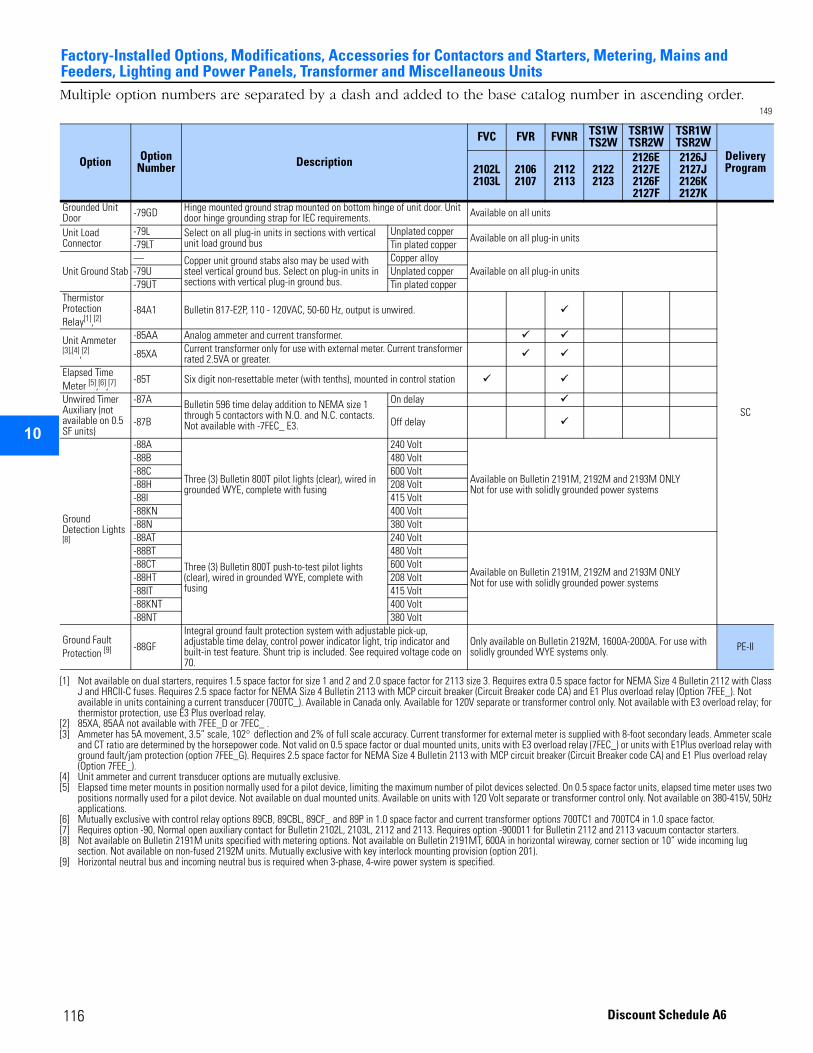
Factory-Installed Options, Modifications, Accessories for Contactors and Starters, Metering, Mains and Feeders, Lighting and Power Panels, Transformer and Miscellaneous Units
2
3
4
5
9
10
11
12
13
14
15
16
17
Multiple option numbers are separated by a dash and added to the base catalog number in ascending order.149
Option OptionNumber Description
FVC FVR FVNR TS1WTS2W
TSR1WTSR2W
TSR1WTSR2W
Delivery Program2102L
2103L21062107
21122113
21222123
2126E2127E2126F2127F
2126J2127J2126K2127K
Grounded Unit Door -79GD Hinge mounted ground strap mounted on bottom hinge of unit door. Unit
door hinge grounding strap for IEC requirements. Available on all units
SC
Unit Load Connector
-79L Select on all plug-in units in sections with vertical unit load ground bus
Unplated copperAvailable on all plug-in units
-79LT Tin plated copper
Unit Ground Stab— Copper unit ground stabs also may be used with
steel vertical ground bus. Select on plug-in units in sections with vertical plug-in ground bus.
Copper alloyAvailable on all plug-in units-79U Unplated copper
-79UT Tin plated copperThermistor Protection Relay[1],[2]
[1] Not available on dual starters, requires 1.5 space factor for size 1 and 2 and 2.0 space factor for 2113 size 3. Requires extra 0.5 space factor for NEMA Size 4 Bulletin 2112 with Class J and HRCII-C fuses. Requires 2.5 space factor for NEMA Size 4 Bulletin 2113 with MCP circuit breaker (Circuit Breaker code CA) and E1 Plus overload relay (Option 7FEE_). Not available in units containing a current transducer (700TC_). Available in Canada only. Available for 120V separate or transformer control only. Not available with E3 overload relay; for thermistor protection, use E3 Plus overload relay.
[2] 85XA, 85AA not available with 7FEE_D or 7FEC_ .
-84A1 Bulletin 817-E2P, 110 - 120VAC, 50-60 Hz, output is unwired.
Unit Ammeter [3],[4],[2]
[3] Ammeter has 5A movement, 3.5” scale, 102° deflection and 2% of full scale accuracy. Current transformer for external meter is supplied with 8-foot secondary leads. Ammeter scale and CT ratio are determined by the horsepower code. Not valid on 0.5 space factor or dual mounted units, units with E3 overload relay (7FEC_) or units with E1Plus overload relay with ground fault/jam protection (option 7FEE_G). Requires 2.5 space factor for NEMA Size 4 Bulletin 2113 with MCP circuit breaker (Circuit Breaker code CA) and E1 Plus overload relay (Option 7FEE_).
[4] Unit ammeter and current transducer options are mutually exclusive.
-85AA Analog ammeter and current transformer.
-85XA Current transformer only for use with external meter. Current transformer rated 2.5VA or greater.
Elapsed Time Meter [5],[6],[7]
[5] Elapsed time meter mounts in position normally used for a pilot device, limiting the maximum number of pilot devices selected. On 0.5 space factor units, elapsed time meter uses two positions normally used for a pilot device. Not available on dual mounted units. Available on units with 120 Volt separate or transformer control only. Not available on 380-415V, 50Hz applications.
[6] Mutually exclusive with control relay options 89CB, 89CBL, 89CF_ and 89P in 1.0 space factor and current transformer options 700TC1 and 700TC4 in 1.0 space factor.[7] Requires option -90, Normal open auxiliary contact for Bulletin 2102L, 2103L, 2112 and 2113. Requires option -900011 for Bulletin 2112 and 2113 vacuum contactor starters.
-85T Six digit non-resettable meter (with tenths), mounted in control station
Unwired Timer Auxiliary (not available on 0.5 SF units)
-87A Bulletin 596 time delay addition to NEMA size 1 through 5 contactors with N.O. and N.C. contacts. Not available with -7FEC_ E3.
On delay
-87B Off delay
Ground Detection Lights [8]
[8] Not available on Bulletin 2191M units specified with metering options. Not available on Bulletin 2191MT, 600A in horizontal wireway, corner section or 10” wide incoming lug section. Not available on non-fused 2192M units. Mutually exclusive with key interlock mounting provision (option 201).
-88A
Three (3) Bulletin 800T pilot lights (clear), wired in grounded WYE, complete with fusing
240 Volt
Available on Bulletin 2191M, 2192M and 2193M ONLYNot for use with solidly grounded power systems
-88B 480 Volt-88C 600 Volt-88H 208 Volt-88I 415 Volt-88KN 400 Volt-88N 380 Volt-88AT
Three (3) Bulletin 800T push-to-test pilot lights (clear), wired in grounded WYE, complete with fusing
240 Volt
Available on Bulletin 2191M, 2192M and 2193M ONLYNot for use with solidly grounded power systems
-88BT 480 Volt-88CT 600 Volt-88HT 208 Volt-88IT 415 Volt-88KNT 400 Volt-88NT 380 Volt
Ground Fault Protection [9]
[9] Horizontal neutral bus and incoming neutral bus is required when 3-phase, 4-wire power system is specified.
-88GF
Integral ground fault protection system with adjustable pick-up, adjustable time delay, control power indicator light, trip indicator and built-in test feature. Shunt trip is included. See required voltage code on 70.
Only available on Bulletin 2192M, 1600A-2000A. For use with solidly grounded WYE systems only. PE-II
116 Discount Schedule A6
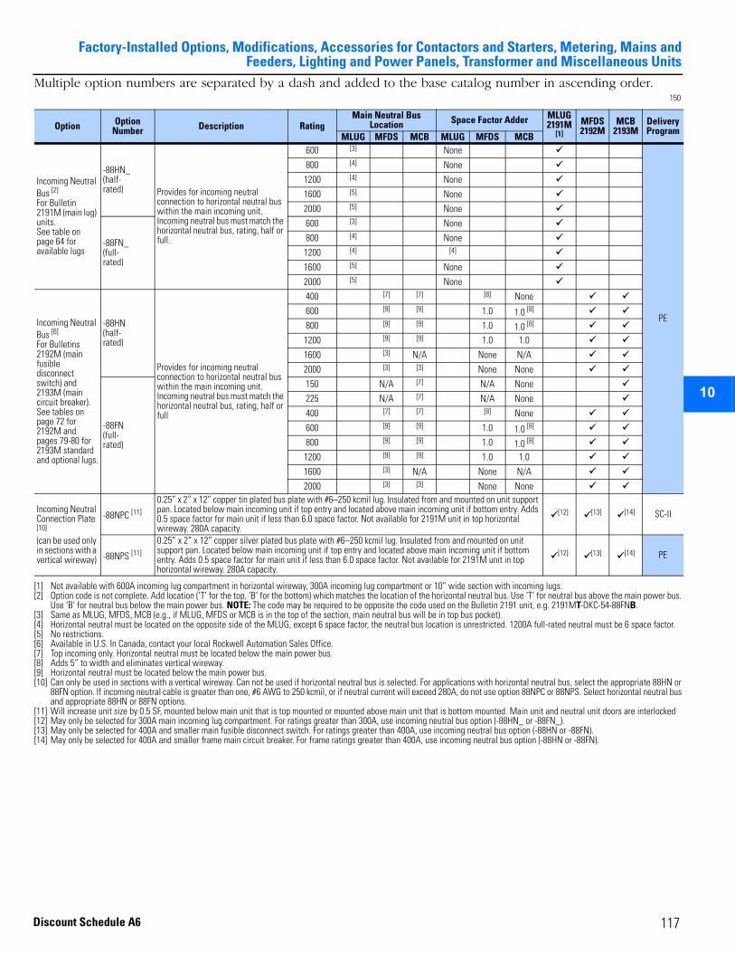
Factory-Installed Options, Modifications, Accessories for Contactors and Starters, Metering, Mains andFeeders, Lighting and Power Panels, Transformer and Miscellaneous Units
2
3
4
5
6
7
8
9
10
11
12
13
14
15
16
17
Multiple option numbers are separated by a dash and added to the base catalog number in ascending order.150
Option Option Number Description Rating
Main Neutral Bus Location Space Factor Adder MLUG
2191M [1]
[1] Not available with 600A incoming lug compartment in horizontal wireway, 300A incoming lug compartment or 10” wide section with incoming lugs.
MFDS 2192M
MCB2193M
Delivery Program
MLUG MFDS MCB MLUG MFDS MCB
Incoming Neutral Bus [2]
For Bulletin 2191M (main lug) units.See table on page 64 for available lugs
[2] Option code is not complete. Add location (‘T’ for the top, ‘B’ for the bottom) which matches the location of the horizontal neutral bus. Use ‘T’ for neutral bus above the main power bus. Use ‘B’ for neutral bus below the main power bus. NOTE: The code may be required to be opposite the code used on the Bulletin 2191 unit, e.g. 2191MT-DKC-54-88FNB.
-88HN_(half-rated) Provides for incoming neutral
connection to horizontal neutral bus within the main incoming unit. Incoming neutral bus must match the horizontal neutral bus, rating, half or full.
600 [3]
[3] Same as MLUG, MFDS, MCB (e.g., if MLUG, MFDS or MCB is in the top of the section, main neutral bus will be in top bus pocket).
None
PE
800 [4]
[4] Horizontal neutral must be located on the opposite side of the MLUG, except 6 space factor, the neutral bus location is unrestricted. 1200A full-rated neutral must be 6 space factor.
None
1200 [4] None
1600 [5]
[5] No restrictions.
None
2000 [5] None
-88FN_(full-rated)
600 [3] None
800 [4] None
1200 [4] [4]
1600 [5] None
2000 [5] None
Incoming Neutral Bus [6]
For Bulletins 2192M (main fusible disconnect switch) and 2193M (main circuit breaker).See tables on page 72 for 2192M and pages 79-80 for 2193M standard and optional lugs.
[6] Available in U.S. In Canada, contact your local Rockwell Automation Sales Office.
-88HN(half-rated)
Provides for incoming neutral connection to horizontal neutral bus within the main incoming unit. Incoming neutral bus must match the horizontal neutral bus, rating, half or full
400 [7] [7]
[7] Top incoming only. Horizontal neutral must be located below the main power bus.
[8]
[8] Adds 5” to width and eliminates vertical wireway.
None
600 [9]
[9] Horizontal neutral must be located below the main power bus.
[9] 1.0 1.0 [8]
800 [9] [9] 1.0 1.0 [8]
1200 [9] [9] 1.0 1.0
1600 [3] N/A None N/A
2000 [3] [3] None None
-88FN(full-rated)
150 N/A [7] N/A None
225 N/A [7] N/A None
400 [7] [7] [8] None
600 [9] [9] 1.0 1.0 [8]
800 [9] [9] 1.0 1.0 [8]
1200 [9] [9] 1.0 1.0
1600 [3] N/A None N/A
2000 [3] [3] None None
Incoming Neutral Connection Plate [10]
(can be used only in sections with a vertical wireway)
[10] Can only be used in sections with a vertical wireway. Can not be used if horizontal neutral bus is selected. For applications with horizontal neutral bus, select the appropriate 88HN or 88FN option. If incoming neutral cable is greater than one, #6 AWG to 250 kcmil, or if neutral current will exceed 280A, do not use option 88NPC or 88NPS. Select horizontal neutral bus and appropriate 88HN or 88FN options.
-88NPC [11]
[11] Will increase unit size by 0.5 SF, mounted below main unit that is top mounted or mounted above main unit that is bottom mounted. Main unit and neutral unit doors are interlocked
0.25” x 2” x 12” copper tin plated bus plate with #6–250 kcmil lug. Insulated from and mounted on unit support pan. Located below main incoming unit if top entry and located above main incoming unit if bottom entry. Adds 0.5 space factor for main unit if less than 6.0 space factor. Not available for 2191M unit in top horizontal wireway. 280A capacity.
[12]
[12] May only be selected for 300A main incoming lug compartment. For ratings greater than 300A, use incoming neutral bus option (-88HN_ or -88FN_).
[13]
[13] May only be selected for 400A and smaller main fusible disconnect switch. For ratings greater than 400A, use incoming neutral bus option (-88HN or -88FN).
[14]
[14] May only be selected for 400A and smaller frame main circuit breaker. For frame ratings greater than 400A, use incoming neutral bus option (-88HN or -88FN).
SC-II
-88NPS [11]
0.25” x 2” x 12” copper silver plated bus plate with #6–250 kcmil lug. Insulated from and mounted on unit support pan. Located below main incoming unit if top entry and located above main incoming unit if bottom entry. Adds 0.5 space factor for main unit if less than 6.0 space factor. Not available for 2191M unit in top horizontal wireway. 280A capacity.
[12] [13] [14] PE
117Discount Schedule A6

Factory-Installed Options, Modifications, Accessories for Contactors and Starters, Metering, Mains and Feeders, Lighting and Power Panels, Transformer and Miscellaneous Units
2
3
4
5
9
10
11
12
13
14
15
16
17
151
Option Option Number Description
FVC FVR FVNR TS1WTS2W
TSR1WTSR2W
TSR1WTSR2W
Delivery Program2102L
2103L21062107
21122113
21222123
2126E2127E2126F2127F
2126J2127J2126K2127K
Interposing Relay [1]
Mutually exclusive with 89CF and 89P, unwired control relays
[1] 2.0 space factor minimum when selected on Bulletin 2113 size 3 starters and Bulletin 2106 and 2107 size 1 or 2. Not available on dual 2103L, dual 2113 units or 0.5 space factor units. Not available with common control. Mutually exclusive with 7FEC_ options, 11DSA2 or 11DSA3 DeviceNet starter auxiliary options or 7FEE_D.
-89CB
Control circuit interposing relay. Utilizes Bulletin 700-CF control relay to control starter coil in control circuit. Available on NEMA sizes 1 through 5 and vacuum contactor starters. The starter or contactor coil voltages and interposing relay coil voltages are the same as the control voltage.
SC [2]
[2] SC delivery for 110-120V control voltage. PE delivery for 220-240V control voltage.
-89CBL [3]
[3] Options 89CBL and 17 are mutually exclusive. When one (1) control circuit fuse for separate control (21) is selected with 89CBL on 1.0 space factor Bulletin 2102L, 2103L, 2112 or 2113 units, one (1) auxiliary contact mounting position (P3) is given up for the control circuit fuse.
Line circuit interposing relay. Utilizes Bulletin 700-CF control relay to control starter coil in control circuit. Available on NEMA sizes 1 through 5. The starter or contactor coil voltages are the same as the line voltage. The interposing relay coil voltage is the same as the control voltage.
118 Discount Schedule A6
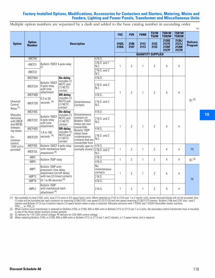
Factory-Installed Options, Modifications, Accessories for Contactors and Starters, Metering, Mains andFeeders, Lighting and Power Panels, Transformer and Miscellaneous Units
2
3
4
5
6
7
8
9
10
11
12
13
14
15
16
17
Multiple option numbers are separated by a dash and added to the base catalog number in ascending order.152
Option OptionNumber Description
FVC FVR FVNR TS1WTS2W
TSR1WTSR2W
TSR1WTSR2W
Delivery Program2102L
2103L21062107
21122113
21222123
2126E2127E2126F2127F
2126J2127J2126K2127K
QUANTITY SUPPLIED
Unwired Control Relay [1]
Mutually exclusive with 89CB and 89CBL interpos-ing relays
For common control, 120V coil is provided
[1] Not available on dual 2103L units, dual 2113 units or 0.5 space factor units. When selected on 2122 or 2123 size 1 or 2 starter units, power terminal blocks will not be provided. One (1) relay will be furnished per each contactor on reversing (2106/2107), two speed (2122/2123) and two-speed reversing (2126/2127) starters. Bulletin 2106 and 2107 size 1 and 2 starters and Bulletin 2113 size 3 starters require 2.0 space factors when a relay is selected. Mutually exclusive with 11DSA2 and 11DSA3 DeviceNet starter auxiliary, 7FEC_ _ or 7FEE_D.
-89CF40
Bulletin 700CF 4-pole relay [2]
[2] When control circuit transformer is selected on Bulletin 2102L or 2103L 30A or 60A units or Bulletin 2112 or 2113 size 1 or 2 units, the secondary control transformer fuse is mounted in one of the three starter auxiliary contact pockets.
Instantaneous Contacts
(Instantaneous contacts on Bulletin 700CF relays are non-convertible. Bulletin 700P relays have instantaneous contacts that are convertible from normally open to normally closed.)
4 N.O.
1 2 1 2 4 4
SC [3]
[3] SC delivery for 110-120V control voltage. PE delivery for 220-240V control voltage.
-89CF31 3 N.O. and 1 N.C.
-89CF22 2 N.O. and 2 N.C.
-89CF40A
Bulletin 700CF 4-pole relay with time attachment
0.3 to 30 seconds [4]
[4] When selecting Bulletin 2102L or 2103L 30A or 60A units or Bulletin 2112 or 2113 size 1 and 2 starters, a 1.5 space factor unit is required.
On-delay includes (1) NOTC and (1) NCTO contact
4 N.O.
1 2 1 2 4 4
-89CF22A 2 N.O. and 2 N.C.
-89CF40B Off-delay includes (1) NOTO and (1) NCTC contact
4 N.O.
-89CF22B 2 N.O. and 2 N.C.
-89CF40C
Bulletin 700CF 4-pole relay with time attachment
1.8 to 180 seconds [4]
On-delay includes (1) NOTC and (1) NCTO contact
4 N.O.
1 2 1 2 4 4
-89CF22C 2 N.O. and 2 N.C.
-89CF40D Off-delay includes (1) NOTO and (1) NCTC contact
4 N.O.
-89CF22D 2 N.O. and 2 N.C.
-89CF40L Bulletin 700CF 4-pole relay with mechanical latch attachment [4]
4 N.O.1 2 1 2 4 4 PE
-89CF22L 2 N.O. and 2 N.C.
-89P2Bulletin 700P relay
2 N.O.1 2 1 2 4 4 SC [3]
-89P4 4 N.O.
-89PTBulletin 700P with pneumatic time delay attachment (on/off delay) with two (2) timed contacts (0.1 to 60 seconds) [4]
Noinstantaneous contacts 1 2 1 2 4 4
PE-89PT2 2 N.O.-89PT4 4 N.O.
-89PL2Bulletin 700Pwith mechanical latch attachment [4]
2 N.O. 1 2 1 2 4 4
119Discount Schedule A6

Factory-Installed Options, Modifications, Accessories for Contactors and Starters, Metering, Mains and Feeders, Lighting and Power Panels, Transformer and Miscellaneous Units
2
3
4
5
9
10
11
12
13
14
15
16
17
Multiple option numbers are separated by a dash and added to the base catalog number in ascending order.153
Maximum Number of Additional Auxiliary Contacts Per Starter/Contactor 154
Option Option Number Description NEMA Size Wiring
Type
Misc.Units FVC [1]
[1] For vacuum contactor starters only option -91 or -900111 is allowed.
FVR FVNR [1] TS1WTS2W
TSR1WTSR2W FDS CB Xfmr
Delivery Program
2100
D
2100
M
2102
L
2103
L
2106
2107
2112
2113
2122
2123
2126
2127
2192
F
2192
M
2193
F
2193
M
2196
2197
Auxiliary Contacts[2]
[2] Multiple auxiliary contacts must be group coded by adding the second and third digit of the special feature number to the base digit “9” (e.g., 90-91-98X-99, when group coded, reads 9018X9).
-90NORMALLY OPENOne (1) N.O. auxiliary contact mounted on each contactor or starter
1-6
A
SC
B [3]
[3] Type B auxiliary contacts are wired to terminal blocks. If the number of auxiliary contact wiring points required exceeds the number of terminals available in the unit, remaining auxiliary contacts will be unwired. Refer to wiring diagram.
-91NORMALLY CLOSEDOne (1) N.C. auxiliary contact mounted on each contactor or starter
1-6
A
B [3]
-98 [4]
[4] The maximum number of auxiliary contacts that can be supplied is two (2), in any combination. Contacts actuate with movement of unit handle to ON or OFF position only. Contacts are not designed to actuate as the result of a circuit breaker trip. For such applications, auxiliary contacts mounted internally (98X or 99X) must be selected. Auxiliary contacts are supplied unwired. Not available on dual 2192F units or 1600A and 2000A 2193M units.
NORMALLY OPENOne (1) N.O. auxiliary contact (operates with movement of external handle only)
1-5A or B
[5]
[5] For 1600A and 2000A 2192M, the maximum number of auxiliary contacts is four (4). The following contact arrangements are allowed.• -98, -99, or -989 two contacts, (1) N.O/N.C. Form-C contacts• -988, -999 four contacts, two (1) N.O/N.C. Form-C contactsThe auxiliary contacts are mounted external to the switch and are actuated by the movement of the operating handle. Auxiliary contacts are supplied unwired.
6
-98X [6]
[6] The maximum number of auxiliary contacts that can be supplied internally is (2) N.O. and (2) N.C. With a shunt trip, the maximum is (1) N.O. and (1) N.C.. Not available for 2193F single or dual mounted when one or both trip codes are ‘00’.
NORMALLY OPENOne (1) N.O. auxiliary contact mounted internally in circuit breaker
1-6 A or B
-99 [4]NORMALLY CLOSEDOne (1) N.C. auxiliary contact (operates with movement of external handle only)
1-5A or B
[5]
6
-99X [6]NORMALLY CLOSEDOne (1) N.C. auxiliary contact mounted internally in circuit breaker
1-6 A or B
Bulletin Number [1]
[1] Units selected with OFF pilot light will use one of these contacts. Bulletins 2126 and 2127 will use two of these contacts.
NEMASize 1-2 Size 3-5 Size 6
2102L, 2103L [2]
66
—
2112/2113 [2]
[2] When Bulletin 596 timers are selected on 30-300A contactors or size 1-5 starters, auxiliary mounting positions (P3 and P4) are used, limiting the maximum number of starter auxiliaries to two (2). When 89CB, 89CBL, 89CF, 89P, 700TC_, 11DSA2 or 11DSA3 with NEMA Type B wiring is present with transformer control in 1.0 space factor units, the number of starter auxiliary contacts is limited to four (4). When 89CBL is present with separate control and control circuit fuse (21) in 1.0 space factor units, the number of starter auxiliary contacts is limited to four (4) for units with 7FEC_ _. In E3 overloads, the number of starter auxiliary contacts is limited to five (5). For size 2 units with 7FEEE_ or 7FEE_D, E1 Plus Overload, the number of auxiliary contacts is limited to five (5)
42103L/2113 Dual — —2106/2107
4 4 —2122/21232102L/2103L/2112/2113 0.5SF 3 — —2126/2127 4 — —
120 Discount Schedule A6
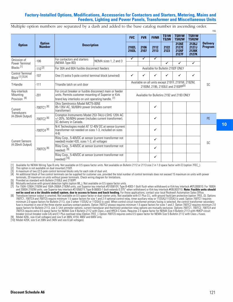
Factory-Installed Options, Modifications, Accessories for Contactors and Starters, Metering, Mains andFeeders, Lighting and Power Panels, Transformer and Miscellaneous Units
2
3
4
5
6
7
8
9
10
11
12
13
14
15
16
17
Multiple option numbers are separated by a dash and added to the base catalog number in ascending order.155
Option OptionNumber Description
FVC FVR FVNR TS1WTS2W
TSR1WTSR2W
TSR1WTSR2W
Delivery Program2102L
2103L21062107
21122113
21222123
2126E2127E2126F2127F
2126J2127J2126K2127K
Omission of Power Terminal Blocks [1]
[1] Available for NEMA Wiring Type B only. Not available on 0.5 space factor units. Not available on Bulletin 2112 or 2113 size 2 in 1.0 space factor with E3 (option 7FEC_).
-106 For contactors and starters (NEMA Type BD) NEMA sizes 1, 2 and 3
SC
-110 [2]
[2] This option is not available on dual mounted 2192F.
For 30A and 60A fusible disconnect feeders Available for Bulletin 2192F ONLYControl Terminal Block [1],[3],[4]
[3] A maximum of two (2) 5-pole control terminal blocks only for each side of dual unit.[4] An additional block of five control terminals can be supplied for customer use, provided the total number of control terminals does not exceed 15 maximum on units with power
terminals, 20 maximum on units without power terminals. Check wiring diagram for limitations.
-107 One (1) extra 5-pole control terminal block (unwired)
T-Handle -111 T-handle latch on unit doorAvailable on all units except 2191F, 2191M, 2192M,
2193M, 2195, 2193LE and 2193PP[5]
[5] Provided as standard with Bulletin 2193LE and 2193PP.
Key-interlock Mounting Provision [6]
[6] Mutually exclusive with ground detection lights (option 88_). Not available on 0.5 space factor units.
-201For circuit breaker or fusible disconnect main or feeder units. Permits customer mounting of Superior or Kirk brand key interlocks on unit operating handle. [7]
[7] For 150A-1200A 2192M and 150A-2000A 2193M units, use Superior key interlock #S105810Y, Type B-4003-1 (bolt flush when withdrawn) or Kirk key interlock #KFL000010. For 1600A and 2000A 2192M units, use Superior key interlock #S105821Y, Type B-06003-1 (bolt extends 0.375” when withdrawn) or Kirk key interlock #KBL003710. Note: Fusible units should not be used on a tie (double ended) system, due to access to fuses and back feeding. For these applications, contact your local Rockwell Automation Sales Office.
Available for Bulletins 2192 and 2193 ONLY
Current Transducers (4-20mA Output)
-700TC1 [8]
[8] Transducer/sensor output is unwired. Not available on 0.5 space factor or dual starter units. Not available with E1 Plus O.L. with ground fault/jam protection (option 7FEE_G). Options 700TC1, 700TC4 and 700TC5 require minimum 1.5 space factors for size 1 and 2 if optional control relay, timer auxiliary relay or 11DSA2/11DSA3 is used. Option 700TC1 requires minimum 2.0 space factors for Bulletin 2113, size 3 when 11DSA2 or 11DSA3 is used. When control circuit transformer primary fusing is selected, the control transformer secondary fuse is mounted in one of the three starter auxiliary contact pockets. Option 700TC2 always requires minimum 1.5 space factors for sizes 1 and 2. Option 700TC2 requires minimum 2.0 space factors for Bulletin 2113, size 3. Unit ammeter options, current transducer and thermistor protection relay options are mutually exclusive. Options 700TC1, 700TC2, 700TC4 and 700TC5 require extra 0.5 space factor for NEMA Size 4 Bulletin 2112 with Class J and HRCII-C fuses. Requires 2.5 space factor for NEMA Size 4 Bulletin 2113 with HMCP circuit breaker (circuit breaker code CA) and E1 Plus overload relay (Option 7FEE_). Option 700TC5 requires extra 0.5 space factor for NEMA Size 5 Bulletin 2112 with Class J fuses.
Ohio Semitronics Model MCT5-005E85-135V AC, 50/60Hz power (includes current transformer)
-700TC2 [8]Crompton Instruments Model 253-TALU-LSHG 120V AC +/-20%, 50/60Hz power (includes current transformer). SC delivery in Canada.
PE
Current Sensors(4-20mA Output)
-700TC4 [8] N-K Technologies model AT 12-40V DC at sensor (current transformer not needed on sizes 1-3, included on sizes 4-6)
SC
-700TC5 [8]
Riley Corp., 5-40VDC at sensor (current transformer not needed) model 420, sizes 1-3, all voltagesRiley Corp., 5-40VDC at sensor (current transformer not needed) [9]
[9] Model 420L, size 4 (all voltages) and size 5 at 380V, 415V, 480V and 600V only.
Riley Corp., 5-40VDC at sensor (current transformer not needed) [10]
[10] Model 420X, size 5 at 208V and 240V and size 6 (all voltages).
121Discount Schedule A6
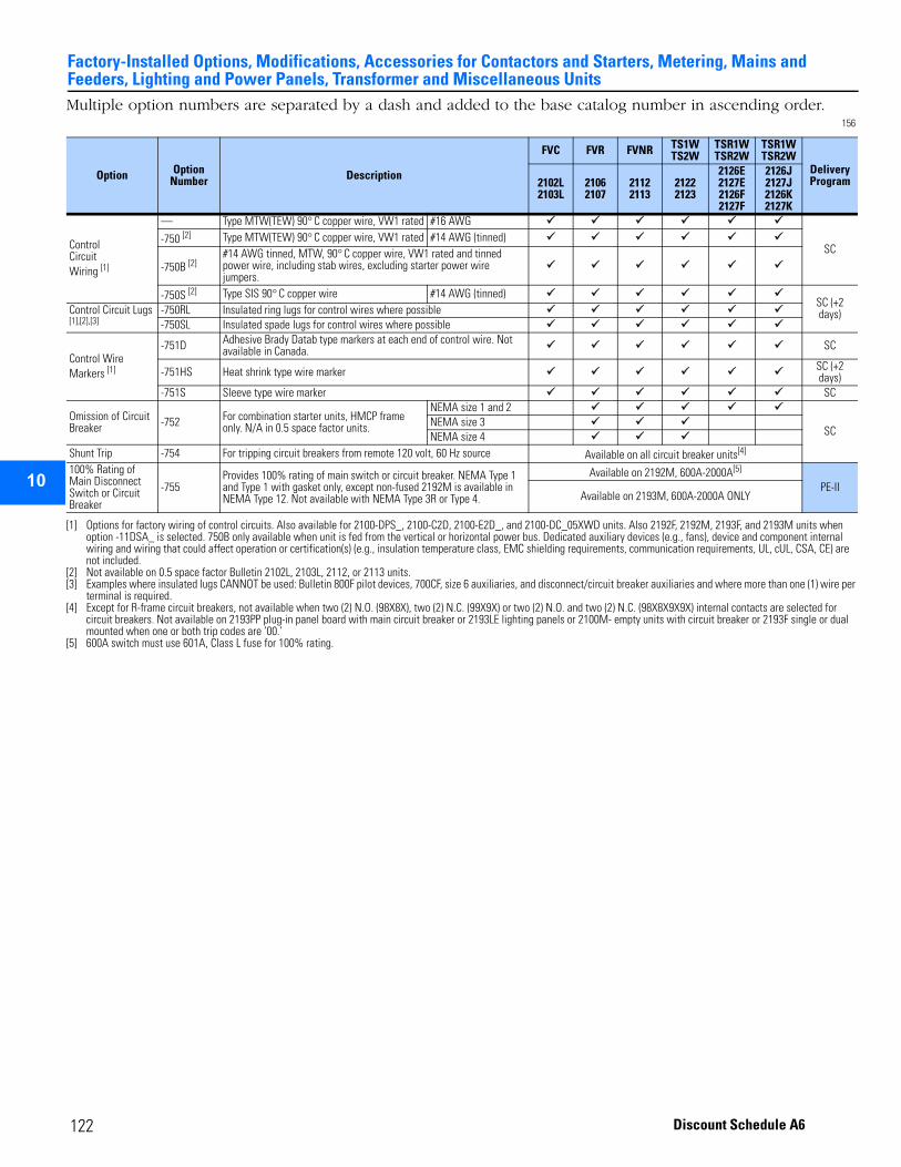
Factory-Installed Options, Modifications, Accessories for Contactors and Starters, Metering, Mains and Feeders, Lighting and Power Panels, Transformer and Miscellaneous Units
2
3
4
5
9
10
11
12
13
14
15
16
17
Multiple option numbers are separated by a dash and added to the base catalog number in ascending order.156
Option OptionNumber Description
FVC FVR FVNR TS1WTS2W
TSR1WTSR2W
TSR1WTSR2W
Delivery Program2102L
2103L21062107
21122113
21222123
2126E2127E2126F2127F
2126J2127J2126K2127K
ControlCircuitWiring [1]
[1] Options for factory wiring of control circuits. Also available for 2100-DPS_, 2100-C2D, 2100-E2D_, and 2100-DC_05XWD units. Also 2192F, 2192M, 2193F, and 2193M units when option -11DSA_ is selected. 750B only available when unit is fed from the vertical or horizontal power bus. Dedicated auxiliary devices (e.g., fans), device and component internal wiring and wiring that could affect operation or certification(s) (e.g., insulation temperature class, EMC shielding requirements, communication requirements, UL, cUL, CSA, CE) are not included.
— Type MTW(TEW) 90° C copper wire, VW1 rated #16 AWG
SC-750 [2]
[2] Not available on 0.5 space factor Bulletin 2102L, 2103L, 2112, or 2113 units.
Type MTW(TEW) 90° C copper wire, VW1 rated #14 AWG (tinned)
-750B [2]#14 AWG tinned, MTW, 90° C copper wire, VW1 rated and tinned power wire, including stab wires, excluding starter power wire jumpers.
-750S [2] Type SIS 90° C copper wire #14 AWG (tinned)SC (+2 days)Control Circuit Lugs
[1],[2],[3]
[3] Examples where insulated lugs CANNOT be used: Bulletin 800F pilot devices, 700CF, size 6 auxiliaries, and disconnect/circuit breaker auxiliaries and where more than one (1) wire per terminal is required.
-750RL Insulated ring lugs for control wires where possible-750SL Insulated spade lugs for control wires where possible
Control Wire Markers [1]
-751D Adhesive Brady Datab type markers at each end of control wire. Not available in Canada. SC
-751HS Heat shrink type wire marker SC (+2 days)
-751S Sleeve type wire marker SC
Omission of Circuit Breaker -752 For combination starter units, HMCP frame
only. N/A in 0.5 space factor units.
NEMA size 1 and 2
SCNEMA size 3NEMA size 4
Shunt Trip -754 For tripping circuit breakers from remote 120 volt, 60 Hz source Available on all circuit breaker units[4]
[4] Except for R-frame circuit breakers, not available when two (2) N.O. (98X8X), two (2) N.C. (99X9X) or two (2) N.O. and two (2) N.C. (98X8X9X9X) internal contacts are selected for circuit breakers. Not available on 2193PP plug-in panel board with main circuit breaker or 2193LE lighting panels or 2100M- empty units with circuit breaker or 2193F single or dual mounted when one or both trip codes are ‘00.’
100% Rating of Main Disconnect Switch or Circuit Breaker
-755Provides 100% rating of main switch or circuit breaker. NEMA Type 1 and Type 1 with gasket only, except non-fused 2192M is available in NEMA Type 12. Not available with NEMA Type 3R or Type 4.
Available on 2192M, 600A-2000A[5]
[5] 600A switch must use 601A, Class L fuse for 100% rating.
PE-IIAvailable on 2193M, 600A-2000A ONLY
122 Discount Schedule A6
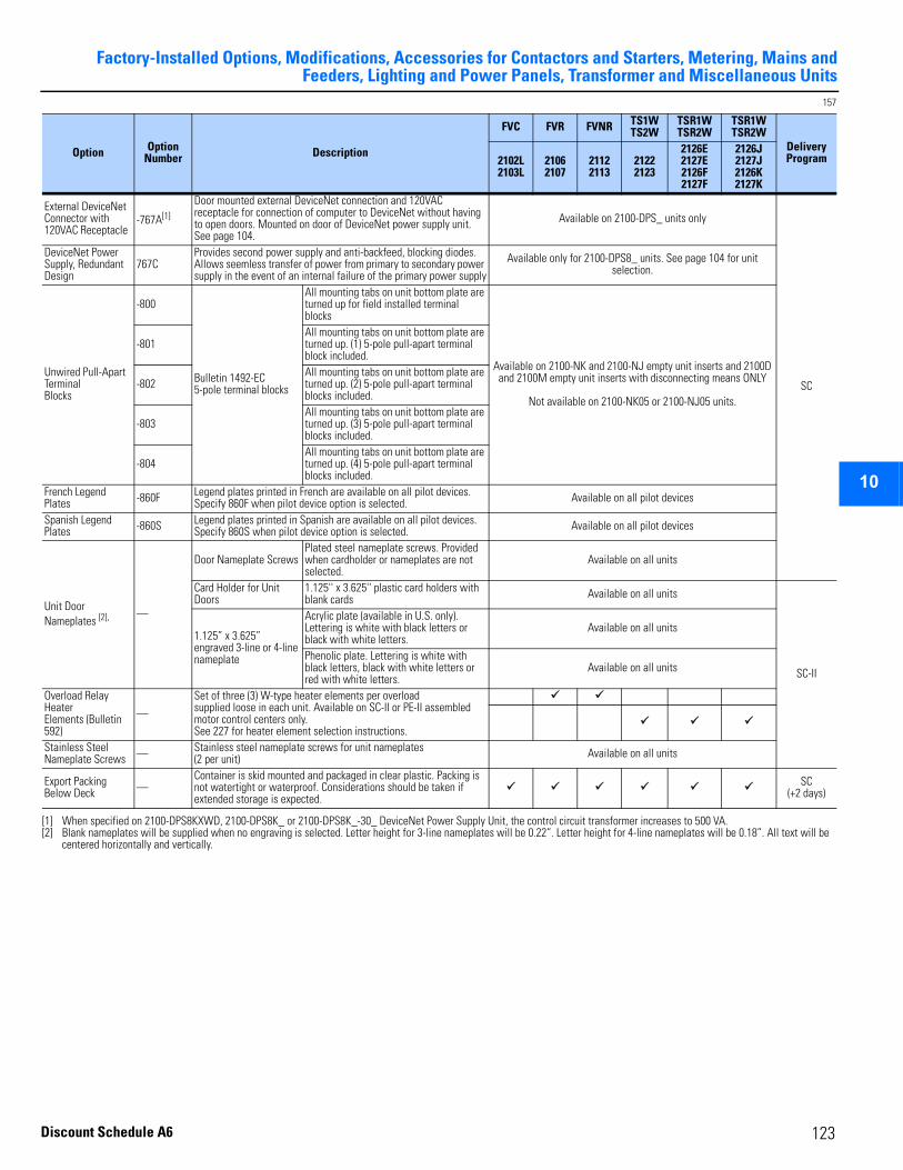
Factory-Installed Options, Modifications, Accessories for Contactors and Starters, Metering, Mains andFeeders, Lighting and Power Panels, Transformer and Miscellaneous Units
2
3
4
5
6
7
8
9
10
11
12
13
14
15
16
17
157
Option Option Number Description
FVC FVR FVNR TS1WTS2W
TSR1WTSR2W
TSR1WTSR2W
Delivery Program2102L
2103L21062107
21122113
21222123
2126E2127E2126F2127F
2126J2127J2126K2127K
External DeviceNet Connector with 120VAC Receptacle
-767A[1]
[1] When specified on 2100-DPS8KXWD, 2100-DPS8K_ or 2100-DPS8K_-30_ DeviceNet Power Supply Unit, the control circuit transformer increases to 500 VA.
Door mounted external DeviceNet connection and 120VAC receptacle for connection of computer to DeviceNet without having to open doors. Mounted on door of DeviceNet power supply unit. See page 104.
Available on 2100-DPS_ units only
SC
DeviceNet Power Supply, Redundant Design
767CProvides second power supply and anti-backfeed, blocking diodes. Allows seemless transfer of power from primary to secondary power supply in the event of an internal failure of the primary power supply
Available only for 2100-DPS8_ units. See page 104 for unit selection.
Unwired Pull-Apart Terminal Blocks
-800
Bulletin 1492-EC 5-pole terminal blocks
All mounting tabs on unit bottom plate are turned up for field installed terminal blocks
Available on 2100-NK and 2100-NJ empty unit inserts and 2100D and 2100M empty unit inserts with disconnecting means ONLY
Not available on 2100-NK05 or 2100-NJ05 units.
-801All mounting tabs on unit bottom plate are turned up. (1) 5-pole pull-apart terminal block included.
-802All mounting tabs on unit bottom plate are turned up. (2) 5-pole pull-apart terminal blocks included.
-803All mounting tabs on unit bottom plate are turned up. (3) 5-pole pull-apart terminal blocks included.
-804All mounting tabs on unit bottom plate are turned up. (4) 5-pole pull-apart terminal blocks included.
French Legend Plates -860F Legend plates printed in French are available on all pilot devices.
Specify 860F when pilot device option is selected. Available on all pilot devices
Spanish Legend Plates -860S Legend plates printed in Spanish are available on all pilot devices.
Specify 860S when pilot device option is selected. Available on all pilot devices
Unit Door Nameplates [2],
[2] Blank nameplates will be supplied when no engraving is selected. Letter height for 3-line nameplates will be 0.22”. Letter height for 4-line nameplates will be 0.18”. All text will be centered horizontally and vertically.
—
Door Nameplate ScrewsPlated steel nameplate screws. Provided when cardholder or nameplates are not selected.
Available on all units
Card Holder for Unit Doors
1.125'' x 3.625'' plastic card holders with blank cards Available on all units
SC-II
1.125” x 3.625” engraved 3-line or 4-line nameplate
Acrylic plate (available in U.S. only). Lettering is white with black letters or black with white letters.
Available on all units
Phenolic plate. Lettering is white with black letters, black with white letters or red with white letters.
Available on all units
Overload Relay HeaterElements (Bulletin 592)
—
Set of three (3) W-type heater elements per overload supplied loose in each unit. Available on SC-II or PE-II assembled motor control centers only. See 227 for heater element selection instructions.
Stainless Steel Nameplate Screws — Stainless steel nameplate screws for unit nameplates
(2 per unit) Available on all units
Export Packing Below Deck —
Container is skid mounted and packaged in clear plastic. Packing is not watertight or waterproof. Considerations should be taken if extended storage is expected.
SC (+2 days)
123
Discount Schedule A6
Factory-Installed Options, Modifications, Accessories for Contactors and Starters, Metering, Mains and Feeders, Lighting and Power Panels, Transformer and Miscellaneous Units
2
3
4
5
9
10
11
12
13
14
15
16
17
124
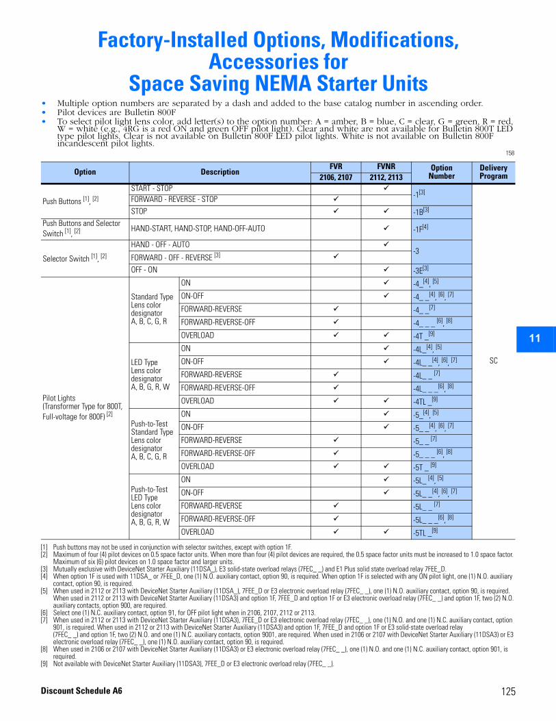
2
3
4
5
6
7
8
9
10
11
12
13
14
15
16
17
Factory-Installed Options, Modifications, Accessories for
Space Saving NEMA Starter Units• Multiple option numbers are separated by a dash and added to the base catalog number in ascending order.• Pilot devices are Bulletin 800F• To select pilot light lens color, add letter(s) to the option number: A = amber, B = blue, C = clear, G = green, R = red,
W = white (e.g., 4RG is a red ON and green OFF pilot light). Clear and white are not available for Bulletin 800T LED type pilot lights. Clear is not available on Bulletin 800F LED pilot lights. White is not available on Bulletin 800F incandescent pilot lights.
158
Option DescriptionFVR FVNR Option
NumberDelivery Program2106, 2107 2112, 2113
Push Buttons [1], [2]
[1] Push buttons may not be used in conjunction with selector switches, except with option 1F.[2] Maximum of four (4) pilot devices on 0.5 space factor units. When more than four (4) pilot devices are required, the 0.5 space factor units must be increased to 1.0 space factor.
Maximum of six (6) pilot devices on 1.0 space factor and larger units.
START - STOP -1[3]
[3] Mutually exclusive with DeviceNet Starter Auxiliary (11DSA_), E3 solid-state overload relays (7FEC_ _) and E1 Plus solid state overload relay 7FEE_D.
SC
FORWARD - REVERSE - STOPSTOP -1B[3]
Push Buttons and Selector Switch [1], [2] HAND-START, HAND-STOP, HAND-OFF-AUTO -1F[4]
[4] When option 1F is used with 11DSA_ or 7FEE_D, one (1) N.O. auxiliary contact, option 90, is required. When option 1F is selected with any ON pilot light, one (1) N.O. auxiliary contact, option 90, is required.
Selector Switch [1], [2]
HAND - OFF - AUTO-3
FORWARD - OFF - REVERSE [3]
OFF - ON -3E[3]
Pilot Lights (Transformer Type for 800T, Full-voltage for 800F) [2]
Standard TypeLens color designatorA, B, C, G, R
ON -4_[4], [5]
[5] When used in 2112 or 2113 with DeviceNet Starter Auxiliary (11DSA_), 7FEE_D or E3 electronic overload relay (7FEC_ _), one (1) N.O. auxiliary contact, option 90, is required. When used in 2112 or 2113 with DeviceNet Starter Auxiliary (11DSA3) and option 1F, 7FEE_D and option 1F or E3 electronic overload relay (7FEC_ _) and option 1F, two (2) N.O. auxiliary contacts, option 900, are required.
ON-OFF -4_ _[4], [6], [7]
[6] Select one (1) N.C. auxiliary contact, option 91, for OFF pilot light when in 2106, 2107, 2112 or 2113.[7] When used in 2112 or 2113 with DeviceNet Starter Auxiliary (11DSA3), 7FEE_D or E3 electronic overload relay (7FEC_ _), one (1) N.O. and one (1) N.C. auxiliary contact, option
901, is required. When used in 2112 or 2113 with DeviceNet Starter Auxiliary (11DSA3) and option 1F, 7FEE_D and option 1F or E3 solid-state overload relay (7FEC_ _) and option 1F, two (2) N.O. and one (1) N.C. auxiliary contacts, option 9001, are required. When used in 2106 or 2107 with DeviceNet Starter Auxiliary (11DSA3) or E3 electronic overload relay (7FEC_ _), one (1) N.O. auxiliary contact, option 90, is required.
FORWARD-REVERSE -4_ _[7]
FORWARD-REVERSE-OFF -4_ _ _ [6], [8]
OVERLOAD -4T _[9]
LED TypeLens color designatorA, B, G, R, W
ON -4L_[4], [5]
ON-OFF -4L_ _[4], [6], [7]
FORWARD-REVERSE -4L_ _ [7]
FORWARD-REVERSE-OFF -4L_ _ _[6], [8]
OVERLOAD -4TL _[9]
Push-to-Test Standard TypeLens color designatorA, B, C, G, R
ON -5_[4], [5]
ON-OFF -5_ _[4], [6], [7]
FORWARD-REVERSE -5_ _ [7]
FORWARD-REVERSE-OFF -5_ _ _ [6], [8]
OVERLOAD -5T _ [9]
Push-to-Test LED TypeLens color designatorA, B, G, R, W
ON -5L_ [4], [5]
ON-OFF -5L_ _[4], [6], [7]
FORWARD-REVERSE -5L_ _ [7]
FORWARD-REVERSE-OFF -5L_ _ _[6], [8]
[8] When used in 2106 or 2107 with DeviceNet Starter Auxiliary (11DSA3) or E3 electronic overload relay (7FEC_ _), one (1) N.O. and one (1) N.C. auxiliary contact, option 901, is required.
OVERLOAD -5TL _[9]
[9] Not available with DeviceNet Starter Auxiliary (11DSA3), 7FEE_D or E3 electronic overload relay (7FEC_ _).
125Discount Schedule A6
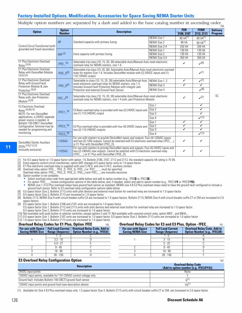
12
Factory-Installed Options, Modifications, Accessories for Space Saving NEMA Starter Units
2
3
4
5
9
10
11
12
13
14
15
16
17
Multiple option numbers are separated by a dash and added to the base catalog number in ascending order. 159
Option Option Number Description FVR FVNR Delivery
Program2106, 2107 2112, 2113
Control Circuit Transformer (with grounded and fused secondary)
-6P Standard capacity with primary fusingNEMA Size 1 80 VA[1]
[1] For 0.5 space factor or 1.0 space factor with option -15; Bulletin 2106, 2107, 2112 and 2113, the standard capacity VA rating is 75 VA.
80 VA[1]
SC
NEMA Size 2 80 VA 80 VA[1]
NEMA Size 3-4 250 VA 250 VA
-6XP [2]
[2] Extra capacity control circuit transformer, option 6XP, changes 0.5 space factor units to 1.0 space factor.
Extra capacity with primary fusingNEMA Size 1 130 VA 130 VANEMA Size 2 130 VA 130 VANEMA Size 3-4 350 VA 350 VA
E1 Plus Electronic Overload Relay [3],[4]
[3] E1 Plus electronic overload relay is supplied with one (1) N.O. and one (1) N.C. auxiliary contact.[4] Overload relay option 7FEE_, 7FEE_D, 7FEE_G, 7FEE_J or 7FEC_ _ _ must be specified.
Overload relay option 7FEE_, 7FEE_D, 7FEE_G, 7FEE_J and 7FEC_ _ are mutually exclusive.
-7FEE_ [5]
[5] Option number is not complete. • Select overload relay code from appropriate table below and add to option number (e.g., 7FEED or 7FEC2B). • For option 7FEC_ _, review configuration options in the table below, and, if needed, select and add to option number (e.g., 7FEC1BY or 7FEC3FYG).• NEMA size 1-3 E3 Plus overload relays have ground fault sensor as standard. NEMA size 4-6 E3 Plus overload relays need to have the ground fault configured to include a
ground fault sensor. Refer to E3 overload relay configuration options table below.
Selectable trip class (10, 15, 20, 30) selectable Auto/Manual-Auto reset electronic overload relay for NEMA starters, size 1-4.
[6]
[6] 0.5 space factor Size 2, Bulletin 2113 units with pilot devices and external reset button for overload relay are increased to 1.0 space factor.
E1 Plus Electronic Overload Relay with DeviceNet Module [3],[4],[10]
-7FEE_D[5]Selectable trip class (10, 20, 30). Selectable Auto/Manual-Auto reset electronic overload relay for starters Size 1-4. Includes DeviceNet module with (2) 24VDC inputs and (1) 110-120VAC output.
[7]
[7] 0.5 space factor Size 2, Bulletin 2113 are increased to 1.0 space factor.
E1 Plus Electronic Overload Relay with Ground Fault Protection Module & Jam Protection [3],[4]
-7FEE_G[5]
Selectable to class (10, 15, 20, 30) selectable Auto/Manual-Auto reset electronic overload relay for NEMA starters, size 1-3. Includes Ground Fault Protection Module with integral Jam Protection and external Ground Fault Sensor.
NEMA Size 1, 2 [7]
NEMA Size 3NEMA Size 4 [8]
[8] Bulletin 2113, NEMA Size 4 with circuit breaker suffix CA are increased to 1.5 space factors. Bulletin 2113, NEMA Size 4 with circuit breaker suffix CT or CM are increased to 2.0 space factors.
E1 Plus Electronic Overload Relay with Jam Protection Module [3],[4]
7FEE_J[5] Selectable trip class (10, 15, 20, 30) selectable Auto/Manual-Auto reset electronic overload relay for NEMA starters, size 1-4 with Jam Protection Module
[7]
E3 Electronic Overload Relay [4],[9],[10]
NOTE: For non-DeviceNet applications, a 24VDC separate power source is needed. A Bulletin 193-DNCT DeviceNet Configuration Terminal may be needed for programming and monitoring.
[9] 0.5 space factor Size 1, Bulletin 2106 and 2107 units are increased to 1.0 space factor.0.5 space factor Size 1, Bulletin 2112 and 2113 units with pilot devices and external reset button for overload relay are increased to 1.0 space factor. 0.5 space factor Size 2, Bulletin 2113 units are increased to 1.0 space factor.
-7FEC1_[5] E3 Basic overload relay is provided with two (2) 24VDC inputs and one (1) 110-240VAC output
Size 1Size 2Size 3Size 4 [12]
-7FEC2_[5] E3 Plus overload relay is provided with four (4) 24VDC inputs and two (2) 110-240VAC outputs
Size 1Size 2Size 3
-7FEC3_[5] Size 4 [12]
DeviceNet Starter Auxiliary (DSA) [10],[11],[12]
(mutually exclusive)
[10] Not available with push button or selector switches, except options 3 and 1F. Not available with unwired control relay, option 89CF_ and 89HA_.[11] 0.5 space factor Size 1, Bulletin 2107 units are increased to 1.0 space factor. 0.5 space factor Size 2, Bulletin 2113 units are increased to 1.0 space factor.[12] 1.0 space factor Size 4, Bulletin 2113 units are increased to 1.5 space factor.
-11DSA2For use with starters to provide DeviceNet inputs and outputs. Four (4) 120VAC inputs and two (2) 120V outputs. Cannot be selected with E3 electronic overload relay (7FEC_ _) or E1 Plus with DeviceNet (7FEE_D).
-11DSA3For use with starters to provide DeviceNet inputs and outputs. Four (4) 24VDC inputs and two (2) 240VAC max outputs. Cannot be selected with E3 electronic overload relay (7FEC_ _) or E1 Plus with DeviceNet (7FEE_D).
Overload Relay Codes for E1 Plus, Option 7FEE 160 Overload Relay Codes for E3 and E3 Plus, Option -7FEC_ 161 For use with Space Saving NEMA Size
Full Load Current Range (Amperes)
Overload Relay Code, Add to Option Number (e.g., 7FEED)
For use with Space Saving NEMA Size
Full Load Current Range (Amperes)
Overload Relay Code, Add to Option Number (e.g., 7FEC2B)
11 - 5 C
11 - 5 A
3.2 - 16 D 3 - 15 B5.4 - 27 E 5 - 25 C
2 9 - 45 F 2 9 - 45 D3 18 - 90 G 3 18 - 90 E4 30 - 150 H 4 28 - 140 F
E3 Overload Relay Configuration Option 162
Description Overload Relay Code (Add to option number [e.g. 7FEC3FYG])
24VDC input points None120VAC input points, available for 110-120VAC control voltage only YGround fault. Includes Bulletin 193-CBCT3 ground fault sensor G[1]
[1] Available for Size 4 E3 Plus overload relays only. 1.5 space factor Size 4, Bulletin 2113 units with circuit breaker suffix CT or CM, are increased to 2.0 space factor.
120VAC input points and ground fault (see description above) YG[1]
6 Discount Schedule A6
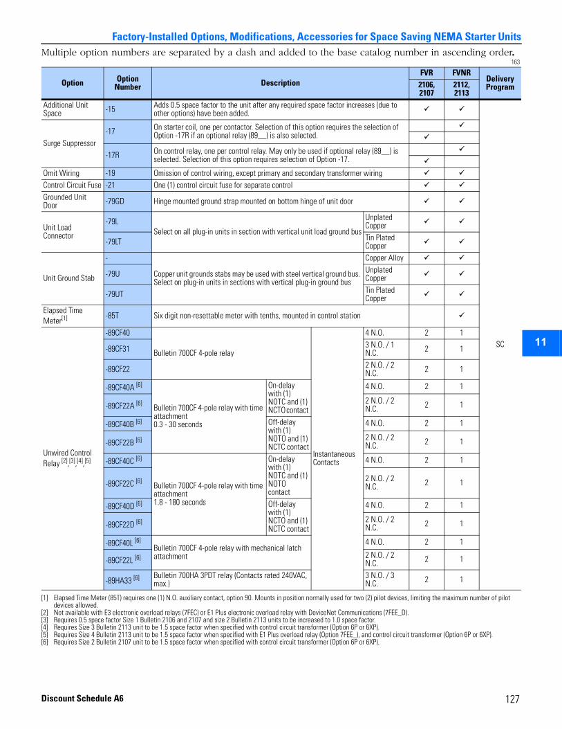
2
3
4
5
6
7
8
9
10
11
12
13
14
15
16
17
Factory-Installed Options, Modifications, Accessories for Space Saving NEMA Starter UnitsMultiple option numbers are separated by a dash and added to the base catalog number in ascending order.
163
Option Option Number Description
FVR FVNRDelivery Program2106,
21072112, 2113
Additional Unit Space -15 Adds 0.5 space factor to the unit after any required space factor increases (due to
other options) have been added.
SC
Surge Suppressor-17 On starter coil, one per contactor. Selection of this option requires the selection of
Option -17R if an optional relay (89__) is also selected.
-17R On control relay, one per control relay. May only be used if optional relay (89__) is selected. Selection of this option requires selection of Option -17.
Omit Wiring -19 Omission of control wiring, except primary and secondary transformer wiringControl Circuit Fuse -21 One (1) control circuit fuse for separate controlGrounded Unit Door -79GD Hinge mounted ground strap mounted on bottom hinge of unit door
Unit Load Connector
-79LSelect on all plug-in units in section with vertical unit load ground bus
Unplated Copper
-79LT Tin Plated Copper
Unit Ground Stab
-
Copper unit grounds stabs may be used with steel vertical ground bus. Select on plug-in units in sections with vertical plug-in ground bus
Copper Alloy
-79U Unplated Copper
-79UT Tin Plated Copper
Elapsed Time Meter[1]
[1] Elapsed Time Meter (85T) requires one (1) N.O. auxiliary contact, option 90. Mounts in position normally used for two (2) pilot devices, limiting the maximum number of pilot devices allowed.
-85T Six digit non-resettable meter with tenths, mounted in control station
Unwired Control Relay [2],[3],[4],[5]
[2] Not available with E3 electronic overload relays (7FEC) or E1 Plus electronic overload relay with DeviceNet Communications (7FEE_D).[3] Requires 0.5 space factor Size 1 Bulletin 2106 and 2107 and size 2 Bulletin 2113 units to be increased to 1.0 space factor.[4] Requires Size 3 Bulletin 2113 unit to be 1.5 space factor when specified with control circuit transformer (Option 6P or 6XP).[5] Requires Size 4 Bulletin 2113 unit to be 1.5 space factor when specified with E1 Plus overload relay (Option 7FEE_), and control circuit transformer (Option 6P or 6XP).
-89CF40
Bulletin 700CF 4-pole relay
Instantaneous Contacts
4 N.O. 2 1
-89CF31 3 N.O. / 1 N.C. 2 1
-89CF22 2 N.O. / 2 N.C. 2 1
-89CF40A [6]
[6] Requires Size 2 Bulletin 2107 unit to be 1.5 space factor when specified with control circuit transformer (Option 6P or 6XP).
Bulletin 700CF 4-pole relay with time attachment 0.3 - 30 seconds
On-delay with (1) NOTC and (1) NCTO contact
4 N.O. 2 1
-89CF22A [6] 2 N.O. / 2 N.C. 2 1
-89CF40B [6] Off-delay with (1) NOTO and (1) NCTC contact
4 N.O. 2 1
-89CF22B [6] 2 N.O. / 2 N.C. 2 1
-89CF40C [6]
Bulletin 700CF 4-pole relay with time attachment 1.8 - 180 seconds
On-delay with (1) NOTC and (1) NOTO contact
4 N.O. 2 1
-89CF22C [6] 2 N.O. / 2 N.C. 2 1
-89CF40D [6] Off-delay with (1) NCTO and (1) NCTC contact
4 N.O. 2 1
-89CF22D [6] 2 N.O. / 2 N.C. 2 1
-89CF40L [6]Bulletin 700CF 4-pole relay with mechanical latch attachment
4 N.O. 2 1
-89CF22L [6] 2 N.O. / 2 N.C. 2 1
-89HA33 [6] Bulletin 700HA 3PDT relay (Contacts rated 240VAC, max.)
3 N.O. / 3 N.C. 2 1
127Discount Schedule A6
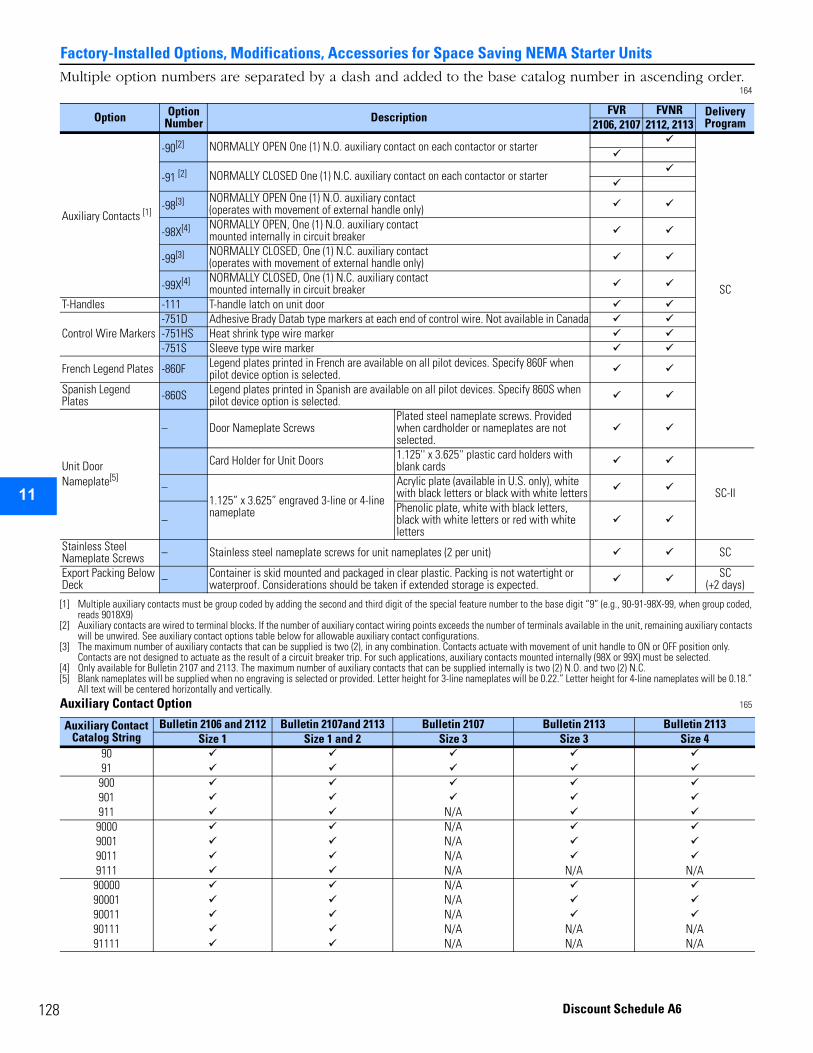
12
Factory-Installed Options, Modifications, Accessories for Space Saving NEMA Starter Units
2
3
4
5
9
10
11
12
13
14
15
16
17
Multiple option numbers are separated by a dash and added to the base catalog number in ascending order.164
Auxiliary Contact Option 165
Option Option Number Description
FVR FVNR Delivery Program2106, 2107 2112, 2113
Auxiliary Contacts [1]
[1] Multiple auxiliary contacts must be group coded by adding the second and third digit of the special feature number to the base digit “9” (e.g., 90-91-98X-99, when group coded, reads 9018X9)
-90[2]
[2] Auxiliary contacts are wired to terminal blocks. If the number of auxiliary contact wiring points exceeds the number of terminals available in the unit, remaining auxiliary contacts will be unwired. See auxiliary contact options table below for allowable auxiliary contact configurations.
NORMALLY OPEN One (1) N.O. auxiliary contact on each contactor or starter
SC
-91 [2] NORMALLY CLOSED One (1) N.C. auxiliary contact on each contactor or starter
-98[3]
[3] The maximum number of auxiliary contacts that can be supplied is two (2), in any combination. Contacts actuate with movement of unit handle to ON or OFF position only. Contacts are not designed to actuate as the result of a circuit breaker trip. For such applications, auxiliary contacts mounted internally (98X or 99X) must be selected.
NORMALLY OPEN One (1) N.O. auxiliary contact (operates with movement of external handle only)
-98X[4]
[4] Only available for Bulletin 2107 and 2113. The maximum number of auxiliary contacts that can be supplied internally is two (2) N.O. and two (2) N.C.
NORMALLY OPEN, One (1) N.O. auxiliary contact mounted internally in circuit breaker
-99[3] NORMALLY CLOSED, One (1) N.C. auxiliary contact (operates with movement of external handle only)
-99X[4] NORMALLY CLOSED, One (1) N.C. auxiliary contact mounted internally in circuit breaker
T-Handles -111 T-handle latch on unit door
Control Wire Markers-751D Adhesive Brady Datab type markers at each end of control wire. Not available in Canada-751HS Heat shrink type wire marker-751S Sleeve type wire marker
French Legend Plates -860F Legend plates printed in French are available on all pilot devices. Specify 860F when pilot device option is selected.
Spanish Legend Plates -860S Legend plates printed in Spanish are available on all pilot devices. Specify 860S when
pilot device option is selected.
Unit Door Nameplate[5]
[5] Blank nameplates will be supplied when no engraving is selected or provided. Letter height for 3-line nameplates will be 0.22.” Letter height for 4-line nameplates will be 0.18.” All text will be centered horizontally and vertically.
– Door Nameplate ScrewsPlated steel nameplate screws. Provided when cardholder or nameplates are not selected.
Card Holder for Unit Doors 1.125'' x 3.625'' plastic card holders with blank cards
SC-II–1.125” x 3.625” engraved 3-line or 4-line nameplate
Acrylic plate (available in U.S. only), white with black letters or black with white letters
–Phenolic plate, white with black letters, black with white letters or red with white letters
Stainless Steel Nameplate Screws – Stainless steel nameplate screws for unit nameplates (2 per unit) SC
Export Packing Below Deck – Container is skid mounted and packaged in clear plastic. Packing is not watertight or
waterproof. Considerations should be taken if extended storage is expected.SC
(+2 days)
Auxiliary Contact Catalog String
Bulletin 2106 and 2112 Bulletin 2107and 2113 Bulletin 2107 Bulletin 2113 Bulletin 2113Size 1 Size 1 and 2 Size 3 Size 3 Size 4
9091
900901911 N/A9000 N/A9001 N/A9011 N/A9111 N/A N/A N/A90000 N/A90001 N/A90011 N/A90111 N/A N/A N/A91111 N/A N/A N/A
8 Discount Schedule A6
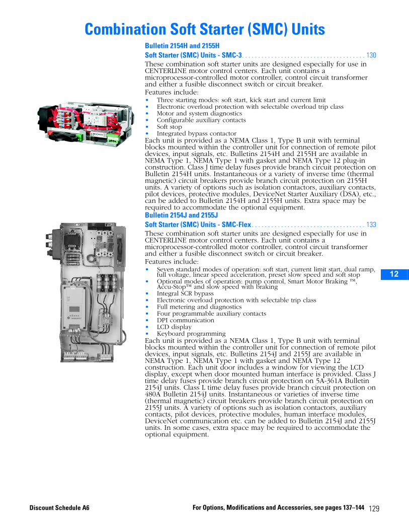
2
3
4
5
6
7
8
9
10
11
12
13
14
15
16
17
Combination Soft Starter (SMC) UnitsBulletin 2154H and 2155HSoft Starter (SMC) Units - SMC-3. . . . . . . . . . . . . . . . . . . . . . . . . . . . . . . . . . . . . . 130These combination soft starter units are designed especially for use in CENTERLINE motor control centers. Each unit contains a microprocessor-controlled motor controller, control circuit transformer and either a fusible disconnect switch or circuit breaker.Features include:• Three starting modes: soft start, kick start and current limit• Electronic overload protection with selectable overload trip class• Motor and system diagnostics• Configurable auxiliary contacts• Soft stop• Integrated bypass contactorEach unit is provided as a NEMA Class 1, Type B unit with terminal blocks mounted within the controller unit for connection of remote pilot devices, input signals, etc. Bulletins 2154H and 2155H are available in NEMA Type 1, NEMA Type 1 with gasket and NEMA Type 12 plug-in construction. Class J time delay fuses provide branch circuit protection on Bulletin 2154H units. Instantaneous or a variety of inverse time (thermal magnetic) circuit breakers provide branch circuit protection on 2155H units. A variety of options such as isolation contactors, auxiliary contacts, pilot devices, protective modules, DeviceNet Starter Auxiliary (DSA), etc., can be added to Bulletin 2154H and 2155H units. Extra space may be required to accommodate the optional equipment.Bulletin 2154J and 2155JSoft Starter (SMC) Units - SMC-Flex . . . . . . . . . . . . . . . . . . . . . . . . . . . . . . . . . . . 133These combination soft starter units are designed especially for use in CENTERLINE motor control centers. Each unit contains a microprocessor-controlled motor controller, control circuit transformer and either a fusible disconnect switch or circuit breaker.Features include:• Seven standard modes of operation: soft start, current limit start, dual ramp,
full voltage, linear speed acceleration, preset slow speed and soft stop• Optional modes of operation: pump control, Smart Motor Braking ™,
Accu-Stop™ and slow speed with braking• Integral SCR bypass• Electronic overload protection with selectable trip class• Full metering and diagnostics• Four programmable auxiliary contacts• DPI communication• LCD display• Keyboard programmingEach unit is provided as a NEMA Class 1, Type B unit with terminal blocks mounted within the controller unit for connection of remote pilot devices, input signals, etc. Bulletins 2154J and 2155J are available in NEMA Type 1, NEMA Type 1 with gasket and NEMA Type 12 construction. Each unit door includes a window for viewing the LCD display, except when door mounted human interface is provided. Class J time delay fuses provide branch circuit protection on 5A-361A Bulletin 2154J units. Class L time delay fuses provide branch circuit protection on 480A Bulletin 2154J units. Instantaneous or varieties of inverse time (thermal magnetic) circuit breakers provide branch circuit protection on 2155J units. A variety of options such as isolation contactors, auxiliary contacts, pilot devices, protective modules, human interface modules, DeviceNet communication etc. can be added to Bulletin 2154J and 2155J units. In some cases, extra space may be required to accommodate the optional equipment.
129For Options, Modifications and Accessories, see pages 137–144Discount Schedule A6
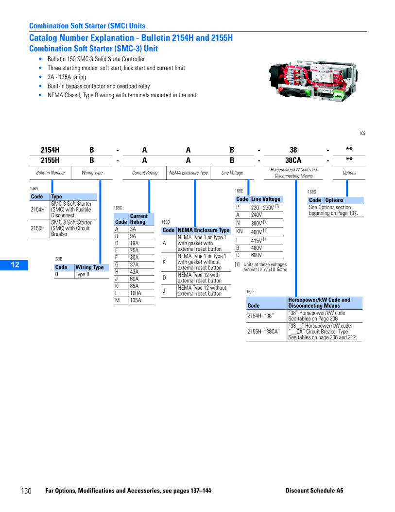
1
Combination Soft Starter (SMC) Units
2
3
4
5
9
10
11
12
13
14
15
16
17
Catalog Number Explanation - Bulletin 2154H and 2155HCombination Soft Starter (SMC-3) Unit
• Bulletin 150 SMC-3 Solid State Controller• Three starting modes: soft start, kick start and current limit• 3A - 135A rating• Built-in bypass contactor and overload relay• NEMA Class I, Type B wiring with terminals mounted in the unit
169
2154H B - A A B - 38 - **2155H B - A A B - 38CA - **
Bulletin Number Wiring Type Current Rating NEMA Enclosure Type Line VoltageHorsepower/kW Code and
Disconnecting MeansOptions
169A
Code Type
2154HSMC-3 Soft Starter (SMC) with Fusible Disconnect
2155HSMC-3 Soft Starter (SMC) with Circuit Breaker
169C
CodeCurrent Rating
A 3AB 9AD 19AE 25AF 30AG 37AH 43AJ 60AK 85AL 108AM 135A
169B
Code Wiring TypeB Type B
169D
Code NEMA Enclosure Type
ANEMA Type 1 or Type 1 with gasket with external reset button
KNEMA Type 1 or Type 1 with gasket without external reset button
D NEMA Type 12 with external reset button
J NEMA Type 12 without external reset button
169E
Code Line Voltage P 220 - 230V [1]
[1] Units at these voltages are not UL or cUL listed.
A 240VN 380V [1]
KN 400V [1]
I 415V [1]
B 480VC 600V
169F
CodeHorsepower/kW Code and Disconnecting Means
2154H- “38” “38” Horsepower/kW codeSee tables on Page 206
2155H- “38CA”“38__” Horsepower/kW code“__CA” Circuit Breaker TypeSee tables on page 206 and 212
169G
Code OptionsSee Options section beginning on Page 137.
30 Fo
r Options, Modificatio ns and Accessorie s, see pages 137–144 Discou nt Schedule A6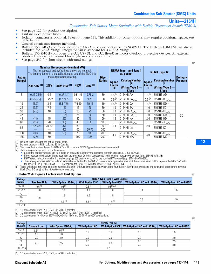
Combination Soft Starter (SMC) Units
2
3
4
5
6
7
8
9
10
11
12
13
14
15
16
17
Units—2154HCombination Soft Starter Motor Controller with Fusible Disconnect Switch (SMC-3)
• See page 129 for product description.• Unit includes power fuses.• Isolation contactor is optional. Select on page 141. This addition or other options may require additional space, see
table below.• Control circuit transformer included.• Bulletin 150 SMC-3 controller includes (1) N.O. auxiliary contact set to NORMAL. The Bulletin 150-CF64 fan also is
included for 3-37A ratings. Integrated fan is standard for 43-135A ratings.• Bulletin 150 SMC-3 controllers are cUL US (UL and cUL listed) as motor overload protective devices. An external
overload relay is not required for single motor applications.• See page 237 for short circuit withstand ratings.
170
Bulletin 2154H Space Factors with Unit Options 171
172
Rating (Amps)
Nominal Horsepower (Nominal kW)The horsepower and kW ratings shown are nominal.
The limiting factor in the application and use of the SMC-3 is the output ampere rating. Disc.
Rating
NEMA Type 1 and Type 1 w/ gasket NEMA Type 12
Delivery Program
220-230V [1]
[1] Units at these voltages are not UL or cUL listed.
240V 380V-415V [1] 480V 600V [2]
[2] Delivery program is PE in U.S. and SC in Canada.
Space Factor
[3]
[3] See space factor tables below for NEMA Type 12 or for any NEMA Type when options are selected.
Catalog Number [4]
Wiring Type B—Class I
[4] The catalog numbers listed are not complete:• Select the control voltage code from table on page 205 to identify the preferred control voltage (e.g., 2154HB-AAB).• If horsepower rated, select the number from table on page 206 that corresponds to the nominal horsepower desired (e.g., 2154HB-AAB-35).• If kW rated, select the number from table on page 206 that corresponds to the nominal kW desired (e.g., 2154HB-AAN-35K).• The catalog numbers listed include an external reset button for the SMC-3. To order catalog numbers without the external reset button, replace the letter “A” with
the letter “K” (e.g., 2154HB-AK __-__) or replace the letter “D” with the letter “J” (e.g., 2154HB-AJ__-__).
Space Factor
[3]
Catalog Number [4]
Wiring Type B—Class I
3 (0.25-0.55) 0.5 (0.37-1.1) 0.5-1.5 0.75-2 30 0.5 [5]
[5] These units have horizontal operating handles, Bulletin 194R fused molded case switch, up to four Bulletin 800F pilot devices and one 10 pt. pull-apart control terminal block (Type B-D only), with #16 AWG control wire only.
2154HB-AA_-_ 0.5 [5] 2154HB-AD_-_
SC
9 (0.75-2.2) 0.75-2 (1.5-3.7) 2-5 3-7.5 30 0.5 [5] 2154HB-BA_-_ 0.5 [5] 2154HB-BD_-_19 (3.7) 3-5 (5.5-7.5) 7.5-10 10-15 30 0.5 [5] 2154HB-DA_-_ 0.5 [5] 2154HB-DD_-_25 (5.5) 7.5 (11) 15 20 30 1.0 2154HB-EA_-_ 1.0 2154HB-ED_-_30 (7.5) 10 (15) 20 25 60 1.0 2154HB-FA_-_ 1.0 2154HB-FD_-_37 — — (18.5) 25 30 60 1.0 2154HB-GA_-_ 1.0 2154HB-GD_-_43 (11) 15 (22) 30 40 60 1.5 2154HB-HA_-_ 2.0 2154HB-HD_-_60 (15) 20 (30) 40 50 100
1.52154HB-JA_-_
2.52154HB-JD_-_
85 (18.5-22) 25-30 (37) 50 — 100 2154HB-KA_-_ 2154HB-KD_-_— — (45) 60 60-75 200108 (30) 40 (55) 75 100 200 3.5 2154HB-LA_-_ 4.0 2154HB-LD_-_135 (37) 50 — 100 125 200 2154HB-MA_-_ 2154HB-MD_-_
Ratings (Amps)
NEMA Type 1 and 1 with GasketStandard Unit With Option 13DSA_ With Option 13IC With Option 89CF With Option 13IC and 13DSA_ With Option 13IC and 89CF
3 - 19 0.5[1]
[1] 1.0 space factor when -750, -750B, or -750S is selected.
0.5[1] 0.5[1] 0.5[1],[2]
[2] 1.0 space factor when -89CF_A, -89CF_B, -89CF_C, -89CF_D or -89CF_L specified.
1.5 1.525 - 37 1.0 1.0 1.0 1.043
1.51.5 1.5 1.5
602.0 2.0
85 1.5 [3]
[3] 2.0 space factor for 45kw at 380V-415V, 60HP at 480V and 60-75HP at 600V applications.
1.5[3] 1.5[3]
108 - 135 3.5
Ratings (Amps)
NEMA Type 12Standard Unit With Option 13DSA_ With Option 13IC With Option 89CF With Option 13IC and 13DSA_ With Option 13IC and 89CF
3 - 19 0.5[1]
[1] 1.0 space factor when -750, -750B, or -750S is selected.
0.5[1]1.0 1.0 1.5 1.5
25 - 37 1.0 1.043 2.0 2.0 2.0 2.0 2.0 2.060
2.5 2.52.5
2.52.5 2.5
85 3.0 3.0 3.0108 - 135 4.0
131For Options, Modifications and Accessories, see pages 137–144Discount Schedule A6
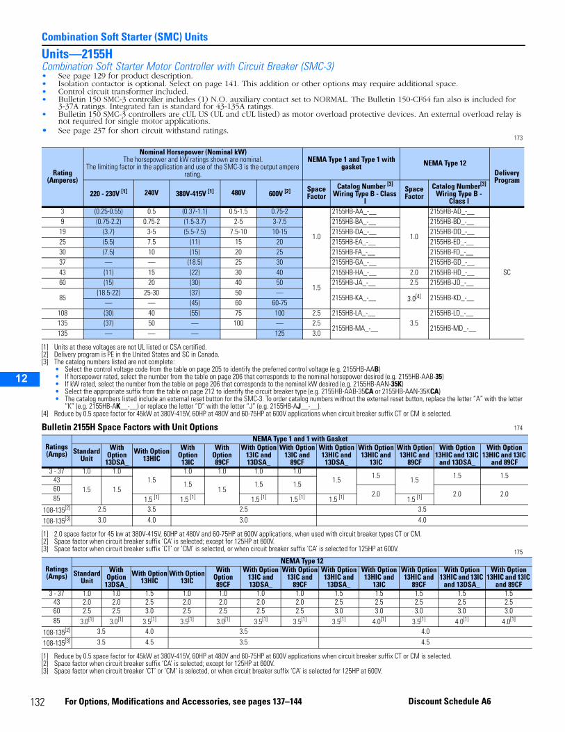
1
Combination Soft Starter (SMC) Units
2
3
4
5
9
10
11
12
13
14
15
16
17
Units—2155HCombination Soft Starter Motor Controller with Circuit Breaker (SMC-3)• See page 129 for product description.• Isolation contactor is optional. Select on page 141. This addition or other options may require additional space.• Control circuit transformer included.• Bulletin 150 SMC-3 controller includes (1) N.O. auxiliary contact set to NORMAL. The Bulletin 150-CF64 fan also is included for
3-37A ratings. Integrated fan is standard for 43-135A ratings.• Bulletin 150 SMC-3 controllers are cUL US (UL and cUL listed) as motor overload protective devices. An external overload relay is
not required for single motor applications.• See page 237 for short circuit withstand ratings.
173
Bulletin 2155H Space Factors with Unit Options 174
175
Rating (Amperes)
Nominal Horsepower (Nominal kW) The horsepower and kW ratings shown are nominal.
The limiting factor in the application and use of the SMC-3 is the output ampere rating.
NEMA Type 1 and Type 1 with gasket NEMA Type 12
Delivery Program
220 - 230V [1] 240V 380V-415V [1]
[1] Units at these voltages are not UL listed or CSA certified.
480V 600V [2]
[2] Delivery program is PE in the United States and SC in Canada.
Space Factor
Catalog Number [3]
Wiring Type B - Class I
[3] The catalog numbers listed are not complete:• Select the control voltage code from the table on page 205 to identify the preferred control voltage (e.g. 2155HB-AAB)• If horsepower rated, select the number from the table on page 206 that corresponds to the nominal horsepower desired (e.g. 2155HB-AAB-35)• If kW rated, select the number from the table on page 206 that corresponds to the nominal kW desired (e.g. 2155HB-AAN-35K)• Select the appropriate suffix from the table on page 212 to identify the circuit breaker type (e.g. 2155HB-AAB-35CA or 2155HB-AAN-35KCA)• The catalog numbers listed include an external reset button for the SMC-3. To order catalog numbers without the external reset button, replace the letter “A” with the letter
“K” (e.g. 2155HB-AK__-__) or replace the letter “D” with the letter “J” (e.g. 2155HB-AJ__-__).
Space Factor
Catalog Number[3] Wiring Type B -
Class I 3 (0.25-0.55) 0.5 (0.37-1.1) 0.5-1.5 0.75-2
1.0
2155HB-AA_-__
1.0
2155HB-AD_-__
SC
9 (0.75-2.2) 0.75-2 (1.5-3.7) 2-5 3-7.5 2155HB-BA_-__ 2155HB-BD_-__19 (3.7) 3-5 (5.5-7.5) 7.5-10 10-15 2155HB-DA_-__ 2155HB-DD_-__25 (5.5) 7.5 (11) 15 20 2155HB-EA_-__ 2155HB-ED_-__30 (7.5) 10 (15) 20 25 2155HB-FA_-__ 2155HB-FD_-__37 — — (18.5) 25 30 2155HB-GA_-__ 2155HB-GD_-__43 (11) 15 (22) 30 40
1.5
2155HB-HA_-__ 2.0 2155HB-HD_-__60 (15) 20 (30) 40 50 2155HB-JA_-__ 2.5 2155HB-JD_-__
85(18.5-22) 25-30 (37) 50 —
2155HB-KA_-__ 3.0[4]
[4] Reduce by 0.5 space factor for 45kW at 380V-415V, 60HP at 480V and 60-75HP at 600V applications when circuit breaker suffix CT or CM is selected.
2155HB-KD_-__— — (45) 60 60-75
108 (30) 40 (55) 75 100 2.5 2155HB-LA_-__3.5
2155HB-LD_-__135 (37) 50 — 100 — 2.5
2155HB-MA_-__ 2155HB-MD_-__135 — — — 125 3.0
Ratings(Amps)
NEMA Type 1 and 1 with Gasket
Standard Unit
With Option
13DSA_With Option
13HICWith
Option13IC
With Option89CF
With Option13IC and 13DSA_
With Option13IC and
89CF
With Option13HIC and
13DSA_
With Option13HIC and
13IC
With Option13HIC and
89CF
With Option 13HIC and 13IC
and 13DSA_
With Option 13HIC and 13IC
and 89CF3 - 37 1.0 1.0
1.51.0 1.0 1.0 1.0
1.5 1.5 1.5 1.5 1.5431.5 1.5
1.51.5
1.5 1.5602.0 2.0 2.085 1.5 [1] 1.5 [1] 1.5 [1] 1.5 [1] 1.5 [1] 1.5 [1]
[1] 2.0 space factor for 45 kw at 380V-415V, 60HP at 480V and 60-75HP at 600V applications, when used with circuit breaker types CT or CM.
108-135[2]
[2] Space factor when circuit breaker suffix ‘CA’ is selected; except for 125HP at 600V.
2.5 3.5 2.5 3.5
108-135[3]
[3] Space factor when circuit breaker suffix ‘CT’ or ‘CM’ is selected, or when circuit breaker suffix ‘CA’ is selected for 125HP at 600V.
3.0 4.0 3.0 4.0
Ratings (Amps)
NEMA Type 12
Standard Unit
With Option
13DSA_With Option
13HICWith Option
13ICWith
Option89CF
With Option13IC and 13DSA_
With Option13IC and
89CF
With Option13HIC and
13DSA_
With Option13HIC and
13IC
With Option13HIC and
89CF
With Option 13HIC and 13IC
and 13DSA_
With Option 13HIC and 13IC
and 89CF3 - 37 1.0 1.0 1.5 1.0 1.0 1.0 1.0 1.5 1.5 1.5 1.5 1.5
43 2.0 2.0 2.5 2.0 2.0 2.0 2.0 2.5 2.5 2.5 2.5 2.560 2.5 2.5 3.0 2.5 2.5 2.5 2.5 3.0 3.0 3.0 3.0 3.085 3.0[1]
[1] Reduce by 0.5 space factor for 45kW at 380V-415V, 60HP at 480V and 60-75HP at 600V applications when circuit breaker suffix CT or CM is selected.
3.0[1] 3.5[1] 3.5[1] 3.0[1] 3.5[1] 3.5[1] 3.5[1] 4.0[1] 3.5[1] 4.0[1] 4.0[1]
108-135[2]
[2] Space factor when circuit breaker suffix ‘CA’ is selected; except for 125HP at 600V.
3.5 4.0 3.5 4.0
108-135[3]
[3] Space factor when circuit breaker ‘CT’ or ‘CM’ is selected, or when circuit breaker suffix ‘CA’ is selected for 125HP at 600V.
3.5 4.5 3.5 4.5
32 For Options, Modifications and Accessories, see pages 137–144 Discount Schedule A6
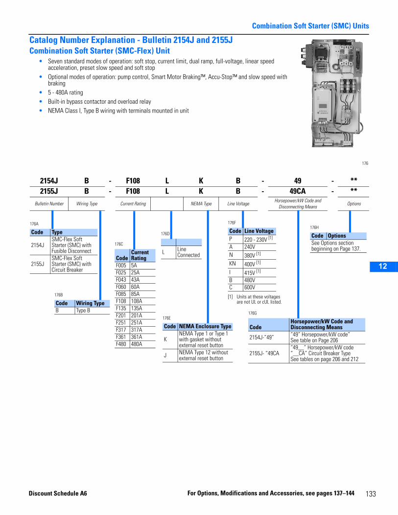
Combination Soft Starter (SMC) Units
2
3
4
5
6
7
8
9
10
11
12
13
14
15
16
17
Catalog Number Explanation - Bulletin 2154J and 2155JCombination Soft Starter (SMC-Flex) Unit
• Seven standard modes of operation: soft stop, current limit, dual ramp, full-voltage, linear speed acceleration, preset slow speed and soft stop
• Optional modes of operation: pump control, Smart Motor Braking™, Accu-Stop™ and slow speed with braking
• 5 - 480A rating• Built-in bypass contactor and overload relay• NEMA Class I, Type B wiring with terminals mounted in unit
176
2154J B - F108 L K B - 49 - **2155J B - F108 L K B - 49CA - **
Bulletin Number Wiring Type Current Rating NEMA Type Line VoltageHorsepower/kW Code and
Disconnecting MeansOptions
176A
Code Type
2154JSMC-Flex Soft Starter (SMC) with Fusible Disconnect
2155JSMC-Flex Soft Starter (SMC) with Circuit Breaker
176C
CodeCurrent Rating
F005 5AF025 25AF043 43AF060 60AF085 85AF108 108AF135 135AF201 201AF251 251AF317 317AF361 361AF480 480A
176B
Code Wiring TypeB Type B
176E
Code NEMA Enclosure Type
KNEMA Type 1 or Type 1 with gasket without external reset button
J NEMA Type 12 without external reset button
176F
Code Line Voltage P 220 - 230V [1]
[1] Units at these voltages are not UL or cUL listed.
A 240VN 380V [1]
KN 400V [1]
I 415V [1]
B 480VC 600V
176G
CodeHorsepower/kW Code and Disconnecting Means
2154J-”49” “49” Horsepower/kW code”See table on Page 206
2155J- “49CA“49__” Horsepower/kW code“__CA” Circuit Breaker TypeSee tables on page 206 and 212
176H
Code OptionsSee Options section beginning on Page 137.
176D
L Line Connected
Discoun
133For Options, Modifications and Accessories, see pages 137–144t Schedule A6
1
Combination Soft Starter (SMC) Units
2
3
4
5
9
10
11
12
13
14
15
16
17
Units—2154JCombination Soft Starter Motor Controller with Fusible Disconnect Switch (SMC-Flex) - Line Connected• See page 129 for product description.• SMC-Flex units are configured as line connected, for Delta connected contact factory.• Isolation contactor is optional. Select on page 141. The addition of this option may require additional space. See the
table below, for space factor of units with option.• Unit includes power fuses.• Control circuit transformer included.• Bulletin 150 SMC-Flex controllers are C-UL US (UL and C-UL listed) as motor overload protective devices. An external
overload relay is not required for single motor applications.• See page 237 for short circuit withstand ratings.
177
Bulletin 2154J Space Factors with Unit Options 178
Rating (Amps)
Nominal Horsepower (Nominal kW)The horsepower and kW ratings shown are nominal.
The limiting factor in the application and use of the SMC-Flex is the output ampere rating. Disc.
Rating
NEMA Type 1 and Type 1 w/ gasket NEMA Type 12
Delivery Program
220-230V [1]
[1] Units at these voltages are not UL listed or CSA certified.
240V 380V-415V [1] 480V 600V [2]
[2] Delivery program is PE-II in the United States and SC-II in Canada.
Space Factor
Catalog Number [3]
Wiring Type B—Class It
[3] The catalog numbers listed are not complete:• Select the control voltage code from table on page 205 to identify the preferred control voltage (e.g., 2154JB-F108LKB).• If horsepower rated, select the number from table on page 206 that corresponds to the nominal horsepower desired, (e.g., 2154JB-F108LKB-49).• If kW rated, select the number from table on page 206 that corresponds to the nominal kW desired, (e.g., 2154JB-F108LKN-49K).
Space Factor
Catalog Number [3]
Wiring Type B—Class I
5 (0.25-1.1) 0.5-1 (0.37-2.2 0.5-3 0.75-3 302.0
2154JB-F005LK_-__
3.0
2154JB-F005LJ_-__
SC
25 (1.5-5.5) 1.5-7.5 (3.7-11) 5-15 5-20 30 2154JB-F025LK_-__ 2154JB-F025LJ_-__43 (7.5-11) 10-15 (15-22) 20-30 25-40 60 2154JB-F043LK_-__ 2154JB-F043LJ_-__60 (15) 20 (30) 40 50 100
2.52154JB-F060LK_-__ 2154JB-F060LJ_-__
85(18.5-22) 25-30 (37) 50 — 100
2154JB-F085LK_-__ 2154JB-F085LJ_-__— — (45) 60 60-75 200 3.5
108 (30) 40 (55) 75 100 2003.5
2154JB-F108LK_-__4.0
2154JB-F108LJ_-__135 (37) 50 — 100 125 200 2154JB-F135LK_-__ 2154JB-F135LJ_-__201 (45-55) 60-75 (75-90) 125-150 150-200 400
6.0[4], 20” W
[4] Frame mounted unit, section does not have vertical wireway. The design of these units is optimized for bottom entry of load cables. For top entry of load cables, consult the factory.
2154JB-F201LK_-__6.0[4], 20” W
2154JB-F201LJ_-__
SC-II251 (75) 100 (110-132) 200 250 400 2154JB-F251LK_-__ 2154JB-F251LJ_-__317 (90) 125 (150-160) 250 300 400
6.0[5], 20” W, 20” D
[5] Frame mounted unit, section does not have vertical wireway. Horizontal bus is 5” deeper than standard. The design of these units is optimized for bottom entry of load cables. For top entry of load cables, consult the factory.
2154JB-F317LK_-__6.0[5],
20” W, 20” D
2154JB-F317LJ_-__361 (110) 150 (185) 300 350 600 2154JB-F361LK_-__ 2154JB-F361LJ_-__480 (132) 200 (200-250) 350-400 400-500 600 2154JB-F480LK_-__ 2154JB-F480LJ_-__
Rating (Amperes)
Space Factor for NEMA Type 1 and Type 1 w/ gasket Units Space Factor for NEMA Type 12 Units
Standard Unit With Option 13GF With Option 13IC With Options 13GF
and 13IC Standard Unit With Option 13GF With Option 13IC With Options 13GF
and 13IC5
2.03.0
254360
2.585 3.0 / 3.5 [1]
[1] Requires 3.5 space factor for 45kW @ 380-415V, 60HP @ 480V and 60-75HP @ 600V.
108 3.5 4.0135 3.5 4.0201 6.0, 20” W 6.0, 20” W251 6.0, 20” W 6.0, 20” W317 6.0, 20” W, 20” D 6.0, 25” W, 20” D 6.0, 20” W, 20” D 6.0, 25” W, 20” D361 6.0, 20” W, 20” D 6.0, 25” W, 20” D 6.0, 20” W, 20” D 6.0, 25” W, 20” D480 6.0, 20” W, 20” D 6.0, 30” W, 20” D 6.0, 20” W, 20” D 6.0, 30” W, 20” D
34 For Options, Modifications and Accessories, see pages 137–144 Discount Schedule A6
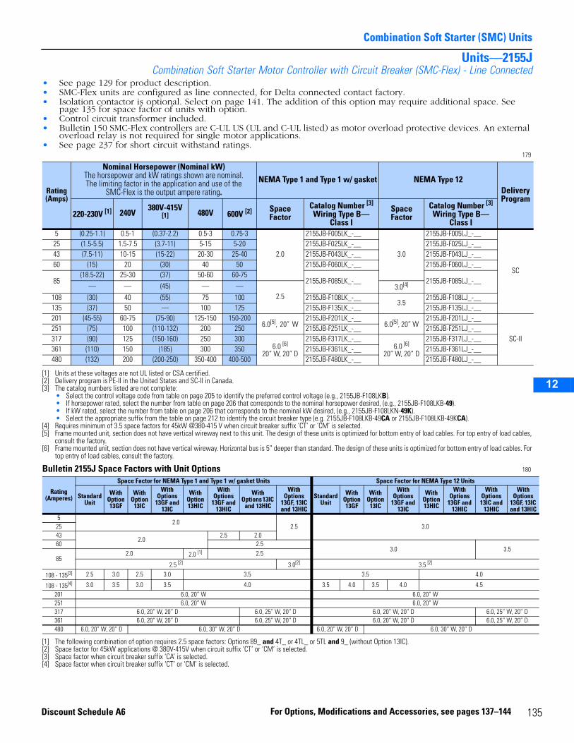
Combination Soft Starter (SMC) Units
2
3
4
5
6
7
8
9
10
11
12
13
14
15
16
17
Units—2155JCombination Soft Starter Motor Controller with Circuit Breaker (SMC-Flex) - Line Connected
• See page 129 for product description.• SMC-Flex units are configured as line connected, for Delta connected contact factory.• Isolation contactor is optional. Select on page 141. The addition of this option may require additional space. See
page 135 for space factor of units with option.• Control circuit transformer included.• Bulletin 150 SMC-Flex controllers are C-UL US (UL and C-UL listed) as motor overload protective devices. An external
overload relay is not required for single motor applications.• See page 237 for short circuit withstand ratings.
179
Bulletin 2155J Space Factors with Unit Options 180
Rating (Amps)
Nominal Horsepower (Nominal kW)The horsepower and kW ratings shown are nominal.The limiting factor in the application and use of the
SMC-Flex is the output ampere rating.NEMA Type 1 and Type 1 w/ gasket NEMA Type 12
Delivery Program
220-230V [1]
[1] Units at these voltages are not UL listed or CSA certified.
240V 380V-415V
[1] 480V 600V [2]
[2] Delivery program is PE-II in the United States and SC-II in Canada.
Space Factor
Catalog Number [3]
Wiring Type B—Class I
[3] The catalog numbers listed are not complete:• Select the control voltage code from table on page 205 to identify the preferred control voltage (e.g., 2155JB-F108LKB).• If horsepower rated, select the number from table on page 206 that corresponds to the nominal horsepower desired, (e.g., 2155JB-F108LKB-49).• If kW rated, select the number from table on page 206 that corresponds to the nominal kW desired, (e.g., 2155JB-F108LKN-49K).• Select the appropriate suffix from the table on page 212 to identify the circuit breaker type (e.g. 2155JB-F108LKB-49CA or 2155JB-F108LKB-49KCA).
Space Factor
Catalog Number [3]
Wiring Type B—Class I
5 (0.25-1.1) 0.5-1 (0.37-2.2) 0.5-3 0.75-3
2.0
2155JB-F005LK_-__
3.0
2155JB-F005LJ_-__
SC
25 (1.5-5.5) 1.5-7.5 (3.7-11) 5-15 5-20 2155JB-F025LK_-__ 2155JB-F025LJ_-__43 (7.5-11) 10-15 (15-22) 20-30 25-40 2155JB-F043LK_-__ 2155JB-F043LJ_-__60 (15) 20 (30) 40 50 2155JB-F060LK_-__ 2155JB-F060LJ_-__
85(18.5-22) 25-30 (37) 50-60 60-75
2155JB-F085LK_-__ 2155JB-F085LJ_-__— — (45) — —
2.53.0[4]
[4] Requires minimum of 3.5 space factors for 45kW @380-415 V when circuit breaker suffix ‘CT’ or ‘CM’ is selected.
108 (30) 40 (55) 75 100 2155JB-F108LK_-__3.5
2155JB-F108LJ_-__135 (37) 50 — 100 125 2155JB-F135LK_-__ 2155JB-F135LJ_-__201 (45-55) 60-75 (75-90) 125-150 150-200
6.0[5], 20” W
[5] Frame mounted unit, section does not have vertical wireway next to this unit. The design of these units is optimized for bottom entry of load cables. For top entry of load cables, consult the factory.
2155JB-F201LK_-__6.0[5], 20” W
2155JB-F201LJ_-__
SC-II251 (75) 100 (110-132) 200 250 2155JB-F251LK_-__ 2155JB-F251LJ_-__317 (90) 125 (150-160) 250 300
6.0 [6] 20” W, 20” D
[6] Frame mounted unit, section does not have vertical wireway. Horizontal bus is 5” deeper than standard. The design of these units is optimized for bottom entry of load cables. For top entry of load cables, consult the factory.
2155JB-F317LK_-__6.0 [6]
20” W, 20” D
2155JB-F317LJ_-__361 (110) 150 (185) 300 350 2155JB-F361LK_-__ 2155JB-F361LJ_-__480 (132) 200 (200-250) 350-400 400-500 2155JB-F480LK_-__ 2155JB-F480LJ_-__
Rating (Amperes)
Space Factor for NEMA Type 1 and Type 1 w/ gasket Units Space Factor for NEMA Type 12 Units
Standard Unit
With Option 13GF
With Option
13IC
With Options
13GF and 13IC
With Option 13HIC
With Options
13GF and 13HIC
With Options 13IC
and 13HIC
With Options
13GF, 13IC and 13HIC
Standard Unit
With Option 13GF
With Option
13IC
With Options
13GF and 13IC
With Option 13HIC
With Options
13GF and 13HIC
With Options 13IC and
13HIC
With Options
13GF, 13IC and 13HIC
52.0
2.5 3.02543
2.02.5 2.0
60 2.53.0 3.5
852.0 2.0 [1]
[1] The following combination of option requires 2.5 space factors: Options 89_ and 4T_ or 4TL_ or 5TL and 9_ (without Option 13IC).
2.5
2.5 [2] 3.0[2] 3.5 [2]
[2] Space factor for 45kW applications @ 380V-415V when circuit suffix ‘CT’ or ‘CM’ is selected.
108 - 135[3]
[3] Space factor when circuit breaker suffix ‘CA’ is selected.
2.5 3.0 2.5 3.0 3.5 3.5 4.0
108 - 135[4]
[4] Space factor when circuit breaker suffix ‘CT’ or ‘CM’ is selected.
3.0 3.5 3.0 3.5 4.0 3.5 4.0 3.5 4.0 4.5201 6.0, 20” W 6.0, 20” W251 6.0, 20” W 6.0, 20” W317 6.0, 20” W, 20” D 6.0, 25” W, 20” D 6.0, 20” W, 20” D 6.0, 25” W, 20” D361 6.0, 20” W, 20” D 6.0, 25” W, 20” D 6.0, 20” W, 20” D 6.0, 25” W, 20” D480 6.0, 20” W, 20” D 6.0, 30” W, 20” D 6.0, 20” W, 20” D 6.0, 30” W, 20” D
135For Options, Modifications and Accessories, see pages 137–144Discount Schedule A6
1
2
3
4
5
9
10
11
12
13
14
15
16
17
Combination Soft Starter (SMC) Units
36 For Options, Modifications and Accessories, see pages 137–144 Discount Schedule A6
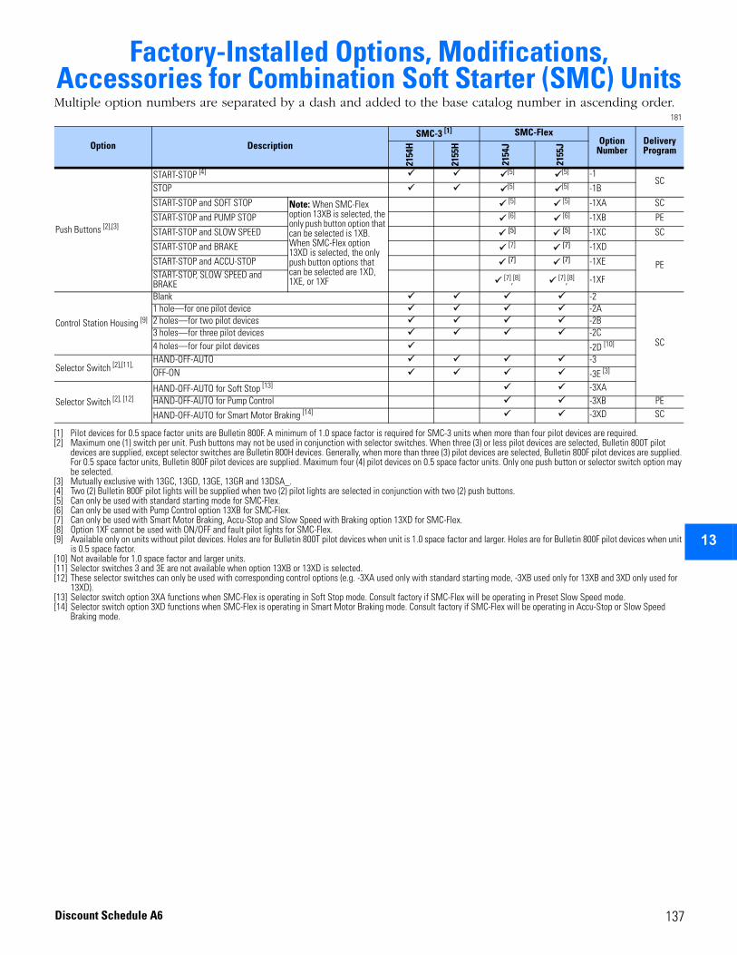
2
3
4
5
6
7
8
9
10
11
12
13
14
15
16
17
Factory-Installed Options, Modifications, Accessories for Combination Soft Starter (SMC) UnitsMultiple option numbers are separated by a dash and added to the base catalog number in ascending order.
181
Option DescriptionSMC-3 [1]
[1] Pilot devices for 0.5 space factor units are Bulletin 800F. A minimum of 1.0 space factor is required for SMC-3 units when more than four pilot devices are required.
SMC-FlexOption
NumberDelivery Program
2154
H
2155
H
2154
J
2155
J
Push Buttons [2],[3]
[2] Maximum one (1) switch per unit. Push buttons may not be used in conjunction with selector switches. When three (3) or less pilot devices are selected, Bulletin 800T pilot devices are supplied, except selector switches are Bulletin 800H devices. Generally, when more than three (3) pilot devices are selected, Bulletin 800F pilot devices are supplied. For 0.5 space factor units, Bulletin 800F pilot devices are supplied. Maximum four (4) pilot devices on 0.5 space factor units. Only one push button or selector switch option may be selected.
[3] Mutually exclusive with 13GC, 13GD, 13GE, 13GR and 13DSA_.
START-STOP [4]
[4] Two (2) Bulletin 800F pilot lights will be supplied when two (2) pilot lights are selected in conjunction with two (2) push buttons.
[5]
[5] Can only be used with standard starting mode for SMC-Flex.
[5] -1SC
STOP [5] [5] -1B
START-STOP and SOFT STOP Note: When SMC-Flex option 13XB is selected, the only push button option that can be selected is 1XB. When SMC-Flex option 13XD is selected, the only push button options that can be selected are 1XD, 1XE, or 1XF
[5] [5] -1XA SC
START-STOP and PUMP STOP [6]
[6] Can only be used with Pump Control option 13XB for SMC-Flex.
[6] -1XB PE
START-STOP and SLOW SPEED [5] [5] -1XC SC
START-STOP and BRAKE [7]
[7] Can only be used with Smart Motor Braking, Accu-Stop and Slow Speed with Braking option 13XD for SMC-Flex.
[7] -1XD
PESTART-STOP and ACCU-STOP [7] [7] -1XE START-STOP, SLOW SPEED and BRAKE [7],[8]
[8] Option 1XF cannot be used with ON/OFF and fault pilot lights for SMC-Flex.
[7],[8] -1XF
Control Station Housing [9]
[9] Available only on units without pilot devices. Holes are for Bulletin 800T pilot devices when unit is 1.0 space factor and larger. Holes are for Bulletin 800F pilot devices when unit is 0.5 space factor.
Blank -2
SC
1 hole—for one pilot device -2A2 holes—for two pilot devices -2B3 holes—for three pilot devices -2C4 holes—for four pilot devices -2D [10]
[10] Not available for 1.0 space factor and larger units.
Selector Switch [2],[11],
[11] Selector switches 3 and 3E are not available when option 13XB or 13XD is selected.
HAND-OFF-AUTO -3OFF-ON -3E [3]
Selector Switch [2], [12]
[12] These selector switches can only be used with corresponding control options (e.g. -3XA used only with standard starting mode, -3XB used only for 13XB and 3XD only used for 13XD).
HAND-OFF-AUTO for Soft Stop [13]
[13] Selector switch option 3XA functions when SMC-Flex is operating in Soft Stop mode. Consult factory if SMC-Flex will be operating in Preset Slow Speed mode.
-3XAHAND-OFF-AUTO for Pump Control -3XB PE
HAND-OFF-AUTO for Smart Motor Braking [14]
[14] Selector switch option 3XD functions when SMC-Flex is operating in Smart Motor Braking mode. Consult factory if SMC-Flex will be operating in Accu-Stop or Slow Speed Braking mode.
-3XD SC
137Discount Schedule A6
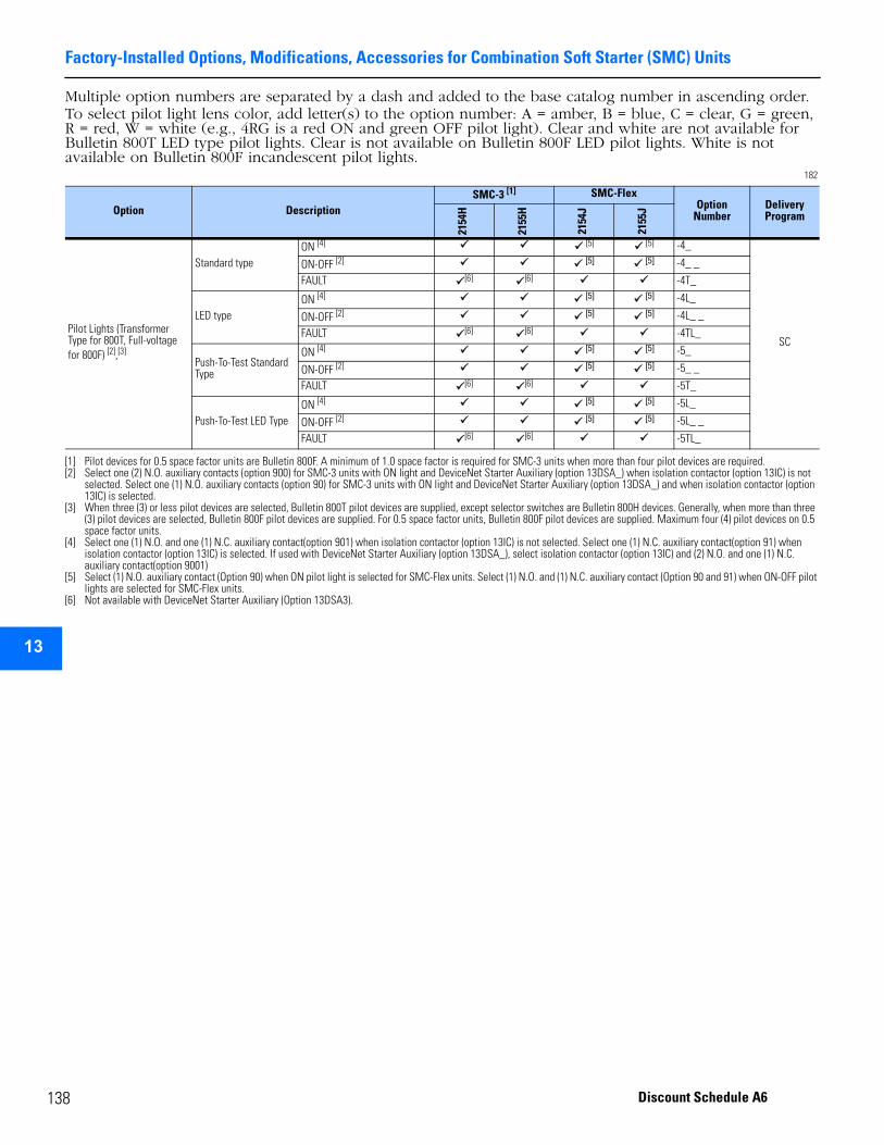
Factory-Installed Options, Modifications, Accessories for Combination Soft Starter (SMC) Units
1
2
3
4
5
9
10
11
12
13
14
15
16
17
Multiple option numbers are separated by a dash and added to the base catalog number in ascending order.To select pilot light lens color, add letter(s) to the option number: A = amber, B = blue, C = clear, G = green, R = red, W = white (e.g., 4RG is a red ON and green OFF pilot light). Clear and white are not available for Bulletin 800T LED type pilot lights. Clear is not available on Bulletin 800F LED pilot lights. White is not available on Bulletin 800F incandescent pilot lights.
182
Option DescriptionSMC-3 [1]
[1] Pilot devices for 0.5 space factor units are Bulletin 800F. A minimum of 1.0 space factor is required for SMC-3 units when more than four pilot devices are required.
SMC-FlexOption
NumberDelivery Program
2154
H
2155
H
2154
J
2155
J
Pilot Lights (Transformer Type for 800T, Full-voltage for 800F) [2],[3]
[2] Select one (2) N.O. auxiliary contacts (option 900) for SMC-3 units with ON light and DeviceNet Starter Auxiliary (option 13DSA_) when isolation contactor (option 13IC) is not selected. Select one (1) N.O. auxiliary contacts (option 90) for SMC-3 units with ON light and DeviceNet Starter Auxiliary (option 13DSA_) and when isolation contactor (option 13IC) is selected.
[3] When three (3) or less pilot devices are selected, Bulletin 800T pilot devices are supplied, except selector switches are Bulletin 800H devices. Generally, when more than three (3) pilot devices are selected, Bulletin 800F pilot devices are supplied. For 0.5 space factor units, Bulletin 800F pilot devices are supplied. Maximum four (4) pilot devices on 0.5 space factor units.
Standard typeON [4]
[4] Select one (1) N.O. and one (1) N.C. auxiliary contact(option 901) when isolation contactor (option 13IC) is not selected. Select one (1) N.C. auxiliary contact(option 91) when isolation contactor (option 13IC) is selected. If used with DeviceNet Starter Auxiliary (option 13DSA_), select isolation contactor (option 13IC) and (2) N.O. and one (1) N.C. auxiliary contact(option 9001)
[5]
[5] Select (1) N.O. auxiliary contact (Option 90) when ON pilot light is selected for SMC-Flex units. Select (1) N.O. and (1) N.C. auxiliary contact (Option 90 and 91) when ON-OFF pilot lights are selected for SMC-Flex units.
[5] -4_
SC
ON-OFF [2] [5] [5] -4_ _
FAULT [6] [6] -4T_
LED type ON [4] [5] [5] -4L_
ON-OFF [2] [5] [5] -4L_ _
FAULT [6]
[6] Not available with DeviceNet Starter Auxiliary (Option 13DSA3).
[6] -4TL_
Push-To-Test Standard Type
ON [4] [5] [5] -5_
ON-OFF [2] [5] [5] -5_ _
FAULT [6] [6] -5T_
Push-To-Test LED TypeON [4] [5] [5] -5L_
ON-OFF [2] [5] [5] -5L_ _
FAULT [6] [6] -5TL_
38 Discount Schedule A6
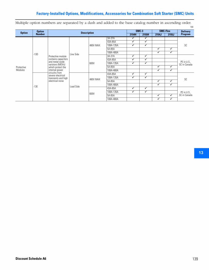
Factory-Installed Options, Modifications, Accessories for Combination Soft Starter (SMC) Units
2
3
4
5
6
7
8
9
10
11
12
13
14
15
16
17
Multiple option numbers are separated by a dash and added to the base catalog number in ascending order.184
Option OptionNumber Description
SMC-3 SMC-Flex DeliveryProgram2154H 2155H 2154J 2155J
Protective Modules
-13DProtective module contains capacitors and metal oxide varistors (MOVs) which protect the internal power circuitry from severe electrical transients and high electrical noise
Line Side
480V MAX
3A-37A
SC43A-85A108A-135A5A-85A108A-480A
600V
3A-37A
PE in U.S., SC in Canada
43A-85A108A-135A5A-85A108A-480A
-13E Load Side
480V MAX
43A-85A
SC108A-135A5A-85A108A-480A
600V
43A-85APE in U.S.,
SC in Canada108A-135A5A-85A108A-480A
139Discount Schedule A6
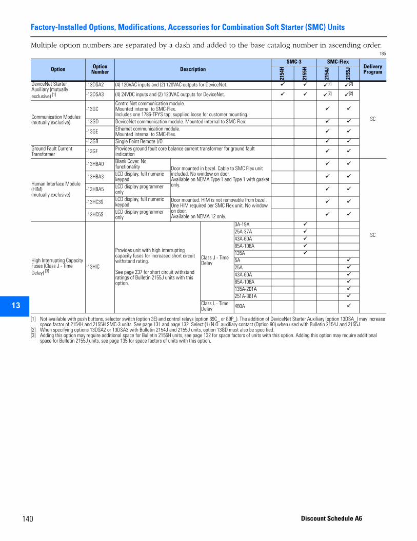
Factory-Installed Options, Modifications, Accessories for Combination Soft Starter (SMC) Units
1
2
3
4
5
9
10
11
12
13
14
15
16
17
Multiple option numbers are separated by a dash and added to the base catalog number in ascending order. 185
Option OptionNumber Description
SMC-3 SMC-FlexDeliveryProgram
2154
H
2155
H
2154
J
2155
J
DeviceNet Starter Auxiliary (mutually exclusive) [1]
[1] Not available with push buttons, selector switch (option 3E) and control relays (option 89C_ or 89P_). The addition of DeviceNet Starter Auxiliary (option 13DSA_) may increase space factor of 2154H and 2155H SMC-3 units. See page 131 and page 132. Select (1) N.O. auxiliary contact (Option 90) when used with Bulletin 2154J and 2155J.
-13DSA2 (4) 120VAC inputs and (2) 120VAC outputs for DeviceNet. [2]
[2] When specifying options 13DSA2 or 13DSA3 with Bulletin 2154J and 2155J units, option 13GD must also be specified.
[2]
SC
-13DSA3 (4) 24VDC inputs and (2) 120VAC outputs for DeviceNet. [2] [2]
Communication Modules (mutually exclusive)
-13GCControlNet communication module.Mounted internal to SMC-Flex.Includes one 1786-TPYS tap, supplied loose for customer mounting.
-13GD DeviceNet communication module. Mounted internal to SMC-Flex.
-13GE Ethernet communication module.Mounted internal to SMC-Flex.
-13GR Single Point Remote I/OGround Fault Current Transformer -13GF Provides ground fault core balance current transformer for ground fault
indication
Human Interface Module (HIM) (mutually exclusive)
-13HBA0 Blank Cover. No functionality Door mounted in bezel. Cable to SMC Flex unit
included. No window on door.Available on NEMA Type 1 and Type 1 with gasket only.
SC
-13HBA3 LCD display, full numeric keypad
-13HBA5 LCD display programmer only
-13HC3S LCD display, full numeric keypad
Door mounted. HIM is not removable from bezel. One HIM required per SMC Flex unit. No window on door.Available on NEMA 12 only.-13HC5S LCD display programmer
only
High Interrupting Capacity Fuses (Class J - Time Delay) [3]
[3] Adding this option may require additional space for Bulletin 2155H units, see page 132 for space factors of units with this option. Adding this option may require additional space for Bulletin 2155J units, see page 135 for space factors of units with this option.
-13HIC
Provides unit with high interrupting capacity fuses for increased short circuit withstand rating.
See page 237 for short circuit withstand ratings of Bulletin 2155J units with this option.
Class J - Time Delay
3A-19A25A-37A43A-60A85A-108A135A5A25A43A-60A85A-108A135A-201A251A-361A
Class L - Time Delay 480A
40 Discount Schedule A6
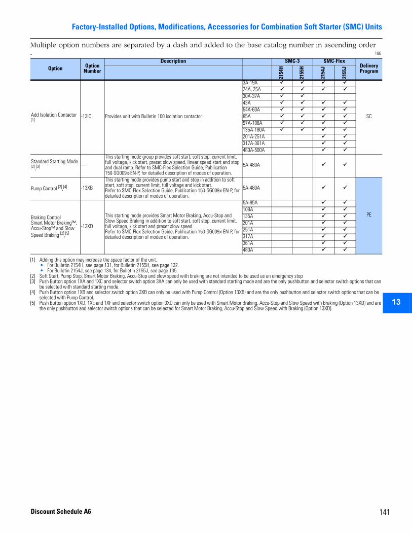
Factory-Installed Options, Modifications, Accessories for Combination Soft Starter (SMC) Units
2
3
4
5
6
7
8
9
10
11
12
13
14
15
16
17
Multiple option numbers are separated by a dash and added to the base catalog number in ascending order. 186
Option OptionNumber
Description SMC-3 SMC-FlexDeliveryProgram
2154
H
2155
H
2154
J
2155
J
Add Isolation Contactor
[1]
[1] Adding this option may increase the space factor of the unit. • For Bulletin 2154H, see page 131, for Bulletin 2155H, see page 132. • For Bulletin 2154J, see page 134, for Bulletin 2155J, see page 135.
-13IC Provides unit with Bulletin 100 isolation contactor.
3A-19A
SC
24A, 25A 30A-37A43A 54A-60A 85A 97A-108A 135A-180A 201A-251A 317A-361A 480A-500A
Standard Starting Mode [2],[3]
[2] Soft Start, Pump Stop, Smart Motor Braking, Accu-Stop and slow speed with braking are not intended to be used as an emergency stop[3] Push Button option 1XA and 1XC and selector switch option 3XA can only be used with standard starting mode and are the only pushbutton and selector switch options that can
be selected with standard starting mode.
—
This starting mode group provides soft start, soft stop, current limit, full voltage, kick start, preset slow speed, linear speed start and stop and dual ramp. Refer to SMC-Flex Selection Guide, Publication 150-SG009x-EN-P, for detailed description of modes of operation.
5A-480A
Pump Control [2],[4]
[4] Push Button option 1XB and selector switch option 3XB can only be used with Pump Control (Option 13XB) and are the only pushbutton and selector switch options that can be selected with Pump Control.
-13XB
This starting mode provides pump start and stop in addition to soft start, soft stop, current limit, full voltage and kick start. Refer to SMC-Flex Selection Guide, Publication 150-SG009x-EN-P, for detailed description of modes of operation.
5A-480A
PEBraking Control Smart Motor Braking™, Accu-Stop™ and Slow Speed Braking [2],[5]
[5] Push Button option 1XD, 1XE and 1XF and selector switch option 3XD can only be used with Smart Motor Braking, Accu-Stop and Slow Speed with Braking (Option 13XD) and are the only pushbutton and selector switch options that can be selected for Smart Motor Braking, Accu-Stop and Slow Speed with Braking (Option 13XD).
-13XD
This starting mode provides Smart Motor Braking, Accu-Stop and Slow Speed Braking in addition to soft start, soft stop, current limit, full voltage, kick start and preset slow speed.Refer to SMC-Flex Selection Guide, Publication 150-SG009x-EN-P, for detailed description of modes of operation.
5A-85A108A135A201A251A317A361A480A
141Discount Schedule A6
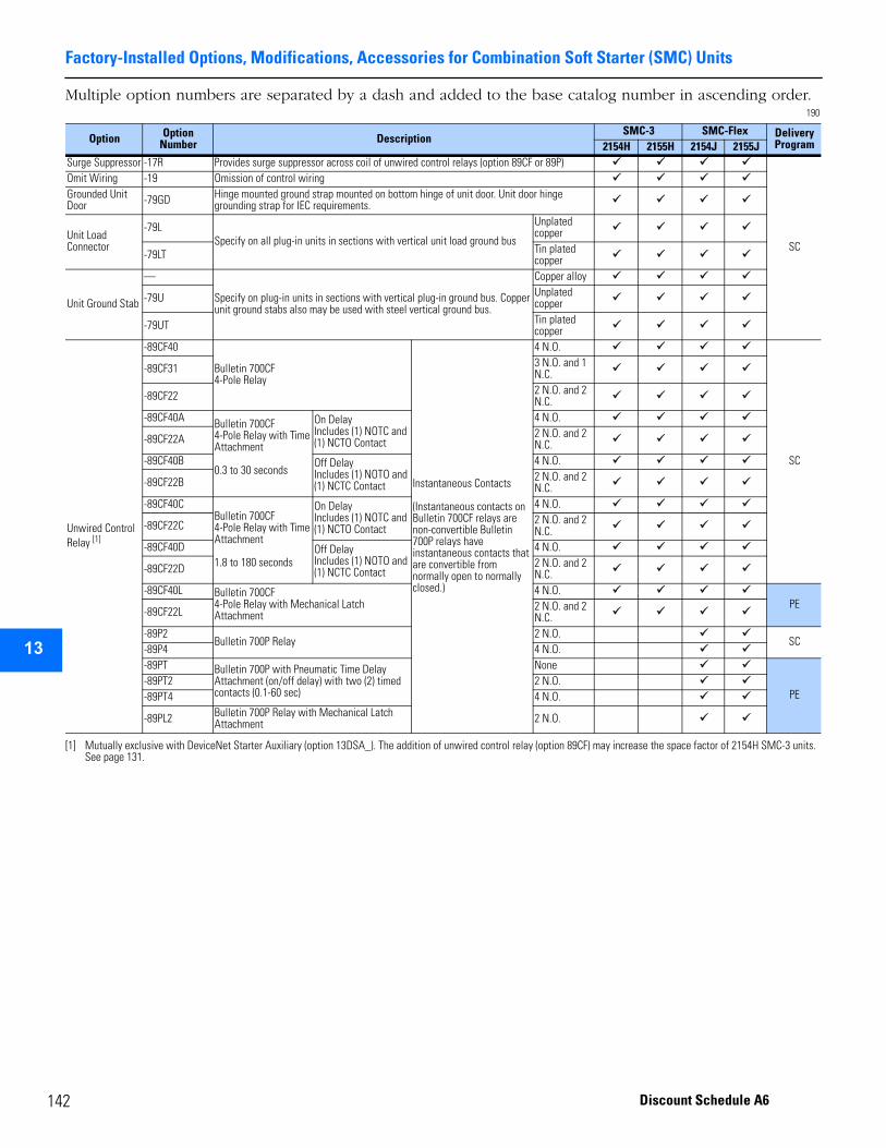
Factory-Installed Options, Modifications, Accessories for Combination Soft Starter (SMC) Units
1
2
3
4
5
9
10
11
12
13
14
15
16
17
Multiple option numbers are separated by a dash and added to the base catalog number in ascending order.190
Option Option Number Description
SMC-3 SMC-Flex Delivery Program2154H 2155H 2154J 2155J
Surge Suppressor -17R Provides surge suppressor across coil of unwired control relays (option 89CF or 89P)
SC
Omit Wiring -19 Omission of control wiringGrounded Unit Door -79GD Hinge mounted ground strap mounted on bottom hinge of unit door. Unit door hinge
grounding strap for IEC requirements.
Unit Load Connector
-79LSpecify on all plug-in units in sections with vertical unit load ground bus
Unplated copper
-79LT Tin plated copper
Unit Ground Stab
—
Specify on plug-in units in sections with vertical plug-in ground bus. Copper unit ground stabs also may be used with steel vertical ground bus.
Copper alloy
-79U Unplated copper
-79UT Tin plated copper
Unwired Control Relay [1]
[1] Mutually exclusive with DeviceNet Starter Auxiliary (option 13DSA_). The addition of unwired control relay (option 89CF) may increase the space factor of 2154H SMC-3 units. See page 131.
-89CF40
Bulletin 700CF4-Pole Relay
Instantaneous Contacts
(Instantaneous contacts on Bulletin 700CF relays arenon-convertible Bulletin 700P relays have instantaneous contacts that are convertible from normally open to normally closed.)
4 N.O.
SC
-89CF31 3 N.O. and 1 N.C.
-89CF22 2 N.O. and 2 N.C.
-89CF40A Bulletin 700CF4-Pole Relay with Time Attachment
0.3 to 30 seconds
On DelayIncludes (1) NOTC and (1) NCTO Contact
4 N.O.
-89CF22A 2 N.O. and 2 N.C.
-89CF40B Off DelayIncludes (1) NOTO and (1) NCTC Contact
4 N.O.
-89CF22B 2 N.O. and 2 N.C.
-89CF40CBulletin 700CF4-Pole Relay with Time Attachment
1.8 to 180 seconds
On DelayIncludes (1) NOTC and (1) NCTO Contact
4 N.O.
-89CF22C 2 N.O. and 2 N.C.
-89CF40D Off DelayIncludes (1) NOTO and (1) NCTC Contact
4 N.O.
-89CF22D 2 N.O. and 2 N.C.
-89CF40L Bulletin 700CF4-Pole Relay with Mechanical Latch Attachment
4 N.O.PE
-89CF22L 2 N.O. and 2 N.C.
-89P2Bulletin 700P Relay
2 N.O.SC
-89P4 4 N.O.-89PT Bulletin 700P with Pneumatic Time Delay
Attachment (on/off delay) with two (2) timed contacts (0.1-60 sec)
None
PE-89PT2 2 N.O.-89PT4 4 N.O.
-89PL2 Bulletin 700P Relay with Mechanical Latch Attachment 2 N.O.
42 Discount Schedule A6

Factory-Installed Options, Modifications, Accessories for Combination Soft Starter (SMC) Units
2
3
4
5
6
7
8
9
10
11
12
13
14
15
16
17
Multiple option numbers are separated by a dash and added to the base catalog number in ascending order.191
Option Option Number Description
SMC-3 SMC-Flex Delivery Program2154H 2155H 2154J 2155J
Auxiliary ContactsType B Wiring
-90 Normally Open—1 N.O. auxiliary contact mounted on isolation contactor (13IC) when supplied
[1]
[1] The following apply to auxiliary contacts for Bulletin 2154H and 2155H SMC-3 units:• Bulletin 150 SMC-3 controller includes one N.O. auxiliary contact set to NORMAL (unless otherwise specified below).• When isolation contactor (option -13IC) is not selected, the maximum number of auxiliary contacts is two (2) in the following combinations (2) N.O. or (1) N.O. and (1) N.C.
The auxiliary contacts are side-mounted on the SMC-3 and set to NORMAL. The standard SMC-3 N.O. auxiliary contact is set for AT SPEED and is not used.• When isolation contactor (option -13IC) is selected, the maximum number auxiliary contacts is four (4) in any combination (except (3) N.C, (4) N.C., or (1) N.O. & (3) N.C.).
These auxiliary contacts are on the isolation contactor. The standard SMC-3 N.O. auxiliary contact is set for NORMAL and is used to control the isolation contactor.• When ON pilot light or DeviceNet Starter Auxiliary (option -13DSA_) is selected in SMC-3 units, without an isolation contactor and without any additional auxiliary contacts,
the standard SMC-3 N.O. auxiliary contact will be used and set to NORMAL.• When ON pilot light or DeviceNet Starter Auxiliary (option -13DSA_) is selected in SMC-3 units, without an isolation contactor, only one additional N.O. or N.C. contact may
be selected, select (2) N.O. auxiliary contacts (option -900) or (1) N.O. and (1) N.C. auxiliary contacts (option -901). The auxiliary contacts are side-mounted on the SMC-3 and set to NORMAL. The standard SMC-3 N.O. auxiliary contact is set for AT SPEED and is not used.
• When ON pilot light and DeviceNet Starter Auxiliary (option -13DSA_) are selected in SMC-3 units, select (2) N.O. auxiliary contacts (option -900). Without an isolation contactor (option-13IC) the auxiliary contacts are side-mounted on the SMC-3 and set to NORMAL. The standard SMC-3 N.O. auxiliary contact is set for AT SPEED and is not used.
• When ON-OFF pilot lights are selected on SMC-3 units, select (1) N.O. auxiliary contact and (1) N.C. auxiliary contact (option -901). Without an isolation contactor (option-13IC) the auxiliary contacts are side-mounted on the SMC-3 and set to NORMAL. The standard SMC-3 N.O. auxiliary contact is set for AT SPEED and is not used.
• When ON-OFF pilot lights and DeviceNet Starter Auxiliary (option -13DSA_) are selected on SMC-3 units, select (2) N.O. and (1) N.C. auxiliary contact (option -9001). Note: this number of auxiliary contacts requires the selection of an isolation contactor (option -13IC).
[1] [2]
[2] The following apply to auxiliary contacts for Bulletin 2154J and 2155J SMC Flex units:• When isolation contactor (Option 13IC) is selected, the maximum number of auxiliary contacts is four (4) in any combination (except (3) N.C., (4) N.C., or (1) N.O. & (3) N.C.).• When isolation contactor (Option 13IC) is not selected, the maximum number of auxiliary contacts is four (4) in the following combinations: (2) N.O. / (2) N.C., (3) N.O. / (1)
N.C., (4) N.O. or (4) N.C.• When ON pilot light is selected on SMC-Flex units, select (1) N.O. auxiliary contact (option -90).• When ON-OFF pilot lights are selected on SMC-Flex units, select (1) N.O. and (1) N.C. auxiliary contact (option -90 and -91).• When DeviceNet Starter Auxiliary (-13DSA_) is selected on SMC-Flex units, select (1) N.O. auxiliary contact (option -90).
[2]
SC
-91 Normally Closed—1 N.C. auxiliary contact mounted on isolation contactor (13IC) when supplied [1] [1] [2] [2]
-98 [3]
[3] The maximum number of auxiliary contacts that can be supplied is two (2), in any combination. Contacts actuate with movement of unit handle to ON or OFF position only. Contacts are not designed to actuate as a result of a circuit breaker trip. For such applications, auxiliary contacts “mounted internally” (98X or 99X) must be selected. Auxiliary contacts are supplied unwired.
Normally Open—1 N.O. mounted on operating mechanism (operates with movement of external handle only)
-98X [4]
[4] The maximum number of auxiliary contacts that can be supplied internally is (2) N.O. and (2) N.C. (form C). Internal auxiliary contacts (98X or 99X) are wired to a 3-point unmounted terminal block.
Normally Open—1 N.O. mounted internally. Circuit breaker units only.
-99 [3] Normally Closed—1 N.C. mounted on operating mechanism (operates with movement of external handle only)
-99X [4] Normally Closed—1 N.C. mounted internally. Circuit breaker units only.
143Discount Schedule A6
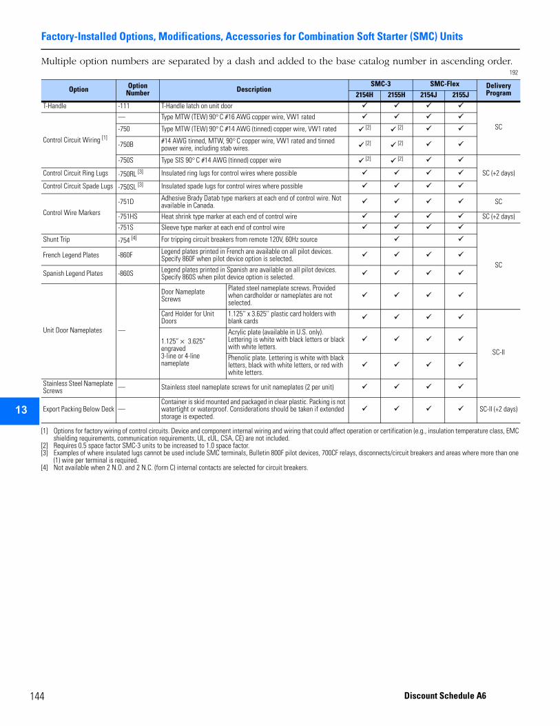
Factory-Installed Options, Modifications, Accessories for Combination Soft Starter (SMC) Units
1
2
3
4
5
9
10
11
12
13
14
15
16
17
Multiple option numbers are separated by a dash and added to the base catalog number in ascending order.192
Option Option Number Description
SMC-3 SMC-Flex Delivery Program2154H 2155H 2154J 2155J
T-Handle -111 T-Handle latch on unit door
SC
Control Circuit Wiring [1]
[1] Options for factory wiring of control circuits. Device and component internal wiring and wiring that could affect operation or certification (e.g., insulation temperature class, EMC shielding requirements, communication requirements, UL, cUL, CSA, CE) are not included.
— Type MTW (TEW) 90° C #16 AWG copper wire, VW1 rated
-750 Type MTW (TEW) 90° C #14 AWG (tinned) copper wire, VW1 rated [2] [2]
-750B #14 AWG tinned, MTW, 90° C copper wire, VW1 rated and tinned power wire, including stab wires. [2]
[2] Requires 0.5 space factor SMC-3 units to be increased to 1.0 space factor.
[2]
-750S Type SIS 90° C #14 AWG (tinned) copper wire [2] [2]
SC (+2 days)Control Circuit Ring Lugs -750RL [3]
[3] Examples of where insulated lugs cannot be used include SMC terminals, Bulletin 800F pilot devices, 700CF relays, disconnects/circuit breakers and areas where more than one (1) wire per terminal is required.
Insulated ring lugs for control wires where possible
Control Circuit Spade Lugs -750SL [3] Insulated spade lugs for control wires where possible
Control Wire Markers
-751D Adhesive Brady Datab type markers at each end of control wire. Not available in Canada. SC
-751HS Heat shrink type marker at each end of control wire SC (+2 days)
-751S Sleeve type marker at each end of control wire
SC
Shunt Trip -754 [4]
[4] Not available when 2 N.O. and 2 N.C. (form C) internal contacts are selected for circuit breakers.
For tripping circuit breakers from remote 120V, 60Hz source
French Legend Plates -860F Legend plates printed in French are available on all pilot devices. Specify 860F when pilot device option is selected.
Spanish Legend Plates -860S Legend plates printed in Spanish are available on all pilot devices. Specify 860S when pilot device option is selected.
Unit Door Nameplates —
Door Nameplate Screws
Plated steel nameplate screws. Provided when cardholder or nameplates are not selected.
Card Holder for Unit Doors
1.125'' x 3.625'' plastic card holders with blank cards
SC-II
1.125” × 3.625” engraved 3-line or 4-line nameplate
Acrylic plate (available in U.S. only). Lettering is white with black letters or black with white letters.
Phenolic plate. Lettering is white with black letters, black with white letters, or red with white letters.
Stainless Steel Nameplate Screws — Stainless steel nameplate screws for unit nameplates (2 per unit)
Export Packing Below Deck —Container is skid mounted and packaged in clear plastic. Packing is not watertight or waterproof. Considerations should be taken if extended storage is expected.
SC-II (+2 days)
44 Discount Schedule A6
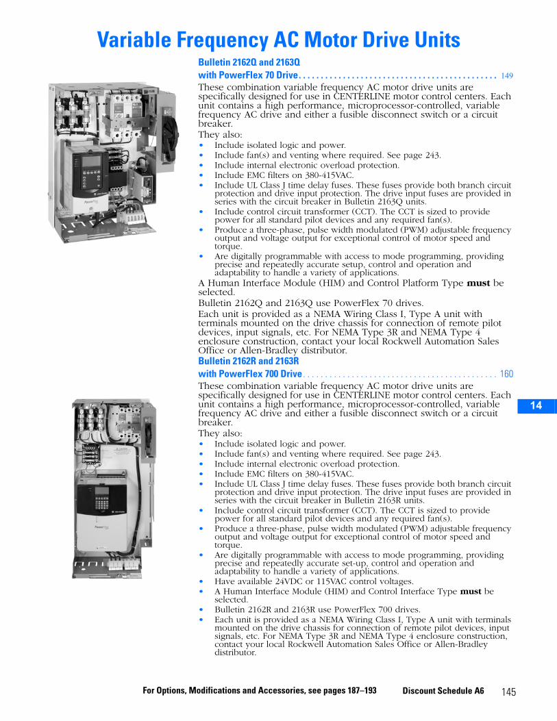
14
Variable Frequency AC Motor Drive UnitsBulletin 2162Q and 2163Q with PowerFlex 70 Drive. . . . . . . . . . . . . . . . . . . . . . . . . . . . . . . . . . . . . . . . . . . . . 149These combination variable frequency AC motor drive units are specifically designed for use in CENTERLINE motor control centers. Each unit contains a high performance, microprocessor-controlled, variable frequency AC drive and either a fusible disconnect switch or a circuit breaker.They also:• Include isolated logic and power.• Include fan(s) and venting where required. See page 243.• Include internal electronic overload protection.• Include EMC filters on 380-415VAC.• Include UL Class J time delay fuses. These fuses provide both branch circuit
protection and drive input protection. The drive input fuses are provided in series with the circuit breaker in Bulletin 2163Q units.
• Include control circuit transformer (CCT). The CCT is sized to provide power for all standard pilot devices and any required fan(s).
• Produce a three-phase, pulse width modulated (PWM) adjustable frequency output and voltage output for exceptional control of motor speed and torque.
• Are digitally programmable with access to mode programming, providing precise and repeatedly accurate setup, control and operation and adaptability to handle a variety of applications.
A Human Interface Module (HIM) and Control Platform Type must be selected.Bulletin 2162Q and 2163Q use PowerFlex 70 drives.Each unit is provided as a NEMA Wiring Class I, Type A unit with terminals mounted on the drive chassis for connection of remote pilot devices, input signals, etc. For NEMA Type 3R and NEMA Type 4 enclosure construction, contact your local Rockwell Automation Sales Office or Allen-Bradley distributor.Bulletin 2162R and 2163R with PowerFlex 700 Drive . . . . . . . . . . . . . . . . . . . . . . . . . . . . . . . . . . . . . . . . . . . . 160These combination variable frequency AC motor drive units are specifically designed for use in CENTERLINE motor control centers. Each unit contains a high performance, microprocessor-controlled, variable frequency AC drive and either a fusible disconnect switch or a circuit breaker.They also:• Include isolated logic and power.• Include fan(s) and venting where required. See page 243.• Include internal electronic overload protection.• Include EMC filters on 380-415VAC.• Include UL Class J time delay fuses. These fuses provide both branch circuit
protection and drive input protection. The drive input fuses are provided in series with the circuit breaker in Bulletin 2163R units.
• Include control circuit transformer (CCT). The CCT is sized to provide power for all standard pilot devices and any required fan(s).
• Produce a three-phase, pulse width modulated (PWM) adjustable frequency output and voltage output for exceptional control of motor speed and torque.
• Are digitally programmable with access to mode programming, providing precise and repeatedly accurate set-up, control and operation and adaptability to handle a variety of applications.
• Have available 24VDC or 115VAC control voltages.• A Human Interface Module (HIM) and Control Interface Type must be
selected.• Bulletin 2162R and 2163R use PowerFlex 700 drives.• Each unit is provided as a NEMA Wiring Class I, Type A unit with terminals
mounted on the drive chassis for connection of remote pilot devices, input signals, etc. For NEMA Type 3R and NEMA Type 4 enclosure construction, contact your local Rockwell Automation Sales Office or Allen-Bradley distributor.
145For Options, Modifications and Accessories, see pages 187–193 Discount Schedule A6
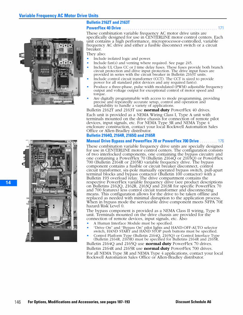
14
Variable Frequency AC Motor Drive UnitsBulletin 2162T and 2163TPowerFlex 40 Drive . . . . . . . . . . . . . . . . . . . . . . . . . . . . . . . . . . . . . . . . . . . . . . . . . 171These combination variable frequency AC motor drive units are specifically designed for use in CENTERLINE motor control centers. Each unit contains a high performance, microprocessor-controlled, variable frequency AC drive and either a fusible disconnect switch or a circuit breaker.They also:• Include isolated logic and power.• Include fan(s) and venting where required. See page 245.• Include UL Class CC or J time delay fuses. These fuses provide both branch
circuit protection and drive input protection. The drive input fuses are provided in series with the circuit breaker in Bulletin 2163T units.
• Include control circuit transformer (CCT). The CCT is sized to provide power for all standard pilot devices and any required fan(s).
• Produce a three-phase, pulse width modulated (PWM) adjustable frequency output and voltage output for exceptional control of motor speed and torque.
• Are digitally programmable with access to mode programming, providing precise and repeatedly accurate setup, control and operation and adaptability to handle a variety of applications.
Bulletin 2162T and 2163T use normal duty PowerFlex 40 drives.Each unit is provided as a NEMA Wiring Class I, Type A unit with terminals mounted on the drive chassis for connection of remote pilot devices, input signals, etc. For NEMA Type 3R and NEMA Type 4 enclosure construction, contact your local Rockwell Automation Sales Office or Allen-Bradley distributor.Bulletin 2164Q, 2164R, 2165Q and 2165R Manual Drive Bypass and PowerFlex 70 or PowerFlex 700 Drive . . . . . . . . . 176These combination variable frequency drive units are specially designed for use in CENTERLINE motor control centers. The configuration consists of two interlocked components, one containing the bypass circuitry and one containing a PowerFlex 70 (Bulletin 2164Q or 2165Q) or PowerFlex 700 (Bulletin 2164R or 2165R) variable frequency drive. The bypass component contains a fusible or circuit breaker disconnect, control circuit transformer, six-pole manually operated bypass switch, pull-apart terminal blocks and bypass contactor (Bulletin 100 contactor) with a Bulletin 193 overload relay. The drive compartment contains the respective PowerFlex variable frequency drive (see product descriptions on Bulletins 2162Q, 2162R, 2163Q and 2163R for specific PowerFlex 70 and 700 features) less control circuit transformer and disconnecting means. This configuration allows for the drive to be taken offline and replaced as needed with minimal disruption to the application process. When in bypass mode the serviceable drive component meets NFPA 70E hazard/Risk Level 0.The bypass component is provided as a NEMA Class II wiring, Type B unit. Terminals mounted on the drive chassis are provided for the connection of remote devices, input signals, etc. Also• A Human Interface Module must be specified.• “Drive On” and “Bypass On” pilot lights and HAND-OFF-AUTO selector
switch, HAND START and HAND STOP push buttons must be specified.• Control Platform Type (Bulletin 2164Q, 2165Q) or Control Interface Type
(Bulletin 2164R, 2165R) must be specified for Bulletins 2164R and 2165R.Bulletin 2164Q and 2165Q use normal duty PowerFlex 70 drives.Bulletin 2164R and 2165R use normal duty PowerFlex 700 drives.For all NEMA Type 3R and NEMA Type 4 applications, contact your local Rockwell Automation Sales Office or Allen-Bradley distributor.
146 For Options, Modifications and Accessories, see pages 187–193 Discount Schedule A6
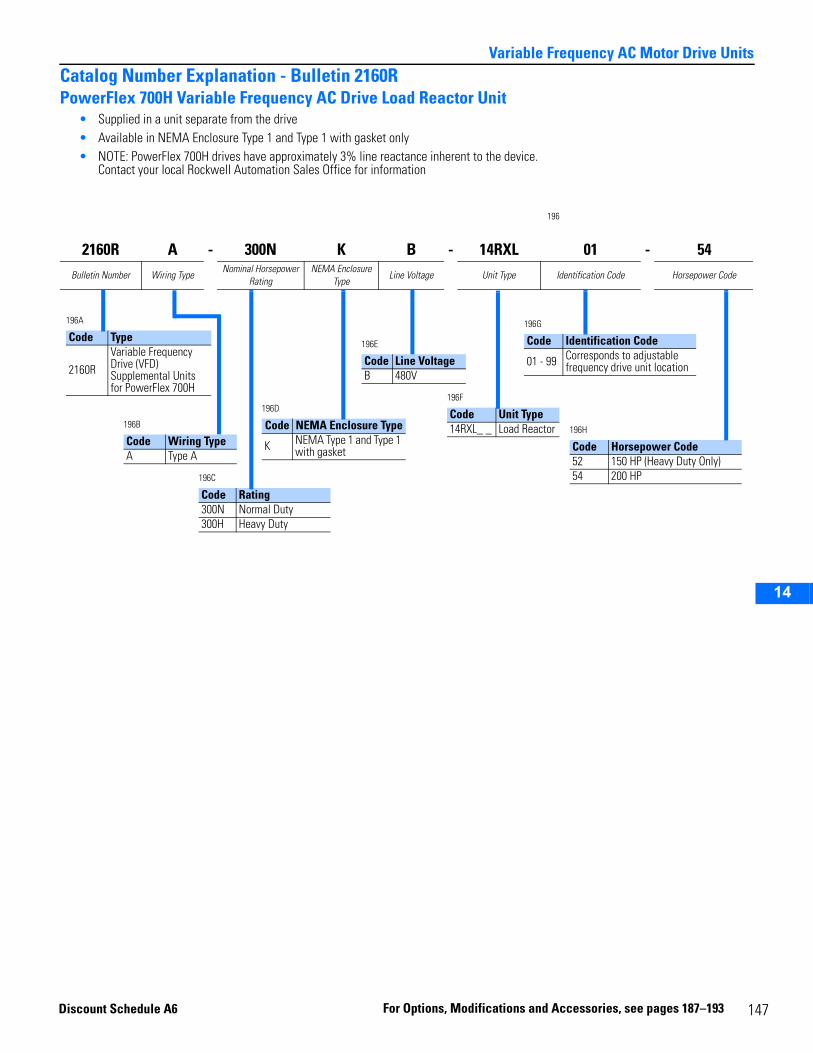
14
Variable Frequency AC Motor Drive UnitsCatalog Number Explanation - Bulletin 2160RPowerFlex 700H Variable Frequency AC Drive Load Reactor Unit
• Supplied in a unit separate from the drive• Available in NEMA Enclosure Type 1 and Type 1 with gasket only• NOTE: PowerFlex 700H drives have approximately 3% line reactance inherent to the device.
Contact your local Rockwell Automation Sales Office for information
196
2160R A - 300N K B - 14RXL 01 - 54Bulletin Number Wiring Type
Nominal Horsepower Rating
NEMA Enclosure Type
Line Voltage Unit Type Identification Code Horsepower Code
196A
Code Type
2160RVariable Frequency Drive (VFD) Supplemental Units for PowerFlex 700H
196C
Code Rating300N Normal Duty300H Heavy Duty
196B
Code Wiring TypeA Type A
196D
Code NEMA Enclosure Type
K NEMA Type 1 and Type 1 with gasket
196F
Code Unit Type14RXL_ _ Load Reactor
196G
Code Identification Code
01 - 99 Corresponds to adjustable frequency drive unit location
196E
Code Line VoltageB 480V
196H
Code Horsepower Code52 150 HP (Heavy Duty Only)54 200 HP
Discount S
chedule A6 For Option s, Modificatio ns and A 147ccessories, see pages 187–193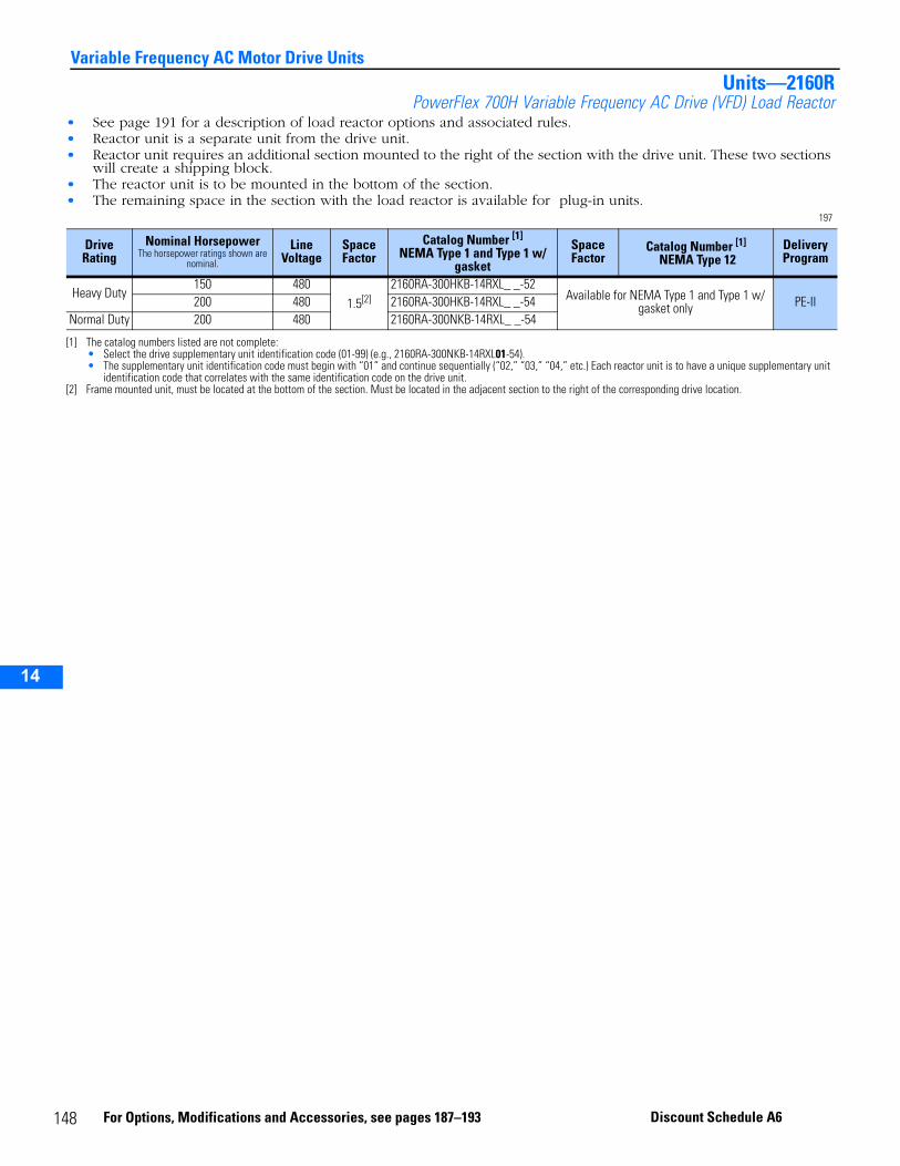
14
Variable Frequency AC Motor Drive UnitsUnits—2160R
PowerFlex 700H Variable Frequency AC Drive (VFD) Load Reactor• See page 191 for a description of load reactor options and associated rules.• Reactor unit is a separate unit from the drive unit.• Reactor unit requires an additional section mounted to the right of the section with the drive unit. These two sections
will create a shipping block.• The reactor unit is to be mounted in the bottom of the section.• The remaining space in the section with the load reactor is available for plug-in units.
197
Drive Rating
Nominal Horsepower The horsepower ratings shown are
nominal.
Line Voltage
Space Factor
Catalog Number [1]
NEMA Type 1 and Type 1 w/ gasket
[1] The catalog numbers listed are not complete:• Select the drive supplementary unit identification code (01-99) (e.g., 2160RA-300NKB-14RXL01-54). • The supplementary unit identification code must begin with “01” and continue sequentially (“02,” “03,” “04,” etc.) Each reactor unit is to have a unique supplementary unit
identification code that correlates with the same identification code on the drive unit.
Space Factor
Catalog Number [1]
NEMA Type 12Delivery Program
Heavy Duty150 480
1.5[2]
[2] Frame mounted unit, must be located at the bottom of the section. Must be located in the adjacent section to the right of the corresponding drive location.
2160RA-300HKB-14RXL_ _-52Available for NEMA Type 1 and Type 1 w/
gasket only PE-II200 480 2160RA-300HKB-14RXL_ _-54Normal Duty 200 480 2160RA-300NKB-14RXL_ _-54
148 For Options, Modifications and Accessories, see pages 187–193 Discount Schedule A6
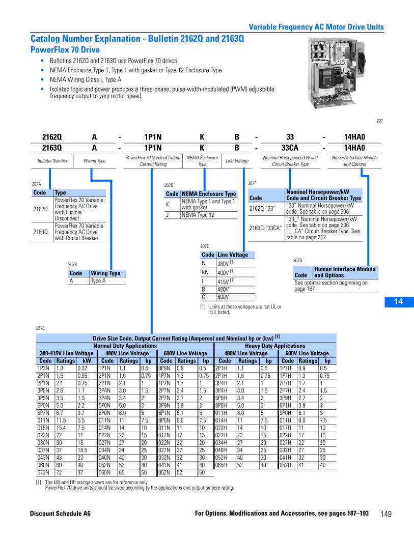
14
Variable Frequency AC Motor Drive UnitsCatalog Number Explanation - Bulletin 2162Q and 2163QPowerFlex 70 Drive
• Bulletins 2162Q and 2163Q use PowerFlex 70 drives• NEMA Enclosure Type 1, Type 1 with gasket or Type 12 Enclosure Type• NEMA Wiring Class I, Type A• Isolated logic and power produces a three-phase, pulse-width-modulated (PWM) adjustable
frequency output to vary motor speed
207
2162Q A - 1P1N K B - 33 - 14HA02163Q A - 1P1N K B - 33CA - 14HA0
Bulletin Number Wiring TypePowerFlex 70 Nominal Output
Current RatingNEMA Enclosure
TypeLine Voltage
Nominal Horsepower/kW and Circuit Breaker Type
Human Interface Module and Options
207A
Code Type
2162QPowerFlex 70 Variable Frequency AC Drive with Fusible Disconnect
2163QPowerFlex 70 Variable Frequency AC Drive with Circuit Breaker
207C
Drive Size Code, Output Current Rating (Amperes) and Nominal hp or (kw) [1]
[1] The kW and HP ratings shown are for reference only. PowerFlex 70 drive units should be sized according to the applications and output ampere rating.
Normal Duty Applications Heavy Duty Applications380-415V Line Voltage 480V Line Voltage 600V Line Voltage 480V Line Voltage 600V Line VoltageCode Ratings kW Code Ratings hp Code Ratings hp Code Ratings hp Code Ratings hp
1P3N 1.3 0.37 1P1N 1.1 0.5 0P9N 0.9 0.5 2P1H 1.1 0.5 1P7H 0.9 0.52P1N 1.5 0.55 2P1N 1.6 0.75 1P7N 1.3 0.75 2P1H 1.6 0.75 1P7H 1.3 0.752P1N 2.1 0.75 2P1N 2.1 1 1P7N 1.7 1 3P4H 2.1 1 2P7H 1.7 13P5N 2.6 1.1 3P4N 3.0 1.5 2P7N 2.4 1.5 3P4H 3.0 1.5 2P7H 2.4 1.53P5N 3.5 1.5 3P4N 3.4 2 2P7N 2.7 2 5P0H 3.4 2 3P9H 2.7 25P0N 5.0 2.2 5P0N 5.0 3 3P9N 3.9 3 8P0H 5.0 3 6P1H 3.9 38P7N 8.7 3.7 8P0N 8.0 5 6P1N 6.1 5 011H 8.0 5 9P0H 6.1 5011N 11.5 5.5 011N 11 7.5 9P0N 9.0 7.5 014H 11 7.5 011H 9.0 7.5015N 15.4 7.5 014N 14 10 011N 11 10 022H 14 10 017H 11 10022N 22 11 022N 22 15 017N 17 15 027H 22 15 022H 17 15030N 30 15 027N 27 20 022N 22 20 034H 27 20 027H 22 20037N 37 18.5 034N 34 25 027N 27 25 040H 34 25 032H 27 25043N 43 22 040N 40 30 032N 32 30 052H 40 30 041H 32 30060N 60 30 052N 52 40 041N 41 40 065H 52 40 052H 41 40072N 72 37 065N 65 50 052N 52 50
207B
Code Wiring TypeA Type A
207D
Code NEMA Enclosure Type
K NEMA Type 1 and Type 1 with gasket
J NEMA Type 12
207F
CodeNominal Horsepower/kW Code and Circuit Breaker Type
2162Q-”33” “33” Nominal Horsepower/kW code. See table on page 206
2163Q-”33CA”“33_” Nominal Horsepower/kW code. See table on page 206“__CA” Circuit Breaker Type. See table on page 212
207G
CodeHuman Interface Module and Options
See options section beginning on page 187
207E
Code Line VoltageN 380V [1]
[1] Units at these voltages are not UL or cUL listed.
KN 400V [1]
I 415V [1]
B 480VC 600V
Discount Sc
hedule A6 For Options, Modi fications and Ac 149cessories, see pages 187–193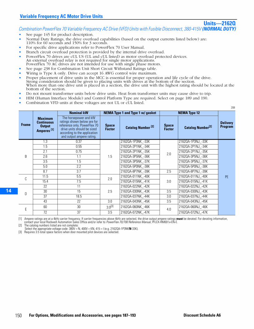
14
Variable Frequency AC Motor Drive UnitsUnits—2162Q
Combination PowerFlex 70 Variable Frequency AC Drive (VFD) Units with Fusible Disconnect, 380-415V (NORMAL DUTY)• See page 145 for product description.• Normal Duty Ratings, the drive overload capabilities (based on the output currents listed below) are:
110% for 60 seconds and 150% for 3 seconds.• For specific drive applications refer to PowerFlex 70 User Manual.• Branch circuit overload protection is provided by the internal drive overload.• PowerFlex 70 drives are cUL US (UL and cUL listed) as motor overload protected devices.
An external overload relay is not required for single motor applications.PowerFlex 70 AC drives are not intended for use with single phase motors.
• See page 238 for Combination Unit Short Circuit Withstand Ratings table.• Wiring is Type A only. Drive can accept 16 AWG control wire maximum.• Proper placement of drive units in the MCC is essential for proper operation and life cycle of the drive.
Strong consideration should be given to placing units with drives at the bottom of the section. When more than one drive unit is placed in a section, the drive unit with the highest rating should be located at the bottom of the section.
• Do not mount transformer units below drive units. Heat from transformer units may cause drive to trip.• HIM (Human Interface Module) and Control Platform Type are required. Select on page 189 and 190.• Combination VFD units at these voltages are not UL or cUL listed.
208
Frame
Maximum Continuous
Output Amperes [1]
[1] Ampere ratings are at a 4kHz carrier frequency. If carrier frequencies above 4kHz are selected, the drive output ampere ratings must be derated. For derating information, contact your local Rockwell Automation Sales Office and/or refer to PowerFlex 70/700 Reference Manual, PFLEX-RM001x-EN-E.
Nominal kW NEMA Type 1 and Type 1 w/ gasket NEMA Type 12
Delivery Program
The horsepower and kW ratings shown below are for reference only. PowerFlex 70 drive units should be sized
according to the application and output ampere rating.
Space Factor Catalog Number [2]
[2] The catalog numbers listed are not complete:Select the appropriate voltage code: 380V = N, 400V = KN, 415 = I (e.g. 2162QA-1P3NKN-33K).
Space Factor Catalog Number[2]
B
1.3 0.37
1.5
2162QA-1P3NK_-33K
2.0
2162QA-1P3NJ_-33K
PE
1.5 0.55 2162QA-2P1NK_-34K 2162QA-2P1NJ_-34K2.1 0.75 2162QA-2P1NK_-35K 2162QA-2P1NJ_-35K2.6 1.1 2162QA-3P5NK_-36K 2162QA-3P5NJ_-36K3.5 1.5 2162QA-3P5NK_-37K 2162QA-3P5NJ_-37K5.0 2.2 2162QA-5P0NK_-38K 2162QA-5P0NJ_-38K8.7 3.7 2162QA-8P7NK_-39K 2.5 2162QA-8P7NJ_-39K
C11.5 5.5
2.02162QA-011NK_-40K
3.02162QA-011NJ_-40K
15.4 7.5 2162QA-015NK_-41K 2162QA-015NJ_-41K
D
22 112.5
2162QA-022NK_-42K 2162QA-022NJ_-42K30 15 2162QA-030NK_-43K 3.5 2162QA-030NJ_-43K37 18.5 2162QA-037NK_-44K 3.0 2162QA-037NJ_-44K43 22 3.0 2162QA-043NK_-45K 3.5 2162QA-043NJ_-45K
E60 30 3.0[3]
[3] Requires 3.5 total space factors when door mounted pilot devices are selected.
2162QA-060NK_-46K4.0
2162QA-060NJ_-46K72 37 3.5 2162QA-072NK_-47K 2162QA-072NJ_-47K
150 For Options, Modifications and Accessories, see pages 187–193 Discount Schedule A6
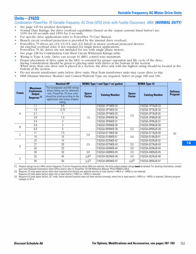
14
Variable Frequency AC Motor Drive UnitsUnits—2162QCombination PowerFlex 70 Variable Frequency AC Drive (VFD) Units with Fusible Disconnect, 480V (NORMAL DUTY)• See page 145 for product description.• Normal Duty Ratings, the drive overload capabilities (based on the output currents listed below) are:
110% for 60 seconds and 150% for 3 seconds.• For specific drive applications refer to PowerFlex 70 User Manual.• Branch circuit overload protection is provided by the internal drive overload.• PowerFlex 70 drives are cUL US (UL and cUL listed) as motor overload protected devices.
An external overload relay is not required for single motor applications.PowerFlex 70 AC drives are not intended for use with single phase motors.
• See page 238 for Combination Unit Short Circuit Withstand Ratings table.• Wiring is Type A only. Drive can accept 16 AWG control wire maximum.• Proper placement of drive units in the MCC is essential for proper operation and life cycle of the drive.
Strong consideration should be given to placing units with drives at the bottom of the section. When more than one drive unit is placed in a section, the drive unit with the highest rating should be located at the bottom of the section.
• Do not mount transformer units below drive units. Heat from transformer units may cause drive to trip.• HIM (Human Interface Module) and Control Platform Type are required. Select on page 189 and 190.
209
Frame
Maximum Continuous
Output Amperes [1]
[1] Ampere ratings are at a 4kHz carrier frequency. If carrier frequencies above 4kHz are selected, the drive output ampere ratings must be derated. For derating information, contact your local Rockwell Automation Sales Office and/or refer to PowerFlex 70/700 Reference Manual, PFLEX-RM001x-EN-E.
Nominal HP NEMA Type 1 and Type 1 w/ gasket NEMA Type 12
Delivery Program
The horsepower and kW ratings shown below are for reference only. PowerFlex 70 drive units
should be sized according to the application and output ampere
rating.
Space Factor Catalog Number Space
Factor Catalog Number
A
1.1 0.5
1.5
2162QA-1P1NKB-33
2.0
2162QA-1P1NJB-33
SC
1.6 0.75 2162QA-2P1NKB-34 2162QA-2P1NJB-342.1 1 2162QA-2P1NKB-35 2162QA-2P1NJB-353.0 1.5 2162QA-3P4NKB-36 2162QA-3P4NJB-363.4 2 2162QA-3P4NKB-37 2162QA-3P4NJB-37
B5.0 3 2162QA-5P0NKB-38 2162QA-5P0NJB-388.0 5 2162QA-8P0NKB-39 2.5 2162QA-8P0NJB-39
C11 7.5
2.02162QA-011NKB-40
3.02162QA-011NJB-40
14 10 2162QA-014NKB-41 2162QA-014NJB-41
D
22 152.5
2162QA-022NKB-42 2162QA-022NJB-4227 20 2162QA-027NKB-43 3.5 2162QA-027NJB-4334 25 2162QA-034NKB-44 3.0 2162QA-034NJB-4440 30 3.0 2162QA-040NKB-45 3.5 2162QA-040NJB-45
E52 40 3.0[2]
[2] Requires 3.5 total space factors when door mounted pilot devices are selected and line or load reactor (-14RLX or -14RXL) is not selected.Requires 4.0 total space factors when line or load reactor (-14RLX or -14RXL) is selected.
2162QA-052NKB-46 4.0 2162QA-052NJB-46
65 50 3.5[3]
[3] Requires 6.0 total space factors, 20” wide, frame mounted (section does not have vertical wireway), when line or load reactor (-14RLX or -14RXL) is selected. Delivery program changes to SC-II.
2162QA-065NKB-47 4.0[3] 2162QA-065NJB-47
151For Options, Modifications and Accessories, see pages 187–193Discount Schedule A6

14
Variable Frequency AC Motor Drive UnitsUnits—2162QCombination PowerFlex 70 Variable Frequency AC Drive (VFD) Units with Fusible Disconnect, 480V (HEAVY DUTY)• See page 145 for product description.• Heavy Duty Ratings, the drive overload capabilities (based on the output currents listed below) are:
150% for 60 seconds and 200% for 3 seconds.• For specific drive applications refer to PowerFlex 70 User Manual.• Branch circuit overload protection is provided by the internal drive overload.• PowerFlex 70 drives are cUL US (UL and cUL listed) as motor overload protected devices.
An external overload relay is not required for single motor applications.PowerFlex 70 AC drives are not intended for use with single phase motors.
• See page 238 for Combination Unit Short Circuit Withstand Ratings table.• Wiring is Type A only. Drive can accept 16 AWG control wire maximum.• Proper placement of drive units in the MCC is essential for proper operation and life cycle of the drive.
Strong consideration should be given to placing units with drives at the bottom of the section. When more than one drive unit is placed in a section, the drive unit with the highest rating should be located at the bottom of the section.
• Do not mount transformer units below drive units. Heat from transformer units may cause drive to trip.• HIM (Human Interface Module) and Control Platform Type are required. Select on page 189 and 190.
210
Frame
Maximum Continuous
Output Amperes [1]
[1] Ampere ratings are at a 4kHz carrier frequency. If carrier frequencies above 4kHz are selected, the drive output ampere ratings must be derated. For derating information, contact your local Rockwell Automation Sales Office and/or refer to PowerFlex 70/700 Reference Manual, PFLEX-RM001x-EN-E.
Nominal HP NEMA Type 1 and Type 1 w/ gasket NEMA Type 12
Delivery Program
The horsepower and kW ratings shown below are for reference only. PowerFlex 70 drive units
should be sized according to the application and output ampere
rating.
Space Factor Catalog Number Space
Factor Catalog Number
A
1.1 0.5
1.5
2162QA-2P1HKB-33
2.0
2162QA-2P1HJB-33
SC
1.6 0.75 2162QA-2P1HKB-34 2162QA-2P1HJB-342.1 1 2162QA-3P4HKB-35 2162QA-3P4HJB-353.0 1.5 2162QA-3P4HKB-36 2162QA-3P4HJB-36
B3.4 2 2162QA-5P0HKB-37 2162QA-5P0HJB-375.0 3 2162QA-8P0HKB-38 2.5 2162QA-8P0HJB-38
C8.0 5
2.02162QA-011HKB-39
3.02162QA-011HJB-39
11 7.5 2162QA-014HKB-40 2162QA-014HJB-40
D
14 102.5
2162QA-022HKB-41 2162QA-022HJB-4122 15 2162QA-027HKB-42 3.5 2162QA-027HJB-4227 20 2162QA-034HKB-43 3.0 2162QA-034HJB-4334 25 3.0 2162QA-040HKB-44 3.5 2162QA-040HJB-44
E40 30 3.0[2]
[2] Requires 3.5 total space factors when door mounted pilot devices are selected and line or load reactor (-14RLX or -14RXL) is not selected.Requires 4.0 total space factors when line or load reactor (-14RLX or -14RXL) is selected.
2162QA-052HKB-45 4.0 2162QA-052HJB-45
52 40 3.5[3]
[3] Requires 6.0 total space factors, 20” wide, frame mounted (section does not have vertical wireway), when line or load reactor (-14RLX or -14RXL) is selected. Delivery program changes to SC-II.
2162QA-065HKB-46 4.0[3] 2162QA-065HJB-46
152 For Options, Modifications and Accessories, see pages 187–193 Discount Schedule A6
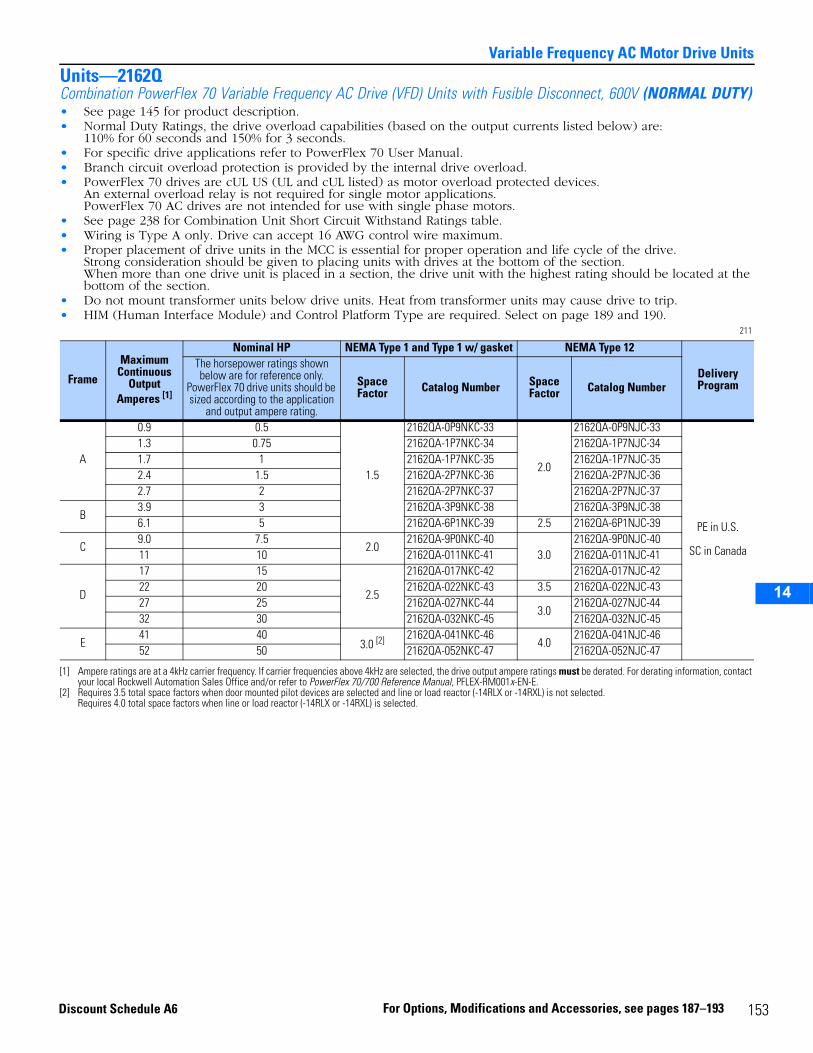
14
Variable Frequency AC Motor Drive UnitsUnits—2162QCombination PowerFlex 70 Variable Frequency AC Drive (VFD) Units with Fusible Disconnect, 600V (NORMAL DUTY)• See page 145 for product description.• Normal Duty Ratings, the drive overload capabilities (based on the output currents listed below) are:
110% for 60 seconds and 150% for 3 seconds.• For specific drive applications refer to PowerFlex 70 User Manual.• Branch circuit overload protection is provided by the internal drive overload.• PowerFlex 70 drives are cUL US (UL and cUL listed) as motor overload protected devices.
An external overload relay is not required for single motor applications.PowerFlex 70 AC drives are not intended for use with single phase motors.
• See page 238 for Combination Unit Short Circuit Withstand Ratings table.• Wiring is Type A only. Drive can accept 16 AWG control wire maximum.• Proper placement of drive units in the MCC is essential for proper operation and life cycle of the drive.
Strong consideration should be given to placing units with drives at the bottom of the section. When more than one drive unit is placed in a section, the drive unit with the highest rating should be located at the bottom of the section.
• Do not mount transformer units below drive units. Heat from transformer units may cause drive to trip.• HIM (Human Interface Module) and Control Platform Type are required. Select on page 189 and 190.
211
Frame
Maximum Continuous
Output Amperes [1]
[1] Ampere ratings are at a 4kHz carrier frequency. If carrier frequencies above 4kHz are selected, the drive output ampere ratings must be derated. For derating information, contact your local Rockwell Automation Sales Office and/or refer to PowerFlex 70/700 Reference Manual, PFLEX-RM001x-EN-E.
Nominal HP NEMA Type 1 and Type 1 w/ gasket NEMA Type 12
Delivery Program
The horsepower ratings shown below are for reference only.
PowerFlex 70 drive units should be sized according to the application
and output ampere rating.
Space Factor Catalog Number Space
Factor Catalog Number
A
0.9 0.5
1.5
2162QA-0P9NKC-33
2.0
2162QA-0P9NJC-33
PE in U.S.
SC in Canada
1.3 0.75 2162QA-1P7NKC-34 2162QA-1P7NJC-341.7 1 2162QA-1P7NKC-35 2162QA-1P7NJC-352.4 1.5 2162QA-2P7NKC-36 2162QA-2P7NJC-362.7 2 2162QA-2P7NKC-37 2162QA-2P7NJC-37
B3.9 3 2162QA-3P9NKC-38 2162QA-3P9NJC-386.1 5 2162QA-6P1NKC-39 2.5 2162QA-6P1NJC-39
C9.0 7.5
2.02162QA-9P0NKC-40
3.02162QA-9P0NJC-40
11 10 2162QA-011NKC-41 2162QA-011NJC-41
D
17 15
2.5
2162QA-017NKC-42 2162QA-017NJC-4222 20 2162QA-022NKC-43 3.5 2162QA-022NJC-4327 25 2162QA-027NKC-44
3.02162QA-027NJC-44
32 30 2162QA-032NKC-45 2162QA-032NJC-45
E41 40
3.0 [2]
[2] Requires 3.5 total space factors when door mounted pilot devices are selected and line or load reactor (-14RLX or -14RXL) is not selected.Requires 4.0 total space factors when line or load reactor (-14RLX or -14RXL) is selected.
2162QA-041NKC-464.0
2162QA-041NJC-4652 50 2162QA-052NKC-47 2162QA-052NJC-47
153For Options, Modifications and Accessories, see pages 187–193Discount Schedule A6
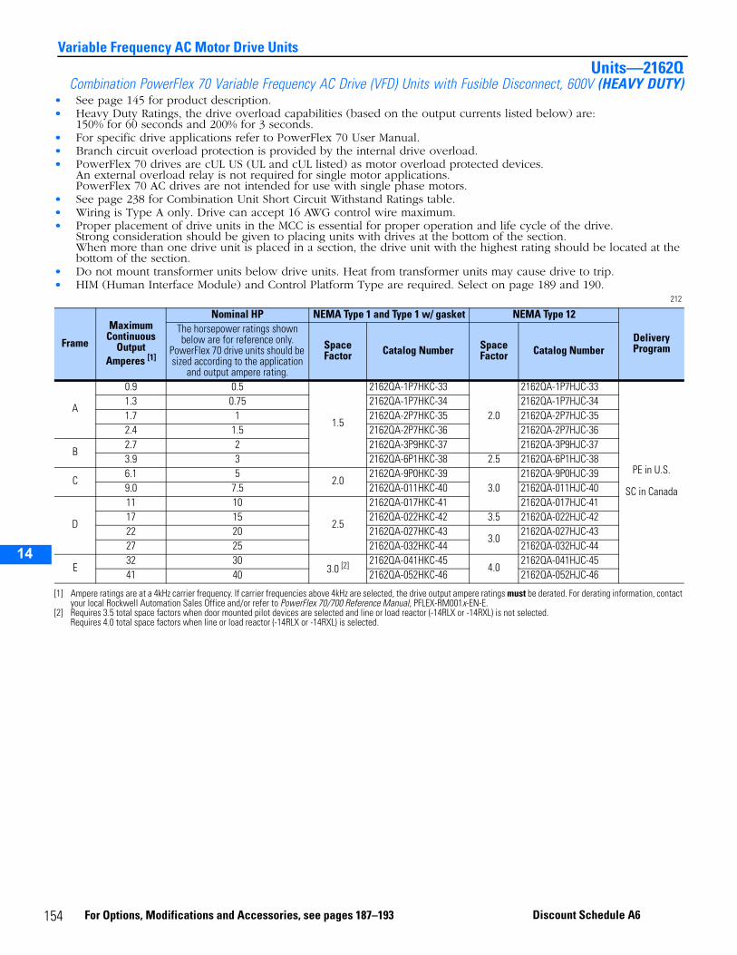
14
Variable Frequency AC Motor Drive UnitsUnits—2162Q
Combination PowerFlex 70 Variable Frequency AC Drive (VFD) Units with Fusible Disconnect, 600V (HEAVY DUTY)• See page 145 for product description.• Heavy Duty Ratings, the drive overload capabilities (based on the output currents listed below) are:
150% for 60 seconds and 200% for 3 seconds.• For specific drive applications refer to PowerFlex 70 User Manual.• Branch circuit overload protection is provided by the internal drive overload.• PowerFlex 70 drives are cUL US (UL and cUL listed) as motor overload protected devices.
An external overload relay is not required for single motor applications.PowerFlex 70 AC drives are not intended for use with single phase motors.
• See page 238 for Combination Unit Short Circuit Withstand Ratings table.• Wiring is Type A only. Drive can accept 16 AWG control wire maximum.• Proper placement of drive units in the MCC is essential for proper operation and life cycle of the drive.
Strong consideration should be given to placing units with drives at the bottom of the section. When more than one drive unit is placed in a section, the drive unit with the highest rating should be located at the bottom of the section.
• Do not mount transformer units below drive units. Heat from transformer units may cause drive to trip.• HIM (Human Interface Module) and Control Platform Type are required. Select on page 189 and 190.
212
Frame
Maximum Continuous
Output Amperes [1]
[1] Ampere ratings are at a 4kHz carrier frequency. If carrier frequencies above 4kHz are selected, the drive output ampere ratings must be derated. For derating information, contact your local Rockwell Automation Sales Office and/or refer to PowerFlex 70/700 Reference Manual, PFLEX-RM001x-EN-E.
Nominal HP NEMA Type 1 and Type 1 w/ gasket NEMA Type 12
Delivery Program
The horsepower ratings shown below are for reference only.
PowerFlex 70 drive units should be sized according to the application
and output ampere rating.
Space Factor Catalog Number Space
Factor Catalog Number
A
0.9 0.5
1.5
2162QA-1P7HKC-33
2.0
2162QA-1P7HJC-33
PE in U.S.
SC in Canada
1.3 0.75 2162QA-1P7HKC-34 2162QA-1P7HJC-341.7 1 2162QA-2P7HKC-35 2162QA-2P7HJC-352.4 1.5 2162QA-2P7HKC-36 2162QA-2P7HJC-36
B2.7 2 2162QA-3P9HKC-37 2162QA-3P9HJC-373.9 3 2162QA-6P1HKC-38 2.5 2162QA-6P1HJC-38
C6.1 5
2.02162QA-9P0HKC-39
3.02162QA-9P0HJC-39
9.0 7.5 2162QA-011HKC-40 2162QA-011HJC-40
D
11 10
2.5
2162QA-017HKC-41 2162QA-017HJC-4117 15 2162QA-022HKC-42 3.5 2162QA-022HJC-4222 20 2162QA-027HKC-43
3.02162QA-027HJC-43
27 25 2162QA-032HKC-44 2162QA-032HJC-44
E32 30
3.0 [2]
[2] Requires 3.5 total space factors when door mounted pilot devices are selected and line or load reactor (-14RLX or -14RXL) is not selected.Requires 4.0 total space factors when line or load reactor (-14RLX or -14RXL) is selected.
2162QA-041HKC-454.0
2162QA-041HJC-4541 40 2162QA-052HKC-46 2162QA-052HJC-46
154 For Options, Modifications and Accessories, see pages 187–193 Discount Schedule A6
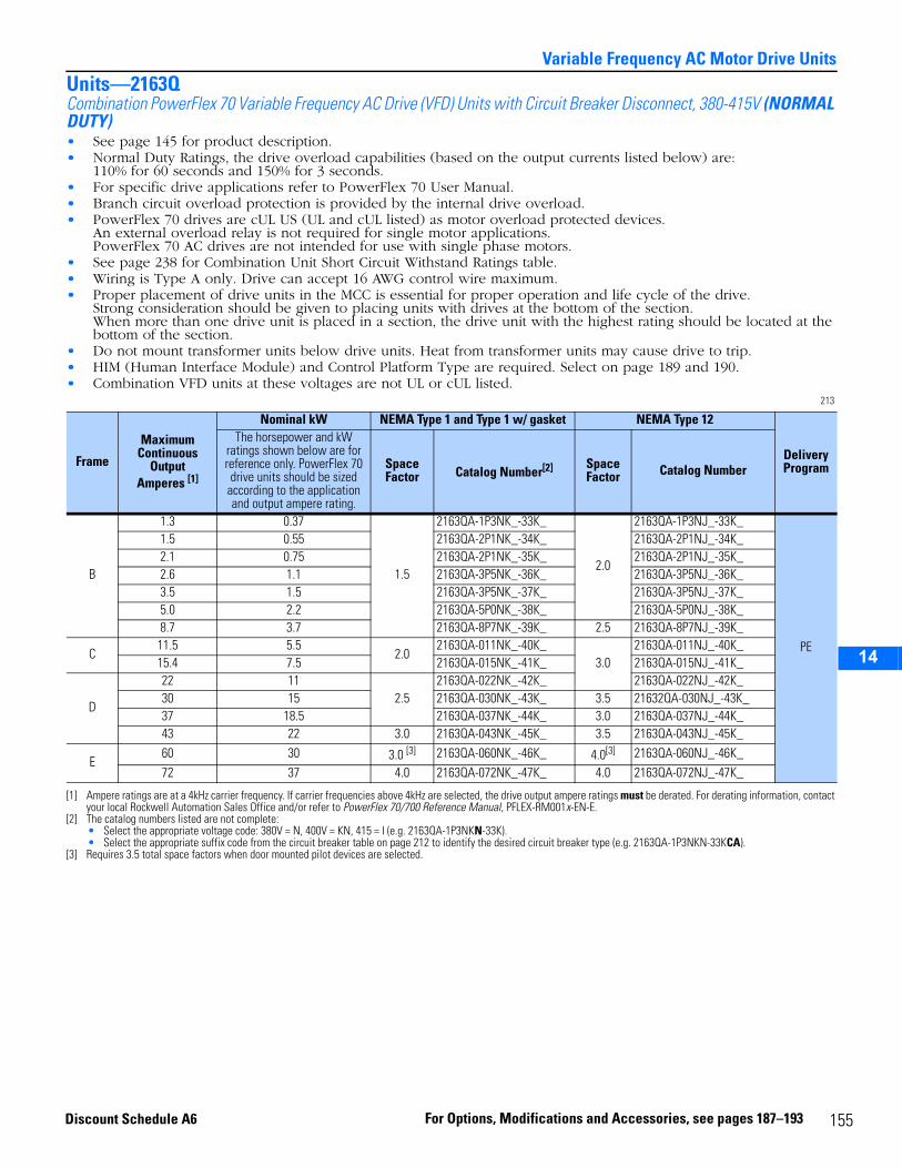
14
Variable Frequency AC Motor Drive UnitsUnits—2163QCombination PowerFlex 70 Variable Frequency AC Drive (VFD) Units with Circuit Breaker Disconnect, 380-415V (NORMAL DUTY)• See page 145 for product description.• Normal Duty Ratings, the drive overload capabilities (based on the output currents listed below) are:
110% for 60 seconds and 150% for 3 seconds.• For specific drive applications refer to PowerFlex 70 User Manual.• Branch circuit overload protection is provided by the internal drive overload.• PowerFlex 70 drives are cUL US (UL and cUL listed) as motor overload protected devices.
An external overload relay is not required for single motor applications.PowerFlex 70 AC drives are not intended for use with single phase motors.
• See page 238 for Combination Unit Short Circuit Withstand Ratings table.• Wiring is Type A only. Drive can accept 16 AWG control wire maximum.• Proper placement of drive units in the MCC is essential for proper operation and life cycle of the drive.
Strong consideration should be given to placing units with drives at the bottom of the section. When more than one drive unit is placed in a section, the drive unit with the highest rating should be located at the bottom of the section.
• Do not mount transformer units below drive units. Heat from transformer units may cause drive to trip.• HIM (Human Interface Module) and Control Platform Type are required. Select on page 189 and 190.• Combination VFD units at these voltages are not UL or cUL listed.
213
Frame
Maximum Continuous
Output Amperes [1]
[1] Ampere ratings are at a 4kHz carrier frequency. If carrier frequencies above 4kHz are selected, the drive output ampere ratings must be derated. For derating information, contact your local Rockwell Automation Sales Office and/or refer to PowerFlex 70/700 Reference Manual, PFLEX-RM001x-EN-E.
Nominal kW NEMA Type 1 and Type 1 w/ gasket NEMA Type 12
Delivery Program
The horsepower and kW ratings shown below are for reference only. PowerFlex 70 drive units should be sized
according to the application and output ampere rating.
Space Factor Catalog Number[2]
[2] The catalog numbers listed are not complete:• Select the appropriate voltage code: 380V = N, 400V = KN, 415 = I (e.g. 2163QA-1P3NKN-33K).• Select the appropriate suffix code from the circuit breaker table on page 212 to identify the desired circuit breaker type (e.g. 2163QA-1P3NKN-33KCA).
Space Factor Catalog Number
B
1.3 0.37
1.5
2163QA-1P3NK_-33K_
2.0
2163QA-1P3NJ_-33K_
PE
1.5 0.55 2163QA-2P1NK_-34K_ 2163QA-2P1NJ_-34K_2.1 0.75 2163QA-2P1NK_-35K_ 2163QA-2P1NJ_-35K_2.6 1.1 2163QA-3P5NK_-36K_ 2163QA-3P5NJ_-36K_3.5 1.5 2163QA-3P5NK_-37K_ 2163QA-3P5NJ_-37K_5.0 2.2 2163QA-5P0NK_-38K_ 2163QA-5P0NJ_-38K_8.7 3.7 2163QA-8P7NK_-39K_ 2.5 2163QA-8P7NJ_-39K_
C11.5 5.5
2.02163QA-011NK_-40K_
3.02163QA-011NJ_-40K_
15.4 7.5 2163QA-015NK_-41K_ 2163QA-015NJ_-41K_
D
22 112.5
2163QA-022NK_-42K_ 2163QA-022NJ_-42K_30 15 2163QA-030NK_-43K_ 3.5 21632QA-030NJ_-43K_37 18.5 2163QA-037NK_-44K_ 3.0 2163QA-037NJ_-44K_43 22 3.0 2163QA-043NK_-45K_ 3.5 2163QA-043NJ_-45K_
E60 30 3.0 [3]
[3] Requires 3.5 total space factors when door mounted pilot devices are selected.
2163QA-060NK_-46K_ 4.0[3] 2163QA-060NJ_-46K_72 37 4.0 2163QA-072NK_-47K_ 4.0 2163QA-072NJ_-47K_
155For Options, Modifications and Accessories, see pages 187–193Discount Schedule A6
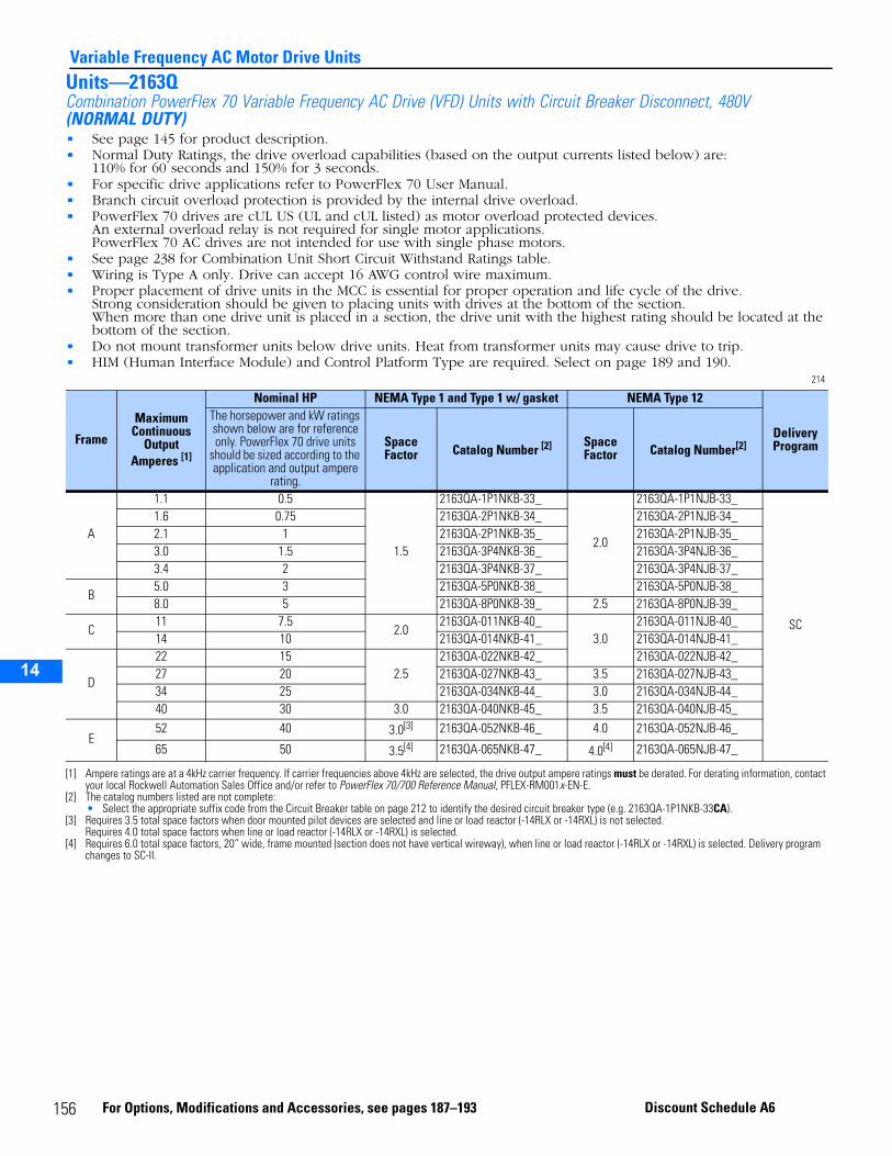
14
Variable Frequency AC Motor Drive UnitsUnits—2163QCombination PowerFlex 70 Variable Frequency AC Drive (VFD) Units with Circuit Breaker Disconnect, 480V (NORMAL DUTY)• See page 145 for product description.• Normal Duty Ratings, the drive overload capabilities (based on the output currents listed below) are:
110% for 60 seconds and 150% for 3 seconds.• For specific drive applications refer to PowerFlex 70 User Manual.• Branch circuit overload protection is provided by the internal drive overload.• PowerFlex 70 drives are cUL US (UL and cUL listed) as motor overload protected devices.
An external overload relay is not required for single motor applications.PowerFlex 70 AC drives are not intended for use with single phase motors.
• See page 238 for Combination Unit Short Circuit Withstand Ratings table.• Wiring is Type A only. Drive can accept 16 AWG control wire maximum.• Proper placement of drive units in the MCC is essential for proper operation and life cycle of the drive.
Strong consideration should be given to placing units with drives at the bottom of the section. When more than one drive unit is placed in a section, the drive unit with the highest rating should be located at the bottom of the section.
• Do not mount transformer units below drive units. Heat from transformer units may cause drive to trip.• HIM (Human Interface Module) and Control Platform Type are required. Select on page 189 and 190.
214
Frame
Maximum Continuous
Output Amperes [1]
[1] Ampere ratings are at a 4kHz carrier frequency. If carrier frequencies above 4kHz are selected, the drive output ampere ratings must be derated. For derating information, contact your local Rockwell Automation Sales Office and/or refer to PowerFlex 70/700 Reference Manual, PFLEX-RM001x-EN-E.
Nominal HP NEMA Type 1 and Type 1 w/ gasket NEMA Type 12
Delivery Program
The horsepower and kW ratings shown below are for reference only. PowerFlex 70 drive units
should be sized according to the application and output ampere
rating.
Space Factor Catalog Number [2]
[2] The catalog numbers listed are not complete:• Select the appropriate suffix code from the Circuit Breaker table on page 212 to identify the desired circuit breaker type (e.g. 2163QA-1P1NKB-33CA).
Space Factor Catalog Number[2]
A
1.1 0.5
1.5
2163QA-1P1NKB-33_
2.0
2163QA-1P1NJB-33_
SC
1.6 0.75 2163QA-2P1NKB-34_ 2163QA-2P1NJB-34_2.1 1 2163QA-2P1NKB-35_ 2163QA-2P1NJB-35_3.0 1.5 2163QA-3P4NKB-36_ 2163QA-3P4NJB-36_3.4 2 2163QA-3P4NKB-37_ 2163QA-3P4NJB-37_
B5.0 3 2163QA-5P0NKB-38_ 2163QA-5P0NJB-38_8.0 5 2163QA-8P0NKB-39_ 2.5 2163QA-8P0NJB-39_
C11 7.5
2.02163QA-011NKB-40_
3.02163QA-011NJB-40_
14 10 2163QA-014NKB-41_ 2163QA-014NJB-41_
D
22 152.5
2163QA-022NKB-42_ 2163QA-022NJB-42_27 20 2163QA-027NKB-43_ 3.5 2163QA-027NJB-43_34 25 2163QA-034NKB-44_ 3.0 2163QA-034NJB-44_40 30 3.0 2163QA-040NKB-45_ 3.5 2163QA-040NJB-45_
E52 40 3.0[3]
[3] Requires 3.5 total space factors when door mounted pilot devices are selected and line or load reactor (-14RLX or -14RXL) is not selected.Requires 4.0 total space factors when line or load reactor (-14RLX or -14RXL) is selected.
2163QA-052NKB-46_ 4.0 2163QA-052NJB-46_
65 50 3.5[4] 2163QA-065NKB-47_ 4.0[4]
[4] Requires 6.0 total space factors, 20” wide, frame mounted (section does not have vertical wireway), when line or load reactor (-14RLX or -14RXL) is selected. Delivery program changes to SC-II.
2163QA-065NJB-47_
156 For Options, Modifications and Accessories, see pages 187–193 Discount Schedule A6
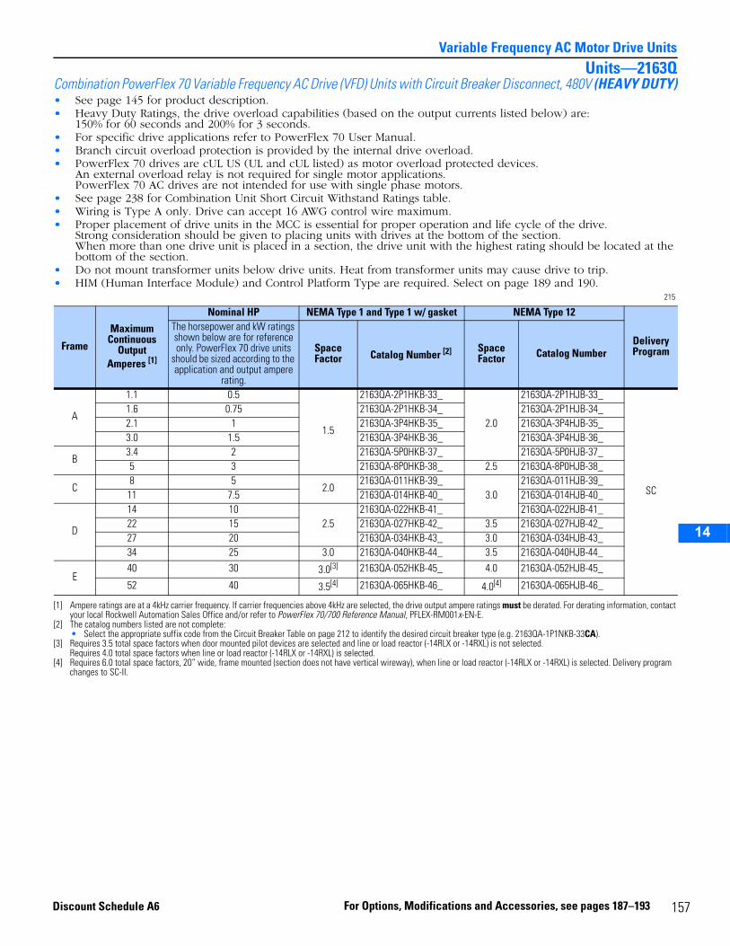
14
Variable Frequency AC Motor Drive UnitsUnits—2163Q
Combination PowerFlex 70 Variable Frequency AC Drive (VFD) Units with Circuit Breaker Disconnect, 480V (HEAVY DUTY)• See page 145 for product description.• Heavy Duty Ratings, the drive overload capabilities (based on the output currents listed below) are:
150% for 60 seconds and 200% for 3 seconds.• For specific drive applications refer to PowerFlex 70 User Manual.• Branch circuit overload protection is provided by the internal drive overload.• PowerFlex 70 drives are cUL US (UL and cUL listed) as motor overload protected devices.
An external overload relay is not required for single motor applications.PowerFlex 70 AC drives are not intended for use with single phase motors.
• See page 238 for Combination Unit Short Circuit Withstand Ratings table.• Wiring is Type A only. Drive can accept 16 AWG control wire maximum.• Proper placement of drive units in the MCC is essential for proper operation and life cycle of the drive.
Strong consideration should be given to placing units with drives at the bottom of the section. When more than one drive unit is placed in a section, the drive unit with the highest rating should be located at the bottom of the section.
• Do not mount transformer units below drive units. Heat from transformer units may cause drive to trip.• HIM (Human Interface Module) and Control Platform Type are required. Select on page 189 and 190.
215
Frame
Maximum Continuous
Output Amperes [1]
[1] Ampere ratings are at a 4kHz carrier frequency. If carrier frequencies above 4kHz are selected, the drive output ampere ratings must be derated. For derating information, contact your local Rockwell Automation Sales Office and/or refer to PowerFlex 70/700 Reference Manual, PFLEX-RM001x-EN-E.
Nominal HP NEMA Type 1 and Type 1 w/ gasket NEMA Type 12
Delivery Program
The horsepower and kW ratings shown below are for reference only. PowerFlex 70 drive units
should be sized according to the application and output ampere
rating.
Space Factor Catalog Number [2]
[2] The catalog numbers listed are not complete:• Select the appropriate suffix code from the Circuit Breaker Table on page 212 to identify the desired circuit breaker type (e.g. 2163QA-1P1NKB-33CA).
Space Factor Catalog Number
A
1.1 0.5
1.5
2163QA-2P1HKB-33_
2.0
2163QA-2P1HJB-33_
SC
1.6 0.75 2163QA-2P1HKB-34_ 2163QA-2P1HJB-34_2.1 1 2163QA-3P4HKB-35_ 2163QA-3P4HJB-35_3.0 1.5 2163QA-3P4HKB-36_ 2163QA-3P4HJB-36_
B3.4 2 2163QA-5P0HKB-37_ 2163QA-5P0HJB-37_5 3 2163QA-8P0HKB-38_ 2.5 2163QA-8P0HJB-38_
C8 5
2.02163QA-011HKB-39_
3.02163QA-011HJB-39_
11 7.5 2163QA-014HKB-40_ 2163QA-014HJB-40_
D
14 102.5
2163QA-022HKB-41_ 2163QA-022HJB-41_22 15 2163QA-027HKB-42_ 3.5 2163QA-027HJB-42_27 20 2163QA-034HKB-43_ 3.0 2163QA-034HJB-43_34 25 3.0 2163QA-040HKB-44_ 3.5 2163QA-040HJB-44_
E40 30 3.0[3]
[3] Requires 3.5 total space factors when door mounted pilot devices are selected and line or load reactor (-14RLX or -14RXL) is not selected.Requires 4.0 total space factors when line or load reactor (-14RLX or -14RXL) is selected.
2163QA-052HKB-45_ 4.0 2163QA-052HJB-45_
52 40 3.5[4] 2163QA-065HKB-46_ 4.0[4]
[4] Requires 6.0 total space factors, 20” wide, frame mounted (section does not have vertical wireway), when line or load reactor (-14RLX or -14RXL) is selected. Delivery program changes to SC-II.
2163QA-065HJB-46_
157For Options, Modifications and Accessories, see pages 187–193Discount Schedule A6
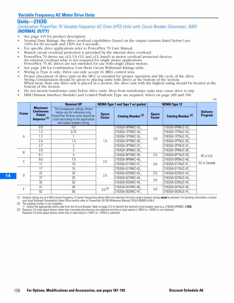
14
Variable Frequency AC Motor Drive UnitsUnits—2163QCombination PowerFlex 70 Variable Frequency AC Drive (VFD) Units with Circuit Breaker Disconnect, 600V (NORMAL DUTY)• See page 145 for product description.• Normal Duty Ratings, the drive overload capabilities (based on the output currents listed below) are:
110% for 60 seconds and 150% for 3 seconds.• For specific drive applications refer to PowerFlex 70 User Manual.• Branch circuit overload protection is provided by the internal drive overload.• PowerFlex 70 drives are cUL US (UL and cUL listed) as motor overload protected devices.
An external overload relay is not required for single motor applications.PowerFlex 70 AC drives are not intended for use with single phase motors.
• See page 238 for Combination Unit Short Circuit Withstand Ratings table.• Wiring is Type A only. Drive can only accept 16 AWG control wire.• Proper placement of drive units in the MCC is essential for proper operation and life cycle of the drive.
Strong consideration should be given to placing units with drives at the bottom of the section. When more than one drive unit is placed in a section, the drive unit with the highest rating should be located at the bottom of the section.
• Do not mount transformer units below drive units. Heat from transformer units may cause drive to trip.• HIM (Human Interface Module) and Control Platform Type are required. Select on page 189 and 190.
216
Frame
Maximum Continuous
Output Amperes [1]
[1] Ampere ratings are at a 4kHz carrier frequency. If carrier frequencies above 4kHz are selected, the drive output ampere ratings must be derated. For derating information, contact your local Rockwell Automation Sales Office and/or refer to PowerFlex 70/700 Reference Manual, PFLEX-RM001x-EN-E.
Nominal HP NEMA Type 1 and Type 1 w/ gasket NEMA Type 12
Delivery Program
The horsepower ratings shown below are for reference only.
PowerFlex 70 drive units should be sized according to the application
and output ampere rating.
Space Factor Catalog Number [2]
[2] The catalog number is not complete:• Select the appropriate suffix code from the Circuit Breaker Table on page 212 to identify the desired circuit breaker type (e.g. 2163QA-0P9NKC-33CA).
Space Factor Catalog Number [2]
A
0.9 0.5
1.5
2163QA-0P9NKC-33_
2.0
2163QA-0P9NJC-33_
PE in U.S.
SC in Canada
1.3 0.75 2163QA-1P7NKC-34_ 2163QA-1P7NJC-34_1.7 1 2163QA-1P7NKC-35_ 2163QA-1P7NJC-35_2.4 1.5 2163QA-2P7NKC-36_ 2163QA-2P7NJC-36_2.7 2 2163QA-2P7NKC-37_ 2163QA-2P7NJC-37_
B3.9 3 2163QA-3P9NKC-38_ 2163QA-3P9NJC-38_6.1 5 2163QA-6P1NKC-39_ 2.5 2163QA-6P1NJC-39_
C9.0 7.5
2.02163QA-9P0NKC-40_
3.02163QA-9P0NJC-40_
11 10 2163QA-011NKC-41_ 2163QA-011NJC-41_
D
17 15
2.5
2163QA-017NKC-42_ 2163QA-017NJC-42_22 20 2163QA-022NKC-43_ 3.5 2163QA-022NJC-43_27 25 2163QA-027NKC-44_
3.02163QA-027NJC-44_
32 30 2163QA-032NKC-45_ 2163QA-032NJC-45_
E41 40
3.0 [3]
[3] Requires 3.5 total space factors when door mounted pilot devices are selected and line or load reactor (-14RLX or -14RXL) is not selected.Requires 4.0 total space factors when line or load reactor (-14RLX or -14RXL) is selected.
2163QA-041NKC-46_4.0
2163QA-041NJC-46_52 50 2163QA-052NKC-47_ 2163QA-052NJC-47_
158 For Options, Modifications and Accessories, see pages 187–193 Discount Schedule A6
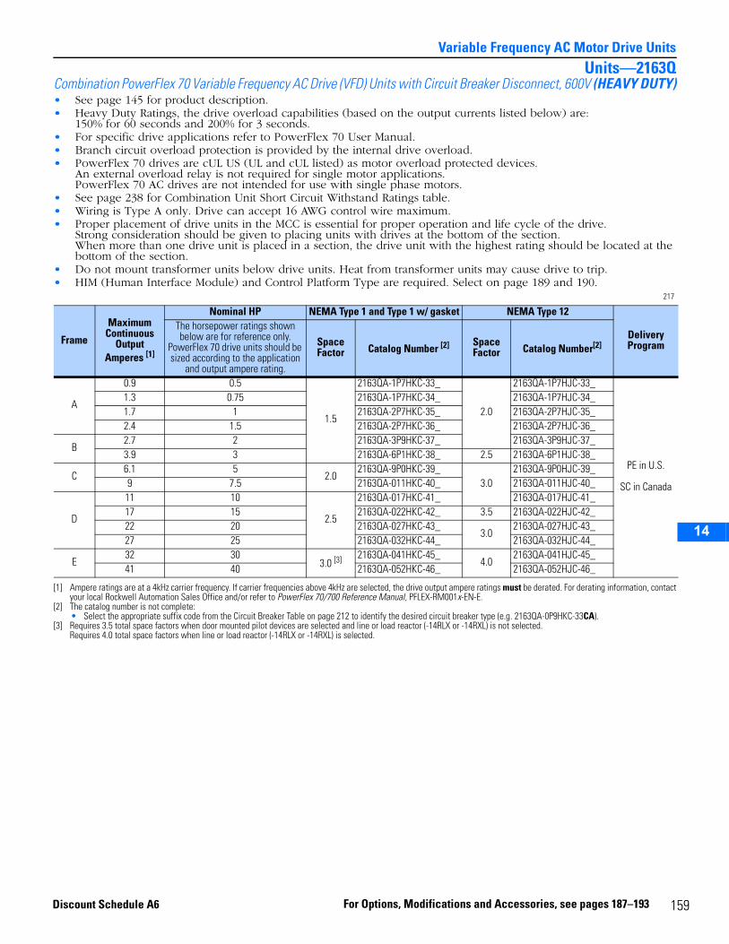
14
Variable Frequency AC Motor Drive UnitsUnits—2163Q
Combination PowerFlex 70 Variable Frequency AC Drive (VFD) Units with Circuit Breaker Disconnect, 600V (HEAVY DUTY)• See page 145 for product description.• Heavy Duty Ratings, the drive overload capabilities (based on the output currents listed below) are:
150% for 60 seconds and 200% for 3 seconds.• For specific drive applications refer to PowerFlex 70 User Manual.• Branch circuit overload protection is provided by the internal drive overload.• PowerFlex 70 drives are cUL US (UL and cUL listed) as motor overload protected devices.
An external overload relay is not required for single motor applications.PowerFlex 70 AC drives are not intended for use with single phase motors.
• See page 238 for Combination Unit Short Circuit Withstand Ratings table.• Wiring is Type A only. Drive can accept 16 AWG control wire maximum.• Proper placement of drive units in the MCC is essential for proper operation and life cycle of the drive.
Strong consideration should be given to placing units with drives at the bottom of the section. When more than one drive unit is placed in a section, the drive unit with the highest rating should be located at the bottom of the section.
• Do not mount transformer units below drive units. Heat from transformer units may cause drive to trip.• HIM (Human Interface Module) and Control Platform Type are required. Select on page 189 and 190.
217
Frame
Maximum Continuous
Output Amperes [1]
[1] Ampere ratings are at a 4kHz carrier frequency. If carrier frequencies above 4kHz are selected, the drive output ampere ratings must be derated. For derating information, contact your local Rockwell Automation Sales Office and/or refer to PowerFlex 70/700 Reference Manual, PFLEX-RM001x-EN-E.
Nominal HP NEMA Type 1 and Type 1 w/ gasket NEMA Type 12
Delivery Program
The horsepower ratings shown below are for reference only.
PowerFlex 70 drive units should be sized according to the application
and output ampere rating.
Space Factor Catalog Number [2]
[2] The catalog number is not complete:• Select the appropriate suffix code from the Circuit Breaker Table on page 212 to identify the desired circuit breaker type (e.g. 2163QA-0P9HKC-33CA).
Space Factor Catalog Number[2]
A
0.9 0.5
1.5
2163QA-1P7HKC-33_
2.0
2163QA-1P7HJC-33_
PE in U.S.
SC in Canada
1.3 0.75 2163QA-1P7HKC-34_ 2163QA-1P7HJC-34_1.7 1 2163QA-2P7HKC-35_ 2163QA-2P7HJC-35_2.4 1.5 2163QA-2P7HKC-36_ 2163QA-2P7HJC-36_
B2.7 2 2163QA-3P9HKC-37_ 2163QA-3P9HJC-37_3.9 3 2163QA-6P1HKC-38_ 2.5 2163QA-6P1HJC-38_
C6.1 5
2.02163QA-9P0HKC-39_
3.02163QA-9P0HJC-39_
9 7.5 2163QA-011HKC-40_ 2163QA-011HJC-40_
D
11 10
2.5
2163QA-017HKC-41_ 2163QA-017HJC-41_17 15 2163QA-022HKC-42_ 3.5 2163QA-022HJC-42_22 20 2163QA-027HKC-43_
3.02163QA-027HJC-43_
27 25 2163QA-032HKC-44_ 2163QA-032HJC-44_
E32 30
3.0 [3]
[3] Requires 3.5 total space factors when door mounted pilot devices are selected and line or load reactor (-14RLX or -14RXL) is not selected.Requires 4.0 total space factors when line or load reactor (-14RLX or -14RXL) is selected.
2163QA-041HKC-45_4.0
2163QA-041HJC-45_41 40 2163QA-052HKC-46_ 2163QA-052HJC-46_
159For Options, Modifications and Accessories, see pages 187–193Discount Schedule A6
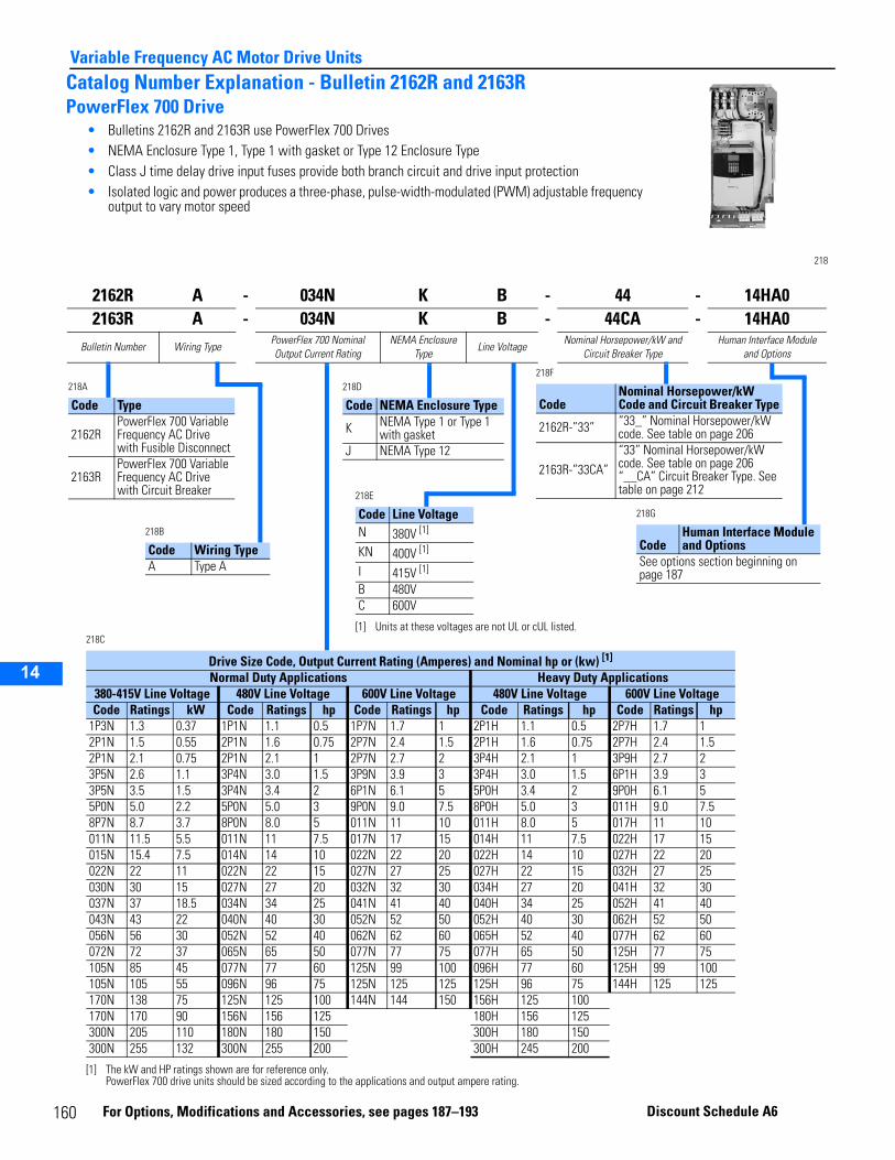
14
Variable Frequency AC Motor Drive UnitsCatalog Number Explanation - Bulletin 2162R and 2163RPowerFlex 700 Drive
• Bulletins 2162R and 2163R use PowerFlex 700 Drives• NEMA Enclosure Type 1, Type 1 with gasket or Type 12 Enclosure Type• Class J time delay drive input fuses provide both branch circuit and drive input protection• Isolated logic and power produces a three-phase, pulse-width-modulated (PWM) adjustable frequency
output to vary motor speed
218
2162R A - 034N K B - 44 - 14HA02163R A - 034N K B - 44CA - 14HA0
Bulletin Number Wiring TypePowerFlex 700 Nominal Output Current Rating
NEMA Enclosure Type
Line VoltageNominal Horsepower/kW and
Circuit Breaker TypeHuman Interface Module
and Options
218A
Code Type
2162RPowerFlex 700 Variable Frequency AC Drive with Fusible Disconnect
2163RPowerFlex 700 Variable Frequency AC Drive with Circuit Breaker
218B
Code Wiring TypeA Type A
218D
Code NEMA Enclosure Type
K NEMA Type 1 or Type 1 with gasket
J NEMA Type 12
218F
CodeNominal Horsepower/kW Code and Circuit Breaker Type
2162R-”33” “33_” Nominal Horsepower/kW code. See table on page 206
2163R-”33CA”“33” Nominal Horsepower/kW code. See table on page 206“__CA” Circuit Breaker Type. See table on page 212218E
Code Line VoltageN 380V [1]
[1] Units at these voltages are not UL or cUL listed.
KN 400V [1]
I 415V [1]
B 480VC 600V
218G
CodeHuman Interface Module and Options
See options section beginning on page 187
218C
Drive Size Code, Output Current Rating (Amperes) and Nominal hp or (kw) [1]
[1] The kW and HP ratings shown are for reference only. PowerFlex 700 drive units should be sized according to the applications and output ampere rating.
Normal Duty Applications Heavy Duty Applications380-415V Line Voltage 480V Line Voltage 600V Line Voltage 480V Line Voltage 600V Line VoltageCode Ratings kW Code Ratings hp Code Ratings hp Code Ratings hp Code Ratings hp
1P3N 1.3 0.37 1P1N 1.1 0.5 1P7N 1.7 1 2P1H 1.1 0.5 2P7H 1.7 12P1N 1.5 0.55 2P1N 1.6 0.75 2P7N 2.4 1.5 2P1H 1.6 0.75 2P7H 2.4 1.52P1N 2.1 0.75 2P1N 2.1 1 2P7N 2.7 2 3P4H 2.1 1 3P9H 2.7 23P5N 2.6 1.1 3P4N 3.0 1.5 3P9N 3.9 3 3P4H 3.0 1.5 6P1H 3.9 33P5N 3.5 1.5 3P4N 3.4 2 6P1N 6.1 5 5P0H 3.4 2 9P0H 6.1 55P0N 5.0 2.2 5P0N 5.0 3 9P0N 9.0 7.5 8P0H 5.0 3 011H 9.0 7.58P7N 8.7 3.7 8P0N 8.0 5 011N 11 10 011H 8.0 5 017H 11 10011N 11.5 5.5 011N 11 7.5 017N 17 15 014H 11 7.5 022H 17 15015N 15.4 7.5 014N 14 10 022N 22 20 022H 14 10 027H 22 20022N 22 11 022N 22 15 027N 27 25 027H 22 15 032H 27 25030N 30 15 027N 27 20 032N 32 30 034H 27 20 041H 32 30037N 37 18.5 034N 34 25 041N 41 40 040H 34 25 052H 41 40043N 43 22 040N 40 30 052N 52 50 052H 40 30 062H 52 50056N 56 30 052N 52 40 062N 62 60 065H 52 40 077H 62 60072N 72 37 065N 65 50 077N 77 75 077H 65 50 125H 77 75105N 85 45 077N 77 60 125N 99 100 096H 77 60 125H 99 100105N 105 55 096N 96 75 125N 125 125 125H 96 75 144H 125 125170N 138 75 125N 125 100 144N 144 150 156H 125 100170N 170 90 156N 156 125 180H 156 125300N 205 110 180N 180 150 300H 180 150300N 255 132 300N 255 200 300H 245 200
1
60 For O ptions, Modifications and Access or ies, see pages 187–193 Discount Schedule A6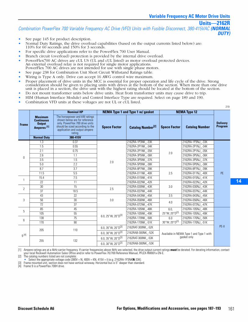
14
Variable Frequency AC Motor Drive UnitsUnits—2162R
Combination PowerFlex 700 Variable Frequency AC Drive (VFD) Units with Fusible Disconnect, 380-415VAC (NORMALDUTY)
• See page 145 for product description.• Normal Duty Ratings, the drive overload capabilities (based on the output currents listed below) are:
110% for 60 seconds and 150% for 3 seconds.• For specific drive applications refer to the PowerFlex 700 User Manual.• Branch circuit (overload) protection is provided by the internal drive overload.• PowerFlex700 AC drives are cUL US (UL and cUL listed) as motor overload protected devices.
An external overload relay is not required for single motor applications.PowerFlex 700 AC drives are not intended for use with single phase motors.
• See page 238 for Combination Unit Short Circuit Withstand Ratings table.• Wiring is Type A only. Drive can accept 16 AWG control wire maximum.• Proper placement of drive units in the MCC is essential for proper operation and life cycle of the drive. Strong
consideration should be given to placing units with drives at the bottom of the section. When more than one drive unit is placed in a section, the drive unit with the highest rating should be located at the bottom of the section.
• Do not mount transformer units below drive units. Heat from transformer units may cause drive to trip.• HIM (Human Interface Module) and Control Interface Type are required. Select on page 189 and 190.• Combination VFD units at these voltages are not UL or cUL listed.
219
Frame
Maximum Continuous
Output Amperes [1]
[1] Ampere ratings are at a 4kHz carrier frequency. If carrier frequencies above 4kHz are selected, the drive output current ratings must be derated. For derating information, contact your local Rockwell Automation Sales Office and/or refer to PowerFlex 70/700 Reference Manual, PFLEX-RM001x-EN-E.
Nominal HP NEMA Type 1 and Type 1 w/ gasket NEMA Type 12
Delivery Program
The horsepower and kW ratings shown below are for reference only. PowerFlex 700 drive units should be sized according to the application and output ampere
rating.
Space Factor Catalog Number[2]
[2] The catalog numbers listed are not complete:• Select the appropriate voltage code (380V = N, 400V = KN, 415V = I) (e.g. 2162RA-1P3NKN-33K).
Space Factor Catalog Number
Normal Duty 380-415V
0
1.3 0.37
2.0
2162RA-1P3NK_-33K
2.0
2162RA-1P3NJ_-33K
PE
1.5 0.55 2162RA-2P1NK_-34K 2162RA-2P1NJ_-34K2.1 0.75 2162RA-2P1NK_-35K 2162RA-2P1NJ_-35K2.6 1.1 2162RA-3P5NK_-36K 2162RA-3P5NJ_-36K3.5 1.5 2162RA-3P5NK_-37K 2162RA-3P5NJ_-37K5.0 2.2 2162RA-5P0NK_-38K 2162RA-5P0NJ_-38K8.7 3.7 2162RA-8P7NK_-39K
2.52162RA-8P7NJ_-39K
11.5 5.5 2162RA-011NK_-40K 2162RA-011NJ_-40K
115.4 7.5 2162RA-015NK_-41K 2162RA-015NJ_-41K22 11 2162RA-022NK_-42K
3.02162RA-022NJ_-42K
230 15
2.52162RA-030NK_-43K 2162RA-030NJ_-43K
37 18.5 2162RA-037NK_-44K 2162RA-037NJ_-44K
343 22
3.02162RA-043NK_-45K 3.5 2162RA-043NJ_-45K
56 30 2162RA-056NK_-46K4.0
2162RA-056NJ_-46K72 37 2162RA-072NK_-47K 2162RA-072NJ_-47K
585 45
6.0, 25”W, 20”D[3]
[3] Frame mounted unit, section does not have vertical wireway. Horizontal bus is 5” deeper than standard.
2162RA-105NK_-48K 6.0, 25”W, 20”D[3]
2162RA-105NJ_-48K
PE-II
105 55 2162RA-105NK_-49K 2162RA-105NJ_-49K
6138 75 2162RA-170NK_-50K 6.0
30”W, 20”D[3]2162RA-170NJ_-50K
170 90 2162RA-170NK_-51K 2162RA-170NJ_-51K
9 [4]
[4] Frame 9 is a PowerFlex 700H drive.
205 1106.0, 35”W, 20”D[3] 2162RAT-300NK_-52K
Available in NEMA Type 1 and Type 1 with gasket only
6.0, 30”W, 20”D[3] 2162RAB-300NK_-52K
255 1326.0, 35”W, 20”D[3] 2162RAT-300NK_-53K
6.0, 30”W, 20”D[3] 2162RAB-300NK_-53K
161For Options, Modifications and Accessories, see pages 187–193Discount Schedule A6
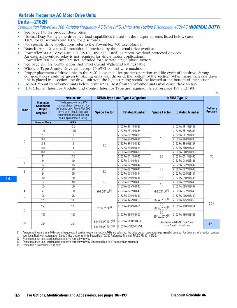
14
Variable Frequency AC Motor Drive UnitsUnits—2162RCombination PowerFlex 700 Variable Frequency AC Drive (VFD) Units with Fusible Disconnect, 480VAC (NORMAL DUTY)• See page 145 for product description.• Normal Duty Ratings, the drive overload capabilities (based on the output currents listed below) are:
110% for 60 seconds and 150% for 3 seconds.• For specific drive applications refer to the PowerFlex 700 User Manual.• Branch circuit (overload) protection is provided by the internal drive overload.• PowerFlex700 AC drives are cUL US (UL and cUL listed) as motor overload protected devices.
An external overload relay is not required for single motor applications.PowerFlex 700 AC drives are not intended for use with single phase motors.
• See page 238 for Combination Unit Short Circuit Withstand Ratings table.• Wiring is Type A only. Drive can accept 16 AWG control wire maximum.• Proper placement of drive units in the MCC is essential for proper operation and life cycle of the drive. Strong
consideration should be given to placing units with drives at the bottom of the section. When more than one drive unit is placed in a section, the drive unit with the highest rating should be located at the bottom of the section.
• Do not mount transformer units below drive units. Heat from transformer units may cause drive to trip.• HIM (Human Interface Module) and Control Interface Type are required. Select on page 189 and 190.
220
Frame
Maximum Continuous
Output Amperes [1]
[1] Ampere ratings are at a 4kHz carrier frequency. If carrier frequencies above 4kHz are selected, the drive output current ratings must be derated. For derating information, contact your local Rockwell Automation Sales Office and/or refer to PowerFlex 70/700 Reference Manual, PFLEX-RM001x-EN-E.
Nominal HP NEMA Type 1 and Type 1 w/ gasket NEMA Type 12
Delivery Program
The horsepower and kW ratings shown below are for
reference only. PowerFlex 700 drive units should be sized
according to the application and output ampere rating.
Space Factor Catalog Number Space Factor Catalog Number
Normal Duty 480V
0
1.1 0.5
2.0
2162RA-1P1NKB-33
2.0
2162RA-1P1NJB-33
SC
1.6 0.75 2162RA-2P1NKB-34 2162RA-2P1NJB-342.1 1 2162RA-2P1NKB-35 2162RA-2P1NJB-353.0 1.5 2162RA-3P4NKB-36 2162RA-3P4NJB-363.4 2 2162RA-3P4NKB-37 2162RA-3P4NJB-375.0 3 2162RA-5P0NKB-38 2162RA-5P0NJB-388.0 5 2162RA-8P0NKB-39
2.52162RA-8P0NJB-39
11 7.5 2162RA-011NKB-40 2162RA-011NJB-40
114 10 2162RA-014NKB-41 2162RA-014NJB-4122 15 2162RA-022NKB-42
3.02162RA-022NJB-42
227 20
2.52162RA-027NKB-43 2162RA-027NJB-43
34 25 2162RA-034NKB-44 2162RA-034NJB-44
340 30
3.02162RA-040NKB-45 3.5 2162RA-040NJB-45
52 40 2162RA-052NKB-464.0
2162RA-052NJB-4665 50 2162RA-065NKB-47 2162RA-065NJB-47
4 77 60 6.0, 20” W[2]
[2] Frame mounted unit, section does not have vertical wireway.
2162RA-077NKB-48 6.0, 25” W[2] 2162RA-077NJB-48
SC-II
596 75
6.025”W, 20”D[3]
[3] Frame mounted unit, section does not have vertical wireway. Horizontal bus is 5” deeper than standard.
2162RA-096NKB-49 6.025”W, 20”D[3]
2162RA-096NJB-49125 100 2162RA-125NKB-50 2162RA-125NJB-50
6156 125 2162RA-156NKB-51
6.030”W, 20”D[3] 2162RA-156NJB-51
180 150 2162RA-180NKB-526.0
35”W, 20”D[3] 2162RA-180NJB-52
9[4]
[4] Frame 9 is a PowerFlex 700H drive.
255 2006.0, 35”W, 20”D[3] 2162RAT-300NKB-54 Available in NEMA Type 1 and
Type 1 with gasket only PE-II6.0, 30”W, 20”D[3] 2162RAB-300NKB-54
162 For Options, Modifications and Accessories, see pages 187–193 Discount Schedule A6
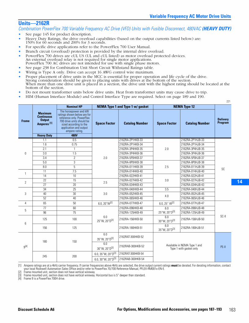
14
Variable Frequency AC Motor Drive UnitsUnits—2162RCombination PowerFlex 700 Variable Frequency AC Drive (VFD) Units with Fusible Disconnect, 480VAC (HEAVY DUTY)• See page 145 for product description.• Heavy Duty Ratings, the drive overload capabilities (based on the output currents listed below) are:
150% for 60 seconds and 200% for 3 seconds.• For specific drive applications refer to the PowerFlex 700 User Manual.• Branch circuit (overload) protection is provided by the internal drive overload.• PowerFlex 700 drives are cUL US (UL and cUL listed) as motor overload protected devices.
An external overload relay is not required for single motor applications. PowerFlex 700 AC drives are not intended for use with single phase motors.
• See page 238 for Combination Unit Short Circuit Withstand Ratings table.• Wiring is Type A only. Drive can accept 16 AWG control wire maximum.• Proper placement of drive units in the MCC is essential for proper operation and life cycle of the drive.
Strong consideration should be given to placing units with drives at the bottom of the section. When more than one drive unit is placed in a section, the drive unit with the highest rating should be located at the bottom of the section.
• Do not mount transformer units below drive units. Heat from transformer units may cause drive to trip.• HIM (Human Interface Module) and Control Interface Type are required. Select on page 189 and 190.
221
Frame
Maximum Continuous
Output Amperes [1]
[1] Ampere ratings are at a 4kHz carrier frequency. If carrier frequencies above 4kHz are selected, the drive output current ratings must be derated. For derating information, contact your local Rockwell Automation Sales Office and/or refer to PowerFlex 70/700 Reference Manual, PFLEX-RM001x-EN-E.
Nominal HP NEMA Type 1 and Type 1 w/ gasket NEMA Type 12
Delivery Program
The horsepower and kW ratings shown below are for
reference only. PowerFlex 700 drive units should be
sized according to the application and output
ampere rating.
Space Factor Catalog Number Space Factor Catalog Number
Heavy Duty 480V
0
1.1 0.5
2.0
2162RA-2P1HKB-33
2.0
2162RA-2P1HJB-33
SC
1.6 0.75 2162RA-2P1HKB-34 2162RA-2P1HJB-342.1 1 2162RA-3P4HKB-35 2162RA-3P4HJB-353.0 1.5 2162RA-3P4HKB-36 2162RA-3P4HJB-363.4 2 2162RA-5P0HKB-37 2162RA-5P0HJB-375.0 3 2162RA-8P0HKB-38
2.52162RA-8P0HJB-38
8.0 5 2162RA-011HKB-39 2162RA-011HJB-39
111 7.5 2162RA-014HKB-40 2162RA-014HJB-4014 10 2162RA-022HKB-41
3.02162RA-022HJB-41
222 15
2.52162RA-027HKB-42 2162RA-027HJB-42
27 20 2162RA-034HKB-43 2162RA-034HJB-43
334 25
3.02162RA-040HKB-44 3.5 2162RA-040HJB-44
40 30 2162RA-052HKB-454.0
2162RA-052HJB-4552 40 2162RA-065HKB-46 2162RA-065HJB-46
4 65 50 6.0, 20”W[2]
[2] Frame mounted unit, section does not have vertical wireway.
2162RA-077HKB-47 6.0, 25” W[2] 2162RA-077HJB-47
SC-II
577 60
6.025”W, 20”D[3]
[3] Frame mounted unit, section does not have vertical wireway. Horizontal bus is 5” deeper than standard.
2162RA-096HKB-48 6.025”W, 20”D[3]
2162RA-096HJB-4896 75 2162RA-125HKB-49 2162RA-125HJB-49
6125 100 2162RA-156HKB-50
6.030”W, 20”D[3] 2162RA-156HJB-50
156 125 2162RA-180HKB-516.0
35”W, 20”D[3] 2162RA-180HJB-51
9[4]
[4] Frame 9 is a PowerFlex 700H drive.
180 150
6.0
35”W, 20”D[3] 2162RAT-300HKB-52
Available in NEMA Type 1 and Type 1 with gasket only PE-II
6.0
30”W, 20”D[3] 2162RAB-300HKB-52
245 2006.0, 35”W, 20”D[3] 2162RAT-300HKB-54
6.0, 30”W, 20”D[3] 2162RAB-300HKB-54
163For Options, Modifications and Accessories, see pages 187–193Discount Schedule A6
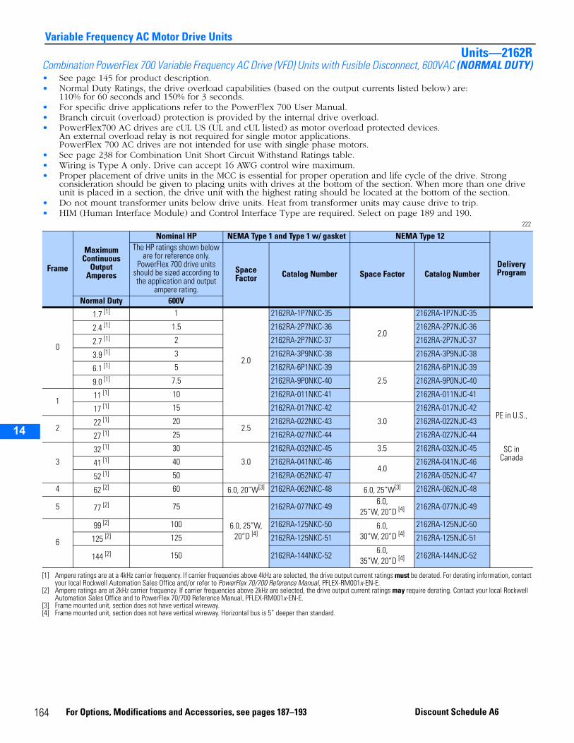
14
Variable Frequency AC Motor Drive UnitsUnits—2162R
Combination PowerFlex 700 Variable Frequency AC Drive (VFD) Units with Fusible Disconnect, 600VAC (NORMAL DUTY)• See page 145 for product description.• Normal Duty Ratings, the drive overload capabilities (based on the output currents listed below) are:
110% for 60 seconds and 150% for 3 seconds.• For specific drive applications refer to the PowerFlex 700 User Manual.• Branch circuit (overload) protection is provided by the internal drive overload.• PowerFlex700 AC drives are cUL US (UL and cUL listed) as motor overload protected devices.
An external overload relay is not required for single motor applications.PowerFlex 700 AC drives are not intended for use with single phase motors.
• See page 238 for Combination Unit Short Circuit Withstand Ratings table.• Wiring is Type A only. Drive can accept 16 AWG control wire maximum.• Proper placement of drive units in the MCC is essential for proper operation and life cycle of the drive. Strong
consideration should be given to placing units with drives at the bottom of the section. When more than one drive unit is placed in a section, the drive unit with the highest rating should be located at the bottom of the section.
• Do not mount transformer units below drive units. Heat from transformer units may cause drive to trip.• HIM (Human Interface Module) and Control Interface Type are required. Select on page 189 and 190.
222
Frame
Maximum Continuous
Output Amperes
Nominal HP NEMA Type 1 and Type 1 w/ gasket NEMA Type 12
Delivery Program
The HP ratings shown below are for reference only.
PowerFlex 700 drive units should be sized according to the application and output
ampere rating.
Space Factor Catalog Number Space Factor Catalog Number
Normal Duty 600V
0
1.7 [1]
[1] Ampere ratings are at a 4kHz carrier frequency. If carrier frequencies above 4kHz are selected, the drive output current ratings must be derated. For derating information, contact your local Rockwell Automation Sales Office and/or refer to PowerFlex 70/700 Reference Manual, PFLEX-RM001x-EN-E.
1
2.0
2162RA-1P7NKC-35
2.0
2162RA-1P7NJC-35
PE in U.S.,
SC in Canada
2.4 [1] 1.5 2162RA-2P7NKC-36 2162RA-2P7NJC-36
2.7 [1] 2 2162RA-2P7NKC-37 2162RA-2P7NJC-37
3.9 [1] 3 2162RA-3P9NKC-38 2162RA-3P9NJC-38
6.1 [1] 5 2162RA-6P1NKC-39
2.5
2162RA-6P1NJC-39
9.0 [1] 7.5 2162RA-9P0NKC-40 2162RA-9P0NJC-40
111 [1] 10 2162RA-011NKC-41 2162RA-011NJC-41
17 [1] 15 2162RA-017NKC-42
3.0
2162RA-017NJC-42
222 [1] 20
2.52162RA-022NKC-43 2162RA-022NJC-43
27 [1] 25 2162RA-027NKC-44 2162RA-027NJC-44
332 [1] 30
3.0
2162RA-032NKC-45 3.5 2162RA-032NJC-45
41 [1] 40 2162RA-041NKC-464.0
2162RA-041NJC-46
52 [1] 50 2162RA-052NKC-47 2162RA-052NJC-47
4 62 [2]
[2] Ampere ratings are at 2kHz carrier frequency. If carrier frequencies above 2kHz are selected, the drive output current ratings may require derating. Contact your local Rockwell Automation Sales Office and to PowerFlex 70/700 Reference Manual, PFLEX-RM001x-EN-E.
60 6.0, 20”W[3]
[3] Frame mounted unit, section does not have vertical wireway.
2162RA-062NKC-48 6.0, 25”W[3] 2162RA-062NJC-48
5 77 [2] 75
6.0, 25”W, 20”D [4]
[4] Frame mounted unit, section does not have vertical wireway. Horizontal bus is 5” deeper than standard.
2162RA-077NKC-496.0,
25”W, 20”D [4] 2162RA-077NJC-49
6
99 [2] 100 2162RA-125NKC-50 6.0, 30”W, 20”D [4]
2162RA-125NJC-50
125 [2] 125 2162RA-125NKC-51 2162RA-125NJC-51
144 [2] 150 2162RA-144NKC-526.0,
35”W, 20”D [4] 2162RA-144NJC-52
164 For Options, Modifications and Accessories, see pages 187–193 Discount Schedule A6
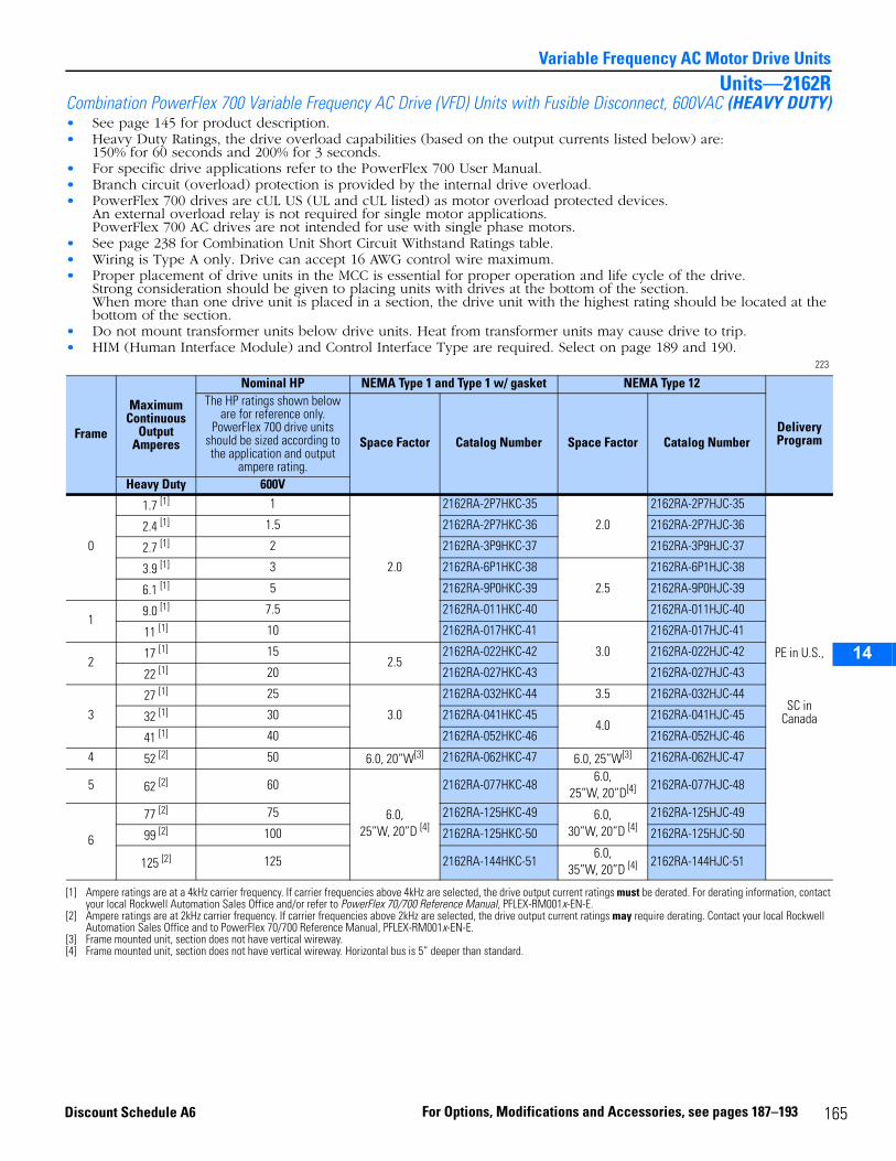
14
Variable Frequency AC Motor Drive UnitsUnits—2162R
Combination PowerFlex 700 Variable Frequency AC Drive (VFD) Units with Fusible Disconnect, 600VAC (HEAVY DUTY)• See page 145 for product description.• Heavy Duty Ratings, the drive overload capabilities (based on the output currents listed below) are:
150% for 60 seconds and 200% for 3 seconds.• For specific drive applications refer to the PowerFlex 700 User Manual.• Branch circuit (overload) protection is provided by the internal drive overload.• PowerFlex 700 drives are cUL US (UL and cUL listed) as motor overload protected devices.
An external overload relay is not required for single motor applications. PowerFlex 700 AC drives are not intended for use with single phase motors.
• See page 238 for Combination Unit Short Circuit Withstand Ratings table.• Wiring is Type A only. Drive can accept 16 AWG control wire maximum.• Proper placement of drive units in the MCC is essential for proper operation and life cycle of the drive.
Strong consideration should be given to placing units with drives at the bottom of the section. When more than one drive unit is placed in a section, the drive unit with the highest rating should be located at the bottom of the section.
• Do not mount transformer units below drive units. Heat from transformer units may cause drive to trip.• HIM (Human Interface Module) and Control Interface Type are required. Select on page 189 and 190.
223
Frame
Maximum Continuous
Output Amperes
Nominal HP NEMA Type 1 and Type 1 w/ gasket NEMA Type 12
Delivery Program
The HP ratings shown below are for reference only.
PowerFlex 700 drive units should be sized according to the application and output
ampere rating.
Space Factor Catalog Number Space Factor Catalog Number
Heavy Duty 600V
0
1.7 [1]
[1] Ampere ratings are at a 4kHz carrier frequency. If carrier frequencies above 4kHz are selected, the drive output current ratings must be derated. For derating information, contact your local Rockwell Automation Sales Office and/or refer to PowerFlex 70/700 Reference Manual, PFLEX-RM001x-EN-E.
1
2.0
2162RA-2P7HKC-35
2.0
2162RA-2P7HJC-35
PE in U.S.,
SC in Canada
2.4 [1] 1.5 2162RA-2P7HKC-36 2162RA-2P7HJC-36
2.7 [1] 2 2162RA-3P9HKC-37 2162RA-3P9HJC-37
3.9 [1] 3 2162RA-6P1HKC-38
2.5
2162RA-6P1HJC-38
6.1 [1] 5 2162RA-9P0HKC-39 2162RA-9P0HJC-39
19.0 [1] 7.5 2162RA-011HKC-40 2162RA-011HJC-40
11 [1] 10 2162RA-017HKC-41
3.0
2162RA-017HJC-41
217 [1] 15
2.52162RA-022HKC-42 2162RA-022HJC-42
22 [1] 20 2162RA-027HKC-43 2162RA-027HJC-43
327 [1] 25
3.0
2162RA-032HKC-44 3.5 2162RA-032HJC-44
32 [1] 30 2162RA-041HKC-454.0
2162RA-041HJC-45
41 [1] 40 2162RA-052HKC-46 2162RA-052HJC-46
4 52 [2]
[2] Ampere ratings are at 2kHz carrier frequency. If carrier frequencies above 2kHz are selected, the drive output current ratings may require derating. Contact your local Rockwell Automation Sales Office and to PowerFlex 70/700 Reference Manual, PFLEX-RM001x-EN-E.
50 6.0, 20”W[3]
[3] Frame mounted unit, section does not have vertical wireway.
2162RA-062HKC-47 6.0, 25”W[3] 2162RA-062HJC-47
5 62 [2] 60
6.0, 25”W, 20”D [4]
[4] Frame mounted unit, section does not have vertical wireway. Horizontal bus is 5” deeper than standard.
2162RA-077HKC-486.0,
25”W, 20”D[4] 2162RA-077HJC-48
6
77 [2] 75 2162RA-125HKC-49 6.0, 30”W, 20”D [4]
2162RA-125HJC-49
99 [2] 100 2162RA-125HKC-50 2162RA-125HJC-50
125 [2] 125 2162RA-144HKC-516.0,
35”W, 20”D [4] 2162RA-144HJC-51
165For Options, Modifications and Accessories, see pages 187–193Discount Schedule A6
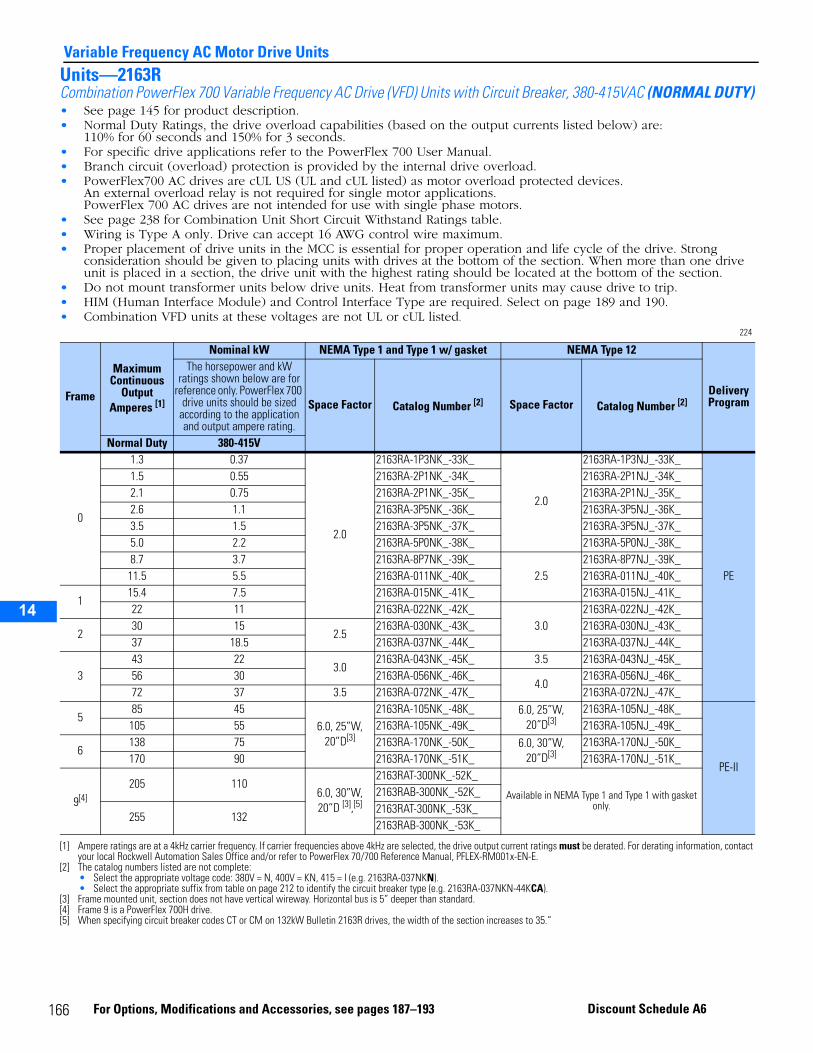
14
Variable Frequency AC Motor Drive UnitsUnits—2163RCombination PowerFlex 700 Variable Frequency AC Drive (VFD) Units with Circuit Breaker, 380-415VAC (NORMAL DUTY)• See page 145 for product description.• Normal Duty Ratings, the drive overload capabilities (based on the output currents listed below) are:
110% for 60 seconds and 150% for 3 seconds.• For specific drive applications refer to the PowerFlex 700 User Manual.• Branch circuit (overload) protection is provided by the internal drive overload.• PowerFlex700 AC drives are cUL US (UL and cUL listed) as motor overload protected devices.
An external overload relay is not required for single motor applications.PowerFlex 700 AC drives are not intended for use with single phase motors.
• See page 238 for Combination Unit Short Circuit Withstand Ratings table.• Wiring is Type A only. Drive can accept 16 AWG control wire maximum.• Proper placement of drive units in the MCC is essential for proper operation and life cycle of the drive. Strong
consideration should be given to placing units with drives at the bottom of the section. When more than one drive unit is placed in a section, the drive unit with the highest rating should be located at the bottom of the section.
• Do not mount transformer units below drive units. Heat from transformer units may cause drive to trip.• HIM (Human Interface Module) and Control Interface Type are required. Select on page 189 and 190.• Combination VFD units at these voltages are not UL or cUL listed.
224
Frame
Maximum Continuous
Output Amperes [1]
[1] Ampere ratings are at a 4kHz carrier frequency. If carrier frequencies above 4kHz are selected, the drive output current ratings must be derated. For derating information, contact your local Rockwell Automation Sales Office and/or refer to PowerFlex 70/700 Reference Manual, PFLEX-RM001x-EN-E.
Nominal kW NEMA Type 1 and Type 1 w/ gasket NEMA Type 12
Delivery Program
The horsepower and kW ratings shown below are for
reference only. PowerFlex 700 drive units should be sized
according to the application and output ampere rating.
Space Factor Catalog Number [2]
[2] The catalog numbers listed are not complete:• Select the appropriate voltage code: 380V = N, 400V = KN, 415 = I (e.g. 2163RA-037NKN).• Select the appropriate suffix from table on page 212 to identify the circuit breaker type (e.g. 2163RA-037NKN-44KCA).
Space Factor Catalog Number [2]
Normal Duty 380-415V
0
1.3 0.37
2.0
2163RA-1P3NK_-33K_
2.0
2163RA-1P3NJ_-33K_
PE
1.5 0.55 2163RA-2P1NK_-34K_ 2163RA-2P1NJ_-34K_2.1 0.75 2163RA-2P1NK_-35K_ 2163RA-2P1NJ_-35K_2.6 1.1 2163RA-3P5NK_-36K_ 2163RA-3P5NJ_-36K_3.5 1.5 2163RA-3P5NK_-37K_ 2163RA-3P5NJ_-37K_5.0 2.2 2163RA-5P0NK_-38K_ 2163RA-5P0NJ_-38K_8.7 3.7 2163RA-8P7NK_-39K_
2.52163RA-8P7NJ_-39K_
11.5 5.5 2163RA-011NK_-40K_ 2163RA-011NJ_-40K_
115.4 7.5 2163RA-015NK_-41K_ 2163RA-015NJ_-41K_22 11 2163RA-022NK_-42K_
3.02163RA-022NJ_-42K_
230 15
2.52163RA-030NK_-43K_ 2163RA-030NJ_-43K_
37 18.5 2163RA-037NK_-44K_ 2163RA-037NJ_-44K_
343 22
3.02163RA-043NK_-45K_ 3.5 2163RA-043NJ_-45K_
56 30 2163RA-056NK_-46K_4.0
2163RA-056NJ_-46K_72 37 3.5 2163RA-072NK_-47K_ 2163RA-072NJ_-47K_
585 45
6.0, 25”W, 20”D[3]
[3] Frame mounted unit, section does not have vertical wireway. Horizontal bus is 5” deeper than standard.
2163RA-105NK_-48K_ 6.0, 25”W, 20”D[3]
2163RA-105NJ_-48K_
PE-II
105 55 2163RA-105NK_-49K_ 2163RA-105NJ_-49K_
6138 75 2163RA-170NK_-50K_ 6.0, 30”W,
20”D[3]2163RA-170NJ_-50K_
170 90 2163RA-170NK_-51K_ 2163RA-170NJ_-51K_
9[4]
[4] Frame 9 is a PowerFlex 700H drive.
205 1106.0, 30”W, 20”D [3],[5]
[5] When specifying circuit breaker codes CT or CM on 132kW Bulletin 2163R drives, the width of the section increases to 35.”
2163RAT-300NK_-52K_
Available in NEMA Type 1 and Type 1 with gasket only.
2163RAB-300NK_-52K_
255 1322163RAT-300NK_-53K_2163RAB-300NK_-53K_
166 For Options, Modifications and Accessories, see pages 187–193 Discount Schedule A6
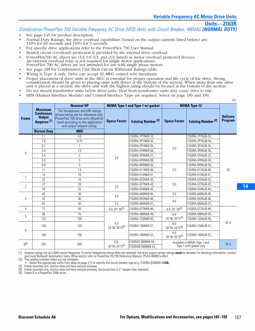
14
Variable Frequency AC Motor Drive UnitsUnits—2163R
Combination PowerFlex 700 Variable Frequency AC Drive (VFD) Units with Circuit Breaker, 480VAC (NORMAL DUTY)• See page 145 for product description.• Normal Duty Ratings, the drive overload capabilities (based on the output currents listed below) are:
110% for 60 seconds and 150% for 3 seconds.• For specific drive applications refer to the PowerFlex 700 User Manual.• Branch circuit (overload) protection is provided by the internal drive overload.• PowerFlex700 AC drives are cUL US (UL and cUL listed) as motor overload protected devices.
An external overload relay is not required for single motor applications.PowerFlex 700 AC drives are not intended for use with single phase motors.
• See page 238 for Combination Unit Short Circuit Withstand Ratings table.• Wiring is Type A only. Drive can accept 16 AWG control wire maximum.• Proper placement of drive units in the MCC is essential for proper operation and life cycle of the drive. Strong
consideration should be given to placing units with drives at the bottom of the section. When more than one drive unit is placed in a section, the drive unit with the highest rating should be located at the bottom of the section.
• Do not mount transformer units below drive units. Heat from transformer units may cause drive to trip.• HIM (Human Interface Module) and Control Interface Type are required. Select on page 189 and 190.
225
Frame
Maximum Continuous
Output Amperes [1]
[1] Ampere ratings are at a 4kHz carrier frequency. If carrier frequencies above 4kHz are selected, the drive output current ratings must be derated. For derating information, contact your local Rockwell Automation Sales Office and/or refer to PowerFlex 70/700 Reference Manual, PFLEX-RM001x-EN-E.
Nominal HP NEMA Type 1 and Type 1 w/ gasket NEMA Type 12
Delivery Program
The horsepower and kW ratings shown below are for reference only. PowerFlex 700 drive units should be sized according to the application
and output ampere rating.Space Factor Catalog Number [2]
[2] The catalog numbers listed are not complete:• Select the appropriate suffix from table on page 212 to identify the circuit breaker type (e.g. 2163RA-034NKB-44CA).
Space Factor Catalog Number [2]
Normal Duty 480V
0
1.1 0.5
2.0
2163RA-1P1NKB-33_
2.0
2163RA-1P1NJB-33_
SC
1.6 0.75 2163RA-2P1NKB-34_ 2163RA-2P1NJB-34_2.1 1 2163RA-2P1NKB-35_ 2163RA-2P1NJB-35_3.0 1.5 2163RA-3P4NKB-36_ 2163RA-3P4NJB-36_3.4 2 2163RA-3P4NKB-37_ 2163RA-3P4NJB-37_5.0 3 2163RA-5P0NKB-38_ 2163RA-5P0NJB-38_8.0 5 2163RA-8P0NKB-39_
2.52163RA-8P0NJB-39_
11 7.5 2163RA-011NKB-40_ 2163RA-011NJB-40_
114 10 2163RA-014NKB-41_ 2163RA-014NJB-41_22 15 2163RA-022NKB-42_
3.02163RA-022NJB-42_
227 20
2.52163RA-027NKB-43_ 2163RA-027NJB-43_
34 25 2163RA-034NKB-44_ 2163RA-034NJB-44_
340 30
3.02163RA-040NKB-45_ 3.5 2163RA-040NJB-45_
52 40 2163RA-052NKB-46_4.0
2163RA-052NJB-46_65 50 3.5 2163RA-065NKB-47_ 2163RA-065NJB-47_
4 77 60 6.0, 20” W[3]
[3] Frame mounted unit, section does not have vertical wireway.
2163RA-077NKB-48_ 6.0, 25” W[3] 2163RA-077NJB-48_
SC-II
596 75
6.025”W, 20”D[4]
[4] Frame mounted unit, section does not have vertical wireway. Horizontal bus is 5” deeper than standard.
2163RA-096NKB-49_ 6.025”W, 20”D[4]
2163RA-096NJB-49_125 100 2163RA-125NKB-50_ 2163RA-125NJB-50_
6156 125 2163RA-156NKB-51_
6.030”W, 20”D[4] 2163RA-156NJB-51_
180 150 2163RA-180NKB-52_6.0
35”W, 20”D[4] 2163RA-180NJB-52_
9[5]
[5] Frame 9 is a PowerFlex 700H drive.
255 2006.0,
30”W, 20”D[4]2163RAT-300NKB-54_ Available in NEMA Type 1 and
Type 1 with gasket only PE-II2163RAB-300NKB-54_
167For Options, Modifications and Accessories, see pages 187–193Discount Schedule A6
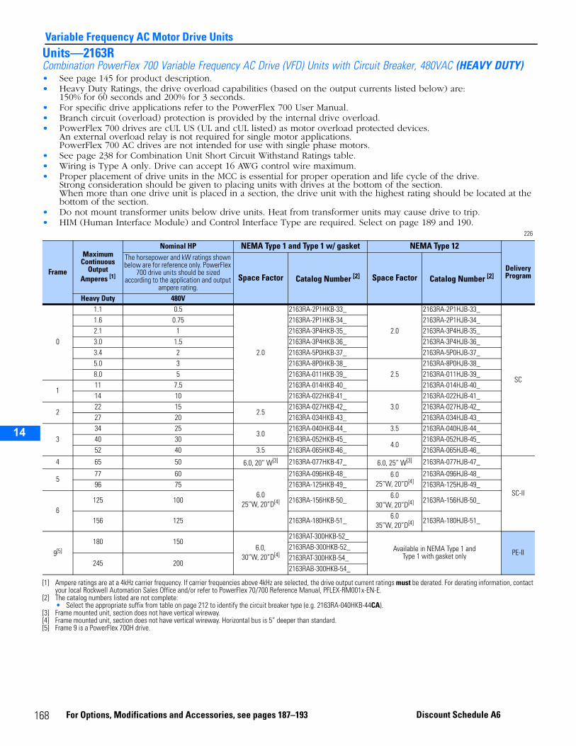
14
Variable Frequency AC Motor Drive UnitsUnits—2163RCombination PowerFlex 700 Variable Frequency AC Drive (VFD) Units with Circuit Breaker, 480VAC (HEAVY DUTY) • See page 145 for product description.• Heavy Duty Ratings, the drive overload capabilities (based on the output currents listed below) are:
150% for 60 seconds and 200% for 3 seconds.• For specific drive applications refer to the PowerFlex 700 User Manual.• Branch circuit (overload) protection is provided by the internal drive overload.• PowerFlex 700 drives are cUL US (UL and cUL listed) as motor overload protected devices.
An external overload relay is not required for single motor applications. PowerFlex 700 AC drives are not intended for use with single phase motors.
• See page 238 for Combination Unit Short Circuit Withstand Ratings table.• Wiring is Type A only. Drive can accept 16 AWG control wire maximum.• Proper placement of drive units in the MCC is essential for proper operation and life cycle of the drive.
Strong consideration should be given to placing units with drives at the bottom of the section. When more than one drive unit is placed in a section, the drive unit with the highest rating should be located at the bottom of the section.
• Do not mount transformer units below drive units. Heat from transformer units may cause drive to trip.• HIM (Human Interface Module) and Control Interface Type are required. Select on page 189 and 190.
226
Frame
Maximum Continuous
Output Amperes [1]
[1] Ampere ratings are at a 4kHz carrier frequency. If carrier frequencies above 4kHz are selected, the drive output current ratings must be derated. For derating information, contact your local Rockwell Automation Sales Office and/or refer to PowerFlex 70/700 Reference Manual, PFLEX-RM001x-EN-E.
Nominal HP NEMA Type 1 and Type 1 w/ gasket NEMA Type 12
Delivery Program
The horsepower and kW ratings shown below are for reference only. PowerFlex
700 drive units should be sized according to the application and output
ampere rating.Space Factor Catalog Number [2]
[2] The catalog numbers listed are not complete:• Select the appropriate suffix from table on page 212 to identify the circuit breaker type (e.g. 2163RA-040HKB-44CA).
Space Factor Catalog Number [2]
Heavy Duty 480V
0
1.1 0.5
2.0
2163RA-2P1HKB-33_
2.0
2163RA-2P1HJB-33_
SC
1.6 0.75 2163RA-2P1HKB-34_ 2163RA-2P1HJB-34_2.1 1 2163RA-3P4HKB-35_ 2163RA-3P4HJB-35_3.0 1.5 2163RA-3P4HKB-36_ 2163RA-3P4HJB-36_3.4 2 2163RA-5P0HKB-37_ 2163RA-5P0HJB-37_5.0 3 2163RA-8P0HKB-38_
2.52163RA-8P0HJB-38_
8.0 5 2163RA-011HKB-39_ 2163RA-011HJB-39_
111 7.5 2163RA-014HKB-40_ 2163RA-014HJB-40_14 10 2163RA-022HKB-41_
3.02163RA-022HJB-41_
222 15
2.52163RA-027HKB-42_ 2163RA-027HJB-42_
27 20 2163RA-034HKB-43_ 2163RA-034HJB-43_
334 25
3.02163RA-040HKB-44_ 3.5 2163RA-040HJB-44_
40 30 2163RA-052HKB-45_4.0
2163RA-052HJB-45_52 40 3.5 2163RA-065HKB-46_ 2163RA-065HJB-46_
4 65 50 6.0, 20” W[3]
[3] Frame mounted unit, section does not have vertical wireway.
2163RA-077HKB-47_ 6.0, 25” W[3] 2163RA-077HJB-47_
SC-II
577 60
6.025”W, 20”D[4]
[4] Frame mounted unit, section does not have vertical wireway. Horizontal bus is 5” deeper than standard.
2163RA-096HKB-48_ 6.025”W, 20”D[4]
2163RA-096HJB-48_96 75 2163RA-125HKB-49_ 2163RA-125HJB-49_
6125 100 2163RA-156HKB-50_
6.030”W, 20”D[4] 2163RA-156HJB-50_
156 125 2163RA-180HKB-51_6.0
35”W, 20”D[4] 2163RA-180HJB-51_
9[5]
[5] Frame 9 is a PowerFlex 700H drive.
180 1506.0,
30”W, 20”D[4]
2163RAT-300HKB-52_
Available in NEMA Type 1 and Type 1 with gasket only PE-II
2163RAB-300HKB-52_
245 2002163RAT-300HKB-54_2163RAB-300HKB-54_
168 For Options, Modifications and Accessories, see pages 187–193 Discount Schedule A6
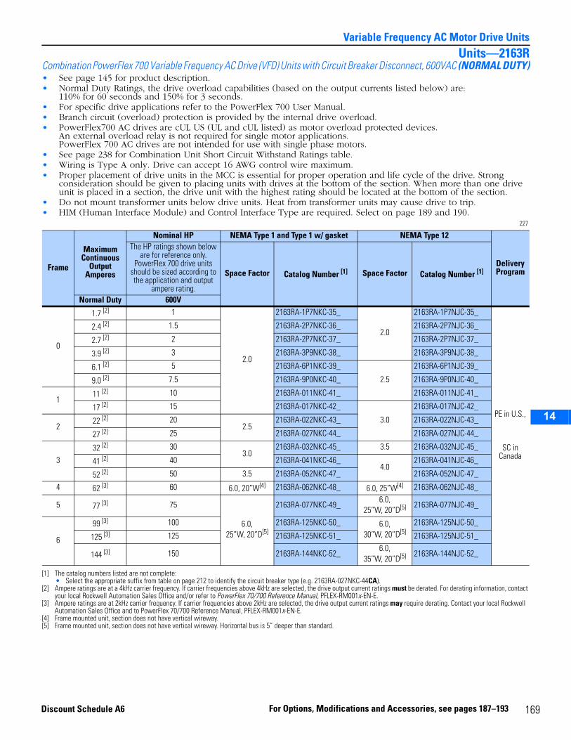
14
Variable Frequency AC Motor Drive UnitsUnits—2163R
Combination PowerFlex 700 Variable Frequency AC Drive (VFD) Units with Circuit Breaker Disconnect, 600VAC (NORMAL DUTY)• See page 145 for product description.• Normal Duty Ratings, the drive overload capabilities (based on the output currents listed below) are:
110% for 60 seconds and 150% for 3 seconds.• For specific drive applications refer to the PowerFlex 700 User Manual.• Branch circuit (overload) protection is provided by the internal drive overload.• PowerFlex700 AC drives are cUL US (UL and cUL listed) as motor overload protected devices.
An external overload relay is not required for single motor applications.PowerFlex 700 AC drives are not intended for use with single phase motors.
• See page 238 for Combination Unit Short Circuit Withstand Ratings table.• Wiring is Type A only. Drive can accept 16 AWG control wire maximum.• Proper placement of drive units in the MCC is essential for proper operation and life cycle of the drive. Strong
consideration should be given to placing units with drives at the bottom of the section. When more than one drive unit is placed in a section, the drive unit with the highest rating should be located at the bottom of the section.
• Do not mount transformer units below drive units. Heat from transformer units may cause drive to trip.• HIM (Human Interface Module) and Control Interface Type are required. Select on page 189 and 190.
227
Frame
Maximum Continuous
Output Amperes
Nominal HP NEMA Type 1 and Type 1 w/ gasket NEMA Type 12
Delivery Program
The HP ratings shown below are for reference only.
PowerFlex 700 drive units should be sized according to the application and output
ampere rating.
Space Factor Catalog Number [1]
[1] The catalog numbers listed are not complete:• Select the appropriate suffix from table on page 212 to identify the circuit breaker type (e.g. 2163RA-027NKC-44CA).
Space Factor Catalog Number [1]
Normal Duty 600V
0
1.7 [2]
[2] Ampere ratings are at a 4kHz carrier frequency. If carrier frequencies above 4kHz are selected, the drive output current ratings must be derated. For derating information, contact your local Rockwell Automation Sales Office and/or refer to PowerFlex 70/700 Reference Manual, PFLEX-RM001x-EN-E.
1
2.0
2163RA-1P7NKC-35_
2.0
2163RA-1P7NJC-35_
PE in U.S.,
SC in Canada
2.4 [2] 1.5 2163RA-2P7NKC-36_ 2163RA-2P7NJC-36_
2.7 [2] 2 2163RA-2P7NKC-37_ 2163RA-2P7NJC-37_
3.9 [2] 3 2163RA-3P9NKC-38_ 2163RA-3P9NJC-38_
6.1 [2] 5 2163RA-6P1NKC-39_
2.5
2163RA-6P1NJC-39_
9.0 [2] 7.5 2163RA-9P0NKC-40_ 2163RA-9P0NJC-40_
111 [2] 10 2163RA-011NKC-41_ 2163RA-011NJC-41_
17 [2] 15 2163RA-017NKC-42_
3.0
2163RA-017NJC-42_
222 [2] 20
2.52163RA-022NKC-43_ 2163RA-022NJC-43_
27 [2] 25 2163RA-027NKC-44_ 2163RA-027NJC-44_
332 [2] 30
3.02163RA-032NKC-45_ 3.5 2163RA-032NJC-45_
41 [2] 40 2163RA-041NKC-46_4.0
2163RA-041NJC-46_
52 [2] 50 3.5 2163RA-052NKC-47_ 2163RA-052NJC-47_
4 62 [3]
[3] Ampere ratings are at 2kHz carrier frequency. If carrier frequencies above 2kHz are selected, the drive output current ratings may require derating. Contact your local Rockwell Automation Sales Office and to PowerFlex 70/700 Reference Manual, PFLEX-RM001x-EN-E.
60 6.0, 20”W[4]
[4] Frame mounted unit, section does not have vertical wireway.
2163RA-062NKC-48_ 6.0, 25”W[4] 2163RA-062NJC-48_
5 77 [3] 75
6.0, 25”W, 20”D[5]
[5] Frame mounted unit, section does not have vertical wireway. Horizontal bus is 5” deeper than standard.
2163RA-077NKC-49_6.0,
25”W, 20”D[5] 2163RA-077NJC-49_
6
99 [3] 100 2163RA-125NKC-50_ 6.0, 30”W, 20”D[5]
2163RA-125NJC-50_
125 [3] 125 2163RA-125NKC-51_ 2163RA-125NJC-51_
144 [3] 150 2163RA-144NKC-52_6.0,
35”W, 20”D[5] 2163RA-144NJC-52_
169For Options, Modifications and Accessories, see pages 187–193Discount Schedule A6
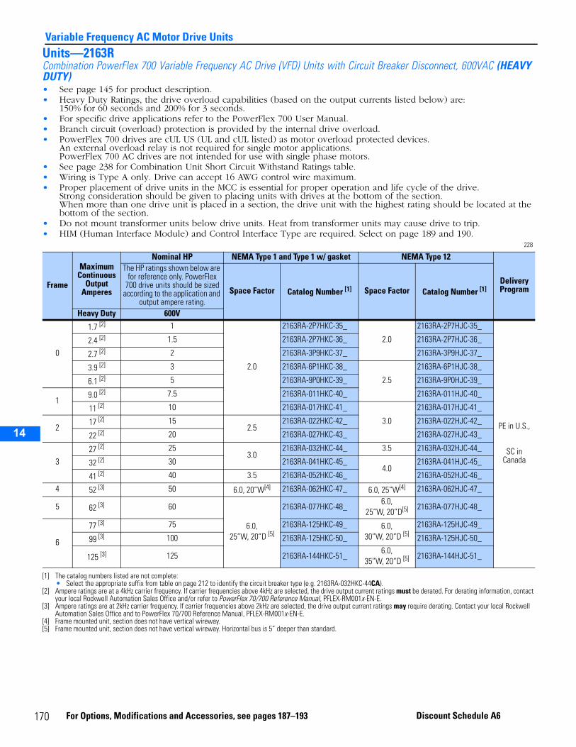
14
Variable Frequency AC Motor Drive UnitsUnits—2163RCombination PowerFlex 700 Variable Frequency AC Drive (VFD) Units with Circuit Breaker Disconnect, 600VAC (HEAVY DUTY)• See page 145 for product description.• Heavy Duty Ratings, the drive overload capabilities (based on the output currents listed below) are:
150% for 60 seconds and 200% for 3 seconds.• For specific drive applications refer to the PowerFlex 700 User Manual.• Branch circuit (overload) protection is provided by the internal drive overload.• PowerFlex 700 drives are cUL US (UL and cUL listed) as motor overload protected devices.
An external overload relay is not required for single motor applications. PowerFlex 700 AC drives are not intended for use with single phase motors.
• See page 238 for Combination Unit Short Circuit Withstand Ratings table.• Wiring is Type A only. Drive can accept 16 AWG control wire maximum.• Proper placement of drive units in the MCC is essential for proper operation and life cycle of the drive.
Strong consideration should be given to placing units with drives at the bottom of the section. When more than one drive unit is placed in a section, the drive unit with the highest rating should be located at the bottom of the section.
• Do not mount transformer units below drive units. Heat from transformer units may cause drive to trip.• HIM (Human Interface Module) and Control Interface Type are required. Select on page 189 and 190.
228
Frame
Maximum Continuous
Output Amperes
Nominal HP NEMA Type 1 and Type 1 w/ gasket NEMA Type 12
Delivery Program
The HP ratings shown below are for reference only. PowerFlex
700 drive units should be sized according to the application and
output ampere rating.Space Factor Catalog Number [1]
[1] The catalog numbers listed are not complete:• Select the appropriate suffix from table on page 212 to identify the circuit breaker type (e.g. 2163RA-032HKC-44CA).
Space Factor Catalog Number [1]
Heavy Duty 600V
0
1.7 [2]
[2] Ampere ratings are at a 4kHz carrier frequency. If carrier frequencies above 4kHz are selected, the drive output current ratings must be derated. For derating information, contact your local Rockwell Automation Sales Office and/or refer to PowerFlex 70/700 Reference Manual, PFLEX-RM001x-EN-E.
1
2.0
2163RA-2P7HKC-35_
2.0
2163RA-2P7HJC-35_
PE in U.S.,
SC in Canada
2.4 [2] 1.5 2163RA-2P7HKC-36_ 2163RA-2P7HJC-36_
2.7 [2] 2 2163RA-3P9HKC-37_ 2163RA-3P9HJC-37_
3.9 [2] 3 2163RA-6P1HKC-38_
2.5
2163RA-6P1HJC-38_
6.1 [2] 5 2163RA-9P0HKC-39_ 2163RA-9P0HJC-39_
19.0 [2] 7.5 2163RA-011HKC-40_ 2163RA-011HJC-40_
11 [2] 10 2163RA-017HKC-41_
3.0
2163RA-017HJC-41_
217 [2] 15
2.52163RA-022HKC-42_ 2163RA-022HJC-42_
22 [2] 20 2163RA-027HKC-43_ 2163RA-027HJC-43_
327 [2] 25
3.02163RA-032HKC-44_ 3.5 2163RA-032HJC-44_
32 [2] 30 2163RA-041HKC-45_4.0
2163RA-041HJC-45_
41 [2] 40 3.5 2163RA-052HKC-46_ 2163RA-052HJC-46_
4 52 [3]
[3] Ampere ratings are at 2kHz carrier frequency. If carrier frequencies above 2kHz are selected, the drive output current ratings may require derating. Contact your local Rockwell Automation Sales Office and to PowerFlex 70/700 Reference Manual, PFLEX-RM001x-EN-E.
50 6.0, 20”W[4]
[4] Frame mounted unit, section does not have vertical wireway.
2163RA-062HKC-47_ 6.0, 25”W[4] 2163RA-062HJC-47_
5 62 [3] 60
6.0, 25”W, 20”D [5]
[5] Frame mounted unit, section does not have vertical wireway. Horizontal bus is 5” deeper than standard.
2163RA-077HKC-48_6.0,
25”W, 20”D[5] 2163RA-077HJC-48_
6
77 [3] 75 2163RA-125HKC-49_ 6.0, 30”W, 20”D [5]
2163RA-125HJC-49_
99 [3] 100 2163RA-125HKC-50_ 2163RA-125HJC-50_
125 [3] 125 2163RA-144HKC-51_6.0,
35”W, 20”D [5] 2163RA-144HJC-51_
170 For Options, Modifications and Accessories, see pages 187–193 Discount Schedule A6
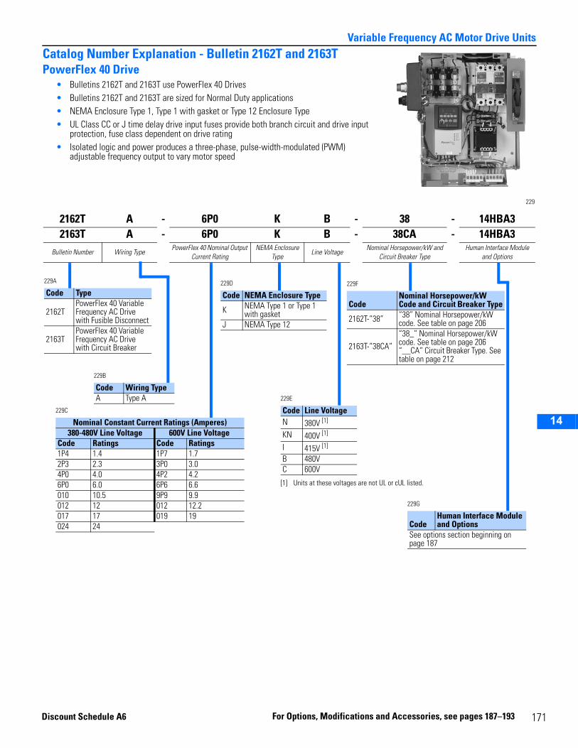
14
Variable Frequency AC Motor Drive UnitsCatalog Number Explanation - Bulletin 2162T and 2163TPowerFlex 40 Drive
• Bulletins 2162T and 2163T use PowerFlex 40 Drives• Bulletins 2162T and 2163T are sized for Normal Duty applications• NEMA Enclosure Type 1, Type 1 with gasket or Type 12 Enclosure Type• UL Class CC or J time delay drive input fuses provide both branch circuit and drive input
protection, fuse class dependent on drive rating• Isolated logic and power produces a three-phase, pulse-width-modulated (PWM)
adjustable frequency output to vary motor speed
229
2162T A - 6P0 K B - 38 - 14HBA32163T A - 6P0 K B - 38CA - 14HBA3
Bulletin Number Wiring TypePowerFlex 40 Nominal Output
Current RatingNEMA Enclosure
TypeLine Voltage
Nominal Horsepower/kW and Circuit Breaker Type
Human Interface Module and Options
229A
Code Type
2162TPowerFlex 40 Variable Frequency AC Drive with Fusible Disconnect
2163TPowerFlex 40 Variable Frequency AC Drive with Circuit Breaker
229B
Code Wiring TypeA Type A
229D
Code NEMA Enclosure Type
K NEMA Type 1 or Type 1 with gasket
J NEMA Type 12
229F
CodeNominal Horsepower/kW Code and Circuit Breaker Type
2162T-”38” “38” Nominal Horsepower/kW code. See table on page 206
2163T-”38CA”“38_” Nominal Horsepower/kW code. See table on page 206“__CA” Circuit Breaker Type. See table on page 212
229E
Code Line VoltageN 380V [1]
[1] Units at these voltages are not UL or cUL listed.
KN 400V [1]
I 415V [1]
B 480VC 600V
229G
CodeHuman Interface Module and Options
See options section beginning on page 187
229C
Nominal Constant Current Ratings (Amperes) 380-480V Line Voltage 600V Line Voltage
Code Ratings Code Ratings 1P4 1.4 1P7 1.72P3 2.3 3P0 3.04P0 4.0 4P2 4.26P0 6.0 6P6 6.6010 10.5 9P9 9.9012 12 012 12.2017 17 019 19024 24
Discount Sc
hedule A6 F or Options, Modi fications and Ac 171cessories, see pages 187–193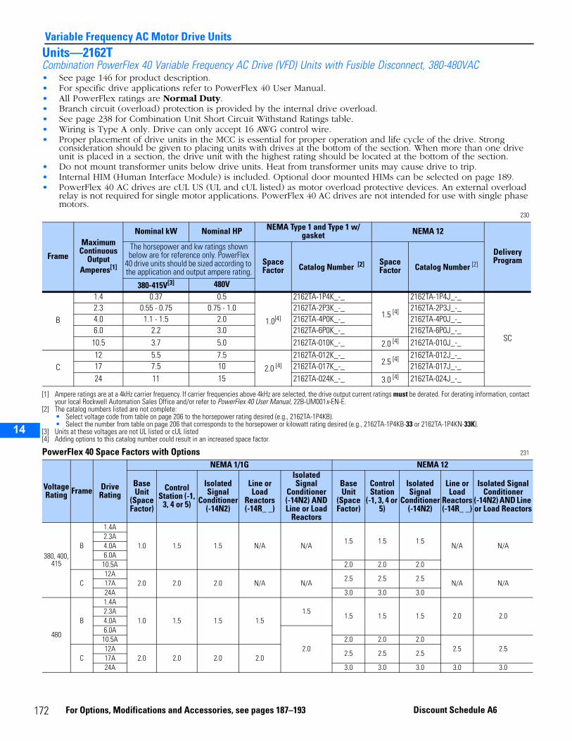
14
Variable Frequency AC Motor Drive UnitsUnits—2162TCombination PowerFlex 40 Variable Frequency AC Drive (VFD) Units with Fusible Disconnect, 380-480VAC• See page 146 for product description.• For specific drive applications refer to PowerFlex 40 User Manual.• All PowerFlex ratings are Normal Duty.• Branch circuit (overload) protection is provided by the internal drive overload.• See page 238 for Combination Unit Short Circuit Withstand Ratings table.• Wiring is Type A only. Drive can only accept 16 AWG control wire.• Proper placement of drive units in the MCC is essential for proper operation and life cycle of the drive. Strong
consideration should be given to placing units with drives at the bottom of the section. When more than one drive unit is placed in a section, the drive unit with the highest rating should be located at the bottom of the section.
• Do not mount transformer units below drive units. Heat from transformer units may cause drive to trip.• Internal HIM (Human Interface Module) is included. Optional door mounted HIMs can be selected on page 189.• PowerFlex 40 AC drives are cUL US (UL and cUL listed) as motor overload protective devices. An external overload
relay is not required for single motor applications. PowerFlex 40 AC drives are not intended for use with single phase motors.
230
PowerFlex 40 Space Factors with Options 231
Frame
Maximum Continuous
Output Amperes[1]
[1] Ampere ratings are at a 4kHz carrier frequency. If carrier frequencies above 4kHz are selected, the drive output current ratings must be derated. For derating information, contact your local Rockwell Automation Sales Office and/or refer to PowerFlex 40 User Manual, 22B-UM001x-EN-E.
Nominal kW Nominal HP NEMA Type 1 and Type 1 w/ gasket NEMA 12
Delivery Program
The horsepower and kw ratings shown below are for reference only. PowerFlex
40 drive units should be sized according to the application and output ampere rating.
Space Factor Catalog Number [2]
[2] The catalog numbers listed are not complete:• Select voltage code from table on page 206 to the horsepower rating desired (e.g., 2162TA-1P4KB).• Select the number from table on page 206 that corresponds to the horsepower or kilowatt rating desired (e.g., 2162TA-1P4KB-33 or 2162TA-1P4KN-33K).
Space Factor Catalog Number [2]
380-415V[3]
[3] Units at these voltages are not UL listed or cUL listed
480V
B
1.4 0.37 0.5
1.0[4]
[4] Adding options to this catalog number could result in an increased space factor.
2162TA-1P4K_-_
1.5 [4]
2162TA-1P4J_-_
SC
2.3 0.55 - 0.75 0.75 - 1.0 2162TA-2P3K_-_ 2162TA-2P3J_-_4.0 1.1 - 1.5 2.0 2162TA-4P0K_-_ 2162TA-4P0J_-_6.0 2.2 3.0 2162TA-6P0K_-_ 2162TA-6P0J_-_10.5 3.7 5.0 2162TA-010K_-_ 2.0 [4] 2162TA-010J_-_
C12 5.5 7.5
2.0 [4]2162TA-012K_-_
2.5 [4] 2162TA-012J_-_17 7.5 10 2162TA-017K_-_ 2162TA-017J_-_24 11 15 2162TA-024K_-_ 3.0 [4] 2162TA-024J_-_
Voltage Rating Frame Drive
Rating
NEMA 1/1G NEMA 12
Base Unit
(Space Factor)
Control Station (-1,
3, 4 or 5)
Isolated Signal
Conditioner (-14N2)
Line or Load
Reactors (-14R_ _)
Isolated Signal
Conditioner (-14N2) AND Line or Load
Reactors
Base Unit
(Space Factor)
Control Station
(-1, 3, 4 or 5)
Isolated Signal
Conditioner (-14N2)
Line or Load
Reactors (-14R_ _)
Isolated Signal Conditioner
(-14N2) AND Line or Load Reactors
380, 400, 415
B
1.4A
1.0 1.5 1.5 N/A N/A1.5 1.5 1.5
N/A N/A2.3A4.0A6.0A10.5A 2.0 2.0 2.0
C12A
2.0 2.0 2.0 N/A N/A2.5 2.5 2.5
N/A N/A17A24A 3.0 3.0 3.0
480
B
1.4A
1.0 1.5 1.5 1.51.5
1.5 1.5 1.5 2.0 2.02.3A4.0A6.0A
2.010.5A 2.0 2.0 2.0
2.5 2.5C
12A2.0 2.0 2.0 2.0
2.5 2.5 2.517A24A 3.0 3.0 3.0 3.0 3.0
172 For Options, Modifications and Accessories, see pages 187–193 Discount Schedule A6
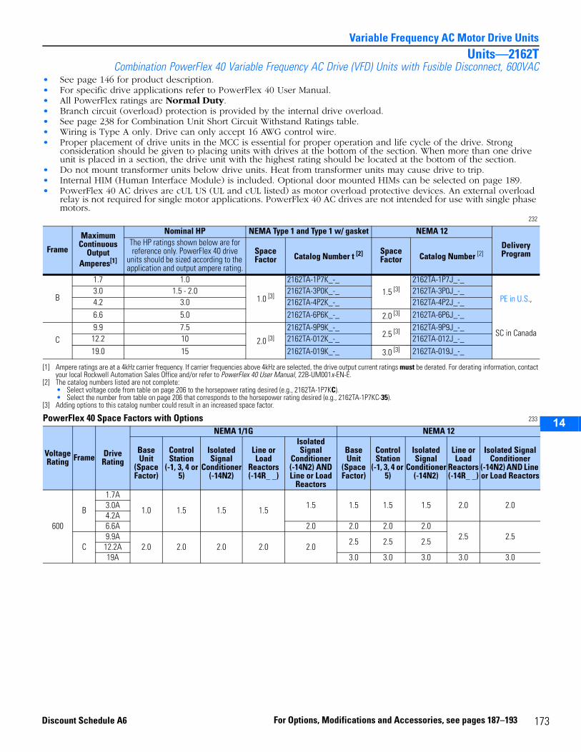
14
Variable Frequency AC Motor Drive UnitsUnits—2162T
Combination PowerFlex 40 Variable Frequency AC Drive (VFD) Units with Fusible Disconnect, 600VAC• See page 146 for product description.• For specific drive applications refer to PowerFlex 40 User Manual.• All PowerFlex ratings are Normal Duty.• Branch circuit (overload) protection is provided by the internal drive overload.• See page 238 for Combination Unit Short Circuit Withstand Ratings table.• Wiring is Type A only. Drive can only accept 16 AWG control wire.• Proper placement of drive units in the MCC is essential for proper operation and life cycle of the drive. Strong
consideration should be given to placing units with drives at the bottom of the section. When more than one drive unit is placed in a section, the drive unit with the highest rating should be located at the bottom of the section.
• Do not mount transformer units below drive units. Heat from transformer units may cause drive to trip.• Internal HIM (Human Interface Module) is included. Optional door mounted HIMs can be selected on page 189.• PowerFlex 40 AC drives are cUL US (UL and cUL listed) as motor overload protective devices. An external overload
relay is not required for single motor applications. PowerFlex 40 AC drives are not intended for use with single phase motors.
232
PowerFlex 40 Space Factors with Options 233
Frame
Maximum Continuous
Output Amperes[1]
[1] Ampere ratings are at a 4kHz carrier frequency. If carrier frequencies above 4kHz are selected, the drive output current ratings must be derated. For derating information, contact your local Rockwell Automation Sales Office and/or refer to PowerFlex 40 User Manual, 22B-UM001x-EN-E.
Nominal HP NEMA Type 1 and Type 1 w/ gasket NEMA 12
Delivery Program
The HP ratings shown below are for reference only. PowerFlex 40 drive
units should be sized according to the application and output ampere rating.
Space Factor Catalog Number t [2]
[2] The catalog numbers listed are not complete:• Select voltage code from table on page 206 to the horsepower rating desired (e.g., 2162TA-1P7KC).• Select the number from table on page 206 that corresponds to the horsepower rating desired (e.g., 2162TA-1P7KC-35).
Space Factor Catalog Number [2]
B
1.7 1.0
1.0 [3]
[3] Adding options to this catalog number could result in an increased space factor.
2162TA-1P7K_-_1.5 [3]
2162TA-1P7J_-_
PE in U.S.,
SC in Canada
3.0 1.5 - 2.0 2162TA-3P0K_-_ 2162TA-3P0J_-_4.2 3.0 2162TA-4P2K_-_ 2162TA-4P2J_-_6.6 5.0 2162TA-6P6K_-_ 2.0 [3] 2162TA-6P6J_-_
C9.9 7.5
2.0 [3]2162TA-9P9K_-_
2.5 [3] 2162TA-9P9J_-_12.2 10 2162TA-012K_-_ 2162TA-012J_-_19.0 15 2162TA-019K_-_ 3.0 [3] 2162TA-019J_-_
Voltage Rating Frame Drive
Rating
NEMA 1/1G NEMA 12
Base Unit
(Space Factor)
Control Station
(-1, 3, 4 or 5)
Isolated Signal
Conditioner (-14N2)
Line or Load
Reactors (-14R_ _)
Isolated Signal
Conditioner (-14N2) AND Line or Load
Reactors
Base Unit
(Space Factor)
Control Station
(-1, 3, 4 or 5)
Isolated Signal
Conditioner (-14N2)
Line or Load
Reactors (-14R_ _)
Isolated Signal Conditioner
(-14N2) AND Line or Load Reactors
600
B
1.7A
1.0 1.5 1.5 1.51.5 1.5 1.5 1.5 2.0 2.03.0A
4.2A6.6A 2.0 2.0 2.0 2.0
2.5 2.5C
9.9A2.0 2.0 2.0 2.0 2.0
2.5 2.5 2.512.2A19A 3.0 3.0 3.0 3.0 3.0
173For Options, Modifications and Accessories, see pages 187–193Discount Schedule A6

14
Variable Frequency AC Motor Drive UnitsUnits—2163TCombination PowerFlex 40 Variable Frequency AC Drive (VFD) Units with Circuit Breaker, 380-480VAC• See page 146 for product description.• For specific drive applications refer to PowerFlex 40 User Manual.• All PowerFlex ratings are Normal Duty.• Branch circuit (overload) protection is provided by the internal drive overload.• See page 238 for Combination Unit Short Circuit Withstand Ratings table.• Wiring is Type A only. Drive can only accept 16 AWG control wire.• Proper placement of drive units in the MCC is essential for proper operation and life cycle of the drive. Strong
consideration should be given to placing units with drives at the bottom of the section. When more than one drive unit is placed in a section, the drive unit with the highest rating should be located at the bottom of the section.
• Do not mount transformer units below drive units. Heat from transformer units may cause drive to trip.• Internal HIM (Human Interface Module) is included. Optional door mounted HIMs can be selected on page 189.• PowerFlex 40 AC drives are cUL US (UL and cUL listed) as motor overload protective devices. An external overload
relay is not required for single motor applications. PowerFlex 40 AC drives are not intended for use with single phase motors.
234
PowerFlex 40 Space Factors with Options 235
Frame
Maximum Continuous
Output Amperes[1]
[1] Ampere ratings are at a 4kHz carrier frequency. If carrier frequencies above 4kHz are selected, the drive output current ratings must be derated. For derating information, contact your local Rockwell Automation Sales Office and/or refer to PowerFlex 40 User Manual, 22B-UM001x-EN-E.
Nominal kW Nominal HP NEMA Type 1 and Type 1 w/ gasket NEMA 12
Delivery Program
The HP and kW ratings shown below are for reference only. PowerFlex 40 drive units
should be sized according to the application and output ampere rating.
Space Factor Catalog Number t [2]
[2] The catalog numbers listed are not complete:• Select voltage code from table on page 206 to the horsepower rating desired (e.g., 2163TA-1P4KB).• Select the number from table on page 206 that corresponds to the horsepower rating desired (e.g., 2163TA-1P4KB-33).• Select the appropriate suffix from table on page 212 to identify the circuit breaker type (e.g., 2163TA-1P4KB-33CA).
Space Factor Catalog Number [2]
380-415V [3]
[3] Units at these voltages are not UL listed or cUL listed.
480V
B
1.4 0.37 0.5
1.0 [4]
[4] Adding options to this catalog number could result in an increased space factor.
2163TA-1P4K_-_
1.5 [4]
2163TA-1P4J_-_
SC
2.3 0.55 - 0.75 0.75 - 1.0 2163TA-2P3K_-_ 2163TA-2P3J_-_4.0 1.1 - 1.5 1.5 - 2.0 2163TA-4P0K_-_ 2163TA-4P0J_-_6.0 2.2 3.0 2163TA-6P0K_-_ 2163TA-6P0J_-_
10.5 3.7 5.0 2163TA-010K_-_ 2.0 [4] 2163TA-010J_-_
C
12 5.5 7.5
2.0 [4]
2163TA-012K_-_2.5 [4] 2163TA-012J_-_
17 7.5 10 2163TA-017K_-_ 2163TA-017J_-_
24 11 15 2163TA-024K_-_ 3.0 [4] 2163TA-024J_-_
Voltage Rating Frame Drive
Rating
NEMA 1/1G NEMA 12
Base Unit (Space Factor)
Control Station (-1,
3, 4 or 5)
Isolated Signal
Conditioner (-14N2)
Line or Load Reactors (-14R_ _)
Isolated Signal Conditioner (-14N2) AND Line or Load
Reactors
Base Unit (Space Factor)
Control Station (-1,
3, 4 or 5)
Isolated Signal
Conditioner (-14N2)
Line or Load
Reactors (-14R_ _)
Isolated Signal Conditioner (-14N2) AND Line or Load
Reactors
380, 400, 415
B
1.4A
1.0 1.5 1.5 N/A N/A 1.5 1.5 1.5 N/A N/A2.3A4.0A6.0A
10.5A 2.0 2.0 2.0
C12A
2.0 2.0 2.0 N/A N/A 2.5 2.5 2.5 N/A N/A17A24A 3.0 3.0 3.0
480
B
1.4A
1.0 1.5 1.5 1.51.5 1.5 1.5 1.5 2.0 2.02.3A
4.0A6.0A
2.010.5A 2.0 2.0 2.0
2.5 2.5C
12A2.0 2.0 2.0 2.0 2.5 2.5 2.517A
24A 3.0 3.0 3.0 3.0 3.0
174 For Options, Modifications and Accessories, see pages 187–193 Discount Schedule A6
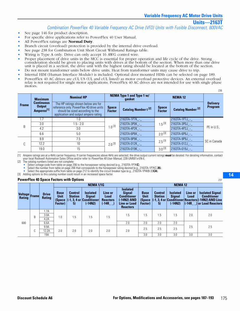
14
Variable Frequency AC Motor Drive UnitsUnits—2163T
Combination PowerFlex 40 Variable Frequency AC Drive (VFD) Units with Fusible Disconnect, 600VAC• See page 146 for product description.• For specific drive applications refer to PowerFlex 40 User Manual.• All PowerFlex ratings are Normal Duty.• Branch circuit (overload) protection is provided by the internal drive overload.• See page 238 for Combination Unit Short Circuit Withstand Ratings table.• Wiring is Type A only. Drive can only accept 16 AWG control wire.• Proper placement of drive units in the MCC is essential for proper operation and life cycle of the drive. Strong
consideration should be given to placing units with drives at the bottom of the section. When more than one drive unit is placed in a section, the drive unit with the highest rating should be located at the bottom of the section.
• Do not mount transformer units below drive units. Heat from transformer units may cause drive to trip.• Internal HIM (Human Interface Module) is included. Optional door mounted HIMs can be selected on page 189.• PowerFlex 40 AC drives are cUL US (UL and cUL listed) as motor overload protective devices. An external overload
relay is not required for single motor applications. PowerFlex 40 AC drives are not intended for use with single phase motors.
236
PowerFlex 40 Space Factors with Options 237
Frame
Maximum Continuous
Output Amperes[1]
[1] Ampere ratings are at a 4kHz carrier frequency. If carrier frequencies above 4kHz are selected, the drive output current ratings must be derated. For derating information, contact your local Rockwell Automation Sales Office and/or refer to PowerFlex 40 User Manual, 22B-UM001x-EN-E.
Nominal HP NEMA Type 1 and Type 1 w/ gasket NEMA 12
Delivery Program
The HP ratings shown below are for reference only. PowerFlex 40 drive units
should be sized according to the application and output ampere rating.
Space Factor Catalog Number t [2]
[2] The catalog numbers listed are not complete:• Select voltage code from table on page 206 to the horsepower rating desired (e.g., 2163TA-1P7KC).• Select the number from table on page 206 that corresponds to the horsepower rating desired (e.g., 2163TA-1P7KC-35).• Select the appropriate suffix from table on page 212 to identify the circuit breaker type (e.g., 2163TA-1P4KB-33CA).
Space Factor Catalog Number [2]
B
1.7 1.0
1.0 [3]
[3] Adding options to this catalog number could result in an increased space factor.
2163TA-1P7K_-_1.5 [3]
2163TA-1P7J_-_
PE in U.S.,
SC in Canada
3.0 1.5 - 2.0 2163TA-3P0K_-_ 2163TA-3P0J_-_4.2 3.0 2163TA-4P2K_-_ 2163TA-4P2J_-_6.6 5.0 2163TA-6P6K_-_ 2.0 [3] 2163TA-6P6J_-_
C9.9 7.5
2.0 [3]2163TA-9P9K_-_
2.5 [3] 2163TA-9P9J_-_12.2 10 2163TA-012K_-_ 2163TA-012J_-_19.0 15 2163TA-019K_-_ 3.0 [3] 2163TA-019J_-_
Voltage Rating Frame Drive
Rating
NEMA 1/1G NEMA 12
Base Unit
(Space Factor)
Control Station
(-1, 3, 4 or 5)
Isolated Signal
Conditioner (-14N2)
Line or Load
Reactors (-14R_ _)
Isolated Signal
Conditioner (-14N2) AND Line or Load
Reactors
Base Unit
(Space Factor)
Control Station
(-1, 3, 4 or 5)
Isolated Signal
Conditioner (-14N2)
Line or Load
Reactors (-14R_ _)
Isolated Signal Conditioner
(-14N2) AND Line or Load Reactors
600
B
1.7A
1.0 1.5 1.5 1.51.5 1.5 1.5 1.5 2.0 2.03.0A
4.2A6.6A 2.0 2.0 2.0 2.0
2.5 2.5C
9.9A2.0 2.0 2.0 2.0 2.0
2.5 2.5 2.512.2A19A 3.0 3.0 3.0 3.0 3.0
175For Options, Modifications and Accessories, see pages 187–193Discount Schedule A6
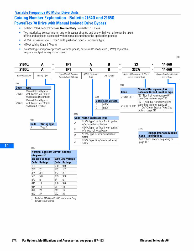
14
Variable Frequency AC Motor Drive UnitsCatalog Number Explanation - Bulletin 2164Q and 2165QPowerFlex 70 Drive with Manual Isolated Drive Bypass
• Bulletins 2164Q and 2165Q use Normal Duty PowerFlex 70 Drives• Two interlocked compartments, one with bypass circuitry and one with drive - drive can be taken
offline and replaced as needed with minimal disruption to the application process• NEMA Enclosure Type 1, Type 1 with gasket or Type 12 Enclosure Type• NEMA Wiring Class I, Type A• Isolated logic and power produces a three-phase, pulse-width-modulated (PWM) adjustable
frequency output to vary motor speed 238
2164Q A - 1P1 A B - 33 - 14HA02165Q A - 1P1 A B - 33CA - 14HA0
Bulletin Number Wiring TypePowerFlex 70 Nominal Output Current Rating
NEMA Enclosure Type
Line VoltageNominal Horsepower/kW and
Circuit Breaker TypeHuman Interface Module
and Options
238A
Code Type
2164QManual Drive Bypass with PowerFlex 70 VFD and Fusible Disconnect
2165QManual Drive Bypass with PowerFlex 70 VFD and Circuit Breaker
238B
Code Wiring TypeA Type A
238D
Code NEMA Enclosure Type
A NEMA Type 1 or Type 1 with gasket w/ external reset button
K NEMA Type 1 or Type 1 with gasket w/o external reset button
D NEMA Type 12 w/ external reset button
J NEMA Type 12 w/o external reset button
238F
CodeNominal Horsepower/kW Code and Circuit Breaker Type
2164Q-“33” “33” Nominal Horsepower/kW code. See table on page 206
2165Q-“33CA”“33_” Nominal Horsepower/kW code. See table on page 206“__CA” Circuit Breaker Type. See table on page 212
238E
Code Line VoltageB 480VC 600V
238G
CodeHuman Interface Module and Options
See options section beginning on page 187
238C
Nominal Constant Current Ratings (Amperes) [1]
[1] Bulletins 2164Q and 2165Q use Normal Duty PowerFlex 70 Drives.
480 Line Voltage 600V Line VoltageCode Ratings Code Ratings1P1 1.1 0P9 0.92P1 2.1 1P7 1.73P4 3.4 2P7 2.75P0 5.0 3P9 3.98P0 8 6P1 6.1011 11 9P0 9.0014 14 011 11022 22 017 17027 27 022 22
1
76 For O ptions, Modifications and Access ories, see pages 187–193 Discount Schedule A6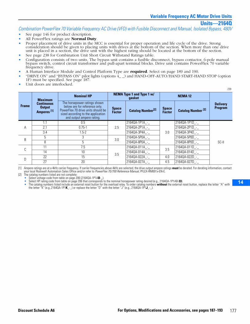
14
Variable Frequency AC Motor Drive UnitsUnits—2164Q
Combination PowerFlex 70 Variable Frequency AC Drive (VFD) with Fusible Disconnect and Manual, Isolated Bypass, 480V• See page 146 for product description.• All PowerFlex ratings are Normal Duty.• Proper placement of drive units in the MCC is essential for proper operation and life cycle of the drive. Strong
consideration should be given to placing units with drives at the bottom of the section. When more than one drive unit is placed in a section, the drive unit with the highest rating should be located at the bottom of the section.
• See page 238 for Combination Unit Short Circuit Withstand Ratings table.• Configuration consists of two units. The bypass unit contains a fusible disconnect, bypass contactor, 6-pole manual
bypass switch, control circuit transformer and pull-apart terminal blocks. Drive unit contains PowerFlex 70 variable frequency drive.
• A Human Interface Module and Control Platform Type are required. Select on page 189 and 190.• “DRIVE ON” and “BYPASS ON” pilot lights (options 4_ _) and HAND-OFF-AUTO/HAND START-HAND STOP (option
1F) must be specified. See page 187.• Unit doors are interlocked.
239
Frame
Maximum Continuous
Output Amperes [1]
[1] Ampere ratings are at a 4kHz carrier frequency. If carrier frequencies above 4kHz are selected, the drive output ampere ratings must be derated. For derating information, contact your local Rockwell Automation Sales Office and/or refer to PowerFlex 70/700 Reference Manual, PFLEX-RM001x-EN-E.
Nominal HP NEMA Type 1 and Type 1 w/ gasket NEMA 12
Delivery Program
The horsepower ratings shown below are for reference only.
PowerFlex 70 drive units should be sized according to the application
and output ampere rating.
Space Factor Catalog Number[2]
[2] The catalog numbers listed are not complete:• Select voltage code from table on page 206 (2164QA-1P1AB-_).• Select HP rating code from table on page 206 that corresponds to the nominal horsepower rating desired (e.g., 2164QA-1P1AB-33).• The catalog numbers listed include an external reset button for the overload relay. To order catalog numbers without the external reset button, replace the letter “A” with
the letter “K” (e.g.,2164QA-1P1K_-_) or replace the letter “D” with the letter “J” (e.g., 2164QA-1P1J_-_).
Space Factor Catalog Number [2]
A1.1 0.5
2.52164QA-1P1A_-_
3.0
2164QA-1P1D_-_
SC-II
2.1 0.75-1 2164QA-2P1A_-_ 2164QA-2P1D_-_3.4 1.5-2 2164QA-3P4A_-_ 2164QA-3P4D_-_
B5 3
3.02164QA-5P0A_-_ 2164QA-5P0D_-_
8 5 2164QA-8P0A_-_ 2164QA-8P0D_-_
C11 7.5
3.5
2164QA-011A_-_3.5
2164QA-011D_-_14 10 2164QA-014A_-_ 2164QA-014D_-_
D22 15 2164QA-022A_-_ 4.0 2164QA-022D_-_27 20 2164QA-027A_-_ 4.5 2164QA-027D_-_
177For Options, Modifications and Accessories, see pages 187–193Discount Schedule A6
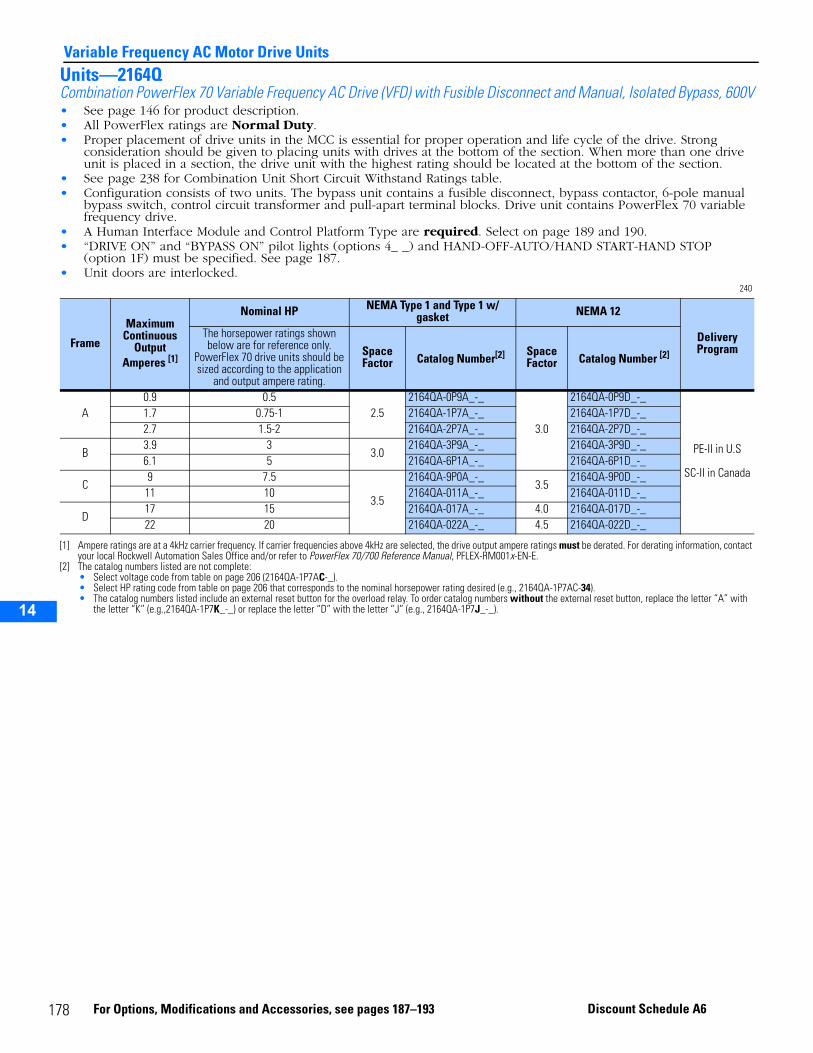
14
Variable Frequency AC Motor Drive UnitsUnits—2164QCombination PowerFlex 70 Variable Frequency AC Drive (VFD) with Fusible Disconnect and Manual, Isolated Bypass, 600V• See page 146 for product description.• All PowerFlex ratings are Normal Duty.• Proper placement of drive units in the MCC is essential for proper operation and life cycle of the drive. Strong
consideration should be given to placing units with drives at the bottom of the section. When more than one drive unit is placed in a section, the drive unit with the highest rating should be located at the bottom of the section.
• See page 238 for Combination Unit Short Circuit Withstand Ratings table.• Configuration consists of two units. The bypass unit contains a fusible disconnect, bypass contactor, 6-pole manual
bypass switch, control circuit transformer and pull-apart terminal blocks. Drive unit contains PowerFlex 70 variable frequency drive.
• A Human Interface Module and Control Platform Type are required. Select on page 189 and 190.• “DRIVE ON” and “BYPASS ON” pilot lights (options 4_ _) and HAND-OFF-AUTO/HAND START-HAND STOP
(option 1F) must be specified. See page 187.• Unit doors are interlocked.
240
Frame
Maximum Continuous
Output Amperes [1]
[1] Ampere ratings are at a 4kHz carrier frequency. If carrier frequencies above 4kHz are selected, the drive output ampere ratings must be derated. For derating information, contact your local Rockwell Automation Sales Office and/or refer to PowerFlex 70/700 Reference Manual, PFLEX-RM001x-EN-E.
Nominal HP NEMA Type 1 and Type 1 w/ gasket NEMA 12
Delivery Program
The horsepower ratings shown below are for reference only.
PowerFlex 70 drive units should be sized according to the application
and output ampere rating.
Space Factor Catalog Number[2]
[2] The catalog numbers listed are not complete:• Select voltage code from table on page 206 (2164QA-1P7AC-_).• Select HP rating code from table on page 206 that corresponds to the nominal horsepower rating desired (e.g., 2164QA-1P7AC-34).• The catalog numbers listed include an external reset button for the overload relay. To order catalog numbers without the external reset button, replace the letter “A” with
the letter “K” (e.g.,2164QA-1P7K_-_) or replace the letter “D” with the letter “J” (e.g., 2164QA-1P7J_-_).
Space Factor Catalog Number [2]
A0.9 0.5
2.52164QA-0P9A_-_
3.0
2164QA-0P9D_-_
PE-II in U.S
SC-II in Canada
1.7 0.75-1 2164QA-1P7A_-_ 2164QA-1P7D_-_2.7 1.5-2 2164QA-2P7A_-_ 2164QA-2P7D_-_
B3.9 3
3.02164QA-3P9A_-_ 2164QA-3P9D_-_
6.1 5 2164QA-6P1A_-_ 2164QA-6P1D_-_
C9 7.5
3.5
2164QA-9P0A_-_3.5
2164QA-9P0D_-_11 10 2164QA-011A_-_ 2164QA-011D_-_
D17 15 2164QA-017A_-_ 4.0 2164QA-017D_-_22 20 2164QA-022A_-_ 4.5 2164QA-022D_-_
178 For Options, Modifications and Accessories, see pages 187–193 Discount Schedule A6
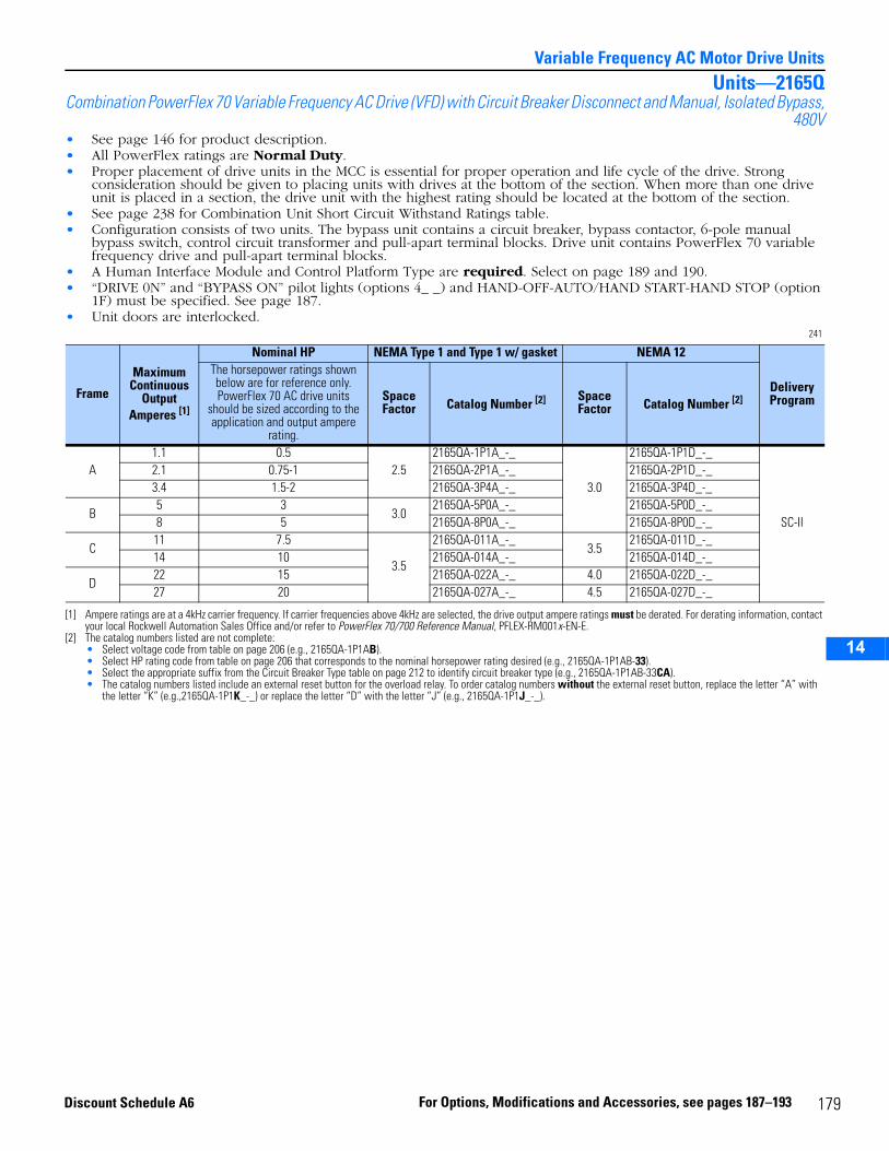
14
Variable Frequency AC Motor Drive UnitsUnits—2165Q
Combination PowerFlex 70 Variable Frequency AC Drive (VFD) with Circuit Breaker Disconnect and Manual, Isolated Bypass,480V
• See page 146 for product description.• All PowerFlex ratings are Normal Duty.• Proper placement of drive units in the MCC is essential for proper operation and life cycle of the drive. Strong
consideration should be given to placing units with drives at the bottom of the section. When more than one drive unit is placed in a section, the drive unit with the highest rating should be located at the bottom of the section.
• See page 238 for Combination Unit Short Circuit Withstand Ratings table.• Configuration consists of two units. The bypass unit contains a circuit breaker, bypass contactor, 6-pole manual
bypass switch, control circuit transformer and pull-apart terminal blocks. Drive unit contains PowerFlex 70 variable frequency drive and pull-apart terminal blocks.
• A Human Interface Module and Control Platform Type are required. Select on page 189 and 190.• “DRIVE 0N” and “BYPASS ON” pilot lights (options 4_ _) and HAND-OFF-AUTO/HAND START-HAND STOP (option
1F) must be specified. See page 187.• Unit doors are interlocked.
241
Frame
Maximum Continuous
Output Amperes [1]
[1] Ampere ratings are at a 4kHz carrier frequency. If carrier frequencies above 4kHz are selected, the drive output ampere ratings must be derated. For derating information, contact your local Rockwell Automation Sales Office and/or refer to PowerFlex 70/700 Reference Manual, PFLEX-RM001x-EN-E.
Nominal HP NEMA Type 1 and Type 1 w/ gasket NEMA 12
Delivery Program
The horsepower ratings shown below are for reference only. PowerFlex 70 AC drive units
should be sized according to the application and output ampere
rating.
Space Factor Catalog Number [2]
[2] The catalog numbers listed are not complete:• Select voltage code from table on page 206 (e.g., 2165QA-1P1AB).• Select HP rating code from table on page 206 that corresponds to the nominal horsepower rating desired (e.g., 2165QA-1P1AB-33).• Select the appropriate suffix from the Circuit Breaker Type table on page 212 to identify circuit breaker type (e.g., 2165QA-1P1AB-33CA).• The catalog numbers listed include an external reset button for the overload relay. To order catalog numbers without the external reset button, replace the letter “A” with
the letter “K” (e.g.,2165QA-1P1K_-_) or replace the letter “D” with the letter “J” (e.g., 2165QA-1P1J_-_).
Space Factor Catalog Number [2]
A1.1 0.5
2.52165QA-1P1A_-_
3.0
2165QA-1P1D_-_
SC-II
2.1 0.75-1 2165QA-2P1A_-_ 2165QA-2P1D_-_3.4 1.5-2 2165QA-3P4A_-_ 2165QA-3P4D_-_
B5 3
3.02165QA-5P0A_-_ 2165QA-5P0D_-_
8 5 2165QA-8P0A_-_ 2165QA-8P0D_-_
C11 7.5
3.5
2165QA-011A_-_3.5
2165QA-011D_-_14 10 2165QA-014A_-_ 2165QA-014D_-_
D22 15 2165QA-022A_-_ 4.0 2165QA-022D_-_27 20 2165QA-027A_-_ 4.5 2165QA-027D_-_
179For Options, Modifications and Accessories, see pages 187–193Discount Schedule A6
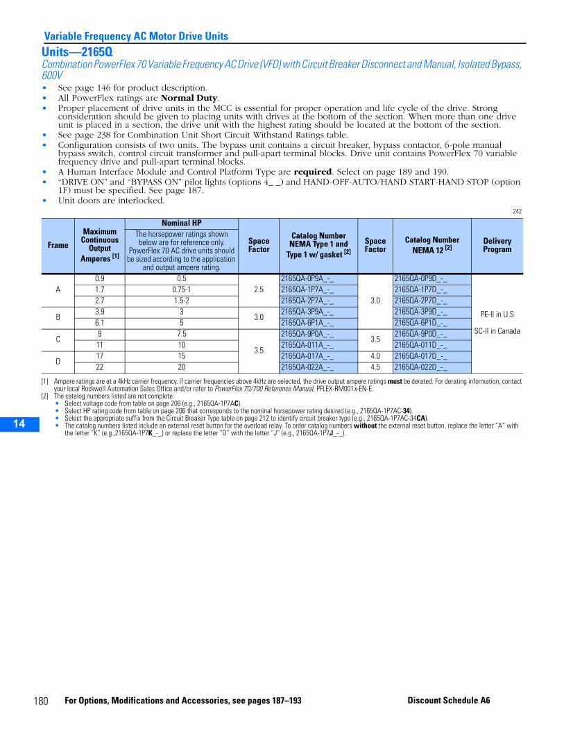
14
Variable Frequency AC Motor Drive UnitsUnits—2165QCombination PowerFlex 70 Variable Frequency AC Drive (VFD) with Circuit Breaker Disconnect and Manual, Isolated Bypass, 600V• See page 146 for product description.• All PowerFlex ratings are Normal Duty.• Proper placement of drive units in the MCC is essential for proper operation and life cycle of the drive. Strong
consideration should be given to placing units with drives at the bottom of the section. When more than one drive unit is placed in a section, the drive unit with the highest rating should be located at the bottom of the section.
• See page 238 for Combination Unit Short Circuit Withstand Ratings table.• Configuration consists of two units. The bypass unit contains a circuit breaker, bypass contactor, 6-pole manual
bypass switch, control circuit transformer and pull-apart terminal blocks. Drive unit contains PowerFlex 70 variable frequency drive and pull-apart terminal blocks.
• A Human Interface Module and Control Platform Type are required. Select on page 189 and 190.• “DRIVE ON” and “BYPASS ON” pilot lights (options 4_ _) and HAND-OFF-AUTO/HAND START-HAND STOP (option
1F) must be specified. See page 187.• Unit doors are interlocked.
242
Frame
Maximum Continuous
Output Amperes [1]
[1] Ampere ratings are at a 4kHz carrier frequency. If carrier frequencies above 4kHz are selected, the drive output ampere ratings must be derated. For derating information, contact your local Rockwell Automation Sales Office and/or refer to PowerFlex 70/700 Reference Manual, PFLEX-RM001x-EN-E.
Nominal HP
Space Factor
Catalog Number NEMA Type 1 and
Type 1 w/ gasket [2]
[2] The catalog numbers listed are not complete:• Select voltage code from table on page 206 (e.g., 2165QA-1P7AC).• Select HP rating code from table on page 206 that corresponds to the nominal horsepower rating desired (e.g., 2165QA-1P7AC-34).• Select the appropriate suffix from the Circuit Breaker Type table on page 212 to identify circuit breaker type (e.g., 2165QA-1P7AC-34CA).• The catalog numbers listed include an external reset button for the overload relay. To order catalog numbers without the external reset button, replace the letter “A” with
the letter “K” (e.g.,2165QA-1P7K_-_) or replace the letter “D” with the letter “J” (e.g., 2165QA-1P7J_-_).
Space Factor
Catalog Number NEMA 12 [2]
Delivery Program
The horsepower ratings shown below are for reference only.
PowerFlex 70 AC drive units should be sized according to the application
and output ampere rating.
A0.9 0.5
2.52165QA-0P9A_-_
3.0
2165QA-0P9D_-_
PE-II in U.S
SC-II in Canada
1.7 0.75-1 2165QA-1P7A_-_ 2165QA-1P7D_-_2.7 1.5-2 2165QA-2P7A_-_ 2165QA-2P7D_-_
B3.9 3
3.02165QA-3P9A_-_ 2165QA-3P9D_-_
6.1 5 2165QA-6P1A_-_ 2165QA-6P1D_-_
C9 7.5
3.5
2165QA-9P0A_-_3.5
2165QA-9P0D_-_11 10 2165QA-011A_-_ 2165QA-011D_-_
D17 15 2165QA-017A_-_ 4.0 2165QA-017D_-_22 20 2165QA-022A_-_ 4.5 2165QA-022D_-_
180 For Options, Modifications and Accessories, see pages 187–193 Discount Schedule A6
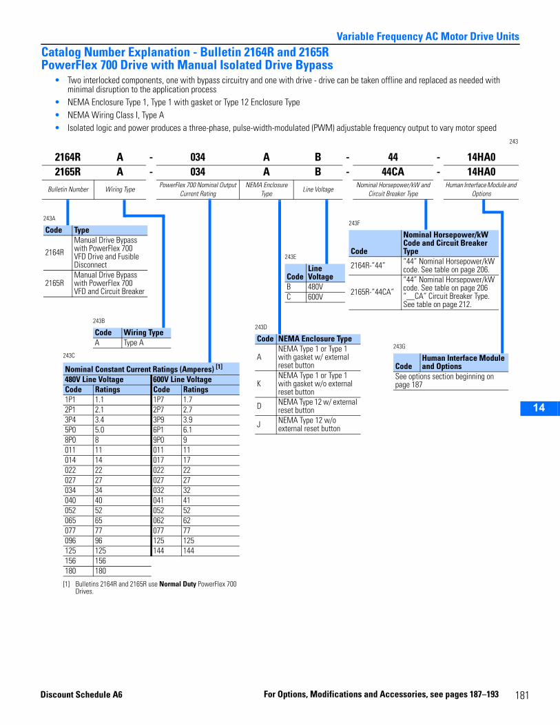
14
Variable Frequency AC Motor Drive UnitsCatalog Number Explanation - Bulletin 2164R and 2165RPowerFlex 700 Drive with Manual Isolated Drive Bypass
• Two interlocked components, one with bypass circuitry and one with drive - drive can be taken offline and replaced as needed with minimal disruption to the application process
• NEMA Enclosure Type 1, Type 1 with gasket or Type 12 Enclosure Type• NEMA Wiring Class I, Type A• Isolated logic and power produces a three-phase, pulse-width-modulated (PWM) adjustable frequency output to vary motor speed
243
2164R A - 034 A B - 44 - 14HA02165R A - 034 A B - 44CA - 14HA0
Bulletin Number Wiring TypePowerFlex 700 Nominal Output
Current RatingNEMA Enclosure
TypeLine Voltage
Nominal Horsepower/kW and Circuit Breaker Type
Human Interface Module and Options
243A
Code Type
2164RManual Drive Bypass with PowerFlex 700 VFD Drive and Fusible Disconnect
2165RManual Drive Bypass with PowerFlex 700 VFD and Circuit Breaker
243B
Code Wiring TypeA Type A
243D
Code NEMA Enclosure Type
ANEMA Type 1 or Type 1 with gasket w/ external reset button
KNEMA Type 1 or Type 1 with gasket w/o external reset button
D NEMA Type 12 w/ external reset button
J NEMA Type 12 w/o external reset button
243F
Code
Nominal Horsepower/kW Code and Circuit Breaker Type
2164R-”44” “44” Nominal Horsepower/kW code. See table on page 206.
2165R-”44CA”“44” Nominal Horsepower/kW code. See table on page 206“__CA” Circuit Breaker Type. See table on page 212.
243E
CodeLine Voltage
B 480VC 600V
243G
CodeHuman Interface Module and Options
See options section beginning on page 187
243C
Nominal Constant Current Ratings (Amperes) [1]
[1] Bulletins 2164R and 2165R use Normal Duty PowerFlex 700 Drives.
480V Line Voltage 600V Line VoltageCode Ratings Code Ratings 1P1 1.1 1P7 1.72P1 2.1 2P7 2.73P4 3.4 3P9 3.95P0 5.0 6P1 6.18P0 8 9P0 9011 11 011 11014 14 017 17022 22 022 22027 27 027 27034 34 032 32040 40 041 41052 52 052 52065 65 062 62077 77 077 77096 96 125 125125 125 144 144156 156180 180
Discount Sc
hedule A6 For Options, Modifica tions and A 181ccessories, see pages 187–193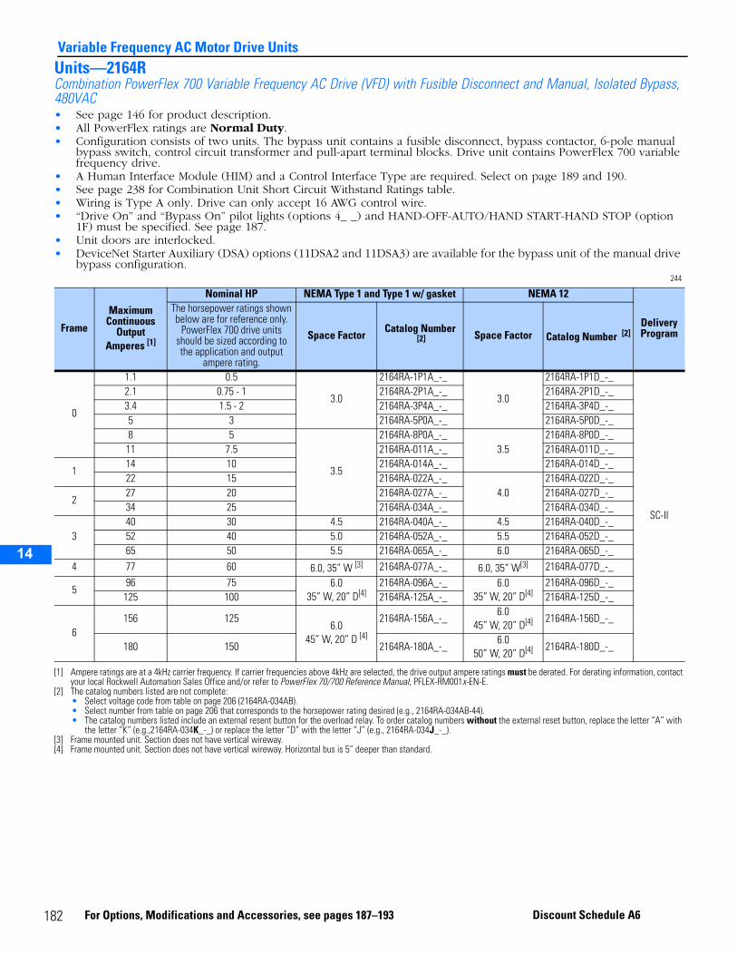
14
Variable Frequency AC Motor Drive UnitsUnits—2164RCombination PowerFlex 700 Variable Frequency AC Drive (VFD) with Fusible Disconnect and Manual, Isolated Bypass, 480VAC • See page 146 for product description.• All PowerFlex ratings are Normal Duty.• Configuration consists of two units. The bypass unit contains a fusible disconnect, bypass contactor, 6-pole manual
bypass switch, control circuit transformer and pull-apart terminal blocks. Drive unit contains PowerFlex 700 variable frequency drive.
• A Human Interface Module (HIM) and a Control Interface Type are required. Select on page 189 and 190.• See page 238 for Combination Unit Short Circuit Withstand Ratings table.• Wiring is Type A only. Drive can only accept 16 AWG control wire.• “Drive On” and “Bypass On” pilot lights (options 4_ _) and HAND-OFF-AUTO/HAND START-HAND STOP (option
1F) must be specified. See page 187.• Unit doors are interlocked.• DeviceNet Starter Auxiliary (DSA) options (11DSA2 and 11DSA3) are available for the bypass unit of the manual drive
bypass configuration.244
Frame
Maximum Continuous
Output Amperes [1]
[1] Ampere ratings are at a 4kHz carrier frequency. If carrier frequencies above 4kHz are selected, the drive output ampere ratings must be derated. For derating information, contact your local Rockwell Automation Sales Office and/or refer to PowerFlex 70/700 Reference Manual, PFLEX-RM001x-EN-E.
Nominal HP NEMA Type 1 and Type 1 w/ gasket NEMA 12
Delivery Program
The horsepower ratings shown below are for reference only.
PowerFlex 700 drive units should be sized according to the application and output
ampere rating.
Space FactorCatalog Number
[2]
[2] The catalog numbers listed are not complete:• Select voltage code from table on page 206 (2164RA-034AB).• Select number from table on page 206 that corresponds to the horsepower rating desired (e.g., 2164RA-034AB-44).• The catalog numbers listed include an external resent button for the overload relay. To order catalog numbers without the external reset button, replace the letter “A” with
the letter “K” (e.g.,2164RA-034K_-_) or replace the letter “D” with the letter “J” (e.g., 2164RA-034J_-_).
Space Factor Catalog Number [2]
0
1.1 0.5
3.0
2164RA-1P1A_-_
3.0
2164RA-1P1D_-_
SC-II
2.1 0.75 - 1 2164RA-2P1A_-_ 2164RA-2P1D_-_3.4 1.5 - 2 2164RA-3P4A_-_ 2164RA-3P4D_-_5 3 2164RA-5P0A_-_ 2164RA-5P0D_-_8 5
3.5
2164RA-8P0A_-_3.5
2164RA-8P0D_-_11 7.5 2164RA-011A_-_ 2164RA-011D_-_
114 10 2164RA-014A_-_ 2164RA-014D_-_22 15 2164RA-022A_-_
4.02164RA-022D_-_
227 20 2164RA-027A_-_ 2164RA-027D_-_34 25 2164RA-034A_-_ 2164RA-034D_-_
340 30 4.5 2164RA-040A_-_ 4.5 2164RA-040D_-_52 40 5.0 2164RA-052A_-_ 5.5 2164RA-052D_-_65 50 5.5 2164RA-065A_-_ 6.0 2164RA-065D_-_
4 77 60 6.0, 35” W [3]
[3] Frame mounted unit. Section does not have vertical wireway.
2164RA-077A_-_ 6.0, 35” W[3] 2164RA-077D_-_
596 75 6.0
35” W, 20” D[4]
[4] Frame mounted unit. Section does not have vertical wireway. Horizontal bus is 5” deeper than standard.
2164RA-096A_-_ 6.035” W, 20” D[4]
2164RA-096D_-_125 100 2164RA-125A_-_ 2164RA-125D_-_
6156 125
6.045” W, 20” D [4]
2164RA-156A_-_6.0
45” W, 20” D[4] 2164RA-156D_-_
180 150 2164RA-180A_-_6.0
50” W, 20” D[4] 2164RA-180D_-_
182 For Options, Modifications and Accessories, see pages 187–193 Discount Schedule A6
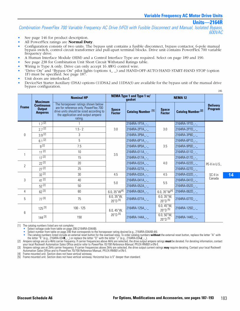
14
Variable Frequency AC Motor Drive UnitsUnits—2164R
Combination PowerFlex 700 Variable Frequency AC Drive (VFD) with Fusible Disconnect and Manual, Isolated Bypass,600VAC
• See page 146 for product description.• All PowerFlex ratings are Normal Duty.• Configuration consists of two units. The bypass unit contains a fusible disconnect, bypass contactor, 6-pole manual
bypass switch, control circuit transformer and pull-apart terminal blocks. Drive unit contains PowerFlex 700 variable frequency drive.
• A Human Interface Module (HIM) and a Control Interface Type are required. Select on page 189 and 190.• See page 238 for Combination Unit Short Circuit Withstand Ratings table.• Wiring is Type A only. Drive can only accept 16 AWG control wire.• “Drive On” and “Bypass On” pilot lights (options 4_ _) and HAND-OFF-AUTO/HAND START-HAND STOP (option
1F) must be specified. See page 187.• Unit doors are interlocked.• DeviceNet Starter Auxiliary (DSA) options (11DSA2 and 11DSA3) are available for the bypass unit of the manual drive
bypass configuration.245
FrameMaximum
Continuous Output
Amperes
Nominal HP NEMA Type 1 and Type 1 w/ gasket NEMA 12
Delivery Program
The horsepower ratings shown below are for reference only. PowerFlex 700
drive units should be sized according to the application and output ampere
rating.
Space Factor Catalog Number [1]
[1] The catalog numbers listed are not complete:• Select voltage code from table on page 206 (2164RA-034AB).• Select number from table on page 206 that corresponds to the horsepower rating desired (e.g., 2164RA-034AB-44).• The catalog numbers listed include an external reset button for the overload relay. To order catalog numbers without the external reset button, replace the letter “A” with
the letter “K” (e.g., 2164RA-034K_-_) or replace the letter “D” with the letter “J” (e.g., 2164RA-034J_-_).
Space Factor Catalog Number [2]
0
1.7 [2]
[2] Ampere ratings are at a 4kHz carrier frequency. If carrier frequencies above 4kHz are selected, the drive output ampere ratings must be derated. For derating information, contact your local Rockwell Automation Sales Office and/or refer to PowerFlex 70/700 Reference Manual, PFLEX-RM001x-EN-E.
1
3.0
2164RA-1P7A_-_
3.0
2164RA-1P7D_-_
PE-II in U.S.,
SC-II in Canada
2.7 [2] 1.5 - 2 2164RA-2P7A_-_ 2164RA-2P7D_-_
3.9 [2] 3 2164RA-3P9A_-_ 2164RA-3P9D_-_
6.1 [2] 5
3.5
2164RA-6P1A_-_
3.5
2164RA-6P1D_-_
9 [2] 7.5 2164RA-9P0A_-_ 2164RA-9P0D_-_
111 [2] 10 2164RA-011A_-_ 2164RA-011D_-_
17 [2] 15 2164RA-017A_-_
4.0
2164RA-017D_-_
222 [2] 20 2164RA-022A_-_ 2164RA-022D_-_
27 [2] 25 2164RA-027A_-_ 2164RA-027D_-_
332 [2] 30 4.5 2164RA-032A_-_ 4.5 2164RA-032D_-_
41 [2] 405.0
2164RA-041A_-_5.5
2164RA-041D_-_
52 [2] 50 2164RA-052A_-_ 2164RA-052D_-_
4 62 [3]
[3] Ampere ratings are at 2kHz carrier frequency. If carrier frequencies above 2kHz are selected, the drive output current ratings may require derating. Contact your local Rockwell Automation Sales Office and to PowerFlex 70/700 Reference Manual, PFLEX-RM001x-EN-E.
60 6.0, 35”W[4]
[4] Frame mounted unit. Section does not have vertical wireway.
2164RA-062A_-_ 6.0, 35”W[4] 2164RA-062D_-_
5 77 [3] 756.0, 35”W,
20”D [5]
[5] Frame mounted unit. Section does not have vertical wireway. Horizontal bus is 5” deeper than standard.
2164RA-077A_-_6.0, 35”W,
20”D [5] 2164RA-077D_-_
6125 [3] 100 - 125
6.0, 45”W, 20”D [5]
2164RA-125A_-_6.0, 45”W,
20”D [5] 2164RA-125D_-_
144 [3] 150 2164RA-144A_-_6.0, 50”W,
20”D [5] 2164RA-144D_-_
183For Options, Modifications and Accessories, see pages 187–193Discount Schedule A6
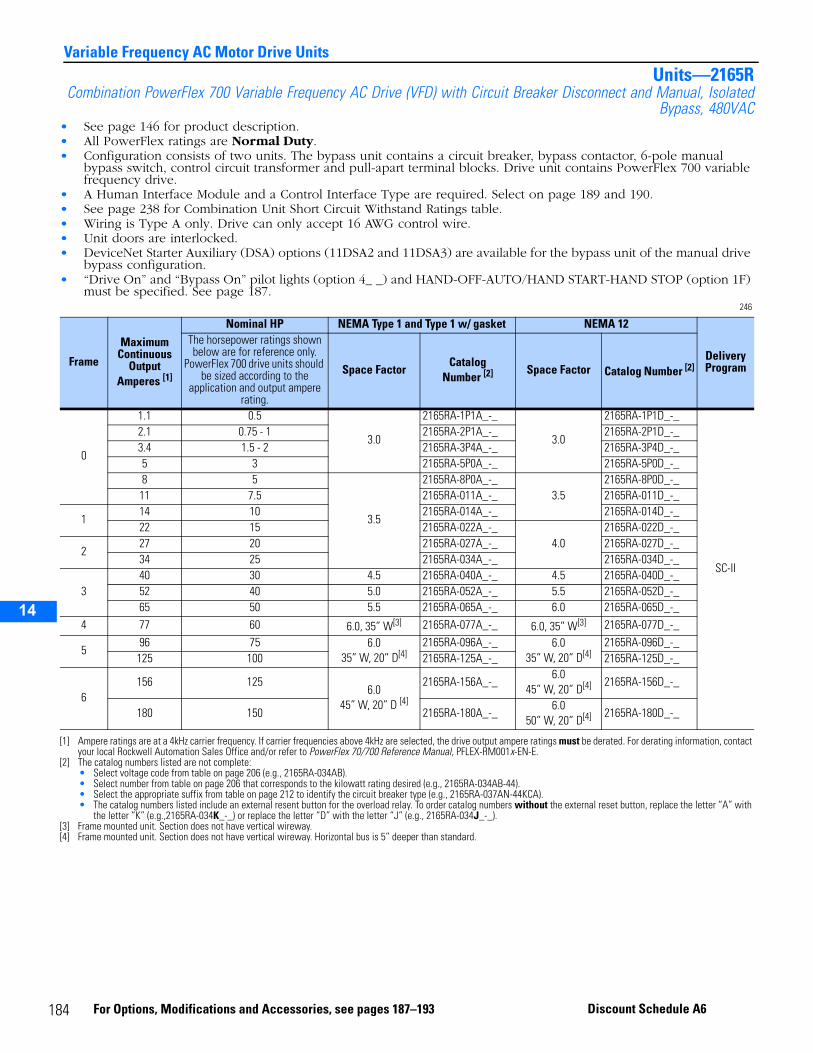
14
Variable Frequency AC Motor Drive UnitsUnits—2165R
Combination PowerFlex 700 Variable Frequency AC Drive (VFD) with Circuit Breaker Disconnect and Manual, IsolatedBypass, 480VAC
• See page 146 for product description.• All PowerFlex ratings are Normal Duty.• Configuration consists of two units. The bypass unit contains a circuit breaker, bypass contactor, 6-pole manual
bypass switch, control circuit transformer and pull-apart terminal blocks. Drive unit contains PowerFlex 700 variable frequency drive.
• A Human Interface Module and a Control Interface Type are required. Select on page 189 and 190.• See page 238 for Combination Unit Short Circuit Withstand Ratings table.• Wiring is Type A only. Drive can only accept 16 AWG control wire.• Unit doors are interlocked.• DeviceNet Starter Auxiliary (DSA) options (11DSA2 and 11DSA3) are available for the bypass unit of the manual drive
bypass configuration.• “Drive On” and “Bypass On” pilot lights (option 4_ _) and HAND-OFF-AUTO/HAND START-HAND STOP (option 1F)
must be specified. See page 187.246
Frame
Maximum Continuous
Output Amperes [1]
[1] Ampere ratings are at a 4kHz carrier frequency. If carrier frequencies above 4kHz are selected, the drive output ampere ratings must be derated. For derating information, contact your local Rockwell Automation Sales Office and/or refer to PowerFlex 70/700 Reference Manual, PFLEX-RM001x-EN-E.
Nominal HP NEMA Type 1 and Type 1 w/ gasket NEMA 12
Delivery Program
The horsepower ratings shown below are for reference only.
PowerFlex 700 drive units should be sized according to the
application and output ampere rating.
Space FactorCatalog
Number [2]
[2] The catalog numbers listed are not complete:• Select voltage code from table on page 206 (e.g., 2165RA-034AB).• Select number from table on page 206 that corresponds to the kilowatt rating desired (e.g., 2165RA-034AB-44).• Select the appropriate suffix from table on page 212 to identify the circuit breaker type (e.g., 2165RA-037AN-44KCA).• The catalog numbers listed include an external resent button for the overload relay. To order catalog numbers without the external reset button, replace the letter “A” with
the letter “K” (e.g.,2165RA-034K_-_) or replace the letter “D” with the letter “J” (e.g., 2165RA-034J_-_).
Space Factor Catalog Number [2]
0
1.1 0.5
3.0
2165RA-1P1A_-_
3.0
2165RA-1P1D_-_
SC-II
2.1 0.75 - 1 2165RA-2P1A_-_ 2165RA-2P1D_-_3.4 1.5 - 2 2165RA-3P4A_-_ 2165RA-3P4D_-_5 3 2165RA-5P0A_-_ 2165RA-5P0D_-_8 5
3.5
2165RA-8P0A_-_3.5
2165RA-8P0D_-_11 7.5 2165RA-011A_-_ 2165RA-011D_-_
114 10 2165RA-014A_-_ 2165RA-014D_-_22 15 2165RA-022A_-_
4.02165RA-022D_-_
227 20 2165RA-027A_-_ 2165RA-027D_-_34 25 2165RA-034A_-_ 2165RA-034D_-_
340 30 4.5 2165RA-040A_-_ 4.5 2165RA-040D_-_52 40 5.0 2165RA-052A_-_ 5.5 2165RA-052D_-_65 50 5.5 2165RA-065A_-_ 6.0 2165RA-065D_-_
4 77 60 6.0, 35” W[3]
[3] Frame mounted unit. Section does not have vertical wireway.
2165RA-077A_-_ 6.0, 35” W[3] 2165RA-077D_-_
596 75 6.0
35” W, 20” D[4]
[4] Frame mounted unit. Section does not have vertical wireway. Horizontal bus is 5” deeper than standard.
2165RA-096A_-_ 6.035” W, 20” D[4]
2165RA-096D_-_125 100 2165RA-125A_-_ 2165RA-125D_-_
6156 125
6.045” W, 20” D [4]
2165RA-156A_-_6.0
45” W, 20” D[4] 2165RA-156D_-_
180 150 2165RA-180A_-_6.0
50” W, 20” D[4] 2165RA-180D_-_
184 For Options, Modifications and Accessories, see pages 187–193 Discount Schedule A6
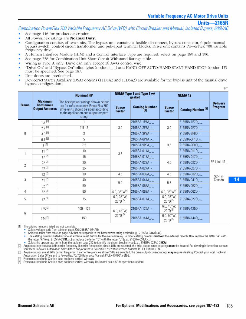
14
Variable Frequency AC Motor Drive UnitsUnits—2165R
Combination PowerFlex 700 Variable Frequency AC Drive (VFD) with Circuit Breaker and Manual, Isolated Bypass, 600VAC• See page 146 for product description.• All PowerFlex ratings are Normal Duty.• Configuration consists of two units. The bypass unit contains a fusible disconnect, bypass contactor, 6-pole manual
bypass switch, control circuit transformer and pull-apart terminal blocks. Drive unit contains PowerFlex 700 variable frequency drive.
• A Human Interface Module (HIM) and a Control Interface Type are required. Select on page 189 and 190.• See page 238 for Combination Unit Short Circuit Withstand Ratings table.• Wiring is Type A only. Drive can only accept 16 AWG control wire.• “Drive On” and “Bypass On” pilot lights (option 4_ _) and HAND-OFF-AUTO/HAND START-HAND STOP (option 1F)
must be specified. See page 187.• Unit doors are interlocked.• DeviceNet Starter Auxiliary (DSA) options (11DSA2 and 11DSA3) are available for the bypass unit of the manual drive
bypass configuration.247
FrameMaximum
Continuous Output Amperes
Nominal HP NEMA Type 1 and Type 1 w/ gasket NEMA 12
Delivery Program
The horsepower ratings shown below are for reference only. PowerFlex 700 drive units should be sized according to the application and output ampere
rating.
Space Factor
Catalog Number [1]
[1] The catalog numbers listed are not complete:• Select voltage code from table on page 206 (2164RA-034AB).• Select number from table on page 206 that corresponds to the horsepower rating desired (e.g., 2165RA-034AB-44).• The catalog numbers listed include an external reset button for the overload relay. To order catalog numbers without the external reset button, replace the letter “A” with
the letter “K” (e.g., 2165RA-034K_-_) or replace the letter “D” with the letter “J” (e.g., 2165RA-034J_-_).• Select the appropriate suffix from the table on page 212 to identify the circuit breaker type (e.g., 2165RA-022AC-33CA)
Space Factor Catalog Number [2]
0
1.7 [2]
[2] Ampere ratings are at a 4kHz carrier frequency. If carrier frequencies above 4kHz are selected, the drive output ampere ratings must be derated. For derating information, contact your local Rockwell Automation Sales Office and/or refer to PowerFlex 70/700 Reference Manual, PFLEX-RM001x-EN-E.
1
3.0
2165RA-1P7A_-_
3.0
2165RA-1P7D_-_
PE-II in U.S.,
SC-II in Canada
2.7 [2] 1.5 - 2 2165RA-2P7A_-_ 2165RA-2P7D_-_
3.9 [2] 3 2165RA-3P9A_-_ 2165RA-3P9D_-_
6.1 [2] 5
3.5
2165RA-6P1A_-_
3.5
2165RA-6P1D_-_
9 [2] 7.5 2165RA-9P0A_-_ 2165RA-9P0D_-_
111 [2] 10 2165RA-011A_-_ 2165RA-011D_-_
17 [2] 15 2165RA-017A_-_
4.0
2165RA-017D_-_
222 [2] 20 2165RA-022A_-_ 2165RA-022D_-_
27 [2] 25 2165RA-027A_-_ 2165RA-027D_-_
332 [2] 30 4.5 2165RA-032A_-_ 4.5 2165RA-032D_-_
41 [2] 405.0
2165RA-041A_-_5.5
2165RA-041D_-_
52 [2] 50 2165RA-052A_-_ 2165RA-052D_-_
4 62 [3]
[3] Ampere ratings are at 2kHz carrier frequency. If carrier frequencies above 2kHz are selected, the drive output current ratings may require derating. Contact your local Rockwell Automation Sales Office and to PowerFlex 70/700 Reference Manual, PFLEX-RM001x-EN-E.
60 6.0, 35”W[4]
[4] Frame mounted unit. Section does not have vertical wireway.
2165RA-062A_-_ 6.0, 35”W[4] 2165RA-062D_-_
5 77 [3] 756.0, 35”W,
20”D [5]
[5] Frame mounted unit. Section does not have vertical wireway. Horizontal bus is 5” deeper than standard.
2165RA-077A_-_6.0, 35”W,
20”D [5] 2165RA-077D_-_
6125 [3] 100 - 125
6.0, 45”W, 20”D [5]
2165RA-125A_-_6.0, 45”W,
20”D [5] 2165RA-125D_-_
144 [3] 150 2165RA-144A_-_6.0, 50”W,
20”D [5] 2165RA-144D_-_
185For Options, Modifications and Accessories, see pages 187–193Discount Schedule A6
14
Variable Frequency AC Motor Drive Units
186 For Options, Modifications and Accessories, see pages 187–193 Discount Schedule A6
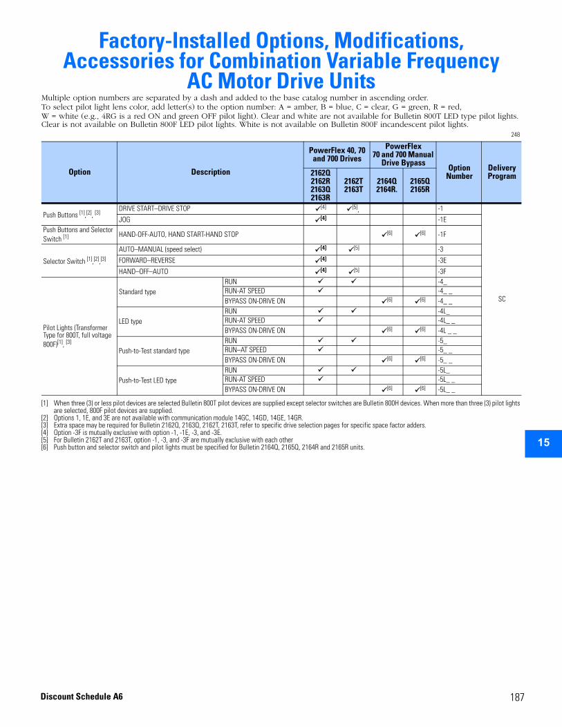
15
Factory-Installed Options, Modifications, Accessories for Combination Variable Frequency
AC Motor Drive UnitsMultiple option numbers are separated by a dash and added to the base catalog number in ascending order.To select pilot light lens color, add letter(s) to the option number: A = amber, B = blue, C = clear, G = green, R = red, W = white (e.g., 4RG is a red ON and green OFF pilot light). Clear and white are not available for Bulletin 800T LED type pilot lights. Clear is not available on Bulletin 800F LED pilot lights. White is not available on Bulletin 800F incandescent pilot lights.
248
Option Description
PowerFlex 40, 70 and 700 Drives
PowerFlex 70 and 700 Manual
Drive Bypass Option
NumberDelivery Program2162Q
2162R2163Q2163R
2162T2163T
2164Q2164R.
2165Q2165R
Push Buttons [1],[2], [3]
[1] When three (3) or less pilot devices are selected Bulletin 800T pilot devices are supplied except selector switches are Bulletin 800H devices. When more than three (3) pilot lights are selected, 800F pilot devices are supplied.
[2] Options 1, 1E, and 3E are not available with communication module 14GC, 14GD, 14GE, 14GR.[3] Extra space may be required for Bulletin 2162Q, 2163Q, 2162T, 2163T, refer to specific drive selection pages for specific space factor adders.
DRIVE START–DRIVE STOP [4]
[4] Option -3F is mutually exclusive with option -1, -1E, -3, and -3E.
[5],
[5] For Bulletin 2162T and 2163T, option -1, -3, and -3F are mutually exclusive with each other
-1
SC
JOG [4] -1EPush Buttons and Selector Switch [1] HAND-OFF-AUTO, HAND START-HAND STOP [6]
[6] Push button and selector switch and pilot lights must be specified for Bulletin 2164Q, 2165Q, 2164R and 2165R units.
[6] -1F
Selector Switch [1],[2],[3]
AUTO–MANUAL (speed select) [4] [5] -3
FORWARD–REVERSE [4] -3E
HAND–OFF–AUTO [4] [5] -3F
Pilot Lights (Transformer Type for 800T, full voltage 800F)[1], [3]
Standard typeRUN -4_RUN-AT SPEED -4_ _BYPASS ON-DRIVE ON [6] [6] -4_ _
LED typeRUN -4L_RUN-AT SPEED -4L_ _BYPASS ON-DRIVE ON [6] [6] -4L _ _
Push-to-Test standard typeRUN -5_RUN–AT SPEED -5_ _BYPASS ON-DRIVE ON [6] [6] -5_ _
Push-to-Test LED typeRUN -5L_RUN-AT SPEED -5L_ _BYPASS ON-DRIVE ON [6] [6] -5L_ _
187Discount Schedule A6
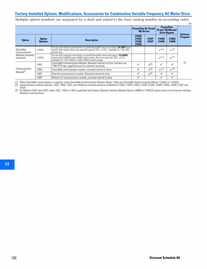
1
Factory-Installed Options, Modifications, Accessories for Combination Variable Frequency AC Motor Drive
15
Multiple option numbers are separated by a dash and added to the base catalog number in ascending order.250
PowerFlex 40, 70 and 700 Drives
PowerFlex 70 and 700 Manual
Drive Bypass Delivery Program
Option Option Number Description
2162Q2163Q2162R2163R
2162T2163T
2164Q2164R
2165Q2165R
DeviceNet Communication Modules (mutually exclusive)
-11DSA2For use with contactors and starters to provide DeviceNet inputs and outputs. (4) 120V inputs and (2) 120V outputs. Not to be used with options 7FEC_ or 7FC_. Available for 110V-120V control only.
[1]
[1] When DeviceNet communication is required, select DeviceNet Communication Module (Option 14GD) and DeviceNet Starter Auxiliary (Option 11DSA2 or 11DSA3).
[1]
SC
-11DSA3For use with contactors and starters to provide DeviceNet inputs and outputs. (4) 24VDC inputs and (2) 240VAC (max), 30VDC (max) outputs. Not to be used with 7FEC_ or 7FC_. Available for 110V-120VAC or 220V-240VAC control voltage.
[1] [1]
Communication Module[2]
[2] Communication modules (options -14GC, 14GD, 14GE, and 14GR) are mutually exclusive on Bulletins 2162Q, 2162R, 2163Q, 2163R, 2164Q, 2164R, 2165Q, 2165R, 2162T and 2163T.
-14GC ControlNet Communication Module, Mounted Internal to Drive. Includes one 1786-TPYS tap, supplied loose for customer mounting
[3]
[3] For Bulletin 2162T and 2163T, when 14GC, 14GD or 14GE is specified with Human Operator Interface Module (Option 14HBA3 or 14HC2S) speed control on the Human Interface Module is not functional.
-14GD DeviceNet communication module, mounted internal to drive [3] [1] [1]
-14GE Ethernet communication module. Mounted internal to drive. [3]
-14GR Remote I/O communication module, mounted internal to drive
88 Discount Schedule A6
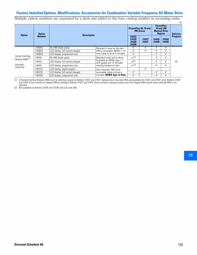
Factory-Installed Options, Modifications, Accessories for Combination Variable Frequency AC Motor Drive
15
Multiple option numbers are separated by a dash and added to the base catalog number in ascending order.251
Option Option Number Description
PowerFlex 40, 70 and 700 Drives
PowerFlex 70 and 700
Manual Drive Bypass Delivery
Program2162Q2163Q2162R2163R
2162T2163T
2164Q2164R
2165Q2165R
Human Interface Module (HIM) [1]
(mutually exclusive)
[1] A Human Interface Module (HIM) must be selected, except on Bulletin 2162T and 2163T. Optional door mounted HIMs are available for 2162T and 2163T units. Bulletin 2162T and 2163T drives include an integral HIM as standard. Bulletin 2162T and 2163T drives include a viewing window over the integral HIM module when optional HIM is not selected.
-14HBA0 No HIM (blank plate) Mounted in bezel on the door. HIM is removable. NEMA 1, 1G only. Cable to drive is included.
SC
-14HBA3 LCD display, full numeric keypad -14HBA5 LCD display, programmer only -14HA0 No HIM (blank plate) Mounted inside unit on drive.
Available on NEMA Type 1, 1 with gasket and 12. Includes viewing window on door.
[2]
[2] Not available on Bulletin 2162R and 2163R with size code 300.
-14HA3 LCD display, full numeric keypad [2]
-14HA5 LCD display, programmer only [2]
-14HC2S LCD display, digital keypad Door mounted. HIM is not removable. Cable to drive is included. NEMA Type 12 Only.
-14HC3S LCD display, full numeric keypad -14HC5S LCD display, programmer only
189Discount Schedule A6
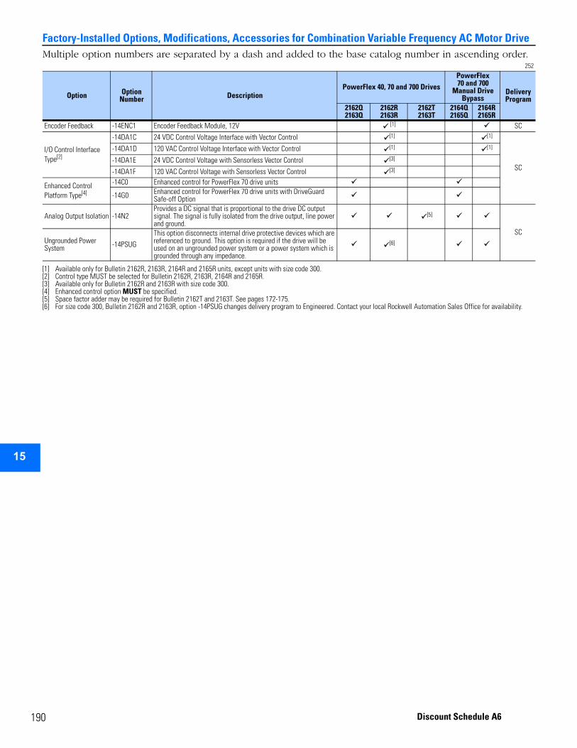
1
Factory-Installed Options, Modifications, Accessories for Combination Variable Frequency AC Motor Drive
15
Multiple option numbers are separated by a dash and added to the base catalog number in ascending order.252
Option Option Number Description
PowerFlex 40, 70 and 700 DrivesPowerFlex 70 and 700
Manual Drive Bypass
Delivery Program
2162Q2163Q
2162R2163R
2162T2163T
2164Q2165Q
2164R2165R
Encoder Feedback -14ENC1 Encoder Feedback Module, 12V [1]
[1] Available only for Bulletin 2162R, 2163R, 2164R and 2165R units, except units with size code 300.
SC
I/O Control Interface Type[2]
[2] Control type MUST be selected for Bulletin 2162R, 2163R, 2164R and 2165R.
-14DA1C 24 VDC Control Voltage Interface with Vector Control [1] [1]
SC
-14DA1D 120 VAC Control Voltage Interface with Vector Control [1] [1]
-14DA1E 24 VDC Control Voltage with Sensorless Vector Control [3]
[3] Available only for Bulletin 2162R and 2163R with size code 300.
-14DA1F 120 VAC Control Voltage with Sensorless Vector Control [3]
Enhanced Control Platform Type[4]
[4] Enhanced control option MUST be specified.
-14C0 Enhanced control for PowerFlex 70 drive units
-14G0 Enhanced control for PowerFlex 70 drive units with DriveGuard Safe-off Option
Analog Output Isolation -14N2 Provides a DC signal that is proportional to the drive DC output signal. The signal is fully isolated from the drive output, line power and ground.
[5]
[5] Space factor adder may be required for Bulletin 2162T and 2163T. See pages 172-175.
SCUngrounded Power System -14PSUG
This option disconnects internal drive protective devices which are referenced to ground. This option is required if the drive will be used on an ungrounded power system or a power system which is grounded through any impedance.
[6]
[6] For size code 300, Bulletin 2162R and 2163R, option -14PSUG changes delivery program to Engineered. Contact your local Rockwell Automation Sales Office for availability.
90 Discount Schedule A6
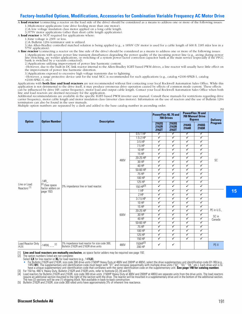
Factory-Installed Options, Modifications, Accessories for Combination Variable Frequency AC Motor Drive
15
A load reactor (connecting a reactor on the load side of the drive) should be considered as a means to address one or more of the following issues:1.)Multi-motor applications (one drive feeding more than one motor).2.)A low voltage insulation class motor applied on a long cable length.3.)575V motor applications (other than short cable length applications).
A load reactor is NOT required for applications where:1.)Line voltage is 230V or less.2.)A Bulletin 1204 terminator unit is utilized.3.)An Allen-Bradley controlled matched solution is being applied (e.g., a 1850V CIV motor is used for a cable length of 600 ft. [185 m]or less in a 575V application).
A line reactor (connecting a reactor on the line side of the drive) should be considered as a means to address one or more of the following issues:1.)Applications with severe power line transient disturbances degrading the power quality of the incoming power line (e.g., arcing during power line switching, arc welder applications, or switching of a system power factor correction capacitor bank at the main service [especially if the PFCC bank is switched by a vacuum contactor]).2.)Applications utilizing improvement of power line harmonic content.–However, due to the built-in DC link reactor internal to the Allen-Bradley IGBT-based PWM drives, a line reactor will usually have little effect on the improvement of power line harmonic distortion.3.)Applications exposed to excessive high voltage transients due to lightning.–However, a surge protective device unit for the total MCC is recommended for such applications (e.g., catalog #2100-SPKB-1, catalog #2100-SPKC-1, etc.).
Applications with both line and load reactors are not recommended without first contacting your local Rockwell Automation Sales Office. While this application is not detrimental to the drive itself, it may produce erroneous drive operation caused by effects of common mode current. These effects can be influenced by drive HP, carrier frequency, motor load and output cable length. Contact your local Rockwell Automation Sales Office when both line and load reactors are deemed necessary for the application.Additional recommendations are available in the specific IGBT-based PWM inverter user manual. Consult these manuals for restrictions regarding drive carrier frequency, motor cable length and motor insulation class (inverter class motors). Information on the use of reactors and the use of Bulletin 1204 terminators can also be found in the user manuals.Multiple option numbers are separated by a dash and added to the base catalog number in ascending order.
253
Option Option Number Description
PowerFlex 40, 70 and 700 Drives
PowerFlex 70 and 700 Manual Drive
Bypass Delivery Program2162Q
2162R2162T
2163Q2163R2163T
2164Q2164R
2165Q2165R
Line or Load Reactors [1]
[1] Line and load reactors are mutually exclusive, as space factor adders may be required see page 192.
-14R_[2] (See space factor adders on page 192)
[2] The option numbers listed are not complete:Select LX for line reactor or XL for load reactors (e.g., 14RLX).• For Bulletin 2162R and 2163R, size code 300 drive units (150HP Heavy Duty at 480V and 200HP at 480V), select the drive supplementary unit identification code (01-99) (e.g.,
14RLX01). The supplementary unit identification code must begin with “01” and increase sequentially with multiple drive units (“02,” “03,” “04,” etc.). Each drive unit is to have a unique supplementary unit identification code that correlates with the same identification code on the supplementary unit. See page 148 for catalog number.
3% impedance line or load reactor.
480V
0.5-1 HP
SC
1.5-2 HP3-5 HP7.5 HP10 HP15 HP
20-25 HP30 HP40 HP
50-60 HP75 HP100 HP125 HP
150 HP[3]
[3] For 150 hp, 480 V, Heavy Duty, Bulletin 2162R and 2163R units, refer to footnote [2], [4] and [5].
600V
1 HP
PE in U.S.,
SC in Canada
2 HP3-7.5 HP
10 HP15 HP
20-25 HP30 HP40 HP
50-60 HP75 HP100 HP125 HP150 HP
Load Reactor Only [4],[5]
[4] Load reactors for Bulletin 2162R and 2163R, size code 300 drive units (150HP Heavy Duty at 480V and 200HP at 480V) are separate units from the drive units. The load reactors require an additional section mounted to the right of the section with the drive. The reactor will be mounted in a supplementary drive unit in the bottom of the additional section. The two (2) sections will be one (1) shipping block. Not available in back-to-back construction.
[5] Bulletin 2162R and 2163R, size code 300 rated units have approximately 3% of inherent line reactance.
-14RXL _ _ [2] 3% impedance load reactor for size code 300, Bulletin 2162R and 2163R drive units 480V 150HP[3]
200 HPPE-II
191Discount Schedule A6
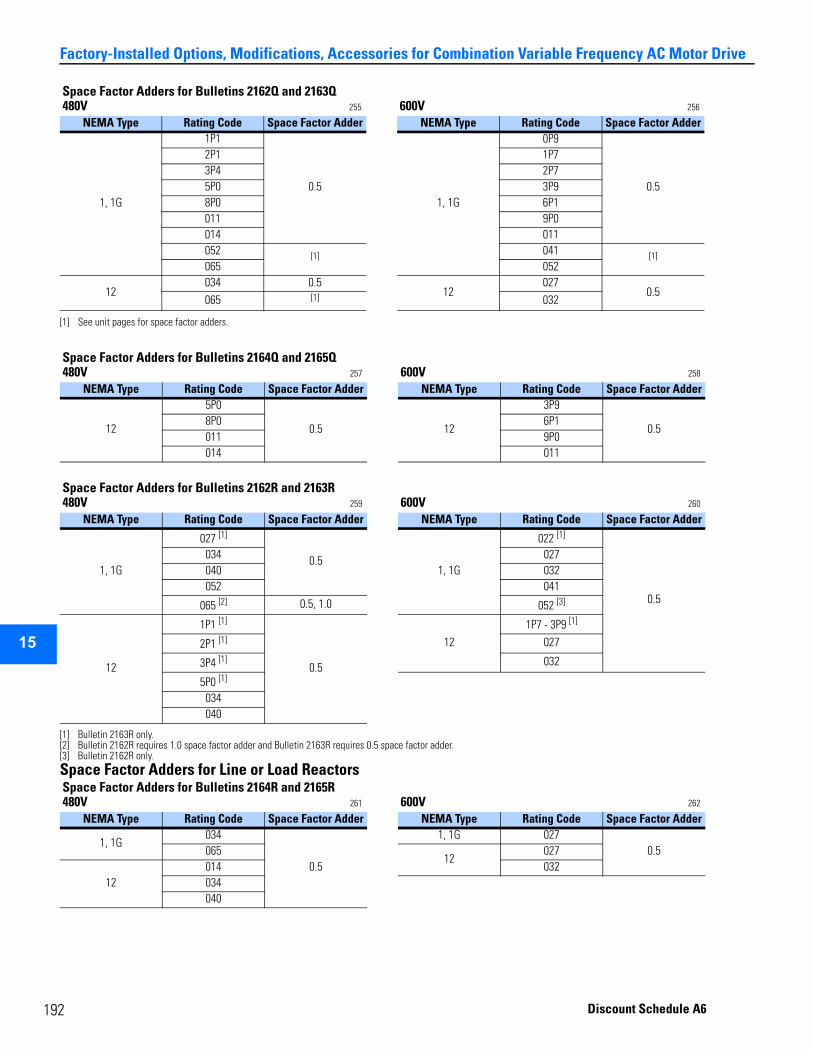
1
15
92
Factory-Installed Options, Modifications, Accessories for Combination Variable Frequency AC Motor Drive
Space Factor Adders for Line or Load Reactors
Space Factor Adders for Bulletins 2162Q and 2163Q480V 255 600V 256
NEMA Type Rating Code Space Factor Adder NEMA Type Rating Code Space Factor Adder
1, 1G
1P1
0.51, 1G
0P9
0.5
2P1 1P73P4 2P75P0 3P98P0 6P1011 9P0014 011052 [1]
[1] See unit pages for space factor adders.
041 [1]065 052
12034 0.5
12027
0.5065 [1] 032
Space Factor Adders for Bulletins 2164Q and 2165Q480V 257 600V 258
NEMA Type Rating Code Space Factor Adder NEMA Type Rating Code Space Factor Adder
12
5P0
0.5 12
3P9
0.58P0 6P1011 9P0014 011
Space Factor Adders for Bulletins 2162R and 2163R480V 259 600V 260
NEMA Type Rating Code Space Factor Adder NEMA Type Rating Code Space Factor Adder
1, 1G
027 [1]
[1] Bulletin 2163R only.
0.51, 1G
022 [1]
0.5
034 027040 032052 041
065 [2]
[2] Bulletin 2162R requires 1.0 space factor adder and Bulletin 2163R requires 0.5 space factor adder.
0.5, 1.0 052 [3]
[3] Bulletin 2162R only.
12
1P1 [1]
0.5
121P7 - 3P9 [1]
2P1 [1] 027
3P4 [1] 032
5P0 [1]
034040
Space Factor Adders for Bulletins 2164R and 2165R480V 261 600V 262
NEMA Type Rating Code Space Factor Adder NEMA Type Rating Code Space Factor Adder
1, 1G034
0.5
1, 1G 0270.5065
12027
12014 032034040
Discount Schedule A6
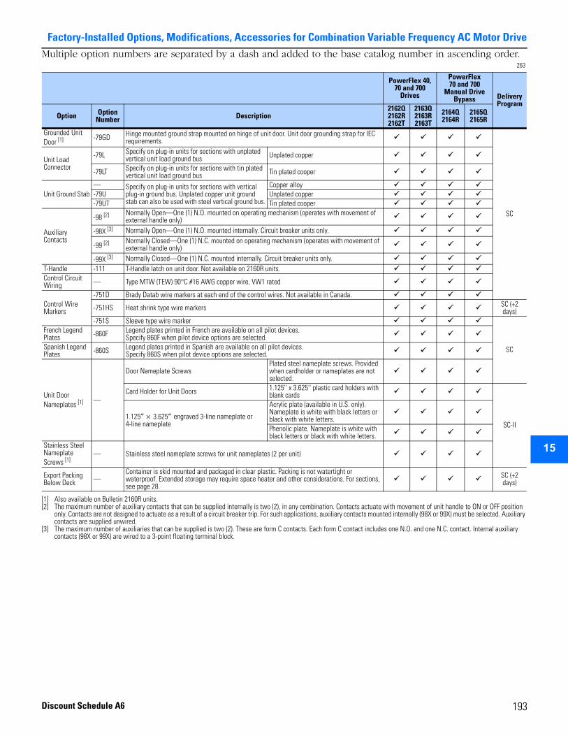
Factory-Installed Options, Modifications, Accessories for Combination Variable Frequency AC Motor Drive
15
Multiple option numbers are separated by a dash and added to the base catalog number in ascending order.263
PowerFlex 40, 70 and 700
Drives
PowerFlex 70 and 700
Manual Drive Bypass Delivery
Program
Option Option Number Description
2162Q2162R2162T
2163Q2163R2163T
2164Q2164R
2165Q2165R
Grounded Unit Door [1]
[1] Also available on Bulletin 2160R units.
-79GD Hinge mounted ground strap mounted on hinge of unit door. Unit door grounding strap for IEC requirements.
SC
Unit Load Connector
-79L Specify on plug-in units for sections with unplated vertical unit load ground bus Unplated copper
-79LT Specify on plug-in units for sections with tin plated vertical unit load ground bus Tin plated cooper
Unit Ground Stab— Specify on plug-in units for sections with vertical
plug-in ground bus. Unplated copper unit ground stab can also be used with steel vertical ground bus.
Copper alloy-79U Unplated copper-79UT Tin plated cooper
Auxiliary Contacts
-98 [2]
[2] The maximum number of auxiliary contacts that can be supplied internally is two (2), in any combination. Contacts actuate with movement of unit handle to ON or OFF position only. Contacts are not designed to actuate as a result of a circuit breaker trip. For such applications, auxiliary contacts mounted internally (98X or 99X) must be selected. Auxiliary contacts are supplied unwired.
Normally Open—One (1) N.O. mounted on operating mechanism (operates with movement of external handle only)
-98X [3]
[3] The maximum number of auxiliaries that can be supplied is two (2). These are form C contacts. Each form C contact includes one N.O. and one N.C. contact. Internal auxiliary contacts (98X or 99X) are wired to a 3-point floating terminal block.
Normally Open—One (1) N.O. mounted internally. Circuit breaker units only.
-99 [2] Normally Closed—One (1) N.C. mounted on operating mechanism (operates with movement of external handle only)
-99X [3] Normally Closed—One (1) N.C. mounted internally. Circuit breaker units only.T-Handle -111 T-Handle latch on unit door. Not available on 2160R units.Control Circuit Wiring — Type MTW (TEW) 90°C #16 AWG copper wire, VW1 rated
Control Wire Markers
-751D Brady Datab wire markers at each end of the control wires. Not available in Canada.
-751HS Heat shrink type wire markers SC (+2 days)
-751S Sleeve type wire marker
SC
French Legend Plates -860F Legend plates printed in French are available on all pilot devices.
Specify 860F when pilot device options are selected.Spanish Legend Plates -860S Legend plates printed in Spanish are available on all pilot devices.
Specify 860S when pilot device options are selected.
Unit Door Nameplates [1] —
Door Nameplate ScrewsPlated steel nameplate screws. Provided when cardholder or nameplates are not selected.
Card Holder for Unit Doors 1.125'' x 3.625'' plastic card holders with blank cards
SC-II1.125″ × 3.625″ engraved 3-line nameplate or 4-line nameplate
Acrylic plate (available in U.S. only). Nameplate is white with black letters or black with white letters.Phenolic plate. Nameplate is white with black letters or black with white letters.
Stainless Steel Nameplate Screws [1]
— Stainless steel nameplate screws for unit nameplates (2 per unit)
Export Packing Below Deck —
Container is skid mounted and packaged in clear plastic. Packing is not watertight or waterproof. Extended storage may require space heater and other considerations. For sections, see page 28.
SC (+2 days)
193Discount Schedule A6
1
Factory-Installed Options, Modifications, Accessories for Combination Variable Frequency AC Motor Drive
15
94 Discount Schedule A6
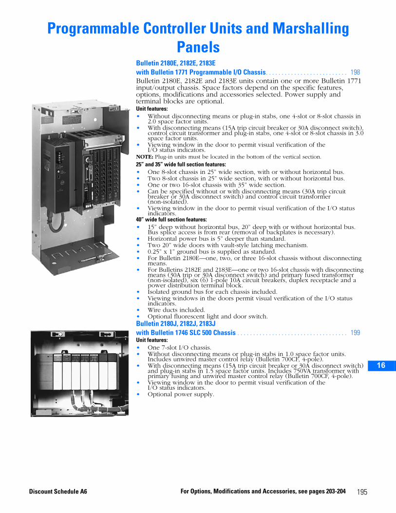
2
3
4
5
6
7
8
9
10
11
12
13
14
15
16
Programmable Controller Units and Marshalling Panels
Bulletin 2180E, 2182E, 2183E with Bulletin 1771 Programmable I/O Chassis. . . . . . . . . . . . . . . . . . . . . . . . . . 198Bulletin 2180E, 2182E and 2183E units contain one or more Bulletin 1771 input/output chassis. Space factors depend on the specific features, options, modifications and accessories selected. Power supply and terminal blocks are optional. Unit features:• Without disconnecting means or plug-in stabs, one 4-slot or 8-slot chassis in
2.0 space factor units.• With disconnecting means (15A trip circuit breaker or 30A disconnect switch),
control circuit transformer and plug-in stabs, one 4-slot or 8-slot chassis in 3.0 space factor units.
• Viewing window in the door to permit visual verification of the I/O status indicators.
NOTE: Plug-in units must be located in the bottom of the vertical section.25” and 35” wide full section features:• One 8-slot chassis in 25” wide section, with or without horizontal bus.• Two 8-slot chassis in 25” wide section, with or without horizontal bus.• One or two 16-slot chassis with 35” wide section.• Can be specified without or with disconnecting means (30A trip circuit
breaker or 30A disconnect switch) and control circuit transformer (non-isolated).
• Viewing window in the door to permit visual verification of the I/O status indicators.
40” wide full section features:• 15” deep without horizontal bus, 20” deep with or without horizontal bus.
Bus splice access is from rear (removal of backplates is necessary).• Horizontal power bus is 5” deeper than standard. • Two 20” wide doors with vault-style latching mechanism.• 0.25” x 1” ground bus is supplied as standard.• For Bulletin 2180E—one, two, or three 16-slot chassis without disconnecting
means.• For Bulletins 2182E and 2183E—one or two 16-slot chassis with disconnecting
means (30A trip or 30A disconnect switch) and primary fused transformer (non-isolated), six (6) 1-pole 10A circuit breakers, duplex receptacle and a power distribution terminal block.
• Isolated ground bus for each chassis included.• Viewing windows in the doors permit visual verification of the I/O status
indicators.• Wire ducts included.• Optional fluorescent light and door switch.Bulletin 2180J, 2182J, 2183Jwith Bulletin 1746 SLC 500 Chassis . . . . . . . . . . . . . . . . . . . . . . . . . . . . . . . . . . . 199Unit features:• One 7-slot I/O chassis.• Without disconnecting means or plug-in stabs in 1.0 space factor units.
Includes unwired master control relay (Bulletin 700CF, 4-pole).• With disconnecting means (15A trip circuit breaker or 30A disconnect switch)
and plug-in stabs in 1.5 space factor units. Includes 750VA transformer with primary fusing and unwired master control relay (Bulletin 700CF, 4-pole).
• Viewing window in the door to permit visual verification of the I/O status indicators.
• Optional power supply.
195For Options, Modifications and Accessories, see pages 203-204Discount Schedule A6
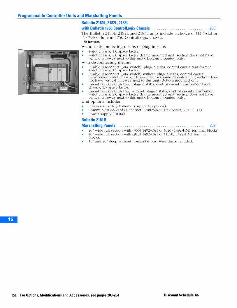
19
Programmable Controller Units and Marshalling Panels
2
3
4
5
10
11
12
13
14
15
16
Bulletin 2180L, 2182L, 2183Lwith Bulletin 1756 ControlLogix Chassis . . . . . . . . . . . . . . . . . . . . . . . . . . . . . . . 200The Bulletin 2180L, 2182L and 2183L units include a choice of (1) 4-slot or (1) 7-slot Bulletin 1756 ControlLogix chassis.Unit features:Without disconnecting means or plug-in stabs• 4-slot chassis, 1.0 space factor.• 7-slot chassis, 2.0 space factor (frame mounted unit, section does not have
vertical wireway next to this unit). Bottom mounted only.With disconnecting means:• Fusible disconnect (30A switch), plug-in stabs, control circuit transformer,
4-slot chassis, 1.5 space factor.• Fusible disconnect (30A switch) without plug-in stabs, control circuit
transformer, 7-slot chassis, 2.0 space factor (frame mounted unit, section does not have vertical wireway next to this unit).Bottom mounted only.
• Circuit breaker (15A trip), plug-in stabs, control circuit transformer, 4-slot chassis, 1.5 space factor.
• Circuit breaker (15A trip) without plug-in stabs, control circuit transformer, 7-slot chassis, 2.0 space factor (frame mounted unit, section does not have vertical wireway next to this unit). Bottom mounted only.
Unit options include:• Processor cards (all memory upgrade options).• Communication cards (Ethernet, ControlNet, DeviceNet, RI/O DH+).• Power supply (10.0A)
Bulletin 2181BMarshalling Panels . . . . . . . . . . . . . . . . . . . . . . . . . . . . . . . . . . . . . . . . . . . . . . . . . 202• 20” wide full section with (366) 1492-CA1 or (620) 1492-HM1 terminal blocks.• 40” wide full section with (915) 1492-CA1 or (1550) 1492-HM1 terminal
blocks.• 15” and 20” deep without horizontal bus. Wire ducts included.
6 For Options, Modifications and Accessories, see pages 203-204 Discount Schedule A6
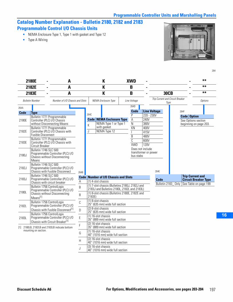
2
3
4
5
6
7
8
9
10
11
12
13
14
15
16
Programmable Controller Units and Marshalling Panels
Catalog Number Explanation - Bulletin 2180, 2182 and 2183Programmable Control I/O Chassis Units
• NEMA Enclosure Type 1, Type 1 with gasket and Type 12• Type A Wiring
264
2180E - A K XWD - - **2182E - A K B - - **2183E - A K B - 30CB - **
Bulletin Number Number of I/O Chassis and Slots NEMA Enclosure Type Line VoltageTrip Current and Circuit Breaker
TypeOptions
264A
Code Type
2180EBulletin 1771 Programmable Controller (PLC) I/O Chassis without Disconnecting Means
2182EBulletin 1771 Programmable Controller (PLC) I/O Chassis with Fusible Disconnect
2183EBulletin 1771 Programmable Controller (PLC) I/O Chassis with Circuit Breaker
2180JBulletin 1746 SLC 500 Programmable Controller (PLC) I/O Chassis without Disconnecting Means
2182JBulletin 1746 SLC 500 Programmable Controller (PLC) I/O Chassis with Fusible Disconnect
2183JBulletin 1746 SLC 500 Programmable Controller (PLC) I/O Chassis with circuit breaker
2180L
Bulletin 1756 ControlLogix Programmable Controller (PLC) I/O Chassis without Disconnecting Means[1]
[1] 2180LB, 2182LB and 2183LB indicate bottom mounting on section.
2182LBulletin 1756 ControlLogix Programmable Controller (PLC) I/O Chassis with Fusible Disconnect[1]
2183LBulletin 1756 ControlLogix Programmable Controller (PLC) I/O Chassis with Circuit Breaker[1]
264B
Code Number of I/O Chassis and SlotsA (1) 4-slot chassis
B (1) 7-slot chassis (Bulletins 2180J, 2182J and 2183J and Bulletins 2180L, 2182L and 2183L)
B (1) 8-slot chassis (Bulletins 2180E, 2182E and 2183E)
C (1) 8-slot chassis 25” (635 mm) wide full section
D (2) 8-slot chassis25” (635 mm) wide full section
E (1) 16-slot chassis35” (889 mm) wide full section
F (2) 16-slot chassis35” (889 mm) wide full section
G (1) 16-slot chassis 40” (1016 mm) wide full section
H (2) 16-slot chassis40” (1016 mm) wide full section
J (3) 16-slot chassis40” (1016 mm) wide full section
264D
Code Line VoltageP 220 - 230VA 240VN 380VKN 400VI 415VB 480VC 600VXWD 120VDoes not include transformer or power bus stabs
264C
Code NEMA Enclosure Type
K NEMA Type 1 or Type 1 with gasket
J NEMA Type 12
264E
CodeTrip Current and Circuit Breaker Type
Bulletin 2183_ Only See Table on page 199
264F
Code OptionSee Options section beginning on page 203.
Discount Schedule A6
For Options, M odifications an d Accessories, s 197ee pages 203-204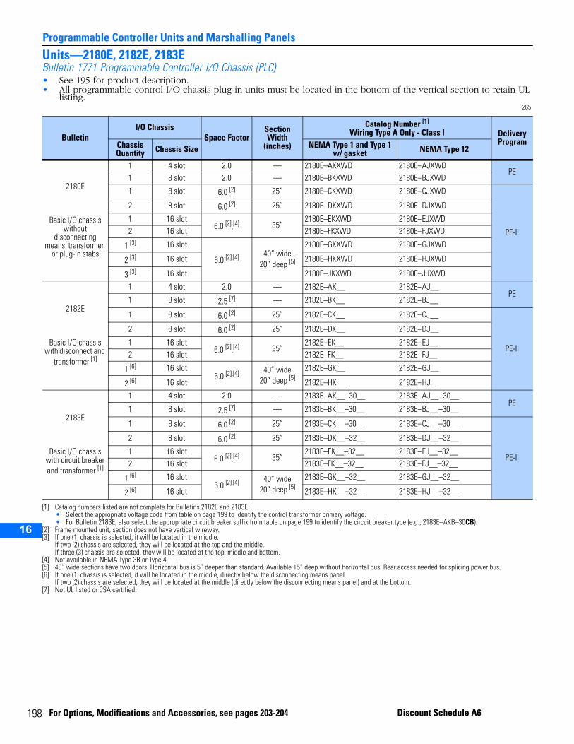
19
Programmable Controller Units and Marshalling Panels
2
3
4
5
10
11
12
13
14
15
16
Units—2180E, 2182E, 2183EBulletin 1771 Programmable Controller I/O Chassis (PLC)• See 195 for product description.• All programmable control I/O chassis plug-in units must be located in the bottom of the vertical section to retain UL
listing.265
BulletinI/O Chassis
Space FactorSection Width
(inches)
Catalog Number [1]
Wiring Type A Only - Class I
[1] Catalog numbers listed are not complete for Bulletins 2182E and 2183E:• Select the appropriate voltage code from table on page 199 to identify the control transformer primary voltage.• For Bulletin 2183E, also select the appropriate circuit breaker suffix from table on page 199 to identify the circuit breaker type (e.g., 2183E–AKB–30CB).
Delivery ProgramChassis
Quantity Chassis Size NEMA Type 1 and Type 1 w/ gasket NEMA Type 12
2180E
Basic I/O chassis without
disconnecting means, transformer,
or plug-in stabs
1 4 slot 2.0 — 2180E–AKXWD 2180E–AJXWDPE
1 8 slot 2.0 — 2180E–BKXWD 2180E–BJXWD
1 8 slot 6.0 [2]
[2] Frame mounted unit, section does not have vertical wireway.
25” 2180E–CKXWD 2180E–CJXWD
PE-II
2 8 slot 6.0 [2] 25” 2180E–DKXWD 2180E–DJXWD
1 16 slot6.0 [2],[4] 35”
2180E–EKXWD 2180E–EJXWD2 16 slot 2180E–FKXWD 2180E–FJXWD
1 [3]
[3] If one (1) chassis is selected, it will be located in the middle.If two (2) chassis are selected, they will be located at the top and the middle.If three (3) chassis are selected, they will be located at the top, middle and bottom.
16 slot
6.0 [2],[4]
[4] Not available in NEMA Type 3R or Type 4.
40” wide20” deep [5]
[5] 40” wide sections have two doors. Horizontal bus is 5” deeper than standard. Available 15” deep without horizontal bus. Rear access needed for splicing power bus.
2180E–GKXWD 2180E–GJXWD
2 [3] 16 slot 2180E–HKXWD 2180E–HJXWD
3 [3] 16 slot 2180E–JKXWD 2180E–JJXWD
2182E
Basic I/O chassis with disconnect and
transformer [1]
1 4 slot 2.0 — 2182E–AK__ 2182E–AJ__PE
1 8 slot 2.5 [7] — 2182E–BK__ 2182E–BJ__
1 8 slot 6.0 [2] 25” 2182E–CK__ 2182E–CJ__
PE-II
2 8 slot 6.0 [2] 25” 2182E–DK__ 2182E–DJ__
1 16 slot6.0 [2],[4] 35”
2182E–EK__ 2182E–EJ__2 16 slot 2182E–FK__ 2182E–FJ__
1 [6]
[6] If one (1) chassis is selected, it will be located in the middle, directly below the disconnecting means panel.If two (2) chassis are selected, they will be located at the middle (directly below the disconnecting means panel) and at the bottom.
16 slot6.0 [2],[4] 40” wide
20” deep [5]2182E–GK__ 2182E–GJ__
2 [6] 16 slot 2182E–HK__ 2182E–HJ__
2183E
Basic I/O chassis with circuit breaker and transformer [1]
1 4 slot 2.0 — 2183E–AK__–30__ 2183E–AJ__–30__PE
1 8 slot 2.5 [7]
[7] Not UL listed or CSA certified.
— 2183E–BK__–30__ 2183E–BJ__–30__
1 8 slot 6.0 [2] 25” 2183E–CK__–30__ 2183E–CJ__–30__
PE-II
2 8 slot 6.0 [2] 25” 2183E–DK__–32__ 2183E–DJ__–32__
1 16 slot6.0 [2],[4] 35”
2183E–EK__–32__ 2183E–EJ__–32__2 16 slot 2183E–FK__–32__ 2183E–FJ__–32__
1 [6] 16 slot6.0 [2],[4] 40” wide
20” deep [5]2183E–GK__–32__ 2183E–GJ__–32__
2 [6] 16 slot 2183E–HK__–32__ 2183E–HJ__–32__
8 For Options, Modifications and Accessories, see pages 203-204 Discount Schedule A6
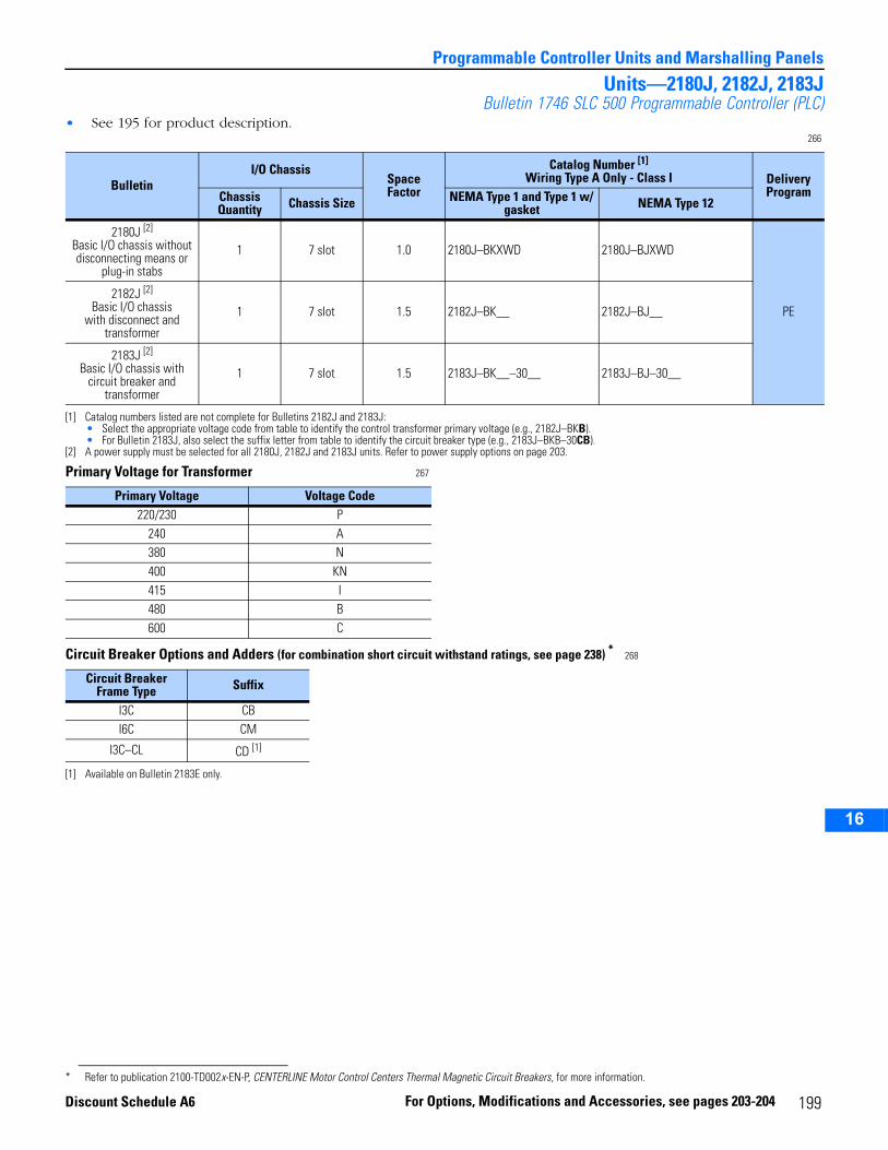
2
3
4
5
6
7
8
9
10
11
12
13
14
15
16
Programmable Controller Units and Marshalling Panels
Units—2180J, 2182J, 2183JBulletin 1746 SLC 500 Programmable Controller (PLC)
• See 195 for product description.266
Primary Voltage for Transformer 267
Circuit Breaker Options and Adders (for combination short circuit withstand ratings, see page 238) * 268
BulletinI/O Chassis
SpaceFactor
Catalog Number [1]
Wiring Type A Only - Class I
[1] Catalog numbers listed are not complete for Bulletins 2182J and 2183J:• Select the appropriate voltage code from table to identify the control transformer primary voltage (e.g., 2182J–BKB).• For Bulletin 2183J, also select the suffix letter from table to identify the circuit breaker type (e.g., 2183J–BKB–30CB).
Delivery ProgramChassis
Quantity Chassis Size NEMA Type 1 and Type 1 w/ gasket NEMA Type 12
2180J [2]
Basic I/O chassis without disconnecting means or
plug-in stabs
[2] A power supply must be selected for all 2180J, 2182J and 2183J units. Refer to power supply options on page 203.
1 7 slot 1.0 2180J–BKXWD 2180J–BJXWD
PE2182J [2]
Basic I/O chassiswith disconnect and
transformer
1 7 slot 1.5 2182J–BK__ 2182J–BJ__
2183J [2]
Basic I/O chassis with circuit breaker and
transformer
1 7 slot 1.5 2183J–BK__–30__ 2183J–BJ–30__
Primary Voltage Voltage Code220/230 P
240 A380 N400 KN 415 I480 B600 C
Circuit BreakerFrame Type Suffix
I3C CBI6C CM
I3C–CL CD [1]
[1] Available on Bulletin 2183E only.
* Refer to publication 2100-TD002x-EN-P, CENTERLINE Motor Control Centers Thermal Magnetic Circuit Breakers, for more information.
199For Options, Modifications and Accessories, see pages 203-204Discount Schedule A6
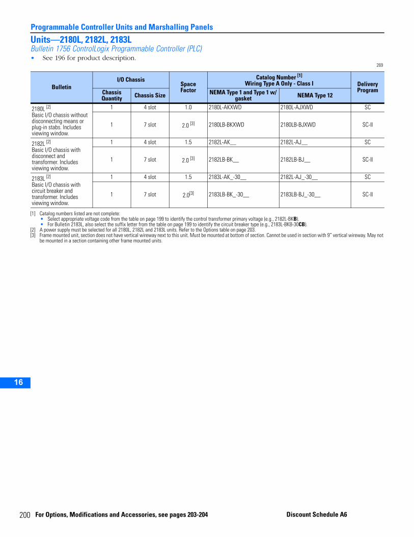
20
Programmable Controller Units and Marshalling Panels
2
3
4
5
10
11
12
13
14
15
16
Units—2180L, 2182L, 2183LBulletin 1756 ControlLogix Programmable Controller (PLC)• See 196 for product description.
269
BulletinI/O Chassis
SpaceFactor
Catalog Number [1]
Wiring Type A Only - Class I
[1] Catalog numbers listed are not complete:• Select appropriate voltage code from the table on page 199 to identify the control transformer primary voltage (e.g., 2182L-BKB).• For Bulletin 2183L, also select the suffix letter from the table on page 199 to identify the circuit breaker type (e.g., 2183L-BKB-30CB).
Delivery ProgramChassis
Quantity Chassis Size NEMA Type 1 and Type 1 w/ gasket NEMA Type 12
2180L [2]
Basic I/O chassis without disconnecting means or plug-in stabs. Includes viewing window.
[2] A power supply must be selected for all 2180L, 2182L and 2183L units. Refer to the Options table on page 203.
1 4 slot 1.0 2180L-AKXWD 2180L-AJXWD SC
1 7 slot 2.0 [3]
[3] Frame mounted unit, section does not have vertical wireway next to this unit. Must be mounted at bottom of section. Cannot be used in section with 9” vertical wireway. May not be mounted in a section containing other frame mounted units.
2180LB-BKXWD 2180LB-BJXWD SC-II
2182L [2]
Basic I/O chassis with disconnect and transformer. Includes viewing window.
1 4 slot 1.5 2182L-AK__ 2182L-AJ__ SC
1 7 slot 2.0 [3] 2182LB-BK__ 2182LB-BJ__ SC-II
2183L [2]
Basic I/O chassis with circuit breaker and transformer. Includes viewing window.
1 4 slot 1.5 2183L-AK_-30__ 2182L-AJ_-30__ SC
1 7 slot 2.0[3] 2183LB-BK_-30__ 2183LB-BJ_-30__ SC-II
0 For Options, Modifications and Accessories, see pages 203-204 Discount Schedule A6
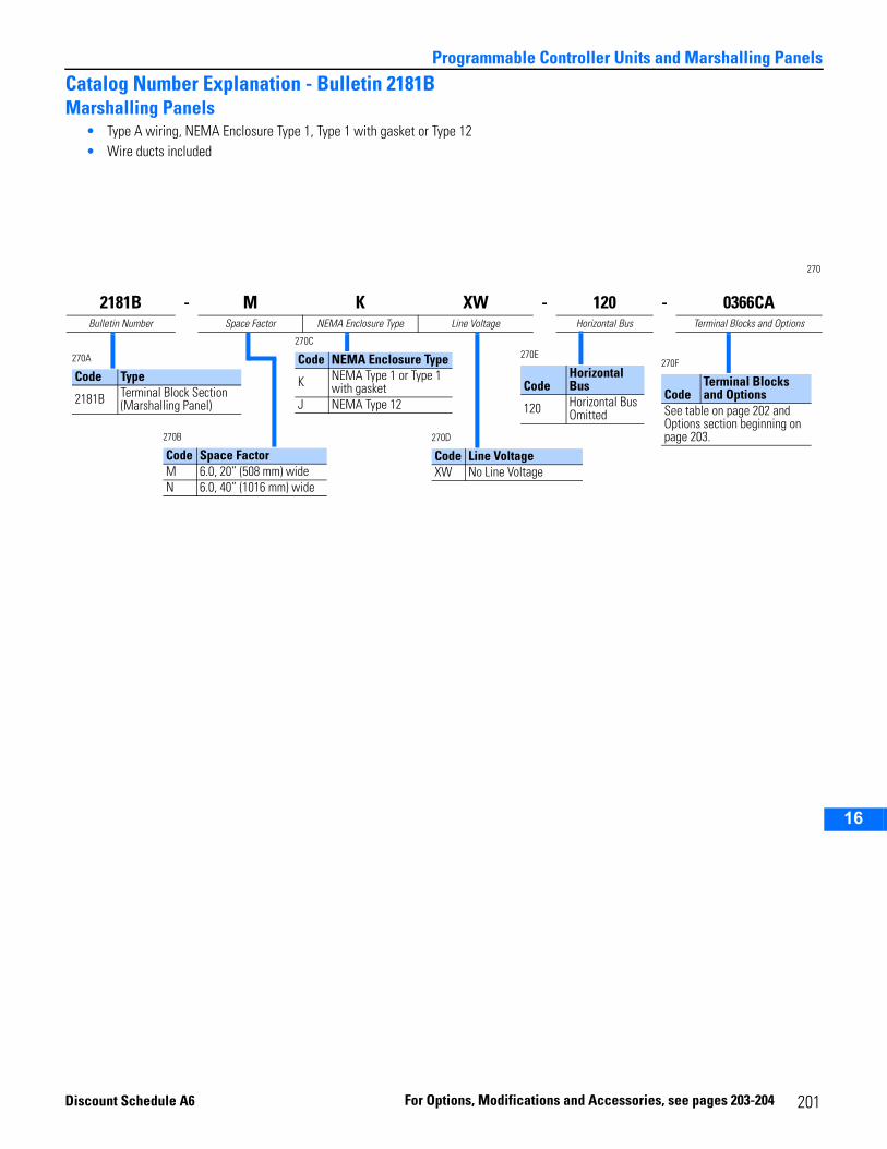
2
3
4
5
6
7
8
9
10
11
12
13
14
15
16
Programmable Controller Units and Marshalling Panels
Catalog Number Explanation - Bulletin 2181BMarshalling Panels
• Type A wiring, NEMA Enclosure Type 1, Type 1 with gasket or Type 12• Wire ducts included
270
2181B - M K XW - 120 - 0366CABulletin Number Space Factor NEMA Enclosure Type Line Voltage Horizontal Bus Terminal Blocks and Options
270A
Code Type
2181B Terminal Block Section (Marshalling Panel)
270B
Code Space FactorM 6.0, 20” (508 mm) wideN 6.0, 40” (1016 mm) wide
270E
CodeHorizontal Bus
120 Horizontal Bus Omitted
270C
Code NEMA Enclosure Type
K NEMA Type 1 or Type 1 with gasket
J NEMA Type 12
270D
Code Line VoltageXW No Line Voltage
270F
CodeTerminal Blocks and Options
See table on page 202 and Options section beginning on page 203.
Discount Sche
dule A6 Fo r Options, Modi fications and Accessorie 201s, see pages 203-204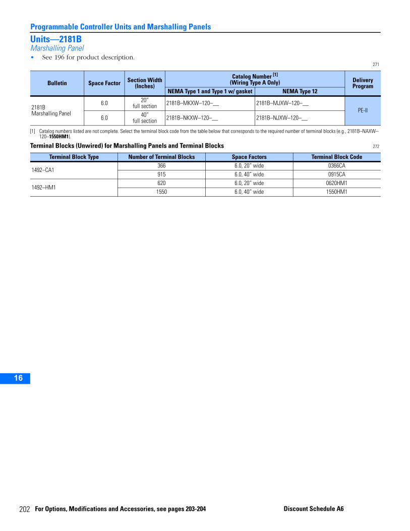
20
Programmable Controller Units and Marshalling Panels
2
3
4
5
10
11
12
13
14
15
16
Units—2181BMarshalling Panel• See 196 for product description.
271
Terminal Blocks (Unwired) for Marshalling Panels and Terminal Blocks 272
Bulletin Space Factor Section Width(Inches)
Catalog Number [1]
(Wiring Type A Only)
[1] Catalog numbers listed are not complete. Select the terminal block code from the table below that corresponds to the required number of terminal blocks (e.g., 2181B–NAXW–120–1550HM1).
Delivery Program
NEMA Type 1 and Type 1 w/ gasket NEMA Type 12
2181BMarshalling Panel
6.0 20”full section 2181B–MKXW–120–__ 2181B–MJXW–120–__
PE-II6.0 40”
full section 2181B–NKXW–120–__ 2181B–NJXW–120–__
Terminal Block Type Number of Terminal Blocks Space Factors Terminal Block Code
1492–CA1366 6.0, 20” wide 0366CA915 6.0, 40” wide 0915CA
1492–HM1620 6.0, 20” wide 0620HM11550 6.0, 40” wide 1550HM1
2 For Options, Modifications and Accessories, see pages 203-204 Discount Schedule A6
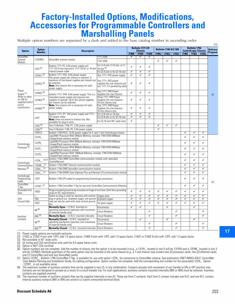
2
3
4
5
6
7
8
9
10
11
12
13
14
15
16
17
203
Factory-Installed Options, Modifications, Accessories for Programmable Controllers and
Marshalling PanelsMultiple option numbers are separated by a dash and added to the base catalog number in ascending order.
273
Option Option Number Description
Bulletin 1771 I/O Chassis Bulletin 1746 SLC 500 Bulletin 1756
ControlLogix Chassis Delivery Program2180E 2182E 2183E 2180J 2182J 2183J 2180L 2182L 2183L
DeviceNet Scanner Module
-12SDN01 DeviceNet scanner module1771-SDN
PE
1747-SDN
Power Supply [1]
(Refer to table on 246 for supplied control circuit transformer)
[1] Power supply options are mutually exclusive.
-12P2 [2]
[2] 2182E or 2183E 4-slot with 12P2: add 1.0 space factor. 2180E 8-slot with 12P2: add 1.0 space factor. 2182E or 2183E 8-slot with 12P2: add 1.0 space factor.
Bulletin 1771-P2, 6.5A power supply and 1771-CE (4-slot chassis) or 1771-CD (8- or 16-slot chassis) power cable
For (1) 4-slot, (1) 8-slot, or (1) 16-slot [3]
[3] Not available in 40” wide units.
For (2) 8-slot or for (2) 16-slot-12P4S1 [4]
[4] UL listing and CSA certification only valid for 6.0 space factor units.
Bulletin 1771–P4S, 8.0A power supply. One power supply per chassis is required. A maximum of two power supplies per chassis can be selected. Note: One chassis slot is necessary for each power supply.
One 1771–P4S power supply
-12P4S2 [4]Two 1771–P4S power supplies (for one chassis) and one 1771–CT paralleling cable
-12P4R2 [4]Bulletin 1771–P4R, 8.0A power supply. This is a redundant power supply and requires two supplies to operate. Up to four power supplies per chassis can be selected.Note: One chassis slot is necessary for each power supply.
Two 1771–P4R Power Supplies (for one chassis)
-12P4R3 [4]Three 1771–P4R Power Supplies (for one chassis) – 16-slot chassis only
-12P4R4 [4]Four 1771–P4R Power Supplies (for one chassis) – 16-slot chassis only
-12P7
Bulletin 1771–P7, 16A power supply and 1771–CP2 power cable.Note: Does not mount in chassis slot. Not available for plug-in units.
For (1) 8-slot or 16-slotFor (2) 8-slot or for (2) 16-slot
For (3) 16-slot (40” wide only)
-12PA [5]
[5] Option is NOT CSA certified.
One (1) Bulletin 1746–P1, 2.0A power supply
-12PB [5] One (1) Bulletin 1746–P2, 5.0A power supply-12PA72 Bulletin 1756-PA72, 10.0A power supply for 4- and 7-slot ControlLogix chassis
ControlLogix Processor [6]
[6] Option numbers are not complete. Add the number of chassis slot the option is to be mounted in (e.g., a 12LPA_ located in slot 0 will be 12LPA0 and a 12ENB_ located in slot 3 will be 12ENB3). Multiple quantities of the same option may be mounted in the same chassis (e.g., a 7-slot chassis may contain two [2] processor cards, two [2] ethernet cards, one [1] ControlNet card and two DeviceNet cards).
-12LPA_ Logix5561 Processor With 2Mbyte Memory, includes 1784-CF64 64Mbyte CompactFlash memory module
SC
-12LPB_ Logix5562 Processor With 4Mbyte Memory, includes 1784-CF64 64Mbyte CompactFlash memory module
-12LPC_ Logix5563 Processor With 8Mbyte Memory, includes 1784-CF64 64Mbyte CompactFlash memory module
-12LPD_ Logix5564 Processor With 16Mbyte Memory, includes 1784-CF64 64Mbyte CompactFlash memory module
ControlLogix Communication Modules [6]
-12CN__ [2],[7]
[7] Option 12CNT_, Bulletin 1786 ControlNet T-Tap, is available for use with option 12CN_ for connection to ControlNet scheme. See publication CNET-IN002x-EN-P, ControlNet Coax Media Planning and Installation Guide, for cabling configuration. Option number not complete. Add the corresponding slot number for the associated 12CN_. Option -12CNT_ is not available alone.
Bulletin 1756-CNBR ControlNet communication module with redundant ControlNet port
-12ENB__[2] Bulletin 1756-ENBT Ethernet communication module
-12DN__ [2] Bulletin 1756-DNB DeviceNet communication module
-12DH__ [2] Bulletin 1756-DHRIO Data Highway Plus and Remote I/O communication moduleControlLogix Programming Cable
-12CP Bulletin 1756-CP3 cable for programming ControlLogix processors
ControlNet T-Tap -12CNT_[7] Bulletin 1786 ControlNet T-Tap for use with ControlNet Communication Modules
Grounded Unit Door -79GD Hinge mounted ground strap mounted on hinge of unit door. (Unit door grounding
strap for IEC requirements.)
UnitGround Stab
— Select on plug-in units for sections with vertical plug-in ground bus. Unplated copper unit ground stab can also be used with steel vertical ground bus.
Copper alloy-79U Unplated copper
-79UT Tin plate copper
Auxiliary Contacts
-98 [8]
[8] The maximum number of auxiliary contacts that can be supplied is two (2), in any combination. Contacts actuate with movement of unit handle to ON or OFF position only. Contacts are not designed to actuate as a result of a circuit breaker trip. For such applications, auxiliary contacts mounted internally (98X or 99X) must be selected. Auxiliary contacts are supplied unwired.
Normally Open—(1) N.O. mounted on operating mechanism (operates with movement of external handle only)
Disconnects
Circuit Breakers
-98X [9]
[9] The maximum number of auxiliary contacts that can be supplied internally is two (2). These are form C contacts. Each form C contact includes one N.O. and one N.C. contact. Internal auxiliary contacts (98X or 99X) are wired to a 3-point unmounted terminal block.
Normally Open—(1) N.O. mounted internally Circuit Breakers
-99 [8]Normally Closed—(1) N.C. mounted on operating mechanism (operates with movement of external handle only)
Disconnects
Circuit Breakers
-99X [9] Normally Closed—(1) N.C. mounted internally Circuit Breakers
Discount Schedule A6
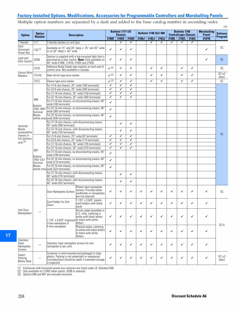
2
3
4
5
9
10
11
12
13
14
15
16
17
Factory-Installed Options, Modifications, Accessories for Programmable Controllers and Marshalling PanelsMultiple option numbers are separated by a dash and added to the base catalog number in ascending order.
274
Option Option Number Description
Bulletin 1771 I/O Chassis Bulletin 1746 SLC 500 Bulletin 1756
ControlLogix ChassisMarshalling
Panel Delivery Program
2180E 2182E 2183E 2180J 2182J 2183J 2180L 2182L 2183L 2181BT-Handle -111 T-Handle latches on unit door
SCOmit HorizontalPower Bus
-120 [1]
[1] Enclosures with horizontal power bus omission are listed under UL Standard 508.
Available on 15” and 20” deep × 25” and 35” wide or on 20” deep × 40” wide
Light and Door Switch -203B
Section is supplied with a top-mounted light that is activated by a door switch. Note: Only available on 40” wide 2180E, 2181B, 2182E and 2183E.
PE
Control Wire Markers
-751D Adhesive Brady Datab type markers at each end of control wire. Not available in Canada. [2]
[2] Only available for 2180E when option -203B is selected.
SC
-751HS Heat shrink type wire marker [2] SC (+2 days)
-751S Sleeve type wire marker [2] SC
Terminal Blocks (unwired) for chassis in full sections only [3]
[3] Options 806 and 807 are mutually exclusive.
-806
Bulletin 1492–HM1 Terminal Blocks (white only)
For (1) 8-slot chassis, 25” wide (100 terminals)
PE
For (2) 8-slot chassis, 25” wide (200 terminals)For (1) 16-slot chassis, 35” wide (150 terminals)For (2) 16-slot chassis, 35” wide (300 terminals)For (1) 16-slot chassis, no disconnecting means, 40” wide (180 terminals)For (2) 16-slot chassis, no disconnecting means, 40” wide (360 terminals)For (3) 16-slot chassis, no disconnecting means, 40” wide (540 terminals)For (1) 16-slot chassis, with disconnecting means, 40” wide (360 terminals)For (2) 16-slot chassis, with disconnecting means, 40” wide (720 terminals)
-807
Bulletin 1492–CA1 Terminal Blocks (white only)
For (1) 8-slot chassis, 25” wide (87 terminals)For (2) 8-slot chassis, 25” wide (174 terminals)For (1) 16-slot chassis, 35” wide (135 terminals)For (2) 16-slot chassis, 35” wide (270 terminals)For (1) 16-slot chassis, no disconnecting means, 40” wide (108 terminals)For (2) 16-slot chassis, no disconnecting means, 40” wide (216 terminals)For (3) 16-slot chassis, no disconnecting means, 40” wide (324 terminals)For (1) 16-slot chassis, with disconnecting means, 40” wide (216 terminals)For (2) 16-slot chassis, with disconnecting means, 40” wide (432 terminals)
Unit Door Nameplates —
Door Nameplate Screws
Plated steel nameplate screws. Provided when cardholder or nameplates are not selected.
SC
Card Holder for Unit Doors
1.125'' x 3.625'' plastic card holders with blank cards
SC-II
1.125” x 3.625” engraved 3-line nameplate or 4-line nameplate
Acrylic plate (available in U.S. only). Lettering is white with black letters or black with white letters.Phenolic plate. Lettering is white with black letters or black with white letters.
Stainless Steel Nameplate Screws
— Stainless steel nameplate screws for unit nameplate (2 per unit)
Export Packing Below Deck
—
Container is skid mounted and packaged in clear plastic. Packing is not watertight or waterproof. Considerations should be taken if extended storage is expected.
SC (+2 days)
204 Discount Schedule A6
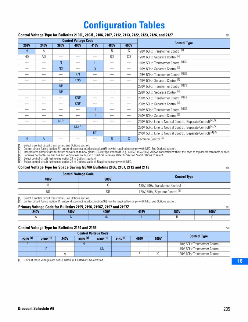
2
3
4
5
6
7
8
9
10
11
12
13
14
15
16
17
18
Configuration TablesControl Voltage Type for Bulletins 2102L, 2103L, 2106, 2107, 2112, 2113, 2122, 2123, 2126, and 2127 275
Control Voltage Type for Space Saving NEMA Bulletins 2106, 2107, 2112 and 2113 276
Primary Voltage Code for Bulletins 2195, 2196, 2196Z, 2197 and 2197Z 277
Control Voltage Type for Bulletins 2154 and 2155 278
Control Voltage CodeControl Type
208V 240V 380V 400V 415V 480V 600VH A — — — B C 120V, 60Hz, Transformer Control [1]
[1] Select a control circuit transformer. See Options section.
HD AD — — — BD CD 120V, 60Hz, Separate Control [2]
[2] Control circuit fusing (option 21) and/or disconnect interlock (option 98) may be required to comply with NEC. See Options section.
— — N — I — — 110V, 50Hz, Transformer Control [1],[3]
[3] Incorporates primary taps for future conversion to new global IEC voltage standards (e.g., 400V/115V/230V). Allows conversion without the need to replace transformers or coils.
— — NS — IS — — 110V, 50Hz, Separate Control [2]
— — — KN — — — 115V, 50Hz, Transformer Control [1],[3]
— — — KNS — — — 115V, 50Hz, Separate Control [2]
— — NP — — — — 220V, 50Hz, Transformer Control [1],[3]
— — NP — — — — 220V, 50Hz, Separate Control [2]
— — — KNP — — — 230V, 50Hz, Transformer Control [1],[3]
— — — KNP — — — 230V, 50Hz, Separate Control [2]
— — — — IT — — 240V, 50Hz, Transformer Control [1],[3]
— — — — IT — — 240V, 50Hz, Separate Control [2]
— — NLP — — — — 220V, 50Hz, Line to Neutral Control, (Separate Control) [4],[5]
[4] Requires horizontal neutral bus and vertical neutral bus in 9” vertical wireway. Refer to Section Modifications to select.[5] Select control circuit fusing (see option 21 in Options section).
— — — KNLP — — — 230V, 50Hz, Line to Neutral Control, (Separate Control) [4],[5]
— — — — ILT — — 240V, 50Hz, Line to Neutral Control, (Separate Control) [4],[5]
H A — — — B C Common Control [6]
[6] Select control circuit fusing (see option 22 in Options section). Required to comply with NEC.
Control Voltage CodeControl Type
480V 600V
B C 120V, 60Hz, Transformer Control [1]
[1] Select a control circuit transformer. See Options section.
BD CD 120V, 60Hz, Separate Control [2]
[2] Control circuit fusing (option 21) and/or disconnect interlock (option 98) may be required to comply with NEC. See Options section.
240V 380V 400V 415V 480V 600VA N KN I B C
Control Voltage CodeControl Type
220V [1]
[1] Units at these voltages are not UL listed, cUL listed or CSA certified.
230V [1] 240V 380V [1] 400V [1] 415V [1] 480V 600VP — — N — I — — 110V, 50Hz Transformer Control
— P — — KN — — — 115V, 50Hz Transformer Control— — A — — — B C 120V, 60Hz Transformer Control
205Discount Schedule A6
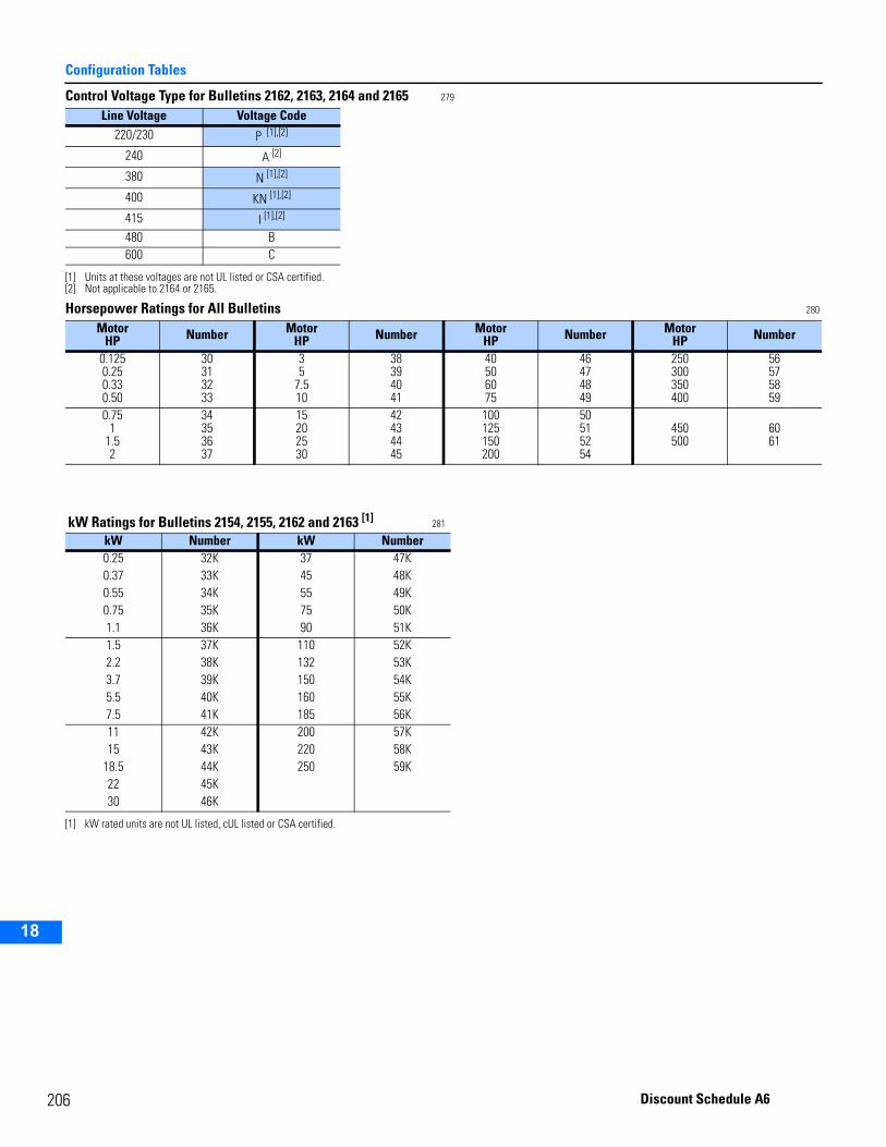
2
Configuration Tables
2
3
4
5
9
10
11
12
13
14
15
16
17
18
Control Voltage Type for Bulletins 2162, 2163, 2164 and 2165 279
Horsepower Ratings for All Bulletins 280
Line Voltage Voltage Code220/230 P [1],[2]
[1] Units at these voltages are not UL listed or CSA certified.[2] Not applicable to 2164 or 2165.
240 A [2]
380 N [1],[2]
400 KN [1],[2]
415 I [1],[2]
480 B 600 C
MotorHP Number Motor
HP Number MotorHP Number Motor
HP Number
0.1250.250.330.50
30313233
35
7.510
38394041
40506075
46474849
250300350400
56575859
0.751
1.52
34353637
15202530
42434445
100125150200
50515254
450500
6061
kW Ratings for Bulletins 2154, 2155, 2162 and 2163 [1] 281
[1] kW rated units are not UL listed, cUL listed or CSA certified.
kW Number kW Number0.25 32K 37 47K0.37 33K 45 48K0.55 34K 55 49K0.75 35K 75 50K1.1 36K 90 51K1.5 37K 110 52K2.2 38K 132 53K3.7 39K 150 54K5.5 40K 160 55K7.5 41K 185 56K11 42K 200 57K15 43K 220 58K
18.5 44K 250 59K22 45K30 46K
06 Discount Schedule A6
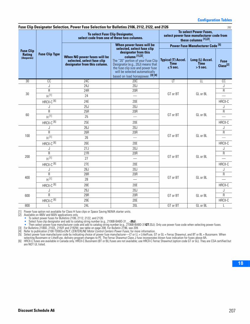
Configuration Tables
2
3
4
5
6
7
8
9
10
11
12
13
14
15
16
17
18
Fuse Clip Designator Selection, Power Fuse Selection for Bulletins 2106, 2112, 2122, and 2126 282
Fuse Clip Rating
(Amperes)Fuse Clip Type
To select Fuse Clip Designator,select code from one of these two columns.
To select Power Fuses,select power fuse manufacturer code from
these columns [1],[2].
When NO power fuses will be selected, select fuse clip
designator from this column.
When power fuses will be selected, select fuse clip
designator from this column [1],[2].
The “20” portion of your Fuse Clip Designator (e.g., 20J) means that the fuse clip size and power fuse
will be selected automatically based on load horsepower. [3],[4]
[1] Power fuse option not available for Class H fuse clips or Space Saving NEMA starter units.[2] Available on 480V and 600V applications only.
• To select power fuses for Bulletins 2106, 2112, 2122, and 2126:• Select fuse clip designator and add to catalog string number (e.g., 2106B-BABD-31__-20J).• Then select power fuse manufacturer code and add to catalog string number (e.g., 2106B-BABD-31GT-20J). Only use power fuse code when selecting power fuses.
[3] For Bulletins 2100D, 2102L, 2192F and 2192M, see table on page 208. For Bulletin 2196, see 209.[4] Refer to publication 2100-TD003x-EN-P, CENTERLINE Motor Control Centers Power Fuses, for more information.
Power Fuse Manufacturer Code [5]
[5] Select power fuse manufacturer code by indicating choice of power fuse manufacturer—LT or LL = LittelFuse, GT or GL = Ferraz Shawmut, and BT or BL = Bussmann. When selecting Bussmann or LittelFuse, delivery program changes to PE. The Ferraz Shawmut Class J fuse incorporates blown fuse indication for fuses above 8A.
Typical (T) Accel. Time
< 5 sec.
Long (L) Accel. Time
> 5 sec.
Fuse Class[2]
30 CC 24C 20C LT LL CC
30
J 24J 20J
GT or BT GL or BL
JR 24R 20R R
H [1] 24 — —
HRCII-C [6]
[6] HRCII-C fuses are available in Canada only. HRCII-C Bussmann (BT or BL) fuses are not available; use HRCII-C Ferraz Shawmut (option code GT or GL). They are CSA certified but are NOT UL listed.
24E 20E HRCII-C
60
J 25J 20J
GT or BT GL or BL
JR 25R 20R R
H [1] 25 — —
HRCII-C [6] 25E 20E HRCII-C
100
J 26J 20J
GT or BT GL or BL
JR 26R 20R R
H [1] 26 — —
HRCII-C [6] 26E 20E HRCII-C
200
J 27J 20J
GT or BT GL or BL
JR 27R 20R R
H [1] 27 — —
HRCII-C [6] 27E 20E HRCII-C
400
J 28J 20J
GT or BT GL or BL
JR 28R 20R R
H [1] 28 — —
HRCII-C [6] 28E 20E HRCII-C
600J 29J 20J
GT or BT GL or BLJ
R 29R 20R R
HRCII-C [6] 29E 20E HRCII-C800 L 24L 20L GT or BT GL or BL L
207Discount Schedule A6
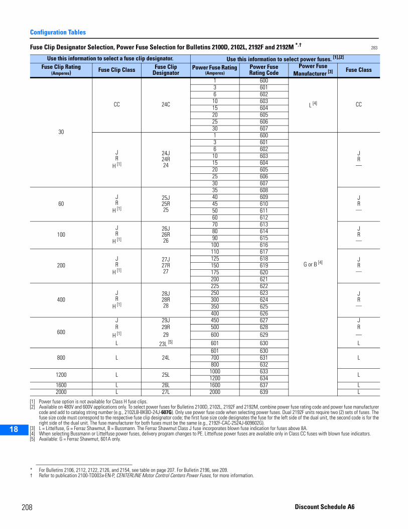
2
Configuration Tables
2
3
4
5
9
10
11
12
13
14
15
16
17
18
Fuse Clip Designator Selection, Power Fuse Selection for Bulletins 2100D, 2102L, 2192F and 2192M *,† 283
Use this information to select a fuse clip designator. Use this information to select power fuses. [1],[2]
[1] Power fuse option is not available for Class H fuse clips.[2] Available on 480V and 600V applications only. To select power fuses for Bulletins 2100D, 2102L, 2192F and 2192M, combine power fuse rating code and power fuse manufacturer
code and add to catalog string number (e.g., 2102LB-BKBD-24J-607G). Only use power fuse code when selecting power fuses. Dual 2192F units require two (2) sets of fuses. The fuse size code must correspond to the respective fuse clip designator code; the first fuse size code designates the fuse for the left side of the dual unit, the second code is for the right side of the dual unit. The fuse manufacturer for both fuses must be the same (e.g., 2192F-CAC-2524J-609602G).
Fuse Clip Rating(Amperes) Fuse Clip Class Fuse Clip
DesignatorPower Fuse Rating
(Amperes)Power FuseRating Code
Power Fuse Manufacturer [3]
[3] L = Littelfuse, G = Ferraz Shawmut, B = Bussmann. The Ferraz Shawmut Class J fuse incorporates blown fuse indication for fuses above 8A.
Fuse Class
30
CC 24C
1 600
L [4]
[4] When selecting Bussmann or Littelfuse power fuses, delivery program changes to PE. Littelfuse power fuses are available only in Class CC fuses with blown fuse indicators.
CC
3 6016 602
10 60315 60420 60525 60630 607
JR
H [1]
24J24R24
1 600
G or B [4]
JR
—
3 6016 602
10 60315 60420 60525 60630 607
60JR
H [1]
25J25R25
35 608JR
—
40 60945 61050 61160 612
100JR
H [1]
26J26R26
70 613JR
—
80 61490 615100 616
200JR
H [1]
27J27R27
110 617JR
—
125 618150 619175 620200 621
400JR
H [1]
28J28R28
225 622JR
—
250 623300 624350 625400 626
600
J 29J 450 627 JR 29R 500 628 R
H [1] 29 600 629 —L 23L [5]
[5] Available: G = Ferraz Shawmut, 601A only.
601 630 L
800 L 24L601 630
L700 631800 632
1200 L 25L 1000 633 L1200 6341600 L 26L 1600 637 L2000 L 27L 2000 639 L
* For Bulletins 2106, 2112, 2122, 2126, and 2154, see table on page 207. For Bulletin 2196, see 209.† Refer to publication 2100-TD003x-EN-P, CENTERLINE Motor Control Centers Power Fuses, for more information.
08 Discount Schedule A6
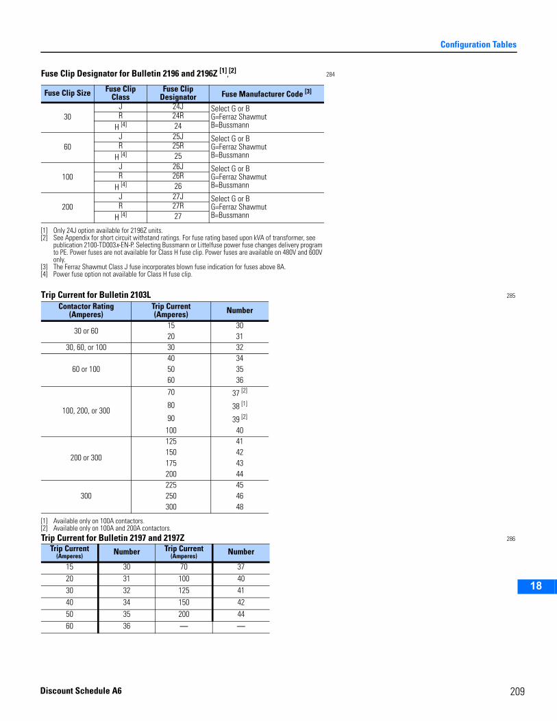
Configuration Tables
2
3
4
5
6
7
8
9
10
11
12
13
14
15
16
17
18
Trip Current for Bulletin 2103L 285
Trip Current for Bulletin 2197 and 2197Z 286
Fuse Clip Designator for Bulletin 2196 and 2196Z [1],[2] 284
[1] Only 24J option available for 2196Z units.[2] See Appendix for short circuit withstand ratings. For fuse rating based upon kVA of transformer, see
publication 2100-TD003x-EN-P. Selecting Bussmann or Littelfuse power fuse changes delivery program to PE. Power fuses are not available for Class H fuse clip. Power fuses are available on 480V and 600V only.
Fuse Clip Size Fuse Clip Class
Fuse Clip Designator Fuse Manufacturer Code [3]
[3] The Ferraz Shawmut Class J fuse incorporates blown fuse indication for fuses above 8A.
30J 24J Select G or B
G=Ferraz ShawmutB=Bussmann
R 24RH [4]
[4] Power fuse option not available for Class H fuse clip.
24
60J 25J Select G or B
G=Ferraz ShawmutB=Bussmann
R 25RH [4] 25
100J 26J Select G or B
G=Ferraz ShawmutB=Bussmann
R 26RH [4] 26
200J 27J Select G or B
G=Ferraz ShawmutB=Bussmann
R 27RH [4] 27
Contactor Rating(Amperes)
Trip Current(Amperes) Number
30 or 6015 3020 31
30, 60, or 100 30 32
60 or 10040 3450 3560 36
100, 200, or 300
70 37 [2]
80 38 [1]
[1] Available only on 100A contactors.
90 39 [2]
[2] Available only on 100A and 200A contactors.
100 40
200 or 300
125 41150 42175 43200 44
300225 45250 46300 48
Trip Current(Amperes) Number Trip Current
(Amperes) Number
15 30 70 3720 31 100 4030 32 125 4140 34 150 4250 35 200 4460 36 — —
209Discount Schedule A6
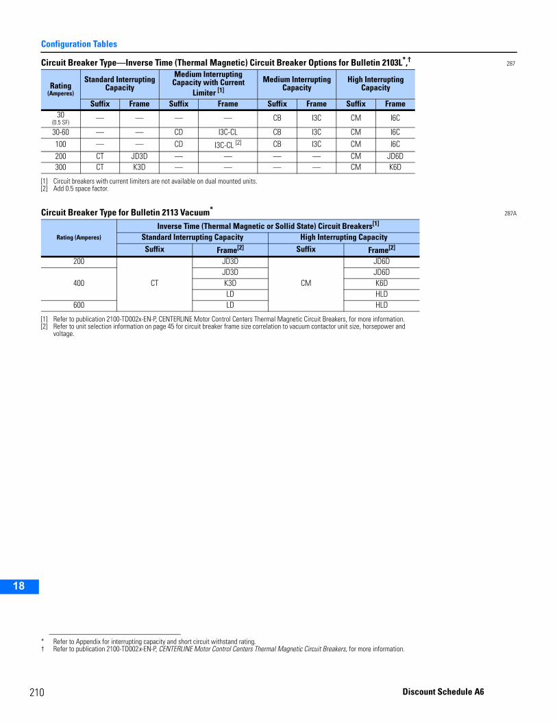
2
Configuration Tables
2
3
4
5
9
10
11
12
13
14
15
16
17
18
Circuit Breaker Type—Inverse Time (Thermal Magnetic) Circuit Breaker Options for Bulletin 2103L*,† 287
Circuit Breaker Type for Bulletin 2113 Vacuum* 287A
Rating (Amperes)
Standard Interrupting Capacity
Medium InterruptingCapacity with Current
Limiter [1]
[1] Circuit breakers with current limiters are not available on dual mounted units.
Medium Interrupting Capacity
High InterruptingCapacity
Suffix Frame Suffix Frame Suffix Frame Suffix Frame30
(0.5 SF)— — — — CB I3C CM I6C
30-60 — — CD I3C-CL CB I3C CM I6C100 — — CD I3C-CL [2]
[2] Add 0.5 space factor.
CB I3C CM I6C200 CT JD3D — — — — CM JD6D300 CT K3D — — — — CM K6D
* Refer to Appendix for interrupting capacity and short circuit withstand rating.† Refer to publication 2100-TD002x-EN-P, CENTERLINE Motor Control Centers Thermal Magnetic Circuit Breakers, for more information.
Rating (Amperes)
Inverse Time (Thermal Magnetic or Sollid State) Circuit Breakers[1]
[1] Refer to publication 2100-TD002x-EN-P, CENTERLINE Motor Control Centers Thermal Magnetic Circuit Breakers, for more information.
Standard Interrupting Capacity High Interrupting CapacitySuffix Frame[2]
[2] Refer to unit selection information on page 45 for circuit breaker frame size correlation to vacuum contactor unit size, horsepower and voltage.
Suffix Frame[2]
200
CT
JD3D
CM
JD6D
400JD3D JD6DK3D K6DLD HLD
600 LD HLD
10 Discount Schedule A6
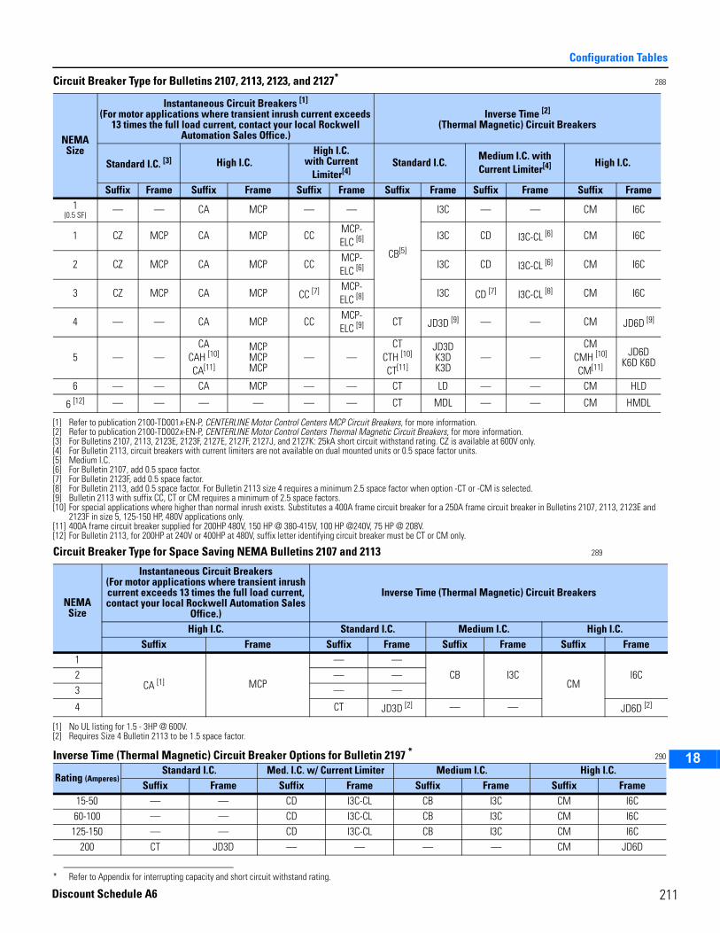
Configuration Tables
2
3
4
5
6
7
8
9
10
11
12
13
14
15
16
17
18
Circuit Breaker Type for Bulletins 2107, 2113, 2123, and 2127* 288
Circuit Breaker Type for Space Saving NEMA Bulletins 2107 and 2113 289
Inverse Time (Thermal Magnetic) Circuit Breaker Options for Bulletin 2197 * 290
NEMASize
Instantaneous Circuit Breakers [1]
(For motor applications where transient inrush current exceeds 13 times the full load current, contact your local Rockwell
Automation Sales Office.)
[1] Refer to publication 2100-TD001x-EN-P, CENTERLINE Motor Control Centers MCP Circuit Breakers, for more information.
Inverse Time [2]
(Thermal Magnetic) Circuit Breakers
[2] Refer to publication 2100-TD002x-EN-P, CENTERLINE Motor Control Centers Thermal Magnetic Circuit Breakers, for more information.
Standard I.C. [3]
[3] For Bulletins 2107, 2113, 2123E, 2123F, 2127E, 2127F, 2127J, and 2127K: 25kA short circuit withstand rating. CZ is available at 600V only.
High I.C.High I.C.
with Current Limiter[4]
[4] For Bulletin 2113, circuit breakers with current limiters are not available on dual mounted units or 0.5 space factor units.
Standard I.C.Medium I.C. with Current Limiter[4] High I.C.
Suffix Frame Suffix Frame Suffix Frame Suffix Frame Suffix Frame Suffix Frame1
(0.5 SF) — — CA MCP — —
CB[5]
[5] Medium I.C.
I3C — — CM I6C
1 CZ MCP CA MCP CCMCP-ELC [6]
[6] For Bulletin 2107, add 0.5 space factor.
I3C CD I3C-CL [6] CM I6C
2 CZ MCP CA MCP CCMCP-ELC [6] I3C CD I3C-CL [6] CM I6C
3 CZ MCP CA MCP CC [7]
[7] For Bulletin 2123F, add 0.5 space factor.
MCP-ELC [8]
[8] For Bulletin 2113, add 0.5 space factor. For Bulletin 2113 size 4 requires a minimum 2.5 space factor when option -CT or -CM is selected.
I3C CD [7] I3C-CL [8] CM I6C
4 — — CA MCP CCMCP-ELC [9]
[9] Bulletin 2113 with suffix CC, CT or CM requires a minimum of 2.5 space factors.
CT JD3D [9] — — CM JD6D [9]
5 — —CA
CAH [10] CA[11]
[10] For special applications where higher than normal inrush exists. Substitutes a 400A frame circuit breaker for a 250A frame circuit breaker in Bulletins 2107, 2113, 2123E and 2123F in size 5, 125-150 HP, 480V applications only.
[11] 400A frame circuit breaker supplied for 200HP 480V, 150 HP @ 380-415V, 100 HP @240V, 75 HP @ 208V.
MCPMCP MCP
— —CT
CTH [10]
CT[11]
JD3DK3D K3D
— —CM
CMH [10] CM[11]
JD6DK6D K6D
6 — — CA MCP — — CT LD — — CM HLD
6 [12]
[12] For Bulletin 2113, for 200HP at 240V or 400HP at 480V, suffix letter identifying circuit breaker must be CT or CM only.
— — — — — — CT MDL — — CM HMDL
* Refer to Appendix for interrupting capacity and short circuit withstand rating.
NEMASize
Instantaneous Circuit Breakers (For motor applications where transient inrush current exceeds 13 times the full load current, contact your local Rockwell Automation Sales
Office.)
Inverse Time (Thermal Magnetic) Circuit Breakers
High I.C. Standard I.C. Medium I.C. High I.C.Suffix Frame Suffix Frame Suffix Frame Suffix Frame
1
CA [1]
[1] No UL listing for 1.5 - 3HP @ 600V.
MCP
— —CB I3C
CMI6C2 — —
3 — —
4 CT JD3D [2]
[2] Requires Size 4 Bulletin 2113 to be 1.5 space factor.
— — JD6D [2]
Rating (Amperes)Standard I.C. Med. I.C. w/ Current Limiter Medium I.C. High I.C.
Suffix Frame Suffix Frame Suffix Frame Suffix Frame15-50 — — CD I3C-CL CB I3C CM I6C60-100 — — CD I3C-CL CB I3C CM I6C125-150 — — CD I3C-CL CB I3C CM I6C
200 CT JD3D — — — — CM JD6D
211Discount Schedule A6
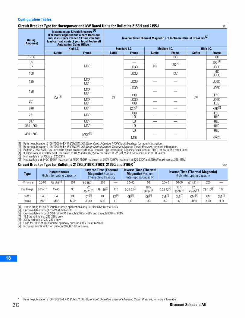
2
Configuration Tables
2
3
4
5
9
10
11
12
13
14
15
16
17
18
Circuit Breaker Type for Horsepower and kW Rated Units for Bulletins 2155H and 2155J 291
Circuit Breaker Type for Bulletins 2163Q, 2163R, 2163T, 2165Q and 2165R * 292
Rating(Amperes)
Instantaneous Circuit Breakers [1]
(For motor applications where transient inrush currents exceed 13 times the full
load current, contact your local Rockwell Automation Sales Office.)
[1] Refer to publication 2100-TD001x-EN-P, CENTERLINE Motor Control Centers MCP Circuit Breakers, for more information.
Inverse Time (Thermal Magnetic or Electronic) Circuit Breakers [2]
[2] Refer to publication 2100-TD002x-EN-P, CENTERLINE Motor Control Centers Thermal Magnetic Circuit Breakers, for more information.
High I.C. Standard I.C. Medium I.C. High I.C.Suffix Frame Suffix Frame Suffix Frame Suffix Frame
3 - 60
CA [3]
[3] Bulletin 2155J SMC-Flex units with circuit breaker suffix CA requires High Interrupting Capacity fuses (option 13HIC) for 5A to 85A rated units.
MCP
CT
—
CB
I3C
CM
I6C85 —
I3C [4] I6C [4]
[4] 30HP maximum at 240V, 50HP maximum at 480V and 600V, 22kW maximum at 220-230V and 37kW maximum at 380-415V.
97 JD3D JD6D
108 JD3D I3C I6CJD6D
135 MCPMCP JD3D — — JD6D
180 MCPMCP
JD3D
K3D— —
JD6D
K6D
201 MCPMCP
JD3DK3D — — JD6D
K6D240 MCP K3D[5]
[5] Not available for 75kW at 220-230V
— — K6D[5]
251 MCP K3DLD — — K6D
HLD317 MCP LD — — HLD
360 - 361 MCP LD — — HLD
480 - 500 MCP [6]
[6] Not available at 240V, 350HP maximum at 480V, 450HP maximum at 600V, 132kW maximum at 220-230V and 220kW maximum at 380-415V.
LD
MDL— —
HLD
HMDL
Type InstantaneousHigh Interrupting Capacity
Inverse Time (Thermal Magnetic) Standard Interrupting Capacity
Inverse Time (Thermal Magnetic) Medium Interrupting Capacity
Inverse Time (Thermal Magnetic) High Interrupting Capacity
HP Range 0.5-60 60-150 [1]
[1] 150HP rating for 480V variable torque applications only. 60HP Heavy Duty at 480V.
200 60-150 [1] 200 — 0.5-40 50 0.5-40 50-60 60-150 [1] 200 —
kW Range 0.25-37 45-75 9022,
45-75 [2]
[2] Only available through 15kW at 220-230V.
75-110[3]
[3] Only available through 30HP at 240V, through 50HP at 480V and through 60HP at 600V.
132 0.25-22[2] 18.5,30-37 [4]
[4] 18.5kW rating is at 220-230V only.
0.25-22[4] 18.5,30-37 [4]
22,45-75 [5]
[5] 22kW rating is at 220-230V only.
75-110[3] 132
Suffix CA CA CA CT [6]
[6] Used for 60HP at 480V and 50 hp heavy duty for 480 V Bulletin 2163R.
CT CT[7]
[7] Increases width to 35” on Bulletin 2163R, 132kW drives.
CB [3] CB [3] CM [3] CM [3] CM [6] CM CM [7]
Frame MCP MCP MCP JD3D K3D LD I3C I3C I6C I6C JD6D K6D HLD
* Refer to publication 2100-TD002x-EN-P, CENTERLINE Motor Control Centers Thermal Magnetic Circuit Breakers, for more information.
12 Discount Schedule A6
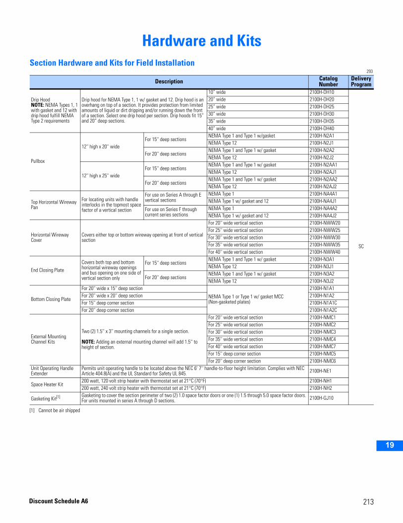
2
3
4
5
6
7
8
9
10
11
12
13
14
15
16
17
18
19
Hardware and KitsSection Hardware and Kits for Field Installation
293
Description Catalog Number
Delivery Program
Drip HoodNOTE: NEMA Types 1, 1 with gasket and 12 with drip hood fulfill NEMA Type 2 requirements
Drip hood for NEMA Type 1, 1 w/ gasket and 12. Drip hood is an overhang on top of a section. It provides protection from limited amounts of liquid or dirt dripping and/or running down the front of a section. Select one drip hood per section. Drip hoods fit 15” and 20” deep sections.
10” wide 2100H-DH10
SC
20” wide 2100H-DH2025” wide 2100H-DH2530” wide 2100H-DH3035” wide 2100H-DH3540” wide 2100H-DH40
Pullbox
12'' high x 20'' wideFor 15'' deep sections
NEMA Type 1 and Type 1 w/gasket 2100H-N2A1NEMA Type 12 2100H-N2J1
For 20'' deep sectionsNEMA Type 1 and Type 1 w/ gasket 2100H-N2A2NEMA Type 12 2100H-N2J2
12'' high x 25'' wideFor 15'' deep sections
NEMA Type 1 and Type 1 w/ gasket 2100H-N2AA1NEMA Type 12 2100H-N2AJ1
For 20'' deep sectionsNEMA Type 1 and Type 1 w/ gasket 2100H-N2AA2NEMA Type 12 2100H-N2AJ2
Top Horizontal Wireway Pan
For locating units with handle interlocks in the topmost space factor of a vertical section
For use on Series A through E vertical sections
NEMA Type 1 2100H-NA4A1NEMA Type 1 w/ gasket and 12 2100H-NA4J1
For use on Series F through current series sections
NEMA Type 1 2100H-NA4A2NEMA Type 1 w/ gasket and 12 2100H-NA4J2
Horizontal Wireway Cover
Covers either top or bottom wireway opening at front of vertical section
For 20'' wide vertical section 2100H-NWW20For 25'' wide vertical section 2100H-NWW25For 30'' wide vertical section 2100H-NWW30For 35'' wide vertical section 2100H-NWW35For 40'' wide vertical section 2100H-NWW40
End Closing Plate
Covers both top and bottom horizontal wireway openings and bus opening on one side of vertical section only
For 15'' deep sectionsNEMA Type 1 and Type 1 w/ gasket 2100H-N3A1NEMA Type 12 2100H-N3J1
For 20'' deep sectionsNEMA Type 1 and Type 1 w/ gasket 2100H-N3A2NEMA Type 12 2100H-N3J2
Bottom Closing Plate
For 20'' wide x 15'' deep section
NEMA Type 1 or Type 1 w/ gasket MCC (Non-gasketed plates)
2100H-N1A1For 20'' wide x 20'' deep section 2100H-N1A2For 15'' deep corner section 2100H-N1A1CFor 20'' deep corner section 2100H-N1A2C
External Mounting Channel Kits
Two (2) 1.5'' x 3'' mounting channels for a single section.
NOTE: Adding an external mounting channel will add 1.5'' to height of section.
For 20'' wide vertical section 2100H-NMC1For 25'' wide vertical section 2100H-NMC2For 30'' wide vertical section 2100H-NMC3For 35'' wide vertical section 2100H-NMC4For 40'' wide vertical section 2100H-NMC7For 15'' deep corner section 2100H-NMC5For 20'' deep corner section 2100H-NMC6
Unit Operating Handle Extender
Permits unit operating handle to be located above the NEC 6' 7'' handle-to-floor height limitation. Complies with NEC Article 404.8(A) and the UL Standard for Safety UL 845. 2100H-NE1
Space Heater Kit200 watt, 120 volt strip heater with thermostat set at 21°C (70°F) 2100H-NH1200 watt, 240 volt strip heater with thermostat set at 21°C (70°F) 2100H-NH2
Gasketing Kit[1]
[1] Cannot be air shipped
Gasketing to cover the section perimeter of two (2) 1.0 space factor doors or one (1) 1.5 through 5.0 space factor doors. For units mounted in series A through D sections. 2100H-GJ10
213Discount Schedule A6
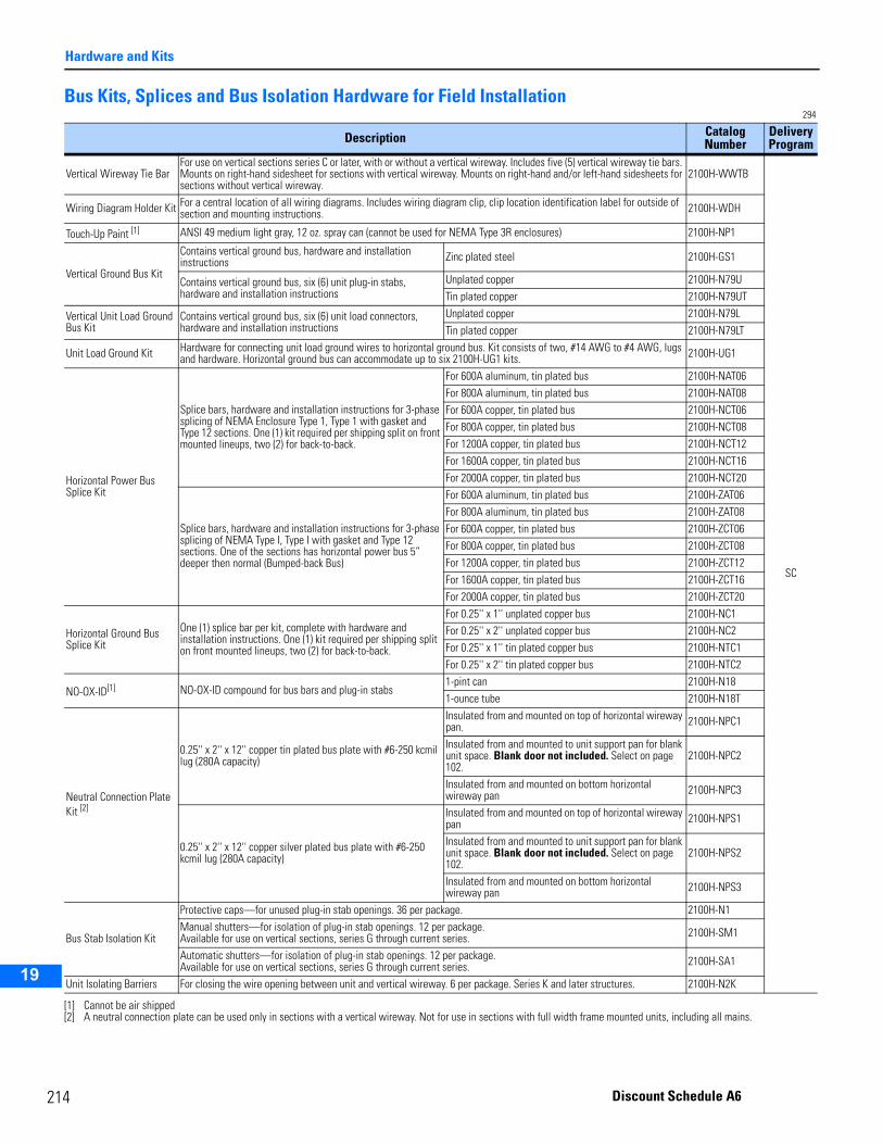
2
Hardware and Kits
2
3
4
5
9
10
11
12
13
14
15
16
17
19
Bus Kits, Splices and Bus Isolation Hardware for Field Installation294
Description Catalog Number
Delivery Program
Vertical Wireway Tie BarFor use on vertical sections series C or later, with or without a vertical wireway. Includes five (5) vertical wireway tie bars. Mounts on right-hand sidesheet for sections with vertical wireway. Mounts on right-hand and/or left-hand sidesheets for sections without vertical wireway.
2100H-WWTB
SC
Wiring Diagram Holder Kit For a central location of all wiring diagrams. Includes wiring diagram clip, clip location identification label for outside of section and mounting instructions. 2100H-WDH
Touch-Up Paint [1] ANSI 49 medium light gray, 12 oz. spray can (cannot be used for NEMA Type 3R enclosures) 2100H-NP1
Vertical Ground Bus Kit
Contains vertical ground bus, hardware and installation instructions Zinc plated steel 2100H-GS1
Contains vertical ground bus, six (6) unit plug-in stabs, hardware and installation instructions
Unplated copper 2100H-N79UTin plated copper 2100H-N79UT
Vertical Unit Load Ground Bus Kit
Contains vertical ground bus, six (6) unit load connectors, hardware and installation instructions
Unplated copper 2100H-N79LTin plated copper 2100H-N79LT
Unit Load Ground Kit Hardware for connecting unit load ground wires to horizontal ground bus. Kit consists of two, #14 AWG to #4 AWG, lugs and hardware. Horizontal ground bus can accommodate up to six 2100H-UG1 kits. 2100H-UG1
Horizontal Power Bus Splice Kit
Splice bars, hardware and installation instructions for 3-phase splicing of NEMA Enclosure Type 1, Type 1 with gasket and Type 12 sections. One (1) kit required per shipping split on front mounted lineups, two (2) for back-to-back.
For 600A aluminum, tin plated bus 2100H-NAT06For 800A aluminum, tin plated bus 2100H-NAT08For 600A copper, tin plated bus 2100H-NCT06For 800A copper, tin plated bus 2100H-NCT08For 1200A copper, tin plated bus 2100H-NCT12For 1600A copper, tin plated bus 2100H-NCT16For 2000A copper, tin plated bus 2100H-NCT20
Splice bars, hardware and installation instructions for 3-phase splicing of NEMA Type I, Type I with gasket and Type 12 sections. One of the sections has horizontal power bus 5” deeper then normal (Bumped-back Bus)
For 600A aluminum, tin plated bus 2100H-ZAT06For 800A aluminum, tin plated bus 2100H-ZAT08For 600A copper, tin plated bus 2100H-ZCT06For 800A copper, tin plated bus 2100H-ZCT08For 1200A copper, tin plated bus 2100H-ZCT12For 1600A copper, tin plated bus 2100H-ZCT16For 2000A copper, tin plated bus 2100H-ZCT20
Horizontal Ground Bus Splice Kit
One (1) splice bar per kit, complete with hardware and installation instructions. One (1) kit required per shipping split on front mounted lineups, two (2) for back-to-back.
For 0.25'' x 1'' unplated copper bus 2100H-NC1For 0.25'' x 2'' unplated copper bus 2100H-NC2For 0.25'' x 1'' tin plated copper bus 2100H-NTC1For 0.25'' x 2'' tin plated copper bus 2100H-NTC2
NO-OX-ID[1]
[1] Cannot be air shipped
NO-OX-ID compound for bus bars and plug-in stabs1-pint can 2100H-N181-ounce tube 2100H-N18T
Neutral Connection Plate Kit [2]
[2] A neutral connection plate can be used only in sections with a vertical wireway. Not for use in sections with full width frame mounted units, including all mains.
0.25'' x 2'' x 12'' copper tin plated bus plate with #6-250 kcmil lug (280A capacity)
Insulated from and mounted on top of horizontal wireway pan. 2100H-NPC1
Insulated from and mounted to unit support pan for blank unit space. Blank door not included. Select on page 102.
2100H-NPC2
Insulated from and mounted on bottom horizontal wireway pan 2100H-NPC3
0.25'' x 2'' x 12'' copper silver plated bus plate with #6-250 kcmil lug (280A capacity)
Insulated from and mounted on top of horizontal wireway pan 2100H-NPS1
Insulated from and mounted to unit support pan for blank unit space. Blank door not included. Select on page 102.
2100H-NPS2
Insulated from and mounted on bottom horizontal wireway pan 2100H-NPS3
Bus Stab Isolation Kit
Protective caps—for unused plug-in stab openings. 36 per package. 2100H-N1Manual shutters—for isolation of plug-in stab openings. 12 per package.Available for use on vertical sections, series G through current series. 2100H-SM1
Automatic shutters—for isolation of plug-in stab openings. 12 per package.Available for use on vertical sections, series G through current series. 2100H-SA1
Unit Isolating Barriers For closing the wire opening between unit and vertical wireway. 6 per package. Series K and later structures. 2100H-N2K
14 Discount Schedule A6
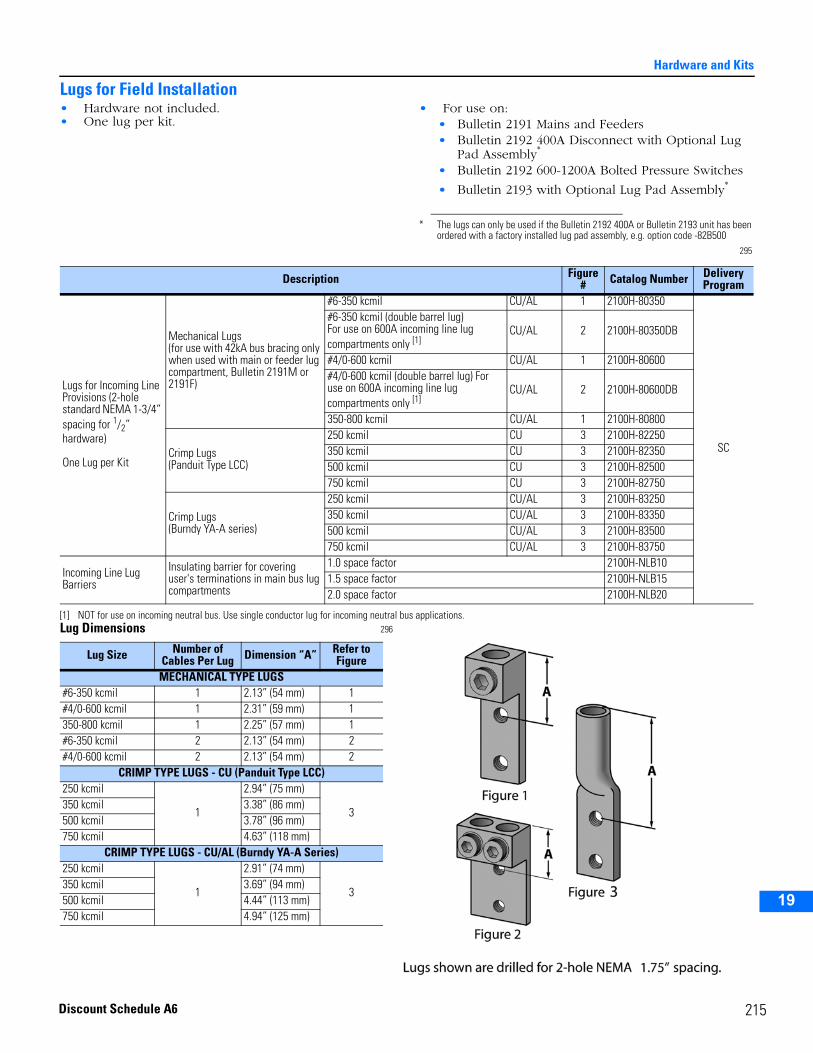
Hardware and Kits
2
3
4
5
6
7
8
9
10
11
12
13
14
15
16
17
18
19
Lugs for Field Installation• Hardware not included.• One lug per kit.
• For use on:• Bulletin 2191 Mains and Feeders• Bulletin 2192 400A Disconnect with Optional Lug
Pad Assembly*
• Bulletin 2192 600-1200A Bolted Pressure Switches
• Bulletin 2193 with Optional Lug Pad Assembly*
Lug Dimensions 296
* The lugs can only be used if the Bulletin 2192 400A or Bulletin 2193 unit has been ordered with a factory installed lug pad assembly, e.g. option code -82B500
295
Description Figure # Catalog Number Delivery
Program
Lugs for Incoming Line Provisions (2-hole standard NEMA 1-3/4” spacing for 1/2” hardware)
One Lug per Kit
Mechanical Lugs(for use with 42kA bus bracing only when used with main or feeder lug compartment, Bulletin 2191M or 2191F)
#6-350 kcmil CU/AL 1 2100H-80350
SC
#6-350 kcmil (double barrel lug)For use on 600A incoming line lug compartments only [1]
CU/AL 2 2100H-80350DB
#4/0-600 kcmil CU/AL 1 2100H-80600#4/0-600 kcmil (double barrel lug) For use on 600A incoming line lug compartments only [1]
CU/AL 2 2100H-80600DB
350-800 kcmil CU/AL 1 2100H-80800
Crimp Lugs(Panduit Type LCC)
250 kcmil CU 3 2100H-82250350 kcmil CU 3 2100H-82350500 kcmil CU 3 2100H-82500750 kcmil CU 3 2100H-82750
Crimp Lugs(Burndy YA-A series)
250 kcmil CU/AL 3 2100H-83250350 kcmil CU/AL 3 2100H-83350500 kcmil CU/AL 3 2100H-83500750 kcmil CU/AL 3 2100H-83750
Incoming Line Lug Barriers
Insulating barrier for covering user's terminations in main bus lug compartments
1.0 space factor 2100H-NLB101.5 space factor 2100H-NLB152.0 space factor 2100H-NLB20
[1] NOT for use on incoming neutral bus. Use single conductor lug for incoming neutral bus applications.
Lug Size Number of Cables Per Lug Dimension “A” Refer to
FigureMECHANICAL TYPE LUGS
#6-350 kcmil 1 2.13” (54 mm) 1#4/0-600 kcmil 1 2.31” (59 mm) 1350-800 kcmil 1 2.25” (57 mm) 1#6-350 kcmil 2 2.13” (54 mm) 2#4/0-600 kcmil 2 2.13” (54 mm) 2
CRIMP TYPE LUGS - CU (Panduit Type LCC)250 kcmil
1
2.94” (75 mm)
3350 kcmil 3.38” (86 mm)500 kcmil 3.78” (96 mm)750 kcmil 4.63” (118 mm)
CRIMP TYPE LUGS - CU/AL (Burndy YA-A Series)250 kcmil
1
2.91” (74 mm)
3350 kcmil 3.69” (94 mm)500 kcmil 4.44” (113 mm)750 kcmil 4.94” (125 mm)
215Discount Schedule A6
2
Hardware and Kits
2
3
4
5
9
10
11
12
13
14
15
16
17
19
Unit Hardware and Kits for Field Installation297
297A
Description Catalog Number Delivery Program
Control Station Housing
Available for use on units series letter H through current series. Housings for series A through G are no longer available.
Blank 2100H-N8
SC
1 hole—for one (1) Bulletin 800T pilot device 2100H-N92 hole—for two (2) Bulletin 800T pilot devices 2100H-N103 hole—for three (3) Bulletin 800T pilot devices 2100H-N11
Control Station Mounting Plate
Blank (Bulletin 2103L and 2113 dual only) 2100H-N8D1 hole—for one (1) Bulletin 800T pilot device (Bulletin 2103L and 2113 dual only) 2100H-N9D2 hole—for two (2) Bulletin 800T pilot devices (Bulletin 2103L and 2113 dual only) 2100H-N10D3 hole—for three (3) Bulletin 800T pilot devices (Bulletin 2103L and 2113 dual only) 2100H-N11D
Door Hardware KitIncludes two (2) door latch assemblies and two (2) door hinge assemblies
Series H or later1.0 space factor 2100H-NDH2
0.5 space factor 2100H-NDH3
Door Hinge Kit [1]
[1] Use the table below for determining the quantity of hinge and hinge pin kits needed.297
Includes two (2) hinges and two (2) hinge pins
Series H or later 0.5 space factor door 2100H-NHP1Series E or later 1.0 space factor (or larger) door 2100H-NHP2
Cardholder for Unit Doors 1.125'' x 3.625'' plastic card holders with blank cards 6 per package 2100H-CH1
Unit Door Nameplates
Engravable acrylic(1.125'' x 3.625'')(not available in Canada)
White background with black lettering
Blank (6 per package) 2100H-N3AWWith legend 2100H-N3EAW
Black background with white lettering
Blank (6 per package) 2100H-N3ABWith legend 2100H-N3EAB
Engravable phenolic(1.125'' x 3.625'')
White background with black lettering
Blank (6 per package) 2100H-N3WWith legend 2100H-N3EW
Red background with white lettering
Blank (6 per package) 2100H-N3RWith legend 2100H-N3ER
Black background with white lettering
Blank (6 per package) 2100H-N3BWith legend 2100H-N3EB
Master Nameplates Engravable phenolic(2” x 6”)
White background with black lettering
With legend2100H-N3EMW
Black background with white lettering 2100H-N3EMB
Stainless Steel Nameplate Screws Stainless steel nameplate screws for door or master nameplates (12 per package) 2100H-SSNS1
Unit Support Pan
Style 1 for units 1.0 space factor or larger, series A through D sections
NEMA Enclosure Type 1, Type 1 with gasket and Type 12 2100H-UAJ1
Style 3 for units 1.0 space factor or larger, series E through current series (replaces style 2)
NEMA Enclosure Type 1 2100H-UA1NEMA Enclosure Type 1 with gasket and Type 12 2100H-UJ1
Style 3 with interlock bushing, for 0.5 space factor units, series E through current series, with horizontally-toggled unit operating handles (replaces style 2)
NEMA Enclosure Type 1 2100H-USPA1NEMA Enclosure Type 1 with gasket and Type 12 2100H-USPJ1
Space Factor Quantity of Kits Needed0.5 11.0 11.5 12.0 12.5 23.0 23.5 24.0 24.5 26.0 3
16 Discount Schedule A6
Hardware and Kits
2
3
4
5
6
7
8
9
10
11
12
13
14
15
16
17
18
19
Unit Hardware and Kits for Field Installation, continued298
Description Catalog Number Delivery Program
Plug-In Unit Retrofit Kit
Permits installation of half (0.5) space factor and NEMA Space Saving starter plug-in units into existing series E through J CENTERLINE 2100 vertical section. Includes hinges, grounding wire and extended unit door latch(es).
0.5 space factor 2100H-R1
SC
Greater than 0.5 space factor
2100H-R2
Unit Insert Extension Kit
Includes 0.5 space factor door and unit extension, twenty (20) pull-apart terminals and hardware to increase usable mounting space of plug-in units
For expanding all 1.0 SF units and Series T and later 1.5 SF units[1]
[1] 1.5 space factor Bulletin 2193F with 225 A frame breakers, use kit 2100H-NXT05B2.
2100H-NXT05B1
For expanding Series R and earlier 1.5 SF units and all 2.0 SF through 3.5 SF units[1] 2100H-NXT05B2
Unit Door Grounding Kit Unit door is grounded by a hinge mounted ground wire. Mounts on bottom hinge of unit door. 2100H-GD1
Extended Reset Button Kit
Mounts externally to existing door overload reset button. Allows reset of overload relays without use of tools
For small 0.38'' reset button screw head. Includes five (5) reset button heads. 2100H-NRB1
For large 0.50'' reset button screw head. Includes five (5) reset button heads. 2100H-NRB2
Pull-Apart Terminal Bocks [2]
[2] Plug-in units have provision for a maximum of four (4) pull-apart terminal blocks (any combination of 3-pole or 5-pole blocks). Not available on 0.5 space factor units.
Power terminal block 60A, 3-pole block, accepts #4-#14 AWG wire. Not for use on 0.5 space factor units. 1492-ED103
Control terminal block 25A, 5-pole block, accepts #12-#20 AWG wire. Not for use on 0.5 space factor units. 1492-EC85
Line Terminal Shield
Transparent polycarbonate wraparound line terminal shield permits visual monitoring of conductors and power terminations. Replaces standard line terminal shield. Not available on 0.5 space factor units.
For 30A, 60A, 100A fusible disconnect. 10 per package. 2100H-NLT26For 200A fusible disconnect. Series A-M. 5 per package. 2100H-NLT27For 200A fusible disconnect. Series N and later. 5 per package. 2100H-NLT28
For 400A fusible disconnect. Series N and later. 5 per package. 2100H-NLT29
External Auxiliary Contact Adapter Kits FOR FUSIBLEDISCONNECT:Not for use on 0.5 space factor or dual-mounted units. Auxiliaries are actuated by the unit operating handle.
Permits mounting amaximum of two (2) Bulletin 1495-N8 (normally open) or 1495-N9 (normally closed) auxiliary contacts on the unit operating mechanism, external to the disconnect.
For units with 30A, 60A, 100A, or 200A fusible disconnects Units Series A-N None required
For units with 400A fusible disconnects
Unit Series A-C 1495-N16
Unit Series D-M 595-N1 [3]
[3] Kit permits mounting of two (2) Bulletin 595-A (normally open) or 595-B (normally closed) auxiliary contacts only. Not compatible with Bulletin 1495-NB or 1495-NP auxiliary contact kits.
Unit Series N None required
For units with 600A or 800A fusible disconnects Unit Series C- L 1495-N13
Permits mounting amaximum of two (2) Bulletin 2100H-N19 (normally open) or 2100H-N20 (normally closed) auxiliary contacts on the unit operating mechanism, external to the disconnect.
For units with 30A, 60A, 100A, 200A or 400A fusible disconnects
Unit Series Q and later 2100H-N21
External Auxiliary Contact
One (1) Normally OpenMust be used with external auxiliary adapter kit Unit Series Q
or later2100H-N19
One (1) Normally Closed 2100H-N20
FOR BOLTED PRESSURE SWITCHES: For 2192F and 2192M 600A, 800A and 1200A units.
Mounts one (1) form C auxiliary contact on the operating mechanism, external to the bolted pressure switch
Unit Series Q and later
2100H-N26A
Mounts two (2) form C auxiliary contacts on the operating mechanism, external to the bolted pressure switch 2100H-N26B
217Discount Schedule A6
2
Hardware and Kits
2
3
4
5
9
10
11
12
13
14
15
16
17
19
Unit Hardware and Kits for Field Installation, continued299
Description Catalog Number
Delivery Program
External Auxiliary Contact Kits
FOR CIRCUIT BREAKERS:For 0.5 space factor units.Auxiliaries are actuated by the unit operating handle only and will not reflect a circuit breaker trip
Mounts one (1) form C auxiliary contact on the operating mechanism, external to the breaker. Allen-Bradley I-Frame or JD-Frame or Cutler-Hammer 150A HMCP, FDB, FD, HFD, FDB-LFD, FDC and 225A JD, HJD and JDC. Unit Series P and
later
2100H-N18A
SC
Mounts two (2) form C auxiliary contacts on the operating mechanism, external to the breaker. Allen-Bradley I-Frame or JD-Frame or Cutler-Hammer 150A HMCP, FDB, FD, HFD, FDB-LFD, FDC and 225A JD, HJD and JDC.
2100H-N18B
FOR CIRCUIT BREAKERS:For dual 2103, 2113 and 2193F units
Mounts one (1) form C auxiliary contact on the operating mechanism, external to the breaker. Allen-Bradley I-Frame or Cutler-Hammer FDB, FD, HFD, FDB-LFD and FDC. Unit Series Q and
later
2100H-N25A
Mounts two (2) form C auxiliary contacts on the operating mechanism, external to the breaker. Allen-Bradley I-Frame or Cutler-Hammer FDB, FD, HFD, FDB-LFD and FDC.
2100H-N25B
External Auxiliary Contact Adapter KitsFOR CIRCUITBREAKERS: Not for use on 0.5 space factor units.Auxiliaries are actuated by the unit operating handle only and will not reflect a circuit breaker trip.
Permits mounting a maximum of two (2) Bulletin 1495-N8 (normally open) or 1495-N9 (normally closed) auxiliary contacts on the unit operating mechanism, external to the circuit breaker
For units with dual circuit breakers only. Allen-Bradley I-Frame or Cutler-Hammer Series C 150A HMCP, FDB, FD, HFD, FDB-LFD and FDC.
Unit Series K-N
2100H-N16
For units with single circuit breakers only. Allen-Bradley I, JD, or K Frame or Cutler-Hammer Series C150A HMCP, FDB, FD, HFD, FDB-LFD, FDC 225/250A JD, HFD, JDC, HMCP400A HMCP, KD, HKD and KDC.
2100H-N17
For units with Cutler-Hammer 225A frame (MCP 225A and JB) and 400A frame (MCP 400, LBB, or HLB) circuit breakers Unit Series C-G 1495-N16
For units with Cutler-Hammer 600A LC, HLC circuit breakers Unit Series C-N
1495-N13
For units with Cutler-Hammer 800A MC, HMC, MDS, ND, HND, or NDC circuit breakers Unit Series C-N
For units with Allen-Bradley Q Frame MCP or Cutler-Hammer 600A L-frame (LD, HLD, or LDC) and 600A HMCP circuit breakers Unit Series N
For units with Cutler-Hammer 1200A NC, HNC, ND, HND, or NDC circuit breakers Unit Series C-N
Permits mounting a maximum of two (2) normally open (2100H-N19) or normally closed (2100H-N20) auxiliary contacts on the unit operating mechanism, external to the circuit breaker
For units with single circuit breakers only. Allen-Bradley I, JD, or K Frame or Cutler-Hammer Series C.150A HMCP, FDB, FD, HFD, FDB-LFD and FDC.250A HMCP, JD, HJD and JDC.400A HMCP, KD, HKD and KDC.
Units Series Q and later 2100H-N22
For units with Allen-Bradley Q Frame MCP or Cutler-Hammer 600A HMCP, LD, HLD, or LDC.800A MC, HMC, MDS, MDL, HMDL, ND, HND, or NDC.1200A ND, HND, or NDC circuit breakers.
Unit Series Q and later 2100H-N23
18 Discount Schedule A6
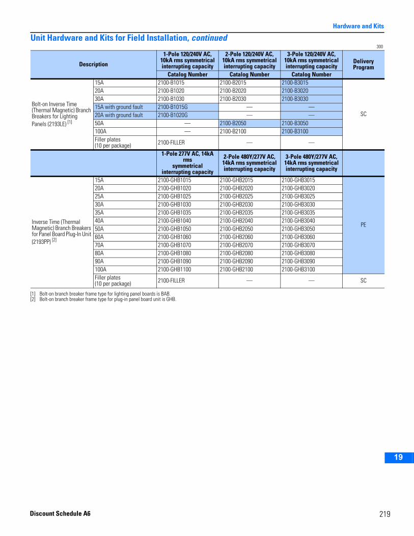
Hardware and Kits
2
3
4
5
6
7
8
9
10
11
12
13
14
15
16
17
18
19
Unit Hardware and Kits for Field Installation, continued300
Description
1-Pole 120/240V AC, 10kA rms symmetrical interrupting capacity
2-Pole 120/240V AC, 10kA rms symmetrical interrupting capacity
3-Pole 120/240V AC, 10kA rms symmetrical interrupting capacity
Delivery Program
Catalog Number Catalog Number Catalog Number
Bolt-on Inverse Time (Thermal Magnetic) Branch Breakers for Lighting Panels (2193LE) [1]
[1] Bolt-on branch breaker frame type for lighting panel boards is BAB.
15A 2100-B1015 2100-B2015 2100-B3015
SC
20A 2100-B1020 2100-B2020 2100-B302030A 2100-B1030 2100-B2030 2100-B303015A with ground fault 2100-B1015G — —20A with ground fault 2100-B1020G — —50A — 2100-B2050 2100-B3050100A — 2100-B2100 2100-B3100Filler plates(10 per package) 2100-FILLER — —
1-Pole 277V AC, 14kA rms
symmetrical interrupting capacity
2-Pole 480Y/277V AC, 14kA rms symmetrical interrupting capacity
3-Pole 480Y/277V AC, 14kA rms symmetrical interrupting capacity
Inverse Time (Thermal Magnetic) Branch Breakers for Panel Board Plug-In Unit (2193PP) [2]
[2] Bolt-on branch breaker frame type for plug-in panel board unit is GHB.
15A 2100-GHB1015 2100-GHB2015 2100-GHB3015
PE
20A 2100-GHB1020 2100-GHB2020 2100-GHB302025A 2100-GHB1025 2100-GHB2025 2100-GHB302530A 2100-GHB1030 2100-GHB2030 2100-GHB303035A 2100-GHB1035 2100-GHB2035 2100-GHB303540A 2100-GHB1040 2100-GHB2040 2100-GHB304050A 2100-GHB1050 2100-GHB2050 2100-GHB305060A 2100-GHB1060 2100-GHB2060 2100-GHB306070A 2100-GHB1070 2100-GHB2070 2100-GHB307080A 2100-GHB1080 2100-GHB2080 2100-GHB308090A 2100-GHB1090 2100-GHB2090 2100-GHB3090100A 2100-GHB1100 2100-GHB2100 2100-GHB3100Filler plates(10 per package) 2100-FILLER — — SC
219Discount Schedule A6
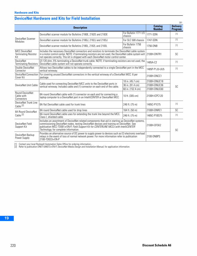
2
Hardware and Kits
2
3
4
5
9
10
11
12
13
14
15
16
17
19
DeviceNet Hardware and Kits for Field Installation 301
Description CatalogNumber
Delivery Program
DeviceNet Scanner Modules
DeviceNet scanner module for Bulletins 2180E, 2182E and 2183E For Bulletin 1771 I/O chassis 1771-SDN [1]
[1] Contact your local Rockwell Automation Sales Office for ordering information.-
DeviceNet scanner module for Bulletins 2180J, 2182J and 2183J For SLC 500 chassis 1747-SDN [1]
DeviceNet scanner module for Bulletins 2180L, 2182L and 2183L For Bulletin 1756 chassis 1756-DNB [1]
MCC DeviceNet Terminating Resistor Kit
Includes the necessary DeviceNet connectors and resistors to terminate the DeviceNet cable system in a motor control center. NOTE: if terminating resistors are not used, the DeviceNet cable system will not operate correctly. This kit is shipped with each DeviceNet motor control center.
2100H-DNTR1 SC
DeviceNet Terminating Resistors
(2) 120 ohm, 5% terminating a DeviceNet trunk cable. NOTE: if terminating resistors are not used, the DeviceNet cable system will not operate correctly. 1485A-C2 [1]
Double DeviceNet Connector
Allows two DeviceNet cables to be independently connected to a single DeviceNet port in the MCC vertical wireway. 1485P-P1J5-UU5 [1]
DeviceNet Connection Cover Kit
For covering unused DeviceNet connectors in the vertical wireway of a DeviceNet MCC. 6 per package. 2100H-DNCC1
SCDeviceNet Unit Cable Cable used for connecting DeviceNet MCC units to the DeviceNet ports in vertical wireway. Includes cable and (1) connector on each end of the cable.
18 in. (45.7 cm) 2100H-DNUC1836 in. (91.4 cm) 2100H-DNUC3660 in. (152.4 cm) 2100H-DNUC60
Round DeviceNet Cable with Connectors
8A round DeviceNet cable with (1) connector on each end for connecting a laptop computer to a DeviceNet port in an IntelliCENTER or DeviceNet MCC 10 ft. (305 cm) 2100H-ICPC120
DeviceNet Trunk Line Cable [2]
[2] Refer to publication DNET-UM072x-EN-P, DeviceNet Media Design and Installation Manual, for application information.
8A flat DeviceNet cable used for trunk lines 246 ft. (75 m) 1485C-P1E75 [1]
8A Round DeviceNet Cable [2]
8A round DeviceNet cable used for drop lines 164 ft. (50 m) 2100H-DNRC1 SC8A round DeviceNet cable uses for extending the trunk line beyond the MCC. Class I, shielded cable 246 ft. (75 m) 1485C-P1BS75 [1]
DeviceNet Field Support Kit
Includes an assortment of DeviceNet-related components that aid in starting up DeviceNet systems, commissioning DeviceNet nodes, testing DeviceNet devices and training on DeviceNet. See publication MCC-TD001x-EN-P, Field Support Kit for CENTERLINE MCCs with IntelliCENTER Technology, for complete information.
2100H-DFSK2
SC
DeviceNet Backup Power Supply
Provides an alternative source of DC power to supply power to devices such as E3 electronic overload relays in the event of loss of normal network power. For more information refer to publication 2100-TD022x-EN-P
2100-DNBPS
20 Discount Schedule A6
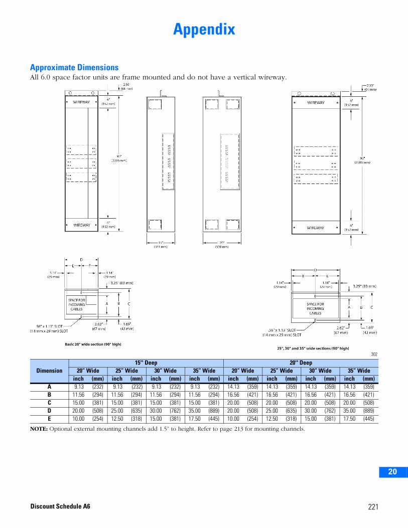
2
3
4
5
6
7
8
9
10
11
12
13
14
15
16
17
18
19
20
Appendix
Approximate DimensionsAll 6.0 space factor units are frame mounted and do not have a vertical wireway.
302
NOTE: Optional external mounting channels add 1.5” to height. Refer to page 213 for mounting channels.
Dimension15'' Deep 20'' Deep
20” Wide 25” Wide 30” Wide 35” Wide 20” Wide 25” Wide 30” Wide 35” Wideinch (mm) inch (mm) inch (mm) inch (mm) inch (mm) inch (mm) inch (mm) inch (mm)
A 9.13 (232) 9.13 (232) 9.13 (232) 9.13 (232) 14.13 (359) 14.13 (359) 14.13 (359) 14.13 (359)B 11.56 (294) 11.56 (294) 11.56 (294) 11.56 (294) 16.56 (421) 16.56 (421) 16.56 (421) 16.56 (421)C 15.00 (381) 15.00 (381) 15.00 (381) 15.00 (381) 20.00 (508) 20.00 (508) 20.00 (508) 20.00 (508)D 20.00 (508) 25.00 (635) 30.00 (762) 35.00 (889) 20.00 (508) 25.00 (635) 30.00 (762) 35.00 (889)E 10.00 (254) 12.50 (318) 15.00 (381) 17.50 (445) 10.00 (254) 12.50 (318) 15.00 (381) 17.50 (445)
221Discount Schedule A6
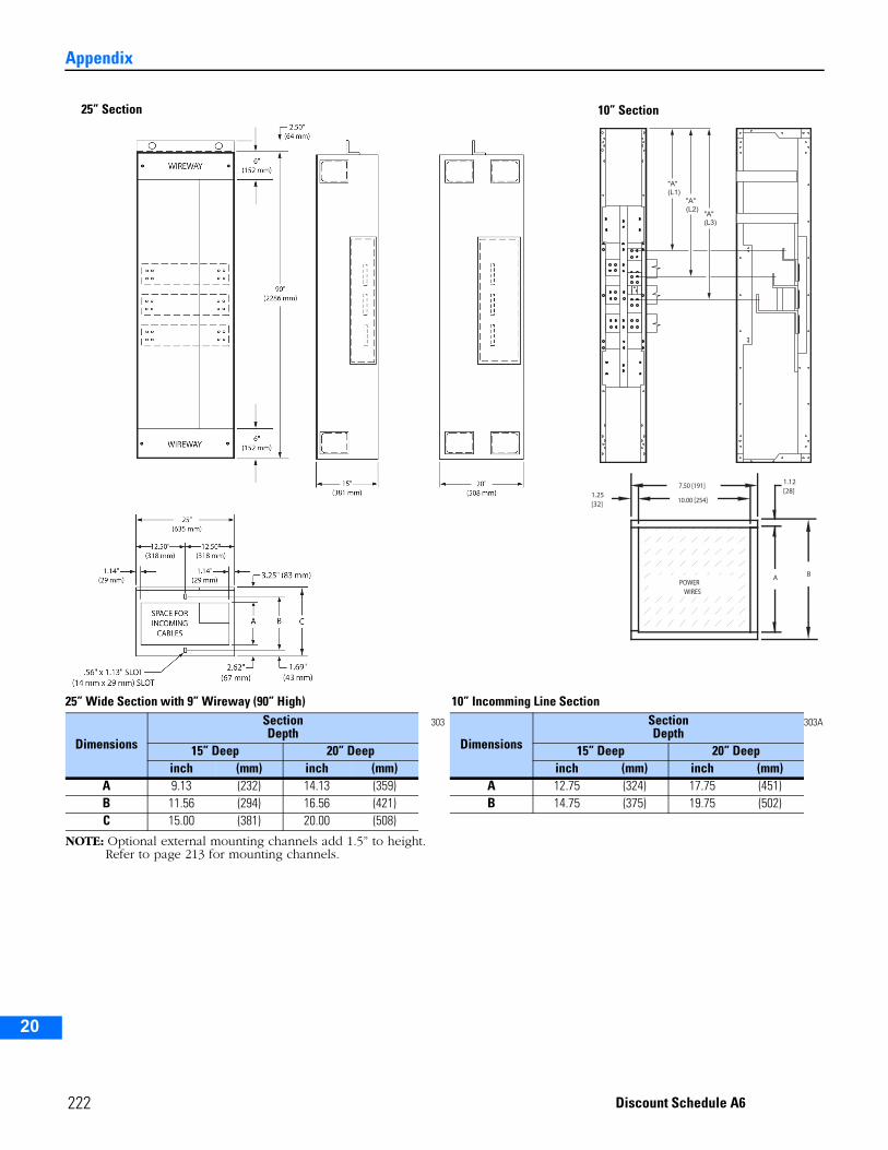
Appendix
2
3
4
5
9
10
11
12
13
14
15
16
17
18
19
20
25” Wide Section with 9” Wireway (90” High) 10” Incomming Line Section
NOTE: Optional external mounting channels add 1.5” to height.Refer to page 213 for mounting channels.
Dimensions
SectionDepth
303
Dimensions
SectionDepth
303A
15” Deep 20” Deep 15” Deep 20” Deepinch (mm) inch (mm) inch (mm) inch (mm)
A 9.13 (232) 14.13 (359) A 12.75 (324) 17.75 (451)B 11.56 (294) 16.56 (421) B 14.75 (375) 19.75 (502)C 15.00 (381) 20.00 (508)
"A"(L1)
"A"(L3)
"A"(L2)
A B
[32]1.25
[28]1.12
POWERWIRES
7.50 [191]
10.00 [254]
25” Section 10” Section
222 Discount Schedule A6
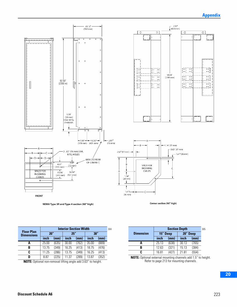
2
3
4
5
6
7
8
9
10
11
12
13
14
15
16
17
18
19
20
Appendix
Floor Plan Dimensions
Interior Section Width 304
DimensionSection Depth 305
20” 25” 30” 15” Deep 20” Deepinch (mm) inch (mm) inch (mm) inch (mm) inch (mm)
A 25.00 (635) 30.00 (762) 35.00 (889) A 25.13 (638) 30.13 (765)B 13.75 (349) 16.25 (413) 18.75 (476) B 12.63 (321) 15.13 (384)C 11.25 (286) 13.75 (349) 16.25 (413) C 16.81 (427) 21.81 (554)D 8.87 (225) 11.37 (289) 13.87 (352) NOTE: Optional external mounting channels add 1.5” to height.
Refer to page 213 for mounting channels.NOTE: Optional non-removal lifting angle add 3.63” to height.
92.50"(2350 m)
223Discount Schedule A6
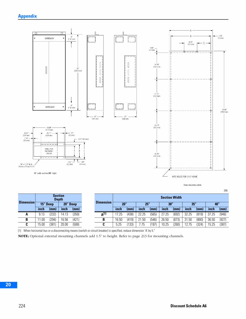
Appendix
2
3
4
5
9
10
11
12
13
14
15
16
17
18
19
20
306
NOTE: Optional external mounting channels add 1.5” to height. Refer to page 213 for mounting channels.
Dimension
SectionDepth
Dimension Section Width
15” Deep 20” Deep 20” 25” 30” 35” 40”inch (mm) inch (mm) inch (mm) inch (mm) inch (mm) inch (mm) inch (mm)
A 9.13 (232) 14.13 (359) A[1]
[1] When horizontal bus or a disconnecting means (switch or circuit breaker) is specified, reduce dimension ‘A’ by 5.”
17.25 (438) 22.25 (565) 27.25 (692) 32.25 (819) 37.25 (946)B 11.00 (294) 16.56 (421) B 16.50 (419) 21.50 (546) 26.50 (673) 31.50 (800) 36.50 (927)C 15.00 (381) 20.00 (508) C 5.25 (133) 7.75 (197) 10.25 (260) 12.75 (324) 15.25 (387)
224 Discount Schedule A6

2
3
4
5
6
7
8
9
10
11
12
13
14
15
16
17
18
19
20
Appendix
307
NOTE: Refer to page 221 for details of cabinet bottom.
DimensionsSection Depth
15” Deep 20” Deepinch (mm) inch (mm)
A 15.00 (380) 20.00 (508)B 14.75 (374) 19.75 (500)C 5.12 (130) 10.12 (256)D 4 (101) 8 (203)E — — 4.40 (112)
70.48"(1790.19 mm)
70.48"(1790.19 mm)
71" high section(1803.4 mm)
20"(508 mm)
20"(508 mm)
A
B
C
E
D
2.50"(64 mm)
2.50"(64 mm)
225Discount Schedule A6
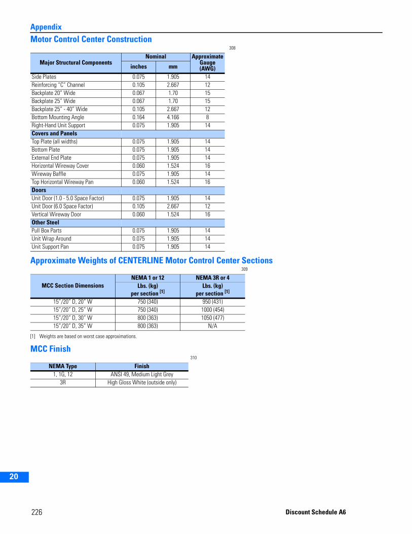
Appendix
2
3
4
5
9
10
11
12
13
14
15
16
17
18
19
20
Motor Control Center Construction308
Approximate Weights of CENTERLINE Motor Control Center Sections309
MCC Finish310
Major Structural ComponentsNominal Approximate
Gauge (AWG)inches mm
Side Plates 0.075 1.905 14Reinforcing “C” Channel 0.105 2.667 12Backplate 20” Wide 0.067 1.70 15Backplate 25” Wide 0.067 1.70 15Backplate 25” - 40” Wide 0.105 2.667 12Bottom Mounting Angle 0.164 4.166 8Right-Hand Unit Support 0.075 1.905 14Covers and PanelsTop Plate (all widths) 0.075 1.905 14Bottom Plate 0.075 1.905 14External End Plate 0.075 1.905 14Horizontal Wireway Cover 0.060 1.524 16Wireway Baffle 0.075 1.905 14Top Horizontal Wireway Pan 0.060 1.524 16DoorsUnit Door (1.0 - 5.0 Space Factor) 0.075 1.905 14Unit Door (6.0 Space Factor) 0.105 2.667 12Vertical Wireway Door 0.060 1.524 16Other SteelPull Box Parts 0.075 1.905 14Unit Wrap Around 0.075 1.905 14Unit Support Pan 0.075 1.905 14
MCC Section Dimensions NEMA 1 or 12 NEMA 3R or 4
Lbs. (kg)per section [1]
[1] Weights are based on worst case approximations.
Lbs. (kg)per section [1]
15”/20” D, 20” W 750 (340) 950 (431)15”/20” D, 25” W 750 (340) 1000 (454)15”/20” D, 30” W 800 (363) 1050 (477)15”/20” D, 35” W 800 (363) N/A
NEMA Type Finish1, 1G, 12 ANSI 49, Medium Light Grey
3R High Gloss White (outside only)
226 Discount Schedule A6
2
3
4
5
6
7
8
9
10
11
12
13
14
15
16
17
18
19
20
AppendixHeater Element SelectionOverload Relay Class DesignationsIndustry standard NEMA Part ICS 2-222 designates an overload relay by a class number, indicating the maximum time in seconds at which the relay will trip when carrying a current equal to 600 percent of its current rating.A class 10 overload relay will trip in 10 seconds or less at a current equal to 600 percent of its rating. Applications include hermetric motors, submersible pumps and motors with short locked rotor time capability.A class 20 overload relay will trip in 20 seconds or less at a current equal to 600 percent of its rating. They are often used for applications involving motors driving high inertia loads, where additional accelerating time is needed.Allen-Bradley standard overload relay protection using type W heater elements provides class 20 operation and is recommended for general applications. For applications regarding class 10 and 30 overload relays, consult your local Rockwell Automation Sales Office.Heater Element SelectionThe “Full Load Amps” listed in the table are to be used for heater element selection. The rating of the relay in amperes at 40°C is 115% of the full load amps listed for the “Heater Element No.”Refer to the motor nameplate for the full load current, the service factor and the motor classification by application and temperature rise.Use this motor nameplate information, the application rules and the full load amps listed in the tables to determine the Heater Element No.Motors Rated For Continuous DutyMotors with marked service factor of not less than 1.15 or motors with a marked temperature rise not over 40°C.1.) The same temperature at the controller and motor—Select the heater element number with the listed full load amps
nearest the full load value shown on the motor nameplate. This will provide integral horsepower motors with protection between 110 and 120% of the nameplate full load currents.
2.) Higher temperature at the controller than at the motor—*If the full load current value shown on the motor nameplate is between the listed full load amps, select the heater element number with the higher value. This will provide integral horsepower motors with protection between 115 and 125% of the nameplate full load currents.
3.) Lower temperature at the controller than at the motor—If the full load current value shown on the motor nameplate is between the listed full load amps, select the heater element number with the lower value. This will provide integral horsepower motors with protection between 105 and 115% of the nameplate full load currents.
All Other Motors Rated For Continuous Duty (Includes Motors With Marked Service Factor Of 1.0)Select the heater element number one rating smaller than determined by the rules in paragraphs 1, 2 and 3. This will provide protection at current levels 10% lower than indicated above.Motors Rated For Intermittent DutyConsult your local Rockwell Automation Sales Office.
* Rules 2 and 3 apply when the temperature difference does not exceed 10°C (18°F). Consult your local Rockwell Automation Sales Office when the temperature difference is greater.
227Discount Schedule A6
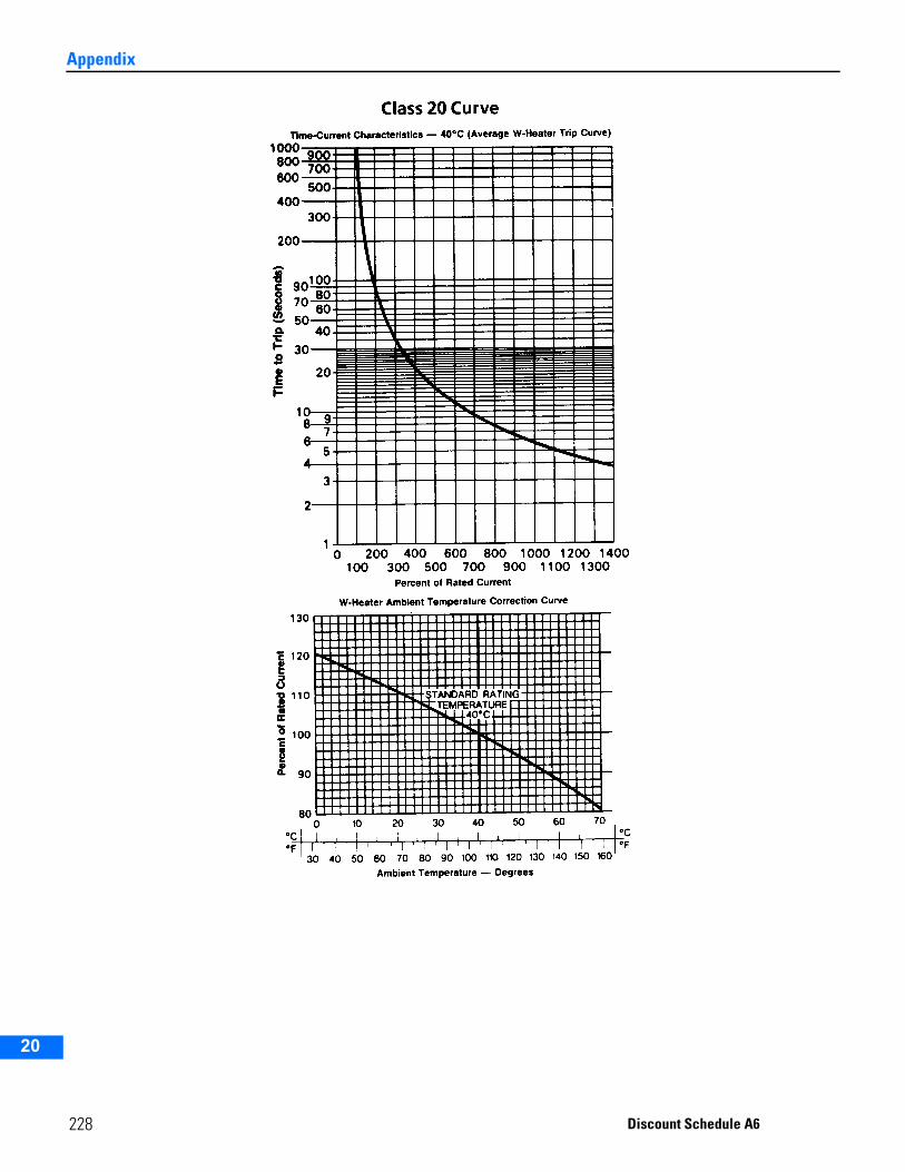
Appendix
2
3
4
5
9
10
11
12
13
14
15
16
17
18
19
20
228 Discount Schedule A6
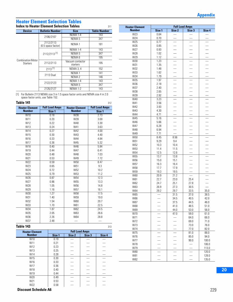
2
3
4
5
6
7
8
9
10
11
12
13
14
15
16
17
18
19
20
AppendixHeater Element Selection TablesIndex to Heater Element Selection Tables 311
Table 141 312
Table 143 313
Device Bulletin Number Size Table Number
Combination Motor Starters
2106/2107NEMA 1-4 143NEMA 5 347
2112/2113(0.5 space factor) NEMA 1 181
2112/2113 [1]
[1] For Bulletin 2113 NEMA size 3 in 1.5 space factor units and NEMA size 4 in 2.0 space factor units, use Table 152.
NEMA 1-4 143NEMA 5 347NEMA 6 195
2112/2113 Vacuum contactor starters 195
2113 [1] NEMA 3, 4 152
2113 DualNEMA 1 141NEMA 2 146
2122/2123NEMA 1-4 143NEMA 5 347
2126/2127 NEMA 1-2 143
Heater Element Number
Full Load Amps Heater Element Number
Full Load AmpsSize 1 Size 1
W10 0.18 W38 2.73W11 0.20 W39 3.00W12 0.22 W40 3.30W13 0.24 W41 3.63W14 0.27 W42 4.00W15 0.30 W43 4.40W16 0.33 W44 4.84W17 0.36 W45 5.32W18 0.40 W46 5.84W19 0.44 W47 6.41W20 0.48 W48 7.03W21 0.53 W49 7.72W22 0.59 W50 8.47W23 0.65 W51 9.3W24 0.72 W52 10.2W25 0.79 W53 11.2W26 0.87 W54 12.3W27 0.96 W55 13.3W28 1.05 W56 14.8W29 1.16 W57 16.1W30 1.27 W58 17.5W31 1.40 W59 19.0W32 1.54 W60 20.7W33 1.70 W61 22.5W34 1.87 W62 24.5W35 2.05 W63 26.6W36 2.26 W64 28.8W37 2.48 — —
Heater ElementNumber
Full Load AmpsSize 1 Size 2 Size 3 Size 4
W10 0.19 — — —W11 0.21 — — —W12 0.23 — — —W13 0.25 — — —W14 0.28 — — —W15 0.30 — — —W16 0.33 — — —W17 0.36 — — —W18 0.40 — — —W19 0.44 — — —W20 0.49 — — —W21 0.53 — — —W22 0.58 — — —
W23 0.64 — — —W24 0.70 — — —W25 0.77 — — —W26 0.85 — — —W27 0.93 — — —W28 1.02 — — —W29 1.12 — — —W30 1.23 — — —W31 1.35 — — —W32 1.48 — — —W33 1.62 — — —W34 1.79 — — —W35 1.97 — — —W36 2.18 — — —W37 2.40 — — —W38 2.65 — — —W39 2.92 — — —W40 3.23 — — —W41 3.56 — — —W42 3.93 — — —W43 4.30 — — —W44 4.71 — — —W45 5.16 — — —W46 5.66 — — —W47 6.28 — — —W48 6.94 — — —W49 7.71 — — —W50 8.45 8.56 — —W51 9.29 9.4 — —W52 10.3 10.4 — —W53 11.4 11.5 — —W54 12.5 12.6 — —W55 13.7 13.8 — —W56 15.0 15.1 — —W57 16.3 16.4 — —W58 17.7 17.9 — —W59 19.3 19.5 — —W60 20.9 21.2 — —W61 22.7 23.0 25.4 —W62 24.7 25.1 27.8 —W63 26.9 27.3 30.5 —W64 29.2 29.7 33.5 35.0W65 — 31.5 37.0 38.5W66 — 34.5 40.5 42.0W67 — 37.5 44.5 46.0W68 — 41.0 48.5 51.0W69 — 44.0 53.0 56.0W70 — 47.0 59.0 61.0W71 — — 64.0 66.0W72 — — 69.0 71.0W73 — — 73.0 76.0W74 — — 77.0 82.0W75 — — 81.0 88.0W76 — — 85.0 94.0W77 — — 90.0 100.0W78 — — — 106.0W79 — — — 113.0W80 — — — 120.0W81 — — — 128.0W82 — — — 135.0
Heater ElementNumber
Full Load AmpsSize 1 Size 2 Size 3 Size 4
Discount Schedule A6
229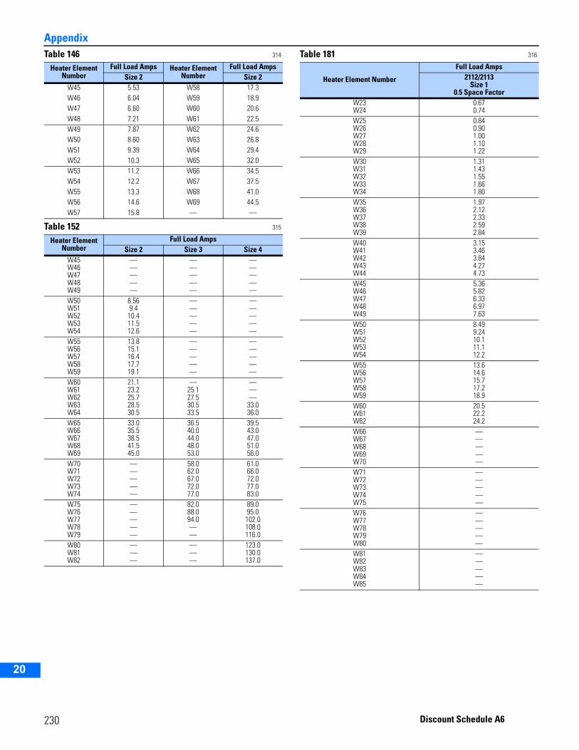
Appendix
2
3
4
5
9
10
11
12
13
14
15
16
17
18
19
20
Table 146 314
Table 152 315
Table 181 316
Heater Element Number
Full Load Amps Heater Element Number
Full Load AmpsSize 2 Size 2
W45 5.53 W58 17.3W46 6.04 W59 18.9W47 6.60 W60 20.6W48 7.21 W61 22.5W49 7.87 W62 24.6W50 8.60 W63 26.8W51 9.39 W64 29.4W52 10.3 W65 32.0W53 11.2 W66 34.5W54 12.2 W67 37.5W55 13.3 W68 41.0W56 14.6 W69 44.5W57 15.8 — —
Heater Element Number
Full Load AmpsSize 2 Size 3 Size 4
W45W46W47W48W49
—————
—————
—————
W50W51W52W53W54
8.569.4
10.411.512.6
—————
—————
W55W56W57W58W59
13.815.116.417.719.1
—————
—————
W60W61W62W63W64
21.123.225.728.530.5
—25.127.530.533.5
———
33.036.0
W65W66W67W68W69
33.035.538.541.545.0
36.540.044.048.053.0
39.543.047.051.056.0
W70W71W72W73W74
—————
58.062.067.072.077.0
61.066.072.077.083.0
W75W76W77W78W79
—————
82.088.094.0——
89.095.0102.0108.0116.0
W80W81W82
———
———
123.0130.0137.0
Heater Element Number
Full Load Amps2112/2113
Size 10.5 Space Factor
W23W24
0.670.74
W25W26W27W28W29
0.840.901.001.101.22
W30W31W32W33W34
1.311.431.551.661.80
W35W36W37W38W39
1.972.122.332.592.84
W40W41W42W43W44
3.153.463.844.274.73
W45W46W47W48W49
5.365.826.336.977.63
W50W51W52W53W54
8.499.2410.111.112.2
W55W56W57W58W59
13.614.615.717.218.9
W60W61W62
20.522.224.2
W66W67W68W69W70
—————
W71W72W73W74W75
—————
W76W77W78W79W80
—————
W81W82W83W84W85
—————
230 Discount Schedule A6
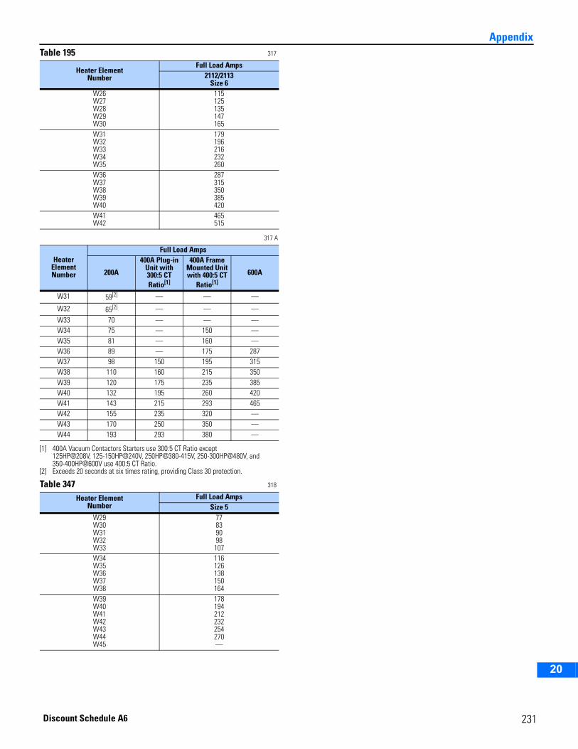
2
3
4
5
6
7
8
9
10
11
12
13
14
15
16
17
18
19
20
AppendixTable 195 317
317 A
Table 347 318
Heater ElementNumber
Full Load Amps2112/2113
Size 6W26W27W28W29W30
115125135147165
W31W32W33W34W35
179196216232260
W36W37W38W39W40
287315350385420
W41W42
465515
Heater ElementNumber
Full Load Amps
200A
400A Plug-in Unit with 300:5 CT Ratio[1]
[1] 400A Vacuum Contactors Starters use 300:5 CT Ratio except125HP@208V, 125-150HP@240V, 250HP@380-415V, 250-300HP@480V, and 350-400HP@600V use 400:5 CT Ratio.
400A Frame Mounted Unit with 400:5 CT
Ratio[1]
600A
W31 59[2]
[2] Exceeds 20 seconds at six times rating, providing Class 30 protection.
— — —
W32 65[2] — — —
W33 70 — — —W34 75 — 150 —W35 81 — 160 —W36 89 — 175 287W37 98 150 195 315W38 110 160 215 350W39 120 175 235 385W40 132 195 260 420W41 143 215 293 465W42 155 235 320 —W43 170 250 350 —W44 193 293 380 —
Heater ElementNumber
Full Load AmpsSize 5
W29W30W31W32W33
77839098107
W34W35W36W37W38
116126138150164
W39W40W41W42W43W44W45
178194212232254270—
231Discount Schedule A6
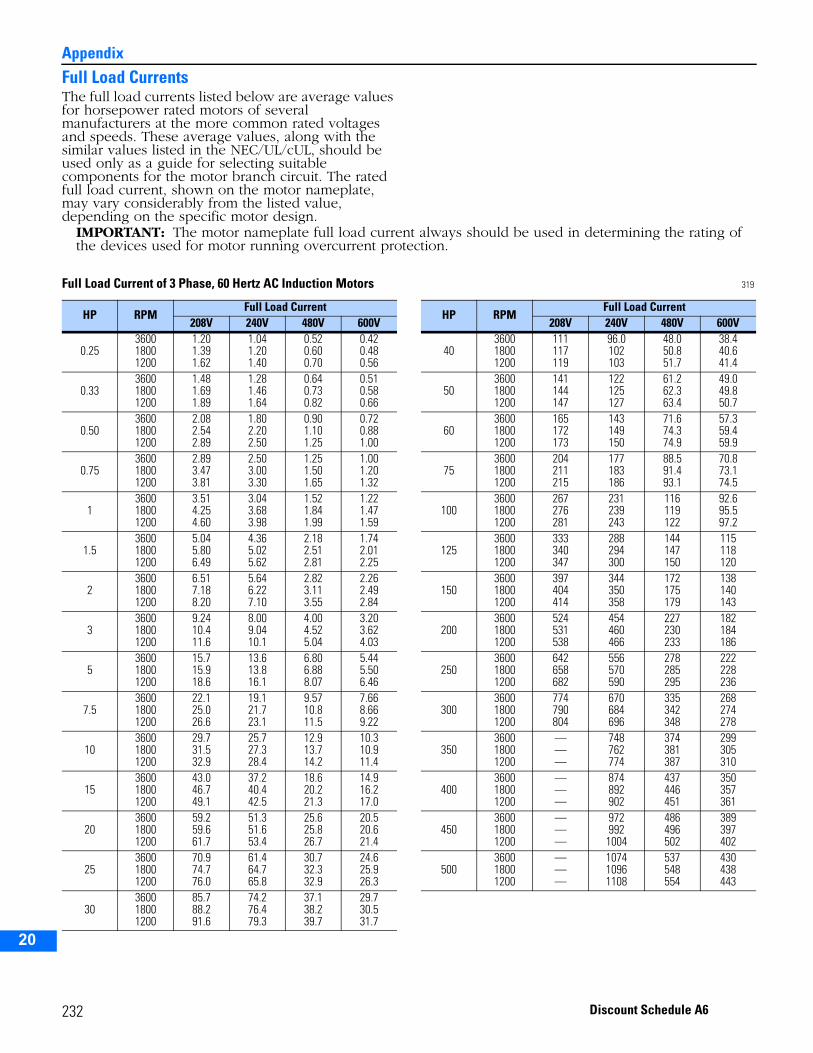
Appendix
2
3
4
5
9
10
11
12
13
14
15
16
17
18
19
20
Full Load CurrentsThe full load currents listed below are average values for horsepower rated motors of several manufacturers at the more common rated voltages and speeds. These average values, along with the similar values listed in the NEC/UL/cUL, should be used only as a guide for selecting suitable components for the motor branch circuit. The rated full load current, shown on the motor nameplate, may vary considerably from the listed value, depending on the specific motor design.
IMPORTANT: The motor nameplate full load current always should be used in determining the rating of the devices used for motor running overcurrent protection.
Full Load Current of 3 Phase, 60 Hertz AC Induction Motors 319
HP RPMFull Load Current
HP RPMFull Load Current
208V 240V 480V 600V 208V 240V 480V 600V
0.25360018001200
1.201.391.62
1.041.201.40
0.520.600.70
0.420.480.56
40360018001200
111117119
96.0102103
48.050.851.7
38.440.641.4
0.33360018001200
1.481.691.89
1.281.461.64
0.640.730.82
0.510.580.66
50360018001200
141144147
122125127
61.262.363.4
49.049.850.7
0.50360018001200
2.082.542.89
1.802.202.50
0.901.101.25
0.720.881.00
60360018001200
165172173
143149150
71.674.374.9
57.359.459.9
0.75360018001200
2.893.473.81
2.503.003.30
1.251.501.65
1.001.201.32
75360018001200
204211215
177183186
88.591.493.1
70.873.174.5
1360018001200
3.514.254.60
3.043.683.98
1.521.841.99
1.221.471.59
100360018001200
267276281
231239243
116119122
92.695.597.2
1.5360018001200
5.045.806.49
4.365.025.62
2.182.512.81
1.742.012.25
125360018001200
333340347
288294300
144147150
115118120
2360018001200
6.517.188.20
5.646.227.10
2.823.113.55
2.262.492.84
150360018001200
397404414
344350358
172175179
138140143
3360018001200
9.2410.411.6
8.009.0410.1
4.004.525.04
3.203.624.03
200360018001200
524531538
454460466
227230233
182184186
5360018001200
15.715.918.6
13.613.816.1
6.806.888.07
5.445.506.46
250360018001200
642658682
556570590
278285295
222228236
7.5360018001200
22.125.026.6
19.121.723.1
9.5710.811.5
7.668.669.22
300360018001200
774790804
670684696
335342348
268274278
10360018001200
29.731.532.9
25.727.328.4
12.913.714.2
10.310.911.4
350360018001200
———
748762774
374381387
299305310
15360018001200
43.046.749.1
37.240.442.5
18.620.221.3
14.916.217.0
400360018001200
———
874892902
437446451
350357361
20360018001200
59.259.661.7
51.351.653.4
25.625.826.7
20.520.621.4
450360018001200
———
9729921004
486496502
389397402
25360018001200
70.974.776.0
61.464.765.8
30.732.332.9
24.625.926.3
500360018001200
———
107410961108
537548554
430438443
30360018001200
85.788.291.6
74.276.479.3
37.138.239.7
29.730.531.7
232 Discount Schedule A6
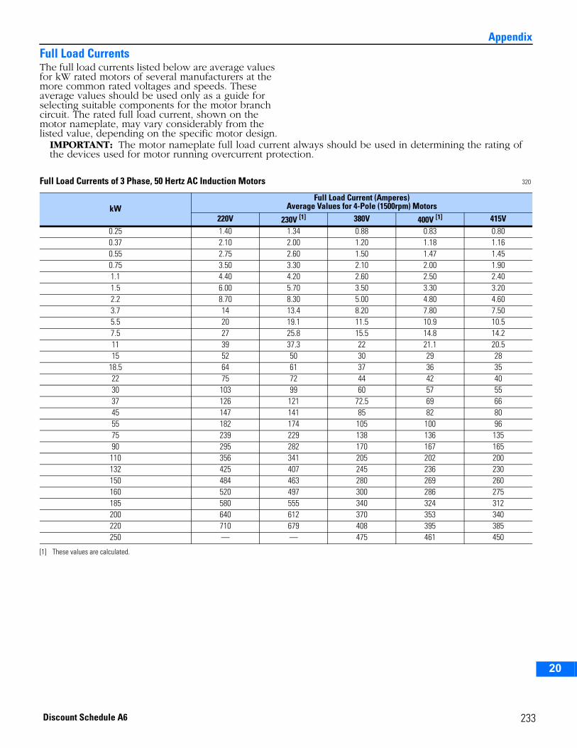
2
3
4
5
6
7
8
9
10
11
12
13
14
15
16
17
18
19
20
AppendixFull Load CurrentsThe full load currents listed below are average values for kW rated motors of several manufacturers at the more common rated voltages and speeds. These average values should be used only as a guide for selecting suitable components for the motor branch circuit. The rated full load current, shown on the motor nameplate, may vary considerably from the listed value, depending on the specific motor design.
IMPORTANT: The motor nameplate full load current always should be used in determining the rating of the devices used for motor running overcurrent protection.
Full Load Currents of 3 Phase, 50 Hertz AC Induction Motors 320
kWFull Load Current (Amperes)
Average Values for 4-Pole (1500rpm) Motors220V 230V [1] 380V 400V [1] 415V
0.25 1.40 1.34 0.88 0.83 0.800.37 2.10 2.00 1.20 1.18 1.160.55 2.75 2.60 1.50 1.47 1.450.75 3.50 3.30 2.10 2.00 1.901.1 4.40 4.20 2.60 2.50 2.401.5 6.00 5.70 3.50 3.30 3.202.2 8.70 8.30 5.00 4.80 4.603.7 14 13.4 8.20 7.80 7.505.5 20 19.1 11.5 10.9 10.57.5 27 25.8 15.5 14.8 14.211 39 37.3 22 21.1 20.515 52 50 30 29 28
18.5 64 61 37 36 3522 75 72 44 42 4030 103 99 60 57 5537 126 121 72.5 69 6645 147 141 85 82 8055 182 174 105 100 9675 239 229 138 136 13590 295 282 170 167 165110 356 341 205 202 200132 425 407 245 236 230150 484 463 280 269 260160 520 497 300 286 275185 580 555 340 324 312200 640 612 370 353 340220 710 679 408 395 385250 — — 475 461 450
[1] These values are calculated.
233Discount Schedule A6
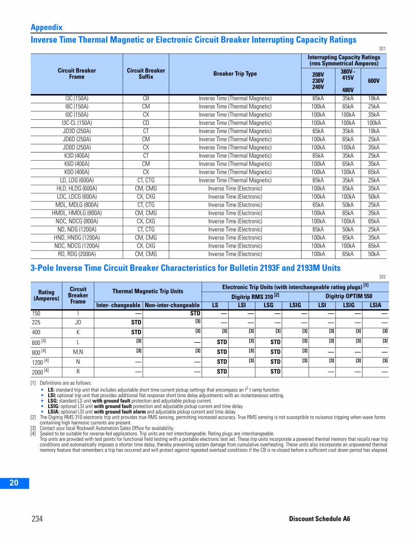
Appendix
2
3
4
5
9
10
11
12
13
14
15
16
17
18
19
20
Inverse Time Thermal Magnetic or Electronic Circuit Breaker Interrupting Capacity Ratings321
3-Pole Inverse Time Circuit Breaker Characteristics for Bulletin 2193F and 2193M Units322
Circuit BreakerFrame
Circuit Breaker Suffix Breaker Trip Type
Interrupting Capacity Ratings(rms Symmetrical Amperes)
208V230V240V
380V– 415V
480V600V
I3C (150A) CB Inverse Time (Thermal Magnetic) 65kA 35kA 18kAI6C (150A) CM Inverse Time (Thermal Magnetic) 100kA 65kA 25kAI0C (150A) CX Inverse Time (Thermal Magnetic) 100kA 100kA 35kA
I3C-CL (150A) CD Inverse Time (Thermal Magnetic) 100kA 100kA 100kAJD3D (250A) CT Inverse Time (Thermal Magnetic) 65kA 35kA 18kAJD6D (250A) CM Inverse Time (Thermal Magnetic) 100kA 65kA 25kAJD0D (250A) CX Inverse Time (Thermal Magnetic) 100kA 100kA 35kAK3D (400A) CT Inverse Time (Thermal Magnetic) 65kA 35kA 25kAK6D (400A) CM Inverse Time (Thermal Magnetic) 100kA 65kA 35kAK0D (400A) CX Inverse Time (Thermal Magnetic) 100kA 100kA 65kA
LD, LDG (600A) CT, CTG Inverse Time (Thermal Magnetic) 65kA 35kA 25kAHLD, HLDG (600A) CM, CMG Inverse Time (Electronic) 100kA 65kA 35kALDC, LDCG (600A) CX, CXG Inverse Time (Electronic) 100kA 100kA 50kA
MDL, MDLG (800A) CT, CTG Inverse Time (Electronic) 65kA 50kA 25kAHMDL, HMDLG (800A) CM, CMG Inverse Time (Electronic) 100kA 65kA 35kA
NDC, NDCG (800A) CX, CXG Inverse Time (Electronic) 100kA 100kA 65kAND, NDG (1200A) CT, CTG Inverse Time (Electronic) 65kA 50kA 25kA
HND, HNDG (1200A) CM, CMG Inverse Time (Electronic) 100kA 65kA 35kANDC, NDCG (1200A) CX, CXG Inverse Time (Electronic) 100kA 100kA 65kA
RD, RDG (2000A) CM, CMG Inverse Time (Electronic) 100kA 65kA 50kA
Rating (Amperes)
Circuit Breaker Frame
Thermal Magnetic Trip UnitsElectronic Trip Units (with interchangeable rating plugs) [1]
[1] Definitions are as follows:• LS: standard trip unit that includes adjustable short time current pickup settings that encompass an I2 t ramp function.• LSI: optional trip unit that provides additional flat response short time delay adjustments with an instantaneous setting.• LSG: standard LS unit with ground fault protection and adjustable pickup current.• LSIG: optional LSI unit with ground fault protection and adjustable pickup current and time delay.• LSIA: optional LSI unit with ground fault alarm and adjustable pickup current and time delay.
Digitrip RMS 310 [2]
[2] The Digitrip RMS 310 electronic trip unit provides true RMS sensing, permitting increased accuracy. True RMS sensing is not susceptible to nuisance tripping when wave forms containing high harmonic currents are present.
Digitrip OPTIM 550Inter- changeable Non-inter-changeable LS LSI LSG LSIG LSI LSIG LSIA
150 I — STD — — — — — — —225 JD STD [3]
[3] Contact your local Rockwell Automation Sales Office for availability.
— — — — — — —
400 K STD [3] [3] [3] [3] [3] [3] [3] [3]
600 [4]
[4] Sealed to be suitable for reverse-fed applications. Trip units are not interchangeable. Rating plugs are interchangeable.Trip units are provided with test points for functional field testing with a portable electronic test set. These trip units incorporate a powered thermal memory that recalls near trip conditions and automatically imposes a shorter time delay, thereby preventing system damage from cumulative overheating. These units also incorporate an unpowered thermal memory feature that remembers a trip has occurred and will protect against repeated overload conditions if the CB is re-closed before a sufficient cool down period has elapsed.
L [3] — STD [3] STD [3] [3] [3] [3]
800 [4] M,N [3] [3] STD [3] STD [3] — — —
1200 [4] N — — STD [3] STD [3] [3] [3] [3]
2000 [4] R — — STD STD — — —
234 Discount Schedule A6
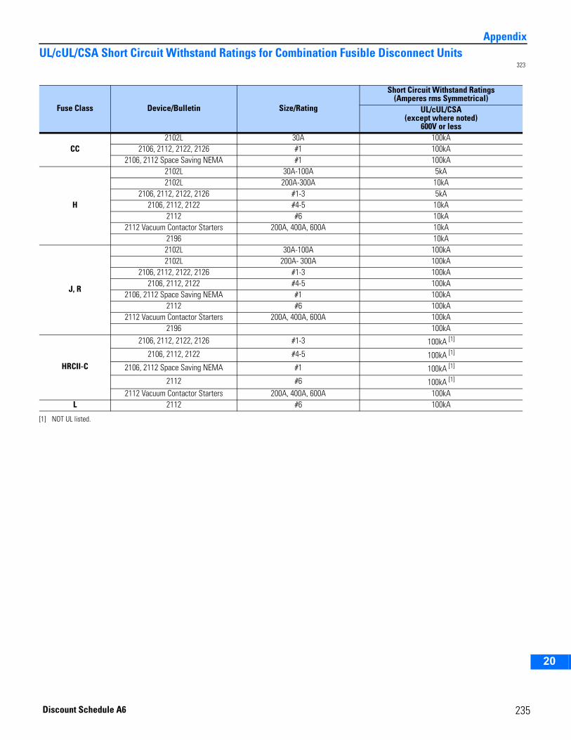
2
3
4
5
6
7
8
9
10
11
12
13
14
15
16
17
18
19
20
AppendixUL/cUL/CSA Short Circuit Withstand Ratings for Combination Fusible Disconnect Units
323
Fuse Class Device/Bulletin Size/Rating
Short Circuit Withstand Ratings(Amperes rms Symmetrical)
UL/cUL/CSA(except where noted)
600V or less
CC2102L 30A 100kA
2106, 2112, 2122, 2126 #1 100kA2106, 2112 Space Saving NEMA #1 100kA
H
2102L 30A-100A 5kA2102L 200A-300A 10kA
2106, 2112, 2122, 2126 #1-3 5kA2106, 2112, 2122 #4-5 10kA
2112 #6 10kA2112 Vacuum Contactor Starters 200A, 400A, 600A 10kA
2196 10kA
J, R
2102L 30A-100A 100kA2102L 200A- 300A 100kA
2106, 2112, 2122, 2126 #1-3 100kA2106, 2112, 2122 #4-5 100kA
2106, 2112 Space Saving NEMA #1 100kA2112 #6 100kA
2112 Vacuum Contactor Starters 200A, 400A, 600A 100kA2196 100kA
HRCII-C
2106, 2112, 2122, 2126 #1-3 100kA [1]
2106, 2112, 2122 #4-5 100kA [1]
2106, 2112 Space Saving NEMA #1 100kA [1]
2112 #6 100kA [1]
2112 Vacuum Contactor Starters 200A, 400A, 600A 100kAL 2112 #6 100kA
[1] NOT UL listed.
235Discount Schedule A6
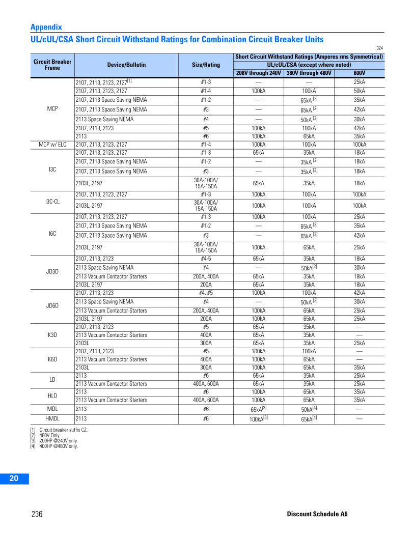
Appendix
2
3
4
5
9
10
11
12
13
14
15
16
17
18
19
20
236
UL/cUL/CSA Short Circuit Withstand Ratings for Combination Circuit Breaker Units324
Circuit Breaker Frame Device/Bulletin Size/Rating
Short Circuit Withstand Ratings (Amperes rms Symmetrical)UL/cUL/CSA (except where noted)
208V through 240V 380V through 480V 600V
MCP
2107, 2113, 2123, 2127[1]
[1] Circuit breaker suffix CZ.
#1-3 — — 25kA2107, 2113, 2123, 2127 #1-4 100kA 100kA 50kA2107, 2113 Space Saving NEMA #1-2 — 65kA [2] 35kA
2107, 2113 Space Saving NEMA #3 — 65kA [2] 42kA
2113 Space Saving NEMA #4 — 50kA [2] 30kA2107, 2113, 2123 #5 100kA 100kA 42kA2113 #6 100kA 65kA 35kA
MCP w/ ELC 2107, 2113, 2123, 2127 #1-4 100kA 100kA 100kA
I3C
2107, 2113, 2123, 2127 #1-3 65kA 35kA 18kA2107, 2113 Space Saving NEMA #1-2 — 35kA [2] 18kA
2107, 2113 Space Saving NEMA #3 — 35kA [2] 18kA
2103L, 2197 30A-100A/15A-150A 65kA 35kA 18kA
I3C-CL2107, 2113, 2123, 2127 #1-3 100kA 100kA 100kA
2103L, 2197 30A-100A/15A-150A 100kA 100kA 100kA
I6C
2107, 2113, 2123, 2127 #1-3 100kA 100kA 25kA2107, 2113 Space Saving NEMA #1-2 — 65kA [2]
[2] 480V Only.
35kA
2107, 2113 Space Saving NEMA #3 — 65kA [2] 42kA
2103L, 2197 30A-100A/15A-150A 100kA 65kA 25kA
JD3D
2107, 2113, 2123 #4-5 65kA 35kA 18kA2113 Space Saving NEMA #4 — 50kA[2] 30kA2113 Vacuum Contactor Starters 200A, 400A 65kA 35kA 18kA2103L, 2197 200A 65kA 35kA 18kA
JD6D
2107, 2113, 2123 #4, #5 100kA 100kA 42kA2113 Space Saving NEMA #4 — 50kA [2] 30kA2113 Vacuum Contactor Starters 200A, 400A 100kA 65kA 25kA2103L, 2197 200A 100kA 65kA 25kA
K3D2107, 2113, 2123 #5 65kA 35kA —2113 Vacuum Contactor Starters 400A 65kA 35kA —2103L 300A 65kA 35kA 25kA
K6D2107, 2113, 2123 #5 100kA 100kA —2113 Vacuum Contactor Starters 400A 100kA 65kA —2103L 300A 100kA 65kA 35kA
LD2113 #6 65kA 35kA 25kA2113 Vacuum Contactor Starters 400A, 600A 65kA 35kA 25kA
HLD2113 #6 100kA 65kA 35kA2113 Vacuum Contactor Starters 400A, 600A 100kA 65kA 35kA
MDL 2113 #6 65kA[3]
[3] 200HP @240V only.
50kA[4]
[4] 400HP @480V only.
—
HMDL 2113 #6 100kA[3] 65kA[4] —
Discount Schedule A6
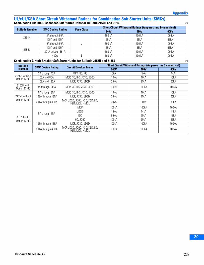
2
3
4
5
6
7
8
9
10
11
12
13
14
15
16
17
18
19
20
AppendixUL/cUL/CSA Short Circuit Withstand Ratings for Combination Soft Starter Units (SMCs)Combination Fusible Disconnect Soft Starter Units for Bulletin 2154H and 2154J 325
Combination Circuit Breaker Soft Starter Units for Bulletin 2155H and 2155J 326
Bulletin Number SMC Device Rating Fuse ClassShort Circuit Withstand Ratings (Amperes rms Symmetrical)
240V 480V 600V
2154H3A through 85A
J
100 kA 100 kA 100 kA108A and 135A 65kA 65kA 65kA
2154J
5A through 85A 100 kA 100 kA 100 kA108A and 135A 65kA 65kA 65kA
201A through 361A 100 kA 100 kA 100 kA480A L 100 kA 100 kA 100 kA
Bulletin Number SMC Device Rating Circuit Breaker Frame
Short Circuit Withstand Ratings (Amperes rms Symmetrical)240V 480V 600V
2155H without Option 13HIC
3A through 43A MCP, I3C, I6C 5kA 5kA 5kA60A and 85A MCP, I3C, I6C, JD3D, JD6D 10kA 10kA 10kA
108A and 135A MCP, JD3D, JD6D 25kA 25kA 25kA2155H with
Option 13HIC 3A through 135A MCP, I3C, I6C, JD3D, JD6D 100kA 100kA 100kA
2155J without Option 13HIC
5A through 85A MCP, I3C, I6C, JD3D, JD6D 10kA 10kA 10kA108A through 135A MCP, JD3D, JD6D 25kA 25kA 25kA
201A through 480A MCP, JD3D, JD6D, K3D, K6D, LD, HLD, MDL, HMDL 30kA 30kA 30kA
2155J with Option 13HIC
5A through 85A
MCP 100kA 100kA 100kAJD3D 18kA 14kA 14kAI3C 65kA 25kA 18kA
I6C, JD6D 100kA 65kA 25kA108A through 135A MCP, JD3D, JD6D 100kA 100kA 100kA
201A through 480A MCP, JD3D, JD6D, K3D, K6D, LD, HLD, MDL, HMDL 100kA 100kA 100kA
237Discount Schedule A6
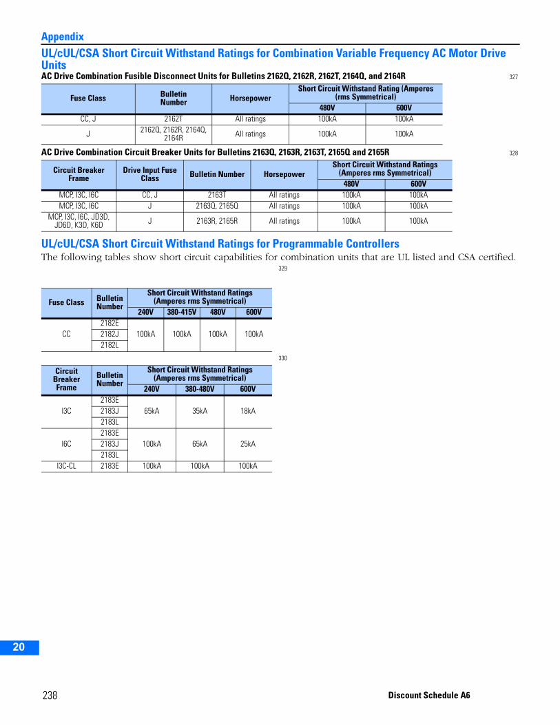
Appendix
2
3
4
5
9
10
11
12
13
14
15
16
17
18
19
20
UL/cUL/CSA Short Circuit Withstand Ratings for Combination Variable Frequency AC Motor Drive UnitsAC Drive Combination Fusible Disconnect Units for Bulletins 2162Q, 2162R, 2162T, 2164Q, and 2164R 327
AC Drive Combination Circuit Breaker Units for Bulletins 2163Q, 2163R, 2163T, 2165Q and 2165R 328
UL/cUL/CSA Short Circuit Withstand Ratings for Programmable ControllersThe following tables show short circuit capabilities for combination units that are UL listed and CSA certified.
329
330
Fuse Class BulletinNumber Horsepower
Short Circuit Withstand Rating (Amperes (rms Symmetrical)
480V 600VCC, J 2162T All ratings 100kA 100kA
J 2162Q, 2162R, 2164Q, 2164R All ratings 100kA 100kA
Circuit Breaker Frame
Drive Input Fuse Class Bulletin Number Horsepower
Short Circuit Withstand Ratings (Amperes rms Symmetrical)
480V 600VMCP, I3C, I6C CC, J 2163T All ratings 100kA 100kAMCP, I3C, I6C J 2163Q, 2165Q All ratings 100kA 100kA
MCP, I3C, I6C, JD3D, JD6D, K3D, K6D J 2163R, 2165R All ratings 100kA 100kA
Fuse Class Bulletin Number
Short Circuit Withstand Ratings (Amperes rms Symmetrical)
240V 380-415V 480V 600V
CC2182E
100kA 100kA 100kA 100kA2182J2182L
Circuit Breaker Frame
Bulletin Number
Short Circuit Withstand Ratings(Amperes rms Symmetrical)
240V 380-480V 600V
I3C2183E
65kA 35kA 18kA2183J2183L
I6C2183E
100kA 65kA 25kA2183J2183L
I3C-CL 2183E 100kA 100kA 100kA
238 Discount Schedule A6
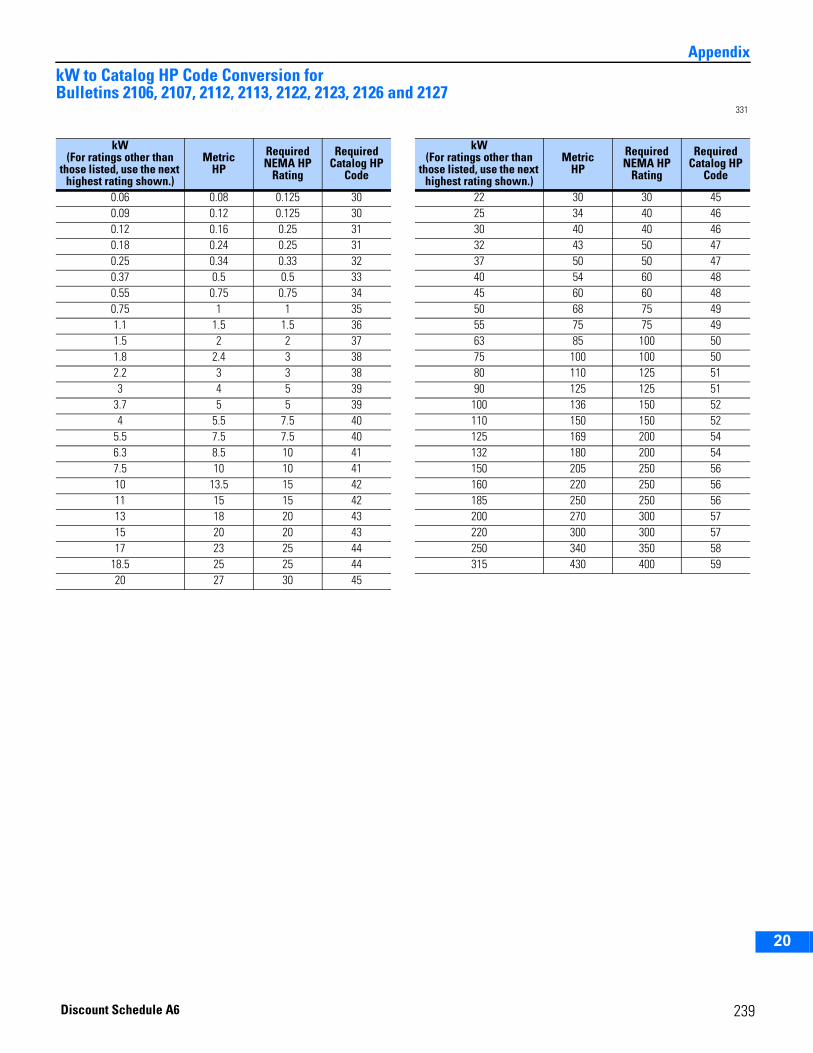
2
3
4
5
6
7
8
9
10
11
12
13
14
15
16
17
18
19
20
AppendixkW to Catalog HP Code Conversion for Bulletins 2106, 2107, 2112, 2113, 2122, 2123, 2126 and 2127
331
kW(For ratings other than
those listed, use the next highest rating shown.)
Metric HP
Required NEMA HP
Rating
Required Catalog HP
Code
0.06 0.08 0.125 300.09 0.12 0.125 300.12 0.16 0.25 310.18 0.24 0.25 310.25 0.34 0.33 320.37 0.5 0.5 330.55 0.75 0.75 340.75 1 1 351.1 1.5 1.5 361.5 2 2 371.8 2.4 3 382.2 3 3 383 4 5 39
3.7 5 5 394 5.5 7.5 40
5.5 7.5 7.5 406.3 8.5 10 417.5 10 10 4110 13.5 15 4211 15 15 4213 18 20 4315 20 20 4317 23 25 44
18.5 25 25 4420 27 30 45
kW(For ratings other than
those listed, use the next highest rating shown.)
Metric HP
Required NEMA HP
Rating
Required Catalog HP
Code
22 30 30 4525 34 40 4630 40 40 4632 43 50 4737 50 50 4740 54 60 4845 60 60 4850 68 75 4955 75 75 4963 85 100 5075 100 100 5080 110 125 5190 125 125 51
100 136 150 52110 150 150 52125 169 200 54132 180 200 54150 205 250 56160 220 250 56185 250 250 56200 270 300 57220 300 300 57250 340 350 58315 430 400 59
239Discount Schedule A6
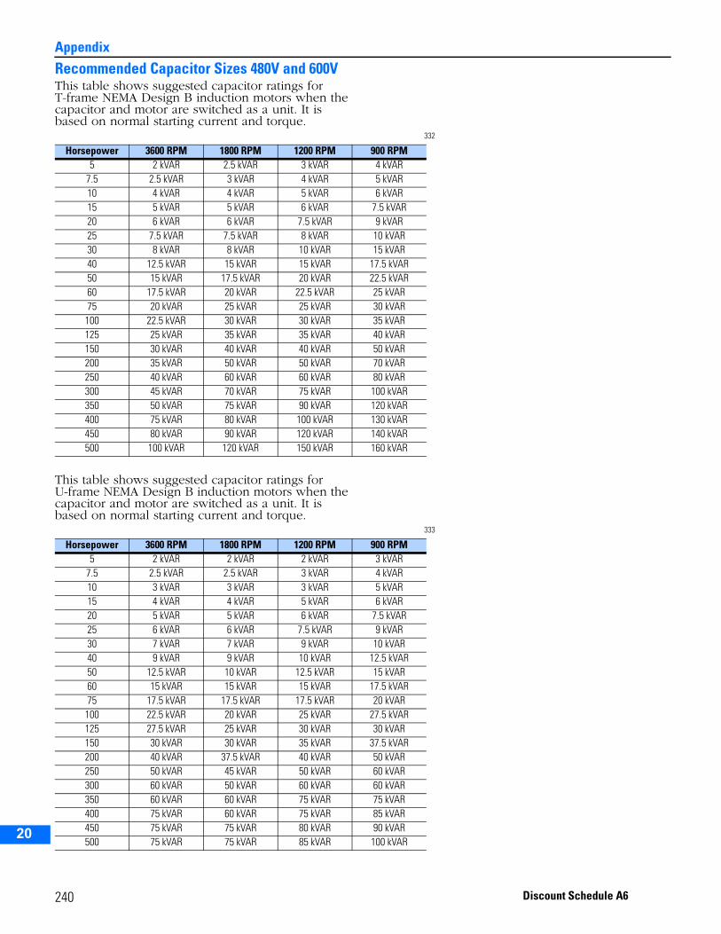
Appendix
2
3
4
5
9
10
11
12
13
14
15
16
17
18
19
20
Recommended Capacitor Sizes 480V and 600VThis table shows suggested capacitor ratings for T-frame NEMA Design B induction motors when the capacitor and motor are switched as a unit. It is based on normal starting current and torque.
332
This table shows suggested capacitor ratings for U-frame NEMA Design B induction motors when the capacitor and motor are switched as a unit. It is based on normal starting current and torque.
333
Horsepower 3600 RPM 1800 RPM 1200 RPM 900 RPM5 2 kVAR 2.5 kVAR 3 kVAR 4 kVAR
7.5 2.5 kVAR 3 kVAR 4 kVAR 5 kVAR10 4 kVAR 4 kVAR 5 kVAR 6 kVAR15 5 kVAR 5 kVAR 6 kVAR 7.5 kVAR20 6 kVAR 6 kVAR 7.5 kVAR 9 kVAR25 7.5 kVAR 7.5 kVAR 8 kVAR 10 kVAR30 8 kVAR 8 kVAR 10 kVAR 15 kVAR40 12.5 kVAR 15 kVAR 15 kVAR 17.5 kVAR50 15 kVAR 17.5 kVAR 20 kVAR 22.5 kVAR60 17.5 kVAR 20 kVAR 22.5 kVAR 25 kVAR75 20 kVAR 25 kVAR 25 kVAR 30 kVAR100 22.5 kVAR 30 kVAR 30 kVAR 35 kVAR125 25 kVAR 35 kVAR 35 kVAR 40 kVAR150 30 kVAR 40 kVAR 40 kVAR 50 kVAR200 35 kVAR 50 kVAR 50 kVAR 70 kVAR250 40 kVAR 60 kVAR 60 kVAR 80 kVAR300 45 kVAR 70 kVAR 75 kVAR 100 kVAR350 50 kVAR 75 kVAR 90 kVAR 120 kVAR400 75 kVAR 80 kVAR 100 kVAR 130 kVAR450 80 kVAR 90 kVAR 120 kVAR 140 kVAR500 100 kVAR 120 kVAR 150 kVAR 160 kVAR
Horsepower 3600 RPM 1800 RPM 1200 RPM 900 RPM5 2 kVAR 2 kVAR 2 kVAR 3 kVAR
7.5 2.5 kVAR 2.5 kVAR 3 kVAR 4 kVAR10 3 kVAR 3 kVAR 3 kVAR 5 kVAR15 4 kVAR 4 kVAR 5 kVAR 6 kVAR20 5 kVAR 5 kVAR 6 kVAR 7.5 kVAR25 6 kVAR 6 kVAR 7.5 kVAR 9 kVAR30 7 kVAR 7 kVAR 9 kVAR 10 kVAR40 9 kVAR 9 kVAR 10 kVAR 12.5 kVAR50 12.5 kVAR 10 kVAR 12.5 kVAR 15 kVAR60 15 kVAR 15 kVAR 15 kVAR 17.5 kVAR75 17.5 kVAR 17.5 kVAR 17.5 kVAR 20 kVAR100 22.5 kVAR 20 kVAR 25 kVAR 27.5 kVAR125 27.5 kVAR 25 kVAR 30 kVAR 30 kVAR150 30 kVAR 30 kVAR 35 kVAR 37.5 kVAR200 40 kVAR 37.5 kVAR 40 kVAR 50 kVAR250 50 kVAR 45 kVAR 50 kVAR 60 kVAR300 60 kVAR 50 kVAR 60 kVAR 60 kVAR350 60 kVAR 60 kVAR 75 kVAR 75 kVAR400 75 kVAR 60 kVAR 75 kVAR 85 kVAR450 75 kVAR 75 kVAR 80 kVAR 90 kVAR500 75 kVAR 75 kVAR 85 kVAR 100 kVAR
240 Discount Schedule A6
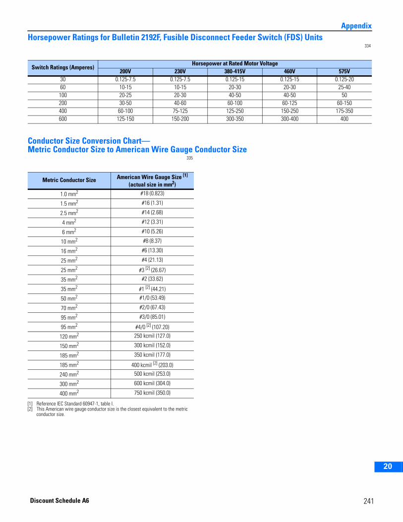
2
3
4
5
6
7
8
9
10
11
12
13
14
15
16
17
18
19
20
AppendixHorsepower Ratings for Bulletin 2192F, Fusible Disconnect Feeder Switch (FDS) Units
334
Conductor Size Conversion Chart—Metric Conductor Size to American Wire Gauge Conductor Size
335
Switch Ratings (Amperes)Horsepower at Rated Motor Voltage
200V 230V 380-415V 460V 575V30 0.125-7.5 0.125-7.5 0.125-15 0.125-15 0.125-2060 10-15 10-15 20-30 20-30 25-40100 20-25 20-30 40-50 40-50 50200 30-50 40-60 60-100 60-125 60-150400 60-100 75-125 125-250 150-250 175-350600 125-150 150-200 300-350 300-400 400
Metric Conductor Size American Wire Gauge Size [1] (actual size in mm2)
[1] Reference IEC Standard 60947-1, table I.
1.0 mm2 #18 (0.823)
1.5 mm2 #16 (1.31)
2.5 mm2 #14 (2.68)
4 mm2 #12 (3.31)
6 mm2 #10 (5.26)
10 mm2 #8 (8.37)
16 mm2 #6 (13.30)
25 mm2 #4 (21.13)
25 mm2 #3 [2] (26.67)
[2] This American wire gauge conductor size is the closest equivalent to the metric conductor size.
35 mm2 #2 (33.62)
35 mm2 #1 [2] (44.21)
50 mm2 #1/0 (53.49)
70 mm2 #2/0 (67.43)
95 mm2 #3/0 (85.01)
95 mm2 #4/0 [2] (107.20)
120 mm2 250 kcmil (127.0)
150 mm2 300 kcmil (152.0)
185 mm2 350 kcmil (177.0)
185 mm2 400 kcmil [2] (203.0)
240 mm2 500 kcmil (253.0)
300 mm2 600 kcmil (304.0)
400 mm2 750 kcmil (350.0)
241Discount Schedule A6
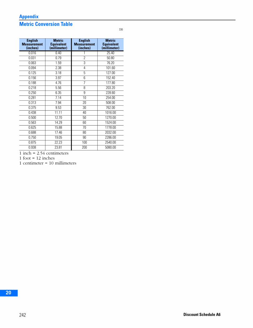
Appendix
2
3
4
5
9
10
11
12
13
14
15
16
17
18
19
20
Metric Conversion Table336
1 inch = 2.54 centimeters1 foot = 12 inches1 centimeter = 10 millimeters
English Measurement
(inches)
Metric Equivalent (millimeter)
English Measurement
(inches)
Metric Equivalent
(millimeter)0.016 0.40 1 25.400.031 0.79 2 50.800.063 1.59 3 76.200.094 2.38 4 101.600.125 3.18 5 127.000.156 3.97 6 152.400.188 4.76 7 177.800.218 5.56 8 203.200.250 6.35 9 228.600.281 7.14 10 254.000.313 7.94 20 508.000.375 9.53 30 762.000.438 11.11 40 1016.000.500 12.70 50 1270.000.563 14.29 60 1524.000.625 15.88 70 1778.000.688 17.46 80 2032.000.750 19.05 90 2286.000.875 22.23 100 2540.000.938 23.81 200 5080.00
242 Discount Schedule A6
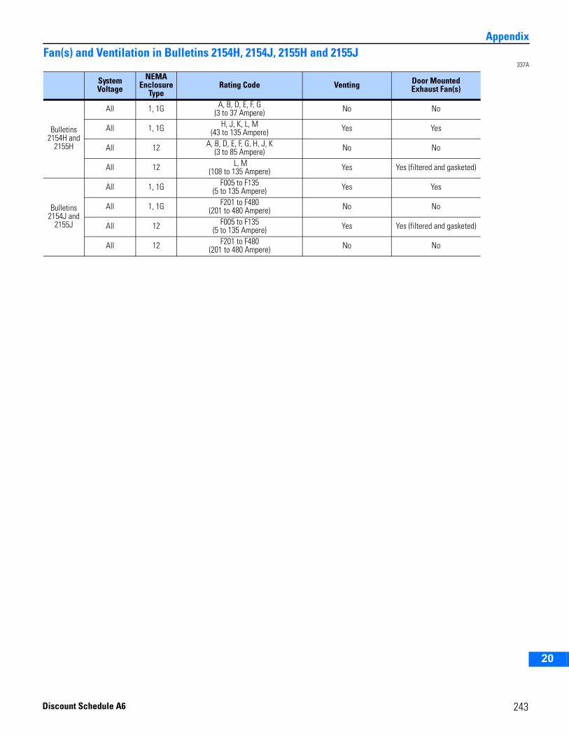
2
3
4
5
6
7
8
9
10
11
12
13
14
15
16
17
18
19
20
AppendixFan(s) and Ventilation in Bulletins 2154H, 2154J, 2155H and 2155J
337A
System Voltage
NEMA Enclosure
TypeRating Code Venting Door Mounted
Exhaust Fan(s)
Bulletins 2154H and
2155H
All 1, 1G A, B, D, E, F, G(3 to 37 Ampere) No No
All 1, 1G H, J, K, L, M(43 to 135 Ampere) Yes Yes
All 12 A, B, D, E, F, G, H, J, K(3 to 85 Ampere) No No
All 12 L, M(108 to 135 Ampere) Yes Yes (filtered and gasketed)
Bulletins 2154J and
2155J
All 1, 1G F005 to F135(5 to 135 Ampere) Yes Yes
All 1, 1G F201 to F480(201 to 480 Ampere) No No
All 12 F005 to F135(5 to 135 Ampere) Yes Yes (filtered and gasketed)
All 12 F201 to F480(201 to 480 Ampere) No No
243Discount Schedule A6
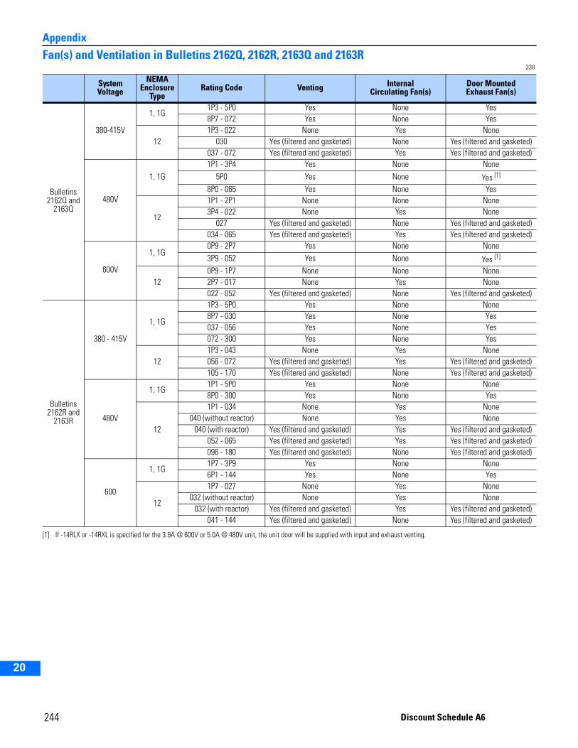
Appendix
2
3
4
5
9
10
11
12
13
14
15
16
17
18
19
20
Fan(s) and Ventilation in Bulletins 2162Q, 2162R, 2163Q and 2163R338
System Voltage
NEMA Enclosure
TypeRating Code Venting Internal
Circulating Fan(s)Door Mounted Exhaust Fan(s)
Bulletins 2162Q and
2163Q
380-415V
1, 1G1P3 - 5P0 Yes None Yes8P7 - 072 Yes None Yes
121P3 - 022 None Yes None
030 Yes (filtered and gasketed) None Yes (filtered and gasketed)037 - 072 Yes (filtered and gasketed) Yes Yes (filtered and gasketed)
480V
1, 1G1P1 - 3P4 Yes None None
5P0 Yes None Yes [1]
[1] If -14RLX or -14RXL is specified for the 3.9A @ 600V or 5.0A @ 480V unit, the unit door will be supplied with input and exhaust venting.
8P0 - 065 Yes None Yes
12
1P1 - 2P1 None None None3P4 - 022 None Yes None
027 Yes (filtered and gasketed) None Yes (filtered and gasketed)034 - 065 Yes (filtered and gasketed) Yes Yes (filtered and gasketed)
600V
1, 1G0P9 - 2P7 Yes None None3P9 - 052 Yes None Yes [1]
120P9 - 1P7 None None None2P7 - 017 None Yes None022 - 052 Yes (filtered and gasketed) None Yes (filtered and gasketed)
Bulletins 2162R and
2163R
380 - 415V
1, 1G
1P3 - 5P0 Yes None None8P7 - 030 Yes None Yes037 - 056 Yes None Yes072 - 300 Yes None Yes
121P3 - 043 None Yes None056 - 072 Yes (filtered and gasketed) Yes Yes (filtered and gasketed)105 - 170 Yes (filtered and gasketed) None Yes (filtered and gasketed)
480V
1, 1G1P1 - 5P0 Yes None None8P0 - 300 Yes None Yes
12
1P1 - 034 None Yes None040 (without reactor) None Yes None
040 (with reactor) Yes (filtered and gasketed) Yes Yes (filtered and gasketed)052 - 065 Yes (filtered and gasketed) Yes Yes (filtered and gasketed)096 - 180 Yes (filtered and gasketed) None Yes (filtered and gasketed)
600
1, 1G1P7 - 3P9 Yes None None6P1 - 144 Yes None Yes
12
1P7 - 027 None Yes None032 (without reactor) None Yes None
032 (with reactor) Yes (filtered and gasketed) Yes Yes (filtered and gasketed)041 - 144 Yes (filtered and gasketed) None Yes (filtered and gasketed)
244 Discount Schedule A6
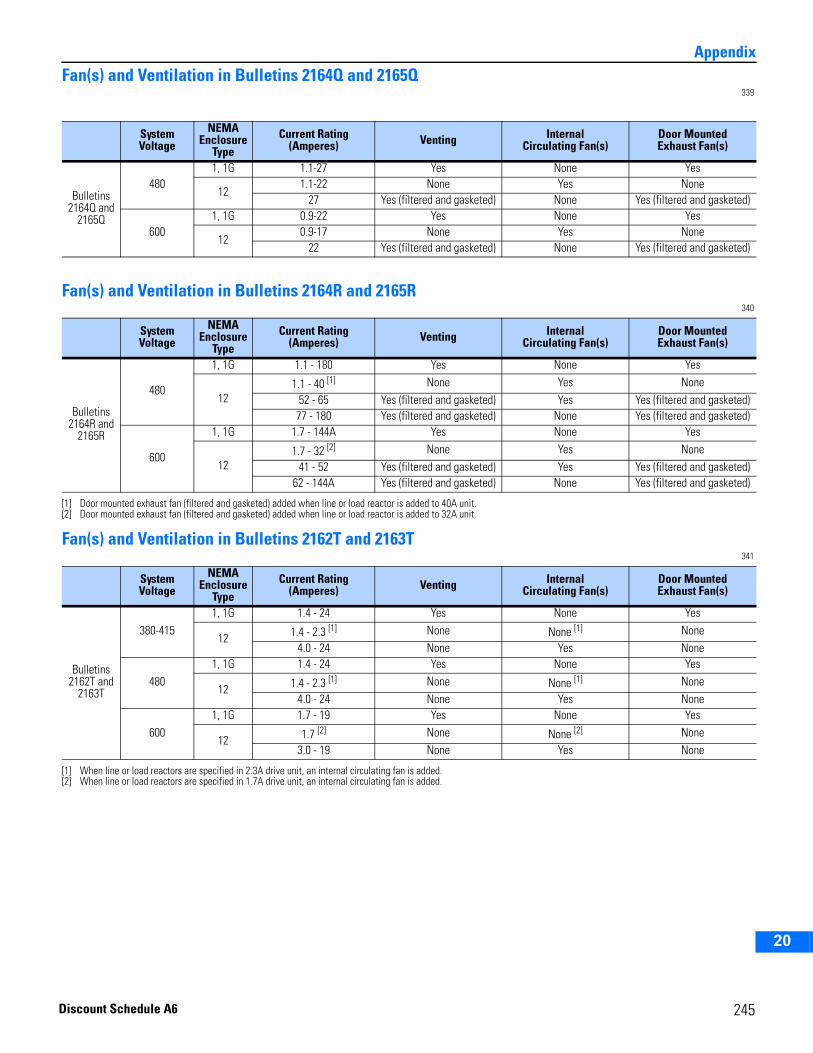
2
3
4
5
6
7
8
9
10
11
12
13
14
15
16
17
18
19
20
AppendixFan(s) and Ventilation in Bulletins 2164Q and 2165Q
339
Fan(s) and Ventilation in Bulletins 2164R and 2165R340
Fan(s) and Ventilation in Bulletins 2162T and 2163T341
System Voltage
NEMA Enclosure
TypeCurrent Rating
(Amperes) Venting Internal Circulating Fan(s)
Door Mounted Exhaust Fan(s)
Bulletins 2164Q and
2165Q
4801, 1G 1.1-27 Yes None Yes
121.1-22 None Yes None
27 Yes (filtered and gasketed) None Yes (filtered and gasketed)
6001, 1G 0.9-22 Yes None Yes
120.9-17 None Yes None
22 Yes (filtered and gasketed) None Yes (filtered and gasketed)
System Voltage
NEMA Enclosure
TypeCurrent Rating
(Amperes) Venting Internal Circulating Fan(s)
Door Mounted Exhaust Fan(s)
Bulletins 2164R and
2165R
480
1, 1G 1.1 - 180 Yes None Yes
121.1 - 40 [1]
[1] Door mounted exhaust fan (filtered and gasketed) added when line or load reactor is added to 40A unit.
None Yes None52 - 65 Yes (filtered and gasketed) Yes Yes (filtered and gasketed)77 - 180 Yes (filtered and gasketed) None Yes (filtered and gasketed)
600
1, 1G 1.7 - 144A Yes None Yes
121.7 - 32 [2]
[2] Door mounted exhaust fan (filtered and gasketed) added when line or load reactor is added to 32A unit.
None Yes None41 - 52 Yes (filtered and gasketed) Yes Yes (filtered and gasketed)
62 - 144A Yes (filtered and gasketed) None Yes (filtered and gasketed)
System Voltage
NEMA Enclosure
TypeCurrent Rating
(Amperes) Venting Internal Circulating Fan(s)
Door Mounted Exhaust Fan(s)
Bulletins 2162T and
2163T
380-4151, 1G 1.4 - 24 Yes None Yes
12 1.4 - 2.3 [1] None None [1] None4.0 - 24 None Yes None
4801, 1G 1.4 - 24 Yes None Yes
12 1.4 - 2.3 [1]
[1] When line or load reactors are specified in 2.3A drive unit, an internal circulating fan is added.
None None [1] None4.0 - 24 None Yes None
6001, 1G 1.7 - 19 Yes None Yes
12 1.7 [2]
[2] When line or load reactors are specified in 1.7A drive unit, an internal circulating fan is added.
None None [2] None3.0 - 19 None Yes None
245Discount Schedule A6
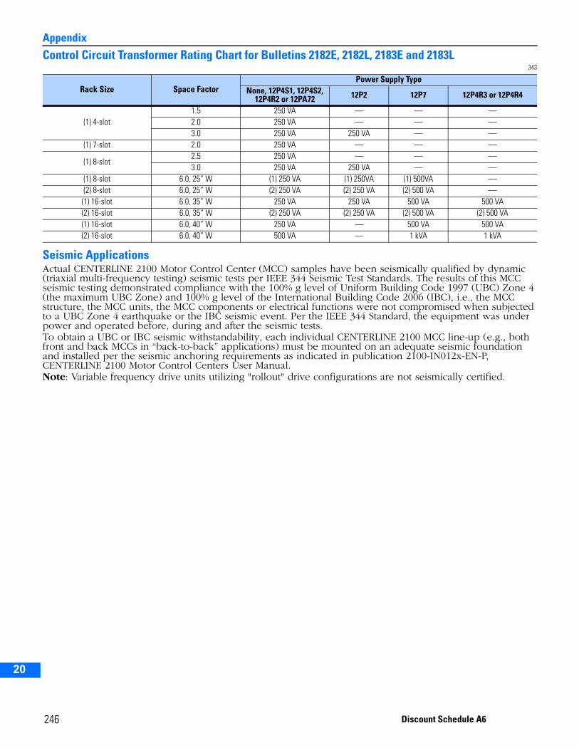
Appendix
2
3
4
5
9
10
11
12
13
14
15
16
17
18
19
20
Control Circuit Transformer Rating Chart for Bulletins 2182E, 2182L, 2183E and 2183L343
Seismic ApplicationsActual CENTERLINE 2100 Motor Control Center (MCC) samples have been seismically qualified by dynamic (triaxial multi-frequency testing) seismic tests per IEEE 344 Seismic Test Standards. The results of this MCC seismic testing demonstrated compliance with the 100% g level of Uniform Building Code 1997 (UBC) Zone 4 (the maximum UBC Zone) and 100% g level of the International Building Code 2006 (IBC), i.e., the MCC structure, the MCC units, the MCC components or electrical functions were not compromised when subjected to a UBC Zone 4 earthquake or the IBC seismic event. Per the IEEE 344 Standard, the equipment was under power and operated before, during and after the seismic tests.To obtain a UBC or IBC seismic withstandability, each individual CENTERLINE 2100 MCC line-up (e.g., both front and back MCCs in “back-to-back” applications) must be mounted on an adequate seismic foundation and installed per the seismic anchoring requirements as indicated in publication 2100-IN012x-EN-P, CENTERLINE 2100 Motor Control Centers User Manual.Note: Variable frequency drive units utilizing "rollout" drive configurations are not seismically certified.
Rack Size Space FactorPower Supply Type
None, 12P4S1, 12P4S2, 12P4R2 or 12PA72 12P2 12P7 12P4R3 or 12P4R4
(1) 4-slot1.5 250 VA — — —2.0 250 VA — — —3.0 250 VA 250 VA — —
(1) 7-slot 2.0 250 VA — — —
(1) 8-slot2.5 250 VA — — —3.0 250 VA 250 VA — —
(1) 8-slot 6.0, 25” W (1) 250 VA (1) 250VA (1) 500VA —(2) 8-slot 6.0, 25” W (2) 250 VA (2) 250 VA (2) 500 VA —(1) 16-slot 6.0, 35” W 250 VA 250 VA 500 VA 500 VA(2) 16-slot 6.0, 35” W (2) 250 VA (2) 250 VA (2) 500 VA (2) 500 VA(1) 16-slot 6.0, 40” W 250 VA — 500 VA 500 VA(2) 16-slot 6.0, 40” W 500 VA — 1 kVA 1 kVA
246 Discount Schedule A6
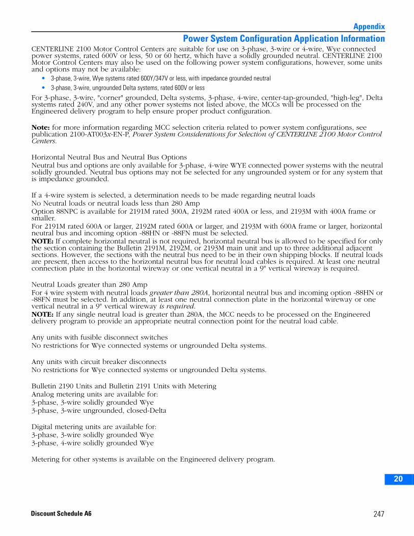
2
3
4
5
6
7
8
9
10
11
12
13
14
15
16
17
18
19
20
Appendix
Power System Configuration Application InformationCENTERLINE 2100 Motor Control Centers are suitable for use on 3-phase, 3-wire or 4-wire, Wye connected power systems, rated 600V or less, 50 or 60 hertz, which have a solidly grounded neutral. CENTERLINE 2100 Motor Control Centers may also be used on the following power system configurations, however, some units and options may not be available:
• 3-phase, 3-wire, Wye systems rated 600Y/347V or less, with impedance grounded neutral• 3-phase, 3-wire, ungrounded Delta systems, rated 600V or less
For 3-phase, 3-wire, "corner" grounded, Delta systems, 3-phase, 4-wire, center-tap-grounded, "high-leg", Delta systems rated 240V, and any other power systems not listed above, the MCCs will be processed on the Engineered delivery program to help ensure proper product configuration.
Note: for more information regarding MCC selection criteria related to power system configurations, see publication 2100-AT003x-EN-P, Power System Considerations for Selection of CENTERLINE 2100 Motor Control Centers.
Horizontal Neutral Bus and Neutral Bus OptionsNeutral bus and options are only available for 3-phase, 4-wire WYE connected power systems with the neutral solidly grounded. Neutral bus options may not be selected for any ungrounded system or for any system that is impedance grounded.
If a 4-wire system is selected, a determination needs to be made regarding neutral loadsNo Neutral loads or neutral loads less than 280 AmpOption 88NPC is available for 2191M rated 300A, 2192M rated 400A or less, and 2193M with 400A frame or smaller.For 2191M rated 600A or larger, 2192M rated 600A or larger, and 2193M with 600A frame or larger, horizontal neutral bus and incoming option -88HN or -88FN must be selected.NOTE: If complete horizontal neutral is not required, horizontal neutral bus is allowed to be specified for only the section containing the Bulletin 2191M, 2192M, or 2193M main unit and up to three additional adjacent sections. However, the sections with the neutral bus need to be in their own shipping blocks. If neutral loads are present, then access to the horizontal neutral bus for neutral load cables is required. At least one neutral connection plate in the horizontal wireway or one vertical neutral in a 9" vertical wireway is required.
Neutral Loads greater than 280 AmpFor 4 wire system with neutral loads greater than 280A, horizontal neutral bus and incoming option -88HN or -88FN must be selected. In addition, at least one neutral connection plate in the horizontal wireway or one vertical neutral in a 9" vertical wireway is required.NOTE: If any single neutral load is greater than 280A, the MCC needs to be processed on the Engineered delivery program to provide an appropriate neutral connection point for the neutral load cable.
Any units with fusible disconnect switches No restrictions for Wye connected systems or ungrounded Delta systems.
Any units with circuit breaker disconnectsNo restrictions for Wye connected systems or ungrounded Delta systems.
Bulletin 2190 Units and Bulletin 2191 Units with MeteringAnalog metering units are available for:3-phase, 3-wire solidly grounded Wye 3-phase, 3-wire ungrounded, closed-Delta
Digital metering units are available for:3-phase, 3-wire solidly grounded Wye3-phase, 4-wire solidly grounded Wye
Metering for other systems is available on the Engineered delivery program.
247Discount Schedule A6

Appendix
2
3
4
5
9
10
11
12
13
14
15
16
17
18
19
20
248 Discount Schedule A6
2
3
4
5
6
7
8
9
10
11
12
13
14
15
16
17
18
19
20
21
IndexNumerics100% Rating of Main Disconnect Switch or Circuit Breaker 12271" High Section 248A Round DeviceNet Cable 220AABS 2Additional Unit Space on Contactors and Starters, Metering, Mainsand Feeders, Lighting and Power Panels, and Transformer Units 114American Bureau of Shipping 3Analog Output Isolation on Combination Variable Frequency AC MotorDrive Units 190Appendix 221Automatic Shutters 28Auxiliary Contacts on Combination Soft Starter Controller Units 143Auxiliary Contacts on Combination Variable Frequency AC Motor DriveUnits 193Auxiliary Contacts on Contactors and Starters, Metering, Mains andFeeders, Lighting and Power Panels, and Transformer Units 120, 128Auxiliary Contacts on Marshalling Panels and Programmable Control-lers 203Auxiliary Contacts on SC-I and PE-I 23BBack-to-Back Section 24Blank Unit Door 102Blown Fuse Indicator Lights on Contactors and Starters, Metering,Mains and Feeders, Lighting and Power Panels, and Transformer Units115Bolt-on Inverse Time (Thermal Magnetic) Branch Breakers for LightingPanels 219Bottom Closing Plate 24, 213Bulletin
2100D Empty Unit Insert with Disconnect Switch 1022100M Empty Unit Insert with Circuit Breaker 1022100N Empty Unit Insert without power stabs 1022102L, Full Voltage Lighting Contactor Unit with Fusible Discon-
nect Switch (FVLC) 362103L, Full Voltage Lighting Contactor Unit with Circuit Breaker
(FVLC) 372106, Full Voltage Reversing Starter Unit with Fusible Disconnect
Switch (FVR) 392106, Space Saving NEMA Full Voltage Reversing Starter Unit
with Fused Disconnect Switch (FVR) 412107, Full Voltage Reversing Starter Unit with Circuit Breaker
(FVR) 392107, Space Saving NEMA Full Voltage Reversing Starter Unit
with Circuit Breaker (FVR) 412112, Full Voltage Non-Reversing Starter Units with Fusible Dis-
connect Switch (FVNR) 432112, Space Saving NEMA Full Voltage Non-Reversing Starter
Unit with Fused Disconnect Switch (FVNR) 472113, Full Voltage Non-Reversing Starter Unit with Circuit Break-
er (FVNR) 452113, Space Saving NEMA Full Voltage Non-Reversing Starter
Unit with Circuit Breaker (FVNR) 47
2122E, Two Speed 2-Winding Starter Unit with Fusible Discon-nect Switch (TS2W) 49
2122F, Two Speed 1-Winding Starter Unit with Fusible Discon-nect Switch (TS1W) 50
2123E, Two Speed 2-Winding Starter Unit with Circuit Breaker(TS2W) 51
2123F, Two Speed 1-Winding Starter Unit with Circuit Breaker(TS1W) 51
2126E, Two Speed Reversing 2-Winding Starters with FusibleDisconnect Switch (TSR2W) 53
2126F, Two Speed Reversing 1-Winding Starter Unit with FusibleDisconnect Switch (TSR1W) 53
2126J, Two Speed Reversing in Low Speed Only 2-Winding Start-er Unit with Fusible Disconnect Switch (TSR2W) 54
2126K, Two Speed Reversing in Low Speed Only 1-Winding Start-er Unit with Fusible Disconnect Switch (TSR1W) 54
2127E, Two Speed Reversing 2-Winding Starter Unit with CircuitBreaker (TSR2W) 55
2127F, Two Speed Reversing 1-Winding Starter Unit with CircuitBreaker (TSR1W) 55
2127J, Two Speed Reversing in Low Speed Only 2-Winding Start-er Unit with Circuit Breaker (TSR2W) 56
2127K, Two Speed Reversing in Low Speed Only 1-Winding Start-er Unit with Circuit Breaker (TSR1W) 56
2154H, Combination Soft Starter Motor Controller with FusibleDisconnect Switch (SMC-3) 131
2154J, Combination Soft Starter Motor Controller with FusibleDisconnect Switch (SMC-Flex) 134
2155H, Combination Soft Starter Motor Controller with CircuitBreaker (SMC-3) 132
2155J, Combination Soft Starter Motor Controller with CircuitBreaker (SMC-Flex) 135
2162Q, Combination PowerFlex 70 Variable Frequency AC Drive(VFD) Units with Fusible Disconnect, 380-480V 150,151, 152, 153, 154, 155, 156, 157, 158,159
2162R, Combination PowerFlex 700 Variable Frequency AC Drive(VFD) Units with Fusible Disconnect, 380-480VAC 161,162, 163, 164, 165, 169, 170
2162T, Combination PowerFlex 40 Variable Frequency AC Drive(VFD) Units with Fusible Disconnect, 380-480VAC 172
2162T, Combination PowerFlex 40 Variable Frequency AC Drive(VFD) Units with Fusible Disconnect, 600VAC 173
2163R, Combination PowerFlex 700 Variable Frequency AC Drive(VFD) Units with Circuit Breaker, 380-480VAC 166,167, 168
2163T, Combination PowerFlex 40 Variable Frequency AC Drive(VFD) Units with Fusible Disconnect, 380-480VAC 174
2163T, Combination PowerFlex 700 Variable Frequency AC Drive(VFD) Units with Fusible Disconnect, 600VAC 175
2164Q, Combination PowerFlex 70 Variable Frequency AC Drive(VFD) with Fusible Disconnect and Manual, Isolated By-pass, 480V 177
2164Q, Combination PowerFlex 70 Variable Frequency AC Drive(VFD) with Fusible Disconnect and Manual, Isolated By-pass, 600V 178
249Discount Schedule A6
Index
2
3
4
5
6
7
8
9
10
11
12
13
14
15
16
17
18
19
20
21
2164R, Combination PowerFlex 700 Variable Frequency AC Drive(VFD) with Fusible Disconnect and Manual, Isolated By-pass, 480VAC 182
2164R, Combination PowerFlex 700 Variable Frequency AC Drive(VFD) with Fusible Disconnect and Manual, Isolated By-pass, 600VAC 183, 185
2165Q, Combination PowerFlex 70 Variable Frequency AC Drive(VFD) with Circuit Breaker Disconnect and Manual, Iso-lated Bypass, 480V 179
2165Q, Combination PowerFlex 70 Variable Frequency AC Drive(VFD) with Circuit Breaker Disconnect and Manual, Iso-lated Bypass, 600V 180
2165R, Combination PowerFlex 700 Variable Frequency AC Drive(VFD) with Circuit Breaker Disconnect and Manual, Iso-lated Bypass, 480VAC 184
2180E, 2182E, and 2183E, Bulletin 1771 Programmable ControllerI/O Chassis (PLC) 198
2180J, 2182J, and 2183J, Bulletin 1746 SLC 500 ProgrammableController (PLC) 199
2180L, 2182L, and 2183L, Bulletin 1756 ControlLogix Programma-ble Controller (PLC) 200
2181B, Marshalling Panel 2022190, Metering Compartments (METER) 58, 602191M and 2191F, Lug Compartments—Provisions for Basic Sec-
tions/Incoming Lines (MLUG) and Outgoing Feeders(FLUG) 63
2191M, Lug Compartments/Incoming Line—Dimensions 67, 682191M, Lug Compartments/Incoming Lines Metering Options 662192F, Fusible Disconnect Switch—Feeders (FDS) 702192M, Fusible Disconnect Switch—Mains (MFDS) 712193F, 3-Pole Feeder Circuit Breaker (FCB) 74, 75, 762193LE, Frame-Mounted Lighting Panel for Bolt-on Branch Circuit
Breakers (LPAN) 832193M, 3-Pole Main Circuit Breaker (MCB) 77, 78, 79, 802193PP, Plug-in Panel Board with Main Circuit Breaker (PPAN) 852195, Control and Lighting Transformer Unit without Disconnect-
ing Means (XFMR) 89, 902196, Control and Lighting Transformer Unit with Fusible Discon-
nect Switch (XFMR) 91, 92, 93, 942197, Control and Lighting Transformer Unit with Circuit Breaker
(XFMR) 95, 96, 97, 98Bus Bracing 26Bus Stab Isolation Kit 214CCapacitor Sizes 240Cardholder for Unit Doors 216CE Marking 2Circuit Breaker Characteristics for Bulletin 2193F and 2193M Units234Circuit Breaker Interrupting Capacity Ratings 234Circuit Breaker on Contactors and Starters, Metering, Mains and Feed-ers, Lighting and Power Panels, and Transformer Units 122Circuit Breaker Suffix Letter Designation 9Circuit Breaker Type
for Bulletins 2107, 2113, 2123, and 2127 211for Bulletins 2163, and 2165 212for Horsepower and kW Rated Units for Bulletins 2155 212
Inverse Time (Thermal Magnetic or Solid State) Circuit BreakerOptions for Bulletin 2103L 210
Inverse Time (Thermal Magnetic) Circuit Breaker Options for Bul-letin 2197 211
Communication Module on Combination Soft Starter Controller Units140Communication Modules on Combination Variable Frequency AC Mo-tor Drive Units 188Conductor Size Conversion Chart 241Contactors and Starters
Catalog Number Explanations 35, 57, 62, 69, 73, 82, 84,88, 99, 130, 133, 201
Control Circuit Fuse on Contactors and Starters, Metering, Mains andFeeders, Lighting and Power Panels, and Transformer Units 114Control Circuit Lugs on Contactors and Starters, Metering, Mains andFeeders, Lighting and Power Panels, and Transformer Units 122Control Circuit Ring Lugs on Combination Soft Starter Controller Units144Control Circuit Spade Lugs on Combination Soft Starter ControllerUnits 144Control Circuit Transformer on Contactors and Starters, Metering,Mains and Feeders, Lighting and Power Panels, and Transformer Units110, 126Control Circuit Transformer Rating Chart 246Control Circuit Wiring on Combination Soft Starter Controller Units144Control Circuit Wiring on Combination Variable Frequency AC MotorDrive Units 193Control Circuit Wiring on Contactors and Starters, Metering, Mainsand Feeders, Lighting and Power Panels, and Transformer Units 122Control Station Housing 216Control Station Housing on Combination Soft Starter Controller Units137Control Station Housing on Contactors and Starters, Metering, Mainsand Feeders, Lighting and Power Panels, and Transformer Units 107Control Station Mounting Plate 216Control Terminal Block on Contactors and Starters, Metering, Mainsand Feeders, Lighting and Power Panels, and Transformer Units 121Control Voltage Type
for Bulletins 2102, 2103, 2106, 2107, 2112, 2113, 2122, 2123,2126, and 2127 205
for Bulletins 2154 and 2155 205for Bulletins 2162, 2163, 2164, and 2165 206
Control Wire Markers on Combination Soft Starter Controller Units144Control Wire Markers on Combination Variable Frequency AC MotorDrive Units 193Control Wire Markers on Contactors and Starters, Metering, Mainsand Feeders, Lighting and Power Panels, and Transformer Units 122,204ControlLogix Communication Modules on Marshalling Panels and Pro-grammable Controllers 203ControlLogix Processor on Marshalling Panels and Programmable Con-trollers 203ControlLogix Programming Cable on Marshalling Panels and Program-mable Controllers 203ControlNet to DeviceNet Linking Device 104
250 Discount Schedule A6
2
3
4
5
6
7
8
9
10
11
12
13
14
15
16
17
18
19
20
21
IndexControlNet T-Tap on Marshalling Panels and Programmable Control-lers 203Corner Section 24CSA Marking 1C-UL Marking 1Current Sensors on Contactors and Starters, Metering, Mains andFeeders, Lighting and Power Panels, and Transformer Units 121Current Transducers on Contactors and Starters, Metering, Mains andFeeders, Lighting and Power Panels, and Transformer Units 121DDelivery Programs 3DeviceNet
Cabling Options 29Hardware and Kits 220Miscellaneous Units 104Products 3
DeviceNet Communication Module on Combination Soft Starter Con-troller Units 140DeviceNet Communication Modules on Combination Variable Frequen-cy AC Motor Drive Units 188DeviceNet Connection Cover Kit 220DeviceNet Field Support Kit 220DeviceNet Scanner Module on Marshalling Panels and ProgrammableControllers 203DeviceNet Scanner Modules 220DeviceNet Starter Auxiliary on Combination Soft Starter ControllerUnits 140DeviceNet Starter Auxiliary on Contactors and Starters, Metering,Mains and Feeders, Lighting and Power Panels, and Transformer Units114DeviceNet Terminating Resistors 220DeviceNet Trunk Line Cable 220DeviceNet Unit Cable 220Dimensions 221Documentation 3Door Hardware Kit 216Door Hinge Kit 216Door, Blank 102Drip Hood 24, 213EE3 Solid-State Overload Relay on Contactors and Starters, Metering,Mains and Feeders, Lighting and Power Panels, and Transformer Units113Elapsed Time Meter on Contactors and Starters, Metering, Mains andFeeders, Lighting and Power Panels, and Transformer Units 116Empty Unit Insert 102Empty Unit Insert with Disconnecting Means 102End Closing Plate 213Ethernet to DeviceNet Linking Device 104Export Packing Below Deck for Sections on SC-I and PE-I 23Export Packing Below Deck on Combination Soft Starter ControllerUnits 144Export Packing Below Deck on Combination Variable Frequency ACMotor Drive Units 193Export Packing Below Deck on Contactors and Starters, Metering,Mains and Feeders, Lighting and Power Panels, and Transformer Units123
Export Packing Below Deck on Marshalling Panels and ProgrammableControllers 204Extended Reset Button Kit 217External Auxiliary Contact 217External Auxiliary Contact Adapter Kits 217, 218External Auxiliary Contact Kits 218External DeviceNet Connector Unit 104External DeviceNet Connector with 120VAC Receptacle on Contactorsand Starters, Metering, Mains and Feeders, Lighting and Power Pan-els, and Transformer Units 123External Mounting Channel Kits 213FFan(s) and Ventilation
in Bulletins 2154H, 2154J, 2155H, and 2155J 243in Bulletins 2162Q, 2162R, 2163Q, and 2163R 244in Bulletins 2162T and 2163T 245in Bulletins 2164Q and 2165Q 245in Bulletins 2164R and 2165R 245
Field-Mounted Equipment Units 102Filters for Door Vents on Contactors and Starters, Metering, Mains andFeeders, Lighting and Power Panels, and Transformer Units 114Footnotes 1French Legend Plates on Combination Soft Starter Controller Units144French Legend Plates on Combination Variable Frequency AC MotorDrive Units 193French Legend Plates on Contactors and Starters, Metering, Mains andFeeders, Lighting and Power Panels, and Transformer Units 123Full Load Currents 232, 233Fuse Clip Designator Selection, and Power Fuse Selection
for Bulletins 2100D, 2102L, 2192F, and 2192M 208for Bulletins 2106, 2112, 2122, 2126, and 2127 207
GGasketing Kit 213Ground Detection Lights on Contactors and Starters, Metering, Mainsand Feeders, Lighting and Power Panels, and Transformer Units 116Ground Fault Protection on Contactors and Starters, Metering, Mainsand Feeders, Lighting and Power Panels, and Transformer Units 116Ground Lug, Outgoing 28Grounded Unit Door on Combination Soft Starter Controller Units 142Grounded Unit Door on Combination Variable Frequency AC MotorDrive Units 193Grounded Unit Door on Contactors and Starters, Metering, Mains andFeeders, Lighting and Power Panels, and Transformer Units 116Grounded Unit Door on Marshalling Panels and Programmable Control-lers 203Grounded Unit Door on SC-I and PE-I 23HHardware and Kits
8A Round DeviceNet Cable 220Bolt-on Inverse Time (Thermal Magnetic) Branch Breakers for
Lighting Panels 219Bottom Closing Plate 213Bus Stab Isolation Kit 214Cardholder for Unit Doors 216Control Station Housing 216Control Station Mounting Plate 216
251Discount Schedule A6
Index
2
3
4
5
6
7
8
9
10
11
12
13
14
15
16
17
18
19
20
21
DeviceNet Connection Cover Kit 220DeviceNet Field Support Kit 220DeviceNet Scanner Modules 220DeviceNet Terminating Resistors 220DeviceNet Trunk Line Cable 220DeviceNet Unit Cable 220Door Hardware Kit 216Door Hinge Kit 216Drip Hood 213End Closing Plate 213Extended Reset Button Kit 217External Auxiliary Contact 217External Auxiliary Contact Adapter Kits 217, 218External Auxiliary Contact Kits 218External Mounting Channel Kits 213Gasketing Kit 213Horizontal Ground Bus Splice Kit 214Horizontal Power Bus Splice Kit 214Horizontal Wireway Cover 213Incoming Line Lug Barriers 215Inverse Time (Thermal Magnetic) Branch Breakers for Panel Board
Plug-In Unit 219Line Terminal Shield 217Lugs for Incoming Line Provisions 215MCC DeviceNet Terminating Resistor Kit 220Neutral Connection Plate Kit 214NO-OX-ID 214Plug-In Unit Retrofit Kit 217Pull-Apart Terminal Bocks 217Pullbox 213Round DeviceNet Cable with Connectors 220Space Heater Kit 213Stainless Steel Nameplate Screws 216Top Horizontal Wireway Pan 213Touch-Up Paint 214Unit Door Grounding Kit 217Unit Door Nameplates 216Unit Insert Extension Kit 217Unit Isolating Barriers 214Unit Operating Handle Extender 213Unit Support Pan 216Vertical Ground Bus Kit 214Vertical Unit Load Ground Bus Kit 214Vertical Wireway Tie Bar 214Wiring Diagram Holder Kit 214
Heater Element Selection 227Heater Element Selection Tables 229, 232Horizontal Ground Bus 26Horizontal Ground Bus Splice Kit 214Horizontal Power Bus on Marshalling Panels and Programmable Con-trollers 204Horizontal Power Bus Splice Kit 214Horizontal Wireway Cover 213Horsepower Ratings 241Horsepower Ratings for All Bulletins 206Human Interface Module (HIM) on Combination Soft Starter ControllerUnits 140
Human Interface Module (HIM) on Combination Variable Frequency ACMotor Drive Units 189II/O Control Voltage on Combination Variable Frequency AC MotorDrive Units 190IEC 60439 2Incoming Line Lug Barriers 215Incoming Lug Compartments 63Incoming Neutral Bus on Contactors and Starters, Metering, Mains andFeeders, Lighting and Power Panels, and Transformer Units 117Incoming Neutral Connection Plate on Contactors and Starters, Meter-ing, Mains and Feeders, Lighting and Power Panels, and TransformerUnits 117IntelliCENTER Technology
Motor Control Center 29Software 30
Interposing Relay on Contactors and Starters, Metering, Mains andFeeders, Lighting and Power Panels, and Transformer Units 118Inverse Time (Thermal Magnetic) Branch Breakers for Panel BoardPlug-In Unit 219ISO 9001 Certification 1Isolation Contactor on Combination Soft Starter Controller Units 141KKey-interlock Mounting Provision on Contactors and Starters, Meter-ing, Mains and Feeders, Lighting and Power Panels, and TransformerUnits 121kW Ratings for Bulletins 2154, 2155, 2162, 2163, 2164, and 2165 206kW to Catalog Hp Code Conversion 239LLight and Door Switch on Marshalling Panels and Programmable Con-trollers 204Line or Load Reactors on Combination Variable Frequency AC MotorDrive Units 191Line Reactor Space Factor Adders 192, 193Line Terminal Shield 217Lug Compartments 64, 65, 83, 90Lugs for Incoming Line Provisions 215MManual Shutters 28Master Nameplates 216MCC DeviceNet Terminating Resistor Kit 220Meter Types 59, 60Metric Conversion Table 242Miscellaneous DeviceNet Units 104Miscellaneous Units 99, 105Motor Applications 3NNEMA
Class 2Defined 2Enclosure Type Descriptions 2Type 1 2Type 1 with gasket 2Type 12 2Type 3R 2Type 4 2
NEMA/IEC Enclosure Comparison 2
252 Discount Schedule A6
2
3
4
5
6
7
8
9
10
11
12
13
14
15
16
17
18
19
20
21
IndexNetwork built into MCC Sections 29Neutral Bus 25Neutral Connection Plate 25Neutral Connection Plate Kit 214Neutral Connection Plate Unit 105NO-OX-ID 214OO/L Contact on Left Side of Circuit on Contactors and Starters, Meter-ing, Mains and Feeders, Lighting and Power Panels, and TransformerUnits 114Options for Combination Soft Starter Controller Units
Add Isolation Contactor 141Auxiliary Contacts 143Communication Module 140Control Circuit Ring Lugs 144Control Circuit Spade Lugs 144Control Circuit Wiring 144Control Station Housing 137Control Wire Markers 144DeviceNet Communication Module 140DeviceNet Starter Auxiliary 140Export Packing Below Deck 144French Legend Plates 144Ground Fault Current Transformer 140Grounded Unit Door 142High Interrupting Capacity Fuses 140Human Interface Module (HIM) 140Omit Wiring 142Pilot Lights 138Protective Modules 139Push Buttons 137Selector Switch 137Shunt Trip 144Spanish Legend Plates 144Stainless Steel Nameplate Screws 144Surge Suppressor 142T-Handle 144Unit Door Nameplates 144Unit Ground Stab 142Unit Load Connector 142Unwired Control Relay 142
Options for Combination Variable Frequency AC Motor Drive UnitsAnalog Output Isolation 190Auxiliary Contacts 193Communication Modules 188Control Circuit Wiring 193Control Wire Markers 193DeviceNet Communication Modules 188Export Packing Below Deck 193French Legend Plates 193Grounded Unit Door 193Human Interface Module (HIM) 189I/O Control Voltage 190Line or Load Reactors 191Pilot Lights 187Push Buttons 187Push Buttons and Selector Switch 187
Selector Switch 187Spanish Legend Plates 193Stainless Steel Nameplate Screws 193T-Handle 193Unit Door Nameplates 193Unit Ground Stab 193Unit Load Connector 193
Options for Contactors and Starters, Metering, Mains and Feeders,Lighting and Power Panels, and Transformer Units
100% Rating of Main Disconnect Switch or Circuit Breaker 122480V and 600V Power Factor Correction Capacitors 115Additional Unit Space 114Auxiliary Contacts 120Blown Fuse Indicator Lights 115Control Circuit Fuse 114Control Circuit Lugs 122Control Circuit Transformer 110Control Circuit Wiring 122Control Station Housing 107Control Terminal Block 121Control Wire Markers 122, 204Current Sensors 121Current Transducers 121DeviceNet Starter Auxiliary 114E3 Electronic Overload Relay 113Elapsed Time Meter 116Export Packing Below Deck 123External DeviceNet Connector with 120VAC Receptacle 123Filters for Door Vents 114French Legend Plates 123Ground Detection Lights 116Ground Fault Protection 116Grounded Unit Door 116Incoming Neutral Bus 117Incoming Neutral Connection Plate 117Interposing Relay 118Key-interlock Mounting Provision 121O/L Contact on Left Side of Circuit 114Omission of Circuit Breaker 122Omission of Power Terminal Blocks 121Omit Wiring 114Overload Relay Auxiliary Contact (Eutectic Alloy) 114Overload Relay Heater Elements 123Push Buttons 107Push Buttons and Selector Switch 107Selector Switch 107Shunt Trip 122Spanish Legend Plates 123Stainless Steel Nameplate Screws 123Surge Suppressor 114T-Handle 121Thermistor Protection Relay 116Unit Ammeter 116Unit Door Nameplates 123Unit Ground Stab 116Unit Load Connector 116Unwired Control Relay 119Unwired Pull-Apart Terminal Blocks 123
253Discount Schedule A6
Index
2
3
4
5
6
7
8
9
10
11
12
13
14
15
16
17
18
19
20
21
Unwired Timer Auxiliary 116Options for Marshalling Panels and Programmable Controllers
Auxiliary Contacts 203ControlLogix Communication Modules 203ControlLogix Processor 203ControlLogix Programming Cable 203ControlNet T-Tap 203DeviceNet Scanner Module 203Export Packing Below Deck 204Grounded Unit Door 203Light and Door Switch 204Omit Horizontal Power Bus 204Power Supply 203Stainless Steel Nameplate Screws 204Terminal Blocks 204T-Handle 204Unit Door Nameplates 204Unit Ground Stab 203
Options for SC-I and PE-I SectionsAuxiliary Contacts 23Export Packing Below Deck for Sections 23Grounded Unit Door 23Shunt Trip 23T-Handle 23
Options for Space Saving NEMA Starter UnitsAdditional Unit Space 127Auxiliary Contacts 128Control Circuit Fuse 127Control Circuit Transformer 126Control Wire Markers 128DeviceNet Starter Auxiliary 126E1 Plus Electronic Overload Relay 126E3 Electronic Overload Relay 126Elapsed Time Meter 127Export Packing Below Deck 128French Legend Plates 128Grounded Unit Door 127Omit Wiring 127Pilot Lights 125Push Buttons 125Push Buttons and Selector Switch 125Selector Switch 125Spanish Legend Plates 128Stainless Steel Nameplate Screws 128Surge Suppressor 127T-Handles 128Unit Door Nameplate 128Unit Ground Stab 127Unit Load Connector 127Unwired Control Relay 127
Outgoing Lug Compartments 63Overload Relay Auxiliary Contact (Eutectic Alloy) on Contactors andStarters, Metering, Mains and Feeders, Lighting and Power Panels,and Transformer Units 114Overload Relay Class Designations 227
Overload Relay Heater Elements on Contactors and Starters, Metering,Mains and Feeders, Lighting and Power Panels, and Transformer Units123PParts Illustrations
Typical 15" Deep Section Construction 11Pilot Lights on Combination Soft Starter Controller Units 138Pilot Lights on Combination Variable Frequency AC Motor Drive Units187Pilot Lights on Contactors and Starters, Metering, Mains and Feeders,Lighting and Power Panels, and Transformer Units 125Plug-In Unit Retrofit Kit 217Power Factor Correction Capacitors on Contactors and Starters, Meter-ing, Mains and Feeders, Lighting and Power Panels, and TransformerUnits 115Power Supply on Marshalling Panels and Programmable Controllers203Power System 247Power Terminal Blocks on Contactors and Starters, Metering, Mainsand Feeders, Lighting and Power Panels, and Transformer Units 121Primary Voltage Code for Bulletins 2195, 2196, and 2197 205Protective Caps 28Protective Modules on Combination Soft Starter Controller Units 139Publication Overview 1Pull-Apart Terminal Bocks 217Pullbox 213Push Buttons and Selector Switch on Contactors and Starters, Meter-ing, Mains and Feeders, Lighting and Power Panels, and TransformerUnits 107Push Buttons on Combination Soft Starter Controller Units 137Push Buttons on Combination Variable Frequency AC Motor Drive Units187Push Buttons on Contactors and Starters, Metering, Mains and Feed-ers, Lighting and Power Panels, and Transformer Units 107RRound DeviceNet Cable with Connectors 220SSection Modification
SC and PE-I 23SC-II and PE-II 24, 25, 26, 27, 28
Seismic Applications 3, 246Selector Switch on Combination Soft Starter Controller Units 137Selector Switch on Combination Variable Frequency AC Motor DriveUnits 187Selector Switch on Contactors and Starters, Metering, Mains andFeeders, Lighting and Power Panels, and Transformer Units 107Serial Number Information 5Series Letter Information 5Service and Storage Conditions, 3Short Circuit Withstand Ratings for Combination Circuit Breaker Units236Short Circuit Withstand Ratings for Combination Fusible DisconnectUnits 235Short Circuit Withstand Ratings for Combination Soft Starter ControllerUnits (SMCs) 237Short Circuit Withstand Ratings for Combination Variable FrequencyAC Motor Drive Units 238
254 Discount Schedule A6
2
3
4
5
6
7
8
9
10
11
12
13
14
15
16
17
18
19
20
21
IndexShort Circuit Withstand Ratings for Programmable Controllers 238Shunt Trip on Combination Soft Starter Controller Units 144Shunt Trip on Contactors and Starters, Metering, Mains and Feeders,Lighting and Power Panels, and Transformer Units 122Shunt Trip on SC-I and PE-I 23Shutters 28Smoke Detector Unit 105Soft Starter Controller (SMC) Units 129Software, IntelliCENTER 30Space Heater Factory Installed in MCC 28Space Heater Kit 213Space Saving NEMA Bulletin 2106 and 2107, Full Voltage ReversingStarters (FVR) 40Space Saving NEMA Bulletin 2112 and 2113, Full Voltage Non-Revers-ing Starters (FVNR) 46Stainless Steel Nameplate Screws 216Stainless Steel Nameplate Screws on Combination Soft Starter Con-troller Units 144Stainless Steel Nameplate Screws on Combination Variable FrequencyAC Motor Drive Units 193Stainless Steel Nameplate Screws on Contactors and Starters, Meter-ing, Mains and Feeders, Lighting and Power Panels, and TransformerUnits 123Stainless Steel Nameplate Screws on Marshalling Panels and Pro-grammable Controllers 204Storage Conditions 1Suffix Letter Designation
Circuit Breaker 9Surge Protective Device Unit 105Surge Suppressor on Combination Soft Starter Controller Units 142Surge Suppressor on Contactors and Starters, Metering, Mains andFeeders, Lighting and Power Panels, and Transformer Units 114TTerminal Blocks on Marshalling Panels and Programmable Controllers204T-Handle 28T-Handle on Combination Soft Starter Controller Units 144T-Handle on Combination Variable Frequency AC Motor Drive Units193T-Handle on Contactors and Starters, Metering, Mains and Feeders,Lighting and Power Panels, and Transformer Units 121T-Handle on Marshalling Panels and Programmable Controllers 204T-Handle on SC-I and PE-I 23Thermistor Protection Relay on Contactors and Starters, Metering,Mains and Feeders, Lighting and Power Panels, and Transformer Units116Top Horizontal Wireway Pan 213Touch-Up Paint 214Trip Current for Bulletin 2103L 209Type 2 Protection 3UUL/cUL/CSA Marking 1Unit Ammeter on Contactors and Starters, Metering, Mains and Feed-ers, Lighting and Power Panels, and Transformer Units 116Unit Door Grounding Kit 217Unit Door Nameplates 216
Unit Door Nameplates on Combination Soft Starter Controller Units144Unit Door Nameplates on Combination Variable Frequency AC MotorDrive Units 193Unit Door Nameplates on Contactors and Starters, Metering, Mainsand Feeders, Lighting and Power Panels, and Transformer Units 123Unit Door Nameplates on Marshalling Panels and Programmable Con-trollers 204Unit Ground Stab on Combination Soft Starter Controller Units 142Unit Ground Stab on Combination Variable Frequency AC Motor DriveUnits 193Unit Ground Stab on Contactors and Starters, Metering, Mains andFeeders, Lighting and Power Panels, and Transformer Units 116Unit Ground Stab on Marshalling Panels and Programmable Controllers203Unit Insert Extension Kit 217Unit Insert, Empty 102Unit Isolating Barriers 28, 214Unit Load Connector on Combination Soft Starter Controller Units 142Unit Load Connector on Combination Variable Frequency AC MotorDrive Units 193Unit Load Connector on Contactors and Starters, Metering, Mains andFeeders, Lighting and Power Panels, and Transformer Units 116Unit Operating Handle Extender 213Unit Support Pan 216Units and Sections
Series Lettering 8Unwired Control Relay on Combination Soft Starter Controller Units142Unwired Control Relay on Contactors and Starters, Metering, Mainsand Feeders, Lighting and Power Panels, and Transformer Units 119Unwired Pull-Apart Terminal Blocks on Contactors and Starters, Me-tering, Mains and Feeders, Lighting and Power Panels, and Transform-er Units 123Unwired Timer Auxiliary on Contactors and Starters, Metering, Mainsand Feeders, Lighting and Power Panels, and Transformer Units 116VVertical Ground Bus 26Vertical Ground Bus Kit 214Vertical Section Catalog Numbers
Configuring 23Vertical Sections 11
Catalog Number Explanations 12Vertical Unit Load Ground Bus 26Vertical Unit Load Ground Bus Kit 214Vertical Wireway Tie Bar 214WWeights of CENTERLINE Motor Control Center Sections 226Wire Markers, Control 122, 204Wiring Class 2Wiring Diagram Holder Kit 214Wiring on Combination Soft Starter Controller Units 142Wiring on Contactors and Starters, Metering, Mains and Feeders,Lighting and Power Panels, and Transformer Units 114Wiring Type 2
255Discount Schedule A6

Index
2
3
4
5
6
7
8
9
10
11
12
13
14
15
16
17
18
19
20
21
256 Discount Schedule A6

Publication 2100-CA001F-EN-P – August 2008 Copyright ©2008 Rockwell Automation, Inc. All Rights Reserved. Printed in USA.Supersedes Publication 2100-CA001E-EN-P – August 2007
MOTOR CONTROL CENTERSCATALOG
• CENTERLINE® 2100 Motor Control Centers
CENTERLINE®, CenterONE®, ControlLogix®, DeviceLogix™, IntelliCENTER®, PowerFlex®, Product Selection Toolbox™, Rockwell Automation®,
RSView®, SMC™, SMC™ 3, SMC™ Dialog Plus, SMC™ Flex, Powermonitor™, ArcShield™, Allen-Bradley® are trademarks of Rockwell Automation, Inc.
Trademarks not belonging to Rockwell Automation are property of their respective companies.