Embed Size (px)
Citation preview
WATER COOLED SYSTEM
All rights reservedAD.
c
Specifications, designs and other content appearing in this brochure are current as of May 2016 but subject to change without notice.
1. Air conditioners should not be installed in areas where corrosive gases, such as acid gas or alkaline gas, are produced.2. If the outdoor unit is to be installed close to the sea shore, direct exposure to the sea breeze should be avoided. If you need to install the outdoor unit close to the sea shore, contact your local distributor.
Cautions on product corrosion
Warning Ask a qualified installer or contractor to install this product. Do not try to install the product yourself. Improper installation can result in water or refrigerant leakage, electrical shock, fire or explosion.
Use only those parts and accessories supplied or specified by Daikin. Ask a qualified installer or contractor to install those parts and accessories. Use of unauthorised parts and accessories or improper installation of parts and accessories can result in water or refrigerant leakage, electrical shock, fire or explosion.
Read the user's manual carefully before using this product. The user's manual provides important safety instructions and warnings. Be sure to follow these instructions and warnings.
If you have any enquiries, please contact your local importer, distributor and/or retailer.
W SERIES
PCVVN1608aprv
Heat Pump / Heat Recovery 50 Hz
21
* VRV is a trademark of Daikin Industries, Ltd.
Easy installationCompact & lightweight design
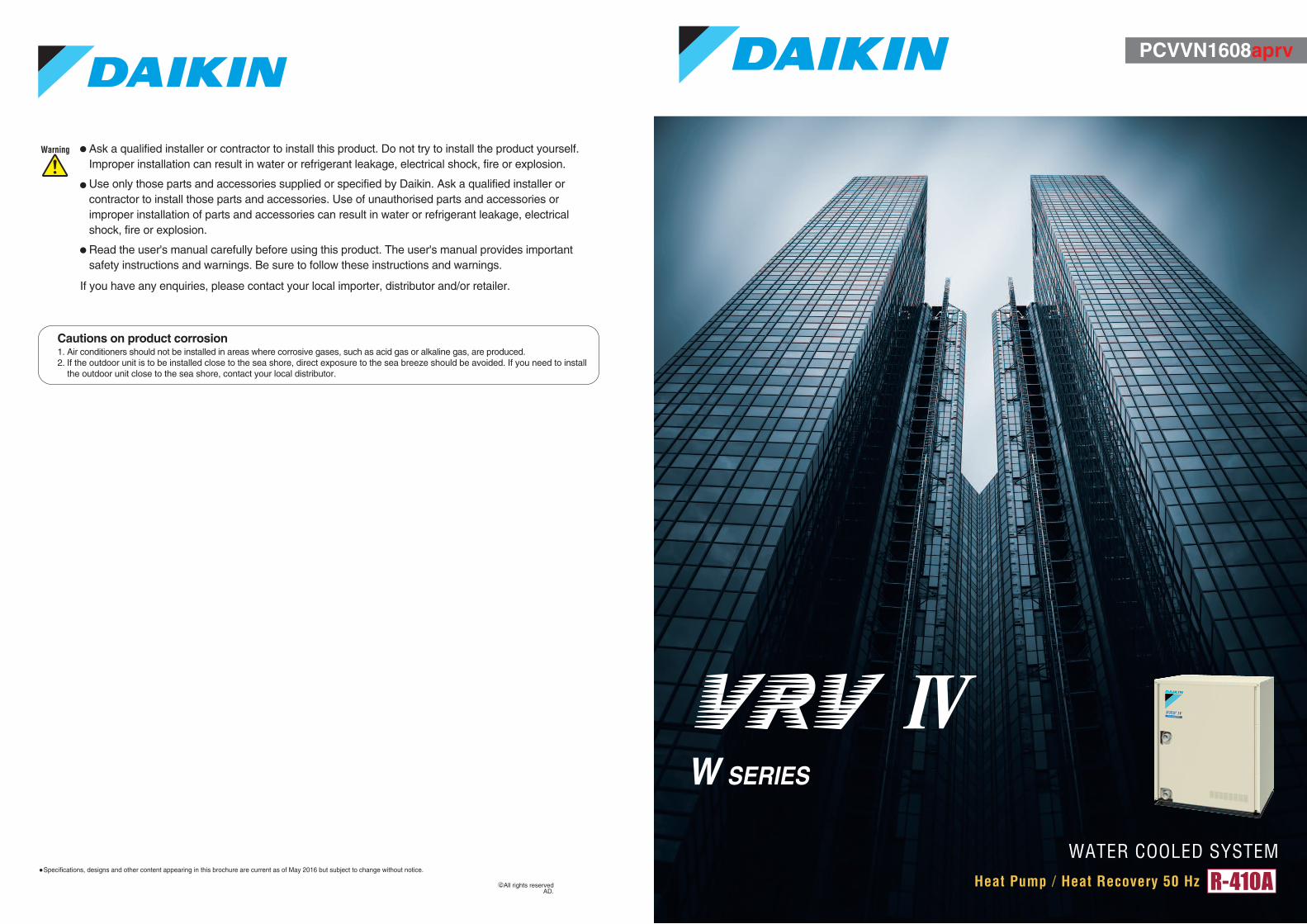
The VRV IV W series combines the characteristics of a water cooled system with the VRV system.
INDEX
P3Main Features
P23Indoor Unit Lineup
P48Speci�cations
P63Option List
P69Control Systems
P81
Air Treatment Equipment Lineup
P98Air Handling Unit
Cooling tower (closed type)
• Individual air conditioning is achieved via on-demand operation in each room.
• Outside units can be installed anywhere in a building if they can be connected with water piping.
• The length of the refrigerant piping can be minimized by installing outside units in proximity to indoor units. [ The system can easily fit into long building floors. ] [ The system helps reduce energy loss caused by long refrigerant piping. ]
• Refrigerant piping is connected to indoor units. This design helps reduce the risks of indoor water leakage.
Outside unit
Indoor unit
Refrigerant piping
Water piping
W SERIES
Wide capacity range from 6 to 36 HP
Enhanced lineup Energy savingHigher COP & VRT technology
Enhanced usabilityCentralised interlocking function
A water cooled intelligent individual air conditioning system suitable for tall multi-storey buildings.
What is a water cooled system?
Air cooled system
While an air cooled air conditioning system is designed to exchange heat recovered from indoors with outdoor air, a water cooled air conditioning system is designed for heat exchange with water.
Heat releases outdoors
Refrigerant-air heat exchanger
Outdoor unit
Refrigerant piping
Indoor unit
Heat from indoorsCompressor
Refrigerant-air heat exchanger
Refrigerant-water heat exchanger
Outside unit
Refrigerant piping
Indoor unit
Heat from indoorsCompressor
Refrigerant-air heat exchanger
Heat releasesinto the cooling water
To a cooling tower
Water piping
Water cooled system
As a water cooled system does not require to exchange heat with outdoor air,
• Outside units can be installed indoors, for example, on basement floors.
High installation flexibility
• The air conditioning operation is stable even when the outdoor air temperature is high. Improved comfort
Boiler (for heating)
3 4
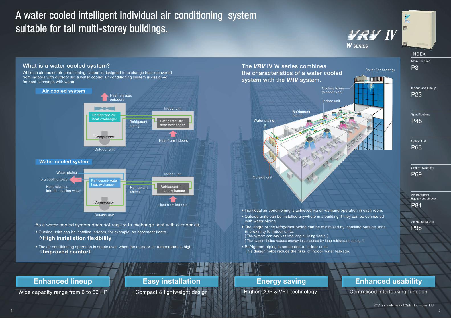
The VRV IV W series can meet various air conditioning needs by taking full advantage of the characteristics of a water cooled system.
1000
mm
780 mm 550 mm
Adaptable to high-rise buildings due to easy installation on each �oor
Compact outside units can be easily installed in the machine rooms on each �oor. This helps overcome the restriction on differences in height of refrigerant piping. Individual air conditioning can be easily provided in high-rise buildings using this VRV system.
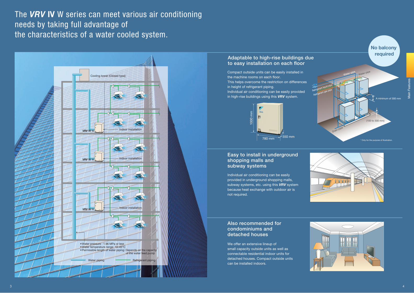
Easy to install in underground shopping malls and subway systems
Individual air conditioning can be easily provided in underground shopping malls, subway systems, etc. using this VRV system because heat exchange with outdoor air is not required.
Also recommended for condominiums and detached houses
We offer an extensive lineup of small capacity outside units as well as connectable residential indoor units for detached houses. Compact outside units can be installed indoors.
Water piping Refrigerant piping
* Only for the purpose of illustration.
A minimum of 300 mm
Drain pipe
Water pipeWater pipe
Refrigerant liquid pipe
Refrigerant gas pipe
(100 to 300 mm)
No balcony required
Indoor installation
Cooling tower (Closed type)
Indoor installation
Indoor installationVRV IV W
VRV IV W
VRV IV W
•Water pressure : 1.96 MPa or less•Water temperature range: 10–45°C•Permissible length of water piping: Depends on the capacity of the water feed pump
Mai
n Fe
atur
es
5 6
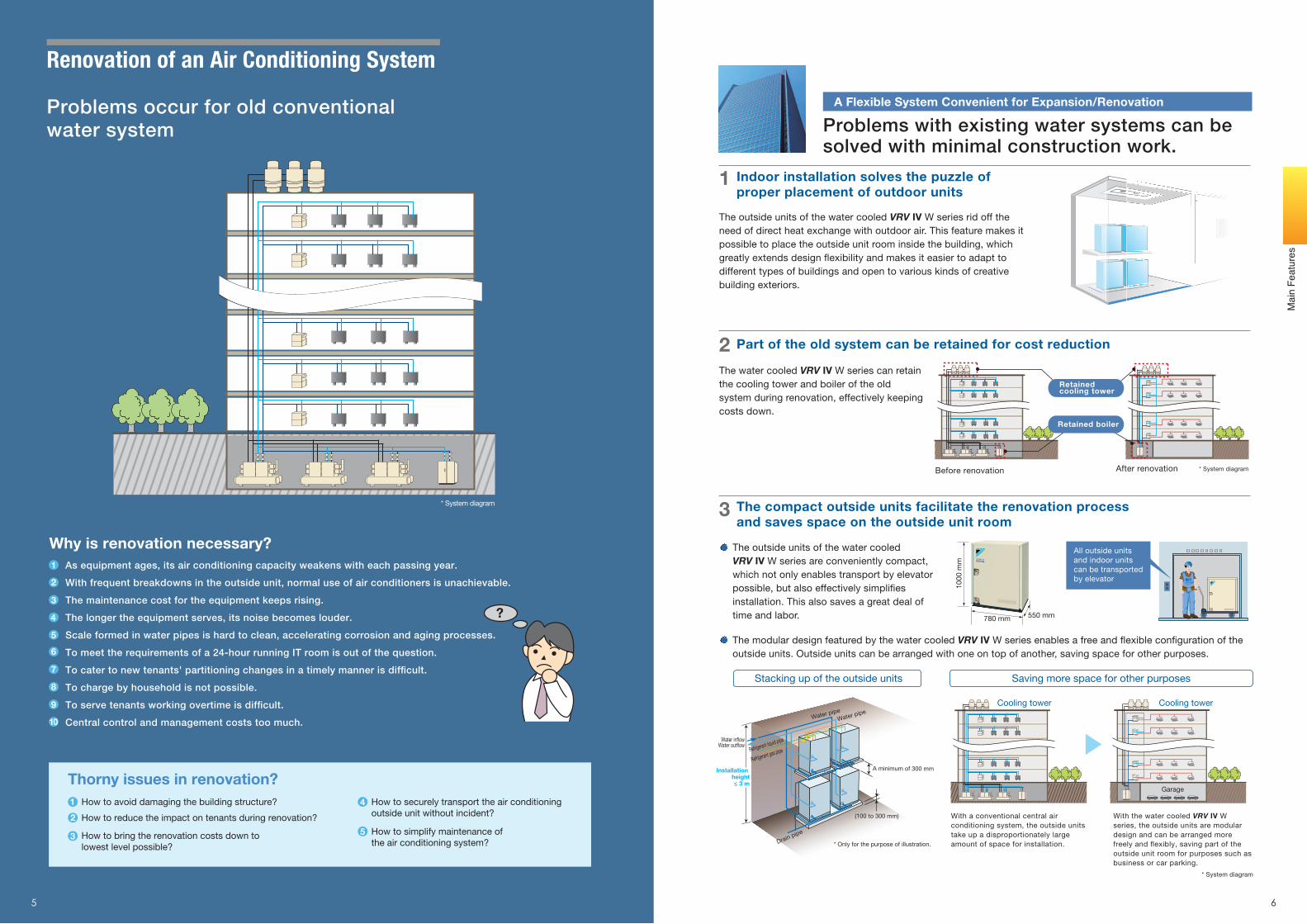
The outside units of the water cooled VRV IV W series are conveniently compact, which not only enables transport by elevator possible, but also effectively simpli�es installation. This also saves a great deal of time and labor.
Indoor installation solves the puzzle of proper placement of outdoor units
Part of the old system can be retained for cost reduction
Why is renovation necessary?
8
9
10
1
2
3
4
5
6
7
How to bring the renovation costs down to lowest level possible?
3
Thorny issues in renovation?How to avoid damaging the building structure?1
How to reduce the impact on tenants during renovation?2
How to securely transport the air conditioning outside unit without incident?
4
How to simplify maintenance of the air conditioning system?
5
* System diagram
The compact outside units facilitate the renovation processand saves space on the outside unit room
1000
mm
780 mm 550 mm
Stacking up of the outside units
A minimum of 300 mm
Water in�owWater out�ow
Drain pipe
Water pipeWater pipe
Refrigerant liquid pipe
Refrigerant gas pipe
Installation height≤ 3 m
(100 to 300 mm)
* Only for the purpose of illustration.
The water cooled VRV IV W series can retain the cooling tower and boiler of the old system during renovation, effectively keeping costs down.
All outside units and indoor units can be transported by elevator
The modular design featured by the water cooled VRV IV W series enables a free and �exible con�guration of the outside units. Outside units can be arranged with one on top of another, saving space for other purposes.
Saving more space for other purposes
With a conventional central air conditioning system, the outside units take up a disproportionately large amount of space for installation.
With the water cooled VRV IV W series, the outside units are modular design and can be arranged more freely and �exibly, saving part of the outside unit room for purposes such as business or car parking.
The outside units of the water cooled VRV IV W series rid off the need of direct heat exchange with outdoor air. This feature makes it possible to place the outside unit room inside the building, which greatly extends design �exibility and makes it easier to adapt to different types of buildings and open to various kinds of creative building exteriors.
Problems occur for old conventional water system
Renovation of an Air Conditioning System
A Flexible System Convenient for Expansion/Renovation
1
2
3
?
Problems with existing water systems can besolved with minimal construction work.
Before renovation After renovation * System diagram
* System diagram
As equipment ages, its air conditioning capacity weakens with each passing year.
With frequent breakdowns in the outside unit, normal use of air conditioners is unachievable.
The maintenance cost for the equipment keeps rising.
The longer the equipment serves, its noise becomes louder.
Scale formed in water pipes is hard to clean, accelerating corrosion and aging processes.
To meet the requirements of a 24-hour running IT room is out of the question.
To cater to new tenants' partitioning changes in a timely manner is dif�cult.
To charge by household is not possible.
To serve tenants working overtime is dif�cult.
Central control and management costs too much.
Mai
n Fe
atur
es
Retained cooling tower
Retained boiler
Cooling tower
Garage
Cooling tower
7 8
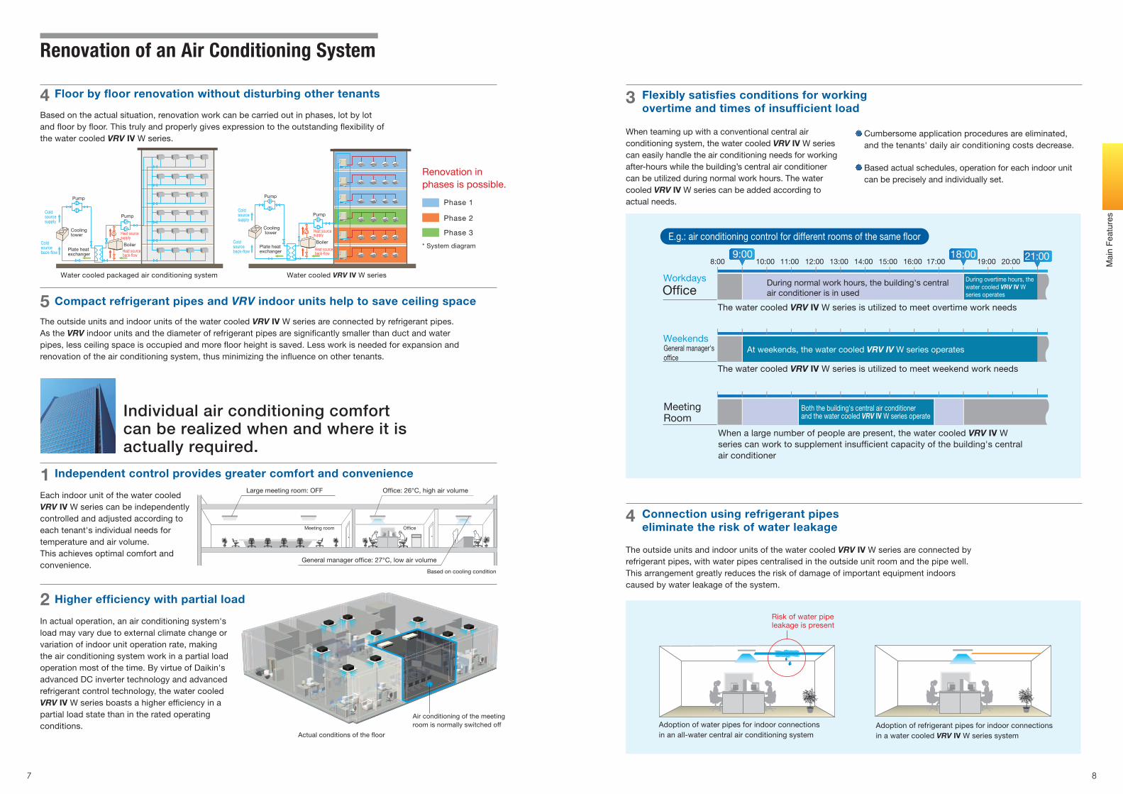
Cumbersome application procedures are eliminated, and the tenants' daily air conditioning costs decrease.
Based actual schedules, operation for each indoor unit can be precisely and individually set.
When teaming up with a conventional central air conditioning system, the water cooled VRV IV W series can easily handle the air conditioning needs for working after-hours while the building’s central air conditioner can be utilized during normal work hours. The water cooled VRV IV W series can be added according to actual needs.
8:00 10:00 11:00 12:00 13:00 14:00 15:00 16:00 17:00 19:00 20:009:00 18:00 21:00
During normal work hours, the building's central air conditioner is in used
At weekends, the water cooled VRV IV W series operates
Of�ce
General manager's of�ce
Meeting Room
The water cooled VRV IV W series is utilized to meet overtime work needs
The water cooled VRV IV W series is utilized to meet weekend work needs
Workdays
Weekends
E.g.: air conditioning control for different rooms of the same �oor
During overtime hours, thewater cooled VRV IV Wseries operates
Both the building's central air conditionerand the water cooled VRV IV W series operate
When a large number of people are present, the water cooled VRV IV Wseries can work to supplement insuf�cient capacity of the building's centralair conditioner
Each indoor unit of the water cooledVRV IV W series can be independentlycontrolled and adjusted according toeach tenant's individual needs fortemperature and air volume. This achieves optimal comfort andconvenience.
Flexibly satisfies conditions for workingovertime and times of insufficient load
Connection using refrigerant pipeseliminate the risk of water leakage
Actual conditions of the �oor
Air conditioning of the meetingroom is normally switched off
In actual operation, an air conditioning system's load may vary due to external climate change or variation of indoor unit operation rate, making the air conditioning system work in a partial load operation most of the time. By virtue of Daikin's advanced DC inverter technology and advanced refrigerant control technology, the water cooled VRV IV W series boasts a higher ef�ciency in a partial load state than in the rated operating conditions.
The outside units and indoor units of the water cooled VRV IV W series are connected byrefrigerant pipes, with water pipes centralised in the outside unit room and the pipe well. This arrangement greatly reduces the risk of damage of important equipment indoors caused by water leakage of the system.
Independent control provides greater comfort and convenience
Higher efficiency with partial loadRisk of water pipeleakage is present
Adoption of water pipes for indoor connectionsin an all-water central air conditioning system
Adoption of refrigerant pipes for indoor connectionsin a water cooled VRV IV W series system
Based on cooling condition
Of�ceMeeting room
Large meeting room: OFF
General manager of�ce: 27°C, low air volume
Of�ce: 26°C, high air volume
Compact refrigerant pipes and VRV indoor units help to save ceiling space
The outside units and indoor units of the water cooled VRV IV W series are connected by refrigerant pipes. As the VRV indoor units and the diameter of refrigerant pipes are signi�cantly smaller than duct and water pipes, less ceiling space is occupied and more �oor height is saved. Less work is needed for expansion and renovation of the air conditioning system, thus minimizing the in�uence on other tenants.
Floor by floor renovation without disturbing other tenants
Phase 1
Phase 2
Phase 3
* System diagram
Based on the actual situation, renovation work can be carried out in phases, lot by lot and �oor by �oor. This truly and properly gives expression to the outstanding �exibility of the water cooled VRV IV W series.
Renovation in phases is possible.
4
5
1
2
3
4
Renovation of an Air Conditioning System
Individual air conditioning comfort can be realized when and where it is actually required.
Water cooled packaged air conditioning system Water cooled VRV IV W series
Mai
n Fe
atur
es
Cold source back-�ow
Cold source supply
Cooling tower Heat source
supply
Heat source back-�ow
Pump
Pump
BoilerPlate heat exchanger
Cold source back-�ow
Cold source supply
Heat source supply
Heat source back-�ow
Cooling tower
Pump
Pump
BoilerPlate heat exchanger
9 10
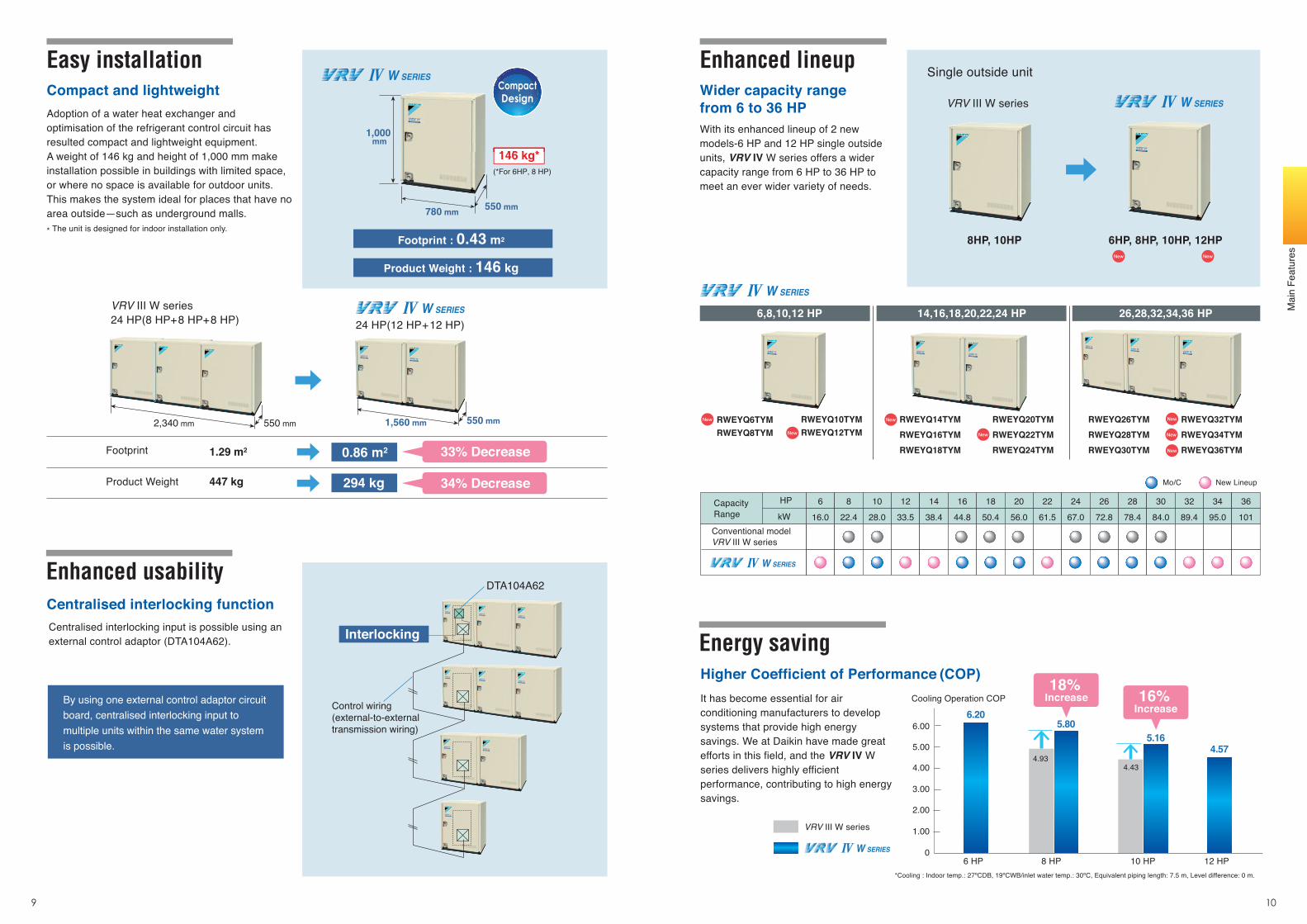
Easy installationCompact and lightweightAdoption of a water heat exchanger and optimisation of the refrigerant control circuit has resulted compact and lightweight equipment. A weight of 146 kg and height of 1,000 mm make installation possible in buildings with limited space, or where no space is available for outdoor units. This makes the system ideal for places that have no area outside—such as underground malls. * The unit is designed for indoor installation only.
Centralised interlocking input is possible using an external control adaptor (DTA104A62).
Centralised interlocking functionDTA104A62
Interlocking
Control wiring (external-to-external transmission wiring)
By using one external control adaptor circuit board, centralised interlocking input to multiple units within the same water system is possible.
Enhanced lineup
Enhanced usability
Energy saving
6,8,10,12 HP 14,16,18,20,22,24 HP 26,28,32,34,36 HP
With its enhanced lineup of 2 new models-6 HP and 12 HP single outside units, VRV IV W series offers a wider capacity range from 6 HP to 36 HP to meet an ever wider variety of needs.
Wider capacity range from 6 to 36 HP
RWEYQ6TYMRWEYQ8TYM
RWEYQ14TYMRWEYQ16TYMRWEYQ18TYM
RWEYQ26TYMRWEYQ28TYMRWEYQ30TYM
Higher Coefficient of Performance (COP)It has become essential for air conditioning manufacturers to develop systems that provide high energy savings. We at Daikin have made great efforts in this field, and the VRV IV W series delivers highly efficient performance, contributing to high energy savings.
*Cooling : Indoor temp.: 27ºCDB, 19ºCWB/inlet water temp.: 30ºC, Equivalent piping length: 7.5 m, Level difference: 0 m.
Cooling Operation COP
6.20
8 HP 10 HP 12 HP6 HP
RWEYQ20TYMRWEYQ22TYMRWEYQ24TYM
RWEYQ32TYMRWEYQ34TYMRWEYQ36TYM
5.805.16
4.574.93
4.43
W SERIES
VRV Ⅲ W series
New Lineup
Conventional model VRV Ⅲ W series
6 8 10 12 14 16 18 20 22 24 26 28 30 32 34 36
Mo/C
16.0 22.4 28.0 33.5 38.4 44.8 50.4 56.0 61.5 67.0 72.8 78.4 84.0 89.4 95.0 101
HP
kW
6.00
5.00
4.00
3.00
2.00
1.00
0
RWEYQ10TYMRWEYQ12TYM
W SERIES
1,000 mm
780 mm 550 mm
(*For 6HP, 8 HP)
146 kg*
Single outside unit
VRV III W series
8HP, 10HP 6HP, 8HP, 10HP, 12HP
Footprint
Product Weight
1.29 m2
447 kg
VRV III W series 24 HP(8 HP+8 HP+8 HP)
0.86 m2
294 kg
W SERIES24 HP(12 HP+12 HP)
550 mm2,340 mm
18% Increase 16%
Increase
W SERIES
CapacityRange
550 mm1,560 mm
33% Decrease
34% Decrease
Footprint : 0.43 m2
Product Weight : 146 kg
W SERIES
W SERIES
146 kg*
CompactDesign
Mai
n Fe
atur
es
VRT-Variable Refrigerant Temperature
11 12
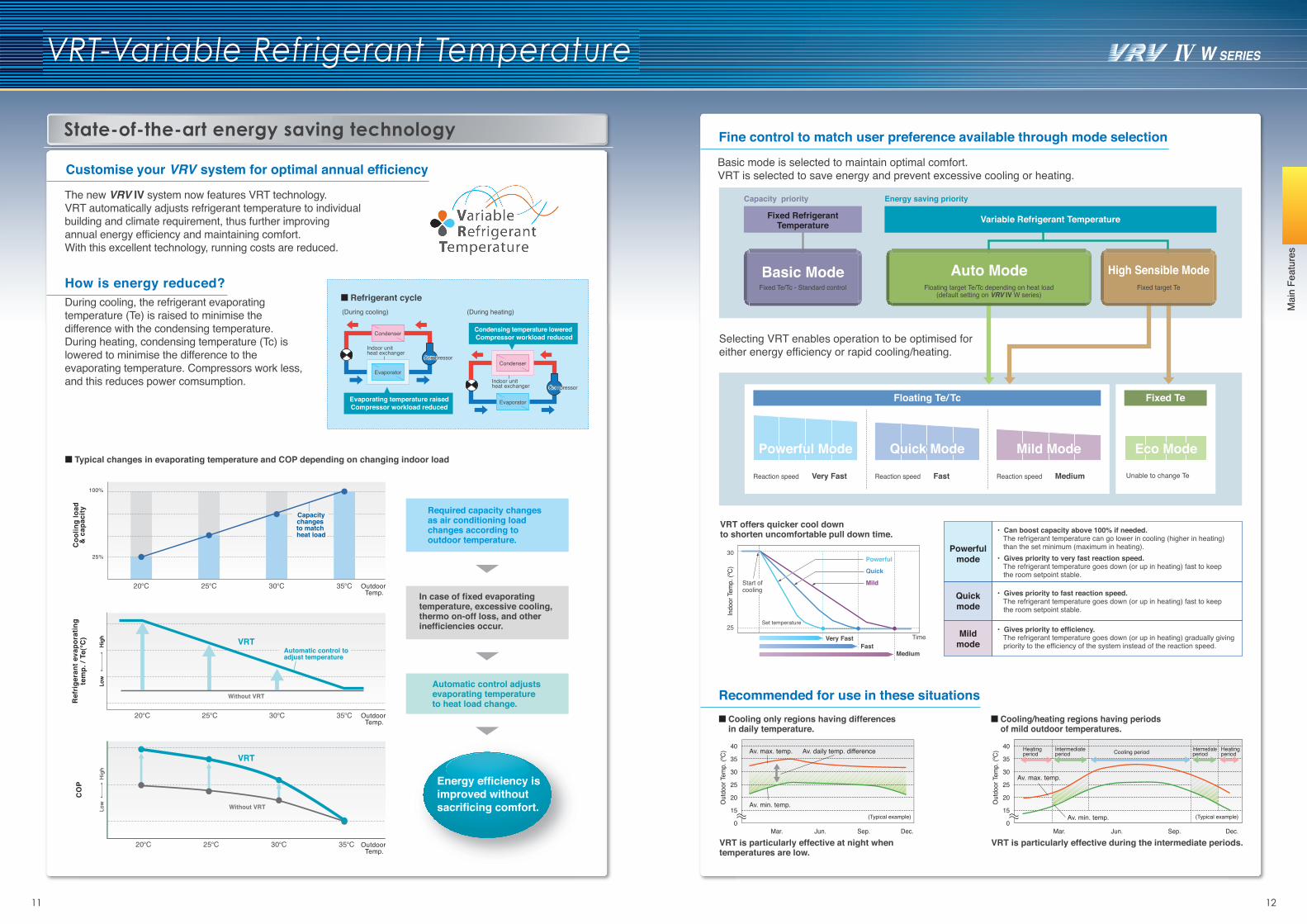
How is energy reduced?During cooling, the refrigerant evaporating temperature (Te) is raised to minimise the difference with the condensing temperature.During heating, condensing temperature (Tc) is lowered to minimise the difference to the evaporating temperature. Compressors work less, and this reduces power comsumption.
State-of-the-art energy saving technology
• Can boost capacity above 100% if needed. The refrigerant temperature can go lower in cooling (higher in heating) than the set minimum (maximum in heating).• Gives priority to very fast reaction speed. The refrigerant temperature goes down (or up in heating) fast to keep
the room setpoint stable.
• Gives priority to fast reaction speed. The refrigerant temperature goes down (or up in heating) fast to keep
the room setpoint stable.
• Gives priority to efficiency. The refrigerant temperature goes down (or up in heating) gradually giving
priority to the efficiency of the system instead of the reaction speed.
CompressorCompressor
(During cooling)
Evaporator
Condenser
Evaporating temperature raisedCompressor workload reduced
Indoor unitheat exchanger
CompressorCompressor
Evaporator
Condenser
Indoor unitheat exchanger
(During heating)
Condensing temperature lowered Compressor workload reduced
Mildmode
Quickmode
Powerfulmode
Variable Refrigerant TemperatureFixed Refrigerant Temperature
High Sensible ModeFixed target Te
Auto ModeFloating target Te/Tc depending on heat load
(default setting on VRV IV W series)
Basic ModeFixed Te/Tc - Standard control
Unable to change Te
Powerful ModePowerful Mode
Reaction speed Very Fast
Quick ModeQuick Mode
Reaction speed Fast
Mild ModeMild Mode
Reaction speed Medium
Eco ModeEco Mode
Energy saving priorityCapacity priority
40
35
30
25
20
15
0Mar. Jun. Sep. Dec.
Av. max. temp. Av. daily temp. difference
Av. min. temp.(Typical example)
Out
door
Tem
p. (º
C)
VRT is particularly effective at night when temperatures are low.
40
35
30
25
20
15
0Mar. Jun. Sep. Dec.
Av. max. temp.
Heatingperiod
Heatingperiod
Intermediateperiod
IntermediateperiodCooling period
Av. min. temp.
Out
door
Tem
p. (º
C)
Set temperature
Very Fast Time
30
Start ofcooling
25
FastMedium
Indo
or T
emp.
(ºC)
VRT offers quicker cool downto shorten uncomfortable pull down time.
Mild
Quick
Powerful
Coo
ling
load
& c
apac
ity
25%
100%
Outdoor Temp.
35°C30°C25°C20°C
Capacitychanges to match heat load
Floating Te/Tc Fixed Te
(Typical example)
Refrigerant cycle
Typical changes in evaporating temperature and COP depending on changing indoor load
Outdoor Temp.
VRT
Without VRT
Low
Hig
hLo
wH
igh
35°C30°C25°C20°C
Ref
riger
ant e
vapo
ratin
gte
mp.
/ Te(℃
)
Automatic control to adjust temperature
Fine control to match user preference available through mode selection
Recommended for use in these situations
Basic mode is selected to maintain optimal comfort.VRT is selected to save energy and prevent excessive cooling or heating.
Cooling only regions having differences in daily temperature.
Cooling/heating regions having periods of mild outdoor temperatures.
VRT is particularly effective during the intermediate periods.
Selecting VRT enables operation to be optimised for either energy efficiency or rapid cooling/heating.
Outdoor Temp.
CO
P
35°C30°C25°C20°C
Without VRT
VRT
Low
Hig
h
Customise your VRV system for optimal annual efficiency
The new VRV IV system now features VRT technology.VRT automatically adjusts refrigerant temperature to individual building and climate requirement, thus further improving annual energy efficiency and maintaining comfort.With this excellent technology, running costs are reduced.
Required capacity changes as air conditioning load changes according to outdoor temperature.
Energy efficiency is improved without sacrificing comfort.
Automatic control adjusts evaporating temperature to heat load change.
In case of fixed evaporating temperature, excessive cooling, thermo on-off loss, and other inefficiencies occur.
Mai
n Fe
atur
es
13 14
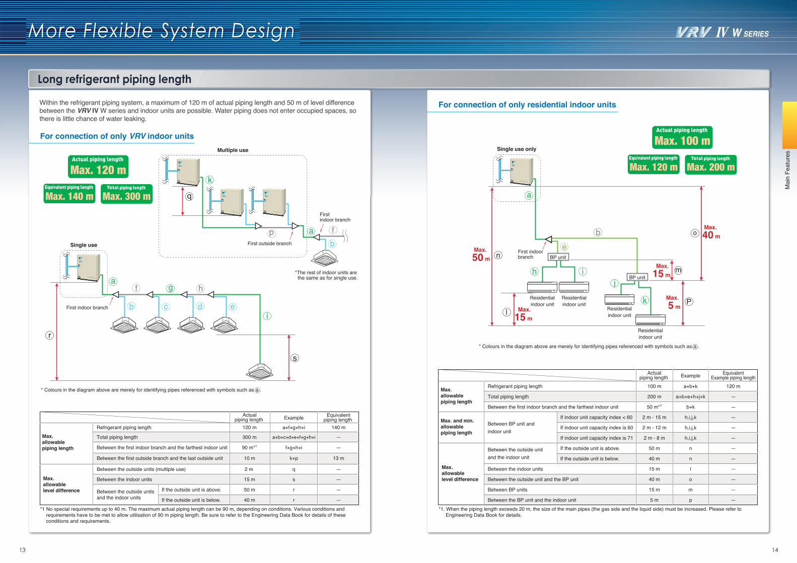
Long refrigerant piping length
Max. 50 m
Max. 40 m
Max. 15 m
Max. 15 m
a
o
l
n
be
First indoor branch
Max. 5 m
P
mh ij
k
BP unit
BP unit
Residentialindoor unit
Residentialindoor unit
Residentialindoor unit
Residentialindoor unit
For connection of only VRV indoor units
Within the refrigerant piping system, a maximum of 120 m of actual piping length and 50 m of level difference between the VRV IV W series and indoor units are possible. Water piping does not enter occupied spaces, so there is little chance of water leaking.
For connection of only residential indoor units
More Flexible System Design
p
q
k
First outside branch
fab
Firstindoor branch
*1 No special requirements up to 40 m. The maximum actual piping length can be 90 m, depending on conditions. Various conditions and requirements have to be met to allow utilisation of 90 m piping length. Be sure to refer to the Engineering Data Book for details of these conditions and requirements.
Multiple use
*The rest of indoor units are the same as for single use.
* Colours in the diagram above are merely for identifying pipes referenced with symbols such as a .
* Colours in the diagram above are merely for identifying pipes referenced with symbols such as a .
a
i
s
r
hgf
edcbFirst indoor branch
Single use
Max. 120 m
Max. 140 m Max. 300 m
Max.allowablelevel difference
Max.allowablepiping length
Between the outside units and the indoor units
Between the indoor units
Between the outside units (multiple use)
Between the first indoor branch and the farthest indoor unit
Between the first outside branch and the last outside unit
Total piping length
Refrigerant piping length
15 m
50 m
2 m
—
—
—
—
—
q
s
rIf the outside unit is above.
If the outside unit is below. 40 m —r
a+b+c+d+e+f+g+h+i
a+f+g+h+i
f+g+h+i
k+p
120 m 140 m
300 m
90 m*1
10 m 13 m
Actualpiping length
Equivalentpiping length Example
*1. When the piping length exceeds 20 m, the size of the main pipes (the gas side and the liquid side) must be increased. Please refer to Engineering Data Book for details.
Single use onlyMax. 100 m
Max. 120 m Max. 200 m
Max.allowablelevel difference
Max.allowablepiping length
Max. and min.allowablepiping length
If indoor unit capacity index < 60
If indoor unit capacity index is 60
If indoor unit capacity index is 71
If the outside unit is above.
If the outside unit is below.
a+b+k
a+b+e+h+j+k
b+k
h,i,j,k
h,i,j,k
h,i,j,k
n
n
l
o
m
p
100 m
200 m
50 m*1
2 m - 15 m
2 m - 12 m
2 m - 8 m
50 m
40 m
15 m
40 m
15 m
5 m
120 m
—
—
—
—
—
—
—
—
—
—
—
Refrigerant piping length
Total piping length
Between the first indoor branch and the farthest indoor unit
Between BP unit and indoor unit
Between the outside unit and the indoor unit
Between the indoor units
Between the outside unit and the BP unit
Between BP units
Between the BP unit and the indoor unit
Actualpiping length
EquivalentExample piping lengthExample
Mai
n Fe
atur
es
15 16
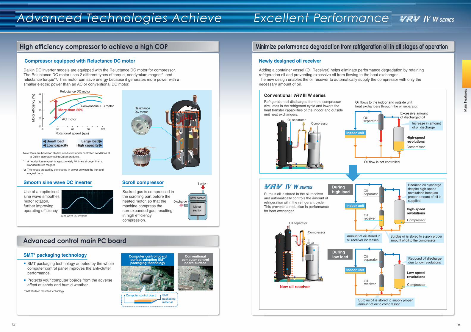
Advanced Technologies Achieve Excellent Performance
High efficiency compressor to achieve a high COP
Newly designed oil receiver
Adding a container vessel (Oil Receiver) helps eliminate performance degradation by retaining refrigeration oil and preventing excessive oil from flowing to the heat exchanger.The new design enables the oil receiver to automatically supply the compressor with only the necessary amount of oil.
Advanced control main PC board
Computer control board SMT packaging material
*SMT: Surface mounted technology
Computer control board surface adopting SMT packaging technology
Conventional computer control
board surfaceSMT packaging technology adopted by the whole computer control panel improves the anti-clutter performance.
Protects your computer boards from the adverse effect of sandy and humid weather.
SMT* packaging technology
Conventional VRV III W series
Oil separatorCompressor
Sine wave DC inverter
Smooth sine wave DC inverter
Use of an optimised sine wave smoothes motor rotation, further improving operating efficiency.
Daikin DC inverter models are equipped with the Reluctance DC motor for compressor. The Reluctance DC motor uses 2 different types of torque, neodymium magnet*1 and reluctance torque*2. This motor can save energy because it generates more power with a smaller electric power than an AC or conventional DC motor.
Compressor equipped with Reluctance DC motor
Reluctance DC motor
Conventional DC motor
AC motor
Rotational speed (rps)
Mot
or e
fficie
ncy
(%) 90
80
70
60
500 30 60 90 120
More than 20%More than 20%
Small loadLow capacity
Large loadHigh capacity
Scroll compressor
Scroll section
Suction
DischargeMotor section
Note: Data are based on studies conducted under controlled conditions at a Daikin laboratory using Daikin products.
*1 A neodymium magnet is approximately 10 times stronger than a standard ferrite magnet.
*2 The torque created by the change in power between the iron and magnet parts.
Sucked gas is compressed in the scrolling part before the heated motor, so that the machine compress the non-expanded gas, resulting in high efficiency compression.
ReluctanceDC motor
New oil receiver
Oil separator
Compressor
Refrigeration oil discharged from the compressor circulates in the refrigerant cycle and lowers the heat transfer capabilities of the indoor and outside unit heat exchangers.
Surplus oil is stored in the oil receiver and automatically controls the amount of refrigeration oil in the refrigerant cycle.This prevents a reduction in performancefor heat exchanger.
Compressor
Oil separator
Indoor unit
Reduced oil discharge despite high-speed revolutions becauseproper amount of oil is supplied
Amount of oil stored in oil receiver increases
Increase in amount of oil discharge
Reduced oil discharge due to low revolutions
Oil separator
Oilreceiver Compressor
Surplus oil is stored to supply proper amount of oil to the compressor
Compressor
Oil separator
Oilreceiver
Surplus oil is stored to supply proper amount of oil to compressor
During high load
Minimize performance degradation from refrigeration oil in all stages of operation
Oil flows to the indoor and outside unit heat exchangers through the oil separator.
High-speedrevolutions
Oil flow is not controlled
Excessive amount of discharged oil
High-speed revolutions
Low-speed revolutions
During low load
Indoor unit
Indoor unit
Mai
n Fe
atur
es
17 18
Reliable and Stable System
Mai
n Fe
atur
es
Reliable and convenient air conditioning system
Auto-restart technology after power interruption
No matter whether the indoor or outside unit accidentally experiences a power interruption during normal operation, the system will keep a record of the operating mode adopted before the power interruption. When the power supply recovers, the air conditioning system will then restore itself back into the recorded operating status, simplifying the operation after an accidental power interruption.
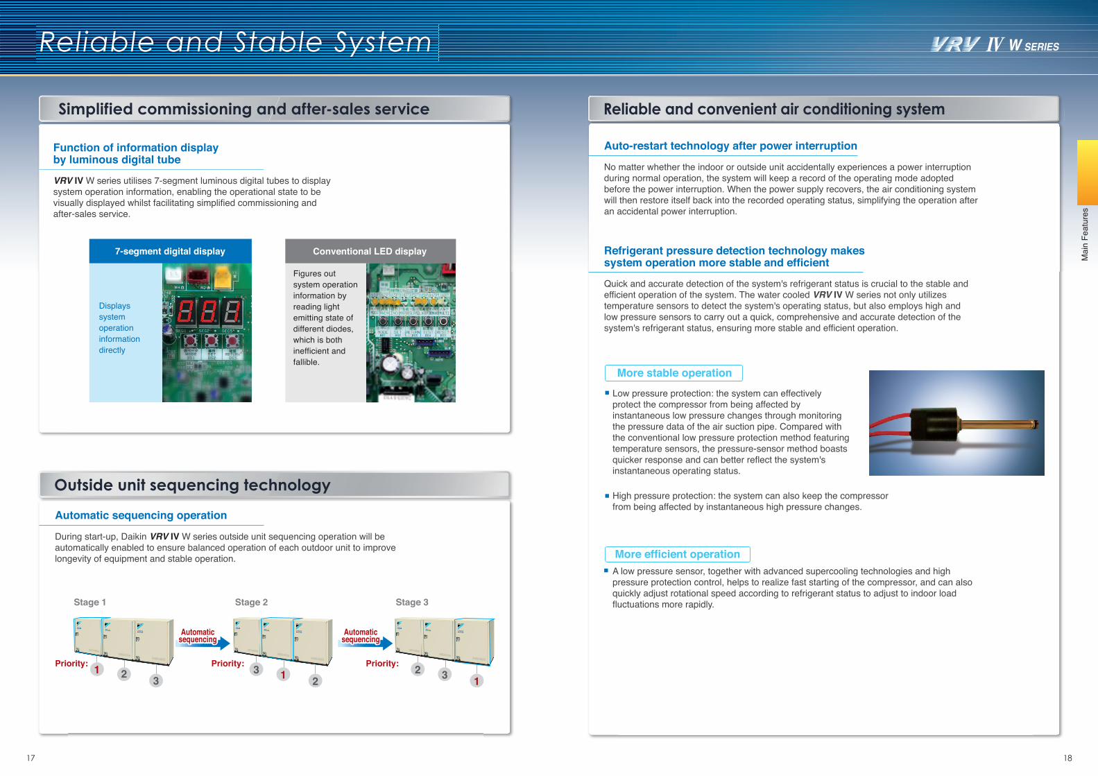
Simplified commissioning and after-sales service
Automatic sequencing operation
During start-up, Daikin VRV IV W series outside unit sequencing operation will be automatically enabled to ensure balanced operation of each outdoor unit to improve longevity of equipment and stable operation.
Stage 1 Stage 2 Stage 3
Priority: Priority: Priority:
AutomaticsequencingAutomatic
sequencingAutomatic
sequencingAutomatic
sequencing
VRV IV W series utilises 7-segment luminous digital tubes to display system operation information, enabling the operational state to be visually displayed whilst facilitating simplified commissioning and after-sales service.
Function of information display by luminous digital tube
Quick and accurate detection of the system's refrigerant status is crucial to the stable and efficient operation of the system. The water cooled VRV IV W series not only utilizes temperature sensors to detect the system's operating status, but also employs high and low pressure sensors to carry out a quick, comprehensive and accurate detection of the system's refrigerant status, ensuring more stable and efficient operation.
Refrigerant pressure detection technology makes system operation more stable and efficient
Displays system operation information directly
Figures out system operation information by reading light emitting state of different diodes, which is both inefficient and fallible.
7-segment digital display Conventional LED display
More efficient operation
More stable operation
High pressure protection: the system can also keep the compressor from being affected by instantaneous high pressure changes.
A low pressure sensor, together with advanced supercooling technologies and high pressure protection control, helps to realize fast starting of the compressor, and can also quickly adjust rotational speed according to refrigerant status to adjust to indoor load fluctuations more rapidly.
Low pressure protection: the system can effectively protect the compressor from being affected by instantaneous low pressure changes through monitoring the pressure data of the air suction pipe. Compared with the conventional low pressure protection method featuring temperature sensors, the pressure-sensor method boasts quicker response and can better reflect the system's instantaneous operating status.
Outside unit sequencing technology
19 20
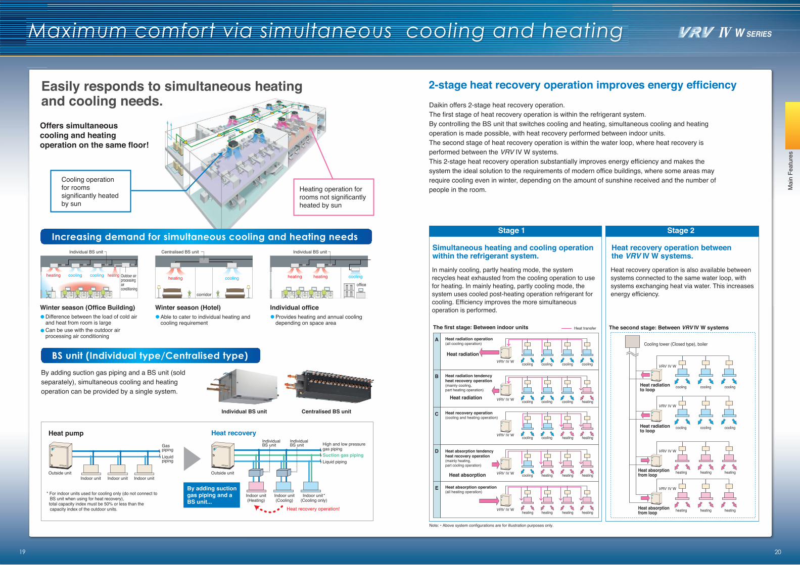
Maximum comfort via simultaneous cooling and heating
Offers simultaneous cooling and heating operation on the same floor!
By adding suction gas piping and a BS unit (sold separately), simultaneous cooling and heating operation can be provided by a single system.
Heat pump Heat recovery
* For indoor units used for cooling only (do not connect to BS unit when using for heat recovery),
total capacity index must be 50% or less than the capacity index of the outdoor units.
BS unit (Individual type/Centralised type)
Increasing demand for simultaneous cooling and heating needs
Outside unit
Gas pipingLiquid piping
Indoor unit Indoor unitIndoor unit
By adding suction gas piping and a BS unit...
Heat recovery operation!
Outside unit
High and low pressuregas pipingSuction gas pipingLiquid piping
Indoor unit(Heating)
Indoor unit(Cooling)
Indoor unit*(Cooling only)
IndividualBS unit
IndividualBS unit
Centralised BS unit
heating cooling
corridor
heating cooling cooling heating Outdoor airprocessingair conditioning
Individual BS unit
heating heating cooling
office
Individual BS unit
Winter season (Office Building)Difference between the load of cold air and heat from room is largeCan be use with the outdoor air processing air conditioning
Winter season (Hotel)Able to cater to individual heating and cooling requirement
Individual officeProvides heating and annual coolingdepending on space area
Individual BS unit Centralised BS unit
Mai
n Fe
atur
es
In mainly cooling, partly heating mode, the system recycles heat exhausted from the cooling operation to use for heating. In mainly heating, partly cooling mode, the system uses cooled post-heating operation refrigerant for cooling. Efficiency improves the more simultaneous operation is performed.
Note: • Above system configurations are for illustration purposes only.
Simultaneous heating and cooling operationwithin the refrigerant system.
Heat recovery operation is also available between systems connected to the same water loop, with systems exchanging heat via water. This increases energy efficiency.
Heat recovery operation betweenthe VRV IV W systems.
Daikin offers 2-stage heat recovery operation. The first stage of heat recovery operation is within the refrigerant system. By controlling the BS unit that switches cooling and heating, simultaneous cooling and heating operation is made possible, with heat recovery performed between indoor units. The second stage of heat recovery operation is within the water loop, where heat recovery is performed between the VRV IV W systems. This 2-stage heat recovery operation substantially improves energy efficiency and makes the system the ideal solution to the requirements of modern office buildings, where some areas may require cooling even in winter, depending on the amount of sunshine received and the number of people in the room.
Stage 1 Stage 2
The first stage: Between indoor units
A
B
C
D
E
Heat radiation operation (all cooling operation)
Heat radiation tendency heat recovery operation (mainly cooling, part heating operation)
Heat recovery operation (cooling and heating operation)
Heat absorption tendency heat recovery operation (mainly heating, part cooling operation)
Heat absorption operation (all heating operation)
Heat radiation
Heat absorption
Heat radiation
cooling coolingcoolingcooling
cooling heatingcoolingcooling
heating heatingcoolingcooling
heating heatingheatingcooling
heating heatingheatingheating
Heat transfer
Heat radiationto loop
Heat radiationto loop
Cooling tower (Closed type), boiler
coolingcoolingcooling
coolingcoolingcooling
The second stage: Between VRV IV W systems
Heat absorptionfrom loop
Heat absorptionfrom loop
heatingheatingheating
heatingheatingheating
2-stage heat recovery operation improves energy efficiency Easily responds to simultaneous heatingand cooling needs.
Cooling operation for rooms significantly heated by sun
Heating operation for rooms not significantly heated by sun
VRV IV W
VRV IV W
VRV IV W
VRV IV W
VRV IV W
VRV IV W
VRV IV W
VRV IV W
VRV IV W
21 22
Enhanced Lineup of BS Units
Mai
n Fe
atur
es
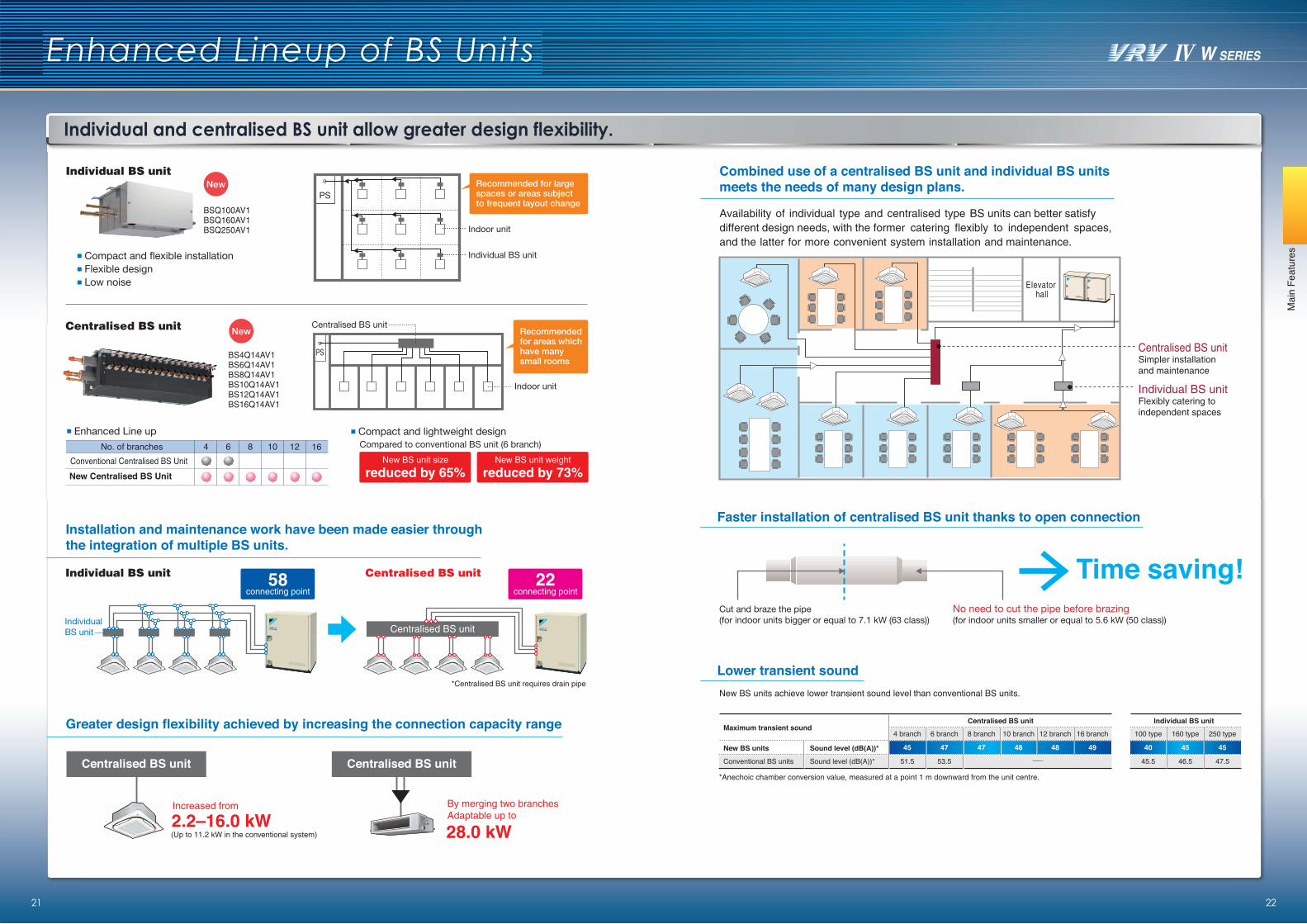
Combined use of a centralised BS unit and individual BS units meets the needs of many design plans.
Installation and maintenance work have been made easier through the integration of multiple BS units.
Greater design flexibility achieved by increasing the connection capacity range
Faster installation of centralised BS unit thanks to open connection
Individual and centralised BS unit allow greater design flexibility.
BSQ100AV1BSQ160AV1BSQ250AV1
Compact and flexible installationFlexible designLow noise
Enhanced Line up Compact and lightweight design
Conventional Centralised BS UnitNo. of branches 4 6 8 10 12 16
New Centralised BS Unit
Indoor unit
PS
Individual BS unit
Recommended for large spaces or areas subject to frequent layout change
BS4Q14AV1BS6Q14AV1BS8Q14AV1BS10Q14AV1BS12Q14AV1BS16Q14AV1
Centralised BS unit
58connecting point
22connecting point
reduced by 65%New BS unit size
reduced by 73%New BS unit weight
2.2–16.0 kW
Centralised BS unit
Increased from
(Up to 11.2 kW in the conventional system)
Centralised BS unit
28.0 kW
By merging two branchesAdaptable up to
*Centralised BS unit requires drain pipe
No need to cut the pipe before brazing(for indoor units smaller or equal to 5.6 kW (50 class))
Cut and braze the pipe(for indoor units bigger or equal to 7.1 kW (63 class))
Time saving!
New BS units achieve lower transient sound level than conventional BS units.
Lower transient sound
*Anechoic chamber conversion value, measured at a point 1 m downward from the unit centre.
Compared to conventional BS unit (6 branch)
Centralised BS unit
PS
Indoor unit
Recommended for areas which have many small rooms
Individual BS unit
Maximum transient sound4 branch
45
51.5
6 branch
47
53.5
8 branch
47
10 branch
48
12 branch
48
16 branch
49Sound level (dB(A))*
Sound level (dB(A))*
New BS units
Conventional BS units
Centralised BS unit
100 type
40
45.5
160 type
45
46.5
250 type
45
47.5
Individual BS unit
Elevatorhall
Individual BS unitFlexibly catering toindependent spaces
Centralised BS unitSimpler installation and maintenance
Availability of individual type and centralised type BS units can better satisfy different design needs, with the former catering flexibly to independent spaces, and the latter for more convenient system installation and maintenance.
Individual BS unit
Centralised BS unit
Individual BS unit Centralised BS unit
Enhanced range of choices
Indoor Unit Lineup
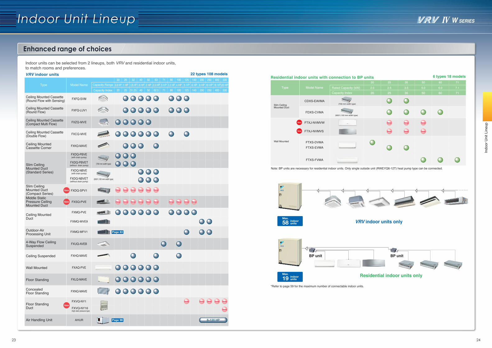
Indoor units can be selected from 2 lineups, both VRV and residential indoor units, to match rooms and preferences.VRV indoor units
Indo
or U
nit L
ineu
p
23 24
VRV indoor units only58Max.
indoorunits
*Refer to page 59 for the maximum number of connectable indoor units.
Residential indoor units with connection to BP units
FXSQ-PVEMiddle StaticPressure CeilingMounted Duct
Type Model Name
FXFQ-SVMCeiling Mounted Cassette(Round Flow with Sensing)
Ceiling Mounted Cassette(Round Flow)
Ceiling Mounted Cassette(Compact Multi Flow)
Ceiling Mounted Cassette(Double Flow)
Ceiling Mounted Cassette Corner
Slim Ceiling Mounted Duct(Standard Series)
Ceiling Mounted Duct
Ceiling Suspended
Wall Mounted
Floor Standing
ConcealedFloor Standing
4-Way Flow Ceiling Suspended
Air Handling Unit
Outdoor-Air Processing Unit
6 types 18 models
Rated Capacity (kW)Type Model NameCapacity Index
Slim CeilingMounted Duct
Wall Mounted
CDXS-EAVMA
FDXS-CVMA
FTXS-DVMAFTXS-EVMA
FTXS-FVMA
(700 mm width type)
(900/1,100 mm width type)
FTXJ-NVMVW
FTXJ-NVMVS
FXVQ-NY1
FXVQ-NY16(high static pressure type)
Floor StandingDuct
FXDQ-SPV1Slim CeilingMounted Duct(Compact Series)
BP unit
Residential indoor units only19Max.
indoorunits
BP unit
22 types 108 models
FXMQ-MFV1
FXMQ-MVE9
AHUR 8–120 HP
Page 83
Page 98
25 35
25 352.5 3.5
50 60 71
50 60 715.0 6.0 7.1
20
202.0
Note: BP units are necessary for residential indoor units. Only single outside unit (RWEYQ6-12T) heat pump type can be connected.
Indoor Unit Lineup
Indo
or U
nit L
ineu
p
25 26
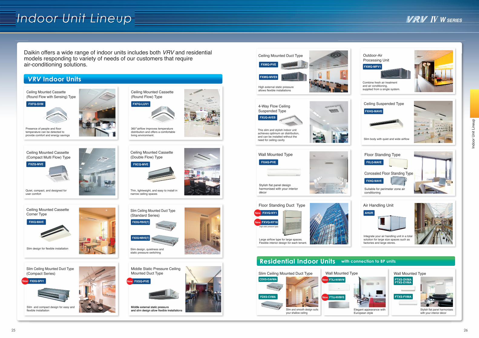
Daikin offers a wide range of indoor units includes both VRV and residential models responding to variety of needs of our customers that require air-conditioning solutions.
VRV Indoor Units
Residential Indoor Units with connection to BP units
Presence of people and floor temperature can be detected to provide comfort and energy savings
Ceiling Mounted Cassette (Round Flow) Type
Ceiling Mounted Cassette (Double Flow) Type
Thin, lightweight, and easy to install in narrow ceiling spaces
Slim Ceiling Mounted Duct Type (Standard Series)
Slim design, quietness and static pressure switching
Ceiling Mounted Cassette (Compact Multi Flow) Type
Quiet, compact, and designed for user comfort
Ceiling Mounted Cassette Corner Type
Slim design for flexible installation
360 airflow improves temperature distribution and offers a comfortable living environment.
Ceiling Mounted Cassette (Round Flow with Sensing) Type
FXFQ-SVM FXFQ-LUV1
FXZQ-MVE FXCQ-MVE
FXKQ-MAVE FXDQ-PBVE(T)
FXDQ-NBVE(T)
Slim Ceiling Mounted Duct Type (Compact Series)
Slim and compact design for easy andflexible installation
FXDQ-SPV1
Middle Static Pressure Ceiling Mounted Duct Type
FXSQ-PVE
Middle external static pressureand slim design allow flexible installationsMiddle external static pressureand slim design allow flexible installations
Outdoor-Air Processing Unit
Combine fresh air treatment and air conditioning, supplied from a single system.
FXMQ-MFV1
4-Way Flow Ceiling Suspended Type
This slim and stylish indoor unit achieves optimum air distribution, and can be installed without the need for ceiling cavity
FXUQ-AVEB
Ceiling Suspended Type
Slim body with quiet and wide airflow
FXHQ-MAVE
Ceiling Mounted Duct Type
High external static pressure allows flexible installations
FXMQ-PVE
FXMQ-MVE9
Wall Mounted Type
Stylish flat panel design harmonised with your interior décor
FXAQ-PVE
Air Handling Unit
Integrate your air handling unit in a total solution for large size spaces such as factories and large stores.
AHUR
Floor Standing Type
Concealed Floor Standing Type
Suitable for perimeter zone air conditioning
FXLQ-MAVE
FXNQ-MAVE
Slim Ceiling Mounted Duct Type
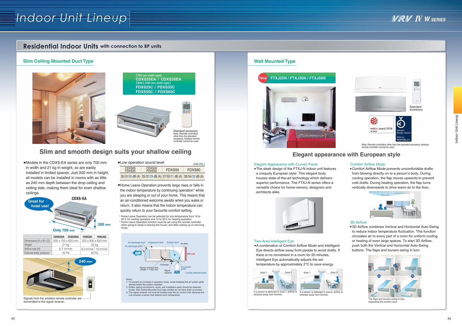
Slim and smooth design suitsyour shallow ceiling
CDXS-EAVMA
FDXS-CVMA
Elegant appearance with European style
Wall Mounted Type Wall Mounted Type
Stylish flat panel harmonises with your interior décor
FTXJ-NVMVW
FTXJ-NVMVS
FTXS-DVMAFTXS-EVMA
FTXS-FVMA
Floor Standing Duct Type
Large airfiow type for large spaces.Flexible interior design for each tenant.
FXVQ-NY1
FXVQ-NY16(high static pressure type)
Indoor Unit Lineup
VRV Indoor Units
27 28
Indo
or U
nit L
ineu
p
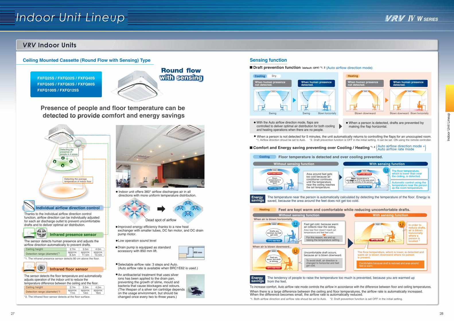
Ceiling Mounted Cassette (Round Flow with Sensing) Type
FXFQ25S / FXFQ32S / FXFQ40S
FXFQ50S / FXFQ63S / FXFQ80S
FXFQ100S / FXFQ125S
Presence of people and floor temperature can be detected to provide comfort and energy savings
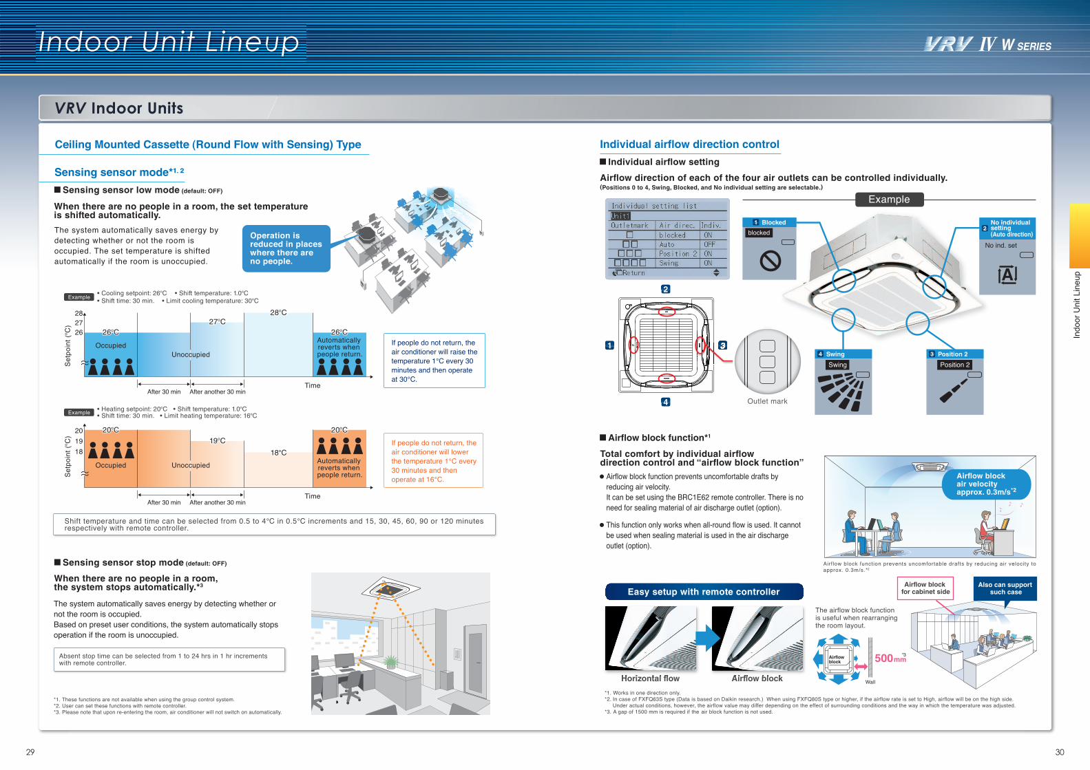
Thanks to the individual airflow direction control function, airflow direction can be individually adjusted for each air discharge outlet to prevent uncomfortable drafts and to deliver optimal air distribution.
The sensor detects human presence and adjusts the airflow direction automatically to prevent drafts.
The sensor detects the floor temperature and automatically adjusts operation of the indoor unit to reduce the temperature difference between the ceiling and the floor.
Infrared presence sensor
Infrared floor sensor
Ceiling heightDetection range (diameter)
2.7mapprox.
11m
3.5mapprox.
14m
4.0mapprox.
16m*2. The infrared floor sensor detects at the floor surface.
*1. The infrared presence sensor detects 80 cm above the floor.
*2
Ceiling heightDetection range (diameter)
2.7mapprox.
8.5m
3.5mapprox.11.5m
4.0mapprox.13.5m*1
Individual airflow direction control
AD
CB
Dead spot of airflow
Indoor unit offers 360° airflow discharges air in all directions with more uniform temperature distribution.
detected to provide comfort and energy savings
AD
CB
Selectable airflow rate: 3 steps and Auto.(Auto airflow rate is available when BRC1E62 is used.)
An antibacterial treatment that uses silver ions has been applied to the drain pan, preventing the growth of slime, mould and bacteria that cause blockages and odours.(The lifespan of a silver ion cartridge depends on the usage environment, but should be changed once every two to three years.)
Improved energy efficiency thanks to a new heat exchanger with smaller tubes, DC fan motor, and DC drain pump motor.
Drain pump is equipped as standard accessory with 850 mm lift.
Low operation sound level
850 mm
Detecting the presence of people in 4 areas
Detecting the average temperature of indoor floor
With the Auto airflow direction mode, flaps are controlled to deliver optimal air distribution for both cooling and heating operations when there are no people.
When a person is detected, drafts are prevented by making the flap horizontal.
When a person is not detected for 5 minutes, the unit automatically returns to controlling the flaps for an unoccupied room.
When human presence not detected.
When human presence detected.
Swing Swing Blown horizontally Blown downward
Draft prevention function (default: OFF) *1. 2
Blown downward Blown horizontally
Cooling Dry Heating
(Auto airflow direction mode)
*1. Airflow direction shoud be set to Auto. *2. Draft prevention function is OFF in the initial setting. It can be set ON using the remote controller.
When human presence not detected.
When human presence detected.
When there is a large difference between the ceiling and floor temperatures, the airflow rate is automatically increased.When the difference becomes small, the airflow rate is automatically reduced.*1. Both airflow direction and airflow rate shoud be set to Auto. *2. Draft prevention function is set OFF in the initial setting.
Comfort and Energy saving preventing over Cooling / Heating *1. 2
Floor temperature is detected and over cooling prevented.
To increase comfort, Auto airflow rate mode controls the airflow in accordance with the difference between floor and ceiling temperatures.
Feet are kept warm and comfortable while reducing uncomfortable drafts.
When air is blown horizontally...
When air is blown downward...
20°C near floor
17°C near floor
Drafts are minimal, but feet
get cold.
Feet are warm, but draft
is strong.
The temperature near the person is automatically calculated by detecting the temperature of the floor. Energy is saved, because the area around the feet does not get too cold.
Auto airflow direction mode +Auto airflow rate mode
Without sensing function With sensing function
Without sensing function With sensing function
Feet get cold, because warm air collects near the ceiling. Area near floor doesn’t reach set temperature and feet feel cold.
For this reason, we end up raising the temperature setting.
Uncomfortable draft occurs, because air is blown downward.
To avoid draft, air direction is changed to horizontal and feet get cold.
30°C near ceiling
20°C near floor
Room temperature is
detected as 30°C.
Area around feet gets too cold because air conditioner continues until the temperature near the ceiling reaches the set temperature.
Room temperature is calculated as 27°C in the area which
is in the vicinity of the person.
24°C near floor
Room temperature is calculated as 27°C in the area which calculated as 27°C in the area which
is in the vicinity of the person.is in the vicinity of the person.
30°C near ceilingThe floor temperature, which is lower than near the ceiling, is detected.
Energy savings
Energy savings
When air is blown horizontally...
The tendency of people to raise the temperature too much is prevented, because you are warmed up from the feet.
20°C near floor
Automatic control using the temperature near the person as the room temperature.
20°C near floor
The floor temperature, which is lower, is detected and warm air is blown downward where no person is present.
Comfortable because draft is reduced and area around feet is warm.
In order to reduce drafts, air is blown horizontally where a person is located.*2
Cooling
Heating
Sensing function
( )
Indoor Unit Lineup
29 30
Indo
or U
nit L
ineu
p
VRV Indoor Units
Ceiling Mounted Cassette (Round Flow with Sensing) Type
If people do not return, the air conditioner will raise the temperature 1℃ every 30 minutes and then operate at 30℃.
If people do not return, the air conditioner will lower the temperature 1°C every 30 minutes and then operate at 16°C.
The system automatically saves energy by detecting whether or not the room is occupied. The set temperature is shifted automatically if the room is unoccupied.
The system automatically saves energy by detecting whether or not the room is occupied. Based on preset user conditions, the system automatically stops operation if the room is unoccupied.
Example • Cooling setpoint: 26°C • Shift temperature: 1.0°C • Shift time: 30 min. • Limit cooling temperature: 30°C
Example • Heating setpoint: 20°C • Shift temperature: 1.0°C • Shift time: 30 min. • Limit heating temperature: 16°C
201918
Occupied Unoccupied Automatically reverts when people return.
19°C
18°C
20°C20°C 20°C20°C19°C
18°C
Se
tpo
int
(°C
)
TimeAfter 30 min After another 30 min
282726
OccupiedUnoccupied
Automatically reverts when people return.
27°C28°C
26°C26°C 26°C26°C27°C
28°C
Se
tpo
int
(°C
)
TimeAfter 30 min After another 30 min
Absent stop time can be selected from 1 to 24 hrs in 1 hr increments with remote controller.
Shift temperature and time can be selected from 0.5 to 4℃ in 0.5℃ increments and 15, 30, 45, 60, 90 or 120 minutes respectively with remote controller.
*1. These functions are not available when using the group control system. *2. User can set these functions with remote controller.*3. Please note that upon re-entering the room, air conditioner will not switch on automatically.
When there are no people in a room, the set temperature is shifted automatically.
When there are no people in a room, the system stops automatically.*3
Operation is reduced in places where there are no people.
Sensing sensor low mode (default: OFF)
Sensing sensor mode*1. 2
Sensing sensor stop mode (default: OFF)
Airflow block air velocity approx. 0.3m/s*2
Airflow block function prevents uncomfortable drafts by reducing air velocity to approx. 0.3m/s.*2
Airflow block function prevents uncomfortable drafts by reducing air velocity. It can be set using the BRC1E62 remote controller. There is no need for sealing material of air discharge outlet (option).
This function only works when all-round flow is used. It cannot be used when sealing material is used in the air discharge outlet (option).
*1. Works in one direction only.*2. In case of FXFQ63S type (Data is based on Daikin research.) When using FXFQ80S type or higher, if the airflow rate is set to High, airflow will be on the high side. Under actual conditions, however, the airflow value may differ depending on the effect of surrounding conditions and the way in which the temperature was adjusted.*3. A gap of 1500 mm is required if the air block function is not used.
Airflow direction of each of the four air outlets can be controlled individually. (Positions 0 to 4, Swing, Blocked, and No individual setting are selectable.)
Total comfort by individual airflow direction control and “airflow block function”
1
2
3
4 Outlet mark
33
1 Blocked
3 Position 24 Swing
2No individual setting(Auto direction)
Example
Swing Position 2
blocked
No ind. set
A
Horizontal flow Airflow block
500mm
Wall
Airflowblock
*3
Also can support such case
Airflow block for cabinet side
The airflow block function is useful when rearranging the room layout.
Easy setup with remote controller
Horizontal flow Airflow block
Individual airflow setting
Individual airflow direction control
Airflow block function*1
VRV Indoor Units
Indoor Unit Lineup
31 32
Indo
or U
nit L
ineu
p
Note: Whatever the discharge direction, the same type of panel is used. If installing for other than all-round flow, an air discharge outlet sealing material (option) must be used to close each unused outlet.
3-way flow L-shaped 2-way flowAll-round flow 4-way flow
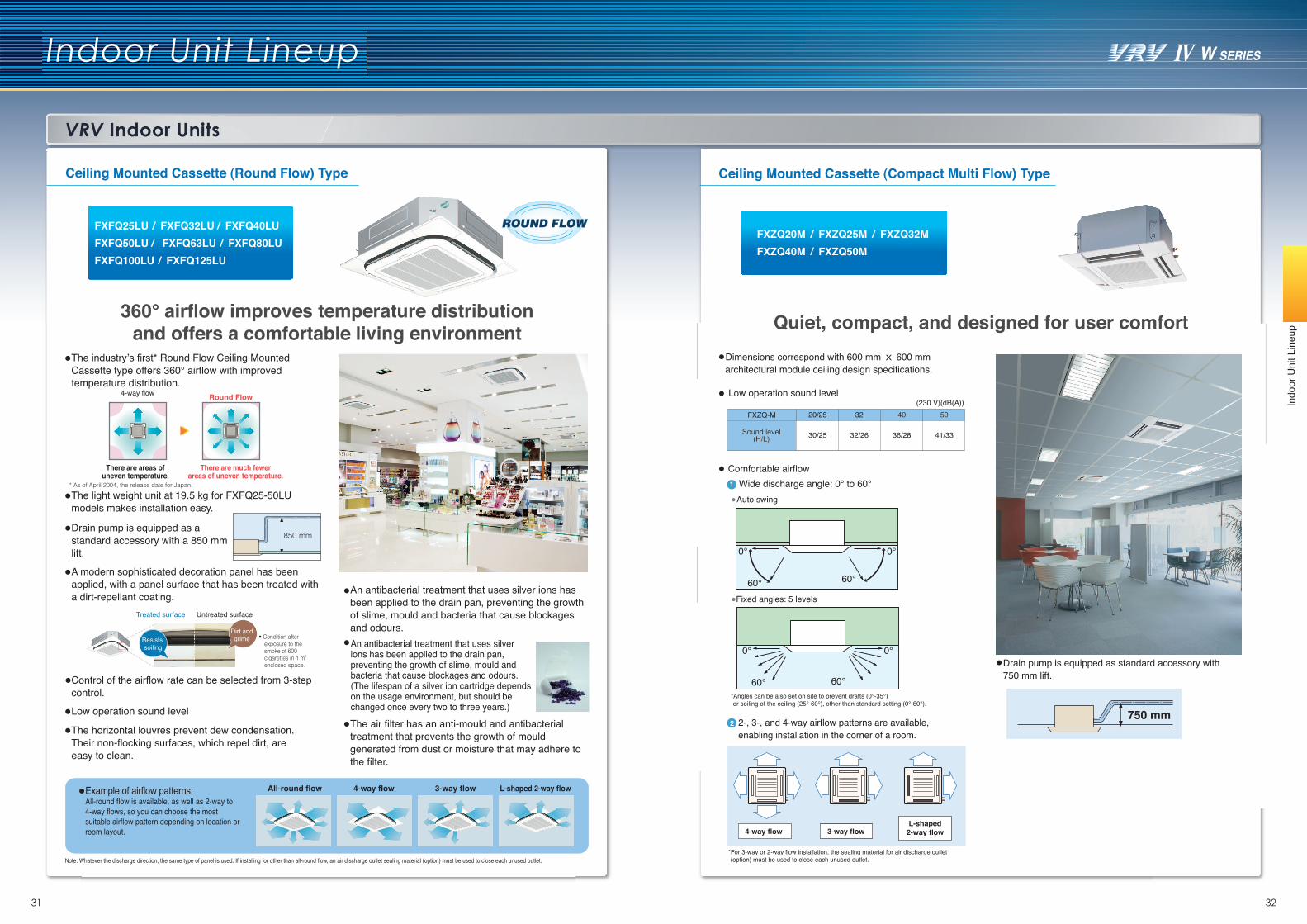
The industry’s first* Round Flow Ceiling Mounted Cassette type offers 360° airflow with improved temperature distribution.
The light weight unit at 19.5 kg for FXFQ25-50LU models makes installation easy.
A modern sophisticated decoration panel has been applied, with a panel surface that has been treated with a dirt-repellant coating. An antibacterial treatment that uses silver ions has
been applied to the drain pan, preventing the growth of slime, mould and bacteria that cause blockages and odours.
The horizontal louvres prevent dew condensation. Their non-flocking surfaces, which repel dirt, are easy to clean.
The air filter has an anti-mould and antibacterial treatment that prevents the growth of mould generated from dust or moisture that may adhere to the filter.
Example of airflow patterns:All-round flow is available, as well as 2-way to 4-way flows, so you can choose the most suitable airflow pattern depending on location or room layout.
Drain pump is equipped as a standard accessory with a 850 mm lift.
Treated surface Untreated surface
Resists soiling
• Condition after exposure to the smoke of 600 cigarettes in 1 m3 enclosed space.
Dirt andgrime
Control of the airflow rate can be selected from 3-step control.
4-way flow Round Flow
There are areas of uneven temperature.
There are much fewerareas of uneven temperature.
* As of April 2004, the release date for Japan.
Low operation sound level
850 mm
Ceiling Mounted Cassette (Round Flow) Type
Quiet, compact, and designed for user comfort Dimensions correspond with 600 mm X 600 mm
architectural module ceiling design specifications.
Wide discharge angle: 0° to 60°
2-, 3-, and 4-way airflow patterns are available, enabling installation in the corner of a room.
0°
60°
0°
60°
Auto swing
Fixed angles: 5 levels
*Angles can be also set on site to prevent drafts (0°-35°) or soiling of the ceiling (25°-60°), other than standard setting (0°-60°).
750 mm
4-way flow 3-way flowL-shaped
2-way flow
1
2
0° 0°
60° 60°
Comfortable airflow
Drain pump is equipped as standard accessory with 750 mm lift.
*For 3-way or 2-way flow installation, the sealing material for air discharge outlet (option) must be used to close each unused outlet.
Ceiling Mounted Cassette (Compact Multi Flow) Type
FXZQ20M / FXZQ25M / FXZQ32MFXZQ40M / FXZQ50M
FXFQ25LU / FXFQ32LU / FXFQ40LUFXFQ50LU / FXFQ63LU / FXFQ80LUFXFQ100LU / FXFQ125LU
Low operation sound level(230 V)(dB(A))
20/25 32 4040 5050FXZQ-M
Sound level(H/L)
Sound level(H/L) 30/25 32/26 36/28 41/33
360° airflow improves temperature distributionand offers a comfortable living environment
An antibacterial treatment that uses silver ions has been applied to the drain pan, preventing the growth of slime, mould and bacteria that cause blockages and odours.(The lifespan of a silver ion cartridge depends on the usage environment, but should be changed once every two to three years.)
VRV Indoor Units
Indoor Unit Lineup
33 34
Indo
or U
nit L
ineu
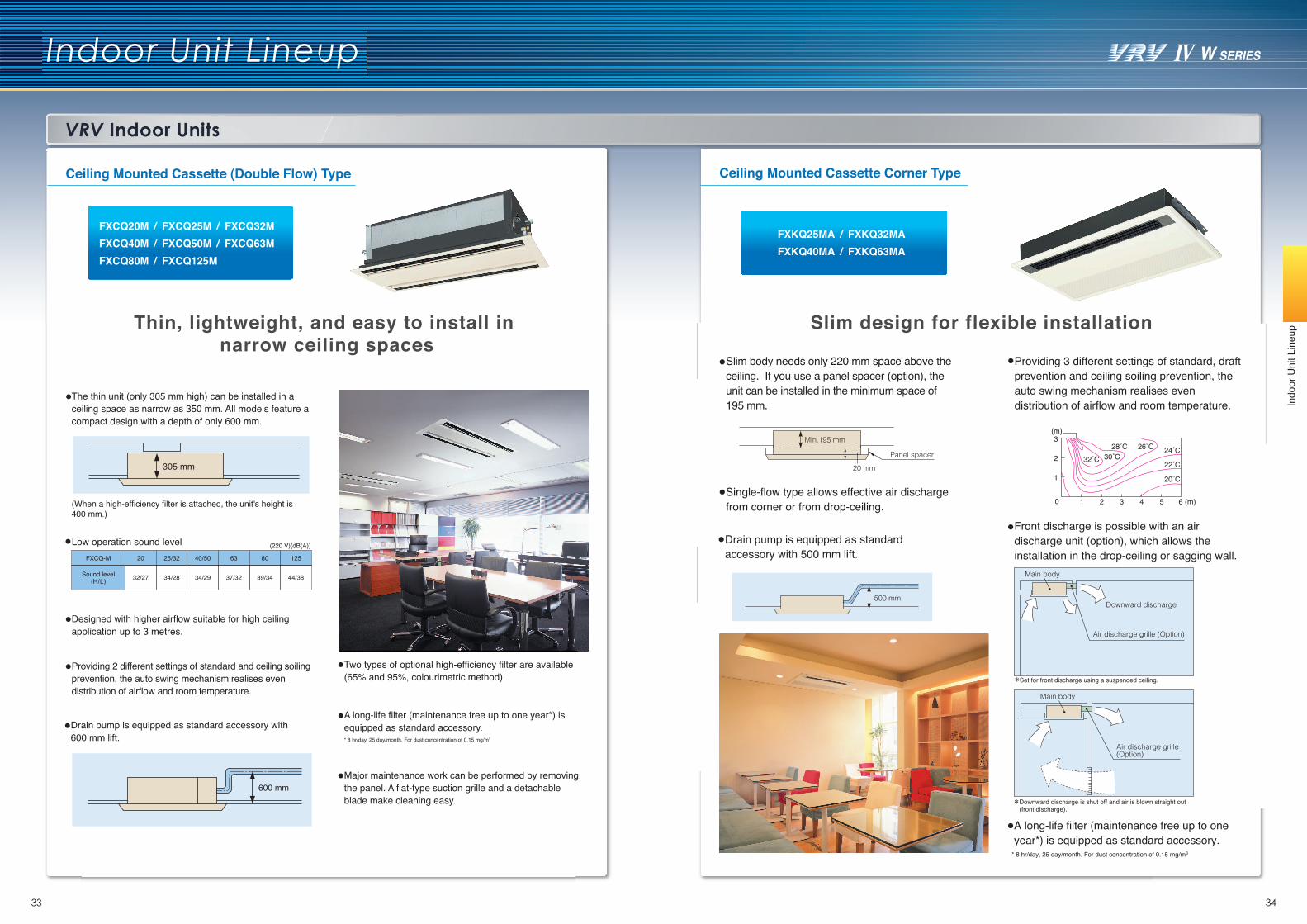
pThin, lightweight, and easy to install in narrow ceiling spaces
305 mm
The thin unit (only 305 mm high) can be installed in a ceiling space as narrow as 350 mm. All models feature a compact design with a depth of only 600 mm.
(When a high-efficiency filter is attached, the unit's height is 400 mm.)
Designed with higher airflow suitable for high ceiling application up to 3 metres.
Providing 2 different settings of standard and ceiling soiling prevention, the auto swing mechanism realises even distribution of airflow and room temperature.
Two types of optional high-efficiency filter are available (65% and 95%, colourimetric method).
A long-life filter (maintenance free up to one year*) is equipped as standard accessory.* 8 hr/day, 25 day/month. For dust concentration of 0.15 mg/m3
Major maintenance work can be performed by removing the panel. A flat-type suction grille and a detachable blade make cleaning easy.
Ceiling Mounted Cassette (Double Flow) Type
FXCQ20M / FXCQ25M / FXCQ32MFXCQ40M / FXCQ50M / FXCQ63MFXCQ80M / FXCQ125M
Drain pump is equipped as standard accessory with 600 mm lift.
600 mm
(220 V)(dB(A))Low operation sound level
Ceiling Mounted Cassette Corner Type
Slim design for flexible installation
Main body
Air discharge grille (Option)
Set for front discharge using a suspended ceiling.
Downward discharge is shut off and air is blown straight out (front discharge).
Front discharge is possible with an air discharge unit (option), which allows the installation in the drop-ceiling or sagging wall.
Single-flow type allows effective air discharge from corner or from drop-ceiling.
Providing 3 different settings of standard, draft prevention and ceiling soiling prevention, the auto swing mechanism realises even distribution of airflow and room temperature.
Main body
Downward discharge
Air discharge grille (Option)
3
32˚C 30˚C28˚C 26˚C 24˚C
22˚C
20˚C
2
1
0 1 2 3 4 5 6 (m)
(m)
500 mm
Drain pump is equipped as standard accessory with 500 mm lift.
Panel spacer
20 mm
Min.195 mm
Slim body needs only 220 mm space above the ceiling. If you use a panel spacer (option), the unit can be installed in the minimum space of 195 mm.
A long-life filter (maintenance free up to one year*) is equipped as standard accessory.
* 8 hr/day, 25 day/month. For dust concentration of 0.15 mg/m3
FXKQ25MA / FXKQ32MAFXKQ40MA / FXKQ63MA
FXCQ-M 20
32/27
25/32
34/28
63
37/32
40/50
34/29
80
39/34
125
44/38Sound level(H/L)
VRV Indoor Units
Indoor Unit Lineup
35 36
Indo
or U
nit L
ineu
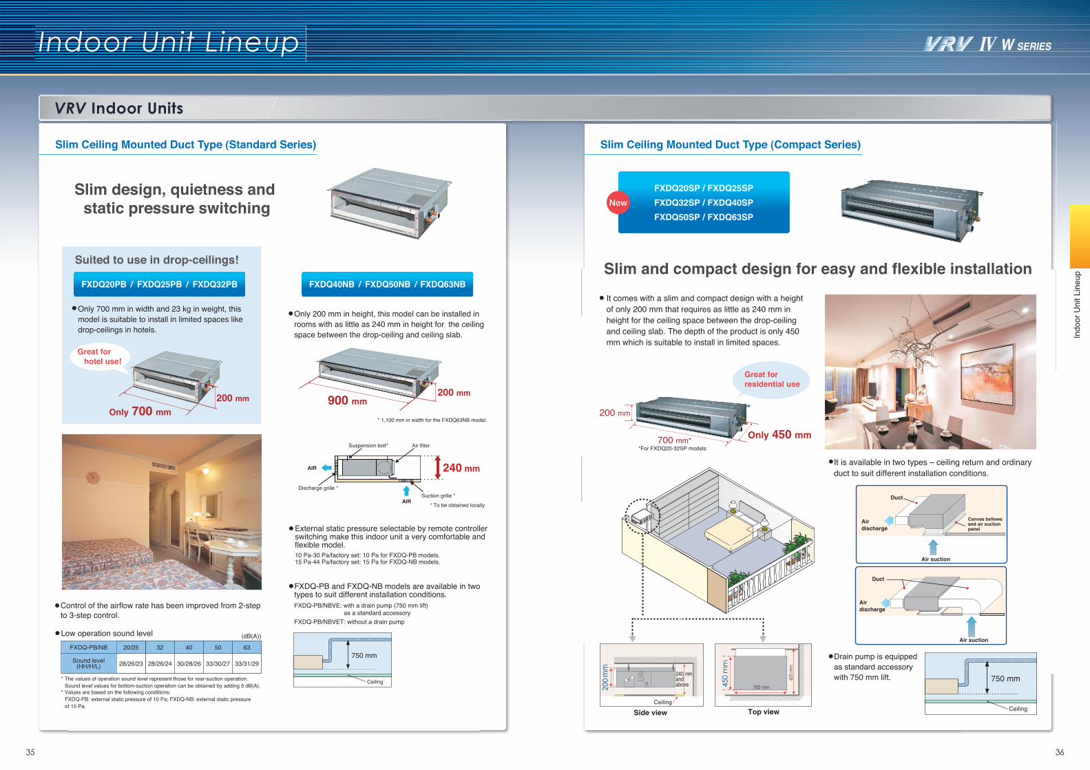
pSlim and compact design for easy and flexible installation
Slim design, quietness and static pressure switching
Only 200 mm in height, this model can be installed in rooms with as little as 240 mm in height for the ceiling space between the drop-ceiling and ceiling slab.
Only 700 mm in width and 23 kg in weight, this model is suitable to install in limited spaces like drop-ceilings in hotels.
* The values of operation sound level represent those for rear-suction operation.Sound level values for bottom-suction operation can be obtained by adding 5 dB(A).
* Values are based on the following conditions:FXDQ-PB: external static pressure of 10 Pa; FXDQ-NB: external static pressure of 15 Pa.
* 1,100 mm in width for the FXDQ63NB model.
200 mm900 mm
Suction grille *AIR
AIR
Discharge grille *
Air filterSuspension bolt*
240 mm
* To be obtained locally
Only 700 mm200 mm
Great for hotel use!
Suited to use in drop-ceilings!
Control of the airflow rate has been improved from 2-step to 3-step control.
Slim Ceiling Mounted Duct Type (Standard Series) Slim Ceiling Mounted Duct Type (Compact Series)
FXDQ20PB / FXDQ25PB / FXDQ32PB FXDQ40NB / FXDQ50NB / FXDQ63NB
Low operation sound level (dB(A))
33/31/29
63
33/30/27
50
30/28/26
40
28/26/23
20/25
Sound level(HH/H/L)
FXDQ-PB/NB
28/26/24
32
External static pressure selectable by remote controller switching make this indoor unit a very comfortable and flexible model.10 Pa-30 Pa/factory set: 10 Pa for FXDQ-PB models.15 Pa-44 Pa/factory set: 15 Pa for FXDQ-NB models.
750 mm
Ceiling
FXDQ-PB and FXDQ-NB models are available in two types to suit different installation conditions.FXDQ-PB/NBVE: with a drain pump (750 mm lift) as a standard accessoryFXDQ-PB/NBVET: without a drain pump
FXDQ20SP / FXDQ25SP
FXDQ32SP / FXDQ40SP
FXDQ50SP / FXDQ63SP
It is available in two types – ceiling return and ordinary duct to suit different installation conditions.
Duct
Air discharge
Air suction
Duct
Canvas bellowsand air suctionpanel
Air discharge
Air suction
750 mm
Ceiling
Drain pump is equipped as standard accessory with 750 mm lift.
200 mm
Only 450 mm
It comes with a slim and compact design with a height of only 200 mm that requires as little as 240 mm inheight for the ceiling space between the drop-ceiling and ceiling slab. The depth of the product is only 450 mm which is suitable to install in limited spaces.
700 mm**For FXDQ20-32SP models
Side view Top view
240 mmandabove
Ceiling
200 mm
Great for residential use
Indo
or U
nit L
ineu
p
Indoor Unit Lineup
VRV Indoor Units
37 38
Middle Static Pressure Ceiling Mounted Duct Type
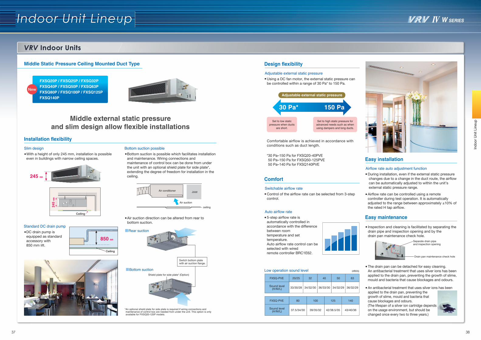
Middle external static pressureand slim design allow flexible installations
FXSQ20P / FXSQ25P / FXSQ32PFXSQ40P / FXSQ50P / FXSQ63PFXSQ80P / FXSQ100P / FXSQ125PFXSQ140P
Installation flexibility
Design flexibility
Comfort
Easy maintenance
Easy installation
850 mm
Ceiling
Air suction
JoistAir conditioner
ceiling
Switch bottom platewith air suction flange.
Shield plate for side plate* (Option)
Ceiling
245 m
m
245 mm
*An optional shield plate for side plate is required if wiring connections and maintenance of control box are needed from under the unit. This option is only available for FXSQ20-125P models.
Slim design
Standard DC drain pump
Bottom suction possible
*30 Pa–150 Pa for FXSQ20-40PVE 50 Pa–150 Pa for FXSQ50-125PVE 50 Pa–140 Pa for FXSQ140PVE
Comfortable airflow is achieved in accordance with conditions such as duct length.
Adjustable external static pressure
30 Pa* 150 Pa
Set to high static pressure for advanced needs such as when using dampers and long ducts.
Set to low static pressure when ducts
are short.
Adjustable external static pressure
(dB(A))
Switchable airflow rate
Auto airflow rate
Drain pan maintenance check hole
Separate drain pipeand inspection opening
Airflow rate auto adjustment function
With a height of only 245 mm, installation is possibleeven in buildings with narrow ceiling spaces.
Bottom suction is possible which facilitates installationand maintenance. Wiring connections and maintenance of control box can be done from under the unit with an optional shield plate for side plate*, extending the degree of freedom for installation in the ceiling.
Air suction direction can be altered from rear tobottom suction.
DC drain pump is equipped as standard accessory with850 mm lift.
Using a DC fan motor, the external static pressure canbe controlled within a range of 30 Pa* to 150 Pa.
Control of the airflow rate can be selected from 3-step control.
5-step airflow rate is automatically controlled inaccordance with the difference between roomtemperature and set temperature. Auto airflow rate control can be selected with wiredremote controller BRC1E62.
During installation, even if the external static pressure changes due to a change in the duct route, the airflow can be automatically adjusted to within the unit’s external static pressure range.
Airflow rate can be controlled using a remotecontroller during test operation. It is automaticallyadjusted to the range between approximately ±10% ofthe rated H tap airflow.
Inspection and cleaning is facilitated by separating thedrain pipe and inspection opening and by the drain pan maintenance check hole.
The drain pan can be detached for easy cleaning. An antibacterial treatment that uses silver ions has beenapplied to the drain pan, preventing the growth of slime,mould and bacteria that cause blockages and odours.
An antibacterial treatment that uses silver ions has been applied to the drain pan, preventing the growth of slime, mould and bacteria that cause blockages and odours.(The lifespan of a silver ion cartridge depends on the usage environment, but should be changed once every two to three years.)
36/32/29
63
34/32/29
50
36/33/30
40
34/32/30
32
33/30/28
20/25
Sound level(H/M/L)
FXSQ-PVE
43/40/36
140
42/38.5/35
125
39/35/32
100
37.5/34/30
80
Sound level(H/M/L)
FXSQ-PVE
Low operation sound level
VRV Indoor Units
Indoor Unit Lineup
39 40
Indo
or U
nit L
ineu
p
Ceiling Mounted Duct Type
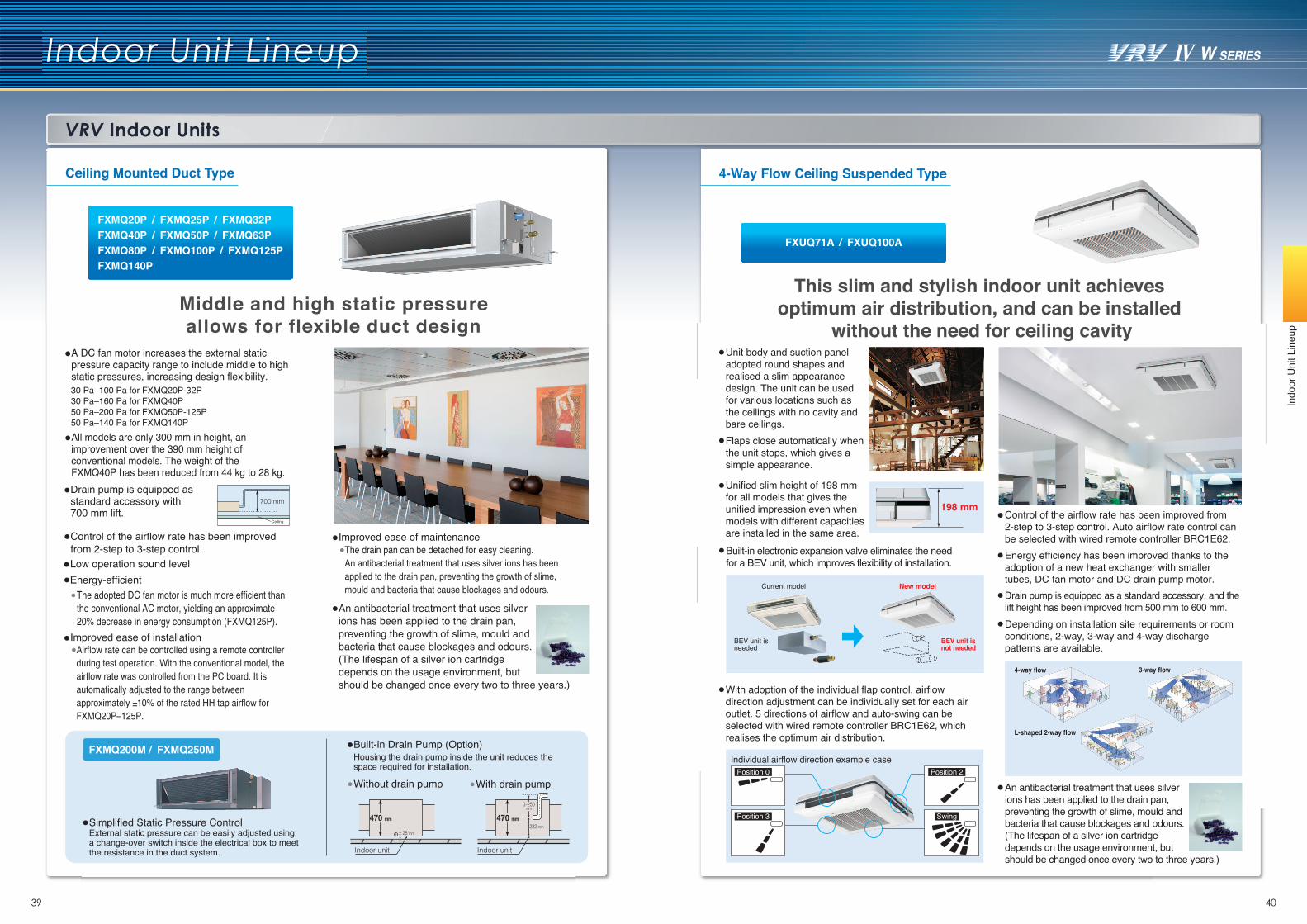
Middle and high static pressureallows for flexible duct design
Built-in Drain Pump (Option)Housing the drain pump inside the unit reduces the space required for installation.
All models are only 300 mm in height, an improvement over the 390 mm height of conventional models. The weight of the FXMQ40P has been reduced from 44 kg to 28 kg.
A DC fan motor increases the external static pressure capacity range to include middle to high static pressures, increasing design flexibility.
Indoor unit
470 mm
Indoor unit
470 mm
0–250mm
222 mm
Without drain pump With drain pump
Simplified Static Pressure ControlExternal static pressure can be easily adjusted using a change-over switch inside the electrical box to meet the resistance in the duct system.
FXMQ200M / FXMQ250M
Drain pump is equipped as standard accessory with 700 mm lift.
Control of the airflow rate has been improved from 2-step to 3-step control.
An antibacterial treatment that uses silver ions has been applied to the drain pan, preventing the growth of slime, mould and bacteria that cause blockages and odours.(The lifespan of a silver ion cartridge depends on the usage environment, but should be changed once every two to three years.)
700 mm
Ceiling
30 Pa–100 Pa for FXMQ20P-32P30 Pa–160 Pa for FXMQ40P50 Pa–200 Pa for FXMQ50P-125P50 Pa–140 Pa for FXMQ140P
Low operation sound level
Improved ease of maintenance
Improved ease of installationAirflow rate can be controlled using a remote controller during test operation. With the conventional model, the airflow rate was controlled from the PC board. It is automatically adjusted to the range between approximately ±10% of the rated HH tap airflow for FXMQ20P–125P.
The drain pan can be detached for easy cleaning. An antibacterial treatment that uses silver ions has been applied to the drain pan, preventing the growth of slime, mould and bacteria that cause blockages and odours.
Energy-efficientThe adopted DC fan motor is much more efficient than the conventional AC motor, yielding an approximate 20% decrease in energy consumption (FXMQ125P).
25 mm
FXMQ20P / FXMQ25P / FXMQ32PFXMQ40P / FXMQ50P / FXMQ63PFXMQ80P / FXMQ100P / FXMQ125PFXMQ140P
This slim and stylish indoor unit achieves optimum air distribution, and can be installed
without the need for ceiling cavityUnit body and suction panel adopted round shapes and realised a slim appearance design. The unit can be used for various locations such as the ceilings with no cavity and bare ceilings. Flaps close automatically when the unit stops, which gives a simple appearance.
Unified slim height of 198 mm for all models that gives the unified impression even when models with different capacities are installed in the same area.Built-in electronic expansion valve eliminates the need for a BEV unit, which improves flexibility of installation.
With adoption of the individual flap control, airflow direction adjustment can be individually set for each air outlet. 5 directions of airflow and auto-swing can be selected with wired remote controller BRC1E62, which realises the optimum air distribution.
Control of the airflow rate has been improved from 2-step to 3-step control. Auto airflow rate control can be selected with wired remote controller BRC1E62. Energy efficiency has been improved thanks to the adoption of a new heat exchanger with smaller tubes, DC fan motor and DC drain pump motor.Drain pump is equipped as a standard accessory, and the lift height has been improved from 500 mm to 600 mm.
An antibacterial treatment that uses silver ions has been applied to the drain pan, preventing the growth of slime, mould and bacteria that cause blockages and odours.(The lifespan of a silver ion cartridge depends on the usage environment, but should be changed once every two to three years.)
Depending on installation site requirements or room conditions, 2-way, 3-way and 4-way discharge patterns are available.
4-way flow 3-way flow
L-shaped 2-way flow
198 mm
BEV unit is not needed
BEV unit is needed
Current model New model
4-Way Flow Ceiling Suspended Type
Position 0 Position 2
Position 3 Swing
Individual airflow direction example case
FXUQ71A / FXUQ100A
VRV Indoor Units
Indoor Unit Lineup
41 42
Indo
or U
nit L
ineu
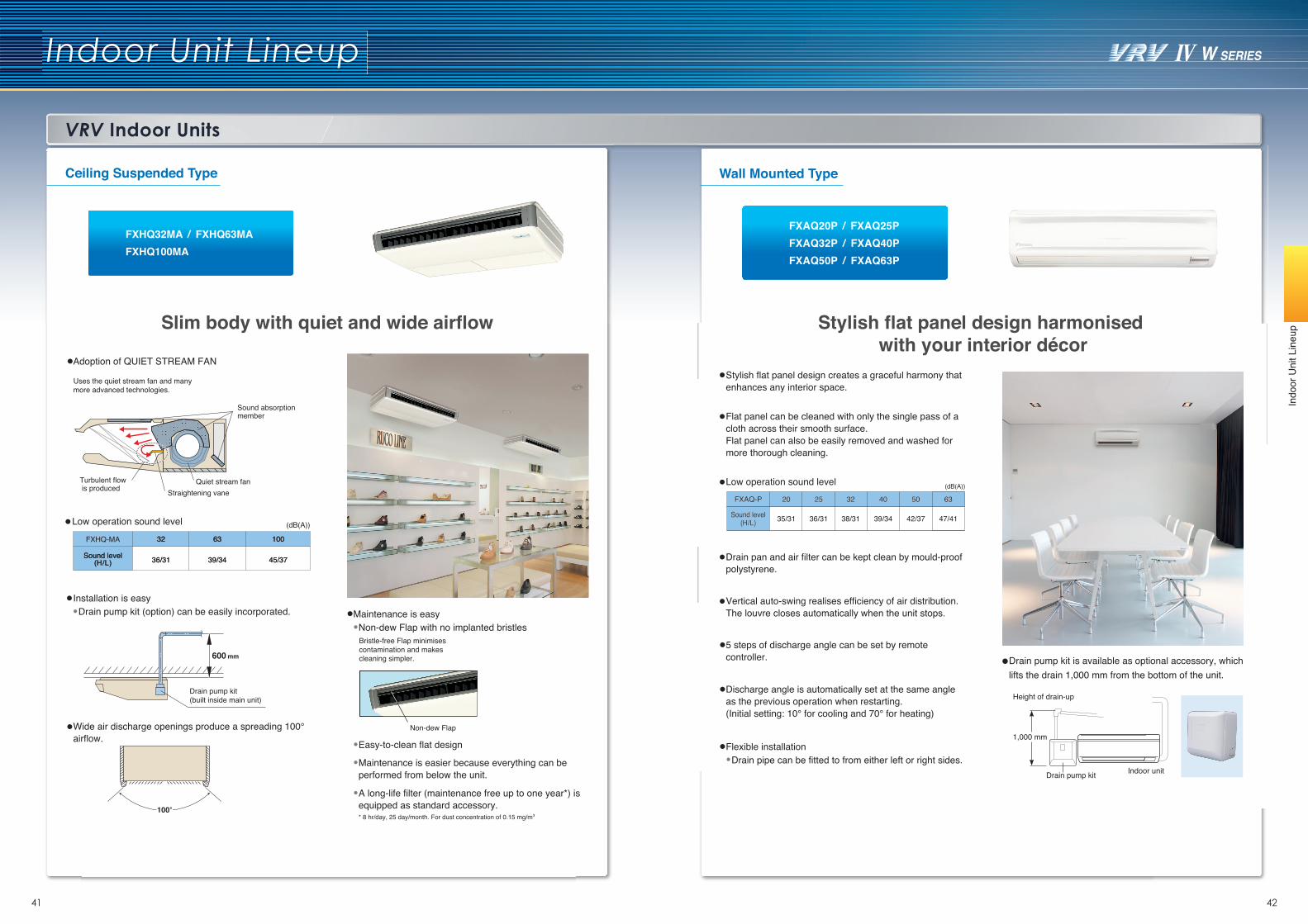
pSlim body with quiet and wide airflow
Adoption of QUIET STREAM FAN
Drain pump kit (option) can be easily incorporated.
Easy-to-clean flat design
Maintenance is easier because everything can be performed from below the unit.
Non-dew Flap with no implanted bristles
Uses the quiet stream fan and many more advanced technologies.
Sound absorptionmember
Turbulent flow is produced Straightening vane
Quiet stream fan
Installation is easyMaintenance is easy
Drain pump kit(built inside main unit)
600 mm
Bristle-free Flap minimises contamination and makes cleaning simpler.
Non-dew Flap
100°
Wide air discharge openings produce a spreading 100° airflow.
A long-life filter (maintenance free up to one year*) is equipped as standard accessory.* 8 hr/day, 25 day/month. For dust concentration of 0.15 mg/m3
Ceiling Suspended Type
FXHQ32MA / FXHQ63MAFXHQ100MA
FXHQ-MA
Sound level(H/L)
Sound level(H/L)
3232
36/3136/31
6363
39/3439/34
100100
45/3745/37
(dB(A))Low operation sound level
Stylish flat panel design harmonised with your interior décor
Drain pan and air filter can be kept clean by mould-proof polystyrene.
Vertical auto-swing realises efficiency of air distribution. The louvre closes automatically when the unit stops.
5 steps of discharge angle can be set by remote controller.
Discharge angle is automatically set at the same angle as the previous operation when restarting. (Initial setting: 10° for cooling and 70° for heating)
Flexible installationDrain pipe can be fitted to from either left or right sides.
Stylish flat panel design creates a graceful harmony that enhances any interior space.
Flat panel can be cleaned with only the single pass of a cloth across their smooth surface.Flat panel can also be easily removed and washed for more thorough cleaning.
Wall Mounted Type
Drain pump kit is available as optional accessory, which lifts the drain 1,000 mm from the bottom of the unit.
Drain pump kit
1,000 mm
Height of drain-up
Indoor unit
FXAQ20P / FXAQ25PFXAQ32P / FXAQ40PFXAQ50P / FXAQ63P
Low operation sound level (dB(A))
47/4147/41
6363
42/3742/37
5050
39/3439/34
4040
38/3138/31
3232
36/3136/31
2525
35/3135/31
2020
Sound level(H/L)
Sound level(H/L)
FXAQ-PFXAQ-P
VRV Indoor Units
Indoor Unit Lineup
43 44
Indo
or U
nit L
ineu
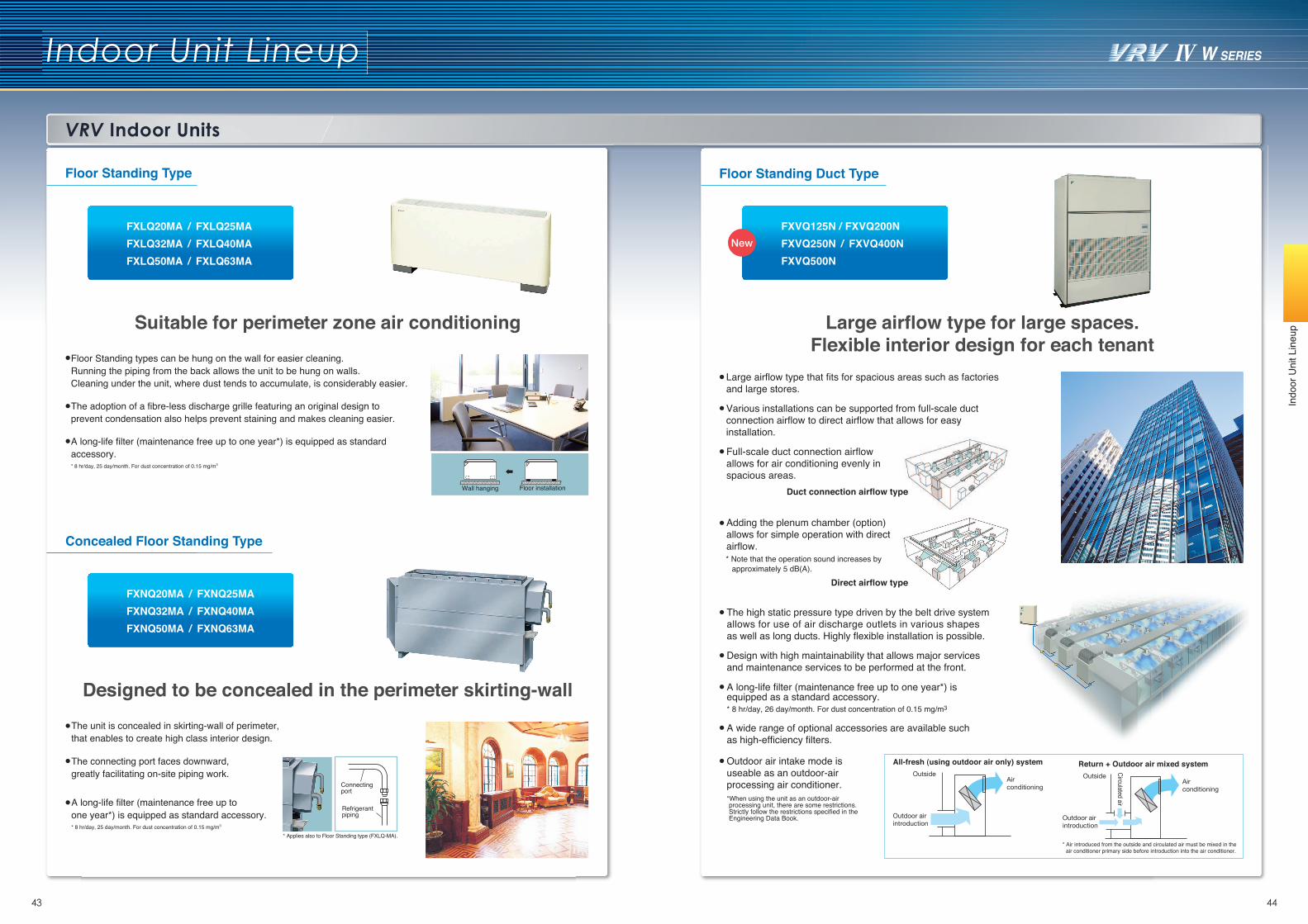
pSuitable for perimeter zone air conditioning
Wall hanging Floor installation
Floor Standing types can be hung on the wall for easier cleaning. Running the piping from the back allows the unit to be hung on walls. Cleaning under the unit, where dust tends to accumulate, is considerably easier.
A long-life filter (maintenance free up to one year*) is equipped as standard accessory.* 8 hr/day, 25 day/month. For dust concentration of 0.15 mg/m3
The adoption of a fibre-less discharge grille featuring an original design to prevent condensation also helps prevent staining and makes cleaning easier.
Designed to be concealed in the perimeter skirting-wall
Connecting port
Refrigerant piping
* Applies also to Floor Standing type (FXLQ-MA).
The unit is concealed in skirting-wall of perimeter, that enables to create high class interior design.
The connecting port faces downward, greatly facilitating on-site piping work.
A long-life filter (maintenance free up to one year*) is equipped as standard accessory.* 8 hr/day, 25 day/month. For dust concentration of 0.15 mg/m3
Floor Standing Type
Concealed Floor Standing Type
FXLQ20MA / FXLQ25MAFXLQ32MA / FXLQ40MAFXLQ50MA / FXLQ63MA
FXNQ20MA / FXNQ25MAFXNQ32MA / FXNQ40MAFXNQ50MA / FXNQ63MA
FXVQ125N / FXVQ200NFXVQ250N / FXVQ400NFXVQ500N
Floor Standing Duct Type
Large airflow type for large spaces.Flexible interior design for each tenant
The high static pressure type driven by the belt drive system allows for use of air discharge outlets in various shapes as well as long ducts. Highly flexible installation is possible.
Design with high maintainability that allows major services and maintenance services to be performed at the front.
A long-life filter (maintenance free up to one year*) is equipped as a standard accessory. * 8 hr/day, 26 day/month. For dust concentration of 0.15 mg/m3
A wide range of optional accessories are available such as high-efficiency filters.
Outdoor air intake mode is useable as an outdoor-air processing air conditioner.*When using the unit as an outdoor-air processing unit, there are some restrictions. Strictly follow the restrictions specified in the Engineering Data Book.
All-fresh (using outdoor air only) system Return + Outdoor air mixed systemOutside
Air conditioning
Outdoor air introduction
Air conditioning
Circulated air
Outdoor air introduction
Outside
* Air introduced from the outside and circulated air must be mixed in the air conditioner primary side before introduction into the air conditioner.
Large airflow type that fits for spacious areas such as factories and large stores.
Various installations can be supported from full-scale ductconnection airflow to direct airflow that allows for easy installation.
Adding the plenum chamber (option) allows for simple operation with direct airflow.* Note that the operation sound increases by
approximately 5 dB(A).Direct airflow type
Full-scale duct connection airflow allows for air conditioning evenly in spacious areas.
Duct connection airflow type
Residential Indoor Units with connection to BP units
Indoor Unit Lineup
45 46
Indo
or U
nit L
ineu
p
Wall Mounted TypeSlim Ceiling Mounted Duct Type
Slim and smooth design suits your shallow ceiling
Signals from the wireless remote controller aretransmitted to the signal receiver.
240 mm
Home Leave Operation prevents large rises or falls in the indoor temperature by continuing operation* while you are sleeping or out of your home. This means that an air-conditioned welcome awaits when you wake or return. It also means that the indoor temperature can quickly return to your favourite comfort setting.
Notes: 1. To prevent an increase in operation noise, avoid installing the air suction grille
directly below the suction chamber.2. Grilles, piping connections, ducts, and installation parts should be obtained
locally. Slim Ceiling Mounted Duct type models do not have drain-up pumps.3. The signal receiver unit must be located near the air suction inlet, because the
unit includes a sensor that detects room temperature.
* Locally obtained partsAIRAir suction grille*
Suction duct*
Signal receiver
Air discharge duct* Suspension bolt*
Air discharge grille*
Signal receiver wireLength = 1,900 mm
Chamber
AIR
Air filter
* Home Leave Operation can be selected for any temperature from 18 to 32˚C for cooling operation and 10 to 30˚C for heating operation.
* Home Leave Operation function must be set using the remote controller when going to sleep or leaving the house, and after waking up or returning home.
Standard accessoryNote: Remote controllers other than the standard accessory wireless remote controller cannot be used.
3D Airflow3D Airflow combines Vertical and Horizontal Auto-Swing to reduce indoor temperature fluctuation. This function circulates air to every part of a room for uniform cooling or heating of even large spaces. To start 3D Airflow, push both the Vertical and Horizontal Auto-Swing buttons. The flaps and louvers swing in turn.
Two-Area Intelligent EyeA combination of Comfort Airflow Mode and Intelligent Eye directs airflow away from people to avoid drafts. If there is no movement in a room for 20 minutes, Intelligent Eye automatically adjusts the set temperature by approximately 2°C to save energy.
Area 2Area 1
If a person is detected in area 1, airflow is directed away from him/her.
Area 2Area 1
If a person is detected in area 2, airflow is directed away from him/her.
Elegant Appearance with Curved PanelThe sleek design of the FTXJ-N indoor unit features a uniquely European style. This elegant body houses state-of-the-art technology which delivers superior performance. The FTXJ-N series offers a versatile choice for home-owners, designers and architects alike.
Comfort Airflow ModeComfort Airflow Mode prevents uncomfortable drafts from blowing directly on to a person’s body. During cooling operation, the flap moves upwards to prevent cold drafts. During heating operation, the flap turns vertically downwards to drive warm air to the floor.
The flaps and louvers swing in turn, expanding the comfort zone.
FTXJ25N / FTXJ35N / FTXJ50N
Standard accessory
Elegant appearance with European style
700 mm width type
900/1,1000 mm width typeCDXS25EA / CDXS35EA
FDXS25C / FDXS35C FDXS50C / FDXS60C
200 mm
Only 700 mm
CDXS-EA
Dimensions (H x W x D)WeightAirflow rate (H)External static pressure
200 x 700 x 620 mm21 kg
8.7 m3/min30 Pa
200 x 900 x 620 mm25 kg
40 Pa
CDXS25EA CDXS35EA FDXS25C FDXS35C
9.5 m3/min 10 m3/min
Models in the CDXS-EA series are only 700 mm in width and 21 kg in weight, so are easily installed in limited spaces. Just 200 mm in height, all models can be installed in rooms with as little as 240 mm depth between the drop ceiling and ceiling slab, making them ideal for even shallow ceilings.
Great for hotel use!
35/31/29 dB (A) 35/31/29 dB (A)FDXS50
37/33/31 dB (A)FDXS60
38/34/32 dB (A)
(H/L/SL)Low operation sound level
Note: Remote controllers other than the standard accessory wireless remote controller cannot be used.
CDXS25FDXS25
CDXS35FDXS35
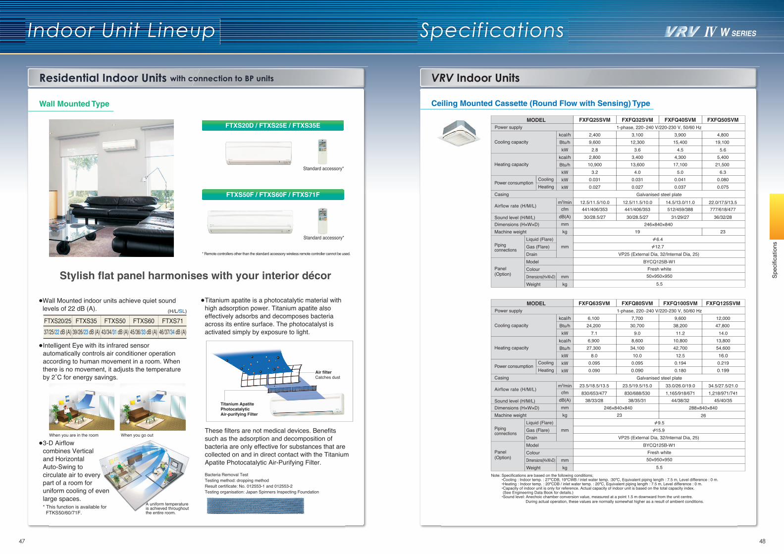
Indoor Unit Lineup Specifications
47 48
Residential Indoor Units with connection to BP units VRV Indoor Units
Spec
ifica
tions
Wall Mounted Type Ceiling Mounted Cassette (Round Flow with Sensing) Type
Intelligent Eye with its infrared sensor automatically controls air conditioner operation according to human movement in a room. When there is no movement, it adjusts the temperature by 2˚C for energy savings.
3-D Airflow combines Vertical and Horizontal Auto-Swing to circulate air to every part of a room for uniform cooling of even large spaces.* This function is available for
FTKS50/60/71F.
FTXS20/2537/25/22 dB (A)
FTXS3539/26/23 dB (A)
FTXS5043/34/31 dB (A)
FTXS6045/36/33 dB (A)
FTXS7146/37/34 dB (A)
(H/L/SL)
When you are in the room When you go out
A uniform temperatureis achieved throughout the entire room.
Stylish flat panel harmonises with your interior décor
* Remote controllers other than the standard accessory wireless remote controller cannot be used.
Standard accessory*
Standard accessory*
FTXS20D / FTXS25E / FTXS35E
FTXS50F / FTXS60F / FTXS71F
Wall Mounted indoor units achieve quiet soundlevels of 22 dB (A).
Titanium apatite is a photocatalytic material with high adsorption power. Titanium apatite also effectively adsorbs and decomposes bacteria across its entire surface. The photocatalyst is activated simply by exposure to light.
These filters are not medical devices. Benefits such as the adsorption and decomposition of bacteria are only effective for substances that are collected on and in direct contact with the Titanium Apatite Photocatalytic Air-Purifying Filter.Bacteria Removal TestTesting method: dropping methodResult certificate: No. 012553-1 and 012553-2Testing organisation: Japan Spinners Inspecting Foundation
Titanium Apatite Photocatalytic Air-purifying Filter
Air filterCatches dust
Note: Specifications are based on the following conditions;•Cooling : Indoor temp. : 27ºCDB, 19ºCWB / inlet water temp. :30ºC, Equivalent piping length : 7.5 m, Level difference : 0 m.•Heating : Indoor temp. : 20ºCDB / inlet water temp. : 20ºC, Equivalent piping length : 7.5 m, Level difference : 0 m.•Capacity of indoor unit is only for reference. Actual capacity of indoor unit is based on the total capacity index. (See Engineering Data Book for details.) •Sound level: Anechoic chamber conversion value, measured at a point 1.5 m downward from the unit centre.
During actual operation, these values are normally somewhat higher as a result of ambient conditions.
Fresh white50×950×950
5.5
19246×840×840
Galvanised steel plate
1-phase, 220-240 V/220-230 V, 50/60 Hz
441/406/35330/28.5/27
12.5/11.5/10.0
0.031
2.89,6002,400
FXFQ25SVM
441/406/35330/28.5/27
12.5/11.5/10.0
0.031
3.612,3003,100
FXFQ32SVM
512/459/38831/29/27
14.5/13.0/11.0
0.041
4.515,4003,900
FXFQ40SVM
23
777/618/47736/32/28
22.0/17.5/13.5
0.080
5.619,100 4,800
3.210,9002,800
4.013,6003,400
5.017,1004,300
6.321,500 5,400
FXFQ50SVM
BYCQ125B-W1
6.412.7
VP25 (External Dia, 32/Internal Dia, 25)
cfmdB(A)mmkg
mm
mmkg
Liquid (Flare)Gas (Flare)DrainModelColourDimensions(H×W×D)Weight
Power consumption
Casing
Sound level (H/M/L)
Airflow rate (H/M/L)
Dimensions (H×W×D)Machine weight
Piping connections
Panel(Option)
Power supply
Cooling capacity
Heating capacity
MODEL
Cooling0.027 0.027 0.037 0.075Heating
Fresh white50×950×950
5.5
246×840×840 288×840×840
Galvanised steel plate
1-phase, 220-240 V/220-230 V, 50/60 Hz
23
BYCQ125B-W1VP25 (External Dia, 32/Internal Dia, 25)
15.99.5
7.124,200 6,100
FXFQ63SVM
830/653/47738/33/28
23.5/18.5/13.5
0.095
11.238,2009,600
FXFQ100SVM
1,165/918/67144/38/32
33.0/26.0/19.0
0.194
9.030,7007,700
FXFQ80SVM
830/688/53038/35/31
23.5/19.5/15.0
0.095
14.047,800 12,000
FXFQ125SVM
1,218/971/74145/40/35
34.5/27.5/21.0
0.219
26
cfmdB(A)mmkg
mm
mmkg
Liquid (Flare)Gas (Flare)DrainModelColourDimensions(H×W×D)Weight
Power consumption
Casing
Sound level (H/M/L)
Airflow rate (H/M/L)
Dimensions (H×W×D)Machine weight
Piping connections
Panel(Option)
Power supply
Cooling capacity
8.027,300 6,900
12.542,70010,800
10.034,1008,600
16.054,60013,800
Heating capacity
MODEL
Cooling0.090 0.1800.090 0.199Heating
kcal/hBtu/hkW
kcal/hBtu/hkWkWkW
m3/min
kcal/hBtu/hkW
kcal/hBtu/hkWkWkW
m3/min
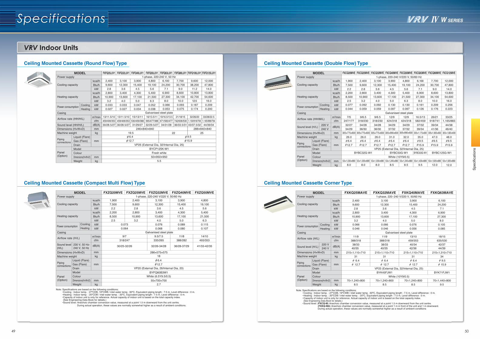
49 50
Spec
ifica
tions
VRV Indoor Units
Specifications
Ceiling Mounted Cassette (Round Flow) Type
Ceiling Mounted Cassette (Compact Multi Flow) Type
Ceiling Mounted Cassette (Double Flow) Type
Ceiling Mounted Cassette Corner Type
1-phase, 220-240 V, 50 Hz2,4009,6002.8
2,80010,900
3.20.0330.027
3,10012,300
3.63,400
13,6004.0
0.0330.027
3,90015,400
4.54,300
17,1005.0
0.0470.034
4,80019,100
5.65,400
21,5006.3
0.0520.038
13/11.5/10459/406/35330/28.5/27
15/13/11530/459/38831/29/27
16/13.5/11565/477/38832/29.5/27
FXFQ25LUV1 FXFQ32LUV1 FXFQ40LUV1 FXFQ50LUV1
Galvanised steel plate
6,100 7,700 9,600 12,00024,200 30,700 38,200 47,800
7.1 9.0 11.2 14.0
0.066 0.093 0.187 0.209
19/16.5/13.5671/583/47734/31/28
32/26/201,130/918/70643/37.5/32
33/28/22.51,165/989/79444/39/34
21/18/15742/636/53036/33.5/31
FXFQ63LUV1 FXFQ80LUV1 FXFQ100LUV1 FXFQ125LUV1
9.5 15.9
VP25 (External Dia, 32/Internal Dia, 25)BYCP125K-W1
Fresh white50X950X950
5.5
6.4 12.7
13/11.5/10459/406/35330/28.5/27
cfmdB(A)mmkg
mm
mmkg
Liquid (Flare)Gas (Flare)DrainModelColourDimensions(H×W×D)Weight
Casing
Sound level (HH/H/L)Dimensions (H×W×D)Machine weight
Piping connections
Panel(Option)
Power supply
Cooling capacity
6,900 8,600 10,800 13,80027,300 34,100 42,700 54,600
8.0 10.0 12.5 16.0Heating capacity
MODEL
Cooling
Airflow rate (HH/H/L)
22 25246X840X840 288X840X840
19.5
Power consumption0.053 0.075 0.174 0.200Heating
1-phase, 220-240 V/220 V, 50/60 Hz1,9007,5002.2
2,2008,5002.5
2,4009,6002.8
2,80010,900
3.2
3,10012,300
3.63,400
13,6004.0
0.0760.068
3,90015,400
4.54,300
17,1005.0
0.0890.080
4,80019,100
5.65,400
21,5006.3
0.1150.107
Galvanised steel plate9/7 9.5/7.5 11/8 14/10
318/247 335/265 388/282 493/353
30/25-32/26 32/26-34/28 36/28-37/29 41/33-42/35
286×575×575186.412.7
VP20 (External Dia, 26/Internal Dia, 20)BYFQ60B3W1
White (6.5Y9.5/0.5)55×700×700
2.7
FXZQ20MVE FXZQ25MVE FXZQ32MVE FXZQ50MVEFXZQ40MVE
0.073
cfm
dB(A)
mmkg
mm
mmkg
kcal/hBtu/hkW
kcal/hBtu/hkWkWkW
m3/min
Liquid (Flare)Gas (Flare)DrainModelColourDimensions(H×W×D)Weight
Casing
Dimensions (H×W×D)Machine weight
Piping connections
Panel(Option)
Power supply
Cooling capacity
Heating capacity
MODEL
Cooling0.064Heating
Airflow rate (H/L)
Sound level (H/L)
230 V, 50 Hz-240 V, 50 Hz
Power consumption
Note: Specifications are based on the following conditions;•Cooling : Indoor temp. : 27ºCDB, 19ºCWB / inlet water temp. :30ºC, Equivalent piping length : 7.5 m, Level difference : 0 m.•Heating : Indoor temp. : 20ºCDB / inlet water temp. : 20ºC, Equivalent piping length : 7.5 m, Level difference : 0 m.•Capacity of indoor unit is only for reference. Actual capacity of indoor unit is based on the total capacity index. (See Engineering Data Book for details.)•Sound level: Anechoic chamber conversion value, measured at a point 1.5 m downward from the unit centre.
During actual operation, these values are normally somewhat higher as a result of ambient conditions.
FXCQ20MVE FXCQ25MVE FXCQ32MVE FXCQ40MVE FXCQ50MVE FXCQ63MVE FXCQ80MVE FXCQ125MVE1-phase, 220-240 V/220 V, 50/60 Hz
1,900 2,400 3,100 3,900 4,800 6,100 7,700 12,0007,500 9,600 12,300 15,400 19,100 24,200 30,700 47,800
2.2 2.8 3.6 4.5 5.6 7.1 9.0 14.0
Galvanised steel plate7/5 9/6.5 9/6.5 12/9 12/9 16.5/13 26/21 33/25
247/177 318/230 318/230 424/318 424/318 582/459 918/741 1,165/88332/27 34/28 34/28 34/29 34/29 37/32 39/34 44/38
305×775×600 305×775×600 305×775×600 305×990×600 305×990×600 305×1,175×600 305×1,665×600 305×1,665×60026.0 26.0 26.0 31.0 32.0 35.0 47.0 48.06.4 6.4 6.4 6.4 6.4 9.5 9.5 9.512.7 12.7 12.7 12.7 12.7 15.9 15.9 15.9
VP25 (External Dia, 32/Internal Dia, 25)BYBC32G-W1 BYBC50G-W1 BYBC63G-W1 BYBC125G-W1
White (10Y9/0.5)53×1,030×680 53×1,030×680 53×1,030×680 53×1,245×680 53×1,245×680 53×1,430×680 53×1,920×680 53×1,920×680
8.0 8.0 8.0 8.5 8.5 9.5 12.0 12.0
cfm
dB(A)
mmkg
mm
mmkg
kcal/hBtu/hkW
kcal/hBtu/hkWkWkW
m3/min
Liquid (Flare)Gas (Flare)DrainModelColourDimensions(H×W×D)Weight
Power consumption
Casing
Sound level (H/L)
Dimensions (H×W×D)Machine weight
Piping connections
Panel(Option)
Power supply
Cooling capacity
2,2008,500
2.50.0770.044
2,80010,900
3.20.0920.059
3,40013,600
4.00.0920.059
4,30017,100
5.00.1300.097
5,40021,500
6.30.1300.097
6,90027,300
8.00.1610.126
8,60034,10010.0
0.2090.176
13,80054,60016.0
0.2560.223
Heating capacity
MODEL
CoolingHeating
Airflow rate (HH/M/L)
220 V240 V 34/29 36/30 36/30 37/32 37/32 39/34 41/36 46/40
FXKQ25MAVE
9,6002,400
Galvanised steel plate11/9
FXKQ32MAVE
12,3003,100
FXKQ40MAVE
15,4003,900
FXKQ63MAVE
2.8 3.6 4.5 7.124,2006,100
11/9 13/10 18/15388/318 388/318 459/353 635/530
215X1,110X71031
6.4 12.7
VP25 (External Dia, 32/Internal Dia, 25)BYK45FJW1
White (10Y9/0.5)70X1,240X800
8.5
215X1,110X71031
6.4 12.7
70X1,240X8008.5
215X1,110X71031
6.4 12.7
70X1,240X8008.5
215X1,310X71034
9.5 15.9
BYK71FJW1
70X1,440X8009.5
38/33 38/33 40/34 42/37
1-phase, 220-240 V/220 V, 50/60 Hz
Note: Specifications are based on the following conditions;•Cooling : Indoor temp. : 27ºCDB, 19ºCWB / inlet water temp. :30ºC, Equivalent piping length : 7.5 m, Level difference : 0 m.•Heating : Indoor temp. : 20ºCDB / inlet water temp. : 20ºC, Equivalent piping length : 7.5 m, Level difference : 0 m.•Capacity of indoor unit is only for reference. Actual capacity of indoor unit is based on the total capacity index. (See Engineering Data Book for details.)•Sound level: (FXCQ-M) Anechoic chamber conversion value, measured at a point 1.5 m downward from the unit centre.
(FXKQ-MA) Anechoic chamber conversion value, measured at a point 1 m in front of the unit and 1 m downward. During actual operation, these values are normally somewhat higher as a result of ambient conditions
2,80010,900
3.20.0660.046
3,40013,600
4.00.0660.046
4,30017,100
5.00.0760.056
6,90027,300
8.00.1050.085
cfm
mmkg
mm
mmkg
kcal/hBtu/h
kcal/hBtu/hkWkWkW
m3/min
Liquid (Flare)Gas (Flare)DrainModelColourDimensions(H×W×D)Weight
Power consumption
Casing
Sound level (H/L)
Dimensions (H×W×D)Machine weight
Piping connections
Panel(Option)
Power supply
Cooling capacity
Heating capacity
MODEL
CoolingHeating
kW
220 V240 V dB(A)
Airflow rate (H/L)
40/35 40/35 42/36 44/39
kcal/hBtu/hkW
kcal/hBtu/hkWkWkW
m3/min
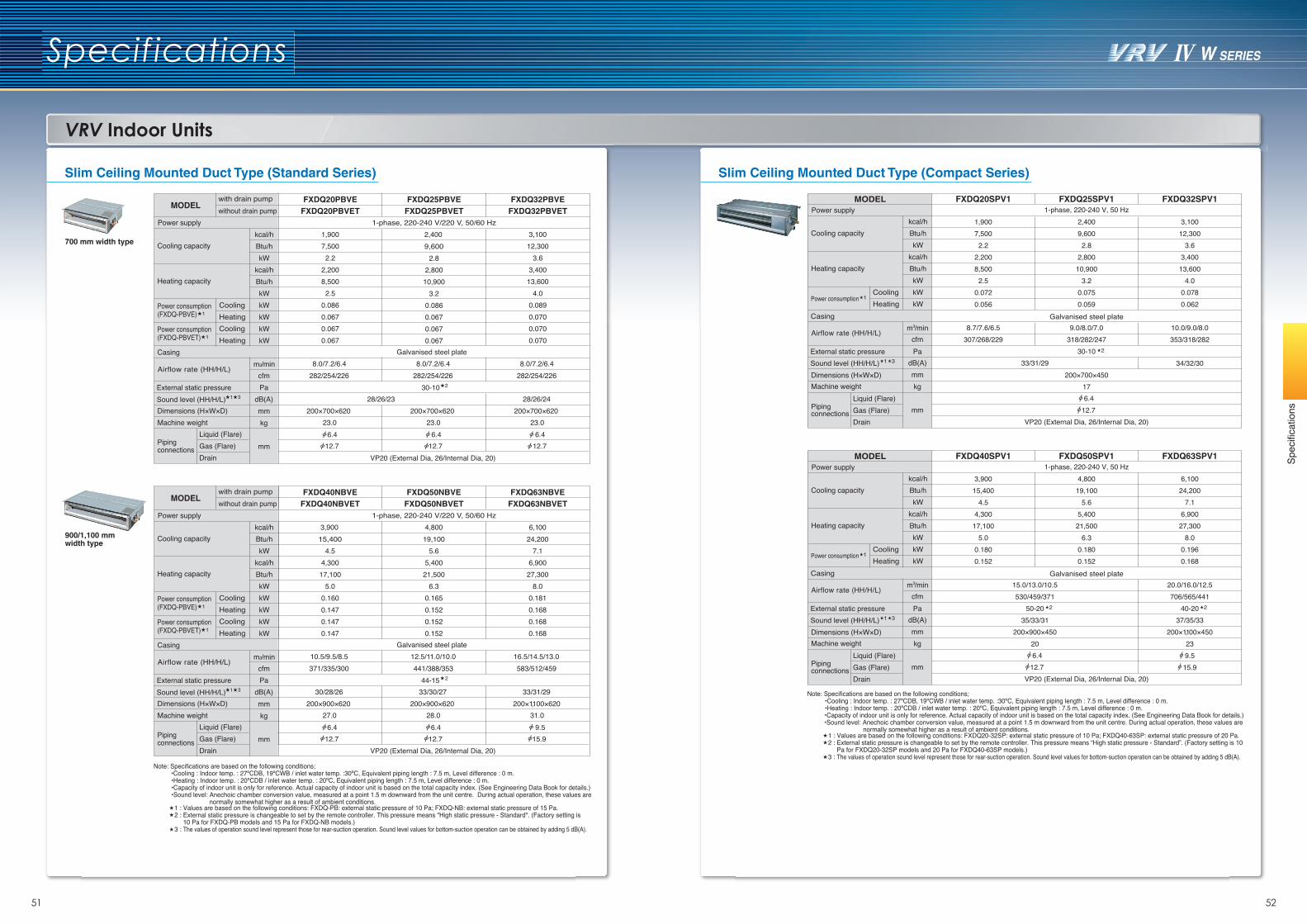
51 52
Spec
ifica
tions
VRV Indoor Units
Specifications
Slim Ceiling Mounted Duct Type (Standard Series) Slim Ceiling Mounted Duct Type (Compact Series)
700 mm width type
900/1,100 mm width type
FXDQ20PBVE FXDQ25PBVE FXDQ32PBVEFXDQ20PBVET FXDQ25PBVET FXDQ32PBVET
FXDQ40NBVEFXDQ40NBVET
FXDQ50NBVEFXDQ50NBVET
FXDQ63NBVEFXDQ63NBVET
1-phase, 220-240 V/220 V, 50/60 Hz
1,9007,500
2.22,2008,500
2.50.0860.0670.0670.067
2,400 3,10012,300
3.63,400
13,6004.0
0.0890.0700.0700.070
9,6002.8
2,80010,900
3.20.0860.0670.0670.067
Galvanised steel plate
8.0/7.2/6.4 8.0/7.2/6.4 8.0/7.2/6.4282/254/226 282/254/226 282/254/226
28/26/23 28/26/24200×700×620 200×700×620 200×700×620
23.0 23.0 23.0
VP20 (External Dia, 26/Internal Dia, 20)
3,900 4,800 6,10015,400 19,100 24,200
10.5/9.5/8.5 12.5/11.0/10.0 16.5/14.5/13.0371/335/300 441/388/353 583/512/459
30/28/26 33/30/27 33/31/29200×900×620 200×900×620 200×1,100×620
27.0 28.0 31.0
cfmPa
dB(A)mmkg
mm
kcal/hBtu/hkW
kcal/hBtu/hkWkWkWkWkW
m3/min
Liquid (Flare)Gas (Flare)Drain
Power consumption(FXDQ-PBVET)
Power consumption(FXDQ-PBVE)
Casing
Dimensions (H×W×D)Machine weight
Piping connections
Power supply
Cooling capacity
Heating capacity
MODEL
HeatingCooling
HeatingCooling
with drain pumpwithout drain pump
External static pressureSound level (HH/H/L)
Airflow rate (HH/H/L)
1 3
30-10 2
1
1
1-phase, 220-240 V/220 V, 50/60 Hz
Galvanised steel plate
VP20 (External Dia, 26/Internal Dia, 20)
cfmPa
dB(A)mmkg
mm
kcal/hBtu/hkW
kcal/hBtu/hkWkWkWkWkW
m3/min
Liquid (Flare)Gas (Flare)Drain
Power consumption(FXDQ-PBVET)
Power consumption(FXDQ-PBVE)
Casing
Dimensions (H×W×D)Machine weight
Piping connections
Power supply
Cooling capacity
Heating capacity
MODEL
CoolingHeatingCoolingHeating
with drain pumpwithout drain pump
External static pressureSound level (HH/H/L)
Airflow rate (HH/H/L)
1 3
1
1
44-15 2
6.4 6.4 6.412.712.712.7
6.412.7 12.7 15.9
6.4 9.5
FXDQ20SPV1 FXDQ25SPV1 FXDQ32SPV1
FXDQ40SPV1 FXDQ50SPV1 FXDQ63SPV1
2
Galvanised steel plate
1-phase, 220-240 V, 50 Hz
1,9007,500
2.22,2008,500
2.50.0720.056
2,4009,600
2.82,800
10,9003.2
0.0750.059
3,10012,300
3.63,40013,600
4.00.0780.062
3,90015,400
4.54,300
17,1005.0
0.1800.152
4,80019,100
5.65,400
21,5006.3
0.1800.152
6,10024,200
7.16,90027,300
8.00.1960.168
9.0/8.0/7.0318/282/247
30-10
8.7/7.6/6.5307/268/229
10.0/9.0/8.0353/318/282
2
15.0/13.0/10.5530/459/371
50-2035/33/31
200×900×45020
2
33/31/29200×700×450
17
VP20 (External Dia, 26/Internal Dia, 20)
34/32/30
cfmPa
dB(A)mmkg
mm
kcal/hBtu/hkW
kcal/hBtu/hkWkWkW
Liquid (Flare)Gas (Flare)Drain
Casing
Dimensions (H×W×D)Machine weight
Piping connections
Power supply
Cooling capacity
Heating capacity
MODEL
CoolingHeating
External static pressureSound level (HH/H/L)
Airflow rate (HH/H/L) m3/min
Power consumption 1
6.412.7
20.0/16.0/12.5706/565/441
40-2037/35/33
200×1,100×450239.515.9
1 3
Galvanised steel plate
1-phase, 220-240 V, 50 Hz
VP20 (External Dia, 26/Internal Dia, 20)
cfmPa
dB(A)mmkg
mm
kcal/hBtu/hkW
kcal/hBtu/hkWkWkW
Liquid (Flare)Gas (Flare)Drain
Casing
Dimensions (H×W×D)Machine weight
Piping connections
Power supply
Cooling capacity
Heating capacity
MODEL
CoolingHeating
External static pressureSound level (HH/H/L)
Airflow rate (HH/H/L) m3/min
Power consumption 1
6.412.7
1 3
4.54,300
17,1005.0
0.1600.1470.1470.147
5.65,400
21,5006.3
0.1650.1520.1520.152
7.16,900
27,3008.0
0.1810.1680.1680.168
Note: Specifications are based on the following conditions;•Cooling : Indoor temp. : 27ºCDB, 19ºCWB / inlet water temp. :30ºC, Equivalent piping length : 7.5 m, Level difference : 0 m.•Heating : Indoor temp. : 20ºCDB / inlet water temp. : 20ºC, Equivalent piping length : 7.5 m, Level difference : 0 m.•Capacity of indoor unit is only for reference. Actual capacity of indoor unit is based on the total capacity index. (See Engineering Data Book for details.) •Sound level: Anechoic chamber conversion value, measured at a point 1.5 m downward from the unit centre. During actual operation, these values are normally somewhat higher as a result of ambient conditions. 1 : Values are based on the following conditions: FXDQ-PB: external static pressure of 10 Pa; FXDQ-NB: external static pressure of 15 Pa.2 : External static pressure is changeable to set by the remote controller. This pressure means "High static pressure - Standard". (Factory setting is 10 Pa for FXDQ-PB models and 15 Pa for FXDQ-NB models.)3 : The values of operation sound level represent those for rear-suction operation. Sound level values for bottom-suction operation can be obtained by adding 5 dB(A).
Note: Specifications are based on the following conditions;•Cooling : Indoor temp. : 27ºCDB, 19ºCWB / inlet water temp. :30ºC, Equivalent piping length : 7.5 m, Level difference : 0 m.•Heating : Indoor temp. : 20ºCDB / inlet water temp. : 20ºC, Equivalent piping length : 7.5 m, Level difference : 0 m.•Capacity of indoor unit is only for reference. Actual capacity of indoor unit is based on the total capacity index. (See Engineering Data Book for details.)•Sound level: Anechoic chamber conversion value, measured at a point 1.5 m downward from the unit centre. During actual operation, these values are normally somewhat higher as a result of ambient conditions.1 : Values are based on the following conditions: FXDQ20-32SP: external static pressure of 10 Pa; FXDQ40-63SP: external static pressure of 20 Pa.2 : External static pressure is changeable to set by the remote controller. This pressure means “High static pressure - Standard”. (Factory setting is 10 Pa for FXDQ20-32SP models and 20 Pa for FXDQ40-63SP models.)3 : The values of operation sound level represent those for rear-suction operation. Sound level values for bottom-suction operation can be obtained by adding 5 dB(A).
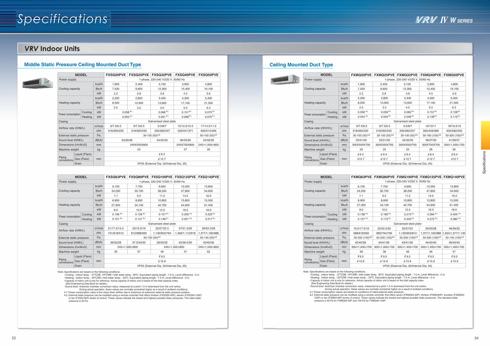
53 54
Spec
ifica
tions
VRV Indoor Units
Specifications
Ceiling Mounted Duct Type
15,4003,900
565/459/388
19,1004,800
635/582/530
4.5 5.6
6.4 12.7
6.4 12.7
16/13/11 18/16.5/15
11111
11111
7,5001,900
318/265/230
2.2
6.4 12.7
9/7.5/6.5
9,6002,400
318/265/230
2.8
6.4 12.7
9/7.5/6.5
12,3003,100
335/282/247
3.6
6.4 12.7
9.5/8/7
VP25 (External Dia, 32/Internal Dia, 25)
24,2006,100
688/618/565
9.5 15.9
30,7007,700
883/794/706
9.5 15.9
38,2009,600
1,130/953/812
9.5 15.9
47,80012,000
1,377/1,165/988
9.5 15.9
7.1 9.0 11.2 14.0
19.5/17.5/16 25/22.5/20 32/27/23 39/33/28
42/40/38 43/41/39 43/41/39 44/42/40
54,60013,800
1,624/1,377/1,130
9.5 15.9
16.0
46/39/32
46/45/43
FXMQ20PVE FXMQ25PVE FXMQ32PVE FXMQ40PVE FXMQ50PVE
11111
11111
300X1,000X700300X700X700300X550X700300X550X700300X550X7003628252525
5,40021,500
6.30.1280.116
4,30017,100
5.00.1510.139
3,40013,600
4.00.0600.048
2,80010,900
3.20.0560.044
2,2008,500
2.50.0560.044
41/39/3739/37/3534/32/3033/31/2933/31/29
cfmPa
dB(A)mmkg
mm
kcal/hBtu/hkW
kcal/hBtu/hkWkWkW
m3/min
Liquid (Flare)Gas (Flare)Drain
Power consumption
Casing
Dimensions (H×W×D)Machine weight
Piping connections
Power supply
Cooling capacity
Heating capacity
MODEL
CoolingHeating
External static pressureSound level (HH/H/L)
cfmPa
dB(A)mmkg
mm
kcal/hBtu/hkW
kcal/hBtu/hkWkWkW
m3/min
Liquid (Flare)Gas (Flare)Drain
Power consumption
Casing
Dimensions (H×W×D)Machine weight
Piping connections
Power supply
Cooling capacity
Heating capacity
MODEL FXMQ63PVE FXMQ80PVE FXMQ100PVE1-phase, 220-240 V/220 V, 50/60 Hz
Galvanised steel plate
300X1,400X70046
300X1,000X70036
300X1,000X70036
300X1,400X70046
300X1,400X70047
10,80042,700
12.50.2150.203
8,60034,100
10.00.1850.173
6,90027,300
8.00.1380.127
13,80054,600
16.00.2840.272
15,50061,400
18.00.4050.380
FXMQ125PVE FXMQ140PVE
CoolingHeating
External static pressureSound level (HH/H/L)
Airflow rate (HH/H/L)
Airflow rate (HH/H/L)
230-100 (50) 230-100 (50) 230-100 (50) 230-160 (100) 250-200 (100)
250-200 (100)250-200 (100)250-200 (100)250-200 (100) 250-140 (100)
1-phase, 220-240 V/220 V, 50/60 Hz
Galvanised steel plate
VP25 (External Dia, 32/Internal Dia, 25)
Middle Static Pressure Ceiling Mounted Duct Type
15,4003,900
530/441/371
19,1004,800
600/512/406
4.5 5.6
15/12.5/10.5 17/14.5/11.5
111
11111
7,5001,900
318/265/230
2.2
9/7.5/6.5
9,6002,400
318/265/230
2.8
9/7.5/6.5
12,3003,100
335/282/247
3.6
6.4 12.7
9.5/8/7
VP25 (External Dia, 32/Internal Dia, 25)
24,2006,100
741/618/512
30,7007,700
812/688/565
38,2009,600
1,130/953/794
9.5 15.9
47,80012,000
1,306/1,112/918
7.1 9.0 11.2 14.0
21/17.5/14.5 23/19.5/16 32/27/22.5 37/31.5/26
36/32/29 37.5/34/30 39/35/32 42/38.5/35
54,60013,800
1,377/1,183/988
16.0
39/33.5/28
43/40/36
FXSQ20PVE FXSQ25PVE FXSQ32PVE FXSQ40PVE FXSQ50PVE
10.05810.053
0.106 0.126 0.151 0.206 0.222111110.101 0.121 0.146 0.201 0.217
0.066 0.101 0.0751110.061 0.096 0.070
245X1,000X800245X700X800245X550X800352725
34/32/2936/33/3034/32/3033/30/28
5,40021,500
6.3
4,30017,100
5.0
3,40013,600
4.0
2,2008,500
2.5
2,80010,900
3.2
cfmPa
dB(A)mmkg
mm
kcal/hBtu/hkW
kcal/hBtu/hkWkWkW
m3/min
Liquid (Flare)Gas (Flare)Drain
Power consumption
Casing
Dimensions (H×W×D)Machine weight
Piping connections
Power supply
Cooling capacity
Heating capacity
MODEL
Cooling
External static pressureSound level (H/M/L)
cfmPa
dB(A)mmkg
mm
kcal/hBtu/hkW
kcal/hBtu/hkWkWkW
m3/min
Liquid (Flare)Gas (Flare)Drain
Power consumption
Casing
Dimensions (H×W×D)Machine weight
Piping connections
Power supply
Cooling capacity
Heating capacity
MODEL FXSQ63PVE FXSQ80PVE FXSQ100PVE1-phase, 220-240 V/220 V, 50/60 Hz
Galvanised steel plate
245X1,400X8004637
245X1,000X80035 47
245X1,550X80052
10,80042,700
12.5
8,60034,100
10.0
6,90027,300
8.0
13,80054,600
16.0
15,50061,400
18.0
FXSQ125PVE FXSQ140PVE
Cooling
Heating
Heating
External static pressureSound level (H/M/L)
Airflow rate (H/M/L)
Airflow rate (H/M/L)
230-150 (50) 250-150 (50)
250-150 (50) 250-140 (50)
1-phase, 220-240 V/220 V, 50/60 Hz
Galvanised steel plate
VP25 (External Dia, 32/Internal Dia, 25)
Note: Specifications are based on the following conditions;•Cooling : Indoor temp. : 27ºCDB, 19ºCWB / inlet water temp. :30ºC, Equivalent piping length : 7.5 m, Level difference : 0 m.•Heating : Indoor temp. : 20ºCDB / inlet water temp. : 20ºC, Equivalent piping length : 7.5 m, Level difference : 0 m.
•Capacity of indoor unit is only for reference. Actual capacity of indoor unit is based on the total capacity index. (See Engineering Data Book for details.)•Sound level: Anechoic chamber conversion value, measured at a point 1.5 m downward from the unit centre. During actual operation, these values are normally somewhat higher as a result of ambient conditions. 1 : Power consumption value is the value when airflow rate is maximum at maximum external static pressure position. 2: External static pressure can be modified using a remote controller that offers thirteen (FXSQ20-40P), eleven (FXSQ50-125P) or ten (FXSQ140P) levels of control. These values indicate the lowest and highest possible static pressures. The rated static
pressure is 50 Pa.
Note: Specifications are based on the following conditions;•Cooling : Indoor temp. : 27ºCDB, 19ºCWB / inlet water temp. :30ºC, Equivalent piping length : 7.5 m, Level difference : 0 m.•Heating : Indoor temp. : 20ºCDB / inlet water temp. : 20ºC, Equivalent piping length : 7.5 m, Level difference : 0 m.•Capacity of indoor unit is only for reference. Actual capacity of indoor unit is based on the total capacity index. (See Engineering Data Book for details.)•Sound level: Anechoic chamber conversion value, measured at a point 1.5 m downward from the unit centre. During actual operation, these values are normally somewhat higher as a result of ambient conditions. 1 : Power consumption values are based on conditions of rated external static pressure. 2: External static pressure can be modified using a remote controller that offers seven (FXMQ20-32P), thirteen (FXMQ40P), fourteen (FXMQ50-
125P) or ten (FXMQ140P) levels of control. These values indicate the lowest and highest possible static pressures. The standard static pressure is 50 Pa for FXMQ20-32P and 100 Pa for FXMQ40-140P.
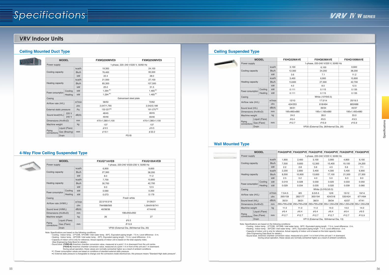
55 56
Spec
ifica
tions
VRV Indoor Units
Specifications
Ceiling Suspended Type
Wall Mounted Type
FXHQ32MAVE FXHQ63MAVE FXHQ100MAVE1-phase, 220-240 V/220 V, 50/60 Hz
3,100 6,100 9,60012,300 24,200 38,200
3.6 7.1 11.23,40013,600
4.00.1110.111
6,90027,300
8.00.1150.115
10,80042,70012.5
0.1350.135
White (10Y9/0.5)12/10 17.5/14 25/19.5
424/353 618/494 883/68836/31 39/34 45/37
195×960×680 195×1,160×680 195×1,400×68024.0 28.0 33.0
VP20 (External Dia, 26/Internal Dia, 20)
cfmdB(A)mmkg
mm
kcal/hBtu/hkW
kcal/hBtu/hkWkWkW
m3/min
Liquid (Flare)Gas (Flare)Drain
Power consumption
Casing
Dimensions (H×W×D)Machine weight
Piping connections
Power supply
Cooling capacity
Heating capacity
MODEL
CoolingHeating
Sound level (H/L)
Airflow rate (H/L)
6.412.7 15.9 15.9
9.5 9.5
FXAQ20PVE FXAQ25PVE FXAQ32PVE FXAQ40PVE FXAQ50PVE FXAQ63PVE1-phase, 220-240 V/220 V, 50/60 Hz
1,900 2,400 3,100 3,900 4,800 6,1007,500 9,600 12,300 15,400 19,100 24,2002.2 2.8 3.6 4.5 5.6 7.1
2,2008,500
2.50.0190.029
2,80010,900
3.20.0280.034
White (3.0Y8.5/0.5)7.5/4.5 8/5 8.5/5.5 12/9 15/12 19/14
265/159 282/177 300/194 424/318 530/424 671/49435/31 36/31 38/31 42/3739/34 47/41
290×795×238 290×795×238 290×795×238 290×1,050×238 290×1,050×238 290×1,050×23811.0 11.0 11.0 14.0 14.0 14.06.4 6.4 6.4 6.4 6.4 9.5
12.7 12.7 12.7 12.7 12.7 15.9VP13 (External Dia, 18/Internal Dia, 13)
cfmdB(A)mmkg
mm
kcal/hBtu/hkW
kcal/hBtu/hkWkWkW
m3/min
Liquid (Flare)Gas (Flare)Drain
Power consumption
Casing
Dimensions (H×W×D)Machine weight
Piping connections
Power supply
Cooling capacity
Heating capacity
MODEL
CoolingHeating
Sound level (H/L)
Airflow rate (H/L)
• Cooling : Indoor temp. : 27ºCDB, 19ºCWB / inlet water temp. :30ºC, Equivalent piping length : 7.5 m, Level difference : 0 m.• Heating : Indoor temp. : 20ºCDB / inlet water temp. : 20ºC, Equivalent piping length : 7.5 m, Level difference : 0 m.Capacity of indoor unit is only for reference. Actual capacity of indoor unit is based on the total capacity index.(See Engineering Data Book for details.) • Sound level: Anechoic chamber conversion value, measured at a point 1 m in front of the unit and 1 m downward.
During actual operation, these values are normally somewhat higher as a result of ambient conditions.
•
Ceiling Mounted Duct Type
4-Way Flow Ceiling Suspended Type
FXMQ200MVE9 FXMQ250MVE9
76,40019,300
22.4 28.095,50024,100
1-phase, 220-240 V/220 V, 50/60 Hz
Galvanised steel plate58/50
2,047/1,765
470X1,380X1,100137
9.5 19.1
PS1B
72/622,542/2,189
470X1,380X1,100137
9.5 22.2
132-221 191-270 2 2
48/45 48/4549/46 49/46
cfmPa
mmkg
mm
kcal/hBtu/hkW
kcal/hBtu/hkWkWkW
m3/min
Liquid (Flare)Gas (Brazing)Drain
Power consumption
Casing
Dimensions (H×W×D)Machine weight
Piping connections
Power supply
Cooling capacity
Heating capacity
MODEL
Cooling
External static pressure
Sound level(H/L)220 V240 V
dB(A)
Airflow rate (H/L)
1 1
1 1
• Cooling : Indoor temp. : 27ºCDB, 19ºCWB / inlet water temp. :30ºC, Equivalent piping length : 7.5 m, Level difference : 0 m.• Heating : Indoor temp. : 20ºCDB / inlet water temp. : 20ºC, Equivalent piping length : 7.5 m, Level difference : 0 m.• Capacity of indoor unit is only for reference. Actual capacity of indoor unit is based on the total capacity index.
(See Engineering Data Book for details.) • Sound level: (FXMQ-M) Anechoic chamber conversion value, measured at a point 1.5 m downward from the unit centre. (FXUQ-A) Anechoic chamber conversion value, measured at a point 1 m in front of the unit and 1 m downward. During actual operation, these values are normally somewhat higher as a result of ambient conditions 1 : Power consumption values are based on conditions of standard external static pressure. 2 : External static pressure is changeable to change over the connectors inside electrical box, this pressure means "Standard-High static pressure".
1-phase, 220-240 V/220-230 V, 50/60 Hz6,900 9,600
27,300 38,2008.0
7,70030,700
9.00.0900.073
11.210,80042,70012.5
0.2000.179
Fresh white22.5/19.5/16 31/26/21794/688/565 1,094/918/741
40/38/36 47/44/40198×950×950
26 279.515.9
VP20 (External Dia, 26/Internal Dia, 20)
FXUQ71AVEB FXUQ100AVEB
21,50085,30025.0
1.2941.294
27,100107,500
31.51.4651.465
cfmdB(A)mmkg
mm
kcal/hBtu/hkW
kcal/hBtu/hkWkWkW
m3/min
Liquid (Flare)Gas (Flare)Drain
Casing
Sound level (H/M/L)Dimensions (H×W×D)Machine weight
Piping connections
Power supply
Cooling capacity
Heating capacity
MODEL
Cooling
Heating
Heating
Airflow rate (H/M/L)
Power consumption
3,40013,600
4.00.0300.035
4,30017,100
5.00.0200.020
5,40021,500
6.30.0330.039
6,90027,300
8.00.0500.060
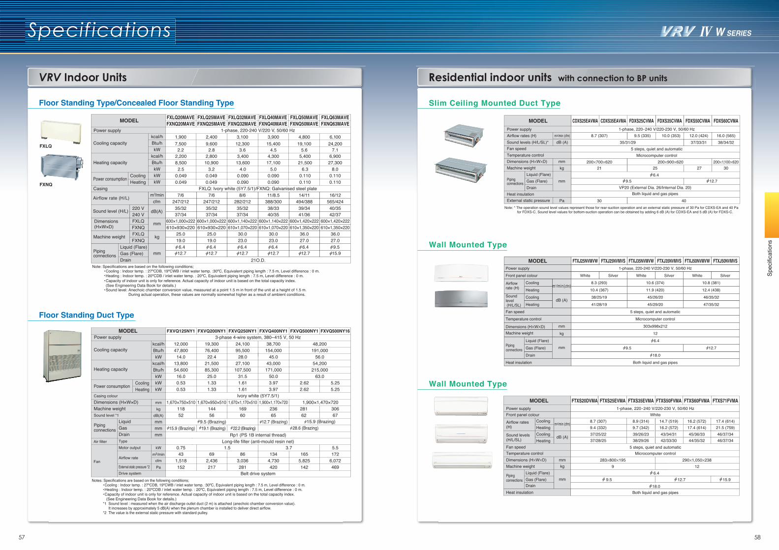
57 58
Spec
ifica
tions
Specifications
VRV Indoor Units Residential indoor units with connection to BP units
Slim Ceiling Mounted Duct Type
Wall Mounted Type
Wall Mounted Type
Floor Standing Type/Concealed Floor Standing Type
FXLQ
FXNQ
2,2008,5002.5
0.0490.049
2,80010,900
3.20.0490.049
3,40013,600
4.00.0900.090
4,30017,100
5.00.0900.090
5,40021,500
6.30.1100.110
6,90027,300
8.00.1100.110
FXLQ50MAVEFXNQ50MAVE
FXLQ40MAVEFXNQ40MAVE
FXLQ32MAVEFXNQ32MAVE
FXLQ25MAVEFXNQ25MAVE
FXLQ20MAVEFXNQ20MAVE
FXLQ63MAVEFXNQ63MAVE
1-phase, 220-240 V/220 V, 50/60 Hz1,900 2,400 3,100 3,900 4,800 6,1007,500 9,600 12,300 15,400 19,100 24,2002.2 2.8 3.6 4.5 5.6 7.1
FXLQ: Ivory white (5Y7.5/1)/FXNQ: Galvanised steel plate7/6 7/6 8/6 11/8.5 14/11 16/12
247/212 247/212 282/212 388/300 494/388 565/42435/32 35/32 35/32 38/33 39/34 40/35
600×1,000×222 600×1,000×222 600×1,140×222 600×1,140×222 600×1,420×222 600×1,420×222610×930×220 610×930×220 610×1,070×220 610×1,070×220 610×1,350×220 610×1,350×220
25.0 25.0 30.0 30.0 36.0 36.019.0 19.0 23.0 23.0 27.0 27.06.4 6.4 6.4 6.4 6.4 9.5
12.7 12.7 12.7 12.7 12.7 15.921O.D.
Power consumption
Casing
Power supply
Cooling capacity
Heating capacity
MODEL
CoolingHeating
cfm
dB(A)
kcal/hBtu/hkW
kcal/hBtu/hkWkWkW
m3/min
Liquid (Flare)Gas (Flare)Drain
Machine weight
Piping connections
Sound level (H/L)
Dimensions (H×W×D)
FXLQFXNQFXLQFXNQ
mm
kg
mm
Airflow rate (H/L)
220 V240 V 37/34 37/34 37/34 40/35 41/36 42/37
Rp1 (PS 1B internal thread)Long-life filter (anti-mould resin net)
Belt drive system
3-phase 4-wire system, 380–415 V, 50 Hz
Ivory white (5Y7.5/1)
FXVQ125NY1
1,670×750×51011852
15.9 (Brazing)
FXVQ250NY1 FXVQ400NY1 FXVQ500NY16
28162
1,900×1,170×72023665
12.7 (Brazing)
FXVQ200NY1
12,00047,80014.0
19,30076,40022.4
24,10095,50028.0
38,700154,000
45.013,80054,60016.00.530.53
21,50085,30025.01.331.33
27,100107,500
31.51.611.61
43,000171,000
50.03.973.97
2.622.62
5.255.25
30667
5.5172
6,072469
1,670×1,170×51016960
22.2 (Brazing)
1,670×950×51014456
9.5 (Brazing) 19.1 (Brazing)
FXVQ500NY1
48,200191,000
56.054,200
215,00063.0
1,900×1,470×720
15.9 (Brazing)
0.7543
1,518152
1.569
2,436217
863,036281
3.7134
4,730420
1655,825142
mmkg
dB(A)mmmmmm
kWm3/min
cfmPa
kcal/hBtu/hkW
kcal/hBtu/hkWkWkW
LiquidGasDrainTypeMotor output
Airflow rate
External static pressure *2Drive system
Power consumption HeatingCooling
Casing colour
Sound level *1
Dimensions (H×W×D)Machine weight
Piping connections
Power supply
Cooling capacity
Heating capacity
MODEL
Air filter
Fan
Floor Standing Duct Type
28.6 (Brazing)
Notes: Specifications are based on the following conditions;•Cooling : Indoor temp. : 27ºCDB, 19ºCWB / inlet water temp. :30ºC, Equivalent piping length : 7.5 m, Level difference : 0 m.•Heating : Indoor temp. : 20ºCDB / inlet water temp. : 20ºC, Equivalent piping length : 7.5 m, Level difference : 0 m. •Capacity of indoor unit is only for reference. Actual capacity of indoor unit is based on the total capacity index. (See Engineering Data Book for details.)*1 Sound level : measured when the air discharge outlet duct (2 m) is attached (anechoic chamber conversion value). It increases by approximately 5 dB(A) when the plenum chamber is installed to deliver direct airflow.*2 The value is the external static pressure with standard pulley.
• Cooling : Indoor temp. : 27ºCDB, 19ºCWB / inlet water temp. :30ºC, Equivalent piping length : 7.5 m, Level difference : 0 m. Heating : Indoor temp. : 20ºCDB / inlet water temp. : 20ºC, Equivalent piping length : 7.5 m, Level difference : 0 m.••Capacity of indoor unit is only for reference. Actual capacity of indoor unit is based on the total capacity index.(See Engineering Data Book for details.) • Sound level: Anechoic chamber conversion value, measured at a point 1.5 m in front of the unit at a height of 1.5 m.
During actual operation, these values are normally somewhat higher as a result of ambient conditions.
Note: * The operation sound level values represent those for rear-suction operation and an external static pressure of 30 Pa for CDXS-EA and 40 Pa for FDXS-C. Sound level values for bottom-suction operation can be obtained by adding 6 dB (A) for CDXS-EA and 5 dB (A) for FDXS-C.
8.7 (307)
200X700X620 200X900X620 200X1,100X6203027
40
25
VP20 (External Dia. 26/Internal Dia. 20)Both liquid and gas pipes
21
30
9.5 (335) 10.0 (353) 12.0 (424)37/33/3135/31/29
16.0 (565)38/34/32
1-phase, 220-240 V/220-230 V, 50/60 Hz
5 steps, quiet and automaticMicrocomputer control
MODEL
Power supplyAirflow rates (H) m3/min (cfm)Sound levels (H/L/SL)* dB (A)Fan speedTemperature controlDimensions (HXWXD) mm
kg
mm
Pa
Machine weightLiquid (Flare)Gas (Flare)Drain
Pipingconnections
Heat insulationExternal static pressure
9.5 6.4
12.7
283X800X1959
8.7 (307) 8.9 (314) 14.7 (519) 16.2 (572) 17.4 (614)9.4 (332) 9.7 (342) 16.2 (572) 17.4 (614) 21.5 (759)37/25/22 39/26/23 43/34/31 45/36/33 46/37/3437/28/25 38/29/26 42/33/30 44/35/32 46/37/34
1-phase, 220-240 V/220-230 V, 50/60 Hz
5 steps, quiet and automaticMicrocomputer control
Both liquid and gas pipes
White
6.4
18.0 9.5 12.7 15.9
290X1,050X23812
FTXS20DVMA FTXS25EVMA FTXS35EVMA FTXS50FVMA FTXS60FVMA FTXS71FVMAPower supplyFront panel colour
Airflow rates (H)
Cooling m3/min (cfm)
dB (A)
mmkg
mm
HeatingCooling Heating
Sound levels (H/L/SL)Fan speedTemperature controlDimensions (HXWXD)Machine weight
Liquid (Flare)Gas (Flare)Drain
Pipingconnections
Heat insulation
MODEL
CDXS25EAVMA CDXS35EAVMA FDXS25CVMA FDXS35CVMA FDXS50CVMA FDXS60CVMA
FTXJ25NVMVS1-phase, 220-240 V/220-230 V, 50/60 Hz
5 steps, quiet and automatic
FTXJ35NVMVW FTXJ35NVMVS FTXJ50NVMVSFTXJ50NVMVW
10.8 (381)
FTXJ25NVMVW
12.4 (438)
10.6 (374)
11.9 (420)
8.3 (293)
10.4 (367)
45/26/2038/25/19
45/29/20
46/35/32
47/35/3241/28/19
MODELPower supply
SilverWhite Silver White Silver WhiteFront panel colour
Both liquid and gas pipesHeat insulation
Fan speed
Microcomputer control
18.0
6.4
12
303x998x212
Temperature control
Airflowrate (H) m3/min(cfm)
Dimensions (HXWXD) mmMachine weight kg
Pipingconnections
Drain
Liquid (Flare)
Gas (Flare)
Cooling
Heating
mm
Soundlevel (H/L/SL)
dB (A)Cooling
Heating
12.79.5
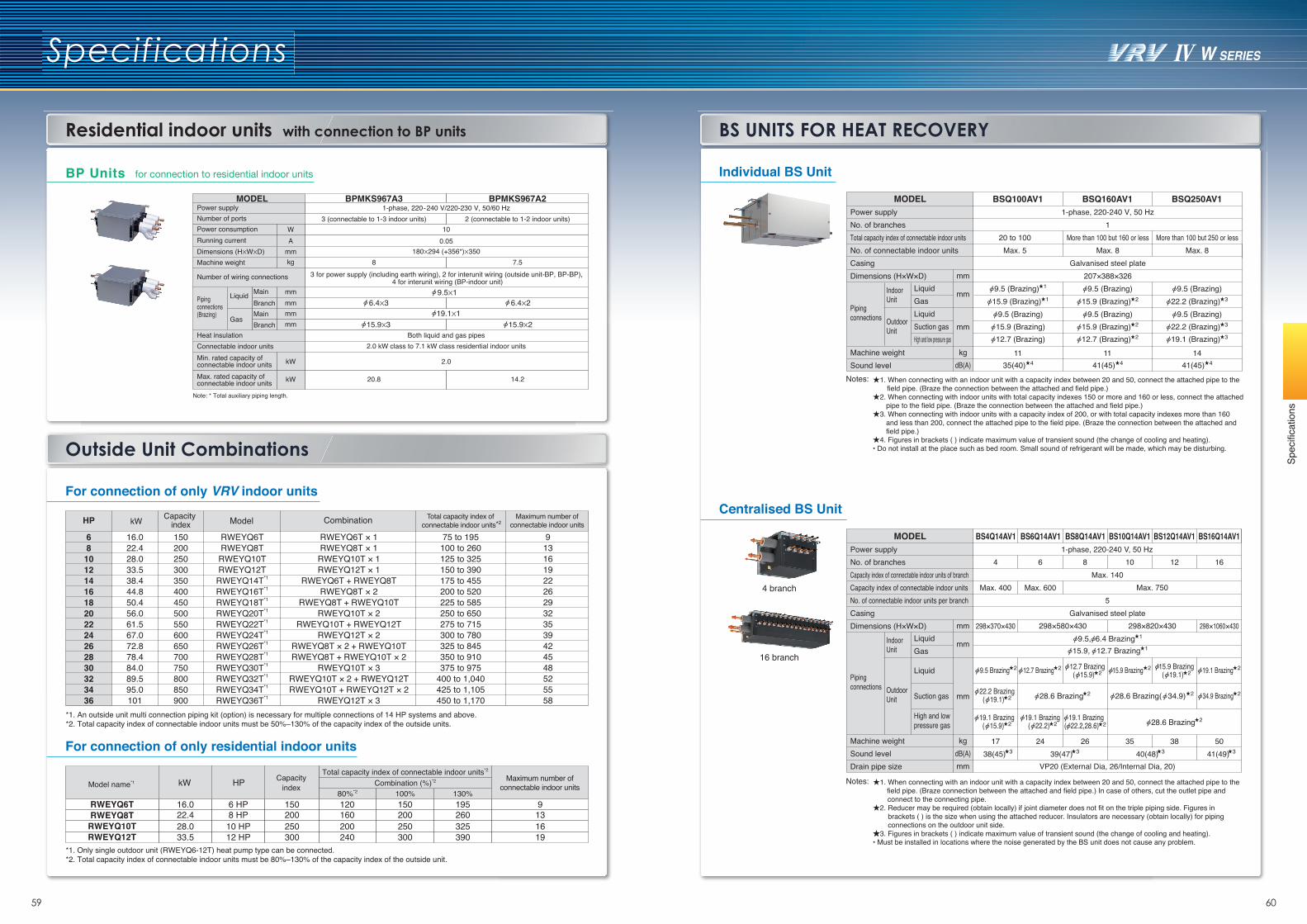
59 60
Spec
ifica
tions
Outside Unit Combinations
Residential indoor units with connection to BP units BS UNITS FOR HEAT RECOVERY
Specifications
Centralised BS Unit
Individual BS Unit
*1. Only single outdoor unit (RWEYQ6-12T) heat pump type can be connected.*2. Total capacity index of connectable indoor units must be 80%–130% of the capacity index of the outside unit.
RWEYQ6TRWEYQ8T
RWEYQ10TRWEYQ12T
16.022.428.033.5
6 HP8 HP10 HP12 HP
150200250300
120160200240
80%*2Combination (%)*2
Total capacity index of connectable indoor units*2
9131619
Model name*1 kW HP Capacityindex
Maximum number ofconnectable indoor units
For connection of only residential indoor units
150200250300
100%195
130%
260325390
For connection of only VRV indoor units
HP Model Combination
681012141618202224262830323436
16.022.428.033.538.444.850.456.061.567.072.878.484.089.595.0101
RWEYQ6TRWEYQ8TRWEYQ10TRWEYQ12TRWEYQ14T*1
RWEYQ16T*1
RWEYQ18T*1
RWEYQ20T*1
RWEYQ22T*1
RWEYQ24T*1
RWEYQ26T*1
RWEYQ28T*1
RWEYQ30T*1
RWEYQ32T*1
RWEYQ34T*1
RWEYQ36T*1
RWEYQ6T × 1RWEYQ8T × 1
RWEYQ10T × 1RWEYQ12T × 1
RWEYQ6T + RWEYQ8TRWEYQ8T × 2
RWEYQ8T + RWEYQ10TRWEYQ10T × 2
RWEYQ10T + RWEYQ12TRWEYQ12T × 2
RWEYQ8T × 2 + RWEYQ10TRWEYQ8T + RWEYQ10T × 2
RWEYQ10T × 3RWEYQ10T × 2 + RWEYQ12TRWEYQ10T + RWEYQ12T × 2
RWEYQ12T × 3
75 to 195100 to 260125 to 325150 to 390175 to 455200 to 520225 to 585250 to 650275 to 715300 to 780325 to 845350 to 910375 to 975
400 to 1,040425 to 1,105450 to 1,170
9131619222629323539424548525558
*1. An outside unit multi connection piping kit (option) is necessary for multiple connections of 14 HP systems and above.*2. Total capacity index of connectable indoor units must be 50%–130% of the capacity index of the outside units.
kW
150200250300350400450500550600650700750800850900
Capacity index
Total capacity index of connectable indoor units*2
Maximum number ofconnectable indoor units
BP Units for connection to residential indoor units
Note: * Total auxiliary piping length.
1-phase, 220-240 V/220-230 V, 50/60 Hz
100.05
180X294 (+356*)X350
3 for power supply (including earth wiring), 2 for interunit wiring (outside unit-BP, BP-BP), 4 for interunit wiring (BP-indoor unit)
Both liquid and gas pipes2.0 kW class to 7.1 kW class residential indoor units
2.0
Power supplyNumber of portsPower consumptionRunning currentDimensions (HXWXD)Machine weight
Number of wiring connections
Pipingconnections(Brazing)
Liquid MainBranchMainBranch
Gas
Heat insulationConnectable indoor unitsMin. rated capacity of connectable indoor unitsMax. rated capacity of connectable indoor units
MODEL BPMKS967A3
3 (connectable to 1-3 indoor units)
8
20.8
BPMKS967A2
2 (connectable to 1-2 indoor units)
7.5
14.2
WA
mm
mmmmmmmm
kW
kW
kg
9.5X1
19.1X16.4X3
15.9X3
6.4X2
15.9X2
1. When connecting with an indoor unit with a capacity index between 20 and 50, connect the attached pipe to the field pipe. (Braze the connection between the attached and field pipe.)
2. When connecting with indoor units with total capacity indexes 150 or more and 160 or less, connect the attached pipe to the field pipe. (Braze the connection between the attached and field pipe.)
3. When connecting with indoor units with a capacity index of 200, or with total capacity indexes more than 160 and less than 200, connect the attached pipe to the field pipe. (Braze the connection between the attached and field pipe.)
4. Figures in brackets ( ) indicate maximum value of transient sound (the change of cooling and heating).• Do not install at the place such as bed room. Small sound of refrigerant will be made, which may be disturbing.
Notes:
1. When connecting with an indoor unit with a capacity index between 20 and 50, connect the attached pipe to the field pipe. (Braze connection between the attached and field pipe.) In case of others, cut the outlet pipe and connect to the connecting pipe.
2. Reducer may be required (obtain locally) if joint diameter does not fit on the triple piping side. Figures in brackets ( ) is the size when using the attached reducer. Insulators are necessary (obtain locally) for piping connections on the outdoor unit side.
3. Figures in brackets ( ) indicate maximum value of transient sound (the change of cooling and heating).• Must be installed in locations where the noise generated by the BS unit does not cause any problem.
Notes:
BSQ100AV1 BSQ160AV1
11
BSQ250AV1
mm
mm
mm
kgdB(A)
MODEL
9.5 (Brazing)215.9 (Brazing)
215.9 (Brazing)
441(45)
212.7 (Brazing)
9.5 (Brazing)
11
115.9 (Brazing)
15.9 (Brazing)
435(40)
12.7 (Brazing)
9.5 (Brazing)
14
More than 100 but 250 or lessMax. 8
9.5 (Brazing)322.2 (Brazing)
322.2 (Brazing)
441(45)
319.1 (Brazing)
9.5 (Brazing)Pipingconnections
IndoorUnit
OutdoorUnit
LiquidGasLiquidSuction gasHigh and low pressure gas
20 to 100Max. 5
9.5 (Brazing) 1
BS4Q14AV1 BS6Q14AV1 BS8Q14AV1 BS10Q14AV1 BS12Q14AV1 BS16Q14AV11-phase, 220-240 V, 50 Hz
Max. 140
5Galvanised steel plate
1738(45) 39(47) 40(48)
5041(49)
6
Max. 600
8 10 12
24 26 35 38
mm
mm
mm
kgdB(A)mm
MODEL
9.5, 6.4 Brazing
34.9 Brazing
12.7 Brazing
22.2 Brazing
19.1 Brazing 19.1 Brazing 19.1 Brazing
15.9 Brazing
15.9, 12.7 Brazing
Pipingconnections
IndoorUnit
OutdoorUnit
LiquidGas
Liquid
Suction gas
High and low pressure gas
1
1
9.5 Brazing 2 12.7 Brazing 2 15.9 Brazing 2 19.1 Brazing 2
28.6 Brazing 2 28.6 Brazing( 34.9) 2 2
( 15.9) 2 ( 22.2) 2 ( 22.2,28.6) 2
( 15.9) 2
( 19.1) 2
( 19.1) 2
28.6 Brazing 2
VP20 (External Dia, 26/Internal Dia, 20)
3 3 3 3
4 branch
16 branch
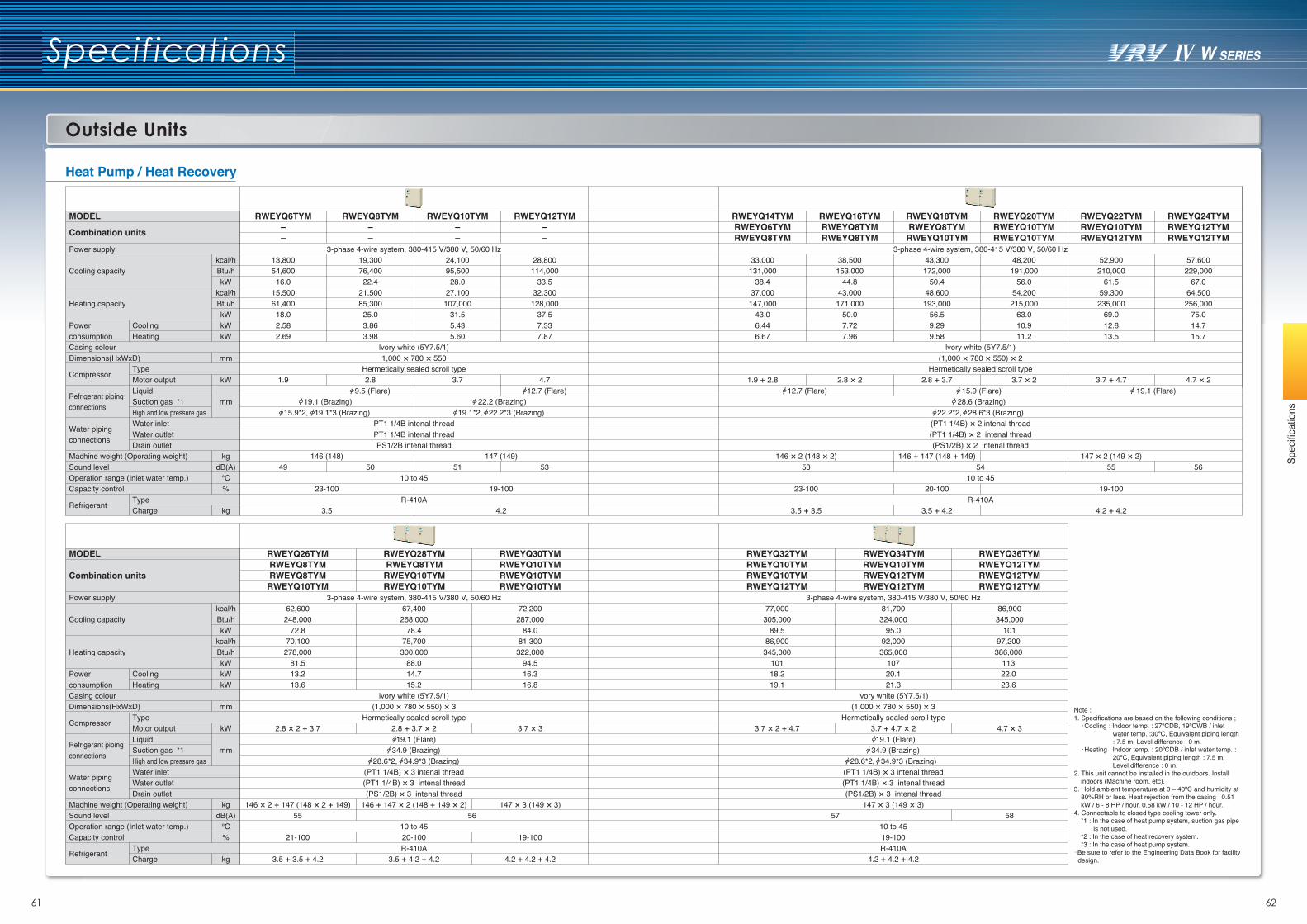
Spec
ifica
tions
Specifications
Heat Pump / Heat Recovery
61 62
RWEYQ6TYM––
3-phase 4-wire system, 380-415 V/380 V, 50/60 Hz
lvory white (5Y7.5/1)1,000 × 780 × 550
Hermetically sealed scroll type
PT1 1/4B intenal threadPT1 1/4B intenal threadPS1/2B intenal thread
10 to 45
R-410A
3-phase 4-wire system, 380-415 V/380 V, 50/60 Hz
lvory white (5Y7.5/1)(1,000 × 780 × 550) × 2
Hermetically sealed scroll type
15.9 (Flare) 28.6 (Brazing)
22.2*2, 28.6*3 (Brazing) (PT1 1/4B) × 2 intenal thread(PT1 1/4B) × 2 intenal thread(PS1/2B) × 2 intenal thread
5410 to 45
R-410A
13,80054,60016.0
15,50061,40018.02.582.69
1.9
49146 (148)
23-100
3.5
147 (149)
19-100
4.2
19.1 (Brazing) 15.9*2, 19.1*3 (Brazing)
22.2 (Brazing) 19.1*2, 22.2*3 (Brazing)
RWEYQ8TYM––
19,30076,40022.4
21,50085,30025.03.863.98
2.8 9.5 (Flare)
50
RWEYQ10TYM––
24,10095,50028.0
27,100107,000
31.55.435.60
3.7
51
RWEYQ12TYM––
28,800114,000
33.532,300
128,00037.57.337.87
4.7 12.7 (Flare)
53
RWEYQ14TYMRWEYQ6TYMRWEYQ8TYM
33,000131,000
38.437,000147,000
43.06.446.67
1.9 + 2.8
146 × 2 (148 × 2)53
23-100
3.5 + 3.5
12.7 (Flare) 19.1 (Flare)
38,500153,000
44.843,000171,000
50.07.727.96
2.8 × 2
43,300172,000
50.448,600193,000
56.59.299.58
2.8 + 3.7
146 + 147 (148 + 149)
20-100
3.5 + 4.2
48,200191,000
56.054,200215,000
63.010.911.2
3.7 × 2
52,900210,000
61.559,300235,000
69.012.813.5
3.7 + 4.7
147 × 2 (149 × 2)55
19-100
4.2 + 4.2
57,600229,000
67.064,500
256,00075.014.715.7
4.7 × 2
56
RWEYQ16TYMRWEYQ8TYMRWEYQ8TYM
RWEYQ18TYMRWEYQ8TYMRWEYQ10TYM
RWEYQ20TYMRWEYQ10TYMRWEYQ10TYM
RWEYQ22TYMRWEYQ10TYMRWEYQ12TYM
RWEYQ24TYMRWEYQ12TYMRWEYQ12TYM
kcal/hBtu/hkW
kcal/hBtu/hkWkWkW
mm
kW
mm
kgdB(A)
°C%
kg
TypeMotor outputLiquidSuction gas *1High and low pressure gasWater inletWater outletDrain outlet
TypeCharge
CoolingHeating
MODEL
Combination units
Power supply
Cooling capacity
Heating capacity
Power consumptionCasing colourDimensions(HⅹWⅹD)
Compressor
Refrigerant piping connections
Water piping connections
Machine weight (Operating weight)Sound level Operation range (Inlet water temp.)Capacity control
Refrigerant
RWEYQ26TYMRWEYQ8TYMRWEYQ8TYMRWEYQ10TYM
RWEYQ28TYMRWEYQ8TYMRWEYQ10TYMRWEYQ10TYM
RWEYQ30TYMRWEYQ10TYMRWEYQ10TYMRWEYQ10TYM
72,200287,000
84.081,300
322,00094.516.316.8
3.7 × 3
147 × 3 (149 × 3)
19-100
4.2 + 4.2 + 4.2
kcal/hBtu/hkW
kcal/hBtu/hkWkWkW
mm
kW
mm
kgdB(A)
°C%
kg
TypeMotor outputLiquidSuction gas *1High and low pressure gasWater inletWater outletDrain outlet
TypeCharge
CoolingHeating
MODEL
Combination units
Power supply
Cooling capacity
Heating capacity
Power consumptionCasing colourDimensions(HⅹWⅹD)
Compressor
Refrigerant piping connections
Water piping connections
Machine weight (Operating weight)Sound level Operation range (Inlet water temp.)Capacity control
Refrigerant
3-phase 4-wire system, 380-415 V/380 V, 50/60 Hz67,400
268,00078.4
75,700300,000
88.014.715.2
lvory white (5Y7.5/1)(1,000 × 780 × 550) × 3
Hermetically sealed scroll type2.8 + 3.7 × 2 19.1 (Flare)
34.9 (Brazing) 28.6*2, 34.9*3 (Brazing)
(PT1 1/4B) × 3 intenal thread(PT1 1/4B) × 3 intenal thread(PS1/2B) × 3 intenal thread
146 + 147 × 2 (148 + 149 × 2)
10 to 4520-100R-410A
3.5 + 4.2 + 4.2
56
RWEYQ32TYMRWEYQ10TYMRWEYQ10TYMRWEYQ12TYM
77,000305,000
89.586,900345,000
10118.219.1
3.7 × 2 + 4.7
57
RWEYQ34TYMRWEYQ10TYMRWEYQ12TYMRWEYQ12TYM
RWEYQ36TYMRWEYQ12TYMRWEYQ12TYMRWEYQ12TYM
86,900345,000
10197,200 386,000
113 22.0 23.6
4.7 × 3
58
3-phase 4-wire system, 380-415 V/380 V, 50/60 Hz81,700324,000
95.092,000365,000
10720.121.3
lvory white (5Y7.5/1)(1,000 × 780 × 550) × 3
Hermetically sealed scroll type3.7 + 4.7 × 2 19.1 (Flare)
34.9 (Brazing) 28.6*2, 34.9*3 (Brazing)
(PT1 1/4B) × 3 intenal thread(PT1 1/4B) × 3 intenal thread(PS1/2B) × 3 intenal thread
147 × 3 (149 × 3)
10 to 4519-100R-410A
4.2 + 4.2 + 4.2
Outside Units
62,600248,000
72.870,100
278,00081.513.213.6
2.8 × 2 + 3.7
146 × 2 + 147 (148 × 2 + 149)55
21-100
3.5 + 3.5 + 4.2
Note :1. Specifications are based on the following conditions ;
·Cooling : Indoor temp. : 27ºCDB, 19ºCWB / inlet water temp. :30ºC, Equivalent piping length : 7.5 m, Level difference : 0 m.
·Heating : Indoor temp. : 20ºCDB / inlet water temp. : 20ºC, Equivalent piping length : 7.5 m, Level difference : 0 m.
2. This unit cannot be installed in the outdoors. Install indoors (Machine room, etc).
3. Hold ambient temperature at 0 – 40ºC and humidity at 80%RH or less. Heat rejection from the casing : 0.51 kW / 6 - 8 HP / hour, 0.58 kW / 10 - 12 HP / hour.
4. Connectable to closed type cooling tower only.*1 : In the case of heat pump system, suction gas pipe
is not used.*2 : In the case of heat recovery system.*3 : In the case of heat pump system.
·Be sure to refer to the Engineering Data Book for facility design.
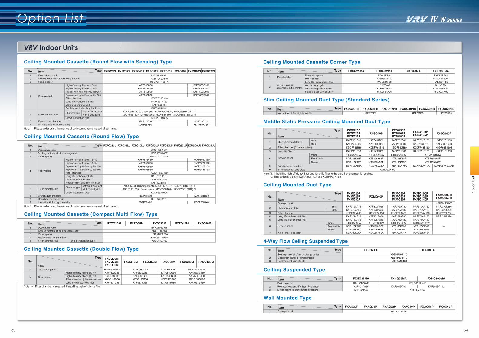
VRV Indoor Units
Option List
03 046463
Opt
ion
List
Ceiling Mounted Cassette (Round Flow with Sensing) Type
Ceiling Mounted Cassette (Round Flow) Type
Ceiling Mounted Cassette (Compact Multi Flow) Type
4-Way Flow Ceiling Suspended TypeCeiling Mounted Cassette (Double Flow) Type
Ceiling Mounted Cassette Corner Type
Slim Ceiling Mounted Duct Type (Standard Series)FXDQ25PB FXDQ32PBFXDQ20PB
KDT25N32 KDT25N50 KDT25N63Insulation kit for high humidity
TypeItem FXDQ63NBFXDQ50NBFXDQ40NBNo.1
Middle Static Pressure Ceiling Mounted Duct Type
FXSQ40P FXSQ140P
KAFP633B80 KAFP633B160KDDF63B160B KDDFP63B80 KDDFP63B160
KAFP631B80 KAFP631B160KTBJ25K80W KTBJ25K160WKTBJ25K80F
KAFP633B56 KDDFP63B56KAFP631B56 KTBJ25K56WKTBJ25K56F
KAFP633B36KAFP632B80 KAFP632B160KAFP632B56KAFP632B36
KDDFP63B36KAFP631B36KTBJ25K36WKTBJ25K36F KTBJ25K160F
KTBJ25K80T KTBJ25K160T KDAP25A71A KDAP25A140A
KTBJ25K56T KDAP25A56A
KTBJ25K36T KDAP25A36A
KDBD63A160KDAP25A160A *2
—
Item
Type
KAF632B160BKAF633B160B
KAF631B160B
FXSQ50PFXSQ63PFXSQ80P
FXSQ100PFXSQ125PNo.
1
23
4
56
FXSQ20PFXSQ25PFXSQ32P
*1. If installing high efficiency filter and long-life filter to the unit, filter chamber is required.*2. This option is a set of KDAP25A140A and KDBHP37A160.
Note:
High efficiency filter *1
Filter chamber (for rear suction) *1Long-life filter *1
Service panel
Air discharge adaptorShield plate for side plate
65%90%
WhiteFresh whiteBrown
Ceiling Suspended TypeFXHQ32MA
1 Drain pump kit2 Replacement long-life filter (Resin net)
KDU50N60VEKAF501DA56
3 L-type piping kit (for upward direction) KHFP5MA63
FXHQ63MA
KDU50N125VEKAF501DA80
KHFP5MA160
FXHQ100MA
KAF501DA112
No. TypeItem
Wall Mounted Type
*1. Please order using the names of both components instead of set name.Note:
Ceiling Mounted Duct Type
*1. Please order using the names of both components instead of set name.Note:
Type FXFQ25S FXFQ32S FXFQ40S FXFQ50S FXFQ63S FXFQ80S FXFQ100S FXFQ125SItemNo.1 Decoration panel
Sealing material of air discharge outletPanel spacer
High efficiency filter unit 65%High efficiency filter unit 90%Replacement high efficiency filter 65%Replacement high efficiency filter 90%Filter chamberLong life replacement filterUltra long-life filter unitReplacement ultra long-life filter
Chamber type Without T-duct jointWith T-duct joint
Direct installation type
Filter related
Fresh air intake kit
Branch duct chamberInsulation kit for high humidity
23
4
5
67
BYCQ125B-W1KDBHQ55B140KDBP55H160FA
KDDFP55C160KAFP551K160KAFP55C160
KAFP55H160HKDDQ55B140 (Components: KDDP55C160-1, KDDQ55B140-2 ) *1KDDP55B160K (Components: KDDP55C160-1, KDDP55B160K2) *1
KDDP55X160A
KAFP556C80KAFP557C80KAFP552B80KAFP553B80
KAFP556C160KAFP557C160KAFP552B160KAFP553B160
KDJP55B80KDTP55K80
KDJP55B160KDTP55K160
FXFQ25LU FXFQ32LU FXFQ40LU FXFQ50LU FXFQ63LU FXFQ80LU FXFQ100LU FXFQ125LUBYCP125K-W1
KAFP556C80 KAFP556C160KAFP557C80 KAFP557C160KAFP552B80 KAFP552B160KAFP553B80 KAFP553B160
KDTP55K160
KDJP55B160
Filter related
Fresh air intake kit
Decoration panelKDBH55K160FSealing material of air discharge outlet
KDBP55H160FAPanel spacerHigh efficiency filter unit 65%High efficiency filter unit 90%Replacement high efficiency filter 65%Replacement high efficiency filter 90%Filter chamberLong life replacement filter
Chamber type Without T-duct jointWith T-duct joint
KDDFP55C160
Ultra long-life filter unitReplacement ultra long-life filter
Direct installation type
KAFP551K160KAFP55C160
KAFP55H160HKDDP55B160 (Components: KDDP55C160-1, KDDP55B160-2) *1
KDDP55B160K (Components: KDDP55C160-1, KDDP55B160K2) *1KDDP55X160A
TypeItem
KDJP55B80Branch duct chamberKKSJ55KA160Chamber connection kit
KDTP55K80Insulation kit for high humidity
No.123
4
5
678
FXZQ20M FXZQ25M FXZQ32M FXZQ40M FXZQ50MDecoration panelSealing material of air discharge outletPanel spacerReplacement long-life filter
BYFQ60B3W1KDBH44BA60
KDBQ44BA60AKAFQ441BA60
Fresh air intake kit Direct installation type KDDQ44XA60
TypeItemNo.12345
Decoration panelHigh efficiency filter 65%High efficiency filter 90%
Long life replacement filter
Filter relatedbottom suction
KAFJ532G36 KAFJ532G56 KAFJ532G160KAFJ532G80KAFJ533G36 KAFJ533G56 KAFJ533G160KAFJ533G80KDDFJ53G36Filter chamber KDDFJ53G56 KDDFJ53G160KDDFJ53G80KAFJ531G36 KAFJ531G56 KAFJ531G160KAFJ531G80
Type
ItemBYBC32G-W1 BYBC50G-W1 BYBC125G-W1BYBC63G-W1
Note: 1 Filter chamber is required if installing high efficiency filter.
11
FXCQ20MFXCQ25MFXCQ32M
FXCQ40M FXCQ50M FXCQ63M FXCQ80M FXCQ125MNo.
1
2
TypeItem FXKQ25MA FXKQ32MA FXKQ40MA FXKQ63MABYK45FJW1 BYK71FJW1
KPBJ52F56W KPBJ52F80WKAFJ521F56 KAFJ521F80
K-HV7AW K-HV9AWKDBJ52F56W KDBJ52F80WKFDJ52FA56 KFDJ52FA80
Panel related
Air inlet and air discharge outlet related
Decoration panelPanel spacerLong life replacement filterAir discharge grilleAir discharge blind panelFlexible duct (with shutter)
No.
1
2
FXMQ40P FXMQ200MFXMQ250M
KDU30L250VE—KAFJ372L280KAF372AA80 KAF372AA160KAFJ373L280KAF373AA80 KAF373AA160KDJ3705L280KDDF37AA80 KDDF37AA160KAFJ371L280KAF371AA80 KAF371AA160
KAF375AA80
KAF372AA56KAF373AA56KDDF37AA56KAF371AA56KAF375AA56
KAF372AA36KAF373AA36KDDF37AA36KAF371AA36KAF375AA36 KAF375AA160
KTBJ25K80W KTBJ25K160WKTBJ25K80F KTBJ25K160FKTBJ25K80T
KTBJ25K56WKTBJ25K56FKTBJ25K56T
KTBJ25K36WKTBJ25K36FKTBJ25K36T KTBJ25K160T
KDAJ25K71AKDAJ25K56AKDAJ25K36A KDAJ25K140A
Item
65%90%
WhiteFresh whiteBrown
Type FXMQ20PFXMQ25PFXMQ32P
FXMQ50PFXMQ63PFXMQ80P
FXMQ100PFXMQ125PFXMQ140P
No.
1
2
345
6
7
Drain pump kit
High efficiency filter
Filter chamberLong life replacement filterLong life filter chamber kit
Service panel
Air discharge adaptor
—
FXUQ71A FXUQ100ASealing material of air discharge outletDecoration panel for air dischargeReplacement long-life filter
KDBHP49B140KDBTP49B140KAFP551K160
TypeItemNo.123
FXAQ25PFXAQ20P
K-KDU572EVE
FXAQ32P FXAQ40P FXAQ50P FXAQ63PNo. TypeItem1 Drain pump kit
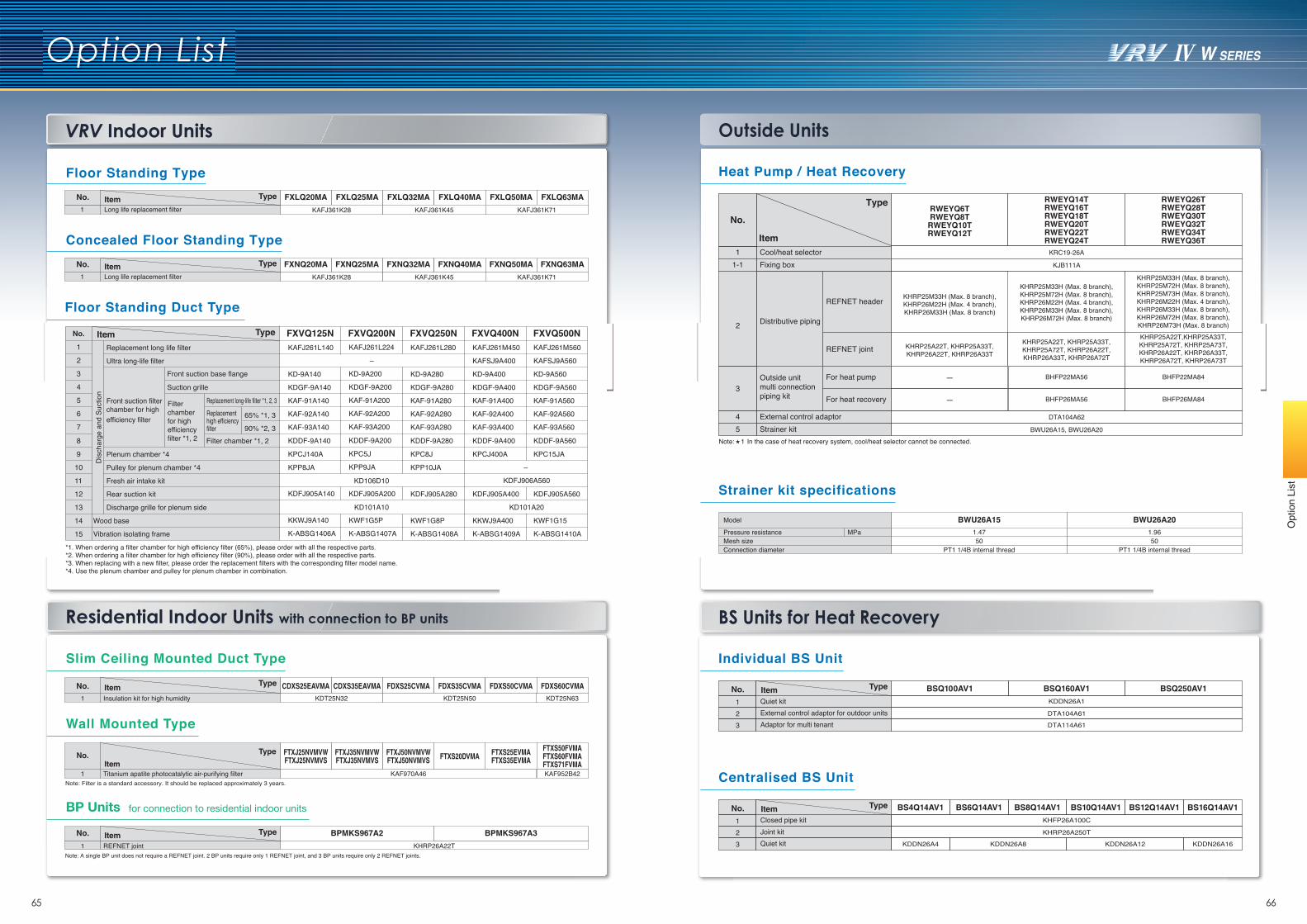
VRV Indoor Units
Option List
03 0465 66
Opt
ion
List
Residential Indoor Units with connection to BP units BS Units for Heat Recovery
Outside Units
Floor Standing Duct Type
Individual BS Unit
Centralised BS Unit
Heat Pump / Heat Recovery
Wall Mounted Type
BP Units for connection to residential indoor units
Slim Ceiling Mounted Duct Type
Strainer kit specifications
Model
Mesh size
BWU26A15
50Pressure resistance MPa
BWU26A20
501.47 1.96
Connection diameter PT1 1/4B internal thread PT1 1/4B internal thread*1. When ordering a filter chamber for high efficiency filter (65%), please order with all the respective parts.*2. When ordering a filter chamber for high efficiency filter (90%), please order with all the respective parts.*3. When replacing with a new filter, please order the replacement filters with the corresponding filter model name.*4. Use the plenum chamber and pulley for plenum chamber in combination.
Concealed Floor Standing TypeFXNQ20MA FXNQ25MA FXNQ32MA FXNQ40MA FXNQ50MA FXNQ63MA
KAFJ361K28 KAFJ361K45 KAFJ361K71
No. TypeItem1 Long life replacement filter
Floor Standing TypeFXLQ20MA FXLQ25MA FXLQ32MA FXLQ40MA FXLQ50MA FXLQ63MA
KAFJ361K28 KAFJ361K45 KAFJ361K71
No. TypeItem1 Long life replacement filter
FXVQ125N FXVQ200N FXVQ250N FXVQ500NFXVQ400NTypeItemReplacement long life filter
Ultra long-life filter
Front suction filter chamber for highefficiency filter
Plenum chamber *4
Pulley for plenum chamber *4
Fresh air intake kit
Rear suction kit
Discharge grille for plenum side
Wood base
Vibration isolating frame
KAFJ261L140
KD-9A140
KDGF-9A140
KAF-91A140
KAF-92A140
KAF-93A140
KDDF-9A140
KPCJ140A
KPP8JA
KDFJ905A140
KKWJ9A140
K-ABSG1406A
KAFJ261L224
–
KD-9A200
KDGF-9A200
KAF-91A200
KAF-92A200
KAF-93A200
KDDF-9A200
KPC5J
KPP9JA
KAFJ261L280
KD-9A280
KDGF-9A280
KAF-91A280
KAF-92A280
KAF-93A280
KDDF-9A280
KPC8J
KPP10JA
KAFJ261M450
KAFSJ9A400
KD-9A400
KDGF-9A400
KAF-91A400
KAF-92A400
KAF-93A400
KDDF-9A400
KPCJ400A
KAFJ261M560
KAFSJ9A560
KD-9A560
KDGF-9A560
KAF-91A560
KAF-92A560
KAF-93A560
KDDF-9A560
KPC15JA
KDFJ905A200
KWF1G5P
K-ABSG1407A
KDFJ905A280
KWF1G8P
K-ABSG1408A
KDFJ905A400
KKWJ9A400
K-ABSG1409A
KDFJ905A560
KWF1G15
K-ABSG1410A
Front suction base flange
Suction grille
Filter chamber *1, 2
Replacement long-life filter *1, 2, 3
Dis
char
ge a
nd S
uctio
n
No.
1
2
3
4
5
6
7
8
9
10
11
12
13
14
15
KDFJ906A560KD106D10
KD101A10
–
KD101A20
Filter chamber for high efficiency filter *1, 2
Replacement high efficiency filter
65% *1, 3
90% *2, 3
Note: A single BP unit does not require a REFNET joint. 2 BP units require only 1 REFNET joint, and 3 BP units require only 2 REFNET joints.
BPMKS967A2
1 REFNET joint KHRP26A22T
BPMKS967A3No. TypeItem
CDXS35EAVMACDXS25EAVMA1 Insulation kit for high humidity KDT25N32
FDXS25CVMA FDXS35CVMA FDXS50CVMA FDXS60CVMANo. TypeItemKDT25N50 KDT25N63
Note: Filter is a standard accessory. It should be replaced approximately 3 years.
FTXS25EVMAFTXS35EVMA
FTXS50FVMAFTXS60FVMAFTXS71FVMA
FTXS20DVMA
1 Titanium apatite photocatalytic air-purifying filter KAF970A46 KAF952B42
FTXJ35NVMVWFTXJ35NVMVS
FTXJ25NVMVWFTXJ25NVMVS
FTXJ50NVMVWFTXJ50NVMVS
No. TypeItem
No.
123
KDDN26A1
DTA104A61
DTA114A61
External control adaptor for outdoor unitsAdaptor for multi tenant
Quiet kitBSQ100AV1 BSQ160AV1 BSQ250AV1Item Type
No.
123
KHFP26A100C
KHRP26A250T
Closed pipe kitJoint kit
KDDN26A4 KDDN26A16KDDN26A8 KDDN26A12Quiet kit
BS4Q14AV1 BS6Q14AV1 BS8Q14AV1 BS10Q14AV1 BS12Q14AV1 BS16Q14AV1Item Type
RWEYQ6TRWEYQ8T
RWEYQ10TRWEYQ12T
RWEYQ14TRWEYQ16TRWEYQ18TRWEYQ20TRWEYQ22TRWEYQ24T
RWEYQ26TRWEYQ28TRWEYQ30TRWEYQ32TRWEYQ34TRWEYQ36T
REFNET header
Distributive piping
KHRP25M33H (Max. 8 branch), KHRP26M22H (Max. 4 branch), KHRP26M33H (Max. 8 branch)
Cool/heat selector KRC19-26A
Fixing box KJB111A
KHRP25M33H (Max. 8 branch),KHRP25M72H (Max. 8 branch),KHRP26M22H (Max. 4 branch),KHRP26M33H (Max. 8 branch),KHRP26M72H (Max. 8 branch)
KHRP25M33H (Max. 8 branch), KHRP25M72H (Max. 8 branch), KHRP25M73H (Max. 8 branch), KHRP26M22H (Max. 4 branch), KHRP26M33H (Max. 8 branch), KHRP26M72H (Max. 8 branch),KHRP26M73H (Max. 8 branch)
REFNET joint KHRP25A22T, KHRP25A33T, KHRP26A22T, KHRP26A33T
KHRP25A22T, KHRP25A33T,KHRP25A72T, KHRP26A22T,KHRP26A33T, KHRP26A72T
KHRP25A22T,KHRP25A33T, KHRP25A72T, KHRP25A73T, KHRP26A22T, KHRP26A33T, KHRP26A72T, KHRP26A73T
Strainer kit BWU26A15, BWU26A20
DTA104A62External control adaptor
Outside unit multi connection piping kit
For heat pump
For heat recovery —
—
BHFP26MA84
BHFP22MA84
Item
Type
BHFP26MA56
BHFP22MA56
11-1
45
3
2
No.
Note: 1 In the case of heat recovery system, cool/heat selector cannot be connected.
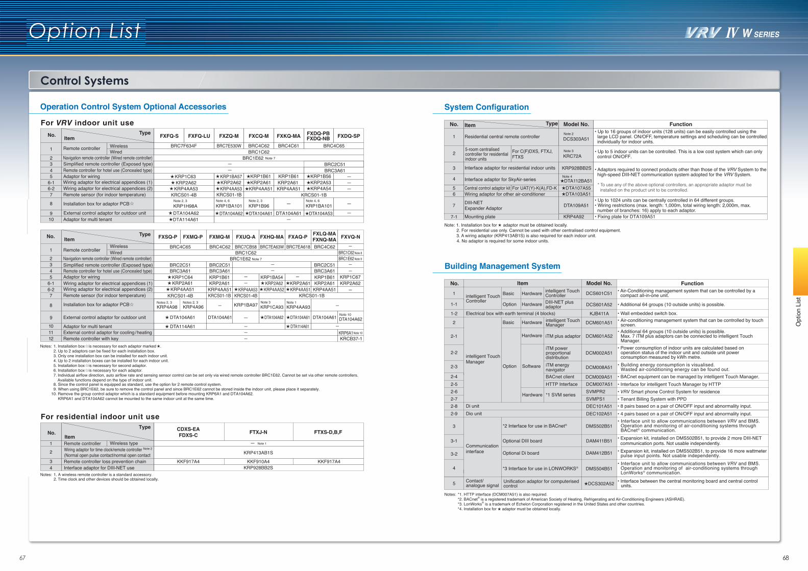
Control Systems
6867
Option List
Opt
ion
List
Operation Control System Optional Accessories System Configuration
Building Management System
No. TypeItem FXFQ-S FXFQ-LU FXZQ-M FXCQ-M FXKQ-MA FXDQ-SPFXDQ-PB
FXDQ-NB
1 Remote controller WirelessWired BRC1C62
2 Navigation remote controller (Wired remote controller) Note 7BRC1E623 Simplified remote controller (Exposed type) — BRC2C514 Remote controller for hotel use (Concealed type) —5 Adaptor for wiring KRP1BA57 KRP1B61 KRP1B56KRP1B61
KRP2A61 KRP4AA51
6-1 Wiring adaptor for electrical appendices (1) KRP2A62 KRP2A61 KRP2A536-2 Wiring adaptor for electrical appendices (2)
KRP1C63 KRP2A62
KRP4AA53 KRP4AA53 KRP4AA51 KRP4A547 Remote sensor (for indoor temperature) KRCS01-1B
8 Installation box for adaptor PCBNote 4, 6KRP1BA101
Note 2, 3KRP1B96
Note 10
Note 10
Note 4, 6KRP1BA101
9 External control adaptor for outdoor unit DTA104A62
KRCS01-4B
DTA104A62 DTA104A61 DTA104A61 DTA104A5310 Adaptor for multi tenant —
— —
No. TypeItem FXMQ-P FXMQ-M FXUQ-A FXHQ-MA FXAQ-P
FXLQ-MAFXNQ-MA
1 Remote controllerWireless
BRC7F634F BRC7E530W BRC4C62 BRC4C61 BRC4C65
BRC7CB58BRC4C65 BRC4C62 BRC7EA63W BRC7EA618 BRC4C62Wired BRC1C62
2 Navigation remote controller (Wired remote controller) Note 7BRC1E623 Simplified remote controller (Exposed type) BRC2C51 BRC2C51 — BRC2C514 Remote controller for hotel use (Concealed type) BRC3A61 BRC3A61 — BRC3A615 Adaptor for wiring KRP1B61
KRCS01-4B
KRP1BA54 ———
KRP1B616-1 Wiring adaptor for electrical appendices (1) KRP2A61
———
KRP2A616-2 Wiring adaptor for electrical appendices (2) KRP4AA51 KRP4AA53
KRCS01-1B
KRCS01-4BKRP4AA51
7 Remote sensor (for indoor temperature) KRCS01-1BKRCS01-1B
8 Installation box for adaptor PCB — KRP1BA97 Note 3KRP1CA93KRP4A96
Notes 2, 3KRP4A98Notes 2, 3 Note 1
KRP4AA93 —
9 External control adaptor for outdoor unit DTA104A61 —
—
DTA104A61
10 Adaptor for multi tenant ——
—
.Notes: 1. Installation box is necessary for each adaptor marked 2. Up to 2 adaptors can be fixed for each installation box.3. Only one installation box can be installed for each indoor unit.4. Up to 2 installation boxes can be installed for each indoor unit.5. Installation box is necessary for second adaptor.6. Installation box is necessary for each adaptor.7. Individual airflow direction, auto airflow rate and sensing sensor control can be set only via wired remote controller BRC1E62. Cannot be set via other remote controllers.
Available functions depend on the type of indoor unit.8. Since the control panel is equipped as standard, use the option for 2 remote control system.9. When using BRC1E62, be sure to remove the control panel and since BRC1E62 cannot be stored inside the indoor unit, please place it separately.
For residential indoor unit use
For VRV indoor unit use
Notes: 1. A wireless remote controller is a standard accessory. 2. Time clock and other devices should be obtained locally.
Type
ItemNo.
11 External control adaptor for cooling / heating
KRP413AB1S
Wireless typeRemote controller
KKF910A4KKF917A4 KKF917A4Remote controller loss prevention chain
Wiring adaptor for time clock/remote controller Note 2
(Normal open pulse contact/normal open contact
1
2
3
— Note 1
CDXS-EAFDXS-C
FXVQ-N
—
—
—
KRP2A62KRP1C67
—
KRP6A1—12 Remote controller with key KRCB37-1
DTA104A62
Note 9BRC1E62Note 8BRC1C62
FTXS-D,B,FFTXJ-N
10. Remove the group control adaptor which is a standard equipment before mounting KRP6A1 and DTA104A62. KRP6A1 and DTA104A62 cannot be mounted to the same indoor unit at the same time.
KRP928BB2SInterface adaptor for DIII-NET use4
FXSQ-P
DTA114A61
Note 2, 3KRP1H98A
BRC3A61
DTA114A61
DTA104A61
KRP4AA51KRP2A61KRP1C64
KRP2A62KRP4AA52
DTA104A62
DTA114A61
DTA104A61
KRP2A61KRP4AA51
No. TypeItem Model No. Function
1 Residential central remote controller Note 2DCS303A51
Note 3KRC72A
• Up to 16 groups of indoor units (128 units) can be easily controlled using the large LCD panel. ON/OFF, temperature settings and scheduling can be controlled individually for indoor units.
3 Interface adaptor for residential indoor units KRP928BB2S
25-room centralised controller for residential indoor units
• Up to 5 indoor units can be controlled. This is a low cost system which can only control ON/OFF.
4 Interface adaptor for SkyAir-series
For C(F)DXS, FTXJ, FTXS
DTA112BA51
• Adaptors required to connect products other than those of the VRV System to the high-speed DIII-NET communication system adopted for the VRV System.
* To use any of the above optional controllers, an appropriate adaptor must be installed on the product unit to be controlled.5 Central control adaptor kit For UAT(Y)-K(A),FD-K DTA107A55
6 Wiring adaptor for other air-conditioner DTA103A51
7 DIII-NETExpander Adaptor DTA109A51
• Up to 1024 units can be centrally controlled in 64 different groups.• Wiring restrictions (max. length: 1,000m, total wiring length: 2,000m, max. number of branches: 16) apply to each adaptor.
Note: 1. Installation box for adaptor must be obtained locally. 2. For residential use only. Cannot be used with other centralised control equipment. 3. A wiring adaptor (KRP413AB1S) is also required for each indoor unit. 4. No adaptor is required for some indoor units.
7-1 Mounting plate KRP4A92 • Fixing plate for DTA109A51
Note 4
No. Item Model No. Function
1 intelligent Touch Controller
Basic Hardware intelligent Touch Controller DCS601C51 • Air-Conditioning management system that can be controlled by a
compact all-in-one unit.
1-1 Option Hardware DIII-NET plus adaptor DCS601A52 • Additional 64 groups (10 outside units) is possible.
1-2 Electrical box with earth terminal (4 blocks) KJB411A • Wall embedded switch box.
2
intelligent TouchManager
Basic Hardware intelligent Touch Manager DCM601A51 • Air-conditioning management system that can be controlled by touch
screen.
2-1
Option
Hardware iTM plus adaptor DCM601A52• Additional 64 groups (10 outside units) is possible. Max. 7 iTM plus adaptors can be connected to intelligent Touch Manager.
2-2
2-3 Software
Hardware
iTM powerproportionaldistribution
DCM002A51• Power consumption of indoor units are calculated based on operation status of the indoor unit and outside unit power consumption measured by kWh metre.
2-42-5
iTM energynavigator DCM008A51 • Building energy consumption is visualised.
Wasted air-conditioning energy can be found out.• BACnet equipment can be managed by intelligent Touch Manager.BACnet client DCM009A51
DEC101A51 • 8 pairs based on a pair of ON/OFF input and abnormality input.2-8 Di unit2-9 Dio unit DEC102A51 • 4 pairs based on a pair of ON/OFF input and abnormality input.
3
Communicationinterface
*2 Interface for use in BACnet® DMS502B51• Interface unit to allow communications between VRV and BMS. Operation and monitoring of air-conditioning systems through BACnet® communication.
3-1 Optional DIII board DAM411B51 • Expansion kit, installed on DMS502B51, to provide 2 more DIII-NETcommunication ports. Not usable independently.
3-2 Optional Di board DAM412B51 • Expansion kit, installed on DMS502B51, to provide 16 more wattmeter pulse input points. Not usable independently.
4 *3 Interface for use in LONWORKS® DMS504B51• Interface unit to allow communications between VRV and BMS. Operation and monitoring of air-conditioning systems through LonWorks® communication.
5 Contact/analogue signal
Unification adaptor for computerisedcontrol DCS302A52 • Interface between the central monitoring board and central control
units.
Notes:*2. BACnet*1. HTTP interface (DCM007A51) is also required.
® is a registered trademark of American Society of Heating, Refrigerating and Air-Conditioning Engineers (ASHRAE).*3. LonWorks® is a trademark of Echelon Corporation registered in the United States and other countries.*4. Installation box for adaptor must be obtained locally.
2-62-7
• Interface for intelligent Touch Manager by HTTP• VRV Smart phone Control System for residence• Tenant Billing System with PPD
DCM007A51SVMPR2SVMPS1
HTTP Interface
*1 SVM series
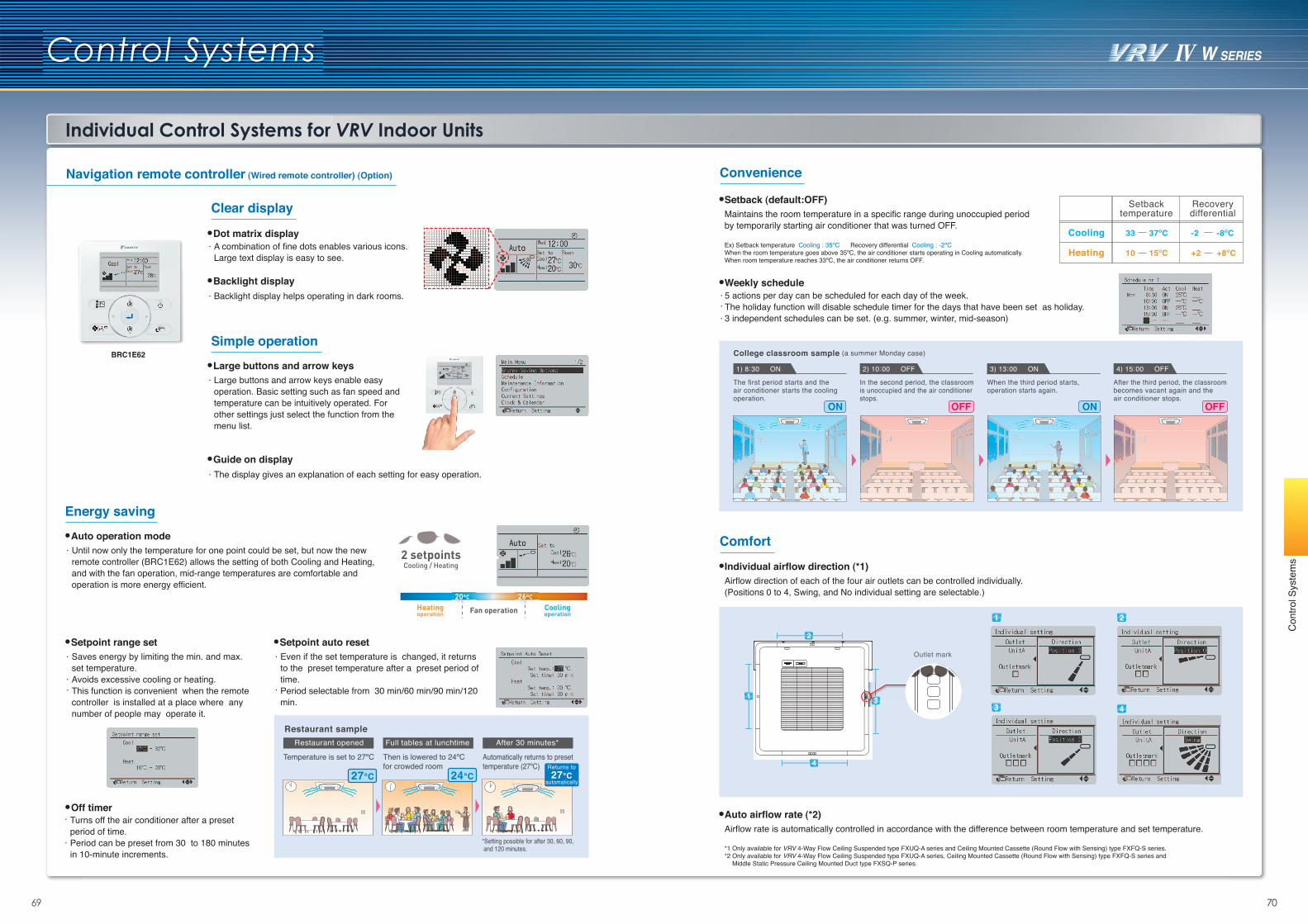
Individual Control Systems for VRV Indoor Units
03 047069
Con
trol S
yste
ms
Control Systems
Navigation remote controller (Wired remote controller) (Option)
Clear display
Dot matrix displayA combination of fine dots enables various icons.Large text display is easy to see.
Backlight displayBacklight display helps operating in dark rooms.
Simple operation
Guide on displayThe display gives an explanation of each setting for easy operation.
Large buttons and arrow keysLarge buttons and arrow keys enable easy operation. Basic setting such as fan speed and temperature can be intuitively operated. For other settings just select the function from the menu list.
Auto airflow rate (*2)Airflow rate is automatically controlled in accordance with the difference between room temperature and set temperature.
Setback (default:OFF)Maintains the room temperature in a specific range during unoccupied periodby temporarily starting air conditioner that was turned OFF.
Ex) Setback temperature Cooling : 35ºC Recovery differential Cooling : -2ºCWhen the room temperature goes above 35ºC, the air conditioner starts operating in Cooling automatically.When room temperature reaches 33ºC, the air conditioner returns OFF.
Cooling
Setbacktemperature
Recoverydifferential
33 -237ºC -8ºC
Heating 10 +215ºC +8ºC
*1 Only available for VRV 4-Way Flow Ceiling Suspended type FXUQ-A series and Ceiling Mounted Cassette (Round Flow with Sensing) type FXFQ-S series.*2 Only available for VRV 4-Way Flow Ceiling Suspended type FXUQ-A series, Ceiling Mounted Cassette (Round Flow with Sensing) type FXFQ-S series and
Middle Static Pressure Ceiling Mounted Duct type FXSQ-P series.
Individual airflow direction (*1)Airflow direction of each of the four air outlets can be controlled individually. (Positions 0 to 4, Swing, and No individual setting are selectable.)
1 2
3 4
Outlet mark
1
2
4
33
5 actions per day can be scheduled for each day of the week.The holiday function will disable schedule timer for the days that have been set as holiday.3 independent schedules can be set. (e.g. summer, winter, mid-season)
Weekly schedule
The first period starts and the air conditioner starts the coolingoperation.
College classroom sample (a summer Monday case)
1) 8:30 ON
ON OFF ON OFF
In the second period, the classroomis unoccupied and the air conditionerstops.
2) 10:00 OFF
When the third period starts, operation starts again.
3) 13:00 ON
After the third period, the classroom becomes vacant again and the air conditioner stops.
4) 15:00 OFF
Energy saving
Off timer Turns off the air conditioner after a preset period of time.Period can be preset from 30 to 180 minutes in 10-minute increments.
Auto operation modeUntil now only the temperature for one point could be set, but now the new remote controller (BRC1E62) allows the setting of both Cooling and Heating, and with the fan operation, mid-range temperatures are comfortable and operation is more energy efficient.
Setpoint auto resetEven if the set temperature is changed, it returns to the preset temperature after a preset period of time.Period selectable from 30 min/60 min/90 min/120 min.
Restaurant sampleRestaurant opened
Temperature is set to 27ºC
Full tables at lunchtime
Then is lowered to 24ºC for crowded room
After 30 minutes*
Automatically returns to preset temperature (27ºC)
*Setting possible for after 30, 60, 90, and 120 minutes.
27°C 24°CReturns to27°C
automatically
Convenience
Comfort
Setpoint range setSaves energy by limiting the min. and max. set temperature.Avoids excessive cooling or heating. This function is convenient when the remote controller is installed at a place where any number of people may operate it.
BRC1E62
2 setpointsCooling / Heating
Heatingoperation
20ºC 26ºC
CoolingoperationFan operation
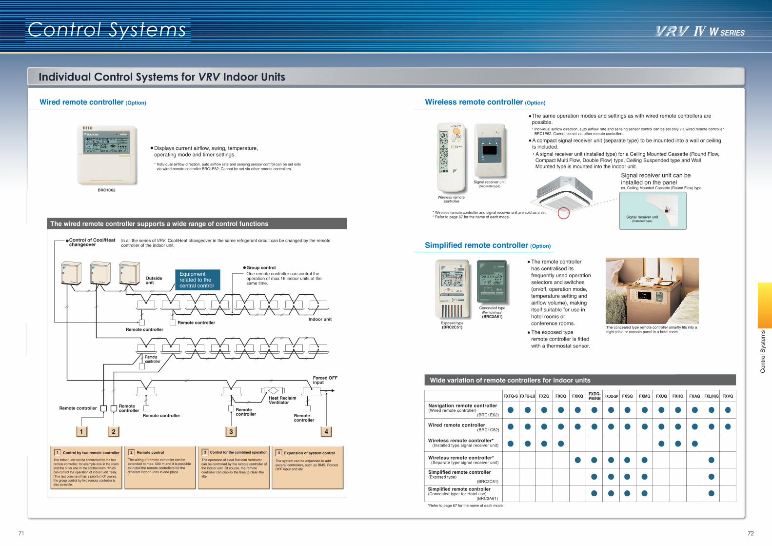
Individual Control Systems for VRV Indoor Units
03 047271
Con
trol S
yste
ms
Control Systems
Wired remote controller (Option) Wireless remote controller (Option)
Wide variation of remote controllers for indoor units
Simplified remote controller (Option)
The system can be expanded to add several controllers, such as BMS, Forced OFF input and etc.
Expansion of system control4
The operation of Heat Reclaim Ventilator can be controlled by the remote controller of the indoor unit. Of course, the remote controller can display the time to clean the filter.
Control for the combined operation3
The wiring of remote controller can be extended to max. 500 m and it is possible to install the remote controllers for the different indoor units in one place.
Remote control2
The indoor unit can be connected by the two remote controller, for example one in the room and the other one in the control room, which can control the operation of indoor unit freely.(The last command has a priority.) Of course, the group control by two remote controller is also possible.
Control by two remote controller1
The wired remote controller supports a wide range of control functions
Displays current airflow, swing, temperature, operating mode and timer settings.
BRC1C62
* Individual airflow direction, auto airflow rate and sensing sensor control can be set only via wired remote controller BRC1E62. Cannot be set via other remote controllers.
Outside unit
Indoor unit
Forced OFF input
Remote controller
Remote controllerRemote controller Remote
controller
Remote controller
Remote controller
Remote controller
Remote controller
In all the series of VRV, Cool/Heat changeover in the same refrigerant circuit can be changed by the remote controller of the indoor unit.
One remote controller can control the operation of max.16 indoor units at the same time.
Group control
Equipment related to the central control
1 2 3 4
Heat Reclaim Ventilator
Control of Cool/Heat changeover
The same operation modes and settings as with wired remote controllers are possible.* Individual airflow direction, auto airflow rate and sensing sensor control can be set only via wired remote controller
BRC1E62. Cannot be set via other remote controllers.
• A signal receiver unit (installed type) for a Ceiling Mounted Cassette (Round Flow, Compact Multi Flow, Double Flow) type, Ceiling Suspended type and Wall Mounted type is mounted into the indoor unit.
The remote controller has centralised its frequently used operation selectors and switches (on/off, operation mode, temperature setting and airflow volume), making itself suitable for use in hotel rooms or conference rooms.The exposed type remote controller is fitted with a thermostat sensor.
Signal receiver unit(Separate type)
Wireless remote controller
The concealed type remote controller smartly fits into a night table or console panel in a hotel room.
Exposed type(BRC2C51)
Concealed type(For hotel use)(BRC3A61)
Signal receiver unit(Installed type)
Signal receiver unit can be installed on the panel ex. Ceiling Mounted Cassette (Round Flow) type
* Wireless remote controller and signal receiver unit are sold as a set. * Refer to page 67 for the name of each model.
*Refer to page 67 for the name of each model.
Simplified remote controller(Exposed type) (BRC2C51)
Wireless remote controller* (Separate type signal receiver unit)
Navigation remote controller(Wired remote controller) (BRC1E62)
Wired remote controller (BRC1C62)
Wireless remote controller* (Installed type signal receiver unit)
Simplified remote controller(Concealed type: for Hotel use) (BRC3A61)
A compact signal receiver unit (separate type) to be mounted into a wall or ceiling is included.
FXFQ-S FXFQ-LU FXZQ FXCQ FXUQFXKQ FXMQFXSQ FXHQ FXAQ FXL(N)Q FXVQFXDQ-PB/NB FXDQ-SP
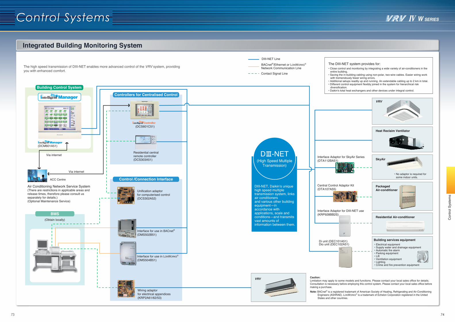
03 047473
Control Systems
Integrated Building Monitoring System
Con
trol S
yste
ms
(DCM601A51)
BMS(Obtain locally)
Wiring adaptorfor electrical appendices(KRP2A61/62/53)
Interface Adaptor for SkyAir Series(DTA112BA51)
Central Control Adaptor Kit(DTA107A55)
Interface Adaptor for DIII-NET use(KRP928BB2S)
(DCS601C51)
Unification adaptorfor computerised control(DCS302A52)
DIII-NET Line
BACnet®/Ethernet or LONWORKS®
Network Communication LineContact Signal Line
Caution: Limitation may apply to some models and functions. Please contact your local sales office for details. Consultation is necessary before employing this control system. Please contact your local sales office before making a purchase.
Air Conditioning Network Service System(There are restrictions in applicable areas and release times, therefore please consult us separately for details.)(Optional Maintenance Service)
Control /Connection Interface
Building Control System
Interface for use in BACnet®(DMS502B51)
Interface for use in LONWORKS®
(DMS504B51)
ACC Centre
Di unit (DEC101A51)Dio unit (DEC102A51)
Building services equipment• Electrical equipment• Supply water and drainage equipment• Automatic fire alarm• Parking equipment• Lift• Ventilation equipment• Lighting• Crime and fire prevention equipment
Controllers for Centralised Control
The high speed transmission of DIII-NET enables more advanced control of the VRV system, providing you with enhanced comfort.
Note: BACnet® is a registered trademark of American Society of Heating, Refrigerating and Air-Conditioning Engineers (ASHRAE). LONWORKS® is a trademark of Echelon Corporation registered in the United States and other countries.
The DIII-NET system provides for:• Close control and monitoring by integrating a wide variety of air-conditioners in the
entire building.• Saving the in-building cabling using non-polar, two-wire cables. Easier wiring work
with tremendously fewer wiring errors.• Additional setups readily up and running. An extendable cabling up to 2 km in total.• Different control equipment flexibly joined in the system for hierarchical risk
diversification.• Daikin's total heat exchangers and other devices under integral control.
VRV
Heat Reclaim Ventilator
SkyAir
Packaged Air-conditioner
Residential Air-conditioner
* No adaptor is required for some indoor units.
VRV
Via internet
Via internet D -NET(High Speed Multiple
Transmission)
DIII-NET, Daikin’s unique high speed multiple transmission system, links air conditioners and various other building equipment—in accordance with applications, scale and conditions—and transmits vast amounts of information between them.
Residential central remote controller(DCS303A51)
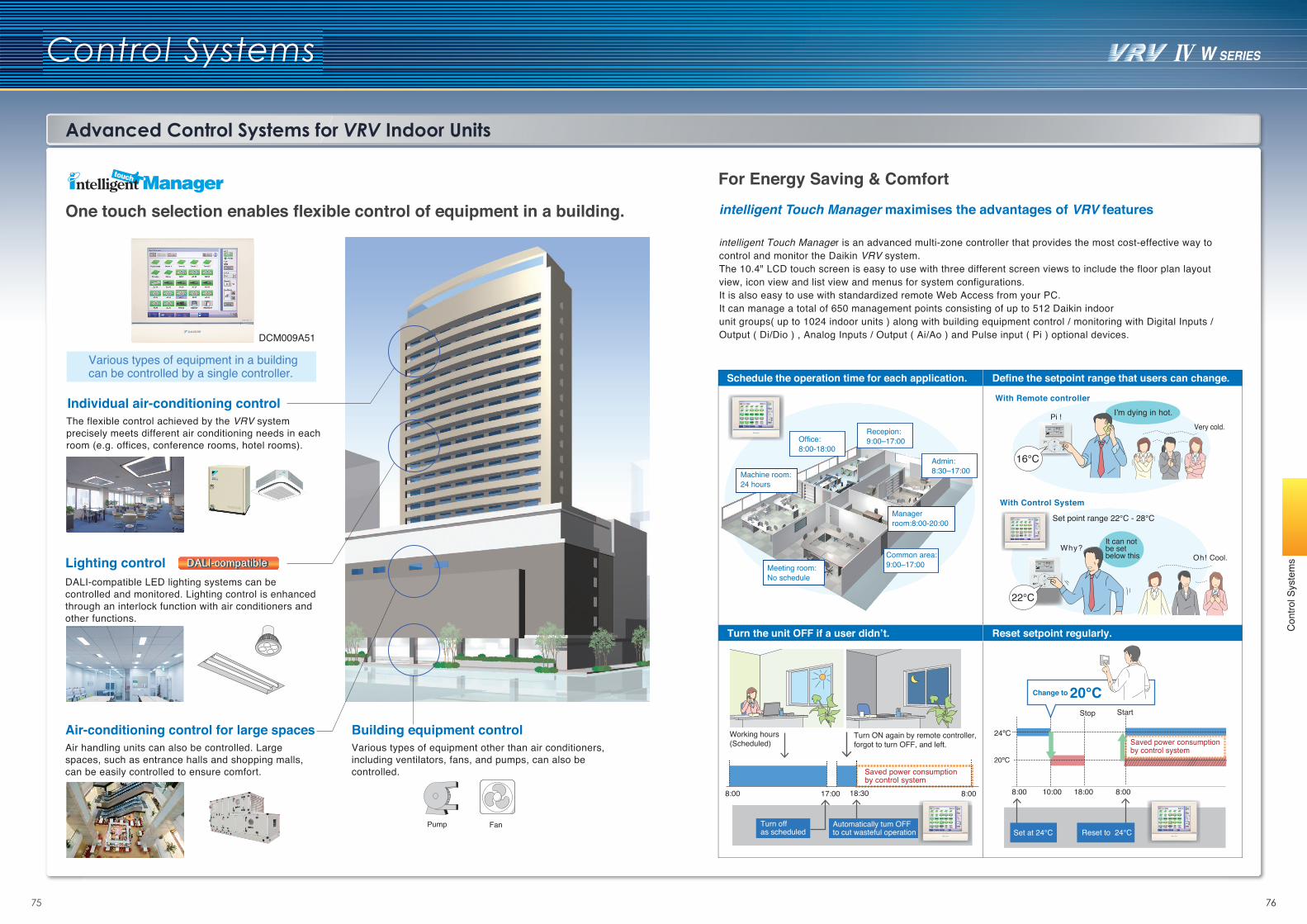
03 047675
Control Systems
Advanced Control Systems for VRV Indoor Units
Schedule the operation time for each application. Define the setpoint range that users can change.
With Remote controller
With Control System
I’m dying in hot.
Turn the unit OFF if a user didn’t.
Turn ON again by remote controller, forgot to turn OFF, and left.
Saved power consumption by control system
Reset setpoint regularly.
8:00 17:00 18:30 8:00 8:00 10:00 18:00
Stop Start
8:00
Working hours(Scheduled)
Turn off as scheduled
Automatically tum OFF to cut wasteful operation Set at 24°C Reset to 24°C
Change to 20°C
Managerroom:8:00-20:00
Machine room: 24 hours
Admin:8:30–17:00
Common area:9:00–17:00Meeting room:
No schedule
Office:8:00-18:00
Recepion:9:00–17:00
16°C
22°C
Pi !Very cold.
Oh! Cool.
Set point range 22°C - 28°C
Why?It can not be set below this
Saved power consumption by control system
24ºC
20ºC
Pump Fan
The flexible control achieved by the VRV system precisely meets different air conditioning needs in each room (e.g. offices, conference rooms, hotel rooms).
Lighting controlDALI-compatible LED lighting systems can be controlled and monitored. Lighting control is enhanced through an interlock function with air conditioners and other functions.
Air-conditioning control for large spacesAir handling units can also be controlled. Large spaces, such as entrance halls and shopping malls, can be easily controlled to ensure comfort.
Building equipment controlVarious types of equipment other than air conditioners, including ventilators, fans, and pumps, can also be controlled.
Various types of equipment in a building can be controlled by a single controller.
Individual air-conditioning control
DALI-compatibleDALI-compatible
One touch selection enables flexible control of equipment in a building.
For Energy Saving & Comfortintelligent Touch Manager maximises the advantages of VRV features
intelligent Touch Manager is an advanced multi-zone controller that provides the most cost-effective way to control and monitor the Daikin VRV system.The 10.4" LCD touch screen is easy to use with three different screen views to include the floor plan layout view, icon view and list view and menus for system configurations. It is also easy to use with standardized remote Web Access from your PC. It can manage a total of 650 management points consisting of up to 512 Daikin indoor unit groups( up to 1024 indoor units ) along with building equipment control / monitoring with Digital Inputs / Output ( Di/Dio ) , Analog Inputs / Output ( Ai/Ao ) and Pulse input ( Pi ) optional devices.DCM009A51
Con
trol S
yste
ms
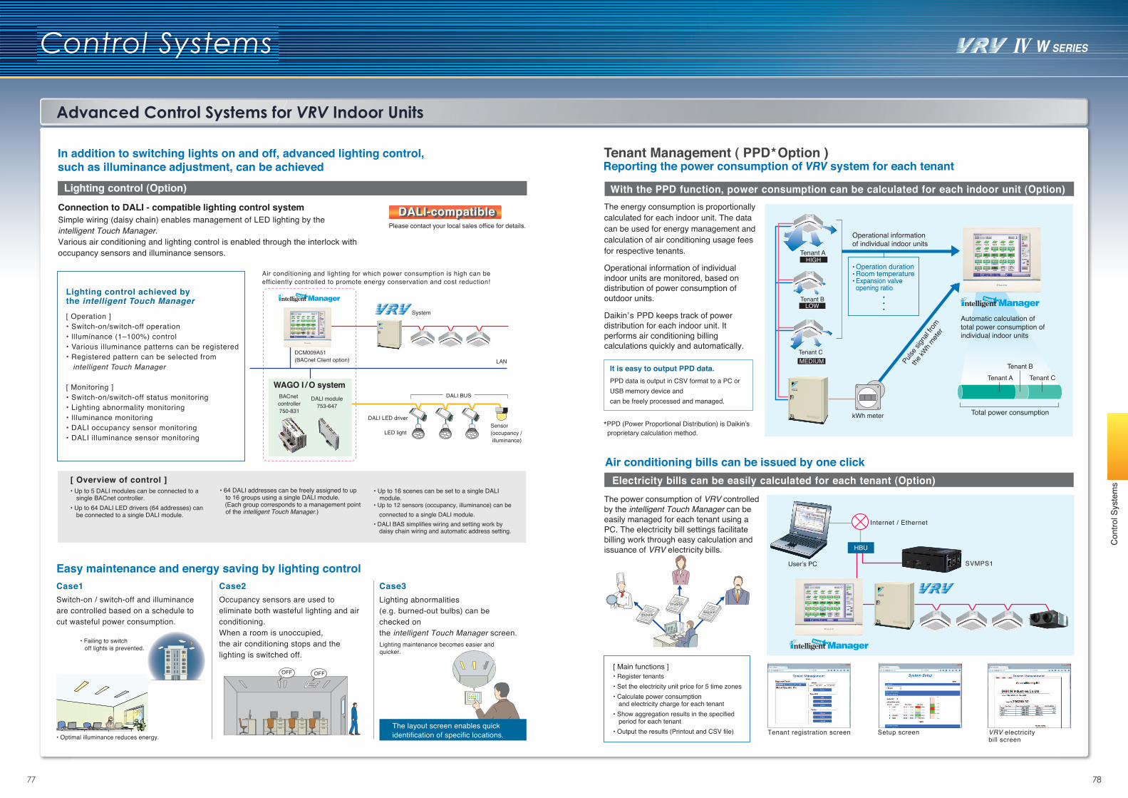
03 047877
Control Systems
Advanced Control Systems for VRV Indoor Units
Connection to DALI - compatible lighting control system Simple wiring (daisy chain) enables management of LED lighting by the intelligent Touch Manager. Various air conditioning and lighting control is enabled through the interlock with occupancy sensors and illuminance sensors.
Lighting control (Option)
In addition to switching lights on and off, advanced lighting control, such as illuminance adjustment, can be achieved
Easy maintenance and energy saving by lighting controlCase1 Case2 Case3
Lighting abnormalities (e.g. burned-out bulbs) can bechecked on the intelligent Touch Manager screen.
Air conditioning and lighting for which power consumption is high can be efficiently controlled to promote energy conservation and cost reduction!
DALI BUS
LED light
DALI LED driver
LAN
Sensor(occupancy / illuminance)
DCM009A51(BACnet Client option)
BACnet controller750-831
DALI module753-647
WAGO I / O system
Please contact your local sales office for details.
Lighting maintenance becomes easier and quicker.
The layout screen enables quick identification of specific locations.
Occupancy sensors are used to eliminate both wasteful lighting and air conditioning.When a room is unoccupied, the air conditioning stops and the lighting is switched off.
Switch-on / switch-off and illuminance are controlled based on a schedule to cut wasteful power consumption.
• Up to 5 DALI modules can be connected to a single BACnet controller.
• Up to 64 DALI LED drivers (64 addresses) can be connected to a single DALI module.
• 64 DALI addresses can be freely assigned to up to 16 groups using a single DALI module.
(Each group corresponds to a management point of the intelligent Touch Manager.)
• Up to 16 scenes can be set to a single DALI module.
• Up to 12 sensors (occupancy, illuminance) can be connected to a single DALI module.
• DALI BAS simplifies wiring and setting work by daisy chain wiring and automatic address setting.
• Failing to switch off lights is prevented.
• Optimal illuminance reduces energy.
Lighting control achieved by the intelligent Touch Manager
[ Operation ]• Switch-on/switch-off operation• Illuminance (1–100%) control• Various illuminance patterns can be registered• Registered pattern can be selected from
intelligent Touch Manager
[ Monitoring ]• Switch-on/switch-off status monitoring• Lighting abnormality monitoring• Illuminance monitoring• DALI occupancy sensor monitoring• DALI illuminance sensor monitoring
[ Overview of control ]
DALI-compatibleDALI-compatible
OFF OFF
With the PPD function, power consumption can be calculated for each indoor unit (Option)
Operational information of individual indoor units are monitored, based on distribution of power consumption of outdoor units.
Daikin’s PPD keeps track of power distribution for each indoor unit. It performs air conditioning billing calculations quickly and automatically.
Operation durationRoom temperatureExpansion valve opening ratio
Operational informationof individual indoor units
Automatic calculation oftotal power consumption ofindividual indoor units
Total power consumption
Pulse
sign
al fro
m
the kW
h mete
r
Tenant A
Tenant A
Tenant B
Tenant BTenant C
Tenant C
kWh meter
HIGH
LOW
MEDIUM
The energy consumption is proportionally calculated for each indoor unit. The data can be used for energy management and calculation of air conditioning usage fees for respective tenants.
Reporting the power consumption of VRV system for each tenant
Electricity bills can be easily calculated for each tenant (Option)The power consumption of VRV controlled by the intelligent Touch Manager can be easily managed for each tenant using a PC. The electricity bill settings facilitate billing work through easy calculation and issuance of VRV electricity bills.
Air conditioning bills can be issued by one click
It is easy to output PPD data.PPD data is output in CSV format to a PC or USB memory device and can be freely processed and managed.
SVMPS1
Internet / Ethernet
[ Main functions ]• Register tenants• Set the electricity unit price for 5 time zones• Calculate power consumption
and electricity charge for each tenant• Show aggregation results in the specified
period for each tenant• Output the results (Printout and CSV file)
User’s PC
Tenant registration screen VRV electricity bill screen
Invoice Invoice
Invoice
Tenant Management ( PPD Option )*
HBU
Setup screen
*PPD (Power Proportional Distribution) is Daikin’s proprietary calculation method.
System
Con
trol S
yste
ms
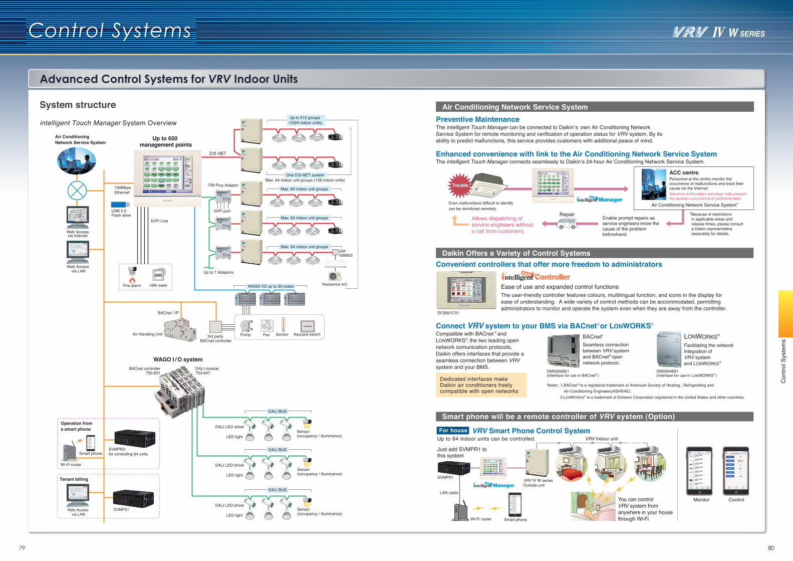
03 048079
Control Systems
Advanced Control Systems for VRV Indoor Units
System structure
intelligent Touch Manager System Overview
Pump Fan Sensor Keycard switch
Web Access via Internet
Web Access via LAN
Web Access via LAN
100Mbps Ethernet
Fire alarm
Di/Pi port
kWh meter WAGO I/O up to 30 nodes
Up to 512 groups (1024 indoor units)
Max. 64 indoor unit groups
One D -NET systemMax. 64 indoor unit groups (128 indoor units)
Max. 64 indoor unit groups
Max. 64 indoor unit groups
DALI BUS
USB 2.0 Flash drive
iTM Plus Adaptor
Up to 7 Adaptors
Up to 650 management points
Di/Pi Line
BACnet / IP
3rd party BACnet controller
DALI module753-647
Air Handling Unit
Air Conditioning Network Service System
KRP928BB2S
Residential A/C
WAGO I / O systemBACnet controller
750-831
LED light
DALI LED driverSensor(occupancy / illuminance)
DALI BUS
LED light
DALI LED driver
DALI BUS
LED light
DALI LED driverSVMPS1
SVMPR2: for controlling 64 unitsSmart phone
Wi-Fi router
Operation from a smart phone
Tenant billing
Sensor(occupancy / illuminance)
Sensor(occupancy / illuminance)
Preventive Maintenance
Enhanced convenience with link to the Air Conditioning Network Service System
Air Conditioning Network Service System*
ACC centrePersonnel at the centre monitor the occurrence of malfunctions and track their cause via the Internet.
Enable prompt repairs as service engineers know the cause of the problem beforehand.
Advance malfunction warnings help prevent the sudden occurrence of problems later.
The intelligent Touch Manager connects seamlessly to Daikin’s 24-hour Air Conditioning Network Service System.
Trouble
The intelligent Touch Manager can be connected to Daikin’s own Air Conditioning Network Service System for remote monitoring and verification of operation status for VRV system. By its ability to predict malfunctions, this service provides customers with additional peace of mind.
Even malfunctions difficult to identify can be monitored remotely.
Air Conditioning Network Service System
The user-friendly controller features colours, multilingual function, and icons in the display for ease of understanding. A wide variety of control methods can be accommodated, permitting administrators to monitor and operate the system even when they are away from the controller.
Compatible with BACnet ® and LONWORKS®, the two leading open network comunication protocols, Daikin offers interfaces that provide a seamless connection between VRV system and your BMS.
Seamless connection between VRV system and BACnet® open network protocol.
Facilitating the network integration of VRV systemand LONWORKS®
BACnet® LONWORKS®
Ease of use and expanded control functions
DMS502B51(Interface for use in BACnet® )
DMS504B51(Interface for use in LONWORKS® )
Daikin Offers a Variety of Control SystemsConvenient controllers that offer more freedom to administrators
Connect VRV system to your BMS via BACnet® or LONWORKS®
DCS601C51
RepairAllows dispatching of service engineers without a call from customers.
*Because of restrictions in applicable areas and release times, please consult a Daikin representative separately for details.
Dedicated interfaces make Daikin air conditioners freely compatible with open networks
1.BACnet ® is a registered trademark of American Society of Heating , Refrigerating and Air-Conditioning Engineers(ASHRAE).
2.LONWORKS® is a trademark of Echelon Corporation registered in the United States and other countries.
Notes:
Monitor Control
Smart phone will be a remote controller of VRV system (Option)
VRV Indoor unit
You can control VRV system from anywhere in your house through Wi-Fi
LAN cable
SVMPR1
Wi-Fi router Smart phone
VRV IV W series Outside unit
Just add SVMPR1 to this system
For houseUp to 64 indoor units can be controlled.
VRV Smart Phone Control System
Con
trol S
yste
ms
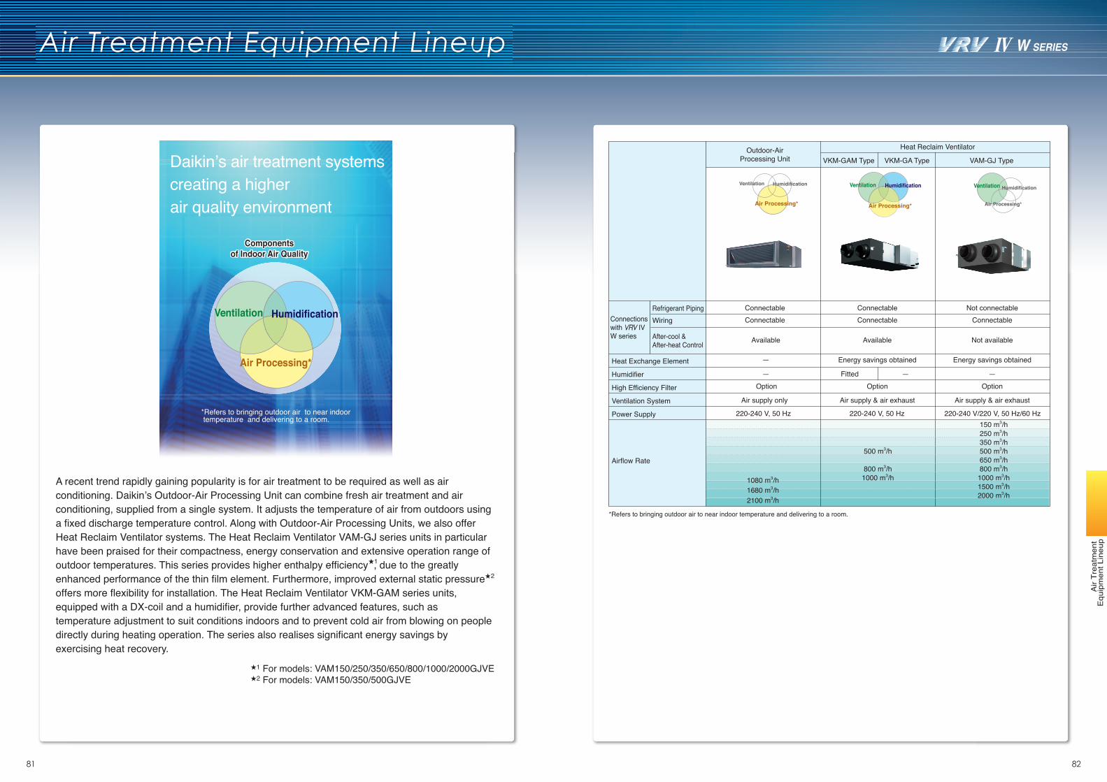
81 82
Air Treatment Equipment Lineup
Air
Trea
tmen
t E
quip
men
t Lin
eup
For models: VAM150/250/350/650/800/1000/2000GJVEFor models: VAM150/350/500GJVE2
1
1
A recent trend rapidly gaining popularity is for air treatment to be required as well as air conditioning. Daikin’s Outdoor-Air Processing Unit can combine fresh air treatment and air conditioning, supplied from a single system. It adjusts the temperature of air from outdoors using a fixed discharge temperature control. Along with Outdoor-Air Processing Units, we also offer Heat Reclaim Ventilator systems. The Heat Reclaim Ventilator VAM-GJ series units in particular have been praised for their compactness, energy conservation and extensive operation range of outdoor temperatures. This series provides higher enthalpy efficiency , due to the greatly enhanced performance of the thin film element. Furthermore, improved external static pressure offers more flexibility for installation. The Heat Reclaim Ventilator VKM-GAM series units, equipped with a DX-coil and a humidifier, provide further advanced features, such as temperature adjustment to suit conditions indoors and to prevent cold air from blowing on people directly during heating operation. The series also realises significant energy savings by exercising heat recovery.
2
Ventilation Humidification
Air Processing*
Ventilation Ventilation Humidification
Air Processing*
Humidification
Air Processing*
Outdoor-AirProcessing Unit VKM-GAM Type VKM-GA Type VAM-GJ Type
Refrigerant Piping Connectable Not connectableWiring Connectable Connectable
After-cool &After-heat Control Available Not available
—
— — —
Energy savings obtained
FittedOption Option
Air supply only Air supply & air exhaust
220-240 V, 50 Hz 220-240 V/220 V, 50 Hz/60 Hz
Heat Reclaim Ventilator
Connectionswith VRV IVW series
ConnectableConnectable
Available
Heat Exchange Element Energy savings obtained
Humidifier
High Efficiency Filter Option
Ventilation System Air supply & air exhaust
Power Supply 220-240 V, 50 Hz
Airflow Rate
150 m3/h250 m3/h350 m3/h500 m3/h650 m3/h800 m3/h
1080 m3/h 1000 m3/h
500 m3/h
800 m3/h1000 m3/h
1680 m3/h 1500 m3/h
2100 m3/h 2000 m3/h
*Refers to bringing outdoor air to near indoor temperature and delivering to a room.
Daikin’s air treatment systemscreating a higherair quality environment
Componentsof Indoor Air Quality
Componentsof Indoor Air Quality
*Refers to bringing outdoor air to near indoor temperature and delivering to a room.
Ventilation Humidification
Air Processing*
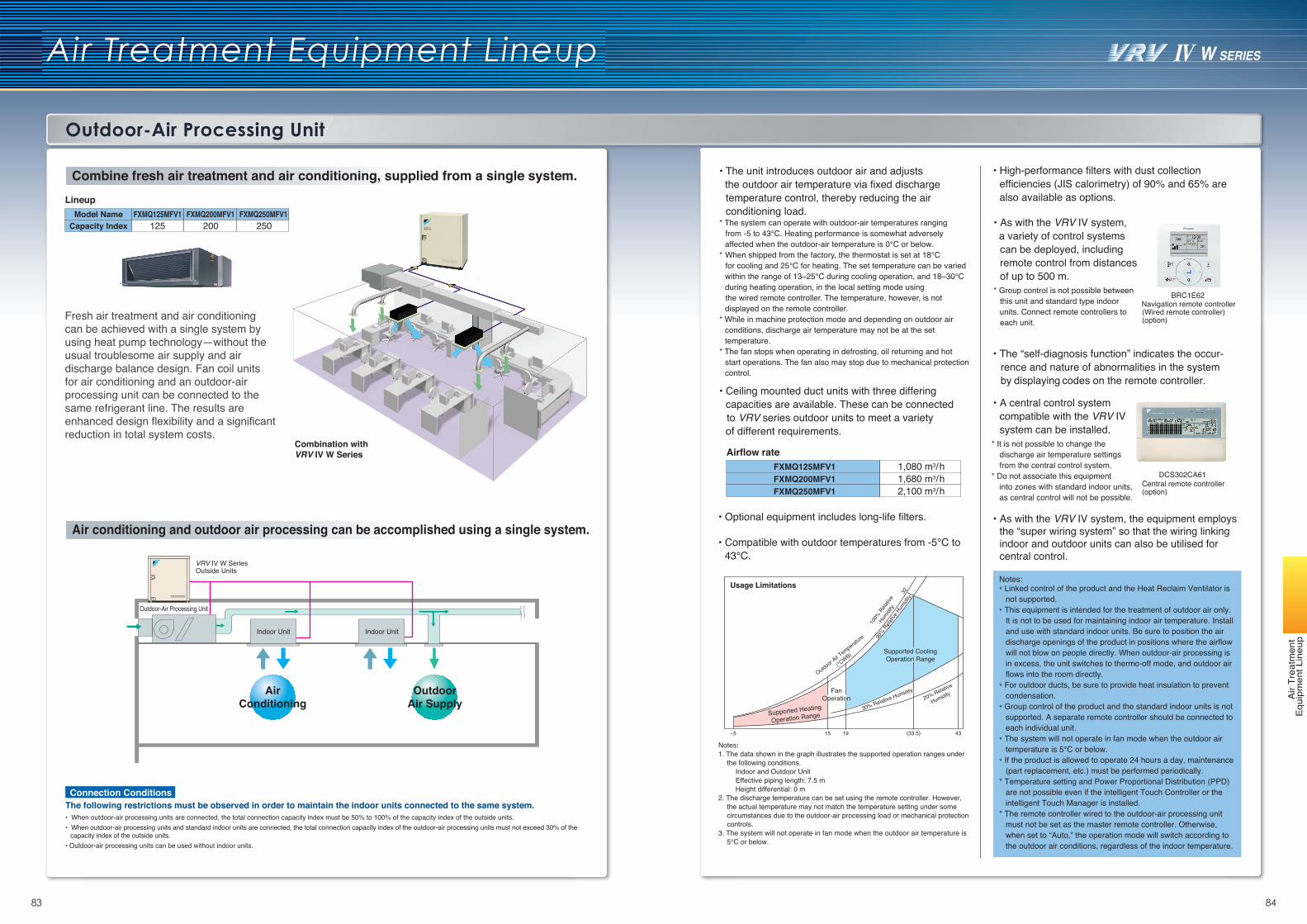
83 84
Air Treatment Equipment Lineup
Outdoor-Air Processing Unit
Air
Trea
tmen
t E
quip
men
t Lin
eup
Lineup
Fresh air treatment and air conditioning can be achieved with a single system by using heat pump technology—without the usual troublesome air supply and air discharge balance design. Fan coil units for air conditioning and an outdoor-air processing unit can be connected to the same refrigerant line. The results are enhanced design flexibility and a significant reduction in total system costs.
The following restrictions must be observed in order to maintain the indoor units connected to the same system.Connection Conditions
• When outdoor-air processing units are connected, the total connection capacity index must be 50% to 100% of the capacity index of the outside units. • When outdoor-air processing units and standard indoor units are connected, the total connection capacity index of the outdoor-air processing units must not exceed 30% of the
capacity index of the outside units.• Outdoor-air processing units can be used without indoor units.
• The unit introduces outdoor air and adjusts the outdoor air temperature via fixed discharge
temperature control, thereby reducing the air conditioning load.
* The system can operate with outdoor-air temperatures ranging from -5 to 43℃. Heating performance is somewhat adversely affected when the outdoor-air temperature is 0℃ or below.
* When shipped from the factory, the thermostat is set at 18℃ for cooling and 25℃ for heating. The set temperature can be varied within the range of 13–25℃ during cooling operation, and 18–30℃ during heating operation, in the local setting mode using
the wired remote controller. The temperature, however, is not displayed on the remote controller.
* While in machine protection mode and depending on outdoor air conditions, discharge air temperature may not be at the set temperature.
* The fan stops when operating in defrosting, oil returning and hot start operations. The fan also may stop due to mechanical protection control.
• Ceiling mounted duct units with three differing capacities are available. These can be connectedto VRV series outdoor units to meet a varietyof different requirements.
Airflow rate
• The “self-diagnosis function” indicates the occur-rence and nature of abnormalities in the systemby displaying codes on the remote controller.
• Optional equipment includes long-life filters.
• Compatible with outdoor temperatures from -5℃ to 43℃.
Notes:1. The data shown in the graph illustrates the supported operation ranges under
the following conditions.Indoor and Outdoor UnitEffective piping length: 7.5 mHeight differential: 0 m
2. The discharge temperature can be set using the remote controller. However, the actual temperature may not match the temperature setting under some circumstances due to the outdoor-air processing load or mechanical protection controls.
3. The system will not operate in fan mode when the outdoor air temperature is 5℃ or below.
• High-performance filters with dust collection efficiencies (JIS calorimetry) of 90% and 65% are also available as options.
• As with the VRV Ⅳ system,a variety of control systems can be deployed, including remote control from distances of up to 500 m.
* Group control is not possible between this unit and standard type indoor
units. Connect remote controllers to each unit.
Navigation remote controller(Wired remote controller)(option)
• A central control system compatible with the VRV Ⅳ system can be installed.
* It is not possible to change the discharge air temperature settings from the central control system.
* Do not associate this equipment into zones with standard indoor units,
as central control will not be possible.Central remote controller (option)
• As with the VRV Ⅳ system, the equipment employs the “super wiring system” so that the wiring linking indoor and outdoor units can also be utilised for central control.
DCS302CA61
BRC1E62
Notes:* Linked control of the product and the Heat Reclaim Ventilator is
not supported.* This equipment is intended for the treatment of outdoor air only.
It is not to be used for maintaining indoor air temperature. Install and use with standard indoor units. Be sure to position the air discharge openings of the product in positions where the airflow will not blow on people directly. When outdoor-air processing is in excess, the unit switches to thermo-off mode, and outdoor air flows into the room directly.
* For outdoor ducts, be sure to provide heat insulation to prevent condensation.
* Group control of the product and the standard indoor units is not supported. A separate remote controller should be connected to each individual unit.
* The system will not operate in fan mode when the outdoor air temperature is 5℃ or below.
* If the product is allowed to operate 24 hours a day, maintenance (part replacement, etc.) must be performed periodically.
* Temperature setting and Power Proportional Distribution (PPD) are not possible even if the intelligent Touch Controller or the intelligent Touch Manager is installed.
* The remote controller wired to the outdoor-air processing unit must not be set as the master remote controller. Otherwise, when set to “Auto,” the operation mode will switch according to the outdoor air conditions, regardless of the indoor temperature.
–5 15 19 (33.5) 43
32
Usage Limitations
Supported Heating
Operation Range
FanOperation
Supported CoolingOperation Range
Outdoor Air T
emperature
(℃WB)
100%
Rela
tive
Humidi
ty
90% R
elativ
e Hum
idity
20% Relative
Humidity
30% Relative Humidity
Outdoor-Air Processing Unit
Indoor Unit Indoor Unit
AirConditioning
OutdoorAir Supply
Combine fresh air treatment and air conditioning, supplied from a single system.
Air conditioning and outdoor air processing can be accomplished using a single system.
FXMQ125MFV1Model NameCapacity Index
FXMQ200MFV1 FXMQ250MFV1125 200 250
2,100 m3/h1,680 m3/h1,080 m3/h
FXMQ250MFV1FXMQ200MFV1FXMQ125MFV1
VRV Ⅳ W SeriesOutside Units
Combination with VRV Ⅳ W Series
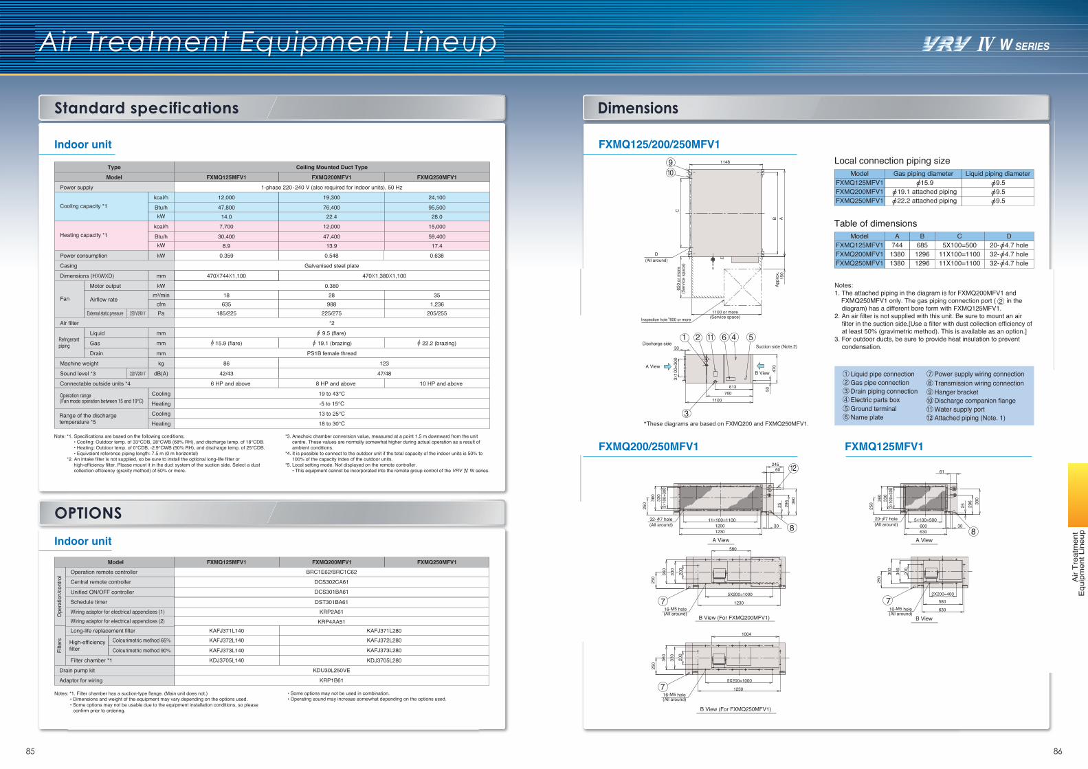
Dimensions
Air Treatment Equipment Lineup
85 86
Standard specifications
Air
Trea
tmen
t E
quip
men
t Lin
eup
FXMQ125/200/250MFV1
FXMQ200/250MFV1 FXMQ125MFV1
*These diagrams are based on FXMQ200 and FXMQ250MFV1.
FXMQ200MFV1FXMQ125MFV1
Model Gas piping diameter 15.9
19.1 attached piping
Liquid piping diameter 9.5 9.5
Local connection piping size
1 Liquid pipe connection2 Gas pipe connection3 Drain piping connection4 Electric parts box5 Ground terminal6 Name plate
7 Power supply wiring connection8 Transmission wiring connection9 Hanger bracket
10 Discharge companion flange11 Water supply port12 Attached piping (Note. 1)
FXMQ250MFV1 22.2 attached piping 9.5
Table of dimensions
FXMQ200MFV1FXMQ125MFV1
Model A B C744 685 5X100=5001380 1296 11X100=1100
D20- 4.7 hole32- 4.7 hole
FXMQ250MFV1 1380 1296 11X100=1100 32- 4.7 hole(All around)
650
or m
ore
(Ser
vice
spa
ce)
Inspection hole 600 or more
1148
1100 or more(Service space)
Appr
ox.
150
910
C
AB
D
A View
3X10
0=30
0
5047
0
Suction side (Note.2)
7601100
613
2 51 4611Discharge side
30
3
B View
360
250 3X10
0=30
033
0
B View
390
30
296
25
630
5X100=500600
20- 7 hole(All around)
8
360
200
250
346
10-M5 hole(All around)
2X200=400580
6307
61
Notes:1. The attached piping in the diagram is for FXMQ200MFV1 and FXMQ250MFV1 only. The gas piping connection port ( in the
diagram) has a different bore form with FXMQ125MFV1. 2. An air filter is not supplied with this unit. Be sure to mount an air
filter in the suction side.[Use a filter with dust collection efficiency of at least 50% (gravimetric method). This is available as an option.]
3. For outdoor ducts, be sure to provide heat insulation to prevent condensation.
A View A View1230
11X100=11001200
245
390
30
60
296
25
360
250 3X10
0=30
033
0
32- 7 hole(All around)
12
8
1004
5X200=1000
123016-M5 hole(All around)
360
200
250
330
B View (For FXMQ250MFV1)
7
5X200=1000
1230
580
360
200
250
330
16-M5 hole(All around)
B View (For FXMQ200MFV1)
7
2
Indoor unit
Indoor unitModel
Operation remote controller
FXMQ125MFV1 FXMQ200MFV1 FXMQ250MFV1BRC1E62/BRC1C62
DCS302CA61
DCS301BA61
DST301BA61KRP2A61
KRP4AA51KAFJ371L140 KAFJ371L280KAFJ372L140 KAFJ372L280
KAFJ373L140 KAFJ373L280
KDJ3705L140 KDJ3705L280
Ope
ratio
n/co
ntro
lFi
lters
Central remote controller
Long-life replacement filterColourimetric method 65%
Colourimetric method 90%High-efficiency filter
Filter chamber *1
KRP1B61Adaptor for wiring
KDU30L250VEDrain pump kit
Unified ON/OFF controller
Schedule timer
Wiring adaptor for electrical appendices (1)Wiring adaptor for electrical appendices (2)
Notes: *1. Filter chamber has a suction-type flange. (Main unit does not.) • Dimensions and weight of the equipment may vary depending on the options used. • Some options may not be usable due to the equipment installation conditions, so please confirm prior to ordering.
• Some options may not be used in combination. • Operating sound may increase somewhat depending on the options used.
OPTIONS
Type Ceiling Mounted Duct Type
Model
Power supply
Cooling capacity *1
Machine weight
Sound level *3
kcal/h
FXMQ125MFV1 FXMQ200MFV1 FXMQ250MFV1
1-phase 220-240 V (also required for indoor units), 50 Hz
12,000 19,300 24,100
0.38018 28 35
185/225 225/275 205/255
9.5 (flare)
15.9 (flare) 19.1 (brazing) 22.2 (brazing)
PS1B female thread
86 123
42/43 47/48
8 HP and above6 HP and above 10 HP and above
Dimensions (HXWXD) 470X744X1,100 470X1,380X1,100
Btu/h 47,800 76,400 95,500kW 14.0 22.4 28.0
Heating capacity *1kcal/h 7,700 12,000 15,000
Btu/h 30,400 47,400 59,400kW 8.9 13.9 17.4
mm
Casing Galvanised steel plate
kWm3/min
Pa
Drain
mm
mm
mm
kg
dB(A)
Motor output
Airflow rate635 988 1,236cfm
Fan
Refrigerantpiping
External static pressure
Liquid
Gas
Connectable outside units *4
-5 to 15℃
19 to 43℃Cooling
Heating
Cooling
Heating Range of the discharge temperature *5
13 to 25℃
18 to 30℃
Power consumption 0.359 0.6380.548kW
Note: *1. Specifications are based on the following conditions; • Cooling: Outdoor temp. of 33℃DB, 28℃WB (68% RH), and discharge temp. of 18℃DB. • Heating: Outdoor temp. of 0℃DB, -2.9℃WB (50% RH), and discharge temp. of 25℃DB. • Equivalent reference piping length: 7.5 m (0 m horizontal) *2. An intake filter is not supplied, so be sure to install the optional long-life filter or high-efficiency filter. Please mount it in the duct system of the suction side. Select a dust collection efficiency (gravity method) of 50% or more.
220 V/240 V
220 V/240 V
Air filter *2
*3. Anechoic chamber conversion value, measured at a point 1.5 m downward from the unit centre. These values are normally somewhat higher during actual operation as a result of ambient conditions. *4. It is possible to connect to the outdoor unit if the total capacity of the indoor units is 50% to 100% of the capacity index of the outdoor units.
*5. Local setting mode. Not displayed on the remote controller. • This equipment cannot be incorporated into the remote group control of the VRV W series.
Operation range (Fan mode operation between 15 and 19℃)
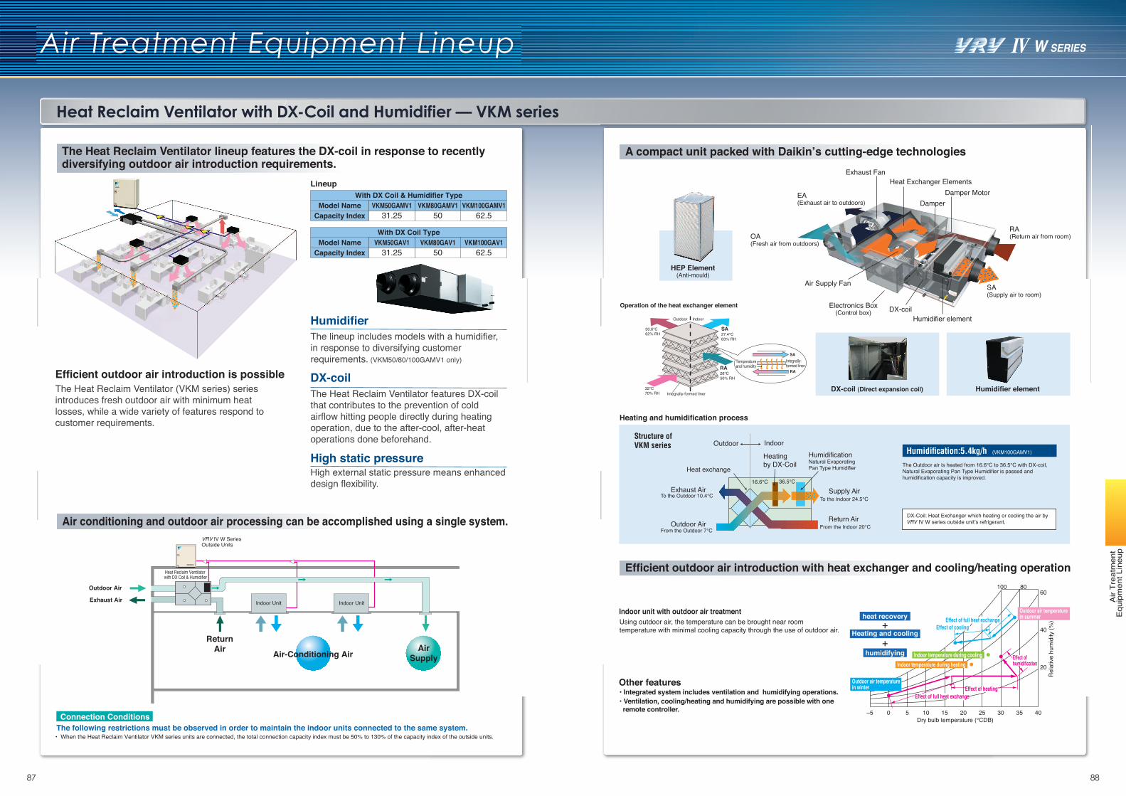
87 88
Heat Reclaim Ventilator with DX-Coil and Humidifier — VKM series
Air Treatment Equipment Lineup
Air
Trea
tmen
t E
quip
men
t Lin
eup
The Heat Reclaim Ventilator (VKM series) series introduces fresh outdoor air with minimum heat losses, while a wide variety of features respond to customer requirements.
Efficient outdoor air introduction is possible
Humidifier
DX-coil
High static pressure
The lineup includes models with a humidifier, in response to diversifying customer requirements. (VKM50/80/100GAMV1 only)
The Heat Reclaim Ventilator features DX-coil that contributes to the prevention of cold airflow hitting people directly during heating operation, due to the after-cool, after-heat operations done beforehand.
High external static pressure means enhanced design flexibility.
Model Name
LineupWith DX Coil & Humidifier Type
Capacity Index 62.5VKM100GAMV1
50VKM80GAMV1
31.25VKM50GAMV1
Model NameWith DX Coil Type
Capacity Index 62.5VKM100GAV1
50VKM80GAV1
31.25VKM50GAV1
The following restrictions must be observed in order to maintain the indoor units connected to the same system.Connection Conditions
• When the Heat Reclaim Ventilator VKM series units are connected, the total connection capacity index must be 50% to 130% of the capacity index of the outside units.
Humidifier elementDX-coil (Direct expansion coil)
OA(Fresh air from outdoors)
SA(Supply air to room)
EA(Exhaust air to outdoors)
RA(Return air from room)
Air Supply Fan
Electronics Box(Control box)
Exhaust FanHeat Exchanger Elements
DamperDamper Motor
DX-coilHumidifier element
30.6℃62% RH 27.4℃
63% RH
26℃50% RH
Integrally-formed liner
Indoor
SA
RA
Outdoor
32℃70% RH
Integrally-formed liner
Temperatureand humidity
RA
SA
Operation of the heat exchanger element
HEP Element(Anti-mould)
• Integrated system includes ventilation and humidifying operations.• Ventilation, cooling/heating and humidifying are possible with one remote controller.
Indoor unit with outdoor air treatment
Heating and cooling+
+
heat recovery
humidifying
–5 0 5 10 15 20Dry bulb temperature (℃DB)
25 30 35 40
Rel
ativ
e hu
mid
ity (%
)
20
40
6080100
Effect of full heat exchangeEffect of full heat exchange
Effect of full heat exchangeEffect of cooling
Outdoor air temperature in summer
Indoor temperature during heatingIndoor temperature during cooling
Outdoor air temperature in winter Effect of heatingEffect of heating
Effect of humidification
Using outdoor air, the temperature can be brought near room temperature with minimal cooling capacity through the use of outdoor air.
Other features
Structure of VKM series
The Outdoor air is heated from 16.6℃ to 36.5℃ with DX-coil, Natural Evaporating Pan Type Humidifier is passed and humidification capacity is improved.
Heating and humidification process
Heatingby DX-Coil
Heat exchange
To the Outdoor 10.4℃
Outdoor AirFrom the Outdoor 7℃ From the Indoor 20℃
Return Air
To the Indoor 24.5℃Supply Air
HumidificationNatural Evaporating Pan Type Humidifier
Exhaust Air36.5℃16.6℃
Outdoor Indoor
DX-Coil: Heat Exchanger which heating or cooling the air by VRV IV W series outside unit’s refrigerant.
Humidification:5.4kg/h (VKM100GAMV1)
Efficient outdoor air introduction with heat exchanger and cooling/heating operation
A compact unit packed with Daikin’s cutting-edge technologiesThe Heat Reclaim Ventilator lineup features the DX-coil in response to recently diversifying outdoor air introduction requirements.
Air conditioning and outdoor air processing can be accomplished using a single system.
Indoor Unit Indoor Unit
VRV Ⅳ W Series Outside Units
Air-Conditioning AirAir
Supply
ReturnAir
Heat Reclaim Ventilator with DX Coil & Humidifier
Outdoor Air
Exhaust Air
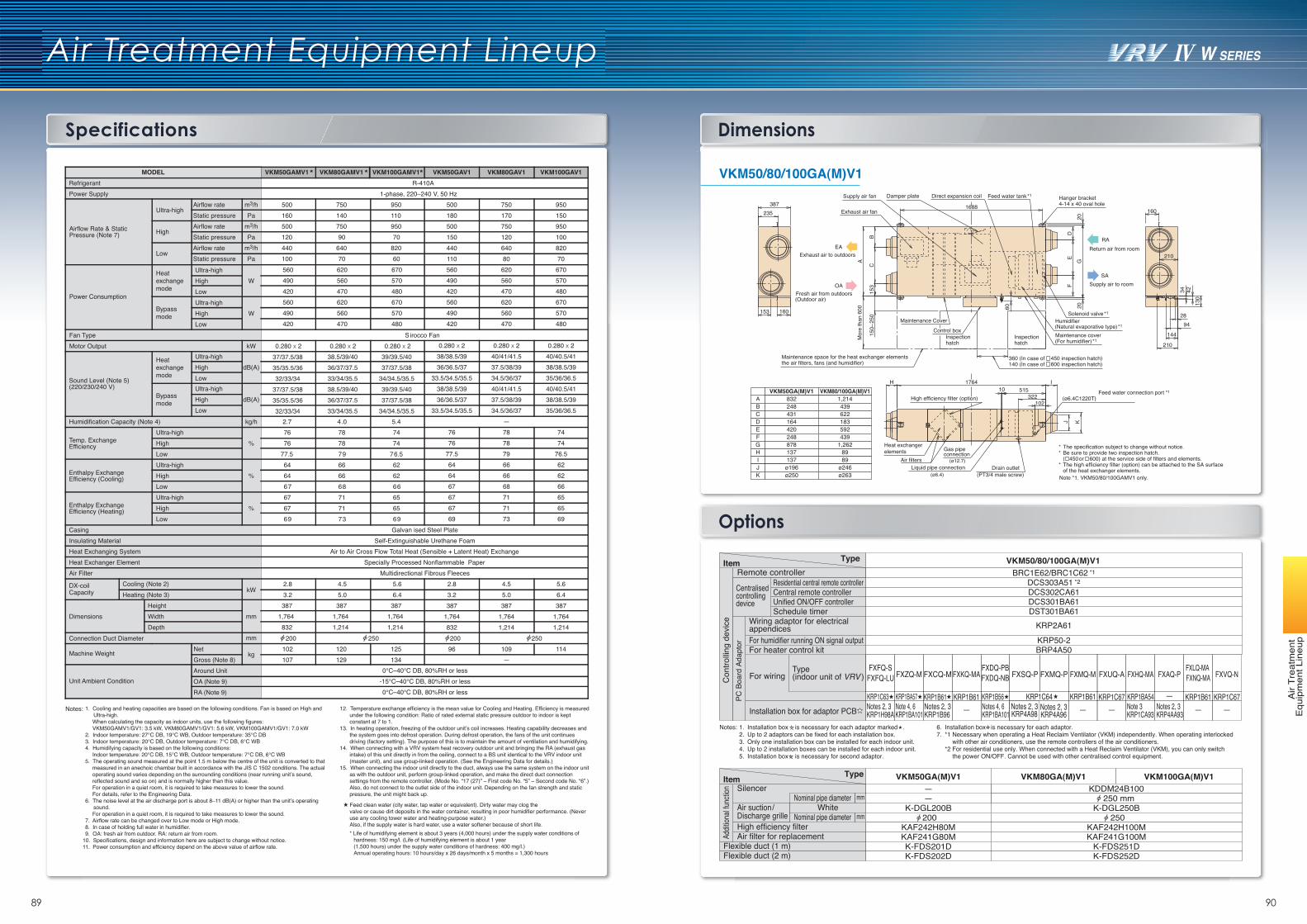
89 90
Air Treatment Equipment Lineup
Air
Trea
tmen
t E
quip
men
t Lin
eup
Specifications Dimensions
Options
Central remote controller
Remote controller
Wiring adaptor for electrical appendices
Unified ON/OFF controllerSchedule timer
For humidifier running ON signal outputFor heater control kit
BRC1E62/BRC1C62 *1
DCS302CA61Residential central remote controller DCS303A51 *2
DCS301BA61DST301BA61
KRP2A61KRP50-2BRP4A50
Con
trollin
g de
vice
PC B
oard
Ada
ptor
Centralised controlling device
Notes: 1.2.3.4.5.
Installation box is necessary for each adaptor marked . Up to 2 adaptors can be fixed for each installation box.Only one installation box can be installed for each indoor unit.Up to 2 installation boxes can be installed for each indoor unit.Installation box is necessary for second adaptor.
6.7.
Installation box is necessary for each adaptor.*1 Necessary when operating a Heat Reclaim Ventilator (VKM) independently. When operating interlocked
with other air conditioners, use the remote controllers of the air conditioners.*2 For residential use only. When connected with a Heat Reclaim Ventilator (VKM), you can only switch
the power ON/OFF. Cannot be used with other centralised control equipment.
VKM50/80/100GA(M)V1
Silencer
Air suction/Discharge grilleHigh efficiency filter
Flexible duct (1 m)Flexible duct (2 m)
VKM50GA(M)V1 VKM80GA(M)V1 VKM100GA(M)V1KDDM24B100
250 mmK-DGL200B
—K-DGL250B
200 250KAF242H80M KAF242H100M
Air filter for replacement KAF241G80M KAF241G100MK-FDS201D K-FDS251DK-FDS202D K-FDS252D
—
White
Addit
ional
functi
on
Nominal pipe diameter
Nominal pipe diameter
mm
mm
For wiring
Installation box for adaptor PCB
Type (indoor unit of VRV )
VKM50/80/100GA(M)V1
4-14 x 40 oval holeHanger bracket
Supply air to roomSA
Return air from roomRA
(For humidifier) *1Maintenance cover(Natural evaporative type) *1Humidifier
Solenoid valve *1
EA
(Outdoor air)Fresh air from outdoors
Exhaust air to outdoors
OA
Control box
Maintenance Cover
Mor
e th
an 6
00
hatchInspection
hatchInspection
the air filters, fans (and humidifier)Maintenance space for the heat exchanger elements
140 (In case of 600 inspection hatch)360 (In case of 450 inspection hatch)
High efficiency filter (option)
Liquid pipe connectionAir filters
(PT3/4 male screw)
(ø12.7)
(ø6.4)
connectionGas pipe
Heat exchanger elements
Drain outlet
(ø6.4C1220T)Feed water connection port *1
of the heat exchanger elements.Note *1. VKM50/80/100GAMV1 only.
The high efficiency filter (option) can be attached to the SA surface*( 450 or 600) at the service side of filters and elements.Be sure to provide two inspection hatch.*The specification subject to change without notice.*
210
B
42
Supply air fan
160
250
150–
153
C
Damper plate
210
GK
1688387235
60
10I
20
153 F
Feed water tank *1
D
130
E
160
144
A
28
102
Direct expansion coil
34
H
J
322
20
1764515
Exhaust air fan
94
VKM50GA(M)V1 VKM80/100GA(M)V1832A 1,214248B 439431C 622164D 183420E 592248F 439878G 1,262137H 89137I 89
ø196J ø246ø250K ø263
kg/h
%
%
%
kW
mm
NetGross (Note 8)
kg
Around UnitOA (Note 9)RA (Note 9)
mm
MODELRefrigerantPower Supply
Airflow rate m3/hStatic pressure PaAirflow rate m3/hStatic pressure Pa
Heat exchange mode
Bypass mode
Airflow rate m3/hStatic pressure Pa
kWUltra-highHigh dB(A)LowUltra-highHigh dB(A)Low
Ultra-highHigh WLow
Ultra-highHigh WLow
Airflow Rate & Static Pressure (Note 7)
Ultra-high
High
Low
Heat exchange mode
Bypass mode
Fan TypeMotor Output
Sound Level (Note 5)(220/230/240 V)
Humidification Capacity (Note 4)
Temp. Exchange Efficiency
Ultra-highHighLow
Enthalpy Exchange Efficiency (Cooling)
Ultra-highHighLow
Enthalpy Exchange Efficiency (Heating)
Ultra-highHighLow
CasingInsulating MaterialHeat Exchanging SystemHeat Exchanger ElementAir Filter
DX-coilCapacity
Cooling (Note 2)Heating (Note 3)
HeightWidthDepth
Dimensions
Machine Weight
Unit Ambient Condition
Connection Duct Diameter
Power Consumption
Notes: 1. Cooling and heating capacities are based on the following conditions. Fan is based on High and Ultra-high.When calculating the capacity as indoor units, use the following figures:VKM50GAMV1/GV1: 3.5 kW, VKM80GAMV1/GV1: 5.6 kW, VKM100GAMV1/GV1: 7.0 kW
2. Indoor temperature: 27℃ DB, 19℃ WB, Outdoor temperature: 35℃ DB3. Indoor temperature: 20℃ DB, Outdoor temperature: 7℃ DB, 6℃ WB4. Humidifying capacity is based on the following conditions:
Indoor temperature: 20℃ DB, 15℃ WB, Outdoor temperature: 7℃ DB, 6℃ WB5. The operating sound measured at the point 1.5 m below the centre of the unit is converted to that
measured in an anechoic chambar built in accordance with the JIS C 1502 conditions. The actual operating sound varies depending on the surrounding conditions (near running unit’s sound, reflected sound and so on) and is normally higher than this value.For operation in a quiet room, it is required to take measures to lower the sound. For details, refer to the Engineering Data.
6. The noise level at the air discharge port is about 8–11 dB(A) or higher than the unit’s operating sound.For operation in a quiet room, it is required to take measures to lower the sound.
7. Airflow rate can be changed over to Low mode or High mode.8. In case of holding full water in humidifier.9. OA: fresh air from outdoor. RA: return air from room.
10. Specifications, design and information here are subject to change without notice.11. Power consumption and efficiency depend on the above value of airflow rate.
12. Temperature exchange efficiency is the mean value for Cooling and Heating. Efficiency is measured under the following condition: Ratio of rated external static pressure outdoor to indoor is kept constant at 7 to 1.
13. In heating operation, freezing of the outdoor unit’s coil increases. Heating capability decreases and the system goes into defrost operation. During defrost operation, the fans of the unit continues driving (factory setting). The purpose of this is to maintain the amount of ventilation and humidifying.
14. When connecting with a VRV system heat recovery outdoor unit and bringing the RA (exhaust gas intake) of this unit directly in from the ceiling, connect to a BS unit identical to the VRV indoor unit (master unit), and use group-linked operation. (See the Engineering Data for details.)
15. When connecting the indoor unit directly to the duct, always use the same system on the indoor unit as with the outdoor unit, perform group-linked operation, and make the direct duct connection settings from the remote controller. (Mode No. “17 (27)” – First code No. “5” – Second code No. “6”.) Also, do not connect to the outlet side of the indoor unit. Depending on the fan strength and static pressure, the unit might back up.
Feed clean water (city water, tap water or equivalent). Dirty water may clog the valve or cause dirt deposits in the water container, resulting in poor humidifier performance. (Never use any cooling tower water and heating-purpose water.)Also, if the supply water is hard water, use a water softener because of short life.* Life of humidifying element is about 3 years (4,000 hours) under the supply water conditions of
hardness: 150 mg/l. (Life of humidifying element is about 1 year (1,500 hours) under the supply water conditions of hardness: 400 mg/l.)Annual operating hours: 10 hours/day x 26 days/month x 5 months = 1,300 hours
VKM50GAMV1 VKM80GAMV1 VKM100GAMV1 VKM50GAV1 VKM80GAV1 VKM100GAV1R-410A
1-phase, 220–240 V, 50 Hz500 750 950160 140 110500 750 950120 90 70440 640 820100 70 60560490420560490420
620560470620560470
670570480670570480
Sirocco Fan0.280 x 2 0.280 x 2 0.280 x 2
37/37.5/3835/35.5/3632/33/34
37/37.5/3835/35.5/3632/33/34
38.5/39/4036/37/37.533/34/35.538.5/39/4036/37/37.533/34/35.5
39/39.5/4037/37.5/38
34/34.5/35.539/39.5/4037/37.5/38
34/34.5/35.52.7 4.0 5.476 78 7476 78 74
77.5 79 76.564 66 6264 66 6267 68 6667 71 6567 71 6569 73 69
Galvan ised Steel PlateSelf-Extinguishable Urethane Foam
Air to Air Cross Flow Total Heat (Sensible + Latent Heat) ExchangeSpecially Processed Nonflammable Paper
Multidirectional Fibrous Fleeces
0℃–40℃ DB, 80%RH or less-15℃–40℃ DB, 80%RH or less0℃–40℃ DB, 80%RH or less
387 387 3871,764 1,764 1,764
832 1,214 1,214
500180500150440110560490420560490420
0.280 x 238/38.5/3936/36.5/37
33.5/34.5/35.538/38.5/3936/36.5/37
33.5/34.5/35.5
7676
77.5646467676769
75017075012064080
620560470620560470
0.280 x 240/41/41.537.5/38/3934.5/36/3740/41/41.537.5/38/3934.5/36/37
—787879666668717173
95015095010082070
670570480670570480
0.280 x 240/40.5/4138/38.5/3935/36/36.540/40.5/4138/38.5/3935/36/36.5
7474
76.5626266656569
2.83.2387
1,764832
96
2.83.2
4.55.0
5.66.4
4.55.0387
1,7641,214
109—
5.66.4387
1,7641,214
114102107
120129
125134
200 250 200 250
Item Type
Item Type
FXFQ-SFXFQ-LU FXZQ-M FXCQ-M FXKQ-MA
FXDQ-PBFXDQ-NB FXMQ-P FXMQ-M FXHQ-MA FXAQ-P
FXLQ-MA FXNQ-MA
KRP1BA57KRP1C63 KRP1B61 KRP1B61 KRP1B56 KRP1B61 KRP1BA54 — KRP1B61Note 4, 6KRP1BA101
Notes 2, 3KRP1H98A
Notes 2, 3KRP1B96 —
FXUQ-A
KRP1C67—Notes 4, 6
KRP1BA101 — Note 3KRP1CA93
Notes 2, 3KRP4AA93 —
FXVQ-N
KRP1C67—
FXSQ-P
KRP1C64Notes 2, 3KRP4A96
Notes 2, 3KRP4A98
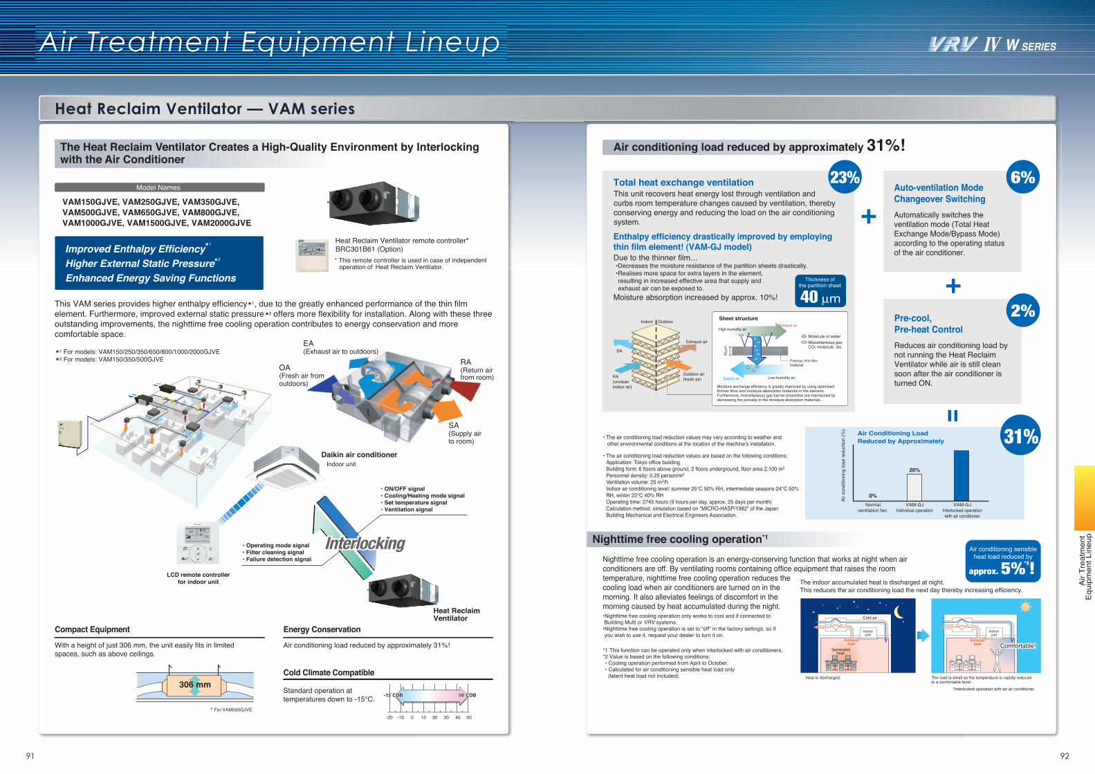
91 92
Heat Reclaim Ventilator — VAM series
Air Treatment Equipment Lineup
Air
Trea
tmen
t E
quip
men
t Lin
eup
The Heat Reclaim Ventilator Creates a High-Quality Environment by Interlocking with the Air Conditioner
306 mm
Energy Conservation
Air conditioning load reduced by approximately 31%!With a height of just 306 mm, the unit easily fits in limited spaces, such as above ceilings.
BRC301B61 (Option)
-20 -10 0 10 20 30 40 50
50˚CDB-15˚CDB 50˚CDB-15˚CDB
* For VAM500GJVE
VAM150GJVE, VAM250GJVE, VAM350GJVE, VAM500GJVE, VAM650GJVE, VAM800GJVE, VAM1000GJVE, VAM1500GJVE, VAM2000GJVE
Model Names
Indoor unitDaikin air conditioner
LCD remote controllerfor indoor unit
• Operating mode signal • Filter cleaning signal • Failure detection signal
• ON/OFF signal• Cooling/Heating mode signal• Set temperature signal• Ventilation signal
Heat Reclaim Ventilator
InterlockingInterlocking
Compact Equipment
Cold Climate Compatible
Standard operation at temperatures down to -15℃.
Improved Enthalpy Efficiency Higher External Static PressureEnhanced Energy Saving Functions
1
2
For models: VAM150/250/350/650/800/1000/2000GJVEFor models: VAM150/350/500GJVE2
1
2
1
OA(Fresh air fromoutdoors)
SA(Supply airto room)
EA(Exhaust air to outdoors)
RA(Return airfrom room)
Heat Reclaim Ventilator remote controller*
* This remote controller is used in case of independent operation of Heat Reclaim Ventilator.
Exhaustheat
Exhaustheat
The indoor accumulated heat is discharged at night.This reduces the air conditioning load the next day thereby increasing efficiency.
Indoorunit
Indoorunit
Cold air
Generatedheat
Heat is discharged. The load is small so the temperature is rapidly reducedto a comfortable level.
*Interlocked operation with an air conditioner
Comfortable!Comfortable!
This unit recovers heat energy lost through ventilation and curbs room temperature changes caused by ventilation, thereby conserving energy and reducing the load on the air conditioning system.
Molecule of waterMiscellaneous gas CO2 molecule, etc.
Sheet structureOutdoor
Exhaust air
SA
Indoor
RA(uncleanindoor air)
Outdoor air (fresh air)
Total heat exchange ventilation
Enthalpy efficiency drastically improved by employing thin film element! (VAM-GJ model)
Thickness ofthe partition sheet
Due to the thinner film…•Decreases the moisture resistance of the partition sheets drastically.•Realises more space for extra layers in the element, resulting in increased effective area that supply and exhaust air can be exposed to.
Moisture absorption increased by approx. 10%!
Moisture exchange efficiency is greatly improved by using optimised thinner films and moisture-absorption materials in the element. Furthermore, miscellaneous gas barrier properties are maintained by decreasing the porosity in the moisture-absorption materials.
Automatically switches the ventilation mode (Total Heat Exchange Mode/Bypass Mode) according to the operating status of the air conditioner.
Auto-ventilation ModeChangeover Switching
Reduces air conditioning load by not running the Heat Reclaim Ventilator while air is still clean soon after the air conditioner is turned ON.
Pre-cool,Pre-heat Control
Air conditioning sensibleheat load reduced by
approx. 5%*2!
23% 6%
2%
• The air conditioning load reduction values are based on the following conditions;Application: Tokyo office buildingBuilding form: 6 floors above ground, 2 floors underground, floor area 2,100 m2
Personnel density: 0.25 person/m2
Ventilation volume: 25 m3/hIndoor air conditioning level: summer 25℃ 50% RH, intermediate seasons 24℃ 50%RH, winter 22℃ 40% RHOperating time: 2745 hours (9 hours per day, approx. 25 days per month)Calculation method: simulation based on "MICRO-HASP/1982" of the JapanBuilding Mechanical and Electrical Engineers Association.
VAM-GJIndividual operation
Normalventilation fan
VAM-GJInterlocked operationwith air conditioner
Air c
ondi
tioni
ng lo
ad re
duct
ion
(%)
20%
0%
Air Conditioning LoadReduced by Approximately 31%• The air conditioning load reduction values may vary according to weather and
other environmental conditions at the location of the machine's installation.
Nighttime free cooling operation is an energy-conserving function that works at night when air conditioners are off. By ventilating rooms containing office equipment that raises the room temperature, nighttime free cooling operation reduces the cooling load when air conditioners are turned on in the morning. It also alleviates feelings of discomfort in the morning caused by heat accumulated during the night.•Nighttime free cooling operation only works to cool and if connected to Building Multi or VRV systems. •Nighttime free cooling operation is set to “off” in the factory settings, so if you wish to use it, request your dealer to turn it on.
*1 This function can be operated only when interlocked with air conditioners.*2 Value is based on the following conditions:• Cooling operation performed from April to October.• Calculated for air conditioning sensible heat load only (latent heat load not included).
High-humidity air
Low-humidity air
Precise, thin-filmmaterial
Exhaust air
Supply air
Nighttime free cooling operation*1
Air conditioning load reduced by approximately 31%!
This VAM series provides higher enthalpy efficiency , due to the greatly enhanced performance of the thin film element. Furthermore, improved external static pressure offers more flexibility for installation. Along with these three outstanding improvements, the nighttime free cooling operation contributes to energy conservation and more comfortable space.
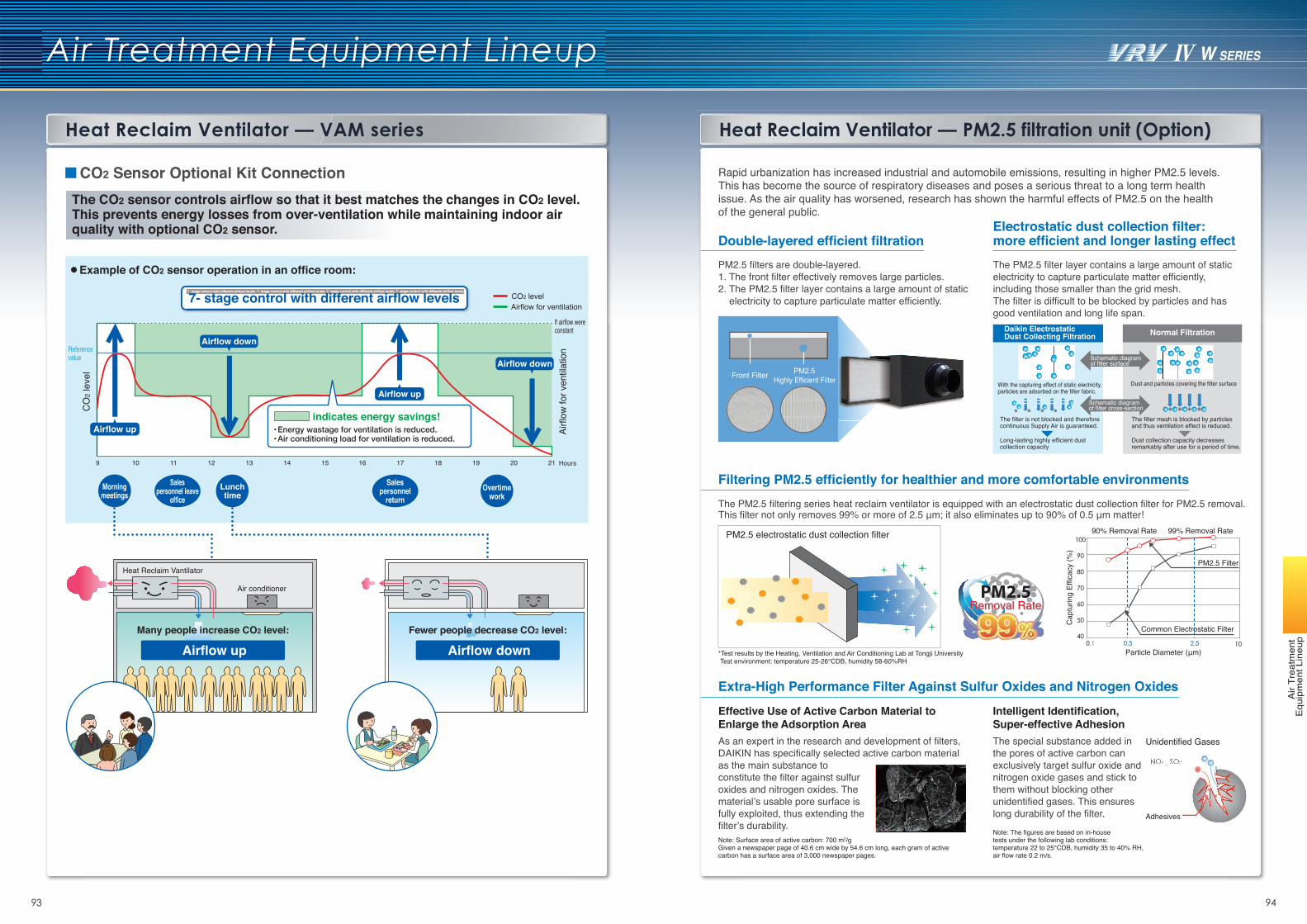
93 94
Air Treatment Equipment Lineup
Air
Trea
tmen
t E
quip
men
t Lin
eup
The CO2 sensor controls airflow so that it best matches the changes in CO2 level. This prevents energy losses from over-ventilation while maintaining indoor air quality with optional CO2 sensor.
CO2 Sensor Optional Kit Connection
Example of CO2 sensor operation in an office room:
9 10 11 12 13 14 15 16 17 18 19 20 21 Hours
Heat Reclaim Vantilator
Air conditioner
Airflow for ventilation
Energy wastage for ventilation is reduced.Air conditioning load for ventilation is reduced.
CO2 level
Reference value
CO
2 lev
el
Airfl
ow fo
r ven
tilat
ion
If airflow were constant
Airflow up
Airflow up
Airflow up
7- stage control with different airflow levels
indicates energy savings!
Many people increase CO2 level:
Airflow downFewer people decrease CO2 level:
Overtimework
Morningmeetings
Salespersonnel leave
office
Salespersonnel
returnLunchtime
Airflow down
Airflow down
Heat Reclaim Ventilator — VAM series Heat Reclaim Ventilator — PM2.5 filtration unit (Option)
Rapid urbanization has increased industrial and automobile emissions, resulting in higher PM2.5 levels. This has become the source of respiratory diseases and poses a serious threat to a long term health issue. As the air quality has worsened, research has shown the harmful effects of PM2.5 on the health of the general public.
Extra-High Performance Filter Against Sulfur Oxides and Nitrogen Oxides
Effective Use of Active Carbon Material to Enlarge the Adsorption Area
Note: Surface area of active carbon: 700 m2/gGiven a newspaper page of 40.6 cm wide by 54.6 cm long, each gram of active carbon has a surface area of 3,000 newspaper pages.
Intelligent Identification, Super-effective AdhesionThe special substance added in the pores of active carbon can exclusively target sulfur oxide and nitrogen oxide gases and stick to them without blocking other unidentified gases. This ensures long durability of the filter.Note: The figures are based on in-house tests under the following lab conditions: temperature 22 to 25°CDB, humidity 35 to 40% RH, air flow rate 0.2 m/s.
Unidentified Gases
Normal Filtration
Removal RateRemoval Rate
Double-layered efficient filtration
Front Filter Highly Efficient Filter
Electrostatic dust collection filter: more efficient and longer lasting effect
Schematic diagram of filter surface
With the capturing effect of static electricity, particles are adsorbed on the filter fabric.
The filter is not blocked and therefore continuous Supply Air is guaranteed.
Long-lasting highly efficient dust collection capacity
The filter mesh is blocked by particles and thus ventilation effect is reduced.
Dust collection capacity decreases remarkably after use for a period of time.
Filtering PM2.5 efficiently for healthier and more comfortable environments
PM2.5 electrostatic dust collection filter 90% Removal Rate 99% Removal Rate
Cap
turin
g Ef
ficac
y (%
)
PM2.5 Filter
Common Electrostatic Filter
Particle Diameter (μm)
The PM2.5 filter layer contains a large amount of static electricity to capture particulate matter efficiently, including those smaller than the grid mesh.The filter is difficult to be blocked by particles and has good ventilation and long life span.
Daikin Electrostatic Dust Collecting Filtration
Dust and particles covering the filter surface
*Test results by the Heating, Ventilation and Air Conditioning Lab at Tongji UniversityTest environment: temperature 25-26°CDB, humidity 58-60%RH
PM2.5 filters are double-layered.1. The front filter effectively removes large particles.2. The PM2.5 filter layer contains a large amount of static
electricity to capture particulate matter efficiently.
The PM2.5 filtering series heat reclaim ventilator is equipped with an electrostatic dust collection filter for PM2.5 removal. This filter not only removes 99% or more of 2.5 μm; it also eliminates up to 90% of 0.5 μm matter!
As an expert in the research and development of filters, DAIKIN has specifically selected active carbon material as the main substance to constitute the filter against sulfur oxides and nitrogen oxides. The material’s usable pore surface is fully exploited, thus extending the filter’s durability.
Adhesives
Schematic diagram of filter cross-section
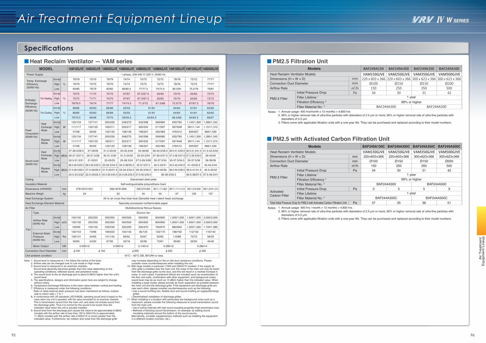
95 96
Specifications
Air Treatment Equipment Lineup
Air
Trea
tmen
t E
quip
men
t Lin
eup
PM2.5 Filtration Unit
Dimensions (H × W × D)Connection Duct Diameter
BAF249A300C BAF249A350C BAF249A500C
220×603×366220×603×366 300×623×366300×623×366Ø100 Ø150 Ø150 Ø200
BAF244A300 BAF244A500
BAF244A300C BAF244A500C
150 250 350 500
3 5 5 9
37 35 36 51
34 30 31 421 year
1 year
99% or higher
Models
Airflow Rate
PM2.5 Filter
ActivatedCarbon Filter
1. Annual usage: 400 hrs / month × 12 months = 4,800 hrs.2. 99% or higher removal rate of ultra-fine particles with diameters of 2.5 µm or more; 90% or higher removal rate of ultra-fine particles with
diameters of 0.5 µm.3. Filters come with applicable filtration units with a one-year life. They can be purchased and replaced according to their model numbers.
BAF249A150C
Initial Pressure DropFilter Lifetime 1
Filtration Efficiency 2
Filter Material No. 3
Initial Pressure DropFilter LifetimeFilter Material No. 3
Total Initial Pressure Drop for PM2.5 with Activated Carbon Filtration UnitNotes:
Initial Pressure DropFilter Lifetime 1
Filtration Efficiency 2
Filter Material No. 3
m3/h
mmmm
Pa
Pa
Pa
PM2.5 with Activated Carbon Filtration Unit
Heat Reclaim Ventilator Models
Heat Reclaim Ventilator Models
Dimensions (H × W × D)Connection Duct DiameterAirflow Rate
1 year99% or higher
Notes: 1. Annual usage: 400 hrs/month x 12 months = 4,800 hrs2. 99% or higher removal rate of ultra-fine particles with diameters of 2.5 μm or more; 90% or higher removal rate of ultra-fine particles with
diameters of 0.5 μm.3. Filters come with applicable filtration units with a one-year life. They can be purchased and replaced according to their model numbers.
PM2.5 Filter
ModelsVAM150GJVE VAM250GJVE VAM350GJVE VAM500GJVE
84/85 79/79
79/79 75/75
79/79 75/75
79/79 74/74
79/79 74/74
75/75 72/72
75/75 72/72
78/78 72/72
78/78 72/72
77/77
77/77
82/82 80/80.5
1-phase, 220-240 V/ 220 V, 50/60 Hz
VAM650GJVE VAM800GJVE VAM1000GJVE VAM1500GJVE
77/77.5 74/74.5 80.5/81 75.5/76
VAM2000GJVE
79/81
MODEL
Temp. Exchange Efficiency(50/60 Hz)
Ultra-High
High
Enthalpy ExchangeEfficiency(50/60 Hz)
For Heating
Low%
Ultra-High
High
Low%
For Cooling
Ultra-High
High
Low%
Power Supply
27-28.5/28.5 27-29/29 31.5-33/33 33-35.5/34
26-27.5/27.5 26-27.5/28 30-31.5/30 31.5-34/32
20.5-21.5/21 21-22/21 23-25/23 25-28.5/24
28.5-29.5/29.5 28.5-30.5/30.5 33-34.5/34.5 34.5-36/35.5
27.5-28.5/28.5 27.5-29/29.5 31.5-33/31.5 33-34.5/33.5
22.5-23.5/22
Galvanised steel plate
22.5-23/22.5 24.5-26.5/24.5 25.5-28.5/25.5
150/150 250/250 350/350 500/500
150/150 250/250 350/350 500/500
100/95 155/155 230/230 320/295
278X810X551 306X879X800
24 32
Self-extinguishable polyurethane foam
Air to air cross flow total heat (Sensible heat + latent heat) exchange
Specially processed nonflammable paper
Multidirectional fibrous fleeces
Sirocco fan
0.030X2 0.090X2
100 150 200
-15℃ – 50℃ DB, 80%RH or less
120/154 70/96 169/222 105/150
106/131 54/65 141/145 66/52
56/60 24/20 67/30 32/18
34-36/36 39-40.5/39.5 39.5-41.5/39.5 39.5-41.5/41.5
33-34.5/34 37-39.5/37.5 37.5-39.5/37.5 37.5-39.5/39.5
27.5-29.5/28 35-37.5/34 35-37.5/34.5 35-37.5/36
35-37.5/37.5 40.5-42/41 40.5-42.5/40.5 41-43/42.5
33-35.5/35.5 38.5-40/39 38.5-40.5/38.5 39.5-41/41.5
27.5-30.5/29.5 36-38.5/35.5 36.5-38/37.5
650/650 800/800 1,000/1,000 1,500/1,500
650/650 800/800 1,000/1,000 1,500/1,500
500/470 700/670 860/840 1,320/1,260
387X1,111X1,214387X1,111X832338X973X832
45 55 67
785X1,619X832 785X1,619X1,214
129
0.140X2 0.280X2 0.280X4
250 350
85/125 133/170 168/192 112/150
53/67 92/85 110/86 73/72
35/38 72/61 85/60 56/50
41.5-43.5/42
39-43/40
36-39/39
43-45.5/44
40.5-45/42
37.5-39.5/41
2,000/2,000
2,000/2,000
1,720/1,580
157
116/140
58/32
45/45
Fan
HeatExchangeMode
Sound Level(50/60 Hz)
BypassMode
Ultra-High
High
Low
Ultra-High
High
Low
dB(A)
dB(A)
Ultra-High
High
Low
mm
kg
Casing
Insulation Material
Heat Exchange System
Heat Exchange Element Material
Air Filter
Type
Dimensions (HXWXD)
Machine Weigh
kW
mm
Unit ambient condition
Motor Output
Connection Duct Diameter
Airflow Rate(50/60 Hz)
Ultra-High
High
Low
m3/h
PaExternal Static Pressure(50/60 Hz)
125/134 137/141 200/226 248/270
111/117 120/125 182/211 225/217
57/58 60/59 122/120 128/136
125/134 137/141 200/226 248/270
111/117 120/125 182/211 225/217
57/58 60/59 122/120 128/136
342/398 599/680 635/760 1,145/1,300
300/332 517/597 567/648 991/1,144
196/207 435/483 476/512 835/927
342/398 599/680 635/760 1,145/1,300
300/332 517/597 567/648 991/1,144
196/207 435/483 476/512 835/927
1,289/1,542
1,151/1,315
966/1,039
1,289/1,542
1,151/1,315
966/1,039
HeatExchangeModePower
Consumption (50/60 Hz)
BypassMode
Ultra-High
High
Low
Ultra-High
High
Low
W
W
1. Sound level is measured at 1.5m below the centre of the body. 2. Airflow rate can be changed over to Low mode or High mode. 3. Sound level is measured in an anechoic chamber. Sound level generally becomes greater than this value depending on the
operating conditions, reflected sound, and peripheral noise. 4. The sound level at the air discharge port is about 8 dB(A) higher than the unit's
sound level. 5. The specifications, designs and information given here are subject to change
without notice. 6. Temperature Exchange Efficiency is the mean value between cooling and heating. 7. Efficiency is measured under the following conditions: Ratio of rated external static pressure has been maintained as follows; outdoor
side to indoor side = 7 to 1. 8. In conformance with JIS standards (JIS B 8628), operating sound level is based on the
value when one unit is operated, with the value converted for an anechoic chamber. This is transmission sound from the main unit, and does not include sound from
the discharge grille. Thus it is normal for the sound to be louder than the indicated value when the unit is actually installed.
9. Sound level from the discharge port causes the value to be approximately 8 dB(A) (models with the airflow rate of less than 150 to 500m3/h) to approximately 11 dB(A) (models with the airflow rate of 650m3/h or more) greater than the indicated value. Furthermore, fan rotation and noise from the discharge grille
may increase depending on the on-site duct resistance conditions. Please consider noise countermeasures when installing the unit.
10. With large models in particular (1500 and 2000m3/h models), if the supply air (SA) grille is installed near the main unit, the noise of the main unit may be heard from the discharge grille via the duct, and this will result in a marked increase in noise. In such cases, if peripheral effects are included (such as reverberation of the floor and walls, combination with other equipment, and background noise), sound level may be as much as 15 dB(A) higher than the indicated value. When installing a large model, please provide as much separation as possible between the main unit and the discharge grille. If the equipment and discharge grille are near each other, please consider countermeasures such as the following:
• Use a sound-muffling box, flexible duct and sound-muffling air supply/discharge grilles
• Decentralised installation of discharge grilles11. When installing in a location with particularly low background noise such as a
classroom, please consider the following measures to avoid transmission sound from the main unit:
• Use of ceiling materials with high sound insulating properties (high transmission loss) • Methods of blocking sound transmission, for example, by adding sound
insulating materials around the bottom of the sound source. Alternatively, consider supplementary methods such as installing the equipment
in a different location (corridor, etc.)
Note:
72/72
72/72
76/76.5
66/66
66/66
70/70.5
71/72
71/71
74/74
63/63
63/63
66/66
70/70
70/70
77/77
66/66
66/66
70/70
67/67
67/67
74/74.5
55/55
55/55
59/59.5
67.5/67.5
67.5/67.5
71.5/72
61/61
61/61
64/64.5
65/65
65/65
67.5/68
70/70
70/70
72.5/73
64/64
64/64
68.5/69
65/65
65/65
67/67.5
61/61
61/61
64/64.5
72/72
72/72
76/76
62/62
62/62
66/67
Heat Reclaim Ventilator — VAM series
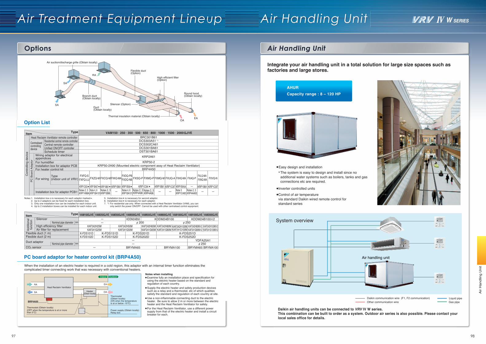
Options
Air Treatment Equipment Lineup
97 98
Air
Han
dlin
g U
nit
Option List
PC board adaptor for heater control kit (BRP4A50)
SilencerVAM150GJVE VAM250GJVE VAM350GJVE VAM500GJVE VAM650GJVE VAM800GJVE VAM1000GJVE VAM1500GJVE VAM2000GJVE
——
KDDM24B50 KDDM24B100 KDDM24B100X2 200 250
Air suction/discharge grille (Obtain locally)
Branch duct(Obtain locally)
SA
SA
RA
EAOA
Duct(Obtain locally)
Flexible duct(Option)
Silencer (Option)
Round hood(Obtain locally)
Thermal insulation material (Obtain locally)
High efficient filter(Option)
Item
Addi
tiona
lfu
nctio
n
Type
High efficiency filter
Flexible duct (1 m)Flexible duct (2 m)Duct adaptor
KAF242H25M KAF242H50M KAF242H65M KAF242H80MKAF241G65M KAF241G80M
KAF242H100M KAF242H80MX2 KAF242H100MX2Air filter for replacement KAF241G25M KAF241G50M KAF241G100M KAF241G80MX2 KAF241G100MX2
K-FDS101D K-FDS151D K-FDS201D K-FDS251DK-FDS102D K-FDS152D K-FDS202D K-FDS252D
——
YDFA25A1 250
EA
OA
RA
SA
Power supply (Obtain locally)Relay box
Thermostat (Obtain locally)(ON when the temperature is at or below -10℃)
Heat Reclaim VentilatorHeater
(Obtain locally)
BRP4A50
Thermostat (Obtain locally)(OFF when the temperature is at or more than 5℃)
Indoor Outdoor
When the installation of an electric heater is required in a cold region, this adaptor with an internal timer function eliminates the complicated timer connecting work that was necessary with conventional heaters.
Examine fully an installation place and specification for using the electric heater based on the standard and regulation of each country.Supply the electric heater and safety production devices such as a relay and a thermostat, etc of which qualities satisfy the standard and regulation of each country at site.Use a non-inflammable connecting duct to the electric heater. Be sure to allow 2 m or more between the electric heater and the Heat Reclaim Ventilator for safety.For the Heat Reclaim Ventilator, use a different power supply from that of the electric heater and install a circuit breaker for each.
Notes when installing
Nominal pipe diameter mm
Nominal pipe diameter mm
For wiring
Installation box for adaptor PCB
Type (indoor unit of VRV )
Central remote controller
Heat Reclaim Ventilator remote controller
Wiring adaptor for electrical appendices
Installation box for adaptor PCB
Unified ON/OFF controllerSchedule timer
For humidifier
For heater control kit
BRC301B61
DCS302CA61Residential central remote controller DCS303A51 *1
DCS301BA61DST301BA61
KRP2A61KRP50-2
BRP4A50KRP50-2A90 (Mounted electric component assy of Heat Reclaim Ventilator)
Item Type
Con
trollin
g de
vice
PC B
oard
Ada
ptor
Centralised controlling device
Notes:1.2.3.4.
Installation box is necessary for each adaptor marked . Up to 2 adaptors can be fixed for each installation box.Only one installation box can be installed for each indoor unit.Up to 2 installation boxes can be installed for each indoor unit.
5.6.7.
Installation box is necessary for second adaptor.Installation box is necessary for each adaptor. *1 For residential use only. When connected with a Heat Reclaim Ventilator (VAM), you can
only switch the power ON/OFF. Cannot be used with other centralised control equipment.
— BRYMA65 BRYMA100 BRYMA65 BRYMA100CO2 sensor
FXFQ-SFXFQ-LU FXZQ-M FXCQ-M FXKQ-MA
FXDQ-PBFXDQ-NB FXMQ-P FXMQ-M FXHQ-MA FXAQ-P
FXLQ-MA FXNQ-MA
KRP1BA57KRP1C63 KRP1B61 KRP1B61 KRP1B56 KRP1B61 KRP1BA54 — KRP1B61Note 4, 6KRP1BA101
Notes 2, 3KRP1H98A
Notes 2, 3KRP1B96 —
FXUQ-A
KRP1C67—Notes 4, 6
KRP1BA101 — Note 3KRP1CA93
Notes 2, 3KRP4AA93 —
FXVQ-N
KRP1C67—
FXSQ-P
KRP1C64Notes 2, 3KRP4A96
Notes 2, 3KRP4A98
Air Handling Unit
Air Handling Unit
Daikin communication wire (F1, F2 communication)Other communication wire
Liquid pipeGas pipe
Daikin air handling units can be connected to VRV IV W series. This combination can be built to order as a system. Outdoor air series is also possible. Please contact your local sales office for details.
Inverter controlled unitsControl of air temperature via standard Daikin wired remote control for standard series
Easy design and installationThe system is easy to design and install since no additional water systems such as boilers, tanks and gas connections etc are required.
System overview
Air handling unit
Integrate your air handling unit in a total solution for large size spaces such as factories and large stores.
AHUR
Capacity range : 8 – 120 HP