Embed Size (px)
Citation preview
←TR
IM
2013 Daikin All Products Catalog Commercial, Industrial and Institutional HVAC
Engineered for flexibility and performance™
2 2013 Daikin All Products Catalog
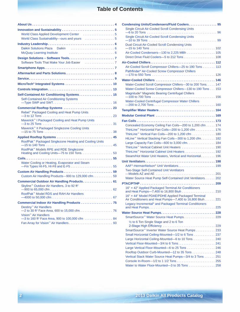
Table of Contents
About Us . . . . . . . . . . . . . . . . . . . . . . . . . . . . . . . . . . . . . . . . . . . . . . . 4Innovation and Sustainability . . . . . . . . . . . . . . . . . . . . . . . . . . . . . . 5
World Class Applied Development Center . . . . . . . . . . . . . . . . . . 5World Class Sustainability—ours and yours . . . . . . . . . . . . . . . . . 5
Industry Leadership . . . . . . . . . . . . . . . . . . . . . . . . . . . . . . . . . . . . . . 6 . . . . . . . . . . . . . . . . . . . . . . . . . 6Daikin Solutions Plaza Daikin
McQuay Learning Institute . . . . . . . . . . . . . . . . . . . . . . . . . . 6
Design Solutions – Software Tools . . . . . . . . . . . . . . . . . . . . . . . . . . 7Software Tools That Make Your Job Easier . . . . . . . . . . . . . . . . . 7
Smartphone Apps . . . . . . . . . . . . . . . . . . . . . . . . . . . . . . . . . . . . . . . . 7Aftermarket and Parts Solutions . . . . . . . . . . . . . . . . . . . . . . . . . . . . 8Service . . . . . . . . . . . . . . . . . . . . . . . . . . . . . . . . . . . . . . . . . . . . . . . . . 9MicroTech® Integrated Systems . . . . . . . . . . . . . . . . . . . . . . . . . . . 10Controls Integration . . . . . . . . . . . . . . . . . . . . . . . . . . . . . . . . . . . . . 13Self-Contained Air Conditioning Systems . . . . . . . . . . . . . . . . . . . 15
Self-Contained Air Conditioning Systems —Type SWP and SWT . . . . . . . . . . . . . . . . . . . . . . . . . . . . . . . . . . 16
Commercial Rooftop Systems . . . . . . . . . . . . . . . . . . . . . . . . . . . . 23Rebel™ Packaged Cooling and Heat Pump Units —3 to 12 Tons . . . . . . . . . . . . . . . . . . . . . . . . . . . . . . . . . . . . . . . . 23Maverick™ I Packaged Cooling and Heat Pump Units —3 to 25 Tons . . . . . . . . . . . . . . . . . . . . . . . . . . . . . . . . . . . . . . . . 31Maverick™ II Packaged Singlezone Cooling Units —15 to 75 Tons . . . . . . . . . . . . . . . . . . . . . . . . . . . . . . . . . . . . . . . 38
Applied Rooftop Systems . . . . . . . . . . . . . . . . . . . . . . . . . . . . . . . . 45RoofPak™ Packaged Singlezone Heating and Cooling Units —15 to 140 Tons . . . . . . . . . . . . . . . . . . . . . . . . . . . . . . . . . . . . . . 45RoofPak™ Models RPE and RDE Singlezone Heating and Cooling Units—75 to 150 Tons . . . . . . . . . . . . . . . . . . 53
Coils . . . . . . . . . . . . . . . . . . . . . . . . . . . . . . . . . . . . . . . . . . . . . . . . . . 55Water Cooling or Heating, Evaporator and Steam —Fin Types HI-F5, HI-F8 and E-F5 . . . . . . . . . . . . . . . . . . . . . . . . 55
Custom Air Handling Products . . . . . . . . . . . . . . . . . . . . . . . . . . . . 59Custom Air Handling Products—900 to 129,000 cfm . . . . . . . . . . . 59
Commercial Outdoor Air Handling Products . . . . . . . . . . . . . . . . . 61Skyline™ Outdoor Air Handlers, 3 to 92 ft2
—900 to 65,000 cfm . . . . . . . . . . . . . . . . . . . . . . . . . . . . . . . . . . . . 62RoofPak™ Model RDS and RAH Air Handlers —4000 to 50,000 cfm . . . . . . . . . . . . . . . . . . . . . . . . . . . . . . . . . . . 67
Commercial Indoor Air Handling Products . . . . . . . . . . . . . . . . . . 75Destiny™ Air Handlers —2 to 30 ft2 Face Area, 600 to 15,000 cfm . . . . . . . . . . . . . . . . . . . 76Vision™ Air Handlers —3 to 160 ft2 Face Area, 900 to 100,000 cfm . . . . . . . . . . . . . . . . 84Fan Array for Vision™ Air Handlers . . . . . . . . . . . . . . . . . . . . . . . . . 93
Condensing Units/Condensers/Fluid Coolers . . . . . . . . . . . . . . . . 95Single Circuit Air-Cooled Scroll Condensing Units —6 to 20 Tons . . . . . . . . . . . . . . . . . . . . . . . . . . . . . . . . . . . . . . . . 96Single Circuit Air-Cooled Scroll Condensing Units —10 to 39 Tons . . . . . . . . . . . . . . . . . . . . . . . . . . . . . . . . . . . . . . . 99Dual Circuit Air-Cooled Scroll Condensing Units —15 to 140 Tons . . . . . . . . . . . . . . . . . . . . . . . . . . . . . . . . . . . . . 102Air-Cooled Condensers—130 to 2,225 MBh . . . . . . . . . . . . . . . . 105Direct Drive Fluid Coolers—5 to 212 Tons . . . . . . . . . . . . . . . . . . 108
Air-Cooled Chillers . . . . . . . . . . . . . . . . . . . . . . . . . . . . . . . . . . . . . 112Air-Cooled Scroll Compressor Chillers—25 to 190 Tons . . . . . . . 113Pathfinder® Air-Cooled Screw Compressor Chillers —170 to 550 Tons . . . . . . . . . . . . . . . . . . . . . . . . . . . . . . . . . . . . 126
Water-Cooled Chillers . . . . . . . . . . . . . . . . . . . . . . . . . . . . . . . . . . 146Water-Cooled Scroll Compressor Chillers—30 to 200 Tons . . . . . 147Water-Cooled Screw Compressor Chillers—130 to 190 Tons . . . 153Magnitude® Magnetic Bearing Centrifugal Chillers —100 to 700 Tons . . . . . . . . . . . . . . . . . . . . . . . . . . . . . . . . . . . . 156Water-Cooled Centrifugal Compressor Water Chillers —200 to 2,700 Tons . . . . . . . . . . . . . . . . . . . . . . . . . . . . . . . . . . . 160
Templifier Water Heaters . . . . . . . . . . . . . . . . . . . . . . . . . . . . . . . . 164Modular Central Plant . . . . . . . . . . . . . . . . . . . . . . . . . . . . . . . . . . 169Fan Coils . . . . . . . . . . . . . . . . . . . . . . . . . . . . . . . . . . . . . . . . . . . . . 173
Concealed Economy Ceiling Fan Coils—200 to 1,200 cfm . . . . . 174ThinLine™ Horizontal Fan Coils—200 to 1,200 cfm . . . . . . . . . . . 176ThinLine™ Vertical Fan Coils—200 to 1,200 cfm . . . . . . . . . . . . . 180HiLine™ Vertical Stacking Fan Coils—300 to 1,200 cfm . . . . . . . . 182Large Capacity Fan Coils—600 to 3,000 cfm . . . . . . . . . . . . . . . . 184ThinLine™ Vertical Cabinet Unit Heaters . . . . . . . . . . . . . . . . . . . 190ThinLine™ Horizontal Cabinet Unit Heaters . . . . . . . . . . . . . . . . . 192Steam/Hot Water Unit Heaters, Vertical and Horizontal . . . . . . . . 196
Unit Ventilators . . . . . . . . . . . . . . . . . . . . . . . . . . . . . . . . . . . . . . . . 198AAF®-HermanNelson® Unit Ventilators . . . . . . . . . . . . . . . . . . . . . 199Two-Stage Self-Contained Unit Ventilators —Models AZ and AE . . . . . . . . . . . . . . . . . . . . . . . . . . . . . . . . . . 201Water Source Heat Pump Self-Contained Unit Ventilators . . . . . . 202
PTAC/PTHP . . . . . . . . . . . . . . . . . . . . . . . . . . . . . . . . . . . . . . . . . . . 20916" × 42" Applied Packaged Terminal Air Conditioners and Heat Pumps—7,400 to 16,800 Btuh . . . . . . . . . . . . . . . . . . . 21016" × 44" Model PDAE/PDHE Applied Packaged Terminal Air Conditioners and Heat Pumps—7,400 to 16,800 Btuh . . . . . . 221Legacy Incremental® and Packaged Terminal Conditioners and Heat Pumps . . . . . . . . . . . . . . . . . . . . . . . . . . . . . . . . . . . . . . 225
Water Source Heat Pumps . . . . . . . . . . . . . . . . . . . . . . . . . . . . . . . 228SmartSource™ Water Source Heat Pumps . . . . . . . . . . . . . . . . . . 229
½ to 6 Ton Single Stage and 2 to 6 Ton 2-Stage High Efficiency . . . . . . . . . . . . . . . . . . . . . . . . . . . . . . 229
SmartSource™ Inverter Water Source Heat Pumps . . . . . . . . . . . 233Small Horizontal Ceiling-Mounted—1/2 to 6 Tons . . . . . . . . . . . . 237Large Horizontal Ceiling-Mounted—6 to 10 Tons . . . . . . . . . . . . . 240Vertical Floor-Mounted—3/4 to 6 Tons . . . . . . . . . . . . . . . . . . . . . 241Large Vertical Floor-Mounted—6 to 25 Tons . . . . . . . . . . . . . . . . 246Rooftop Outdoor Curb-Mounted—12 to 35 Tons . . . . . . . . . . . . . 248Vertical Stack Water Source Heat Pumps—3/4 to 3 Tons . . . . . . 251Console In-Room—1/2 to 1 1/2 Tons . . . . . . . . . . . . . . . . . . . . . . 255Water to Water Floor-Mounted—3 to 35 Tons . . . . . . . . . . . . . . . 258
2013 Daikin All Products Catalog 3
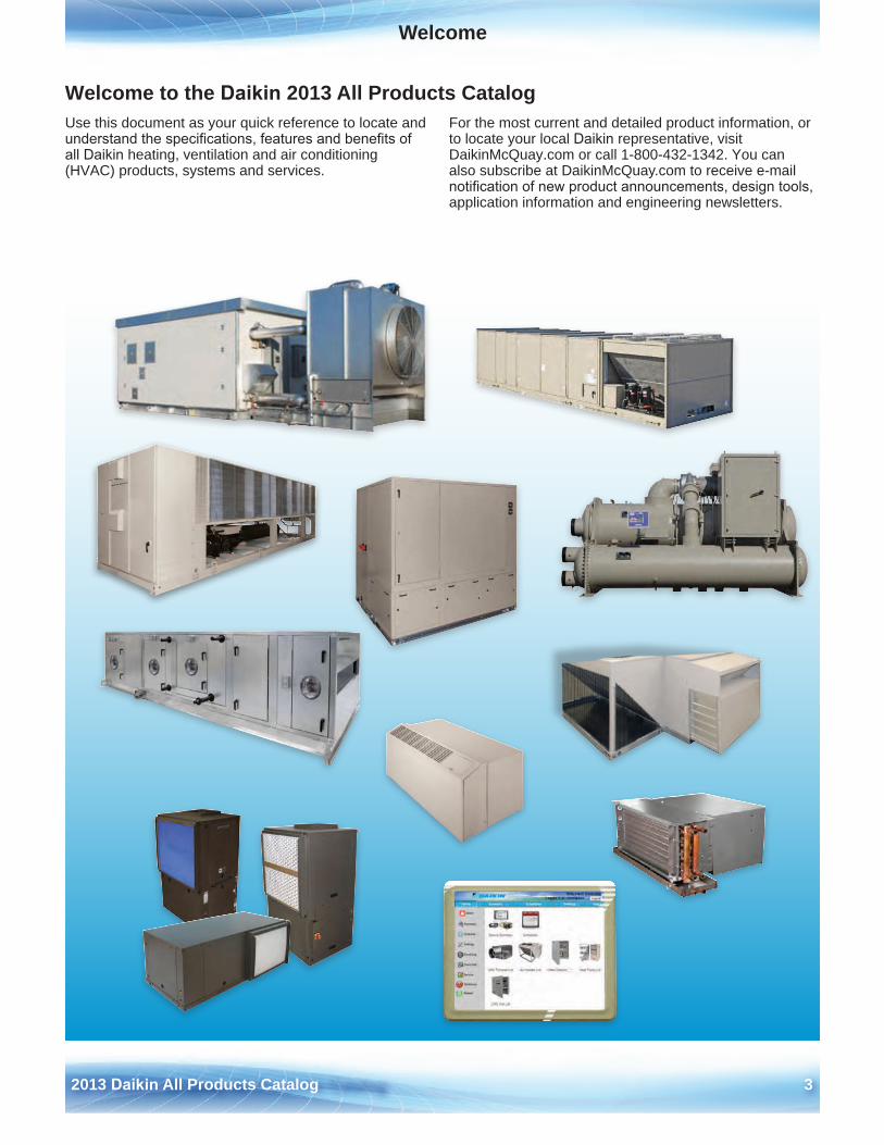
Welcome
Welcome to the Daikin 2013 All Products Catalog Use this document as your quick reference to locate and understand the specifications, features and benefits of all Daikin heating, ventilation and air conditioning (HVAC) products, systems and services .
For the most current and detailed product information, or to locate your local Daikin representative, visit DaikinMcQuay .com or call 1-800-432-1342 . You can also subscribe at DaikinMcQuay .com to receive e-mail notification of new product announcements, design tools, application information and engineering newsletters .
4 2013 Daikin All Products Catalog
About UsA
bout
Daikin
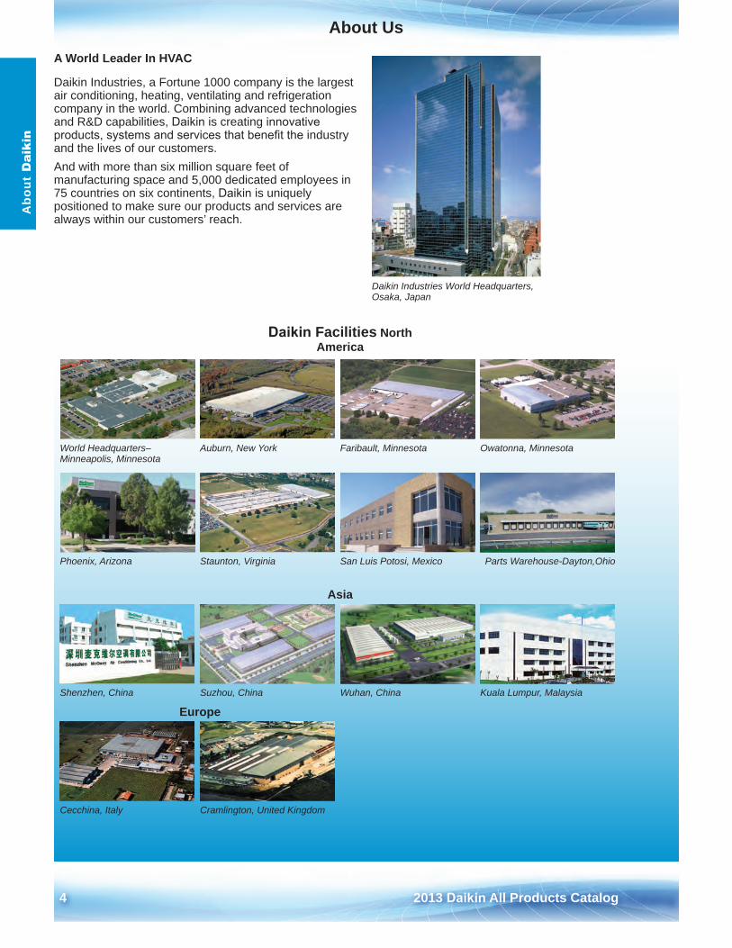
A World Leader In HVAC
Daikin Industries, a Fortune 1000 company is the largest air conditioning, heating, ventilating and refrigeration company in the world . Combining advanced technologies and R&D capabilities, Daikin is creating innovative products, systems and services that benefit the industry and the lives of our customers . And with more than six million square feet of manufacturing space and 5,000 dedicated employees in 75 countries on six continents, Daikin is uniquely positioned to make sure our products and services are always within our customers’ reach .
Daikin Industries World Headquarters, Osaka, Japan
Daikin Facilities North America
World Headquarters– Minneapolis, Minnesota
Auburn, New York Faribault, Minnesota Owatonna, Minnesota
Phoenix, Arizona Staunton, Virginia San Luis Potosi, Mexico Parts Warehouse-Dayton,Ohio
Asia
Shenzhen, China Suzhou, China Wuhan, China Kuala Lumpur, Malaysia
Europe
Cecchina, Italy Cramlington, United Kingdom

2013 Daikin All Products Catalog 5
Innovation and SustainabilityInnovation and S
ustainability
World Class Applied Development Center The Daikin Applied Development Center supports product development, testing and verification of a full range of Daikin and Daikin commercial heating, ventilation, air conditioning and refrigeration (HVAC) systems for worldwide markets . The state-of-the-art center includes the latest technological advancements in the HVAC industry .
The Applied Development Center, located at Daikin Daikin's Minneapolis headquarters, allows the expertise of each company to be leveraged in a combined facility to accelerate the development of innovative, environmentally responsible products, systems and services that benefit the industry and our customers. It is also an exciting and concrete example of Daikin’s commitment to growth in the commercial HVAC market in North America . Awarded LEED® Gold Certification.
Applied Development Center–Interior Applied Development Center–Exterior
World Class Sustainability—ours and yours In addition to the Applied Development Center, other Daikin facilities have been recognized for sustainability . The national Parts warehouse has been certified as an Energy Star® building by the U .S . EPA while the Chiller Engineering offices in the Staunton facility are certified LEED® Silver .
ISO 14001 Certified Facilities
Five facilities in North America are certified to the ISO 14001 environmental management system standard aimed at continuous environmental improvement . Daikin is aggressively pursuing ISO 14001 certification in all its facilities .
High Performance Systems for High Performance Buildings
Daikin offers a variety of design tools to help system designers achieve their goals of efficient, sustainable facilities . Because many of our sales and service representatives are certified as LEED APs, we can help system designers meet their own sustainability goals . As a result, Daikin systems are a popular choice for high performance buildings .
The San Francisco Public Utilities Commission headquarters has been certified as LEED® Platinum and called “the greenest office building in America”. Two Daikin Magnitude® magnetic bearing chillers are at the heart of the high efficiency HVAC system in the building.
Pho
to ©
201
2 B
ruce
Dam
onte
6 2013 Daikin All Products Catalog
Industry LeadershipIn
dust
ry L
eade
rshi
p
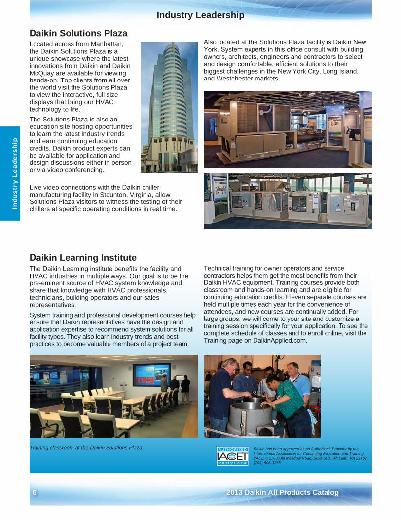
Daikin Solutions Plaza Located across from Manhattan, the Daikin Solutions Plaza is a unique showcase where the latest innovations from Daikin and Daikin McQuay are available for viewing hands-on . Top clients from all over the world visit the Solutions Plaza to view the interactive, full size displays that bring our HVAC technology to life .The Solutions Plaza is also an education site hosting opportunities to learn the latest industry trends and earn continuing education credits . Daikin product experts can be available for application and design discussions either in person or via video conferencing .
Live video connections with the Daikin chiller manufacturing facility in Staunton, Virginia, allow Solutions Plaza visitors to witness the testing of their chillers at specific operating conditions in real time.
Also located at the Solutions Plaza facility is Daikin New York. System experts in this office consult with building owners, architects, engineers and contractors to select and design comfortable, efficient solutions to their biggest challenges in the New York City, Long Island, and Westchester markets .
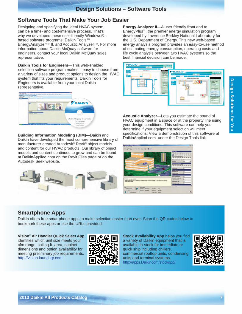
Daikin Learning InstituteThe Daikin Learning institute benefits the facility and HVAC industries in multiple ways . Our goal is to be the pre-eminent source of HVAC system knowledge and share that knowledge with HVAC professionals, technicians, building operators and our sales representatives . System training and professional development courses help ensure that Daikin representatives have the design and application expertise to recommend system solutions for all facility types . They also learn industry trends and best practices to become valuable members of a project team .
Training classroom at the Daikin Solutions Plaza
Technical training for owner operators and service contractors helps them get the most benefits from their Daikin HVAC equipment . Training courses provide both classroom and hands-on learning and are eligible for continuing education credits . Eleven separate courses are held multiple times each year for the convenience of attendees, and new courses are continually added . For large groups, we will come to your site and customize a training session specifically for your application. To see the complete schedule of classes and to enroll online, visit the Training page on DaikinApplied.com .
Daikin has been approved as an Authorized Provider by the International Association for Continuing Education and Training (IACET) 1760 Old Meadow Road, Suite 500, McLean, VA 22102, (703) 506-3275.
2013 Daikin All Products Catalog 7
Design Solutions – Software ToolsD
esign Solutions for You
Software Tools That Make Your Job Easier Designing and specifying the ideal HVAC system can be a time- and cost-intensive process . That’s why we developed these user-friendly Windows® - based software programs; Daikin Tools™, EnergyAnalyzer™ II, and Acoustic Analyzer™ . For more information about Daikin McQuay software for engineers, contact your local Daikin McQuay sales representative .
Daikin Tools for Engineers—This web-enabled selection software program makes it easy to choose from a variety of sizes and product options to design the HVAC system that fits your requirements. Daikin Tools for Engineers is available from your local Daikin representative .
Building Information Modeling (BIM)—Daikin and Daikin have developed the most comprehensive library of manufacturer-created Autodesk® Revit® object models and content for our HVAC products . Our library of object models and content continues to grow and can be found at DaikinApplied .com on the Revit Files page or on the Autodesk Seek website .
Energy Analyzer II—A user friendly front end to EnergyPlus™, the premier energy simulation program developed by Lawrence Berkley National Laboratory for the U .S . Department of Energy . This new web-based energy analysis program provides an easy-to-use method of estimating energy consumption, operating costs and life cycle analysis between two HVAC systems so the best financial decision can be made.
Acoustic Analyzer—Lets you estimate the sound of HVAC equipment in a space or at the property line using your design conditions . This software can help you determine if your equipment selection will meet specifications. View a demonstration of this software at DaikinApplied.com under the Design Tools link .
Smartphone AppsDaikin offers free smartphone apps to make selection easier than ever . Scan the QR codes below to bookmark these apps or use the URLs provided .
Vision® Air Handler Quick Select App identifies which unit size meets your cfm range, coil sq .ft . area, cabinet dimensions and option availability for meeting preliminary job requirements .http://vision .launchqr .com
Stock Availability App helps you find a variety of Daikin equipment that is available in-stock for immediate or quick ship including chillers, commercial rooftop units, condensing units and terminal systems .http://apps .Daikincom/stockapp/
8 2013 Daikin All Products Catalog
Aftermarket and Parts SolutionsP
arts
and
Ser
vice
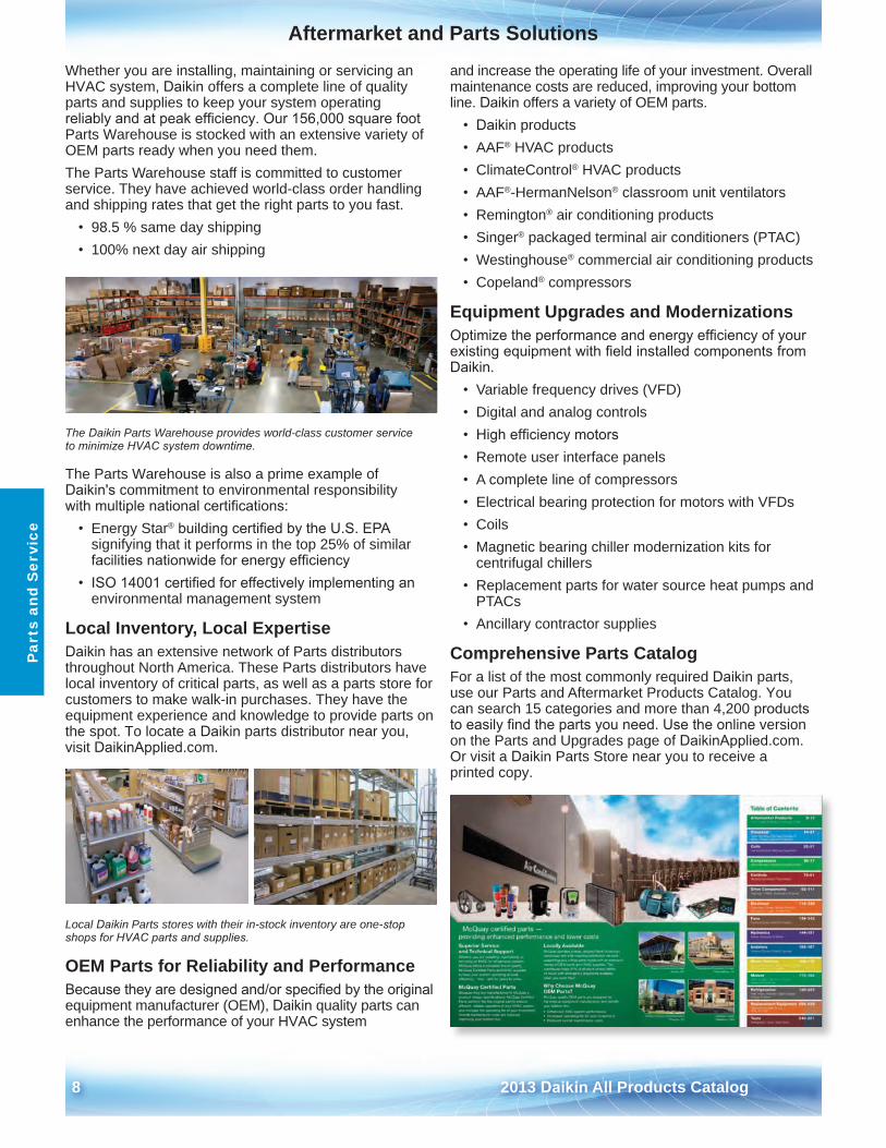
Whether you are installing, maintaining or servicing an HVAC system, Daikin offers a complete line of quality parts and supplies to keep your system operating reliably and at peak efficiency. Our 156,000 square foot Parts Warehouse is stocked with an extensive variety of OEM parts ready when you need them .The Parts Warehouse staff is committed to customer service . They have achieved world-class order handling and shipping rates that get the right parts to you fast .
• 98 .5 % same day shipping• 100% next day air shipping
The Daikin Parts Warehouse provides world-class customer service to minimize HVAC system downtime.
The Parts Warehouse is also a prime example of Daikin's commitment to environmental responsibility with multiple national certifications:
• Energy Star® building certified by the U.S. EPAsignifying that it performs in the top 25% of similarfacilities nationwide for energy efficiency
• ISO 14001 certified for effectively implementing anenvironmental management system
Local Inventory, Local ExpertiseDaikin has an extensive network of Parts distributors throughout North America . These Parts distributors have local inventory of critical parts, as well as a parts store for customers to make walk-in purchases . They have the equipment experience and knowledge to provide parts on the spot . To locate a Daikin parts distributor near you, visit DaikinApplied .com .
Local Daikin Parts stores with their in-stock inventory are one-stop shops for HVAC parts and supplies.
OEM Parts for Reliability and PerformanceBecause they are designed and/or specified by the original equipment manufacturer (OEM), Daikin quality parts can enhance the performance of your HVAC system
and increase the operating life of your investment . Overall maintenance costs are reduced, improving your bottom line . Daikin offers a variety of OEM parts .
• Daikin products• AAF® HVAC products• ClimateControl® HVAC products• AAF®-HermanNelson® classroom unit ventilators• Remington® air conditioning products• Singer® packaged terminal air conditioners (PTAC)• Westinghouse® commercial air conditioning products• Copeland® compressors
Equipment Upgrades and ModernizationsOptimize the performance and energy efficiency of your existing equipment with field installed components from Daikin .
• Variable frequency drives (VFD)• Digital and analog controls• High efficiency motors• Remote user interface panels• A complete line of compressors• Electrical bearing protection for motors with VFDs• Coils• Magnetic bearing chiller modernization kits for
centrifugal chillers• Replacement parts for water source heat pumps and
PTACs• Ancillary contractor supplies
Comprehensive Parts Catalog For a list of the most commonly required Daikin parts, use our Parts and Aftermarket Products Catalog . You can search 15 categories and more than 4,200 products to easily find the parts you need. Use the online version on the Parts and Upgrades page of DaikinApplied .com . Or visit a Daikin Parts Store near you to receive a printed copy .

2013 Daikin All Products Catalog 9
ServiceP
arts and Service
Daikin Service SolutionsCapital BudgetingEnhance your business with strategic HVAC asset planning to offset future energy costs and aging infrastructure .
Planned Maintenance Protect your valuable assets with a results-oriented maintenance strategy designed to meet your specific business requirements and objectives .
Emergency Repairs We offer emergency repair services 24 hours, 7 days a week on Daikin and other HVAC equipment .
Equipment Upgrades Our technicians can optimize your older chiller by adding digital controls and variable frequency drives to improve its energy efficiency.
Equipment Replacements If you’re looking to replace equipment, we can do fully engineered, turnkey equipment replacements . Newer, more efficient equipment can pay for itself in a short time based on energy savings alone .
Training for Maintenance Staff Reduce your maintenance costs by learning how to perform routine maintenance and troubleshooting tasks . The Daikin Learning Institute offers both classroom service training and on-site training .
Complete Building HVAC ServiceOur account representatives and factory trained technicians can provide quick response and proactive solutions for any building requirement .
We offer complete building services for all brands including Daikin and all types of HVAC systems:
• Centrifugal chillers, including magnetic bearing• Screw chillers• Scroll chillers• Absorption chillers• Cooling towers• Boilers• Packaged rooftop units• Air handling equipment• Exhaust/make-up air systems• Pumping systems• Water treatment• Split DX systems• Building controls• And more
D-Net® Performance Services for Quicker Response and Enhanced SupportDaikin's maintenance and service offerings now include enhanced options for D-Net®
Performance Services capabilities .
As an innovative, web-based offering, D-Net facilitates remote diagnostics, service, and performance monitoring .
This capability enables McQuay Service to flag maintenance proactively, evaluate and/or resolve issues quickly, and provide regular, documented communication to facilitate not only service and maintenance decisions, but also decisions about equipment upgrades or replacement .
10 2013 Daikin All Products Catalog
MicroTech® Integrated SystemsM
icro
Tech
In
tegr
ated
Sys
tem
s
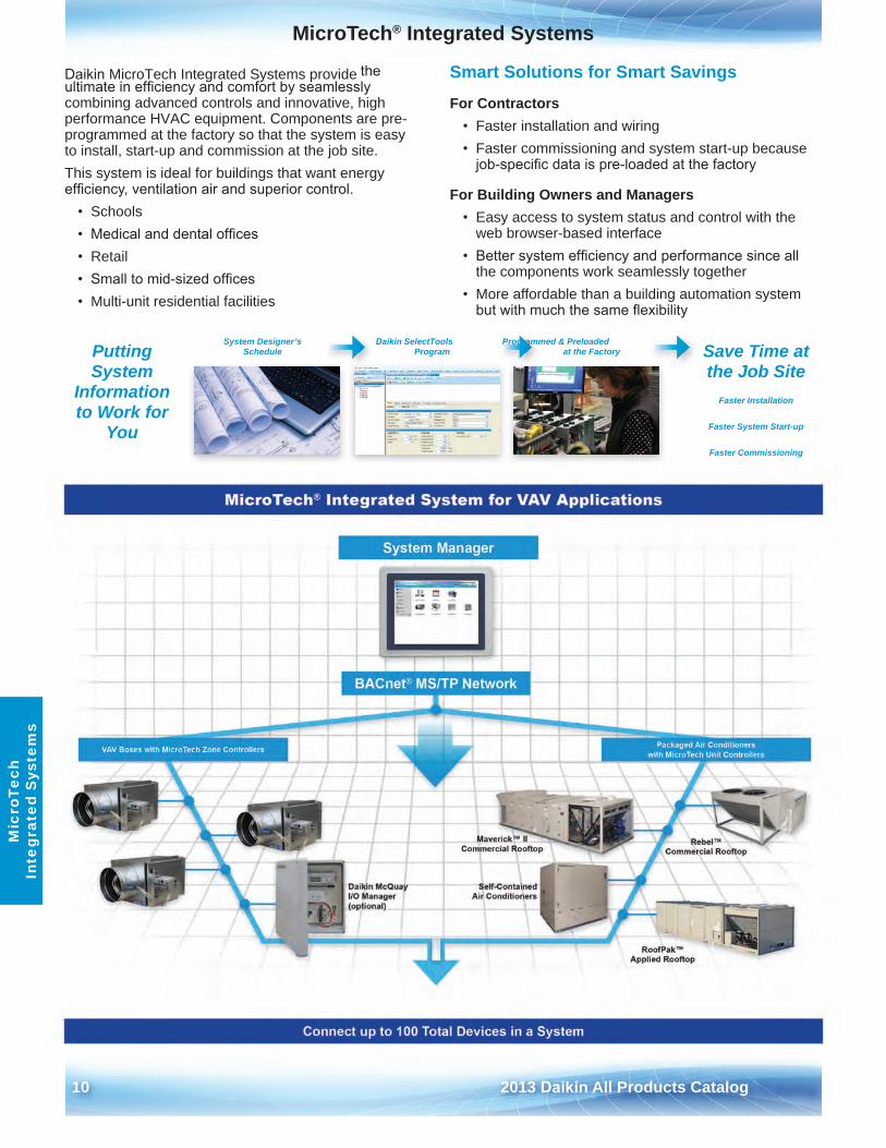
Daikin MicroTech Integrated Systems provide the ultimate in efficiency and comfort by seamlessly combining advanced controls and innovative, high performance HVAC equipment . Components are pre-programmed at the factory so that the system is easy to install, start-up and commission at the job site .This system is ideal for buildings that want energy efficiency, ventilation air and superior control.
• Schools• Medical and dental offices• Retail• Small to mid-sized offices• Multi-unit residential facilities
Smart Solutions for Smart Savings
For Contractors• Faster installation and wiring• Faster commissioning and system start-up because
job-specific data is pre-loaded at the factory
For Building Owners and Managers• Easy access to system status and control with the
web browser-based interface• Better system efficiency and performance since all
the components work seamlessly together• More affordable than a building automation system
Putting System
Information to Work for
You
Save Time at the Job Site
Faster Installation
Faster System Start-up
Faster Commissioning
System Designer’s
but with much the same flexibility
Daikin SelectTools Programmed & Preloaded Schedule Program at the Factory
2013 Daikin All Products Catalog 11
MicroTech® Integrated SystemsM
icroTech Integrated S
ystems
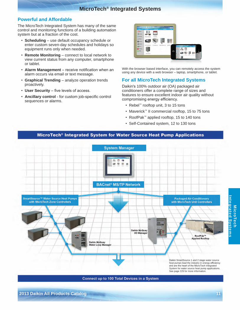
Powerful and AffordableThe MicroTech Integrated System has many of the same control and monitoring functions of a building automation system but at a fraction of the cost .
• Scheduling – use default occupancy schedule orenter custom seven-day schedules and holidays so equipment runs only when needed .
• Remote Monitoring – connect to local network toview current status from any computer, smartphone or tablet .
• Alarm Management – receive notification when analarm occurs via email or text message .
• Graphical Trending – analyze operation trendsproactively .
• User Security – five levels of access.• Ancillary control - for custom job-specific control
sequences or alarms .
With the browser based interface, you can remotely access the system using any device with a web browser – laptop, smartphone, or tablet .
For all MicroTech Integrated SystemsDaikin's 100% outdoor air (OA) packaged air conditioners offer a complete range of sizes and features to ensure excellent indoor air quality without compromising energy efficiency.
• Rebel™ rooftop unit, 3 to 15 tons• Maverick™ II commercial rooftop, 15 to 75 tons• RoofPak™ applied rooftop, 15 to 140 tons• Self-Contained system, 12 to 130 tons
Daikin SmartSource 1 and 2 stage water source heat pumps lead the industry in energy efficiency and are the heart of the MicroTech Integrated System for water source heat pump applications . See page 229 for more information .
12 2013 Daikin All Products Catalog
MicroTech® Integrated SystemsM
icro
Tech
In
tegr
ated
Sys
tem
s
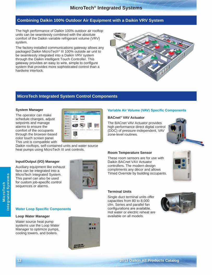
The high performance of Daikin 100% outdoor air rooftop units can be seamlessly combined with the absolute comfort of the Daikin variable refrigerant volume (VRV) system . The factory-installed communications gateway allows any packaged Daikin MicroTech® III 100% outside air unit to be seamlessly integrated into a Daikin VRV system through the Daikin intelligent Touch Controller . This gateway provides an easy to wire, simple to configure system that provides more sophisticated control than a hardwire interlock .
System ManagerThe operator can make schedule changes, adjust setpoints and manage alarms to ensure the comfort of the occupants through the browser-based color touch screen panel . This unit is compatible with Daikin rooftops, self-contained units and water source heat pumps using MicroTech III unit controls .
Input/Output (I/O) ManagerAuxiliary equipment like exhaust fans can be integrated into a MicroTech Integrated System . This panel can also be used for custom job-specific control sequences or alarms .
Water Loop Specific Components
Loop Water ManagerWater source heat pump systems use the Loop Water Manager to optimize pumps, cooling towers, and boilers .
Variable Air Volume (VAV) Specific Components
BACnet® VAV ActuatorThe BACnet VAV Actuator provides high performance direct digital control (DDC) of pressure-independent, VAV zone-level routines .
Room Temperature SensorThese room sensors are for use with Daikin BACnet VAV Actuator controllers . The modern design compliments any décor and allows Timed Override by building occupants .
Terminal UnitsSingle duct terminal units offer capacities from 80 to 8,000 cfm . Series and parallel fan configurations are available. Hot water or electric reheat are available on all models .
Combining Daikin 100% Outdoor Air Equipment with a Daikin VRV System
MicroTech Integrated System Control Components
2013 Daikin All Products Catalog 13
Controls IntegrationC
ontrols Integration
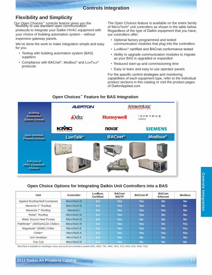
Flexibility and Simplicity Our Open Choices™ controls feature gives you the flexibility to use standard open communication protocols to integrate your Daikin HVAC equipment with your choice of building automation system – without expensive gateway panels .We’ve done the work to make integration simple and easy for you .
• Testing with building automation system (BAS)suppliers
• Compliance with BACnet®, Modbus® and LonTaLk®
protocols
The Open Choices feature is available on the entire family of MicroTech® unit controllers as shown in the table below . Regardless of the type of Daikin equipment that you have, our controllers offer:
• Optional factory-programmed and testedcommunication modules that plug into the controllers
• LonMark® certified and BACnet conformance tested• Ability to upgrade communication modules to migrate
as your BAS is upgraded or expanded• Reduced start-up and commissioning time• Easy to learn and easy to use operator panels
For the specific control strategies and monitoring capabilities of each equipment type, refer to the individual product sections in this catalog or visit the product pages of DaikinApplied.com
Open Choices™ Feature for BAS Integration
Building Automation
System Choices
Open Standard Protocol Choices LonTalk® BACnet® Modbus®
Full Line of HVAC Equipment
Choices
Open Choice Options for Integrating Daikin Unit Controllers into a BAS
Unit Controller LonMark Certified
BACnet MS/TP BACnet IP BACnet
Ethernet Modbus
Applied Rooftop/Self-Contained MicroTech III 3 .4 Yes Yes No NoMaverick II™ Rooftop MicroTech III 3 .4 Yes Yes No NoMaverick I™ Rooftop Maverick I 3 .4 Yes Yes Yes No
Rebel™ Rooftop MicroTech III 3 .4 Yes Yes No NoWater Source Heat Pumps MicroTech III 3 .4 Yes No No No
Pathfinder™ (AWS)/AGZD Chillers MicroTech III 3 .4 Yes Yes No YesMagnitude® (WME) Chiller MicroTech E 3 .4 Yes Yes Yes Yes
Chiller* MicroTech II 3 .3 Yes Yes Yes YesUnit Ventilator MicroTech II 3 .3 Yes No No No
Fan Coil MicroTech III 3 .4 Yes No No No*MicroTech II available for centrifugal, screw, and scroll unit controllers (models WSC, WDC, TSC, WMC, WCC, ACZ, WGZ, AGS, WGS, TGZ)

14 2013 Daikin All Products Catalog
This page intentionally left blank.
2013 Daikin All Products Catalog 15
Self-Contained Air Conditioning SystemsS
elf-Contained A
ir C
onditioning System
s
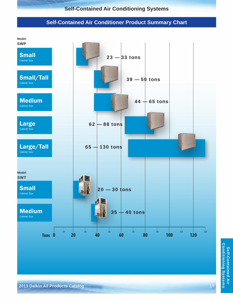
Self-Contained Air Conditioner Product Summary Chart
10 30 50 70 90 110 130
0 20 40 60 80 100 120Tons
SmallCabinet Size
SmallCabinet Size
LargeCabinet Size
Small/TallCabinet Size
Large/TallCabinet Size
MediumCabinet Size
MediumCabinet Size
Model:
SWP
Model:
SWT
39 — 50 tons
44 — 65 tons
62 — 88 tons
65 — 130 tons
23 — 33 tons
20 — 30 tons
35 — 40 tons
16 2013 Daikin All Products Catalog
Self-Contained Air Conditioning SystemsS
elf-
Con
tain
ed A
ir
Con
diti
onin
g S
yste
ms
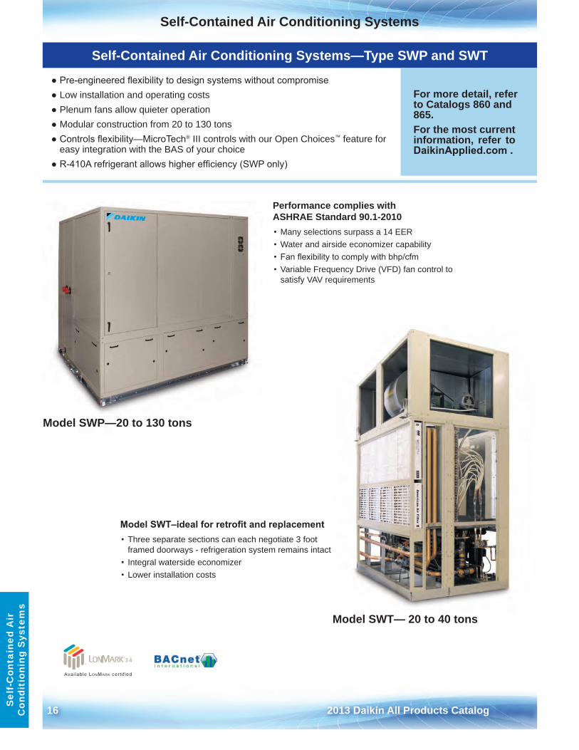
Self-Contained Air Conditioning Systems—Type SWP and SWT
● Pre-engineered flexibility to design systems without compromise● Low installation and operating costs● Plenum fans allow quieter operation● Modular construction from 20 to 130 tons● Controls flexibility—MicroTech® III controls with our Open Choices™ feature for
easy integration with the BAS of your choice● R-410A refrigerant allows higher efficiency (SWP only)
For more detail, refer to Catalogs 860 and 865 .For the most current information, refer to DaikinApplied.com .
Performance complies with ASHRAE Standard 90 .1-2010• Many selections surpass a 14 EER• Water and airside economizer capability• Fan flexibility to comply with bhp/cfm• Variable Frequency Drive (VFD) fan control to
satisfy VAV requirements
Model SWT–ideal for retrofit and replacement• Three separate sections can each negotiate 3 foot
framed doorways - refrigeration system remains intact• Integral waterside economizer• Lower installation costs
Model SWP—20 to 130 tons
Model SWT— 20 to 40 tons
Available LonMark cert i f ied
Self-Contained Air Conditioning Systems
2013 Daikin All Products Catalog 17
Self-C
ontained Air
Conditioning S
ystems
Self-Contained Air Conditioning Systems Features and Options
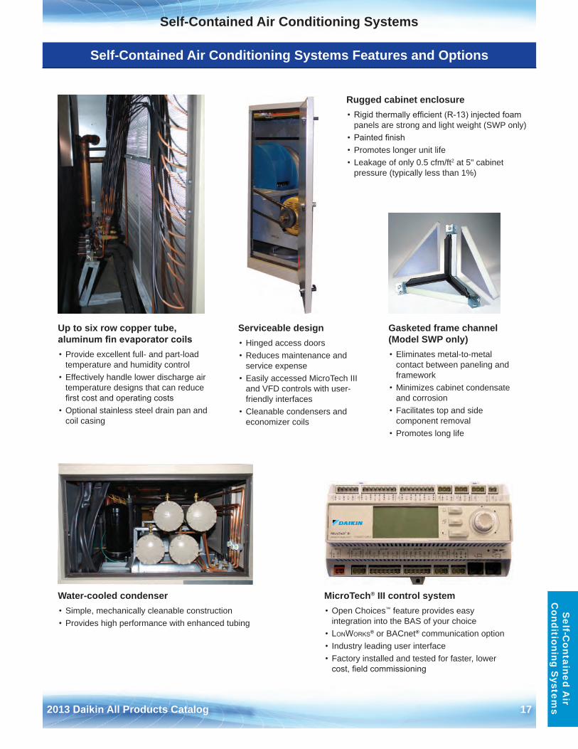
Up to six row copper tube, aluminum fin evaporator coils• Provide excellent full- and part-load
temperature and humidity control• Effectively handle lower discharge air
temperature designs that can reduce first cost and operating costs
• Optional stainless steel drain pan andcoil casing
Serviceable design• Hinged access doors• Reduces maintenance and
service expense• Easily accessed MicroTech III
and VFD controls with user-friendly interfaces
• Cleanable condensers andeconomizer coils
Gasketed frame channel (Model SWP only)• Eliminates metal-to-metal
contact between paneling and framework
• Minimizes cabinet condensateand corrosion
• Facilitates top and sidecomponent removal
• Promotes long life
Rugged cabinet enclosure• Rigid thermally efficient (R-13) injected foam
panels are strong and light weight (SWP only)• Painted finish• Promotes longer unit life• Leakage of only 0 .5 cfm/ft2 at 5" cabinet
pressure (typically less than 1%)
Water-cooled condenser• Simple, mechanically cleanable construction• Provides high performance with enhanced tubing
MicroTech® III control system• Open Choices™ feature provides easy
integration into the BAS of your choice• LonWorks® or BACnet® communication option• Industry leading user interface• Factory installed and tested for faster, lower
cost, field commissioning
Self-Contained Air Conditioning Systems
18 2013 Daikin All Products Catalog
Sel
f-C
onta
ined
Air
C
ondi
tion
ing
Sys
tem
s
Self-Contained Air Conditioning System Model SWP—20 to 130 Tons
1
2
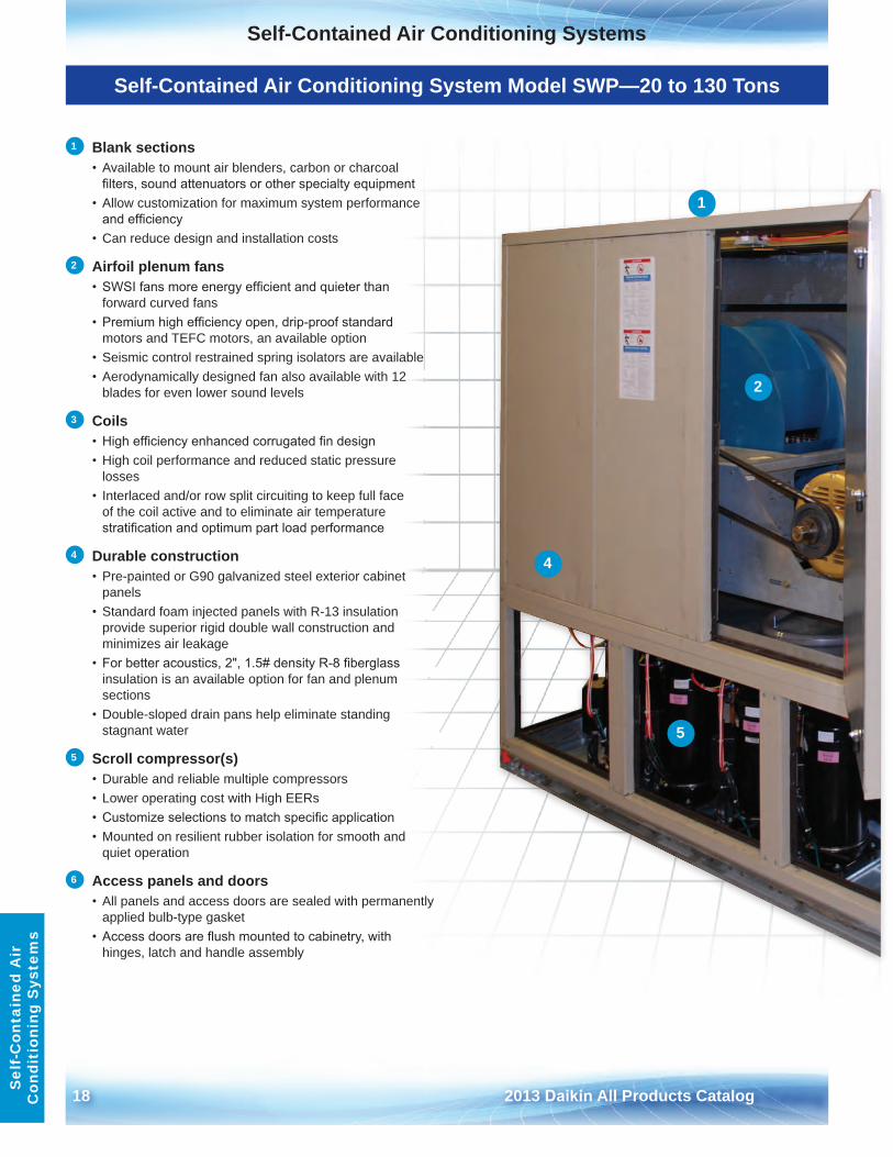
1 Blank sections• Available to mount air blenders, carbon or charcoal
filters, sound attenuators or other specialty equipment• Allow customization for maximum system performance
and efficiency• Can reduce design and installation costs
2 Airfoil plenum fans• SWSI fans more energy efficient and quieter than
forward curved fans• Premium high efficiency open, drip-proof standard
motors and TEFC motors, an available option• Seismic control restrained spring isolators are available• Aerodynamically designed fan also available with 12
blades for even lower sound levels
3 Coils• High efficiency enhanced corrugated fin design• High coil performance and reduced static pressure
losses• Interlaced and/or row split circuiting to keep full face
of the coil active and to eliminate air temperaturestratification and optimum part load performance
4 Durable construction• Pre-painted or G90 galvanized steel exterior cabinet
panels• Standard foam injected panels with R-13 insulation
provide superior rigid double wall construction and minimizes air leakage
• For better acoustics, 2", 1.5# density R-8 fiberglassinsulation is an available option for fan and plenum sections
• Double-sloped drain pans help eliminate standingstagnant water
5 Scroll compressor(s) • Durable and reliable multiple compressors• Lower operating cost with High EERs• Customize selections to match specific application• Mounted on resilient rubber isolation for smooth and
quiet operation
6 Access panels and doors• All panels and access doors are sealed with permanently
applied bulb-type gasket• Access doors are flush mounted to cabinetry, with
hinges, latch and handle assembly
4
5
Self-Contained Air Conditioning Systems
2013 Daikin All Products Catalog 19
Self-C
ontained Air
Conditioning S
ystems
Self-Contained Air Conditioning Systems Features and Options
3
6
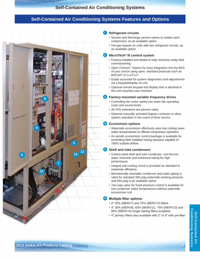
7 Refrigerant circuits• Suction and discharge service valves to isolate each
compressor, as an available option• Hot gas bypass on units with two refrigerant circuits, as
an available option
8 MicroTech® III control system• Factory-installed and tested to help minimize costly field
commissioning• Open Choices™ feature for easy integration into the BAS
of your choice using open, standard protocols such as BACnet® or LonTaLk®
• Easily accessed for system diagnostics and adjustmentsvia a keypad/display on unit
• Optional remote keypad and display that is identical tothe unit-mounted user interface
9 Factory-mounted variable frequency drives• Controlling fan motor speed can lower fan operating
costs and sound levels• All VFD selections are plenum rated• Optional manually activated bypass contactor to allow
system operation in the event of drive service
10 Economizer options• Waterside economizer effectively uses low cooling tower
water temperatures to offload compressor operation• An airside economizer control package is available for
controlling field installed mixing dampers capable of 100% outside airflow
11 Shell and tube condensers• Carbon-steel shell and tube condenser, non-ferrous
water channels and enhanced tubing for high performance
• Integral sub-cooling circuit is provided as standard tomaximize efficiency
• Mechanically cleanable condenser and water piping israted for standard 300 psig waterside working pressure and 450 psig is an available option
• Two-way valve for head pressure control is available forlow condenser water temperatures without waterside economizer coil
12 Multiple filter options• 2" 30% (MERV7) and 75% (MERV13) filters• 4" 30% (MERV8), 65% (MERV11), 75% (MERV13) and
85% (MERV14) longer lasting filters available• 4" primary filters also available with 2" or 4" with pre-filter
7
8
9
10
11
12
Self-Contained Air Conditioning Systems
20 2013 Daikin All Products Catalog
Sel
f-C
onta
ined
Air
C
ondi
tion
ing
Sys
tem
s
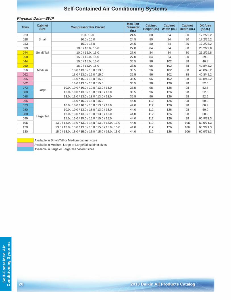
Physical Data—SWP
Tons Cabinet Size Compressor Per Circuit
Max Fan Diameter
(in .)Cabinet
Height (in .)Cabinet
Width (in .)Cabinet
Depth (in .)DX Area (sq .ft .)
023Small
6 .0 / 15 .0 24 .5 80 84 80 17 .2/25 .2028 10 .0 / 15 .0 24 .5 80 84 80 17 .2/25 .2033 15 .0 / 15 .0 24 .5 80 84 80 17 .2/25 .2039
Small/Tall10 .0 / 10 .0 / 15 .0 27 .0 84 84 80 25 .2/29 .8
044 10 .0 / 15 .0 / 15 .0 27 .0 84 84 80 25 .2/29 .8050 15 .0 / 15 .0 / 15 .0 27 .0 84 84 80 29 .8044
Medium
10 .0 / 15 .0 / 15 .0 36 .5 96 102 88 40 .8050 15 .0 / 15 .0 / 15 .0 36 .5 96 102 88 40 .8/45 .2056 13 .0 / 13 .0 / 13 .0 / 13 .0 36 .5 96 102 88 40 .8/45 .2062 13 .0 / 13 .0 / 15 .0 / 15 .0 36 .5 96 102 88 40 .8/45 .2065 15 .0 / 15 .0 / 15 .0 / 15 .0 36 .5 96 102 88 40 .8/45 .2062
Large
13 .0 / 13 .0 / 15 .0 / 15 .0 36 .5 96 126 98 52 .5073 10 .0 / 10 .0 / 10 .0 / 10 .0 / 13 .0 / 13 .0 36 .5 96 126 98 52 .5080 10 .0 / 10 .0 / 13 .0 / 13 .0 / 13 .0 / 13 .0 36 .5 96 126 98 52 .5088 13 .0 / 13 .0 / 13 .0 / 13 .0 / 13 .0 / 13 .0 36 .5 96 126 98 52 .5065
Large/Tall
15 .0 / 15 .0 / 15 .0 / 15 .0 44 .0 112 126 98 60 .9073 10 .0 / 10 .0 / 10 .0 / 10 .0 / 13 .0 / 13 .0 44 .0 112 126 98 60 .9080 10 .0 / 10 .0 / 13 .0 / 13 .0 / 13 .0 / 13 .0 44 .0 112 126 98 60 .9088 13 .0 / 13 .0 / 13 .0 / 13 .0 / 13 .0 / 13 .0 44 .0 112 126 98 60 .9099 15 .0 / 15 .0 / 15 .0 / 15 .0 / 15 .0 / 15 .0 44 .0 112 126 98 60 .9/71 .3105 13 .0 / 13 .0 / 13 .0 / 13 .0 / 13 .0 / 13 .0 / 13 .0 / 13 .0 44 .0 112 126 106 60 .9/71 .3120 13 .0 / 13 .0 / 13 .0 / 13 .0 / 15 .0 / 15 .0 / 15 .0 / 15 .0 44 .0 112 126 106 60 .9/71 .3130 15 .0 / 15 .0 / 15 .0 / 15 .0 / 15 .0 / 15 .0 / 15 .0 / 15 .0 44 .0 112 126 106 60 .9/71 .3
Available in Small/Tall or Medium cabinet sizesAvailable in Medium, Large or Large/Tall cabinet sizesAvailable in Large or Large/Tall cabinet sizes
Self-Contained Air Conditioning Systems
2013 Daikin All Products Catalog 21
Self-C
ontained Air
Conditioning S
ystems
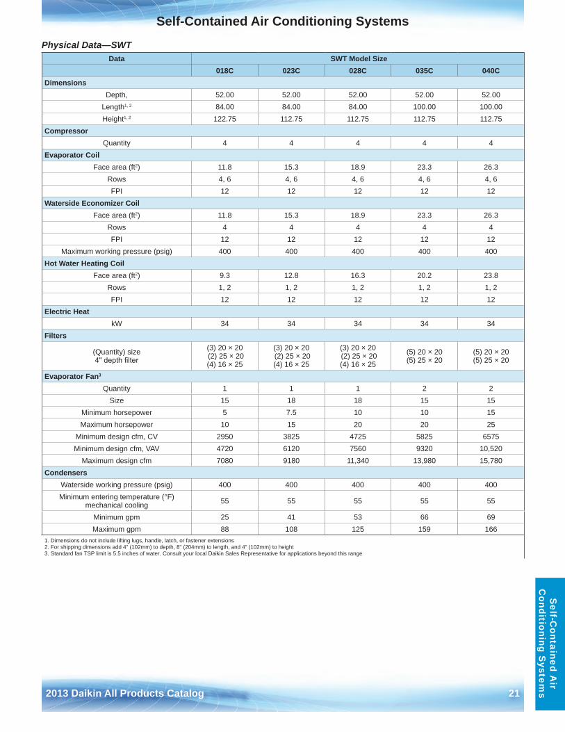
Physical Data—SWT Data SWT Model Size
018C 023C 028C 035C 040CDimensions
Depth, 52 .00 52 .00 52 .00 52 .00 52 .00Length1, 2 84 .00 84 .00 84 .00 100 .00 100 .00Height1, 2 122 .75 112 .75 112 .75 112 .75 112 .75
CompressorQuantity 4 4 4 4 4
Evaporator CoilFace area (ft2) 11 .8 15 .3 18 .9 23 .3 26 .3
Rows 4, 6 4, 6 4, 6 4, 6 4, 6FPI 12 12 12 12 12
Waterside Economizer CoilFace area (ft2) 11 .8 15 .3 18 .9 23 .3 26 .3
Rows 4 4 4 4 4FPI 12 12 12 12 12
Maximum working pressure (psig) 400 400 400 400 400Hot Water Heating Coil
Face area (ft2) 9 .3 12 .8 16 .3 20 .2 23 .8Rows 1, 2 1, 2 1, 2 1, 2 1, 2FPI 12 12 12 12 12
Electric HeatkW 34 34 34 34 34
Filters
(Quantity) size 4" depth filter
(3) 20 × 20 (2) 25 × 20(4) 16 × 25
(3) 20 × 20 (2) 25 × 20(4) 16 × 25
(3) 20 × 20 (2) 25 × 20(4) 16 × 25
(5) 20 × 20(5) 25 × 20
(5) 20 × 20(5) 25 × 20
Evaporator Fan3
Quantity 1 1 1 2 2Size 15 18 18 15 15
Minimum horsepower 5 7 .5 10 10 15Maximum horsepower 10 15 20 20 25
Minimum design cfm, CV 2950 3825 4725 5825 6575Minimum design cfm, VAV 4720 6120 7560 9320 10,520
Maximum design cfm 7080 9180 11,340 13,980 15,780Condensers
Waterside working pressure (psig) 400 400 400 400 400Minimum entering temperature (°F)
mechanical cooling 55 55 55 55 55
Minimum gpm 25 41 53 66 69Maximum gpm 88 108 125 159 166
1 . Dimensions do not include lifting lugs, handle, latch, or fastener extensions2 . For shipping dimensions add 4" (102mm) to depth, 8" (204mm) to length, and 4" (102mm) to height3 . Standard fan TSP limit is 5 .5 inches of water . Consult your local Daikin Sales Representative for applications beyond this range
22 2013 Daikin All Products Catalog
Rooftop SystemsR
ooft
op S
yste
ms
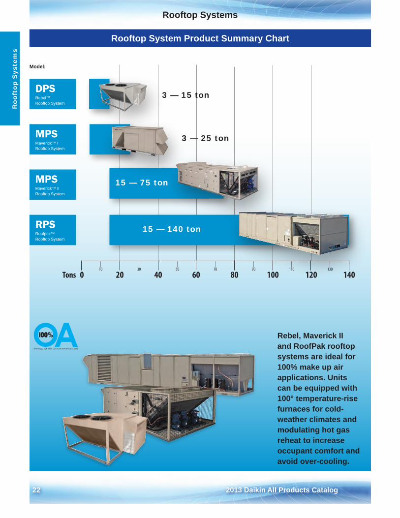
Rooftop System Product Summary Chart
10 30 50 70 90 110 130
0 20 40 60 80 100 120 140Tons
DPSRebel™ Rooftop System
MPSMaverick™ II Rooftop System
MPSMaverick™ I Rooftop System
RPSRoofpak™ Rooftop System
Model:
3 — 25 ton
15 — 75 ton
3 — 15 ton
15 — 140 ton
Rebel, Maverick II and RoofPak rooftop systems are ideal for 100% make up air applications . Units can be equipped with 100° temperature-rise furnaces for cold-weather climates and modulating hot gas reheat to increase occupant comfort and avoid over-cooling .
Commercial Rooftop Systems
2013 Daikin All Products Catalog 23
Commercial Rooftop SystemsC
omm
ercial R
ooftop System
s
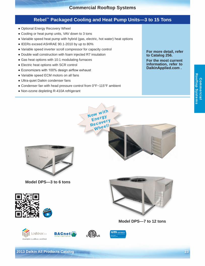
Rebel™ Packaged Cooling and Heat Pump Units—3 to 15 Tons
● Optional Energy Recovery Wheel● Cooling or heat pump units, VAV down to 3 tons● Variable speed heat pump with hybrid (gas, electric, hot water) heat options● IEERs exceed ASHRAE 90 .1-2010 by up to 80%● Variable speed inverter scroll compressor for capacity control● Double wall construction with foam injected R7 insulation● Gas heat options with 10:1 modulating furnaces● Electric heat options with SCR control● Economizers with 100% design airflow exhaust● Variable speed ECM motors on all fans● Ultra-quiet Daikin condenser fans● Condenser fan with head pressure control from 0°F~115°F ambient● Non-ozone depleting R-410A refrigerant
For more detail, refer to Catalog 256 .For the most current information, refer to DaikinApplied.com .
Model DPS—3 to 6 tons
Model DPS—7 to 12 tons
Available LonMark cert i f ied
Now with
Energy
Recovery
Wheel!
24 2013 Daikin All Products Catalog
Commercial Rooftop SystemsC
omm
erci
al
Roo
ftop
Sys
tem
s
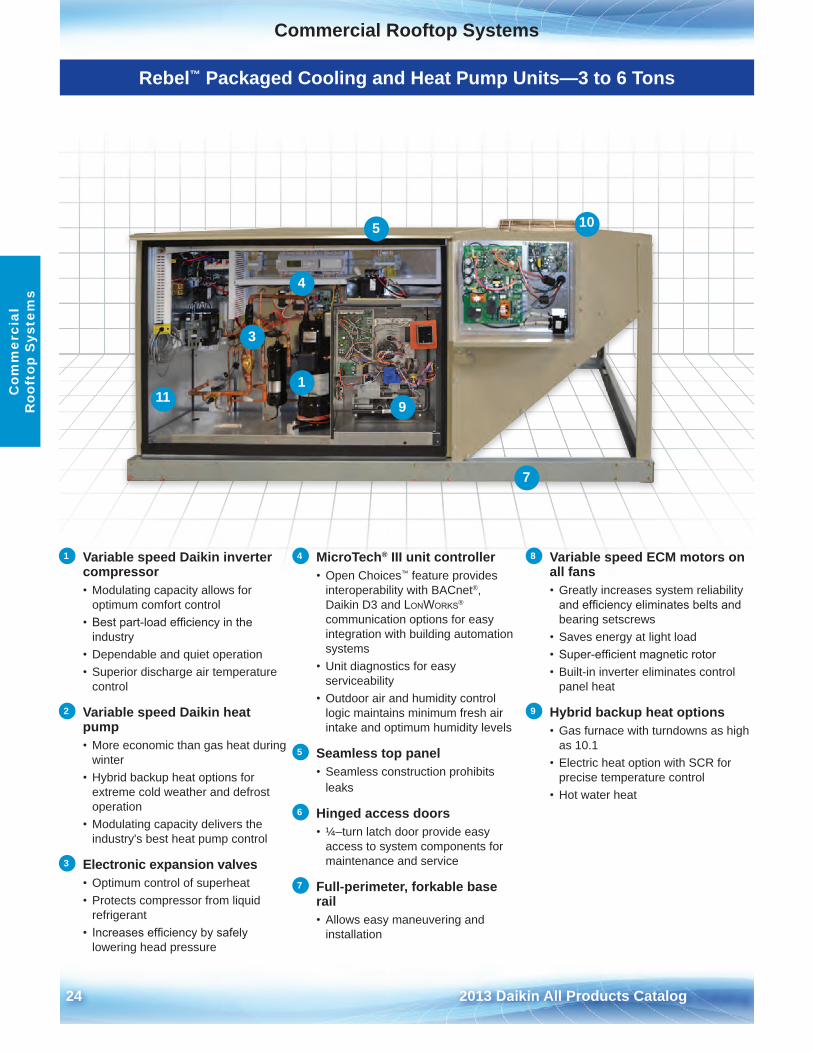
Rebel™ Packaged Cooling and Heat Pump Units—3 to 6 Tons
1 Variable speed Daikin inverter compressor• Modulating capacity allows for
optimum comfort control• Best part-load efficiency in the
industry• Dependable and quiet operation• Superior discharge air temperature
control
2 Variable speed Daikin heat pump• More economic than gas heat during
winter• Hybrid backup heat options for
extreme cold weather and defrostoperation
• Modulating capacity delivers theindustry's best heat pump control
3 Electronic expansion valves• Optimum control of superheat• Protects compressor from liquid
refrigerant• Increases efficiency by safely
lowering head pressure
4 MicroTech® III unit controller• Open Choices™ feature provides
interoperability with BACnet®,Daikin D3 and LonWorks®
communication options for easyintegration with building automationsystems
• Unit diagnostics for easyserviceability
• Outdoor air and humidity controllogic maintains minimum fresh airintake and optimum humidity levels
5 Seamless top panel• Seamless construction prohibits
leaks
6 Hinged access doors• ¼–turn latch door provide easy
access to system components formaintenance and service
7 Full-perimeter, forkable base rail• Allows easy maneuvering and
installation
8 Variable speed ECM motors on all fans• Greatly increases system reliability
and efficiency eliminates belts andbearing setscrews
• Saves energy at light load• Super-efficient magnetic rotor• Built-in inverter eliminates control
panel heat
9 Hybrid backup heat options• Gas furnace with turndowns as high
as 10 .1• Electric heat option with SCR for
precise temperature control• Hot water heat
1
4
3
5
9
7
10
11
Commercial Rooftop Systems
2013 Daikin All Products Catalog 25
Commercial Rooftop SystemsC
omm
ercial R
ooftop System
s
Rebel Packaged Cooling and Heat Pump Units Features and Options
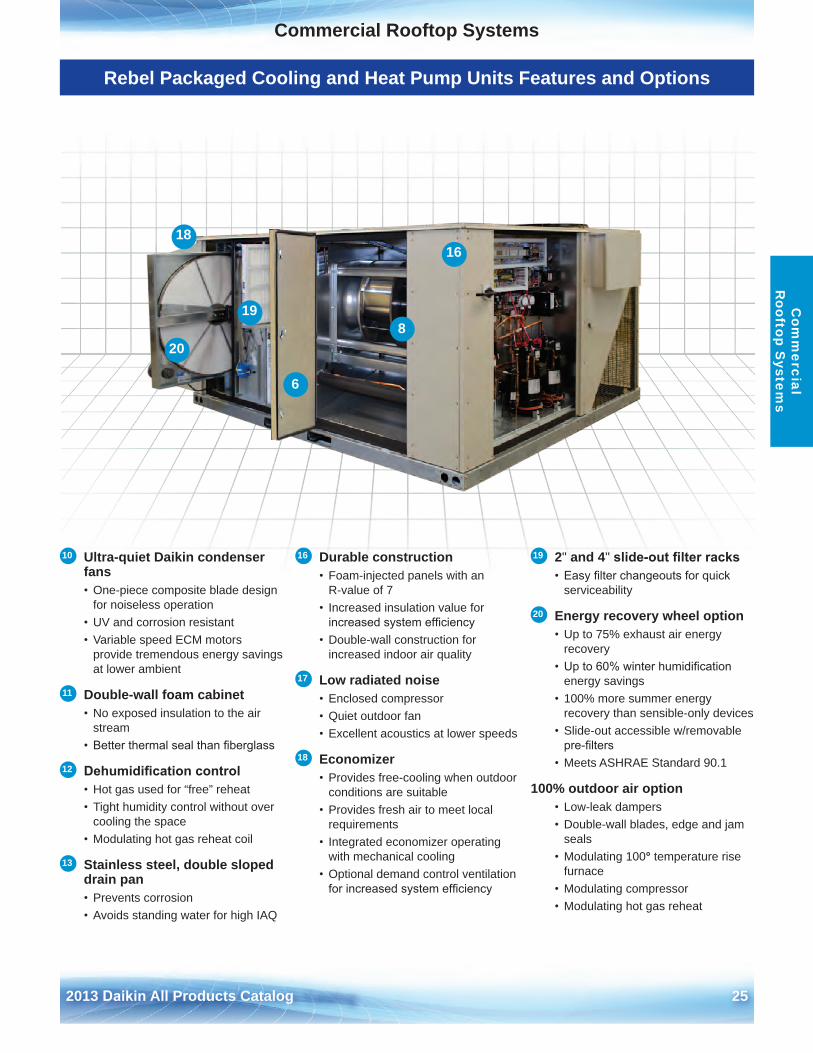
10 Ultra-quiet Daikin condenser fans• One-piece composite blade design
for noiseless operation• UV and corrosion resistant• Variable speed ECM motors
provide tremendous energy savingsat lower ambient
11 Double-wall foam cabinet• No exposed insulation to the air
stream• Better thermal seal than fiberglass
12 Dehumidification control• Hot gas used for “free” reheat• Tight humidity control without over
cooling the space• Modulating hot gas reheat coil
13 Stainless steel, double sloped drain pan• Prevents corrosion• Avoids standing water for high IAQ
16 Durable construction• Foam-injected panels with an
R-value of 7• Increased insulation value for
increased system efficiency• Double-wall construction for
increased indoor air quality
17 Low radiated noise• Enclosed compressor• Quiet outdoor fan• Excellent acoustics at lower speeds
18 Economizer• Provides free-cooling when outdoor
conditions are suitable• Provides fresh air to meet local
requirements• Integrated economizer operating
with mechanical cooling• Optional demand control ventilation
for increased system efficiency
19 2" and 4" slide-out filter racks• Easy filter changeouts for quick
serviceability
20 Energy recovery wheel option• Up to 75% exhaust air energy
recovery• Up to 60% winter humidification
energy savings• 100% more summer energy
recovery than sensible-only devices• Slide-out accessible w/removable
pre-filters• Meets ASHRAE Standard 90 .1
100% outdoor air option• Low-leak dampers• Double-wall blades, edge and jam
seals• Modulating 100° temperature rise
furnace• Modulating compressor• Modulating hot gas reheat
8
6
18
20
19
16
26 2013 Daikin All Products Catalog
Commercial Rooftop SystemsC
omm
erci
al
Roo
ftop
Sys
tem
s
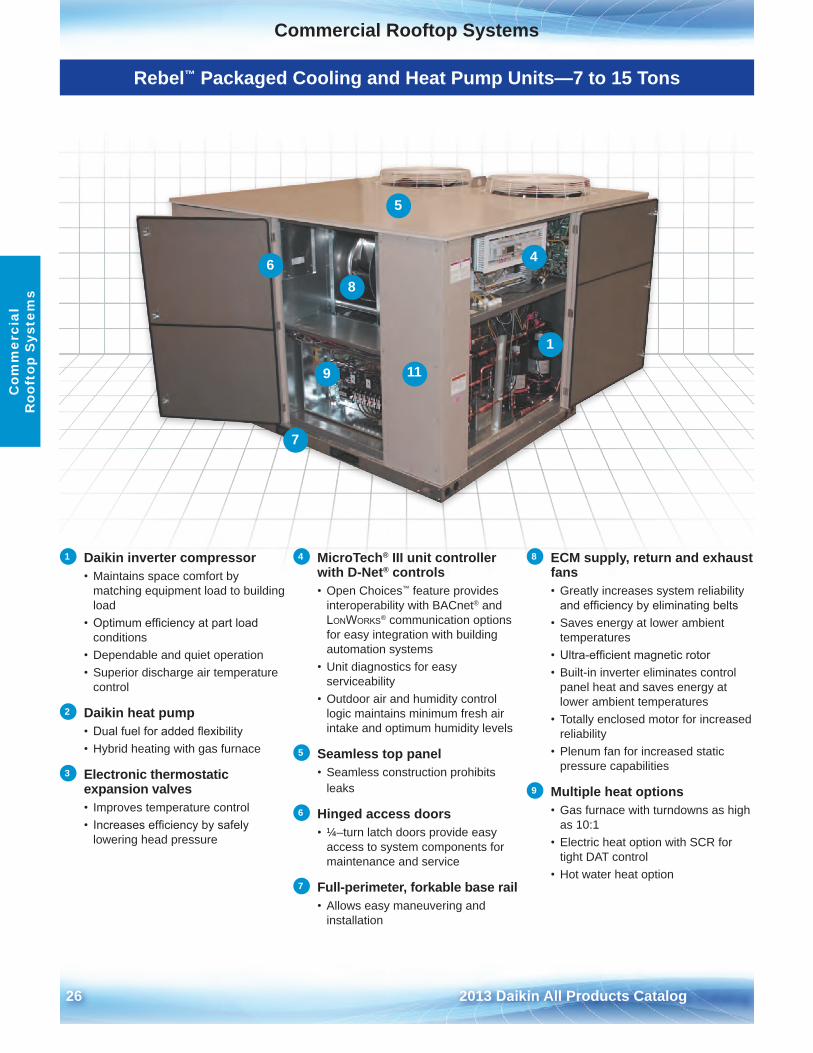
Rebel™ Packaged Cooling and Heat Pump Units—7 to 15 Tons
1 Daikin inverter compressor• Maintains space comfort by
matching equipment load to building load
• Optimum efficiency at part loadconditions
• Dependable and quiet operation• Superior discharge air temperature
control
2 Daikin heat pump• Dual fuel for added flexibility• Hybrid heating with gas furnace
3 Electronic thermostatic expansion valves• Improves temperature control• Increases efficiency by safely
lowering head pressure
4 MicroTech® III unit controller with D-Net® controls• Open Choices™ feature provides
interoperability with BACnet® and LonWorks® communication options for easy integration with building automation systems
• Unit diagnostics for easyserviceability
• Outdoor air and humidity controllogic maintains minimum fresh air intake and optimum humidity levels
5 Seamless top panel• Seamless construction prohibits
leaks
6 Hinged access doors• ¼–turn latch doors provide easy
access to system components for maintenance and service
7 Full-perimeter, forkable base rail• Allows easy maneuvering and
installation
8 ECM supply, return and exhaust fans• Greatly increases system reliability
and efficiency by eliminating belts• Saves energy at lower ambient
temperatures• Ultra-efficient magnetic rotor• Built-in inverter eliminates control
panel heat and saves energy atlower ambient temperatures
• Totally enclosed motor for increasedreliability
• Plenum fan for increased staticpressure capabilities
9 Multiple heat options• Gas furnace with turndowns as high
as 10:1• Electric heat option with SCR for
tight DAT control• Hot water heat option
1
8
4
5
6
9
7
11
Commercial Rooftop Systems
2013 Daikin All Products Catalog 27
Commercial Rooftop SystemsC
omm
ercial R
ooftop System
s
Rebel Packaged Cooling and Heat Pump Units Features and Options
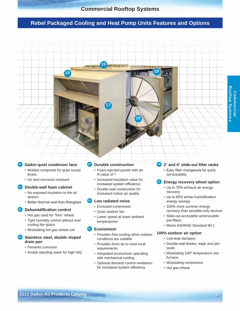
10 Daikin quiet condenser fans• Molded composite for quiet sound
levels• UV and corrosion resistant
11 Double-wall foam cabinet• No exposed insulation to the air
stream• Better thermal seal than fiberglass
12 Dehumidification control• Hot gas used for “free” reheat• Tight humidity control without over
cooling the space• Modulating hot gas reheat coil
13 Stainless steel, double sloped drain pan• Prevents corrosion• Avoids standing water for high IAQ
15 Durable construction• Foam-injected panels with an
R-value of 7• Increased insulation value for
increased system efficiency• Double-wall construction for
increased indoor air quality
16 Low radiated noise• Enclosed compressor• Quiet outdoor fan• Lower speed at lower ambient
temperatures
17 Economizer• Provides free-cooling when outdoor
conditions are suitable• Provides fresh air to meet local
requirements• Integrated economizer operating
with mechanical cooling• Optional demand control ventilation
for increased system efficiency
18 2" and 4" slide-out filter racks• Easy filter changeouts for quick
serviceability
19 Energy recovery wheel option• Up to 75% exhaust air energy
recovery• Up to 60% winter humidification
energy savings• 100% more summer energy
recovery than sensible-only devices• Slide-out accessible w/removable
pre-filters • Meets ASHRAE Standard 90 .1
100% outdoor air option• Low-leak dampers• Double-wall blades, edge and jam
seals• Modulating 100° temperature rise
furnace• Modulating compressor• Hot gas reheat
10
15
17
18
19
28 2013 Daikin All Products Catalog
Commercial Rooftop SystemsC
omm
erci
al
Roo
ftop
Sys
tem
s
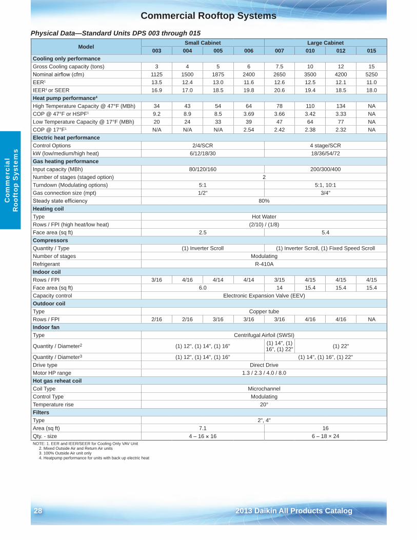
Physical Data—Standard Units DPS 003 through 015
ModelSmall Cabinet Large Cabinet
003 004 005 006 007 010 012 015Cooling only performanceGross Cooling capacity (tons) 3 4 5 6 7 .5 10 12 15Nominal airflow (cfm) 1125 1500 1875 2400 2650 3500 4200 5250EER1 13 .5 12 .4 13 .0 11 .6 12 .6 12 .5 12 .1 11 .0IEER1 or SEER 16 .9 17 .0 18 .5 19 .8 20 .6 19 .4 18 .5 18 .0Heat pump performance4
High Temperature Capacity @ 47°F (MBh) 34 43 54 64 78 110 134 NACOP @ 47°F or HSPF1 9 .2 8 .9 8 .5 3 .69 3 .66 3 .42 3 .33 NALow Temperature Capacity @ 17°F (MBh) 20 24 33 39 47 64 77 NACOP @ 17°F1 N/A N/A N/A 2 .54 2 .42 2 .38 2 .32 NAElectric heat performanceControl Options 2/4/SCR 4 stage/SCRkW (low/medium/high heat) 6/12/18/30 18/36/54/72Gas heating performanceInput capacity (MBh) 80/120/160 200/300/400Number of stages (staged option) 2Turndown (Modulating options) 5:1 5:1, 10:1Gas connection size (mpt) 1/2" 3/4"Steady state efficiency 80%Heating coilType Hot WaterRows / FPI (high heat/low heat) (2/10) / (1/8)Face area (sq ft) 2 .5 5 .4CompressorsQuantity / Type (1) Inverter Scroll (1) Inverter Scroll, (1) Fixed Speed ScrollNumber of stages ModulatingRefrigerant R-410AIndoor coilRows / FPI 3/16 4/16 4/14 4/14 3/15 4/15 4/15 4/15Face area (sq ft) 6 .0 14 15 .4 15 .4 15 .4Capacity control Electronic Expansion Valve (EEV)Outdoor coilType Copper tubeRows / FPI 2/16 2/16 3/16 3/16 3/16 4/16 4/16 NAIndoor fanType Centrifugal Airfoil (SWSI)
Quantity / Diameter2 (1) 12", (1) 14", (1) 16" (1) 14", (1) 16", (1) 22" (1) 22"
Quantity / Diameter3 (1) 12", (1) 14", (1) 16" (1) 14", (1) 16", (1) 22"Drive type Direct DriveMotor HP range 1 .3 / 2 .3 / 4 .0 / 8 .0Hot gas reheat coilCoil Type MicrochannelControl Type ModulatingTemperature rise 20°FiltersType 2", 4"Area (sq ft) 7 .1 16Qty . - size 4 – 16 × 16 6 – 18 × 24NOTE: 1 . EER and IEER/SEER for Cooling Only VAV Unit
2 . Mixed Outside Air and Return Air units 3 . 100% Outside Air unit only4 . Heatpump performance for units with back up electric heat
Commercial Rooftop SystemsCommercial Rooftop Systems
2013 Daikin All Products Catalog 29
Com
mercial
Rooftop S
ystems
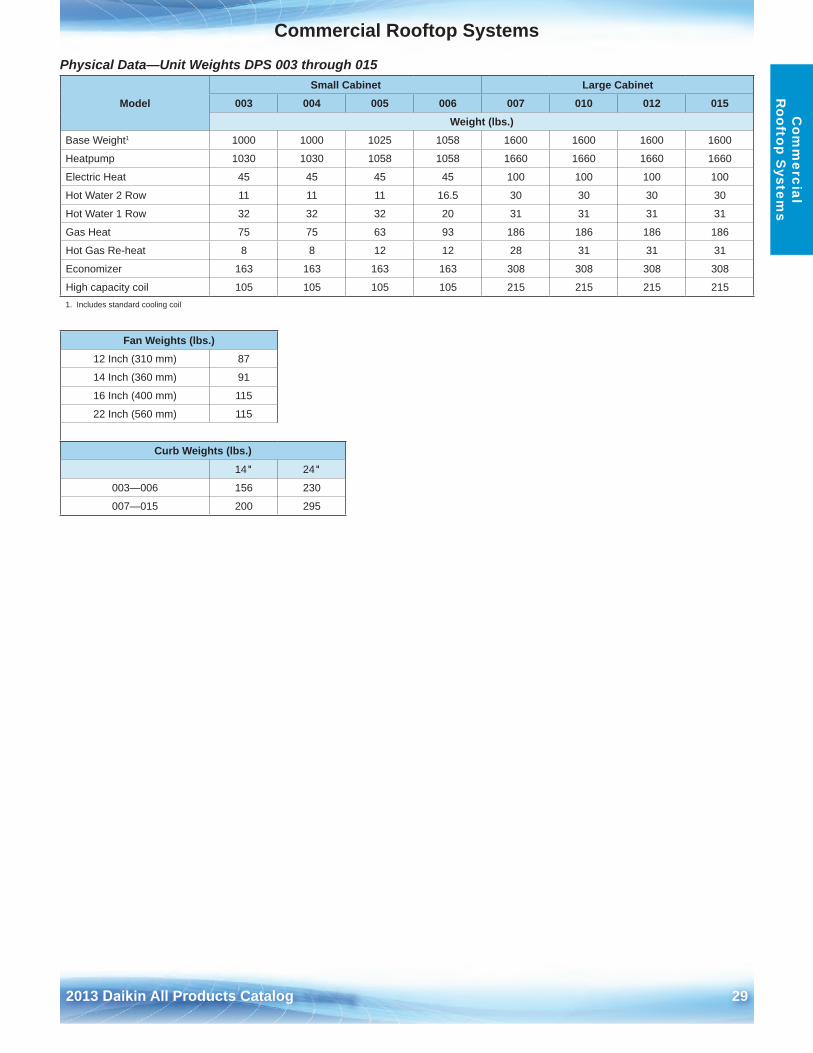
Physical Data—Unit Weights DPS 003 through 015
ModelSmall Cabinet Large Cabinet
003 004 005 006 007 010 012 015Weight (lbs .)
Base Weight1 1000 1000 1025 1058 1600 1600 1600 1600
Heatpump 1030 1030 1058 1058 1660 1660 1660 1660
Electric Heat 45 45 45 45 100 100 100 100
Hot Water 2 Row 11 11 11 16 .5 30 30 30 30
Hot Water 1 Row 32 32 32 20 31 31 31 31
Gas Heat 75 75 63 93 186 186 186 186
Hot Gas Re-heat 8 8 12 12 28 31 31 31
Economizer 163 163 163 163 308 308 308 308
High capacity coil 105 105 105 105 215 215 215 2151 . Includes standard cooling coil
Fan Weights (lbs .)12 Inch (310 mm) 87
14 Inch (360 mm) 91
16 Inch (400 mm) 115
22 Inch (560 mm) 115
Curb Weights (lbs .)
14" 24"
003—006 156 230
007—015 200 295

30 2013 Daikin All Products Catalog
This page intentionally left blank.
Commercial Rooftop Systems
2013 Daikin All Products Catalog 31
Com
mercial
Rooftop S
ystems
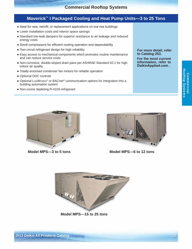
Model MPS—3 to 5 tons Model MPS—6 to 12 tons
Model MPS—15 to 25 tons
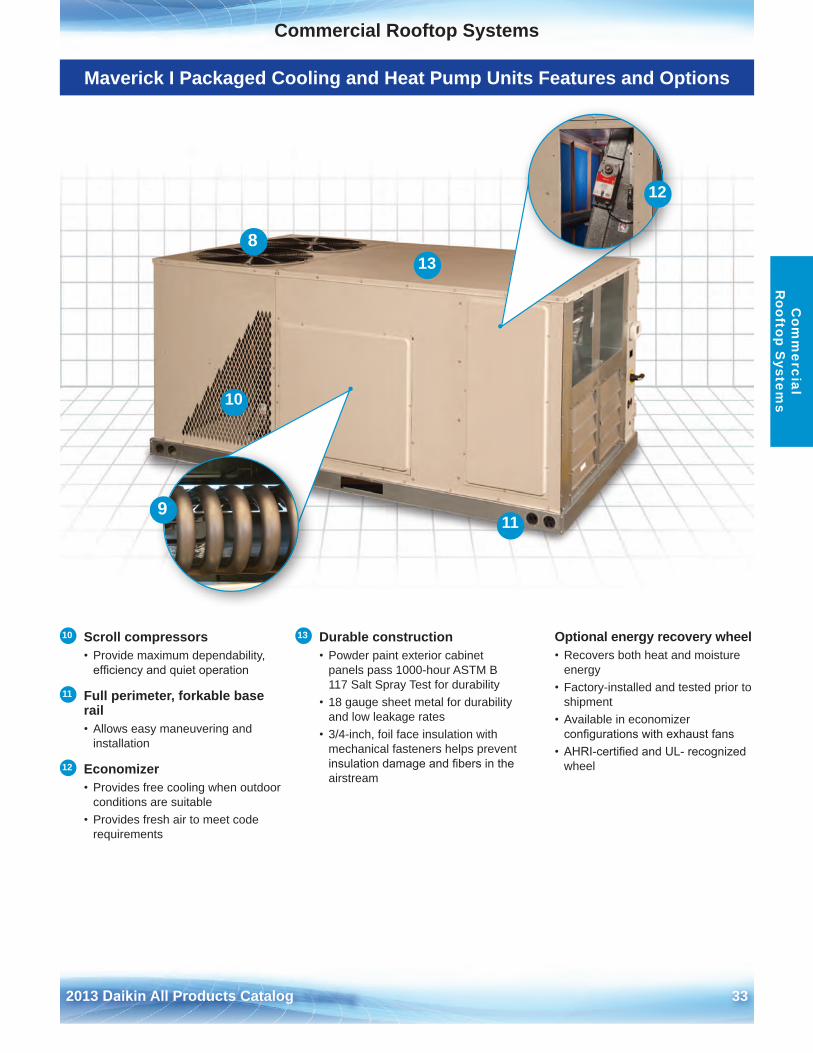
Maverick™ I Packaged Cooling and Heat Pump Units—3 to 25 Tons
● Ideal for new, retrofit, or replacement applications on low rise buildings● Lower installation costs and interior space savings● Standard low-leak dampers for superior resistance to air leakage and reduced
energy costs● Scroll compressors for efficient cooling operation and dependability● Two-circuit refrigerant design for high reliability● Easy access to mechanical components which promotes routine maintenance
and can reduce service costs● Non-corrosive, double-sloped drain pans per ASHRAE Standard 62 .1 for high
indoor air quality● Totally enclosed condenser fan motors for reliable operation● Optional DDC controls● Optional LonWorks® or BACnet® communication options for integration into a
building automation system● Non-ozone depleting R-410A refrigerant
For more detail, refer to Catalog 253 .For the most current information, refer to DaikinApplied.com .
32 2013 Daikin All Products Catalog
Commercial Rooftop SystemsC
omm
erci
al
Roo
ftop
Sys
tem
s
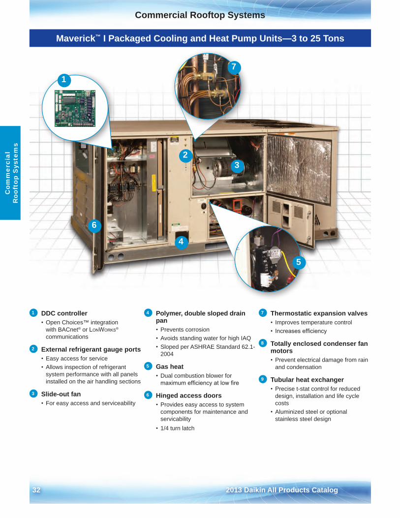
Maverick™ I Packaged Cooling and Heat Pump Units—3 to 25 Tons
2
6
4
3
5
71
1 DDC controller• Open Choices™ integration
with BACnet® or LonWorks® communications
2 External refrigerant gauge ports• Easy access for service• Allows inspection of refrigerant
system performance with all panelsinstalled on the air handling sections
3 Slide-out fan• For easy access and serviceability
4 Polymer, double sloped drain pan• Prevents corrosion• Avoids standing water for high IAQ• Sloped per ASHRAE Standard 62 .1-
2004
5 Gas heat• Dual combustion blower for
maximum efficiency at low fire
6 Hinged access doors• Provides easy access to system
components for maintenance and servicability
• 1/4 turn latch
7 Thermostatic expansion valves• Improves temperature control• Increases efficiency
8 Totally enclosed condenser fan motors• Prevent electrical damage from rain
and condensation
9 Tubular heat exchanger• Precise t-stat control for reduced
design, installation and life cycle costs
• Aluminized steel or optionalstainless steel design
Commercial Rooftop Systems
2013 Daikin All Products Catalog 33
Commercial Rooftop SystemsC
omm
ercial R
ooftop System
s
Maverick I Packaged Cooling and Heat Pump Units Features and Options
8
11
13
9
12
10
10 Scroll compressors• Provide maximum dependability,
efficiency and quiet operation
11 Full perimeter, forkable base rail• Allows easy maneuvering and
installation
12 Economizer• Provides free cooling when outdoor
conditions are suitable• Provides fresh air to meet code
requirements
13 Durable construction • Powder paint exterior cabinet
panels pass 1000-hour ASTM B117 Salt Spray Test for durability
• 18 gauge sheet metal for durabilityand low leakage rates
• 3/4-inch, foil face insulation withmechanical fasteners helps preventinsulation damage and fibers in theairstream
Optional energy recovery wheel• Recovers both heat and moisture
energy• Factory-installed and tested prior to
shipment• Available in economizer
configurations with exhaust fans• AHRI-certified and UL- recognized
wheel
34 2013 Daikin All Products Catalog
Commercial Rooftop SystemsC
omm
erci
al
Roo
ftop
Sys
tem
s
Maverick I Packaged Cooling and Heat Pump Units Features and Options
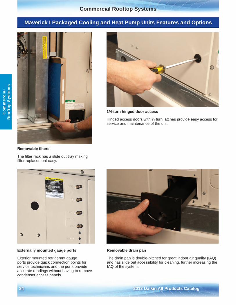
Removable filters
The filter rack has a slide out tray making filter replacement easy.
1/4-turn hinged door access
Hinged access doors with ¼ turn latches provide easy access for service and maintenance of the unit .
Externally mounted gauge ports
Exterior mounted refrigerant gauge ports provide quick connection points for service technicians and the ports provide accurate readings without having to remove condenser access panels .
Removable drain pan
The drain pan is double-pitched for great indoor air quality (IAQ) and has slide out accessibility for cleaning, further increasing the IAQ of the system .
Commercial Rooftop Systems
2013 Daikin All Products Catalog 35
Commercial Rooftop SystemsC
omm
ercial R
ooftop System
s
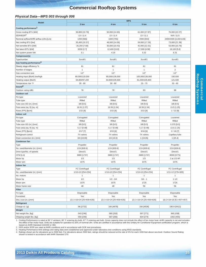
Physical Data—MPS 003 through 006 Model
MPS3 ton 4 ton 5 ton 6 ton
Cooling performance1
Gross cooling BTU [kW] 36,800 [10 .78] 50,000 [14 .65] 61,000 [17 .87] 76,000 [22 .27]
EER/IEER2 13 / 11 .4 13 / 11 .4 13 / 11 .1 N/A / 11 .5
Nominal airflow/AHRI airflow (cfm) [L/s] 1200 [566] 1600 [755] 2000 [944] 2400/2400 [1133/1133]
Net cooling BTU [kw] 35,400 [10 .37] 48,000 [14 .06] 59,000 [17 .29] 73,000 [21 .39]
Net sensible BTU [kW] 26,200 [7 .68] 35,600 [10 .43] 42,000 [12 .31] 53,900 [15 .79]
Net latent BTU [kW] 9200 [2 .7] 12,400 [3 .63] 17,000 [4 .98] 19,100 [5 .6]
Net system power kW 3 .1 4 .19 5 .32 6 .31
Compressor(s)Type/number Scroll/1 Scroll/1 Scroll/1 Scroll/1
Gas heating performance3
Steady stage efficiency % 81 81 81 81
Number of stages 1 1 1 2
Gas connection size 1/2" 1/2" 1/2" 1/2"
Heating input (BtuH) low/high 80,000/120,000 80,000/135,000 100,000/135,000 150,000
Heating output (BtuH) 64,800/97,200 64,800/109,400 81,000/109,400 121,500
Temperature rise °F 30 - 80 30 - 80 25 - 70 30 - 60
Sound4
Outdoor rating (dB) 78 78 83 88
Outdoor coilFin type Louvered Louvered Louvered Louvered
Tube type Rifled Rifled Rifled Rifled
Tube size OD (in .) [mm] 3/8 [9 .5] 3/8 [9 .5] 3/8 [9 .5] 3/8 [9 .5]
Face area (sq . ft) [sq . m] 16 .91 [1 .57] 16 .56 [1 .54] 16 .56 [1 .54] 13 .5 [1 .25]
Rows (FPI) [fpcm] 1/22 [9] 2/22 [9] 2/22 [9] 1 / 22 [9]
Indoor coilFin type Corrugated Corrugated Corrugated Louvered
Tube type Rifled Rifled Rifled Rifled
Tube size OD (in .) [mm] 3/8 [9 .5] 3/8 [9 .5] 3/8 [9 .5] 0 .375 [9 .5]
Face area (sq . ft) [sq . m] 5 .17 [0 .48] 5 .17 [0 .48] 5 .17 [0 .48] 13 .5 [1 .25]
Rows (FPI) [fpcm] 2/17 [7] 3/15 [6] 3/16 [6] 2 / 18 [7]
Refrigerant control TX valves TX valves TX valves Capillary tube
Drain connection (in .) [mm] 3/4 [19 .00] 3/4 [19 .0] 1 [19 .05] 1 [25 .4]
Condenser fanType Propeller Propeller Propeller Propeller
No . used/diameter (in .) [mm] 1/24 [609 .6] 1/24 [609 .6] 1/24 [609 .6] 2/24 [609 .6]
Drive type/No . of speeds Direct/1 Direct/1 Direct/1 Direct/1
CFM [L/s] 3680 [1737] 3680 [1737] 3680 [1737] 8000 [3775]
Motor hp 1/3 1/3 1/3 2 at 1/3 HP
Motor rpm 1075 1075 1075 1075
Indoor fanType FC Centrifugal FC Centrifugal FC Centrifugal FC Centrifugal
No . used/diameter (in .) [mm] 1/10×10 [254×254] 1/10×10 [254×254] 1/10×10 [254×254] 1/11×12 [279×305]
No . motors 1 1 1 1
Motor hp 1/2 1/2 - 3/4 3/4 - 1 1 1/2
Motor rpm 1075 1075 1725 1725
Motor frame size 48 48 56 56
FilterFin type Disposable Disposable Disposable Disposable
Furnished Yes Yes Yes Yes
(No .) size (in .) [mm] (2) 1×16×24 [25×406×635] (2) 1×16×24 [25×406×635] (2) 1×16×24 [25×406×635] (6) 2×18×18 [51×457×457]
RefrigerantCharge oz . [g] 96 [2722] 165 [4678] 160 [4536] 190 .9 [5412]
WeightNet weight lbs . [kg] 543 [246] 580 [263] 597 [271] 965 [438]
Shipping weight lbs . [kg] 550 [249] 587 [266] 604 [274] 1002 [455]
1 . Cooling Performance is rated at 95° F ambient, 80° F entering dry bulb, 67° F entering wet bulb . Gross capacity does not include the effect of fan motor heat . AHRI capacity is net and includes the effect of fan motor heat. Units are suitable for operation to 20% of nominal cfm. Units are certified in accordance with the Unitary Air Conditioner Equipment certification program, which is based on AHRI Standard 210/240 or 360 .
2 . EER and/or IEER are rated at AHRI conditions and in accordance with DOE test procedures .3 . Heating Performance limit settings and rating data were established and approved under laboratory test conditions using ANSI standards . 4 . Ratings shown are for elevations up to 2000 feet . For elevations above 2000 feet, ratings should be reduced at the rate of 4% for each 1000 feet above sea level . Outdoor Sound Rating
shown is tested in accordance with AHRI Standard 270 .
36 2013 Daikin All Products Catalog
Commercial Rooftop SystemsC
omm
erci
al
Roo
ftop
Sys
tem
s
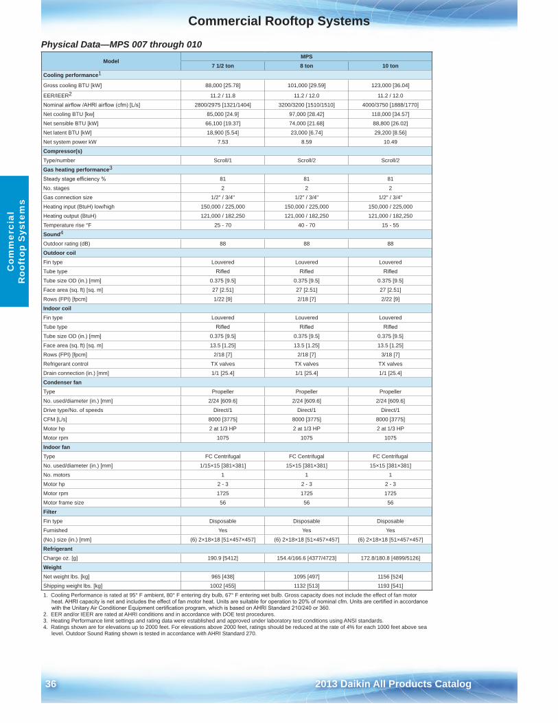
Physical Data—MPS 007 through 010 Model
MPS7 1/2 ton 8 ton 10 ton
Cooling performance1
Gross cooling BTU [kW] 88,000 [25 .78] 101,000 [29 .59] 123,000 [36 .04]
EER/IEER2 11 .2 / 11 .8 11 .2 / 12 .0 11 .2 / 12 .0
Nominal airflow /AHRI airflow (cfm) [L/s] 2800/2975 [1321/1404] 3200/3200 [1510/1510] 4000/3750 [1888/1770]
Net cooling BTU [kw] 85,000 [24 .9] 97,000 [28 .42] 118,000 [34 .57]
Net sensible BTU [kW] 66,100 [19 .37] 74,000 [21 .68] 88,800 [26 .02]
Net latent BTU [kW] 18,900 [5 .54] 23,000 [6 .74] 29,200 [8 .56]
Net system power kW 7 .53 8 .59 10 .49
Compressor(s)Type/number Scroll/1 Scroll/2 Scroll/2
Gas heating performance3
Steady stage efficiency % 81 81 81
No . stages 2 2 2
Gas connection size 1/2" / 3/4" 1/2" / 3/4" 1/2" / 3/4"
Heating input (BtuH) low/high 150,000 / 225,000 150,000 / 225,000 150,000 / 225,000
Heating output (BtuH) 121,000 / 182,250 121,000 / 182,250 121,000 / 182,250
Temperature rise °F 25 - 70 40 - 70 15 - 55
Sound4
Outdoor rating (dB) 88 88 88
Outdoor coilFin type Louvered Louvered Louvered
Tube type Rifled Rifled Rifled
Tube size OD (in .) [mm] 0 .375 [9 .5] 0 .375 [9 .5] 0 .375 [9 .5]
Face area (sq . ft) [sq . m] 27 [2 .51] 27 [2 .51] 27 [2 .51]
Rows (FPI) [fpcm] 1/22 [9] 2/18 [7] 2/22 [9]
Indoor coilFin type Louvered Louvered Louvered
Tube type Rifled Rifled Rifled
Tube size OD (in .) [mm] 0 .375 [9 .5] 0 .375 [9 .5] 0 .375 [9 .5]
Face area (sq . ft) [sq . m] 13 .5 [1 .25] 13 .5 [1 .25] 13 .5 [1 .25]
Rows (FPI) [fpcm] 2/18 [7] 2/18 [7] 3/18 [7]
Refrigerant control TX valves TX valves TX valves
Drain connection (in .) [mm] 1/1 [25 .4] 1/1 [25 .4] 1/1 [25 .4]
Condenser fanType Propeller Propeller Propeller
No . used/diameter (in .) [mm] 2/24 [609 .6] 2/24 [609 .6] 2/24 [609 .6]
Drive type/No . of speeds Direct/1 Direct/1 Direct/1
CFM [L/s] 8000 [3775] 8000 [3775] 8000 [3775]
Motor hp 2 at 1/3 HP 2 at 1/3 HP 2 at 1/3 HP
Motor rpm 1075 1075 1075
Indoor fanType FC Centrifugal FC Centrifugal FC Centrifugal
No . used/diameter (in .) [mm] 1/15×15 [381×381] 15×15 [381×381] 15×15 [381×381]
No . motors 1 1 1
Motor hp 2 - 3 2 - 3 2 - 3
Motor rpm 1725 1725 1725
Motor frame size 56 56 56
FilterFin type Disposable Disposable Disposable
Furnished Yes Yes Yes
(No .) size (in .) [mm] (6) 2×18×18 [51×457×457] (6) 2×18×18 [51×457×457] (6) 2×18×18 [51×457×457]
RefrigerantCharge oz . [g] 190 .9 [5412] 154 .4/166 .6 [4377/4723] 172 .8/180 .8 [4899/5126]
WeightNet weight lbs . [kg] 965 [438] 1095 [497] 1156 [524]
Shipping weight lbs . [kg] 1002 [455] 1132 [513] 1193 [541]
1 . Cooling Performance is rated at 95° F ambient, 80° F entering dry bulb, 67° F entering wet bulb . Gross capacity does not include the effect of fan motor heat. AHRI capacity is net and includes the effect of fan motor heat. Units are suitable for operation to 20% of nominal cfm. Units are certified in accordance with the Unitary Air Conditioner Equipment certification program, which is based on AHRI Standard 210/240 or 360.
2 . EER and/or IEER are rated at AHRI conditions and in accordance with DOE test procedures .3 . Heating Performance limit settings and rating data were established and approved under laboratory test conditions using ANSI standards . 4 . Ratings shown are for elevations up to 2000 feet . For elevations above 2000 feet, ratings should be reduced at the rate of 4% for each 1000 feet above sea
level . Outdoor Sound Rating shown is tested in accordance with AHRI Standard 270 .

Commercial Rooftop Systems
2013 Daikin All Products Catalog 37
Commercial Rooftop SystemsC
omm
ercial R
ooftop System
s
Physical Data—MPS 012 through 025 Model
MPS12 ton 15 ton 20 ton 25 ton
Cooling performance1
Gross cooling BTU [kW] 156,000 [45 .71] 188,000 [55 .08] 244,000 [71 .49] 312,000 [91 .42]
EER/IEER2 11 / 11 .4 11 .1 / 12 .4 11 .1 / 11 .4 10 / 10 .1
Nominal airflow/AHRI airflow (cfm) [L/s] 5000/4400 [2360/2076] 6000/5900 [2831/2784] 8000/7725 [3775/3645] 10000/9475 [4719/4471]
Net cooling BTU [kw] 148,000 [43 .36] 182,000 [53 .33] 234,000 [68 .56] 294,000 [86 .14]
Net sensible BTU [kW] 107,600 [31 .53] 135,700 [39 .76] 171,600 [50 .28] 214,100 [62 .73]
Net latent BTU [kW] 40,400 [11 .84] 46,300 [13 .57] 62,400 [18 .28] 79,900 [23 .41]
Net system power kW 13 .39 16 .35 21 .04 29 .39
Compressor(s)Type/number Scroll/2 Scroll/2 Scroll/2 Scroll/2
Gas heating performance3
Steady stage efficiency % 81 81 81 81
No . stages 2 2 2 2
Gas connection size 1/2" / 3/4" 3/4" 3/4" 3/4"
Heating input (BtuH) 150,000 / 252,000 250,000 / 350,000 300,000 / 400,000 300,000 / 400,000
Heating output (BtuH) 121,500 / 204,000 203,000 / 284,000 243,000 / 324,000 243,000 / 324,000
Temperature rise °F 15 - 55 15 - 60 15 - 55 10 - 45
Sound4
Outdoor rating (dB) 88 91 91 92
Outdoor coilFin type Louvered Louvered Louvered Louvered
Tube type Microchannel Rifled Rifled Rifled
Tube size OD (in .) [mm] 1 [25 .4] 0 .375 [9 .5] 0 .375 [9 .5] 0 .375 [9 .5]
Face area (sq . ft) [sq . m] 27 [2 .51] 53 .3 [4 .95] 53 .3 [4 .95] 53 .3 [4 .95]
Rows (FPI) [fpcm] 2 / 20 [8] 1/22 [9] 2/22 [9] 2/22 [9]
Indoor coilFin type Louvered Louvered Louvered Louvered
Tube type Rifled Rifled Rifled Rifled
Tube size OD (in .) [mm] 0 .375 [9 .5] 0 .375 [9 .5] 0 .375 [9 .5] 0 .375 [9 .5]
Face area (sq . ft) [sq . m] 13 .5 [1 .25] 26 .67 [2 .48] 26 .67 [2 .48] 26 .67 [2 .48]
Rows (FPI) [fpcm] 4 / 15 [6] 2/18 [7] 3/13 [5] 4/15 [6]
Refrigerant control TX valves TX valves TX valves TX valves
Drain connection (in .) [mm] 1 [25 .4] 1 [25 .4] 1 [25 .4] 1 [25 .4]
Condenser fanType Propeller Propeller Propeller Propeller
No . used/diameter (in .) [mm] 2/24 [609 .6] 4/24 [609 .6] 6/24 [609 .6] 6/24 [609 .6]
Drive type/No . of speeds Direct/1 Direct/1 Direct/1 Direct/1
CFM [L/s] 8000 [3775] 16,000 [7550] 19,800 [9344] 19,800 [9344]
Motor hp 2 at 1/2 HP 4 at 1/3 HP 6 at 1/3 HP 6 at 1/3 HP
Motor rpm 1075 1075 1075 1075
Motor frame size 56/184 56/184 184/213 213/215
Indoor fanType FC Centrifugal FC Centrifugal FC Centrifugal FC Centrifugal
No . used/diameter (in .) [mm] 1/15×15 [381×381] 2/18×9 [457×229] 2/18×9 [457×229] 2/18×9 [457×229]
No . motors 1 1 1 1
Motor hp 3, 5 3, 5 5, 7-1/2 7-1/2, 10
Motor rpm 1725 1725 1725 1725
FilterFin type Disposable Disposable Disposable Disposable
Furnished Yes Yes Yes Yes
(No .) size (in .) [mm] (6) 2×18×18 [51×457×457] (8) 2×25×20 [51×635×508] (8) 2×25×20 [51×635×508] (8) 2×25×20 [51×635×508]
RefrigerantCharge oz . [g] 159 .2/156 [4513/4423] 205/211 [5812/5982] 402/331 [11397/9384] 339/357 [9611/10121]
WeightNet weight lbs . [kg] 1230 [558] 2000 [907] 2341 [1062] 2433 [1104]
Shipping weight lbs . [kg] 1267 [575] 2100 [953] 2441 [1107] 2533 [1149]
1 . Cooling Performance is rated at 95° F ambient, 80° F entering dry bulb, 67° F entering wet bulb . Gross capacity does not include the effect of fan motor heat . AHRI capacity is net and includes the effect of fan motor heat. Units are suitable for operation to 20% of nominal cfm. Units are certified in accordance with the Unitary Air Conditioner Equipment certification program, which is based on AHRI Standard 210/240 or 360 .
2 . EER and/or IEER are rated at AHRI conditions and in accordance with DOE test procedures .3 . Heating Performance limit settings and rating data were established and approved under laboratory test conditions using ANSI standards . 4 . Ratings shown are for elevations up to 2000 feet . For elevations above 2000 feet, ratings should be reduced at the rate of 4% for each 1000 feet above sea level . Outdoor Sound Rating
shown is tested in accordance with AHRI Standard 270 .
38 2013 Daikin All Products Catalog
Commercial Rooftop SystemsC
omm
erci
al
Roo
ftop
Sys
tem
s
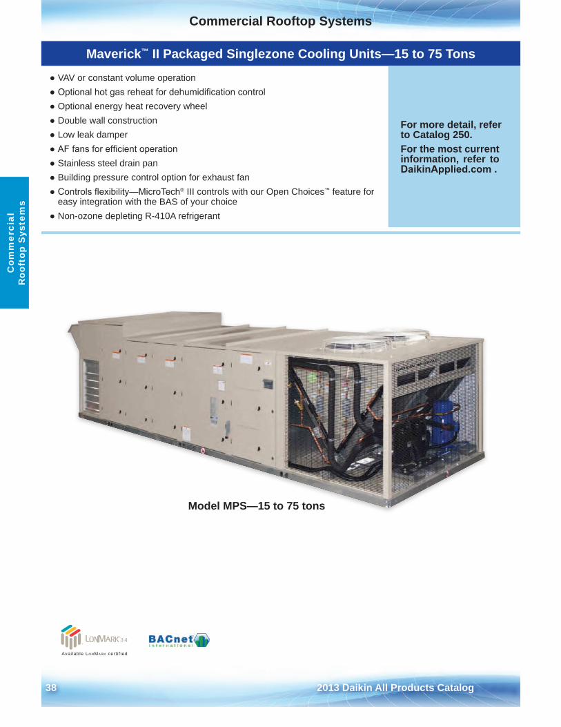
Maverick™ II Packaged Singlezone Cooling Units—15 to 75 Tons
● VAV or constant volume operation● Optional hot gas reheat for dehumidification control● Optional energy heat recovery wheel● Double wall construction● Low leak damper● AF fans for efficient operation● Stainless steel drain pan● Building pressure control option for exhaust fan● Controls flexibility—MicroTech® III controls with our Open Choices™ feature for
easy integration with the BAS of your choice● Non-ozone depleting R-410A refrigerant
For more detail, refer to Catalog 250 .For the most current information, refer to DaikinApplied.com .
Available LonMark cert i f ied
Model MPS—15 to 75 tons
Commercial Rooftop Systems
2013 Daikin All Products Catalog 39
Commercial Rooftop SystemsC
omm
ercial R
ooftop System
s
Maverick II Packaged Singlezone Cooling Unit Features and Options
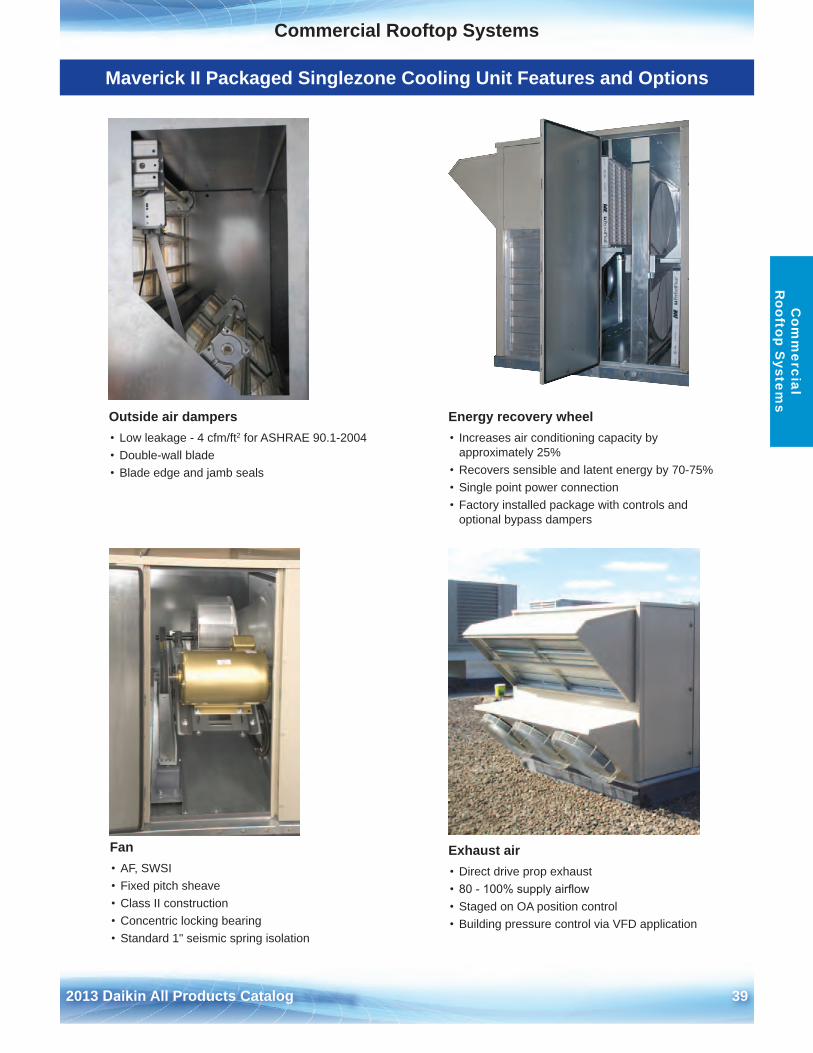
Exhaust air• Direct drive prop exhaust• 80 - 100% supply airflow• Staged on OA position control• Building pressure control via VFD application
Fan• AF, SWSI• Fixed pitch sheave• Class II construction• Concentric locking bearing• Standard 1" seismic spring isolation
Energy recovery wheel• Increases air conditioning capacity by
approximately 25%• Recovers sensible and latent energy by 70-75%• Single point power connection• Factory installed package with controls and
optional bypass dampers
Outside air dampers• Low leakage - 4 cfm/ft2 for ASHRAE 90 .1-2004• Double-wall blade• Blade edge and jamb seals
40 2013 Daikin All Products Catalog
Commercial Rooftop SystemsC
omm
erci
al
Roo
ftop
Sys
tem
s
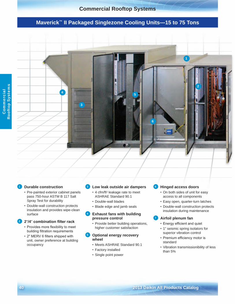
Maverick™ II Packaged Singlezone Cooling Units—15 to 75 Tons
1 Durable construction• Pre-painted exterior cabinet panels
pass 750-hour ASTM B 117 SaltSpray Test for durability
• Double-wall construction protectsinsulation and provides wipe-cleansurface
2 2"/4" combination filter rack• Provides more flexibility to meet
building filtration requirements• 2" MERV 6 filters shipped with
unit, owner preference at buildingoccupancy
3 Low leak outside air dampers • 4 cfm/ft2 leakage rate to meet
ASHRAE Standard 90 .1• Double-wall blades• Blade edge and jamb seals
4 Exhaust fans with building pressure control• Provide better building operations,
higher customer satisfaction
5 Optional energy recovery wheel• Meets ASHRAE Standard 90 .1• Factory installed• Single point power
6 Hinged access doors• On both sides of unit for easy
access to all components• Easy open, quarter-turn latches• Double-wall construction protects
insulation during maintenance
7 Airfoil plenum fan• Energy efficient and quiet• 1" seismic spring isolators for
superior vibration control• Premium efficiency motor is
standard• Vibration transmissionibility of less
than 5%
1
2
3
4 5
6
Commercial Rooftop Systems
2013 Daikin All Products Catalog 41
Commercial Rooftop SystemsC
omm
ercial R
ooftop System
s
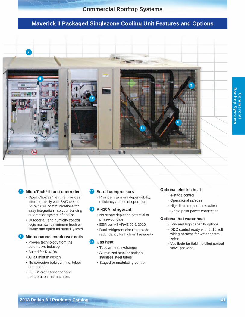
Maverick II Packaged Singlezone Cooling Unit Features and Options
7
12
8
9
1011
8 MicroTech® III unit controller• Open Choices™ feature provides
interoperability with BACnet® or LonWorks® communications for easy integration into your building automation system of choice
• Outdoor air and humidity controllogic maintains minimum fresh air intake and optimum humidity levels
9 Microchannel condenser coils• Proven technology from the
automotive industry• Suited for R-410A• All aluminum design• No corrosion between fins, tubes
and header• LEED® credit for enhanced
refrigeration management
10 Scroll compressors• Provide maximum dependability,
efficiency and quiet operation
11 R-410A refrigerant• No ozone depletion potential or
phase-out date• EER per ASHRAE 90 .1 2010• Dual refrigerant circuits provide
redundancy for high unit reliability
12 Gas heat• Tubular heat exchanger• Aluminized steel or optional
stainless steel tubes• Staged or modulating control
Optional electric heat• 4-stage control• Operational safeties• High-limit temperature switch• Single point power connection
Optional hot water heat• Low and high capacity options• DDC control ready with 0–10 volt
wiring harness for water controlvalve
• Vestibule for field installed controlvalve package
42 2013 Daikin All Products Catalog
Commercial Rooftop SystemsC
omm
erci
al
Roo
ftop
Sys
tem
s
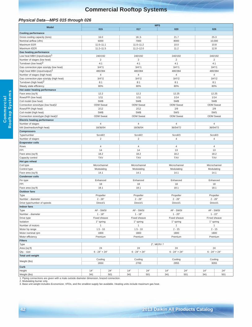
Physical Data—MPS 015 through 026 Model
MPS015 017 020 026
Cooling performanceGross cooling capacity (tons) 16 .0 18 .;5 21 .7 25 .3Nominal airflow (cfm) 6000 7000 8000 10,000Maximum EER 11 .0–11 .1 11 .0–11 .2 10 .0 10 .8Maximum IEER 11 .2–11 .5 11 .2–12 .0 11 .2 12 .8Gas heating performanceLow heat MBH (input/output)1 240/192 240/192 240/192 240/192Number of stages (low heat) 2 2 2 2Turndown (low heat)2 4:1 4:1 4:1 4:1Gas connection pipe size/qty (low heat) 3/4"/1 3/4"/1 3/4"/1 3/4"/1High heat MBH (input/output)1 480/384 480/384 480/384 480/384Number of stages (high heat) 4 4 4 4Gas connection pipe size/qty (high heat) 3/4"/2 3/4"/2 3/4"/2 3/4"/2Turndown (high heat)2 8:1 8:1 8:1 8:1Steady state efficiency 80% 80% 80% 80%Hot water heating performanceFace area (sq ft) 12 .2 12 .2 12 .25 12 .25Rows/FPI (low heat) 1/11 1/11 1/14 1/14Coil model (low heat) 5WB 5WB 5WB 5WBConnection sizes/type (low heat)2 ODM Sweat ODM Sweat ODM Sweat ODM SweatRows/FPI (high heat) 2/12 2/12 2/9 2/9Coil model (high heat) 5WB 5WB 5WS 5WSConnection sizes/type (high heat)2 ODM Sweat ODM Sweat ODM Sweat ODM SweatElectric heating performanceNumber of stages 4 4 4 4kW (low/medium/high heat) 18/36/54 18/36/54 36/54/72 36/54/72CompressorsType/number Scroll/2 Scroll/2 Scroll/3 Scroll/3Number of stages 2 2 4 4Evaporator coilsRows 4 4 4 4FPI 14 14 13 13Face area (sq ft) 18 .2 18 .2 18 .2 18 .2Capacity control TXV TXV TXV TXVHot gas reheatCoil type Microchannel Microchannel Microchannel MicrochannelControl type Modulating Modulating Modulating ModulatingFace area (sq ft) 14 .1 14 .1 14 .1 14 .1Condenser coilsFin type Enhanced Enhanced Enhanced EnhancedFPI 18 18 18 18Face area (sq ft) 18 .1 18 .1 18 .1 18 .1Outdoor fansType Propeller Propeller Propeller PropellerNumber - diameter 2 - 26" 2 - 26" 2 - 26" 2 - 26"Drive type/number of speeds Direct/1 Direct/1 Direct/1 Direct/1Indoor fansType AF - SWSI AF - SWSI AF - SWSI AF - SWSINumber - diameter 1 - 18" 1 - 18" 1 - 20" 1 - 22"Drive type Fixed sheave Fixed sheave Fixed sheave Fi×ed sheaveIsolation 1" spring 1" spring 1" spring 1" springNumber of motors 1 1 1 1Motor hp range 1 .5 - 10 1 .5 - 10 2 - 15 2 - 15Motor nominal rpm 1800 1800 1800 1800Motor efficiency Premium Premium Premium PremiumFiltersType 2", MERV 7Area (sq ft) 24 24 24 24Qty . - size 6 - 24" × 24" 6 - 24" × 24" 6 - 24" × 24" 6 - 24" × 24"Total unit weight
Weight (lbs)Cooling Cooling Cooling Cooling
2650 2700 2955 3055CurbHeight 14" 24" 14" 24" 14" 24" 14" 24"Weight (lbs) 341 501 341 501 341 501 341 5011 . Piping connections are given with a male outside diameter dimension, brazed connection .2 . Modulating burner only .3 . Base unit weight includes Economizer, VFDs, and the smallest supply fan available . Heating units include maximum gas heat .
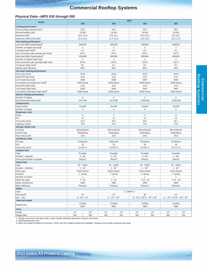
Commercial Rooftop Systems
2013 Daikin All Products Catalog 43
Commercial Rooftop SystemsC
omm
ercial R
ooftop System
s
Physical Data—MPS 030 through 050 Model
MPS030 035 040 050
Cooling performanceGross cooling capacity (tons) 30 .0 34 .0 40 .0 50 .0Nominal airflow (cfm) 12,000 14,000 16,000 20,000Maximum EER 10 .2–10 .4 9 .9–10 .1 10 .0–10 .3 9 .8–10 .2Maximum IEER (CAV-VAV) 12 .2–13 .1 11 .4–12 .3 11 .8–13 .2 11 .6–12 .3Gas heating performanceLow heat MBH (input/output)1 300/240 300/240 400/320 400/320Number of stages (low heat) 2 2 2 2Turndown (low heat)2 4:1 4:1 4:1 4:1Gas connection pipe size/qty (low heat) 3/4"/1 3/4"/1 3/4"/1 3/4"/1High heat MBH (input/output)1 600/480 600/480 800/640 800/640Number of stages (high heat) 4 4 4 4Gas connection pipe size/qty (high heat) 3/4"/2 3/4"/2 3/4"/2 3/4"/2Turndown (high heat)2 8:1 8:1 8:1 8:1Steady state efficiency 80% 80% 80% 80%Hot water heating performanceFace area (sq ft) 19 .25 19 .25 19 .25 19 .25Rows/FPI (low heat) 1/12 1/12 1/11 1/11Coil model (low heat) 5WB 5WB 5WH 5WHConnection sizes/type (low heat)2 ODM Sweat ODM Sweat ODM Sweat ODM SweatRows/FPI (high heat) 2/10 2/10 2/13 2/13Coil model (high heat) 5WS 5WS 5WS 5WSConnection sizes/type (high heat)2 ODM Sweat ODM Sweat ODM Sweat ODM SweatElectric heating performanceNumber of stages 4 4 4 4kW (low/medium/high heat) 54/72/90 54/72/90 72/90/108 72/90/108CompressorsType/number Scroll/3 Scroll/3 Scroll/4 Scroll/4Number of stages 5 5 5 5Evaporator coilsRows 4 4 4 4FPI 12 12 12 12Face area (sq ft) 25 .4 25 .4 29 .4 35 .7Capacity control TXV TXV TXV TXVHot gas reheat coilsCoil type Microchannel Microchannel Microchannel MicrochannelControl type Modulating Modulating Modulating ModulatingFace area (sq ft) 19 .9 19 .9 26 .8 26 .8Condenser coilsFin type Enhanced Enhanced Enhanced EnhancedFPI 18 18 18 18Face area (sq ft) 13 .4/27 .5 13 .4/27 .5 13 .4/27 .5 27 .5 (× 2)Outdoor fansType Propeller Propeller Propeller PropellerNumber - diameter 3 - 26" 3 - 26" 4 - 26" 4 - 26"Drive type/number of speeds Direct/1 Direct/1 Direct/1 Direct/1Indoor fansType AF - SWSI AF - SWSI AF - SWSI AF - SWSINumber - diameter 1 - 24" 1 - 24" 1 - 30" 1 - 30"Drive type Fixed sheave Fixed sheave Fixed sheave Fixed sheaveIsolation 1" spring 1" spring 1" spring 1" springNumber of motors 1 1 1 1Motor hp range 5 - 20 5 - 20 7-1/2 - 30 7-1/2 - 30Motor nominal rpm 1800 1800 1800 1800Motor efficiency Premium Premium Premium PremiumFiltersType 2", MERV 6Area (sq ft) 32 32 36 44Qty . - size 8 - 24" × 24" 8 – 24" × 24" 8 – 24" × 24"/4 – 18" × 24" 8 – 24" × 24"/4 – 18" × 24"Total unit weight
Weight (lbs)Cooling Cooling Cooling Cooling
3660 3660 4685 4985CurbHeight 14" 24" 14" 24" 14" 24" 14" 24"Weight (lbs) 341 501 341 501 481 501 481 5011 . Piping connections are given with a male outside diameter dimension, brazed connection .2 . Modulating burner only3 . Base unit weight includes Economizer, VFDs, and the smallest supply fan available . Heating units include maximum gas heat .
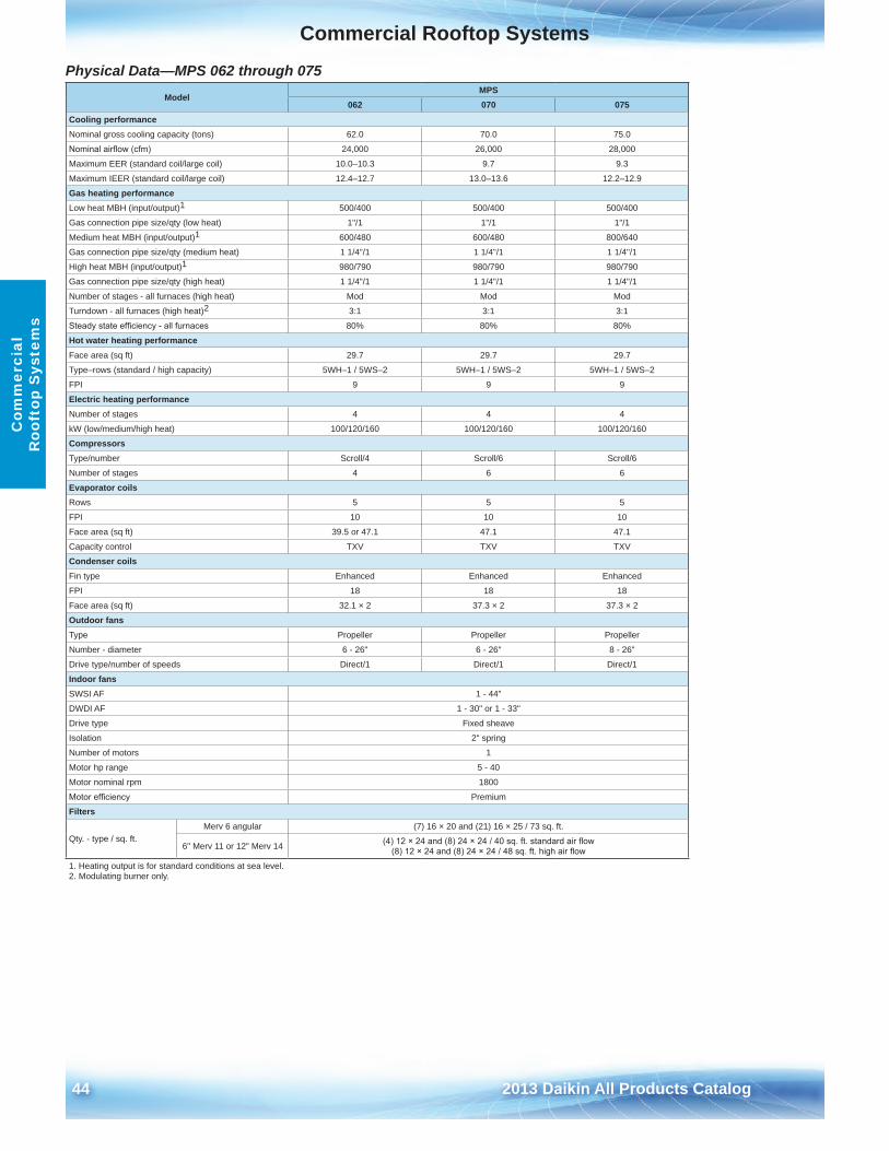
44 2013 Daikin All Products Catalog
Commercial Rooftop SystemsC
omm
erci
al
Roo
ftop
Sys
tem
s
Physical Data—MPS 062 through 075 Model
MPS062 070 075
Cooling performanceNominal gross cooling capacity (tons) 62 .0 70 .0 75 .0
Nominal airflow (cfm) 24,000 26,000 28,000
Maximum EER (standard coil/large coil) 10 .0–10 .3 9 .7 9 .3
Maximum IEER (standard coil/large coil) 12 .4–12 .7 13 .0–13 .6 12 .2–12 .9
Gas heating performanceLow heat MBH (input/output)1 500/400 500/400 500/400
Gas connection pipe size/qty (low heat) 1"/1 1"/1 1"/1
Medium heat MBH (input/output)1 600/480 600/480 800/640
Gas connection pipe size/qty (medium heat) 1 1/4"/1 1 1/4"/1 1 1/4"/1
High heat MBH (input/output)1 980/790 980/790 980/790
Gas connection pipe size/qty (high heat) 1 1/4"/1 1 1/4"/1 1 1/4"/1
Number of stages - all furnaces (high heat) Mod Mod Mod
Turndown - all furnaces (high heat)2 3:1 3:1 3:1
Steady state efficiency - all furnaces 80% 80% 80%
Hot water heating performanceFace area (sq ft) 29 .7 29 .7 29 .7
Type–rows (standard / high capacity) 5WH–1 / 5WS–2 5WH–1 / 5WS–2 5WH–1 / 5WS–2
FPI 9 9 9
Electric heating performanceNumber of stages 4 4 4
kW (low/medium/high heat) 100/120/160 100/120/160 100/120/160
CompressorsType/number Scroll/4 Scroll/6 Scroll/6
Number of stages 4 6 6
Evaporator coilsRows 5 5 5
FPI 10 10 10
Face area (sq ft) 39 .5 or 47 .1 47 .1 47 .1
Capacity control TXV TXV TXV
Condenser coilsFin type Enhanced Enhanced Enhanced
FPI 18 18 18
Face area (sq ft) 32 .1 × 2 37 .3 × 2 37 .3 × 2
Outdoor fansType Propeller Propeller Propeller
Number - diameter 6 - 26" 6 - 26" 8 - 26"
Drive type/number of speeds Direct/1 Direct/1 Direct/1
Indoor fansSWSI AF 1 - 44"
DWDI AF 1 - 30" or 1 - 33"
Drive type Fixed sheave
Isolation 2" spring
Number of motors 1
Motor hp range 5 - 40
Motor nominal rpm 1800
Motor efficiency Premium
Filters
Qty . - type / sq . ft .Merv 6 angular (7) 16 × 20 and (21) 16 × 25 / 73 sq . ft .
6" Merv 11 or 12" Merv 14 (4) 12 × 24 and (8) 24 × 24 / 40 sq. ft. standard air flow(8) 12 × 24 and (8) 24 × 24 / 48 sq. ft. high air flow
1 . Heating output is for standard conditions at sea level .2 . Modulating burner only .
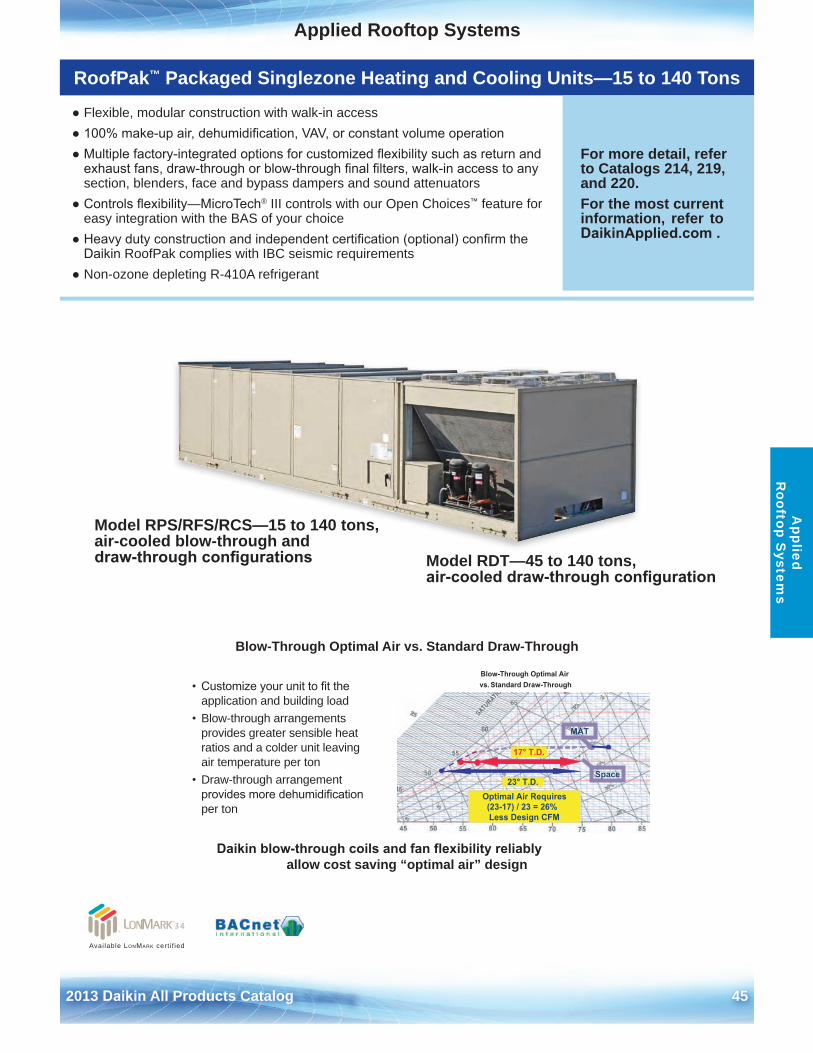
2013 Daikin All Products Catalog 45
Applied Rooftop SystemsA
pplied R
ooftop System
s
RoofPak™ Packaged Singlezone Heating and Cooling Units—15 to 140 Tons
● Flexible, modular construction with walk-in access● 100% make-up air, dehumidification, VAV, or constant volume operation● Multiple factory-integrated options for customized flexibility such as return and
exhaust fans, draw-through or blow-through final filters, walk-in access to anysection, blenders, face and bypass dampers and sound attenuators
● Controls flexibility—MicroTech® III controls with our Open Choices™ feature foreasy integration with the BAS of your choice
● Heavy duty construction and independent certification (optional) confirm theDaikin RoofPak complies with IBC seismic requirements
● Non-ozone depleting R-410A refrigerant
For more detail, refer to Catalogs 214, 219, and 220 .For the most current information, refer to DaikinApplied.com .
Model RPS/RFS/RCS—15 to 140 tons, air-cooled blow-through and draw-through configurations Model RDT—45 to 140 tons,
air-cooled draw-through configuration
Available LonMark cert i f ied
Blow-Through Optimal Air vs . Standard Draw-Through
Daikin blow-through coils and fan flexibility reliably allow cost saving “optimal air” design
23° T.D.
17° T.D.
Optimal Air Requires (23-17) / 23 = 26%Less Design CFM
Space
Blow-Through Optimal Airvs. Standard Draw-Through
MAT
• Customize your unit to fit the application and building load
• Blow-through arrangementsprovides greater sensible heatratios and a colder unit leavingair temperature per ton
• Draw-through arrangementprovides more dehumidificationper ton
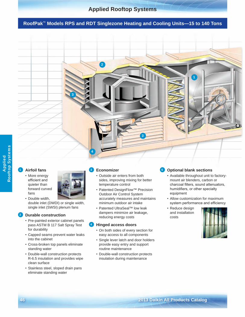
46 2013 Daikin All Products Catalog
Applied Rooftop SystemsA
pplie
d R
ooft
op S
yste
ms
RoofPak™ Models RPS and RDT Singlezone Heating and Cooling Units—15 to 140 Tons
1 Airfoil fans • More energy
efficient and quieter than forward curved fans
• Double width,double inlet (DWDI) or single width, single inlet (SWSI) plenum fans
2 Durable construction• Pre-painted exterior cabinet panels
pass ASTM B 117 Salt Spray Test for durability
• Capped seams prevent water leaksinto the cabinet
• Cross-broken top panels eliminatestanding water
• Double-wall construction protectsR-6 .5 insulation and provides wipe clean surface
• Stainless steel, sloped drain panseliminate standing water
3 Economizer• Outside air enters from both
sides, improving mixing for better temperature control
• Patented DesignFlow™ PrecisionOutdoor Air Control System accurately measures and maintains minimum outdoor air intake
• Patented UltraSeal™ low leakdampers minimize air leakage, reducing energy costs
4 Hinged access doors• On both sides of every section for
easy access to all components• Single lever latch and door holders
provide easy entry and support routine maintenance
• Double-wall construction protectsinsulation during maintenance
5 Optional blank sections • Available throughout unit to factory-
mount air blenders, carbon or charcoal filters, sound attenuators, humidifiers, or other specialty equipment
• Allow customization for maximumsystem performance and efficiency
• Reduce designand installation costs
1
2
3
3
4
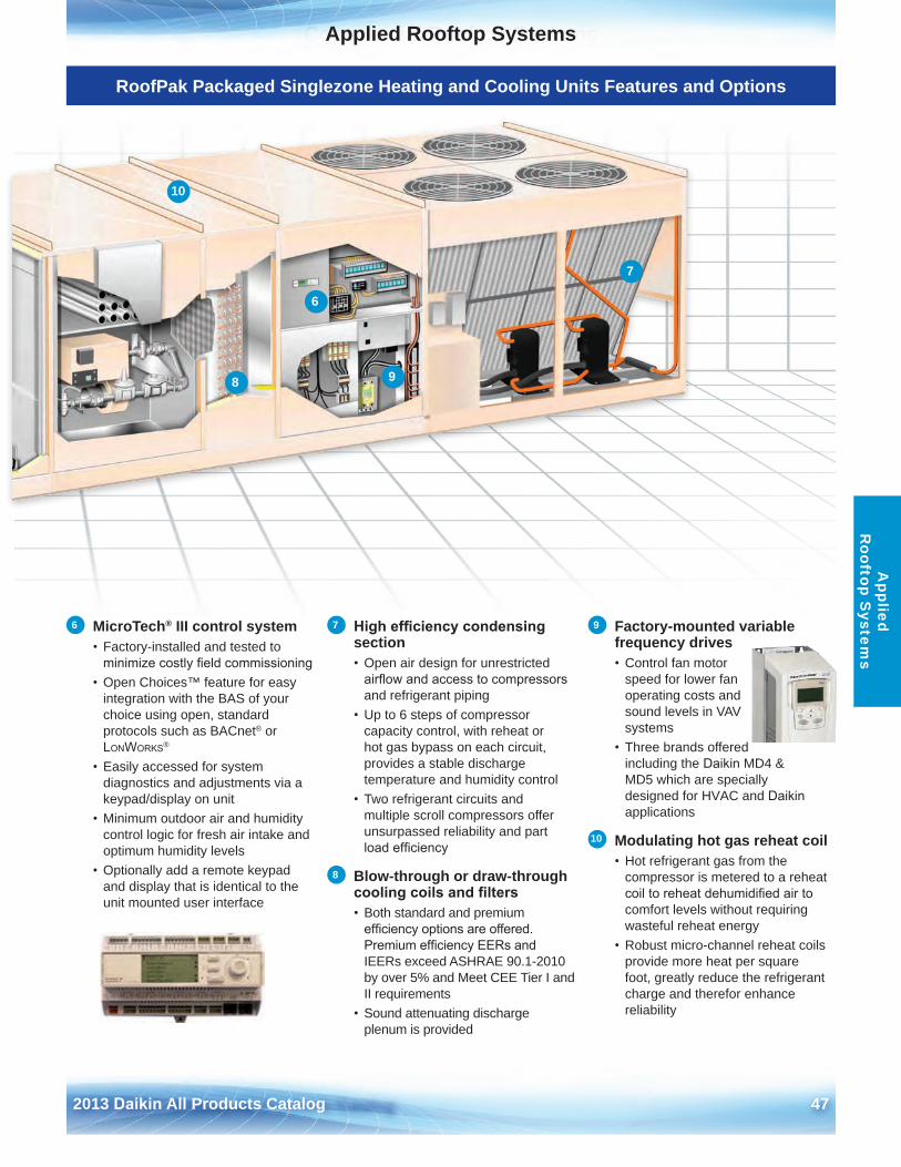
Commercial Rooftop Systems
2013 Daikin All Products Catalog 47
Applied Rooftop SystemsA
pplied R
ooftop System
s
RoofPak Packaged Singlezone Heating and Cooling Units Features and Options
6 MicroTech® III control system • Factory-installed and tested to
minimize costly field commissioning• Open Choices™ feature for easy
integration with the BAS of your choice using open, standard protocols such as BACnet® or LonWorks®
• Easily accessed for systemdiagnostics and adjustments via a keypad/display on unit
• Minimum outdoor air and humiditycontrol logic for fresh air intake and optimum humidity levels
• Optionally add a remote keypadand display that is identical to the unit mounted user interface
7 High efficiency condensing section• Open air design for unrestricted
airflow and access to compressors and refrigerant piping
• Up to 6 steps of compressorcapacity control, with reheat or hot gas bypass on each circuit, provides a stable discharge temperature and humidity control
• Two refrigerant circuits andmultiple scroll compressors offer unsurpassed reliability and part load efficiency
8 Blow-through or draw-through cooling coils and filters• Both standard and premium
efficiency options are offered. Premium efficiency EERs and IEERs exceed ASHRAE 90 .1-2010 by over 5% and Meet CEE Tier I and II requirements
• Sound attenuating dischargeplenum is provided
9 Factory-mounted variable frequency drives • Control fan motor
speed for lower fan operating costs and sound levels in VAV systems
• Three brands offeredincluding the Daikin MD4 & MD5 which are specially designed for HVAC and Daikin applications
10 Modulating hot gas reheat coil • Hot refrigerant gas from the
compressor is metered to a reheat coil to reheat dehumidified air to comfort levels without requiring wasteful reheat energy
• Robust micro-channel reheat coilsprovide more heat per square foot, greatly reduce the refrigerant charge and therefor enhance reliability
6
7
10
8 9
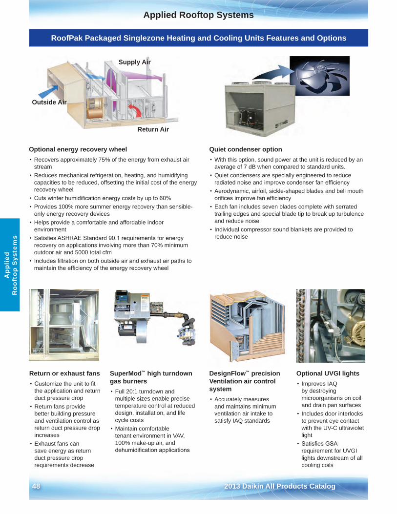
48 2013 Daikin All Products Catalog
Applied Rooftop SystemsA
pplie
d R
ooft
op S
yste
ms
RoofPak Packaged Singlezone Heating and Cooling Units Features and Options
Quiet condenser option• With this option, sound power at the unit is reduced by an
average of 7 dB when compared to standard units .• Quiet condensers are specially engineered to reduce
radiated noise and improve condenser fan efficiency• Aerodynamic, airfoil, sickle-shaped blades and bell mouth
orifices improve fan efficiency• Each fan includes seven blades complete with serrated
trailing edges and special blade tip to break up turbulence and reduce noise
• Individual compressor sound blankets are provided toreduce noise
DesignFlow™ precision Ventilation air control system• Accurately measures
and maintains minimum ventilation air intake to satisfy IAQ standards
SuperMod™ high turndown gas burners• Full 20:1 turndown and
multiple sizes enable precise temperature control at reduced design, installation, and life cycle costs
• Maintain comfortabletenant environment in VAV, 100% make-up air, and dehumidification applications
Optional UVGI lights• Improves IAQ
by destroying microorganisms on coil and drain pan surfaces
• Includes door interlocksto prevent eye contact with the UV-C ultraviolet light
• Satisfies GSArequirement for UVGI lights downstream of all cooling coils
Optional energy recovery wheel• Recovers approximately 75% of the energy from exhaust air
stream• Reduces mechanical refrigeration, heating, and humidifying
capacities to be reduced, offsetting the initial cost of the energy recovery wheel
• Cuts winter humidification energy costs by up to 60%• Provides 100% more summer energy recovery than sensible-
only energy recovery devices• Helps provide a comfortable and affordable indoor
environment• Satisfies ASHRAE Standard 90.1 requirements for energy
recovery on applications involving more than 70% minimumoutdoor air and 5000 total cfm
• Includes filtration on both outside air and exhaust air paths tomaintain the efficiency of the energy recovery wheel
Outside Air
Return Air
Supply Air
Return or exhaust fans • Customize the unit to fit
the application and return duct pressure drop
• Return fans providebetter building pressure and ventilation control as return duct pressure drop increases
• Exhaust fans cansave energy as return duct pressure drop requirements decrease
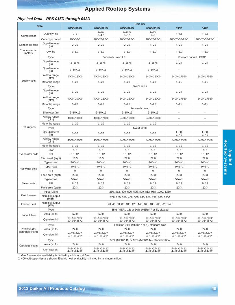
Commercial Rooftop Systems
2013 Daikin All Products Catalog 49
Applied Rooftop SystemsA
pplied R
ooftop System
s
Physical Data—RPS 015D through 042D
DataUnit size
015D/016D 020D/021D 025D/026D 030D/031D 035D 042D
CompressorQuantity–hp 2–7 1–10,
2–4 .51–11 .5, 2–5 .5
1–13, 2–6 4–7 .5 4–8 .5
Capacity control 100-50-0 100-78-22-0 100-78-22-0 100-78-22-0 100-75-50-25-0 100-75-50-25-0
Condenser fans Qty–diameter (in) 2–26 2–26 2–26 4–26 4–26 4–26
Condenser fan motors Qty–hp 2–1 .0 2–1 .0 2–1 .0 4–1 .0 4–1 .0 4–1 .0
Supply fans
Type Forward curved LP Forward curved LP/MPQty–diameter
(in) 2–15×6 2–15×6 2–15×6 2–15×6 1–24 1–24
Qty–diameter (in) 2–15×15 2–15×15 2–15×15 2–15×15 – –
Airflow range (cfm) 4000–12000 4000–12000 5400–16000 5400–16000 5400–17550 5400–17550
Motor hp range 1–20 1–20 1–20 1–20 1–25 1–25Type DWDI airfoil
Qty–diameter (in) 1–20 1–20 1–20 1–20 1–24 1–24
Airflow range (cfm) 4000–10000 4000–12000 5400–16000 5400–16000 5400–17550 5400–17550
Motor hp range 1–20 1–20 1–20 1–20 1–25 1–25
Return fans
Type Forward curvedDiameter (in) 2–15×15 2–15×15 2–15×15 2–15×15 – –Airflow range
(cfm) 4000–10000 4000–12000 5400–16000 5400–16000 – –
Motor hp range 1–10 1–10 1–10 1–10 – –Type SWSI airfoil
Qty–diameter (in) 1–30 1–30 1–30 1–30 1–30,
1–401–30, 1–40
Airflow range (cfm) 4000–10000 4000–12000 5400–16000 5400–16000 5400–17550 5400–17550
Motor hp range 1–10 1–10 1–10 1–10 1–10 1–10
Evaporator coilsRows 4, 5 4, 5 4, 5 4, 5 4, 5 4, 5FPI 10, 12 10, 12 10, 12 10, 12 10, 12 10, 12
F .A ., small (sq ft) 18 .5 18 .5 27 .0 27 .0 27 .0 27 .0
Hot water coils
Type–rows 5WH–1 5WH–1 5WH–1 5WH–1 5WH–1 5WH–1Type–rows 5WS–2 5WS–2 5WS–2 5WS–2 5WS–2 5WS–2
FPI 9 9 9 9 9 9Face area (sq ft) 20 .3 20 .3 20 .3 20 .3 20 .3 20 .3
Steam coilsType–rows 5JA–1 5JA–1 5JA–1 5JA–1 5JA–1 5JA–1
FPI 6, 12 6, 12 6, 12 6, 12 6, 12 6, 12Face area (sq ft) 20 .3 20 .3 20 .3 20 .3 20 .3 20 .3
Gas furnaceInput (MBh) 250, 312, 400, 500, 625, 800, 812, 988, 1000, 1250
Nominal output (MBh) 200, 250, 320, 400, 500, 640, 650, 790, 800, 1000
Electric heat Nominal output (kW) 20, 40, 60, 80, 100, 120, 140, 160, 180, 200, 220, 240
Panel filters
Type 85% (MERV 13) or 30% (MERV 7 or 8), pleatedArea (sq ft) 50 .0 50 .0 50 .0 50 .0 50 .0 50 .0
Qty–size (in) 10–16×20×2 10–16×25×2
10–16×20×2 10–16×25×2
10–16×20×2 10–16×25×2
10–16×20×2 10–16×25×2
10–16×20×2 10–16×25×2
10–16×20×2 10–16×25×2
Prefilters (for cartridge filters)
Type Prefilter, 30% (MERV 7 or 8), standard flowArea (sq ft) 24 .0 24 .0 24 .0 24 .0 24 .0 24 .0
Qty–size (in) 4–24×24×2 4–12×24×2
4–24×24×2 4–12×24×2
4–24×24×2 4–12×24×2
4–24×24×2 4–12×24×2
4–24×24×2 4–12×24×2
4–24×24×2 4–12×24×2
Cartridge filters
Type 65% (MERV 11) or 95% (MERV 14), standard flowArea (sq ft) 24 .0 24 .0 24 .0 24 .0 24 .0 24 .0
Qty–size (in) 4–24×24×12 4–12×24×12
4–24×24×12 4–12×24×12
4–24×24×12 4–12×24×12
4–24×24×12 4–12×24×12
4–24×24×12 4–12×24×12
4–24×24×12 4–12×24×12
1. Gas furnace size availability is limited by minimum airflow.2. 460-volt capacities are shown. Electric heat availability is limited by minimum airflow.
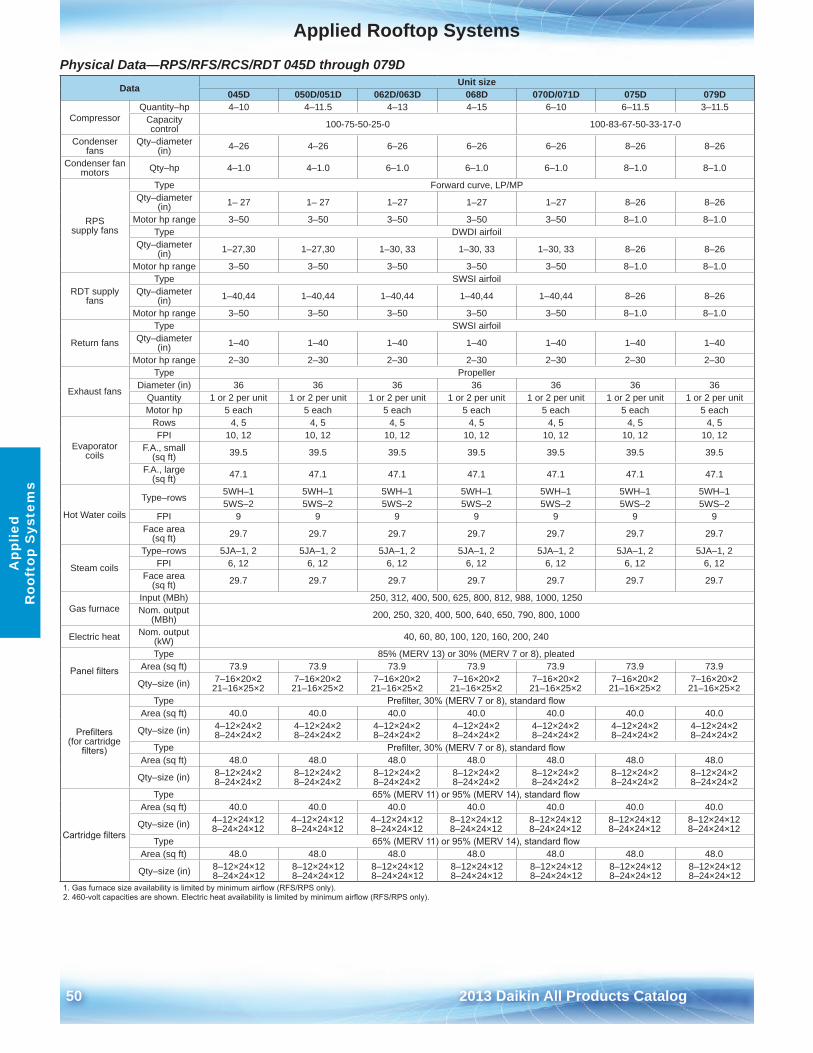
50 2013 Daikin All Products Catalog
Applied Rooftop SystemsA
pplie
d R
ooft
op S
yste
ms
Physical Data—RPS/RFS/RCS/RDT 045D through 079D Data Unit size
045D 050D/051D 062D/063D 068D 070D/071D 075D 079D
CompressorQuantity–hp 4–10 4–11 .5 4–13 4–15 6–10 6–11 .5 3–11 .5
Capacity control 100-75-50-25-0 100-83-67-50-33-17-0
Condenser fans
Qty–diameter (in) 4–26 4–26 6–26 6–26 6–26 8–26 8–26
Condenser fan motors Qty–hp 4–1 .0 4–1 .0 6–1 .0 6–1 .0 6–1 .0 8–1 .0 8–1 .0
RPS supply fans
Type Forward curve, LP/MPQty–diameter
(in) 1– 27 1– 27 1–27 1–27 1–27 8–26 8–26
Motor hp range 3–50 3–50 3–50 3–50 3–50 8–1 .0 8–1 .0Type DWDI airfoil
Qty–diameter (in) 1–27,30 1–27,30 1–30, 33 1–30, 33 1–30, 33 8–26 8–26
Motor hp range 3–50 3–50 3–50 3–50 3–50 8–1 .0 8–1 .0
RDT supply fans
Type SWSI airfoilQty–diameter
(in) 1–40,44 1–40,44 1–40,44 1–40,44 1–40,44 8–26 8–26
Motor hp range 3–50 3–50 3–50 3–50 3–50 8–1 .0 8–1 .0
Return fans
Type SWSI airfoilQty–diameter
(in) 1–40 1–40 1–40 1–40 1–40 1–40 1–40
Motor hp range 2–30 2–30 2–30 2–30 2–30 2–30 2–30
Exhaust fans
Type PropellerDiameter (in) 36 36 36 36 36 36 36
Quantity 1 or 2 per unit 1 or 2 per unit 1 or 2 per unit 1 or 2 per unit 1 or 2 per unit 1 or 2 per unit 1 or 2 per unitMotor hp 5 each 5 each 5 each 5 each 5 each 5 each 5 each
Evaporator coils
Rows 4, 5 4, 5 4, 5 4, 5 4, 5 4, 5 4, 5FPI 10, 12 10, 12 10, 12 10, 12 10, 12 10, 12 10, 12
F .A ., small (sq ft) 39 .5 39 .5 39 .5 39 .5 39 .5 39 .5 39 .5
F .A ., large (sq ft) 47 .1 47 .1 47 .1 47 .1 47 .1 47 .1 47 .1
Hot Water coils
Type–rows5WH–1 5WH–1 5WH–1 5WH–1 5WH–1 5WH–1 5WH–15WS–2 5WS–2 5WS–2 5WS–2 5WS–2 5WS–2 5WS–2
FPI 9 9 9 9 9 9 9Face area
(sq ft) 29 .7 29 .7 29 .7 29 .7 29 .7 29 .7 29 .7
Steam coils
Type–rows 5JA–1, 2 5JA–1, 2 5JA–1, 2 5JA–1, 2 5JA–1, 2 5JA–1, 2 5JA–1, 2FPI 6, 12 6, 12 6, 12 6, 12 6, 12 6, 12 6, 12
Face area (sq ft) 29 .7 29 .7 29 .7 29 .7 29 .7 29 .7 29 .7
Gas furnaceInput (MBh) 250, 312, 400, 500, 625, 800, 812, 988, 1000, 1250Nom . output
(MBh) 200, 250, 320, 400, 500, 640, 650, 790, 800, 1000
Electric heat Nom . output (kW) 40, 60, 80, 100, 120, 160, 200, 240
Panel filters
Type 85% (MERV 13) or 30% (MERV 7 or 8), pleatedArea (sq ft) 73 .9 73 .9 73 .9 73 .9 73 .9 73 .9 73 .9
Qty–size (in) 7–16×20×2 21–16×25×2
7–16×20×2 21–16×25×2
7–16×20×2 21–16×25×2
7–16×20×2 21–16×25×2
7–16×20×2 21–16×25×2
7–16×20×2 21–16×25×2
7–16×20×2 21–16×25×2
Prefilters (for cartridge
filters)
Type Prefilter, 30% (MERV 7 or 8), standard flowArea (sq ft) 40 .0 40 .0 40 .0 40 .0 40 .0 40 .0 40 .0
Qty–size (in) 4–12×24×2 8–24×24×2
4–12×24×2 8–24×24×2
4–12×24×2 8–24×24×2
4–12×24×2 8–24×24×2
4–12×24×2 8–24×24×2
4–12×24×2 8–24×24×2
4–12×24×2 8–24×24×2
Type Prefilter, 30% (MERV 7 or 8), standard flowArea (sq ft) 48 .0 48 .0 48 .0 48 .0 48 .0 48 .0 48 .0
Qty–size (in) 8–12×24×2 8–24×24×2
8–12×24×2 8–24×24×2
8–12×24×2 8–24×24×2
8–12×24×2 8–24×24×2
8–12×24×2 8–24×24×2
8–12×24×2 8–24×24×2
8–12×24×2 8–24×24×2
Cartridge filters
Type 65% (MERV 11) or 95% (MERV 14), standard flowArea (sq ft) 40 .0 40 .0 40 .0 40 .0 40 .0 40 .0 40 .0
Qty–size (in) 4–12×24×12 8–24×24×12
4–12×24×12 8–24×24×12
4–12×24×12 8–24×24×12
8–12×24×12 8–24×24×12
8–12×24×12 8–24×24×12
8–12×24×12 8–24×24×12
8–12×24×12 8–24×24×12
Type 65% (MERV 11) or 95% (MERV 14), standard flowArea (sq ft) 48 .0 48 .0 48 .0 48 .0 48 .0 48 .0 48 .0
Qty–size (in) 8–12×24×12 8–24×24×12
8–12×24×12 8–24×24×12
8–12×24×12 8–24×24×12
8–12×24×12 8–24×24×12
8–12×24×12 8–24×24×12
8–12×24×12 8–24×24×12
8–12×24×12 8–24×24×12
1. Gas furnace size availability is limited by minimum airflow (RFS/RPS only).2. 460-volt capacities are shown. Electric heat availability is limited by minimum airflow (RFS/RPS only).
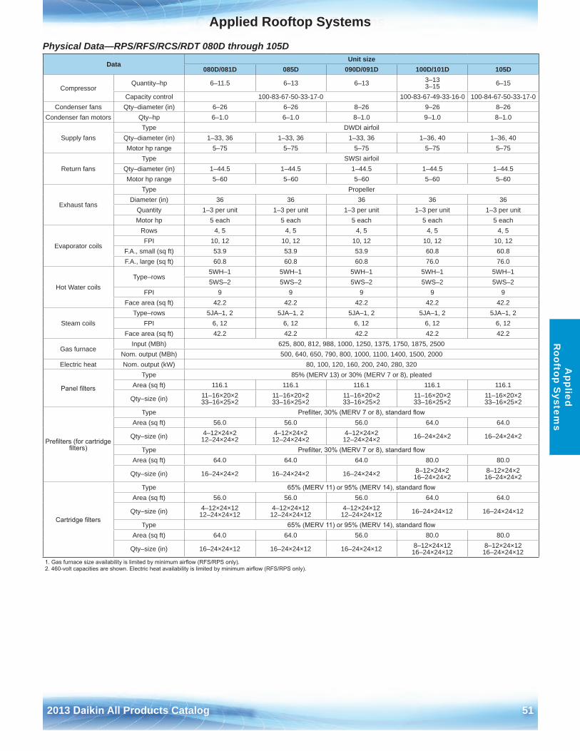
Commercial Rooftop Systems
2013 Daikin All Products Catalog 51
Applied Rooftop SystemsA
pplied R
ooftop System
s
Physical Data—RPS/RFS/RCS/RDT 080D through 105D
DataUnit size
080D/081D 085D 090D/091D 100D/101D 105D
CompressorQuantity–hp 6–11 .5 6–13 6–13 3–13
3–15 6–15
Capacity control 100-83-67-50-33-17-0 100-83-67-49-33-16-0 100-84-67-50-33-17-0Condenser fans Qty–diameter (in) 6–26 6–26 8–26 9–26 8–26
Condenser fan motors Qty–hp 6–1 .0 6–1 .0 8–1 .0 9–1 .0 8–1 .0
Supply fansType DWDI airfoil
Qty–diameter (in) 1–33, 36 1–33, 36 1–33, 36 1–36, 40 1–36, 40Motor hp range 5–75 5–75 5–75 5–75 5–75
Return fansType SWSI airfoil
Qty–diameter (in) 1–44 .5 1–44 .5 1–44 .5 1–44 .5 1–44 .5Motor hp range 5–60 5–60 5–60 5–60 5–60
Exhaust fans
Type PropellerDiameter (in) 36 36 36 36 36
Quantity 1–3 per unit 1–3 per unit 1–3 per unit 1–3 per unit 1–3 per unitMotor hp 5 each 5 each 5 each 5 each 5 each
Evaporator coils
Rows 4, 5 4, 5 4, 5 4, 5 4, 5FPI 10, 12 10, 12 10, 12 10, 12 10, 12
F .A ., small (sq ft) 53 .9 53 .9 53 .9 60 .8 60 .8F .A ., large (sq ft) 60 .8 60 .8 60 .8 76 .0 76 .0
Hot Water coilsType–rows
5WH–1 5WH–1 5WH–1 5WH–1 5WH–15WS–2 5WS–2 5WS–2 5WS–2 5WS–2
FPI 9 9 9 9 9Face area (sq ft) 42 .2 42 .2 42 .2 42 .2 42 .2
Steam coilsType–rows 5JA–1, 2 5JA–1, 2 5JA–1, 2 5JA–1, 2 5JA–1, 2
FPI 6, 12 6, 12 6, 12 6, 12 6, 12Face area (sq ft) 42 .2 42 .2 42 .2 42 .2 42 .2
Gas furnaceInput (MBh) 625, 800, 812, 988, 1000, 1250, 1375, 1750, 1875, 2500
Nom . output (MBh) 500, 640, 650, 790, 800, 1000, 1100, 1400, 1500, 2000Electric heat Nom . output (kW) 80, 100, 120, 160, 200, 240, 280, 320
Panel filters
Type 85% (MERV 13) or 30% (MERV 7 or 8), pleatedArea (sq ft) 116 .1 116 .1 116 .1 116 .1 116 .1
Qty–size (in) 11–16×20×2 33–16×25×2
11–16×20×2 33–16×25×2
11–16×20×2 33–16×25×2
11–16×20×2 33–16×25×2
11–16×20×2 33–16×25×2
Prefilters (for cartridge filters)
Type Prefilter, 30% (MERV 7 or 8), standard flowArea (sq ft) 56 .0 56 .0 56 .0 64 .0 64 .0
Qty–size (in) 4–12×24×2 12–24×24×2
4–12×24×2 12–24×24×2
4–12×24×2 12–24×24×2 16–24×24×2 16–24×24×2
Type Prefilter, 30% (MERV 7 or 8), standard flowArea (sq ft) 64 .0 64 .0 64 .0 80 .0 80 .0
Qty–size (in) 16–24×24×2 16–24×24×2 16–24×24×2 8–12×24×2 16–24×24×2
8–12×24×2 16–24×24×2
Cartridge filters
Type 65% (MERV 11) or 95% (MERV 14), standard flowArea (sq ft) 56 .0 56 .0 56 .0 64 .0 64 .0
Qty–size (in) 4–12×24×12 12–24×24×12
4–12×24×12 12–24×24×12
4–12×24×12 12–24×24×12 16–24×24×12 16–24×24×12
Type 65% (MERV 11) or 95% (MERV 14), standard flowArea (sq ft) 64 .0 64 .0 56 .0 80 .0 80 .0
Qty–size (in) 16–24×24×12 16–24×24×12 16–24×24×12 8–12×24×12 16–24×24×12
8–12×24×12 16–24×24×12
1. Gas furnace size availability is limited by minimum airflow (RFS/RPS only).2. 460-volt capacities are shown. Electric heat availability is limited by minimum airflow (RFS/RPS only).
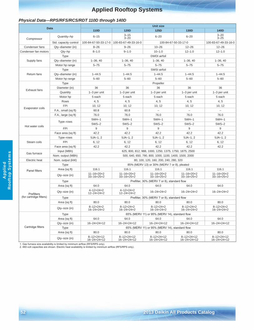
52 2013 Daikin All Products Catalog
Applied Rooftop SystemsA
pplie
d R
ooft
op S
yste
ms
Physical Data—RPS/RFS/RCS/RDT 110D through 140D
DataUnit size
110D 120D 125D 130D 140D
CompressorQuantity–hp 6–15 3–15
3–20 6–20 6–20 3–20 3–25
Std . capacity control 100-84-67-50-33-17-0 100-83-67-49-33-16-0 100-84-67-50-33-17-0 100-83-67-49-33-16-0Condenser fans Qty–diameter (in) 8–26 9–26 10–26 12–26 12–26
Condenser fan motors Qty–hp 8–1 .0 9–1 .0 10–1 .0 12–1 .0 12–1 .0
Supply fansType DWDI airfoil
Qty–diameter (in) 1–36, 40 1–36, 40 1–36, 40 1–36, 40 1–36, 40Motor hp range 5–75 5–75 5–75 5–75 5–75
Return fansType SWSI airfoil
Qty–diameter (in) 1–44 .5 1–44 .5 1–44 .5 1–44 .5 1–44 .5Motor hp range 5–60 5–60 5–60 5–60 5–60
Exhaust fans
Type PropellerDiameter (in) 36 36 36 36 36
Quantity 1–3 per unit 1–3 per unit 1–3 per unit 1–3 per unit 1–3 per unitMotor hp 5 each 5 each 5 each 5 each 5 each
Evaporator coils
Rows 4, 5 4, 5 4, 5 4, 5 4, 5FPI 10, 12 10, 12 10, 12 10, 12 10, 12
F .A ., small (sq ft) 60 .8 60 .8 – – –F .A ., large (sq ft) 76 .0 76 .0 76 .0 76 .0 76 .0
Hot water coilsType–rows
5WH–1 5WH–1 5WH–1 5WH–1 5WH–15WS–2 5WS–2 5WS–2 5WS–2 5WS–2
FPI 9 9 9 9 9Face area (sq ft) 42 .2 42 .2 42 .2 42 .2 42 .2
Steam coilsType–rows 5JA–1, 2 5JA–1, 2 5JA–1, 2 5JA–1, 2 5JA–1, 2
FPI 6, 12 6, 12 6, 12 6, 12 6, 12Face area (sq ft) 42 .2 42 .2 42 .2 42 .2 42 .2
Gas furnaceInput (MBh) 625, 800, 812, 988, 1000, 1250, 1375, 1750, 1875, 2500
Nom . output (MBh) 500, 640, 650, 790, 800, 1000, 1100, 1400, 1500, 2000Electric heat Nom . output (kW) 80, 100, 120, 160, 200, 240, 280, 320
Panel filters
Type 85% (MERV 13) or 30% (MERV 7 or 8), pleatedArea (sq ft) 116 .1 116 .1 116 .1 116 .1 116 .1
Qty–size (in) 11–16×20×2 33–16×25×2
11–16×20×2 33–16×25×2
11–16×20×2 33–16×25×2
11–16×20×2 33–16×25×2
11–16×20×2 33–16×25×2
Prefilters (for cartridge filters)
Type Prefilter, 30% (MERV 7 or 8), standard flowArea (sq ft) 64 .0 64 .0 64 .0 64 .0 64 .0
Qty–size (in) 4–12×24×2 12–24×24×2
4–12×24×2 12–24×24×2 16–24×24×2 16–24×24×2 16–24×24×2
Type Prefilter, 30% (MERV 7 or 8), standard flowArea (sq ft) 80 .0 80 .0 80 .0 80 .0 80 .0
Qty–size (in) 8–12×24×2 16–24×24×2
8–12×24×216–24×24×2
8–12×24×2 16–24×24×2
8–12×24×2 16–24×24×2
8–12×24×2 16–24×24×2
Cartridge filters
Type 65% (MERV 11) or 95% (MERV 14), standard flowArea (sq ft) 64 .0 64 .0 64 .0 64 .0 64 .0
Qty–size (in) 16–24×24×12 16–24×24×12 16–24×24×12 16–24×24×12 16–24×24×12Type 65% (MERV 11) or 95% (MERV 14), standard flow
Area (sq ft) 80 .0 80 .0 80 .0 80 .0 80 .0
Qty–size (in) 8–12×24×12 16–24×24×12
8–12×24×12 16–24×24×12
8–12×24×12 16–24×24×12
8–12×24×12 16–24×24×12
8–12×24×12 16–24×24×12
1. Gas furnace size availability is limited by minimum airflow (RFS/RPS only).2. 460-volt capacities are shown. Electric heat availability is limited by minimum airflow (RFS/RPS only).
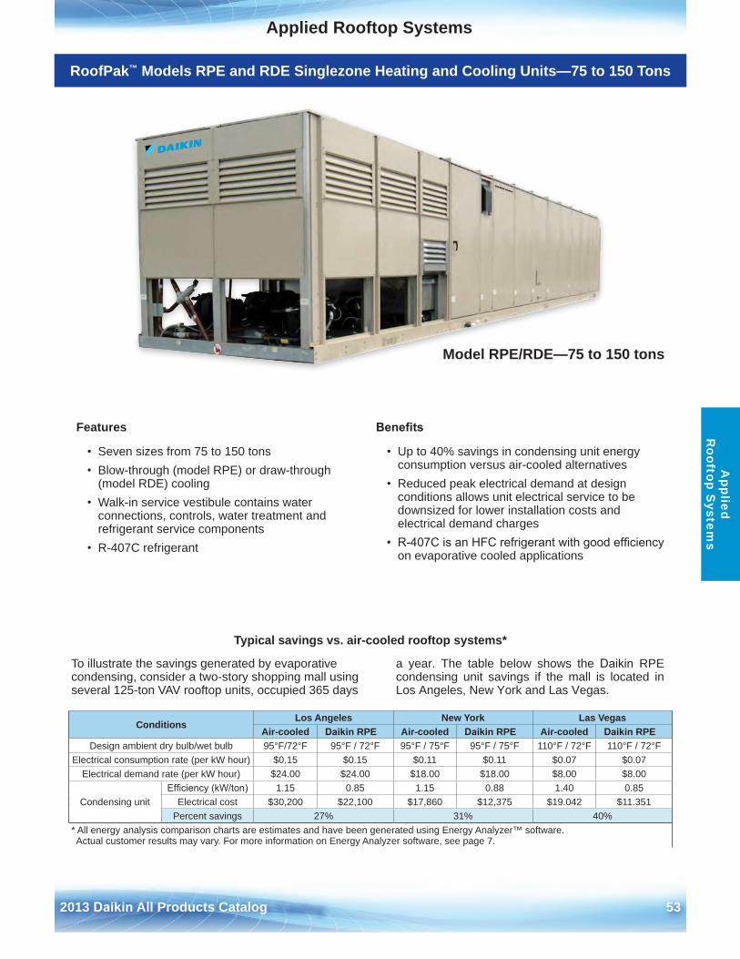
2013 Daikin All Products Catalog 53
Applied Rooftop SystemsA
pplied R
ooftop System
s
ProductRoofPak™ Models RPE and RDE Singlezone Heating and Cooling Units—75 to 150 Tons
Features
• Seven sizes from 75 to 150 tons• Blow-through (model RPE) or draw-through
(model RDE) cooling• Walk-in service vestibule contains water
connections, controls, water treatment andrefrigerant service components
• R-407C refrigerant
Benefits
• Up to 40% savings in condensing unit energyconsumption versus air-cooled alternatives
• Reduced peak electrical demand at designconditions allows unit electrical service to bedownsized for lower installation costs andelectrical demand charges
• R-407C is an HFC refrigerant with good efficiencyon evaporative cooled applications
Typical savings vs . air-cooled rooftop systems*
To illustrate the savings generated by evaporative condensing, consider a two-story shopping mall using several 125-ton VAV rooftop units, occupied 365 days
a year . The table below shows the Daikin RPE condensing unit savings if the mall is located in Los Angeles, New York and Las Vegas .
ConditionsLos Angeles New York Las Vegas
Air-cooled Daikin RPE Air-cooled Daikin RPE Air-cooled Daikin RPEDesign ambient dry bulb/wet bulb 95°F/72°F 95°F / 72°F 95°F / 75°F 95°F / 75°F 110°F / 72°F 110°F / 72°F
Electrical consumption rate (per kW hour) $0 .15 $0 .15 $0 .11 $0 .11 $0 .07 $0 .07Electrical demand rate (per kW hour) $24 .00 $24 .00 $18 .00 $18 .00 $8 .00 $8 .00
Condensing unitEfficiency (kW/ton) 1 .15 0 .85 1 .15 0 .88 1 .40 0 .85
Electrical cost $30,200 $22,100 $17,860 $12,375 $19 .042 $11 .351Percent savings 27% 31% 40%
* All energy analysis comparison charts are estimates and have been generated using Energy Analyzer™ software . Actual customer results may vary . For more information on Energy Analyzer software, see page 7 .
Model RPE/RDE—75 to 150 tons
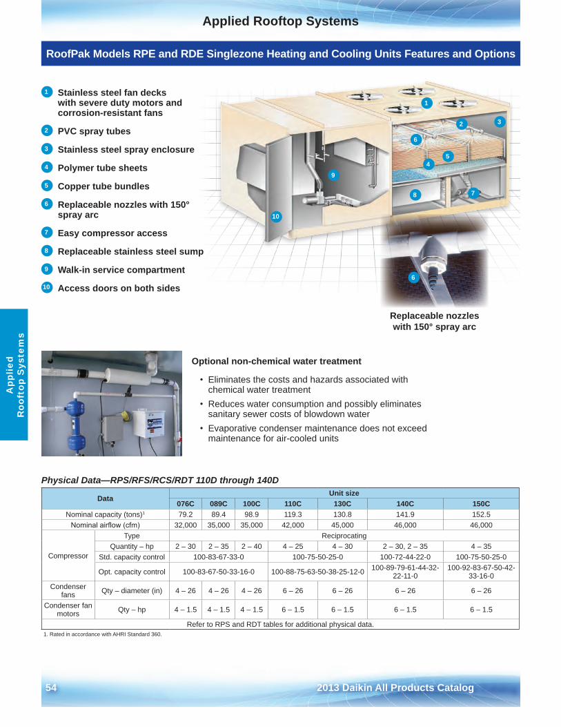
54 2013 Daikin All Products Catalog
Applied Rooftop SystemsA
pplie
d R
ooft
op S
yste
ms
Physical Data—RPS/RFS/RCS/RDT 110D through 140D
DataUnit size
076C 089C 100C 110C 130C 140C 150CNominal capacity (tons)1 79 .2 89 .4 98 .9 119 .3 130 .8 141 .9 152 .5
Nominal airflow (cfm) 32,000 35,000 35,000 42,000 45,000 46,000 46,000
Compressor
Type ReciprocatingQuantity – hp 2 – 30 2 – 35 2 – 40 4 – 25 4 – 30 2 – 30, 2 – 35 4 – 35
Std . capacity control 100-83-67-33-0 100-75-50-25-0 100-72-44-22-0 100-75-50-25-0
Opt . capacity control 100-83-67-50-33-16-0 100-88-75-63-50-38-25-12-0 100-89-79-61-44-32-22-11-0
100-92-83-67-50-42-33-16-0
Condenser fans Qty – diameter (in) 4 – 26 4 – 26 4 – 26 6 – 26 6 – 26 6 – 26 6 – 26
Condenser fan motors Qty – hp 4 – 1 .5 4 – 1 .5 4 – 1 .5 6 – 1 .5 6 – 1 .5 6 – 1 .5 6 – 1 .5
Refer to RPS and RDT tables for additional physical data .1 . Rated in accordance with AHRI Standard 360 .
Optional non-chemical water treatment
• Eliminates the costs and hazards associated withchemical water treatment
• Reduces water consumption and possibly eliminatessanitary sewer costs of blowdown water
• Evaporative condenser maintenance does not exceedmaintenance for air-cooled units
Replaceable nozzles with 150° spray arc
1 Stainless steel fan decks with severe duty motors and corrosion-resistant fans
2 PVC spray tubes
3 Stainless steel spray enclosure
4 Polymer tube sheets
5 Copper tube bundles
6 Replaceable nozzles with 150° spray arc
7 Easy compressor access
8 Replaceable stainless steel sump
9 Walk-in service compartment
10 Access doors on both sides
RoofPak Models RPE and RDE Singlezone Heating and Cooling Units Features and Options
1
2 3
45
6
6
78
9
10
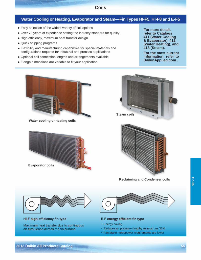
2013 Daikin All Products Catalog 55
CoilsC
oils
Water Cooling or Heating, Evaporator and Steam—Fin Types HI-F5, HI-F8 and E-F5
● Easy selection of the widest variety of coil options● Over 70 years of experience setting the industry standard for quality● High efficiency, maximum heat transfer design● Quick shipping programs● Flexibility and manufacturing capabilities for special materials and
configurations required for industrial and process applications● Optional coil connection lengths and arrangements available● Flange dimensions are variable to fit your application
For more detail, refer to Catalogs 411 (Water Cooling & Evaporator), 412 (Water Heating), and 413 (Steam) . For the most current information, refer to DaikinApplied.com .
HI-F high efficiency fin type
Maximum heat transfer due to continuous air turbulence across the fin surface
E-F energy efficient fin type• Energy saving• Reduces air pressure drop by as much as 33%• Fan brake horsepower requirements are lower
Reclaiming and Condenser coils
Steam coils
Water cooling or heating coils
Evaporator coils
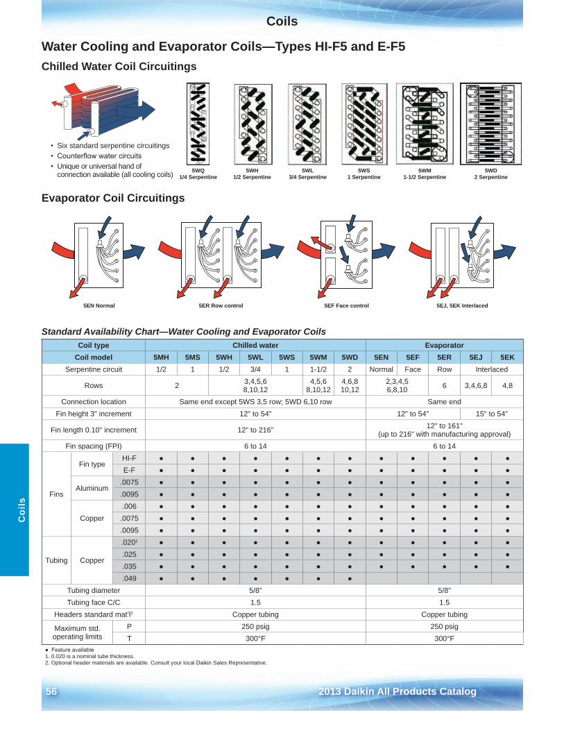
Coils
56 2013 Daikin All Products Catalog
Coi
ls
Water Cooling and Evaporator Coils—Types HI-F5 and E-F5 Chilled Water Coil Circuitings
Evaporator Coil Circuitings
Standard Availability Chart—Water Cooling and Evaporator Coils Coil type Chilled water Evaporator
Coil model 5MH 5MS 5WH 5WL 5WS 5WM 5WD 5EN 5EF 5ER 5EJ 5EKSerpentine circuit 1/2 1 1/2 3/4 1 1-1/2 2 Normal Face Row Interlaced
Rows 2 3,4,5,6 8,10,12
4,5,6 8,10,12
4,6,8 10,12
2,3,4,5 6,8,10 6 3,4,6,8 4,8
Connection location Same end except 5WS 3,5 row; 5WD 6,10 row Same endFin height 3" increment 12" to 54" 12" to 54" 15" to 54"
Fin length 0 .10" increment 12" to 216" 12" to 161" (up to 216" with manufacturing approval)
Fin spacing (FPI) 6 to 14 6 to 14
Fins
Fin typeHI-F ● ● ● ● ● ● ● ● ● ● ● ●E-F ● ● ● ● ● ● ● ● ● ● ● ●
Aluminum .0075 ● ● ● ● ● ● ● ● ● ● ● ● .0095 ● ● ● ● ● ● ● ● ● ● ● ●
Copper .006 ● ● ● ● ● ● ● ● ● ● ● ● .0075 ● ● ● ● ● ● ● ● ● ● ● ● .0095 ● ● ● ● ● ● ● ● ● ● ● ●
Tubing Copper
.0201 ● ● ● ● ● ● ● ● ● ● ● ● .025 ● ● ● ● ● ● ● ● ● ● ● ● .035 ● ● ● ● ● ● ● ● ● ● ● ● .049 ● ● ● ● ● ● ●
Tubing diameter 5/8" 5/8"Tubing face C/C 1 .5 1 .5
Headers standard mat’l2 Copper tubing Copper tubing
Maximum std . operating limits
P 250 psig 250 psigT 300°F 300°F
● Feature available1 . 0 .020 is a nominal tube thickness .2 . Optional header materials are available . Consult your local Daikin Sales Representative .
5EJ, 5EK Interlaced5EF Face control5ER Row control5EN Normal
5WD 2 Serpentine
5WM 1-1/2 Serpentine
5WS 1 Serpentine
5WL 3/4 Serpentine
5WH 1/2 Serpentine
5WQ 1/4 Serpentine
• Six standard serpentine circuitings• Counterflow water circuits• Unique or universal hand of
connection available (all cooling coils)
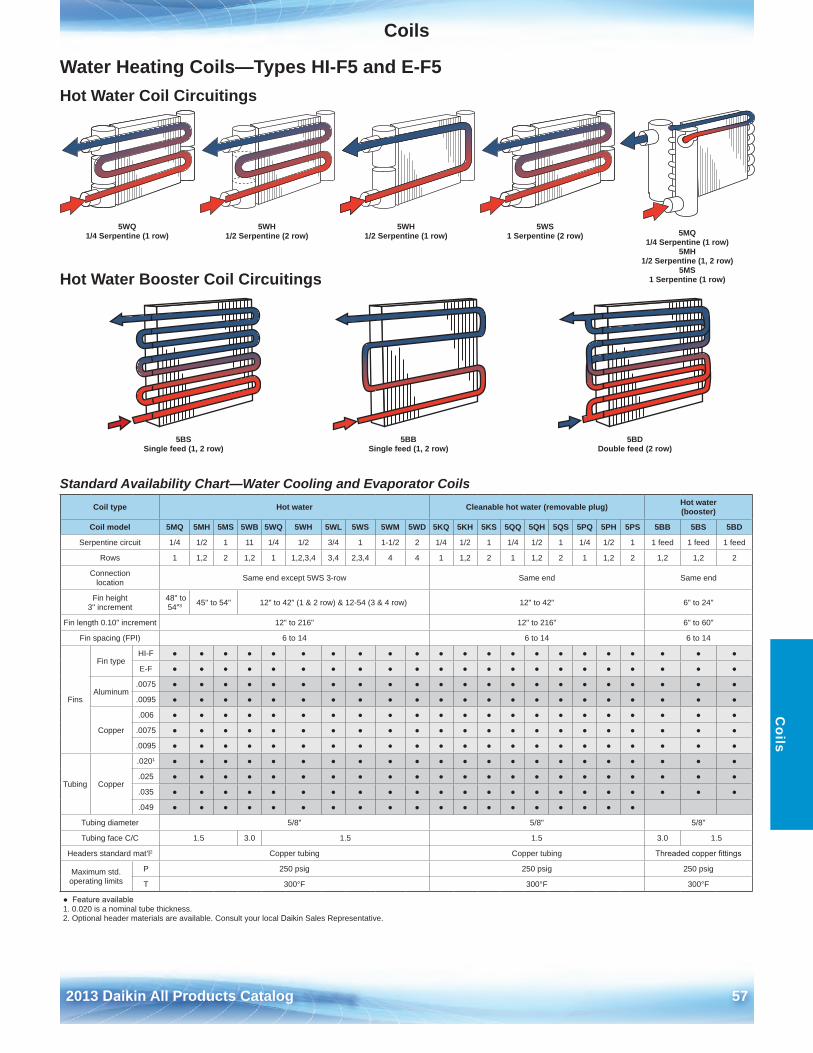
Coils
2013 Daikin All Products Catalog 57
Coils
Standard Availability Chart—Water Cooling and Evaporator Coils Coil type Hot water Cleanable hot water (removable plug) Hot water
(booster)
Coil model 5MQ 5MH 5MS 5WB 5WQ 5WH 5WL 5WS 5WM 5WD 5KQ 5KH 5KS 5QQ 5QH 5QS 5PQ 5PH 5PS 5BB 5BS 5BD
Serpentine circuit 1/4 1/2 1 11 1/4 1/2 3/4 1 1-1/2 2 1/4 1/2 1 1/4 1/2 1 1/4 1/2 1 1 feed 1 feed 1 feed
Rows 1 1,2 2 1,2 1 1,2,3,4 3,4 2,3,4 4 4 1 1,2 2 1 1,2 2 1 1,2 2 1,2 1,2 2
Connection location Same end except 5WS 3-row Same end Same end
Fin height 3" increment
48" to 54"3 45" to 54" 12" to 42" (1 & 2 row) & 12-54 (3 & 4 row) 12" to 42" 6" to 24"
Fin length 0 .10" increment 12" to 216" 12" to 216" 6" to 60"
Fin spacing (FPI) 6 to 14 6 to 14 6 to 14
Fins
Fin typeHI-F ● ● ● ● ● ● ● ● ● ● ● ● ● ● ● ● ● ● ● ● ● ●
E-F ● ● ● ● ● ● ● ● ● ● ● ● ● ● ● ● ● ● ● ● ● ●
Aluminum .0075 ● ● ● ● ● ● ● ● ● ● ● ● ● ● ● ● ● ● ● ● ● ●
.0095 ● ● ● ● ● ● ● ● ● ● ● ● ● ● ● ● ● ● ● ● ● ●
Copper
.006 ● ● ● ● ● ● ● ● ● ● ● ● ● ● ● ● ● ● ● ● ● ●
.0075 ● ● ● ● ● ● ● ● ● ● ● ● ● ● ● ● ● ● ● ● ● ●
.0095 ● ● ● ● ● ● ● ● ● ● ● ● ● ● ● ● ● ● ● ● ● ●
Tubing Copper
.0201 ● ● ● ● ● ● ● ● ● ● ● ● ● ● ● ● ● ● ● ● ● ●
.025 ● ● ● ● ● ● ● ● ● ● ● ● ● ● ● ● ● ● ● ● ● ●
.035 ● ● ● ● ● ● ● ● ● ● ● ● ● ● ● ● ● ● ● ● ● ●
.049 ● ● ● ● ● ● ● ● ● ● ● ● ● ● ● ● ● ● ●
Tubing diameter 5/8" 5/8" 5/8"
Tubing face C/C 1 .5 3 .0 1 .5 1 .5 3 .0 1 .5
Headers standard mat’l2 Copper tubing Copper tubing Threaded copper fittings
Maximum std . operating limits
P 250 psig 250 psig 250 psig
T 300°F 300°F 300°F
● Feature available1 . 0 .020 is a nominal tube thickness .2 . Optional header materials are available . Consult your local Daikin Sales Representative .
Water Heating Coils—Types HI-F5 and E-F5 Hot Water Coil Circuitings
Hot Water Booster Coil Circuitings
5WQ 1/4 Serpentine (1 row)
5BS Single feed (1, 2 row)
5BB Single feed (1, 2 row)
5BD Double feed (2 row)
5WH 1/2 Serpentine (2 row)
5WH 1/2 Serpentine (1 row)
5WS 1 Serpentine (2 row) 5MQ
1/4 Serpentine (1 row)5MH
1/2 Serpentine (1, 2 row)5MS
1 Serpentine (1 row)
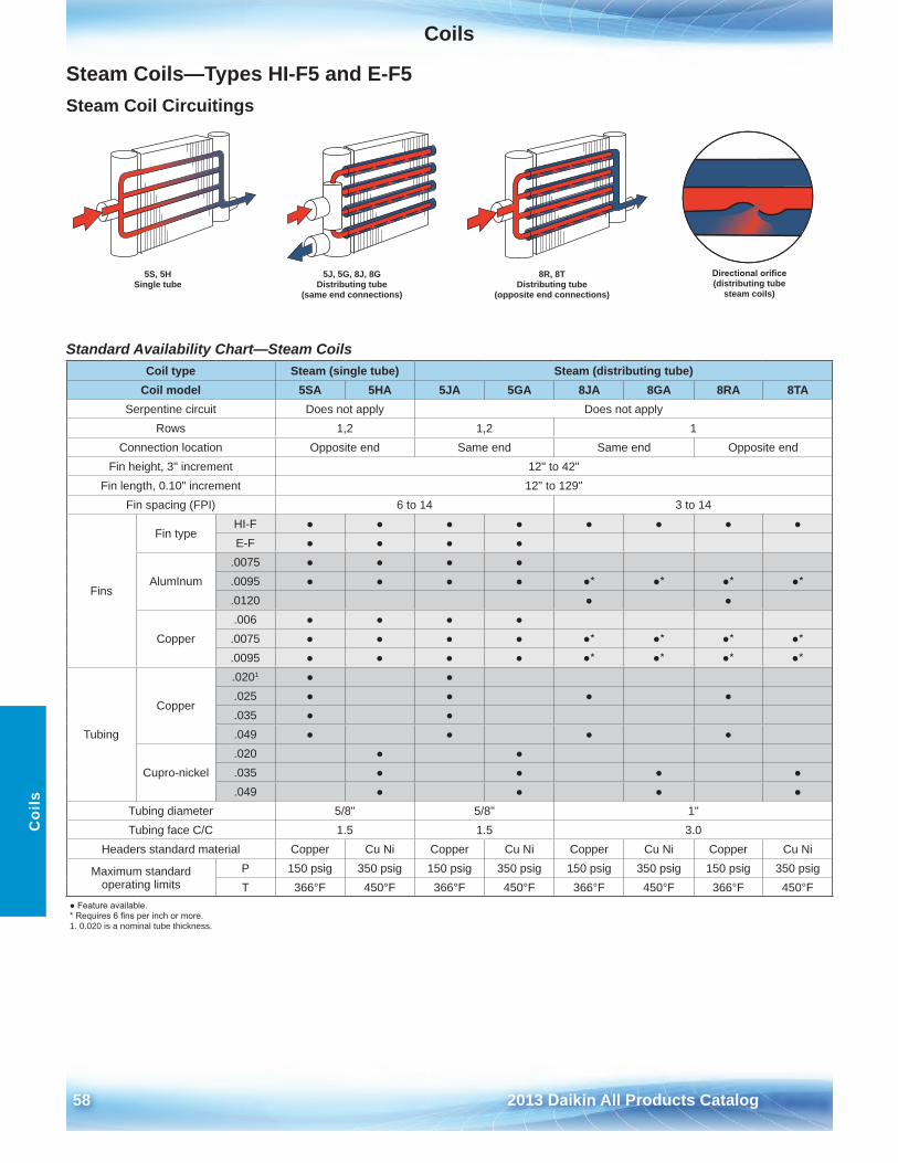
Coils
58 2013 Daikin All Products Catalog
Coi
ls
Steam Coils—Types HI-F5 and E-F5 Steam Coil Circuitings
Standard Availability Chart—Steam Coils Coil type Steam (single tube) Steam (distributing tube)
Coil model 5SA 5HA 5JA 5GA 8JA 8GA 8RA 8TASerpentine circuit Does not apply Does not apply
Rows 1,2 1,2 1Connection location Opposite end Same end Same end Opposite end
Fin height, 3" increment 12" to 42"Fin length, 0 .10" increment 12" to 129"
Fin spacing (FPI) 6 to 14 3 to 14
Fins
Fin typeHI-F ● ● ● ● ● ● ● ● E-F ● ● ● ●
AlumInum .0075 ● ● ● ● .0095 ● ● ● ● ●* ●* ●* ●* .0120 ● ●
Copper .006 ● ● ● ●
.0075 ● ● ● ● ●* ●* ●* ●* .0095 ● ● ● ● ●* ●* ●* ●*
Tubing
Copper
.0201 ● ● .025 ● ● ● ● .035 ● ● .049 ● ● ● ●
Cupro-nickel .020 ● ● .035 ● ● ● ● .049 ● ● ● ●
Tubing diameter 5/8" 5/8" 1"Tubing face C/C 1 .5 1 .5 3 .0
Headers standard material Copper Cu Ni Copper Cu Ni Copper Cu Ni Copper Cu Ni
Maximum standard operating limits
P 150 psig 350 psig 150 psig 350 psig 150 psig 350 psig 150 psig 350 psigT 366°F 450°F 366°F 450°F 366°F 450°F 366°F 450°F
● Feature available.* Requires 6 fins per inch or more.1 . 0 .020 is a nominal tube thickness .
Directional orifice (distributing tube
steam coils)
8R, 8T Distributing tube
(opposite end connections)
5J, 5G, 8J, 8G Distributing tube
(same end connections)
5S, 5H Single tube
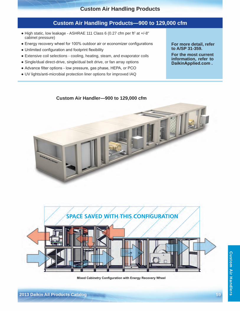
2013 Daikin All Products Catalog 59
Custom Air Handling ProductsC
ustom A
ir Handlers
Custom Air Handling Products—900 to 129,000 cfm
● High static, low leakage - ASHRAE 111 Class 6 (0 .27 cfm per ft2 at +/-8”cabinet pressure)
● Energy recovery wheel for 100% outdoor air or economizer configurations● Unlimited configuration and footprint flexibility● Extensive coil selections - cooling, heating, steam, and evaporator coils● Single/dual direct-drive, single/dual belt drive, or fan array options● Advance filter options - low pressure, gas phase, HEPA, or PCO● UV lights/anti-microbial protection liner options for improved IAQ
For more detail, refer to A/SP 31-359 .For the most current information, refer to DaikinApplied.com .
Custom Air Handler—900 to 129,000 cfm
SPACE SAVED WITH THIS CONFIGURATION
Mixed Cabinetry Configuration with Energy Recovery Wheel
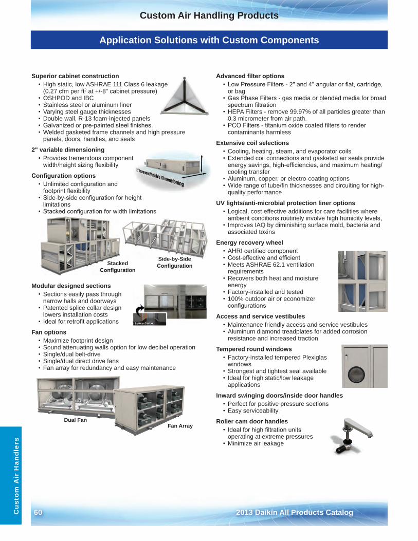
60 2013 Daikin All Products Catalog
Custom Air Handling ProductsC
usto
m A
ir H
andl
ers
Application Solutions with Custom Components
Superior cabinet construction • High static, low ASHRAE 111 Class 6 leakage
(0 .27 cfm per ft2 at +/-8" cabinet pressure)• OSHPOD and IBC• Stainless steel or aluminum liner• Varying steel gauge thicknesses• Double wall, R-13 foam-injected panels• Galvanized or pre-painted steel finishes.• Welded gasketed frame channels and high pressure
panels, doors, handles, and seals
2" variable dimensioning • Provides tremendous component
width/height sizing flexibility
Configuration options• Unlimited configuration and
footprint flexibility• Side-by-side configuration for height
limitations• Stacked configuration for width limitations
Modular designed sections • Sections easily pass through
narrow halls and doorways• Patented splice collar design
lowers installation costs• Ideal for retrofit applications
Fan options • Maximize footprint design• Sound attenuating walls option for low decibel operation• Single/dual belt-drive• Single/dual direct drive fans• Fan array for redundancy and easy maintenance
Advanced filter options• Low Pressure Filters - 2" and 4" angular or flat, cartridge,
or bag• Gas Phase Filters - gas media or blended media for broad
spectrum filtration• HEPA Filters - remove 99 .97% of all particles greater than
0 .3 micrometer from air path .• PCO Filters - titanium oxide coated filters to render
contaminants harmless
Extensive coil selections• Cooling, heating, steam, and evaporator coils• Extended coil connections and gasketed air seals provide
energy savings, high-efficiencies, and maximum heating/cooling transfer
• Aluminum, copper, or electro-coating options• Wide range of tube/fin thicknesses and circuiting for high-
quality performance
UV lights/anti-microbial protection liner options• Logical, cost effective additions for care facilities where
ambient conditions routinely involve high humidity levels,• Improves IAQ by diminishing surface mold, bacteria and
associated toxins
Energy recovery wheel • AHRI certified component• Cost-effective and efficient• Meets ASHRAE 62 .1 ventilation
requirements• Recovers both heat and moisture
energy• Factory-installed and tested• 100% outdoor air or economizer
configurations
Access and service vestibules• Maintenance friendly access and service vestibules• Aluminum diamond treadplates for added corrosion
resistance and increased traction
Tempered round windows • Factory-installed tempered Plexiglas
windows• Strongest and tightest seal available• Ideal for high static/low leakage
applications
Inward swinging doors/inside door handles• Perfect for positive pressure sections• Easy serviceability
Roller cam door handles • Ideal for high filtration units
operating at extreme pressures• Minimize air leakage
StackedConfiguration
Side-by-SideConfiguration
Dual FanFan Array
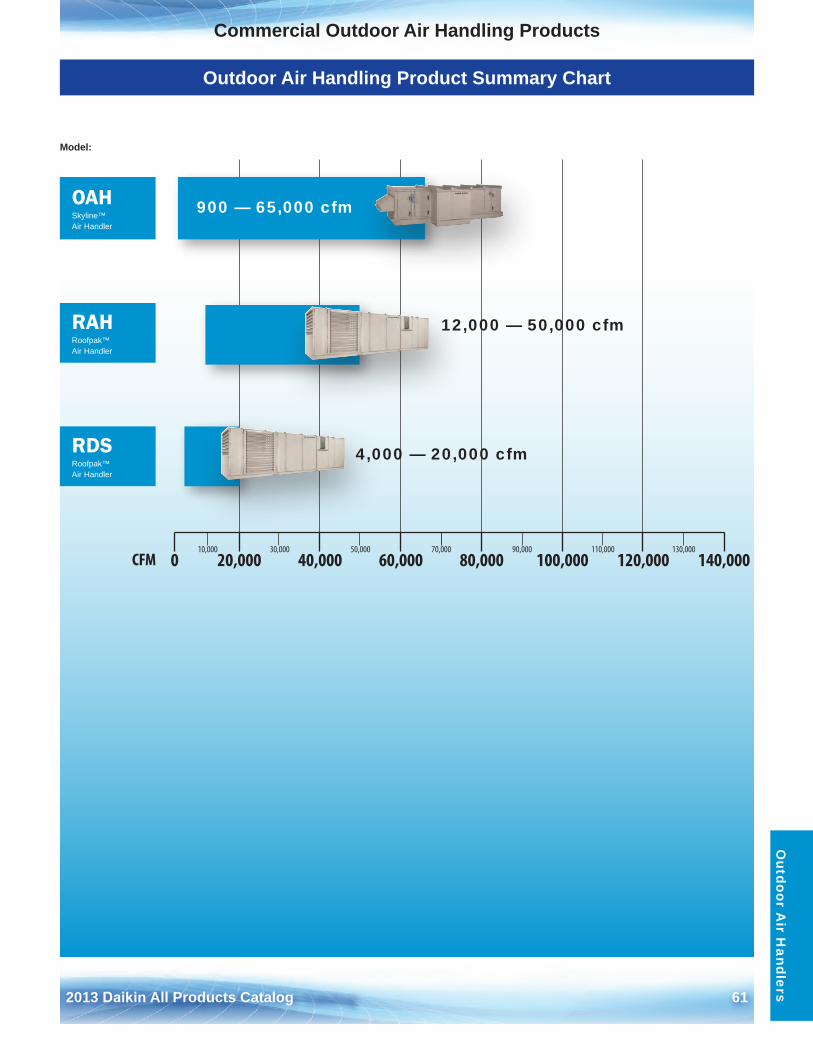
2013 Daikin All Products Catalog 61
Commercial Outdoor Air Handling ProductsO
utdoor Air H
andlers
Outdoor Air Handling Product Summary Chart
10,000 30,000 50,000 70,000 90,000 110,000 130,000
0 20,000 40,000 60,000 80,000 100,000 120,000 140,000CFM
Model:
OAHSkyline™ Air Handler
RAHRoofpak™ Air Handler
RDSRoofpak™ Air Handler
900 — 65,000 cfm
12,000 — 50,000 cfm
4,000 — 20,000 cfm
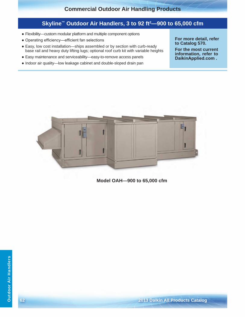
62 2013 Daikin All Products Catalog
Commercial Outdoor Air Handling ProductsO
utdo
or A
ir H
andl
ers
Skyline™ Outdoor Air Handlers, 3 to 92 ft2—900 to 65,000 cfm
● Flexibility—custom modular platform and multiple component options● Operating efficiency—efficient fan selections● Easy, low cost installation—ships assembled or by section with curb-ready
base rail and heavy duty lifting lugs; optional roof curb kit with variable heights● Easy maintenance and serviceability—easy-to-remove access panels● Indoor air quality—low leakage cabinet and double-sloped drain pan
For more detail, refer to Catalog 570 .For the most current information, refer to DaikinApplied.com .
Model OAH—900 to 65,000 cfm
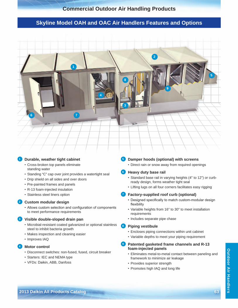
2013 Daikin All Products Catalog 63
Commercial Outdoor Air Handling ProductsO
utdoor Air H
andlers
Skyline Model OAH and OAC Air Handlers Features and Options
1 Durable, weather tight cabinet• Cross-broken top panels eliminate
standing water• Standing “C” cap over joint provides a watertight seal• Drip shield on all sides and over doors• Pre-painted frames and panels• R-13 foam-injected insulation• Stainless steel liners option
2 Custom modular design• Allows custom selection and configuration of components
to meet performance requirements
3 Visible double-sloped drain pan• Microbial-resistant coated galvanized or optional stainless
steel to inhibit bacteria growth• Makes inspection and cleaning easier• Improves IAQ
4 Motor control• Disconnect switches: non-fused, fused, circuit breaker• Starters: IEC and NEMA type• VFDs: Daikin, ABB, Danfoss
5 Damper hoods (optional) with screens• Direct rain or snow away from required openings
6 Heavy duty base rail • Standard base rail in varying heights (4" to 12") or curb-
ready design, forms weather tight seal• Lifting lugs on all four corners facilitates easy rigging
7 Factory-supplied roof curb (optional)• Designed specifically to match custom-modular design
flexibility• Variable heights from 16" to 30" to meet installation
requirements• Includes separate pipe chase
8 Piping vestibule• Encloses piping connections within unit cabinet• Variable depths to meet your piping requirement
9 Patented gasketed frame channels and R-13 foam-injected panels• Eliminates metal-to-metal contact between paneling and
framework to minimize air leakage • Provides superior strength• Promotes high IAQ and long life
1
2
3
4
5
6 7
8
9
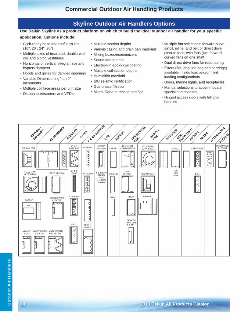
64 2013 Daikin All Products Catalog
Commercial Outdoor Air Handling ProductsO
utdo
or A
ir H
andl
ers
Skyline Outdoor Air Handlers OptionsUse Daikin Skyline as a product platform on which to build the ideal outdoor air handler for your specific application. Options include:• Curb-ready base and roof curb kits
(16", 20", 24", 30")• Multiple sizes of insulated, double-wall
coil and piping vestibules• Horizontal or vertical integral face and
bypass dampers• Hoods and grilles for damper openings• Variable Dimensioning™ on 2"
increments• Multiple coil face areas per unit size• Disconnects/starters and VFD’s
• Multiple section depths• Various casing and drain pan materials• Mixing boxes/economizers• Sound attenuators• Electro-Fin epoxy coil coating• Multiple coil section depths• Humidifier manifold• IBC seismic certification• Gas-phase filtration• Miami-Dade hurricane certified
• Multiple fan selections: forward curve,airfoil, inline, and belt or direct driveplenum fans; twin fans (two forwardcurved fans on one shaft)
• Dual direct-drive fans for redundancy• Filters (flat, angular, bag and cartridge)
available in side load and/or frontloading configurations
• Doors, marine lights, and receptacles• Manual selections to accommodate
special components• Hinged access doors with full grip
handles
PLENUM FAN
PLENUM FAN
HORIZHORIZ
HEATING
MIXING BOX
RETURN /
EXHAUST
ECONOMIZER
BLENDER
DIFFUSER
PLENUM
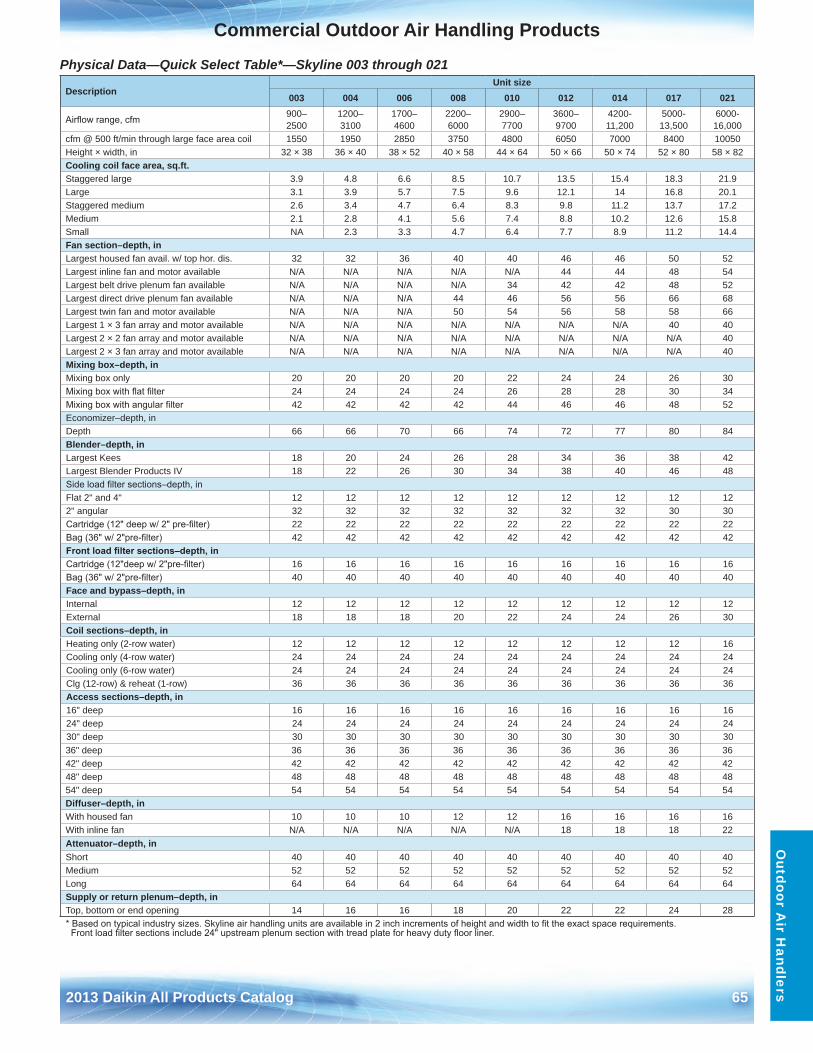
2013 Daikin All Products Catalog 65
Commercial Outdoor Air Handling ProductsO
utdoor Air H
andlers
Physical Data—Quick Select Table*—Skyline 003 through 021
DescriptionUnit size
003 004 006 008 010 012 014 017 021
Airflow range, cfm 900– 2500
1200– 3100
1700– 4600
2200– 6000
2900– 7700
3600– 9700
4200-11,200
5000-13,500
6000-16,000
cfm @ 500 ft/min through large face area coil 1550 1950 2850 3750 4800 6050 7000 8400 10050Height × width, in 32 × 38 36 × 40 38 × 52 40 × 58 44 × 64 50 × 66 50 × 74 52 × 80 58 × 82Cooling coil face area, sq .ft .Staggered large 3 .9 4 .8 6 .6 8 .5 10 .7 13 .5 15 .4 18 .3 21 .9Large 3 .1 3 .9 5 .7 7 .5 9 .6 12 .1 14 16 .8 20 .1Staggered medium 2 .6 3 .4 4 .7 6 .4 8 .3 9 .8 11 .2 13 .7 17 .2Medium 2 .1 2 .8 4 .1 5 .6 7 .4 8 .8 10 .2 12 .6 15 .8Small NA 2 .3 3 .3 4 .7 6 .4 7 .7 8 .9 11 .2 14 .4Fan section–depth, inLargest housed fan avail . w/ top hor . dis . 32 32 36 40 40 46 46 50 52Largest inline fan and motor available N/A N/A N/A N/A N/A 44 44 48 54Largest belt drive plenum fan available N/A N/A N/A N/A 34 42 42 48 52Largest direct drive plenum fan available N/A N/A N/A 44 46 56 56 66 68Largest twin fan and motor available N/A N/A N/A 50 54 56 58 58 66Largest 1 × 3 fan array and motor available N/A N/A N/A N/A N/A N/A N/A 40 40Largest 2 × 2 fan array and motor available N/A N/A N/A N/A N/A N/A N/A N/A 40Largest 2 × 3 fan array and motor available N/A N/A N/A N/A N/A N/A N/A N/A 40Mixing box–depth, inMixing box only 20 20 20 20 22 24 24 26 30Mixing box with flat filter 24 24 24 24 26 28 28 30 34Mixing box with angular filter 42 42 42 42 44 46 46 48 52Economizer–depth, inDepth 66 66 70 66 74 72 77 80 84Blender–depth, inLargest Kees 18 20 24 26 28 34 36 38 42Largest Blender Products IV 18 22 26 30 34 38 40 46 48Side load filter sections–depth, inFlat 2" and 4" 12 12 12 12 12 12 12 12 122" angular 32 32 32 32 32 32 32 30 30Cartridge (12" deep w/ 2" pre-filter) 22 22 22 22 22 22 22 22 22Bag (36" w/ 2"pre-filter) 42 42 42 42 42 42 42 42 42Front load filter sections–depth, inCartridge (12"deep w/ 2"pre-filter) 16 16 16 16 16 16 16 16 16Bag (36" w/ 2"pre-filter) 40 40 40 40 40 40 40 40 40Face and bypass–depth, inInternal 12 12 12 12 12 12 12 12 12External 18 18 18 20 22 24 24 26 30Coil sections–depth, inHeating only (2-row water) 12 12 12 12 12 12 12 12 16Cooling only (4-row water) 24 24 24 24 24 24 24 24 24Cooling only (6-row water) 24 24 24 24 24 24 24 24 24Clg (12-row) & reheat (1-row) 36 36 36 36 36 36 36 36 36Access sections–depth, in16" deep 16 16 16 16 16 16 16 16 1624" deep 24 24 24 24 24 24 24 24 2430" deep 30 30 30 30 30 30 30 30 3036" deep 36 36 36 36 36 36 36 36 3642" deep 42 42 42 42 42 42 42 42 4248" deep 48 48 48 48 48 48 48 48 4854" deep 54 54 54 54 54 54 54 54 54Diffuser–depth, inWith housed fan 10 10 10 12 12 16 16 16 16With inline fan N/A N/A N/A N/A N/A 18 18 18 22Attenuator–depth, inShort 40 40 40 40 40 40 40 40 40Medium 52 52 52 52 52 52 52 52 52Long 64 64 64 64 64 64 64 64 64Supply or return plenum–depth, inTop, bottom or end opening 14 16 16 18 20 22 22 24 28* Based on typical industry sizes. Skyline air handling units are available in 2 inch increments of height and width to fit the exact space requirements.Front load filter sections include 24" upstream plenum section with tread plate for heavy duty floor liner.
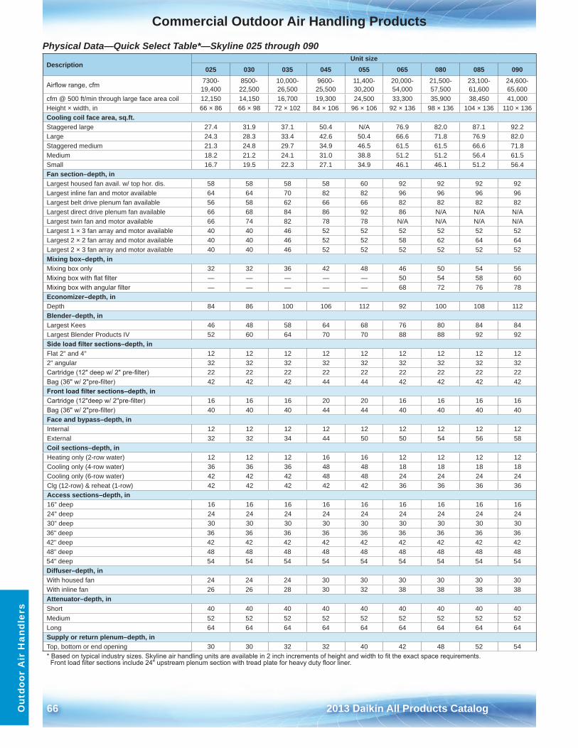
66 2013 Daikin All Products Catalog
Commercial Outdoor Air Handling ProductsO
utdo
or A
ir H
andl
ers
Physical Data—Quick Select Table*—Skyline 025 through 090
DescriptionUnit size
025 030 035 045 055 065 080 085 090
Airflow range, cfm 7300-19,400
8500-22,500
10,000-26,500
9600-25,500
11,400-30,200
20,000-54,000
21,500-57,500
23,100-61,600
24,600-65,600
cfm @ 500 ft/min through large face area coil 12,150 14,150 16,700 19,300 24,500 33,300 35,900 38,450 41,000Height × width, in 66 × 86 66 × 98 72 × 102 84 × 106 96 × 106 92 × 136 98 × 136 104 × 136 110 × 136Cooling coil face area, sq .ft .Staggered large 27 .4 31 .9 37 .1 50 .4 N/A 76 .9 82 .0 87 .1 92 .2Large 24 .3 28 .3 33 .4 42 .6 50 .4 66 .6 71 .8 76 .9 82 .0Staggered medium 21 .3 24 .8 29 .7 34 .9 46 .5 61 .5 61 .5 66 .6 71 .8Medium 18 .2 21 .2 24 .1 31 .0 38 .8 51 .2 51 .2 56 .4 61 .5Small 16 .7 19 .5 22 .3 27 .1 34 .9 46 .1 46 .1 51 .2 56 .4Fan section–depth, inLargest housed fan avail . w/ top hor . dis . 58 58 58 58 60 92 92 92 92 Largest inline fan and motor available 64 64 70 82 82 96 96 96 96 Largest belt drive plenum fan available 56 58 62 66 66 82 82 82 82 Largest direct drive plenum fan available 66 68 84 86 92 86 N/A N/A N/ALargest twin fan and motor available 66 74 82 78 78 N/A N/A N/A N/ALargest 1 × 3 fan array and motor available 40 40 46 52 52 52 52 52 52Largest 2 × 2 fan array and motor available 40 40 46 52 52 58 62 64 64Largest 2 × 3 fan array and motor available 40 40 46 52 52 52 52 52 52Mixing box–depth, inMixing box only 32 32 36 42 48 46 50 54 56 Mixing box with flat filter — — — — — 50 54 58 60 Mixing box with angular filter — — — — — 68 72 76 78 Economizer–depth, inDepth 84 86 100 106 112 92 100 108 112 Blender–depth, inLargest Kees 46 48 58 64 68 76 80 84 84 Largest Blender Products IV 52 60 64 70 70 88 88 92 92 Side load filter sections–depth, inFlat 2" and 4" 12 12 12 12 12 12 12 12 12 2" angular 32 32 32 32 32 32 32 32 32 Cartridge (12" deep w/ 2" pre-filter) 22 22 22 22 22 22 22 22 22 Bag (36" w/ 2"pre-filter) 42 42 42 44 44 42 42 42 42 Front load filter sections–depth, inCartridge (12"deep w/ 2"pre-filter) 16 16 16 20 20 16 16 16 16 Bag (36" w/ 2"pre-filter) 40 40 40 44 44 40 40 40 40 Face and bypass–depth, inInternal 12 12 12 12 12 12 12 12 12 External 32 32 34 44 50 50 54 56 58 Coil sections–depth, inHeating only (2-row water) 12 12 12 16 16 12 12 12 12 Cooling only (4-row water) 36 36 36 48 48 18 18 18 18 Cooling only (6-row water) 42 42 42 48 48 24 24 24 24 Clg (12-row) & reheat (1-row) 42 42 42 42 42 36 36 36 36 Access sections–depth, in16" deep 16 16 16 16 16 16 16 16 16 24" deep 24 24 24 24 24 24 24 24 24 30" deep 30 30 30 30 30 30 30 30 30 36" deep 36 36 36 36 36 36 36 36 36 42" deep 42 42 42 42 42 42 42 42 42 48" deep 48 48 48 48 48 48 48 48 48 54" deep 54 54 54 54 54 54 54 54 54 Diffuser–depth, inWith housed fan 24 24 24 30 30 30 30 30 30 With inline fan 26 26 28 30 32 38 38 38 38 Attenuator–depth, inShort 40 40 40 40 40 40 40 40 40Medium 52 52 52 52 52 52 52 52 52Long 64 64 64 64 64 64 64 64 64Supply or return plenum–depth, inTop, bottom or end opening 30 30 32 32 40 42 48 52 54* Based on typical industry sizes. Skyline air handling units are available in 2 inch increments of height and width to fit the exact space requirements.Front load filter sections include 24" upstream plenum section with tread plate for heavy duty floor liner.
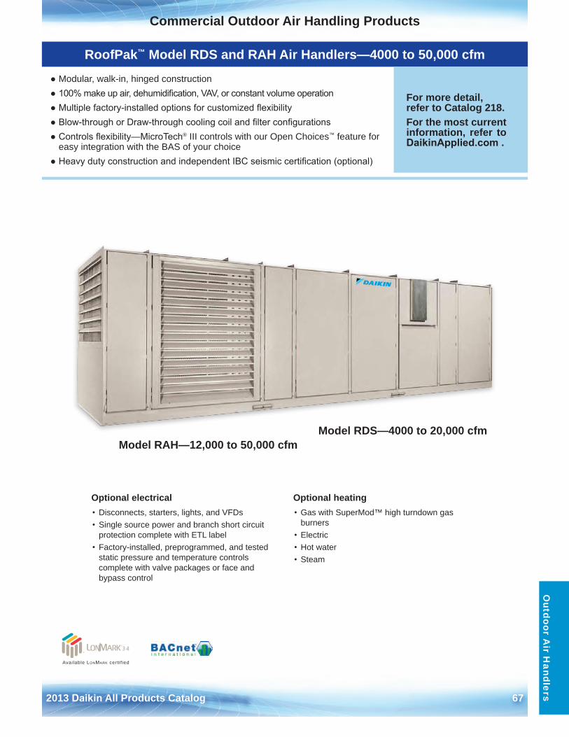
2013 Daikin All Products Catalog 67
Commercial Outdoor Air Handling ProductsO
utdoor Air H
andlers
RoofPak™ Model RDS and RAH Air Handlers—4000 to 50,000 cfm
● Modular, walk-in, hinged construction● 100% make up air, dehumidification, VAV, or constant volume operation● Multiple factory-installed options for customized flexibility● Blow-through or Draw-through cooling coil and filter configurations● Controls flexibility—MicroTech® III controls with our Open Choices™ feature for
easy integration with the BAS of your choice● Heavy duty construction and independent IBC seismic certification (optional)
For more detail, refer to Catalog 218 . For the most current information, refer to DaikinApplied.com .
Optional electrical• Disconnects, starters, lights, and VFDs• Single source power and branch short circuit
protection complete with ETL label• Factory-installed, preprogrammed, and tested
static pressure and temperature controlscomplete with valve packages or face andbypass control
Optional heating• Gas with SuperMod™ high turndown gas
burners• Electric• Hot water• Steam
Model RDS—4000 to 20,000 cfmModel RAH—12,000 to 50,000 cfm
Available LonMark cert i f ied
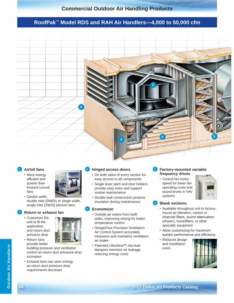
68 2013 Daikin All Products Catalog
Commercial Outdoor Air Handling ProductsO
utdo
or A
ir H
andl
ers
RoofPak™ Model RDS and RAH Air Handlers—4,000 to 50,000 cfm
1 Airfoil fans • More energy
efficient andquieter thanforward curvedfans
• Double width,double inlet (DWDI) or single width,single inlet (SWSI) plenum fans
2 Return or exhaust fan • Customize the
unit to fit theapplicationand return ductpressure drop
• Return fansprovide betterbuilding pressure and ventilationcontrol as return duct pressure dropincreases
• Exhaust fans can save energyas return duct pressure droprequirements decrease
3 Hinged access doors• On both sides of every section for
easy access to all components• Single lever latch and door holders
provide easy entry and supportroutine maintenance
• Double-wall construction protectsinsulation during maintenance
4 Economizer• Outside air enters from both
sides, improving mixing for bettertemperature control
• DesignFlow Precision VentilationAir Control System accuratelymeasures and maintains ventilationair intake
• Patented UltraSeal™ low leakdampers minimize air leakage,reducing energy costs
5 Factory-mounted variable frequency drives • Control fan motor
speed for lower fanoperating costs andsound levels in VAVsystems
6 Blank sections • Available throughout unit to factory-
mount air blenders, carbon orcharcoal filters, sound attenuators(shown), humidifiers, or otherspecialty equipment
• Allow customizing for maximumsystem performance and efficiency
• Reduced designand installationcosts
2
3
4
4 5
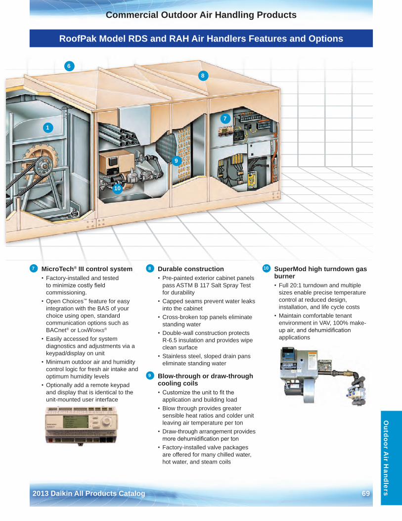
2013 Daikin All Products Catalog 69
Commercial Outdoor Air Handling ProductsO
utdoor Air H
andlers
RoofPak Model RDS and RAH Air Handlers Features and Options
1
6
7
8
9
10
7 MicroTech® III control system • Factory-installed and tested
to minimize costly field commissioning .
• Open Choices™ feature for easyintegration with the BAS of your choice using open, standard communication options such as BACnet® or LonWorks®
• Easily accessed for systemdiagnostics and adjustments via a keypad/display on unit
• Minimum outdoor air and humiditycontrol logic for fresh air intake and optimum humidity levels
• Optionally add a remote keypadand display that is identical to the unit-mounted user interface
8 Durable construction• Pre-painted exterior cabinet panels
pass ASTM B 117 Salt Spray Test for durability
• Capped seams prevent water leaksinto the cabinet
• Cross-broken top panels eliminatestanding water
• Double-wall construction protectsR-6 .5 insulation and provides wipe clean surface
• Stainless steel, sloped drain panseliminate standing water
9 Blow-through or draw-through cooling coils• Customize the unit to fit the
application and building load• Blow through provides greater
sensible heat ratios and colder unit leaving air temperature per ton
• Draw-through arrangement providesmore dehumidification per ton
• Factory-installed valve packagesare offered for many chilled water, hot water, and steam coils
10 SuperMod high turndown gas burner • Full 20:1 turndown and multiple
sizes enable precise temperature control at reduced design, installation, and life cycle costs
• Maintain comfortable tenantenvironment in VAV, 100% make-up air, and dehumidification applications
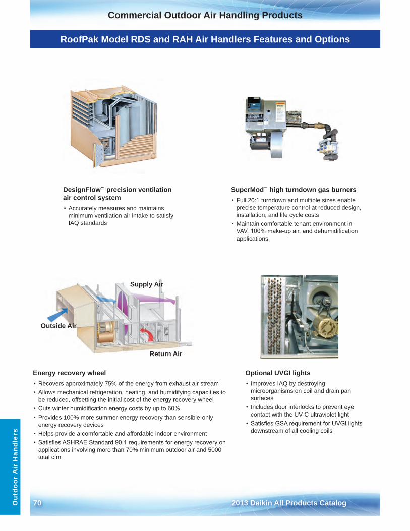
70 2013 Daikin All Products Catalog
Commercial Outdoor Air Handling ProductsO
utdo
or A
ir H
andl
ers
RoofPak Model RDS and RAH Air Handlers Features and Options
DesignFlow™ precision ventilation air control system• Accurately measures and maintains
minimum ventilation air intake to satisfy IAQ standards
SuperMod™ high turndown gas burners• Full 20:1 turndown and multiple sizes enable
precise temperature control at reduced design, installation, and life cycle costs
• Maintain comfortable tenant environment inVAV, 100% make-up air, and dehumidification applications
Optional UVGI lights• Improves IAQ by destroying
microorganisms on coil and drain pan surfaces
• Includes door interlocks to prevent eyecontact with the UV-C ultraviolet light
• Satisfies GSA requirement for UVGI lightsdownstream of all cooling coils
Energy recovery wheel• Recovers approximately 75% of the energy from exhaust air stream• Allows mechanical refrigeration, heating, and humidifying capacities to
be reduced, offsetting the initial cost of the energy recovery wheel• Cuts winter humidification energy costs by up to 60%• Provides 100% more summer energy recovery than sensible-only
energy recovery devices• Helps provide a comfortable and affordable indoor environment• Satisfies ASHRAE Standard 90.1 requirements for energy recovery on
applications involving more than 70% minimum outdoor air and 5000total cfm
Outside Air
Return Air
Supply Air
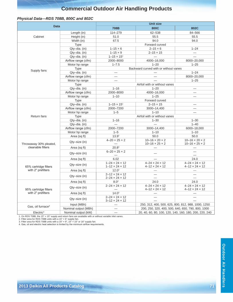
2013 Daikin All Products Catalog 71
Commercial Outdoor Air Handling ProductsO
utdoor Air H
andlers
Physical Data—RDS 708B, 800C and 802C
DataUnit size
708B 800C 802C
CabinetLength (in) 114–279 62–538 84–566Height (in) 51 .0 55 .5 55 .5Width (in) 67 .5 94 .0 94 .0
Supply fans
Type Forward curvedQty–dia . (in) 1–15 × 6 2–15 × 6 1–24Qty–dia . (in) 1–15 × 9 2–15 × 15 —Qty–dia . (in) 1–15 × 151 — —
Airflow range (cfm) 2000–8000 4000–16,000 8000–20,000Motor hp range 1–7 .5 1–20 1–25
Type Backward curved with or without vanesQty–dia . (in) — — 1–24
Airflow range (cfm) — — 8000–20,000Motor hp range — — 1–25
Type Airfoil with or without vanesQty–dia . (in) 1–16 1–20 —
Airflow range (cfm) 2000–8000 4000–16,000 —Motor hp range 1–10 1–25 —
Return fans
Type Forward curvedQty–dia . (in) 1–15 × 151 2–15 × 15 —
Airflow range (cfm) 2000–7200 3000–14,400 —Motor hp range 1–5 1–10 —
Type Airfoil with or without vanes Qty–dia . (in) 1–16 1–30 1–30Qty–dia . (in) — — 1–40
Airflow range (cfm) 2000–7200 3000–14,400 6000–18,000Motor hp range 1–5 1–10 1–10
Throwaway 30% pleated, cleanable filters
Area (sq ft) 13 .92 50 .0 50 .0
Qty–size (in) 4–20 × 25 × 2—
10–16 × 20 × 210–16 × 25 × 2
10–16 × 20 × 210–16 × 25 × 2
Area (sq ft) 20 .83 — —
Qty–size (in) 6–20 × 25 × 2— — —
—
65% cartridge filters with 2" prefilters
Area (sq ft) 6 .02 — 24 .0
Qty–size (in) 1–24 × 24 × 121–12 × 24 × 12
4–24 × 24 × 124–12 × 24 × 12
4–24 × 24 × 124–12 × 24 × 12
Area (sq ft) 12 .03 — —
Qty–size (in) 2–12 × 24 × 122–24 × 24 × 12
——
——
95% cartridge filters with 2" prefilters
Area (sq ft) 8 .02 24 .0 24 .0
Qty–size (in) 2–24 × 24 × 12—
4–24 × 24 × 124–12 × 24 × 12
4–24 × 24 × 124–12 × 24 × 12
Area (sq ft) 14 .03 — —
Qty–size (in) 2–24 × 24 × 123–12 × 24 × 12
——
——
Gas, oil furnace4 Input (MBh) — 250, 312, 400, 500, 625, 800, 812, 988, 1000, 1250Nominal output (MBh) — 200, 250, 320, 400, 500, 640, 650, 790, 800, 1000
Electric4 Nominal output (kW) — 20, 40, 60, 80, 100, 120, 140, 160, 180, 200, 220, 2401 . On RDS 708B, the 15" × 15" supply and return fans are available with or without variable inlet vanes .2 . Filter area for RDS 708B units with a 15" × 6" supply fan .3 . Filter area for RDS 708B units with a 15" × 9", 15" × 15" or 16" supply fan .4. Gas, oil and electric heat selection is limited by the minimum airflow requirements.
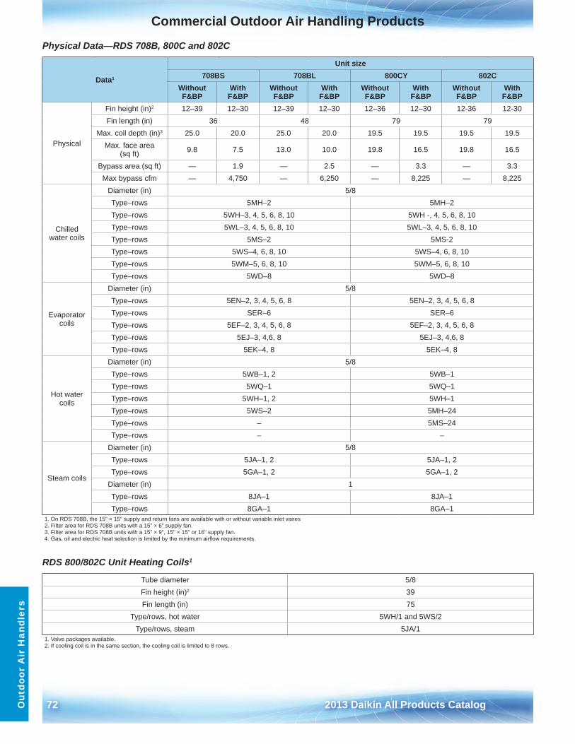
72 2013 Daikin All Products Catalog
Commercial Outdoor Air Handling ProductsO
utdo
or A
ir H
andl
ers
Physical Data—RDS 708B, 800C and 802C
Data1
Unit size708BS 708BL 800CY 802C
Without F&BP
With F&BP
Without F&BP
With F&BP
Without F&BP
With F&BP
Without F&BP
With F&BP
Physical
Fin height (in)2 12–39 12–30 12–39 12–30 12–36 12–30 12-36 12-30Fin length (in) 36 48 79 79
Max . coil depth (in)3 25 .0 20 .0 25 .0 20 .0 19 .5 19 .5 19 .5 19 .5Max . face area
(sq ft) 9 .8 7 .5 13 .0 10 .0 19 .8 16 .5 19 .8 16 .5
Bypass area (sq ft) — 1 .9 — 2 .5 — 3 .3 — 3 .3Max bypass cfm — 4,750 — 6,250 — 8,225 — 8,225
Chilled water coils
Diameter (in) 5/8Type–rows 5MH–2 5MH–2Type–rows 5WH–3, 4, 5, 6, 8, 10 5WH -, 4, 5, 6, 8, 10Type–rows 5WL–3, 4, 5, 6, 8, 10 5WL–3, 4, 5, 6, 8, 10Type–rows 5MS–2 5MS-2Type–rows 5WS–4, 6, 8, 10 5WS–4, 6, 8, 10Type–rows 5WM–5, 6, 8, 10 5WM–5, 6, 8, 10Type–rows 5WD–8 5WD–8
Evaporator coils
Diameter (in) 5/8Type–rows 5EN–2, 3, 4, 5, 6, 8 5EN–2, 3, 4, 5, 6, 8Type–rows SER–6 SER–6Type–rows 5EF–2, 3, 4, 5, 6, 8 5EF–2, 3, 4, 5, 6, 8Type–rows 5EJ–3, 4,6, 8 5EJ–3, 4,6, 8Type–rows 5EK–4, 8 5EK–4, 8
Hot water coils
Diameter (in) 5/8Type–rows 5WB–1, 2 5WB–1Type–rows 5WQ–1 5WQ–1Type–rows 5WH–1, 2 5WH–1Type–rows 5WS–2 5MH–24 Type–rows – 5MS–24Type–rows – –
Steam coils
Diameter (in) 5/8Type–rows 5JA–1, 2 5JA–1, 2Type–rows 5GA–1, 2 5GA–1, 2
Diameter (in) 1Type–rows 8JA–1 8JA–1Type–rows 8GA–1 8GA–1
1 . On RDS 708B, the 15" × 15" supply and return fans are available with or without variable inlet vanes2 . Filter area for RDS 708B units with a 15" × 6" supply fan .3 . Filter area for RDS 708B units with a 15" × 9", 15" × 15" or 16" supply fan .4. Gas, oil and electric heat selection is limited by the minimum airflow requirements.
RDS 800/802C Unit Heating Coils1
Tube diameter 5/8Fin height (in)2 39Fin length (in) 75
Type/rows, hot water 5WH/1 and 5WS/2Type/rows, steam 5JA/1
1 . Valve packages available .2 . If cooling coil is in the same section, the cooling coil is limited to 8 rows .
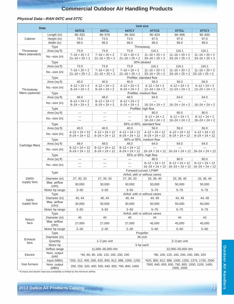
2013 Daikin All Products Catalog 73
Commercial Outdoor Air Handling ProductsO
utdoor Air H
andlers
Physical Data—RAH 047C and 077C
Data Unit size047CS 047CL 047CY 077CS 077CL 077CY
CabinetLength (in) 96–552 96–576 96–504 96–624 96–696 96–600Height (in) 73 .0 73 .0 73 .0 97 .0 97 .0 97 .0Width (in) 99 .0 99 .0 99 .0 99 .0 99 .0 99 .0
Throwaway filters (standard)
Type ThrowawayArea (sq ft) 73 .9 73 .9 73 .9 116 .1 116 .1 116 .1
No .–size (in) 7–16 × 20 × 221–16 × 25 × 2
7–16 × 20 × 221–16 × 25 × 2
7–16 × 20 × 221–16 × 25 × 2
11–16 × 20 × 233–16 × 25 × 2
11–16 × 20 × 233–16 × 25 × 2
11–16 × 20 × 233–16 × 25 × 2
Throwaway filters (optional)
Type 30% pleatedArea (sq ft) 73 .9 73 .9 73 .9 116 .1 116 .1 116 .1
No .–size (in) 7–16 × 20 × 221–16 × 25 × 2
7–16 × 20 × 221–16 × 25 × 2
7–16 × 20 × 221–16 × 25 × 2
11–16 × 20 × 233–16 × 25 × 2
11–16 × 20 × 233–16 × 25 × 2
11–16 × 20 × 233–16 × 25 × 2
Type Prefilter, standard flowArea (sq ft) 40 .0 40 .0 40 .0 56 .0 56 .0 56 .0
No .–size (in) 4–12 × 24 × 28–24 × 24 × 2
4–12 × 24 × 28–24 × 24 × 2
4–12 × 24 × 28–24 × 24 × 2
4–12 × 24 × 212–24 × 24 × 2
4–12 × 24 × 212–24 × 24 × 2
4–12 × 24 × 212–24 × 24 × 2
Type Prefilter, medium flowArea (sq ft) 48 .0 48 .0 48 .0 64 .0 64 .0 64 .0
No .–size (in) 8–12 × 24 × 28–24 × 24 × 2
8–12 × 24 × 28–24 × 24 × 2
8–12 × 24 × 28–24 × 24 × 2
—16–24 × 24 × 2
—16–24 × 24 × 2
—16–24 × 24 × 2
Type Prefilter, high flowArea (sq ft) — — — 80 .0 80 .0 80 .0
No .–size (in) ——
——
——
8–12 × 24 × 216–24 × 24 × 2
8–12 × 24 × 216–24 × 24 × 2
8–12 × 24 × 216–24 × 24 × 2
Cartridge filters
Type 65% or 95%, standard flowArea (sq ft) 40 .0 40 .0 40 .0 56 .0 56 .0 56 .0
No .–size (in) 4–12 × 24 × 128–24 × 24 × 12
4–12 × 24 × 128–24 × 24 × 12
4–12 × 24 × 128–24 × 24 × 12
4–12 × 24 × 128–24 × 24 × 12
4–12 × 24 × 128–24 × 24 × 12
4–12 × 24 × 128–24 × 24 × 12
Type 65% or 95%, medium flowArea (sq ft) 48 .0 48 .0 48 .0 64 .0 64 .0 64 .0
No .–size (in) 8–12 × 24 × 128–24 × 24 × 12
8–12 × 24 × 128–24 × 24 × 12
8–12 × 24 × 128–24 × 24 × 12
—16–24 × 24 × 12
—16–24 × 24 × 12
—16–24 × 24 × 12
Type 65% or 95%, high flowArea (sq ft) — — — 80 .0 80 .0 80 .0
No .–size (in) ——
——
——
8–12 × 24 × 1216–24 × 24 × 12
8–12 × 24 × 1216–24 × 24 × 12
8–12 × 24 × 1216–24 × 24 × 12
DWDI supply fans
Type Forward-curved, LP/MPAirfoil, with or without vanes
Diameter (in) 27, 30, 33 27, 30, 33 27, 30, 33 33, 36, 40 33, 36, 40 33, 36, 40Max. airflow
(cfm) 30,000 30,000 30,000 50,000 50,000 50,000
Motor hp range 3–50 3–50 3–50 5–75 5–75 5–75
SWSI supply fans
Type Airfoil, with or without vanesDiameter (in) 40, 44 40, 44 40, 44 44, 49 44, 49 44, 49Max. airflow
(cfm) 30,000 30,000 30,000 50,000 50,000 50,000
Motor hp range 3–50 3–50 3–50 5–75 5–75 5–75
Return fans
Type Airfoil, with or without vanesDiameter (in) 40 40 40 44 44 44Max. airflow
(cfm) 27,000 27,000 27,000 45,000 45,000 45,000
Motor hp range 2–30 2–30 2–30 5–60 5–60 5–60
Exhaust fans
Type PropellerDiameter (in) 36 inch
Quantity 1–2 per unit 2–3 per unitMotor hp 5 hp each
Airflow range 11,000–30,000 cfm 22,000–50,000 cfm
Electric Nom . output (kW) *40, 60, 80, 100, 120, 160, 200, 240 *80, 100, 120, 160, 200, 240, 280, 320
Gas furnaceInput (MBh) *250, 312, 400, 500, 625, 800, 812, 988, 1000, 1250 *625, 800, 812, 988, 1000, 1250, 1375, 1750, 2500Nom . output
(MBh) 200, 250, 320, 400, 500, 640, 650, 790, 800, 1000 *500, 640, 650, 650, 790, 800, 1000, 1100, 1400,1500, 2000
* Furnace and electric heat size availability is limited by the minimum airflow.
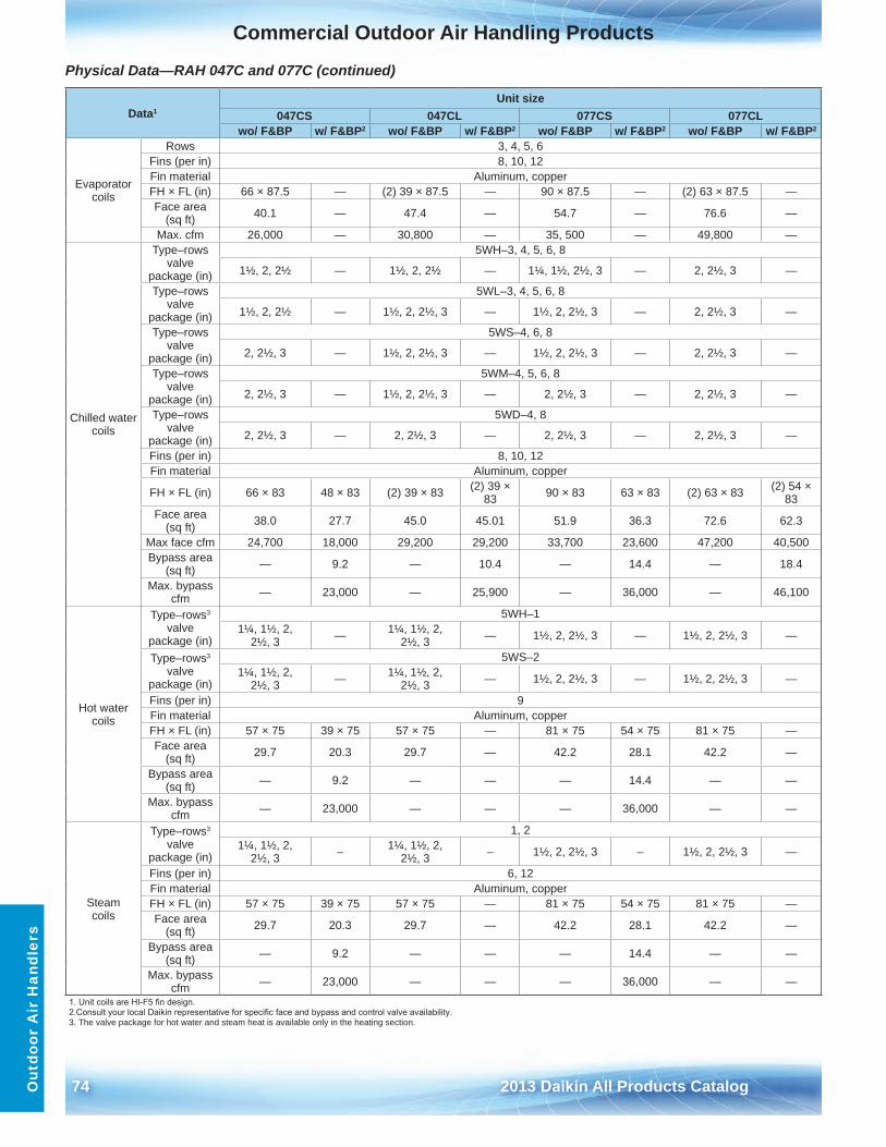
74 2013 Daikin All Products Catalog
Commercial Outdoor Air Handling ProductsO
utdo
or A
ir H
andl
ers
Physical Data—RAH 047C and 077C (continued)
Data1Unit size
047CS 047CL 077CS 077CLwo/ F&BP w/ F&BP2 wo/ F&BP w/ F&BP2 wo/ F&BP w/ F&BP2 wo/ F&BP w/ F&BP2
Evaporator coils
Rows 3, 4, 5, 6Fins (per in) 8, 10, 12 Fin material Aluminum, copperFH × FL (in) 66 × 87 .5 — (2) 39 × 87 .5 — 90 × 87 .5 — (2) 63 × 87 .5 —Face area
(sq ft) 40 .1 — 47 .4 — 54 .7 — 76 .6 —
Max . cfm 26,000 — 30,800 — 35, 500 — 49,800 —
Chilled water coils
Type–rows valve
package (in)
5WH–3, 4, 5, 6, 8
1½, 2, 2½ — 1½, 2, 2½ — 1¼, 1½, 2½, 3 — 2, 2½, 3 —
Type–rows valve
package (in)
5WL–3, 4, 5, 6, 8
1½, 2, 2½ — 1½, 2, 2½, 3 — 1½, 2, 2½, 3 — 2, 2½, 3 —
Type–rows valve
package (in)
5WS–4, 6, 8
2, 2½, 3 — 1½, 2, 2½, 3 — 1½, 2, 2½, 3 — 2, 2½, 3 —
Type–rows valve
package (in)
5WM–4, 5, 6, 8
2, 2½, 3 — 1½, 2, 2½, 3 — 2, 2½, 3 — 2, 2½, 3 —
Type–rows valve
package (in)
5WD–4, 8
2, 2½, 3 — 2, 2½, 3 — 2, 2½, 3 — 2, 2½, 3 —
Fins (per in) 8, 10, 12Fin material Aluminum, copper
FH × FL (in) 66 × 83 48 × 83 (2) 39 × 83 (2) 39 × 83 90 × 83 63 × 83 (2) 63 × 83 (2) 54 ×
83Face area
(sq ft) 38 .0 27 .7 45 .0 45 .01 51 .9 36 .3 72 .6 62 .3
Max face cfm 24,700 18,000 29,200 29,200 33,700 23,600 47,200 40,500Bypass area
(sq ft) — 9 .2 — 10 .4 — 14 .4 — 18 .4
Max . bypass cfm — 23,000 — 25,900 — 36,000 — 46,100
Hot water coils
Type–rows3 valve
package (in)
5WH–11¼, 1½, 2,
2½, 3 — 1¼, 1½, 2, 2½, 3 — 1½, 2, 2½, 3 — 1½, 2, 2½, 3 —
Type–rows3 valve
package (in)
5WS–21¼, 1½, 2,
2½, 3 — 1¼, 1½, 2, 2½, 3 — 1½, 2, 2½, 3 — 1½, 2, 2½, 3 —
Fins (per in) 9Fin material Aluminum, copperFH × FL (in) 57 × 75 39 × 75 57 × 75 — 81 × 75 54 × 75 81 × 75 —Face area
(sq ft) 29 .7 20 .3 29 .7 — 42 .2 28 .1 42 .2 —
Bypass area (sq ft) — 9 .2 — — — 14 .4 — —
Max . bypass cfm — 23,000 — — — 36,000 — —
Steam coils
Type–rows3 valve
package (in)
1, 21¼, 1½, 2,
2½, 3 – 1¼, 1½, 2, 2½, 3 – 1½, 2, 2½, 3 – 1½, 2, 2½, 3 —
Fins (per in) 6, 12Fin material Aluminum, copperFH × FL (in) 57 × 75 39 × 75 57 × 75 — 81 × 75 54 × 75 81 × 75 —Face area
(sq ft) 29 .7 20 .3 29 .7 — 42 .2 28 .1 42 .2 —
Bypass area (sq ft) — 9 .2 — — — 14 .4 — —
Max . bypass cfm — 23,000 — — — 36,000 — —
1. Unit coils are HI-F5 fin design.2. Consult your local Daikin representative for specific face and bypass and control valve availability.3 . The valve package for hot water and steam heat is available only in the heating section .
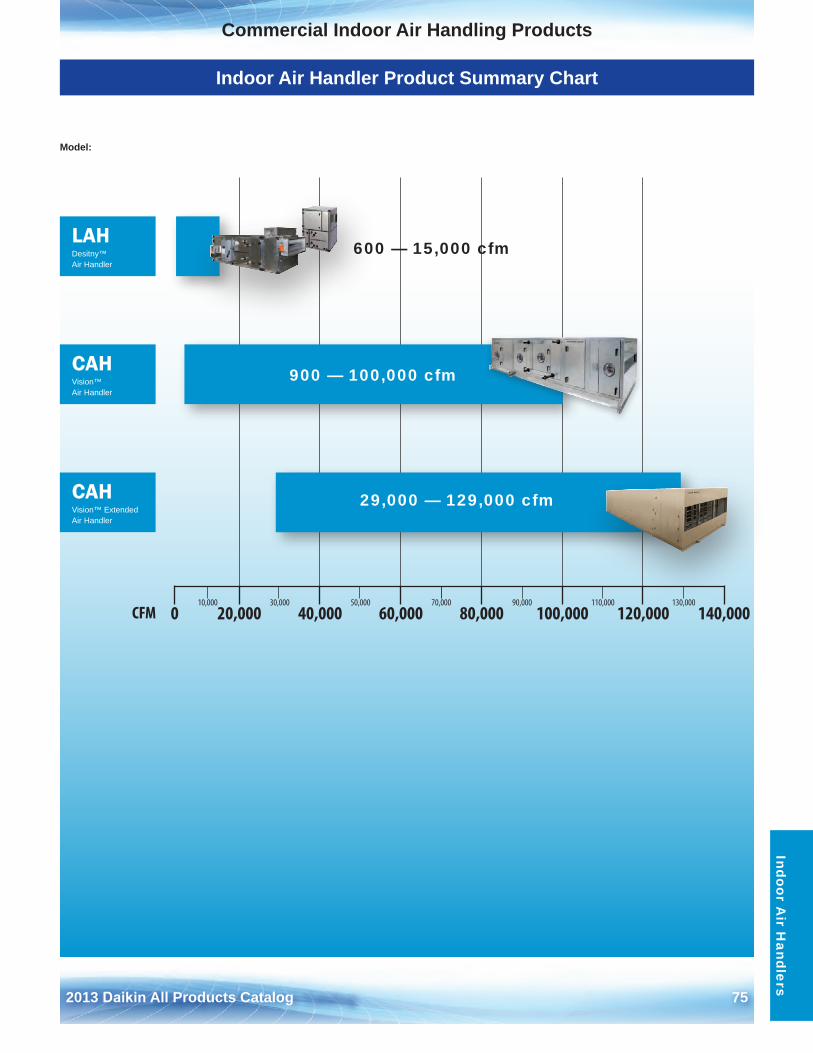
2013 Daikin All Products Catalog 75
Commercial Indoor Air Handling ProductsO
utdoor Air H
andlersIndoor A
ir Handlers
Indoor Air Handler Product Summary Chart
10,000 30,000 50,000 70,000 90,000 110,000 130,000
0 20,000 40,000 60,000 80,000 100,000 120,000 140,000CFM
LAHDesitny™ Air Handler
CAHVision™ Air Handler
CAHVision™ Extended Air Handler
Model:
900 — 100,000 cfm
29,000 — 129,000 cfm
600 — 15,000 cfm
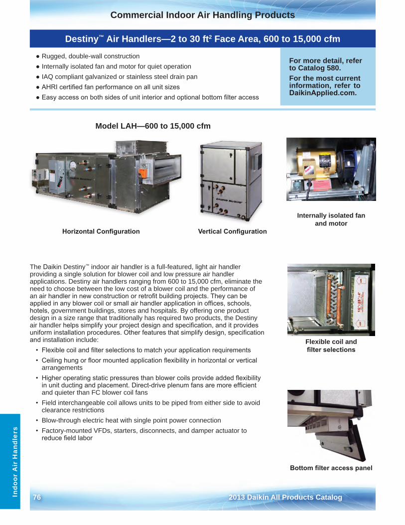
76 2013 Daikin All Products Catalog
Commercial Indoor Air Handling ProductsO
utdo
or A
ir H
andl
ers
Indo
or A
ir H
andl
ers
Model LAH—600 to 15,000 cfm
Destiny™ Air Handlers—2 to 30 ft2 Face Area, 600 to 15,000 cfm
● Rugged, double-wall construction● Internally isolated fan and motor for quiet operation● IAQ compliant galvanized or stainless steel drain pan● AHRI certified fan performance on all unit sizes● Easy access on both sides of unit interior and optional bottom filter access
For more detail, refer to Catalog 580 .For the most current information, refer to DaikinApplied.com .
The Daikin Destiny™ indoor air handler is a full-featured, light air handler providing a single solution for blower coil and low pressure air handler applications . Destiny air handlers ranging from 600 to 15,000 cfm, eliminate the need to choose between the low cost of a blower coil and the performance of an air handler in new construction or retrofit building projects. They can be applied in any blower coil or small air handler application in offices, schools, hotels, government buildings, stores and hospitals . By offering one product design in a size range that traditionally has required two products, the Destiny air handler helps simplify your project design and specification, and it provides uniform installation procedures. Other features that simplify design, specification and installation include:
• Flexible coil and filter selections to match your application requirements• Ceiling hung or floor mounted application flexibility in horizontal or vertical
arrangements• Higher operating static pressures than blower coils provide added flexibility
in unit ducting and placement. Direct-drive plenum fans are more efficientand quieter than FC blower coil fans
• Field interchangeable coil allows units to be piped from either side to avoidclearance restrictions
• Blow-through electric heat with single point power connection• Factory-mounted VFDs, starters, disconnects, and damper actuator to
reduce field labor
Internally isolated fan and motor
Flexible coil and filter selections
Bottom filter access panel
Vertical ConfigurationHorizontal Configuration
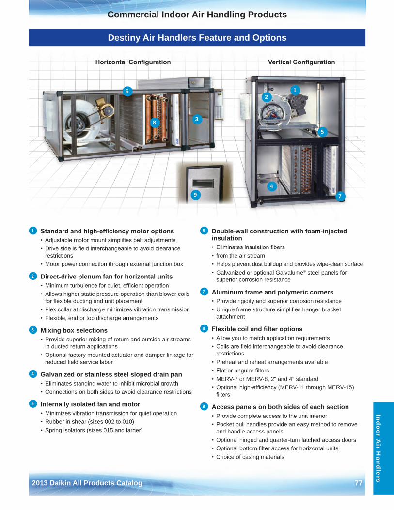
2013 Daikin All Products Catalog 77
Commercial Indoor Air Handling ProductsIndoor A
ir Handlers
Destiny Air Handlers Feature and Options
1 Standard and high-efficiency motor options• Adjustable motor mount simplifies belt adjustments• Drive side is field interchangeable to avoid clearance
restrictions• Motor power connection through external junction box
2 Direct-drive plenum fan for horizontal units• Minimum turbulence for quiet, efficient operation• Allows higher static pressure operation than blower coils
for flexible ducting and unit placement• Flex collar at discharge minimizes vibration transmission• Flexible, end or top discharge arrangements
3 Mixing box selections • Provide superior mixing of return and outside air streams
in ducted return applications• Optional factory mounted actuator and damper linkage for
reduced field service labor
4 Galvanized or stainless steel sloped drain pan• Eliminates standing water to inhibit microbial growth• Connections on both sides to avoid clearance restrictions
5 Internally isolated fan and motor• Minimizes vibration transmission for quiet operation• Rubber in shear (sizes 002 to 010)• Spring isolators (sizes 015 and larger)
6 Double-wall construction with foam-injected insulation • Eliminates insulation fibers• from the air stream• Helps prevent dust buildup and provides wipe-clean surface• Galvanized or optional Galvalume® steel panels for
superior corrosion resistance
7 Aluminum frame and polymeric corners• Provide rigidity and superior corrosion resistance• Unique frame structure simplifies hanger bracket
attachment
8 Flexible coil and filter options• Allow you to match application requirements• Coils are field interchangeable to avoid clearance
restrictions• Preheat and reheat arrangements available• Flat or angular filters• MERV-7 or MERV-8, 2" and 4" standard• Optional high-efficiency (MERV-11 through MERV-15)
filters
9 Access panels on both sides of each section• Provide complete access to the unit interior• Pocket pull handles provide an easy method to remove
and handle access panels• Optional hinged and quarter-turn latched access doors• Optional bottom filter access for horizontal units• Choice of casing materials
Vertical ConfigurationHorizontal Configuration
12
3
4
5
6
7
8
9
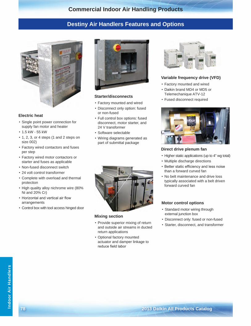
78 2013 Daikin All Products Catalog
Commercial Indoor Air Handling ProductsO
utdo
or A
ir H
andl
ers
Indo
or A
ir H
andl
ers
Destiny Air Handlers Features and Options
Electric heat• Single point power connection for
supply fan motor and heater• 1 .5 kW - 55 kW• 1, 2, 3, or 4 steps (1 and 2 steps on
size 002)• Factory wired contactors and fuses
per step• Factory wired motor contactors or
starter and fuses as applicable• Non-fused disconnect switch• 24 volt control transformer• Complete with overload and thermal
protection• High quality alloy nichrome wire (80%
Ni and 20% Cr)• Horizontal and vertical air flow
arrangements• Control box with tool access hinged door
Variable frequency drive (VFD)• Factory mounted and wired• Daikin brand MD4 or MD5 or
Telemechanique ATV-12• Fused disconnect required
Mixing section• Provide superior mixing of return
and outside air streams in ductedreturn applications
• Optional factory mountedactuator and damper linkage toreduce field labor
Direct drive plenum fan• Higher static applications (up to 4" wg total)• Multiple discharge directions• Better static efficiency and less noise
than a forward curved fan• No belt maintenance and drive loss
typically associated with a belt drivenforward curved fan
Starter/disconnects• Factory mounted and wired• Disconnect only option: fused
or non-fused• Full control box options: fused
disconnect, motor starter, and24 V transformer
• Software selectable• Wiring diagrams generated as
part of submittal package
Motor control options• Standard motor wiring through
external junction box• Disconnect only: fused or non-fused• Starter, disconnect, and transformer
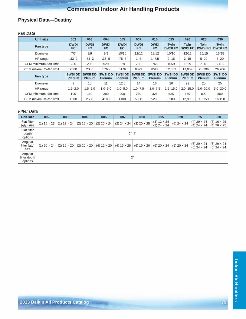
2013 Daikin All Products Catalog 79
Commercial Indoor Air Handling ProductsO
utdoor Air H
andlersIndoor A
ir Handlers
Physical Data—Destiny
Fan Data
Filter Data
Unit size 002 003 004 005 007 010 015 020 025 030
Fan type DWDI FC
DWDI FC
DWDI FC
DWDI FC
DWDI FC
DWDI FC
Twin DWDI FC
Twin DWDI FC
Twin DWDI FC
Twin DWDI FC
Diameter 7/7 9/9 9/9 10/10 12/12 12/12 10/10 12/12 15/15 15/15HP range .33–2 .33–3 .33–5 .75–5 1–5 1–7 .5 2–15 3–15 5–20 5–20
CFM minimum–fan limit 206 206 529 529 765 765 1059 1529 2118 2118CFM maximum–fan limit 2088 2088 5765 6176 8529 8529 12,353 17,059 26,706 26,706
Fan type SWSI DD Plenum
SWSI DD Plenum
SWSI DD Plenum
SWSI DD Plenum
SWSI DD Plenum
SWSI DD Plenum
SWSI DD Plenum
SWSI DD Plenum
SWSI DD Plenum
SWSI DD Plenum
Diameter 9 10 11 12 .5 14 16 20 22 25 25HP range 1 .5–2 .0 1 .5–5 .0 1 .0–5 .0 1 .0–5 .0 1 .0–7 .5 1 .0–7 .5 1 .5–15 .0 2 .0–15 .0 5 .0–20 .0 5 .0–20 .0
CFM minimum–fan limit 100 150 200 200 250 325 525 650 800 800CFM maximum–fan limit 1800 2650 4100 4100 5000 5200 9200 12,900 16,150 16,150
Unit size 002 003 004 005 007 010 015 020 025 030Flat filter (qty) size (1) 16 × 25 (1) 18 × 24 (2) 16 × 20 (2) 20 × 24 (2) 24 × 24 (3) 20 × 25 (3) 12 × 24
(3) 24 × 24 (6) 24 × 24 (4) 20 × 24 (4) 24 × 24
(6) 16 × 25 (4) 20 × 25
Flat filter depth
options2", 4"
Angular filter (qty)
size(1) 20 × 24 (2) 16 × 20 (2) 20 × 20 (4) 16 × 20 (4) 16 × 25 (6) 16 × 20 (6) 20 × 24 (9) 20 × 24 (6) 20 × 24
(6) 24 × 24(6) 20 × 24 (6) 24 × 24
Angular filter depth
options2"
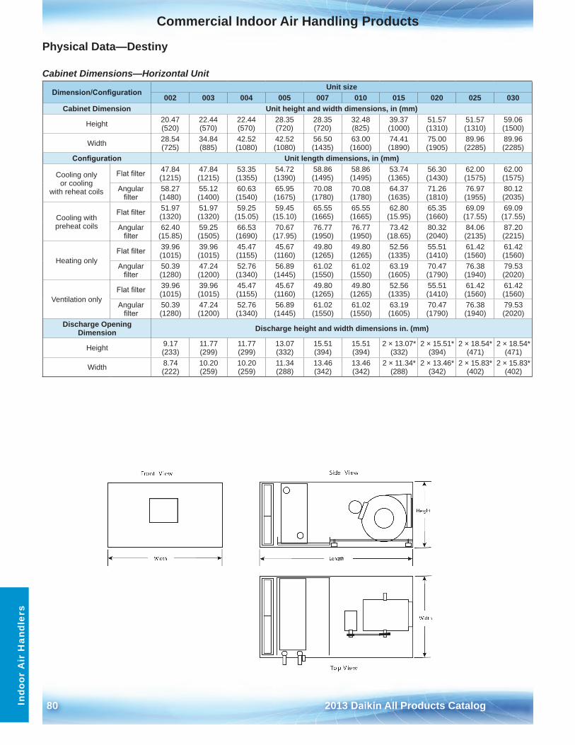
80 2013 Daikin All Products Catalog
Commercial Indoor Air Handling ProductsO
utdo
or A
ir H
andl
ers
Indo
or A
ir H
andl
ers
Physical Data—Destiny
Cabinet Dimensions—Horizontal Unit
Dimension/ConfigurationUnit size
002 003 004 005 007 010 015 020 025 030Cabinet Dimension Unit height and width dimensions, in (mm)
Height 20 .47 (520)
22 .44 (570)
22 .44 (570)
28 .35 (720)
28 .35 (720)
32 .48 (825)
39 .37 (1000)
51 .57 (1310)
51 .57 (1310)
59 .06 (1500)
Width 28 .54 (725)
34 .84 (885)
42 .52 (1080)
42 .52 (1080)
56 .50 (1435)
63 .00 (1600)
74 .41 (1890)
75 .00 (1905)
89 .96 (2285)
89 .96 (2285)
Configuration Unit length dimensions, in (mm)
Cooling only or cooling
with reheat coils
Flat filter 47 .84 (1215)
47 .84 (1215)
53 .35 (1355)
54 .72 (1390)
58 .86 (1495)
58 .86 (1495)
53 .74 (1365)
56 .30 (1430)
62 .00 (1575)
62 .00 (1575)
Angular filter
58 .27 (1480)
55 .12 (1400)
60 .63 (1540)
65 .95 (1675)
70 .08 (1780)
70 .08 (1780)
64 .37 (1635)
71 .26 (1810)
76 .97 (1955)
80 .12 (2035)
Cooling with preheat coils
Flat filter 51 .97 (1320)
51 .97 (1320)
59 .25 (15 .05)
59 .45 (15 .10)
65 .55 (1665)
65 .55 (1665)
62 .80 (15 .95)
65 .35 (1660)
69 .09 (17 .55)
69 .09 (17 .55)
Angular filter
62 .40 (15 .85)
59 .25 (1505)
66 .53 (1690)
70 .67 (17 .95)
76 .77 (1950)
76 .77 (1950)
73 .42 (18 .65)
80 .32 (2040)
84 .06 (2135)
87 .20 (2215)
Heating onlyFlat filter 39 .96
(1015)39 .96 (1015)
45 .47 (1155)
45 .67 (1160)
49 .80 (1265)
49 .80 (1265)
52 .56 (1335)
55 .51 (1410)
61 .42 (1560)
61 .42 (1560)
Angular filter
50 .39 (1280)
47 .24 (1200)
52 .76 (1340)
56 .89 (1445)
61 .02 (1550)
61 .02 (1550)
63 .19 (1605)
70 .47 (1790)
76 .38 (1940)
79 .53 (2020)
Ventilation onlyFlat filter 39 .96
(1015)39 .96 (1015)
45 .47 (1155)
45 .67 (1160)
49 .80 (1265)
49 .80 (1265)
52 .56 (1335)
55 .51 (1410)
61 .42 (1560)
61 .42 (1560)
Angular filter
50 .39 (1280)
47 .24 (1200)
52 .76 (1340)
56 .89 (1445)
61 .02 (1550)
61 .02 (1550)
63 .19 (1605)
70 .47 (1790)
76 .38 (1940)
79 .53 (2020)
Discharge Opening Dimension Discharge height and width dimensions in . (mm)
Height 9 .17 (233)
11 .77 (299)
11 .77 (299)
13 .07 (332)
15 .51 (394)
15 .51 (394)
2 × 13 .07* (332)
2 × 15 .51* (394)
2 × 18 .54* (471)
2 × 18 .54* (471)
Width 8 .74 (222)
10 .20 (259)
10 .20 (259)
11 .34 (288)
13 .46 (342)
13 .46 (342)
2 × 11 .34* (288)
2 × 13 .46* (342)
2 × 15 .83* (402)
2 × 15 .83* (402)
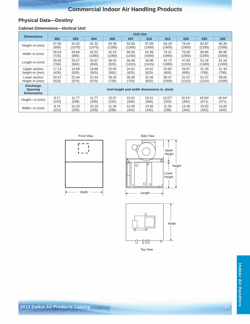
2013 Daikin All Products Catalog 81
Commercial Indoor Air Handling ProductsO
utdoor Air H
andlersIndoor A
ir Handlers
Physical Data—DestinyCabinet Dimensions—Vertical Unit
DimensionsUnit size
002 003 004 005 007 010 015 020 025 030
Height–in (mm) 37 .60 (955)
42 .32 (1075)
42 .32 (1075)
50 .39 (1280)
52 .95 (1345)
57 .09 (1450)
63 .19 (1605)
78 .54 (1905)
82 .87 (2285)
90 .35 (2295)
Width–in (mm) 28 .54 (725)
34 .84 (885)
42 .52 (1080)
42 .52 (1080)
56 .50 (1435)
62 .99 (1600)
74 .41 (1890)
75 .00 (1905)
89 .96 (2285)
89 .96 (2285)
Length–in (mm) 29 .92 (760)
33 .07 (840)
33 .07 (840)
36 .42 (925)
39 .96 (1015)
39 .96 (1015)
42 .72 (1085)
47 .83 (1215)
51 .18 (1300)
51 .18 (1300)
Upper section height–in (mm)
17 .13 (435)
19 .88 (505)
19 .88 (505)
22 .05 (560)
24 .61 (625)
24 .61 (625)
23 .82 (605)
26 .97 (685)
31 .30 (795)
31 .30 (795)
Lower section height–in (mm)
20 .47 (520)
22 .44 (570)
22 .44 (570)
28 .35 (720)
28 .35 (720)
32 .48 (825)
39 .37 (1000)
51 .57 (1310)
51 .57 (1310)
59 .06 (1500)
Discharge Opening
DimensionsUnit height and width dimensions in . (mm)
Height—in (mm) 9 .17 (233)
11 .77 (299)
11 .77 (299)
13 .07 (332)
15 .51 (394)
15 .51 (394)
13 .07* (332)
15 .51* (394)
18 .54* (471)
18 .54* (471)
Width—in (mm) 8 .74 (222)
10 .20 (259)
10 .20 (259)
11 .34 (288)
13 .46 (342)
13 .46 (342)
11 .34 (288)
13 .46 (342)
15 .83 (402)
15 .83 (402)
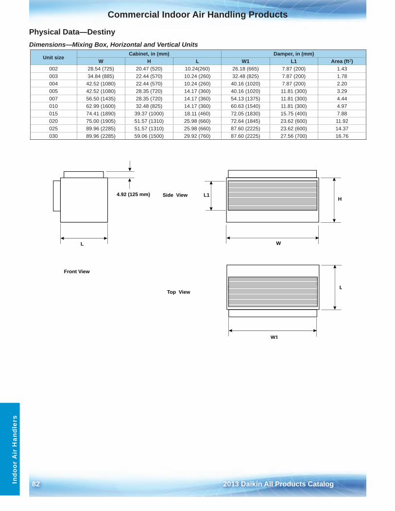
82 2013 Daikin All Products Catalog
Commercial Indoor Air Handling ProductsO
utdo
or A
ir H
andl
ers
Indo
or A
ir H
andl
ers
Physical Data—DestinyDimensions—Mixing Box, Horizontal and Vertical Units
Unit sizeCabinet, in (mm) Damper, in (mm)
W H L W1 L1 Area (ft2)002 28 .54 (725) 20 .47 (520) 10 .24(260) 26 .18 (665) 7 .87 (200) 1 .43003 34 .84 (885) 22 .44 (570) 10 .24 (260) 32 .48 (825) 7 .87 (200) 1 .78004 42 .52 (1080) 22 .44 (570) 10 .24 (260) 40 .16 (1020) 7 .87 (200) 2 .20005 42 .52 (1080) 28 .35 (720) 14 .17 (360) 40 .16 (1020) 11 .81 (300) 3 .29007 56 .50 (1435) 28 .35 (720) 14 .17 (360) 54 .13 (1375) 11 .81 (300) 4 .44010 62 .99 (1600) 32 .48 (825) 14 .17 (360) 60 .63 (1540) 11 .81 (300) 4 .97015 74 .41 (1890) 39 .37 (1000) 18 .11 (460) 72 .05 (1830) 15 .75 (400) 7 .88020 75 .00 (1905) 51 .57 (1310) 25 .98 (660) 72 .64 (1845) 23 .62 (600) 11 .92025 89 .96 (2285) 51 .57 (1310) 25 .98 (660) 87 .60 (2225) 23 .62 (600) 14 .37030 89 .96 (2285) 59 .06 (1500) 29 .92 (760) 87 .60 (2225) 27 .56 (700) 16 .76
4 .92 (125 mm)
Front View
Side View
Top View
L1
WL
W1
L
H
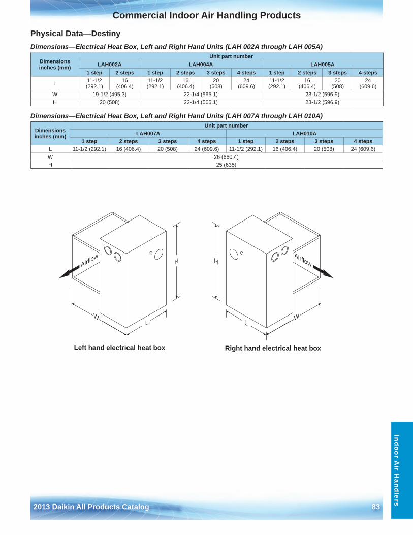
2013 Daikin All Products Catalog 83
Commercial Indoor Air Handling ProductsO
utdoor Air H
andlersIndoor A
ir Handlers
Physical Data—DestinyDimensions—Electrical Heat Box, Left and Right Hand Units (LAH 002A through LAH 005A)
Dimensions—Electrical Heat Box, Left and Right Hand Units (LAH 007A through LAH 010A)
Dimensions inches (mm)
Unit part numberLAH002A LAH004A LAH005A
1 step 2 steps 1 step 2 steps 3 steps 4 steps 1 step 2 steps 3 steps 4 steps
L 11-1/2 (292 .1)
16 (406 .4)
11-1/2 (292 .1)
16 (406 .4)
20 (508)
24 (609 .6)
11-1/2 (292 .1)
16 (406 .4)
20 (508)
24 (609 .6)
W 19-1/2 (495 .3) 22-1/4 (565 .1) 23-1/2 (596 .9)H 20 (508) 22-1/4 (565 .1) 23-1/2 (596 .9)
Dimensions inches (mm)
Unit part numberLAH007A LAH010A
1 step 2 steps 3 steps 4 steps 1 step 2 steps 3 steps 4 stepsL 11-1/2 (292 .1) 16 (406 .4) 20 (508) 24 (609 .6) 11-1/2 (292 .1) 16 (406 .4) 20 (508) 24 (609 .6)W 26 (660 .4)H 25 (635)
Left hand electrical heat box Right hand electrical heat box
H
W
L
Airflo
wH
W
L
Airflow
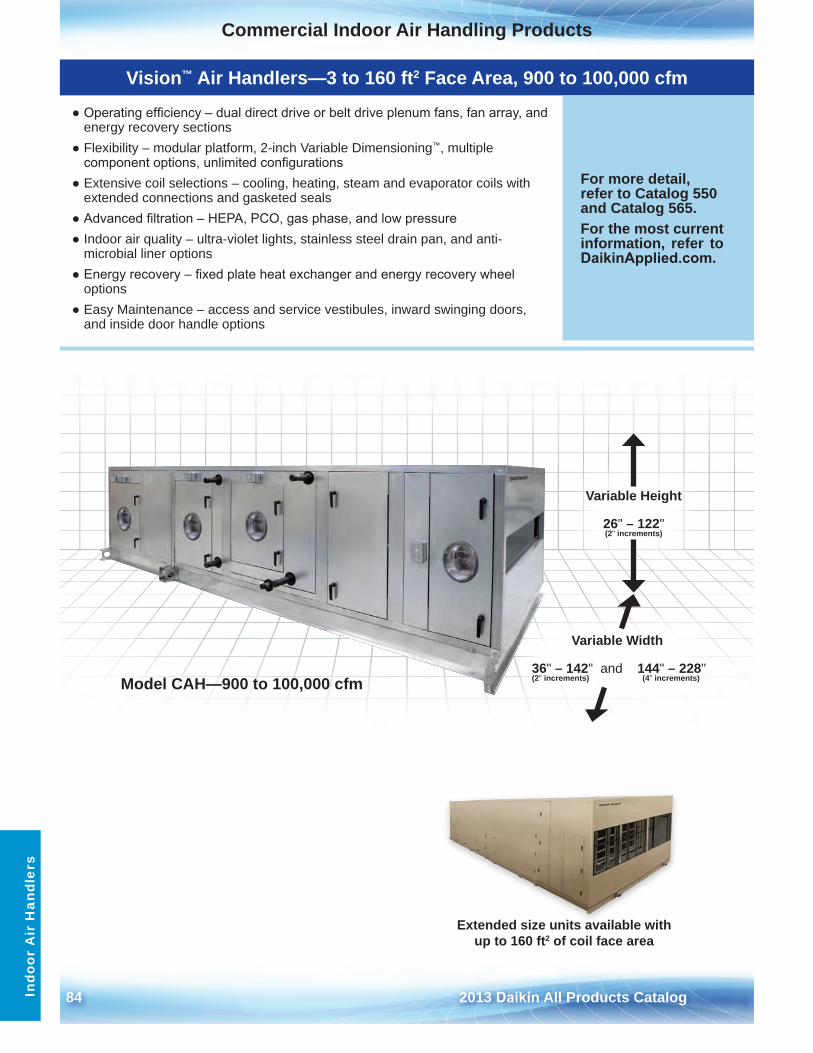
84 2013 Daikin All Products Catalog
Commercial Indoor Air Handling ProductsO
utdo
or A
ir H
andl
ers
Indo
or A
ir H
andl
ers
Vision™ Air Handlers—3 to 160 ft2 Face Area, 900 to 100,000 cfm
● Operating efficiency – dual direct drive or belt drive plenum fans, fan array, andenergy recovery sections
● Flexibility – modular platform, 2-inch Variable Dimensioning™, multiplecomponent options, unlimited configurations
● Extensive coil selections – cooling, heating, steam and evaporator coils withextended connections and gasketed seals
● Advanced filtration – HEPA, PCO, gas phase, and low pressure● Indoor air quality – ultra-violet lights, stainless steel drain pan, and anti-
microbial liner options● Energy recovery – fixed plate heat exchanger and energy recovery wheel
options● Easy Maintenance – access and service vestibules, inward swinging doors,
and inside door handle options
For more detail, refer to Catalog 550 and Catalog 565 .For the most current information, refer to DaikinApplied.com .
Extended size units available with up to 160 ft2 of coil face area
Model CAH—900 to 100,000 cfm
Variable Height
26" – 122" (2" increments)
Variable Width
36" – 142" and 144" – 228" (2" increments) (4" increments)
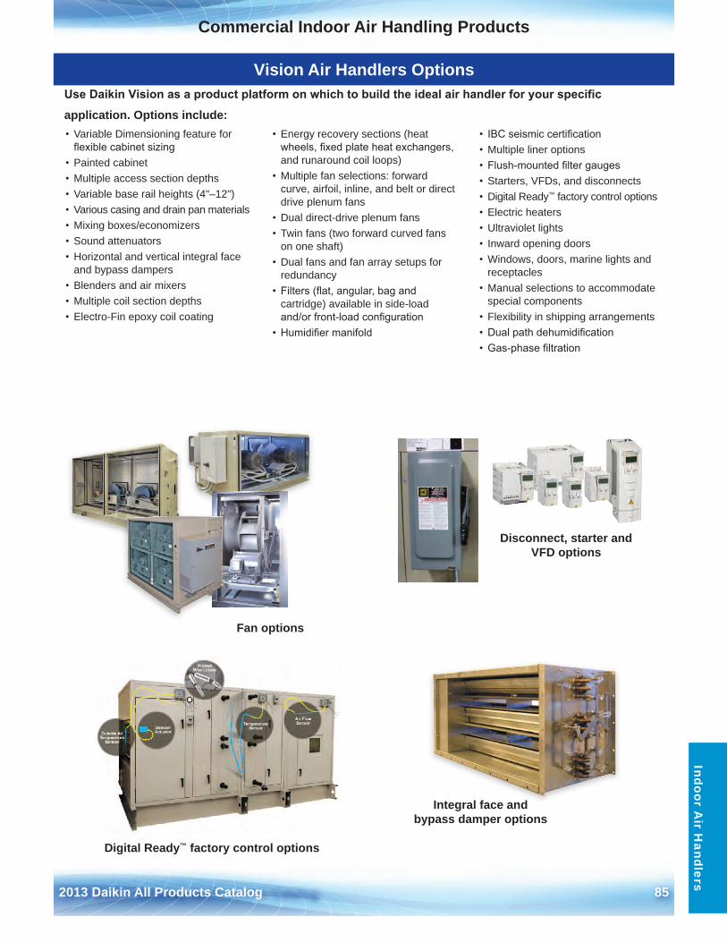
2013 Daikin All Products Catalog 85
Commercial Indoor Air Handling ProductsO
utdoor Air H
andlersIndoor A
ir Handlers
Disconnect, starter and VFD options
Integral face and bypass damper options
Digital Ready™ factory control options
Fan options
Vision Air Handlers OptionsUse Daikin Vision as a product platform on which to build the ideal air handler for your specific
application . Options include:• Variable Dimensioning feature for
flexible cabinet sizing• Painted cabinet• Multiple access section depths• Variable base rail heights (4"–12")• Various casing and drain pan materials• Mixing boxes/economizers• Sound attenuators• Horizontal and vertical integral face
and bypass dampers• Blenders and air mixers• Multiple coil section depths• Electro-Fin epoxy coil coating
• Energy recovery sections (heatwheels, fixed plate heat exchangers,and runaround coil loops)
• Multiple fan selections: forwardcurve, airfoil, inline, and belt or directdrive plenum fans
• Dual direct-drive plenum fans• Twin fans (two forward curved fans
on one shaft)• Dual fans and fan array setups for
redundancy• Filters (flat, angular, bag and
cartridge) available in side-loadand/or front-load configuration
• Humidifier manifold
• IBC seismic certification• Multiple liner options• Flush-mounted filter gauges• Starters, VFDs, and disconnects• Digital Ready™ factory control options• Electric heaters• Ultraviolet lights• Inward opening doors• Windows, doors, marine lights and
receptacles• Manual selections to accommodate
special components• Flexibility in shipping arrangements• Dual path dehumidification• Gas-phase filtration
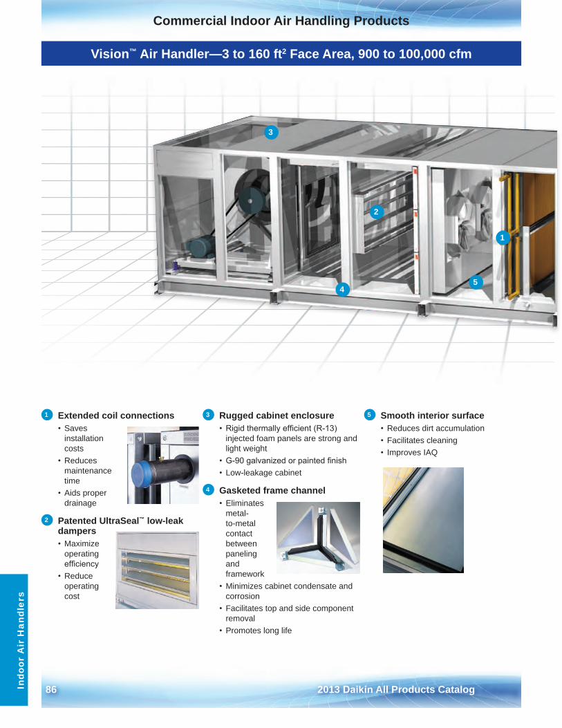
86 2013 Daikin All Products Catalog
Commercial Indoor Air Handling ProductsIn
door
Air
Han
dler
s
Vision™ Air Handler—3 to 160 ft2 Face Area, 900 to 100,000 cfm
1
2
3
45
1 Extended coil connections • Saves
installation costs
• Reducesmaintenance time
• Aids properdrainage
2 Patented UltraSeal™ low-leak dampers • Maximize
operating efficiency
• Reduceoperating cost
3 Rugged cabinet enclosure• Rigid thermally efficient (R-13)
injected foam panels are strong and light weight
• G-90 galvanized or painted finish• Low-leakage cabinet
4 Gasketed frame channel • Eliminates
metal-to-metal contact between paneling and framework
• Minimizes cabinet condensate andcorrosion
• Facilitates top and side componentremoval
• Promotes long life
5 Smooth interior surface • Reduces dirt accumulation• Facilitates cleaning• Improves IAQ
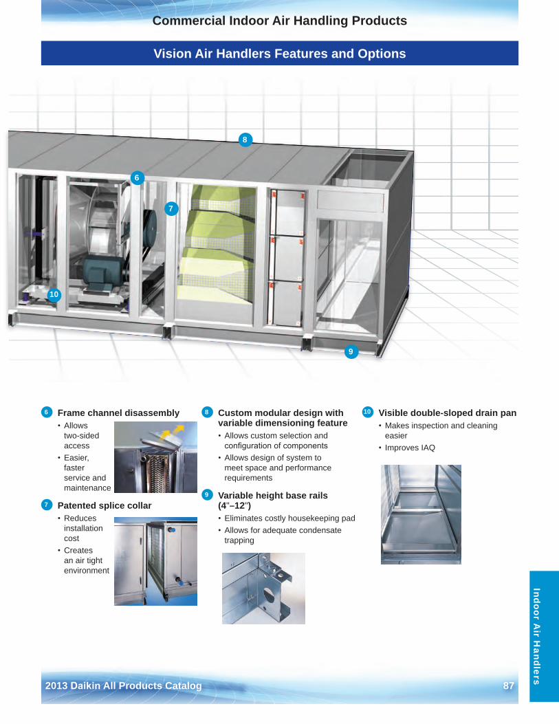
2013 Daikin All Products Catalog 87
Commercial Indoor Air Handling ProductsIndoor A
ir Handlers
Vision Air Handlers Features and Options
6
7
8
9
10
6 Frame channel disassembly • Allows
two-sidedaccess
• Easier,fasterservice andmaintenance
7 Patented splice collar • Reduces
installationcost
• Createsan air tightenvironment
8 Custom modular design with variable dimensioning feature• Allows custom selection and
configuration of components• Allows design of system to
meet space and performancerequirements
9 Variable height base rails (4"–12") • Eliminates costly housekeeping pad• Allows for adequate condensate
trapping
10 Visible double-sloped drain pan • Makes inspection and cleaning
easier• Improves IAQ
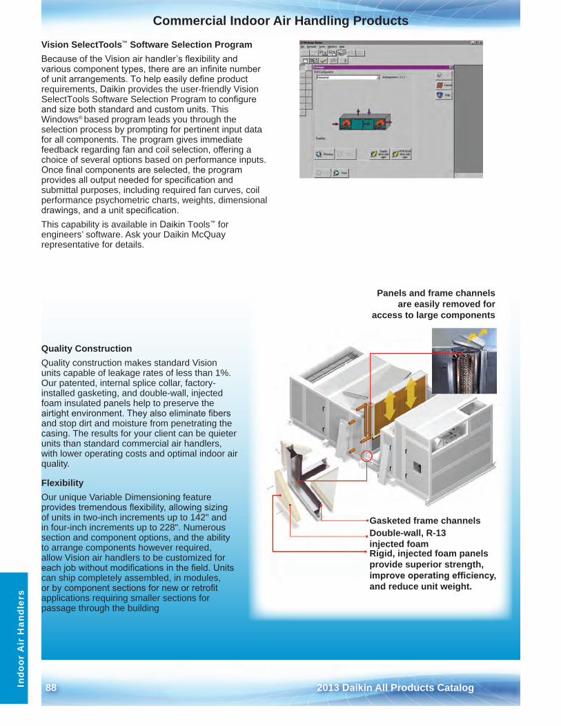
88 2013 Daikin All Products Catalog
Commercial Indoor Air Handling ProductsIn
door
Air
Han
dler
s
Vision SelectTools™ Software Selection ProgramBecause of the Vision air handler’s flexibility and various component types, there are an infinite number of unit arrangements. To help easily define product requirements, Daikin provides the user-friendly Vision SelectTools Software Selection Program to configure and size both standard and custom units. This Windows® based program leads you through the selection process by prompting for pertinent input data for all components . The program gives immediate feedback regarding fan and coil selection, offering a choice of several options based on performance inputs . Once final components are selected, the program provides all output needed for specification and submittal purposes, including required fan curves, coil performance psychometric charts, weights, dimensional drawings, and a unit specification.This capability is available in Daikin Tools™ for engineers’ software . Ask your Daikin McQuay representative for details .
Panels and frame channels are easily removed for
access to large components
Rigid, injected foam panels provide superior strength, improve operating efficiency, and reduce unit weight .
Gasketed frame channelsDouble-wall, R-13 injected foam
Quality ConstructionQuality construction makes standard Vision units capable of leakage rates of less than 1% . Our patented, internal splice collar, factory-installed gasketing, and double-wall, injected foam insulated panels help to preserve the airtight environment. They also eliminate fibers and stop dirt and moisture from penetrating the casing . The results for your client can be quieter units than standard commercial air handlers, with lower operating costs and optimal indoor air quality .
FlexibilityOur unique Variable Dimensioning feature provides tremendous flexibility, allowing sizing of units in two-inch increments up to 142" and in four-inch increments up to 228" . Numerous section and component options, and the ability to arrange components however required, allow Vision air handlers to be customized for each job without modifications in the field. Units can ship completely assembled, in modules, or by component sections for new or retrofit applications requiring smaller sections for passage through the building
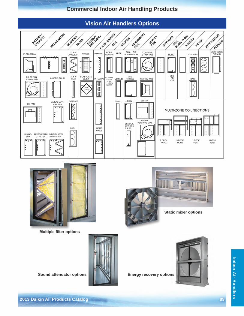
2013 Daikin All Products Catalog 89
Commercial Indoor Air Handling ProductsIndoor A
ir Handlers
Vision Air Handlers Options
Static mixer options
Multiple filter options
Sound attenuator options Energy recovery options
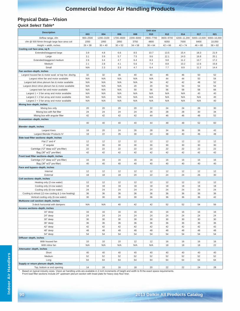
90 2013 Daikin All Products Catalog
Commercial Indoor Air Handling ProductsIn
door
Air
Han
dler
s
Physical Data—VisionQuick Select Table*
Description Unit size
003 004 006 008 010 012 014 017 021Airflow range, cfm 900–2500 1200–3100 1700–4600 2200–6000 2900–7700 3600–9700 4200–11,200 5000–13,500 6000–16,000
cfm @ 500 ft/min through large face area coil 1550 1950 2850 3750 4800 6050 7000 8400 10,050Height × width, inches 26 × 38 30 × 40 30 × 52 34 × 58 36 × 64 42 × 66 42 × 74 46 × 80 58 × 82
Cooling coil face area, sq ftExtended/staggered large 3 .9 4 .8 6 .6 8 .5 10 .7 13 .5 15 .4 18 .3 21 .9
Large 3 .1 3 .9 5 .7 7 .5 9 .6 12 .1 14 .0 16 .8 20 .1Extended/staggered medium 2 .6 3 .4 4 .7 6 .4 8 .3 9 .8 11 .2 13 .7 17 .2
Medium 2 .1 2 .8 4 .1 5 .6 7 .4 8 .8 10 .2 12 .6 15 .8Small N/A 2 .3 3 .3 4 .7 6 .4 7 .7 8 .9 11 .2 14 .4
Fan section–depth, inchesLargest housed fan & motor avail . w/ top hor . dischg . 32 32 36 40 40 46 46 50 52
Largest inline fan and motor available N/A N/A N/A N/A N/A 44 44 50 54Largest belt drive plenum fan & motor available N/A N/A N/A N/A 34 42 42 48 52
Largest direct drive plenum fan & motor available N/A N/A N/A 20 20 54 54 54 54Largest twin fan and motor available N/A N/A N/A 50 56 56 58 58 66
Largest 1 × 3 fan array and motor available N/A N/A N/A N/A N/A N/A N/A 40 40Largest 2 × 2 fan array and motor available N/A N/A N/A N/A N/A N/A N/A N/A 40Largest 2 × 3 fan array and motor available N/A N/A N/A N/A N/A N/A N/A N/A 40
Mixing box–depth, inchesMixing box only 20 20 20 20 22 24 24 26 30
Mixing box with flat filter 24 24 24 24 26 28 28 30 34Mixing box with angular filter 42 42 42 42 44 46 46 48 52
Economizer–depth, inches 40 40 40 40 44 48 48 52 60
Blender–depth, inches Largest Kees 18 20 24 26 28 34 36 38 42
Largest Blender Products IV 18 22 26 30 34 38 40 46 48Side load filter sections–depth, inches
Flat 2" and 4" 12 12 12 12 12 12 12 12 122" angular 32 30 30 30 30 30 30 30 30
Cartridge (12" deep w/2" pre-filter) 22 22 22 22 22 22 22 22 22Bag (36" w/2" pre-filter) 42 42 42 42 42 42 42 42 42
Front load filter sections–depth, inchesCartridge (12" deep w/2" pre-filter) 16 16 16 16 16 16 16 16 16
Bag (36" w/2" pre-filter) 40 40 40 40 40 40 40 40 40Face and bypass–depth, inches
Internal 12 12 12 12 12 12 12 12 12External 18 18 18 20 22 24 24 26 30
Coil sections–depth, inches Heating only (2-row water) 12 12 12 12 12 12 12 12 12 Cooling only (4-row water) 18 18 18 18 18 18 18 18 18 Cooling only (6-row water) 24 24 24 24 24 24 24 24 24
Cooling & reheat (12-row cooling & 1-row heating) 36 36 36 36 36 36 36 36 36 Vertical cooling only (6-row water) 30 30 30 30 36 36 36 36 42
Multizone coil section–depth, inches3-deck horizontal with dampers N/A N/A 40 42 42 52 52 54 56
Access sections–depth, inches16" deep 16 16 16 16 16 16 16 16 16 24" deep 24 24 24 24 24 24 24 24 24 30" deep 30 30 30 30 30 30 30 30 30 36" deep 36 36 36 36 36 36 36 36 36 42" deep 42 42 42 42 42 42 42 42 42 48" deep 48 48 48 48 48 48 48 48 48 54" deep 54 54 54 54 54 54 54 54 54
Diffuser–depth, inchesWith housed fan 10 10 10 12 12 16 16 16 16 With inline fan N/A N/A N/A N/A N/A 18 18 18 22
Attenuator–depth, inchesShort 40 40 40 40 40 40 40 40 40
Medium 52 52 52 52 52 52 52 52 52 Long 64 64 64 64 64 64 64 64 64
Supply or return plenum–depth, inchesTop, bottom or end opening 14 16 16 18 20 22 22 24 28
* Based on typical industry sizes. Vision air handling units are available in 2 inch increments of height and width to fit the exact space requirements.Front load filter sections include 24" upstream plenum section with tread plate for heavy duty floor liner.
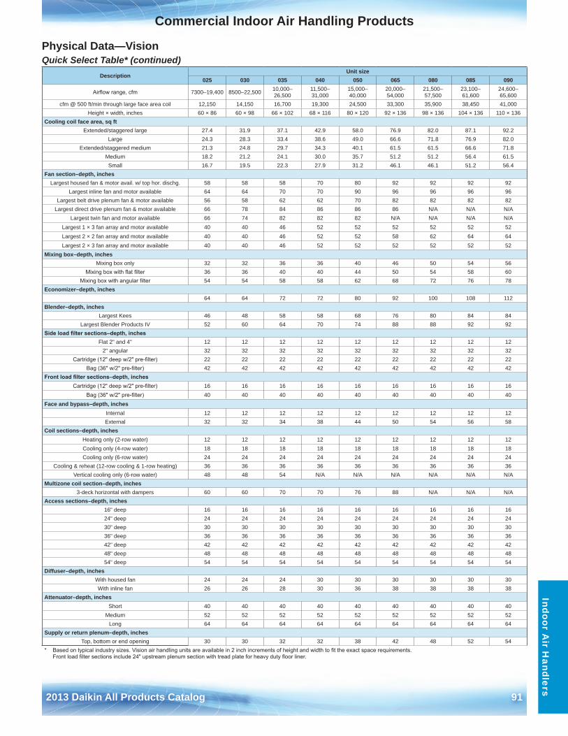
2013 Daikin All Products Catalog 91
Commercial Indoor Air Handling ProductsIndoor A
ir Handlers
Physical Data—VisionQuick Select Table* (continued)
Description Unit size
025 030 035 040 050 065 080 085 090
Airflow range, cfm 7300–19,400 8500–22,500 10,000–26,500
11,500–31,000
15,000–40,000
20,000–54,000
21,500–57,500
23,100–61,600
24,600–65,600
cfm @ 500 ft/min through large face area coil 12,150 14,150 16,700 19,300 24,500 33,300 35,900 38,450 41,000Height × width, inches 60 × 86 60 × 98 66 × 102 68 × 116 80 × 120 92 × 136 98 × 136 104 × 136 110 × 136
Cooling coil face area, sq ftExtended/staggered large 27 .4 31 .9 37 .1 42 .9 58 .0 76 .9 82 .0 87 .1 92 .2
Large 24 .3 28 .3 33 .4 38 .6 49 .0 66 .6 71 .8 76 .9 82 .0Extended/staggered medium 21 .3 24 .8 29 .7 34 .3 40 .1 61 .5 61 .5 66 .6 71 .8
Medium 18 .2 21 .2 24 .1 30 .0 35 .7 51 .2 51 .2 56 .4 61 .5Small 16 .7 19 .5 22 .3 27 .9 31 .2 46 .1 46 .1 51 .2 56 .4
Fan section–depth, inchesLargest housed fan & motor avail . w/ top hor . dischg . 58 58 58 70 80 92 92 92 92
Largest inline fan and motor available 64 64 70 70 90 96 96 96 96 Largest belt drive plenum fan & motor available 56 58 62 62 70 82 82 82 82
Largest direct drive plenum fan & motor available 66 78 84 86 86 86 N/A N/A N/ALargest twin fan and motor available 66 74 82 82 82 N/A N/A N/A N/A
Largest 1 × 3 fan array and motor available 40 40 46 52 52 52 52 52 52Largest 2 × 2 fan array and motor available 40 40 46 52 52 58 62 64 64Largest 2 × 3 fan array and motor available 40 40 46 52 52 52 52 52 52
Mixing box–depth, inchesMixing box only 32 32 36 36 40 46 50 54 56
Mixing box with flat filter 36 36 40 40 44 50 54 58 60 Mixing box with angular filter 54 54 58 58 62 68 72 76 78
Economizer–depth, inches 64 64 72 72 80 92 100 108 112
Blender–depth, inches Largest Kees 46 48 58 58 68 76 80 84 84
Largest Blender Products IV 52 60 64 70 74 88 88 92 92 Side load filter sections–depth, inches
Flat 2" and 4" 12 12 12 12 12 12 12 12 12 2" angular 32 32 32 32 32 32 32 32 32
Cartridge (12" deep w/2" pre-filter) 22 22 22 22 22 22 22 22 22 Bag (36" w/2" pre-filter) 42 42 42 42 42 42 42 42 42
Front load filter sections–depth, inchesCartridge (12" deep w/2" pre-filter) 16 16 16 16 16 16 16 16 16
Bag (36" w/2" pre-filter) 40 40 40 40 40 40 40 40 40 Face and bypass–depth, inches
Internal 12 12 12 12 12 12 12 12 12 External 32 32 34 38 44 50 54 56 58
Coil sections–depth, inches Heating only (2-row water) 12 12 12 12 12 12 12 12 12 Cooling only (4-row water) 18 18 18 18 18 18 18 18 18 Cooling only (6-row water) 24 24 24 24 24 24 24 24 24
Cooling & reheat (12-row cooling & 1-row heating) 36 36 36 36 36 36 36 36 36 Vertical cooling only (6-row water) 48 48 54 N/A N/A N/A N/A N/A N/A
Multizone coil section–depth, inches3-deck horizontal with dampers 60 60 70 70 76 88 N/A N/A N/A
Access sections–depth, inches16" deep 16 16 16 16 16 16 16 16 16 24" deep 24 24 24 24 24 24 24 24 24 30" deep 30 30 30 30 30 30 30 30 30 36" deep 36 36 36 36 36 36 36 36 36 42" deep 42 42 42 42 42 42 42 42 42 48" deep 48 48 48 48 48 48 48 48 48 54" deep 54 54 54 54 54 54 54 54 54
Diffuser–depth, inchesWith housed fan 24 24 24 30 30 30 30 30 30 With inline fan 26 26 28 30 36 38 38 38 38
Attenuator–depth, inchesShort 40 40 40 40 40 40 40 40 40
Medium 52 52 52 52 52 52 52 52 52 Long 64 64 64 64 64 64 64 64 64
Supply or return plenum–depth, inchesTop, bottom or end opening 30 30 32 32 38 42 48 52 54
* Based on typical industry sizes. Vision air handling units are available in 2 inch increments of height and width to fit the exact space requirements.Front load filter sections include 24" upstream plenum section with tread plate for heavy duty floor liner.
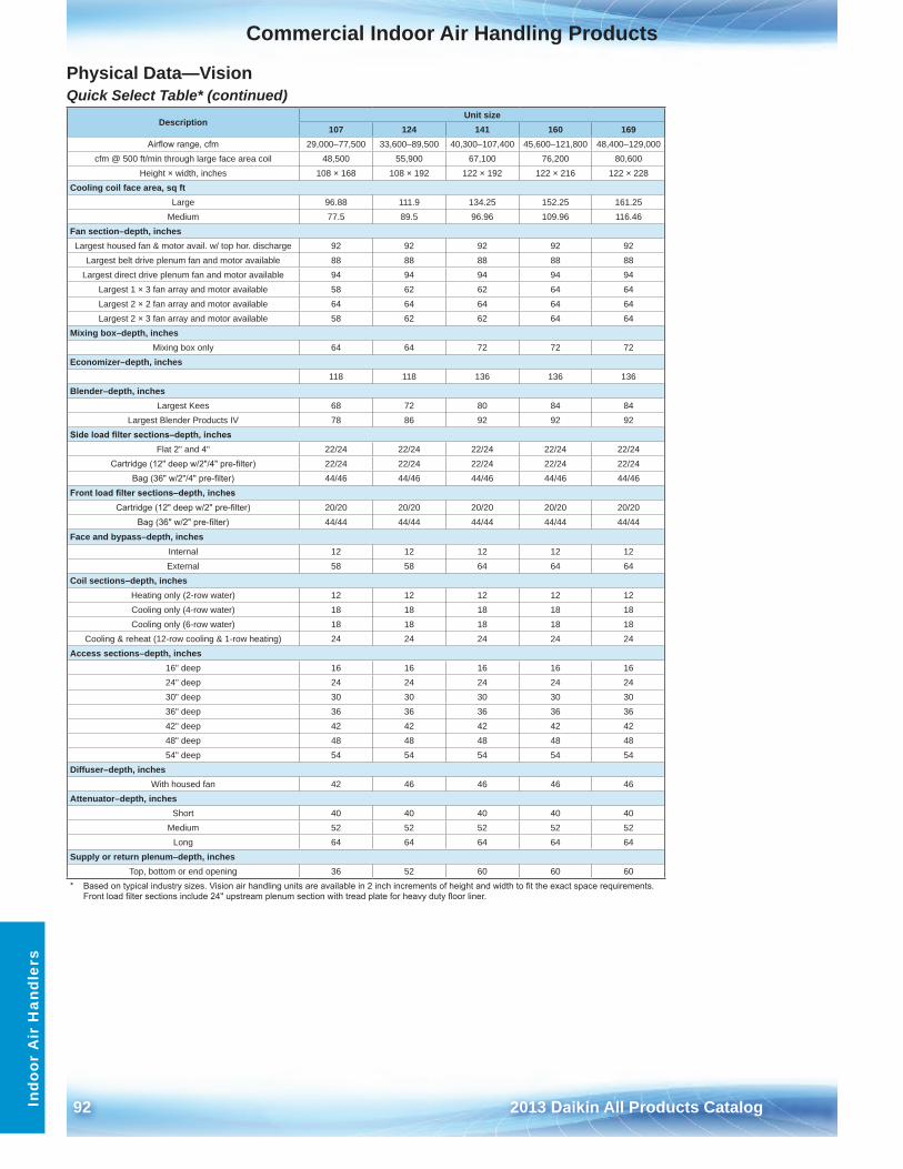
92 2013 Daikin All Products Catalog
Commercial Indoor Air Handling ProductsIn
door
Air
Han
dler
s
Physical Data—VisionQuick Select Table* (continued)
Description Unit size
107 124 141 160 169Airflow range, cfm 29,000–77,500 33,600–89,500 40,300–107,400 45,600–121,800 48,400–129,000
cfm @ 500 ft/min through large face area coil 48,500 55,900 67,100 76,200 80,600Height × width, inches 108 × 168 108 × 192 122 × 192 122 × 216 122 × 228
Cooling coil face area, sq ftLarge 96 .88 111 .9 134 .25 152 .25 161 .25
Medium 77 .5 89 .5 96 .96 109 .96 116 .46Fan section–depth, inchesLargest housed fan & motor avail . w/ top hor . discharge 92 92 92 92 92
Largest belt drive plenum fan and motor available 88 88 88 88 88Largest direct drive plenum fan and motor available 94 94 94 94 94
Largest 1 × 3 fan array and motor available 58 62 62 64 64Largest 2 × 2 fan array and motor available 64 64 64 64 64Largest 2 × 3 fan array and motor available 58 62 62 64 64
Mixing box–depth, inchesMixing box only 64 64 72 72 72
Economizer–depth, inches 118 118 136 136 136
Blender–depth, inches Largest Kees 68 72 80 84 84
Largest Blender Products IV 78 86 92 92 92Side load filter sections–depth, inches
Flat 2" and 4" 22/24 22/24 22/24 22/24 22/24Cartridge (12" deep w/2"/4" pre-filter) 22/24 22/24 22/24 22/24 22/24
Bag (36" w/2"/4" pre-filter) 44/46 44/46 44/46 44/46 44/46Front load filter sections–depth, inches
Cartridge (12" deep w/2" pre-filter) 20/20 20/20 20/20 20/20 20/20Bag (36" w/2" pre-filter) 44/44 44/44 44/44 44/44 44/44
Face and bypass–depth, inches Internal 12 12 12 12 12External 58 58 64 64 64
Coil sections–depth, inches Heating only (2-row water) 12 12 12 12 12Cooling only (4-row water) 18 18 18 18 18Cooling only (6-row water) 18 18 18 18 18
Cooling & reheat (12-row cooling & 1-row heating) 24 24 24 24 24Access sections–depth, inches
16" deep 16 16 16 16 1624" deep 24 24 24 24 2430" deep 30 30 30 30 3036" deep 36 36 36 36 3642" deep 42 42 42 42 4248" deep 48 48 48 48 4854" deep 54 54 54 54 54
Diffuser–depth, inchesWith housed fan 42 46 46 46 46
Attenuator–depth, inchesShort 40 40 40 40 40
Medium 52 52 52 52 52Long 64 64 64 64 64
Supply or return plenum–depth, inchesTop, bottom or end opening 36 52 60 60 60
* Based on typical industry sizes. Vision air handling units are available in 2 inch increments of height and width to fit the exact space requirements.Front load filter sections include 24" upstream plenum section with tread plate for heavy duty floor liner.
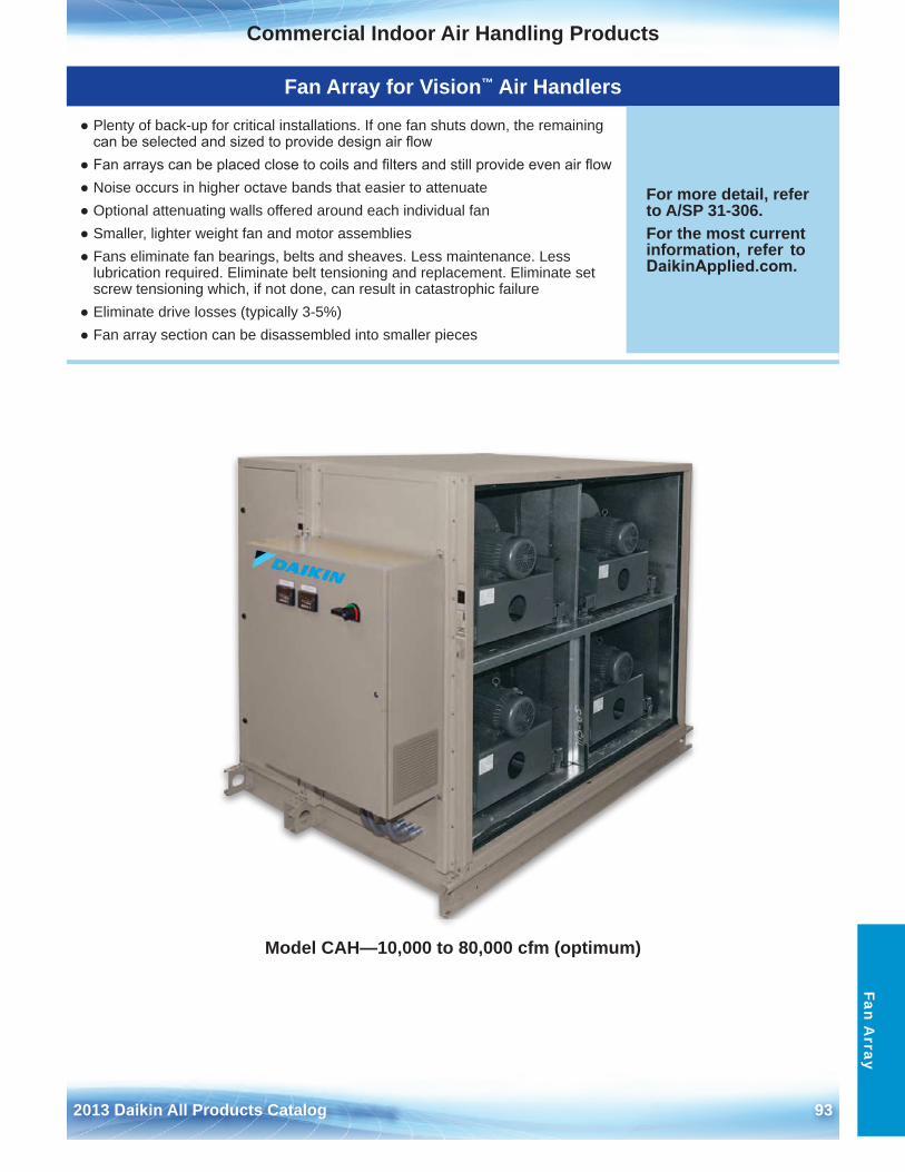
2013 Daikin All Products Catalog 93
Commercial Indoor Air Handling Products
Fan Array for Vision™ Air Handlers
● Plenty of back-up for critical installations . If one fan shuts down, the remainingcan be selected and sized to provide design air flow
● Fan arrays can be placed close to coils and filters and still provide even air flow● Noise occurs in higher octave bands that easier to attenuate● Optional attenuating walls offered around each individual fan● Smaller, lighter weight fan and motor assemblies● Fans eliminate fan bearings, belts and sheaves . Less maintenance . Less
lubrication required . Eliminate belt tensioning and replacement . Eliminate setscrew tensioning which, if not done, can result in catastrophic failure
● Eliminate drive losses (typically 3-5%)● Fan array section can be disassembled into smaller pieces
For more detail, refer to A/SP 31-306 .For the most current information, refer to DaikinApplied.com .
Fan Array
Model CAH—10,000 to 80,000 cfm (optimum)
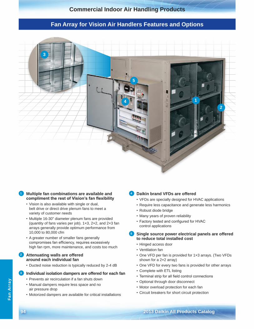
94 2013 Daikin All Products Catalog
Commercial Indoor Air Handling ProductsFa
n A
rray
Fan Array for Vision Air Handlers Features and Options
1 Multiple fan combinations are available and compliment the rest of Vision’s fan flexibility• Vision is also available with single or dual,
belt drive or direct drive plenum fans to meet avariety of customer needs
• Multiple 16-30" diameter plenum fans are provided(quantity of fans varies per job) . 1×3, 2×2, and 2×3 fanarrays generally provide optimum performance from10,000 to 80,000 cfm
• A greater number of smaller fans generallycompromises fan efficiency, requires excessivelyhigh fan rpm, more maintenance, and costs too much
2 Attenuating walls are offered around each individual fan • Ducted noise reduction is typically reduced by 2-4 dB
3 Individual isolation dampers are offered for each fan • Prevents air recirculation if a fan shuts down• Manual dampers require less space and no
air pressure drop• Motorized dampers are available for critical installations
4 Daikin brand VFDs are offered • VFDs are specially designed for HVAC applications• Require less capacitance and generate less harmonics• Robust diode bridge• Many years of proven reliability• Factory tested and configured for HVAC
control applications
5 Single source power electrical panels are offered to reduce total installed cost • Hinged access door• Ventilation fan• One VFD per fan is provided for 1×3 arrays . (Two VFDs
shown for a 2×2 array)• One VFD for every two fans is provided for other arrays• Complete with ETL listing• Terminal strip for all field control connections• Optional through door disconnect• Motor overload protection for each fan• Circuit breakers for short circuit protection
12
3
4
5
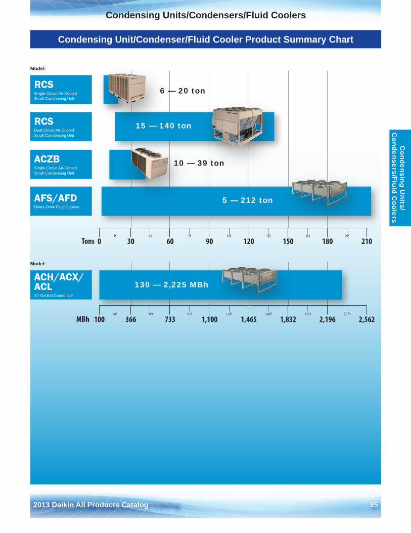
2013 Daikin All Products Catalog 95
Condensing Units/Condensers/Fluid CoolersC
ondensing Units/
Condensers/Fluid C
oolers
Condensing Unit/Condenser/Fluid Cooler Product Summary Chart
15 45 75 105 135 165 195
0 30 60 90 120 150 180 210
183 549 915 1,281 1,647 2,013 2,379
100 366 733 1,100 1,465 1,832 2,196 2,562
Tons
MBh
RCSSingle Circuit Air-Cooled Scroll Condensing Unit
ACH/ACX/ACLAir-Cooled Condenser
ACZBSingle Circuit Air-Cooled Scroll Condensing Unit
RCSDual Circuit Air-Cooled Scroll Condensing Unit
AFS/AFDDirect-Drive Fluid Coolers
Model:
Model:
15 — 140 ton
130 — 2,225 MBh
10 — 39 ton
6 — 20 ton
5 — 212 ton
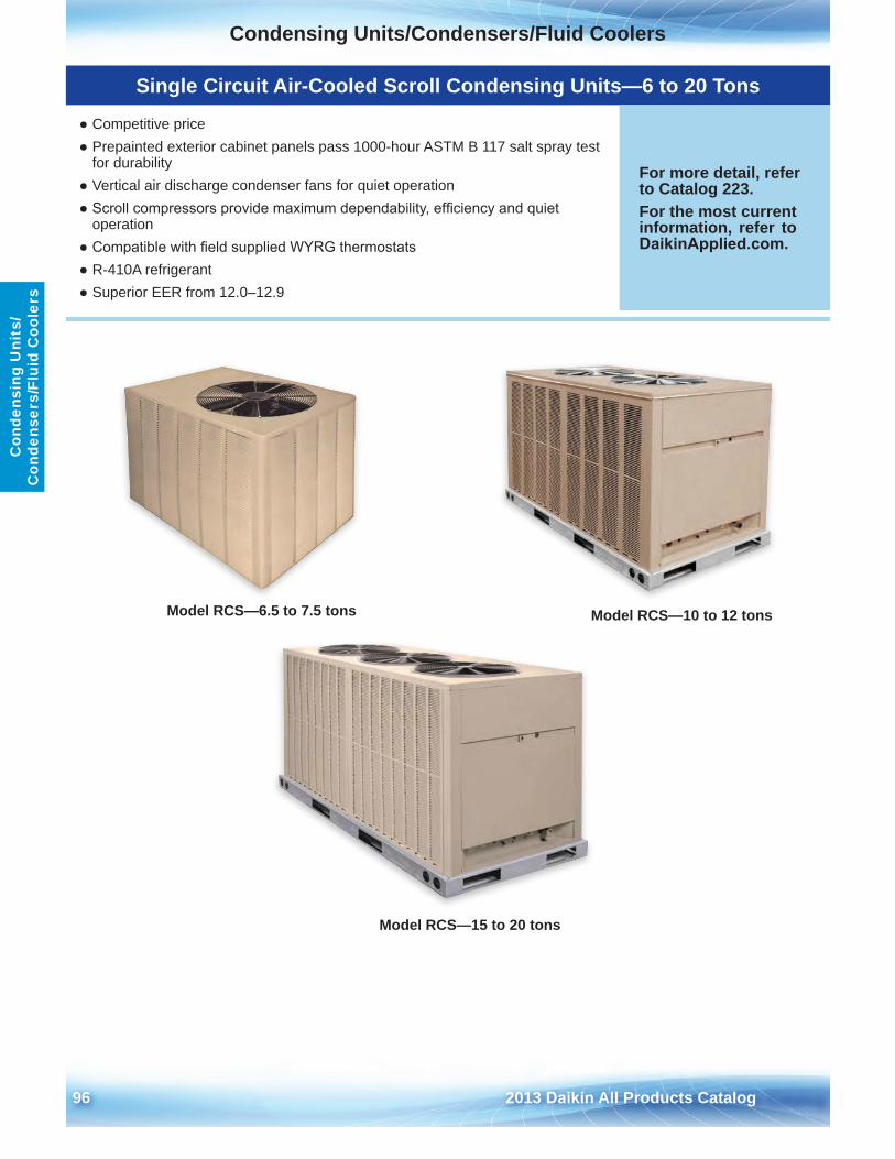
Condensing Units/Condensers/Fluid Coolers
96 2013 Daikin All Products Catalog
Con
dens
ing
Uni
ts/
Con
dens
ers/
Flui
d C
oole
rs
Model RCS—6 .5 to 7 .5 tons Model RCS—10 to 12 tons
Model RCS—15 to 20 tons
Single Circuit Air-Cooled Scroll Condensing Units—6 to 20 Tons
● Competitive price● Prepainted exterior cabinet panels pass 1000-hour ASTM B 117 salt spray test
for durability● Vertical air discharge condenser fans for quiet operation● Scroll compressors provide maximum dependability, efficiency and quiet
operation● Compatible with field supplied WYRG thermostats● R-410A refrigerant● Superior EER from 12 .0–12 .9
For more detail, refer to Catalog 223 .For the most current information, refer to DaikinApplied.com .
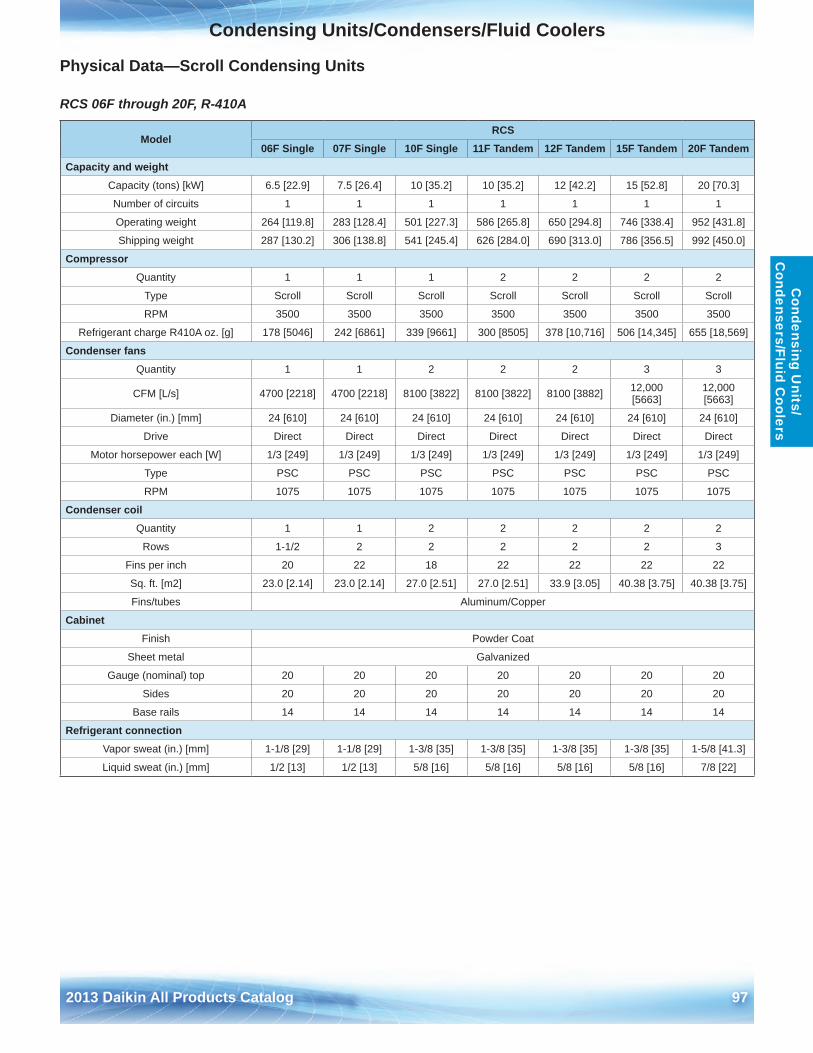
Condensing Units/Condensers/Fluid Coolers
2013 Daikin All Products Catalog 97
Condensing U
nits/ C
ondensers/Fluid Coolers
Physical Data—Scroll Condensing Units
RCS 06F through 20F, R-410A
ModelRCS
06F Single 07F Single 10F Single 11F Tandem 12F Tandem 15F Tandem 20F TandemCapacity and weight
Capacity (tons) [kW] 6 .5 [22 .9] 7 .5 [26 .4] 10 [35 .2] 10 [35 .2] 12 [42 .2] 15 [52 .8] 20 [70 .3]
Number of circuits 1 1 1 1 1 1 1
Operating weight 264 [119 .8] 283 [128 .4] 501 [227 .3] 586 [265 .8] 650 [294 .8] 746 [338 .4] 952 [431 .8]
Shipping weight 287 [130 .2] 306 [138 .8] 541 [245 .4] 626 [284 .0] 690 [313 .0] 786 [356 .5] 992 [450 .0]
CompressorQuantity 1 1 1 2 2 2 2
Type Scroll Scroll Scroll Scroll Scroll Scroll Scroll
RPM 3500 3500 3500 3500 3500 3500 3500
Refrigerant charge R410A oz . [g] 178 [5046] 242 [6861] 339 [9661] 300 [8505] 378 [10,716] 506 [14,345] 655 [18,569]
Condenser fansQuantity 1 1 2 2 2 3 3
CFM [L/s] 4700 [2218] 4700 [2218] 8100 [3822] 8100 [3822] 8100 [3882] 12,000 [5663]
12,000 [5663]
Diameter (in .) [mm] 24 [610] 24 [610] 24 [610] 24 [610] 24 [610] 24 [610] 24 [610]
Drive Direct Direct Direct Direct Direct Direct Direct
Motor horsepower each [W] 1/3 [249] 1/3 [249] 1/3 [249] 1/3 [249] 1/3 [249] 1/3 [249] 1/3 [249]
Type PSC PSC PSC PSC PSC PSC PSC
RPM 1075 1075 1075 1075 1075 1075 1075
Condenser coilQuantity 1 1 2 2 2 2 2
Rows 1-1/2 2 2 2 2 2 3
Fins per inch 20 22 18 22 22 22 22
Sq . ft . [m2] 23 .0 [2 .14] 23 .0 [2 .14] 27 .0 [2 .51] 27 .0 [2 .51] 33 .9 [3 .05] 40 .38 [3 .75] 40 .38 [3 .75]
Fins/tubes Aluminum/Copper
CabinetFinish Powder Coat
Sheet metal Galvanized
Gauge (nominal) top 20 20 20 20 20 20 20
Sides 20 20 20 20 20 20 20
Base rails 14 14 14 14 14 14 14
Refrigerant connectionVapor sweat (in .) [mm] 1-1/8 [29] 1-1/8 [29] 1-3/8 [35] 1-3/8 [35] 1-3/8 [35] 1-3/8 [35] 1-5/8 [41 .3]
Liquid sweat (in .) [mm] 1/2 [13] 1/2 [13] 5/8 [16] 5/8 [16] 5/8 [16] 5/8 [16] 7/8 [22]
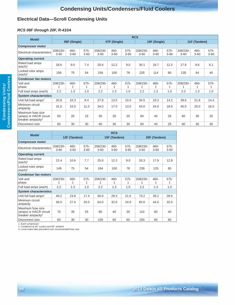
Condensing Units/Condensers/Fluid Coolers
98 2013 Daikin All Products Catalog
Con
dens
ing
Uni
ts/
Con
dens
ers/
Flui
d C
oole
rs
Electrical Data—Scroll Condensing Units
RCS 06F through 20F, R-410A
ModelRCS
06F (Single) 07F (Single) 10F (Single) 11F (Tandem)Compressor motor
Electrical characteristics 208/230-3-60
460- 3-60
575- 3-60
208/230-3-60
460- 3-60
575- 3-60
208/230-3-60
460- 3-60
575- 3-60
208/230-3-60
460- 3-60
575- 3-60
Operating currentRated load amps (each)1 18 .6 9 .0 7 .4 25 .6 12 .2 9 .0 30 .1 16 .7 12 .2 17 .6 9 .6 6 .1
Locked rotor amps (each)1 156 75 54 156 100 78 225 114 80 135 64 40
Condenser fan motorsVolt and phase
208/230-1
460- 1
575- 1
208/230-1
460- 1
575- 1
208/230-1
460- 1
575- 1
208/230-1
460- 1
575- 1
Full load amps (each) 2 .2 1 .3 1 .0 2 .2 1 .3 1 .0 2 .2 1 .3 1 .0 2 .2 1 .3 1 .0System characteristicsUnit full load amps2 20 .8 10 .3 8 .4 27 .8 13 .5 10 .0 34 .5 19 .3 14 .2 39 .6 21 .8 14 .4Minimum circuit ampacity 31 .0 15 .0 11 .0 34 .0 17 .0 13 .0 43 .0 24 .0 18 .0 45 .0 25 .0 16 .0
Maximum fuse size (amps) or HACR circuit breaker ampacity3
50 25 15 50 25 20 60 40 25 60 30 20
Disconnect size 60 30 30 60 30 30 60 40 25 60 30 30
ModelRCS
12F (Tandem) 15F (Tandem) 20F (Tandem)Compressor motor
Electrical characteristics 208/230-3-60
460- 3-60
575- 3-60
208/230-3-60
460- 3-60
575- 3-60
208/230-3-60
460- 3-60
575- 3-60
Operating currentRated load amps (each)1 22 .4 10 .6 7 .7 25 .0 12 .2 9 .0 33 .3 17 .9 12 .8
Locked rotor amps (each)1 149 75 54 164 100 78 239 125 80
Condenser fan motorsVolt and phase
208/230-1
460- 1
575- 1
208/230-1
460- 1
575- 1
208/230-1
460- 1
575- 1
Full load amps (each) 2 .2 1 .3 1 .0 2 .2 1 .3 1 .0 2 .2 1 .3 1 .0System characteristicsUnit full load amps2 49 .2 23 .8 17 .4 56 .6 28 .3 21 .0 73 .2 39 .2 28 .6Minimum circuit ampacity 56 .0 27 .0 20 .0 64 .0 32 .0 24 .0 83 .0 44 .0 32 .0
Maximum fuse size (amps) or HACR circuit breaker ampacity3
70 35 25 80 40 30 110 60 40
Disconnect size 60 30 30 100 60 60 200 60 601 . Each compressor2 . Conditions at 45° suction and 95° ambient3 . Local codes take precedent over recommended fuse size
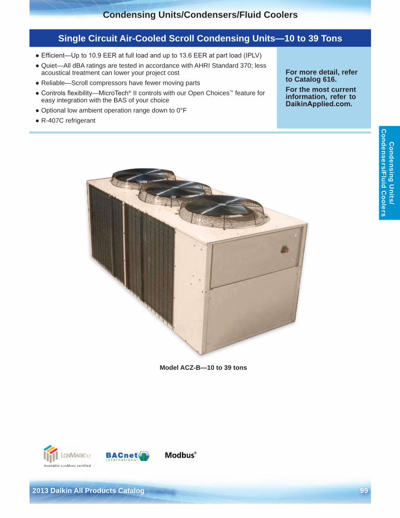
Condensing Units/Condensers/Fluid Coolers
2013 Daikin All Products Catalog 99
Condensing U
nits/ C
ondensers/Fluid Coolers
Model ACZ-B—10 to 39 tons
Available LonMark cert i f ied
Single Circuit Air-Cooled Scroll Condensing Units—10 to 39 Tons
● Efficient—Up to 10.9 EER at full load and up to 13.6 EER at part load (IPLV)● Quiet—All dBA ratings are tested in accordance with AHRI Standard 370; less
acoustical treatment can lower your project cost● Reliable—Scroll compressors have fewer moving parts● Controls flexibility—MicroTech® II controls with our Open Choices™ feature for
easy integration with the BAS of your choice● Optional low ambient operation range down to 0°F● R-407C refrigerant
For more detail, refer to Catalog 616 . For the most current information, refer to DaikinApplied.com .
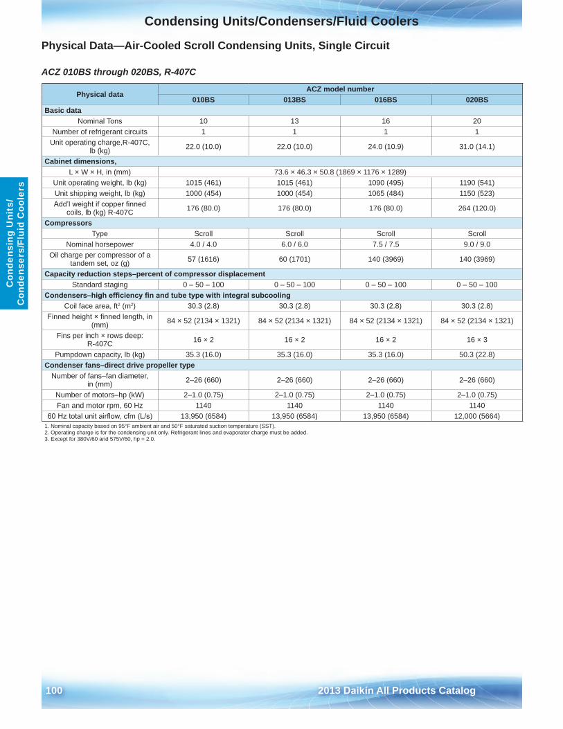
Condensing Units/Condensers/Fluid Coolers
100 2013 Daikin All Products Catalog
Con
dens
ing
Uni
ts/
Con
dens
ers/
Flui
d C
oole
rs
Physical Data—Air-Cooled Scroll Condensing Units, Single Circuit
ACZ 010BS through 020BS, R-407C
Physical dataACZ model number
010BS 013BS 016BS 020BSBasic data
Nominal Tons 10 13 16 20Number of refrigerant circuits 1 1 1 1
Unit operating charge,R-407C, lb (kg) 22 .0 (10 .0) 22 .0 (10 .0) 24 .0 (10 .9) 31 .0 (14 .1)
Cabinet dimensions, L × W × H, in (mm) 73 .6 × 46 .3 × 50 .8 (1869 × 1176 × 1289)
Unit operating weight, lb (kg) 1015 (461) 1015 (461) 1090 (495) 1190 (541)Unit shipping weight, lb (kg) 1000 (454) 1000 (454) 1065 (484) 1150 (523)Add’l weight if copper finned
coils, lb (kg) R-407C 176 (80 .0) 176 (80 .0) 176 (80 .0) 264 (120 .0)
CompressorsType Scroll Scroll Scroll Scroll
Nominal horsepower 4 .0 / 4 .0 6 .0 / 6 .0 7 .5 / 7 .5 9 .0 / 9 .0Oil charge per compressor of a
tandem set, oz (g) 57 (1616) 60 (1701) 140 (3969) 140 (3969)
Capacity reduction steps–percent of compressor displacementStandard staging 0 – 50 – 100 0 – 50 – 100 0 – 50 – 100 0 – 50 – 100
Condensers–high efficiency fin and tube type with integral subcoolingCoil face area, ft2 (m2) 30 .3 (2 .8) 30 .3 (2 .8) 30 .3 (2 .8) 30 .3 (2 .8)
Finned height × finned length, in (mm) 84 × 52 (2134 × 1321) 84 × 52 (2134 × 1321) 84 × 52 (2134 × 1321) 84 × 52 (2134 × 1321)
Fins per inch × rows deep: R-407C 16 × 2 16 × 2 16 × 2 16 × 3
Pumpdown capacity, lb (kg) 35 .3 (16 .0) 35 .3 (16 .0) 35 .3 (16 .0) 50 .3 (22 .8)Condenser fans–direct drive propeller type
Number of fans–fan diameter, in (mm) 2–26 (660) 2–26 (660) 2–26 (660) 2–26 (660)
Number of motors–hp (kW) 2–1 .0 (0 .75) 2–1 .0 (0 .75) 2–1 .0 (0 .75) 2–1 .0 (0 .75)Fan and motor rpm, 60 Hz 1140 1140 1140 1140
60 Hz total unit airflow, cfm (L/s) 13,950 (6584) 13,950 (6584) 13,950 (6584) 12,000 (5664)1 . Nominal capacity based on 95°F ambient air and 50°F saturated suction temperature (SST) .2 . Operating charge is for the condensing unit only . Refrigerant lines and evaporator charge must be added .3 . Except for 380V/60 and 575V/60, hp = 2 .0 .
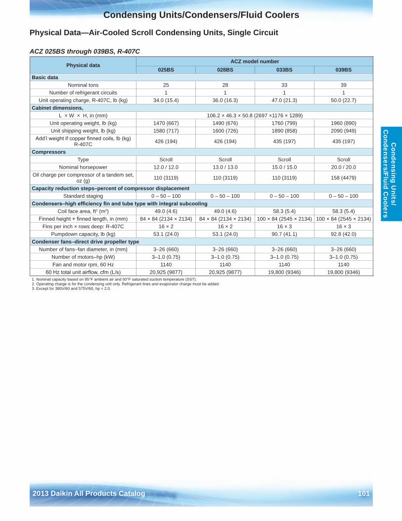
Condensing Units/Condensers/Fluid Coolers
2013 Daikin All Products Catalog 101
Condensing U
nits/ C
ondensers/Fluid Coolers
Physical Data—Air-Cooled Scroll Condensing Units, Single Circuit
ACZ 025BS through 039BS, R-407C
Physical dataACZ model number
025BS 028BS 033BS 039BSBasic data
Nominal tons 25 28 33 39Number of refrigerant circuits 1 1 1 1
Unit operating charge, R-407C, lb (kg) 34 .0 (15 .4) 36 .0 (16 .3) 47 .0 (21 .3) 50 .0 (22 .7)Cabinet dimensions,
L × W × H, in (mm) 106 .2 × 46 .3 × 50 .8 (2697 ×1176 × 1289)Unit operating weight, lb (kg) 1470 (667) 1490 (676) 1760 (799) 1960 (890)Unit shipping weight, lb (kg) 1580 (717) 1600 (726) 1890 (858) 2090 (949)
Add’l weight if copper finned coils, lb (kg) R-407C 426 (194) 426 (194) 435 (197) 435 (197)
CompressorsType Scroll Scroll Scroll Scroll
Nominal horsepower 12 .0 / 12 .0 13 .0 / 13 .0 15 .0 / 15 .0 20 .0 / 20 .0Oil charge per compressor of a tandem set,
oz (g) 110 (3119) 110 (3119) 110 (3119) 158 (4479)
Capacity reduction steps–percent of compressor displacementStandard staging 0 – 50 – 100 0 – 50 – 100 0 – 50 – 100 0 – 50 – 100
Condensers–high efficiency fin and tube type with integral subcoolingCoil face area, ft2 (m2) 49 .0 (4 .6) 49 .0 (4 .6) 58 .3 (5 .4) 58 .3 (5 .4)
Finned height × finned length, in (mm) 84 × 84 (2134 × 2134) 84 × 84 (2134 × 2134) 100 × 84 (2545 × 2134) 100 × 84 (2545 × 2134)Fins per inch × rows deep: R-407C 16 × 2 16 × 2 16 × 3 16 × 3
Pumpdown capacity, lb (kg) 53 .1 (24 .0) 53 .1 (24 .0) 90 .7 (41 .1) 92 .8 (42 .0)Condenser fans–direct drive propeller type
Number of fans–fan diameter, in (mm) 3–26 (660) 3–26 (660) 3–26 (660) 3–26 (660)Number of motors–hp (kW) 3–1 .0 (0 .75) 3–1 .0 (0 .75) 3–1 .0 (0 .75) 3–1 .0 (0 .75)Fan and motor rpm, 60 Hz 1140 1140 1140 1140
60 Hz total unit airflow, cfm (L/s) 20,925 (9877) 20,925 (9877) 19,800 (9346) 19,800 (9346)1 . Nominal capacity based on 95°F ambient air and 50°F saturated suction temperature (SST) .2 . Operating charge is for the condensing unit only . Refrigerant lines and evaporator charge must be added .3 . Except for 380V/60 and 575V/60, hp = 2 .0 .
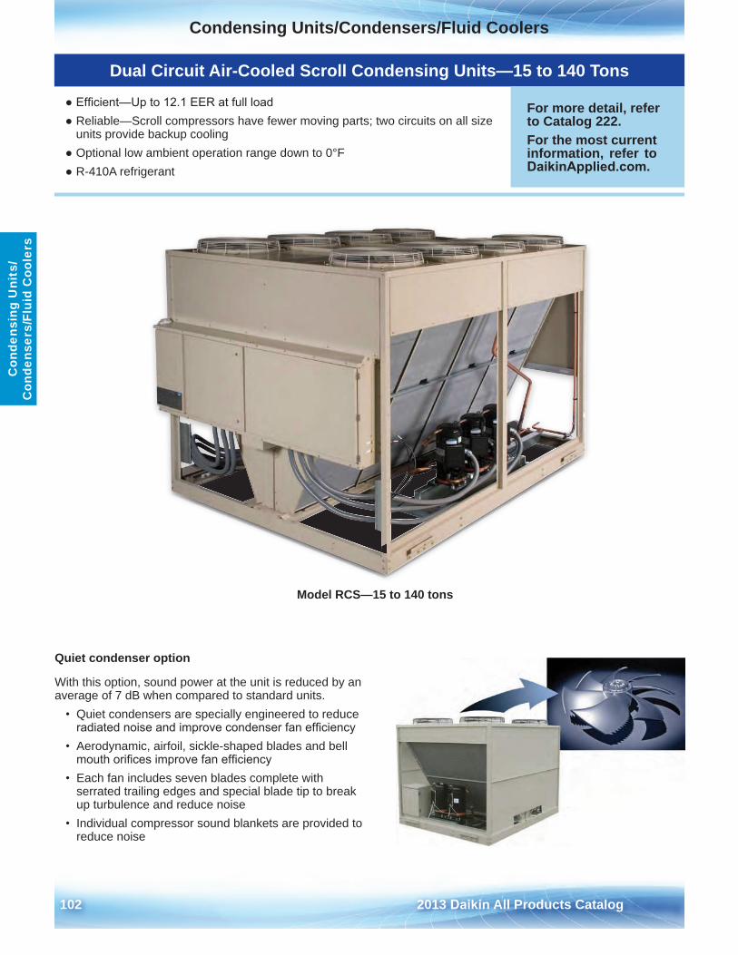
Condensing Units/Condensers/Fluid Coolers
102 2013 Daikin All Products Catalog
Con
dens
ing
Uni
ts/
Con
dens
ers/
Flui
d C
oole
rs
Model RCS—15 to 140 tons
Quiet condenser option
With this option, sound power at the unit is reduced by an average of 7 dB when compared to standard units .
• Quiet condensers are specially engineered to reduceradiated noise and improve condenser fan efficiency
• Aerodynamic, airfoil, sickle-shaped blades and bellmouth orifices improve fan efficiency
• Each fan includes seven blades complete withserrated trailing edges and special blade tip to break up turbulence and reduce noise
• Individual compressor sound blankets are provided toreduce noise
Dual Circuit Air-Cooled Scroll Condensing Units—15 to 140 Tons
● Efficient—Up to 12.1 EER at full load● Reliable—Scroll compressors have fewer moving parts; two circuits on all size
units provide backup cooling● Optional low ambient operation range down to 0°F● R-410A refrigerant
For more detail, refer to Catalog 222 . For the most current information, refer to DaikinApplied.com .
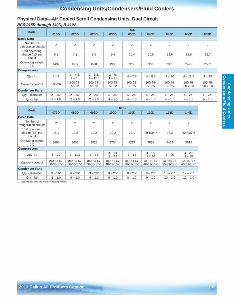
Condensing Units/Condensers/Fluid Coolers
2013 Daikin All Products Catalog 103
Condensing U
nits/ C
ondensers/Fluid Coolers
Physical Data—Air Cooled Scroll Condensing Units, Dual CircuitRCS 015D through 140D, R-410A
ModelRCS
015D 020D 025D 030D 035D 040D 045D 050D 062DBasic Data
Number of refrigeration circuits 2 2 2 2 2 2 2 2 2
Unit operating charge (lb)1 per
circuit6 .5 7 .1 8 .0 9 .6 10 .4 10 .8 12 .6 12 .6 12 .7
Operating weight (lb) 1492 1577 1581 1986 2203 2229 2305 2425 2552
Compressors
Qty .- hp 2 – 7 2 – 4 .5, 1 – 10
2 – 5 .5, 1 – 11 .5
2 – 6, 1 – 13 4 – 7 .5 4 – 8 .5 4 – 10 4 – 11 .5 4 – 13
Capacity control 100-50 100-78- 55-22
100-78- 55-22
100-78- 55-22
100-75- 50-25
100-75- 50-25
100-75- 50-25
100-75- 50-25-0
100-75- 50-25-0
Condenser Fans Qty . - diameter 2 – 26" 2 – 26" 2 – 26" 4 – 26" 4 – 26" 4 – 26" 4 – 26" 4 – 26" 6 – 26"
Qty . - hp 2 – 1 .0 2 – 1 .0 2 – 1 .0 4 – 1 .0 4 – 1 .0 4 – 1 .0 4 – 1 .0 4 – 1 .0 6 – 1 .0
ModelRCS
072D 080D 092D 100D 110D 120D 125D 140DBasic Data
Number of refrigeration circuits 2 2 2 2 2 2 2 2
Unit operating charge (lb)1 per
circuit15 .1 19 .0 19 .2 19 .2 29 .1 29 .1/34 .7 32 .3 32 .3/37 .5
Operating weight (lb) 3496 3603 3828 3764 4277 4858 5439 5619
Compressors
Qty .- hp 6 – 10 6 – 11 .5 6 – 13 3 – 13, 3 – 15 6 – 15 3 – 15,
3 – 20 6 – 20 3 – 20, 3 – 25
Capacity control 100-83-67-50-33-17-0
100-83-67-50-33-17-0
100-83-67-50-33-17-0
100-81-67-48-33-15-0
100-84-67-50-33-17-0
100-81-67-48-33-15-0
100-84-67-50-33-17-0
100-81-67-48-33-15-0
Condenser Fans Qty . - diameter 8 – 26" 6 – 26" 9 – 26" 9 – 26" 8 – 26" 9 – 26" 10 – 26" 12 – 26"
Qty . - hp 8 – 1 .0 6 – 1 .0 9 – 1 .0 9 – 1 .0 8 – 1 .0 9 – 1 .0 10 – 1 .0 12 – 1 .01 . Unit shipped with dry nitrogen holding charge .
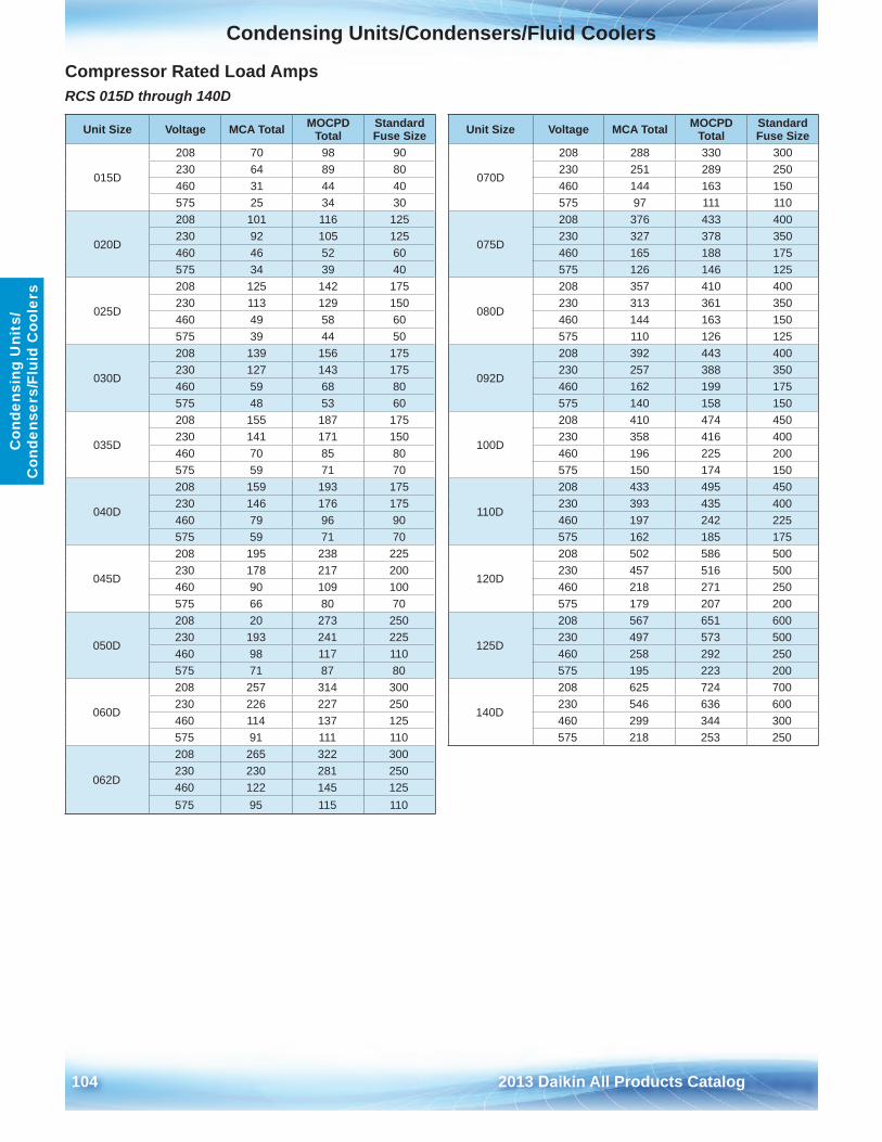
Condensing Units/Condensers/Fluid Coolers
104 2013 Daikin All Products Catalog
Con
dens
ing
Uni
ts/
Con
dens
ers/
Flui
d C
oole
rs
Compressor Rated Load AmpsRCS 015D through 140D
Unit Size Voltage MCA Total MOCPD Total
Standard Fuse Size Unit Size Voltage MCA Total MOCPD
TotalStandard Fuse Size
015D
208 70 98 90
070D
208 288 330 300230 64 89 80 230 251 289 250460 31 44 40 460 144 163 150575 25 34 30 575 97 111 110
020D
208 101 116 125
075D
208 376 433 400230 92 105 125 230 327 378 350460 46 52 60 460 165 188 175575 34 39 40 575 126 146 125
025D
208 125 142 175
080D
208 357 410 400230 113 129 150 230 313 361 350460 49 58 60 460 144 163 150575 39 44 50 575 110 126 125
030D
208 139 156 175
092D
208 392 443 400230 127 143 175 230 257 388 350460 59 68 80 460 162 199 175575 48 53 60 575 140 158 150
035D
208 155 187 175
100D
208 410 474 450230 141 171 150 230 358 416 400460 70 85 80 460 196 225 200575 59 71 70 575 150 174 150
040D
208 159 193 175
110D
208 433 495 450230 146 176 175 230 393 435 400460 79 96 90 460 197 242 225575 59 71 70 575 162 185 175
045D
208 195 238 225
120D
208 502 586 500230 178 217 200 230 457 516 500460 90 109 100 460 218 271 250575 66 80 70 575 179 207 200
050D
208 20 273 250
125D
208 567 651 600230 193 241 225 230 497 573 500460 98 117 110 460 258 292 250575 71 87 80 575 195 223 200
060D
208 257 314 300
140D
208 625 724 700230 226 227 250 230 546 636 600460 114 137 125 460 299 344 300575 91 111 110 575 218 253 250
062D
208 265 322 300230 230 281 250460 122 145 125575 95 115 110
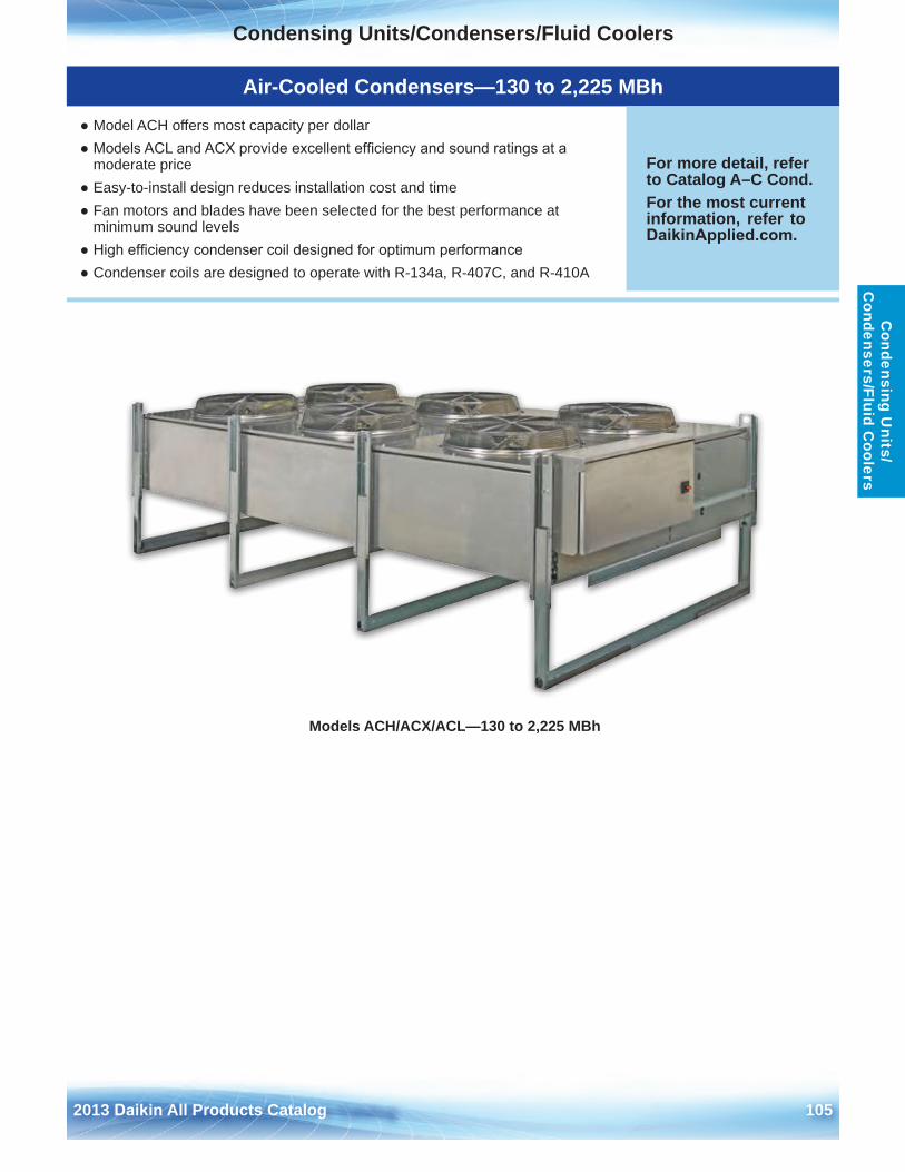
Condensing Units/Condensers/Fluid Coolers
2013 Daikin All Products Catalog 105
Condensing U
nits/ C
ondensers/Fluid Coolers
Models ACH/ACX/ACL—130 to 2,225 MBh
Air-Cooled Condensers—130 to 2,225 MBh
● Model ACH offers most capacity per dollar● Models ACL and ACX provide excellent efficiency and sound ratings at a
moderate price● Easy-to-install design reduces installation cost and time● Fan motors and blades have been selected for the best performance at
minimum sound levels● High efficiency condenser coil designed for optimum performance● Condenser coils are designed to operate with R-134a, R-407C, and R-410A
For more detail, refer to Catalog A–C Cond . For the most current information, refer to DaikinApplied.com .
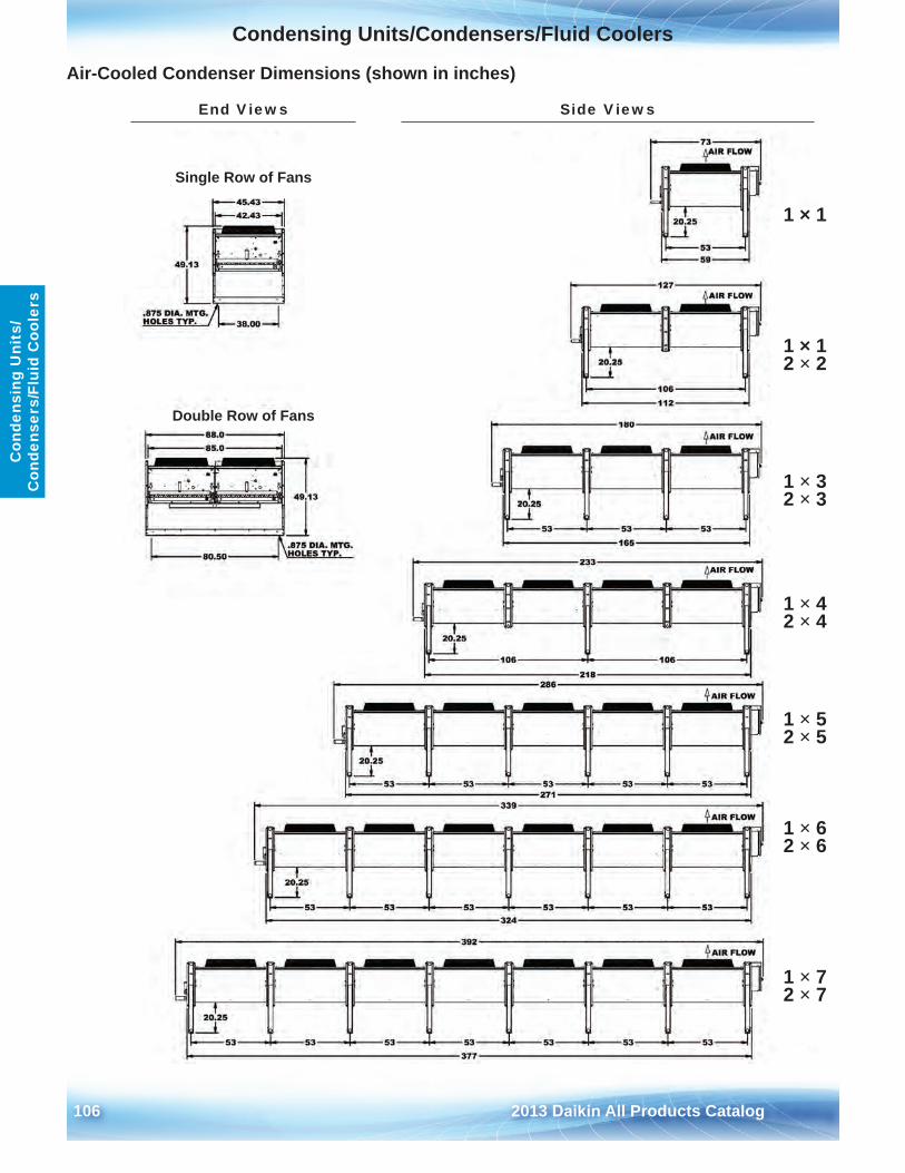
Condensing Units/Condensers/Fluid Coolers
106 2013 Daikin All Products Catalog
Con
dens
ing
Uni
ts/
Con
dens
ers/
Flui
d C
oole
rs
Air-Cooled Condenser Dimensions (shown in inches)
Single Row of Fans
Double Row of Fans
End Views Side Views
1 × 1
1 × 1 2 × 2
1 × 3 2 × 3
1 × 4 2 × 4
1 × 5 2 × 5
1 × 6 2 × 6
1 × 7 2 × 7
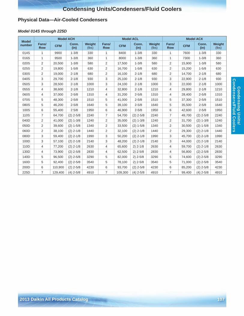
Condensing Units/Condensers/Fluid Coolers
2013 Daikin All Products Catalog 107
Condensing U
nits/ C
ondensers/Fluid Coolers
Physical Data—Air-Cooled Condensers
Model 014S through 225D
Model number
Model ACH Model ACL Model ACXFans/ Row CFM Conn .
(in)Weight
(lbs)Fans/ Row CFM Conn .
(in)Weight
(lbs)Fans/ Row CFM Conn .
(in)Weight
(lbs)014S 1 9900 1-3/8 330 1 8400 1-3/8 330 1 7600 1-3/8 330016S 1 9500 1-3/8 360 1 8000 1-3/8 360 1 7300 1-3/8 360020S 2 20,500 1-3/8 580 2 17,500 1-3/8 580 2 15,900 1-3/8 580025S 2 19,800 1-5/8 630 2 16,700 1-5/8 630 2 15,200 1-5/8 630030S 2 19,000 2-1/8 680 2 16,100 2-1/8 680 2 14,700 2-1/8 680040S 3 29,700 2-1/8 930 3 25,100 2-1/8 930 3 22,900 2-1/8 930050S 3 28,500 2-1/8 1000 3 24,100 2-1/8 1000 3 22,000 2-1/8 1000055S 4 38,600 2-1/8 1210 4 32,800 2-1/8 1210 4 29,800 2-1/8 1210060S 4 37,000 2-5/8 1310 4 31,200 2-5/8 1310 4 28,400 2-5/8 1310070S 5 48,300 2-5/8 1510 5 41,000 2-5/8 1510 5 37,300 2-5/8 1510080S 5 46,200 2-5/8 1640 5 39,100 2-5/8 1640 5 35,500 2-5/8 1640100S 6 55,400 2 5/8 1950 6 46,900 2-5/8 1950 6 42,600 2-5/8 1950110S 7 64,700 (2) 2-5/8 2240 7 54,700 (2) 2-5/8 2240 7 49,700 (2) 2-5/8 2240040D 2 41,000 (2) 1-3/8 1240 2 35,000 (2) 1-3/8 1240 2 31,700 (2) 1-3/8 1240050D 2 39,600 (2) 1-5/8 1340 2 33,500 (2) 1-5/8 1340 2 30,500 (2) 1-5/8 1340060D 2 38,100 (2) 2-1/8 1440 2 32,100 (2) 2-1/8 1440 2 29,300 (2) 2-1/8 1440080D 3 59,400 (2) 2-1/8 1990 3 50,200 (2) 2-1/8 1990 3 45,700 (2) 2-1/8 1990100D 3 57,100 (2) 2-1/8 2140 3 48,200 (2) 2-1/8 2140 3 44,000 (2) 2-1/8 2140110D 4 77,200 (2) 2-1/8 2630 4 65,600 2) 2-1/8 2630 4 59,700 (2) 2-1/8 2630130D 4 73,900 (2) 2-5/8 2830 4 62,500 2) 2-5/8 2830 4 56,800 (2) 2-5/8 2830140D 5 96,500 (2) 2-5/8 3290 5 82,000 2) 2-5/8 3290 5 74,600 (2) 2-5/8 3290160D 5 92,400 (2) 2-5/8 3540 5 78,100 2) 2-5/8 3540 5 71,000 (2) 2-5/8 3540200D 6 110,900 (2) 2-5/8 4230 6 93,700 (2) 2-5/8 4230 6 85,200 (2) 2-5/8 4230225D 7 129,400 (4) 2-5/8 4910 7 109,300 (4) 2-5/8 4910 7 99,400 (4) 2-5/8 4910
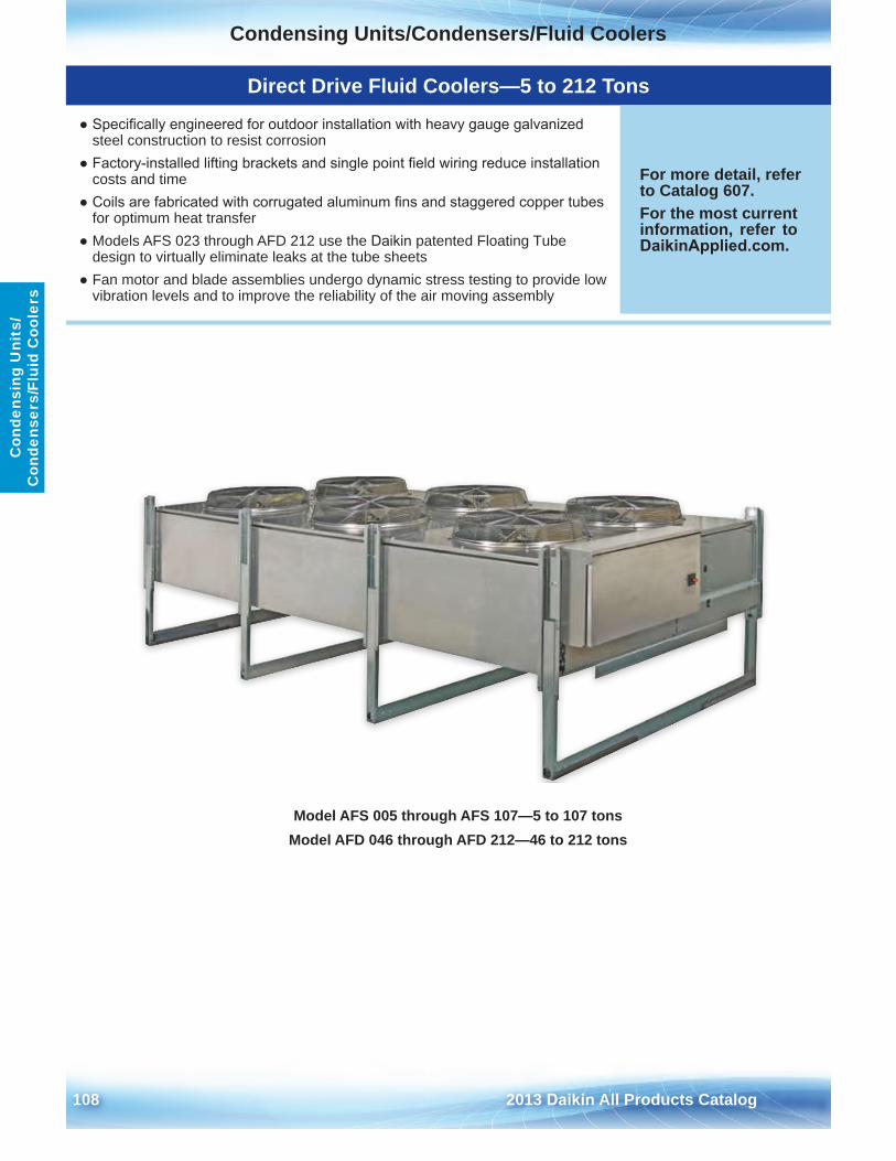
Condensing Units/Condensers/Fluid Coolers
108 2013 Daikin All Products Catalog
Con
dens
ing
Uni
ts/
Con
dens
ers/
Flui
d C
oole
rs
Model AFS 005 through AFS 107—5 to 107 tonsModel AFD 046 through AFD 212—46 to 212 tons
Direct Drive Fluid Coolers—5 to 212 Tons
● Specifically engineered for outdoor installation with heavy gauge galvanizedsteel construction to resist corrosion
● Factory-installed lifting brackets and single point field wiring reduce installationcosts and time
● Coils are fabricated with corrugated aluminum fins and staggered copper tubesfor optimum heat transfer
● Models AFS 023 through AFD 212 use the Daikin patented Floating Tube design to virtually eliminate leaks at the tube sheets
● Fan motor and blade assemblies undergo dynamic stress testing to provide lowvibration levels and to improve the reliability of the air moving assembly
For more detail, refer to Catalog 607 .For the most current information, refer to DaikinApplied.com .
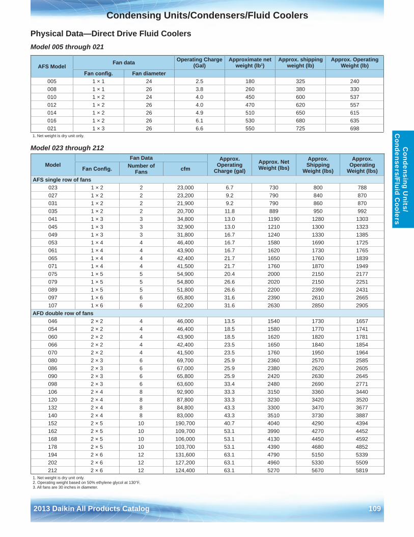
Condensing Units/Condensers/Fluid Coolers
2013 Daikin All Products Catalog 109
Condensing U
nits/ C
ondensers/Fluid Coolers
Physical Data—Direct Drive Fluid CoolersModel 005 through 021
Model 023 through 212
AFS ModelFan data Operating Charge
(Gal)Approximate net
weight (lb1)Approx . shipping
weight (lb)Approx . Operating
Weight (lb)Fan config. Fan diameter
005 1 × 1 24 2 .5 180 325 240008 1 × 1 26 3 .8 260 380 330010 1 × 2 24 4 .0 450 600 537012 1 × 2 26 4 .0 470 620 557014 1 × 2 26 4 .9 510 650 615016 1 × 2 26 6 .1 530 680 635021 1 × 3 26 6 .6 550 725 698
1 . Net weight is dry unit only .
ModelFan Data Approx .
Operating Charge (gal)
Approx . Net Weight (lbs)
Approx . Shipping
Weight (lbs)
Approx . Operating
Weight (lbs)Fan Config. Number of Fans cfm
AFS single row of fans023 1 × 2 2 23,000 6 .7 730 800 788027 1 × 2 2 23,200 9 .2 790 840 870031 1 × 2 2 21,900 9 .2 790 860 870035 1 × 2 2 20,700 11 .8 889 950 992041 1 × 3 3 34,800 13 .0 1190 1280 1303045 1 × 3 3 32,900 13 .0 1210 1300 1323049 1 × 3 3 31,800 16 .7 1240 1330 1385053 1 × 4 4 46,400 16 .7 1580 1690 1725061 1 × 4 4 43,900 16 .7 1620 1730 1765065 1 × 4 4 42,400 21 .7 1650 1760 1839071 1 × 4 4 41,500 21 .7 1760 1870 1949075 1 × 5 5 54,900 20 .4 2000 2150 2177079 1 × 5 5 54,800 26 .6 2020 2150 2251089 1 × 5 5 51,800 26 .6 2200 2390 2431097 1 × 6 6 65,800 31 .6 2390 2610 2665107 1 × 6 6 62,200 31 .6 2630 2850 2905
AFD double row of fans046 2 × 2 4 46,000 13 .5 1540 1730 1657054 2 × 2 4 46,400 18 .5 1580 1770 1741060 2 × 2 4 43,900 18 .5 1620 1820 1781066 2 × 2 4 42,400 23 .5 1650 1840 1854070 2 × 2 4 41,500 23 .5 1760 1950 1964080 2 × 3 6 69,700 25 .9 2360 2570 2585086 2 × 3 6 67,000 25 .9 2380 2620 2605090 2 × 3 6 65,800 25 .9 2420 2630 2645098 2 × 3 6 63,600 33 .4 2480 2690 2771106 2 × 4 8 92,900 33 .3 3150 3360 3440120 2 × 4 8 87,800 33 .3 3230 3420 3520132 2 × 4 8 84,800 43 .3 3300 3470 3677140 2 × 4 8 83,000 43 .3 3510 3730 3887152 2 × 5 10 190,700 40 .7 4040 4290 4394162 2 × 5 10 109,700 53 .1 3990 4270 4452168 2 × 5 10 106,000 53 .1 4130 4450 4592178 2 × 5 10 103,700 53 .1 4390 4680 4852194 2 × 6 12 131,600 63 .1 4790 5150 5339202 2 × 6 12 127,200 63 .1 4960 5330 5509212 2 × 6 12 124,400 63 .1 5270 5670 5819
1 . Net weight is dry unit only .2 . Operating weight based on 50% ethylene glycol at 130°F .3 . All fans are 30 inches in diameter .
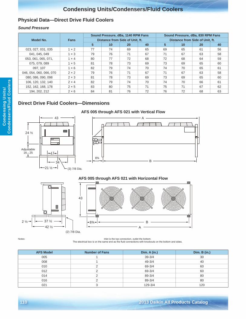
Condensing Units/Condensers/Fluid Coolers
110 2013 Daikin All Products Catalog
Con
dens
ing
Uni
ts/
Con
dens
ers/
Flui
d C
oole
rs
Physical Data—Direct Drive Fluid CoolersSound Pressure
Direct Drive Fluid Coolers—Dimensions
AFS 005 through AFS 021 with Vertical Flow
AFS 005 through AFS 021 with Horizontal Flow
Notes: Inlet is the top connection, outlet the bottom . The electrical box is on the same end as the fluid connections with knockouts on the bottom and sides.
Model No . FansSound Pressure, dBa, 1140 RPM Fans Sound Pressure, dBa, 830 RPM Fans
Distance from Side of Unit, ft . Distance from Side of Unit, ft .5 10 20 40 5 10 20 40
023, 027, 031, 035 1 × 2 77 74 69 65 69 65 61 56041, 045, 049 1 × 3 79 76 71 67 71 67 63 58
053, 061, 065, 071, 1 × 4 80 77 72 68 72 68 64 59075, 079, 089 1 × 5 81 78 73 69 73 69 65 60
097, 107 1 × 6 82 79 74 70 74 70 65 61046, 054, 060, 066, 070 2 × 2 79 76 71 67 71 67 63 58
080, 086, 090, 098 2 × 3 81 78 73 69 73 69 65 60106, 120, 132, 140 2 × 4 82 79 74 70 74 70 66 61152, 162, 168, 178 2 × 5 83 80 75 71 75 71 67 62
194, 202, 212 2 × 6 84 81 76 72 76 72 68 63
8¾B
A
24 ½
Adjustable16 - 25 17
3421 ½ (3) 7/8 Dia.
43
2 ½ 37 ½42 ½
(2) 7/8 Dia.A
43
B8¾
AFS Model Number of Fans Dim . A (in .) Dim . B (in .)005 1 39-3/4 30008 1 49-3/4 40010 2 69-3/4 60012 2 69-3/4 60014 2 89-3/4 80016 2 89-3/4 80021 3 129-3/4 120
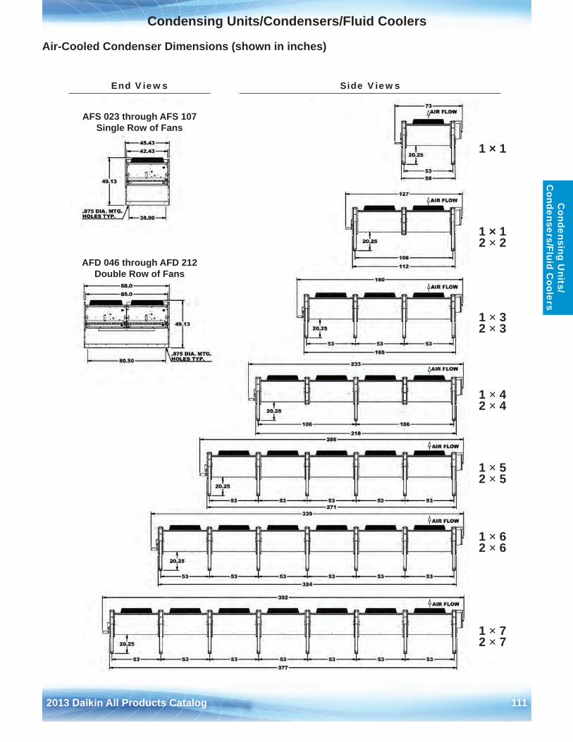
Condensing Units/Condensers/Fluid Coolers
2013 Daikin All Products Catalog 111
Condensing U
nits/ C
ondensers/Fluid Coolers
Air-Cooled Condenser Dimensions (shown in inches)
AFS 023 through AFS 107 Single Row of Fans
AFD 046 through AFD 212 Double Row of Fans
End Views Side Views
1 × 1
1 × 1 2 × 2
1 × 3 2 × 3
1 × 4 2 × 4
1 × 5 2 × 5
1 × 6 2 × 6
1 × 7 2 × 7
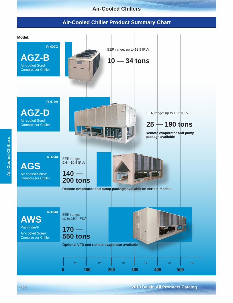
112 2013 Daikin All Products Catalog
Air-Cooled ChillersA
ir-C
oole
d C
hille
rs
Air-Cooled Chiller Product Summary Chart
Model:
R-407C
AGZ-BAir-cooled Scroll Compressor Chiller
R-410A
AGZ-DAir-cooled Scroll Compressor Chiller
R-134a
AGSAir-cooled Screw Compressor Chiller
R-134a
AWSPathfinder®
Air-cooled Screw Compressor Chiller
50 150 250 350 450 550
0 100 200 300 400 500
EER range: up to 13 .9 IPLV
10 — 34 tons
EER range: up to 15 .6 IPLV
25 — 190 tons
EER range: 9 .6—10 .5 IPLV
140 — 200 tonsRemote evaporator and pump package available on certain models
EER range: up to 19 .4 IPLV
170 — 550 tonsOptional VFD and remote evaporator available
Remote evaporator and pump package available
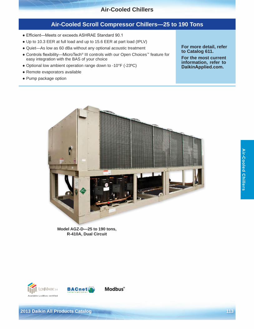
Air-Cooled Chillers
2013 Daikin All Products Catalog 113
Air-C
ooled Chillers
Model AGZ-D—25 to 190 tons, R-410A, Dual Circuit
Available LonMark cert i f ied
Air-Cooled Scroll Compressor Chillers—25 to 190 Tons
● Efficient—Meets or exceeds ASHRAE Standard 90.1● Up to 10 .3 EER at full load and up to 15 .6 EER at part load (IPLV)● Quiet—As low as 60 dBa without any optional acoustic treatment● Controls flexibility—MicroTech® III controls with our Open Choices™ feature for
easy integration with the BAS of your choice● Optional low ambient operation range down to -10°F (-23ºC)● Remote evaporators available● Pump package option
For more detail, refer to Catalog 611 .For the most current information, refer to DaikinApplied.com .
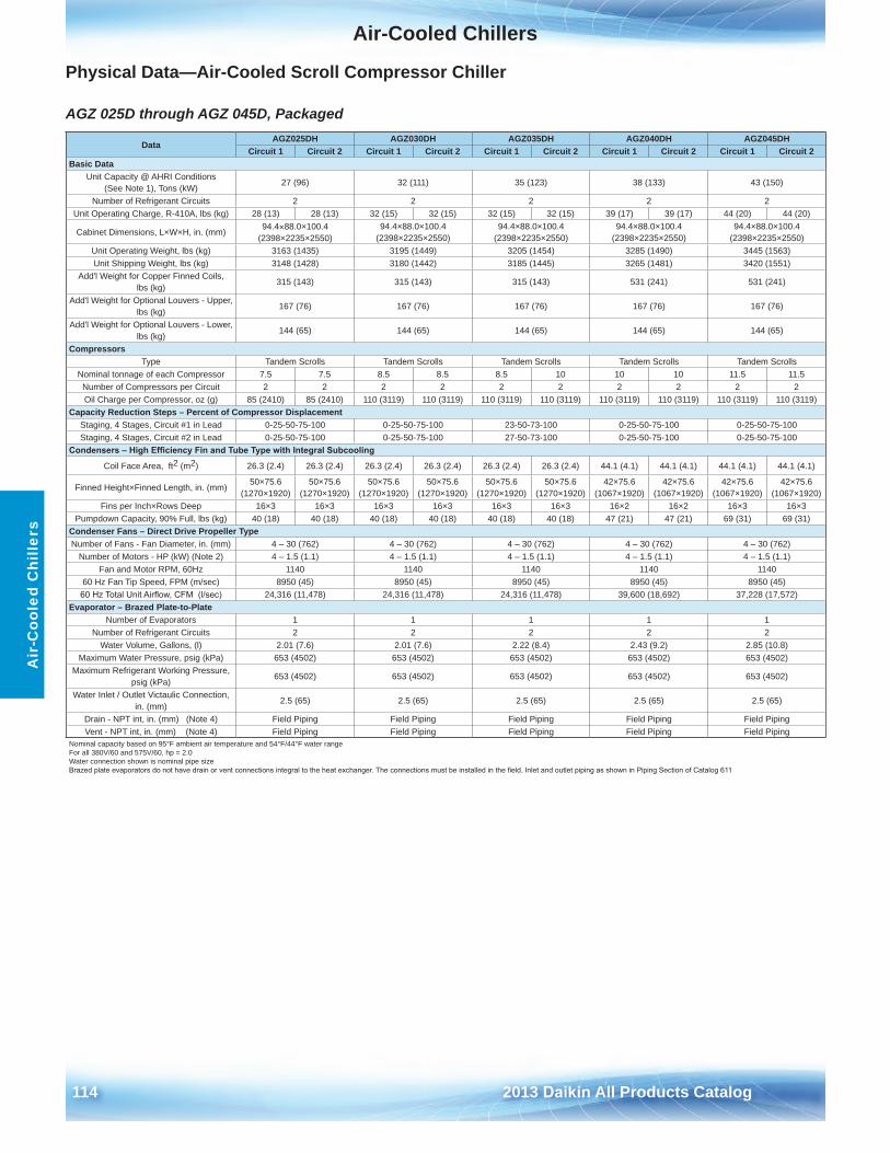
Air-Cooled Chillers
114 2013 Daikin All Products Catalog
Air
-Coo
led
Chi
llers
Physical Data—Air-Cooled Scroll Compressor Chiller
AGZ 025D through AGZ 045D, Packaged
DataAGZ025DH AGZ030DH AGZ035DH AGZ040DH AGZ045DH
Circuit 1 Circuit 2 Circuit 1 Circuit 2 Circuit 1 Circuit 2 Circuit 1 Circuit 2 Circuit 1 Circuit 2Basic Data
Unit Capacity @ AHRI Conditions (See Note 1), Tons (kW)
27 (96) 32 (111) 35 (123) 38 (133) 43 (150)
Number of Refrigerant Circuits 2 2 2 2 2Unit Operating Charge, R-410A, lbs (kg) 28 (13) 28 (13) 32 (15) 32 (15) 32 (15) 32 (15) 39 (17) 39 (17) 44 (20) 44 (20)
Cabinet Dimensions, L×W×H, in . (mm) 94 .4×88 .0×100 .4(2398×2235×2550)
94 .4×88 .0×100 .4(2398×2235×2550)
94 .4×88 .0×100 .4(2398×2235×2550)
94 .4×88 .0×100 .4(2398×2235×2550)
94 .4×88 .0×100 .4 (2398×2235×2550)
Unit Operating Weight, lbs (kg) 3163 (1435) 3195 (1449) 3205 (1454) 3285 (1490) 3445 (1563)Unit Shipping Weight, lbs (kg) 3148 (1428) 3180 (1442) 3185 (1445) 3265 (1481) 3420 (1551)
Add'l Weight for Copper Finned Coils, lbs (kg)
315 (143) 315 (143) 315 (143) 531 (241) 531 (241)
Add'l Weight for Optional Louvers - Upper, lbs (kg)
167 (76) 167 (76) 167 (76) 167 (76) 167 (76)
Add'l Weight for Optional Louvers - Lower, lbs (kg)
144 (65) 144 (65) 144 (65) 144 (65) 144 (65)
CompressorsType Tandem Scrolls Tandem Scrolls Tandem Scrolls Tandem Scrolls Tandem Scrolls
Nominal tonnage of each Compressor 7 .5 7 .5 8 .5 8 .5 8 .5 10 10 10 11 .5 11 .5Number of Compressors per Circuit 2 2 2 2 2 2 2 2 2 2Oil Charge per Compressor, oz (g) 85 (2410) 85 (2410) 110 (3119) 110 (3119) 110 (3119) 110 (3119) 110 (3119) 110 (3119) 110 (3119) 110 (3119)
Capacity Reduction Steps – Percent of Compressor DisplacementStaging, 4 Stages, Circuit #1 in Lead 0-25-50-75-100 0-25-50-75-100 23-50-73-100 0-25-50-75-100 0-25-50-75-100Staging, 4 Stages, Circuit #2 in Lead 0-25-50-75-100 0-25-50-75-100 27-50-73-100 0-25-50-75-100 0-25-50-75-100
Condensers – High Efficiency Fin and Tube Type with Integral Subcooling
Coil Face Area, ft2 (m2) 26 .3 (2 .4) 26 .3 (2 .4) 26 .3 (2 .4) 26 .3 (2 .4) 26 .3 (2 .4) 26 .3 (2 .4) 44 .1 (4 .1) 44 .1 (4 .1) 44 .1 (4 .1) 44 .1 (4 .1)
Finned Height×Finned Length, in . (mm)50×75 .6
(1270×1920)50×75 .6
(1270×1920)50×75 .6
(1270×1920)50×75 .6
(1270×1920)50×75 .6
(1270×1920)50×75 .6
(1270×1920)42×75 .6
(1067×1920)42×75 .6
(1067×1920)42×75 .6
(1067×1920)42×75 .6
(1067×1920)Fins per Inch×Rows Deep 16×3 16×3 16×3 16×3 16×3 16×3 16×2 16×2 16×3 16×3
Pumpdown Capacity, 90% Full, lbs (kg) 40 (18) 40 (18) 40 (18) 40 (18) 40 (18) 40 (18) 47 (21) 47 (21) 69 (31) 69 (31)Condenser Fans – Direct Drive Propeller TypeNumber of Fans - Fan Diameter, in . (mm) 4 – 30 (762) 4 – 30 (762) 4 – 30 (762) 4 – 30 (762) 4 – 30 (762)
Number of Motors - HP (kW) (Note 2) 4 – 1 .5 (1 .1) 4 – 1 .5 (1 .1) 4 – 1 .5 (1 .1) 4 – 1 .5 (1 .1) 4 – 1 .5 (1 .1)Fan and Motor RPM, 60Hz 1140 1140 1140 1140 1140
60 Hz Fan Tip Speed, FPM (m/sec) 8950 (45) 8950 (45) 8950 (45) 8950 (45) 8950 (45)60 Hz Total Unit Airflow, CFM (l/sec) 24,316 (11,478) 24,316 (11,478) 24,316 (11,478) 39,600 (18,692) 37,228 (17,572)
Evaporator – Brazed Plate-to-Plate Number of Evaporators 1 1 1 1 1
Number of Refrigerant Circuits 2 2 2 2 2Water Volume, Gallons, (l) 2 .01 (7 .6) 2 .01 (7 .6) 2 .22 (8 .4) 2 .43 (9 .2) 2 .85 (10 .8)
Maximum Water Pressure, psig (kPa) 653 (4502) 653 (4502) 653 (4502) 653 (4502) 653 (4502)Maximum Refrigerant Working Pressure,
psig (kPa)653 (4502) 653 (4502) 653 (4502) 653 (4502) 653 (4502)
Water Inlet / Outlet Victaulic Connection, in . (mm)
2 .5 (65) 2 .5 (65) 2 .5 (65) 2 .5 (65) 2 .5 (65)
Drain - NPT int, in . (mm) (Note 4) Field Piping Field Piping Field Piping Field Piping Field PipingVent - NPT int, in . (mm) (Note 4) Field Piping Field Piping Field Piping Field Piping Field Piping
Nominal capacity based on 95°F ambient air temperature and 54°F/44°F water rangeFor all 380V/60 and 575V/60, hp = 2 .0Water connection shown is nominal pipe sizeBrazed plate evaporators do not have drain or vent connections integral to the heat exchanger. The connections must be installed in the field. Inlet and outlet piping as shown in Piping Section of Catalog 611
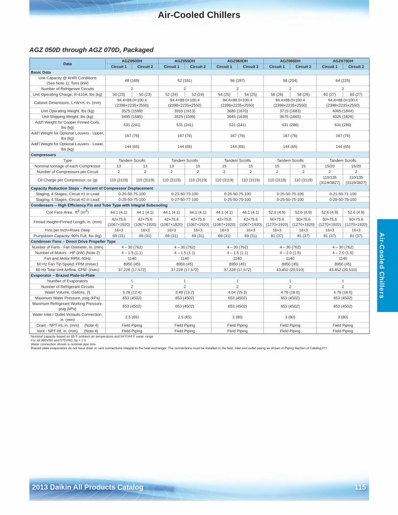
Air-Cooled Chillers
2013 Daikin All Products Catalog 115
Air-C
ooled Chillers
AGZ 050D through AGZ 070D, Packaged
DataAGZ050DH AGZ055DH AGZ060DH AGZ065DH AGZ070DH
Circuit 1 Circuit 2 Circuit 1 Circuit 2 Circuit 1 Circuit 2 Circuit 1 Circuit 2 Circuit 1 Circuit 2Basic Data
Unit Capacity @ AHRI Conditions (See Note 1), Tons (kW)
48 (169) 52 (181) 56 (197) 58 (204) 64 (225)
Number of Refrigerant Circuits 2 2 2 2 2Unit Operating Charge, R-410A, lbs (kg) 50 (23) 50 (23) 52 (24) 52 (24) 54 (25) 54 (25) 58 (26) 58 (26) 60 (27) 60 (27)
Cabinet Dimensions, L×W×H, in . (mm)94 .4×88 .0×100 .4
(2398×2235×2550)94 .4×88 .0×100 .4
(2398×2235×2550)94 .4×88 .0×100 .4
(2398×2235×2550)94 .4×88 .0×100 .4
(2398×2235×2550)94 .4×88 .0×100 .4
(2398×2235×2550)Unit Operating Weight, lbs (kg) 3525 (1599) 3555 (1613) 3680 (1670) 3715 (1683) 4065 (1844)Unit Shipping Weight, lbs (kg) 3495 (1585) 3525 (1599) 3645 (1639) 3675 (1665) 4025 (1826)
Add'l Weight for Copper Finned Coils, lbs (kg)
531 (241) 531 (241) 531 (241) 631 (286) 631 (286)
Add'l Weight for Optional Louvers - Upper, lbs (kg)
167 (76) 167 (76) 167 (76) 167 (76) 167 (76)
Add'l Weight for Optional Louvers - Lower, lbs (kg)
144 (65) 144 (65) 144 (65) 144 (65) 144 (65)
CompressorsType Tandem Scrolls Tandem Scrolls Tandem Scrolls Tandem Scrolls Tandem Scrolls
Nominal tonnage of each Compressor 13 13 13 15 15 15 15 15 15/20 15/20Number of Compressors per Circuit 2 2 2 2 2 2 2 2 2 2
Oil Charge per Compressor, oz (g) 110 (3119) 110 (3119) 110 (3119) 110 (3119) 110 (3119) 110 (3119) 110 (3119) 110 (3119)110/135
(3119/3827)110/135
(3119/3827)Capacity Reduction Steps – Percent of Compressor Displacement
Staging, 4 Stages, Circuit #1 in Lead 0-25-50-75-100 0-23-50-73-100 0-25-50-75-100 0-25-50-75-100 0-21-50-71-100Staging, 4 Stages, Circuit #2 in Lead 0-25-50-75-100 0-27-50-77-100 0-25-50-75-100 0-25-50-75-100 0-28-50-78-100
Condensers – High Efficiency Fin and Tube Type with Integral Subcooling
Coil Face Area, ft2 (m2) 44 .1 (4 .1) 44 .1 (4 .1) 44 .1 (4 .1) 44 .1 (4 .1) 44 .1 (4 .1) 44 .1 (4 .1) 52 .6 (4 .9) 52 .6 (4 .9) 52 .6 (4 .9) 52 .6 (4 .9)
Finned Height×Finned Length, in . (mm)42×75 .6
(1067×1920)42×75 .6
(1067×1920)42×75 .6
(1067×1920)42×75 .6
(1067×1920)42×75 .6
(1067×1920)42×75 .6
(1067×1920)50×75 .6
(1270×1920)50×75 .6
(1270×1920)50×75 .6
(1270×1920)50×75 .6
(1270×1920)Fins per Inch×Rows Deep 16×3 16×3 16×3 16×3 16×3 16×3 16×3 16×3 16×3 16×3
Pumpdown Capacity, 90% Full, lbs (kg) 69 (31) 69 (31) 69 (31) 69 (31) 69 (31) 69 (31) 81 (37) 81 (37) 81 (37) 81 (37)Condenser Fans – Direct Drive Propeller TypeNumber of Fans - Fan Diameter, in . (mm) 4 – 30 (762) 4 – 30 (762) 4 – 30 (762) 4 – 30 (762) 4 – 30 (762)
Number of Motors - HP (kW) (Note 2) 4 – 1 .5 (1 .1) 4 – 1 .5 (1 .1) 4 – 1 .5 (1 .1) 4 – 2 .0 (1 .5) 4 – 2 .0 (1 .5)Fan and Motor RPM, 60Hz 1140 1140 1140 1140 1140
60 Hz Fan Tip Speed, FPM (m/sec) 8950 (45) 8950 (45) 8950 (45) 8950 (45) 8950 (45)60 Hz Total Unit Airflow, CFM (l/sec) 37,228 (17,572) 37,228 (17,572) 37,228 (17,572) 43,452 (20,510) 43,452 (20,510)
Evaporator – Brazed Plate-to-Plate Number of Evaporators 1 1 1 1 1
Number of Refrigerant Circuits 2 2 2 2 2Water Volume, Gallons, (l) 3 .28 (12 .4) 3 .49 (13 .2) 4 .04 (15 .3) 4 .76 (18 .0) 4 .76 (18 .0)
Maximum Water Pressure, psig (kPa) 653 (4502) 653 (4502) 653 (4502) 653 (4502) 653 (4502)Maximum Refrigerant Working Pressure,
psig (kPa)653 (4502) 653 (4502) 653 (4502) 653 (4502) 653 (4502)
Water Inlet / Outlet Victaulic Connection, in . (mm)
2 .5 (65) 2 .5 (65) 3 (80) 3 (80) 3 (80)
Drain - NPT int, in . (mm) (Note 4) Field Piping Field Piping Field Piping Field Piping Field PipingVent - NPT int, in . (mm) (Note 4) Field Piping Field Piping Field Piping Field Piping Field Piping
Nominal capacity based on 95°F ambient air temperature and 54°F/44°F water rangeFor all 380V/60 and 575V/60, hp = 2 .0Water connection shown is nominal pipe sizeBrazed plate evaporators do not have drain or vent connections integral to the heat exchanger. The connections must be installed in the field. Inlet and outlet piping as shown in Piping Section of Catalog 611
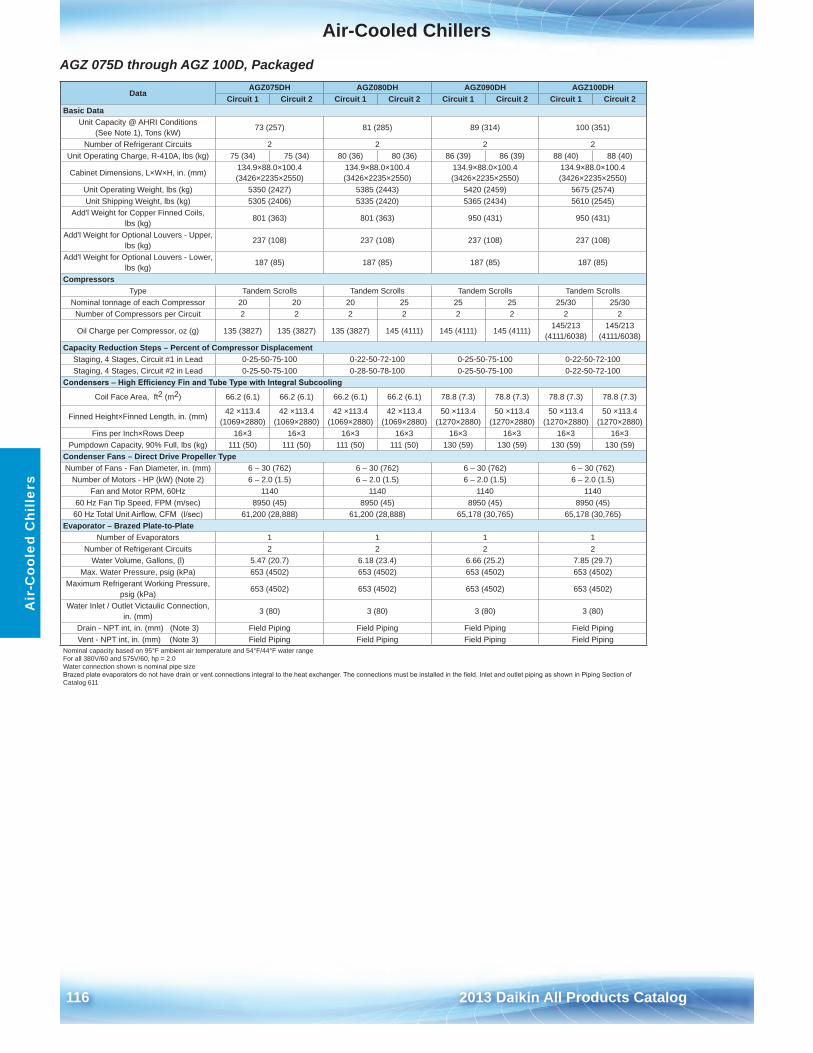
Air-Cooled Chillers
116 2013 Daikin All Products Catalog
Air
-Coo
led
Chi
llers
AGZ 075D through AGZ 100D, Packaged
DataAGZ075DH AGZ080DH AGZ090DH AGZ100DH
Circuit 1 Circuit 2 Circuit 1 Circuit 2 Circuit 1 Circuit 2 Circuit 1 Circuit 2Basic Data
Unit Capacity @ AHRI Conditions (See Note 1), Tons (kW)
73 (257) 81 (285) 89 (314) 100 (351)
Number of Refrigerant Circuits 2 2 2 2Unit Operating Charge, R-410A, lbs (kg) 75 (34) 75 (34) 80 (36) 80 (36) 86 (39) 86 (39) 88 (40) 88 (40)
Cabinet Dimensions, L×W×H, in . (mm)134 .9×88 .0×100 .4 (3426×2235×2550)
134 .9×88 .0×100 .4 (3426×2235×2550)
134 .9×88 .0×100 .4 (3426×2235×2550)
134 .9×88 .0×100 .4 (3426×2235×2550)
Unit Operating Weight, lbs (kg) 5350 (2427) 5385 (2443) 5420 (2459) 5675 (2574)Unit Shipping Weight, lbs (kg) 5305 (2406) 5335 (2420) 5365 (2434) 5610 (2545)
Add'l Weight for Copper Finned Coils, lbs (kg)
801 (363) 801 (363) 950 (431) 950 (431)
Add'l Weight for Optional Louvers - Upper, lbs (kg)
237 (108) 237 (108) 237 (108) 237 (108)
Add'l Weight for Optional Louvers - Lower, lbs (kg)
187 (85) 187 (85) 187 (85) 187 (85)
CompressorsType Tandem Scrolls Tandem Scrolls Tandem Scrolls Tandem Scrolls
Nominal tonnage of each Compressor 20 20 20 25 25 25 25/30 25/30Number of Compressors per Circuit 2 2 2 2 2 2 2 2
Oil Charge per Compressor, oz (g) 135 (3827) 135 (3827) 135 (3827) 145 (4111) 145 (4111) 145 (4111)145/213
(4111/6038)145/213
(4111/6038)Capacity Reduction Steps – Percent of Compressor Displacement
Staging, 4 Stages, Circuit #1 in Lead 0-25-50-75-100 0-22-50-72-100 0-25-50-75-100 0-22-50-72-100Staging, 4 Stages, Circuit #2 in Lead 0-25-50-75-100 0-28-50-78-100 0-25-50-75-100 0-22-50-72-100
Condensers – High Efficiency Fin and Tube Type with Integral Subcooling
Coil Face Area, ft2 (m2) 66 .2 (6 .1) 66 .2 (6 .1) 66 .2 (6 .1) 66 .2 (6 .1) 78 .8 (7 .3) 78 .8 (7 .3) 78 .8 (7 .3) 78 .8 (7 .3)
Finned Height×Finned Length, in . (mm)42 ×113 .4
(1069×2880)42 ×113 .4
(1069×2880)42 ×113 .4
(1069×2880)42 ×113 .4
(1069×2880)50 ×113 .4
(1270×2880)50 ×113 .4
(1270×2880)50 ×113 .4
(1270×2880)50 ×113 .4
(1270×2880)Fins per Inch×Rows Deep 16×3 16×3 16×3 16×3 16×3 16×3 16×3 16×3
Pumpdown Capacity, 90% Full, lbs (kg) 111 (50) 111 (50) 111 (50) 111 (50) 130 (59) 130 (59) 130 (59) 130 (59)Condenser Fans – Direct Drive Propeller TypeNumber of Fans - Fan Diameter, in . (mm) 6 – 30 (762) 6 – 30 (762) 6 – 30 (762) 6 – 30 (762)
Number of Motors - HP (kW) (Note 2) 6 – 2 .0 (1 .5) 6 – 2 .0 (1 .5) 6 – 2 .0 (1 .5) 6 – 2 .0 (1 .5)Fan and Motor RPM, 60Hz 1140 1140 1140 1140
60 Hz Fan Tip Speed, FPM (m/sec) 8950 (45) 8950 (45) 8950 (45) 8950 (45)60 Hz Total Unit Airflow, CFM (l/sec) 61,200 (28,888) 61,200 (28,888) 65,178 (30,765) 65,178 (30,765)
Evaporator – Brazed Plate-to-Plate Number of Evaporators 1 1 1 1
Number of Refrigerant Circuits 2 2 2 2Water Volume, Gallons, (l) 5 .47 (20 .7) 6 .18 (23 .4) 6 .66 (25 .2) 7 .85 (29 .7)
Max . Water Pressure, psig (kPa) 653 (4502) 653 (4502) 653 (4502) 653 (4502)Maximum Refrigerant Working Pressure,
psig (kPa)653 (4502) 653 (4502) 653 (4502) 653 (4502)
Water Inlet / Outlet Victaulic Connection, in . (mm)
3 (80) 3 (80) 3 (80) 3 (80)
Drain - NPT int, in . (mm) (Note 3) Field Piping Field Piping Field Piping Field PipingVent - NPT int, in . (mm) (Note 3) Field Piping Field Piping Field Piping Field Piping
Nominal capacity based on 95°F ambient air temperature and 54°F/44°F water rangeFor all 380V/60 and 575V/60, hp = 2 .0Water connection shown is nominal pipe sizeBrazed plate evaporators do not have drain or vent connections integral to the heat exchanger. The connections must be installed in the field. Inlet and outlet piping as shown in Piping Section ofCatalog 611
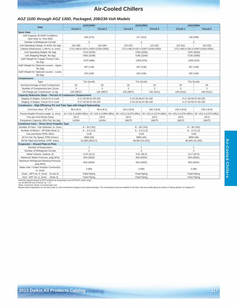
Air-Cooled Chillers
2013 Daikin All Products Catalog 117
Air-C
ooled Chillers
AGZ 110D through AGZ 130D, Packaged, 208/230-Volt Models
DataAGZ110DH AGZ125DH AGZ130DH
Circuit 1 Circuit 2 Circuit 1 Circuit 2 Circuit 1 Circuit 2Basic Data
Unit Capacity @ AHRI Conditions (See Note 1), Tons (kW)
106 (373) 117 (412) 130 (456)
Number of Refrigerant Circuits 2 2 2Unit Operating Charge, R-410A, lbs (kg) 102 (46) 102 (46) 115 (52) 115 (52) 115 (52) 115 (52)Cabinet Dimensions, L×W×H, in . (mm) 173 .1×88 .0×100 .4 (4397×2235×2550) 173 .1×88 .0×100 .4 (4397×2235×2550) 173 .1×88 .0×100 .4 (4397×2235×2550)
Unit Operating Weight, lbs (kg) 7120 (3230) 7265 (3295) 7320 (3320)Unit Shipping Weight, lbs (kg) 7050 (3198) 7185 (3259) 7230 (3280)
Add'l Weight for Copper Finned Coils, lbs (kg)
1070 (486) 1269 (576) 1269 (576)
Add'l Weight for Optional Louvers - Upper, lbs (kg)
307 (139) 307 (139) 307 (139)
Add'l Weight for Optional Louvers - Lower, lbs (kg)
230 (105) 230 (105) 230 (105)
CompressorsType Trio Scrolls Trio Scrolls Trio Scrolls
Nominal tonnage of each Compressor 20 20 20 25 25 25Number of Compressors per Circuit 3 3 3 3 3 3Oil Charge per Compressor, oz (g) 135 (3827) 135 (3827) 135 (3827) 145 (4111) 145 (4111) 145 (4111)
Capacity Reduction Steps – Percent of Compressor DisplacementStaging, 6 Stages, Circuit #1 in Lead 0-17-33-50-67-83-100 0-15-33-48-67-81-100 0-17-33-50-67-83-100Staging, 6 Stages, Circuit #2 in Lead 0-17-33-50-67-83-100 0-19-33-52-67-86-100 0-17-33-50-67-83-100
Condensers – High Efficiency Fin and Tube Type with Integral Subcooling
Coil Face Area, ft2 (m2) 88 .4 (8 .2) 88 .4 (8 .2) 105 .3 (9 .8) 105 .3 (9 .8) 105 .3 (9 .8) 105 .3 (9 .8)
Finned Height×Finned Length, in . (mm) 42 ×151 .6 (1069×3851) 42 ×151 .6 (1069×3851) 50 ×151 .6 (1270×3851) 50 ×151 .6 (1270×3851) 50 ×151 .6 (1270×3851) 50 ×151 .6 (1270×3851)Fins per Inch×Rows Deep 16×3 16×3 16×3 16×3 16×3 16×3
Pumpdown Capacity, 90% Full, lbs (kg) 142/64 142/64 166/75 166/75 166/75 166/75Condenser Fans – Direct Drive Propeller TypeNumber of Fans - Fan Diameter, in . (mm) 8 – 30 (762) 8 – 30 (762) 8 – 30 (762)
Number of Motors - HP (kW) (Note 2) 8 – 2 .0 (1 .5) 8 – 2 .0 (1 .5) 8 – 2 .0 (1 .5)Fan and Motor RPM, 60Hz 1140 1140 1140
60 Hz Fan Tip Speed, FPM (m/sec) 8950 (45) 8950 (45) 8950 (45)60 Hz Total Unit Airflow, CFM (l/sec) 81,600 (38,517) 86,904 (41,020) 86,904 (41,020)
Evaporator – Brazed Plate-to-PlateNumber of Evaporators 1 1 1
Number of Refrigerant Circuits 2 2 2Water Volume, Gallons, (l) 8 .32 (31 .5) 9 .51 (36 .0) 10 .7 (40 .5)
Maximum Water Pressure, psig (kPa) 653 (4502) 653 (4502) 653 (4502)Maximum Refrigerant Working Pressure,
psig (kPa)653 (4502) 653 (4502) 653 (4502)
Water Inlet / Outlet Victaulic Connection, in . (mm)
3 (80) 3 (80) 3 (80)
Drain - NPT int, in . (mm) (N ote 3) Field Piping Field Piping Field PipingVent - NPT int, in . (mm) (Note 3) Field Piping Field Piping Field Piping
Nominal capacity based on 95°F ambient air temperature and 54°F/44°F water rangeFor all 380V/60 and 575V/60, hp = 2 .0Water connection shown is nominal pipe sizeBrazed plate evaporators do not have drain or vent connections integral to the heat exchanger. The connections must be installed in the field. Inlet and outlet piping as shown in Piping Section of Catalog 611
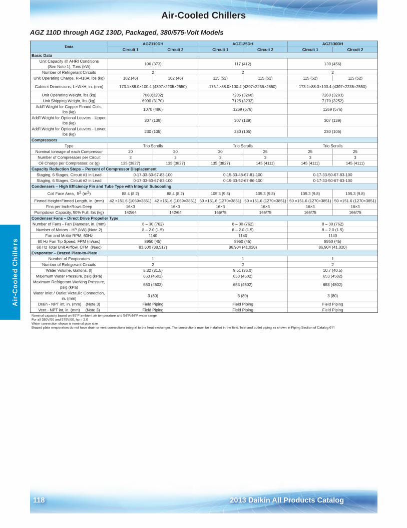
Air-Cooled Chillers
118 2013 Daikin All Products Catalog
Air
-Coo
led
Chi
llers
AGZ 110D through AGZ 130D, Packaged, 380/575-Volt Models
DataAGZ110DH AGZ125DH AGZ130DH
Circuit 1 Circuit 2 Circuit 1 Circuit 2 Circuit 1 Circuit 2Basic Data
Unit Capacity @ AHRI Conditions (See Note 1), Tons (kW)
106 (373) 117 (412) 130 (456)
Number of Refrigerant Circuits 2 2 2Unit Operating Charge, R-410A, lbs (kg) 102 (46) 102 (46) 115 (52) 115 (52) 115 (52) 115 (52)
Cabinet Dimensions, L×W×H, in . (mm) 173 .1×88 .0×100 .4 (4397×2235×2550) 173 .1×88 .0×100 .4 (4397×2235×2550) 173 .1×88 .0×100 .4 (4397×2235×2550)
Unit Operating Weight, lbs (kg) 7060(3202) 7205 (3268) 7260 (3293)Unit Shipping Weight, lbs (kg) 6990 (3170) 7125 (3232) 7170 (3252)
Add'l Weight for Copper Finned Coils, lbs (kg)
1070 (486) 1269 (576) 1269 (576)
Add'l Weight for Optional Louvers - Upper, lbs (kg)
307 (139) 307 (139) 307 (139)
Add'l Weight for Optional Louvers - Lower, lbs (kg)
230 (105) 230 (105) 230 (105)
CompressorsType Trio Scrolls Trio Scrolls Trio Scrolls
Nominal tonnage of each Compressor 20 20 20 25 25 25Number of Compressors per Circuit 3 3 3 3 3 3Oil Charge per Compressor, oz (g) 135 (3827) 135 (3827) 135 (3827) 145 (4111) 145 (4111) 145 (4111)
Capacity Reduction Steps – Percent of Compressor DisplacementStaging, 6 Stages, Circuit #1 in Lead 0-17-33-50-67-83-100 0-15-33-48-67-81-100 0-17-33-50-67-83-100Staging, 6 Stages, Circuit #2 in Lead 0-17-33-50-67-83-100 0-19-33-52-67-86-100 0-17-33-50-67-83-100
Condensers – High Efficiency Fin and Tube Type with Integral Subcooling
Coil Face Area, ft2 (m2) 88 .4 (8 .2) 88 .4 (8 .2) 105 .3 (9 .8) 105 .3 (9 .8) 105 .3 (9 .8) 105 .3 (9 .8)
Finned Height×Finned Length, in . (mm) 42 ×151 .6 (1069×3851) 42 ×151 .6 (1069×3851) 50 ×151 .6 (1270×3851) 50 ×151 .6 (1270×3851) 50 ×151 .6 (1270×3851) 50 ×151 .6 (1270×3851)Fins per Inch×Rows Deep 16×3 16×3 16×3 16×3 16×3 16×3
Pumpdown Capacity, 90% Full, lbs (kg) 142/64 142/64 166/75 166/75 166/75 166/75Condenser Fans – Direct Drive Propeller TypeNumber of Fans - Fan Diameter, in . (mm) 8 – 30 (762) 8 – 30 (762) 8 – 30 (762)
Number of Motors - HP (kW) (Note 2) 8 – 2 .0 (1 .5) 8 – 2 .0 (1 .5) 8 – 2 .0 (1 .5)Fan and Motor RPM, 60Hz 1140 1140 1140
60 Hz Fan Tip Speed, FPM (m/sec) 8950 (45) 8950 (45) 8950 (45)60 Hz Total Unit Airflow, CFM (l/sec) 81,600 (38,517) 86,904 (41,020) 86,904 (41,020)
Evaporator – Brazed Plate-to-PlateNumber of Evaporators 1 1 1
Number of Refrigerant Circuits 2 2 2Water Volume, Gallons, (l) 8 .32 (31 .5) 9 .51 (36 .0) 10 .7 (40 .5)
Maximum Water Pressure, psig (kPa) 653 (4502) 653 (4502) 653 (4502)Maximum Refrigerant Working Pressure,
psig (kPa)653 (4502) 653 (4502) 653 (4502)
Water Inlet / Outlet Victaulic Connection, in . (mm)
3 (80) 3 (80) 3 (80)
Drain - NPT int, in . (mm) (Note 3) Field Piping Field Piping Field PipingVent - NPT int, in . (mm) (Note 3) Field Piping Field Piping Field Piping
Nominal capacity based on 95°F ambient air temperature and 54°F/44°F water rangeFor all 380V/60 and 575V/60, hp = 2 .0Water connection shown is nominal pipe sizeBrazed plate evaporators do not have drain or vent connections integral to the heat exchanger. The connections must be installed in the field. Inlet and outlet piping as shown in Piping Section of Catalog 611
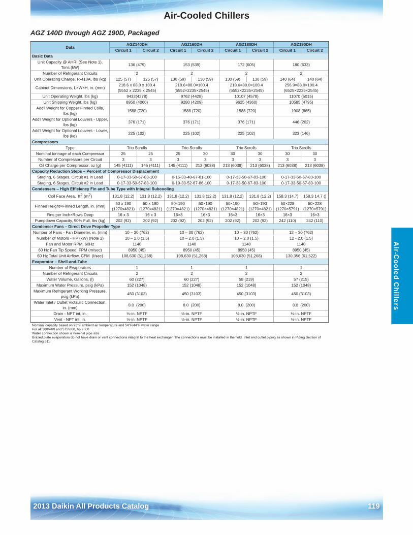
Air-Cooled Chillers
2013 Daikin All Products Catalog 119
Air-C
ooled Chillers
AGZ 140D through AGZ 190D, Packaged
DataAGZ140DH AGZ160DH AGZ180DH AGZ190DH
Circuit 1 Circuit 2 Circuit 1 Circuit 2 Circuit 1 Circuit 2 Circuit 1 Circuit 2Basic Data
Unit Capacity @ AHRI (See Note 1), Tons (kW)
136 (479) 153 (539) 172 (605) 180 (633)
Number of Refrigerant Circuits 2 2 2 2Unit Operating Charge, R-410A, lbs (kg) 125 (57) 125 (57) 130 (59) 130 (59) 130 (59) 130 (59) 140 (64) 140 (64)
Cabinet Dimensions, L×W×H, in . (mm)218 .6 x 88 .0 x 100 .4 (5552 x 2235 x 2545)
218 .6×88 .0×100 .4 (5552×2235×2545)
218 .6×88 .0×100 .4 (5552×2235×2545)
256 .9×88 .0×100 .4 (6525×2235×2545)
Unit Operating Weight, lbs (kg) 9432(4278) 9762 (4428) 10107 (4578) 11070 (5015)Unit Shipping Weight, lbs (kg) 8950 (4060) 9280 (4209) 9625 (4360) 10585 (4795)
Add'l Weight for Copper Finned Coils, lbs (kg)
1588 (720) 1588 (720) 1588 (720) 1908 (865)
Add'l Weight for Optional Louvers - Upper, lbs (kg)
376 (171) 376 (171) 376 (171) 446 (202)
Add'l Weight for Optional Louvers - Lower, lbs (kg)
225 (102) 225 (102) 225 (102) 323 (146)
CompressorsType Trio Scrolls Trio Scrolls Trio Scrolls Trio Scrolls
Nominal tonnage of each Compressor 25 25 25 30 30 30 30 30Number of Compressors per Circuit 3 3 3 3 3 3 3 3Oil Charge per Compressor, oz (g) 145 (4111) 145 (4111) 145 (4111) 213 (6038) 213 (6038) 213 (6038) 213 (6038) 213 (6038)
Capacity Reduction Steps – Percent of Compressor DisplacementStaging, 6 Stages, Circuit #1 in Lead 0-17-33-50-67-83-100 0-15-33-48-67-81-100 0-17-33-50-67-83-100 0-17-33-50-67-83-100Staging, 6 Stages, Circuit #2 in Lead 0-17-33-50-67-83-100 0-19-33-52-67-86-100 0-17-33-50-67-83-100 0-17-33-50-67-83-100
Condensers – High Efficiency Fin and Tube Type with Integral Subcooling
Coil Face Area, ft2 (m2) 131 .8 (12 .2) 131 .8 (12 .2) 131 .8 (12 .2) 131 .8 (12 .2) 131 .8 (12 .2) 131 .8 (12 .2) 158 .3 (14 .7) 158 .3 14 .7 ()
Finned Height×Finned Length, in . (mm)50 x 190
(1270x4821)50 x 190
(1270x4821)50×190
(1270×4821)50×190
(1270×4821)50×190
(1270×4821)50×190
(1270×4821)50×228
(1270×5791)50×228
(1270×5791)Fins per Inch×Rows Deep 16 x 3 16 x 3 16×3 16×3 16×3 16×3 16×3 16×3
Pumpdown Capacity, 90% Full, lbs (kg) 202 (92) 202 (92) 202 (92) 202 (92) 202 (92) 202 (92) 242 (110) 242 (110)Condenser Fans – Direct Drive Propeller TypeNumber of Fans - Fan Diameter, in . (mm) 10 – 30 (762) 10 – 30 (762) 10 – 30 (762) 12 – 30 (762)
Number of Motors - HP (kW) (Note 2) 10 – 2 .0 (1 .5) 10 – 2 .0 (1 .5) 10 – 2 .0 (1 .5) 12 - 2 .0 (1 .5)Fan and Motor RPM, 60Hz 1140 1140 1140 1140
60 Hz Fan Tip Speed, FPM (m/sec) 8950 (45) 8950 (45) 8950 (45) 8950 (45)60 Hz Total Unit Airflow, CFM (l/sec) 108,630 (51,268) 108,630 (51,268) 108,630 (51,268) 130,356 (61,522)
Evaporator – Shell-and-Tube Number of Evaporators 1 1 1 1
Number of Refrigerant Circuits 2 2 2 2Water Volume, Gallons, (l) 60 (227) 60 (227) 58 (219) 57 (215)
Maximum Water Pressure, psig (kPa) 152 (1048) 152 (1048) 152 (1048) 152 (1048)Maximum Refrigerant Working Pressure,
psig (kPa)450 (3103) 450 (3103) 450 (3103) 450 (3103)
Water Inlet / Outlet Victaulic Connection, in . (mm)
8 .0 (200) 8 .0 (200) 8 .0 (200) 8 .0 (200)
Drain - NPT int, in . ½-in . NPTF ½-in . NPTF ½-in . NPTF ½-in . NPTFVent - NPT int, in . ½-in . NPTF ½-in . NPTF ½-in . NPTF ½-in . NPTF
Nominal capacity based on 95°F ambient air temperature and 54°F/44°F water rangeFor all 380V/60 and 575V/60, hp = 2 .0Water connection shown is nominal pipe sizeBrazed plate evaporators do not have drain or vent connections integral to the heat exchanger. The connections must be installed in the field. Inlet and outlet piping as shown in Piping Section of Catalog 611
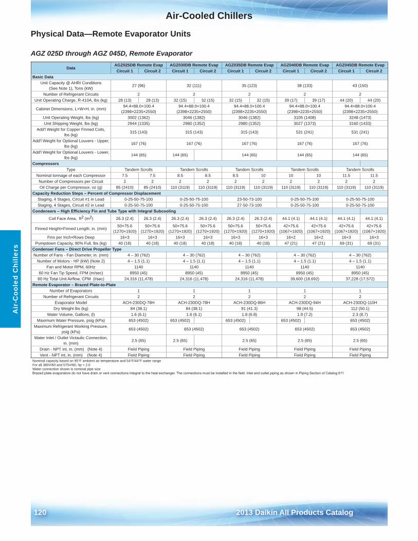
Air-Cooled Chillers
120 2013 Daikin All Products Catalog
Air
-Coo
led
Chi
llers
Physical Data—Remote Evaporator Units
AGZ 025D through AGZ 045D, Remote Evaporator
DataAGZ025DB Remote Evap AGZ030DB Remote Evap AGZ035DB Remote Evap AGZ040DB Remote Evap AGZ045DB Remote EvapCircuit 1 Circuit 2 Circuit 1 Circuit 2 Circuit 1 Circuit 2 Circuit 1 Circuit 2 Circuit 1 Circuit 2
Basic DataUnit Capacity @ AHRI Conditions
(See Note 1), Tons (kW)27 (96) 32 (111) 35 (123) 38 (133) 43 (150)
Number of Refrigerant Circuits 2 2 2 2 2Unit Operating Charge, R-410A, lbs (kg) 28 (13) 28 (13) 32 (15) 32 (15) 32 (15) 32 (15) 39 (17) 39 (17) 44 (20) 44 (20)
Cabinet Dimensions, L×W×H, in . (mm)94 .4×88 .0×100 .4
(2398×2235×2550)94 .4×88 .0×100 .4
(2398×2235×2550)94 .4×88 .0×100 .4
(2398×2235×2550)94 .4×88 .0×100 .4
(2398×2235×2550)94 .4×88 .0×100 .4
(2398×2235×2550)Unit Operating Weight, lbs (kg) 3002 (1362) 3046 (1382) 3046 (1382) 3105 (1408) 3248 (1473)Unit Shipping Weight, lbs (kg) 2944 (1335) 2980 (1352) 2980 (1352) 3027 (1373) 3160 (1433)
Add'l Weight for Copper Finned Coils, lbs (kg)
315 (143) 315 (143) 315 (143) 531 (241) 531 (241)
Add'l Weight for Optional Louvers - Upper, lbs (kg)
167 (76) 167 (76) 167 (76) 167 (76) 167 (76)
Add'l Weight for Optional Louvers - Lower, lbs (kg)
144 (65) 144 (65) 144 (65) 144 (65) 144 (65)
CompressorsType Tandem Scrolls Tandem Scrolls Tandem Scrolls Tandem Scrolls Tandem Scrolls
Nominal tonnage of each Compressor 7 .5 7 .5 8 .5 8 .5 8 .5 10 10 10 11 .5 11 .5Number of Compressors per Circuit 2 2 2 2 2 2 2 2 2 2Oil Charge per Compressor, oz (g) 85 (2410) 85 (2410) 110 (3119) 110 (3119) 110 (3119) 110 (3119) 110 (3119) 110 (3119) 110 (3119) 110 (3119)
Capacity Reduction Steps – Percent of Compressor DisplacementStaging, 4 Stages, Circuit #1 in Lead 0-25-50-75-100 0-25-50-75-100 23-50-73-100 0-25-50-75-100 0-25-50-75-100Staging, 4 Stages, Circuit #2 in Lead 0-25-50-75-100 0-25-50-75-100 27-50-73-100 0-25-50-75-100 0-25-50-75-100
Condensers – High Efficiency Fin and Tube Type with Integral Subcooling
Coil Face Area, ft2 (m2) 26 .3 (2 .4) 26 .3 (2 .4) 26 .3 (2 .4) 26 .3 (2 .4) 26 .3 (2 .4) 26 .3 (2 .4) 44 .1 (4 .1) 44 .1 (4 .1) 44 .1 (4 .1) 44 .1 (4 .1)
Finned Height×Finned Length, in . (mm)50×75 .6
(1270×1920)50×75 .6
(1270×1920)50×75 .6
(1270×1920)50×75 .6
(1270×1920)50×75 .6
(1270×1920)50×75 .6
(1270×1920)42×75 .6
(1067×1920)42×75 .6
(1067×1920)42×75 .6
(1067×1920)42×75 .6
(1067×1920)Fins per Inch×Rows Deep 16×3 16×3 16×3 16×3 16×3 16×3 16×2 16×2 16×3 16×3
Pumpdown Capacity, 90% Full, lbs (kg) 40 (18) 40 (18) 40 (18) 40 (18) 40 (18) 40 (18) 47 (21) 47 (21) 69 (31) 69 (31)Condenser Fans – Direct Drive Propeller TypeNumber of Fans - Fan Diameter, in . (mm) 4 – 30 (762) 4 – 30 (762) 4 – 30 (762) 4 – 30 (762) 4 – 30 (762)
Number of Motors - HP (kW) (Note 2) 4 – 1 .5 (1 .1) 4 – 1 .5 (1 .1) 4 – 1 .5 (1 .1) 4 – 1 .5 (1 .1) 4 – 1 .5 (1 .1)Fan and Motor RPM, 60Hz 1140 1140 1140 1140 1140
60 Hz Fan Tip Speed, FPM (m/sec) 8950 (45) 8950 (45) 8950 (45) 8950 (45) 8950 (45)60 Hz Total Unit Airflow, CFM (l/sec) 24,316 (11,478) 24,316 (11,478) 24,316 (11,478) 39,600 (18,692) 37,228 (17,572)
Remote Evaporator – Brazed Plate-to-Plate Number of Evaporators 1 1 1 1 1
Number of Refrigerant Circuits 2 2 2 2 2Evaporator Model ACH-230DQ-78H ACH-230DQ-78H ACH-230DQ-86H ACH-230DQ-94H ACH-230DQ-110H
Dry Weight lbs (kg) 84 (38 .1) 84 (38 .1) 91 (41 .3) 98 (44 .5) 112 (50 .1)Water Volume, Gallons, (l) 1 .6 (6 .1) 1 .6 (6 .1) 1 .8 (6 .8) 1 .9 (7 .2) 2 .3 (8 .7)
Maximum Water Pressure, psig (kPa) 653 (4502) 653 (4502) 653 (4502) 653 (4502) 653 (4502)Maximum Refrigerant Working Pressure,
psig (kPa)653 (4502) 653 (4502) 653 (4502) 653 (4502) 653 (4502)
Water Inlet / Outlet Victaulic Connection, in . (mm)
2 .5 (65) 2 .5 (65) 2 .5 (65) 2 .5 (65) 2 .5 (65)
Drain - NPT int, in . (mm) (Note 4) Field Piping Field Piping Field Piping Field Piping Field PipingVent - NPT int, in . (mm) (Note 4) Field Piping Field Piping Field Piping Field Piping Field Piping
Nominal capacity based on 95°F ambient air temperature and 54°F/44°F water rangeFor all 380V/60 and 575V/60, hp = 2 .0Water connection shown is nominal pipe sizeBrazed plate evaporators do not have drain or vent connections integral to the heat exchanger. The connections must be installed in the field. Inlet and outlet piping as shown in Piping Section of Catalog 611
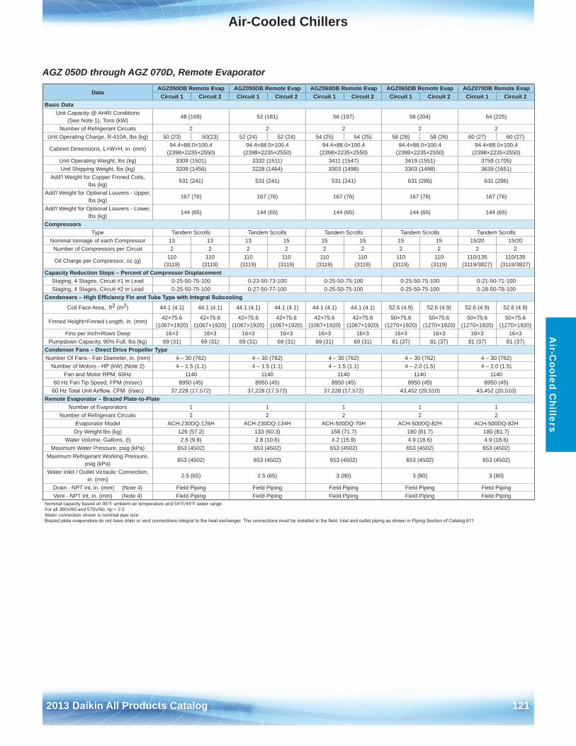
Air-Cooled Chillers
2013 Daikin All Products Catalog 121
Air-C
ooled Chillers
AGZ 050D through AGZ 070D, Remote Evaporator
DataAGZ050DB Remote Evap AGZ055DB Remote Evap AGZ060DB Remote Evap AGZ065DB Remote Evap AGZ070DB Remote EvapCircuit 1 Circuit 2 Circuit 1 Circuit 2 Circuit 1 Circuit 2 Circuit 1 Circuit 2 Circuit 1 Circuit 2
Basic DataUnit Capacity @ AHRI Conditions
(See Note 1), Tons (kW)48 (169) 52 (181) 56 (197) 58 (204) 64 (225)
Number of Refrigerant Circuits 2 2 2 2 2Unit Operating Charge, R-410A, lbs (kg) 50 (23) 50(23) 52 (24) 52 (24) 54 (25) 54 (25) 58 (26) 58 (26) 60 (27) 60 (27)
Cabinet Dimensions, L×W×H, in . (mm)94 .4×88 .0×100 .4
(2398×2235×2550)94 .4×88 .0×100 .4
(2398×2235×2550)94 .4×88 .0×100 .4
(2398×2235×2550)94 .4×88 .0×100 .4
(2398×2235×2550)94 .4×88 .0×100 .4
(2398×2235×2550)Unit Operating Weight, lbs (kg) 3309 (1501) 3332 (1511) 3411 (1547) 3419 (1551) 3759 (1705)Unit Shipping Weight, lbs (kg) 3209 (1456) 3228 (1464) 3303 (1498) 3303 (1498) 3639 (1651)
Add'l Weight for Copper Finned Coils, lbs (kg)
531 (241) 531 (241) 531 (241) 631 (286) 631 (286)
Add'l Weight for Optional Louvers - Upper, lbs (kg)
167 (76) 167 (76) 167 (76) 167 (76) 167 (76)
Add'l Weight for Optional Louvers - Lower, lbs (kg)
144 (65) 144 (65) 144 (65) 144 (65) 144 (65)
CompressorsType Tandem Scrolls Tandem Scrolls Tandem Scrolls Tandem Scrolls Tandem Scrolls
Nominal tonnage of each Compressor 13 13 13 15 15 15 15 15 15/20 15/20Number of Compressors per Circuit 2 2 2 2 2 2 2 2 2 2
Oil Charge per Compressor, oz (g)110
(3119)110
(3119)110
(3119)110
(3119)110
(3119)110
(3119)110
(3119)110
(3119)110/135
(3119/3827)110/135
(3119/3827)Capacity Reduction Steps – Percent of Compressor Displacement
Staging, 4 Stages, Circuit #1 in Lead 0-25-50-75-100 0-23-50-73-100 0-25-50-75-100 0-25-50-75-100 0-21-50-71-100Staging, 4 Stages, Circuit #2 in Lead 0-25-50-75-100 0-27-50-77-100 0-25-50-75-100 0-25-50-75-100 0-28-50-78-100
Condensers – High Efficiency Fin and Tube Type with Integral Subcooling
Coil Face Area, ft2 (m2) 44 .1 (4 .1) 44 .1 (4 .1) 44 .1 (4 .1) 44 .1 (4 .1) 44 .1 (4 .1) 44 .1 (4 .1) 52 .6 (4 .9) 52 .6 (4 .9) 52 .6 (4 .9) 52 .6 (4 .9)
Finned Height×Finned Length, in . (mm)42×75 .6
(1067×1920)42×75 .6
(1067×1920)42×75 .6
(1067×1920)42×75 .6
(1067×1920)42×75 .6
(1067×1920)42×75 .6
(1067×1920)50×75 .6
(1270×1920)50×75 .6
(1270×1920)50×75 .6
(1270×1920)50×75 .6
(1270×1920)Fins per Inch×Rows Deep 16×3 16×3 16×3 16×3 16×3 16×3 16×3 16×3 16×3 16×3
Pumpdown Capacity, 90% Full, lbs (kg) 69 (31) 69 (31) 69 (31) 69 (31) 69 (31) 69 (31) 81 (37) 81 (37) 81 (37) 81 (37)Condenser Fans – Direct Drive Propeller TypeNumber Of Fans - Fan Diameter, in . (mm) 4 – 30 (762) 4 – 30 (762) 4 – 30 (762) 4 – 30 (762) 4 – 30 (762)
Number of Motors - HP (kW) (Note 2) 4 – 1 .5 (1 .1) 4 – 1 .5 (1 .1) 4 – 1 .5 (1 .1) 4 – 2 .0 (1 .5) 4 – 2 .0 (1 .5)Fan and Motor RPM, 60Hz 1140 1140 1140 1140 1140
60 Hz Fan Tip Speed, FPM (m/sec) 8950 (45) 8950 (45) 8950 (45) 8950 (45) 8950 (45)60 Hz Total Unit Airflow, CFM (l/sec) 37,228 (17,572) 37,228 (17,572) 37,228 (17,572) 43,452 (20,510) 43,452 (20,510)
Remote Evaporator – Brazed Plate-to-Plate Number of Evaporators 1 1 1 1 1
Number of Refrigerant Circuits 2 2 2 2 2Evaporator Model ACH-230DQ-126H ACH-230DQ-134H ACH-500DQ-70H ACH-500DQ-82H ACH-500DQ-82H
Dry Weight lbs (kg) 126 (57 .2) 133 (60 .3) 158 (71 .7) 180 (81 .7) 180 (81 .7)Water Volume, Gallons, (l) 2 .6 (9 .8) 2 .8 (10 .6) 4 .2 (15 .9) 4 .9 (18 .6) 4 .9 (18 .6)
Maximum Water Pressure, psig (kPa) 653 (4502) 653 (4502) 653 (4502) 653 (4502) 653 (4502)Maximum Refrigerant Working Pressure,
psig (kPa)653 (4502) 653 (4502) 653 (4502) 653 (4502) 653 (4502)
Water Inlet / Outlet Victaulic Connection, in . (mm)
2 .5 (65) 2 .5 (65) 3 (80) 3 (80) 3 (80)
Drain - NPT int, in . (mm) (Note 4) Field Piping Field Piping Field Piping Field Piping Field PipingVent - NPT int, in . (mm) (Note 4) Field Piping Field Piping Field Piping Field Piping Field Piping
Nominal capacity based on 95°F ambient air temperature and 54°F/44°F water rangeFor all 380V/60 and 575V/60, hp = 2 .0Water connection shown is nominal pipe sizeBrazed plate evaporators do not have drain or vent connections integral to the heat exchanger. The connections must be installed in the field. Inlet and outlet piping as shown in Piping Section of Catalog 611
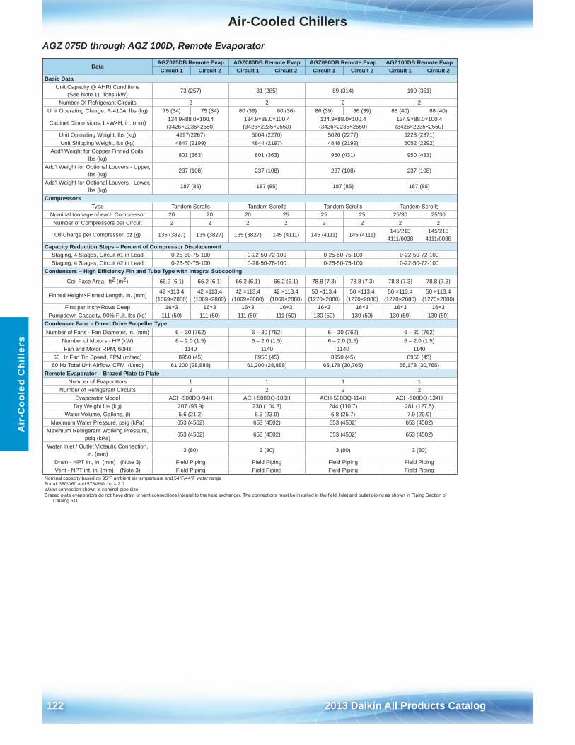
Air-Cooled Chillers
122 2013 Daikin All Products Catalog
Air
-Coo
led
Chi
llers
AGZ 075D through AGZ 100D, Remote Evaporator
DataAGZ075DB Remote Evap AGZ080DB Remote Evap AGZ090DB Remote Evap AGZ100DB Remote EvapCircuit 1 Circuit 2 Circuit 1 Circuit 2 Circuit 1 Circuit 2 Circuit 1 Circuit 2
Basic DataUnit Capacity @ AHRI Conditions
(See Note 1), Tons (kW)73 (257) 81 (285) 89 (314) 100 (351)
Number Of Refrigerant Circuits 2 2 2 2Unit Operating Charge, R-410A, lbs (kg) 75 (34) 75 (34) 80 (36) 80 (36) 86 (39) 86 (39) 88 (40) 88 (40)
Cabinet Dimensions, L×W×H, in . (mm) 134 .9×88 .0×100 .4 (3426×2235×2550)
134 .9×88 .0×100 .4 (3426×2235×2550)
134 .9×88 .0×100 .4 (3426×2235×2550)
134 .9×88 .0×100 .4 (3426×2235×2550)
Unit Operating Weight, lbs (kg) 4997(2267) 5004 (2270) 5020 (2277) 5228 (2371)Unit Shipping Weight, lbs (kg) 4847 (2199) 4844 (2197) 4848 (2199) 5052 (2292)
Add'l Weight for Copper Finned Coils, lbs (kg)
801 (363) 801 (363) 950 (431) 950 (431)
Add'l Weight for Optional Louvers - Upper, lbs (kg)
237 (108) 237 (108) 237 (108) 237 (108)
Add'l Weight for Optional Louvers - Lower, lbs (kg)
187 (85) 187 (85) 187 (85) 187 (85)
CompressorsType Tandem Scrolls Tandem Scrolls Tandem Scrolls Tandem Scrolls
Nominal tonnage of each Compressor 20 20 20 25 25 25 25/30 25/30Number of Compressors per Circuit 2 2 2 2 2 2 2 2
Oil Charge per Compressor, oz (g) 135 (3827) 135 (3827) 135 (3827) 145 (4111) 145 (4111) 145 (4111)145/213
4111/6038145/213
4111/6038Capacity Reduction Steps – Percent of Compressor Displacement
Staging, 4 Stages, Circuit #1 in Lead 0-25-50-75-100 0-22-50-72-100 0-25-50-75-100 0-22-50-72-100Staging, 4 Stages, Circuit #2 in Lead 0-25-50-75-100 0-28-50-78-100 0-25-50-75-100 0-22-50-72-100
Condensers – High Efficiency Fin and Tube Type with Integral Subcooling
Coil Face Area, ft2 (m2) 66 .2 (6 .1) 66 .2 (6 .1) 66 .2 (6 .1) 66 .2 (6 .1) 78 .8 (7 .3) 78 .8 (7 .3) 78 .8 (7 .3) 78 .8 (7 .3)
Finned Height×Finned Length, in . (mm)42 ×113 .4
(1069×2880)42 ×113 .4
(1069×2880)42 ×113 .4
(1069×2880)42 ×113 .4
(1069×2880)50 ×113 .4
(1270×2880)50 ×113 .4
(1270×2880)50 ×113 .4
(1270×2880)50 ×113 .4
(1270×2880)Fins per Inch×Rows Deep 16×3 16×3 16×3 16×3 16×3 16×3 16×3 16×3
Pumpdown Capacity, 90% Full, lbs (kg) 111 (50) 111 (50) 111 (50) 111 (50) 130 (59) 130 (59) 130 (59) 130 (59)Condenser Fans – Direct Drive Propeller TypeNumber of Fans - Fan Diameter, in . (mm) 6 – 30 (762) 6 – 30 (762) 6 – 30 (762) 6 – 30 (762)
Number of Motors - HP (kW) 6 – 2 .0 (1 .5) 6 – 2 .0 (1 .5) 6 – 2 .0 (1 .5) 6 – 2 .0 (1 .5)Fan and Motor RPM, 60Hz 1140 1140 1140 1140
60 Hz Fan Tip Speed, FPM (m/sec) 8950 (45) 8950 (45) 8950 (45) 8950 (45)60 Hz Total Unit Airflow, CFM (l/sec) 61,200 (28,888) 61,200 (28,888) 65,178 (30,765) 65,178 (30,765)
Remote Evaporator – Brazed Plate-to-Plate Number of Evaporators 1 1 1 1
Number of Refrigerant Circuits 2 2 2 2Evaporator Model ACH-500DQ-94H ACH-500DQ-106H ACH-500DQ-114H ACH-500DQ-134H
Dry Weight lbs (kg) 207 (93 .9) 230 (104 .3) 244 (110 .7) 281 (127 .5)Water Volume, Gallons, (l) 5 .6 (21 .2) 6 .3 (23 .9) 6 .8 (25 .7) 7 .9 (29 .9)
Maximum Water Pressure, psig (kPa) 653 (4502) 653 (4502) 653 (4502) 653 (4502)Maximum Refrigerant Working Pressure,
psig (kPa)653 (4502) 653 (4502) 653 (4502) 653 (4502)
Water Inlet / Outlet Victaulic Connection, in . (mm)
3 (80) 3 (80) 3 (80) 3 (80)
Drain - NPT int, in . (mm) (Note 3) Field Piping Field Piping Field Piping Field PipingVent - NPT int, in . (mm) (Note 3) Field Piping Field Piping Field Piping Field Piping
Nominal capacity based on 95°F ambient air temperature and 54°F/44°F water rangeFor all 380V/60 and 575V/60, hp = 2 .0Water connection shown is nominal pipe sizeBrazed plate evaporators do not have drain or vent connections integral to the heat exchanger. The connections must be installed in the field. Inlet and outlet piping as shown in Piping Section of
Catalog 611
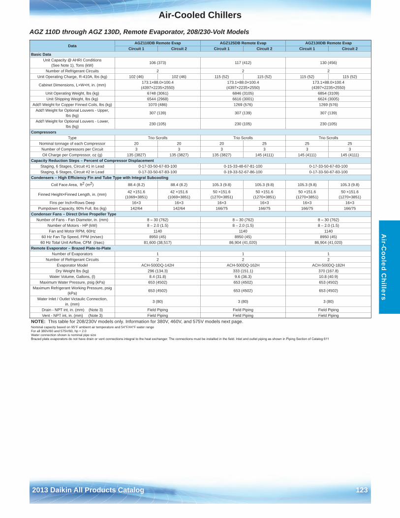
Air-Cooled Chillers
2013 Daikin All Products Catalog 123
Air-C
ooled Chillers
AGZ 110D through AGZ 130D, Remote Evaporator, 208/230-Volt Models
DataAGZ110DB Remote Evap AGZ125DB Remote Evap AGZ130DB Remote Evap
Circuit 1 Circuit 2 Circuit 1 Circuit 2 Circuit 1 Circuit 2Basic Data
Unit Capacity @ AHRI Conditions (See Note 1), Tons (kW)
106 (373) 117 (412) 130 (456)
Number of Refrigerant Circuits 2 2 2Unit Operating Charge, R-410A, lbs (kg) 102 (46) 102 (46) 115 (52) 115 (52) 115 (52) 115 (52)
Cabinet Dimensions, L×W×H, in . (mm)173 .1×88 .0×100 .4 (4397×2235×2550)
173 .1×88 .0×100 .4 (4397×2235×2550)
173 .1×88 .0×100 .4 (4397×2235×2550)
Unit Operating Weight, lbs (kg) 6748 (3061) 6846 (3105) 6854 (3109)Unit Shipping Weight, lbs (kg) 6544 (2968) 6616 (3001) 6624 (3005)
Add'l Weight for Copper Finned Coils, lbs (kg) 1070 (486) 1269 (576) 1269 (576)Add'l Weight for Optional Louvers - Upper,
lbs (kg)307 (139) 307 (139) 307 (139)
Add'l Weight for Optional Louvers - Lower, lbs (kg)
230 (105) 230 (105) 230 (105)
CompressorsType Trio Scrolls Trio Scrolls Trio Scrolls
Nominal tonnage of each Compressor 20 20 20 25 25 25Number of Compressors per Circuit 3 3 3 3 3 3Oil Charge per Compressor, oz (g) 135 (3827) 135 (3827) 135 (3827) 145 (4111) 145 (4111) 145 (4111)
Capacity Reduction Steps – Percent of Compressor DisplacementStaging, 6 Stages, Circuit #1 in Lead 0-17-33-50-67-83-100 0-15-33-48-67-81-100 0-17-33-50-67-83-100Staging, 6 Stages, Circuit #2 in Lead 0-17-33-50-67-83-100 0-19-33-52-67-86-100 0-17-33-50-67-83-100
Condensers – High Efficiency Fin and Tube Type with Integral Subcooling
Coil Face Area, ft2 (m2) 88 .4 (8 .2) 88 .4 (8 .2) 105 .3 (9 .8) 105 .3 (9 .8) 105 .3 (9 .8) 105 .3 (9 .8)
Finned Height×Finned Length, in . (mm)42 ×151 .6
(1069×3851)42 ×151 .6
(1069×3851)50 ×151 .6
(1270×3851)50 ×151 .6
(1270×3851)50 ×151 .6
(1270×3851)50 ×151 .6
(1270×3851)Fins per Inch×Rows Deep 16×3 16×3 16×3 16×3 16×3 16×3
Pumpdown Capacity, 90% Full, lbs (kg) 142/64 142/64 166/75 166/75 166/75 166/75Condenser Fans – Direct Drive Propeller Type
Number of Fans - Fan Diameter, in . (mm) 8 – 30 (762) 8 – 30 (762) 8 – 30 (762)Number of Motors - HP (kW) 8 – 2 .0 (1 .5) 8 – 2 .0 (1 .5) 8 – 2 .0 (1 .5)Fan and Motor RPM, 60Hz 1140 1140 1140
60 Hz Fan Tip Speed, FPM (m/sec) 8950 (45) 8950 (45) 8950 (45)60 Hz Total Unit Airflow, CFM (l/sec) 81,600 (38,517) 86,904 (41,020) 86,904 (41,020)
Remote Evaporator – Brazed Plate-to-Plate Number of Evaporators 1 1 1
Number of Refrigerant Circuits 2 2 2Evaporator Model ACH-500DQ-142H ACH-500DQ-162H ACH-500DQ-182H
Dry Weight lbs (kg) 296 (134 .3) 333 (151 .1) 370 (167 .8)Water Volume, Gallons, (l) 8 .4 (31 .8) 9 .6 (36 .3) 10 .8 (40 .9)
Maximum Water Pressure, psig (kPa) 653 (4502) 653 (4502) 653 (4502)Maximum Refrigerant Working Pressure, psig
(kPa)653 (4502) 653 (4502) 653 (4502)
Water Inlet / Outlet Victaulic Connection, in . (mm)
3 (80) 3 (80) 3 (80)
Drain - NPT int, in . (mm) (Note 3) Field Piping Field Piping Field PipingVent - NPT int, in . (mm) (Note 3) Field Piping Field Piping Field Piping
NOTE: This table for 208/230V models only . Information for 380V, 460V, and 575V models next page .Nominal capacity based on 95°F ambient air temperature and 54°F/44°F water rangeFor all 380V/60 and 575V/60, hp = 2 .0Water connection shown is nominal pipe sizeBrazed plate evaporators do not have drain or vent connections integral to the heat exchanger. The connections must be installed in the field. Inlet and outlet piping as shown in Piping Section of Catalog 611
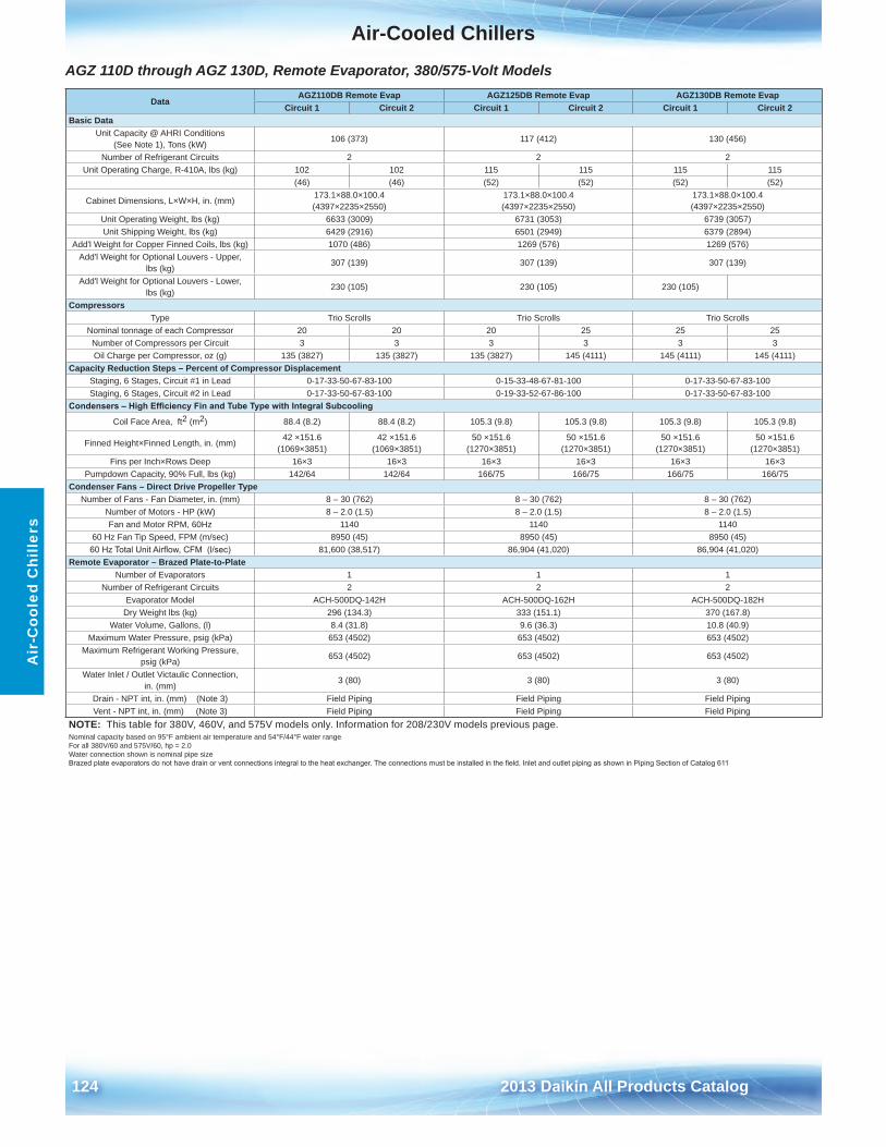
Air-Cooled Chillers
124 2013 Daikin All Products Catalog
Air
-Coo
led
Chi
llers
AGZ 110D through AGZ 130D, Remote Evaporator, 380/575-Volt Models
DataAGZ110DB Remote Evap AGZ125DB Remote Evap AGZ130DB Remote Evap
Circuit 1 Circuit 2 Circuit 1 Circuit 2 Circuit 1 Circuit 2Basic Data
Unit Capacity @ AHRI Conditions (See Note 1), Tons (kW)
106 (373) 117 (412) 130 (456)
Number of Refrigerant Circuits 2 2 2Unit Operating Charge, R-410A, lbs (kg) 102 102 115 115 115 115
(46) (46) (52) (52) (52) (52)
Cabinet Dimensions, L×W×H, in . (mm)173 .1×88 .0×100 .4 (4397×2235×2550)
173 .1×88 .0×100 .4 (4397×2235×2550)
173 .1×88 .0×100 .4 (4397×2235×2550)
Unit Operating Weight, lbs (kg) 6633 (3009) 6731 (3053) 6739 (3057)Unit Shipping Weight, lbs (kg) 6429 (2916) 6501 (2949) 6379 (2894)
Add'l Weight for Copper Finned Coils, lbs (kg) 1070 (486) 1269 (576) 1269 (576)Add'l Weight for Optional Louvers - Upper,
lbs (kg)307 (139) 307 (139) 307 (139)
Add'l Weight for Optional Louvers - Lower, lbs (kg)
230 (105) 230 (105) 230 (105)
CompressorsType Trio Scrolls Trio Scrolls Trio Scrolls
Nominal tonnage of each Compressor 20 20 20 25 25 25Number of Compressors per Circuit 3 3 3 3 3 3Oil Charge per Compressor, oz (g) 135 (3827) 135 (3827) 135 (3827) 145 (4111) 145 (4111) 145 (4111)
Capacity Reduction Steps – Percent of Compressor DisplacementStaging, 6 Stages, Circuit #1 in Lead 0-17-33-50-67-83-100 0-15-33-48-67-81-100 0-17-33-50-67-83-100Staging, 6 Stages, Circuit #2 in Lead 0-17-33-50-67-83-100 0-19-33-52-67-86-100 0-17-33-50-67-83-100
Condensers – High Efficiency Fin and Tube Type with Integral Subcooling
Coil Face Area, ft2 (m2) 88 .4 (8 .2) 88 .4 (8 .2) 105 .3 (9 .8) 105 .3 (9 .8) 105 .3 (9 .8) 105 .3 (9 .8)
Finned Height×Finned Length, in . (mm)42 ×151 .6
(1069×3851)42 ×151 .6
(1069×3851)50 ×151 .6
(1270×3851)50 ×151 .6
(1270×3851)50 ×151 .6
(1270×3851)50 ×151 .6
(1270×3851)Fins per Inch×Rows Deep 16×3 16×3 16×3 16×3 16×3 16×3
Pumpdown Capacity, 90% Full, lbs (kg) 142/64 142/64 166/75 166/75 166/75 166/75Condenser Fans – Direct Drive Propeller Type
Number of Fans - Fan Diameter, in . (mm) 8 – 30 (762) 8 – 30 (762) 8 – 30 (762)Number of Motors - HP (kW) 8 – 2 .0 (1 .5) 8 – 2 .0 (1 .5) 8 – 2 .0 (1 .5)Fan and Motor RPM, 60Hz 1140 1140 1140
60 Hz Fan Tip Speed, FPM (m/sec) 8950 (45) 8950 (45) 8950 (45)60 Hz Total Unit Airflow, CFM (l/sec) 81,600 (38,517) 86,904 (41,020) 86,904 (41,020)
Remote Evaporator – Brazed Plate-to-Plate Number of Evaporators 1 1 1
Number of Refrigerant Circuits 2 2 2Evaporator Model ACH-500DQ-142H ACH-500DQ-162H ACH-500DQ-182H
Dry Weight lbs (kg) 296 (134 .3) 333 (151 .1) 370 (167 .8)Water Volume, Gallons, (l) 8 .4 (31 .8) 9 .6 (36 .3) 10 .8 (40 .9)
Maximum Water Pressure, psig (kPa) 653 (4502) 653 (4502) 653 (4502)Maximum Refrigerant Working Pressure,
psig (kPa)653 (4502) 653 (4502) 653 (4502)
Water Inlet / Outlet Victaulic Connection, in . (mm)
3 (80) 3 (80) 3 (80)
Drain - NPT int, in . (mm) (Note 3) Field Piping Field Piping Field PipingVent - NPT int, in . (mm) (Note 3) Field Piping Field Piping Field Piping
NOTE: This table for 380V, 460V, and 575V models only . Information for 208/230V models previous page .Nominal capacity based on 95°F ambient air temperature and 54°F/44°F water rangeFor all 380V/60 and 575V/60, hp = 2 .0Water connection shown is nominal pipe sizeBrazed plate evaporators do not have drain or vent connections integral to the heat exchanger. The connections must be installed in the field. Inlet and outlet piping as shown in Piping Section of Catalog 611
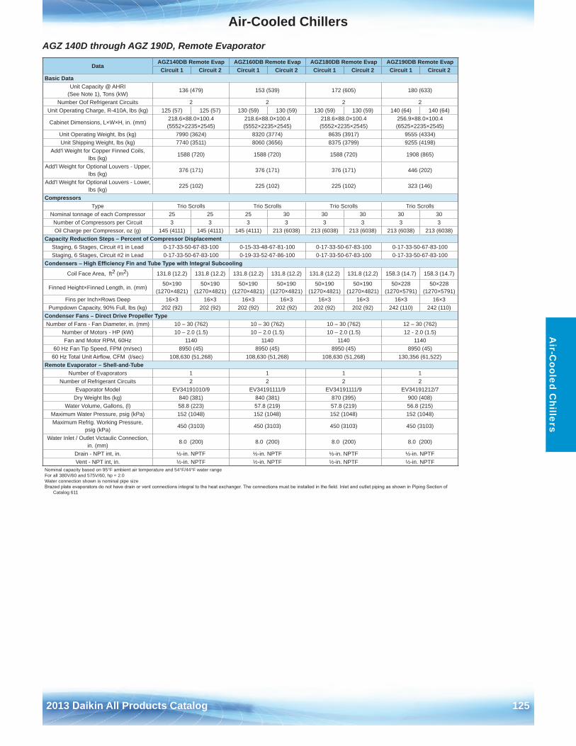
Air-Cooled Chillers
2013 Daikin All Products Catalog 125
Air-C
ooled Chillers
AGZ 140D through AGZ 190D, Remote Evaporator
DataAGZ140DB Remote Evap AGZ160DB Remote Evap AGZ180DB Remote Evap AGZ190DB Remote EvapCircuit 1 Circuit 2 Circuit 1 Circuit 2 Circuit 1 Circuit 2 Circuit 1 Circuit 2
Basic DataUnit Capacity @ AHRI
(See Note 1), Tons (kW)136 (479) 153 (539) 172 (605) 180 (633)
Number Oof Refrigerant Circuits 2 2 2 2Unit Operating Charge, R-410A, lbs (kg) 125 (57) 125 (57) 130 (59) 130 (59) 130 (59) 130 (59) 140 (64) 140 (64)
Cabinet Dimensions, L×W×H, in . (mm)218 .6×88 .0×100 .4 (5552×2235×2545)
218 .6×88 .0×100 .4 (5552×2235×2545)
218 .6×88 .0×100 .4 (5552×2235×2545)
256 .9×88 .0×100 .4 (6525×2235×2545)
Unit Operating Weight, lbs (kg) 7990 (3624) 8320 (3774) 8635 (3917) 9555 (4334)Unit Shipping Weight, lbs (kg) 7740 (3511) 8060 (3656) 8375 (3799) 9255 (4198)
Add'l Weight for Copper Finned Coils, lbs (kg)
1588 (720) 1588 (720) 1588 (720) 1908 (865)
Add'l Weight for Optional Louvers - Upper, lbs (kg)
376 (171) 376 (171) 376 (171) 446 (202)
Add'l Weight for Optional Louvers - Lower, lbs (kg)
225 (102) 225 (102) 225 (102) 323 (146)
CompressorsType Trio Scrolls Trio Scrolls Trio Scrolls Trio Scrolls
Nominal tonnage of each Compressor 25 25 25 30 30 30 30 30Number of Compressors per Circuit 3 3 3 3 3 3 3 3Oil Charge per Compressor, oz (g) 145 (4111) 145 (4111) 145 (4111) 213 (6038) 213 (6038) 213 (6038) 213 (6038) 213 (6038)
Capacity Reduction Steps – Percent of Compressor DisplacementStaging, 6 Stages, Circuit #1 in Lead 0-17-33-50-67-83-100 0-15-33-48-67-81-100 0-17-33-50-67-83-100 0-17-33-50-67-83-100Staging, 6 Stages, Circuit #2 in Lead 0-17-33-50-67-83-100 0-19-33-52-67-86-100 0-17-33-50-67-83-100 0-17-33-50-67-83-100
Condensers – High Efficiency Fin and Tube Type with Integral Subcooling
Coil Face Area, ft2 (m2) 131 .8 (12 .2) 131 .8 (12 .2) 131 .8 (12 .2) 131 .8 (12 .2) 131 .8 (12 .2) 131 .8 (12 .2) 158 .3 (14 .7) 158 .3 (14 .7)
Finned Height×Finned Length, in . (mm)50×190
(1270×4821)50×190
(1270×4821)50×190
(1270×4821)50×190
(1270×4821)50×190
(1270×4821)50×190
(1270×4821)50×228
(1270×5791)50×228
(1270×5791)Fins per Inch×Rows Deep 16×3 16×3 16×3 16×3 16×3 16×3 16×3 16×3
Pumpdown Capacity, 90% Full, lbs (kg) 202 (92) 202 (92) 202 (92) 202 (92) 202 (92) 202 (92) 242 (110) 242 (110)Condenser Fans – Direct Drive Propeller TypeNumber of Fans - Fan Diameter, in . (mm) 10 – 30 (762) 10 – 30 (762) 10 – 30 (762) 12 – 30 (762)
Number of Motors - HP (kW) 10 – 2 .0 (1 .5) 10 – 2 .0 (1 .5) 10 – 2 .0 (1 .5) 12 - 2 .0 (1 .5)Fan and Motor RPM, 60Hz 1140 1140 1140 1140
60 Hz Fan Tip Speed, FPM (m/sec) 8950 (45) 8950 (45) 8950 (45) 8950 (45)60 Hz Total Unit Airflow, CFM (l/sec) 108,630 (51,268) 108,630 (51,268) 108,630 (51,268) 130,356 (61,522)
Remote Evaporator – Shell-and-Tube Number of Evaporators 1 1 1 1
Number of Refrigerant Circuits 2 2 2 2Evaporator Model EV34191010/9 EV34191111/9 EV34191111/9 EV34191212/7
Dry Weight lbs (kg) 840 (381) 840 (381) 870 (395) 900 (408)Water Volume, Gallons, (l) 58 .8 (223) 57 .8 (219) 57 .8 (219) 56 .8 (215)
Maximum Water Pressure, psig (kPa) 152 (1048) 152 (1048) 152 (1048) 152 (1048)Maximum Refrig . Working Pressure,
psig (kPa)450 (3103) 450 (3103) 450 (3103) 450 (3103)
Water Inlet / Outlet Victaulic Connection, in . (mm)
8 .0 (200) 8 .0 (200) 8 .0 (200) 8 .0 (200)
Drain - NPT int, in . ½-in . NPTF ½-in . NPTF ½-in . NPTF ½-in . NPTFVent - NPT int, in . ½-in . NPTF ½-in . NPTF ½-in . NPTF ½-in . NPTF
Nominal capacity based on 95°F ambient air temperature and 54°F/44°F water rangeFor all 380V/60 and 575V/60, hp = 2 .0Water connection shown is nominal pipe sizeBrazed plate evaporators do not have drain or vent connections integral to the heat exchanger. The connections must be installed in the field. Inlet and outlet piping as shown in Piping Section of
Catalog 611
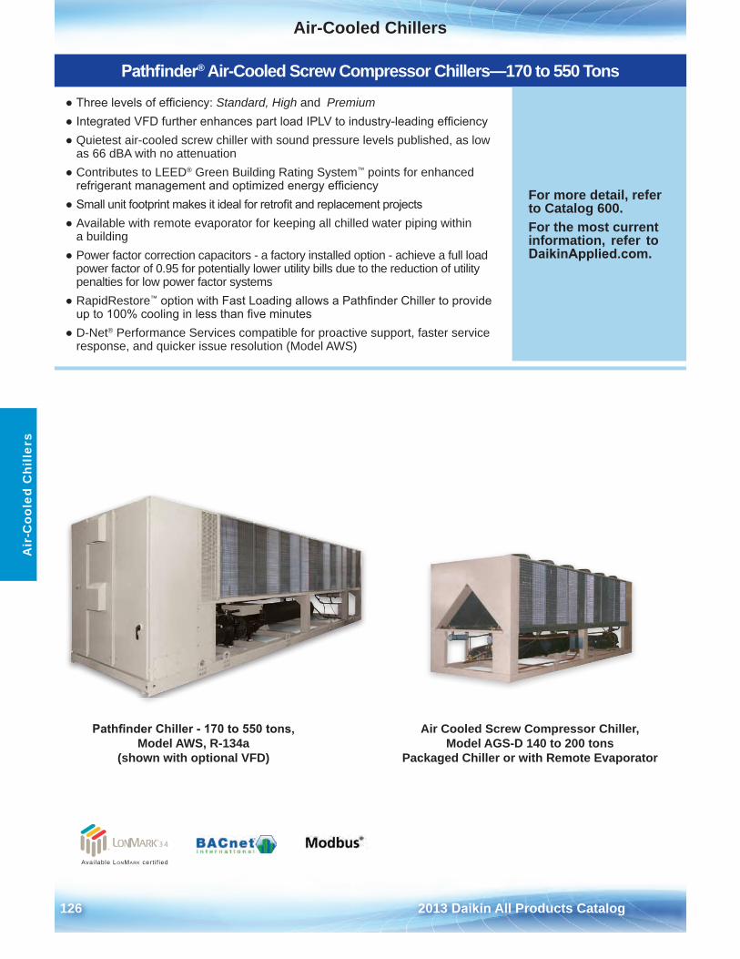
Air-Cooled Chillers
126 2013 Daikin All Products Catalog
Air
-Coo
led
Chi
llers
Pathfinder Chiller - 170 to 550 tons, Model AWS, R-134a
(shown with optional VFD)
Available LonMark cert i f ied
Pathfinder® Air-Cooled Screw Compressor Chillers—170 to 550 Tons
● Three levels of efficiency: Standard, High and Premium● Integrated VFD further enhances part load IPLV to industry-leading efficiency● Quietest air-cooled screw chiller with sound pressure levels published, as low
as 66 dBA with no attenuation● Contributes to LEED® Green Building Rating System™ points for enhanced
refrigerant management and optimized energy efficiency● Small unit footprint makes it ideal for retrofit and replacement projects● Available with remote evaporator for keeping all chilled water piping within
a building● Power factor correction capacitors - a factory installed option - achieve a full load
power factor of 0 .95 for potentially lower utility bills due to the reduction of utilitypenalties for low power factor systems
● RapidRestore™ option with Fast Loading allows a Pathfinder Chiller to provideup to 100% cooling in less than five minutes
● D-Net® Performance Services compatible for proactive support, faster serviceresponse, and quicker issue resolution (Model AWS)
For more detail, refer to Catalog 600 .For the most current information, refer to DaikinApplied.com .
Air Cooled Screw Compressor Chiller, Model AGS-D 140 to 200 tons
Packaged Chiller or with Remote Evaporator
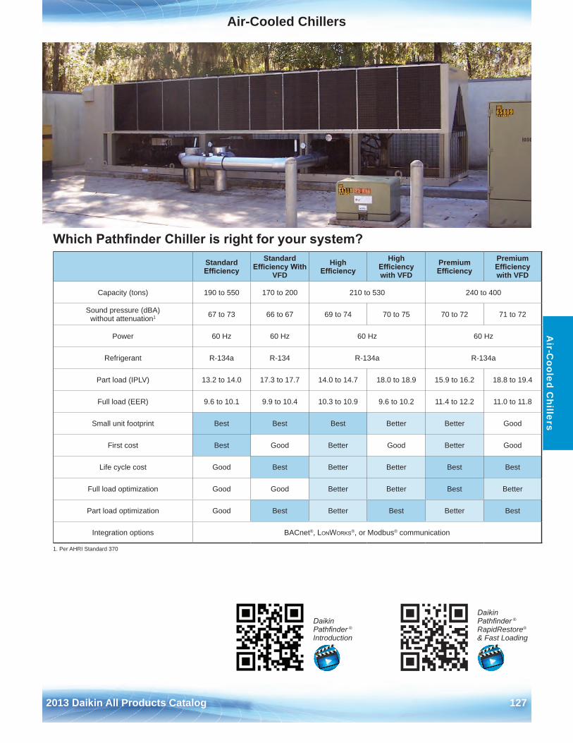
Air-Cooled Chillers
2013 Daikin All Products Catalog 127
Air-C
ooled Chillers
Which Pathfinder Chiller is right for your system?Standard Efficiency
Standard Efficiency With
VFDHigh
EfficiencyHigh
Efficiency with VFD
Premium Efficiency
Premium Efficiency with VFD
Capacity (tons) 190 to 550 170 to 200 210 to 530 240 to 400
Sound pressure (dBA) without attenuation1 67 to 73 66 to 67 69 to 74 70 to 75 70 to 72 71 to 72
Power 60 Hz 60 Hz 60 Hz 60 Hz
Refrigerant R-134a R-134 R-134a R-134a
Part load (IPLV) 13 .2 to 14 .0 17 .3 to 17 .7 14 .0 to 14 .7 18 .0 to 18 .9 15 .9 to 16 .2 18 .8 to 19 .4
Full load (EER) 9 .6 to 10 .1 9 .9 to 10 .4 10 .3 to 10 .9 9 .6 to 10 .2 11 .4 to 12 .2 11 .0 to 11 .8
Small unit footprint Best Best Best Better Better Good
First cost Best Good Better Good Better Good
Life cycle cost Good Best Better Better Best Best
Full load optimization Good Good Better Better Best Better
Part load optimization Good Best Better Best Better Best
Integration options BACnet®, LonWorks®, or Modbus® communication
1 . Per AHRI Standard 370
Daikin Pathfinder ®
Introduction
Daikin Pathfinder ®
RapidRestore®
& Fast Loading
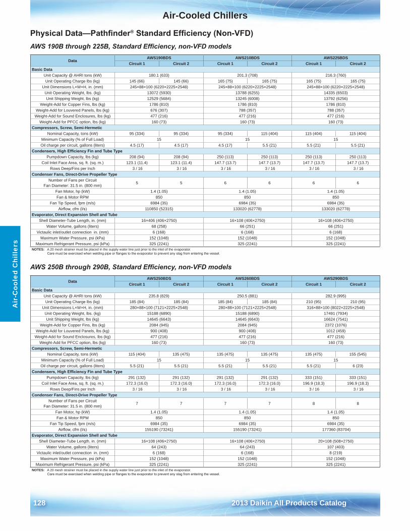
Air-Cooled Chillers
128 2013 Daikin All Products Catalog
Air
-Coo
led
Chi
llers
Physical Data—Pathfinder® Standard Efficiency (Non-VFD)AWS 190B through 225B, Standard Efficiency, non-VFD models
AWS 250B through 290B, Standard Efficiency, non-VFD models
DataAWS190BDS AWS210BDS AWS225BDS
Circuit 1 Circuit 2 Circuit 1 Circuit 2 Circuit 1 Circuit 2Basic Data
Unit Capacity @ AHRI tons (kW) 180 .1 (633) 201 .3 (708) 216 .3 (760)Unit Operating Charge lbs (kg) 145 (66) 145 (66) 165 (75) 165 (75) 165 (75) 165 (75)
Unit Dimensions L×W×H, in . (mm) 245×88×100 (6220×2225×2548) 245×88×100 (6220×2225×2548) 245×88×100 (6220×2225×2548)Unit Operating Weight, lbs . (kg) 13072 (5930) 13788 (6255) 14335 (6503)Unit Shipping Weight, lbs (kg) 12529 (5684) 13245 (6008) 13792 (6256)
Weight-Add for Copper Fins, lbs (kg) 1786 (810) 1786 (810) 1786 (810)Weight-Add for Louvered Panels, lbs (kg) 676 (307) 788 (357) 788 (357)
Weight-Add for Sound Enclosures, lbs (kg) 477 (216) 477 (216) 477 (216)Weight-Add for PFCC option, lbs (kg) 160 (73) 160 (73) 160 (73)
Compressors, Screw, Semi-HermeticNominal Capacity, tons (kW) 95 (334) 95 (334) 95 (334) 115 (404) 115 (404) 115 (404)
Minimum Capacity (% of Full Load) 15 15 15Oil charge per circuit, gallons (liters) 4 .5 (17) 4 .5 (17) 4 .5 (17) 5 .5 (21) 5 .5 (21) 5 .5 (21)
Condensers, High Efficiency Fin and Tube TypePumpdown Capacity, lbs (kg) 208 (94) 208 (94) 250 (113) 250 (113) 250 (113) 250 (113)
Coil Inlet Face Area, sq . ft . (sq . m .) 123 .1 (11 .4) 123 .1 (11 .4) 147 .7 (13 .7) 147 .7 (13 .7) 147 .7 (13 .7) 147 .7 (13 .7)Rows Deep/Fins per Inch 3 / 16 3 / 16 3 / 16 3 / 16 3 / 16 3 / 16
Condenser Fans, Direct-Drive Propeller TypeNumber of Fans per Circuit
Fan Diameter: 31 .5 in . (800 mm)5 5 6 6 6 6
Fan Motor, hp (kW) 1 .4 (1 .05) 1 .4 (1 .05) 1 .4 (1 .05)Fan & Motor RPM 850 850 850
Fan Tip Speed, fpm (m/s) 6984 (35) 6984 (35) 6984 (35)Airflow, cfm (l/s) 110850 (52315) 133020 (62778) 133020 (62778)
Evaporator, Direct Expansion Shell and TubeShell Diameter-Tube Length, in . (mm) 16×406 (406×2750) 16×108 (406×2750) 16×108 (406×2750)
Water Volume, gallons (liters) 68 (258) 66 (251) 66 (251)Victaulic inlet/outlet connection in . (mm) 6 (168) 6 (168) 6 (168)
Maximum Water Pressure, psi (kPa) 152 (1048) 152 (1048) 152 (1048)Maximum Refrigerant Pressure, psi (kPa) 325 (2241) 325 (2241) 325 (2241)
NOTES: A 20 mesh strainer must be placed in the supply water line just prior to the inlet of the evaporator . Care must be exercised when welding pipe or flanges to the evaporator to prevent any slag from entering the vessel.
DataAWS250BDS AWS260BDS AWS290BDS
Circuit 1 Circuit 2 Circuit 1 Circuit 2 Circuit 1 Circuit 2Basic Data
Unit Capacity @ AHRI tons (kW) 235 .8 (829) 250 .5 (881) 282 .9 (995)Unit Operating Charge lbs (kg) 185 (84) 185 (84) 185 (84) 185 (84) 210 (95) 210 (95)
Unit Dimensions L×W×H, in . (mm) 280×88×100 (7121×2225×2548) 280×88×100 (7121×2225×2548) 316×88×100 (8022×2225×2548)Unit Operating Weight, lbs . (kg) 15188 (6890) 15188 (6890) 17491 (7934)Unit Shipping Weight, lbs (kg) 14645 (6643) 14645 (6643) 16624 (7541)
Weight-Add for Copper Fins, lbs (kg) 2084 (945) 2084 (945) 2372 (1076)Weight-Add for Louvered Panels, lbs (kg) 900 (408) 900 (408) 1012 (459)
Weight-Add for Sound Enclosures, lbs (kg) 477 (216) 477 (216) 477 (216)Weight-Add for PFCC option, lbs (kg) 160 (73) 160 (73) 160 (73)
Compressors, Screw, Semi-HermeticNominal Capacity, tons (kW) 115 (404) 135 (475) 135 (475) 135 (475) 135 (475) 155 (545)
Minimum Capacity (% of Full Load) 15 15 15Oil charge per circuit, gallons (liters) 5 .5 (21) 5 .5 (21) 5 .5 (21) 5 .5 (21) 5 .5 (21) 6 (23)
Condensers, High Efficiency Fin and Tube TypePumpdown Capacity, lbs (kg) 291 (132) 291 (132) 291 (132) 291 (132) 333 (151) 333 (151)
Coil Inlet Face Area, sq . ft . (sq . m .) 172 .3 (16 .0) 172 .3 (16 .0) 172 .3 (16 .0) 172 .3 (16 .0) 196 .9 (18 .3) 196 .9 (18 .3)Rows Deep/Fins per Inch 3 / 16 3 / 16 3 / 16 3 / 16 3 / 16 3 / 16
Condenser Fans, Direct-Drive Propeller TypeNumber of Fans per Circuit
Fan Diameter: 31 .5 in . (800 mm)7 7 7 7 8 8
Fan Motor, hp (kW) 1 .4 (1 .05) 1 .4 (1 .05) 1 .4 (1 .05)Fan & Motor RPM 850 850 850
Fan Tip Speed, fpm (m/s) 6984 (35) 6984 (35) 6984 (35)Airflow, cfm (l/s) 155190 (73241) 155190 (73241) 177360 (83704)
Evaporator, Direct Expansion Shell and TubeShell Diameter-Tube Length, in . (mm) 16×108 (406×2750) 16×108 (406×2750) 20×108 (508×2750)
Water Volume, gallons (liters) 64 (243) 64 (243) 107 (403)Victaulic inlet/outlet connection in . (mm) 6 (168) 6 (168) 8 (219)
Maximum Water Pressure, psi (kPa) 152 (1048) 152 (1048) 152 (1048)Maximum Refrigerant Pressure, psi (kPa) 325 (2241) 325 (2241) 325 (2241)
NOTES: A 20 mesh strainer must be placed in the supply water line just prior to the inlet of the evaporator . Care must be exercised when welding pipe or flanges to the evaporator to prevent any slag from entering the vessel.
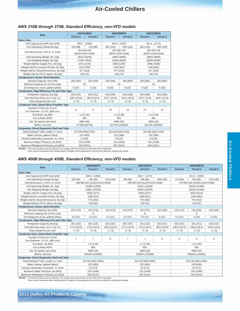
Air-Cooled Chillers
2013 Daikin All Products Catalog 129
Air-C
ooled Chillers
AWS 310B through 375B, Standard Efficiency, non-VFD models
AWS 400B through 450B, Standard Efficiency, non-VFD models
DataAWS310BDS AWS350BDS AWS375BDS
Circuit 1 Circuit 2 Circuit 1 Circuit 2 Circuit 1 Circuit 2Basic Data
Unit Capacity @ AHRI tons (kW) 300 .4 (1056) 340 .6 (1197) 361 .4 (1271)Unit Operating Charge lbs (kg) 215 (98) 215 (98) 265 (120) 265 (120) 265 (120) 265 (120)
Unit Dimensions L×W×H, in . (mm)316×88×100
(8026×2225×2548)387×88×100
(9823×2225×2548)387×88×100
(9823×2225×2548)Unit Operating Weight, lbs . (kg) 18161 (8238) 19803 (8983) 19803 (8983)Unit Shipping Weight, lbs (kg) 17294 (7845) 18936 (8590) 18936 (8590)
Weight-Add for Copper Fins, lbs (kg) 2372 (1076) 2968 (1346) 2968 (1346)Weight-Add for Louvered Panels, lbs (kg) 1012 (459) 1236 (561) 1236 (561)
Weight-Add for Sound Enclosures, lbs (kg) 477 (216) 477 (216) 477 (216)Weight-Add for PFCC option, lbs (kg) 160 (73) 160 (73) 160 (73)
Compressors, Screw, Semi-HermeticNominal Capacity, tons (kW) 155 (545) 155 (545) 155 (545) 185 (650) 185 (650) 185 (650)
Minimum Capacity (% of Full Load) 15 15 15Oil charge per circuit, gallons (liters) 6 (23) 6 (23) 6 (23) 6 (23) 6 (23) 6 (23)
Condensers, High Efficiency Fin and Tube TypePumpdown Capacity, lbs (kg) 333 (151) 333 (151) 416 (189) 416 (189) 416 (189) 416 (189)
Coil Inlet Face Area, sq . ft . (sq . m .) 196 .9 (18 .3) 196 .9 (18 .3) 246 .1 (22 .8) 246 .1 (22 .8) 246 .1 (22 .8) 246 .1 (22 .8)Rows Deep/Fins per Inch 3 / 16 3 / 16 3 / 16 3 / 16 3 / 16 3 / 16
Condenser Fans, Direct-Drive Propeller TypeNumber of Fans per Circuit
Fan Diameter: 31 .5 in . (800 mm)8 8 10 10 10 10
Fan Motor, hp (kW) 1 .4 (1 .05) 1 .4 (1 .05) 1 .4 (1 .05)Fan & Motor RPM 850 850 850
Fan Tip Speed, fpm (m/s) 6984 (35) 6984 (35) 6984 (35)Airflow, cfm (l/s) 177360 (83704) 221700 (104630) 221700 (104630)
Evaporator, Direct Expansion Shell and TubeShell Diameter-Tube Length, in . (mm) 20×108 (508×2750) 20×108 (508×2750) 20×108 (508×2750)
Water Volume, gallons (liters) 107 (403) 102 (386) 102 (386)Victaulic inlet/outlet connection in . (mm) 8 (219) 8 (219) 8 (219)
Maximum Water Pressure, psi (kPa) 152 (1048) 152 (1048) 152 (1048)Maximum Refrigerant Pressure, psi (kPa) 325 (2241) 325 (2241) 325 (2241)
NOTES: A 20 mesh strainer must be placed in the supply water line just prior to the inlet of the evaporator . Care must be exercised when welding pipe or flanges to the evaporator to prevent any slag from entering the vessel.
DataAWS400BTS AWS425BTS AWS450BTS
Circuit 1 Circuit 2 Circuit 3 Circuit 1 Circuit 2 Circuit 3 Circuit 1 Circuit 2 Circuit 3Basic Data
Unit Capacity @ AHRI tons (kW) 398 .3 (1400) 418 .7 (1472) 441 .4 (1552)Unit Operating Charge lbs (kg) 185 (84) 185 (84) 220 (100) 185 (84) 185 (84) 220 (100) 210 (95) 210 (95) 220 (100)
Unit Dimensions L×W×H, in . (mm) 438×88×100 (11123×2225×2548) 438×88×100 (11123×2225×2548) 473×88×100 (12024×2225×2548)Unit Operating Weight, lbs . (kg) 24260 (11005) 24931 (11309) 26418 (11984)Unit Shipping Weight, lbs (kg) 22861 (10370) 23532 (10674) 25019 (11349)
Weight-Add for Copper Fins, lbs (kg) 3256 (1477) 3256 (1477) 3553 (1612)Weight-Add for Louvered Panels, lbs (kg) 1348 (611) 1348 (611) 1460 (662)
Weight-Add for Sound Enclosures, lbs (kg) 776 (352) 776 (352) 776 (352)Weight-Add for PFCC option, lbs (kg) 120 (55) 120 (55) 120 (55)
Compressors, Screw, Semi-HermeticNominal Capacity, tons (kW) 135 (475) 135 (475) 135 (475) 135 (475) 135 (475) 155 (545) 135 (475) 155 (545) 155 (545)
Minimum Capacity (% of Full Load) 8 8 8Oil charge per circuit, gallons (liters) 5 .5 (21) 5 .5 (21) 5 .5 (21) 5 .5 (21) 5 .5 (21) 6 (23) 5 .5 (21) 6 (23) 6 (23)
Condensers, High Efficiency Fin and Tube TypePumpdown Capacity, lbs (kg) 291 (132) 291 (132) 333 (151) 291 (132) 291 (132) 333 (151) 333 (151) 333 (151) 333 (151)
Coil Inlet Face Area, sq . ft . (sq . m .) 172 .3 (16 .0) 172 .3 (16 .0) 196 .9 (18 .3) 172 .3 (16 .0) 172 .3 (16 .0) 196 .9 (18 .3) 196 .9 (18 .3) 196 .9 (18 .3) 196 .9 (18 .3)Rows Deep/Fins per Inch 3 / 16 3 / 16 3 / 16 3 / 16 3 / 16 3 / 16 3 / 16 3 / 16 3 / 16
Condenser Fans, Direct-Drive Propeller TypeNumber of Fans per Circuit
Fan Diameter: 31 .5 in . (800 mm)7 7 8 7 7 8 8 8 8
Fan Motor, hp (kW) 1 .4 (1 .05) 1 .4 (1 .05) 1 .4 (1 .05)Fan & Motor RPM 850 850 850
Fan Tip Speed, fpm (m/s) 6984 (35) 6984 (35) 6984 (35)Airflow, cfm (l/s) 266040 (125556) 243870 (115094) 266040 (125556)
Evaporator, Direct Expansion Shell and TubeShell Diameter-Tube Length, in . (mm) 26×130 (660×3300) 26×130 (660×3300) 26×130 (660×3300)
Water Volume, gallons (liters) 225 (850) 225 (850) 225 (850)Victaulic inlet/outlet connection in . (mm) 10 (273) 10 (273) 10 (273)
Maximum Water Pressure, psi (kPa) 152 (1048) 152 (1048) 152 (1048)Maximum Refrigerant Pressure, psi (kPa) 325 (2241) 325 (2241) 325 (2241)
NOTES: A 20 mesh strainer must be placed in the supply water line just prior to the inlet of the evaporator . Care must be exercised when welding pipe or flanges to the evaporator to prevent any slag from entering the vessel.
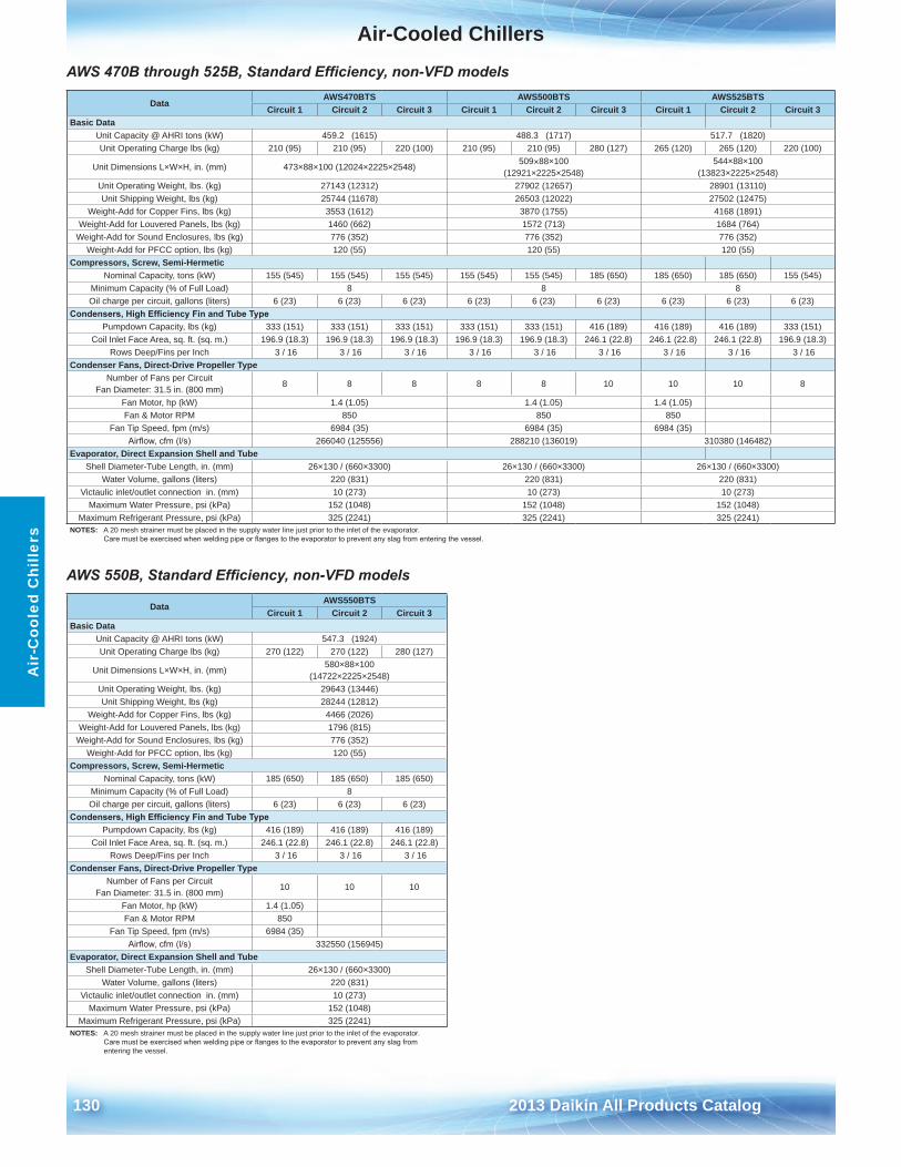
Air-Cooled Chillers
130 2013 Daikin All Products Catalog
Air
-Coo
led
Chi
llers
AWS 470B through 525B, Standard Efficiency, non-VFD models
AWS 550B, Standard Efficiency, non-VFD models
DataAWS470BTS AWS500BTS AWS525BTS
Circuit 1 Circuit 2 Circuit 3 Circuit 1 Circuit 2 Circuit 3 Circuit 1 Circuit 2 Circuit 3Basic Data
Unit Capacity @ AHRI tons (kW) 459 .2 (1615) 488 .3 (1717) 517 .7 (1820)Unit Operating Charge lbs (kg) 210 (95) 210 (95) 220 (100) 210 (95) 210 (95) 280 (127) 265 (120) 265 (120) 220 (100)
Unit Dimensions L×W×H, in . (mm) 473×88×100 (12024×2225×2548) 509×88×100 (12921×2225×2548)
544×88×100 (13823×2225×2548)
Unit Operating Weight, lbs . (kg) 27143 (12312) 27902 (12657) 28901 (13110)Unit Shipping Weight, lbs (kg) 25744 (11678) 26503 (12022) 27502 (12475)
Weight-Add for Copper Fins, lbs (kg) 3553 (1612) 3870 (1755) 4168 (1891)Weight-Add for Louvered Panels, lbs (kg) 1460 (662) 1572 (713) 1684 (764)
Weight-Add for Sound Enclosures, lbs (kg) 776 (352) 776 (352) 776 (352)Weight-Add for PFCC option, lbs (kg) 120 (55) 120 (55) 120 (55)
Compressors, Screw, Semi-HermeticNominal Capacity, tons (kW) 155 (545) 155 (545) 155 (545) 155 (545) 155 (545) 185 (650) 185 (650) 185 (650) 155 (545)
Minimum Capacity (% of Full Load) 8 8 8Oil charge per circuit, gallons (liters) 6 (23) 6 (23) 6 (23) 6 (23) 6 (23) 6 (23) 6 (23) 6 (23) 6 (23)
Condensers, High Efficiency Fin and Tube TypePumpdown Capacity, lbs (kg) 333 (151) 333 (151) 333 (151) 333 (151) 333 (151) 416 (189) 416 (189) 416 (189) 333 (151)
Coil Inlet Face Area, sq . ft . (sq . m .) 196 .9 (18 .3) 196 .9 (18 .3) 196 .9 (18 .3) 196 .9 (18 .3) 196 .9 (18 .3) 246 .1 (22 .8) 246 .1 (22 .8) 246 .1 (22 .8) 196 .9 (18 .3)Rows Deep/Fins per Inch 3 / 16 3 / 16 3 / 16 3 / 16 3 / 16 3 / 16 3 / 16 3 / 16 3 / 16
Condenser Fans, Direct-Drive Propeller TypeNumber of Fans per Circuit
Fan Diameter: 31 .5 in . (800 mm)8 8 8 8 8 10 10 10 8
Fan Motor, hp (kW) 1 .4 (1 .05) 1 .4 (1 .05) 1 .4 (1 .05)Fan & Motor RPM 850 850 850
Fan Tip Speed, fpm (m/s) 6984 (35) 6984 (35) 6984 (35)Airflow, cfm (l/s) 266040 (125556) 288210 (136019) 310380 (146482)
Evaporator, Direct Expansion Shell and TubeShell Diameter-Tube Length, in . (mm) 26×130 / (660×3300) 26×130 / (660×3300) 26×130 / (660×3300)
Water Volume, gallons (liters) 220 (831) 220 (831) 220 (831)Victaulic inlet/outlet connection in . (mm) 10 (273) 10 (273) 10 (273)
Maximum Water Pressure, psi (kPa) 152 (1048) 152 (1048) 152 (1048)Maximum Refrigerant Pressure, psi (kPa) 325 (2241) 325 (2241) 325 (2241)
NOTES: A 20 mesh strainer must be placed in the supply water line just prior to the inlet of the evaporator . Care must be exercised when welding pipe or flanges to the evaporator to prevent any slag from entering the vessel.
DataAWS550BTS
Circuit 1 Circuit 2 Circuit 3Basic Data
Unit Capacity @ AHRI tons (kW) 547 .3 (1924)Unit Operating Charge lbs (kg) 270 (122) 270 (122) 280 (127)
Unit Dimensions L×W×H, in . (mm)580×88×100
(14722×2225×2548)Unit Operating Weight, lbs . (kg) 29643 (13446)Unit Shipping Weight, lbs (kg) 28244 (12812)
Weight-Add for Copper Fins, lbs (kg) 4466 (2026)Weight-Add for Louvered Panels, lbs (kg) 1796 (815)
Weight-Add for Sound Enclosures, lbs (kg) 776 (352)Weight-Add for PFCC option, lbs (kg) 120 (55)
Compressors, Screw, Semi-HermeticNominal Capacity, tons (kW) 185 (650) 185 (650) 185 (650)
Minimum Capacity (% of Full Load) 8Oil charge per circuit, gallons (liters) 6 (23) 6 (23) 6 (23)
Condensers, High Efficiency Fin and Tube TypePumpdown Capacity, lbs (kg) 416 (189) 416 (189) 416 (189)
Coil Inlet Face Area, sq . ft . (sq . m .) 246 .1 (22 .8) 246 .1 (22 .8) 246 .1 (22 .8)Rows Deep/Fins per Inch 3 / 16 3 / 16 3 / 16
Condenser Fans, Direct-Drive Propeller TypeNumber of Fans per Circuit
Fan Diameter: 31 .5 in . (800 mm)10 10 10
Fan Motor, hp (kW) 1 .4 (1 .05)Fan & Motor RPM 850
Fan Tip Speed, fpm (m/s) 6984 (35)Airflow, cfm (l/s) 332550 (156945)
Evaporator, Direct Expansion Shell and TubeShell Diameter-Tube Length, in . (mm) 26×130 / (660×3300)
Water Volume, gallons (liters) 220 (831)Victaulic inlet/outlet connection in . (mm) 10 (273)
Maximum Water Pressure, psi (kPa) 152 (1048)Maximum Refrigerant Pressure, psi (kPa) 325 (2241)
NOTES: A 20 mesh strainer must be placed in the supply water line just prior to the inlet of the evaporator . Care must be exercised when welding pipe or flanges to the evaporator to prevent any slag from entering the vessel .
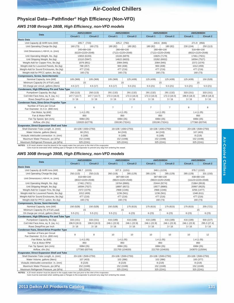
Air-Cooled Chillers
2013 Daikin All Products Catalog 131
Air-C
ooled Chillers
Physical Data—Pathfinder® High Efficiency (Non-VFD)AWS 210B through 280B, High Efficiency, non-VFD models
AWS 300B through 390B, High Efficiency, non-VFD models
DataAWS210BDH AWS230BDH AWS250BDH AWS280BDH
Circuit 1 Circuit 2 Circuit 1 Circuit 2 Circuit 1 Circuit 2 Circuit 1 Circuit 2Basic Data
Unit Capacity @ AHRI tons (kW) 205 .7 (723) 225 .2 (792) 240 .6 (846) 271 .9 (956)Unit Operating Charge lbs (kg) 160 (73) 160 (73) 180 (82) 180 (82) 180 (82) 180 (82) 230 (104) 250 (113)
Unit Dimensions L×W×H, in . (mm)245×88×100
(6220×2225×2548)280×88×100
(7121×2225×2548)280×88×100
(7121×2225×2548)316×88×100
(8022×2225×2548)Unit Operating Weight, lbs . (kg) 13653 (6193) 15165 (6879) 15825 (7179) 17461 (7921)Unit Shipping Weight, lbs (kg) 13110 (5947) 14622 (6633) 15282 (6932) 16594 (7527)
Weight-Add for Copper Fins, lbs (kg) 1876 (851) 2084 (945) 2084 (945) 2372 (1076)Weight-Add for Louvered Panels, lbs (kg) 788 (357) 900 (408) 900 (408) 1012 (459)
Weight-Add for Sound Enclosures, lbs (kg) 477 (216) 477 (216) 477 (216) 477 (216)Weight-Add for PFCC option, lbs (kg) 160 (73) 160 (73) 160 (73) 160 (73)
Compressors, Screw, Semi-HermeticNominal Capacity, tons (kW) 105 (369) 105 (369) 105 (369) 125 (439) 125 (439) 125 (439) 125 (439) 150 (528)
Minimum Capacity (% of Full Load) 15 15 15 15Oil charge per circuit, gallons (liters) 4 .5 (17) 4 .5 (17) 4 .5 (17) 5 .5 (21) 5 .5 (21) 5 .5 (21) 5 .5 (21) 5 .5 (21)
Condensers, High Efficiency Fin and Tube TypePumpdown Capacity, lbs (kg) 250 (113) 250 (113) 291 (132) 291 (132) 291 (132) 291 (132) 333 (151) 333 (151)
Coil Inlet Face Area, sq . ft . (sq . m .) 147 .7 (13 .7) 147 .7 (13 .7) 172 .3 (16 .0) 172 .3 (16 .0) 172 .3 (16 .0) 172 .3 (16 .0) 196 .9 (18 .3) 196 .9 (18 .3)Rows Deep/Fins per Inch 3 / 16 3 / 16 3 / 16 3 / 16 3 / 16 3 / 16 3 / 16 3 / 16
Condenser Fans, Direc-Drive Propeller TypeNumber of Fans per Circuit
Fan Diameter: 31 .5 in . (800 mm)6 6 7 7 7 7 8 8
Fan Motor, hp (kW) 1 .4 (1 .05) 1 .4 (1 .05) 1 .4 (1 .05) 1 .4 (1 .05)Fan & Motor RPM 850 850 850 850
Fan Tip Speed, fpm (m/s) 6984 (35) 6984 (35) 6984 (35) 6984 (35)Airflow, cfm (l/s) 133020 (62778) 155190 (73241) 155190 (73241) 177360 (83704)
Evaporator, Direct Expansion Shell and TubeShell Diameter-Tube Length, in . (mm) 16×108 / (406×2750) 16×108 / (406×2750) 16×108 / (406×2750) 20×108 / (508×2750)
Water Volume, gallons (liters) 66 (251) 64 (243) 64 (243) 107 (403)Victaulic inlet/outlet connection in . (mm) 6 (168) 6 (168) 6 (168) 8 (219)
Maximum Water Pressure, psi (kPa) 152 (1048) 152 (1048) 152 (1048) 152 (1048)Maximum Refrigerant Pressure, psi (kPa) 325 (2241) 325 (2241) 325 (2241) 325 (2241)
NOTES: A 20 mesh strainer must be placed in the supply water line just prior to the inlet of the evaporator . Care must be exercised when welding pipe or flanges to the evaporator to prevent any slag from entering the vessel.
DataAWS300BDH AWS330BDH AWS350BDH AWS390BDH
Circuit 1 Circuit 2 Circuit 1 Circuit 2 Circuit 1 Circuit 2 Circuit 1 Circuit 2Basic Data
Unit Capacity @ AHRI tons (kW) 288 .7 (1015) 327 .3 (1151) 348 .1 (1224) 378 .7 (1332)Unit Operating Charge lbs (kg) 250 (113) 250 (113) 260 (118) 285 (129) 285 (129) 285 (129) 285 (129) 331 (150)
Unit Dimensions L×W×H, in . (mm)316×88×100
(8022×2225×2548)387×88×100
(9823×2225×2548)387×88×100
(9823×2225×2548)438×88×100
(11123×2225×2548)Unit Operating Weight, lbs . (kg) 17461 (7921) 19764 (8965) 20444 (9274) 21864 (9918)Unit Shipping Weight, lbs (kg) 16594 (7527) 18897 (8572) 19577 (8880) 20997 (9525)
Weight-Add for Copper Fins, lbs (kg) 2372 (1076) 2968 (1346) 2968 (1346) 3256 (1477)Weight-Add for Louvered Panels, lbs (kg) 1012 (459) 1236 (561) 1236 (561) 1348 (611)
Weight-Add for Sound Enclosures, lbs (kg) 477 (216) 477 (216) 477 (216) 477 (216)Weight-Add for PFCC option, lbs (kg) 160 (73) 160 (73) 160 (73) 160 (73)
Compressors, Screw, Semi-HermeticNominal Capacity, tons (kW) 150 (528) 150 (528) 150 (528) 175 (615) 175 (615) 175 (615) 175 (615) 205 (721)
Minimum Capacity (% of Full Load) 15 15 15 15Oil charge per circuit, gallons (liters) 5 .5 (21) 5 .5 (21) 5 .5 (21) 6 (23) 6 (23) 6 (23) 6 (23) 6 (23)
Condensers, High Efficiency Fin and Tube TypePumpdown Capacity, lbs (kg) 333 (151) 333 (151) 416 (189) 416 (189) 416 (189) 416 (189) 416 (189) 500 (227)
Coil Inlet Face Area, sq . ft . (sq . m .) 196 .9 (18 .3) 196 .9 (18 .3) 246 .1 (22 .8) 246 .1 (22 .8) 246 .1 (22 .8) 246 .1 (22 .8) 246 .1 (22 .8) 295 .3 (27 .4)Rows Deep/Fins per Inch 3 / 16 3 / 16 3 / 16 3 / 16 3 / 16 3 / 16 3 / 16 3 / 16
Condenser Fans, Direct-Drive Propeller TypeNumber of Fans per Circuit
Fan Diameter: 31 .5 in . (800 mm)8 8 10 10 10 10 10 12
Fan Motor, hp (kW) 1 .4 (1 .05) 1 .4 (1 .05) 1 .4 (1 .05) 1 .4 (1 .05)Fan & Motor RPM 850 850 850 850
Fan Tip Speed, fpm (m/s) 6984 (35) 6984 (35) 6984 (35) 6984 (35)Airflow, cfm (l/s) 177360 (83704) 221700 (104630) 221700 (104630) 243870 (115094)
Evaporator, Direct Expansion Shell and TubeShell Diameter-Tube Length, in . (mm) 20×108 / (508×2750) 20×108 / (508×2750) 20×108 / (508×2750) 20×108 / (508×2750)
Water Volume, gallons (liters) 107 (403) 102 (386) 102 (386) 100 (377)Victaulic inlet/outlet connection in . (mm) 8 (219) 8 (219) 8 (219) 8 (219)
Maximum Water Pressure, psi (kPa) 152 (1048) 152 (1048) 152 (1048) 152 (1048)Maximum Refrigerant Pressure, psi (kPa) 325 (2241) 325 (2241) 325 (2241) 325 (2241)
NOTES: A 20 mesh strainer must be placed in the supply water line just prior to the inlet of the evaporator . Care must be exercised when welding pipe or flanges to the evaporator to prevent any slag from entering the vessel.
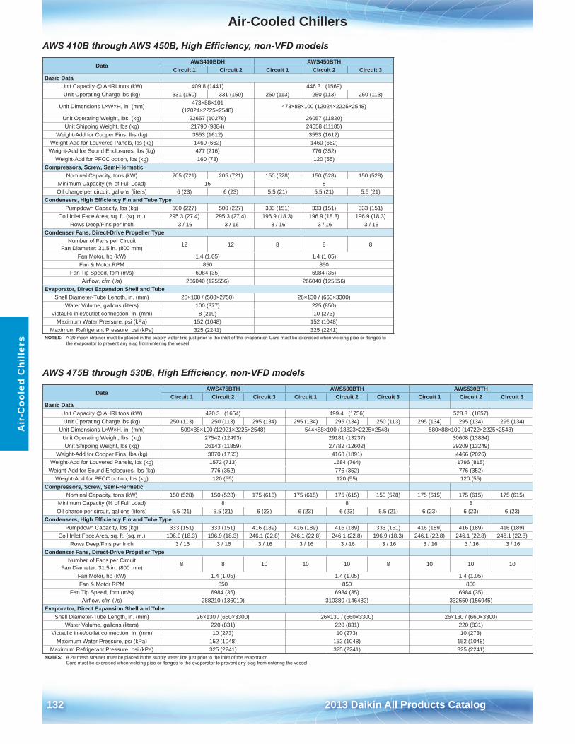
Air-Cooled Chillers
132 2013 Daikin All Products Catalog
Air
-Coo
led
Chi
llers
AWS 410B through AWS 450B, High Efficiency, non-VFD models
AWS 475B through 530B, High Efficiency, non-VFD models
DataAWS410BDH AWS450BTH
Circuit 1 Circuit 2 Circuit 1 Circuit 2 Circuit 3Basic Data
Unit Capacity @ AHRI tons (kW) 409 .8 (1441) 446 .3 (1569)Unit Operating Charge lbs (kg) 331 (150) 331 (150) 250 (113) 250 (113) 250 (113)
Unit Dimensions L×W×H, in . (mm)473×88×101
(12024×2225×2548)473×88×100 (12024×2225×2548)
Unit Operating Weight, lbs . (kg) 22657 (10278) 26057 (11820)Unit Shipping Weight, lbs (kg) 21790 (9884) 24658 (11185)
Weight-Add for Copper Fins, lbs (kg) 3553 (1612) 3553 (1612)Weight-Add for Louvered Panels, lbs (kg) 1460 (662) 1460 (662)
Weight-Add for Sound Enclosures, lbs (kg) 477 (216) 776 (352)Weight-Add for PFCC option, lbs (kg) 160 (73) 120 (55)
Compressors, Screw, Semi-HermeticNominal Capacity, tons (kW) 205 (721) 205 (721) 150 (528) 150 (528) 150 (528)
Minimum Capacity (% of Full Load) 15 8Oil charge per circuit, gallons (liters) 6 (23) 6 (23) 5 .5 (21) 5 .5 (21) 5 .5 (21)
Condensers, High Efficiency Fin and Tube TypePumpdown Capacity, lbs (kg) 500 (227) 500 (227) 333 (151) 333 (151) 333 (151)
Coil Inlet Face Area, sq . ft . (sq . m .) 295 .3 (27 .4) 295 .3 (27 .4) 196 .9 (18 .3) 196 .9 (18 .3) 196 .9 (18 .3)Rows Deep/Fins per Inch 3 / 16 3 / 16 3 / 16 3 / 16 3 / 16
Condenser Fans, Direct-Drive Propeller TypeNumber of Fans per Circuit
Fan Diameter: 31 .5 in . (800 mm)12 12 8 8 8
Fan Motor, hp (kW) 1 .4 (1 .05) 1 .4 (1 .05)Fan & Motor RPM 850 850
Fan Tip Speed, fpm (m/s) 6984 (35) 6984 (35)Airflow, cfm (l/s) 266040 (125556) 266040 (125556)
Evaporator, Direct Expansion Shell and TubeShell Diameter-Tube Length, in . (mm) 20×108 / (508×2750) 26×130 / (660×3300)
Water Volume, gallons (liters) 100 (377) 225 (850)Victaulic inlet/outlet connection in . (mm) 8 (219) 10 (273)
Maximum Water Pressure, psi (kPa) 152 (1048) 152 (1048)Maximum Refrigerant Pressure, psi (kPa) 325 (2241) 325 (2241)
NOTES: A 20 mesh strainer must be placed in the supply water line just prior to the inlet of the evaporator. Care must be exercised when welding pipe or flanges to the evaporator to prevent any slag from entering the vessel .
DataAWS475BTH AWS500BTH AWS530BTH
Circuit 1 Circuit 2 Circuit 3 Circuit 1 Circuit 2 Circuit 3 Circuit 1 Circuit 2 Circuit 3Basic Data
Unit Capacity @ AHRI tons (kW) 470 .3 (1654) 499 .4 (1756) 528 .3 (1857)Unit Operating Charge lbs (kg) 250 (113) 250 (113) 295 (134) 295 (134) 295 (134) 250 (113) 295 (134) 295 (134) 295 (134)
Unit Dimensions L×W×H, in . (mm) 509×88×100 (12921×2225×2548) 544×88×100 (13823×2225×2548) 580×88×100 (14722×2225×2548)Unit Operating Weight, lbs . (kg) 27542 (12493) 29181 (13237) 30608 (13884)Unit Shipping Weight, lbs (kg) 26143 (11859) 27782 (12602) 29209 (13249)
Weight-Add for Copper Fins, lbs (kg) 3870 (1755) 4168 (1891) 4466 (2026)Weight-Add for Louvered Panels, lbs (kg) 1572 (713) 1684 (764) 1796 (815)
Weight-Add for Sound Enclosures, lbs (kg) 776 (352) 776 (352) 776 (352)Weight-Add for PFCC option, lbs (kg) 120 (55) 120 (55) 120 (55)
Compressors, Screw, Semi-HermeticNominal Capacity, tons (kW) 150 (528) 150 (528) 175 (615) 175 (615) 175 (615) 150 (528) 175 (615) 175 (615) 175 (615)
Minimum Capacity (% of Full Load) 8 8 8Oil charge per circuit, gallons (liters) 5 .5 (21) 5 .5 (21) 6 (23) 6 (23) 6 (23) 5 .5 (21) 6 (23) 6 (23) 6 (23)
Condensers, High Efficiency Fin and Tube TypePumpdown Capacity, lbs (kg) 333 (151) 333 (151) 416 (189) 416 (189) 416 (189) 333 (151) 416 (189) 416 (189) 416 (189)
Coil Inlet Face Area, sq . ft . (sq . m .) 196 .9 (18 .3) 196 .9 (18 .3) 246 .1 (22 .8) 246 .1 (22 .8) 246 .1 (22 .8) 196 .9 (18 .3) 246 .1 (22 .8) 246 .1 (22 .8) 246 .1 (22 .8)Rows Deep/Fins per Inch 3 / 16 3 / 16 3 / 16 3 / 16 3 / 16 3 / 16 3 / 16 3 / 16 3 / 16
Condenser Fans, Direct-Drive Propeller TypeNumber of Fans per Circuit
Fan Diameter: 31 .5 in . (800 mm)8 8 10 10 10 8 10 10 10
Fan Motor, hp (kW) 1 .4 (1 .05) 1 .4 (1 .05) 1 .4 (1 .05)Fan & Motor RPM 850 850 850
Fan Tip Speed, fpm (m/s) 6984 (35) 6984 (35) 6984 (35)Airflow, cfm (l/s) 288210 (136019) 310380 (146482) 332550 (156945)
Evaporator, Direct Expansion Shell and TubeShell Diameter-Tube Length, in . (mm) 26×130 / (660×3300) 26×130 / (660×3300) 26×130 / (660×3300)
Water Volume, gallons (liters) 220 (831) 220 (831) 220 (831)Victaulic inlet/outlet connection in . (mm) 10 (273) 10 (273) 10 (273)
Maximum Water Pressure, psi (kPa) 152 (1048) 152 (1048) 152 (1048)Maximum Refrigerant Pressure, psi (kPa) 325 (2241) 325 (2241) 325 (2241)
NOTES: A 20 mesh strainer must be placed in the supply water line just prior to the inlet of the evaporator . Care must be exercised when welding pipe or flanges to the evaporator to prevent any slag from entering the vessel.
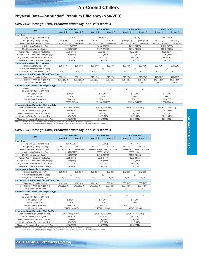
Air-Cooled Chillers
2013 Daikin All Products Catalog 133
Air-C
ooled Chillers
Physical Data—Pathfinder® Premium Efficiency (Non-VFD)
AWS 240B through 310B, Premium Efficiency, non-VFD models
AWS 330B through 400B, Premium Efficiency, non-VFD models
DataAWS240BDP AWS265BDP AWS290BDP AWS310BDP
Circuit 1 Circuit 2 Circuit 1 Circuit 2 Circuit 1 Circuit 2 Circuit 1 Circuit 2Basic Data
Unit Capacity @ AHRI tons (kW) 232 .8 (818) 256 .4 (901) 277 .5 (976) 303 .9 (1068)Unit Operating Charge lbs (kg) 200 (91) 200 (91) 225 (102) 225 (102) (235) (107) (235) (107) 250 (113) 250 (113)
Unit Dimensions L×W×H, in . (mm) 316×88×100 (8022×2225×2548) 351×88×100 (8923×2225×2548) 351×88×100 (8923×2225×2548) 387×88×100 (9823×2225×2545)Unit Operating Weight, lbs . (kg) 17210 (7807) 18631 (8451) 20722 (9400) 21559 (9779)Unit Shipping Weight, lbs (kg) 15958 (7239) 17379 (7883) 19069 (8650) 19906 (9030)
Weight-Add for Copper Fins, lbs (kg) 2372 (1076) 2679 (1215) 2679 (1215) 2968 (1346)Weight-Add for Louvered Panels, lbs (kg) 1012 (459) 1124 (510) 1124 (510) 1236 (561)
Weight-Add for Sound Enclosures, lbs (kg) 477 (216) 477 (216) 477 (216) 477 (216)Weight-Add for PFCC option, lbs (kg) 160 (73) 160 (73) 160 (73) 160 (73)
Compressors, Screw, Semi-HermeticNominal Capacity, tons (kW) 105 (369) 105 (369) 105 (369) 125 (439) 125 (439) 125 (439) 125 (439) 150 (528)
Minimum Capacity (% of Full Load) 15 15 15 15Oil charge per circuit, gallons (liters) 4 .5 (17) 4 .5 (17) 4 .5 (17) 5 .5 (21) 5 .5 (21) 5 .5 (21) 5 .5 (21) 5 .5 (21)
Condensers, High Efficiency Fin and Tube TypePumpdown Capacity, lbs (kg) 333 (151) 333 (151) 375 (170) 375 (170) 375 (170) 375 (170) 416 (189) 416 (189)
Coil Inlet Face Area, sq . ft . (sq . m .) 196 .9 (18 .3) 196 .9 (18 .3) 221 .5 (20 .6) 221 .5 (20 .6) 221 .5 (20 .6) 221 .5 (20 .6) 246 .1 (22 .8) 246 .1 (22 .8)Rows Deep/Fins per Inch 3 / 16 3 / 16 3 / 16 3 / 16 3 / 16 3 / 16 3 / 16 3 / 16
Condenser Fans, Direct-Drive Propeller TypeNumber of Fans per Circuit
Fan Diameter: 31 .5 in . (800 mm)8 8 9 9 9 9 10 10
Fan Motor, hp (kW) 1 .4 (1 .05) 1 .4 (1 .05) 1 .4 (1 .05) 1 .4 (1 .05)Fan & Motor RPM 850 850 850 850
Fan Tip Speed, fpm (m/s) 6984 (35) 6984 (35) 6984 (35) 6984 (35)Airflow, cfm (l/s) 177360 (83704) 199530 (94167) 199530 (94167) 221700 (104630)
Evaporator, Direct Expansion Shell and TubeShell Diameter-Tube Length, in .(mm) 20×154 / (508×3900) 20×154 / (508×3900) 26×154 / (660×3900) 26×154 / (660×3900)
Water Volume, gallons (liters) 158 (599) 158 (599) 276 (1043) 276 (1043)Victaulic inlet/outlet connection in . (mm) 8 (2199 8 (219) 10 (273) 10 (273)
Maximum Water Pressure, psi (kPa) 152 (1048) 152 (1048) 152 (1048) 152 (1048)Maximum Refrigerant Pressure, psi (kPa) 325 (2241) 325 (2241) 325 (2241) 325 (2241)
NOTES: A 20 mesh strainer must be placed in the supply water line just prior to the inlet of the evaporator . Care must be exercised when welding pipe or flanges to the evaporator to prevent any slag from entering the vessel.
DataAWS330BDP AWS365BDP AWS400BDP
Circuit 1 Circuit 2 Circuit 1 Circuit 2 Circuit 1 Circuit 2Basic Data
Unit Capacity @ AHRI tons (kW) 324 .9 (1142) 355 (1248) 385 .4 (1355)Unit Operating Charge lbs (kg) 260 (118) 260 (118) 260 (118) 300 (136) 310 (141) 310 (141)
Unit Dimensions L×W×H, in . (mm) 387×88×100 (9823×2225×2545) 438×88×100 (11123×2225×2548) 473×88×100 (12024×2225×2548)Unit Operating Weight, lbs . (kg) 21559 (9779) 23659 (10732) 25093 (11382)Unit Shipping Weight, lbs (kg) 19906 (9030) 22006 (9982) 23440 (10633)
Weight-Add for Copper Fins, lbs (kg) 2968 (1346) 3256 (1477) 3553 (1612)Weight-Add for Louvered Panels, lbs (kg) 1236 (561) 1348 (611) 1460 (662)
Weight-Add for Sound Enclosures, lbs (kg) 477 (216) 477 (216) 477 (216)Weight-Add for PFCC option, lbs (kg) 160 (73) 160 (73) 160 (73)
Compressors, Screw, Semi-HermeticNominal Capacity, tons (kW) 150 (528) 150 (528) 150 (528) 175 (615) 175 (615) 175 (615)
Minimum Capacity (% of Full Load) 15 15 15Oil charge per circuit, gallons (liters) 5 .5 (21) 5 .5 (21) 5 .5 (21) 6 (23) 6 (23) 6 (23)
Condensers, High Efficiency Fin and Tube TypePumpdown Capacity, lbs (kg) 416 (189) 416 (189) 416 (189) 500 (227) 500 (227) 500 (227)
Coil Inlet Face Area, sq . ft . (sq . m .) 246 .1 (22 .8) 246 .1 (22 .8) 246 .1 (22 .8) 295 .3 (27 .4) 295 .3 (27 .4) 295 .3 (27 .4)Rows Deep/Fins per Inch 3 / 16 3 / 16 3 / 16 3 / 16 3 / 16 3 / 16
Condenser Fans, Direct-Drive Propeller TypeNumber of Fans per Circuit
Fan Diameter: 31 .5 in . (800 mm)10 10 10 12 12 12
Fan Motor, hp (kW) 1 .4 (1 .05) 1 .4 (1 .05) 1 .4 (1 .05)Fan & Motor RPM 850 850 850
Fan Tip Speed, fpm (m/s) 6984 (35) 6984 (35) 6984 (35)Airflow, cfm (l/s) 221700 (104630) 243870 (115093) 266040 (125556)
Evaporator, Direct Expansion Shell And TubeShell Diameter-Tube Length, in . (mm) 26×154 / (660×3900) 26×154 / (660×3900) 26×154 / (660×3900)
Water Volume, gallons (liters) 259 (979) 259 (979) 259 (979)Victaulic inlet/outlet connection in . (mm) 10 (273) 10 (273) 10 (273)
Maximum Water Pressure, psi (kPa) 152 (1048) 152 (1048) 152 (1048)Maximum Refrigerant Pressure, psi (kPa) 325 (2241) 325 (2241) 325 (2241)
NOTES: A 20 mesh strainer must be placed in the supply water line just prior to the inlet of the evaporator . Care must be exercised when welding pipe or flanges to the evaporator to prevent any slag from entering the vessel.
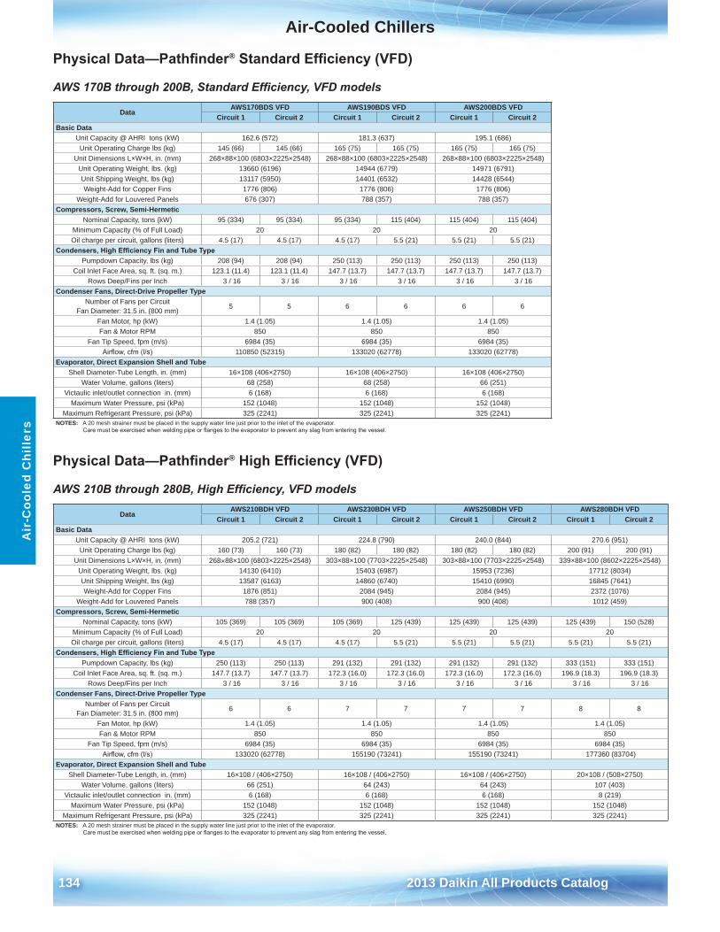
Air-Cooled Chillers
134 2013 Daikin All Products Catalog
Air
-Coo
led
Chi
llers
Physical Data—Pathfinder® Standard Efficiency (VFD)
AWS 170B through 200B, Standard Efficiency, VFD models
Physical Data—Pathfinder® High Efficiency (VFD)
AWS 210B through 280B, High Efficiency, VFD models
DataAWS170BDS VFD AWS190BDS VFD AWS200BDS VFD
Circuit 1 Circuit 2 Circuit 1 Circuit 2 Circuit 1 Circuit 2Basic Data
Unit Capacity @ AHRI tons (kW) 162 .6 (572) 181 .3 (637) 195 .1 (686)Unit Operating Charge lbs (kg) 145 (66) 145 (66) 165 (75) 165 (75) 165 (75) 165 (75)
Unit Dimensions L×W×H, in . (mm) 268×88×100 (6803×2225×2548) 268×88×100 (6803×2225×2548) 268×88×100 (6803×2225×2548)Unit Operating Weight, lbs . (kg) 13660 (6196) 14944 (6779) 14971 (6791)Unit Shipping Weight, lbs (kg) 13117 (5950) 14401 (6532) 14428 (6544)Weight-Add for Copper Fins 1776 (806) 1776 (806) 1776 (806)
Weight-Add for Louvered Panels 676 (307) 788 (357) 788 (357)Compressors, Screw, Semi-Hermetic
Nominal Capacity, tons (kW) 95 (334) 95 (334) 95 (334) 115 (404) 115 (404) 115 (404)Minimum Capacity (% of Full Load) 20 20 20Oil charge per circuit, gallons (liters) 4 .5 (17) 4 .5 (17) 4 .5 (17) 5 .5 (21) 5 .5 (21) 5 .5 (21)
Condensers, High Efficiency Fin and Tube TypePumpdown Capacity, lbs (kg) 208 (94) 208 (94) 250 (113) 250 (113) 250 (113) 250 (113)
Coil Inlet Face Area, sq . ft . (sq . m .) 123 .1 (11 .4) 123 .1 (11 .4) 147 .7 (13 .7) 147 .7 (13 .7) 147 .7 (13 .7) 147 .7 (13 .7)Rows Deep/Fins per Inch 3 / 16 3 / 16 3 / 16 3 / 16 3 / 16 3 / 16
Condenser Fans, Direct-Drive Propeller TypeNumber of Fans per Circuit
Fan Diameter: 31 .5 in . (800 mm)5 5 6 6 6 6
Fan Motor, hp (kW) 1 .4 (1 .05) 1 .4 (1 .05) 1 .4 (1 .05)Fan & Motor RPM 850 850 850
Fan Tip Speed, fpm (m/s) 6984 (35) 6984 (35) 6984 (35)Airflow, cfm (l/s) 110850 (52315) 133020 (62778) 133020 (62778)
Evaporator, Direct Expansion Shell and TubeShell Diameter-Tube Length, in . (mm) 16×108 (406×2750) 16×108 (406×2750) 16×108 (406×2750)
Water Volume, gallons (liters) 68 (258) 68 (258) 66 (251)Victaulic inlet/outlet connection in . (mm) 6 (168) 6 (168) 6 (168)
Maximum Water Pressure, psi (kPa) 152 (1048) 152 (1048) 152 (1048)Maximum Refrigerant Pressure, psi (kPa) 325 (2241) 325 (2241) 325 (2241)
NOTES: A 20 mesh strainer must be placed in the supply water line just prior to the inlet of the evaporator . Care must be exercised when welding pipe or flanges to the evaporator to prevent any slag from entering the vessel.
DataAWS210BDH VFD AWS230BDH VFD AWS250BDH VFD AWS280BDH VFD
Circuit 1 Circuit 2 Circuit 1 Circuit 2 Circuit 1 Circuit 2 Circuit 1 Circuit 2Basic Data
Unit Capacity @ AHRI tons (kW) 205 .2 (721) 224 .8 (790) 240 .0 (844) 270 .6 (951)Unit Operating Charge lbs (kg) 160 (73) 160 (73) 180 (82) 180 (82) 180 (82) 180 (82) 200 (91) 200 (91)
Unit Dimensions L×W×H, in . (mm) 268×88×100 (6803×2225×2548) 303×88×100 (7703×2225×2548) 303×88×100 (7703×2225×2548) 339×88×100 (8602×2225×2548)Unit Operating Weight, lbs . (kg) 14130 (6410) 15403 (6987) 15953 (7236) 17712 (8034)Unit Shipping Weight, lbs (kg) 13587 (6163) 14860 (6740) 15410 (6990) 16845 (7641)Weight-Add for Copper Fins 1876 (851) 2084 (945) 2084 (945) 2372 (1076)
Weight-Add for Louvered Panels 788 (357) 900 (408) 900 (408) 1012 (459)Compressors, Screw, Semi-Hermetic
Nominal Capacity, tons (kW) 105 (369) 105 (369) 105 (369) 125 (439) 125 (439) 125 (439) 125 (439) 150 (528)Minimum Capacity (% of Full Load) 20 20 20 20Oil charge per circuit, gallons (liters) 4 .5 (17) 4 .5 (17) 4 .5 (17) 5 .5 (21) 5 .5 (21) 5 .5 (21) 5 .5 (21) 5 .5 (21)
Condensers, High Efficiency Fin and Tube TypePumpdown Capacity, lbs (kg) 250 (113) 250 (113) 291 (132) 291 (132) 291 (132) 291 (132) 333 (151) 333 (151)
Coil Inlet Face Area, sq . ft . (sq . m .) 147 .7 (13 .7) 147 .7 (13 .7) 172 .3 (16 .0) 172 .3 (16 .0) 172 .3 (16 .0) 172 .3 (16 .0) 196 .9 (18 .3) 196 .9 (18 .3)Rows Deep/Fins per Inch 3 / 16 3 / 16 3 / 16 3 / 16 3 / 16 3 / 16 3 / 16 3 / 16
Condenser Fans, Direct-Drive Propeller TypeNumber of Fans per Circuit
Fan Diameter: 31 .5 in . (800 mm)6 6 7 7 7 7 8 8
Fan Motor, hp (kW) 1 .4 (1 .05) 1 .4 (1 .05) 1 .4 (1 .05) 1 .4 (1 .05)Fan & Motor RPM 850 850 850 850
Fan Tip Speed, fpm (m/s) 6984 (35) 6984 (35) 6984 (35) 6984 (35)Airflow, cfm (l/s) 133020 (62778) 155190 (73241) 155190 (73241) 177360 (83704)
Evaporator, Direct Expansion Shell and TubeShell Diameter-Tube Length, in . (mm) 16×108 / (406×2750) 16×108 / (406×2750) 16×108 / (406×2750) 20×108 / (508×2750)
Water Volume, gallons (liters) 66 (251) 64 (243) 64 (243) 107 (403)Victaulic inlet/outlet connection in . (mm) 6 (168) 6 (168) 6 (168) 8 (219)
Maximum Water Pressure, psi (kPa) 152 (1048) 152 (1048) 152 (1048) 152 (1048)Maximum Refrigerant Pressure, psi (kPa) 325 (2241) 325 (2241) 325 (2241) 325 (2241)
NOTES: A 20 mesh strainer must be placed in the supply water line just prior to the inlet of the evaporator . Care must be exercised when welding pipe or flanges to the evaporator to prevent any slag from entering the vessel.
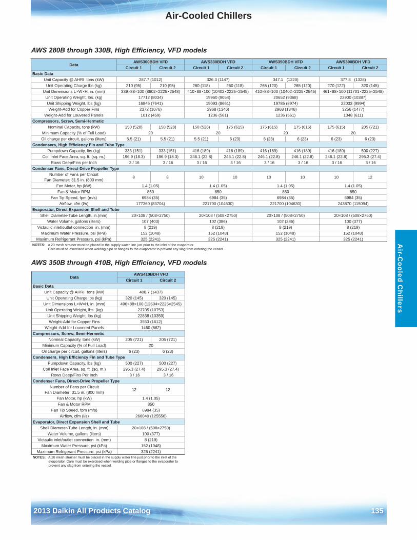
Air-Cooled Chillers
2013 Daikin All Products Catalog 135
Air-C
ooled Chillers
AWS 280B through 330B, High Efficiency, VFD models
AWS 350B through 410B, High Efficiency, VFD models
DataAWS300BDH VFD AWS330BDH VFD AWS350BDH VFD AWS390BDH VFD
Circuit 1 Circuit 2 Circuit 1 Circuit 2 Circuit 1 Circuit 2 Circuit 1 Circuit 2Basic Data
Unit Capacity @ AHRI tons (kW) 287 .7 (1012) 326 .3 (1147) 347 .1 (1220) 377 .8 (1328)Unit Operating Charge lbs (kg) 210 (95) 210 (95) 260 (118) 260 (118) 265 (120) 265 (120) 270 (122) 320 (145)
Unit Dimensions L×W×H, in . (mm) 339×88×100 (8602×2225×2548) 410×88×100 (10402×2225×2545) 410×88×100 (10402×2225×2545) 461×88×100 (11701×2225×2548)Unit Operating Weight, lbs . (kg) 17712 (8034) 19960 (9054) 20652 (9368) 22900 (10387)Unit Shipping Weight, lbs (kg) 16845 (7641) 19093 (8661) 19785 (8974) 22033 (9994)Weight-Add for Copper Fins 2372 (1076) 2968 (1346) 2968 (1346) 3256 (1477)
Weight-Add for Louvered Panels 1012 (459) 1236 (561) 1236 (561) 1348 (611)Compressors, Screw, Semi-Hermetic
Nominal Capacity, tons (kW) 150 (528) 150 (528) 150 (528) 175 (615) 175 (615) 175 (615) 175 (615) 205 (721)Minimum Capacity (% of Full Load) 20 20 20 20Oil charge per circuit, gallons (liters) 5 .5 (21) 5 .5 (21) 5 .5 (21) 6 (23) 6 (23) 6 (23) 6 (23) 6 (23)
Condensers, High Efficiency Fin and Tube TypePumpdown Capacity, lbs (kg) 333 (151) 333 (151) 416 (189) 416 (189) 416 (189) 416 (189) 416 (189) 500 (227)
Coil Inlet Face Area, sq . ft . (sq . m .) 196 .9 (18 .3) 196 .9 (18 .3) 246 .1 (22 .8) 246 .1 (22 .8) 246 .1 (22 .8) 246 .1 (22 .8) 246 .1 (22 .8) 295 .3 (27 .4)Rows Deep/Fins per Inch 3 / 16 3 / 16 3 / 16 3 / 16 3 / 16 3 / 16 3 / 16 3 / 16
Condenser Fans, Direct-Drive Propeller TypeNumber of Fans per Circuit
Fan Diameter: 31 .5 in . (800 mm)8 8 10 10 10 10 10 12
Fan Motor, hp (kW) 1 .4 (1 .05) 1 .4 (1 .05) 1 .4 (1 .05) 1 .4 (1 .05)Fan & Motor RPM 850 850 850 850
Fan Tip Speed, fpm (m/s) 6984 (35) 6984 (35) 6984 (35) 6984 (35)Airflow, cfm (l/s) 177360 (83704) 221700 (104630) 221700 (104630) 243870 (115094)
Evaporator, Direct Expansion Shell and TubeShell Diameter-Tube Length, in .(mm) 20×108 / (508×2750) 20×108 / (508×2750) 20×108 / (508×2750) 20×108 / (508×2750)
Water Volume, gallons (liters) 107 (403) 102 (386) 102 (386) 100 (377)Victaulic inlet/outlet connection in . (mm) 8 (219) 8 (219) 8 (219) 8 (219)
Maximum Water Pressure, psi (kPa) 152 (1048) 152 (1048) 152 (1048) 152 (1048)Maximum Refrigerant Pressure, psi (kPa) 325 (2241) 325 (2241) 325 (2241) 325 (2241)
NOTES: A 20 mesh strainer must be placed in the supply water line just prior to the inlet of the evaporator . Care must be exercised when welding pipe or flanges to the evaporator to prevent any slag from entering the vessel.
DataAWS410BDH VFD
Circuit 1 Circuit 2Basic Data
Unit Capacity @ AHRI tons (kW) 408 .7 (1437)Unit Operating Charge lbs (kg) 320 (145) 320 (145)
Unit Dimensions L×W×H, in . (mm) 496×88×100 (12604×2225×2545)Unit Operating Weight, lbs . (kg) 23705 (10753)Unit Shipping Weight, lbs (kg) 22838 (10359)Weight-Add for Copper Fins 3553 (1612)
Weight-Add for Louvered Panels 1460 (662)Compressors, Screw, Semi-Hermetic
Nominal Capacity, tons (kW) 205 (721) 205 (721)Minimum Capacity (% of Full Load) 20Oil charge per circuit, gallons (liters) 6 (23) 6 (23)
Condensers, High Efficiency Fin and Tube TypePumpdown Capacity, lbs (kg) 500 (227) 500 (227)
Coil Inlet Face Area, sq . ft . (sq . m .) 295 .3 (27 .4) 295 .3 (27 .4)Rows Deep/Fins Per Inch 3 / 16 3 / 16
Condenser Fans, Direct-Drive Propeller TypeNumber of Fans per Circuit
Fan Diameter: 31 .5 in . (800 mm)12 12
Fan Motor, hp (kW) 1 .4 (1 .05)Fan & Motor RPM 850
Fan Tip Speed, fpm (m/s) 6984 (35)Airflow, cfm (l/s) 266040 (125556)
Evaporator, Direct Expansion Shell and TubeShell Diameter-Tube Length, in . (mm) 20×108 / (508×2750)
Water Volume, gallons (liters) 100 (377)Victaulic inlet/outlet connection in . (mm) 8 (219)
Maximum Water Pressure, psi (kPa) 152 (1048)Maximum Refrigerant Pressure, psi (kPa) 325 (2241)
NOTES: A 20 mesh strainer must be placed in the supply water line just prior to the inlet of the evaporator. Care must be exercised when welding pipe or flanges to the evaporator to prevent any slag from entering the vessel .
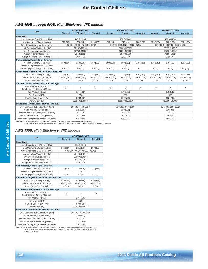
Air-Cooled Chillers
136 2013 Daikin All Products Catalog
Air
-Coo
led
Chi
llers
AWS 450B through 500B, High Efficiency, VFD models
AWS 530B, High Efficiency, VFD models
DataAWS450BTH VFD AWS475BTH VFD AWS500BTH VFD
Circuit 1 Circuit 2 Circuit 3 Circuit 1 Circuit 2 Circuit 3 Circuit 1 Circuit 2 Circuit 3Basic Data
Unit Capacity @ AHRI tons (kW) 445 .2 (1565) 467 .7 (1644) 497 .8 (1750)Unit Operating Charge lbs (kg) 210 (95) 210 (95) 220 (100) 210 (95) 210 (95) 280 (187) 265 (120) 265 (120) 220 (100)
Unit Dimensions L×W×H, in . (mm) 496×88×100 (12605×2225×2548) 532×88×100 (13504×2225×2545) 567×88×100 (14405×2225×2548)Unit Operating Weight, lbs . (kg) 27152 (12316) 28300 (12837) 30117 (13661)Unit Shipping Weight, lbs (kg) 25753 (11682) 26901 (12202) 28718 (13026)Weight-Add for Copper Fins 3553 (1612) 3870 (1755) 4168 (1891)
Weight-Add for Louvered Panels 1460 (662) 1572 (713) 1684 (764)Compressors, Screw, Semi-Hermetic
Nominal Capacity, tons (kW) 150 (528) 150 (528) 150 (528) 150 (528) 150 (528) 175 (615) 175 (615) 175 (615) 150 (528)Minimum Capacity (% of Full Load) 13 13 13Oil charge per circuit, gallons (liters) 5 .5 (21) 5 .5 (21) 5 .5 (21) 5 .5 (21) 5 .5 (21) 6 (23) 6 (23) 6 (23) 5 .5 (21)
Condensers, High Efficiency Fin and Tube TypePumpdown Capacity, lbs (kg) 333 (151) 333 (151) 333 (151) 333 (151) 333 (151) 416 (189) 416 (189) 416 (189) 333 (151)
Coil Inlet Face Area, sq . ft . (sq . m .) 196 .9 (18 .3) 196 .9 (18 .3) 196 .9 (18 .3) 196 .9 (18 .3) 196 .9 (18 .3) 246 .1 (22 .8) 246 .1 (22 .8) 246 .1 (22 .8) 196 .9 (18 .3)Rows Deep/Fins per Inch 3 / 16 3 / 16 3 / 16 3 / 16 3 / 16 3 / 16 3 / 16 3 / 16 3 / 16
Condenser Fans, Direct-Drive Propeller TypeNumber of Fans per Circuit
Fan Diameter: 31 .5 in . (800 mm)8 8 8 8 8 10 10 10 8
Fan Motor, hp (kW) 1 .4 (1 .05) 1 .4 (1 .05) 1 .4 (1 .05)Fan & Motor RPM 850 850 850
Fan Tip Speed, fpm (m/s) 6984 (35) 6984 (35) 6984 (35)Airflow, cfm (l/s) 266040 (125556) 288210 (136019) 310380 (146482)
Evaporator, Direct Expansion Shell and TubeShell Diameter-Tube Length, in . (mm) 26×130 / (660×3300) 26×130 / (660×3300) 26×130 / (660×3300)
Water Volume, gallons (liters) 225 (850) 220 (831) 220 (831)Victaulic inlet/outlet connection in . (mm) 10 (273) 10 (273) 10 (273)
Maximum Water Pressure, psi (kPa) 152 (1048) 152 (1048) 152 (1048)Maximum Refrigerant Pressure, psi (kPa) 325 (2241) 325 (2241) 325 (2241)
NOTES: A 20 mesh strainer must be placed in the supply water line just prior to the inlet of the evaporator . Care must be exercised when welding pipe or flanges to the evaporator to prevent any slag from entering the vessel.
DataAWS530BTH VFD
Circuit 1 Circuit 2 Circuit 3Basic Data
Unit Capacity @ AHRI tons (kW) 524 .8 (1845)Unit Operating Charge lbs (kg) 265 (120) 265 (120) 280 (187)
Unit Dimensions L×W×H, in . (mm) 603×88×100 (15304×2225×2545)Unit Operating Weight, lbs . (kg) 31446 (14264)Unit Shipping Weight, lbs (kg) 30047 (13629)Weight-Add for Copper Fins 4466 (2026)
Weight-Add for Louvered Panels 1796 (815)Compressors, Screw, Semi-Hermetic
Nominal Capacity, tons (kW) 175 (615) 175 (615) 175 (615)Minimum Capacity (% of Full Load) 13Oil charge per circuit, gallons (liters) 6 (23) 6 (23) 6 (23)
Condensers, High Efficiency Fin and Tube TypePumpdown Capacity, lbs (kg) 416 (189) 416 (189) 416 (189)
Coil Inlet Face Area, sq . ft . (sq . m .) 246 .1 (22 .8) 246 .1 (22 .8) 246 .1 (22 .8)Rows Deep/Fins Per Inch 3 / 16 3 / 16 3 / 16
Condenser Fans, Direct-Drive Propeller TypeNumber of Fans per Circuit
Fan Diameter: 31 .5 in . (800 mm)10 10 10
Fan Motor, hp (kW) 1 .4 (1 .05)Fan & Motor RPM 850
Fan Tip Speed, fpm (m/s) 6984 (35)Airflow, cfm (l/s) 332550 (156945)
Evaporator, Direct Expansion Shell and TubeShell Diameter-Tube Length, in . (mm) 26×130 / (660×3300)
Water Volume, gallons (liters) 220 (831)Victaulic inlet/outlet connection in . (mm) 10 (273)
Maximum Water Pressure, psi (kPa) 152 (1048)Maximum Refrigerant Pressure, psi (kPa) 325 (2241)
NOTES: A 20 mesh strainer must be placed in the supply water line just prior to the inlet of the evaporator . Care must be exercised when welding pipe or flanges to the evaporator to prevent any slag from entering the vessel .
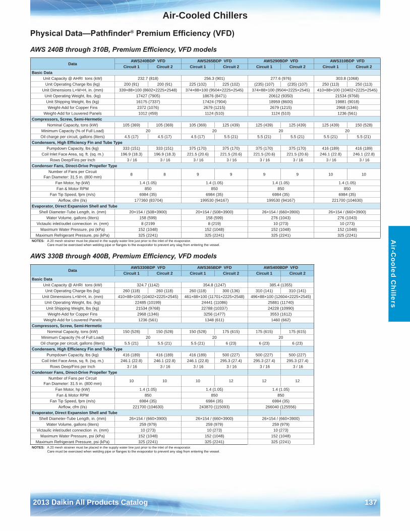
Air-Cooled Chillers
2013 Daikin All Products Catalog 137
Air-C
ooled Chillers
Physical Data—Pathfinder® Premium Efficiency (VFD)
AWS 240B through 310B, Premium Efficiency, VFD models
AWS 330B through 400B, Premium Efficiency, VFD models
DataAWS240BDP VFD AWS265BDP VFD AWS290BDP VFD AWS310BDP VFD
Circuit 1 Circuit 2 Circuit 1 Circuit 2 Circuit 1 Circuit 2 Circuit 1 Circuit 2Basic Data
Unit Capacity @ AHRI tons (kW) 232 .7 (818) 256 .3 (901) 277 .6 (976) 303 .8 (1068)Unit Operating Charge lbs (kg) 200 (91) 200 (91) 225 (102) 225 (102) (235) (107) (235) (107) 250 (113) 250 (113)
Unit Dimensions L×W×H, in . (mm) 339×88×100 (8602×2225×2548) 374×88×100 (9504×2225×2545) 374×88×100 (9504×2225×2545) 410×88×100 (10402×2225×2545)Unit Operating Weight, lbs . (kg) 17427 (7905) 18676 (8471) 20612 (9350) 21534 (9768)Unit Shipping Weight, lbs (kg) 16175 (7337) 17424 (7904) 18959 (8600) 19881 (9018)Weight-Add for Copper Fins 2372 (1076) 2679 (1215) 2679 (1215) 2968 (1346)
Weight-Add for Louvered Panels 1012 (459) 1124 (510) 1124 (510) 1236 (561)Compressors, Screw, Semi-Hermetic
Nominal Capacity, tons (kW) 105 (369) 105 (369) 105 (369) 125 (439) 125 (439) 125 (439) 125 (439) 150 (528)Minimum Capacity (% of Full Load) 20 20 20 20Oil charge per circuit, gallons (liters) 4 .5 (17) 4 .5 (17) 4 .5 (17) 5 .5 (21) 5 .5 (21) 5 .5 (21) 5 .5 (21) 5 .5 (21)
Condensers, High Efficiency Fin and Tube TypePumpdown Capacity, lbs (kg) 333 (151) 333 (151) 375 (170) 375 (170) 375 (170) 375 (170) 416 (189) 416 (189)
Coil Inlet Face Area, sq . ft . (sq . m .) 196 .9 (18 .3) 196 .9 (18 .3) 221 .5 (20 .6) 221 .5 (20 .6) 221 .5 (20 .6) 221 .5 (20 .6) 246 .1 (22 .8) 246 .1 (22 .8)Rows Deep/Fins per Inch 3 / 16 3 / 16 3 / 16 3 / 16 3 / 16 3 / 16 3 / 16 3 / 16
Condenser Fans, Direct-Drive Propeller TypeNumber of Fans per Circuit
Fan Diameter: 31 .5 in . (800 mm)8 8 9 9 9 9 10 10
Fan Motor, hp (kW) 1 .4 (1 .05) 1 .4 (1 .05) 1 .4 (1 .05) 1 .4 (1 .05)Fan & Motor RPM 850 850 850 850
Fan Tip Speed, fpm (m/s) 6984 (35) 6984 (35) 6984 (35) 6984 (35)Airflow, cfm (l/s) 177360 (83704) 199530 (94167) 199530 (94167) 221700 (104630)
Evaporator, Direct Expansion Shell and TubeShell Diameter-Tube Length, in . (mm) 20×154 / (508×3900) 20×154 / (508×3900) 26×154 / (660×3900) 26×154 / (660×3900)
Water Volume, gallons (liters) 158 (599) 158 (599) 276 (1043) 276 (1043)Victaulic inlet/outlet connection in . (mm) 8 (2199 8 (219) 10 (273) 10 (273)
Maximum Water Pressure, psi (kPa) 152 (1048) 152 (1048) 152 (1048) 152 (1048)Maximum Refrigerant Pressure, psi (kPa) 325 (2241) 325 (2241) 325 (2241) 325 (2241)
NOTES: A 20 mesh strainer must be placed in the supply water line just prior to the inlet of the evaporator . Care must be exercised when welding pipe or flanges to the evaporator to prevent any slag from entering the vessel.
DataAWS330BDP VFD AWS365BDP VFD AWS400BDP VFD
Circuit 1 Circuit 2 Circuit 1 Circuit 2 Circuit 1 Circuit 2Basic Data
Unit Capacity @ AHRI tons (kW) 324 .7 (1142) 354 .8 (1247) 385 .4 (1355)Unit Operating Charge lbs (kg) 260 (118) 260 (118) 260 (118) 300 (136) 310 (141) 310 (141)
Unit Dimensions L×W×H, in . (mm) 410×88×100 (10402×2225×2545) 461×88×100 (11701×2225×2548) 496×88×100 (12604×2225×2545)Unit Operating Weight, lbs . (kg) 22485 (10199) 24441 (11086) 25881 (11740)Unit Shipping Weight, lbs (kg) 21534 (9768) 22788 (10337) 24228 (10990)Weight-Add for Copper Fins 2968 (1346) 3256 (1477) 3553 (1612)
Weight-Add for Louvered Panels 1236 (561) 1348 (611) 1460 (662)Compressors, Screw, Semi-Hermetic
Nominal Capacity, tons (kW) 150 (528) 150 (528) 150 (528) 175 (615) 175 (615) 175 (615)Minimum Capacity (% of Full Load) 20 20 20Oil charge per circuit, gallons (liters) 5 .5 (21) 5 .5 (21) 5 .5 (21) 6 (23) 6 (23) 6 (23)
Condensers, High Efficiency Fin and Tube TypePumpdown Capacity, lbs (kg) 416 (189) 416 (189) 416 (189) 500 (227) 500 (227) 500 (227)
Coil Inlet Face Area, sq . ft . (sq . m .) 246 .1 (22 .8) 246 .1 (22 .8) 246 .1 (22 .8) 295 .3 (27 .4) 295 .3 (27 .4) 295 .3 (27 .4)Rows Deep/Fins per Inch 3 / 16 3 / 16 3 / 16 3 / 16 3 / 16 3 / 16
Condenser Fans, Direct-Drive Propeller TypeNumber of Fans per Circuit
Fan Diameter: 31 .5 in . (800 mm)10 10 10 12 12 12
Fan Motor, hp (kW) 1 .4 (1 .05) 1 .4 (1 .05) 1 .4 (1 .05)Fan & Motor RPM 850 850 850
Fan Tip Speed, fpm (m/s) 6984 (35) 6984 (35) 6984 (35)Airflow, cfm (l/s) 221700 (104630) 243870 (115093) 266040 (125556)
Evaporator, Direct Expansion Shell and TubeShell Diameter-Tube Length, in . (mm) 26×154 / (660×3900) 26×154 / (660×3900) 26×154 / (660×3900)
Water Volume, gallons (liters) 259 (979) 259 (979) 259 (979)Victaulic inlet/outlet connection in . (mm) 10 (273) 10 (273) 10 (273)
Maximum Water Pressure, psi (kPa) 152 (1048) 152 (1048) 152 (1048)Maximum Refrigerant Pressure, psi (kPa) 325 (2241) 325 (2241) 325 (2241)
NOTES: A 20 mesh strainer must be placed in the supply water line just prior to the inlet of the evaporator . Care must be exercised when welding pipe or flanges to the evaporator to prevent any slag from entering the vessel.
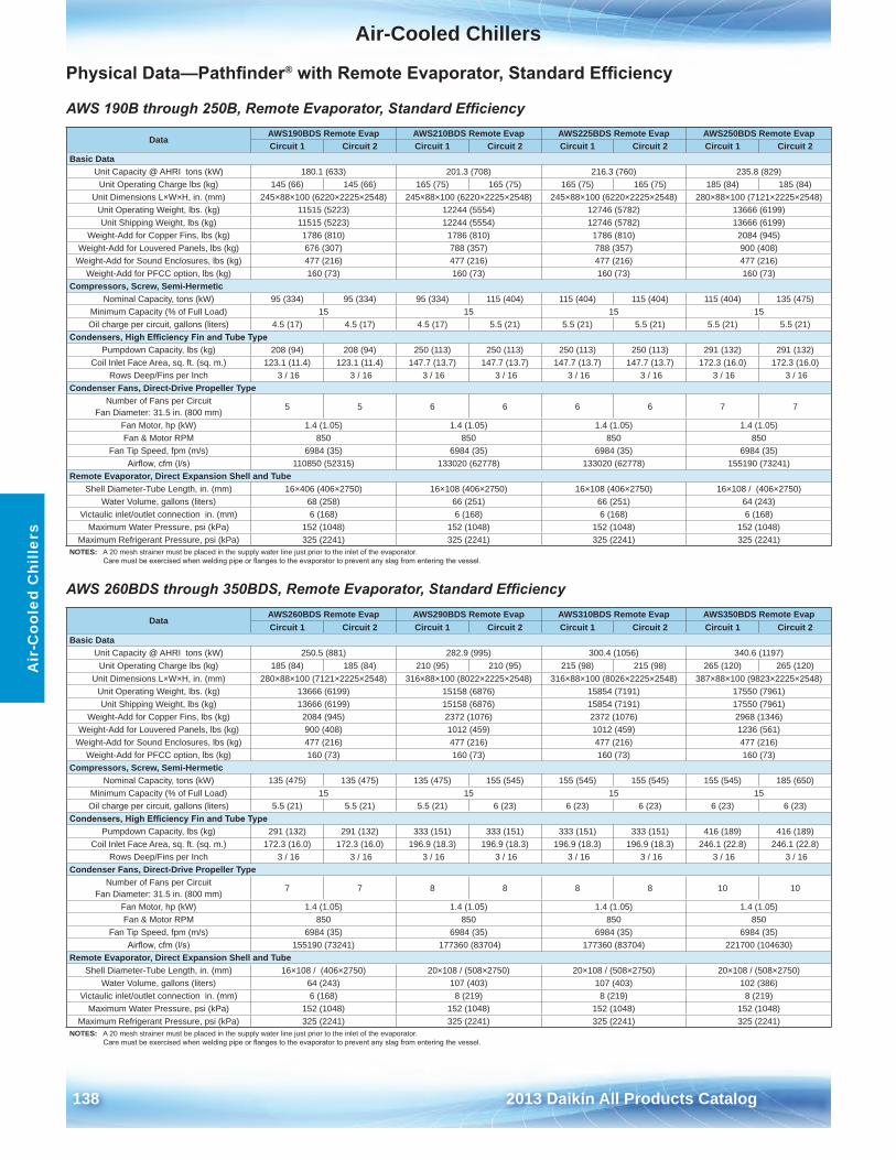
Air-Cooled Chillers
138 2013 Daikin All Products Catalog
Air
-Coo
led
Chi
llers
Physical Data—Pathfinder® with Remote Evaporator, Standard Efficiency
AWS 190B through 250B, Remote Evaporator, Standard Efficiency
AWS 260BDS through 350BDS, Remote Evaporator, Standard Efficiency
DataAWS190BDS Remote Evap AWS210BDS Remote Evap AWS225BDS Remote Evap AWS250BDS Remote EvapCircuit 1 Circuit 2 Circuit 1 Circuit 2 Circuit 1 Circuit 2 Circuit 1 Circuit 2
Basic DataUnit Capacity @ AHRI tons (kW) 180 .1 (633) 201 .3 (708) 216 .3 (760) 235 .8 (829)
Unit Operating Charge lbs (kg) 145 (66) 145 (66) 165 (75) 165 (75) 165 (75) 165 (75) 185 (84) 185 (84)Unit Dimensions L×W×H, in . (mm) 245×88×100 (6220×2225×2548) 245×88×100 (6220×2225×2548) 245×88×100 (6220×2225×2548) 280×88×100 (7121×2225×2548)
Unit Operating Weight, lbs . (kg) 11515 (5223) 12244 (5554) 12746 (5782) 13666 (6199)Unit Shipping Weight, lbs (kg) 11515 (5223) 12244 (5554) 12746 (5782) 13666 (6199)
Weight-Add for Copper Fins, lbs (kg) 1786 (810) 1786 (810) 1786 (810) 2084 (945)Weight-Add for Louvered Panels, lbs (kg) 676 (307) 788 (357) 788 (357) 900 (408)
Weight-Add for Sound Enclosures, lbs (kg) 477 (216) 477 (216) 477 (216) 477 (216)Weight-Add for PFCC option, lbs (kg) 160 (73) 160 (73) 160 (73) 160 (73)
Compressors, Screw, Semi-HermeticNominal Capacity, tons (kW) 95 (334) 95 (334) 95 (334) 115 (404) 115 (404) 115 (404) 115 (404) 135 (475)
Minimum Capacity (% of Full Load) 15 15 15 15Oil charge per circuit, gallons (liters) 4 .5 (17) 4 .5 (17) 4 .5 (17) 5 .5 (21) 5 .5 (21) 5 .5 (21) 5 .5 (21) 5 .5 (21)
Condensers, High Efficiency Fin and Tube TypePumpdown Capacity, lbs (kg) 208 (94) 208 (94) 250 (113) 250 (113) 250 (113) 250 (113) 291 (132) 291 (132)
Coil Inlet Face Area, sq . ft . (sq . m .) 123 .1 (11 .4) 123 .1 (11 .4) 147 .7 (13 .7) 147 .7 (13 .7) 147 .7 (13 .7) 147 .7 (13 .7) 172 .3 (16 .0) 172 .3 (16 .0)Rows Deep/Fins per Inch 3 / 16 3 / 16 3 / 16 3 / 16 3 / 16 3 / 16 3 / 16 3 / 16
Condenser Fans, Direct-Drive Propeller TypeNumber of Fans per Circuit
Fan Diameter: 31 .5 in . (800 mm)5 5 6 6 6 6 7 7
Fan Motor, hp (kW) 1 .4 (1 .05) 1 .4 (1 .05) 1 .4 (1 .05) 1 .4 (1 .05)Fan & Motor RPM 850 850 850 850
Fan Tip Speed, fpm (m/s) 6984 (35) 6984 (35) 6984 (35) 6984 (35)Airflow, cfm (l/s) 110850 (52315) 133020 (62778) 133020 (62778) 155190 (73241)
Remote Evaporator, Direct Expansion Shell and TubeShell Diameter-Tube Length, in . (mm) 16×406 (406×2750) 16×108 (406×2750) 16×108 (406×2750) 16×108 / (406×2750)
Water Volume, gallons (liters) 68 (258) 66 (251) 66 (251) 64 (243)Victaulic inlet/outlet connection in . (mm) 6 (168) 6 (168) 6 (168) 6 (168)
Maximum Water Pressure, psi (kPa) 152 (1048) 152 (1048) 152 (1048) 152 (1048)Maximum Refrigerant Pressure, psi (kPa) 325 (2241) 325 (2241) 325 (2241) 325 (2241)
NOTES: A 20 mesh strainer must be placed in the supply water line just prior to the inlet of the evaporator . Care must be exercised when welding pipe or flanges to the evaporator to prevent any slag from entering the vessel.
DataAWS260BDS Remote Evap AWS290BDS Remote Evap AWS310BDS Remote Evap AWS350BDS Remote EvapCircuit 1 Circuit 2 Circuit 1 Circuit 2 Circuit 1 Circuit 2 Circuit 1 Circuit 2
Basic DataUnit Capacity @ AHRI tons (kW) 250 .5 (881) 282 .9 (995) 300 .4 (1056) 340 .6 (1197)
Unit Operating Charge lbs (kg) 185 (84) 185 (84) 210 (95) 210 (95) 215 (98) 215 (98) 265 (120) 265 (120)Unit Dimensions L×W×H, in . (mm) 280×88×100 (7121×2225×2548) 316×88×100 (8022×2225×2548) 316×88×100 (8026×2225×2548) 387×88×100 (9823×2225×2548)
Unit Operating Weight, lbs . (kg) 13666 (6199) 15158 (6876) 15854 (7191) 17550 (7961)Unit Shipping Weight, lbs (kg) 13666 (6199) 15158 (6876) 15854 (7191) 17550 (7961)
Weight-Add for Copper Fins, lbs (kg) 2084 (945) 2372 (1076) 2372 (1076) 2968 (1346)Weight-Add for Louvered Panels, lbs (kg) 900 (408) 1012 (459) 1012 (459) 1236 (561)
Weight-Add for Sound Enclosures, lbs (kg) 477 (216) 477 (216) 477 (216) 477 (216)Weight-Add for PFCC option, lbs (kg) 160 (73) 160 (73) 160 (73) 160 (73)
Compressors, Screw, Semi-HermeticNominal Capacity, tons (kW) 135 (475) 135 (475) 135 (475) 155 (545) 155 (545) 155 (545) 155 (545) 185 (650)
Minimum Capacity (% of Full Load) 15 15 15 15Oil charge per circuit, gallons (liters) 5 .5 (21) 5 .5 (21) 5 .5 (21) 6 (23) 6 (23) 6 (23) 6 (23) 6 (23)
Condensers, High Efficiency Fin and Tube TypePumpdown Capacity, lbs (kg) 291 (132) 291 (132) 333 (151) 333 (151) 333 (151) 333 (151) 416 (189) 416 (189)
Coil Inlet Face Area, sq . ft . (sq . m .) 172 .3 (16 .0) 172 .3 (16 .0) 196 .9 (18 .3) 196 .9 (18 .3) 196 .9 (18 .3) 196 .9 (18 .3) 246 .1 (22 .8) 246 .1 (22 .8)Rows Deep/Fins per Inch 3 / 16 3 / 16 3 / 16 3 / 16 3 / 16 3 / 16 3 / 16 3 / 16
Condenser Fans, Direct-Drive Propeller TypeNumber of Fans per Circuit
Fan Diameter: 31 .5 in . (800 mm)7 7 8 8 8 8 10 10
Fan Motor, hp (kW) 1 .4 (1 .05) 1 .4 (1 .05) 1 .4 (1 .05) 1 .4 (1 .05)Fan & Motor RPM 850 850 850 850
Fan Tip Speed, fpm (m/s) 6984 (35) 6984 (35) 6984 (35) 6984 (35)Airflow, cfm (l/s) 155190 (73241) 177360 (83704) 177360 (83704) 221700 (104630)
Remote Evaporator, Direct Expansion Shell and TubeShell Diameter-Tube Length, in . (mm) 16×108 / (406×2750) 20×108 / (508×2750) 20×108 / (508×2750) 20×108 / (508×2750)
Water Volume, gallons (liters) 64 (243) 107 (403) 107 (403) 102 (386)Victaulic inlet/outlet connection in . (mm) 6 (168) 8 (219) 8 (219) 8 (219)
Maximum Water Pressure, psi (kPa) 152 (1048) 152 (1048) 152 (1048) 152 (1048)Maximum Refrigerant Pressure, psi (kPa) 325 (2241) 325 (2241) 325 (2241) 325 (2241)
NOTES: A 20 mesh strainer must be placed in the supply water line just prior to the inlet of the evaporator . Care must be exercised when welding pipe or flanges to the evaporator to prevent any slag from entering the vessel.
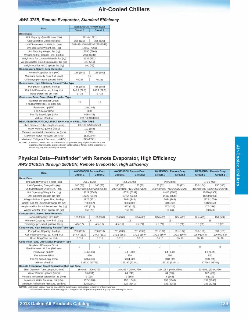
Air-Cooled Chillers
2013 Daikin All Products Catalog 139
Air-C
ooled Chillers
AWS 375B, Remote Evaporator, Standard Efficiency
Physical Data—Pathfinder® with Remote Evaporator, High EfficiencyAWS 210BDH through 280BDH, Remote Evaporator, High Efficiency
DataAWS375BDS Remote EvapCircuit 1 Circuit 2
Basic DataUnit Capacity @ AHRI tons (kW) 361 .4 (1271)
Unit Operating Charge lbs (kg) 265 (120) 265 (120)Unit Dimensions L×W×H, in . (mm) 387×88×100 (9823×2225×2548)
Unit Operating Weight, lbs . (kg) 17550 (7961)Unit Shipping Weight, lbs (kg) 17550 (7961)
Weight-Add for Copper Fins, lbs (kg) 2968 (1346)Weight-Add for Louvered Panels, lbs (kg) 1236 (561)
Weight-Add for Sound Enclosures, lbs (kg) 477 (216)Weight-Add for PFCC option, lbs (kg) 160 (73)
Compressors, Screw, Semi-HermeticNominal Capacity, tons (kW) 185 (650) 185 (650)
Minimum Capacity (% of Full Load) 15Oil charge per circuit, gallons (liters) 6 (23) 6 (23)
Condensers, High Efficiency Fin and Tube TypePumpdown Capacity, lbs (kg) 416 (189) 416 (189)
Coil Inlet Face Area, sq . ft . (sq . m .) 246 .1 (22 .8) 246 .1 (22 .8)Rows Deep/Fins per Inch 3 / 16 3 / 16
Condenser Fans, Direct-Drive Propeller TypeNumber of Fans per Circuit
Fan Diameter: 31 .5 in . (800 mm)10 10
Fan Motor, hp (kW) 1 .4 (1 .05)Fan & Motor RPM 850
Fan Tip Speed, fpm (m/s) 6984 (35)Airflow, cfm (l/s) 221700 (104630)
REMOTE EVAPORATOR, DIRECT EXPANSION SHELL AND TUBEShell Diameter-Tube Length, in . (mm) 20×108 / (508×2750)
Water Volume, gallons (liters) 102 (386)Victaulic inlet/outlet connection in . (mm) 8 (219)
Maximum Water Pressure, psi (kPa) 152 (1048)Maximum Refrigerant Pressure, psi (kPa) 325 (2241)
NOTES: A 20 mesh strainer must be placed in the supply water line just prior to the inlet of the evaporator. Care must be exercised when welding pipe or flanges to the evaporator to prevent any slag from entering the vessel .
DataAWS210BDH Remote Evap AWS230BDH Remote Evap AWS250BDH Remote Evap AWS280BDH Remote EvapCircuit 1 Circuit 2 Circuit 1 Circuit 2 Circuit 1 Circuit 2 Circuit 1 Circuit 2
Basic DataUnit Capacity @ AHRI tons (kW) 205 .7 (723) 225 .2 (792) 240 .6 (846) 271 .9 (956)
Unit Operating Charge lbs (kg) 160 (73) 160 (73) 180 (82) 180 (82) 180 (82) 180 (82) 230 (104) 250 (113)Unit Dimensions L×W×H, in . (mm) 245×88×100 (6220×2225×2548) 280×88×100 (7121×2225×2548) 280×88×100 (7121×2225×2548) 316×88×100 (8022×2225×2548)
Unit Operating Weight, lbs . (kg) 12229 (5547) 13754 (6239) 14417 (6540) 15230 (6908)Unit Shipping Weight, lbs (kg) 12229 (5547) 13754 (6239) 14417 (6540) 15230 (6908)
Weight-Add for Copper Fins, lbs (kg) 1876 (851) 2084 (945) 2084 (945) 2372 (1076)Weight-Add for Louvered Panels, lbs (kg) 788 (357) 900 (408) 900 (408) 1012 (459)
Weight-Add for Sound Enclosures, lbs (kg) 477 (216) 477 (216) 477 (216) 477 (216)Weight-Add for PFCC option, lbs (kg) 160 (73) 160 (73) 160 (73) 160 (73)
Compressors, Screw, Semi-HermeticNominal Capacity, tons (kW) 105 (369) 105 (369) 105 (369) 125 (439) 125 (439) 125 (439) 125 (439) 150 (528)
Minimum Capacity (% of Full Load) 15 15 15 15Oil charge per circuit, gallons (liters) 4 .5 (17) 4 .5 (17) 4 .5 (17) 5 .5 (21) 5 .5 (21) 5 .5 (21) 5 .5 (21) 5 .5 (21)
Condensers, High Efficiency Fin and Tube TypePumpdown Capacity, lbs (kg) 250 (113) 250 (113) 291 (132) 291 (132) 291 (132) 291 (132) 333 (151) 333 (151)
Coil Inlet Face Area, sq . ft . (sq . m .) 147 .7 (13 .7) 147 .7 (13 .7) 172 .3 (16 .0) 172 .3 (16 .0) 172 .3 (16 .0) 172 .3 (16 .0) 196 .9 (18 .3) 196 .9 (18 .3)Rows Deep/Fins per Inch 3 / 16 3 / 16 3 / 16 3 / 16 3 / 16 3 / 16 3 / 16 3 / 16
Condenser Fans, Direct-Drive Propeller TypeNumber of Fans per Circuit
Fan Diameter: 31 .5 in . (800 mm)6 6 7 7 7 7 8 8
Fan Motor, hp (kW) 1 .4 (1 .05) 1 .4 (1 .05) 1 .4 (1 .05) 1 .4 (1 .05)Fan & Motor RPM 850 850 850 850
Fan Tip Speed, fpm (m/s) 6984 (35) 6984 (35) 6984 (35) 6984 (35)Airflow, cfm (l/s) 133020 (62778) 155190 (73241) 155190 (73241) 177360 (83704)
Remote Evaporator, Direct Expansion Shell and TubeShell Diameter-Tube Length, in . (mm) 16×108 / (406×2750) 16×108 / (406×2750) 16×108 / (406×2750) 20×108 / (508×2750)
Water Volume, gallons (liters) 66 (251) 64 (243) 64 (243) 107 (403)Victaulic inlet/outlet connection in . (mm) 6 (168) 6 (168) 6 (168) 8 (219)
Maximum Water Pressure, psi (kPa) 152 (1048) 152 (1048) 152 (1048) 152 (1048)Maximum Refrigerant Pressure, psi (kPa) 325 (2241) 325 (2241) 325 (2241) 325 (2241)
NOTES: A 20 mesh strainer must be placed in the supply water line just prior to the inlet of the evaporator . Care must be exercised when welding pipe or flanges to the evaporator to prevent any slag from entering the vessel.
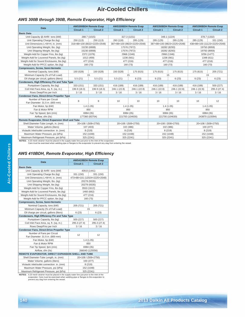
Air-Cooled Chillers
140 2013 Daikin All Products Catalog
Air
-Coo
led
Chi
llers
AWS 300B through 390B, Remote Evaporator, High Efficiency
AWS 410BDH, Remote Evaporator, High Efficiency
DataAWS300BDH Remote Evap AWS330BDH Remote Evap AWS350BDH Remote Evap AWS390BDH Remote EvapCircuit 1 Circuit 2 Circuit 1 Circuit 2 Circuit 1 Circuit 2 Circuit 1 Circuit 2
Basic DataUnit Capacity @ AHRI tons (kW) 288 .7 (1015) 327 .3 (1151) 348 .1 (1224) 378 .7 (1332)
Unit Operating Charge lbs (kg) 250 (113) 250 (113) 260 (118) 285 (129) 285 (129) 285 (129) 285 (129) 331 (150)Unit Dimensions L×W×H, in . (mm) 316×88×100 (8022×2225×2548) 387×88×100 (9823×2225×2548) 387×88×100 (9823×2225×2548) 438×88×100 (11123×2225×2548)
Unit Operating Weight, lbs . (kg) 15230 (6908) 17576 (7972) 18282 (8293) 19750 (8959)Unit Shipping Weight, lbs (kg) 15230 (6908) 17576 (7972) 18282 (8293) 19750 (8959)
Weight-Add for Copper Fins, lbs (kg) 2372 (1076) 2968 (1346) 2968 (1346) 3256 (1477)Weight-Add for Louvered Panels, lbs (kg) 1012 (459) 1236 (561) 1236 (561) 1348 (611)
Weight-Add for Sound Enclosures, lbs (kg) 477 (216) 477 (216) 477 (216) 477 (216)Weight-Add for PFCC option, lbs (kg) 160 (73) 160 (73) 160 (73) 160 (73)
Compressors, Screw, Semi-HermeticNominal Capacity, tons (kW) 150 (528) 150 (528) 150 (528) 175 (615) 175 (615) 175 (615) 175 (615) 205 (721)
Minimum Capacity (% of Full Load) 15 15 15 15Oil charge per circuit, gallons (liters) 5 .5 (21) 5 .5 (21) 5 .5 (21) 6 (23) 6 (23) 6 (23) 6 (23) 6 (23)
Condensers, High Efficiency Fin and Tube TypePumpdown Capacity, lbs (kg) 333 (151) 333 (151) 416 (189) 416 (189) 416 (189) 416 (189) 416 (189) 500 (227)
Coil Inlet Face Area, sq . ft . (sq . m .) 196 .9 (18 .3) 196 .9 (18 .3) 246 .1 (22 .8) 246 .1 (22 .8) 246 .1 (22 .8) 246 .1 (22 .8) 246 .1 (22 .8) 295 .3 (27 .4)Rows Deep/Fins per Inch 3 / 16 3 / 16 3 / 16 3 / 16 3 / 16 3 / 16 3 / 16 3 / 16
Condenser Fans, Direct-Drive Propeller TypeNumber of Fans per Circuit
Fan Diameter: 31 .5 in . (800 mm)8 8 10 10 10 10 10 12
Fan Motor, hp (kW) 1 .4 (1 .05) 1 .4 (1 .05) 1 .4 (1 .05) 1 .4 (1 .05)Fan & Motor RPM 850 850 850 850
Fan Tip Speed, fpm (m/s) 6984 (35) 6984 (35) 6984 (35) 6984 (35)Airflow, cfm (l/s) 177360 (83704) 221700 (104630) 221700 (104630) 243870 (115094)
Remote Evaporator, Direct Expansion Shell and TubeShell Diameter-Tube Length, in . (mm) 20×108 / (508×2750) 20×108 / (508×2750) 20×108 / (508×2750) 20×108 / (508×2750)
Water Volume, gallons (liters) 107 (403) 102 (386) 102 (386) 100 (377)Victaulic inlet/outlet connection in . (mm) 8 (219) 8 (219) 8 (219) 8 (219)
Maximum Water Pressure, psi (kPa) 152 (1048) 152 (1048) 152 (1048) 152 (1048)Maximum Refrigerant Pressure, psi (kPa) 325 (2241) 325 (2241) 325 (2241) 325 (2241)
NOTES: A 20 mesh strainer must be placed in the supply water line just prior to the inlet of the evaporator . Care must be exercised when welding pipe or flanges to the evaporator to prevent any slag from entering the vessel.
DataAWS410BDH Remote EvapCircuit 1 Circuit 2
Basic DataUnit Capacity @ AHRI tons (kW) 409 .8 (1441)
Unit Operating Charge lbs (kg) 331 (150) 331 (150)Unit Dimensions L×W×H, in . (mm) 473×88×101 (12024×2225×2548)
Unit Operating Weight, lbs . (kg) 20279 (9335)Unit Shipping Weight, lbs (kg) 20279 (9335)
Weight-Add for Copper Fins, lbs (kg) 3553 (1612)Weight-Add for Louvered Panels, lbs (kg) 1460 (662)
Weight-Add for Sound Enclosures, lbs (kg) 477 (216)Weight-Add for PFCC option, lbs (kg) 160 (73)
Compressors, Screw, Semi-HermeticNominal Capacity, tons (kW) 205 (721) 205 (721)
Minimum Capacity (% of Full Load) 15Oil charge per circuit, gallons (liters) 6 (23) 6 (23)
Condensers, High Efficiency Fin and Tube TypePumpdown Capacity, lbs (kg) 500 (227) 500 (227)
Coil Inlet Face Area, sq . ft . (sq . m .) 295 .3 (27 .4) 295 .3 (27 .4)Rows Deep/Fins per Inch 3 / 16 3 / 16
Condenser Fans, Direct-Drive Propeller TypeNumber of Fans per Circuit
Fan Diameter: 31 .5 in . (800 mm)12 12
Fan Motor, hp (kW) 1 .4 (1 .05)Fan & Motor RPM 850
Fan Tip Speed, fpm (m/s) 6984 (35)Airflow, cfm (l/s) 266040 (125556)
REMOTE EVAPORATOR, DIRECT EXPANSION SHELL AND TUBEShell Diameter-Tube Length, in . (mm) 20×108 / (508×2750)
Water Volume, gallons (liters) 100 (377)Victaulic inlet/outlet connection in . (mm) 8 (219)
Maximum Water Pressure, psi (kPa) 152 (1048)Maximum Refrigerant Pressure, psi (kPa) 325 (2241)
NOTES: A 20 mesh strainer must be placed in the supply water line just prior to the inlet of the evaporator. Care must be exercised when welding pipe or flanges to the evaporator to prevent any slag from entering the vessel .
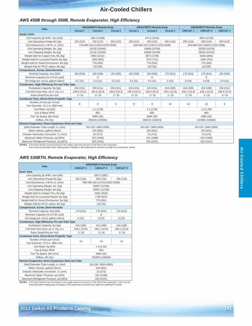
Air-Cooled Chillers
2013 Daikin All Products Catalog 141
Air-C
ooled Chillers
AWS 450B through 500B, Remote Evaporator, High Efficiency
AWS 530BTH, Remote Evaporator, High Efficiency
DataAWS450BTH Remote Evap AWS475BTH Remote Evap AWS500BTH Remote Evap
Circuit 1 Circuit 2 Circuit 3 Circuit 1 Circuit 2 Circuit 3 CIRCUIT 1 CIRCUIT 2 CIRCUIT 3BASIC DATA
Unit Capacity @ AHRI tons (kW) 446 .3 (1569) 470 .3 (1654) 499 .4 (1756)Unit Operating Charge lbs (kg) 250 (113) 250 (113) 250 (113) 250 (113) 250 (113) 295 (134) 295 (134) 295 (134) 250 (113)
Unit Dimensions L×W×H, in . (mm) 473×88×100 (12024×2225×2548) 509×88×100 (12921×2225×2548) 544×88×100 (13823×2225×2548)Unit Operating Weight, lbs . (kg) 22135 (10040) 23608 (10709) 25528 (11579)Unit Shipping Weight, lbs (kg) 22135 (10040) 23608 (10709) 25528 (11579)
Weight-Add for Copper Fins, lbs (kg) 3553 (1612) 3870 (1755) 4168 (1891)Weight-Add for Louvered Panels, lbs (kg) 1460 (662) 1572 (713) 1684 (764)
Weight-Add for Sound Enclosures, lbs (kg) 776 (352) 776 (352) 776 (352)Weight-Add for PFCC option, lbs (kg) 120 (55) 120 (55) 120 (55)
Compressors, Screw, Semi-HermeticNominal Capacity, tons (kW) 150 (528) 150 (528) 150 (528) 150 (528) 150 (528) 175 (615) 175 (615) 175 (615) 150 (528)
Minimum Capacity (% of Full Load) 8 8 8Oil charge per circuit, gallons (liters) 5 .5 (21) 5 .5 (21) 5 .5 (21) 5 .5 (21) 5 .5 (21) 6 (23) 6 (23) 6 (23) 5 .5 (21)
Condensers, High Efficiency Fin and Tube TypePumpdown Capacity, lbs (kg) 333 (151) 333 (151) 333 (151) 333 (151) 333 (151) 416 (189) 416 (189) 416 (189) 333 (151)
Coil Inlet Face Area, sq . ft . (sq . m .) 196 .9 (18 .3) 196 .9 (18 .3) 196 .9 (18 .3) 196 .9 (18 .3) 196 .9 (18 .3) 246 .1 (22 .8) 246 .1 (22 .8) 246 .1 (22 .8) 196 .9 (18 .3)Rows Deep/Fins per Inch 3 / 16 3 / 16 3 / 16 3 / 16 3 / 16 3 / 16 3 / 16 3 / 16 3 / 16
Condenser Fans, Direct-Drive Propeller TypeNumber of Fans per Circuit
Fan Diameter: 31 .5 in . (800 mm)8 8 8 8 8 10 10 10 8
Fan Motor, hp (kW) 1 .4 (1 .05) 1 .4 (1 .05) 1 .4 (1 .05)Fan & Motor RPM 850 850 850
Fan Tip Speed, fpm (m/s) 6984 (35) 6984 (35) 6984 (35)Airflow, cfm (l/s) 266040 (125556) 288210 (136019) 310380 (146482)
Remote Evaporator, Direct Expansion Shell and TubeShell Diameter-Tube Length, in . (mm) 26×130 / (660×3300) 26×130 / (660×3300) 26×130 / (660×3300)
Water Volume, gallons (liters) 225 (850) 220 (831) 220 (831)Victaulic inlet/outlet connection in . (mm) 10 (273) 10 (273) 10 (273)
Maximum Water Pressure, psi (kPa) 152 (1048) 152 (1048) 152 (1048)Maximum Refrigerant Pressure, psi (kPa) 325 (2241) 325 (2241) 325 (2241)
NOTES: A 20 mesh strainer must be placed in the supply water line just prior to the inlet of the evaporator . Care must be exercised when welding pipe or flanges to the evaporator to prevent any slag from entering the vessel.
DataAWS530BTH Remote Evap
CIRCUIT 1 CIRCUIT 2 CIRCUIT 3Basic Data
Unit Capacity @ AHRI tons (kW) 528 .3 (1857)Unit Operating Charge lbs (kg) 295 (134) 295 (134) 295 (134)
Unit Dimensions L×W×H, in . (mm) 580×88×100 (14722×2225×2548)Unit Operating Weight, lbs . (kg) 26997 (12248)Unit Shipping Weight, lbs (kg) 26997 (12248)
Weight-Add for Copper Fins, lbs (kg) 4466 (2026)Weight-Add for Louvered Panels, lbs (kg) 1796 (815)
Weight-Add for Sound Enclosures, lbs (kg) 776 (352)Weight-Add for PFCC option, lbs (kg) 120 (55)
Compressors, Screw, Semi-HermeticNominal Capacity, tons (kW) 175 (615) 175 (615) 175 (615)
Minimum Capacity (% of Full Load) 8Oil charge per circuit, gallons (liters) 6 (23) 6 (23) 6 (23)
Condensers, High Efficiency Fin and Tube TypePumpdown Capacity, lbs (kg) 416 (189) 416 (189) 416 (189)
Coil Inlet Face Area, sq . ft . (sq . m .) 246 .1 (22 .8) 246 .1 (22 .8) 246 .1 (22 .8)Rows Deep/Fins per Inch 3 / 16 3 / 16 3 / 16
Condenser Fans, Direct-Drive Propeller TypeNumber of Fans per Circuit
Fan Diameter: 31 .5 in . (800 mm)10 10 10
Fan Motor, hp (kW) 1 .4 (1 .05)Fan & Motor RPM 850
Fan Tip Speed, fpm (m/s) 6984 (35)Airflow, cfm (l/s) 332550 (156945)
Remote Evaporator, Direct Expansion Shell and TubeShell Diameter-Tube Length, in . (mm) 26×130 / (660×3300)
Water Volume, gallons (liters) 220 (831)Victaulic inlet/outlet connection in . (mm) 10 (273)
Maximum Water Pressure, psi (kPa) 152 (1048)Maximum Refrigerant Pressure, psi (kPa) 325 (2241)
NOTES: A 20 mesh strainer must be placed in the supply water line just prior to the inlet of the evaporator . Care must be exercised when welding pipe or flanges to the evaporator to prevent any slag from entering the vessel.
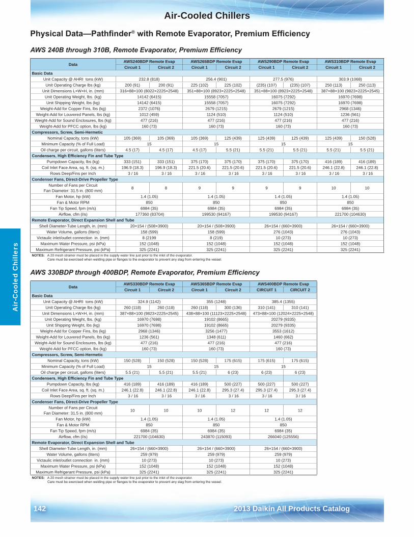
Air-Cooled Chillers
142 2013 Daikin All Products Catalog
Air
-Coo
led
Chi
llers
Physical Data—Pathfinder® with Remote Evaporator, Premium Efficiency
AWS 240B through 310B, Remote Evaporator, Premium Efficiency
AWS 330BDP through 400BDP, Remote Evaporator, Premium Efficiency
DataAWS240BDP Remote Evap AWS265BDP Remote Evap AWS290BDP Remote Evap AWS310BDP Remote EvapCircuit 1 Circuit 2 Circuit 1 Circuit 2 Circuit 1 Circuit 2 Circuit 1 Circuit 2
Basic DataUnit Capacity @ AHRI tons (kW) 232 .8 (818) 256 .4 (901) 277 .5 (976) 303 .9 (1068)
Unit Operating Charge lbs (kg) 200 (91) 200 (91) 225 (102) 225 (102) (235) (107) (235) (107) 250 (113) 250 (113)Unit Dimensions L×W×H, in . (mm) 316×88×100 (8022×2225×2548) 351×88×100 (8923×2225×2548) 351×88×100 (8923×2225×2548) 387×88×100 (9823×2225×2545)
Unit Operating Weight, lbs . (kg) 14142 (6415) 15558 (7057) 16075 (7292) 16970 (7698)Unit Shipping Weight, lbs (kg) 14142 (6415) 15558 (7057) 16075 (7292) 16970 (7698)
Weight-Add for Copper Fins, lbs (kg) 2372 (1076) 2679 (1215) 2679 (1215) 2968 (1346)Weight-Add for Louvered Panels, lbs (kg) 1012 (459) 1124 (510) 1124 (510) 1236 (561)
Weight-Add for Sound Enclosures, lbs (kg) 477 (216) 477 (216) 477 (216) 477 (216)Weight-Add for PFCC option, lbs (kg) 160 (73) 160 (73) 160 (73) 160 (73)
Compressors, Screw, Semi-HermeticNominal Capacity, tons (kW) 105 (369) 105 (369) 105 (369) 125 (439) 125 (439) 125 (439) 125 (439) 150 (528)
Minimum Capacity (% of Full Load) 15 15 15 15Oil charge per circuit, gallons (liters) 4 .5 (17) 4 .5 (17) 4 .5 (17) 5 .5 (21) 5 .5 (21) 5 .5 (21) 5 .5 (21) 5 .5 (21)
Condensers, High Efficiency Fin and Tube TypePumpdown Capacity, lbs (kg) 333 (151) 333 (151) 375 (170) 375 (170) 375 (170) 375 (170) 416 (189) 416 (189)
Coil Inlet Face Area, sq . ft . (sq . m .) 196 .9 (18 .3) 196 .9 (18 .3) 221 .5 (20 .6) 221 .5 (20 .6) 221 .5 (20 .6) 221 .5 (20 .6) 246 .1 (22 .8) 246 .1 (22 .8)Rows Deep/Fins per Inch 3 / 16 3 / 16 3 / 16 3 / 16 3 / 16 3 / 16 3 / 16 3 / 16
Condenser Fans, Direct-Drive Propeller TypeNumber of Fans per Circuit
Fan Diameter: 31 .5 in . (800 mm)8 8 9 9 9 9 10 10
Fan Motor, hp (kW) 1 .4 (1 .05) 1 .4 (1 .05) 1 .4 (1 .05) 1 .4 (1 .05)Fan & Motor RPM 850 850 850 850
Fan Tip Speed, fpm (m/s) 6984 (35) 6984 (35) 6984 (35) 6984 (35)Airflow, cfm (l/s) 177360 (83704) 199530 (94167) 199530 (94167) 221700 (104630)
Remote Evaporator, Direct Expansion Shell and TubeShell Diameter-Tube Length, in . (mm) 20×154 / (508×3900) 20×154 / (508×3900) 26×154 / (660×3900) 26×154 / (660×3900)
Water Volume, gallons (liters) 158 (599) 158 (599) 276 (1043) 276 (1043)Victaulic inlet/outlet connection in . (mm) 8 (2199 8 (219) 10 (273) 10 (273)
Maximum Water Pressure, psi (kPa) 152 (1048) 152 (1048) 152 (1048) 152 (1048)Maximum Refrigerant Pressure, psi (kPa) 325 (2241) 325 (2241) 325 (2241) 325 (2241)
NOTES: A 20 mesh strainer must be placed in the supply water line just prior to the inlet of the evaporator . Care must be exercised when welding pipe or flanges to the evaporator to prevent any slag from entering the vessel.
DataAWS330BDP Remote Evap AWS365BDP Remote Evap AWS400BDP Remote EvapCircuit 1 Circuit 2 Circuit 1 Circuit 2 CIRCUIT 1 CIRCUIT 2
Basic DataUnit Capacity @ AHRI tons (kW) 324 .9 (1142) 355 (1248) 385 .4 (1355)
Unit Operating Charge lbs (kg) 260 (118) 260 (118) 260 (118) 300 (136) 310 (141) 310 (141)Unit Dimensions L×W×H, in . (mm) 387×88×100 (9823×2225×2545) 438×88×100 (11123×2225×2548) 473×88×100 (12024×2225×2548)
Unit Operating Weight, lbs . (kg) 16970 (7698) 19102 (8665) 20279 (9335)Unit Shipping Weight, lbs (kg) 16970 (7698) 19102 (8665) 20279 (9335)
Weight-Add for Copper Fins, lbs (kg) 2968 (1346) 3256 (1477) 3553 (1612)Weight-Add for Louvered Panels, lbs (kg) 1236 (561) 1348 (611) 1460 (662)
Weight-Add for Sound Enclosures, lbs (kg) 477 (216) 477 (216) 477 (216)Weight-Add for PFCC option, lbs (kg) 160 (73) 160 (73) 160 (73)
Compressors, Screw, Semi-HermeticNominal Capacity, tons (kW) 150 (528) 150 (528) 150 (528) 175 (615) 175 (615) 175 (615)
Minimum Capacity (% of Full Load) 15 15 15Oil charge per circuit, gallons (liters) 5 .5 (21) 5 .5 (21) 5 .5 (21) 6 (23) 6 (23) 6 (23)
Condensers, High Efficiency Fin and Tube TypePumpdown Capacity, lbs (kg) 416 (189) 416 (189) 416 (189) 500 (227) 500 (227) 500 (227)
Coil Inlet Face Area, sq . ft . (sq . m .) 246 .1 (22 .8) 246 .1 (22 .8) 246 .1 (22 .8) 295 .3 (27 .4) 295 .3 (27 .4) 295 .3 (27 .4)Rows Deep/Fins per Inch 3 / 16 3 / 16 3 / 16 3 / 16 3 / 16 3 / 16
Condenser Fans, Direct-Drive Propeller TypeNumber of Fans per Circuit
Fan Diameter: 31 .5 in . (800 mm)10 10 10 12 12 12
Fan Motor, hp (kW) 1 .4 (1 .05) 1 .4 (1 .05) 1 .4 (1 .05)Fan & Motor RPM 850 850 850
Fan Tip Speed, fpm (m/s) 6984 (35) 6984 (35) 6984 (35)Airflow, cfm (l/s) 221700 (104630) 243870 (115093) 266040 (125556)
Remote Evaporator, Direct Expansion Shell and TubeShell Diameter-Tube Length, in . (mm) 26×154 / (660×3900) 26×154 / (660×3900) 26×154 / (660×3900)
Water Volume, gallons (liters) 259 (979) 259 (979) 259 (979)Victaulic inlet/outlet connection in . (mm) 10 (273) 10 (273) 10 (273)
Maximum Water Pressure, psi (kPa) 152 (1048) 152 (1048) 152 (1048)Maximum Refrigerant Pressure, psi (kPa) 325 (2241) 325 (2241) 325 (2241)
NOTES: A 20 mesh strainer must be placed in the supply water line just prior to the inlet of the evaporator . Care must be exercised when welding pipe or flanges to the evaporator to prevent any slag from entering the vessel.
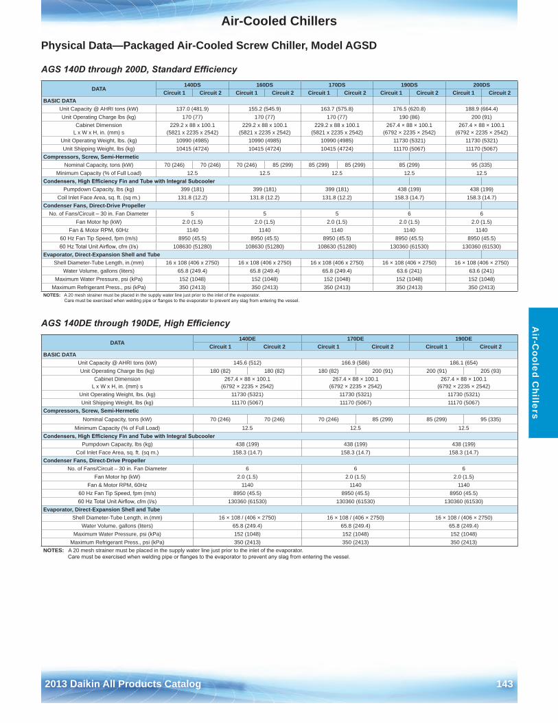
Air-Cooled Chillers
2013 Daikin All Products Catalog 143
Air-C
ooled Chillers
Physical Data—Packaged Air-Cooled Screw Chiller, Model AGSD
AGS 140D through 200D, Standard Efficiency
AGS 140DE through 190DE, High Efficiency
DATA140DS 160DS 170DS 190DS 200DS
Circuit 1 Circuit 2 Circuit 1 Circuit 2 Circuit 1 Circuit 2 Circuit 1 Circuit 2 Circuit 1 Circuit 2BASIC DATA
Unit Capacity @ AHRI tons (kW) 137 .0 (481 .9) 155 .2 (545 .9) 163 .7 (575 .8) 176 .5 (620 .8) 188 .9 (664 .4)Unit Operating Charge lbs (kg) 170 (77) 170 (77) 170 (77) 190 (86) 200 (91)
Cabinet Dimension L x W x H, in . (mm) s
229 .2 x 88 x 100 .1 (5821 x 2235 x 2542)
229 .2 x 88 x 100 .1 (5821 x 2235 x 2542)
229 .2 x 88 x 100 .1 (5821 x 2235 x 2542)
267 .4 × 88 × 100 .1 (6792 × 2235 × 2542)
267 .4 × 88 × 100 .1 (6792 × 2235 × 2542)
Unit Operating Weight, lbs . (kg) 10990 (4985) 10990 (4985) 10990 (4985) 11730 (5321) 11730 (5321)Unit Shipping Weight, lbs (kg) 10415 (4724) 10415 (4724) 10415 (4724) 11170 (5067) 11170 (5067)
Compressors, Screw, Semi-HermeticNominal Capacity, tons (kW) 70 (246) 70 (246) 70 (246) 85 (299) 85 (299) 85 (299) 85 (299) 95 (335)
Minimum Capacity (% of Full Load) 12 .5 12 .5 12 .5 12 .5 12 .5Condensers, High Efficiency Fin and Tube with Integral Subcooler
Pumpdown Capacity, lbs (kg) 399 (181) 399 (181) 399 (181) 438 (199) 438 (199)Coil Inlet Face Area, sq . ft . (sq m .) 131 .8 (12 .2) 131 .8 (12 .2) 131 .8 (12 .2) 158 .3 (14 .7) 158 .3 (14 .7)
Condenser Fans, Direct-Drive PropellerNo . of Fans/Circuit – 30 in . Fan Diameter 5 5 5 6 6
Fan Motor hp (kW) 2 .0 (1 .5) 2 .0 (1 .5) 2 .0 (1 .5) 2 .0 (1 .5) 2 .0 (1 .5)Fan & Motor RPM, 60Hz 1140 1140 1140 1140 1140
60 Hz Fan Tip Speed, fpm (m/s) 8950 (45 .5) 8950 (45 .5) 8950 (45 .5) 8950 (45 .5) 8950 (45 .5)60 Hz Total Unit Airflow, cfm (l/s) 108630 (51280) 108630 (51280) 108630 (51280) 130360 (61530) 130360 (61530)
Evaporator, Direct-Expansion Shell and TubeShell Diameter-Tube Length, in .(mm) 16 x 108 (406 x 2750) 16 x 108 (406 x 2750) 16 x 108 (406 x 2750) 16 × 108 (406 × 2750) 16 × 108 (406 × 2750)
Water Volume, gallons (liters) 65 .8 (249 .4) 65 .8 (249 .4) 65 .8 (249 .4) 63 .6 (241) 63 .6 (241)Maximum Water Pressure, psi (kPa) 152 (1048) 152 (1048) 152 (1048) 152 (1048) 152 (1048)
Maximum Refrigerant Press ., psi (kPa) 350 (2413) 350 (2413) 350 (2413) 350 (2413) 350 (2413)NOTES: A 20 mesh strainer must be placed in the supply water line just prior to the inlet of the evaporator .
Care must be exercised when welding pipe or flanges to the evaporator to prevent any slag from entering the vessel.
DATA140DE 170DE 190DE
Circuit 1 Circuit 2 Circuit 1 Circuit 2 Circuit 1 Circuit 2BASIC DATA
Unit Capacity @ AHRI tons (kW) 145 .6 (512) 166 .9 (586) 186 .1 (654)Unit Operating Charge lbs (kg) 180 (82) 180 (82) 180 (82) 200 (91) 200 (91) 205 (93)
Cabinet Dimension L x W x H, in . (mm) s
267 .4 × 88 × 100 .1 (6792 × 2235 × 2542)
267 .4 × 88 × 100 .1 (6792 × 2235 × 2542)
267 .4 × 88 × 100 .1 (6792 × 2235 × 2542)
Unit Operating Weight, lbs . (kg) 11730 (5321) 11730 (5321) 11730 (5321)Unit Shipping Weight, lbs (kg) 11170 (5067) 11170 (5067) 11170 (5067)
Compressors, Screw, Semi-HermeticNominal Capacity, tons (kW) 70 (246) 70 (246) 70 (246) 85 (299) 85 (299) 95 (335)
Minimum Capacity (% of Full Load) 12 .5 12 .5 12 .5Condensers, High Efficiency Fin and Tube with Integral Subcooler
Pumpdown Capacity, lbs (kg) 438 (199) 438 (199) 438 (199)Coil Inlet Face Area, sq . ft . (sq m .) 158 .3 (14 .7) 158 .3 (14 .7) 158 .3 (14 .7)
Condenser Fans, Direct-Drive PropellerNo . of Fans/Circuit – 30 in . Fan Diameter 6 6 6
Fan Motor hp (kW) 2 .0 (1 .5) 2 .0 (1 .5) 2 .0 (1 .5)Fan & Motor RPM, 60Hz 1140 1140 1140
60 Hz Fan Tip Speed, fpm (m/s) 8950 (45 .5) 8950 (45 .5) 8950 (45 .5)60 Hz Total Unit Airflow, cfm (l/s) 130360 (61530) 130360 (61530) 130360 (61530)
Evaporator, Direct-Expansion Shell and TubeShell Diameter-Tube Length, in .(mm) 16 × 108 / (406 × 2750) 16 × 108 / (406 × 2750) 16 × 108 / (406 × 2750)
Water Volume, gallons (liters) 65 .8 (249 .4) 65 .8 (249 .4) 65 .8 (249 .4)Maximum Water Pressure, psi (kPa) 152 (1048) 152 (1048) 152 (1048)
Maximum Refrigerant Press ., psi (kPa) 350 (2413) 350 (2413) 350 (2413)NOTES: A 20 mesh strainer must be placed in the supply water line just prior to the inlet of the evaporator .
Care must be exercised when welding pipe or flanges to the evaporator to prevent any slag from entering the vessel.
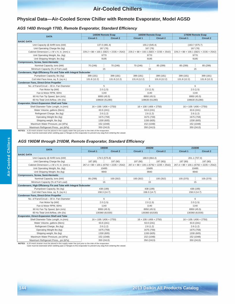
Air-Cooled Chillers
144 2013 Daikin All Products Catalog
Air
-Coo
led
Chi
llers
Physical Data—Air-Cooled Screw Chiller with Remote Evaporator, Model AGSD
AGS 140D through 170D, Remote Evaporator, Standard Efficiency
AGS 190DM through 210DM, Remote Evaporator, Standard Efficiency
DATA140DM Remote Evap 160DM Remote Evap 170DM Remote Evap
Circuit 1 Circuit 2 Circuit 1 Circuit 2 Circuit 1 Circuit 2BASIC DATA
Unit Capacity @ AHRI tons (kW) 137 .0 (481 .4) 155 .2 (545 .4) (163 .7 (575 .7)Unit Operating Charge lbs (kg) 167 (76) 167 (76) 167 (76)
Cabinet Dimension L x W x H, in . (mm) s 229 .2 × 88 × 100 .1 (5821 × 2235 × 2542) 229 .2 × 88 × 100 .1 (5821 × 2235 × 2542) 229 .2 × 88 × 100 .1 (5821 × 2235 × 2542)Unit Operating Weight, lbs . (kg) 9770 9770 9770Unit Shipping Weight, lbs (kg) 9195 9195 9195
Compressors, Screw, Semi-HermeticNominal Capacity, tons (kW) 70 (246) 70 (246) 70 (246) 85 (299) 85 (299) 85 (299)
Minimum Capacity (% of Full Load) 15 15 15Condensers, High Efficiency Fin and Tube with Integral Subcooler
Pumpdown Capacity, lbs (kg) 399 (181) 399 (181) 399 (181) 399 (181) 399 (181) 399 (181)Coil Inlet Face Area, sq . ft . (sq m .) 131 .8 (12 .2) 131 .8 (12 .2) 131 .8 (12 .2) 131 .8 (12 .2) 131 .8 (12 .2) 131 .8 (12 .2)
Condenser Fans, Direct-Drive PropellerNo . of Fans/Circuit – 30 in . Fan Diameter 5 6 6
Fan Motor hp (kW) 2 .0 (1 .5) 2 .0 (1 .5) 2 .0 (1 .5)Fan & Motor RPM, 60Hz 1140 1140 1140
60 Hz Fan Tip Speed, fpm (m/s) 8950 (45 .5) 8950 (45 .5) 8950 (45 .5)60 Hz Total Unit Airflow, cfm (l/s) 108630 (51280) 108630 (51280) 108630 (51280)
Evaporator, Direct-Expansion Shell and TubeShell Diameter-Tube Length, in .(mm) 16 × 108 / (406 × 2750) 16 × 108 / (406 × 2750) 16 × 108 / (406 × 2750)
Water Volume, gallons (liters) 63 .6 (241) 63 .6 (241) 63 .6 (241)Refrigerant Charge, lbs (kg) 2 .6 (1 .2) 2 .6 (1 .2) 2 .6 (1 .2)Operating Weight lbs (kg) 1675 (759) 1675 (759) 1675 (759)Shipping weight, lbs (kg) 1330 (605) 1330 (605) 1330 (605)
Maximum Water Pressure, psi (kPa) 152 (1048) 152 (1048) 152 (1048)Maximum Refrigerant Press ., psi (kPa) 350 (2413) 350 (2413) 350 (2413)
NOTES: A 20 mesh strainer must be placed in the supply water line just prior to the inlet of the evaporator . Care must be exercised when welding pipe or flanges to the evaporator to prevent any slag from entering the vessel.
DATA190DM 200DM 210DM
Circuit 1 Circuit 2 Circuit 1 Circuit 2 Circuit 1 Circuit 2BASIC DATA
Unit Capacity @ AHRI tons (kW) 176 .5 (575 .8) 188 .9 (664 .4) 201 .1 (707 .4)Unit Operating Charge lbs (kg) 187 (85) 197 (90) 197 (90) 197 (90)) 197 (90) 197 (90)
Cabinet Dimension L x W x H, in . (mm) s 267 .4 × 88 × 100 .1 (6792 × 2235 × 2542) 267 .4 × 88 × 100 .1 (6792 × 2235 × 2542) 267 .4 × 88 × 100 .1 (6792 × 2235 × 2542)Unit Operating Weight, lbs . (kg) 10495 10495 10495Unit Shipping Weight, lbs (kg) 9940 9940 9940
Compressors, Screw, Semi-HermeticNominal Capacity, tons (kW) 85 (299) 100 (352) 100 (352) 100 (352) 105 (370) 105 (370)
Minimum Capacity (% of Full Load) 15 15 15Condensers, High Efficiency Fin and Tube with Integral Subcooler
Pumpdown Capacity, lbs (kg) 438 (199) 438 (199) 438 (199)Coil Inlet Face Area, sq . ft . (sq m .) 158 .3 (14 .7) 158 .3 (14 .7) 158 .3 (14 .7)
Condenser Fans, Direct-Drive PropellerNo . of Fans/Circuit – 30 in . Fan Diameter 6 6 6
Fan Motor hp (kW) 2 .0 (1 .5) 2 .0 (1 .5) 2 .0 (1 .5)Fan & Motor RPM, 60Hz 1140 1140 1140
60 Hz Fan Tip Speed, fpm (m/s) 8950 (45 .5) 8950 (45 .5) 8950 (45 .5)60 Hz Total Unit Airflow, cfm (l/s) 130360 (61530) 130360 (61530) 130360 (61530)
Evaporator, Direct-Expansion Shell and TubeShell Diameter-Tube Length, in .(mm) 16 × 108 / (406 × 2750) 16 × 108 / (406 × 2750) 16 × 108 / (406 × 2750)
Water Volume, gallons (liters) 63 .6 (241) 63 .6 (241) 63 .6 (241)Refrigerant Charge, lbs (kg) 2 .6 (1 .2) 2 .6 (1 .2) 2 .6 (1 .2)Operating Weight lbs (kg) 1675 (759) 1675 (759) 1675 (759)Shipping weight, lbs (kg) 1330 (605) 1330 (605) 1330 (605)
Maximum Water Pressure, psi (kPa) 152 (1048) 152 (1048) 152 (1048)Maximum Refrigerant Press ., psi (kPa) 350 (2413) 350 (2413) 350 (2413)
NOTES: A 20 mesh strainer must be placed in the supply water line just prior to the inlet of the evaporator . Care must be exercised when welding pipe or flanges to the evaporator to prevent any slag from entering the vessel.
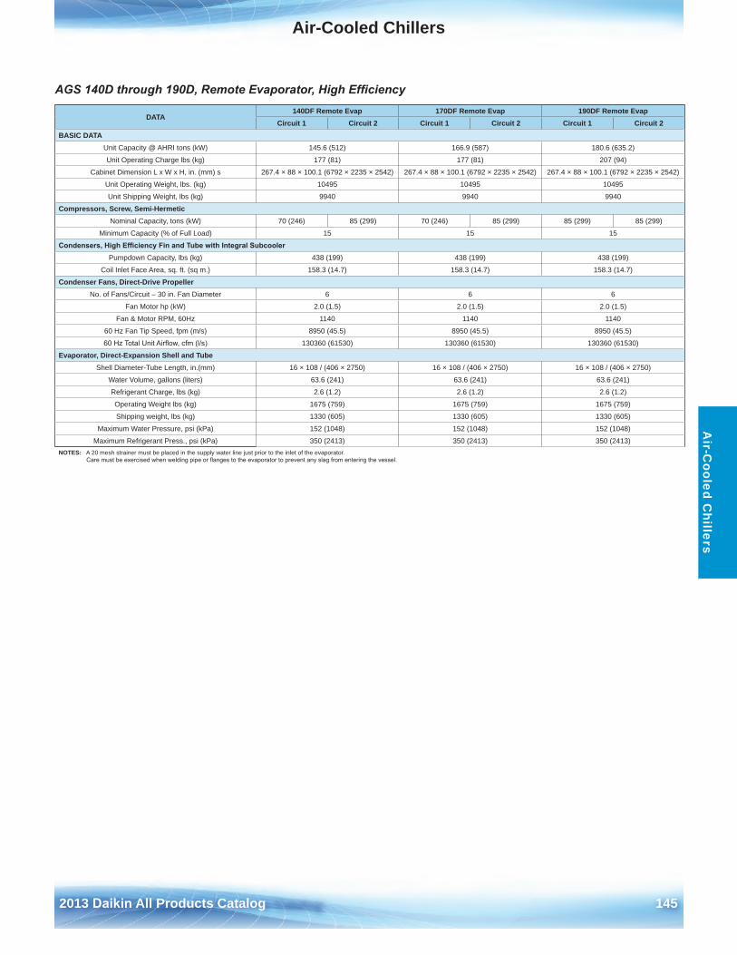
Air-Cooled Chillers
2013 Daikin All Products Catalog 145
Air-C
ooled Chillers
AGS 140D through 190D, Remote Evaporator, High Efficiency
DATA140DF Remote Evap 170DF Remote Evap 190DF Remote Evap
Circuit 1 Circuit 2 Circuit 1 Circuit 2 Circuit 1 Circuit 2BASIC DATA
Unit Capacity @ AHRI tons (kW) 145 .6 (512) 166 .9 (587) 180 .6 (635 .2)
Unit Operating Charge lbs (kg) 177 (81) 177 (81) 207 (94)
Cabinet Dimension L x W x H, in . (mm) s 267 .4 × 88 × 100 .1 (6792 × 2235 × 2542) 267 .4 × 88 × 100 .1 (6792 × 2235 × 2542) 267 .4 × 88 × 100 .1 (6792 × 2235 × 2542)
Unit Operating Weight, lbs . (kg) 10495 10495 10495
Unit Shipping Weight, lbs (kg) 9940 9940 9940
Compressors, Screw, Semi-HermeticNominal Capacity, tons (kW) 70 (246) 85 (299) 70 (246) 85 (299) 85 (299) 85 (299)
Minimum Capacity (% of Full Load) 15 15 15
Condensers, High Efficiency Fin and Tube with Integral SubcoolerPumpdown Capacity, lbs (kg) 438 (199) 438 (199) 438 (199)
Coil Inlet Face Area, sq . ft . (sq m .) 158 .3 (14 .7) 158 .3 (14 .7) 158 .3 (14 .7)
Condenser Fans, Direct-Drive PropellerNo . of Fans/Circuit – 30 in . Fan Diameter 6 6 6
Fan Motor hp (kW) 2 .0 (1 .5) 2 .0 (1 .5) 2 .0 (1 .5)
Fan & Motor RPM, 60Hz 1140 1140 1140
60 Hz Fan Tip Speed, fpm (m/s) 8950 (45 .5) 8950 (45 .5) 8950 (45 .5)
60 Hz Total Unit Airflow, cfm (l/s) 130360 (61530) 130360 (61530) 130360 (61530)
Evaporator, Direct-Expansion Shell and TubeShell Diameter-Tube Length, in .(mm) 16 × 108 / (406 × 2750) 16 × 108 / (406 × 2750) 16 × 108 / (406 × 2750)
Water Volume, gallons (liters) 63 .6 (241) 63 .6 (241) 63 .6 (241)
Refrigerant Charge, lbs (kg) 2 .6 (1 .2) 2 .6 (1 .2) 2 .6 (1 .2)
Operating Weight lbs (kg) 1675 (759) 1675 (759) 1675 (759)
Shipping weight, lbs (kg) 1330 (605) 1330 (605) 1330 (605)
Maximum Water Pressure, psi (kPa) 152 (1048) 152 (1048) 152 (1048)
Maximum Refrigerant Press ., psi (kPa) 350 (2413) 350 (2413) 350 (2413)NOTES: A 20 mesh strainer must be placed in the supply water line just prior to the inlet of the evaporator .
Care must be exercised when welding pipe or flanges to the evaporator to prevent any slag from entering the vessel.
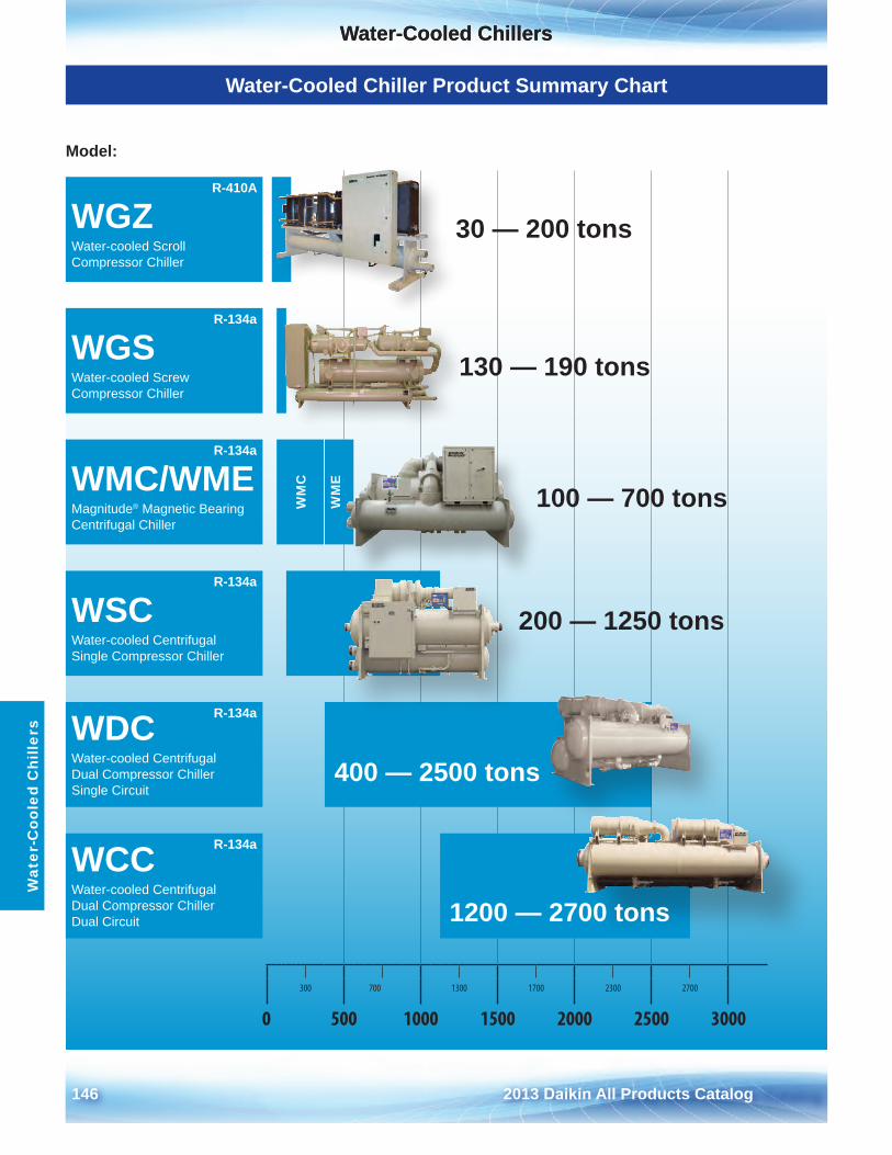
Water-Cooled Chillers
146 2013 Daikin All Products Catalog
Water-Cooled ChillersW
ater
-Coo
led
Chi
llers
Water-Cooled Chiller Product Summary Chart
Model:
R-410A
WGZWater-cooled Scroll Compressor Chiller
R-134a
WGSWater-cooled Screw Compressor Chiller
R-134a
WMC/WMEMagnitude® Magnetic Bearing Centrifugal Chiller
WM
C
WM
E
R-134a
WSCWater-cooled Centrifugal Single Compressor Chiller
R-134aWDCWater-cooled Centrifugal Dual Compressor Chiller Single Circuit
R-134aWCCWater-cooled Centrifugal Dual Compressor Chiller Dual Circuit
300 700 1300 1700 2300 2700
0 500 1000 1500 2000 2500 3000
30 — 200 tons
130 — 190 tons
100 — 700 tons
200 — 1250 tons
400 — 2500 tons
1200 — 2700 tons
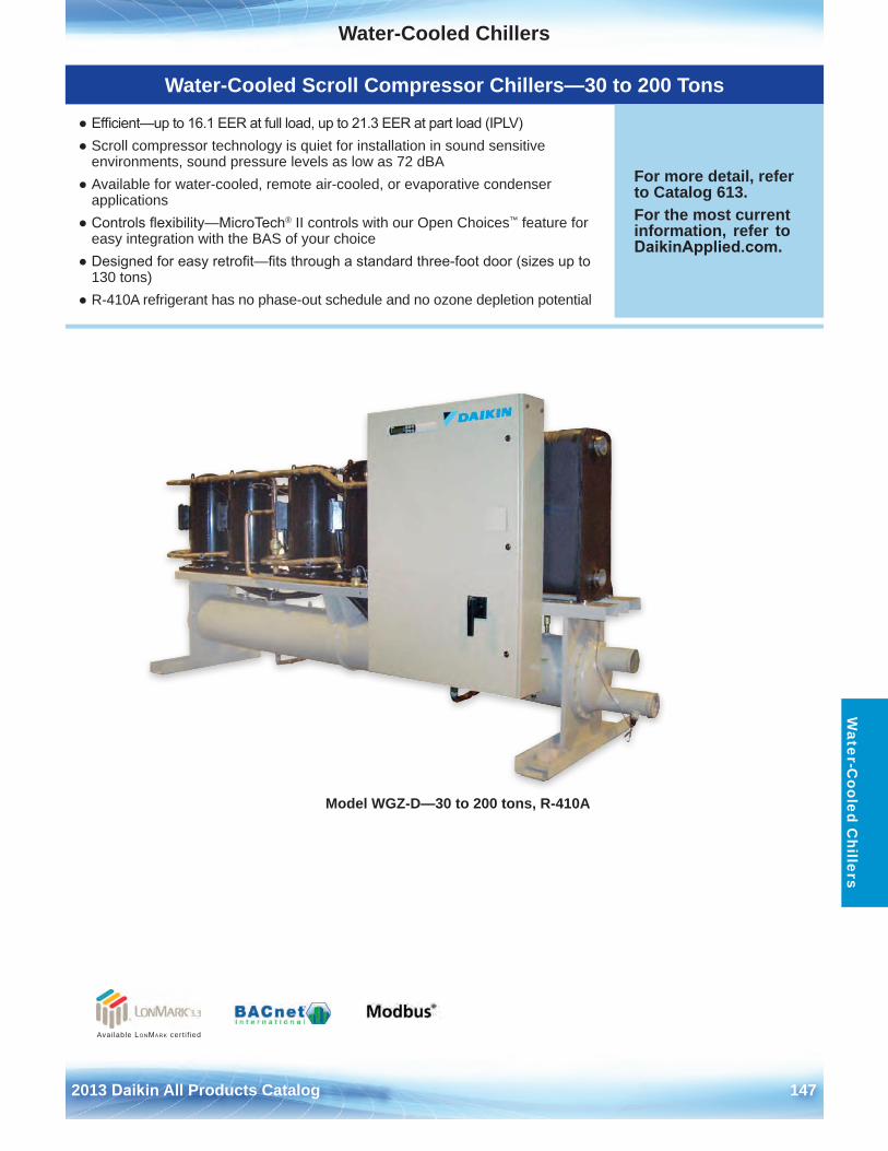
Water-Cooled Chillers
2013 Daikin All Products Catalog 147
Water-C
ooled Chillers
Model WGZ-D—30 to 200 tons, R-410A
Available LonMark cert i f ied
Water-Cooled Scroll Compressor Chillers—30 to 200 Tons
● Efficient—up to 16.1 EER at full load, up to 21.3 EER at part load (IPLV)● Scroll compressor technology is quiet for installation in sound sensitive
environments, sound pressure levels as low as 72 dBA● Available for water-cooled, remote air-cooled, or evaporative condenser
applications● Controls flexibility—MicroTech® II controls with our Open Choices™ feature for
easy integration with the BAS of your choice● Designed for easy retrofit—fits through a standard three-foot door (sizes up to
130 tons)● R-410A refrigerant has no phase-out schedule and no ozone depletion potential
For more detail, refer to Catalog 613 .For the most current information, refer to DaikinApplied.com .
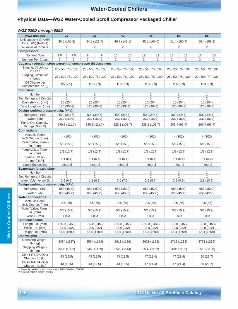
Water-Cooled Chillers
148 2013 Daikin All Products Catalog
Wat
er-C
oole
d C
hille
rs
Physical Data—WGZ Water-Cooled Scroll Compressor Packaged Chiller
WGZ 030D through 055D WGZ unit size 30 35 40 45 50 55
Unit capacity @ AHRI tons, (kW) (Note 1) 30 .0 (105 .5) 34 .6 (121 .7) 40 .7 (143 .1) 45 .5 (160 .0) 51 .4 (180 .7) 56 .4 (198 .3)
Number of Circuits 2 2 2 2 2 2Compressors
Nominal Tons 7 .5 7 .5 9 9 10 10 12 12 13 13 13 15Number Per Circuit 2 2 2 2 2 2 2 2 2 2 2 2
Capacity reduction steps percent of compressor displacementStaging, Circuit #1
in Lead 25 / 50 / 75 / 100 25 / 50 / 75 / 100 25 / 50 / 75 / 100 25 / 50 / 75 / 100 25 / 50 / 75 / 100 23 / 50 / 73 / 100
Staging, Circuit #2 in Lead 25 / 50 / 75 / 100 25 / 50 / 75 / 100 25 / 50 / 75 / 100 25 / 50 / 75 / 100 25 / 50 / 75 / 100 27 / 50 / 77 / 100
Oil Charge per Compressor- oz . (l) 85 (2 .5) 110 (3 .3) 110 (3 .3) 110 (3 .3) 110 (3 .3) 110 (3 .3)
CondenserNumber 1 1 1 1 1 1
No . Refrigerant Circuits 2 2 2 2 2 2Diameter- in . (mm) 10 (254) 10 (254) 10 (254) 10 (254) 10 (254) 10 (254)
Tube Length-in . (mm) 120 (3048) 120 (3048) 120 (3048) 120 (3048) 120 (3048) 120 (3048)Design working pressure psig, (kPa):
Refrigerant Side 500 (3447) 500 (3447) 500 (3447) 500 (3447) 500 (3447) 500 (3447)Water Side 232 (1599) 232 (1599) 232 (1599) 232 (1599) 232 (1599) 232 (1599)
Pump-Out Capacity- lb . (kg) (Note 2) 245 .8 (111 .7) 245 .8 (111 .7) 228 .2 (103 .7) 228 .2 (103 .7) 205 .4 (93 .4) 205 .4 (93 .4)
ConnectionsVictaulic Conn .
In & Out - in . (mm) 4 (102) 4 (102) 4 (102) 4 (102) 4 (102) 4 (102)
Relief Valve, Flare - in . (mm) 5/8 (15 .9) 5/8 (15 .9) 5/8 (15 .9) 5/8 (15 .9) 5/8 (15 .9) 5/8 (15 .9)
Purge Valve, Flare - in . (mm) 1/2 (12 .7) 1/2 (12 .7) 1/2 (12 .7) 1/2 (12 .7) 1/2 (12 .7) 1/2 (12 .7)
Vent & Drain - in . (mm) NPT 1/4 (6 .4) 1/4 (6 .4) 1/4 (6 .4) 1/4 (6 .4) 1/4 (6 .4) 1/4 (6 .4)
Liquid Subcooling Integral Integral Integral Integral Integral IntegralEvaporator, brazed plate
Number 1 1 1 1 1 1No . Refrigerant Circuits 2 2 2 2 2 2Water Volume- gal (l) 1 .6 (6 .1) 1 .8 (6 .8) 2 .0 (7 .6) 2 .3 (8 .7) 2 .6 (9 .8) 2 .8 (10 .6)
Design working pressure- psig, (kPa):Refrigerant Side 653 (4500) 653 (4500) 653 (4500) 653 (4500) 653 (4500) 653 (4500)
Water Side 653 (4500) 653 (4500) 653 (4500) 653 (4500) 653 (4500) 653 (4500)Water connections
Victaulic Conn . In & Out - in . (mm) 2 .5 (65) 2 .5 (65) 2 .5 (65) 2 .5 (65) 2 .5 (65) 2 .5 (65)
Relief Valve, Flare - in . (mm) 5/8 (15 .9) 5/8 (15 .9) 5/8 (15 .9) 5/8 (15 .9) 5/8 (15 .9) 5/8 (15 .9)
Vent & Drain Field Field Field Field Field FieldUnit dimensions
Length - in . (mm) 136 .0 (3455) 136 .0 (3455) 136 .0 (3455) 136 .0 (3455) 136 .0 (3455) 136 .0 (3455)Width - in . (mm) 32 .8 (832) 32 .8 (832) 32 .8 (832) 32 .8 (832) 32 .8 (832) 32 .8 (832)Height - in . (mm) 63 .4 (1609) 63 .4 (1609) 63 .4 (1609) 63 .4 (1609) 63 .4 (1609) 63 .4 (1609)
Unit weightsOperating Weight -
lb . (kg) 2484 (1127) 2564 (1163) 2615 (1186) 2631 (1193) 2719 (1233) 2731 (1239)
Shipping Weight - lb . (kg) 2408 (1092) 2488 (1129) 2523 (1144) 2539 (1152) 2606 (1182) 2618 (1188)
Cir #1 R410A Oper Charge - lb . (kg) 43 (19 .5) 43 (19 .5) 43 (19 .5) 47 (21 .4) 47 (21 .4) 50 (22 .7)
Cir #2 R410A Oper Charge - lb . (kg) 43 (19 .5) 43 (19 .5) 43 (19 .5) 47 (21 .4) 47 (21 .4) 50 (22 .7)
1. Capacity certified in accordance with AHRI Standard 550/5902 . 90% full R410A at 90°F (32°C)
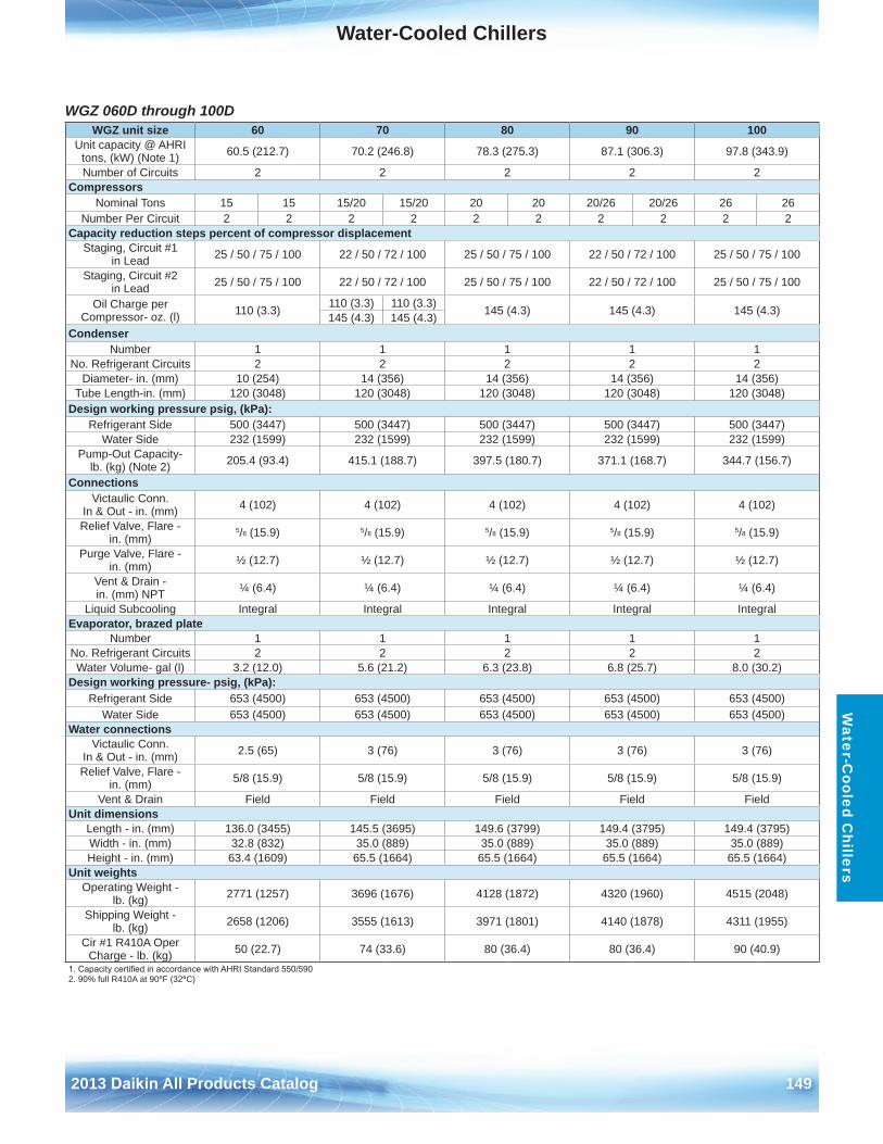
Water-Cooled Chillers
2013 Daikin All Products Catalog 149
Water-C
ooled Chillers
WGZ 060D through 100D WGZ unit size 60 70 80 90 100
Unit capacity @ AHRI tons, (kW) (Note 1) 60 .5 (212 .7) 70 .2 (246 .8) 78 .3 (275 .3) 87 .1 (306 .3) 97 .8 (343 .9)
Number of Circuits 2 2 2 2 2Compressors
Nominal Tons 15 15 15/20 15/20 20 20 20/26 20/26 26 26Number Per Circuit 2 2 2 2 2 2 2 2 2 2
Capacity reduction steps percent of compressor displacementStaging, Circuit #1
in Lead 25 / 50 / 75 / 100 22 / 50 / 72 / 100 25 / 50 / 75 / 100 22 / 50 / 72 / 100 25 / 50 / 75 / 100
Staging, Circuit #2 in Lead 25 / 50 / 75 / 100 22 / 50 / 72 / 100 25 / 50 / 75 / 100 22 / 50 / 72 / 100 25 / 50 / 75 / 100
Oil Charge per Compressor- oz . (l) 110 (3 .3) 110 (3 .3) 110 (3 .3) 145 (4 .3) 145 (4 .3) 145 (4 .3)145 (4 .3) 145 (4 .3)
CondenserNumber 1 1 1 1 1
No . Refrigerant Circuits 2 2 2 2 2Diameter- in . (mm) 10 (254) 14 (356) 14 (356) 14 (356) 14 (356)
Tube Length-in . (mm) 120 (3048) 120 (3048) 120 (3048) 120 (3048) 120 (3048)Design working pressure psig, (kPa):
Refrigerant Side 500 (3447) 500 (3447) 500 (3447) 500 (3447) 500 (3447)Water Side 232 (1599) 232 (1599) 232 (1599) 232 (1599) 232 (1599)
Pump-Out Capacity- lb . (kg) (Note 2) 205 .4 (93 .4) 415 .1 (188 .7) 397 .5 (180 .7) 371 .1 (168 .7) 344 .7 (156 .7)
ConnectionsVictaulic Conn .
In & Out - in . (mm) 4 (102) 4 (102) 4 (102) 4 (102) 4 (102)
Relief Valve, Flare - in . (mm)
5/8 (15 .9) 5/8 (15 .9) 5/8 (15 .9) 5/8 (15 .9) 5/8 (15 .9)
Purge Valve, Flare - in . (mm) ½ (12 .7) ½ (12 .7) ½ (12 .7) ½ (12 .7) ½ (12 .7)
Vent & Drain - in . (mm) NPT ¼ (6 .4) ¼ (6 .4) ¼ (6 .4) ¼ (6 .4) ¼ (6 .4)
Liquid Subcooling Integral Integral Integral Integral IntegralEvaporator, brazed plate
Number 1 1 1 1 1No . Refrigerant Circuits 2 2 2 2 2Water Volume- gal (l) 3 .2 (12 .0) 5 .6 (21 .2) 6 .3 (23 .8) 6 .8 (25 .7) 8 .0 (30 .2)
Design working pressure- psig, (kPa):Refrigerant Side 653 (4500) 653 (4500) 653 (4500) 653 (4500) 653 (4500)
Water Side 653 (4500) 653 (4500) 653 (4500) 653 (4500) 653 (4500)Water connections
Victaulic Conn . In & Out - in . (mm) 2 .5 (65) 3 (76) 3 (76) 3 (76) 3 (76)
Relief Valve, Flare - in . (mm) 5/8 (15 .9) 5/8 (15 .9) 5/8 (15 .9) 5/8 (15 .9) 5/8 (15 .9)
Vent & Drain Field Field Field Field FieldUnit dimensions
Length - in . (mm) 136 .0 (3455) 145 .5 (3695) 149 .6 (3799) 149 .4 (3795) 149 .4 (3795)Width - in . (mm) 32 .8 (832) 35 .0 (889) 35 .0 (889) 35 .0 (889) 35 .0 (889)Height - in . (mm) 63 .4 (1609) 65 .5 (1664) 65 .5 (1664) 65 .5 (1664) 65 .5 (1664)
Unit weightsOperating Weight -
lb . (kg) 2771 (1257) 3696 (1676) 4128 (1872) 4320 (1960) 4515 (2048)
Shipping Weight - lb . (kg) 2658 (1206) 3555 (1613) 3971 (1801) 4140 (1878) 4311 (1955)
Cir #1 R410A Oper Charge - lb . (kg) 50 (22 .7) 74 (33 .6) 80 (36 .4) 80 (36 .4) 90 (40 .9)
1. Capacity certified in accordance with AHRI Standard 550/5902 . 90% full R410A at 90°F (32°C)
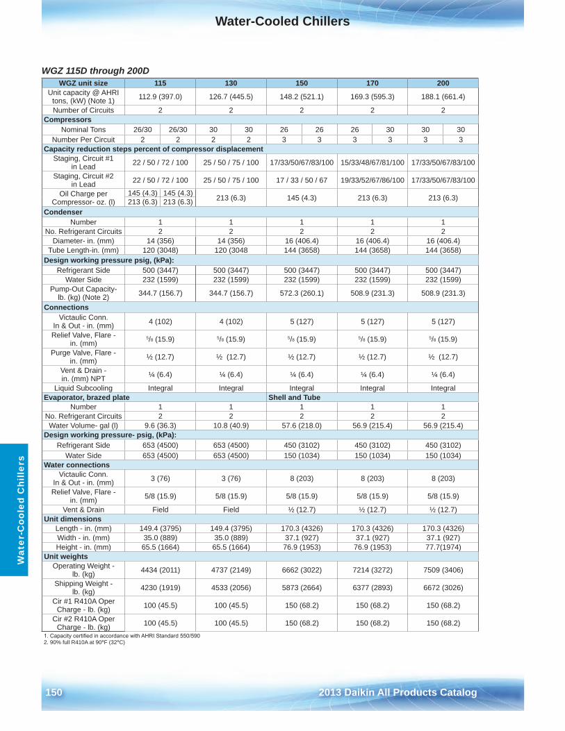
Water-Cooled Chillers
150 2013 Daikin All Products Catalog
Wat
er-C
oole
d C
hille
rs
WGZ 115D through 200D WGZ unit size 115 130 150 170 200
Unit capacity @ AHRI tons, (kW) (Note 1) 112 .9 (397 .0) 126 .7 (445 .5) 148 .2 (521 .1) 169 .3 (595 .3) 188 .1 (661 .4)
Number of Circuits 2 2 2 2 2Compressors
Nominal Tons 26/30 26/30 30 30 26 26 26 30 30 30Number Per Circuit 2 2 2 2 3 3 3 3 3 3
Capacity reduction steps percent of compressor displacementStaging, Circuit #1
in Lead 22 / 50 / 72 / 100 25 / 50 / 75 / 100 17/33/50/67/83/100 15/33/48/67/81/100 17/33/50/67/83/100
Staging, Circuit #2 in Lead 22 / 50 / 72 / 100 25 / 50 / 75 / 100 17 / 33 / 50 / 67 19/33/52/67/86/100 17/33/50/67/83/100
Oil Charge per Compressor- oz . (l)
145 (4 .3) 145 (4 .3) 213 (6 .3) 145 (4 .3) 213 (6 .3) 213 (6 .3)213 (6 .3) 213 (6 .3)Condenser
Number 1 1 1 1 1No . Refrigerant Circuits 2 2 2 2 2
Diameter- in . (mm) 14 (356) 14 (356) 16 (406 .4) 16 (406 .4) 16 (406 .4)Tube Length-in . (mm) 120 (3048) 120 (3048 144 (3658) 144 (3658) 144 (3658)
Design working pressure psig, (kPa):Refrigerant Side 500 (3447) 500 (3447) 500 (3447) 500 (3447) 500 (3447)
Water Side 232 (1599) 232 (1599) 232 (1599) 232 (1599) 232 (1599)Pump-Out Capacity-
lb . (kg) (Note 2) 344 .7 (156 .7) 344 .7 (156 .7) 572 .3 (260 .1) 508 .9 (231 .3) 508 .9 (231 .3)
ConnectionsVictaulic Conn .
In & Out - in . (mm) 4 (102) 4 (102) 5 (127) 5 (127) 5 (127)
Relief Valve, Flare - in . (mm)
5/8 (15 .9) 5/8 (15 .9) 5/8 (15 .9) 5/8 (15 .9) 5/8 (15 .9)
Purge Valve, Flare - in . (mm) ½ (12 .7) ½ (12 .7) ½ (12 .7) ½ (12 .7) ½ (12 .7)
Vent & Drain - in . (mm) NPT ¼ (6 .4) ¼ (6 .4) ¼ (6 .4) ¼ (6 .4) ¼ (6 .4)
Liquid Subcooling Integral Integral Integral Integral IntegralEvaporator, brazed plate Shell and Tube
Number 1 1 1 1 1No . Refrigerant Circuits 2 2 2 2 2Water Volume- gal (l) 9 .6 (36 .3) 10 .8 (40 .9) 57 .6 (218 .0) 56 .9 (215 .4) 56 .9 (215 .4)
Design working pressure- psig, (kPa):Refrigerant Side 653 (4500) 653 (4500) 450 (3102) 450 (3102) 450 (3102)
Water Side 653 (4500) 653 (4500) 150 (1034) 150 (1034) 150 (1034)Water connections
Victaulic Conn . In & Out - in . (mm) 3 (76) 3 (76) 8 (203) 8 (203) 8 (203)
Relief Valve, Flare - in . (mm) 5/8 (15 .9) 5/8 (15 .9) 5/8 (15 .9) 5/8 (15 .9) 5/8 (15 .9)
Vent & Drain Field Field ½ (12 .7) ½ (12 .7) ½ (12 .7)Unit dimensions
Length - in . (mm) 149 .4 (3795) 149 .4 (3795) 170 .3 (4326) 170 .3 (4326) 170 .3 (4326)Width - in . (mm) 35 .0 (889) 35 .0 (889) 37 .1 (927) 37 .1 (927) 37 .1 (927)Height - in . (mm) 65 .5 (1664) 65 .5 (1664) 76 .9 (1953) 76 .9 (1953) 77 .7(1974)
Unit weightsOperating Weight -
lb . (kg) 4434 (2011) 4737 (2149) 6662 (3022) 7214 (3272) 7509 (3406)
Shipping Weight - lb . (kg) 4230 (1919) 4533 (2056) 5873 (2664) 6377 (2893) 6672 (3026)
Cir #1 R410A Oper Charge - lb . (kg) 100 (45 .5) 100 (45 .5) 150 (68 .2) 150 (68 .2) 150 (68 .2)
Cir #2 R410A Oper Charge - lb . (kg) 100 (45 .5) 100 (45 .5) 150 (68 .2) 150 (68 .2) 150 (68 .2)
1. Capacity certified in accordance with AHRI Standard 550/5902 . 90% full R410A at 90°F (32°C)
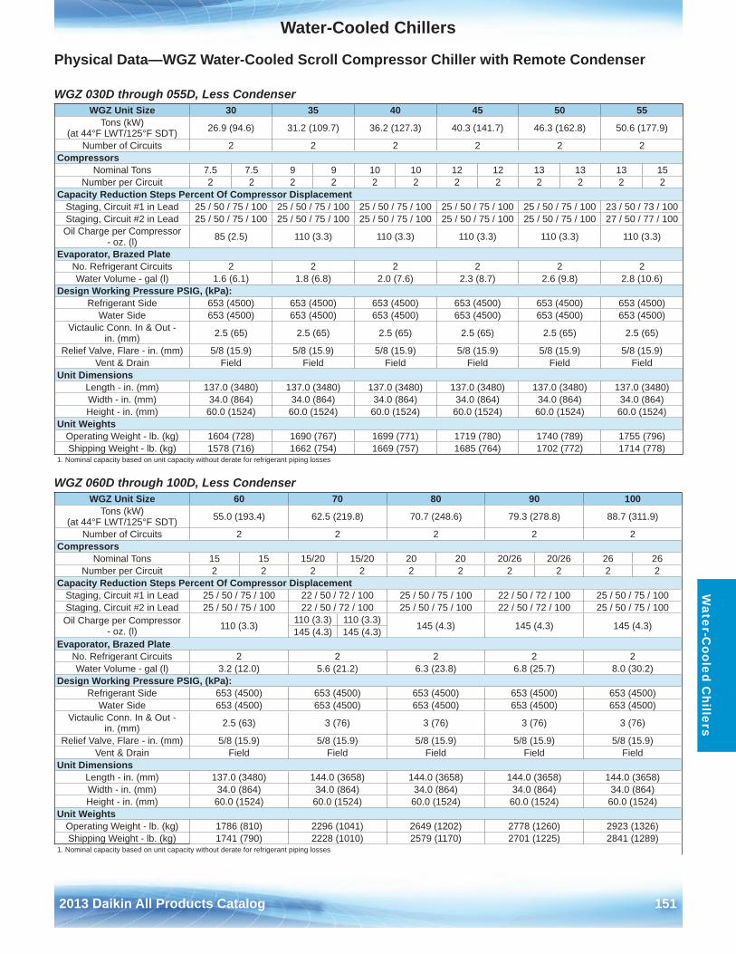
Water-Cooled Chillers
2013 Daikin All Products Catalog 151
Water-C
ooled Chillers
Physical Data—WGZ Water-Cooled Scroll Compressor Chiller with Remote Condenser
WGZ 030D through 055D, Less Condenser
WGZ 060D through 100D, Less Condenser
WGZ Unit Size 30 35 40 45 50 55Tons (kW)
(at 44°F LWT/125°F SDT) 26 .9 (94 .6) 31 .2 (109 .7) 36 .2 (127 .3) 40 .3 (141 .7) 46 .3 (162 .8) 50 .6 (177 .9)
Number of Circuits 2 2 2 2 2 2Compressors
Nominal Tons 7 .5 7 .5 9 9 10 10 12 12 13 13 13 15Number per Circuit 2 2 2 2 2 2 2 2 2 2 2 2
Capacity Reduction Steps Percent Of Compressor DisplacementStaging, Circuit #1 in Lead 25 / 50 / 75 / 100 25 / 50 / 75 / 100 25 / 50 / 75 / 100 25 / 50 / 75 / 100 25 / 50 / 75 / 100 23 / 50 / 73 / 100Staging, Circuit #2 in Lead 25 / 50 / 75 / 100 25 / 50 / 75 / 100 25 / 50 / 75 / 100 25 / 50 / 75 / 100 25 / 50 / 75 / 100 27 / 50 / 77 / 100Oil Charge per Compressor
- oz . (l) 85 (2 .5) 110 (3 .3) 110 (3 .3) 110 (3 .3) 110 (3 .3) 110 (3 .3)
Evaporator, Brazed PlateNo . Refrigerant Circuits 2 2 2 2 2 2Water Volume - gal (l) 1 .6 (6 .1) 1 .8 (6 .8) 2 .0 (7 .6) 2 .3 (8 .7) 2 .6 (9 .8) 2 .8 (10 .6)
Design Working Pressure PSIG, (kPa):Refrigerant Side 653 (4500) 653 (4500) 653 (4500) 653 (4500) 653 (4500) 653 (4500)
Water Side 653 (4500) 653 (4500) 653 (4500) 653 (4500) 653 (4500) 653 (4500)Victaulic Conn . In & Out -
in . (mm) 2 .5 (65) 2 .5 (65) 2 .5 (65) 2 .5 (65) 2 .5 (65) 2 .5 (65)
Relief Valve, Flare - in . (mm) 5/8 (15 .9) 5/8 (15 .9) 5/8 (15 .9) 5/8 (15 .9) 5/8 (15 .9) 5/8 (15 .9)Vent & Drain Field Field Field Field Field Field
Unit DimensionsLength - in . (mm) 137 .0 (3480) 137 .0 (3480) 137 .0 (3480) 137 .0 (3480) 137 .0 (3480) 137 .0 (3480)Width - in . (mm) 34 .0 (864) 34 .0 (864) 34 .0 (864) 34 .0 (864) 34 .0 (864) 34 .0 (864)Height - in . (mm) 60 .0 (1524) 60 .0 (1524) 60 .0 (1524) 60 .0 (1524) 60 .0 (1524) 60 .0 (1524)
Unit WeightsOperating Weight - lb . (kg) 1604 (728) 1690 (767) 1699 (771) 1719 (780) 1740 (789) 1755 (796)Shipping Weight - lb . (kg) 1578 (716) 1662 (754) 1669 (757) 1685 (764) 1702 (772) 1714 (778)
1 . Nominal capacity based on unit capacity without derate for refrigerant piping losses
WGZ Unit Size 60 70 80 90 100Tons (kW)
(at 44°F LWT/125°F SDT) 55 .0 (193 .4) 62 .5 (219 .8) 70 .7 (248 .6) 79 .3 (278 .8) 88 .7 (311 .9)
Number of Circuits 2 2 2 2 2Compressors
Nominal Tons 15 15 15/20 15/20 20 20 20/26 20/26 26 26Number per Circuit 2 2 2 2 2 2 2 2 2 2
Capacity Reduction Steps Percent Of Compressor DisplacementStaging, Circuit #1 in Lead 25 / 50 / 75 / 100 22 / 50 / 72 / 100 25 / 50 / 75 / 100 22 / 50 / 72 / 100 25 / 50 / 75 / 100Staging, Circuit #2 in Lead 25 / 50 / 75 / 100 22 / 50 / 72 / 100 25 / 50 / 75 / 100 22 / 50 / 72 / 100 25 / 50 / 75 / 100Oil Charge per Compressor
- oz . (l) 110 (3 .3) 110 (3 .3) 110 (3 .3) 145 (4 .3) 145 (4 .3) 145 (4 .3)145 (4 .3) 145 (4 .3)Evaporator, Brazed Plate
No . Refrigerant Circuits 2 2 2 2 2Water Volume - gal (l) 3 .2 (12 .0) 5 .6 (21 .2) 6 .3 (23 .8) 6 .8 (25 .7) 8 .0 (30 .2)
Design Working Pressure PSIG, (kPa):Refrigerant Side 653 (4500) 653 (4500) 653 (4500) 653 (4500) 653 (4500)
Water Side 653 (4500) 653 (4500) 653 (4500) 653 (4500) 653 (4500)Victaulic Conn . In & Out -
in . (mm) 2 .5 (63) 3 (76) 3 (76) 3 (76) 3 (76)
Relief Valve, Flare - in . (mm) 5/8 (15 .9) 5/8 (15 .9) 5/8 (15 .9) 5/8 (15 .9) 5/8 (15 .9)Vent & Drain Field Field Field Field Field
Unit DimensionsLength - in . (mm) 137 .0 (3480) 144 .0 (3658) 144 .0 (3658) 144 .0 (3658) 144 .0 (3658)Width - in . (mm) 34 .0 (864) 34 .0 (864) 34 .0 (864) 34 .0 (864) 34 .0 (864)Height - in . (mm) 60 .0 (1524) 60 .0 (1524) 60 .0 (1524) 60 .0 (1524) 60 .0 (1524)
Unit WeightsOperating Weight - lb . (kg) 1786 (810) 2296 (1041) 2649 (1202) 2778 (1260) 2923 (1326)Shipping Weight - lb . (kg) 1741 (790) 2228 (1010) 2579 (1170) 2701 (1225) 2841 (1289)
1 . Nominal capacity based on unit capacity without derate for refrigerant piping losses
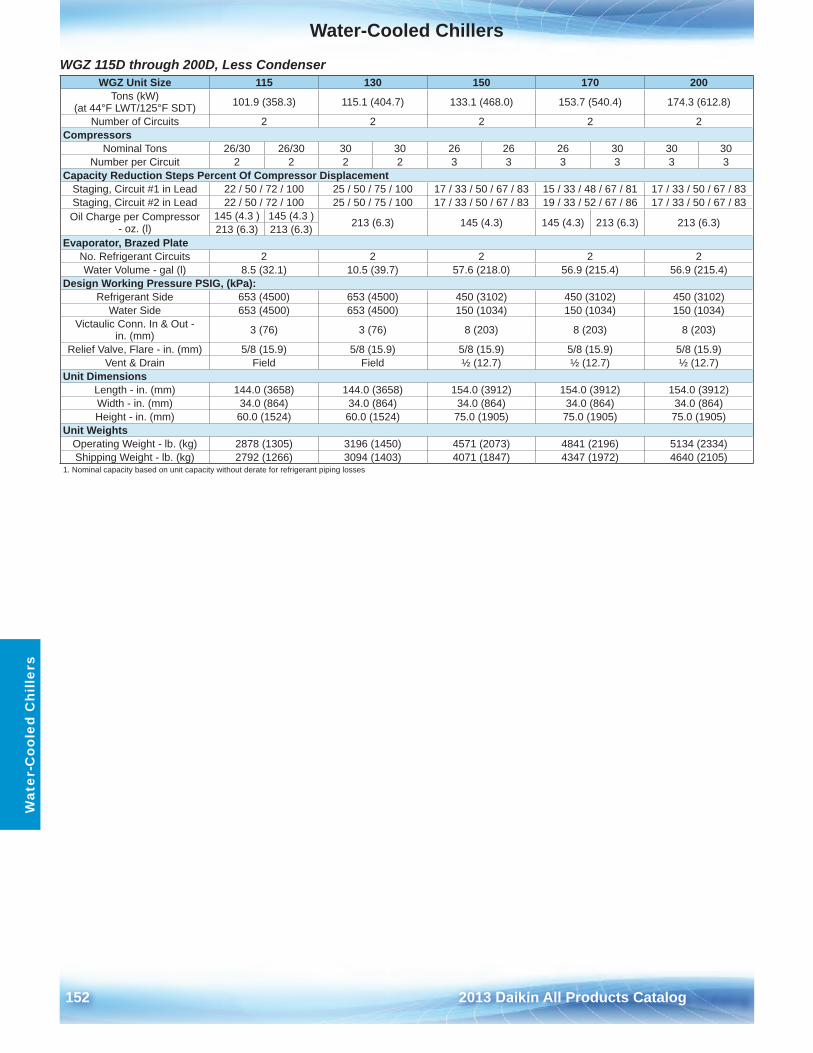
Water-Cooled Chillers
152 2013 Daikin All Products Catalog
Wat
er-C
oole
d C
hille
rs
WGZ 115D through 200D, Less Condenser WGZ Unit Size 115 130 150 170 200
Tons (kW) (at 44°F LWT/125°F SDT) 101 .9 (358 .3) 115 .1 (404 .7) 133 .1 (468 .0) 153 .7 (540 .4) 174 .3 (612 .8)
Number of Circuits 2 2 2 2 2Compressors
Nominal Tons 26/30 26/30 30 30 26 26 26 30 30 30Number per Circuit 2 2 2 2 3 3 3 3 3 3
Capacity Reduction Steps Percent Of Compressor DisplacementStaging, Circuit #1 in Lead 22 / 50 / 72 / 100 25 / 50 / 75 / 100 17 / 33 / 50 / 67 / 83 15 / 33 / 48 / 67 / 81 17 / 33 / 50 / 67 / 83Staging, Circuit #2 in Lead 22 / 50 / 72 / 100 25 / 50 / 75 / 100 17 / 33 / 50 / 67 / 83 19 / 33 / 52 / 67 / 86 17 / 33 / 50 / 67 / 83Oil Charge per Compressor
- oz . (l)145 (4 .3 ) 145 (4 .3 ) 213 (6 .3) 145 (4 .3) 145 (4 .3) 213 (6 .3) 213 (6 .3)213 (6 .3) 213 (6 .3)
Evaporator, Brazed PlateNo . Refrigerant Circuits 2 2 2 2 2Water Volume - gal (l) 8 .5 (32 .1) 10 .5 (39 .7) 57 .6 (218 .0) 56 .9 (215 .4) 56 .9 (215 .4)
Design Working Pressure PSIG, (kPa):Refrigerant Side 653 (4500) 653 (4500) 450 (3102) 450 (3102) 450 (3102)
Water Side 653 (4500) 653 (4500) 150 (1034) 150 (1034) 150 (1034)Victaulic Conn . In & Out -
in . (mm) 3 (76) 3 (76) 8 (203) 8 (203) 8 (203)
Relief Valve, Flare - in . (mm) 5/8 (15 .9) 5/8 (15 .9) 5/8 (15 .9) 5/8 (15 .9) 5/8 (15 .9)Vent & Drain Field Field ½ (12 .7) ½ (12 .7) ½ (12 .7)
Unit DimensionsLength - in . (mm) 144 .0 (3658) 144 .0 (3658) 154 .0 (3912) 154 .0 (3912) 154 .0 (3912)Width - in . (mm) 34 .0 (864) 34 .0 (864) 34 .0 (864) 34 .0 (864) 34 .0 (864)Height - in . (mm) 60 .0 (1524) 60 .0 (1524) 75 .0 (1905) 75 .0 (1905) 75 .0 (1905)
Unit WeightsOperating Weight - lb . (kg) 2878 (1305) 3196 (1450) 4571 (2073) 4841 (2196) 5134 (2334)Shipping Weight - lb . (kg) 2792 (1266) 3094 (1403) 4071 (1847) 4347 (1972) 4640 (2105)
1 . Nominal capacity based on unit capacity without derate for refrigerant piping losses
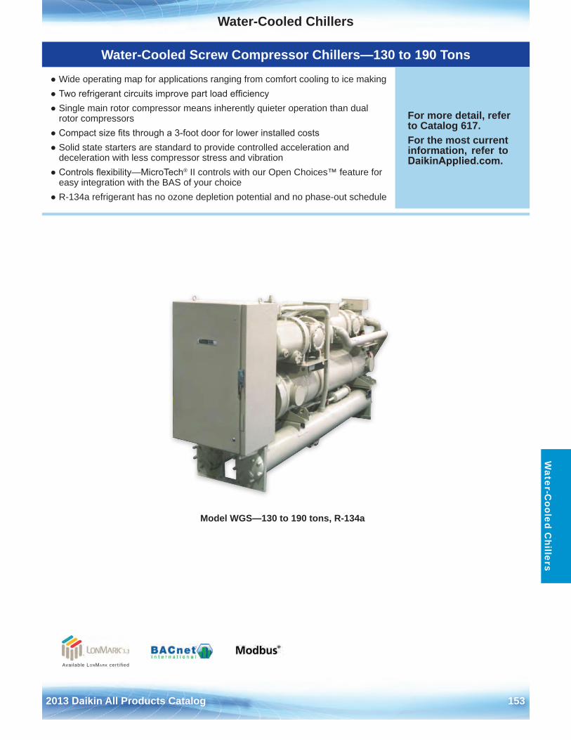
Water-Cooled Chillers
2013 Daikin All Products Catalog 153
Water-C
ooled Chillers
Model WGS—130 to 190 tons, R-134a
Available LonMark cert i f ied
Water-Cooled Screw Compressor Chillers—130 to 190 Tons
● Wide operating map for applications ranging from comfort cooling to ice making● Two refrigerant circuits improve part load efficiency● Single main rotor compressor means inherently quieter operation than dual
rotor compressors● Compact size fits through a 3-foot door for lower installed costs● Solid state starters are standard to provide controlled acceleration and
deceleration with less compressor stress and vibration● Controls flexibility—MicroTech® II controls with our Open Choices™ feature for
easy integration with the BAS of your choice● R-134a refrigerant has no ozone depletion potential and no phase-out schedule
For more detail, refer to Catalog 617 .For the most current information, refer to DaikinApplied.com .
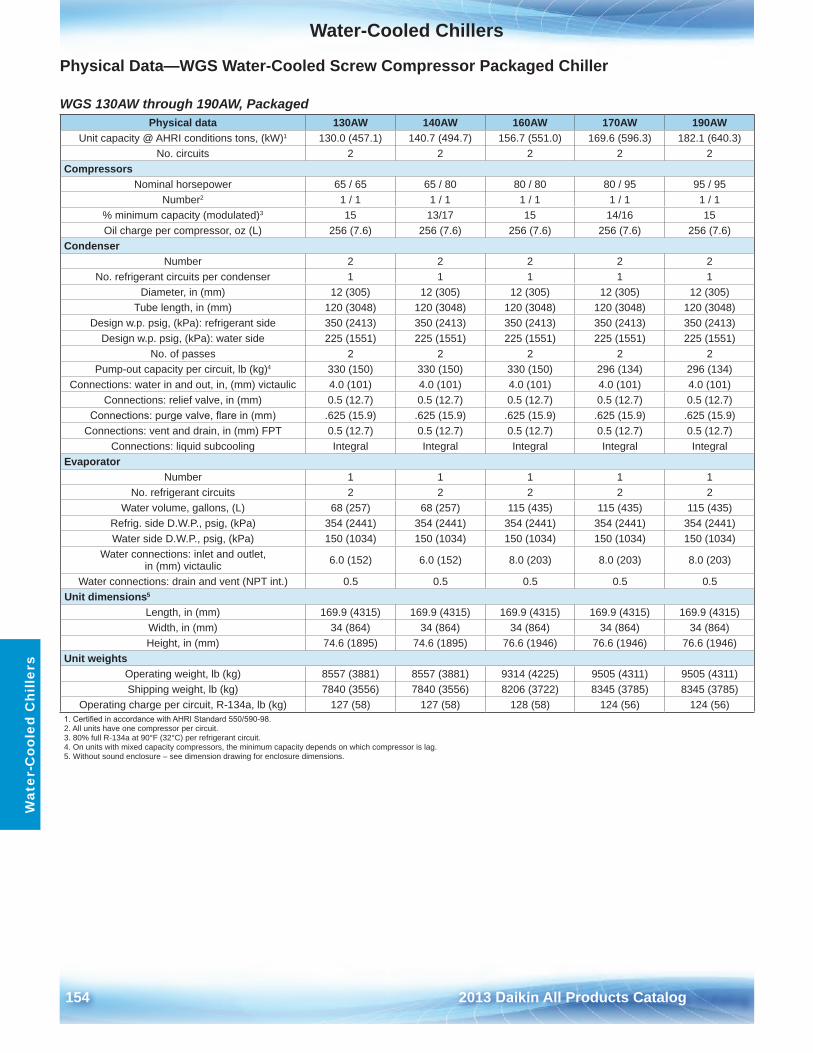
Water-Cooled Chillers
154 2013 Daikin All Products Catalog
Wat
er-C
oole
d C
hille
rs
Physical Data—WGS Water-Cooled Screw Compressor Packaged Chiller
WGS 130AW through 190AW, Packaged Physical data 130AW 140AW 160AW 170AW 190AW
Unit capacity @ AHRI conditions tons, (kW)1 130 .0 (457 .1) 140 .7 (494 .7) 156 .7 (551 .0) 169 .6 (596 .3) 182 .1 (640 .3)No . circuits 2 2 2 2 2
CompressorsNominal horsepower 65 / 65 65 / 80 80 / 80 80 / 95 95 / 95
Number2 1 / 1 1 / 1 1 / 1 1 / 1 1 / 1% minimum capacity (modulated)3 15 13/17 15 14/16 15Oil charge per compressor, oz (L) 256 (7 .6) 256 (7 .6) 256 (7 .6) 256 (7 .6) 256 (7 .6)
CondenserNumber 2 2 2 2 2
No . refrigerant circuits per condenser 1 1 1 1 1Diameter, in (mm) 12 (305) 12 (305) 12 (305) 12 (305) 12 (305)
Tube length, in (mm) 120 (3048) 120 (3048) 120 (3048) 120 (3048) 120 (3048)Design w .p . psig, (kPa): refrigerant side 350 (2413) 350 (2413) 350 (2413) 350 (2413) 350 (2413)
Design w .p . psig, (kPa): water side 225 (1551) 225 (1551) 225 (1551) 225 (1551) 225 (1551)No . of passes 2 2 2 2 2
Pump-out capacity per circuit, lb (kg)4 330 (150) 330 (150) 330 (150) 296 (134) 296 (134)Connections: water in and out, in, (mm) victaulic 4 .0 (101) 4 .0 (101) 4 .0 (101) 4 .0 (101) 4 .0 (101)
Connections: relief valve, in (mm) 0 .5 (12 .7) 0 .5 (12 .7) 0 .5 (12 .7) 0 .5 (12 .7) 0 .5 (12 .7)Connections: purge valve, flare in (mm) .625 (15 .9) .625 (15 .9) .625 (15 .9) .625 (15 .9) .625 (15 .9)
Connections: vent and drain, in (mm) FPT 0 .5 (12 .7) 0 .5 (12 .7) 0 .5 (12 .7) 0 .5 (12 .7) 0 .5 (12 .7)Connections: liquid subcooling Integral Integral Integral Integral Integral
EvaporatorNumber 1 1 1 1 1
No . refrigerant circuits 2 2 2 2 2Water volume, gallons, (L) 68 (257) 68 (257) 115 (435) 115 (435) 115 (435)
Refrig . side D .W .P ., psig, (kPa) 354 (2441) 354 (2441) 354 (2441) 354 (2441) 354 (2441)Water side D .W .P ., psig, (kPa) 150 (1034) 150 (1034) 150 (1034) 150 (1034) 150 (1034)
Water connections: inlet and outlet, in (mm) victaulic 6 .0 (152) 6 .0 (152) 8 .0 (203) 8 .0 (203) 8 .0 (203)
Water connections: drain and vent (NPT int .) 0 .5 0 .5 0 .5 0 .5 0 .5Unit dimensions5
Length, in (mm) 169 .9 (4315) 169 .9 (4315) 169 .9 (4315) 169 .9 (4315) 169 .9 (4315)Width, in (mm) 34 (864) 34 (864) 34 (864) 34 (864) 34 (864)Height, in (mm) 74 .6 (1895) 74 .6 (1895) 76 .6 (1946) 76 .6 (1946) 76 .6 (1946)
Unit weightsOperating weight, lb (kg) 8557 (3881) 8557 (3881) 9314 (4225) 9505 (4311) 9505 (4311)Shipping weight, lb (kg) 7840 (3556) 7840 (3556) 8206 (3722) 8345 (3785) 8345 (3785)
Operating charge per circuit, R-134a, lb (kg) 127 (58) 127 (58) 128 (58) 124 (56) 124 (56)1. Certified in accordance with AHRI Standard 550/590-98.2 . All units have one compressor per circuit .3 . 80% full R-134a at 90°F (32°C) per refrigerant circuit .4 . On units with mixed capacity compressors, the minimum capacity depends on which compressor is lag .5 . Without sound enclosure – see dimension drawing for enclosure dimensions .
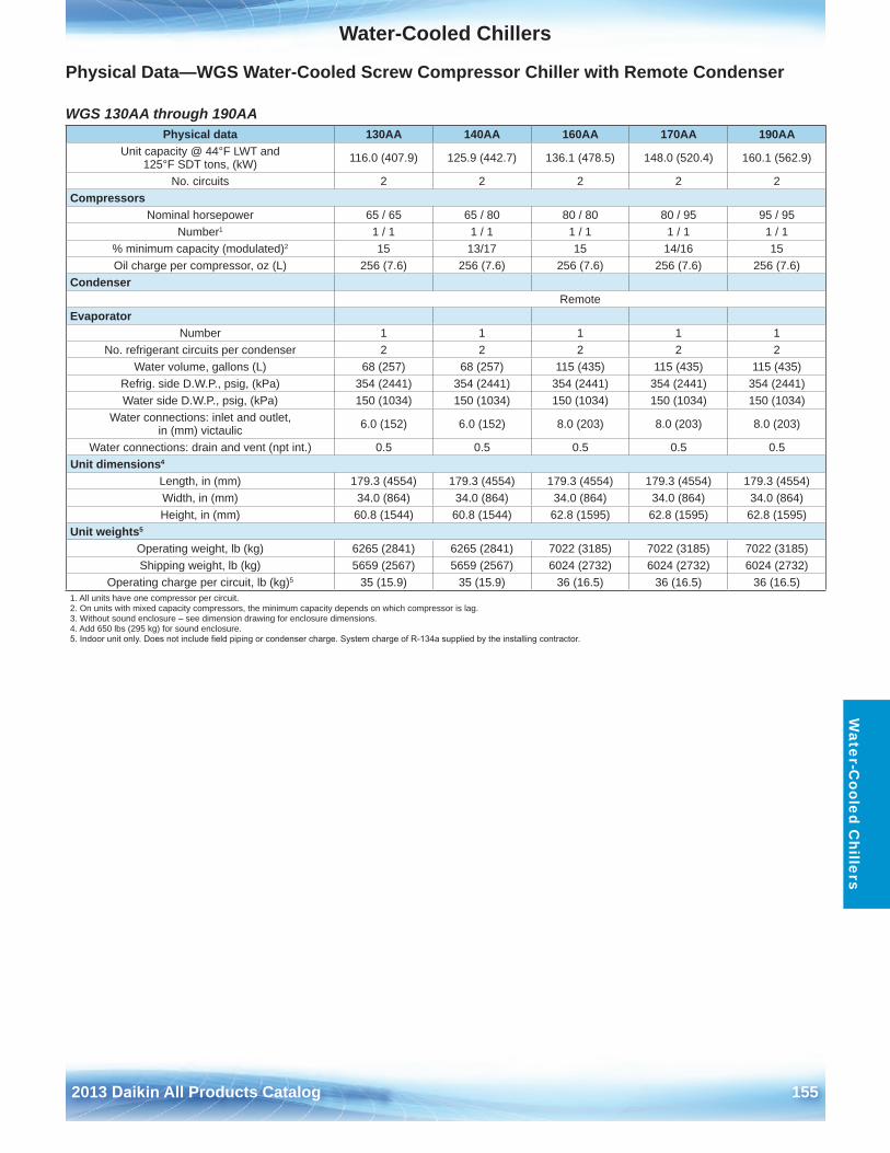
Water-Cooled Chillers
2013 Daikin All Products Catalog 155
Water-C
ooled Chillers
Physical Data—WGS Water-Cooled Screw Compressor Chiller with Remote Condenser
WGS 130AA through 190AA Physical data 130AA 140AA 160AA 170AA 190AA
Unit capacity @ 44°F LWT and 125°F SDT tons, (kW) 116 .0 (407 .9) 125 .9 (442 .7) 136 .1 (478 .5) 148 .0 (520 .4) 160 .1 (562 .9)
No . circuits 2 2 2 2 2Compressors
Nominal horsepower 65 / 65 65 / 80 80 / 80 80 / 95 95 / 95Number1 1 / 1 1 / 1 1 / 1 1 / 1 1 / 1
% minimum capacity (modulated)2 15 13/17 15 14/16 15Oil charge per compressor, oz (L) 256 (7 .6) 256 (7 .6) 256 (7 .6) 256 (7 .6) 256 (7 .6)
CondenserRemote
EvaporatorNumber 1 1 1 1 1
No . refrigerant circuits per condenser 2 2 2 2 2Water volume, gallons (L) 68 (257) 68 (257) 115 (435) 115 (435) 115 (435)
Refrig . side D .W .P ., psig, (kPa) 354 (2441) 354 (2441) 354 (2441) 354 (2441) 354 (2441)Water side D .W .P ., psig, (kPa) 150 (1034) 150 (1034) 150 (1034) 150 (1034) 150 (1034)
Water connections: inlet and outlet, in (mm) victaulic 6 .0 (152) 6 .0 (152) 8 .0 (203) 8 .0 (203) 8 .0 (203)
Water connections: drain and vent (npt int .) 0 .5 0 .5 0 .5 0 .5 0 .5Unit dimensions4
Length, in (mm) 179 .3 (4554) 179 .3 (4554) 179 .3 (4554) 179 .3 (4554) 179 .3 (4554)Width, in (mm) 34 .0 (864) 34 .0 (864) 34 .0 (864) 34 .0 (864) 34 .0 (864)Height, in (mm) 60 .8 (1544) 60 .8 (1544) 62 .8 (1595) 62 .8 (1595) 62 .8 (1595)
Unit weights5
Operating weight, lb (kg) 6265 (2841) 6265 (2841) 7022 (3185) 7022 (3185) 7022 (3185)Shipping weight, lb (kg) 5659 (2567) 5659 (2567) 6024 (2732) 6024 (2732) 6024 (2732)
Operating charge per circuit, lb (kg)5 35 (15 .9) 35 (15 .9) 36 (16 .5) 36 (16 .5) 36 (16 .5)1 . All units have one compressor per circuit .2 . On units with mixed capacity compressors, the minimum capacity depends on which compressor is lag .3 . Without sound enclosure – see dimension drawing for enclosure dimensions .4 . Add 650 lbs (295 kg) for sound enclosure .5. Indoor unit only. Does not include field piping or condenser charge. System charge of R-134a supplied by the installing contractor.
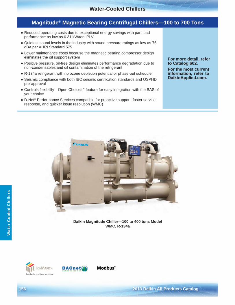
Water-Cooled Chillers
156 2013 Daikin All Products Catalog
Wat
er-C
oole
d C
hille
rs
Available LonMark cert i f ied
Magnitude® Magnetic Bearing Centrifugal Chillers—100 to 700 Tons
● Reduced operating costs due to exceptional energy savings with part loadperformance as low as 0 .31 kW/ton IPLV
● Quietest sound levels in the industry with sound pressure ratings as low as 76dBA per AHRI Standard 575
● Lower maintenance costs because the magnetic bearing compressor designeliminates the oil support system
● Positive pressure, oil-free design eliminates performance degradation due tonon-condensables and oil contamination of the refrigerant
● R-134a refrigerant with no ozone depletion potential or phase-out schedule● Seismic compliance with both IBC seismic certification standards and OSPHD
pre-approval● Controls flexibility—Open Choices™ feature for easy integration with the BAS of
your choice● D-Net® Performance Services compatible for proactive support, faster service
response, and quicker issue resolution (WMC)
For more detail, refer to Catalog 602 .For the most current information, refer to DaikinApplied.com .
Daikin Magnitude Chiller—100 to 400 tons Model WMC, R-134a
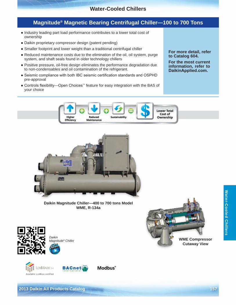
Water-Cooled Chillers
2013 Daikin All Products Catalog 157
Water-C
ooled Chillers
Daikin Magnitude Chiller—400 to 700 tons Model WME, R-134a
WME Compressor Cutaway View
Available LonMark cert i f ied
Daikin Magnitude® Chiller
Magnitude® Magnetic Bearing Centrifugal Chiller—100 to 700 Tons
● Industry leading part load performance contributes to a lower total cost ofownership
● Daikin proprietary compressor design (patent pending)● Smaller footprint and lower weight than a traditional centrifugal chiller● Reduced maintenance costs due to the elimination of the oil, oil system, purge
system, and shaft seals found in older technology chillers● Positive pressure, oil-free design eliminates the performance degradation due
to non-condensables and oil contamination of the refrigerant .● Seismic compliance with both IBC seismic certification standards and OSPHD
pre-approval● Controls flexibility—Open Choices™ feature for easy integration with the BAS of
your choice
For more detail, refer to Catalog 604 .For the most current information, refer to DaikinApplied.com .
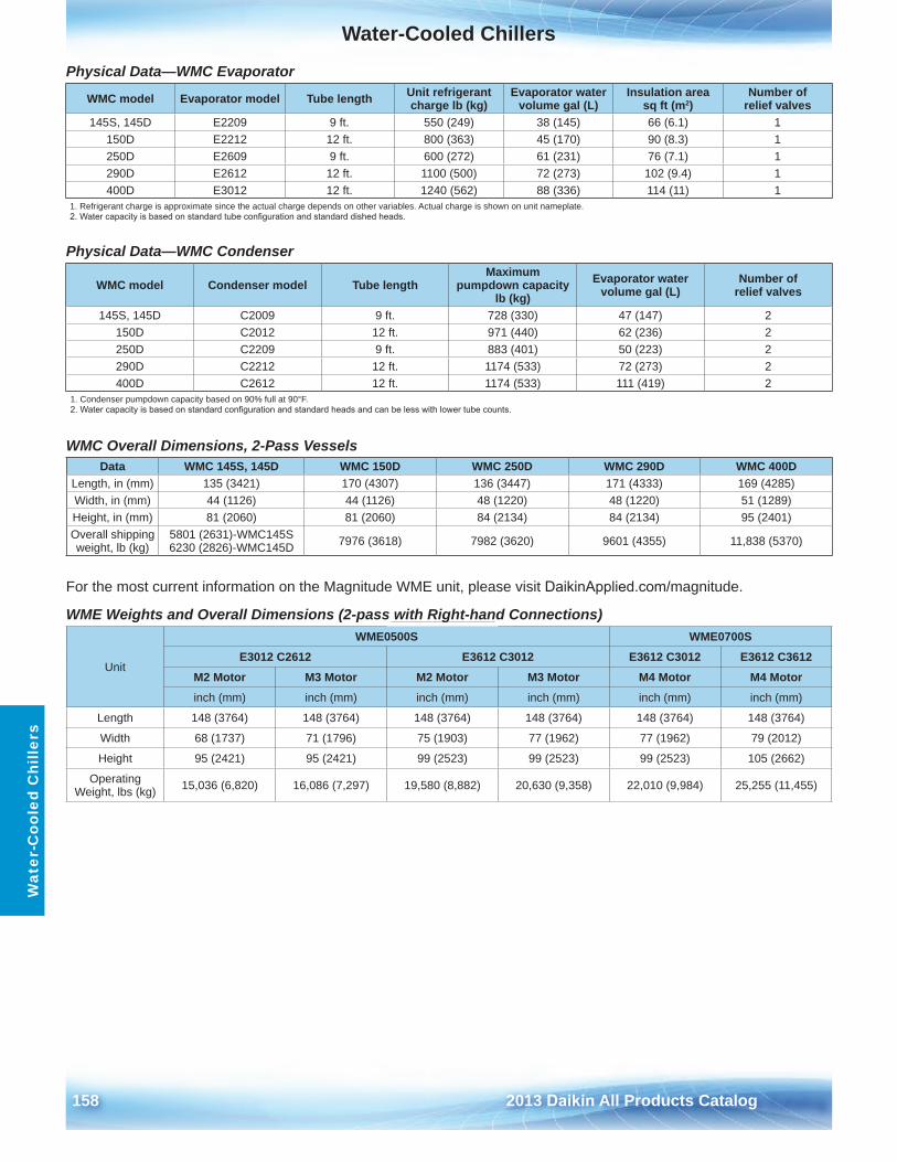
Water-Cooled Chillers
158 2013 Daikin All Products Catalog
Wat
er-C
oole
d C
hille
rs
Physical Data—WMC Evaporator
Physical Data—WMC Condenser
WMC Overall Dimensions, 2-Pass Vessels
For the most current information on the Magnitude WME unit, please visit DaikinApplied.com/magnitude .
WME Weights and Overall Dimensions (2-pass with Right-hand Connections)
WMC model Evaporator model Tube length Unit refrigerant charge lb (kg)
Evaporator water volume gal (L)
Insulation area sq ft (m2)
Number of relief valves
145S, 145D E2209 9 ft . 550 (249) 38 (145) 66 (6 .1) 1150D E2212 12 ft . 800 (363) 45 (170) 90 (8 .3) 1250D E2609 9 ft . 600 (272) 61 (231) 76 (7 .1) 1290D E2612 12 ft . 1100 (500) 72 (273) 102 (9 .4) 1400D E3012 12 ft . 1240 (562) 88 (336) 114 (11) 1
1 . Refrigerant charge is approximate since the actual charge depends on other variables . Actual charge is shown on unit nameplate .2. Water capacity is based on standard tube configuration and standard dished heads.
WMC model Condenser model Tube lengthMaximum
pumpdown capacity lb (kg)
Evaporator water volume gal (L)
Number of relief valves
145S, 145D C2009 9 ft . 728 (330) 47 (147) 2150D C2012 12 ft . 971 (440) 62 (236) 2250D C2209 9 ft . 883 (401) 50 (223) 2290D C2212 12 ft . 1174 (533) 72 (273) 2400D C2612 12 ft . 1174 (533) 111 (419) 2
1 . Condenser pumpdown capacity based on 90% full at 90°F . 2. Water capacity is based on standard configuration and standard heads and can be less with lower tube counts.
Data WMC 145S, 145D WMC 150D WMC 250D WMC 290D WMC 400DLength, in (mm) 135 (3421) 170 (4307) 136 (3447) 171 (4333) 169 (4285)Width, in (mm) 44 (1126) 44 (1126) 48 (1220) 48 (1220) 51 (1289)Height, in (mm) 81 (2060) 81 (2060) 84 (2134) 84 (2134) 95 (2401)Overall shipping weight, lb (kg)
5801 (2631)-WMC145S 6230 (2826)-WMC145D 7976 (3618) 7982 (3620) 9601 (4355) 11,838 (5370)
Unit
WME0500S WME0700SE3012 C2612 E3612 C3012 E3612 C3012 E3612 C3612
M2 Motor M3 Motor M2 Motor M3 Motor M4 Motor M4 Motorinch (mm) inch (mm) inch (mm) inch (mm) inch (mm) inch (mm)
Length 148 (3764) 148 (3764) 148 (3764) 148 (3764) 148 (3764) 148 (3764)
Width 68 (1737) 71 (1796) 75 (1903) 77 (1962) 77 (1962) 79 (2012)
Height 95 (2421) 95 (2421) 99 (2523) 99 (2523) 99 (2523) 105 (2662)
Operating Weight, lbs (kg) 15,036 (6,820) 16,086 (7,297) 19,580 (8,882) 20,630 (9,358) 22,010 (9,984) 25,255 (11,455)
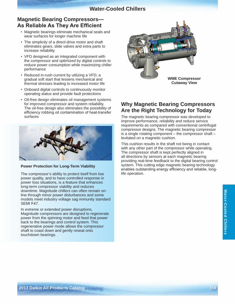
Water-Cooled Chillers
2013 Daikin All Products Catalog 159
Water-C
ooled Chillers
Magnetic Bearing Compressors— As Reliable As They Are Efficient
• Magnetic bearings eliminate mechanical seals andwear surfaces for longer machine life
• The simplicity of a direct-drive motor and shafteliminates gears, slide valves and extra parts toincrease reliability
• VFD designed as an integrated component withthe compressor and optimized by digital controls toreduce power consumption while maximizing chillerperformance
• Reduced in-rush current by utilizing a VFD; agradual soft start that lessens mechanical andthermal stresses leading to increased motor life
• Onboard digital controls to continuously monitoroperating status and provide fault protections
• Oil-free design eliminates oil management systemsfor improved compressor and system reliability . The oil-free design also eliminates the possibility ofefficiency robbing oil contamination of heat-transfersurfaces
Why Magnetic Bearing Compressors Are the Right Technology for TodayThe magnetic bearing compressor was developed to improve performance, reliability and reduce service requirements as compared with conventional centrifugal compressor designs . The magnetic bearing compressor is a single rotating component – the compressor shaft – levitated on a magnetic cushion . This cushion results in the shaft not being in contact with any other part of the compressor while operating . The compressor shaft is kept perfectly aligned in all directions by sensors at each magnetic bearing providing real-time feedback to the digital bearing control system . This cutting edge magnetic bearing technology enables outstanding energy efficiency and reliable, long-life operation .
Power Protection for Long-Term Viability
The compressor’s ability to protect itself from low power quality, and to have controlled response in power loss situations, is a feature that enhances long-term compressor viability and reduces downtime . Magnitude chillers can often remain on-line through minor power disturbances and some models meet industry voltage sag immunity standard SEMI F47 . In extreme or extended power disruptions, Magnitude compressors are designed to regenerate power from the spinning motor and feed that power back to the bearings and control system . This regenerative power mode allows the compressor shaft to coast down and gently reseat onto touchdown bearings .
WME Compressor Cutaway View
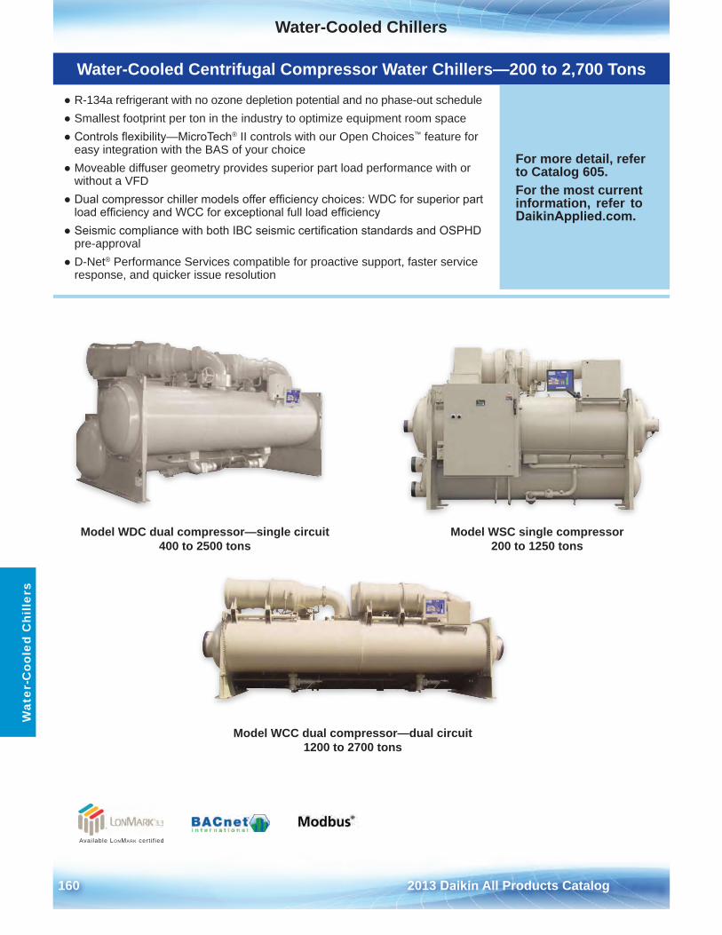
Water-Cooled Chillers
160 2013 Daikin All Products Catalog
Wat
er-C
oole
d C
hille
rs
Model WDC dual compressor—single circuit 400 to 2500 tons
Model WSC single compressor 200 to 1250 tons
Model WCC dual compressor—dual circuit 1200 to 2700 tons
Available LonMark cert i f ied
Water-Cooled Centrifugal Compressor Water Chillers—200 to 2,700 Tons
● R-134a refrigerant with no ozone depletion potential and no phase-out schedule● Smallest footprint per ton in the industry to optimize equipment room space● Controls flexibility—MicroTech® II controls with our Open Choices™ feature for
easy integration with the BAS of your choice● Moveable diffuser geometry provides superior part load performance with or
without a VFD● Dual compressor chiller models offer efficiency choices: WDC for superior part
load efficiency and WCC for exceptional full load efficiency● Seismic compliance with both IBC seismic certification standards and OSPHD
pre-approval● D-Net® Performance Services compatible for proactive support, faster service
response, and quicker issue resolution
For more detail, refer to Catalog 605 .For the most current information, refer to DaikinApplied.com .
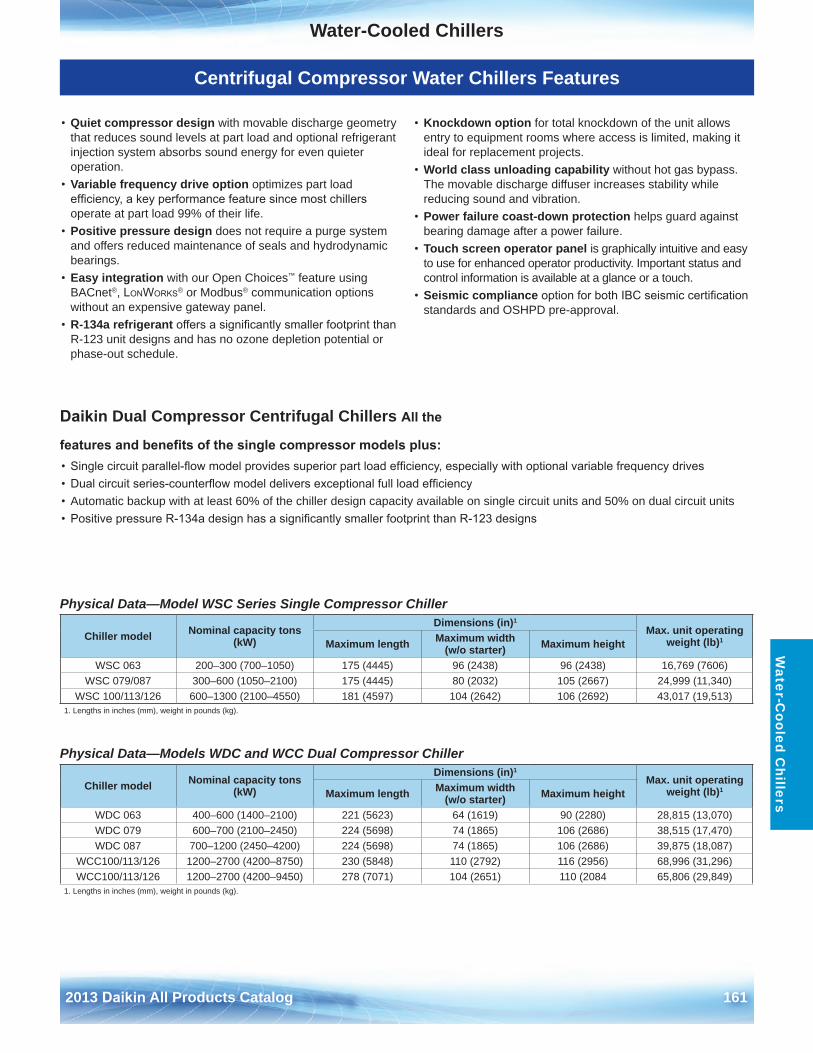
Water-Cooled Chillers
2013 Daikin All Products Catalog 161
Water-C
ooled Chillers
• Quiet compressor design with movable discharge geometrythat reduces sound levels at part load and optional refrigerantinjection system absorbs sound energy for even quieteroperation .
• Variable frequency drive option optimizes part loadefficiency, a key performance feature since most chillersoperate at part load 99% of their life .
• Positive pressure design does not require a purge systemand offers reduced maintenance of seals and hydrodynamicbearings .
• Easy integration with our Open Choices™ feature usingBACnet®, LonWorks® or Modbus® communication optionswithout an expensive gateway panel .
• R-134a refrigerant offers a significantly smaller footprint thanR-123 unit designs and has no ozone depletion potential orphase-out schedule .
• Knockdown option for total knockdown of the unit allowsentry to equipment rooms where access is limited, making itideal for replacement projects .
• World class unloading capability without hot gas bypass . The movable discharge diffuser increases stability whilereducing sound and vibration .
• Power failure coast-down protection helps guard againstbearing damage after a power failure .
• Touch screen operator panel is graphically intuitive and easyto use for enhanced operator productivity . Important status andcontrol information is available at a glance or a touch .
• Seismic compliance option for both IBC seismic certificationstandards and OSHPD pre-approval .
Physical Data—Model WSC Series Single Compressor Chiller
Physical Data—Models WDC and WCC Dual Compressor Chiller
Chiller model Nominal capacity tons (kW)
Dimensions (in)1
Max . unit operating weight (lb)1Maximum length Maximum width
(w/o starter) Maximum height
WSC 063 200–300 (700–1050) 175 (4445) 96 (2438) 96 (2438) 16,769 (7606)WSC 079/087 300–600 (1050–2100) 175 (4445) 80 (2032) 105 (2667) 24,999 (11,340)
WSC 100/113/126 600–1300 (2100–4550) 181 (4597) 104 (2642) 106 (2692) 43,017 (19,513)1 . Lengths in inches (mm), weight in pounds (kg) .
Chiller model Nominal capacity tons (kW)
Dimensions (in)1
Max . unit operating weight (lb)1Maximum length Maximum width
(w/o starter) Maximum height
WDC 063 400–600 (1400–2100) 221 (5623) 64 (1619) 90 (2280) 28,815 (13,070)WDC 079 600–700 (2100–2450) 224 (5698) 74 (1865) 106 (2686) 38,515 (17,470)WDC 087 700–1200 (2450–4200) 224 (5698) 74 (1865) 106 (2686) 39,875 (18,087)
WCC100/113/126 1200–2700 (4200–8750) 230 (5848) 110 (2792) 116 (2956) 68,996 (31,296)WCC100/113/126 1200–2700 (4200–9450) 278 (7071) 104 (2651) 110 (2084 65,806 (29,849)
1 . Lengths in inches (mm), weight in pounds (kg) .
Daikin Dual Compressor Centrifugal Chillers All the
features and benefits of the single compressor models plus:• Single circuit parallel-flow model provides superior part load efficiency, especially with optional variable frequency drives• Dual circuit series-counterflow model delivers exceptional full load efficiency• Automatic backup with at least 60% of the chiller design capacity available on single circuit units and 50% on dual circuit units• Positive pressure R-134a design has a significantly smaller footprint than R-123 designs
Centrifugal Compressor Water Chillers Features
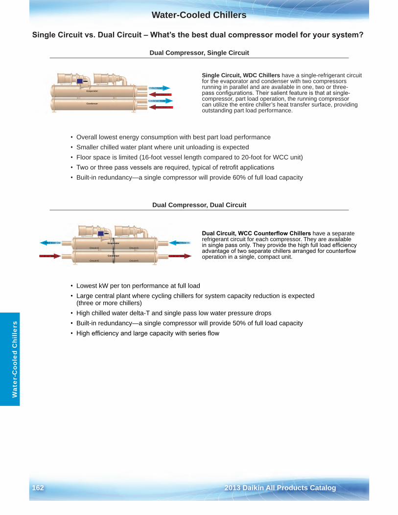
Water-Cooled Chillers
162 2013 Daikin All Products Catalog
Wat
er-C
oole
d C
hille
rs
Single Circuit vs. Dual Circuit – What’s the best dual compressor model for your system?
Dual Compressor, Single CircuitSingle Circuit WDC
Condenser Water In
Condenser Water Out
Chilled Water Out
Chilled Water In
Condenser
Evaporator
Single Circuit, WDC Chillers have a single-refrigerant circuit for the evaporator and condenser with two compressors running in parallel and are available in one, two or three-pass configurations. Their salient feature is that at single-compressor, part load operation, the running compressor can utilize the entire chiller’s heat transfer surface, providing outstanding part load performance .
• Overall lowest energy consumption with best part load performance• Smaller chilled water plant where unit unloading is expected• Floor space is limited (16-foot vessel length compared to 20-foot for WCC unit)• Two or three pass vessels are required, typical of retrofit applications• Built-in redundancy—a single compressor will provide 60% of full load capacity
Dual Compressor, Dual Circuit
Circuit #1
Circuit #1Circuit #2
Condenser Water In Condenser Water Out
Chilled Water Out Chilled Water In
Condenser
Evaporator
Circuit #2
Dual Circuit, WCC Counterflow Chillers have a separate refrigerant circuit for each compressor . They are available in single pass only. They provide the high full load efficiency advantage of two separate chillers arranged for counterflow operation in a single, compact unit .
• Lowest kW per ton performance at full load• Large central plant where cycling chillers for system capacity reduction is expected
(three or more chillers)• High chilled water delta-T and single pass low water pressure drops• Built-in redundancy—a single compressor will provide 50% of full load capacity• High efficiency and large capacity with series flow

2013 Daikin All Products Catalog 163
This page intentionally left blank.
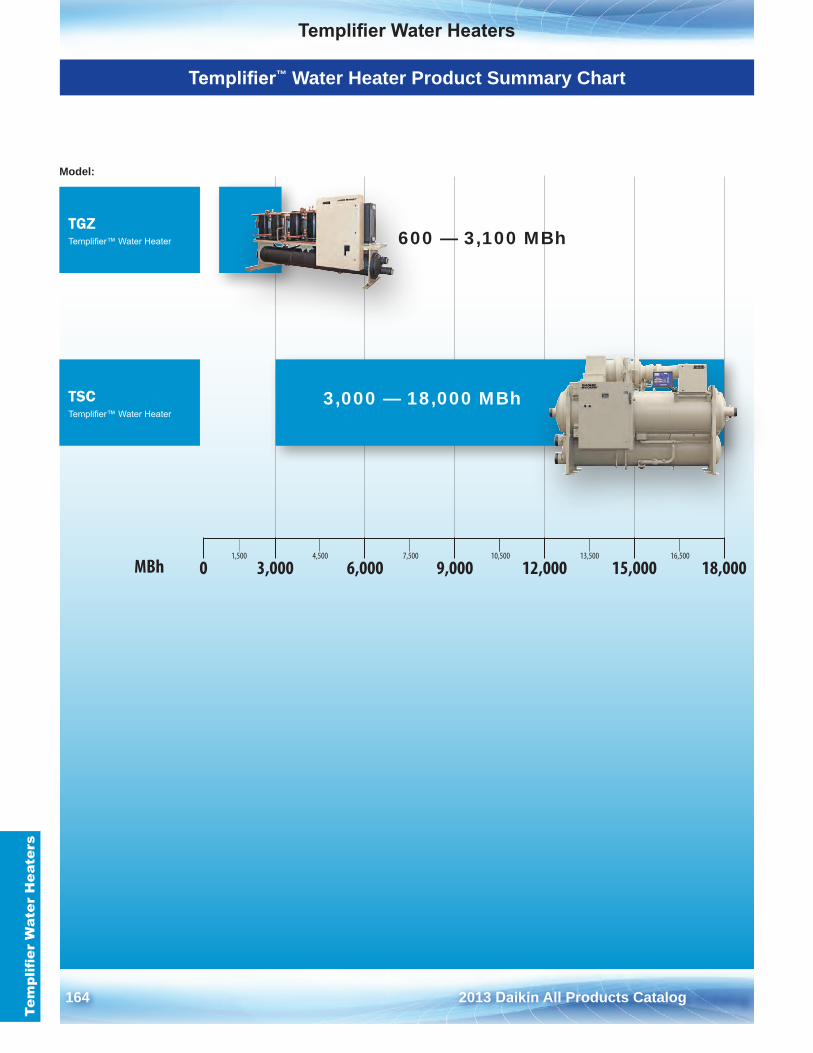
164 2013 Daikin All Products Catalog
Templifier Water HeatersTe
mpl
ifier
Wat
er H
eate
rs
Templifier™ Water Heater Product Summary Chart
1,500 4,500 7,500 10,500 13,500 16,500
0 3,000 6,000 9,000 12,000 15,000 18,000MBh
TGZTemplifier™ Water Heater
TSCTemplifier™ Water Heater
Model:
600 — 3,100 MBh
3,000 — 18,000 MBh
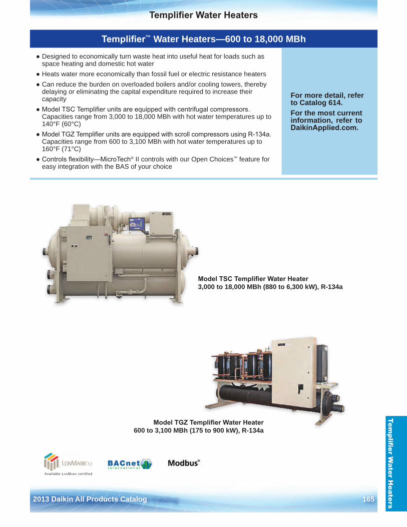
Templifier Water Heaters
2013 Daikin All Products Catalog 165
Templifier W
ater Heaters
Model TSC Templifier Water Heater 3,000 to 18,000 MBh (880 to 6,300 kW), R-134a
Available LonMark cert i f ied
Model TGZ Templifier Water Heater 600 to 3,100 MBh (175 to 900 kW), R-134a
Templifier™ Water Heaters—600 to 18,000 MBh
● Designed to economically turn waste heat into useful heat for loads such asspace heating and domestic hot water
● Heats water more economically than fossil fuel or electric resistance heaters● Can reduce the burden on overloaded boilers and/or cooling towers, thereby
delaying or eliminating the capital expenditure required to increase theircapacity
● Model TSC Templifier units are equipped with centrifugal compressors.Capacities range from 3,000 to 18,000 MBh with hot water temperatures up to140°F (60°C)
● Model TGZ Templifier units are equipped with scroll compressors using R-134a.Capacities range from 600 to 3,100 MBh with hot water temperatures up to160°F (71°C)
● Controls flexibility—MicroTech® II controls with our Open Choices™ feature foreasy integration with the BAS of your choice
For more detail, refer to Catalog 614 .For the most current information, refer to DaikinApplied.com .
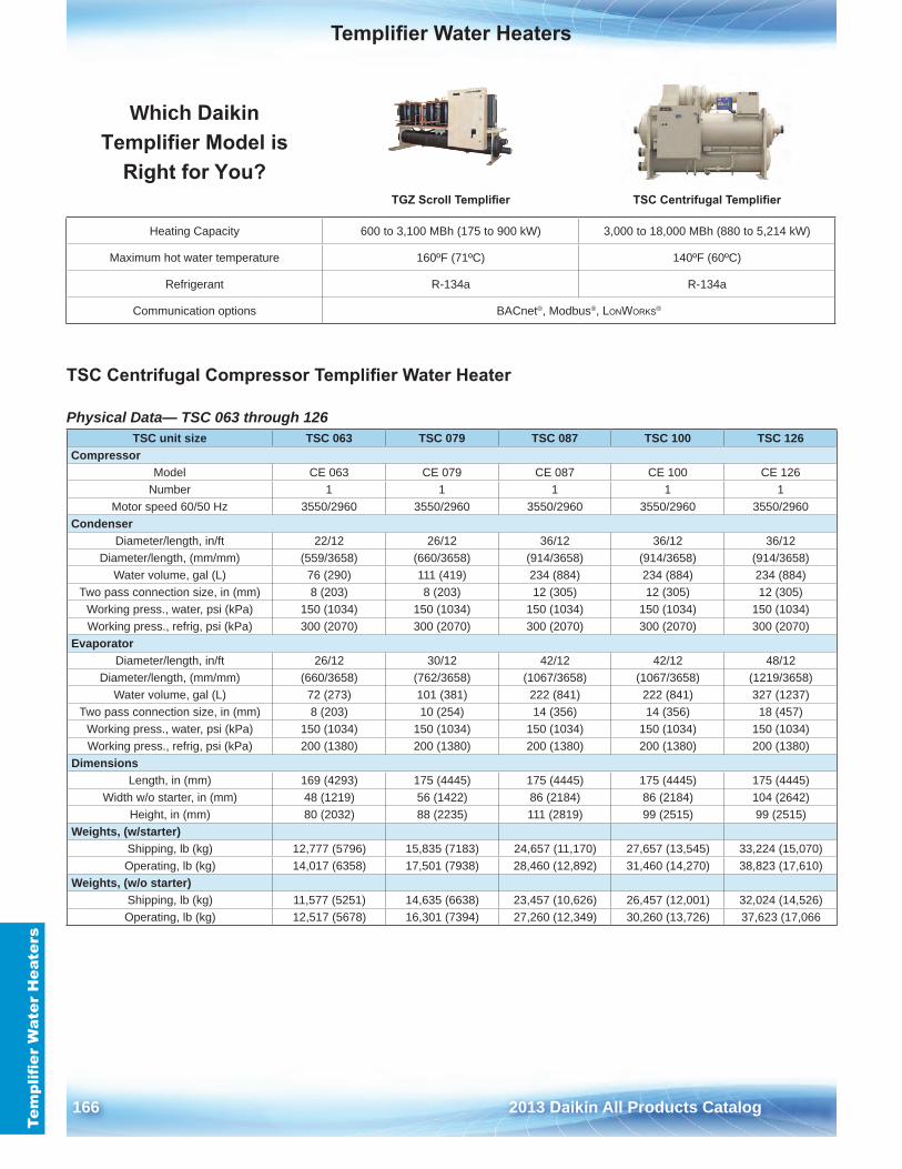
Templifier Water Heaters
166 2013 Daikin All Products Catalog
Tem
plifi
er W
ater
Hea
ters
TSC Centrifugal Compressor Templifier Water Heater
Physical Data— TSC 063 through 126
Which Daikin Templifier Model is
Right for You?TGZ Scroll Templifier TSC Centrifugal Templifier
Heating Capacity 600 to 3,100 MBh (175 to 900 kW) 3,000 to 18,000 MBh (880 to 5,214 kW)
Maximum hot water temperature 160ºF (71ºC) 140ºF (60ºC)
Refrigerant R-134a R-134a
Communication options BACnet®, Modbus®, LonWorks®
TSC unit size TSC 063 TSC 079 TSC 087 TSC 100 TSC 126Compressor
Model CE 063 CE 079 CE 087 CE 100 CE 126Number 1 1 1 1 1
Motor speed 60/50 Hz 3550/2960 3550/2960 3550/2960 3550/2960 3550/2960Condenser
Diameter/length, in/ft 22/12 26/12 36/12 36/12 36/12Diameter/length, (mm/mm) (559/3658) (660/3658) (914/3658) (914/3658) (914/3658)
Water volume, gal (L) 76 (290) 111 (419) 234 (884) 234 (884) 234 (884)Two pass connection size, in (mm) 8 (203) 8 (203) 12 (305) 12 (305) 12 (305)
Working press ., water, psi (kPa) 150 (1034) 150 (1034) 150 (1034) 150 (1034) 150 (1034)Working press ., refrig, psi (kPa) 300 (2070) 300 (2070) 300 (2070) 300 (2070) 300 (2070)
EvaporatorDiameter/length, in/ft 26/12 30/12 42/12 42/12 48/12
Diameter/length, (mm/mm) (660/3658) (762/3658) (1067/3658) (1067/3658) (1219/3658)Water volume, gal (L) 72 (273) 101 (381) 222 (841) 222 (841) 327 (1237)
Two pass connection size, in (mm) 8 (203) 10 (254) 14 (356) 14 (356) 18 (457)Working press ., water, psi (kPa) 150 (1034) 150 (1034) 150 (1034) 150 (1034) 150 (1034)Working press ., refrig, psi (kPa) 200 (1380) 200 (1380) 200 (1380) 200 (1380) 200 (1380)
DimensionsLength, in (mm) 169 (4293) 175 (4445) 175 (4445) 175 (4445) 175 (4445)
Width w/o starter, in (mm) 48 (1219) 56 (1422) 86 (2184) 86 (2184) 104 (2642)Height, in (mm) 80 (2032) 88 (2235) 111 (2819) 99 (2515) 99 (2515)
Weights, (w/starter)Shipping, lb (kg) 12,777 (5796) 15,835 (7183) 24,657 (11,170) 27,657 (13,545) 33,224 (15,070)Operating, lb (kg) 14,017 (6358) 17,501 (7938) 28,460 (12,892) 31,460 (14,270) 38,823 (17,610)
Weights, (w/o starter)Shipping, lb (kg) 11,577 (5251) 14,635 (6638) 23,457 (10,626) 26,457 (12,001) 32,024 (14,526)Operating, lb (kg) 12,517 (5678) 16,301 (7394) 27,260 (12,349) 30,260 (13,726) 37,623 (17,066
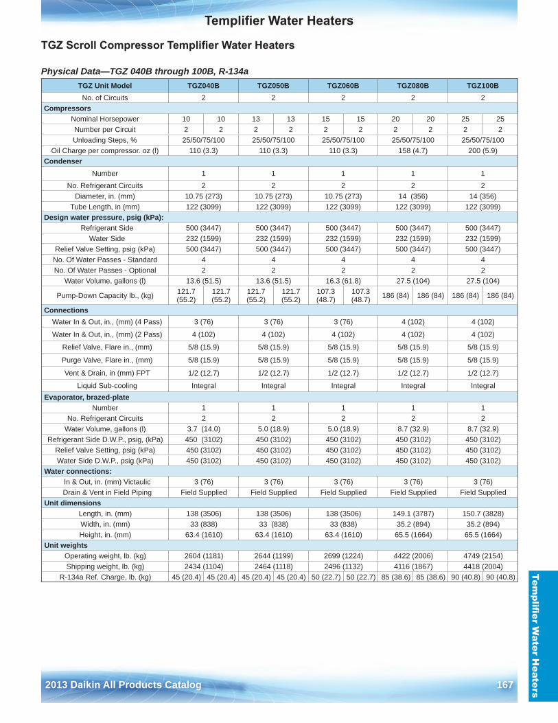
Templifier Water Heaters
2013 Daikin All Products Catalog 167
Templifier W
ater Heaters
TGZ Scroll Compressor Templifier Water Heaters
Physical Data—TGZ 040B through 100B, R-134a TGZ Unit Model TGZ040B TGZ050B TGZ060B TGZ080B TGZ100BNo . of Circuits 2 2 2 2 2
Compressors Nominal Horsepower 10 10 13 13 15 15 20 20 25 25Number per Circuit 2 2 2 2 2 2 2 2 2 2Unloading Steps, % 25/50/75/100 25/50/75/100 25/50/75/100 25/50/75/100 25/50/75/100
Oil Charge per compressor . oz (l) 110 (3 .3) 110 (3 .3) 110 (3 .3) 158 (4 .7) 200 (5 .9)Condenser
Number 1 1 1 1 1
No . Refrigerant Circuits 2 2 2 2 2Diameter, in . (mm) 10 .75 (273) 10 .75 (273) 10 .75 (273) 14 (356) 14 (356)
Tube Length, in (mm) 122 (3099) 122 (3099) 122 (3099) 122 (3099) 122 (3099)Design water pressure, psig (kPa):
Refrigerant Side 500 (3447) 500 (3447) 500 (3447) 500 (3447) 500 (3447) Water Side 232 (1599) 232 (1599) 232 (1599) 232 (1599) 232 (1599)
Relief Valve Setting, psig (kPa) 500 (3447) 500 (3447) 500 (3447) 500 (3447) 500 (3447)No . Of Water Passes - Standard 4 4 4 4 4No . Of Water Passes - Optional 2 2 2 2 2
Water Volume, gallons (l) 13 .6 (51 .5) 13 .6 (51 .5) 16 .3 (61 .8) 27 .5 (104) 27 .5 (104)
Pump-Down Capacity lb ., (kg) 121 .7 (55 .2)
121 .7 (55 .2)
121 .7 (55 .2)
121 .7 (55 .2)
107 .3 (48 .7)
107 .3 (48 .7) 186 (84) 186 (84) 186 (84) 186 (84)
Connections Water In & Out, in ., (mm) (4 Pass) 3 (76) 3 (76) 3 (76) 4 (102) 4 (102)
Water In & Out, in ., (mm) (2 Pass) 4 (102) 4 (102) 4 (102) 4 (102) 4 (102)
Relief Valve, Flare in ., (mm) 5/8 (15 .9) 5/8 (15 .9) 5/8 (15 .9) 5/8 (15 .9) 5/8 (15 .9)
Purge Valve, Flare in ., (mm) 5/8 (15 .9) 5/8 (15 .9) 5/8 (15 .9) 5/8 (15 .9) 5/8 (15 .9)
Vent & Drain, in (mm) FPT 1/2 (12 .7) 1/2 (12 .7) 1/2 (12 .7) 1/2 (12 .7) 1/2 (12 .7)
Liquid Sub-cooling Integral Integral Integral Integral Integral Evaporator, brazed-plate
Number 1 1 1 1 1No . Refrigerant Circuits 2 2 2 2 2
Water Volume, gallons (l) 3 .7 (14 .0) 5 .0 (18 .9) 5 .0 (18 .9) 8 .7 (32 .9) 8 .7 (32 .9)Refrigerant Side D .W .P ., psig, (kPa) 450 (3102) 450 (3102) 450 (3102) 450 (3102) 450 (3102)
Relief Valve Setting, psig (kPa) 450 (3102) 450 (3102) 450 (3102) 450 (3102) 450 (3102)Water Side D .W .P ., psig (kPa) 450 (3102) 450 (3102) 450 (3102) 450 (3102) 450 (3102)
Water connections: In & Out, in . (mm) Victaulic 3 (76) 3 (76) 3 (76) 3 (76) 3 (76) Drain & Vent in Field Piping Field Supplied Field Supplied Field Supplied Field Supplied Field Supplied
Unit dimensionsLength, in . (mm) 138 (3506) 138 (3506) 138 (3506) 149 .1 (3787) 150 .7 (3828)Width, in . (mm) 33 (838) 33 (838) 33 (838) 35 .2 (894) 35 .2 (894)Height, in . (mm) 63 .4 (1610) 63 .4 (1610) 63 .4 (1610) 65 .5 (1664) 65 .5 (1664)
Unit weights Operating weight, lb . (kg) 2604 (1181) 2644 (1199) 2699 (1224) 4422 (2006) 4749 (2154)Shipping weight, lb . (kg) 2434 (1104) 2464 (1118) 2496 (1132) 4116 (1867) 4418 (2004)
R-134a Ref . Charge, lb . (kg) 45 (20 .4) 45 (20 .4) 45 (20 .4) 45 (20 .4) 50 (22 .7) 50 (22 .7) 85 (38 .6) 85 (38 .6) 90 (40 .8) 90 (40 .8)
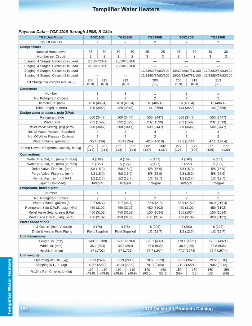
Templifier Water Heaters
168 2013 Daikin All Products Catalog
Tem
plifi
er W
ater
Hea
ters
Physical Data—TGZ 110B through 190B, R-134a TGZ Unit Model TGZ110B TGZ120B TGZ150B TGZ170B TGZ190BNo . Of Circuits 2 2 2 2 2
Compressors Nominal Horsepower 25 30 30 30 25 25 25 30 30 30Number per Circuit 2 2 2 2 3 3 3 3 3 3
Staging, 4 Stages, Circuit #1 in Lead 23/50/73/100 25/50/75/100 — — —Staging, 4 Stages, Circuit #2 in Lead 27/50/77/100 25/50/75/100 — — —Staging, 6 Stages, Circuit #1 in Lead — — 17/33/50/67/83/100 15/33/48/67/81/100 17/33/50/67/83/100Staging, 6 Stages, Circuit #2 in Lead — — 17/33/50/67/83/100 19/33/52/67/85/100 17/33/50/67/83/100
Oil Charge per compressor . oz (l) 200 (5 .9)
213 (6 .3)
213 (6 .3)
200 (5 .9)
200 (5 .9)
213 (6 .3)
213 (6 .3)
CondenserNumber 1 1 1 1 1
No . Refrigerant Circuits 2 2 2 2 2Diameter, in . (mm) 16 .0 (406 .4) 16 .0 (406 .4) 16 (406 .4) 16 (406 .4) 16 (406 .4)
Tube Length, in (mm) 120 (3048) 120 (3048) 144 (3658) 144 (3658) 144 (3658)Design water pressure, psig (kPa):
Refrigerant Side 500 (3447) 500 (3447) 500 (3447) 500 (3447) 500 (3447) Water Side 232 (1599) 232 (1599) 232 (1599) 232 (1599) 232 (1599)
Relief Valve Setting, psig (kPa) 500 (3447) 500 (3447) 500 (3447) 500 (3447) 500 (3447)No . Of Water Passes - Standard 4 4 4 4 4No . Of Water Passes - Optional 2 2 2 2 2
Water Volume, gallons (l) 35 .4 (134) 35 .4 (134) 42 .5 (160 .9) 47 .1 (178 .4) 47 .1 (178 .4)
Pump-Down Refrigerant Capacity, lb . (kg 252 (114)
252 (114)
252 (114)
252 (114)
302 (137)
302 (137)
277 (126)
277 (126)
277 (126)
277 (126)
Connections Water In & Out, in ., (mm) (4 Pass) 4 (102) 4 (102) 4 (102) 4 (102) 4 (102) Water In & Out, in ., (mm) (2 Pass) 5 (127) 5 (127) 5 (127) 5 (127) 5 (127)
Relief Valve, Flare in ., (mm) 5/8 (15 .9) 5/8 (15 .9) 5/8 (15 .9) 5/8 (15 .9) 5/8 (15 .9) Purge Valve, Flare in ., (mm) 5/8 (15 .9) 5/8 (15 .9) 5/8 (15 .9) 5/8 (15 .9) 5/8 (15 .9) Vent & Drain, in (mm) FPT 1/2 (12 .7) 1/2 (12 .7) 1/2 (12 .7) 1/2 (12 .7) 1/2 (12 .7)
Liquid Sub-cooling Integral Integral Integral Integral Integral Evaporator, brazed-plate
Number 1 1 1 1 1No . Refrigerant Circuits 2 2 2 2 2
Water Volume, gallons (l) 9 .7 (36 .7) 9 .7 (36 .7) 57 .6 (218) 56 .9 (215 .4) 56 .9 (215 .4)Refrigerant Side D .W .P ., psig, (kPa) 450 (3102) 450 (3102) 450 (3102) 450 (3102) 450 (3102)
Relief Valve Setting, psig (kPa) 450 (3102) 450 (3102) 150 (1034) 150 (1034) 150 (1034)Water Side D .W .P ., psig, (kPa) 450 (3102) 450 (3102) 450 (3102) 450 (3102) 450 (3102)
Water connections: In & Out, in . (mm) Victaulic 3 (76) 3 (76) 8 (203) 8 (203) 8 (203) Drain & Vent in Field Piping Field Supplied Field Supplied 1/2 (12 .7) 1/2 (12 .7) 1/2 (12 .7)
Unit dimensionsLength, in . (mm) 148 .8 (3780) 148 .8 (3780) 170 .1 (4321) 170 .1 (4321) 170 .1 (4321)Width, in . (mm) 35 .2 (894) 35 .2 (894) 36 .8 (935) 36 .8 (935) 36 .8 (935)Height, in . (mm) 67 (1702) 67 (1702) 77 .7 (1974) 77 .7 (1974) 77 .7 (1974)
Unit weightsOperating WT ., lb ., (kg) 5373 (2437) 5319 (2413) 7877 (3573) 7991 (3625) 7972 (3616)Shipping WT ., lb . (kg) 4967 (2253) 4913 (2229) 7019 (3184) 7101 (3221) 7082 (3212)
R-134a Ref . Charge, lb . (kg) 110 (49 .9)
110 (49 .9)
110 (49 .9)
110 (49 .9)
140 (63 .5)
140 (63 .5)
150 (68)
150 (68)
150 (68)
150 (68)
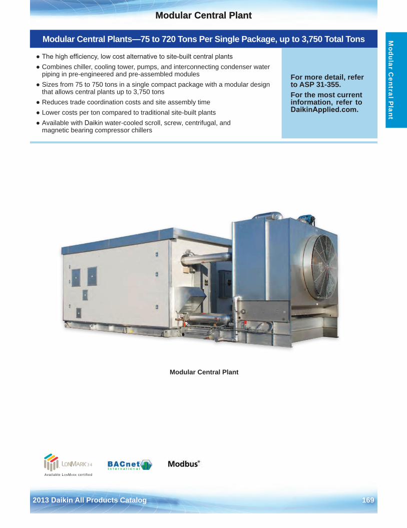
Modular Central Plant
2013 Daikin All Products Catalog 169
Modular Central PlantM
odular Central P
lant
Modular Central Plants—75 to 720 Tons Per Single Package, up to 3,750 Total Tons
● The high efficiency, low cost alternative to site-built central plants● Combines chiller, cooling tower, pumps, and interconnecting condenser water
piping in pre-engineered and pre-assembled modules● Sizes from 75 to 750 tons in a single compact package with a modular design
that allows central plants up to 3,750 tons● Reduces trade coordination costs and site assembly time● Lower costs per ton compared to traditional site-built plants● Available with Daikin water-cooled scroll, screw, centrifugal, and
magnetic bearing compressor chillers
For more detail, refer to ASP 31-355 .For the most current information, refer to DaikinApplied.com .
Modular Central Plant
Available LonMark cert i f ied
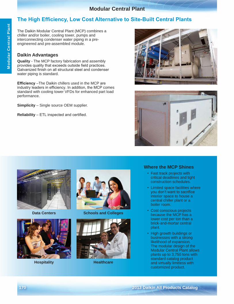
Modular Central Plant
170 2013 Daikin All Products Catalog
Mod
ular
Cen
tral
Pla
nt
The High Efficiency, Low Cost Alternative to Site-Built Central Plants
The Daikin Modular Central Plant (MCP) combines a chiller and/or boiler, cooling tower, pumps and interconnecting condenser water piping in a pre-engineered and pre-assembled module .
Daikin AdvantagesQuality - The MCP factory fabrication and assembly provides quality that exceeds outside field practices. Galvanized finish on all structural steel and condenser water piping is standard .
Efficiency –The Daikin chillers used in the MCP are industry leaders in efficiency. In addition, the MCP comes standard with cooling tower VFDs for enhanced part load performance .
Simplicity – Single source OEM supplier .
Reliability – ETL inspected and certified.
Where the MCP Shines • Fast track projects with
critical deadlines and tight construction schedules .
• Limited space facilities whereyou don’t want to sacrifice interior space to house a central chiller plant or a boiler room .
• Cost conscious projectsbecause the MCP has a lower cost per ton than a brick-and-mortar central plant .
• High growth buildings orbusinesses with a strong likelihood of expansion . The modular design of the Modular Central Plant allows plants up to 3,750 tons with standard catalog product and virtually limitless with customized product .
Data Centers
Hospitality
Schools and Colleges
Healthcare
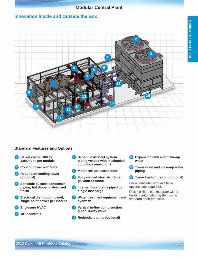
Modular Central Plant
2013 Daikin All Products Catalog 171
Modular C
entral Plant
10
2
5
1
3
7
9
68
4
12
Innovation Inside and Outside the Box
Standard Features and Options
1 Daikin chiller, 100 to 1,000 tons per module
2 Cooling tower with VFD
3 Redundant cooling tower (optional)
4 Schedule 40 steel condenser piping, hot dipped galvanized finish
5 Electrical distribution panel, single point power per module
6 Enclosure HVAC
7 MCP controls
8 Schedule 40 steel system piping welded with mechanical coupling connections
9 Motor roll-up access door
10 Fully welded steel structure, galvanized finish
11 Internal floor drains piped to single discharge
12 Water treatment equipment and eyewash
13 Vertical in-line pump suction guide, 3-way valve
14 Redundant pump (optional)
15 Expansion tank and make-up water
16 Tower drain and make-up water piping
17 Tower basin filtration (optional)
For a complete list of available options, see page 172 .Daikin chillers can integrate with a building automation system using standard open protocols .
13
11
16
1514
17
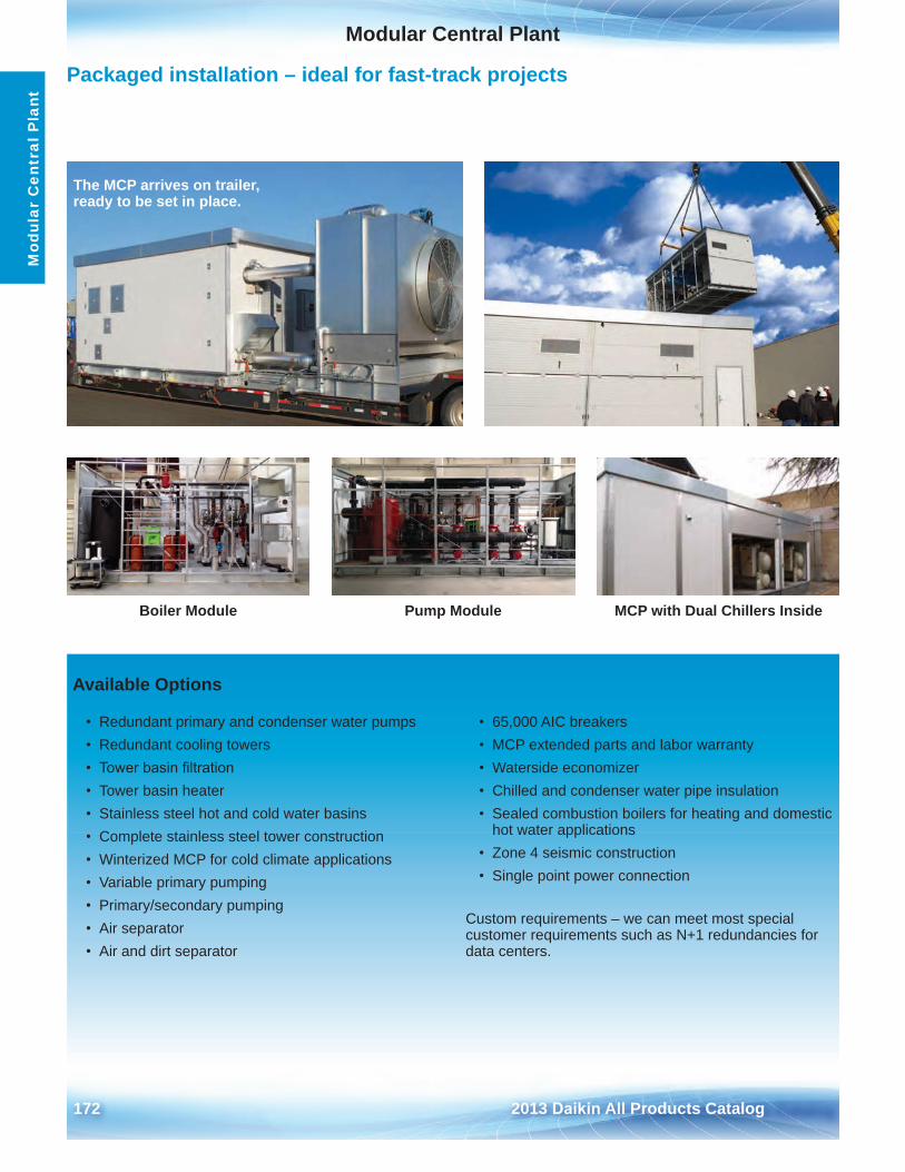
Modular Central Plant
172 2013 Daikin All Products Catalog
Mod
ular
Cen
tral
Pla
nt
Available Options
• Redundant primary and condenser water pumps• Redundant cooling towers• Tower basin filtration• Tower basin heater• Stainless steel hot and cold water basins• Complete stainless steel tower construction• Winterized MCP for cold climate applications• Variable primary pumping• Primary/secondary pumping• Air separator• Air and dirt separator
• 65,000 AIC breakers• MCP extended parts and labor warranty• Waterside economizer• Chilled and condenser water pipe insulation• Sealed combustion boilers for heating and domestic
hot water applications• Zone 4 seismic construction• Single point power connection
Custom requirements – we can meet most special customer requirements such as N+1 redundancies for data centers .
Packaged installation – ideal for fast-track projects
Boiler Module Pump Module MCP with Dual Chillers Inside
The MCP arrives on trailer,ready to be set in place .
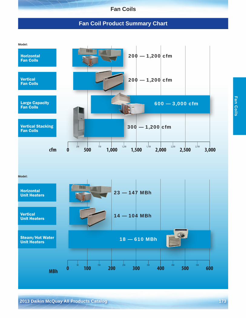
2012 McQuay Products Catalog 1732013 Daikin McQuay All Products Catalog 173
Fan CoilsFan C
oils
Fan Coil Product Summary Chart
250 750 1,250 1,750 2,250 2,750
0 500 1,000 1,500 2,000 2,500 3,000cfm
Large Capacity Fan Coils
Horizontal Fan Coils
Vertical Stacking Fan Coils
Model:
200 — 1,200 cfm
600 — 3,000 cfm
300 — 1,200 cfm
50 150 250 350 450 550
0 100 200 300 400 500 600MBh
Steam/Hot Water Unit Heaters
Vertical Unit Heaters
Horizontal Unit Heaters
Model:
18 — 610 MBh
14 — 104 MBh
23 — 147 MBh
Vertical Fan Coils
200 — 1,200 cfm
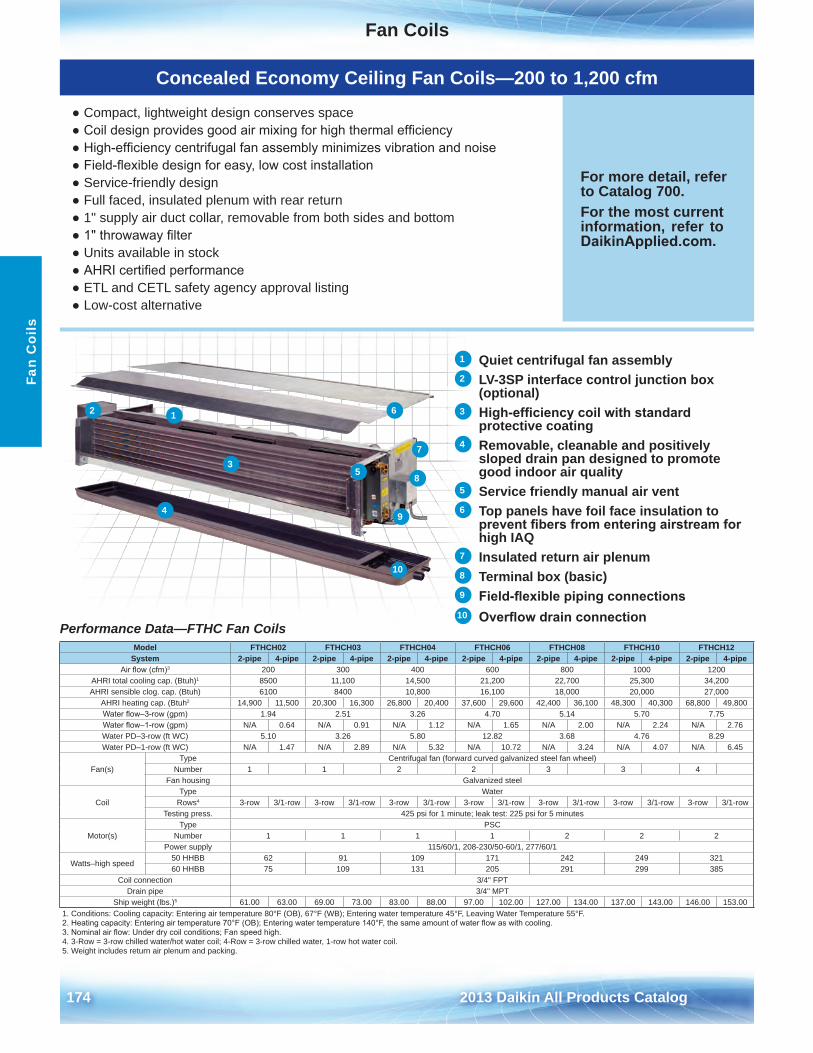
Fan Coils
174 2013 Daikin All Products Catalog
Fan
Coi
ls
Concealed Economy Ceiling Fan Coils—200 to 1,200 cfm
● Compact, lightweight design conserves space● Coil design provides good air mixing for high thermal efficiency● High-efficiency centrifugal fan assembly minimizes vibration and noise● Field-flexible design for easy, low cost installation● Service-friendly design● Full faced, insulated plenum with rear return● 1" supply air duct collar, removable from both sides and bottom● 1" throwaway filter● Units available in stock● AHRI certified performance● ETL and CETL safety agency approval listing● Low-cost alternative
For more detail, refer to Catalog 700 .For the most current information, refer to DaikinApplied.com .
Performance Data—FTHC Fan Coils Model FTHCH02 FTHCH03 FTHCH04 FTHCH06 FTHCH08 FTHCH10 FTHCH12
System 2-pipe 4-pipe 2-pipe 4-pipe 2-pipe 4-pipe 2-pipe 4-pipe 2-pipe 4-pipe 2-pipe 4-pipe 2-pipe 4-pipeAir flow (cfm)3 200 300 400 600 800 1000 1200
AHRI total cooling cap . (Btuh)1 8500 11,100 14,500 21,200 22,700 25,300 34,200AHRI sensible clog . cap . (Btuh) 6100 8400 10,800 16,100 18,000 20,000 27,000
AHRI heating cap . (Btuh2 14,900 11,500 20,300 16,300 26,800 20,400 37,600 29,600 42,400 36,100 48,300 40,300 68,800 49,800Water flow–3-row (gpm) 1 .94 2 .51 3 .26 4 .70 5 .14 5 .70 7 .75Water flow–1-row (gpm) N/A 0 .64 N/A 0 .91 N/A 1 .12 N/A 1 .65 N/A 2 .00 N/A 2 .24 N/A 2 .76Water PD–3-row (ft WC) 5 .10 3 .26 5 .80 12 .82 3 .68 4 .76 8 .29Water PD–1-row (ft WC) N/A 1 .47 N/A 2 .89 N/A 5 .32 N/A 10 .72 N/A 3 .24 N/A 4 .07 N/A 6 .45
Fan(s)Type Centrifugal fan (forward curved galvanized steel fan wheel)
Number 1 1 2 2 3 3 4Fan housing Galvanized steel
CoilType Water
Rows4 3-row 3/1-row 3-row 3/1-row 3-row 3/1-row 3-row 3/1-row 3-row 3/1-row 3-row 3/1-row 3-row 3/1-rowTesting press . 425 psi for 1 minute; leak test: 225 psi for 5 minutes
Motor(s)Type PSC
Number 1 1 1 1 2 2 2Power supply 115/60/1, 208-230/50-60/1, 277/60/1
Watts–high speed50 HHBB 62 91 109 171 242 249 32160 HHBB 75 109 131 205 291 299 385
Coil connection 3/4" FPTDrain pipe 3/4" MPT
Ship weight (lbs .)5 61 .00 63 .00 69 .00 73 .00 83 .00 88 .00 97 .00 102 .00 127 .00 134 .00 137 .00 143 .00 146 .00 153 .001 . Conditions: Cooling capacity: Entering air temperature 80°F (OB), 67°F (WB); Entering water temperature 45°F, Leaving Water Temperature 55°F .2. Heating capacity: Entering air temperature 70°F (OB); Entering water temperature 140°F, the same amount of water flow as with cooling.3. Nominal air flow: Under dry coil conditions; Fan speed high.4 . 3-Row = 3-row chilled water/hot water coil; 4-Row = 3-row chilled water, 1-row hot water coil .5 . Weight includes return air plenum and packing .
1 Quiet centrifugal fan assembly2 LV-3SP interface control junction box
(optional)3 High-efficiency coil with standard
protective coating4 Removable, cleanable and positively
sloped drain pan designed to promote good indoor air quality
5 Service friendly manual air vent6 Top panels have foil face insulation to
prevent fibers from entering airstream for high IAQ
7 Insulated return air plenum8 Terminal box (basic)9 Field-flexible piping connections
10 Overflow drain connection
12
3
4
5
6
7
8
9
10
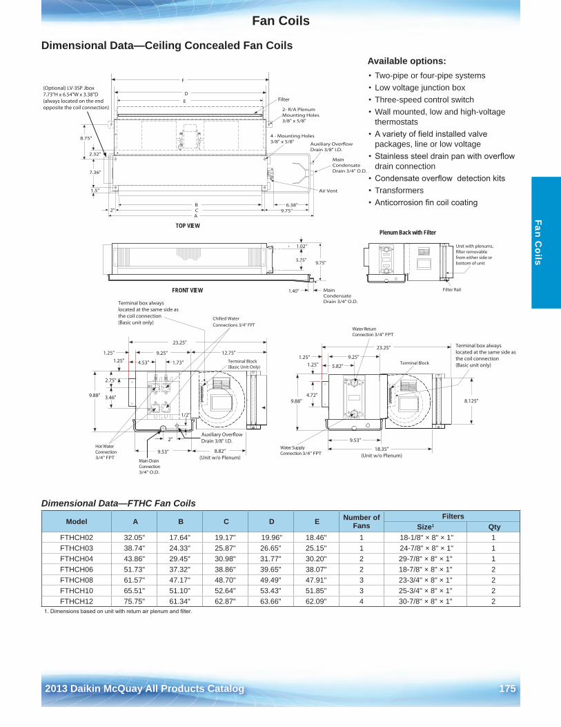
Fan Coils
2012 McQuay Products Catalog 1752013 Daikin McQuay All Products Catalog 175
Fan Coils
Dimensional Data—Ceiling Concealed Fan Coils
Dimensional Data—FTHC Fan Coils
Terminal Block(Basic Unit Only)
4.53"
1.25"
9.53"
Chilled Water Connections 3/4" FPT
9.88"
1.25"
5.82"
9.25"
23.25"
1.25"
4.72"
9.53"
Water Return Connection 3/4" FPT
Air Vent
FilterED
4 - Mounting Holes 3/8" x 5/8"
TOP VIEW
8.125"
2- R/A PlenumMounting Holes 3/8" x 5/8"
F
2"Auxiliary Over�ow Drain 3/8" I.D.
Auxiliary Over�owDrain 3/8" I.D.
Terminal box always located at the same side as the coil connection(Basic unit only)
Main Condensate Drain 3/4" O.D.
1/2"
1.25"
23.25"
9.25"
9.88"
1.73"
2.75"
3.46"
2.32"
7.36"
6.38"
A9.75"
B
1.5"
C
1.02"
5.75" 9.75"
1.40"
12.75"
8.75"
2"
Plenum Back with Filter
Filter Rail
Unit with plenums,�lter removablefrom either side orbottom of unit
FRONT VIEW Main Condensate Drain 3/4" O.D.
Terminal Block
Water Supply Connection 3/4" FPT
Hot Water Connection 3/4" FPT
Main DrainConnection 3/4" O.D.
8.82"(Unit w/o Plenum)
18.35"(Unit w/o Plenum)
(Optional) LV-3SP Jbox7.73"H x 6.54"W x 3.38"D (always located on the end opposite the coil connection)
Terminal box always located at the same side as the coil connection(Basic unit only)
Available options:• Two-pipe or four-pipe systems• Low voltage junction box• Three-speed control switch• Wall mounted, low and high-voltage
thermostats• A variety of field installed valve
packages, line or low voltage• Stainless steel drain pan with overflow
drain connection• Condensate overflow detection kits• Transformers• Anticorrosion fin coil coating
Model A B C D E Number of Fans
FiltersSize1 Qty
FTHCH02 32 .05" 17 .64" 19 .17" 19 .96" 18 .46" 1 18-1/8" × 8" × 1" 1FTHCH03 38 .74" 24 .33" 25 .87" 26 .65" 25 .15" 1 24-7/8" × 8" × 1" 1FTHCH04 43 .86" 29 .45" 30 .98" 31 .77" 30 .20" 2 29-7/8" × 8" × 1" 1FTHCH06 51 .73" 37 .32" 38 .86" 39 .65" 38 .07" 2 18-7/8" × 8" × 1" 2FTHCH08 61 .57" 47 .17" 48 .70" 49 .49" 47 .91" 3 23-3/4" × 8" × 1" 2FTHCH10 65 .51" 51 .10" 52 .64" 53 .43" 51 .85" 3 25-3/4" × 8" × 1" 2FTHCH12 75 .75" 61 .34" 62 .87" 63 .66" 62 .09" 4 30-7/8" × 8" × 1" 2
1. Dimensions based on unit with return air plenum and filter.
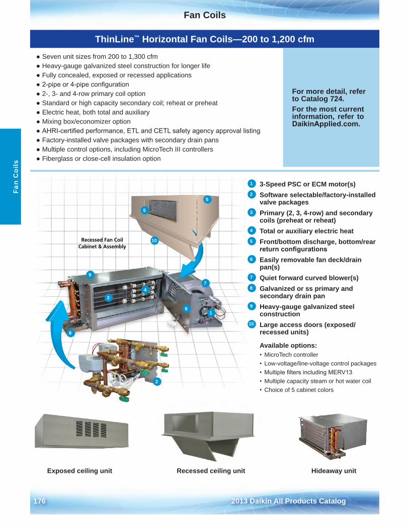
Fan Coils
176 2013 Daikin All Products Catalog
Fan
Coi
ls
ThinLine™ Horizontal Fan Coils—200 to 1,200 cfm
● Seven unit sizes from 200 to 1,300 cfm● Heavy-gauge galvanized steel construction for longer life● Fully concealed, exposed or recessed applications● 2-pipe or 4-pipe configuration● 2-, 3- and 4-row primary coil option● Standard or high capacity secondary coil; reheat or preheat● Electric heat, both total and auxiliary● Mixing box/economizer option● AHRI-certified performance, ETL and CETL safety agency approval listing● Factory-installed valve packages with secondary drain pans● Multiple control options, including MicroTech III controllers● Fiberglass or close-cell insulation option
For more detail, refer to Catalog 724 .For the most current information, refer to DaikinApplied.com .
1 3-Speed PSC or ECM motor(s)2 Software selectable/factory-installed
valve packages3 Primary (2, 3, 4-row) and secondary
coils (preheat or reheat) 4 Total or auxiliary electric heat5 Front/bottom discharge, bottom/rear
return configurations6 Easily removable fan deck/drain
pan(s)7 Quiet forward curved blower(s)8 Galvanized or ss primary and
secondary drain pan9 Heavy-gauge galvanized steel
construction10 Large access doors (exposed/
recessed units)
Available options:• MicroTech controller• Low-voltage/line-voltage control packages• Multiple filters including MERV13• Multiple capacity steam or hot water coil• Choice of 5 cabinet colors
Recessed Fan Coil Cabinet & Assembly
Exposed ceiling unit Recessed ceiling unit Hideaway unit
1
2
34
5
5
6
7
8
9
10
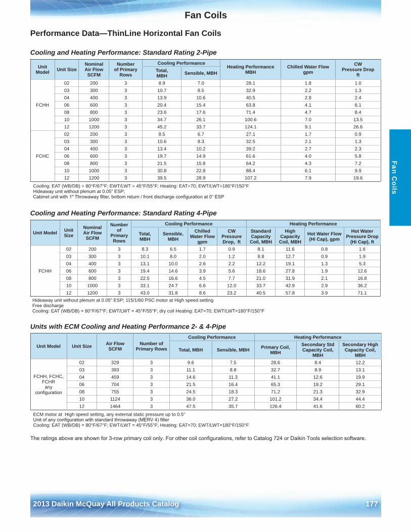
Fan Coils
2012 McQuay Products Catalog 1772013 Daikin McQuay All Products Catalog 177
Fan Coils
Performance Data—ThinLine Horizontal Fan Coils
Cooling and Heating Performance: Standard Rating 2-Pipe
Unit Model Unit Size
Nominal Air Flow SCFM
Number of Primary
Rows
Cooling Performance Heating Performance
MBHChilled Water Flow
gpmCW
Pressure Dropft
Total, MBH Sensible, MBH
FCHH
02 200 3 8 .9 7 .0 28 .1 1 .8 1 .003 300 3 10 .7 8 .5 32 .9 2 .2 1 .304 400 3 13 .9 10 .6 40 .5 2 .8 2 .406 600 3 20 .4 15 .4 63 .8 4 .1 6 .108 800 3 23 .6 17 .6 71 .4 4 .7 8 .410 1000 3 34 .7 26 .1 100 .6 7 .0 13 .512 1200 3 45 .2 33 .7 124 .1 9 .1 26 .6
FCHC
02 200 3 8 .5 6 .7 27 .1 1 .7 0 .903 300 3 10 .6 8 .3 32 .5 2 .1 1 .304 400 3 13 .4 10 .2 39 .2 2 .7 2 .306 600 3 19 .7 14 .9 61 .6 4 .0 5 .808 800 3 21 .5 15 .8 64 .2 4 .3 7 .210 1000 3 30 .8 22 .8 88 .4 6 .1 9 .912 1200 3 39 .5 28 .9 107 .2 7 .9 19 .6
Cooling: EAT (WB/DB) = 80°F/67°F; EWT/LWT = 45°F/55°F; Heating: EAT=70; EWT/LWT=180°F/150°F Hideaway unit without plenum at 0 .05” ESP; Cabinet unit with 1" Throwaway filter, bottom return / front discharge configuration at 0” ESP
Cooling and Heating Performance: Standard Rating 4-Pipe
Unit Model Unit Size
Nominal Air Flow SCFM
Number of
Primary Rows
Cooling Performance Heating Performance
Total, MBH
Sensible, MBH
Chilled Water Flow
gpm
CW Pressure Drop, ft
Standard Capacity Coil, MBH
High Capacity Coil, MBH
Hot Water Flow (Hi Cap), gpm
Hot Water Pressure Drop
(Hi Cap), ft
FCHH
02 200 3 8 .3 6 .5 1 .7 0 .9 8 .1 11 .6 0 .8 1 .603 300 3 10 .1 8 .0 2 .0 1 .2 8 .8 12 .7 0 .9 1 .904 400 3 13 .1 10 .0 2 .6 2 .2 12 .2 19 .1 1 .3 5 .306 600 3 19 .4 14 .6 3 .9 5 .6 18 .6 27 .8 1 .9 12 .608 800 3 22 .5 16 .6 4 .5 7 .7 21 .0 31 .9 2 .1 16 .810 1000 3 33 .1 24 .7 6 .6 12 .0 33 .7 42 .9 2 .9 36 .212 1200 3 43 .0 31 .8 8 .6 23 .2 40 .5 57 .8 3 .9 71 .1
Hideaway unit without plenum at 0 .05" ESP; 115/1/60 PSC motor at High speed setting Free discharge Cooling: EAT (WB/DB) = 80°F/67°F; EWT/LWT = 45°F/55°F; dry coil Heating: EAT=70; EWT/LWT=180°F/150°F
Units with ECM Cooling and Heating Performance 2- & 4-Pipe
Unit Model Unit Size Air Flow SCFM
Number of Primary Rows
Cooling Performance Heating Performance
Total, MBH Sensible, MBH Primary Coil, MBH
Secondary Std Capacity Coil,
MBH
Secondary High Capacity Coil,
MBH
FCHH, FCHC, FCHR
any configuration
02 329 3 9 .6 7 .5 28 .6 8 .4 12 .203 393 3 11 .1 8 .8 32 .7 8 .9 13 .104 459 3 14 .6 11 .3 41 .1 12 .6 19 .906 704 3 21 .5 16 .4 65 .3 19 .2 29 .108 755 3 24 .5 18 .3 71 .2 21 .3 32 .910 1124 3 36 .0 27 .2 101 .2 34 .4 44 .412 1464 3 47 .5 35 .7 126 .4 41 .6 60 .2
ECM motor at High speed setting, any external static pressure up to 0 .5" Unit of any configuration with standard throwaway (MERV 4) filter Cooling: EAT (WB/DB) = 80°F/67°F; EWT/LWT = 45°F/55°F; Heating: EAT=70; EWT/LWT=180°F/150°F
The ratings above are shown for 3-row primary coil only. For other coil configurations, refer to Catalog 724 or Daikin Tools selection software.
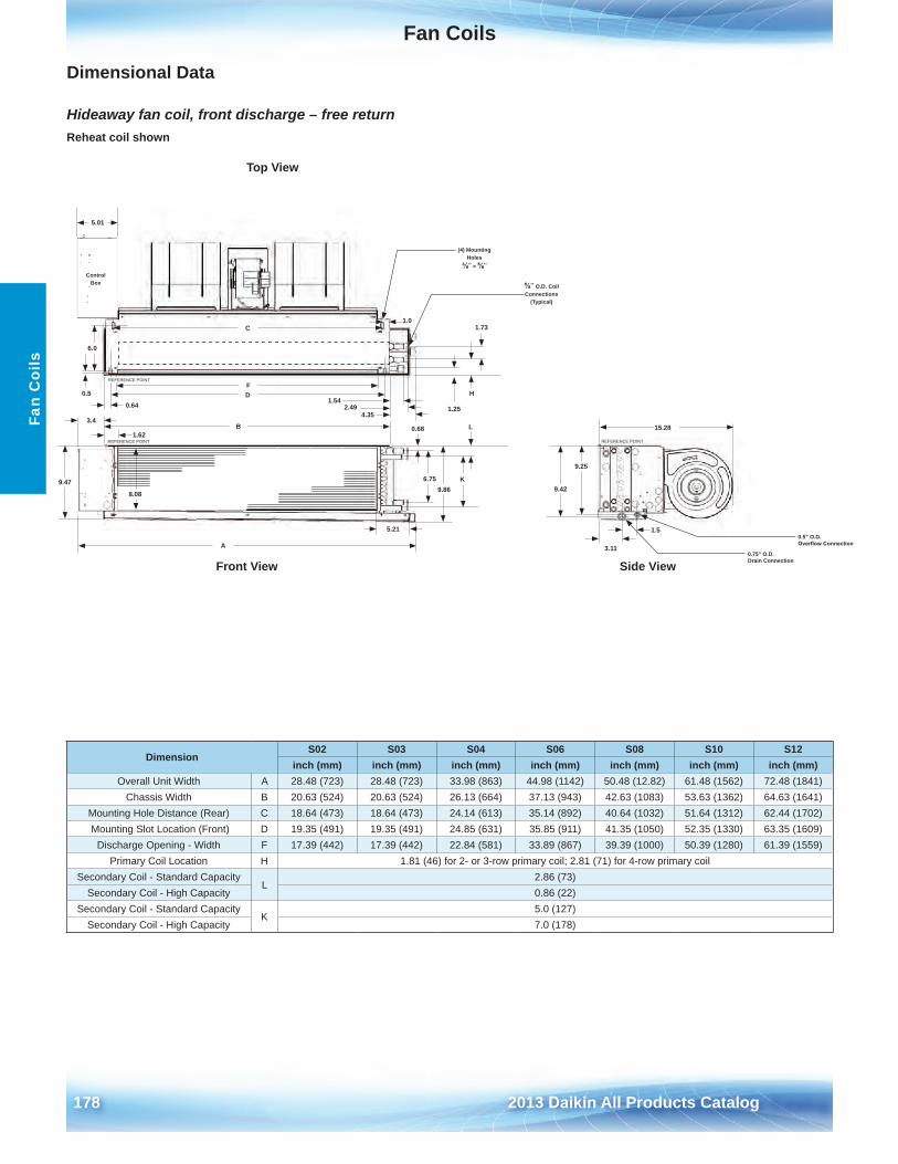
Fan Coils
178 2013 Daikin All Products Catalog
Fan
Coi
ls
Dimensional Data
Hideaway fan coil, front discharge – free return
5 .21
9 .47 6 .759 .86
0 .68
8 .08
(4) Mounting Holes
⅜" × ⅝"
6 .0
3 .11
15 .28 (2)
1 .50 .5" O .D .Overfl ow Connection
0 .75" O .D .Drain Connection
5 .01
⅝" O .D . CoilConnections
(Typical)
9 .25
9 .42
H
1 .73
D0 .5
0 .644 .35
2 .491 .54
1 .0
B
C
1 .62
3 .4
A
F
1 .25
K
L
Top View
Side ViewFront View
Control Box
○×REFERENCE POINT
○×REFERENCE POINT
○×REFERENCE POINT
Reheat coil shown
DimensionS02 S03 S04 S06 S08 S10 S12
inch (mm) inch (mm) inch (mm) inch (mm) inch (mm) inch (mm) inch (mm)Overall Unit Width A 28 .48 (723) 28 .48 (723) 33 .98 (863) 44 .98 (1142) 50 .48 (12 .82) 61 .48 (1562) 72 .48 (1841)
Chassis Width B 20 .63 (524) 20 .63 (524) 26 .13 (664) 37 .13 (943) 42 .63 (1083) 53 .63 (1362) 64 .63 (1641)Mounting Hole Distance (Rear) C 18 .64 (473) 18 .64 (473) 24 .14 (613) 35 .14 (892) 40 .64 (1032) 51 .64 (1312) 62 .44 (1702) Mounting Slot Location (Front) D 19 .35 (491) 19 .35 (491) 24 .85 (631) 35 .85 (911) 41 .35 (1050) 52 .35 (1330) 63 .35 (1609)
Discharge Opening - Width F 17 .39 (442) 17 .39 (442) 22 .84 (581) 33 .89 (867) 39 .39 (1000) 50 .39 (1280) 61 .39 (1559)Primary Coil Location H 1 .81 (46) for 2- or 3-row primary coil; 2 .81 (71) for 4-row primary coil
Secondary Coil - Standard CapacityL
2 .86 (73)Secondary Coil - High Capacity 0 .86 (22)
Secondary Coil - Standard CapacityK
5 .0 (127)Secondary Coil - High Capacity 7 .0 (178)
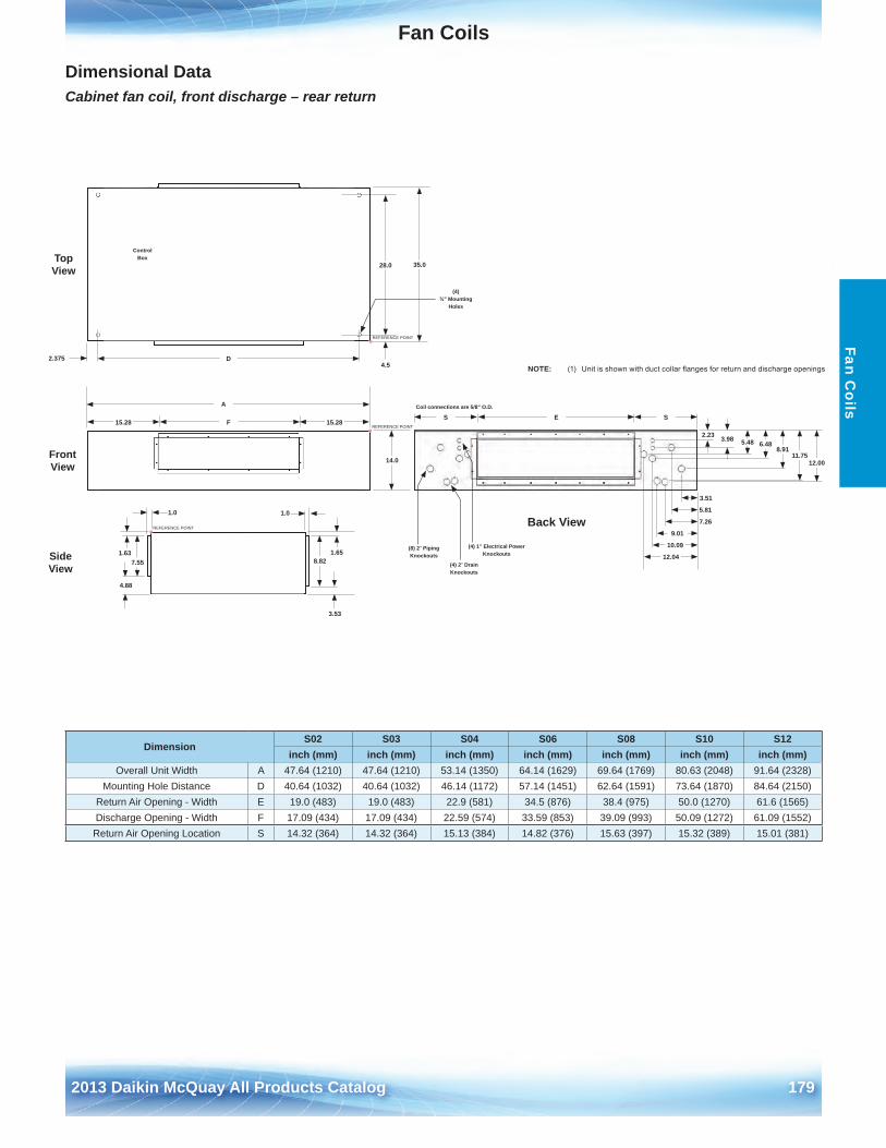
Fan Coils
2012 McQuay Products Catalog 1792013 Daikin McQuay All Products Catalog 179
Fan Coils
Dimensional Data Cabinet fan coil, front discharge – rear return
15 .28 15 .28
35 .0
14 .0
7 .55 8 .82
4 .88
3 .53
1 .65
C .XX2 .375 D
28 .0
4 .5
1 .01 .0
1 .63
(4) ¾" Mounting
Holes
A
F
Back View
12 .0011 .75
8 .916 .485 .483 .982 .23
12 .04
10 .09
9 .01
7 .26
5 .81
3 .51
(8) 2" Piping Knockouts
(4) 2" Drain Knockouts
(4) 1" Electrical Power Knockouts
E SSCoil connections are 5/8" O .D .
Front View
Top View
SideView
Control Box
○×REFERENCE POINT
○×REFERENCE POINT
○×REFERENCE POINT
NOTE: (1) Unit is shown with duct collar fl anges for return and discharge openings
DimensionS02 S03 S04 S06 S08 S10 S12
inch (mm) inch (mm) inch (mm) inch (mm) inch (mm) inch (mm) inch (mm)Overall Unit Width A 47 .64 (1210) 47 .64 (1210) 53 .14 (1350) 64 .14 (1629) 69 .64 (1769) 80 .63 (2048) 91 .64 (2328)
Mounting Hole Distance D 40 .64 (1032) 40 .64 (1032) 46 .14 (1172) 57 .14 (1451) 62 .64 (1591) 73 .64 (1870) 84 .64 (2150)Return Air Opening - Width E 19 .0 (483) 19 .0 (483) 22 .9 (581) 34 .5 (876) 38 .4 (975) 50 .0 (1270) 61 .6 (1565)Discharge Opening - Width F 17 .09 (434) 17 .09 (434) 22 .59 (574) 33 .59 (853) 39 .09 (993) 50 .09 (1272) 61 .09 (1552)
Return Air Opening Location S 14 .32 (364) 14 .32 (364) 15 .13 (384) 14 .82 (376) 15 .63 (397) 15 .32 (389) 15 .01 (381)
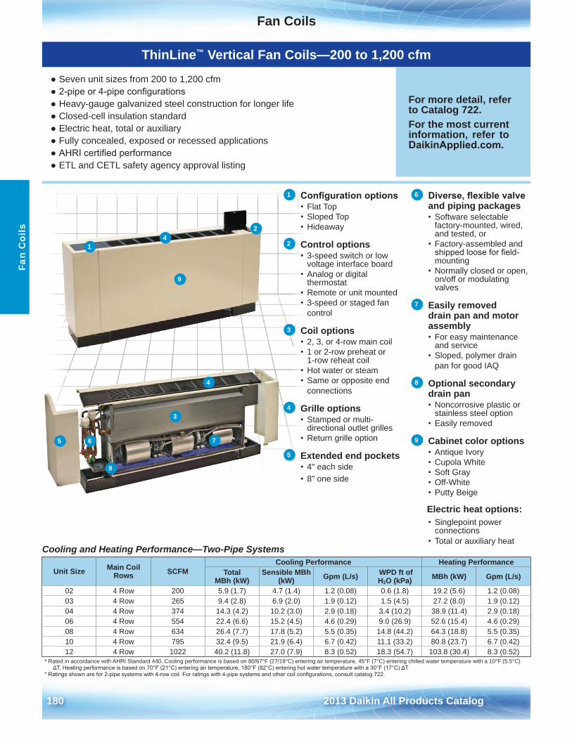
Fan Coils
180 2013 Daikin All Products Catalog
Fan
Coi
ls
Cooling and Heating Performance—Two-Pipe Systems
Unit Size Main Coil Rows SCFM
Cooling Performance Heating PerformanceTotal
MBh (kW)Sensible MBh
(kW) Gpm (L/s) WPD ft of H2O (kPa) MBh (kW) Gpm (L/s)
02 4 Row 200 5 .9 (1 .7) 4 .7 (1 .4) 1 .2 (0 .08) 0 .6 (1 .8) 19 .2 (5 .6) 1 .2 (0 .08)03 4 Row 265 9 .4 (2 .8) 6 .9 (2 .0) 1 .9 (0 .12) 1 .5 (4 .5) 27 .2 (8 .0) 1 .9 (0 .12)04 4 Row 374 14 .3 (4 .2) 10 .2 (3 .0) 2 .9 (0 .18) 3 .4 (10 .2) 38 .9 (11 .4) 2 .9 (0 .18)06 4 Row 554 22 .4 (6 .6) 15 .2 (4 .5) 4 .6 (0 .29) 9 .0 (26 .9) 52 .6 (15 .4) 4 .6 (0 .29)08 4 Row 634 26 .4 (7 .7) 17 .8 (5 .2) 5 .5 (0 .35) 14 .8 (44 .2) 64 .3 (18 .8) 5 .5 (0 .35)10 4 Row 795 32 .4 (9 .5) 21 .9 (6 .4) 6 .7 (0 .42) 11 .1 (33 .2) 80 .8 (23 .7) 6 .7 (0 .42)12 4 Row 1022 40 .2 (11 .8) 27 .0 (7 .9) 8 .3 (0 .52) 18 .3 (54 .7) 103 .8 (30 .4) 8 .3 (0 .52)
* Rated in accordance with AHRI Standard 440 . Cooling performance is based on 80/67°F (27/19°C) entering air temperature, 45°F (7°C) entering chilled water temperature with a 10°F (5 .5°C) ΔT. Heating performance is based on 70°F (21°C) entering air temperature, 180°F (82°C) entering hot water temperature with a 30°F (17°C) ΔT
* Ratings shown are for 2-pipe systems with 4-row coil. For ratings with 4-pipe systems and other coil configurations, consult catalog 722.
1 Configuration options• Flat Top• Sloped Top• Hideaway
2 Control options• 3-speed switch or low
voltage interface board• Analog or digital
thermostat• Remote or unit mounted• 3-speed or staged fan
control
3 Coil options• 2, 3, or 4-row main coil• 1 or 2-row preheat or
1-row reheat coil• Hot water or steam• Same or opposite end
connections
4 Grille options• Stamped or multi-
directional outlet grilles• Return grille option
5 Extended end pockets• 4" each side• 8" one side
6 Diverse, flexible valve and piping packages• Software selectable
factory-mounted, wired, and tested, or
• Factory-assembled andshipped loose for field-mounting
• Normally closed or open,on/off or modulating valves
7 Easily removed drain pan and motor assembly• For easy maintenance
and service• Sloped, polymer drain
pan for good IAQ
8 Optional secondary drain pan• Noncorrosive plastic or
stainless steel option• Easily removed
9 Cabinet color options• Antique Ivory• Cupola White• Soft Gray• Off-White• Putty Beige
Electric heat options:• Singlepoint power
connections• Total or auxiliary heat
ThinLine™ Vertical Fan Coils—200 to 1,200 cfm
● Seven unit sizes from 200 to 1,200 cfm● 2-pipe or 4-pipe configurations● Heavy-gauge galvanized steel construction for longer life● Closed-cell insulation standard● Electric heat, total or auxiliary● Fully concealed, exposed or recessed applications● AHRI certified performance● ETL and CETL safety agency approval listing
For more detail, refer to Catalog 722 .For the most current information, refer to DaikinApplied.com .
2
1
3
4
4
65 7
8
9
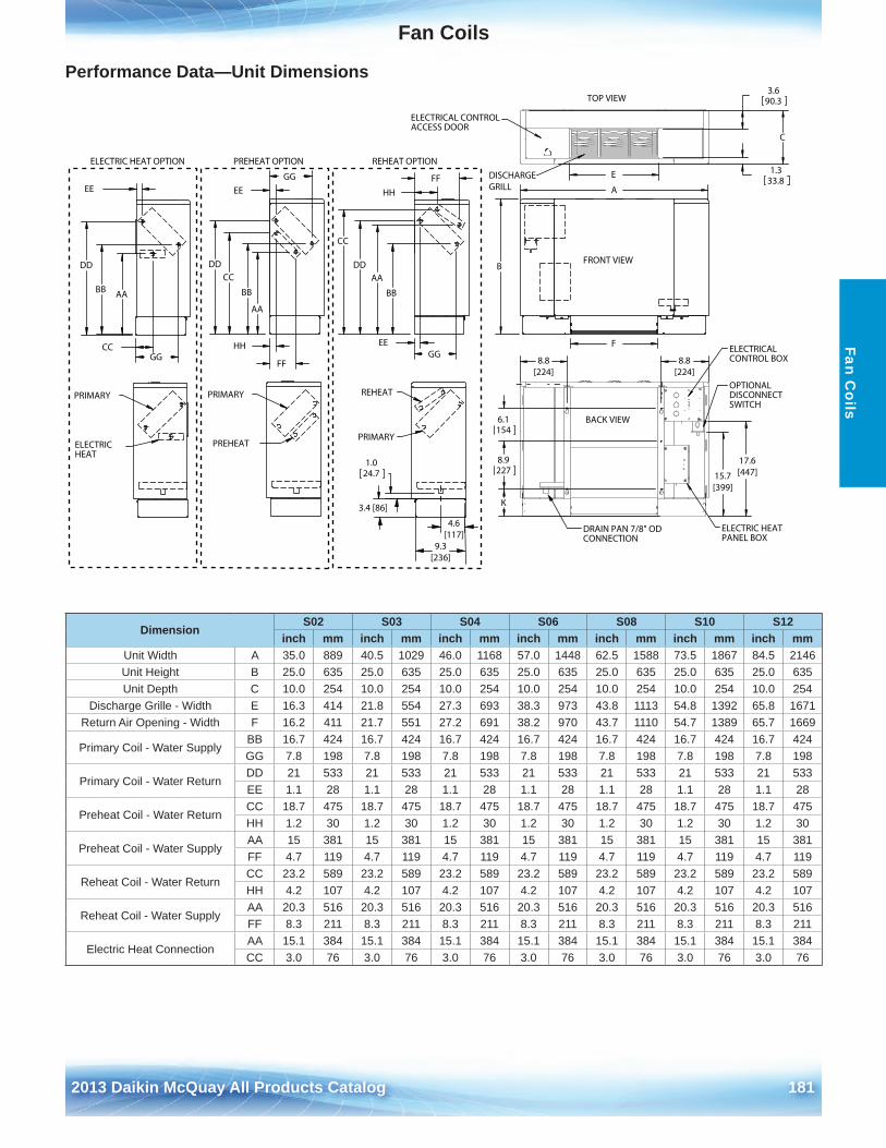
Fan Coils
2012 McQuay Products Catalog 1812013 Daikin McQuay All Products Catalog 181
Fan Coils
Performance Data—Unit Dimensions
PREHEAT OPTION ONITPOTAEHERNOITPOTAEHCIRTCELE
PRIMARY
PREHEAT
EE
DD
GG
AA
CC
BB
HH
FF
A
B
F
FRONT VIEW
K
8.9227
6.1154
8.8[224]
8.8[224]
BACK VIEW
ELECTRICALCONTROL BOX
OPTIONALDISCONNECTSWITCH
DRAIN PAN 7/8" ODCONNECTION
ELECTRIC HEATPANEL BOX
1.333.8
C
3.690.3
E
TOP VIEW
DISCHARGEGRILL
ELECTRICAL CONTROLACCESS DOOR
ELECTRICHEAT
PRIMARY
EE
AABB
DD
CCGG
1.024.7
PRIMARY
REHEAT
DD
GG
BB
EE
HH
FF
CC
AA
4.6[117]
9.3[236]
3.4 [86]
15.7[399]
17.6[447]
DimensionS02 S03 S04 S06 S08 S10 S12
inch mm inch mm inch mm inch mm inch mm inch mm inch mmUnit Width A 35 .0 889 40 .5 1029 46 .0 1168 57 .0 1448 62 .5 1588 73 .5 1867 84 .5 2146Unit Height B 25 .0 635 25 .0 635 25 .0 635 25 .0 635 25 .0 635 25 .0 635 25 .0 635Unit Depth C 10 .0 254 10 .0 254 10 .0 254 10 .0 254 10 .0 254 10 .0 254 10 .0 254
Discharge Grille - Width E 16 .3 414 21 .8 554 27 .3 693 38 .3 973 43 .8 1113 54 .8 1392 65 .8 1671Return Air Opening - Width F 16 .2 411 21 .7 551 27 .2 691 38 .2 970 43 .7 1110 54 .7 1389 65 .7 1669
Primary Coil - Water Supply BB 16 .7 424 16 .7 424 16 .7 424 16 .7 424 16 .7 424 16 .7 424 16 .7 424GG 7 .8 198 7 .8 198 7 .8 198 7 .8 198 7 .8 198 7 .8 198 7 .8 198
Primary Coil - Water ReturnDD 21 533 21 533 21 533 21 533 21 533 21 533 21 533EE 1 .1 28 1 .1 28 1 .1 28 1 .1 28 1 .1 28 1 .1 28 1 .1 28
Preheat Coil - Water ReturnCC 18 .7 475 18 .7 475 18 .7 475 18 .7 475 18 .7 475 18 .7 475 18 .7 475HH 1 .2 30 1 .2 30 1 .2 30 1 .2 30 1 .2 30 1 .2 30 1 .2 30
Preheat Coil - Water SupplyAA 15 381 15 381 15 381 15 381 15 381 15 381 15 381FF 4 .7 119 4 .7 119 4 .7 119 4 .7 119 4 .7 119 4 .7 119 4 .7 119
Reheat Coil - Water ReturnCC 23 .2 589 23 .2 589 23 .2 589 23 .2 589 23 .2 589 23 .2 589 23 .2 589HH 4 .2 107 4 .2 107 4 .2 107 4 .2 107 4 .2 107 4 .2 107 4 .2 107
Reheat Coil - Water SupplyAA 20 .3 516 20 .3 516 20 .3 516 20 .3 516 20 .3 516 20 .3 516 20 .3 516FF 8 .3 211 8 .3 211 8 .3 211 8 .3 211 8 .3 211 8 .3 211 8 .3 211
Electric Heat ConnectionAA 15 .1 384 15 .1 384 15 .1 384 15 .1 384 15 .1 384 15 .1 384 15 .1 384CC 3 .0 76 3 .0 76 3 .0 76 3 .0 76 3 .0 76 3 .0 76 3 .0 76
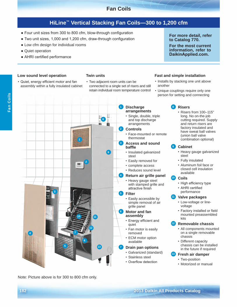
Fan Coils
182 2013 Daikin All Products Catalog
HiLine™ Vertical Stacking Fan Coils—300 to 1,200 cfm
● Four unit sizes from 300 to 800 cfm, blow-through configuration● Two unit sizes, 1,000 and 1,200 cfm, draw-through configuration● Low cfm design for individual rooms● Quiet operation● AHRI certified performance
For more detail, refer to Catalog 770 .For the most current information, refer to DaikinApplied.com .
Fan
Coi
ls
1 Discharge arrangements• Single, double, triple
and top discharge arrangements
2 Controls• Face-mounted or remote
thermostat3 Access and sound
baffle• Insulated galvanized
steel • Easily removed for• complete access• Reduces sound level
4 Return air grille panel• Heavy gauge steel
with stamped grille and attractive finish
5 Filter• Easily accessible by
simple removal of air grille panel
6 Motor and fan assembly• Energy efficient and
quiet• Fan motor is easily
removed• ECM motor option
available7 Drain pan options
• Galvanized (standard)• Stainless steel• Overflow detection
8 Risers• Risers from 100–115"
long . No on-the-job cutting required . Supply and return risers are factory insulated and have sweat ball valves (union ball valve combination optional)
9 Cabinet• Heavy gauge galvanized
steel• Fully insulated• Aluminum foil face or
closed cell insulationavailable
10 Coils• High efficiency type• AHRI certified
performance11 Valve packages
• Low-voltage or line-voltage
• Factory installed or fieldmounted preassembled kits
12 Removable chassis• All components mounted
on a single removable chassis
• Different capacitychassis can be installed in the future if required
13 Fresh air damper• Two-position• Motorized or manual
Low sound level operation• Quiet, energy efficient motor and fan
assembly within a fully insulated cabinet
Twin units• Two adjacent room units can be
connected to a single set of risers and still retain individual room temperature control
Fast and simple installation• Installs by stacking one unit above
another• Unique couplings require only one
person for setting and connecting
1
2
3
4
5
6
7
8
9
10 11
12
13
Note: Picture above is for 300 to 800 cfm only .
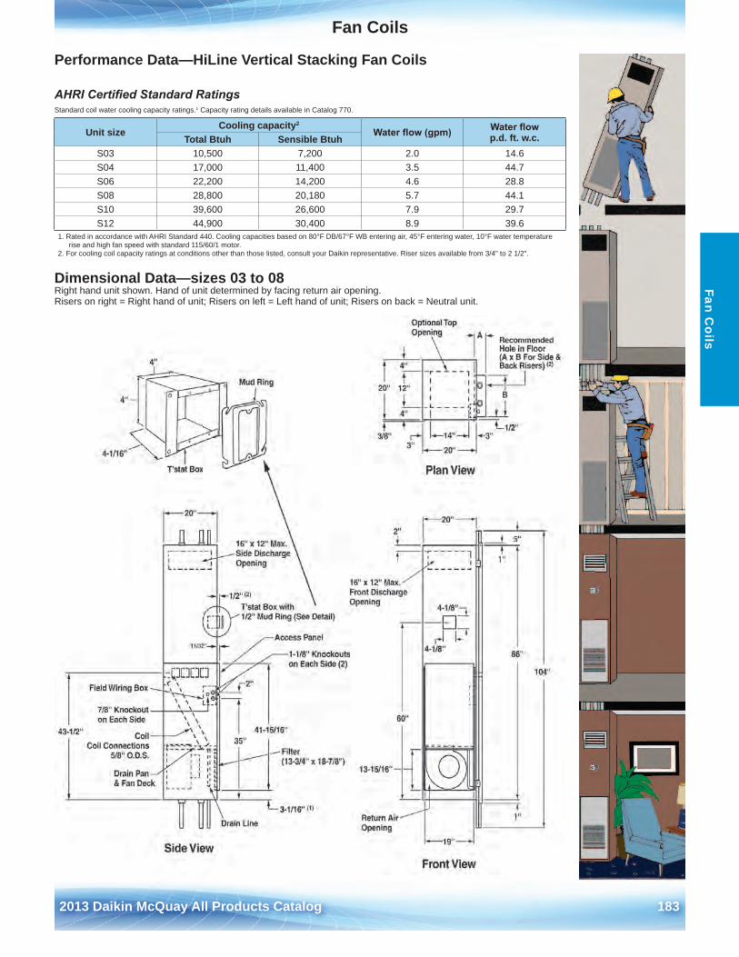
Fan Coils
2012 McQuay Products Catalog 1832013 Daikin McQuay All Products Catalog 183
Fan Coils
Performance Data—HiLine Vertical Stacking Fan Coils
AHRI Certified Standard Ratings Standard coil water cooling capacity ratings .1 Capacity rating details available in Catalog 770 .
Dimensional Data—sizes 03 to 08Right hand unit shown . Hand of unit determined by facing return air opening .Risers on right = Right hand of unit; Risers on left = Left hand of unit; Risers on back = Neutral unit .
Unit sizeCooling capacity2
Water flow (gpm) Water flow p .d . ft . w .c .Total Btuh Sensible Btuh
S03 10,500 7,200 2 .0 14 .6S04 17,000 11,400 3 .5 44 .7S06 22,200 14,200 4 .6 28 .8S08 28,800 20,180 5 .7 44 .1S10 39,600 26,600 7 .9 29 .7S12 44,900 30,400 8 .9 39 .6
1 . Rated in accordance with AHRI Standard 440 . Cooling capacities based on 80°F DB/67°F WB entering air, 45°F entering water, 10°F water temperature rise and high fan speed with standard 115/60/1 motor .
2 . For cooling coil capacity ratings at conditions other than those listed, consult your Daikin representative . Riser sizes available from 3/4" to 2 1/2" .
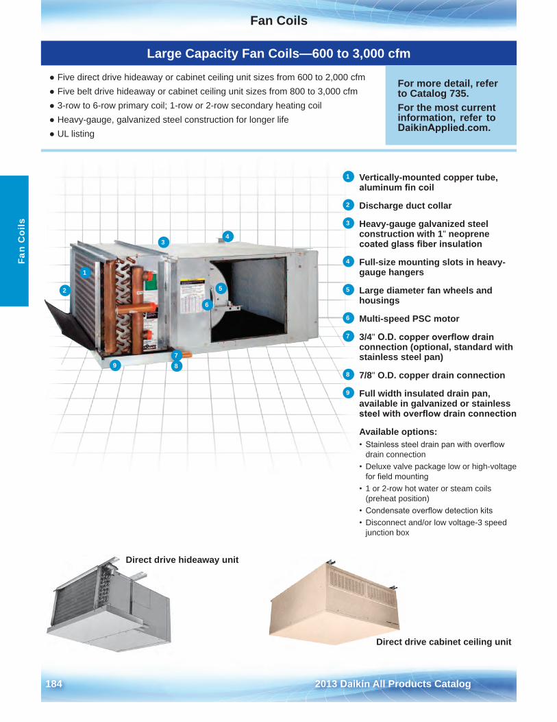
Fan Coils
184 2013 Daikin All Products Catalog
Fan
Coi
ls
Direct drive hideaway unit
Direct drive cabinet ceiling unit
1 Vertically-mounted copper tube, aluminum fin coil
2 Discharge duct collar
3 Heavy-gauge galvanized steel construction with 1" neoprene coated glass fiber insulation
4 Full-size mounting slots in heavy-gauge hangers
5 Large diameter fan wheels and housings
6 Multi-speed PSC motor
7 3/4" O.D. copper overflow drain connection (optional, standard with stainless steel pan)
8 7/8" O .D . copper drain connection
9 Full width insulated drain pan, available in galvanized or stainless steel with overflow drain connection
Available options:• Stainless steel drain pan with overflow
drain connection• Deluxe valve package low or high-voltage
for field mounting• 1 or 2-row hot water or steam coils
(preheat position)• Condensate overflow detection kits• Disconnect and/or low voltage-3 speed
junction box
1
2
34
5
6
789
Large Capacity Fan Coils—600 to 3,000 cfm
● Five direct drive hideaway or cabinet ceiling unit sizes from 600 to 2,000 cfm● Five belt drive hideaway or cabinet ceiling unit sizes from 800 to 3,000 cfm● 3-row to 6-row primary coil; 1-row or 2-row secondary heating coil● Heavy-gauge, galvanized steel construction for longer life● UL listing
For more detail, refer to Catalog 735 .For the most current information, refer to DaikinApplied.com .
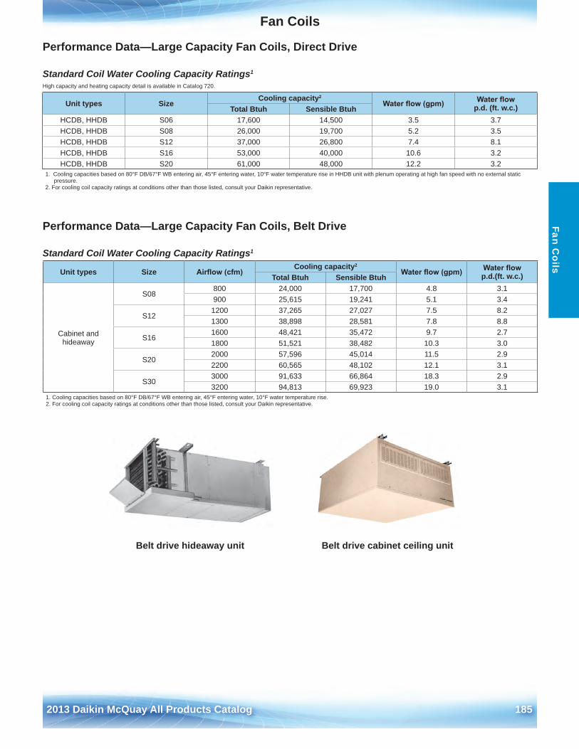
Fan Coils
2012 McQuay Products Catalog 1852013 Daikin McQuay All Products Catalog 185
Fan Coils
Performance Data—Large Capacity Fan Coils, Direct Drive
Standard Coil Water Cooling Capacity Ratings1
High capacity and heating capacity detail is available in Catalog 720 .
Performance Data—Large Capacity Fan Coils, Belt Drive
Standard Coil Water Cooling Capacity Ratings1
Unit types SizeCooling capacity2
Water flow (gpm) Water flow p .d . (ft . w .c .)Total Btuh Sensible Btuh
HCDB, HHDB S06 17,600 14,500 3 .5 3 .7HCDB, HHDB S08 26,000 19,700 5 .2 3 .5HCDB, HHDB S12 37,000 26,800 7 .4 8 .1HCDB, HHDB S16 53,000 40,000 10 .6 3 .2HCDB, HHDB S20 61,000 48,000 12 .2 3 .2
1 . Cooling capacities based on 80°F DB/67°F WB entering air, 45°F entering water, 10°F water temperature rise in HHDB unit with plenum operating at high fan speed with no external static pressure .
2 . For cooling coil capacity ratings at conditions other than those listed, consult your Daikin representative .
Unit types Size Airflow (cfm)Cooling capacity2
Water flow (gpm) Water flow p .d .(ft . w .c .)Total Btuh Sensible Btuh
Cabinet and hideaway
S08800 24,000 17,700 4 .8 3 .1900 25,615 19,241 5 .1 3 .4
S121200 37,265 27,027 7 .5 8 .21300 38,898 28,581 7 .8 8 .8
S161600 48,421 35,472 9 .7 2 .71800 51,521 38,482 10 .3 3 .0
S202000 57,596 45,014 11 .5 2 .92200 60,565 48,102 12 .1 3 .1
S303000 91,633 66,864 18 .3 2 .93200 94,813 69,923 19 .0 3 .1
1 . Cooling capacities based on 80°F DB/67°F WB entering air, 45°F entering water, 10°F water temperature rise .2 . For cooling coil capacity ratings at conditions other than those listed, consult your Daikin representative .
Belt drive hideaway unit Belt drive cabinet ceiling unit
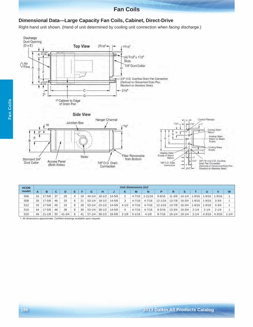
Fan Coils
186 2013 Daikin All Products Catalog
Fan
Coi
ls
Dimensional Data—Large Capacity Fan Coils, Cabinet, Direct-DriveRight-hand unit shown . (Hand of unit determined by cooling unit connection when facing discharge.)
HCDB model
Unit dimensions (in)1
A B C D E F G H J K M N P R S T U V WS06 24 17-5/8 37 20 4 19 44-1/4 18-1/2 14-5/8 2 4-7/16 2-11/16 9-9/16 11-3/8 14-1/4 1-9/16 1-9/16 1-9/16 1S08 26 17-5/8 46 20 6 21 53-1/4 18-1/2 14-5/8 3 4-7/16 4-7/16 12-1/16 13-7/8 16-3/4 1-9/16 1-9/16 3-3/4 1S12 33 17-5/8 46 24 8 28 53-1/4 23-1/2 14-5/8 4-1/2 4-7/16 4-7/16 12-1/16 13-7/8 16-3/4 1-9/16 1-9/16 3-3/4 1S16 44 17-5/8 46 36 8 39 53-1/4 38-1/2 14-5/8 4 4-7/16 4-7/16 8-3/16 13-3/4 16-3/4 2-1/4 2-1/4 2-1/4 1S20 46 21-1/8 50 41-3/4 6 41 57-1/4 38-1/2 18-5/8 2-1/8 5-1/16 4-1/8 9-7/16 16-1/4 19-1/4 2-1/4 4-3/16 4-3/16 1-1/4
1. All dimensions approximate. Certified drawings available upon request.
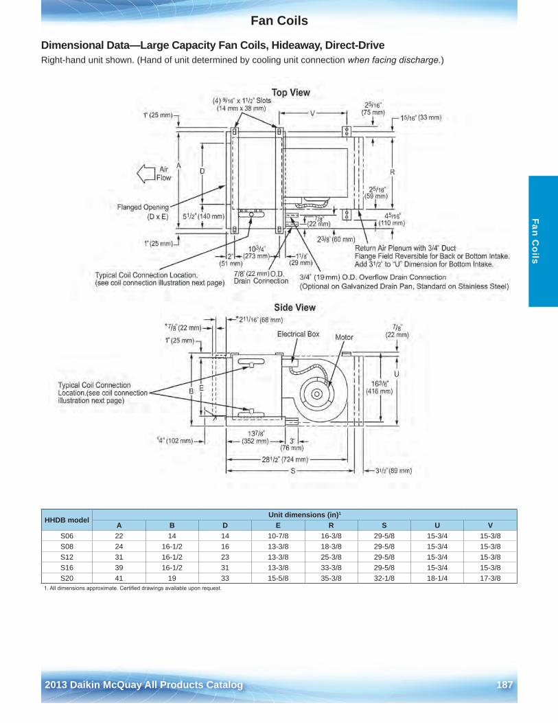
Fan Coils
2012 McQuay Products Catalog 1872013 Daikin McQuay All Products Catalog 187
Fan Coils
Dimensional Data—Large Capacity Fan Coils, Hideaway, Direct-DriveRight-hand unit shown . (Hand of unit determined by cooling unit connection when facing discharge.)
HHDB model
Unit dimensions (in)1
A B D E R S U VS06 22 14 14 10-7/8 16-3/8 29-5/8 15-3/4 15-3/8S08 24 16-1/2 16 13-3/8 18-3/8 29-5/8 15-3/4 15-3/8S12 31 16-1/2 23 13-3/8 25-3/8 29-5/8 15-3/4 15-3/8S16 39 16-1/2 31 13-3/8 33-3/8 29-5/8 15-3/4 15-3/8S20 41 19 33 15-5/8 35-3/8 32-1/8 18-1/4 17-3/8
1. All dimensions approximate. Certified drawings available upon request.
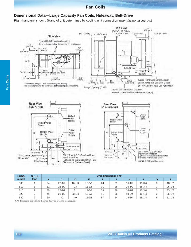
Fan Coils
188 2013 Daikin All Products Catalog
Fan
Coi
ls
Dimensional Data—Large Capacity Fan Coils, Hideaway, Belt-DriveRight-hand unit shown . (Hand of unit determined by cooling unit connection when facing discharge.)
HHBB model
No . of fans
Unit dimensions (in)1
A C D E F J N P Q RS08 1 24 28-1/2 16-1/4 13-3/8 24 21 16-1/2 15-3/4 3 18-1/2S12 1 31 28-1/2 23 13-3/8 31 28 16-1/2 15-3/4 3 25-1/2S16 2 39 28-1/2 31 13-3/8 39 36 16-1/2 15-3/4 3 33-1/2S20 2 41 28-1/2 33-1/4 15-3/8 41 38 18-3/4 18-1/4 3 35-1/2S30 2 60 30 49 15-3/8 57 54 18-3/4 18-1/4 6 51-1/2
1. All dimensions approximate. Certified drawings available upon request.
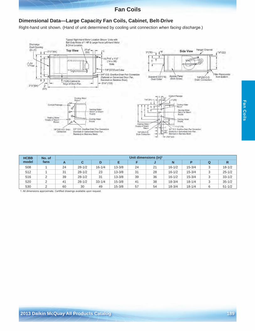
Fan Coils
2012 McQuay Products Catalog 1892013 Daikin McQuay All Products Catalog 189
Fan Coils
Dimensional Data—Large Capacity Fan Coils, Cabinet, Belt-DriveRight-hand unit shown . (Hand of unit determined by cooling unit connection when facing discharge.)
HCBB model
No . of fans
Unit dimensions (in)1
A C D E F J N P Q RS08 1 24 28-1/2 16-1/4 13-3/8 24 21 16-1/2 15-3/4 3 18-1/2S12 1 31 28-1/2 23 13-3/8 31 28 16-1/2 15-3/4 3 25-1/2S16 2 39 28-1/2 31 13-3/8 39 36 16-1/2 15-3/4 3 33-1/2S20 2 41 28-1/2 33-1/4 15-3/8 41 38 18-3/4 18-1/4 3 35-1/2S30 2 60 30 49 15-3/8 57 54 18-3/4 18-1/4 6 51-1/2
1. All dimensions approximate. Certified drawings available upon request.
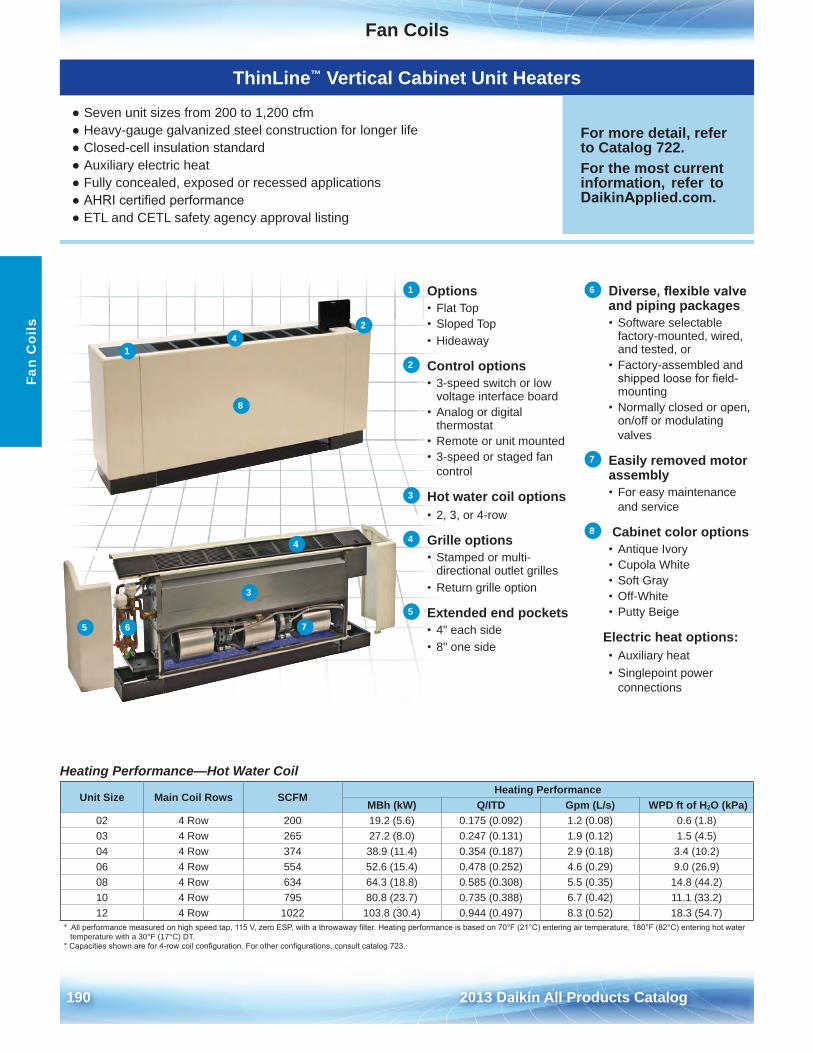
Fan Coils
190 2013 Daikin All Products Catalog
Fan
Coi
ls
Heating Performance—Hot Water Coil
Unit Size Main Coil Rows SCFMHeating Performance
MBh (kW) Q/ITD Gpm (L/s) WPD ft of H2O (kPa)02 4 Row 200 19 .2 (5 .6) 0 .175 (0 .092) 1 .2 (0 .08) 0 .6 (1 .8)03 4 Row 265 27 .2 (8 .0) 0 .247 (0 .131) 1 .9 (0 .12) 1 .5 (4 .5)04 4 Row 374 38 .9 (11 .4) 0 .354 (0 .187) 2 .9 (0 .18) 3 .4 (10 .2)06 4 Row 554 52 .6 (15 .4) 0 .478 (0 .252) 4 .6 (0 .29) 9 .0 (26 .9)08 4 Row 634 64 .3 (18 .8) 0 .585 (0 .308) 5 .5 (0 .35) 14 .8 (44 .2)10 4 Row 795 80 .8 (23 .7) 0 .735 (0 .388) 6 .7 (0 .42) 11 .1 (33 .2)12 4 Row 1022 103 .8 (30 .4) 0 .944 (0 .497) 8 .3 (0 .52) 18 .3 (54 .7)
* All performance measured on high speed tap, 115 V, zero ESP, with a throwaway filter. Heating performance is based on 70°F (21°C) entering air temperature, 180°F (82°C) entering hot water temperature with a 30°F (17°C) DT .
* Capacities shown are for 4-row coil configuration. For other configurations, consult catalog 723.
1 Options• Flat Top• Sloped Top• Hideaway
2 Control options• 3-speed switch or low
voltage interface board• Analog or digital
thermostat• Remote or unit mounted• 3-speed or staged fan
control
3 Hot water coil options• 2, 3, or 4-row
4 Grille options• Stamped or multi-
directional outlet grilles• Return grille option
5 Extended end pockets• 4" each side• 8" one side
6 Diverse, flexible valve and piping packages• Software selectable
factory-mounted, wired,and tested, or
• Factory-assembled andshipped loose for field-mounting
• Normally closed or open,on/off or modulatingvalves
7 Easily removed motor assembly• For easy maintenance
and service
8 Cabinet color options• Antique Ivory• Cupola White• Soft Gray• Off-White• Putty Beige
Electric heat options:• Auxiliary heat• Singlepoint power
connections
ThinLine™ Vertical Cabinet Unit Heaters
● Seven unit sizes from 200 to 1,200 cfm● Heavy-gauge galvanized steel construction for longer life● Closed-cell insulation standard● Auxiliary electric heat● Fully concealed, exposed or recessed applications● AHRI certified performance● ETL and CETL safety agency approval listing
For more detail, refer to Catalog 722 .For the most current information, refer to DaikinApplied.com .
2
1
3
4
4
65 7
8
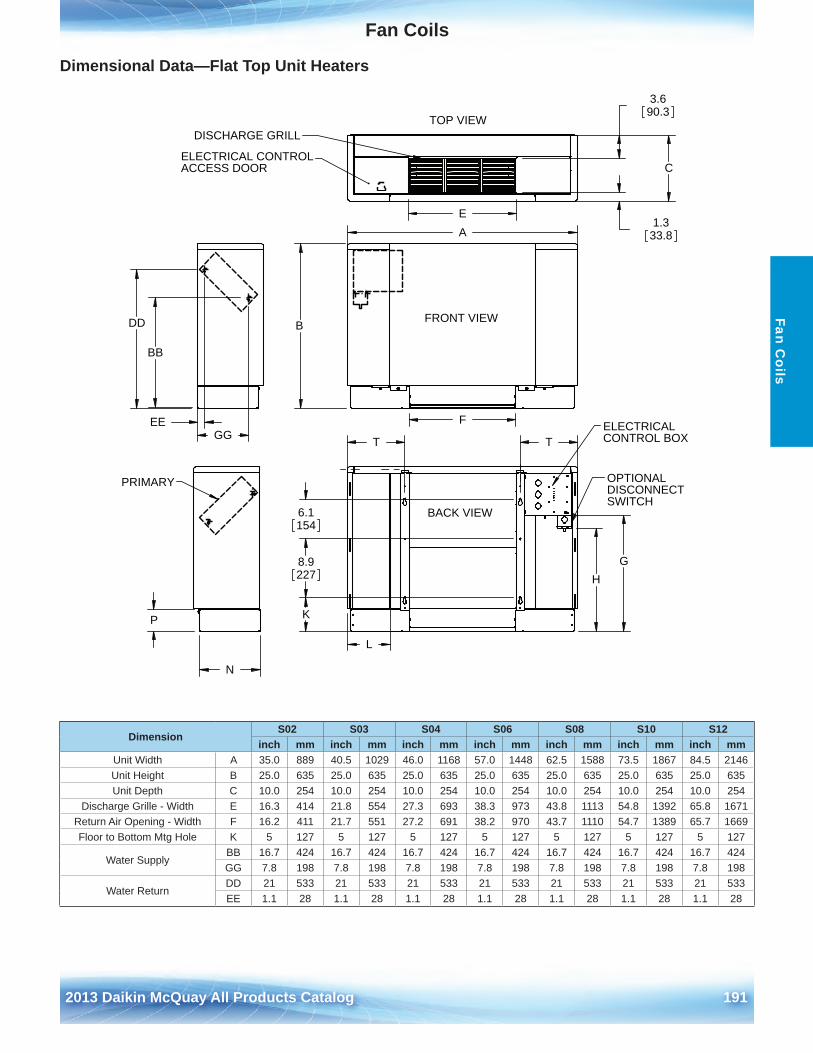
Fan Coils
2012 McQuay Products Catalog 1912013 Daikin McQuay All Products Catalog 191
Fan Coils
Dimensional Data—Flat Top Unit Heaters
A
B
F
FRONT VIEW
K
8.9227
6.1154
TT
HG
L
BACK VIEW
ELECTRICALCONTROL BOX
OPTIONALDISCONNECTSWITCH
1.333.8
C
3.690.3
E
TOP VIEWDISCHARGE GRILL
ELECTRICAL CONTROLACCESS DOOR
P
N
PRIMARY
EE
BB
DD
GG
DimensionS02 S03 S04 S06 S08 S10 S12
inch mm inch mm inch mm inch mm inch mm inch mm inch mmUnit Width A 35 .0 889 40 .5 1029 46 .0 1168 57 .0 1448 62 .5 1588 73 .5 1867 84 .5 2146Unit Height B 25 .0 635 25 .0 635 25 .0 635 25 .0 635 25 .0 635 25 .0 635 25 .0 635Unit Depth C 10 .0 254 10 .0 254 10 .0 254 10 .0 254 10 .0 254 10 .0 254 10 .0 254
Discharge Grille - Width E 16 .3 414 21 .8 554 27 .3 693 38 .3 973 43 .8 1113 54 .8 1392 65 .8 1671Return Air Opening - Width F 16 .2 411 21 .7 551 27 .2 691 38 .2 970 43 .7 1110 54 .7 1389 65 .7 1669Floor to Bottom Mtg Hole K 5 127 5 127 5 127 5 127 5 127 5 127 5 127
Water SupplyBB 16 .7 424 16 .7 424 16 .7 424 16 .7 424 16 .7 424 16 .7 424 16 .7 424GG 7 .8 198 7 .8 198 7 .8 198 7 .8 198 7 .8 198 7 .8 198 7 .8 198
Water ReturnDD 21 533 21 533 21 533 21 533 21 533 21 533 21 533EE 1 .1 28 1 .1 28 1 .1 28 1 .1 28 1 .1 28 1 .1 28 1 .1 28
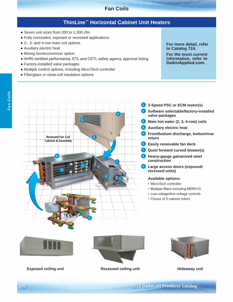
Fan Coils
192 2013 Daikin All Products Catalog
Fan
Coi
ls
ThinLine™ Horizontal Cabinet Unit Heaters
● Seven unit sizes from 200 to 1,300 cfm● Fully concealed, exposed or recessed applications● 2-, 3- and 4-row main coil options● Auxiliary electric heat● Mixing box/economizer option● AHRI-certified performance, ETL and CETL safety agency approval listing● Factory-installed valve packages● Multiple control options, including MicroTech controller● Fiberglass or close-cell insulation options
For more detail, refer to Catalog 724 .For the most current information, refer to DaikinApplied.com .
1 3-Speed PSC or ECM motor(s)2 Software selectable/factory-installed
valve packages3 Main hot water (2, 3, 4-row) coils4 Auxiliary electric heat5 Front/bottom discharge, bottom/rear
return6 Easily removable fan deck7 Quiet forward curved blower(s)8 Heavy-gauge galvanized steel
construction9 Large access doors (exposed/
recessed units)
Available options:• MicroTech controller• Multiple filters including MERV13• Low-voltage/line-voltage controls• Choice of 5 cabinet colors
Recessed Fan Coil Cabinet & Assembly
Exposed ceiling unit Recessed ceiling unit Hideaway unit
1
2
34
5
5
6
7
8
9
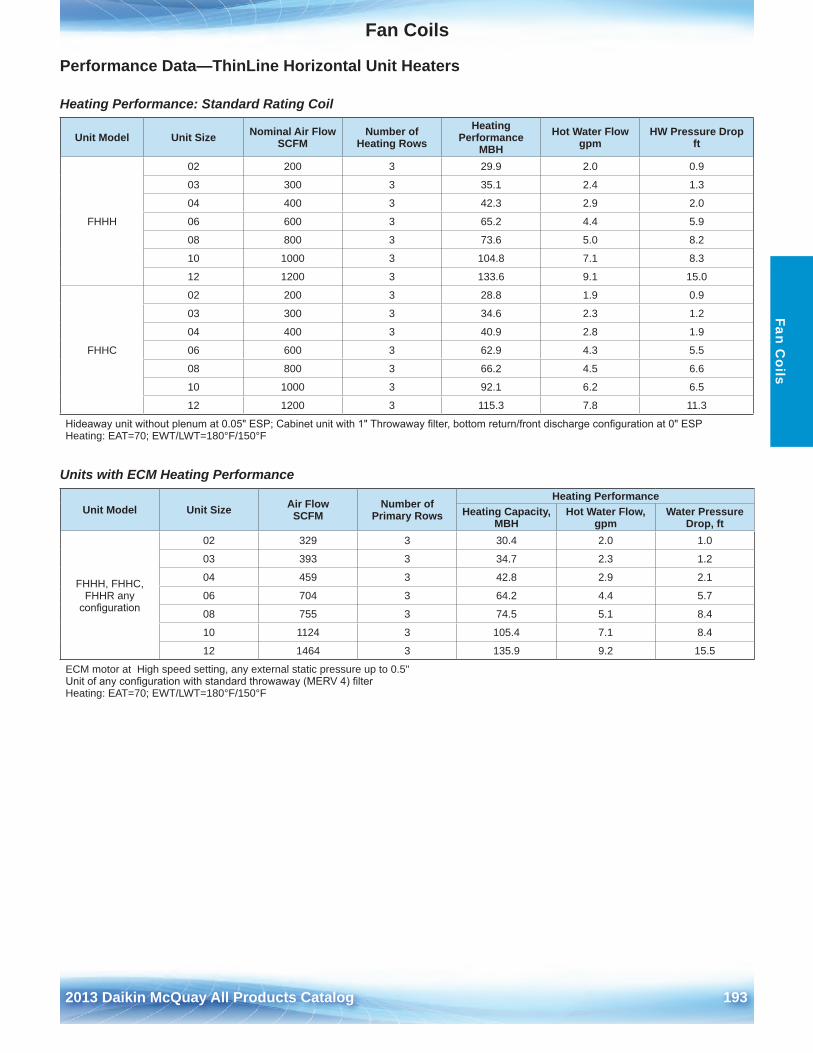
Fan Coils
2012 McQuay Products Catalog 1932013 Daikin McQuay All Products Catalog 193
Fan Coils
Performance Data—ThinLine Horizontal Unit Heaters
Heating Performance: Standard Rating Coil
Unit Model Unit Size Nominal Air FlowSCFM
Number of Heating Rows
Heating Performance
MBHHot Water Flow
gpmHW Pressure Drop
ft
FHHH
02 200 3 29 .9 2 .0 0 .9
03 300 3 35 .1 2 .4 1 .3
04 400 3 42 .3 2 .9 2 .0
06 600 3 65 .2 4 .4 5 .9
08 800 3 73 .6 5 .0 8 .2
10 1000 3 104 .8 7 .1 8 .3
12 1200 3 133 .6 9 .1 15 .0
FHHC
02 200 3 28 .8 1 .9 0 .9
03 300 3 34 .6 2 .3 1 .2
04 400 3 40 .9 2 .8 1 .9
06 600 3 62 .9 4 .3 5 .5
08 800 3 66 .2 4 .5 6 .6
10 1000 3 92 .1 6 .2 6 .5
12 1200 3 115 .3 7 .8 11 .3
Hideaway unit without plenum at 0.05" ESP; Cabinet unit with 1" Throwaway filter, bottom return/front discharge configuration at 0" ESP Heating: EAT=70; EWT/LWT=180°F/150°F
Units with ECM Heating Performance
Unit Model Unit Size Air FlowSCFM
Number of Primary Rows
Heating PerformanceHeating Capacity,
MBHHot Water Flow,
gpmWater Pressure
Drop, ft
FHHH, FHHC, FHHR any
configuration
02 329 3 30 .4 2 .0 1 .0
03 393 3 34 .7 2 .3 1 .2
04 459 3 42 .8 2 .9 2 .1
06 704 3 64 .2 4 .4 5 .7
08 755 3 74 .5 5 .1 8 .4
10 1124 3 105 .4 7 .1 8 .4
12 1464 3 135 .9 9 .2 15 .5
ECM motor at High speed setting, any external static pressure up to 0 .5" Unit of any configuration with standard throwaway (MERV 4) filter Heating: EAT=70; EWT/LWT=180°F/150°F
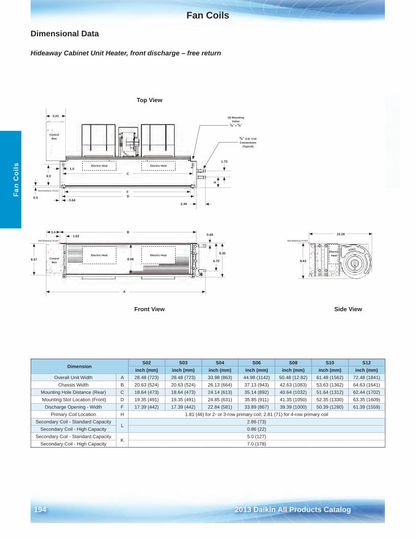
Fan Coils
194 2013 Daikin All Products Catalog
Fan
Coi
ls
Dimensional Data
Hideaway Cabinet Unit Heater, front discharge – free return
DimensionS02 S03 S04 S06 S08 S10 S12
inch (mm) inch (mm) inch (mm) inch (mm) inch (mm) inch (mm) inch (mm)Overall Unit Width A 28 .48 (723) 28 .48 (723) 33 .98 (863) 44 .98 (1142) 50 .48 (12 .82) 61 .48 (1562) 72 .48 (1841)
Chassis Width B 20 .63 (524) 20 .63 (524) 26 .13 (664) 37 .13 (943) 42 .63 (1083) 53 .63 (1362) 64 .63 (1641)Mounting Hole Distance (Rear) C 18 .64 (473) 18 .64 (473) 24 .14 (613) 35 .14 (892) 40 .64 (1032) 51 .64 (1312) 62 .44 (1702) Mounting Slot Location (Front) D 19 .35 (491) 19 .35 (491) 24 .85 (631) 35 .85 (911) 41 .35 (1050) 52 .35 (1330) 63 .35 (1609)
Discharge Opening - Width F 17 .39 (442) 17 .39 (442) 22 .84 (581) 33 .89 (867) 39 .39 (1000) 50 .39 (1280) 61 .39 (1559)Primary Coil Location H 1 .81 (46) for 2- or 3-row primary coil; 2 .81 (71) for 4-row primary coil
Secondary Coil - Standard CapacityL
2 .86 (73)Secondary Coil - High Capacity 0 .86 (22)
Secondary Coil - Standard CapacityK
5 .0 (127)Secondary Coil - High Capacity 7 .0 (178)
Electric Heat
Electric Heat
Electric Heat
Electric Heat
Electric Heat8.57 6.75
9.35
0.68
8.08
(4) Mounting Holes
⅜" × ⅝"
6.0
15.28
5.01
3.4
⅝" O.D. Coil Connections
(Typical)
9.63
H
1.73
D
1.62
0.50.64
2.49
1.0
B
F
C
A
Top View
Side ViewFront View
Control Box
Control Box
REFERENCE POINT○×
REFERENCE POINT○×
REFERENCE POINT○×
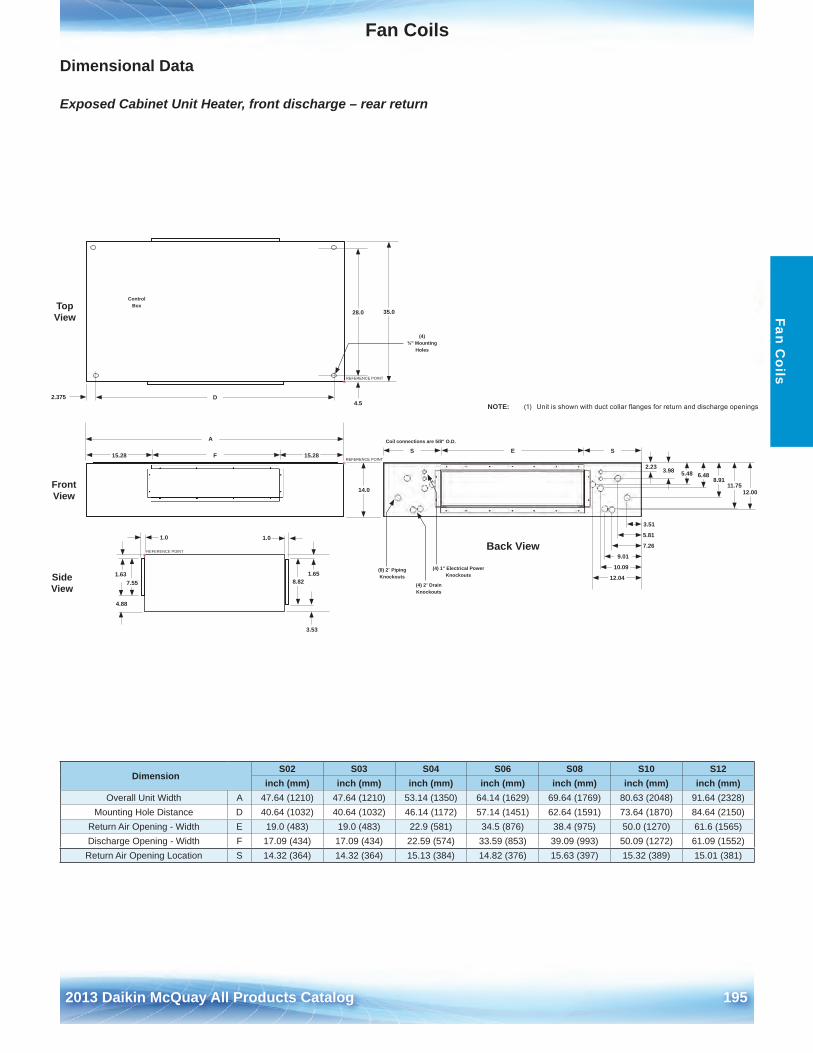
Fan Coils
2012 McQuay Products Catalog 1952013 Daikin McQuay All Products Catalog 195
Fan Coils
Dimensional Data
Exposed Cabinet Unit Heater, front discharge – rear return
DimensionS02 S03 S04 S06 S08 S10 S12
inch (mm) inch (mm) inch (mm) inch (mm) inch (mm) inch (mm) inch (mm)Overall Unit Width A 47 .64 (1210) 47 .64 (1210) 53 .14 (1350) 64 .14 (1629) 69 .64 (1769) 80 .63 (2048) 91 .64 (2328)
Mounting Hole Distance D 40 .64 (1032) 40 .64 (1032) 46 .14 (1172) 57 .14 (1451) 62 .64 (1591) 73 .64 (1870) 84 .64 (2150)Return Air Opening - Width E 19 .0 (483) 19 .0 (483) 22 .9 (581) 34 .5 (876) 38 .4 (975) 50 .0 (1270) 61 .6 (1565)Discharge Opening - Width F 17 .09 (434) 17 .09 (434) 22 .59 (574) 33 .59 (853) 39 .09 (993) 50 .09 (1272) 61 .09 (1552)
Return Air Opening Location S 14 .32 (364) 14 .32 (364) 15 .13 (384) 14 .82 (376) 15 .63 (397) 15 .32 (389) 15 .01 (381)
15.28 15.28
35.0
14.0
7.55 8.82
4.88
3.53
1.65
C.XX2.375 D
28.0
4.5
1.01.0
1.63
(4) ¾" Mounting
Holes
A
F
Back View
12.0011.75
8.916.485.483.982.23
12.04
10.09
9.01
7.26
5.81
3.51
(8) 2" Piping Knockouts
(4) 2" Drain Knockouts
(4) 1" Electrical Power Knockouts
E SSCoil connections are 5/8" O.D.
Front View
Top View
Side View
Control Box
○×REFERENCE POINT
○×REFERENCE POINT
○×REFERENCE POINT
NOTE: (1) Unitisshownwithductcollarflangesforreturnanddischargeopenings
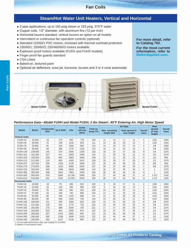
Fan Coils
196 2013 Daikin All Products Catalog
Fan
Coi
ls
Steam/Hot Water Unit Heaters, Vertical and Horizontal
● 2-pipe applications, up to 150 psig steam or 220 psig, 375°F water● Copper coils, 1/2" diameter, with aluminum fins (12 per inch)● Horizontal louvers standard, vertical louvers an option on all models● Intermittent or continuous fan operation controls (optional)● Standard 115/60/1 PSC motors, enclosed with thermal overload protection● 230/60/1; 200/60/3; 230/460/60/3 motors available● Explosion proof motors available (FUDX and FUHX models)● Finger-proof fan guards standard● CSA Listed● Baked-on, textured paint● Optional air deflectors: cone jet, truncone, louvers and 3 or 4 cone anemostat
For more detail, refer to Catalog 702 .For the most current information, refer to DaikinApplied.com .
Performance Data—Model FUHH and Model FUDH; 2 lbs Steam1, 60°F Entering Air, High Motor Speed
Model Btu/hr Condensate lb/hr Sq ft EDR Cfm
Outlet velocity
(fpm)Final air temp (°F)
Air Data Heat spread @ max height
Sound classMax . mounting
height (ft)2Heat spread @
max heightSound class
Vertical UnitsFUDH-42 42,000 43 175 950 779 103 11 15 17 11 II 1/20 1550FUDH-59 59,000 61 246 1150 943 111 13 18 20 13 II 1/20 1550FUDH-78 78,000 81 325 1550 992 110 14 19 22 14 II 1/8 1550FUDH-95 95,000 99 396 1775 1136 113 16 21 24 16 II 1/8 1550
FUDH-139 139,000 144 579 2500 1284 116 18 24 27 18 III 1/4 1075FUDH-161 161,000 167 671 2900 1490 115 21 28 31 21 III 1/4 1075FUDH-193 193,000 200 804 3900 1643 109 23 31 34 23 IV 1/2 900FUDH-212 212,000 219 883 4300 1812 109 25 33 37 25 IV 1/2 1075FUDH-247 247,000 256 1029 5130 1805 107 26 34 39 26 IV 5/8 900FUDH-279 279,000 288 1163 5800 2040 107 30 37 45 30 V 5/8 1075FUDH-333 333,000 345 1388 6600 1968 110 30 37 45 30 V 1 1075FUDH-385 385,000 398 1604 7860 1930 106 30 36 45 30 VI 1 1140FUDH-500 500,000 518 2083 10,790 2490 103 37 44 56 37 VI 1-1/2 1140FUDH-610 610,000 631 2542 12,350 2345 106 36 43 54 36 VI 1-1/2 1140
Horizontal UnitsFUHH-18 18,000 18 75 400 510 102 9 15 17 11 II 1/30 1550FUHH-24 24,000 25 100 450 580 109 9 18 18 13 II 1/30 1550FUHH-33 33,000 35 138 630 510 109 10 19 20 14 II 1/15 1550FUHH-47 47,000 49 196 730 600 120 12 21 25 16 III 1/15 1550FUHH-63 63,000 66 263 1120 605 112 14 24 29 18 III 1/10 1550FUHH-86 86,000 89 358 1340 730 119 15 28 31 21 III 1/10 1550
FUHH-108 108,000 111 450 1550 625 125 15 31 32 23 III 1/8 1075FUHH-121 121,000 126 504 1775 715 123 16 34 33 25 III 1/8 1075FUHH-165 165,000 170 688 2500 750 121 17 37 34 26 IV 1/4 1075FUHH-193 193,000 200 804 2900 870 122 18 37 37 30 IV 1/4 1075FUHH-258 258,000 267 1075 3900 920 121 19 36 40 30 V 1/3 1075FUHH-290 290,000 300 1208 4300 1010 122 20 44 44 37 V 1/2 1100FUHH-340 340,000 352 1417 5130 965 121 20 43 46 36 V 1/2 1100
1 . For hot water performance data, see Catalog FC-FUHH00 .2 . Applies to most popular motor .
Model FUHHModel FUDH
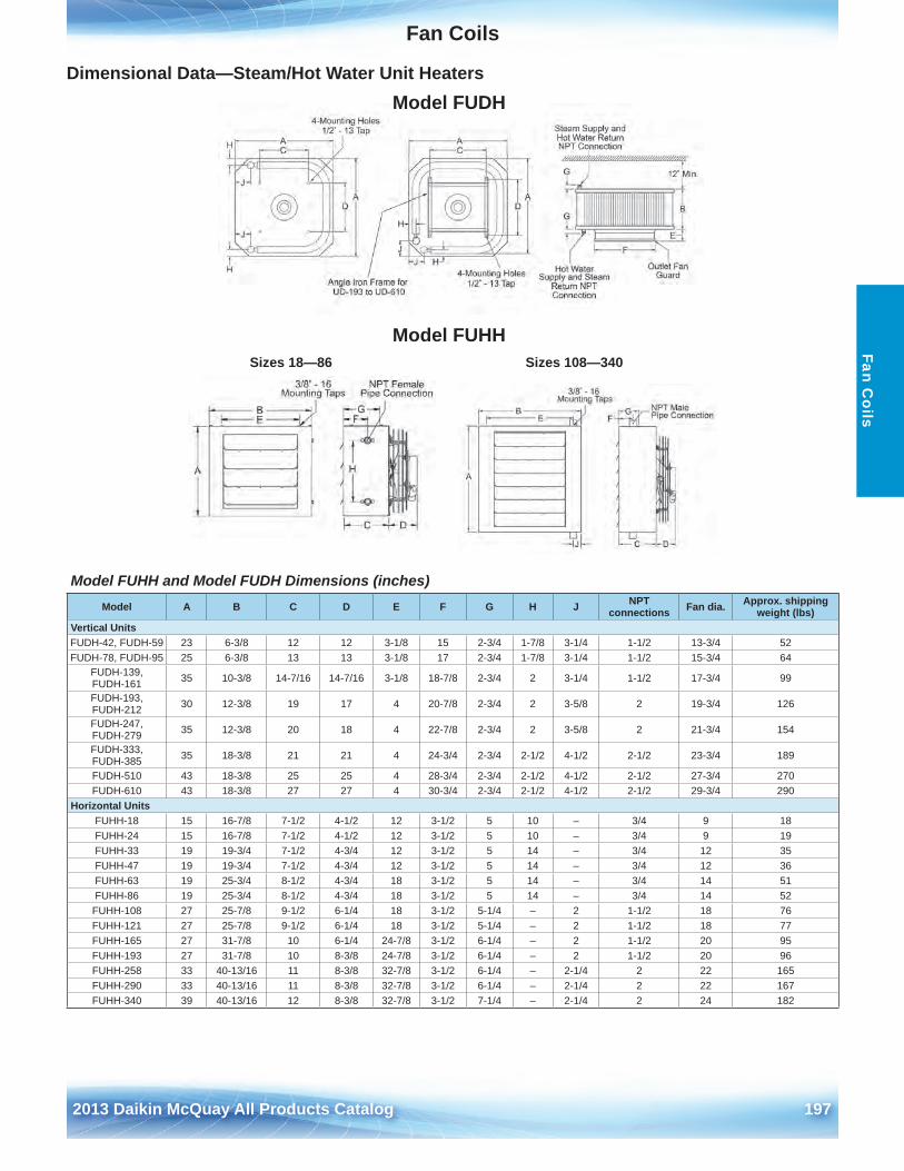
Fan Coils
2012 McQuay Products Catalog 1972013 Daikin McQuay All Products Catalog 197
Fan Coils
Dimensional Data—Steam/Hot Water Unit Heaters
Model FUHH and Model FUDH Dimensions (inches)
Model FUDH
Model FUHHSizes 18—86 Sizes 108—340
Model A B C D E F G H J NPT connections Fan dia . Approx . shipping
weight (lbs)Vertical UnitsFUDH-42, FUDH-59 23 6-3/8 12 12 3-1/8 15 2-3/4 1-7/8 3-1/4 1-1/2 13-3/4 52FUDH-78, FUDH-95 25 6-3/8 13 13 3-1/8 17 2-3/4 1-7/8 3-1/4 1-1/2 15-3/4 64
FUDH-139, FUDH-161 35 10-3/8 14-7/16 14-7/16 3-1/8 18-7/8 2-3/4 2 3-1/4 1-1/2 17-3/4 99
FUDH-193, FUDH-212 30 12-3/8 19 17 4 20-7/8 2-3/4 2 3-5/8 2 19-3/4 126
FUDH-247, FUDH-279 35 12-3/8 20 18 4 22-7/8 2-3/4 2 3-5/8 2 21-3/4 154
FUDH-333, FUDH-385 35 18-3/8 21 21 4 24-3/4 2-3/4 2-1/2 4-1/2 2-1/2 23-3/4 189
FUDH-510 43 18-3/8 25 25 4 28-3/4 2-3/4 2-1/2 4-1/2 2-1/2 27-3/4 270FUDH-610 43 18-3/8 27 27 4 30-3/4 2-3/4 2-1/2 4-1/2 2-1/2 29-3/4 290
Horizontal UnitsFUHH-18 15 16-7/8 7-1/2 4-1/2 12 3-1/2 5 10 – 3/4 9 18FUHH-24 15 16-7/8 7-1/2 4-1/2 12 3-1/2 5 10 – 3/4 9 19FUHH-33 19 19-3/4 7-1/2 4-3/4 12 3-1/2 5 14 – 3/4 12 35FUHH-47 19 19-3/4 7-1/2 4-3/4 12 3-1/2 5 14 – 3/4 12 36FUHH-63 19 25-3/4 8-1/2 4-3/4 18 3-1/2 5 14 – 3/4 14 51FUHH-86 19 25-3/4 8-1/2 4-3/4 18 3-1/2 5 14 – 3/4 14 52
FUHH-108 27 25-7/8 9-1/2 6-1/4 18 3-1/2 5-1/4 – 2 1-1/2 18 76FUHH-121 27 25-7/8 9-1/2 6-1/4 18 3-1/2 5-1/4 – 2 1-1/2 18 77FUHH-165 27 31-7/8 10 6-1/4 24-7/8 3-1/2 6-1/4 – 2 1-1/2 20 95FUHH-193 27 31-7/8 10 8-3/8 24-7/8 3-1/2 6-1/4 – 2 1-1/2 20 96FUHH-258 33 40-13/16 11 8-3/8 32-7/8 3-1/2 6-1/4 – 2-1/4 2 22 165FUHH-290 33 40-13/16 11 8-3/8 32-7/8 3-1/2 6-1/4 – 2-1/4 2 22 167FUHH-340 39 40-13/16 12 8-3/8 32-7/8 3-1/2 7-1/4 – 2-1/4 2 24 182
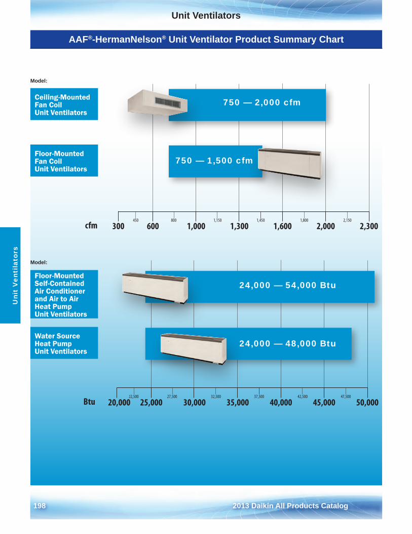
198 2013 Daikin All Products Catalog
Unit VentilatorsU
nit
Ven
tila
tors
AAF®-HermanNelson® Unit Ventilator Product Summary Chart
450 800 1,150 1,450 1,800 2,150
300 600 1,000 1,300 1,600 2,000 2,300
22,500 27,500 32,500 37,500 42,500 47,500
20,000 25,000 30,000 35,000 40,000 45,000 50,000
cfm
Btu
Model:
Model:
Ceiling-Mounted Fan Coil Unit Ventilators
Floor-Mounted Self-Contained Air Conditioner and Air to Air Heat Pump Unit Ventilators
Floor-Mounted Fan Coil Unit Ventilators
Water Source Heat Pump Unit Ventilators
24,000 — 54,000 Btu
24,000 — 48,000 Btu
750 — 2,000 cfm
750 — 1,500 cfm
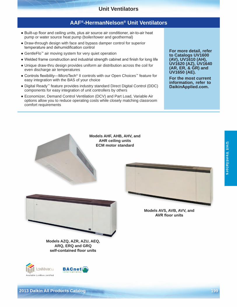
Unit Ventilators
2013 Daikin All Products Catalog 199
Unit V
entilators
AAF®-HermanNelson® Unit Ventilators
● Built-up floor and ceiling units, plus air source air conditioner, air-to-air heatpump or water source heat pump (boiler/tower and geothermal)
● Draw-through design with face and bypass damper control for superiortemperature and dehumidification control
● GentleFlo™ air moving system for very quiet operation● Welded frame construction and industrial strength cabinet and finish for long life● Unique draw-thru design provides uniform air distribution across the coil for
even discharge air temperatures● Controls flexibility—MicroTech® II controls with our Open Choices™ feature for
easy integration with the BAS of your choice● Digital Ready™ feature provides industry standard Direct Digital Control (DDC)
components for easy integration of unit controllers by others● Economizer, Demand Control Ventilation (DCV) and Part Load, Variable Air
options allow you to reduce operating costs while closely matching classroomcomfort requirements
For more detail, refer to Catalogs UV1600 (AV), UV1610 (AH), UV1620 (AZ), UV1640 (AR, ER, & GR) and UV1650 (AE) .For the most current information, refer to DaikinApplied.com .
Models AHF, AHB, AHV, and AHR ceiling units
ECM motor standard
Models AVS, AVB, AVV, and AVR floor units
Models AZQ, AZR, AZU, AEQ, ARQ, ERQ and GRQ
self-contained floor units
Available LonMark cert i f ied
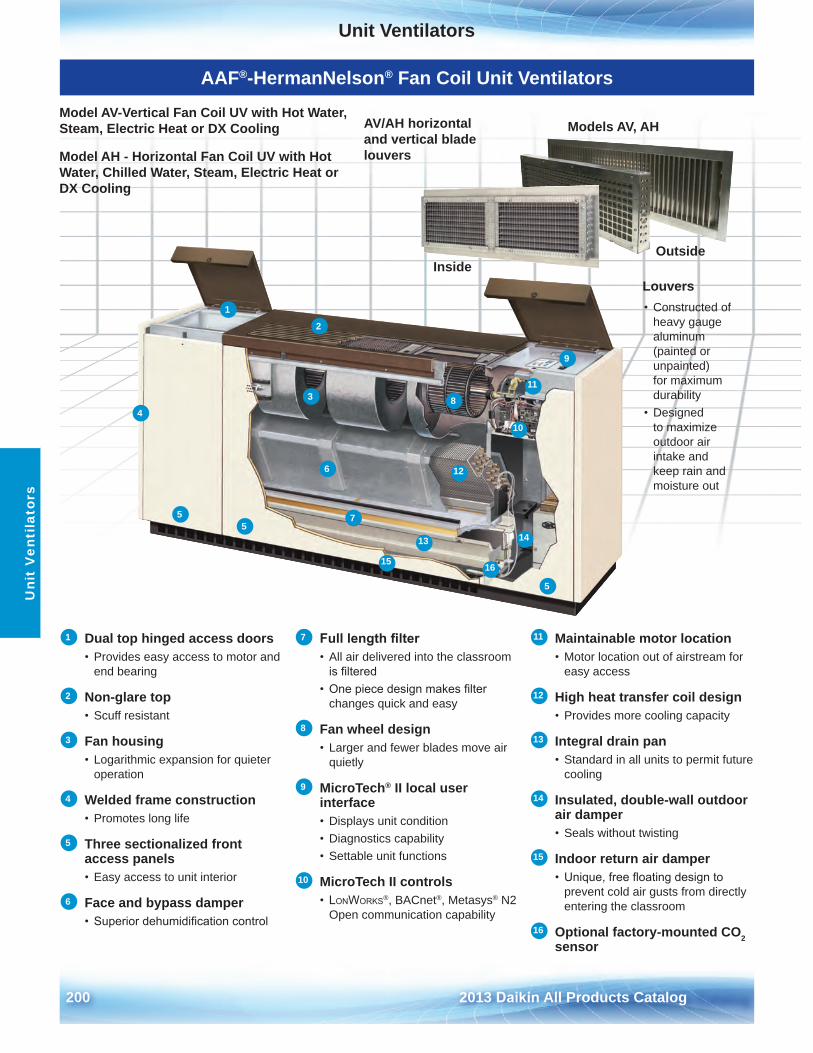
Unit Ventilators
200 2013 Daikin All Products Catalog
Uni
t V
enti
lato
rs
AAF®-HermanNelson® Fan Coil Unit Ventilators
Model AV-Vertical Fan Coil UV with Hot Water, Steam, Electric Heat or DX Cooling
Model AH - Horizontal Fan Coil UV with Hot Water, Chilled Water, Steam, Electric Heat or DX Cooling
Louvers• Constructed of
heavy gauge aluminum (painted or unpainted) for maximum durability
• Designedto maximize outdoor air intake and keep rain and moisture out
Outside
Models AV, AH
Inside
AV/AH horizontal and vertical blade louvers
1 Dual top hinged access doors• Provides easy access to motor and
end bearing
2 Non-glare top• Scuff resistant
3 Fan housing• Logarithmic expansion for quieter
operation
4 Welded frame construction• Promotes long life
5 Three sectionalized front access panels• Easy access to unit interior
6 Face and bypass damper• Superior dehumidification control
7 Full length filter• All air delivered into the classroom
is filtered• One piece design makes filter
changes quick and easy
8 Fan wheel design• Larger and fewer blades move air
quietly
9 MicroTech® II local user interface• Displays unit condition• Diagnostics capability• Settable unit functions
10 MicroTech II controls• LonWorks®, BACnet®, Metasys® N2
Open communication capability
11 Maintainable motor location• Motor location out of airstream for
easy access
12 High heat transfer coil design• Provides more cooling capacity
13 Integral drain pan• Standard in all units to permit future
cooling
14 Insulated, double-wall outdoor air damper• Seals without twisting
15 Indoor return air damper• Unique, free floating design to
prevent cold air gusts from directly entering the classroom
16 Optional factory-mounted CO2 sensor
1
2
3
4
55
6
7
8
9
10
11
12
13 14
15 16
5
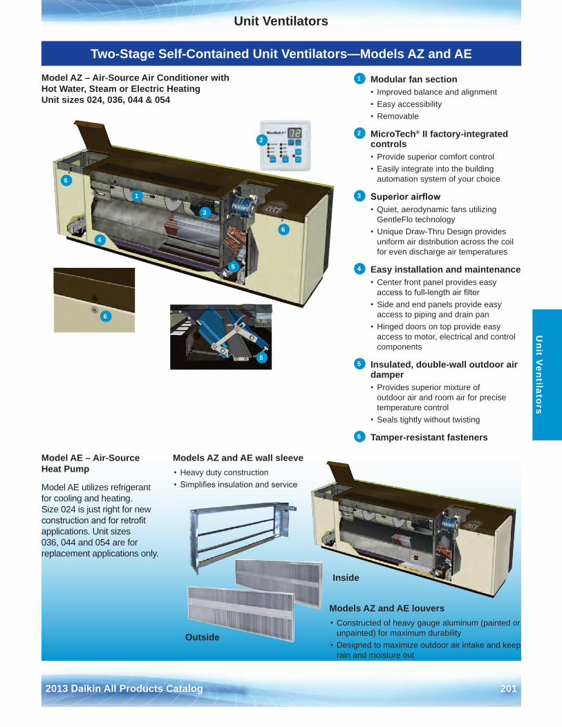
Unit Ventilators
2013 Daikin All Products Catalog 201
Unit V
entilators
Two-Stage Self-Contained Unit Ventilators—Models AZ and AE
Model AZ – Air-Source Air Conditioner with Hot Water, Steam or Electric Heating Unit sizes 024, 036, 044 & 054
Models AZ and AE wall sleeve• Heavy duty construction• Simplifies insulation and service
Models AZ and AE louvers• Constructed of heavy gauge aluminum (painted or
unpainted) for maximum durability• Designed to maximize outdoor air intake and keep
rain and moisture out
Model AE – Air-Source Heat Pump
Model AE utilizes refrigerant for cooling and heating . Size 024 is just right for new construction and for retrofit applications . Unit sizes 036, 044 and 054 are for replacement applications only .
Inside
Outside
1 Modular fan section• Improved balance and alignment• Easy accessibility• Removable
2 MicroTech® II factory-integrated controls• Provide superior comfort control• Easily integrate into the building
automation system of your choice
3 Superior airflow• Quiet, aerodynamic fans utilizing
GentleFlo technology• Unique Draw-Thru Design provides
uniform air distribution across the coil for even discharge air temperatures
4 Easy installation and maintenance• Center front panel provides easy
access to full-length air filter• Side and end panels provide easy
access to piping and drain pan• Hinged doors on top provide easy
access to motor, electrical and control components
5 Insulated, double-wall outdoor air damper• Provides superior mixture of
outdoor air and room air for precise temperature control
• Seals tightly without twisting
6 Tamper-resistant fasteners
1
2
3
4
5
5
6
6
6
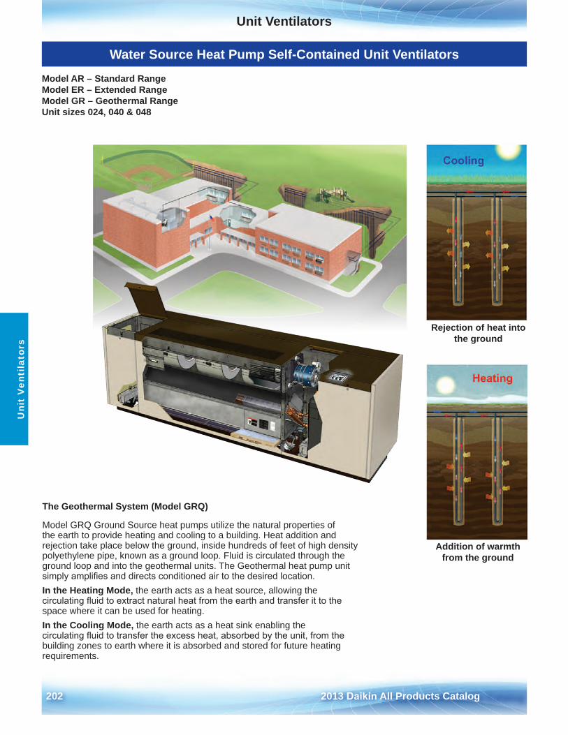
Unit Ventilators
202 2013 Daikin All Products Catalog
Uni
t V
enti
lato
rs
Water Source Heat Pump Self-Contained Unit Ventilators
Model AR – Standard Range Model ER – Extended Range Model GR – Geothermal Range Unit sizes 024, 040 & 048
Rejection of heat into the ground
Addition of warmth from the ground
The Geothermal System (Model GRQ)
Model GRQ Ground Source heat pumps utilize the natural properties of the earth to provide heating and cooling to a building . Heat addition and rejection take place below the ground, inside hundreds of feet of high density polyethylene pipe, known as a ground loop . Fluid is circulated through the ground loop and into the geothermal units . The Geothermal heat pump unit simply amplifies and directs conditioned air to the desired location.In the Heating Mode, the earth acts as a heat source, allowing the circulating fluid to extract natural heat from the earth and transfer it to the space where it can be used for heating .In the Cooling Mode, the earth acts as a heat sink enabling the circulating fluid to transfer the excess heat, absorbed by the unit, from the building zones to earth where it is absorbed and stored for future heating requirements .
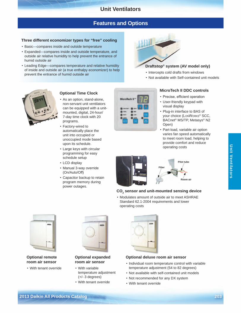
Unit Ventilators
2013 Daikin All Products Catalog 203
Unit V
entilators
Features and Options
Filter
Pitot tube
Room air
CO2 sensor and unit-mounted sensing device• Modulates amount of outside air to meet ASHRAE
Standard 62 .1-2004 requirements and lower operating costs
MicroTech II DDC controls• Precise, efficient operation• User-friendly keypad with
visual display• Plug-in interface to BAS of
your choice (LonWorks® SCC,BACnet® MS/TP, Metasys® N2Open)
• Part-load, variable air optionvaries fan speed automaticallyto meet room load, helping toprovide comfort and reduceoperating costs
Draftstop® system (AV model only)• Intercepts cold drafts from windows• Not available with Self-contained unit models
Optional deluxe room air sensor• Individual room temperature control with variable
temperature adjustment (54 to 82 degrees)• Not available with self-contained unit models• Not recommended for any DX system• With tenant override
Optional Time Clock• As an option, stand-alone,
non-servant unit ventilators can be equipped with a unit-mounted, digital, 24-hour/ 7-day time clock with 20 programs .
• Factory-wired toautomatically place the unit into occupied or unoccupied mode based upon its schedule .
• Large keys with circularprogramming for easy schedule setup
• LCD display• Manual 3-way override
(On/Auto/Off)• Capacitor backup to retain
program memory duringpower outages .
Optional expanded room air sensor• With variable
temperature adjustment (+/- 3 degrees)
• With tenant override
Optional remote room air sensor• With tenant override
Three different economizer types for “free” cooling• Basic—compares inside and outside temperature• Expanded—compares inside and outside temperature, and
outside air relative humidity to help prevent the entrance ofhumid outside air
• Leading Edge—compares temperature and relative humidityof inside and outside air (a true enthalpy economizer) to helpprevent the entrance of humid outside air
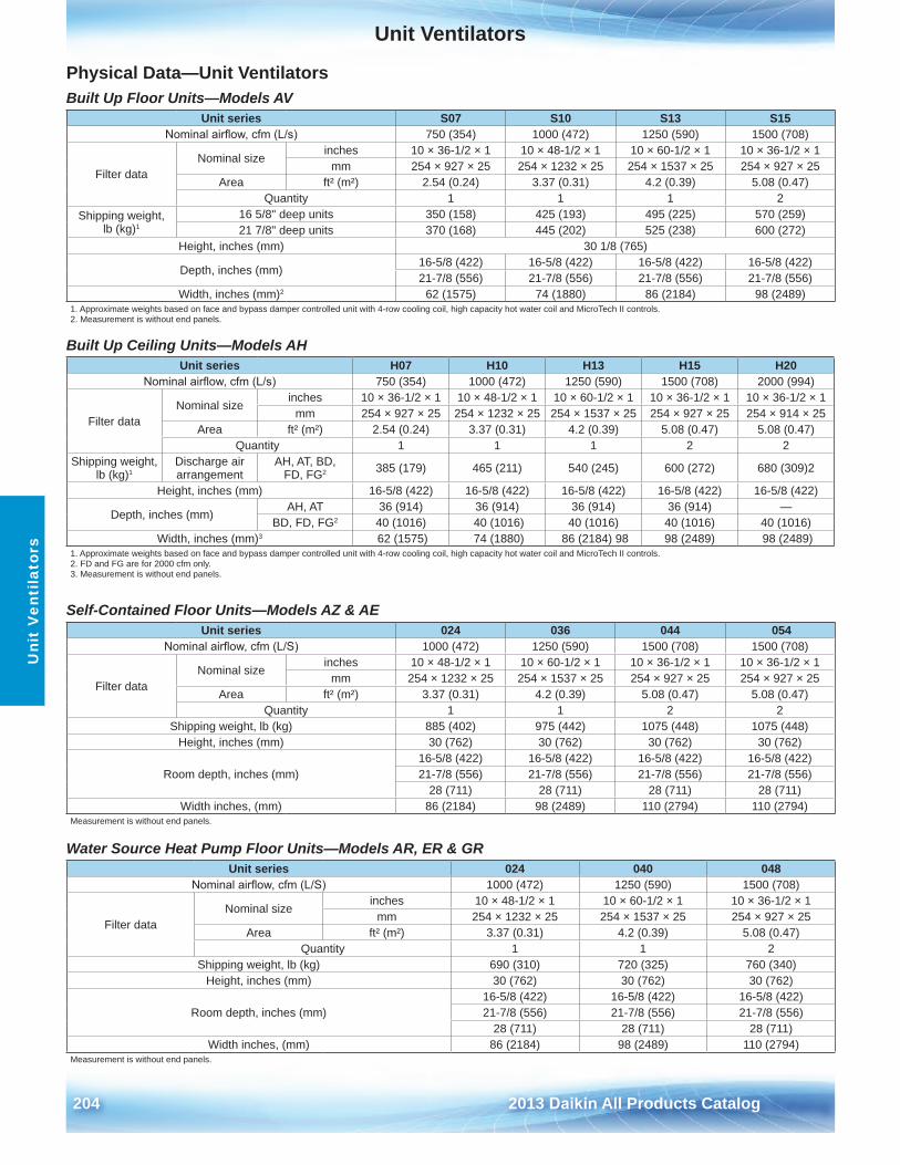
Unit Ventilators
204 2013 Daikin All Products Catalog
Uni
t V
enti
lato
rs
Physical Data—Unit VentilatorsBuilt Up Floor Units—Models AV
Built Up Ceiling Units—Models AH
Self-Contained Floor Units—Models AZ & AE
Water Source Heat Pump Floor Units—Models AR, ER & GR
Unit series S07 S10 S13 S15Nominal airflow, cfm (L/s) 750 (354) 1000 (472) 1250 (590) 1500 (708)
Filter dataNominal size
inches 10 × 36-1/2 × 1 10 × 48-1/2 × 1 10 × 60-1/2 × 1 10 × 36-1/2 × 1mm 254 × 927 × 25 254 × 1232 × 25 254 × 1537 × 25 254 × 927 × 25
Area ft² (m²) 2 .54 (0 .24) 3 .37 (0 .31) 4 .2 (0 .39) 5 .08 (0 .47)Quantity 1 1 1 2
Shipping weight, lb (kg)1
16 5/8" deep units 350 (158) 425 (193) 495 (225) 570 (259)21 7/8" deep units 370 (168) 445 (202) 525 (238) 600 (272)
Height, inches (mm) 30 1/8 (765)
Depth, inches (mm)16-5/8 (422) 16-5/8 (422) 16-5/8 (422) 16-5/8 (422)21-7/8 (556) 21-7/8 (556) 21-7/8 (556) 21-7/8 (556)
Width, inches (mm)2 62 (1575) 74 (1880) 86 (2184) 98 (2489)1 . Approximate weights based on face and bypass damper controlled unit with 4-row cooling coil, high capacity hot water coil and MicroTech II controls .2 . Measurement is without end panels .
Unit series H07 H10 H13 H15 H20Nominal airflow, cfm (L/s) 750 (354) 1000 (472) 1250 (590) 1500 (708) 2000 (994)
Filter dataNominal size
inches 10 × 36-1/2 × 1 10 × 48-1/2 × 1 10 × 60-1/2 × 1 10 × 36-1/2 × 1 10 × 36-1/2 × 1mm 254 × 927 × 25 254 × 1232 × 25 254 × 1537 × 25 254 × 927 × 25 254 × 914 × 25
Area ft² (m²) 2 .54 (0 .24) 3 .37 (0 .31) 4 .2 (0 .39) 5 .08 (0 .47) 5 .08 (0 .47)Quantity 1 1 1 2 2
Shipping weight, lb (kg)1
Discharge air arrangement
AH, AT, BD, FD, FG2 385 (179) 465 (211) 540 (245) 600 (272) 680 (309)2
Height, inches (mm) 16-5/8 (422) 16-5/8 (422) 16-5/8 (422) 16-5/8 (422) 16-5/8 (422)
Depth, inches (mm)AH, AT 36 (914) 36 (914) 36 (914) 36 (914) —
BD, FD, FG2 40 (1016) 40 (1016) 40 (1016) 40 (1016) 40 (1016) Width, inches (mm)3 62 (1575) 74 (1880) 86 (2184) 98 98 (2489) 98 (2489)
1 . Approximate weights based on face and bypass damper controlled unit with 4-row cooling coil, high capacity hot water coil and MicroTech II controls .2 . FD and FG are for 2000 cfm only .3 . Measurement is without end panels .
Unit series 024 036 044 054Nominal airflow, cfm (L/S) 1000 (472) 1250 (590) 1500 (708) 1500 (708)
Filter dataNominal size
inches 10 × 48-1/2 × 1 10 × 60-1/2 × 1 10 × 36-1/2 × 1 10 × 36-1/2 × 1mm 254 × 1232 × 25 254 × 1537 × 25 254 × 927 × 25 254 × 927 × 25
Area ft² (m²) 3 .37 (0 .31) 4 .2 (0 .39) 5 .08 (0 .47) 5 .08 (0 .47)Quantity 1 1 2 2
Shipping weight, lb (kg) 885 (402) 975 (442) 1075 (448) 1075 (448)Height, inches (mm) 30 (762) 30 (762) 30 (762) 30 (762)
Room depth, inches (mm)16-5/8 (422) 16-5/8 (422) 16-5/8 (422) 16-5/8 (422)21-7/8 (556) 21-7/8 (556) 21-7/8 (556) 21-7/8 (556)
28 (711) 28 (711) 28 (711) 28 (711)Width inches, (mm) 86 (2184) 98 (2489) 110 (2794) 110 (2794)
Measurement is without end panels .
Unit series 024 040 048Nominal airflow, cfm (L/S) 1000 (472) 1250 (590) 1500 (708)
Filter dataNominal size
inches 10 × 48-1/2 × 1 10 × 60-1/2 × 1 10 × 36-1/2 × 1mm 254 × 1232 × 25 254 × 1537 × 25 254 × 927 × 25
Area ft² (m²) 3 .37 (0 .31) 4 .2 (0 .39) 5 .08 (0 .47)Quantity 1 1 2
Shipping weight, lb (kg) 690 (310) 720 (325) 760 (340)Height, inches (mm) 30 (762) 30 (762) 30 (762)
Room depth, inches (mm)16-5/8 (422) 16-5/8 (422) 16-5/8 (422)21-7/8 (556) 21-7/8 (556) 21-7/8 (556)
28 (711) 28 (711) 28 (711)Width inches, (mm) 86 (2184) 98 (2489) 110 (2794)
Measurement is without end panels .
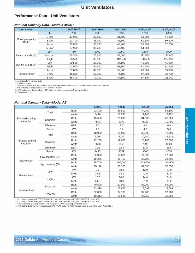
Unit Ventilators
2013 Daikin All Products Catalog 205
Unit V
entilators
Performance Data—Unit Ventilators
Nominal Capacity Data—Models AV/AH
Nominal Capacity Data—Model AZ
Unit series1 S076, H072 S106, H102 S136, H132 S156, H152 S206, H202
Cooling capacity (Btuh)3
cfm 750 1000 1250 1500 20002-row 17,900 23,600 31,500 38,800 44,9003-row 21,700 33,300 41,100 51,200 50,8004-row 27,800 35,600 43,400 56,700 62,2005-row6 27,900 35,200 45,400 54,500 —
Steam heat (Btuh)4
cfm 750 1000 1250 1500 2000Standard 50,300 75,200 89,000 111,500 140,800
High 66,500 89,900 112,500 128,500 227,900
Electric heat (Btuh)Low 20,500 27,300 34,100 41,000 41,000High 41,000 54,600 68,300 81,900 81,900
Hot water heat5
1-row 37,000 49,500 57,000 66,000 69,8002-row 48,300 62,000 74,100 97,200 96,7003-row 56,800 72,000 84,500 97,500 115,000
1 . All data is for F Vintage units .2 . Ceiling unit only .3 . 80°F/67°F entering air temperature; 45°F entering water temperature; 10°F water temperature rise; 10 GPM .4 . 0°F entering air temperature; 2 PSI steam at 218 .5°F .5. 60°F entering air temperature; 160°F entering water temperature; 6 gpm water flow.6 . Vertical unit only .
Unit series AZ024 AZ036 AZ044 AZ054
Full load cooling capacity1
TotalBtuh 22,100 36,800 44,000 52,100Watts 6478 10,786 12,986 15,271
SensibleBtuh 15,500 23,800 31,500 35,500Watts 4543 6976 9233 10,405
Efficiency EER 9 .7 9 .5 9 .4 9 .3Power kW 2 .3 3 .9 4 .7 5 .6
Part load cooling capacity2
TotalBtuh 18,000 28,000 36,300 42,700Watts 5276 8207 10,640 12,515
SensibleBtuh 12,200 19,000 24,900 27,500Watts 3576 5569 7298 8060
Efficiency EER 12 .6 12 .4 11 .8 11 .8Power kW 1423 2259 3060 3600
Steam heat3
Low capacity (68)Btuh 52,000 64,000 77,800 77,800Watts 15,236 18,752 22,795 22,795
High capacity (69)Btuh 85,700 105,000 128,500 128,500Watts 25,110 30,765 37,650 37,650
Electric heatLow
kW 8 .0 10 .0 12 .0 12 .0MBh 27 .3 34 .1 41 .0 41 .0
HighkW 16 .0 20 .0 24 .0 24 .0
MBh 54 .6 68 .3 81 .9 81 .9
Hot water heat4
1-row coilBtuh 49,500 57,000 66,000 66,000Watts 13,390 15,851 18,693 18,693
2-row coilBtuh 62,000 74,100 97,200 97,200Watts 18,313 21,536 25,959 25,959
1 . Conditions: Indoor 80ºF (27ºC) DB / 67ºF (19ºC) WB, Outdoor 95ºF (35ºC) DB / 75ºF (24ºC) WB2 . Conditions: Indoor 80ºF (27ºC) DB / 67ºF (19ºC) WB, Outdoor 82ºF (28ºC) DB / 65ºF (18ºC) WB3 . Steam Heating @ 2 psig Steam (13 .8 KPa); 60°F (16ºC) Entering Air Temperature .4 . 60°F (16ºC) Entering Air Temperature; 160°F (71ºC) Entering Water Temperature; 6 gpm (22 .7 Lpm) Water Flow .
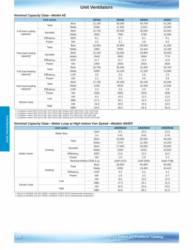
Unit Ventilators
206 2013 Daikin All Products Catalog
Uni
t V
enti
lato
rs
Nominal Capacity Data—Model AE
Nominal Capacity Data—Water Loop at High Indoor Fan Speed—Models AR/ER
Unit series AE024 AE036 AE044 AE054
Full load cooling capacity1
TotalBtuh 21,100 39,300 43,700 51,200Watts 6180 11,520 1,810 15,000
SensibleBtuh 15,700 25,500 30,000 34,400Watts 4530 7500 8790 10,080
Efficiency EER 9 .1 9 .7 9 .1 9 .1Power kW 2 .3 4 .1 4 .8 5 .6
Part load cooling capacity2
TotalBtuh 16,900 30,800 35,500 41,600Watts 4950 9030 10,410 12,180
SensibleBtuh 12,100 20,000 23,800 26,600Watts 3540 5850 6990 7770
Efficiency EER 11 .7 11 .7 11 .8 11 .5Power kW 1450 2630 3010 3620
Full load heating capacity3
TotalBtuh 20,700 35,000 41,600 49,700Watts 6090 10,230 12,180 14,580
Efficiency COP 3 .0 2 .6 2 .6 2 .5Power kW 2 .1 3 .9 4 .6 5 .8
Part load heating capacity4
TotalBtuh 17,700 29,100 36,100 43,000Watts 5160 8520 10,560 12,600
Efficiency COP 3 .3 2 .8 3 .0 2 .8Power kW 1560 3055 3525 4500
Electric heatLow
kW 8 .0 10 .0 12 .0 12 .0MBh 27 .3 34 .1 41 .0 41 .0
HighkW 16 .0 20 .0 24 .0 24 .0
MBh 54 .6 68 .3 81 .9 81 .91 . Conditions: Indoor 80ºF (27ºC) DB / 67ºF (19ºC) WB, Outdoor 95ºF (35ºC) DB / 75ºF (24ºC) WB2 . Conditions: Indoor 80ºF (27ºC) DB / 67ºF (19ºC) WB, Outdoor 82ºF (28ºC) DB / 65ºF (18ºC) WB3 . Conditions: Indoor 70ºF (21ºC) DB / 60ºF (16ºC) WB, Outdoor 47ºF (8ºC) DB / 43ºF (6ºC) WB4 . Conditions: Indoor 70ºF (21ºC) DB / 60ºF (16ºC) WB, Outdoor 62ºF (17ºC) DB / 56 .5ºF (14ºC) WB
Unit series AR/ER024 AR/ER040 AR/ER048
Boiler/ tower
Water flowGpm 6 .5 10 .0 12 .0L/s 0 .41 0 .63 0 .76
Cooling1
TotalBtuh 23,000 39,200 48,100Watts 6740 11,490 14,100
SensibleBtuh 17,600 28,000 35,900Watts 5160 8210 10,520
Efficiency EER 13 .0 13 .5 14 .0Power kW 1 .8 2 .9 3 .4Nominal Airflow CFM (L/s) 1000 (472) 1250 (590) 1500 (708)
Heating2
TotalBtuh 28,500 45,900 56,000Watts 8350 13,450 16,410
Efficiency COP 4 .5 4 .2 4 .4Power kW 1 .8 3 .2 3 .7
Electric heatLow
kW 8 .0 10 .0 12 .0MBh 27 .3 34 .1 41 .0
HighkW 16 .0 20 .0 24 .0
MBh 54 .6 68 .3 81 .91 . Based on ASHRAE and ISO 13256-1 conditions of 86°F (30°C) entering water temperature .2 . Based on ASHRAE and ISO 13256-1 conditions of 68°F (20°C) entering water temperature .
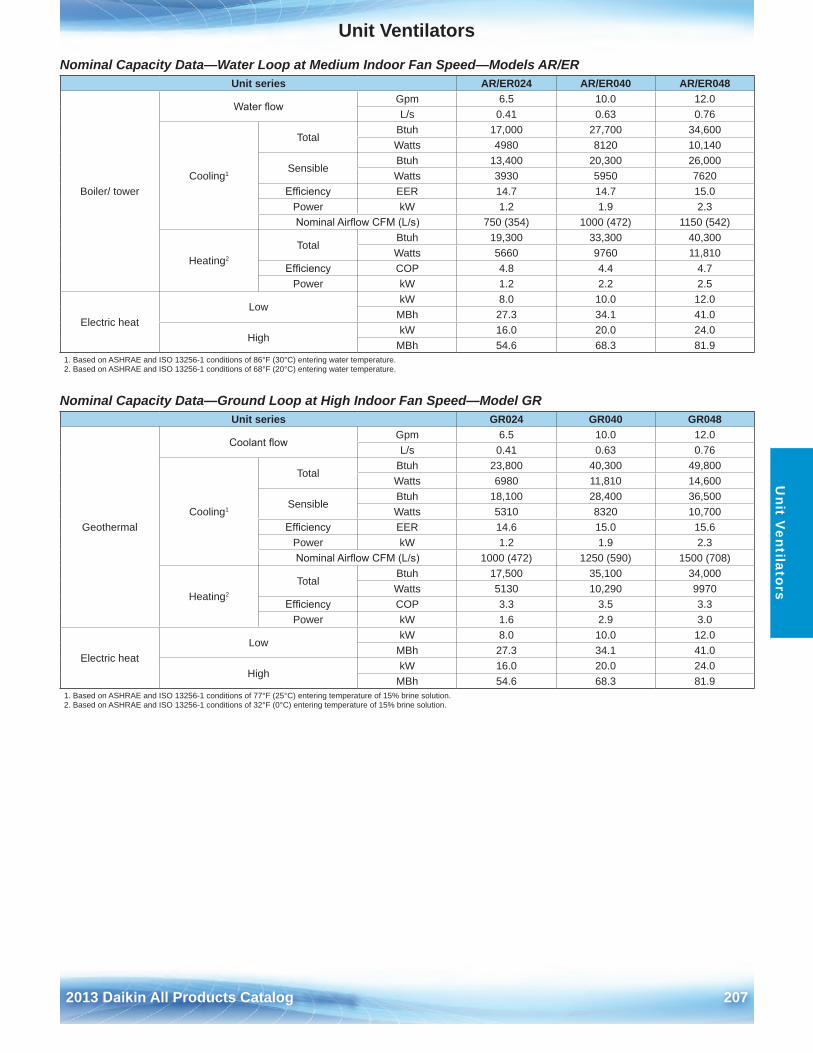
Unit Ventilators
2013 Daikin All Products Catalog 207
Unit V
entilators
Nominal Capacity Data—Water Loop at Medium Indoor Fan Speed—Models AR/ER
Nominal Capacity Data—Ground Loop at High Indoor Fan Speed—Model GR
Unit series AR/ER024 AR/ER040 AR/ER048
Boiler/ tower
Water flowGpm 6 .5 10 .0 12 .0L/s 0 .41 0 .63 0 .76
Cooling1
TotalBtuh 17,000 27,700 34,600Watts 4980 8120 10,140
SensibleBtuh 13,400 20,300 26,000Watts 3930 5950 7620
Efficiency EER 14 .7 14 .7 15 .0Power kW 1 .2 1 .9 2 .3Nominal Airflow CFM (L/s) 750 (354) 1000 (472) 1150 (542)
Heating2
TotalBtuh 19,300 33,300 40,300Watts 5660 9760 11,810
Efficiency COP 4 .8 4 .4 4 .7Power kW 1 .2 2 .2 2 .5
Electric heatLow
kW 8 .0 10 .0 12 .0MBh 27 .3 34 .1 41 .0
HighkW 16 .0 20 .0 24 .0
MBh 54 .6 68 .3 81 .91 . Based on ASHRAE and ISO 13256-1 conditions of 86°F (30°C) entering water temperature .2 . Based on ASHRAE and ISO 13256-1 conditions of 68°F (20°C) entering water temperature .
Unit series GR024 GR040 GR048
Geothermal
Coolant flowGpm 6 .5 10 .0 12 .0L/s 0 .41 0 .63 0 .76
Cooling1
TotalBtuh 23,800 40,300 49,800Watts 6980 11,810 14,600
SensibleBtuh 18,100 28,400 36,500Watts 5310 8320 10,700
Efficiency EER 14 .6 15 .0 15 .6Power kW 1 .2 1 .9 2 .3Nominal Airflow CFM (L/s) 1000 (472) 1250 (590) 1500 (708)
Heating2
TotalBtuh 17,500 35,100 34,000Watts 5130 10,290 9970
Efficiency COP 3 .3 3 .5 3 .3Power kW 1 .6 2 .9 3 .0
Electric heatLow
kW 8 .0 10 .0 12 .0MBh 27 .3 34 .1 41 .0
HighkW 16 .0 20 .0 24 .0
MBh 54 .6 68 .3 81 .91 . Based on ASHRAE and ISO 13256-1 conditions of 77°F (25°C) entering temperature of 15% brine solution .2 . Based on ASHRAE and ISO 13256-1 conditions of 32°F (0°C) entering temperature of 15% brine solution .
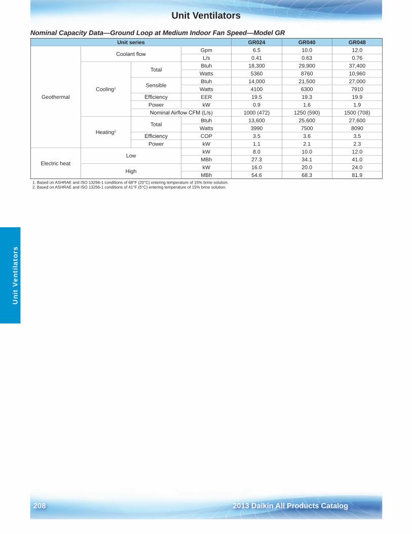
Unit Ventilators
208 2013 Daikin All Products Catalog
Uni
t V
enti
lato
rs
Nominal Capacity Data—Ground Loop at Medium Indoor Fan Speed—Model GR Unit series GR024 GR040 GR048
Geothermal
Coolant flowGpm 6 .5 10 .0 12 .0L/s 0 .41 0 .63 0 .76
Cooling1
TotalBtuh 18,300 29,900 37,400Watts 5360 8760 10,960
SensibleBtuh 14,000 21,500 27,000Watts 4100 6300 7910
Efficiency EER 19 .5 19 .3 19 .9Power kW 0 .9 1 .6 1 .9Nominal Airflow CFM (L/s) 1000 (472) 1250 (590) 1500 (708)
Heating2
TotalBtuh 13,600 25,600 27,600Watts 3990 7500 8090
Efficiency COP 3 .5 3 .6 3 .5Power kW 1 .1 2 .1 2 .3
Electric heatLow
kW 8 .0 10 .0 12 .0MBh 27 .3 34 .1 41 .0
HighkW 16 .0 20 .0 24 .0
MBh 54 .6 68 .3 81 .91 . Based on ASHRAE and ISO 13256-1 conditions of 68°F (20°C) entering temperature of 15% brine solution .2 . Based on ASHRAE and ISO 13256-1 conditions of 41°F (5°C) entering temperature of 15% brine solution .
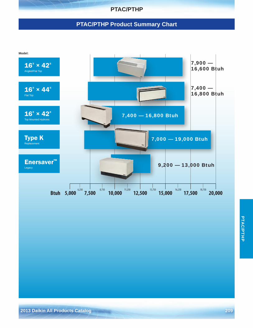
2013 Daikin All Products Catalog 209
PTAC/PTHPP
TAC
/PT
HP
PTAC/PTHP Product Summary Chart
6,250 8,750 11,250 13,750 16,250 18,750
5,000 7,500 10,000 12,500 15,000 17,500 20,000Btuh
16" × 42"Angled/Flat Top
16" × 42"Top Mounted Hydronic
Enersaver™
Legacy
16" × 44"Flat Top
Type KReplacement
Model:
7,400 — 16,800 Btuh
9,200 — 13,000 Btuh
7,000 — 19,000 Btuh
7,900 — 16,600 Btuh
7,400 — 16,800 Btuh
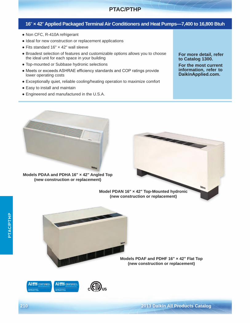
PTAC/PTHP
210 2013 Daikin All Products Catalog
PTA
C/P
TH
P
16" × 42" Applied Packaged Terminal Air Conditioners and Heat Pumps—7,400 to 16,800 Btuh
● Non CFC, R-410A refrigerant● Ideal for new construction or replacement applications● Fits standard 16" × 42" wall sleeve● Broadest selection of features and customizable options allows you to choose
the ideal unit for each space in your building● Top-mounted or Subbase hydronic selections● Meets or exceeds ASHRAE efficiency standards and COP ratings provide
lower operating costs● Exceptionally quiet, reliable cooling/heating operation to maximize comfort● Easy to install and maintain● Engineered and manufactured in the U .S .A .
For more detail, refer to Catalog 1300 .For the most current information, refer to DaikinApplied.com .
Models PDAA and PDHA 16" × 42" Angled Top (new construction or replacement)
Model PDAN 16" × 42" Top-Mounted hydronic (new construction or replacement)
Models PDAF and PDHF 16" × 42" Flat Top (new construction or replacement)
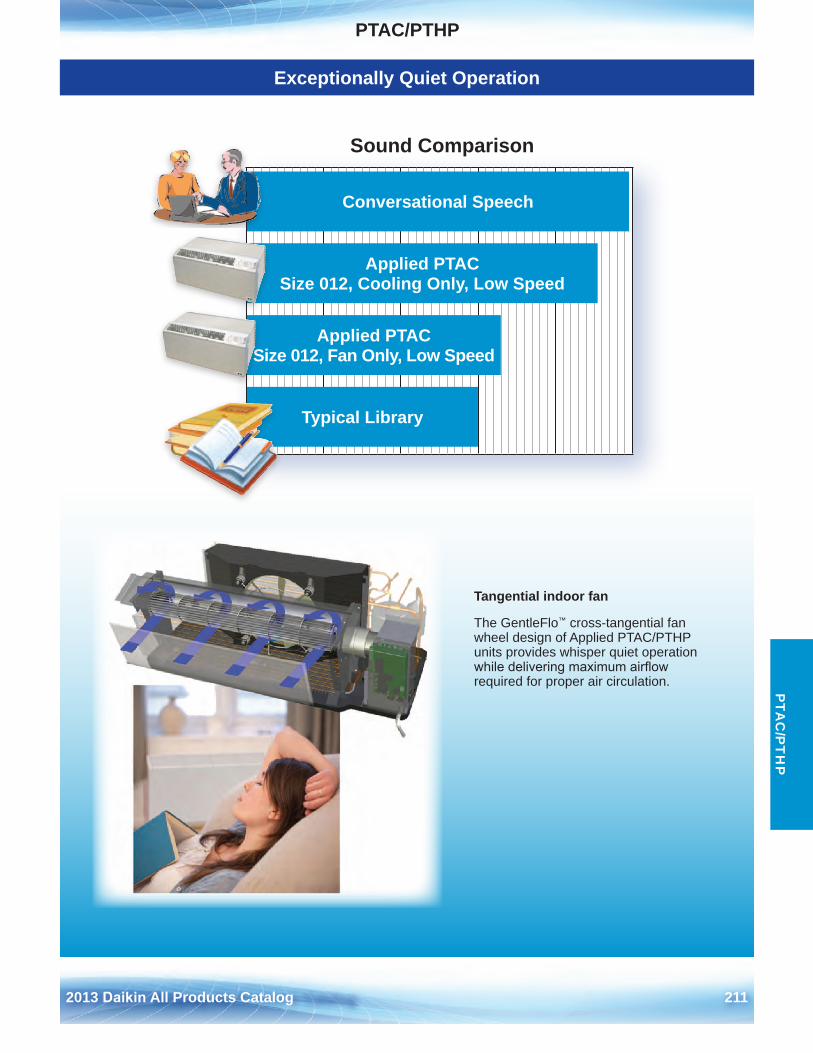
PTAC/PTHP
2013 Daikin All Products Catalog 211
PTA
C/P
TH
P
Exceptionally Quiet Operation
Tangential indoor fan
The GentleFlo™ cross-tangential fan wheel design of Applied PTAC/PTHP units provides whisper quiet operation while delivering maximum airflow required for proper air circulation .
Conversational Speech
Applied PTAC Size 012, Cooling Only, Low Speed
Applied PTAC Size 012, Fan Only, Low Speed
Typical Library
Sound Comparison
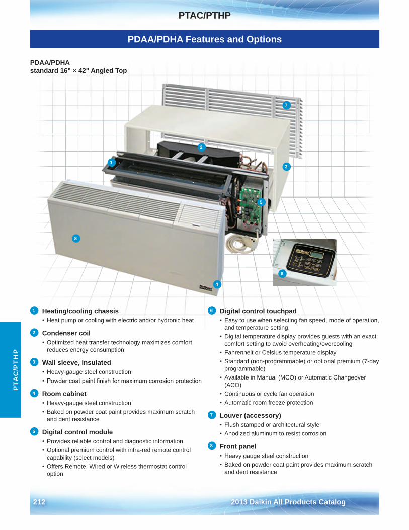
PTAC/PTHP
212 2013 Daikin All Products Catalog
PTA
C/P
TH
P
PDAA/PDHA Features and Options
1 Heating/cooling chassis• Heat pump or cooling with electric and/or hydronic heat
2 Condenser coil• Optimized heat transfer technology maximizes comfort,
reduces energy consumption
3 Wall sleeve, insulated• Heavy-gauge steel construction• Powder coat paint finish for maximum corrosion protection
4 Room cabinet• Heavy-gauge steel construction• Baked on powder coat paint provides maximum scratch
and dent resistance
5 Digital control module• Provides reliable control and diagnostic information• Optional premium control with infra-red remote control
capability (select models)• Offers Remote, Wired or Wireless thermostat control
option
6 Digital control touchpad• Easy to use when selecting fan speed, mode of operation,
and temperature setting .• Digital temperature display provides guests with an exact
comfort setting to avoid overheating/overcooling• Fahrenheit or Celsius temperature display• Standard (non-programmable) or optional premium (7-day
programmable)• Available in Manual (MCO) or Automatic Changeover
(ACO)• Continuous or cycle fan operation• Automatic room freeze protection
7 Louver (accessory)• Flush stamped or architectural style• Anodized aluminum to resist corrosion
8 Front panel• Heavy gauge steel construction• Baked on powder coat paint provides maximum scratch
and dent resistance
PDAA/PDHA standard 16" × 42" Angled Top
3
4
6
7
8
12
5
8
4
1
2
5
3
7
6
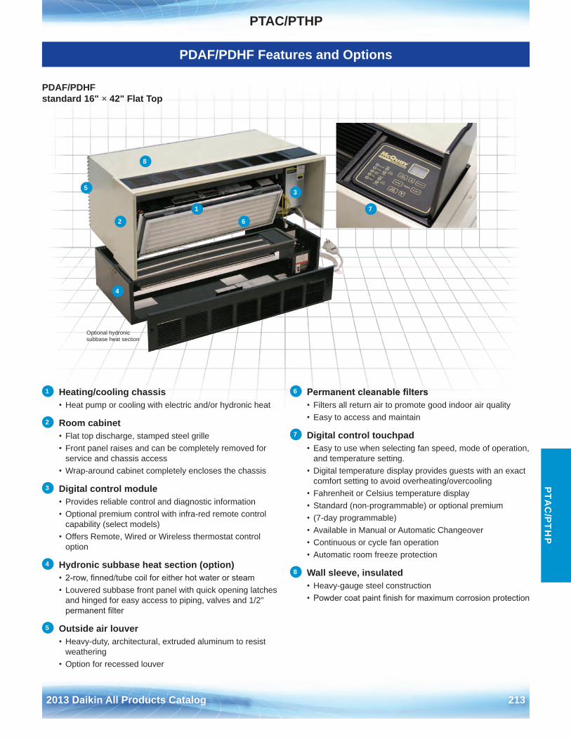
PTAC/PTHP
2013 Daikin All Products Catalog 213
PTA
C/P
TH
P
PDAF/PDHF Features and Options
PDAF/PDHF standard 16" × 42" Flat Top
1 Heating/cooling chassis• Heat pump or cooling with electric and/or hydronic heat
2 Room cabinet• Flat top discharge, stamped steel grille• Front panel raises and can be completely removed for
service and chassis access• Wrap-around cabinet completely encloses the chassis
3 Digital control module• Provides reliable control and diagnostic information• Optional premium control with infra-red remote control
capability (select models)• Offers Remote, Wired or Wireless thermostat control
option
4 Hydronic subbase heat section (option)• 2-row, finned/tube coil for either hot water or steam• Louvered subbase front panel with quick opening latches
and hinged for easy access to piping, valves and 1/2"permanent filter
5 Outside air louver• Heavy-duty, architectural, extruded aluminum to resist
weathering• Option for recessed louver
6 Permanent cleanable filters• Filters all return air to promote good indoor air quality• Easy to access and maintain
7 Digital control touchpad• Easy to use when selecting fan speed, mode of operation,
and temperature setting .• Digital temperature display provides guests with an exact
comfort setting to avoid overheating/overcooling• Fahrenheit or Celsius temperature display• Standard (non-programmable) or optional premium• (7-day programmable)• Available in Manual or Automatic Changeover• Continuous or cycle fan operation• Automatic room freeze protection
8 Wall sleeve, insulated• Heavy-gauge steel construction• Powder coat paint finish for maximum corrosion protection
Optional hydronic subbase heat section
1
2
3
4
5
8
6
7
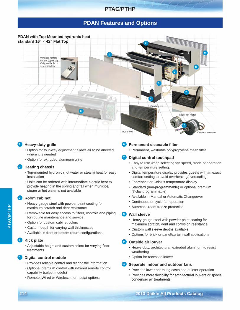
PTAC/PTHP
214 2013 Daikin All Products Catalog
PTA
C/P
TH
P
PDAN Features and Options
1 Heavy-duty grille• Option for four-way adjustment allows air to be directed
where it is needed• Option for extruded aluminum grille
2 Heating chassis• Top-mounted hydronic (hot water or steam) heat for easy
installation• Units can be ordered with intermediate electric heat to
provide heating in the spring and fall when municipal steam or hot water is not available
3 Room cabinet• Heavy-gauge steel with powder paint coating for
maximum scratch and dent resistance• Removable for easy access to filters, controls and piping
for routine maintenance and service• Option for custom cabinet colors• Custom depth for varying wall thicknesses• Available in front or bottom return configurations
4 Kick plate• Adjustable height and custom colors for varying floor
treatments
5 Digital control module• Provides reliable control and diagnostic information• Optional premium control with infrared remote control
capability (select models)• Remote, Wired or Wireless thermostat options
6 Permanent cleanable filter• Permanent, washable polypropylene mesh filter
7 Digital control touchpad• Easy to use when selecting fan speed, mode of operation,
and temperature setting .• Digital temperature display provides guests with an exact
comfort setting to avoid overheating/overcooling• Fahrenheit or Celsius temperature display• Standard (non-programmable) or optional premium
(7-day programmable)• Available in Manual or Automatic Changeover• Continuous or cycle fan operation• Automatic room freeze protection
8 Wall sleeve• Heavy-gauge steel with powder paint coating for
maximum scratch, dent and corrosion resistance• Custom wall sleeve depths available• Options for brick or panel/curtain wall applications
9 Outside air louver• Heavy-duty, architectural, extruded aluminum to resist
weathering• Option for recessed louver
10 Separate indoor and outdoor fans• Provides lower operating costs and quieter operation• Provides more flexibility for architectural louvers or special
condenser air treatments
10
6
1
2
3
4
5
7
8
9
Indoor coil
Outdoor coil
Indoor fan motor
Outdoor fan motor
Wireless remotecontrol (optional)Only available onselect models
PDAN with Top-Mounted hydronic heat standard 16" × 42" Flat Top
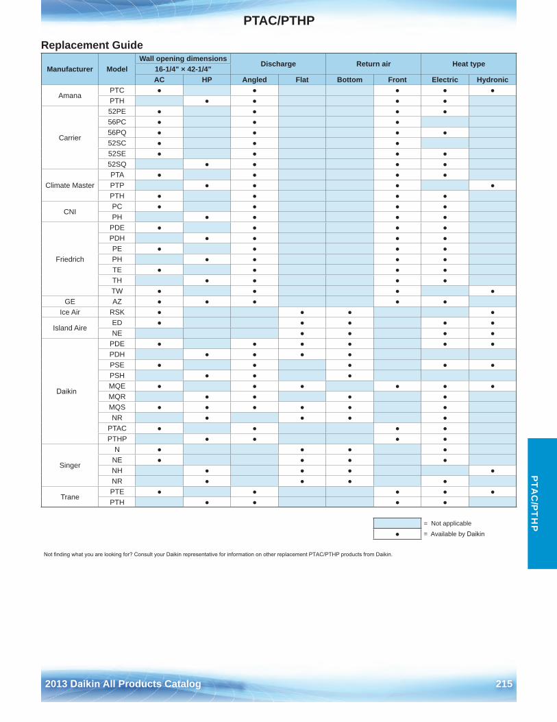
PTAC/PTHP
2013 Daikin All Products Catalog 215
PTA
C/P
TH
P
Replacement Guide
Manufacturer ModelWall opening dimensions
Discharge Return air Heat type16-1/4" × 42-1/4"AC HP Angled Flat Bottom Front Electric Hydronic
AmanaPTC ● ● ● ● ●PTH ● ● ● ●
Carrier
52PE ● ● ● ●56PC ● ● ●56PQ ● ● ● ●52SC ● ● ●52SE ● ● ● ●52SQ ● ● ● ●
Climate MasterPTA ● ● ● ●PTP ● ● ● ●PTH ● ● ● ●
CNIPC ● ● ● ●PH ● ● ● ●
Friedrich
PDE ● ● ● ●PDH ● ● ● ●PE ● ● ● ●PH ● ● ● ●TE ● ● ● ●TH ● ● ● ●TW ● ● ● ●
GE AZ ● ● ● ● ●Ice Air RSK ● ● ● ●
Island AireED ● ● ● ● ●NE ● ● ● ●
Daikin
PDE ● ● ● ● ● ●PDH ● ● ● ●PSE ● ● ● ● ●PSH ● ● ●MQE ● ● ● ● ● ●MQR ● ● ● ●MQS ● ● ● ● ● ●NR ● ● ● ●
PTAC ● ● ● ●PTHP ● ● ● ●
Singer
N ● ● ● ●NE ● ● ● ●NH ● ● ● ●NR ● ● ● ●
TranePTE ● ● ● ● ●PTH ● ● ● ●
●= Not applicable= Available by Daikin
Not finding what you are looking for? Consult your Daikin representative for information on other replacement PTAC/PTHP products from Daikin.
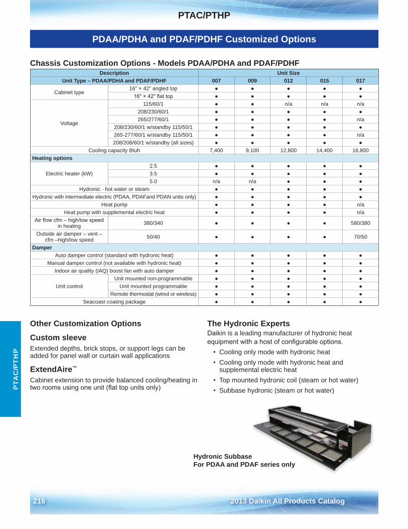
PTAC/PTHP
216 2013 Daikin All Products Catalog
PTA
C/P
TH
P
PDAA/PDHA and PDAF/PDHF Customized Options
Chassis Customization Options - Models PDAA/PDHA and PDAF/PDHF Description Unit Size
Unit Type – PDAA/PDHA and PDAF/PDHF 007 009 012 015 017
Cabinet type16" × 42" angled top ● ● ● ● ●
16" × 42" flat top ● ● ● ● ●
Voltage
115/60/1 ● ● n/a n/a n/a208/230/60/1 ● ● ● ● ●265/277/60/1 ● ● ● ● n/a
208/230/60/1 w/standby 115/50/1 ● ● ● ● ●265-277/60/1 w/standby 115/50/1 ● ● ● ● n/a208/208/60/1 w/standby (all sizes) ● ● ● ● ●
Cooling capacity Btuh 7,400 9,100 12,800 14,400 16,800Heating options
Electric heater (kW)2 .5 ● ● ● ● ●3 .5 ● ● ● ● ●5 .0 n/a n/a ● ● ●
Hydronic - hot water or steam ● ● ● ● ●Hydronic with intermediate electric (PDAA, PDAFand PDAN units only) ● ● ● ● ●
Heat pump ● ● ● ● n/aHeat pump with supplemental electric heat ● ● ● ● n/a
Air flow cfm – high/low speed in heating 380/340 ● ● ● ● 580/380
Outside air damper – vent – cfm –high/low speed 50/40 ● ● ● ● 70/50
DamperAuto damper control (standard with hydronic heat) ● ● ● ● ●
Manual damper control (not available with hydronic heat) ● ● ● ● ●Indoor air quality (IAQ) boost fan with auto damper ● ● ● ● ●
Unit controlUnit mounted non-programmable ● ● ● ● ●
Unit mounted programmable ● ● ● ● ●Remote thermostat (wired or wireless) ● ● ● ● ●
Seacoast coating package ● ● ● ● ●
Other Customization Options
Custom sleeveExtended depths, brick stops, or support legs can be added for panel wall or curtain wall applications
ExtendAire™
Cabinet extension to provide balanced cooling/heating in two rooms using one unit (flat top units only)
The Hydronic ExpertsDaikin is a leading manufacturer of hydronic heat equipment with a host of configurable options.
• Cooling only mode with hydronic heat• Cooling only mode with hydronic heat and
supplemental electric heat• Top mounted hydronic coil (steam or hot water)• Subbase hydronic (steam or hot water)
Hydronic Subbase For PDAA and PDAF series only
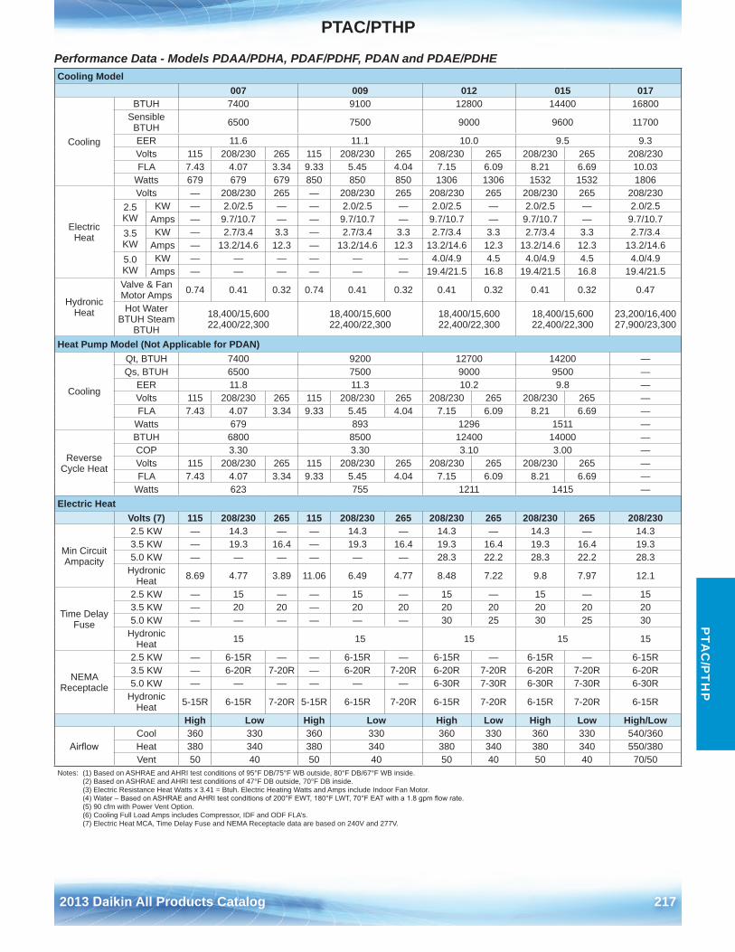
PTAC/PTHP
2013 Daikin All Products Catalog 217
PTA
C/P
TH
P
Performance Data - Models PDAA/PDHA, PDAF/PDHF, PDAN and PDAE/PDHE Cooling Model
007 009 012 015 017
Cooling
BTUH 7400 9100 12800 14400 16800Sensible
BTUH 6500 7500 9000 9600 11700
EER 11 .6 11 .1 10 .0 9 .5 9 .3Volts 115 208/230 265 115 208/230 265 208/230 265 208/230 265 208/230FLA 7 .43 4 .07 3 .34 9 .33 5 .45 4 .04 7 .15 6 .09 8 .21 6 .69 10 .03
Watts 679 679 679 850 850 850 1306 1306 1532 1532 1806
ElectricHeat
Volts — 208/230 265 — 208/230 265 208/230 265 208/230 265 208/2302 .5 KW
KW — 2 .0/2 .5 — — 2 .0/2 .5 — 2 .0/2 .5 — 2 .0/2 .5 — 2 .0/2 .5Amps — 9 .7/10 .7 — — 9 .7/10 .7 — 9 .7/10 .7 — 9 .7/10 .7 — 9 .7/10 .7
3 .5 KW
KW — 2 .7/3 .4 3 .3 — 2 .7/3 .4 3 .3 2 .7/3 .4 3 .3 2 .7/3 .4 3 .3 2 .7/3 .4Amps — 13 .2/14 .6 12 .3 — 13 .2/14 .6 12 .3 13 .2/14 .6 12 .3 13 .2/14 .6 12 .3 13 .2/14 .6
5 .0 KW
KW — — — — — — 4 .0/4 .9 4 .5 4 .0/4 .9 4 .5 4 .0/4 .9Amps — — — — — — 19 .4/21 .5 16 .8 19 .4/21 .5 16 .8 19 .4/21 .5
Hydronic Heat
Valve & Fan Motor Amps 0 .74 0 .41 0 .32 0 .74 0 .41 0 .32 0 .41 0 .32 0 .41 0 .32 0 .47
Hot Water BTUH Steam
BTUH
18,400/15,600 22,400/22,300
18,400/15,600 22,400/22,300
18,400/15,600 22,400/22,300
18,400/15,600 22,400/22,300
23,200/16,400 27,900/23,300
Heat Pump Model (Not Applicable for PDAN)
Cooling
Qt, BTUH 7400 9200 12700 14200 —Qs, BTUH 6500 7500 9000 9500 —
EER 11 .8 11 .3 10 .2 9 .8 —Volts 115 208/230 265 115 208/230 265 208/230 265 208/230 265 —FLA 7 .43 4 .07 3 .34 9 .33 5 .45 4 .04 7 .15 6 .09 8 .21 6 .69 —
Watts 679 893 1296 1511 —
Reverse Cycle Heat
BTUH 6800 8500 12400 14000 —COP 3 .30 3 .30 3 .10 3 .00 —Volts 115 208/230 265 115 208/230 265 208/230 265 208/230 265 —FLA 7 .43 4 .07 3 .34 9 .33 5 .45 4 .04 7 .15 6 .09 8 .21 6 .69 —
Watts 623 755 1211 1415 —Electric Heat
Volts (7) 115 208/230 265 115 208/230 265 208/230 265 208/230 265 208/230
Min Circuit Ampacity
2 .5 KW — 14 .3 — — 14 .3 — 14 .3 — 14 .3 — 14 .33 .5 KW — 19 .3 16 .4 — 19 .3 16 .4 19 .3 16 .4 19 .3 16 .4 19 .35 .0 KW — — — — — — 28 .3 22 .2 28 .3 22 .2 28 .3
Hydronic Heat 8 .69 4 .77 3 .89 11 .06 6 .49 4 .77 8 .48 7 .22 9 .8 7 .97 12 .1
Time Delay Fuse
2 .5 KW — 15 — — 15 — 15 — 15 — 153 .5 KW — 20 20 — 20 20 20 20 20 20 205 .0 KW — — — — — — 30 25 30 25 30
Hydronic Heat 15 15 15 15 15
NEMAReceptacle
2 .5 KW — 6-15R — — 6-15R — 6-15R — 6-15R — 6-15R3 .5 KW — 6-20R 7-20R — 6-20R 7-20R 6-20R 7-20R 6-20R 7-20R 6-20R5 .0 KW — — — — — — 6-30R 7-30R 6-30R 7-30R 6-30R
Hydronic Heat 5-15R 6-15R 7-20R 5-15R 6-15R 7-20R 6-15R 7-20R 6-15R 7-20R 6-15R
High Low High Low High Low High Low High/Low
AirflowCool 360 330 360 330 360 330 360 330 540/360Heat 380 340 380 340 380 340 380 340 550/380Vent 50 40 50 40 50 40 50 40 70/50
Notes: (1) Based on ASHRAE and AHRI test conditions of 95°F DB/75°F WB outside, 80°F DB/67°F WB inside . (2) Based on ASHRAE and AHRI test conditions of 47°F DB outside, 70°F DB inside . (3) Electric Resistance Heat Watts x 3 .41 = Btuh . Electric Heating Watts and Amps include Indoor Fan Motor . (4) Water – Based on ASHRAE and AHRI test conditions of 200°F EWT, 180°F LWT, 70°F EAT with a 1.8 gpm flow rate. (5) 90 cfm with Power Vent Option . (6) Cooling Full Load Amps includes Compressor, IDF and ODF FLA’s . (7) Electric Heat MCA, Time Delay Fuse and NEMA Receptacle data are based on 240V and 277V .
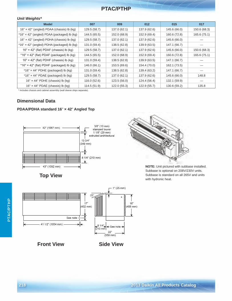
PTAC/PTHP
218 2013 Daikin All Products Catalog
PTA
C/P
TH
P
Unit Weights*
Dimensional Data
PDAA/PDHA standard 16" × 42" Angled Top
Model 007 009 012 015 01716" × 42" (angled) PDAA (chassis) lb (kg) 129 .5 (58 .7) 137 .0 (62 .1) 137 .9 (62 .6) 145 .6 (66 .0) 150 .6 (68 .3)
*16" × 42" (angled) PDAA (packaged) lb (kg) 144 .5 (65 .5) 152 .0 (68 .9) 152 .9 (69 .4) 160 .6 (72 .8) 165 .6 (75 .1)
16" × 42" (angled) PDHA (chassis) lb (kg) 129 .5 (58 .7) 137 .0 (62 .1) 137 .9 (62 .6) 145 .6 (66 .0) —
*16" × 42" (angled) PDHA (packaged) lb (kg) 131 .0 (59 .4) 138 .5 (62 .8) 139 .9 (63 .5) 147 .1 (66 .7) —
16" × 42" (flat) PDAF (chassis) lb (kg) 129 .5 (58 .7) 137 .0 (62 .1) 137 .9 (62 .6) 145 .6 (66 .0) 150 .6 (68 .3)
*16" × 42" (flat) PDAF (packaged) lb (kg) 144 .5 (65 .5) 152 .0 (68 .9) 152 .9 (69 .4) 160 .6 (72 .8) 165 .6 (75 .1)
16" × 42" (flat) PDHF (chassis) lb (kg) 131 .0 (59 .4) 138 .5 (62 .8) 139 .9 (63 .5) 147 .1 (66 .7) —
*16" × 42" (flat) PDHF (packaged) lb (kg) 146 .0 (66 .1) 153 .5 (69 .6) 154 .4 (70 .0) 162 .1 (73 .5) —
*16" × 44" PDHE (packaged) lb (kg) 131 .0 (59 .4) 138 .5 (62 .8) 139 .4 (63 .2) 147 .1 (66 .7) —
*16" × 44" PDAE (packaged) lb (kg) 129 .5 (58 .7) 137 .0 (62 .1) 137 .9 (62 .6) 145 .6 (66 .0) 148 .8
16" × 44" PDHE (chassis) lb (kg) 116 .0 (52 .6) 123 .5 (56 .0) 124 .4 (56 .4) 132 .1 (59 .9) —
16" × 44" PDAE (chassis) lb (kg) 114 .5 (51 .9) 122 .0 (55 .3) 122 .9 (55 .7) 130 .6 (59 .2) 135 .8* Includes chassis and cabinet assembly (wall sleeve ships separate) .
Top View
Front View Side View
NOTE: Unit pictured with subbase installed.Subbase is optional on 208V/230V units.Subbase is standard on all 265V and unitswith hydronic heat.
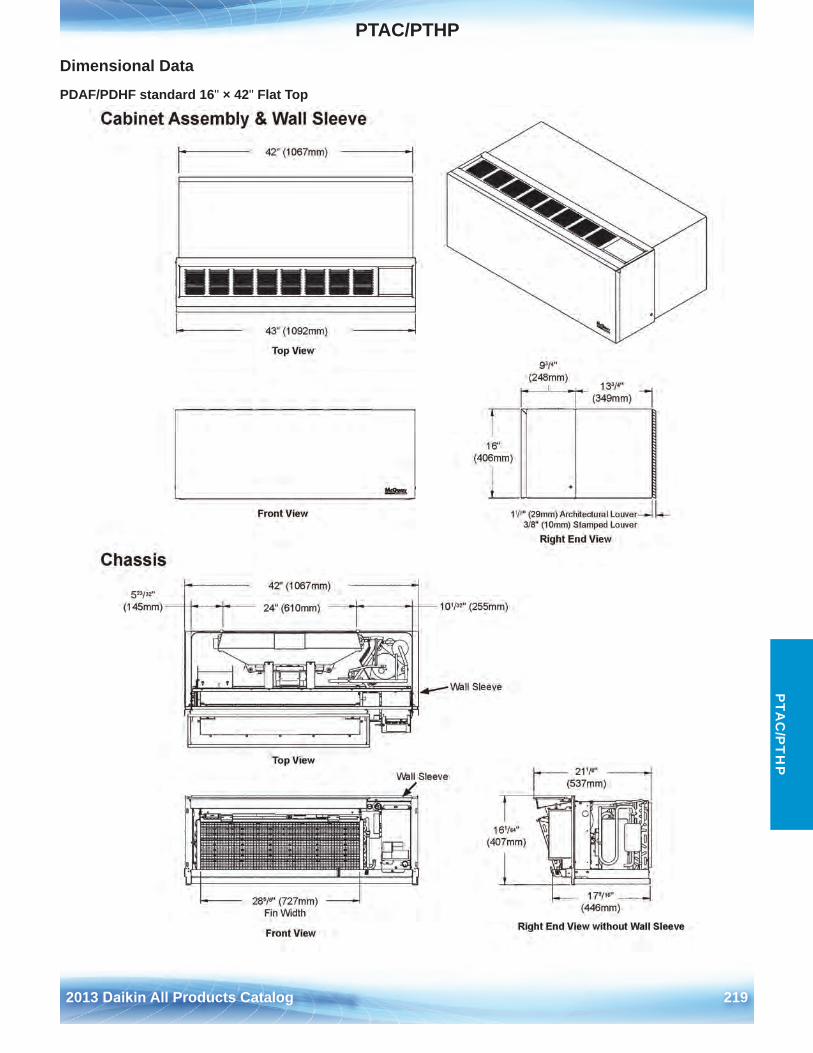
PTAC/PTHP
2013 Daikin All Products Catalog 219
PTA
C/P
TH
P
Dimensional Data
PDAF/PDHF standard 16" × 42" Flat Top
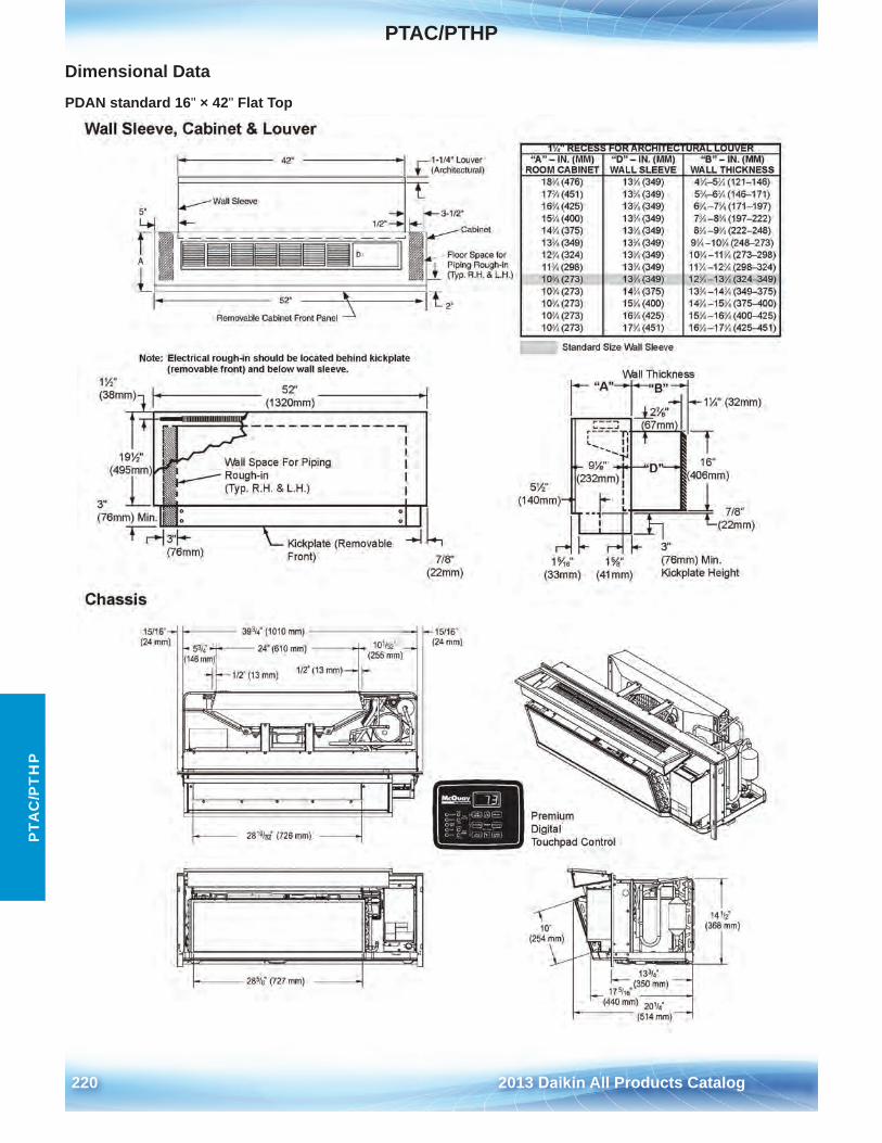
PTAC/PTHP
220 2013 Daikin All Products Catalog
PTA
C/P
TH
P
Dimensional Data
PDAN standard 16" × 42" Flat Top
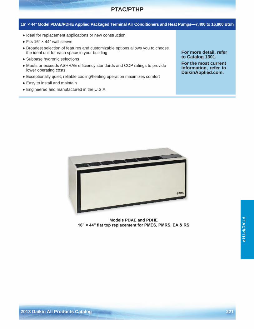
PTAC/PTHP
2013 Daikin All Products Catalog 221
PTA
C/P
TH
P
Models PDAE and PDHE 16" × 44" flat top replacement for PMES, PMRS, EA & RS
16" × 44" Model PDAE/PDHE Applied Packaged Terminal Air Conditioners and Heat Pumps—7,400 to 16,800 Btuh
● Ideal for replacement applications or new construction● Fits 16" × 44" wall sleeve● Broadest selection of features and customizable options allows you to choose
the ideal unit for each space in your building● Subbase hydronic selections● Meets or exceeds ASHRAE efficiency standards and COP ratings to provide
lower operating costs● Exceptionally quiet, reliable cooling/heating operation maximizes comfort● Easy to install and maintain● Engineered and manufactured in the U .S .A .
For more detail, refer to Catalog 1301 .For the most current information, refer to DaikinApplied.com .
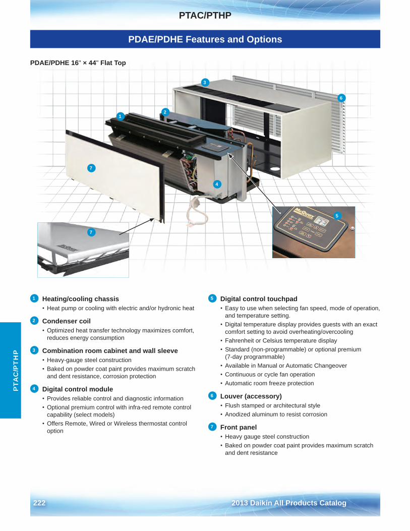
PTAC/PTHP
222 2013 Daikin All Products Catalog
PTA
C/P
TH
P
PDAE/PDHE 16" × 44" Flat Top
1 Heating/cooling chassis• Heat pump or cooling with electric and/or hydronic heat
2 Condenser coil• Optimized heat transfer technology maximizes comfort,
reduces energy consumption
3 Combination room cabinet and wall sleeve• Heavy-gauge steel construction• Baked on powder coat paint provides maximum scratch
and dent resistance, corrosion protection
4 Digital control module• Provides reliable control and diagnostic information• Optional premium control with infra-red remote control
capability (select models)• Offers Remote, Wired or Wireless thermostat control
option
5 Digital control touchpad• Easy to use when selecting fan speed, mode of operation,
and temperature setting .• Digital temperature display provides guests with an exact
comfort setting to avoid overheating/overcooling• Fahrenheit or Celsius temperature display• Standard (non-programmable) or optional premium
(7-day programmable)• Available in Manual or Automatic Changeover• Continuous or cycle fan operation• Automatic room freeze protection
6 Louver (accessory)• Flush stamped or architectural style• Anodized aluminum to resist corrosion
7 Front panel• Heavy gauge steel construction• Baked on powder coat paint provides maximum scratch
and dent resistance
3
4
6
7
1 2
5
7
3
4
6
7
1 2
5
7
7
7
12
3
6
5
4
PDAE/PDHE Features and Options
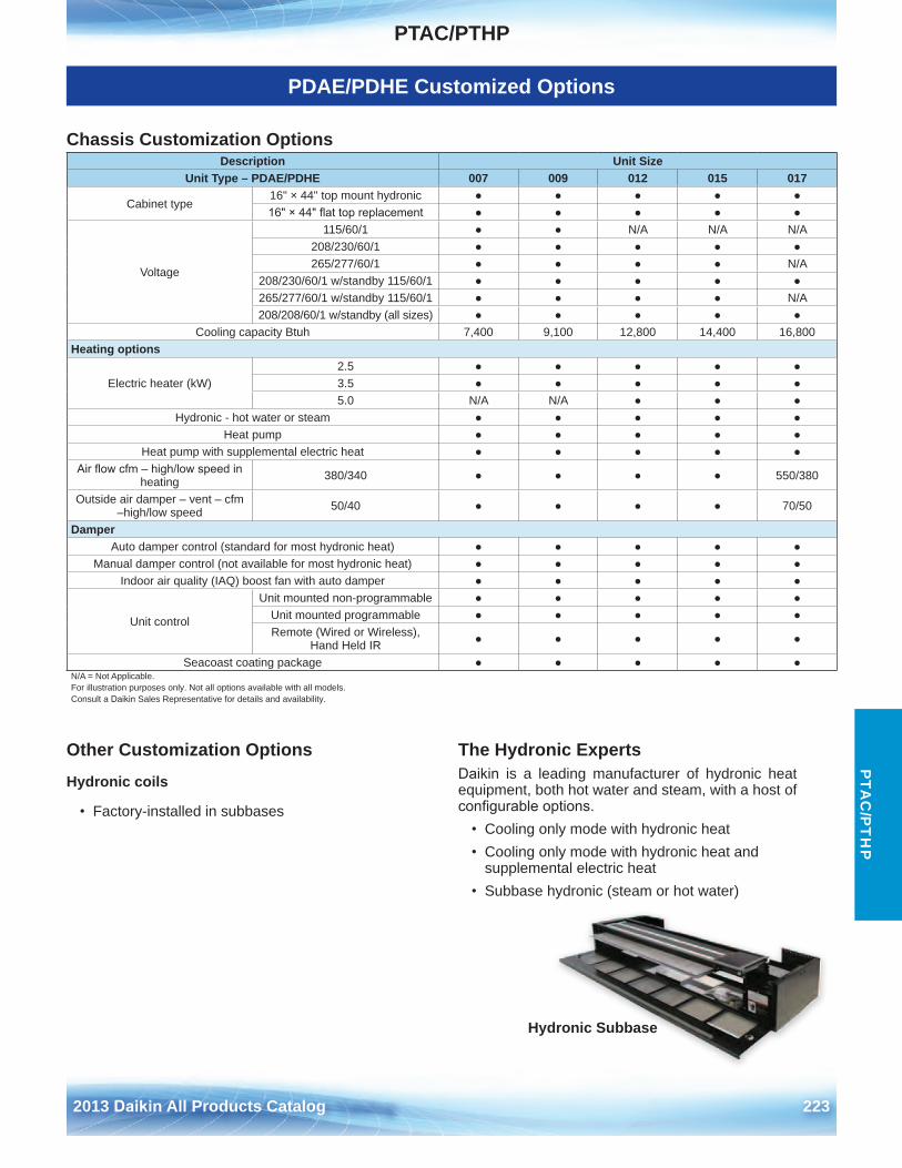
PTAC/PTHP
2013 Daikin All Products Catalog 223
PTA
C/P
TH
P
PDAE/PDHE Customized Options
Chassis Customization Options Description Unit Size
Unit Type – PDAE/PDHE 007 009 012 015 017
Cabinet type16" × 44" top mount hydronic ● ● ● ● ●16" × 44" flat top replacement ● ● ● ● ●
Voltage
115/60/1 ● ● N/A N/A N/A208/230/60/1 ● ● ● ● ●265/277/60/1 ● ● ● ● N/A
208/230/60/1 w/standby 115/60/1 ● ● ● ● ●265/277/60/1 w/standby 115/60/1 ● ● ● ● N/A208/208/60/1 w/standby (all sizes) ● ● ● ● ●
Cooling capacity Btuh 7,400 9,100 12,800 14,400 16,800Heating options
Electric heater (kW)2 .5 ● ● ● ● ●3 .5 ● ● ● ● ●5 .0 N/A N/A ● ● ●
Hydronic - hot water or steam ● ● ● ● ●Heat pump ● ● ● ● ●
Heat pump with supplemental electric heat ● ● ● ● ●Air flow cfm – high/low speed in
heating 380/340 ● ● ● ● 550/380
Outside air damper – vent – cfm –high/low speed 50/40 ● ● ● ● 70/50
DamperAuto damper control (standard for most hydronic heat) ● ● ● ● ●
Manual damper control (not available for most hydronic heat) ● ● ● ● ●Indoor air quality (IAQ) boost fan with auto damper ● ● ● ● ●
Unit control
Unit mounted non-programmable ● ● ● ● ●Unit mounted programmable ● ● ● ● ●Remote (Wired or Wireless),
Hand Held IR ● ● ● ● ●
● ● ● ● ●Seacoast coating packageN/A = Not Applicable .For illustration purposes only . Not all options available with all models . Consult a Daikin Sales Representative for details and availability .
Other Customization Options
Hydronic coils
• Factory-installed in subbases
The Hydronic ExpertsDaikin is a leading manufacturer of hydronic heat equipment, both hot water and steam, with a host of configurable options.
• Cooling only mode with hydronic heat• Cooling only mode with hydronic heat and
supplemental electric heat• Subbase hydronic (steam or hot water)
Hydronic Subbase
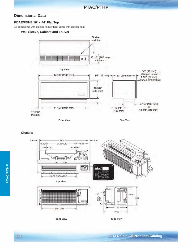
PTAC/PTHP
224 2013 Daikin All Products Catalog
PTA
C/P
TH
P
Dimensional Data
PDAE/PDHE 16" × 44" Flat TopAir conditioner with electric heat or heat pump with electric heat
Top View
Front View Side View
Wall Sleeve, Cabinet and Louver
Top View
Front View Side View
Chassis
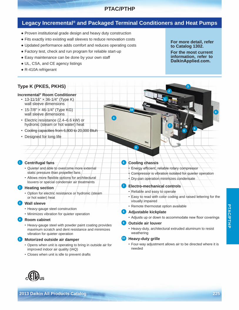
PTAC/PTHP
2013 Daikin All Products Catalog 225
PTA
C/P
TH
P
Type K (PKES, PKHS)
Incremental® Room Conditioner • 13-11/16" × 36-1/4" (Type K)
wall sleeve dimensions• 15-7/8" × 46-1/4" (Type KG)
wall sleeve dimensions• Electric resistance (2 .4–6 .6 kW) or
hydronic (steam or hot water) heat• Cooling capacities from 6,800 to 20,000 Btuh• Designed for long life
1 Centrifugal fans• Quieter and able to overcome more external
static pressure than propeller fans• Allows more flexible options for architectural
louvers or special condenser air treatments2 Heating section
• Option for electric resistance or hydronic (steamor hot water) heat
3 Wall sleeve • Heavy-gauge steel construction• Minimizes vibration for quieter operation
4 Room cabinet • Heavy-gauge steel with powder paint coating provides
maximum scratch and dent resistance and minimizes vibration for quieter operation
5 Motorized outside air damper• Opens when unit is operating to bring in outside air for
improved indoor air quality (IAQ)• Closes when unit is idle to prevent drafts
6 Cooling chassis• Energy efficient, reliable rotary compressor• Compressor is vibration isolated for quieter operation• Dry-pan operation minimizes condensate
7 Electro-mechanical controls• Reliable and easy to operate• Easy to read with color coding and raised lettering for the
visually impaired• Remote thermostat option available
8 Adjustable kickplate • Adjusts up or down to accommodate new floor coverings
9 Outside air louver• Heavy-duty, architectural extruded aluminum to resist
weathering10 Heavy-duty grille
• Four-way adjustment allows air to be directed where it isneeded
Legacy Incremental® and Packaged Terminal Conditioners and Heat Pumps
● Proven institutional grade design and heavy duty construction● Fits exactly into existing wall sleeves to reduce renovation costs● Updated performance adds comfort and reduces operating costs● Factory test, check and run program for reliable start-up● Easy maintenance can be done by your own staff● UL, CSA, and CE agency listings● R-410A refrigerant
For more detail, refer to Catalog 1302 .For the most current information, refer to DaikinApplied.com .
1
23
4
56
7
8
910
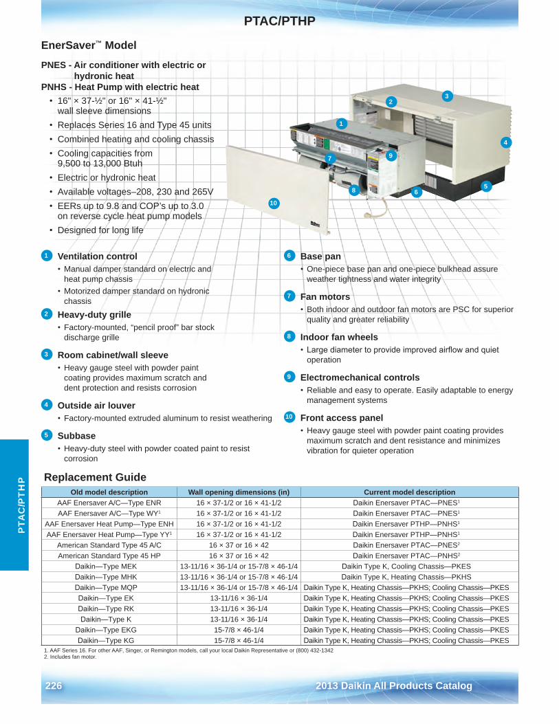
PTAC/PTHP
226 2013 Daikin All Products Catalog
PTA
C/P
TH
P
EnerSaver™ Model
PNES - Air conditioner with electric or hydronic heat
PNHS - Heat Pump with electric heat • 16" × 37-½" or 16" × 41-½"
wall sleeve dimensions• Replaces Series 16 and Type 45 units• Combined heating and cooling chassis• Cooling capacities from
9,500 to 13,000 Btuh• Electric or hydronic heat• Available voltages–208, 230 and 265V• EERs up to 9 .8 and COP’s up to 3 .0
on reverse cycle heat pump models• Designed for long life
1 Ventilation control• Manual damper standard on electric and
heat pump chassis• Motorized damper standard on hydronic
chassis 2 Heavy-duty grille
• Factory-mounted, “pencil proof” bar stockdischarge grille
3 Room cabinet/wall sleeve • Heavy gauge steel with powder paint
coating provides maximum scratch and dent protection and resists corrosion
4 Outside air louver • Factory-mounted extruded aluminum to resist weathering
5 Subbase• Heavy-duty steel with powder coated paint to resist
corrosion
6 Base pan• One-piece base pan and one-piece bulkhead assure
weather tightness and water integrity
7 Fan motors• Both indoor and outdoor fan motors are PSC for superior
quality and greater reliability
8 Indoor fan wheels • Large diameter to provide improved airflow and quiet
operation
9 Electromechanical controls• Reliable and easy to operate . Easily adaptable to energy
management systems
10 Front access panel • Heavy gauge steel with powder paint coating provides
maximum scratch and dent resistance and minimizes vibration for quieter operation
Replacement GuideOld model description Wall opening dimensions (in) Current model description
AAF Enersaver A/C—Type ENR 16 × 37-1/2 or 16 × 41-1/2 Daikin Enersaver PTAC—PNES1
AAF Enersaver A/C—Type WY1 16 × 37-1/2 or 16 × 41-1/2 Daikin Enersaver PTAC—PNES1
AAF Enersaver Heat Pump—Type ENH 16 × 37-1/2 or 16 × 41-1/2 Daikin Enersaver PTHP—PNHS1
AAF Enersaver Heat Pump—Type YY1 16 × 37-1/2 or 16 × 41-1/2 Daikin Enersaver PTHP—PNHS1
American Standard Type 45 A/C 16 × 37 or 16 × 42 Daikin Enersaver PTAC—PNES2
American Standard Type 45 HP 16 × 37 or 16 × 42 Daikin Enersaver PTAC—PNHS2
Daikin—Type MEK 13-11/16 × 36-1/4 or 15-7/8 × 46-1/4 Daikin Type K, Cooling Chassis—PKESDaikin—Type MHK 13-11/16 × 36-1/4 or 15-7/8 × 46-1/4 Daikin Type K, Heating Chassis—PKHSDaikin—Type MQP 13-11/16 × 36-1/4 or 15-7/8 × 46-1/4 Daikin Type K, Heating Chassis—PKHS; Cooling Chassis—PKESDaikin—Type EK 13-11/16 × 36-1/4 Daikin Type K, Heating Chassis—PKHS; Cooling Chassis—PKESDaikin—Type RK 13-11/16 × 36-1/4 Daikin Type K, Heating Chassis—PKHS; Cooling Chassis—PKESDaikin—Type K 13-11/16 × 36-1/4 Daikin Type K, Heating Chassis—PKHS; Cooling Chassis—PKES
Daikin—Type EKG 15-7/8 × 46-1/4 Daikin Type K, Heating Chassis—PKHS; Cooling Chassis—PKESDaikin—Type KG 15-7/8 × 46-1/4 Daikin Type K, Heating Chassis—PKHS; Cooling Chassis—PKES
1 . AAF Series 16 . For other AAF, Singer, or Remington models, call your local Daikin Representative or (800) 432-13422 . Includes fan motor .
10
7
8 6
9
1
23
4
5
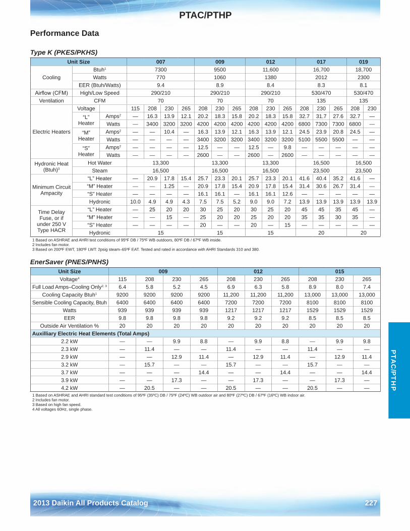
PTAC/PTHP
2013 Daikin All Products Catalog 227
PTA
C/P
TH
P
Performance Data
Type K (PKES/PKHS)
EnerSaver (PNES/PNHS)
Unit Size 007 009 012 017 019
CoolingBtuh1 7300 9500 11,600 16,700 18,700Watts 770 1060 1380 2012 2300
EER (Btuh/Watts) 9 .4 8 .9 8 .4 8 .3 8 .1Airflow (CFM) High/Low Speed 290/210 290/210 290/210 530/470 530/470
Ventilation CFM 70 70 70 135 135
Electric Heaters
Voltage 115 208 230 265 208 230 265 208 230 265 208 230 265 208 230“L”
HeaterAmps2 — 16 .3 13 .9 12 .1 20 .2 18 .3 15 .8 20 .2 18 .3 15 .8 32 .7 31 .7 27 .6 32 .7 —Watts — 3400 3200 3200 4200 4200 4200 4200 4200 4200 6800 7300 7300 6800 —
“M” Heater
Amps2 — — 10 .4 — 16 .3 13 .9 12 .1 16 .3 13 .9 12 .1 24 .5 23 .9 20 .8 24 .5 —Watts — — — — 3400 3200 3200 3400 3200 3200 5100 5500 5500 — —
“S” Heater
Amps2 — — — — 12 .5 — — 12 .5 — 9 .8 — — — — —Watts — — — — 2600 — — 2600 — 2600 — — — — —
Hydronic Heat (Btuh)3
Hot Water 13,300 13,300 13,300 16,500 16,500Steam 16,500 16,500 16,500 23,500 23,500
Minimum Circuit Ampacity
“L” Heater — 20 .9 17 .8 15 .4 25 .7 23 .3 20 .1 25 .7 23 .3 20 .1 41 .6 40 .4 35 .2 41 .6 —“M” Heater — — 1 .25 — 20 .9 17 .8 15 .4 20 .9 17 .8 15 .4 31 .4 30 .6 26 .7 31 .4 —“S” Heater — — — — 16 .1 16 .1 — 16 .1 16 .1 12 .6 — — — — —Hydronic 10 .0 4 .9 4 .9 4 .3 7 .5 7 .5 5 .2 9 .0 9 .0 7 .2 13 .9 13 .9 13 .9 13 .9 13 .9
Time Delay Fuse, or if
under 250 V Type HACR
“L” Heater — 25 20 20 30 25 20 30 25 20 45 45 35 45 —“M” Heater — — 15 — 25 20 20 25 20 20 35 35 30 35 —“S” Heater — — — — 20 — — 20 — 15 — — — — —Hydronic 15 15 15 20 20
1 Based on ASHRAE and AHRI test conditions of 95ºF DB / 75ºF WB outdoors, 80ºF DB / 67ºF WB inside .2 Includes fan motor .3 Based on 200ºF EWT, 180ºF LWT: 2psig steam–65ºF EAT . Tested and rated in accordance with AHRI Standards 310 and 380 .
Unit Size 009 012 015Voltage4 115 208 230 265 208 230 265 208 230 265
Full Load Amps–Cooling Only2, 3 6 .4 5 .8 5 .2 4 .5 6 .9 6 .3 5 .8 8 .9 8 .0 7 .4Cooling Capacity Btuh1 9200 9200 9200 9200 11,200 11,200 11,200 13,000 13,000 13,000
Sensible Cooling Capacity, Btuh 6400 6400 6400 6400 7200 7200 7200 8100 8100 8100Watts 939 939 939 939 1217 1217 1217 1529 1529 1529EER 9 .8 9 .8 9 .8 9 .8 9 .2 9 .2 9 .2 8 .5 8 .5 8 .5
Outside Air Ventilation % 20 20 20 20 20 20 20 20 20 20Auxilliary Electric Heat Elements (Total Amps)
2 .2 kW — — 9 .9 8 .8 — 9 .9 8 .8 — 9 .9 9 .82 .3 kW — 11 .4 — — 11 .4 — — 11 .4 — —2 .9 kW — — 12 .9 11 .4 — 12 .9 11 .4 — 12 .9 11 .43 .2 kW — 15 .7 — — 15 .7 — — 15 .7 — —3 .7 kW — — — 14 .4 — — 14 .4 — — 14 .43 .9 kW — — 17 .3 — — 17 .3 — — 17 .3 —4 .2 kW — 20 .5 — — 20 .5 — — 20 .5 — —
1 Based on ASHRAE and AHRI standard test conditions of 95ºF (35ºC) DB / 75ºF (24ºC) WB outdoor air and 80ºF (27ºC) DB / 67ºF (16ºC) WB indoor air .2 Includes fan motor .3 Based on high fan speed .4 All voltages 60Hz, single phase .
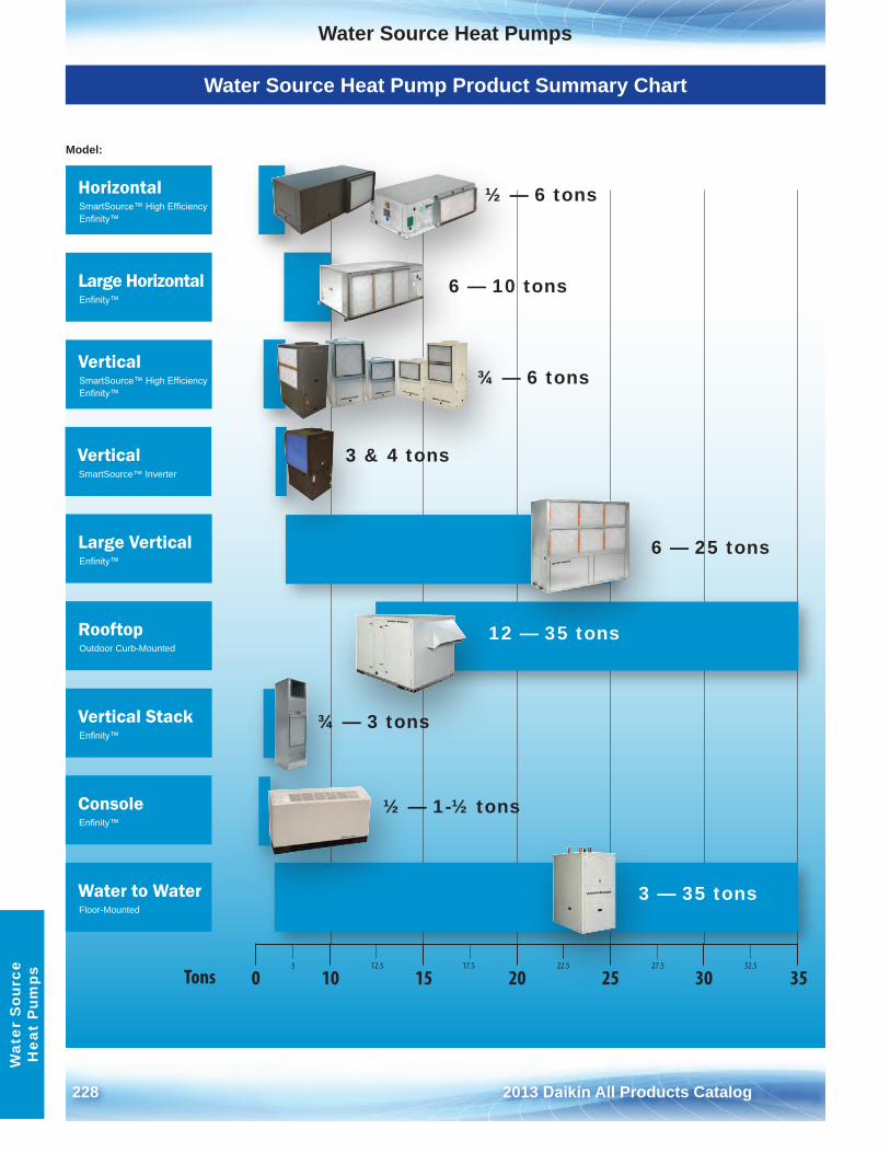
228 2013 Daikin All Products Catalog
Water Source Heat PumpsW
ater
Sou
rce
Hea
t P
umps
Water Source Heat Pump Product Summary Chart
5 12.5 17.5 22.5 27.5 32.5
0 10 15 20 25 30 35Tons
HorizontalSmartSource™ High Efficiency Enfinity™
VerticalSmartSource™ High Efficiency Enfinity™
VerticalSmartSource™ Inverter
RooftopOutdoor Curb-Mounted
ConsoleEnfinity™
Large HorizontalEnfinity™
Large VerticalEnfinity™
Vertical StackEnfinity™
Water to WaterFloor-Mounted
Model:
¾ — 6 tons
6 — 25 tons
3 & 4 tons
¾ — 3 tons
½ — 1-½ tons
½ — 6 tons
6 — 10 tons
12 — 35 tons
3 — 35 tons
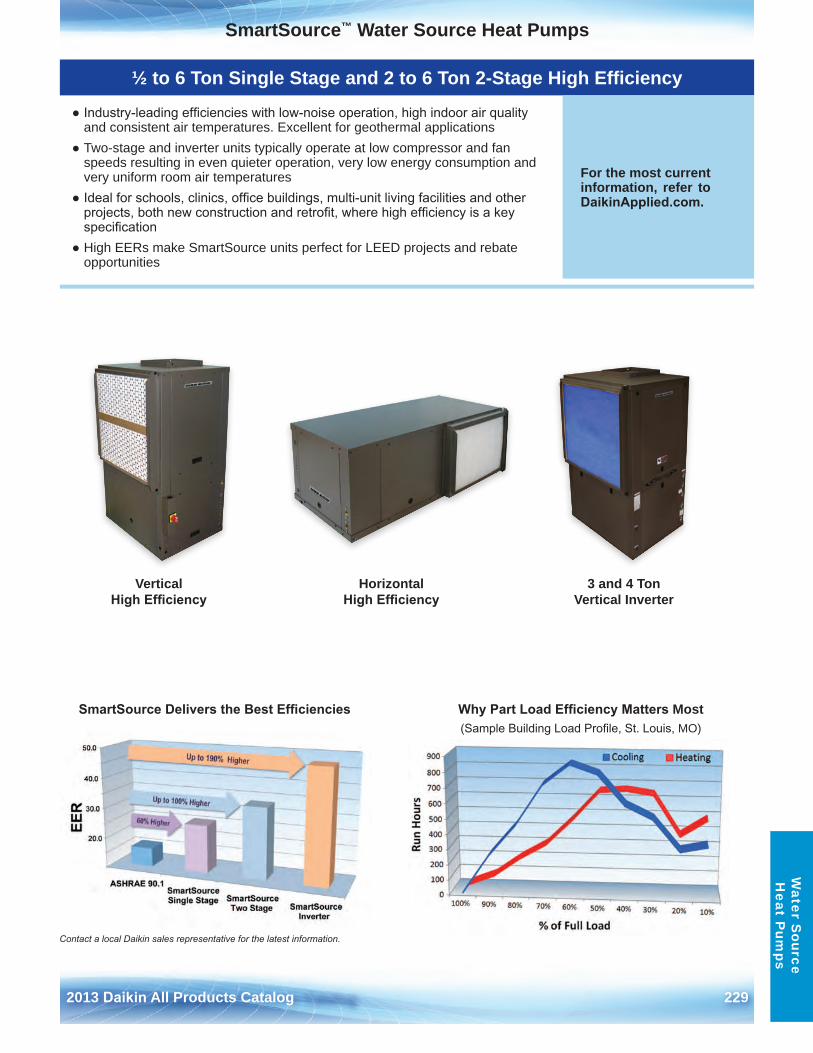
2013 Daikin All Products Catalog 229
SmartSource™ Water Source Heat PumpsW
ater Source
Heat P
umps
Vertical High Efficiency
Horizontal High Efficiency
½ to 6 Ton Single Stage and 2 to 6 Ton 2-Stage High Efficiency
● Industry-leading efficiencies with low-noise operation, high indoor air qualityand consistent air temperatures . Excellent for geothermal applications
● Two-stage and inverter units typically operate at low compressor and fanspeeds resulting in even quieter operation, very low energy consumption andvery uniform room air temperatures
● Ideal for schools, clinics, office buildings, multi-unit living facilities and otherprojects, both new construction and retrofit, where high efficiency is a keyspecification
● High EERs make SmartSource units perfect for LEED projects and rebateopportunities
For the most current information, refer to DaikinApplied.com .
3 and 4 Ton Vertical Inverter
Contact a local Daikin sales representative for the latest information.
SmartSource Delivers the Best Efficiencies Why Part Load Efficiency Matters Most (Sample Building Load Profile, St. Louis, MO)
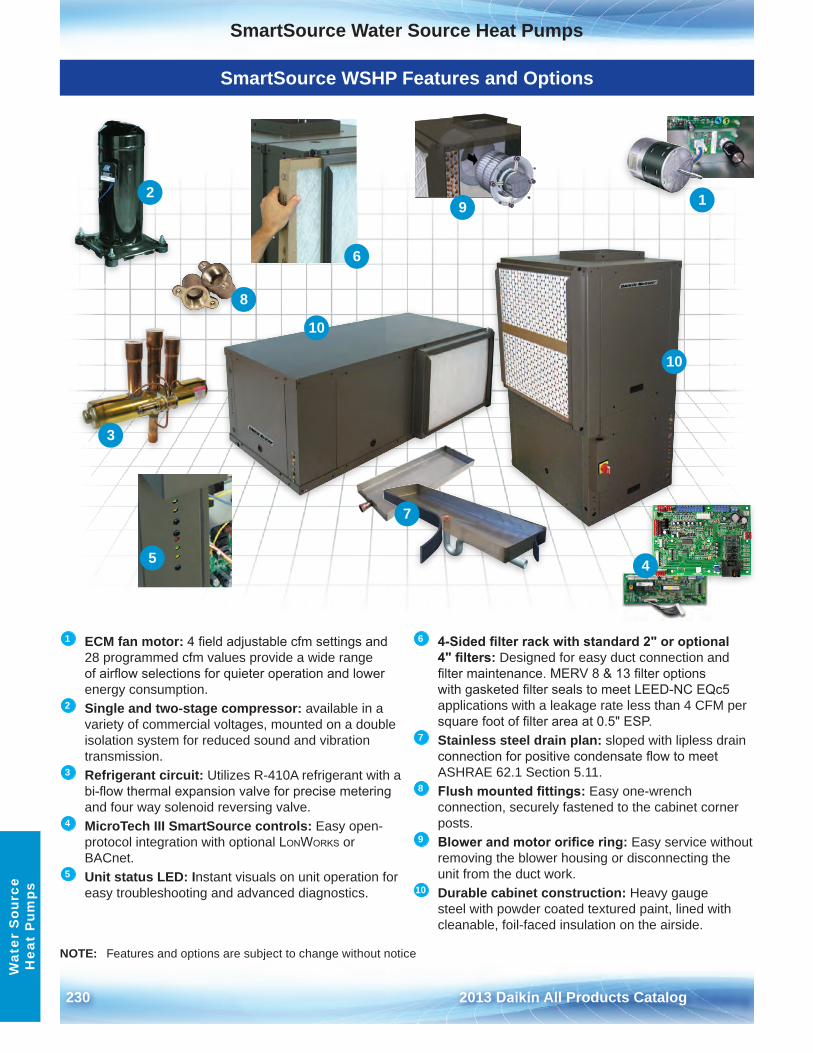
230 2013 Daikin All Products Catalog
SmartSource Water Source Heat PumpsW
ater
Sou
rce
Hea
t P
umps
1 ECM fan motor: 4 field adjustable cfm settings and 28 programmed cfm values provide a wide range of airflow selections for quieter operation and lower energy consumption .
2 Single and two-stage compressor: available in a variety of commercial voltages, mounted on a double isolation system for reduced sound and vibration transmission .
3 Refrigerant circuit: Utilizes R-410A refrigerant with a bi-flow thermal expansion valve for precise metering and four way solenoid reversing valve .
4 MicroTech III SmartSource controls: Easy open-protocol integration with optional LonWorks or BACnet .
5 Unit status LED: Instant visuals on unit operation for easy troubleshooting and advanced diagnostics .
6 4-Sided filter rack with standard 2" or optional 4" filters: Designed for easy duct connection and filter maintenance. MERV 8 & 13 filter options with gasketed filter seals to meet LEED-NC EQc5 applications with a leakage rate less than 4 CFM per square foot of filter area at 0.5" ESP.
7 Stainless steel drain plan: sloped with lipless drain connection for positive condensate flow to meet ASHRAE 62 .1 Section 5 .11 .
8 Flush mounted fittings: Easy one-wrench connection, securely fastened to the cabinet corner posts .
9 Blower and motor orifice ring: Easy service without removing the blower housing or disconnecting the unit from the duct work .
10 Durable cabinet construction: Heavy gauge steel with powder coated textured paint, lined with cleanable, foil-faced insulation on the airside .
SmartSource WSHP Features and Options
NOTE: Features and options are subject to change without notice
9 12
3
45
6
8
10
10
7
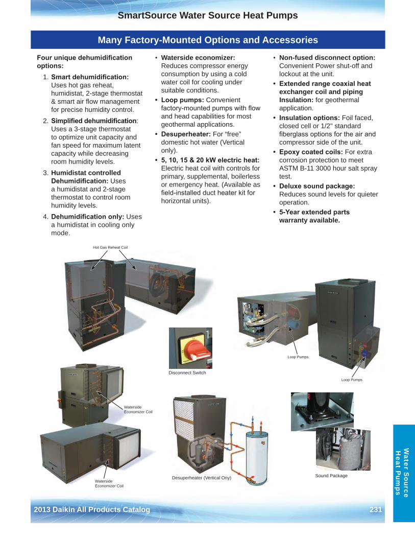
2013 Daikin All Products Catalog 231
SmartSource Water Source Heat PumpsW
ater Source
Heat P
umps
Many Factory-Mounted Options and Accessories
Four unique dehumidification options:
1 . Smart dehumidification: Uses hot gas reheat, humidistat, 2-stage thermostat & smart air flow management for precise humidity control .
2 . Simplified dehumidification: Uses a 3-stage thermostat to optimize unit capacity and fan speed for maximum latent capacity while decreasing room humidity levels .
3 . Humidistat controlled Dehumidification: Uses a humidistat and 2-stage thermostat to control room humidity levels .
4 . Dehumidification only: Uses a humidistat in cooling only mode .
• Waterside economizer:Reduces compressor energyconsumption by using a coldwater coil for cooling undersuitable conditions .
• Loop pumps: Convenientfactory-mounted pumps with flowand head capabilities for mostgeothermal applications .
• Desuperheater: For “free”domestic hot water (Verticalonly) .
• 5, 10, 15 & 20 kW electric heat:Electric heat coil with controls forprimary, supplemental, boilerlessor emergency heat . (Available asfield-installed duct heater kit forhorizontal units) .
• Non-fused disconnect option:Convenient Power shut-off andlockout at the unit .
• Extended range coaxial heatexchanger coil and pipingInsulation: for geothermalapplication .
• Insulation options: Foil faced,closed cell or 1/2" standardfiberglass options for the air andcompressor side of the unit .
• Epoxy coated coils: For extracorrosion protection to meetASTM B-11 3000 hour salt spraytest .
• Deluxe sound package:Reduces sound levels for quieteroperation .
• 5-Year extended partswarranty available .
Waterside Economizer Coil
Waterside Economizer Coil
Hot Gas Reheat Coil
Loop Pumps
Loop Pumps
Sound Package
Disconnect Switch
Desuperheater (Vertical Ony)
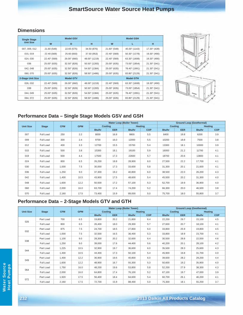
232 2013 Daikin All Products Catalog
SmartSource Water Source Heat PumpsW
ater
Sou
rce
Hea
t P
umps
Dimensions
Single StageUnit Size
Model GSV Model GSH
W D H W L H
007, 009, 012 21 .60 (549) 22 .65 (575) 34 .50 (876) 21 .60" (549) 45 .00" (1143) 17 .30" (439)
015, 019 22 .40 (569) 25 .60 (650) 37 .50 (953) 22 .40" (569) 50 .30" (1278) 19 .30" (490)
024, 030 22 .40" (569) 26 .00" (660) 48 .00" (1219) 22 .40" (569) 63 .30" (1608) 19 .30" (490)
036 25 .00" (635) 32 .50" (826) 50 .50" (1283) 25 .00" (635) 73 .00" (1854) 21 .30" (541)
042, 048 25 .00" (635) 32 .50" (826) 54 .50" (1384) 25 .00" (635) 78 .40" (1991) 21 .30" (541)
060, 070 25 .00" (635) 32 .50" (826) 58 .50" (1486) 25 .00" (635) 83 .80" (2129) 21 .30" (541)
2-Stage Unit Size Model GTV Model GTH
026, 032 22 .40" (569) 26 .00" (660) 48 .00" (1219) 22 .40" (569) 63 .30" (1608) 19 .30" (490)
038 25 .00" (635) 32 .50" (826) 50 .50" (1283) 25 .00" (635) 73 .00" (1854) 21 .30" (541)
044, 049 25 .00" (635) 32 .50" (826) 54 .50" (1384) 25 .00" (635) 78 .40" (1991) 21 .30" (541)
064, 072 25 .00" (635) 32 .50" (826) 58 .50" (1486) 25 .00" (635) 83 .80" (2129) 21 .30" (541)
Performance Data – Single Stage Models GSV and GSH
Unit Size Stage CFM GPMWater Loop (Boiler Tower) Ground Loop (Geothermal)
Cooling Heating Cooling HeatingBtu/hr EER Btu/hr COP Btu/hr EER Btu/hr COP
007 Full Load 250 2 .2 8000 16 .8 9800 5 .5 8400 19 .8 6200 3 .9
009 Full Load 300 2 .4 9700 16 .0 12000 5 .5 10200 18 .8 7500 3 .8
012 Full Load 400 3 .3 12700 15 .5 15700 5 .4 13300 18 .1 10000 3 .9
015 Full Load 500 3 .8 15300 18 .1 19100 5 .9 16000 21 .2 11700 4 .1
019 Full Load 600 4 .4 17500 17 .3 22600 5 .7 18700 20 .6 13800 4 .1
024 Full Load 800 6 .5 26,200 18 .8 28,900 6 .0 27,500 22 .2 17,700 4 .1
030 Full Load 1,000 7 .5 30,000 17 .3 33,600 5 .8 31,300 20 .1 21,600 4 .1
036 Full Load 1,250 9 .0 37,300 19 .2 40,800 6 .0 38,500 22 .0 26,200 4 .3
042 Full Load 1,400 10 .5 43,900 17 .5 48,600 5 .4 45,500 20 .2 31,300 4 .0
048 Full Load 1,600 12 .2 50,500 17 .2 57,100 5 .3 52,700 19 .9 36,900 4 .0
060 Full Load 2,000 16 .0 63,700 17 .4 74,200 5 .2 66,300 20 .0 46,500 3 .8
070 Full Load 2,160 17 .5 73,400 15 .9 89,000 5 .0 75,700 18 .0 55,800 3 .7
Performance Data – 2-Stage Models GTV and GTH
Unit Size Stage CFM GPMWater Loop (Boiler Tower) Ground Loop (Geothermal)
Cooling Heating Cooling HeatingBtu/hr EER Btu/hr COP Btu/hr EER Btu/hr COP
026Part Load 700 6 .5 19,800 20 .2 21,800 6 .4 22,200 29 .7 15,100 4 .5
Full Load 800 6 .5 26,400 18 .0 29,300 5 .7 27,600 20 .7 18,100 4 .1
032Part Load 875 7 .5 24,700 18 .5 27,800 6 .0 33,800 25 .9 19,800 4 .5
Full Load 1,000 7 .5 32,500 16 .5 36,400 5 .3 33,800 18 .9 23,700 4 .1
038Part Load 1,100 9 .0 28,300 20 .2 32,600 6 .4 30,500 28 .8 22,500 4 .6
Full Load 1,250 9 .0 39,000 17 .6 44,400 5 .6 40,200 20 .1 28,100 4 .2
044Part Load 1,225 10 .5 32,900 19 .7 36,600 6 .0 35,500 28 .3 25,600 4 .3
Full Load 1,400 10 .5 44,400 17 .3 50,100 5 .4 45,900 19 .8 31,700 4 .0
049Part Load 1,400 12 .2 36,900 19 .5 40,800 6 .0 39,600 28 .2 29,200 4 .4
Full Load 1,600 12 .2 48,900 16 .7 55,300 5 .3 50,600 19 .2 35,900 4 .0
064Part Load 1,750 16 .0 48,200 19 .6 53,800 5 .8 52,200 27 .9 38,300 4 .3
Full Load 2,000 16 .0 64,800 17 .4 76,100 5 .2 67,100 19 .7 47,000 3 .9
072Part Load 1,920 17 .5 56,400 18 .4 64,600 5 .4 60,700 26 .1 46,200 4 .1
Full Load 2,160 17 .5 72,700 15 .9 88,400 5 .0 75,300 18 .1 55,200 3 .7
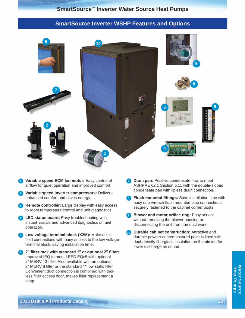
2013 Daikin All Products Catalog 233
SmartSource™ Inverter Water Source Heat PumpsW
ater Source
Heat P
umps
SmartSource Inverter WSHP Features and Options
1 Variable speed ECM fan motor: Easy control of airflow for quiet operation and improved comfort.
2 Variable speed inverter compressors: Delivers enhanced comfort and saves energy .
3 Remote controller: Large display with easy access to room temperature control and unit diagnostics .
4 LED status board: Easy troubleshooting with instant visuals and advanced diagnostics on unit operation .
5 Low voltage terminal block (X2M): Make quick field connections with easy access to the low voltage terminal block, saving installation time .
6 2" filter rack with standard 1" or optional 2" filter: Improved IEQ to meet LEED EQc5 with optional 2" MERV 13 filter. Also available with an optional 2" MERV 8 filter or the standard 1" low static filter. Convenient duct connection is combined with tool-less filter access door, makes filter replacement a snap .
7 Drain pan: Positive condensate flow to meet ASHRAE 62 .1 Section 5 .11 with the double-sloped condensate pan with lipless drain connection .
8 Flush mounted fittings: Save installation time with easy one-wrench flush mounted pipe connections, securely fastened to the cabinet corner posts .
9 Blower and motor orifice ring: Easy service without removing the blower housing or disconnecting the unit from the duct work .
10 Durable cabinet construction: Attractive and durable powder coated textured paint is lined with dual-density fiberglass insulation on the airside for lower discharge air sound .
6
1
9
10
8
53
4
2
7
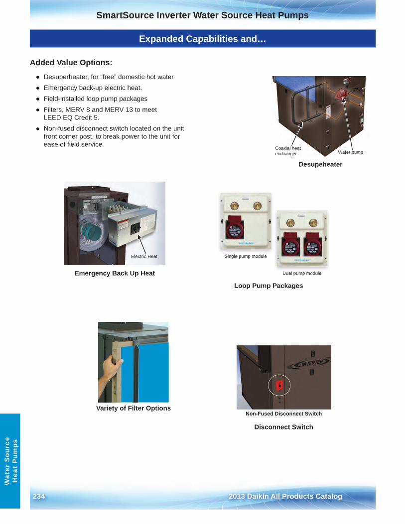
234 2013 Daikin All Products Catalog
SmartSource Inverter Water Source Heat PumpsW
ater
Sou
rce
Hea
t P
umps
Expanded Capabilities and…
Added Value Options:
● Desuperheater, for “free” domestic hot water● Emergency back-up electric heat .● Field-installed loop pump packages● Filters, MERV 8 and MERV 13 to meet
LEED EQ Credit 5 .● Non-fused disconnect switch located on the unit
front corner post, to break power to the unit forease of field service
Coaxial heat exchanger Water pump
Desupeheater
Loop Pump Packages
Dual pump module
Single pump module
Emergency Back Up Heat
Electric Heat
Disconnect Switch
Non-Fused Disconnect SwitchVariety of Filter Options
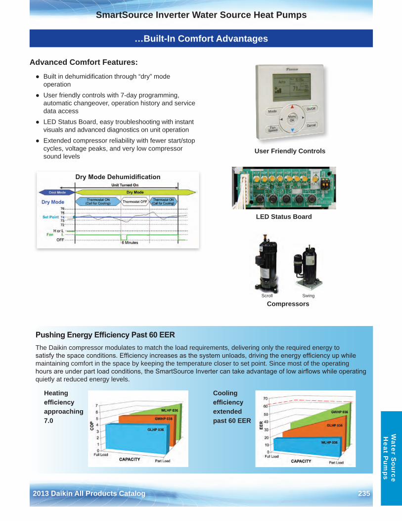
2013 Daikin All Products Catalog 235
SmartSource Inverter Water Source Heat PumpsW
ater Source
Heat P
umps
…Built-In Comfort Advantages
Advanced Comfort Features:
● Built in dehumidification through “dry” modeoperation
● User friendly controls with 7-day programming,automatic changeover, operation history and servicedata access
● LED Status Board, easy troubleshooting with instantvisuals and advanced diagnostics on unit operation
● Extended compressor reliability with fewer start/stopcycles, voltage peaks, and very low compressorsound levels
Pushing Energy Efficiency Past 60 EERThe Daikin compressor modulates to match the load requirements, delivering only the required energy to satisfy the space conditions. Efficiency increases as the system unloads, driving the energy efficiency up while maintaining comfort in the space by keeping the temperature closer to set point . Since most of the operating hours are under part load conditions, the SmartSource Inverter can take advantage of low airflows while operating quietly at reduced energy levels .
Dry Mode Dehumidification
User Friendly Controls
Scroll Swing
Compressors
LED Status Board
Cooling efficiency extended past 60 EER
Heating efficiency approaching 7 .0
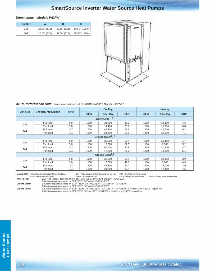
236 2013 Daikin All Products Catalog
SmartSource Inverter Water Source Heat PumpsW
ater
Sou
rce
Hea
t P
umps
Dimensions – Models WDFW
Unit Size W D H
036 25 .00" (635) 32 .50" (826) 50 .50" (1283)
048 25 .00" (635) 32 .50" (826) 58 .50" (1486)
AHRI Performance Data Rated in accordance with AHRI/ASHRAE/ISO Standard 13256-1.
Unit Size Capacity Modulation GPMCooling Heating
CFM Total Cap EER CFM Total Cap COP
Water Loop1, 2
036 Full load 9 .0 1160 31,900 16 .2 1160 32,100 4 .6Part load 9 .0 1160 14,400 23 .8 1160 10,900 6 .8
048 Full load 12 .0 1600 42,300 15 .9 1600 47,900 5 .3Part load 12 .0 1600 21,600 20 .1 1600 21,200 7 .1
Ground Water1, 2
036 Full load 9 .0 1160 38,900 29 .4 1160 30,100 4 .7Part load 9 .0 1160 15,900 62 .5 1160 9,900 5 .2
048 Full load 12 .0 1600 50,900 30 .5 1600 40,700 4 .7Part load 12 .0 1600 17,200 39 .2 1600 18,800 5 .1
Ground Loop1,2
036 Full load 9 .0 1160 35,600 20 .4 1160 23,400 3 .9Part load 9 .0 1160 15,600 47 .3 1160 8,700 4 .3
048 Full load 12 .0 1600 46,600 20 .2 1600 32,000 3 .9Part load 12 .0 1600 21,700 33 .4 1600 17,100 4 .5
Legend: CFM = Airflow Rate, Cubic Feet per Minute Total Cap., Btuh = Total Capacity British Thermal Units per Hour COP = Coefficient of Performance EER = Energy Efficiency Ratio GPM = Gallons per Minute EAT = Entering Air Temperature EWT = Entering Water Temperature
Water Loop: 1 .Cooling capacity based on 80 .6°F db, 66 .2°F wb (27/19°C) EAT and 86°F (30°C) EWT .2 . Heating capacity is based on 68°F (20°C) EAT and 68°F (20°C) EWT .
Ground Water: 1 . Cooling capacity is based on 80 .6°F db, 66 .2°F wb (27/19°C) EAT and 59°F (15°C) EWT .2 . Heating capacity is based on 68°F (20°C) EAT and 50°F (10°C) EWT .
Ground Loop: 1 . Cooling capacity is based on 80 .6°F db, 66 .2°F wb (27/19°C) EAT and 77°F (25°C) EWT at full load or 68°F (20°C) at part load .2 . Heating capacity is based on 68°F (20°C) EAT, and 32°F (0°C) EWT at full load or 41°F (5°C) at part load .
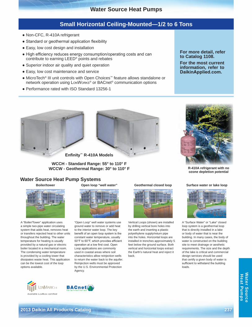
Water Source Heat Pumps
2013 Daikin All Products Catalog 237
Water S
ource H
eat Pum
ps
Small Horizontal Ceiling-Mounted—1/2 to 6 Tons
● Non-CFC, R-410A refrigerant● Standard or geothermal application flexibility● Easy, low cost design and installation● High efficiency reduces energy consumption/operating costs and can
contribute to earning LEED® points and rebates● Superior indoor air quality and quiet operation● Easy, low cost maintenance and service● MicroTech® III unit controls with Open Choices™ feature allows standalone or
network operation using LonWorks® or BACnet® communication options● Performance rated with ISO Standard 13256-1
For more detail, refer to Catalog 1108 .For the most current information, refer to DaikinApplied.com .
Water Source Heat Pump SystemsBoiler/tower Open loop “well water” Geothermal closed loop Surface water or lake loop
A “Boiler/Tower” application uses a simple two-pipe water circulating system that adds heat, removes heat or transfers rejected heat to other units throughout the building . The water temperature for heating is usually provided by a natural gas or electric boiler located in a mechanical room . The condensing water temperature is provided by a cooling tower that dissipates waste heat . This application can be the lowest cost of the loop options available .
“Open Loop” well water systems use ground water to remove or add heat to the interior water loop . The key benefit of an open loop system is the constant water temperature, usually 50°F to 60°F, which provides efficient operation at a low first cost. Open Loop applications are commonly used in coastal areas where soil characteristics allow reinjection wells to return the water back to the aquifer . Reinjection wells must be approved by the U .S . Environmental Protection Agency .
Vertical Loops (shown) are installed by drilling vertical bore holes into the earth and inserting a plastic polyethylene supply/return pipe into the holes . Horizontal loops are installed in trenches approximately 5 feet below the ground surface . Both vertical and horizontal loops extract the Earth’s natural heat and reject it back .
A “Surface Water” or “Lake” closed loop system is a geothermal loop that is directly installed in a lake or body of water that is near the building . In many cases, the body of water is constructed on the building site to meet drainage or aesthetic requirements . The size and the depth of the lake is critical and commercial design services should be used that certify a given body of water is sufficient to withstand the building loads .
R-410A refrigerant with no ozone depletion potential
Enfinity™ R-410A Models
WCCH - Standard Range: 55° to 110° F WCCW - Geothermal Range: 30° to 110° F
Available LonMark cert i f ied
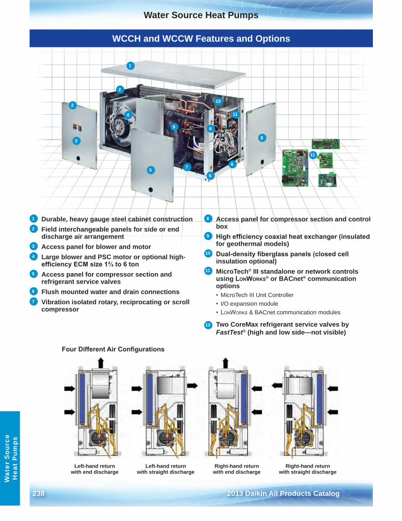
Water Source Heat Pumps
238 2013 Daikin All Products Catalog
Wat
er S
ourc
e H
eat
Pum
ps
WCCH and WCCW Features and Options
Four Different Air Configurations
Left-hand return with end discharge
Left-hand return with straight discharge
Right-hand return with end discharge
Right-hand return with straight discharge
1 Durable, heavy gauge steel cabinet construction2 Field interchangeable panels for side or end
discharge air arrangement3 Access panel for blower and motor4 Large blower and PSC motor or optional high-
efficiency ECM size 1¾ to 6 ton5 Access panel for compressor section and
refrigerant service valves6 Flush mounted water and drain connections7 Vibration isolated rotary, reciprocating or scroll
compressor
8 Access panel for compressor section and control box
9 High efficiency coaxial heat exchanger (insulated for geothermal models)
10 Dual-density fiberglass panels (closed cell insulation optional)
11 MicroTech® III standalone or network controls using LonWorks® or BACnet® communication options• MicroTech III Unit Controller• I/O expansion module• LonWorks & BACnet communication modules
12 Two CoreMax refrigerant service valves by FastTest® (high and low side—not visible)
2
2
3
4
56
6
6
7
8
9
10
11
11
1
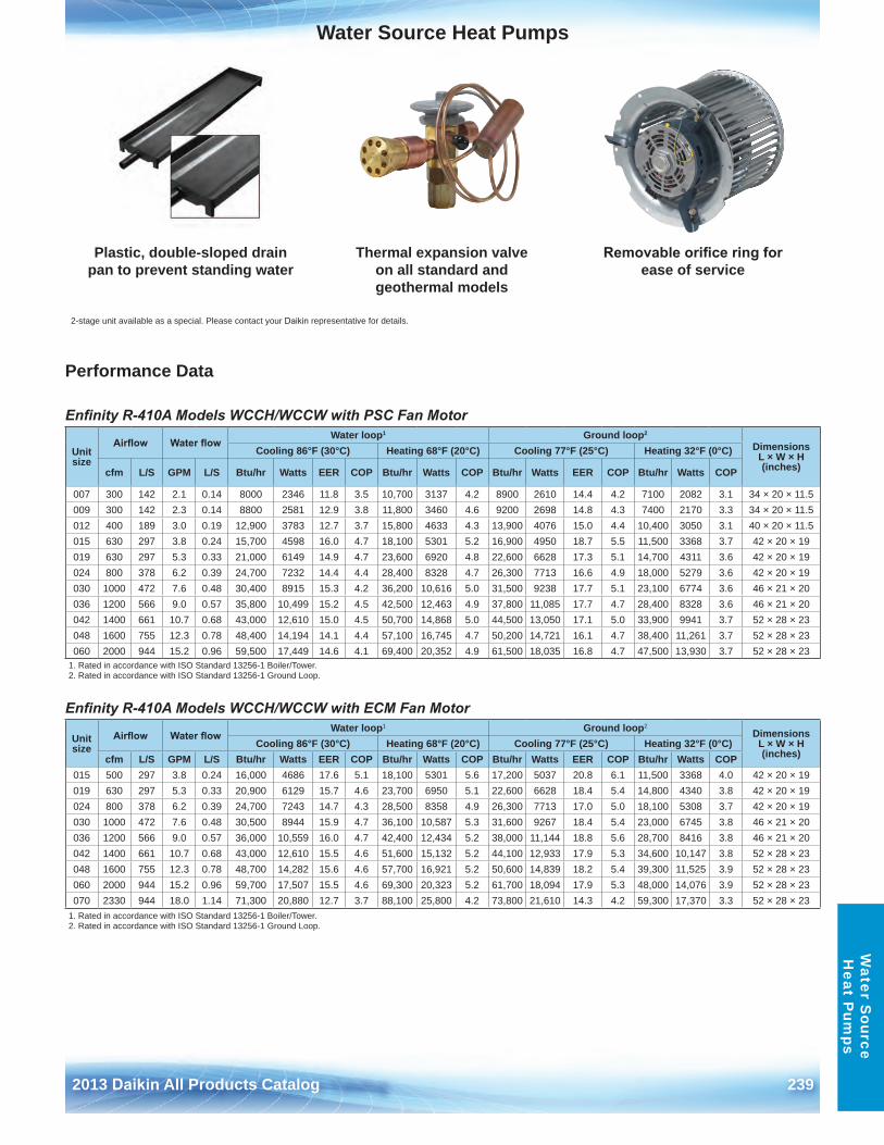
Water Source Heat Pumps
2013 Daikin All Products Catalog 239
Water S
ource H
eat Pum
ps
Plastic, double-sloped drain pan to prevent standing water
Thermal expansion valve on all standard and geothermal models
Removable orifice ring for ease of service
2-stage unit available as a special . Please contact your Daikin representative for details .
Performance Data
Enfinity R-410A Models WCCH/WCCW with PSC Fan Motor
Enfinity R-410A Models WCCH/WCCW with ECM Fan Motor
Unit size
Airflow Water flowWater loop1 Ground loop2
Dimensions L × W × H (inches)
Cooling 86°F (30°C) Heating 68°F (20°C) Cooling 77°F (25°C) Heating 32°F (0°C)
cfm L/S GPM L/S Btu/hr Watts EER COP Btu/hr Watts COP Btu/hr Watts EER COP Btu/hr Watts COP
007 300 142 2 .1 0 .14 8000 2346 11 .8 3 .5 10,700 3137 4 .2 8900 2610 14 .4 4 .2 7100 2082 3 .1 34 × 20 × 11 .5009 300 142 2 .3 0 .14 8800 2581 12 .9 3 .8 11,800 3460 4 .6 9200 2698 14 .8 4 .3 7400 2170 3 .3 34 × 20 × 11 .5012 400 189 3 .0 0 .19 12,900 3783 12 .7 3 .7 15,800 4633 4 .3 13,900 4076 15 .0 4 .4 10,400 3050 3 .1 40 × 20 × 11 .5015 630 297 3 .8 0 .24 15,700 4598 16 .0 4 .7 18,100 5301 5 .2 16,900 4950 18 .7 5 .5 11,500 3368 3 .7 42 × 20 × 19019 630 297 5 .3 0 .33 21,000 6149 14 .9 4 .7 23,600 6920 4 .8 22,600 6628 17 .3 5 .1 14,700 4311 3 .6 42 × 20 × 19024 800 378 6 .2 0 .39 24,700 7232 14 .4 4 .4 28,400 8328 4 .7 26,300 7713 16 .6 4 .9 18,000 5279 3 .6 42 × 20 × 19030 1000 472 7 .6 0 .48 30,400 8915 15 .3 4 .2 36,200 10,616 5 .0 31,500 9238 17 .7 5 .1 23,100 6774 3 .6 46 × 21 × 20036 1200 566 9 .0 0 .57 35,800 10,499 15 .2 4 .5 42,500 12,463 4 .9 37,800 11,085 17 .7 4 .7 28,400 8328 3 .6 46 × 21 × 20042 1400 661 10 .7 0 .68 43,000 12,610 15 .0 4 .5 50,700 14,868 5 .0 44,500 13,050 17 .1 5 .0 33,900 9941 3 .7 52 × 28 × 23048 1600 755 12 .3 0 .78 48,400 14,194 14 .1 4 .4 57,100 16,745 4 .7 50,200 14,721 16 .1 4 .7 38,400 11,261 3 .7 52 × 28 × 23060 2000 944 15 .2 0 .96 59,500 17,449 14 .6 4 .1 69,400 20,352 4 .9 61,500 18,035 16 .8 4 .7 47,500 13,930 3 .7 52 × 28 × 23
1 . Rated in accordance with ISO Standard 13256-1 Boiler/Tower .2 . Rated in accordance with ISO Standard 13256-1 Ground Loop .
Unit size
Airflow Water flowWater loop1 Ground loop2
Dimensions L × W × H (inches)
Cooling 86°F (30°C) Heating 68°F (20°C) Cooling 77°F (25°C) Heating 32°F (0°C)cfm L/S GPM L/S Btu/hr Watts EER COP Btu/hr Watts COP Btu/hr Watts EER COP Btu/hr Watts COP
015 500 297 3 .8 0 .24 16,000 4686 17 .6 5 .1 18,100 5301 5 .6 17,200 5037 20 .8 6 .1 11,500 3368 4 .0 42 × 20 × 19019 630 297 5 .3 0 .33 20,900 6129 15 .7 4 .6 23,700 6950 5 .1 22,600 6628 18 .4 5 .4 14,800 4340 3 .8 42 × 20 × 19024 800 378 6 .2 0 .39 24,700 7243 14 .7 4 .3 28,500 8358 4 .9 26,300 7713 17 .0 5 .0 18,100 5308 3 .7 42 × 20 × 19030 1000 472 7 .6 0 .48 30,500 8944 15 .9 4 .7 36,100 10,587 5 .3 31,600 9267 18 .4 5 .4 23,000 6745 3 .8 46 × 21 × 20036 1200 566 9 .0 0 .57 36,000 10,559 16 .0 4 .7 42,400 12,434 5 .2 38,000 11,144 18 .8 5 .6 28,700 8416 3 .8 46 × 21 × 20042 1400 661 10 .7 0 .68 43,000 12,610 15 .5 4 .6 51,600 15,132 5 .2 44,100 12,933 17 .9 5 .3 34,600 10,147 3 .8 52 × 28 × 23048 1600 755 12 .3 0 .78 48,700 14,282 15 .6 4 .6 57,700 16,921 5 .2 50,600 14,839 18 .2 5 .4 39,300 11,525 3 .9 52 × 28 × 23060 2000 944 15 .2 0 .96 59,700 17,507 15 .5 4 .6 69,300 20,323 5 .2 61,700 18,094 17 .9 5 .3 48,000 14,076 3 .9 52 × 28 × 23070 2330 944 18 .0 1 .14 71,300 20,880 12 .7 3 .7 88,100 25,800 4 .2 73,800 21,610 14 .3 4 .2 59,300 17,370 3 .3 52 × 28 × 23
1 . Rated in accordance with ISO Standard 13256-1 Boiler/Tower .2 . Rated in accordance with ISO Standard 13256-1 Ground Loop .
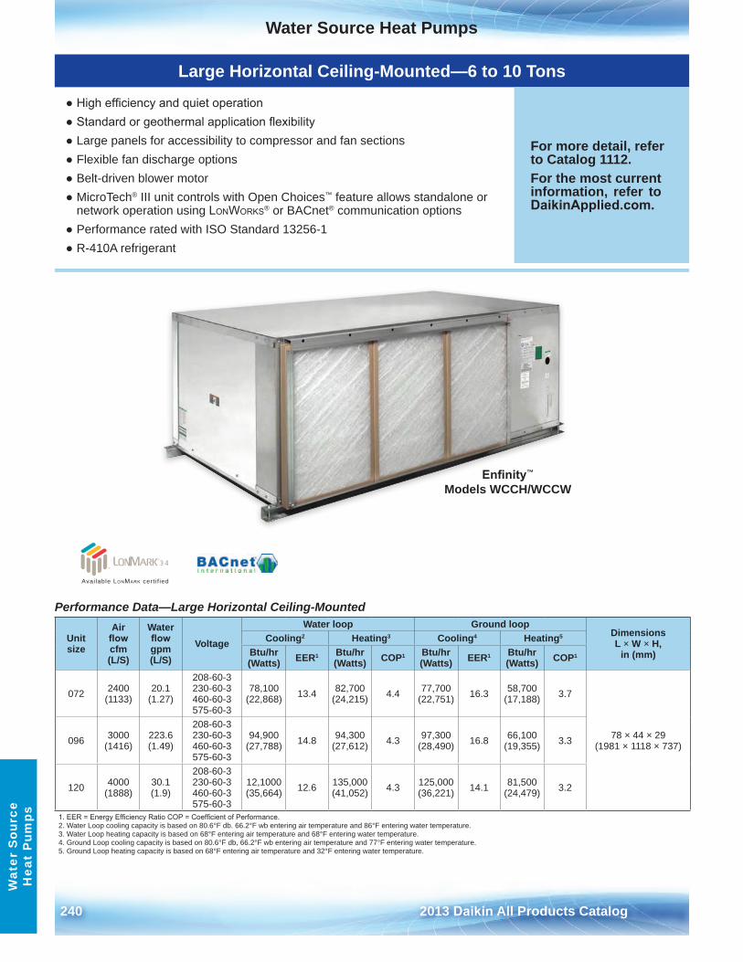
Water Source Heat Pumps
240 2013 Daikin All Products Catalog
Wat
er S
ourc
e H
eat
Pum
ps
Large Horizontal Ceiling-Mounted—6 to 10 Tons
● High efficiency and quiet operation● Standard or geothermal application flexibility● Large panels for accessibility to compressor and fan sections● Flexible fan discharge options● Belt-driven blower motor● MicroTech® III unit controls with Open Choices™ feature allows standalone or
network operation using LonWorks® or BACnet® communication options● Performance rated with ISO Standard 13256-1● R-410A refrigerant
For more detail, refer to Catalog 1112 .For the most current information, refer to DaikinApplied.com .
Performance Data—Large Horizontal Ceiling-Mounted
Unit size
Air flow cfm (L/S)
Water flow gpm (L/S)
Voltage
Water loop Ground loopDimensions L × W × H,
in (mm)Cooling2 Heating3 Cooling4 Heating5
Btu/hr (Watts) EER1 Btu/hr
(Watts) COP1 Btu/hr (Watts) EER1 Btu/hr
(Watts) COP1
072 2400 (1133)
20 .1 (1 .27)
208-60-3 230-60-3 460-60-3 575-60-3
78,100 (22,868) 13 .4 82,700
(24,215) 4 .4 77,700 (22,751) 16 .3 58,700
(17,188) 3 .7
78 × 44 × 29 (1981 × 1118 × 737)096 3000
(1416)223 .6 (1 .49)
208-60-3 230-60-3 460-60-3 575-60-3
94,900 (27,788) 14 .8 94,300
(27,612) 4 .3 97,300 (28,490) 16 .8 66,100
(19,355) 3 .3
120 4000 (1888)
30 .1 (1 .9)
208-60-3 230-60-3 460-60-3 575-60-3
12,1000 (35,664) 12 .6 135,000
(41,052) 4 .3 125,000 (36,221) 14 .1 81,500
(24,479) 3 .2
1. EER = Energy Efficiency Ratio COP = Coefficient of Performance.2 . Water Loop cooling capacity is based on 80 .6°F db . 66 .2°F wb entering air temperature and 86°F entering water temperature .3 . Water Loop heating capacity is based on 68°F entering air temperature and 68°F entering water temperature . 4 . Ground Loop cooling capacity is based on 80 .6°F db, 66 .2°F wb entering air temperature and 77°F entering water temperature .5 . Ground Loop heating capacity is based on 68°F entering air temperature and 32°F entering water temperature .
Available LonMark cert i f ied
Enfinity™ Models WCCH/WCCW
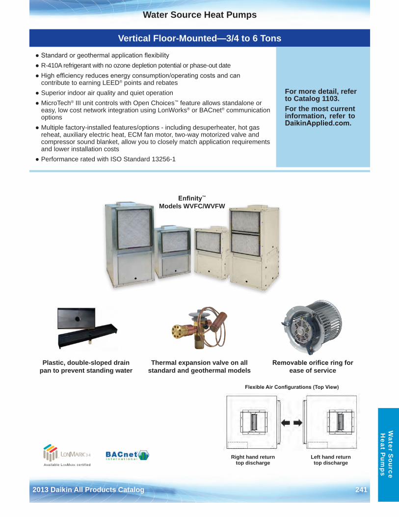
Water Source Heat Pumps
2013 Daikin All Products Catalog 241
Water S
ource H
eat Pum
ps
Vertical Floor-Mounted—3/4 to 6 Tons
● Standard or geothermal application flexibility● R-410A refrigerant with no ozone depletion potential or phase-out date● High efficiency reduces energy consumption/operating costs and can
contribute to earning LEED® points and rebates● Superior indoor air quality and quiet operation● MicroTech® III unit controls with Open Choices™ feature allows standalone or
easy, low cost network integration using LonWorks® or BACnet® communicationoptions
● Multiple factory-installed features/options - including desuperheater, hot gasreheat, auxiliary electric heat, ECM fan motor, two-way motorized valve andcompressor sound blanket, allow you to closely match application requirementsand lower installation costs
● Performance rated with ISO Standard 13256-1
For more detail, refer to Catalog 1103 .For the most current information, refer to DaikinApplied.com .
Plastic, double-sloped drain pan to prevent standing water
Thermal expansion valve on all standard and geothermal models
Removable orifice ring for ease of service
Enfinity™ Models WVFC/WVFW
Flexible Air Configurations (Top View)
Right hand return top discharge
Left hand return top dischargeAvailable LonMark cert i f ied
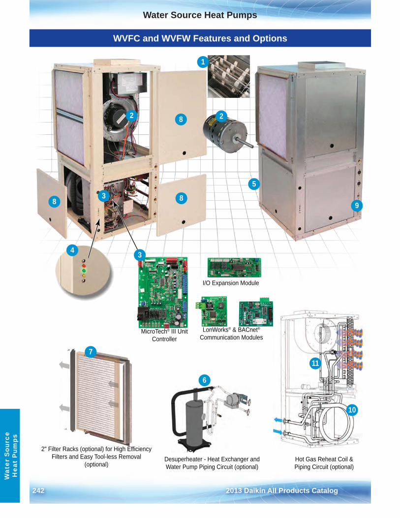
Water Source Heat Pumps
242 2013 Daikin All Products Catalog
Wat
er S
ourc
e H
eat
Pum
ps
WVFC and WVFW Features and Options
I/O Expansion Module
LonWorks® & BACnet®
Communication ModulesMicroTech® III Unit
Controller
2" Filter Racks (optional) for High EfficiencyFilters and Easy Tool-less Removal
(optional)Desuperheater - Heat Exchanger and Water Pump Piping Circuit (optional)
Hot Gas Reheat Coil & Piping Circuit (optional)
9
2
3
4
5
6
7
8
88
10
1
11
2
3
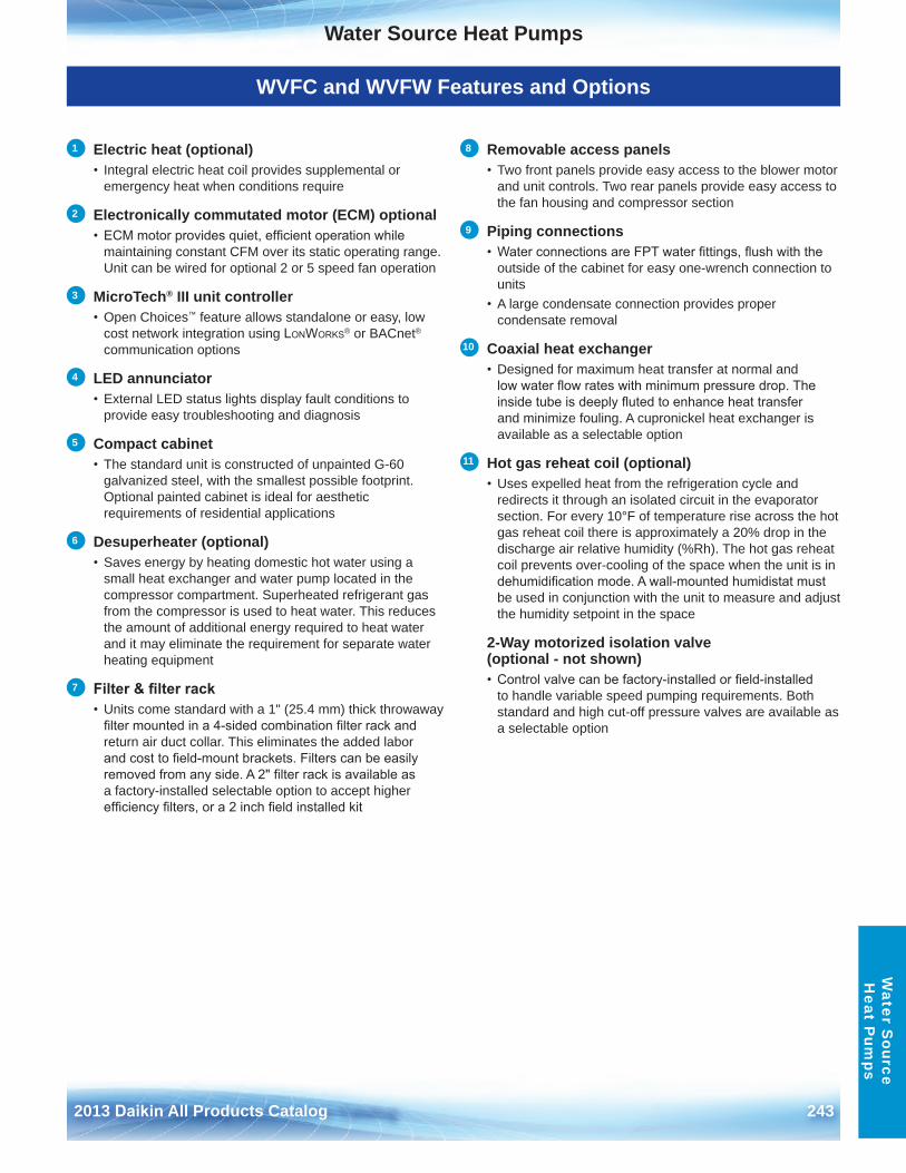
Water Source Heat Pumps
2013 Daikin All Products Catalog 243
Water S
ource H
eat Pum
ps
WVFC and WVFW Features and Options
1 Electric heat (optional)• Integral electric heat coil provides supplemental or
emergency heat when conditions require
2 Electronically commutated motor (ECM) optional• ECM motor provides quiet, efficient operation while
maintaining constant CFM over its static operating range . Unit can be wired for optional 2 or 5 speed fan operation
3 MicroTech® III unit controller• Open Choices™ feature allows standalone or easy, low
cost network integration using LonWorks® or BACnet®
communication options
4 LED annunciator • External LED status lights display fault conditions to
provide easy troubleshooting and diagnosis
5 Compact cabinet• The standard unit is constructed of unpainted G-60
galvanized steel, with the smallest possible footprint . Optional painted cabinet is ideal for aestheticrequirements of residential applications
6 Desuperheater (optional)• Saves energy by heating domestic hot water using a
small heat exchanger and water pump located in thecompressor compartment . Superheated refrigerant gasfrom the compressor is used to heat water . This reducesthe amount of additional energy required to heat waterand it may eliminate the requirement for separate waterheating equipment
7 Filter & filter rack• Units come standard with a 1" (25 .4 mm) thick throwaway
filter mounted in a 4-sided combination filter rack andreturn air duct collar . This eliminates the added laborand cost to field-mount brackets. Filters can be easilyremoved from any side. A 2" filter rack is available asa factory-installed selectable option to accept higherefficiency filters, or a 2 inch field installed kit
8 Removable access panels• Two front panels provide easy access to the blower motor
and unit controls . Two rear panels provide easy access tothe fan housing and compressor section
9 Piping connections• Water connections are FPT water fittings, flush with the
outside of the cabinet for easy one-wrench connection tounits
• A large condensate connection provides propercondensate removal
10 Coaxial heat exchanger• Designed for maximum heat transfer at normal and
low water flow rates with minimum pressure drop. Theinside tube is deeply fluted to enhance heat transferand minimize fouling . A cupronickel heat exchanger isavailable as a selectable option
11 Hot gas reheat coil (optional)• Uses expelled heat from the refrigeration cycle and
redirects it through an isolated circuit in the evaporatorsection . For every 10°F of temperature rise across the hotgas reheat coil there is approximately a 20% drop in thedischarge air relative humidity (%Rh) . The hot gas reheatcoil prevents over-cooling of the space when the unit is indehumidification mode. A wall-mounted humidistat mustbe used in conjunction with the unit to measure and adjustthe humidity setpoint in the space
2-Way motorized isolation valve (optional - not shown)• Control valve can be factory-installed or field-installed
to handle variable speed pumping requirements . Bothstandard and high cut-off pressure valves are available asa selectable option
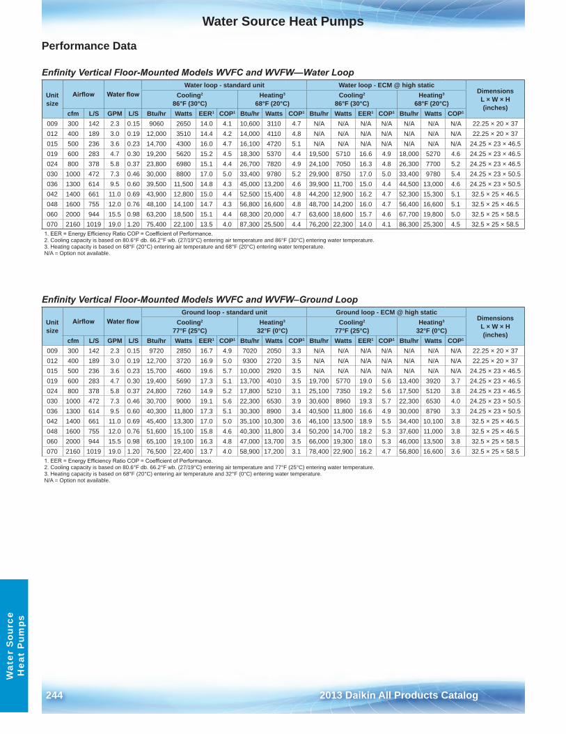
Water Source Heat Pumps
244 2013 Daikin All Products Catalog
Wat
er S
ourc
e H
eat
Pum
ps
Performance Data
Enfinity Vertical Floor-Mounted Models WVFC and WVFW—Water Loop
Enfinity Vertical Floor-Mounted Models WVFC and WVFW–Ground Loop
Unit size
Airflow Water flowWater loop - standard unit Water loop - ECM @ high static
Dimensions L × W × H (inches)
Cooling2 86°F (30°C)
Heating3 68°F (20°C)
Cooling2
86°F (30°C)Heating3
68°F (20°C)cfm L/S GPM L/S Btu/hr Watts EER1 COP1 Btu/hr Watts COP1 Btu/hr Watts EER1 COP1 Btu/hr Watts COP1
009 300 142 2 .3 0 .15 9060 2650 14 .0 4 .1 10,600 3110 4 .7 N/A N/A N/A N/A N/A N/A N/A 22 .25 × 20 × 37012 400 189 3 .0 0 .19 12,000 3510 14 .4 4 .2 14,000 4110 4 .8 N/A N/A N/A N/A N/A N/A N/A 22 .25 × 20 × 37015 500 236 3 .6 0 .23 14,700 4300 16 .0 4 .7 16,100 4720 5 .1 N/A N/A N/A N/A N/A N/A N/A 24 .25 × 23 × 46 .5019 600 283 4 .7 0 .30 19,200 5620 15 .2 4 .5 18,300 5370 4 .4 19,500 5710 16 .6 4 .9 18,000 5270 4 .6 24 .25 × 23 × 46 .5024 800 378 5 .8 0 .37 23,800 6980 15 .1 4 .4 26,700 7820 4 .9 24,100 7050 16 .3 4 .8 26,300 7700 5 .2 24 .25 × 23 × 46 .5030 1000 472 7 .3 0 .46 30,000 8800 17 .0 5 .0 33,400 9780 5 .2 29,900 8750 17 .0 5 .0 33,400 9780 5 .4 24 .25 × 23 × 50 .5036 1300 614 9 .5 0 .60 39,500 11,500 14 .8 4 .3 45,000 13,200 4 .6 39,900 11,700 15 .0 4 .4 44,500 13,000 4 .6 24 .25 × 23 × 50 .5042 1400 661 11 .0 0 .69 43,900 12,800 15 .0 4 .4 52,500 15,400 4 .8 44,200 12,900 16 .2 4 .7 52,300 15,300 5 .1 32 .5 × 25 × 46 .5048 1600 755 12 .0 0 .76 48,100 14,100 14 .7 4 .3 56,800 16,600 4 .8 48,700 14,200 16 .0 4 .7 56,400 16,600 5 .1 32 .5 × 25 × 46 .5060 2000 944 15 .5 0 .98 63,200 18,500 15 .1 4 .4 68,300 20,000 4 .7 63,600 18,600 15 .7 4 .6 67,700 19,800 5 .0 32 .5 × 25 × 58 .5070 2160 1019 19 .0 1 .20 75,400 22,100 13 .5 4 .0 87,300 25,500 4 .4 76,200 22,300 14 .0 4 .1 86,300 25,300 4 .5 32 .5 × 25 × 58 .5
1. EER = Energy Efficiency Ratio COP = Coefficient of Performance.2 . Cooling capacity is based on 80 .6°F db . 66 .2°F wb . (27/19°C) entering air temperature and 86°F (30°C) entering water temperature .3 . Heating capacity is based on 68°F (20°C) entering air temperature and 68°F (20°C) entering water temperature .N/A = Option not available .
Unit size
Airflow Water flowGround loop - standard unit Ground loop - ECM @ high static
Dimensions L × W × H (inches)
Cooling2 77°F (25°C)
Heating3 32°F (0°C)
Cooling2
77°F (25°C)Heating3
32°F (0°C)cfm L/S GPM L/S Btu/hr Watts EER1 COP1 Btu/hr Watts COP1 Btu/hr Watts EER1 COP1 Btu/hr Watts COP1
009 300 142 2 .3 0 .15 9720 2850 16 .7 4 .9 7020 2050 3 .3 N/A N/A N/A N/A N/A N/A N/A 22 .25 × 20 × 37012 400 189 3 .0 0 .19 12,700 3720 16 .9 5 .0 9300 2720 3 .5 N/A N/A N/A N/A N/A N/A N/A 22 .25 × 20 × 37015 500 236 3 .6 0 .23 15,700 4600 19 .6 5 .7 10,000 2920 3 .5 N/A N/A N/A N/A N/A N/A N/A 24 .25 × 23 × 46 .5019 600 283 4 .7 0 .30 19,400 5690 17 .3 5 .1 13,700 4010 3 .5 19,700 5770 19 .0 5 .6 13,400 3920 3 .7 24 .25 × 23 × 46 .5024 800 378 5 .8 0 .37 24,800 7260 14 .9 5 .2 17,800 5210 3 .1 25,100 7350 19 .2 5 .6 17,500 5120 3 .8 24 .25 × 23 × 46 .5030 1000 472 7 .3 0 .46 30,700 9000 19 .1 5 .6 22,300 6530 3 .9 30,600 8960 19 .3 5 .7 22,300 6530 4 .0 24 .25 × 23 × 50 .5036 1300 614 9 .5 0 .60 40,300 11,800 17 .3 5 .1 30,300 8900 3 .4 40,500 11,800 16 .6 4 .9 30,000 8790 3 .3 24 .25 × 23 × 50 .5042 1400 661 11 .0 0 .69 45,400 13,300 17 .0 5 .0 35,100 10,300 3 .6 46,100 13,500 18 .9 5 .5 34,400 10,100 3 .8 32 .5 × 25 × 46 .5048 1600 755 12 .0 0 .76 51,600 15,100 15 .8 4 .6 40,300 11,800 3 .4 50,200 14,700 18 .2 5 .3 37,600 11,000 3 .8 32 .5 × 25 × 46 .5060 2000 944 15 .5 0 .98 65,100 19,100 16 .3 4 .8 47,000 13,700 3 .5 66,000 19,300 18 .0 5 .3 46,000 13,500 3 .8 32 .5 × 25 × 58 .5070 2160 1019 19 .0 1 .20 76,500 22,400 13 .7 4 .0 58,900 17,200 3 .1 78,400 22,900 16 .2 4 .7 56,800 16,600 3 .6 32 .5 × 25 × 58 .5
1. EER = Energy Efficiency Ratio COP = Coefficient of Performance.2 . Cooling capacity is based on 80 .6°F db . 66 .2°F wb . (27/19°C) entering air temperature and 77°F (25°C) entering water temperature .3 . Heating capacity is based on 68°F (20°C) entering air temperature and 32°F (0°C) entering water temperature .N/A = Option not available .
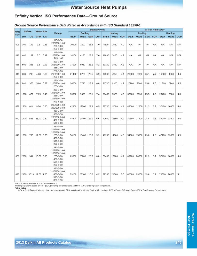
Water Source Heat Pumps
2013 Daikin All Products Catalog 245
Water S
ource H
eat Pum
ps
Enfinity Vertical ISO Performance Data—Ground Source
Ground Source Performance Data Rated in Accordance with ISO Standard 13256-1
Unit size
Airflow Water flowVoltage
Standard Unit ECM at High StaticCooling Heating Cooling Heating
cfm L/S GPM L/S Btu/h Watts EER COP Btu/h Watts COP Btu/h Watts EER COP Btu/h Watts COP
009 300 142 2 .3 0 .15
115-1-60 208/230-1-60
265-1-60 230-1-50
10900 3200 23 .8 7 .0 8820 2580 4 .0 N/A N/A N/A N/A N/A N/A N/A
012 400 189 3 .0 0 .19115-1-60
208/230-1-60 265-1-60
14100 4130 23 .8 7 .0 11800 3450 4 .2 N/A N/A N/A N/A N/A N/A N/A
015 500 236 3 .6 0 .23230-1-50
208/230-1-60 265-1-60
17100 5010 28 .1 8 .2 13100 3830 4 .3 N/A N/A N/A N/A N/A N/A N/A
019 600 283 4 .68 0 .30230-1-50
208/230-1-60 265-1-60
21400 6270 23 .5 6 .9 16900 4950 4 .1 21600 6320 26 .1 7 .7 16600 4860 4 .4
024 800 378 5 .80 0 .37230-1-50
208/230-1-60 265-1-60
26600 7790 23 .3 6 .8 21700 6360 4 .2 26900 7880 25 .8 7 .6 21300 6240 4 .5
030 1000 472 7 .25 0 .46
230-1-50 208/230-1-60
265-1-60 208/230-3-60
33000 9600 25 .1 7 .4 28400 8320 4 .6 32900 9630 25 .5 7 .5 28400 8300 4 .8
036 1300 614 9 .50 0 .60
230-1-50 208/230-1-60 208/230-3-60
460-3-60
42900 12500 22 .3 6 .5 37700 11000 4 .1 43000 12600 21 .3 6 .2 37400 10900 4 .0
042 1400 661 11 .00 0 .69
380-3-50 208/230-3-60
460-3-60 575-3-60
48800 14300 22 .1 6 .5 42900 12500 4 .2 49100 14400 24 .8 7 .3 43000 12600 4 .5
048 1600 755 12 .00 0 .76
380-3-50 208/230-1-60 208/230-3-60
265-1-60 460-3-60 575-3-60 230-1-50
56100 16400 20 .3 5 .9 48900 14300 4 .0 54300 15900 23 .8 7 .0 47100 13800 4 .5
060 2000 944 15 .50 0 .98
380-3-50 208/230-1-60 208/230-3-60
265-1-60 460-3-60 575-3-60 230-1-50
69000 20200 20 .5 6 .0 58400 17100 4 .1 69900 20500 22 .9 6 .7 57400 16800 4 .4
070 2160 1019 19 .00 1 .20
380-3-50 208/230-3-60
460-3-60 575-3-60 380-3-50
79100 23100 16 .6 4 .9 72700 21300 3 .6 80600 23600 19 .6 5 .7 70500 20600 4 .1
N/A = ECM not available in unit sizes 009 or 012 . Heating capacity is based on 68°F (20°C) entering air temperature and 50°F (10°C) entering water temperature . Table notes:
CFM = Cubic Feet per Minute; L/S = Liters per second; GPM = Gallons Per Minute; Btu/h = BTU per hour; EER = Energy Efficiency Ratio; COP = Coefficient of Performance
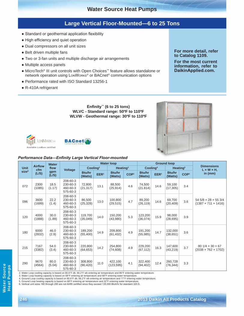
Water Source Heat Pumps
246 2013 Daikin All Products Catalog
Wat
er S
ourc
e H
eat
Pum
ps
Large Vertical Floor-Mounted—6 to 25 Tons
● Standard or geothermal application flexibility● High efficiency and quiet operation● Dual compressors on all unit sizes● Belt driven multiple fans● Two or 3-fan units and multiple discharge air arrangements● Multiple access panels● MicroTech® III unit controls with Open Choices™ feature allows standalone or
network operation using LonWorks® or BACnet® communication options● Performance rated with ISO Standard 13256-1● R-410A refrigerant
For more detail, refer to Catalog 1109 .For the most current information, refer to DaikinApplied.com .
Enfinity™ (6 to 25 tons) WLVC - Standard range: 50ºF to 110ºF
WLVW - Geothermal range: 30ºF to 110ºF
Performance Data—Enfinity Large Vertical Floor-mounted
Unit size6
Airflow cfm (L/S)
Water flow gpm (L/S)
Voltage
Water loop Ground loopDimensions L × W × H,
in (mm)Cooling2 Heating3 Cooling4 Heating5
Btu/hr (Watts) EER1 Btu/hr
(Watts) COP1 Btu/hr (Watts) EER1 Btu/hr
(Watts) COP1
072 2300 (1085)
18 .5 (1 .17)
208-60-3 230-60-3 460-60-3 575-60-3
72,800 (21,317) 13 .1 88,500
(25,914) 4 .6 74,500 (21 .814) 14 .6 59,100
(17,305) 3 .4
54 5/8 × 28 × 55 3/4 (1387 × 711 × 1416)096 3600
(1699)22 .2 (1 .4)
208-60-3 230-60-3 460-60-3 575-60-3
86,500 (25,328) 13 .0 100,800
(29,515) 4 .7 89,200 (26,119) 14 .6 69,700
(20,409) 3 .6
120 4000 (1888)
30 .0 (1 .89)
208-60-3 230-60-3 460-60-3 575-60-3
119,700 (35,049) 14 .0 150,200
(43,980) 5 .3 123,200 (36,074) 15 .9 98,000
(28,695) 3 .9
180 6000 (2832)
46 .0 (2 .9)
208-60-3 230-60-3 460-60-3 575-60-3
189,200 (55,400) 14 .9 209,800
(61,432) 4 .9 191,200 (55,985) 14 .7 132,000
(38,651) 3 .6
80 1/4 × 30 × 67 (2038 × 762 × 1702)215 7167
(3382)54 .0 (3 .4)
208-60-3 230-60-3 460-60-3 575-60-3
220,800 (64,653) 14 .2 254,800
(74,608) 4 .9 229,200 (67,112) 16 .3 147,600
(43,219) 3 .7
290 9670 (4564)
80 .0 (5 .04)
208-60-3 230-60-3 460-60-3 575-60-3
308,800 (90,420) 11 .0 422,100
(123,595) 4 .1 322,400 (94,402) 12 .4 260,728
(76,344) 3 .3
2 . Water Loop cooling capacity is based on 80 .6°F db . 66 .2°F wb entering air temperature and 86°F entering water temperature .3 . Water Loop heating capacity is based on 68°F entering air temperature and 68°F entering water temperature . 4 . Ground Loop cooling capacity is based on 80 .6°F db, 66 .2°F wb entering air temperature and 77°F entering water temperature .5 . Ground Loop heating capacity is based on 68°F entering air temperature and 32°F entering water temperature .6. Vertical unit sizes 180 through 290 are not AHRI certified since they exceed 135,000 Btuh/hr for standard 320.S.
Available LonMark cert i f ied
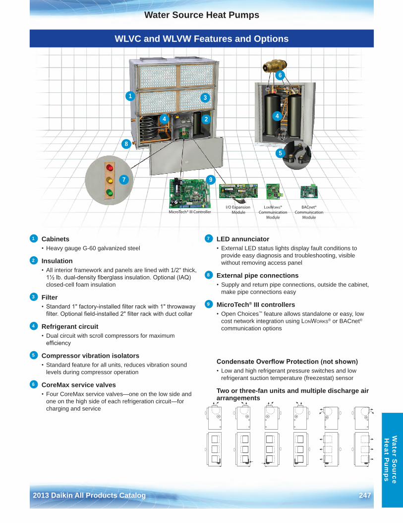
Water Source Heat Pumps
2013 Daikin All Products Catalog 247
Water S
ource H
eat Pum
ps
WLVC and WLVW Features and Options
1 Cabinets• Heavy gauge G-60 galvanized steel
2 Insulation• All interior framework and panels are lined with 1/2" thick,
1½ lb. dual-density fiberglass insulation. Optional (IAQ) closed-cell foam insulation
3 Filter• Standard 1" factory-installed filter rack with 1" throwaway
filter. Optional field-installed 2" filter rack with duct collar
4 Refrigerant circuit • Dual circuit with scroll compressors for maximum
efficiency
5 Compressor vibration isolators• Standard feature for all units, reduces vibration sound
levels during compressor operation
6 CoreMax service valves• Four CoreMax service valves—one on the low side and
one on the high side of each refrigeration circuit—for charging and service
7 LED annunciator• External LED status lights display fault conditions to
provide easy diagnosis and troubleshooting, visible without removing access panel
8 External pipe connections • Supply and return pipe connections, outside the cabinet,
make pipe connections easy
9 MicroTech® III controllers• Open Choices™ feature allows standalone or easy, low
cost network integration using LonWorks® or BACnet® communication options
Condensate Overflow Protection (not shown) • Low and high refrigerant pressure switches and low
refrigerant suction temperature (freezestat) sensor
Two or three-fan units and multiple discharge air arrangements
MicroTech® III ControllerI/O Expansion
ModuleLONWORKS®
CommunicationModule
BACnet®Communication
Module
1
2
3
5
6
4 4
7
8
9
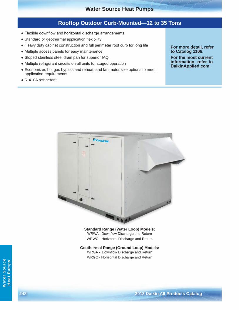
Water Source Heat Pumps
248 2013 Daikin All Products Catalog
Wat
er S
ourc
e H
eat
Pum
ps
Rooftop Outdoor Curb-Mounted—12 to 35 Tons
● Flexible downflow and horizontal discharge arrangements● Standard or geothermal application flexibility● Heavy duty cabinet construction and full perimeter roof curb for long life● Multiple access panels for easy maintenance● Sloped stainless steel drain pan for superior IAQ● Multiple refrigerant circuits on all units for staged operation● Economizer, hot gas bypass and reheat, and fan motor size options to meet
application requirements● R-410A refrigerant
For more detail, refer to Catalog 1106 .For the most current information, refer to DaikinApplied.com .
Standard Range (Water Loop) Models:WRWA - Downflow Discharge and ReturnWRWC - Horizontal Discharge and Return
Geothermal Range (Ground Loop) Models:WRGA - Downflow Discharge and ReturnWRGC - Horizontal Discharge and Return
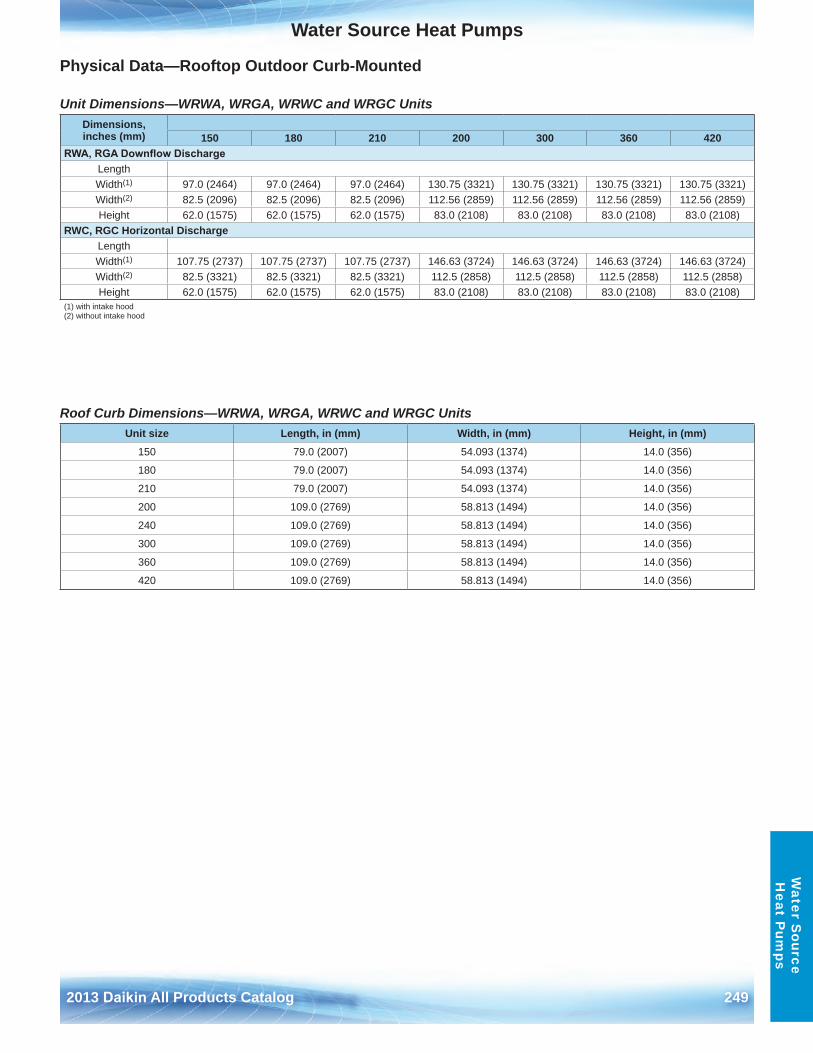
Water Source Heat Pumps
2013 Daikin All Products Catalog 249
Water S
ource H
eat Pum
ps
Physical Data—Rooftop Outdoor Curb-Mounted
Unit Dimensions—WRWA, WRGA, WRWC and WRGC Units
Roof Curb Dimensions—WRWA, WRGA, WRWC and WRGC Units
Dimensions,inches (mm) 150 180 210 200 300 360 420
RWA, RGA Downflow DischargeLengthWidth(1) 97 .0 (2464) 97 .0 (2464) 97 .0 (2464) 130 .75 (3321) 130 .75 (3321) 130 .75 (3321) 130 .75 (3321)Width(2) 82 .5 (2096) 82 .5 (2096) 82 .5 (2096) 112 .56 (2859) 112 .56 (2859) 112 .56 (2859) 112 .56 (2859)Height 62 .0 (1575) 62 .0 (1575) 62 .0 (1575) 83 .0 (2108) 83 .0 (2108) 83 .0 (2108) 83 .0 (2108)
RWC, RGC Horizontal DischargeLengthWidth(1) 107 .75 (2737) 107 .75 (2737) 107 .75 (2737) 146 .63 (3724) 146 .63 (3724) 146 .63 (3724) 146 .63 (3724)Width(2) 82 .5 (3321) 82 .5 (3321) 82 .5 (3321) 112 .5 (2858) 112 .5 (2858) 112 .5 (2858) 112 .5 (2858)Height 62 .0 (1575) 62 .0 (1575) 62 .0 (1575) 83 .0 (2108) 83 .0 (2108) 83 .0 (2108) 83 .0 (2108)
(1) with intake hood(2) without intake hood
Unit size Length, in (mm) Width, in (mm) Height, in (mm)150 79 .0 (2007) 54 .093 (1374) 14 .0 (356)
180 79 .0 (2007) 54 .093 (1374) 14 .0 (356)
210 79 .0 (2007) 54 .093 (1374) 14 .0 (356)
200 109 .0 (2769) 58 .813 (1494) 14 .0 (356)
240 109 .0 (2769) 58 .813 (1494) 14 .0 (356)
300 109 .0 (2769) 58 .813 (1494) 14 .0 (356)
360 109 .0 (2769) 58 .813 (1494) 14 .0 (356)
420 109 .0 (2769) 58 .813 (1494) 14 .0 (356)
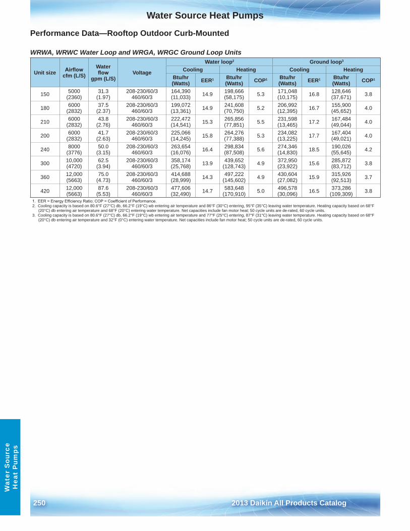
Water Source Heat Pumps
250 2013 Daikin All Products Catalog
Wat
er S
ourc
e H
eat
Pum
ps
Performance Data—Rooftop Outdoor Curb-Mounted
WRWA, WRWC Water Loop and WRGA, WRGC Ground Loop Units
Unit size Airflowcfm (L/S)
Water flow
gpm (L/S) Voltage
Water loop2 Ground loop3
Cooling Heating Cooling HeatingBtu/hr (Watts) EER1 Btu/hr
(Watts) COP1 Btu/hr (Watts) EER1 Btu/hr
(Watts) COP1
150 5000 (2360)
31 .3 (1 .97)
208-230/60/3 460/60/3
164,390 (11,033) 14 .9 198,666
(58,175) 5 .3 171,048 (10,175) 16 .8 128,646
(37,671) 3 .8
180 6000 (2832)
37 .5 (2 .37)
208-230/60/3 460/60/3
199,072 (13,361) 14 .9 241,608
(70,750) 5 .2 206,992 (12,395) 16 .7 155,900
(45,652) 4 .0
210 6000 (2832)
43 .8 (2 .76)
208-230/60/3 460/60/3
222,472 (14,541) 15 .3 265,856
(77,851) 5 .5 231,598 (13,465) 17 .2 167,484
(49,044) 4 .0
200 6000 (2832)
41 .7 (2 .63)
208-230/60/3 460/60/3
225,066 (14,245) 15 .8 264,276
(77,388) 5 .3 234,082 (13,225) 17 .7 167,404
(49,021) 4 .0
240 8000 (3776)
50 .0 (3 .15)
208-230/60/3 460/60/3
263,654 (16,076) 16 .4 298,834
(87,508) 5 .6 274,346 (14,830) 18 .5 190,026
(55,645) 4 .2
300 10,000 (4720)
62 .5 (3 .94)
208-230/60/3 460/60/3
358,174 (25,768) 13 .9 439,652
(128,743) 4 .9 372,950 (23,922) 15 .6 285,872
(83,712) 3 .8
360 12,000 (5663)
75 .0 (4 .73)
208-230/60/3 460/60/3
414,688 (28,999) 14 .3 497,222
(145,602) 4 .9 430,604 (27,082) 15 .9 315,926
(92,513) 3 .7
420 12,000 (5663)
87 .6 (5 .53)
208-230/60/3 460/60/3
477,606 (32,490) 14 .7 583,648
(170,910) 5 .0 496,578 (30,096) 16 .5 373,286
(109,309) 3 .8
1. EER = Energy Efficiency Ratio; COP = Coefficient of Performance.2 . Cooling capacity is based on 80 .6°F (27°C) db, 66 .2°F (19°C) wb entering air temperature and 86°F (30°C) entering, 95°F (35°C) leaving water temperature . Heating capacity based on 68°F
(20°C) db entering air temperature and 68°F (20°C) entering water temperature . Net capacities include fan motor heat; 50 cycle units are de-rated, 60 cycle units .3 . Cooling capacity is based on 80 .6°F (27°C) db, 66 .2°F (19°C) wb entering air temperature and 77°F (25°C) entering, 87°F (31°C) leaving water temperature . Heating capacity based on 68°F
(20°C) db entering air temperature and 32°F (0°C) entering water temperature . Net capacities include fan motor heat; 50 cycle units are de-rated, 60 cycle units .
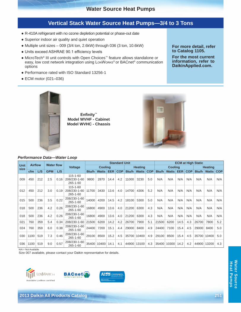
Water Source Heat Pumps
2013 Daikin All Products Catalog 251
Water S
ource H
eat Pum
ps
Vertical Stack Water Source Heat Pumps—3/4 to 3 Tons
● R-410A refrigerant with no ozone depletion potential or phase-out date● Superior indoor air quality and quiet operation● Multiple unit sizes – 009 (3/4 ton, 2 .6kW) through 036 (3 ton, 10 .6kW)● Units exceed ASHRAE 90.1 efficiency levels● MicroTech® III unit controls with Open Choices™ feature allows standalone or
easy, low cost network integration using LonWorks® or BACnet® communicationoptions
● Performance rated with ISO Standard 13256-1● ECM motor (021–036)
For more detail, refer to Catalog 1105 .For the most current information, refer to DaikinApplied.com .
Performance Data—Water Loop
Unit size
Airflow Water flow VoltageStandard Unit ECM at High Static
Cooling Heating Cooling Heatingcfm L/S GPM L/S Btu/h Watts EER COP Btu/h Watts COP Btu/h Watts EER COP Btu/h Watts COP
009 450 212 2 .5 0 .16115-1-60
208/230-1-60 265-1-60
9800 2870 14 .4 4 .2 11000 3230 5 .0 N/A N/A N/A N/A N/A N/A N/A
012 450 212 3 .0 0 .19115-1-60
208/230-1-60 265-1-60
11700 3430 13 .6 4 .0 14700 4306 5 .2 N/A N/A N/A N/A N/A N/A N/A
015 500 236 3 .5 0 .22 208/230-1-60 265-1-60 14000 4200 14 .5 4 .2 18100 5300 5 .0 N/A N/A N/A N/A N/A N/A N/A
018 500 236 4 .2 0 .26 208/230-1-60 265-1-60 16800 4900 13 .6 4 .0 21200 6300 4 .3 N/A N/A N/A N/A N/A N/A N/A
018 500 236 4 .2 0 .26 208/230-1-60 265-1-60 16800 4900 13 .6 4 .0 21200 6300 4 .3 N/A N/A N/A N/A N/A N/A N/A
021 760 359 5 .4 0 .34 208/230-1-60 21500 6200 14 .2 4 .2 26700 7900 5 .1 21500 6200 14 .5 4 .3 26700 7800 5 .2
024 760 359 6 .0 0 .38 208/230-1-60 265-1-60 24400 7200 15 .1 4 .4 29000 8400 4 .9 24400 7100 15 .4 4 .5 29000 8400 5 .0
030 1100 519 7 .3 0 .46 208/230-1-60 265-1-60 29100 8500 15 .2 4 .5 35700 10400 4 .9 29100 8500 15 .4 4 .5 35700 10400 5 .0
036 1100 519 9 .0 0 .57 208/230-1-60 265-1-60 35400 10400 14 .1 4 .1 44900 13100 4 .3 35400 10300 14 .2 4 .2 44900 13200 4 .3
N/A = Not AvailableSize 007 available, please contact your Daikin representative for details .
Enfinity™ Model WVHF - Cabinet Model WVHC - Chassis
Available LonMark cert i f ied
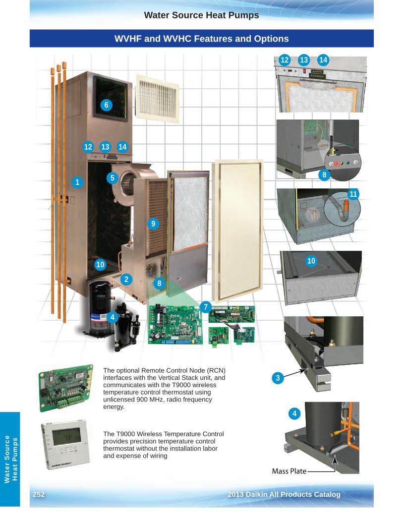
Water Source Heat Pumps
252 2013 Daikin All Products Catalog
Wat
er S
ourc
e H
eat
Pum
ps
WVHF and WVHC Features and Options
9
12
4
6
7
13 14
12 13 14
81
11
2 8
4
5
10
3
Mass Plate
10
The optional Remote Control Node (RCN) interfaces with the Vertical Stack unit, and communicates with the T9000 wireless temperature control thermostat using unlicensed 900 MHz, radio frequency energy .
The T9000 Wireless Temperature Control provides precision temperature control thermostat without the installation labor and expense of wiring
Water Source Heat Pumps
2013 Daikin All Products Catalog 253
Water S
ource H
eat Pum
ps
WVHF and WVHC Features and Options
1 Compact cabinets• Constructed of unpainted galvanized steel, with the
smallest possible footprint . 18" × 18" cabinet for unit sizes009 through 018 and 24" × 24" for unit sizes 021 through036
2 Chassis• Removable, allows staged installation and ease of service
and routine maintenance
3 Chassis vibration isolators• Vibration isolators are integral to the chassis support
rails to help minimize noise and vibration transmissionresulting in a quiet occupied space
4 Compressors • High efficiency rotary and scroll, available with optional
mass plate and/or compressor sound blanket (scrollcompressor only) for quiet operation (unit sizes 021-036)
5 Motor/blower assembly • PSC standard fan motor and housing is removable and
slides out through the front of the cabinet . Optional ECMmotor available in unit sizes 021-036
6 Supply air plenum • Allows for multiple discharge air configurations
7 Microtech® III control system • Open Choices™ feature allows standalone or easy, low
cost network integration using LonWorks® or BACnet®
communication options
8 LED annunciator• LED status lights display fault conditions to provide easy
troubleshooting and diagnosis . Accessed by opening thefront panel
9 Primary condensate drain pan• Is sloped and constructed of a corrosion resistant ABS
plastic . It sits below the air coil to capture all condensatein cooling mode. A factory installed condensate overflowsensor disables unit operation when the condensate levelreaches the sensor
10 Secondary IAQ condensate drain pan • Sits below the chassis to prevent condensate or other
liquids from dripping into the cabinet and possiblyreaching the living space . Available in optional corrosionresistant stainless steel or standard galvanized steel . Thisdrain pan also includes a factory installed condensateoverflow sensor
11 Condensate drain hose IAQ J-trap • Formed, flexible condensate trap helps prevent
undesirable odors from backing up into the unit and intothe supply air stream
12 Front-mounted disconnect switch • Easy-access disconnect switch allows the user to turn off
power to the unit for service/maintenance
13 Two-speed fan toggle switch • Convenient location for easy high/low fan speed change
14 Front-mounted thermostat terminal strip • Provides easy connection of wall-mounted thermostat
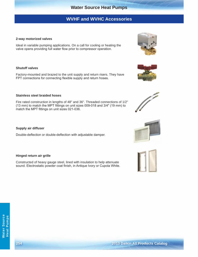
Water Source Heat Pumps
254 2013 Daikin All Products Catalog
Wat
er S
ourc
e H
eat
Pum
ps
WVHF and WVHC Accessories
2-way motorized valves
Ideal in variable pumping applications . On a call for cooling or heating the valve opens providing full water flow prior to compressor operation.
Shutoff valves
Factory-mounted and brazed to the unit supply and return risers . They have FPT connections for connecting flexible supply and return hoses.
Stainless steel braided hoses
Fire rated construction in lengths of 48" and 36" . Threaded connections of 1/2" (13 mm) to match the MPT fittings on unit sizes 009-018 and 3/4" (19 mm) to match the MPT fittings on unit sizes 021-036.
Supply air diffuser
Double-deflection or double-deflection with adjustable damper.
Hinged return air grille
Constructed of heavy gauge steel, lined with insulation to help attenuate sound. Electrostatic powder coat finish, in Antique Ivory or Cupola White.
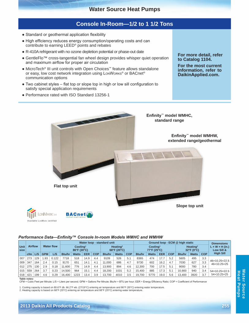
Water Source Heat Pumps
2013 Daikin All Products Catalog 255
Water S
ource H
eat Pum
ps
Console In-Room—1/2 to 1 1/2 Tons
● Standard or geothermal application flexibility● High efficiency reduces energy consumption/operating costs and can
contribute to earning LEED® points and rebates● R-410A refrigerant with no ozone depletion potential or phase-out date● GentleFlo™ cross-tangential fan wheel design provides whisper quiet operation
and maximum airflow for proper air circulation● MicroTech® III unit controls with Open Choices™ feature allows standalone
or easy, low cost network integration using LonWorks® or BACnet®
communication options● Two cabinet styles – flat top or slope top in high or low sill configuration to
satisfy special application requirements● Performance rated with ISO Standard 13256-1
For more detail, refer to Catalog 1104 .For the most current information, refer to DaikinApplied.com .
Performance Data—Enfinity™ Console In-room Models WMHC and WMHW
Unit size
Airflow Water flowWater loop - standard unit Ground loop - ECM @ high static Dimensions
L × W × H (in .) Low Sill & High Sill
Cooling1 86°F (30°C)
Heating2 68°F (20°C)
Cooling1 77°F (25°C)
Heating2 32°F (0°C)
cfm L/S GPM L/S Btu/hr Watts EER COP Btu/hr Watts COP Btu/hr Watts EER COP Btu/hr Watts COP007 273 129 1 .93 0 .122 7718 518 14 .9 4 .4 9109 526 5 .1 8365 474 17 .7 5 .2 5605 495 3 .3
46×10 .25×22 .5 46×10 .25×25009 347 164 2 .4 0 .15 9170 651 14 .1 4 .1 11,000 686 4 .7 9730 602 16 .2 4 .7 7030 627 3 .3
012 275 130 2 .9 0 .18 11,600 776 14 .9 4 .4 13,900 894 4 .6 12,300 700 17 .5 5 .1 9000 780 3 .4015 559 264 3 .7 0 .23 14,500 964 15 .1 4 .4 18,200 1031 5 .2 15,400 885 17 .3 5 .1 10,900 940 3 .4 54×10 .25×22 .5
54×10 .25×25018 421 199 4 .6 0 .29 16,400 1223 13 .4 3 .9 13,700 4010 3 .5 19,700 5770 19 .0 5 .6 13,400 3920 3 .7Table notes:CFM = Cubic Feet per Minute; L/S = Liters per second; GPM = Gallons Per Minute; Btu/hr = BTU per hour; EER = Energy Efficiency Ratio; COP = Coefficient of Performance
1 . Cooling capacity is based on 80 .6°F db . 66 .2°F wb . (27/19°C) entering air temperature and 86°F (30°C) entering water temperature .2 . Heating capacity is based on 68°F (20°C) entering air temperature and 68°F (20°C) entering water temperature .
Enfinity™ model WMHC, standard range
Enfinity™ model WMHW, extended range/geothermal
Flat top unit
Slope top unit
Available LonMark cert i f ied
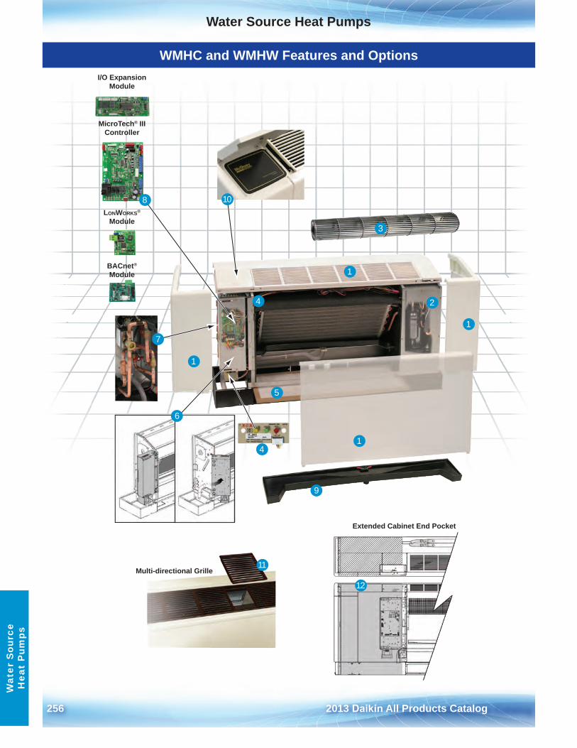
Water Source Heat Pumps
256 2013 Daikin All Products Catalog
Wat
er S
ourc
e H
eat
Pum
ps
WMHC and WMHW Features and Options
Multi-directional Grille
Extended Cabinet End Pocket
MicroTech® IIIController
LONWORKS®
Module
BACnet®
Module
I/O ExpansionModule
1
1
1
1
10
11
12
2
3
4
4
5
6
7
8
9
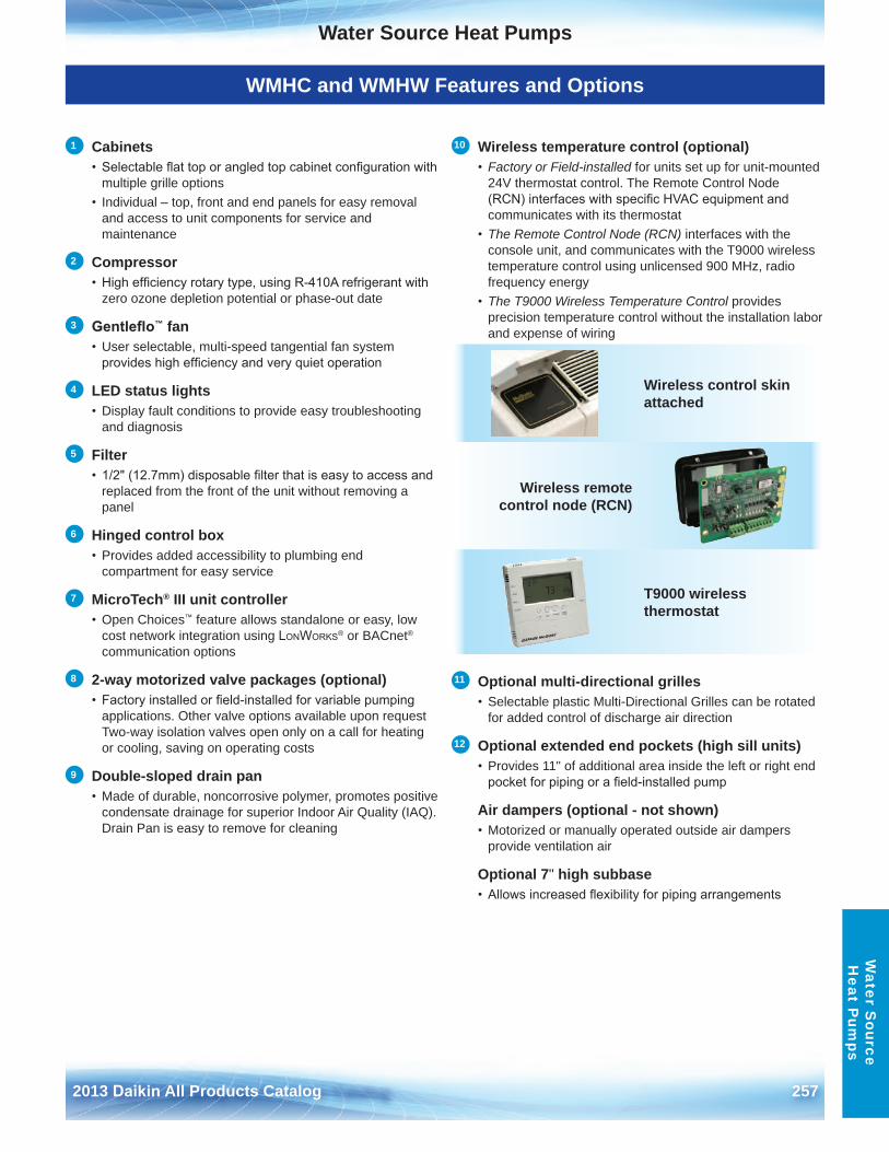
Water Source Heat Pumps
2013 Daikin All Products Catalog 257
Water S
ource H
eat Pum
ps
WMHC and WMHW Features and Options
1 Cabinets• Selectable flat top or angled top cabinet configuration with
multiple grille options • Individual – top, front and end panels for easy removal
and access to unit components for service and maintenance
2 Compressor• High efficiency rotary type, using R-410A refrigerant with
zero ozone depletion potential or phase-out date
3 Gentleflo™ fan• User selectable, multi-speed tangential fan system
provides high efficiency and very quiet operation
4 LED status lights• Display fault conditions to provide easy troubleshooting
and diagnosis
5 Filter• 1/2" (12.7mm) disposable filter that is easy to access and
replaced from the front of the unit without removing a panel
6 Hinged control box• Provides added accessibility to plumbing end
compartment for easy service
7 MicroTech® III unit controller• Open Choices™ feature allows standalone or easy, low
cost network integration using LonWorks® or BACnet® communication options
8 2-way motorized valve packages (optional)• Factory installed or field-installed for variable pumping
applications . Other valve options available upon request Two-way isolation valves open only on a call for heating or cooling, saving on operating costs
9 Double-sloped drain pan• Made of durable, noncorrosive polymer, promotes positive
condensate drainage for superior Indoor Air Quality (IAQ) . Drain Pan is easy to remove for cleaning
10 Wireless temperature control (optional) • Factory or Field-installed for units set up for unit-mounted
24V thermostat control . The Remote Control Node (RCN) interfaces with specific HVAC equipment and communicates with its thermostat
• The Remote Control Node (RCN) interfaces with theconsole unit, and communicates with the T9000 wireless temperature control using unlicensed 900 MHz, radio frequency energy
• The T9000 Wireless Temperature Control providesprecision temperature control without the installation labor and expense of wiring
11 Optional multi-directional grilles• Selectable plastic Multi-Directional Grilles can be rotated
for added control of discharge air direction
12 Optional extended end pockets (high sill units)• Provides 11" of additional area inside the left or right end
pocket for piping or a field-installed pump
Air dampers (optional - not shown)• Motorized or manually operated outside air dampers
provide ventilation air
Optional 7" high subbase• Allows increased flexibility for piping arrangements
Wireless control skin attached
Wireless remote control node (RCN)
T9000 wireless thermostat
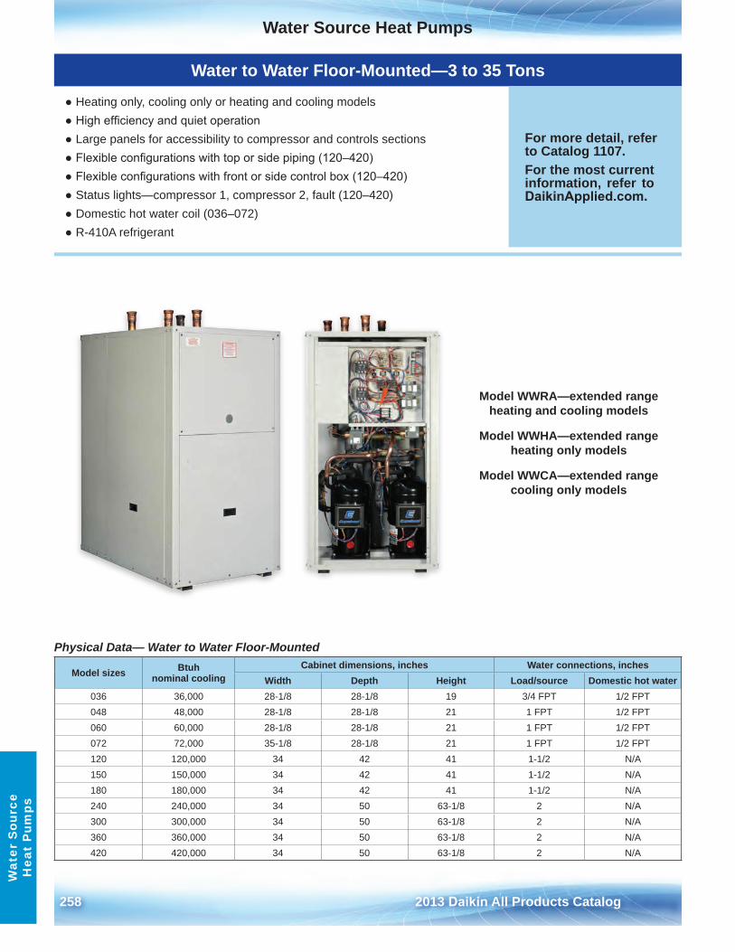
Water Source Heat Pumps
258 2013 Daikin All Products Catalog
Wat
er S
ourc
e H
eat
Pum
ps
Water to Water Floor-Mounted—3 to 35 Tons
● Heating only, cooling only or heating and cooling models● High efficiency and quiet operation● Large panels for accessibility to compressor and controls sections● Flexible configurations with top or side piping (120–420)● Flexible configurations with front or side control box (120–420)● Status lights—compressor 1, compressor 2, fault (120–420)● Domestic hot water coil (036–072)● R-410A refrigerant
For more detail, refer to Catalog 1107 .For the most current information, refer to DaikinApplied.com .
Physical Data— Water to Water Floor-Mounted
Model sizes Btuh nominal cooling
Cabinet dimensions, inches Water connections, inchesWidth Depth Height Load/source Domestic hot water
036 36,000 28-1/8 28-1/8 19 3/4 FPT 1/2 FPT048 48,000 28-1/8 28-1/8 21 1 FPT 1/2 FPT060 60,000 28-1/8 28-1/8 21 1 FPT 1/2 FPT072 72,000 35-1/8 28-1/8 21 1 FPT 1/2 FPT120 120,000 34 42 41 1-1/2 N/A150 150,000 34 42 41 1-1/2 N/A180 180,000 34 42 41 1-1/2 N/A240 240,000 34 50 63-1/8 2 N/A300 300,000 34 50 63-1/8 2 N/A360 360,000 34 50 63-1/8 2 N/A420 420,000 34 50 63-1/8 2 N/A
Model WWRA—extended range heating and cooling models
Model WWHA—extended range heating only models
Model WWCA—extended range cooling only models

←TRIM
TRIM→
2013 Daikin A
ll Products C
atalogA
/SP
31-29 (03/13)
™® The following are tradenames or registered trademarks of their respective companies: BACnet from ASHRAE;Modbus from Schneider Electric Ltd; MicroTech III, Open Choices, from Daikin; LonMark, LonTaLk, and LonWorks are managed, granted and used by LonMark International under a license granted by Echelon Corporation .
©2013 Daikin Applied A/SP 31-29 (03/13)
Products manufactured in ISO certified facilities.
WarrantyAll Daikin equipment is sold pursuant to Daikin's Standard Terms and Conditions of Sale and Limited Product Warranty.
800 .432 .1342www .DaikinApplied.com


