Embed Size (px)
Citation preview
SS-DRG7 www.daikinac.com 07/22Supersedes 05/22
DRG Commercial
High-Efficiency Gas/Electric Packaged Rooftop Unit
DRG Commercial7.5 - 12.5 Nominal Tons
Up to 17 IEER / 12.2 EER
* Complete warranty details available from your local distributor or manufacturer’s representative or at www.daikincomfort.com or www.daikinac.com

2
Our Perfect Package:Harnessing energy-efficient performance, proven technology, and enhanced comfort for life.
Since becoming the first company in Japan to manufacture packaged
air conditioning systems, in 1951, Daikin has supported comfortable
indoor living based on the strengths and technologies that have
led to the growth of the company becoming one of the
world’s largest manufacturers of HVAC products, systems
and refrigerants.
Today, as a comprehensive global manufacturer of HVAC products
and systems, the Daikin brand is committed to being recognized
as a truly global and excellent company capable of continually
creating new value for its customers. The company plans to pursue
sustainable growth and foster business operations that consistently
harmonize with the goals of improving indoor comfort.
The group philosophy of the company includes: » Creating new value continuously for customers
» Developing world leading energy-saving technology
» Being a flexible and dynamic organization
» Allowing employees to be the driving force for the success of the company
» Fostering an atmosphere of best practices, boldness, and innovation
» Thinking and acting globally
3
Contents2 Introduction 2
4 Nomenclature 4
5 Features and Benefits 5
Applications 8
Serviceability 8
9 Product Specifications 9
Coil Dimension 27
AHRI Ratings 27
Sound Data 27
28 Expanding Cooling Data 28
36 Heating Data 36
37 Air Flow 37
85 DDC Airflow 85
100 Static Pressure 100
101 HGRH Performance 101
105 Electrical Data 105
108 Wiring Diagrams 108
112 Dimensional Data 112
113 Electrical Connections 113
Unit Clearances 113114 Installation 114
Weights 114
For details on accessories refer to document PM-LC-ACCESSORIES

Nomenclature
SS-DRG7 www.daikinac.com 54 www.daikinac.com SS-DRG7
D R G 120 3 D 130 C A A
1 2 3 4,5,6 7 8 9,10,11 12 13 14
BrandD Daikin
ConfigurationR High Efficiency
ApplicationC CoolingG Gas HeatH Heat Pump
Nominal Cooling Capacity090 7½ Tons102 8½ Tons120 10 Tons150 12½ tons
Voltage3 208-230/3/60 7 575/3/604 460/3/60
Supply Fan/Drive Type/MotorD Direct Drive-Standard StaticL Direct Drive -Medium StaticW Direct Drive -High Static
Nominal Heating CapacityGas/Electric A/C H/P Factory-Installed Electric Heat130 130,000 BTU/h XXX No Heat180 180,000 BTU/h 010 10 kW225 225,000 BTU/h 015 15 kW240 240,000 BTU/h 020 20 kW
030 30 kW045 45 kW060 60 kW
See product specifications for heat size(s) available for each capacity.
Refrigeration SystemsC Two-stage cooling modesF Two stage cooling modes with Hot Gas Reheat and Low-ambient control
Heat ExchangerX No optionsA Standard Aluminized ExchangerS Stainless Steel Exchanger
ControlsA Electro-mechanical controlsB DDC w/ BACnet™ interface
X X X X X X X X A *
15 16 17 18 19 20 21 22 23 24
Revision Levels
Major & Minor
X No Options
PE ConnectionX No OptionsB Single-point power connection for Power Exhaust
X No Options
Service OptionsX No OptionA Powered convenience outletB Non-powered convenience outletC Hinge PanelsD Hinged Panels and Powered convenience outletE Hinged Panels and non-powered convenience outletM Metal frame filter and Hinged Panels (National Account Customers Only)
ElectricalX No OptionsA Non-Fused DisconnectB Phase MonitorC Thru-the-base connectionsE Non-Fused Disconnect and Phase MonitorF Non-Fused Disconnect and Thru-the-base connectionsH Phase Monitor and Thru-the-base connectionsL Non-Fused Disconnect, Thru-the-base connections and Phase Monitor
EconomizerX No OptionsA Ultra Low-Leak Downflow Economizer w/ Enthalpy SensorB Low-Leak Downflow Economizer w/ Enthalpy SensorE Ultra Low-Leak Downflow Economizer for DDC controls w/ Enthalpy SensorG Ultra Low-Leak Downflow Economizer w/ Dry Bulb SensorH Low-Leak Downflow Economizer w/ Dry Bulb SensorL Ultra Low-Leak Downflow Economizer for DDC controls w/ Dry Bulb SensorN Low-Leak Downflow Economizer for DDC controls w/ Enthalpy SensorP Low-Leak Downflow Economizer for DDC controls w/ Dry Bulb Sensor
Hail guardX No OptionsC Hail Guard
SensorsX No OptionsA RA Smoke DetectorB SA Smoke DetectorC RA & SA Smoke Detector
G/E Stocking ModelsDaikin 7.5-12.5 Ton Belt-Drive
Model Number Code String Model Number Code String Model Number Code StringDRG0903DL00001S DRG0903D130CAAXXXXXXXXAA DRG1024DL00001S DRG1024D130CAAXXXXXXXXAA DRG1207DL00001S DRG1207D130CAAXXXXXXXXAADRG0903DM00001S DRG0903D180CAAXXXXXXXXAA DRG1024DM00001S DRG1024D180CAAXXXXXXXXAA DRG1207DM00001S DRG1207D180CAAXXXXXXXXAADRG0903DH00001S DRG0903D225CAAXXXXXXXXAA DRG1024DH00001S DRG1024D225CAAXXXXXXXXAA DRG1207DH00001S DRG1207D240CAAXXXXXXXXAADRG0904DL00001S DRG0904D130CAAXXXXXXXXAA DRG1027DL00001S DRG1027D130CAAXXXXXXXXAA DRG1503DL00001S DRG1503D130CAAXXXXXXXXAADRG0904DM00001S DRG0904D180CAAXXXXXXXXAA DRG1027DM00001S DRG1027D180CAAXXXXXXXXAA DRG1503DM00001S DRG1503D180CAAXXXXXXXXAADRG0904DH00001S DRG0904D225CAAXXXXXXXXAA DRG1027DH00001S DRG1027D225CAAXXXXXXXXAA DRG1503DH00001S DRG1503D240CAAXXXXXXXXAADRG0907DL00001S DRG0907D130CAAXXXXXXXXAA DRG1203DL00001S DRG1203D130CAAXXXXXXXXAA DRG1504DL00001S DRG1504D130CAAXXXXXXXXAADRG0907DM00001S DRG0907D180CAAXXXXXXXXAA DRG1203DM00001S DRG1203D180CAAXXXXXXXXAA DRG1504DM00001S DRG1504D180CAAXXXXXXXXAADRG0907DH00001S DRG0907D225CAAXXXXXXXXAA DRG1203DH00001S DRG1203D240CAAXXXXXXXXAA DRG1504DH00001S DRG1504D240CAAXXXXXXXXAADRG1023DL00001S DRG1023D130CAAXXXXXXXXAA DRG1204DL00001S DRG1204D130CAAXXXXXXXXAA DRG1507DL00001S DRG1507D130CAAXXXXXXXXAADRG1023DM00001S DRG1023D180CAAXXXXXXXXAA DRG1204DM00001S DRG1204D180CAAXXXXXXXXAA DRG1507DM00001S DRG1507D180CAAXXXXXXXXAADRG1023DH00001S DRG1023D225CAAXXXXXXXXAA DRG1204DH00001S DRG1204D240CAAXXXXXXXXAA DRG1507DH00001S DRG1507D240CAAXXXXXXXXAA

Features and Benefits
SS-DRG7 www.daikinac.com 54 www.daikinac.com SS-DRG7
Installation Daikin Packaged units are designed with fast and easy installation in mind and are ideal for both new construction and retrofit projects. Our packaged rooftop units are built to be a direct replacement for most rooftop units on the field without the need of a curb adapter, to be able to replace the unit in a shorter time and at a lower cost (compared to the previous design).
Cabinet Construction Daikin packaged rooftop units are made with high quality galvanized steel with a powder-paint finish to provide higher corrosion resistance.
» Easy accessibility using our tool-less filter access
» The interior surface in the indoor air section is fully insulated to prevent sweating and thermal losses, using our foil face fiberglass insulation which also omits exposed filter fibers into the airstream.
» 1" Raised flanged edges around the supply and return offer easy installation for the duct connections.
» The full perimeter base rail is built using heavy gauge galvanized steel for a stronger structural installation. The base rails are a minimum of 3½" tall and include holes to allow for overhead rigging and lifting with forklifts.
» Electrical lines and gas lines can be brought through the base of the unit or through the horizontal knockout for easy installation and accessibility on the field.
Compressor High performance, low noise scroll compressors to match the required total load.
» Resiliently factory-mounted on rubber grommets for vibration isolation
» Refrigeration circuit includes both low- and high-pressure transducer, high pressure safety switch and temperature sensors for the suction and discharge lines.
» Unit is factory charged with environmentally friendly R-410A refrigerant.
» Compressor location outside the condenser section to avoid air bypass.
» Internal overload protection included with compressor.
» Dual single-stage scroll compressor for partial load applications.
Supply Fan The direct-drive with airfoil single width, single inlet (SWSI) Class II construction supply fan with aluminum fan +blades provides efficient and quiet operation at wide ranging static pressure and air flow requirements.
» Fan wheel is continuously welded to the hub plate and end rim for long lasting reliable operation.
» Direct-drive ECM motor removes the need for belts, sheaves, or bearings and its permanently lubricated motors provides low maintenance cost.
» Each fan assembly is dynamically trim balanced at the factory before shipment for quick start-up and efficient operation.
» Electromechanical integrated controls modulate the supply fan motor
» Motor with thermal overload is provided for motor long lasting operation.
Coils All units use large face area outdoor coils. These coils are constructed with seamless copper tubes, mechanically bonded into aluminum plate-type fins with full drawn collars to completely cover the tubes for high operating efficiencies.
The indoor coil section is installed in a draw through configuration to provide better dehumidification.
Daikin Packaged Rooftop Units (RTUs) are built to perform, with features and options that help provide low installation and operation costs, superior indoor air quality, efficient operation, and longevity.

SS-DRG7 www.daikinac.com 76 www.daikinac.com SS-DRG7
Features and Benefits
» Coils are factory pressure tested to ensure pressure and leak integrity.
» Copper tube / aluminum fin coils on condenser and evaporator
» 5mm Smart Coil Technology on all condenser coils for improved performance and reduced refrigerant load.
Controls and Wiring Packaged rooftop units come equipped with a well-organized, large, easy to use, weatherproof internal control box with easy access, for a better user experience.
» Units are factory-wired with labeled color-coded wires and complete 24-volt Electromechanical controls package.
» Terminal blocks are provided as standard for easy installation and field power wiring.
» The Daikin iLINQ Controller is a factory-installed solution to provide intelligent control for Daikin Light Commercial rooftop units* (RTUs). iLINQ provides physical inputs and outputs to control and monitor the RTU and features a graphic web interface for remote access (via a computer or tablet). Equipped with built-in BACnet™ IP and MS/TP interface or it can be used with an optional LonWorks® card that is available to integrate the Daikin RTU with building automation systems (BMS).
Filtration Unit provides a draw-through filter section as standard for better air quality and long lasting component maintenance.
» Filters installed on the units are standard off the shelf sizes for easy replacement.
» One size filter per unit for low maintenance cost and easy replacement.
» Tool-less filter access for easy and fast filter replacement and service.
Heating Section Wide range of natural gas selections effectively handle most comfort heating demand from morning warm-up control to full heat, all available with Daikin’s Wrinkle Bend heat exchanger technology.
Gas Furnace ETL certified heating modules provide a custom match to specific design requirement.
» Wrinkle Bend Technology available on all Daikin gas heat exchangers. The Wrinkle Bend Technology reduces the manufacturing stress that leads to defects and pinholes in the tubes at the same time as it increases the gas turbulence to amplify the heat transfer.
» All 3-Phase models have a minimum 80% T.E. (Thermal Efficiency)
» User has the flexibility to order heat exchanger tubes with 20 Gauge, G160, aluminized steel or stainless steel to meet your application needs.
» The furnace has a tubular design with in-shot gas burner manifold and is installed downstream of the supply fan.
» The module contains an induced draft fan that will maintain a negative pressure in the heat exchanger tubes for the removal of the flue gases to protect indoor air quality.
» Each burner module provides flame roll-out safety protection switches and a high temperature limit switch for reliable operation.
» Induced draft fan includes an airflow safety switch to prevent heating operation in the event of no airflow for occupant safety.
» All burner assemblies are factory tested and adjusted prior to shipment.
» Heating control is fully integrated into the unit’s control system for quick start-up and reliable control.
» Optional field installed LP kits are available for staged heating modules as well as high altitude kits.
Electrical Units are completely wired and tested at the factory to provide faster commissioning and start-up.
» Wiring complies with NEC requirements and all applicable UL standards.
» For ease of use, wiring and electrical components are number coded and labeled according to the electrical diagram.
» A 115 V GFI convenience outlet requiring independent power supply for the receptacle is optional.
» An optional unit powered 20 amp 115 V convenience outlet, complete with factory mounted transformer, disconnect switch, and primary and secondary overload protection, eliminates the need to pull a separate 115 V power source.
» Supply air fan, compressor, and condenser fan motor branch circuits have individual short circuit protection. Unit includes knockouts in the bottom of the main control panels for field wiring entrance.
» A single-point power connection with power block is standard and a terminal board is provided for connecting low voltage control wiring.
» For better serviceability an optional non-fused disconnect switch can be installed inside the control panel and operated by an externally mounted handle to disconnect the electrical power at the unit.
Daikin Modulating Hot Gas Reheat Dehumidification Using a space sensor in conjunction with the Daikin iLINQ Controller and Reheat Module, the unit can initiate a Dehumidification Mode as the space humidity rises above setpoint. In this mode, the modulating valve diverts a percentage of the hot gas to the reheat coil as required in order to maintain supply air temperature requirements while lowering the space relative humidity. The modulating valve system allows smooth transition into dehumidification and longer run time at a steady supply air temperature. The indoor fan will operate at high and low speed during dehumidification mode.

SS-DRG7 www.daikinac.com 76 www.daikinac.com SS-DRG7

SS-DRG7 www.daikinac.com 98 www.daikinac.com SS-DRG7
Applications & Serviceability
SS-DRG7 www.daikinac.com 98 www.daikinac.com SS-DRG7
ApplicationsDaikin Rooftop units are intended for comfort cooling applications in normal heating, ventilating, and air conditioning. Consult your local Daikin sales representative for applications involving operations at high ambient temperatures, high altitudes, non-cataloged voltages, or for job-specific unit selections that fall outside of the range of the catalog tables.
For proper operation, units should be rigged in accordance with instructions stated on the installation manual. Fire dampers, if required, must be installed in the ductwork according to local and/or state codes. No space is allowed for these dampers in the unit.
Follow factory check, test and start procedures explicitly to achieve satisfactory start-up and operation.
Most rooftop applications take advantage of the significant energy savings provided with economizer operation. When an economizer system is used, mechanical refrigeration is typically not required below an ambient temperature of 50°F.
Serviceability Daikin packaged rooftop units are built with serviceability in mind, designed to make future maintenance and service on the unit easy and accessible.
» Our packaged rooftop units offer a slide out blower to facilitate the access and removal of the fan.
» Filter panels on the small chassis line offer tool-less access for easy maintenance.
» Independent compressor outside of the air bypass to eliminate component blockage and provide easy access.
» Labeled field connections, color coded and continuously marked wire to identify point-to-point component connections.
» All 7.5- 12.5 ton units are designed for convertible airflow orientation to serve downflow or horizontal applications. Every unit ships prepared to convert to horizontal orientation in the field if required.
» Condenser clean out from inside-out.
» Easy access to gas valves and control panel.

Product Specifications
SS-DRG7 www.daikinac.com 98 www.daikinac.com SS-DRG7 SS-DRG7 www.daikinac.com 98 www.daikinac.com SS-DRG7
Model DRG0903DL000001S DRG0903DM000001SDRG0903DH000001S DRG0904DL00001S DRG0904DM00001S DRG0904DH00001SCOOLING CAPACITYTotal, BTU/h 90,000 90,000 90,000 90,000 90,000 90,000IEER / EER 16/12.2 16/12.2 16/12.2 16/12.2 16/12.2 16/12.2AHRI Reference # 206913013 206913013 206913013 206913013 206913013 206913013HEATING CAPACITY Heat Range LOW MEDIUM HIGH LOW MEDIUM HIGHNo. of Burners 5 6 7 5 6 7High Stage Input / Output (KBTU/H) 130/105.3 180/145.8 225/182.25 130/105.3 180/145.8 225/182.25Low Stage Input / Output (KBTU/H) 97.5/79 135/109.35 168.75/136.69 97.5/79 135/109.35 168.75/136.69Thermal Efficiency (T.E.) 81% 81% 81% 81% 81% 81%Annual Fuel Utilization Efficiency (AFUE) N/A N/A N/A N/A N/A N/A
High Stage Temperature Rise Range (°F) 25 - 55 25 - 55 40 - 70 25 - 55 25 - 55 40 - 70
Low Stage Temperature Rise Range (°F) 25 - 55 25 - 55 40 - 70 25 - 55 25 - 55 40 - 70
EVAPORATOR MOTOR COILMotor Type DIRECT DRIVE DIRECT DRIVE DIRECT DRIVE DIRECT DRIVE DIRECT DRIVE DIRECT DRIVE External Static Pressure (ESP) 0.8 IN.W.G. 0.8 IN.W.G. 0.8 IN.W.G. 0.8 IN.W.G. 0.8 IN.W.G. 0.8 IN.W.G.Wheel Dia. X Width Ø15.12 X 12.62 Ø15.12 X 12.62 Ø15.12 X 12.62 Ø15.12 X 12.62 Ø15.12 X 12.62 Ø15.12 X 12.62Indoor Nominal CFM 3000 3000 3000 3000 3000 3000RPM 1300 1300 1300 1300 1300 1300Indoor Horsepower 2.4 2.4 2.4 2.4 2.4 2.4Filter Size (in) 16X25X2 (4) 16X25X2 (4) 16X25X2 (4) 16X25X2 (4) 16X25X2 (4) 16X25X2 (4)Drain Size (NPT) 3/4 3/4 3/4 3/4 3/4 3/4R-410A Refrigerant Charge (oz.) 133/133 133/133 133/133 133/133 133/133 133/133Evaporator Coil Face Area (ft²) 12.8 12.8 12.8 12.8 12.8 12.8Rows Deep/ Fins per Inch 4/16 4/16 4/16 4/16 4/16 4/16CONDENSER FAN/COILQuantity of Condenser Fan Motors 2 2 2 2 2 2RPM (High/Low stage) 1122 1122 1122 1050 1050 1050Outdoor Horsepower 1/3 1/3 1/3 1/3 1/3 1/3Fan Diameter/ # Fan Blades 22/3 22/3 22/3 22/3 22/3 22/3Face Area (ft²) 35.3 35.3 35.3 35.3 35.3 35.3Rows Deep / Fins per Inch 2/28±1 2/28±1 2/28±1 2/28±1 2/28±1 2/28±1COMPRESSORQuantity / Type / Stages 2/SCROLL/1 2/SCROLL/1 2/SCROLL/1 2/SCROLL/1 2/SCROLL/1 2/SCROLL/1Compressor RLA / LRA 13.1/83.1 13.1/83.1 13.1/83.1 6.1/41.0 6.1/41.0 6.1/41.0ELECTRICAL DATA Voltage-Phase-Frequency 208/230-3-60 208/230-3-60 208/230-3-60 460-3-60 460-3-60 460-3-60Indoor Blower FLA 8 8 8 5.4 5.4 5.4Max External Static (In. W.C.) 0.8 0.8 0.8 0.8 0.8 0.8Outdoor Fan FLA 2 2 2 0.85 0.85 0.85Min. Circuit Ampacity¹ 41.6/41.6 41.6/41.6 41.6/41.6 20.8 20.8 20.8Max. Overcurrent Protection (A)² 50/50 50/50 50/50 25 25 25Power Supply Conduit Hole Dia. (in) 1.375 1.375 1.375 1.375 1.375 1.375Low-VoltageConduit Hole Dia. (in) 0.375 0.375 0.375 0.375 0.375 0.375OPERATING WEIGHT (LBS.)Operating Weight (lbs) 1162 1172 1181 1162 1172 1181SHIPPING WEIGHT (LBS.)Ship Weight (lbs) 1237 1247 1256 1237 1247 1256
¹ Wire size should be determined in accordance with National Electrical Codes. Extensive wire runs will require larger wire sizes. ² May use fuses or HACR-type circuit breakers of the same size as noted. Note: Always check the S&R plate for electrical data on the unit being installed.
7.5 to 12.5 Ton - Standard Static

Product Specifications
SS-DRG7 www.daikinac.com 1110 www.daikinac.com SS-DRG7
Model DRG0907DL00001S DRG0907DM00001S DRG0907DH00001S DRG1023DL00001S DRG1023DM00001S DRG1023DH00001SCOOLING CAPACITYTotal, BTU/h 90,000 90,000 90,000 102,000 102,000 102,000IEER / EER 16/12.2 16/12.2 16/12.2 17/12.2 17/12.2 17/12.2AHRI Reference # 206913013 206913013 206913013 206913015 206913015 206913015HEATING CAPACITY Heat Range LOW MEDIUM HIGH LOW MEDIUM HIGHNo. of Burners 5 6 7 5 6 7High Stage Input / Output (KBTU/H) 130/105.3 180/145.8 225/182.25 130/105.3 180/145.8 225/182.25Low Stage Input / Output (KBTU/H) 97.5/79 135/109.35 168.75/136.69 97.5/79 135/109.35 168.75/136.69Thermal Efficiency (T.E.) 81% 81% 81% 81% 81% 81%Annual Fuel Utilization Efficiency (AFUE) N/A N/A N/A N/A N/A N/A
High Stage Temperature Rise Range (°F) 25 - 55 25 - 55 40 - 70 25 - 55 25 - 55 40 - 70
Low Stage Temperature Rise Range (°F) 25 - 55 25 - 55 40 - 70 25 - 55 25 - 55 40 - 70
EVAPORATOR MOTOR COILMotor Type DIRECT DRIVE DIRECT DRIVE DIRECT DRIVE DIRECT DRIVE DIRECT DRIVE DIRECT DRIVE External Static Pressure (ESP) 0.8 IN.W.G. 0.8 IN.W.G. 0.8 IN.W.G. 0.8 IN.W.G. 0.8 IN.W.G. 0.8 IN.W.G.Wheel Dia. X Width Ø15.12 X 12.62 Ø15.12 X 12.62 Ø15.12 X 12.62 Ø15.12 X 12.62 Ø15.12 X 12.62 Ø15.12 X 12.62Indoor Nominal CFM 3000 3000 3000 3100 3100 3100RPM 1300 1300 1300 1300 1300 1300Indoor Horsepower 2.4 2.4 2.4 2.4 2.4 2.4
Filter Size (in) 16X25X2 (4) 16X25X2 (4) 16X25X2 (4) 20x25x2(2) + 25x25x2(2)
20x25x2(2) + 25x25x2(2)
20x25x2(2) + 25x25x2(2)
Drain Size (NPT) 3/4 3/4 3/4 3/4 3/4 3/4R-410A Refrigerant Charge (oz.) 133/133 133/133 133/133 155/155 155/155 155/155Evaporator Coil Face Area (ft²) 12.8 12.8 12.8 16.6 16.6 16.6Rows Deep/ Fins per Inch 4/16 4/16 4/16 4/16 4/16 4/16CONDENSER FAN/COILQuantity of Condenser Fan Motors 2 2 2 2 2 2RPM (High/Low stage) 1050 1050 1050 1122 1122 1122Outdoor Horsepower 1/3 1/3 1/3 1/3 1/3 1/3Fan Diameter/ # Fan Blades 22/3 22/3 22/3 22/3 22/3 22/3Face Area (ft²) 35.3 35.3 35.3 35.3 35.3 35.3Rows Deep / Fins per Inch 2/28±1 2/28±1 2/28±1 2/28±1 2/28±1 2/28±1COMPRESSORQuantity / Type / Stages 2/SCROLL/1 2/SCROLL/1 2/SCROLL/1 2/SCROLL/1 2/SCROLL/1 2/SCROLL/1Compressor RLA / LRA 4.4/33.0 4.4/33.0 4.4/33.0 14.5/98.0 14.5/98.0 14.5/98.0ELECTRICAL DATA Voltage-Phase-Frequency 575-3-60 575-3-60 575-3-60 208/230-3-60 208/230-3-60 208/230-3-60Indoor Blower FLA 4 4 4 8 8 8Max External Static (In. W.C.) 0.8 0.8 0.8 0.8 0.8 0.8Outdoor Fan FLA 0.67 0.67 0.67 2 2 2Min. Circuit Ampacity¹ 15.1 15.1 15.1 44.6/44.6 44.6/44.6 44.6/44.6Max. Overcurrent Protection (A)² 20 20 20 50/50 50/50 50/50Power Supply Conduit Hole Dia. (in) 1.375 1.375 1.375 1.375 1.375 1.375Low-VoltageConduit Hole Dia. (in) 0.375 0.375 0.375 0.375 0.375 0.375OPERATING WEIGHT (LBS.)Operating Weight (lbs) 1162 1172 1181 1173 1183 1192SHIPPING WEIGHT (LBS.)Ship Weight (lbs) 1237 1247 1256 1248 1258 1267
¹ Wire size should be determined in accordance with National Electrical Codes. Extensive wire runs will require larger wire sizes. ² May use fuses or HACR-type circuit breakers of the same size as noted. Note: Always check the S&R plate for electrical data on the unit being installed.
7.5 to 12.5 Ton - Standard Static (cont.)

Product Specifications
SS-DRG7 www.daikinac.com 1110 www.daikinac.com SS-DRG7
7.5 to 12.5 Ton - Standard Static (cont.)
Model DRG1024DL00001S DRG1024DM00001S DRG1024DH00001S DRG1027DL00001S DRG1027DM00001S DRG1027DH00001SCOOLING CAPACITYTotal, BTU/h 102,000 102,000 102,000 102,000 102,000 102,000IEER / EER 17/12.2 17/12.2 17/12.2 17/12.2 17/12.2 17/12.2AHRI Reference # 206913015 206913015 206913015 206913015 206913015 206913015HEATING CAPACITY Heat Range LOW MEDIUM HIGH LOW MEDIUM HIGHNo. of Burners 5 6 7 5 6 7High Stage Input / Output (KBTU/H) 130/105.3 180/145.8 225/182.25 130/105.3 180/145.8 225/182.25Low Stage Input / Output (KBTU/H) 97.5/79 135/109.35 168.75/136.69 97.5/79 135/109.35 168.75/136.69Thermal Efficiency (T.E.) 81% 81% 81% 81% 81% 81%Annual Fuel Utilization Efficiency (AFUE) N/A N/A N/A N/A N/A N/A
High Stage Temperature Rise Range (°F) 25 - 55 25 - 55 40 - 70 25 - 55 25 - 55 40 - 70
Low Stage Temperature Rise Range (°F) 25 - 55 25 - 55 40 - 70 25 - 55 25 - 55 40 - 70
EVAPORATOR MOTOR COILMotor Type DIRECT DRIVE DIRECT DRIVE DIRECT DRIVE DIRECT DRIVE DIRECT DRIVE DIRECT DRIVE External Static Pressure (ESP) 0.8 IN.W.G. 0.8 IN.W.G. 0.8 IN.W.G. 0.8 IN.W.G. 0.8 IN.W.G. 0.8 IN.W.G.Wheel Dia. X Width Ø15.12 X 12.62 Ø15.12 X 12.62 Ø15.12 X 12.62 Ø15.12 X 12.62 Ø15.12 X 12.62 Ø15.12 X 12.62Indoor Nominal CFM 3100 3100 3100 3100 3100 3100RPM 1300 1300 1300 1300 1300 1300Indoor Horsepower 2.4 2.4 2.4 2.4 2.4 2.4
Filter Size (in) 20x25x2(2) + 25x25x2(2)
20x25x2(2) + 25x25x2(2)
20x25x2(2) + 25x25x2(2)
20x25x2(2) + 25x25x2(2)
20x25x2(2) + 25x25x2(2)
20x25x2(2) + 25x25x2(2)
Drain Size (NPT) 3/4 3/4 3/4 3/4 3/4 3/4R-410A Refrigerant Charge (oz.) 155/155 155/155 155/155 155/155 155/155 155/155Evaporator Coil Face Area (ft²) 16.6 16.6 16.6 16.6 16.6 16.6Rows Deep/ Fins per Inch 4/16 4/16 4/16 4/16 4/16 4/16CONDENSER FAN/COILQuantity of Condenser Fan Motors 2 2 2 2 2 2RPM (High/Low stage) 1050 1050 1050 1050 1050 1050Outdoor Horsepower 1/3 1/3 1/3 1/3 1/3 1/3Fan Diameter/ # Fan Blades 22/3 22/3 22/3 22/3 22/3 22/3Face Area (ft²) 35.3 35.3 35.3 35.3 35.3 35.3Rows Deep / Fins per Inch 2/28±1 2/28±1 2/28±1 2/28±1 2/28±1 2/28±1COMPRESSORQuantity / Type / Stages 2/SCROLL/1 2/SCROLL/1 2/SCROLL/1 2/SCROLL/1 2/SCROLL/1 2/SCROLL/1Compressor RLA / LRA 6.3/55.0 6.3/55.0 6.3/55.0 6.0/41.0 6.0/41.0 6.0/41.0ELECTRICAL DATA Voltage-Phase-Frequency 460-3-60 460-3-60 460-3-60 575-3-60 575-3-60 575-3-60Indoor Blower FLA 5.4 5.4 5.4 4 4 4Max External Static (In. W.C.) 0.8 0.8 0.8 0.8 0.8 0.8Outdoor Fan FLA 0.85 0.85 0.85 0.67 0.67 0.67Min. Circuit Ampacity¹ 21.4 21.4 21.4 18.9 18.9 18.9Max. Overcurrent Protection (A)² 25 25 25 20 20 20Power Supply Conduit Hole Dia. (in) 1.375 1.375 1.375 1.375 1.375 1.375Low-VoltageConduit Hole Dia. (in) 0.375 0.375 0.375 0.375 0.375 0.375OPERATING WEIGHT (LBS.)Operating Weight (lbs) 1173 1183 1192 1173 1183 1192SHIPPING WEIGHT (LBS.)Ship Weight (lbs) 1248 1258 1267 1248 1258 1267
¹ Wire size should be determined in accordance with National Electrical Codes. Extensive wire runs will require larger wire sizes. ² May use fuses or HACR-type circuit breakers of the same size as noted. Note: Always check the S&R plate for electrical data on the unit being installed.

Product Specifications
SS-DRG7 www.daikinac.com 1312 www.daikinac.com SS-DRG7
7.5 to 12.5 Ton - Standard Static (cont.)
Model DRG1203DL00001S DRG1203DM00001S DRG1203DH00001S DRG1204DL00001S DRG1204DM00001SDRG1204DH00001SCOOLING CAPACITYTotal, BTU/h 115,000 115,000 115,000 115,000 115,000 115,000IEER / EER 17/12.2 17/12.2 17/12.2 17/12.2 17/12.2 17/12.2AHRI Reference # 206913017 206913017 206913017 206913017 206913017 206913017HEATING CAPACITY Heat Range LOW MEDIUM HIGH LOW MEDIUM HIGHNo. of Burners 5 6 7 5 6 7High Stage Input / Output (KBTU/H) 130/105.3 180/145.8 240/194.4 130/105.3 180/145.8 240/194.4Low Stage Input / Output (KBTU/H) 97.5/79 135/109.35 180/145.8 97.5/79 135/109.35 180/145.8Thermal Efficiency (T.E.) 81% 81% 81% 81% 81% 81%Annual Fuel Utilization Efficiency (AFUE) N/A N/A N/A N/A N/A N/A
High Stage Temperature Rise Range (°F) 25 - 55 25 - 55 30 - 60 25 - 55 25 - 55 30 - 60
Low Stage Temperature Rise Range (°F) 25 - 55 25 - 55 30 - 60 25 - 55 25 - 55 30 - 60
EVAPORATOR MOTOR COILMotor Type DIRECT DRIVE DIRECT DRIVE DIRECT DRIVE DIRECT DRIVE DIRECT DRIVE DIRECT DRIVE External Static Pressure (ESP) 0.8 IN.W.G. 0.8 IN.W.G. 0.8 IN.W.G. 0.8 IN.W.G. 0.8 IN.W.G. 0.8 IN.W.G.Wheel Dia. X Width Ø15.12 X 15.00 Ø15.12 X 15.00 Ø15.12 X 15.00 Ø15.12 X 15.00 Ø15.12 X 15.00 Ø15.12 X 15.00Indoor Nominal CFM 3550 3550 3550 3550 3550 3550RPM 1300 1300 1300 1300 1300 1300Indoor Horsepower 2.4 2.4 2.4 2.4 2.4 2.4
Filter Size (in) 20x25x2(2) + 25x25x2(2)
20x25x2(2) + 25x25x2(2)
20x25x2(2) + 25x25x2(2)
20x25x2(2) + 25x25x2(2)
20x25x2(2) + 25x25x2(2)
20x25x2(2) + 25x25x2(2)
Drain Size (NPT) 3/4 3/4 3/4 3/4 3/4 3/4R-410A Refrigerant Charge (oz.) 184/180 184/180 184/180 184/180 184/180 184/180Evaporator Coil Face Area (ft²) 16.6 16.6 16.6 16.6 16.6 16.6Rows Deep/ Fins per Inch 4/16 4/16 4/16 4/16 4/16 4/16CONDENSER FAN/COILQuantity of Condenser Fan Motors 2 2 2 2 2 2RPM (High/Low stage) 1122 1122 1122 1050 1050 1050Outdoor Horsepower 1/3 1/3 1/3 1/3 1/3 1/3Fan Diameter/ # Fan Blades 22/3 22/3 22/3 22/3 22/3 22/3Face Area (ft²) 39.6 39.6 39.6 39.6 39.6 39.6Rows Deep / Fins per Inch 2/28±1 2/28±1 2/28±1 2/28±1 2/28±1 2/28±1COMPRESSORQuantity / Type / Stages 2/SCROLL/1 2/SCROLL/1 2/SCROLL/1 2/SCROLL/1 2/SCROLL/1 2/SCROLL/1Compressor RLA / LRA 15.9/110 15.9/110 15.9/110 7.1/52.0 7.1/52.0 7.1/52.0ELECTRICAL DATA Voltage-Phase-Frequency 208/230-3-60 208/230-3-60 208/230-3-60 460-3-60 460-3-60 460-3-60Indoor Blower FLA 8 8 8 5.4 5.4 5.4Max External Static (In. W.C.) 0.8 0.8 0.8 0.8 0.8 0.8Outdoor Fan FLA 2 2 2 0.85 0.85 0.85Min. Circuit Ampacity¹ 47.8/47.8 47.8/47.8 47.8/47.8 23 23 23Max. Overcurrent Protection (A)² 60/60 60/60 60/60 30 30 30Power Supply Conduit Hole Dia. (in) 1.375 1.375 1.375 1.375 1.375 1.375Low-VoltageConduit Hole Dia. (in) 0.375 0.375 0.375 0.375 0.375 0.375OPERATING WEIGHT (LBS.)Operating Weight (lbs) 1192 1202 1215 1192 1202 1215SHIPPING WEIGHT (LBS.)Ship Weight (lbs) 1267 1277 1290 1267 1277 1290
¹ Wire size should be determined in accordance with National Electrical Codes. Extensive wire runs will require larger wire sizes. ² May use fuses or HACR-type circuit breakers of the same size as noted. Note: Always check the S&R plate for electrical data on the unit being installed.

Product Specifications
SS-DRG7 www.daikinac.com 1312 www.daikinac.com SS-DRG7
Model DRG1207DL00001S DRG1207DM00001S DRG1207DH00001S DRG1503DL00001S DRG1503DM00001S DRG1503DH00001SCOOLING CAPACITYTotal, BTU/h 115,000 115,000 115,000 137,000 137,000 137,000IEER / EER 17/12.2 17/12.2 17/12.2 15.5/11.5 15.5/11.5 15.5/11.5AHRI Reference # 206913017 206913017 206913017 206913019 206913019 206913019HEATING CAPACITY Heat Range LOW MEDIUM HIGH LOW MEDIUM HIGHNo. of Burners 5 6 7 5 6 7High Stage Input / Output (KBTU/H) 130/105.3 180/145.8 240/194.4 130/105.3 180/145.8 240/194.4Low Stage Input / Output (KBTU/H) 97.5/79 135/109.35 180/145.8 97.5/79 135/109.35 180/145.8Thermal Efficiency (T.E.) 81% 81% 81% 81% 81% 81%Annual Fuel Utilization Efficiency (AFUE) N/A N/A N/A N/A N/A N/A
High Stage Temperature Rise Range (°F) 25 - 55 25 - 55 30 - 60 25 - 55 25 - 55 35 - 65
Low Stage Temperature Rise Range (°F) 25 - 55 25 - 55 30 - 60 25 - 55 25 - 55 35 - 65
EVAPORATOR MOTOR COILMotor Type DIRECT DRIVE DIRECT DRIVE DIRECT DRIVE DIRECT DRIVE DIRECT DRIVE DIRECT DRIVE External Static Pressure (ESP) 0.8 IN.W.G. 0.8 IN.W.G. 0.8 IN.W.G. 0.8 IN.W.G. 0.8 IN.W.G. 0.8 IN.W.G.Wheel Dia. X Width Ø15.12 X 15.00 Ø15.12 X 15.00 Ø15.12 X 15.00 Ø15.12 X 15.00 Ø15.12 X 15.00 Ø15.12 X 15.00Indoor Nominal CFM 3550 3550 3550 3800 3800 3800RPM 1300 1300 1300 1300 1300 1300Indoor Horsepower 2.4 2.4 2.4 3.5 3.5 3.5
Filter Size (in) 20x25x2(2) + 25x25x2(2)
20x25x2(2) + 25x25x2(2)
20x25x2(2) + 25x25x2(2) 25x25x2(4) 25x25x2(4) 25x25x2(4)
Drain Size (NPT) 3/4 3/4 3/4 3/4 3/4 3/4R-410A Refrigerant Charge (oz.) 184/180 184/180 184/180 190/188 190/188 190/188Evaporator Coil Face Area (ft²) 16.6 16.6 16.6 19.1 19.1 19.1Rows Deep/ Fins per Inch 4/16 4/16 4/16 4/16 4/16 4/16CONDENSER FAN/COILQuantity of Condenser Fan Motors 2 2 2 2 2 2RPM (High/Low stage) 1050 1050 1050 1122 1122 1122Outdoor Horsepower 1/3 1/3 1/3 1/3 1/3 1/3Fan Diameter/ # Fan Blades 22/3 22/3 22/3 22/3 22/3 22/3Face Area (ft²) 39.6 39.6 39.6 43.8 43.8 43.8Rows Deep / Fins per Inch 2/28±1 2/28±1 2/28±1 2/28±1 2/28±1 2/28±1COMPRESSORQuantity / Type / Stages 2/SCROLL/1 2/SCROLL/1 2/SCROLL/1 2/SCROLL/1 2/SCROLL/1 2/SCROLL/1Compressor RLA / LRA 5.1/39.5 5.1/39.5 5.1/39.5 19/123.0 19/123.0 19/123.0ELECTRICAL DATA Voltage-Phase-Frequency 575-3-60 575-3-60 575-3-60 208/230-3-60 208/230-3-60 208/230-3-60Indoor Blower FLA 4 4 4 10.9 10.9 10.9Max External Static (In. W.C.) 0.8 0.8 0.8 0.8 0.8 0.8Outdoor Fan FLA 0.67 0.67 0.67 2 2 2Min. Circuit Ampacity¹ 16.9 16.9 16.9 60.7/60.7 60.7/60.7 60.7/60.7Max. Overcurrent Protection (A)² 20 20 20 70/70 70/70 70/70Power Supply Conduit Hole Dia. (in) 1.375 1.375 1.375 1.375 1.375 1.375Low-VoltageConduit Hole Dia. (in) 0.375 0.375 0.375 0.375 0.375 0.375OPERATING WEIGHT (LBS.)Operating Weight (lbs) 1192 1202 1215 1270 1280 1293SHIPPING WEIGHT (LBS.)Ship Weight (lbs) 1267 1277 1290 1345 1355 1368
¹ Wire size should be determined in accordance with National Electrical Codes. Extensive wire runs will require larger wire sizes. ² May use fuses or HACR-type circuit breakers of the same size as noted. Note: Always check the S&R plate for electrical data on the unit being installed.
7.5 to 12.5 Ton - Standard Static (cont.)

Product Specifications
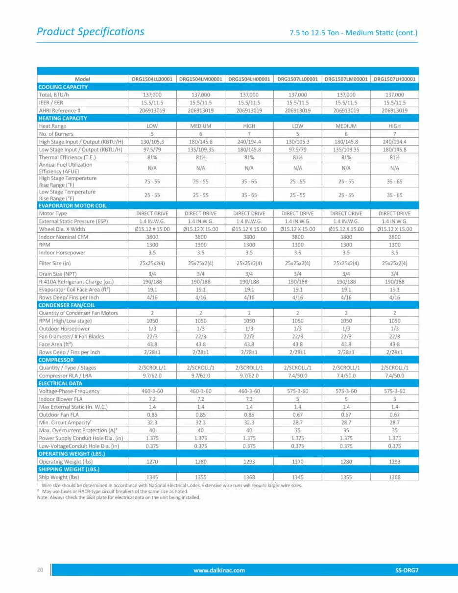
SS-DRG7 www.daikinac.com 1514 www.daikinac.com SS-DRG7
Model DRG1504DL00001S DRG1504DM00001S DRG1504DH00001S DRG1507DL00001S DRG1507DM00001S DRG1507DH00001SCOOLING CAPACITYTotal, BTU/h 137,000 137,000 137,000 137,000 137,000 137,000IEER / EER 15.5/11.5 15.5/11.5 15.5/11.5 15.5/11.5 15.5/11.5 15.5/11.5AHRI Reference # 206913019 206913019 206913019 206913019 206913019 206913019HEATING CAPACITY Heat Range LOW MEDIUM HIGH LOW MEDIUM HIGHNo. of Burners 5 6 7 5 6 7High Stage Input / Output (KBTU/H) 130/105.3 180/145.8 240/194.4 130/105.3 180/145.8 240/194.4Low Stage Input / Output (KBTU/H) 97.5/79 135/109.35 180/145.8 97.5/79 135/109.35 180/145.8Thermal Efficiency (T.E.) 81% 81% 81% 81% 81% 81%Annual Fuel Utilization Efficiency (AFUE) N/A N/A N/A N/A N/A N/A
High Stage Temperature Rise Range (°F) 25 - 55 25 - 55 35 - 65 25 - 55 25 - 55 35 - 65
Low Stage Temperature Rise Range (°F) 25 - 55 25 - 55 35 - 65 25 - 55 25 - 55 35 - 65
EVAPORATOR MOTOR COILMotor Type DIRECT DRIVE DIRECT DRIVE DIRECT DRIVE DIRECT DRIVE DIRECT DRIVE DIRECT DRIVE External Static Pressure (ESP) 0.8 IN.W.G. 0.8 IN.W.G. 0.8 IN.W.G. 0.8 IN.W.G. 0.8 IN.W.G. 0.8 IN.W.G.Wheel Dia. X Width Ø15.12 X 15.00 Ø15.12 X 15.00 Ø15.12 X 15.00 Ø15.12 X 15.00 Ø15.12 X 15.00 Ø15.12 X 15.00Indoor Nominal CFM 3800 3800 3800 3800 3800 3800RPM 1300 1300 1300 1300 1300 1300Indoor Horsepower 3.5 3.5 3.5 3.5 3.5 3.5Filter Size (in) 25x25x2(4) 25x25x2(4) 25x25x2(4) 25x25x2(4) 25x25x2(4) 25x25x2(4)Drain Size (NPT) 3/4 3/4 3/4 3/4 3/4 3/4R-410A Refrigerant Charge (oz.) 190/188 190/188 190/188 190/188 190/188 190/188Evaporator Coil Face Area (ft²) 19.1 19.1 19.1 19.1 19.1 19.1Rows Deep/ Fins per Inch 4/16 4/16 4/16 4/16 4/16 4/16CONDENSER FAN/COILQuantity of Condenser Fan Motors 2 2 2 2 2 2RPM (High/Low stage) 1050 1050 1050 1050 1050 1050Outdoor Horsepower 1/3 1/3 1/3 1/3 1/3 1/3Fan Diameter/ # Fan Blades 22/3 22/3 22/3 22/3 22/3 22/3Face Area (ft²) 43.8 43.8 43.8 43.8 43.8 43.8Rows Deep / Fins per Inch 2/28±1 2/28±1 2/28±1 2/28±1 2/28±1 2/28±1COMPRESSORQuantity / Type / Stages 2/SCROLL/1 2/SCROLL/1 2/SCROLL/1 2/SCROLL/1 2/SCROLL/1 2/SCROLL/1Compressor RLA / LRA 9.7/62.0 9.7/62.0 9.7/62.0 7.4/50.0 7.4/50.0 7.4/50.0ELECTRICAL DATA Voltage-Phase-Frequency 460-3-60 460-3-60 460-3-60 575-3-60 575-3-60 575-3-60Indoor Blower FLA 7.2 7.2 7.2 5 5 5Max External Static (In. W.C.) 0.8 0.8 0.8 0.8 0.8 0.8Outdoor Fan FLA 0.85 0.85 0.85 0.67 0.67 0.67Min. Circuit Ampacity¹ 32.3 32.3 32.3 28.7 28.7 28.7Max. Overcurrent Protection (A)² 40 40 40 35 35 35Power Supply Conduit Hole Dia. (in) 1.375 1.375 1.375 1.375 1.375 1.375Low-VoltageConduit Hole Dia. (in) 0.375 0.375 0.375 0.375 0.375 0.375OPERATING WEIGHT (LBS.)Operating Weight (lbs) 1270 1280 1293 1270 1280 1293SHIPPING WEIGHT (LBS.)Ship Weight (lbs) 1345 1355 1368 1345 1355 1368
¹ Wire size should be determined in accordance with National Electrical Codes. Extensive wire runs will require larger wire sizes. ² May use fuses or HACR-type circuit breakers of the same size as noted. Note: Always check the S&R plate for electrical data on the unit being installed.
7.5 to 12.5 Ton - Standard Static (cont.)

Product Specifications
SS-DRG7 www.daikinac.com 1514 www.daikinac.com SS-DRG7
Model DRG0903LL000001 DRG0903LM000001 DRG0903LH000001 DRG0904LL00001 DRG0904LM00001 DRG0904LH00001COOLING CAPACITYTotal, BTU/h 90,000 90,000 90,000 90,000 90,000 90,000IEER / EER 16/12.2 16/12.2 16/12.2 16/12.2 16/12.2 16/12.2AHRI Reference # 206913013 206913013 206913013 206913013 206913013 206913013HEATING CAPACITY Heat Range LOW MEDIUM HIGH LOW MEDIUM HIGHNo. of Burners 5 6 7 5 6 7High Stage Input / Output (KBTU/H) 130/105.3 180/145.8 225/182.25 130/105.3 180/145.8 225/182.25Low Stage Input / Output (KBTU/H) 97.5/79 135/109.35 168.75/136.69 97.5/79 135/109.35 168.75/136.69Thermal Efficiency (T.E.) 81% 81% 81% 81% 81% 81%Annual Fuel Utilization Efficiency (AFUE) N/A N/A N/A N/A N/A N/A
High Stage Temperature Rise Range (°F) 25 - 55 25 - 55 40 - 70 25 - 55 25 - 55 40 - 70
Low Stage Temperature Rise Range (°F) 25 - 55 25 - 55 40 - 70 25 - 55 25 - 55 40 - 70
EVAPORATOR MOTOR COILMotor Type DIRECT DRIVE DIRECT DRIVE DIRECT DRIVE DIRECT DRIVE DIRECT DRIVE DIRECT DRIVE External Static Pressure (ESP) 1.4 IN.W.G. 1.4 IN.W.G. 1.4 IN.W.G. 1.4 IN.W.G. 1.4 IN.W.G. 1.4 IN.W.G.Wheel Dia. X Width Ø15.12 X 12.62 Ø15.12 X 12.62 Ø15.12 X 12.62 Ø15.12 X 12.62 Ø15.12 X 12.62 Ø15.12 X 12.62Indoor Nominal CFM 3000 3000 3000 3000 3000 3000RPM 1300 1300 1300 1300 1300 1300Indoor Horsepower 2.4 2.4 2.4 2.4 2.4 2.4Filter Size (in) 16X25X2 (4) 16X25X2 (4) 16X25X2 (4) 16X25X2 (4) 16X25X2 (4) 16X25X2 (4)Drain Size (NPT) 3/4 3/4 3/4 3/4 3/4 3/4R-410A Refrigerant Charge (oz.) 133/133 133/133 133/133 133/133 133/133 133/133Evaporator Coil Face Area (ft²) 12.8 12.8 12.8 12.8 12.8 12.8Rows Deep/ Fins per Inch 4/16 4/16 4/16 4/16 4/16 4/16CONDENSER FAN/COILQuantity of Condenser Fan Motors 2 2 2 2 2 2RPM (High/Low stage) 1122 1122 1122 1050 1050 1050Outdoor Horsepower 1/3 1/3 1/3 1/3 1/3 1/3Fan Diameter/ # Fan Blades 22/3 22/3 22/3 22/3 22/3 22/3Face Area (ft²) 35.3 35.3 35.3 35.3 35.3 35.3Rows Deep / Fins per Inch 2/28±1 2/28±1 2/28±1 2/28±1 2/28±1 2/28±1COMPRESSORQuantity / Type / Stages 2/SCROLL/1 2/SCROLL/1 2/SCROLL/1 2/SCROLL/1 2/SCROLL/1 2/SCROLL/1Compressor RLA / LRA 13.1/83.1 13.1/83.1 13.1/83.1 6.1/41.0 6.1/41.0 6.1/41.0ELECTRICAL DATA Voltage-Phase-Frequency 208/230-3-60 208/230-3-60 208/230-3-60 460-3-60 460-3-60 460-3-60Indoor Blower FLA 8 8 8 5.4 5.4 5.4Max External Static (In. W.C.) 1.4 1.4 1.4 1.4 1.4 1.4Outdoor Fan FLA 2 2 2 0.85 0.85 0.85Min. Circuit Ampacity¹ 41.6/41.6 41.6/41.6 41.6/41.6 20.8 20.8 20.8Max. Overcurrent Protection (A)² 50/50 50/50 50/50 25 25 25Power Supply Conduit Hole Dia. (in) 1.375 1.375 1.375 1.375 1.375 1.375Low-VoltageConduit Hole Dia. (in) 0.375 0.375 0.375 0.375 0.375 0.375OPERATING WEIGHT (LBS.)Operating Weight (lbs) 1162 1172 1181 1162 1172 1181SHIPPING WEIGHT (LBS.)Ship Weight (lbs) 1237 1247 1256 1237 1247 1256
¹ Wire size should be determined in accordance with National Electrical Codes. Extensive wire runs will require larger wire sizes. ² May use fuses or HACR-type circuit breakers of the same size as noted. Note: Always check the S&R plate for electrical data on the unit being installed.
7.5 to 12.5 Ton - Medium Static

Product Specifications
SS-DRG7 www.daikinac.com 1716 www.daikinac.com SS-DRG7
Model DRG0907LL00001 DRG0907LM00001 DRG0907LH00001 DRG1023LL00001 DRG1023LM00001 DRG1023LH00001COOLING CAPACITYTotal, BTU/h 90,000 90,000 90,000 102,000 102,000 102,000IEER / EER 16/12.2 16/12.2 16/12.2 17/12.2 17/12.2 17/12.2AHRI Reference # 206913013 206913013 206913013 206913015 206913015 206913015HEATING CAPACITY Heat Range LOW MEDIUM HIGH LOW MEDIUM HIGHNo. of Burners 5 6 7 5 6 7High Stage Input / Output (KBTU/H) 130/105.3 180/145.8 225/182.25 130/105.3 180/145.8 225/182.25Low Stage Input / Output (KBTU/H) 97.5/79 135/109.35 168.75/136.69 97.5/79 135/109.35 168.75/136.69Thermal Efficiency (T.E.) 81% 81% 81% 81% 81% 81%Annual Fuel Utilization Efficiency (AFUE) N/A N/A N/A N/A N/A N/A
High Stage Temperature Rise Range (°F) 25 - 55 25 - 55 40 - 70 25 - 55 25 - 55 40 - 70
Low Stage Temperature Rise Range (°F) 25 - 55 25 - 55 40 - 70 25 - 55 25 - 55 40 - 70
EVAPORATOR MOTOR COILMotor Type DIRECT DRIVE DIRECT DRIVE DIRECT DRIVE DIRECT DRIVE DIRECT DRIVE DIRECT DRIVE External Static Pressure (ESP) 1.4 IN.W.G. 1.4 IN.W.G. 1.4 IN.W.G. 1.4 IN.W.G. 1.4 IN.W.G. 1.4 IN.W.G.Wheel Dia. X Width Ø15.12 X 12.62 Ø15.12 X 12.62 Ø15.12 X 12.62 Ø15.12 X 12.62 Ø15.12 X 12.62 Ø15.12 X 12.62Indoor Nominal CFM 3000 3000 3000 3100 3100 3100RPM 1300 1300 1300 1300 1300 1300Indoor Horsepower 2.4 2.4 2.4 3.5 3.5 3.5
Filter Size (in) 16X25X2 (4) 16X25X2 (4) 16X25X2 (4) 20x25x2(2) + 25x25x2(2)
20x25x2(2) + 25x25x2(2)
20x25x2(2) + 25x25x2(2)
Drain Size (NPT) 3/4 3/4 3/4 3/4 3/4 3/4R-410A Refrigerant Charge (oz.) 133/133 133/133 133/133 155/155 155/155 155/155Evaporator Coil Face Area (ft²) 12.8 12.8 12.8 16.6 16.6 16.6Rows Deep/ Fins per Inch 4/16 4/16 4/16 4/16 4/16 4/16CONDENSER FAN/COILQuantity of Condenser Fan Motors 2 2 2 2 2 2RPM (High/Low stage) 1050 1050 1050 1122 1122 1122Outdoor Horsepower 1/3 1/3 1/3 1/3 1/3 1/3Fan Diameter/ # Fan Blades 22/3 22/3 22/3 22/3 22/3 22/3Face Area (ft²) 35.3 35.3 35.3 35.3 35.3 35.3Rows Deep / Fins per Inch 2/28±1 2/28±1 2/28±1 2/28±1 2/28±1 2/28±1COMPRESSORQuantity / Type / Stages 2/SCROLL/1 2/SCROLL/1 2/SCROLL/1 2/SCROLL/1 2/SCROLL/1 2/SCROLL/1Compressor RLA / LRA 4.4/33.0 4.4/33.0 4.4/33.0 14.5/98.0 14.5/98.0 14.5/98.0ELECTRICAL DATA Voltage-Phase-Frequency 575-3-60 575-3-60 575-3-60 208/230-3-60 208/230-3-60 208/230-3-60Indoor Blower FLA 4 4 4 10.9 10.9 10.9Max External Static (In. W.C.) 1.4 1.4 1.4 1.4 1.4 1.4Outdoor Fan FLA 0.67 0.67 0.67 2 2 2Min. Circuit Ampacity¹ 15.1 15.1 15.1 47.5/47.5 47.5/47.5 47.5/47.5Max. Overcurrent Protection (A)² 20 20 20 60/60 60/60 60/60Power Supply Conduit Hole Dia. (in) 1.375 1.375 1.375 1.375 1.375 1.375Low-VoltageConduit Hole Dia. (in) 0.375 0.375 0.375 0.375 0.375 0.375OPERATING WEIGHT (LBS.)Operating Weight (lbs) 1162 1172 1181 1173 1183 1192SHIPPING WEIGHT (LBS.)Ship Weight (lbs) 1237 1247 1256 1248 1258 1267
¹ Wire size should be determined in accordance with National Electrical Codes. Extensive wire runs will require larger wire sizes. ² May use fuses or HACR-type circuit breakers of the same size as noted. Note: Always check the S&R plate for electrical data on the unit being installed.
7.5 to 12.5 Ton - Medium Static (cont.)

Product Specifications
SS-DRG7 www.daikinac.com 1716 www.daikinac.com SS-DRG7
7.5 to 12.5 Ton - Medium Static (cont.)
Model DRG1024LL00001 DRG1024LM00001 DRG1024LH00001 DRG1027LL00001 DRG1027LM00001 DRG1027LH00001COOLING CAPACITYTotal, BTU/h 102,000 102,000 102,000 102,000 102,000 102,000IEER / EER 17/12.2 17/12.2 17/12.2 17/12.2 17/12.2 17/12.2AHRI Reference # 206913015 206913015 206913015 206913015 206913015 206913015HEATING CAPACITY Heat Range LOW MEDIUM HIGH LOW MEDIUM HIGHNo. of Burners 5 6 7 5 6 7High Stage Input / Output (KBTU/H) 130/105.3 180/145.8 225/182.25 130/105.3 180/145.8 225/182.25Low Stage Input / Output (KBTU/H) 97.5/79 135/109.35 168.75/136.69 97.5/79 135/109.35 168.75/136.69Thermal Efficiency (T.E.) 81% 81% 81% 81% 81% 81%Annual Fuel Utilization Efficiency (AFUE) N/A N/A N/A N/A N/A N/A
High Stage Temperature Rise Range (°F) 25 - 55 25 - 55 40 - 70 25 - 55 25 - 55 40 - 70
Low Stage Temperature Rise Range (°F) 25 - 55 25 - 55 40 - 70 25 - 55 25 - 55 40 - 70
EVAPORATOR MOTOR COILMotor Type DIRECT DRIVE DIRECT DRIVE DIRECT DRIVE DIRECT DRIVE DIRECT DRIVE DIRECT DRIVE External Static Pressure (ESP) 1.4 IN.W.G. 1.4 IN.W.G. 1.4 IN.W.G. 1.4 IN.W.G. 1.4 IN.W.G. 1.4 IN.W.G.Wheel Dia. X Width Ø15.12 X 12.62 Ø15.12 X 12.62 Ø15.12 X 12.62 Ø15.12 X 12.62 Ø15.12 X 12.62 Ø15.12 X 12.62Indoor Nominal CFM 3100 3100 3100 3100 3100 3100RPM 1300 1300 1300 1300 1300 1300Indoor Horsepower 3.5 3.5 3.5 3.5 3.5 3.5
Filter Size (in) 20x25x2(2) + 25x25x2(2)
20x25x2(2) + 25x25x2(2)
20x25x2(2) + 25x25x2(2)
20x25x2(2) + 25x25x2(2)
20x25x2(2) + 25x25x2(2)
20x25x2(2) + 25x25x2(2)
Drain Size (NPT) 3/4 3/4 3/4 3/4 3/4 3/4R-410A Refrigerant Charge (oz.) 155/155 155/155 155/155 155/155 155/155 155/155Evaporator Coil Face Area (ft²) 16.6 16.6 16.6 16.6 16.6 16.6Rows Deep/ Fins per Inch 4/16 4/16 4/16 4/16 4/16 4/16CONDENSER FAN/COILQuantity of Condenser Fan Motors 2 2 2 2 2 2RPM (High/Low stage) 1050 1050 1050 1050 1050 1050Outdoor Horsepower 1/3 1/3 1/3 1/3 1/3 1/3Fan Diameter/ # Fan Blades 22/3 22/3 22/3 22/3 22/3 22/3Face Area (ft²) 35.3 35.3 35.3 35.3 35.3 35.3Rows Deep / Fins per Inch 2/28±1 2/28±1 2/28±1 2/28±1 2/28±1 2/28±1COMPRESSORQuantity / Type / Stages 2/SCROLL/1 2/SCROLL/1 2/SCROLL/1 2/SCROLL/1 2/SCROLL/1 2/SCROLL/1Compressor RLA / LRA 6.3/55.0 6.3/55.0 6.3/55.0 6.0/41.0 6.0/41.0 6.0/41.0ELECTRICAL DATA Voltage-Phase-Frequency 460-3-60 460-3-60 460-3-60 575-3-60 575-3-60 575-3-60Indoor Blower FLA 7.2 7.2 7.2 5 5 5Max External Static (In. W.C.) 1.4 1.4 1.4 1.4 1.4 1.4Outdoor Fan FLA 0.85 0.85 0.85 0.67 0.67 0.67Min. Circuit Ampacity¹ 23.2 23.2 23.2 19.9 19.9 19.9Max. Overcurrent Protection (A)² 25 25 25 25 25 25Power Supply Conduit Hole Dia. (in) 1.375 1.375 1.375 1.375 1.375 1.375Low-VoltageConduit Hole Dia. (in) 0.375 0.375 0.375 0.375 0.375 0.375OPERATING WEIGHT (LBS.)Operating Weight (lbs) 1173 1183 1192 1173 1183 1192SHIPPING WEIGHT (LBS.)Ship Weight (lbs) 1248 1258 1267 1248 1258 1267
¹ Wire size should be determined in accordance with National Electrical Codes. Extensive wire runs will require larger wire sizes. ² May use fuses or HACR-type circuit breakers of the same size as noted. Note: Always check the S&R plate for electrical data on the unit being installed.

Product Specifications
SS-DRG7 www.daikinac.com 1918 www.daikinac.com SS-DRG7
Model DRG1203LL00001 DRG1203LM00001 DRG1203LH00001 DRG1204LL00001 DRG1204LM00001 DRG1204LH00001COOLING CAPACITYTotal, BTU/h 115,000 115,000 115,000 115,000 115,000 115,000IEER / EER 17/12.2 17/12.2 17/12.2 17/12.2 17/12.2 17/12.2AHRI Reference # 206913017 206913017 206913017 206913017 206913017 206913017HEATING CAPACITY Heat Range LOW MEDIUM HIGH LOW MEDIUM HIGHNo. of Burners 5 6 7 5 6 7High Stage Input / Output (KBTU/H) 130/105.3 180/145.8 240/194.4 130/105.3 180/145.8 240/194.4Low Stage Input / Output (KBTU/H) 97.5/79 135/109.35 180/145.8 97.5/79 135/109.35 180/145.8Thermal Efficiency (T.E.) 81% 81% 81% 81% 81% 81%Annual Fuel Utilization Efficiency (AFUE) N/A N/A N/A N/A N/A N/A
High Stage Temperature Rise Range (°F) 25 - 55 25 - 55 30 - 60 25 - 55 25 - 55 30 - 60
Low Stage Temperature Rise Range (°F) 25 - 55 25 - 55 30 - 60 25 - 55 25 - 55 30 - 60
EVAPORATOR MOTOR COILMotor Type DIRECT DRIVE DIRECT DRIVE DIRECT DRIVE DIRECT DRIVE DIRECT DRIVE DIRECT DRIVE External Static Pressure (ESP) 1.4 IN.W.G. 1.4 IN.W.G. 1.4 IN.W.G. 1.4 IN.W.G. 1.4 IN.W.G. 1.4 IN.W.G.Wheel Dia. X Width Ø15.12 X 15.00 Ø15.12 X 15.00 Ø15.12 X 15.00 Ø15.12 X 15.00 Ø15.12 X 15.00 Ø15.12 X 15.00Indoor Nominal CFM 3550 3550 3550 3550 3550 3550RPM 1300 1300 1300 1300 1300 1300Indoor Horsepower 3.5 3.5 3.5 3.5 3.5 3.5
Filter Size (in) 20x25x2(2) + 25x25x2(2)
20x25x2(2) + 25x25x2(2)
20x25x2(2) + 25x25x2(2)
20x25x2(2) + 25x25x2(2)
20x25x2(2) + 25x25x2(2)
20x25x2(2) + 25x25x2(2)
Drain Size (NPT) 3/4 3/4 3/4 3/4 3/4 3/4R-410A Refrigerant Charge (oz.) 184/180 184/180 184/180 184/180 184/180 184/180Evaporator Coil Face Area (ft²) 16.6 16.6 16.6 16.6 16.6 16.6Rows Deep/ Fins per Inch 4/16 4/16 4/16 4/16 4/16 4/16CONDENSER FAN/COILQuantity of Condenser Fan Motors 2 2 2 2 2 2RPM (High/Low stage) 1122 1122 1122 1050 1050 1050Outdoor Horsepower 1/3 1/3 1/3 1/3 1/3 1/3Fan Diameter/ # Fan Blades 22/3 22/3 22/3 22/3 22/3 22/3Face Area (ft²) 39.6 39.6 39.6 39.6 39.6 39.6Rows Deep / Fins per Inch 2/28±1 2/28±1 2/28±1 2/28±1 2/28±1 2/28±1COMPRESSORQuantity / Type / Stages 2/SCROLL/1 2/SCROLL/1 2/SCROLL/1 2/SCROLL/1 2/SCROLL/1 2/SCROLL/1Compressor RLA / LRA 15.9/110 15.9/110 15.9/110 7.1/52.0 7.1/52.0 7.1/52.0ELECTRICAL DATA Voltage-Phase-Frequency 208/230-3-60 208/230-3-60 208/230-3-60 460-3-60 460-3-60 460-3-60Indoor Blower FLA 10.9 10.9 10.9 7.2 7.2 7.2Max External Static (In. W.C.) 1.4 1.4 1.4 1.4 1.4 1.4Outdoor Fan FLA 2 2 2 0.85 0.85 0.85Min. Circuit Ampacity¹ 50.7/50.7 50.7/50.7 50.7/50.7 24.8 24.8 24.8Max. Overcurrent Protection (A)² 60/60 60/60 60/60 30 30 30Power Supply Conduit Hole Dia. (in) 1.375 1.375 1.375 1.375 1.375 1.375Low-VoltageConduit Hole Dia. (in) 0.375 0.375 0.375 0.375 0.375 0.375OPERATING WEIGHT (LBS.)Operating Weight (lbs) 1192 1202 1215 1192 1202 1215SHIPPING WEIGHT (LBS.)Ship Weight (lbs) 1267 1277 1290 1267 1277 1290
¹ Wire size should be determined in accordance with National Electrical Codes. Extensive wire runs will require larger wire sizes. ² May use fuses or HACR-type circuit breakers of the same size as noted. Note: Always check the S&R plate for electrical data on the unit being installed.
7.5 to 12.5 Ton - Medium Static (cont.)

Product Specifications
SS-DRG7 www.daikinac.com 1918 www.daikinac.com SS-DRG7
DRG120 - Medium Static (cont.)
Model DRG1207LL00001 DRG1207LM00001 DRG1207LH00001 DRG1503LL00001 DRG1503LM00001 DRG1503LH00001COOLING CAPACITYTotal, BTU/h 115,000 115,000 115,000 137,000 137,000 137,000IEER / EER 17/12.2 17/12.2 17/12.2 15.5/11.5 15.5/11.5 15.5/11.5AHRI Reference # 206913017 206913017 206913017 206913019 206913019 206913019HEATING CAPACITY Heat Range LOW MEDIUM HIGH LOW MEDIUM HIGHNo. of Burners 5 6 7 5 6 7High Stage Input / Output (KBTU/H) 130/105.3 180/145.8 240/194.4 130/105.3 180/145.8 240/194.4Low Stage Input / Output (KBTU/H) 97.5/79 135/109.35 180/145.8 97.5/79 135/109.35 180/145.8Thermal Efficiency (T.E.) 81% 81% 81% 81% 81% 81%Annual Fuel Utilization Efficiency (AFUE) N/A N/A N/A N/A N/A N/A
High Stage Temperature Rise Range (°F) 25 - 55 25 - 55 30 - 60 25 - 55 25 - 55 35 - 65
Low Stage Temperature Rise Range (°F) 25 - 55 25 - 55 30 - 60 25 - 55 25 - 55 35 - 65
EVAPORATOR MOTOR COILMotor Type DIRECT DRIVE DIRECT DRIVE DIRECT DRIVE DIRECT DRIVE DIRECT DRIVE DIRECT DRIVE External Static Pressure (ESP) 1.4 IN.W.G. 1.4 IN.W.G. 1.4 IN.W.G. 1.4 IN.W.G. 1.4 IN.W.G. 1.4 IN.W.G.Wheel Dia. X Width Ø15.12 X 15.00 Ø15.12 X 15.00 Ø15.12 X 15.00 Ø15.12 X 15.00 Ø15.12 X 15.00 Ø15.12 X 15.00Indoor Nominal CFM 3550 3550 3550 3800 3800 3800RPM 1300 1300 1300 1300 1300 1300Indoor Horsepower 3.5 3.5 3.5 3.5 3.5 3.5
Filter Size (in) 20x25x2(2) + 25x25x2(2)
20x25x2(2) + 25x25x2(2)
20x25x2(2) + 25x25x2(2) 25x25x2(4) 25x25x2(4) 25x25x2(4)
Drain Size (NPT) 3/4 3/4 3/4 3/4 3/4 3/4R-410A Refrigerant Charge (oz.) 184/180 184/180 184/180 190/188 190/188 190/188Evaporator Coil Face Area (ft²) 16.6 16.6 16.6 19.1 19.1 19.1Rows Deep/ Fins per Inch 4/16 4/16 4/16 4/16 4/16 4/16CONDENSER FAN/COILQuantity of Condenser Fan Motors 2 2 2 2 2 2RPM (High/Low stage) 1050 1050 1050 1122 1122 1122Outdoor Horsepower 1/3 1/3 1/3 1/3 1/3 1/3Fan Diameter/ # Fan Blades 22/3 22/3 22/3 22/3 22/3 22/3Face Area (ft²) 39.6 39.6 39.6 43.8 43.8 43.8Rows Deep / Fins per Inch 2/28±1 2/28±1 2/28±1 2/28±1 2/28±1 2/28±1COMPRESSORQuantity / Type / Stages 2/SCROLL/1 2/SCROLL/1 2/SCROLL/1 2/SCROLL/1 2/SCROLL/1 2/SCROLL/1Compressor RLA / LRA 5.1/39.5 5.1/39.5 5.1/39.5 19/123.0 19/123.0 19/123.0ELECTRICAL DATA Voltage-Phase-Frequency 575-3-60 575-3-60 575-3-60 208/230-3-60 208/230-3-60 208/230-3-60Indoor Blower FLA 5 5 5 10.9 10.9 10.9Max External Static (In. W.C.) 1.4 1.4 1.4 1.4 1.4 1.4Outdoor Fan FLA 0.67 0.67 0.67 2 2 2Min. Circuit Ampacity¹ 17.9 17.9 17.9 60.7/60.7 60.7/60.7 60.7/60.7Max. Overcurrent Protection (A)² 20 20 20 70/70 70/70 70/70Power Supply Conduit Hole Dia. (in) 1.375 1.375 1.375 1.375 1.375 1.375Low-VoltageConduit Hole Dia. (in) 0.375 0.375 0.375 0.375 0.375 0.375OPERATING WEIGHT (LBS.)Operating Weight (lbs) 1192 1202 1215 1270 1280 1293SHIPPING WEIGHT (LBS.)Ship Weight (lbs) 1267 1277 1290 1345 1355 1368
¹ Wire size should be determined in accordance with National Electrical Codes. Extensive wire runs will require larger wire sizes. ² May use fuses or HACR-type circuit breakers of the same size as noted. Note: Always check the S&R plate for electrical data on the unit being installed.
Product Specifications
SS-DRG7 www.daikinac.com 2120 www.daikinac.com SS-DRG7
Model DRG1504LL00001 DRG1504LM00001 DRG1504LH00001 DRG1507LL00001 DRG1507LM00001 DRG1507LH00001COOLING CAPACITYTotal, BTU/h 137,000 137,000 137,000 137,000 137,000 137,000IEER / EER 15.5/11.5 15.5/11.5 15.5/11.5 15.5/11.5 15.5/11.5 15.5/11.5AHRI Reference # 206913019 206913019 206913019 206913019 206913019 206913019HEATING CAPACITY Heat Range LOW MEDIUM HIGH LOW MEDIUM HIGHNo. of Burners 5 6 7 5 6 7High Stage Input / Output (KBTU/H) 130/105.3 180/145.8 240/194.4 130/105.3 180/145.8 240/194.4Low Stage Input / Output (KBTU/H) 97.5/79 135/109.35 180/145.8 97.5/79 135/109.35 180/145.8Thermal Efficiency (T.E.) 81% 81% 81% 81% 81% 81%Annual Fuel Utilization Efficiency (AFUE) N/A N/A N/A N/A N/A N/A
High Stage Temperature Rise Range (°F) 25 - 55 25 - 55 35 - 65 25 - 55 25 - 55 35 - 65
Low Stage Temperature Rise Range (°F) 25 - 55 25 - 55 35 - 65 25 - 55 25 - 55 35 - 65
EVAPORATOR MOTOR COILMotor Type DIRECT DRIVE DIRECT DRIVE DIRECT DRIVE DIRECT DRIVE DIRECT DRIVE DIRECT DRIVE External Static Pressure (ESP) 1.4 IN.W.G. 1.4 IN.W.G. 1.4 IN.W.G. 1.4 IN.W.G. 1.4 IN.W.G. 1.4 IN.W.G.Wheel Dia. X Width Ø15.12 X 15.00 Ø15.12 X 15.00 Ø15.12 X 15.00 Ø15.12 X 15.00 Ø15.12 X 15.00 Ø15.12 X 15.00Indoor Nominal CFM 3800 3800 3800 3800 3800 3800RPM 1300 1300 1300 1300 1300 1300Indoor Horsepower 3.5 3.5 3.5 3.5 3.5 3.5
Filter Size (in) 25x25x2(4) 25x25x2(4) 25x25x2(4) 25x25x2(4) 25x25x2(4) 25x25x2(4)
Drain Size (NPT) 3/4 3/4 3/4 3/4 3/4 3/4R-410A Refrigerant Charge (oz.) 190/188 190/188 190/188 190/188 190/188 190/188Evaporator Coil Face Area (ft²) 19.1 19.1 19.1 19.1 19.1 19.1Rows Deep/ Fins per Inch 4/16 4/16 4/16 4/16 4/16 4/16CONDENSER FAN/COILQuantity of Condenser Fan Motors 2 2 2 2 2 2RPM (High/Low stage) 1050 1050 1050 1050 1050 1050Outdoor Horsepower 1/3 1/3 1/3 1/3 1/3 1/3Fan Diameter/ # Fan Blades 22/3 22/3 22/3 22/3 22/3 22/3Face Area (ft²) 43.8 43.8 43.8 43.8 43.8 43.8Rows Deep / Fins per Inch 2/28±1 2/28±1 2/28±1 2/28±1 2/28±1 2/28±1COMPRESSORQuantity / Type / Stages 2/SCROLL/1 2/SCROLL/1 2/SCROLL/1 2/SCROLL/1 2/SCROLL/1 2/SCROLL/1Compressor RLA / LRA 9.7/62.0 9.7/62.0 9.7/62.0 7.4/50.0 7.4/50.0 7.4/50.0ELECTRICAL DATA Voltage-Phase-Frequency 460-3-60 460-3-60 460-3-60 575-3-60 575-3-60 575-3-60Indoor Blower FLA 7.2 7.2 7.2 5 5 5Max External Static (In. W.C.) 1.4 1.4 1.4 1.4 1.4 1.4Outdoor Fan FLA 0.85 0.85 0.85 0.67 0.67 0.67Min. Circuit Ampacity¹ 32.3 32.3 32.3 28.7 28.7 28.7Max. Overcurrent Protection (A)² 40 40 40 35 35 35Power Supply Conduit Hole Dia. (in) 1.375 1.375 1.375 1.375 1.375 1.375Low-VoltageConduit Hole Dia. (in) 0.375 0.375 0.375 0.375 0.375 0.375OPERATING WEIGHT (LBS.)Operating Weight (lbs) 1270 1280 1293 1270 1280 1293SHIPPING WEIGHT (LBS.)Ship Weight (lbs) 1345 1355 1368 1345 1355 1368
¹ Wire size should be determined in accordance with National Electrical Codes. Extensive wire runs will require larger wire sizes. ² May use fuses or HACR-type circuit breakers of the same size as noted. Note: Always check the S&R plate for electrical data on the unit being installed.
7.5 to 12.5 Ton - Medium Static (cont.)

Product Specifications
SS-DRG7 www.daikinac.com 2120 www.daikinac.com SS-DRG7
7.5 to 12.5 Ton - High Static
Model DRG0903WL000001 DRG0903WM000001 DRG0903WH000001 DRG0904WL00001 DRG0904WM00001 DRG0904WH00001COOLING CAPACITYTotal, BTU/h 90,000 90,000 90,000 90,000 90,000 90,000IEER / EER 16/12.2 16/12.2 16/12.2 16/12.2 16/12.2 16/12.2AHRI Reference # 206913013 206913013 206913013 206913013 206913013 206913013HEATING CAPACITY Heat Range LOW MEDIUM HIGH LOW MEDIUM HIGHNo. of Burners 5 6 7 5 6 7High Stage Input / Output (KBTU/H) 130/105.3 180/145.8 225/182.25 130/105.3 180/145.8 225/182.25Low Stage Input / Output (KBTU/H) 97.5/79 135/109.35 168.75/136.69 97.5/79 135/109.35 168.75/136.69Thermal Efficiency (T.E.) 81% 81% 81% 81% 81% 81%Annual Fuel Utilization Efficiency (AFUE) N/A N/A N/A N/A N/A N/A
High Stage Temperature Rise Range (°F) 25 - 55 25 - 55 40 - 70 25 - 55 25 - 55 40 - 70
Low Stage Temperature Rise Range (°F) 25 - 55 25 - 55 40 - 70 25 - 55 25 - 55 40 - 70
EVAPORATOR MOTOR COILMotor Type DIRECT DRIVE DIRECT DRIVE DIRECT DRIVE DIRECT DRIVE DIRECT DRIVE DIRECT DRIVE External Static Pressure (ESP) 2.0 IN.W.G. 2.0 IN.W.G. 2.0 IN.W.G. 2.0 IN.W.G. 2.0 IN.W.G. 2.0 IN.W.G.Wheel Dia. X Width Ø15.12 X 12.62 Ø15.12 X 12.62 Ø15.12 X 12.62 Ø15.12 X 12.62 Ø15.12 X 12.62 Ø15.12 X 12.62Indoor Nominal CFM 3000 3000 3000 3000 3000 3000RPM 1300 1300 1300 1300 1300 1300Indoor Horsepower 3.5 3.5 3.5 3.5 3.5 3.5
Filter Size (in) 16X25X2 (4) 16X25X2 (4) 16X25X2 (4) 16X25X2 (4) 16X25X2 (4) 16X25X2 (4)
Drain Size (NPT) 3/4 3/4 3/4 3/4 3/4 3/4R-410A Refrigerant Charge (oz.) 133/133 133/133 133/133 133/133 133/133 133/133Evaporator Coil Face Area (ft²) 12.8 12.8 12.8 12.8 12.8 12.8Rows Deep/ Fins per Inch 4/16 4/16 4/16 4/16 4/16 4/16CONDENSER FAN/COILQuantity of Condenser Fan Motors 2 2 2 2 2 2RPM (High/Low stage) 1122 1122 1122 1050 1050 1050Outdoor Horsepower 1/3 1/3 1/3 1/3 1/3 1/3Fan Diameter/ # Fan Blades 22/3 22/3 22/3 22/3 22/3 22/3Face Area (ft²) 35.3 35.3 35.3 35.3 35.3 35.3Rows Deep / Fins per Inch 2/28±1 2/28±1 2/28±1 2/28±1 2/28±1 2/28±1COMPRESSORQuantity / Type / Stages 2/SCROLL/1 2/SCROLL/1 2/SCROLL/1 2/SCROLL/1 2/SCROLL/1 2/SCROLL/1Compressor RLA / LRA 13.1/83.1 13.1/83.1 13.1/83.1 6.1/41.0 6.1/41.0 6.1/41.0ELECTRICAL DATA Voltage-Phase-Frequency 208/230-3-60 208/230-3-60 208/230-3-60 460-3-60 460-3-60 460-3-60Indoor Blower FLA 10.9 10.9 10.9 7.2 7.2 7.2Max External Static (In. W.C.) 2 2 2 2 2 2Outdoor Fan FLA 2 2 2 0.85 0.85 0.85Min. Circuit Ampacity¹ 44.5/44.5 44.5/44.5 44.5/44.5 22.6 22.6 22.6Max. Overcurrent Protection (A)² 50/50 50/50 50/50 25 25 25Power Supply Conduit Hole Dia. (in) 1.375 1.375 1.375 1.375 1.375 1.375Low-VoltageConduit Hole Dia. (in) 0.375 0.375 0.375 0.375 0.375 0.375OPERATING WEIGHT (LBS.)Operating Weight (lbs) 1162 1172 1181 1162 1172 1181SHIPPING WEIGHT (LBS.)Ship Weight (lbs) 1237 1247 1256 1237 1247 1256
¹ Wire size should be determined in accordance with National Electrical Codes. Extensive wire runs will require larger wire sizes. ² May use fuses or HACR-type circuit breakers of the same size as noted. Note: Always check the S&R plate for electrical data on the unit being installed.

Product Specifications
SS-DRG7 www.daikinac.com 2322 www.daikinac.com SS-DRG7
Model DRG0907WL00001 DRG0907WM00001 DRG0907WH00001 DRG1023WL00001 DRG1023WM00001 DRG1023WH00001COOLING CAPACITYTotal, BTU/h 90,000 90,000 90,000 102,000 102,000 102,000IEER / EER 16/12.2 16/12.2 16/12.2 17/12.2 17/12.2 17/12.2AHRI Reference # 206913013 206913013 206913013 206913015 206913015 206913015HEATING CAPACITY Heat Range LOW MEDIUM HIGH LOW MEDIUM HIGHNo. of Burners 5 6 7 5 6 7High Stage Input / Output (KBTU/H) 130/105.3 180/145.8 225/182.25 130/105.3 180/145.8 225/182.25Low Stage Input / Output (KBTU/H) 97.5/79 135/109.35 168.75/136.69 97.5/79 135/109.35 168.75/136.69Thermal Efficiency (T.E.) 81% 81% 81% 81% 81% 81%Annual Fuel Utilization Efficiency (AFUE) N/A N/A N/A N/A N/A N/A
High Stage Temperature Rise Range (°F) 25 - 55 25 - 55 40 - 70 25 - 55 25 - 55 40 - 70
Low Stage Temperature Rise Range (°F) 25 - 55 25 - 55 40 - 70 25 - 55 25 - 55 40 - 70
EVAPORATOR MOTOR COILMotor Type DIRECT DRIVE DIRECT DRIVE DIRECT DRIVE DIRECT DRIVE DIRECT DRIVE DIRECT DRIVE External Static Pressure (ESP) 2.0 IN.W.G. 2.0 IN.W.G. 2.0 IN.W.G. 2.0 IN.W.G. 2.0 IN.W.G. 2.0 IN.W.G.Wheel Dia. X Width Ø15.12 X 12.62 Ø15.12 X 12.62 Ø15.12 X 12.62 Ø15.12 X 12.62 Ø15.12 X 12.62 Ø15.12 X 12.62Indoor Nominal CFM 3000 3000 3000 3100 3100 3100RPM 1300 1300 1300 1300 1300 1300Indoor Horsepower 3.5 3.5 3.5 3.5 3.5 3.5
Filter Size (in) 16X25X2 (4) 16X25X2 (4) 16X25X2 (4) 20x25x2(2) + 25x25x2(2)
20x25x2(2) + 25x25x2(2)
20x25x2(2) + 25x25x2(2)
Drain Size (NPT) 3/4 3/4 3/4 3/4 3/4 3/4R-410A Refrigerant Charge (oz.) 133/133 133/133 133/133 155/155 155/155 155/155Evaporator Coil Face Area (ft²) 12.8 12.8 12.8 16.6 16.6 16.6Rows Deep/ Fins per Inch 4/16 4/16 4/16 4/16 4/16 4/16CONDENSER FAN/COILQuantity of Condenser Fan Motors 2 2 2 2 2 2RPM (High/Low stage) 1050 1050 1050 1122 1122 1122Outdoor Horsepower 1/3 1/3 1/3 1/3 1/3 1/3Fan Diameter/ # Fan Blades 22/3 22/3 22/3 22/3 22/3 22/3Face Area (ft²) 35.3 35.3 35.3 35.3 35.3 35.3Rows Deep / Fins per Inch 2/28±1 2/28±1 2/28±1 2/28±1 2/28±1 2/28±1COMPRESSORQuantity / Type / Stages 2/SCROLL/1 2/SCROLL/1 2/SCROLL/1 2/SCROLL/1 2/SCROLL/1 2/SCROLL/1Compressor RLA / LRA 4.4/33.0 4.4/33.0 4.4/33.0 14.5/98.0 14.5/98.0 14.5/98.0ELECTRICAL DATA Voltage-Phase-Frequency 575-3-60 575-3-60 575-3-60 208/230-3-60 208/230-3-60 208/230-3-60Indoor Blower FLA 5 5 5 10.9 10.9 10.9Max External Static (In. W.C.) 2 2 2 2 2 2Outdoor Fan FLA 0.67 0.67 0.67 2 2 2Min. Circuit Ampacity¹ 16.1 16.1 16.1 47.5/47.5 47.5/47.5 47.5/47.5Max. Overcurrent Protection (A)² 20 20 20 60/60 60/60 60/60Power Supply Conduit Hole Dia. (in) 1.375 1.375 1.375 1.375 1.375 1.375Low-VoltageConduit Hole Dia. (in) 0.375 0.375 0.375 0.375 0.375 0.375OPERATING WEIGHT (LBS.)Operating Weight (lbs) 1162 1172 1181 1173 1183 1192SHIPPING WEIGHT (LBS.)Ship Weight (lbs) 1237 1247 1256 1248 1258 1267
¹ Wire size should be determined in accordance with National Electrical Codes. Extensive wire runs will require larger wire sizes. ² May use fuses or HACR-type circuit breakers of the same size as noted. Note: Always check the S&R plate for electrical data on the unit being installed.
7.5 to 12.5 Ton - High Static (cont.)

Product Specifications
SS-DRG7 www.daikinac.com 2322 www.daikinac.com SS-DRG7
7.5 to 12.5 Ton - High Static (cont.)
Model DRG1024WL00001 DRG1024WM00001 DRG1024WH00001 DRG1027WL00001 DRG1027WM00001 DRG1027WH00001COOLING CAPACITYTotal, BTU/h 102,000 102,000 102,000 102,000 102,000 102,000IEER / EER 17/12.2 17/12.2 17/12.2 17/12.2 17/12.2 17/12.2AHRI Reference # 206913015 206913015 206913015 206913015 206913015 206913015HEATING CAPACITY Heat Range LOW MEDIUM HIGH LOW MEDIUM HIGHNo. of Burners 5 6 7 5 6 7High Stage Input / Output (KBTU/H) 130/105.3 180/145.8 225/182.25 130/105.3 180/145.8 225/182.25Low Stage Input / Output (KBTU/H) 97.5/79 135/109.35 168.75/136.69 97.5/79 135/109.35 168.75/136.69Thermal Efficiency (T.E.) 81% 81% 81% 81% 81% 81%Annual Fuel Utilization Efficiency (AFUE) N/A N/A N/A N/A N/A N/A
High Stage Temperature Rise Range (°F) 25 - 55 25 - 55 40 - 70 25 - 55 25 - 55 40 - 70
Low Stage Temperature Rise Range (°F) 25 - 55 25 - 55 40 - 70 25 - 55 25 - 55 40 - 70
EVAPORATOR MOTOR COILMotor Type DIRECT DRIVE DIRECT DRIVE DIRECT DRIVE DIRECT DRIVE DIRECT DRIVE DIRECT DRIVE External Static Pressure (ESP) 2.0 IN.W.G. 2.0 IN.W.G. 2.0 IN.W.G. 2.0 IN.W.G. 2.0 IN.W.G. 2.0 IN.W.G.Wheel Dia. X Width Ø15.12 X 12.62 Ø15.12 X 12.62 Ø15.12 X 12.62 Ø15.12 X 12.62 Ø15.12 X 12.62 Ø15.12 X 12.62Indoor Nominal CFM 3100 3100 3100 3100 3100 3100RPM 1300 1300 1300 1300 1300 1300Indoor Horsepower 3.5 3.5 3.5 3.5 3.5 3.5
Filter Size (in) 20x25x2(2) + 25x25x2(2)
20x25x2(2) + 25x25x2(2)
20x25x2(2) + 25x25x2(2)
20x25x2(2) + 25x25x2(2)
20x25x2(2) + 25x25x2(2)
20x25x2(2) + 25x25x2(2)
Drain Size (NPT) 3/4 3/4 3/4 3/4 3/4 3/4R-410A Refrigerant Charge (oz.) 155/155 155/155 155/155 155/155 155/155 155/155Evaporator Coil Face Area (ft²) 16.6 16.6 16.6 16.6 16.6 16.6Rows Deep/ Fins per Inch 4/16 4/16 4/16 4/16 4/16 4/16CONDENSER FAN/COILQuantity of Condenser Fan Motors 2 2 2 2 2 2RPM (High/Low stage) 1050 1050 1050 1050 1050 1050Outdoor Horsepower 1/3 1/3 1/3 1/3 1/3 1/3Fan Diameter/ # Fan Blades 22/3 22/3 22/3 22/3 22/3 22/3Face Area (ft²) 35.3 35.3 35.3 35.3 35.3 35.3Rows Deep / Fins per Inch 2/28±1 2/28±1 2/28±1 2/28±1 2/28±1 2/28±1COMPRESSORQuantity / Type / Stages 2/SCROLL/1 2/SCROLL/1 2/SCROLL/1 2/SCROLL/1 2/SCROLL/1 2/SCROLL/1Compressor RLA / LRA 6.3/55.0 6.3/55.0 6.3/55.0 6.0/41.0 6.0/41.0 6.0/41.0ELECTRICAL DATA Voltage-Phase-Frequency 460-3-60 460-3-60 460-3-60 575-3-60 575-3-60 575-3-60Indoor Blower FLA 7.2 7.2 7.2 5 5 5Max External Static (In. W.C.) 2 2 2 2 2 2Outdoor Fan FLA 0.85 0.85 0.85 0.67 0.67 0.67Min. Circuit Ampacity¹ 23.2 23.2 23.2 19.9 19.9 19.9Max. Overcurrent Protection (A)² 25 25 25 25 25 25Power Supply Conduit Hole Dia. (in) 1.375 1.375 1.375 1.375 1.375 1.375Low-VoltageConduit Hole Dia. (in) 0.375 0.375 0.375 0.375 0.375 0.375OPERATING WEIGHT (LBS.)Operating Weight (lbs) 1173 1183 1192 1173 1183 1192SHIPPING WEIGHT (LBS.)Ship Weight (lbs) 1248 1258 1267 1248 1258 1267
¹ Wire size should be determined in accordance with National Electrical Codes. Extensive wire runs will require larger wire sizes. ² May use fuses or HACR-type circuit breakers of the same size as noted. Note: Always check the S&R plate for electrical data on the unit being installed.

Product Specifications
SS-DRG7 www.daikinac.com 2524 www.daikinac.com SS-DRG7
Model DRG1203WL00001 DRG1203WM00001 DRG1203WH00001 DRG1204WL00001 DRG1204WM00001 DRG1204WH00001COOLING CAPACITYTotal, BTU/h 115,000 115,000 115,000 115,000 115,000 115,000IEER / EER 17/12.2 17/12.2 17/12.2 17/12.2 17/12.2 17/12.2AHRI Reference # 206913017 206913017 206913017 206913017 206913017 206913017HEATING CAPACITY Heat Range LOW MEDIUM HIGH LOW MEDIUM HIGHNo. of Burners 5 6 7 5 6 7High Stage Input / Output (KBTU/H) 130/105.3 180/145.8 240/194.4 130/105.3 180/145.8 240/194.4Low Stage Input / Output (KBTU/H) 97.5/79 135/109.35 180/145.8 97.5/79 135/109.35 180/145.8Thermal Efficiency (T.E.) 81% 81% 81% 81% 81% 81%Annual Fuel Utilization Efficiency (AFUE) N/A N/A N/A N/A N/A N/A
High Stage Temperature Rise Range (°F) 25 - 55 25 - 55 30 - 60 25 - 55 25 - 55 30 - 60
Low Stage Temperature Rise Range (°F) 25 - 55 25 - 55 30 - 60 25 - 55 25 - 55 30 - 60
EVAPORATOR MOTOR COILMotor Type DIRECT DRIVE DIRECT DRIVE DIRECT DRIVE DIRECT DRIVE DIRECT DRIVE DIRECT DRIVE External Static Pressure (ESP) 2.0 IN.W.G. 2.0 IN.W.G. 2.0 IN.W.G. 2.0 IN.W.G. 2.0 IN.W.G. 2.0 IN.W.G.Wheel Dia. X Width Ø15.12 X 15.00 Ø15.12 X 15.00 Ø15.12 X 15.00 Ø15.12 X 15.00 Ø15.12 X 15.00 Ø15.12 X 15.00Indoor Nominal CFM 3550 3550 3550 3550 3550 3550RPM 1300 1300 1300 1300 1300 1300Indoor Horsepower 5 5 5 5 5 5
Filter Size (in) 20x25x2(2) + 25x25x2(2)
20x25x2(2) + 25x25x2(2)
20x25x2(2) + 25x25x2(2)
20x25x2(2) + 25x25x2(2)
20x25x2(2) + 25x25x2(2)
20x25x2(2) + 25x25x2(2)
Drain Size (NPT) 3/4 3/4 3/4 3/4 3/4 3/4R-410A Refrigerant Charge (oz.) 184/180 184/180 184/180 184/180 184/180 184/180Evaporator Coil Face Area (ft²) 16.6 16.6 16.6 16.6 16.6 16.6Rows Deep/ Fins per Inch 4/16 4/16 4/16 4/16 4/16 4/16CONDENSER FAN/COILQuantity of Condenser Fan Motors 2 2 2 2 2 2RPM (High/Low stage) 1122 1122 1122 1050 1050 1050Outdoor Horsepower 1/3 1/3 1/3 1/3 1/3 1/3Fan Diameter/ # Fan Blades 22/3 22/3 22/3 22/3 22/3 22/3Face Area (ft²) 39.6 39.6 39.6 39.6 39.6 39.6Rows Deep / Fins per Inch 2/28±1 2/28±1 2/28±1 2/28±1 2/28±1 2/28±1COMPRESSORQuantity / Type / Stages 2/SCROLL/1 2/SCROLL/1 2/SCROLL/1 2/SCROLL/1 2/SCROLL/1 2/SCROLL/1Compressor RLA / LRA 15.9/110 15.9/110 15.9/110 7.1/52.0 7.1/52.0 7.1/52.0ELECTRICAL DATA Voltage-Phase-Frequency 208/230-3-60 208/230-3-60 208/230-3-60 460-3-60 460-3-60 460-3-60Indoor Blower FLA 14.5 14.5 14.5 10.6 10.6 10.6Max External Static (In. W.C.) 2 2 2 2 2 2Outdoor Fan FLA 2 2 2 0.85 0.85 0.85Min. Circuit Ampacity¹ 54.3/54.3 54.3/54.3 54.3/54.3 28.2 28.2 28.2Max. Overcurrent Protection (A)² 70/70 70/70 70/70 35 35 35Power Supply Conduit Hole Dia. (in) 1.375 1.375 1.375 1.375 1.375 1.375Low-VoltageConduit Hole Dia. (in) 0.375 0.375 0.375 0.375 0.375 0.375OPERATING WEIGHT (LBS.)Operating Weight (lbs) 1199 1208 1222 1199 1208 1222SHIPPING WEIGHT (LBS.)Ship Weight (lbs) 1274 1283 1297 1274 1283 1297
¹ Wire size should be determined in accordance with National Electrical Codes. Extensive wire runs will require larger wire sizes. ² May use fuses or HACR-type circuit breakers of the same size as noted. Note: Always check the S&R plate for electrical data on the unit being installed.
7.5 to 12.5 Ton - High Static (cont.)
Product Specifications
SS-DRG7 www.daikinac.com 2524 www.daikinac.com SS-DRG7
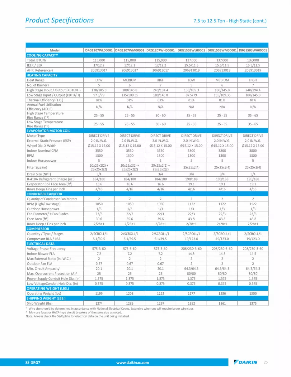
7.5 to 12.5 Ton - High Static (cont.)
Model DRG1207WL00001 DRG1207WM00001 DRG1207WH00001 DRG1503WL00001 DRG1503WM00001 DRG1503WH00001COOLING CAPACITYTotal, BTU/h 115,000 115,000 115,000 137,000 137,000 137,000IEER / EER 17/12.2 17/12.2 17/12.2 15.5/11.5 15.5/11.5 15.5/11.5AHRI Reference # 206913017 206913017 206913017 206913019 206913019 206913019HEATING CAPACITY Heat Range LOW MEDIUM HIGH LOW MEDIUM HIGHNo. of Burners 5 6 7 5 6 7High Stage Input / Output (KBTU/H) 130/105.3 180/145.8 240/194.4 130/105.3 180/145.8 240/194.4Low Stage Input / Output (KBTU/H) 97.5/79 135/109.35 180/145.8 97.5/79 135/109.35 180/145.8Thermal Efficiency (T.E.) 81% 81% 81% 81% 81% 81%Annual Fuel Utilization Efficiency (AFUE) N/A N/A N/A N/A N/A N/A
High Stage Temperature Rise Range (°F) 25 - 55 25 - 55 30 - 60 25 - 55 25 - 55 35 - 65
Low Stage Temperature Rise Range (°F) 25 - 55 25 - 55 30 - 60 25 - 55 25 - 55 35 - 65
EVAPORATOR MOTOR COILMotor Type DIRECT DRIVE DIRECT DRIVE DIRECT DRIVE DIRECT DRIVE DIRECT DRIVE DIRECT DRIVE External Static Pressure (ESP) 2.0 IN.W.G. 2.0 IN.W.G. 2.0 IN.W.G. 2.0 IN.W.G. 2.0 IN.W.G. 2.0 IN.W.G.Wheel Dia. X Width Ø15.12 X 15.00 Ø15.12 X 15.00 Ø15.12 X 15.00 Ø15.12 X 15.00 Ø15.12 X 15.00 Ø15.12 X 15.00Indoor Nominal CFM 3550 3550 3550 3800 3800 3800RPM 1300 1300 1300 1300 1300 1300Indoor Horsepower 5 5 5 5 5 5
Filter Size (in) 20x25x2(2) + 25x25x2(2)
20x25x2(2) + 25x25x2(2)
20x25x2(2) + 25x25x2(2) 25x25x2(4) 25x25x2(4) 25x25x2(4)
Drain Size (NPT) 3/4 3/4 3/4 3/4 3/4 3/4R-410A Refrigerant Charge (oz.) 184/180 184/180 184/180 190/188 190/188 190/188Evaporator Coil Face Area (ft²) 16.6 16.6 16.6 19.1 19.1 19.1Rows Deep/ Fins per Inch 4/16 4/16 4/16 4/16 4/16 4/16CONDENSER FAN/COILQuantity of Condenser Fan Motors 2 2 2 2 2 2RPM (High/Low stage) 1050 1050 1050 1122 1122 1122Outdoor Horsepower 1/3 1/3 1/3 1/3 1/3 1/3Fan Diameter/ # Fan Blades 22/3 22/3 22/3 22/3 22/3 22/3Face Area (ft²) 39.6 39.6 39.6 43.8 43.8 43.8Rows Deep / Fins per Inch 2/28±1 2/28±1 2/28±1 2/28±1 2/28±1 2/28±1COMPRESSORQuantity / Type / Stages 2/SCROLL/1 2/SCROLL/1 2/SCROLL/1 2/SCROLL/1 2/SCROLL/1 2/SCROLL/1Compressor RLA / LRA 5.1/39.5 5.1/39.5 5.1/39.5 19/123.0 19/123.0 19/123.0ELECTRICAL DATA Voltage-Phase-Frequency 575-3-60 575-3-60 575-3-60 208/230-3-60 208/230-3-60 208/230-3-60Indoor Blower FLA 7.2 7.2 7.2 14.5 14.5 14.5Max External Static (In. W.C.) 2 2 2 2 2 2Outdoor Fan FLA 0.67 0.67 0.67 2 2 2Min. Circuit Ampacity¹ 20.1 20.1 20.1 64.3/64.3 64.3/64.3 64.3/64.3Max. Overcurrent Protection (A)² 25 25 25 80/80 80/80 80/80Power Supply Conduit Hole Dia. (in) 1.375 1.375 1.375 1.375 1.375 1.375Low-VoltageConduit Hole Dia. (in) 0.375 0.375 0.375 0.375 0.375 0.375OPERATING WEIGHT (LBS.)Operating Weight (lbs) 1199 1208 1222 1277 1286 1300SHIPPING WEIGHT (LBS.)Ship Weight (lbs) 1274 1283 1297 1352 1361 1375
¹ Wire size should be determined in accordance with National Electrical Codes. Extensive wire runs will require larger wire sizes. ² May use fuses or HACR-type circuit breakers of the same size as noted. Note: Always check the S&R plate for electrical data on the unit being installed.

Product Specifications
SS-DRG7 www.daikinac.com 2726 www.daikinac.com SS-DRG7
Model DRG1504WL00001 DRG1504WM00001 DRG1504WH00001 DRG1507WL00001 DRG1507WM00001 DRG1507WH00001COOLING CAPACITYTotal, BTU/h 137,000 137,000 137,000 137,000 137,000 137,000IEER / EER 15.5/11.5 15.5/11.5 15.5/11.5 15.5/11.5 15.5/11.5 15.5/11.5AHRI Reference # 206913019 206913019 206913019 206913019 206913019 206913019HEATING CAPACITY Heat Range LOW MEDIUM HIGH LOW MEDIUM HIGHNo. of Burners 5 6 7 5 6 7High Stage Input / Output (KBTU/H) 130/105.3 180/145.8 240/194.4 130/105.3 180/145.8 240/194.4Low Stage Input / Output (KBTU/H) 97.5/79 135/109.35 180/145.8 97.5/79 135/109.35 180/145.8Thermal Efficiency (T.E.) 81% 81% 81% 81% 81% 81%Annual Fuel Utilization Efficiency (AFUE) N/A N/A N/A N/A N/A N/A
High Stage Temperature Rise Range (°F) 25 - 55 25 - 55 35 - 65 25 - 55 25 - 55 35 - 65
Low Stage Temperature Rise Range (°F) 25 - 55 25 - 55 35 - 65 25 - 55 25 - 55 35 - 65
EVAPORATOR MOTOR COILMotor Type DIRECT DRIVE DIRECT DRIVE DIRECT DRIVE DIRECT DRIVE DIRECT DRIVE DIRECT DRIVE External Static Pressure (ESP) 2.0 IN.W.G. 2.0 IN.W.G. 2.0 IN.W.G. 2.0 IN.W.G. 2.0 IN.W.G. 2.0 IN.W.G.Wheel Dia. X Width Ø15.12 X 15.00 Ø15.12 X 15.00 Ø15.12 X 15.00 Ø15.12 X 15.00 Ø15.12 X 15.00 Ø15.12 X 15.00Indoor Nominal CFM 3800 3800 3800 3800 3800 3800RPM 1300 1300 1300 1300 1300 1300Indoor Horsepower 5 5 5 5 5 5Filter Size (in) 25x25x2(4) 25x25x2(4) 25x25x2(4) 25x25x2(4) 25x25x2(4) 25x25x2(4)Drain Size (NPT) 3/4 3/4 3/4 3/4 3/4 3/4R-410A Refrigerant Charge (oz.) 190/188 190/188 190/188 190/188 190/188 190/188Evaporator Coil Face Area (ft²) 19.1 19.1 19.1 19.1 19.1 19.1Rows Deep/ Fins per Inch 4/16 4/16 4/16 4/16 4/16 4/16CONDENSER FAN/COILQuantity of Condenser Fan Motors 2 2 2 2 2 2RPM (High/Low stage) 1050 1050 1050 1050 1050 1050Outdoor Horsepower 1/3 1/3 1/3 1/3 1/3 1/3Fan Diameter/ # Fan Blades 22/3 22/3 22/3 22/3 22/3 22/3Face Area (ft²) 43.8 43.8 43.8 43.8 43.8 43.8Rows Deep / Fins per Inch 2/28±1 2/28±1 2/28±1 2/28±1 2/28±1 2/28±1COMPRESSORQuantity / Type / Stages 2/SCROLL/1 2/SCROLL/1 2/SCROLL/1 2/SCROLL/1 2/SCROLL/1 2/SCROLL/1Compressor RLA / LRA 9.7/62.0 9.7/62.0 9.7/62.0 7.4/50.0 7.4/50.0 7.4/50.0ELECTRICAL DATA Voltage-Phase-Frequency 460-3-60 460-3-60 460-3-60 575-3-60 575-3-60 575-3-60Indoor Blower FLA 10.6 10.6 10.6 7.2 7.2 7.2Max External Static (In. W.C.) 2 2 2 2 2 2Outdoor Fan FLA 0.85 0.85 0.85 0.67 0.67 0.67Min. Circuit Ampacity¹ 35.7 35.7 35.7 30.9 30.9 30.9Max. Overcurrent Protection (A)² 45 45 45 35 35 35Power Supply Conduit Hole Dia. (in) 1.375 1.375 1.375 1.375 1.375 1.375Low-VoltageConduit Hole Dia. (in) 0.375 0.375 0.375 0.375 0.375 0.375OPERATING WEIGHT (LBS.)Operating Weight (lbs) 1277 1286 1300 1277 1286 1300SHIPPING WEIGHT (LBS.)Ship Weight (lbs) 1352 1361 1375 1352 1361 1375
¹ Wire size should be determined in accordance with National Electrical Codes. Extensive wire runs will require larger wire sizes. ² May use fuses or HACR-type circuit breakers of the same size as noted. Note: Always check the S&R plate for electrical data on the unit being installed.
7.5 to 12.5 Ton - High Static (cont.)
Product Specifications
SS-DRG7 www.daikinac.com 2726 www.daikinac.com SS-DRG7
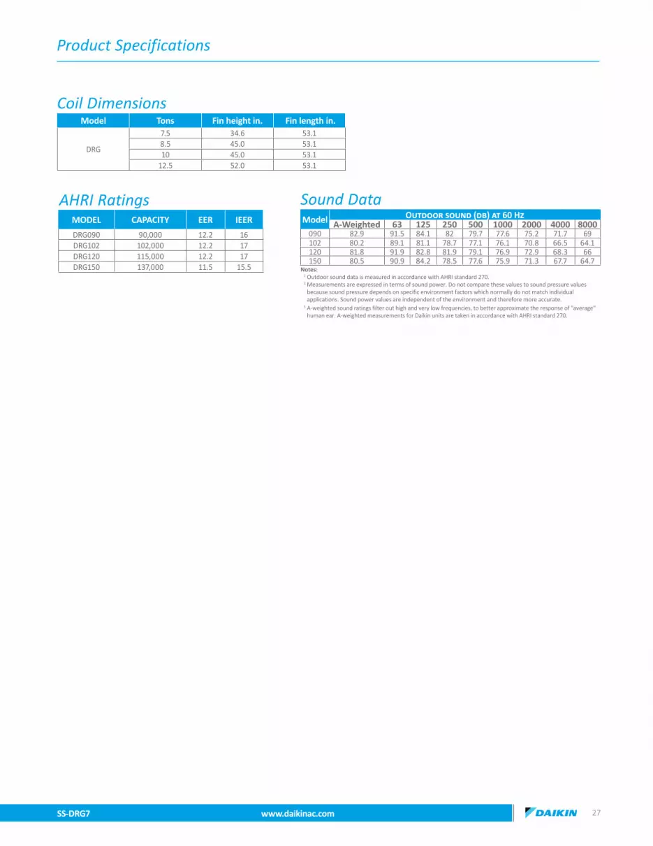
MODEL CAPACITY EER IEER
DRG090 90,000 12.2 16DRG102 102,000 12.2 17DRG120 115,000 12.2 17DRG150 137,000 11.5 15.5
AHRI Ratings Sound DataModel Outdoor sound (db) at 60 Hz
A-Weighted 63 125 250 500 1000 2000 4000 8000090 82.9 91.5 84.1 82 79.7 77.6 75.2 71.7 69102 80.2 89.1 81.1 78.7 77.1 76.1 70.8 66.5 64.1120 81.8 91.9 82.8 81.9 79.1 76.9 72.9 68.3 66150 80.5 90.9 84.2 78.5 77.6 75.9 71.3 67.7 64.7
Notes:1 Outdoor sound data is measured in accordance with AHRI standard 270. 2 Measurements are expressed in terms of sound power. Do not compare these values to sound pressure values because sound pressure depends on specific environment factors which normally do not match individual applications. Sound power values are independent of the environment and therefore more accurate.3 A-weighted sound ratings filter out high and very low frequencies, to better approximate the response of "average" human ear. A-weighted measurements for Daikin units are taken in accordance with AHRI standard 270.
Model Tons Fin height in. Fin length in.
DRG
7.5 34.6 53.18.5 45.0 53.110 45.0 53.1
12.5 52.0 53.1
Coil Dimensions

Expanded Cooling Data
SS-DRG7 www.daikinac.com 2928 www.daikinac.com SS-DRG7
DRG090O
utdo
or A
mbi
ent T
empe
ratu
re
6575
8595
105
115
Ente
ring
Indo
or W
et B
ulb
Tem
pera
ture
IDB
Air
flow
ID W
B59
6367
7159
6367
7159
6367
7159
6367
7159
6367
7159
6367
71
70
2625
MBh
91.6
92.9
95.6
98.6
90.7
92.0
94.8
97.8
88.4
89.6
92.4
95.4
84.2
85.5
88.3
91.3
79.2
80.5
83.2
86.2
74.6
75.9
78.7
81.7
S/T
0.59
0.52
0.38
0.28
0.60
0.52
0.39
0.28
0.62
0.55
0.41
0.31
1.00
0.57
0.43
0.33
1.00
0.59
0.46
0.35
1.00
0.64
0.51
0.40
∆T19
.52
17.7
214
.35
11.7
19.4
717
.67
14.3
011
.619
.73
17.9
214
.55
11.9
19.4
617
.65
14.2
811
.619
.21
17.4
114
.04
11.4
20.3
418
.54
15.1
712
.5
kW5.
415.
415.
405.
46.
026.
016.
006.
06.
696.
686.
676.
77.
427.
417.
407.
48.
238.
228.
218.
29.
189.
189.
179.
2
Amps
20.4
720
.44
20.4
020
.523
.22
23.2
023
.15
23.3
26.3
026
.28
26.2
326
.329
.63
29.6
129
.56
29.7
33.3
533
.33
33.2
833
.437
.71
37.6
937
.64
37.8
Hi P
R23
924
024
224
4.7
277
278
280
282.
531
631
831
932
2.0
359
360
362
364.
640
540
640
841
0.5
454
455
457
459.
5Lo
PR
127
128
132
135.
513
513
613
914
3.2
141
143
146
149.
914
714
915
215
5.7
153
154
157
161.
316
016
116
416
8.3
3000
MBh
92.8
94.1
96.8
99.8
91.9
93.2
96.0
99.0
89.6
90.9
93.6
96.6
85.4
86.7
89.5
92.5
80.4
81.7
84.4
87.4
75.8
77.1
79.9
82.9
S/T
0.65
0.57
0.44
0.3
0.66
0.58
0.45
0.3
1.00
0.61
0.47
0.4
1.00
0.62
0.49
0.4
1.00
0.65
0.51
0.4
1.00
0.70
0.56
0.5
∆T18
.43
16.6
313
.26
10.6
18.3
816
.58
13.2
110
.518
.64
16.8
313
.46
10.8
18.3
616
.56
13.1
910
.518
.12
16.3
212
.95
10.3
19.2
517
.45
14.0
811
.4
kW5.
455.
445.
435.
56.
056.
046.
036.
16.
726.
716.
706.
77.
457.
447.
437.
58.
268.
268.
248.
39.
219.
219.
209.
2
Amps
20.6
120
.59
20.5
420
.723
.37
23.3
423
.30
23.4
26.4
426
.42
26.3
726
.529
.77
29.7
529
.70
29.8
33.4
933
.47
33.4
233
.537
.86
37.8
437
.79
37.9
Hi P
R24
124
224
424
6.7
279
280
282
284.
531
932
032
132
4.0
361
362
364
366.
640
740
841
041
2.5
456
457
459
461.
5Lo
PR
129
130
134
137.
313
613
814
114
5.0
143
145
148
151.
814
915
015
415
7.5
155
156
159
163.
116
216
316
617
0.2
3375
MBh
94.2
95.5
98.2
101.
293
.494
.797
.410
0.4
91.0
92.3
95.0
98.0
86.9
88.2
90.9
93.9
81.9
83.2
85.9
88.9
77.3
78.6
81.3
84.3
S/T
0.68
0.61
0.48
0.4
0.69
0.61
0.48
0.4
1.00
0.64
0.51
0.4
1.00
0.66
0.53
0.4
1.00
0.68
0.55
0.4
1.00
1.00
0.60
0.5
∆T17
.51
15.7
112
.34
9.7
17.4
615
.66
12.2
99.
617
.72
15.9
112
.54
9.9
17.4
515
.64
12.2
79.
617
.21
15.4
012
.03
9.3
18.3
416
.53
13.1
610
.5
kW5.
475.
475.
465.
56.
076.
076.
066.
16.
756.
746.
736.
87.
477.
477.
467.
58.
298.
288.
278.
39.
249.
249.
229.
3
Amps
20.7
320
.71
20.6
620
.823
.49
23.4
623
.42
23.5
26.5
626
.54
26.4
926
.629
.89
29.8
729
.82
29.9
33.6
133
.59
33.5
433
.737
.98
37.9
537
.91
38.0
Hi P
R24
324
424
624
8.7
281
282
284
286.
532
032
232
332
6.0
363
364
366
368.
640
941
041
241
4.5
458
459
461
463.
5Lo
PR
131
132
136
139.
413
814
014
314
7.1
145
147
150
153.
915
115
315
615
9.6
157
158
161
165.
216
416
516
817
2.2
75
2625
MBh
91.6
92.9
95.6
99.8
90.8
92.1
94.8
99.0
88.4
89.7
92.4
96.6
84.3
85.6
88.3
92.5
79.3
80.6
83.3
87.5
74.7
76.0
78.7
82.9
S/T
0.72
0.64
0.51
0.4
1.00
0.65
0.52
0.4
1.00
0.67
0.54
0.4
1.00
0.69
0.56
0.4
1.00
0.71
0.58
0.4
1.00
1.00
0.63
0.5
∆T23
.49
21.6
918
.32
14.8
23.4
421
.64
18.2
714
.823
.70
21.8
918
.52
15.0
23.4
321
.62
18.2
514
.823
.18
21.3
818
.01
14.5
24.3
122
.51
19.1
415
.6
kW5.
415.
415.
395.
46.
016.
016.
006.
06.
686.
686.
676.
77.
417.
417.
407.
48.
228.
228.
218.
39.
189.
179.
169.
2
Amps
20.4
520
.43
20.3
820
.623
.20
23.1
823
.14
23.3
26.2
826
.26
26.2
126
.429
.61
29.5
929
.54
29.8
33.3
333
.31
33.2
633
.537
.70
37.6
737
.63
37.8
Hi P
R23
924
024
224
6.3
277
278
280
284.
031
731
831
932
3.6
359
360
362
366.
240
540
640
841
2.1
454
455
457
461.
1Lo
PR
127
128
132
137.
113
513
613
914
4.8
141
143
146
151.
614
714
915
215
7.3
153
154
157
162.
916
016
116
416
9.9
3000
MBh
92.8
94.1
96.8
101.
092
.093
.396
.010
0.2
89.6
90.9
93.6
97.8
85.5
86.8
89.5
93.7
80.5
81.8
84.5
88.7
75.9
77.2
79.9
84.1
S/T
0.77
0.70
0.57
0.4
1.00
0.71
0.57
0.4
1.00
0.73
0.60
0.5
1.00
0.75
0.62
0.5
1.00
1.00
0.64
0.5
1.00
1.00
0.69
0.6
∆T22
.40
20.6
017
.23
13.7
22.3
520
.55
17.1
813
.722
.61
20.8
017
.43
13.9
22.3
320
.53
17.1
613
.722
.09
20.2
916
.92
13.4
23.2
221
.42
18.0
514
.6
kW5.
445.
445.
435.
56.
046.
046.
036.
16.
726.
716.
706.
77.
447.
447.
437.
58.
268.
258.
248.
39.
219.
219.
199.
2
Amps
20.5
920
.57
20.5
220
.723
.35
23.3
323
.28
23.5
26.4
226
.40
26.3
626
.629
.75
29.7
329
.69
29.9
33.4
733
.45
33.4
133
.637
.84
37.8
237
.77
38.0
Hi P
R24
124
224
424
8.3
279
280
282
286.
131
932
032
132
5.6
361
362
364
368.
240
740
841
041
4.1
456
457
459
463.
1Lo
PR
129
130
134
138.
913
613
814
114
6.7
143
145
148
153.
414
915
115
415
9.1
155
156
159
164.
716
216
316
617
1.8
3375
MBh
94.3
95.6
98.3
102.
593
.494
.797
.510
1.7
91.1
92.3
95.1
99.3
86.9
88.2
91.0
95.1
81.9
83.2
85.9
90.1
77.3
78.6
81.4
85.5
S/T
0.81
0.73
0.60
0.5
1.00
0.74
0.61
0.5
1.00
0.76
0.63
0.5
1.00
0.78
0.65
0.5
1.00
1.00
0.67
0.5
1.00
1.00
0.72
0.6
∆T21
.48
19.6
816
.31
12.8
21.4
319
.63
16.2
612
.821
.69
19.8
816
.51
13.0
21.4
219
.61
16.2
412
.721
.17
19.3
716
.00
12.5
22.3
120
.50
17.1
313
.6
kW5.
475.
465.
455.
56.
076.
066.
056.
16.
746.
746.
736.
87.
477.
467.
457.
58.
288.
288.
278.
39.
249.
239.
229.
3
Amps
20.7
120
.69
20.6
420
.923
.47
23.4
523
.40
23.6
26.5
426
.52
26.4
826
.729
.87
29.8
529
.81
30.0
33.5
933
.57
33.5
333
.737
.96
37.9
437
.89
38.1
Hi P
R24
324
424
625
0.3
281
282
284
288.
032
132
232
332
7.6
363
364
366
370.
240
941
041
241
6.1
458
459
461
465.
1Lo
PR
131
132
136
141.
013
914
014
314
8.7
145
147
150
155.
515
115
315
616
1.2
157
158
161
166.
816
416
516
817
3.8
IDB:
Ent
erin
g In
door
Dry
Bul
b Te
mpe
ratu
reSh
aded
are
a re
flect
s A
CCA
(TVA
) con
diti
ons
kW =
Tot
al s
yste
m p
ower
Hig
h an
d lo
w p
ress
ures
are
mea
sure
d at
the
liqui
d an
d su
ctio
n ac
cess
fitt
ings
.A
mps
: Uni
t am
ps (c
omp.
+ ev
apor
ator
+ c
onde
nser
fan
mot
ors)
Des
ign
Subc
oolin
g, 1
6 - 1
9 °F
@ th
e liq
uid
acce
ss fi
ttin
g co
nnec
tion
ARI
95
test
con
ditio
ns. D
esig
n Su
perh
eat 8
- 12
°F @
the
com
pres
sor s
uctio
n ac
cess
fitt
ing
conn
ectio
n.
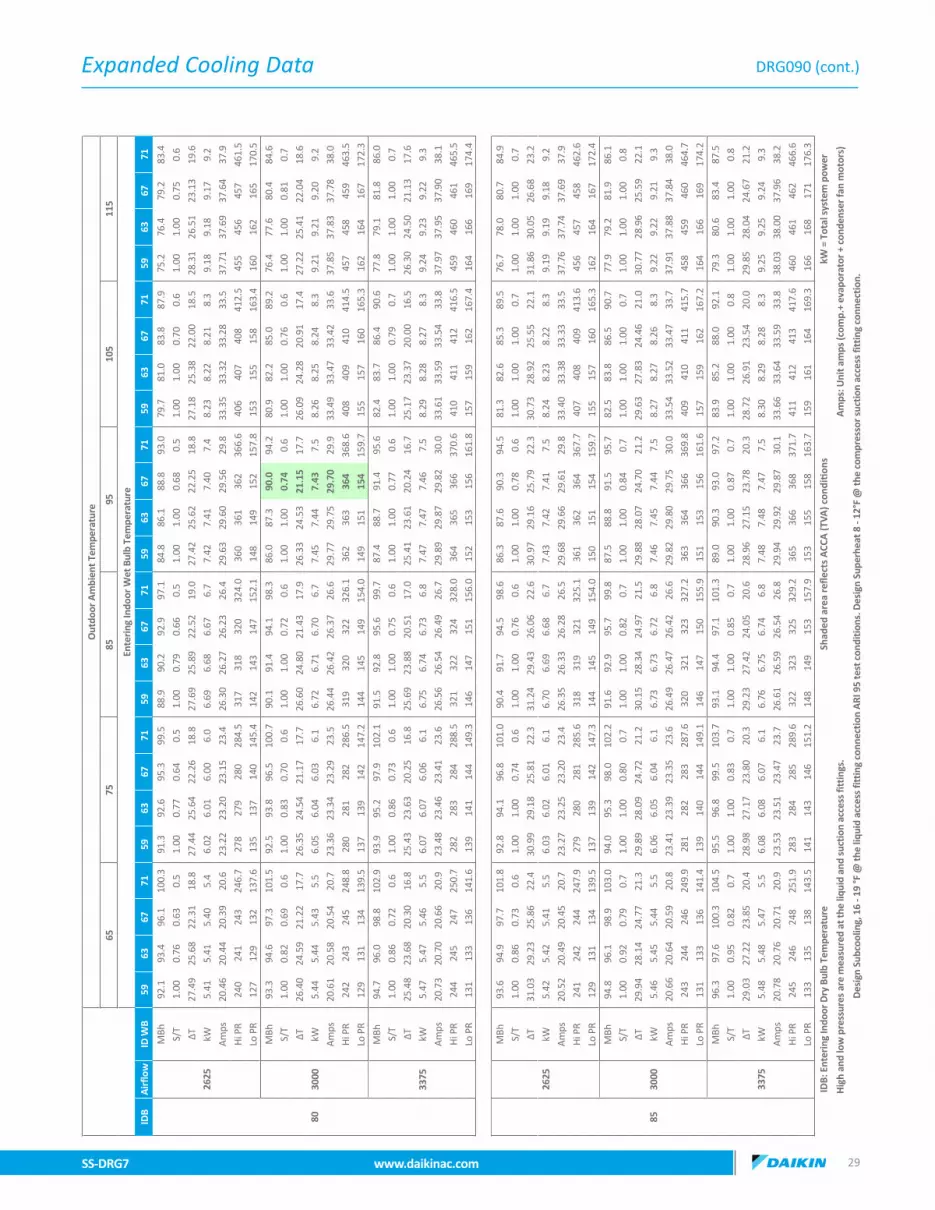
Expanded Cooling Data
SS-DRG7 www.daikinac.com 2928 www.daikinac.com SS-DRG7
Out
door
Am
bien
t Tem
pera
ture
6575
8595
105
115
Ente
ring
Indo
or W
et B
ulb
Tem
pera
ture
IDB
Air
flow
ID W
B59
6367
7159
6367
7159
6367
7159
6367
7159
6367
7159
6367
71
70
2625
MBh
91.6
92.9
95.6
98.6
90.7
92.0
94.8
97.8
88.4
89.6
92.4
95.4
84.2
85.5
88.3
91.3
79.2
80.5
83.2
86.2
74.6
75.9
78.7
81.7
S/T
0.59
0.52
0.38
0.28
0.60
0.52
0.39
0.28
0.62
0.55
0.41
0.31
1.00
0.57
0.43
0.33
1.00
0.59
0.46
0.35
1.00
0.64
0.51
0.40
∆T19
.52
17.7
214
.35
11.7
19.4
717
.67
14.3
011
.619
.73
17.9
214
.55
11.9
19.4
617
.65
14.2
811
.619
.21
17.4
114
.04
11.4
20.3
418
.54
15.1
712
.5
kW5.
415.
415.
405.
46.
026.
016.
006.
06.
696.
686.
676.
77.
427.
417.
407.
48.
238.
228.
218.
29.
189.
189.
179.
2
Amps
20.4
720
.44
20.4
020
.523
.22
23.2
023
.15
23.3
26.3
026
.28
26.2
326
.329
.63
29.6
129
.56
29.7
33.3
533
.33
33.2
833
.437
.71
37.6
937
.64
37.8
Hi P
R23
924
024
224
4.7
277
278
280
282.
531
631
831
932
2.0
359
360
362
364.
640
540
640
841
0.5
454
455
457
459.
5Lo
PR
127
128
132
135.
513
513
613
914
3.2
141
143
146
149.
914
714
915
215
5.7
153
154
157
161.
316
016
116
416
8.3
3000
MBh
92.8
94.1
96.8
99.8
91.9
93.2
96.0
99.0
89.6
90.9
93.6
96.6
85.4
86.7
89.5
92.5
80.4
81.7
84.4
87.4
75.8
77.1
79.9
82.9
S/T
0.65
0.57
0.44
0.3
0.66
0.58
0.45
0.3
1.00
0.61
0.47
0.4
1.00
0.62
0.49
0.4
1.00
0.65
0.51
0.4
1.00
0.70
0.56
0.5
∆T18
.43
16.6
313
.26
10.6
18.3
816
.58
13.2
110
.518
.64
16.8
313
.46
10.8
18.3
616
.56
13.1
910
.518
.12
16.3
212
.95
10.3
19.2
517
.45
14.0
811
.4
kW5.
455.
445.
435.
56.
056.
046.
036.
16.
726.
716.
706.
77.
457.
447.
437.
58.
268.
268.
248.
39.
219.
219.
209.
2
Amps
20.6
120
.59
20.5
420
.723
.37
23.3
423
.30
23.4
26.4
426
.42
26.3
726
.529
.77
29.7
529
.70
29.8
33.4
933
.47
33.4
233
.537
.86
37.8
437
.79
37.9
Hi P
R24
124
224
424
6.7
279
280
282
284.
531
932
032
132
4.0
361
362
364
366.
640
740
841
041
2.5
456
457
459
461.
5Lo
PR
129
130
134
137.
313
613
814
114
5.0
143
145
148
151.
814
915
015
415
7.5
155
156
159
163.
116
216
316
617
0.2
3375
MBh
94.2
95.5
98.2
101.
293
.494
.797
.410
0.4
91.0
92.3
95.0
98.0
86.9
88.2
90.9
93.9
81.9
83.2
85.9
88.9
77.3
78.6
81.3
84.3
S/T
0.68
0.61
0.48
0.4
0.69
0.61
0.48
0.4
1.00
0.64
0.51
0.4
1.00
0.66
0.53
0.4
1.00
0.68
0.55
0.4
1.00
1.00
0.60
0.5
∆T17
.51
15.7
112
.34
9.7
17.4
615
.66
12.2
99.
617
.72
15.9
112
.54
9.9
17.4
515
.64
12.2
79.
617
.21
15.4
012
.03
9.3
18.3
416
.53
13.1
610
.5
kW5.
475.
475.
465.
56.
076.
076.
066.
16.
756.
746.
736.
87.
477.
477.
467.
58.
298.
288.
278.
39.
249.
249.
229.
3
Amps
20.7
320
.71
20.6
620
.823
.49
23.4
623
.42
23.5
26.5
626
.54
26.4
926
.629
.89
29.8
729
.82
29.9
33.6
133
.59
33.5
433
.737
.98
37.9
537
.91
38.0
Hi P
R24
324
424
624
8.7
281
282
284
286.
532
032
232
332
6.0
363
364
366
368.
640
941
041
241
4.5
458
459
461
463.
5Lo
PR
131
132
136
139.
413
814
014
314
7.1
145
147
150
153.
915
115
315
615
9.6
157
158
161
165.
216
416
516
817
2.2
75
2625
MBh
91.6
92.9
95.6
99.8
90.8
92.1
94.8
99.0
88.4
89.7
92.4
96.6
84.3
85.6
88.3
92.5
79.3
80.6
83.3
87.5
74.7
76.0
78.7
82.9
S/T
0.72
0.64
0.51
0.4
1.00
0.65
0.52
0.4
1.00
0.67
0.54
0.4
1.00
0.69
0.56
0.4
1.00
0.71
0.58
0.4
1.00
1.00
0.63
0.5
∆T23
.49
21.6
918
.32
14.8
23.4
421
.64
18.2
714
.823
.70
21.8
918
.52
15.0
23.4
321
.62
18.2
514
.823
.18
21.3
818
.01
14.5
24.3
122
.51
19.1
415
.6
kW5.
415.
415.
395.
46.
016.
016.
006.
06.
686.
686.
676.
77.
417.
417.
407.
48.
228.
228.
218.
39.
189.
179.
169.
2
Amps
20.4
520
.43
20.3
820
.623
.20
23.1
823
.14
23.3
26.2
826
.26
26.2
126
.429
.61
29.5
929
.54
29.8
33.3
333
.31
33.2
633
.537
.70
37.6
737
.63
37.8
Hi P
R23
924
024
224
6.3
277
278
280
284.
031
731
831
932
3.6
359
360
362
366.
240
540
640
841
2.1
454
455
457
461.
1Lo
PR
127
128
132
137.
113
513
613
914
4.8
141
143
146
151.
614
714
915
215
7.3
153
154
157
162.
916
016
116
416
9.9
3000
MBh
92.8
94.1
96.8
101.
092
.093
.396
.010
0.2
89.6
90.9
93.6
97.8
85.5
86.8
89.5
93.7
80.5
81.8
84.5
88.7
75.9
77.2
79.9
84.1
S/T
0.77
0.70
0.57
0.4
1.00
0.71
0.57
0.4
1.00
0.73
0.60
0.5
1.00
0.75
0.62
0.5
1.00
1.00
0.64
0.5
1.00
1.00
0.69
0.6
∆T22
.40
20.6
017
.23
13.7
22.3
520
.55
17.1
813
.722
.61
20.8
017
.43
13.9
22.3
320
.53
17.1
613
.722
.09
20.2
916
.92
13.4
23.2
221
.42
18.0
514
.6
kW5.
445.
445.
435.
56.
046.
046.
036.
16.
726.
716.
706.
77.
447.
447.
437.
58.
268.
258.
248.
39.
219.
219.
199.
2
Amps
20.5
920
.57
20.5
220
.723
.35
23.3
323
.28
23.5
26.4
226
.40
26.3
626
.629
.75
29.7
329
.69
29.9
33.4
733
.45
33.4
133
.637
.84
37.8
237
.77
38.0
Hi P
R24
124
224
424
8.3
279
280
282
286.
131
932
032
132
5.6
361
362
364
368.
240
740
841
041
4.1
456
457
459
463.
1Lo
PR
129
130
134
138.
913
613
814
114
6.7
143
145
148
153.
414
915
115
415
9.1
155
156
159
164.
716
216
316
617
1.8
3375
MBh
94.3
95.6
98.3
102.
593
.494
.797
.510
1.7
91.1
92.3
95.1
99.3
86.9
88.2
91.0
95.1
81.9
83.2
85.9
90.1
77.3
78.6
81.4
85.5
S/T
0.81
0.73
0.60
0.5
1.00
0.74
0.61
0.5
1.00
0.76
0.63
0.5
1.00
0.78
0.65
0.5
1.00
1.00
0.67
0.5
1.00
1.00
0.72
0.6
∆T21
.48
19.6
816
.31
12.8
21.4
319
.63
16.2
612
.821
.69
19.8
816
.51
13.0
21.4
219
.61
16.2
412
.721
.17
19.3
716
.00
12.5
22.3
120
.50
17.1
313
.6
kW5.
475.
465.
455.
56.
076.
066.
056.
16.
746.
746.
736.
87.
477.
467.
457.
58.
288.
288.
278.
39.
249.
239.
229.
3
Amps
20.7
120
.69
20.6
420
.923
.47
23.4
523
.40
23.6
26.5
426
.52
26.4
826
.729
.87
29.8
529
.81
30.0
33.5
933
.57
33.5
333
.737
.96
37.9
437
.89
38.1
Hi P
R24
324
424
625
0.3
281
282
284
288.
032
132
232
332
7.6
363
364
366
370.
240
941
041
241
6.1
458
459
461
465.
1Lo
PR
131
132
136
141.
013
914
014
314
8.7
145
147
150
155.
515
115
315
616
1.2
157
158
161
166.
816
416
516
817
3.8
IDB:
Ent
erin
g In
door
Dry
Bul
b Te
mpe
ratu
reSh
aded
are
a re
flect
s A
CCA
(TVA
) con
diti
ons
kW =
Tot
al s
yste
m p
ower
Hig
h an
d lo
w p
ress
ures
are
mea
sure
d at
the
liqui
d an
d su
ctio
n ac
cess
fitt
ings
.A
mps
: Uni
t am
ps (c
omp.
+ ev
apor
ator
+ c
onde
nser
fan
mot
ors)
Des
ign
Subc
oolin
g, 1
6 - 1
9 °F
@ th
e liq
uid
acce
ss fi
ttin
g co
nnec
tion
ARI
95
test
con
ditio
ns. D
esig
n Su
perh
eat 8
- 12
°F @
the
com
pres
sor s
uctio
n ac
cess
fitt
ing
conn
ectio
n.
DRG090 (cont.)O
utdo
or A
mbi
ent T
empe
ratu
re
6575
8595
105
115
Ente
ring
Indo
or W
et B
ulb
Tem
pera
ture
IDB
Air
flow
ID W
B59
6367
7159
6367
7159
6367
7159
6367
7159
6367
7159
6367
71
80
2625
MBh
92.1
93.4
96.1
100.
391
.392
.695
.399
.588
.990
.292
.997
.184
.886
.188
.893
.079
.781
.083
.887
.975
.276
.479
.283
.4
S/T
1.00
0.76
0.63
0.5
1.00
0.77
0.64
0.5
1.00
0.79
0.66
0.5
1.00
1.00
0.68
0.5
1.00
1.00
0.70
0.6
1.00
1.00
0.75
0.6
∆T27
.49
25.6
822
.31
18.8
27.4
425
.64
22.2
618
.827
.69
25.8
922
.52
19.0
27.4
225
.62
22.2
518
.827
.18
25.3
822
.00
18.5
28.3
126
.51
23.1
319
.6
kW5.
415.
415.
405.
46.
026.
016.
006.
06.
696.
686.
676.
77.
427.
417.
407.
48.
238.
228.
218.
39.
189.
189.
179.
2
Amps
20.4
620
.44
20.3
920
.623
.22
23.2
023
.15
23.4
26.3
026
.27
26.2
326
.429
.63
29.6
029
.56
29.8
33.3
533
.32
33.2
833
.537
.71
37.6
937
.64
37.9
Hi P
R24
024
124
324
6.7
278
279
280
284.
531
731
832
032
4.0
360
361
362
366.
640
640
740
841
2.5
455
456
457
461.
5Lo
PR
127
129
132
137.
613
513
714
014
5.4
142
143
147
152.
114
814
915
215
7.8
153
155
158
163.
416
016
216
517
0.5
3000
MBh
93.3
94.6
97.3
101.
592
.593
.896
.510
0.7
90.1
91.4
94.1
98.3
86.0
87.3
90.0
94.2
80.9
82.2
85.0
89.2
76.4
77.6
80.4
84.6
S/T
1.00
0.82
0.69
0.6
1.00
0.83
0.70
0.6
1.00
1.00
0.72
0.6
1.00
1.00
0.74
0.6
1.00
1.00
0.76
0.6
1.00
1.00
0.81
0.7
∆T26
.40
24.5
921
.22
17.7
26.3
524
.54
21.1
717
.726
.60
24.8
021
.43
17.9
26.3
324
.53
21.1
517
.726
.09
24.2
820
.91
17.4
27.2
225
.41
22.0
418
.6
kW5.
445.
445.
435.
56.
056.
046.
036.
16.
726.
716.
706.
77.
457.
447.
437.
58.
268.
258.
248.
39.
219.
219.
209.
2
Amps
20.6
120
.58
20.5
420
.723
.36
23.3
423
.29
23.5
26.4
426
.42
26.3
726
.629
.77
29.7
529
.70
29.9
33.4
933
.47
33.4
233
.637
.85
37.8
337
.78
38.0
Hi P
R24
224
324
524
8.8
280
281
282
286.
531
932
032
232
6.1
362
363
364
368.
640
840
941
041
4.5
457
458
459
463.
5Lo
PR
129
131
134
139.
513
713
914
214
7.2
144
145
149
154.
014
915
115
415
9.7
155
157
160
165.
316
216
416
717
2.3
3375
MBh
94.7
96.0
98.8
102.
993
.995
.297
.910
2.1
91.5
92.8
95.6
99.7
87.4
88.7
91.4
95.6
82.4
83.7
86.4
90.6
77.8
79.1
81.8
86.0
S/T
1.00
0.86
0.72
0.6
1.00
0.86
0.73
0.6
1.00
1.00
0.75
0.6
1.00
1.00
0.77
0.6
1.00
1.00
0.79
0.7
1.00
1.00
1.00
0.7
∆T25
.48
23.6
820
.30
16.8
25.4
323
.63
20.2
516
.825
.69
23.8
820
.51
17.0
25.4
123
.61
20.2
416
.725
.17
23.3
720
.00
16.5
26.3
024
.50
21.1
317
.6
kW5.
475.
475.
465.
56.
076.
076.
066.
16.
756.
746.
736.
87.
477.
477.
467.
58.
298.
288.
278.
39.
249.
239.
229.
3
Amps
20.7
320
.70
20.6
620
.923
.48
23.4
623
.41
23.6
26.5
626
.54
26.4
926
.729
.89
29.8
729
.82
30.0
33.6
133
.59
33.5
433
.837
.97
37.9
537
.90
38.1
Hi P
R24
424
524
725
0.7
282
283
284
288.
532
132
232
432
8.0
364
365
366
370.
641
041
141
241
6.5
459
460
461
465.
5Lo
PR
131
133
136
141.
613
914
114
414
9.3
146
147
151
156.
015
215
315
616
1.8
157
159
162
167.
416
416
616
917
4.4
85
2625
MBh
93.6
94.9
97.7
101.
892
.894
.196
.810
1.0
90.4
91.7
94.5
98.6
86.3
87.6
90.3
94.5
81.3
82.6
85.3
89.5
76.7
78.0
80.7
84.9
S/T
1.00
0.86
0.73
0.6
1.00
1.00
0.74
0.6
1.00
1.00
0.76
0.6
1.00
1.00
0.78
0.6
1.00
1.00
1.00
0.7
1.00
1.00
1.00
0.7
∆T31
.03
29.2
325
.86
22.4
30.9
929
.18
25.8
122
.331
.24
29.4
326
.06
22.6
30.9
729
.16
25.7
922
.330
.73
28.9
225
.55
22.1
31.8
630
.05
26.6
823
.2
kW5.
425.
425.
415.
56.
036.
026.
016.
16.
706.
696.
686.
77.
437.
427.
417.
58.
248.
238.
228.
39.
199.
199.
189.
2
Amps
20.5
220
.49
20.4
520
.723
.27
23.2
523
.20
23.4
26.3
526
.33
26.2
826
.529
.68
29.6
629
.61
29.8
33.4
033
.38
33.3
333
.537
.76
37.7
437
.69
37.9
Hi P
R24
124
224
424
7.9
279
280
281
285.
631
831
932
132
5.1
361
362
364
367.
740
740
840
941
3.6
456
457
458
462.
6Lo
PR
129
131
134
139.
513
713
914
214
7.3
144
145
149
154.
015
015
115
415
9.7
155
157
160
165.
316
216
416
717
2.4
3000
MBh
94.8
96.1
98.9
103.
094
.095
.398
.010
2.2
91.6
92.9
95.7
99.8
87.5
88.8
91.5
95.7
82.5
83.8
86.5
90.7
77.9
79.2
81.9
86.1
S/T
1.00
0.92
0.79
0.7
1.00
1.00
0.80
0.7
1.00
1.00
0.82
0.7
1.00
1.00
0.84
0.7
1.00
1.00
1.00
0.7
1.00
1.00
1.00
0.8
∆T29
.94
28.1
424
.77
21.3
29.8
928
.09
24.7
221
.230
.15
28.3
424
.97
21.5
29.8
828
.07
24.7
021
.229
.63
27.8
324
.46
21.0
30.7
728
.96
25.5
922
.1
kW5.
465.
455.
445.
56.
066.
056.
046.
16.
736.
736.
726.
87.
467.
457.
447.
58.
278.
278.
268.
39.
229.
229.
219.
3
Amps
20.6
620
.64
20.5
920
.823
.41
23.3
923
.35
23.6
26.4
926
.47
26.4
226
.629
.82
29.8
029
.75
30.0
33.5
433
.52
33.4
733
.737
.91
37.8
837
.84
38.0
Hi P
R24
324
424
624
9.9
281
282
283
287.
632
032
132
332
7.2
363
364
366
369.
840
941
041
141
5.7
458
459
460
464.
7Lo
PR
131
133
136
141.
413
914
014
414
9.1
146
147
150
155.
915
115
315
616
1.6
157
159
162
167.
216
416
616
917
4.2
3375
MBh
96.3
97.6
100.
310
4.5
95.5
96.8
99.5
103.
793
.194
.497
.110
1.3
89.0
90.3
93.0
97.2
83.9
85.2
88.0
92.1
79.3
80.6
83.4
87.5
S/T
1.00
0.95
0.82
0.7
1.00
1.00
0.83
0.7
1.00
1.00
0.85
0.7
1.00
1.00
0.87
0.7
1.00
1.00
1.00
0.8
1.00
1.00
1.00
0.8
∆T29
.03
27.2
223
.85
20.4
28.9
827
.17
23.8
020
.329
.23
27.4
224
.05
20.6
28.9
627
.15
23.7
820
.328
.72
26.9
123
.54
20.0
29.8
528
.04
24.6
721
.2
kW5.
485.
485.
475.
56.
086.
086.
076.
16.
766.
756.
746.
87.
487.
487.
477.
58.
308.
298.
288.
39.
259.
259.
249.
3
Amps
20.7
820
.76
20.7
120
.923
.53
23.5
123
.47
23.7
26.6
126
.59
26.5
426
.829
.94
29.9
229
.87
30.1
33.6
633
.64
33.5
933
.838
.03
38.0
037
.96
38.2
Hi P
R24
524
624
825
1.9
283
284
285
289.
632
232
332
532
9.2
365
366
368
371.
741
141
241
341
7.6
460
461
462
466.
6Lo
PR
133
135
138
143.
514
114
314
615
1.2
148
149
153
157.
915
315
515
816
3.7
159
161
164
169.
316
616
817
117
6.3
IDB:
Ent
erin
g In
door
Dry
Bul
b Te
mpe
ratu
reSh
aded
are
a re
flect
s A
CCA
(TVA
) con
diti
ons
kW =
Tot
al s
yste
m p
ower
Hig
h an
d lo
w p
ress
ures
are
mea
sure
d at
the
liqui
d an
d su
ctio
n ac
cess
fitt
ings
.A
mps
: Uni
t am
ps (c
omp.
+ ev
apor
ator
+ c
onde
nser
fan
mot
ors)
Des
ign
Subc
oolin
g, 1
6 - 1
9 °F
@ th
e liq
uid
acce
ss fi
ttin
g co
nnec
tion
ARI
95
test
con
ditio
ns. D
esig
n Su
perh
eat 8
- 12
°F @
the
com
pres
sor s
uctio
n ac
cess
fitt
ing
conn
ectio
n.

Expanded Cooling Data
SS-DRG7 www.daikinac.com 3130 www.daikinac.com SS-DRG7
DRG102O
utdo
or A
mbi
ent T
empe
ratu
re
6575
8595
105
115
Ente
ring
Indo
or W
et B
ulb
Tem
pera
ture
IDB
Air
flow
ID W
B59
6367
7159
6367
7159
6367
7159
6367
7159
6367
7159
6367
71
70
2625
MBh
105.
110
6.6
109.
711
3.1
104.
210
5.7
108.
811
2.2
101.
510
3.0
106.
110
9.5
96.8
98.3
101.
410
4.8
91.1
92.6
95.7
95.7
85.9
87.4
90.5
93.9
S/T
0.62
0.55
0.42
0.32
0.63
0.56
0.43
0.33
0.65
0.58
0.45
0.35
1.00
0.60
0.47
0.37
1.00
0.62
0.49
0.49
1.00
0.67
0.54
0.44
∆T19
.06
17.2
013
.71
10.9
19.0
117
.14
13.6
610
.919
.27
17.4
113
.92
11.1
18.9
917
.13
13.6
410
.918
.74
16.8
813
.39
13.4
19.9
118
.04
14.5
611
.8
kW6.
046.
046.
026.
16.
776.
766.
756.
87.
577.
577.
557.
68.
448.
448.
438.
59.
429.
419.
409.
410
.56
10.5
610
.55
10.6
Amps
23.9
923
.97
23.9
124
.127
.30
27.2
827
.22
27.4
30.9
930
.97
30.9
131
.134
.99
34.9
634
.91
35.0
39.4
539
.42
39.3
739
.444
.69
44.6
644
.60
44.7
Hi P
R25
325
425
625
9.0
293
294
296
298.
633
433
533
734
0.1
379
380
382
384.
842
742
843
043
0.1
479
480
482
484.
5Lo
PR
125
126
129
133.
113
213
413
714
0.6
139
140
143
147.
114
414
614
915
2.7
150
151
154
154.
415
715
816
116
4.9
3000
MBh
106.
410
7.8
110.
911
4.3
105.
410
6.9
110.
011
3.4
102.
710
4.2
107.
311
0.7
98.1
99.5
102.
610
6.0
92.4
93.8
96.9
96.9
87.2
88.6
91.7
95.1
S/T
0.65
0.58
0.45
0.3
0.66
0.58
0.46
0.4
0.68
0.61
0.48
0.4
1.00
0.63
0.50
0.4
1.00
0.65
0.52
0.5
1.00
0.69
0.57
0.5
∆T18
.32
16.4
512
.96
10.2
18.2
616
.40
12.9
110
.118
.53
16.6
613
.17
10.4
18.2
516
.38
12.8
910
.118
.00
16.1
312
.64
12.6
19.1
717
.30
13.8
111
.0
kW6.
076.
066.
056.
16.
796.
786.
776.
87.
607.
597.
587.
68.
478.
468.
458.
59.
449.
449.
439.
410
.59
10.5
810
.57
10.6
Amps
24.1
124
.08
24.0
324
.227
.41
27.3
927
.33
27.5
31.1
131
.08
31.0
231
.235
.10
35.0
735
.02
35.2
39.5
639
.54
39.4
839
.544
.80
44.7
744
.72
44.9
Hi P
R25
525
625
826
0.6
294
296
297
300.
233
633
733
934
1.7
381
382
384
386.
442
943
043
243
1.7
480
481
483
486.
1Lo
PR
126
128
131
134.
613
413
513
814
2.1
140
142
145
148.
714
614
715
115
4.2
151
153
156
155.
915
816
016
316
6.5
3375
MBh
108.
510
9.9
113.
011
6.4
107.
510
9.0
112.
111
5.5
104.
810
6.3
109.
411
2.8
100.
210
1.6
104.
710
8.1
94.5
95.9
99.0
99.0
89.3
90.7
93.8
97.2
S/T
0.66
0.59
0.47
0.4
0.67
0.60
0.47
0.4
0.69
0.62
0.50
0.4
1.00
0.64
0.51
0.4
1.00
0.66
0.53
0.5
1.00
0.71
0.58
0.5
∆T17
.38
15.5
112
.02
9.2
17.3
215
.46
11.9
79.
217
.59
15.7
212
.23
9.5
17.3
115
.44
11.9
59.
217
.06
15.1
911
.70
11.7
18.2
216
.36
12.8
710
.1
kW6.
106.
096.
086.
16.
826.
826.
806.
87.
637.
627.
617.
68.
508.
498.
488.
59.
489.
479.
469.
510
.62
10.6
110
.60
10.6
Amps
24.2
524
.22
24.1
724
.327
.56
27.5
327
.47
27.6
31.2
531
.22
31.1
731
.335
.24
35.2
235
.16
35.3
39.7
139
.68
39.6
239
.644
.94
44.9
244
.86
45.0
Hi P
R25
725
826
026
2.9
297
298
300
302.
533
833
934
134
4.1
383
384
386
388.
743
143
243
443
4.0
483
484
485
488.
4Lo
PR
129
130
133
137.
113
613
814
114
4.6
143
144
147
151.
114
815
015
315
6.7
154
155
158
158.
416
116
216
516
8.9
75
2625
MBh
105.
210
6.7
109.
811
4.5
104.
310
5.7
108.
811
3.6
101.
610
3.0
106.
111
0.9
96.9
98.4
101.
510
6.2
91.2
92.7
95.8
100.
586
.087
.590
.695
.3S/
T0.
740.
670.
550.
40.
750.
680.
550.
41.
000.
700.
570.
41.
000.
720.
590.
51.
000.
740.
610.
51.
001.
000.
660.
5
∆T23
.17
21.3
017
.81
14.2
23.1
221
.25
17.7
614
.223
.38
21.5
118
.03
14.4
23.1
021
.23
17.7
414
.122
.85
20.9
817
.49
13.9
24.0
222
.15
18.6
615
.1
kW6.
046.
036.
026.
16.
766.
756.
746.
87.
577.
567.
557.
68.
448.
438.
428.
59.
429.
419.
409.
510
.56
10.5
510
.54
10.6
Amps
23.9
723
.95
23.8
924
.127
.28
27.2
527
.20
27.5
30.9
730
.95
30.8
931
.134
.97
34.9
434
.88
35.1
39.4
339
.40
39.3
539
.644
.67
44.6
444
.58
44.8
Hi P
R25
325
525
626
0.7
293
294
296
300.
333
533
633
734
1.8
379
380
382
386.
542
742
943
043
4.7
479
480
482
486.
1Lo
PR
125
126
129
134.
713
213
413
714
2.2
139
140
143
148.
714
414
614
915
4.2
150
151
154
159.
715
715
816
116
6.5
3000
MBh
106.
410
7.9
111.
011
5.7
105.
510
7.0
110.
111
4.8
102.
810
4.3
107.
411
2.1
98.1
99.6
102.
710
7.4
92.4
93.9
97.0
101.
787
.288
.791
.896
.5S/
T0.
770.
700.
570.
41.
000.
700.
580.
41.
000.
730.
600.
51.
000.
750.
620.
51.
000.
770.
640.
51.
001.
000.
690.
6
∆T22
.42
20.5
517
.07
13.5
22.3
720
.50
17.0
213
.422
.63
20.7
717
.28
13.7
22.3
520
.48
17.0
013
.422
.10
20.2
316
.75
13.1
23.2
721
.40
17.9
214
.3
kW6.
066.
066.
046.
16.
796.
786.
776.
87.
597.
597.
577.
68.
468.
468.
458.
59.
449.
439.
429.
510
.58
10.5
810
.57
10.6
Amps
24.0
924
.06
24.0
024
.327
.39
27.3
727
.31
27.6
31.0
831
.06
31.0
031
.335
.08
35.0
535
.00
35.2
39.5
439
.52
39.4
639
.744
.78
44.7
544
.70
44.9
Hi P
R25
525
625
826
2.3
295
296
298
301.
933
633
733
934
3.4
381
382
384
388.
142
943
043
243
6.3
480
482
483
487.
7Lo
PR
126
128
131
136.
213
413
513
814
3.7
140
142
145
150.
214
614
715
115
5.8
151
153
156
161.
215
816
016
316
8.0
3375
MBh
108.
511
0.0
113.
111
7.8
107.
610
9.1
112.
211
6.9
104.
910
6.4
109.
511
4.2
100.
210
1.7
104.
810
9.5
94.5
96.0
99.1
103.
889
.390
.893
.998
.6S/
T0.
790.
710.
590.
51.
000.
720.
590.
51.
000.
740.
620.
51.
000.
760.
630.
51.
001.
000.
660.
51.
001.
000.
700.
6
∆T21
.48
19.6
116
.13
12.5
21.4
319
.56
16.0
812
.521
.69
19.8
216
.34
12.7
21.4
119
.54
16.0
612
.421
.16
19.2
915
.81
12.2
22.3
320
.46
16.9
813
.4
kW6.
096.
096.
086.
16.
826.
816.
806.
97.
627.
627.
607.
78.
508.
498.
488.
59.
479.
479.
459.
510
.62
10.6
110
.60
10.7
Amps
24.2
324
.20
24.1
524
.427
.53
27.5
127
.45
27.7
31.2
331
.20
31.1
431
.435
.22
35.2
035
.14
35.4
39.6
839
.66
39.6
039
.944
.92
44.8
944
.84
45.1
Hi P
R25
725
826
026
4.6
297
298
300
304.
233
834
034
134
5.7
383
384
386
390.
443
143
243
443
8.6
483
484
486
490.
0Lo
PR
129
130
133
138.
613
613
814
114
6.1
143
144
147
152.
714
815
015
315
8.2
154
155
158
163.
616
116
216
517
0.5
IDB:
Ent
erin
g In
door
Dry
Bul
b Te
mpe
ratu
reSh
aded
are
a re
flect
s A
CCA
(TVA
) con
diti
ons
kW =
Tot
al s
yste
m p
ower
Hig
h an
d lo
w p
ress
ures
are
mea
sure
d at
the
liqui
d an
d su
ctio
n ac
cess
fitt
ings
.A
mps
: Uni
t am
ps (c
omp.
+ ev
apor
ator
+ c
onde
nser
fan
mot
ors)
Des
ign
Subc
oolin
g, 1
6 - 1
9 °F
@ th
e liq
uid
acce
ss fi
ttin
g co
nnec
tion
ARI
95
test
con
ditio
ns. D
esig
n Su
perh
eat 8
- 12
°F @
the
com
pres
sor s
uctio
n ac
cess
fitt
ing
conn
ectio
n.

Expanded Cooling Data
SS-DRG7 www.daikinac.com 3130 www.daikinac.com SS-DRG7
DRG102 (cont.)
Out
door
Am
bien
t Tem
pera
ture
6575
8595
105
115
Ente
ring
Indo
or W
et B
ulb
Tem
pera
ture
IDB
Air
flow
ID W
B59
6367
7159
6367
7159
6367
7159
6367
7159
6367
7159
6367
71
70
2625
MBh
105.
110
6.6
109.
711
3.1
104.
210
5.7
108.
811
2.2
101.
510
3.0
106.
110
9.5
96.8
98.3
101.
410
4.8
91.1
92.6
95.7
95.7
85.9
87.4
90.5
93.9
S/T
0.62
0.55
0.42
0.32
0.63
0.56
0.43
0.33
0.65
0.58
0.45
0.35
1.00
0.60
0.47
0.37
1.00
0.62
0.49
0.49
1.00
0.67
0.54
0.44
∆T19
.06
17.2
013
.71
10.9
19.0
117
.14
13.6
610
.919
.27
17.4
113
.92
11.1
18.9
917
.13
13.6
410
.918
.74
16.8
813
.39
13.4
19.9
118
.04
14.5
611
.8
kW6.
046.
046.
026.
16.
776.
766.
756.
87.
577.
577.
557.
68.
448.
448.
438.
59.
429.
419.
409.
410
.56
10.5
610
.55
10.6
Amps
23.9
923
.97
23.9
124
.127
.30
27.2
827
.22
27.4
30.9
930
.97
30.9
131
.134
.99
34.9
634
.91
35.0
39.4
539
.42
39.3
739
.444
.69
44.6
644
.60
44.7
Hi P
R25
325
425
625
9.0
293
294
296
298.
633
433
533
734
0.1
379
380
382
384.
842
742
843
043
0.1
479
480
482
484.
5Lo
PR
125
126
129
133.
113
213
413
714
0.6
139
140
143
147.
114
414
614
915
2.7
150
151
154
154.
415
715
816
116
4.9
3000
MBh
106.
410
7.8
110.
911
4.3
105.
410
6.9
110.
011
3.4
102.
710
4.2
107.
311
0.7
98.1
99.5
102.
610
6.0
92.4
93.8
96.9
96.9
87.2
88.6
91.7
95.1
S/T
0.65
0.58
0.45
0.3
0.66
0.58
0.46
0.4
0.68
0.61
0.48
0.4
1.00
0.63
0.50
0.4
1.00
0.65
0.52
0.5
1.00
0.69
0.57
0.5
∆T18
.32
16.4
512
.96
10.2
18.2
616
.40
12.9
110
.118
.53
16.6
613
.17
10.4
18.2
516
.38
12.8
910
.118
.00
16.1
312
.64
12.6
19.1
717
.30
13.8
111
.0
kW6.
076.
066.
056.
16.
796.
786.
776.
87.
607.
597.
587.
68.
478.
468.
458.
59.
449.
449.
439.
410
.59
10.5
810
.57
10.6
Amps
24.1
124
.08
24.0
324
.227
.41
27.3
927
.33
27.5
31.1
131
.08
31.0
231
.235
.10
35.0
735
.02
35.2
39.5
639
.54
39.4
839
.544
.80
44.7
744
.72
44.9
Hi P
R25
525
625
826
0.6
294
296
297
300.
233
633
733
934
1.7
381
382
384
386.
442
943
043
243
1.7
480
481
483
486.
1Lo
PR
126
128
131
134.
613
413
513
814
2.1
140
142
145
148.
714
614
715
115
4.2
151
153
156
155.
915
816
016
316
6.5
3375
MBh
108.
510
9.9
113.
011
6.4
107.
510
9.0
112.
111
5.5
104.
810
6.3
109.
411
2.8
100.
210
1.6
104.
710
8.1
94.5
95.9
99.0
99.0
89.3
90.7
93.8
97.2
S/T
0.66
0.59
0.47
0.4
0.67
0.60
0.47
0.4
0.69
0.62
0.50
0.4
1.00
0.64
0.51
0.4
1.00
0.66
0.53
0.5
1.00
0.71
0.58
0.5
∆T17
.38
15.5
112
.02
9.2
17.3
215
.46
11.9
79.
217
.59
15.7
212
.23
9.5
17.3
115
.44
11.9
59.
217
.06
15.1
911
.70
11.7
18.2
216
.36
12.8
710
.1
kW6.
106.
096.
086.
16.
826.
826.
806.
87.
637.
627.
617.
68.
508.
498.
488.
59.
489.
479.
469.
510
.62
10.6
110
.60
10.6
Amps
24.2
524
.22
24.1
724
.327
.56
27.5
327
.47
27.6
31.2
531
.22
31.1
731
.335
.24
35.2
235
.16
35.3
39.7
139
.68
39.6
239
.644
.94
44.9
244
.86
45.0
Hi P
R25
725
826
026
2.9
297
298
300
302.
533
833
934
134
4.1
383
384
386
388.
743
143
243
443
4.0
483
484
485
488.
4Lo
PR
129
130
133
137.
113
613
814
114
4.6
143
144
147
151.
114
815
015
315
6.7
154
155
158
158.
416
116
216
516
8.9
75
2625
MBh
105.
210
6.7
109.
811
4.5
104.
310
5.7
108.
811
3.6
101.
610
3.0
106.
111
0.9
96.9
98.4
101.
510
6.2
91.2
92.7
95.8
100.
586
.087
.590
.695
.3S/
T0.
740.
670.
550.
40.
750.
680.
550.
41.
000.
700.
570.
41.
000.
720.
590.
51.
000.
740.
610.
51.
001.
000.
660.
5
∆T23
.17
21.3
017
.81
14.2
23.1
221
.25
17.7
614
.223
.38
21.5
118
.03
14.4
23.1
021
.23
17.7
414
.122
.85
20.9
817
.49
13.9
24.0
222
.15
18.6
615
.1
kW6.
046.
036.
026.
16.
766.
756.
746.
87.
577.
567.
557.
68.
448.
438.
428.
59.
429.
419.
409.
510
.56
10.5
510
.54
10.6
Amps
23.9
723
.95
23.8
924
.127
.28
27.2
527
.20
27.5
30.9
730
.95
30.8
931
.134
.97
34.9
434
.88
35.1
39.4
339
.40
39.3
539
.644
.67
44.6
444
.58
44.8
Hi P
R25
325
525
626
0.7
293
294
296
300.
333
533
633
734
1.8
379
380
382
386.
542
742
943
043
4.7
479
480
482
486.
1Lo
PR
125
126
129
134.
713
213
413
714
2.2
139
140
143
148.
714
414
614
915
4.2
150
151
154
159.
715
715
816
116
6.5
3000
MBh
106.
410
7.9
111.
011
5.7
105.
510
7.0
110.
111
4.8
102.
810
4.3
107.
411
2.1
98.1
99.6
102.
710
7.4
92.4
93.9
97.0
101.
787
.288
.791
.896
.5S/
T0.
770.
700.
570.
41.
000.
700.
580.
41.
000.
730.
600.
51.
000.
750.
620.
51.
000.
770.
640.
51.
001.
000.
690.
6
∆T22
.42
20.5
517
.07
13.5
22.3
720
.50
17.0
213
.422
.63
20.7
717
.28
13.7
22.3
520
.48
17.0
013
.422
.10
20.2
316
.75
13.1
23.2
721
.40
17.9
214
.3
kW6.
066.
066.
046.
16.
796.
786.
776.
87.
597.
597.
577.
68.
468.
468.
458.
59.
449.
439.
429.
510
.58
10.5
810
.57
10.6
Amps
24.0
924
.06
24.0
024
.327
.39
27.3
727
.31
27.6
31.0
831
.06
31.0
031
.335
.08
35.0
535
.00
35.2
39.5
439
.52
39.4
639
.744
.78
44.7
544
.70
44.9
Hi P
R25
525
625
826
2.3
295
296
298
301.
933
633
733
934
3.4
381
382
384
388.
142
943
043
243
6.3
480
482
483
487.
7Lo
PR
126
128
131
136.
213
413
513
814
3.7
140
142
145
150.
214
614
715
115
5.8
151
153
156
161.
215
816
016
316
8.0
3375
MBh
108.
511
0.0
113.
111
7.8
107.
610
9.1
112.
211
6.9
104.
910
6.4
109.
511
4.2
100.
210
1.7
104.
810
9.5
94.5
96.0
99.1
103.
889
.390
.893
.998
.6S/
T0.
790.
710.
590.
51.
000.
720.
590.
51.
000.
740.
620.
51.
000.
760.
630.
51.
001.
000.
660.
51.
001.
000.
700.
6
∆T21
.48
19.6
116
.13
12.5
21.4
319
.56
16.0
812
.521
.69
19.8
216
.34
12.7
21.4
119
.54
16.0
612
.421
.16
19.2
915
.81
12.2
22.3
320
.46
16.9
813
.4
kW6.
096.
096.
086.
16.
826.
816.
806.
97.
627.
627.
607.
78.
508.
498.
488.
59.
479.
479.
459.
510
.62
10.6
110
.60
10.7
Amps
24.2
324
.20
24.1
524
.427
.53
27.5
127
.45
27.7
31.2
331
.20
31.1
431
.435
.22
35.2
035
.14
35.4
39.6
839
.66
39.6
039
.944
.92
44.8
944
.84
45.1
Hi P
R25
725
826
026
4.6
297
298
300
304.
233
834
034
134
5.7
383
384
386
390.
443
143
243
443
8.6
483
484
486
490.
0Lo
PR
129
130
133
138.
613
613
814
114
6.1
143
144
147
152.
714
815
015
315
8.2
154
155
158
163.
616
116
216
517
0.5
IDB:
Ent
erin
g In
door
Dry
Bul
b Te
mpe
ratu
reSh
aded
are
a re
flect
s A
CCA
(TVA
) con
diti
ons
kW =
Tot
al s
yste
m p
ower
Hig
h an
d lo
w p
ress
ures
are
mea
sure
d at
the
liqui
d an
d su
ctio
n ac
cess
fitt
ings
.A
mps
: Uni
t am
ps (c
omp.
+ ev
apor
ator
+ c
onde
nser
fan
mot
ors)
Des
ign
Subc
oolin
g, 1
6 - 1
9 °F
@ th
e liq
uid
acce
ss fi
ttin
g co
nnec
tion
ARI
95
test
con
ditio
ns. D
esig
n Su
perh
eat 8
- 12
°F @
the
com
pres
sor s
uctio
n ac
cess
fitt
ing
conn
ectio
n.
Out
door
Am
bien
t Tem
pera
ture
6575
8595
105
115
Ente
ring
Indo
or W
et B
ulb
Tem
pera
ture
IDB
Air
flow
ID W
B59
6367
7159
6367
7159
6367
7159
6367
7159
6367
7159
6367
71
80
2625
MBh
105.
710
7.2
110.
311
5.0
104.
810
6.3
109.
411
4.1
102.
110
3.6
106.
711
1.4
97.4
98.9
102.
010
6.7
91.7
93.2
96.3
101.
086
.588
.091
.195
.8
S/T
1.00
0.79
0.66
0.5
1.00
0.80
0.67
0.5
1.00
0.82
0.69
0.6
1.00
1.00
0.71
0.6
1.00
1.00
0.73
0.6
1.00
1.00
0.78
0.6
∆T27
.30
25.4
321
.95
18.3
27.2
525
.38
21.9
018
.327
.51
25.6
522
.16
18.5
27.2
325
.36
21.8
818
.326
.98
25.1
121
.63
18.0
28.1
526
.28
22.8
019
.2
kW6.
046.
046.
026.
16.
766.
766.
756.
87.
577.
577.
557.
68.
448.
448.
438.
59.
429.
419.
409.
510
.56
10.5
610
.55
10.6
Amps
23.9
923
.96
23.9
124
.227
.30
27.2
727
.21
27.5
30.9
930
.96
30.9
131
.234
.98
34.9
634
.90
35.2
39.4
539
.42
39.3
639
.644
.68
44.6
644
.60
44.9
Hi P
R25
425
525
726
1.1
294
295
296
300.
833
533
633
834
2.3
380
381
383
387.
042
842
943
143
5.2
479
480
482
486.
6Lo
PR
125
127
130
135.
213
313
413
714
2.7
139
141
144
149.
214
514
615
015
4.8
150
152
155
160.
215
715
916
216
7.0
3000
MBh
107.
010
8.4
111.
511
6.3
106.
010
7.5
110.
611
5.3
103.
310
4.8
107.
911
2.6
98.7
100.
110
3.2
108.
093
.094
.497
.510
2.3
87.8
89.2
92.3
97.1
S/T
1.00
0.82
0.69
0.6
1.00
0.82
0.70
0.6
1.00
0.85
0.72
0.6
1.00
1.00
0.74
0.6
1.00
1.00
0.76
0.6
1.00
1.00
0.81
0.7
∆T26
.56
24.6
921
.20
17.6
26.5
024
.64
21.1
517
.526
.77
24.9
021
.41
17.8
26.4
824
.62
21.1
317
.526
.24
24.3
720
.88
17.3
27.4
025
.54
22.0
518
.4
kW6.
076.
066.
056.
16.
796.
786.
776.
87.
607.
597.
587.
68.
478.
468.
458.
59.
449.
449.
439.
510
.59
10.5
810
.57
10.6
Amps
24.1
024
.08
24.0
224
.327
.41
27.3
827
.33
27.6
31.1
031
.08
31.0
231
.335
.10
35.0
735
.01
35.3
39.5
639
.53
39.4
839
.744
.80
44.7
744
.71
45.0
Hi P
R25
625
725
826
2.7
295
296
298
302.
433
733
833
934
3.9
381
382
384
388.
643
043
143
243
6.8
481
482
484
488.
2Lo
PR
127
128
132
136.
713
413
613
914
4.2
141
142
146
150.
814
614
815
115
6.3
152
153
157
161.
815
916
016
316
8.6
3375
MBh
109.
111
0.5
113.
611
8.4
108.
110
9.6
112.
711
7.4
105.
410
6.9
110.
011
4.7
100.
810
2.2
105.
311
0.1
95.1
96.5
99.6
104.
489
.991
.394
.499
.2S/
T1.
000.
830.
700.
61.
000.
840.
710.
61.
000.
860.
730.
61.
001.
000.
750.
61.
001.
000.
770.
61.
001.
000.
820.
7
∆T25
.61
23.7
520
.26
16.6
25.5
623
.70
20.2
116
.625
.83
23.9
620
.47
16.9
25.5
423
.68
20.1
916
.625
.29
23.4
319
.94
16.3
26.4
624
.60
21.1
117
.5
kW6.
106.
096.
086.
16.
826.
816.
806.
97.
637.
627.
617.
78.
508.
498.
488.
59.
479.
479.
469.
510
.62
10.6
110
.60
10.7
Amps
24.2
524
.22
24.1
624
.427
.55
27.5
327
.47
27.7
31.2
431
.22
31.1
631
.435
.24
35.2
135
.16
35.4
39.7
039
.68
39.6
239
.944
.94
44.9
144
.86
45.1
Hi P
R25
825
926
126
5.1
297
299
300
304.
733
934
034
234
6.2
384
385
387
390.
943
243
343
543
9.1
483
484
486
490.
5Lo
PR
129
131
134
139.
213
713
814
114
6.7
143
145
148
153.
214
915
015
415
8.8
154
156
159
164.
216
116
316
617
1.0
85
2625
MBh
107.
510
8.9
112.
011
6.8
106.
610
8.0
111.
111
5.9
103.
810
5.3
108.
411
3.1
99.2
100.
610
3.7
108.
593
.595
.098
.110
2.8
88.3
89.7
92.8
97.6
S/T
1.00
0.88
0.76
0.6
1.00
1.00
0.76
0.6
1.00
1.00
0.79
0.7
1.00
1.00
0.80
0.7
1.00
1.00
0.83
0.7
1.00
1.00
1.00
0.7
∆T30
.97
29.1
025
.61
22.0
30.9
229
.05
25.5
622
.031
.18
29.3
125
.83
22.2
30.9
029
.03
25.5
421
.930
.65
28.7
825
.29
21.7
31.8
229
.95
26.4
622
.9
kW6.
066.
056.
046.
16.
786.
776.
766.
87.
587.
587.
577.
68.
468.
458.
448.
59.
439.
439.
419.
510
.58
10.5
710
.56
10.6
Amps
24.0
524
.03
23.9
724
.227
.36
27.3
327
.28
27.5
31.0
531
.03
30.9
731
.235
.05
35.0
234
.96
35.2
39.5
139
.48
39.4
339
.744
.75
44.7
244
.66
44.9
Hi P
R25
525
625
826
2.3
295
296
298
301.
933
633
733
934
3.4
381
382
384
388.
142
943
043
243
6.3
481
482
483
487.
8Lo
PR
127
129
132
137.
113
513
613
914
4.5
141
143
146
151.
114
714
815
115
6.6
152
154
157
162.
115
916
116
416
8.9
3000
MBh
108.
711
0.2
113.
311
8.0
107.
810
9.3
112.
411
7.1
105.
110
6.6
109.
711
4.4
100.
410
1.9
105.
010
9.7
94.7
96.2
99.3
104.
089
.591
.094
.198
.8S/
T1.
000.
910.
780.
71.
001.
000.
790.
71.
001.
000.
810.
71.
001.
000.
830.
71.
001.
001.
000.
71.
001.
001.
000.
8
∆T30
.22
28.3
524
.87
21.3
30.1
728
.30
24.8
221
.230
.43
28.5
725
.08
21.5
30.1
528
.28
24.8
021
.229
.90
28.0
324
.55
20.9
31.0
729
.20
25.7
222
.1
kW6.
086.
076.
066.
16.
806.
806.
786.
87.
617.
607.
597.
68.
488.
488.
468.
59.
469.
459.
449.
510
.60
10.6
010
.58
10.6
Amps
24.1
724
.14
24.0
824
.327
.47
27.4
527
.39
27.6
31.1
731
.14
31.0
831
.335
.16
35.1
335
.08
35.3
39.6
239
.60
39.5
439
.844
.86
44.8
344
.78
45.0
Hi P
R25
725
826
026
3.9
296
297
299
303.
533
833
934
134
5.1
383
384
385
389.
743
143
243
443
7.9
482
483
485
489.
4Lo
PR
129
130
133
138.
613
613
814
114
6.1
143
144
147
152.
614
815
015
315
8.2
154
155
158
163.
616
116
216
517
0.4
3375
MBh
110.
811
2.3
115.
412
0.1
109.
911
1.3
114.
411
9.2
107.
210
8.6
111.
711
6.5
102.
510
4.0
107.
111
1.8
96.8
98.3
101.
410
6.1
91.6
93.1
96.2
100.
9S/
T1.
000.
930.
800.
71.
001.
000.
810.
71.
001.
000.
830.
71.
001.
000.
850.
71.
001.
001.
000.
71.
001.
001.
000.
8
∆T29
.28
27.4
123
.93
20.3
29.2
327
.36
23.8
820
.329
.49
27.6
224
.14
20.5
29.2
127
.34
23.8
620
.228
.96
27.0
923
.61
20.0
30.1
328
.26
24.7
821
.2
kW6.
116.
116.
096.
16.
836.
836.
826.
97.
647.
637.
627.
78.
518.
518.
508.
69.
499.
489.
479.
510
.63
10.6
310
.61
10.7
Amps
24.3
124
.28
24.2
324
.527
.62
27.5
927
.53
27.8
31.3
131
.28
31.2
231
.535
.30
35.2
835
.22
35.5
39.7
739
.74
39.6
839
.945
.00
44.9
844
.92
45.2
Hi P
R25
926
026
226
6.2
299
300
301
305.
934
034
134
334
7.4
385
386
388
392.
143
343
443
644
0.2
484
486
487
491.
7Lo
PR
131
133
136
141.
013
914
014
314
8.5
145
147
150
155.
115
115
215
516
0.6
156
158
161
166.
016
316
416
817
2.8
IDB:
Ent
erin
g In
door
Dry
Bul
b Te
mpe
ratu
reSh
aded
are
a re
flect
s A
CCA
(TVA
) con
diti
ons
kW =
Tot
al s
yste
m p
ower
Hig
h an
d lo
w p
ress
ures
are
mea
sure
d at
the
liqui
d an
d su
ctio
n ac
cess
fitt
ings
.A
mps
: Uni
t am
ps (c
omp.
+ ev
apor
ator
+ c
onde
nser
fan
mot
ors)
Des
ign
Subc
oolin
g, 1
6 - 1
9 °F
@ th
e liq
uid
acce
ss fi
ttin
g co
nnec
tion
ARI
95
test
con
ditio
ns. D
esig
n Su
perh
eat 8
- 12
°F @
the
com
pres
sor s
uctio
n ac
cess
fitt
ing
conn
ectio
n.
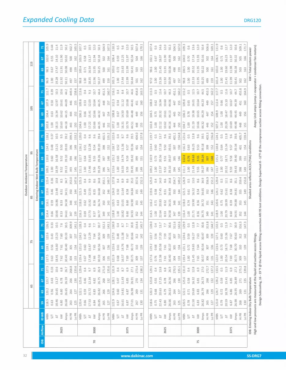
Expanded Cooling Data
SS-DRG7 www.daikinac.com 3332 www.daikinac.com SS-DRG7
DRG120O
utdo
or A
mbi
ent T
empe
ratu
re
6575
8595
105
115
Ente
ring
Indo
or W
et B
ulb
Tem
pera
ture
IDB
Air
flow
ID W
B59
6367
7159
6367
7159
6367
7159
6367
7159
6367
7159
6367
71
70
2625
MBh
118.
512
0.2
123.
712
7.5
117.
511
9.1
122.
612
6.5
114.
411
6.1
119.
612
3.4
109.
211
0.8
114.
311
8.2
102.
810
4.4
107.
911
1.7
96.9
98.5
102.
010
5.9
S/T
0.63
0.56
0.43
0.33
0.63
0.56
0.43
0.33
0.66
0.59
0.46
0.36
1.00
0.60
0.48
0.37
1.00
0.63
0.50
0.39
1.00
0.67
0.55
0.44
∆T18
.46
16.6
513
.27
10.6
18.4
116
.60
13.2
310
.518
.66
16.8
613
.48
10.8
18.3
916
.58
13.2
110
.518
.15
16.3
412
.97
10.3
19.2
817
.47
14.1
011
.4
kW6.
806.
806.
786.
87.
627.
617.
607.
68.
538.
538.
518.
59.
529.
529.
509.
510
.63
10.6
210
.61
10.6
11.9
211
.91
11.9
011
.9
Amps
26.6
826
.65
26.5
926
.730
.43
30.4
030
.33
30.5
34.6
134
.58
34.5
134
.739
.13
39.1
039
.03
39.2
44.1
844
.15
44.0
944
.250
.11
50.0
850
.02
50.2
Hi P
R26
326
426
626
8.8
304
305
307
309.
934
734
835
035
3.0
393
394
396
399.
344
344
444
644
9.4
497
498
500
502.
7Lo
PR
125
127
130
133.
613
313
413
714
1.1
139
141
144
147.
614
514
614
915
3.2
150
152
155
158.
615
715
916
216
5.5
3000
MBh
120.
412
2.1
125.
612
9.4
119.
412
1.0
124.
512
8.3
116.
311
8.0
121.
512
5.3
111.
111
2.7
116.
212
0.0
104.
610
6.3
109.
811
3.6
98.8
100.
410
3.9
107.
7S/
T0.
660.
590.
460.
40.
670.
600.
470.
40.
690.
620.
490.
41.
000.
640.
510.
41.
000.
660.
530.
41.
000.
710.
580.
5
∆T17
.53
15.7
212
.34
9.7
17.4
815
.67
12.2
99.
617
.73
15.9
212
.55
9.9
17.4
615
.65
12.2
89.
617
.22
15.4
112
.03
9.3
18.3
516
.54
13.1
710
.5
kW6.
846.
836.
826.
97.
667.
657.
647.
78.
578.
568.
558.
69.
569.
559.
549.
610
.66
10.6
610
.64
10.7
11.9
611
.95
11.9
412
.0
Amps
26.8
526
.82
26.7
526
.930
.59
30.5
630
.50
30.7
34.7
734
.74
34.6
834
.839
.29
39.2
639
.20
39.4
44.3
544
.32
44.2
544
.450
.27
50.2
550
.18
50.3
Hi P
R26
526
626
827
1.0
306
307
309
312.
134
935
035
235
5.1
396
397
398
401.
544
644
744
845
1.5
499
500
502
504.
9Lo
PR
127
129
132
135.
613
513
613
914
3.1
141
143
146
149.
714
714
815
215
5.2
152
154
157
160.
715
916
116
416
7.5
3375
MBh
122.
912
4.6
128.
113
1.9
121.
912
3.6
127.
013
0.9
118.
812
0.5
124.
012
7.8
113.
611
5.2
118.
712
2.6
107.
210
8.8
112.
311
6.1
101.
310
3.0
106.
411
0.3
S/T
0.67
0.60
0.47
0.4
0.68
0.61
0.48
0.4
1.00
0.63
0.50
0.4
1.00
0.65
0.52
0.4
1.00
0.67
0.54
0.4
1.00
0.72
0.59
0.5
∆T16
.61
14.8
111
.43
8.7
16.5
714
.76
11.3
88.
716
.82
15.0
111
.64
8.9
16.5
514
.74
11.3
68.
716
.31
14.5
011
.12
8.4
17.4
415
.63
12.2
59.
6
kW6.
876.
876.
856.
97.
697.
687.
677.
78.
608.
608.
588.
69.
599.
599.
579.
610
.70
10.6
910
.68
10.7
11.9
911
.99
11.9
712
.0
Amps
27.0
126
.98
26.9
127
.130
.75
30.7
230
.66
30.8
34.9
334
.90
34.8
435
.039
.45
39.4
239
.36
39.5
44.5
144
.48
44.4
144
.650
.44
50.4
150
.34
50.5
Hi P
R26
726
927
027
3.4
309
310
312
314.
635
235
335
535
7.6
398
399
401
404.
044
844
945
145
4.0
501
503
504
507.
4Lo
PR
130
131
134
138.
213
713
914
214
5.7
144
145
149
152.
314
915
115
415
7.8
155
156
160
163.
316
216
316
617
0.1
75
2625
MBh
118.
612
0.3
123.
812
9.1
117.
611
9.2
122.
712
8.0
114.
511
6.2
119.
612
5.0
109.
211
0.9
114.
411
9.7
102.
810
4.5
108.
011
3.3
97.0
98.6
102.
110
7.4
S/T
0.75
0.68
0.55
0.4
0.76
0.68
0.56
0.4
1.00
0.71
0.58
0.4
1.00
0.73
0.60
0.5
1.00
0.75
0.62
0.5
1.00
1.00
0.67
0.5
∆T22
.43
20.6
317
.25
13.8
22.3
820
.58
17.2
013
.722
.64
20.8
317
.45
14.0
22.3
720
.56
17.1
813
.722
.12
20.3
216
.94
13.4
23.2
621
.45
18.0
714
.6
kW6.
806.
796.
786.
87.
617.
617.
597.
78.
538.
528.
518.
69.
529.
519.
509.
610
.62
10.6
110
.60
10.7
11.9
211
.91
11.9
012
.0
Amps
26.6
626
.63
26.5
626
.930
.40
30.3
730
.31
30.6
34.5
834
.55
34.4
934
.839
.10
39.0
739
.01
39.3
44.1
644
.13
44.0
644
.350
.09
50.0
649
.99
50.3
Hi P
R26
326
426
627
0.5
304
305
307
311.
634
734
835
035
4.7
394
395
397
401.
144
444
544
745
1.1
497
498
500
504.
5Lo
PR
125
127
130
135.
113
313
413
714
2.6
139
141
144
149.
214
514
615
015
4.8
150
152
155
160.
215
715
916
216
7.0
3000
MBh
120.
512
2.1
125.
613
1.0
119.
412
1.1
124.
612
9.9
116.
411
8.0
121.
512
6.9
111.
111
2.8
116.
312
1.6
104.
710
6.3
109.
811
5.2
98.8
100.
510
4.0
109.
3S/
T0.
780.
710.
580.
41.
000.
720.
590.
51.
000.
740.
610.
51.
000.
760.
630.
51.
000.
780.
650.
51.
001.
000.
700.
6
∆T21
.50
19.6
916
.32
12.8
21.4
519
.65
16.2
712
.821
.71
19.9
016
.52
13.0
21.4
319
.63
16.2
512
.821
.19
19.3
816
.01
12.5
22.3
320
.52
17.1
413
.6
kW6.
836.
836.
816.
97.
657.
647.
637.
78.
568.
568.
548.
69.
559.
559.
539.
610
.66
10.6
510
.64
10.7
11.9
511
.95
11.9
312
.0
Amps
26.8
226
.79
26.7
327
.030
.57
30.5
430
.47
30.8
34.7
534
.72
34.6
534
.939
.27
39.2
439
.18
39.5
44.3
244
.29
44.2
344
.550
.25
50.2
250
.16
50.4
Hi P
R26
526
626
827
2.7
306
307
309
313.
834
935
135
235
6.9
396
397
399
403.
344
644
744
945
3.3
499
500
502
506.
6Lo
PR
127
129
132
137.
213
513
613
914
4.7
141
143
146
151.
214
714
815
215
6.8
152
154
157
162.
215
916
116
416
9.1
3375
MBh
123.
012
4.7
128.
213
3.5
122.
012
3.6
127.
113
2.5
118.
912
0.6
124.
112
9.4
113.
711
5.3
118.
812
4.1
107.
210
8.9
112.
411
7.7
101.
410
3.0
106.
511
1.9
S/T
0.79
0.72
0.59
0.5
1.00
0.73
0.60
0.5
1.00
0.75
0.62
0.5
1.00
0.77
0.64
0.5
1.00
1.00
0.66
0.5
1.00
1.00
0.71
0.6
∆T20
.59
18.7
815
.41
11.9
20.5
418
.73
15.3
611
.920
.79
18.9
915
.61
12.1
20.5
218
.71
15.3
411
.820
.28
18.4
715
.10
11.6
21.4
119
.60
16.2
312
.7
kW6.
876.
866.
856.
97.
697.
687.
677.
78.
608.
598.
588.
69.
599.
589.
579.
610
.69
10.6
910
.67
10.7
11.9
911
.98
11.9
712
.0
Amps
26.9
826
.95
26.8
927
.230
.73
30.7
030
.63
30.9
34.9
134
.88
34.8
135
.139
.43
39.4
039
.34
39.6
44.4
844
.45
44.3
944
.750
.41
50.3
850
.32
50.6
Hi P
R26
826
927
127
5.2
309
310
312
316.
335
235
335
535
9.4
398
399
401
405.
744
844
945
145
5.8
502
503
505
509.
1Lo
PR
130
131
135
139.
813
713
914
214
7.3
144
145
149
153.
814
915
115
415
9.4
155
156
160
164.
916
216
316
617
1.7
IDB:
Ent
erin
g In
door
Dry
Bul
b Te
mpe
ratu
reSh
aded
are
a re
flect
s A
CCA
(TVA
) con
diti
ons
kW =
Tot
al s
yste
m p
ower
Hig
h an
d lo
w p
ress
ures
are
mea
sure
d at
the
liqui
d an
d su
ctio
n ac
cess
fitt
ings
.A
mps
: Uni
t am
ps (c
omp.
+ ev
apor
ator
+ c
onde
nser
fan
mot
ors)
Des
ign
Subc
oolin
g, 1
6 - 1
9 °F
@ th
e liq
uid
acce
ss fi
ttin
g co
nnec
tion
ARI
95
test
con
ditio
ns. D
esig
n Su
perh
eat 8
- 12
°F @
the
com
pres
sor s
uctio
n ac
cess
fitt
ing
conn
ectio
n.

Expanded Cooling Data
SS-DRG7 www.daikinac.com 3332 www.daikinac.com SS-DRG7
DRG120 (cont.)
Out
door
Am
bien
t Tem
pera
ture
6575
8595
105
115
Ente
ring
Indo
or W
et B
ulb
Tem
pera
ture
IDB
Air
flow
ID W
B59
6367
7159
6367
7159
6367
7159
6367
7159
6367
7159
6367
71
70
2625
MBh
118.
512
0.2
123.
712
7.5
117.
511
9.1
122.
612
6.5
114.
411
6.1
119.
612
3.4
109.
211
0.8
114.
311
8.2
102.
810
4.4
107.
911
1.7
96.9
98.5
102.
010
5.9
S/T
0.63
0.56
0.43
0.33
0.63
0.56
0.43
0.33
0.66
0.59
0.46
0.36
1.00
0.60
0.48
0.37
1.00
0.63
0.50
0.39
1.00
0.67
0.55
0.44
∆T18
.46
16.6
513
.27
10.6
18.4
116
.60
13.2
310
.518
.66
16.8
613
.48
10.8
18.3
916
.58
13.2
110
.518
.15
16.3
412
.97
10.3
19.2
817
.47
14.1
011
.4
kW6.
806.
806.
786.
87.
627.
617.
607.
68.
538.
538.
518.
59.
529.
529.
509.
510
.63
10.6
210
.61
10.6
11.9
211
.91
11.9
011
.9
Amps
26.6
826
.65
26.5
926
.730
.43
30.4
030
.33
30.5
34.6
134
.58
34.5
134
.739
.13
39.1
039
.03
39.2
44.1
844
.15
44.0
944
.250
.11
50.0
850
.02
50.2
Hi P
R26
326
426
626
8.8
304
305
307
309.
934
734
835
035
3.0
393
394
396
399.
344
344
444
644
9.4
497
498
500
502.
7Lo
PR
125
127
130
133.
613
313
413
714
1.1
139
141
144
147.
614
514
614
915
3.2
150
152
155
158.
615
715
916
216
5.5
3000
MBh
120.
412
2.1
125.
612
9.4
119.
412
1.0
124.
512
8.3
116.
311
8.0
121.
512
5.3
111.
111
2.7
116.
212
0.0
104.
610
6.3
109.
811
3.6
98.8
100.
410
3.9
107.
7S/
T0.
660.
590.
460.
40.
670.
600.
470.
40.
690.
620.
490.
41.
000.
640.
510.
41.
000.
660.
530.
41.
000.
710.
580.
5
∆T17
.53
15.7
212
.34
9.7
17.4
815
.67
12.2
99.
617
.73
15.9
212
.55
9.9
17.4
615
.65
12.2
89.
617
.22
15.4
112
.03
9.3
18.3
516
.54
13.1
710
.5
kW6.
846.
836.
826.
97.
667.
657.
647.
78.
578.
568.
558.
69.
569.
559.
549.
610
.66
10.6
610
.64
10.7
11.9
611
.95
11.9
412
.0
Amps
26.8
526
.82
26.7
526
.930
.59
30.5
630
.50
30.7
34.7
734
.74
34.6
834
.839
.29
39.2
639
.20
39.4
44.3
544
.32
44.2
544
.450
.27
50.2
550
.18
50.3
Hi P
R26
526
626
827
1.0
306
307
309
312.
134
935
035
235
5.1
396
397
398
401.
544
644
744
845
1.5
499
500
502
504.
9Lo
PR
127
129
132
135.
613
513
613
914
3.1
141
143
146
149.
714
714
815
215
5.2
152
154
157
160.
715
916
116
416
7.5
3375
MBh
122.
912
4.6
128.
113
1.9
121.
912
3.6
127.
013
0.9
118.
812
0.5
124.
012
7.8
113.
611
5.2
118.
712
2.6
107.
210
8.8
112.
311
6.1
101.
310
3.0
106.
411
0.3
S/T
0.67
0.60
0.47
0.4
0.68
0.61
0.48
0.4
1.00
0.63
0.50
0.4
1.00
0.65
0.52
0.4
1.00
0.67
0.54
0.4
1.00
0.72
0.59
0.5
∆T16
.61
14.8
111
.43
8.7
16.5
714
.76
11.3
88.
716
.82
15.0
111
.64
8.9
16.5
514
.74
11.3
68.
716
.31
14.5
011
.12
8.4
17.4
415
.63
12.2
59.
6
kW6.
876.
876.
856.
97.
697.
687.
677.
78.
608.
608.
588.
69.
599.
599.
579.
610
.70
10.6
910
.68
10.7
11.9
911
.99
11.9
712
.0
Amps
27.0
126
.98
26.9
127
.130
.75
30.7
230
.66
30.8
34.9
334
.90
34.8
435
.039
.45
39.4
239
.36
39.5
44.5
144
.48
44.4
144
.650
.44
50.4
150
.34
50.5
Hi P
R26
726
927
027
3.4
309
310
312
314.
635
235
335
535
7.6
398
399
401
404.
044
844
945
145
4.0
501
503
504
507.
4Lo
PR
130
131
134
138.
213
713
914
214
5.7
144
145
149
152.
314
915
115
415
7.8
155
156
160
163.
316
216
316
617
0.1
75
2625
MBh
118.
612
0.3
123.
812
9.1
117.
611
9.2
122.
712
8.0
114.
511
6.2
119.
612
5.0
109.
211
0.9
114.
411
9.7
102.
810
4.5
108.
011
3.3
97.0
98.6
102.
110
7.4
S/T
0.75
0.68
0.55
0.4
0.76
0.68
0.56
0.4
1.00
0.71
0.58
0.4
1.00
0.73
0.60
0.5
1.00
0.75
0.62
0.5
1.00
1.00
0.67
0.5
∆T22
.43
20.6
317
.25
13.8
22.3
820
.58
17.2
013
.722
.64
20.8
317
.45
14.0
22.3
720
.56
17.1
813
.722
.12
20.3
216
.94
13.4
23.2
621
.45
18.0
714
.6
kW6.
806.
796.
786.
87.
617.
617.
597.
78.
538.
528.
518.
69.
529.
519.
509.
610
.62
10.6
110
.60
10.7
11.9
211
.91
11.9
012
.0
Amps
26.6
626
.63
26.5
626
.930
.40
30.3
730
.31
30.6
34.5
834
.55
34.4
934
.839
.10
39.0
739
.01
39.3
44.1
644
.13
44.0
644
.350
.09
50.0
649
.99
50.3
Hi P
R26
326
426
627
0.5
304
305
307
311.
634
734
835
035
4.7
394
395
397
401.
144
444
544
745
1.1
497
498
500
504.
5Lo
PR
125
127
130
135.
113
313
413
714
2.6
139
141
144
149.
214
514
615
015
4.8
150
152
155
160.
215
715
916
216
7.0
3000
MBh
120.
512
2.1
125.
613
1.0
119.
412
1.1
124.
612
9.9
116.
411
8.0
121.
512
6.9
111.
111
2.8
116.
312
1.6
104.
710
6.3
109.
811
5.2
98.8
100.
510
4.0
109.
3S/
T0.
780.
710.
580.
41.
000.
720.
590.
51.
000.
740.
610.
51.
000.
760.
630.
51.
000.
780.
650.
51.
001.
000.
700.
6
∆T21
.50
19.6
916
.32
12.8
21.4
519
.65
16.2
712
.821
.71
19.9
016
.52
13.0
21.4
319
.63
16.2
512
.821
.19
19.3
816
.01
12.5
22.3
320
.52
17.1
413
.6
kW6.
836.
836.
816.
97.
657.
647.
637.
78.
568.
568.
548.
69.
559.
559.
539.
610
.66
10.6
510
.64
10.7
11.9
511
.95
11.9
312
.0
Amps
26.8
226
.79
26.7
327
.030
.57
30.5
430
.47
30.8
34.7
534
.72
34.6
534
.939
.27
39.2
439
.18
39.5
44.3
244
.29
44.2
344
.550
.25
50.2
250
.16
50.4
Hi P
R26
526
626
827
2.7
306
307
309
313.
834
935
135
235
6.9
396
397
399
403.
344
644
744
945
3.3
499
500
502
506.
6Lo
PR
127
129
132
137.
213
513
613
914
4.7
141
143
146
151.
214
714
815
215
6.8
152
154
157
162.
215
916
116
416
9.1
3375
MBh
123.
012
4.7
128.
213
3.5
122.
012
3.6
127.
113
2.5
118.
912
0.6
124.
112
9.4
113.
711
5.3
118.
812
4.1
107.
210
8.9
112.
411
7.7
101.
410
3.0
106.
511
1.9
S/T
0.79
0.72
0.59
0.5
1.00
0.73
0.60
0.5
1.00
0.75
0.62
0.5
1.00
0.77
0.64
0.5
1.00
1.00
0.66
0.5
1.00
1.00
0.71
0.6
∆T20
.59
18.7
815
.41
11.9
20.5
418
.73
15.3
611
.920
.79
18.9
915
.61
12.1
20.5
218
.71
15.3
411
.820
.28
18.4
715
.10
11.6
21.4
119
.60
16.2
312
.7
kW6.
876.
866.
856.
97.
697.
687.
677.
78.
608.
598.
588.
69.
599.
589.
579.
610
.69
10.6
910
.67
10.7
11.9
911
.98
11.9
712
.0
Amps
26.9
826
.95
26.8
927
.230
.73
30.7
030
.63
30.9
34.9
134
.88
34.8
135
.139
.43
39.4
039
.34
39.6
44.4
844
.45
44.3
944
.750
.41
50.3
850
.32
50.6
Hi P
R26
826
927
127
5.2
309
310
312
316.
335
235
335
535
9.4
398
399
401
405.
744
844
945
145
5.8
502
503
505
509.
1Lo
PR
130
131
135
139.
813
713
914
214
7.3
144
145
149
153.
814
915
115
415
9.4
155
156
160
164.
916
216
316
617
1.7
IDB:
Ent
erin
g In
door
Dry
Bul
b Te
mpe
ratu
reSh
aded
are
a re
flect
s A
CCA
(TVA
) con
diti
ons
kW =
Tot
al s
yste
m p
ower
Hig
h an
d lo
w p
ress
ures
are
mea
sure
d at
the
liqui
d an
d su
ctio
n ac
cess
fitt
ings
.A
mps
: Uni
t am
ps (c
omp.
+ ev
apor
ator
+ c
onde
nser
fan
mot
ors)
Des
ign
Subc
oolin
g, 1
6 - 1
9 °F
@ th
e liq
uid
acce
ss fi
ttin
g co
nnec
tion
ARI
95
test
con
ditio
ns. D
esig
n Su
perh
eat 8
- 12
°F @
the
com
pres
sor s
uctio
n ac
cess
fitt
ing
conn
ectio
n.
Out
door
Am
bien
t Tem
pera
ture
6575
8595
105
115
Ente
ring
Indo
or W
et B
ulb
Tem
pera
ture
IDB
Air
flow
ID W
B59
6367
7159
6367
7159
6367
7159
6367
7159
6367
7159
6367
71
80
2625
MBh
119.
212
0.9
124.
412
9.7
118.
211
9.8
123.
312
8.6
115.
111
6.8
120.
312
5.6
109.
911
1.5
115.
012
0.3
103.
410
5.1
108.
611
3.9
97.6
99.2
102.
710
8.0
S/T
1.00
0.80
0.67
0.5
1.00
0.80
0.68
0.5
1.00
0.83
0.70
0.6
1.00
1.00
0.72
0.6
1.00
1.00
0.74
0.6
1.00
1.00
0.79
0.7
∆T26
.44
24.6
321
.25
17.8
26.3
924
.58
21.2
017
.726
.64
24.8
321
.46
18.0
26.3
724
.56
21.1
817
.726
.13
24.3
220
.94
17.4
27.2
625
.45
22.0
818
.6
kW6.
806.
796.
786.
87.
627.
617.
607.
78.
538.
538.
518.
69.
529.
519.
509.
610
.62
10.6
210
.60
10.7
11.9
211
.91
11.9
012
.0
Amps
26.6
826
.65
26.5
826
.930
.42
30.3
930
.33
30.6
34.6
034
.57
34.5
134
.839
.12
39.0
939
.03
39.3
44.1
844
.15
44.0
844
.450
.11
50.0
850
.01
50.3
Hi P
R26
326
526
627
1.0
305
306
308
312.
134
834
935
135
5.2
394
395
397
401.
644
444
544
745
1.6
497
499
500
504.
9Lo
PR
126
127
130
135.
713
313
513
814
3.2
140
141
144
149.
714
514
715
015
5.3
151
152
156
160.
815
815
916
216
7.6
3000
MBh
121.
112
2.7
126.
213
1.6
120.
012
1.7
125.
213
0.5
117.
011
8.6
122.
112
7.5
111.
711
3.4
116.
912
2.2
105.
310
7.0
110.
411
5.8
99.4
101.
110
4.6
109.
9S/
T1.
000.
830.
700.
61.
000.
840.
710.
61.
000.
860.
730.
61.
001.
000.
750.
61.
001.
000.
770.
61.
001.
000.
820.
7
∆T25
.51
23.7
020
.32
16.8
25.4
623
.65
20.2
716
.825
.71
23.9
020
.53
17.0
25.4
423
.63
20.2
516
.825
.20
23.3
920
.01
16.5
26.3
324
.52
21.1
417
.6
kW6.
846.
836.
826.
97.
667.
657.
637.
78.
578.
568.
558.
69.
569.
559.
549.
610
.66
10.6
510
.64
10.7
11.9
611
.95
11.9
412
.0
Amps
26.8
426
.81
26.7
527
.030
.59
30.5
630
.49
30.8
34.7
734
.74
34.6
735
.039
.29
39.2
639
.19
39.5
44.3
444
.31
44.2
544
.550
.27
50.2
450
.18
50.5
Hi P
R26
626
726
927
3.2
307
308
310
314.
335
035
135
335
7.4
396
397
399
403.
744
644
744
945
3.7
500
501
503
507.
1Lo
PR
128
129
132
137.
713
513
714
014
5.2
142
143
147
151.
814
714
915
215
7.3
153
154
158
162.
816
016
116
416
9.6
3375
MBh
123.
612
5.3
128.
813
4.1
122.
612
4.2
127.
713
3.1
119.
512
1.2
124.
713
0.0
114.
311
5.9
119.
412
4.7
107.
810
9.5
113.
011
8.3
102.
010
3.6
107.
111
2.5
S/T
1.00
0.84
0.71
0.6
1.00
0.85
0.72
0.6
1.00
1.00
0.74
0.6
1.00
1.00
0.76
0.6
1.00
1.00
0.78
0.6
1.00
1.00
0.83
0.7
∆T24
.59
22.7
819
.41
15.9
24.5
422
.73
19.3
615
.924
.80
22.9
919
.61
16.1
24.5
222
.72
19.3
415
.824
.28
22.4
719
.10
15.6
25.4
223
.61
20.2
316
.7
kW6.
876.
876.
856.
97.
697.
687.
677.
78.
608.
608.
588.
69.
599.
599.
579.
610
.70
10.6
910
.68
10.7
11.9
911
.98
11.9
712
.0
Amps
27.0
026
.97
26.9
127
.230
.75
30.7
230
.65
30.9
34.9
334
.90
34.8
335
.139
.45
39.4
239
.36
39.6
44.5
044
.47
44.4
144
.750
.43
50.4
050
.34
50.6
Hi P
R26
826
927
127
5.7
309
310
312
316.
835
235
335
535
9.8
399
400
402
406.
244
945
045
245
6.2
502
503
505
509.
6Lo
PR
130
132
135
140.
313
813
914
314
7.8
144
146
149
154.
415
015
215
515
9.9
155
157
160
165.
416
216
416
717
2.2
85
2625
MBh
121.
212
2.8
126.
313
1.7
120.
112
1.8
125.
313
0.6
117.
111
8.7
122.
212
7.6
111.
811
3.5
117.
012
2.3
105.
410
7.1
110.
511
5.9
99.5
101.
210
4.7
110.
0S/
T1.
000.
890.
760.
61.
001.
000.
770.
61.
001.
000.
790.
71.
001.
000.
810.
71.
001.
000.
830.
71.
001.
001.
000.
7
∆T29
.99
28.1
824
.80
21.3
29.9
428
.13
24.7
521
.330
.19
28.3
825
.01
21.5
29.9
228
.11
24.7
321
.229
.68
27.8
724
.49
21.0
30.8
129
.00
25.6
322
.1
kW6.
826.
816.
806.
97.
637.
637.
617.
78.
558.
548.
538.
69.
549.
539.
529.
610
.64
10.6
310
.62
10.7
11.9
411
.93
11.9
212
.0
Amps
26.7
526
.72
26.6
626
.930
.49
30.4
630
.40
30.7
34.6
734
.64
34.5
834
.939
.20
39.1
739
.10
39.4
44.2
544
.22
44.1
544
.450
.18
50.1
550
.08
50.4
Hi P
R26
526
626
827
2.2
306
307
309
313.
334
935
035
235
6.4
395
396
398
402.
844
544
644
845
2.8
499
500
502
506.
2Lo
PR
128
129
132
137.
513
513
714
014
5.0
142
143
146
151.
614
714
915
215
7.2
153
154
157
162.
616
016
116
416
9.4
3000
MBh
123.
112
4.7
128.
213
3.5
122.
012
3.7
127.
213
2.5
119.
012
0.6
124.
112
9.4
113.
711
5.4
118.
812
4.2
107.
310
8.9
112.
411
7.8
101.
410
3.1
106.
611
1.9
S/T
1.00
0.93
0.80
0.7
1.00
1.00
0.80
0.7
1.00
1.00
0.83
0.7
1.00
1.00
0.85
0.7
1.00
1.00
1.00
0.7
1.00
1.00
1.00
0.8
∆T29
.05
27.2
523
.87
20.4
29.0
127
.20
23.8
220
.329
.26
27.4
524
.08
20.6
28.9
927
.18
23.8
020
.328
.75
26.9
423
.56
20.1
29.8
828
.07
24.6
921
.2
kW6.
856.
856.
836.
97.
677.
667.
657.
78.
588.
588.
568.
69.
579.
579.
559.
610
.68
10.6
710
.66
10.7
11.9
711
.97
11.9
512
.0
Amps
26.9
126
.88
26.8
227
.130
.66
30.6
330
.56
30.9
34.8
434
.81
34.7
435
.039
.36
39.3
339
.27
39.6
44.4
144
.38
44.3
244
.650
.34
50.3
150
.25
50.5
Hi P
R26
726
827
027
4.4
308
309
311
315.
535
135
235
435
8.6
397
399
400
405.
044
744
945
045
5.0
501
502
504
508.
3Lo
PR
130
131
134
139.
613
713
914
214
7.1
144
145
148
153.
614
915
115
415
9.2
155
156
159
164.
616
216
316
617
1.5
3375
MBh
125.
612
7.2
130.
713
6.1
124.
512
6.2
129.
713
5.0
121.
512
3.1
126.
613
2.0
116.
211
7.9
121.
412
6.7
109.
811
1.5
115.
012
0.3
103.
910
5.6
109.
111
4.4
S/T
1.00
0.94
0.81
0.7
1.00
1.00
0.81
0.7
1.00
1.00
0.84
0.7
1.00
1.00
0.86
0.7
1.00
1.00
1.00
0.7
1.00
1.00
1.00
0.8
∆T28
.14
26.3
322
.96
19.5
28.0
926
.28
22.9
119
.428
.35
26.5
423
.16
19.7
28.0
726
.27
22.8
919
.427
.83
26.0
222
.65
19.2
28.9
627
.16
23.7
820
.3
kW6.
896.
886.
876.
97.
717.
707.
697.
78.
628.
618.
608.
79.
619.
609.
599.
610
.71
10.7
010
.69
10.8
12.0
112
.00
11.9
912
.0
Amps
27.0
727
.05
26.9
827
.330
.82
30.7
930
.73
31.0
35.0
034
.97
34.9
035
.239
.52
39.4
939
.43
39.7
44.5
744
.54
44.4
844
.850
.50
50.4
750
.41
50.7
Hi P
R26
927
127
227
6.9
310
312
313
318.
035
435
535
736
1.1
400
401
403
407.
545
045
145
345
7.5
503
504
506
510.
8Lo
PR
132
134
137
142.
214
014
114
414
9.7
146
148
151
156.
215
215
315
716
1.8
157
159
162
167.
216
416
616
917
4.1
IDB:
Ent
erin
g In
door
Dry
Bul
b Te
mpe
ratu
reSh
aded
are
a re
flect
s A
CCA
(TVA
) con
diti
ons
kW =
Tot
al s
yste
m p
ower
Hig
h an
d lo
w p
ress
ures
are
mea
sure
d at
the
liqui
d an
d su
ctio
n ac
cess
fitt
ings
.A
mps
: Uni
t am
ps (c
omp.
+ ev
apor
ator
+ c
onde
nser
fan
mot
ors)
Des
ign
Subc
oolin
g, 1
6 - 1
9 °F
@ th
e liq
uid
acce
ss fi
ttin
g co
nnec
tion
ARI
95
test
con
ditio
ns. D
esig
n Su
perh
eat 8
- 12
°F @
the
com
pres
sor s
uctio
n ac
cess
fitt
ing
conn
ectio
n.

Expanded Cooling Data
SS-DRG7 www.daikinac.com 3534 www.daikinac.com SS-DRG7
DRG150O
utdo
or A
mbi
ent T
empe
ratu
re
6575
8595
105
115
Ente
ring
Indo
or W
et B
ulb
Tem
pera
ture
IDB
Air
flow
ID W
B59
6367
7159
6367
7159
6367
7159
6367
7159
6367
7159
6367
71
70
2625
MBh
141.
214
3.2
147.
315
1.9
140.
014
1.9
146.
115
0.7
136.
313
8.3
142.
514
7.0
130.
113
2.0
136.
214
0.8
122.
412
4.4
128.
513
3.1
115.
411
7.4
121.
612
6.1
S/T
0.62
0.55
0.42
0.32
0.63
0.56
0.43
0.33
0.65
0.58
0.45
0.35
0.67
0.60
0.47
0.37
1.00
0.62
0.49
0.39
1.00
0.67
0.54
0.44
∆T20
.24
18.2
614
.56
11.6
20.1
918
.21
14.5
011
.620
.47
18.4
914
.78
11.8
20.1
718
.19
14.4
811
.519
.90
17.9
214
.22
11.3
21.1
519
.16
15.4
612
.5
kW8.
568.
558.
538.
69.
609.
609.
589.
610
.77
10.7
610
.75
10.8
12.0
312
.03
12.0
112
.113
.45
13.4
413
.42
13.5
15.1
015
.09
15.0
815
.1
Amps
32.6
132
.58
32.4
932
.737
.40
37.3
637
.28
37.5
42.7
442
.71
42.6
242
.848
.53
48.4
948
.41
48.6
54.9
954
.95
54.8
755
.162
.57
62.5
362
.45
62.7
Hi P
R26
126
226
426
7.2
302
303
305
308.
134
534
634
835
0.9
391
392
394
397.
044
144
244
444
6.7
494
495
497
499.
8Lo
PR
120
122
125
128.
312
712
913
213
5.5
134
135
138
141.
813
914
114
414
7.2
144
146
149
152.
415
115
215
515
9.0
3000
MBh
147.
614
9.6
153.
815
8.3
146.
414
8.4
152.
515
7.1
142.
814
4.7
148.
915
3.5
136.
513
8.5
142.
614
7.2
128.
813
0.8
135.
013
9.5
121.
912
3.8
128.
013
2.6
S/T
0.66
0.59
0.46
0.4
0.67
0.60
0.47
0.4
0.69
0.62
0.49
0.4
1.00
0.64
0.51
0.4
1.00
0.66
0.53
0.4
1.00
0.71
0.58
0.5
∆T17
.90
15.9
212
.21
9.3
17.8
415
.86
12.1
69.
218
.12
16.1
412
.44
9.5
17.8
215
.84
12.1
49.
217
.56
15.5
811
.87
8.9
18.8
016
.82
13.1
210
.2
kW8.
668.
668.
648.
79.
719.
709.
689.
710
.88
10.8
710
.85
10.9
12.1
412
.13
12.1
112
.213
.55
13.5
413
.53
13.6
15.2
115
.20
15.1
815
.2
Amps
33.1
033
.06
32.9
833
.237
.88
37.8
437
.76
38.0
43.2
343
.19
43.1
143
.349
.01
48.9
748
.89
49.1
55.4
755
.43
55.3
555
.663
.05
63.0
162
.93
63.1
Hi P
R26
726
827
027
2.7
308
309
311
313.
635
035
235
335
6.4
397
398
399
402.
544
644
744
945
2.2
499
500
502
505.
3Lo
PR
126
127
130
133.
713
313
413
714
0.9
139
141
144
147.
214
514
614
915
2.6
150
151
154
157.
815
615
816
116
4.4
3375
MBh
152.
315
4.3
158.
416
3.0
151.
115
3.0
157.
216
1.7
147.
414
9.4
153.
515
8.1
141.
214
3.1
147.
315
1.8
133.
513
5.5
139.
614
4.2
126.
512
8.5
132.
613
7.2
S/T
0.63
0.56
0.44
0.3
0.64
0.57
0.44
0.3
0.66
0.59
0.46
0.4
1.00
0.61
0.48
0.4
1.00
0.63
0.50
0.4
1.00
0.68
0.55
0.4
∆T16
.84
14.8
511
.15
8.2
16.7
814
.80
11.1
08.
117
.06
15.0
811
.38
8.4
16.7
614
.78
11.0
88.
116
.50
14.5
110
.81
7.9
17.7
415
.76
12.0
59.
1
kW8.
718.
708.
688.
79.
769.
759.
739.
810
.92
10.9
210
.90
10.9
12.1
912
.18
12.1
612
.213
.60
13.5
913
.57
13.6
15.2
615
.25
15.2
315
.3
Amps
33.3
133
.27
33.1
933
.438
.10
38.0
637
.98
38.2
43.4
443
.40
43.3
243
.549
.22
49.1
949
.10
49.3
55.6
855
.65
55.5
755
.863
.26
63.2
363
.15
63.4
Hi P
R27
027
127
327
6.0
311
312
314
316.
835
435
535
735
9.7
400
401
403
405.
845
045
145
245
5.5
503
504
506
508.
5Lo
PR
129
131
134
137.
413
713
814
114
4.6
143
144
147
150.
914
815
015
315
6.2
153
155
158
161.
516
016
116
416
8.0
75
2625
MBh
141.
314
3.3
147.
415
3.8
140.
014
2.0
146.
215
2.5
136.
413
8.4
142.
514
8.9
130.
113
2.1
136.
314
2.6
122.
512
4.5
128.
613
5.0
115.
511
7.5
121.
612
8.0
S/T
0.74
0.67
0.54
0.4
0.75
0.68
0.55
0.4
1.00
0.70
0.57
0.4
1.00
0.72
0.59
0.5
1.00
0.74
0.61
0.5
1.00
0.79
0.66
0.5
∆T24
.60
22.6
218
.92
15.1
24.5
522
.57
18.8
615
.024
.83
22.8
519
.14
15.3
24.5
322
.55
18.8
415
.024
.26
22.2
818
.58
14.7
25.5
123
.52
19.8
216
.0
kW8.
558.
548.
538.
69.
609.
599.
579.
710
.76
10.7
610
.74
10.8
12.0
312
.02
12.0
012
.113
.44
13.4
313
.41
13.5
15.1
015
.09
15.0
715
.1
Amps
32.5
832
.54
32.4
632
.837
.37
37.3
337
.25
37.6
42.7
142
.67
42.5
943
.048
.49
48.4
648
.37
48.7
54.9
654
.92
54.8
455
.262
.53
62.5
062
.42
62.8
Hi P
R26
126
326
426
8.9
302
303
305
309.
834
534
634
835
2.6
391
392
394
398.
744
144
244
444
8.4
494
495
497
501.
5Lo
PR
120
122
125
129.
812
712
913
213
7.0
134
135
138
143.
313
914
114
414
8.7
144
146
149
153.
915
115
215
516
0.5
3000
MBh
147.
714
9.7
153.
916
0.2
146.
514
8.4
152.
615
9.0
142.
814
4.8
149.
015
5.3
136.
613
8.5
142.
714
9.1
128.
913
0.9
135.
114
1.4
121.
912
3.9
128.
113
4.4
S/T
0.78
0.71
0.58
0.5
0.79
0.72
0.59
0.5
1.00
0.74
0.61
0.5
1.00
0.76
0.63
0.5
1.00
0.78
0.65
0.5
1.00
1.00
0.70
0.6
∆T22
.26
20.2
816
.57
12.7
22.2
020
.22
16.5
212
.722
.48
20.5
016
.80
13.0
22.1
820
.20
16.5
012
.721
.92
19.9
416
.23
12.4
23.1
621
.18
17.4
813
.6
kW8.
668.
658.
638.
79.
709.
699.
689.
810
.87
10.8
610
.84
10.9
12.1
312
.13
12.1
112
.213
.55
13.5
413
.52
13.6
15.2
015
.19
15.1
815
.3
Amps
33.0
633
.03
32.9
433
.337
.85
37.8
137
.73
38.1
43.1
943
.16
43.0
743
.448
.98
48.9
448
.86
49.2
55.4
455
.40
55.3
255
.763
.02
62.9
862
.90
63.3
Hi P
R26
726
827
027
4.4
308
309
311
315.
335
135
235
435
8.1
397
398
400
404.
244
644
844
945
4.0
500
501
502
507.
0Lo
PR
126
127
130
135.
213
313
413
714
2.4
139
141
144
148.
714
514
614
915
4.1
150
151
154
159.
315
615
816
116
5.9
3375
MBh
152.
415
4.3
158.
516
4.9
151.
115
3.1
157.
316
3.6
147.
514
9.5
153.
616
0.0
141.
214
3.2
147.
415
3.7
133.
613
5.5
139.
714
6.1
126.
612
8.6
132.
713
9.1
S/T
0.75
0.68
0.56
0.4
1.00
0.69
0.56
0.4
1.00
0.71
0.59
0.5
1.00
0.73
0.60
0.5
1.00
1.00
0.62
0.5
1.00
1.00
0.67
0.5
∆T21
.20
19.2
115
.51
11.7
21.1
419
.16
15.4
611
.621
.42
19.4
415
.74
11.9
21.1
219
.14
15.4
411
.620
.86
18.8
715
.17
11.3
22.1
020
.12
16.4
112
.6
kW8.
708.
708.
688.
89.
759.
749.
729.
810
.92
10.9
110
.89
11.0
12.1
812
.17
12.1
512
.213
.59
13.5
813
.57
13.6
15.2
515
.24
15.2
215
.3
Amps
33.2
833
.24
33.1
633
.538
.07
38.0
337
.95
38.3
43.4
143
.37
43.2
943
.749
.19
49.1
649
.07
49.4
55.6
555
.62
55.5
355
.963
.23
63.2
063
.11
63.5
Hi P
R27
027
127
327
7.7
311
312
314
318.
635
435
535
736
1.4
400
401
403
407.
545
045
145
345
7.2
503
504
506
510.
3Lo
PR
129
131
134
138.
913
713
814
114
6.1
143
144
147
152.
414
815
015
315
7.8
153
155
158
163.
016
016
116
516
9.6
IDB:
Ent
erin
g In
door
Dry
Bul
b Te
mpe
ratu
reSh
aded
are
a re
flect
s A
CCA
(TVA
) con
diti
ons
kW =
Tot
al s
yste
m p
ower
Hig
h an
d lo
w p
ress
ures
are
mea
sure
d at
the
liqui
d an
d su
ctio
n ac
cess
fitt
ings
.A
mps
: Uni
t am
ps (c
omp.
+ ev
apor
ator
+ c
onde
nser
fan
mot
ors)
Des
ign
Subc
oolin
g, 1
6 - 1
9 °F
@ th
e liq
uid
acce
ss fi
ttin
g co
nnec
tion
ARI
95
test
con
ditio
ns. D
esig
n Su
perh
eat 8
- 12
°F @
the
com
pres
sor s
uctio
n ac
cess
fitt
ing
conn
ectio
n.

Expanded Cooling Data
SS-DRG7 www.daikinac.com 3534 www.daikinac.com SS-DRG7
DRG150 (cont.)
Out
door
Am
bien
t Tem
pera
ture
6575
8595
105
115
Ente
ring
Indo
or W
et B
ulb
Tem
pera
ture
IDB
Air
flow
ID W
B59
6367
7159
6367
7159
6367
7159
6367
7159
6367
7159
6367
71
70
2625
MBh
141.
214
3.2
147.
315
1.9
140.
014
1.9
146.
115
0.7
136.
313
8.3
142.
514
7.0
130.
113
2.0
136.
214
0.8
122.
412
4.4
128.
513
3.1
115.
411
7.4
121.
612
6.1
S/T
0.62
0.55
0.42
0.32
0.63
0.56
0.43
0.33
0.65
0.58
0.45
0.35
0.67
0.60
0.47
0.37
1.00
0.62
0.49
0.39
1.00
0.67
0.54
0.44
∆T20
.24
18.2
614
.56
11.6
20.1
918
.21
14.5
011
.620
.47
18.4
914
.78
11.8
20.1
718
.19
14.4
811
.519
.90
17.9
214
.22
11.3
21.1
519
.16
15.4
612
.5
kW8.
568.
558.
538.
69.
609.
609.
589.
610
.77
10.7
610
.75
10.8
12.0
312
.03
12.0
112
.113
.45
13.4
413
.42
13.5
15.1
015
.09
15.0
815
.1
Amps
32.6
132
.58
32.4
932
.737
.40
37.3
637
.28
37.5
42.7
442
.71
42.6
242
.848
.53
48.4
948
.41
48.6
54.9
954
.95
54.8
755
.162
.57
62.5
362
.45
62.7
Hi P
R26
126
226
426
7.2
302
303
305
308.
134
534
634
835
0.9
391
392
394
397.
044
144
244
444
6.7
494
495
497
499.
8Lo
PR
120
122
125
128.
312
712
913
213
5.5
134
135
138
141.
813
914
114
414
7.2
144
146
149
152.
415
115
215
515
9.0
3000
MBh
147.
614
9.6
153.
815
8.3
146.
414
8.4
152.
515
7.1
142.
814
4.7
148.
915
3.5
136.
513
8.5
142.
614
7.2
128.
813
0.8
135.
013
9.5
121.
912
3.8
128.
013
2.6
S/T
0.66
0.59
0.46
0.4
0.67
0.60
0.47
0.4
0.69
0.62
0.49
0.4
1.00
0.64
0.51
0.4
1.00
0.66
0.53
0.4
1.00
0.71
0.58
0.5
∆T17
.90
15.9
212
.21
9.3
17.8
415
.86
12.1
69.
218
.12
16.1
412
.44
9.5
17.8
215
.84
12.1
49.
217
.56
15.5
811
.87
8.9
18.8
016
.82
13.1
210
.2
kW8.
668.
668.
648.
79.
719.
709.
689.
710
.88
10.8
710
.85
10.9
12.1
412
.13
12.1
112
.213
.55
13.5
413
.53
13.6
15.2
115
.20
15.1
815
.2
Amps
33.1
033
.06
32.9
833
.237
.88
37.8
437
.76
38.0
43.2
343
.19
43.1
143
.349
.01
48.9
748
.89
49.1
55.4
755
.43
55.3
555
.663
.05
63.0
162
.93
63.1
Hi P
R26
726
827
027
2.7
308
309
311
313.
635
035
235
335
6.4
397
398
399
402.
544
644
744
945
2.2
499
500
502
505.
3Lo
PR
126
127
130
133.
713
313
413
714
0.9
139
141
144
147.
214
514
614
915
2.6
150
151
154
157.
815
615
816
116
4.4
3375
MBh
152.
315
4.3
158.
416
3.0
151.
115
3.0
157.
216
1.7
147.
414
9.4
153.
515
8.1
141.
214
3.1
147.
315
1.8
133.
513
5.5
139.
614
4.2
126.
512
8.5
132.
613
7.2
S/T
0.63
0.56
0.44
0.3
0.64
0.57
0.44
0.3
0.66
0.59
0.46
0.4
1.00
0.61
0.48
0.4
1.00
0.63
0.50
0.4
1.00
0.68
0.55
0.4
∆T16
.84
14.8
511
.15
8.2
16.7
814
.80
11.1
08.
117
.06
15.0
811
.38
8.4
16.7
614
.78
11.0
88.
116
.50
14.5
110
.81
7.9
17.7
415
.76
12.0
59.
1
kW8.
718.
708.
688.
79.
769.
759.
739.
810
.92
10.9
210
.90
10.9
12.1
912
.18
12.1
612
.213
.60
13.5
913
.57
13.6
15.2
615
.25
15.2
315
.3
Amps
33.3
133
.27
33.1
933
.438
.10
38.0
637
.98
38.2
43.4
443
.40
43.3
243
.549
.22
49.1
949
.10
49.3
55.6
855
.65
55.5
755
.863
.26
63.2
363
.15
63.4
Hi P
R27
027
127
327
6.0
311
312
314
316.
835
435
535
735
9.7
400
401
403
405.
845
045
145
245
5.5
503
504
506
508.
5Lo
PR
129
131
134
137.
413
713
814
114
4.6
143
144
147
150.
914
815
015
315
6.2
153
155
158
161.
516
016
116
416
8.0
75
2625
MBh
141.
314
3.3
147.
415
3.8
140.
014
2.0
146.
215
2.5
136.
413
8.4
142.
514
8.9
130.
113
2.1
136.
314
2.6
122.
512
4.5
128.
613
5.0
115.
511
7.5
121.
612
8.0
S/T
0.74
0.67
0.54
0.4
0.75
0.68
0.55
0.4
1.00
0.70
0.57
0.4
1.00
0.72
0.59
0.5
1.00
0.74
0.61
0.5
1.00
0.79
0.66
0.5
∆T24
.60
22.6
218
.92
15.1
24.5
522
.57
18.8
615
.024
.83
22.8
519
.14
15.3
24.5
322
.55
18.8
415
.024
.26
22.2
818
.58
14.7
25.5
123
.52
19.8
216
.0
kW8.
558.
548.
538.
69.
609.
599.
579.
710
.76
10.7
610
.74
10.8
12.0
312
.02
12.0
012
.113
.44
13.4
313
.41
13.5
15.1
015
.09
15.0
715
.1
Amps
32.5
832
.54
32.4
632
.837
.37
37.3
337
.25
37.6
42.7
142
.67
42.5
943
.048
.49
48.4
648
.37
48.7
54.9
654
.92
54.8
455
.262
.53
62.5
062
.42
62.8
Hi P
R26
126
326
426
8.9
302
303
305
309.
834
534
634
835
2.6
391
392
394
398.
744
144
244
444
8.4
494
495
497
501.
5Lo
PR
120
122
125
129.
812
712
913
213
7.0
134
135
138
143.
313
914
114
414
8.7
144
146
149
153.
915
115
215
516
0.5
3000
MBh
147.
714
9.7
153.
916
0.2
146.
514
8.4
152.
615
9.0
142.
814
4.8
149.
015
5.3
136.
613
8.5
142.
714
9.1
128.
913
0.9
135.
114
1.4
121.
912
3.9
128.
113
4.4
S/T
0.78
0.71
0.58
0.5
0.79
0.72
0.59
0.5
1.00
0.74
0.61
0.5
1.00
0.76
0.63
0.5
1.00
0.78
0.65
0.5
1.00
1.00
0.70
0.6
∆T22
.26
20.2
816
.57
12.7
22.2
020
.22
16.5
212
.722
.48
20.5
016
.80
13.0
22.1
820
.20
16.5
012
.721
.92
19.9
416
.23
12.4
23.1
621
.18
17.4
813
.6
kW8.
668.
658.
638.
79.
709.
699.
689.
810
.87
10.8
610
.84
10.9
12.1
312
.13
12.1
112
.213
.55
13.5
413
.52
13.6
15.2
015
.19
15.1
815
.3
Amps
33.0
633
.03
32.9
433
.337
.85
37.8
137
.73
38.1
43.1
943
.16
43.0
743
.448
.98
48.9
448
.86
49.2
55.4
455
.40
55.3
255
.763
.02
62.9
862
.90
63.3
Hi P
R26
726
827
027
4.4
308
309
311
315.
335
135
235
435
8.1
397
398
400
404.
244
644
844
945
4.0
500
501
502
507.
0Lo
PR
126
127
130
135.
213
313
413
714
2.4
139
141
144
148.
714
514
614
915
4.1
150
151
154
159.
315
615
816
116
5.9
3375
MBh
152.
415
4.3
158.
516
4.9
151.
115
3.1
157.
316
3.6
147.
514
9.5
153.
616
0.0
141.
214
3.2
147.
415
3.7
133.
613
5.5
139.
714
6.1
126.
612
8.6
132.
713
9.1
S/T
0.75
0.68
0.56
0.4
1.00
0.69
0.56
0.4
1.00
0.71
0.59
0.5
1.00
0.73
0.60
0.5
1.00
1.00
0.62
0.5
1.00
1.00
0.67
0.5
∆T21
.20
19.2
115
.51
11.7
21.1
419
.16
15.4
611
.621
.42
19.4
415
.74
11.9
21.1
219
.14
15.4
411
.620
.86
18.8
715
.17
11.3
22.1
020
.12
16.4
112
.6
kW8.
708.
708.
688.
89.
759.
749.
729.
810
.92
10.9
110
.89
11.0
12.1
812
.17
12.1
512
.213
.59
13.5
813
.57
13.6
15.2
515
.24
15.2
215
.3
Amps
33.2
833
.24
33.1
633
.538
.07
38.0
337
.95
38.3
43.4
143
.37
43.2
943
.749
.19
49.1
649
.07
49.4
55.6
555
.62
55.5
355
.963
.23
63.2
063
.11
63.5
Hi P
R27
027
127
327
7.7
311
312
314
318.
635
435
535
736
1.4
400
401
403
407.
545
045
145
345
7.2
503
504
506
510.
3Lo
PR
129
131
134
138.
913
713
814
114
6.1
143
144
147
152.
414
815
015
315
7.8
153
155
158
163.
016
016
116
516
9.6
IDB:
Ent
erin
g In
door
Dry
Bul
b Te
mpe
ratu
reSh
aded
are
a re
flect
s A
CCA
(TVA
) con
diti
ons
kW =
Tot
al s
yste
m p
ower
Hig
h an
d lo
w p
ress
ures
are
mea
sure
d at
the
liqui
d an
d su
ctio
n ac
cess
fitt
ings
.A
mps
: Uni
t am
ps (c
omp.
+ ev
apor
ator
+ c
onde
nser
fan
mot
ors)
Des
ign
Subc
oolin
g, 1
6 - 1
9 °F
@ th
e liq
uid
acce
ss fi
ttin
g co
nnec
tion
ARI
95
test
con
ditio
ns. D
esig
n Su
perh
eat 8
- 12
°F @
the
com
pres
sor s
uctio
n ac
cess
fitt
ing
conn
ectio
n.
Out
door
Am
bien
t Tem
pera
ture
6575
8595
105
115
Ente
ring
Indo
or W
et B
ulb
Tem
pera
ture
IDB
Air
flow
ID W
B59
6367
7159
6367
7159
6367
7159
6367
7159
6367
7159
6367
71
80
2625
MBh
142.
014
4.0
148.
115
4.5
140.
814
2.7
146.
915
3.3
137.
113
9.1
143.
314
9.6
130.
913
2.8
137.
014
3.4
123.
212
5.2
129.
313
5.7
116.
211
8.2
122.
412
8.7
S/T
0.86
0.79
0.66
0.5
1.00
0.79
0.67
0.5
1.00
0.82
0.69
0.6
1.00
0.84
0.71
0.6
1.00
1.00
0.73
0.6
1.00
1.00
0.78
0.6
∆T28
.99
27.0
123
.31
19.5
28.9
426
.96
23.2
519
.429
.22
27.2
423
.53
19.7
28.9
226
.94
23.2
319
.428
.65
26.6
722
.97
19.1
29.9
027
.91
24.2
120
.4
kW8.
568.
558.
538.
69.
609.
599.
589.
710
.77
10.7
610
.74
10.8
12.0
312
.03
12.0
112
.113
.45
13.4
413
.42
13.5
15.1
015
.09
15.0
815
.2
Amps
32.6
132
.57
32.4
932
.937
.39
37.3
637
.27
37.6
42.7
442
.70
42.6
243
.048
.52
48.4
848
.40
48.8
54.9
854
.94
54.8
655
.262
.56
62.5
262
.44
62.8
Hi P
R26
226
326
526
9.4
303
304
306
310.
334
634
734
935
3.1
392
393
395
399.
244
144
344
444
8.9
494
496
497
501.
9Lo
PR
121
122
125
130.
312
812
913
213
7.5
134
136
139
143.
814
014
114
414
9.2
145
146
149
154.
415
115
315
616
1.0
3000
MBh
148.
415
0.4
154.
616
0.9
147.
214
9.2
153.
315
9.7
143.
614
5.5
149.
715
6.1
137.
313
9.3
143.
414
9.8
129.
613
1.6
135.
814
2.1
122.
712
4.6
128.
813
5.2
S/T
1.00
0.83
0.70
0.6
1.00
0.83
0.71
0.6
1.00
0.86
0.73
0.6
1.00
1.00
0.75
0.6
1.00
1.00
0.77
0.6
1.00
1.00
0.82
0.7
∆T26
.65
24.6
720
.96
17.1
26.5
924
.61
20.9
117
.126
.87
24.8
921
.19
17.4
26.5
724
.59
20.8
917
.126
.31
24.3
320
.62
16.8
27.5
525
.57
21.8
718
.0
kW8.
668.
658.
648.
79.
719.
709.
689.
810
.88
10.8
710
.85
10.9
12.1
412
.13
12.1
112
.213
.55
13.5
413
.52
13.6
15.2
115
.20
15.1
815
.3
Amps
33.0
933
.05
32.9
733
.337
.88
37.8
437
.76
38.1
43.2
243
.18
43.1
043
.549
.00
48.9
648
.88
49.2
55.4
655
.43
55.3
455
.763
.04
63.0
062
.92
63.3
Hi P
R26
726
927
027
4.9
308
309
311
315.
835
135
235
435
8.6
397
398
400
404.
744
744
845
045
4.4
500
501
503
507.
5Lo
PR
126
128
131
135.
713
313
513
814
2.9
140
141
144
149.
314
514
715
015
4.6
150
152
155
159.
815
715
816
116
6.4
3375
MBh
153.
115
5.1
159.
216
5.6
151.
915
3.8
158.
016
4.3
148.
215
0.2
154.
316
0.7
142.
014
3.9
148.
115
4.4
134.
313
6.3
140.
414
6.8
127.
312
9.3
133.
413
9.8
S/T
1.00
0.80
0.67
0.5
1.00
0.81
0.68
0.5
1.00
0.83
0.70
0.6
1.00
1.00
0.72
0.6
1.00
1.00
0.74
0.6
1.00
1.00
0.79
0.7
∆T25
.59
23.6
019
.90
16.1
25.5
323
.55
19.8
516
.025
.81
23.8
320
.13
16.3
25.5
123
.53
19.8
316
.025
.25
23.2
619
.56
15.7
26.4
924
.51
20.8
017
.0
kW8.
718.
708.
688.
89.
769.
759.
739.
810
.92
10.9
110
.90
11.0
12.1
912
.18
12.1
612
.213
.60
13.5
913
.57
13.7
15.2
515
.25
15.2
315
.3
Amps
33.3
133
.27
33.1
933
.638
.09
38.0
637
.97
38.3
43.4
443
.40
43.3
243
.749
.22
49.1
849
.10
49.5
55.6
855
.64
55.5
655
.963
.26
63.2
263
.14
63.5
Hi P
R27
127
227
427
8.2
312
313
315
319.
035
435
635
736
1.9
401
402
403
408.
045
045
145
345
7.7
503
504
506
510.
7Lo
PR
130
131
134
139.
413
713
914
214
6.6
143
145
148
152.
914
915
015
315
8.3
154
155
158
163.
516
116
216
517
0.1
85
2625
MBh
144.
414
6.3
150.
515
6.9
143.
114
5.1
149.
215
5.6
139.
514
1.4
145.
615
2.0
133.
213
5.2
139.
314
5.7
125.
612
7.5
131.
713
8.1
118.
612
0.5
124.
713
1.1
S/T
1.00
0.88
0.76
0.6
1.00
0.89
0.76
0.6
1.00
1.00
0.79
0.7
1.00
1.00
0.80
0.7
1.00
1.00
0.82
0.7
1.00
1.00
0.87
0.7
∆T32
.89
30.9
027
.20
23.4
32.8
330
.85
27.1
523
.333
.11
31.1
327
.43
23.6
32.8
130
.83
27.1
323
.332
.55
30.5
626
.86
23.0
33.7
931
.81
28.1
024
.3
kW8.
588.
578.
558.
69.
629.
619.
609.
710
.79
10.7
810
.76
10.8
12.0
512
.05
12.0
312
.113
.47
13.4
613
.44
13.5
15.1
215
.11
15.1
015
.2
Amps
32.7
032
.66
32.5
832
.937
.49
37.4
537
.37
37.7
42.8
342
.79
42.7
143
.148
.61
48.5
748
.49
48.9
55.0
755
.03
54.9
555
.362
.65
62.6
162
.53
62.9
Hi P
R26
326
426
627
0.6
304
305
307
311.
534
734
835
035
4.3
393
394
396
400.
444
344
444
645
0.1
496
497
499
503.
2Lo
PR
123
124
127
132.
113
013
113
413
9.3
136
138
141
145.
614
114
314
615
1.0
147
148
151
156.
215
315
515
816
2.8
3000
MBh
150.
815
2.8
156.
916
3.3
149.
515
1.5
155.
716
2.0
145.
914
7.9
152.
015
8.4
139.
614
1.6
145.
815
2.1
132.
013
4.0
138.
114
4.5
125.
012
7.0
131.
113
7.5
S/T
1.00
0.92
0.80
0.7
1.00
1.00
0.80
0.7
1.00
1.00
0.83
0.7
1.00
1.00
0.84
0.7
1.00
1.00
0.86
0.7
1.00
1.00
1.00
0.8
∆T30
.54
28.5
624
.86
21.0
30.4
928
.50
24.8
021
.030
.77
28.7
825
.08
21.2
30.4
728
.48
24.7
820
.930
.20
28.2
224
.52
20.7
31.4
429
.46
25.7
621
.9
kW8.
688.
678.
668.
79.
739.
729.
709.
810
.90
10.8
910
.87
10.9
12.1
612
.15
12.1
312
.213
.57
13.5
613
.54
13.6
15.2
315
.22
15.2
015
.3
Amps
33.1
833
.14
33.0
633
.437
.97
37.9
337
.85
38.2
43.3
143
.27
43.1
943
.649
.09
49.0
648
.97
49.3
55.5
555
.52
55.4
355
.863
.13
63.1
063
.01
63.4
Hi P
R26
927
027
227
6.1
310
311
312
317.
035
235
335
535
9.8
398
400
401
405.
944
844
945
145
5.6
501
502
504
508.
7Lo
PR
128
129
132
137.
513
513
714
014
4.7
142
143
146
151.
014
714
815
115
6.4
152
154
157
161.
615
916
016
316
8.2
3375
MBh
155.
515
7.4
161.
616
7.9
154.
215
6.2
160.
316
6.7
150.
615
2.5
156.
716
3.1
144.
314
6.3
150.
415
6.8
136.
613
8.6
142.
814
9.1
129.
713
1.6
135.
814
2.2
S/T
1.00
0.89
0.77
0.6
1.00
1.00
0.77
0.6
1.00
1.00
0.80
0.7
1.00
1.00
0.81
0.7
1.00
1.00
1.00
0.7
1.00
1.00
1.00
0.8
∆T29
.48
27.5
023
.79
20.0
29.4
327
.44
23.7
419
.929
.70
27.7
224
.02
20.2
29.4
127
.42
23.7
219
.929
.14
27.1
623
.45
19.6
30.3
828
.40
24.7
020
.9
kW8.
738.
728.
708.
89.
789.
779.
759.
810
.94
10.9
310
.92
11.0
12.2
112
.20
12.1
812
.313
.62
13.6
113
.59
13.7
15.2
715
.27
15.2
515
.3
Amps
33.4
033
.36
33.2
833
.638
.18
38.1
538
.06
38.4
43.5
343
.49
43.4
143
.849
.31
49.2
749
.19
49.6
55.7
755
.73
55.6
556
.063
.35
63.3
163
.23
63.6
Hi P
R27
227
327
527
9.4
313
314
316
320.
335
635
735
936
3.1
402
403
405
409.
245
145
345
445
8.9
504
506
507
512.
0Lo
PR
132
133
136
141.
213
914
014
314
8.4
145
147
150
154.
715
115
215
516
0.1
156
157
160
165.
316
216
416
717
1.9
IDB:
Ent
erin
g In
door
Dry
Bul
b Te
mpe
ratu
reSh
aded
are
a re
flect
s A
CCA
(TVA
) con
diti
ons
kW =
Tot
al s
yste
m p
ower
Hig
h an
d lo
w p
ress
ures
are
mea
sure
d at
the
liqui
d an
d su
ctio
n ac
cess
fitt
ings
.A
mps
: Uni
t am
ps (c
omp.
+ ev
apor
ator
+ c
onde
nser
fan
mot
ors)
Des
ign
Subc
oolin
g, 1
6 - 1
9 °F
@ th
e liq
uid
acce
ss fi
ttin
g co
nnec
tion
ARI
95
test
con
ditio
ns. D
esig
n Su
perh
eat 8
- 12
°F @
the
com
pres
sor s
uctio
n ac
cess
fitt
ing
conn
ectio
n.
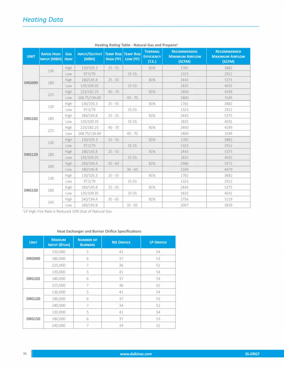
SS-DRG7 www.daikinac.com 3736 www.daikinac.com SS-DRG7
Heating Data
SS-DRG7 www.daikinac.com 3736 www.daikinac.com SS-DRG7
Heat Exchanger and Burner Orifice Specifications
UnitMaxium
Input (Btuh)Number of
BurnersNG Orifice LP Orifice
DRG090
130,000 5 41 54
180,000 6 37 53
225,000 7 36 52
DRG102
130,000 5 41 54
180,000 6 37 53
225,000 7 36 52
DRG120
130,000 5 41 54
180,000 6 37 53
240,000 7 34 51
DRG150
130,000 5 41 54
180,000 6 37 53
240,000 7 34 51
Heating Rating Table - Natural Gas and Propane1
UNITRated High
Input (MBH)Gas Heat
Input/Output (MBH)
Temp Rise High (ºF)
Temp Rise Low (ºF)
Thermal Efficiency
(T.E.)
Recommended Minimum Airflow
(SCFM)
Recommended Maximum Airflow
(SCFM)
DRG090
130High 130/105.3 25 - 55 81% 1765 3882Low 97.5/79 25-55 1323 2912
180High 180/145.8 25 - 55 81% 2443 5375Low 135/109.35 25-55 1832 4031
225High 225/182.25 40 - 70 81% 2400 4199Low 168.75/136.69 40 - 70 1800 3149
DRG102
130High 130/105.3 25 - 55 81% 1765 3882Low 97.5/79 25-55 1323 2912
180High 180/145.8 25 - 55 81% 2443 5375Low 135/109.35 25-55 1832 4031
225High 225/182.25 40 - 70 81% 2400 4199Low 168.75/136.69 40 - 70 1800 3149
DRG120
130High 130/105.3 25 - 55 81% 1765 3882Low 97.5/79 25-55 1323 2912
180High 180/145.8 25 - 55 81% 2443 5375Low 135/109.35 25-55 1832 4031
240High 240/194.4 30 - 60 81% 2986 5972Low 180/145.8 30 - 60 2240 4479
DRG150
130High 130/105.3 25 - 55 81% 1765 3882Low 97.5/79 25-55 1323 2912
180High 180/145.8 25 - 55 81% 2443 5375Low 135/109.35 25-55 1832 4031
240High 240/194.4 35 - 65 81% 2756 5119Low 180/145.8 35 - 65 2067 3839
1LP High Fire Rate is Reduced 10% that of Natural Gas

Airflow
SS-DRG7 www.daikinac.com 3736 www.daikinac.com SS-DRG7 SS-DRG7 www.daikinac.com 3736 www.daikinac.com SS-DRG7
7.5 Ton (130 MBH) DRG090 - Standard
7.5 Ton • 130 MBH Gas Heat Exchanger • Standard Static Direct Drive
Models: DRG0903DL, DRG0904DL, DRG0907DL
Down Flow Horizontal Flow
Speed Tap ESP CFM RPM BHP Speed Tap ESP CFM RPM BHP
T1
0.2 1882 544 0.38
T1
0.2 2029 488 0.340.4 - - - 0.4 - - -0.6 - - - 0.6 - - -0.8 - - - 0.8 - - -
T2
0.2 2589 629 0.67
T2
0.2 2748 571 0.610.4 2410 681 0.73 0.4 2554 627 0.670.6 2216 734 0.79 0.6 2337 697 0.750.8 2038 782 0.84 0.8 2148 750 0.80
T3
0.2 3144 708 1.01
T3
0.2 3289 649 0.930.4 2961 753 1.08 0.4 3133 690 0.990.6 2802 799 1.14 0.6 2972 745 1.060.8 2651 841 1.20 0.8 2802 792 1.13
T4
0.2 3413 753 1.23
T4
0.2 3539 693 1.130.4 3222 794 1.29 0.4 3419 726 1.180.6 3070 836 1.36 0.6 3282 773 1.260.8 2940 875 1.43 0.8 3132 816 1.33
T5
0.2 3622 793 1.43
T5
0.2 3724 732 1.320.4 3422 830 1.50 0.4 3647 757 1.370.6 3268 868 1.57 0.6 3525 797 1.440.8 3160 904 1.64 0.8 3401 836 1.51
T6
0.2 1901 546 0.38
T6
0.2 2048 490 0.340.4 1713 605 0.42 0.4 1853 561 0.390.6 1453 667 0.47 0.6 1559 646 0.450.8 - - - 0.8 1374 707 0.49
T7
0.2 2107 569 0.46
T7
0.2 2260 513 0.410.4 1922 627 0.50 0.4 2061 580 0.470.6 1684 686 0.55 0.6 1791 660 0.530.8 1495 738 0.59 0.8 1602 719 0.58
T8
0.2 2301 592 0.54
T8
0.2 2458 535 0.490.4 2119 648 0.59 0.4 2259 598 0.540.6 1900 704 0.64 0.6 2011 674 0.610.8 - - - 0.8 1820 731 0.66
T9
0.2 2920 674 0.86
T9
0.2 3074 616 0.790.4 2740 722 0.92 0.4 2897 663 0.850.6 2569 771 0.98 0.6 2715 724 0.920.8 2405 816 1.04 0.8 2534 774 0.99
T10
0.2 3427 756 1.24
T10
0.2 3552 696 1.140.4 3236 797 1.31 0.4 3435 728 1.200.6 3084 838 1.38 0.6 3299 774 1.270.8 2955 877 1.44 0.8 3151 817 1.34

Airflow
SS-DRG7 www.daikinac.com 3938 www.daikinac.com SS-DRG7
7.5 Ton (130 MBH) DRG090 - Medium
7.5 Ton • 130 MBH Gas Heat Exchanger • Medium Static Direct Drive
Models: DRG0903LL, DRG0904LL, DRG0907LL
Down Flow Horizontal Flow
Speed Tap ESP CFM RPM BHP Speed Tap ESP CFM RPM BHP
T1
0.2 1882 544 0.38
T1
0.2 2029 488 0.340.4 - - - 0.4 - - -0.6 - - - 0.6 - - -0.8 - - - 0.8 - - -1.0 - - - 1.0 - - -1.2 - - - 1.2 - - -1.4 - - - 1.4 - - -
T2
0.2 3059 695 0.95
T2
0.2 3208 636 0.870.4 2877 741 1.01 0.4 3043 680 0.930.6 2714 788 1.08 0.6 2874 737 1.010.8 2558 831 1.14 0.8 2699 785 1.071.0 2412 870 1.19 1.0 2519 829 1.131.2 2218 922 1.26 1.2 2312 884 1.211.4 2028 965 1.32 1.4 2103 948 1.30
T3
0.2 3144 708 1.01
T3
0.2 3289 649 0.930.4 2961 753 1.08 0.4 3133 690 0.990.6 2802 799 1.14 0.6 2972 745 1.060.8 2651 841 1.20 0.8 2802 792 1.131.0 2493 880 1.26 1.0 2632 836 1.191.2 2307 930 1.33 1.2 2436 889 1.271.4 - - - 1.4 - - -
T4
0.2 - - -
T4
0.2 - - -0.4 3622 874 1.77 0.4 - - -0.6 3458 907 1.83 0.6 - - -0.8 3380 940 1.90 0.8 3693 861 1.741.0 3265 975 1.97 1.0 3575 905 1.831.2 3138 1008 2.04 1.2 3461 941 1.901.4 2994 1043 2.11 1.4 3345 991 2.00
T5
0.2 - - -
T5
0.2 - - -0.4 3725 901 1.94 0.4 - - -0.6 3549 931 2.00 0.6 - - -0.8 3492 961 2.07 0.8 - - -1.0 3423 996 2.15 1.0 3737 920 1.981.2 3307 1026 2.21 1.2 3633 952 2.051.4 3180 1059 2.28 1.4 3524 999 2.15
T6
0.2 2139 573 0.47
T6
0.2 2293 516 0.420.4 1955 630 0.52 0.4 2093 583 0.480.6 1720 689 0.57 0.6 1827 663 0.540.8 1531 741 0.61 0.8 1637 721 0.591.0 1623 782 0.64 1.0 - - -1.2 1351 849 0.70 1.2 - - -1.4 - - - 1.4 - - -
T7
0.2 2691 642 0.73
T7
0.2 2849 584 0.660.4 2512 693 0.78 0.4 2659 638 0.720.6 2325 745 0.84 0.6 2453 705 0.800.8 2152 792 0.90 0.8 2265 757 0.861.0 2079 832 0.94 1.0 2034 801 0.911.2 1854 890 1.01 1.2 1777 864 0.981.4 1662 937 1.06 1.4 1511 932 1.05
T8
0.2 3162 711 1.02
T8
0.2 3307 652 0.940.4 2979 756 1.09 0.4 3152 692 1.000.6 2820 801 1.15 0.6 2993 747 1.080.8 2671 843 1.22 0.8 2824 794 1.141.0 2511 882 1.27 1.0 2657 837 1.211.2 2326 931 1.34 1.2 2463 891 1.281.4 2139 974 1.40 1.4 2269 952 1.37
T9
0.2 3681 805 1.50
T9
0.2 3774 744 1.390.4 3477 842 1.57 0.4 3713 767 1.430.6 3322 878 1.64 0.6 3594 804 1.500.8 3220 913 1.70 0.8 3478 843 1.571.0 3066 950 1.77 1.0 3356 886 1.651.2 2925 987 1.84 1.2 3226 927 1.731.4 2765 1024 1.91 1.4 3096 980 1.83
T10
0.2 - - -
T10
0.2 - - -0.4 3811 927 2.12 0.4 - - -0.6 3620 954 2.18 0.6 - - -0.8 3586 983 2.25 0.8 - - -1.0 3578 1017 2.32 1.0 3881 936 2.141.2 3471 1043 2.38 1.2 3786 964 2.201.4 3363 1074 2.45 1.4 3680 1008 2.30

Airflow
SS-DRG7 www.daikinac.com 3938 www.daikinac.com SS-DRG7
7.5 Ton (130 MBH) DRG090 - High
7.5 Ton • 130 MBH Gas Heat Exchanger • High Static Direct Drive
Models: DRG0903WL, DRG0904WL, DRG0907WL
Down Flow Horizontal Flow
Speed Tap ESP CFM RPM BHP Speed Tap ESP CFM RPM BHP
T1
0.2 1882 544 0.38
T1
0.2 2029 488 0.340.4 - - - 0.4 - - -0.6 - - - 0.6 - - -0.8 - - - 0.8 - - -1.0 - - - 1.0 - - -1.2 - - - 1.2 - - -1.4 - - - 1.4 - - -1.6 - - - 1.6 - - -1.8 - - - 1.8 - - -2.0 - - - 2.0 - - -
T2
0.2 3527 774 1.34
T2
0.2 3642 714 1.230.4 3332 814 1.40 0.4 3544 743 1.280.6 3180 853 1.47 0.6 3415 786 1.360.8 3061 891 1.54 0.8 3278 827 1.431.0 2889 927 1.60 1.0 3147 870 1.501.2 2735 969 1.67 1.2 2998 915 1.581.4 2563 1008 1.74 1.4 2852 971 1.681.6 2392 1050 1.81 1.6 2666 1010 1.741.8 2237 1086 1.87 1.8 2482 1060 1.832.0 2077 1119 1.93 2.0 2323 1096 1.89
T3
0.2 3144 708 1.01
T3
0.2 3289 649 0.930.4 2961 753 1.08 0.4 3133 690 0.990.6 2802 799 1.14 0.6 2972 745 1.060.8 2651 841 1.20 0.8 2802 792 1.131.0 2493 880 1.26 1.0 2632 836 1.191.2 2307 930 1.33 1.2 2436 889 1.271.4 - - - 1.4 - - -1.6 - - - 1.6 - - -1.8 - - - 1.8 - - -2.0 - - - 2.0 - - -
T4
0.2 - - -
T4
0.2 - - -0.4 - - - 0.4 - - -0.6 - - - 0.6 - - -0.8 - - - 0.8 - - -1.0 3620 1023 2.37 1.0 - - -1.2 3514 1048 2.43 1.2 - - -1.4 3412 1078 2.50 1.4 3718 1010 2.341.6 3263 1117 2.59 1.6 3610 1040 2.411.8 3081 1148 2.66 1.8 3473 1094 2.542.0 2915 1184 2.75 2.0 3351 1130 2.62
T5
0.2 - - -
T5
0.2 - - -0.4 - - - 0.4 - - -0.6 - - - 0.6 - - -0.8 - - - 0.8 - - -1.0 - - - 1.0 - - -1.2 3728 1071 2.68 1.2 - - -1.4 3656 1100 2.75 1.4 - - -1.6 3519 1137 2.84 1.6 3825 1049 2.621.8 3325 1166 2.91 1.8 3707 1104 2.762.0 3161 1203 3.01 2.0 3599 1140 2.85
T6
0.2 2457 612 0.61
T6
0.2 2616 554 0.550.4 2277 665 0.66 0.4 2418 613 0.610.6 2072 720 0.72 0.6 2188 686 0.680.8 1891 769 0.77 0.8 1997 741 0.741.0 1881 810 0.81 1.0 1729 785 0.781.2 1636 872 0.87 1.2 1439 852 0.851.4 1447 921 0.92 1.4 - - -1.6 - - - 1.6 - - -1.8 - - - 1.8 - - -2.0 - - - 2.0 - - -
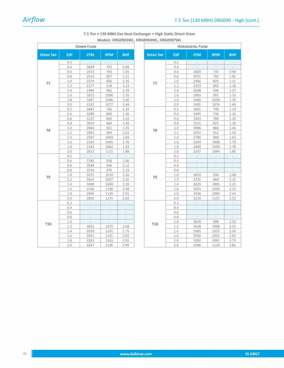
Airflow
SS-DRG7 www.daikinac.com 4140 www.daikinac.com SS-DRG7
7.5 Ton (130 MBH) DRG090 - High (cont.)
7.5 Ton • 130 MBH Gas Heat Exchanger • High Static Direct Drive
Models: DRG0903WL, DRG0904WL, DRG0907WL
Down Flow Horizontal Flow
Speed Tap ESP CFM RPM BHP Speed Tap ESP CFM RPM BHP
T7
0.2 - - -
T7
0.2 - - -0.4 2838 735 0.99 0.4 - - -0.6 2672 783 1.05 0.6 2828 733 0.980.8 2514 827 1.11 0.8 2651 782 1.051.0 2374 866 1.16 1.0 2466 825 1.111.2 2177 918 1.23 1.2 2253 882 1.181.4 1986 962 1.29 1.4 2038 946 1.271.6 1815 1006 1.35 1.6 1869 991 1.331.8 1667 1046 1.40 1.8 1668 1038 1.392.0 1522 1077 1.44 2.0 1495 1074 1.44
T8
0.2 3482 766 1.29
T8
0.2 3601 706 1.190.4 3289 806 1.36 0.4 3495 736 1.240.6 3137 846 1.43 0.6 3363 780 1.320.8 3014 884 1.49 0.8 3221 822 1.391.0 2840 921 1.55 1.0 3086 866 1.461.2 2682 964 1.63 1.2 2932 912 1.541.4 2507 1003 1.69 1.4 2780 969 1.631.6 2335 1045 1.76 1.6 2594 1008 1.701.8 2182 1082 1.83 1.8 2408 1058 1.782.0 2022 1115 1.88 2.0 2247 1094 1.85
T9
0.2 - - -
T9
0.2 - - -0.4 3783 918 2.06 0.4 - - -0.6 3598 946 2.12 0.6 - - -0.8 3556 976 2.19 0.8 - - -1.0 3525 1010 2.26 1.0 3833 930 2.081.2 3415 1037 2.32 1.2 3735 960 2.151.4 3300 1069 2.39 1.4 3629 1005 2.251.6 3146 1108 2.48 1.6 3503 1036 2.321.8 2969 1139 2.55 1.8 3358 1089 2.442.0 2802 1175 2.63 2.0 3229 1125 2.52
T10
0.2 - - -
T10
0.2 - - -0.4 - - - 0.4 - - -0.6 - - - 0.6 - - -0.8 - - - 0.8 - - -1.0 - - - 1.0 3659 998 2.501.2 3653 1072 2.68 1.2 3638 1008 2.521.4 3550 1101 2.75 1.4 3585 1022 2.561.6 3452 1131 2.83 1.6 3500 1052 2.631.8 3353 1163 2.91 1.8 3382 1091 2.732.0 3247 1196 2.99 2.0 3286 1124 2.81

Airflow
SS-DRG7 www.daikinac.com 4140 www.daikinac.com SS-DRG7
7.5 Ton (180 MBH) DRG090 - Standard
7.5 Ton • 180 MBH Gas Heat Exchanger • Standard Static Direct Drive
Models: DRG0903DM, DRG0904DM, DRG0907DM
Down Flow Horizontal Flow
Speed Tap ESP CFM RPM BHP Speed Tap ESP CFM RPM BHP
T1
0.2 1954 552 0.40
T1
0.2 2030 500 0.360.4 - - - 0.4 - - -0.6 - - - 0.6 - - -0.8 - - - 0.8 - - -
T2
0.2 2589 629 0.67
T2
0.2 2675 594 0.640.4 2410 681 0.73 0.4 2487 642 0.690.6 2216 734 0.79 0.6 2336 698 0.750.8 2038 782 0.84 0.8 2089 777 0.83
T3
0.2 3017 730 1.06
T3
0.2 3161 679 0.990.4 2897 773 1.13 0.4 3068 713 1.040.6 2760 818 1.19 0.6 2899 768 1.120.8 2633 859 1.25 0.8 2776 809 1.18
T4
0.2 3251 774 1.26
T4
0.2 3413 704 1.150.4 3095 813 1.33 0.4 3244 742 1.210.6 2954 853 1.39 0.6 3108 785 1.280.8 2827 893 1.46 0.8 2963 823 1.34
T5
0.2 3417 815 1.47
T5
0.2 3563 693 1.250.4 3274 846 1.53 0.4 3526 771 1.390.6 3126 887 1.60 0.6 3402 814 1.470.8 2988 923 1.66 0.8 3317 858 1.55
T6
0.2 1416 213 0.21
T6
0.2 1604 448 0.250.4 - - - 0.4 - - -0.6 - - - 0.6 - - -0.8 - - - 0.8 - - -
T7
0.2 1975 554 0.41
T7
0.2 2056 505 0.370.4 - - - 0.4 1832 582 0.430.6 - - - 0.6 - - -0.8 - - - 0.8 - - -
T8
0.2 2156 579 0.54
T8
0.2 2434 558 0.520.4 1956 637 0.59 0.4 2251 616 0.570.6 - - - 0.6 - - -0.8 - - - 0.8 - - -
T9
0.2 2936 677 0.87
T9
0.2 2975 642 0.830.4 2756 724 0.93 0.4 2799 680 0.880.6 2586 773 0.99 0.6 2585 734 0.940.8 - - - 0.8 - - -
T10
0.2 3427 756 1.24
T10
0.2 3413 704 1.150.4 3236 797 1.31 0.4 3244 742 1.210.6 3084 838 1.38 0.6 3108 785 1.280.8 2955 877 1.44 0.8 2963 823 1.34
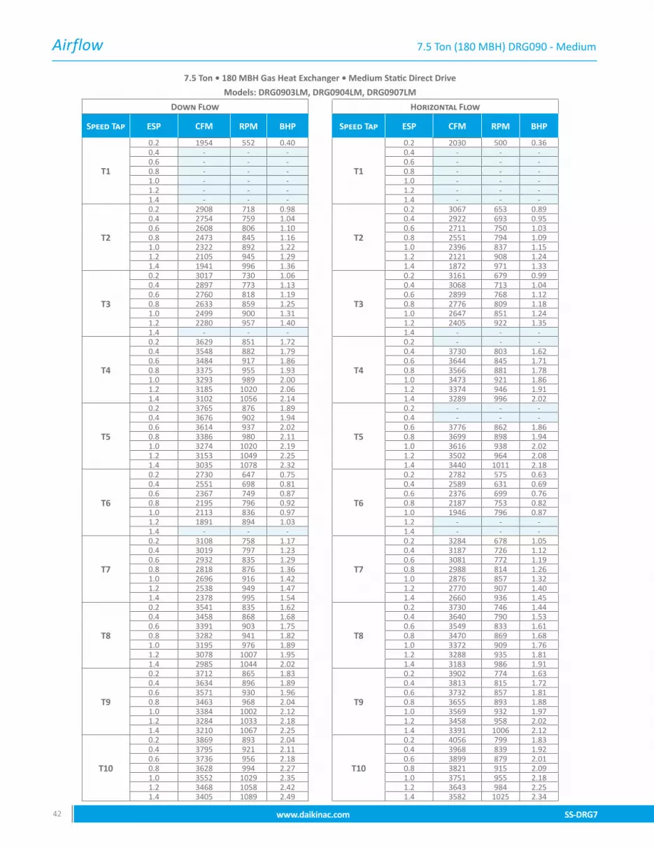
Airflow
SS-DRG7 www.daikinac.com 4342 www.daikinac.com SS-DRG7
7.5 Ton (180 MBH) DRG090 - Medium
7.5 Ton • 180 MBH Gas Heat Exchanger • Medium Static Direct Drive
Models: DRG0903LM, DRG0904LM, DRG0907LM
Down Flow Horizontal Flow
Speed Tap ESP CFM RPM BHP Speed Tap ESP CFM RPM BHP
T1
0.2 1954 552 0.40
T1
0.2 2030 500 0.360.4 - - - 0.4 - - -0.6 - - - 0.6 - - -0.8 - - - 0.8 - - -1.0 - - - 1.0 - - -1.2 - - - 1.2 - - -1.4 - - - 1.4 - - -
T2
0.2 2908 718 0.98
T2
0.2 3067 653 0.890.4 2754 759 1.04 0.4 2922 693 0.950.6 2608 806 1.10 0.6 2711 750 1.030.8 2473 845 1.16 0.8 2551 794 1.091.0 2322 892 1.22 1.0 2396 837 1.151.2 2105 945 1.29 1.2 2121 908 1.241.4 1941 996 1.36 1.4 1872 971 1.33
T3
0.2 3017 730 1.06
T3
0.2 3161 679 0.990.4 2897 773 1.13 0.4 3068 713 1.040.6 2760 818 1.19 0.6 2899 768 1.120.8 2633 859 1.25 0.8 2776 809 1.181.0 2499 900 1.31 1.0 2647 851 1.241.2 2280 957 1.40 1.2 2405 922 1.351.4 - - - 1.4 - - -
T4
0.2 3629 851 1.72
T4
0.2 - - -0.4 3548 882 1.79 0.4 3730 803 1.620.6 3484 917 1.86 0.6 3644 845 1.710.8 3375 955 1.93 0.8 3566 881 1.781.0 3293 989 2.00 1.0 3473 921 1.861.2 3185 1020 2.06 1.2 3374 946 1.911.4 3102 1056 2.14 1.4 3289 996 2.02
T5
0.2 3765 876 1.89
T5
0.2 - - -0.4 3676 902 1.94 0.4 - - -0.6 3614 937 2.02 0.6 3776 862 1.860.8 3386 980 2.11 0.8 3699 898 1.941.0 3274 1020 2.19 1.0 3616 938 2.021.2 3153 1049 2.25 1.2 3502 964 2.081.4 3035 1078 2.32 1.4 3440 1011 2.18
T6
0.2 2730 647 0.75
T6
0.2 2782 575 0.630.4 2551 698 0.81 0.4 2589 631 0.690.6 2367 749 0.87 0.6 2376 699 0.760.8 2195 796 0.92 0.8 2187 753 0.821.0 2113 836 0.97 1.0 1946 796 0.871.2 1891 894 1.03 1.2 - - -1.4 - - - 1.4 - - -
T7
0.2 3108 758 1.17
T7
0.2 3284 678 1.050.4 3019 797 1.23 0.4 3187 726 1.120.6 2932 835 1.29 0.6 3081 772 1.190.8 2818 876 1.36 0.8 2988 814 1.261.0 2696 916 1.42 1.0 2876 857 1.321.2 2538 949 1.47 1.2 2770 907 1.401.4 2378 995 1.54 1.4 2660 936 1.45
T8
0.2 3541 835 1.62
T8
0.2 3730 746 1.440.4 3458 868 1.68 0.4 3640 790 1.530.6 3391 903 1.75 0.6 3549 833 1.610.8 3282 941 1.82 0.8 3470 869 1.681.0 3195 976 1.89 1.0 3372 909 1.761.2 3078 1007 1.95 1.2 3288 935 1.811.4 2985 1044 2.02 1.4 3183 986 1.91
T9
0.2 3712 865 1.83
T9
0.2 3902 774 1.630.4 3634 896 1.89 0.4 3813 815 1.720.6 3571 930 1.96 0.6 3732 857 1.810.8 3463 968 2.04 0.8 3655 893 1.881.0 3384 1002 2.12 1.0 3569 932 1.971.2 3284 1033 2.18 1.2 3458 958 2.021.4 3210 1067 2.25 1.4 3391 1006 2.12
T10
0.2 3869 893 2.04
T10
0.2 4056 799 1.830.4 3795 921 2.11 0.4 3968 839 1.920.6 3736 956 2.18 0.6 3899 879 2.010.8 3628 994 2.27 0.8 3821 915 2.091.0 3552 1029 2.35 1.0 3751 955 2.181.2 3468 1058 2.42 1.2 3643 984 2.251.4 3405 1089 2.49 1.4 3582 1025 2.34
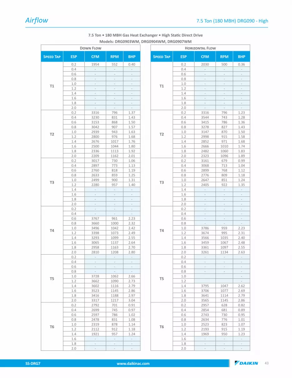
Airflow
SS-DRG7 www.daikinac.com 4342 www.daikinac.com SS-DRG7
7.5 Ton (180 MBH) DRG090 - High
7.5 Ton • 180 MBH Gas Heat Exchanger • High Static Direct Drive
Models: DRG0903WM, DRG0904WM, DRG0907WM
Down Flow Horizontal Flow
Speed Tap ESP CFM RPM BHP Speed Tap ESP CFM RPM BHP
T1
0.2 1954 552 0.40
T1
0.2 2030 500 0.360.4 - - - 0.4 - - -0.6 - - - 0.6 - - -0.8 - - - 0.8 - - -1.0 - - - 1.0 - - -1.2 - - - 1.2 - - -1.4 - - - 1.4 - - -1.6 - - - 1.6 - - -1.8 - - - 1.8 - - -2.0 - - - 2.0 - - -
T2
0.2 3316 796 1.37
T2
0.2 3316 796 1.230.4 3230 831 1.43 0.4 3544 743 1.280.6 3153 868 1.50 0.6 3415 786 1.360.8 3042 907 1.57 0.8 3278 827 1.431.0 2939 943 1.63 1.0 3147 870 1.501.2 2800 976 1.68 1.2 2998 915 1.581.4 2676 1017 1.76 1.4 2852 971 1.681.6 2500 1044 1.80 1.6 2666 1010 1.741.8 2336 1113 1.92 1.8 2482 1060 1.832.0 2209 1162 2.01 2.0 2323 1096 1.89
T3
0.2 3017 730 1.06
T3
0.2 3161 679 0.990.4 2897 773 1.13 0.4 3068 713 1.040.6 2760 818 1.19 0.6 2899 768 1.120.8 2633 859 1.25 0.8 2776 809 1.181.0 2499 900 1.31 1.0 2647 851 1.241.2 2280 957 1.40 1.2 2405 922 1.351.4 - - - 1.4 - - -1.6 - - - 1.6 - - -1.8 - - - 1.8 - - -2.0 - - - 2.0 - - -
T4
0.2 - - -
T4
0.2 - - -0.4 - - - 0.4 - - -0.6 3767 961 2.23 0.6 - - -0.8 3660 1000 2.32 0.8 - - -1.0 3496 1042 2.42 1.0 3786 959 2.231.2 3398 1073 2.49 1.2 3674 995 2.311.4 3293 1099 2.55 1.4 3566 1035 2.401.6 3065 1137 2.64 1.6 3459 1067 2.481.8 2958 1163 2.70 1.8 3361 1097 2.552.0 2810 1208 2.80 2.0 3261 1134 2.63
T5
0.2 - - -
T5
0.2 - - -0.4 - - - 0.4 - - -0.6 - - - 0.6 - - -0.8 - - - 0.8 - - -1.0 3728 1062 2.66 1.0 -1.2 3662 1090 2.73 1.2 -1.4 3602 1116 2.79 1.4 3795 1047 2.621.6 3523 1145 2.86 1.6 3706 1077 2.691.8 3416 1188 2.97 1.8 3641 1114 2.792.0 3317 1217 3.04 2.0 3565 1145 2.86
T6
0.2 2792 701 0.91
T6
0.2 2957 628 0.820.4 2699 745 0.97 0.4 2854 681 0.890.6 2597 786 1.02 0.6 2743 730 0.950.8 2478 831 1.08 0.8 2634 776 1.011.0 2319 878 1.14 1.0 2523 823 1.071.2 2112 912 1.18 1.2 2193 915 1.191.4 1921 957 1.24 1.4 1969 950 1.231.6 - - - 1.6 - - -1.8 - - - 1.8 - - -2.0 - - - 2.0 - - -

Airflow
SS-DRG7 www.daikinac.com 4544 www.daikinac.com SS-DRG7
7.5 Ton (180 MBH) DRG090 - High (cont.)
7.5 Ton • 180 MBH Gas Heat Exchanger • High Static Direct Drive
Models: DRG0903WM, DRG0904WM, DRG0907WM
Down Flow Horizontal Flow
Speed Tap ESP CFM RPM BHP Speed Tap ESP CFM RPM BHP
T7
0.2 3464 822 1.53
T7
0.2 3652 734 1.370.4 3380 855 1.59 0.4 3562 778 1.450.6 3309 891 1.66 0.6 3467 822 1.530.8 3200 929 1.73 0.8 3386 859 1.601.0 3108 964 1.80 1.0 3284 899 1.671.2 2984 996 1.85 1.2 3212 927 1.731.4 2881 1035 1.93 1.4 3090 977 1.821.6 2717 1062 1.98 1.6 2966 1013 1.891.8 2550 1130 2.10 1.8 2649 1112 2.072.0 2357 1171 2.18 2.0 2521 1147 2.14
T8
0.2 3983 912 2.21
T8
0.2 4167 817 1.980.4 3912 940 2.28 0.4 4077 857 2.080.6 3855 974 2.36 0.6 4019 895 2.170.8 3748 1014 2.46 0.8 3939 931 2.261.0 3671 1051 2.55 1.0 3885 973 2.361.2 3598 1079 2.62 1.2 3827 1008 2.441.4 3538 1107 2.68 1.4 3723 1040 2.521.6 3446 1136 2.75 1.6 3622 1070 2.591.8 3326 1183 2.87 1.8 3569 1108 2.692.0 3210 1213 2.94 2.0 3472 1139 2.76
T9
0.2 4119 935 2.44
T9
0.2 4296 839 2.190.4 4054 962 2.51 0.4 4205 878 2.290.6 3998 997 2.60 0.6 4163 915 2.390.8 3890 1039 2.71 0.8 4077 952 2.491.0 3806 1079 2.82 1.0 4047 996 2.601.2 3747 1106 2.89 1.2 3954 1041 2.721.4 3686 1130 2.95 1.4 3894 1058 2.761.6 3625 1160 3.03 1.6 3827 1088 2.841.8 3541 1195 3.12 1.8 3735 1123 2.932.0 3456 1222 3.19 2.0 3680 1154 3.01
T10
0.2 - - -
T10
0.2 - - -0.4 - - - 0.4 - - -0.6 - - - 0.6 - - -0.8 - - - 0.8 - - -1.0 4156 1104 3.08 1.0 - - -1.2 4032 1128 3.14 1.2 - - -1.4 3908 1151 3.21 1.4 4040 1074 2.991.6 3784 1175 3.27 1.6 4023 1106 3.081.8 3660 1198 3.34 1.8 3859 1138 3.172.0 3536 1222 3.40 2.0 3812 1167 3.25
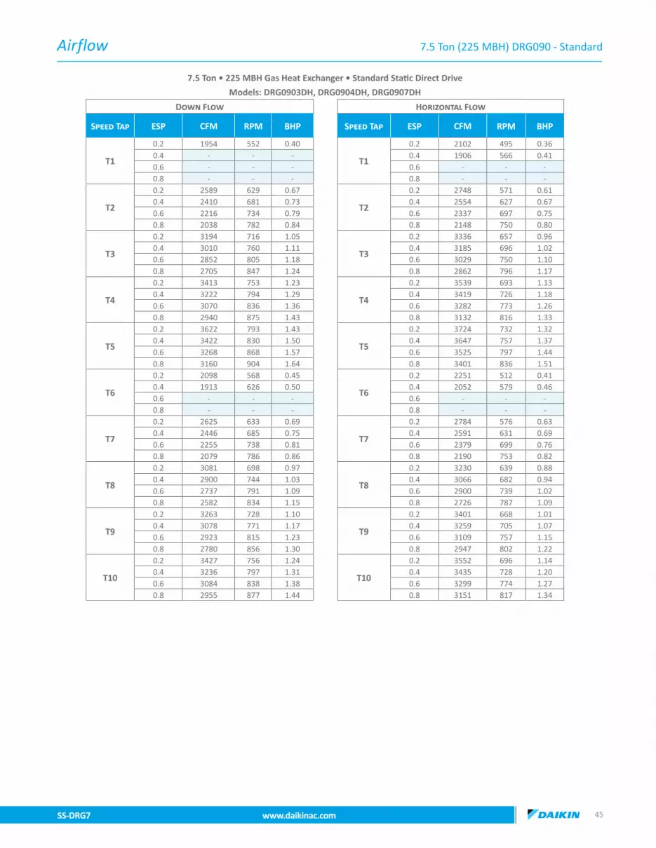
Airflow
SS-DRG7 www.daikinac.com 4544 www.daikinac.com SS-DRG7
7.5 Ton (225 MBH) DRG090 - Standard
7.5 Ton • 225 MBH Gas Heat Exchanger • Standard Static Direct Drive
Models: DRG0903DH, DRG0904DH, DRG0907DH
Down Flow Horizontal Flow
Speed Tap ESP CFM RPM BHP Speed Tap ESP CFM RPM BHP
T1
0.2 1954 552 0.40
T1
0.2 2102 495 0.360.4 - - - 0.4 1906 566 0.410.6 - - - 0.6 - - -0.8 - - - 0.8 - - -
T2
0.2 2589 629 0.67
T2
0.2 2748 571 0.610.4 2410 681 0.73 0.4 2554 627 0.670.6 2216 734 0.79 0.6 2337 697 0.750.8 2038 782 0.84 0.8 2148 750 0.80
T3
0.2 3194 716 1.05
T3
0.2 3336 657 0.960.4 3010 760 1.11 0.4 3185 696 1.020.6 2852 805 1.18 0.6 3029 750 1.100.8 2705 847 1.24 0.8 2862 796 1.17
T4
0.2 3413 753 1.23
T4
0.2 3539 693 1.130.4 3222 794 1.29 0.4 3419 726 1.180.6 3070 836 1.36 0.6 3282 773 1.260.8 2940 875 1.43 0.8 3132 816 1.33
T5
0.2 3622 793 1.43
T5
0.2 3724 732 1.320.4 3422 830 1.50 0.4 3647 757 1.370.6 3268 868 1.57 0.6 3525 797 1.440.8 3160 904 1.64 0.8 3401 836 1.51
T6
0.2 2098 568 0.45
T6
0.2 2251 512 0.410.4 1913 626 0.50 0.4 2052 579 0.460.6 - - - 0.6 - - -0.8 - - - 0.8 - - -
T7
0.2 2625 633 0.69
T7
0.2 2784 576 0.630.4 2446 685 0.75 0.4 2591 631 0.690.6 2255 738 0.81 0.6 2379 699 0.760.8 2079 786 0.86 0.8 2190 753 0.82
T8
0.2 3081 698 0.97
T8
0.2 3230 639 0.880.4 2900 744 1.03 0.4 3066 682 0.940.6 2737 791 1.09 0.6 2900 739 1.020.8 2582 834 1.15 0.8 2726 787 1.09
T9
0.2 3263 728 1.10
T9
0.2 3401 668 1.010.4 3078 771 1.17 0.4 3259 705 1.070.6 2923 815 1.23 0.6 3109 757 1.150.8 2780 856 1.30 0.8 2947 802 1.22
T10
0.2 3427 756 1.24
T10
0.2 3552 696 1.140.4 3236 797 1.31 0.4 3435 728 1.200.6 3084 838 1.38 0.6 3299 774 1.270.8 2955 877 1.44 0.8 3151 817 1.34

Airflow
SS-DRG7 www.daikinac.com 4746 www.daikinac.com SS-DRG7
7.5 Ton (225 MBH) DRG090 - Medium
7.5 Ton • 225 MBH Gas Heat Exchanger • Medium Static Direct Drive
Models: DRG0903LH, DRG0904LH, DRG0907LH
Down Flow Horizontal Flow
Speed Tap ESP CFM RPM BHP Speed Tap ESP CFM RPM BHP
T1
0.2 1954 552 0.40
T1
0.2 2102 495 0.360.4 - - - 0.4 1906 566 0.410.6 - - - 0.6 - - -0.8 - - - 0.8 - - -1.0 - - - 1.0 - - -1.2 - - - 1.2 - - -1.4 - - - 1.4 - - -
T2
0.2 3059 695 0.95
T2
0.2 3208 636 0.870.4 2877 741 1.01 0.4 3043 680 0.930.6 2714 788 1.08 0.6 2874 737 1.010.8 2558 831 1.14 0.8 2699 785 1.071.0 2412 870 1.19 1.0 2519 829 1.131.2 2218 922 1.26 1.2 2312 884 1.211.4 2028 965 1.32 1.4 2103 948 1.30
T3
0.2 3194 716 1.05
T3
0.2 3336 657 0.960.4 3010 760 1.11 0.4 3185 696 1.020.6 2852 805 1.18 0.6 3029 750 1.100.8 2705 847 1.24 0.8 2862 796 1.171.0 2542 885 1.30 1.0 2699 840 1.231.2 2360 934 1.37 1.2 2509 893 1.311.4 - - - 1.4 2320 954 1.40
T4
0.2 - - -
T4
0.2 - - -0.4 3622 874 1.77 0.4 - - -0.6 3458 907 1.83 0.6 - - -0.8 3380 940 1.90 0.8 3693 861 1.741.0 3265 975 1.97 1.0 3575 905 1.831.2 3138 1008 2.04 1.2 3461 941 1.901.4 2994 1043 2.11 1.4 3345 991 2.00
T5
0.2 - - -
T5
0.2 - - -0.4 3725 901 1.94 0.4 - - -0.6 3549 931 2.00 0.6 - - -0.8 3492 961 2.07 0.8 - - -1.0 3423 996 2.15 1.0 3737 920 1.981.2 3307 1026 2.21 1.2 3633 952 2.051.4 3180 1059 2.28 1.4 3524 999 2.15
T6
0.2 2231 516 0.50
T6
0.2 2410 585 0.570.4 2028 649 0.63 0.4 2385 610 0.590.6 1835 696 0.68 0.6 2243 664 0.650.8 - - - 0.8 1983 748 0.731.0 - - - 1.0 - - -1.2 - - - 1.2 - - -1.4 - - - 1.4 - - -
T7
0.2 2987 684 0.90
T7
0.2 3139 625 0.830.4 2806 731 0.96 0.4 2967 671 0.890.6 2639 779 1.03 0.6 2791 730 0.960.8 2479 823 1.09 0.8 2613 779 1.031.0 2344 862 1.14 1.0 2424 823 1.091.2 2144 915 1.21 1.2 2207 880 1.161.4 1953 959 1.27 1.4 1987 944 1.25
T8
0.2 3456 761 1.27
T8
0.2 3578 701 1.170.4 3264 801 1.34 0.4 3467 732 1.220.6 3112 842 1.40 0.6 3333 778 1.300.8 2986 881 1.47 0.8 3188 820 1.371.0 2812 918 1.53 1.0 3051 863 1.441.2 2652 961 1.60 1.2 2894 910 1.521.4 2476 1001 1.67 1.4 2739 967 1.61
T9
0.2 3569 838 1.66
T9
0.2 3868 769 1.520.4 3500 874 1.73 0.4 3839 787 1.550.6 3434 910 1.80 0.6 3727 820 1.620.8 3325 947 1.87 0.8 3631 856 1.691.0 3240 982 1.94 1.0 3513 900 1.781.2 3128 1013 2.00 1.2 3394 937 1.851.4 3040 1049 2.07 1.4 3274 987 1.95
T10
0.2 3893 882 1.99
T10
0.2 4122 792 1.790.4 3766 916 2.07 0.4 4001 828 1.870.6 3687 945 2.14 0.6 3881 865 1.960.8 3584 977 2.21 0.8 3800 910 2.061.0 3501 1006 2.28 1.0 3594 930 2.101.2 3392 1042 2.36 1.2 3519 974 2.201.4 3289 1068 2.42 1.4 3391 1007 2.28

Airflow
SS-DRG7 www.daikinac.com 4746 www.daikinac.com SS-DRG7
7.5 Ton (225 MBH) DRG090 - High
7.5 Ton • 225 MBH Gas Heat Exchanger • High Static Direct Drive
Models: DRG0903WH, DRG0904WH, DRG0907WH
Down Flow Horizontal Flow
Speed Tap ESP CFM RPM BHP Speed Tap ESP CFM RPM BHP
T1
0.2 1954 552 0.40
T1
0.2 2102 495 0.360.4 - - - 0.4 1906 566 0.410.6 - - - 0.6 - - -0.8 - - - 0.8 - - -1.0 - - - 1.0 - - -1.2 - - - 1.2 - - -1.4 - - - 1.4 - - -1.6 - - - 1.6 - - -1.8 - - - 1.8 - - -2.0 - - - 2.0 - - -
T2
0.2 3527 774 1.34
T2
0.2 3642 714 1.230.4 3332 814 1.40 0.4 3544 743 1.280.6 3180 853 1.47 0.6 3415 786 1.360.8 3061 891 1.54 0.8 3278 827 1.431.0 2889 927 1.60 1.0 3147 870 1.501.2 2735 969 1.67 1.2 2998 915 1.581.4 2563 1008 1.74 1.4 2852 971 1.681.6 2392 1050 1.81 1.6 2666 1010 1.741.8 2237 1086 1.87 1.8 2482 1060 1.832.0 2077 1119 1.93 2.0 2323 1096 1.89
T3
0.2 3194 716 1.05
T3
0.2 3336 657 0.960.4 3010 760 1.11 0.4 3185 696 1.020.6 2852 805 1.18 0.6 3029 750 1.100.8 2705 847 1.24 0.8 2862 796 1.171.0 2542 885 1.30 1.0 2699 840 1.231.2 2360 934 1.37 1.2 2509 893 1.311.4 - - - 1.4 2320 954 1.401.6 - - - 1.6 - - -1.8 - - - 1.8 - - -2.0 - - - 2.0 - - -
T4
0.2 - - -
T4
0.2 - - -0.4 - - - 0.4 - - -0.6 3769 961 2.22 0.6 - - -0.8 3645 1000 2.32 0.8 - - -1.0 3496 1042 2.42 1.0 - - -1.2 3398 1073 2.49 1.2 3674 995 2.311.4 3293 1099 2.55 1.4 3566 1035 2.401.6 3065 1137 2.64 1.6 3459 1067 2.481.8 2958 1163 2.70 1.8 3361 1097 2.552.0 2810 1208 2.80 2.0 3261 1134 2.63
T5
0.2 - - -
T5
0.2 - - -0.4 - - - 0.4 - - -0.6 - - - 0.6 - - -0.8 - - - 0.8 - - -1.0 3754 1063 2.66 1.0 - - -1.2 3662 1090 2.73 1.2 - - -1.4 3578 1115 2.80 1.4 3795 1047 2.621.6 3519 1137 2.84 1.6 3706 1077 2.691.8 3325 1166 2.91 1.8 3641 1114 2.792.0 3161 1203 3.01 2.0 3565 1145 2.86
T6
0.2 2569 626 0.66
T6
0.2 2728 568 0.600.4 2389 678 0.72 0.4 2533 625 0.660.6 2194 732 0.78 0.6 2314 695 0.740.8 2015 780 0.83 0.8 2125 749 0.791.0 1974 821 0.87 1.0 1875 792 0.841.2 - - - 1.2 - - -1.4 - - - 1.4 - - -1.6 - - - 1.6 - - -1.8 - - - 1.8 - - -2.0 - - - 2.0 - - -

Airflow
SS-DRG7 www.daikinac.com 4948 www.daikinac.com SS-DRG7
7.5 Ton (225 MBH) DRG090 - High (cont.)
7.5 Ton • 225 MBH Gas Heat Exchanger • High Static Direct Drive
Models: DRG0903WH, DRG0904WH, DRG0907WH
Down Flow Horizontal Flow
Speed Tap ESP CFM RPM BHP Speed Tap ESP CFM RPM BHP
T7
0.2 - - -
T7
0.2 - - -0.4 3048 766 1.14 0.4 - - -0.6 2892 811 1.21 0.6 3074 754 1.130.8 2747 852 1.27 0.8 2910 800 1.191.0 2581 890 1.33 1.0 2751 843 1.261.2 2402 938 1.40 1.2 2566 895 1.341.4 2216 980 1.46 1.4 2382 956 1.431.6 2043 1023 1.53 1.6 2200 998 1.491.8 1893 1062 1.58 1.8 2005 1047 1.562.0 - - - 2.0 1836 1083 1.62
T8
0.2 3744 819 1.58
T8
0.2 3828 758 1.460.4 3536 854 1.64 0.4 3784 778 1.500.6 3378 889 1.71 0.6 3669 813 1.570.8 3286 924 1.78 0.8 3564 850 1.641.0 3144 960 1.85 1.0 3444 894 1.721.2 3009 995 1.92 1.2 3320 933 1.801.4 2855 1031 1.99 1.4 3197 984 1.891.6 2687 1072 2.06 1.6 3023 1020 1.961.8 2526 1107 2.13 1.8 2852 1071 2.062.0 - - - 2.0 2703 1107 2.13
T9
0.2 3998 907 2.14
T9
0.2 - - -0.4 3905 939 2.22 0.4 - - -0.6 3812 972 2.29 0.6 4100 872 2.060.8 3693 1005 2.37 0.8 4086 901 2.121.0 3617 1041 2.46 1.0 3955 944 2.231.2 3539 1069 2.52 1.2 3864 970 2.291.4 3478 1098 2.59 1.4 3758 1013 2.391.6 3376 1127 2.66 1.6 3659 1042 2.461.8 3271 1162 2.74 1.8 3525 1096 2.592.0 3111 1208 2.85 2.0 3406 1132 2.67
T10
0.2 - - -
T10
0.2 - - -0.4 - - - 0.4 - - -0.6 - - - 0.6 - - -0.8 - - - 0.8 - - -1.0 4156 1104 3.08 1.0 - - -1.2 4032 1128 3.14 1.2 - - -1.4 3908 1151 3.21 1.4 4040 1074 2.991.6 3784 1175 3.27 1.6 4023 1106 3.081.8 3660 1198 3.34 1.8 3859 1138 3.172.0 3536 1222 3.40 2.0 3812 1167 3.25

Airflow
SS-DRG7 www.daikinac.com 4948 www.daikinac.com SS-DRG7
8.5 Ton (130 MBH) DRG102 - Standard
8.5 Ton • 130 MBH Gas Heat Exchanger • Standard Static Direct Drive
Models: DRG1023DL, DRG1024DL, DRG1027DL
Down Flow Horizontal Flow
Speed Tap ESP CFM RPM BHP Speed Tap ESP CFM RPM BHP
T1
0.2 1714 496 0.32
T1
0.2 1856 423 0.270.4 - - - 0.4 - - -0.6 - - - 0.6 - - -0.8 - - - 0.8 - - -
T2
0.2 2365 599 0.61
T2
0.2 2671 503 0.510.4 2208 649 0.66 0.4 2492 568 0.570.6 2048 695 0.70 0.6 2335 628 0.640.8 - - - 0.8 2027 690 0.70
T3
0.2 2798 671 0.88
T3
0.2 3144 564 0.740.4 2687 713 0.93 0.4 3005 607 0.790.6 - - - 0.6 2824 671 0.880.8 - - - 0.8 2661 722 0.95
T4
0.2 3522 795 1.51
T4
0.2 3921 655 1.250.4 3389 828 1.58 0.4 3775 700 1.330.6 3240 865 1.65 0.6 3630 745 1.420.8 3083 898 1.71 0.8 3449 786 1.50
T5
0.2 3830 847 1.83
T5
0.2 4210 694 1.490.4 3702 881 1.90 0.4 4071 737 1.590.6 3563 915 1.97 0.6 3942 777 1.670.8 3399 946 2.04 0.8 3746 819 1.76
T6
0.2 1889 528 0.38
T6
0.2 2056 443 0.320.4 1827 589 0.43 0.4 1887 522 0.380.6 1445 667 0.48 0.6 1702 591 0.430.8 - - - 0.8 1327 707 0.51
T7
0.2 2193 571 0.53
T7
0.2 2445 487 0.450.4 2090 635 0.59 0.4 2283 556 0.510.6 1959 698 0.64 0.6 2098 617 0.570.8 1704 763 0.70 0.8 1828 688 0.64
T8
0.2 2489 616 0.69
T8
0.2 2760 545 0.610.4 2351 679 0.76 0.4 2630 587 0.660.6 2235 729 0.82 0.6 2487 641 0.720.8 2050 780 0.87 0.8 2264 701 0.79
T9
0.2 2860 679 0.94
T9
0.2 3234 581 0.800.4 2699 735 1.02 0.4 3043 626 0.870.6 2554 774 1.07 0.6 2866 675 0.930.8 2446 817 1.13 0.8 2677 729 1.01
T10
0.2 3182 743 1.22
T10
0.2 3655 604 0.990.4 3041 788 1.30 0.4 3427 663 1.090.6 2953 821 1.35 0.6 3210 714 1.170.8 2797 868 1.43 0.8 3066 759 1.25

Airflow
SS-DRG7 www.daikinac.com 5150 www.daikinac.com SS-DRG7
8.5 Ton (130 MBH) DRG102 - Medium
8.5 Ton • 130 MBH Gas Heat Exchanger • Medium Static Direct Drive
Models: DRG1023LL, DRG1024LL, DRG1027LL
Down Flow Horizontal Flow
Speed Tap ESP CFM RPM BHP Speed Tap ESP CFM RPM BHP
T1
0.2 1714 496 0.32
T1
0.2 1856 423 0.270.4 - - - 0.4 - - -0.6 - - - 0.6 - - -0.8 - - - 0.8 - - -1.0 - - - 1.0 - - -1.2 - - - 1.2 - - -1.4 - - - 1.4 - - -
T2
0.2 3114 722 1.12
T2
0.2 3458 603 0.930.4 2977 761 1.18 0.4 3292 658 1.020.6 2825 800 1.24 0.6 3155 700 1.080.8 2634 846 1.31 0.8 3007 747 1.161.0 2474 878 1.36 1.0 2844 797 1.231.2 2236 931 1.44 1.2 2681 836 1.291.4 1990 986 1.53 1.4 2469 885 1.37
T3
0.2 2798 671 0.88
T3
0.2 3144 564 0.740.4 2687 713 0.93 0.4 3005 607 0.790.6 - - - 0.6 2824 671 0.880.8 - - - 0.8 2661 722 0.951.0 - - - 1.0 - - -1.2 - - - 1.2 - - -1.4 - - - 1.4 - - -
T4
0.2 3997 874 1.99
T4
0.2 - - -0.4 3869 909 2.07 0.4 4200 754 1.710.6 3740 942 2.14 0.6 4070 791 1.800.8 3578 975 2.22 0.8 3879 838 1.911.0 3417 1009 2.29 1.0 3699 874 1.991.2 3257 1039 2.36 1.2 3535 923 2.101.4 3091 1069 2.43 1.4 3341 946 2.15
T5
0.2 - - -
T5
0.2 - - -0.4 4125 958 2.46 0.4 - - -0.6 3997 992 2.55 0.6 - - -0.8 3806 1021 2.63 0.8 4194 863 2.221.0 3701 1056 2.72 1.0 4012 898 2.311.2 3547 1081 2.78 1.2 3879 955 2.451.4 3374 1101 2.83 1.4 3683 967 2.49
T6
0.2 1863 520 0.37
T6
0.2 2029 440 0.310.4 1748 587 0.42 0.4 1855 519 0.370.6 1403 671 0.48 0.6 1666 593 0.420.8 - - - 0.8 - - -1.0 - - - 1.0 - - -1.2 - - - 1.2 - - -1.4 - - - 1.4 - - -
T7
0.2 2398 602 0.64
T7
0.2 2645 528 0.560.4 2270 665 0.70 0.4 2515 577 0.610.6 2161 719 0.76 0.6 2360 634 0.670.8 1948 774 0.82 0.8 2137 694 0.741.0 1818 821 0.87 1.0 1801 757 0.801.2 1520 901 0.95 1.2 1532 814 0.861.4 1487 951 1.01 1.4 - - -
T8
0.2 2398 602 0.64
T8
0.2 2645 528 0.560.4 2270 665 0.70 0.4 2515 577 0.610.6 2161 719 0.76 0.6 2360 634 0.670.8 1948 774 0.82 0.8 2137 694 0.741.0 1818 821 0.87 1.0 1801 757 0.801.2 - - - 1.2 - - -1.4 - - - 1.4 - - -
T9
0.2 3203 753 1.25
T9
0.2 3664 603 1.010.4 3097 795 1.32 0.4 3429 666 1.110.6 2992 833 1.39 0.6 3240 718 1.200.8 2871 874 1.46 0.8 3088 761 1.271.0 2716 917 1.53 1.0 2883 808 1.351.2 2580 951 1.59 1.2 2651 857 1.431.4 2375 1004 1.67 1.4 2470 900 1.50
T10
0.2 3879 753 1.72
T10
0.2 - - -0.4 3777 802 1.83 0.4 - - -0.6 3658 923 2.11 0.6 - - -0.8 3532 980 2.24 0.8 - - -1.0 3416 1008 2.30 1.0 3711 872 1.991.2 3280 1038 2.37 1.2 3501 907 2.071.4 3152 1071 2.45 1.4 2986 951 2.17

Airflow
SS-DRG7 www.daikinac.com 5150 www.daikinac.com SS-DRG7
8.5 Ton (130 MBH) DRG102 - High
8.5 Ton • 130 MBH Gas Heat Exchanger • High Static Direct Drive
Models: DRG1023WL, DRG1024WL, DRG1027WL
Down Flow Horizontal Flow
Speed Tap ESP CFM RPM BHP Speed Tap ESP CFM RPM BHP
T1
0.2 1714 496 0.32
T1
0.2 1856 423 0.270.4 - - - 0.4 - - -0.6 - - - 0.6 - - -0.8 - - - 0.8 - - -1.0 - - - 1.0 - - -1.2 - - - 1.2 - - -1.4 - - - 1.4 - - -1.6 - - - 1.6 - - -1.8 - - - 1.8 - - -2.0 - - - 2.0 - - -
T2
0.2 3674 820 1.66
T2
0.2 4061 675 1.370.4 3544 853 1.73 0.4 3919 720 1.460.6 3402 889 1.80 0.6 3792 761 1.540.8 3235 920 1.86 0.8 3610 802 1.621.0 3055 956 1.94 1.0 3427 845 1.711.2 2891 986 2.00 1.2 3261 894 1.811.4 2708 1011 2.05 1.4 3042 919 1.861.6 2499 1071 2.17 1.6 2865 962 1.951.8 2307 1103 2.23 1.8 2649 1020 2.062.0 2054 1146 2.32 2.0 2487 1041 2.11
T3
0.2 2798 671 0.88
T3
0.2 3144 564 0.740.4 2687 713 0.93 0.4 3005 607 0.790.6 - - - 0.6 2824 671 0.880.8 - - - 0.8 2661 722 0.951.0 - - - 1.0 - - -1.2 - - - 1.2 - - -1.4 - - - 1.4 - - -1.6 - - - 1.6 - - -1.8 - - - 1.8 - - -2.0 - - - 2.0 - - -
T4
0.2 4166 907 2.22
T4
0.2 - - -0.4 4029 939 2.30 0.4 - - -0.6 3906 969 2.37 0.6 4261 812 1.990.8 3717 1003 2.45 0.8 4051 849 2.081.0 3544 1037 2.54 1.0 3857 885 2.171.2 3394 1064 2.60 1.2 3718 922 2.251.4 3219 1092 2.67 1.4 3536 957 2.341.6 3060 1121 2.74 1.6 3369 993 2.431.8 2887 1148 2.81 1.8 3199 1028 2.522.0 2721 1176 2.88 2.0 3048 1064 2.60
T5
0.2 - - -
T5
0.2 - - -0.4 - - - 0.4 - - -0.6 4221 1022 2.85 0.6 - - -0.8 4047 1052 2.93 0.8 - - -1.0 3889 1084 3.02 1.0 - - -1.2 3734 1109 3.09 1.2 4145 950 2.651.4 3555 1133 3.16 1.4 3925 986 2.751.6 3396 1162 3.24 1.6 3783 1018 2.841.8 3210 1186 3.30 1.8 3606 1051 2.932.0 3041 1211 3.37 2.0 3415 1085 3.02
T6
0.2 2398 602 0.64
T6
0.2 2645 528 0.560.4 2270 665 0.70 0.4 2515 577 0.610.6 2161 719 0.76 0.6 2360 634 0.670.8 1948 774 0.82 0.8 2137 694 0.741.0 1818 821 0.87 1.0 1801 757 0.801.2 1520 901 0.95 1.2 1532 814 0.861.4 - - - 1.4 - - -1.6 - - - 1.6 - - -1.8 - - - 1.8 - - -2.0 - - - 2.0 - - -

Airflow
SS-DRG7 www.daikinac.com 5352 www.daikinac.com SS-DRG7
8.5 Ton • 130 MBH Gas Heat Exchanger • High Static Direct Drive
Models: DRG1023WL, DRG1024WL, DRG1027WL
Down Flow Horizontal Flow
Speed Tap ESP CFM RPM BHP Speed Tap ESP CFM RPM BHP
T7
0.2 - - -
T7
0.2 - - -0.4 2729 741 1.06 0.4 - - -0.6 2574 789 1.13 0.6 - - -0.8 2447 824 1.18 0.8 2767 734 1.051.0 2310 847 1.21 1.0 2539 781 1.121.2 2126 857 1.22 1.2 2280 837 1.201.4 1858 948 1.35 1.4 2083 892 1.271.6 1746 1021 1.46 1.6 1834 946 1.351.8 1577 1075 1.54 1.8 1477 1014 1.452.0 1420 1111 1.59 2.0 - - -
T8
0.2 2947 695 1.01
T8
0.2 3354 587 0.850.4 2787 749 1.09 0.4 3145 635 0.920.6 2649 786 1.14 0.6 2952 685 0.990.8 2539 829 1.20 0.8 2776 736 1.071.0 2287 872 1.26 1.0 2573 785 1.141.2 2202 917 1.33 1.2 2318 840 1.221.4 1896 972 1.41 1.4 2119 896 1.301.6 - - - 1.6 1875 950 1.381.8 - - - 1.8 - - -2.0 - - - 2.0 - - -
T9
0.2 3704 751 1.59
T9
0.2 - - -0.4 3606 786 1.67 0.4 - - -0.6 3491 903 1.92 0.6 - - -0.8 3366 951 2.02 0.8 3761 817 1.731.0 3247 981 2.08 1.0 3588 854 1.811.2 3108 1015 2.15 1.2 3342 894 1.901.4 2970 1050 2.23 1.4 3145 938 1.991.6 2833 1082 2.30 1.6 2888 981 2.081.8 2661 1117 2.37 1.8 2688 1022 2.172.0 2477 1179 2.50 2.0 2433 1065 2.26
T10
0.2 - - -
T10
0.2 - - -0.4 - - - 0.4 - - -0.6 - - - 0.6 - - -0.8 - - - 0.8 - - -1.0 3867 1078 3.00 1.0 - - -1.2 3743 1109 3.09 1.2 - - -1.4 3606 1138 3.17 1.4 - - -1.6 3474 1165 3.25 1.6 3767 1022 2.851.8 3340 1193 3.32 1.8 3581 1060 2.952.0 3204 1219 3.40 2.0 3370 1096 3.05
8.5 Ton (130 MBH) DRG102 - High (cont.)

Airflow
SS-DRG7 www.daikinac.com 5352 www.daikinac.com SS-DRG7
8.5 Ton (180 MBH) DRG102 - Standard
8.5 Ton • 180 MBH Gas Heat Exchanger • Standard Static Direct Drive
Models: DRG1023DM, DRG1024DM, DRG1027DM
Down Flow Horizontal Flow
Speed Tap ESP CFM RPM BHP Speed Tap ESP CFM RPM BHP
T1
0.2 1902 520 0.37
T1
0.2 2029 440 0.310.4 - - - 0.4 - - -0.6 - - - 0.6 - - -0.8 - - - 0.8 - - -
T2
0.2 2365 599 0.61
T2
0.2 2671 503 0.510.4 2208 649 0.66 0.4 2492 568 0.570.6 2048 695 0.70 0.6 2335 628 0.640.8 1892 736 0.74 0.8 2027 690 0.70
T3
0.2 3026 709 1.06
T3
0.2 3391 593 0.880.4 2905 748 1.11 0.4 3245 641 0.950.6 2735 788 1.17 0.6 3095 693 1.030.8 2593 831 1.24 0.8 2948 739 1.10
T4
0.2 3522 795 1.51
T4
0.2 3921 655 1.250.4 3389 828 1.58 0.4 3775 700 1.330.6 3240 865 1.65 0.6 3630 745 1.420.8 3083 898 1.71 0.8 3449 786 1.50
T5
0.2 3830 847 1.83
T5
0.2 4210 694 1.490.4 3702 881 1.90 0.4 4071 737 1.590.6 3563 915 1.97 0.6 3942 777 1.670.8 3399 946 2.04 0.8 3746 819 1.76
T6
0.2 1539 469 0.27
T6
0.2 1650 405 0.230.4 1317 556 0.31 0.4 1369 515 0.290.6 994 634 0.36 0.6 1105 589 0.330.8 - - - 0.8 - - -
T7
0.2 2327 591 0.60
T7
0.2 2571 513 0.520.4 2207 655 0.66 0.4 2433 570 0.580.6 2098 712 0.72 0.6 2261 630 0.640.8 1865 770 0.78 0.8 2042 690 0.70
T8
0.2 2266 588 0.56
T8
0.2 2491 493 0.470.4 2126 638 0.61 0.4 2318 560 0.530.6 1989 694 0.66 0.6 2125 625 0.600.8 1747 765 0.73 0.8 1918 683 0.65
T9
0.2 2743 658 0.85
T9
0.2 3073 572 0.740.4 2585 717 0.93 0.4 2909 613 0.800.6 2443 759 0.99 0.6 2751 663 0.860.8 - - - 0.8 2547 719 0.93
T10
0.2 3182 743 1.22
T10
0.2 3655 604 0.990.4 3041 788 1.30 0.4 3427 663 1.090.6 2953 821 1.35 0.6 3210 714 1.170.8 2797 868 1.43 0.8 3066 759 1.25

Airflow
SS-DRG7 www.daikinac.com 5554 www.daikinac.com SS-DRG7
8.5 Ton (180 MBH) DRG102 - Medium
8.5 Ton • 180 MBH Gas Heat Exchanger • Medium Static Direct Drive
Models: DRG1023LM, DRG1024LM, DRG1027LM
Down Flow Horizontal Flow
Speed Tap ESP CFM RPM BHP Speed Tap ESP CFM RPM BHP
T1
0.2 1863 520 0.37
T1
0.2 2029 440 0.310.4 - - - 0.4 1855 519 0.370.6 - - - 0.6 - - -0.8 - - - 0.8 - - -1.0 - - - 1.0 - - -1.2 - - - 1.2 - - -1.4 - - - 1.4 - - -
T2
0.2 3114 722 1.12
T2
0.2 3458 603 0.930.4 2977 761 1.18 0.4 3292 658 1.020.6 2825 800 1.24 0.6 3155 700 1.080.8 2634 846 1.31 0.8 3007 747 1.161.0 2474 878 1.36 1.0 2844 797 1.231.2 2236 931 1.44 1.2 2681 836 1.291.4 1990 986 1.53 1.4 2469 885 1.37
T3
0.2 3026 709 1.06
T3
0.2 3391 593 0.880.4 2905 748 1.11 0.4 3245 641 0.950.6 2735 788 1.17 0.6 3095 693 1.030.8 2593 831 1.24 0.8 2948 739 1.101.0 - - - 1.0 2789 789 1.171.2 - - - 1.2 2614 847 1.261.4 - - - 1.4 - - -
T4
0.2 3997 874 1.99
T4
0.2 - - -0.4 3869 909 2.07 0.4 4200 754 1.710.6 3740 942 2.14 0.6 4070 791 1.800.8 3578 975 2.22 0.8 3879 838 1.911.0 3417 1009 2.29 1.0 3699 874 1.991.2 3257 1039 2.36 1.2 3535 923 2.101.4 3091 1069 2.43 1.4 3341 946 2.15
T5
0.2 - - -
T5
0.2 - - -0.4 4125 958 2.46 0.4 - - -0.6 3997 992 2.55 0.6 - - -0.8 3806 1021 2.63 0.8 4194 863 2.221.0 3701 1056 2.72 1.0 4012 898 2.311.2 3547 1081 2.78 1.2 3879 955 2.451.4 3374 1101 2.83 1.4 3683 967 2.49
T6
0.2 2137 563 0.50
T6
0.2 2382 479 0.420.4 2041 626 0.56 0.4 2229 549 0.490.6 1888 692 0.61 0.6 2053 611 0.540.8 - - - 0.8 - - -1.0 - - - 1.0 - - -1.2 - - - 1.2 - - -1.4 - - - 1.4 - - -
T7
0.2 2948 681 0.97
T7
0.2 3346 591 0.840.4 2729 741 1.06 0.4 3123 632 0.900.6 2574 789 1.13 0.6 2931 681 0.970.8 2447 824 1.18 0.8 2767 734 1.051.0 2310 847 1.21 1.0 2539 781 1.121.2 2126 857 1.22 1.2 2280 837 1.201.4 1858 948 1.35 1.4 2083 892 1.27
T8
0.2 3256 760 1.30
T8
0.2 3734 613 1.050.4 3128 802 1.37 0.4 3520 673 1.150.6 3059 834 1.42 0.6 3311 723 1.240.8 2885 884 1.51 0.8 3172 767 1.311.0 2779 916 1.6 1.0 2951 811 1.391.2 2619 955 1.63 1.2 2724 859 1.471.4 2449 1000 1.71 1.4 2547 909 1.55
T9
0.2 3571 777 1.55
T9
0.2 3992 669 1.340.4 3475 815 1.63 0.4 3881 710 1.420.6 3364 887 1.77 0.6 3776 756 1.510.8 3239 920 1.84 0.8 3631 804 1.611.0 3115 957 1.91 1.0 3474 841 1.681.2 2974 997 2.00 1.2 3329 884 1.771.4 2825 1031 2.06 1.4 3125 928 1.86
T10
0.2 3879 753 1.72
T10
0.2 4350 708 1.620.4 3777 802 1.83 0.4 4212 747 1.710.6 3658 923 2.11 0.6 4054 789 1.800.8 3532 980 2.24 0.8 3912 834 1.911.0 3416 1008 2.30 1.0 3711 872 1.991.2 3280 1038 2.37 1.2 3501 907 2.071.4 3152 1071 2.45 1.4 2986 951 2.17

Airflow
SS-DRG7 www.daikinac.com 5554 www.daikinac.com SS-DRG7
8.5 Ton (180 MBH) DRG102 - High
8.5 Ton • 180 MBH Gas Heat Exchanger • High Static Direct Drive
Models: DRG1023WM, DRG1024WM, DRG1027WM
Down Flow Horizontal Flow
Speed Tap ESP CFM RPM BHP Speed Tap ESP CFM RPM BHP
T1
0.2 1863 520 0.37
T1
0.2 2029 440 0.310.4 - - - 0.4 1855 519 0.370.6 - - - 0.6 - - -0.8 - - - 0.8 - - -1.0 - - - 1.0 - - -1.2 - - - 1.2 - - -1.4 - - - 1.4 - - -1.6 - - - 1.6 - - -1.8 - - - 1.8 - - -2.0 - - - 2.0 - - -
T2
0.2 3674 820 1.66
T2
0.2 4061 675 1.370.4 3544 853 1.73 0.4 3919 720 1.460.6 3402 889 1.80 0.6 3792 761 1.540.8 3235 920 1.86 0.8 3610 802 1.621.0 3055 956 1.94 1.0 3427 845 1.711.2 2891 986 2.00 1.2 3261 894 1.811.4 2708 1011 2.05 1.4 3042 919 1.861.6 2499 1071 2.17 1.6 2865 962 1.951.8 2307 1103 2.23 1.8 2649 1020 2.062.0 2054 1146 2.32 2.0 2487 1041 2.11
T3
0.2 3026 709 1.06
T3
0.2 3391 593 0.880.4 2905 748 1.11 0.4 3245 641 0.950.6 2735 788 1.17 0.6 3095 693 1.030.8 2593 831 1.24 0.8 2948 739 1.101.0 - - - 1.0 2789 789 1.171.2 - - - 1.2 2614 847 1.261.4 - - - 1.4 - - -1.6 - - - 1.6 - - -1.8 - - - 1.8 - - -2.0 - - - 2.0 - - -
T4
0.2 4166 907 2.22
T4
0.2 - - -0.4 4029 939 2.30 0.4 - - -0.6 3906 969 2.37 0.6 - - -0.8 3717 1003 2.45 0.8 4051 849 2.081.0 3544 1037 2.54 1.0 3857 885 2.171.2 3394 1064 2.60 1.2 3718 922 2.251.4 3219 1092 2.67 1.4 3536 957 2.341.6 3060 1121 2.74 1.6 3369 993 2.431.8 2887 1148 2.81 1.8 3199 1028 2.522.0 2721 1176 2.88 2.0 3048 1064 2.60
T5
0.2 - - -
T5
0.2 - - -0.4 - - - 0.4 - - -0.6 4221 1022 2.85 0.6 - - -0.8 4047 1052 2.93 0.8 - - -1.0 3889 1084 3.02 1.0 - - -1.2 3734 1109 3.09 1.2 4145 950 2.651.4 3555 1133 3.16 1.4 3925 986 2.751.6 3396 1162 3.24 1.6 3783 1018 2.841.8 3210 1186 3.30 1.8 3606 1051 2.932.0 3041 1211 3.37 2.0 3415 1085 3.02
T6
0.2 2464 612 0.68
T6
0.2 2719 539 0.600.4 2329 675 0.75 0.4 2590 584 0.640.6 2215 727 0.80 0.6 2444 638 0.700.8 2022 778 0.86 0.8 2221 699 0.771.0 - - - 1.0 1930 759 0.841.2 - - - 1.2 - - -1.4 - - - 1.4 - - -1.6 - - - 1.6 - - -1.8 - - - 1.8 - - -2.0 - - - 2.0 - - -

Airflow
SS-DRG7 www.daikinac.com 5756 www.daikinac.com SS-DRG7
8.5 Ton • 180 MBH Gas Heat Exchanger • High Static Direct Drive
Models: DRG1023WM, DRG1024WM, DRG1027WM
Down Flow Horizontal Flow
Speed Tap ESP CFM RPM BHP Speed Tap ESP CFM RPM BHP
T7
0.2 3302 768 1.35
T7
0.2 3734 626 1.100.4 3209 847 1.49 0.4 3574 679 1.200.6 3103 851 1.50 0.6 3431 729 1.280.8 2979 886 1.56 0.8 3283 775 1.371.0 2840 930 1.64 1.0 3115 817 1.441.2 2696 964 1.70 1.2 2941 865 1.521.4 2513 1027 1.81 1.4 2747 908 1.601.6 2312 1039 1.83 1.6 2425 958 1.691.8 2123 1102 1.94 1.8 2211 1011 1.782.0 1895 1155 2.03 2.0 1860 1086 1.91
T8
0.2 3392 853 1.57
T8
0.2 3835 638 1.170.4 3298 852 1.57 0.4 3695 691 1.270.6 3191 864 1.59 0.6 3544 739 1.360.8 3066 864 1.59 0.8 3402 784 1.441.0 2933 915 1.68 1.0 3228 826 1.521.2 2790 975 1.79 1.2 3034 870 1.601.4 2620 1002 1.84 1.4 2840 920 1.691.6 - - - 1.6 2615 962 1.771.8 - - - 1.8 - - -2.0 - - - 2.0 - - -
T9
0.2 3912 757 1.75
T9
0.2 4388 712 1.650.4 3808 816 1.89 0.4 4245 751 1.740.6 3689 927 2.15 0.6 4081 792 1.840.8 3562 984 2.28 0.8 3940 837 1.941.0 3447 1012 2.35 1.0 3734 875 2.031.2 3312 1042 2.41 1.2 3539 910 2.111.4 3185 1075 2.49 1.4 3317 953 2.211.6 3063 1106 2.56 1.6 3092 995 2.311.8 2903 1126 2.61 1.8 2880 1030 2.392.0 2773 1181 2.74 2.0 2653 1068 2.48
T10
0.2 4380 941 2.62
T10
0.2 4802 776 2.160.4 4256 977 2.72 0.4 4695 811 2.260.6 4126 1012 2.82 0.6 4585 847 2.360.8 3991 1046 2.91 0.8 4462 883 2.461.0 3867 1078 3.00 1.0 4315 922 2.571.2 3743 1109 3.09 1.2 4153 952 2.651.4 3606 1138 3.17 1.4 3975 989 2.761.6 3474 1165 3.25 1.6 3767 1022 2.851.8 3340 1193 3.32 1.8 3581 1060 2.952.0 3204 1219 3.40 2.0 3370 1096 3.05
8.5 Ton (180 MBH) DRG102 - High (cont.)

Airflow
SS-DRG7 www.daikinac.com 5756 www.daikinac.com SS-DRG7
8.5 Ton (225 MBH) DRG102 - Standard
8.5 Ton • 225 MBH Gas Heat Exchanger • Standard Static Direct Drive
Models: DRG1023DH, DRG1024DH, DRG1027DH
Down Flow Horizontal Flow
Speed Tap ESP CFM RPM BHP Speed Tap ESP CFM RPM BHP
T1
0.2 1902 520 0.37
T1
0.2 2029 440 0.310.4 - - - 0.4 - - -0.6 - - - 0.6 - - -0.8 - - - 0.8 - - -
T2
0.2 2365 599 0.61
T2
0.2 2671 503 0.510.4 2208 649 0.66 0.4 2492 568 0.570.6 2048 695 0.70 0.6 2335 628 0.640.8 1892 736 0.74 0.8 2027 690 0.70
T3
0.2 3026 709 1.06
T3
0.2 3391 593 0.880.4 2905 748 1.11 0.4 3245 641 0.950.6 2735 788 1.17 0.6 3095 693 1.030.8 2593 831 1.24 0.8 2948 739 1.10
T4
0.2 3522 795 1.51
T4
0.2 3921 655 1.250.4 3389 828 1.58 0.4 3775 700 1.330.6 3240 865 1.65 0.6 3630 745 1.420.8 3083 898 1.71 0.8 3449 786 1.50
T5
0.2 3830 847 1.83
T5
0.2 4210 694 1.490.4 3702 881 1.90 0.4 4071 737 1.590.6 3563 915 1.97 0.6 3942 777 1.670.8 3399 946 2.04 0.8 3746 819 1.76
T6
0.2 2024 546 0.44
T6
0.2 2216 459 0.370.4 1928 606 0.48 0.4 2066 533 0.430.6 - - - 0.6 1894 599 0.480.8 - - - 0.8 - - -
T7
0.2 2398 602 0.64
T7
0.2 2645 528 0.560.4 2270 665 0.70 0.4 2515 577 0.610.6 2161 719 0.76 0.6 2360 634 0.670.8 1948 774 0.82 0.8 2137 694 0.74
T8
0.2 2774 663 0.88
T8
0.2 3116 575 0.760.4 2615 722 0.95 0.4 2944 616 0.810.6 2471 763 1.01 0.6 2782 666 0.880.8 - - - 0.8 2582 722 0.95
T9
0.2 2988 703 1.04
T9
0.2 3410 589 0.870.4 2829 756 1.12 0.4 3193 640 0.950.6 2697 792 1.17 0.6 2993 690 1.020.8 2583 835 1.24 0.8 2823 740 1.10
T10
0.2 3182 743 1.22
T10
0.2 3655 604 0.990.4 3041 788 1.30 0.4 3427 663 1.090.6 2953 821 1.35 0.6 3210 714 1.170.8 2797 868 1.43 0.8 3066 759 1.25

Airflow
SS-DRG7 www.daikinac.com 5958 www.daikinac.com SS-DRG7
8.5 Ton (225 MBH) DRG102 - Medium
8.5 Ton • 225 MBH Gas Heat Exchanger • Medium Static Direct Drive
Models: DRG1023LH, DRG1024LH, DRG1027LH
Down Flow Horizontal Flow
Speed Tap ESP CFM RPM BHP Speed Tap ESP CFM RPM BHP
T1
0.2 1863 520 0.37
T1
0.2 2029 440 0.310.4 - - - 0.4 1855 519 0.370.6 - - - 0.6 - - -0.8 - - - 0.8 - - -1.0 - - - 1.0 - - -1.2 - - - 1.2 - - -1.4 - - - 1.4 - - -
T2
0.2 3114 722 1.12
T2
0.2 3458 603 0.930.4 2977 761 1.18 0.4 3292 658 1.020.6 2825 800 1.24 0.6 3155 700 1.080.8 2634 846 1.31 0.8 3007 747 1.161.0 2474 878 1.36 1.0 2844 797 1.231.2 2236 931 1.44 1.2 2681 836 1.291.4 1990 986 1.53 1.4 2469 885 1.37
T3
0.2 3026 709 1.06
T3
0.2 3391 593 0.880.4 2905 748 1.11 0.4 3245 641 0.950.6 2735 788 1.17 0.6 3095 693 1.030.8 2593 831 1.24 0.8 2948 739 1.101.0 - - - 1.0 2789 789 1.171.2 - - - 1.2 2614 847 1.261.4 - - - 1.4 - - -
T4
0.2 3997 874 1.99
T4
0.2 - - -0.4 3869 909 2.07 0.4 4200 754 1.710.6 3740 942 2.14 0.6 4070 791 1.800.8 3578 975 2.22 0.8 3879 838 1.911.0 3417 1009 2.29 1.0 3699 874 1.991.2 3257 1039 2.36 1.2 3535 923 2.101.4 3091 1069 2.43 1.4 3341 946 2.15
T5
0.2 - - -
T5
0.2 - - -0.4 4125 958 2.46 0.4 - - -0.6 3997 992 2.55 0.6 - - -0.8 3806 1021 2.63 0.8 4194 863 2.221.0 3701 1056 2.72 1.0 4012 898 2.311.2 3547 1081 2.78 1.2 3879 955 2.451.4 3374 1101 2.83 1.4 3683 967 2.49
T6
0.2 2202 572 0.53
T6
0.2 2455 488 0.450.4 2098 636 0.59 0.4 2291 558 0.520.6 1969 698 0.65 0.6 2105 618 0.570.8 - - - 0.8 1842 688 0.641.0 - - - 1.0 - - -1.2 - - - 1.2 - - -1.4 - - - 1.4 - - -
T7
0.2 2948 681 0.97
T7
0.2 - - -0.4 2729 741 1.06 0.4 3123 632 0.900.6 2574 789 1.13 0.6 2931 681 0.970.8 2447 824 1.18 0.8 2767 734 1.051.0 2310 847 1.21 1.0 2539 781 1.121.2 2126 857 1.22 1.2 2280 837 1.201.4 1858 948 1.35 1.4 2083 892 1.27
T8
0.2 3256 760 1.30
T8
0.2 3734 613 1.050.4 3128 802 1.37 0.4 3520 673 1.150.6 3059 834 1.42 0.6 3311 723 1.240.8 2885 884 1.51 0.8 3172 767 1.311.0 2779 916 1.6 1.0 2951 811 1.391.2 2619 955 1.63 1.2 2724 859 1.471.4 2449 1000 1.71 1.4 2547 909 1.55
T9
0.2 3571 777 1.55
T9
0.2 3992 669 1.340.4 3475 815 1.63 0.4 3881 710 1.420.6 3364 887 1.77 0.6 3776 756 1.510.8 3239 920 1.84 0.8 3631 804 1.611.0 3115 957 1.91 1.0 3474 841 1.681.2 2974 997 2.00 1.2 3329 884 1.771.4 2825 1031 2.06 1.4 3125 928 1.86
T10
0.2 3879 753 1.72
T10
0.2 - - -0.4 3777 802 1.83 0.4 - - -0.6 3658 923 2.11 0.6 4054 789 1.800.8 3532 980 2.24 0.8 3912 834 1.911.0 3416 1008 2.30 1.0 3711 872 1.991.2 3280 1038 2.37 1.2 3501 907 2.071.4 3152 1071 2.45 1.4 2986 951 2.17

Airflow
SS-DRG7 www.daikinac.com 5958 www.daikinac.com SS-DRG7
8.5 Ton (225 MBH) DRG102 - High
8.5 Ton • 225 MBH Gas Heat Exchanger • High Static Direct Drive
Models: DRG1023WH, DRG1024WH, DRG1027WH
Down Flow Horizontal Flow
Speed Tap ESP CFM RPM BHP Speed Tap ESP CFM RPM BHP
T1
0.2 1863 520 0.37
T1
0.2 2029 440 0.310.4 - - - 0.4 1855 519 0.370.6 - - - 0.6 - - -0.8 - - - 0.8 - - -1.0 - - - 1.0 - - -1.2 - - - 1.2 - - -1.4 - - - 1.4 - - -1.6 - - - 1.6 - - -1.8 - - - 1.8 - - -2.0 - - - 2.0 - - -
T2
0.2 3674 820 1.66
T2
0.2 4061 675 1.370.4 3544 853 1.73 0.4 3919 720 1.460.6 3402 889 1.80 0.6 3792 761 1.540.8 3235 920 1.86 0.8 3610 802 1.621.0 3055 956 1.94 1.0 3427 845 1.711.2 2891 986 2.00 1.2 3261 894 1.811.4 2708 1011 2.05 1.4 3042 919 1.861.6 2499 1071 2.17 1.6 2865 962 1.951.8 2307 1103 2.23 1.8 2649 1020 2.062.0 2054 1146 2.32 2.0 2487 1041 2.11
T3
0.2 3026 709 1.06
T3
0.2 3391 593 0.880.4 2905 748 1.11 0.4 3245 641 0.950.6 2735 788 1.17 0.6 3095 693 1.030.8 2593 831 1.24 0.8 2948 739 1.101.0 - - - 1.0 2789 789 1.171.2 - - - 1.2 2614 847 1.261.4 - - - 1.4 - - -1.6 - - - 1.6 - - -1.8 - - - 1.8 - - -2.0 - - - 2.0 - - -
T4
0.2 4166 907 2.22
T4
0.2 - - -0.4 4029 939 2.30 0.4 - - -0.6 3906 969 2.37 0.6 - - -0.8 3717 1003 2.45 0.8 4051 849 2.081.0 3544 1037 2.54 1.0 3857 885 2.171.2 3394 1064 2.60 1.2 3718 922 2.251.4 3219 1092 2.67 1.4 3536 957 2.341.6 3060 1121 2.74 1.6 3369 993 2.431.8 2887 1148 2.81 1.8 3199 1028 2.522.0 2721 1176 2.88 2.0 3048 1064 2.60
T5
0.2 - - -
T5
0.2 - - -0.4 - - - 0.4 - - -0.6 4221 1022 2.85 0.6 - - -0.8 4047 1052 2.93 0.8 - - -1.0 3889 1084 3.02 1.0 - - -1.2 3734 1109 3.09 1.2 4145 950 2.651.4 3555 1133 3.16 1.4 3925 986 2.751.6 3396 1162 3.24 1.6 3783 1018 2.841.8 3210 1186 3.30 1.8 3606 1051 2.932.0 3041 1211 3.37 2.0 3415 1085 3.02
T6
0.2 2522 621 0.71
T6
0.2 2787 548 0.630.4 2381 684 0.78 0.4 2656 590 0.670.6 2261 733 0.84 0.6 2514 643 0.730.8 2087 783 0.89 0.8 2292 703 0.801.0 - - - 1.0 2032 762 0.871.2 - - - 1.2 - - -1.4 - - - 1.4 - - -1.6 - - - 1.6 - - -1.8 - - - 1.8 - - -2.0 - - - 2.0 - - -

Airflow
SS-DRG7 www.daikinac.com 6160 www.daikinac.com SS-DRG7
8.5 Ton • 225 MBH Gas Heat Exchanger • High Static Direct Drive
Models: DRG1023WM, DRG1024WM, DRG1027WM
Down Flow Horizontal Flow
Speed Tap ESP CFM RPM BHP Speed Tap ESP CFM RPM BHP
T7
0.2 - - -
T7
0.2 - - -0.4 - - - 0.4 - - -0.6 3103 851 1.50 0.6 - - -0.8 2979 886 1.56 0.8 - - -1.0 2840 930 1.64 1.0 3115 817 1.441.2 2696 964 1.70 1.2 2941 865 1.521.4 2513 1027 1.81 1.4 2747 908 1.601.6 2312 1039 1.83 1.6 2425 958 1.691.8 2123 1102 1.94 1.8 2211 1011 1.782.0 1895 1155 2.03 2.0 1860 1086 1.91
T8
0.2 3531 789 1.55
T8
0.2 3949 663 1.300.4 3436 825 1.62 0.4 3837 705 1.390.6 3325 882 1.73 0.6 3733 752 1.480.8 3201 910 1.79 0.8 3588 800 1.571.0 3075 948 1.86 1.0 3433 837 1.651.2 2934 992 1.95 1.2 3129 881 1.731.4 2780 1025 2.01 1.4 3097 925 1.821.6 2620 1063 2.09 1.6 2817 970 1.901.8 2441 1111 2.18 1.8 2577 1016 2.002.0 - - - 2.0 - - -
T9
0.2 3999 765 1.82
T9
0.2 - - -0.4 3878 856 2.04 0.4 - - -0.6 3755 928 2.21 0.6 4157 801 1.910.8 3630 990 2.36 0.8 4013 842 2.011.0 3505 1020 2.43 1.0 3816 885 2.111.2 3378 1051 2.50 1.2 3618 913 2.171.4 3246 1083 2.58 1.4 3417 958 2.281.6 3113 1114 2.65 1.6 3179 997 2.371.8 2981 1138 2.71 1.8 2971 1036 2.472.0 2846 1172 2.79 2.0 2740 1075 2.56
T10
0.2 - - -
T10
0.2 - - -0.4 - - - 0.4 - - -0.6 4126 1012 2.82 0.6 - - -0.8 3991 1046 2.91 0.8 - - -1.0 3867 1078 3.00 1.0 - - -1.2 3743 1109 3.09 1.2 4153 952 2.651.4 3606 1138 3.17 1.4 3975 989 2.761.6 3474 1165 3.25 1.6 3767 1022 2.851.8 3340 1193 3.32 1.8 3581 1060 2.952.0 3204 1219 3.40 2.0 3370 1096 3.05
8.5 Ton (225 MBH) DRG102 - High (cont.)

Airflow
SS-DRG7 www.daikinac.com 6160 www.daikinac.com SS-DRG7
10 Ton (130 MBH) DRG120 - Standard
10 Ton • 130 MBH Gas Heat Exchanger • Standard Static Direct Drive
Models: DRG1203DL, DRG1204DL, DRG1207DL
Down Flow Horizontal Flow
Speed Tap ESP CFM RPM BHP Speed Tap ESP CFM RPM BHP
T1
0.2 2255 553 0.42
T1
0.2 2267 492 0.370.4 - - - 0.4 - - -0.6 - - - 0.6 - - -0.8 - - - 0.8 - - -
T2
0.2 2910 654 0.78
T2
0.2 2942 562 0.670.4 2702 687 0.82 0.4 2760 613 0.730.6 2410 753 0.90 0.6 2431 706 0.840.8 2250 827 0.98 0.8 2350 802 0.95
T3
0.2 3293 675 1.04
T3
0.2 3464 626 0.970.4 3137 725 1.12 0.4 3294 683 1.060.6 3010 766 1.19 0.6 3139 730 1.130.8 - - - 0.8 - - -
T4
0.2 3940 774 1.62
T4
0.2 4159 707 1.480.4 3827 812 1.70 0.4 4062 742 1.560.6 3696 850 1.78 0.6 3880 794 1.660.8 3571 892 1.87 0.8 3722 844 1.77
T5
0.2 4126 802 1.82
T5
0.2 4366 732 1.660.4 4022 838 1.91 0.4 4177 786 1.790.6 3889 877 1.99 0.6 4097 817 1.860.8 3808 908 2.07 0.8 3973 854 1.94
T6
0.2 1756 460 0.24
T6
0.2 1853 430 0.240.4 1547 535 0.29 0.4 1379 522 0.290.6 1338 599 0.34 0.6 1363 845 0.470.8 - - - 0.8 - - -
T7
0.2 2111 508 0.38
T7
0.2 2222 470 0.360.4 1917 575 0.43 0.4 1895 550 0.420.6 1742 634 0.48 0.6 1755 611 0.460.8 1585 688 0.52 0.8 1510 726 0.55
T8
0.2 2443 554 0.53
T8
0.2 2574 509 0.480.4 2264 612 0.58 0.4 2344 577 0.550.6 2109 669 0.64 0.6 2128 654 0.620.8 - - - 0.8 1856 738 0.70
T9
0.2 3440 692 1.12
T9
0.2 3639 629 1.020.4 3308 734 1.19 0.4 3491 672 1.090.6 3158 782 1.27 0.6 3267 768 1.240.8 3012 827 1.34 0.8 3045 789 1.28
T10
0.2 3575 710 1.23
T10
0.2 3794 646 1.120.4 3469 749 1.29 0.4 3620 688 1.190.6 3293 798 1.38 0.6 3421 745 1.290.8 3170 840 1.45 0.8 3224 800 1.38

Airflow
SS-DRG7 www.daikinac.com 6362 www.daikinac.com SS-DRG7
10 Ton (130 MBH) DRG120 - Medium
10 Ton • 130 MBH Gas Heat Exchanger • Medium Static Direct Drive
Models: DRG1203LL, DRG1204LL, DRG1207LL
Down Flow Horizontal Flow
Speed Tap ESP CFM RPM BHP Speed Tap ESP CFM RPM BHP
T1
0.2 2255 553 0.42
T1
0.2 2267 492 0.370.4 - - - 0.4 - - -0.6 - - - 0.6 - - -0.8 - - - 0.8 - - -1.0 - - - 1.0 - - -1.2 - - - 1.2 - - -1.4 - - - 1.4 - - -
T2
0.2 3293 675 1.04
T2
0.2 3464 626 0.970.4 3137 725 1.12 0.4 3294 683 1.060.6 3010 766 1.19 0.6 3139 730 1.130.8 2781 825 1.28 0.8 2859 807 1.251.0 2580 876 1.36 1.0 2544 884 1.371.2 2426 913 1.41 1.2 2387 920 1.421.4 2241 954 1.48 1.4 2208 963 1.49
T3
0.2 3293 675 1.04
T3
0.2 3464 626 0.970.4 3137 725 1.12 0.4 3294 683 1.060.6 3010 766 1.19 0.6 3139 730 1.130.8 - - - 0.8 - - -1.0 - - - 1.0 - - -1.2 - - - 1.2 - - -1.4 - - - 1.4 - - -
T4
0.2 4426 847 2.17
T4
0.2 4671 773 1.980.4 4311 880 2.25 0.4 4596 820 2.100.6 4180 916 2.34 0.6 4420 854 2.190.8 4102 944 2.42 0.8 4250 894 2.291.0 3957 982 2.51 1.0 4119 928 2.381.2 3858 1013 2.59 1.2 3987 960 2.461.4 3742 1047 2.68 1.4 3873 1008 2.58
T5
0.2 4628 878 2.45
T5
0.2 4896 802 2.230.4 4516 912 2.54 0.4 4771 839 2.340.6 4402 945 2.63 0.6 4646 878 2.450.8 4295 978 2.72 0.8 4510 915 2.551.0 4186 1011 2.82 1.0 4378 950 2.651.2 4076 1042 2.90 1.2 4242 992 2.761.4 3969 1073 2.99 1.4 4093 1035 2.88
T6
0.2 1955 487 0.32
T6
0.2 2060 453 0.300.4 1755 557 0.36 0.4 1674 537 0.360.6 1567 619 0.41 0.6 1582 627 0.420.8 - - - 0.8 1359 721 0.481.0 - - - 1.0 - - -1.2 - - - 1.2 - - -1.4 - - - 1.4 - - -
T7
0.2 2628 581 0.62
T7
0.2 2741 534 0.570.4 2464 636 0.68 0.4 2519 599 0.640.6 2300 691 0.74 0.6 2296 665 0.710.8 2136 745 0.80 0.8 2074 731 0.781.0 1972 800 0.86 1.0 1852 797 0.851.2 1807 855 0.92 1.2 1629 863 0.921.4 1643 910 0.97 1.4 1407 929 1.00
T8
0.2 2691 588 0.65
T8
0.2 2834 538 0.590.4 2523 641 0.71 0.4 2651 599 0.660.6 2376 696 0.77 0.6 2405 806 0.890.8 2017 782 0.86 0.8 2128 748 0.831.0 - - - 1.0 - - -1.2 - - - 1.2 - - -1.4 - - - 1.4 - - -
T9
0.2 3575 710 1.23
T9
0.2 3794 646 1.120.4 3469 749 1.29 0.4 3620 688 1.190.6 3293 798 1.38 0.6 3421 745 1.290.8 3170 840 1.45 0.8 3224 800 1.381.0 3046 880 1.52 1.0 3047 854 1.471.2 2786 939 1.62 1.2 2743 927 1.601.4 2545 995 1.72 1.4 2406 998 1.72
T10
0.2 3848 750 1.46
T10
0.2 - - -0.4 3737 790 1.54 0.4 - - -0.6 3579 833 1.62 0.6 3752 817 1.590.8 3471 872 1.70 0.8 3588 820 1.601.0 3357 912 1.78 1.0 3437 871 1.701.2 3145 958 1.87 1.2 3191 941 1.831.4 2952 1009 1.97 1.4 2911 970 1.89

Airflow
SS-DRG7 www.daikinac.com 6362 www.daikinac.com SS-DRG7
10 Ton (130 MBH) DRG120 - High
10 Ton • 130 MBH Gas Heat Exchanger • High Static Direct Drive
Models: DRG1203WL, DRG1204WL, DRG1207WL
Down Flow Horizontal Flow
Speed Tap ESP CFM RPM BHP Speed Tap ESP CFM RPM BHP
T1
0.2 2248 535 0.44
T1
0.2 2312 493 0.400.4 - - - 0.4 - - -0.6 - - - 0.6 - - -0.8 - - - 0.8 - - -1.0 - - - 1.0 - - -1.2 - - - 1.2 - - -1.4 - - - 1.4 - - -1.6 - - - 1.6 - - -1.8 - - - 1.8 - - -2.0 - - - 2.0 - - -
T2
0.2 3814 761 1.35
T2
0.2 3815 680 1.210.4 3709 802 1.42 0.4 3705 721 1.280.6 3534 839 1.49 0.6 3514 777 1.380.8 3399 887 1.57 0.8 3367 823 1.461.0 3265 919 1.63 1.0 3222 867 1.541.2 3012 967 1.72 1.2 2937 938 1.661.4 2779 1027 1.82 1.4 2670 1004 1.781.6 2643 1042 1.85 1.6 2522 1040 1.841.8 2509 1060 1.88 1.8 2375 1072 1.902.0 2383 1120 1.99 2.0 2222 1107 1.96
T3
0.2 3814 761 1.35
T3
0.2 3815 680 1.210.4 3709 802 1.42 0.4 3705 721 1.280.6 3534 839 1.49 0.6 3514 777 1.380.8 3399 887 1.57 0.8 3367 823 1.461.0 3265 919 1.63 1.0 3222 867 1.541.2 3012 967 1.72 1.2 - - -1.4 - - - 1.4 - - -1.6 - - - 1.6 - - -1.8 - - - 1.8 - - -2.0 - - - 2.0 - - -
T4
0.2 4790 914 2.55
T4
0.2 4915 830 2.310.4 4674 948 2.64 0.4 4789 872 2.430.6 4565 982 2.74 0.6 4659 905 2.520.8 4440 1013 2.82 0.8 4533 959 2.671.0 4321 1046 2.91 1.0 4420 980 2.731.2 4211 1076 3.00 1.2 4278 1050 2.931.4 4094 1104 3.08 1.4 4139 1055 2.941.6 3988 1135 3.16 1.6 4024 1145 3.191.8 3884 1163 3.24 1.8 3892 1125 3.132.0 3770 1192 3.32 2.0 3778 1150 3.20
T5
0.2 4976 948 2.83
T5
0.2 - - -0.4 4866 979 2.93 0.4 4972 891 2.660.6 4763 1010 3.02 0.6 4843 925 2.760.8 4634 1040 3.11 0.8 4720 964 2.881.0 4520 1071 3.20 1.0 4607 1002 2.991.2 4408 1099 3.28 1.2 4471 1036 3.091.4 4288 1128 3.37 1.4 4338 1070 3.201.6 4187 1157 3.46 1.6 4223 1105 3.301.8 4078 1182 3.53 1.8 4095 1140 3.412.0 3976 1214 3.63 2.0 3983 1170 3.50
T6
0.2 2306 543 0.46
T6
0.2 2376 500 0.420.4 2069 595 0.50 0.4 2175 571 0.480.6 1774 631 0.53 0.6 2024 657 0.560.8 1416 649 0.55 0.8 1884 689 0.581.0 - - - 1.0 - - -1.2 - - - 1.2 - - -1.4 - - - 1.4 - - -1.6 - - - 1.6 - - -1.8 - - - 1.8 - - -2.0 - - - 2.0 - - -
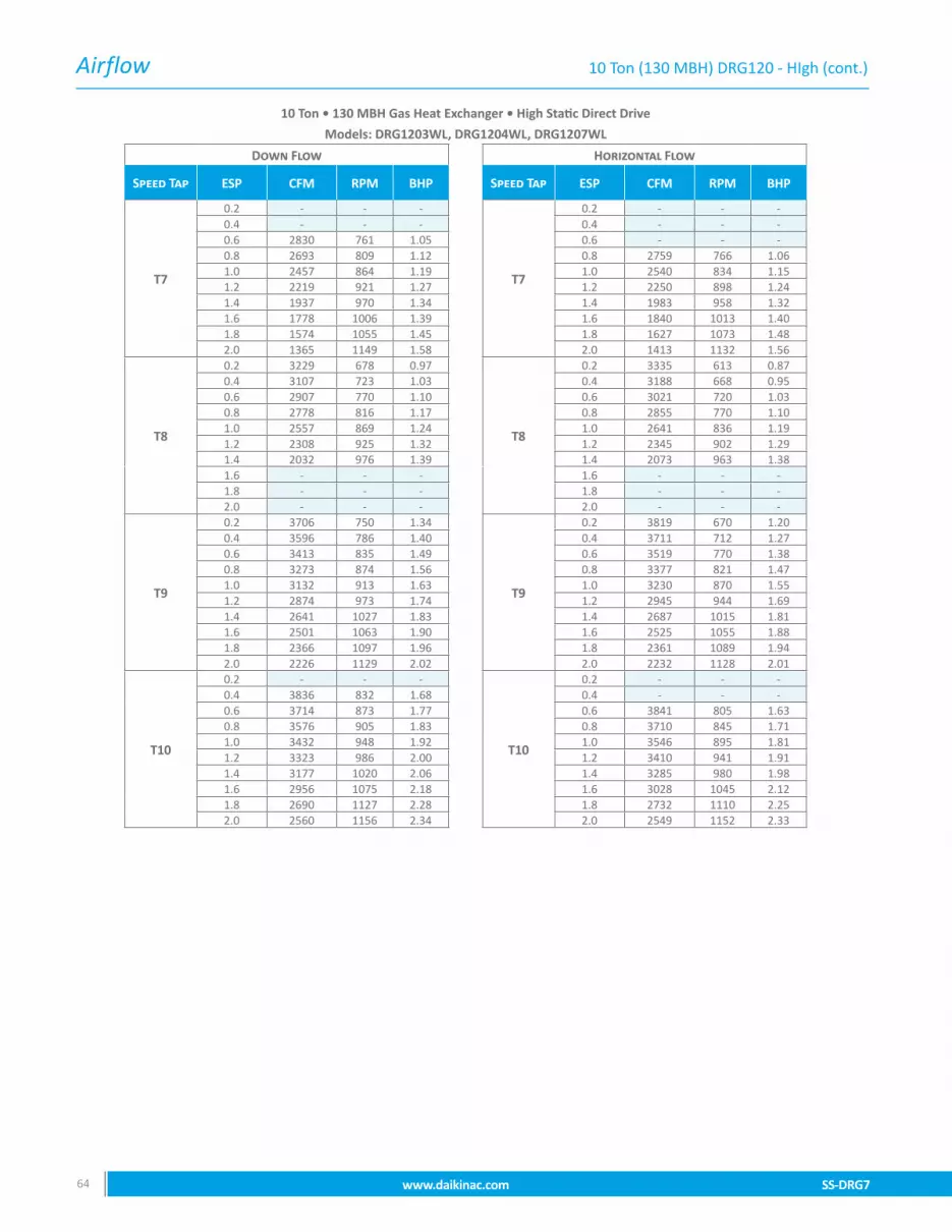
Airflow
SS-DRG7 www.daikinac.com 6564 www.daikinac.com SS-DRG7
10 Ton • 130 MBH Gas Heat Exchanger • High Static Direct Drive
Models: DRG1203WL, DRG1204WL, DRG1207WL
Down Flow Horizontal Flow
Speed Tap ESP CFM RPM BHP Speed Tap ESP CFM RPM BHP
T7
0.2 - - -
T7
0.2 - - -0.4 - - - 0.4 - - -0.6 2830 761 1.05 0.6 - - -0.8 2693 809 1.12 0.8 2759 766 1.061.0 2457 864 1.19 1.0 2540 834 1.151.2 2219 921 1.27 1.2 2250 898 1.241.4 1937 970 1.34 1.4 1983 958 1.321.6 1778 1006 1.39 1.6 1840 1013 1.401.8 1574 1055 1.45 1.8 1627 1073 1.482.0 1365 1149 1.58 2.0 1413 1132 1.56
T8
0.2 3229 678 0.97
T8
0.2 3335 613 0.870.4 3107 723 1.03 0.4 3188 668 0.950.6 2907 770 1.10 0.6 3021 720 1.030.8 2778 816 1.17 0.8 2855 770 1.101.0 2557 869 1.24 1.0 2641 836 1.191.2 2308 925 1.32 1.2 2345 902 1.291.4 2032 976 1.39 1.4 2073 963 1.381.6 - - - 1.6 - - -1.8 - - - 1.8 - - -2.0 - - - 2.0 - - -
T9
0.2 3706 750 1.34
T9
0.2 3819 670 1.200.4 3596 786 1.40 0.4 3711 712 1.270.6 3413 835 1.49 0.6 3519 770 1.380.8 3273 874 1.56 0.8 3377 821 1.471.0 3132 913 1.63 1.0 3230 870 1.551.2 2874 973 1.74 1.2 2945 944 1.691.4 2641 1027 1.83 1.4 2687 1015 1.811.6 2501 1063 1.90 1.6 2525 1055 1.881.8 2366 1097 1.96 1.8 2361 1089 1.942.0 2226 1129 2.02 2.0 2232 1128 2.01
T10
0.2 - - -
T10
0.2 - - -0.4 3836 832 1.68 0.4 - - -0.6 3714 873 1.77 0.6 3841 805 1.630.8 3576 905 1.83 0.8 3710 845 1.711.0 3432 948 1.92 1.0 3546 895 1.811.2 3323 986 2.00 1.2 3410 941 1.911.4 3177 1020 2.06 1.4 3285 980 1.981.6 2956 1075 2.18 1.6 3028 1045 2.121.8 2690 1127 2.28 1.8 2732 1110 2.252.0 2560 1156 2.34 2.0 2549 1152 2.33
10 Ton (130 MBH) DRG120 - HIgh (cont.)

Airflow
SS-DRG7 www.daikinac.com 6564 www.daikinac.com SS-DRG7
10 Ton (180 MBH) DRG120 - Standard
10 Ton • 180 MBH Gas Heat Exchanger • Standard Static Direct Drive
Models: DRG1203DM, DRG1204DM, DRG1207DM
Down Flow Horizontal Flow
Speed Tap ESP CFM RPM BHP Speed Tap ESP CFM RPM BHP
T1
0.2 2184 520 0.43
T1
0.2 2286 486 0.410.4 - - - 0.4 - - -0.6 - - - 0.6 - - -0.8 - - - 0.8 - - -
T2
0.2 2910 654 0.78
T2
0.2 2942 562 0.670.4 2702 687 0.82 0.4 2760 613 0.730.6 2410 753 0.90 0.6 2431 706 0.840.8 2250 792 0.94 0.8 2350 802 0.95
T3
0.2 3669 734 1.36
T3
0.2 3874 673 1.250.4 3556 775 1.44 0.4 3699 713 1.320.6 3428 816 1.52 0.6 3560 769 1.430.8 3274 859 1.60 0.8 3438 820 1.52
T4
0.2 3940 774 1.62
T4
0.2 4159 707 1.480.4 3827 812 1.70 0.4 4062 742 1.560.6 3696 850 1.78 0.6 3880 794 1.660.8 3571 892 1.87 0.8 3722 844 1.77
T5
0.2 4126 802 1.82
T5
0.2 4366 732 1.660.4 4022 838 1.91 0.4 4177 786 1.790.6 3889 877 1.99 0.6 4097 817 1.860.8 3808 908 2.07 0.8 3973 854 1.94
T6
0.2 1938 485 0.31
T6
0.2 2042 451 0.300.4 - - - 0.4 - - -0.6 - - - 0.6 - - -0.8 - - - 0.8 - - -
T7
0.2 2621 582 0.62
T7
0.2 2751 534 0.570.4 2465 637 0.68 0.4 2525 595 0.640.6 2300 690 0.74 0.6 2291 668 0.710.8 2136 745 0.80 0.8 2074 731 0.78
T8
0.2 2731 593 0.67
T8
0.2 2876 543 0.610.4 2564 646 0.73 0.4 2699 602 0.680.6 - - - 0.6 2450 657 0.740.8 - - - 0.8 - - -
T9
0.2 3555 708 1.21
T9
0.2 3765 643 1.100.4 3428 749 1.28 0.4 3610 684 1.170.6 3275 796 1.36 0.6 3402 681 1.160.8 3145 838 1.43 0.8 3195 797 1.36
T10
0.2 4200 800 1.82
T10
0.2 4468 726 1.650.4 4081 842 1.91 0.4 4258 766 1.740.6 3956 882 2.01 0.6 4175 811 1.840.8 3855 919 2.09 0.8 4056 851 1.93

Airflow
SS-DRG7 www.daikinac.com 6766 www.daikinac.com SS-DRG7
10 Ton (180 MBH) DRG120 - Medium
10 Ton • 180 MBH Gas Heat Exchanger • Medium Static Direct Drive
Models: DRG1203LM, DRG1204LM, DRG1207LM
Down Flow Horizontal Flow
Speed Tap ESP CFM RPM BHP Speed Tap ESP CFM RPM BHP
T1
0.2 2184 520 0.43
T1
0.2 2286 486 0.410.4 - - - 0.4 - - -0.6 - - - 0.6 - - -0.8 - - - 0.8 - - -1.0 - - - 1.0 - - -1.2 - - - 1.2 - - -1.4 - - - 1.4 - - -
T2
0.2 3293 675 1.04
T2
0.2 3464 626 0.970.4 3137 725 1.12 0.4 3294 683 1.060.6 3010 766 1.19 0.6 3139 730 1.130.8 2781 825 1.28 0.8 2859 807 1.251.0 2580 876 1.36 1.0 2544 884 1.371.2 2426 913 1.41 1.2 2387 920 1.421.4 2241 954 1.48 1.4 2208 963 1.49
T3
0.2 3669 734 1.36
T3
0.2 3874 673 1.250.4 3556 775 1.44 0.4 3699 713 1.320.6 3428 816 1.52 0.6 3560 769 1.430.8 3274 859 1.60 0.8 3438 820 1.521.0 3171 892 1.66 1.0 3243 870 1.621.2 - - - 1.2 - - -1.4 - - - 1.4 - - -
T4
0.2 4426 847 2.17
T4
0.2 4671 773 1.980.4 4311 880 2.25 0.4 4596 820 2.100.6 4180 916 2.34 0.6 4420 854 2.190.8 4102 944 2.42 0.8 4250 894 2.291.0 3957 982 2.51 1.0 4119 928 2.381.2 3858 1013 2.59 1.2 3987 960 2.461.4 3742 1047 2.68 1.4 3873 1008 2.58
T5
0.2 4628 878 2.45
T5
0.2 4896 802 2.230.4 4516 912 2.54 0.4 4771 839 2.340.6 4402 945 2.63 0.6 4646 878 2.450.8 4295 978 2.72 0.8 4510 915 2.551.0 4186 1011 2.82 1.0 4378 950 2.651.2 4076 1042 2.90 1.2 4242 992 2.761.4 3969 1073 2.99 1.4 4093 1035 2.88
T6
0.2 2516 564 0.56
T6
0.2 2648 517 0.510.4 2340 621 0.62 0.4 2434 583 0.580.6 2188 677 0.67 0.6 2208 647 0.640.8 - - - 0.8 1933 741 0.741.0 - - - 1.0 - - -1.2 - - - 1.2 - - -1.4 - - - 1.4 - - -
T7
0.2 3329 682 1.08
T7
0.2 3582 622 0.980.4 3186 728 1.15 0.4 3436 666 1.050.6 3056 770 1.22 0.6 3206 812 1.280.8 2852 823 1.30 0.8 2978 785 1.241.0 2679 876 1.38 1.0 2769 842 1.331.2 2500 911 1.44 1.2 2454 913 1.441.4 2290 959 1.51 1.4 2144 957 1.51
T8
0.2 4018 786 1.70
T8
0.2 4359 712 1.540.4 3911 823 1.78 0.4 4170 749 1.620.6 3776 862 1.87 0.6 4044 821 1.780.8 3674 899 1.95 0.8 3910 842 1.821.0 3529 973 2.1 1.0 3732 890 1.931.2 3391 975 2.11 1.2 3574 945 2.01.4 3222 1014 2.20 1.4 3379 977 2.1
T9
0.2 4343 835 2.07
T9
0.2 4707 754 1.870.4 4237 869 2.16 0.4 4534 792 1.970.6 4109 905 2.25 0.6 4425 828 2.050.8 4022 938 2.33 0.8 4306 877 2.181.0 3530 973 2.41 1.0 4102 919 2.281.2 3771 1008 2.50 1.2 4026 954 2.371.4 3639 1038 2.57 1.4 3925 995 2.47
T10
0.2 4628 878 2.45
T10
0.2 5018 794 2.210.4 4516 912 2.54 0.4 4884 834 2.320.6 4402 945 2.63 0.6 4750 875 2.440.8 4295 978 2.72 0.8 4613 912 2.541.0 4186 1011 2.82 1.0 4481 950 2.651.2 4076 1042 2.90 1.2 4339 990 2.761.4 3969 1073 2.99 1.4 4187 1030 2.87

Airflow
SS-DRG7 www.daikinac.com 6766 www.daikinac.com SS-DRG7
10 Ton (180 MBH) DRG120 - High
10 Ton • 180 MBH Gas Heat Exchanger • High Static Direct Drive
Models: DRG1203WM, DRG1204WM, DRG1207WM
Down Flow Horizontal Flow
Speed Tap ESP CFM RPM BHP Speed Tap ESP CFM RPM BHP
T1
0.2 2248 535 0.44
T1
0.2 2312 493 0.400.4 - - - 0.4 - - -0.6 - - - 0.6 - - -0.8 - - - 0.8 - - -1.0 - - - 1.0 - - -1.2 - - - 1.2 - - -1.4 - - - 1.4 - - -1.6 - - - 1.6 - - -1.8 - - - 1.8 - - -2.0 - - - 2.0 - - -
T2
0.2 3814 761 1.35
T2
0.2 3815 680 1.210.4 3709 802 1.42 0.4 3705 721 1.280.6 3534 839 1.49 0.6 3514 777 1.380.8 3399 887 1.57 0.8 3367 823 1.461.0 3265 919 1.63 1.0 3222 867 1.541.2 3012 967 1.72 1.2 2937 938 1.661.4 2779 1027 1.82 1.4 2670 1004 1.781.6 2643 1042 1.85 1.6 2522 1040 1.841.8 2509 1060 1.88 1.8 2375 1072 1.902.0 2383 1120 1.99 2.0 2222 1107 1.96
T3
0.2 3814 761 1.35
T3
0.2 3815 680 1.210.4 3709 802 1.42 0.4 3705 721 1.280.6 3534 839 1.49 0.6 3514 777 1.380.8 3399 887 1.57 0.8 3367 823 1.461.0 3265 919 1.63 1.0 3222 867 1.541.2 3012 967 1.72 1.2 - - -1.4 - - - 1.4 - - -1.6 - - - 1.6 - - -1.8 - - - 1.8 - - -2.0 - - - 2.0 - - -
T4
0.2 4790 914 2.55
T4
0.2 4915 830 2.310.4 4674 948 2.64 0.4 4789 872 2.430.6 4565 982 2.74 0.6 4659 905 2.520.8 4440 1013 2.82 0.8 4533 959 2.671.0 4321 1046 2.91 1.0 4420 980 2.731.2 4211 1076 3.00 1.2 4278 1050 2.931.4 4094 1104 3.08 1.4 4139 1055 2.941.6 3988 1135 3.16 1.6 4024 1145 3.191.8 3884 1163 3.24 1.8 3892 1125 3.132.0 3770 1192 3.32 2.0 3778 1150 3.20
T5
0.2 4976 948 2.83
T5
0.2 - - -0.4 4866 979 2.93 0.4 4972 891 2.660.6 4763 1010 3.02 0.6 4843 925 2.760.8 4634 1040 3.11 0.8 4720 964 2.881.0 4520 1071 3.20 1.0 4607 1002 2.991.2 4408 1099 3.28 1.2 4471 1036 3.091.4 4288 1128 3.37 1.4 4338 1070 3.201.6 4187 1157 3.46 1.6 4223 1105 3.301.8 4078 1182 3.53 1.8 4095 1140 3.412.0 3976 1214 3.63 2.0 3983 1170 3.50
T6
0.2 3493 718 1.16
T6
0.2 3603 644 1.040.4 3374 758 1.23 0.4 3478 693 1.120.6 3189 805 1.30 0.6 3301 750 1.210.8 3053 847 1.37 0.8 3171 791 1.281.0 2899 890 1.44 1.0 2993 853 1.381.2 2628 949 1.54 1.2 2691 919 1.491.4 2393 1001 1.62 1.4 2418 988 1.601.6 2242 1050 1.70 1.6 2278 1035 1.681.8 2059 1094 1.77 1.8 2123 1070 1.732.0 1897 1131 1.83 2.0 1933 1128 1.83

Airflow
SS-DRG7 www.daikinac.com 6968 www.daikinac.com SS-DRG7
10 Ton • 180 MBH Gas Heat Exchanger • High Static Direct Drive
Models: DRG1203WM, DRG1204WM, DRG1207WM
Down Flow Horizontal Flow
Speed Tap ESP CFM RPM BHP Speed Tap ESP CFM RPM BHP
T7
0.2 - - -
T7
0.2 - - -0.4 - - - 0.4 - - -0.6 2830 761 1.05 0.6 - - -0.8 2693 809 1.12 0.8 2759 766 1.061.0 2457 864 1.19 1.0 2540 834 1.151.2 2219 921 1.27 1.2 2250 898 1.241.4 1937 970 1.34 1.4 1983 958 1.321.6 1778 1006 1.39 1.6 1840 1013 1.401.8 1574 1055 1.45 1.8 1627 1073 1.482.0 1365 1149 1.58 2.0 1413 1132 1.56
T8
0.2 3229 678 0.97
T8
0.2 3335 613 0.870.4 3107 723 1.03 0.4 3188 668 0.950.6 2907 770 1.10 0.6 3021 720 1.030.8 2778 816 1.17 0.8 2855 770 1.101.0 2557 869 1.24 1.0 2641 836 1.191.2 2308 925 1.32 1.2 2345 902 1.291.4 2032 976 1.39 1.4 2073 963 1.381.6 - - - 1.6 - - -1.8 - - - 1.8 - - -2.0 - - - 2.0 - - -
T9
0.2 3706 750 1.34
T9
0.2 3819 670 1.200.4 3596 786 1.40 0.4 3711 712 1.270.6 3413 835 1.49 0.6 3519 770 1.380.8 3273 874 1.56 0.8 3377 821 1.471.0 3132 913 1.63 1.0 3230 870 1.551.2 2874 973 1.74 1.2 2945 944 1.691.4 2641 1027 1.83 1.4 2687 1015 1.811.6 2501 1063 1.90 1.6 2525 1055 1.881.8 2366 1097 1.96 1.8 2361 1089 1.942.0 2226 1129 2.02 2.0 2232 1128 2.01
T10
0.2 - - -
T10
0.2 - - -0.4 3836 832 1.68 0.4 - - -0.6 3714 873 1.77 0.6 3841 805 1.630.8 3576 905 1.83 0.8 3710 845 1.711.0 3432 948 1.92 1.0 3546 895 1.811.2 3323 986 2.00 1.2 3410 941 1.911.4 3177 1020 2.06 1.4 3285 980 1.981.6 2956 1075 2.18 1.6 3028 1045 2.121.8 2690 1127 2.28 1.8 2732 1110 2.252.0 2560 1156 2.34 2.0 2549 1152 2.33
10 Ton (180 MBH) DRG120 - HIgh (cont.)

Airflow
SS-DRG7 www.daikinac.com 6968 www.daikinac.com SS-DRG7
10 Ton (240 MBH) DRG120 - Standard
10 Ton • 240 MBH Gas Heat Exchanger • Standard Static Direct Drive
Models: DRG1203DH, DRG1204DH, DRG1207DH
Down Flow Horizontal Flow
Speed Tap ESP CFM RPM BHP Speed Tap ESP CFM RPM BHP
T1
0.2 2184 520 0.43
T1
0.2 2286 486 0.410.4 - - - 0.4 - - -0.6 - - - 0.6 - - -0.8 - - - 0.8 - - -
T2
0.2 2910 654 0.78
T2
0.2 2942 562 0.670.4 2702 687 0.82 0.4 2760 613 0.730.6 2410 753 0.90 0.6 2431 706 0.840.8 2250 792 0.94 0.8 2317 733 0.87
T3
0.2 3669 734 1.36
T3
0.2 3874 673 1.250.4 3556 775 1.44 0.4 3699 713 1.320.6 3428 816 1.52 0.6 3560 769 1.430.8 3274 859 1.60 0.8 3438 820 1.52
T4
0.2 3940 774 1.62
T4
0.2 4159 707 1.480.4 3827 812 1.70 0.4 4062 742 1.560.6 3696 850 1.78 0.6 3880 794 1.660.8 3571 892 1.87 0.8 3722 844 1.77
T5
0.2 4126 802 1.82
T5
0.2 4366 732 1.660.4 4022 838 1.91 0.4 4177 786 1.790.6 3889 877 1.99 0.6 4097 817 1.860.8 3808 908 2.07 0.8 3973 854 1.94
T6
0.2 2223 524 0.43
T6
0.2 2340 483 0.400.4 - - - 0.4 - - -0.6 - - - 0.6 - - -0.8 - - - 0.8 - - -
T7
0.2 3023 634 0.84
T7
0.2 3187 577 0.760.4 2870 681 0.90 0.4 3038 629 0.830.6 2725 733 0.97 0.6 2783 664 0.880.8 2486 795 1.05 0.8 2519 764 1.01
T8
0.2 3720 732 1.35
T8
0.2 3947 664 1.220.4 3602 772 1.42 0.4 3781 703 1.290.6 3446 817 1.50 0.6 3599 816 1.500.8 3331 857 1.58 0.8 3416 1002 1.84
T9
0.2 3979 769 1.59
T9
0.2 4237 698 1.440.4 3875 809 1.67 0.4 4053 734 1.520.6 3717 850 1.76 0.6 3912 819 1.690.8 3611 890 1.84 0.8 3765 831 1.72
T10
0.2 4200 800 1.82
T10
0.2 4468 726 1.650.4 4081 842 1.91 0.4 4258 766 1.740.6 3956 882 2.01 0.6 4175 811 1.840.8 3855 919 2.09 0.8 4056 851 1.93

Airflow
SS-DRG7 www.daikinac.com 7170 www.daikinac.com SS-DRG7
10 Ton • 240 MBH Gas Heat Exchanger • Medium Static Direct Drive
Models: DRG1203LH, DRG1204LH, DRG1207LH
Down Flow Horizontal Flow
Speed Tap ESP CFM RPM BHP Speed Tap ESP CFM RPM BHP
T1
0.2 2184 520 0.43
T1
0.2 2286 486 0.410.4 - - - 0.4 - - -0.6 - - - 0.6 - - -0.8 - - - 0.8 - - -1.0 - - - 1.0 - - -1.2 - - - 1.2 - - -1.4 - - - 1.4 - - -
T2
0.2 3293 675 1.04
T2
0.2 3464 626 0.970.4 3137 725 1.12 0.4 3294 683 1.060.6 3010 766 1.19 0.6 3139 730 1.130.8 2781 825 1.28 0.8 2859 807 1.251.0 2580 876 1.36 1.0 2544 884 1.371.2 2426 913 1.41 1.2 2387 920 1.421.4 2241 954 1.48 1.4 2208 963 1.49
T3
0.2 3669 734 1.36
T3
0.2 3874 673 1.250.4 3556 775 1.44 0.4 3699 713 1.320.6 3428 816 1.52 0.6 3560 769 1.430.8 3274 859 1.60 0.8 3438 820 1.521.0 3171 892 1.66 1.0 3243 870 1.621.2 - - - 1.2 - - -1.4 - - - 1.4 - - -
T4
0.2 4426 847 2.17
T4
0.2 4671 773 1.980.4 4311 880 2.25 0.4 4596 820 2.100.6 4180 916 2.34 0.6 4420 854 2.190.8 4102 944 2.42 0.8 4250 894 2.291.0 3957 982 2.51 1.0 4119 928 2.381.2 3858 1013 2.59 1.2 3987 960 2.461.4 3742 1047 2.68 1.4 3873 1008 2.58
T5
0.2 4628 878 2.45
T5
0.2 4896 802 2.230.4 4516 912 2.54 0.4 4771 839 2.340.6 4402 945 2.63 0.6 4646 878 2.450.8 4295 978 2.72 0.8 4510 915 2.551.0 4186 1011 2.82 1.0 4378 950 2.651.2 4076 1042 2.90 1.2 4242 992 2.761.4 3969 1073 2.99 1.4 4093 1035 2.88
T6
0.2 2516 564 0.56
T6
0.2 2648 517 0.510.4 2340 621 0.62 0.4 2434 583 0.580.6 2188 677 0.67 0.6 2208 647 0.640.8 - - - 0.8 1933 741 0.741.0 - - - 1.0 - - -1.2 - - - 1.2 - - -1.4 - - - 1.4 - - -
T7
0.2 3329 682 1.08
T7
0.2 3582 622 0.980.4 3186 728 1.15 0.4 3436 666 1.050.6 3056 770 1.22 0.6 3206 812 1.280.8 2852 823 1.30 0.8 2978 785 1.241.0 2679 876 1.38 1.0 2769 842 1.331.2 2500 911 1.44 1.2 2454 913 1.441.4 2290 959 1.51 1.4 2144 957 1.51
T8
0.2 4018 786 1.70
T8
0.2 4359 712 1.540.4 3911 823 1.78 0.4 4170 749 1.620.6 3776 862 1.87 0.6 4044 821 1.780.8 3674 899 1.95 0.8 3910 842 1.821.0 3529 973 2.1 1.0 3732 890 1.931.2 3391 975 2.11 1.2 3574 945 2.01.4 3222 1014 2.20 1.4 3379 977 2.1
T9
0.2 4343 835 2.07
T9
0.2 4707 754 1.870.4 4237 869 2.16 0.4 4534 792 1.970.6 4109 905 2.25 0.6 4425 828 2.050.8 4022 938 2.33 0.8 4306 877 2.181.0 3530 973 2.41 1.0 4102 919 2.281.2 3771 1008 2.50 1.2 4026 954 2.371.4 3639 1038 2.57 1.4 3925 995 2.47
T10
0.2 4628 878 2.45
T10
0.2 5018 794 2.210.4 4516 912 2.54 0.4 4884 834 2.320.6 4402 945 2.63 0.6 4750 875 2.440.8 4295 978 2.72 0.8 4613 912 2.541.0 4186 1011 2.82 1.0 4481 950 2.651.2 4076 1042 2.90 1.2 4339 990 2.761.4 3969 1073 2.99 1.4 4187 1030 2.87
10 Ton (240 MBH) DRG120 - Medium
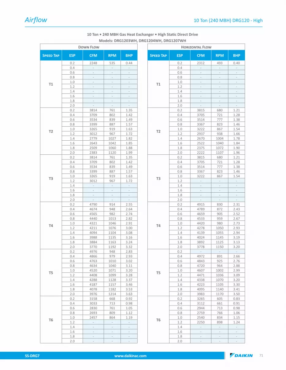
Airflow
SS-DRG7 www.daikinac.com 7170 www.daikinac.com SS-DRG7
10 Ton (240 MBH) DRG120 - High
10 Ton • 240 MBH Gas Heat Exchanger • High Static Direct Drive
Models: DRG1203WH, DRG1204WH, DRG1207WH
Down Flow Horizontal Flow
Speed Tap ESP CFM RPM BHP Speed Tap ESP CFM RPM BHP
T1
0.2 2248 535 0.44
T1
0.2 2312 493 0.400.4 - - - 0.4 - - -0.6 - - - 0.6 - - -0.8 - - - 0.8 - - -1.0 - - - 1.0 - - -1.2 - - - 1.2 - - -1.4 - - - 1.4 - - -1.6 - - - 1.6 - - -1.8 - - - 1.8 - - -2.0 - - - 2.0 - - -
T2
0.2 3814 761 1.35
T2
0.2 3815 680 1.210.4 3709 802 1.42 0.4 3705 721 1.280.6 3534 839 1.49 0.6 3514 777 1.380.8 3399 887 1.57 0.8 3367 823 1.461.0 3265 919 1.63 1.0 3222 867 1.541.2 3012 967 1.72 1.2 2937 938 1.661.4 2779 1027 1.82 1.4 2670 1004 1.781.6 2643 1042 1.85 1.6 2522 1040 1.841.8 2509 1060 1.88 1.8 2375 1072 1.902.0 2383 1120 1.99 2.0 2222 1107 1.96
T3
0.2 3814 761 1.35
T3
0.2 3815 680 1.210.4 3709 802 1.42 0.4 3705 721 1.280.6 3534 839 1.49 0.6 3514 777 1.380.8 3399 887 1.57 0.8 3367 823 1.461.0 3265 919 1.63 1.0 3222 867 1.541.2 3012 967 1.72 1.2 - - -1.4 - - - 1.4 - - -1.6 - - - 1.6 - - -1.8 - - - 1.8 - - -2.0 - - - 2.0 - - -
T4
0.2 4790 914 2.55
T4
0.2 4915 830 2.310.4 4674 948 2.64 0.4 4789 872 2.430.6 4565 982 2.74 0.6 4659 905 2.520.8 4440 1013 2.82 0.8 4533 959 2.671.0 4321 1046 2.91 1.0 4420 980 2.731.2 4211 1076 3.00 1.2 4278 1050 2.931.4 4094 1104 3.08 1.4 4139 1055 2.941.6 3988 1135 3.16 1.6 4024 1145 3.191.8 3884 1163 3.24 1.8 3892 1125 3.132.0 3770 1192 3.32 2.0 3778 1150 3.20
T5
0.2 4976 948 2.83
T5
0.2 - - -0.4 4866 979 2.93 0.4 4972 891 2.660.6 4763 1010 3.02 0.6 4843 925 2.760.8 4634 1040 3.11 0.8 4720 964 2.881.0 4520 1071 3.20 1.0 4607 1002 2.991.2 4408 1099 3.28 1.2 4471 1036 3.091.4 4288 1128 3.37 1.4 4338 1070 3.201.6 4187 1157 3.46 1.6 4223 1105 3.301.8 4078 1182 3.53 1.8 4095 1140 3.412.0 3976 1214 3.63 2.0 3983 1170 3.50
T6
0.2 3158 668 0.92
T6
0.2 3265 605 0.830.4 3033 713 0.98 0.4 3112 661 0.910.6 2830 761 1.05 0.6 2944 713 0.980.8 2693 809 1.12 0.8 2759 766 1.061.0 2457 864 1.19 1.0 2540 834 1.151.2 - - - 1.2 2250 898 1.241.4 - - - 1.4 - - -1.6 - - - 1.6 - - -1.8 - - - 1.8 - - -2.0 - - - 2.0 - - -

Airflow
SS-DRG7 www.daikinac.com 7372 www.daikinac.com SS-DRG7
10 Ton • 240 MBH Gas Heat Exchanger • High Static Direct Drive
Models: DRG1203WH, DRG1204WH, DRG1207WH
Down Flow Horizontal Flow
Speed Tap ESP CFM RPM BHP Speed Tap ESP CFM RPM BHP
T7
0.2 3926 777 1.46
T7
0.2 3932 685 1.290.4 3816 817 1.54 0.4 3813 730 1.380.6 3651 855 1.61 0.6 3645 782 1.470.8 3520 900 1.70 0.8 3511 829 1.561.0 3387 933 1.76 1.0 3357 879 1.661.2 3162 978 1.84 1.2 3137 941 1.771.4 2953 1032 1.95 1.4 2982 998 1.881.6 2820 1051 1.98 1.6 2729 1048 1.981.8 2694 1072 2.02 1.8 2521 1095 2.072.0 2566 1125 2.12 2.0 2372 1127 2.13
T8
0.2 4420 851 2.04
T8
0.2 4542 765 1.830.4 4301 890 2.13 0.4 4402 809 1.940.6 4173 927 2.22 0.6 4283 851 2.040.8 4049 963 2.30 0.8 4162 893 2.141.0 3923 997 2.39 1.0 4027 934 2.241.2 3788 1032 2.47 1.2 3927 977 2.341.4 3652 1066 2.55 1.4 3761 1017 2.431.6 3535 1096 2.62 1.6 3596 1073 2.571.8 3430 1125 2.69 1.8 3376 1110 2.662.0 3302 1157 2.77 2.0 3089 1165 2.79
T9
0.2 4973 947 3.02
T9
0.2 5135 840 2.620.4 4862 978 3.12 0.4 5018 884 2.760.6 4760 1010 3.22 0.6 4882 916 2.860.8 4629 1039 3.31 0.8 4780 957 2.991.0 4509 1067 3.40 1.0 4670 992 3.091.2 4402 1098 3.50 1.2 4535 1031 3.221.4 4287 1128 3.60 1.4 4464 1075 3.351.6 4181 1156 3.69 1.6 4305 1109 3.461.8 4069 1184 3.78 1.8 4188 1154 3.602.0 3972 1214 3.87 2.0 4102 1128 3.52
T10
0.2 5486 1024 3.94
T10
0.2 5656 926 3.560.4 5379 1069 4.11 0.4 5524 956 3.670.6 5276 1093 4.20 0.6 5386 985 3.780.8 5157 1107 4.26 0.8 5281 1019 3.921.0 5049 1140 4.38 1.0 5155 1049 4.031.2 4938 1164 4.47 1.2 5040 1083 4.161.4 4824 1190 4.57 1.4 4940 1117 4.291.6 4720 1219 4.68 1.6 4800 1148 4.411.8 4609 1246 4.79 1.8 4678 1188 4.572.0 4509 1273 4.89 2.0 4557 1209 4.65
10 Ton (240 MBH) DRG120 - HIgh (cont.)

Airflow
SS-DRG7 www.daikinac.com 7372 www.daikinac.com SS-DRG7
12.5 Ton (130 MBH) DRG150 - Standard
12.5 Ton • 130 MBH Gas Heat Exchanger • Standard Static Direct Drive
Models: DRG1503DL, DRG1504DL, DRG1507DL
Down Flow Horizontal Flow
Speed Tap ESP CFM RPM BHP Speed Tap ESP CFM RPM BHP
T1
0.2 2377 559 0.52
T1
0.2 2478 525 0.490.4 - - - 0.4 - - -0.6 - - - 0.6 - - -0.8 - - - 0.8 - - -
T2
0.2 3178 662 0.93
T2
0.2 3261 616 0.870.4 3007 705 0.99 0.4 3134 667 0.940.6 2856 751 1.05 0.6 3011 717 1.010.8 2533 822 1.16 0.8 2786 779 1.09
T3
0.2 3944 784 1.59
T3
0.2 4019 720 1.460.4 3783 823 1.67 0.4 3926 756 1.530.6 - - - 0.6 3807 805 1.630.8 - - - 0.8 - - -
T4
0.2 4435 842 2.08
T4
0.2 4484 786 1.950.4 4287 886 2.19 0.4 4364 830 2.050.6 4153 922 2.28 0.6 4287 863 2.140.8 4025 952 2.36 0.8 4194 899 2.23
T5
0.2 4719 897 2.50
T5
0.2 4777 830 2.310.4 4587 929 2.59 0.4 4680 865 2.410.6 4458 962 2.68 0.6 4581 901 2.510.8 4329 993 2.77 0.8 4485 934 2.60
T6
0.2 1828 480 0.30
T6
0.2 1946 462 0.290.4 1418 565 0.35 0.4 1869 607 0.380.6 - - - 0.6 - - -0.8 - - - 0.8 - - -
T7
0.2 2150 527 0.42
T7
0.2 2256 499 0.400.4 1867 601 0.48 0.4 1980 532 0.430.6 1628 666 0.53 0.6 1756 654 0.520.8 1400 724 0.58 0.8 1432 725 0.58
T8
0.2 2454 570 0.56
T8
0.2 2552 534 0.520.4 2253 635 0.62 0.4 2287 549 0.540.6 2022 698 0.68 0.6 2199 672 0.650.8 - - - 0.8 1853 746 0.73
T9
0.2 2634 596 0.64
T9
0.2 2728 556 0.600.4 2464 655 0.71 0.4 2519 587 0.630.6 2245 716 0.77 0.6 2428 683 0.740.8 1963 785 0.85 0.8 2154 755 0.82
T10
0.2 2801 625 0.74
T10
0.2 2900 577 0.690.4 2646 676 0.81 0.4 2744 638 0.760.6 2488 730 0.87 0.6 2586 702 0.840.8 2145 805 0.96 0.8 2435 756 0.90

Airflow
SS-DRG7 www.daikinac.com 7574 www.daikinac.com SS-DRG7
12.5 Ton • 130 MBH Gas Heat Exchanger • Medium Static Direct Drive
Models: DRG1503LL, DRG1504LL, DRG1507LL
Down Flow Horizontal Flow
Speed Tap ESP CFM RPM BHP Speed Tap ESP CFM RPM BHP
T1
0.2 2377 559 0.52
T1
0.2 2478 525 0.490.4 - - - 0.4 - - -0.6 - - - 0.6 - - -0.8 - - - 0.8 - - -1.0 - - - 1.0 - - -1.2 - - - 1.2 - - -1.4 - - - 1.4 - - -
T2
0.2 3655 740 1.32
T2
0.2 3743 682 1.220.4 3495 782 1.40 0.4 3661 715 1.280.6 3361 820 1.46 0.6 3519 772 1.380.8 3231 857 1.53 0.8 3457 814 1.451.0 2967 915 1.63 1.0 3294 858 1.531.2 2685 969 1.73 1.2 3051 924 1.651.4 2550 1001 1.79 1.4 2667 995 1.78
T3
0.2 3944 784 1.59
T3
0.2 4019 720 1.460.4 3783 823 1.67 0.4 3926 756 1.530.6 - - - 0.6 3807 805 1.630.8 - - - 0.8 - - -1.0 - - - 1.0 - - -1.2 - - - 1.2 - - -1.4 - - - 1.4 - - -
T4
0.2 4536 878 2.30
T4
0.2 4609 807 2.110.4 4407 910 2.38 0.4 4517 843 2.210.6 4304 939 2.46 0.6 4424 882 2.310.8 4176 974 2.55 0.8 4323 915 2.401.0 4066 1004 2.63 1.0 4216 951 2.491.2 3946 1036 2.71 1.2 4115 989 2.591.4 3826 1067 2.79 1.4 4010 1025 2.68
T5
0.2 4719 897 2.50
T5
0.2 4777 830 2.310.4 4587 929 2.59 0.4 4680 865 2.410.6 4458 962 2.68 0.6 4581 901 2.510.8 4329 993 2.77 0.8 4485 934 2.601.0 4211 1025 2.86 1.0 4387 970 2.701.2 4087 1057 2.94 1.2 4285 1005 2.801.4 3975 1087 3.03 1.4 4184 1039 2.89
T6
0.2 2072 515 0.39
T6
0.2 2181 490 0.370.4 1763 592 0.45 0.4 1930 540 0.410.6 1524 658 0.50 0.6 1632 649 0.490.8 - - - 0.8 1355 719 0.541.0 - - - 1.0 - - -1.2 - - - 1.2 - - -1.4 - - - 1.4 - - -
T7
0.2 2712 607 0.69
T7
0.2 2806 565 0.640.4 2553 665 0.75 0.4 2623 608 0.690.6 2339 724 0.82 0.6 2520 688 0.780.8 2056 793 0.90 0.8 2285 758 0.861.0 1860 839 0.95 1.0 2051 818 0.931.2 1712 895 1.01 1.2 1803 886 1.001.4 1479 904 1.02 1.4 1651 957 1.08
T8
0.2 2940 640 0.82
T8
0.2 3033 593 0.760.4 2797 691 0.88 0.4 2898 651 0.830.6 2603 746 0.95 0.6 2749 702 0.900.8 2325 813 1.04 0.8 2619 766 0.981.0 2109 864 1.1 1.0 2313 815 1.041.2 1975 914 1.17 1.2 2042 873 1.11.4 1797 944 1.21 1.4 1798 909 1.2
T9
0.2 3281 688 1.04
T9
0.2 3379 636 0.960.4 3136 733 1.11 0.4 3177 687 1.040.6 2976 779 1.18 0.6 3045 725 1.100.8 2731 838 1.27 0.8 2914 782 1.191.0 2505 892 1.35 1.0 2687 819 1.241.2 2356 933 1.41 1.2 2461 867 1.311.4 2107 944 1.43 1.4 2235 933 1.41
T10
0.2 3586 732 1.28
T10
0.2 3697 677 1.190.4 3419 772 1.35 0.4 3487 722 1.270.6 3288 811 1.42 0.6 3346 758 1.330.8 3089 858 1.50 0.8 3228 812 1.421.0 2878 909 1.59 1.0 3136 862 1.511.2 2754 948 1.66 1.2 2969 911 1.601.4 2404 1009 1.77 1.4 2739 979 1.72
12.5 Ton (130 MBH) DRG150 - Medium

Airflow
SS-DRG7 www.daikinac.com 7574 www.daikinac.com SS-DRG7
12.5 Ton (130 MBH) DRG150 - High
12.5 Ton • 130 MBH Gas Heat Exchanger • High Static Direct Drive
Models: DRG1503WL, DRG1504WL, DRG1507WL
Down Flow Horizontal Flow
Speed Tap ESP CFM RPM BHP Speed Tap ESP CFM RPM BHP
T1
0.2 2511 639 0.63
T1
0.2 2735 543 0.540.4 - - - 0.4 2600 606 0.600.6 - - - 0.6 - - -0.8 - - - 0.8 - - -1.0 - - - 1.0 - - -1.2 - - - 1.2 - - -1.4 - - - 1.4 - - -1.6 - - - 1.6 - - -1.8 - - - 1.8 - - -2.0 - - - 2.0 - - -
T2
0.2 3737 894 1.97
T2
0.2 4297 761 1.680.4 3699 919 2.03 0.4 4168 801 1.760.6 3604 952 2.10 0.6 4081 844 1.860.8 3476 990 2.18 0.8 4030 856 1.891.0 3276 1035 2.28 1.0 3939 926 2.041.2 3052 1082 2.38 1.2 3789 966 2.131.4 2890 1120 2.47 1.4 3553 1033 2.271.6 2738 1154 2.54 1.6 3290 1090 2.401.8 2584 1186 2.61 1.8 3097 1158 2.552.0 2499 1207 2.66 2.0 2906 1192 2.63
T3
0.2 3953 863 1.80
T3
0.2 4165 735 1.530.4 3837 903 1.88 0.4 4089 772 1.610.6 - - - 0.6 3985 824 1.720.8 - - - 0.8 - - -1.0 - - - 1.0 - - -1.2 - - - 1.2 - - -1.4 - - - 1.4 - - -1.6 - - - 1.6 - - -1.8 - - - 1.8 - - -2.0 - - - 2.0 - - -
T4
0.2 4964 1024 3.47
T4
0.2 5300 888 3.010.4 4909 1046 3.55 0.4 5215 918 3.120.6 4808 1079 3.66 0.6 5121 951 3.230.8 4764 1096 3.72 0.8 5044 979 3.321.0 4626 1123 3.81 1.0 4957 1015 3.441.2 4507 1167 3.96 1.2 4861 1040 3.531.4 4409 1207 4.10 1.4 4769 1082 3.671.6 4137 1257 4.26 1.6 4665 1099 3.731.8 3878 1311 4.45 1.8 4563 1150 3.902.0 3835 1332 4.52 2.0 4455 1181 4.01
T5
0.2 5128 1078 3.88
T5
0.2 5478 900 3.050.4 5061 1102 3.96 0.4 5390 936 3.170.6 4965 1131 4.07 0.6 5309 971 3.290.8 4899 1154 4.15 0.8 5216 1003 3.401.0 4779 1182 4.25 1.0 5127 1036 3.521.2 4668 1214 4.37 1.2 5046 1067 3.621.4 4583 1242 4.47 1.4 4954 1096 3.721.6 4367 1283 4.61 1.6 4872 1128 3.831.8 4137 1330 4.78 1.8 4794 1156 3.922.0 4015 1356 4.88 2.0 4681 1188 4.03
T6
0.2 2308 613 0.61
T6
0.2 2644 545 0.540.4 2028 682 0.68 0.4 2483 620 0.610.6 1744 739 0.73 0.6 2299 683 0.680.8 1619 784 0.78 0.8 1979 773 0.771.0 - - - 1.0 1758 817 0.811.2 - - - 1.2 1558 877 0.871.4 - - - 1.4 1448 920 0.911.6 - - - 1.6 - - -1.8 - - - 1.8 - - -2.0 - - - 2.0 - - -

Airflow
SS-DRG7 www.daikinac.com 7776 www.daikinac.com SS-DRG7
12.5 Ton • 130 MBH Gas Heat Exchanger • High Static Direct Drive
Models: DRG1503WL, DRG1504WL, DRG1507WL
Down Flow Horizontal Flow
Speed Tap ESP CFM RPM BHP Speed Tap ESP CFM RPM BHP
T7
0.2 - - -
T7
0.2 - - -0.4 2903 798 1.24 0.4 - - -0.6 2673 845 1.31 0.6 - - -0.8 2525 888 1.37 0.8 - - -1.0 2282 933 1.44 1.0 - - -1.2 1982 972 1.50 1.2 2716 928 1.441.4 1803 1007 1.56 1.4 2495 989 1.531.6 1671 1031 1.60 1.6 2298 1033 1.601.8 1475 1065 1.65 1.8 2137 1076 1.662.0 1335 1097 1.70 2.0 2078 1101 1.70
T8
0.2 3136 755 1.22
T8
0.2 3602 665 1.080.4 3006 812 1.32 0.4 3491 707 1.150.6 2794 858 1.39 0.6 3379 759 1.230.8 2632 901 1.46 0.8 3205 818 1.331.0 2409 945 1.53 1.0 3052 874 1.421.2 2114 984 1.59 1.2 2852 932 1.511.4 1963 1025 1.66 1.4 2617 995 1.611.6 1854 1046 1.70 1.6 2401 1045 1.691.8 - - - 1.8 2234 1092 1.772.0 - - - 2.0 2196 1112 1.80
T9
0.2 3308 785 1.39
T9
0.2 3793 691 1.220.4 3202 839 1.48 0.4 3667 731 1.290.6 3028 883 1.56 0.6 3566 780 1.380.8 2838 925 1.63 0.8 3441 827 1.461.0 2655 967 1.71 1.0 3306 887 1.571.2 2380 1007 1.78 1.2 3114 939 1.661.4 2257 1056 1.86 1.4 2858 1006 1.781.6 2164 1076 1.90 1.6 2608 1066 1.881.8 1994 1113 1.97 1.8 2426 1123 1.982.0 1914 1139 2.01 2.0 2404 1132 2.00
T10
0.2 3472 814 1.56
T10
0.2 - - -0.4 3384 865 1.65 0.4 3835 756 1.440.6 3244 907 1.73 0.6 3741 801 1.530.8 3032 948 1.81 0.8 3656 835 1.601.0 2886 989 1.89 1.0 3536 900 1.721.2 2639 1029 1.97 1.2 3355 947 1.811.4 2515 1083 2.07 1.4 3092 1015 1.941.6 2411 1105 2.11 1.6 2821 1080 2.061.8 2255 1141 2.18 1.8 2627 1152 2.202.0 2192 1165 2.22 2.0 2584 1152 2.20
12.5 Ton (130 MBH) DRG150 - HIgh (cont.)

Airflow
SS-DRG7 www.daikinac.com 7776 www.daikinac.com SS-DRG7
12.5 Ton (180 MBH) DRG150 - Standard
12.5 Ton • 180 MBH Gas Heat Exchanger • Standard Static Direct Drive
Models: DRG1503DM, DRG1504DM, DRG1507DM
Down Flow Horizontal Flow
Speed Tap ESP CFM RPM BHP Speed Tap ESP CFM RPM BHP
T1
0.2 2377 559 0.52
T1
0.2 2478 525 0.490.4 - - - 0.4 - - -0.6 - - - 0.6 - - -0.8 - - - 0.8 - - -
T2
0.2 3178 662 0.93
T2
0.2 3261 616 0.870.4 3007 705 0.99 0.4 3134 667 0.940.6 2856 751 1.05 0.6 3011 717 1.010.8 2533 822 1.16 0.8 2786 779 1.09
T3
0.2 3944 784 1.59
T3
0.2 4019 720 1.460.4 3783 823 1.67 0.4 3926 756 1.530.6 - - - 0.6 3807 805 1.630.8 - - - 0.8 - - -
T4
0.2 4435 842 2.08
T4
0.2 4484 786 1.950.4 4287 886 2.19 0.4 4364 830 2.050.6 4153 922 2.28 0.6 4287 863 2.140.8 4025 952 2.36 0.8 4194 899 2.23
T5
0.2 4719 897 2.50
T5
0.2 4777 830 2.310.4 4587 929 2.59 0.4 4680 865 2.410.6 4458 962 2.68 0.6 4581 901 2.510.8 4329 993 2.77 0.8 4485 934 2.60
T6
0.2 2072 515 0.39
T6
0.2 2181 490 0.370.4 - - - 0.4 1930 540 0.410.6 - - - 0.6 - - -0.8 - - - 0.8 - - -
T7
0.2 2634 596 0.64
T7
0.2 2728 556 0.600.4 2464 655 0.71 0.4 2519 587 0.630.6 2245 716 0.77 0.6 2428 683 0.740.8 1963 785 0.85 0.8 2154 755 0.82
T8
0.2 3004 649 0.86
T8
0.2 3097 601 0.790.4 2863 699 0.92 0.4 2961 712 0.940.6 2675 752 0.99 0.6 2776 707 0.930.8 - - - 0.8 2632 763 1.01
T9
0.2 3250 684 1.02
T9
0.2 3347 632 0.940.4 3106 729 1.09 0.4 3147 684 1.020.6 2943 776 1.16 0.6 3015 723 1.080.8 2694 836 1.25 0.8 2882 780 1.16
T10
0.2 3474 714 1.19
T10
0.2 3605 663 1.100.4 3314 759 1.27 0.4 3377 708 1.180.6 3178 799 1.33 0.6 3240 746 1.240.8 3035 841 1.40 0.8 3121 801 1.34

Airflow
SS-DRG7 www.daikinac.com 7978 www.daikinac.com SS-DRG7
12.5 Ton • 180 MBH Gas Heat Exchanger • Medium Static Direct Drive
Models: DRG1503LM, DRG1504LM, DRG1507LM
Down Flow Horizontal Flow
Speed Tap ESP CFM RPM BHP Speed Tap ESP CFM RPM BHP
T1
0.2 2377 559 0.52
T1
0.2 2478 525 0.490.4 - - - 0.4 - - -0.6 - - - 0.6 - - -0.8 - - - 0.8 - - -1.0 - - - 1.0 - - -1.2 - - - 1.2 - - -1.4 - - - 1.4 - - -
T2
0.2 3655 740 1.32
T2
0.2 3743 682 1.220.4 3495 782 1.40 0.4 3661 715 1.280.6 3361 820 1.46 0.6 3519 772 1.380.8 3231 857 1.53 0.8 3457 814 1.451.0 2967 915 1.63 1.0 3294 858 1.531.2 2685 969 1.73 1.2 3051 924 1.651.4 2550 1001 1.79 1.4 2667 995 1.78
T3
0.2 3944 784 1.59
T3
0.2 4019 720 1.460.4 3783 823 1.67 0.4 3926 756 1.530.6 - - - 0.6 3807 805 1.630.8 - - - 0.8 - - -1.0 - - - 1.0 - - -1.2 - - - 1.2 - - -1.4 - - - 1.4 - - -
T4
0.2 4536 878 2.30
T4
0.2 4609 807 2.110.4 4407 910 2.38 0.4 4517 843 2.210.6 4304 939 2.46 0.6 4424 882 2.310.8 4176 974 2.55 0.8 4323 915 2.401.0 4066 1004 2.63 1.0 4216 951 2.491.2 3946 1036 2.71 1.2 4115 989 2.591.4 3826 1067 2.79 1.4 4010 1025 2.68
T5
0.2 4719 897 2.50
T5
0.2 4777 830 2.310.4 4587 929 2.59 0.4 4680 865 2.410.6 4458 962 2.68 0.6 4581 901 2.510.8 4329 993 2.77 0.8 4485 934 2.601.0 4211 1025 2.86 1.0 4387 970 2.701.2 4087 1057 2.94 1.2 4285 1005 2.801.4 3975 1087 3.03 1.4 4184 1039 2.89
T6
0.2 2379 559 0.52
T6
0.2 2478 525 0.490.4 2161 626 0.58 0.4 2198 539 0.500.6 1927 690 0.64 0.6 2096 668 0.620.8 - - - 0.8 - - -1.0 - - - 1.0 - - -1.2 - - - 1.2 - - -1.4 - - - 1.4 - - -
T7
0.2 3161 672 0.96
T7
0.2 3256 621 0.890.4 2995 722 1.03 0.4 3060 673 0.960.6 2866 762 1.09 0.6 2927 713 1.020.8 2551 840 1.20 0.8 2787 773 1.101.0 2392 878 1.25 1.0 2516 807 1.151.2 2198 923 1.32 1.2 2205 837 1.201.4 2034 961 1.37 1.4 2046 919 1.31
T8
0.2 3310 692 1.06
T8
0.2 3409 640 0.980.4 3163 736 1.13 0.4 3206 690 1.060.6 3006 782 1.20 0.6 3073 727 1.120.8 2765 840 1.29 0.8 2943 785 1.211.0 2540 894 1.37 1.0 2731 823 1.261.2 - - - 1.2 2519 873 1.31.4 - - - 1.4 - - -
T9
0.2 3586 732 1.28
T9
0.2 3697 677 1.190.4 3419 772 1.35 0.4 3487 722 1.270.6 3288 811 1.42 0.6 3346 758 1.330.8 3089 858 1.50 0.8 3228 812 1.421.0 2878 909 1.59 1.0 3136 862 1.511.2 2754 948 1.66 1.2 2969 911 1.601.4 - - - 1.4 2739 979 1.72
T10
0.2 3834 767 1.51
T10
0.2 3963 713 1.400.4 3647 805 1.59 0.4 3752 752 1.480.6 3528 839 1.65 0.6 3607 787 1.550.8 3369 876 1.73 0.8 3497 839 1.651.0 3183 923 1.82 1.0 3398 881 1.741.2 3149 962 1.90 1.2 3217 925 1.821.4 2667 1024 2.02 1.4 3004 994 1.96
12.5 Ton (180 MBH) DRG150 - Medium

Airflow
SS-DRG7 www.daikinac.com 7978 www.daikinac.com SS-DRG7
12.5 Ton (180 MBH) DRG150 - High
12.5 Ton • 180 MBH Gas Heat Exchanger • High Static Direct Drive
Models: DRG1503WM, DRG1504WM, DRG1507WM
Down Flow Horizontal Flow
Speed Tap ESP CFM RPM BHP Speed Tap ESP CFM RPM BHP
T1
0.2 2511 639 0.63
T1
0.2 2735 543 0.540.4 - - - 0.4 2600 606 0.600.6 - - - 0.6 - - -0.8 - - - 0.8 - - -1.0 - - - 1.0 - - -1.2 - - - 1.2 - - -1.4 - - - 1.4 - - -1.6 - - - 1.6 - - -1.8 - - - 1.8 - - -2.0 - - - 2.0 - - -
T2
0.2 3737 894 1.97
T2
0.2 4297 761 1.680.4 3699 919 2.03 0.4 4168 801 1.760.6 3604 952 2.10 0.6 4081 844 1.860.8 3476 990 2.18 0.8 4030 856 1.891.0 3276 1035 2.28 1.0 3939 926 2.041.2 3052 1082 2.38 1.2 3789 966 2.131.4 2890 1120 2.47 1.4 3553 1033 2.271.6 2738 1154 2.54 1.6 3290 1090 2.401.8 2584 1186 2.61 1.8 3097 1158 2.552.0 2499 1207 2.66 2.0 2906 1192 2.63
T3
0.2 3953 863 1.80
T3
0.2 4165 735 1.530.4 3837 903 1.88 0.4 4089 772 1.610.6 - - - 0.6 3985 824 1.720.8 - - - 0.8 - - -1.0 - - - 1.0 - - -1.2 - - - 1.2 - - -1.4 - - - 1.4 - - -1.6 - - - 1.6 - - -1.8 - - - 1.8 - - -2.0 - - - 2.0 - - -
T4
0.2 4964 1024 3.47
T4
0.2 5300 888 3.010.4 4909 1046 3.55 0.4 5215 918 3.120.6 4808 1079 3.66 0.6 5121 951 3.230.8 4764 1096 3.72 0.8 5044 979 3.321.0 4626 1123 3.81 1.0 4957 1015 3.441.2 4507 1167 3.96 1.2 4861 1040 3.531.4 4409 1207 4.10 1.4 4769 1082 3.671.6 4137 1257 4.26 1.6 4665 1099 3.731.8 3878 1311 4.45 1.8 4563 1150 3.902.0 3835 1332 4.52 2.0 4455 1181 4.01
T5
0.2 5128 1078 3.88
T5
0.2 5478 900 3.050.4 5061 1102 3.96 0.4 5390 936 3.170.6 4965 1131 4.07 0.6 5309 971 3.290.8 4899 1154 4.15 0.8 5216 1003 3.401.0 4779 1182 4.25 1.0 5127 1036 3.521.2 4668 1214 4.37 1.2 5046 1067 3.621.4 4583 1242 4.47 1.4 4954 1096 3.721.6 4367 1283 4.61 1.6 4872 1128 3.831.8 4137 1330 4.78 1.8 4794 1156 3.922.0 4015 1356 4.88 2.0 4681 1188 4.03
T6
0.2 2642 670 0.83
T6
0.2 3038 593 0.730.4 2424 734 0.91 0.4 2944 646 0.800.6 2138 787 0.97 0.6 2790 708 0.870.8 2032 831 1.03 0.8 2484 795 0.981.0 - - - 1.0 2287 839 1.031.2 - - - 1.2 2082 906 1.121.4 - - - 1.4 1935 956 1.181.6 - - - 1.6 - - -1.8 - - - 1.8 - - -2.0 - - - 2.0 - - -

Airflow
SS-DRG7 www.daikinac.com 8180 www.daikinac.com SS-DRG7
12.5 Ton • 180 MBH Gas Heat Exchanger • High Static Direct Drive
Models: DRG1503WM, DRG1504WM, DRG1507WM
Down Flow Horizontal Flow
Speed Tap ESP CFM RPM BHP Speed Tap ESP CFM RPM BHP
T7
0.2 3338 800 1.43
T7
0.2 3805 695 1.240.4 3257 846 1.51 0.4 3702 740 1.320.6 3135 889 1.59 0.6 3604 785 1.400.8 2997 928 1.66 0.8 3490 833 1.491.0 2772 977 1.75 1.0 3390 879 1.571.2 2524 1027 1.83 1.2 3220 935 1.671.4 2381 1057 1.89 1.4 2939 1006 1.801.6 2249 1086 1.94 1.6 2663 1072 1.911.8 2096 1121 2.00 1.8 2474 1119 2.002.0 2026 1147 2.05 2.0 2431 1134 2.03
T8
0.2 3731 860 1.85
T8
0.2 4243 753 1.620.4 3658 907 1.95 0.4 4111 794 1.710.6 3568 945 2.03 0.6 4023 836 1.800.8 3334 985 2.12 0.8 3970 852 1.831.0 3233 1023 2.20 1.0 3875 921 1.981.2 3041 1063 2.29 1.2 3719 962 2.071.4 2883 1118 2.41 1.4 3475 1030 2.221.6 2729 1147 2.47 1.6 3204 1090 2.351.8 2587 1180 2.54 1.8 3009 1171 2.522.0 2525 1203 2.59 2.0 2852 1185 2.55
T9
0.2 3877 887 2.04
T9
0.2 4392 774 1.780.4 3804 930 2.14 0.4 4274 814 1.870.6 3734 966 2.22 0.6 4186 857 1.970.8 3502 1005 2.31 0.8 4133 864 1.981.0 3416 1042 2.39 1.0 4050 934 2.151.2 3255 1082 2.49 1.2 3912 974 2.241.4 3070 1135 2.61 1.4 3695 1037 2.381.6 2883 1168 2.68 1.6 3449 1089 2.501.8 2743 1199 2.75 1.8 3265 1140 2.622.0 2669 1223 2.81 2.0 3008 1205 2.77
T10
0.2 4016 912 2.23
T10
0.2 4530 794 1.940.4 3936 952 2.33 0.4 4433 832 2.030.6 3878 987 2.41 0.6 4343 875 2.140.8 3659 1025 2.50 0.8 4276 878 2.141.0 3577 1060 2.59 1.0 4202 947 2.311.2 3443 1100 2.69 1.2 4083 986 2.411.4 3235 1150 2.81 1.4 3904 1045 2.551.6 3020 1185 2.89 1.6 3697 1085 2.651.8 2878 1215 2.97 1.8 3534 1128 2.752.0 2786 1242 3.03 2.0 3172 1224 2.99
12.5 Ton (180 MBH) DRG150 - HIgh (cont.)

Airflow
SS-DRG7 www.daikinac.com 8180 www.daikinac.com SS-DRG7
12.5 Ton (240 MBH) DRG150 - Standard
12.5 Ton • 240 MBH Gas Heat Exchanger • Standard Static Direct Drive
Models: DRG1503DH, DRG1504DH, DRG1507DH
Down Flow Horizontal Flow
Speed Tap ESP CFM RPM BHP Speed Tap ESP CFM RPM BHP
T1
0.2 2377 559 0.52
T1
0.2 2478 525 0.490.4 - - - 0.4 - - -0.6 - - - 0.6 - - -0.8 - - - 0.8 - - -
T2
0.2 3178 662 0.93
T2
0.2 3261 616 0.870.4 3007 705 0.99 0.4 3134 667 0.940.6 2856 751 1.05 0.6 3011 717 1.010.8 2533 822 1.16 0.8 2786 779 1.09
T3
0.2 3944 784 1.59
T3
0.2 4019 720 1.460.4 3783 823 1.67 0.4 3926 756 1.530.6 - - - 0.6 3807 805 1.630.8 - - - 0.8 - - -
T4
0.2 4435 842 2.08
T4
0.2 4484 786 1.950.4 4287 886 2.19 0.4 4364 830 2.050.6 4153 922 2.28 0.6 4287 863 2.140.8 4025 952 2.36 0.8 4194 899 2.23
T5
0.2 4719 897 2.50
T5
0.2 4777 830 2.310.4 4587 929 2.59 0.4 4680 865 2.410.6 4458 962 2.68 0.6 4581 901 2.510.8 4329 993 2.77 0.8 4485 934 2.60
T6
0.2 2227 538 0.45
T6
0.2 2330 508 0.430.4 - - - 0.4 - - -0.6 - - - 0.6 - - -0.8 - - - 0.8 - - -
T7
0.2 2737 611 0.70
T7
0.2 2831 568 0.650.4 2580 667 0.77 0.4 2655 616 0.710.6 2368 726 0.83 0.6 2547 689 0.790.8 2085 795 0.91 0.8 2325 759 0.87
T8
0.2 3190 675 0.98
T8
0.2 3286 625 0.910.4 3049 722 1.05 0.4 3092 677 0.980.6 2880 770 1.12 0.6 2952 716 1.040.8 - - - 0.8 2818 775 1.12
T9
0.2 3714 750 1.40
T9
0.2 3833 695 1.290.4 3536 788 1.47 0.4 3618 737 1.370.6 3412 825 1.54 0.6 3479 771 1.440.8 3235 867 1.61 0.8 3366 825 1.54
T10
0.2 4133 809 1.84
T10
0.2 4297 759 1.730.4 3953 848 1.93 0.4 4107 793 1.800.6 3812 881 2.00 0.6 3960 842 1.920.8 3676 912 2.07 0.8 3859 876 1.99

Airflow
SS-DRG7 www.daikinac.com 8382 www.daikinac.com SS-DRG7
12.5 Ton • 240 MBH Gas Heat Exchanger • Medium Static Direct Drive
Models: DRG1503LH, DRG1504LH, DRG1507LH
Down Flow Horizontal Flow
Speed Tap ESP CFM RPM BHP Speed Tap ESP CFM RPM BHP
T1
0.2 2377 559 0.52
T1
0.2 2478 525 0.490.4 - - - 0.4 - - -0.6 - - - 0.6 - - -0.8 - - - 0.8 - - -1.0 - - - 1.0 - - -1.2 - - - 1.2 - - -1.4 - - - 1.4 - - -
T2
0.2 3655 740 1.32
T2
0.2 3743 682 1.220.4 3495 782 1.40 0.4 3661 715 1.280.6 3361 820 1.46 0.6 3519 772 1.380.8 3231 857 1.53 0.8 3457 814 1.451.0 2967 915 1.63 1.0 3294 858 1.531.2 2685 969 1.73 1.2 3051 924 1.651.4 2550 1001 1.79 1.4 2667 995 1.78
T3
0.2 3944 784 1.59
T3
0.2 4019 720 1.460.4 3783 823 1.67 0.4 3926 756 1.530.6 - - - 0.6 3807 805 1.630.8 - - - 0.8 - - -1.0 - - - 1.0 - - -1.2 - - - 1.2 - - -1.4 - - - 1.4 - - -
T4
0.2 4536 878 2.30
T4
0.2 4609 807 2.110.4 4407 910 2.38 0.4 4517 843 2.210.6 4304 939 2.46 0.6 4424 882 2.310.8 4176 974 2.55 0.8 4323 915 2.401.0 4066 1004 2.63 1.0 4216 951 2.491.2 3946 1036 2.71 1.2 4115 989 2.591.4 3826 1067 2.79 1.4 4010 1025 2.68
T5
0.2 4719 897 2.50
T5
0.2 4777 830 2.310.4 4587 929 2.59 0.4 4680 865 2.410.6 4458 962 2.68 0.6 4581 901 2.510.8 4329 993 2.77 0.8 4485 934 2.601.0 4211 1025 2.86 1.0 4387 970 2.701.2 4087 1057 2.94 1.2 4285 1005 2.801.4 3975 1087 3.03 1.4 4184 1039 2.89
T6
0.2 2669 601 0.66
T6
0.2 2763 560 0.620.4 2504 659 0.73 0.4 2565 596 0.660.6 2287 719 0.79 0.6 2469 685 0.760.8 - - - 0.8 2212 756 0.831.0 - - - 1.0 - - -1.2 - - - 1.2 - - -1.4 - - - 1.4 - - -
T7
0.2 3310 692 1.06
T7
0.2 3409 640 0.980.4 3163 736 1.13 0.4 3206 690 1.060.6 3006 782 1.20 0.6 3073 727 1.120.8 2765 840 1.29 0.8 2943 785 1.211.0 2540 894 1.37 1.0 2731 823 1.261.2 2390 935 1.44 1.2 2519 873 1.341.4 2163 988 1.52 1.4 2284 938 1.44
T8
0.2 3834 767 1.51
T8
0.2 3963 713 1.400.4 3647 805 1.59 0.4 3752 752 1.480.6 3528 839 1.65 0.6 3607 787 1.550.8 3369 876 1.73 0.8 3497 839 1.651.0 3183 923 1.82 1.0 3398 881 1.741.2 3149 962 1.90 1.2 3217 925 1.81.4 - - - 1.4 3004 994 2.0
T9
0.2 4218 823 1.96
T9
0.2 4404 775 1.840.4 4046 860 2.05 0.4 4224 807 1.920.6 3902 895 2.13 0.6 4087 852 2.030.8 3774 927 2.21 0.8 3989 888 2.111.0 3631 963 2.29 1.0 3865 925 2.201.2 3485 1000 2.38 1.2 3723 963 2.291.4 3327 1032 2.46 1.4 3608 999 2.38
T10
0.2 4537 901 2.51
T10
0.2 4777 830 2.310.4 4382 931 2.59 0.4 5442 854 2.380.6 4251 961 2.68 0.6 4581 901 2.510.8 4142 989 2.75 0.8 4322 934 2.601.0 4026 1019 2.84 1.0 4387 970 2.701.2 3906 1046 2.91 1.2 4080 1002 2.791.4 3763 1078 3.00 1.4 3916 1037 2.89
12.5 Ton (240 MBH) DRG150 - Medium

Airflow
SS-DRG7 www.daikinac.com 8382 www.daikinac.com SS-DRG7
12.5 Ton (240 MBH) DRG150 - High
12.5 Ton • 240 MBH Gas Heat Exchanger • High Static Direct Drive
Models: DRG1503WH, DRG1504WH, DRG1507WH
Down Flow Horizontal Flow
Speed Tap ESP CFM RPM BHP Speed Tap ESP CFM RPM BHP
T1
0.2 2511 639 0.63
T1
0.2 2735 543 0.540.4 - - - 0.4 2600 606 0.600.6 - - - 0.6 - - -0.8 - - - 0.8 - - -1.0 - - - 1.0 - - -1.2 - - - 1.2 - - -1.4 - - - 1.4 - - -1.6 - - - 1.6 - - -1.8 - - - 1.8 - - -2.0 - - - 2.0 - - -
T2
0.2 3737 894 1.97
T2
0.2 4297 761 1.680.4 3699 919 2.03 0.4 4168 801 1.760.6 3604 952 2.10 0.6 4081 844 1.860.8 3476 990 2.18 0.8 4030 856 1.891.0 3276 1035 2.28 1.0 3939 926 2.041.2 3052 1082 2.38 1.2 3789 966 2.131.4 2890 1120 2.47 1.4 3553 1033 2.271.6 2738 1154 2.54 1.6 3290 1090 2.401.8 2584 1186 2.61 1.8 3097 1158 2.552.0 2499 1207 2.66 2.0 2906 1192 2.63
T3
0.2 3953 863 1.80
T3
0.2 4165 735 1.530.4 3837 903 1.88 0.4 4089 772 1.610.6 - - - 0.6 3985 824 1.720.8 - - - 0.8 - - -1.0 - - - 1.0 - - -1.2 - - - 1.2 - - -1.4 - - - 1.4 - - -1.6 - - - 1.6 - - -1.8 - - - 1.8 - - -2.0 - - - 2.0 - - -
T4
0.2 4964 1024 3.47
T4
0.2 5300 888 3.010.4 4909 1046 3.55 0.4 5215 918 3.120.6 4808 1079 3.66 0.6 5121 951 3.230.8 4764 1096 3.72 0.8 5044 979 3.321.0 4626 1123 3.81 1.0 4957 1015 3.441.2 4507 1167 3.96 1.2 4861 1040 3.531.4 4409 1207 4.10 1.4 4769 1082 3.671.6 4137 1257 4.26 1.6 4665 1099 3.731.8 3878 1311 4.45 1.8 4563 1150 3.902.0 3835 1332 4.52 2.0 4455 1181 4.01
T5
0.2 5128 1078 3.88
T5
0.2 5478 900 3.050.4 5061 1102 3.96 0.4 5390 936 3.170.6 4965 1131 4.07 0.6 5309 971 3.290.8 4899 1154 4.15 0.8 5216 1003 3.401.0 4779 1182 4.25 1.0 5127 1036 3.521.2 4668 1214 4.37 1.2 5046 1067 3.621.4 4583 1242 4.47 1.4 4954 1096 3.721.6 4367 1283 4.61 1.6 4872 1128 3.831.8 4137 1330 4.78 1.8 4794 1156 3.922.0 4015 1356 4.88 2.0 4681 1188 4.03
T6
0.2 2642 670 0.83
T6
0.2 3259 621 0.860.4 2424 734 0.91 0.4 3169 667 0.920.6 2138 787 0.97 0.6 3032 726 1.000.8 2032 831 1.03 0.8 2769 805 1.111.0 - - - 1.0 2588 852 1.171.2 - - - 1.2 2383 918 1.271.4 - - - 1.4 2201 973 1.341.6 - - - 1.6 - - -1.8 - - - 1.8 - - -2.0 - - - 2.0 - - -

SS-DRG7 www.daikinac.com 8584 www.daikinac.com SS-DRG7
Airflow
SS-DRG7 www.daikinac.com 8584 www.daikinac.com SS-DRG7
12.5 Ton • 240 MBH Gas Heat Exchanger • High Static Direct Drive
Models: DRG1503WM, DRG1504WM, DRG1507WM
Down Flow Horizontal Flow
Speed Tap ESP CFM RPM BHP Speed Tap ESP CFM RPM BHP
T7
0.2 3533 825 1.62
T7
0.2 - - -0.4 3449 875 1.72 0.4 - - -0.6 3322 916 1.80 0.6 3807 809 1.590.8 3103 957 1.88 0.8 3732 839 1.651.0 2969 997 1.96 1.0 3619 905 1.781.2 2734 1037 2.04 1.2 3443 950 1.871.4 2605 1092 2.14 1.4 3180 1019 2.001.6 2492 1115 2.19 1.6 2905 1084 2.131.8 2340 1151 2.26 1.8 2709 1161 2.282.0 2281 1174 2.31 2.0 2647 1160 2.28
T8
0.2 3830 878 1.97
T8
0.2 4345 768 1.730.4 3757 922 2.07 0.4 4221 808 1.820.6 3682 959 2.16 0.6 4134 850 1.910.8 3448 999 2.25 0.8 4082 860 1.931.0 3358 1036 2.33 1.0 3995 930 2.091.2 3188 1076 2.42 1.2 3851 970 2.181.4 3011 1130 2.54 1.4 3624 1035 2.331.6 2835 1162 2.61 1.6 3368 1090 2.451.8 - - - 1.8 3179 1148 2.582.0 - - - 2.0 2956 1199 2.70
T9
0.2 4169 940 2.45
T9
0.2 4675 815 2.130.4 4075 977 2.55 0.4 4607 850 2.220.6 4019 1009 2.63 0.6 4514 895 2.340.8 3828 1046 2.73 0.8 4421 896 2.341.0 3739 1080 2.82 1.0 4355 962 2.511.2 3628 1119 2.92 1.2 4255 1001 2.611.4 3405 1164 3.04 1.4 4126 1052 2.751.6 3171 1200 3.13 1.6 3975 1077 2.811.8 3021 1230 3.21 1.8 3843 1128 2.952.0 2903 1262 3.30 2.0 3566 1206 3.15
T10
0.2 4464 995 2.96
T10
0.2 4935 851 2.530.4 4325 1025 3.05 0.4 4889 876 2.610.6 4238 1053 3.13 0.6 4793 927 2.760.8 4143 1088 3.23 0.8 4667 943 2.801.0 4001 1118 3.32 1.0 4603 993 2.951.2 3910 1155 3.43 1.2 4527 1028 3.061.4 3708 1187 3.53 1.4 4465 1067 3.171.6 3493 1213 3.60 1.6 4399 1067 3.171.8 3312 1251 3.72 1.8 4327 1145 3.402.0 3137 1299 3.86 2.0 4181 1168 3.47
12.5 Ton (240 MBH) DRG150 - HIgh (cont.)

DDC Airflow
SS-DRG7 www.daikinac.com 8584 www.daikinac.com SS-DRG7 SS-DRG7 www.daikinac.com 8584 www.daikinac.com SS-DRG7
7.5 Ton Models : DRG0903D, DRG0904D & DRG0907D with DDC Controls • Standard Static to 2.4 HP (0.2 ~ 0.8 Esp) • Down Flow
CFM0.2 0.4 0.6 0.8 1.0
RPM DDC % BHP RPM DDC % BHP RPM DDC % BHP RPM DDC % BHP RPM DDC % BHP1800 519 22 0.39 584 24 0.50 643 26 0.55 717 27 0.73 - - -2000 554 26 0.46 618 27 0.58 676 29 0.63 747 31 0.84 - - -2200 589 29 0.53 653 31 0.69 709 33 0.72 777 35 0.97 - - -2400 624 33 0.63 687 35 0.81 743 37 0.83 807 39 1.11 - - -2600 659 36 0.74 721 38 0.95 776 40 0.96 838 42 1.28 - - -2800 693 40 0.86 756 42 1.11 809 44 1.10 868 46 1.47 - - -3000 728 43 1.01 790 46 1.30 842 48 1.26 898 50 1.69 - - -3200 763 47 1.19 824 49 1.53 875 51 1.45 928 53 1.94 - - -3400 798 50 1.40 859 53 1.79 908 55 1.67 959 57 2.24 - - -3600 833 53 1.64 893 57 2.10 941 59 1.92 989 61 2.57 - - -
Shaded area indicates air flow below 2250 SCFM (300 SCFM/ton) that is not recommended for High Stage cooling or heating.Valid motor operating range for DDC% setting is 20 - 90.
HORIZONTAL FLOW
CFM0.2 0.4 0.6 0.8 1.0
RPM DDC % BHP RPM DDC % BHP RPM DDC % BHP RPM DDC % BHP RPM DDC % BHP1800 456 21 0.31 541 22 0.38 610 23 0.50 684 25 0.57 - - -2000 486 24 0.37 568 25 0.44 636 27 0.58 706 29 0.64 - - -2200 516 27 0.43 595 29 0.50 661 30 0.66 729 32 0.72 - - -2400 546 31 0.51 622 32 0.58 687 34 0.76 751 36 0.81 - - -2600 576 34 0.59 649 36 0.67 712 38 0.88 774 39 0.91 - - -2800 606 38 0.70 676 39 0.77 737 41 1.01 796 43 1.03 - - -3000 636 41 0.82 703 43 0.88 763 45 1.16 818 47 1.16 - - -3200 666 45 0.96 730 46 1.02 788 48 1.33 841 50 1.31 - - -3400 696 48 1.13 757 50 1.17 814 52 1.53 863 54 1.48 - - -3600 726 52 1.32 784 53 1.34 839 55 1.76 886 57 1.66 - - -3800 756 55 1.55 811 57 1.55 865 59 2.03 908 61 1.88 - - -
Shaded area indicates air flow below 2250 SCFM (300 SCFM/ton) that is not recommended for High Stage cooling or heating.Valid motor operating range for DDC% setting is 20 - 90.
7.5 Ton Models : DRG0903L, DRG0904L & DRG0907L with DDC Controls • Medium Static to 2.4 HP (0.2 ~ 1.4 ESP) • Down Flow
CFM0.2 0.4 0.6 0.8 1.0
RPM DDC % BHP RPM DDC % BHP RPM DDC % BHP RPM DDC % BHP RPM DDC % BHP1400 449 16 0.28 516 17 0.36 577 18 0.41 656 20 0.55 742 24 0.661600 484 19 0.33 550 20 0.42 610 22 0.47 686 24 0.63 767 27 0.731800 519 22 0.39 584 24 0.50 643 26 0.55 717 27 0.73 793 31 0.802000 554 26 0.46 618 27 0.58 676 29 0.63 747 31 0.84 818 34 0.892200 589 29 0.53 653 31 0.69 709 33 0.72 777 35 0.97 844 38 0.982400 624 33 0.63 687 35 0.81 743 37 0.83 807 39 1.11 869 41 1.082600 659 36 0.74 721 38 0.95 776 40 0.96 838 42 1.28 895 45 1.202800 693 40 0.86 756 42 1.11 809 44 1.10 868 46 1.47 920 48 1.323000 728 43 1.01 790 46 1.30 842 48 1.26 898 50 1.69 946 52 1.463200 763 47 1.19 824 49 1.53 875 51 1.45 928 53 1.94 971 55 1.623400 798 50 1.40 859 53 1.79 908 55 1.67 959 57 2.24 997 58 1.793600 833 53 1.64 893 57 2.10 941 59 1.92 989 61 2.57 1022 62 1.973800 868 57 1.92 927 60 2.47 975 62 2.21 1019 64 2.96 1048 65 2.18
DDC Air Flow 7.5 to 12.5 Ton

DDC Airflow
SS-DRG7 www.daikinac.com 8786 www.daikinac.com SS-DRG7
DDC Air Flow 7.5 to 12.5 Ton
CFM1.2 1.4 1.6 1.8 2.0
RPM DDC % BHP RPM DDC % BHP RPM DDC % BHP RPM DDC % BHP RPM DDC % BHP1400 853 27 0.87 853 29 0.96 - - - - - - - - -1600 871 30 0.96 876 32 1.04 - - - - - - - - -1800 890 34 1.06 899 36 1.12 - - - - - - - - -2000 908 37 1.17 922 39 1.22 - - - - - - - - -2200 926 40 1.30 945 42 1.32 - - - - - - - - -2400 945 44 1.43 968 46 1.43 - - - - - - - - -2600 963 47 1.58 991 49 1.55 - - - - - - - - -2800 981 50 1.75 1015 53 1.68 - - - - - - - - -3000 1000 54 1.94 1038 56 1.82 - - - - - - - - -3200 1018 57 2.14 1061 59 1.97 - - - - - - - - -3400 1036 61 2.36 1084 63 2.13 - - - - - - - - -3600 1055 64 2.61 1107 66 2.31 - - - - - - - - -3800 1073 67 2.89 1130 70 2.50 - - - - - - - - -
Shaded area indicates air flow below 2250 SCFM (300 SCFM/ton) that is not recommended for High Stage cooling or heating.Valid motor operating range for DDC% setting is 20 - 90.
HORIZONTAL FLOW
CFM0.2 0.4 0.6 0.8 1.0
RPM DDC % BHP RPM DDC % BHP RPM DDC % BHP RPM DDC % BHP RPM DDC % BHP1400 396 14 0.23 487 15 0.29 559 16 0.38 639 18 0.44 702 21 0.581600 426 17 0.27 514 18 0.33 585 20 0.44 661 22 0.50 724 25 0.641800 456 21 0.31 541 22 0.38 610 23 0.50 684 25 0.57 745 28 0.702000 486 24 0.37 568 25 0.44 636 27 0.58 706 29 0.64 766 31 0.782200 516 27 0.43 595 29 0.50 661 30 0.66 729 32 0.72 787 35 0.862400 546 31 0.51 622 32 0.58 687 34 0.76 751 36 0.81 809 38 0.952600 576 34 0.59 649 36 0.67 712 38 0.88 774 39 0.91 830 42 1.052800 606 38 0.70 676 39 0.77 737 41 1.01 796 43 1.03 851 45 1.163000 636 41 0.82 703 43 0.88 763 45 1.16 818 47 1.16 872 49 1.283200 666 45 0.96 730 46 1.02 788 48 1.33 841 50 1.31 894 52 1.413400 696 48 1.13 757 50 1.17 814 52 1.53 863 54 1.48 915 55 1.563600 726 52 1.32 784 53 1.34 839 55 1.76 886 57 1.66 936 59 1.733800 756 55 1.55 811 57 1.55 865 59 2.03 908 61 1.88 957 62 1.91
CFM1.2 1.4 1.6 1.8 2.0
RPM DDC % BHP RPM DDC % BHP RPM DDC % BHP RPM DDC % BHP RPM DDC % BHP1400 754 25 0.85 825 27 0.93 - - - - - - - - -1600 774 28 0.93 843 30 1.01 - - - - - - - - -1800 795 31 1.03 862 34 1.10 - - - - - - - - -2000 816 34 1.14 880 37 1.19 - - - - - - - - -2200 836 38 1.26 898 40 1.29 - - - - - - - - -2400 857 41 1.39 917 43 1.39 - - - - - - - - -2600 878 44 1.54 935 46 1.51 - - - - - - - - -2800 899 48 1.70 954 50 1.64 - - - - - - - - -3000 919 51 1.88 972 53 1.77 - - - - - - - - -3200 940 54 2.08 990 56 1.92 - - - - - - - - -3400 961 57 2.30 1009 59 2.08 - - - - - - - - -3600 981 61 2.54 1027 62 2.25 - - - - - - - - -3800 1002 64 2.81 1046 66 2.44 - - - - - - - - -
Shaded area indicates air flow below 2250 SCFM (300 SCFM/ton) that is not recommended for High Stage cooling or heating.Valid motor operating range for DDC% setting is 20 - 90.

DDC Airflow
SS-DRG7 www.daikinac.com 8786 www.daikinac.com SS-DRG7
DDC Air Flow 7.5 to 12.5 Ton
7.5 Ton Models : DRG0903W, DRG0904W & DRG0907W with DDC Controls • High Static to 3.5 HP (0.2 ~ 2.0 ESP) • Down Flow
CFM0.2 0.4 0.6 0.8 1.0
RPM DDC % BHP RPM DDC % BHP RPM DDC % BHP RPM DDC % BHP RPM DDC % BHP1800 519 22 0.39 584 24 0.50 643 26 0.55 717 27 0.73 793 31 0.802000 554 26 0.46 618 27 0.58 676 29 0.63 747 31 0.84 818 34 0.892200 589 29 0.53 653 31 0.69 709 33 0.72 777 35 0.97 844 38 0.982400 624 33 0.63 687 35 0.81 743 37 0.83 807 39 1.11 869 41 1.082600 659 36 0.74 721 38 0.95 776 40 0.96 838 42 1.28 895 45 1.202800 693 40 0.86 756 42 1.11 809 44 1.10 868 46 1.47 920 48 1.323000 728 43 1.01 790 46 1.30 842 48 1.26 898 50 1.69 946 52 1.463200 763 47 1.19 824 49 1.53 875 51 1.45 928 53 1.94 971 55 1.623400 798 50 1.40 859 53 1.79 908 55 1.67 959 57 2.24 997 58 1.793600 833 53 1.64 893 57 2.10 941 59 1.92 989 61 2.57 1022 62 1.973800 868 57 1.92 927 60 2.47 975 62 2.21 1019 64 2.96 1048 65 2.18
CFM1.2 1.4 1.6 1.8 2.0
RPM DDC % BHP RPM DDC % BHP RPM DDC % BHP RPM DDC % BHP RPM DDC % BHP1800 890 34 1.06 899 36 1.12 1023 39 1.42 1077 41 1.64 1129 44 1.902000 908 37 1.17 922 39 1.22 1036 42 1.54 1088 44 1.78 1140 47 2.062200 926 40 1.30 945 42 1.32 1048 46 1.66 1099 48 1.93 1151 50 2.232400 945 44 1.43 968 46 1.43 1060 49 1.80 1110 51 2.09 1161 53 2.412600 963 47 1.58 991 49 1.55 1073 52 1.95 1122 54 2.26 1172 57 2.612800 981 50 1.75 1015 53 1.68 1085 55 2.12 1133 58 2.45 1183 60 2.833000 1000 54 1.94 1038 56 1.82 1097 58 2.29 1144 61 2.65 1194 63 3.073200 1018 57 2.14 1061 59 1.97 1110 62 2.48 1155 64 2.87 1204 67 3.323400 1036 61 2.36 1084 63 2.13 1122 65 2.69 1166 67 3.11 1215 70 3.603600 1055 64 2.61 1107 66 2.31 1134 68 2.91 1178 71 3.37 1226 73 3.903800 1073 67 2.89 1130 70 2.50 1147 71 3.16 1189 74 3.65 1237 77 4.22
Shaded area indicates air flow below 2250 SCFM (300 SCFM/ton) that is not recommended for High Stage cooling or heating.Valid motor operating range for DDC% setting is 20 - 90.
HORIZONTAL FLOW
CFM0.2 0.4 0.6 0.8 1.0
RPM DDC % BHP RPM DDC % BHP RPM DDC % BHP RPM DDC % BHP RPM DDC % BHP1800 456 21 0.31 541 22 0.38 610 23 0.50 684 25 0.57 745 28 0.702000 486 24 0.37 568 25 0.44 636 27 0.58 706 29 0.64 766 31 0.782200 516 27 0.43 595 29 0.50 661 30 0.66 729 32 0.72 787 35 0.862400 546 31 0.51 622 32 0.58 687 34 0.76 751 36 0.81 809 38 0.952600 576 34 0.59 649 36 0.67 712 38 0.88 774 39 0.91 830 42 1.052800 606 38 0.70 676 39 0.77 737 41 1.01 796 43 1.03 851 45 1.163000 636 41 0.82 703 43 0.88 763 45 1.16 818 47 1.16 872 49 1.283200 666 45 0.96 730 46 1.02 788 48 1.33 841 50 1.31 894 52 1.413400 696 48 1.13 757 50 1.17 814 52 1.53 863 54 1.48 915 55 1.563600 726 52 1.32 784 53 1.34 839 55 1.76 886 57 1.66 936 59 1.733800 756 55 1.55 811 57 1.55 865 59 2.03 908 61 1.88 957 62 1.91
CFM1.2 1.4 1.6 1.8 2.0
RPM DDC % BHP RPM DDC % BHP RPM DDC % BHP RPM DDC % BHP RPM DDC % BHP1800 795 31 1.03 862 34 1.10 986 38 1.38 1040 41 1.33 1081 43 1.502000 816 34 1.14 880 37 1.19 992 41 1.50 1046 44 1.41 1088 46 1.592200 836 38 1.26 898 40 1.29 999 44 1.62 1053 47 1.50 1094 49 1.692400 857 41 1.39 917 43 1.39 1005 47 1.76 1059 49 1.59 1100 52 1.802600 878 44 1.54 935 46 1.51 1011 50 1.90 1066 52 1.69 1106 54 1.912800 899 48 1.70 954 50 1.64 1018 53 2.06 1072 55 1.80 1112 57 2.023000 919 51 1.88 972 53 1.77 1024 55 2.23 1079 58 1.91 1119 60 2.153200 940 54 2.08 990 56 1.92 1030 58 2.42 1085 60 2.02 1125 62 2.283400 961 57 2.30 1009 59 2.08 1037 61 2.62 1091 63 2.15 1131 65 2.423600 981 61 2.54 1027 62 2.25 1043 64 2.84 1098 66 2.28 1137 68 2.573800 1002 64 2.81 1046 66 2.44 1049 67 3.07 1104 69 2.42 1143 70 2.73
Shaded area indicates air flow below 2250 SCFM (300 SCFM/ton) that is not recommended for High Stage cooling or heating.Valid motor operating range for DDC% setting is 20 - 90.

DDC Airflow
SS-DRG7 www.daikinac.com 8988 www.daikinac.com SS-DRG7
8.5 Ton Models: DRG1023D,DRG1024D & DRG1027D with DDC Controls • Standard Static to 2.4 HP (0.2 ~ 0.8 ESP) • Down Flow
CFM0.2 0.4 0.6 0.8 1.0
RPM DDC % BHP RPM DDC % BHP RPM DDC % BHP RPM DDC % BHP RPM DDC % BHP1600 447 16 0.30 528 17 0.36 609 19 0.50 678 21 0.55 - - -1800 478 19 0.35 557 21 0.42 635 23 0.57 702 25 0.62 - - -2000 509 23 0.41 586 25 0.48 661 27 0.66 727 29 0.70 - - -2200 541 26 0.48 615 28 0.55 688 30 0.76 752 32 0.79 - - -2400 572 30 0.56 645 32 0.64 714 34 0.87 776 36 0.89 - - -2600 604 34 0.66 674 36 0.73 740 38 1.00 801 40 1.01 - - -2800 635 37 0.77 703 39 0.84 767 42 1.15 826 44 1.14 - - -3000 667 41 0.91 733 43 0.97 793 45 1.33 850 47 1.28 - - -3200 698 44 1.06 762 47 1.11 820 49 1.52 875 51 1.44 - - -3400 730 48 1.25 791 50 1.28 846 53 1.75 900 55 1.63 - - -3600 761 52 1.47 820 54 1.48 872 57 2.02 924 59 1.83 - - -3800 793 55 1.72 850 58 1.70 899 60 2.32 949 62 2.07 - - -
Shaded area indicates air flow below 2550 SCFM (300 SCFM/ton) that is not recommended for High Stage cooling or heating.Valid motor operating range for DDC% setting is 20 - 90.
HORIZONTAL FLOW
CFM0.2 0.4 0.6 0.8 1.0
RPM DDC % BHP RPM DDC % BHP RPM DDC % BHP RPM DDC % BHP RPM DDC % BHP1600 408 16 0.28 496 18 0.36 574 19 0.41 649 21 0.55 - - -1800 436 20 0.33 521 21 0.41 597 23 0.46 670 25 0.62 - - -2000 463 23 0.39 546 25 0.47 620 27 0.52 691 29 0.69 - - -2200 491 27 0.46 571 28 0.54 642 30 0.59 711 32 0.78 - - -2400 519 30 0.54 596 32 0.62 665 34 0.67 732 36 0.88 - - -2600 547 34 0.63 621 35 0.72 688 37 0.75 753 39 1.00 - - -2800 575 37 0.74 646 39 0.82 710 41 0.85 773 43 1.12 - - -3000 602 40 0.87 671 42 0.95 733 44 0.96 794 46 1.26 - - -3200 630 44 1.02 696 46 1.09 756 48 1.08 815 50 1.43 - - -3400 658 47 1.20 721 49 1.25 778 51 1.21 836 54 1.61 - - -3600 686 51 1.41 746 53 1.44 801 55 1.37 856 57 1.81 - - -3800 714 54 1.65 771 56 1.66 823 58 1.54 877 61 2.04 - - -
Shaded area indicates air flow below 2550 SCFM (300 SCFM/ton) that is not recommended for High Stage cooling or heating.Valid motor operating range for DDC% setting is 20 - 90.
8.5 Ton Models: DRG1023L,DRG1024L & DRG1027L with DDC Controls • Medium Static to 3.5 HP (0.2 ~1.4 ESP) • Down Flow
CFM0.2 0.4 0.6 0.8 1.0
RPM DDC % BHP RPM DDC % BHP RPM DDC % BHP RPM DDC % BHP RPM DDC % BHP1600 447 16 0.30 528 17 0.36 609 19 0.50 678 21 0.55 757 23 0.731800 478 19 0.35 557 21 0.42 635 23 0.57 702 25 0.62 778 27 0.822000 509 23 0.41 586 25 0.48 661 27 0.66 727 29 0.70 799 31 0.932200 541 26 0.48 615 28 0.55 688 30 0.76 752 32 0.79 820 35 1.042400 572 30 0.56 645 32 0.64 714 34 0.87 776 36 0.89 841 38 1.182600 604 34 0.66 674 36 0.73 740 38 1.00 801 40 1.01 862 42 1.332800 635 37 0.77 703 39 0.84 767 42 1.15 826 44 1.14 883 46 1.503000 667 41 0.91 733 43 0.97 793 45 1.33 850 47 1.28 904 50 1.693200 698 44 1.06 762 47 1.11 820 49 1.52 875 51 1.44 925 54 1.903400 730 48 1.25 791 50 1.28 846 53 1.75 900 55 1.63 946 57 2.153600 761 52 1.47 820 54 1.48 872 57 2.02 924 59 1.83 967 61 2.423800 793 55 1.72 850 58 1.70 899 60 2.32 949 62 2.07 988 65 2.73
DDC Air Flow 7.5 to 12.5 Ton
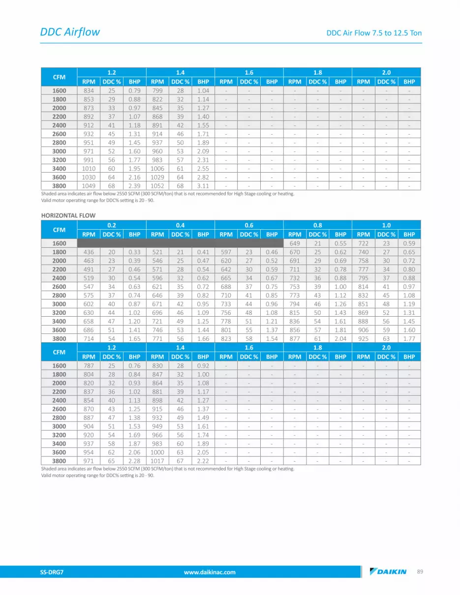
DDC Airflow
SS-DRG7 www.daikinac.com 8988 www.daikinac.com SS-DRG7
CFM1.2 1.4 1.6 1.8 2.0
RPM DDC % BHP RPM DDC % BHP RPM DDC % BHP RPM DDC % BHP RPM DDC % BHP1600 834 25 0.79 799 28 1.04 - - - - - - - - -1800 853 29 0.88 822 32 1.14 - - - - - - - - -2000 873 33 0.97 845 35 1.27 - - - - - - - - -2200 892 37 1.07 868 39 1.40 - - - - - - - - -2400 912 41 1.18 891 42 1.55 - - - - - - - - -2600 932 45 1.31 914 46 1.71 - - - - - - - - -2800 951 49 1.45 937 50 1.89 - - - - - - - - -3000 971 52 1.60 960 53 2.09 - - - - - - - - -3200 991 56 1.77 983 57 2.31 - - - - - - - - -3400 1010 60 1.95 1006 61 2.55 - - - - - - - - -3600 1030 64 2.16 1029 64 2.82 - - - - - - - - -3800 1049 68 2.39 1052 68 3.11 - - - - - - - - -
Shaded area indicates air flow below 2550 SCFM (300 SCFM/ton) that is not recommended for High Stage cooling or heating.Valid motor operating range for DDC% setting is 20 - 90.
HORIZONTAL FLOW
CFM0.2 0.4 0.6 0.8 1.0
RPM DDC % BHP RPM DDC % BHP RPM DDC % BHP RPM DDC % BHP RPM DDC % BHP1600 408 16 0.28 496 18 0.36 574 19 0.41 649 21 0.55 722 23 0.591800 436 20 0.33 521 21 0.41 597 23 0.46 670 25 0.62 740 27 0.652000 463 23 0.39 546 25 0.47 620 27 0.52 691 29 0.69 758 30 0.722200 491 27 0.46 571 28 0.54 642 30 0.59 711 32 0.78 777 34 0.802400 519 30 0.54 596 32 0.62 665 34 0.67 732 36 0.88 795 37 0.882600 547 34 0.63 621 35 0.72 688 37 0.75 753 39 1.00 814 41 0.972800 575 37 0.74 646 39 0.82 710 41 0.85 773 43 1.12 832 45 1.083000 602 40 0.87 671 42 0.95 733 44 0.96 794 46 1.26 851 48 1.193200 630 44 1.02 696 46 1.09 756 48 1.08 815 50 1.43 869 52 1.313400 658 47 1.20 721 49 1.25 778 51 1.21 836 54 1.61 888 56 1.453600 686 51 1.41 746 53 1.44 801 55 1.37 856 57 1.81 906 59 1.603800 714 54 1.65 771 56 1.66 823 58 1.54 877 61 2.04 925 63 1.77
CFM1.2 1.4 1.6 1.8 2.0
RPM DDC % BHP RPM DDC % BHP RPM DDC % BHP RPM DDC % BHP RPM DDC % BHP1600 787 25 0.76 830 28 0.92 - - - - - - - - -1800 804 28 0.84 847 32 1.00 - - - - - - - - -2000 820 32 0.93 864 35 1.08 - - - - - - - - -2200 837 36 1.02 881 39 1.17 - - - - - - - - -2400 854 40 1.13 898 42 1.27 - - - - - - - - -2600 870 43 1.25 915 46 1.37 - - - - - - - - -2800 887 47 1.38 932 49 1.49 - - - - - - - - -3000 904 51 1.53 949 53 1.61 - - - - - - - - -3200 920 54 1.69 966 56 1.74 - - - - - - - - -3400 937 58 1.87 983 60 1.89 - - - - - - - - -3600 954 62 2.06 1000 63 2.05 - - - - - - - - -3800 971 65 2.28 1017 67 2.22 - - - - - - - - -
Shaded area indicates air flow below 2550 SCFM (300 SCFM/ton) that is not recommended for High Stage cooling or heating.Valid motor operating range for DDC% setting is 20 - 90.
DDC Air Flow 7.5 to 12.5 Ton

DDC Airflow
SS-DRG7 www.daikinac.com 9190 www.daikinac.com SS-DRG7
8.5 Ton Models: DRG1023W,DRG1024W & DRG1027W with DDC Controls • High Static to 3.5 HP (0.2 ~ 2.0 ESP) • Down Flow
CFM0.2 0.4 0.6 0.8 1.0
RPM DDC % BHP RPM DDC % BHP RPM DDC % BHP RPM DDC % BHP RPM DDC % BHP1600 447 16 0.30 528 17 0.36 609 19 0.50 678 21 0.55 757 23 0.731800 478 19 0.35 557 21 0.42 635 23 0.57 702 25 0.62 778 27 0.822000 509 23 0.41 586 25 0.48 661 27 0.66 727 29 0.70 799 31 0.932200 541 26 0.48 615 28 0.55 688 30 0.76 752 32 0.79 820 35 1.042400 572 30 0.56 645 32 0.64 714 34 0.87 776 36 0.89 841 38 1.182600 604 34 0.66 674 36 0.73 740 38 1.00 801 40 1.01 862 42 1.332800 635 37 0.77 703 39 0.84 767 42 1.15 826 44 1.14 883 46 1.503000 667 41 0.91 733 43 0.97 793 45 1.33 850 47 1.28 904 50 1.693200 698 44 1.06 762 47 1.11 820 49 1.52 875 51 1.44 925 54 1.903400 730 48 1.25 791 50 1.28 846 53 1.75 900 55 1.63 946 57 2.153600 761 52 1.47 820 54 1.48 872 57 2.02 924 59 1.83 967 61 2.423800 793 55 1.72 850 58 1.70 899 60 2.32 949 62 2.07 988 65 2.734000 824 59 2.02 879 61 1.95 925 64 2.67 974 66 2.33 1009 69 3.084200 856 62 2.37 908 65 2.25 951 68 3.07 998 70 2.63 1030 73 3.47
CFM1.2 1.4 1.6 1.8 2.0
RPM DDC % BHP RPM DDC % BHP RPM DDC % BHP RPM DDC % BHP RPM DDC % BHP1600 834 25 0.79 799 28 1.04 30 30 1.08 945 33 1.29 1006 32 1.391800 853 29 0.88 822 32 1.14 34 34 1.17 965 37 1.40 1025 36 1.512000 873 33 0.97 845 35 1.27 38 38 1.26 986 40 1.52 1045 40 1.632200 892 37 1.07 868 39 1.40 41 41 1.37 1007 44 1.64 1064 44 1.772400 912 41 1.18 891 42 1.55 45 45 1.48 1028 47 1.78 1084 48 1.922600 932 45 1.31 914 46 1.71 49 49 1.61 1049 51 1.93 1103 52 2.082800 951 49 1.45 937 50 1.89 52 52 1.74 1070 55 2.09 1122 57 2.253000 971 52 1.60 960 53 2.09 56 56 1.88 1091 58 2.27 1142 61 2.443200 991 56 1.77 983 57 2.31 60 60 2.04 1112 62 2.45 1161 65 2.643400 1010 60 1.95 1006 61 2.55 63 63 2.21 1133 66 2.66 1180 69 2.863600 1030 64 2.16 1029 64 2.82 67 67 2.39 1154 69 2.88 1200 73 3.103800 1049 68 2.39 1052 68 3.11 70 70 2.59 1175 73 3.12 1219 78 3.354000 1069 72 2.64 1075 71 3.44 74 74 2.81 1196 77 3.38 1239 82 3.634200 1089 76 2.91 1098 75 3.80 78 78 3.04 1217 80 3.66 1258 86 3.94
Shaded area indicates air flow below 2550 SCFM (300 SCFM/ton) that is not recommended for High Stage cooling or heating.Valid motor operating range for DDC% setting is 20 - 90.
DDC Air Flow 7.5 to 12.5 Ton

DDC Airflow
SS-DRG7 www.daikinac.com 9190 www.daikinac.com SS-DRG7
DDC Air Flow 7.5 to 12.5 Ton
HORIZONTAL FLOW
CFM0.2 0.4 0.6 0.8 1.0
RPM DDC % BHP RPM DDC % BHP RPM DDC % BHP RPM DDC % BHP RPM DDC % BHP1600 408 16 0.28 496 18 0.36 574 19 0.41 649 21 0.55 722 23 0.591800 436 20 0.33 521 21 0.41 597 23 0.46 670 25 0.62 740 27 0.652000 463 23 0.39 546 25 0.47 620 27 0.52 691 29 0.69 758 30 0.722200 491 27 0.46 571 28 0.54 642 30 0.59 711 32 0.78 777 34 0.802400 519 30 0.54 596 32 0.62 665 34 0.67 732 36 0.88 795 37 0.882600 547 34 0.63 621 35 0.72 688 37 0.75 753 39 1.00 814 41 0.972800 575 37 0.74 646 39 0.82 710 41 0.85 773 43 1.12 832 45 1.083000 602 40 0.87 671 42 0.95 733 44 0.96 794 46 1.26 851 48 1.193200 630 44 1.02 696 46 1.09 756 48 1.08 815 50 1.43 869 52 1.313400 658 47 1.20 721 49 1.25 778 51 1.21 836 54 1.61 888 56 1.453600 686 51 1.41 746 53 1.44 801 55 1.37 856 57 1.81 906 59 1.603800 714 54 1.65 771 56 1.66 823 58 1.54 877 61 2.04 925 63 1.774000 741 58 1.94 797 60 1.91 846 62 1.74 898 64 2.30 943 67 1.964200 769 61 2.27 822 63 2.19 869 65 1.96 918 68 2.60 962 70 2.17
CFM1.2 1.4 1.6 1.8 2.0
RPM DDC % BHP RPM DDC % BHP RPM DDC % BHP RPM DDC % BHP RPM DDC % BHP1600 787 25 0.76 830 28 0.92 908 31 1.24 950 33 1.27 978 36 1.591800 804 28 0.84 847 32 1.00 922 35 1.35 964 37 1.35 993 39 1.692000 820 32 0.93 864 35 1.08 936 38 1.46 978 40 1.43 1009 42 1.792200 837 36 1.02 881 39 1.17 950 42 1.58 992 44 1.52 1024 46 1.902400 854 40 1.13 898 42 1.27 964 45 1.71 1006 47 1.62 1039 49 2.022600 870 43 1.25 915 46 1.37 977 48 1.85 1020 51 1.72 1054 53 2.152800 887 47 1.38 932 49 1.49 991 52 2.01 1033 54 1.82 1069 56 2.283000 904 51 1.53 949 53 1.61 1005 55 2.17 1047 58 1.93 1084 60 2.423200 920 54 1.69 966 56 1.74 1019 59 2.36 1061 61 2.05 1099 63 2.573400 937 58 1.87 983 60 1.89 1033 62 2.55 1075 65 2.18 1115 67 2.733600 954 62 2.06 1000 63 2.05 1047 66 2.76 1089 68 2.32 1130 70 2.903800 971 65 2.28 1017 67 2.22 1060 69 2.99 1103 71 2.46 1145 74 3.084000 987 69 2.52 1034 70 2.40 1074 73 3.24 1116 75 2.61 1160 77 3.274200 1004 73 2.78 1051 74 2.60 1088 76 3.51 1130 78 2.77 1175 80 3.47
Shaded area indicates air flow below 2550 SCFM (300 SCFM/ton) that is not recommended for High Stage cooling or heating.Valid motor operating range for DDC% setting is 20 - 90.

DDC Airflow
SS-DRG7 www.daikinac.com 9392 www.daikinac.com SS-DRG7
10 Ton Models: DRG1203D, DRG1204D & DRG1207D with DDC Controls • Standard Static to 2.4 HP (0.2 ~ 0.8 ESP) • Down Flow
CFM 0.2 0.4 0.6 0.8 1.0RPM DDC % BHP RPM DDC % BHP RPM DDC % BHP RPM DDC % BHP RPM DDC % BHP
2000 504 17 0.38 582 20 0.55 644 20 0.65 712 21 0.81 - - -2200 533 21 0.43 610 24 0.62 671 25 0.73 737 26 0.91 - - -2400 563 25 0.49 638 28 0.70 699 29 0.82 763 30 1.03 - - -2600 593 29 0.55 666 32 0.79 726 33 0.93 789 35 1.16 - - -2800 622 32 0.62 694 36 0.89 754 37 1.05 814 39 1.31 - - -3000 652 36 0.70 723 40 1.00 781 42 1.18 840 44 1.47 - - -3200 681 40 0.79 751 44 1.13 809 46 1.33 866 48 1.66 - - -3400 711 44 0.89 779 48 1.27 836 50 1.50 891 52 1.87 - - -3600 740 48 1.00 807 52 1.43 864 54 1.69 917 57 2.11 - - -3800 770 52 1.13 835 56 1.61 891 59 1.90 943 61 2.38 - - -4000 800 56 1.27 863 60 1.82 919 63 2.15 968 66 2.68 - - -4200 829 60 1.44 892 64 2.05 946 67 2.42 994 70 3.02 - - -
Shaded area indicates air flow below 3000 SCFM (300 SCFM/ton) that is not recommended for High Stage cooling or heating.Valid motor operating range for DDC% setting is 20 - 90.
HORIZONTAL FLOW
CFM0.2 0.4 0.6 0.8 1.0
RPM DDC % BHP RPM DDC % BHP RPM DDC % BHP RPM DDC % BHP RPM DDC % BHP2000 447 15 0.37 528 17 0.42 607 20 0.60 22 685 0.64 - - -2200 473 19 0.42 552 21 0.48 628 24 0.68 26 704 0.71 - - -2400 499 23 0.49 576 25 0.54 650 28 0.77 30 723 0.78 - - -2600 525 27 0.56 600 29 0.61 671 32 0.86 34 742 0.87 - - -2800 551 31 0.65 623 33 0.69 693 35 0.97 38 762 0.96 - - -3000 578 35 0.74 647 37 0.77 714 39 1.10 42 781 1.06 - - -3200 604 39 0.85 671 41 0.87 736 43 1.24 46 800 1.17 - - -3400 630 43 0.98 695 45 0.98 757 47 1.40 50 819 1.29 - - -3600 656 47 1.13 719 49 1.11 779 51 1.57 54 839 1.43 - - -3800 682 51 1.30 743 53 1.25 800 55 1.78 58 858 1.58 - - -4000 708 55 1.49 767 57 1.41 822 59 2.00 62 877 1.75 - - -4200 734 59 1.72 791 61 1.59 843 63 2.26 66 896 1.93 - - -
Shaded area indicates air flow below 3000 SCFM (300 SCFM/ton) that is not recommended for High Stage cooling or heating.Valid motor operating range for DDC% setting is 20 - 90.
10 Ton Models: DRG1203L, DRG1204L & DRG1207L with DDC Controls • Medium Static to 3.5 HP (0.2 ~ 1.4 ESP) • Down Flow
CFM0.2 0.4 0.6 0.8 1.0
RPM DDC % BHP RPM DDC % BHP RPM DDC % BHP RPM DDC % BHP RPM DDC % BHP1800 474 13 0.34 554 16 0.49 617 16 0.57 686 17 0.72 765 21 0.872000 504 17 0.38 582 20 0.55 644 20 0.65 712 21 0.81 788 25 0.972200 533 21 0.43 610 24 0.62 671 25 0.73 737 26 0.91 810 30 1.072400 563 25 0.49 638 28 0.70 699 29 0.82 763 30 1.03 833 34 1.182600 593 29 0.55 666 32 0.79 726 33 0.93 789 35 1.16 856 38 1.302800 622 32 0.62 694 36 0.89 754 37 1.05 814 39 1.31 878 42 1.443000 652 36 0.70 723 40 1.00 781 42 1.18 840 44 1.47 901 47 1.593200 681 40 0.79 751 44 1.13 809 46 1.33 866 48 1.66 923 51 1.763400 711 44 0.89 779 48 1.27 836 50 1.50 891 52 1.87 946 55 1.953600 740 48 1.00 807 52 1.43 864 54 1.69 917 57 2.11 969 59 2.153800 770 52 1.13 835 56 1.61 891 59 1.90 943 61 2.38 991 64 2.384000 800 56 1.27 863 60 1.82 919 63 2.15 968 66 2.68 1014 68 2.634200 829 60 1.44 892 64 2.05 946 67 2.42 994 70 3.02 1037 72 2.904400 859 64 1.62 920 68 2.31 974 72 2.73 1020 75 3.41 1059 77 3.214600 888 68 1.82 948 72 2.61 1001 76 3.08 1045 79 3.84 1082 81 3.544800 918 71 2.06 976 76 2.94 1029 80 3.47 1071 84 4.33 1105 85 3.925000 947 75 2.32 1004 80 3.32 1056 84 3.91 1097 88 4.89 1127 89 4.33
DDC Air Flow 7.5 to 12.5 Ton

DDC Airflow
SS-DRG7 www.daikinac.com 9392 www.daikinac.com SS-DRG7
CFM1.2 1.4 1.6 1.8 2.0
RPM DDC % BHP RPM DDC % BHP RPM DDC % BHP RPM DDC % BHP RPM DDC % BHP1800 867 27 1.00 887 31 1.26 - - - - - - - - -2000 885 31 1.09 906 35 1.37 - - - - - - - - -2200 903 35 1.18 926 38 1.48 - - - - - - - - -2400 921 39 1.28 945 42 1.61 - - - - - - - - -2600 939 43 1.38 965 46 1.74 - - - - - - - - -2800 956 47 1.50 985 50 1.89 - - - - - - - - -3000 974 51 1.62 1004 54 2.04 - - - - - - - - -3200 992 55 1.76 1024 58 2.21 - - - - - - - - -3400 1010 59 1.90 1044 62 2.40 - - - - - - - - -3600 1028 63 2.06 1063 66 2.60 - - - - - - - - -3800 1046 67 2.23 1083 70 2.81 - - - - - - - - -4000 1064 71 2.42 1103 73 3.05 - - - - - - - - -4200 1082 75 2.62 1122 77 3.30 - - - - - - - - -4400 1099 79 2.84 1142 81 3.58 - - - - - - - - -4600 1117 83 3.08 1161 85 3.88 - - - - - - - - -4800 1135 87 3.33 1181 89 4.20 - - - - - - - - -5000 1153 91 3.61 1201 93 4.55 - - - - - - - - -
Shaded area indicates air flow below 3000 SCFM (300 SCFM/ton) that is not recommended for High Stage cooling or heating.Valid motor operating range for DDC% setting is 20 - 90.
HORIZONTAL FLOW
CFM0.2 0.4 0.6 0.8 1.0
RPM DDC % BHP RPM DDC % BHP RPM DDC % BHP RPM DDC % BHP RPM DDC % BHP1800 421 11 0.32 504 13 0.38 16 16 0.53 666 18 0.58 740 21 0.852000 447 15 0.37 528 17 0.42 20 20 0.60 685 22 0.64 758 25 0.942200 473 19 0.42 552 21 0.48 24 24 0.68 704 26 0.71 775 29 1.042400 499 23 0.49 576 25 0.54 28 28 0.77 723 30 0.78 792 33 1.152600 525 27 0.56 600 29 0.61 32 32 0.86 742 34 0.87 809 37 1.272800 551 31 0.65 623 33 0.69 35 35 0.97 762 38 0.96 827 41 1.413000 578 35 0.74 647 37 0.77 39 39 1.10 781 42 1.06 844 45 1.563200 604 39 0.85 671 41 0.87 43 43 1.24 800 46 1.17 861 49 1.723400 630 43 0.98 695 45 0.98 47 47 1.40 819 50 1.29 879 53 1.903600 656 47 1.13 719 49 1.11 51 51 1.57 839 54 1.43 896 56 2.103800 682 51 1.30 743 53 1.25 55 55 1.78 858 58 1.58 913 60 2.324000 708 55 1.49 767 57 1.41 59 59 2.00 877 62 1.75 931 64 2.564200 734 59 1.72 791 61 1.59 63 63 2.26 896 66 1.93 948 68 2.834400 760 63 1.98 814 65 1.79 67 67 2.54 916 70 2.13 965 72 3.134600 786 67 2.28 838 69 2.02 71 71 2.87 935 74 2.36 982 76 3.464800 812 71 2.62 862 73 2.28 75 75 3.24 954 78 2.60 1000 80 3.835000 838 75 3.01 886 77 2.57 79 79 3.65 973 82 2.88 1017 84 4.23
CFM1.2 1.4 1.6 1.8 2.0
RPM DDC % BHP RPM DDC % BHP RPM DDC % BHP RPM DDC % BHP RPM DDC % BHP1800 810 24 0.95 848 28 1.29 - - - - - - - - -2000 825 28 1.02 863 32 1.40 - - - - - - - - -2200 841 32 1.11 879 36 1.51 - - - - - - - - -2400 856 36 1.20 895 40 1.64 - - - - - - - - -2600 871 39 1.30 910 43 1.77 - - - - - - - - -2800 886 43 1.41 926 47 1.92 - - - - - - - - -3000 902 47 1.53 942 51 2.08 - - - - - - - - -3200 917 51 1.66 957 55 2.26 - - - - - - - - -3400 932 55 1.79 973 58 2.44 - - - - - - - - -3600 948 59 1.94 989 62 2.65 - - - - - - - - -3800 963 63 2.11 1004 66 2.87 - - - - - - - - -4000 978 67 2.28 1020 70 3.11 - - - - - - - - -4200 994 71 2.47 1036 74 3.37 - - - - - - - - -4400 1009 75 2.68 1051 77 3.65 - - - - - - - - -4600 1024 78 2.90 1067 81 3.95 - - - - - - - - -4800 1039 82 3.14 1082 85 4.28 - - - - - - - - -5000 1055 86 3.40 1098 89 4.64 - - - - - - - - -
Shaded area indicates air flow below 3000 SCFM (300 SCFM/ton) that is not recommended for High Stage cooling or heating.Valid motor operating range for DDC% setting is 20 - 90.
DDC Air Flow 7.5 to 12.5 Ton
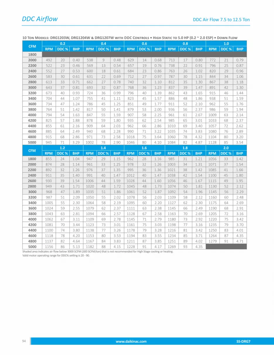
DDC Airflow
SS-DRG7 www.daikinac.com 9594 www.daikinac.com SS-DRG7
10 Ton Models: DRG1203W, DRG1204W & DRG1207W with DDC Controls • High Static to 5.0 HP (0.2 ~ 2.0 ESP) • Down Flow
CFM0.2 0.4 0.6 0.8 1.0
RPM DDC % BHP RPM DDC % BHP RPM DDC % BHP RPM DDC % BHP RPM DDC % BHP1800 462 16 0.35 507 4 0.43 601 10 0.60 688 13 0.71 749 17 0.712000 492 20 0.40 538 9 0.48 629 14 0.68 713 17 0.80 772 21 0.792200 522 23 0.46 569 13 0.54 657 19 0.76 738 22 0.91 796 25 0.872400 552 27 0.53 600 18 0.61 684 23 0.86 763 26 1.02 820 29 0.962600 583 30 0.61 631 22 0.69 712 27 0.97 787 30 1.15 844 34 1.062800 613 33 0.71 662 27 0.78 740 32 1.10 812 35 1.30 867 38 1.183000 643 37 0.81 693 32 0.87 768 36 1.23 837 39 1.47 891 42 1.303200 673 40 0.93 724 36 0.99 796 40 1.39 862 43 1.65 915 46 1.443400 704 44 1.07 755 41 1.11 823 45 1.57 886 48 1.86 938 51 1.593600 734 47 1.24 786 45 1.25 851 49 1.77 911 52 2.10 962 55 1.763800 764 51 1.42 817 50 1.41 879 53 2.00 936 56 2.37 986 59 1.944000 794 54 1.63 847 55 1.59 907 58 2.25 961 61 2.67 1009 63 2.144200 825 57 1.88 878 59 1.80 935 62 2.54 985 65 3.01 1033 68 2.374400 855 61 2.16 909 64 2.03 962 66 2.86 1010 69 3.40 1057 72 2.624600 885 64 2.49 940 68 2.28 990 71 3.22 1035 74 3.83 1080 76 2.894800 915 68 2.86 971 73 2.58 1018 75 3.64 1060 78 4.32 1104 80 3.205000 945 71 3.29 1002 78 2.90 1046 80 4.10 1084 82 4.87 1128 85 3.54
CFM1.2 1.4 1.6 1.8 2.0
RPM DDC % BHP RPM DDC % BHP RPM DDC % BHP RPM DDC % BHP RPM DDC % BHP1800 855 24 1.04 947 29 1.15 962 28 1.16 985 31 1.21 1056 33 1.422000 874 28 1.14 961 33 1.25 978 32 1.26 1003 34 1.31 1071 37 1.542200 892 32 1.26 976 37 1.35 995 36 1.36 1021 38 1.42 1085 41 1.662400 911 35 1.40 991 40 1.47 1012 40 1.47 1038 42 1.54 1100 45 1.802600 930 39 1.54 1006 44 1.59 1028 44 1.60 1056 46 1.67 1115 49 1.952800 949 43 1.71 1020 48 1.72 1045 48 1.73 1074 50 1.81 1130 52 2.123000 968 47 1.89 1035 51 1.86 1061 52 1.87 1092 54 1.96 1145 56 2.293200 987 51 2.09 1050 55 2.02 1078 56 2.03 1109 58 2.12 1160 60 2.483400 1005 55 2.30 1064 58 2.19 1095 60 2.20 1127 62 2.30 1175 64 2.693600 1024 59 2.55 1079 62 2.37 1111 63 2.38 1145 66 2.49 1190 68 2.913800 1043 63 2.81 1094 66 2.57 1128 67 2.58 1163 70 2.69 1205 72 3.164000 1062 67 3.11 1109 69 2.78 1145 71 2.79 1180 73 2.92 1220 75 3.424200 1081 70 3.44 1123 73 3.01 1161 75 3.03 1198 77 3.16 1235 79 3.704400 1100 74 3.80 1138 77 3.26 1178 79 3.28 1216 81 3.42 1250 83 4.014600 1118 78 4.20 1153 80 3.53 1194 83 3.55 1234 85 3.71 1264 87 4.354800 1137 82 4.64 1167 84 3.83 1211 87 3.85 1251 89 4.02 1279 91 4.715000 1156 86 5.13 1182 88 4.15 1228 91 4.17 1269 93 4.35 1294 94 5.10
Shaded area indicates air flow below 3000 SCFM (300 SCFM/ton) that is not recommended for High Stage cooling or heating.Valid motor operating range for DDC% setting is 20 - 90.
DDC Air Flow 7.5 to 12.5 Ton

DDC Airflow
SS-DRG7 www.daikinac.com 9594 www.daikinac.com SS-DRG7
HORIZONTAL FLOW
CFM0.2 0.4 0.6 0.8 1.0
RPM DDC % BHP RPM DDC % BHP RPM DDC % BHP RPM DDC % BHP RPM DDC % BHP1800 419 15 0.29 484 13 0.44 584 17 0.50 662 21 0.64 752 25 0.822000 445 18 0.33 509 17 0.50 606 21 0.55 681 24 0.70 769 28 0.912200 471 22 0.37 534 20 0.56 629 24 0.61 701 28 0.78 786 32 1.002400 497 25 0.42 560 24 0.63 651 28 0.67 721 32 0.86 804 35 1.112600 522 29 0.47 585 28 0.72 673 32 0.74 741 35 0.95 821 39 1.222800 548 32 0.53 610 32 0.81 695 36 0.82 761 39 1.05 838 42 1.353000 574 36 0.60 636 36 0.91 717 39 0.91 781 42 1.16 855 46 1.493200 600 39 0.68 661 40 1.03 739 43 1.00 801 46 1.28 873 49 1.653400 625 43 0.77 686 44 1.16 761 47 1.11 821 50 1.42 890 53 1.833600 651 47 0.86 712 47 1.30 783 51 1.23 841 53 1.56 907 56 2.023800 677 50 0.97 737 51 1.47 805 54 1.35 861 57 1.73 924 60 2.234000 703 54 1.10 762 55 1.66 827 58 1.50 881 60 1.91 941 63 2.464200 728 57 1.24 787 59 1.87 849 62 1.65 901 64 2.11 959 67 2.724400 754 61 1.40 813 63 2.11 871 66 1.83 921 68 2.33 976 70 3.014600 780 64 1.57 838 67 2.38 893 69 2.02 941 71 2.58 993 74 3.334800 806 68 1.77 863 70 2.68 916 73 2.23 961 75 2.85 1010 77 3.685000 831 72 2.00 889 74 3.02 938 77 2.47 981 78 3.15 1028 81 4.06
CFM1.2 1.4 1.6 1.8 2.0
RPM DDC % BHP RPM DDC % BHP RPM DDC % BHP RPM DDC % BHP RPM DDC % BHP1800 860 31 0.96 942 29 1.24 1012 33 1.45 1050 37 1.60 1105 40 1.632000 873 35 1.04 952 33 1.34 1021 37 1.58 1059 40 1.73 1111 43 1.732200 886 38 1.13 963 36 1.45 1030 40 1.71 1067 43 1.88 1116 46 1.842400 900 41 1.22 973 40 1.57 1039 43 1.85 1076 47 2.03 1122 50 1.952600 913 44 1.32 983 43 1.70 1049 47 2.00 1084 50 2.20 1127 53 2.072800 926 47 1.43 993 47 1.84 1058 50 2.17 1093 53 2.39 1133 56 2.203000 940 50 1.55 1003 50 2.00 1067 54 2.35 1101 56 2.59 1139 59 2.343200 953 54 1.68 1013 54 2.16 1076 57 2.55 1110 60 2.80 1144 62 2.483400 966 57 1.82 1023 57 2.34 1085 60 2.76 1118 63 3.03 1150 66 2.643600 980 60 1.98 1033 61 2.54 1094 64 2.99 1127 66 3.29 1155 69 2.803800 993 63 2.14 1043 64 2.75 1103 67 3.24 1135 69 3.56 1161 72 2.974000 1006 66 2.32 1053 68 2.98 1112 70 3.51 1144 73 3.86 1166 75 3.164200 1019 70 2.51 1063 71 3.23 1122 74 3.80 1152 76 4.18 1172 78 3.354400 1033 73 2.72 1073 75 3.49 1131 77 4.12 1161 79 4.53 1177 82 3.564600 1046 76 2.95 1083 78 3.79 1140 81 4.46 1169 83 4.90 1183 85 3.784800 1059 79 3.19 1094 82 4.10 1149 84 4.83 1178 86 5.31 1188 88 4.015000 1073 82 3.46 1104 85 4.44 1158 87 5.23 1186 89 5.76 1194 91 4.26
Shaded area indicates air flow below 3000 SCFM (300 SCFM/ton) that is not recommended for High Stage cooling or heating.Valid motor operating range for DDC% setting is 20 - 90.
DDC Air Flow 7.5 to 12.5 Ton

DDC Airflow
SS-DRG7 www.daikinac.com 9796 www.daikinac.com SS-DRG7
DDC Air Flow 7.5 to 12.5 Ton
12.5 Ton Models: DRG1503D, DRG1504D & DRG1507D with DDC Controls • Standard Static to 3.5 HP (0.2 ~ 0.8 ESP) • Down Flow
CFM0.2 0.4 0.6 0.8 1.0
RPM DDC % BHP RPM DDC % BHP RPM DDC % BHP RPM DDC % BHP RPM DDC % BHP2000 513 17 0.45 571 19 0.59 601 20 0.62 677 22 0.67 - - -2200 537 21 0.51 595 23 0.66 627 24 0.70 700 27 0.75 - - -2400 561 25 0.58 620 27 0.75 653 28 0.79 724 31 0.85 - - -2600 585 29 0.65 644 31 0.84 680 33 0.89 747 35 0.96 - - -2800 610 33 0.74 668 35 0.95 706 37 1.00 770 39 1.08 - - -3000 634 37 0.83 692 39 1.07 733 41 1.13 793 43 1.22 - - -3200 658 41 0.93 717 43 1.21 759 45 1.28 817 47 1.37 - - -3400 682 45 1.05 741 47 1.36 786 49 1.44 840 51 1.55 - - -3600 707 49 1.19 765 52 1.54 812 54 1.62 863 56 1.74 - - -3800 731 54 1.34 789 56 1.73 838 58 1.83 886 60 1.97 - - -4000 755 58 1.51 814 60 1.96 865 62 2.06 909 64 2.22 - - -4200 779 62 1.70 838 64 2.20 891 66 2.33 933 68 2.50 - - -4400 804 66 1.92 862 68 2.49 918 70 2.62 956 72 2.82 - - -4600 828 70 2.16 886 72 2.80 944 75 2.96 979 76 3.18 - - -
Shaded area indicates air flow below 3750 SCFM (300 SCFM/ton) that is not recommended for High Stage cooling or heating.Valid motor operating range for DDC% setting is 20 - 90.
HORIZONTAL FLOW
CFM0.2 0.4 0.6 0.8 1.0
RPM DDC % BHP RPM DDC % BHP RPM DDC % BHP RPM DDC % BHP RPM DDC % BHP2000 466 14 0.45 524 8 0.49 605 15 0.54 668 17 0.63 - - -2200 493 18 0.51 550 13 0.55 629 19 0.60 691 22 0.70 - - -2400 520 23 0.57 577 18 0.62 653 24 0.66 713 26 0.77 - - -2600 547 27 0.65 603 23 0.70 677 29 0.73 736 31 0.85 - - -2800 574 31 0.73 630 28 0.79 700 33 0.81 759 35 0.94 - - -3000 601 36 0.82 657 33 0.89 724 38 0.89 781 40 1.04 - - -3200 629 40 0.93 683 38 1.00 748 42 0.99 804 45 1.15 - - -3400 656 44 1.05 710 43 1.13 772 47 1.09 827 49 1.27 - - -3600 683 48 1.18 736 48 1.27 796 51 1.21 849 54 1.41 - - -3800 710 53 1.33 763 52 1.43 820 56 1.33 872 58 1.56 - - -4000 737 57 1.50 789 57 1.62 844 60 1.47 895 63 1.72 - - -4200 764 61 1.69 816 62 1.82 868 65 1.63 917 67 1.90 - - -4400 791 66 1.91 842 67 2.06 892 70 1.80 940 72 2.10 - - -4600 819 70 2.15 869 72 2.32 916 74 1.99 963 76 2.32 - - -4800 846 74 2.42 896 77 2.61 940 79 2.20 985 81 2.57 - - -
Shaded area indicates air flow below 3750 SCFM (300 SCFM/ton) that is not recommended for High Stage cooling or heating.Valid motor operating range for DDC% setting is 20 - 90.

DDC Airflow
SS-DRG7 www.daikinac.com 9796 www.daikinac.com SS-DRG7
DDC Air Flow 7.5 to 12.5 Ton
12.5 Ton Models: DRG1503L, DRG1504L & DRG1507L with DDC Controls • Medium Static to 3.5 HP (0.2 ~ 1.4 ESP) • Down Flow
CFM0.2 0.4 0.6 0.8 1.0
RPM DDC % BHP RPM DDC % BHP RPM DDC % BHP RPM DDC % BHP RPM DDC % BHP2200 537 21 0.51 595 23 0.66 627 24 0.70 700 27 0.76 764 29 0.872400 561 25 0.58 620 27 0.75 653 28 0.79 724 31 0.84 785 33 0.962600 585 29 0.65 644 31 0.84 680 33 0.89 747 35 0.93 806 37 1.062800 610 33 0.74 668 35 0.95 706 37 1.00 770 39 1.03 827 41 1.183000 634 37 0.83 692 39 1.07 733 41 1.13 793 43 1.14 848 45 1.303200 658 41 0.93 717 43 1.21 759 45 1.28 817 47 1.26 869 49 1.443400 682 45 1.05 741 47 1.36 786 49 1.44 840 51 1.39 890 53 1.593600 707 49 1.19 765 52 1.54 812 54 1.62 863 56 1.54 911 58 1.763800 731 54 1.34 789 56 1.73 838 58 1.83 886 60 1.70 932 62 1.944000 755 58 1.51 814 60 1.96 865 62 2.06 909 64 1.88 953 66 2.144200 779 62 1.70 838 64 2.20 891 66 2.33 933 68 2.08 974 70 2.374400 804 66 1.92 862 68 2.49 918 70 2.62 956 72 2.30 995 74 2.624600 828 70 2.16 886 72 2.80 944 75 2.96 979 76 2.54 1016 78 2.894800 852 74 2.44 911 76 3.16 970 79 3.33 1002 80 2.80 1037 82 3.205000 876 78 2.75 935 80 3.56 997 83 3.76 1026 85 3.10 1058 86 3.54
CFM1.2 1.4 1.6 1.8 2.0
RPM DDC % BHP RPM DDC % BHP RPM DDC % BHP RPM DDC % BHP RPM DDC % BHP2200 825 31 1.09 938 42 0.93 - - - - - - - - -2400 844 35 1.20 949 45 1.20 - - - - - - - - -2600 863 39 1.33 961 48 1.33 - - - - - - - - -2800 883 43 1.47 972 51 1.47 - - - - - - - - -3000 902 48 1.62 984 54 1.62 - - - - - - - - -3200 921 52 1.79 996 57 1.79 - - - - - - - - -3400 940 56 1.98 1007 60 1.98 - - - - - - - - -3600 959 60 2.19 1019 63 2.19 - - - - - - - - -3800 978 64 2.42 1030 66 2.42 - - - - - - - - -4000 997 68 2.67 1042 69 2.67 - - - - - - - - -4200 1016 72 2.96 1054 72 2.96 - - - - - - - - -4400 1036 76 3.27 1065 75 3.27 - - - - - - - - -4600 1055 81 3.61 1077 78 3.61 - - - - - - - - -4800 1074 85 3.99 1088 81 3.99 - - - - - - - - -5000 1093 89 4.41 1100 85 4.41 - - - - - - - - -
Shaded area indicates air flow below 3750 SCFM (300 SCFM/ton) that is not recommended for High Stage cooling or heating.Valid motor operating range for DDC% setting is 20 - 90.

DDC Airflow
SS-DRG7 www.daikinac.com 9998 www.daikinac.com SS-DRG7
DDC Air Flow 7.5 to 12.5 Ton
HORIZONTAL FLOW
CFM0.2 0.4 0.6 0.8 1.0
RPM DDC % BHP RPM DDC % BHP RPM DDC % BHP RPM DDC % BHP RPM DDC % BHP2200 493 18 0.51 550 13 0.55 629 19 0.60 691 22 0.70 750 23 0.832400 520 23 0.57 577 18 0.62 653 24 0.66 713 26 0.77 771 28 0.912600 547 27 0.65 603 23 0.70 677 29 0.73 736 31 0.85 793 32 1.012800 574 31 0.73 630 28 0.79 700 33 0.81 759 35 0.94 814 37 1.123000 601 36 0.82 657 33 0.89 724 38 0.89 781 40 1.04 835 42 1.233200 629 40 0.93 683 38 1.00 748 42 0.99 804 45 1.15 857 46 1.363400 656 44 1.05 710 43 1.13 772 47 1.09 827 49 1.27 878 51 1.513600 683 48 1.18 736 48 1.27 796 51 1.21 849 54 1.41 900 55 1.673800 710 53 1.33 763 52 1.43 820 56 1.33 872 58 1.56 921 60 1.844000 737 57 1.50 789 57 1.62 844 60 1.47 895 63 1.72 942 65 2.034200 764 61 1.69 816 62 1.82 868 65 1.63 917 67 1.90 964 69 2.254400 791 66 1.91 842 67 2.06 892 70 1.80 940 72 2.10 985 74 2.484600 819 70 2.15 869 72 2.32 916 74 1.99 963 76 2.32 1006 78 2.754800 846 74 2.42 896 77 2.61 940 79 2.20 985 81 2.57 1028 83 3.035000 873 79 2.73 922 82 2.95 964 83 2.43 1008 85 2.84 1049 87 3.35
CFM1.2 1.4 1.6 1.8 2.0
RPM DDC % BHP RPM DDC % BHP RPM DDC % BHP RPM DDC % BHP RPM DDC % BHP2200 804 28 1.06 862 27 1.24 - - - - - - - - -2400 825 32 1.17 881 32 1.37 - - - - - - - - -2600 845 36 1.29 900 37 1.52 - - - - - - - - -2800 866 41 1.42 919 41 1.68 - - - - - - - - -3000 887 45 1.57 938 46 1.85 - - - - - - - - -3200 907 49 1.74 957 51 2.05 - - - - - - - - -3400 928 54 1.92 976 55 2.26 - - - - - - - - -3600 948 58 2.13 995 60 2.50 - - - - - - - - -3800 969 62 2.35 1013 65 2.76 - - - - - - - - -4000 989 66 2.60 1032 69 3.05 - - - - - - - - -4200 1010 71 2.87 1051 74 3.38 - - - - - - - - -4400 1030 75 3.17 1070 79 3.73 - - - - - - - - -4600 1051 79 3.50 1089 83 4.12 - - - - - - - - -4800 1072 84 3.87 1108 88 4.56 - - - - - - - - -5000 1092 88 4.28 1127 93 5.04 - - - - - - - - -
Shaded area indicates air flow below 3750 SCFM (300 SCFM/ton) that is not recommended for High Stage cooling or heating.Valid motor operating range for DDC% setting is 20 - 90.
12.5 Ton Models: DRG1503W, DRG1504W & DRG1507W with DDC Controls • High Static to 5.0 HP (0.2 ~ 2.0 ESP) • Down Flow
CFM0.2 0.4 0.6 0.8 1.0
RPM DDC % BHP RPM DDC % BHP RPM DDC % BHP RPM DDC % BHP RPM DDC % BHP2400 635 29 0.78 732 33 1.02 812 38 1.06 877 41 1.32 945 43 1.452600 667 33 0.89 758 37 1.14 835 41 1.18 898 44 1.46 964 46 1.582800 699 37 1.03 785 41 1.29 859 45 1.30 919 47 1.61 982 50 1.713000 731 41 1.18 811 44 1.45 882 48 1.44 939 51 1.78 1000 53 1.853200 763 45 1.36 838 48 1.64 906 52 1.59 960 54 1.97 1018 57 2.003400 795 49 1.56 864 52 1.85 929 55 1.75 980 57 2.18 1036 60 2.173600 827 53 1.80 891 55 2.09 953 59 1.94 1001 61 2.40 1055 64 2.353800 859 57 2.07 917 59 2.35 976 62 2.14 1021 64 2.66 1073 67 2.554000 891 61 2.38 944 62 2.65 1000 65 2.37 1042 67 2.94 1091 70 2.764200 923 64 2.74 970 66 2.99 1023 69 2.62 1063 71 3.25 1109 74 2.994400 955 68 3.15 997 70 3.37 1047 72 2.89 1083 74 3.59 1128 77 3.244600 987 72 3.62 1023 73 3.80 1070 76 3.20 1104 77 3.96 1146 81 3.514800 1019 76 4.16 1050 77 4.28 1094 79 3.53 1124 81 4.38 1164 84 3.805000 1051 80 4.79 1076 81 4.83 1117 83 3.91 1145 84 4.84 1182 88 4.12

DDC Airflow
SS-DRG7 www.daikinac.com 9998 www.daikinac.com SS-DRG7
DDC Air Flow 7.5 to 12.5 Ton
CFM1.2 1.4 1.6 1.8 2.0
RPM DDC % BHP RPM DDC % BHP RPM DDC % BHP RPM DDC % BHP RPM DDC % BHP2400 1010 47 1.84 1065 50 2.10 1102 52 2.13 1159 55 2.30 1193 56 2.702600 1027 51 1.99 1081 53 2.28 1121 55 2.31 1179 58 2.49 1213 60 2.932800 1044 54 2.16 1097 56 2.47 1139 59 2.51 1199 62 2.70 1233 63 3.173000 1061 57 2.34 1112 59 2.68 1158 62 2.71 1219 65 2.93 1252 66 3.433200 1077 60 2.53 1128 62 2.90 1176 65 2.94 1240 68 3.17 1272 70 3.723400 1094 63 2.74 1144 65 3.14 1195 68 3.18 1260 72 3.44 1291 73 4.033600 1111 66 2.97 1159 69 3.40 1213 72 3.45 1280 75 3.72 1311 76 4.373800 1128 70 3.22 1175 72 3.68 1232 75 3.74 1300 78 4.03 1331 80 4.734000 1145 73 3.49 1191 75 3.99 1250 78 4.05 1321 82 4.37 1350 83 5.124200 1161 76 3.78 1206 78 4.32 1269 81 4.39 1341 85 4.73 1370 86 5.554400 1178 79 4.09 1222 81 4.68 1288 85 4.75 1361 89 5.12 1390 90 6.014600 1195 82 4.43 1238 84 5.07 1306 88 5.15 1381 92 5.55 1409 93 6.514800 1212 85 4.80 1253 87 5.50 1325 91 5.58 1402 95 6.01 1429 96 7.065000 1229 89 5.20 1269 90 5.95 1343 94 6.04 1422 99 6.51 1449 100 7.64
Shaded area indicates air flow below 3750 SCFM (300 SCFM/ton) that is not recommended for High Stage cooling or heating.Valid motor operating range for DDC% setting is 20 - 90.
HORIZONTAL FLOW
CFM0.2 0.4 0.6 0.8 1.0
RPM DDC % BHP RPM DDC % BHP RPM DDC % BHP RPM DDC % BHP RPM DDC % BHP2400 509 23 0.44 590 24 0.66 674 27 0.86 767 32 0.98 838 28 0.952600 534 26 0.49 613 28 0.74 694 31 0.97 782 36 1.08 851 32 1.032800 560 30 0.56 635 32 0.83 714 35 1.10 797 39 1.19 865 36 1.123000 586 34 0.63 657 36 0.94 734 39 1.23 811 42 1.32 878 40 1.213200 612 38 0.71 680 40 1.06 754 42 1.39 826 46 1.46 891 44 1.313400 638 42 0.80 702 44 1.19 774 46 1.57 841 49 1.61 904 48 1.423600 664 46 0.90 724 48 1.35 793 50 1.77 856 53 1.78 918 52 1.543800 690 50 1.01 747 51 1.52 813 54 2.00 870 56 1.97 931 57 1.674000 716 53 1.14 769 55 1.71 833 57 2.25 885 60 2.18 944 61 1.804200 742 57 1.29 792 59 1.93 853 61 2.54 900 63 2.40 957 65 1.954400 768 61 1.45 814 63 2.18 873 65 2.86 915 67 2.66 971 69 2.124600 793 65 1.64 836 67 2.45 893 68 3.22 930 70 2.94 984 73 2.294800 819 69 1.85 859 71 2.77 913 72 3.64 944 74 3.25 997 77 2.485000 845 73 2.08 881 75 3.12 932 76 4.10 959 77 3.59 1010 81 2.695200 871 76 2.35 903 78 3.52 952 80 4.62 974 81 3.96 1024 85 2.925400 897 80 2.65 926 82 3.97 972 83 5.21 989 84 4.38 1037 89 3.165600 923 84 2.99 948 86 4.47 992 87 5.88 1003 87 4.84 1050 93 3.42
CFM1.2 1.4 1.6 1.8 2.0
RPM DDC % BHP RPM DDC % BHP RPM DDC % BHP RPM DDC % BHP RPM DDC % BHP2400 908 38 1.20 979 42 1.45 1053 43 1.59 1114 38 1.86 1134 47 1.872600 919 42 1.30 988 45 1.57 1059 47 1.69 1119 42 1.97 1139 50 1.982800 929 45 1.41 997 48 1.70 1064 50 1.79 1123 45 2.09 1144 54 2.113000 940 48 1.53 1007 51 1.85 1070 53 1.90 1127 48 2.22 1150 57 2.243200 951 51 1.66 1016 54 2.00 1075 56 2.02 1131 51 2.36 1155 60 2.373400 961 54 1.79 1025 57 2.17 1081 60 2.14 1135 54 2.51 1161 64 2.523600 972 58 1.94 1035 61 2.35 1086 63 2.28 1139 57 2.66 1166 67 2.683800 983 61 2.11 1044 64 2.54 1092 66 2.42 1143 61 2.83 1172 70 2.844000 993 64 2.28 1053 67 2.75 1097 70 2.57 1148 64 3.00 1177 73 3.024200 1004 67 2.47 1063 70 2.98 1103 73 2.73 1152 67 3.19 1183 77 3.204400 1014 71 2.68 1072 73 3.23 1108 76 2.89 1156 70 3.38 1188 80 3.404600 1025 74 2.90 1081 77 3.50 1114 79 3.07 1160 73 3.59 1194 83 3.614800 1036 77 3.14 1091 80 3.79 1119 83 3.26 1164 77 3.81 1199 86 3.845000 1046 80 3.40 1100 83 4.11 1125 86 3.46 1168 80 4.05 1205 90 4.075200 1057 83 3.69 1109 86 4.45 1130 89 3.68 1172 83 4.30 1210 93 4.325400 1068 87 3.99 1119 89 4.82 1136 92 3.91 1177 86 4.57 1215 96 4.595600 1078 90 4.33 1128 92 5.22 1141 96 4.15 1181 89 4.85 1221 99 4.88
Shaded area indicates air flow below 3750 SCFM (300 SCFM/ton) that is not recommended for High Stage cooling or heating.Valid motor operating range for DDC% setting is 20 - 90.

SS-DRG7 www.daikinac.com 101100 www.daikinac.com SS-DRG7
Static Pressure
SS-DRG7 www.daikinac.com 101100 www.daikinac.com SS-DRG7
7.5-12.5 TONS
DOWNFLOW ECONOMIZER PRESSURE DROP
Cabinet CFM SP in.wg.
7.5 Ton2250 .04"3000 .07"3750 .11"
8.5 Ton2550 .06"3400 .10"4250 .16"
10 Ton3000 .08"4000 .13"5000 .22"
12.5 Ton3750 .14"5000 .24"6250 .36"
7.5-12.5 TONS
HORIZONTAL ECONOMIZER PRESSURE DROP
Cabinet CFM SP in.wg.
7.5 Ton2250 .05"3000 .07"3750 .13"
8.5 Ton2550 .07"3400 .13"4250 .18"
10 Ton3000 .07"4000 .12"5000 .19"
12.5 Ton3750 .09"5000 .15"6250 .24"

HGRH Performance
SS-DRG7 www.daikinac.com 101100 www.daikinac.com SS-DRG7 SS-DRG7 www.daikinac.com 101100 www.daikinac.com SS-DRG7
DRG (7.5 Tons) With DDC Control
DRG 090 (7.5 Tons) With iLINQ Control In Modulating Hot Gas Reheat Mode-High StageEAT (DB °F) 75 75 75 75
EAT (WB °F) 62 64 68 71
Ambient Temperature (DB °F) SCFM 2000 3000 3375 2000 3000 3375 2000 3000 3375 2000 3000 3375
95
TC Btu/h 41,100 46,100 46,100 45,700 50,700 52,500 63,569 72,802 77,118 83,202 95,162 108,031
S/T - 0.63 0.79 0.85 0.51 0.66 0.70 0.35 0.39 0.41 0.30 0.30 0.29
CMPR kW 5.5 5.5 5.5 5.5 5.6 5.6 5.6 5.6 5.7 5.8 5.9 5.9
LDB °F 63.23 63.96 64.45 64.41 64.86 65.1 64.89 66.40 66.48 63.65 66.35 66.56
LWB °F 55.59 57.4 57.99 56.53 58.57 59.02 58.30 60.8 61.22 58.83 62.0 61.94
80
TC Btu/h 46,800 51,800 51,600 51,400 56,400 58,000 66,989 76,038 78,230 84,256 99,845 102,545
S/T - 0.61 0.75 0.81 0.51 0.64 0.68 0.39 0.49 0.44 0.35 0.43 0.40
CMPR kW 4.7 4.7 4.7 4.7 4.7 4.7 4.7 4.7 4.7 4.7 4.8 4.9
LDB °F 62.02 63.23 63.74 63.08 64.06 64.38 63.12 63.71 65.73 61.60 61.99 63.95
LWB °F 54.55 56.74 57.43 55.51 57.92 58.47 57.70 60.40 61.11 58.63 61.50 62.41
75
TC Btu/h 48,700 53,700 53,500 53,300 58,300 59,900 67,929 75,964 78,697 82,566 93,345 99,496
S/T - 0.61 0.74 0.80 0.51 0.64 0.67 0.37 0.45 0.45 0.35 0.44 0.42
CMPR kW 4.6 4.6 4.6 4.6 4.6 4.6 4.6 4.6 4.6 4.6 4.6 4.7
LDB °F 61.5 62.96 63.47 62.64 63.69 64.19 63.6 64.64 65.46 61.9 62.55 63.74
LWB °F 54.2 56.52 57.23 55.17 57.7 58.28 57.55 60.42 61.07 58.92 62.18 62.69
70
TC Btu/h 50,600 55,600 55,300 55,200 60,200 61,700 69,124 76,655 79,899 82,052 90,760 100,132
S/T - 0.60 0.73 0.79 0.51 0.63 0.67 0.39 0.50 0.46 0.35 0.47 0.42
CMPR kW 4.5 4.5 4.5 4.5 4.5 4.5 4.5 4.5 4.5 4.5 4.6 4.6
LDB °F 61.20 62.70 63.23 62.20 63.51 63.86 62.75 63.39 65.10 61.95 62.07 63.67
LWB °F 53.84 56.29 57.05 54.82 57.49 58.10 57.33 60.33 60.95 59.00 62.44 62.63
65
TC Btu/h 52,497 57,497 57,185 57,112 62,112 63,550 70,734 78,681 82,121 83,691 96,543 104,200
S/T - 0.60 0.72 0.78 0.50 0.63 0.66 0.39 0.47 0.44 0.37 0.45 0.40
CMPR kW 4.3 4.3 4.3 4.3 4.3 4.3 4.3 4.4 4.4 4.3 4.5 4.7
LDB °F 60.68 62.46 62.99 62.02 63.14 63.70 62.46 63.79 65.27 60.92 61.84 63.77
LWB °F 53.49 56.07 56.85 54.48 57.27 57.91 57.05 60.12 60.74 58.72 61.84 62.26
DRG 090 (7.5 Tons) With iLINQ Control In Modulating Hot Gas Reheat Mode-Low StageEAT (DB °F) 75 75 75 75
EAT (WB °F) 62 64 68 71
Ambient Temperature (DB °F) SCFM 2000 3000 3375 2000 3000 3375 2000 3000 3375 2000 3000 3375
60
TC Btu/h 6,600 7,900 7,600 6,500 7,800 6,500 7,832 10,061 7,204 9,463 13,294 9,510
S/T - 0.62 0.78 0.79 0.30 0.51 0.45 0.008 0.157 0.033 0.003 0.035 0.008
CMPR kW 2.1 2.1 2.1 2.2 2.1 2.1 2.2 2.1 2.1 2.2 2.1 2.1
LDB °F 73.14 73.13 73.38 74.11 73.79 74.21 74.96 74.51 74.94 75.00 74.88 74.97
LWB °F 61.45 61.66 61.79 63.01 63.21 63.42 66.92 67.07 67.42 69.78 69.86 70.28
50
TC Btu/h 9,100 10,300 10,700 9,000 10,300 9,600 10,500 12,661 11,905 11,916 15,671 13,463
S/T - 0.62 0.75 0.75 0.39 0.54 0.52 0.126 0.210 0.162 0.057 0.065 0.041
CMPR kW 2.1 2.0 2.1 2.1 2.1 2.1 2.1 2.1 2.1 2.1 2.1 2.1
LDB °F 72.44 72.66 72.84 73.4 73.31 73.66 74.38 74.19 74.49 74.68 74.67 74.85
LWB °F 61.05 61.41 61.49 62.62 62.95 63.13 66.54 66.8 67.03 69.46 69.7 69.98
40
TC Btu/h 11,500 12,800 13,900 11,500 12,700 12,800 13,049 15,101 15,016 14,063 17,368 16,919
S/T - 0.63 0.73 0.73 0.44 0.56 0.55 0.20 0.249 0.219 0.091 0.079 0.049
CMPR kW 2.1 2.0 2.0 2.1 2.0 2.0 2.1 2.0 2.0 2.1 2.1 2.0
LDB °F 71.71 72.17 72.27 72.7 72.84 73.1 73.81 73.86 74.11 74.42 74.58 74.77
LWB °F 60.66 61.14 61.19 62.23 62.7 62.84 66.18 66.60 66.76 69.17 69.50 69.71TC: Total Capacity (Btu/h); S/T: Sensible to Total Capacity Ratio; CMPR: Compressor Power (kW); LDB: Leaving Dry Bulb Temperature (°F); LWB: Leaving Wet Bulb Temperature (°F)

HGRH Performance
SS-DRG7 www.daikinac.com 103102 www.daikinac.com SS-DRG7
DRG 102 (8.5 Tons) With iLINQ Control In Modulating Hot Gas Reheat Mode-High StageEAT (DB °F) 75 75 75 75
EAT (WB °F) 62 64 68 71
Ambient Temperature (DB °F) SCFM 2000 3000 4000 2000 3000 4000 2000 3000 4000 2000 3000 4000
95
TC Btu/h 31,200 31,100 33,000 37,200 39,300 40,400 54,170 61,639 62,269 70,900 80,570 87,230
S/T - 0.48 0.81 0.96 0.34 0.59 0.71 0.21 0.31 0.38 0.18 0.24 0.28
CMPR kW 6.1 6.2 6.2 6.1 6.2 6.2 6.2 6.2 6.2 6.4 6.4 6.5
LDB °F 68.19 67.37 67.80 69.25 67.97 68.48 69.83 69.21 69.62 69.20 69.14 69.45
LWB °F 57.36 59.12 59.82 58.04 59.85 60.83 59.90 61.97 63.50 60.88 63.54 65.03
80
TC Btu/h 46,600 49,200 53,800 52,600 57,400 61,200 69,822 81,182 83,231 87,820 106,600 109,100
S/T - 0.49 0.67 0.79 0.39 0.54 0.64 0.29 0.39 0.41 0.26 0.35 0.37
CMPR kW 5.2 5.2 5.2 5.2 5.2 5.2 5.2 5.2 5.2 5.2 5.3 5.4
LDB °F 64.62 65.01 65.34 65.68 65.61 66.1 65.80 65.4 67.2 64.62 63.7 65.8
LWB °F 54.61 57.06 58.07 55.32 57.82 59.11 57.24 59.86 61.87 58.06 60.80 63.38
75
TC Btu/h 51,700 55,300 60,700 57,700 63,500 68,100 74,538 86,019 89,695 90,600 105,700 113,400
S/T - 0.49 0.65 0.75 0.40 0.53 0.63 0.29 0.36 0.42 0.27 0.35 0.39
CMPR kW 5.0 5.0 5.0 5.0 5.0 5.0 5.0 5.0 5.0 5.0 5.1 5.1
LDB °F 63.49 64.11 64.65 64.51 64.8 65.25 65.17 65.62 66.44 63.88 63.79 64.95
LWB °F 53.66 56.34 57.48 54.39 57.12 58.53 56.42 59.34 61.36 57.58 60.90 63.04
70
TC Btu/h 56,900 61,300 67,600 62,800 69,500 75,000 79,409 91,469 96,789 94,260 108,300 121,300
S/T - 0.49 0.63 0.73 0.41 0.52 0.62 0.32 0.40 0.42 0.29 0.38 0.39
CMPR kW 4.8 4.8 4.8 4.8 4.8 4.8 4.8 4.8 4.9 4.8 4.9 4.9
LDB °F 62.33 63.30 63.78 63.30 64.05 64.43 63.45 63.91 65.76 62.57 62.53 64.25
LWB °F 52.68 55.63 56.87 53.44 56.42 57.94 55.54 58.72 60.79 56.94 60.61 62.44
65
TC Btu/h 61,991 67,390 74,566 67,973 75,583 81,951 84,676 98,402 105,050 100,186 119,373 135,857
S/T - 0.49 0.61 0.71 0.42 0.51 0.61 0.33 0.38 0.40 0.31 0.36 0.37
CMPR kW 4.6 4.6 4.6 4.6 4.6 4.6 4.6 4.6 4.6 4.5 4.8 5.0
LDB °F 61.19 62.54 62.97 62.02 63.32 63.64 62.30 63.67 65.45 60.88 61.98 63.58
LWB °F 51.69 54.89 56.26 52.45 55.70 57.34 54.58 57.94 60.12 55.89 59.41 61.30
DRG 102 (8.5 Tons) With iLINQ Control In Modulating Hot Gas Reheat Mode-Low StageEAT (DB °F) 75 75 75 75
EAT (WB °F) 62 64 68 71
Ambient Temperature (DB °F) SCFM 2000 3000 4000 2000 3000 4000 2000 3000 4000 2000 3000 4000
60
TC Btu/h 21,600 15,000 7,900 24,800 18,300 10,800 33,353 27,359 20,355 39,670 36,150 34,810
S/T - 0.64 0.77 0.89 0.51 0.57 0.54 0.27 0.25 0.20 0.10 0.06 0.05
CMPR kW 2.4 2.4 2.4 2.4 2.4 2.4 2.4 2.4 2.4 2.4 2.4 2.4
LDB °F 68.72 71.5 73.4 69.25 71.84 73.67 70.91 72.93 74.07 73.16 74.4 74.62
LWB °F 58.99 60.9 61.87 60.09 62.12 63.18 63.18 65.43 66.59 65.64 67.83 68.73
50
TC Btu/h 25,500 19,000 12,200 28,700 22,200 15,100 36,983 30,968 24,245 41,970 38,330 36,490
S/T - 0.63 0.74 0.80 0.52 0.57 0.56 0.300 0.270 0.250 0.135 0.084 0.064
CMPR kW 2.3 2.3 2.3 2.3 2.3 2.3 2.4 2.3 2.3 2.4 2.4 2.3
LDB °F 67.7 70.74 72.78 68.22 71.17 73.08 69.96 72.47 73.62 72.42 74.02 74.47
LWB °F 58.33 60.47 61.53 59.45 61.7 62.84 62.61 65.08 66.31 65.3 67.62 68.62
40
TC Btu/h 29,400 22,900 16,600 32,600 26,100 19,500 40,504 34,414 27,950 43,650 39,580 37,110
S/T - 0.63 0.71 0.75 0.53 0.58 0.58 0.32 0.29 0.27 0.15 0.09 0.06
CMPR kW 2.3 2.3 2.3 2.3 2.3 2.3 2.3 2.3 2.3 2.4 2.3 2.3
LDB °F 66.58 70.07 72.17 67.15 70.41 72.43 69.11 71.98 73.28 72.02 73.92 74.49
LWB °F 57.66 60.04 61.18 58.79 61.29 62.50 62.06 64.74 66.04 65.05 67.51 68.58TC: Total Capacity (Btu/h); S/T: Sensible to Total Capacity Ratio; CMPR: Compressor Power (kW); LDB: Leaving Dry Bulb Temperature (°F); LWB: Leaving Wet Bulb Temperature (°F)
DRG (8.5 Tons) With DDC Control

HGRH Performance
SS-DRG7 www.daikinac.com 103102 www.daikinac.com SS-DRG7
DRG 120 (10 Tons) With iLINQ Control In Modulating Hot Gas Reheat Mode-High StageEAT (DB °F) 75 75 75 75
EAT (WB °F) 62 64 68 71
Ambient Temperature (DB °F) SCFM 2250 3500 4000 2250 3500 4000 2250 3500 4000 2250 3500 4000
95
TC Btu/h 31,800 24,800 19,500 37,400 30,300 24,600 53,885 46,723 38,710 70,527 61,072 54,228
S/T - 0.35 0.39 0.54 0.23 0.23 0.28 0.12 0.09 0.09 0.10 0.07 0.06
CMPR kW 6.7 6.6 6.6 6.8 6.7 6.7 6.8 6.8 6.8 7.0 7.0 7.1
LDB °F 70.50 72.49 72.61 71.52 73.19 73.43 72.39 73.91 74.21 72.15 73.89 74.26
LWB °F 57.88 60.24 60.95 58.72 61.33 62.12 60.93 64.20 65.28 62.20 66.32 67.41
80
TC Btu/h 47,300 41,100 42,300 54,200 48,000 47,300 72,648 67,885 63,508 91,374 89,139 83,246
S/T - 0.44 0.48 0.59 0.36 0.39 0.45 0.27 0.28 0.26 0.25 0.25 0.24
CMPR kW 5.9 5.8 5.8 5.9 5.9 5.9 5.9 6.0 6.0 5.9 6.1 6.1
LDB °F 66.59 69.88 69.33 67.12 70.14 70.16 67.07 70.06 71.25 65.77 69.21 70.46
LWB °F 55.45 58.68 59.07 56.12 59.67 60.29 58.15 62.34 63.42 59.17 63.95 65.33
75
TC Btu/h 52,700 46,500 47,400 59,500 53,400 52,400 77,626 72,333 68,215 94,353 88,883 86,243
S/T - 0.46 0.50 0.58 0.38 0.41 0.45 0.28 0.28 0.28 0.26 0.27 0.26
CMPR kW 5.8 5.6 5.6 5.8 5.7 5.7 5.8 5.8 5.7 5.8 5.8 5.8
LDB °F 65.21 68.96 68.75 65.86 69.31 69.64 66.22 69.74 70.66 65.09 68.77 69.90
LWB °F 54.57 58.16 58.64 55.27 59.16 59.87 57.39 61.94 63.06 58.73 63.97 65.11
70
TC Btu/h 58,100 51,900 52,500 64,900 58,800 57,500 82,762 77,278 73,408 98,240 91,498 91,998
S/T - 0.47 0.51 0.57 0.40 0.43 0.45 0.32 0.33 0.29 0.28 0.31 0.27
CMPR kW 5.6 5.4 5.4 5.6 5.5 5.5 5.6 5.6 5.6 5.6 5.6 5.7
LDB °F 63.97 68.12 68.20 64.51 68.43 69.12 64.30 68.38 70.16 63.89 67.63 69.35
LWB °F 53.67 57.63 58.20 54.39 58.64 59.45 56.58 61.48 62.66 58.14 63.74 64.68
65
TC Btu/h 63,385 57,309 58,349 70,396 64,320 63,290 88,513 83,780 80,341 104,726 102,800 103,902
S/T - 0.48 0.53 0.57 0.42 0.45 0.47 0.34 0.34 0.29 0.32 0.32 0.27
CMPR kW 5.4 5.2 5.2 5.4 5.3 5.3 5.4 5.4 5.4 5.3 5.6 5.8
LDB °F 62.71 67.11 67.44 63.05 67.48 68.24 62.84 67.60 69.70 61.46 66.46 68.62
LWB °F 52.78 57.09 57.70 53.48 58.10 58.96 55.66 60.89 62.12 57.13 62.75 63.80
DRG (10 Tons) With iLINQ Control In Modulating Hot Gas Reheat Mode-Low StageEAT (DB °F) 75 75 75 75
EAT (WB °F) 62 64 68 71
Ambient Temperature (DB °F) SCFM 2250 3500 4000 2250 3500 4000 2250 3500 4000 2250 3500 4000
60
TC Btu/h 27,200 22,000 18,800 30,600 25,400 23,100 40,553 36,807 35,000 49,000 48,634 46,200
S/T - 0.56 0.77 0.82 0.44 0.59 0.60 0.23 0.27 0.26 0.09 0.06 0.06
CMPR kW 2.8 2.8 2.8 2.8 2.8 2.8 2.8 2.8 2.8 2.8 2.8 2.8
LDB °F 68.85 70.60 71.50 69.56 71.11 71.85 71.23 72.42 72.93 73.22 74.24 74.37
LWB °F 58.56 60.48 61.00 59.71 61.75 62.22 62.77 65.02 65.53 65.08 67.32 67.96
50
TC Btu/h 31,900 26,700 23,100 35,300 30,100 27,300 44,936 41,003 42,622 50,996 50,750 48,200
S/T - 0.59 0.76 0.82 0.47 0.61 0.64 0.27 0.29 0.30 0.12 0.09 0.08
CMPR kW 2.7 2.7 2.7 2.7 2.7 2.7 2.7 2.7 2.7 2.8 2.7 2.7
LDB °F 67.40 69.73 70.70 68.30 70.23 71.03 70.10 71.91 72.09 72.53 73.81 74.12
LWB °F 57.84 60.04 60.65 59.01 61.32 61.88 62.16 64.66 64.97 64.81 67.15 67.82
40
TC Btu/h 36,600 31,400 27,300 40,000 34,800 31,600 49,189 45,031 44,820 53,009 51,791 50,500
S/T - 0.60 0.76 0.83 0.50 0.63 0.66 0.30 0.32 0.32 0.14 0.10 0.07
CMPR kW 2.6 2.6 2.6 2.6 2.6 2.7 2.7 2.6 2.7 2.7 2.7 2.7
LDB °F 66.13 68.80 69.85 66.92 69.31 70.26 69.04 71.26 71.74 72.00 73.65 74.20
LWB °F 57.11 59.59 60.30 58.29 60.88 61.54 61.56 64.32 64.81 64.54 67.06 67.67TC: Total Capacity (Btu/h); S/T: Sensible to Total Capacity Ratio; CMPR: Compressor Power (kW); LDB: Leaving Dry Bulb Temperature (°F); LWB: Leaving Wet Bulb Temperature (°F)
DRG (10 Tons) With DDC Control

SS-DRG7 www.daikinac.com 105104 www.daikinac.com SS-DRG7
HGRH Performance
SS-DRG7 www.daikinac.com 105104 www.daikinac.com SS-DRG7
DRG 150 (12.5 Tons) With iLINQ Control In Modulating Hot Gas Reheat Mode-High StageEAT (DB °F) 75 75 75 75EAT (WB °F) 62 64 68 71
Ambient Temperature (DB °F) SCFM 2250 3800 4200 2250 3800 4200 2250 3800 4200 2250 3800 4200
95
TC Btu/h 45,100 41,500 41,100 50,700 51,900 52,500 75,710 82,800 83,500 99,092 108,230 116,972
S/T - 0.39 0.55 0.59 0.28 0.43 0.48 0.21 0.27 0.33 0.18 0.20 0.24
CMPR kW 8.6 8.7 8.7 8.8 8.9 8.9 9.2 9.3 9.4 9.4 9.7 9.8
LDB °F 67.89 69.54 69.75 69.26 69.66 69.55 68.58 69.65 69.04 67.79 69.82 68.92
LWB °F 55.81 58.96 59.33 56.69 59.69 60.06 57.70 61.59 62.18 58.05 63.05 63.24
80
TC Btu/h 51,900 54,400 55,300 57,800 60,800 61,400 79,180 86,830 88,790 99,590 114,016 116,387
S/T - 0.39 0.55 0.59 0.30 0.42 0.46 0.21 0.27 0.28 0.19 0.24 0.25
CMPR kW 7.5 7.4 7.4 7.6 7.6 7.5 7.8 7.9 8.0 7.7 8.1 8.2
LDB °F 66.82 67.84 67.94 67.99 68.89 68.89 68.28 69.39 69.62 67.35 68.45 68.70
LWB °F 54.71 57.80 58.19 55.56 58.91 59.36 57.17 61.25 61.79 57.97 62.57 63.28
75
TC Btu/h 54,200 58,700 60,100 60,200 63,700 64,300 79,360 87,560 89,790 96,461 107,594 113,520
S/T - 0.39 0.54 0.59 0.30 0.42 0.45 0.20 0.26 0.27 0.19 0.25 0.25
CMPR kW 7.3 7.2 7.2 7.4 7.3 7.3 7.5 7.6 7.7 7.5 7.7 7.8
LDB °F 66.46 67.42 67.32 67.70 68.60 68.74 68.59 69.55 69.75 67.59 68.56 68.86
LWB °F 54.33 57.41 57.80 55.18 58.65 59.14 57.14 61.19 61.72 58.44 63.09 63.48
70
TC Btu/h 56,500 63,000 64,800 62,500 66,700 67,300 80,630 87,630 88,890 95,709 103,755 111,401
S/T - 0.39 0.54 0.59 0.31 0.41 0.45 0.20 0.25 0.27 0.18 0.24 0.25
CMPR kW 7.0 6.9 6.9 7.2 7.1 7.1 7.3 7.4 7.4 7.3 7.4 7.5
LDB °F 66.10 66.86 66.72 67.17 68.46 68.44 68.48 69.76 69.81 68.04 69.04 68.97
LWB °F 53.96 57.01 57.41 54.80 58.38 58.90 56.94 61.19 61.79 58.55 63.40 63.63
65
TC Btu/h 58,802 67,312 69,574 64,872 69,631 70,226 83,937 86,828 85,179 99,312 105,332 110,159
S/T - 0.39 0.54 0.59 0.31 0.41 0.44 0.20 0.25 0.29 0.19 0.24 0.27
CMPR kW 6.7 6.7 6.6 6.9 6.8 6.8 7.0 7.1 7.0 6.9 7.3 7.5
LDB °F 65.73 66.30 66.12 66.87 68.17 68.31 68.22 69.81 69.65 67.38 68.95 68.56
LWB °F 53.57 56.61 57.01 54.42 58.12 58.66 56.43 61.26 62.06 58.01 63.28 63.72
DRG 150 (12.5 Tons) With iLINQ Control In Modulating Hot Gas Reheat Mode-Low StageEAT (DB °F) 75 75 75 75
EAT (WB °F) 62 64 68 71
Ambient Temperature (DB °F) SCFM 2250 3800 4200 2250 3800 4200 2250 3800 4200 2250 3800 4200
60
TC Btu/h 17,700 9,000 6,200 21,500 13,100 10,600 32,772 24,946 24,671 45,000 45,260 44,510
S/T - 0.46 0.68 0.68 0.28 0.31 0.24 0.050 0.040 0.080 0.016 0.007 0.001
CMPR kW 3.7 3.6 3.6 3.7 3.6 3.6 3.7 3.7 3.7 3.8 3.8 3.8
LDB °F 71.71 73.54 74.09 72.57 74.03 74.45 74.34 74.76 74.57 74.71 74.92 74.99
LWB °F 59.98 61.75 62.03 61.04 62.95 63.24 63.84 66.18 66.37 65.60 67.87 68.23
50
TC Btu/h 23,200 15,200 12,500 27,100 19,200 16,900 37,698 31,359 30,049 47,000 46,020 45,550
S/T - 0.49 0.62 0.61 0.35 0.38 0.35 0.110 0.100 0.080 0.011 0.000 0.000
CMPR kW 3.6 3.6 3.6 3.6 3.6 3.6 3.7 3.6 3.6 3.7 3.7 3.7
LDB °F 70.41 72.75 73.35 71.17 73.25 73.72 73.32 74.25 74.48 74.79 75.00 75.00
LWB °F 59.17 61.23 61.56 60.23 62.45 62.77 63.18 65.69 66.01 65.35 67.82 68.16
40
TC Btu/h 28,800 21,300 18,800 32,600 25,300 23,200 42,206 36,367 35,232 46,610 45,820 45,480
S/T - 0.51 0.59 0.59 0.39 0.42 0.40 0.160 0.150 0.150 0.004 0.001 0.000
CMPR kW 3.6 3.5 3.5 3.6 3.6 3.6 3.7 3.6 3.6 3.7 3.7 3.7
LDB °F 69.07 71.99 72.60 69.86 72.46 72.99 72.27 73.69 73.86 74.92 74.99 75.00
LWB °F 58.32 60.71 61.08 59.42 61.95 62.30 62.55 65.31 65.65 65.40 67.83 68.16TC: Total Capacity (Btu/h); S/T: Sensible to Total Capacity Ratio; CMPR: Compressor Power (kW); LDB: Leaving Dry Bulb Temperature (°F); LWB: Leaving Wet Bulb Temperature (°F)
DRG (12.5 Tons) With DDC Control

SS-DRG7 www.daikinac.com 105104 www.daikinac.com SS-DRG7 SS-DRG7 www.daikinac.com 105104 www.daikinac.com SS-DRG7
Electrical Data
Model Number
Electrical Rating
Compressor Outdoor Fan Motor Indoor Fan Motor Optional Electric HeatOptional Powered
Convenience OutletOptional Power
ExhaustPower Supply
QTY RLA LRA QTY HP FLA Type HP FLA Part # KW* FLA FLA FLA MCA MOP
DRG0903D 208/230/3/60 2 13.1 83.1 2 0.33 2Direct Drive
Standard Static
2.4 8
- - - - - 41.6/41.6 50/50
- - - 9.6/8.7 - 51.2/50.3 60/60
- - - - 3.3/3.0 44.9/44.6 50/50
- - - 9.6/8.7 3.3/3.0 54.5/53.3 60/60
DRG0903L 208/230/3/60 2 13.1 83.1 2 0.33 2Direct Drive
Medium Static
2.4 8
- - - - - 41.6/41.6 50/50
- - - 9.6/8.7 - 51.2/50.3 60/60
- - - - 3.3/3.0 44.9/44.6 50/50
- - - 9.6/8.7 3.3/3.0 54.5/53.3 60/60
DRG0903W 208/230/3/60 2 13.1 83.1 2 0.33 2Direct Drive High Static
3.5 10.9
- - - - - 44.5/44.5 50/50
- - - 9.6/8.7 - 54.1/53.2 60/60
- - - - 3.3/3.0 47.8/47.5 50/50
- - - 9.6/8.7 3.3/3.0 57.4/56.2 60/60
DRG0904D 460/3/60 2 6.1 41 2 0.33 0.85Direct Drive
Standard Static
2.4 5.4
- - - - - 20.8 25
- - - 4.3 - 25.1 30
- - - - 1 21.8 25
- - - 4.3 1 26.1 30
DRG0904L 460/3/60 2 6.1 41 2 0.33 0.85Direct Drive
Medium Static
2.4 5.4
- - - - - 20.8 25
- - - 4.3 - 25.1 30
- - - - 1 21.8 25
- - - 4.3 1 26.1 30
DRG0904W 460/3/60 2 6.1 41 2 0.33 0.85Direct Drive High Static
3.5 7.2
- - - - - 22.6 25
- - - 4.3 - 26.9 30
- - - - 1 23.6 25
- - - 4.3 1 27.9 30
DRG0907D 575/3/60 2 4.4 33 2 0.33 0.67Direct Drive
Standard Static
2.4 4
- - - - - 15.1 20
- - - 3.5 - 18.6 20
- - - - 1.2 16.3 20
- - - 3.5 1.2 19.8 20
DRG0907L 575/3/60 2 4.4 33 2 0.33 0.67Direct Drive
Medium Static
2.4 4
- - - - - 15.1 20
- - - 3.5 - 18.6 20
- - - - 1.2 16.3 20
- - - 3.5 1.2 19.8 20
DRG0907W 575/3/60 2 4.4 33 2 0.33 0.67Direct Drive High Static
3.5 5
- - - - - 16.1 20
- - - 3.5 - 19.6 20
- - - - 1.2 17.3 20
- - - 3.5 1.2 20.8 25
DRG1023D 208/230/3/60 2 14.5 98 2 0.33 2Direct Drive
Standard Static
2.4 8
- - - - - 44.6/44.6 50/50
- - - 9.6/8.7 - 54.2/53.3 60/60
- - - - 3.3/3.0 47.9/47.6 50/50
- - - 9.6/8.7 3.3/3.0 57.5/56.3 60/60
DRG1023L 208/230/3/60 2 14.5 98 2 0.33 2Direct Drive
Medium Static
3.5 10.9
- - - - - 47.5/47.5 60/60
- - - 9.6/8.7 - 57.1/56.2 70/70
- - - - 3.3/3.0 50.8/50.5 60/60
- - - 9.6/8.7 3.3/3.0 60.4/59.2 70/70
DRG1023W 208/230/3/60 2 14.5 98 2 0.33 2Direct Drive High Static
3.5 10.9
- - - - - 47.5/47.5 60/60
- - - 9.6/8.7 - 57.1/56.2 70/70
- - - - 3.3/3.0 50.8/50.5 60/60
- - - 9.6/8.7 3.3/3.0 60.4/59.2 70/70
DRG1024D 460/3/60 2 6.3 55 2 0.33 0.85Direct Drive
Standard Static
2.4 5.4
- - - - - 21.4 25
- - - 4.3 - 25.7 30
- - - - 1 22.4 25
- - - 4.3 1 26.7 30
DRG1024L 460/3/60 2 6.3 55 2 0.33 0.85Direct Drive
Medium Static
3.5 7.2
- - - - - 23.2 25
- - - 4.3 - 27.5 30
- - - - 1 24.2 25
- - - 4.3 1 28.5 30

SS-DRG7 www.daikinac.com 107106 www.daikinac.com SS-DRG7
Electrical Data
Model Number
Electrical Rating
Compressor Outdoor Fan Motor Indoor Fan Motor Optional Electric HeatOptional Powered
Convenience OutletOptional Power
ExhaustPower Supply
QTY RLA LRA QTY HP FLA Type HP FLA Part # KW* FLA FLA FLA MCA MOP
DRG1024W 460/3/60 2 6.3 55 2 0.33 0.85Direct Drive High Static
3.5 7.2
- - - - - 23.2 25
- - - 4.3 - 27.5 30
- - - - 1 24.2 25
- - - 4.3 1 28.5 30
DRG1027D 575/3/60 2 6 41 2 0.33 0.67Direct Drive
Standard Static
2.4 4
- - - - - 18.9 20
- - - 3.5 - 22.4 25
- - - - 1.2 20.1 25
- - - 3.5 1.2 23.6 25
DRG1027L 575/3/60 2 6 41 2 0.33 0.67Direct Drive
Medium Static
3.5 5
- - - - - 19.9 25
- - - 3.5 - 23.4 25
- - - - 1.2 21.1 25
- - - 3.5 1.2 24.6 25
DRG1027W 575/3/60 2 6 41 2 0.33 0.67Direct Drive High Static
3.5 5
- - - - - 19.9 25
- - - 3.5 - 23.4 25
- - - - 1.2 21.1 25
- - - 3.5 1.2 24.6 25
DRG1203D 208/230/3/60 2 15.9 110 2 0.33 2Direct Drive
Standard Static
2.4 8
- - - - - 47.8/47.8 60/60
- - - 9.6/8.7 - 57.4/56.5 70/70
- - - - 3.3/3.0 51.1/50.8 60/60
- - - 9.6/8.7 3.3/3.0 60.7/59.5 70/70
DRG1203L 208/230/3/60 2 15.9 110 2 0.33 2Direct Drive
Medium Static
3.5 10.9
- - - - - 50.7/50.7 60/60
- - - 9.6/8.7 - 60.3/59.4 70/70
- - - - 3.3/3.0 54.0/53.7 60/60
- - - 9.6/8.7 3.3/3.0 63.6/62.4 70/70
DRG1203W 208/230/3/60 2 15.9 110 2 0.33 2Direct Drive High Static
5 14.5
- - - - - 54.3/54.3 70/70
- - - 9.6/8.7 - 63.9/63.0 70/70
- - - - 3.3/3.0 57.6/57.3 70/70
- - - 9.6/8.7 3.3/3.0 67.2/66.0 70/70
DRG1204D 460/3/60 2 7.1 52 2 0.33 0.85Direct Drive
Standard Static
2.4 5.4
- - - - - 23 30
- - - 4.3 - 27.3 30
- - - - 1 24 30
- - - 4.3 1 28.3 30
DRG1204L 460/3/60 2 7.1 52 2 0.33 0.85Direct Drive
Medium Static
3.5 7.2
- - - - - 24.8 30
- - - 4.3 - 29.1 35
- - - - 1 25.8 30
- - - 4.3 1 30.1 35
DRG1204W 460/3/60 2 7.1 52 2 0.33 0.85Direct Drive High Static
5 10.6
- - - - - 28.2 35
- - - 4.3 - 32.5 35
- - - - 1 29.2 35
- - - 4.3 1 33.5 35
DRG1207D 575/3/60 2 5.1 39.5 2 0.33 0.67Direct Drive
Standard Static
2.4 4
- - - - - 16.9 20
- - - 3.5 - 20.4 25
- - - - 1.2 18.1 20
- - - 3.5 1.2 21.6 25
DRG1207L 575/3/60 2 5.1 39.5 2 0.33 0.67Direct Drive
Medium Static
3.5 5
- - - - - 17.9 20
- - - 3.5 - 21.4 25
- - - - 1.2 19.1 20
- - - 3.5 1.2 22.6 25
DRG1207W 575/3/60 2 5.1 39.5 2 0.33 0.67Direct Drive High Static
5 7.2
- - - - - 20.1 25
- - - 3.5 - 23.6 25
- - - - 1.2 21.3 25
- - - 3.5 1.2 24.8 25
DRG1503D 208/230/3/60 2 19 123 2 0.33 3.5Direct Drive
Standard Static
2.4 8
- - - - - 57.8/57.8 70/70
- - - 9.6/8.7 - 67.4/66.5 80/80
- - - - 3.3/3.0 61.1/60.8 70/70
- - - 9.6/8.7 3.3/3.0 70.7/69.5 80/80

SS-DRG7 www.daikinac.com 107106 www.daikinac.com SS-DRG7
Electrical Data
Model Number
Electrical Rating
Compressor Outdoor Fan Motor Indoor Fan Motor Optional Electric HeatOptional Powered
Convenience OutletOptional Power
ExhaustPower Supply
QTY RLA LRA QTY HP FLA Type HP FLA Part # KW* FLA FLA FLA MCA MOP
DRG1503L 208/230/3/60 2 19 123 2 0.33 3.5Direct Drive
Medium Static
3.5 10.9
- - - - - 60.7/60.7 70/70
- - - 9.6/8.7 - 70.3/69.4 80/80
- - - - 3.3/3.0 64.0/63.7 70/70
- - - 9.6/8.7 3.3/3.0 73.6/72.4 80/80
DRG1503W 208/230/3/60 2 19 123 2 0.33 3.5Direct Drive High Static
5 14.5
- - - - - 64.3/64.3 80/80
- - - 9.6/8.7 - 73.9/73.0 90/90
- - - - 3.3/3.0 67.6/67.3 80/80
- - - 9.6/8.7 3.3/3.0 77.2/76.0 90/90
DRG1504D 460/3/60 2 9.7 62 2 0.33 1.6Direct Drive
Standard Static
2.4 5.4
- - - - - 30.5 40
- - - 4.3 - 34.8 40
- - - - 1 31.5 40
- - - 4.3 1 35.8 40
DRG1504L 460/3/60 2 9.7 62 2 0.33 1.6Direct Drive
Medium Static
3.5 7.2
- - - - - 32.3 40
- - - 4.3 - 36.6 45
- - - - 1 33.3 40
- - - 4.3 1 37.6 45
DRG1504W 460/3/60 2 9.7 62 2 0.33 1.6Direct Drive High Static
5 10.6
- - - - - 35.7 45
- - - 4.3 - 40 45
- - - - 1 36.7 45
- - - 4.3 1 41 45
DRG1507D 575/3/60 2 7.4 50 2 0.33 3.5Direct Drive
Standard Static
2.4 4
- - - - - 27.7 35
- - - 3.5 - 31.2 35
- - - - 1.2 28.9 35
- - - 3.5 1.2 32.4 35
DRG1507L 575/3/60 2 7.4 50 2 0.33 3.5Direct Drive
Medium Static
3.5 5
- - - - - 28.7 35
- - - 3.5 - 32.2 35
- - - - 1.2 29.9 35
- - - 3.5 1.2 33.4 35
DRG1507W 575/3/60 2 7.4 50 2 0.33 3.5Direct Drive High Static
5 7.2
- - - - - 30.9 35
- - - 3.5 - 34.4 40
- - - - 1.2 32.1 35
- - - 3.5 1.2 35.6 40

Wire Diagram
SS-DRG7 www.daikinac.com 109108 www.daikinac.com SS-DRG7
Wiri
ng i
s su
bjec
t to
cha
nge.
Alw
ays
refe
r to
the
wiri
ng d
iagr
am o
n th
e un
it fo
r th
e m
ost
up-t
o-da
te w
iring
.⚠
War
ning
High
Vol
tage
: D
isco
nnec
t al
l po
wer
bef
ore
serv
icin
g or
ins
talli
ng t
his
unit.
Mul
tiple
pow
er
sour
ces
may
be
pres
ent.
Failu
re to
do
so m
ay c
ause
pro
pert
y da
mag
e, p
erso
nal i
njur
y, o
r dea
th.⚡
3-Phase Diagram
0140
L071
85-A
H
IGH
VOLT
AGE
OPT
IONA
L HI
GH V
OLTA
GE
LOW
VOL
TAGE
OPT
IONA
L LO
W V
OLTA
GE
CH
ASSI
S GR
OUND
REPL
ACEM
ENT
WIR
E M
UST
BE S
AME
SIZE
AND
TYP
E OF
INSU
LATI
ON A
S OR
IGIN
AL (A
T LE
AST
105°
C).
USE
COPP
ER C
ONDU
CTOR
S ON
LY.
USE
N.E.
C. C
LASS
2 W
IRE
FOR
ALL
LOW
VOL
TAGE
FIE
LD C
ONNE
CTIO
NS.
IF O
PTIO
NAL
ECON
OMIZ
ER IS
INST
ALLE
D RE
MOV
E EC
ON P
LM JU
MPE
R AN
D PL
UG IN
NEW
HAR
NESS
FRO
M E
CONO
MIZ
ER K
IT
FUSE
BLO
CK A
RE O
PTIO
NAL
REFE
R TO
TAB
LE F
OR V
ENT
MOT
OR W
IRIN
G IN
STRU
CTIO
NS
TR1
AND
TR2
PRIM
ARY
(HIG
H VO
LTAG
E) C
ONNE
CTIO
NS: O
RANG
E W
IRE
CONN
ECTE
D TO
240
/460
/575
V TA
P AT
THE
FAC
TORY
AND
BLA
CK W
IRE
TO C
OM T
ERM
INAL
.FO
R 20
8V S
UPPL
Y PO
WER
, MOV
E OR
ANGE
WIR
E FR
OM 2
40V
TAP
TO T
HE 2
08V
TAP.
IF O
PTIO
NAL
OEM
SAF
ETY
EQUI
PMEN
T SU
CH A
S A
PHAS
E M
ONIT
OR, F
LOAT
SW
ITCH
OR
SMOK
E DE
TECT
OR IS
INST
ALLE
D, U
NPLU
G JU
MPE
R PL
UG A
ND P
LUG
IN S
AFET
Y DE
VICE
.IF
MUL
TIPL
E SA
FETI
ES A
RE IN
STAL
LED,
PLU
G IN
THE
ADD
ITIO
NAL
DEVI
CES
IN S
ERIE
S. P
LUG
IN JU
MPE
R PL
UG A
T TH
E LA
ST S
AFET
Y DE
VICE
INST
ALLE
D.
IF A
THI
RD P
ARTY
SAF
ETY
DEVI
CE IS
FIE
LD IN
STAL
LED,
CUT
WIR
E ON
THE
JUM
PER
PLUG
AND
WIR
E IT
IN S
ERIE
S W
ITH
THE
SAFE
TY C
IRCU
IT.
FOR
HIGH
ER T
ORQU
E, "Y
L" A
ND/O
R "W
H" W
IRE(
S) C
AN B
E M
OVED
TO
T2 O
N TB
1. S
EE IO
MAN
UAL
FOR
ADDI
TION
AL IN
FORM
ATIO
N.
FOR
HIGH
ER T
ORQU
E, "P
U" A
ND/O
R "B
R" W
IRE(
S) C
AN B
E M
OVED
TO
T4 -
T5 O
N TB
1. S
EE IO
MAN
UAL
FOR
ADDI
TION
AL IN
FORM
ATIO
N.
24VA
C AL
ARM
OUT
PUT
FROM
OPT
IONA
L EC
ONOM
IZER
CON
TROL
MOD
ULE
GR
VENT
MOT
ORM ~1
L1PB
L2L3
GND
5
BLRD
BLRDBK
OR
BKBK
BKOR
COMP
ONEN
T LE
GEND
WIR
E CO
DE
FACT
ORY
WIR
ING
H
IGH
VOLT
AGE
L
OW V
OLTA
GE
E
ARTH
GRO
UND
NOTE
S
1
TR2
COM
CB
TR1
COM
CBGR
TR3
150V
ARD
BKOR
OR
1 2 3 4 5 6 7 8 9 10 11 12
24V
COM GV
LMT
OUT
LMT
IN
PS IN G
PS O
UT R W
COM
P IN
COM
P OU
T
D1 L1 L1 L2 L2 L2 L2
COOL
FAN
HEAT
FAN FS IG
N
SPEE
D - U
P
UNUS
ED
3A PCBA
G123
IIC
1 2 3 4 5 6 7 8 9 10 11 12
PLM
2PL
F2EC
ON
121 2 4 53 6 7 8 9 10 11
121 2 743 65 8 11109
R2R1
t = 1
80s
Y2Y1
TON2
CC1
A1A2
YLBL
CC2
A1A2
PUBL
BCA1
A2PK
BL
VMC
A1A2
WH
BL
BR2
10
YLBL
BR3
10
WH
BL
ALS
AUXI
LIAR
Y LI
MIT
SW
ITCH
BCBL
OWER
CON
TACT
ORBM
BLOW
ER M
OTOR
BRBL
OWER
REL
AYCB
CIRC
UIT
BREA
KER
CCCO
MPR
ESSO
R CO
NTAC
TOR
CCH
CRAN
KCAS
E HE
ATER
CCX
COM
PRES
SOR
CONT
ACTO
R AU
XILI
ARY
CMCO
NDEN
SER
MOT
ORCO
MP
COM
PRES
SOR
ECON
ECON
OMIZ
ERES
EMER
GENC
Y SH
UTDO
WN
FBFU
SE B
LOCK
FCFA
N CA
PACI
TOR
FPS
FREE
ZE P
ROTE
CTIO
N SW
ITCH
FSFL
AME
SENS
ORGA
SFU
RNAC
EGN
DEQ
UIPM
ENT
GROU
ND
GVGA
S VA
LVE
HPS
HIGH
PRE
SSUR
E SW
ITCH
IICIN
TEGR
ATED
IGNI
TION
CON
TROL
LPS
LOW
PRE
SSUR
E SW
ITCH
LSLI
MIT
SW
ITCH
MAT
MIX
ED A
IR T
EMPE
RATU
RE S
ENSO
RPB
POW
ER D
ISTR
IBUT
ION
BLOC
KPL
FFE
MAL
E PL
UG/C
ONNE
CTOR
PLM
MAL
E PL
UG/C
ONNE
CTOR
PSPR
ESSU
RE S
WIT
CHRS
ROLL
OUT
SWIT
CHTB
TERM
INAL
BLO
CKTO
NTI
ME
DELA
Y RE
LAY
(ON)
TRTR
ANSF
ORM
ERVM
CVE
NT M
OTOR
CON
TACT
OR
FIEL
D W
IRIN
G
4 4
BK
WHBKRD
BK WH
L1T1
VMC
L2T2
BK OR
4
PK BL PU RD RD YL GR YL RD WH YL YL
WH PK BL BL YL TN RD OR
POW
ER A
ND C
ONTR
OLS
WIR
ING
DIAG
RAM
DRG
090 -
0120
LINE
VOL
TAGE
:20
8-23
0/46
0/57
5V/3
PH/6
0HZ
PU
WHYL
GRW
HYL
PU YL
BL
BL
BKBL
ACK
BLBL
UEBL
/PK
BLUE
WIT
H PI
NK S
TRIP
EBR
BROW
NGR
GREE
NGY
GRAY
OROR
ANGE
PKPI
NKPU
PURP
LERD
RED
TNTA
NW
HW
HITE
YLYE
LLOW
YL/P
KYE
LLOW
WIT
H PI
NK S
TRIP
E
PUPU
YLYL
FPS
2PU
PUBK
PUPU
BK21
21PL
FPL
MFP
S 2
LPS
2
HPS
2
/YL
PK/
YLPK
/BL
PK/
BLPK
PU PU
YL YL BL31 2
31 2
PLF
PLM
PS 2
BL
FPS
1YL
YLBK
YLYL
BK21
21PL
FPL
MFP
S 1
LPS
1
HPS
1
/YL
PK/
YLPK
/BL
PK/
BLPK
YL YL
YL YL BL31 2
31 2
PLF
PLM
PS 1
BL
GRBM~M 3
GR
2PL
F2
PLM
1PL
M
BM
BM
BL RD GY GR YL PU WH BR BK
41 2 3
41 2 3
91 2 743 65 8
BK RD OR GR
L1T1
BC
RD
RDRD
L2T2
OROR
L3T3
GR
L1 L2 L3~M 1
GR
L1 L2 L3~M 3
L1T1
L2T2
L3T3
COM
P 1
CM 1
CM 1
CC 1
CCX
1CC
H 1
FC 1
BK RD YL
BK BR PU
BK
BKRD BKBK
BR PU
BKRD
RD
BK RD OR
BK RD OR
21
21PL
FPL
M
GR
GR
L1 L2 L3~M 1
GR
L1 L2 L3~M 3
L1T1
L2T2
L3T3
COM
P 2
CM 2
CM 2
CC 2
CCX
2CC
H 2
FC 2
BK RD YL
BK BR PU
GY
GYPK GYGY
BR PU
GYPK
PK
BK RD OR
BK RD OR
21
21PL
FPL
M
GR
2 3 4 5 6A 7 86B
FS
PS
BR BL RD
FB3
F3F3
F3
3
FB2
F2 F2 F2
3
FB1
F1 F1 F1
3
9
6A
AGAG
AGAG
CC
CC
TB2
S1S2
RC
GW
1W
2Y1
Y2O
DHT1
T2T3
T4T5
TB1
PLF1BM
BL GY GR YL PU WH BR
BLBL
BRW
HPU
YLGY
YLW
HGR
RDRD
RD
BL
91 2 4 53 6 7 8
ESPL
FPL
M
41 2 3
41 2 3
RD PK RD
RDPU
PU8
GRBL
BL
BLW
H
7
91 2 743 65 8
GAS
PLM
1
BLBL
PU
BRPK PK
RDBL
BLBK
ORRD
OR
BR
GRWH
BR1
10
BRBL
TROU
BLES
HOOT
ING
THIS
APP
LIANC
E. S
TATU
S LIG
HT C
ODES
ARE
AS
FOLL
OWS:
THE
STAT
US LI
GHT
ON T
HE F
URNA
CE C
ONTR
OL M
AY B
E US
ED A
S A
GUID
E TO
FALS
E FL
AME
SENS
ED
OPEN
LIM
IT S
WIT
CH
PRES
SURE
SW
ITCH
CLO
SED
WIT
HOUT
INDU
CER
ON
PRES
SURE
SW
ITCH
NORM
AL O
PERA
TION
CHEC
K IN
PUT
POW
ER C
HECK
FUS
E CO
NTRO
L
3 BL
INKS
6 BL
INKS
4 BL
INKS
5 BL
INKS
COM
PRES
SOR
OUTP
UT D
ELAY
OFF
ON
1 BL
INK
2 BL
INKS
STAT
US L
IGHT
OPEN
AUX
. LIM
IT
IGNI
TION
FAI
LURE
OPEN
ROL
LOUT
SWIT
CH
OPEN
SWIT
CH
NO P
OWER
OR
INTE
RNAL
CONT
ROL
EQUI
P. S
TATU
S
CHEC
K
ANTI
-CYC
LE T
IMER
MAI
N LI
MIT
OPE
N
STIC
KING
GAS V
ALVE
BAD
SWIT
CH
3 M
IN. C
OMP.
PRES
SURE
SW
ITCH
GAS
PRES
SURE
FLAM
E RO
LLOU
T
AUX.
LIM
IT O
PEN
FLAM
E SE
NSOR
BAD
SWIT
CH
GAS
VALV
E
REPL
ACE
CONT
ROL
GAS
FLOW
PRES
SURE
SW
ITCH
CHEC
K
-
CHEC
K
208V
230V
460/
575V
VM-B
KVM
-RD
VM-R
D
N/A
N/A
VMC-
L1 (B
K)
VMC-
T1
IIC-U
NUSE
D
TR3-
RD
LINE
VOL
TAGE
43
42
BR3
BR
PK
WH
YL
GY7
8BR
32
4BR
18
7BR
2
42
BR2
WH
BLPU BRWHPUYLGRGYBLYL WH
YL
4
RD
RS
XXBL YL XXRD RDPU
1 2 3 4 5 6 7 8 9RDYLBR
RDRDRDRDRDPUBR BL YL YL RD91 2 743 65 8
GAS
PLM
2
XXBL YL XXPU
1 2 3 4 5 6 7 8 9RDYLBR
BR BL YL YL RD
HIGH
COM
LOW
BL
YL
RD
YL
YL
PLF1
PLF2
PLF
PLF
MAT 1 2
BKBKGY PKYL PU PU YL BL GR OR
2PL
M1
PLF1
ECON
121 2 4 53 6 7 8 9 10 11
121 2 743 65 8 11109
GY PKYL PU PU YL BL GR WH
9
LSALS
WH
6B
GRW
H
BL
OR
NOTE
4:
4
VM-B
KVM
-BK
VM-R
D

Wire Diagram
SS-DRG7 www.daikinac.com 109108 www.daikinac.com SS-DRG7
Wiri
ng i
s su
bjec
t to
cha
nge.
Alw
ays
refe
r to
the
wiri
ng d
iagr
am o
n th
e un
it fo
r th
e m
ost
up-t
o-da
te w
iring
.⚠
War
ning
High
Vol
tage
: D
isco
nnec
t al
l po
wer
bef
ore
serv
icin
g or
ins
talli
ng t
his
unit.
Mul
tiple
pow
er
sour
ces
may
be
pres
ent.
Failu
re to
do
so m
ay c
ause
pro
pert
y da
mag
e, p
erso
nal i
njur
y, o
r dea
th.⚡
0140
L071
86-A
REPL
ACEM
ENT
WIR
E M
UST
BE S
AME
SIZE
AND
TYP
E OF
INSU
LATI
ON A
S OR
IGIN
AL (A
T LE
AST
105°
C).
USE
COPP
ER C
ONDU
CTOR
S ON
LY.
USE
N.E.
C. C
LASS
2 W
IRE
FOR
ALL
LOW
VOL
TAGE
FIE
LD C
ONNE
CTIO
NS.
IF O
PTIO
NAL
ECON
OMIZ
ER IS
INST
ALLE
D RE
MOV
E EC
ON P
LM JU
MPE
R AN
D PL
UG IN
NEW
HAR
NESS
FRO
M E
CONO
MIZ
ER K
IT
FUSE
BLO
CK A
RE O
PTIO
NAL
REFE
R TO
TAB
LE F
OR V
ENT
MOT
OR W
IRIN
G IN
STRU
CTIO
NS
TR1
AND
TR2
PRIM
ARY
(HIG
H VO
LTAG
E) C
ONNE
CTIO
NS: O
RANG
E W
IRE
CONN
ECTE
D TO
240
/460
/575
V TA
P AT
THE
FAC
TORY
AND
BLA
CK W
IRE
TO C
OM T
ERM
INAL
.FO
R 20
8V S
UPPL
Y PO
WER
, MOV
E OR
ANGE
WIR
E FR
OM 2
40V
TAP
TO T
HE 2
08V
TAP.
IF O
PTIO
NAL
OEM
SAF
ETY
EQUI
PMEN
T SU
CH A
S A
PHAS
E M
ONIT
OR, F
LOAT
SW
ITCH
OR
SMOK
E DE
TECT
OR IS
INST
ALLE
D, U
NPLU
G JU
MPE
R PL
UG A
ND P
LUG
IN S
AFET
Y DE
VICE
.IF
MUL
TIPL
E SA
FETI
ES A
RE IN
STAL
LED,
PLU
G IN
THE
ADD
ITIO
NAL
DEVI
CES
IN S
ERIE
S. P
LUG
IN JU
MPE
R PL
UG A
T TH
E LA
ST S
AFET
Y DE
VICE
INST
ALLE
D.
IF A
THI
RD P
ARTY
SAF
ETY
DEVI
CE IS
FIE
LD IN
STAL
LED,
CUT
WIR
E ON
THE
JUM
PER
PLUG
AND
WIR
E IT
IN S
ERIE
S W
ITH
THE
SAFE
TY C
IRCU
IT.
FOR
HIGH
ER T
ORQU
E, "Y
L" A
ND/O
R "W
H" W
IRE(
S) C
AN B
E M
OVED
TO
T2 O
N TB
1. S
EE IO
MAN
UAL
FOR
ADDI
TION
AL IN
FORM
ATIO
N.
FOR
HIGH
ER T
ORQU
E, "P
U" A
ND/O
R "B
R" W
IRE(
S) C
AN B
E M
OVED
TO
T4 -
T5 O
N TB
1. S
EE IO
MAN
UAL
FOR
ADDI
TION
AL IN
FORM
ATIO
N.
24VA
C AL
ARM
OUT
PUT
FROM
OPT
IONA
L EC
ONOM
IZER
CON
TROL
MOD
ULE
FOR
575V
STE
P DO
WN
TRAN
SFOR
MER
. SEE
IO M
ANUA
L FO
R AD
DITI
ONAL
INFO
RMAT
ION
L1PB
L2L3
GND
5
BLRD
BLRDBK
OR
BKBK
BKOR
COMP
ONEN
T LE
GEND
NOTE
S
1
TR2CO
M
CB
TR3
150V
ARD
BKOR
1 2 3 4 5 6 7 8 9 10 11 12
24V
COM GV
LMT
OUT
LMT
IN
PS IN G
PS O
UT R W
COM
P IN
COM
P OU
T
D1 L1 L1 L2 L2 L2 L2
COOL
FAN
HEAT
FAN FS IG
N
SPEE
D - U
P
UNUS
ED
3A PCBA
G123
IIC
1 2 3 4 5 6 7 8 9 10 11 12
PLM
2PL
F2EC
ON
121 2 4 53 6 7 8 9 10 11
121 2 743 65 8 11109
BKBK
R2R1
t = 1
80s
Y2Y1
TON2
CC1
A1A2
YLBL
CC2
A1A2
PUBL
CMC
A1A2
PKBL
VMC
A1A2
WH
BL
BR1
10
BRBL
BR2
10
YLBL
BR3
10
WH
BL
9
2
ALS
AUXI
LIAR
Y LI
MIT
SW
ITCH
BCBL
OWER
CO
NTAC
TOR
BMBL
OWER
MOT
ORBR
BLOW
ER R
ELAY
CBCI
RCUI
T BR
EAKE
RCC
COM
PRES
SOR
CONT
ACTO
RCC
HCR
ANKC
ASE
HEAT
ERCC
XCO
MPR
ESSO
R CO
NTAC
TOR
AUXI
LIAR
YCM
CCO
NDEN
SER
MOT
OR C
ONTA
CTOR
COM
PCO
MPR
ESSO
REC
MEL
ECTR
ONIC
ALLY
COM
MUNT
ATED
MOT
OREC
ONEC
ONOM
IZER
ESEM
ERGE
NCY
SHUT
DOW
NFB
FUSE
BLO
CKFP
SFR
EEZE
PRO
TECT
ION
SWIT
CHFS
FLAM
E SE
NSOR
GAS
FURN
ACE
GND
EQUI
PMEN
T GR
OUND
GVGA
S VA
LVE
HPS
HIGH
PRE
SSUR
E SW
ITCH
IICIN
TEGR
ATED
IGNI
TION
CON
TROL
LPS
LOW
PRE
SSUR
E SW
ITCH
LSLI
MIT
SW
ITCH
MAT
MIX
ED A
IR T
EMPE
RATU
RE S
ENSO
RPB
POW
ER D
ISTR
IBUT
ION
BLOC
KPL
FFE
MAL
E PL
UG/C
ONNE
CTOR
PLM
MAL
E PL
UG/C
ONNE
CTOR
PSPR
ESSU
RE S
WIT
CHRS
ROLL
OUT
SWIT
CHTB
TERM
INAL
BLO
CKTO
NTI
ME
DELA
Y RE
LAY
(ON)
TRTR
ANSF
ORM
ERVM
CVE
NT M
OTOR
CON
TACT
OR
4 4
BK
WHBKRD
BK WH
L2T2
BK OR
4
PK BL PU RD RD YL GR YL RD WH YL YL
WH PK BL BL YL TN RD OR
YL PU PU YL BL GR GY OR
BR BL PU YL YL RD
POW
ER A
ND C
ONTR
OLS
WIR
ING
DIAG
RAM
DRG
150
LINE
VOL
TAGE
:20
8-23
0/46
0/57
5V/3
PH/6
0HZ
PUYL
GRW
HYL
PU
BL
BKBL
ACK
BLBL
UEBL
/PK
BLUE
WIT
H PI
NK S
TRIP
EBR
BROW
NGR
GREE
NGY
GRAY
OROR
ANGE
PKPI
NKPU
PURP
LERD
RED
TNTA
NW
HW
HITE
YLYE
LLOW
YL/P
KYE
LLOW
WIT
H PI
NK S
TRIP
E
PUPU
YL
FPS2
PUPU
BK
PUPU
BK21
21PL
FPL
MFP
S2
LPS2
HPS2
/YL
PK/
YLPK
/BL
PK/
BLPK
PU PU
YL YL BL31 2
31 2
PLF
PLM
PS2
BL
FPS1
YLYL
BK
YLYL
BK21
21PL
FPL
MFP
S1
LPS1
HPS1
/YL
PK/
YLPK
/BL
PK/
BLPK
YL YL
YL YL BL31 2
31 2
PLF
PLM
PS1
BL
GRBM~M 3
GR
2PL
F2
PLM
1PL
M
BM
BM
BL RD GY GR YL PU WH BR BK
41 2 3
41 2 3
91 2 743 65 8
L1T1
BC
RD
RDRD
L2T2
OR
GR
L3T3
2 3 4 5 6A 7 86B
4
ALS
RS
FS
PSBR BL
RDRD
BR BL YL YL RD
LS
PK
GV
9
6A
AGAG
AGAG
CC
CC
TB2
S1S2
RC
GW
1W
2Y1
Y2O
DHT1
T2T3
T4T5
TB1
PLF1BM
BL GY GR YL PU WH BR
BLBL
BRW
HPU
YLGY
YLW
HGR
RDRD
RD
BL
91 2 4 53 6 7 8
ESPL
FPL
M
41 2 3
41 2 3
RD PK RD
RDW
HPU
PUBR
YL8
GRBL
BL
BL
WH
7
91 2 743 65 8PLM
1
BLBL
PU
PK PK
RDBL
GR
2M ~3
L1 L3L2CO
MP
3
L1T1
CC2
L2T2
L3T3
CCX2
BK RD OR
BK RD YL GY PK
GY
CCH2 GR
FB2
F2 F2 F2
ECM
2
M 1~
GR
ECM
1
M 1~
GR
BK BR
OR BK
BR GY
10
YL OR BLYL OR BL
L1 L2
T1 T2
CMC
BK
RD
BK BR
BK BR
BK BR
FB4
F4 F4 F4
BK
RD OR
GR
1M ~3
L1 L3L2CO
MP
BK RDBK YL
L1T1
L2T2
L3T3
CC1
CCX1
BK RD OR
BKCC
H1 GRFB
1
F1 F1 F1
3
FB3
F3F3
F3
3
YLBL
ORPU
ECM
1EC
M2
YLOR
BLOR
BLYL
ORBL
YL
BCA1
A2PK
BL
OR
PU
10
BL
BL
TRX
- 2kV
A
BKOR
RD
PKRD
OR
BK RD OR
TR1
COM
CBGR
OR
WH
GR
BLPUWHYL BRWHPUYLGRGYBLORPK BR YL
42
BR2
87
BR2
78
BR3
42
BR3
43
BR
24
BR1
GY
YLW
HYL
WH
21
PLM
1PL
F1EC
ON
121 2 4 53 6 7 8 9 10 11
121 2 743 65 8 11109
YL PU PU YL BL GR GY WH PK
PLF
MAT
BR BL PU YL YL RD
PUBR BL YL YL RD91 2 4 53 6 7 8
GAS
PLF1
91 2 743 65 8PLM
1
RD RD
RD RD
HIGH
COM
LOW
91 2 4 53 6 7 8
GAS
PLF2
3 BK RD OR
BR BR
YLGR
WH
WH
6B
GR
VENT
MOT
ORM ~1
TROU
BLES
HOOT
ING
THIS
APP
LIANC
E. S
TATU
S LIG
HT C
ODES
ARE
AS
FOLL
OWS:
THE
STAT
US LI
GHT
ON T
HE F
URNA
CE C
ONTR
OL M
AY B
E US
ED A
S A
GUID
E TO
FALS
E FL
AME
SENS
ED
OPEN
LIM
IT S
WIT
CH
PRES
SURE
SW
ITCH
CLO
SED
WIT
HOUT
INDU
CER
ON
PRES
SURE
SW
ITCH
NORM
AL O
PERA
TION
CHEC
K IN
PUT
POW
ER C
HECK
FUS
E CO
NTRO
L
3 BL
INKS
6 BL
INKS
4 BL
INKS
5 BL
INKS
COM
PRES
SOR
OUTP
UT D
ELAY
OFF
ON
1 BL
INK
2 BL
INKS
STAT
US L
IGHT
OPEN
AUX
. LIM
IT
IGNI
TION
FAI
LURE
OPEN
ROL
LOUT
SWIT
CH
OPEN
SWIT
CH
NO P
OWER
OR
INTE
RNAL
CONT
ROL
EQUI
P. S
TATU
S
CHEC
K
ANTI
-CYC
LE T
IMER
MAI
N LI
MIT
OPE
N
STIC
KING
GAS
VALV
EBA
D SW
ITCH
3 M
IN. C
OMP.
PRES
SURE
SW
ITCH
GAS
PRES
SURE
FLAM
E RO
LLOU
T
AUX.
LIM
IT O
PEN
FLAM
E SE
NSOR
BAD
SWIT
CH
GAS
VALV
E
REPL
ACE
CONT
ROL
GAS
FLOW
PRES
SURE
SW
ITCH
CHEC
K
-
CHEC
K
WIR
E CO
DE
208V
230V
460/
575V
IIC -
UNUS
EDVM
-RD
VMC
- T1
VM-B
K
VMC-
L1 (B
K)TR
3-RD
N/A
LINE
VOL
TAGE
H
IGH
VOLT
AGE
OPT
IONA
L HI
GH V
OLTA
GE
LOW
VOL
TAGE
OPT
IONA
L LO
W V
OLTA
GE
CH
ASSI
S GR
OUND
FACT
ORY
WIR
ING
H
IGH
VOLT
AGE
LO
W V
OLTA
GE
EAR
TH G
ROUN
D
FIEL
D W
IRIN
G
L1T1
VMC
OR
OR
NOTE
4:
4
VM-R
D
VM-B
K
N/A
VM-R
D
VM-B
K
3-Phase Diagram

Wire Diagram
SS-DRG7 www.daikinac.com 111110 www.daikinac.com SS-DRG7
V2V1
TB1 -
AG
TB1 -
ALM
ALM
CFS
TB1 -
CFS
TB1 -
XS2
TB1 -
XS2
RSS
TB1 -
RSS
TB1 -
XS2
TB1 -
LDS
LDS
SPT
SENS
ORSE
N +
SEN
- / S
ET -
SET
+
TB1 -
XS2
TB1 -
AG
TB1 -
CO2
CO2
VIN
COM
VOU
TTB
1 - A
GTB
1 - O
AH
TB1 -
XS2
VIN
OAH
COM
VOUT
TB1 -
AG
TB1 -
IAH
TB1 -
XS2
VINIAH
COM
VOUT
HIG
H VO
LTAG
E
O
PTIO
NAL H
IGH
VOLT
AGE
LOW
VOL
TAGE
OPT
IONA
L LOW
VOL
TAGE
CHA
SSIS
GRO
UND
REPL
ACEM
ENT
WIR
E MU
ST B
E SA
ME S
IZE
AND
TYPE
OF
INSU
LATI
ON A
S OR
IGIN
AL (A
T LE
AST
105°
C).
USE
COPP
ER C
ONDU
CTOR
S ON
LY.
USE
N.E.
C. C
LASS
2 W
IRE
FOR
ALL L
OW V
OLTA
GE F
IELD
CON
NECT
IONS
.
IF O
PTIO
NAL E
CONO
MIZE
R IS
INST
ALLE
D IN
SERT
ECO
N PL
M PL
UG P
ROVI
DED
BY T
HE E
CONO
MIZE
R KI
T.
OPTI
ONAL
FAC
TORY
INST
ALLE
D EQ
UIPM
ENT.
REFE
R TO
TAB
LE F
OR V
ENT
MOTO
R W
IRIN
G IN
STRU
CTIO
NS.
TR1 A
ND T
R2 P
RIMA
RY (H
IGH
VOLT
AGE)
CON
NECT
IONS
: ORA
NGE
WIR
E CO
NNEC
TED
TO 24
0/46
0/57
5V T
AP A
T TH
E FA
CTOR
Y AN
D BL
ACK
WIR
E TO
COM
TER
MINA
L.FO
R 20
8V S
UPPL
Y PO
WER
, MOV
E OR
ANGE
WIR
E FR
OM 24
0V T
AP T
O TH
E 20
8V T
AP.
IF O
PTIO
NAL O
EM S
AFET
Y EQ
UIPM
ENT
SUCH
AS
A PH
ASE
MONI
TOR,
FLO
AT S
WIT
CH O
R SM
OKE
DETE
CTOR
IS IN
STAL
LED,
UNP
LUG
JUMP
ER P
LUG
AND
PLUG
IN S
AFET
Y DE
VICE
.IF
MUL
TIPL
E SA
FETI
ES A
RE IN
STAL
LED,
PLU
G IN
THE
ADD
ITIO
NAL D
EVIC
ES IN
SER
IES.
PLU
G IN
JUMP
ER P
LUG
AT T
HE LA
ST S
AFET
Y DE
VICE
INST
ALLE
D.
IF A
THI
RD P
ARTY
SAF
ETY
DEVI
CE IS
FIE
LD IN
STAL
LED,
CUT
THE
RED
WIR
E ON
THE
JUMP
ER P
LUG
AND
WIR
E A
NORM
ALLY
CLO
SED
DRY
CONT
ACT
IN S
ERIE
S W
ITH
THE
CUT
WIR
E.
FIEL
D W
IRE
BACN
ET M
S/TP
COM
MUNI
CATI
ON T
O J2
5. SE
E US
ER M
ANUA
L FOR
ADD
ITIO
NAL I
NFOR
MATI
ON.
L1PB
L2L3
GND
5
BLRD
GRRD
BKOR
BKBK
COMP
ONEN
T LEG
END
WIR
E CO
DE
FACT
ORY
WIR
ING
HIG
H VO
LTAG
E
L
OW V
OLTA
GE
EAR
TH G
ROUN
D
NOTE
S
1
TR2
COM
CBGR
CC1
A1A2
YLBL
2
ALM
ALAR
MAL
SAU
XILIA
RY LI
MIT
SWIT
CHBC
BLOW
ER C
ONTA
CTOR
BCS
BLOW
ER C
ONTR
OL S
IGNA
LBM
BLOW
ER M
OTOR
BPS
BLOW
ER P
ROVI
NG S
WIT
CHCB
CIRC
UIT
BREA
KER
CFS
CLOG
GED
FILT
ER S
WIT
CHCC
COMP
RESS
OR C
ONTA
CTOR
CCH
CRAN
KCAS
E HE
ATER
CCP
COMP
RESS
OR/C
OIL P
ROTE
CTIO
NCC
XCO
MPRE
SSOR
CON
TACT
OR A
UXILI
ARY
CMCO
NDEN
SER
MOTO
RCO
2CA
RBON
DIO
XIDE
SEN
SOR
COMP
COMP
RESS
OR
DAT
DISC
HARG
E AI
R TE
MPER
ATUR
EDD
CDI
RECT
DIG
ITAL
CON
TROL
ECON
ECON
OMIZ
ERES
EMER
GENC
Y SH
UTDO
WN
ESR
EMER
GENC
Y SH
UTDO
WN
RELA
YFB
FUSE
BLO
CKFC
FAN
CAPA
CITO
RGN
DEQ
UIPM
ENT
GROU
NDGV
GAS
VALV
EHL
SHI
GH LI
MIT
SWIT
CHHP
SHI
GH P
RESS
URE
SWIT
CHIA
HIN
DOOR
AIR
HUM
IDIT
YIIC
INTE
GRAT
ED IG
NITI
ON C
ONTR
OLLD
SLO
AD S
HEDD
ING
SWIT
CHLP
SLO
W P
RESS
URE
SWIT
CH
FIEL
D W
IRIN
G
POW
ER A
ND C
ONTR
OLS
WIRI
NG D
IAGR
AMDR
G 09
0 - 01
20LIN
E VO
LTAG
E:20
8-23
0/46
0/57
5V/3P
H/60
HZ
BKBL
ACK
BLBL
UEBL
/PK
BLUE
WIT
H PI
NK S
TRIP
EBR
BROW
NGR
GREE
NGY
GRAY
OROR
ANGE
PKPI
NKPU
PURP
LERD
RED
TNTA
NW
HW
HITE
YLYE
LLOW
YL/P
KYE
LLOW
WIT
H PI
NK S
TRIP
E
FPS1
BKYL
BK
BKYL
BK21
21PL
FPL
MFP
S1
LPS1
HPS1
/YL
PK/
YLPK
/BL
PK/
BLPK
YL PK
YL YL BL31 2
31 2
PLF
PLM
PS1
BK
FPS2
GYPU
BK
GYPU
BK21
21PL
FPL
MFP
S2
LPS2
HPS2
/YL
PK/
YLPK
/BL
PK/
BLPK
PU PK
YL YL BL31 2
31 2
PLF
PLM
PS2
GY
GRBM~M 1
GR
PLF2
PLM2
BM
BL RD GY GR YL PU WH BR BK
91 2 743 65 8
PLM1BM
41 2 3
41 2 3
RD
RDRD
OROR
GR
L1 L2 L3~M 1
GR
L1 L2 L3~M 3
L1T1
L2T2
L3T3
COMP
1
CM1
CM1
CC1
CCX1
CCH1
FC1
BK RD YL
BK BR PU
BK
BKRD BKBK
BR PU
BKRD
RD
BK RD OR
BK RD OR
21
21PL
FPL
M
GR
BK
GR
L1 L2 L3~M 1
GR
L1 L2 L3~M 3
L1T1
L2T2
L3T3
COMP
2
CM2
CM2
CC2
CCX2
CCH2
FC2
BK RD YL
BK BR PU
GY
GYPK GYGY
BR PU
GYPK
PK
BK RD OR
BK RD OR
21
21PL
FPL
M
GR
GY
2 3 4 5 6A 6B
0140
L072
31-A
FB3
F3F3
F3
FB2
F2 F2 F2
3
FB1
F1 F1 F1
3
6ABK
RD
91 2 4 53 6 7 8PLF1
BM
ESPL
FPL
M
41 2 3
41 2 3
6B
BKOR
RD
GND
NO7
U2
ID6
Y4
J17
J14
ID13
ID9
J7
Y3
NO13
C12
J13
IDC1
C8
VG0
ID14
ID5
J5
ID2
C13
ID8
U1
NC12
J2
ID10
G0
J18
G
Y2
NO2
NC13IDC9
C7
U7
U4
U8
J16
U5
NO3
J3
+VDC
GND
ID14H
ID3
NO5
U6
C4
J6
GND
DDC
CONT
ROLL
ER
Y1
C9
NO8
ID11
C1
J15
J4
ID1
ID4
ID13H
NO6
C9
NO1
NC8
J12
U3
GND
IDC13
VG
J8
NO4
ID7
ID12
NO9
NO11
C1
J1
+
C4
NO12
J25
NO10
-
C7
DAT OA
T
XSXS
ESES
ESES
ESES
ESC
CC
CC
CC
TB2
XS2
XS2
AGAG
AGDA
TOA
TOA
HCO
2AL
MSP
TSP
AIA
HRS
SLD
SCF
STB
1
BKRD
TR1
COM
CBGR
5
U1U1
U2PU
BKU3
TN
PUBK
U2
U3
U4
TNGY
GY
U4Y4
PU
PU
Y4
U6
U7
U8
ID9
ID10
ID11
ORW
HYL
BRGY
OR
U6U7
U8
ORW
HYL
ID9ID10
ID11
BRGY
OR
BLPK
RDGR
PLF
ECON 121 2 4 53 6 7 8 9 10 11
PK
BK
RD
RDBL
BC1
A1A2
PKBL
ESR
10
PKBL
OROR
BK
21
21PL
FPL
M
BLGR
BK
BCS
31 2
31 2
PLF
PLM
BL
BPS
24
ESR
YL BK PK
31 2
31 2
PLF
PLM
PK
PU GY PK
PK
CC2
A1A2
PUBL
BLBL
BRGR
RDGR
WH
BKYL
PUPK
BLGR
GR BL RD WH BR RDBK
RDRD
GRGR
BLPKRDGRGRRDGR BRWHPK
PK
GYPUYL BK
PKOR
PU YL GR GRBK
BL
PKRD
BL
PKPK
BKBL
PKPU GY
PKW
HBR
YLPU
BKGY
OR
CCP1
PUYL
YLPU
GR
-t°
GR
-t°
PU
VIN
OAH
COM
VOUT
3
3
PKPK
PK
TN
RD GR TN
7
7
OAH
OUTD
OOR
AIR
HUMI
DITY
OAT
OUTD
OOR
AIR
TEMP
ERAT
URE
PBPO
WER
DIS
TRIB
UTIO
N BL
OCK
PLF
FEMA
LE P
LUG/
CONN
ECTO
RPL
MMA
LE P
LUG/
CONN
ECTO
RPS
PRES
SURE
SW
ITCH
RSS
REMO
TE S
TART
/STO
PSP
ASE
T PO
INT
ADJU
STSP
TSP
ACE
TEMP
ERAT
URE
TBTE
RMIN
AL B
LOCK
TRTR
ANSF
ORME
RVM
VENT
MOT
ORVM
CVE
NT M
OTOR
CON
TACT
OR
OPTIO
NAL L
OW V
OLTA
GE FI
ELD
WIR
ING
1 2 3 4 5 6 7 8 9 10 11 12
24V
COM GV
LMT
OUT
LMT
IN
PS IN G
PS O
UT R W
COMP
IN
COMP
OUT
D1 L1 L1 L2 L2 L2 L2
COOL
FAN
HEAT
FAN FS IG
N
SPEE
D - U
P
UNUS
ED
3A
IIC
1 2 3 4 5 6 7 8 9 10 11 12
RD RDPK BLBK OR
91 2 4 53 6 7 8PLF
91 2 743 65 8PLM
WH
WH
ORBL
BKGR
VMC
A1A2
WH
BL
WH
WHGR
WH RD ORBL
PK BL PU RD RD
PKWH
WHYL YL
YL YL RDBL PU WH
WHBR
WH
BK
WH
BR
BL
BL
BR BL
PUPU
BR BL YL YL RD
TR3
150V
ABK
OR
RD
GR
VMM ~1
4 4
WHBKRD
RD WH
L1T1
VMC
L2T2
BK OR
208V
230V
460/5
75V
VM-B
KVM
-RD
VM-R
DVM
-BK
N/A
N/A
VMC-
L1 (B
K)
VMC-
T1
IIC-U
NUSE
D
TR3-
RD
LINE
VOLT
AGE
4
CCP2
GAS
RD BL RD GR
BK RD OR GR
L1T1
BC1
L2T2
L3T3
TROU
BLES
HOOT
ING
THIS
APP
LIANC
E. S
TATU
S LIG
HT C
ODES
ARE
AS
FOLL
OWS:
THE
STAT
US LI
GHT O
N TH
E FU
RNAC
E CO
NTRO
L MAY
BE
USED
AS
A GU
IDE
TO
FALS
E FL
AME
SENS
ED
OPEN
LIMI
T SW
ITCH
PRES
SURE
SW
ITCH
CLO
SED
WIT
HOUT
INDU
CER
ON
PRES
SURE
SW
ITCH
NORM
AL O
PERA
TION
CHEC
K IN
PUT
POW
ER C
HECK
FUS
E CO
NTRO
L
3 BLIN
KS
6 BLIN
KS
4 BLIN
KS5 B
LINKS
COMP
RESS
OR O
UTPU
T DE
LAY
OFF
ON
1 BLIN
K
2 BLIN
KS
STAT
US L
IGHT
OPEN
AUX
. LIM
IT
IGNI
TION
FAI
LURE
OPEN
ROL
LOUT
SWIT
CH
OPEN
SWIT
CH
NO P
OWER
OR
INTE
RNAL
CONT
ROL
EQUI
P. S
TATU
S
CHEC
K
ANTI-
CYCL
E TIM
ER
MAIN
LIMI
T OP
EN
STICK
ING G
AS VA
LVE
BAD
SWIT
CH
3 MIN
. COM
P.
PRES
SURE
SW
ITCH
GAS
PRES
SURE
FLAM
E RO
LLOU
T
AUX.
LIMI
T OP
EN
FLAM
E SE
NSOR
BAD
SWIT
CH
GAS
VALV
E
REPL
ACE
CONT
ROL
GAS
FLOW
PRES
SURE
SW
ITCH
CHEC
K
-
CHEC
K
BL
HLS
ALS
RD RD
RD RD
YL YL3 3
3
GR
BL
91 2 4 53 6 7 8PLF
91 2 743 65 8PLM
RS FSPS
BR BL
RDRD
BR BL YL YL
GV HIGH
COM
LOW
RD
GAS
YLBK
4
NOTE
4:
VM-R
D
VM-B
K
Wiri
ng i
s su
bjec
t to
cha
nge.
Alw
ays
refe
r to
the
wiri
ng d
iagr
am o
n th
e un
it fo
r th
e m
ost
up-t
o-da
te w
iring
.⚠
War
ning
High
Vol
tage
: D
isco
nnec
t al
l po
wer
bef
ore
serv
icin
g or
ins
talli
ng t
his
unit.
Mul
tiple
pow
er
sour
ces
may
be
pres
ent.
Failu
re to
do
so m
ay c
ause
pro
pert
y da
mag
e, p
erso
nal i
njur
y, o
r dea
th.⚡
DDC Power and Control WD DRG090-120

Wire Diagram
SS-DRG7 www.daikinac.com 111110 www.daikinac.com SS-DRG7
0140
L072
32-A
V2V1
TB1 -
AG
TB1
- ALM
ALM
CFS
TB1
- CFS
TB1
- XS2
TB1 -
XS2
RSS
TB1
- RSS
TB1
- XS2
TB1 -
LDS
LDS
SPT
SENS
ORSE
N +
SEN
- / S
ET -
SET
+
TB1
- XS2
TB1
- AG
TB1 -
CO2
CO2
VIN
COM
VOU
TTB
1 - A
GTB
1 - O
AH
TB1
- XS2
VIN
OAH
COM
VOUT
TB1
- AG
TB1 -
IAH
TB1
- XS2
VINIAH
COM
VOUT
HIG
H VO
LTAG
E
O
PTIO
NAL H
IGH
VOLT
AGE
LOW
VOL
TAGE
OPT
IONA
L LOW
VOL
TAGE
CHA
SSIS
GRO
UND
REPL
ACEM
ENT
WIR
E MU
ST B
E SA
ME S
IZE
AND
TYPE
OF
INSU
LATI
ON A
S OR
IGIN
AL (A
T LE
AST
105°
C).
USE
COPP
ER C
ONDU
CTOR
S ON
LY.
USE
N.E.
C. C
LASS
2 W
IRE
FOR
ALL L
OW V
OLTA
GE F
IELD
CON
NECT
IONS
.
IF O
PTIO
NAL E
CONO
MIZE
R IS
INST
ALLE
D IN
SERT
ECO
N PL
M PL
UG P
ROVI
DED
BY T
HE E
CONO
MIZE
R KI
T.
OPTI
ONAL
FAC
TORY
INST
ALLE
D EQ
UIPM
ENT.
REFE
R TO
TAB
LE F
OR V
ENT
MOTO
R W
IRIN
G IN
STRU
CTIO
NS.
TR1 A
ND T
R2 P
RIMA
RY (H
IGH
VOLT
AGE)
CON
NECT
IONS
: ORA
NGE
WIR
E CO
NNEC
TED
TO 24
0/460
/575V
TAP
AT
THE
FACT
ORY
AND
BLAC
K W
IRE
TO C
OM T
ERMI
NAL.
FOR
208V
SUP
PLY
POW
ER, M
OVE
ORAN
GE W
IRE
FROM
240V
TAP
TO
THE
208V
TAP
.
IF O
PTIO
NAL O
EM S
AFET
Y EQ
UIPM
ENT
SUCH
AS
A PH
ASE
MONI
TOR,
FLO
AT S
WIT
CH O
R SM
OKE
DETE
CTOR
IS IN
STAL
LED,
UNP
LUG
JUMP
ER P
LUG
AND
PLUG
IN S
AFET
Y DE
VICE
.IF
MUL
TIPL
E SA
FETI
ES A
RE IN
STAL
LED,
PLU
G IN
THE
ADD
ITIO
NAL D
EVIC
ES IN
SER
IES.
PLU
G IN
JUMP
ER P
LUG
AT T
HE LA
ST S
AFET
Y DE
VICE
INST
ALLE
D.
IF A
THI
RD P
ARTY
SAF
ETY
DEVI
CE IS
FIE
LD IN
STAL
LED,
CUT
THE
RED
WIR
E ON
THE
JUMP
ER P
LUG
AND
WIR
E A
NORM
ALLY
CLO
SED
DRY
CONT
ACT
IN S
ERIE
S W
ITH
THE
CUT
WIR
E..
FIEL
D W
IRE
BACN
ET M
S/TP
COM
MUNI
CATI
ON T
O J2
5. SE
E US
ER M
ANUA
L FOR
ADD
ITIO
NAL I
NFOR
MATI
ON.
L1PB
L2L3
GND 5
BLRD
GRRD
BKOR
BKBK
COMP
ONEN
T LEG
END
WIRE
COD
E
FACT
ORY
WIRI
NG
H
IGH
VOLT
AGE
LOW
VOL
TAGE
EAR
TH G
ROUN
D
NOTE
S
1
TR2
COM
CBGR
CC1
A1A2
YLBL
2
ALM
ALAR
MAL
SAU
XILIA
RY LI
MIT
SWIT
CHBC
BLOW
ER C
ONTA
CTOR
BCS
BLOW
ER C
ONTR
OL S
IGNA
LBM
BLOW
ER M
OTOR
BPS
BLOW
ER P
ROVI
NG S
WIT
CHCB
CIRC
UIT
BREA
KER
CFS
CLOG
GED
FILT
ER S
WIT
CHCC
COMP
RESS
OR C
ONTA
CTOR
CCH
CRAN
KCAS
E HE
ATER
CCP
COMP
RESS
OR/C
OIL P
ROTE
CTIO
NCC
XCO
MPRE
SSOR
CON
TACT
OR A
UXILI
ARY
CMC
COND
ENSE
R MO
TOR
CONT
ACTO
RCO
2CA
RBON
DIO
XIDE
SEN
SOR
COMP
COMP
RESS
OR
DAT
DISC
HARG
E AI
R TE
MPER
ATUR
EDD
CDI
RECT
DIG
ITAL
CON
TROL
ECM
ELEC
TRON
ICAL
LY C
OMMU
TATE
D MO
TOR
ECON
ECON
OMIZ
ERES
EMER
GENC
Y SH
UTDO
WN
ESR
EMER
GENC
Y SH
UTDO
WN
RELA
YFB
FUSE
BLO
CKFP
SFR
EEZE
PRO
TECT
ION
SWIT
CHGN
DEQ
UIPM
ENT
GROU
NDHL
SHI
GH LI
MIT
SWIT
CHHP
SHI
GH P
RESS
URE
SWIT
CHIA
HIN
DOOR
AIR
HUM
IDIT
YIIC
INTE
GRAT
ED IG
NITI
ON C
ONTR
OLLD
SLO
AD S
HEDD
ING
SWIT
CHLP
SLO
W P
RESS
URE
SWIT
CH
FIEL
D WIR
ING
POWE
R AN
D CO
NTRO
LS W
IRIN
G DI
AGRA
MDR
G 15
0LIN
E VO
LTAG
E:20
8-23
0/460
/575V
/3PH/
60HZ
BKBL
ACK
BLBL
UEBL
/PK
BLUE
WIT
H PI
NK S
TRIP
EBR
BROW
NGR
GREE
NGY
GRAY
OROR
ANGE
PKPI
NKPU
PURP
LERD
RED
TNTA
NW
HW
HITE
YLYE
LLOW
YL/P
KYE
LLOW
WIT
H PI
NK S
TRIP
E
FPS1
BKYL
BK
BKYL
BK21
21PL
FPL
MFP
S1
LPS1
HPS1
/YL
PK/
YLPK
/BL
PK/
BLPK
YL PK
YL YL BL31 2
31 2
PLF
PLM
PS1
BK
FPS2
GYPU
BK
GYPU
BK21
21PL
FPL
MFP
S2
LPS2
HPS2
/YL
PK/
YLPK
/BL
PK/
BLPK
PU PK
YL YL BL31 2
31 2
PLF
PLM
PS2
GY
GRBM~M 1
GR
PLF2
PLM2
BM
BL RD GY GR YL PU WH BR BK
91 2 743 65 8
PLM1BM
41 2 3
41 2 3
RD
RDRD
OROR
GR
L1 L2 L3~M 3
L1T1
L2T2
L3T3
COMP
1
CC1
CCX1
CCH1
BK RD YLRD BKBK
BK RD OR
BK RD OR
GR
GR
L1 L2 L3~M 3
L1T1
L2T2
L3T3
COMP
2
CC2
CCX2
CCH2
BK RD YLPK GYGY
BK RD OR
BK RD OR
GR
2 3 4 5 6A 6B
FB3
F3F3
F3
FB2
F2 F2 F2
3
FB1
F1 F1 F1
3
6A
BK
RD
91 2 4 53 6 7 8PLF1
BM
ESPL
FPL
M
41 2 3
41 2 3
6B
BKOR
RD
GND
NO7
U2
ID6
Y4
J17
J14
ID13
ID9
J7
Y3
NO13
C12
J13
IDC1
C8
VG0
ID14
ID5
J5
ID2
C13
ID8
U1
NC12
J2
ID10
G0
J18
G
Y2
NO2
NC13IDC9
C7
U7
U4
U8
J16
U5
NO3
J3
+VDC
GND
ID14H
ID3
NO5
U6
C4
J6
GND
DDC
CONT
ROLL
ER
Y1
C9
NO8
ID11
C1
J15
J4
ID1
ID4
ID13H
NO6
C9
NO1
NC8
J12
U3
GND
IDC13
VG
J8
NO4
ID7
ID12
NO9
NO11
C1
J1
+
C4
NO12
J25
NO10
-
C7
DAT OA
T
XSXS
ESES
ESES
ESES
ESC
CC
CC
CC
TB2
XS2
XS2
AGAG
AGDA
TOA
TOA
HCO
2AL
MSP
TSP
AIA
HRS
SLD
SCF
STB
1
BKRD
TR1
COM
CBGR
5
U1U1
U2PU
BKU3
TN
PUBK
U2
U3
U4
TNGY
GY
U4Y4
PU
PU
Y4
U6
U7
U8
ID9
ID10
ID11
ORW
HYL
BRGY
OR
U6U7
U8
ORW
HYL
ID9ID10
ID11
BRGY
OR
BLPK
RDGR
PLF
ECON 121 2 4 53 6 7 8 9 10 11
PK
BK
RD
RDBL
BC1
A1A2
PKBL
ESR
10
PKBL
OROR
BK21
21PL
FPL
M
BLGR
BK
BCS
31 2
31 2
PLF
PLM
BL
BPS
24
ESR
YL BK PK
31 2
31 2
PLF
PLM
PK
PU GY PK
PK
CC2
A1A2
PUBL
BLBL
BRGR
RDGR
WH
BKYL
PUPK
BLGR
GR BL RD WH BR RDBK
RDRD
GRGR
BLPKRDGRGRRDGR BRWHPK
PK
GYPUYL BK
PKOR
PU YL GR GRBK
BL
PKRD
BL
PKPK
BK
GY
PKW
HBR
YLPU
BKGY
OR
CCP1
PUYL
YL
GR
-t°
GR
-t°
PU
VIN
OAH
COM
VOUT
3
3
PKPK
PK
TN
RD GR TN
7
7
OAH
OUTD
OOR
AIR
HUMI
DITY
OAT
OUTD
OOR
AIR
TEMP
ERAT
URE
PBPO
WER
DIS
TRIB
UTIO
N BL
OCK
PLF
FEMA
LE P
LUG/
CONN
ECTO
RPL
MMA
LE P
LUG/
CONN
ECTO
RPS
PRES
SURE
SW
ITCH
RSS
REMO
TE S
TART
/STO
PSP
ASE
T PO
INT
ADJU
STSP
TSP
ACE
TEMP
ERAT
URE
TBTE
RMIN
AL B
LOCK
TRTR
ANSF
ORME
RVM
VENT
MOT
ORVM
CVE
NT M
OTOR
CON
TACT
OR
OPTIO
NAL
LOW
VOLT
AGE
FIELD
WIR
ING
1 2 3 4 5 6 7 8 9 10 11 12
24V
COM GV
LMT
OUT
LMT
IN
PS IN G
PS O
UT R W
COMP
IN
COMP
OUT
D1 L1 L1 L2 L2 L2 L2
COOL
FAN
HEAT
FAN FS IG
N
SPEE
D - U
P
UNUS
ED
3A
IIC
1 2 3 4 5 6 7 8 9 10 11 12
RD RDPK BLBK OR
91 2 4 53 6 7 8PLF
91 2 743 65 8PLM
WH
WH
ORBL
BK
GR
VMC
A1A2
WH
BL
WH
WHGR
WH RD ORBL
PK BL PU RD RD
PKWH
WHYL YL
YL YL RDBL PU WH
WHBR
WH
BK
WH
BR
BL
BL
BR BL
PUPU
BR BL YL YL RD
TR3
150V
ABK
OR
RD
GR
VMM ~1
4 4
WHBKRD
RD WH
L1T1
VMC
L2T2
BK OR
208V
230V
460/5
75V
VM-B
KVM
-RD
VM-R
D
VM-R
DVM
-BK
VM-B
K
N/A
N/A
VMC-
L1 (B
K)
VMC-
T1
llC-U
NUSE
D
TR3-
RD
LINE
VOLT
AGE
4
CCP2
GAS
RD BL RD GR
BK RD OR GR
L1T1
BC1
L2T2
L3T3
TROU
BLES
HOOT
ING
THIS
APP
LIANC
E. S
TATU
S LIG
HT C
ODES
ARE
AS
FOLL
OWS:
THE
STAT
US LI
GHT O
N TH
E FU
RNAC
E CO
NTRO
L MAY
BE
USED
AS
A GU
IDE
TO
FALS
E FL
AME
SENS
ED
OPEN
LIMI
T SW
ITCH
PRES
SURE
SW
ITCH
CLO
SED
WIT
HOUT
INDU
CER
ON
PRES
SURE
SW
ITCH
NORM
AL O
PERA
TION
CHEC
K IN
PUT
POW
ER C
HECK
FUS
E CO
NTRO
L
3 BLIN
KS
6 BLIN
KS
4 BLIN
KS
5 BLIN
KS
COMP
RESS
OR O
UTPU
T DE
LAY
OFF
ON
1 BLIN
K
2 BLIN
KS
STAT
US LI
GHT
OPEN
AUX
. LIM
IT
IGNI
TION
FAI
LURE
OPEN
ROL
LOUT
SWIT
CH
OPEN
SWIT
CH
NO P
OWER
OR
INTE
RNAL
CONT
ROL
EQUI
P. S
TATU
S
CHEC
K
ANTI-
CYCL
E TIM
ER
MAIN
LIMI
T OP
EN
STICK
ING G
AS VA
LVE
BAD
SWIT
CH
3 MIN
. COM
P.
PRES
SURE
SW
ITCH
GAS
PRES
SURE
FLAM
E RO
LLOU
T
AUX.
LIMI
T OP
EN
FLAM
E SE
NSOR
BAD
SWIT
CH
GAS
VALV
E
REPL
ACE
CONT
ROL
GAS
FLOW
PRES
SURE
SW
ITCH
CHEC
K
-
CHEC
K
BL
HLS
ALS
RD RD
RD RD
YL YL
3
BK RD
CMC
L1T1
L2T2
GRECM1
~M 1
YL
GRECM2
~M 1
OR BL YL OR BL
TR3 -
2kVA
OR
BK RD OR
BK BK
BR
BR
BK BKBR BR
BK
ORBR
GY
BK RD
FB4
F4 F4 F4
3
YLBL
YLOR
BL
ECM1
PUBL
YLOR
BL
ECM2
GR
OROR
GR
BL
YL
PU
CMC
A1A2
BKBL
BL
PK
UN-U
SED
91 2 4 53 6 7 8PLF
91 2 743 65 8PLM
RS FSPS
BR BL
RDRD
BR BL YL YL
GV HIGH
COM
LOW
RD
GAS
BK
YL PU
4
4
NOTE
Wiri
ng i
s su
bjec
t to
cha
nge.
Alw
ays
refe
r to
the
wiri
ng d
iagr
am o
n th
e un
it fo
r th
e m
ost
up-t
o-da
te w
iring
.⚠
War
ning
High
Vol
tage
: D
isco
nnec
t al
l po
wer
bef
ore
serv
icin
g or
ins
talli
ng t
his
unit.
Mul
tiple
pow
er
sour
ces
may
be
pres
ent.
Failu
re to
do
so m
ay c
ause
pro
pert
y da
mag
e, p
erso
nal i
njur
y, o
r dea
th.⚡
DDC Power and Control WD DRG150

SS-DRG7 www.daikinac.com 113112 www.daikinac.com SS-DRG7
Dimensional Data
SS-DRG7 www.daikinac.com 113112 www.daikinac.com SS-DRG7
Dimensions — 7.5 -12.5 Tons
www.daikinac.com SS-DBG7www.daikinac.com SS-DBG7
BOTTOM VIEW OF UNIT
VERTICAL DISCHARGE
HORIZONTAL DISCHARGE
Model Size DIM “A”
DBG090-150 54 1/4
6-7/16
7-1/4
6-5/162-7/8
2
61-7/8
6-5/8
19-11/16
23-15/16
6-3/32
5-3/32
RETURN
13" X 36"
BOTTOM VIEW OF UNIT
VERTICAL DISCHARGE
SUPPLY
14" X 28"
EMBOSS FOR THRU
THE BASE UTILITIES
DRAIN THRU
CURB LOCATION
Model Size DIM “A”
7½ TON GAS 549∕20
8½ TON GAS 549∕20
10 TON GAS 549∕20
12½ TON GAS 583∕5

SS-DRG7 www.daikinac.com 113112 www.daikinac.com SS-DRG7 SS-DRG7 www.daikinac.com 113112 www.daikinac.com SS-DRG7
Electrical Connections
Unit ClearancesService ClearanceAllow for recommended service clearances as shown in figure to the right. In situations that have multiple units, a 36" minimum clearance is required between the condenser coils. A clearance of 48" is recommended on all sides of the unit to allow service access and to ensure proper ventilation and condenser airflow. The top of the unit should be unobstructed. Provide a roof walkway along the sides of the unit for service and access to controls and components. Contact your Daikin sales representative for service requirements less than those recommended.
2¼
613⁄32
43⁄32 DIA.POWER THRUTHE CURB
RETURN
621⁄16
60"60"
CONTROL BOX
HIGH VOLTAGE ENTRANCE (LINE)
TERMINAL BLOCK (LOW VOLTAGE)
THRU CURB ELECTRICAL ENTRANCE
GROUND LUG
LINE VOLTAGE
NOTE: CHECK TRANSFORMERTO MATCH THE CORRECTVOLTAGE. TAP WITH LINE VOLTAGE
THERMAL BLOCK THERMOSTATCONNECTIONS LOW VOLTAGE

SS-DBG7 www.daikinac.com 115114 www.daikinac.com SS-DBG7 SS-DRG7 www.daikinac.com 115114 www.daikinac.com SS-DRG7
Unit LocationThe structural engineer must verify that the roof has adequate support and ability to minimize deflection. Take extreme caution when using on a wooden roof structure. Unit condenser coils should be in a location that avoids any heated exhaust air.
Allow sufficient space around the unit for maintenance/service clearance. Consult your Daikin sales representative if available clearances do not meet minimum recommendations.
Where code considerations, such as the NEC, require extended clearances, these take precedence.
Provisions for forks have been included in the unit base frame. No other fork locations are approved.
» Unit must be lifted by the four lifting holes located at the base frame corners.
» Lifting cables should be attached to the unit with shackles.
» The distance between the crane hook and the top of the unit must not be less than 60".
» Two spreader bars must span over the unit to prevent damage to the cabinet by the lift cables. Spreader bars must be of sufficient length so that cables do not come in contact with the unit during transport. Remove wood struts mounted beneath unit base
Installation
frame before setting unit on roof curb. These struts are intended to protect unit base frame from fork lift damage. To remove the struts, extract the sheet metal retainers and pull the struts through the base of the unit. Refer to rigging label on the unit.
Important: If using bottom discharge with roof curb, duct-work should be attached to the curb prior to installing the unit. Refer to the Roof Curb Installation Instructions for proper curb installation. Curbing must be installed in compliance with the National Roofing Contractors Association Manual. Lower unit carefully onto roof mounting curb. While rigging the unit, the center of gravity will cause the condenser end to be lower than the supply air end. Bring condenser end of unit into alignment with the curb. With condenser end of the unit resting on curb member and using curb as a fulcrum, lower opposite end of the unit until entire unit is seated on the curb. When a rectangular cantilever curb is used, take care to center the unit. Check for proper alignment and orientation of supply and return openings with duct.
Roof Curb InstallationThe roof curb is field-assembled and must be installed level (within 1/16” per foot side to side). A sub-base must be constructed by the contractor in applications involving pitched roofs. Gaskets are furnished and must be installed between the unit and curb. For proper installation, follow NRCA guidelines. In applications requiring post and rail installation, an I-beam securely mounted on multiple posts should support the unit on each side. In addition, the insulation on the underside of the unit should be protected from the elements. Applications in geographic areas subjected to seismic or hurricane conditions must meet code requirements for fastening the unit to the curb and the curb to the building structure. For further and more detailed information please refer to our Daikin Light Commercial Packaged unit IOD.
WeightsModel
Shipping Weight (lbs)
Operating Weight (lbs)
Corner Weights (lbs) Length Width
A B C D X (in) Y (in)
DRG090 1237 1162 316¾ 277¾ 213¾ 353¾ 46 33
DRG102 1248 1173 298 302 252 321 46 32
DRG120 1267 1192 312¼ 287¼ 237¼ 355¼ 47 32
DRG150 1345 1270 301¼ 366¼ 324¼ 278¼ 44 30
X
Y
Corner & Center-of-Gravity Locations
For details on accessories refer to document PM-LC-ACCESSORIES

Notes
SS-DBG7 www.daikinac.com 115114 www.daikinac.com SS-DBG7
Notes
SS-DRG7 www.daikinac.com 115114 www.daikinac.com SS-DRG7

116 www.daikinac.com SS-DRG7
Notes
Our continuing commitment to quality products may mean a change in specifications without notice. © 2022 • Houston, Texas • Printed in the USA.