Embed Size (px)
Citation preview

For certified companies
ROTEXGCU compactInstallation and maintenance instructionsFloor-standing gas condensing boiler with integrated heat storage
Types
GCU compact 315GCU compact 320GCU compact 515GCU compact 520GCU compact 524GCU compact 528
GCU compact 315 BivGCU compact 320 BivGCU compact 515 BivGCU compact 520 BivGCU compact 524 BivGCU compact 528 Biv
GBEdition 06/2017
0063 CR 3574

2 FA ROTEX GCU2 - 06/2017
1 x
Declaration of conformity
CE - D
ECLA
RATIO
N-OF
-CON
FORM
ITYCE
- KON
FORM
ITÄTS
ERKL
ÄRUN
GCE
- DEC
LARA
TION-
DE-C
ONFO
RMITE
CE - C
ONFO
RMITE
ITSVE
RKLA
RING
CE - D
ECLA
RACI
ON-D
E-CO
NFOR
MIDA
DCE
- DIC
HIAR
AZIO
NE-D
I-CON
FORM
ITACE
- H
CE - D
ECLA
RAÇÃ
O-DE
-CON
FORM
IDAD
ECE
- -
-CE
- OVE
RENS
STEM
MELS
ESER
KLÆ
RING
CE - F
ÖRSÄ
KRAN
-OM-
ÖVER
ENST
ÄMME
LSE
CE - E
RKLÆ
RING
OM-
SAMS
VAR
CE - I
LMOI
TUS-
YHDE
NMUK
AISU
UDES
TACE
- PRO
HLÁ
ENÍ-O
-SHO
D
CE - I
ZJAV
A-O-
USKL
AEN
OSTI
CE - M
EGFE
LEL
SÉGI
-NYI
LATK
OZAT
CE - D
EKLA
RACJ
A-ZG
ODNO
CICE
- DEC
LARA
IE-D
E-CO
NFOR
MITA
TE
CE - I
ZJAV
A O
SKLA
DNOS
TICE
- VAS
TAVU
SDEK
LARA
TSIO
ONCE
- -
-
CE - A
TITIK
TIES-
DEKL
ARAC
IJACE
- ATB
ILSTB
AS-D
EKLA
RCI
JACE
- VYH
LÁSE
NIE-
ZHOD
YCE
- UYU
MLUL
UK-B
EYAN
I
01are
in co
nform
ity w
ith th
e foll
owing
stan
dard(
s) or
other
norm
ative
docu
ment(
s), pr
ovide
d tha
t thes
e are
used
in ac
corda
nce w
ith ou
rins
tructi
ons:
02de
r/den
folge
nden
Norm
(en) o
der e
inem
ande
ren N
ormdo
kume
nt od
er -do
kume
nten e
ntspri
cht/e
ntspre
chen
, unte
r der
Vorau
ssetz
ung,
daß s
ie ge
mäß u
nsere
n Anw
eisun
gen e
inges
etzt w
erden
:03
sont
confo
rmes
à la/
aux n
orme(s
) ou a
utre(s
) doc
umen
t(s) n
ormati
f(s), p
our a
utant
qu'ils
soien
t utilis
és co
nform
émen
t à no
s ins
tructi
ons:
04co
nform
de vo
lgend
e norm
(en) o
f één
of m
eer a
ndere
bind
ende
docu
mente
n zijn
, op v
oorw
aarde
dat z
e word
en ge
bruikt
overe
enko
mstig
onze
instr
uctie
s:05
están
en co
nform
idad c
on la
(s) si
guien
te(s)
norm
a(s) u
otro(
s) do
cume
nto(s)
norm
ativo
(s), s
iempre
que s
ean u
tilizad
os de
acue
rdo co
nnu
estra
s ins
trucc
iones
:06
sono
confo
rmi a
l(i) se
guen
te(i) s
tanda
rd(s)
o altro
(i) do
cume
nto(i)
a cara
ttere
norm
ativo
, a pa
tto ch
e ven
gano
usati
in co
nform
ità al
leno
stre i
struz
ioni:
07
()
()
()
()
,
:
08es
tão e
m co
nform
idade
com
a(s) s
eguin
te(s)
norm
a(s) o
u ou
tro(s)
doc
umen
to(s)
norm
ativo
(s), d
esde
que
este
s seja
m uti
lizado
s de
acord
o com
as no
ssas
instr
uçõe
s:09
,
:10
overh
older
følge
nde
stand
ard(er
) elle
r and
et/an
dre re
tning
sgive
nde
doku
ment(
er), f
oruds
at at
disse
anv
ende
s i h
enho
ld til
vore
instru
kser:
11res
pekti
ve u
trustn
ing ä
r utfö
rd i ö
veren
sstäm
melse
med
och
följe
r följ
ande
stan
dard(
er) e
ller a
ndra
norm
givan
de d
okum
ent,
unde
rför
utsätt
ning a
tt anv
ändn
ing sk
er i ö
veren
sstäm
melse
med
våra
instru
ktion
er:12
respe
ktive
utst
yr er
i ove
renss
temme
lse m
ed fø
lgend
e sta
ndard
(er) e
ller a
ndre
norm
given
de d
okum
ent(e
r), un
der f
orutss
etning
av a
tdis
se br
ukes
i hen
hold
til vå
re ins
truks
er:13
vasta
avat
seura
avien
stan
dardi
en ja
muid
en o
hjeell
isten
dok
umen
ttien
vaati
muks
ia ed
ellytt
äen,
että
niitä
käyte
tään
ohjei
demm
emu
kaise
sti:
14za
ped
pokla
du,
e jso
u vyu
íván
y v so
uladu
s na
imi p
okyn
y, od
povíd
ají ná
sledu
jícím
norm
ám ne
bo no
rmati
vním
doku
ment
m:15
u skla
du sa
slije
deim
stan
dardo
m(im
a) ili d
rugim
norm
ativn
im do
kume
ntom(
ima),
uz uv
jet da
se on
i kori
ste u
sklad
u s na
im up
utama
:
16me
gfelel
nek a
z aláb
bi sz
abvá
ny(ok
)nak v
agy e
gyéb
irány
adó d
okum
entum
(ok)na
k, ha
azok
at el
írás s
zerin
t has
ználj
ák:
17sp
eniaj
wym
ogi n
astp
ujcy
ch n
orm i
innyc
h do
kume
ntów
norm
aliza
cyjny
ch, p
od w
arunk
iem
e u
ywan
e s
zgo
dnie
z na
szym
iins
trukc
jami:
18su
nt în
confo
rmita
te cu
urm
torul
(urm
toarel
e) sta
ndard
(e) sa
u alt(e
) doc
umen
t(e) n
ormati
v(e), c
u con
diia
ca ac
estea
s fie
utiliz
ate în
confo
rmita
te cu
instr
uciun
ile no
astre
:19
sklad
ni z n
asled
njimi
stan
dardi
in dr
ugim
i norm
ativi,
pod p
ogoje
m, da
se up
orablj
ajo v
sklad
u z na
imi n
avod
ili:20
on va
stavu
ses j
ärgmi
s(t)e
stand
ardi(te
)ga võ
i teist
e norm
atiivs
ete do
kume
ntide
ga, k
ui ne
id ka
sutat
akse
vasta
valt m
eie ju
hend
itele:
21
,
,
:
22ati
tinka
emi
au nu
rodytu
s stan
dartu
s ir (a
rba) k
itus n
ormini
us do
kume
ntus s
u slyg
a, ka
d yra
naud
ojami
paga
l ms
nurod
ymus
:23
tad, ja
lietot
i atbi
lsto
i rao
tja n
ordj
umiem
, atbi
lst se
kojo
iem st
anda
rtiem
un ci
tiem
norm
atvie
m do
kume
ntiem
:24
sú v
zhod
e s na
sledo
vnou
(ými) n
ormou
(ami) a
lebo i
ným(
i) norm
atívn
ym(i)
doku
mento
m(am
i), za
pred
pokla
du,
e sa p
ouív
ajú v
súlad
esn
aim
návo
dom:
25ürü
nün,
talim
atlar
mza
göre
kulla
nlma
s ko
uluyla
aa
daki
stand
artlar
ve no
rm be
lirten
belge
lerle
uyum
ludur:
01Dir
ectiv
es, a
s ame
nded
.02
Direk
tiven
, gem
äß Än
derun
g.03
Direc
tives
, telle
s que
mod
ifiées
.04
Richtl
ijnen
, zoa
ls ge
amen
deerd
.05
Direc
tivas
, seg
ún lo
enme
ndad
o.06
Dirett
ive, c
ome d
a mod
ifica.
07,
.08
Direc
tivas
, con
forme
alter
ação
em.
09
.
10Dir
ektiv
er, m
ed se
nere
ændri
nger.
11Dir
ektiv,
med
föret
agna
ändri
ngar.
12Dir
ektiv
er, m
ed fo
retatt
e end
ringe
r.13
Direk
tiivejä
, sella
isina k
uin ne
ovat
muute
ttuina
.14
v plat
ném
znní.
15Sm
jernic
e, ka
ko je
izmi
jenjen
o.16
irány
elv(ek
) és m
ódos
ítása
ik ren
delke
zése
it.17
z pó
niejsz
ymi p
opraw
kami
.18
Direc
tivelo
r, cu a
mend
amen
tele r
espe
ctive
.
19Dir
ektiv
e z vs
emi s
preme
mbam
i.20
Direk
tiivid
koos
muu
datus
tega.
21,
.22
Direk
tyvos
e su p
apild
ymais
.23
Direk
tvs u
n to p
apild
injum
os.
24Sm
ernice
, v pl
atnom
znen
í.25
Deit
irilmi
halle
riyle
Yöne
tmeli
kler.
01fol
lowing
the p
rovisio
ns of
:02
gemä
ß den
Vorsc
hrifte
n der:
03co
nform
émen
t aux
stipu
lation
s des
:04
overe
enko
mstig
de be
palin
gen v
an:
05sig
uiend
o las
disp
osicio
nes d
e:06
seco
ndo l
e pres
crizio
ni pe
r:07
:08
de ac
ordo c
om o
previs
to em
:09
:
10un
der ia
gttag
else a
f bes
temme
lserne
i:11
enlig
t villk
oren i
:12
gitt i
henh
old til
beste
mmels
ene i
:13
noud
attae
n mää
räyks
iä:14
za do
dren
í usta
nove
ní pe
dpisu
:15
prema
odred
bama
:16
köve
ti a(z)
:17
zgod
nie z
posta
nowie
niami
Dyre
ktyw:
18în
urma p
reved
erilor
:
19ob
upo
tevan
ju do
lob:
20va
stava
lt nõu
etele:
21
:
22lai
kanti
s nuo
stat,
patei
kiam
:23
ievroj
ot pra
sbas
, kas
notei
ktas:
24od
riav
ajúc u
stano
venia
:25
bunu
n ko
ullar
na uy
gun o
larak
:
01 a
decla
res un
der it
s sole
resp
onsib
ility th
at the
equip
ment
to wh
ich th
is de
clarat
ion re
lates
:02
derk
lärt a
uf se
ine al
leinig
e Vera
ntwort
ung d
aß di
e Aus
rüstun
g für
die di
ese E
rkläru
ng be
stimm
t ist:
03 f
décla
re so
us sa
seule
resp
onsa
bilité
que l
'équip
emen
t visé
par la
prés
ente
décla
ration
:04
lve
rklaa
rt hier
bij op
eige
n exc
lusiev
e vera
ntwoo
rdelijk
heid
dat d
e app
aratuu
r waa
rop de
ze ve
rklari
ng be
trekk
ing he
eft:
05 e
decla
ra ba
jo su
única
resp
onsa
bilida
d que
el eq
uipo a
l que
hace
refer
encia
la de
clarac
ión:
06 i
dichia
ra so
tto la
prop
ria re
spon
sabil
ità ch
e gli a
ppare
cchi
a cui
è rife
rita qu
esta
dichia
razion
e:07
g
:08
pde
clara
sob s
ua ex
clusiv
a res
pons
abilid
ade q
ue os
equip
amen
tos a
que e
sta de
claraç
ão se
refer
e:
09u
, ,
,:
10 q
erklæ
rer un
der e
nean
svarl
ig, at
udsty
ret, s
om er
omfat
tet af
denn
e erkl
æring
:11
sde
klarer
ar i e
gens
kap a
v huv
udan
svari
g, att
utrus
tning
en so
m be
rörs a
v den
na de
klarat
ion in
nebä
r att:
12n
erklæ
rer et
fulls
tendig
ansv
ar for
at de
t utst
yr so
m be
røres
av de
nne d
eklar
asjon
inne
bærer
at:
13 j
ilmoit
taa yk
sinom
aan o
malla
vastu
ullaa
n, ett
ä täm
än ilm
oituk
sen t
arkoit
tamat
laitte
et:14
cpro
hlau
je ve
své p
lné od
pov
dnos
ti, e
zaíze
ní, k
nmu
se t
oto pr
ohlá
ení v
ztahu
je:15y
izjavlju
je po
d isk
ljuivo
vlas
titom
odgo
vorno
u d
a opre
ma na
koju
se ov
a izja
va od
nosi:
16 h
teljes
felel
sség
e tud
atába
n kije
lenti,
hogy
a be
rende
zése
k, me
lyekre
e ny
ilatko
zat v
onatk
ozik:
17m
dekla
ruje n
a was
n i w
ycz
n od
powie
dzial
no,
e urz
dzen
ia, kt
órych
ta de
klarac
ja do
tyczy
:18
rde
clar
pe pr
oprie
rsp
unde
re c
echip
amen
tele l
a care
se re
fer ac
east
decla
raie:
19 o
z vso
odgo
vorno
stjo i
zjavlja
, da j
e opre
ma na
prav,
na ka
tero s
e izja
va na
naa
:20x
kinnit
ab om
a täie
likul
vastu
tusel,
et kä
esole
va de
klarat
sioon
i alla
kuulu
v varu
stus:
21 b
,
,
e
:22
tvis
ika s
avo a
tsako
mybe
skelb
ia, ka
d ran
ga, k
uriai
taiko
ma i
dekla
racija
:23v
ar pil
nu at
bildb
u apli
ecina
, ka t
lk ap
rakst
ts ie
krta
s, uz
kurm
attie
cas
dekla
rcija
:24
kvy
hlasu
je na
vlas
tnú zo
dpov
edno
s, e
zaria
denie
, na k
toré s
a vza
huje
toto v
yhlás
enie:
25 w
tamam
en ke
ndi s
oruml
uluun
da ol
mak ü
zere
bu bi
ldirin
in ilg
ili oldu
u don
anm
nn a
ada
ki gib
i oldu
unu b
eyan
eder:

Table of contents
1 General safety precautions . . . . . . . . . . . . . 51.1 Particular safety instructions . . . . . . . . . . . . . . . . 5
1.1.1 Observing the instructions. . . . . . . . . . . . . . . . . . . . 61.1.2 Meaning of warnings and symbols . . . . . . . . . . . . . 6
1.2 Safety instructions for installation and operation 71.2.1 General . . . . . . . . . . . . . . . . . . . . . . . . . . . . . . . . . . 71.2.2 Use as intended . . . . . . . . . . . . . . . . . . . . . . . . . . . 71.2.3 Device installation room . . . . . . . . . . . . . . . . . . . . . 81.2.4 Electrical installation . . . . . . . . . . . . . . . . . . . . . . . . 81.2.5 Requirements for the heating water . . . . . . . . . . . . 91.2.6 Heating system and sanitary connection. . . . . . . . . 91.2.7 Fuel . . . . . . . . . . . . . . . . . . . . . . . . . . . . . . . . . . . . . 91.2.8 Operation. . . . . . . . . . . . . . . . . . . . . . . . . . . . . . . . . 9
2 Handover to operator and warranty . . . . . 102.1 Instruct the owner . . . . . . . . . . . . . . . . . . . . . . . 102.2 Warranty conditions . . . . . . . . . . . . . . . . . . . . . 10
3 Product description . . . . . . . . . . . . . . . . . . 113.1 Design and components . . . . . . . . . . . . . . . . . . 11
3.1.1 GCU compact 315 / 320 . . . . . . . . . . . . . . . . . . . . 113.1.2 GCU compact 515 / 520 / 524 / 528 . . . . . . . . . . . 12
3.2 Brief description . . . . . . . . . . . . . . . . . . . . . . . . 14
4 Set-up and installation . . . . . . . . . . . . . . . . 164.1 Dimensions and pipe dimensions . . . . . . . . . . . 16
4.1.1 Connecting dimensions for the heating and hot water connections . . . . . . . . . . . . . . . . . . . . . . 18
4.2 Installation versions . . . . . . . . . . . . . . . . . . . . . 204.2.1 Ambient air-independent mode . . . . . . . . . . . . . . . 204.2.2 Partial ambient air-independent mode . . . . . . . . . 214.2.3 Ambient air-dependent mode . . . . . . . . . . . . . . . . 214.2.4 Additional information on equipment type in
accordance with CEN/TR 1749 . . . . . . . . . . . . . . . 214.3 Transport and delivery . . . . . . . . . . . . . . . . . . . 234.4 Installing the GCU compact . . . . . . . . . . . . . . . 23
4.4.1 Selecting the installation site . . . . . . . . . . . . . . . . . 234.4.2 Installing the unit . . . . . . . . . . . . . . . . . . . . . . . . . . 244.4.3 Removing the cover and thermal insulation . . . . . 25
4.5 Air/flue gas system (LAS) . . . . . . . . . . . . . . . . . 264.5.1 General instructions for the flue gas system . . . . . 264.5.2 Connecting a flue gas line . . . . . . . . . . . . . . . . . . . 274.5.3 Flue gas system kits . . . . . . . . . . . . . . . . . . . . . . . 29
4.6 Water connection . . . . . . . . . . . . . . . . . . . . . . . 304.6.1 Aligning the connections of the heating supply
and return . . . . . . . . . . . . . . . . . . . . . . . . . . . . . . . 314.6.2 Connecting hydraulic lines . . . . . . . . . . . . . . . . . . 324.6.3 Connect the condensate drain . . . . . . . . . . . . . . . 334.6.4 Installation of the DB connection kit ( 141590) . . . 334.6.5 Installation of the P connection kit ( 141589) . . . . 33
4.7 Electrical connection . . . . . . . . . . . . . . . . . . . . . 344.7.1 Opening the control unit housing and establishing
electric connections. . . . . . . . . . . . . . . . . . . . . . . . 344.7.2 Integrated heating circulation pump and
3-way valve . . . . . . . . . . . . . . . . . . . . . . . . . . . . . . 364.7.3 Temperature sensors and further electric
components. . . . . . . . . . . . . . . . . . . . . . . . . . . . . . 364.7.4 Connecting the RoCon OT1 external temperature
sensor . . . . . . . . . . . . . . . . . . . . . . . . . . . . . . . . . . 374.7.5 Mixer module RoCon M1. . . . . . . . . . . . . . . . . . . . 384.7.6 Room controller RoCon U1 . . . . . . . . . . . . . . . . . . 384.7.7 Internet gateway RoCon G1 . . . . . . . . . . . . . . . . . 384.7.8 Room thermostat . . . . . . . . . . . . . . . . . . . . . . . . . . 384.7.9 External switching contact . . . . . . . . . . . . . . . . . . . 39
4.8 Connect the gas line, check the burner setting for gas type . . . . . . . . . . . . . . . . . . . . . . . . . . . . 39
4.8.1 Important instructions for gas connection . . . . . . . 394.8.2 Connecting the gas line . . . . . . . . . . . . . . . . . . . . . 394.8.3 Removing/attaching the heat cell panelling . . . . . . 404.8.4 Checking the gas presetting . . . . . . . . . . . . . . . . . 40
4.9 Filling the system . . . . . . . . . . . . . . . . . . . . . . . . 414.9.1 Checking the water quality and adjusting the
pressure gauge . . . . . . . . . . . . . . . . . . . . . . . . . . . 414.9.2 Filling the hot water heat exchanger . . . . . . . . . . . 414.9.3 Filling the storage tank . . . . . . . . . . . . . . . . . . . . . 414.9.4 Filling the heating system . . . . . . . . . . . . . . . . . . . 41
5 Start-up . . . . . . . . . . . . . . . . . . . . . . . . . . . . .425.1 Initial start-up . . . . . . . . . . . . . . . . . . . . . . . . . . . 42
5.1.1 Requirements . . . . . . . . . . . . . . . . . . . . . . . . . . . . 425.1.2 Checks before start-up . . . . . . . . . . . . . . . . . . . . . 425.1.3 Start-up . . . . . . . . . . . . . . . . . . . . . . . . . . . . . . . . . 425.1.4 After start-up . . . . . . . . . . . . . . . . . . . . . . . . . . . . . 43
5.2 Checklists for start-up . . . . . . . . . . . . . . . . . . . . 44
6 Controller and electronic components . . . .456.1 Operating elements on the boiler control panel . 456.2 Replacing the RoCon B1 control panel . . . . . . . 466.3 Changing sensors . . . . . . . . . . . . . . . . . . . . . . . 46
6.3.1 Replacing the inflow temperature sensor / return flow temperature sensor and pressure sensor. . . . . . . . . . . . . . . . . . . . . . . . . . . 47
6.3.2 Replacing the internal mixer sensor for heating support. . . . . . . . . . . . . . . . . . . . . . . . . . . . . . . . . . 48
6.3.3 Changing the storage tank temperature sensor . . 48
7 Heat cell with gas burner . . . . . . . . . . . . . . .497.1 Design and brief description . . . . . . . . . . . . . . . 497.2 Safety function . . . . . . . . . . . . . . . . . . . . . . . . . . 517.3 Burner setting. . . . . . . . . . . . . . . . . . . . . . . . . . . 51
7.3.1 Adjustment values . . . . . . . . . . . . . . . . . . . . . . . . . 527.3.2 Establishing access to the burner . . . . . . . . . . . . . 527.3.3 Checking and setting the burner . . . . . . . . . . . . . . 527.3.4 Starting problems - calibrating the firing unit,
setting the burner blower starting output and gas volume . . . . . . . . . . . . . . . . . . . . . . . . . . . . . . 53
7.3.5 Setting ignition and ionisation electrodes . . . . . . . 547.4 Dismantling the burner . . . . . . . . . . . . . . . . . . . . 55
8 Hydraulic connection . . . . . . . . . . . . . . . . . .578.1 Hydraulic system connection . . . . . . . . . . . . . . . 57
9 Service and maintenance. . . . . . . . . . . . . . .599.1 General overview of service and maintenance . 599.2 Service and maintenance tasks . . . . . . . . . . . . . 59
9.2.1 Checking the connections and pipes. . . . . . . . . . . 599.2.2 Checking and cleaning the condensate drain . . . . 609.2.3 Checking and cleaning the burner . . . . . . . . . . . . . 609.2.4 Filling, topping up the storage tank . . . . . . . . . . . . 619.2.5 Filling, topping up the heating system and storage
tank charging circuit. . . . . . . . . . . . . . . . . . . . . . . . 629.2.6 Venting the hydraulic block . . . . . . . . . . . . . . . . . . 63
FA ROTEX GCU2 - 06/2017 3
Table of contents
10 Faults and malfunctions . . . . . . . . . . . . . . . 6410.1 Troubleshooting . . . . . . . . . . . . . . . . . . . . . . . . . 6410.2 Overview of possible malfunctions. . . . . . . . . . . 6410.3 Fault codes . . . . . . . . . . . . . . . . . . . . . . . . . . . . 6610.4 Rectifying burner malfunctions and STB
malfunctions. . . . . . . . . . . . . . . . . . . . . . . . . . . . 6910.5 Emergency operation . . . . . . . . . . . . . . . . . . . . . 69
11 Taking out of operation. . . . . . . . . . . . . . . . 7011.1 Temporary shutdown . . . . . . . . . . . . . . . . . . . . . 70
11.1.1 Draining the storage tank . . . . . . . . . . . . . . . . . . . 7011.1.2 Draining the heating circuit and hot water circuit . 71
11.2 Final decommissioning and disposal . . . . . . . . . 71
12 Technical data . . . . . . . . . . . . . . . . . . . . . . . 7212.1 Basic data . . . . . . . . . . . . . . . . . . . . . . . . . . . . . 72
12.1.1 GCU compact 3xx . . . . . . . . . . . . . . . . . . . . . . . . . 7212.1.2 GCU compact 5xx . . . . . . . . . . . . . . . . . . . . . . . . . 7312.1.3 Integrated gas boiler . . . . . . . . . . . . . . . . . . . . . . . 7412.1.4 Integrated heating circulation pump,
3-way valves . . . . . . . . . . . . . . . . . . . . . . . . . . . . . 7412.1.5 Information on the type plate. . . . . . . . . . . . . . . . . 7512.1.6 Product fiche (characteristics pursuant to the
European Energy Labelling Directives). . . . . . . . . 7612.2 Gas type, connection pressures . . . . . . . . . . . . 7712.3 Tightening torque . . . . . . . . . . . . . . . . . . . . . . . 7712.4 Flow rate and residual feed height . . . . . . . . . . . 7812.5 Temperature sensor. . . . . . . . . . . . . . . . . . . . . . 7812.6 Electrical connection diagram . . . . . . . . . . . . . . 79
13 Notes. . . . . . . . . . . . . . . . . . . . . . . . . . . . . . . 81
14 List of keywords . . . . . . . . . . . . . . . . . . . . . 83
15 For the chimney sweep. . . . . . . . . . . . . . . . 8415.1 Data for designing the flue gas pipe . . . . . . . . . 8415.2 Emissions measurement . . . . . . . . . . . . . . . . . . 84
4 FA ROTEX GCU2 - 06/2017
1 x General safety precautions
1 General safety precautions
1.1 Particular safety instructions
WARNING!
Heating devices that have not been correctly set up and installed can impair the function of the heating device and/or cause serious or fatal injuries to the user.
Work on the GCU compact (such as set-up, servicing, connection and initial start-up) must only be carried out by persons who are authorised and who have successfully completed qualifying technical or vocational training and who have taken part in advanced training sessions recog-nised by the relevant responsible authorities for the specific activity. These include, in particular, certified heating engineers, qualified electricians and HVAC specialists who, because of their professional training and expert knowledge, have experience in the professional instal-lation and maintenance of heating systems, gas installations and heat water tanks.
WARNING!
Disregarding the following safety instructions may result in serious physical injury or death.
This equipment must only be used by children aged 8 and above and by persons with restricted physical, sensory or mental capabilities or with a lack of experience and knowledge, if they are under supervision or if they have been instructed in the safe use of the equipment and under-stand the dangers arising therefrom. Children must not play with the equipment. Cleaning and user maintenance must not be carried out by children without supervision.
Make up the power supply in accordance with IEC 60335-1, via a separator device which exhibits contact separation in all poles with a contact opening distance that provide full disconnection in accordance with overvoltage category III.
All the electrical work must only be carried out by electrically qualified experts and with consider-ation of the local and national regulations, and the instructions in this manual.Check that a suitable electrical circuit is being used.Inadequate capacity of the power circuit or improperly executed connections can cause electro-cution or fire.
The customer must install a pressure relief device with rated over-pressure less than 0.6 MPa (6 bar). The connected drain line must have a continuous gradient and a free outlet in a frost-free environment (see chap. 4.4).
Water may drip out of the drain line of the pressure relief device. The drain opening must be left free to atmosphere.
The pressure relief device must be operated regularly in order to remove scale deposits and to make sure it is not blocked.
The storage tank and hot water circuit can be drained. The instructions in chap. 11.1 must be observed.
All work on gas-carrying parts must only be carried out by gas-related qualified experts and with consideration of local and national regulations, and the instructions in this manual.
Improperly performed work on gas or gas-carrying lines can endanger life and health and hinder the operation of the heating device.
1 x General safety precautions
1.1.1 Observing the instructions
The original documentation is written in German. All other languages are translations.
Please read this manual carefully and thoroughly before proceeding with the instal-lation or modification of the heating system.
The precautionary measures described in this document cover very important topics. Follow them meticulously.
The installation of the system, and all activities described in this manual and the applicable documents for the installer must be carried out by an approved installer.
This manual provides all the necessary infor-mation for installation, start-up and mainte-nance, as well as basic information on operation and settings. Please see the attached docu-ments for a detailed description of operation and control.
All heating parameters needed for smooth oper-ation are already factory-set. Please refer to other relevant documents for information on setting the control.
Relevant documents– ROTEX GCU compact:
– Operating instructions for the operator.– Operating manual for the operator
– ROTEX RoCon BF: operating instructions.– When additional ROTEX components are
connected: the associated installation and operating instructions.
The guides are included in the scope of supply for the individual units.
1.1.2 Meaning of warnings and symbols
Warnings in this manual are classified according into their severity and probability of occurrence.
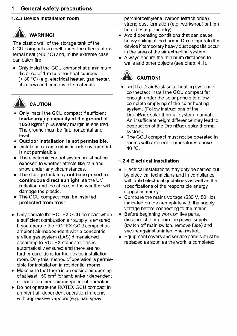
Special warning signsSome types of danger are represented by special symbols:
ValiditySome information in this manual has limited validity. The validity is highlighted by a symbol.
Order numberReferences to order numbers are identified with the shopping basket icon .
Handling instructions Handling instructions are shown as a list.
Actions for which the sequential order must be maintained are numbered. Results of actions are identified with an
arrow.
DANGER!
Draws attention to imminent danger.
Disregarding this warning can lead to serious injury or death.
WARNING!
Indicates a potentially dangerous situation.
Disregarding this warning may result in serious physical injury or death.
CAUTION!
Indicates a situation which may cause possible damage.
Disregarding this warning can cause damage to property and the environment, and result in minor injuries.
This symbol identifies user tips and par-ticularly useful information, but not warn-ings or hazards.
Electric current
Danger of explosion
Risk of burning or scalding
Risk of poisoning
Comply with the stipulated tightening torque (see chap. 12.3)
Only applies for units with unpressurised solar system connection (DrainBack).
Only applies for units with a bivalent solar system connection (Biv).

1 x General safety precautions
1.2 Safety instructions for installation and operation
1.2.1 General
Avoiding dangerROTEX GCU compact conforms to the state-of-the-art and meets all recognised technical requirements. However, improper use may result in serious physical injuries or death, as well as property damage. To prevent such risks, only install and operate the devices:– as stipulated and in perfect condition,– with an awareness of safety and the hazards
involved.
This assumes knowledge and use of the con-tents of this manual, of the relevant accident pre-vention regulations as well as the recognised safety-related and occupational health rules.
Before working on the heating system Only authorised and trained heating techni-
cians may work on the heating system (such as installation, connection and initial start-up).
Switch off the main switch and secure it against unintended switching on when carrying out any work on the heating system.
Seals must not be damaged or removed. Make sure that the safety valves comply with
the requirements of EN 12828 when connecting on the heating side, and with the requirements of EN 12897 when connecting on the domestic water side.
1.2.2 Use as intended
The ROTEX GCU compact may only be used for the heating of hot water heating systems. It may only be installed, connected and operated in ac-cordance with the information in this manual.
The ROTEX GCU compact may only be op-erated with the integrated circulation pump and only in conjunction with a controller system ap-proved by ROTEX.
Any other use outside the intended use is con-sidered as improper and will result in a loss of warranty. The operator alone shall bear respon-sibility for any resulting damage.
The ROTEX GCU compact is suitable for oper-ation with natural gas E, natural gas LL and liquid gas (propane).
Gases from regenerative sources (e.g. biogas) may contain substances that cause corrosion on the gas valve and can impair its function.
The gas composition must comply with the re-quirements on conditions for feeding into the gas distribution grid (low-pressure pipelines) of the public standard gas supply. Gases from regener-ative sources (e.g. biogas) may only be used when they have been previously prepared so that they can be fed into the public natural gas grid in accordance with regional regulations.
Intended use also includes compliance with the maintenance and service conditions. Re-placement parts must at least satisfy the tech-nical requirements defined by the manufacturer. This is the case, for example, with original spare parts.
WARNING!
Heating devices that have not been set up and installed correctly can impair the function of the heating device and/or cause serious or fatal in-juries to the user.
Work on the GCU compact (such as set-up, servicing, connection and initial start-up) must only be carried out by persons who are authorised and who have successfully completed qualifying technical or vocational training and who have taken part in advanced training sessions recognised by the relevant responsible authorities for the specific activity. These include, in particular, certified heating engineers, qualified electricians and HVAC specialists, who because of their professional training and expert knowledge, have experience in the professional installation and maintenance of heating systems, gas installations and heat water tanks.
Switch off the external main switch before starting any work on the GCU compact and secure it against unintentional switch-on.
Do not leave any tools or other objects below the hood of the unit after finishing installation or maintenance work.
1 x General safety precautions
1.2.3 Device installation room
Only operate the ROTEX GCU compact when a sufficient combustion air supply is ensured. If you operate the ROTEX GCU compact as ambient air-independent with a concentric air/flue gas system (LAS) dimensioned according to ROTEX standard, this is automatically ensured and there are no further conditions for the device installation room. Only this method of operation is permis-sible for installation in residential rooms.
Make sure that there is an outside air opening of at least 150 cm2 for ambient-air dependent or partial ambient-air independent operation.
Do not operate the ROTEX GCU compact in ambient-air dependent operation in rooms with aggressive vapours (e.g. hair spray,
perchloroethylene, carbon tetrachloride), strong dust formation (e.g. workshop) or high humidity (e.g. laundry).
Avoid operating conditions that can cause heavy soiling of the burner. Do not operate the device if temporary heavy dust deposits occur in the area of the air extraction system.
Always ensure the minimum distances to walls and other objects (see chap. 4.1).
1.2.4 Electrical installation
Electrical installations may only be carried out by electrical technicians and in compliance with valid electrical guidelines as well as the specifications of the responsible energy supply company.
Compare the mains voltage (230 V, 50 Hz) indicated on the nameplate with the supply voltage before connecting to the mains.
Before beginning work on live parts, disconnect them from the power supply (switch off main switch, remove fuse) and secure against unintentional restart.
Equipment covers and service panels must be replaced as soon as the work is completed.
WARNING!
The plastic wall of the storage tank of the GCU compact can melt under the effects of ex-ternal heat (>80 °C) and, in the extreme case, can catch fire.
Only install the GCU compact at a minimum distance of 1 m to other heat sources (> 80 °C) (e.g. electrical heater, gas heater, chimney) and combustible materials.
CAUTION!
Only install the GCU compact if sufficient load-carrying capacity of the ground of 1050 kg/m2 plus safety margin is ensured. The ground must be flat, horizontal and level.
Outdoor installation is not permissible. Installation in an explosion-risk environment
is not permissible. The electronic control system must not be
exposed to whether effects like rain and snow under any circumstances.
The storage tank may not be exposed to continuous direct sunlight, as the UV radiation and the effects of the weather will damage the plastic.
The GCU compact must be installed protected from frost.
CAUTION!
If a DrainBack solar heating system is connected: Install the GCU compact far enough under the solar panels to allow complete emptying of the solar heating system. (Follow instructions of the DrainBack solar thermal system manual). An insufficient height difference may lead to destruction of the DrainBack solar thermal system.
The GCU compact must not be operated in rooms with ambient temperatures above 40 °C.

1 x General safety precautions
1.2.5 Requirements for the heating water
Damage due to deposits and corrosion: Observe the current technological regulations to prevent corrosion products and deposits.
Measures for desalination, softening or hardness stabilisation are necessary, if the filling and top-up water have a high total hardness (>3 mmol/l - total of the calcium and magnesium concentrations, calculated as calcium car-bonate.
Minimum requirements regarding the quality of filling and supplementary water:– Water hardness (calcium and magnesium,
calculated as calcium carbonate): ≤ 3 mmol/l
– Conductivity: ≤ 1500 (ideal: ≤ 100) μS/cm– Chloride: ≤ 250 mg/l– Sulphate: ≤ 250 mg/l– pH-values (heating water): 6.5 - 8.5
Measures for desalination, softening or hardness stabilisation or other suitable condi-tioning measures are necessary to maintain the required water quality if the filling and top-up water have a high total hardness or other prop-erties divergent from the minimum requirements.
Using filling water and top-up water which does not meet the stated quality requirements can cause a considerably reduced service life of the equipment. The responsibility for this lies solely with the operator.
1.2.6 Heating system and sanitary connection
Create a heating system according to the safety requirements of EN 12828.
The plumbing connection must comply with the requirements of EN 12897. The require-ments of the following must also be observed:– EN 1717 – Protection against pollution of
potable water installations and general requirements of devices to prevent pollu-tion by backflow
– EN 61770 – Electric appliances connected to the water mains – Avoidance of back-siphonage and failure of hose-sets
– EN 806 – Specifications for installations inside buildings conveying water for human consumption
– and, in addition, the country-specific legis-lation.
During operation of the ROTEX GCU compact with additional heat source, the storage tank temperature may exceed 60 °C, above all when solar energy is used. It is advisable therefore to install a protection
from scalding (hot water mixer unit such as VTA32, 15 60 16) at the time of instal-lation.
1.2.7 Fuel
The ROTEX GCU compact is factory set to the gas type indicated on the burner sticker and on the settings type plate and adjusted to the gas pressure indicated on the burner sticker.
Operate the device only with the gas type and at the gas pressure specified on these stickers.
Gas installation and adjustment may only be carried out by gas technicians and in compliance with valid gas guidelines as well as the specifications of the responsible gas supply company.
1.2.8 Operation
Do not operate the ROTEX GCU compact if the protective cover is open.
Only operate the ROTEX GCU compact if all the requirements according to the checklist in chap. 5.2 are satisfied.

2 x Handover to operator and warranty
2 Handover to operator and warranty
2.1 Instruct the owner
Before you hand over the heating system, explain to the owner how he/she can operate and check the heating system.
Hand over the technical documentation (at least the operating instructions and operating manual) to the operator and advise him that these documents must be made available at all times and be stored in the immediate vicinity of the device.
Document the handover by filling out the installation and instruction forms together with the owner and sign them.
2.2 Warranty conditions
The legal guarantee conditions fundamentally apply. Our war-ranty conditions beyond that can be found online on your sales presentative's webpage.
There is only an entitlement to warranty services when it can be certified that the annual maintenance work according to chap. 9 has been regularly completed.

3 x Product description
3 Product description
3.1 Design and components
3.1.1 GCU compact 315 / 320
Fig. 3-1 Design and components of GCU compact 315 / 320 - top view (for legend designations, see tab. 3-1)
Fig. 3-2 Design and components GCU compact 315 / 320 - front view (for legend designations, see tab. 3-1)
Fig. 3-3 Design and components GCU compact 315 / 320 - schematic diagram (for legend designations, see tab. 3-1)
FA ROTEX GCU2 - 06/2017 11
3 x Product description
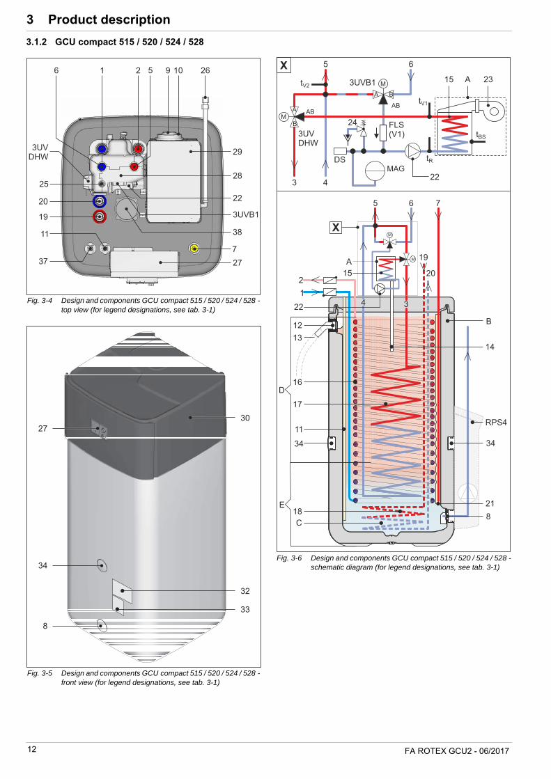
3.1.2 GCU compact 515 / 520 / 524 / 528
Fig. 3-4 Design and components GCU compact 515 / 520 / 524 / 528 - top view (for legend designations, see tab. 3-1)
Fig. 3-5 Design and components GCU compact 515 / 520 / 524 / 528 - front view (for legend designations, see tab. 3-1)
Fig. 3-6 Design and components GCU compact 515 / 520 / 524 / 528 -schematic diagram (for legend designations, see tab. 3-1)
12 FA ROTEX GCU2 - 06/2017

3 x Product description
Fig. 3-7 Design and components diagram for GCU compact 515 / 520 / 524 / 528 (for legend designations, see tab. 3-1)
FA ROTEX GCU2 - 06/2017 13

3 x Product description
Tab. 3-1 Legend for fig. 3-1 to fig. 3-7
3.2 Brief description
The ROTEX Gas Combi Unit 2 (GCU compact) is a fully preas-sembled gas condenser unit integrated in a hot water storage tank. The excellent thermal insulation properties of the plastic storage tank ensure that heat losses are kept to a minimum. The aluminium boiler body is in a metal housing inserted into the cover of the storage tank. The complete flue gas unit is sur-rounded by fresh air.
Operating modeThe ROTEX GCU compact is designed so that it can be operated ambient air-independent (concentric flue gas/supply pipes). The burner suctions the combustion air directly in through an instal-lation shaft or a double-walled flue gas pipe. This method operation is recommended by ROTEX and has many advan-tages:– The heating room does not need any ventilation opening into
the open air and therefore does not cool down.– Lower energy consumption.– Additional energy recovery in the flue gas pipe through pre-
heating the combustion air.– Contamination from the environment of the burner are not
suctioned in. The heating room can thus be used as a work-space, laundry room, etc. at the same time.
– Possible to install in loft areas or attic.
The accumulated condensate is collected in the flue gas collector and transported through a plastic pipe into the storage tank where it is neutralised.
The unpressurised storage tank water acts as the heat storage medium. Useful heat is supplied and removed via the spiral heat
exchanger, which is made from a stainless steel corrugated pipe (1.4404), and is completely immersed in the storage tank water.
The hot water zone in the storage tank works as a combination of heat storage and geyser (see fig. 3-3 and fig. 3-6).
The cold water which flows out when the hot water is removed is first routed to the storage tank at the very bottom of the heat ex-changer, where it cools the lower area of the storage tank down as much as possible. The readiness zone is flowed through and heated from top to bottom by the heat exchanger for the storage tank charging (SL-WT) which is heated by the gas burner.
On its way to the top, the domestic water continuously absorbs the heat of the storage tank water. As the flow direction makes use of the counter flow principle and the heat exchanger has a spiral shape, there is definite temperature stratification within the hot water storage tank. As high temperatures can be maintained for a very long time in the upper section of the storage tank, a high hot water output is achieved even if water is drawn off over a long period of time.
– In the GCU compact 5xx (Biv) models, the SL-WT ends approx. 40 cm above the floor of the container. Only the hot water zone above that point is heated by the boiler. The water below that point in the tank is heated by solar power alone.
– In the GCU compact 3xx (Biv) models, the SL-WT descends to the floor of the container. The entire storage volume is heated by the boiler (greater hot water output readiness).
1 Cold water connection (1" AG) 2)
2 Hot water connection (1" AG) 2)
3 Storage tank - inflow (1" AG) 4 Storage tank - return flow (1" AG) 5 Heater - inflow (1" AG)* 2)
6 Heater - return flow (1" AG)* 7 Solar - inflow (1" IG) 8 Drain connection or
Solar - return flow9 Flue gas10 Supply air11 Sensor immersion sleeve for storage tank
temperature sensor tDHW12 Upper filling connection and condensate
overflow connection 13 Condensate drain hose (on the building
side)14 Condensate pipe15 Heating heat exchanger (boiler body)16 Heat exchanger (stainless steel) for do-
mestic hot water heating17 Heat exchanger (stainless steel) for stor-
age tank charging and heating support18 Heat exchanger (stainless steel) for biva-
lent storage tank charging 1)
19 Biv storage tank charging - inflow 1)2)
(1" IG) 20 Biv storage tank charging - return flow
1)2) (1" IG) 21 Solar - inflow layering pipe22 Heating circulation pump23 Burner blower24 Safety pressure relief valve (heating cir-
cuit) 25 Vent valve (manual)
26 Gas connection (G ½" IG) with connected gas hose
27 Boiler control panel with RoCon BF con-troller
28 Thermal insulation29 Panelling of the heat cell30 Cover31 Holding burls for protective cover32 Type plate33 Settings type plate34 Threaded insert for carrying loop35 Combined filling and draining valve (heat-
ing circuit)36 Automatic vent valve37 Fill level indicator (tank water) 38 Electrical connection of Backup heater
BUxx39 Ball cock (heating circuit)40 MAG connection
3UV DHW3-way valve (distribution valve, hot wa-ter/heating/heating support)
3UVB13-way valve (mixer valve)
tDHW Storage tank temperature sensor tR Return flow temperature sensor (boiler cir-
cuit) tV1 Inflow temperature sensor (boiler circuit)
tV2 Internal mixer sensor = inflow temperature
sensor (heating circuit)
A Gas boiler B Storage tank (polypropylene double walled
jacket with PUR hard foam heat insulation)C Pressure-free storage tank waterD Hot water zoneDS Pressure sensor E Solar zoneFLS
Flow sensor (boiler circuit) MAG
Diaphragm expansion vessel (on the build-ing side)
RPS4Optional: ROTEX Solaris R3 control and pump unit
AG External threadIG Internal threadÜM Union nut
Safety devicesObserve tightening torque!
* Ball cock (1" IG) is supplied.1) Only valid for types with Biv configuration2) Recommended accessories:
Circulation brake SKB (2 pcs each), 16 50 70
14 FA ROTEX GCU2 - 06/2017

3 x Product description
Optimum water hygieneThere are no low flow or unheated zones on the domestic water side with the ROTEX GCU compact. It is not possible for sludge, rust or other sediments to be deposited, as can be the case with other large volume tanks. The water fed into the system first is also discharged first (first in, first out principle).
Low scalingOn the storage tank side scale can only be deposited once. All the stainless steel heat exchanger pipes in the storage tank water largely remain virtually free of solid deposits. This means that the scale cannot build up which would continuously reduce the effi-ciency of heat transfer (as is the case for other storage designs) during the operation time.
The thermal and pressure expansion and high flow rates in the domestic water heat exchanger cause any scale deposits to loosen, and they are then flushed away.
Using solar powerThe hot water storage tank of the ROTEX GCU compact can also be heated by solar energy. The entire hot water storage tank can be heated up depending on the heat available from the sun.. The stored heat is used for the hot water preparation and for the heating system support. The ISM ("Intelligent Storage Manager") controls the integrated 3-way valves in such a way that the solar heat yield is optimally divided and used for hot water preparation and heating support. The high total storage capacity enables bridging of periods without a solar yield.
When a ROTEX pressurised solar system or an external heating boiler is used as an external heat generator, then only one of the GCU compact with Biv configuration - listed in chap. 3.1 - is per-mitted as the primary hot water storage unit.
On the GCU compact Biv models the complete storage tank is designed as a hot water zone. It is possible to make thermal use of solar energy for hot water preparation. The solar component is optimised in combination with an upstream ROTEX Solaris system (pre-heating stage).
Safety managementThe entire safety management of the ROTEX GCU compact is carried out by an electronic controller. It performs a safety switch-off in the event of water shortage, gas shortage or undefined op-erating states. A corresponding fault signal provides an engineer with all the necessary information for troubleshooting.
Electronic controlAn electronic digital controller combined with the burner "intel-ligent" firing unit automatically controls all heating and hot water functions for the direct heating circuit and a storage tank charging circuit.
Optionally, connected RoCon M1 ( 15 70 68) mixer modules can be used to connect and regulate one or more mixed circuits.
All settings, displays and functions are carried out by the inte-grated RoCon BF controller. The display and the operating ele-ments make operation easy.
A digital room controller (RoCon U1, 15 70 34) is optionally available to provide greater ease of operation. It can be used as a remote control and room thermostat.
The controller can be connected to the internet by the optional gateway (RoCon G1, 15 70 56). This enables remote control of the ROTEX GCU compact by mobile phones (by app).
Condensing technologyThe calorific value engineering makes optimum use of the energy contained in the heating gas. The flue gas is cooled down in the boiler – and in the flue system with ambient air-independent op-eration in the concentric flue gas system – to the extent that the temperature is below the dew point. A part of the water vapour generated on combustion of the gas thus condenses. The con-densation heat is fed to the heating, as opposed to low-temper-ature boilers, which enables efficiency rates of over 100% (based on the lower heating value).
FA ROTEX GCU2 - 06/2017 15
4 x Set-up and installation
4 Set-up and installation
Incorrect set-up and installation would render the manufacturer's guarantee void. If you have questions, please contact our Tech-nical Customer Service.
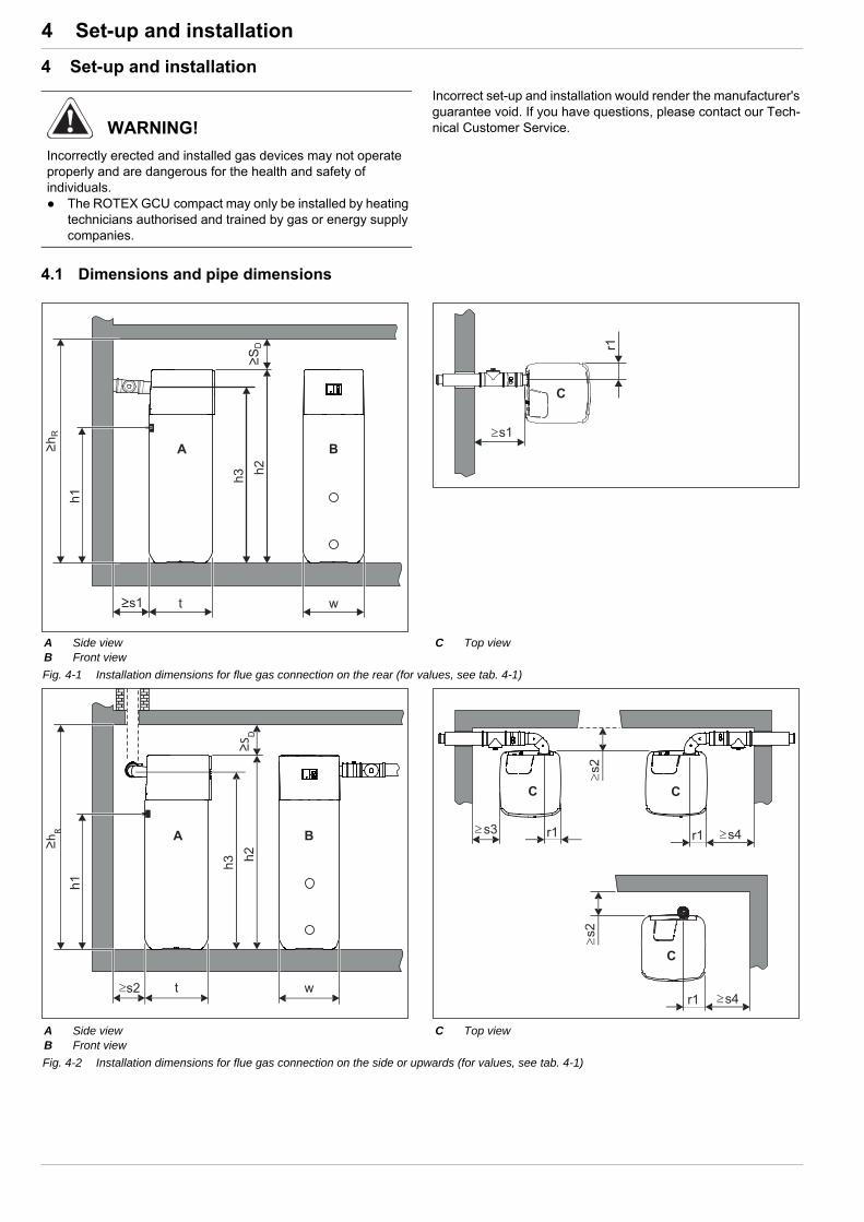
4.1 Dimensions and pipe dimensions
WARNING!
Incorrectly erected and installed gas devices may not operate properly and are dangerous for the health and safety of individuals. The ROTEX GCU compact may only be installed by heating
technicians authorised and trained by gas or energy supply companies.
A Side viewB Front view
C Top view
Fig. 4-1 Installation dimensions for flue gas connection on the rear (for values, see tab. 4-1)
A Side viewB Front view
C Top view
Fig. 4-2 Installation dimensions for flue gas connection on the side or upwards (for values, see tab. 4-1)
h1
h3
t
h2
w
A
s2
B≥hR
≥SD
s2
C
s4r1
C
s3 r1
s2
C
s4r1

4 x Set-up and installation
Tab. 4-1 Connection and installation dimensions of the GCU compact in mm (based on fig. 4-1, fig. 4-2, fig. 4-10, fig. 4-16 to fig. 4-18)
Dim. GCU compact 3xx GCU compact 5xx
h1 1380
h2 1895
h3 1725 1720
hR 2050
r1 165 130
s1 440 370
s2 200
s3 300
s4 435 335
s5 600
s6 600
sD 200
t 615 790
w 595 790
4 x Set-up and installation
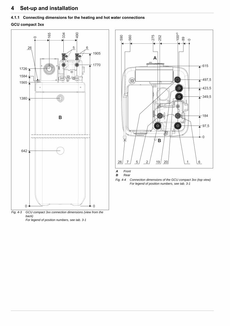
4.1.1 Connecting dimensions for the heating and hot water connections
GCU compact 3xx
Fig. 4-3 GCU compact 3xx connection dimensions (view from the back)For legend of position numbers, see tab. 3-1
A FrontB Rear
Fig. 4-4 Connection dimensions of the GCU compact 3xx (top view)For legend of position numbers, see tab. 3-1

4 x Set-up and installation
GCU compact 5xx
Fig. 4-5 Connection dimensions GCU compact 5xx (view from the back)For legend of position numbers, see tab. 3-1
A FrontB Rear
Fig. 4-6 Connection dimensions GCU compact 5xx (top view)For legend of position numbers tab. 3-1
To prevent increased cooling losses ROTEX recom-mends installation of SKB gravity brake systems ( 16 50 70) or syphoning (lead the connection lines straight downwards) of the drinking water connections.

4 x Set-up and installation
4.2 Installation versions
The ROTEX GCU compact is designed basically for ambient air-independent operation. They are fitted with a concentric flue gas/air supply pipe DN 60/100.
The SET GCU1 ( 15 50 79.17) kit can be used to flexibly ar-range the flue gas/air supply line for the connection directions to the rear, to the side or upwards and extended to DN 80/125.
4.2.1 Ambient air-independent mode
Installation version 1The ROTEX GCU compact with the SET GCU1 and the concentric LAS connection line SET H or SET K is connected to the chimney or an installation shaft.– The combustible air supply from the outside runs through the
chimney or through an installation shaft.– The flue gas discharge to the outside runs through the same
shaft as the air supply.– Minimum vertical distance between flue gas exit and roof
ridge: 40 cm.– Equipment type C93
Installation version 2The ROTEX GCU compact is placed directly below the roof. Connection with SET GCU1 and SET L.– The combustible air supply and flue gas discharge run
through a concentric dual pipe.– The combustible air supply from the outside runs through the
outer ring-shaped gap of the dual pipe, and the flue gas dis-charge to the outside runs through the inner tube.
– Minimum vertical distance between flue gas exit and roof sur-face: 40 cm.
– Minimum height of the flue gas pipe: 2 m.– Equipment type C33
Installation version 3The ROTEX GCU compact is not placed directly below the roof. The dual pipe for the combustible air supply and flue gas duct runs through the roof truss.– The combustible air supply and the flue gas discharge run
through a concentric dual pipe (as in Installation version 2).– In the area of the roof truss, the dual pipe for the combustible
air supply and the flue gas duct must be laid through a protec-tive pipe with sufficient fire resistance or be structurally sepa-rated from the roof truss.
– Equipment type C33
1-6 Installation versions (for the description, see chap. 4.2.1 to 4.2.3)
CA Supply air (combustion air)FG Flue gasRV Rear ventilation
a Installation version for ambient air-independent operation (flue gas/supply air concentric)
b Installation version for partial ambient air-independent operation (flue gas/supply air separate)
c Installation version for ambient air-dependent operationd Longitudinally ventilated shaft with a fire-resistance period of 90
minutes (30 minutes in low height residential buildings). Observe country-specific regulations for fire-resistance periods!
e Ventilation opening (1x150 cm2 or 2x75 cm²)f Rear ventilation opening (150 cm2)
Fig. 4-7 Installation versions for the GCU compact
In some cases, the resonance in the flue gas system can amplify the noise at the mouth of the flue gas duct. The noise level can be effectively reduced by using a silencer (DN 80: E8 MSD, 15 45 78 or DN 110:
E11 MSD, 15 45 79).
Use of the ROTEX GCU compact in ambient air-inde-pendent operation with a concentric flue gas/air supply line is recommended by ROTEX. If possible, choose this installation version!
In partial ambient air-independent operation (separate flue gas/air supply lines with a single-walled connecting pipe) and ambient air-dependent operation the installation room must have a ventilation opening of at least 150 cm2 to the outside.
This reduces the overall energy efficiency of the building ac-cording to European Directive 2010/31/EU: EPBD.
The following descriptions of the different set-ups includes infor-mation regarding the possible classification of equipment based on the type of flue gas routing (equipment type) in accordance with CEN/TR 1749. Chapters 4.2.4 and 4.5 must also be heeded in this regard.
Separate assembly instructions are enclosed with the described SETs.
When equipment is installed in residential rooms only one of the installation versions 1 to 4 is permissible.

4 x Set-up and installation
Installation version 4The ROTEX GCU compact with the SET GCU1 and the LAS connection line SET H or SET K is connected to the exterior wall system SET G.– The combustible air supply from the outside runs through the
ring-shaped gap in the dual pipe, through the outer wall (suc-tion from below).
– The flue gas discharge to the outside runs through a concen-tric pipe, through the outer wall and then up to at least 40 cm over the roof surface. In the external area, the outer air gap serves as heat insulation for the flue gas pipe.
– Equipment type C53
Installation version 5If, for constructional or legal/regulatory reasons, the shaft used for the flue gas routing is not suited for also routing the com-bustion air at the same time, the combustion air must be routed through a separate line.
If the flue gas connection line to the shaft is double-walled and is surrounded by the combustion air, there are no additional venti-lation requirements on the installation room.
– Combustion air supply is routed from the outside via the ade-quately sealed supply line which is connected directly to the concentric exterior pipe of the connection line. The supply line should be sized so that the suction resistance at nominal output is less than 50 Pa.
– The connection line between the ROTEX GCU compact and the installation shaft is completely concentric and surrounded by combustion air.
– Equipment type C53, C83
Installation variant 7 (not shown)Insofar as the local provisions allow, the GCU compact with SET W2 ( 15 50 79.12) can be connected with a horizontal flue gas outlet.
– The combustible air supply and flue gas discharge run through a concentric dual pipe.
– The combustible air supply runs from the outside through the outer ring-shaped gap of the dual pipe (supply air inlet via the intake grille of the wall feed through) and the flue gas dis-charge to the outside runs through the inner tube.
– Minimum height of the flue gas pipe: 2 m– Observe local regulations regarding minimum distances of
windows or other building openings.– Equipment type C13
4.2.2 Partial ambient air-independent mode
Alternative to installation variant 5The ROTEX GCU compact is operated with separately routed supply air/flue gas lines (2-pipe system).– The combustion air supply from the outside runs through an
adequately sealed air supply line through the external wall. The supply line should be sized so that the suction resist-ance at nominal output is less than 50 Pa.
– Flue gas discharge to the outside runs through the chimney or an installation shaft. If the connection line between the ROTEX GCU compact and the installation shaft is single-walled or not completely surrounded by combustion air, a ventilation opening to the outside of at least 150 cm2 is required.
Appropriate measures must be taken to ensure that the burner cannot be operated if the ventilation opening is closed.
– The installation shaft where the flue gas line runs must be rear ventilated. There must be a rear ventilation opening of at least 150 cm2 in the lower area. The cross-section of this installation shaft must be sized so that between the external wall of the flue gas line and the internal face of the installation shaft the following mini-mum distance must be maintained:– with a rectangular shaft cross-section: 2 cm– with a round shaft cross-section: 3 cm.The rear ventilation opening must not be located in rooms where a negative pressure is generated (e.g. by controlled apartment ventilation, a tumble-drier etc.).
– Equipment type C53, C83
4.2.3 Ambient air-dependent mode
Installation version 6The ROTEX GCU compact can also be connected ambient air-dependent. Thereby, only the inner flue gas pipe (plastic pipe Ø 60 mm) of the concentric air-flue gas pipe is connected to the flue gas line. The device sucks the combustible air from the in-stallation room through the ring-shaped gap of the jacket pipe.
For the flue gas routing to the outdoors, the shaft sizing and the rear ventilation, the same conditions apply as in chap. 4.2.2. A ventilation opening to the outside of at least 150 cm2 is imper-ative.
– Equipment type B23, B23P, B33, B53, B53P
4.2.4 Additional information on equipment type in accordance with CEN/TR 1749
C13:– Horizontal openings for flue gas outlet and supply air inlet– Openings within a square of 50 cm x 50 cm
C33:– vertical openings for flue gas outlet and supply air inlet– Openings within a square of 50 cm x 50 cm– Spacing of opening levels < 50 cm
C43:– Connection of more than one piece of equipment to a com-
mon air/flue gas system that is part of the building– vertical opening for flue gas outlet and supply air inlet– Openings within a square of 50 cm x 50 cm– Spacing of opening levels < 50 cm– Suitable calculated dimensioning verification required
because vacuum prevails in the case of the flue gas inlet into the common air/flue gas system. The flue gas must be dis-charged with a natural draught.
– For data on dimensioning calculation, see tab. 15-1.– Condensate flow from the common air/flue gas system must
not be discharged through the equipment.
If the wall feed through is at a height of less than one meter above the ground, ROTEX recommends routing the combustion air through a separate air supply pipe (mounting height: approx. 2 m). W8 ZR,
15 50 79.00 66 or W11 ZR, 15 50 77.00 30
ROTEX basically recommends installing the GCU compact regardless of the room air (equipment type C) and with concentric air/flue gas guides (see chap. 4.2.1). Other permissible applications of the air
intake and flue gas discharge are not described in detail in these instructions.
Special requirements that exist for such systems based on EN 15505 are listed below.

4 x Set-up and installation
C53:– Vertical opening for flue gas outlet– Opening for supply air inlet into different pressure area possi-
ble.– Openings must not be installed on opposite walls of the build-
ing
C63:– Connection to a separately approved and marketed flue
gas/supply air system if allowed by national law.– This allows all other described installation forms to the real-
ised for equipment type C if the conditions of the respective installation form are met.
– If the dimensions of the system used differ from those described in this manual (see chap. 4.5.1), a suitable arith-metical dimensioning verification is required.
– For data on dimensioning calculation, see tab. 15-1.– Properties and possible applications of the pipe system:
a) Minimum requirements according to chap. 4.5.1 fulfilledb) Condensate flow into the equipment allowed with single
assignment, not allowed with multiple assignment.c) Maximum combustion air temperature: 60 °Cd) Maximum allowed flue gas recirculation current under
wind conditions: 10%
C83:– Connection to one or more pieces of equipment to an under-
pressure flue gas system that is part of the building.– Vertical opening for flue gas outlet– Air supply feed via associated second pipe1)
– Opening for supply air inlet into different pressure area possi-ble.
– Suitable arithmetical dimensioning verification required because vacuum prevails in the case of the flue gas inlet into the common air/flue gas system.
– For data on dimensioning calculation, see tab. 15-1.– Properties and application options of the flue gas system:
a) Minimum requirements according to chap. 4.5.1 fulfilled (except for pressure class)
b) Condensate flow into the equipment allowed with single assignment, not allowed with multiple assignment.
C93:– as for C33, but– Connection of the supply air pipe to an existing vertical shaft
(e.g. chimney) that is part of the building.1)
– The cross-section of this installation shaft must be dimen-sioned so that the following minimum distance must be maintained between the external wall of the flue gas line and the internal face of the installation shaft:– with a rectangular shaft cross-section: 2 cm– with a round shaft cross-section: 3 cm.
B23:– Flue gas pipe without flow safeguard - underpressure opera-
tion– Properties and application options of the flue gas pipe:
a) Minimum requirements according to chap. 4.5.1 fulfilled– Opening for flue gas outlet to the outside– Supply air directly from installation room (see chap. 4.2.3)– If the dimensions of the flue gas pipe differ from those
described in these instructions (see tab. 4-2), a suitable cal-culated dimensioning verification is required.
– For data on dimensioning calculation, see tab. 15-1.
B23P:– as for B23, but underpressure operation
B33:– Connection of more than one piece of equipment to a com-
mon flue gas system (underpressure flue gas shaft)– Vertical opening for flue gas outlet– Supply air directly from the installation room (see chap. 4.2.3)– Suitable arithmetical dimensioning verification required
because vacuum prevails in the case of the flue gas inlet into the common air/flue gas system.
– For data on dimensioning calculation, see tab. 15-1.– Parts under overpressure of the connection pipe must be con-
ducted as a concentric pipe system.
B53:– as for B33, but connection to associated flue gas pipe
(ROTEX system) including flue gas opening
B53P:– as for B53, but overpressure operation
1) If the air supply pipe was used beforehand as a flue gas pipe or chimney of an oil or solid fuel furnace, it should be cleaned prior to use as an air supply pipe.

4 x Set-up and installation
4.3 Transport and delivery
The ROTEX GCU compact is delivered on a pallet. All industrial trucks, such as lifting trucks and forklift trucks, are suitable for transporting it.
Scope of delivery– ROTEX GCU compact (preassembled),– Bag of accessories (see fig. 4-8),– External temperature sensor (RoCon OT1), for weather-con-
trolled regulation– Document pack.
For additional accessories, see the ROTEX price list.
4.4 Installing the GCU compact
4.4.1 Selecting the installation site
The installation site for the ROTEX GCU compact must meet the minimum requirements below (see also chap. 1.2.3).
Installation area– The base must be level and smooth and have a sufficient
ground load-bearing capacity of 1050 kg/m² plus safety factor. Install a pedestal if necessary.
– Observe the installation dimensions (see chap. 4.1).
Installation room– There are no special conditions for ventilation of the installa-
tion room for ambient air-independent operations (using a concentric air/flue gas system).
– In partial ambient air-independent and ambient-dependent mode, the installation room must have a ventilation opening of at least 150 cm2 to the outside. If the flue gas line is routed to the outside through an installation shaft, it must be rear-ventilated (see chap. 4.2.2).
– For partial ambient air-independent and for ambient air-dependent mode, the installation room must be free from aggressive vapours (e.g. hair spray, perchloroethylene, car-bon tetrachloride), heavy dust formation and high atmos-pheric humidity (e.g. washhouse).
– Outdoor installation is not permissible. – Installation in an explosion-risk environment is not permissi-
ble.– The electronic controller may never be exposed to the effects
of the weather.– The storage tank may not be exposed to continuous direct
sunlight, as the UV radiation and the effects of the weather will damage the plastic.
– The GCU compact must be installed protected from frost.
Surface temperatures, minimum distance
– In ambient air-independent mode with rated power, the design does not allow temperatures > 70 °C on any compo-nent outside the unit panels. Therefore, no minimum distance is specified for components made with flammable materials.
WARNING!
The ROTEX GCU compact is top-heavy when unfilled and could tilt over during transport. That could put persons in danger or damage the unit. Secure the ROTEX GCU compact well, transport carefully,
use handles.
A Handles (only required for transport)
B Cover screenC Hose connecting piece for
safety overflowD SpannerE Ball cock
F Flat sealG O-ringH Cable tieI StirrupJ Venting hoseK Outside temperature sensor
Fig. 4-8 Contents of bag of accessories
WARNING!
The plastic wall of the storage tank of the ROTEX GCU compact can melt under the effects of external heat (>80 °C) and, in the extreme case, can catch fire. Only install the ROTEX GCU compact with a minimum
distance of 1 m to other heat sources (>80 °C) (e.g. electrical heater, oil heater, chimney) and the material to be combusted.
CAUTION!
If the ROTEX GCU compact is not installed a sufficient distance below the flat solar panels (the top edge of the storage tank is higher than the bottom edge of the solar panels), the unpressurised solar system in the outdoor area will not be able to drain completely. When a solar connection is used, install the GCU compact
low enough at the flat solar panels (observe minimum gradient in the solar connection lines).

4 x Set-up and installation
– A minimum distance of 50 mm between the flue gas line and flammable components should be maintained in a partial ambient air-independent and ambient air-dependent opera-tion (separate flue gas/air supply pipes).
– Do not use or store easily inflammable and easily combustible substances directly next to the ROTEX GCU compact (mini-mum distance 1 m, see fig. 4-10).
– When setting up the equipment as described in chap. 4.4.2, ROTEX recommends maintaining minimum distances from walls and ceilings in order to perform maintenance and repair work without excessive installation effort.
4.4.2 Installing the unit
Precondition– The installation site complies with applicable country-specific
regulations and meets the minimum requirements described in chap. 4.4.1.
Installation Remove packing and dispose of it in an environment-friendly
manner. Pull off the cover screens from the storage tank (fig. 4-9,
item B) and unscrew the threaded fittings (fig. 4-9, item F) from the openings at which the handles are to be fitted.
Screw the handles (fig. 4-9, item A) into the now uncovered threaded holes.
Carefully transport the ROTEX GCU compact to the instal-lation site, use the handles.
Install the ROTEX GCU compact at the installation site.– Recommended minimum distances:
From the wall:to the rear (s1/s2): ≥ 200 mm*to the left (s3): ≥ 300 mmto the right (s4): ≥ 300 mm** or the values according to tab. 4-1 (depending on the
flue gas connection)From the ceiling (sD): ≥ 200 mm.
– Install close to the withdrawal point.
If necessary, install the booster heater with an empty storage tank in the tilted position (see fig. 4-10).
WARNING!
The ROTEX GCU compact is top-heavy when unfilled and could tilt over during transport. That could put persons in danger or damage the unit. Secure the ROTEX GCU compact well, transport carefully,
use handles.
Fig. 4-9 Installing the handles (for legend, see fig. 4-8)
The GCU compact provides the option of installing an electrical auxiliary heater (BUxx booster heater). For example, renewable energy can be used as an addi-tional heat source.

4 x Set-up and installation
Lay the connection lines in such a way that the protective cover can be removed (fig. 4-11).
4.4.3 Removing the cover and thermal insulation
Unhook the protective cover from the rearward facing holding burls, lift at the back and remove to the front.
Fig. 4-10 Minimum distances for setting up the GCU compact(for dimensions, see tab. 4-1) and installing a booster heater at low ceiling heights
Fig. 4-11 Remove the protective cover
Fig. 4-12 ROTEX GCU compact without protective cover
CAUTION!
The thermal insulation (fig. 4-12, item A) consists of pressure-sensitive EPP moulded parts that can be easily damaged if not handled correctly. Only remove the thermal insulation in the order stated below
and in the stated directions. Do not use force. Do not use tools.
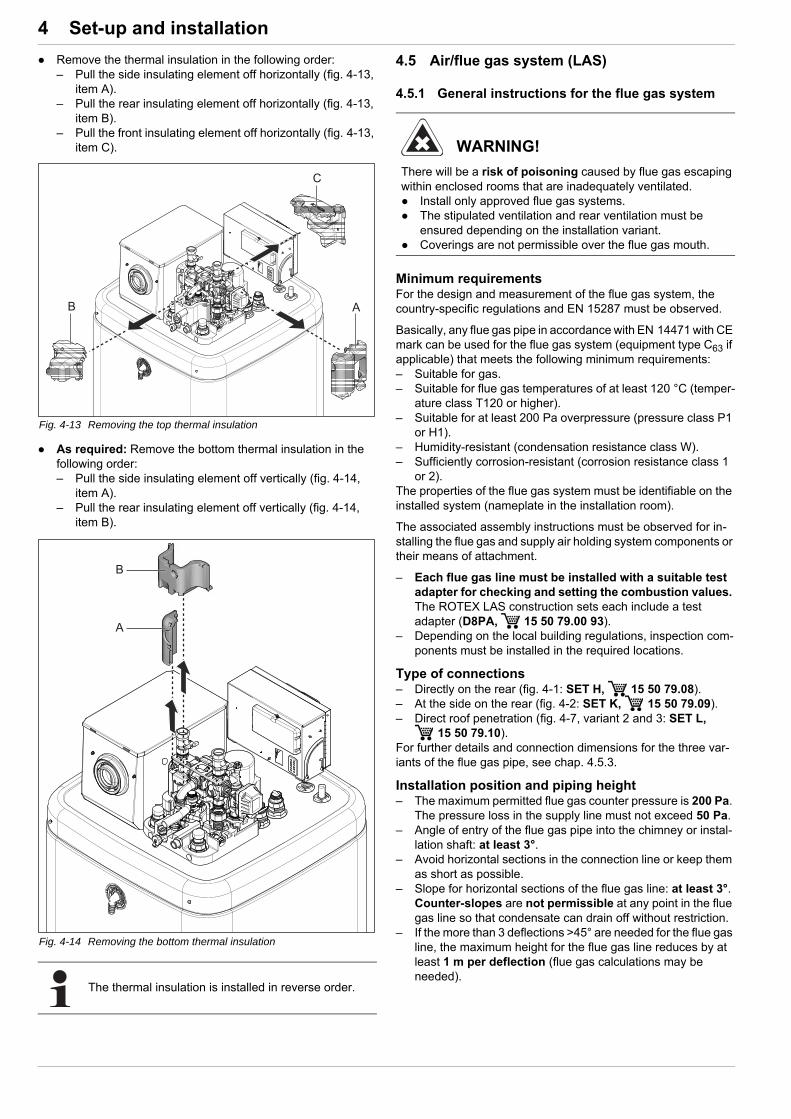
4 x Set-up and installation
Remove the thermal insulation in the following order:– Pull the side insulating element off horizontally (fig. 4-13,
item A).– Pull the rear insulating element off horizontally (fig. 4-13,
item B).– Pull the front insulating element off horizontally (fig. 4-13,
item C).
As required: Remove the bottom thermal insulation in the following order:– Pull the side insulating element off vertically (fig. 4-14,
item A).– Pull the rear insulating element off vertically (fig. 4-14,
item B).
4.5 Air/flue gas system (LAS)
4.5.1 General instructions for the flue gas system
Minimum requirementsFor the design and measurement of the flue gas system, the country-specific regulations and EN 15287 must be observed.
Basically, any flue gas pipe in accordance with EN 14471 with CE mark can be used for the flue gas system (equipment type C63 if applicable) that meets the following minimum requirements:– Suitable for gas.– Suitable for flue gas temperatures of at least 120 °C (temper-
ature class T120 or higher).– Suitable for at least 200 Pa overpressure (pressure class P1
or H1).– Humidity-resistant (condensation resistance class W).– Sufficiently corrosion-resistant (corrosion resistance class 1
or 2).The properties of the flue gas system must be identifiable on the installed system (nameplate in the installation room).
The associated assembly instructions must be observed for in-stalling the flue gas and supply air holding system components or their means of attachment.
– Each flue gas line must be installed with a suitable test adapter for checking and setting the combustion values. The ROTEX LAS construction sets each include a test adapter (D8PA, 15 50 79.00 93).
– Depending on the local building regulations, inspection com-ponents must be installed in the required locations.
Type of connections– Directly on the rear (fig. 4-1: SET H, 15 50 79.08).– At the side on the rear (fig. 4-2: SET K, 15 50 79.09).– Direct roof penetration (fig. 4-7, variant 2 and 3: SET L,
15 50 79.10).For further details and connection dimensions for the three var-iants of the flue gas pipe, see chap. 4.5.3.
Installation position and piping height– The maximum permitted flue gas counter pressure is 200 Pa.
The pressure loss in the supply line must not exceed 50 Pa.– Angle of entry of the flue gas pipe into the chimney or instal-
lation shaft: at least 3°.– Avoid horizontal sections in the connection line or keep them
as short as possible.– Slope for horizontal sections of the flue gas line: at least 3°.
Counter-slopes are not permissible at any point in the flue gas line so that condensate can drain off without restriction.
– If the more than 3 deflections >45° are needed for the flue gas line, the maximum height for the flue gas line reduces by at least 1 m per deflection (flue gas calculations may be needed).
Fig. 4-13 Removing the top thermal insulation
Fig. 4-14 Removing the bottom thermal insulation
The thermal insulation is installed in reverse order.
WARNING!
There will be a risk of poisoning caused by flue gas escaping within enclosed rooms that are inadequately ventilated. Install only approved flue gas systems. The stipulated ventilation and rear ventilation must be
ensured depending on the installation variant. Coverings are not permissible over the flue gas mouth.
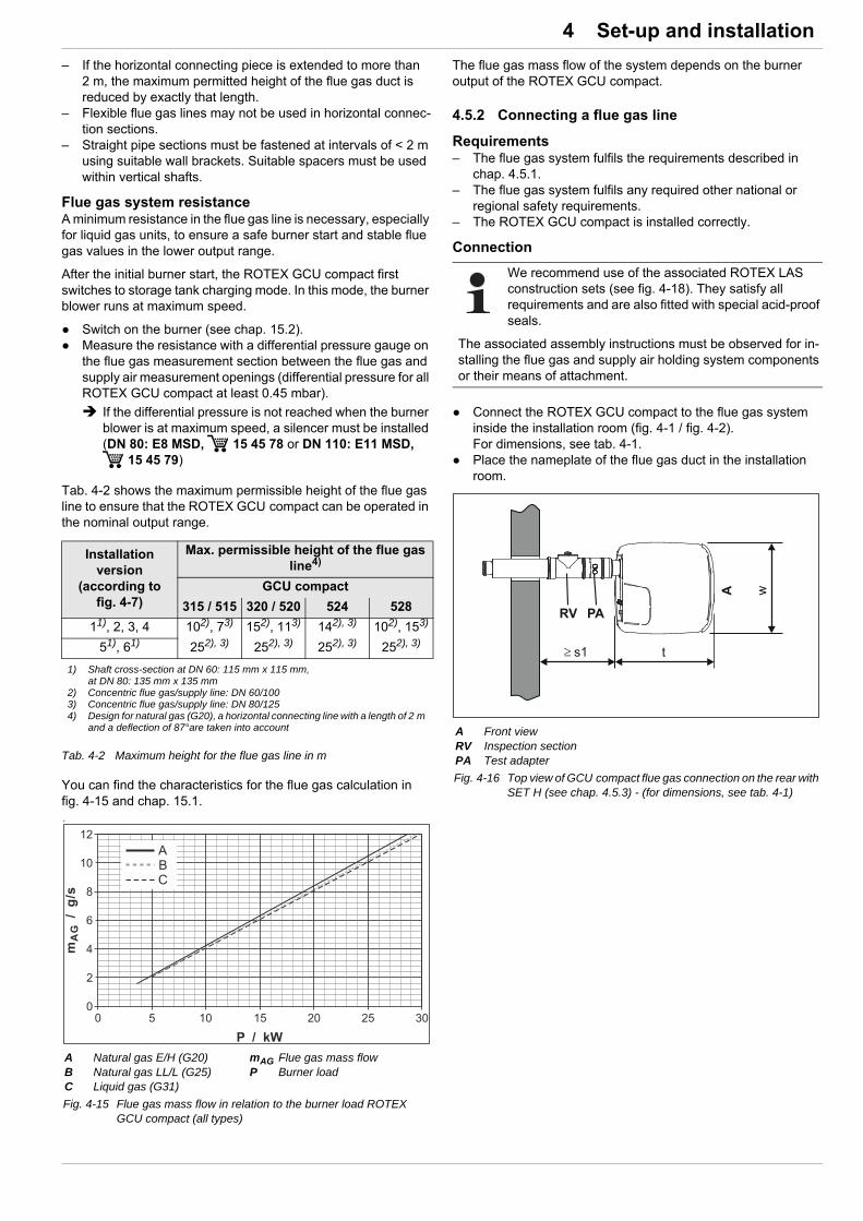
4 x Set-up and installation
– If the horizontal connecting piece is extended to more than 2 m, the maximum permitted height of the flue gas duct is reduced by exactly that length.
– Flexible flue gas lines may not be used in horizontal connec-tion sections.
– Straight pipe sections must be fastened at intervals of < 2 m using suitable wall brackets. Suitable spacers must be used within vertical shafts.
Flue gas system resistanceA minimum resistance in the flue gas line is necessary, especially for liquid gas units, to ensure a safe burner start and stable flue gas values in the lower output range.
After the initial burner start, the ROTEX GCU compact first switches to storage tank charging mode. In this mode, the burner blower runs at maximum speed.
Switch on the burner (see chap. 15.2). Measure the resistance with a differential pressure gauge on
the flue gas measurement section between the flue gas and supply air measurement openings (differential pressure for all ROTEX GCU compact at least 0.45 mbar).
If the differential pressure is not reached when the burner blower is at maximum speed, a silencer must be installed (DN 80: E8 MSD, 15 45 78 or DN 110: E11 MSD,
15 45 79)
Tab. 4-2 shows the maximum permissible height of the flue gas line to ensure that the ROTEX GCU compact can be operated in the nominal output range.
Tab. 4-2 Maximum height for the flue gas line in m
You can find the characteristics for the flue gas calculation in fig. 4-15 and chap. 15.1.
The flue gas mass flow of the system depends on the burner output of the ROTEX GCU compact.
4.5.2 Connecting a flue gas line
Requirements– The flue gas system fulfils the requirements described in
chap. 4.5.1.– The flue gas system fulfils any required other national or
regional safety requirements.– The ROTEX GCU compact is installed correctly.
Connection
Connect the ROTEX GCU compact to the flue gas system inside the installation room (fig. 4-1 / fig. 4-2).For dimensions, see tab. 4-1.
Place the nameplate of the flue gas duct in the installation room.
Installation version
(according to fig. 4-7)
Max. permissible height of the flue gas line4)
GCU compact
315 / 515 320 / 520 524 528
11), 2, 3, 4 102), 73) 152), 113) 142), 3) 102), 153)
51), 61) 252), 3) 252), 3) 252), 3) 252), 3)
1) Shaft cross-section at DN 60: 115 mm x 115 mm, at DN 80: 135 mm x 135 mm
2) Concentric flue gas/supply line: DN 60/1003) Concentric flue gas/supply line: DN 80/1254) Design for natural gas (G20), a horizontal connecting line with a length of 2 m
and a deflection of 87°are taken into account
a
A Natural gas E/H (G20)B Natural gas LL/L (G25)C Liquid gas (G31)
mAG Flue gas mass flowP Burner load
Fig. 4-15 Flue gas mass flow in relation to the burner load ROTEX GCU compact (all types)
We recommend use of the associated ROTEX LAS construction sets (see fig. 4-18). They satisfy all requirements and are also fitted with special acid-proof seals.
The associated assembly instructions must be observed for in-stalling the flue gas and supply air holding system components or their means of attachment.
A Front viewRV Inspection sectionPA Test adapter
Fig. 4-16 Top view of GCU compact flue gas connection on the rear with SET H (see chap. 4.5.3) - (for dimensions, see tab. 4-1)
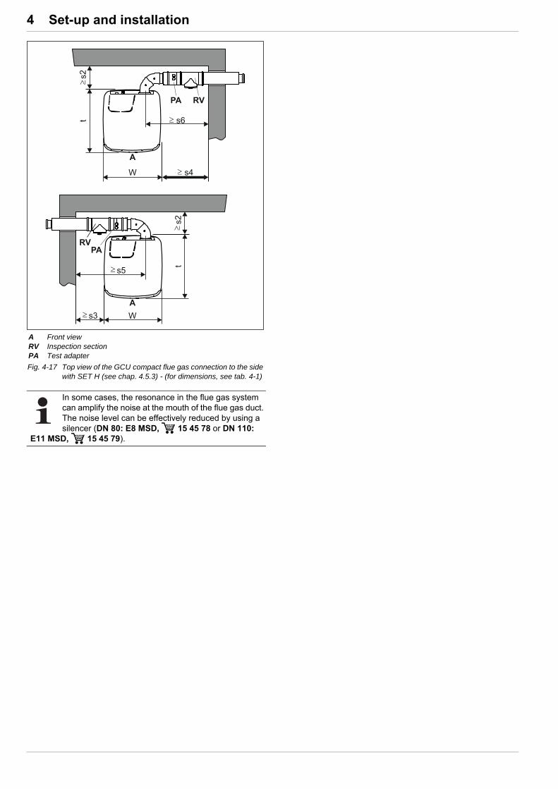
4 x Set-up and installation
A Front viewRV Inspection sectionPA Test adapter
Fig. 4-17 Top view of the GCU compact flue gas connection to the side with SET H (see chap. 4.5.3) - (for dimensions, see tab. 4-1)
In some cases, the resonance in the flue gas system can amplify the noise at the mouth of the flue gas duct. The noise level can be effectively reduced by using a silencer (DN 80: E8 MSD, 15 45 78 or DN 110:
E11 MSD, 15 45 79).

4 x Set-up and installation
4.5.3 Flue gas system kits
Fig. 4-18 Flue gas system kits * If needed** See tab. 4-1(PA) Test adapter
(L) Flue gas connection, left(R) Flue gas connection, right(H) Flue gas connection, rear(O) Flue gas connection, top

4 x Set-up and installation
Additional kits– Flue gas connection to a shaft system (rigid flue gas line
SET E or flexible flue gas line SET O)– Flue gas connection for external wall line (SET G)If necessary, additionally needed concentric LAS pipes for in-creased roof or ceiling heights, single wall PP pipes for flue heights of more than 10 m or additional accessory components must be ordered.
The three-digit numbers in fig. 4-18 assist in finding individual components in the ROTEX price list.
4.6 Water connection
The ROTEX GCU compact connections are located on the unit top or front ( solar return flow). The heating circuit and storage tank charging share the same flow and return flow. The heating circuit for the storage tank charging is integrated at the factory and must not be connected separately.
Important information
CAUTION!
If the ROTEX GCU compact is connected to a heating system with steel pipes, radiators or non-diffusion-proof floor heating pipes, slurry and swarf could enter the hot water storage tank and cause blockages, local overheating or corrosion. Rinse supply lines before filling the device. Rinse out the heat distribution network (in the existing
heating system). Install a dirt filter or sludge separator in the heating return
flow (see chap. 1.2.6).
CAUTION!
If the ROTEX GCU compact is connected to a cold water line where steel pipes are used, chips can go into the special steel corrugated pipe heat exchanger and remain there. This can lead to contact corrosion damage and subsequently to leakage. Flush the feed pipes before filling the heat exchanger. Install a dirt filter in the cold water supply.
– SAS 1 ( 15 60 21)– SAS 2 ( 15 60 23)
CAUTION!
Only Biv
If the heat exchanger for charging the pressurised solar system (see fig. 3-3 / fig. 3-6, item 19 + 20) is connected to an external heating unit (e.g. wood-burning boiler), too high an inflow temperature at these connections can damage or destroy the ROTEX GCU compact. The inflow temperature of the external heating unit should
be limited to max. 95 °C.
CAUTION!
Corrosion may be caused by air entering the heating water network and by a quality of the heating water that does not comply with the requirements in accordance with chap. 1.2.5. Corrosion products (particles) thus created may clog pumps and valves and cause malfunctions. Equipment may not be connected by permeable, flexible
lines.
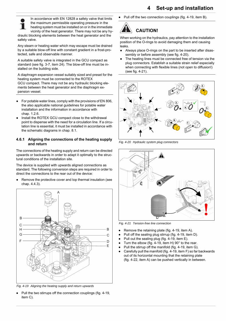
4 x Set-up and installation
For potable water lines, comply with the provisions of EN 806, the also applicable national guidelines for potable water installation and the information in accordance with chap. 1.2.6.
Install the ROTEX GCU compact close to the withdrawal point to dispense with the need for a circulation line. If a circu-lation line is essential, it must be installed in accordance with the schematic diagrams in chap. 8.1.
4.6.1 Aligning the connections of the heating supply and return
The connections of the heating supply and return can be directed upwards or backwards in order to adapt it optimally to the struc-tural conditions of the installation site.
The device is supplied with upwards aligned connections as standard. The following conversion steps are required in order to direct the connections to the rear out of the device:
Remove the protective cover and top thermal insulation (see chap. 4.4.3).
Pull the two stirrups off the connection couplings (fig. 4-19, item C).
Pull off the two connection couplings (fig. 4-19, item B).
Remove the retaining plate (fig. 4-19, item A). Pull off the sealing plug stirrup (fig. 4-19, item D). Pull out the sealing plug (fig. 4-19, item E). Turn the elbow (fig. 4-19, item H) 90° to the rear. Pull the stirrup off the manifold (fig. 4-19, item G). Carefully pull the manifold (fig. 4-19, item F) so far backwards
out of its horizontal mounting that the retaining plate (fig. 4-22, item A) can be pushed vertically in between.
In accordance with EN 12828 a safety valve that limits the maximum permissible operating pressure in the heating system must be installed on or in the immediate vicinity of the heat generator. There may not be any hy-
draulic blocking elements between the heat generator and the safety valve.
Any steam or heating water which may escape must be drained by a suitable blow-off line with constant gradient in a frost-pro-tected, safe and observable manner.
A suitable safety valve is integrated in the GCU compact as standard (see fig. 3-7, item 24). The blow-off line must be in-stalled on the building side.
A diaphragm expansion vessel suitably sized and preset for the heating system must be connected to the ROTEX GCU compact. There may not be any hydraulic blocking ele-ments between the heat generator and the diaphragm ex-pansion vessel.
Fig. 4-19 Aligning the heating supply and return upwards
CAUTION!
When working on the hydraulics, pay attention to the installation position of the O-rings to avoid damaging them and causing leaks. Always place O-rings on the part to be inserted after disas-
sembly or before assembly (see fig. 4-20). The heating lines must be connected free of tension via the
plug connectors. Establish a suitable strain relief especially when connecting with flexible lines (not open to diffusion!) (see fig. 4-21).
Fig. 4-20 Hydraulic system plug connectors
Fig. 4-21 Tension-free line connection

4 x Set-up and installation
Slide the retaining plate between the manifold and its horizontal mounting and insert the manifold (fig. 4-22, item F) back into its mounting through the middle hole of the retaining plate.
Secure the manifold with stirrup (fig. 4-22, item G) in its mounting again.
Insert the two connection couplings (fig. 4-22, item B) into the lateral mountings through the retaining plate.
Secure the two connection couplings with stirrups (fig. 4-22, item C) in their mountings.
Insert the sealing plug (fig. 4-22, item E) into the upper mounting.
Secure the sealing plug with stirrup (fig. 4-22, item D). Cut out side openings in the thermal insulation (fig. 4-23,
item A) using a suitable tool.
4.6.2 Connecting hydraulic lines
Check the cold water connection pressure (maximum 6 bar).– If a higher pressure is present in the domestic water pipe,
a pressure reducer will need to be installed. Establish hydraulic connections on the ROTEX
GCU compact.– Position of the heating connections fig. 4-4 / fig. 4-6, con-
sult tab. 3-1 for sizes.– Comply with the stipulated tightening torque (see
chap. 12.3).– Install the line in such a way that the protective cover of
the ROTEX GCU compact is simple to put on after assem-bly.
– Connect the water for filling or refilling the heating system as specified by EN 1717/EN 61770 to avoid contamina-tion of drinking water by return flow.
Connect the blow-off line to the safety over-pressure valve and diaphragm expansion vessel in accordance with EN 12828.– Any steam or heating water which may escape must be
drained by a suitable blow-off line with constant gradient in a frost-protected, safe and observable manner.
– Install the line in such a way that the protective cover of the ROTEX GCU compact is simple to put on after assem-bly.
– Connect a suitably dimensioned and preset diaphragm expansion vessel for the heating system. There may not be any hydraulic blocking elements between the heat generator and the safety valve.
– Position the diaphragm expansion vessel in an easily accessible place (maintenance, parts replacement).
Carefully insulate pipework against heat loss and to avoid condensation (insulation thickness at least 20 mm).
– Water shortage protection: The ROTEX GCU compact pressure and temperature monitor switches the gas condens-ing boiler safely off and locks it if there is a shortage of water. No additional water shortage protection is needed in the con-struction.
– Avoid damage caused by deposits and corrosion: Com-ply with the requirements on the heating water (see chap. 1.2.5.)
Fig. 4-22 Heating supply and return connections aligned to the rear
CAUTION!
If the stirrups cannot be put on properly, the couplings can be detached from their mountings to ensure a very strong or continuous escape of liquid can occur. Before putting on a stirrup, make sure that the stirrup
engages in the coupling groove. To do so, insert the coupling far enough into the mounting that the groove is visible through the stirrup mounting.
Insert the stirrup up to the end stop.
Fig. 4-23 Cut-out in thermal insulation
The GCU compact is equipped with a pressure sensor. The system pressure in monitored electronically and can be displayed with the device switched on.
Nevertheless, ROTEX recommends installing a mechanical ma-nometer between the GCU compact and the diaphragm ex-pansion vessel, for example.
– Install the manometer so that it is easy to see when filling.
UK only! CAUTION!
If filling or topping up the storage tank is done by means of the boiler filling and drain valve, a temporary filling loop must be used with the appropriate backflow prevention device in ac-cordance with clause G24.2, Guidance to the Water Supply (Water Fittings) Regulations 1999.
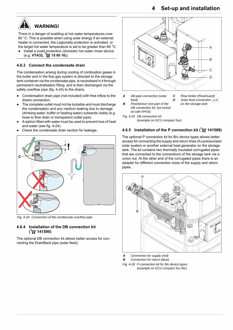
4 x Set-up and installation
4.6.3 Connect the condensate drain
The condensation arising during cooling of combustion gases in the boiler and in the flue gas system is directed to the storage tank container via the condensate pipe, is neutralised in it through permanent neutralisation filling, and is then discharged via the safety overflow pipe (fig. 4-24) to the drains.
Condensation drain pipe (not included) with free inflow to the drains connection.
The complete outlet must not be lockable and must discharge the condensation and any medium leaking due to damage (drinking water, buffer or heating water) outwards visibly (e.g. hose to flow drain or transparent outlet pipe).
A siphon filled with water must be used to prevent loss of heat and water (see fig. 4-24).
Check the condensate drain section for leakage.
4.6.4 Installation of the DB connection kit ( 141590)
The optional DB connection kit allows better access for con-necting the DrainBack pipe (solar feed).
4.6.5 Installation of the P connection kit ( 141589)
The optional P connection kit for Biv device types allows better access for connecting the supply and return lines of a pressurised solar system or another external heat generator on the storage tank. The kit contains two thermally insulated corrugated pipes that are connected to the connections of the storage tank via a union nut. At the other end of the corrugated pipes there is an adapter for different connection sizes of the supply and return pipes.
WARNING!
There is a danger of scalding at hot water temperatures over 60 °C. This is possible when using solar energy if an external heater is connected, the Legionella protection is activated, or the target hot water temperature is set to be greater than 60 °C. Install a scald protection (domestic hot water mixer device
(e.g. VTA32, 15 60 16)).
Fig. 4-24 Connection of the condensate overflow pipe
A DB pipe connection (solar feed)
B FlowSensor (not part of the DB connection kit, but includ-ed with RPS4)
C Flow limiter (FlowGuard)D Solar feed connection
on the storage tank
Fig. 4-25 DB connection kit (example on GCU compact 5xx)
A Connection for supply (red)B Connection for return (blue)
Fig. 4-26 P-connection kit for Biv device types(example on GCU compact 5xx Biv)

4 x Set-up and installation
4.7 Electrical connection
All ROTEX GCU compact control and safety devices are con-nected ready for use and tested. Modifications on the electrical installation are dangerous and prohibited. The operator alone shall bear responsibility for any resulting damage.
The mains connection, external temperature sensor and other optional applications (e.g. circulation pump) still have to be con-nected to the boiler control panel.
4.7.1 Opening the control unit housing and establishing electric connections
Check the supply voltage (~230 V, 50 Hz). Switch the mains switch on the boiler control panel of the
ROTEX GCU compact to "OFF". Switch off the circuit breaker in the junction box of the
domestic power supply. Remove the protective cover (see chap. 4.4.3). Remove the locking screw at top right on the boiler switch
panel (fig. 4-27).
Remove the cable cover from the back of the controller housing (fig. 4-28).
Turn the controller housing to the horizontal installation position
Guide the cables to the controller housing and remove the insulation accordingly fig. 4-30.
WARNING!
Touching live parts can result in an electric shock and lead to potentially fatal injuries and burns. Before beginning work on live parts, disconnect all of the
systems circuits from the power supply (switch off external main switch, disconnect fuse) and secure against unintentional restart.
Establishment of the electrical connection and work on electrical components should only be performed by electrical technicians in compliance with valid standards and guidelines as well as the specifications of the energy supply company and the instructions in this manual.
Never make constructional changes to connectors or other electrical equipment components.
The equipment covers and maintenance opening covers must be re-fitted immediately after completion of the work.
Fig. 4-27 Removing the locking screw.
Fig. 4-28 Removing the cable cover
The controller housing of the GCU compact is designed so that it can be folded forwards for maintenance work.
When cutting to length and laying the cables to be connected, make sure that the tilt movement is tension-free.
Fig. 4-29 Turning the controller housing to the horizontal installation po-sition
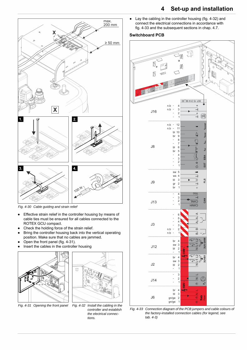
4 x Set-up and installation
Effective strain relief in the controller housing by means of cable ties must be ensured for all cables connected to the ROTEX GCU compact.
Check the holding force of the strain relief. Bring the controller housing back into the vertical operating
position. Make sure that no cables are jammed. Open the front panel (fig. 4-31). Insert the cables in the controller housing
Lay the cabling in the controller housing (fig. 4-32) and connect the electrical connections in accordance with fig. 4-33 and the subsequent sections in chap. 4.7.
Switchboard PCB
Fig. 4-30 Cable guiding and strain relief
Fig. 4-31 Opening the front panel Fig. 4-32 Install the cabling in the controller and establish the electrical connec-tions.
Fig. 4-33 Connection diagram of the PCB jumpers and cable colours of the factory-installed connection cables (for legend, see tab. 4-3)
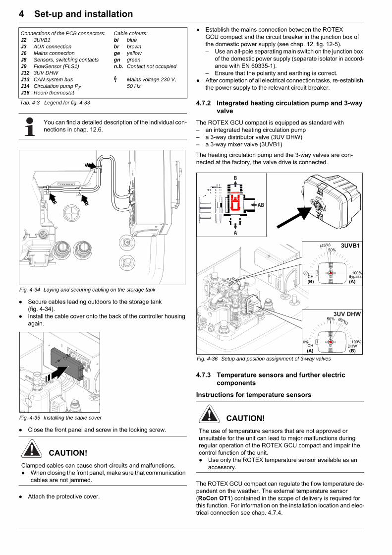
4 x Set-up and installation
Secure cables leading outdoors to the storage tank (fig. 4-34).
Install the cable cover onto the back of the controller housing again.
Close the front panel and screw in the locking screw.
Attach the protective cover.
Establish the mains connection between the ROTEX GCU compact and the circuit breaker in the junction box of the domestic power supply (see chap. 12, fig. 12-5). – Use an all-pole separating main switch on the junction box
of the domestic power supply (separate isolator in accord-ance with EN 60335-1).
– Ensure that the polarity and earthing is correct. After completion of all electrical connection tasks, re-establish
the power supply to the relevant circuit breaker.
4.7.2 Integrated heating circulation pump and 3-way valve
The ROTEX GCU compact is equipped as standard with – an integrated heating circulation pump– a 3-way distributor valve (3UV DHW)– a 3-way mixer valve (3UVB1)
The heating circulation pump and the 3-way valves are con-nected at the factory, the valve drive is connected.
4.7.3 Temperature sensors and further electric components
Instructions for temperature sensors
The ROTEX GCU compact can regulate the flow temperature de-pendent on the weather. The external temperature sensor (RoCon OT1) contained in the scope of delivery is required for this function. For information on the installation location and elec-trical connection see chap. 4.7.4.
Connections of the PCB connectors:J2 3UVB1J3 AUX connectionJ6 Mains connectionJ8 Sensors, switching contacts J9 FlowSensor (FLS1)J12 3UV DHWJ13 CAN system busJ14 Circulation pump PZJ16 Room thermostat
Cable colours:bl bluebr brownge yellowgn greenn.b. Contact not occupied
Mains voltage 230 V, 50 Hz
Tab. 4-3 Legend for fig. 4-33
You can find a detailed description of the individual con-nections in chap. 12.6.
Fig. 4-34 Laying and securing cabling on the storage tank
Fig. 4-35 Installing the cable cover
CAUTION!
Clamped cables can cause short-circuits and malfunctions. When closing the front panel, make sure that communication
cables are not jammed.
Fig. 4-36 Setup and position assignment of 3-way valves
CAUTION!
The use of temperature sensors that are not approved or unsuitable for the unit can lead to major malfunctions during regular operation of the ROTEX GCU compact and impair the control function of the unit. Use only the ROTEX temperature sensor available as an
accessory.

4 x Set-up and installation
The temperatures detected by the internal temperature sensors (flow and return flow temperature sensors, internal mixer sensors) are used to control the burner's output and to detect faults. The temperature sensors are connected in the factory and can be connected to the appropriate sensor directly upon re-placement.
The storage tank temperature sensor is installed and con-nected to the terminals at the factory (NTC thermistor).
To regulate a mixer circuit the (RoCon M1, 15 70 68) mixer module is needed that contains the mixer circuit inflow temper-ature sensor.
Further electric components can be connected to the circuit board connectors:
J13 circuit board connectorFurther optional control system components in the CAN bus system (room controller, mixer module etc.) are connected over the J13 circuit board connector to the control panel (see chap. 4.7.5 to 4.7.7).
J8 circuit board connectorAdditional switching contacts for external boiler control can be connected to the J8 circuit board connector.
– An external operating mode switchover can be made by a potential-free switching contact connected to terminals 1+2 (EXT).When the switching contact is closed switchover is made to the assigned operating mode depending on an intercon-nected resistance - see chap. 4.7.9 and function "Operating mode switchover over EXT input" in the "ROTEX controller RoCon BF" documentation.
– An external heat request can be made by a potential-free switching contact connected to terminals 3+4 (EBA).When the switching contact is closed the target inflow temper-ature is set to the value configured by the parameter [T-Flow Day] on the RoCon BF controller. The EBA switching contact has priority over a request from the room thermostat.Switching by the EXT switching contact has priority over this request.
Terminals 11+12 (tAG/WP) are not occupied for these devices and are available for additional functions.
J3 circuit board connectorAn external control, acquisition or display device (e.g. lamp) can be connected to the internal switching contact on the J3 circuit board connector (terminals A+A1,A2). Different connection conditions must be complied with depending on the model of the external device (see fig. 4-37).
The condition for the switching function can be set by the param-eters [AUX Fct] and [AUX time] on the RoCon BF controller (see the operating instructions for the controller).
The relays user for variant 2 (switched output > 15 W) must be suitable for a 100 % power-on time.
Connection terminals B+B1 are not occupied for these devices or are available for additional functions
J16 circuit board connectorA room thermostat (potential-free switching contact) can be con-nected to the J16 (terminals 1+2) circuit board connector (see chap. 4.7.8). A connected room thermostat has to be activated by parameter [Room thermostat] on the RoCon BF controller.
In "Heating" operating mode and during the active heating phases of the time program, a closed switching contact causes a heat request. This request has priority over the switching func-tions connected over the J8 circuit board connector (exception EBA switching contact).
Frost protection functions are also active when the switching contact is open.
Terminals 3+4 are not occupied for these devices and are available for additional functions.
4.7.4 Connecting the RoCon OT1 external temperature sensor
Choose a location at about one third of the building height (minimum distance from floor: 2 m) at the coldest side of the building (North or North-East). Ensure that the location is not near to any external heat sources (flues, air ducts), nor subject to direct solar radiation.
Place external temperature sensors in such a way that the cable exit points face downwards (prevents humidity ingress).
Fig. 4-37 Connection of switching contact (AUX output)
You will find further instructions and a detailed descrip-tion in the "ROTEX RoCon BF" controller documenta-tion. It is included in the scope of delivery for the ROTEX GCU compact.
CAUTION!
Laying the sensor and mains lines in parallel within a wiring conduit can lead to major malfunctions during regular operation of the ROTEX GCU compact. Always lay the sensor line separately.

4 x Set-up and installation
Connect the exterior temperature sensor to a twin-core sensor line (minimum diameter 1 mm2).
Install the sensor line to the GCU compact. Connect the sensor line in the boiler control panel to the
connector of connecting terminals 7 and 8 of the J8 12-pin sensor connector (see chap. 4.7.1).
Connect the connector to the PCB control panel (fig. 4-38).
Close the control panel.
4.7.5 Mixer module RoCon M1
The RoCon M1 mixer module can be connected to the ROTEX GCU compact (J13 circuit board connector) and is controlled by the electronic boiler controller.
4.7.6 Room controller RoCon U1
A separate RoCon U1 room controller can be connected for each heating circuit to enable remote adjustment of operating modes and target room temperatures from another room.
4.7.7 Internet gateway RoCon G1
The controller can be connected to the internet with the optional RoCon G1 gateway. This enables remote control of the ROTEX GCU compact by mobile phones (by app).
4.7.8 Room thermostatWhen the ROTEX GCU compact is used as master in a CAN bus system ("terminal function" for remote con-trol of other data bus devices), the external temperature sensor must be connected RoCon OT1 directly to the
RoCon BF controller of the master and not to the remotely controlled device (mixer circuit module RoCon M1 or other heat generator).
Fig. 4-38 Connect the J8 sensor connector to the PCB control panel
A separate installation manual is included with this component. See the enclosed control system manual for instructions on setting and operation.
A separate installation manual is included with this component. See the enclosed control system manual for instructions on setting and operation.
A separate installation manual is included with this component. See the enclosed control system manual for instructions on setting and operation.
A separate manual containing instructions about instal-lation and operation is included with this component.
Fig. 4-39 Room thermostat connected by cable(example of RT = ROTEX RKRTW, 14 10 03)
Fig. 4-40 Room thermostat connected by radio(example of RT-E = ROTEX RKRTR, 14 10 04)
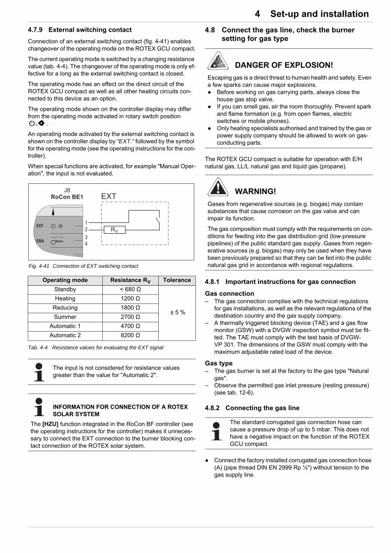
4 x Set-up and installation
4.7.9 External switching contact
Connection of an external switching contact (fig. 4-41) enables changeover of the operating mode on the ROTEX GCU compact.
The current operating mode is switched by a changing resistance value (tab. 4-4). The changeover of the operating mode is only ef-fective for a long as the external switching contact is closed.
The operating mode has an effect on the direct circuit of the ROTEX GCU compact as well as all other heating circuits con-nected to this device as an option.
The operating mode shown on the controller display may differ from the operating mode activated in rotary switch position
.
An operating mode activated by the external switching contact is shown on the controller display by "EXT." followed by the symbol for the operating mode (see the operating instructions for the con-troller).
When special functions are activated, for example "Manual Oper-ation", the input is not evaluated.
Tab. 4-4 Resistance values for evaluating the EXT signal
4.8 Connect the gas line, check the burner setting for gas type
The ROTEX GCU compact is suitable for operation with E/H natural gas, LL/L natural gas and liquid gas (propane).
4.8.1 Important instructions for gas connection
Gas connection– The gas connection complies with the technical regulations
for gas installations, as well as the relevant regulations of the destination country and the gas supply company.
– A thermally triggered blocking device (TAE) and a gas flow monitor (GSW) with a DVGW inspection symbol must be fit-ted. The TAE must comply with the test basis of DVGW-VP 301. The dimensions of the GSW must comply with the maximum adjustable rated load of the device.
Gas type– The gas burner is set at the factory to the gas type "Natural
gas".– Observe the permitted gas inlet pressure (resting pressure)
(see tab. 12-6).
4.8.2 Connecting the gas line
Connect the factory installed corrugated gas connection hose (A) (pipe thread DIN EN 2999 Rp ½") without tension to the gas supply line.
Fig. 4-41 Connection of EXT switching contact
Operating mode Resistance RV Tolerance
Standby < 680 Ω
± 5 %
Heating 1200 Ω
Reducing 1800 Ω
Summer 2700 Ω
Automatic 1 4700 Ω
Automatic 2 8200 Ω
The input is not considered for resistance values greater than the value for "Automatic 2".
INFORMATION FOR CONNECTION OF A ROTEX SOLAR SYSTEM
The [HZU] function integrated in the RoCon BF controller (see the operating instructions for the controller) makes it unneces-sary to connect the EXT connection to the burner blocking con-tact connection of the ROTEX solar system.
DANGER OF EXPLOSION!
Escaping gas is a direct threat to human health and safety. Even a few sparks can cause major explosions. Before working on gas carrying parts, always close the
house gas stop valve. If you can smell gas, air the room thoroughly. Prevent spark
and flame formation (e.g. from open flames, electric switches or mobile phones).
Only heating specialists authorised and trained by the gas or power supply company should be allowed to work on gas-conducting parts.
WARNING!
Gases from regenerative sources (e.g. biogas) may contain substances that cause corrosion on the gas valve and can impair its function.
The gas composition must comply with the requirements on con-ditions for feeding into the gas distribution grid (low-pressure pipelines) of the public standard gas supply. Gases from regen-erative sources (e.g. biogas) may only be used when they have been previously prepared so that they can be fed into the public natural gas grid in accordance with regional regulations.
The standard corrugated gas connection hose can cause a pressure drop of up to 5 mbar. This does not have a negative impact on the function of the ROTEX GCU compact.

4 x Set-up and installation
4.8.3 Removing/attaching the heat cell panelling
Unscrew the locking screws from the lid (fig. 4-43, item 1) and the front panelling of the heat cell (fig. 4-43, item 2).
Remove the lid and front panelling of the heat cell.
Assembly is carried out in reverse order.
Comply with the stipulated tightening torque (see chap. 12.3).
4.8.4 Checking the gas presetting
Compare the available gas type with the position set for the setting screw on the safety gas control block (fig. 4-44, item 3.1).– 1 = Natural gas– 2 = Liquid gas
The gas type must match.
If the burner is not set to the available gas type, change it over to the new gas type (fig. 4-45) and mark it (see chap. 7.3).
Check the inlet gas pressure Turn the screw in the inlet gas pressure measuring
connection (fig. 4-44, item 3.3) half a turn anticlockwise. Vent the gas line in a professional manner. Connect the pressure gauge measuring hose to the inlet gas
pressure measuring connection (fig. 4-44, item 3.3). Check the inlet gas pressure.
If the gas inlet pressure lies outside the permitted range tab. 12-6, inform the responsible gas supply company.For liquid gas: Check the pressure reducer and set the burner to the permissible gas inlet pressure (see chap. 7).
A Corrugated gas connection hose
Fig. 4-42 Gas connection
1 Cell lid of the heat cell2 Front panelling of the heat
cell
3 Safety gas control block4 Basic panelling of the heat
cell
Fig. 4-43 Removing the upper panelling of the heat cell
A changeover of the gas type must also be adjusted in the controller. Comply with the enclosed control system instructions!
3.1 Gas type setting screw3.2 Immersion coil3.3 Measurement connection IN - input gas pressure3.4 Gas input3.5 Gas solenoid valve3.6 Voltage supply to gas solenoid valve3.7 Voltage supply to immersion coil
Fig. 4-44 Safety gas control block
Fig. 4-45 Gas type setting

4 x Set-up and installation
This adjustment must be appropriately labelled with a suit-able burner settings sticker and an entry on the settings type plate (fig. 3-2 / fig. 3-5, item 33).
4.9 Filling the system
Fill the ROTEX GCU compact only after completion of all instal-lation work in the order shown below.
4.9.1 Checking the water quality and adjusting the pressure gauge
Comply with the instructions for water connection (see chap. 4.6) and water quality (see chap. 1.2.5).
Adjust the mechanical manometer (install on the building side in accordance with chap. 4.6.2 or temporarily installed with filling hose).
Rotate the pressure gauge glass so that the minimum pressure mark equates to the system height + 2 m (1 m water column corresponds to 0.1 bar).
4.9.2 Filling the hot water heat exchanger
Open the shutoff valve for the cold water supply pipe. Open the hot water tap connections so that the draw-off
volume can be set as high as possible. Once water has been discharged from the tap connections do
not interrupt the cold water flow; this will ensure that the heat exchanger will be fully vented and that any impurities or residue will be discharged.
4.9.3 Filling the storage tank
See chap. 9.2.4.
4.9.4 Filling the heating system
See chap. 9.2.5.
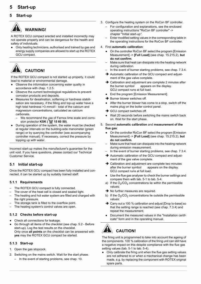
5 x Start-up
5 Start-up
Incorrect start-up makes the manufacturer's guarantee for the unit void. If you have questions, please contact our Technical Customer Service.
5.1 Initial start-up
Once the ROTEX GCU compact has been fully installed and con-nected, it can be started up by suitably trained staff.
5.1.1 Requirements
– The ROTEX GCU compact is fully connected.– The cover of the heat cell is closed and sealed tight.– The heating and hot water system are filled and charged with
the right pressure.– The storage tank is filled to the overflow point.– The heating system's control valves are open.
5.1.2 Checks before start-up
Check all connections for leakage. Go through all items of the checklist (see chap. 5.2 - Before
start-up). Log the test results on the checklist.Only once all points on the checklist can be answered with yes may the ROTEX GCU compact be started.
5.1.3 Start-up
1. Open the gas stopcock.
2. Switching on the mains switch. Wait for the start phase.
– In the event of starting problems, see chap. 10.
3. Configure the heating system on the RoCon BF controller.
– For configuration and explanations, see the enclosed operating instructions "RoCon BF controller" -> chapter "Initial start-up".
– Enter modified setting values in the corresponding table in the operating instructions for the RoCon BF controller.
4. First automatic calibration:
On the controller RoCon BF select the program [Emission Measurement] -> [Full Load] (see chap. 15.215.2), but do not confirm.
– Make sure that heat can dissipate into the heating network during calibration.
– In the event of burner starting problems, see chap. 7.3.4.
Automatic calibration of the GCU compact and adjust-ment of the gas valve complete.
Calibration and adjustment are complete 2 minutes after the burner symbol appears on the display. GCU compact runs at full load.
End the program [Emission Measurement].
Burner blower switches off.
After the burner blower has come to a stop, switch off the mains plug on the boiler control panel.
GCU compact switches off.
Wait 20 seconds before switching the mains switch back on. Wait for the start phase.
5. Second automatic calibration and measurement of the flue gas:
On the controller RoCon BF select the program [Emission Measurement] -> [Full Load] (see chap. 15.215.2), but do not confirm.
– Make sure that heat can dissipate into the heating network during emission measurement.
– In the event of burner starting problems, see chap. 7.3.4.
Automatic calibration of the GCU compact and adjust-ment of the gas valve complete.
Calibration and adjustment are complete two minutes after the burner symbol appears on the display. GCU compact runs at full load.
Use the flue gas analyser to check the burner settings and compare them with tab. 5-1 to tab. 5-4.
a) If the O2/CO2 concentrations lie within the permissible values:
No further measures are required.
b) If the O2/CO2 concentrations lie outside the permissible values:
Carry out a 100 % calibration and adjust [Drop Io-base] so that the setting range is reached (see chap. 7.3.4) and repeat the measurement.
Document the measured values in the "Installation certif-icate" form and in the operating manual.
WARNING!
A ROTEX GCU compact erected and installed incorrectly may not operate properly and can be dangerous for the health and safety of individuals. Only heating technicians, authorised and trained by gas and
energy supply companies are allowed to start up the ROTEX GCU compact.
CAUTION!
If the ROTEX GCU compact is not started up properly, it could lead to material or environmental damage. Observe the information concerning water quality in
accordance with chap. 1.2.5. Observe the current technological regulations to prevent
corrosion products and deposits. Measures for desalination, softening or hardness stabili-
sation are necessary, if the filling and top-up water have a high total hardness >3 mmol/l - total of the calcium and magnesium concentrations, calculated as calcium carbonate.– We recommend the use of Fernox lime scale and corro-
sion protector KSK ( 15 60 50). During operation of the system, the water must be checked
at regular intervals on the building-side manometer (green range) or by querying the controller (see accompanying controller manual). If necessary, correct the pressure by topping up with water.
CAUTION!
The firing unit is programmed to take into account the ageing of the components. 100 % calibration of the firing unit can still have a negative impact on this despite compliance with the flue gas setting values (tab. 5-1 to tab. 5-4). Only calibrate the firing unit when the flue gas setting values
are not adhered to or when a mechanical change has been made, e.g. by replacing the component with ROTEX original spare parts.
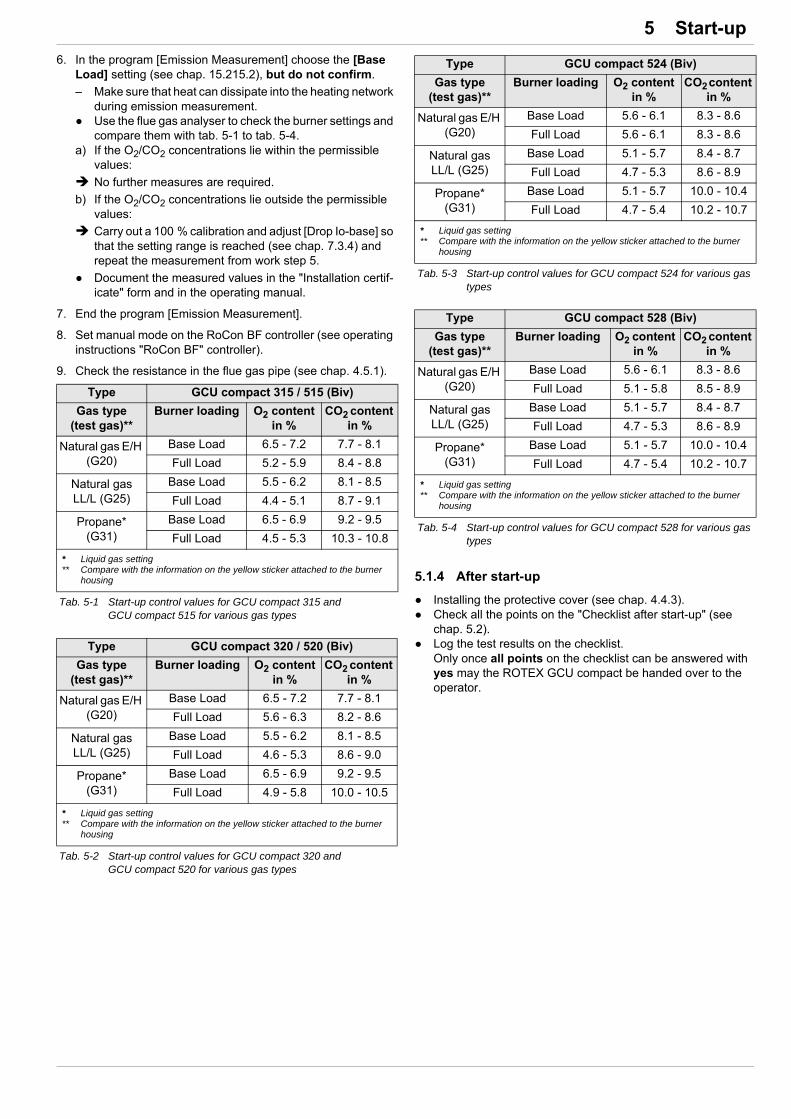
5 x Start-up
6. In the program [Emission Measurement] choose the [Base Load] setting (see chap. 15.215.2), but do not confirm.
– Make sure that heat can dissipate into the heating network during emission measurement.
Use the flue gas analyser to check the burner settings and compare them with tab. 5-1 to tab. 5-4.
a) If the O2/CO2 concentrations lie within the permissible values:
No further measures are required.
b) If the O2/CO2 concentrations lie outside the permissible values:
Carry out a 100 % calibration and adjust [Drop Io-base] so that the setting range is reached (see chap. 7.3.4) and repeat the measurement from work step 5.
Document the measured values in the "Installation certif-icate" form and in the operating manual.
7. End the program [Emission Measurement].
8. Set manual mode on the RoCon BF controller (see operating instructions "RoCon BF" controller).
9. Check the resistance in the flue gas pipe (see chap. 4.5.1).
5.1.4 After start-up
Installing the protective cover (see chap. 4.4.3). Check all the points on the "Checklist after start-up" (see
chap. 5.2). Log the test results on the checklist.
Only once all points on the checklist can be answered with yes may the ROTEX GCU compact be handed over to the operator.
Type GCU compact 315 / 515 (Biv)
Gas type (test gas)**
Burner loading O2 content in %
CO2 content in %
Natural gas E/H (G20)
Base Load 6.5 - 7.2 7.7 - 8.1
Full Load 5.2 - 5.9 8.4 - 8.8
Natural gas LL/L (G25)
Base Load 5.5 - 6.2 8.1 - 8.5
Full Load 4.4 - 5.1 8.7 - 9.1
Propane* (G31)
Base Load 6.5 - 6.9 9.2 - 9.5
Full Load 4.5 - 5.3 10.3 - 10.8
* Liquid gas setting** Compare with the information on the yellow sticker attached to the burner
housing
Tab. 5-1 Start-up control values for GCU compact 315 and GCU compact 515 for various gas types
Type GCU compact 320 / 520 (Biv)
Gas type (test gas)**
Burner loading O2 content in %
CO2 content in %
Natural gas E/H (G20)
Base Load 6.5 - 7.2 7.7 - 8.1
Full Load 5.6 - 6.3 8.2 - 8.6
Natural gas LL/L (G25)
Base Load 5.5 - 6.2 8.1 - 8.5
Full Load 4.6 - 5.3 8.6 - 9.0
Propane* (G31)
Base Load 6.5 - 6.9 9.2 - 9.5
Full Load 4.9 - 5.8 10.0 - 10.5
* Liquid gas setting** Compare with the information on the yellow sticker attached to the burner
housing
Tab. 5-2 Start-up control values for GCU compact 320 and GCU compact 520 for various gas types
Type GCU compact 524 (Biv)
Gas type (test gas)**
Burner loading O2 content in %
CO2 content in %
Natural gas E/H (G20)
Base Load 5.6 - 6.1 8.3 - 8.6
Full Load 5.6 - 6.1 8.3 - 8.6
Natural gas LL/L (G25)
Base Load 5.1 - 5.7 8.4 - 8.7
Full Load 4.7 - 5.3 8.6 - 8.9
Propane* (G31)
Base Load 5.1 - 5.7 10.0 - 10.4
Full Load 4.7 - 5.4 10.2 - 10.7
* Liquid gas setting** Compare with the information on the yellow sticker attached to the burner
housing
Tab. 5-3 Start-up control values for GCU compact 524 for various gas types
Type GCU compact 528 (Biv)
Gas type (test gas)**
Burner loading O2 content in %
CO2 content in %
Natural gas E/H (G20)
Base Load 5.6 - 6.1 8.3 - 8.6
Full Load 5.1 - 5.8 8.5 - 8.9
Natural gas LL/L (G25)
Base Load 5.1 - 5.7 8.4 - 8.7
Full Load 4.7 - 5.3 8.6 - 8.9
Propane* (G31)
Base Load 5.1 - 5.7 10.0 - 10.4
Full Load 4.7 - 5.4 10.2 - 10.7
* Liquid gas setting** Compare with the information on the yellow sticker attached to the burner
housing
Tab. 5-4 Start-up control values for GCU compact 528 for various gas types
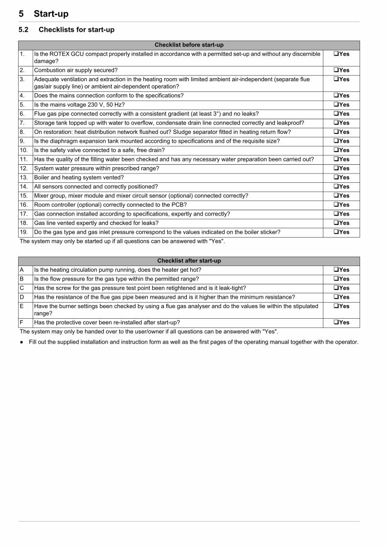
5 x Start-up
5.2 Checklists for start-up
Checklist before start-up
1. Is the ROTEX GCU compact properly installed in accordance with a permitted set-up and without any discernible damage?
Yes
2. Combustion air supply secured? Yes
3. Adequate ventilation and extraction in the heating room with limited ambient air-independent (separate flue gas/air supply line) or ambient air-dependent operation?
Yes
4. Does the mains connection conform to the specifications? Yes
5. Is the mains voltage 230 V, 50 Hz? Yes
6. Flue gas pipe connected correctly with a consistent gradient (at least 3°) and no leaks? Yes
7. Storage tank topped up with water to overflow, condensate drain line connected correctly and leakproof? Yes
8. On restoration: heat distribution network flushed out? Sludge separator fitted in heating return flow? Yes
9. Is the diaphragm expansion tank mounted according to specifications and of the requisite size? Yes
10. Is the safety valve connected to a safe, free drain? Yes
11. Has the quality of the filling water been checked and has any necessary water preparation been carried out? Yes
12. System water pressure within prescribed range? Yes
13. Boiler and heating system vented? Yes
14. All sensors connected and correctly positioned? Yes
15. Mixer group, mixer module and mixer circuit sensor (optional) connected correctly? Yes
16. Room controller (optional) correctly connected to the PCB? Yes
17. Gas connection installed according to specifications, expertly and correctly? Yes
18. Gas line vented expertly and checked for leaks? Yes
19. Do the gas type and gas inlet pressure correspond to the values indicated on the boiler sticker? Yes
The system may only be started up if all questions can be answered with "Yes".
Checklist after start-up
A Is the heating circulation pump running, does the heater get hot? Yes
B Is the flow pressure for the gas type within the permitted range? Yes
C Has the screw for the gas pressure test point been retightened and is it leak-tight? Yes
D Has the resistance of the flue gas pipe been measured and is it higher than the minimum resistance? Yes
E Have the burner settings been checked by using a flue gas analyser and do the values lie within the stipulated range?
Yes
F Has the protective cover been re-installed after start-up? Yes
The system may only be handed over to the user/owner if all questions can be answered with "Yes".
Fill out the supplied installation and instruction form as well as the first pages of the operating manual together with the operator.

6 x Controller and electronic components
6 Controller and electronic components
6.1 Operating elements on the boiler control panel
Mains switchSwitch the ROTEX GCU compact on and off. When the heating system is on, the mains switch is illuminated green.
Control panel for the RoCon B1The control panel is equipped with a coloured backlit clear text display.
The colour of the backlighting indicates the operational status and the programming mode:
In normal system operation the rotary switch should be in the "Info" position.
The most important system temperatures and operating states are shown on the controller display.
The ROTEX GCU compact is fitted with the ROTEX RoCon BF controller. The integrated digital control system actuates a direct heating circuit and a storage tank charging circuit.
It can be extended in many ways with accessory components.
A detailed description is given in the documentation for the "ROTEX RoCon BF controller".
1 Clear text display 2 Setting: Configuration3 Setting: Remote Param4 Rotary switch5 Setting: Info6 Setting: Operating Mode7 Setting: Set Temp Day8 Setting: Set Temp Night
9 Setting: DHW Set Temp10 Rotary button11 Setting: DHW Reheating12 Setting: Time Program13 Exit key14 Control panel RoCon B115 Mains switch
Fig. 6-1 Operating elements on the boiler control panel
Malfunctions are generally indicated by a fault code and a clear text fault message on the display.
For troubleshooting instructions see chap. 10.
White: Standard lighting, normal operating display.
Red: Fault status, the boiler continues to operate with re-strictions depending on the fault type.
Green: Programming mode with operator authorisation.
Blue: Programming mode with specialist authorisation.
You can find additional information and a detailed de-scription in the "ROTEX RoCon BF" controller docu-mentation. It is included in the scope of delivery for the GCU compact.
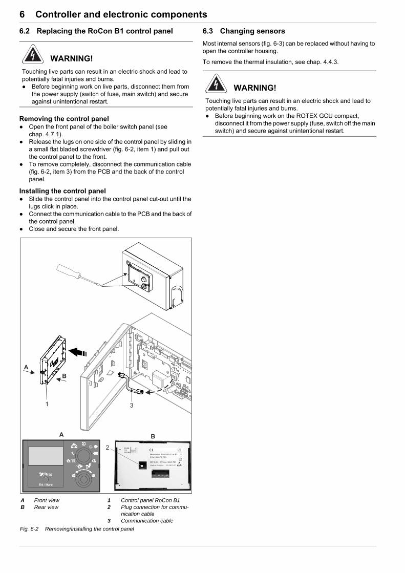
6 x Controller and electronic components
6.2 Replacing the RoCon B1 control panel
Removing the control panel Open the front panel of the boiler switch panel (see
chap. 4.7.1). Release the lugs on one side of the control panel by sliding in
a small flat bladed screwdriver (fig. 6-2, item 1) and pull out the control panel to the front.
To remove completely, disconnect the communication cable (fig. 6-2, item 3) from the PCB and the back of the control panel.
Installing the control panel Slide the control panel into the control panel cut-out until the
lugs click in place. Connect the communication cable to the PCB and the back of
the control panel. Close and secure the front panel.
6.3 Changing sensors
Most internal sensors (fig. 6-3) can be replaced without having to open the controller housing.
To remove the thermal insulation, see chap. 4.4.3.WARNING!
Touching live parts can result in an electric shock and lead to potentially fatal injuries and burns. Before beginning work on live parts, disconnect them from
the power supply (switch of fuse, main switch) and secure against unintentional restart.
A Front viewB Rear view
1 Control panel RoCon B12 Plug connection for commu-
nication cable3 Communication cable
Fig. 6-2 Removing/installing the control panel
WARNING!
Touching live parts can result in an electric shock and lead to potentially fatal injuries and burns. Before beginning work on the ROTEX GCU compact,
disconnect it from the power supply (fuse, switch off the main switch) and secure against unintentional restart.

6 x Controller and electronic components
6.3.1 Replacing the inflow temperature sensor / return flow temperature sensor and pressure sensor
1. Remove the protective cover (see chap. 4.4.3).
2. Remove the upper panelling of the heat cell (see chap. 4.8.3).
3. Disconnect the connector from the sensor being replaced (fig. 6-3, item 2).
4. Unscrew the sensor being replaced with an open-ended spanner WAF 15.
5. Screw in the new sensor and connect the cable and connector.
– The connectors are shape-coded. Do not force the con-nector!
– Comply with the stipulated tightening torque (see chap. 12.3).
tV1 Inflow temperature sensor (boiler circuit)tV2 Internal mixer sensor = inflow temperature sensor (heating circuit)tR Return flow temperature sensor (boiler circuit)22 Heating circulation pump23 Burner blowerDS Pressure sensorFLS Flow sensor3UV DHW
3-way distribution valve3UVB1
3-way mixer valve
Fig. 6-3 Position of sensors and motors on the boiler
WARNING!
There is a danger of scalding from heating water.
Sensors are connected directly to the pressurised heating water. Before removal of the sensors, close the ball cocks on the
boiler inflow and boiler return flow, and depressurise the system with the KFE cock.
WARNING!
Use of an unauthorised temperature sensor causes the safety and control functions to malfunction. Replacement parts must at least satisfy the technical
requirements defined by the manufacturer. This is the case, for example, with original spare parts.
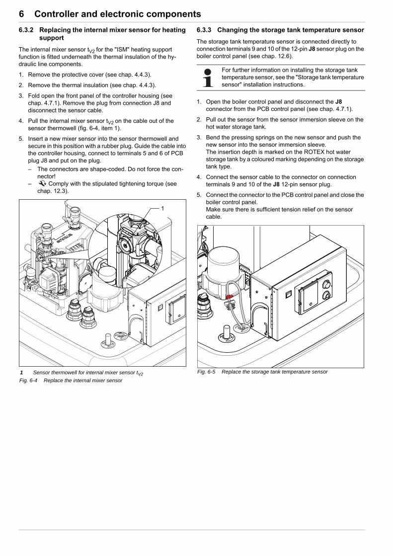
6 x Controller and electronic components
6.3.2 Replacing the internal mixer sensor for heating support
The internal mixer sensor tV2 for the "ISM" heating support function is fitted underneath the thermal insulation of the hy-draulic line components.
1. Remove the protective cover (see chap. 4.4.3).
2. Remove the thermal insulation (see chap. 4.4.3).
3. Fold open the front panel of the controller housing (see chap. 4.7.1). Remove the plug from connection J8 and disconnect the sensor cable.
4. Pull the internal mixer sensor tV2 on the cable out of the sensor thermowell (fig. 6-4, item 1).
5. Insert a new mixer sensor into the sensor thermowell and secure in this position with a rubber plug. Guide the cable into the controller housing, connect to terminals 5 and 6 of PCB plug J8 and put on the plug.
– The connectors are shape-coded. Do not force the con-nector!
– Comply with the stipulated tightening torque (see chap. 12.3).
6.3.3 Changing the storage tank temperature sensor
The storage tank temperature sensor is connected directly to connection terminals 9 and 10 of the 12-pin J8 sensor plug on the boiler control panel (see chap. 12.6).
1. Open the boiler control panel and disconnect the J8 connector from the PCB control panel (see chap. 4.7.1).
2. Pull out the sensor from the sensor immersion sleeve on the hot water storage tank.
3. Bend the pressing springs on the new sensor and push the new sensor into the sensor immersion sleeve.The insertion depth is marked on the ROTEX hot water storage tank by a coloured marking depending on the storage tank type.
4. Connect the sensor cable to the connector on connection terminals 9 and 10 of the J8 12-pin sensor plug.
5. Connect the connector to the PCB control panel and close the boiler control panel.Make sure there is sufficient tension relief on the sensor cable.
1 Sensor thermowell for internal mixer sensor tV2
Fig. 6-4 Replace the internal mixer sensor
For further information on installing the storage tank temperature sensor, see the "Storage tank temperature sensor" installation instructions.
Fig. 6-5 Replace the storage tank temperature sensor

7 x Heat cell with gas burner
7 Heat cell with gas burner
7.1 Design and brief description
Fig. 7-1 GCU compact - heat cell(for legend, see tab. 7-1)
Fig. 7-2 Components of the GCU compact heat cell:Gas section – exploded view(for legend, see tab. 7-1)
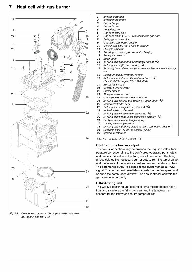
7 x Heat cell with gas burner
Control of the burner outputThe controller continuously determines the required inflow tem-perature corresponding to the configured operating parameters and passes this value to the firing unit of the burner. The firing unit calculates the necessary burner output from the target value and the values of the inflow and return flow temperature probes. The determined output is passed to the burner fan as a PWM signal. The burner fan immediately adjusts the gas fan speed and as such the combustion air flow. The gas controller controls the gas volume accordingly.
CM434 firing unitThe CM434 gas firing unit controlled by a microprocessor con-trols and monitors the firing program and the temperature sensors for the inflow and return temperatures.
Fig. 7-3 Components of the GCU compact - exploded view(for legend, see tab. 7-1)
1 Ignition electrodes2 Ionisation electrode3 Burner flange4 Burner blower5 Venturi nozzle6 Gas connector pipe7 Gas connection G ½" IG with connected gas hose8 Safety gas control block9 Gas valve connection adapter10 Condensate pipe with overfill protection11 Flue gas collector12 Securing stirrup for gas connection line(2x)13 Supply air manifold14 Boiler body15 4x fixing screw(burner blower/burner flange) 16 3x fixing screw (Venturi nozzle) 17 2x O-ring (Venturi nozzle - gas connection line - connection adapt-
er)18 Seal (burner blower/burner flange)19 6x fixing screw (burner flange/boiler body)
(7x with GCU compact 524 / 528 (Biv))20 Burner flange seal21 Seal for burner surface22 Burner surface23 Flue gas collector seal24 O-ring (burner blower - Venturi nozzle)25 2x fixing screws (flue gas collector / boiler body) 26 Ignition electrodes seal27 2x fixing screws (ignition electrodes) 28 Ionisation electrodes seal29 2x fixing screws (ionisation electrode) 30 2x fixing screw (gas valve connection adapter) 31 Seal (connection adapter/gas valve)32 Locking plate for gas valve33 1x fixing screw (locking plate/gas valve connection adapter)34 Seal (gas hose - safety gas control block)35 Ignition transformer
Tab. 7-1 Legend for fig. 7-1 to fig. 7-3
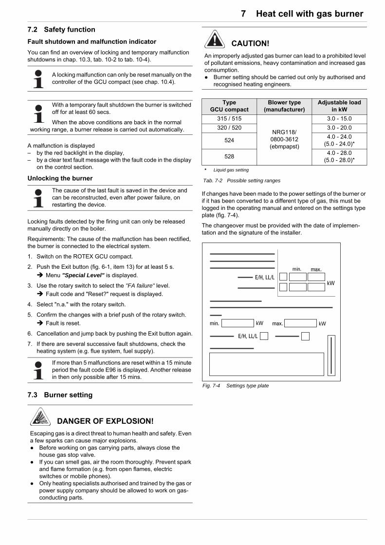
7 x Heat cell with gas burner
7.2 Safety function
Fault shutdown and malfunction indicator
You can find an overview of locking and temporary malfunction shutdowns in chap. 10.3, tab. 10-2 to tab. 10-4).
A malfunction is displayed– by the red backlight in the display,– by a clear text fault message with the fault code in the display
on the control section.
Unlocking the burner
Locking faults detected by the firing unit can only be released manually directly on the boiler.
Requirements: The cause of the malfunction has been rectified, the burner is connected to the electrical system.
1. Switch on the ROTEX GCU compact.
2. Push the Exit button (fig. 6-1, item 13) for at least 5 s.
Menu "Special Level" is displayed.
3. Use the rotary switch to select the "FA failure" level.
Fault code and "Reset?" request is displayed.
4. Select "n.a." with the rotary switch.
5. Confirm the changes with a brief push of the rotary switch.
Fault is reset.
6. Cancellation and jump back by pushing the Exit button again.
7. If there are several successive fault shutdowns, check the heating system (e.g. flue system, fuel supply).
7.3 Burner setting
If changes have been made to the power settings of the burner or if it has been converted to a different type of gas, this must be logged in the operating manual and entered on the settings type plate (fig. 7-4).
The changeover must be provided with the date of implemen-tation and the signature of the installer.
A locking malfunction can only be reset manually on the controller of the GCU compact (see chap. 10.4).
With a temporary fault shutdown the burner is switched off for at least 60 secs.
When the above conditions are back in the normal working range, a burner release is carried out automatically.
The cause of the last fault is saved in the device and can be reconstructed, even after power failure, on restarting the device.
If more than 5 malfunctions are reset within a 15 minute period the fault code E96 is displayed. Another release in then only possible after 15 mins.
DANGER OF EXPLOSION!
Escaping gas is a direct threat to human health and safety. Even a few sparks can cause major explosions. Before working on gas carrying parts, always close the
house gas stop valve. If you can smell gas, air the room thoroughly. Prevent spark
and flame formation (e.g. from open flames, electric switches or mobile phones).
Only heating specialists authorised and trained by the gas or power supply company should be allowed to work on gas-conducting parts.
CAUTION!
An improperly adjusted gas burner can lead to a prohibited level of pollutant emissions, heavy contamination and increased gas consumption. Burner setting should be carried out only by authorised and
recognised heating engineers.
TypeGCU compact
Blower type (manufacturer)
Adjustable load in kW
315 / 515
NRG118/ 0800-3612 (ebmpapst)
3.0 - 15.0
320 / 520 3.0 - 20.0
5244.0 - 24.0
(5.0 - 24.0)*
5284.0 - 28.0
(5.0 - 28.0)*
* Liquid gas setting
Tab. 7-2 Possible setting ranges
Fig. 7-4 Settings type plate
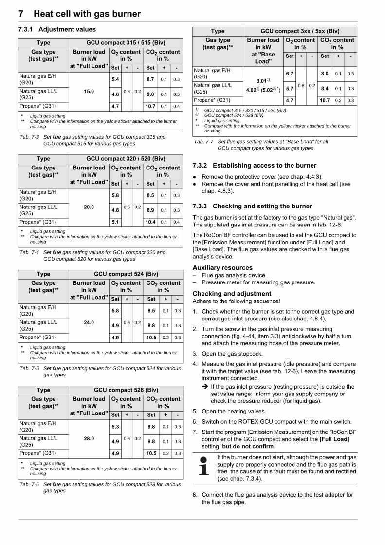
7 x Heat cell with gas burner
7.3.1 Adjustment values
7.3.2 Establishing access to the burner
Remove the protective cover (see chap. 4.4.3). Remove the cover and front panelling of the heat cell (see
chap. 4.8.3).
7.3.3 Checking and setting the burner
The gas burner is set at the factory to the gas type "Natural gas". The stipulated gas inlet pressure can be seen in tab. 12-6.
The RoCon BF controller can be used to set the GCU compact to the [Emission Measurement] function under [Full Load] and [Base Load]. The flue gas values are checked with a flue gas analysis device.
Auxiliary resources– Flue gas analysis device.– Pressure meter for measuring gas pressure.
Checking and adjustmentAdhere to the following sequence!
1. Check whether the burner is set to the correct gas type and correct gas inlet pressure (see also chap. 4.8.4).
2. Turn the screw in the gas inlet pressure measuring connection (fig. 4-44, item 3.3) anticlockwise by half a turn and attach the measuring hose of the pressure meter.
3. Open the gas stopcock.
4. Measure the gas inlet pressure (idle pressure) and compare it with the target value (see tab. 12-6). Leave the measuring instrument connected.
If the gas inlet pressure (resting pressure) is outside the set value range: Inform your gas supply company or check the pressure reducer (for liquid gas).
5. Open the heating valves.
6. Switch on the ROTEX GCU compact with the main switch.
7. Start the program [Emission Measurement] on the RoCon BF controller of the GCU compact and select the [Full Load] setting, but do not confirm.
8. Connect the flue gas analysis device to the test adapter for the flue gas pipe.
Type GCU compact 315 / 515 (Biv)
Gas type (test gas)**
Burner load in kW
at "Full Load"
O2 content in %
CO2 content in %
Set + - Set + -
Natural gas E/H (G20)
15.0
5.4
0.6 0.2
8.7 0.1 0.3
Natural gas LL/L (G25)
4.6 9.0 0.1 0.3
Propane* (G31) 4.7 10.7 0.1 0.4
* Liquid gas setting** Compare with the information on the yellow sticker attached to the burner
housing
Tab. 7-3 Set flue gas setting values for GCU compact 315 and GCU compact 515 for various gas types
Type GCU compact 320 / 520 (Biv)
Gas type (test gas)**
Burner load in kW
at "Full Load"
O2 content in %
CO2 content in %
Set + - Set + -
Natural gas E/H (G20)
20.0
5.8
0.6 0.2
8.5 0.1 0.3
Natural gas LL/L (G25)
4.8 8.9 0.1 0.3
Propane* (G31) 5.1 10.4 0.1 0.4
* Liquid gas setting** Compare with the information on the yellow sticker attached to the burner
housing
Tab. 7-4 Set flue gas setting values for GCU compact 320 and GCU compact 520 for various gas types
Type GCU compact 524 (Biv)
Gas type (test gas)**
Burner load in kW
at "Full Load"
O2 content in %
CO2 content in %
Set + - Set + -
Natural gas E/H (G20)
24.0
5.8
0.6 0.2
8.5 0.1 0.3
Natural gas LL/L (G25)
4.9 8.8 0.1 0.3
Propane* (G31) 4.9 10.5 0.2 0.3
* Liquid gas setting** Compare with the information on the yellow sticker attached to the burner
housing
Tab. 7-5 Set flue gas setting values for GCU compact 524 for various gas types
Type GCU compact 528 (Biv)
Gas type (test gas)**
Burner load in kW
at "Full Load"
O2 content in %
CO2 content in %
Set + - Set + -
Natural gas E/H (G20)
28.0
5.3
0.6 0.2
8.8 0.1 0.3
Natural gas LL/L (G25)
4.9 8.8 0.1 0.3
Propane* (G31) 4.9 10.5 0.2 0.3
* Liquid gas setting** Compare with the information on the yellow sticker attached to the burner
housing
Tab. 7-6 Set flue gas setting values for GCU compact 528 for various gas types
Type GCU compact 3xx / 5xx (Biv)
Gas type (test gas)**
Burner load in kW
at "Base Load"
O2 content in %
CO2 content in %
Set + - Set + -
Natural gas E/H (G20)
3.011)
4.022) (5.022) *)
6.7
0.6 0.2
8.0 0.1 0.3
Natural gas LL/L (G25)
5.7 8.4 0.1 0.3
Propane* (G31) 4.7 10.7 0.2 0.3
1) GCU compact 315 / 320 / 515 / 520 (Biv)2) GCU compact 524 / 528 (Biv)* Liquid gas setting** Compare with the information on the yellow sticker attached to the burner
housing
Tab. 7-7 Set flue gas setting values at "Base Load" for all GCU compact types for various gas types
If the burner does not start, although the power and gas supply are properly connected and the flue gas path is free, the cause of this fault must be found and rectified (see chap. 7.3.4).

7 x Heat cell with gas burner
9. Check flow pressure.
The gas inlet flow pressure must not drop appreciably below the resting pressure minus the pressure drop in the gas connection hose (see tab. 12-6). If the flow pressure is too low, the burner output also drops.
10. If the measured flue gas values do not change any more (at the earliest 2 min after the start of the burner), measure the CO2 and the O2 contents. Compare the measured values with the specified setting values (see chap. 7.3.1).
a) If the O2/CO2 concentrations lie within the permissible values:
No further measures are required.
b) If the O2/CO2 concentrations lie outside the permissible values:
Carry out a 100 % calibration and adjust [Drop Io-base] so that the setting range is reached, see chap. 7.3.4 and repeat the measurement.
11. In the program [Emission Measurement] choose the [Base Load] setting, but do not confirm.
12. If the measured flue gas values do not change any more (at the earliest 2 min after the start of the burner), measure the CO2 and the O2 contents. Compare the measured values with the specified setting values (see chap. 7.3.1).
a) If the O2/CO2 concentrations lie within the permissible values:
No further measures are required.
b) If the O2/CO2 concentrations lie outside the permissible values:
Carry out a 100 % calibration and adjust [Drop Io-base] so that the setting range is reached, see chap. 7.3.4 and repeat the measurement.
Changeover from natural gas to liquid gas
1. Turn the gas/air mix setting screw (fig. 4-44, item 3.1) to position 2.
2. Change the gas type in the controller RoCon BF as follows:
Set the rotary switch to the "Configuration" position.
An overview is displayed.
Use the rotary switch to select the "Lambda-Gx" level.
An overview is displayed.
Use the rotary switch to select the parameter [Gas type] and confirm.
Use the rotary switch to select the value "Liquid gas". Confirm the changes with a brief push of the rotary switch.
Change has been accepted. Jump back to previous dis-play.
3. Enter the gas type changeover on the settings type plate and in the operating manual and confirm with your signature.
4. Affix a device sticker for the gas changeover on the burner housing.
5. Start-up in accordance with chap. 5.1.3. In the event of starting problems, see chap. 7.3.4.
You can find more detailed explanations and possible setting values for these pa-rameters in the "ROTEX RoCon BF" controller operating instructions.
Resetting from Liquid petroleum gas to natural gas
1. Turn the gas/air mix setting screw (fig. 4-44, item 3.1) to position 1.
2. Change the gas type in the controller RoCon BF as follows:
Set the rotary switch to the "Configuration" position.
An overview is displayed.
Use the rotary switch to select the "Lambda-Gx" level.
An overview is displayed.
Use the rotary switch to select the parameter [Gas type] and confirm.
Use the rotary switch to select the value "Natural gas". Confirm the changes with a brief push of the rotary switch.
Change has been accepted. Jump back to previous dis-play.
3. Enter the gas type changeover on the settings type plate and in the operating manual and confirm with your signature.
4. Affix a device sticker for the gas changeover on the burner housing.
5. Start-up in accordance with chap. 5.1.3. In the event of starting problems, see chap. 7.3.4.
You can find more detailed explanations and possible setting values for these pa-rameters in the "ROTEX RoCon BF" controller operating instructions.
7.3.4 Starting problems - calibrating the firing unit, setting the burner blower starting output and gas volume
The factory-set starting output usually provides a problem-free, quiet burner start.
The starting output of the burner blower is factory-set.
If during the starting process an obvious deflagration or whistling sound occur, or several starting attempts are necessary on a regular basis, a slight change in the starting output may help.
For deflagrations: Reduce the starting output or gas vol-ume.
In the event of difficulties starting such as burner whistling or flame formation: Increase the starting output or gas vol-ume.
ROTEX recommends the following procedure for rectifying general starting problems:
Calibration of the firing unit
In the event of starting problems, the starting output of the burner blower can be changed by the heating tech-nician and the firing unit can be recalibrated automati-cally.
You can find more detailed explanations and possible setting values in the "ROTEX RoCon BF" controller operating instruc-tions. This documentation is included in the scope of delivery.
CAUTION!
The firing unit is programmed to take into account the ageing of the components. Calibration of the firing unit can still have a negative impact on this despite compliance with the flue gas setting values (tab. 5-1 to tab. 5-4). Only calibrate the firing unit when the flue gas setting values
are not adhered to or when a mechanical change has been made, e.g. by replacing the component with ROTEX original spare parts.

7 x Heat cell with gas burner
1. Switch the ROTEX GCU compact off and then on again.
2. Set the rotary switch to the "Configuration" position.
An overview is displayed.
3. Use the rotary switch to select the "Lambda-Gx" level.
An overview is displayed.
4. Use the rotary switch to select the parameter [100% Calibration] and confirm.
An overview is displayed.
5. Use the rotary switch to select the parameter [Drop Io-base] and confirm.
Calibration running. After calibration is complete, an adjustment range of -5 to +10 is displayed.
6. Connect the flue gas analysis device to the test adapter for the flue gas pipe.
7. Use the rotary switch to adjust the parameter [Drop Io-base] so that the flue gas values lie in the target value range.
8. Confirm the changes with a brief push of the rotary switch.
Calibration is finished.
Burner starts without problems: No further measures are required.
Burner start still has faults: Check the starting output of the burners and adjust as necessary.
Checking, adjusting the burner starting outputThe setting of the parameter [Corr power start] is directly asso-ciated with the structural design.
1. Set the rotary switch to the "Configuration" position.
An overview is displayed.
2. Use the rotary switch to select the "Lambda-Gx" level.
An overview is displayed.
3. Use the rotary switch to select the parameter [Corr power start] and confirm.
Current value is displayed.
4. Use the rotary switch to adjust the parameter [Corr power start].
5. Confirm the changes with a brief push of the rotary switch.
6. Switch the ROTEX GCU compact off and then on again.
7. Generate a burner demand (e.g. heating operation).
Burner starts without problems: Recheck the flue gas val-ues in accordance with chap. 7.3.3. No further measures are required if the flue gas values lie within permissible limits. Enter the performance change in the operating manual and confirm with your signature.
Burner start still has faults: Readjust the starting output and adjust the gas volume as necessary.
Adjusting the gas volume at the burner startThe gas volume at burner start can be set up by adjusting the pa-rameter [Corr qGas start].
1. Set the rotary switch to the "Configuration" position.
An overview is displayed.
2. Use the rotary switch to select the "Lambda-Gx" level.
An overview is displayed.
3. Use the rotary switch to select the parameter [Corr qGas start] and confirm.
Current value is displayed.
4. Use the rotary switch to adjust the parameter [Corr qGas start].
5. Confirm the changes with a brief push of the rotary switch.
6. Switch the ROTEX GCU compact off and then on again.
7. Generate a burner demand (e.g. heating operation).
Burner starts without problems: Recheck the flue gas val-ues in accordance with chap. 7.3.3. No further measures are required if the flue gas values lie within permissible limits.
The burner start still has faults: See chap. 10.
For starting problems after a replacement of the safety gas control block:
The starting configuration of the safety gas control block can be adjusted for the first burner start by setting the parameter [CL - Offset CES].
1. Set the rotary switch to the "Configuration" position.
An overview is displayed.
2. Use the rotary switch to select the "Lambda-Gx" level.
An overview is displayed.
3. Use the rotary switch to select the parameter [CL - Offset CES] and confirm.
Current value is displayed.
4. Use the rotary switch to adjust the parameter [CL - Offset CES].
5. Confirm the changes with a brief push of the rotary switch.
6. Switch the ROTEX GCU compact off and then on again.
7. Generate a burner demand (e.g. heating operation).
Burner starts without problems: Recheck the flue gas val-ues in accordance with chap. 7.3.3. No further measures are required if the flue gas values lie within permissible limits.
Burner start still has faults after multiple corrections: see chap. 10.
If there are noise problems (such as whistling, humming), ad-justing the starting parameters described above (starting output, gas volume burner start) may help.
Disruptive noise caused by resonance can also be reduced effec-tively using a silencer (see chap. 4.2).
7.3.5 Setting ignition and ionisation electrodes
The electrodes are optimally configured at the factory.
After the replacement or for maintenance purposes, it may be necessary to check the electrode spacing and adjust where nec-essary (for dimensions, see fig. 7-5, test dimensions bold).
After the electrodes have been replaced or adjusted, the burner must be restarted, and the function, leak-tightness of the elec-trode flanges and the burner settings have to be checked (see chap. 7.3.3).
CAUTION!
Ignition electrodes can break with cold deformation. Dismantle the burner before adjusting the electrodes and
make the electrodes glow by using a solder lamp.
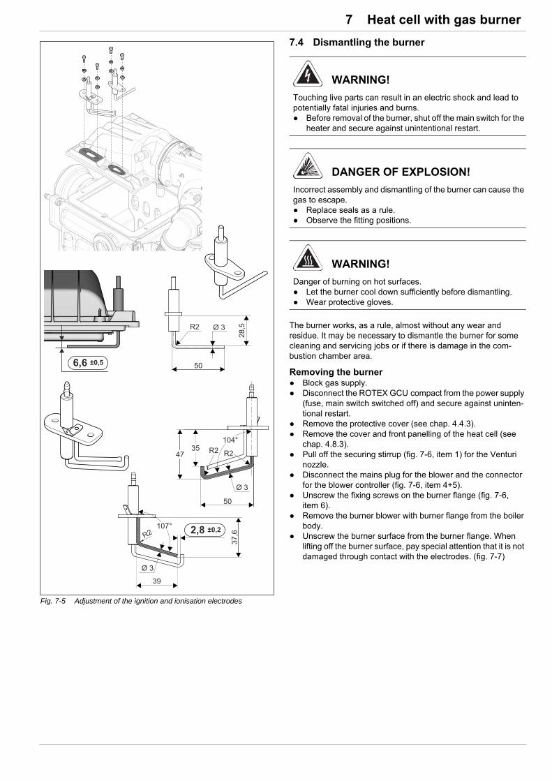
7 x Heat cell with gas burner
7.4 Dismantling the burner
The burner works, as a rule, almost without any wear and residue. It may be necessary to dismantle the burner for some cleaning and servicing jobs or if there is damage in the com-bustion chamber area.
Removing the burner Block gas supply. Disconnect the ROTEX GCU compact from the power supply
(fuse, main switch switched off) and secure against uninten-tional restart.
Remove the protective cover (see chap. 4.4.3). Remove the cover and front panelling of the heat cell (see
chap. 4.8.3). Pull off the securing stirrup (fig. 7-6, item 1) for the Venturi
nozzle. Disconnect the mains plug for the blower and the connector
for the blower controller (fig. 7-6, item 4+5). Unscrew the fixing screws on the burner flange (fig. 7-6,
item 6). Remove the burner blower with burner flange from the boiler
body. Unscrew the burner surface from the burner flange. When
lifting off the burner surface, pay special attention that it is not damaged through contact with the electrodes. (fig. 7-7)
Fig. 7-5 Adjustment of the ignition and ionisation electrodes
WARNING!
Touching live parts can result in an electric shock and lead to potentially fatal injuries and burns. Before removal of the burner, shut off the main switch for the
heater and secure against unintentional restart.
DANGER OF EXPLOSION!
Incorrect assembly and dismantling of the burner can cause the gas to escape. Replace seals as a rule. Observe the fitting positions.
WARNING!
Danger of burning on hot surfaces. Let the burner cool down sufficiently before dismantling. Wear protective gloves.
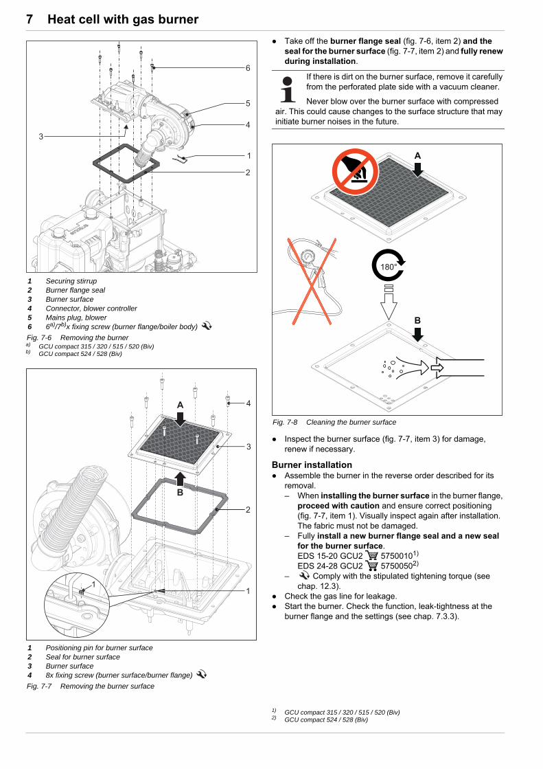
7 x Heat cell with gas burner
Take off the burner flange seal (fig. 7-6, item 2) and the seal for the burner surface (fig. 7-7, item 2) and fully renew during installation.
Inspect the burner surface (fig. 7-7, item 3) for damage, renew if necessary.
Burner installation Assemble the burner in the reverse order described for its
removal.– When installing the burner surface in the burner flange,
proceed with caution and ensure correct positioning (fig. 7-7, item 1). Visually inspect again after installation. The fabric must not be damaged.
– Fully install a new burner flange seal and a new seal for the burner surface.EDS 15-20 GCU2 57500101)
EDS 24-28 GCU2 57500502)
– Comply with the stipulated tightening torque (see chap. 12.3).
Check the gas line for leakage. Start the burner. Check the function, leak-tightness at the
burner flange and the settings (see chap. 7.3.3).
1 Securing stirrup2 Burner flange seal3 Burner surface4 Connector, blower controller5 Mains plug, blower6 6a)/7b)x fixing screw (burner flange/boiler body)
a) GCU compact 315 / 320 / 515 / 520 (Biv)b) GCU compact 524 / 528 (Biv)
Fig. 7-6 Removing the burner
1 Positioning pin for burner surface2 Seal for burner surface3 Burner surface4 8x fixing screw (burner surface/burner flange)
Fig. 7-7 Removing the burner surface
If there is dirt on the burner surface, remove it carefully from the perforated plate side with a vacuum cleaner.
Never blow over the burner surface with compressed air. This could cause changes to the surface structure that may initiate burner noises in the future.
Fig. 7-8 Cleaning the burner surface
1) GCU compact 315 / 320 / 515 / 520 (Biv)2) GCU compact 524 / 528 (Biv)

8 x Hydraulic connection
8 Hydraulic connection
8.1 Hydraulic system connection
WARNING!
To prevent flue gas from escaping, the storage tank must be filled to overflow when starting up the ROTEX GCU compact.
WARNING!
High temperatures can occur in the solar storage tank. Therefore, sufficient scalding protection must be included when the hot water system is installed (automatic hot water mixing device).
CAUTION!
The ROTEX units can also be optionally fitted with gravity breaks ( 16 50 70) made of plastic. They are suitable for maximum operating temperatures of 95 °C. If a heat exchanger is operated at temperatures greater than 95 °C, another gravity brake must be installed in the building.
A selection of diagrams of the most common systems is shown below. The arrangements shown are only examples, and are no substitute for careful system planning. Please visit the ROTEX website for more dia-
grams.
Short name Meaning
1 Cold water distribution network
2 Hot water distribution network
3 Heating flow
4 Heating return flow
5 Mixing circuit
6 Circulation
7 Check valve, return valve
7a Non-return valves
8 Solar circuit
3UV DHW 3-way distribution valve (hot water/heater)
3UVB1 3-way mixer valve (heater/internal boiler circuit)
CW Cold water
DHW Domestic hot water
DSR1 Pressurised solar system
FLSFlowSensor - solar throughput and inflow tem-perature measurement
H1, H2 … Hm Heating circuits
MAG Diaphragm expansion vessel
MIX 3-way-mixer with drive motor
MK1 Mixer group with high-efficiency pump
MK2Mixer group with high-efficiency pump (PWM-regulated)
PK Boiler circuit pump
PMi Mixing circuit pump
PS Solar operating pump
PS1 Solar operating pump
PZ Circulation pump
RDS2 Pressure station
RoCon BF Control GCU compact
RoCon M1 Mixer circuit control
RPS4 Solar control and pump unit
SK Solar panel field
SV Safety overpressure valve
tAU External temperature sensor
tDHW Storage tank temperature sensor
tMi Inflow temperature sensor, mixer circuit
tK Solaris solar panel temperature sensor
tR Solaris return flow temperature sensor
TS Solaris storage tank temperature sensor
TV Solaris flow temperature sensor
VS Scalding protection VTA32
Tab. 8-1 Abbreviations on hydraulics plans

8 x Hydraulic connection
Fig. 8-1 GCU compact 3xx (example) with DrainBack solar (for legend, see tab. 8-1)
Fig. 8-2 GCU compact 5xx Biv with pressurised solar system (for legend, see tab. 8-1)

9 x Service and maintenance
9 Service and maintenance
9.1 General overview of service and maintenance
Regular inspection and maintenance of the heating system re-duces energy consumption and ensures a long life and smooth operation.
Tests performed during the annual service– General condition of the heating system, visual inspection of
connections and pipes.– Check and clean the condensate drain.– Check of the water pressure for the cold water supply
(<6 bar), pressure reducer installation or adjustment as required.
– Burner operation and burner settings.– Visual inspection of storage tank water container fill level (see
chap. 9.2.2).
Top up water if required (see chap. 9.2.4) and also deter-mine and remedy the cause for the low water level.
– Check the system water pressure on the RoCon BF controller for the ROTEX GCU compact.
Top up water in the heating system until the pressure dis-play is in the permissible range (see chap. 9.2.5).
Maintenance work to be carried out annually– Cleaning the burner components, the combustion chamber
and the heating surfaces.– External cleaning of the storage tank and the protective
cover.– Replacement of the wearing parts if required).– Documentation of the maintenance work in the operating
manual.– Before restart of the ROTEX GCU compact after mainte-
nance work, the conditions for start-up according to chap. 5.2 must be checked and fulfilled.
9.2 Service and maintenance tasks
Cleaning the protective cover and storage tank The low-maintenance plastic only needs to be cleaned with a
soft cloth and a mild detergent. Do not use any cleaners with aggressive solvents (damage to
the plastic surface may occur).
9.2.1 Checking the connections and pipes
Remove the protective cover
Check all (flue) gas and water lines and connections for leaks and integrity. If damaged, determine the cause and change the damaged parts.
Check all components of the flue system for leakage and damage. Repair damaged parts or replace them.
Check all electrical components, connections, and pipes. Repair damaged parts.
Have the service and maintenance been carried out by authorised and trained heating technicians once a year and, if possible, before the heating period. This will avoid malfunctions during the heating period.
ROTEX recommends an inspection and maintenance contract to ensure regular inspection and maintenance.
WARNING!
Touching live parts can result in an electric shock and lead to potentially fatal injuries and burns. Before beginning maintenance work, disconnect the ROTEX
GCU compact from the power supply (fuse, switch off main switch) and secure against unintentional restart.
CAUTION!
Danger of burning on hot surfaces. Let the burner cool down for a reasonably long time before
maintenance and service work. Wear protective gloves.
WARNING!
Improperly performed work on power or gas lines can endanger life and health and hinder the operation of the ROTEX GCU compact. Damage repair to power and gas lines on the ROTEX
GCU compact may only be carried out by heating techni-cians authorised and trained by the gas or power supply company.
Fig. 9-1 Unhook the rear protective cover, lift and remove forwards.
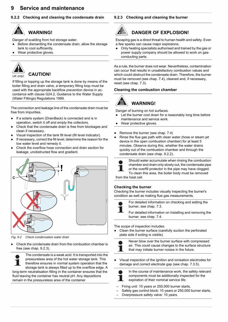
9 x Service and maintenance
9.2.2 Checking and cleaning the condensate drain
The connection and leakage line of the condensate drain must be free from impurities.
If a solaris system (DrainBack) is connected and is in operation, switch it off and empty the collectors.
Check that the condensate drain is free from blockages and clean if necessary.
Visual inspection of the tank fill level (fill level indicator). If necessary, correct the fill level; determine the reason for the
low water level and remedy it. Check the overflow hose connection and drain section for
leakage, unobstructed flow and gradient.
Check the condensate drain from the combustion chamber is free (see chap. 9.2.3).
9.2.3 Checking and cleaning the burner
As a rule, the burner does not wear. Nevertheless, contamination can occur that results in unsatisfactory combustion values and which could obstruct the condensate drain. Therefore, the burner must be removed (see chap. 7.4), cleaned and, if necessary, reset (see chap. 7.3).
Cleaning the combustion chamber
Remove the burner (see chap. 7.4) Rinse the flue gas path with clean water (hose or steam jet
device in the open combustion chamber) for at least 5 minutes. Observe during this, whether the water drains quickly out of the combustion chamber and through the condensate drain (see chap. 9.2.2).
Checking the burnerChecking the burner includes visually inspecting the burner's condition as well as making flue gas measurements.
The scope of inspection includes: Clean the burner surface (carefully suction the perforated
plate side if soiling is visible).
Visual inspection of the ignition and ionisation electrodes for damage and correct electrode gap (see chap. 7.3.5).
WARNING!
Danger of scalding from hot storage water. Before dismantling the condensate drain, allow the storage
tank to cool sufficiently. Wear protective gloves.
UK only! CAUTION!
If filling or topping up the storage tank is done by means of the boiler filling and drain valve, a temporary filling loop must be used with the appropriate backflow prevention device in ac-cordance with clause G24.2, Guidance to the Water Supply (Water Fittings) Regulations 1999.
Fig. 9-2 Check condensation water drain
The condensate is a weak acid. It is transported into the pressureless area of the hot water storage tank. This therefore ensures in normal system operation that the storage tank is always filled up to the overflow edge. A
long-term neutralisation filling in the container ensures that the fluid leaving the container has neutral pH. Any depositions remain in the pressureless area of the container.
DANGER OF EXPLOSION!
Escaping gas is a direct threat to human health and safety. Even a few sparks can cause major explosions. Only heating specialists authorised and trained by the gas or
power supply company should be allowed to work on gas-conducting parts.
WARNING!
Danger of burning on hot surfaces. Let the burner cool down for a reasonably long time before
maintenance and service work. Wear protective gloves.
Should water accumulate when rinsing the combustion chamber and drain only slowly out, the condensate pipe or the overfill protector in the pipe may have clogged. To clean this area, the boiler body must be removed
from the heat cell.
For detailed information on checking and setting the burner, see chap. 7.3.
For detailed information on installing and removing the burner, see chap. 7.4.
Never blow over the burner surface with compressed air. This could cause changes to the surface structure that may initiate burner noises in the future.
In the course of maintenance work, the safety relevant components must be additionally inspected for the expiration of their nominal service life:
– Firing unit: 10 years or 250,000 burner starts,– Safety gas control block: 10 years or 250,000 burner starts,– Overpressure safety valve: 10 years.

9 x Service and maintenance
If necessary, replace faulty parts. Install the burner flange on the boiler body (see chap. 7.4 –
"Burner installation").– Fully install a new burner flange seal and a new seal
for the burner surface (EDS 15-20 GCU2, 57500101), EDS 24-28 GCU2 57500502)).
Check the gas line for leakage. Start the burner, check sealing on the burner flange. Check combustion values:
– Flue gas temperature at measuring sockets of the flue gas pipe. (Target value < 80 °C),
– O2 and CO2 content (see chap. 7.3.1),– CO content (target value < 50 ppm).
If the combustion values do not lie within the set value range, the burner must be adjusted according to chap. 7.3.
9.2.4 Filling, topping up the storage tank
Without installed solar system Connect the filling hose with non-return valve (1/2") to the
"solar inflow connection" (fig. 9-3, item 1). Fill the storage tank of the GCU compact until water
escapes out of the overflow connection (fig. 9-3, item 2). Remove the filling hose with non-return valve (1/2").
With installed solar system Fit the filling connection with KFE cock (accessory: KFE BA,
16 52 15) to the solar control and pump unit (RPS4). Connect the filling hose with non-return valve (1/2") to the
previously installed KFE cock. Fill the storage tank of the GCU compact until water
escapes out of the overflow connection (fig. 9-3, item 2). Remove the filling hose with non-return valve (1/2").
1) GCU compact 315 / 320 / 515 / 520 (Biv)2) GCU compact 524 / 528 (Biv)
We recommend, to enter all measured values and the conducted work with the date and signature into the en-closed operating handbook.
CAUTION!
Escape of flue gas from the system will be damaging to health. Top up the storage tank until it overflows before starting up
the ROTEX GCU compact.
CAUTION!
Filling the storage tank with a too high water pressure or too high flow speed can cause damage to the GCU compact. Only fill with a water pressure <6 bar and a flow speed
<15 l/min.
UK only! CAUTION!
If filling or topping up the storage tank is done by means of the boiler filling and drain valve, a temporary filling loop must be used with the appropriate backflow prevention device in ac-cordance with clause G24.2, Guidance to the Water Supply (Water Fittings) Regulations 1999.
1 Solar inflow2 Safety overflow
Fig. 9-3 Filling buffer storage - without connected DrainBack solar sys-tem

9 x Service and maintenance
9.2.5 Filling, topping up the heating system and storage tank charging circuit
1. Connect the filling hose (fig. 9-4, item 1) with the non-return valve and an external manometer1) (on the building side) to the KFE cock (fig. 9-4, item 2) and secure it against slipping off with a hose clamp.
2. Make sure that the automatic vent valve cap is open (fig. 9-5, item A).
3. Open the water tap (fig. 9-4, item 6) on the feed pipe.
4. Open the KFE cock (fig. 9-4, item 2) and observe the pressure gauge (fig. 9-4, item 8).
5. Fill the system with water until the pressure gauge shows that the system target pressure is reached (system height + 2 m, 1 m water column corresponds to 0.1 bar). The overpressure valve is not to actuate!
6. Close the KFE cock (fig. 9-4, item 2).
7. Vent the hydraulic block (see chap. 9.2.6).
8. Close the water tap (fig. 9-4, item 6) on the feed pipe.
9. Disconnect the filling hose (fig. 9-4, item 1) with non-return valve from the KFE cock (fig. 9-4, item 2).
DANGER!
During the filling process water may escape from any leaking points that can cause an electric shock if it comes into contact with live parts. Before the filling process, de-energise the GCU compact. After the first filling and before switching on the
GCU compact at the mains switch, check whether all electric parts and connection points are dry.
WARNING!
Polluted domestic water is hazardous to health. When filling the heating system, make sure that heating
water cannot flow back into the domestic water pipe.
Comply with the instructions for water connection (see chap. 4.6) and water quality (see chap. 1.2.5).
Fig. 9-4 Filling the heating system and storage tank charging circuit (shown on the GCU compact 5xx)
1 Filling hose with return flow inhibitor (and manometer1))
2 KFE cock3 Heater ball cock - inflow 4 Heater ball cock - return
flow5.1 Valve drive5.2 Unlocking button of the
drive lock
6 Water tap7 Automatic bleeder8 Pressure gauge
3UV DHW3-way distribution valve
3UVB13-way mixer valve
Tab. 9-1 Legend for fig. 9-4
1) if not already installed in the heating system
A Automatic vent valve cap
Fig. 9-5 Undoing the automatic vent valve cap
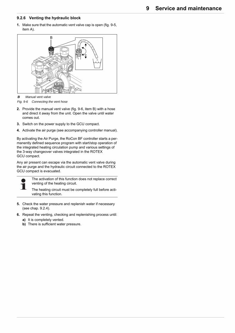
9 x Service and maintenance
9.2.6 Venting the hydraulic block
1. Make sure that the automatic vent valve cap is open (fig. 9-5, item A).
2. Provide the manual vent valve (fig. 9-6, item B) with a hose and direct it away from the unit. Open the valve until water comes out.
3. Switch on the power supply to the GCU compact.
4. Activate the air purge (see accompanying controller manual).
By activating the Air Purge, the RoCon BF controller starts a per-manently defined sequence program with start/stop operation of the integrated heating circulation pump and various settings of the 3-way changeover valves integrated in the ROTEX GCU compact.
Any air present can escape via the automatic vent valve during the air purge and the hydraulic circuit connected to the ROTEX GCU compact is evacuated.
5. Check the water pressure and replenish water if necessary (see chap. 9.2.4).
6. Repeat the venting, checking and replenishing process until:
a) It is completely vented.b) There is sufficient water pressure.
B Manual vent valve
Fig. 9-6 Connecting the vent hose
The activation of this function does not replace correct venting of the heating circuit.
The heating circuit must be completely full before acti-vating this function.
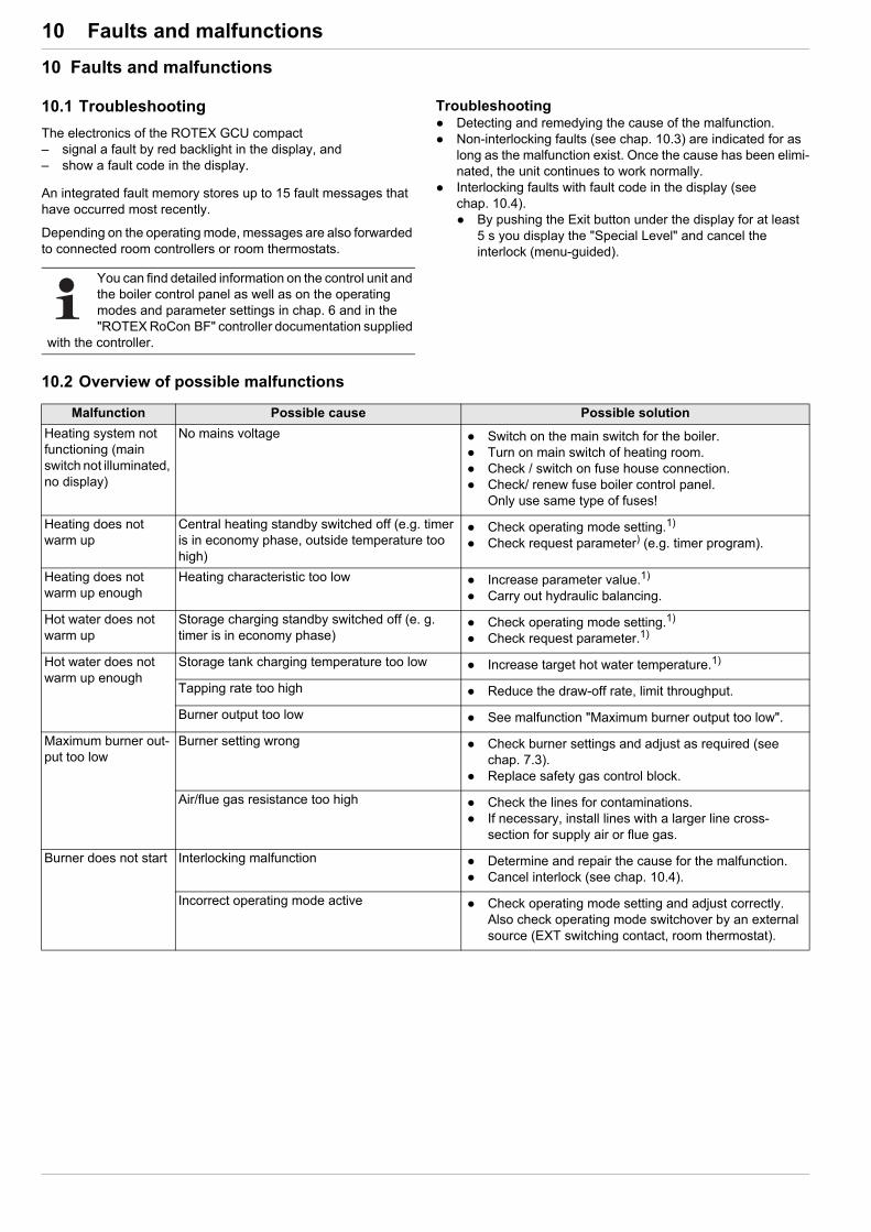
10 x Faults and malfunctions
10 Faults and malfunctions
10.1 Troubleshooting
The electronics of the ROTEX GCU compact– signal a fault by red backlight in the display, and– show a fault code in the display.
An integrated fault memory stores up to 15 fault messages that have occurred most recently.
Depending on the operating mode, messages are also forwarded to connected room controllers or room thermostats.
Troubleshooting Detecting and remedying the cause of the malfunction. Non-interlocking faults (see chap. 10.3) are indicated for as
long as the malfunction exist. Once the cause has been elimi-nated, the unit continues to work normally.
Interlocking faults with fault code in the display (see chap. 10.4). By pushing the Exit button under the display for at least
5 s you display the "Special Level" and cancel the interlock (menu-guided).
10.2 Overview of possible malfunctions
You can find detailed information on the control unit and the boiler control panel as well as on the operating modes and parameter settings in chap. 6 and in the "ROTEX RoCon BF" controller documentation supplied
with the controller.
Malfunction Possible cause Possible solution
Heating system not functioning (main switch not illuminated, no display)
No mains voltage Switch on the main switch for the boiler. Turn on main switch of heating room. Check / switch on fuse house connection. Check/ renew fuse boiler control panel.
Only use same type of fuses!
Heating does not warm up
Central heating standby switched off (e.g. timer is in economy phase, outside temperature too high)
Check operating mode setting.1)
Check request parameter) (e.g. timer program).
Heating does not warm up enough
Heating characteristic too low Increase parameter value.1)
Carry out hydraulic balancing.
Hot water does not warm up
Storage charging standby switched off (e. g. timer is in economy phase)
Check operating mode setting.1)
Check request parameter.1)
Hot water does not warm up enough
Storage tank charging temperature too low Increase target hot water temperature.1)
Tapping rate too high Reduce the draw-off rate, limit throughput.
Burner output too low See malfunction "Maximum burner output too low".
Maximum burner out-put too low
Burner setting wrong Check burner settings and adjust as required (see chap. 7.3).
Replace safety gas control block.
Air/flue gas resistance too high Check the lines for contaminations. If necessary, install lines with a larger line cross-
section for supply air or flue gas.
Burner does not start Interlocking malfunction Determine and repair the cause for the malfunction. Cancel interlock (see chap. 10.4).
Incorrect operating mode active Check operating mode setting and adjust correctly.Also check operating mode switchover by an external source (EXT switching contact, room thermostat).
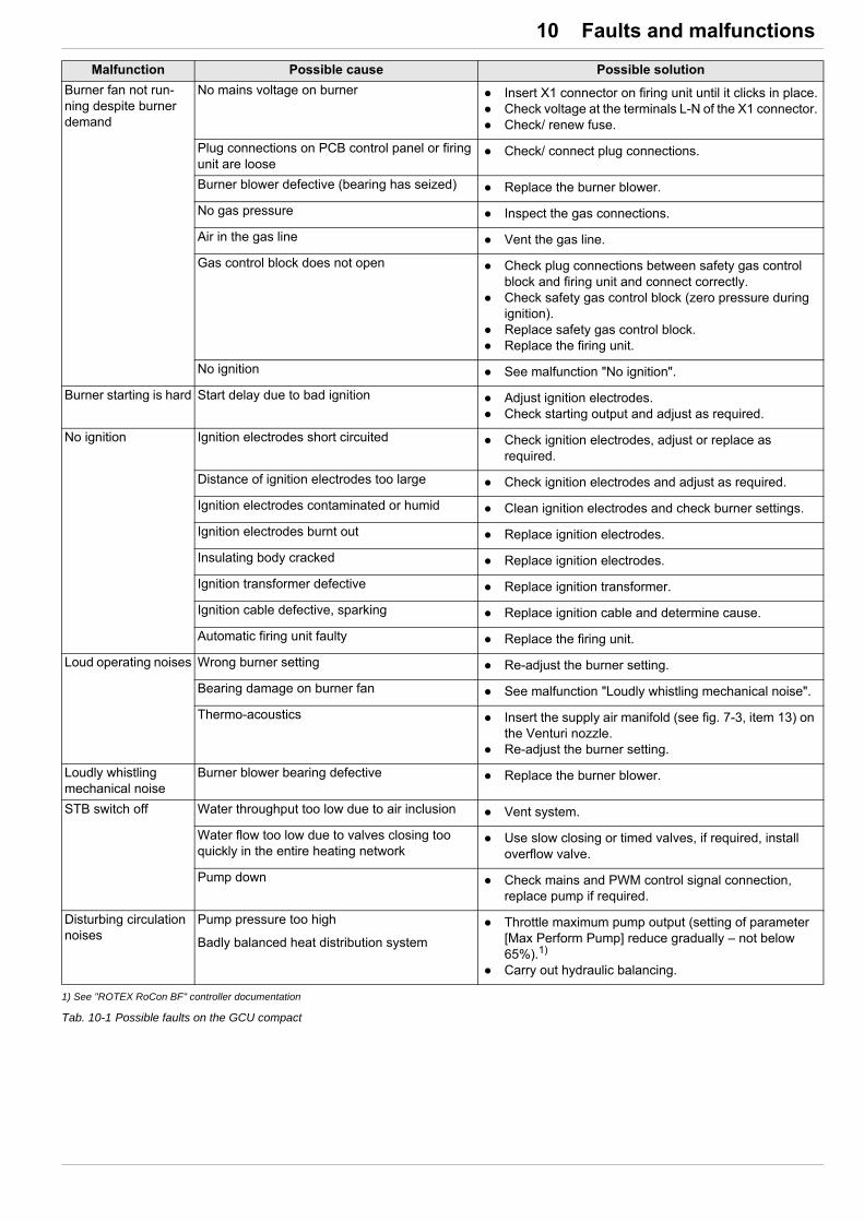
10 x Faults and malfunctions
1) See "ROTEX RoCon BF" controller documentation
Tab. 10-1 Possible faults on the GCU compact
Burner fan not run-ning despite burner demand
No mains voltage on burner Insert X1 connector on firing unit until it clicks in place. Check voltage at the terminals L-N of the X1 connector. Check/ renew fuse.
Plug connections on PCB control panel or firing unit are loose
Check/ connect plug connections.
Burner blower defective (bearing has seized) Replace the burner blower.
No gas pressure Inspect the gas connections.
Air in the gas line Vent the gas line.
Gas control block does not open Check plug connections between safety gas control block and firing unit and connect correctly.
Check safety gas control block (zero pressure during ignition).
Replace safety gas control block. Replace the firing unit.
No ignition See malfunction "No ignition".
Burner starting is hard Start delay due to bad ignition Adjust ignition electrodes. Check starting output and adjust as required.
No ignition Ignition electrodes short circuited Check ignition electrodes, adjust or replace as required.
Distance of ignition electrodes too large Check ignition electrodes and adjust as required.
Ignition electrodes contaminated or humid Clean ignition electrodes and check burner settings.
Ignition electrodes burnt out Replace ignition electrodes.
Insulating body cracked Replace ignition electrodes.
Ignition transformer defective Replace ignition transformer.
Ignition cable defective, sparking Replace ignition cable and determine cause.
Automatic firing unit faulty Replace the firing unit.
Loud operating noises Wrong burner setting Re-adjust the burner setting.
Bearing damage on burner fan See malfunction "Loudly whistling mechanical noise".
Thermo-acoustics Insert the supply air manifold (see fig. 7-3, item 13) on the Venturi nozzle.
Re-adjust the burner setting.
Loudly whistling mechanical noise
Burner blower bearing defective Replace the burner blower.
STB switch off Water throughput too low due to air inclusion Vent system.
Water flow too low due to valves closing too quickly in the entire heating network
Use slow closing or timed valves, if required, install overflow valve.
Pump down Check mains and PWM control signal connection, replace pump if required.
Disturbing circulation noises
Pump pressure too high
Badly balanced heat distribution system
Throttle maximum pump output (setting of parameter [Max Perform Pump] reduce gradually – not below 65%).1)
Carry out hydraulic balancing.
Malfunction Possible cause Possible solution

10 x Faults and malfunctions
10.3 Fault codes
Tab. 10-2 Fault codes for interlocking malfunctions (can be detected by the firing unit)"Inside Unit:" "Heating Module" is shown for the location in the fault display
Code Component/Designation Error
E12
Firing unit
Interlocking fault
tV or tR defective (cable break, short circuit).
E65During calibration, difference from prior value was too high (unclean supply air, electrode re-placement, electrode defective).
E129 Inflow temperature exceeds limiter temperature (overtemperature, no heat dissipation)
E130 Return flow temperature exceeds limiter temperature (overtemperature, no heat dissipation)
E132 2x no flame formation at end of safety time (no gas, valves do not open, no ignition sparks)
E138 2x flame failure at end of safety time (ionisation electrode defective or dirty)
E148Gas valve test negative. A flame is still detected 15 s after the burner shutdown (gas valve jams).
E152Speed not reached during pre- and post-ventilation (burner blower defective, power supply to blower, electronics fault in blower, cable break).
E154Blower stationary position not reached (burner blower defective, electronic fault in burner blower).
E158 EEPROM fault (manufacturer’s parameters).
E159 EEPROM fault (safety parameters).
E189Regulation deviation during ionisation process too high (from 2nd fault) (burner earthed in-correctly or faulty supply voltage firing unit, gas flow pressure too low, ionisation electrode bent or oxidised, ionisation track faulty, safety gas control block defective)
E190
– Impermissible gas fitting initialisation within 10 s (from 2nd fault) or– blower falls below 80 % of the minimum speed within 10 s (from 2nd fault).
(Burner blower defective, wrong gas type set, missing/incorrect gas nozzle, safety gas con-trol block defective, gas flow pressure too low)
E191 Internal electronic fault - from 2nd fault (switch device on/off).
E192A value fell beneath the minimum thresholds during calibration (flue gas recirculation, elec-trodes oxidised, ionisation track faulty, poor earthing, transition resistances).
E194 Interruption during calibration (no heat dissipation, minimum calibration time not met).
E195 Impermissible internal value (electronic fault).
E202A value exceeded the maximum threshold values during calibration (unclean supply air, basis value too high).
E215 EEPROM fault (electronic fault).
E226Fault found in the flame amplifier evaluation during the idle state check (electronic fault, short circuit ionisation electrode or cable).
E227 Firing unit internal fault.

10 x Faults and malfunctions
Tab. 10-3 Fault codes for temporary malfunctions (can be detected by the firing unit)
Code Component/Designation Error
E2
Firing unit
Temporary malfunction, burner shutdown, automatic release when fault condition no longer active.
Return flow temperature exceeds monitor temperature (overtemperature, no heat dissipa-tion)
E6 Inflow flow temperature exceeds monitor temperature (overtemperature, no heat dissipation)
E32Undervoltage with 230 V mains voltage or 18 V internal DC voltage (electronic fault, switch device on/off).
E43Return flow temperature (tR1) is higher than inflow temperature (tV1) + 12 K for longer than 5 s.
E44 Inflow temperature increase too rapid.
E45 Spread (tV1 - tR1) too large.
E66 Interruption during calibration (no heat dissipation, minimum calibration time not met).
E90Communication interrupted between firing unit and controller PCB control panel (check cable and plug connections, total reset, replace controller PCB control panel, replace firing unit).
E96 5x reset within 15 min. Another reset is not possible until a further 15 min.
E98Fault found in the flame amplifier evaluation during the idle state check (electronic fault, short circuit ionisation electrode or cable).
E99 Firing unit internal fault.
E4
Firing unit
Temporary malfunction, device is attempting to restart
1x no flame formation at end of safety time (no gas, valves do not open, no ignition sparks)
E5 Flame failure in flame stabilisation (ionisation electrode defective or dirty).
E10 Flame failure at end of the safety time (ionisation electrode defective or dirty).
E24Value exceeds/falls below min. and max. limits during flame stabilisation or control operation (blower defective, power supply to blower, electronic fault in blower, cable break).
E50 Flame failure in regular operation (no gas, wind effect, safety gas control block supply).
E61Regulation deviation during ionisation process too high (1st fault) (burner earthed incorrectly or faulty supply voltage firing unit, gas flow pressure too low, ionisation electrode bent or oxi-dised, ionisation track faulty, safety gas control block defective)
E62
– Impermissible gas fitting initialisation during 10 s (1st fault) or– blower falls below 80 % of the minimum speed within 10 s (one-off fault).
(Burner blower defective, wrong gas type set, missing/incorrect gas nozzle, safety gas con-trol block defective, gas flow pressure too low)
E63 Internal electronic fault - 1st fault (switch device on/off).
E68 Impermissible GPV offset value (safety gas control block defective).
E69No stable state in partial load reached during adjustment within the tolerance period (wind effect, speed fluctuations, blower).

10 x Faults and malfunctions
Tab. 10-4 Fault codes (can be detected by the PCB control panel)"Inside Unit:" "Boiler" is shown for the location in the fault display
Code Component/Designation Error Possible fault rectification
E72 Internal mixer sensor
Measured value outside measuring range, temperature sensor defective.
Check cable, terminal and plug connec-tions.
Replace temperature sensor.E75 External temperature sensor
E76Storage tank temperature sensor
E81 EEPROMInternal fault.
Total reset Replace PCB control panel in controller.E88 PCB control panel controller
E91 Connected CAN modules CAN module bus ID duplicated. Configure bus addresses correctly.
E100 Flue gas temperature Internal fault. Replace the firing unit.
E129 Pressure sensorMeasured value outside measuring range, sensor / temperature sensor defective.
Check cable, terminal and plug connec-tions.
Replace sensor / temperature sensor.
E198 FlowSensor Volume flow too low. Check heating circulation pump / filter /
heating network.
E200 Communication firing unitCommunication interrupted between firing unit and controller PCB control panel.
Check cable and plug connections. Total reset Replace PCB control panel in Gas Combi
Unit 2. Replace the firing unit.
W8001
FlowSensor
Volume flow fell below the minimum limit. Check parameter settings (see control system instructions).
Check pipes and valves for blockages. Check integrated circulation pump.
E8002Throughput under minimum threshold (300 l/h)
W8003Flue gas temperature
Flue gas temperature has exceeded the threshold temperature.
Clean the boiler.
E8004Flue temperature has exceeded the permissi-ble absolute maximum value.
E8005
Water pressure
Measured value under permissible minimum value.
Top up heating water. Leak test.
W8006Warning message: Maximum permissible pressure drop exceeded.
W8007Warning message: Measured value exceed permissible maximum value.
Check diaphragm expansion vessel. Drain heating water.

10 x Faults and malfunctions
10.4 Rectifying burner malfunctions and STB malfunctions
Locking faults detected by the firing unit can only be released manually directly on the boiler.
Unlocking the firing unit: Requirements: The cause of the malfunction has been rectified, the burner is connected to the electrical system.
1. Switch on the ROTEX GCU compact.
2. Push the Exit button (fig. 6-1, item 13) for at least 5 s.
Menu "Special Level" is displayed.
3. Use the rotary switch to select the "FA failure" level.
Fault code and "Reset?" request is displayed.
4. Select "n.a." with the rotary switch.
5. Confirm the changes with a brief push of the rotary switch.
Fault is reset.
6. Cancellation and jump back by pushing the Exit button again.
10.5 Emergency operation
Emergency heating operation can be maintained if the electronic controller settings are incorrect, . This is done by activating the "Manual Operation" special function on the controller (see en-closed "ROTEX controller RoCon BF" operating instructions).
When the 3-way valves are intact the ROTEX GCU compact switches to heating operation. The required inflow temperature can be adjusted with the rotary switch.
WARNING!
Risk of burns from very hot boiler body for STB malfunction. Do no let any metallic parts come into contact with the boiler. Let the boiler cool down. Wear protective gloves.
The cause of the last fault is saved in the device and can be reconstructed, even after power failure, on restarting the device.
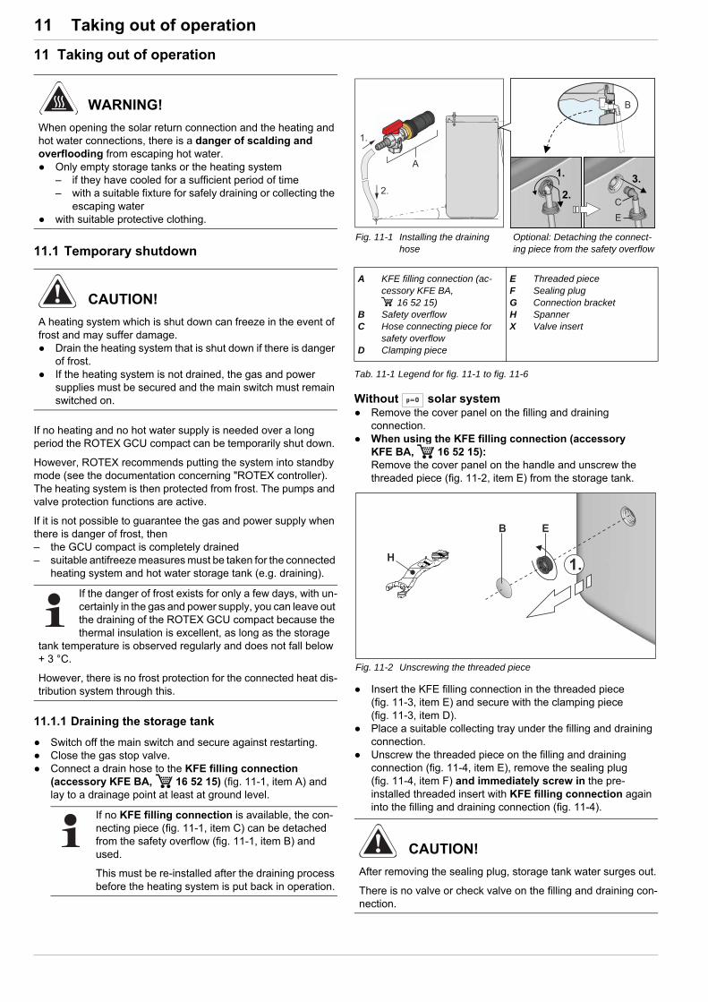
11 x Taking out of operation
11 Taking out of operation
11.1 Temporary shutdown
If no heating and no hot water supply is needed over a long period the ROTEX GCU compact can be temporarily shut down.
However, ROTEX recommends putting the system into standby mode (see the documentation concerning "ROTEX controller). The heating system is then protected from frost. The pumps and valve protection functions are active.
If it is not possible to guarantee the gas and power supply when there is danger of frost, then– the GCU compact is completely drained– suitable antifreeze measures must be taken for the connected
heating system and hot water storage tank (e.g. draining).
11.1.1 Draining the storage tank
Switch off the main switch and secure against restarting. Close the gas stop valve. Connect a drain hose to the KFE filling connection
(accessory KFE BA, 16 52 15) (fig. 11-1, item A) and lay to a drainage point at least at ground level.
Tab. 11-1 Legend for fig. 11-1 to fig. 11-6
Without solar system Remove the cover panel on the filling and draining
connection. When using the KFE filling connection (accessory
KFE BA, 16 52 15):Remove the cover panel on the handle and unscrew the threaded piece (fig. 11-2, item E) from the storage tank.
Insert the KFE filling connection in the threaded piece (fig. 11-3, item E) and secure with the clamping piece (fig. 11-3, item D).
Place a suitable collecting tray under the filling and draining connection.
Unscrew the threaded piece on the filling and draining connection (fig. 11-4, item E), remove the sealing plug (fig. 11-4, item F) and immediately screw in the pre-installed threaded insert with KFE filling connection again into the filling and draining connection (fig. 11-4).
WARNING!
When opening the solar return connection and the heating and hot water connections, there is a danger of scalding and overflooding from escaping hot water. Only empty storage tanks or the heating system
– if they have cooled for a sufficient period of time– with a suitable fixture for safely draining or collecting the
escaping water with suitable protective clothing.
CAUTION!
A heating system which is shut down can freeze in the event of frost and may suffer damage. Drain the heating system that is shut down if there is danger
of frost. If the heating system is not drained, the gas and power
supplies must be secured and the main switch must remain switched on.
If the danger of frost exists for only a few days, with un-certainly in the gas and power supply, you can leave out the draining of the ROTEX GCU compact because the thermal insulation is excellent, as long as the storage
tank temperature is observed regularly and does not fall below + 3 °C.
However, there is no frost protection for the connected heat dis-tribution system through this.
If no KFE filling connection is available, the con-necting piece (fig. 11-1, item C) can be detached from the safety overflow (fig. 11-1, item B) and used.
This must be re-installed after the draining process before the heating system is put back in operation.
Fig. 11-1 Installing the draining hose
Optional: Detaching the connect-ing piece from the safety overflow
A KFE filling connection (ac-cessory KFE BA,
16 52 15)B Safety overflowC Hose connecting piece for
safety overflowD Clamping piece
E Threaded pieceF Sealing plugG Connection bracketH SpannerX Valve insert
Fig. 11-2 Unscrewing the threaded piece
CAUTION!
After removing the sealing plug, storage tank water surges out.
There is no valve or check valve on the filling and draining con-nection.
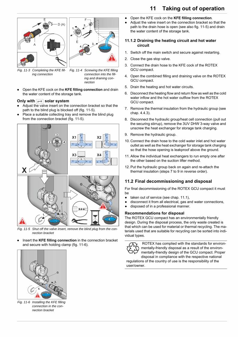
11 x Taking out of operation
Open the KFE cock on the KFE filling connection and drain the water content of the storage tank.
Only with solar system Adjust the valve insert on the connection bracket so that the
path to the blind plug is blocked off (fig. 11-5). Place a suitable collecting tray and remove the blind plug
from the connection bracket (fig. 11-5).
Insert the KFE filling connection in the connection bracket and secure with holding clamp (fig. 11-6).
Open the KFE cock on the KFE filling connection. Adjust the valve insert on the connection bracket so that the
path to the drain hose is open (see also fig. 11-5) and drain the water content of the storage tank.
11.1.2 Draining the heating circuit and hot water circuit
1. Switch off the main switch and secure against restarting.
2. Close the gas stop valve.
3. Connect the drain hose to the KFE cock of the ROTEX GCU compact.
4. Open the combined filling and draining valve on the ROTEX GCU compact.
5. Drain the heating and hot water circuits.
6. Disconnect the heating flow and return flow as well as the cold water inflow and the hot water outflow from the ROTEX GCU compact.
7. Remove the thermal insulation from the hydraulic group (see chap. 4.4.3).
8. Disconnect the hydraulic group/heat cell connection (pull out the securing stirrup), remove the 3UV DHW 3-way valve and unscrew the heat exchanger for storage tank charging.
9. Remove the hydraulic group.
10. Connect the drain hose to the cold water inlet and hot water outlet as well as the heat exchanger for storage tank charging so that the hose opening is leakproof above the ground.
11. Allow the individual heat exchangers to run empty one after the other based on the suction lifter method.
12. Put the hydraulic group back on again and re-attach the thermal insulation (steps 7 to 9 in reverse order).
11.2 Final decommissioning and disposal
For final decommissioning of the ROTEX GCU compact it must be taken out of service (see chap. 11.1), disconnect it from all electrical, gas and water connections, disposed of in a professional manner.
Recommendations for disposalThe ROTEX GCU compact has an environmentally friendly design. During the disposal process, the only waste created is that which can be used for material or thermal recycling. The ma-terials used that are suitable for recycling can be sorted into indi-vidual types.
Fig. 11-3 Completing the KFE fill-ing connection
Fig. 11-4 Screwing the KFE filling connection into the fill-ing and draining con-nection
Fig. 11-5 Shut off the valve insert, remove the blind plug from the con-nection bracket
Fig. 11-6 Installing the KFE filling connection in the con-nection bracket
ROTEX has complied with the standards for environ-mentally-friendly disposal as a result of the environ-mentally-friendly design of the GCU compact. Proper disposal in compliance with the respective national
regulations of the country of use is the responsibility of the user/owner.

12 x Technical data
12 Technical data
12.1 Basic data
12.1.1 GCU compact 3xx
Type (1)* GCU compact
Parameters Unit 315 / 315 Biv 320 / 320 Biv
Permitted ambient temperature °C 1 - 40
Total storage capacity litres 294
Empty weight (11)* kg 76 / 78
Total filled weight kg 370 / 372
Dimensions (H x W x D) cm 59.5 x 61.5 x 189.5
Maximum permissible storage water temperature °C 85
Standby heating power kWh/24h 1.5
Drinking water heat exchanger (stainless steel)
Water capacity heat exchanger litres 19.0
Heat exchanger surface area m2 4
Max. operating pressure for potable water PMW (14)* bar 6
Storage Tank primary heat exchanger (stainless steel)
Water capacity heat exchanger litres 9.4
Heat exchanger surface area m2 1.9
Pressurised solar heat exchanger (stainless steel)
Water capacity heat exchanger litres — / 4.2 — / 4.2
Heat exchanger surface area m2 — / 0.8 — / 0.8
Pipe connections
Cold and hot water inches 1" outer thread
Heating feed and return flow inches 1" inner thread
Thermal performance data (sanitary)
Output characteristic NL in accordance with DIN 47081)
2.0 2.1
D value (specific water flow) conforms to EN 155022) (15)* l/min 22 23
Continuous rating QD according to DIN 4708 kW 15 20
Max. draw-off rate for a period of 10 min at (TKW = 10 °C / TWW = 40 °C / TSP = 60 °C)
litres 19 20
Hot water quantity without reheating with a draw-off rate of 15 l/min<NewLine/>(TKW = 10 °C/TWW = 40 °C/TSP = 60 °C)
litres 200
Hot water quantity with reheating at nominal output and 15 l/min at tapping rate(TKW = 10 °C / TWW = 40 °C / TSP = 60 °C)
litres 300 350
Temporary water volume in 10 min3) litres 190 200
Electrical
Max. electric power consumption(without / with heating circulation pump)
(9)* W 16/76 38/98
Max. electric power consumption in "Standby" oper-ating mode
W 3.1
Voltage supply (8)* ~230 V, 50 Hz
Protection type (10)* IP X0B1) Reheating with nominal output, inflow temp. TV = 80 °C, starting storage tank temp. TSP = 65 °C, cold water temp. TKW = 10 °C, hot water temp. TWW = 45 °C.2) The specif. water flow acc. to EN 15502 is the domestic water flow at an average temperature increase of 30 K, which the ROTEX GCU compact can supply if two
draw-off procedures each of 10 minutes duration are performed one after the other, assuming a charging temp. of 65 °C. A delay of 20 minutes between the two draw-off procedures is usually assumed. The ROTEX GCU compact achieves this value with even shorter waiting periods.
3) Reheating with nominal output, starting storage tank temp. TSP = 60 °C, cold water temp. TKW = 10 °C, hot water temp. TWW = 40 °C.
* For position numbers, see fig. 12-1
Tab. 12-1 Technical data for ROTEX GCU compact 3xx

12 x Technical data
12.1.2 GCU compact 5xx
Type (1)* GCU compact
Parameters Unit 515 / 515 Biv
520 / 520 Biv
524 / 524 Biv
528 / 528 Biv
Permitted ambient temperature °C 1 - 40
Total storage capacity litres 477
Empty weight (11)* kg 102 / 104 104 / 106
Total filled weight kg 579 / 581 581 / 583
Dimensions (H x W x D) cm 79 x 79 x 189.5
Maximum permissible storage water temperature °C 85
Standby heating power kWh/24h 1.7
Drinking water heat exchanger (stainless steel)
Water capacity heat exchanger litres 24.5
Heat exchanger surface area m2 5
Max. operating pressure for potable water PMW (14)* bar 6
Storage Tank primary heat exchanger (stainless steel)
Water capacity heat exchanger litres 10.5 19.3
Heat exchanger surface area m2 2.1 4.0
Pressurised solar heat exchanger (stainless steel)
Water capacity heat exchanger litres — / 12.7
Heat exchanger surface area m2 — / 1.7
Pipe connections
Cold and hot water inches 1" outer thread
Heating feed and return flow inches 1" inner thread
Thermal performance data (sanitary)
Output characteristic NL in accordance with DIN 47081)
2.1 2.2
D value (specific water flow) conforms to EN 155022) (15)* l/min 23 24 25 26
Continuous rating QD according to DIN 4708 kW 15 20 24 28
Max. draw-off rate for a period of 10 min at (TKW = 10 °C / TWW = 40 °C / TSP = 60 °C)
litres 20 21 23 24
Hot water quantity without reheating with a draw-off rate of 15 l/min<NewLine/>(TKW = 10 °C/TWW = 40 °C/TSP = 60 °C)
litres 230
Hot water quantity with reheating at nominal output and 15 l/min at tapping rate(TKW = 10 °C / TWW = 40 °C / TSP = 60 °C)
litres 370 500 600 900
Temporary water volume in 10 min3) litres 200 215 230 235
Electrical
Max. electric power consumption(without / with heating circulation pump)
(9)* W 16/76 38/98 44/104 48/108
Max. electric power consumption in "Standby" oper-ating mode
W 3.1
Voltage supply (8)* ~230 V, 50 Hz
Protection type (10)* IP X0B1) Reheating with nominal output, inflow temp. TV = 80 °C, starting storage tank temp. TSP = 65 °C, cold water temp. TKW = 10 °C, hot water temp. TWW = 45 °C.2) The specif. water flow acc. to EN 15502 is the domestic water flow at an average temperature increase of 30 K, which the ROTEX GCU compact can supply if two
draw-off procedures each of 10 minutes duration are performed one after the other, assuming a charging temp. of 65 °C. A delay of 20 minutes between the two draw-off procedures is usually assumed. The ROTEX GCU compact achieves this value with even shorter waiting periods.
3) Reheating with nominal output, starting storage tank temp. TSP = 60 °C, cold water temp. TKW = 10 °C, hot water temp. TWW = 40 °C.
* For position numbers, see fig. 12-1
Tab. 12-2 Technical data for ROTEX GCU compact 5xx

12 x Technical data
12.1.3 Integrated gas boiler
12.1.4 Integrated heating circulation pump, 3-way valves
Type (1)* GCU compact (Biv)
Parameters Unit 315 / 515 320 / 520 524 528
Permitted ambient temperature °C 1 - 60
Product ID (CE number) (3)* CE-0063 CR 3574
Automatic firing unit Elster QCM434-R1
Safety gas control block Elster CES10
Burner fan ebmpapst NRG 118/0800-3612
Burner weight kg 2.8
Nominal heat output (80/60 °C) Pn(6)* kW 2.9 - 14.6 2.9 - 19.5 3.9 - 23.4
(4.9 - 23.4)1)3.9 - 27.2
(4.9 - 27.2)1)
Nominal heat output with condensation (50/30 °C) Pnc
kW 3.2 - 15.8 3.2 - 21.0 4.3 - 25.1(5.4 - 25.1)1)
4.3 - 29.1(5.4 - 29.1)1)
Rated thermal load Qn(5)* kW 3.0 - 15.0 3.0 - 20.0 4.0 - 24.0
(5.0 - 24.0)1)4.0 - 28.0
(5.0 - 28.0)1)
Device type(2)* B23, B23P, B33, B53, B53P,
C13, C33, C43, C53, C63, C83, C93
NOx class (to EN 15502-1) (4)* 6
NOx output (with reference to calorific value Hs) mg/kWh 23 31 31 31
Boiler body water content litres 1.2
Max. permissible operating pressure PMS (12)* bar 3.0
Max. permissible operating temperature (13)* °C 85
Max. boiler efficiency % 108
Flue gas / air infeed connection diametermm DN 60/100
(DN 80/125 with SET GCU1 ( 15 50 79.17))1) Liquid gas setting* For position numbers, see fig. 12-1
Tab. 12-3 Technical data for GCU compact gas burner
Parameters Unit Heating circulation pump
Type Grundfos UPM3K 25-75 CHBL RT
Voltage V ~230
Frequency (voltage supply) Hz 50
Maximum power consumption W 60
Protection type IP 44
Permitted overpressure bar 3
Maximum pumping height m 7.5
Energy efficiency EEI<0.2 (EN 16297-3)
3-way valves: 3UV DHW / 3UVB1
Type AFRISO USV
Voltage V ~230
Frequency (voltage supply) Hz 50
Maximum power consumption W 7
Protection type IP 54
Turnaround time s 75
Tab. 12-4 Technical data for heating circulation pump, 3-way valves
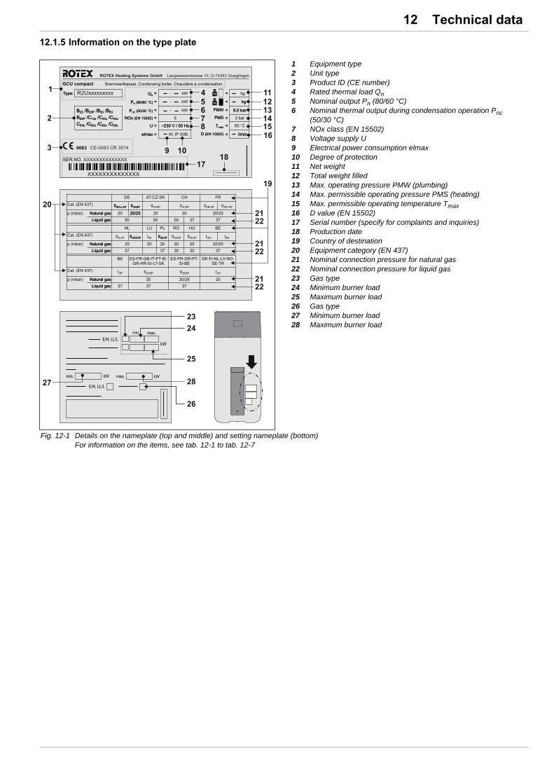
12 x Technical data
12.1.5 Information on the type plate
1 Equipment type2 Unit type3 Product ID (CE number)4 Rated thermal load Qn5 Nominal output Pn (80/60 °C)6 Nominal thermal output during condensation operation Pnc
(50/30 °C)7 NOx class (EN 15502)8 Voltage supply U9 Electrical power consumption elmax10 Degree of protection11 Net weight12 Total weight filled13 Max. operating pressure PMW (plumbing)14 Max. permissible operating pressure PMS (heating)15 Max. permissible operating temperature Tmax16 D value (EN 15502)17 Serial number (specify for complaints and inquiries)18 Production date19 Country of destination20 Equipment category (EN 437)21 Nominal connection pressure for natural gas22 Nominal connection pressure for liquid gas23 Gas type24 Minimum burner load25 Maximum burner load26 Gas type27 Minimum burner load28 Maximum burner load
Fig. 12-1 Details on the nameplate (top and middle) and setting nameplate (bottom) For information on the items, see tab. 12-1 to tab. 12-7

12 x Technical data
12.1.6 Product fiche (characteristics pursuant to the European Energy Labelling Directives)
Energy labelling regulation: (EU) 811/2013 Ecodesign regulation: (EU) 813/2013
Combination heaters designed for using
gaseous fuels
/ Model names ROTEX GCU compact
315 / 315 Biv
320 / 320 Biv
515 / 515 Biv
520 / 520 Biv
524 / 524 Biv
528 / 528 Biv
Load profile for water heating -
Seasonal space heating Energy efficiency class - A A A A A A
Water heating Energy efficiency class - A A A A A A
Prated kW 15 20 15 20 24 28
Annual energy consumption (QHE)kWh /
GJ7,845 /
289,945 /
367,845 /
289,945 /
3612,084 /
4413,807 /
50
Annual fuel consumption for water heating (AFC) GJ 12 12 17 18 18 18
Annual electricity consumption (AEC) kWh 46 51 57 59 62 66
Seasonal space heating efficiency (s) % 92 93 92 93 93 93
Water heating energy efficiency (wh) % 77 78 89 80 82 82
Sound power (LWA) dB(A) 53 55 53 55 56 56
Storage tank
Energy efficiency class - B B B B B B
Standing loss W 62.5 62.5 70.8 70.8 70.8 70.8
Hot water storage tank volume L 294 294 477 477 477 477
Controller
class of temperature control - II II II II II II
contribution to seasonal space heating efficiency
% 2 2 2 2 2 2
Energy efficiency class - A A A A A A
Seasonal space heating efficiency (s) % 93 93 93 93 93 94
Control with RoCon U1/BM1 connected
class of temperature control with RoCon U1/BM1
- VI VI VI VI VI VI
contribution to seasonal space heating efficiency
% 4 4 4 4 4 4
Details and precautions on installation, maintenance and assembly can be found in the installation and or operation manuals. Energy labels and product fiches for additional combinations, packages and other products can be found at www.rotex-heating.com.Sound power in heating mode, measured according to the EN 12102 under conditions of the EN 14825.This data is for comparison of energy efficiencies according to energy label directive 2010/30/EC. For correct selection of products for your application, contact your dealer. Depending on your application and the product selected, an additional supplementary heater may have to be installed.
Tab. 12-5 Characteristic data for determining the values for energy efficiency identification

12 x Technical data
12.2 Gas type, connection pressures
12.3 Tightening torque
Gas type Nominal pressure in mbar Min. inlet pressure in mbar Max. inlet pressure in mbar
Natural gas E/H 20 17 25
Natural gas LL/L 20 18 25
Liquefied petroleum gas 50 42.5 57.5
Tab. 12-6 Permitted gas inlet pressure
Country of destination Appliance category Nominal connection pressure in mbar
Natural gas Liquefied petroleum gas
Natural gas Liquefied petroleum gas
DE II 2N3P 20/25 50
DE II 2ELL3P 20 50
AT, CH, CZ, SK II 2H3P 20 50
CH, ES, FR, GB, IE, GR, IT, HR, PT, SI, LT, SK II 2H3P 20 37
ES, FR, GR, PT, SI II 2N3P 20/25 37
NL II 2L3P 25 37
HU II 2H3P 25 30
FR II 2E+3P 20/25 37
FR II 2Er3P 20 37
DK, FI, LV, NL, NO, SE, TR I 2H 20
BE II 2E+3P 20/25 37
BE II 2N3P 20/25 37
LU I 2E 20
PL II 2E3P 20 37
RO II 2H3P 20 30
Tab. 12-7 Countries of destination, unit categories and associated gas connection pressures (7)*
* For position numbers, see fig. 12-1
Component Remark Tightening torque in Nm
Fixing screws (upper panelling of the heat cell) fig. 4-43, item 1+2 3
Fixing screw (burner flange / boiler body) fig. 7-3, item 19 3
Fixing screw (burner surface / burner flange) fig. 7-7, item 4 3
Fixing screw (Venturi nozzle) fig. 7-3, item 16 3
Fixing screw (ignition electrodes / ionisation electrode) fig. 7-3, item 27+29 3
Fixing screw (burner blower / burner flange) fig. 7-3, item 15 3
Fixing screw (securing plate / connection adapter for gas valve) fig. 7-2, item 33 3
Fixing screw (connection adapter for gas valve) fig. 7-2, item 30 1.5
Fixing screw (exhaust manifold / boiler body) fig. 7-3, item 25 2
Temperature sensors and sensors all Max. 10
Hydraulic line connections (Water) Thread 1" 25 - 30
Tab. 12-8 Tightening torque

12 x Technical data
12.4 Flow rate and residual feed height 12.5 Temperature sensor
pR Residual feed heightmH Heating network flow
1 Modulation range
Fig. 12-2 Residual feed height GCU compact (heating side)
mH Heating network flow Q Heating output
Fig. 12-3 Required flow rates depending on the heating output and the dimensioned temperature spread
RS Sensor resistance T Temperature
Fig. 12-4 Resistance characteristics of the temperature sensor
Measured temperature
in °C
Temperature sensor
Type Specification *
NTC tV1 , tR , tV2, tAU, tDHW, tMi
Sensor resistance in Ohm according to standard or manufacturer's
data
-20 98660
-10 56250
0 33210
10 20240
20 12710
30 8195
40 5416
50 3663
60 2530
70 1782
80 1278
90 932
100 690
110 519
120 395
* For legend, see tab. 8-1 Safety devices
Tab. 12-9 Resistance values of the temperature sensor

12 x Technical data
12.6 Electrical connection diagram
Fig. 12-5 Wiring diagram ROTEX GCU compact (for legend, see tab. 12-10)
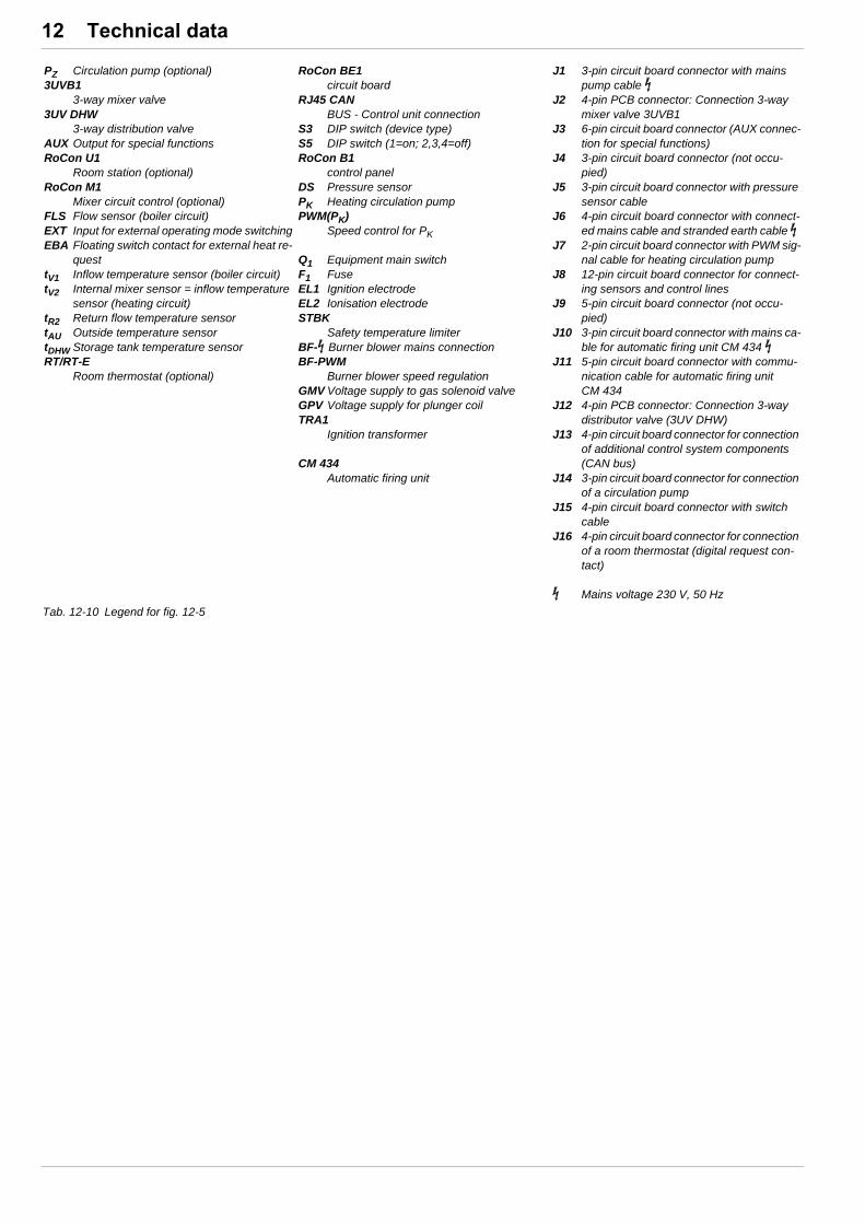
12 x Technical data
PZ Circulation pump (optional)3UVB1
3-way mixer valve3UV DHW
3-way distribution valveAUX Output for special functionsRoCon U1
Room station (optional)RoCon M1
Mixer circuit control (optional)FLS Flow sensor (boiler circuit)EXT Input for external operating mode switchingEBA Floating switch contact for external heat re-
questtV1 Inflow temperature sensor (boiler circuit)tV2 Internal mixer sensor = inflow temperature
sensor (heating circuit)tR2 Return flow temperature sensortAU Outside temperature sensortDHW Storage tank temperature sensorRT/RT-E
Room thermostat (optional)
RoCon BE1circuit board
RJ45 CANBUS - Control unit connection
S3 DIP switch (device type)S5 DIP switch (1=on; 2,3,4=off)RoCon B1
control panelDS Pressure sensorPK Heating circulation pumpPWM(PK)
Speed control for PK
Q1 Equipment main switchF1 FuseEL1 Ignition electrodeEL2 Ionisation electrodeSTBK
Safety temperature limiterBF- Burner blower mains connectionBF-PWM
Burner blower speed regulationGMV Voltage supply to gas solenoid valveGPV Voltage supply for plunger coilTRA1
Ignition transformer
CM 434Automatic firing unit
J1 3-pin circuit board connector with mains pump cable
J2 4-pin PCB connector: Connection 3-way mixer valve 3UVB1
J3 6-pin circuit board connector (AUX connec-tion for special functions)
J4 3-pin circuit board connector (not occu-pied)
J5 3-pin circuit board connector with pressure sensor cable
J6 4-pin circuit board connector with connect-ed mains cable and stranded earth cable
J7 2-pin circuit board connector with PWM sig-nal cable for heating circulation pump
J8 12-pin circuit board connector for connect-ing sensors and control lines
J9 5-pin circuit board connector (not occu-pied)
J10 3-pin circuit board connector with mains ca-ble for automatic firing unit CM 434
J11 5-pin circuit board connector with commu-nication cable for automatic firing unit CM 434
J12 4-pin PCB connector: Connection 3-way distributor valve (3UV DHW)
J13 4-pin circuit board connector for connection of additional control system components (CAN bus)
J14 3-pin circuit board connector for connection of a circulation pump
J15 4-pin circuit board connector with switch cable
J16 4-pin circuit board connector for connection of a room thermostat (digital request con-tact)
Mains voltage 230 V, 50 Hz
Tab. 12-10 Legend for fig. 12-5

13 x Notes
13 Notes

13 x Notes
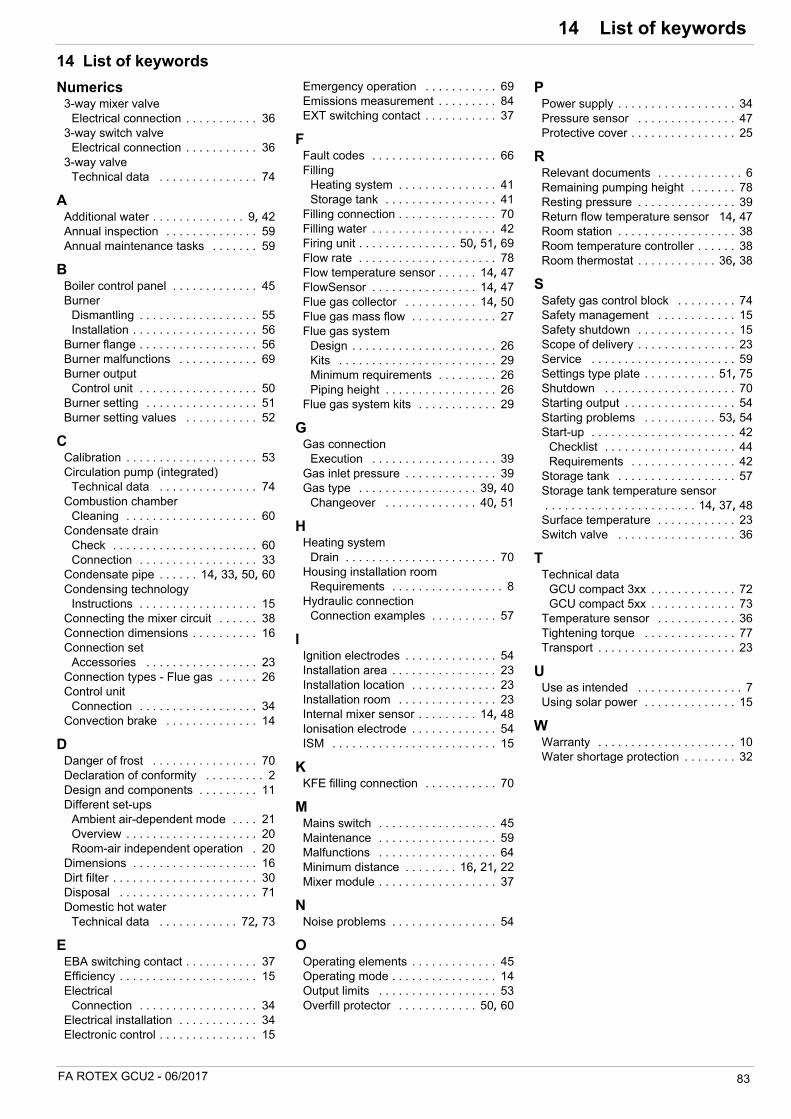
14 x List of keywords
FA ROTEX GCU2 - 06/2017 83
14 List of keywords
Numerics3-way mixer valve
Electrical connection . . . . . . . . . . . 363-way switch valve
Electrical connection . . . . . . . . . . . 363-way valve
Technical data . . . . . . . . . . . . . . . 74
AAdditional water . . . . . . . . . . . . . . 9, 42Annual inspection . . . . . . . . . . . . . . 59Annual maintenance tasks . . . . . . . 59
BBoiler control panel . . . . . . . . . . . . . 45Burner
Dismantling . . . . . . . . . . . . . . . . . . 55Installation . . . . . . . . . . . . . . . . . . . 56
Burner flange . . . . . . . . . . . . . . . . . . 56Burner malfunctions . . . . . . . . . . . . 69Burner output
Control unit . . . . . . . . . . . . . . . . . . 50Burner setting . . . . . . . . . . . . . . . . . 51Burner setting values . . . . . . . . . . . 52
CCalibration . . . . . . . . . . . . . . . . . . . . 53Circulation pump (integrated)
Technical data . . . . . . . . . . . . . . . 74Combustion chamber
Cleaning . . . . . . . . . . . . . . . . . . . . 60Condensate drain
Check . . . . . . . . . . . . . . . . . . . . . . 60Connection . . . . . . . . . . . . . . . . . . 33
Condensate pipe . . . . . . 14, 33, 50, 60Condensing technology
Instructions . . . . . . . . . . . . . . . . . . 15Connecting the mixer circuit . . . . . . 38Connection dimensions . . . . . . . . . . 16Connection set
Accessories . . . . . . . . . . . . . . . . . 23Connection types - Flue gas . . . . . . 26Control unit
Connection . . . . . . . . . . . . . . . . . . 34Convection brake . . . . . . . . . . . . . . 14
DDanger of frost . . . . . . . . . . . . . . . . 70Declaration of conformity . . . . . . . . . 2Design and components . . . . . . . . . 11Different set-ups
Ambient air-dependent mode . . . . 21Overview . . . . . . . . . . . . . . . . . . . . 20Room-air independent operation . 20
Dimensions . . . . . . . . . . . . . . . . . . . 16Dirt filter . . . . . . . . . . . . . . . . . . . . . . 30Disposal . . . . . . . . . . . . . . . . . . . . . 71Domestic hot water
Technical data . . . . . . . . . . . . 72, 73
EEBA switching contact . . . . . . . . . . . 37Efficiency . . . . . . . . . . . . . . . . . . . . . 15Electrical
Connection . . . . . . . . . . . . . . . . . . 34Electrical installation . . . . . . . . . . . . 34Electronic control . . . . . . . . . . . . . . . 15
Emergency operation . . . . . . . . . . . 69Emissions measurement . . . . . . . . . 84EXT switching contact . . . . . . . . . . . 37
FFault codes . . . . . . . . . . . . . . . . . . . 66Filling
Heating system . . . . . . . . . . . . . . . 41Storage tank . . . . . . . . . . . . . . . . . 41
Filling connection . . . . . . . . . . . . . . . 70Filling water . . . . . . . . . . . . . . . . . . . 42Firing unit . . . . . . . . . . . . . . . 50, 51, 69Flow rate . . . . . . . . . . . . . . . . . . . . . 78Flow temperature sensor . . . . . . 14, 47FlowSensor . . . . . . . . . . . . . . . . 14, 47Flue gas collector . . . . . . . . . . . 14, 50Flue gas mass flow . . . . . . . . . . . . . 27Flue gas system
Design . . . . . . . . . . . . . . . . . . . . . . 26Kits . . . . . . . . . . . . . . . . . . . . . . . . 29Minimum requirements . . . . . . . . . 26Piping height . . . . . . . . . . . . . . . . . 26
Flue gas system kits . . . . . . . . . . . . 29
GGas connection
Execution . . . . . . . . . . . . . . . . . . . 39Gas inlet pressure . . . . . . . . . . . . . . 39Gas type . . . . . . . . . . . . . . . . . . 39, 40
Changeover . . . . . . . . . . . . . . 40, 51
HHeating system
Drain . . . . . . . . . . . . . . . . . . . . . . . 70Housing installation room
Requirements . . . . . . . . . . . . . . . . . 8Hydraulic connection
Connection examples . . . . . . . . . . 57
IIgnition electrodes . . . . . . . . . . . . . . 54Installation area . . . . . . . . . . . . . . . . 23Installation location . . . . . . . . . . . . . 23Installation room . . . . . . . . . . . . . . . 23Internal mixer sensor . . . . . . . . . 14, 48Ionisation electrode . . . . . . . . . . . . . 54ISM . . . . . . . . . . . . . . . . . . . . . . . . . 15
KKFE filling connection . . . . . . . . . . . 70
MMains switch . . . . . . . . . . . . . . . . . . 45Maintenance . . . . . . . . . . . . . . . . . . 59Malfunctions . . . . . . . . . . . . . . . . . . 64Minimum distance . . . . . . . . 16, 21, 22Mixer module . . . . . . . . . . . . . . . . . . 37
NNoise problems . . . . . . . . . . . . . . . . 54
OOperating elements . . . . . . . . . . . . . 45Operating mode . . . . . . . . . . . . . . . . 14Output limits . . . . . . . . . . . . . . . . . . 53Overfill protector . . . . . . . . . . . . 50, 60
PPower supply . . . . . . . . . . . . . . . . . . 34Pressure sensor . . . . . . . . . . . . . . . 47Protective cover . . . . . . . . . . . . . . . . 25
RRelevant documents . . . . . . . . . . . . . 6Remaining pumping height . . . . . . . 78Resting pressure . . . . . . . . . . . . . . . 39Return flow temperature sensor 14, 47Room station . . . . . . . . . . . . . . . . . . 38Room temperature controller . . . . . . 38Room thermostat . . . . . . . . . . . . 36, 38
SSafety gas control block . . . . . . . . . 74Safety management . . . . . . . . . . . . 15Safety shutdown . . . . . . . . . . . . . . . 15Scope of delivery . . . . . . . . . . . . . . . 23Service . . . . . . . . . . . . . . . . . . . . . . 59Settings type plate . . . . . . . . . . . 51, 75Shutdown . . . . . . . . . . . . . . . . . . . . 70Starting output . . . . . . . . . . . . . . . . . 54Starting problems . . . . . . . . . . . 53, 54Start-up . . . . . . . . . . . . . . . . . . . . . . 42
Checklist . . . . . . . . . . . . . . . . . . . . 44Requirements . . . . . . . . . . . . . . . . 42
Storage tank . . . . . . . . . . . . . . . . . . 57Storage tank temperature sensor . . . . . . . . . . . . . . . . . . . . . . . 14, 37, 48Surface temperature . . . . . . . . . . . . 23Switch valve . . . . . . . . . . . . . . . . . . 36
TTechnical data
GCU compact 3xx . . . . . . . . . . . . . 72GCU compact 5xx . . . . . . . . . . . . . 73
Temperature sensor . . . . . . . . . . . . 36Tightening torque . . . . . . . . . . . . . . 77Transport . . . . . . . . . . . . . . . . . . . . . 23
UUse as intended . . . . . . . . . . . . . . . . 7Using solar power . . . . . . . . . . . . . . 15
WWarranty . . . . . . . . . . . . . . . . . . . . . 10Water shortage protection . . . . . . . . 32
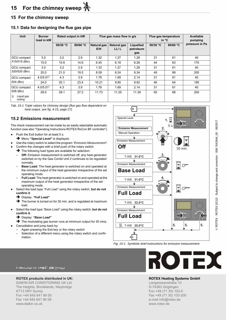
15 x For the chimney sweep
15 For the chimney sweep
15.1 Data for designing the flue gas pipe
Tab. 15-1 Triple values for chimney design (flue gas flow dependent on heat output, see fig. 4-15, page 27)
15.2 Emissions measurement
The check measurement can be made by an easily selectable automatic function (see also "Operating Instructions ROTEX RoCon BF controller").
Push the Exit button for at least 5 s. Menu "Special Level" is displayed.
Use the rotary switch to select the program "Emission Measurement". Confirm the changes with a brief push of the rotary switch. The following load types are available for selection:– Off: Emission measurement is switched off, any heat generator
switched on by the Gas Combi Unit 2 continues to be regulated normally.
– Base Load: The heat generator is switched on and operated at the minimum output of the heat generator irrespective of the set operating mode.
– Full Load: The heat generator is switched on and operated at the maximum output of the heat generator irrespective of the set operating mode.
Select the load type "Full Load" using the rotary switch, but do not confirm it. Display: "Full Load" The burner is turned on for 30 min. and is regulated at maximum
load. Select the load type "Base Load" using the rotary switch, but do not
confirm it. Display: "Base Load" The modulating gas burner runs at minimum output for 30 mins.
Cancellation and jump back by:– Again pressing the Exit key or the rotary switch– Selection of a different menu using the rotary switch and confir-
mation.
Unit Burner load in kW
Rated output in kW Flue gas mass flow in g/s Flue gas temperature in °C
Available pumping
pressure in Pa50/30 °C 80/60 °C Natural gas E/H
Natural gas LL/ L
Liquefied petroleum
gas
50/30 °C 80/60 °C
GCU compact 315/515 (Biv)
3.0 3.2 2.9 1.32 1.27 1.28 31 61 40
15.0 15.8 14.6 6.45 6.18 6.26 44 63 170
GCU compact 320/520 (Biv)
3.0 3.2 2.9 1.32 1.27 1.28 31 61 40
20.0 21.0 19.5 8.59 8.24 8.34 49 68 200
GCU compact 524 (Biv)
4.0/5.01) 4.3 3.9 1.76 1.69 2.14 31 61 40
24.0 25.1 23.4 10.21 9.80 9.92 46 64 185
GCU compact 528 (Biv)
1) Liquid gas setting
4.0/5.01) 4.3 3.9 1.76 1.69 2.14 31 61 40
28.0 29.1 27.2 11.73 11.25 11.39 50 68 200
Fig. 15-1 Symbolic brief instructions for emission measurement
Emission Measurement
Off
Emission Measurement
Base Load
Emission Measurement
Full Load
Emission Measurement
Full Load
Special Level
Emission Measurement
Manual Operation
R
OT
EX
· R
OT
EX
GC
U2
· S
ubje
ct t
o ch
ange
and
cor
rect
ion
· 0
08.
1543
544_
00 ·
06/
2017