Embed Size (px)
Citation preview

USHGC® TECHNICAL COMMITTEE MEETING MONOGRAPH
2022
IAPMO WORLD HEADQUARTERS | ONTARIO, CA | JUNE 21, 2022

TABLE OF CONTENTS
I. Tentative Agenda
II. Tentative Order of Discussion
III. Uniform Solar, Hydronics & Geothermal Code ChangeProposals
IV. Geothermal Energy Systems Task Group Report
V. Hydronics Systems Task Group Report
VI. Net Zero Task Group Report
VII. Solar Thermal Systems Task Group Report
i


AGENDA
2022 Uniform Solar, Hydronics & Geothermal Code Technical Committee Meeting
IAPMO World Headquarters, Ontario, CA Tuesday, June 21, 2022
I. Call to Order
II. Chairman Comments
III. Announcements
IV. Self-Introductions
V. Review and Approval of Agenda
VI. Approval of Minutes from previous meeting (Via teleconference on September 14, 2021)
VII. Report of the Geothermal Energy Systems Task Group (Chair)
VIII. Report of the Hydronics Systems Task Group (Chair)
IX. Report of the Net Zero Task Group (Chair)
X. Report of the Solar Thermal Systems Task Group (Chair)
XI. Review of Code Change Proposals
XII. Other Business
XIII. Next Scheduled Meeting – USHGC TC Meeting (Ontario, CA) May 16, 2023
XIV. Adjournment
iii


TENTATIVE ORDER OF DISCUSSION 2022 PROPOSED CODE CHANGES TO THE
UNIFORM SOLAR, HYDRONICS & GEOTHERMAL CODE
The following is the tentative order of discussion in which the proposed changes will be discussed at the Technical Committee Meeting. Proposed code changes that are grouped together are those that are both indented and separated by lines. Indented proposed code changes are those being discussed out of numerical order.
Item # 001 Item # 002 Item # 003 Item # 004 Item # 005
Item # 006 Item # 007
Item # 008 Item # 009 Item # 010 Item # 011 Item # 012 Item # 013
Item # 014 Item # 015
Item # 016 Item # 017 Item # 018 Item # 019 Item # 020 Item # 021 Item # 022 Item # 023 Item # 024 Item # 025 Item # 026 Item # 027 Item # 028 Item # 029 Item # 030 Item # 031 Item # 032 Item # 033 Item # 034
Item # 035 Item # 036
Item # 037 Item # 038
Item # 039 Item # 040 Item # 041 Item # 042 Item # 043 Item # 044 Item # 045 Item # 046 Item # 047
Item # 048 Item # 049
Item # 050 Item # 051 Item # 052
Item # 053 Item # 054
Item # 055 Item # 056 Item # 057 Item # 058 Item # 059 Item # 060 Item # 061 Item # 062 Item # 063 Item # 064 Item # 065 Item # 066 Item # 067 Item # 068 Item # 069 Item # 070 Item # 071 Item # 072 Item # 075 Item # 076 Item # 077 Item # 078
Item # 079 Item # 080 Item # 081 Item # 082 Item # 083 Item # 084 Item # 085 Item # 086 Item # 087 Item # 088 Item # 089 Item # 090 Item # 091 Item # 092 Item # 093
Item # 073 Item # 074 Item # 094 Item # 095 Item # 096 Item # 097 Item # 098
Item # 099 Item # 100
Item # 101 Item # 102 Item # 103 Item # 104 Item # 105 Item # 106 Item # 107 Item # 108 Item # 109 Item # 110 Item # 111
Item # 112 Item # 113 Item # 114
Item # 115 Item # 116 Item # 117 Item # 118 Item # 119 Item # 120 Item # 121 Item # 122 Item # 123 Item # 124 Item # 125 Item # 126 Item # 127 Item # 128
v


Uniform Solar, Hydronics
& Geothermal Code Change
Proposals

Proposals
Edit Proposal
Item #: 001
USHGC 2024 Section: 104.3, 104.3.1, 104.4.5
SUBMITTER: Jim MajerowiczPlumbers Local Union 130 U.A.
RECOMMENDATION:Revise text
104.0 Permits. 104.3 Application for Permit. To obtain a permit, the applicant shall first file an application therefore in writing on a formfurnished by the Authority Having Jurisdiction for that purpose. Such application shall:(1) Identify and describe the work to be covered by the permit for which application is made.(2) Describe the land upon which the proposed work is to be done by legal description, street address, or similardescription that will readily identify and definitely locate the proposed building or work.(3) Indicate the use or occupancy for which the proposed work is intended.(4) Be accompanied by construction documents and other data in accordance with Section 104.3.1.(5) Be signed by the permittee or the permittee’s authorized agent. The Authority Having Jurisdiction shall be permittedto require evidence to indicate such authority.(6) Give such other data and information in accordance with the Authority Having Jurisdiction.104.3.1 Construction Documents. Construction documents, engineering calculations, diagrams, and other data shallbe submitted in two or more sets, or in a digital format where permitted by the Authority Having Jurisdiction, with eachapplication for a permit. The construction documents, computations, and specifications shall be prepared by, and thesystem designed by, a registered design professional. Construction documents shall be drawn to scale with clarity toidentify that the intended work to be performed is in accordance with the code.Exception: The Authority Having Jurisdiction shall be permitted to waive the submission of construction documents,calculations, or other data where the Authority Having Jurisdiction finds that the nature of the work applied for is such thatreviewing of construction documents is not necessary to obtain compliance with the code.
104.4 Permit Issuance. (remaining text unchanged)104.4.5 Suspension and Revocation. The Authority Having Jurisdiction shall be permitted to, in writing, with writtennotification, to suspend or revoke a permit issued under the provisions of this code where the permit is issued in error oron the basis of incorrect information supplied or in violation of other ordinance or regulation of the jurisdiction.
SUBSTANTIATION:While paper documentation is still used in the field, the submission of digital documentation may be permitted byjurisdictions. The additional language eliminates paper documentation from being printed where unnecessary andallows for faster submission where digital format is allowed and accepted. The above modifications are alsoconsistent with the mechanical code.
1
Proposals
Edit Proposal
Item #: 002
USHGC 2024 Section: 203.0
SUBMITTER: Jazmin CurielSelf
RECOMMENDATION:Add new text
203.0 – A –Antifreeze. An additive used in water-based heat transfer fluids to decrease the freezing temperature of the fluids andprotect hydronic systems from freezing.
SUBSTANTIATION:The term antifreeze is used throughout the USHGC and requires a clear definition. The provided language offerssuch clarity and aligns with the purposes of this code since solar thermal, hydronics, and geothermal systems utilizechemical additives, like glycol, to achieve a lower freezing point of heat transfer fluids and prevent system damagecaused by freezing. Furthermore, this language is consistent with the terminology provided in IAPMO/ANSI H1001.1(Quality of Heat Transfer Fluids Used in Hydronics Systems).
2

Proposals
Edit Proposal
Item #: 003
USHGC 2024 Section: 203.0
SUBMITTER: Jim MajerowiczPlumbers Local Union 130 U.A.
RECOMMENDATION:Add new text
203.0 – A –Automatic. That which provides a function without the necessity of human intervention.
SUBSTANTIATION:The proposed definition supports the various provisions of the code which require automatic operation or automaticcontrol. The terminology provides clarity and also correlates with the mechanical code.
3
Proposals
Edit Proposal
Item #: 004
USHGC 2024 Section: 204.0
SUBMITTER: Jazmin CurielSelf
RECOMMENDATION:Revise text
204.0 – B –Balancing Valves. A valve that regulates the flow rate of liquid, to achieve uniform distribution, throughout multiplecollectors, heat sources, circuits, or emitters.
SUBSTANTIATION:The definition for "balancing valves" is being updated to explain that these valves also regulate flow and achieveuniform distribution throughout heat sources, circuits, and emitters, rather than just through multiple collectors. Thislanguage is also consistent with the mechanical code.
4

Proposals
Edit Proposal
Item #: 005
USHGC 2024 Section: 205.0
SUBMITTER: Jeff MatsonChair, USHGC Hydronics Systems Task Group
RECOMMENDATION:Add new text
205.0 – C –Chilled Water. Water or fluid that is cooled below the surrounding air temperature via mechanical or other means, forthe purpose of removing excess heat from conditioned spaces or equipment via hydronic piping distribution.
SUBSTANTIATION:A definition for “chilled water” does not currently exist in the USHGC, and this new definition will assist users whoare unfamiliar with hydronic cooling and especially radiant cooling where there may be multiple temperatures.Chilled water may be water or another fluid; therefore, the term “fluid” should be used. The term “surrounding airtemperature” is also used to avoid ambiguity.
5

Proposals
Edit Proposal
Item #: 006
USHGC 2024 Section: 205.0
SUBMITTER: Jeff MatsonChair, USHGC Hydronics Systems Task Group
RECOMMENDATION:Revise text
205.0 – C –Closed-Loop System. A system where the captive fluid mass is circulated throughout enclosed in a piping system totransfer heat between sources and emitters and that is not vented to the atmosphere or discharged to a surface source.
SUBSTANTIATION:The definition for “closed-loop system” is being revised to address both hydronic and geothermal systems as thephrase “or discharged to a surface source” is applicable to ground source heat pumps. Additionally, the mention ofheat transfer between sources and emitters is relevant to both types of systems.
6
Proposals
Edit Proposal
Item #: 007
USHGC 2024 Section: 205.0
SUBMITTER: Lee StevensLH Stevens Constructors LLC
RECOMMENDATION:Revise text
205.0 – C –Closed-Loop System. A hydronic system where the fluid is enclosed in a piping system that is not vented to theatmosphere. that uses a captive installed fluid mass that is circulated to transfer thermal energy between heat exchangesources and emitters installed on the system loop.
SUBSTANTIATION:The current definition excludes all systems that incorporate an air separator with an automatic air vent, which isclearly not the intent of the code. This unintended exclusion results in all systems having an exception to waterquality standards, if such standards are accepted to the code, as they can legitimately claim to be “open-loop."
In standard engineering practice, "closed-loop" refers to a constant fluid mass with no exchange of fluid between thesystem and the environment in order to effect thermal energy exchange. The code is best served by maintainingthat distinction in order to properly regulate the various system types. Some form of venting is an essentialcomponent of virtually all closed-loop systems as the initial water charge carries some volume of entrained air orgases that must be vented out for satisfactory system performance and reduction of potential for oxidation of systemcomponents.
7

Proposals
Edit Proposal
Item #: 008
USHGC 2024 Section: 205.0
SUBMITTER: Jazmin CurielSelf
RECOMMENDATION:Add new text
205.0 – C –Corrosion. The gradual degradation and destruction of metals and other natural and synthetic materials typicallyresulting from chemical and/or electrochemical reactions with their environment including, but not limited to, weathering,dissolution, and direct photochemical attack.
SUBSTANTIATION:The USHGC has various requirements addressing corrosion and prevention. In order to provide a relevant definitionwhich aligns with the purposes of this code, the proposed terminology for corrosion was gathered from IAPMO/ANSIH1001.1 (Quality of Heat Transfer Fluids Used in Hydronics Systems). This language appropriately definescorrosion and identifies its causes. For these reasons, the terminology is needed and compliments the requirementsof the USHGC.
8

Proposals
Edit Proposal
Item #: 009
USHGC 2024 Section: 207.0
SUBMITTER: Jazmin CurielSelf
RECOMMENDATION:Add new text
207.0 – E –Electrical Code. The National Electrical Code (NEC) promulgated by the National Fire Protection Association (NFPA),as adopted by this jurisdiction.
SUBSTANTIATION:Only one electrical code is nationally applicable. Reference to this National Electrical Code is made throughout theUniform Codes, and a definition which clarifies this reference is needed. Furthermore, the provided definition isconsistent with the plumbing and mechanical code and is therefore necessary.
9

Proposals
Edit Proposal
Item #: 010
USHGC 2024 Section: 207.0
SUBMITTER: Jazmin CurielSelf
RECOMMENDATION:Revise text
207.0 – E –Expansion Tank. A vessel installed in a system to provide a pneumatic cushion for the expansion of fluid protect closedsystems from excessive pressure.
SUBSTANTIATION:The definition is being modified to specifically state that the purpose of expansion tanks is to protect closed systemsfrom excessive pressures. The previous definition was too broad and not clear enough for the purposes of theUSHGC.
10

Proposals
Edit Proposal
Item #: 011
USHGC 2024 Section: 209.0
SUBMITTER: Jim MajerowiczPlumbers Local Union 130 U.A.
RECOMMENDATION:Add new text
209.0 – G –Geothermal. Renewable energy generated by deep-earth conduction.
SUBSTANTIATION:The term “geothermal” is oddly not defined within Chapter 2 (Definitions), and including such terminology isbeneficial to the code as it supports the lengthy provisions listed within Chapter 7 (Geothermal Energy Systems).The proposed language also correlates with the terminology found in the mechanical code.
11

Proposals
Edit Proposal
Item #: 012
USHGC 2024 Section: 209.0
SUBMITTER: Jim MajerowiczPlumbers Local Union 130 U.A.
RECOMMENDATION:Add new text
209.0 – G –Groundwater. Water that exists beneath the earth’s surface.
SUBSTANTIATION:The term “groundwater” is used throughout Chapter 7 (Geothermal Energy Systems) and is not supported by acurrent definition. Since the reference to groundwater is also within the applicability section of Chapter 7, it isnecessary to provide such terminology for users of the code. Additionally, the language correlates with themechanical code.
12

Proposals
Edit Proposal
Item #: 013
USHGC 2024 Section: 210.0
SUBMITTER: Jeff MatsonChair, USHGC Hydronics Systems Task Group
RECOMMENDATION:Revise text
210.0 – H –Hydronic System. Relating to, or being a system of heating or cooling that involves the transfer of heat by a circulatinga fluid in a liquid state (such as water) or a gaseous state (such as steam vapor).
SUBSTANTIATION:The definition for “hydronic system” is being revised to clarify that the circulating fluid medium may be in either aliquid or gaseous state. This also supports the provisions of Chapter 4 (Hydronics) as the definition is now inclusiveof steam systems.
13

Proposals
Edit Proposal
Item #: 014
USHGC 2024 Section: 217.0
SUBMITTER: Jeff MatsonChair, USHGC Hydronics Systems Task Group
RECOMMENDATION:Revise text
217.0 – O –Open-Loop System. A system where the fluid is enclosed in a piping system that is vented to the atmosphere ordischarged to a surface source.
SUBSTANTIATION:The definition for “open-loop system” is being revised to address both hydronic and geothermal systems as thephrase “or discharged to a surface source” is applicable to ground source heat pumps.
14
Proposals
Edit Proposal
Item #: 015
USHGC 2024 Section: 217.0
SUBMITTER: Lee StevensLH Stevens Constructors LLC
RECOMMENDATION:Revise text
217.0 – O –Open-Loop System. A hydronic system where the fluid is enclosed in a piping system that is vented to the atmosphere.that takes in a fluid mass from an external source, transfers thermal energy into or out of the fluid by means of one ormore heat exchangers, and then returns the fluid mass all or in part to the external source.
SUBSTANTIATION:The current definition includes all hydronic systems that incorporate an air separator with an automatic air vent,which is clearly not the intent of the code. Some form of venting is an essential component of virtually all closed-loop systems, as the initial water charge carries some volume of entrained air or gases that must be vented out forsatisfactory system performance and reduction of potential for oxidation of system components. This unintendedinclusion results in all systems having an exception to water quality standards, if such standards are accepted to thecode, as they can legitimately claim to be “open-loop."
In standard engineering practice, "open-loop" refers to a system wherein fluid mass is brought into the system froman external source, thermal energy is added to or removed from that fluid mass by means of heat exchange devicesinstalled in the system, and then the fluid is returned to the external source. Fluid mass transfer to effect thermalenergy transfer is the sole essential characteristic of an open-loop system. The code is best served by maintainingthat distinction in order to properly regulate the various system types.
15

Proposals
Edit Proposal
Item #: 016
USHGC 2024 Section: 221.0
SUBMITTER: Jim MajerowiczPlumbers Local Union 130 U.A.
RECOMMENDATION:Add new text
221.0 – S –Should. Indicates a recommendation or that which is advised but not required.
SUBSTANTIATION:The definition is required to clarify what terms are considered nonmandatory. Such terminology also aligns with themechanical and plumbing code.
16

Proposals
Edit Proposal
Item #: 017
USHGC 2024 Section: 304.3.4, 304.4.5, 304.4.6
SUBMITTER: IAPMO Staff - Update ExtractsNFPA 54 - Extract Update
RECOMMENDATION:Revise text
304.0 Accessibility for Service. 304.3 Appliances in Attics and Under-Floor Spaces. (remaining text unchanged) 304.3.4 Lighting and Convenience Outlet. A permanent 120V receptacle outlet and a lighting fixture luminaire shall beinstalled near the appliance. The switch controlling the lighting fixture luminaire shall be located at the entrance to thepassageway. [NFPA 54:9.5.3] 304.4 Appliances on Roofs. (remaining text unchanged) 304.4.5 Electrical Power. All aAppliances requiring an external source of electrical power for its operation shall beinstalled in accordance with NFPA 70. provided with the following:(1) A readily accessible electrical disconnecting means within sight of the appliance that completely de-energizes the
appliance.(2) A 120V ac grounding-type receptacle outlet on the roof adjacent to the appliance on the supply side of the
disconnect switch. [NFPA 54:9.4.2.3]304.4.6 Platform or Walkway. Where water stands on the roof at the appliance or in the passageways to the appliance,or where the roof is of a design having a water seal, a suitable platform, walkway, or both shall be provided above thewaterline water line. Such platform(s) or walkway(s) shall be located adjacent to the appliance and control panels so thatthe appliance can be safely serviced where water stands on the roof. [NFPA 54:9.4.2.4]
Note: NFPA 70 meets the requirements for a mandatory referenced standard in accordance with Section 15.0 ofIAPMO’s Regulations Governing Consensus Development of the Uniform Solar, Hydronics & Geothermal andSwimming Pool, Spa & Hot Tub Codes.
SUBSTANTIATION:The above section is being revised to correlate with NFPA 54-2021 (latest version) in accordance with Section 16.0of the IAPMO Regulations Governing Consensus Development of the Uniform Solar, Hydronics & Geothermal andSwimming Pool, Spa & Hot Tub Codes (Extract Guidelines).
17

Proposals
Edit Proposal
Item #: 018
USHGC 2024 Section: 310.2
SUBMITTER: Jeff MatsonChair, USHGC Hydronics Systems Task Group
RECOMMENDATION:Revise text
310.0 Circulators and Pumps. 310.2 Mounting. The circulator or pump shall be installed in such a way that strain from the piping is not transferred tothe circulator or pump housing. The circulator or pump shall be permitted to be directly connected to the piping, providedthe piping is supported on each side of the circulator or pump. Where the installation of a circulator or pump will causestrain on the piping, the circulator or pump shall be installed on a mounting bracket or base plate or securely fastened toor supported by the structure. Where means for controlling vibration of a circulator or pump is required, an approvedmeans for support and restraint shall be provided.
SUBSTANTIATION:Section 310.2 is being updated to include additional installation options for circulators and pumps. These changesalso prevent the language from being overly restrictive.
18

Proposals
Edit Proposal
Item #: 019
USHGC 2024 Section: 312.12
SUBMITTER: Jeff MatsonChair, USHGC Hydronics Systems Task Group
RECOMMENDATION:Add new text
312.0 Valves. 312.12 District Energy and Central Utility Systems. Isolation valves shall be installed on the building supply andreturn of a district energy or central utility system. (renumber remaining sections)
SUBSTANTIATION:This new requirement is being proposed to assist with isolating sections of the piping network for maintenance andrepair. Such provisions prevent disruption from pressure loss, contamination, or other general system issues.Additionally, these requirements further support the other recommendations proposed by this Task Group.
19
Proposals
Edit Proposal
Item #: 020
USHGC 2024 Section: Table 317.3
SUBMITTER: Lance MacNevinPlastics Pipe Institute
RECOMMENDATION:Add new text
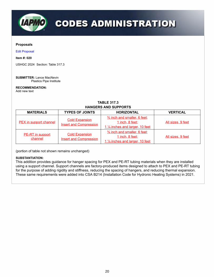
TABLE 317.3HANGERS AND SUPPORTS
MATERIALS TYPES OF JOINTS HORIZONTAL VERTICAL
PEX in support channel Cold ExpansionInsert and Compression
¾ inch and smaller, 6 feet;1 inch, 8 feet;
1 ¼ inches and larger, 10 feetAll sizes, 9 feet
PE-RT in supportchannel
Cold ExpansionInsert and Compression
¾ inch and smaller, 6 feet;1 inch, 8 feet;
1 ¼ inches and larger, 10 feetAll sizes, 9 feet
(portion of table not shown remains unchanged)
SUBSTANTIATION:This addition provides guidance for hanger spacing for PEX and PE-RT tubing materials when they are installedusing a support channel. Support channels are factory-produced items designed to attach to PEX and PE-RT tubingfor the purpose of adding rigidity and stiffness, reducing the spacing of hangers, and reducing thermal expansion.These same requirements were added into CSA B214 (Installation Code for Hydronic Heating Systems) in 2021.
20
Proposals
Edit Proposal
Item #: 021
USHGC 2024 Section: 206.0, 401.1
SUBMITTER: Jeff MatsonChair, USHGC Hydronics Systems Task Group
RECOMMENDATION:Revise text
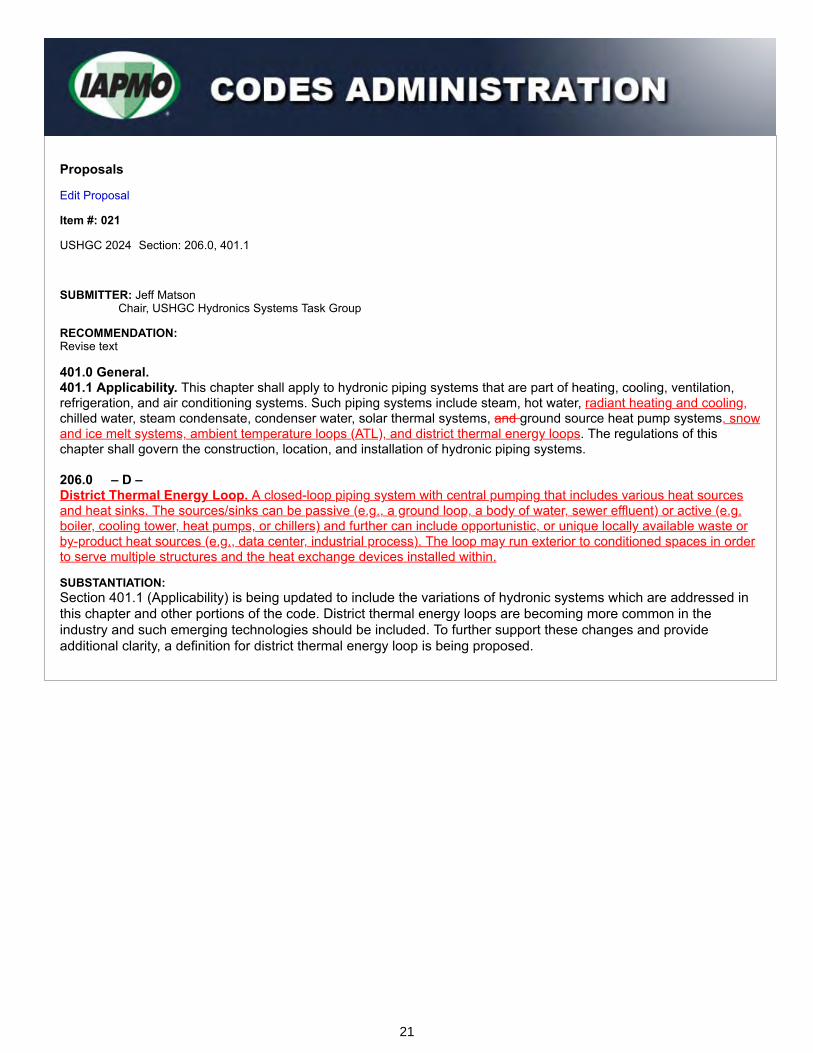
401.0 General.401.1 Applicability. This chapter shall apply to hydronic piping systems that are part of heating, cooling, ventilation,refrigeration, and air conditioning systems. Such piping systems include steam, hot water, radiant heating and cooling,chilled water, steam condensate, condenser water, solar thermal systems, and ground source heat pump systems, snowand ice melt systems, ambient temperature loops (ATL), and district thermal energy loops. The regulations of thischapter shall govern the construction, location, and installation of hydronic piping systems. 206.0 – D –District Thermal Energy Loop. A closed-loop piping system with central pumping that includes various heat sourcesand heat sinks. The sources/sinks can be passive (e.g., a ground loop, a body of water, sewer effluent) or active (e.g.boiler, cooling tower, heat pumps, or chillers) and further can include opportunistic, or unique locally available waste orby-product heat sources (e.g., data center, industrial process). The loop may run exterior to conditioned spaces in orderto serve multiple structures and the heat exchange devices installed within.
SUBSTANTIATION:Section 401.1 (Applicability) is being updated to include the variations of hydronic systems which are addressed inthis chapter and other portions of the code. District thermal energy loops are becoming more common in theindustry and such emerging technologies should be included. To further support these changes and provideadditional clarity, a definition for district thermal energy loop is being proposed.
21

Proposals
Edit Proposal
Item #: 022
USHGC 2024 Section: 401.3, 401.9
SUBMITTER: Jeff MatsonChair, USHGC Hydronics Systems Task Group
RECOMMENDATION:Revise text
401.0 General. 401.3 Water Hammer Protection. The flow of the hydronic piping system shall be designed to prevent water hammer.
401.9 Flexible Connectors. Listed flexible connectors shall be installed in readily accessible locations, unlessotherwise listed.
SUBSTANTIATION:Section 401.3 is being revised since the piping system must be sized to accommodate the flow of hydronic fluidrather than the flow be designed to prevent a water hammer. The current language is oddly worded and may causeconfusion. Such modifications are necessary for clarification.
Furthermore, Section 401.9 is being revised to remove “unless otherwise listed” as this phrase permits theinstallation of connectors in non-accessible locations. Also, the section already specifies that the flexible connectorsare listed.
22

Proposals
Edit Proposal
Item #: 023
USHGC 2024 Section: 401.6, 401.6.1, Table 901.1
SUBMITTER: Jeff MatsonChair, USHGC Hydronics Systems Task Group
RECOMMENDATION:Add new text
401.0 General.
401.6 Heat Transfer Fluid Quality. Heat transfer fluids used in closed-loop hydronic systems shall be in accordancewith IAPMO/ANSI H1001.1.401.6.1 Ethylene Glycol. Ethylene glycol shall not be used in one- and two-unit residential systems. In existingsystems, where ethylene glycol is used, there shall be no direct or permanent potable water connections. Where atemporary potable water connection is required, a backflow preventer shall be installed.
(renumber remaining sections)
TABLE 901.1 REFERENCED STANDARDS
STANDARD NUMBER STANDARD TITLE APPLICATION REFERENCEDSECTIONS
IAPMO/ANSI H1001.1-2021
Quality of Heat Transfer Fluids Used inHydronics Systems
Heat TransferFluid
401.6
(portion of table not shown remains unchanged) Note: IAPMO/ANSI H1001.1 meets the requirements for a mandatory referenced standard in accordance withSection 15.0 of IAPMO’s Regulations Governing Consensus Development of the Uniform Solar, Hydronics &Geothermal and Swimming Pool, Spa & Hot Tub Codes.
SUBSTANTIATION:IAPMO/ANSI H1001.1 (Quality of Heat Transfer Fluids Used in Hydronics Systems) is a newly published standardwhich provides minimum requirements for maintaining the quality of liquid aqueous-based heat transfer fluids overthe life of the system and optimizing the life of system components. The standard is applicable to both residentialand non-residential closed hydronic heating and cooling systems.
IAPMO/ANSI H1001.1 is unique in that it addresses both chemical and non-chemical treatment methods with afocus on the importance of water treatment and corrosion prevention. These provisions are accompanied byhydronic water quality parameters for systems with chemical additives, high purity water systems, and hybridhydronic and ground source heat pump systems.
Additionally, the proposed section for ethylene glycol is needed to protect the potable water supply and ensure thatthis type of glycol is not used in one- and two-unit residential systems. Ethylene glycol ingestion can be lethal tohumans and wildlife while propylene glycol is essentially nontoxic in small quantities.
23

Proposals
Edit Proposal
Item #: 024
USHGC 2024 Section: 401.6, 415.3 - 415.3.2
SUBMITTER: Jeff MatsonChair, USHGC Hydronics Systems Task Group
RECOMMENDATION:Revise text
415.0 Radiant Heating and Cooling.415.1 Installation. (remaining text unchanged)401.6415.1.1 Manifolds. (remaining text unchanged) 415.3 Radiant Cooling Systems. Radiant cooling systems shall be designed to minimize the potential forcondensation. To prevent condensation on any cooled radiant surface, the supply water temperature for a radiantcooling system shall be not less than 3°F (1.7°C) above the anticipated space dew point temperature, or in accordancewith the manufacturer’s recommendation.415.3.1 Minimum Floor Temperatures. The minimum floor surface temperature shall not be less than 66°F (19°C) ingeneral occupied applications.415.3.2 Chilled Water Supply/Distribution Piping. Chilled water piping, valves, and fittings, and manifolds shall beinsulated and vapor sealed to prevent surface condensation.Exception: Piping, valves, fittings, and manifolds used to supply radiant cooling systems and where the watertemperature is above the space dew point temperature shall not require insulation.
SUBSTANTIATION:The revisions to Section 415.3 correlate with the proposals generated by the UMC Radiant Cooling Working Group.This group was formed in January 2020 by members of ASHRAE TC 6.5, Radiant Heating and Cooling.
The current supply water temperature limitation in Section 415.3 is overly restrictive and represents designguidance rather than a proper code minimum for health and safety. The new Section 415.3.1 is required based onASHRAE Standard 55 (Thermal Environmental Conditions for Human Occupancy) which defines the minimumacceptable temperature for a radiant floor to be 66°F (19°C). This temperature is well accepted in North Americaand internationally.
Furthermore, manifolds are being relocated under Section 415.0 as they are another part of the distribution systemcommon to radiant systems.
24

Proposals
Edit Proposal
Item #: 025
USHGC 2024 Section: 401.7
SUBMITTER: Jeff MatsonChair, USHGC Hydronics Systems Task Group
RECOMMENDATION:Add new text
401.0 General.
401.7 Disposal of Hydronic Fluid. Hydronic system fluids that contain additives such as antifreeze, corrosioninhibitors, and cleaning solutions shall be recycled or disposed of in an approved manner in accordance with theAuthority Having Jurisdiction. (renumber remaining sections)
SUBSTANTIATION:Currently, the code is silent on the disposal of used hydronic fluids. The proposed section offers provisionallanguage which ensures proper disposal of such fluids and promotes public health and safety. In some cases, theused hydronic fluid may be recycled. For these reasons, the new language is necessary and beneficial to theUSHGC.
25

Proposals
Edit Proposal
Item #: 026
USHGC 2024 Section: 401.10, Table 401.10
SUBMITTER: Jeff MatsonChair, USHGC Hydronics Systems Task Group
RECOMMENDATION:Revise text
401.0 General.
401.10 Freeze Protection. Hydronic systems and components shall be designed, installed, and protected from freezing.The percent of glycol by volume shall be determined based on the freezing point of the solution and type of mixture inaccordance with Table 401.10, or the manufacturer’s specifications.
TABLE 401.10 PERCENT GLYCOL MIXTURES
PERCENT GLYCOL BY VOLUME
(% v/v)
FREEZING POINT, °FETHYLENE GLYCOL* PROPYLENE GLYCOL
20 16 1830 3 840 -12 -750 -35 -28
For SI units: °C = (°F-32)/1.8*Ethylene glycol shall not be used in one- and two-unit residential systems. Where ethylene glycol is used, there shall beno potable water connections.
SUBSTANTIATION:In systems where glycol is an additive, bacteria can be controlled by maintaining a percent glycol by volume of atleast 20. This percentage may vary based on manufacturer’s specifications; however, both propylene and ethyleneglycol have been proven to inhibit the growth of most microbes at concentrations of 20 percent or more.
Proposed Table 401.10 is an excerpt from IAPMO/ANSI H1001.1 and is beneficial to include in this chapter as itprovides a method for determining the required percent glycol by volume given the freezing point of the solution.Due to the toxicity of ethylene glycol, restrictions for its use have been put in place. Ethylene glycol ingestion can belethal to humans and wildlife while propylene glycol is essentially nontoxic in small quantities.
26
Proposals
Edit Proposal
Item #: 027
USHGC 2024 Section: 401.10.1
SUBMITTER: Jeff MatsonChair, USHGC Hydronics Systems Task Group
RECOMMENDATION:Add new text
401.0 General. 401.10 Freeze Protection. (remaining text unchanged)401.10.1 Antifreeze Requirements. Antifreeze shall be added to a closed hydronic system where one or more of thefollowing conditions are met:(1) System component(s) are exposed to freezing conditions during normal operation,(2) The hydronic system serves as a snow and ice melt system in accordance with Section 417.0, or(3) Where required by the equipment manufacturer.
SUBSTANTIATION:The new language is necessary as it increases freeze protection for hydronic systems. The current language forfreeze protection does not give specific requirements for when freeze protection should be provided. The abovelisted conditions are clear and also assist with maintaining heat transfer fluid quality and improving longevity ofthese systems.
27

Proposals
Edit Proposal
Item #: 028
USHGC 2024 Section: 401.11
SUBMITTER: Jeff MatsonChair, USHGC Hydronics Systems Task Group
RECOMMENDATION:Add new text
401.0 General.
401.11 Documentation. The hydronics as-built installation drawings and instructions shall be provided to the buildingowner or designated agent.
SUBSTANTIATION:Providing documentation for system design eases operation and maintenance over the lifetime of the system.
28

Proposals
Edit Proposal
Item #: 029
USHGC 2024 Section: 403.2
SUBMITTER: Jeff MatsonChair, USHGC Hydronics Systems Task Group
RECOMMENDATION:Revise text
403.0 Capacity of Heat Source. 403.2 Dual Purpose Water Heaters. Water heaters utilized for combined space-heating and water-heating applicationsshall be listed and labeled in accordance comply with the standards referenced in Table 403.2, and shall be installed inaccordance with the manufacturer’s installation instructions. The total heating capacity of a dual purpose water heatershall be based on the sum of the potable hot water requirements and the space heating design requirements correctedfor hot water first-hour draw recovery.
SUBSTANTIATION:The revisions to Section 403.2 clarify requirements for dual purpose water heaters. Rather than requiring listing andlabeling of these heaters, compliance with the applicable standards referenced in Table 403.2 is sufficient. For thesereasons, the above modifications are necessary.
29

Proposals
Edit Proposal
Item #: 030
USHGC 2024 Section: 403.4
SUBMITTER: Lance MacNevinPlastics Pipe Institute
RECOMMENDATION:Add new text
403.0 Capacity of Heat Source.
403.4 Potable Water as a Hydronic Fluid. Potable water shall not be used as a hydronic fluid in an open-loop heatingsystem unless all of the following conditions are met: (1) A maximum of one system loop using potable water as the hydronic fluid is allowed per heat source; (2) The total length of piping of the heating system containing potable water does not exceed 50 feet (15 240 mm); (3) The total volume of potable water in the heating system loop, including the volume within the heat-distribution unit(s),heat exchanger, or radiant surface, does not exceed 13 gallons (49 L); and (4) The normal operating supply temperature of the potable water to the heat-distribution unit(s), heat exchanger, orradiant surface is not less than 140°F (60°C).
SUBSTANTIATION:This proposal will improve the safety of plumbing systems and promote public health by restricting the use ofcombined (also known as cross-connected) potable-hydronic systems, where hydronic water is mixed with potablewater by being returned into the water heater after circulating through hydronic distribution devices and piping.These systems create the risk of stagnant water from the hydronic distribution network being returned into thepotable water system.
Combined potable-hydronic systems are currently allowed by the code without any restriction on the volume ofwater or piping in the hydronic distribution portion. These new restrictions which are proposed for Section 403.4were recently added to the 2021 edition of CSA B214 (Installation Code for Hydronic Heating Systems) in Clause4.2.5.1.
The proposed restriction limits combined systems to only smaller hydronic systems with a minimal amount of waterto reduce the volume of piping and water in which biofilm or bacteria such as Legionella could grow. For example, aradiant heating system with 1,000 feet of tubing receiving its heated water from a potable water heater would not beallowed with this new language. On the other hand, a fan coil that is installed nearby the water heater would still beallowed, as long as the specific limits in the new sections are not exceeded.
Background: Research indicates that bacterium Legionella pneumophila can grow in water between 68°F and 120°F(20°C to 48°C), with an ideal growth range of 85°F to 110°F (29°C to 43°C).
In a typical residential plumbing system, with 200 to 300 feet of hot-water piping, disinfectants in treated water cancontrol the growth of Legionella. Hot water is normally delivered to outlets quickly, and the age of the water is not aconcern. Even though drinking water disinfectants can dissipate quickly after being exposed to the heat of a waterheater, some level of disinfectant normally remains until water is delivered to a fixture.
However, if the plumbing system is connected to a hydronic distribution system, such as a radiant heating system,this can lead to a large volume of water which is stagnant at times. For example, when the heating system turns off,there could be a significant volume of warm stagnant water sitting in pipes, fan coils, radiators, and other hydroniccomponents.
30

Over time, this water could contain little to no disinfectant while being maintained at the ideal temperature range forLegionella growth. When the heating system turns on due to a call for heat, that stagnant water will re-enter thewater heater and then travel through the plumbing distribution system to the next fixture that is opened. Waterbecomes aerosolized (i.e., droplets and vapor) in a shower or near an aerated faucet and is easy to inhale. This is apotentially dangerous situation for people who are susceptible to this type of bacteria, as this can allow Legionella toenter the lungs.
During periods of inactivity (e.g., summer), the water in heating components might be stagnant for weeks or months.Although the water is at or near ambient room temperature, and Legionella will grow more slowly, it does not die.Further, stagnant water has been shown to allow the growth of biofilms inside piping components andappurtenances.
Therefore, this proposal will significantly reduce the potential volume of water in combined (cross-connected)potable-hydronic systems and improve public health and safety.
The potential risks of combined (cross-connected) potable-hydronic systems are described in PPI's "Recommendation Against Mixing Hydronic Heating Water with Potable Water in Combined Systems" https://plasticpipe.org/common/Uploaded%20files/1-PPI/RECOMMENDATIONS/Recommendation%20E.pdf
31

Proposals
Edit Proposal
Item #: 031
USHGC 2024 Section: 403.5
SUBMITTER: Lance MacNevinPlastics Pipe Institute
RECOMMENDATION:Add new text
403.0 Capacity of Heat Source.
403.5 Prevention of Stagnation. An automatic means of flushing shall be provided to prevent the stagnation of potablewater in a hydronic heating system. Contents shall be flushed not less than once every 24 hours. The duration offlushing shall be not less than 5 minutes or as determined in accordance with Equation 403.5.
t = V/Q (Equation 403.5)
Where: t = time, minutes (s) Q = flow rate, gpm (L/s) V = Total volume of the system loop, gallons (L) For SI units: 1 gallon = 3.785 L, 1 gallon per minute = 0.06 L/s
SUBSTANTIATION:This proposal will improve the safety of plumbing systems and increase public health by ensuring that the waterwithin combined (also known as cross-connected) potable-hydronic systems, where hydronic water is mixed withpotable water by being returned into the water heater after circulating through hydronic distribution devices andpiping, is fully flushed at least once every 24 hours.
Combined potable-hydronic systems are currently allowed by the code without any requirements for flushing out thestagnant water. A similar requirement to prevent stagnation of water was added to the 2021 edition of CSA B214(Installation Code for Hydronic Heating Systems) in Clause 4.2.5.2.
Stagnation of water in combined potable-hydronic heating systems should be eliminated because disinfectantsdecay rapidly in stagnant water, promoting the growth of pathogens such as Legionella.
A separate proposal to add Section 403.4 (Potable Water as a Hydronic Fluid) will reduce the volume of combinedsystems, but a requirement to prevent stagnation is also required. Therefore, this proposal is complementary to theother proposed Section 403.4.
This proposal includes both a prescriptive path and method of calculating flushing duration. The prescriptive methodrequires flushing water for at least 5 minutes, which is adequate in smaller systems that comply with the sizingspecifications of proposed Section 403.4. The provided method for calculating flushing duration time is howevermore precise. This is because outside of the heating season, homeowners do not want to flush hot water through aheating coil for any time more than is needed.
Also, if the proposed Section 403.4 is not accepted into this code, then the calculated flushing time is very importantto ensure that all the water in a combined potable-hydronic system is actually flushed and replaced with fresh hotwater with disinfectant.
32

Background: Research indicates that bacterium Legionella pneumophila can grow in water between 68°F and 120°F(20°C to 48°C), with an ideal growth range of 85°F to 110°F (29°C to 43°C).
In a typical residential plumbing system, with 200 to 300 feet of hot-water piping, disinfectants in treated water cancontrol the growth of Legionella. Hot water is normally delivered to outlets quickly, and the age of the water is not aconcern. Even though drinking water disinfectants can dissipate quickly after being exposed to the heat of a waterheater, some level of disinfectant normally remains until water is delivered to a fixture.
However, if the plumbing system is connected to a hydronic distribution system, such as a radiant heating system,this can lead to a large volume of water which is stagnant at times. For example, when the heating system turns off,there could be a significant volume of warm stagnant water sitting in pipes, fan coils, radiators, and other hydroniccomponents. Over time, this water could contain little to no disinfectant while being maintained at the idealtemperature range for Legionella growth. When the heating system turns on due to a call for heat, that stagnantwater will re-enter the water heater and then travel through the plumbing distribution system to the next fixture thatis opened. Water becomes aerosolized (i.e., droplets and vapor) in a shower or near an aerated faucet and is easyto inhale. This is a potentially dangerous situation for people who are susceptible to this type of bacteria, as this canallow Legionella to enter the lungs.
During periods of inactivity (e.g., summer), the water in heating components might be stagnant for weeks or months.Although the water is at or near ambient room temperature, and Legionella will grow more slowly, it does not die.Further, stagnant water has been shown to allow the growth of biofilms inside piping components andappurtenances. Therefore, this proposal will significantly reduce the potential volume of stagnant water in combined(cross-connected) potable-hydronic systems and improve public health and safety.
33
Proposals
Edit Proposal
Item #: 032
USHGC 2024 Section: 404.7
SUBMITTER: Jeff MatsonChair, USHGC Hydronics Systems Task Group
RECOMMENDATION:Revise text
404.0 Identification of Piping Systems. 404.7 Heat Transfer Fluid. Solar thermal Hydronic piping shall be identified with an orange background with blackuppercase lettering, with the words “CAUTION: HEAT TRANSFER FLUID, DO NOT DRINK.” Each solarthermal hydronic system shall be identified to designate the fluid being conveyed. The minimum size of the letters andlength of the color field shall comply with Table 404.3. Each outlet on the solar thermal hydronic piping system shall be posted with black uppercase lettering as follows: “CAUTION: HEAT TRANSFER FLUID, DO NOT DRINK.”
SUBSTANTIATION:Section 404.7 is being updated to reference “hydronic” piping and system components rather than “solar thermal”since this chapter is explicit to hydronics systems. Solar thermal provisions belong in Chapter 5 (Solar ThermalSystems).
34

Proposals
Edit Proposal
Item #: 033
USHGC 2024 Section: 404.8
SUBMITTER: Jeff MatsonChair, USHGC Hydronics Systems Task Group
RECOMMENDATION:Add new text
404.0 Identification of Piping Systems.
404.8 Identification of Chemical Additives. In systems where chemical additives are used, documentation includingthe following information shall be provided:(1) Concentrations(2) Maintenance requirements(3) Maintenance log(4) Manufacturer’s material safety data sheet (SDS)
SUBSTANTIATION:The proposed section is an excerpt from IAPMO/ANSI H1001.1 and is needed since providing documentationpertaining to chemical content eases operation and maintenance over the lifetime of the system. Such information isalso essential to ensure chemical compatibility and safety. Various chemical treatments may be used based on thehydronic system and fluid quality, and keeping such documentation/identification is needed for maintenance andsafe operation.
35
Proposals
Edit Proposal
Item #: 034
USHGC 2024 Section: 407.5, Table 407.5
SUBMITTER: Jeff MatsonChair, USHGC Hydronics Systems Task Group
RECOMMENDATION:Revise text
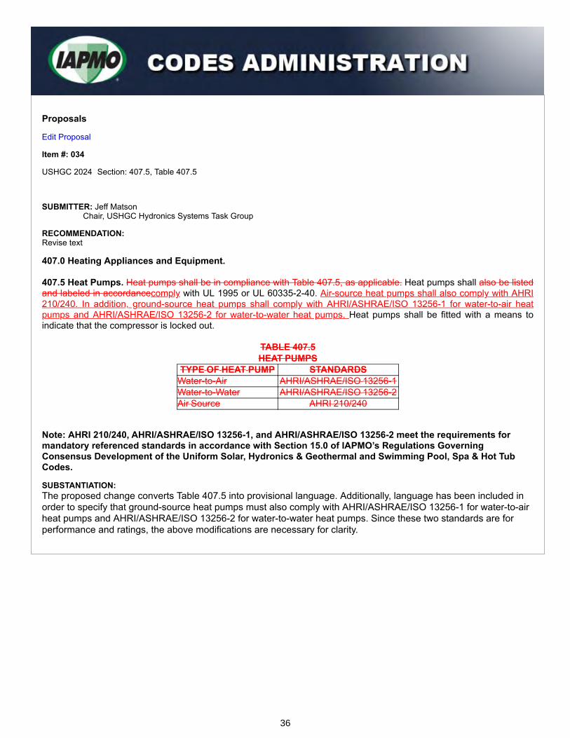
407.0 Heating Appliances and Equipment. 407.5 Heat Pumps. Heat pumps shall be in compliance with Table 407.5, as applicable. Heat pumps shall also be listedand labeled in accordancecomply with UL 1995 or UL 60335-2-40. Air-source heat pumps shall also comply with AHRI210/240. In addition, ground-source heat pumps shall comply with AHRI/ASHRAE/ISO 13256-1 for water-to-air heatpumps and AHRI/ASHRAE/ISO 13256-2 for water-to-water heat pumps. Heat pumps shall be fitted with a means toindicate that the compressor is locked out.
TABLE 407.5HEAT PUMPS
TYPE OF HEAT PUMP STANDARDSWater-to-Air AHRI/ASHRAE/ISO 13256-1Water-to-Water AHRI/ASHRAE/ISO 13256-2Air Source AHRI 210/240
Note: AHRI 210/240, AHRI/ASHRAE/ISO 13256-1, and AHRI/ASHRAE/ISO 13256-2 meet the requirements formandatory referenced standards in accordance with Section 15.0 of IAPMO’s Regulations GoverningConsensus Development of the Uniform Solar, Hydronics & Geothermal and Swimming Pool, Spa & Hot TubCodes.
SUBSTANTIATION:The proposed change converts Table 407.5 into provisional language. Additionally, language has been included inorder to specify that ground-source heat pumps must also comply with AHRI/ASHRAE/ISO 13256-1 for water-to-airheat pumps and AHRI/ASHRAE/ISO 13256-2 for water-to-water heat pumps. Since these two standards are forperformance and ratings, the above modifications are necessary for clarity.
36

Proposals
Edit Proposal
Item #: 035
USHGC 2024 Section: 408.1
SUBMITTER: Jeff MatsonChair, USHGC Hydronics Systems Task Group
RECOMMENDATION:Revise text
408.0 Expansion Tanks. 408.1 General. An expansion tank shall be installed in each closed-loop of a hydronic system to control systempressure due to thermal expansion and contraction. Expansion tanks shall be of the closed type, incorporating adiaphragm or bladder to ensure the isolation of the system fluid from the pre-charge gas or from the atmosphere. Plaincompression tanks shall not be permitted. Expansion tanks shall be rated for the pressure of the system. Exceptions:(1) Drainback type solar thermal systems shall not require a hydronic expansion tank. (2) An alternative engineered fluid expansion storage system shall be permitted where in accordance with Section302.4.
(Section 302.4 is shown for information purposes only)
302.4 Alternative Engineered Design. An alternative engineered design shall comply with the intent of the provisionsof this code and shall provide an equivalent level of quality, strength, effectiveness, fire resistance, durability, and safety.Material, equipment, or components shall be designed and installed in accordance with the manufacturer’s installationinstructions.
SUBSTANTIATION:Requiring a bladder or diaphragm is automatically inclusive of active expansion systems. This requirement does notneed to specify how fluid is moved in or out of the loop, nor how the charge pressure is or is not modulated. Theintent of the proposed language is to eliminate exposure to the atmosphere. For these reasons, the modifications toSection 408.1 are necessary.
37

Proposals
Edit Proposal
Item #: 036
USHGC 2024 Section: 408.1
SUBMITTER: Lee StevensLH Stevens Constructors LLC
RECOMMENDATION:Revise text
408.0 Expansion Tanks.408.1 General. An expansion tank shall be installed in each closed-loop of any hydronic system, to control systempressure due to thermal expansion and contraction. Expansion tanks shall be of the closed type, incorporating adiaphragm or bladder to insure the isolation of the system fluid from the pre-charge gas or from the atmosphere. Plaincompression tanks shall not be permitted. Expansion tanks shall be rated for the pressure of the system.Exceptions:(1) An engineered fluid expansion storage system shall be permitted to incorporate fluid storage in vessels open to theatmosphere. An air separator and automatic air vent shall be required in the system circulation loop. Storage tanks andcomponents for such systems shall be constructed of non-corrosive materials, and/or the system fluid shall be treated toinhibit corrosion.(2) Drainback type solar thermal systems shall not require a hydronic expansion tank.
SUBSTANTIATION:Requiring the bladder or diaphragm is automatically inclusive of an active expansion system. This requirement doesnot, and need not, specify how fluid is moved into or out of the system loop to an expansion tank or storage vessel,nor how the charge pressure is or is not modulated. The intent is to eliminate exposure to the atmosphere whichallows for continual re-oxygenation of the system fluid.
The exception for engineered systems is needed as this is presently used in very large commercial or industrialsystems due to a lack of readily available alternatives. Citing an exception for an engineered alternative, per Section302.2, is not sufficient. The intent of Section 408.1 is to ensure separation of the system fluid from the atmosphere.So unless explicitly stated otherwise, the allowable engineered alternative would be a means of achieving thatseparation by use of something other than a bladder or diaphragm.
Therefore, the exception for these large systems must explicitly state that the language pertains to contact with theatmosphere and should also include the additional requirements to ensure the reliability of the system regardingoxygenation of the fluid.
38

Proposals
Edit Proposal
Item #: 037
USHGC 2024 Section: 408.2, 605.1
SUBMITTER: Jeff MatsonChair, USHGC Hydronics Systems Task Group
RECOMMENDATION:Revise text
408.0 Expansion Tanks. 408.2 Installation. Expansion tanks shall be accessible for maintenance and shall be installed in accordance with themanufacturer’s installation instructions. Each expansion tank shall be equipped with a shutoff device that will remainopen during operation of the hydronic system. Valve handles shall be locked open or removed to prevent from beinginadvertently shut off. Where systems contain more than 5 gallons (19 L) of fluid, pProvisions shall be made for drainingthe tank without emptying the system. Expansion tanks shall be securely fastened to or supported by the structure.Supports shall be capable of carrying twice the weight of the tank filled with water without placing a strain on connectingpiping. Hot-water-heating systems incorporating hot water tanks or fluid relief columns shall be installed to preventfreezing under normal operating conditions. 605.0 Expansion Tanks.605.1 Where Required. An expansion tank shall be installed in a water heating system as a means for controllingincreased pressure caused by thermal expansion. Expansion tanks shall be of the closed type and securely fastened toor supported by the structure. Tanks shall be rated for the pressure of the system. Supports shall be capable of carryingtwice the weight of the tank filled with water without placing strain on the connecting piping. Water-heating systemsincorporating hot water tanks or fluid relief columns shall be installed to prevent freezing under normal operatingconditions.
SUBSTANTIATION:The current language only requires systems larger than 5 gallons to have a means of draining the tank withoutemptying the system. Removing the provided minimum volume makes this requirement applicable to systems of allsizes.
Additionally, the revision made to update the language to show "securely fastened to or supported by the structure"provides further clarification for the installation of expansion tanks and correlates with the other recommendationsprovided by this Task Group. This modification also makes the provisions less restrictive and more practical.
39

Proposals
Edit Proposal
Item #: 038
USHGC 2024 Section: 408.4
SUBMITTER: Jeff MatsonChair, USHGC Hydronics Systems Task Group
RECOMMENDATION:Revise text
408.0 Expansion Tanks. 408.4 Sizing. Expansion tanks shall be sized to accept the design full expansion volume of the fluid in the system. Theminimum capacity of a closed-type expansion tank shall be sized in accordance with Section 605.3.
SUBSTANTIATION:The proposed revision is necessary as it provides clarification for technical accuracy.
40

Proposals
Edit Proposal
Item #: 039
USHGC 2024 Section: 409.1, Table 409.1, Table 901.1
SUBMITTER: Jeff MatsonChair, USHGC Hydronics Systems Task Group
RECOMMENDATION:Revise text
409.0 Materials. 409.1 Pipe, Tubing, and Fittings. Hydronic pipe and tubing shall comply with the applicable standards referenced inTable 409.1 and shall be approved for use based on the intended purpose. Materials shall be rated for the operatingtemperature and pressure of the system and shall be compatible with the type of heat transfer fluid. Pipe fittings andvalves shall be approved for the specific installation with the piping, materials to be installed and shall comply with theapplicable standards referenced in Table 409.1. Where required, exterior piping shall be protected against freezing, UVradiation, corrosion and degradation. Embedded pipe or tubing shall comply with Section 418.2.
TABLE 409.1 MATERIALS FOR HYDRONIC AND SOLAR THERMAL SYSTEM, PIPING, TUBING, AND FITTINGS
MATERIAL STANDARDSPIPING/TUBING FITTINGS
Copper/Copper AlloyASTM B42, ASTM B43, ASTM B75,
ASTM B88, ASTM B135, ASTMB251*2, ASTM B302, ASTM B447
ASME B16.15, ASME B16.18, ASMEB16.22, ASME B16.23, ASMEB16.24, ASME B16.26, ASME
B16.29, ASME B16.51, ASSE 1061,ASTM F3226, IAPMO PS 117
Ductile Iron AWWA C115/A21.15, AWWAC151/A21.51
AWWA C110/A21.101, AWWAC153/A21.53
Steel ASTM A53, ASTM A106, ASTM A254ASME B16.5, ASME B16.9, ASMEB16.11, ASTM A420, ASTM F3226,
IAPMO IGC 353, IAPMO PS 117
Raised Temperature Polyethylene ofRaised Temperature (PE-RT)
ASTM F2165, ASTM F2623, ASTMF2769, CSA B137.18
ASSE 1061, ASTM D3261, ASTMF1055, ASTM F1807, ASTM F2159,ASTM F2165, ASTM F2735, ASTMF2769, ASTM F3347, ASTM F3348,
CSA B137.18
Stainless Steel ASTM A269, ASTM A312, ASTMA554, ASTM A778
ASTM F1476, ASTM F1548, ASTMF3226, IAPMO IGC 353, IAPMO PS
117Notes: 1 Ductile and gray iron. *2 Only Type K, L, or M shall be permitted to be installed.
(portion of table not shown remains unchanged)
41
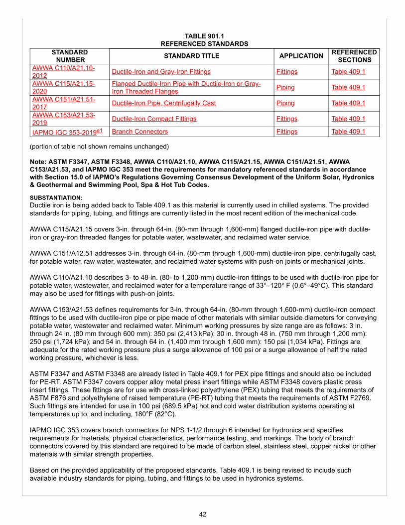
TABLE 901.1 REFERENCED STANDARDS
STANDARD NUMBER STANDARD TITLE APPLICATION REFERENCED
SECTIONSAWWA C110/A21.10-2012 Ductile-Iron and Gray-Iron Fittings Fittings Table 409.1
AWWA C115/A21.15-2020
Flanged Ductile-Iron Pipe with Ductile-Iron or Gray-Iron Threaded Flanges Piping Table 409.1
AWWA C151/A21.51-2017 Ductile-Iron Pipe, Centrifugally Cast Piping Table 409.1
AWWA C153/A21.53-2019 Ductile-Iron Compact Fittings Fittings Table 409.1
IAPMO IGC 353-2019e1 Branch Connectors Fittings Table 409.1
(portion of table not shown remains unchanged)
Note: ASTM F3347, ASTM F3348, AWWA C110/A21.10, AWWA C115/A21.15, AWWA C151/A21.51, AWWAC153/A21.53, and IAPMO IGC 353 meet the requirements for mandatory referenced standards in accordancewith Section 15.0 of IAPMO’s Regulations Governing Consensus Development of the Uniform Solar, Hydronics& Geothermal and Swimming Pool, Spa & Hot Tub Codes.
SUBSTANTIATION:Ductile iron is being added back to Table 409.1 as this material is currently used in chilled systems. The providedstandards for piping, tubing, and fittings are currently listed in the most recent edition of the mechanical code.
AWWA C115/A21.15 covers 3-in. through 64-in. (80-mm through 1,600-mm) flanged ductile-iron pipe with ductile-iron or gray-iron threaded flanges for potable water, wastewater, and reclaimed water service.
AWWA C151/A12.51 addresses 3-in. through 64-in. (80-mm through 1,600-mm) ductile-iron pipe, centrifugally cast,for potable water, raw water, wastewater, and reclaimed water systems with push-on joints or mechanical joints.
AWWA C110/A21.10 describes 3- to 48-in. (80- to 1,200-mm) ductile-iron fittings to be used with ductile-iron pipe forpotable water, wastewater, and reclaimed water for a temperature range of 33°–120° F (0.6°–49°C). This standardmay also be used for fittings with push-on joints.
AWWA C153/A21.53 defines requirements for 3-in. through 64-in. (80-mm through 1,600-mm) ductile-iron compactfittings to be used with ductile-iron pipe or pipe made of other materials with similar outside diameters for conveyingpotable water, wastewater and reclaimed water. Minimum working pressures by size range are as follows: 3 in.through 24 in. (80 mm through 600 mm): 350 psi (2,413 kPa); 30 in. through 48 in. (750 mm through 1,200 mm):250 psi (1,724 kPa); and 54 in. through 64 in. (1,400 mm through 1,600 mm): 150 psi (1,034 kPa). Fittings areadequate for the rated working pressure plus a surge allowance of 100 psi or a surge allowance of half the ratedworking pressure, whichever is less.
ASTM F3347 and ASTM F3348 are already listed in Table 409.1 for PEX pipe fittings and should also be includedfor PE-RT. ASTM F3347 covers copper alloy metal press insert fittings while ASTM F3348 covers plastic pressinsert fittings. These fittings are for use with cross-linked polyethylene (PEX) tubing that meets the requirements ofASTM F876 and polyethylene of raised temperature (PE-RT) tubing that meets the requirements of ASTM F2769.Such fittings are intended for use in 100 psi (689.5 kPa) hot and cold water distribution systems operating attemperatures up to, and including, 180°F (82°C).
IAPMO IGC 353 covers branch connectors for NPS 1-1/2 through 6 intended for hydronics and specifiesrequirements for materials, physical characteristics, performance testing, and markings. The body of branchconnectors covered by this standard are required to be made of carbon steel, stainless steel, copper nickel or othermaterials with similar strength properties.
Based on the provided applicability of the proposed standards, Table 409.1 is being revised to include suchavailable industry standards for piping, tubing, and fittings to be used in hydronics systems.
42

Proposals
Edit Proposal
Item #: 040
USHGC 2024 Section: 409.4
SUBMITTER: Jeff MatsonChair, USHGC Hydronics Systems Task Group
RECOMMENDATION:Revise text
409.0 Materials. 409.4 Oxygen Diffusion Corrosion. PEX and PE-RT tubing in closed hydronic systems shall contain an oxygen barrierwith an oxygen permeation rate not to exceed 4.59 E-04 grains per square foot per day (0.32 mg/m2/day) at 104°F(40°C).Exception: Closed hydronic systems without ferrous components in contact with the hydronic fluid.
SUBSTANTIATION:The current provisions are not enforceable since oxygen barrier tubing is not marked with an exact permeation rate.The oxygen permeation value belongs in the product standard rather than the code. For these reasons, theproposed modification is necessary.
43

Proposals
Edit Proposal
Item #: 041
USHGC 2024 Section: 410.1 - 410.2.3, Table 410.2.2
SUBMITTER: Jeff MatsonChair, USHGC Hydronics Systems Task Group
RECOMMENDATION:Revise text
410.0 Joints and Connections. 410.1 General. Joints and connections shall be of an approved type. Joints shall be gas and watertight and designed forthe pressure of the hydronic system. Changes in direction shall be made by the use of fittings or with pipe bends. Pipebends shall have a radius of not less than six times the outside diameter of the tubing or shall be in accordance with themanufacturer’s installation instructions. Joints between pipe and fittings shall be installed in accordance with themanufacturer’s installation instructions. Joints used underground shall be of an approved type for buried applications.410.2 Pipe Bends. Pipe bends shall be formed in accordance with Section 410.2.1 through Section 410.2.3.410.2.1 Crosslinked Polyethylene (PEX) Tubing. Crosslinked polyethylene (PEX) tubing bends shall have a bendradius of not less than eight times the outside diameter (OD) of the tubing or shall be in accordance with themanufacturer’s installation instructions.410.2.2 Polyethylene (PE) Plastic Pipe/Tubing. Polyethylene pipe and tubing bends shall have a bend radius inaccordance with Table 410.2.2. When a fitting or flange connection is present in the pipe bend, the minimum bendradius shall be one hundred times the pipe outside diameter (OD) for a distance of five times the pipe diameter on eitherside of the fitting location.
TABLE 410.2.2MINIMUM BEND RADIUS FOR PE PIPE INSTALLED IN OPEN CUT TRENCH
DIMENSION RATIO(DR)
MINIMUM COLDBEND RADIUS
720 x Pipe OD7.3
911 25 x Pipe OD13.517 27 x Pipe OD2126 34 x Pipe OD
32.5 42 x Pipe OD41 50 x Pipe OD
Fitting/flange present inbend
100 x Pipe OD
410.2.3 Polyethylene of Raised Temperature (PE-RT) Tubing. Polyethylene of raised temperature (PE-RT) tubingbends shall have a bend radius of not less than eight times the outside diameter (OD) of the tubing or shall be inaccordance with the manufacturer’s installation instructions. (renumber remaining sections)
44
SUBSTANTIATION:The existing language in Section 410.1 regarding pipe bends having a radius of not less than six times the OD is notcorrect for any of the plastic pipe materials found within Section 410.0.
The proposed new language for piping/tubing bend radii are from various publications of The Plastics Pipe Institute(PPI). For PE piping/tubing, the new language including Table 410.2.2 is taken from the PPI “Handbook ofPolyethylene Pipe, Second Edition” Chapter 7.
For PEX tubing, the new language is taken from the “Design Guide – Residential PEX Water Supply PlumbingSystems” Chapter 9, a joint publication of PPI, PPFA, and the Home Innovation Research Labs. For PE-RT tubing,the new language is supported and recommended by PPI.
45
Proposals
Edit Proposal
Item #: 042
USHGC 2024 Section: 410.2, 410.3
SUBMITTER: Jeff MatsonChair, USHGC Hydronics Systems Task Group
RECOMMENDATION:Revise text
410.0 Joints and Connections. 410.2 Chlorinated Polyvinyl Chloride (CPVC) Pipe. Joints between chlorinated polyvinyl chloride (CPVC) pipe andfittings shall be installed in accordance with one of the following methods:(1) Mechanical joints shall include, but not be limited to, flanged, grooved, and push fit fittings. Removable andnonremovable push fit fittings with an elastomeric o-ring that employ quick assembly push fit connectors shall be inaccordance with ASSE 1061.(2) Solvent cement joints for CPVC pipe and fittings shall be clean from dirt and moisture. Solvent cements inaccordance with ASTM F493, requiring the use of a primer shall be orange in color. The primer shall be colored and bein accordance with ASTM F656. Listed solvent cement in accordance with ASTM F493 that does not require the use ofprimers, yellow, green, or red in color, shall be permitted for pipe and fittings manufactured in accordance with ASTMD2846, 1/2 of an inch (15 mm) through 2 inches (50 mm) in diameter or ASTM F442, 1/2 of an inch (15 mm) through 3inches (80 mm) in diameter. Apply primer where required inside the fitting and to the depth of the fitting on pipe. Applyliberal coat of cement to the outside surface of pipe to depth of fitting and inside of fitting. Place pipe inside fitting toforcefully bottom the pipe in the socket and hold together until joint is set.(3) (remaining text unchanged)410.3 CPVC/AL/CPVC Plastic Pipe and Joints. Joints between chlorinated polyvinyl chloride/aluminum/ chlorinatedpolyvinyl chloride (CPVC/AL/CPVC) pipe and fittings shall be installed in accordance with one of the following methods:(1) Mechanical joints shall include, but not be limited to, flanged, grooved and push-fit fittings.(2) (remaining text unchanged)
SUBSTANTIATION:The above minor revisions are being made for correlation with the mechanical code.
46

Proposals
Edit Proposal
Item #: 043
USHGC 2024 Section: 410.5
SUBMITTER: Jeff MatsonChair, USHGC Hydronics Systems Task Group
RECOMMENDATION:Revise text
410.0 Joints and Connections. 410.5 Cross-Linked Polyethylene (PEX) Pipe. Joints between cross-linked polyethylene (PEX) pipe and fittings shallbe installed with fittings for PEX tubing that comply with the applicable standards referenced in Table 409.1. PEX tubinglabeled in accordance with ASTM F876 or ASTM F3253 shall be marked with the applicable standard designation forthe fittings specified for use with the tubing. Mechanical joints shall be installed in accordance with the manufacturer’sinstallation instructions.
Note: ASTM F3253 meets the requirements for a mandatory referenced standard in accordance with Section15.0 of IAPMO’s Regulations Governing Consensus Development of the Uniform Solar, Hydronics & Geothermaland Swimming Pool, Spa & Hot Tub Codes.
SUBSTANTIATION:ASTM F3253 is being added to Section 410.5 as this is a standard for PEX piping intended for use in hydronicssystems. This standard was added to Table 409.1 in the previous edition of the USHGC and should also bereferenced in this location under joints and connections for PEX tubing.
This specification covers test methods and marking requirements for crosslinked polyethylene (PEX) tubing with apolymeric oxygen barrier layer, made in one standard dimension ratio (SDR 9), and distribution system componentsintended for hydronic heating and cooling applications up to and including a maximum working temperature of200°F (93°C).
Based on the above scope for ASTM F3253 and the current reference to this standard in Table 409.1, the proposedadditional language is necessary.
47

Proposals
Edit Proposal
Item #: 044
USHGC 2024 Section: 410.7, Table 901.1
SUBMITTER: Jeff MatsonChair, USHGC Hydronics Systems Task Group
RECOMMENDATION:Add new text
410.0 Joints and Connections. 410.7 Ductile Iron Pipe. Joints between ductile iron pipe and fittings shall be installed in accordance with one of thefollowing methods:(1) Mechanical joints for ductile iron pipe and fittings shall consist of a bell that is cast integrally with the pipe or fittingand provided with an exterior flange having bolt holes and a socket with annular recesses for the sealing gasket and theplain end of the pipe or fitting. The elastomeric gasket shall comply with AWWA C111/A21.11. Lubricant recommendedfor the application by the pipe manufacturer shall be applied to the gasket and plain end of the pipe.(2) Push-on joints for ductile iron pipe and fittings shall consist of a single elastomeric gasket that shall be assembled bypositioning the elastomeric gasket in an annular recess in the pipe or fitting socket and forcing the plain end of the pipeor fitting into the socket. The plain end shall compress the elastomeric gasket to form a positive seal and shall bedesigned so that the elastomeric gasket shall be locked in place against displacement. The elastomeric gasket shallcomply with AWWA C111/A21.11. Lubricant recommended for the application by the pipe manufacturer shall be appliedto the gasket and plain end of the pipe. (renumber remaining sections)
TABLE 901.1 REFERENCED STANDARDS
STANDARD NUMBER STANDARD TITLE APPLICATION REFERENCED
SECTIONSAWWA C111/A21.11-2017
Rubber-Gasket Joints for Ductile-Iron Pressure Pipeand Fittings Joints 410.7
(portion of table not shown remains unchanged)
Note: AWWA C111/A21.11 meets the requirements for a mandatory referenced standard in accordance withSection 15.0 of IAPMO’s Regulations Governing Consensus Development of the Uniform Solar, Hydronics &Geothermal and Swimming Pool, Spa & Hot Tub Codes.
SUBSTANTIATION:Ductile iron provisions are being added back to Section 410.0 (Joints and Connections) to support the proposedinclusion of this material in Table 409.1. Such language correlates with the provisions of the mechanical code.
AWWA C111/A21.11 describes rubber-gasket joints for ductile-iron pressure pipe and ductile-iron and gray-ironfittings, valves, hydrants, and other appurtenances for potable water, raw water, nonaggressive wastewater, andreclaimed water supply service. The joint types covered by this standard include mechanical, push-on, and flanged.For these reasons, the above language is beneficial to the code.
48

Proposals
Edit Proposal
Item #: 045
USHGC 2024 Section: 410.9
SUBMITTER: Jeff MatsonChair, USHGC Hydronics Systems Task Group
RECOMMENDATION:Revise text
410.0 Joints and Connections. 410.9 Polyethylene of Raised Temperature (PE-RT). Joints between polyethylene of raised temperature (PE-RT)tubing and fittings shall be installed with fittings for PE-RT tubing that comply with the applicable standards referenced incomply with the manufacturer’s installation instructions and the standards listed in Table 409.1. Metal insert fittings,metal compression fittings, and plastic fittings shall be manufactured to and marked in accordance with the standards forfittings in Table 409.1.
SUBSTANTIATION:The language in Section 410.9 is being reworded for clarity. The revised language ensures that the manufacturer’sinstallation instructions are followed and that the appropriate industry standards are used.
49
Proposals
Edit Proposal
Item #: 046
USHGC 2024 Section: 410.13 - 410.14, Table 901.1
SUBMITTER: Jeff MatsonChair, USHGC Hydronics Systems Task Group
RECOMMENDATION:Add new text
410.0 Joints and Connections.
410.13 Stainless Steel Pipe and Joints. Joining methods for stainless steel pipe and fittings shall be installed inaccordance with the manufacturer’s installation instructions and shall comply with Section 410.13.1 or Section 410.13.2.410.13.1 Mechanical Joints. Mechanical joints shall be designed for their intended use. Such joints shall includecompression, flanged, grooved, press-connect, and threaded.410.13.2 Welded Joints. Welded joints shall be either fusion or resistance welded based on the selection of the basemetal. The chemical composition of the filler metal shall comply with AWS A5.9 based on the alloy content of the pipingmaterial.410.14 Dielectric Unions. Dielectric unions shall comply with ASSE 1079 or IAPMO PS 66. (renumber remaining sections)
TABLE 901.1REFERENCED STANDARDS
STANDARDNUMBER STANDARD TITLE APPLICATION REFERENCED
SECTIONSAWS A5.9/A5.9M-2017
Welding Consumables - Wire Electrodes, Strip Electrodes,Wires, and Rods for Arc Welding of Stainless and HeatResisting Steels - Classification
Joints 410.13.2
IAPMO PS 66-2015 Dielectric Fittings Joints 410.14
(portion of table not shown remains unchanged)
Note: ASSE 1079, AWS A5.9/A5.9M, and IAPMO PS 66 meet the requirements for mandatory referencedstandards in accordance with Section 15.0 of IAPMO’s Regulations Governing Consensus Development of theUniform Solar, Hydronics & Geothermal and Swimming Pool, Spa & Hot Tub Codes.
SUBSTANTIATION:The new language supports the materials listed in Table 409.1 by addressing joining methods for stainless steelpipe and fittings.
AWS A5.9/A5.9M is appropriate for reference under Section 410.13.1 (Mechanical Joints) as this standardprescribes requirements for the classification of bare stainless steel wire electrodes (including stranded wire inwhich all wires in the strand are from one heat), strip electrodes, wires, and rods for gas metal arc welding, gastungsten arc welding, plasma arc welding, submerged arc welding, electro-slag welding, and laser beam welding ofstainless and heat-resisting steels.
50

Proposed Section 410.14 (Dielectric Unions) references ASSE 1079 and IAPMO PS 66 for the following reasons:
ASSE 1079 provides performance requirements for dielectric pipe unions. These devices are metallic and joinmetallic pipe in a similar manner to standard pipe unions and flanges, with the added ability to electrically insulateone pipe section from another.
IAPMO PS 66 covers insulated, dielectric fittings with male threads, grooved ends, or plain ends, intended to reducegalvanic corrosion in plumbing systems by isolating dissimilar metal piping sections, and specifies requirements formaterials, physical characteristics, performance testing, and markings.
51
Proposals
Edit Proposal
Item #: 047
USHGC 2024 Section: 410.15 - 410.15.3
SUBMITTER: Jeff MatsonChair, USHGC Hydronics Systems Task Group
RECOMMENDATION:Revise text
410.0 Joints and Connections.
410.13410.15 Joints Between Different Materials. Joints between different types of various materials shall be installedin accordance with the manufacturer’s installation instructions and shall comply with Section 410.13.1410.15.1 andSection 410.13.2410.15.3.410.13.1410.15.1 Copper or Copper Alloy Pipe or Tubing to Threaded Pipe Joints. (remaining text unchanged)410.13.2410.15.2 Plastic Pipe to Other Materials. Where connecting plastic pipe to other types of plastic or othertypes of piping material, approved types of listed adapter or transition fittings designed and listed for the specifictransition intended shall be used. Except as provided in the plumbing code, PVC pipe and fittings shall not be solventwelded to any other unlike material.410.15.3 Stainless Steel to Other Materials. Where connecting stainless steel pipe to other types of piping,mechanical joints of the compression type, dielectric fitting, or dielectric union in accordance with ASSE 1079 anddesigned for the specific transition intended shall be used.
Note: ASSE 1079 meets the requirements for a mandatory referenced standard in accordance with Section 15.0of IAPMO’s Regulations Governing Consensus Development of the Uniform Solar, Hydronics & Geothermal andSwimming Pool, Spa & Hot Tub Codes.
SUBSTANTIATION:The revisions to Section 410.15.2 are necessary to specify that adapters and transition fittings between differenttypes of plastic, or between plastic and other materials, must be listed and designed for the specific transitionintended. These modifications are necessary to ensure proper transition joints and to increase system longevity.Additionally, language has been included to prevent solvent welded joints between PVC and any other unlikematerials as this practice is not approved and is essentially an improper use of the product.
Section 410.15.3 is being added to provide the necessary requirements for connections between stainless steel andother types of piping. Since stainless steel is an approved material listed in Table 409.1, the addition of thislanguage supports this already accepted type of material and provides clear requirements which also correlate withthe mechanical code.
ASSE 1079 is referenced within Section 410.15.3 as it provides performance requirements for dielectric pipeunions. These devices are metallic and join metallic pipe in a similar manner to standard pipe unions and flanges,with the added ability to electrically insulate one pipe section from another. For these reasons, the proposedmodifications are necessary and improve the code.
52

Proposals
Edit Proposal
Item #: 048
USHGC 2024 Section: 412.4
SUBMITTER: Jeff MatsonChair, USHGC Hydronics Systems Task Group
RECOMMENDATION:Revise text
412.0 Pressure and Flow Controls. 412.4 Automatic Makeup Fluid. Where an automatic makeup fluid supply fill device is used to maintain the fluidcontent of the heat-source unit, or any closed-loop in the system, the makeup supply shall be located at the expansiontank connection or other approved location. Where the hydronic fluid contains a chemical additive, the potable watersupply shall be protected in accordance with Section 402.0.
A pressure-reducing valve shall be installed on a makeup feed line. The pressure of the feed line shall be set inaccordance with the design of the system, and connections to potable water shall be in accordance with Section 402.0to prevent contamination due to backflow.
(Section 402.0 is shown for information purposes only)
402.0 Protection of Potable Water Supply. 402.1 Prohibited Sources. Hydronic systems or parts thereof, shall be constructed in such a manner that polluted,contaminated water, or substances shall not enter a portion of the potable water system either during normal use orwhere the system is subject to pressure that exceeds the operating pressure in the potable water system. Piping,components, and devices in contact with the potable water shall be approved for such use and where an additive isused it shall not affect the performance of the system. 402.2 Chemical Injection. Additives or chemicals shall be compatible with system components. Where systems includean additive, chemical injection or provisions for such injection, the potable water supply shall be protected by an air gapin accordance with ASME A112.1.2, an air gap fitting listed and labeled in accordance with ASME A112.1.3, or areduced-pressure principle backflow prevention assembly listed and labeled in accordance with ASSE 1013. 402.3 Protection of Potable Water. The potable water system shall be protected from backflow in accordance with theUniform Plumbing Code. 402.4 Compatibility. Fluids used in hydronic systems shall be compatible with all components that will contact the fluid.Where a heat exchanger is installed with a dual purpose water heater, such application shall comply with therequirements for a single wall heat exchanger in Section 313.1.
SUBSTANTIATION:Section 412.4 is being revised to include provisions which protect the potable water supply from contamination.Systems which utilize antifreeze, or any chemical additive, must follow the provisions listed in Section 402.0. Thissection references the UPC and provides clear requirements for compatibility, backflow prevention, and prohibitedsources. For these reasons, the revisions are necessary.
53

Proposals
Edit Proposal
Item #: 049
USHGC 2024 Section: 412.4
SUBMITTER: Mark Eatherton, Advanced Hydronics, Inc.; Ed Shure, Treo Architects LLC;Mark Perry, Mark Perry Construction; Paul Seward, Seward Mechanical Systems
RECOMMENDATION:Revise text
412.0 Pressure and Flow Controls.
412.4 Automatic Makeup Fluid. Where an automatic makeup fluid supply fill device is used to maintain thefluid content of the heat-source unit, or any closed loop in the system, the makeup supply shall be located at theexpansion tank connection or other approved location.
A pressure-reducing valve shall be installed on a makeup feed line. The pressure of the feed line shall be set inaccordance with the design of the system, and connections to potable water shall be in accordance with Section 402.0to prevent contamination due to backflow. Where the system fluid contains a chemical additive, such as antifreeze, adirect connection to a potable water supply system shall not be permitted.
Where an automatic makeup water supply fill device for a closed-loop system is supplied by a potable water supply,the fill system shall automatically shut off flow when the accumulated volume of supplied makeup water exceeds thegreater of 5 gallons (19 L) or five percent of the total system fluid volume, up to a maximum of 50 gallons (189 L). Amanual reset shall be required.
Where an automatic makeup fluid fill device for a closed-loop system is supplied by an isolated tank or reservoir, thefluid capacity of the tank or reservoir shall not exceed the greater of 5 gallons (19 L) or 5 percent of the total system fluidvolume, up to a maximum of 50 gallons (189 L).Exception: In a system in which the volume of introduced makeup fluid is measured and recorded as a function ofpermanently installed system controls, the automatic fluid volume cutoff limitation shall not be required.
SUBSTANTIATION:An automatic feed valve will maintain water pressure in a hydronic system, but will also continually supply abreached system at a potentially high rate of flow. Particularly if a breach occurs while a structure is unattended, thepotential exists for the consequent water damage to far exceed the actual damage to the hydronic system. Waterdamage from a leaking hydronic system can include mold damage, structural damage, and may render a buildingtemporarily uninhabitable and or subject to freezing up with additional damage possible.
As building codes and industry practices have evolved in recent decades, largely pushed by the mandates ofenergy codes, hydronic systems have become more susceptible to damage and leakage. 1. Setback thermostats, along with houses being left unattended, increase the risk of freeze-thaw damage. 2. Cast iron boilers have largely been replaced by high-efficiency units with low-mass stainless steel heatexchangers, which are much more subject to corrosion damage due to water quality issues. 3. High efficiency in-floor radiant heating systems inherently have a greater vulnerability to physical damage, suchas fastener penetration, than traditional baseboard systems.
This proposal does not mandate installation of a makeup supply with a permanent connection to a water supply.This proposal has the explicit intent to limit large-scale consequential water damage to the structure, as a result of abreached hydronic system. Leak detection as a feature is neither implicit nor explicit in the proposed language, andis therefore irrelevant to the consideration of this proposal. This proposal also is explicitly limited to closed-loopsystems, and therefore has no applicability to the makeup supply to steam generating boilers.
54

Any hydronic system installed per the USHGC must have protections against boiler operation (Sections 412.2 &412.3) if a low-water condition and or a low-flow condition is detected. Some industry manufacturers recommendusing a pressure reducing or automatic feed valve ONLY for the initial fill and system setup, and then closing therequired isolation valve to deny makeup fluid during system operation. This is actually very common in the EU, withno adverse consequences. It does mean that human intervention is required for system pressure maintenance.Isolation valves are required on both sides of a pressure-reducing valve (i.e. automatic fill valve) such as installedon a permanent makeup supply line, per Section 312.5. If there were to be an exception in this proposal for thatconfiguration, additionally requiring that the system be operated with the valve closed, it would be unenforceable,ignorable in practice, and would therefore make this proposed language totally moot.
This proposal also specifically addresses and encourages the rarely seen or understood trade practice of use of asystem feeder, in lieu of an automatic feed valve, for the purpose of limiting water release. There are also systemsusing a second expansion tank as a volume-limiting makeup fluid reservoir. Encouraging the use of feeders orreservoirs ties into the objectives of the newly created heat transfer fluid quality standard, IAPMO H1001.1-2021. Ofnote is the 5% volume limitation on makeup in this standard. Data on existing systems shows that actual makeupvolumes are typically 0.25% to 0.5% annually; so that a 5% limitation gives a very generous buffer.
A volume limitation for makeup fluid, as a percentage of total system volume, has the intent to address and allow forthe usual losses of larger volume systems. The impeller-type circulator pumps typically found in hydronic systemswill cavitate to the point of air lock at an air/gas content of about 4% by volume, thus the allowance of 5% for amakeup fluid volume, without intervention.
At this time, there is a device available in Europe at a cost of about $600, which offers automatic makeup fill alongwith a limitation on the volume of water release. This device easily meets the requirements of the proposed newlanguage, should an installer choose to connect to a potable water distribution system. This device has no knownpatent protections, such that equivalent technology could easily be introduced by other entities to the US, withoutrestriction. It is important to note that this type of device is not required to meet the proposed code change, butwould be entirely discretionary.
55

Proposals
Edit Proposal
Item #: 050
USHGC 2024 Section: 415.4 - 415.6, Table 415.4, 417.2.1 - 417.2.3, Table 417.2.1
SUBMITTER: Jeff MatsonChair, USHGC Hydronics Systems Task Group
RECOMMENDATION:Revise text
415.0 Radiant Heating and Cooling. 415.4 Tube Placement. Hydronic radiant system tubing shall be installed in accordance with the manufacturer’sinstallation instructions and with the tube layout and spacing in accordance with the system design. Except fordistribution mains, tube spacing and the individual loop lengths shall be installed with a variance of not more than ±10percent from the design.415.5 Tube Length. The maximum loop length of continuous tubing from a supply-and-return manifold shall not exceedthe lengths specified by the manufacturer or, in the absence of manufacturer’s specifications, the lengths specified inTable 415.4415.5. Actual loop lengths shall be determined by spacing, flow rate, and pressure drop requirements asspecified in accordance with the system design.415.6 Tube Identification. For the purpose of system balancing, each individual loop shall have a tag or label securelyaffixed to the manifold to indicate the length of the loop, and the room(s) and area(s) served.
TABLE 415.4415.5MAXIMUM LOOP LENGTHS OF CONTINUOUS TUBING
FOR RADIANT SYSTEMS FROM A SUPPLY-AND-RETURN MANIFOLD ARRANGEMENT
(portion of table not shown remains unchanged)
417.0 Snow and Ice Melt Systems. 417.2.1 Tube Placement. Snow and ice melt tubing shall be installed in accordance with the manufacturer’s installationinstructions and with the tube layout and spacing in accordance with the system design. Except for distribution mains,tube spacing and the individual loop lengths shall be installed with a variance of not more than ±10 percent from thedesign.417.2.2 Tube Length. The maximum loop length of continuous tubing from a supply-and-return manifold arrangementshall not exceed the lengths specified by the manufacturer or, in the absence of manufacturer’s specifications, thelengths specified in Table 417.2.1417.2.2. Actual loop lengths shall be determined by spacing, flow rate, and pressuredrop in accordance with the system design.417.2.3 Multizone Systems. In multizone systems, each zone shall have a tag or label securely affixed to the manifoldto indicate the length of the loops and the area(s) served.
56

TABLE 417.2.1417.2.2MAXIMUM LOOP LENGTHS FOR SNOW AND ICE MELT SYSTEMS1, 2
NOMINALTUBE SIZE
(inches)
MAXIMUMACTIVE LOOP
LENGTH (feet)
TOTALLOOP
LENGTH (feet)
PE-RT and PEX Tubing1/2 130 1505/8 225 2503/4 300 3251 450 475
Copper Tubing3
1/2 - 1403/4 - 280
For SI units: 1 inch = 25 mm, 1 foot = 304.8 mmNotes:1 The total PE-RT or and PEX loop lengths consist of two separate sections, the active loop, and the leader length. The
active loop is installed within the heated slab. The leader length is the total distance to and from the manifold andheated slab, including any vertical distances.
2 The manifolds shall be installed as close to the snow melt area as possible.3 In concrete use not less than Type L copper water tubing. In bituminous pavement use a Type K copper water tubing.
SUBSTANTIATION:Section 415.4 and Section 417.2.1 are being split to differentiate between tube placement, tube length, andtube/manifold identification.
For snow and ice melt systems, identification labels are only needed on large-scale systems, particularly onsystems with multiple activation sensors. The proposed language in Section 417.2.3 now addresses these largersystems and is better organized for clarity and ease of use.
Furthermore, the title of Table 415.5 is being updated for consistency with the description of provisions in Section415.5. Table 417.2.2 is also being revised to correlate with the mechanical code.
57

Proposals
Edit Proposal
Item #: 051
USHGC 2024 Section: 415.7
SUBMITTER: Jeff MatsonChair, USHGC Hydronics Systems Task Group
RECOMMENDATION:Revise text
415.0 Radiant Heating and Cooling. 415.7 Wall and Ceiling Panels. Where radiant tubing piping is installed in the wall stud cavity or the ceiling joist cavity,the cavity shall be insulated with material having an R-value of not less than R-12. The insulation shall be installed insuch a manner as to prevent uncontrolled heat transfer to and from the space assembly, the tubing shall be located onthe interior side of the insulation to direct the transfer of thermal energy between the tubing and the conditioned space.
An air space of not less than 1 inch (25.4 mm) and not more than 3 inches (76 mm) shall be maintained between theinsulation and the interior surface of the panel unless a conductive plate is installed.
SUBSTANTIATION:Since the listed provisions are applicable to only radiant heating and cooling systems, referring to radiant tubingrather than piping is technically correct. Additionally, reference to the ceiling "assembly" rather than "joist cavity"allows for the requirements of the section to be more inclusive.
Also, the listed insulation value of R-12 is being removed since insulation values vary based on geographicallocation, and providing a universal minimum value is impractical and not applicable nationally. To add further clarity,tubing location in relation to the insulation is now specified within the new proposed language. The purpose of thistubing location has also been provided to support this requirement.
58

Proposals
Edit Proposal
Item #: 052
USHGC 2024 Section: 415.9.1
SUBMITTER: Jeff MatsonChair, USHGC Hydronics Systems Task Group
RECOMMENDATION:Add new text
415.0 Radiant Heating and Cooling. 415.9 Radiant Heating and Cooling Panels. (remaining text unchanged)415.9.1 Electric Heating Panel Systems. Clearances for electric heating panels or between outlets, junction boxes,mounting luminaries, ventilating, or other openings shall comply with NFPA 70. (renumber remaining sections)
Note: NFPA 70 meets the requirements for a mandatory referenced standard in accordance with Section 15.0 ofIAPMO’s Regulations Governing Consensus Development of the Uniform Solar, Hydronics & Geothermal andSwimming Pool, Spa & Hot Tub Codes.
SUBSTANTIATION:Section 415.9.1 is being added to provide necessary electrical requirements and clearances for electrical radiantheating panel systems. Reference to NFPA 70 within this section is beneficial as this standard addresses the safeinstallation of electrical wiring and equipment. For these reasons, the above provisions are necessary and beneficialto the code.
59
Proposals
Edit Proposal
Item #: 053
USHGC 2024 Section: 417.2
SUBMITTER: Jeff MatsonChair, USHGC Hydronics Systems Task Group
RECOMMENDATION:Revise text
417.0 Snow and Ice Melt Systems. 417.2 Snow and Ice Melt Controls. An automatic operating control device that controls the supply hydronic fluidtemperature to the snow and ice melt area shall be installed in the system. A means shall be provided to prevent lowreturn hydronic solution temperature in accordance with Section 401.5. Snow and ice melt systems shall be protectedfrom freezing with a mixture of propylene glycol or ethylene glycol, and water or other approved fluid. Automotiveantifreeze shall not be used. Ethylene glycol shall not be used in one- and two-unit residential systems. Where thehydronic fluid contains a chemical additive, a potable water supply shall be protected in accordance with Section 402.0.
(Section 402.0 is shown for information purposes only)
402.0 Protection of Potable Water Supply.402.1 Prohibited Sources. Hydronic systems or parts thereof, shall be constructed in such a manner that polluted,contaminated water, or substances shall not enter a portion of the potable water system either during normal use orwhere the system is subject to pressure that exceeds the operating pressure in the potable water system. Piping,components, and devices in contact with the potable water shall be approved for such use and where an additive isused it shall not affect the performance of the system.402.2 Chemical Injection. Additives or chemicals shall be compatible with system components. Where systems includean additive, chemical injection or provisions for such injection, the potable water supply shall be protected by an air gapin accordance with ASME A112.1.2, an air gap fitting listed and labeled in accordance with ASME A112.1.3, or areduced-pressure principle backflow prevention assembly listed and labeled in accordance with ASSE 1013.402.3 Protection of Potable Water. The potable water system shall be protected from backflow in accordance with theUniform Plumbing Code.402.4 Compatibility. Fluids used in hydronic systems shall be compatible with all components that will contact the fluid.Where a heat exchanger is installed with a dual purpose water heater, such application shall comply with therequirements for a single wall heat exchanger in Section 313.1.
SUBSTANTIATION:Due to the toxicity of ethylene glycol, restrictions on its use have been put in place. Ethylene glycol ingestion can belethal to humans and wildlife while propylene glycol is essentially nontoxic in small quantities. Such language alsocorrelates with IAPMO/ANSI H1001.1.
Additionally, the section is being revised to include provisions which protect the potable water supply fromcontamination. Systems which utilize antifreeze, or any chemical additive, must follow the provisions listed inSection 402.0. This section references the UPC and provides clear requirements for compatibility, backflowprevention, and prohibited sources. For these reasons, the revisions are necessary.
60
Proposals
Edit Proposal
Item #: 054
USHGC 2024 Section: 417.2
SUBMITTER: Lee StevensLH Stevens Constructors LLC
RECOMMENDATION:Revise text
417.0 Snow and Ice Melt Systems. 417.2 Snow and Ice Melt Controls. An automatic operating control device that controls the supply hydronic fluidtemperature to the snow and ice melt area shall be installed in the system. A means shall be provided to prevent lowreturn hydronic solution temperature in accordance with Section 401.5. Snow and ice melt systems shall be protectedfrom freezing with a mixture of propylene glycol or ethylene glycol, and water or other approved fluid. Automotiveantifreeze shall not be used. Ethylene glycol shall not be used in one- and two-unit residential systems. Where achemical additive, such as antifreeze, is used, there shall be no direct connection to a potable water distribution system.
SUBSTANTIATION:The new restriction is for limitations on the use of toxic ethylene glycol and for protection of the potable water supplysystem. Allowing a direct connection to a potable water supply system has the effect of allowing unlimited dilution ofthe antifreeze content initially installed. Limiting dilution in use after the installation is inspected is unenforceable andrife with possibilities for violation in actual practice.
61

Proposals
Edit Proposal
Item #: 055
USHGC 2024 Section: 417.2.2
SUBMITTER: Jeff MatsonChair, USHGC Hydronics Systems Task Group
RECOMMENDATION:Revise text
417.0 Snow and Ice Melt Systems.
417.2 Snow and Ice Melt Controls. (remaining text unchanged) 417.2.2 Poured Structural Concrete Slab Systems. Where tubes are embedded in a structural concrete slab, suchtubes shall not be larger in outside dimension than one-third of the overall thickness of the slab and shall be spaced notless than six three diameters on center except within 10 feet (3048 mm) of the distribution manifold. The top of thetubing shall be embedded in the slab not less than 2 inches (51 mm) below the surface of the finished concrete slab.
SUBSTANTIATION:Section 417.2.2 is being revised as the spacing requirement of six diameters is not applicable for certain tightspaces. For this reason, the current language is overly restrictive and needs to be modified for practicality.
62

Proposals
Edit Proposal
Item #: 056
USHGC 2024 Section: 417.2.4
SUBMITTER: Jeff MatsonChair, USHGC Hydronics Systems Task Group
RECOMMENDATION:Revise text
417.0 Snow and Ice Melt Systems.
417.2.4 Insulation. Where a poured concrete snow melt system is installed in contact with the soil, insulationrecommended by the manufacturer for such application and with a minimum R value of 5 shall be placed between theconcrete and the subgrade and be extended as close as practicable to the outside edges of the concrete.
SUBSTANTIATION:The minor revision to Section 417.2.4 is needed to clarify that insulation is to be installed between the subgrade andthe concrete. Since "grade" is technically a rating while "subgrade" is the layer of soil on which foundation is laid,such distinction is necessary.
63

Proposals
Edit Proposal
Item #: 057
USHGC 2024 Section: 418.2.3
SUBMITTER: Jeff MatsonChair, USHGC Hydronics Systems Task Group
RECOMMENDATION:Revise text
418.0 Piping Installation. 418.2 Embedded Piping Materials and Joints. (remaining text unchanged) 418.2.3 Plastics. Plastic pipe and tubing shall be installed in continuous lengths or shall be joined by heat fusionmethods or other approved fittings in accordance with Table 409.1 and the manufacturer’s installation instructions.Exception: Solvent cement joints shall not be used in embedded applications.
SUBSTANTIATION:The proposed revision is needed to clarify that the language is a requirement rather than an exception.
64

Proposals
Edit Proposal
Item #: 058
USHGC 2024 Section: 501.4, 501.13.7
SUBMITTER: Adam ChrismanChair, USHGC Solar Thermal Systems Task Group
RECOMMENDATION:Revise text
501.0 General. 501.4 Draining. Solar thermal system piping shall be installed to permit draining of the system. Drainback system pipingabove the fluid level of the drainback reservoir shall have a slope of not less than 1/4 inch per foot (20.8 mm/m). 501.13 Freeze Protection. (remaining text unchanged)
501.13.7 Piping. Fittings, pipe slopes, and collectors shall be designed and installed to allow for manual gravitydraining and air filling of solar thermal system components and piping. Pipe slope for gravity draining shall be not lessthan 1/4 inch per foot (20.8 mm/m) of horizontal length. Collector header pipes or absorber plate riser tubes internal tothe collector shall be sloped in accordance with the manufacturer’s instructions. Where a means to drain the system isprovided a drain valve shall be installed.
SUBSTANTIATION:The provided slope of ¼ inch per foot was derived from sanitary drainage piping requirements for the transport ofsolid waste. Solar thermal systems do not require the same slope since only fluids are circulated through thesystem. Requiring systems to have the same slope as sanitary drainage piping is overly restrictive and serves nopurpose.
65

Proposals
Edit Proposal
Item #: 059
USHGC 2024 Section: 501.5
SUBMITTER: Adam ChrismanChair, USHGC Solar Thermal Systems Task Group
RECOMMENDATION:Revise text
501.0 General. 501.5 Materials. Piping, tubing and fittings materials shall comply with Table 409.1 and shall be approved by themanufacturer for the intended application. Joining methods shall be in accordance with Section 410.0. Materials incontact with heat transfer medium shall be approved for such use. Galvanized steel shall not be used for solar thermalpiping systems containing antifreeze. Black steel shall not be used in systems with entrapped or entrained air. Unionsbetween dissimilar metals shall comply with Section 305.2 and Section 410.13. The material used shall be capable ofwithstanding the maximum temperature and pressure of the system.
SUBSTANTIATION:Although Table 409.1 (Materials for Hydronic and Solar Thermal System Piping, Tubing, and Fittings) includesapproved material standards, a specification should also be included to ensure that the materials being used areapproved by the manufacturer for the intended application.
Entrained air refers to air bubbles smaller than 0.04 inch, and any air bubbles larger are considered entrapped.Including both of these terms is appropriate and provides additional clarity.
66

Proposals
Edit Proposal
Item #: 060
USHGC 2024 Section: 501.5.3
SUBMITTER: Adam ChrismanChair, USHGC Solar Thermal Systems Task Group
RECOMMENDATION:Revise text
501.0 General. 501.5 Materials. (remaining text unchanged) 501.5.3 Adhesives. Adhesives used in a solar thermal collector shall not vaporize at the design temperature and shallbe approved for the intended use.
SUBSTANTIATION:Section 501.5.3 is being revised to clarify the type of solar collector being referenced. Although this Chapter isspecific to solar thermal systems, this distinction is necessary. Furthermore, requiring the adhesives used to beapproved for the intended application is also necessary as adhesives have varying properties including, but notlimited to, environmental resistance to withstand UV radiation and weathering, and elasticity to compensate forvarying coefficients of expansion.
67

Proposals
Edit Proposal
Item #: 061
USHGC 2024 Section: 501.7
SUBMITTER: Adam ChrismanChair, USHGC Solar Thermal Systems Task Group
RECOMMENDATION:Delete text without substitution
501.0 General. 501.7 Drainback Systems. The circulating pump shall be sized to overcome the static head pressure height of thecollector, pressure losses, and provide the required flow rate to the collector. The drainback reservoir shall be located in aconditioned space to prevent freezing. A sight glass, or other method of monitoring the level of fluid in the solar loopshall be installed in the solar loop, or on the drainback reservoir. A drainback system shall be capable of being manuallyisolated and drained.
SUBSTANTIATION:The provisions listed for drainback systems read similarly to terminology rather than requirements. Additionally, thelanguage is unclear, and requiring drainback vessels to be in a conditioned space is impractical and overlyrestrictive. For these reasons, the provisions for drainback systems are being stricken.
68

Proposals
Edit Proposal
Item #: 062
USHGC 2024 Section: 501.10
SUBMITTER: Adam ChrismanChair, USHGC Solar Thermal Systems Task Group
RECOMMENDATION:Revise text
501.0 General. 501.10 Automatic Air Vents. Where installed, automatic air release vents shall be installed located at high points of thesolar thermal system with isolation valves for maintenance and removal in accordance with the system designrequirements and manufacturer’s installation instructions.
SUBSTANTIATION:Trapped air will naturally accumulate at high points within the system. The purpose of air vents is to continuallyrelease excess air out of the system, resulting in smooth and efficient operation. However, automatic air vents areoften failure points within these systems and must be installed with isolation valves to allow for removal and toprevent system failure.
69

Proposals
Edit Proposal
Item #: 063
USHGC 2024 Section: 501.13.5
SUBMITTER: Adam ChrismanChair, USHGC Solar Thermal Systems Task Group
RECOMMENDATION:Delete text without substitution
501.0 General. 501.13 Freeze Protection. (remaining text unchanged) 501.13.5 Air Heating Systems. Air solar heating systems shall be permitted to be used in accordance with themanufacturer’s instructions.
SUBSTANTIATION:A solar air heater is a type of solar thermal system where air is heated in a collector and either transferred directly tothe interior space or to a storage medium. Since these systems convey air and not a heat transfer fluid, there is noneed for freeze protection. Additionally, no other location within Chapter 5 was found to be suitable for permitting airheating systems, and there is nothing within the USHGC that prohibits their use. Therefore, the language is bothmisplaced and unnecessary.
70
Proposals
Edit Proposal
Item #: 064
USHGC 2024 Section: 501.15
SUBMITTER: Adam ChrismanChair, USHGC Solar Thermal Systems Task Group
RECOMMENDATION:Revise text
502.0 Solar Collectors. 502.5 Installation. (remaining text unchanged) 501.15502.5.1 Protection Against Decay. Wood used in the construction of collector or system mounting, and exposedto outdoor conditions shall be pressure-treated with preservative or shall be a naturally durable, decay resistant speciesof lumber. Wood shall not be used in the construction of collector or system mounting.
SUBSTANTIATION:The use of wood should be prohibited as the industry has moved away from using this material. Since thesecollectors will be mounted for long periods of time, more robust mounting systems should be required which canwithstand weathering and degradation by light and moisture. Additionally, this section has been moved to a moreappropriate location.
71
Proposals
Edit Proposal
Item #: 065
USHGC 2024 Section: 502.2
SUBMITTER: Adam ChrismanChair, USHGC Solar Thermal Systems Task Group
RECOMMENDATION:Revise text
502.0 Solar Collectors. 502.2 Fire Safety Requirements. Collectors that function as building components shall be in accordance with thebuilding code and the fire code.
SUBSTANTIATION:In order to ensure compliance with building and fire safety requirements when installing solar thermal systems,reference to the fire code has been added to Section 502.2.
72
Proposals
Edit Proposal
Item #: 066
USHGC 2024 Section: 502.5
SUBMITTER: Adam ChrismanChair, USHGC Solar Thermal Systems Task Group
RECOMMENDATION:Revise text
502.0 Solar Collectors.
502.5 Installation. Solar collectors shall be ballasted or anchored to roof structures or other surfaces in accordance withSection 317.1. Collectors shall be mounted as to minimize the accumulation of debris. Connecting pipes shall not beused to provide support for a solar collector. Collectors shall be installed in accordance with the manufacturer’sinstallation instructions.
SUBSTANTIATION:The current language is overly restrictive in that it only permits the use of anchored systems. It is not uncommon forlow-sloped roofs or ground-mounted systems to have solar ballasts which serve as an alternative to roof and groundpenetrations. Ballasted mounts offer the benefits of solar thermal collectors without the impact on the roof resultingfrom penetrations into the roof rafters. Instead, they sit directly on top, cemented to the surface with concreteblocks. For these reasons the proposed revision is necessary.
73

Proposals
Edit Proposal
Item #: 067
USHGC 2024 Section: 502.7
SUBMITTER: Adam ChrismanChair, USHGC Solar Thermal Systems Task Group
RECOMMENDATION:Add new text
502.0 Solar Collectors. 502.7 Disposal and/or Reuse. Solar collectors made of plastic or copper shall be disposed of and/or reused inaccordance with the Authority Having Jurisdiction.
SUBSTANTIATION:The proposed section ensures proper disposal and reuse/recycling of collector materials. In turn, this requirementalso promotes more sustainable practices for solar collectors at end of life. Since there are varying disposalrequirements based on the type of collector and local jurisdiction, such disposal and/or reuse must be left up to theAHJ.
74

Proposals
Edit Proposal
Item #: 068
USHGC 2024 Section: 503.2, Table 503.3(1), Table 503.3(2)
SUBMITTER: Adam ChrismanChair, USHGC Solar Thermal Systems Task Group
RECOMMENDATION:Revise text
503.0 Insulation. 503.2 Heat Loss. Insulation shall be installed on interconnecting solar and hot water piping. The final 5 feet (1524 mm)of the cold water supply line, or the entire length where less than 5 feet (1524 mm), shall be insulated. The insulationthickness shall be in accordance with Table 503.3(1) or Table 503.3(2), or the insulation installed shall have an R-valueof not less than R-2.6 degree Fahrenheit hour square foot per British thermal unit (°F•h•ft2/Btu) (R-0.46 m2•K/W). Piping,storage tanks, and circulating air ductwork shall be insulated. Ductwork and piping shall be permitted to not be insulatedwhere exposed in conditioned spaces, and the heat loss from such ducts or piping does not otherwise contribute to theheating or cooling load within such space.Exception: Low temperature, aboveground piping installed for swimming pools, spas, and hot tubs in accordance withthe manufacturer’s installation instructions unless such piping is located within a building.
TABLE 503.3(1)PIPE INSULATION THICKNESS
(remove table in its entirety)
TABLE 503.3(2)STANDARD TUBING INSULATION THICKNESS
(remove table in its entirety)
SUBSTANTIATION:Table 503.3(1) and Table 503.3(2) are being deleted as these tables have been removed from the original sourcedocument of which they were derived. In addition, these tables provide insulation thickness to the overall outsidediameter of the pipe assembly rather than required R-values. It is better suited to provide a minimum R-value forease of use, and the R-value of 2.6 currently provided in Section 503.2 is sufficient for ensuring adequate insulationof the piping system.
75

Proposals
Edit Proposal
Item #: 069
USHGC 2024 Section: 503.5
SUBMITTER: Adam ChrismanChair, USHGC Solar Thermal Systems Task Group Task Group
RECOMMENDATION:Revise text
503.0 Insulation. 503.5 Installation. Insulation shall be finished with a jacket or facing with the laps sealed with adhesives or staples soas to secure the insulation on the pipe. Insulation jacket seams shall be on the underside of the piping and shall overlapin accordance with the manufacturer’s installation instructions. Joints and seams shall be sealed with a sealant that isapproved for both the material and environmental conditions. In lieu of jackets, molded insulation shall be permitted tobe secured with approved fasteners 16 gauge galvanized wire ties not exceeding 9 inches (229 mm) on center.
SUBSTANTIATION:Section 503.5 is being revised to remove the language which permits exclusively the use of 16 gauge galvanizedwire ties. Rather than limiting the permitted methods of securing molded insulation, the language should allow forthe use of any approved fasteners as there are various solutions available which are appropriate for this application.For these reasons, the modifications are necessary and improve the code.
76
Proposals
Edit Proposal
Item #: 070
USHGC 2024 Section: 503.5.1
SUBMITTER: Adam ChrismanChair, USHGC Solar Thermal Systems Task Group
RECOMMENDATION:Revise text
503.0 Insulation. 503.5 Installation. (remaining text unchanged)503.5.1 Exterior Applications. Insulation for exterior applications shall be finished with an approved jacket, coating, orfacing with the surfaces and laps sealed. Jacketing, coating, facing, and tape used for exterior applications shall bedesigned for such use. Where flexible insulation is used, it shall be wrapped and sealed against water penetration.Insulation used for exterior applications shall be resistant to extreme temperatures, UV exposure, and moisture. Meansshall be provided to prevent damage from rodents.
SUBSTANTIATION:Section 503.5.1 is being revised to also include "coating" as an approved finishing for insulation installed in exteriorapplications. Coating is not categorized as a type of facing or jacketing and should therefore be included in thelisted approved types. This modification improves the code and prevents overly restrictive language. Furthermore,rodent proofing is being added to the list of insulation protection requirements.
77
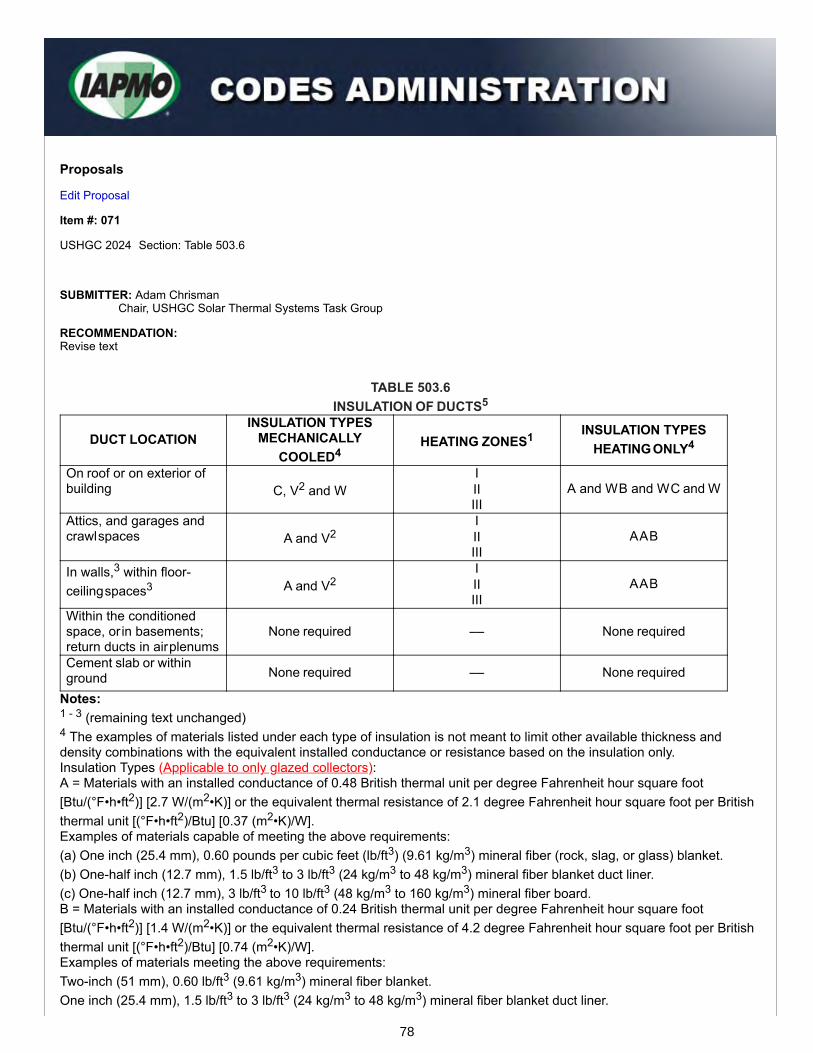
Proposals
Edit Proposal
Item #: 071
USHGC 2024 Section: Table 503.6
SUBMITTER: Adam ChrismanChair, USHGC Solar Thermal Systems Task Group
RECOMMENDATION:Revise text
TABLE 503.6INSULATION OF DUCTS5
DUCT LOCATIONINSULATION TYPES
MECHANICALLYCOOLED4
HEATING ZONES1 INSULATION TYPESHEATING ONLY4
On roof or on exterior ofbuilding C, V2 and W
IIIIII
A and W B and W C and W
Attics, and garages andcrawl spaces A and V2
IIIIII
A A B
In walls,3 within floor-ceiling spaces3 A and V2
IIIIII
A A B
Within the conditionedspace, or in basements;return ducts in air plenums
None required –– None required
Cement slab or withinground None required –– None required
Notes:1 - 3 (remaining text unchanged) 4 The examples of materials listed under each type of insulation is not meant to limit other available thickness anddensity combinations with the equivalent installed conductance or resistance based on the insulation only. Insulation Types (Applicable to only glazed collectors): A = Materials with an installed conductance of 0.48 British thermal unit per degree Fahrenheit hour square foot[Btu/(°F•h•ft2)] [2.7 W/(m2•K)] or the equivalent thermal resistance of 2.1 degree Fahrenheit hour square foot per Britishthermal unit [(°F•h•ft2)/Btu] [0.37 (m2•K)/W]. Examples of materials capable of meeting the above requirements: (a) One inch (25.4 mm), 0.60 pounds per cubic feet (lb/ft3) (9.61 kg/m3) mineral fiber (rock, slag, or glass) blanket. (b) One-half inch (12.7 mm), 1.5 lb/ft3 to 3 lb/ft3 (24 kg/m3 to 48 kg/m3) mineral fiber blanket duct liner. (c) One-half inch (12.7 mm), 3 lb/ft3 to 10 lb/ft3 (48 kg/m3 to 160 kg/m3) mineral fiber board. B = Materials with an installed conductance of 0.24 British thermal unit per degree Fahrenheit hour square foot[Btu/(°F•h•ft2)] [1.4 W/(m2•K)] or the equivalent thermal resistance of 4.2 degree Fahrenheit hour square foot per Britishthermal unit [(°F•h•ft2)/Btu] [0.74 (m2•K)/W]. Examples of materials meeting the above requirements: Two-inch (51 mm), 0.60 lb/ft3 (9.61 kg/m3) mineral fiber blanket. One inch (25.4 mm), 1.5 lb/ft3 to 3 lb/ft3 (24 kg/m3 to 48 kg/m3) mineral fiber blanket duct liner.
78
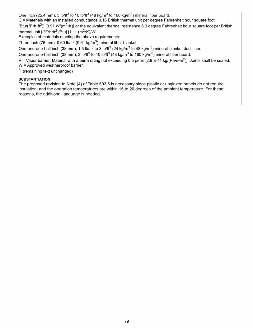
One inch (25.4 mm), 3 lb/ft3 to 10 lb/ft3 (48 kg/m3 to 160 kg/m3) mineral fiber board. C = Materials with an installed conductance 0.16 British thermal unit per degree Fahrenheit hour square foot[Btu/(°F•h•ft2)] [0.91 W/(m2•K)] or the equivalent thermal resistance 6.3 degree Fahrenheit hour square foot per Britishthermal unit [(°F•h•ft2)/Btu] [1.11 (m2•K)/W]. Examples of materials meeting the above requirements: Three-inch (76 mm), 0.60 lb/ft3 (9.61 kg/m3) mineral fiber blanket. One-and-one-half inch (38 mm), 1.5 lb/ft3 to 3 lb/ft3 (24 kg/m3 to 48 kg/m3) mineral blanket duct liner. One-and-one-half inch (38 mm), 3 lb/ft3 to 10 lb/ft3 (48 kg/m3 to 160 kg/m3) mineral fiber board. V = Vapor barrier: Material with a perm rating not exceeding 0.5 perm [2.9 E-11 kg/(Pa•s•m2)]. Joints shall be sealed. W = Approved weatherproof barrier. 5 (remaining text unchanged)
SUBSTANTIATION:The proposed revision to Note (4) of Table 503.6 is necessary since plastic or unglazed panels do not requireinsulation, and the operation temperatures are within 15 to 20 degrees of the ambient temperature. For thesereasons, the additional language is needed.
79

Proposals
Edit Proposal
Item #: 072
USHGC 2024 Section: 606.5, Table 901.1
SUBMITTER: Lance MacNevinPlastics Pipe Institute
RECOMMENDATION:Revise text
606.0 Dry Storage Systems.
606.5 Combustibles Within Ducts or Plenums. Materials exposed within ducts or plenums shall be noncombustible orshall have a flame spread index not to exceed 25 and a smoke developed index not to exceed 50 where tested as acomposite product in accordance with ASTM E84 or UL 723. Exception: Plastic pipe and tubing listed and labeled in accordance with UL 2846 as having a peak optical density notgreater than 0.50, an average optical density not greater than 0.15, and a flame spread distance not greater than 5 feet(1524 mm). Plastic pipe and tubing shall also be installed in accordance with its listing.
TABLE 901.1 REFERENCED STANDARDS
STANDARDNUMBER STANDARD TITLE APPLICATION REFERENCED
SECTIONSUL 2846-2014 Fire Test of Plastic Water Distribution Plumbing Pipe for
Visible Flame and Smoke Characteristics (with revisionsthrough January 14, 2021)
Piping 606.5
(portion of table not shown remains unchanged) Note: UL 2846 meets the requirements for a mandatory referenced standard in accordance with Section 15.0 ofIAPMO’s Regulations Governing Consensus Development of the Uniform Solar, Hydronics & Geothermal andSwimming Pool, Spa & Hot Tub Codes.
SUBSTANTIATION:UL 2846 was developed by UL specifically for testing plastic piping materials. This standard is a test method fordetermining values of flame propagation distance and optical smoke density for individual pairs of plastic plumbingpipes for distribution of potable water, and water used for hydronic heating and cooling applications, waterreclaim/reuse water applications.
The requirements within UL 2846 are no less stringent than the requirements listed within ASTM E84, and themounting methods to be used when testing the plastic piping are specifically described for consistent testing andinterpretation of the results by enforcement agencies.
80

Proposals
Edit Proposal
Item #: 073
USHGC 2024 Section: 701.1, 701.1.3
SUBMITTER: Jeff PersonsChair, USHGC Geothermal Energy Systems Task Group
RECOMMENDATION:Revise text
CHAPTER 7GEOTHERMAL ENERGY SYSTEMS AND DISTRICT GEOTHERMAL LOOPS
Part I – General.
701.0 General.701.1 Applicability. Part I of this chapter shall apply to geothermal energy systems such as, but not limited to, buildingsystems coupled with a ground-heat exchanger, submerged heat exchanger using water-based fluid as a heat transfermedium, or groundwater (well). The regulations of this chapter shall govern the construction, location, and installation ofgeothermal energy systems.
Indoor piping, fittings, and accessories that are part of the groundwater system shall be in accordance with Section703.5 and Chapter 4.
Part I through Part V of this chapter shall apply to geothermal energy systems and district thermal systems thatcirculate ground-ambient-temperature water to be used in end-use buildings as a thermal source or sink via watersource heat pump or reversing chiller. The systems shall operate to permit independent and bi-directional heating andcooling for comfort and water heating such as, but not limited to, building systems coupled with ground coupled districtloops, a ground-heat exchanger, submerged heat exchanger using water-based fluid as a heat transfer medium, orgroundwater (well), or such local resources to the advantage of the district. Central district auxiliary components shalladd or reject heat to benefit district ability, to reduce both power consumption, and demand combined with energysharing. The regulations of this chapter shall govern the construction, location, and installation of ground temperaturethermal distribution districts from 100 percent geothermal energy systems to multiple hybrid district systems. (SeeFigure 701.1 for a schematic of a geothermal system utilizing an ambient temperature loop.)
701.1.3 Indoor Piping. Indoor piping, fittings, and accessories that are part of the groundwater system shall be inaccordance with Section 703.5 and Chapter 4.
SUBSTANTIATION:Section 701.1 (Applicability) is being revised to provide insight into the various parts of Chapter 7 pertaining togeneral requirements, open-loop systems, closed-loop systems, DX systems, and now district ambient temperatureloops. The addition of geothermal district systems supports advanced thermal distribution networks and providesthe code with the necessary requirements for large scale renewable energy systems.
Furthermore, the language pertaining to indoor piping, fittings, and accessories has been moved from theapplicability to Section 701.1.3 (Indoor Piping) as this allows for proper flow of requirements.
81
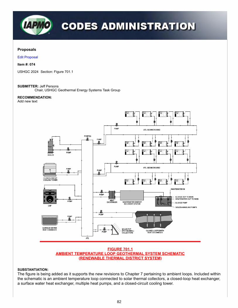
Proposals
Edit Proposal
Item #: 074
USHGC 2024 Section: Figure 701.1
SUBMITTER: Jeff PersonsChair, USHGC Geothermal Energy Systems Task Group
RECOMMENDATION:Add new text
FIGURE 701.1AMBIENT TEMPERATURE LOOP GEOTHERMAL SYSTEM SCHEMATIC
(RENEWABLE THERMAL DISTRICT SYSTEM)
SUBSTANTIATION:The figure is being added as it supports the new revisions to Chapter 7 pertaining to ambient loops. Included withinthe schematic is an ambient temperature loop connected to solar thermal collectors, a closed-loop heat exchanger,a surface water heat exchanger, multiple heat pumps, and a closed-circuit cooling tower.
82

Since wastewater sludge is high in organic content and offers the potential for energy recovery via thermochemicalconversion technologies, a wastewater energy recovery system has been added to the schematic.
The provided schematic offers a simplified and clear visual of an ambient temperature loop system and furthersupports the revised applicability as shown in the previous item submitted by this Task Group. For these reasons,the figure is beneficial to the code and should be included in Chapter 7.
83

Proposals
Edit Proposal
Item #: 075
USHGC 2024 Section: 701.11 – 701.11.1, Table 701.11.1, Table 901.1
SUBMITTER: Jeff PersonsChair, USHGC Geothermal Energy Systems Task Group
RECOMMENDATION:Revise text
701.0 General. 701.11 Heat Transfer Fluid. The heat transfer fluid shall be compatible with the makeup water fluid supplied to thesystem.701.11.1 Water Quality. The makeup water quality within the closed-loop ground source heat pump system shall be inaccordance with IAPMO/ANSI H1001.1, ANSI/CSA/IGSHPA C448, or Table 701.11.1. The quality of potable water shallbe in accordance with the Authority Having Jurisdiction.
TABLE 701.11.1
WATER QUALITYPARAMETER ACCEPTABLE RANGE
Ammonium < 2 ppmChlorides2 < 125 ppm(Free CO2)3 < 50 ppmpH 7.0 – 8.5Sulphates < 125 ppmTDS 10 – 1000 ppmTotal Hardness < 150 ppm
Notes:1 Where chemical additives are used, the acceptable ranges provided shall be in accordance with the equipmentmanufacturer’s specifications, or this Table, whichever is more stringent. 2 The provided acceptable range for chlorides is dependent upon the system heat exchanger and piping materials. Seethe manufacturer’s specifications for equipment and materials used. 3 The limit provided pertains to makeup water.
TABLE 901.1 REFERENCED STANDARDS
STANDARD NUMBER STANDARD TITLE APPLICATION REFERENCEDSECTIONS
ANSI/CSA/IGSHPA C448Series-2016 (R2021)
Design and Installation of Ground Source HeatPump Systems for Commercial and ResidentialBuildings
MiscellaneousGround-SourceHeat Pumps
701.11.1,Table 703.2,Table 703.3,709.1, 710.6,710.6.2, 715.4
IAPMO/ANSI H1001.1-2021
Quality of Heat Transfer Fluids Used in HydronicsSystems
Heat TransferFluid 701.11.1
(portion of table not shown remains unchanged)
84
Note: ANSI/CSA/IGSHPA C448 and IAPMO/ANSI H1001.1 meet the requirements for mandatory referencedstandards in accordance with Section 15.0 of IAPMO’s Regulations Governing Consensus Development of theUniform Solar, Hydronics & Geothermal and Swimming Pool, Spa & Hot Tub Codes.
SUBSTANTIATION:IAPMO/ANSI H1001.1 (Quality of Heat Transfer Fluids Used in Hydronics Systems) is a newly published standardwhich provides minimum requirements for maintaining the quality of liquid aqueous-based heat transfer fluids overthe life of the system and optimizing the life of system components. The standard is applicable to both residentialand non-residential closed hydronic heating and cooling systems.
IAPMO/ANSI H1001.1 is unique in that it addresses both chemical and non-chemical treatment methods with afocus on the importance of water treatment and corrosion prevention. These provisions are accompanied byhydronic water quality parameters for systems with chemical additives, high purity water systems, and hybridhydronic and ground source heat pump systems.
Proposed Table 701.11.1 (Water Quality) is an excerpt from IAPMO/ANSI H1001.1, and the listed parameters areprovided to ensure that the makeup water quality meets the necessary acceptable ranges to prevent corrosionwithin the system. Since IAPMO/ANSI H1001.1 includes references to ANSI/CSA/IGSHPA C448 for ground sourceheat pumps, the standard should also be added to the proposed section.
85

Proposals
Edit Proposal
Item #: 076
USHGC 2024 Section: 701.11, 701.11.2
SUBMITTER: Jeff PersonsChair, USHGC Geothermal Energy Systems Task Group
RECOMMENDATION:Revise text
701.0 General. 701.11 Heat Transfer Fluid. The heat transfer fluid shall be compatible with the makeup water fluid supplied to thesystem. 701.11.2 Compatibility. System components shall be compatible with system fluids including, but not limited to,antifreeze. For systems utilizing chemical additives, system components and fluids shall be tested and approved forcompatibility.
SUBSTANTIATION:Ensuring system longevity and thermal efficiency is necessary when designing geothermal systems. A largecomponent of that design is the selection of system components, heat transfer fluids, and chemical additives.Where incompatible fluids and components are used, corrosion and fouling will lead to decreased efficiency andsystem failure. For these reasons, the proposed Section 701.11.2 (Compatibility) is both necessary and appropriate.
86
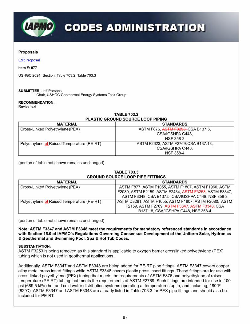
Proposals
Edit Proposal
Item #: 077
USHGC 2024 Section: Table 703.2, Table 703.3
SUBMITTER: Jeff PersonsChair, USHGC Geothermal Energy Systems Task Group
RECOMMENDATION:Revise text
TABLE 703.2 PLASTIC GROUND SOURCE LOOP PIPING
MATERIAL STANDARDSCross-Linked Polyethylene (PEX) ASTM F876, ASTM F3253, CSA B137.5,
CSA/IGSHPA C448, NSF 358-3
Polyethylene of Raised Temperature (PE-RT) ASTM F2623, ASTM F2769, CSA B137.18, CSA/IGSHPA C448,
NSF 358-4 (portion of table not shown remains unchanged)
TABLE 703.3GROUND SOURCE LOOP PIPE FITTINGS
MATERIAL STANDARDSCross-Linked Polyethylene (PEX) ASTM F877, ASTM F1055, ASTM F1807, ASTM F1960, ASTM
F2080, ASTM F2159, ASTM F2434, ASTM F3253, ASTM F3347,ASTM F3348, CSA B137.5, CSA/IGSHPA C448, NSF 358-3
Polyethylene of Raised Temperature (PE-RT) ASTM D3261, ASTM F1055, ASTM F1807, ASTM F2080, ASTMF2159, ASTM F2769, ASTM F3347, ASTM F3348, CSA
B137.18, CSA/IGSHPA C448, NSF 358-4
(portion of table not shown remains unchanged)
Note: ASTM F3347 and ASTM F3348 meet the requirements for mandatory referenced standards in accordancewith Section 15.0 of IAPMO’s Regulations Governing Consensus Development of the Uniform Solar, Hydronics& Geothermal and Swimming Pool, Spa & Hot Tub Codes.
SUBSTANTIATION:ASTM F3253 is being removed as this standard is applicable to oxygen barrier crosslinked polyethylene (PEX)tubing which is not used in geothermal applications.
Additionally, ASTM F3347 and ASTM F3348 are being added for PE-RT pipe fittings. ASTM F3347 covers copperalloy metal press insert fittings while ASTM F3348 covers plastic press insert fittings. These fittings are for use withcross-linked polyethylene (PEX) tubing that meets the requirements of ASTM F876 and polyethylene of raisedtemperature (PE-RT) tubing that meets the requirements of ASTM F2769. Such fittings are intended for use in 100psi (689.5 kPa) hot and cold water distribution systems operating at temperatures up to, and including, 180°F(82°C). ASTM F3347 and ASTM F3348 are already listed in Table 703.3 for PEX pipe fittings and should also beincluded for PE-RT.
87

Proposals
Edit Proposal
Item #: 078
USHGC 2024 Section: 703.3, 703.4, 703.4.2, 703.4.2.1
SUBMITTER: Jeff PersonsChair, USHGC Geothermal Energy Systems Task Group
RECOMMENDATION:Revise text
703.0 Design of Systems. 703.3 Fittings. For water-based systems, fittings for ground source heat pump systems shall be recommended by themanufacturer approved for installation with the piping materials to be installed, and shall comply with the standardslisted in Table 703.3. Fittings for use in DX systems shall comply with Section 715.3.703.4 Underground Piping and Submerged Materials. Underground and submerged piping for a ground-heatexchanger shall be polyethylene (PE) pipe or tubing in accordance with Section 703.4.1 and Section 703.4.1.1,polyethylene of raised temperature (PE-RT) pipe or tubing in accordance with Section 703.4.2 and Section 703.4.2.1, orcross-linked polyethylene (PEX) pipe or tubing in accordance with Section 703.4.2703.4.3 and Section703.4.2.1703.4.3.1.
703.4.2 Polyethylene of Raised Temperature (PE-RT). Polyethylene of raised temperature tubing shall bemanufactured in accordance with the standards listed in Table 703.2. Tubing shall have a minimum wall thickness equalto SDR 9 and shall have a minimum pressure rating of not less than 160 psi (1103 kPa) at 73°F (23°C).
Polyethylene of raised temperature tubing shall be manufactured from a PE compound that has a pipe materialdesignation code of PE 2708, PE 3608, or PE 4710 as defined in the applicable standards referenced in Table 703.2with a cell classification in accordance with ASTM D3350 appropriate for the material designation code. 703.4.2.1 Joining Methods for Polyethylene of Raised Temperature (PE-RT). Joints between polyethylene of raisedtemperature (PE-RT) tubing and fittings shall be installed in accordance with the manufacturer’s installation instructionsand the appropriate standards listed in accordance with Table 703.3. (renumber remaining sections)
Note: ASTM D3350 meets the requirements for a mandatory referenced standard in accordance with Section15.0 of IAPMO’s Regulations Governing Consensus Development of the Uniform Solar, Hydronics & Geothermaland Swimming Pool, Spa & Hot Tub Codes.
SUBSTANTIATION:Polyethylene of Raised Temperature (PE-RT) tubing and fittings are approved for ground loop piping applicationsand are already included within Table 703.2 and Table 703.3 of this chapter.
The proposed language provides missing information about the use of PE-RT tubing and fittings for geothermalapplications and matches the current code language provided for other tubing and fitting materials. These additionalprovisions further support the use of PE-RT tubing and ensure that tubing meeting the necessary minimum wallthicknesses and pressure ratings are selected for installation.
Furthermore, ASTM D3350 is appropriate for reference in Section 703.4.2 as it covers the identification ofpolyethylene plastic pipe and fitting materials by means of a cell classification system. For these reasons, the aboverevisions are beneficial to Chapter 7 (Geothermal Energy Systems).
88

Proposals
Edit Proposal
Item #: 079
USHGC 2024 Section: 703.4.1, Table 703.4.1, 710.3
SUBMITTER: Lance MacNevinPlastics Pipe Institute
RECOMMENDATION:Revise text
Part I – General.
703.0 Design of Systems.
703.4 Underground Piping and Submerged Materials. (remaining text unchanged) 703.4.1 Polyethylene (PE). Polyethylene pipe or tubing shall be manufactured in accordance with the standards listedin Table 703.2. Pipe or tubing shall have a minimum wall thickness equal to SDR-11 and shall have a minimum pressurerating of not less than 160 psi (1103 kPa) at 73°F (23°C). Polyethylene pipe or tubing shall be manufactured from a PE compound that has a pipe material designation code of PE3608, PE 3708, PE 3710, PE 4608, PE 4708, or PE 4710 as defined in the applicable standards referenced in Table703.2, with a cell classification in accordance with ASTM D3350 appropriate for the material designation code, and acolor and ultraviolet stabilizer code of C or E. Code E compounds shall be stabilized against deterioration fromunprotected exposure to ultraviolet rays for not less than 3 years in accordance with the test criteria specified in ASTMD2513 AWWA C901. Polyethylene pipe or tubing shall have a minimum wall thickness in accordance with Table 703.4.1.
TABLE 703.4.1 PE PIPE AND TUBING MINIMUM WALL THICKNESSPE PIPE MATERIAL MINIMUM WALL THICKNESS
PE 3608 SDR 11PE 4710 SDR 13.5
Part II – Closed-Loop Systems. .
710.0 General. 710.3 Borehole Piping and Tubing. Borehole piping or tubing for vertical and horizontally drilled closed-loop systems,shall have a minimum wall thickness in accordance with Table 703.4.1 equal to SDR-11 and shall have a minimumpressure rating of not less than 160 psi (1103 kPa) at 73°F (23°C).
Note: AWWA C901 meets the requirements for a mandatory referenced standard in accordance with Section15.0 of IAPMO’s Regulations Governing Consensus Development of the Uniform Solar, Hydronics & Geothermaland Swimming Pool, Spa & Hot Tub Codes.
SUBSTANTIATION:This proposal recognizes the fact that PE compounds PE 3708, PE 3710, PE 4608, and PE 4708 are not incommercial production for geothermal piping systems. Including them in this code could influence a specifier toselect one of those compounds which would not be commercially available, leading to potential confusion. Theproposal simply removes the non-available piping materials.
89
This proposal would also allow the use of SDR 13.5 pipes produced using PE 4710 compounds because PE 4710pipes have significantly greater resistance to slow crack growth and higher tensile strength than PE 3608 pipes.Therefore, the thicker wall in a SDR 11 pipe is not required for mechanical toughness when PE 4710 pipe is used.SDR 13.5 pipes produced of PE 4710 materials have higher thermal conductivity and flexibility than SDR 11 pipes,have additional advantages for installation and performance, and still meet the minimum pressure requirements.
On the other hand, PE 3608 pipes have lower tensile strength and a greater susceptibility to scratches and gougesthat could lead to slow crack growth. So pipes produced using PE 3608 material should remain as the thicker-wallSDR 11 wall type.
Similar revisions have been agreed by the ANSI/CSA/IGSHPA C448 Piping Task Force for the next edition of thatbi-national standard which is referenced within the USHGC. This proposal also helps to harmonize these twoimportant codes.
90

Proposals
Edit Proposal
Item #: 080
USHGC 2024 Section: 705.1, 705.9, 710.5
SUBMITTER: Jeff PersonsChair, USHGC Geothermal Energy Systems Task Group
RECOMMENDATION:Revise text
Part I - General.
705.0 Valves. 705.1 Where Required. Shutoff valves shall be installed in ground source-loop piping systems in the locations indicatedin Section 705.2 through Section 705.8705.9.
705.9 Bypass Valves. Means shall be provided to allow for bypass of the geothermal system for independent flushingand purging of the geothermal system and building piping system.
Part II – Closed-Loop Systems.
710.0 General.
710.5 Bypass Valves. Means shall be provided to allow for bypass of the closed-loop geothermal system forindependent flushing and purging of the geothermal system and building piping system.
(renumber remaining sections)
SUBSTANTIATION:Section 705.9 and Section 710.5 are needed to ensure that a means of bypass is provided for the purpose offlushing and purging of a geothermal and building piping system. Although Part I (General) applies to all geothermalsystems addressed within this chapter, the Task Group preferred to also repeat this provision under Part II (Closed-Loop Systems). Flushing and purging of these piping systems is crucial for removal of debris and trapped air andassists with successful system maintenance and installation. For these reasons, the additional language is needed.
91
Proposals
Edit Proposal
Item #: 081
USHGC 2024 Section: 705.2
SUBMITTER: Jeff PersonsChair, USHGC Geothermal Energy Systems Task Group
RECOMMENDATION:Revise text
Part I - General.705.0 Valves. 705.2 Heat Exchangers. Shutoff valves shall be installed on the supply and return side of a heat exchanger.Exception: Where a the heat exchanger is an integral part of with a boiler or is a part component of a manufacturedmanufacturer’s boiler and heat exchanger packaged unit, and is capable of being isolated from the hydronic system bythe supply and return valves.
SUBSTANTIATION:Section 705.2 (Heat Exchangers) is being revised to correlate with the mechanical code. The modified language ispreferred and provides clarity for the end user.
92
Proposals
Edit Proposal
Item #: 082
USHGC 2024 Section: 705.6
SUBMITTER: Jeff PersonsChair, USHGC Geothermal Energy Systems Task Group
RECOMMENDATION:Revise text
Part I - General. 705.0 Valves. 705.6 Equipment and Appliances. Shutoff valves shall be installed on connections to mechanical equipment andappliances. This requirement shall not apply to components of a ground source loop system such as pumps, airseparators, metering devices, and similar equipment.
SUBSTANTIATION:Section 705.6 (Equipment and Appliances) is being updated to clarify that “mechanical equipment and appliances”do not refer to components of the ground source loop system but rather externally connected equipment. Thecurrent language enforces impractical and unnecessary requirements. For these reasons, the revision is needed.
93
Proposals
Edit Proposal
Item #: 083
USHGC 2024 Section: 706.1, Table 706.1
SUBMITTER: Jeff PersonsChair, USHGC Geothermal Energy Systems Task Group
RECOMMENDATION:Revise text
706.0 Specific System Components Design.706.1 General. Heat pumps shall be in compliance with Table 706.1, as applicable. Heat pumps shall also be listed andlabeled in accordance with UL 1995 or UL 60335-2-40. Ground coupled and water source heat pumps shall be listed inaccordance with AHRI/ASHRAE/ISO 13256-1 for water-to-air heat pumps and AHRI/ASHRAE/ISO 13256-2 for water-to-water heat pumps. DX heat pumps shall be listed in accordance with ASHRAE 194. All heat pump equipment used inDX systems shall comply with AHRI 870. Heat pumps shall be fitted with a means to indicate that the compressor islocked out.
TABLE 706.1HEAT PUMPS
TYPE OF HEAT PUMP STANDARDSWater-to-Air AHRI/ASHRAE/ISO 13256-1
Water-to-Water AHRI/ASHRAE/ISO 13256-2
Note: AHRI/ASHRAE/ISO 13256-1, AHRI/ASHRAE/ISO 13256-2, UL 1995 and UL 60335-2-40 meet therequirements for mandatory referenced standards in accordance with Section 15.0 of IAPMO’s RegulationsGoverning Consensus Development of the Uniform Solar, Hydronics & Geothermal and Swimming Pool, Spa &Hot Tub Codes.
SUBSTANTIATION:Section 706.1 is being revised to include reference to UL 1995 and UL 60335-2-40 in addition to the performancestandards already provided, AHRI/ASHRAE/ISO 13256-1 and AHRI/ASHRAE/ISO 13256-2.
UL 1995 is applicable as it sets requirements for heating and cooling equipment for use in non-hazardous locationsrated between 600 V and 7200 V. Additionally, UL 60335-2-40 is being proposed as it provides safety requirementsfor electrical heat pumps, air-conditioners, and dehumidifiers. Both of these standards currently exist in Section407.5 (Heat Pumps) and should also be listed for geothermal heat pumps.
Furthermore, these revisions are consistent with the mechanical code and add references to the appropriate safetystandards for heat pumps.
94

Proposals
Edit Proposal
Item #: 084
USHGC 2024 Section: 221.0, 706.3
SUBMITTER: Jeff PersonsChair, USHGC Geothermal Energy Systems Task Group
RECOMMENDATION:Revise text
706.0 Specific System Components Design. 706.3 Heat-Transfer Medium. The heat-transfer medium shall be compatible with components with which it comes intocontact. Where antifreeze or corrosion inhibitors are used, such solutions shall be approved by the Authority HavingJurisdiction. The heat-transfer fluid flash point shall be not less than 50°F (28°C) above the maximum system operatingtemperature. For DX systems, the heat transfer medium shall be a refrigerant listed in ASHRAE 34 or the mechanicalcode. For six-pipe heat pump systems and other specialty heat pumps that comingle source and load fluids, themanufacturer’s recommendations shall apply. 221.0 – S – Six-Pipe Heat Pump System. A hydronic system capable of simultaneously heating and cooling. Dependent upon theequipment, such systems may comingle the source and load fluids.
SUBSTANTIATION:A six-pipe heat pump system serves as a simultaneous chiller and boiler for large-scale or commercial applications.Through the use of connected modules, these systems can serve hot and cold water loops in various controlconfigurations. Six-pipe heat pumps operate at higher efficiency/COPs and have flexibility when sharing thermalloads within the same building.
Section 706.3 (Heat-Transfer Medium) is being revised to mention six-pipe heat pump systems, and since thesecomplex systems may comingle source and load fluids, requiring compliance with the heat pump manufacturer’srecommendations is necessary.
Furthermore, a definition for “six-pipe heat pump system” is being added to provide guidance for users of the codewho may require clarification on the newly proposed provision.
95
Proposals
Edit Proposal
Item #: 085
USHGC 2024 Section: 707.2
SUBMITTER: Jeff PersonsChair, USHGC Geothermal Energy Systems Task Group
RECOMMENDATION:Revise text
707.0 Installation Practices. 707.2 Equipment, Accessories, Components, and Materials. The mechanical equipment, accessories, components,and materials used shall be recommended by the manufacturer of the type and rating approved for the specific use.
SUBSTANTIATION:Section 707.2 (Equipment, Accessories, Components, and Materials) is being revised to correlate with themechanical code. Additionally, the Task Group supports this change as it requires equipment, accessories andcomponents be approved for specific use. Such installation practices facilitate system longevity.
96

Proposals
Edit Proposal
Item #: 086
USHGC 2024 Section: 205.0, 707.5, 713.3, 713.5, 714.4 – 714.6
SUBMITTER: Jeff PersonsChair, USHGC Geothermal Energy Systems Task Group
RECOMMENDATION:Revise text
707.0 Installation Practices.
707.5 Subsurface Investigation. A subsurface investigation shall be performed in accordance with Section 707.5.1 asdetermined by the registered design professional or certified person designer conducting the site survey.
713.0 Open Ground Water Systems.
713.3 Design Considerations. A groundwater heat pump system shall be designed by a registered design professionalor certified person designer. Due design consideration shall be given to the following:(1) - (9) (remaining text unchanged) 713.5 Testing and Sampling. Pumping tests and water sampling shall be done as required by the registered designprofessional or certified person designer.
714.0 Testing and Verification.
714.4 Constant Rate Pump Test. The sustainable well yield, aquifer coefficients, and zones of influences on thegroundwater flow requirements shall be confirmed with a constant rate-pumping test. The constant rate-pumping testshall be done on the water supply and injection wells at rates and durations as specified by the registered designprofessional or certified person designer.714.5 Water Level Monitoring. Water levels shall be monitored in the pumping well and observation wells duringpumping and recovery periods. The monitoring time intervals shall be as specified by the registered design professionalor certified person designer.714.6 Injection Wells. Injection testing shall be performed on water wells that are designated to be used as injectionwells at rates specified by the registered design professional or certified person designer. The results of the drilling andpumping tests shall be provided to the owner or the owner’s representative and provided in accordance withrequirements of the Authority Having Jurisdiction.
205.0 – C –Certified Designer. An individual who has successfully completed the formal training, testing, project designexperience, and continuing education credits to be granted the IGSHPA/AEE title of Certified GeoExchange Designer, orother equivalent approved certification program. Certified Person. A person trained and certified by the equipment manufacturer, or by a recognized organizationthrough a formal certification program for the system to be serviced or cleaned; that is acceptable to the AuthorityHaving Jurisdiction.
97

SUBSTANTIATION:For the purposes of this chapter, “certified designer” is more applicable and appropriate than “certified person.” Theterm “certified designer,” as defined above, is clear and more specific on the type of education, training andcertification required for designing geothermal energy systems.
The provided definition also includes language which addresses other equivalent approved certification programsrather than only referencing one certification agency. Since “certified person” is not used elsewhere within the code,the term is completely being stricken.
98

Proposals
Edit Proposal
Item #: 087
USHGC 2024 Section: 707.6
SUBMITTER: Jeff PersonsChair, USHGC Geothermal Energy Systems Task Group
RECOMMENDATION:Revise text
707.0 Installation Practices. 707.6 Ground Heat-Exchanger Installation Practices. A ground-heat exchanger system shall be installed as follows:(1) - (5) (remaining text unchanged)(6) Vertical and horizontal ground-heat exchangers shall maintain the following setbacks in accordance with theAuthority Having Jurisdiction, or the following:(a) Ten feet (3048 mm) horizontally from a pressure-tested sewer lateral into a building.(b) Twenty Fifty feet (609615 240 mm) horizontally from a non-pressure tested sewer lateral into a building.(c) Three Five feet (9141524 mm) horizontally from buried utilities such as electrical, gas, or water.(d) Fifty feet (15 240 mm) from a water well.(e) Fifty feet (15 240 mm) from a septic tank and 10050 feet (30 48015 240 mm) from a subsurface sewage leaching field.(f) One hundred feet (30 480 mm) from a spring; or at distances specified by the Authority Having Jurisdiction.(7) Wells and boreholes shall be sealed in accordance with the Authority Having Jurisdiction. Where grout is required, itshall be applied in a single continuous operation from the bottom of the borehole by pumping through a tremie pipe.(8) Horizontal ground heat exchangers shall maintain setbacks in accordance with the Authority Having Jurisdiction, orthe following:(a) Five feet (1524 mm) horizontally from a pressure-tested sewer lateral into a building.(b) Ten feet (3048 mm) horizontally from a non-pressure treated sewer lateral into a building.(c) Five feet (1524 mm) horizontally from buried utilities such as electrical gas or water.(d) Ten Feet (3048 mm) from a water well.(e) Ten feet (3048 mm) from a septic tank and 10 feet (3048 mm) from a subsurface leaching field.
SUBSTANTIATION:The proposed revisions are needed to separate the requirements for vertical and horizontal setbacks. Verticalsetbacks are being updated to correlate with current minimum required isolation distances from existing or potentialsources of pollution. Such provisions enhance the requirements of Section 707.6 (Ground Heat-ExchangerInstallation Practices) by providing clear and differentiated setbacks. Additionally, the new language prevents overlyrestrictive setbacks by requiring compliance with either the listed distances or those specified by the AHJ.
99

Proposals
Edit Proposal
Item #: 088
USHGC 2024 Section: 707.13, 707.16.1, 707.17, 707.17.8
SUBMITTER: Jeff PersonsChair, USHGC Geothermal Energy Systems Task Group
RECOMMENDATION:Revise text
707.0 Installation Practices. 707.13 On Site Storage Exterior Piping Protection. Exterior piping shall be fitted with end caps and protected fromfreezing, UV radiation, corrosion, and degradation. 707.16 Horizontal Geothermal Piping - Materials and Methods. (remaining text unchanged)707.16.1 Piping Materials. Piping materials and joining methods for horizontal piping from the ground heat-exchangershall be in accordance with Section 703.2 through Section 703.5, and Section 715.3. 707.17 Trenches, Excavation, and Backfilled. (remaining text unchanged) 707.17.8 Tracer and Warning Markings. Means shall be provided for underground detection or utility location of theburied pipe system. This shall include, but is not limited to, metallic detectable tape, with a thickness of not less than11/64 of an inch (4.4 mm) and a width of 6 inches (152 mm), or non-metallic warning tape used in conjunction withtracer wire that is listed and labeled in accordance complies with UL 2989. The tracer wire diameter shall be inaccordance with the Authority Having Jurisdiction.
Tracer and warning markings shall be permanent, conspicuous and resistant to the environmental conditions andshall be placed within 1 foot to 2 feet (305 mm to 610 mm) on top of the horizontal piping of the heat exchangerinstallation. Tracer wire shall be permitted to be installed at buried pipe grade.
(Section 715.3 is shown for information only)
715.3 DX Systems. Copper pipe and tubing installed for DX systems shall be manufactured in accordance with ASTMB280 and copper fittings in accordance with ASME B16.22. Joints shall be purged with an inert gas and brazed with abrazing alloy having 15 percent silver content in accordance with AWS A5.8. Underground piping and tubing shall havea cathodic protection system installed.
SUBSTANTIATION:The title of Section 707.13 is being updated to represent the accompanying provision more appropriately.
Section 717.16.1 (Piping Materials) is being revised to include reference to Section 715.3 (DX Systems) as thoseprovisions address copper pipe and tubing installed for DX systems.
Section 707.17.8 (Tracer and Warning Markings) is being modified to require compliance with the AHJ for tracerwire diameter sizing. Additionally, the new language permits the installation of tracer wire at buried pipe grade, orbelow grade and in direct contact with soil.
100
Proposals
Edit Proposal
Item #: 089
USHGC 2024 Section: 708.1
SUBMITTER: Jeff PersonsChair, USHGC Geothermal Energy Systems Task Group
RECOMMENDATION:Revise text
708.0 System Start-Up.708.1 General. The following requirements shall be verified prior to system start-up:(1) Piping shall be cleaned, flushed, and purged. To prevent debris in the building piping system from entering thegeothermal loop field piping or residual debris from the geothermal loop field entering the building piping, the connectionbetween building piping and the geothermal loop field shall be isolated so as to allow a bypass for the independentcleaning, flushing, and purging of both the loop field as well as the building piping and equipment prior to theintroduction of building fluid into the geothermal loop field.(2) The ground heat exchanger and building piping shall be cleaned, flushed, and, where required, shall be filled with theheat transfer fluid medium. The ground loop system shall be tested at the design flow rate(s) and differential pressure(s)recorded. Where the actual pressure change at design flow is more than ± 10 percent of the design flow pressure drop,the cause shall be identified and corrective action taken.(3) - (9) (remaining text unchanged)
SUBSTANTIATION:The revisions to Section 708.1 (General) are needed to ensure that a means of isolation and bypass are providedfor the purpose of cleaning, flushing, and purging of geothermal loop field piping. Residual debris from thegeothermal loop may enter the building piping if not flushed and purged. Additionally, the building piping andequipment must be cleaned to prevent contaminants from entering the geothermal loop. Installing a means ofisolation and bypass between the geothermal loop and the building piping is therefore necessary to prepareequipment for connection.
101
Proposals
Edit Proposal
Item #: 090
USHGC 2024 Section: 708.7
SUBMITTER: Jeff PersonsChair, USHGC Geothermal Energy Systems Task Group
RECOMMENDATION:Revise text
708.0 System Start-Up. 708.7 System Start-Up. System start-up shall be in accordance with CSA C448.1, CSA C448.2, ANSI/CSA/IGSHPAC448 and Section 708.0.
TABLE 901.1 REFERENCED STANDARDS
STANDARD NUMBER STANDARD TITLE APPLICATION REFERENCED
SECTIONSCSA C448.1-2016 Design and Installation of Ground Source Heat Pump
Systems for Commercial and Institutional BuildingsGround-SourceHeat Pumps
708.7
CSA C448.2-2016 Design and Installation of Ground Source Heat PumpSystems for Residential and Other Small Buildings
Ground-SourceHeat Pumps
708.7
ANSI/CSA/IGSHPAC448 Series-2016(R2021)
Design and Installation of Ground Source Heat PumpSystems for Commercial and Residential Buildings
MiscellaneousGround-SourceHeat Pumps
Table 703.2,Table 703.3,708.7, 709.1,710.6, 710.6.2,715.4
(portion of table not shown remains unchanged)
Note: ANSI/CSA/IGSHPA C448 meets the requirements for a mandatory referenced standard in accordance withSection 15.0 of IAPMO’s Regulations Governing Consensus Development of the Uniform Solar, Hydronics &Geothermal and Swimming Pool, Spa & Hot Tub Codes.
SUBSTANTIATION:CSA C448.1 and CSA C448.2 are different chapters of ANSI/CSA/IGSHPA C448. It would be more appropriate toreference the entire standard rather than different chapters or sections of ANSI/CSA/IGSHPA C448. Additionally,CSA C448.1 and CSA C448.2 are not referenced in any other portion of the code and are therefore being strickenfrom Table 901.1. For these reasons, the above modifications are necessary.
102
Proposals
Edit Proposal
Item #: 091
USHGC 2024 Section: 710.6.2.2
SUBMITTER: Jeff PersonsChair, USHGC Geothermal Energy Systems Task Group
RECOMMENDATION:Revise text
Part II - Closed-Loop Systems.
710.0 General. 710.6 Vertical Bores. (remaining text unchanged) 710.6.2 U-Bends and Headers. (remaining text unchanged) 710.6.2.2 Testing Procedure. The test section and the test liquid shall be at the same temperature. The test sectionshall be filled with liquid and purged of air. The test section shall be brought to the specified test pressure. Test pressureshall be maintained for 4 hours, with make-up additional fluid added as needed. The test pressure shall be reduced by10 psi (69 kPa) and monitored for 1 hour with no addition of pressure or make-up additional fluid. A passing test isindicated where after a period of 1 hour no visual leakage is observed, and pressure remains equal to or greater than 95percent of the original pressure.
SUBSTANTIATION:Section 710.6.2.2 (Testing Procedure) is being revised to correlate with the mechanical code. The term “makeupfluid” is specific to hydronics and represents fluid that is added to maintain system pressure. For the purposes ofthis chapter, the wording "additional fluid" is more suitable. For these reasons, the proposed modification isnecessary.
103

Proposals
Edit Proposal
Item #: 092
USHGC 2024 Section: 712.1
SUBMITTER: Jeff PersonsChair, USHGC Geothermal Energy Systems Task Group
RECOMMENDATION:Revise text
Part III – Open-Loop Systems. 712.0 General.712.1 Applicability. Part III of this chapter shall apply to geothermal energy systems such as, but not limited to, buildingsystems coupled with a groundwater (well) or surface water open-loop using water-based fluid as a heat transfermedium. The regulations of this chapter shall govern the construction, location and installation of geothermal energysystems.
Indoor piping, fittings, and accessories that are part of the groundwater system shall be in accordance with Section703.5 and Chapter 4. Outdoor piping, fittings, and accessories shall be in accordance with Section 703.2.
Components which come into contact with the system fluids and are installed in a geothermal open-loop system shallbe constructed of corrosion resistant materials or in accordance with the AHJ.
SUBSTANTIATION:Since open-loop geothermal components are continuously exposed to groundwater or surface water, corrosionprevention substantially influences the design of geothermal systems. The water quality of these sources varies andcan in some cases be inferior causing scaling and corrosion. For these reasons, components of the system whichcome into contact with the source fluid need to be constructed of corrosion resistant materials.
104
Proposals
Edit Proposal
Item #: 093
USHGC 2024 Section: 713.4
SUBMITTER: Jeff PersonsChair, USHGC Geothermal Energy Systems Task Group
RECOMMENDATION:Revise text
713.0 Open Ground Water Systems. 713.4 Water Wells and Injection Wells. Water wells and injection wells for groundwater heat pump systems shall beinstalled and tested by a registered professional who is qualified to drill wells that comply with the requirements of theAuthority Having Jurisdiction.
Water supply wells and injection wells shall be developed in accordance with NGWA-01.
SUBSTANTIATION:The additional language ensures that both installation and testing are completed by a registered professional.
105

Proposals
Edit Proposal
Item #: 094
USHGC 2024 Section: 203.0, 208.0, 716.0 – 716.2
SUBMITTER: Jeff PersonsChair, USHGC Geothermal Energy Systems Task Group
RECOMMENDATION:Add new text
Part V – District Ambient Temperature Loop (ATL) Geothermal.
716.0 Ambient Temperature Loop (ATL) Distributed Energy Systems.716.1 General. An ambient temperature loop (ATL) distributed energy system shall be installed in accordance withSection 716.2 through Section 716.6.3, and Section 717.0. ATL systems shall comply with Part I through Part IV of thischapter, as applicable.716.1.1 Fourth Generation (4G) System Configuration. A fourth-generation system configuration shall be a districtgeothermal energy system distributing hot water, cold water, or both to the conditioned space or building for a specificuse. Where a geothermal energy source is used, such systems shall comply with Part I through Part IV of this chapterand Chapter 4.716.1.2 Fifth Generation (5G) System Configurations. An advanced ambient temperature loop (ATL) System or fifthgeneration (5G) ATL system shall also be capable of interacting with the electric utility system as well as other utilitysystems and systems components.System components shall include, but not be limited to, the following:(1) Thermally diverse buildings with independent hydronic systems.(2) Circulation loop.(3) Global control system.(4) Segment isolation capability.Note: System components may include, but are not limited to, the following:(1) Electric grid-interactive enabled buildings(2) Hybrid components(3) Other renewable systems716.2 Permitting. Permits required for the installation and application of an ATL distributed energy system shall beobtained as required by the Authority Having Jurisdiction.
203.0 – A –Ambient Temperature Loop (ATL). A closed loop piping system with central pumping that includes various heatsources and heat sinks to hold the loop fluid temperature near the long term average ambient air temperature for agiven geographical location. The sources/sinks can be passive (e.g., a ground loop, a body of water, sewer effluent) oractive (e.g. a cooling tower) and further can include opportunistic, or unique locally available waste or by-product heatsources (e.g., data center, industrial process). The closed loop piping system typically controls or engages thesesources/sinks to maintain the loop temperature to meet the seasonal requirements as well as specific building needs. 208.0 – F –Fifth Generation (5G) System Configurations. An advanced ambient temperature (ATL) system that distributes nearambient temperature water among and between end use buildings that are equipped with water-source heat pumps orother water source HVAC equipment. Such systems stand in contrast to fourth generation (4G) systems that distributehot water or chilled water to buildings to serve facility loads.Fourth Generation (4G) System Configurations. A district geothermal energy system that distributes dedicated hotwater and chilled water for direct use in the conditioned space.
106

SUBSTANTIATION:Part V (District Ambient Temperature Loop) is being proposed in response to the attention drawn to ambienttemperature loop district systems. Many states have implemented carbon reduction plans and non-combustionalternatives, and district ambient temperature loops coincide with these initiatives. Such systems lack installationrequirements throughout the code and should therefore be provided.
Ambient temperature loops are high efficiency systems that recover wasted energy that is normally rejected to theatmosphere. The proposed provisions in Section 716.1.1 and Section 716.1.2 address the general requirements forfourth and fifth generation systems; along with permitting requirements.
The definitions for "fourth generation (4G) system configuration" and "fifth generation (5G) system configuration" areincluded as such systems are not currently defined and are not commonly known. A definition for "ambienttemperature loop (ATL)" was also added to support the proposed code changes pertaining to these systems. Theprovided language appropriately defines ATL systems and informs users of the code that ATLs are closed-looppiping systems which include various heat sources and heat sinks.
107

Proposals
Edit Proposal
Item #: 095
USHGC 2024 Section: 716.3 – 716.5
SUBMITTER: Jeff PersonsChair, USHGC Geothermal Energy Systems Task Group
RECOMMENDATION:Add new text
716.3 Ambient Loop Temperature Range. The operating loop temperature range of an ambient temperature loop(ATL) system shall be not less than the freezing point of the circulating fluid and not more than the maximumtemperature, as required by the manufacturer’s installation instructions for the attached heat pump equipment inaccordance with Section 716.3.1 and Section 716.3.2. The ATL system shall use treated water as the heat transfermedium.716.3.1 ATL Operating Temperature. For equipment listed to AHRI/ASHRAE/ISO 13256-1 and AHRI/ASHRAE/ISO13256-2, the controlled temperature range of the ambient closed-loop shall be not less than 7°F (4°C) above thefreezing point of the transport fluid and 10°F (6°C) below the (collective) heat pump lowest maximum inlet supplytemperature as recommended by the manufacturer’s instructions.Exception: Equipment that is not listed to AHRI/ASHRAE/ISO 13256-1 and AHRI/ASHRAE/ISO 13256-2, the controlledtemperature range of the ambient closed loop shall be in accordance with Section 716.3.2 for minimum and maximumtemperatures.716.3.2 ATL Operating Temperature Range for Mixed Equipment Certifications. The source inlet temperature rangeof any attached equipment shall govern the design operating temperature range. Such equipment shall be identified inthe design documentation. In any case, the most restrictive minimum and maximum inlet supply temperatures, asrecommended by the manufacturer’s instructions, shall determine the system operating temperature range.716.4 Shutoff Valve. An automatic shutoff valve shall be provided for each individual building or facility transferringenergy to or from an ATL distribution system. The automatic shutoff valve shall automatically shutoff upon operatingcommand.716.4.1 Shutoff Valve Operation. The operation of the automatic shutoff valve shall be in accordance with the systemoperating procedures. Where the operation of a shutoff valve was due to an emergency response, an auxiliary heatingor cooling methodology shall be provided in accordance with Section 717.1.2.716.5 Bypass. The ATL distributed energy system shall be provided with bypass path(s) to reroute the circulating fluidwhen necessary. Note: AHRI/ASHRAE/ISO 13256-1 and AHRI/ASHRAE/ISO 13256-2 meet the requirements for mandatoryreferenced standards in accordance with Section 15.0 of IAPMO’s Regulations Governing ConsensusDevelopment of the Uniform Solar, Hydronics & Geothermal and Swimming Pool, Spa & Hot Tub Codes.
SUBSTANTIATION:Section 716.3 through Section 716.5 further address the characteristics and required components of an ATLsystem. In particular, Section 716.3.1 is necessary as it provides the required controlled temperature range forambient temperature loops where heat pumps are listed to AHRI/ASHRAE/ISO 13256-1 or AHRI/ASHRAE/ISO13256-2.
For systems incorporating heat pumps not listed to those standards, Section 716.3.2 addresses the controlledtemperature range in a conservative manner by requiring the most restrictive minimum and maximum supplytemperatures recommended by the manufacturer.
Section 716.4 is important as it requires automatic shutoff valves for each building or facility connected to the ATLsystem. The proposed language in Section 716.4.1 ensures automatic emergency response via these shutoff valvesand also requires available back-up heating or cooling methods.
108

Proposals
Edit Proposal
Item #: 096
USHGC 2024 Section: 716.6 – 716.6.3
SUBMITTER: Jeff PersonsChair, USHGC Geothermal Energy Systems Task Group
RECOMMENDATION:Add new text
716.6 Metering. Where meters are required by the system design, meter(s) shall be located as specified by themanufacturer on each consumptive or supply source, and the range of the metering shall be appropriate to the thermalproperties and flow rate(s) of the transport fluid.716.6.1 Sub-Metering System Specification. The entire energy measurement system shall be provided with a sub-metering system. The metering system shall be calibrated and shall consist of a flow meter, temperature sensors,temperature thermowells, or other required mechanical installation metering. The sub-meter traceable calibration shallcomply with a National Institute of Standards Technology (NIST) traceable calibration program or in accordance with theAuthority Having Jurisdiction and shall be provided with an ATL distributed energy system.716.6.2 BTU/Thermal Meters. Where used, the Btu/thermal meter shall be bidirectional and shall provide the followinginformation via digital or analog display:(1) LCD, and via serial network communications.(2) Total energy, Btu (kWh).(3) Energy rate, Btu/h (kW).(4) Total flow, gal (L).(5) Flow rate, gpm (L/s).(6) Supply temperature, °F (°C).(7) Return temperature, °F (°C).
Each Btu/thermal meter shall be factory programmed for its specific application and shall be re-programmable toadjust for specific site conditions.716.6.3 Flow Meter. Where used, the flow meter shall be provided with the following information via digital or analogdisplay:(1) LCD, and via serial network communications.(2) Instantaneous fluid rate, gpm (L/s).(3) Cumulative fluid flow volume, gal (L).
SUBSTANTIATION:Section 716.6 through Section 716.6.3 are intended to require energy movement data with sufficient accuracy toboth measure system performance and individual asset performance. The respective metering methods alsoprovide the basis for a use or energy transfer custody platform. In addition, this section is recognizing that there aremultiple ways to effectively measure energy transfer.
Section 716.6.1 calls out the National Institute of Standards Technology (NIST) traceable calibration program forsub-meters to provide users of the code with the most appropriate method of calibration. To prevent overlyrestrictive requirements, the proposed language also leaves the calibration program selection up to the AuthorityHaving Jurisdiction. Such calibration is necessary since the entire energy measurement system is provided with thesub-metering system which relies on inputs from flow meters, temperature sensors, thermowells, etc.
Section 716.6.2 then addresses thermal metering which allows for the measurement of energy used to heat andcool individual units. It is the most accurate method for monitoring heating and cooling consumption. For thesereasons, the proposed requirements for metering are necessary and further support the remaining items submittedpertaining to ATLs in Chapter 7.
109

Proposals
Edit Proposal
Item #: 097
USHGC 2024 Section: 221.0, 222.0, 717.0 – 717.1.2
SUBMITTER: Jeff PersonsChair, USHGC Geothermal Energy Systems Task Group
RECOMMENDATION:Add new text
717.0 ATL Distributed Energy Systems Design Requirements.717.1 Thermal Resources. The ambient temperature loop shall be permitted to connect to a thermal resource(s). Suchresources may be an alternative energy source and sink, such as but not limited to, solar photovoltaic (PV), solarthermal, combined heat power (CHP), and phase change thermal storage. These systems shall be installed and complywith the respective system requirements. ATL distributed energy systems coupled with solar thermal systems shallcomply with this code or equivalent. ATL systems coupled with a solar PV system shall comply with this code or NFPA70, or equivalent. These systems shall optimize the use of the equipment and energy based on the system designintent.717.1.1 System Performance. The System Coefficient of Performance (SCOP) shall account for the net COP of eachindividual component(s) in the district. The SCOP shall be provided by the designer and included in the system designdocuments.717.1.2 Emergency Response. An auxiliary heating or cooling methodology shall be provided with the ATL controlsand shall be adequate to provide temporary service in the absence of an ATL energy transfer. Emergency source/sinkmeasures such as, but not limited to, control subroutines that move energy between spaces in the building, the use oflocally connected ground-source assets, combined heat and power (CHP), conventional equipment, and otherrenewable systems shall be permitted to be used. 221.0 – S –System Coefficient of Performance (SCOP). A ratio of the total system energy moved divided by the total systempurchased energy. 222.0 – T –Thermal Resources. A source for heating and a sink for cooling. There are two types of sources:(1) Conventional-type: such systems are known as geothermal energy systems, including air-source resources andground-source resources.(2) Opportunistic-type: such systems use water-source resources (e.g., oceans, rivers, raw sewage pipes, treatedsewage outfall, potable water pipes, etc.), process byproduct heat resources (e.g., data center cooling process rejectheat, industrial process reject heat, etc.), and other resources.
Note: NFPA 70 meets the requirements for a mandatory referenced standard in accordance with Section 15.0 ofIAPMO’s Regulations Governing Consensus Development of the Uniform Solar, Hydronics & Geothermal andSwimming Pool, Spa & Hot Tub Codes.
SUBSTANTIATION:By definition, the ATL will use multiple types of sources and sinks along with multiple heat transfer devices. Thissection is intended to demonstrate different assets that are commonly used in conjunction with the ATL to meetspecific system needs and ensure that temporary service reductions are anticipated in the design process.
A standard metric, system coefficient of performance (SCOP) must be used to evaluate the ATL design intentperformance to include transport energy and wasted energy recovered. Sources and sinks are usually spreadacross the ATL system, GeoMicroDistrict, or thermal highway and provisions should be made to handle temporaryreduction or loss of services utilizing assets currently connected to the ATL.
110

Section 717.1 (Thermal Resources) is not intended to include a redundant system but rather to address the use ofexisting or attached thermal resources. Furthermore, definitions for "thermal resource" and "system coefficient ofperformance (SCOP)" are being added as they are not currently defined in the code and such inclusion will assistthe end user with interpreting and applying the listed provisions.
111
Proposals
Edit Proposal
Item #: 098
USHGC 2024 Section: 206.0, 209.0, 222.0, 717.2 – 717.2.3
SUBMITTER: Jeff PersonsChair, USHGC Geothermal Energy Systems Task Group
RECOMMENDATION:Add new text
717.2 District Load Profiles. The district load profile of an ambient temperature loop (ATL) distributed energy systemshall be identified and shall be included in the basis-of-design (BOD).717.2.1 System Asset Identification. System assets shall be listed and included in the system design. The systemassets shall include, but not be limited to, the following:(1) Building type and quantity.(2) Natural or constructed sources and sinks such as ground water, boreholes, etc.(3) Other renewable assets.(4) Waste heat recovery.(5) Potable and non-potable water or fluid sources.(6) Conventional assets such as boilers and cooling towers.(7) Other geothermal micro-districts or thermal highways.717.2.2 Driver Building. The driver building profile shall be identified in an ATL distributed energy system and shall bereported in the design documents.717.2.3 Diversity Factor. The diversity factor and/or anticipated wasted energy recovery component of the geothermalmicro-district shall be identified by the designer, and this information shall be included in the drawings andspecifications. 206.0 – D –Driver Building. One or more building(s) or facility(s) that determine the upper and lower temperature limits of a hotfluid or cold fluid delivery system. 209.0 – G –Geothermal Micro-District. A collection of buildings and facilities on an independently pumped ambient temperatureloop (ATL) that supplies or receives energy. An independent segment served by a thermal highway. Also known asGeoMicroDistrict. 222.0 – T –Thermal Highway. A collection of one or more geothermal micro-districts that acts as an energy transport system andsupplies or accepts energy from multiple geothermal micro-districts, individual buildings, or other sources. Also knownas convective circulation circuit.
SUBSTANTIATION:Along with System Coefficient of Performance (SCOP), there are several additional unique characteristics andcomponents that must be identified in the ATL design documents. These components must be identified accuratelyto communicate design intent. In addition, identification of system assets, the driver building(s), and diversity factors(e.g. wasted energy recovery) are imperative for building management system code development, validation/commissioning processes, long term operations management, and future system expansion.
Furthermore, the definitions for "driver building," "geothermal micro-district," and "thermal highway" are being addedto support the proposed language. Such terminology will assist with the enforcement of the section and provideclarity for the end user.
112
Proposals
Edit Proposal
Item #: 099
USHGC 2024 Section: 221.0, Chapter 8
SUBMITTER: IAPMO Staff - Update ExtractsNFPA 70 - Extract Update
RECOMMENDATION:Revise text
221.0 - S -Stand-Alone System. A system that is capable of supplying power independent of an electricpower electric powerproduction and distribution network. [NFPA 70:100]
CHAPTER 8SOLAR PHOTOVOLTAIC SYSTEMS
809.0 Rapid Shutdown of PV Systems on Buildings.809.1 Reduce Shock Hazard. (remaining text unchanged)
809.1.3 Initiation Device. The initiation device(s) shall initiate the rapid shutdown function of the PV system. Thedevice’s “off” position shall indicate that the rapid shutdown function has been initiated for all PV systems connected tothat device. For one-family and two-family dwellings an initiation device(s) shall be located at a readily accessiblelocation outside the building.For a single PV system, the rapid shutdown initiation shall occur by the operation of any single initiation device. Devicesshall consist of at least one or more of the following:(1) Service disconnecting means.(2) PV system disconnecting means.(3) Readily accessible switch that plainly indicates whether it is in the “off” or “on” position. Where multiple PV systems are installed with rapid shutdown functions on a single service, the initiation device(s)shall consist of not more than six switches or six sets of or circuit breakers, or a combination of not more than sixswitches and sets of circuit breakers, mounted in a single enclosure, or in a group of separate enclosures. Theseinitiation device(s) shall initiate the rapid shutdown of all PV systems with rapid shutdown functions on that service.[NFPA 70:690.12(C)]
812.0 Wiring Methods Permitted.
812.2 Identification and Grouping. (remaining text unchanged)812.2.1 Identification. PV system dc circuit conductors shall be identified at all of termination, connection, and splicepoints by color coding, marking tape, tagging, or other approved means. Conductors relying on other than color codingfor polarity identification shall be identified by an approved permanent marking means such as labeling, sleeving, orshrink-tubing that is suitable for the conductor size. The permanent marking means for nonsolidly grounded positiveconductors shall include imprinted plus signs (+) or the word POSITIVE or POS durably marked on insulation of a colorother than green, white, or gray. The permanent marking means for nonsolidly grounded negative conductors shallinclude imprinted negative signs (-) or the word NEGATIVE or NEG durably marked on insulation of a color other thangreen, white, gray, or red. Only solidly grounded PV system dc circuit conductors shall be marked in accordance withSection 200.6 of NFPA 70.Exception: Where the identification of the conductors is evident by spacing or arrangement, further identification shallnot be required. [NFPA 70:690.31(B)(1)]
113

812.7 Photovoltaic System Direct-Current Circuits on or in a Building.812.7.1 Flexible Wiring Methods. Where flexible metal conduit (FMC) smaller than the trade size 3/4 (metric designator21) or Type MC cable less smaller than 1 inch (25 mm) in diameter containing PV power circuit conductors is installedacross ceilings or floors joists, the raceway or cable shall be protected by substantial guard strips that are at least ashigh as the raceway or cable. Where run exposed, other than within 6 feet (1829 mm) of their connection to equipment,these wiring methods shall closely follow the building surface or be protected from physical damage by an approvedmeans. [NFPA 70:690.31(D)(1)]812.7.2 Marking and Labeling Required. Unless located and arranged so the purpose is evident, the following wiringmethods and enclosures that contain PV system dc circuit conductors shall be marked with the wordingPHOTOVOLTAIC POWER SOURCE or SOLAR PV DC CIRCUIT by means of permanently affixed labels or otherapproved permanent marking:(1) Exposed raceways, cable trays, and other wiring methods.(2) Covers or enclosures of pull boxes and junction boxes.(3) Conduit bodies in which any of the available conduit openings are unused. The labels or markings shall be visible after installation. All letters shall be capitalized and shall be a minimum heightof 3/8 of an inch (9.5 mm) in white on a red background. Labels shall appear on every section of the wiring system thatis separated by enclosures, walls, partitions, ceilings, or floors. Spacing between labels or markings, or between a labeland a marking, shall not be more than 10 feet (3048 mm). Labels required by this section shall be suitable for theenvironment where they are installed. [NFPA 70:690.31(D)(2)]
816.0 Grounding and Bonding.
816.3 Ground-Fault Detection. The ground-fault protection device or system shall detect ground fault(s) in the PV arraysystem dc circuit conductors, including any functional grounded conductors, and be listed for providing PV ground-faultprotection. For dc-to-dc converters not listed as providing ground-fault protection, where required, listed ground faultprotection equipment identified for the combination of the dc-to-dc converter and ground-fault protection device shall beinstalled to protect the circuit. [NFPA 70:690.41(B)(1)]
818.0 Equipment Grounding and Bonding.818.1 General. (remaining text unchanged)
818.1.3 With Circuit Conductors. Equipment grounding conductors for the PV array and support structure (whereinstalled) shall be contained within the same raceway or cable or otherwise run with the PV system conductors wherethose circuit conductors leave the vicinity of the PV array. [NFPA 70:690.43(C)]
824.0 Facilities with Stand-Alone Systems.
824.3 Buildings with Rapid Shutdown. (remaining text unchanged)824.3.1 Buildings with More Than One Rapid Shutdown Type. For buildings that have PV systems with more thanone rapid shutdown type or PV systems with no rapid shutdown, a detailed plan view diagram of the roof shall beprovided showing each different PV system with a dotted line around areas that remain energized after rapid shutdown isinitiated. [NFPA 70:690.56(C)(1)]
SUBSTANTIATION:The above section is being revised to correlate with NFPA 70-2020 (latest version) in accordance with Section 16.0of the IAPMO Regulations Governing Consensus Development of the Uniform Solar, Hydronics & Geothermal andSwimming Pool, Spa & Hot Tub Codes (Extract Guidelines).
114

Proposals
Edit Proposal
Item #: 100
USHGC 2024 Section: 802.2.1, Table 802.2.1, 802.6, 828.1, Table 901.1
SUBMITTER: John TaeckerUL LLC
RECOMMENDATION:Revise text
802.0 General Requirements.
802.2 Equipment. (remaining text unchanged) 802.2.1 Listing Requirements. Equipment used in PV power systems shall be listed or field labeled in accordancewith Table 802.2.1. Equipment shall be installed in accordance with its listing and the manufacturer’s installationinstructions.
TABLE 802.2.1 STANDARDS FOR PV EQUIPMENTEQUIPMENT STANDARDS
Molded-Case Circuit Breakers, Molded-Case Switches, and Circuit-Breaker Enclosures UL 489BEnclosed and Dead-Front Switches UL 98BDisconnect Switches UL 508ILow-Voltage Fuses - Fuses UL 2579Building-Integrated PV Roof Coverings UL 7103PV Fuses UL 248PV Junction Boxes UL 3730Rapid Shutdown Equipment and Systems (PV Hazard Control) UL 1741 or UL 3741
(portion of table not shown remains unchanged)
802.6 Photovoltaic Modules/Panels/Shingles. Photovoltaic modules/panels/shingles shall comply with UL 1703 andshall be installed in accordance with the manufacturer’s installation instructions and the building code.
828.0 Self-Regulating Charge Control. 828.1 General. The PV source circuit shall be considered to comply with the requirements of Section 828.1.1through Section 828.1.5 if: (1) The PV source circuit is matched to the voltage rating and charge current requirements of the interconnectedbattery cells, and (2) The maximum charging current multiplied by 1 hour is less than 3 percent of the rated battery capacityexpressed in ampere-hours or as recommended by the battery manufacturer. [NFPA 70:690.72] A charge controller that is integral with an external inverter shall comply with UL 1741.
115

TABLE 901.1 REFERENCED STANDARDS
STANDARDNUMBER STANDARD TITLE APPLICATION REFERENCED
SECTIONSUL 98B-2015 Outline of Investigation for Enclosed and Dead-front Switches
for use in Photovoltaic SystemsElectrical Table 802.2.1
UL 248-2019 Low-Voltage Fuses – Part 19: Photovoltaic Fuses (withrevisions through February 28, 2020)
Electrical Table 802.2.1
UL 489B-2016 Molded-Case Circuit Breakers, Molded-Case Switches, andCircuit-Breaker Enclosures for Use with Photovoltaic (PV)Systems (with revisions through May 19, 2021)
Electrical Table 802.2.1
UL 508I-2015 Outline of Investigation for Disconnect Switches Intended forUse in Photovoltaic Systems
Electrical Table 802.2.1
UL 2579-2013 Outline of Investigation for Low-Voltage Fuses - Fuses forPhotovoltaic Systems
Electrical Table 802.2.1
UL 3730-2014 Photovoltaic Junction Boxes (with revisions through June 11,2021)
Electrical Table 802.2.1
UL 3741-2020 Photovoltaic Hazard Control Electrical Table 802.2.1UL 7103-2019 Outline of Investigation for Building-Integrated Photovoltaic
Roof CoveringsElectrical Table 802.2.1
(portion of table not shown remains unchanged)
Note: UL 248, UL 489B, UL 3730, and UL 3741 meet the requirements for mandatory referenced standards inaccordance with Section 15.0 of IAPMO’s Regulations Governing Consensus Development of the UniformSolar, Hydronics & Geothermal and Swimming Pool, Spa & Hot Tub Codes.
Note: UL 98B, UL 508I, UL 2579, and UL 7103 do not meet the requirements for consensus referencedstandards in accordance with Section 15.2 of IAPMO's Regulations Governing Consensus Development ofthe Uniform Solar, Hydronics & Geothermal and Swimming Pool, Spa & Hot Tub Codes.
SUBSTANTIATION:Listed equipment should be installed in accordance with its listing and the manufacturer's installation instructions.This is fundamental for all references in codes for proper installation.
The USHGC requires that all equipment associated with a PV system must be listed or field labeled; however, theUSHGC falls short on identifying the applicable safety standards. The 2020 National Electrical Code (NEC) includesAnnex A (Product Safety Standards) which provides product safety standards used for product listings where thatlisting is required by the NEC. Since the majority of Chapter 8 (Solar Photovoltaic Systems) is extracted materialwithout the extraction of Annex A, the information that is necessary for the AHJ to determine approval of the productis not available within this code.
Furthermore, Section 828.1 is being revised to remove language referencing UL 1741, and Section 802.6 is beingdeleted in its entirety. Both UL 1703 and UL 1741 are already addressed in Section 802.2.1 and Table 802.2.1. Thusthe language in Section 802.6 and Section 828.1 is redundant and unnecessary.
116
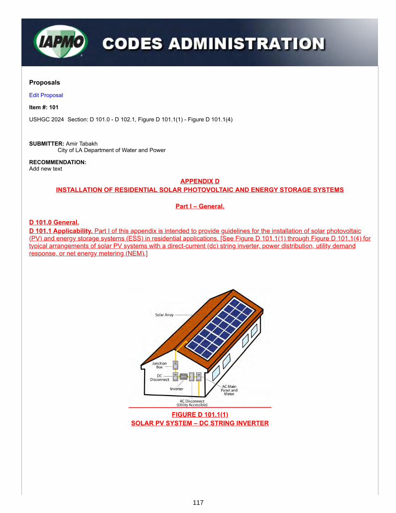
Proposals
Edit Proposal
Item #: 101
USHGC 2024 Section: D 101.0 - D 102.1, Figure D 101.1(1) - Figure D 101.1(4)
SUBMITTER: Amir TabakhCity of LA Department of Water and Power
RECOMMENDATION:Add new text
APPENDIX DINSTALLATION OF RESIDENTIAL SOLAR PHOTOVOLTAIC AND ENERGY STORAGE SYSTEMS
Part I – General.
D 101.0 General.D 101.1 Applicability. Part I of this appendix is intended to provide guidelines for the installation of solar photovoltaic(PV) and energy storage systems (ESS) in residential applications. [See Figure D 101.1(1) through Figure D 101.1(4) fortypical arrangements of solar PV systems with a direct-current (dc) string inverter, power distribution, utility demandresponse, or net energy metering (NEM).]
FIGURE D 101.1(1)SOLAR PV SYSTEM – DC STRING INVERTER
117

FIGURE D 101.1(2)SOLAR PV SYSTEM – POWER DISTRIBUTION
FIGURE D 101.1(3)SOLAR PV SYSTEM – UTILITY DEMAND RESPONSE
FIGURE D 101.1(4)SOLAR PV SYSTEM – NEM PROCESS (SIMPLIFIED)
118

D 101.2 Approval Required. An installed solar PV system shall not begin operation before approval is granted by theAuthority Having Jurisdiction and the local utility.D 101.3 Electrical Requirements. Electrical connections, wiring, and devices shall be installed in accordance withNFPA 70.D 101.3.1 Listing and Labeling. PV equipment shall be listed or labeled in accordance with the appropriate standard,as listed in Table 802.2.1. Equipment used in PV systems shall be listed or field labeled, or evaluated for the applicationand have a field labeled applied. D 101.4 Code Requirements. The installation of a solar PV system shall comply with this code, the mechanical code,the plumbing code, and NFPA 70; or the code requirements as adopted by the Authority Having Jurisdiction.
D 102.0 Definitions.D 102.1 General. For the purpose of this appendix, the following definitions shall apply:Constraints. A limitation on the design or ability of an ESS. Dwelling Unit. A structure, or part of a structure, which serves as a place of residence and provides complete livingfacilities for one or more persons. Dynamic Model of Microgrid. The expected or actual behavior of the microgrid (simulated or modeled) which accountsfor load, storage, and time.Energy Storage System. A device which stores energy for later consumption. Learning-Based GHI Prediction. Predictions initially based on the GHI algorithm and adjusts based on machine inputsand changing parameters.Learning-Based Load Prediction. An algorithm taking into account expected load consumption for the purpose ofmeeting the demands generated by inputs and parameters.Microgrid Interconnection Device. A device which provides a microgrid system with a means of disconnecting fromand reconnecting with a primary power source to function in parallel. Net Energy Metering. The use of any bi-directional meter (e.g. analog, electro-mechanical, smart, radio frequency, etc.)to measure the energy difference between the amount supplied by the utility grid and the amount the utility grid receivesfrom user generation. Objective Function. The programmed function that is designed to arrive at a particular strategy to achieve the goals ofthe system. Goals may include peak shaving, utility bill cost deduction, emergency storage, or any combination ofdesired goals within the strategy.or systems.Plan View. An orthographic projection of the three-dimensional roof or structure, serving as a space for solar PVinstallation, from the position of a horizontal plane.Power Command. The ESS designed and demanded power being called to the user’s facilityShort-Term GHI Prediction. Predictions based on the GHI algorithm that depicts as little as a few minutes or as long asa few days.Short-Term Load Prediction. Load predictions based on expectations within the next few minutes to the next few days.Smart Meter. An electrical meter which features two-way communication with the central computer system and recordsdata including both electrical usage and service characteristics for voltage, amperage, and power factor. Solar Access. The ratio of solar insolation including shading to that without shading. Solar Zone. The total area of an available and appropriate space to be used for future solar PV installation. Solar Zone, Potential. A portion of the solar zone with an annual solar access of at least 70 percent. State of Charge. The current amount of charge in the battery at a given time.
SUBSTANTIATION:The proposed language was gathered from IAPMO IS 34 (Installation Standard for Residential Solar Photovoltaicand Energy Storage Systems), which addresses the most relevant and comprehensive provisional language for theinstallation of these systems.
IAPMO IS 34 was generated by a committee of experts in the installation and inspection of solar PV systemsincluding: LADWP, NECA, Aztec Solar, Sunrun, CSULA, SunEarth, Inc., Sound Geothermal, Donald F. DickersonAssociates, Inc., ASHRAE, and Southern California Pipe Trades Council.
To give users insight as to how solar PV systems function, figures on solar PV systems were incorporated into thestandard. As shown in Figure D 101.1(1), solar PV panels are installed in rows where each row is considered to beon a string. There are various other configurations where multiple rows of strings are combined and connected to asingle string inverter. These strings carry the direct-current produced by the solar PV panel to the string inverter,where it is converted to alternating-current. This flow of energy and conversion for residential use also includesconnection to the utility grid as reflected in Figure D 101.1(2) and Figure D 101.1(3).
119
In both Figure D 101.1(1) and Figure D 101.1(2), the residential PV system is connected to the utility via the meter.In cases where excess electricity is produced, the energy is sent to the utility grid where it becomes accessible forother users. For periods where the solar PV panels do not generate sufficient electricity to meet the demand, thepower is supplied by the public electricity grid. To offer a visual of net metering processes, Figure D 101.1(4) wasalso included.
In support of the remaining submitted proposals for Appendix D, appropriate terminology has been included. Theprovided definitions offer clarity and assist with applying provisions and recommendations.
120

Proposals
Edit Proposal
Item #: 102
USHGC 2024 Section: D 103.0 - D 103.3.1, Figure D 103.2.4, Figure D 103.1(1) - Figure D 103.1(5), Table 901.2
SUBMITTER: Amir TabakhCity of LA Department of Water and Power
RECOMMENDATION:Add new text
D 103.0 Plan Details.D 103.1 General. Plan details shall be generated and submitted to the Authority Having Jurisdiction (Authority HavingJurisdiction) for approval before the installation of a solar PV system or an energy storage system. Site plans shall besized and formatted in accordance with the Authority Having Jurisdiction. Plan details for a solar PV system shall be in accordance with Section D 103.2 through Section D 103.2.7 and therequirements specified by the Authority Having Jurisdiction. Plan details for solar photovoltaic with energy storage systems (PV-ESS) shall be in accordance with Section D103.3 and Section D 103.3.1 and the requirements specified by the Authority Having Jurisdiction. See Figure D 103.1(1) through Figure D 103.1(4) for typical PV-ESS components and configurations. See FigureD 103.1(5) for an example of a combiner box installed with PV-ESS. See Part V for sample site plans for residential PVsystems.D 103.2 PV System Details. The following shall be provided with the plan details of a PV system:(1) Scope of the project, including the dc system kW•h (J) rating, system architecture, and racking type(2) A complete single line diagram including the following:
(a) Utility interconnect(b) Disconnecting means in accordance with Chapter 8 (Part III) or NFPA 70(c) Alternating-current (ac) disconnect switch with visible blades and lockable handle(d) Solar to utility Point of Connection (POC)(e) Maximum ratings(f) Enclosure types(g) Model numbers(h) Module strings to MPPTs(i) Applicable facility loads
(3) A site plan, identifying the location of system components including, but not limited to, the following:(a) Modules on the roof(b) Equipment on the wall(c) Disconnecting means(d) Cross streets(e) Property line(f) Fire access points(g) Pathways(h) Obstructions on the roof(i) North arrow
(4) Type of system (i.e. ac modules, bipolar, grounded, ungrounded, hybrid, isolated, interactive, stand-alone, etc.)(5) Utility service operating voltage or class(6) Information on the size, type, and number of conductors of the dc and ac side of the PV system(7) Type and size of raceway(s)
121
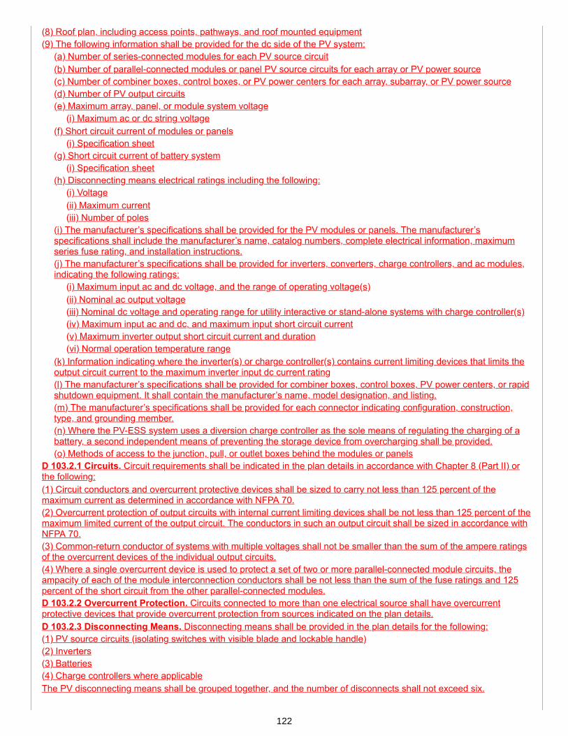
(8) Roof plan, including access points, pathways, and roof mounted equipment(9) The following information shall be provided for the dc side of the PV system:
(a) Number of series-connected modules for each PV source circuit(b) Number of parallel-connected modules or panel PV source circuits for each array or PV power source(c) Number of combiner boxes, control boxes, or PV power centers for each array, subarray, or PV power source(d) Number of PV output circuits(e) Maximum array, panel, or module system voltage
(i) Maximum ac or dc string voltage(f) Short circuit current of modules or panels
(i) Specification sheet(g) Short circuit current of battery system
(i) Specification sheet(h) Disconnecting means electrical ratings including the following:
(i) Voltage(ii) Maximum current(iii) Number of poles
(i) The manufacturer’s specifications shall be provided for the PV modules or panels. The manufacturer’sspecifications shall include the manufacturer’s name, catalog numbers, complete electrical information, maximumseries fuse rating, and installation instructions.(j) The manufacturer’s specifications shall be provided for inverters, converters, charge controllers, and ac modules,indicating the following ratings:
(i) Maximum input ac and dc voltage, and the range of operating voltage(s)(ii) Nominal ac output voltage(iii) Nominal dc voltage and operating range for utility interactive or stand-alone systems with charge controller(s)(iv) Maximum input ac and dc, and maximum input short circuit current(v) Maximum inverter output short circuit current and duration(vi) Normal operation temperature range
(k) Information indicating where the inverter(s) or charge controller(s) contains current limiting devices that limits theoutput circuit current to the maximum inverter input dc current rating(l) The manufacturer’s specifications shall be provided for combiner boxes, control boxes, PV power centers, or rapidshutdown equipment. It shall contain the manufacturer’s name, model designation, and listing.(m) The manufacturer’s specifications shall be provided for each connector indicating configuration, construction,type, and grounding member.(n) Where the PV-ESS system uses a diversion charge controller as the sole means of regulating the charging of abattery, a second independent means of preventing the storage device from overcharging shall be provided.(o) Methods of access to the junction, pull, or outlet boxes behind the modules or panels
D 103.2.1 Circuits. Circuit requirements shall be indicated in the plan details in accordance with Chapter 8 (Part II) orthe following:(1) Circuit conductors and overcurrent protective devices shall be sized to carry not less than 125 percent of themaximum current as determined in accordance with NFPA 70.(2) Overcurrent protection of output circuits with internal current limiting devices shall be not less than 125 percent of themaximum limited current of the output circuit. The conductors in such an output circuit shall be sized in accordance withNFPA 70.(3) Common-return conductor of systems with multiple voltages shall not be smaller than the sum of the ampere ratingsof the overcurrent devices of the individual output circuits.(4) Where a single overcurrent device is used to protect a set of two or more parallel-connected module circuits, theampacity of each of the module interconnection conductors shall be not less than the sum of the fuse ratings and 125percent of the short circuit from the other parallel-connected modules.D 103.2.2 Overcurrent Protection. Circuits connected to more than one electrical source shall have overcurrentprotective devices that provide overcurrent protection from sources indicated on the plan details.D 103.2.3 Disconnecting Means. Disconnecting means shall be provided in the plan details for the following:(1) PV source circuits (isolating switches with visible blade and lockable handle)(2) Inverters(3) Batteries(4) Charge controllers where applicableThe PV disconnecting means shall be grouped together, and the number of disconnects shall not exceed six.
122

D 103.2.4 Grounding. Grounding shall be indicated in the plan details as follows:(1) Where components of the system are negatively or positively grounded(2) The dc circuit grounding shall be made at a single point on the PV output circuit.(3) The equipment-grounding conductor for a PV source and PV output circuits for a roof mounted dc PV array indwellings shall be sized in accordance with NFPA 70.(4) Grounding electrode system used for the ac, dc, or combined ac/dc systems(5) The method used to ensure the removal of equipment from the system that shall not disconnect the bondingconnection between the grounding electrode conductors and exposed conducting surfaces(6) The method used to ensure the removal of a utility-interactive inverter or other equipment that shall not disconnectthe bonding connection between the grounding electrode conductor and the PV source and the output circuit groundedconductor, or both(7) The ground rod details shall be provided. See Figure D 103.2.4 for an example of ground rod details.
FIGURE D 103.2.4SUPPLEMENTAL GROUND ROD DETAIL
D 103.2.5 Ground-Fault Protection. Direct-current ground-fault protection for dwellings with roof mounted dc PV arraysshall be provided on the plan details.D 103.2.6 Systems Over 1000 Volts. Plan details for PV systems over 1000 volts shall indicate the following:(1) The PV system is in accordance with Chapter 8 or NFPA 70, and other applicable installation requirements.(2) The voltage rating of a battery circuit cable shall not be smaller than the charging or equalizing condition of thebattery system.D 103.2.7 Calculations. Calculations shall be provided for solar PV systems in accordance with the following:(1) The maximum system voltage calculation shall be based on the following:
(a) Extreme annual mean minimum design dry bulb temperature in accordance with ASHRAE Handbook –Fundamentals, and(b) Correction factors for ambient temperatures in accordance with Table 804.1.1 or NFPA 70.
(2) The maximum system open-voltage calculation shall be based on the maximum PV system dc voltage (600 V) forPV power source modules made of materials other than crystalline or multi-crystalline silicon.
(a) For PV systems with dc-to-dc converters:(i) The maximum number of dc-to-dc converters in a series shall be calculated based on manufacturer’sinstructions, or(ii) For multiple dc-to-dc converters in series, the sum of the maximum voltage output of the dc-to-dc converteroutputs in the series.
(b) For PV systems without dc-to-dc converters using the following formula: VMAX = VOC, Module x NM x CF (Equation D 103.2.7)
123

Where:CF = Correction factor as determined in accordance with Section D 103.2.7 (1)(b)VMAX = Maximum voltage (V)VOC, Module = Maximum open circuit voltage per module (V)NM = Number of modules in series
(3) The maximum dc circuit current calculation for each PV source circuit(4) The maximum dc current calculation for each PV output circuit(5) The fault current calculation from the utility side to the ac disconnect(s) and inverter(s)(6) Calculations to determine the minimum overcurrent protection device rating for the dc side. Photovoltaic systemcurrents shall be considered as continuous.(7) Calculations showing the size of equipment-grounding conductor for the PV source and PV output circuit size shallbe not less than 125 percent of the short circuit current from the PV source.(8) Calculations showing the required maximum charging current of the interconnected battery cells(9) Calculations for the ampacity of the neutral conductor of a two-wire inverter output connected to the ungroundedconductors of a three-wire or a three-phase, four-wire system(10) Calculations showing that the total dc leakage current in the dc ground or dc grounded circuits in non-isolated PVsystems do not exceed the equipment ground-fault protective device leakage current trip setting(11) Calculations showing the required current and voltage ratings of dc diversion charge controllers and diversion loadsin a circuit(12) Calculations showing the required conductor ampacity and overcurrent protective device rating for circuitscontaining dc diversion charge controllers and diversion loads(13) Calculations showing where expansion fittings are not required for the roof mounted raceways due to thermalexpansion or building expansion joints where the raceway is used as an equipment grounding conductorD 103.3 Energy Storage System (ESS) Details. The following shall be provided with the plan details of an ESS:(1) Scope of the project, including the system kW rating and system architecture. (i.e. dc or ac coupled, etc).(2) Complete single line diagram including the following:
(a) Utility point of interconnection in accordance with Section 822.2 or NFPA 70(b) Disconnecting means in accordance with Chapter 8 (Part III) or NFPA 70(c) All relevant new and existing circuits including, but not limited to, conductor, conduit size, type, and number ofconductors(d) Overcurrent protective device rating(e) Enclosure type maximum ratings in accordance with NEMA 250(f) Model numbers for new and existing service equipment(g) Applicable facility loads that are not backed up(h) Backup loads(i) Grounding and bonding detail(j) Combiner boxes and MIDs
(3) A site plan identifying the location of system components including, but not limited to, the following:(a) Name and address of the property(b) Legend or key for the site plan(c) Plan view of the site(d) Cross streets(e) Property line(f) Gates or fences(g) Clearance from obstructions(h) Clearance from property lines(i) North Arrow(j) Equipment on the wall(k) Disconnecting means(l) Service drop location and overhead conductors as required by the Authority Having Jurisdiction(m) Trench locations containing ESS circuits(n) Location of hidden hazards including, but not limited to, trenched or exposed overhead conductors
124
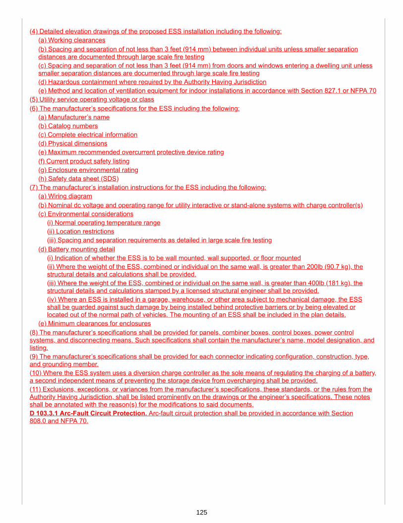
(4) Detailed elevation drawings of the proposed ESS installation including the following:(a) Working clearances(b) Spacing and separation of not less than 3 feet (914 mm) between individual units unless smaller separationdistances are documented through large scale fire testing(c) Spacing and separation of not less than 3 feet (914 mm) from doors and windows entering a dwelling unit unlesssmaller separation distances are documented through large scale fire testing(d) Hazardous containment where required by the Authority Having Jurisdiction(e) Method and location of ventilation equipment for indoor installations in accordance with Section 827.1 or NFPA 70
(5) Utility service operating voltage or class(6) The manufacturer’s specifications for the ESS including the following:
(a) Manufacturer’s name(b) Catalog numbers(c) Complete electrical information(d) Physical dimensions(e) Maximum recommended overcurrent protective device rating(f) Current product safety listing(g) Enclosure environmental rating(h) Safety data sheet (SDS)
(7) The manufacturer’s installation instructions for the ESS including the following:(a) Wiring diagram(b) Nominal dc voltage and operating range for utility interactive or stand-alone systems with charge controller(s)(c) Environmental considerations
(i) Normal operating temperature range(ii) Location restrictions(iii) Spacing and separation requirements as detailed in large scale fire testing
(d) Battery mounting detail(i) Indication of whether the ESS is to be wall mounted, wall supported, or floor mounted(ii) Where the weight of the ESS, combined or individual on the same wall, is greater than 200lb (90.7 kg), thestructural details and calculations shall be provided.(iii) Where the weight of the ESS, combined or individual on the same wall, is greater than 400lb (181 kg), thestructural details and calculations stamped by a licensed structural engineer shall be provided.(iv) Where an ESS is installed in a garage, warehouse, or other area subject to mechanical damage, the ESSshall be guarded against such damage by being installed behind protective barriers or by being elevated orlocated out of the normal path of vehicles. The mounting of an ESS shall be included in the plan details.
(e) Minimum clearances for enclosures(8) The manufacturer’s specifications shall be provided for panels, combiner boxes, control boxes, power controlsystems, and disconnecting means. Such specifications shall contain the manufacturer’s name, model designation, andlisting.(9) The manufacturer’s specifications shall be provided for each connector indicating configuration, construction, type,and grounding member.(10) Where the ESS system uses a diversion charge controller as the sole means of regulating the charging of a battery,a second independent means of preventing the storage device from overcharging shall be provided.(11) Exclusions, exceptions, or variances from the manufacturer’s specifications, these standards, or the rules from theAuthority Having Jurisdiction, shall be listed prominently on the drawings or the engineer’s specifications. These notesshall be annotated with the reason(s) for the modifications to said documents.D 103.3.1 Arc-Fault Circuit Protection. Arc-fault circuit protection shall be provided in accordance with Section808.0 and NFPA 70.
125
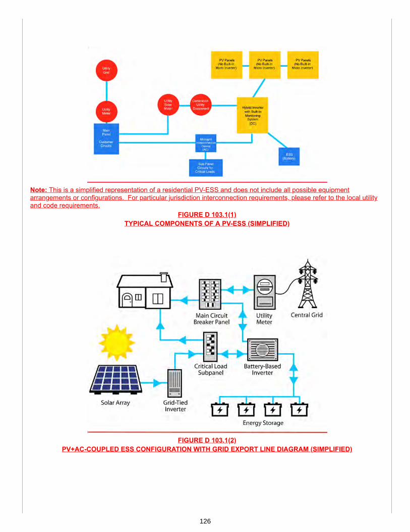
Note: This is a simplified representation of a residential PV-ESS and does not include all possible equipmentarrangements or configurations. For particular jurisdiction interconnection requirements, please refer to the local utilityand code requirements.
FIGURE D 103.1(1)TYPICAL COMPONENTS OF A PV-ESS (SIMPLIFIED)
FIGURE D 103.1(2)PV+AC-COUPLED ESS CONFIGURATION WITH GRID EXPORT LINE DIAGRAM (SIMPLIFIED)
126

Note: This diagram represents one configuration of PV-ESS which does not feed excess energy to the utility grid.Equipment arrangements and configurations may vary.
FIGURE D 103.1(3)PV+DC-COUPLED ESS CONFIGURATION WITHOUT GRID EXPORT (SIMPLIFIED)
Note: This diagram represents one configuration of PV-ESS which feeds excess energy to the utility grid. Equipmentarrangements and configurations may vary.
FIGURE D 103.1(4)PV+DC-COUPLED ESS CONFIGURATION WITH GRID EXPORT (SIMPLIFIED)
127
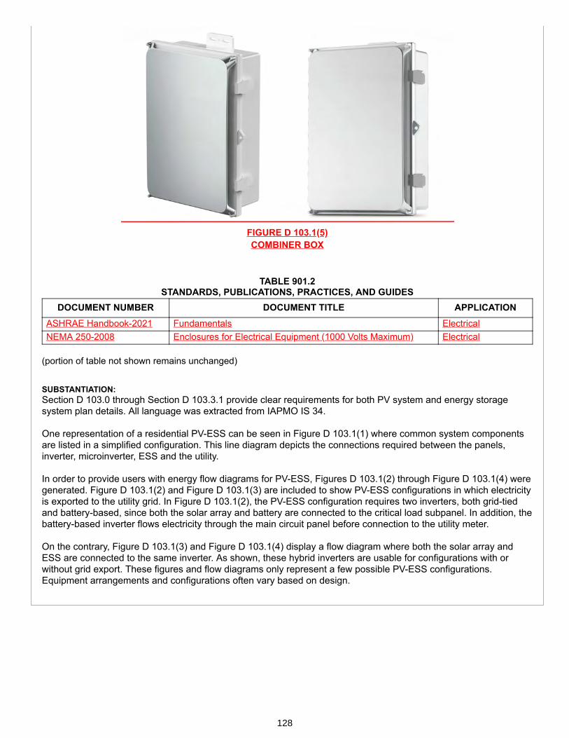
FIGURE D 103.1(5)COMBINER BOX
TABLE 901.2 STANDARDS, PUBLICATIONS, PRACTICES, AND GUIDES
DOCUMENT NUMBER DOCUMENT TITLE APPLICATIONASHRAE Handbook-2021 Fundamentals ElectricalNEMA 250-2008 Enclosures for Electrical Equipment (1000 Volts Maximum) Electrical
(portion of table not shown remains unchanged)
SUBSTANTIATION:Section D 103.0 through Section D 103.3.1 provide clear requirements for both PV system and energy storagesystem plan details. All language was extracted from IAPMO IS 34.
One representation of a residential PV-ESS can be seen in Figure D 103.1(1) where common system componentsare listed in a simplified configuration. This line diagram depicts the connections required between the panels,inverter, microinverter, ESS and the utility.
In order to provide users with energy flow diagrams for PV-ESS, Figures D 103.1(2) through Figure D 103.1(4) weregenerated. Figure D 103.1(2) and Figure D 103.1(3) are included to show PV-ESS configurations in which electricityis exported to the utility grid. In Figure D 103.1(2), the PV-ESS configuration requires two inverters, both grid-tiedand battery-based, since both the solar array and battery are connected to the critical load subpanel. In addition, thebattery-based inverter flows electricity through the main circuit panel before connection to the utility meter.
On the contrary, Figure D 103.1(3) and Figure D 103.1(4) display a flow diagram where both the solar array andESS are connected to the same inverter. As shown, these hybrid inverters are usable for configurations with orwithout grid export. These figures and flow diagrams only represent a few possible PV-ESS configurations.Equipment arrangements and configurations often vary based on design.
128

Proposals
Edit Proposal
Item #: 103
USHGC 2024 Section: D 104.0 - D 104.3, Figure D 104.2.2(1) - Figure D 104.2.2(14), Table 901.2
SUBMITTER: Amir TabakhCity of LA Department of Water and Power
RECOMMENDATION:Add new text
D 104.0 Installation Requirements.D 104.1 General. PV systems installed on a structure or rack shall be in accordance with Section D 104.2 throughSection D 104.2.3.1. Ground-mounted PV systems shall be in accordance with Section D 104.3.D 104.2 Residential Systems – One- and Two-Unit Residential Dwellings. Plan review shall be required, inaccordance with the Authority Having Jurisdiction and the utility, where a PV system is installed on a structure or a rack.D 104.2.1 Solar Zones. Where new construction of a one- or two-unit residential dwelling is installed with a solar zone,the solar zone shall be in accordance with the Authority Having Jurisdiction and the following:(1) Unshaded and free from obstructions(2) Located 90 degrees to 270 degrees true north(3) For roof areas not less than 600 square feet (55.74 m2), the solar zone shall be not less than 300 square feet (27.87 m2) exclusive of the setback requirements in Section D 104.2.2.3.1.Exception: Where a roof area is not less than 600 square feet (55.74 m2) and has less than 70 percent annual solaraccess, the solar zone shall not be less than 50 percent of the potential solar zone.D 104.2.2 Access, Pathways, and Setbacks. Roof access shall be provided in accordance with Section D 104.2.2.1.Pathways and setbacks shall be in accordance with Section D 104.2.2.2 through Section D 104.2.2.3.1. See Figure D104.2.2(1) through Figure D 104.2.2(14) for illustrations of pathways, setbacks, and access.
For SI units: 1 foot = 304.8 mm
FIGURE D 104.2.2(1)PATHWAYS AND SETBACKS ON CROSS GABLE ROOF
129

For SI units: 1 foot = 304.8 mm
FIGURE D 104.2.2(2)PATHWAYS AND SETBACKS ON CROSS GABLE ROOF WITH VALLEY
For SI units: 1 foot = 304.8 mm
FIGURE D 104.2.2(3)PATHWAYS AND SETBACKS ON FULL GABLE ROOF
130

For SI units: 1 foot = 304.8 mm
FIGURE D 104.2.2(4)PATHWAYS AND SETBACKS ON FULL HIP ROOF
For SI units: 1 foot = 304.8 mm
FIGURE D 104.2.2(5)PATHWAYS ACCOUNTING FOR OBSTRUCTIONS
131

For SI units: 1 foot = 304.8 mm
FIGURE D 104.2.2(6)FIRE ACCESS AND SETBACKS
For SI units: 1 foot = 304.8 mm
FIGURE D 104.2.2(7)PATHWAYS AND SETBACKS WHERE PV MODULES OCCUPY LESS THAN 1/3 OF ROOF AREA
(DRIVEWAY ACCESS)
132
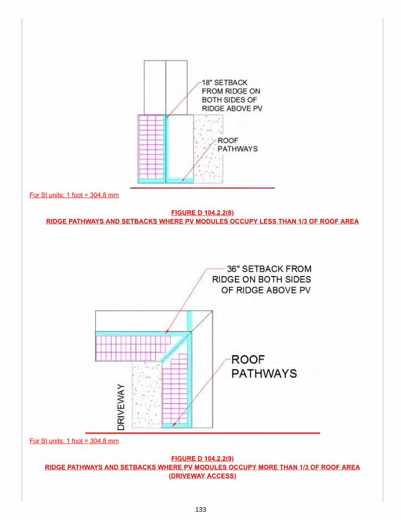
For SI units: 1 foot = 304.8 mm
FIGURE D 104.2.2(8)RIDGE PATHWAYS AND SETBACKS WHERE PV MODULES OCCUPY LESS THAN 1/3 OF ROOF AREA
For SI units: 1 foot = 304.8 mm
FIGURE D 104.2.2(9)RIDGE PATHWAYS AND SETBACKS WHERE PV MODULES OCCUPY MORE THAN 1/3 OF ROOF AREA
(DRIVEWAY ACCESS)
133

For SI units: 1 foot = 304.8 mm
FIGURE D 104.2.2(10)HIP, VALLEY, AND RIDGE PATHWAYS AND SETBACKS WHERE PV MODULES OCCUPY MORE THAN 1/3 OF
ROOF AREA (ALTERNATE DRIVEWAY ACCESS)
For SI units: 1 foot = 304.8 mm
FIGURE D 104.2.2(11)RIDGE PATHWAYS AND SETBACKS WHERE PV MODULES OCCUPY MORE THAN 1/3 OF ROOF AREA
(STREET ACCESS)
134

For SI units: 1 foot = 304.8 mm
FIGURE D 104.2.2(12)RIDGE PATHWAYS AND SETBACKS WHERE PV MODULES OCCUPY MORE THAN 1/3 OF ROOF AREA
For SI units: 1 foot = 304.8 mm
FIGURE D 104.2.2(13)RIDGE PATHWAYS AND SETBACKS ACCOUNTING FOR OBSTRUCTIONS
135

For SI units: 1 foot = 304.8 mm
FIGURE D 104.2.2(14)RIDGE PATHWAYS AND SETBACKS ACCOUNTING FOR LARGE OBSTRUCTIONS
D 104.2.2.1 Access. Roof access for emergency services shall be provided to pathways specified in Section D104.2.2.2 or Section D 104.2.2.3 and shall be located in areas without obstructions. Roof access points and laddersshall be located over areas which do not block windows, doors, or other openings. Minimal spacing for smoke ventilationshall be in accordance with Section D 104.2.3.D 104.2.2.2 Pathways – Flat Roofs. Where roofs are installed with slopes less than two units vertical in twelve unitshorizontal (2:12), a 3 foot (914 mm) wide clear pathway shall be provided around the perimeter of the roof plane.Pathways shall be located over areas capable of supporting the live load of fire fighters with all associated gear.D 104.2.2.3 Pathways – Sloped Roofs. Where roofs are installed with slopes not less than two units vertical in twelveunits horizontal (2:12), pathways shall be provided in accordance with the following:(1) There shall be not less than one 3 foot (914 mm) wide pathway provided for each roof plane where a module isinstalled. The pathway shall be located from the eave to the ridge on the same roof plane as the modules, straddling thesame and adjacent plane, or on an adjacent plane.(2) Modules, on a roof with a ridge, shall be located in a manner that provides two separate 3 foot (914 mm) widepathways from the eave to the ridge on separate roof planes.(3) Modules, adjacent to hips and valleys, shall be located not less than 18 inches (457 mm) from a hip or a valleywhere modules are to be placed on both sides of a hip or valley. Where modules are to be located on one side of a hipor valley that is of equal length, modules shall be permitted to be placed directly adjacent to the hip or valley.(4) There shall be not less than one pathway provided on the driveway or street side of the roof.(5) Pathways shall be located in areas with minimal obstructions (e.g. chimneys, vents, conduit, and mechanicalequipment).D 104.2.2.3.1 Alternate Setback at Ridge. Both sides of a horizontal ridge shall have an unobstructed setback inaccordance with the following:(1) Where PV arrays occupy more than one-third of the total plan view roof area, a 3 foot (914 mm) wide setback shallbe required.(2) Where PV arrays occupy not more than one-third of the total plan view roof area, a setback of not less than 18inches (457 mm) wide shall be required.Exceptions:(1) Where an automatic sprinkler system in accordance with NFPA 13D is installed and PV arrays occupy not more thantwo-thirds of the total plan view roof area, a setback of not less 18 inches (457 mm) wide shall be required.
136

(2) Where an automatic sprinkler system in accordance with NFPA 13D is installed and PV arrays occupy more thantwo-thirds of the total plan view roof area, a setback of not less 3 feet (914 mm) wide shall be required.D 104.2.3 Distance to Plumbing Vents. Where PV panels are installed above a plumbing vent or stack, each vent pipeor stack shall extend through its flashing and shall terminate vertically not less than 6 inches (152 mm) above the roofnor less than 1 foot (305 mm) from a vertical surface, or shall be in accordance with the requirements of the AuthorityHaving Jurisdiction.D 104.2.3.1 Locations in Snow Regions. Where frost or snow closure is likely to occur in locations having a minimumdesign temperature below 0°F (-17.8°C), the installation of a solar panel shall be in accordance with one of the following:(1) The solar panel shall be placed such that the plumbing vent does not terminate under the panel.(2) The vent shall be diverted such that it is not under the solar panel. The change in direction shall be made inside thebuilding not less than 1 foot (305 mm) below the roof in an insulated space and terminate not less than 10 inches (254mm) above the roof and 6 inches (152 mm) from a solar panel, or in accordance with the Authority Having Jurisdiction.D 104.3 Ground-Mounted Panel Systems. Plan review shall be required in accordance with the Authority HavingJurisdiction and the utility where a ground-mounted PV system is installed. See Section D 503.0 for a site plan sampleof a residential ground-mounted PV-ESS. Setback requirements shall not apply to ground-mounted and freestanding PV arrays. A clearance of not less than10 feet (3048 mm) shall be required around ground-mounted PV arrays. Installation and guarding of readily accessible PV source and output circuits, which operate at greater than 30volts, shall be in accordance with Section 812.1 or NFPA 70.
TABLE 901.2 STANDARDS, PUBLICATIONS, PRACTICES, AND GUIDES
DOCUMENT NUMBER DOCUMENT TITLE APPLICATIONNFPA 13D-2022 Installation of Sprinkler Systems in One- and Two-Family
Dwellings and Manufactured HomesFire Safety
(portion of table not shown remains unchanged)
SUBSTANTIATION:Section D 104.0 through Section D 104.3 provide clear requirements for the installation of residential PV systems.Such requirements address determination of solar zones as well as roof access, pathways, setbacks, andclearances from plumbing vents. Installation requirements for ground mounted PV systems have also beenincluded. All language and figures were extracted from IAPMO IS 34.
Since roof construction varies, it was necessary to provide explanatory figures defining correct access, pathways,and setbacks on roofs. Additional clarification was also provided, via these figures, on how to ensure adequateaccess while accounting for roof obstructions and penetrations.
137

Proposals
Edit Proposal
Item #: 104
USHGC 2024 Section: D 105.0 - D 105.3.1
SUBMITTER: Amir TabakhCity of LA Department of Water and Power
RECOMMENDATION:Add new text
D 105.0 Marking and Labeling.D 105.1 General. Photovoltaic (PV) systems shall be marked. Materials used for markings shall be weather resistantand capable of withstanding continuous exposure to sunlight.D 105.2 Main Service Disconnect. Markings shall be permitted to be placed within the main service disconnect. Wherethe main service disconnect is operable with the service panel closed, the marking shall be placed on the outside cover.D 105.2.1 Marking Content and Format. Marking content and format for main service disconnects shall comply withthe following:(1) Marking content in accordance with NFPA 70(2) Red background(3) White lettering(4) Minimum 3/8 of an inch (9.5 mm) letter height(5) Capital letters(6) Arial or similar font, non-bold(7) Reflective, weather-resistant material (durable adhesive materials shall meet this requirement)D 105.3 Marking for DC Conduit, Raceways, Enclosures, Cable Assemblies, and Junction Boxes. Markings shallbe required on interior and exterior dc conduit, raceways, enclosures, cable assemblies, and junction boxes. Markingsshall be placed on interior and exterior dc conduit, raceways, enclosures, and cable assemblies every 10 feet (3048mm), at turns; on both sides of a penetration; and at dc combiner and junction boxes.D 105.3.1 Marking Content and Format. Marking content and format for dc conduit, raceways, enclosures, cableassemblies, and junction boxes shall comply with the following:(1) Marking content in accordance with NFPA 70(2) Red background(3) White lettering(4) Minimum 3/8 of an inch (9.5 mm) letter height(5) Capital letters(6) Arial or similar font, non-bold(7) Reflective, weather-resistant material (durable adhesive materials shall meet this requirement)
SUBSTANTIATION:Section D 105.0 through Section D 105.3.1 provide the necessary requirements for marking and labeling of PVsystems. The proposed language addresses markings for main service disconnect, DC conduit, raceways,enclosures, cable assemblies, and junction boxes. Specifications have also been provided for marking content, font,and format. All language was extracted from IAPMO IS 34.
138
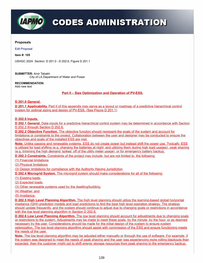
Proposals
Edit Proposal
Item #: 105
USHGC 2024 Section: D 201.0 - D 202.6, Figure D 201.1
SUBMITTER: Amir TabakhCity of LA Department of Water and Power
RECOMMENDATION:Add new text
Part II – Size Optimization and Operation of PV-ESS. D 201.0 General.D 201.1 Applicability. Part II of this appendix may serve as a layout or roadmap of a predictive hierarchical controlsystem for optimal sizing and design of PV-ESS. (See Figure D 201.1) D 202.0 Inputs.D 202.1 General. Data inputs for a predictive hierarchical control system may be determined in accordance with SectionD 202.2 through Section D 202.6.D 202.2 Objective Function. The objective function should represent the goals of the system and account forlimitations or constraints to the project. Collaboration between the user and designer may be conducted to ensure theobjectives and goals of the installed ESS are met.Note: Unlike passive and renewable systems, ESS do not create power but instead shift the power use. Typically, ESSis utilized for load shifting (e.g. charging the batteries at night, and utilizing them during high load usages), peak shaving(e.g. trimming the high demand ‘spikes’ off of the utility meter usage), or for emergency battery backup.D 202.3 Constraints. Constraints of the project may include, but are not limited to, the following:(1) Financial limitations(2) Physical limitations(3) Design limitations for compliance with the Authority Having JurisdictionD 202.4 Microgrid System. The microgrid system should make considerations for all of the following:(1) Existing loads,(2) Expected loads,(3) Other renewable systems used by the dwelling/building,(4) Weather, and(5) Irradiance.D 202.5 High Level Planning Algorithm. The high level planning should utilize the learning-based global horizontalirradiance (GHI) prediction models and load predictions to find the best high level operation strategy. The strategyshould update frequently, and the system should continue to adjust due to changing goals or restrictions in accordancewith the low level planning algorithm in Section D 202.6.D 202.6 Low Level Planning Algorithm. The low level planning should account for adjustments due to changing goalsor restrictions to the system. Adjustments may be made to meet these goals, by the minute, by the hour, or as deemednecessary by the user. Considerations should be made for the initial design of the system to ensure systemoptimization. The low level planning algorithm should assist with commission of the ESS and ensure functioning meetsthe needs of the user.Note: The low level planning algorithm may be adjusted either manually or through the use of software. For example, ifthe system was designed to meet the needs of peak shaving and the user was experiencing more rolling blackouts thanexpected, then the customer might opt to shift energy storage resources from peak shaving to the emergency backup.
139

Note: The low level algorithm shown addresses short-term adjustments required for all of the following:(1) Constraints,(2) GHI predictions,(3) Load predictions, and(4) Objective functions.
FIGURE D 201.1LAYOUT FOR PREDICTIVE HIERARCHICAL CONTROL SYSTEM
SUBSTANTIATION:One of the most innovative concepts listed in IAPMO IS 34, and now in Appendix D, can be found in Part II (SizeOptimization and Operation of PV-ESS) where a layout or roadmap of a PV-ESS hierarchical control system isprovided. (See Figure D 201.1)
This layout includes both high- and low-level planning algorithms to make prediction models that find the mostoptimal operation strategies and concurrently adjust for changing user goals and restrictions. Since ESS is utilizedfor load shifting rather than power generation, the specific goals of the system, as well as the various constraints,must be identified and considered when implementing this type of control system.
140

Proposals
Edit Proposal
Item #: 106
USHGC 2024 Section: D 301.0 - D 306.1, Table 901.2
SUBMITTER: Amir TabakhCity of LA Department of Water and Power
RECOMMENDATION:Add new text
Part III – Best Practices for Electrical Work Safety. D 301.0 General.D 301.1 Applicability. The requirements for safe work practices during electrical installations shall be in accordancewith Part III of this appendix, or NFPA 70E, whichever is more stringent. D 302.0 Preventative Maintenance.D 302.1 General. Maintenance on electrical equipment shall be completed by qualified persons and in accordance withthe manufacturer’s instructions. The equipment owner shall be responsible for maintenance and documentation. Aqualified person(s) shall be as defined in accordance with Chapter 8 or NFPA 70. D 303.0 Arc Flash.D 303.1 General. Arc flash risk assessment shall be in accordance with Section D 303.2. Calculations shall bedetermined in accordance with Section D 303.3. Training and audits shall be in accordance with Section D 303.4.Documentation shall be in accordance with Section D 303.5.D 303.2 Risk Assessment. Arc flash risk assessment shall be completed prior to allowing a worker to perform tasks onenergized equipment. Arc flash risk assessments shall be competed not less than once every five years to account forchanges in the distribution system. In the event of a major modification or renovation, an updated arc flash riskassessment shall be conducted.Note: The latest versions of NFPA 70E limit the use of shock protection approach boundary tables when determining arcflash boundaries and strongly encourage the use of engineering analysis, preferably conducted by a ProfessionalEngineer.D 303.3 Calculations. Arc flash calculations shall be determined using accurate short circuit calculations and protectivedevice coordination data.Note: Activities performed during short circuit and coordination studies include all of the following:(1) Calculating the maximum momentary and interrupting current magnitudes,(2) Comparing these available fault currents to protective device ratings, and(3) Establishing trip settings for all types of protective devices.D 303.4 Training and Audits. An arc flash training program along with a personal protective equipment (PPE) planshall be provided by the employer based on analysis in accordance with Section D 303.2 and Section D 303.3.Individual workers shall undergo annual reviews and audits to ensure compliance with safety practices. Facilities shallaudit their safety policies not less than once every three years.Note: Audits help to identify any deficiencies or areas of non-compliance allowing the facility to make necessaryrevisions and bring all elements of the safety program up to code.D 303.5 Documentation. Documentation shall include, but not be limited to, the following:(1) Arc flash analysis results(2) Meetings with employees to share hazard information(3) Worker training activities
141

(4) Individual worker audits(5) Maintenance activities(6) Safety policy auditsNote: Such documentation may help facilitate an investigation in the event of an arc flash related injury. D 304.0 Protection Scheme Design – Operational Assessment.D 304.1 General. A protection scheme design review and operational assessment of the electrical distribution systemshall be completed.Note: Such design and assessment may help identify and reduce potential electrical hazards. Based on the results ofthe review, experts may help develop mitigation strategies to alter the protection scheme and significantly reduce faultlevels, arcing time, arc incident energy, and arc blast force. D 305.0 Single-Line DiagramsD 305.1 General. A single-line diagram of the electrical system shall be provided. The line diagram shall be accurate,current, and in legible condition.Note: This requirement may necessitate a comprehensive site review in order to develop or update existing diagrams.The resulting schematics are essential for documenting, troubleshooting, and communicating information about yourpower systems. D 306.0 Labeling and Hazard Communication PlanD 306.1 General. Equipment owners shall be responsible for maintaining the condition and accuracy of labels. Whereac or dc equipment requires maintenance while energized, labels shall be provided and shall include the following:(1) Results of the arc flash risk assessment(2) Information for proper selection of PPE
TABLE 901.2 STANDARDS, PUBLICATIONS, PRACTICES, AND GUIDES
DOCUMENTNUMBER DOCUMENT TITLE APPLICATION
NFPA 70E-2021 Electrical Safety in the Workplace Electrical Safety (portion of table not shown remains unchanged)
SUBSTANTIATION:Part III of this appendix provides necessary requirements for safe work practices during electrical installations. Suchrequirements address preventative maintenance, arc flash prevention/protection, protection scheme design review,and accuracy of single line diagrams for electrical systems.
Since arc flash often results in serious injury and even death when in close proximity to humans, it was pertinent toprovided arc flash protection requirements which entail hazard analysis via risk assessments along with propertraining and audits.
NFPA 70E is appropriate for reference as it addresses electrical safety-related work practices and maintenancerequirements for practical safeguarding of workers relative to the hazards associated with electrical energy duringactivities such as the installation, inspection, operation, maintenance, and demolition of electric conductors, electricequipment, signaling and communications conductors and equipment, and raceways. This standard also includessafe work practices for employees performing other work activities that can expose them to electrical hazards aswell as safe work practices.
Furthermore, all language was extracted from IAPMO IS 34. For these reasons, Appendix D (Part III) is beneficialfor inclusion.
NFPA 70E may be accessed via the following links: https://www.nfpa.org/codes-and-standards/all-codes-and-standards/list-of-codes-and-standards/detail?code=70E
142

Proposals
Edit Proposal
Item #: 107
USHGC 2024 Section: D 401.0 - D 404.1, Figure D 402.1, Figure D 403.1(1) - Figure D 403.1(3), Table D 404.1
SUBMITTER: Amir TabakhCity of LA Department of Water and Power
RECOMMENDATION:Add new text
Part IV - Smart Solar Monitoring Technology.
D 401.0 General.D 401.1 Applicability. Part IV of this appendix applies to smart solar technology installed in tandem with solar PVsystems to be utilized as an energy saving tool.Note: Smart solar monitoring technology provides a means of influencing changes in energy conservation behaviors. D 402.0 Smart Meters.D 402.1 General. Smart meters should be installed in new or retro-fit solar PV systems. See Figure D 402.1 for anexample of a smart meter.Notes:(1) Smart meters provide a means of measuring electrical consumption in real-time rather than only measuring totalconsumption. This facilitates more accurate measurements and better management of energy usage.(2) Residential smart meters commonly come equipped with service switches which allow the utility to remotely enablepower services.(3) Some PV inverter equipment includes integrated smart meters with revenue grade metering. D 403.0 Net Energy Metering.D 403.1 General. Net energy metering may be used to measure the value of energy delivered minus the energyreceived over a specified period of time. See Figure D 403.1(1) through Figure D 403.1(4) for examples of NEM displaysand a net energy flow diagram. D 404.0 Interpretation.D 404.1 General. The display ID shown on a NEM (see Figure D 403.1(2) and Figure D 403.1(3) may be interpretedusing Table D 404.1.
143

FIGURE D 402.1SMART METER
FIGURE D 403.1(1)NET ENERGY METER
FIGURE D 403.1(2)NET ENERGY METER DISPLAY
144
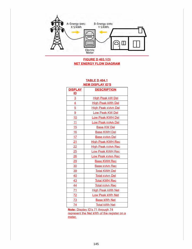
FIGURE D 403.1(3)NET ENERGY FLOW DIAGRAM
TABLE D 404.1 NEM DISPLAY ID’S
DISPLAYID
DESCRIPTION
3 High Peak kW Del4 High Peak kWh Del5 High Peak kVArh Del9 Low Peak KW Del10 Low Peak KWH Del11 Low Peak kVArh Del15 Base KW Del16 Base KWH Del17 Base kVArh Del21 High Peak KWH Rec22 High Peak kVArh Rec25 Low Peak KWH Rec26 Low Peak kVArh Rec29 Base KWH Rec30 Base kVArh Rec39 Total KWH Del40 Total kVArh Del43 Total KWH Rec44 Total kVArh Rec71 High Peak kWh Net72 Low Peak kWh Net73 Base kWh Net74 Total kWh Net
Note: Display ID’s 71 through 74represent the Net kWh of the register on ameter.
145

SUBSTANTIATION:As a result of power distribution and utility demand response, smart solar monitoring devices are commonlyinstalled in tandem with PV systems and serve as energy saving tools. Such technology includes net energymetering and smart meters, which both have the potential to influence changes in energy conservation behaviors.As depicted in Figure D 403.1(3) and Part IV (Smart Solar Monitoring Technology), net energy metering uses a bi-directional meter (e.g. analog, electro-mechanical, smart, radio frequency, etc.) to measure the energy differencebetween the amount supplied by the utility grid and the amount the utility grid receives from user generation.
Smart meters, however, serve a different purpose for solar PV systems in that they provide a means of measuringelectrical consumption in real-time rather than only measuring the total consumption. This allows for more accuratemeasurements and improved management of energy usage.
In addition to smart solar monitoring technology, ESS may be installed and used to collect energy, charging duringpeak sunlight hours and then supplying that energy at night when the PV system generates minimal to no electricity.ESS are commonly installed in combination with renewable energy systems to increase the efficiency andeffectiveness of the overall systems.
146

Proposals
Edit Proposal
Item #: 108
USHGC 2024 Section: D 501.0 - D 502.1
SUBMITTER: Amir TabakhCity of LA Department of Water and Power
RECOMMENDATION:Add new text
Part V - Site Plan Samples
D 501.0 General.D 501.1 Applicability. Part V of this appendix offers sample site plans for residential PV systems.
D 502.0 Site Plan Sample (PV).D 502.1 General. The following is a site plan sample for a residential solar PV system. The sample plan consists of thefollowing:(1) Cover sheet (See sheet number PV-1.0).
(a) Vicinity map(b) Scope of work(c) General notes(d) Legend and abbreviations
(2) Site plan (See sheet number PV-2.0).(a) Roof plan(b) Conduit mounting detail
(3) Layout (See sheet number PV-3.0).(a) Module design criteria
(i) Manufacturer/model number(ii) Dimensions(iii) Clamps(iv) Maximum distributed load(v) Snow load(vi) Wind speed
(b) Module elevation detail(c) Roof type, height, and exposure(d) Roof edge zone(e) Mounting detail(f) Frame material and type(g) Maximum frame span(h) Maximum module overhang
(4) Electrical (See sheet number PV-4.0).(a) Electrical line diagram(b) Conduit schedule(c) Module characteristics(d) Grounding detail(e) Notes to installer
(5) Electrical calculations (See sheet number PV-4.1).(6) Signage (See sheet number PV-5.0).
147

148
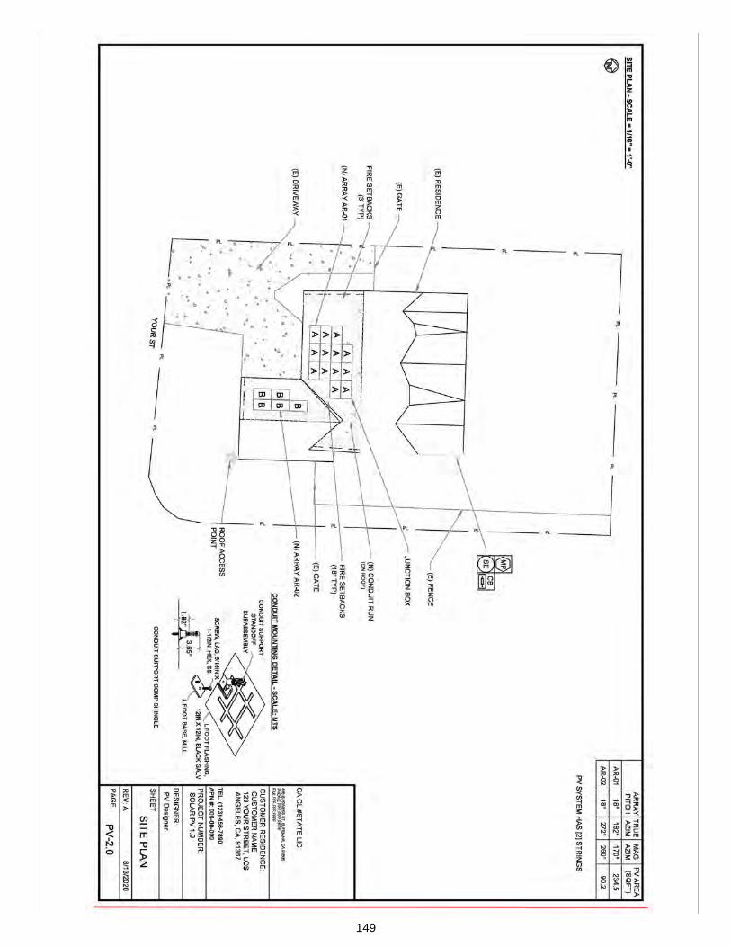
149

150
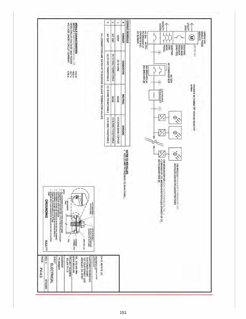
151

152

153

SUBSTANTIATION:Part V of this appendix offers sample site plans for residential PV systems. This proposal includes the sample siteplan for a residential solar PV system. The sample plan includes all information listed in Section 502.1 andreferences the specific sheet numbers for ease use. All information was extracted from IAPMO IS 34.
154

Proposals
Edit Proposal
Item #: 109
USHGC 2024 Section: D 503.0 - D 503.1
SUBMITTER: Amir TabakhCity of LA Department of Water and Power
RECOMMENDATION:Add new text
D 503.0 Site Plan Sample (PV + EV Charging).D 503.1 General. The following is a site plan sample for a residential solar PV system enabled with electrical vehicle(EV) charging. The sample plan consists of the following:(1) Site plan and vicinity map (See sheet number PV-1.0).
(a) Project description(b) Site plan with roof plan(c) House photo(d) Vicinity map(e) Legend
(2) Roof plan and modules (See sheet number PV-2.0).(a) Module type, dimensions, and weight(b) Roof description(c) Array and roof area calculations
(3) Attachment detail (See sheet number PV-3.0).(a) Project details(b) Load assumptions(c) System weight(d) Roof information(e) Span details(f) Reaction forces
(4) Electrical line diagram (See sheet number PV-4.0).(5) Wiring calculations (See sheet number PV-5.0).
(a) Conductor ampacity calculations – junction box to combiner box(b) Conductor ampacity calculations – combiner box to main service panel(c) Microinverter specifications(d) Electrical notes
(6) Placards (See sheet number PV-6.0).(7) Labeling plan (See sheet number PV-7.0).(8) Equipment specifications (See sheet number PV-8.0).
(a) AC electrical specifications(b) DC electrical specifications(c) Operation conditions and safety ratings(d) Mechanical specifications(e) Module dimensions
(9) Stringing diagram (See sheet number PV-9.0).(10) Sticker layout (See sheet number PV-10.0).(11) Site safety plan (See sheet number PV-11.0).
155
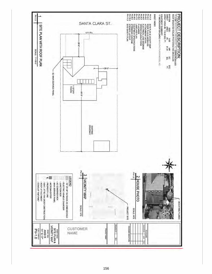
156
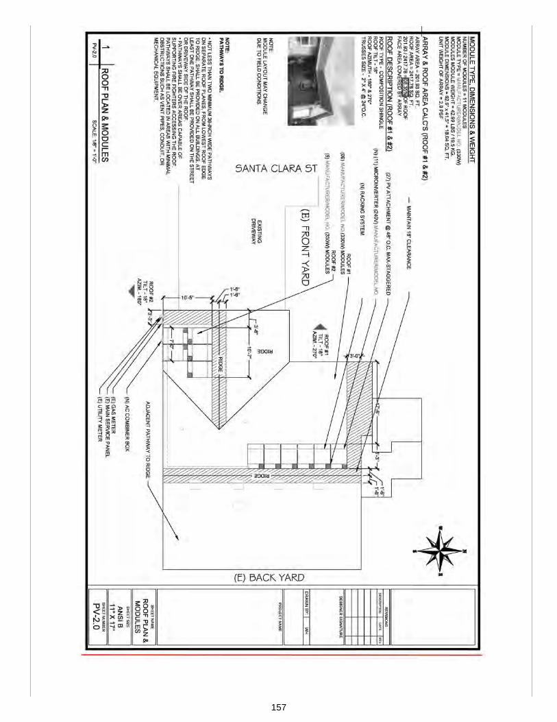
157

158
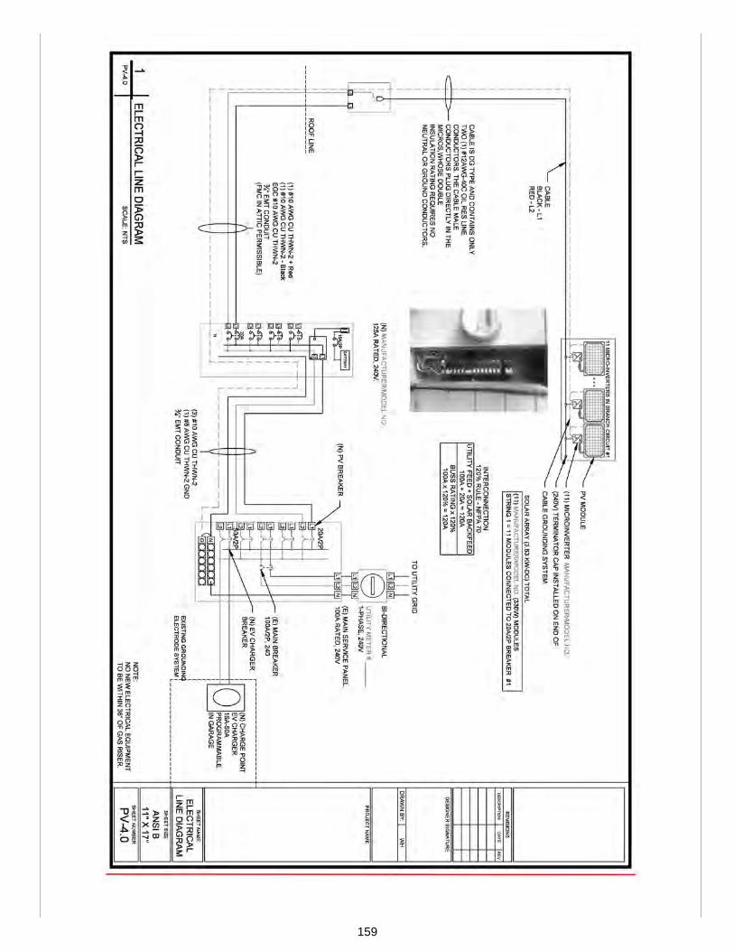
159
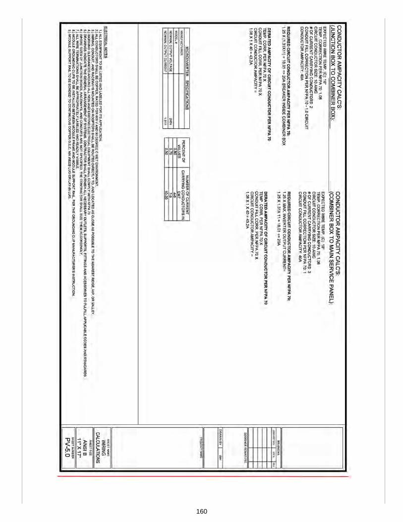
160

161
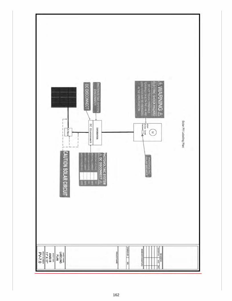
162
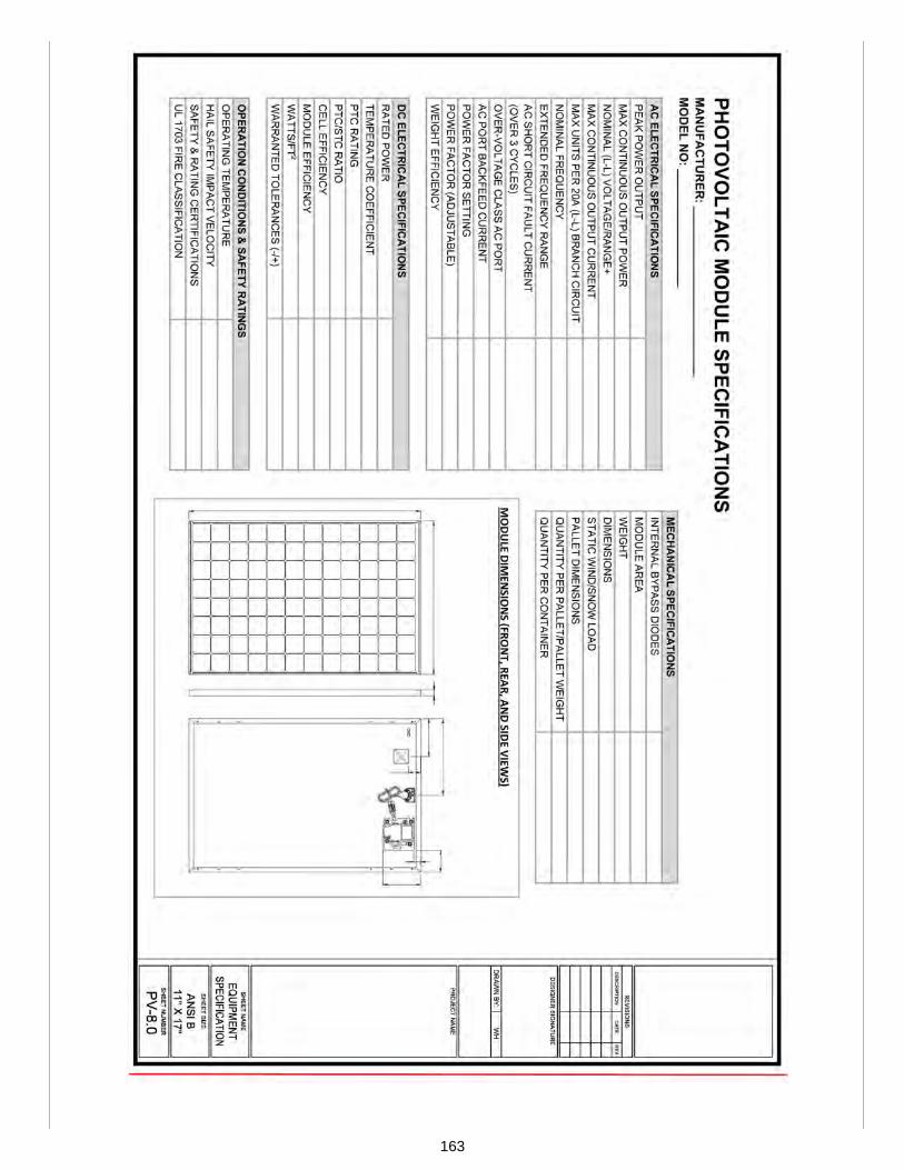
163

164

165

166
SUBSTANTIATION:Part V of this appendix offers sample site plans for residential PV systems. This proposal includes the sample siteplan for a residential solar PV system enabled with electrical vehicle (EV) charging. The sample plan includes allinformation listed in Section 503.1 and references the specific sheet numbers for ease use. All information wasextracted from IAPMO IS 34.
167
Proposals
Edit Proposal
Item #: 110
USHGC 2024 Section: D 504.0 - D 504.1
SUBMITTER: Amir TabakhCity of LA Department of Water and Power
RECOMMENDATION:Add new text
D 504.0 Site Plan Sample (PV-ESS with Whole Home Backup).D 504.1 General. The following is a site plan sample for a residential solar PV system enabled with energy storage andwhole home backup. The sample plan consists of the following:(1) Site plan and vicinity map (See sheet number PV-1.0).
(a) Project description(b) Site plan with roof plan(c) House photo(d) Vicinity map(e) Legend
(2) Roof plan and modules (See sheet number PV-2.0).(a) Module type, dimensions, and weight(b) Roof description(c) Array and roof area calculations(d) Battery type, dimensions, and weight
(3) Attachment detail (See sheet number PV-3.0).(a) Project details(b) Load assumptions(c) System weight(d) Roof information(e) Span details(f) Reaction forces
(4) Electrical line diagram (See sheet number PV-4.0).(5) Wiring calculations (See sheet number PV-5.0).
(a) Conductor ampacity calculations – junction box to combiner box(b) Conductor ampacity calculations – combiner box to main service panel(c) Microinverter specifications(d) Electrical notes
(6) Placards (See sheet number PV-6.0).(7) Labeling plan (See sheet number PV-7.0).(8) Equipment specifications (See sheet number PV-8.0).
(a) AC electrical specifications(b) DC electrical specifications(c) Operation conditions and safety ratings(d) Mechanical specifications(e) Module dimensions
(9) Stringing diagram (See sheet number PV-9.0).(10) Sticker layout (See sheet number PV-10.0).(11) Site safety plan (See sheet number PV-11.0).
168
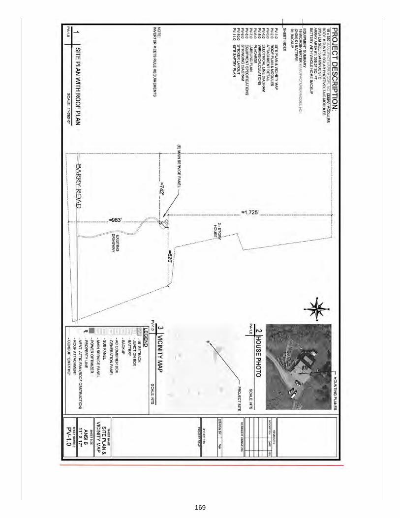
169

170

171

172
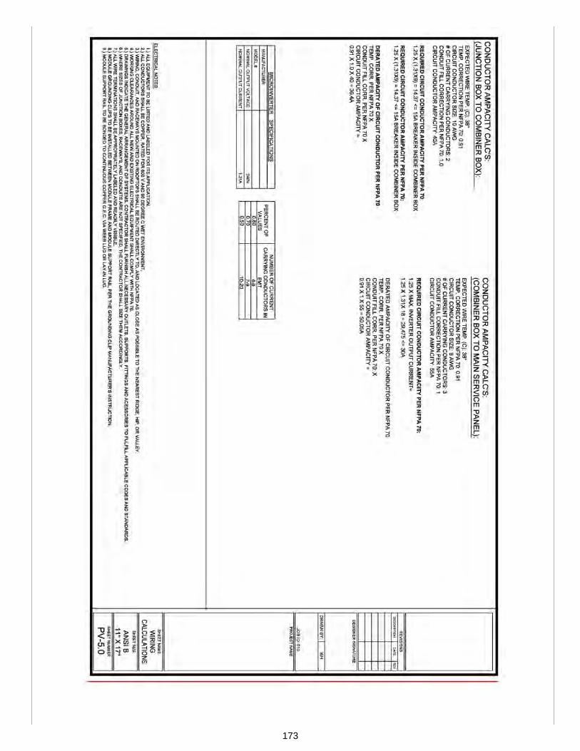
173
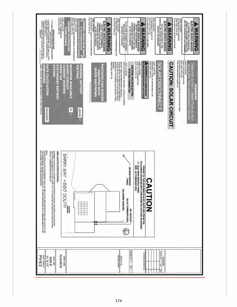
174

175

176

177
178

179

SUBSTANTIATION:Part V of this appendix offers sample site plans for residential PV systems. This proposal includes the sample siteplan for a residential solar PV system enabled with energy storage and whole home backup. The sample planincludes all information listed in Section 504.1 and references the specific sheet numbers for ease use. Allinformation was extracted from IAPMO IS 34.
180

Proposals
Edit Proposal
Item #: 111
USHGC 2024 Section: D 505.0 - D 505.1
SUBMITTER: Amir TabakhCity of LA Department of Water and Power
RECOMMENDATION:Add new text
D 505.0 Site Plan Sample (Ground-Mounted PV-ESS with Whole Home Backup).D 505.1 General. The following is a site plan sample for a ground mounted residential solar PV system enabled withenergy storage and whole home backup. The sample plan consists of the following:(1) Site plan and vicinity map (See sheet number PV-1.0).
(a) Project description(b) Site plan(c) House photo(d) Vicinity map(e) Legend
(2) Roof plan and modules (See sheet number PV-2.0).(a) Project layout(b) Battery type, dimensions, and weight(c) Existing system
(3) Electrical line diagram (See sheet number PV-3.0).(4) Placards (See sheet number PV-4.0).(5) Equipment Specifications
(a) Battery and backup specifications (See sheet number PV-5.0).(i) Performance specifications(ii) Compliance information(iii) Mechanical specifications(iv) Environmental specifications(v) Dimensions
181

182

183
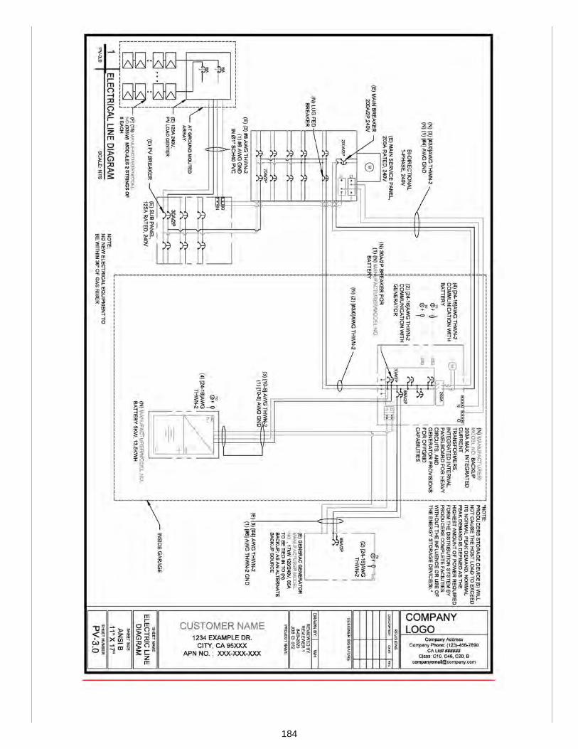
184

185
186

SUBSTANTIATION:Part V of this appendix offers sample site plans for residential PV systems. This proposal includes the sample siteplan for a ground mounted residential solar PV system enabled with energy storage and whole home backup. Thesample plan includes all information listed in Section 505.1 and references the specific sheet numbers for ease use.All information was extracted from IAPMO IS 34.
187

Proposals
Edit Proposal
Item #: 112
USHGC 2024 Section: Appendix B, Table 901.2
SUBMITTER: Jazmin CurielSelf
RECOMMENDATION:Revise text
APPENDIX BCOMMERCIAL SOLAR PHOTOVOLTAIC SYSTEM INSTALLATION GUIDELINES
B 101.0 General. B 101.1 Applicability. This appendix provides installation guidelines for solar PV systems for commercial buildings andresidential housing comprised of three or more units. Provisions contained in these guidelines shall not apply unlessspecifically adopted by local ordinance in accordance with Section 102.8. These guidelines shall not apply to non-habitable structures (e.g., parking shade structures, solar trellises, etc.). B 102.0 Marking.
B 102.2 Main Service Disconnect. For residential applications, the marking shall be permitted to be placed within themain service disconnect. Where the main service disconnect is operable with the service panel closed, the marking shallbe placed on the outside cover. For commercial applications, tThe marking shall be placed adjacent to the main servicedisconnect in a location visible from where the lever is operated.
B 103.0 Access, Pathways, and Smoke Ventilation. B 103.1 General. Access and spacing of PV modules shall comply with Section B 103.2 through Section B 103.3.3 B 103.4.B 103.2 Residential Systems—Single and Two-Unit Residential Dwellings. Plan review shall be required where asystem is installed on more than 50 percent of the roof area of a residential building. See Figure B 103.2(1) throughFigure B 103.2(4). B 103.2.1 Access or Pathways. Access or pathways on the roof shall be provided in accordance with the following: (1) Modules, on a hip roof, shall be located in a manner that provides one 3 foot (914 mm) wide clear access pathwayfrom the eave to the ridge on each roof slope where modules are located. The access pathway shall be located overstructural members. (2) Modules, on a roof with a single ridge, shall be located in a manner that provides two 3 foot (914 mm) wide accesspathways from the eave to the ridge on each roof slope where modules are located. (3) Modules, adjacent to hips and valleys, shall be located not less than 18 inches (457 mm) from a hip or a valleywhere modules are to be placed on both sides of a hip or valley. Where modules are to be located on one side of a hipor valley that is of equal length, modules shall be permitted to be placed directly adjacent to the hip or valley. B 103.2.2 Smoke Ventilation. Smoke ventilation shall be provided by locating modules not more than 3 feet (914 mm)from the lowest level of the ridge. B 103.3 Commercial Buildings and Residential Housing Comprised of Three or More Units. Where the AuthorityHaving Jurisdiction determines that the roof configuration is similar to residential (such as in the case of townhouses,condominiums, or single family attached buildings), the access and ventilation requirements of Section B 103.2 throughSection B 103.2.2 IAPMO IS 34 shall be permitted. See Figure B 103.3(1) B 103.1(1) through Figure B 103.3(4) B 103.1(4). B 103.3.1 B 103.2 Access. (remaining text unchanged) B 103.3.2 B 103.3 Pathways. (remaining text unchanged) B 103.3.3 B 103.4 Smoke Ventilation. (remaining text unchanged)
188
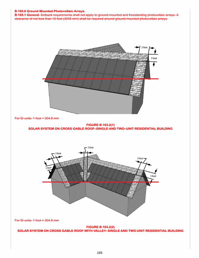
B 105.0 Ground Mounted Photovoltaic Arrays. B 105.1 General. Setback requirements shall not apply to ground-mounted and freestanding photovoltaic arrays. Aclearance of not less than 10 feet (3048 mm) shall be required around ground-mounted photovoltaic arrays.
For SI units: 1 foot = 304.8 mm
FIGURE B 103.2(1) SOLAR SYSTEM ON CROSS GABLE ROOF–SINGLE AND TWO–UNIT RESIDENTIAL BUILDING
For SI units: 1 foot = 304.8 mm
FIGURE B 103.2(2) SOLAR SYSTEM ON CROSS GABLE ROOF WITH VALLEY–SINGLE AND TWO-UNIT RESIDENTIAL BUILDING
189
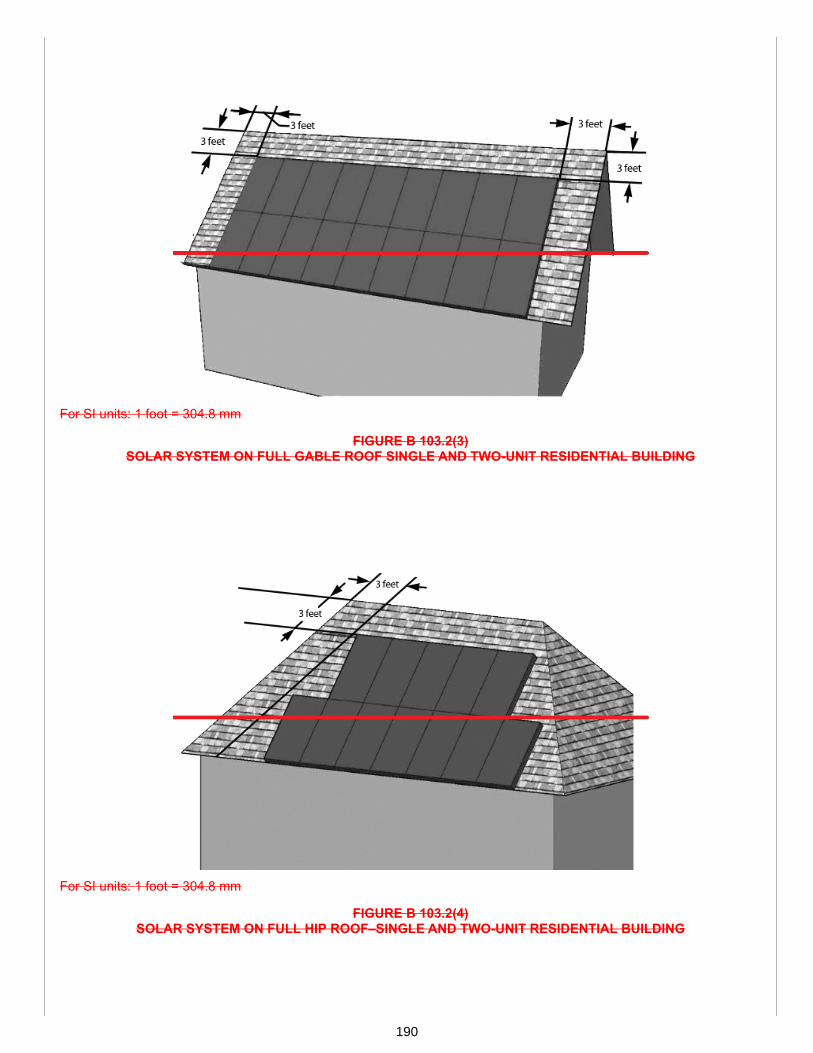
For SI units: 1 foot = 304.8 mm
FIGURE B 103.2(3) SOLAR SYSTEM ON FULL GABLE ROOF SINGLE AND TWO-UNIT RESIDENTIAL BUILDING
For SI units: 1 foot = 304.8 mm
FIGURE B 103.2(4) SOLAR SYSTEM ON FULL HIP ROOF–SINGLE AND TWO-UNIT RESIDENTIAL BUILDING
190

For SI units: 1 foot = 304.8 mm
FIGURE B 103.3(1) B 103.1(1)SOLAR ARRAY INSTALLATION ON LARGE COMMERCIAL BUILDINGS WITH 8 FOOT WALKWAYS
For SI units: 1 foot = 304.8 mm
FIGURE B 103.3(2) B 103.1(2)SOLAR ARRAY INSTALLATION ON LARGE COMMERCIAL BUILDINGS WITH 4 FOOT WIDE WALKWAYS WITH 8
FOOT BY 4 FOOT VENTING CUTOUTS EVERY 20 FOOT LENGTH
191
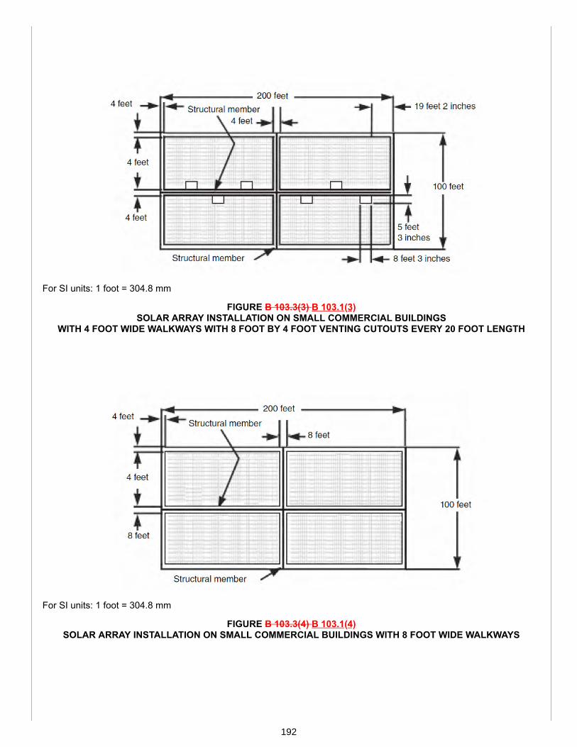
For SI units: 1 foot = 304.8 mm
FIGURE B 103.3(3) B 103.1(3)SOLAR ARRAY INSTALLATION ON SMALL COMMERCIAL BUILDINGS
WITH 4 FOOT WIDE WALKWAYS WITH 8 FOOT BY 4 FOOT VENTING CUTOUTS EVERY 20 FOOT LENGTH
For SI units: 1 foot = 304.8 mm
FIGURE B 103.3(4) B 103.1(4)SOLAR ARRAY INSTALLATION ON SMALL COMMERCIAL BUILDINGS WITH 8 FOOT WIDE WALKWAYS
192

TABLE 901.2 STANDARDS, PUBLICATIONS, PRACTICES, AND GUIDES
DOCUMENTNUMBER DOCUMENT TITLE APPLICATION
IAPMO IS 34-2020 Installation Standard for Residential Solar Photovoltaic and EnergyStorage Systems
Solar PV Systems
(portion of table not shown remains unchanged)
SUBSTANTIATION:Appendix B is being revised to remove installation guidelines pertaining to residential PV systems. The mostrelevant and up to date requirements are now addressed appropriately in IAPMO IS 34, which is referenced withinSection B 103.1.
Furthermore, IAPMO IS 34 contains these residential figures and offers a wide variety of additional figures forsetbacks, access, and pathways which are much clearer. For these reasons, the modifications are beneficial to thecode.
193

Proposals
Edit Proposal
Item #: 113
USHGC 2024 Section: Appendix C
SUBMITTER: Jazmin CurielSelf
RECOMMENDATION:Delete text without substitution
APPENDIX C SUPPLEMENTAL CHECKLIST FOR SOLAR PHOTOVOLTAIC SYSTEMS
C 101.0 Plan Details. C 101.1 General. The following shall be provided with the plan details of a photovoltaic (PV) system: (1) Scope of the project, including the system kW•h (J) rating. (2) Complete single line diagram and utility interconnect. (3) Site plan, including location of system components. (4) Type of system (i.e. alternating-current modules, bipolar, grounded, ungrounded, hybrid, isolated, interactive, stand-alone, etc). (5) Utility service operating voltage or class. (6) Information on the size, type, and insulation ratings (voltage, temperature, etc) of conductors and associated wiringcomponents of the direct-current (dc) and alternating current (ac) side of the PV system. (7) Type, size, and material of raceway(s). (8) Roof plan, including roof access and roof mounted equipment. (9) The following information shall be provided for the dc side of the PV system: (a) Number of series connected modules for each PV source circuit. (b) Number of parallel connected module or panel PV source circuits for each array or PV power source. (c) Number of combiner boxes, control boxes, or PV power centers for each array, subarray, or PV power source. (d) Number of PV output circuits. (e) PV source circuit module or panel connection arrangements. (f) Operating and open-circuit voltage for each module or panel. (g) Operating voltage for each array or PV power source. (h) Operating current for each PV source circuit. (i) Operating current for each array. (j) Maximum array, panel, or module system voltage. (k) Short circuit current of modules or panels. (l) Short circuit current of array and subarrays. (m) Short circuit current of battery system. (n) Disconnecting means electrical ratings. (o) Disconnecting means wiring diagram. (p) Disconnecting means rated short-circuit current per pole. (10) The manufacturer’s instructions shall be provided for the PV modules or panels. The manufacturer’s instructionsshall include the manufacturer’s name, catalog numbers, complete electrical information, required marked acceptableseries backfeed fuse protection rating, and installation instructions. (11) The manufacturer’s instructions shall be provided for inverters, converters, charge controllers, and ac modules,indicating the following ratings: (a) Maximum input ac and dc voltage, and the range of operating voltage(s). (b) Nominal ac output voltage. (c) Nominal dc voltage and operating range for utility interactive or stand-alone systems with charge controller. (d) Maximum input ac and dc current, and maximum input short circuit current. (e) Maximum inverter output short circuit current and duration.
194

(f) Maximum utility source backfeed current, short or open circuit, for utility interactive system with or without chargecontroller. (g) Maximum continuous ac output current and power. (h) Normal operation temperature range. (12) Information indicating where the inverter(s) or charge controller(s) contains current limiting devices that limits theoutput circuit current to the maximum inverter input dc current rating. (13) The manufacturer’s wiring details shall be provided for combiner boxes, control boxes, or PV power centers. It shallcontain the manufacturer’s name, model designation, and listing. (14) The manufacturer’s instructions shall be provided for each connector indicating configuration, construction, type,grounding member, and circuit current interruption capability and method. (15) Where the PV system uses a diversion charge controller as the sole means of regulating the charging of a battery. (16) Methods of access to the junction, pull, or outlet boxes behind the modules or panels. C 101.2 Circuits. Circuit requirements shall be indicated in the detail plans in accordance with the following: (1) Circuit conductors and overcurrent protective devices shall be sized to carry not less than 125 percent of themaximum current in accordance with Section 805.1.1.1. (2) Overcurrent protection of output circuits with internal current limiting devices shall be not less than 125 percent of themaximum limited current of the output circuit. The conductors in such an output circuit shall be sized in accordance withSection 805.1.1.1. (3) Common-return conductor of systems with multiple voltages shall not be smaller than the sum of the ampere ratingsof the overcurrent devices of the individual output circuits. (4) Where a single overcurrent device is used to protect a set of two or more parallel-connected module circuits, theampacity of each of the module interconnection conductors shall be not less than the sum of the fuse rating and 125percent of the short-circuit from the other parallel-connected modules. C 101.3 Overcurrent Protection. Circuits connected to more than one electrical source shall have overcurrentprotective devices that provide overcurrent protection from sources indicated on the plan details. C 101.4 Disconnecting Means. Disconnecting means shall be provided in the plan details for the following: (1) PV source circuits (isolating switches) (2) Overcurrent devices (3) Blocking diodes (4) Inverters (5) Batteries (6) Charge controllers The PV disconnecting means shall be grouped together and the number of disconnects shall not exceed six. C 101.5 Wiring Method. Wires used in a PV system shall be in accordance with Section 812.0. Ungrounded source andoutput circuits shall be installed with disconnects, overcurrent protection, ground-fault protection, and inverter or chargecontrollers and shall be listed for such purpose. Ungrounded sources and circuit conductors shall consist of sheathedmulti-conductor cable or shall be located in an approved raceway. C 101.6 Grounding. Grounding shall be indicated in the plan details as follows: (1) Where components of the system are negatively or positively grounded. (2) The dc circuit grounding shall be made at a single point on the PV output circuit. (3) The equipment-grounding conductor for a PV source and PV output circuits for a roof-mounted dc PV array indwellings shall be sized in accordance with Section 819.0. (4) Grounding electrode system used for the ac, dc, or combined ac/dc systems. (5) The method used to ensure the removal of equipment from the system that shall not disconnect the bondingconnection between the grounding electrode conductors and exposed conducting surfaces. (6) The method used to ensure the removal of a utility-interactive inverter or other equipment that shall not disconnectthe bonding connection between the grounding electrode conductor and the PV source and the output circuit groundedconductor, or both. C 101.7 Ground Fault Protection. Direct-current ground-fault protection for dwellings with roof mounted dc-PV arraysshall be provided on the plan details. C 101.8 Systems Over 1000 Volts. Plan details for PV systems over 1000 volts shall indicate the following: (1) The PV system is in accordance with Section 804.0, and other applicable installation requirements. (2) The voltage rating of a battery circuit cable shall not be smaller than the charging or equalizing condition of thebattery system. C 101.9 Calculations. Calculations shall be provided for solar PV systems in accordance with the following: (1) The maximum system voltage calculation shall be based on the expected ambient temperature. (2) The maximum system open-voltage calculation shall be based on manufacturer’s instructions for PV power sourcemodules made of materials other than crystalline or multi-crystalline silicon. (3) The maximum dc circuit current calculation for each PV source circuit. (4) The maximum dc current calculation for each PV output circuit. (5) The fault current calculation from the utility side to the ac disconnect(s) and inverter(s). (6) Calculations to determine the minimum overcurrent protection device rating for the dc side. Photovoltaic systemcurrents shall be considered as continuous.
195
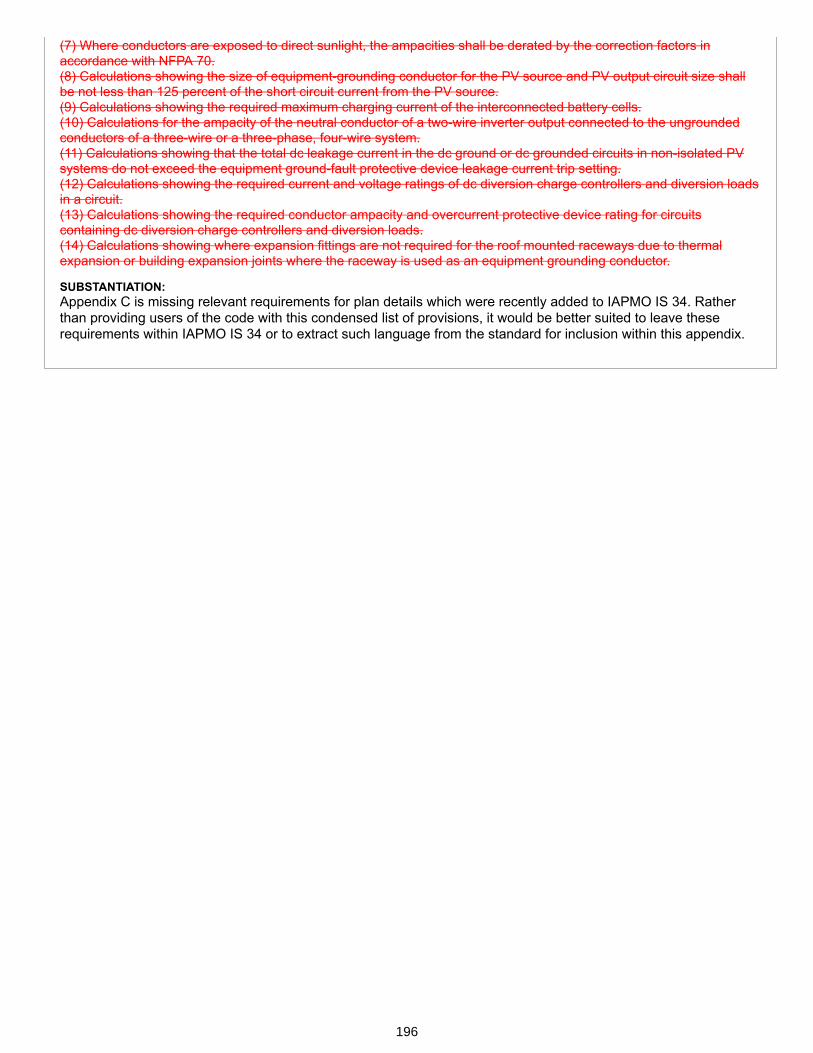
(7) Where conductors are exposed to direct sunlight, the ampacities shall be derated by the correction factors inaccordance with NFPA 70. (8) Calculations showing the size of equipment-grounding conductor for the PV source and PV output circuit size shallbe not less than 125 percent of the short circuit current from the PV source. (9) Calculations showing the required maximum charging current of the interconnected battery cells. (10) Calculations for the ampacity of the neutral conductor of a two-wire inverter output connected to the ungroundedconductors of a three-wire or a three-phase, four-wire system. (11) Calculations showing that the total dc leakage current in the dc ground or dc grounded circuits in non-isolated PVsystems do not exceed the equipment ground-fault protective device leakage current trip setting. (12) Calculations showing the required current and voltage ratings of dc diversion charge controllers and diversion loadsin a circuit. (13) Calculations showing the required conductor ampacity and overcurrent protective device rating for circuitscontaining dc diversion charge controllers and diversion loads. (14) Calculations showing where expansion fittings are not required for the roof mounted raceways due to thermalexpansion or building expansion joints where the raceway is used as an equipment grounding conductor.
SUBSTANTIATION:Appendix C is missing relevant requirements for plan details which were recently added to IAPMO IS 34. Ratherthan providing users of the code with this condensed list of provisions, it would be better suited to leave theserequirements within IAPMO IS 34 or to extract such language from the standard for inclusion within this appendix.
196

Proposals
Edit Proposal
Item #: 114
USHGC 2024 Section: Appendix C, Table 901.2
SUBMITTER: Jazmin CurielSelf
RECOMMENDATION:Add new text
APPENDIX CSOLAR READY BUILDINGS
C 101.0 General.C 101.1 Applicability. The provisions of this appendix shall apply to solar ready construction for low-rise residentialbuildings.C 101.2 Permit. Where solar ready construction is required by the Authority Having Jurisdiction, plans and constructiondocuments in accordance with Section C 101.3 shall be submitted with the building permit application.C 101.3 Plans and Construction Documents. Plans for solar zones shall include connections to a solar photovoltaic(PV), solar thermal system, or both. A copy of the construction documents shall be provided to the building occupant.The construction documents shall include the following:(1) Structural design loads for the solar zone in accordance with the building code.(2) Conduit pathway from the solar zone to the point of interconnection.(3) For solar PV systems, the location for future installation of inverters and metering equipment.(4) For solar thermal systems, the plumbing pathway from the solar zone to the water heating system.
C 102.0 Definitions.C 102.1 General. For the purposes of this appendix, the following definitions shall apply:Solar Access. The ratio of solar insolation including shading to that without shading.Solar Ready. The design and construction of a building which provides locations for future solar thermal and solar PVsystem installations and connections.Solar Zone. The total area of an available and appropriate space to be used for future solar PV or solar thermalinstallation.Solar Zone, Potential. A portion of the solar zone with an annual solar access of at least 70 percent.
C 103.0 Solar Zones.C 103.1 General. Solar zones shall be determined in accordance with Section C 103.2 through Section C 103.5.1.C 103.2 Location. Solar zones shall be located on approved structures in accordance with the building code. Solarzones shall comply with the access, pathway, and setback requirements of the fire code and IAPMO IS 34.C 103.3 Orientation. Solar zones located on roofs with a slope of not less than two units vertical in twelve unitshorizontal (2:12) shall be oriented between 90 degrees and 270 degrees true north.C 103.4 Shading. Solar zones shall be unshaded and have an annual solar access of at least 70 percent.C 103.5 Minimum Area. The solar zone shall not include obstructions and penetrations. Where the total roof area is notless than 600 square feet (ft2) (55.74 m2), the solar zone shall not be less than 300 square feet (ft2) (27.87 m2).Exceptions:(1) Where the total roof area is not less than 600 square feet (ft2) (55.74 m2) and has less than 70 percent annual solaraccess, the solar zone shall not be less than 50 percent of the potential solar zone.(2) Where approved by the Authority Having Jurisdiction, a smaller solar zone shall be permitted.
197

C 103.5.1 Subareas. The total solar zone shall be permitted to be the sum of multiple subareas. No dimension of asubarea shall be less than 5 feet (1524 mm). Where the total roof area exceeds 10 000 square feet (ft2) (929 m2), eachsubarea shall not be less than 160 square feet (ft2) (14.9 m2). Where the total roof area is less than 10 000 square feet(ft2) (929 m2), each subarea shall not be less than 80 square feet (ft2) (7.4 m2).C 103.5.2 Example. A house with a total roof area of 3 000 square feet (ft2) (278.7 m2) has a potential solar zone areaof 500 square feet (ft2) (46.5 m2). Determine the minimum size of the solar zone. See Figure C 103.5.2.
500 ft2 x 0.5 = 250 ft2 (23.2 m2)
FIGURE C 103.5.2SHADED ROOF AREA
TABLE 901.2 STANDARDS, PUBLICATIONS, PRACTICES, AND GUIDES
DOCUMENTNUMBER DOCUMENT TITLE APPLICATION
IAPMO IS 34-2020 Residential Solar Photovoltaic and Energy Storage Systems Solar PV Systems
(portion of table not shown remains unchanged)
SUBSTANTIATION:Solar-ready refers to designing and constructing a building in a way that facilitates and optimizes the installation of afuture rooftop solar energy system. By ensuring solar technical feasibility and planning for PV system optimization,future installation of these systems is more likely.
Part of determining the optimal placement for future installations includes considerations for shading, roofobstructions, pathways, access, and setbacks. The method provided for determining solar zones was gathered fromthe Energy Code and is supported by various local codes.
More specific requirements are left out as they vary by jurisdiction and geographical location. The providedlanguage in this appendix is general enough to apply to all new construction of solar ready buildings.
The provided definitions are needed to assist with understanding the methods for determining solar zones.Additionally, an example has been provided to clarify and guide users on how to properly assess a roof area forsolar access and optimal location for future installation of solar energy systems. Furthermore, the figure providedcoincides with the listed example.
198

Proposals
Edit Proposal
Item #: 115
USHGC 2024 Section: Appendix E, Table 901.2
SUBMITTER: Melanie KwongChair, USHGC Net Zero Task Group
RECOMMENDATION:Add new text
APPENDIX ENET ZERO AND NET POSITIVE APPLICATIONS
E 101.0 General.E 101.1 Applicability. The purpose of this appendix is to provide guidelines for achieving net zero energy and netpositive energy buildings through the use of energy efficient equipment and renewable energy systems. E 102.0 Definitions.E 102.1 General. For the purposes of this appendix, the following definitions shall apply:Energy Loading Order. A design pathway aligned with achieving net zero energy consumption through energy efficientstrategies and measures.Energy Star. A joint program of the U.S. Environmental Protection Agency and the U.S. Department of Energy. EnergyStar is a voluntary program designed to identify and promote energy-efficient products and practices.Net Zero Energy Building. A building with net zero energy consumption; the total annual amount of energy consumedby a building is equal to the amount of on-site renewable energy generated.Renewable Energy Sources. Energy from solar, wind, biomass, or hydro, or extracted from hot fluid or steam heatedwithin the earth.
E 103.0 General Regulations.E 103.1 Installation. Systems covered by this appendix shall be installed in accordance with this code, other applicablecodes, and the manufacturer’s installation and operating instructions.E 103.1.1 Renewable Energy Systems. Renewable energy systems shall be designed and installed as follows:(1) Solar thermal systems in accordance with Chapter 5.(2) Geothermal energy systems in accordance with Chapter 7.(3) Solar photovoltaic systems in accordance with Chapter 8 and IAPMO IS 34.E 103.1.2 Water Conservation. Water efficiency and conservation shall be in accordance with the Water Efficiency andSanitation Standard (WE•Stand).E 103.2 Qualifications. Where permits are required, the Authority Having Jurisdiction shall have the authority to requirecontractors, installers, or service technicians to demonstrate competency. Where determined by the Authority HavingJurisdiction, the contractor, installer, or service technician shall be licensed to perform such work. E 104.0 Certification.E 104.1 General. Net zero buildings shall be certified by one of the following agencies:(1) U.S. Green Building Council (USGBC);(2) International Living Future Institute (ILFI);(3) Department of Energy (DOE);(4) Earth Advantage; or(5) Other equivalent approved agencies.
199

E 105.0 Energy Loading Order.E 105.1 General. New and retrofit construction of residential and commercial buildings shall be designed and installedin the following energy loading order:(1) Building envelope(a) Reduction of infiltration(b) Insulation(c) Glazing of windows and doors(2) Water heating appliances in accordance with the Energy Star program.(3) Space heating(4) Lighting(5) Other appliances(6) Air-Conditioning(7) Renewable energy systems
E 106.0 Sustainable Practices.E 106.1 General. This section covers provisions that promote sustainable practices by enhancing the design andconstruction of mechanical systems to result in a positive long-term environmental impact. (See Figure E 106.1.)
Notes:1 The delivered energy may consist of renewable and nonrenewable sources while only renewable energy is exportedfrom the site boundary.2 Renewable energy generation may be from bulk power systems with utility-scale solar, geothermal, hydro, andbiomass facilities.3 The dashed lines represent the site boundary.
FIGURE E 106.1ENERGY TRANSFER FOR NET ZERO ENERGY PROJECTS
E 106.2 Use of Reclaimed (Recycled) and Onsite Treated Nonpotable Water for Cooling. Where approved for useby the water or wastewater utility and the Authority Having Jurisdiction, reclaimed(recycled), or on-site treatednonpotable water shall be permitted to be used for industrial and commercial cooling or air-conditioning.E 106.3 Heating, Ventilation, and Air Conditioning Systems Commissioning. The provisions of this section apply tothe commissioning of commercial and institutional HVAC systems.E 106.3.1 Commissioning Requirements. HVAC commissioning shall be included in the design and constructionprocesses of the project to verify compliance with this appendix and verify that the HVAC systems and componentsmeet the owner’s project requirements. Commissioning shall be performed in accordance with this appendix bypersonnel trained and certified in commissioning by a nationally recognized organization. Commissioning requirementsshall include the following:(1) Owner’s project requirements.(2) Basis of design.(3) Commissioning measures shown in the construction documents.(4) Commissioning plan.(5) Functional performance.
200

(6) Testing.(7) Post construction documentation and training.(8) Commissioning report.HVAC systems and components covered by this appendix, as well as process equipment and controls, and renewableenergy systems, shall be included in the scope of the commissioning requirements.E 106.3.2 Owner’s Project Requirements (OPR). The performance goals and requirements of the HVAC system shallbe documented before the design phase of the project begins. This documentation shall include not less than thefollowing:(1) Environmental and sustainability goals.(2) Energy efficiency goals.(3) Indoor environmental quality requirements.(4) Equipment and systems performance goals.(5) Building occupant and operations and maintenance (O&M) personnel expectations.E 106.3.3 Basis of Design (BOD). A written explanation of how the design of the HVAC system meets the owner’sproject requirements shall be completed at the design phase of the building project and updated as necessary duringthe design and construction phases. The basis of design document shall cover not less than the following systems:(1) Heating, ventilation, air conditioning (HVAC) systems and controls.(2) Water heating systems.(3) Renewable energy systems.E 106.3.4 Commissioning Plan. A commissioning plan shall be completed to document the approach of how theproject will be commissioned and shall be started during the design phase of the building project. The commissioningplan shall include not less than the following:(1) General project information.(2) Commissioning goals.(3) Systems to be commissioned. Plans to test systems and components shall include at least the following information:(a) A detailed explanation of the original design intent.(b) Equipment and systems to be tested, including the extent of tests.(c) Functions to be tested.(d) Conditions under which the test shall be performed.(e) Measurable criteria for acceptable performance.(4) Commissioning team information.(5) Commissioning process activities, schedules, and responsibilities. Plans for the completion of commissioningrequirements listed in Section E 106.3.5 through Section E 106.5 shall be included.E 106.3.5 Functional Performance Testing. Functional performance tests shall demonstrate the correct installationand operation of each component, system, and system-to-system interface in accordance with the approved plans andspecifications. Functional performance testing reports shall contain information addressing each of the buildingcomponents tested, the testing methods utilized, and readings and adjustments made.E 106.4 Construction Documents. Details of commissioning acceptance requirements shall be incorporated into theconstruction documents, including information that describes the details of the functional tests to be performed. Thisinformation shall be permitted to be integrated into the specifications for testing and air balancing, energy managementand control systems, and equipment startup procedures or commissioning. It is possible that the work will be performedby a combination of the test and balance (TAB) contractor, mechanical/electrical contractor, and the energymanagement control system (EMCS) contractor; so applicable roles and responsibilities shall be clearly called out.E 106.5 Commissioning Tests. Functional tests shall be performed on new equipment and systems installed in eithernew construction or retrofit applications in accordance with the mechanical code and the Authority Having Jurisdiction.The appropriate certificate of acceptance form along with each specific test shall be completed and submitted to theAuthority Having Jurisdiction before a final occupancy permit can be granted.E 106.6 Minimum Equipment Efficiency Tables. The minimum efficiency requirements for listed equipment shallcomply with ASHRAE 90.1.
TABLE 901.2 STANDARDS, PUBLICATIONS, PRACTICES, AND GUIDES
DOCUMENTNUMBER DOCUMENT TITLE APPLICATION
IAPMO IS 34-2020 Residential Solar Photovoltaic and Energy Storage Systems Solar PV SystemsIAPMO/ANSIWE•Stand-2020
Water Efficiency and Sanitation Standard for the Built Environment Water Conservation
(portion of table not shown remains unchanged)
201

SUBSTANTIATION:The proposed new appendix provides guidelines for achieving net zero energy and net positive energy buildingsthrough the use of energy-efficient equipment and renewable energy systems. Net zero energy buildings combineenergy efficiency and renewable energy generation to consume only as much energy as can be produced on-sitethrough renewable resources. Although achieving net zero energy buildings requires a combination of sustainableengineering methods in order to be successful, there is a growing desire for such design and construction in bothprivate and commercial applications.
Section E 103.0 (General Regulations) and supporting subsections address the use of renewable energy systemswith appropriate design and installation requirements. Specific reference to other chapters and industry standardshas been provided for solar thermal systems, geothermal energy systems, and solar photovoltaic systems. Otherrenewable energy systems not addressed by this appendix are required to comply with the applicable recognizedstandards approved by the AHJ. As an additional means of environmental consciousness, the WE-Stand wasreferenced to cover water efficiency and conservation.
Section E 104.0 (Certification) is intended to provide users of the code with available certificationagencies/programs.
The U.S. Green Building Council (USGBC) developed LEED certifications from their green building rating system,and now offer LEED Zero for verification of meeting net zero goals for carbon emissions, source energy usage,potable water usage, and zero waste.
The International Living Future Institute (ILFI) Zero Energy Certification is an international third-party performancecertification based on actual performance reviewed by an auditor. This agency provides a case study platform forprojects to assist and accelerate zero energy efforts.
The DOE Zero Energy Ready Home (ZERH) program is based on the comprehensive building sciencerequirements of ENERGY STAR for Homes, along with proven Building America innovations and best practices.DOE Zero Energy Ready Homes are verified by a qualified third-party and are at least 40%-50% more energy-efficient than a typical new home.
Earth Advantage Zero Energy Certification is designed to create a standard for homes that wish to achieve a higherlevel of energy performance while still maintaining a sustainable approach to building. They also offer the ZeroEnergy Ready certification which focuses on buildings which are “ready” for adding the actual physical renewablesystems in the future.
Furthermore, the provided energy efficient loading order in Section E 105.0 is necessary as it significantly reducesenergy consumption of both residential and commercial buildings. This loading order is a design pathway forachieving net zero and provides the necessary decision making processes for energy efficient strategies andmeasures for various construction projects. Although the methodology is simple, the inclusion of the energy loadingorder within the recommendations of this appendix serve meaningful and effective.
Section E 106.0 (Sustainable Practices) and all subsections were gathered from the mechanical code. Suchrecommendations promote sustainable practices by enhancing the design and construction of mechanical systemsfor a positive long-term environmental impact.
Figure E 106.1 has been provided as it offers a simplified energy flow diagram for net zero applications. Thediagram includes a site boundary with directional delivered and exported energy and lists the possible buildingneeds as well as the types of onsite renewable energy use and generation.
Section E 106.2 was included as it promotes water conversation through the use of reclaimed (recycled) or onsitetreated nonpotable water for industrial and commercial cooling or air-conditioning.
In order to provide comprehensive provisions for net zero applications, the Task Group decided to also includerequirements for commissioning of commercial and institutional HVAC systems. The listed subsections offerprovisional language pertaining to performance goals and requirements, proper documentation, written explanationor basis of design, commissioning plans, as well as functional performance and commissioning testing. Suchlanguage also correlates with the sustainable practices as depicted within the mechanical code.
202

Proposals
Edit Proposal
Item #: 116
USHGC 2024 Section: Table 901.1
SUBMITTER: Karl BestAHRI
RECOMMENDATION:Revise text
TABLE 901.1 REFERENCED STANDARDS
STANDARDNUMBER STANDARD TITLE APPLICATION REFERENCED
SECTIONAHRI 210/240-20172020
Performance Rating of Unitary Air-conditioning & Air- sourceHeat Pump Equipment
Air-SourceHeat Pumps Table 407.5
(portion of table not shown remains unchanged)
Note: AHRI 210/240 meets the requirements for a mandatory referenced standard in accordance withSection 15.0 of IAPMO’s Regulations Governing Consensus Development of the Uniform Solar, Hydronics &Geothermal and Swimming Pool, Spa & Hot Tub Codes.
SUBSTANTIATION:The above revisions reflect the latest updates to the AHRI standards that are referenced in Table 901.1.
203

Proposals
Edit Proposal
Item #: 117
USHGC 2024 Section: Table 901.1, Table 901.2
SUBMITTER: Steven RossiASME
RECOMMENDATION:Revise text
TABLE 901.1REFERENCED STANDARDS
STANDARD NUMBER STANDARD TITLE APPLICATION REFERENCEDSECTION
ASME A112.1.3-2000 (R2015) (R2019)
Air Gap Fittings for Use with Plumbing Fixtures,Appliances, and Appurtenances
BackflowProtection
402.2
ASME B16.3-2016 2021 Malleable Iron Threaded Fittings: Classes 150 and 300 Fittings Table 409.1ASME B16.5-2017 2020 Pipe Flanges and Flanged Fittings: NPS 1/2 Through
NPS 24 Metric/InchFittings Table 409.1
ASME BPVCSection VIII.1-2019 2021
Rules for Construction of Pressure Vessels Division 1 Miscellaneous 408.3, 601.2.1,603.6,
ASME BPVC SectionX- 2019 2021
Fiber-Reinforced Plastic Pressure Vessels PressureVesselConstruction,PressureVessels
605.2
(portion of table not shown remains unchanged)
Note: The ASME standards meet the requirements for mandatory referenced standards in accordance withSection 15.0 of IAPMO’s Regulations Governing Consensus Development of the Uniform Solar, Hydronics &Geothermal and Swimming Pool, Spa & Hot Tub Codes.
TABLE 901.2 STANDARDS, PUBLICATIONS, PRACTICES, AND GUIDES
DOCUMENT NUMBER DOCUMENT TITLE APPLICATIONASME A13.1-2015 2020 Scheme for the Identification of Piping Systems PipingASME B16.21-2016 2021
Nonmetallic Flat Gaskets for Pipe Flanges Joints
ASME B16.34-2017 2020 Valves - Flanged, Threaded, and Welding End ValvesASME B16.47-2017 2020 Large Diameter Steel Flanges: NPS 26 Through NPS 60 Metric/Inch FittingsASME BPVC SectionIV- 2017 2021
Rules for Construction of Heating Boilers Miscellaneous
ASME BPVC SectionIX- 2017 2021
Welding, Brazing, and Fusing Qualifications Certification
(portion of table not shown remains unchanged)
204

SUBSTANTIATION:The above revisions reflect the latest updates to the ASME standards that are referenced in Table 901.1 and Table901.2.
205

Proposals
Edit Proposal
Item #: 118
USHGC 2024 Section: Table 901.1
SUBMITTER: Terry BurgerASSE
RECOMMENDATION:Revise text
TABLE 901.1 REFERENCED STANDARDS
STANDARDNUMBER STANDARD TITLE APPLICATION REFERENCED
SECTIONASSE 1013-20112021
Reduced Pressure Principle Backflow Preventers andReduced Pressure Principle Fire Protection Backflow Pre-venters
BackflowPrevention
402.2
ASSE 1061-20152020
Push-Fit Fittings Fittings Table 409.1,410.2(1),410.4(5)
ASSE 1079-2012(R2021)
Dielectric Pipe Unions Fittings 410.13.1
(portion of table not shown remains unchanged)
Note: The ASSE standards meet the requirements for mandatory referenced standards in accordance withSection 15.0 of IAPMO’s Regulations Governing Consensus Development of the Uniform Solar, Hydronics &Geothermal and Swimming Pool, Spa & Hot Tub Codes.
SUBSTANTIATION:The above revisions reflect the latest updates to the ASSE standards that are referenced in Table 901.1.
206
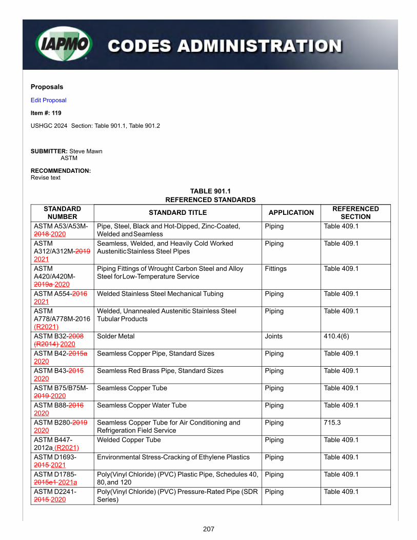
Proposals
Edit Proposal
Item #: 119
USHGC 2024 Section: Table 901.1, Table 901.2
SUBMITTER: Steve MawnASTM
RECOMMENDATION:Revise text
TABLE 901.1REFERENCED STANDARDS
STANDARDNUMBER STANDARD TITLE APPLICATION REFERENCED
SECTIONASTM A53/A53M-2018 2020
Pipe, Steel, Black and Hot-Dipped, Zinc-Coated,Welded and Seamless
Piping Table 409.1
ASTMA312/A312M-20192021
Seamless, Welded, and Heavily Cold WorkedAustenitic Stainless Steel Pipes
Piping Table 409.1
ASTMA420/A420M-2019a 2020
Piping Fittings of Wrought Carbon Steel and AlloySteel for Low-Temperature Service
Fittings Table 409.1
ASTM A554-20162021
Welded Stainless Steel Mechanical Tubing Piping Table 409.1
ASTMA778/A778M-2016(R2021)
Welded, Unannealed Austenitic Stainless SteelTubular Products
Piping Table 409.1
ASTM B32-2008(R2014) 2020
Solder Metal Joints 410.4(6)
ASTM B42-2015a2020
Seamless Copper Pipe, Standard Sizes Piping Table 409.1
ASTM B43-20152020
Seamless Red Brass Pipe, Standard Sizes Piping Table 409.1
ASTM B75/B75M-2019 2020
Seamless Copper Tube Piping Table 409.1
ASTM B88-20162020
Seamless Copper Water Tube Piping Table 409.1
ASTM B280-20192020
Seamless Copper Tube for Air Conditioning andRefrigeration Field Service
Piping 715.3
ASTM B447-2012a (R2021)
Welded Copper Tube Piping Table 409.1
ASTM D1693-2015 2021
Environmental Stress-Cracking of Ethylene Plastics Piping Table 409.1
ASTM D1785-2015e1 2021a
Poly(Vinyl Chloride) (PVC) Plastic Pipe, Schedules 40,80, and 120
Piping Table 409.1
ASTM D2241-2015 2020
Poly(Vinyl Chloride) (PVC) Pressure-Rated Pipe (SDRSeries)
Piping Table 409.1
207

ASTM D2466-2017 2021
Poly(Vinyl Chloride) (PVC) Plastic Pipe Fittings,Schedule 40
Fittings Table 409.1
ASTM D2467-2015 2020
Poly(Vinyl Chloride) (PVC) Plastic Pipe Fittings,Schedule 80
Fittings Table 409.1
ASTM D2513-2019 2020
Polyethylene (PE) Gas Pressure Pipe, Tubing, andFittings
Piping Table 409.1, 703.4.1
ASTM D2564-2012 (R2018)2020
Solvent Cements for Poly(Vinyl Chloride) (PVC)Plastic Piping Systems
Joints 410.11(2)
ASTM D2609-2015 2021
Plastic Insert Fittings for Polyethylene (PE) PlasticPipe
Fittings Table 409.1
ASTM D2683-2014 2020
Socket-Type Polyethylene Fittings for OutsideDiameter- Controlled Polyethylene Pipe and Tubing
Fittings Table 409.1, Table703.3
ASTM D2737-2012a 2021
Polyethylene (PE) Plastic Tubing Piping Table 409.1, Table703.2
ASTM D3035-2015 2021
Polyethylene (PE) Plastic Pipe (DR-PR) Based onControlled Outside Diameter
Piping Table 409.1, Table703.2
ASTM D3350-2014 2021
Polyethylene Plastics Pipe and Fittings Materials Piping Table 409.1, 703.4.1
ASTM E84-2019b2021a
Surface Burning Characteristics of Building Materials Miscellaneous 401.2, 502.4, 503.1,606.5
ASTM F437-20152021
Threaded Chlorinated Poly (Vinyl Chloride) (CPVC)Plastic Pipe Fittings, Schedule 80
Fittings Table 409.1
ASTMF441/F441M-20152020
Chlorinated Poly (Vinyl Chloride) (CPVC) PlasticPipe, Schedules 40 and 80
Piping Table 409.1
ASTMF442/F442M-20192020
Chlorinated Poly (Vinyl Chloride) (CPVC) Plastic Pipe(SDR-PR)
Piping, Plastic Table 409.1,410.2(2)
ASTM F493-20142020
Solvent Cements for Chlorinated Poly (Vinyl Chloride)(CPVC) Plastic Pipe and Fittings
Joints 410.2(2), 410.3(2)
ASTM F656-20152021
Primers for Use in Solvent Cement Joints of Poly(Vinyl Chloride) (PVC) Plastic Pipe and Fittings
Joints 410.2(2), 410.3(2),410.11(2)
ASTM F714-2013(R2019) 2021a
Polyethylene (PE) Plastic Pipe (DR-PR) Based onOutside Diameter
Piping Table 409.1, Table703.2
ASTM F876-2019a2020b
Crosslinked Polyethylene (PEX) Tubing Piping Table 409.1, 410.5,Table 703.2
ASTM F877-20192020
Crosslinked Polyethylene (PEX) Hot- and Cold-WaterDistribution Systems
Piping Table 409.1, Table703.3
ASTM F1281-2017(R2021)e1
Crosslinked Polyethylene/ Aluminum/CrosslinkedPolyethylene (PEX-AL-PEX) Pressure Pipe
Piping Table 409.1
ASTM F1960-2019a 2021
Cold Expansion Fittings with PEX Reinforcing Ringsfor Use with Cross-linked Polyethylene (PEX) andPolyethylene of Raised Temperature (PE-RT) Tubing
Fittings Table 409.1, Table703.3
ASTM F1974-2009 (R2015)(R2020)
Metal Insert Fittings forPolyethylene/Aluminum/Polyethylene and CrosslinkedPolyethylene/Aluminum/Crosslinked PolyethyleneComposite Pressure Pipe
Fittings Table 409.1,410.6(1),410.8(1)
ASTM F2159-2019a 2021
Plastic Insert Fittings Utilizing a Copper Crimp Ring,or Alternate Stainless Steel Clamps for SDR9Crosslinked Polyethylene (PEX) Tubing and SDR9Polyethylene of Raised Temperature (PE-RT) Tubing
Fittings Table 409.1, Table703.3
ASTM F2389-20192021
Pressure-Rated Polypropylene (PP) Piping Systems Piping Table 409.1,410.10(1), Table703.2, Table 703.3
ASTM F2620-20192020ae1
Heat Fusion Joining of Polyethylene Pipe and Fittings Joints 410.7(1), 410.7(3),703.4.1.1(1),703.4.1.1(2)
208
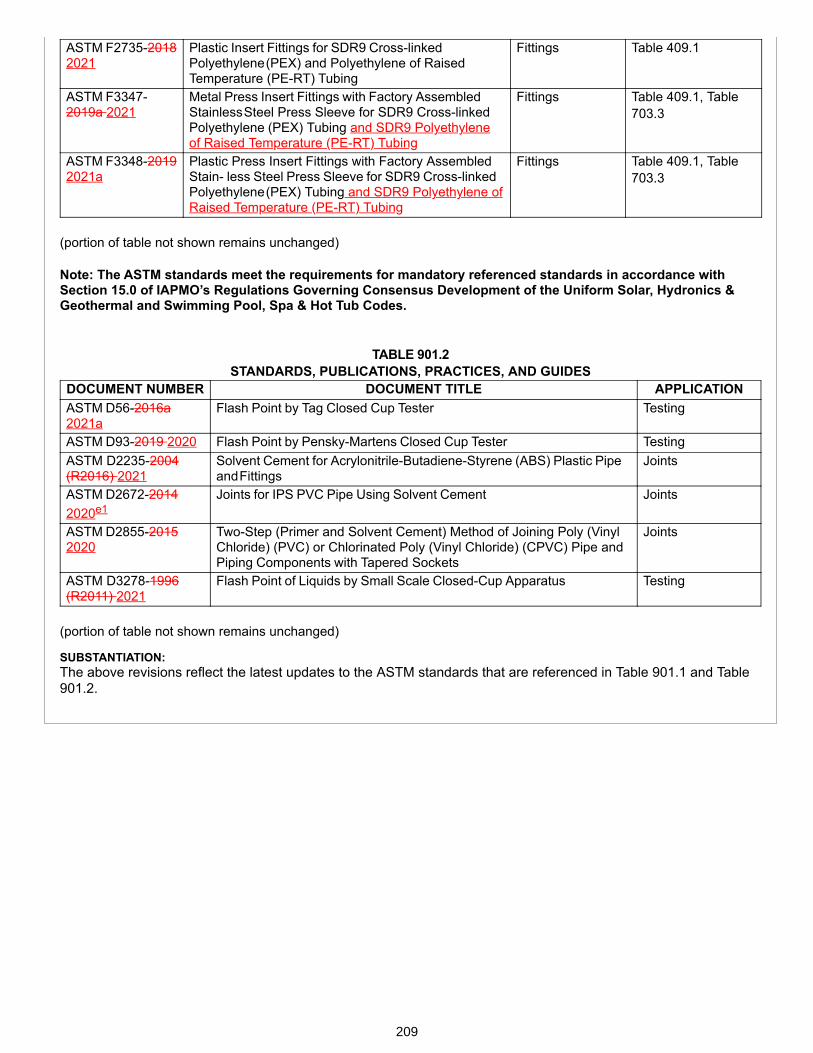
ASTM F2735-20182021
Plastic Insert Fittings for SDR9 Cross-linkedPolyethylene (PEX) and Polyethylene of RaisedTemperature (PE-RT) Tubing
Fittings Table 409.1
ASTM F3347-2019a 2021
Metal Press Insert Fittings with Factory AssembledStainless Steel Press Sleeve for SDR9 Cross-linkedPolyethylene (PEX) Tubing and SDR9 Polyethyleneof Raised Temperature (PE-RT) Tubing
Fittings Table 409.1, Table703.3
ASTM F3348-20192021a
Plastic Press Insert Fittings with Factory AssembledStain- less Steel Press Sleeve for SDR9 Cross-linkedPolyethylene (PEX) Tubing and SDR9 Polyethylene ofRaised Temperature (PE-RT) Tubing
Fittings Table 409.1, Table703.3
(portion of table not shown remains unchanged) Note: The ASTM standards meet the requirements for mandatory referenced standards in accordance withSection 15.0 of IAPMO’s Regulations Governing Consensus Development of the Uniform Solar, Hydronics &Geothermal and Swimming Pool, Spa & Hot Tub Codes.
TABLE 901.2STANDARDS, PUBLICATIONS, PRACTICES, AND GUIDES
DOCUMENT NUMBER DOCUMENT TITLE APPLICATIONASTM D56-2016a2021a
Flash Point by Tag Closed Cup Tester Testing
ASTM D93-2019 2020 Flash Point by Pensky-Martens Closed Cup Tester TestingASTM D2235-2004(R2016) 2021
Solvent Cement for Acrylonitrile-Butadiene-Styrene (ABS) Plastic Pipeand Fittings
Joints
ASTM D2672-20142020e1
Joints for IPS PVC Pipe Using Solvent Cement Joints
ASTM D2855-20152020
Two-Step (Primer and Solvent Cement) Method of Joining Poly (VinylChloride) (PVC) or Chlorinated Poly (Vinyl Chloride) (CPVC) Pipe andPiping Components with Tapered Sockets
Joints
ASTM D3278-1996(R2011) 2021
Flash Point of Liquids by Small Scale Closed-Cup Apparatus Testing
(portion of table not shown remains unchanged)
SUBSTANTIATION:The above revisions reflect the latest updates to the ASTM standards that are referenced in Table 901.1 and Table901.2.
209

Proposals
Edit Proposal
Item #: 120
USHGC 2024 Section: Table 901.1
SUBMITTER: Paul OlsonAWWA
RECOMMENDATION:Revise text
TABLE 901.1 REFERENCED STANDARDS
STANDARDNUMBER STANDARD TITLE APPLICATION REFERENCED
SECTIONAWWA C901-2017 2020
Polyethylene (PE) Pressure Pipe and Tubing, 3/4 In. (19 mm) Through 3 In. (76 mm), for Water Service
Piping Table 409.1,Table 703.2
(portion of table not shown remains unchanged)
Note: AWWA C901 meets the requirements for a mandatory referenced standard in accordance with Section15.0 of IAPMO’s Regulations Governing Consensus Development of the Uniform Solar, Hydronics &Geothermal and Swimming Pool, Spa & Hot Tub Codes.
SUBSTANTIATION:The above revision reflects the latest update to the AWWA standard that is referenced in Table 901.1.
210

Proposals
Edit Proposal
Item #: 121
USHGC 2024 Section: Table 901.2
SUBMITTER: Ed TsangBSI
RECOMMENDATION:Revise text
TABLE 901.2 STANDARDS, PUBLICATIONS, PRACTICES, AND GUIDES
DOCUMENTNUMBER DOCUMENT TITLE APPLICATION
BS EN 12976-1-2017 2021
Thermal Solar Systems and Components – Factory Made Systems – Part 1:General Requirements
Solar ThermalSystems
BS EN 12976-2-2017 2019
Thermal Solar Systems and Components – Factory Made Systems – Part 2: TestMethods
Solar ThermalSystems
(portion of table not shown remains unchanged)
SUBSTANTIATION:The above revisions reflect the latest updates to the BSI standards that are referenced in Table 901.2.
211

Proposals
Edit Proposal
Item #: 122
USHGC 2024 Section: Table 901.1, Table 901.2
SUBMITTER: Lauro Pilla / Nikki KiddCSA
RECOMMENDATION:Revise text
TABLE 901.1 REFERENCED STANDARDS
STANDARDNUMBER STANDARD TITLE APPLICATION REFERENCED
SECTIONCSA B137.1-20172020
Polyethylene (PE) Pipe, Tubing, and Fittings for Cold-WaterPressure Services
Piping Table 409.1,Table 703.2,Table 703.3
CSA B137.2-20172020
Polyvinylchloride (PVC) Injection-Moulded Gasketed Fit- tingsfor Pressure Applications
Fittings Table 409.1
CSA B137.3-20172020
Rigid Polyvinylchloride (PVC) Pipe and Fittings for PressureApplications
Piping, Fittings Table 409.1
CSA B137.5-20172020
Crosslinked Polyethylene (PEX) Tubing Systems forPressure Applications
Piping Table 409.1,Table 703.2,Table 703.3
CSA B137.6-20172020
Chlorinated Polyvinylchloride (CPVC) Pipe, Tubing, andFittings for Hot- and Cold-Water Distribution Systems
Piping, Fittings Table 409.1
CSA B137.9-20172020
Polyethylene/Aluminum/Polyethylene (PE-AL-PE) CompositePressure-Pipe Systems
Piping Table 409.1
CSA B137.10-20172020
Crosslinked Polyethylene/Aluminum/Crosslinked Polyethylene (PEX-AL-PEX) Composite Pressure-Pipe Systems
Piping Table 409.1
CSA B137.11-20172020
Polypropylene (PP-R & PP-RCT) Pipe and Fittings forPressure Applications
Piping Table 409.1,410.10(1),Table 703.2,Table 703.3
CSA B137.18-20172020
Polyethylene of Raised Temperature Resistance (PE-RT)Tubing Systems for Pressure Applications
Piping, Fittings Table 409.1,Table 703.2,Table 703.3
ANSI/CSA/IGSHPAC448.1-2016(R2021)
Design and Installation of Ground Source Heat PumpSystems for Commercial and Institutional Buildings
Ground-Source HeatPumps
708.7
ANSI/CSA/IGSHPAC448.2-2016(R2021)
Design and Installation of Ground Source Heat PumpSystems for Residential and Other Small Buildings
Ground-Source HeatPumps
708.7
ANSI/CSA/IGSHPAC448 Series -2016(R2021)
Design and Installation of Ground Source Heat PumpSystems for Commercial and Residential Buildings
Miscellaneous Table 703.2,Table 703.3,709.1, 710.6,710.6.2, 715.4
212
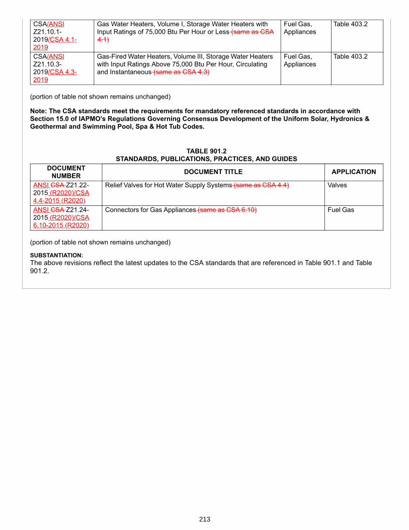
CSA/ANSIZ21.10.1-2019/CSA 4.1-2019
Gas Water Heaters, Volume I, Storage Water Heaters withInput Ratings of 75,000 Btu Per Hour or Less (same as CSA 4.1)
Fuel Gas,Appliances
Table 403.2
CSA/ANSIZ21.10.3-2019/CSA 4.3-2019
Gas-Fired Water Heaters, Volume III, Storage Water Heaterswith Input Ratings Above 75,000 Btu Per Hour, Circulatingand Instantaneous (same as CSA 4.3)
Fuel Gas,Appliances
Table 403.2
(portion of table not shown remains unchanged)
Note: The CSA standards meet the requirements for mandatory referenced standards in accordance withSection 15.0 of IAPMO’s Regulations Governing Consensus Development of the Uniform Solar, Hydronics &Geothermal and Swimming Pool, Spa & Hot Tub Codes.
TABLE 901.2 STANDARDS, PUBLICATIONS, PRACTICES, AND GUIDES
DOCUMENTNUMBER DOCUMENT TITLE APPLICATION
ANSI CSA Z21.22-2015 (R2020)/CSA4.4-2015 (R2020)
Relief Valves for Hot Water Supply Systems (same as CSA 4.4) Valves
ANSI CSA Z21.24-2015 (R2020)/CSA6.10-2015 (R2020)
Connectors for Gas Appliances (same as CSA 6.10) Fuel Gas
(portion of table not shown remains unchanged)
SUBSTANTIATION:The above revisions reflect the latest updates to the CSA standards that are referenced in Table 901.1 and Table901.2.
213

Proposals
Edit Proposal
Item #: 123
USHGC 2024 Section: Table 901.1
SUBMITTER: Terry BurgerIAPMO
RECOMMENDATION:Revise text
TABLE 901.1 REFERENCED STANDARDS
STANDARD NUMBER STANDARD TITLE APPLICATION REFERENCEDSECTION
IAPMO PS 117-2019 2021 Press Connections Fittings Table 409.1
(portion of table not shown remains unchanged)
Note: IAPMO PS 117 meets the requirements for a mandatory referenced standard in accordance withSection 15.0 of IAPMO’s Regulations Governing Consensus Development of the Uniform Solar, Hydronics &Geothermal and Swimming Pool, Spa & Hot Tub Codes.
SUBSTANTIATION:The above revision reflects the latest update to the IAPMO standard that is referenced in Table 901.1.
214
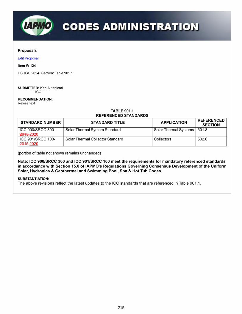
Proposals
Edit Proposal
Item #: 124
USHGC 2024 Section: Table 901.1
SUBMITTER: Karl AittaniemiICC
RECOMMENDATION:Revise text
TABLE 901.1REFERENCED STANDARDS
STANDARD NUMBER STANDARD TITLE APPLICATION REFERENCEDSECTION
ICC 900/SRCC 300-2015 2020
Solar Thermal System Standard Solar Thermal Systems 501.8
ICC 901/SRCC 100-2015 2020
Solar Thermal Collector Standard Collectors 502.6
(portion of table not shown remains unchanged)
Note: ICC 900/SRCC 300 and ICC 901/SRCC 100 meet the requirements for mandatory referenced standardsin accordance with Section 15.0 of IAPMO’s Regulations Governing Consensus Development of the UniformSolar, Hydronics & Geothermal and Swimming Pool, Spa & Hot Tub Codes.
SUBSTANTIATION:The above revisions reflect the latest updates to the ICC standards that are referenced in Table 901.1.
215
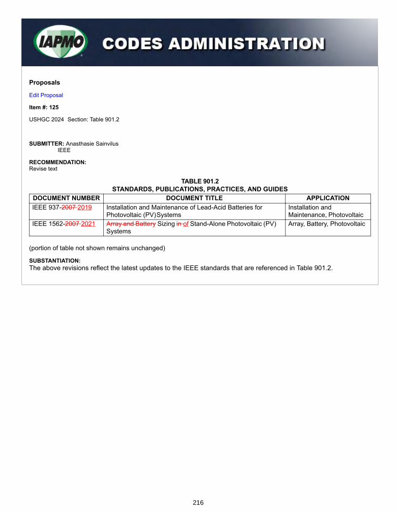
Proposals
Edit Proposal
Item #: 125
USHGC 2024 Section: Table 901.2
SUBMITTER: Anasthasie SainvilusIEEE
RECOMMENDATION:Revise text
TABLE 901.2STANDARDS, PUBLICATIONS, PRACTICES, AND GUIDES
DOCUMENT NUMBER DOCUMENT TITLE APPLICATIONIEEE 937-2007 2019 Installation and Maintenance of Lead-Acid Batteries for
Photovoltaic (PV) SystemsInstallation andMaintenance, Photovoltaic
IEEE 1562-2007 2021 Array and Battery Sizing in of Stand-Alone Photovoltaic (PV)Systems
Array, Battery, Photovoltaic
(portion of table not shown remains unchanged)
SUBSTANTIATION:The above revisions reflect the latest updates to the IEEE standards that are referenced in Table 901.2.
216
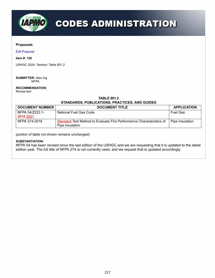
Proposals
Edit Proposal
Item #: 126
USHGC 2024 Section: Table 901.2
SUBMITTER: Alex IngNFPA
RECOMMENDATION:Revise text
TABLE 901.2STANDARDS, PUBLICATIONS, PRACTICES, AND GUIDES
DOCUMENT NUMBER DOCUMENT TITLE APPLICATIONNFPA 54/Z223.1-2018 2021
National Fuel Gas Code Fuel Gas
NFPA 274-2018 Standard Test Method to Evaluate Fire Performance Characteristics ofPipe Insulation
Pipe Insulation
(portion of table not shown remains unchanged)
SUBSTANTIATION:NFPA 54 has been revised since the last edition of the USHGC and we are requesting that it is updated to the latestedition year. The full title of NFPA 274 is not currently used, and we request that is updated accordingly.
217

Proposals
Edit Proposal
Item #: 127
USHGC 2024 Section: Table 901.1, Table 901.2
SUBMITTER: Jeremy BrownNSF
RECOMMENDATION:Revise text
TABLE 901.1 REFERENCED STANDARDS
STANDARD NUMBER STANDARD TITLE APPLICATION REFERENCEDSECTION
NSF/ANSI/CAN 60-20192021
Drinking Water Treatment Chemicals - Health Effects Backfill 710.6.1
NSF/ANSI/CAN 61-20192021
Drinking Water System Components - Health Effects Miscellaneous 501.5.4
NSF/ANSI 358-1-20172021
Polyethylene Pipe and Fittings for Water-BasedGround- Source “Geothermal” Heat Pump Systems
Piping, Fittings Table 409.1,Table 703.2, Table703.3
NSF/ANSI 358-2-2017 Polypropylene Pipe and Fittings for Water-BasedGround- Source “Geothermal” Heat Pump Systems
Piping, Fittings Table 409.1,Table 703.2, Table703.3
NSF/ANSI 358-3-20162021
Cross-Linked Polyethylene (PEX) Pipe and Fittingsfor Water- Based Ground-Source (Geothermal) HeatPump Systems
Piping, Fittings Table 409.1,Table 703.2, Table703.3
NSF/ANSI 358-4-2018 Polyethylene of Raised Temperature (PE-RT) Tubingand Fittings for Water-Based Ground-Source(Geothermal) Heat Pump Systems
Piping, Fittings Table 703.2,Table 703.3
(portion of table not shown remains unchanged)
Note: The NSF standards meet the requirements for mandatory referenced standards in accordance withSection 15.0 of IAPMO’s Regulations Governing Consensus Development of the Uniform Solar, Hydronics &Geothermal and Swimming Pool, Spa & Hot Tub Codes.
TABLE 901.2 STANDARDS, PUBLICATIONS, PRACTICES, AND GUIDES
DOCUMENTNUMBER DOCUMENT TITLE APPLICATION
NSF/ANSI 14-20182020
Plastics Piping System Components and Related Materials Piping, Plastic
(portion of table not shown remains unchanged)
218
SUBSTANTIATION:The above revisions reflect the latest updates to the NSF standards that are referenced in Table 901.1 and Table901.2.
219
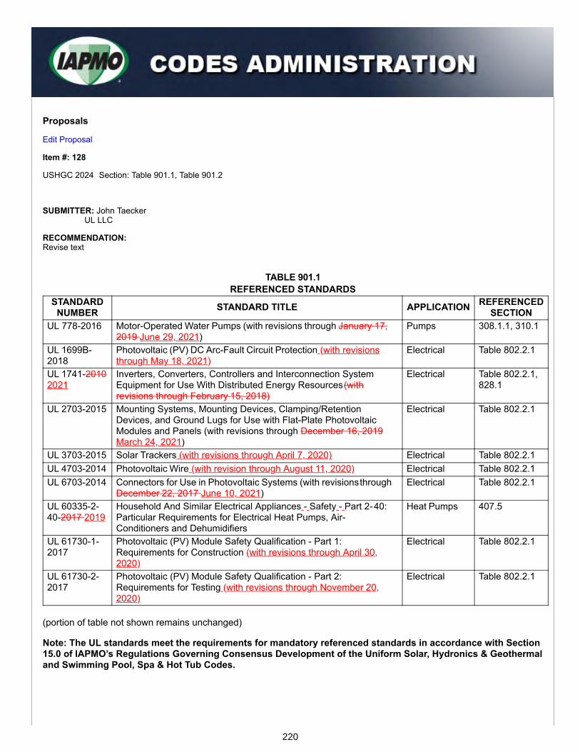
Proposals
Edit Proposal
Item #: 128
USHGC 2024 Section: Table 901.1, Table 901.2
SUBMITTER: John TaeckerUL LLC
RECOMMENDATION:Revise text
TABLE 901.1REFERENCED STANDARDS
STANDARDNUMBER STANDARD TITLE APPLICATION REFERENCED
SECTIONUL 778-2016 Motor-Operated Water Pumps (with revisions through January 17,
2019 June 29, 2021)Pumps 308.1.1, 310.1
UL 1699B-2018
Photovoltaic (PV) DC Arc-Fault Circuit Protection (with revisionsthrough May 18, 2021)
Electrical Table 802.2.1
UL 1741-20102021
Inverters, Converters, Controllers and Interconnection SystemEquipment for Use With Distributed Energy Resources (withrevisions through February 15, 2018)
Electrical Table 802.2.1,828.1
UL 2703-2015 Mounting Systems, Mounting Devices, Clamping/RetentionDevices, and Ground Lugs for Use with Flat-Plate PhotovoltaicModules and Panels (with revisions through December 16, 2019March 24, 2021)
Electrical Table 802.2.1
UL 3703-2015 Solar Trackers (with revisions through April 7, 2020) Electrical Table 802.2.1UL 4703-2014 Photovoltaic Wire (with revision through August 11, 2020) Electrical Table 802.2.1UL 6703-2014 Connectors for Use in Photovoltaic Systems (with revisions through
December 22, 2017 June 10, 2021)Electrical Table 802.2.1
UL 60335-2-40-2017 2019
Household And Similar Electrical Appliances - Safety - Part 2- 40:Particular Requirements for Electrical Heat Pumps, Air-Conditioners and Dehumidifiers
Heat Pumps 407.5
UL 61730-1-2017
Photovoltaic (PV) Module Safety Qualification - Part 1:Requirements for Construction (with revisions through April 30,2020)
Electrical Table 802.2.1
UL 61730-2-2017
Photovoltaic (PV) Module Safety Qualification - Part 2:Requirements for Testing (with revisions through November 20,2020)
Electrical Table 802.2.1
(portion of table not shown remains unchanged)
Note: The UL standards meet the requirements for mandatory referenced standards in accordance with Section15.0 of IAPMO’s Regulations Governing Consensus Development of the Uniform Solar, Hydronics & Geothermaland Swimming Pool, Spa & Hot Tub Codes.
220

TABLE 901.2STANDARDS, PUBLICATIONS, PRACTICES, AND GUIDES
DOCUMENT NUMBER DOCUMENT TITLE APPLICATIONUL 174-2004 Household Electric Storage Tank Water Heaters (with revisions through
December 3, 2019 December 16, 2021)Appliances
UL 873-2007 Temperature-Indicating and -Regulating Equipment (with revisionsthrough February 6, 2015) WITHDRAWN
Electrical
UL 916-2015 Energy Management Equipment (with revisions through October 21,2021)
Electrical
UL 60730-1 2016 Automatic Electrical Controls – Part 1: General Requirements (withrevisions through October 18, 2021)
Electrical
(portion of table not shown remains unchanged)
SUBSTANTIATION:The above revisions reflect the latest updates to the UL standards that are referenced in Table 901.1 and Table901.2.
221


Task Group Reports


Geothermal Energy Systems
Task Group Report

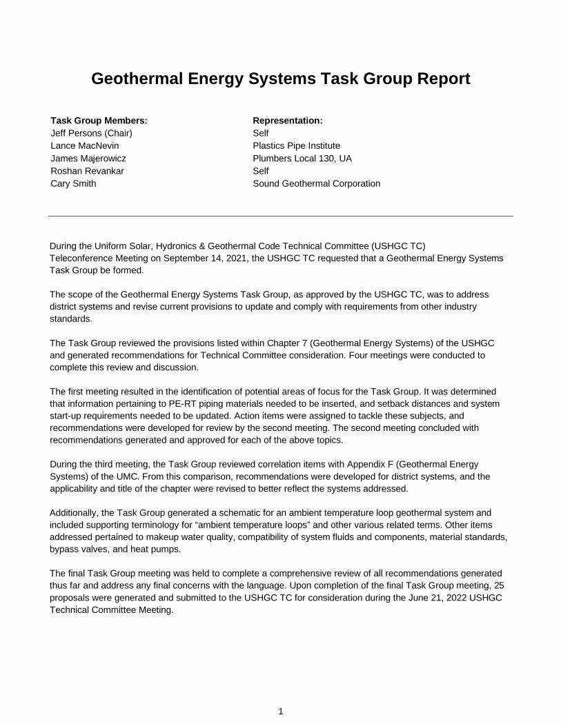
Geothermal Energy Systems Task Group Report
Task Group Members: Representation: Jeff Persons (Chair) Self Lance MacNevin Plastics Pipe Institute James Majerowicz Plumbers Local 130, UA Roshan Revankar Self Cary Smith Sound Geothermal Corporation
During the Uniform Solar, Hydronics & Geothermal Code Technical Committee (USHGC TC) Teleconference Meeting on September 14, 2021, the USHGC TC requested that a Geothermal Energy Systems Task Group be formed.
The scope of the Geothermal Energy Systems Task Group, as approved by the USHGC TC, was to address district systems and revise current provisions to update and comply with requirements from other industry standards.
The Task Group reviewed the provisions listed within Chapter 7 (Geothermal Energy Systems) of the USHGC and generated recommendations for Technical Committee consideration. Four meetings were conducted to complete this review and discussion.
The first meeting resulted in the identification of potential areas of focus for the Task Group. It was determined that information pertaining to PE-RT piping materials needed to be inserted, and setback distances and system start-up requirements needed to be updated. Action items were assigned to tackle these subjects, and recommendations were developed for review by the second meeting. The second meeting concluded with recommendations generated and approved for each of the above topics.
During the third meeting, the Task Group reviewed correlation items with Appendix F (Geothermal Energy Systems) of the UMC. From this comparison, recommendations were developed for district systems, and the applicability and title of the chapter were revised to better reflect the systems addressed.
Additionally, the Task Group generated a schematic for an ambient temperature loop geothermal system and included supporting terminology for “ambient temperature loops” and other various related terms. Other items addressed pertained to makeup water quality, compatibility of system fluids and components, material standards, bypass valves, and heat pumps.
The final Task Group meeting was held to complete a comprehensive review of all recommendations generated thus far and address any final concerns with the language. Upon completion of the final Task Group meeting, 25 proposals were generated and submitted to the USHGC TC for consideration during the June 21, 2022 USHGC Technical Committee Meeting.
1

SECTION #: 701.1, 701.1.3
RECOMMENDATION:
CHAPTER 7 GEOTHERMAL ENERGY SYSTEMS AND DISTRICT GEOTHERMAL LOOPS
Part I – General.
701.0 General. 701.1 Applicability. Part I of this chapter shall apply to geothermal energy systems such as, but not limited to, building systems coupled with a ground-heat exchanger, submerged heat exchanger using water-based fluid as a heat transfer medium, or groundwater (well). The regulations of this chapter shall govern the construction, location, and installation of geothermal energy systems.
Indoor piping, fittings, and accessories that are part of the groundwater system shall be in accordance with Section 703.5 and Chapter 4.
Part I through Part V of this chapter shall apply to geothermal energy systems and district thermal systems that circulate ground-ambient-temperature water to be used in end-use buildings as a thermal source or sink via water source heat pump or reversing chiller. The systems shall operate to permit independent and bi-directional heating and cooling for comfort and water heating such as, but not limited to, building systems coupled with ground coupled district loops, a ground-heat exchanger, submerged heat exchanger using water-based fluid as a heat transfer medium, or groundwater (well), or such local resources to the advantage of the district. Central district auxiliary components shall add or reject heat to benefit district ability, to reduce both power consumption, and demand combined with energy sharing. The regulations of this chapter shall govern the construction, location, and installation of ground temperature thermal distribution districts from 100 percent geothermal energy systems to multiple hybrid district systems. (See Figure 701.1 for a schematic of a geothermal system utilizing an ambient temperature loop.)
701.1.3 Indoor Piping. Indoor piping, fittings, and accessories that are part of the groundwater system shall be in accordance with Section 703.5 and Chapter 4.
SUBSTANTIATION: Section 701.1 (Applicability) is being revised to provide insight into the various parts of Chapter 7 pertaining to general requirements, open-loop systems, closed-loop systems, DX systems, and now district ambient temperature loops.
The addition of geothermal district systems supports advanced thermal distribution networks and provides the code with the necessary requirements for large scale renewable energy systems.
Furthermore, the language pertaining to indoor piping, fittings, and accessories has been moved from the applicability to Section 701.1.3 (Indoor Piping) as this allows for proper flow of requirements.
2
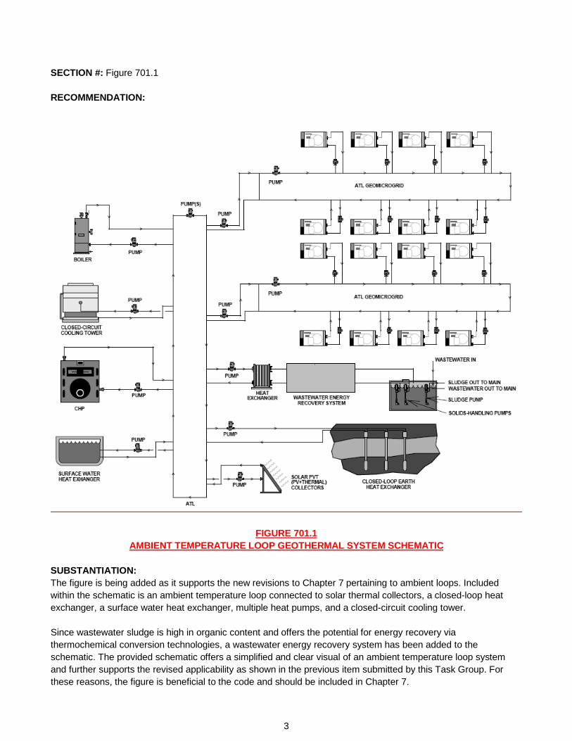
SECTION #: Figure 701.1
RECOMMENDATION:
FIGURE 701.1 AMBIENT TEMPERATURE LOOP GEOTHERMAL SYSTEM SCHEMATIC
SUBSTANTIATION: The figure is being added as it supports the new revisions to Chapter 7 pertaining to ambient loops. Included within the schematic is an ambient temperature loop connected to solar thermal collectors, a closed-loop heat exchanger, a surface water heat exchanger, multiple heat pumps, and a closed-circuit cooling tower.
Since wastewater sludge is high in organic content and offers the potential for energy recovery via thermochemical conversion technologies, a wastewater energy recovery system has been added to the schematic. The provided schematic offers a simplified and clear visual of an ambient temperature loop system and further supports the revised applicability as shown in the previous item submitted by this Task Group. For these reasons, the figure is beneficial to the code and should be included in Chapter 7.
3
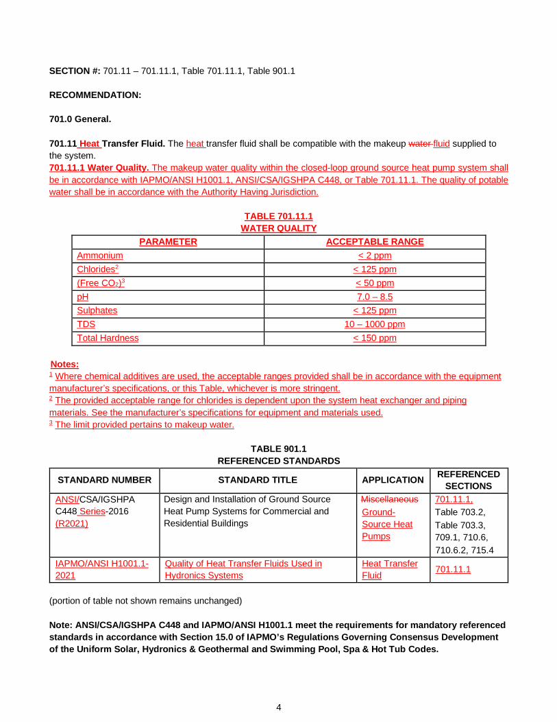
SECTION #: 701.11 – 701.11.1, Table 701.11.1, Table 901.1 RECOMMENDATION: 701.0 General. 701.11 Heat Transfer Fluid. The heat transfer fluid shall be compatible with the makeup water fluid supplied to the system. 701.11.1 Water Quality. The makeup water quality within the closed-loop ground source heat pump system shall be in accordance with IAPMO/ANSI H1001.1, ANSI/CSA/IGSHPA C448, or Table 701.11.1. The quality of potable water shall be in accordance with the Authority Having Jurisdiction.
TABLE 701.11.1
WATER QUALITY PARAMETER ACCEPTABLE RANGE
Ammonium < 2 ppm Chlorides2 < 125 ppm (Free CO2)3 < 50 ppm pH 7.0 – 8.5 Sulphates < 125 ppm TDS 10 – 1000 ppm Total Hardness < 150 ppm
Notes: 1 Where chemical additives are used, the acceptable ranges provided shall be in accordance with the equipment manufacturer’s specifications, or this Table, whichever is more stringent. 2 The provided acceptable range for chlorides is dependent upon the system heat exchanger and piping materials. See the manufacturer’s specifications for equipment and materials used. 3 The limit provided pertains to makeup water.
TABLE 901.1 REFERENCED STANDARDS
STANDARD NUMBER STANDARD TITLE APPLICATION REFERENCED SECTIONS
ANSI/CSA/IGSHPA C448 Series-2016 (R2021)
Design and Installation of Ground Source Heat Pump Systems for Commercial and Residential Buildings
Miscellaneous Ground-Source Heat Pumps
701.11.1, Table 703.2, Table 703.3, 709.1, 710.6, 710.6.2, 715.4
IAPMO/ANSI H1001.1-2021
Quality of Heat Transfer Fluids Used in Hydronics Systems
Heat Transfer Fluid 701.11.1
(portion of table not shown remains unchanged) Note: ANSI/CSA/IGSHPA C448 and IAPMO/ANSI H1001.1 meet the requirements for mandatory referenced standards in accordance with Section 15.0 of IAPMO’s Regulations Governing Consensus Development of the Uniform Solar, Hydronics & Geothermal and Swimming Pool, Spa & Hot Tub Codes.
4

SUBSTANTIATION: IAPMO/ANSI H1001.1 (Quality of Heat Transfer Fluids Used in Hydronics Systems) is a newly published standard which provides minimum requirements for maintaining the quality of liquid aqueous-based heat transfer fluids over the life of the system and optimizing the life of system components. The standard is applicable to both residential and non-residential closed hydronic heating and cooling systems. IAPMO/ANSI H1001.1 is unique in that it addresses both chemical and non-chemical treatment methods with a focus on the importance of water treatment and corrosion prevention. These provisions are accompanied by hydronic water quality parameters for systems with chemical additives, high purity water systems, and hybrid hydronic and ground source heat pump systems. Proposed Table 701.11.1 (Water Quality) is an excerpt from IAPMO/ANSI H1001.1, and the listed parameters are provided to ensure that the makeup water quality meets the necessary acceptable ranges to prevent corrosion within the system. Since IAPMO/ANSI H1001.1 includes references to ANSI/CSA/IGSHPA C448 for ground source heat pumps, the standard should also be added to the proposed section. SECTION #: 701.11, 701.11.2 RECOMMENDATION: 701.0 General. 701.11.2 Compatibility. System components shall be compatible with system fluids including, but not limited to, antifreeze. For systems utilizing chemical additives, system components and fluids shall be tested and approved for compatibility. SUBSTANTIATION: Ensuring system longevity and thermal efficiency is necessary when designing geothermal systems. A large component of that design is the selection of system components, heat transfer fluids, and chemical additives. Where incompatible fluids and components are used, corrosion and fouling will lead to decreased efficiency and system failure. For these reasons, the proposed Section 701.11.2 (Compatibility) is both necessary and appropriate. SECTION #: Table 703.2, Table 703.3 RECOMMENDATION:
TABLE 703.2 PLASTIC GROUND SOURCE LOOP PIPING
MATERIAL STANDARDS Cross-Linked Polyethylene (PEX) ASTM F876, ASTM F3253, CSA B137.5,
CSA/IGSHPA C448, NSF 358-3
Polyethylene of Raised Temperature (PE-RT) ASTM F2623, ASTM F2769, CSA B137.18, CSA/IGSHPA C448,
NSF 358-4 (portion of table not shown remains unchanged)
5
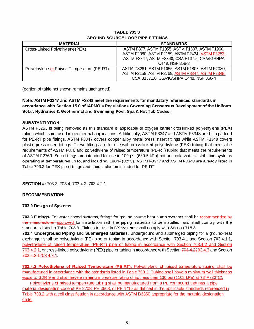
TABLE 703.3 GROUND SOURCE LOOP PIPE FITTINGS
MATERIAL STANDARDS Cross-Linked Polyethylene (PEX) ASTM F877, ASTM F1055, ASTM F1807, ASTM F1960,
ASTM F2080, ASTM F2159, ASTM F2434, ASTM F3253, ASTM F3347, ASTM F3348, CSA B137.5, CSA/IGSHPA
C448, NSF 358-3 Polyethylene of Raised Temperature (PE-RT) ASTM D3261, ASTM F1055, ASTM F1807, ASTM F2080,
ASTM F2159, ASTM F2769, ASTM F3347, ASTM F3348, CSA B137.18, CSA/IGSHPA C448, NSF 358-4
(portion of table not shown remains unchanged)
Note: ASTM F3347 and ASTM F3348 meet the requirements for mandatory referenced standards in accordance with Section 15.0 of IAPMO’s Regulations Governing Consensus Development of the Uniform Solar, Hydronics & Geothermal and Swimming Pool, Spa & Hot Tub Codes.
SUBSTANTIATION: ASTM F3253 is being removed as this standard is applicable to oxygen barrier crosslinked polyethylene (PEX) tubing which is not used in geothermal applications. Additionally, ASTM F3347 and ASTM F3348 are being added for PE-RT pipe fittings. ASTM F3347 covers copper alloy metal press insert fittings while ASTM F3348 covers plastic press insert fittings. These fittings are for use with cross-linked polyethylene (PEX) tubing that meets the requirements of ASTM F876 and polyethylene of raised temperature (PE-RT) tubing that meets the requirements of ASTM F2769. Such fittings are intended for use in 100 psi (689.5 kPa) hot and cold water distribution systems operating at temperatures up to, and including, 180°F (82°C). ASTM F3347 and ASTM F3348 are already listed in Table 703.3 for PEX pipe fittings and should also be included for PE-RT. SECTION #: 703.3, 703.4, 703.4.2, 703.4.2.1 RECOMMENDATION: 703.0 Design of Systems. 703.3 Fittings. For water-based systems, fittings for ground source heat pump systems shall be recommended by the manufacturer approved for installation with the piping materials to be installed, and shall comply with the standards listed in Table 703.3. Fittings for use in DX systems shall comply with Section 715.3. 703.4 Underground Piping and Submerged Materials. Underground and submerged piping for a ground-heat exchanger shall be polyethylene (PE) pipe or tubing in accordance with Section 703.4.1 and Section 703.4.1.1, polyethylene of raised temperature (PE-RT) pipe or tubing in accordance with Section 703.4.2 and Section 703.4.2.1, or cross-linked polyethylene (PEX) pipe or tubing in accordance with Section 703.4.2703.4.3 and Section 703.4.2.1703.4.3.1.
703.4.2 Polyethylene of Raised Temperature (PE-RT). Polyethylene of raised temperature tubing shall be manufactured in accordance with the standards listed in Table 703.2. Tubing shall have a minimum wall thickness equal to SDR 9 and shall have a minimum pressure rating of not less than 160 psi (1103 kPa) at 73°F (23°C).
Polyethylene of raised temperature tubing shall be manufactured from a PE compound that has a pipe material designation code of PE 2708, PE 3608, or PE 4710 as defined in the applicable standards referenced in Table 703.2 with a cell classification in accordance with ASTM D3350 appropriate for the material designation code.
6
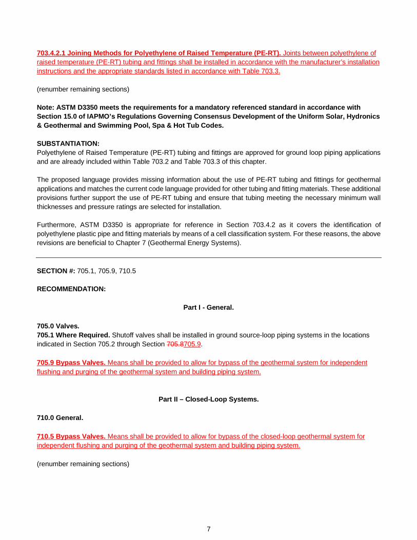
703.4.2.1 Joining Methods for Polyethylene of Raised Temperature (PE-RT). Joints between polyethylene of raised temperature (PE-RT) tubing and fittings shall be installed in accordance with the manufacturer’s installation instructions and the appropriate standards listed in accordance with Table 703.3. (renumber remaining sections) Note: ASTM D3350 meets the requirements for a mandatory referenced standard in accordance with Section 15.0 of IAPMO’s Regulations Governing Consensus Development of the Uniform Solar, Hydronics & Geothermal and Swimming Pool, Spa & Hot Tub Codes. SUBSTANTIATION: Polyethylene of Raised Temperature (PE-RT) tubing and fittings are approved for ground loop piping applications and are already included within Table 703.2 and Table 703.3 of this chapter. The proposed language provides missing information about the use of PE-RT tubing and fittings for geothermal applications and matches the current code language provided for other tubing and fitting materials. These additional provisions further support the use of PE-RT tubing and ensure that tubing meeting the necessary minimum wall thicknesses and pressure ratings are selected for installation. Furthermore, ASTM D3350 is appropriate for reference in Section 703.4.2 as it covers the identification of polyethylene plastic pipe and fitting materials by means of a cell classification system. For these reasons, the above revisions are beneficial to Chapter 7 (Geothermal Energy Systems). SECTION #: 705.1, 705.9, 710.5 RECOMMENDATION:
Part I - General.
705.0 Valves. 705.1 Where Required. Shutoff valves shall be installed in ground source-loop piping systems in the locations indicated in Section 705.2 through Section 705.8705.9.
705.9 Bypass Valves. Means shall be provided to allow for bypass of the geothermal system for independent flushing and purging of the geothermal system and building piping system.
Part II – Closed-Loop Systems.
710.0 General.
710.5 Bypass Valves. Means shall be provided to allow for bypass of the closed-loop geothermal system for independent flushing and purging of the geothermal system and building piping system.
(renumber remaining sections)
7

SUBSTANTIATION: Section 705.9 and Section 710.5 are needed to ensure that a means of bypass is provided for the purpose of flushing and purging of a geothermal and building piping system. Although Part I (General) applies to all geothermal systems addressed within this chapter, the Task Group preferred to also repeat this provision under Part II (Closed-Loop Systems). Flushing and purging of these piping systems is crucial for removal of debris and trapped air and assists with successful system maintenance and installation. For these reasons, the additional language is needed. SECTION #: 705.2 RECOMMENDATION:
Part I - General.
705.0 Valves. 705.2 Heat Exchangers. Shutoff valves shall be installed on the supply and return side of a heat exchanger. Exception: Where a the heat exchanger is an integral part of with a boiler or is a part component of a manufactured manufacturer’s boiler and heat exchanger packaged unit, and is capable of being isolated from the hydronic system by the supply and return valves. SUBSTANTIATION: Section 705.2 (Heat Exchangers) is being revised to correlate with the mechanical code. The modified language is preferred and provides clarity for the end user. SECTION #: 705.6 RECOMMENDATION:
Part I - General.
705.0 Valves. 705.6 Equipment and Appliances. Shutoff valves shall be installed on connections to mechanical equipment and appliances. This requirement shall not apply to components of a ground source loop system such as pumps, air separators, metering devices, and similar equipment. SUBSTANTIATION: Section 705.6 (Equipment and Appliances) is being updated to clarify that “mechanical equipment and appliances” do not refer to components of the ground source loop system but rather externally connected equipment. The current language enforces impractical and unnecessary requirements. For these reasons, the revision is needed.
8

SECTION #: 706.1, Table 706.1 RECOMMENDATION: 706.0 Specific System Components Design. 706.1 General. Heat pumps shall be in compliance with Table 706.1, as applicable. Heat pumps shall also be listed and labeled in accordance with UL 1995 or UL 60335-2-40. Ground coupled and water source heat pumps shall be listed in accordance with AHRI/ASHRAE/ISO 13256-1 for water-to-air heat pumps and AHRI/ASHRAE/ISO 13256-2 for water-to-water heat pumps. DX heat pumps shall be listed in accordance with ASHRAE 194. All heat pump equipment used in DX systems shall comply with AHRI 870. Heat pumps shall be fitted with a means to indicate that the compressor is locked out.
TABLE 706.1 HEAT PUMPS
TYPE OF HEAT PUMP STANDARDS Water-to-Air AHRI/ASHRAE/ISO 13256-1
Water-to-Water AHRI/ASHRAE/ISO 13256-2 Note: AHRI/ASHRAE/ISO 13256-1, AHRI/ASHRAE/ISO 13256-2, UL 1995 and UL 60335-2-40 meet the requirements for mandatory referenced standards in accordance with Section 15.0 of IAPMO’s Regulations Governing Consensus Development of the Uniform Solar, Hydronics & Geothermal and Swimming Pool, Spa & Hot Tub Codes. SUBSTANTIATION: Section 706.1 is being revised to include reference to UL 1995 and UL 60335-2-40 in addition to the performance standards already provided, AHRI/ASHRAE/ISO 13256-1 and AHRI/ASHRAE/ISO 13256-2. UL 1995 is applicable as it sets requirements for heating and cooling equipment for use in non-hazardous locations rated between 600 V and 7200 V. Additionally, UL 60335-2-40 is being proposed as it provides safety requirements for electrical heat pumps, air-conditioners, and dehumidifiers. Both of these standards currently exist in Section 407.5 (Heat Pumps) and should also be listed for geothermal heat pumps. Furthermore, these revisions are consistent with the mechanical code and add references to the appropriate safety standards for heat pumps. SECTION #: 221.0, 706.3 RECOMMENDATION: 706.0 Specific System Components Design. 706.3 Heat-Transfer Medium. The heat-transfer medium shall be compatible with components with which it comes into contact. Where antifreeze or corrosion inhibitors are used, such solutions shall be approved by the Authority Having Jurisdiction. The heat-transfer fluid flash point shall be not less than 50°F (28°C) above the maximum system operating temperature. For DX systems, the heat transfer medium shall be a refrigerant listed in ASHRAE 34 or the mechanical code. For six-pipe heat pump systems and other specialty heat pumps that comingle source and load fluids, the manufacturer’s recommendations shall apply.
9

221.0 – S – Six-Pipe Heat Pump System. A hydronic system capable of simultaneously heating and cooling. Dependent upon the equipment, such systems may comingle the source and load fluids. SUBSTANTIATION: A six-pipe heat pump system serves as a simultaneous chiller and boiler for large-scale or commercial applications. Through the use of connected modules, these systems can serve hot and cold water loops in various control configurations. Six-pipe heat pumps operate at higher efficiency/COPs and have flexibility when sharing thermal loads within the same building. Section 706.3 (Heat-Transfer Medium) is being revised to mention six-pipe heat pump systems, and since these complex systems may comingle source and load fluids, requiring compliance with the heat pump manufacturer’s recommendations is necessary. Furthermore, a definition for “six-pipe heat pump system” is being added to provide guidance for users of the code who may require clarification on the newly proposed provision. SECTION #: 707.2 RECOMMENDATION: 707.0 Installation Practices. 707.2 Equipment, Accessories, Components, and Materials. The mechanical equipment, accessories, components, and materials used shall be recommended by the manufacturer of the type and rating approved for the specific use. SUBSTANTIATION: Section 707.2 (Equipment, Accessories, Components, and Materials) is being revised to correlate with the mechanical code. Additionally, the Task Group supports this change as it requires equipment, accessories and components be approved for specific use. Such installation practices facilitate system longevity. SECTION #: 205.0, 707.5, 713.3, 713.5, 714.4 – 714.6 RECOMMENDATION: 707.0 Installation Practices. 707.5 Subsurface Investigation. A subsurface investigation shall be performed in accordance with Section 707.5.1 as determined by the registered design professional or certified person designer conducting the site survey. 713.0 Open Ground Water Systems. 713.3 Design Considerations. A groundwater heat pump system shall be designed by a registered design professional or certified person designer. Due design consideration shall be given to the following: (1) - (9) (remaining text unchanged)
10

713.5 Testing and Sampling. Pumping tests and water sampling shall be done as required by the registered design professional or certified person designer. 714.0 Testing and Verification. 714.4 Constant Rate Pump Test. The sustainable well yield, aquifer coefficients, and zones of influences on the groundwater flow requirements shall be confirmed with a constant rate-pumping test. The constant rate-pumping test shall be done on the water supply and injection wells at rates and durations as specified by the registered design professional or certified person designer. 714.5 Water Level Monitoring. Water levels shall be monitored in the pumping well and observation wells during pumping and recovery periods. The monitoring time intervals shall be as specified by the registered design professional or certified person designer. 714.6 Injection Wells. Injection testing shall be performed on water wells that are designated to be used as injection wells at rates specified by the registered design professional or certified person designer. The results of the drilling and pumping tests shall be provided to the owner or the owner’s representative and provided in accordance with requirements of the Authority Having Jurisdiction. 205.0 – C – Certified Designer. An individual who has successfully completed the formal training, testing, project design experience, and continuing education credits to be granted the IGSHPA/AEE title of Certified GeoExchange Designer, or other equivalent approved certification program. Certified Person. A person trained and certified by the equipment manufacturer, or by a recognized organization through a formal certification program for the system to be serviced or cleaned; that is acceptable to the Authority Having Jurisdiction. SUBSTANTIATION: For the purposes of this chapter, “certified designer” is more applicable and appropriate than “certified person.” The term “certified designer,” as defined above, is clear and more specific on the type of education, training and certification required for designing geothermal energy systems. The provided definition also includes language which addresses other equivalent approved certification programs rather than only referencing one certification agency. Since “certified person” is not used elsewhere within the code, the term is completely being stricken. SECTION #: 707.6 RECOMMENDATION: 707.0 Installation Practices. 707.6 Ground Heat-Exchanger Installation Practices. A ground-heat exchanger system shall be installed as follows: (1) - (5) (remaining text unchanged) (6) Vertical and horizontal ground-heat exchangers shall maintain the following setbacks in accordance with the Authority Having Jurisdiction, or the following: (a) Ten feet (3048 mm) horizontally from a pressure-tested sewer lateral into a building. (b) Twenty Fifty feet (609615 240 mm) horizontally from a non-pressure tested sewer lateral into a building.
11
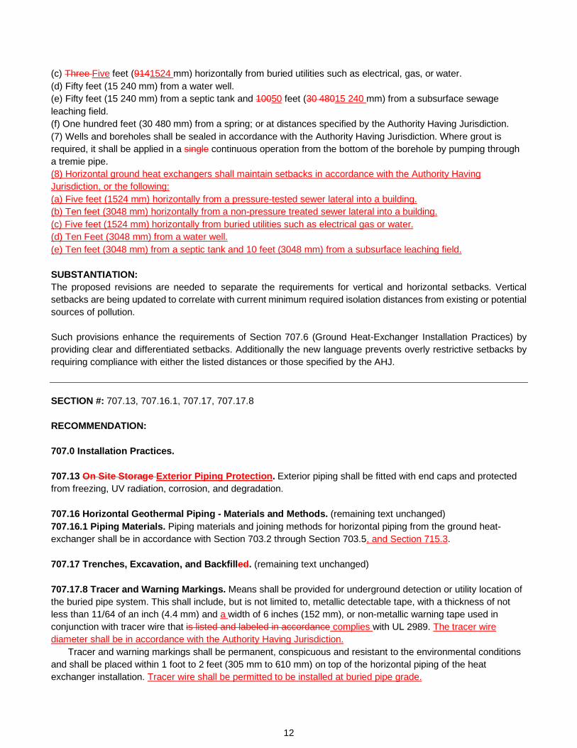
(c) Three Five feet (9141524 mm) horizontally from buried utilities such as electrical, gas, or water. (d) Fifty feet (15 240 mm) from a water well. (e) Fifty feet (15 240 mm) from a septic tank and 10050 feet (30 48015 240 mm) from a subsurface sewage leaching field. (f) One hundred feet (30 480 mm) from a spring; or at distances specified by the Authority Having Jurisdiction. (7) Wells and boreholes shall be sealed in accordance with the Authority Having Jurisdiction. Where grout is required, it shall be applied in a single continuous operation from the bottom of the borehole by pumping through a tremie pipe. (8) Horizontal ground heat exchangers shall maintain setbacks in accordance with the Authority Having Jurisdiction, or the following: (a) Five feet (1524 mm) horizontally from a pressure-tested sewer lateral into a building. (b) Ten feet (3048 mm) horizontally from a non-pressure treated sewer lateral into a building. (c) Five feet (1524 mm) horizontally from buried utilities such as electrical gas or water. (d) Ten Feet (3048 mm) from a water well. (e) Ten feet (3048 mm) from a septic tank and 10 feet (3048 mm) from a subsurface leaching field. SUBSTANTIATION: The proposed revisions are needed to separate the requirements for vertical and horizontal setbacks. Vertical setbacks are being updated to correlate with current minimum required isolation distances from existing or potential sources of pollution. Such provisions enhance the requirements of Section 707.6 (Ground Heat-Exchanger Installation Practices) by providing clear and differentiated setbacks. Additionally the new language prevents overly restrictive setbacks by requiring compliance with either the listed distances or those specified by the AHJ. SECTION #: 707.13, 707.16.1, 707.17, 707.17.8 RECOMMENDATION: 707.0 Installation Practices. 707.13 On Site Storage Exterior Piping Protection. Exterior piping shall be fitted with end caps and protected from freezing, UV radiation, corrosion, and degradation. 707.16 Horizontal Geothermal Piping - Materials and Methods. (remaining text unchanged) 707.16.1 Piping Materials. Piping materials and joining methods for horizontal piping from the ground heat-exchanger shall be in accordance with Section 703.2 through Section 703.5, and Section 715.3. 707.17 Trenches, Excavation, and Backfilled. (remaining text unchanged) 707.17.8 Tracer and Warning Markings. Means shall be provided for underground detection or utility location of the buried pipe system. This shall include, but is not limited to, metallic detectable tape, with a thickness of not less than 11/64 of an inch (4.4 mm) and a width of 6 inches (152 mm), or non-metallic warning tape used in conjunction with tracer wire that is listed and labeled in accordance complies with UL 2989. The tracer wire diameter shall be in accordance with the Authority Having Jurisdiction.
Tracer and warning markings shall be permanent, conspicuous and resistant to the environmental conditions and shall be placed within 1 foot to 2 feet (305 mm to 610 mm) on top of the horizontal piping of the heat exchanger installation. Tracer wire shall be permitted to be installed at buried pipe grade.
12

SUBSTANTIATION: The title of Section 707.13 is being updated to represent the accompanying provision more appropriately. ‘ Section 717.16.1 (Piping Materials) is being revised to include reference to Section 715.3 (DX Systems) as those provisions address copper pipe and tubing installed for DX systems. Section 707.17.8 (Tracer and Warning Markings) is being modified to require compliance with the AHJ for tracer wire diameter sizing. Additionally, the new language permits the installation of tracer wire at buried pipe grade, or below grade and in direct contact with soil. SECTION #: 708.1 RECOMMENDATION: 708.0 System Start-Up. 708.1 General. The following requirements shall be verified prior to system start-up: (1) Piping shall be cleaned, flushed, and purged. To prevent debris in the building piping system from entering the geothermal loop field piping or residual debris from the geothermal loop field entering the building piping, the connection between building piping and the geothermal loop field shall be isolated so as to allow a bypass for the independent cleaning, flushing, and purging of both the loop field as well as the building piping and equipment prior to the introduction of building fluid into the geothermal loop field. (2) The ground heat exchanger and building piping shall be cleaned, flushed, and, where required, shall be filled with the heat transfer fluid medium. The ground loop system shall be tested at the design flow rate(s) and differential pressure(s) recorded. Where the actual pressure change at design flow is more than ± 10 percent of the design flow pressure drop, the cause shall be identified and corrective action taken. (3) - (9) (remaining text unchanged) SUBSTANTIATION: The revisions to Section 708.1 (General) are needed to ensure that a means of isolation and bypass are provided for the purpose of cleaning, flushing, and purging of geothermal loop field piping. Residual debris from the geothermal loop may enter the building piping if not flushed and purged. Additionally, the building piping and equipment must be cleaned to prevent contaminants from entering the geothermal loop. Installing a means of isolation and bypass between the geothermal loop and the building piping is therefore necessary to prepare equipment for connection. SECTION #: 708.7 RECOMMENDATION: 708.0 System Start-Up. 708.7 System Start-Up. System start-up shall be in accordance with CSA C448.1, CSA C448.2, ANSI/CSA/IGSHPA C448 and Section 708.0.
13

TABLE 901.1 REFERENCED STANDARDS
STANDARD NUMBER STANDARD TITLE APPLICATION REFERENCED
SECTIONS CSA C448.1-2016 Design and Installation of Ground Source Heat
Pump Systems for Commercial and Institutional Buildings
Ground-Source Heat Pumps
708.7
CSA C448.2-2016 Design and Installation of Ground Source Heat Pump Systems for Residential and Other Small Buildings
Ground-Source Heat Pumps
708.7
ANSI/CSA/IGSHPA C448 Series-2016 (R2021)
Design and Installation of Ground Source Heat Pump Systems for Commercial and Residential Buildings
Miscellaneous Ground-Source Heat Pumps
Table 703.2, Table 703.3, 708.7, 709.1, 710.6, 710.6.2, 715.4
(portion of table not shown remains unchanged) Note: ANSI/CSA/IGSHPA C448 meets the requirements for a mandatory referenced standard in accordance with Section 15.0 of IAPMO’s Regulations Governing Consensus Development of the Uniform Solar, Hydronics & Geothermal and Swimming Pool, Spa & Hot Tub Codes.
SUBSTANTIATION: CSA C448.1 and CSA C448.2 are different chapters of ANSI/CSA/IGSHPA C448. It would be more appropriate to reference the entire standard rather than different chapters or sections of ANSI/CSA/IGSHPA C448. Additionally, CSA C448.1 and CSA C448.2 are not referenced in any other portion of the code and are therefore being stricken from Table 901.1. For these reasons, the above modifications are necessary. SECTION #: 710.6.2.2 RECOMMENDATION:
Part II - Closed-Loop Systems. 710.0 General. 710.6 Vertical Bores. (remaining text unchanged) 710.6.2 U-Bends and Headers. (remaining text unchanged) 710.6.2.2 Testing Procedure. The test section and the test liquid shall be at the same temperature. The test section shall be filled with liquid and purged of air. The test section shall be brought to the specified test pressure. Test pressure shall be maintained for 4 hours, with make-up additional fluid added as needed. The test pressure shall be reduced by 10 psi (69 kPa) and monitored for 1 hour with no addition of pressure or make-up additional fluid. A passing test is indicated where after a period of 1 hour no visual leakage is observed, and pressure remains equal to or greater than 95 percent of the original pressure.
14

SUBSTANTIATION: Section 710.6.2.2 (Testing Procedure) is being revised to correlate with the mechanical code. The term “makeup fluid” is specific to hydronics and represents fluid that is added to maintain system pressure. For the purposes of this chapter, the wording "additional fluid" is more suitable. For these reasons, the proposed modification is necessary. SECTION #: 712.1 RECOMMENDATION:
Part III – Open-Loop Systems. 712.0 General. 712.1 Applicability. Part III of this chapter shall apply to geothermal energy systems such as, but not limited to, building systems coupled with a groundwater (well) or surface water open-loop using water-based fluid as a heat transfer medium. The regulations of this chapter shall govern the construction, location and installation of geothermal energy systems.
Indoor piping, fittings, and accessories that are part of the groundwater system shall be in accordance with Section 703.5 and Chapter 4. Outdoor piping, fittings, and accessories shall be in accordance with Section 703.2.
Components which come into contact with the system fluids and are installed in a geothermal open-loop system shall be constructed of corrosion resistant materials or in accordance with the AHJ. SUBSTANTIATION: Since open-loop geothermal components are continuously exposed to groundwater or surface water, corrosion prevention substantially influences the design of geothermal systems. The water quality of these sources varies and can in some cases be inferior causing scaling and corrosion. For these reasons, components of the system which come into contact with the source fluid need to be constructed of corrosion resistant materials. SECTION #: 713.4 RECOMMENDATION: 713.0 Open Ground Water Systems. 713.4 Water Wells and Injection Wells. Water wells and injection wells for groundwater heat pump systems shall be installed and tested by a registered professional who is qualified to drill wells that comply with the requirements of the Authority Having Jurisdiction.
Water supply wells and injection wells shall be developed in accordance with NGWA-01. SUBSTANTIATION: The additional language ensures that both installation and testing are completed by a registered professional.
15

SECTION #: 203.0, 208.0, 716.0 – 716.2 RECOMMENDATION:
Part V – District Ambient Temperature Loop (ATL) Geothermal.
716.0 Ambient Temperature Loop (ATL) Distributed Energy Systems. 716.1 General. An ambient temperature loop (ATL) distributed energy system shall be installed in accordance with Section 716.2 through Section 716.6.3, and Section 717.0. ATL systems shall comply with Part I through Part IV of this chapter, as applicable. 716.1.1 Fourth Generation (4G) System Configuration. A fourth-generation system configuration shall be a district geothermal energy system distributing hot water, cold water, or both to the conditioned space or building for a specific use. Where a geothermal energy source is used, such systems shall comply with Part I through Part IV of this chapter and Chapter 4. 716.1.2 Fifth Generation (5G) System Configurations. An advanced ambient temperature loop (ATL) System or fifth generation (5G) ATL system shall also be capable of interacting with the electric utility system as well as other utility systems and systems components. System components shall include, but not be limited to, the following: (1) Thermally diverse buildings with independent hydronic systems. (2) Circulation loop. (3) Global control system. (4) Segment isolation capability. Note: System components may include, but are not limited to, the following: (1) Electric grid-interactive enabled buildings (2) Hybrid components (3) Other renewable systems 716.2 Permitting. Permits required for the installation and application of an ATL distributed energy system shall be obtained as required by the Authority Having Jurisdiction. 203.0 – A – Ambient Temperature Loop (ATL). A closed loop piping system with central pumping that includes various heat sources and heat sinks to hold the loop fluid temperature near the long term average ambient air temperature for a given geographical location. The sources/sinks can be passive (e.g., a ground loop, a body of water, sewer effluent) or active (e.g. a cooling tower) and further can include opportunistic, or unique locally available waste or by-product heat sources (e.g., data center, industrial process). The closed loop piping system typically controls or engages these sources/sinks to maintain the loop temperature to meet the seasonal requirements as well as specific building needs. 208.0 – F – Fifth Generation (5G) System Configurations. An advanced ambient temperature (ATL) system that distributes near ambient temperature water among and between end use buildings that are equipped with water-source heat pumps or other water source HVAC equipment. Such systems stand in contrast to fourth generation (4G) systems that distribute hot water or chilled water to buildings to serve facility loads. Fourth Generation (4G) System Configurations. A district geothermal energy system that distributes dedicated hot water and chilled water for direct use in the conditioned space.
16

SUBSTANTIATION: Part V (District Ambient Temperature Loop) is being proposed in response to the attention drawn to ambient temperature loop district systems. Many states have implemented carbon reduction plans and non-combustion alternatives, and district ambient temperature loops coincide with these initiatives. Such systems lack installation requirements throughout the code and should therefore be provided. Ambient temperature loops are high efficiency systems that recover wasted energy that is normally rejected to the atmosphere. The proposed provisions in Section 716.1.1 and Section 716.1.2 address the general requirements for fourth and fifth generation systems; along with permitting requirements. The definitions for "fourth generation (4G) system configuration" and "fifth generation (5G) system configuration" are included as such systems are not currently defined and are not commonly known. A definition for "ambient temperature loop (ATL)" was also added to support the proposed code changes pertaining to these systems. The provided language appropriately defines ATL systems and informs users of the code that ATLs are closed-loop piping systems which include various heat sources and heat sinks. SECTION #: 716.3 – 716.5 RECOMMENDATION: 716.3 Ambient Loop Temperature Range. The operating loop temperature range of an ambient temperature loop (ATL) system shall be not less than the freezing point of the circulating fluid and not more than the maximum temperature, as required by the manufacturer’s installation instructions for the attached heat pump equipment in accordance with Section 716.3.1 and Section 716.3.2. The ATL system shall use treated water as the heat transfer medium. 716.3.1 ATL Operating Temperature. For equipment listed to AHRI/ASHRAE/ISO 13256-1 and AHRI/ASHRAE/ISO 13256-2, the controlled temperature range of the ambient closed-loop shall be not less than 7°F (4°C) above the freezing point of the transport fluid and 10°F (6°C) below the (collective) heat pump lowest maximum inlet supply temperature as recommended by the manufacturer’s instructions. Exception: Equipment that is not listed to AHRI/ASHRAE/ISO 13256-1 and AHRI/ASHRAE/ISO 13256-2, the controlled temperature range of the ambient closed loop shall be in accordance with Section 716.3.2 for minimum and maximum temperatures. 716.3.2 ATL Operating Temperature Range for Mixed Equipment Certifications. The source inlet temperature range of any attached equipment shall govern the design operating temperature range. Such equipment shall be identified in the design documentation. In any case, the most restrictive minimum and maximum inlet supply temperatures, as recommended by the manufacturer’s instructions, shall determine the system operating temperature range. 716.4 Shutoff Valve. An automatic shutoff valve shall be provided for each individual building or facility transferring energy to or from an ATL distribution system. The automatic shutoff valve shall automatically shutoff upon operating command. 716.4.1 Shutoff Valve Operation. The operation of the automatic shutoff valve shall be in accordance with the system operating procedures. Where the operation of a shutoff valve was due to an emergency response, an auxiliary heating or cooling methodology shall be provided in accordance with Section 717.1.2. 716.5 Bypass. The ATL distributed energy system shall be provided with bypass path(s) to reroute the circulating fluid when necessary. Note: AHRI/ASHRAE/ISO 13256-1 and AHRI/ASHRAE/ISO 13256-2 meet the requirements for mandatory referenced standards in accordance with Section 15.0 of IAPMO’s Regulations Governing Consensus Development of the Uniform Solar, Hydronics & Geothermal and Swimming Pool, Spa & Hot Tub Codes.
17

SUBSTANTIATION: Section 716.3 through Section 716.5 further address the characteristics and required components of an ATL system. In particular, Section 716.3.1 is necessary as it provides the required controlled temperature range for ambient temperature loops where heat pumps are listed to AHRI/ASHRAE/ISO 13256-1 or AHRI/ASHRAE/ISO 13256-2. For systems incorporating heat pumps not listed to those standards, Section 716.3.2 addresses the controlled temperature range in a conservative manner by requiring the most restrictive minimum and maximum supply temperatures recommended by the manufacturer. Section 716.4 is important as it requires automatic shutoff valves for each building or facility connected to the ATL system. The proposed language in Section 716.4.1 ensures automatic emergency response via these shutoff valves and also requires available back-up heating or cooling methods. SECTION #: 716.6 – 716.6.3 RECOMMENDATION: 716.6 Metering. Where meters are required by the system design, meter(s) shall be located as specified by the manufacturer on each consumptive or supply source, and the range of the metering shall be appropriate to the thermal properties and flow rate(s) of the transport fluid. 716.6.1 Sub-Metering System Specification. The entire energy measurement system shall be provided with a sub-metering system. The metering system shall be calibrated and shall consist of a flow meter, temperature sensors, temperature thermowells, or other required mechanical installation metering. The sub-meter traceable calibration shall comply with a National Institute of Standards Technology (NIST) traceable calibration program or in accordance with the Authority Having Jurisdiction and shall be provided with an ATL distributed energy system. 716.6.2 BTU/Thermal Meters. Where used, the Btu/thermal meter shall be bidirectional and shall provide the following information via digital or analog display: (1) LCD, and via serial network communications. (2) Total energy, Btu (kWh). (3) Energy rate, Btu/h (kW). (4) Total flow, gal (L). (5) Flow rate, gpm (L/s). (6) Supply temperature, °F (°C). (7) Return temperature, °F (°C).
Each Btu/thermal meter shall be factory programmed for its specific application and shall be re-programmable to adjust for specific site conditions. 716.6.3 Flow Meter. Where used, the flow meter shall be provided with the following information via digital or analog display: (1) LCD, and via serial network communications. (2) Instantaneous fluid rate, gpm (L/s). (3) Cumulative fluid flow volume, gal (L). SUBSTANTIATION: Section 716.6 through Section 716.6.3 are intended to require energy movement data with sufficient accuracy to both measure system performance and individual asset performance. The respective metering methods also provide the basis for a use or energy transfer custody platform. In addition, this section is recognizing that there are multiple ways to effectively measure energy transfer.
18

Section 716.6.1 calls out the National Institute of Standards Technology (NIST) traceable calibration program for sub-meters to provide users of the code with the most appropriate method of calibration. To prevent overly restrictive requirements, the proposed language also leaves the calibration program selection up to the Authority Having Jurisdiction. Such calibration is necessary since the entire energy measurement system is provided with the sub-metering system which relies on inputs from flow meters, temperature sensors, thermowells, etc. Section 716.6.2 then addresses thermal metering which allows for the measurement of energy used to heat and cool individual units. It is the most accurate method for monitoring heating and cooling consumption. For these reasons, the proposed requirements for metering are necessary and further support the remaining items submitted pertaining to ATLs in Chapter 7. SECTION #: 221.0, 222.0, 717.0 – 717.1.2 RECOMMENDATION: 717.0 ATL Distributed Energy Systems Design Requirements. 717.1 Thermal Resources. The ambient temperature loop shall be permitted to connect to a thermal resource(s). Such resources may be an alternative energy source and sink, such as but not limited to, solar photovoltaic (PV), solar thermal, combined heat power (CHP), and phase change thermal storage. These systems shall be installed and comply with the respective system requirements. ATL distributed energy systems coupled with solar thermal systems shall comply with this code or equivalent. ATL systems coupled with a solar PV system shall comply with this code or NFPA 70, or equivalent. These systems shall optimize the use of the equipment and energy based on the system design intent. 717.1.1 System Performance. The System Coefficient of Performance (SCOP) shall account for the net COP of each individual component(s) in the district. The SCOP shall be provided by the designer and included in the system design documents. 717.1.2 Emergency Response. An auxiliary heating or cooling methodology shall be provided with the ATL controls and shall be adequate to provide temporary service in the absence of an ATL energy transfer. Emergency source/sink measures such as, but not limited to, control subroutines that move energy between spaces in the building, the use of locally connected ground-source assets, combined heat and power (CHP), conventional equipment, and other renewable systems shall be permitted to be used. 221.0 – S – System Coefficient of Performance (SCOP). A ratio of the total system energy moved divided by the total system purchased energy. 222.0 – T – Thermal Resources. A source for heating and a sink for cooling. There are two types of sources: (1) Conventional-type: such systems are known as geothermal energy systems, including air-source resources and ground-source resources. (2) Opportunistic-type: such systems use water-source resources (e.g., oceans, rivers, raw sewage pipes, treated sewage outfall, potable water pipes, etc.), process byproduct heat resources (e.g., data center cooling process reject heat, industrial process reject heat, etc.), and other resources. Note: NFPA 70 meets the requirements for a mandatory referenced standard in accordance with Section 15.0 of IAPMO’s Regulations Governing Consensus Development of the Uniform Solar, Hydronics & Geothermal and Swimming Pool, Spa & Hot Tub Codes.
19

SUBSTANTIATION: By definition, the ATL will use multiple types of sources and sinks along with multiple heat transfer devices. This section is intended to demonstrate different assets that are commonly used in conjunction with the ATL to meet specific system needs and ensure that temporary service reductions are anticipated in the design process. A standard metric, system coefficient of performance (SCOP) must be used to evaluate the ATL design intent performance to include transport energy and wasted energy recovered. Sources and sinks are usually spread across the ATL system, GeoMicroDistrict, or thermal highway and provisions should be made to handle temporary reduction or loss of services utilizing assets currently connected to the ATL. Section 717.1 (Thermal Resources) is not intended to include a redundant system but rather to address the use of existing or attached thermal resources. Furthermore, definitions for "thermal resource" and "system coefficient of performance (SCOP)" are being added as they are not currently defined in the code and such inclusion will assist the end user with interpreting and applying the listed provisions. SECTION #: 206.0, 209.0, 222.0, 717.2 – 717.2.3 RECOMMENDATION: 717.2 District Load Profiles. The district load profile of an ambient temperature loop (ATL) distributed energy system shall be identified and shall be included in the basis-of-design (BOD). 717.2.1 System Asset Identification. System assets shall be listed and included in the system design. The system assets shall include, but not be limited to, the following: (1) Building type and quantity. (2) Natural or constructed sources and sinks such as ground water, boreholes, etc. (3) Other renewable assets. (4) Waste heat recovery. (5) Potable and non-potable water or fluid sources. (6) Conventional assets such as boilers and cooling towers. (7) Other geothermal micro-districts or thermal highways. 717.2.2 Driver Building. The driver building profile shall be identified in an ATL distributed energy system and shall be reported in the design documents. 717.2.3 Diversity Factor. The diversity factor and/or anticipated wasted energy recovery component of the geothermal micro-district shall be identified by the designer, and this information shall be included in the drawings and specifications. 206.0 – D – Driver Building. One or more building(s) or facility(s) that determine the upper and lower temperature limits of a hot fluid or cold fluid delivery system. 209.0 – G – Geothermal Micro-District. A collection of buildings and facilities on an independently pumped ambient temperature loop (ATL) that supplies or receives energy. An independent segment served by a thermal highway. Also known as GeoMicroDistrict.
20

222.0 – T – Thermal Highway. A collection of one or more geothermal micro-districts that acts as an energy transport system and supplies or accepts energy from multiple geothermal micro-districts, individual buildings, or other sources. Also known as convective circulation circuit. SUBSTANTIATION: Along with System Coefficient of Performance (SCOP), there are several additional unique characteristics and components that must be identified in the ATL design documents. These components must be identified accurately to communicate design intent. In addition, identification of system assets, the driver building(s), and diversity factors (e.g. wasted energy recovery) are imperative for building management system code development, validation/ commissioning processes, long term operations management, and future system expansion. Furthermore, the definitions for "driver building," "geothermal micro-district," and "thermal highway" are being added to support the proposed language. Such terminology will assist with the enforcement of the section and provide clarity for the end user.
21


Hydronics Systems
Task Group Report


Hydronics Systems Task Group Report
Task Group Members: Representation: Jeff Matson (Chair) Viega LLC James Baggley Nexus Valve, Inc Jacob Fear TM Sales Todd Gottshall Western Allied Mechanical Chris Haldiman Watts Water Technologies Lance MacNevin Plastics Pipe Institute Jeff Persons Self - Persons Cary Smith Sound Geothermal Corporation Lee Stevens LH Stevens Constructors LLC Kevin Wong UPONOR LTD During the Uniform Solar, Hydronics & Geothermal Code Technical Committee (USHGC TC) Teleconference Meeting on September 14, 2021, the USHGC TC requested that a Hydronics Systems Task Group be formed. The scope of the Hydronics Systems Task Group, as approved by the USHGC TC, was to review and update current provisions for hydronic piping systems to improve requirements for design, construction, location, and installation. The Task Group reviewed the provisions listed within Chapter 4 (Hydronics) of the USHGC and generated recommendations for Technical Committee consideration. Five meetings were conducted to complete this review and discussion. During the first and second Task Group meetings, correlation items with Chapter 12 (Hydronics) of the UMC were reviewed and discussed. From this review, provisions pertaining to water hammer protection, expansion tanks, system materials, joint and connections, radiant cooling systems, electric heating panels, and snow and ice melt controls were either revised or newly added. The focus of the third meeting was placed on reviewing new language developed from conducted research. This included the review of IAPMO/ANSI H1001.1 (Quality of Heat Transfer Fluids Used in Hydronics Systems) from which information was extracted for freeze protection, identification of chemical additives, and glycol concentrations for closed hydronic systems. The fourth meeting included the development of new language for disposal of hydronic fluids as well as valves for district energy and central utility systems. In addition, the Task Group reviewed new language addressing pipe bends for PE and PEX tubing. The final Task Group meeting was held to discuss and review language for incorporating diaphragms or bladders in closed-type expansion tanks to eliminate exposure of the system fluid to the atmosphere. Also reviewed was the current definition for “hydronic system” and proposed new terminology for the varying types of hydronics systems including, “ambient temperature loop,” “closed-loop,” “district thermal energy loop,” “non-oxygen barrier closed-loop,” “open-loop,” and “vented closed-loop.” From this discussion and review, the Task Group determined
1

that the definitions for “hydronic system,” “open-loop system,” and “closed-loop system” were to be revised, but providing terminology for the different types of these systems was not necessary.
Upon completion of the final Task Group meeting, 38 proposals were generated and submitted to the USHGC TC for consideration during the June 21, 2022 USHGC Technical Committee Meeting.
SECTION #: 205.0
RECOMMENDATION:
205.0 – C – Chilled Water. Water or fluid that is cooled below the surrounding air temperature via mechanical or other means, for the purpose of removing excess heat from conditioned spaces or equipment via hydronic piping distribution.
SUBSTANTIATION: A definition for “chilled water” does not currently exist in the USHGC, and this new definition will assist users who are unfamiliar with hydronic cooling and especially radiant cooling where there may be multiple temperatures. Chilled water may be water or another fluid; therefore, the term “fluid” should be used. The term “surrounding air temperature” is also used to avoid ambiguity.
SECTION #: 205.0
RECOMMENDATION:
205.0 – C – Closed-Loop System. A system where the captive fluid mass is circulated throughout enclosed in a piping system to transfer heat between sources and emitters and that is not vented to the atmosphere or discharged to a surface source.
SUBSTANTIATION: The definition for “closed-loop system” is being revised to address both hydronic and geothermal systems as the phrase “or discharged to a surface source” is applicable to ground source heat pumps. Additionally, the mention of heat transfer between sources and emitters is relevant to both types of systems.
SECTION #: 210.0
RECOMMENDATION:
210.0 – H – Hydronic System. Relating to, or being a system of heating or cooling that involves the transfer of heat by a circulating a fluid in a liquid state (such as water) or a gaseous state (such as steam vapor).
SUBSTANTIATION: The definition for “hydronic system” is being revised to clarify that the circulating fluid medium may be in either a liquid or gaseous state. This also supports the provisions of Chapter 4 (Hydronics) as the definition is now inclusive of steam systems.
2
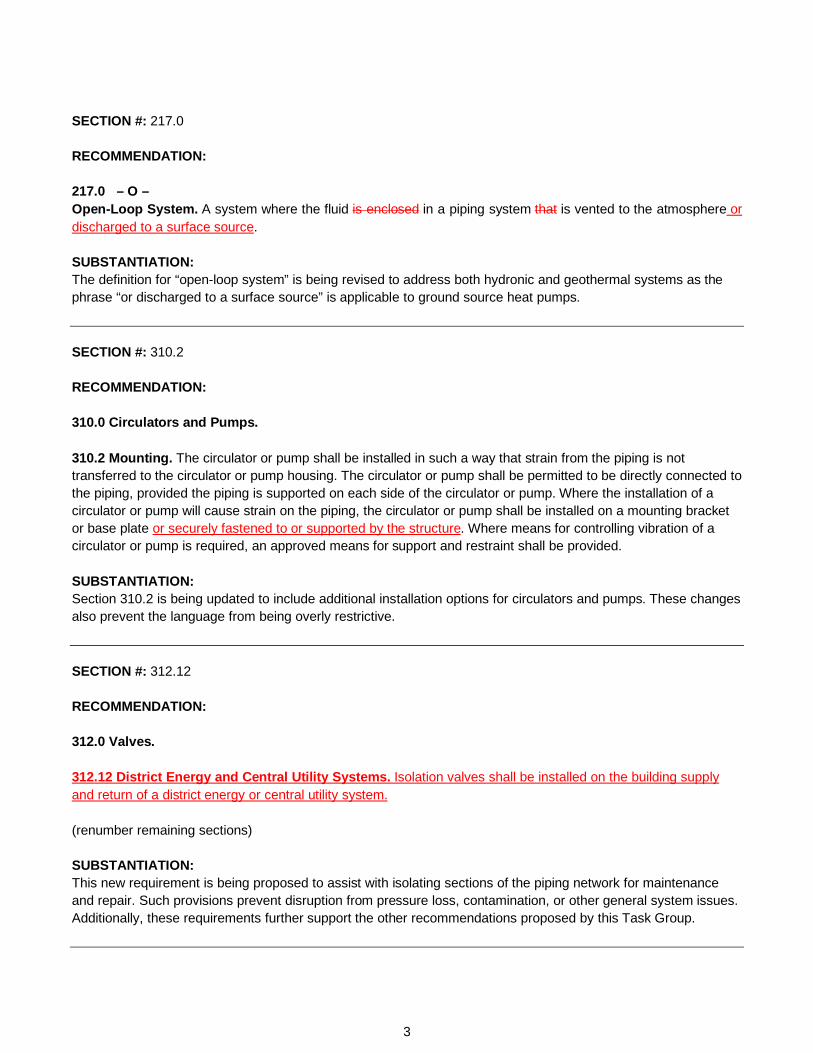
SECTION #: 217.0 RECOMMENDATION: 217.0 – O – Open-Loop System. A system where the fluid is enclosed in a piping system that is vented to the atmosphere or discharged to a surface source. SUBSTANTIATION: The definition for “open-loop system” is being revised to address both hydronic and geothermal systems as the phrase “or discharged to a surface source” is applicable to ground source heat pumps. SECTION #: 310.2 RECOMMENDATION: 310.0 Circulators and Pumps. 310.2 Mounting. The circulator or pump shall be installed in such a way that strain from the piping is not transferred to the circulator or pump housing. The circulator or pump shall be permitted to be directly connected to the piping, provided the piping is supported on each side of the circulator or pump. Where the installation of a circulator or pump will cause strain on the piping, the circulator or pump shall be installed on a mounting bracket or base plate or securely fastened to or supported by the structure. Where means for controlling vibration of a circulator or pump is required, an approved means for support and restraint shall be provided. SUBSTANTIATION: Section 310.2 is being updated to include additional installation options for circulators and pumps. These changes also prevent the language from being overly restrictive. SECTION #: 312.12 RECOMMENDATION: 312.0 Valves. 312.12 District Energy and Central Utility Systems. Isolation valves shall be installed on the building supply and return of a district energy or central utility system. (renumber remaining sections) SUBSTANTIATION: This new requirement is being proposed to assist with isolating sections of the piping network for maintenance and repair. Such provisions prevent disruption from pressure loss, contamination, or other general system issues. Additionally, these requirements further support the other recommendations proposed by this Task Group.
3

SECTION #: 206.0, 401.1 RECOMMENDATION: 401.0 General. 401.1 Applicability. This chapter shall apply to hydronic piping systems that are part of heating, cooling, ventilation, refrigeration, and air conditioning systems. Such piping systems include steam, hot water, radiant heating and cooling, chilled water, steam condensate, condenser water, solar thermal systems, and ground source heat pump systems, snow and ice melt systems, ambient temperature loops (ATL), and district thermal energy loops. The regulations of this chapter shall govern the construction, location, and installation of hydronic piping systems. 206.0 – D – District Thermal Energy Loop. A closed-loop piping system with central pumping that includes various heat sources and heat sinks. The sources/sinks can be passive (e.g., a ground loop, a body of water, sewer effluent) or active (e.g. boiler, cooling tower, heat pumps, or chillers) and further can include opportunistic, or unique locally available waste or by-product heat sources (e.g., data center, industrial process). The loop may run exterior to conditioned spaces in order to serve multiple structures and the heat exchange devices installed within. SUBSTANTIATION: Section 401.1 (Applicability) is being updated to include the variations of hydronic systems which are addressed in this chapter and other portions of the code. District thermal energy loops are becoming more common in the industry and such emerging technologies should be included. To further support these changes and provide additional clarity, a definition for district thermal energy loop is being proposed. SECTION #: 401.3, 401.9 RECOMMENDATION: 401.0 General. 401.3 Water Hammer Protection. The flow of the hydronic piping system shall be designed to prevent water hammer. 401.9 Flexible Connectors. Listed flexible connectors shall be installed in readily accessible locations, unless otherwise listed. SUBSTANTIATION: Section 401.3 is being revised since the piping system must be sized to accommodate the flow of hydronic fluid rather than the flow be designed to prevent a water hammer. The current language is oddly worded and may cause confusion. Such modifications are necessary for clarification. Furthermore, Section 401.9 is being revised to remove “unless otherwise listed” as this phrase permits the installation of connectors in non-accessible locations. Also, the section already specifies that the flexible connectors are listed.
4
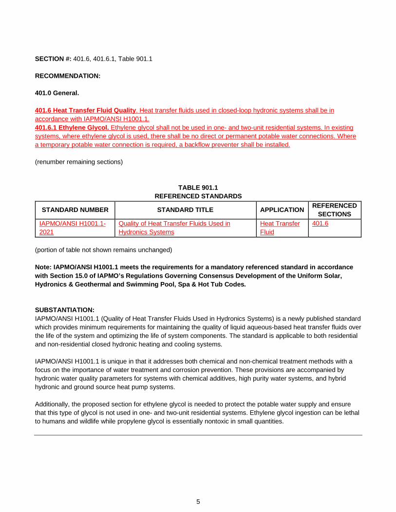
SECTION #: 401.6, 401.6.1, Table 901.1 RECOMMENDATION: 401.0 General. 401.6 Heat Transfer Fluid Quality. Heat transfer fluids used in closed-loop hydronic systems shall be in accordance with IAPMO/ANSI H1001.1. 401.6.1 Ethylene Glycol. Ethylene glycol shall not be used in one- and two-unit residential systems. In existing systems, where ethylene glycol is used, there shall be no direct or permanent potable water connections. Where a temporary potable water connection is required, a backflow preventer shall be installed. (renumber remaining sections)
TABLE 901.1 REFERENCED STANDARDS
STANDARD NUMBER STANDARD TITLE APPLICATION REFERENCED SECTIONS
IAPMO/ANSI H1001.1-2021
Quality of Heat Transfer Fluids Used in Hydronics Systems
Heat Transfer Fluid
401.6
(portion of table not shown remains unchanged) Note: IAPMO/ANSI H1001.1 meets the requirements for a mandatory referenced standard in accordance with Section 15.0 of IAPMO’s Regulations Governing Consensus Development of the Uniform Solar, Hydronics & Geothermal and Swimming Pool, Spa & Hot Tub Codes. SUBSTANTIATION: IAPMO/ANSI H1001.1 (Quality of Heat Transfer Fluids Used in Hydronics Systems) is a newly published standard which provides minimum requirements for maintaining the quality of liquid aqueous-based heat transfer fluids over the life of the system and optimizing the life of system components. The standard is applicable to both residential and non-residential closed hydronic heating and cooling systems. IAPMO/ANSI H1001.1 is unique in that it addresses both chemical and non-chemical treatment methods with a focus on the importance of water treatment and corrosion prevention. These provisions are accompanied by hydronic water quality parameters for systems with chemical additives, high purity water systems, and hybrid hydronic and ground source heat pump systems. Additionally, the proposed section for ethylene glycol is needed to protect the potable water supply and ensure that this type of glycol is not used in one- and two-unit residential systems. Ethylene glycol ingestion can be lethal to humans and wildlife while propylene glycol is essentially nontoxic in small quantities.
5

SECTION #: 401.6, 415.3 - 415.3.2 RECOMMENDATION: 415.0 Radiant Heating and Cooling. 415.1 Installation. (remaining text unchanged) 401.6415.1.1 Manifolds. (remaining text unchanged) 415.3 Radiant Cooling Systems. Radiant cooling systems shall be designed to minimize the potential for condensation. To prevent condensation on any cooled radiant surface, the supply water temperature for a radiant cooling system shall be not less than 3°F (1.7°C) above the anticipated space dew point temperature, or in accordance with the manufacturer’s recommendation. 415.3.1 Minimum Floor Temperatures. The minimum floor surface temperature shall not be less than 66°F (19°C) in general occupied applications. 415.3.2 Chilled Water Supply/Distribution Piping. Chilled water piping, valves, and fittings, and manifolds shall be insulated and vapor sealed to prevent surface condensation. Exception: Piping, valves, fittings, and manifolds used to supply radiant cooling systems and where the water temperature is above the space dew point temperature shall not require insulation. SUBSTANTIATION: The revisions to Section 415.3 correlate with the proposals generated by the UMC Radiant Cooling Working Group. This group was formed in January 2020 by members of ASHRAE TC 6.5, Radiant Heating and Cooling. The current supply water temperature limitation in Section 415.3 is overly restrictive and represents design guidance rather than a proper code minimum for health and safety. The new Section 415.3.1 is required based on ASHRAE Standard 55 (Thermal Environmental Conditions for Human Occupancy) which defines the minimum acceptable temperature for a radiant floor to be 66°F (19°C). This temperature is well accepted in North America and internationally. Furthermore, manifolds are being relocated under Section 415.0 as they are another part of the distribution system common to radiant systems. SECTION #: 401.7 RECOMMENDATION: 401.0 General. 401.7 Disposal of Hydronic Fluid. Hydronic system fluids that contain additives such as antifreeze, corrosion inhibitors, and cleaning solutions shall be recycled or disposed of in an approved manner in accordance with the Authority Having Jurisdiction. (renumber remaining sections) SUBSTANTIATION: Currently, the code is silent on the disposal of used hydronic fluids. The proposed section offers provisional language which ensures proper disposal of such fluids and promotes public health and safety. In some cases, the used hydronic fluid may be recycled. For these reasons, the new language is necessary and beneficial to the USHGC.
6
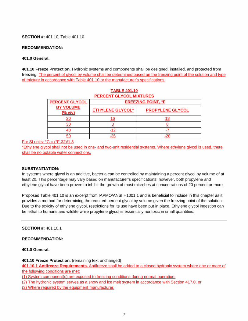
SECTION #: 401.10, Table 401.10 RECOMMENDATION: 401.0 General. 401.10 Freeze Protection. Hydronic systems and components shall be designed, installed, and protected from freezing. The percent of glycol by volume shall be determined based on the freezing point of the solution and type of mixture in accordance with Table 401.10 or the manufacturer’s specifications.
TABLE 401.10 PERCENT GLYCOL MIXTURES
PERCENT GLYCOL BY VOLUME
(% v/v)
FREEZING POINT, °F
ETHYLENE GLYCOL* PROPYLENE GLYCOL
20 16 18 30 3 8 40 -12 -7 50 -35 -28
For SI units: °C = (°F-32)/1.8 *Ethylene glycol shall not be used in one- and two-unit residential systems. Where ethylene glycol is used, there shall be no potable water connections. SUBSTANTIATION: In systems where glycol is an additive, bacteria can be controlled by maintaining a percent glycol by volume of at least 20. This percentage may vary based on manufacturer’s specifications; however, both propylene and ethylene glycol have been proven to inhibit the growth of most microbes at concentrations of 20 percent or more. Proposed Table 401.10 is an excerpt from IAPMO/ANSI H1001.1 and is beneficial to include in this chapter as it provides a method for determining the required percent glycol by volume given the freezing point of the solution. Due to the toxicity of ethylene glycol, restrictions for its use have been put in place. Ethylene glycol ingestion can be lethal to humans and wildlife while propylene glycol is essentially nontoxic in small quantities. SECTION #: 401.10.1 RECOMMENDATION: 401.0 General. 401.10 Freeze Protection. (remaining text unchanged) 401.10.1 Antifreeze Requirements. Antifreeze shall be added to a closed hydronic system where one or more of the following conditions are met: (1) System component(s) are exposed to freezing conditions during normal operation, (2) The hydronic system serves as a snow and ice melt system in accordance with Section 417.0, or (3) Where required by the equipment manufacturer.
7
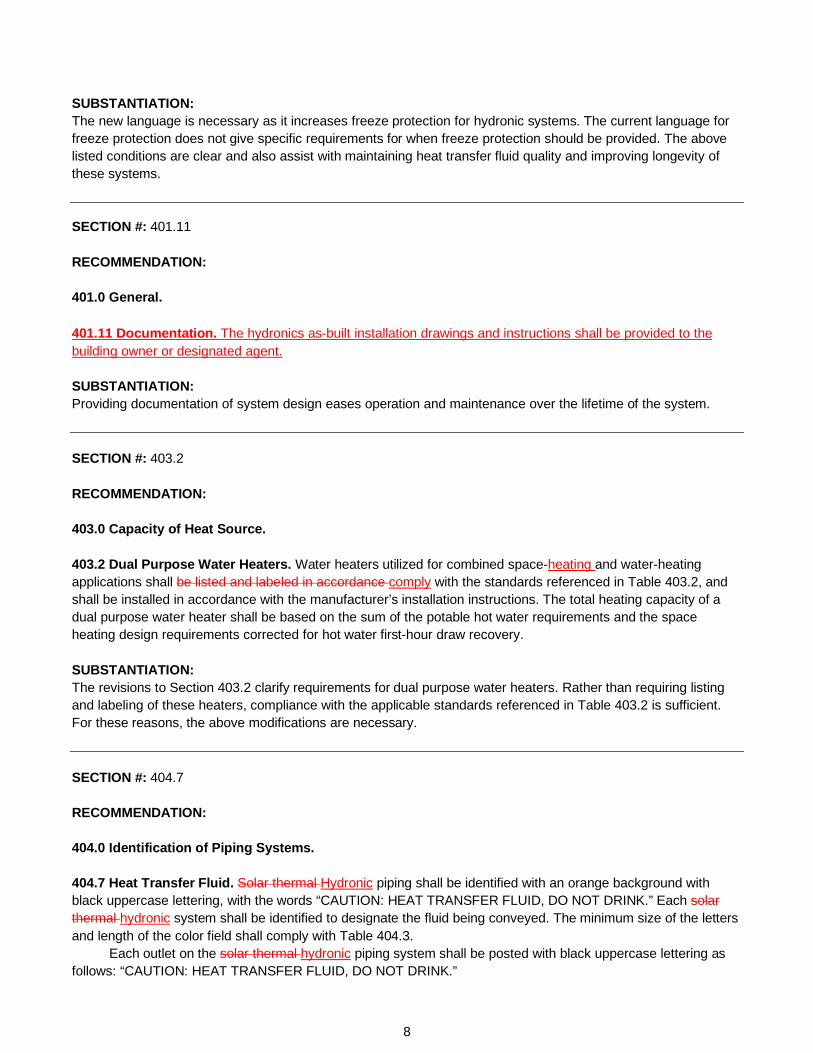
SUBSTANTIATION: The new language is necessary as it increases freeze protection for hydronic systems. The current language for freeze protection does not give specific requirements for when freeze protection should be provided. The above listed conditions are clear and also assist with maintaining heat transfer fluid quality and improving longevity of these systems. SECTION #: 401.11 RECOMMENDATION: 401.0 General. 401.11 Documentation. The hydronics as-built installation drawings and instructions shall be provided to the building owner or designated agent. SUBSTANTIATION: Providing documentation of system design eases operation and maintenance over the lifetime of the system. SECTION #: 403.2 RECOMMENDATION: 403.0 Capacity of Heat Source. 403.2 Dual Purpose Water Heaters. Water heaters utilized for combined space-heating and water-heating applications shall be listed and labeled in accordance comply with the standards referenced in Table 403.2, and shall be installed in accordance with the manufacturer’s installation instructions. The total heating capacity of a dual purpose water heater shall be based on the sum of the potable hot water requirements and the space heating design requirements corrected for hot water first-hour draw recovery. SUBSTANTIATION: The revisions to Section 403.2 clarify requirements for dual purpose water heaters. Rather than requiring listing and labeling of these heaters, compliance with the applicable standards referenced in Table 403.2 is sufficient. For these reasons, the above modifications are necessary. SECTION #: 404.7 RECOMMENDATION: 404.0 Identification of Piping Systems. 404.7 Heat Transfer Fluid. Solar thermal Hydronic piping shall be identified with an orange background with black uppercase lettering, with the words “CAUTION: HEAT TRANSFER FLUID, DO NOT DRINK.” Each solar thermal hydronic system shall be identified to designate the fluid being conveyed. The minimum size of the letters and length of the color field shall comply with Table 404.3. Each outlet on the solar thermal hydronic piping system shall be posted with black uppercase lettering as follows: “CAUTION: HEAT TRANSFER FLUID, DO NOT DRINK.”
8

SUBSTANTIATION: Section 404.7 is being updated to reference “hydronic” piping and system components rather than “solar thermal” since this chapter is explicit to hydronics systems. Solar thermal provisions belong in Chapter 5 (Solar Thermal Systems). SECTION #: 404.8 RECOMMENDATION: 404.0 Identification of Piping Systems. 404.8 Identification of Chemical Additives. In systems where chemical additives are used, documentation including the following information shall be provided: (1) Concentrations (2) Maintenance requirements (3) Maintenance log (4) Manufacturer’s material safety data sheet (SDS) SUBSTANTIATION: The proposed section is an excerpt from IAPMO/ANSI H1001.1 and is needed since providing documentation pertaining to chemical content eases operation and maintenance over the lifetime of the system. Such information is also essential to ensure chemical compatibility and safety. Various chemical treatments may be used based on the hydronic system and fluid quality, and keeping such documentation/identification is needed for maintenance and safe operation. SECTION #: 407.5, Table 407.5 RECOMMENDATION: 407.0 Heating Appliances and Equipment. 407.5 Heat Pumps. Heat pumps shall be in compliance with Table 407.5, as applicable. Heat pumps shall also be listed and labeled in accordancecomply with UL 1995 or UL 60335-2-40. Air-source heat pumps shall also comply with AHRI 210/240. In addition, ground-source heat pumps shall comply with AHRI/ASHRAE/ISO 13256-1 for water-to-air heat pumps and AHRI/ASHRAE/ISO 13256-2 for water-to-water heat pumps. Heat pumps shall be fitted with a means to indicate that the compressor is locked out.
TABLE 407.5 HEAT PUMPS
TYPE OF HEAT PUMP STANDARDS Water-to-Air AHRI/ASHRAE/ISO 13256-1 Water-to-Water AHRI/ASHRAE/ISO 13256-2 Air Source AHRI 210/240
9

Note: AHRI 210/240, AHRI/ASHRAE/ISO 13256-1, and AHRI/ASHRAE/ISO 13256-2 meet the requirements for mandatory referenced standards in accordance with Section 15.0 of IAPMO’s Regulations Governing Consensus Development of the Uniform Solar, Hydronics & Geothermal and Swimming Pool, Spa & Hot Tub Codes. SUBSTANTIATION: The proposed change converts Table 407.5 into provisional language. Additionally, language has been included in order to specify that ground-source heat pumps must also comply with AHRI/ASHRAE/ISO 13256-1 for water-to-air heat pumps and AHRI/ASHRAE/ISO 13256-2 for water-to-water heat pumps. Since these two standards are for performance and ratings, the above modifications are necessary for clarity. SECTION #: 408.1 RECOMMENDATION: 408.0 Expansion Tanks. 408.1 General. An expansion tank shall be installed in each closed-loop of a hydronic system to control system pressure due to thermal expansion and contraction. Expansion tanks shall be of the closed type, incorporating a diaphragm or bladder to ensure the isolation of the system fluid from the pre-charge gas or from the atmosphere. Plain compression tanks shall not be permitted. Expansion tanks shall be rated for the pressure of the system. Exceptions: (1) Drainback type solar thermal systems shall not require a hydronic expansion tank. (2) An alternative engineered fluid expansion storage system shall be permitted where in accordance with Section 302.4. SUBSTANTIATION: Requiring a bladder or diaphragm is automatically inclusive of active expansion systems. This requirement does not need to specify how fluid is moved in or out of the loop, nor how the charge pressure is or is not modulated. The intent of the proposed language is to eliminate exposure to the atmosphere. For these reasons, the modifications to Section 408.1 are necessary. SECTION #: 408.2, 605.1 RECOMMENDATION: 408.0 Expansion Tanks. 408.2 Installation. Expansion tanks shall be accessible for maintenance and shall be installed in accordance with the manufacturer’s installation instructions. Each expansion tank shall be equipped with a shutoff device that will remain open during operation of the hydronic system. Valve handles shall be locked open or removed to prevent from being inadvertently shut off. Where systems contain more than 5 gallons (19 L) of fluid, pProvisions shall be made for draining the tank without emptying the system. Expansion tanks shall be securely fastened to or supported by the structure. Supports shall be capable of carrying twice the weight of the tank filled with water without placing a strain on connecting piping. Hot-water-heating systems incorporating hot water tanks or fluid relief columns shall be installed to prevent freezing under normal operating conditions.
10
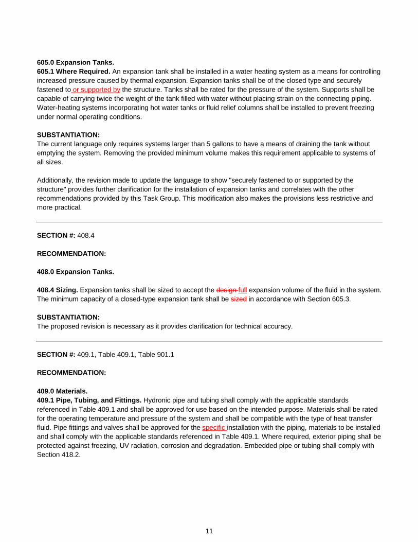
605.0 Expansion Tanks. 605.1 Where Required. An expansion tank shall be installed in a water heating system as a means for controlling increased pressure caused by thermal expansion. Expansion tanks shall be of the closed type and securely fastened to or supported by the structure. Tanks shall be rated for the pressure of the system. Supports shall be capable of carrying twice the weight of the tank filled with water without placing strain on the connecting piping. Water-heating systems incorporating hot water tanks or fluid relief columns shall be installed to prevent freezing under normal operating conditions. SUBSTANTIATION: The current language only requires systems larger than 5 gallons to have a means of draining the tank without emptying the system. Removing the provided minimum volume makes this requirement applicable to systems of all sizes. Additionally, the revision made to update the language to show "securely fastened to or supported by the structure" provides further clarification for the installation of expansion tanks and correlates with the other recommendations provided by this Task Group. This modification also makes the provisions less restrictive and more practical. SECTION #: 408.4 RECOMMENDATION: 408.0 Expansion Tanks. 408.4 Sizing. Expansion tanks shall be sized to accept the design full expansion volume of the fluid in the system. The minimum capacity of a closed-type expansion tank shall be sized in accordance with Section 605.3. SUBSTANTIATION: The proposed revision is necessary as it provides clarification for technical accuracy. SECTION #: 409.1, Table 409.1, Table 901.1 RECOMMENDATION:
409.0 Materials. 409.1 Pipe, Tubing, and Fittings. Hydronic pipe and tubing shall comply with the applicable standards referenced in Table 409.1 and shall be approved for use based on the intended purpose. Materials shall be rated for the operating temperature and pressure of the system and shall be compatible with the type of heat transfer fluid. Pipe fittings and valves shall be approved for the specific installation with the piping, materials to be installed and shall comply with the applicable standards referenced in Table 409.1. Where required, exterior piping shall be protected against freezing, UV radiation, corrosion and degradation. Embedded pipe or tubing shall comply with Section 418.2.
11

TABLE 409.1 MATERIALS FOR HYDRONIC AND SOLAR THERMAL SYSTEM, PIPING, TUBING, AND FITTINGS
MATERIAL STANDARDS
PIPING/TUBING FITTINGS
Copper/Copper Alloy
ASTM B42, ASTM B43, ASTM B75, ASTM B88, ASTM B135,
ASTM B251*2, ASTM B302, ASTM B447
ASME B16.15, ASME B16.18, ASME B16.22, ASME B16.23, ASME B16.24, ASME B16.26, ASME B16.29, ASME B16.51,
ASSE 1061, ASTM F3226, IAPMO PS 117
Ductile Iron AWWA C115/A21.15, AWWA C151/A21.51
AWWA C110/A21.101, AWWA C153/A21.53
Steel ASTM A53, ASTM A106, ASTM A254
ASME B16.5, ASME B16.9, ASME B16.11, ASTM A420, ASTM
F3226, IAPMO IGC 353, IAPMO PS 117
Raised Temperature Polyethylene of Raised Temperature (PE-RT)
ASTM F2165, ASTM F2623, ASTM F2769, CSA B137.18
ASSE 1061, ASTM D3261, ASTM F1055, ASTM F1807, ASTM F2159, ASTM F2165, ASTM F2735, ASTM
F2769, ASTM F3347, ASTM F3348, CSA B137.18
Stainless Steel ASTM A269, ASTM A312, ASTM A554, ASTM A778
ASTM F1476, ASTM F1548, ASTM F3226, IAPMO IGC 353, IAPMO PS
117 Notes: 1 Ductile and gray iron. *2 Only Type K, L, or M shall be permitted to be installed.
(portion of table not shown remains unchanged)
TABLE 901.1 REFERENCED STANDARDS
STANDARD NUMBER STANDARD TITLE APPLICATION
REFERENCED SECTIONS
AWWA C110/A21.10-2012 Ductile-Iron and Gray-Iron Fittings Fittings Table 409.1
AWWA C115/A21.15-2020 Flanged Ductile-Iron Pipe with Ductile-Iron or Gray-Iron Threaded Flanges
Piping Table 409.1
AWWA C151/A21.51-2017 Ductile-Iron Pipe, Centrifugally Cast Piping Table 409.1 AWWA C153/A21.53-2019 Ductile-Iron Compact Fittings Fittings Table 409.1 IAPMO IGC 353-2019e1 Branch Connectors Fittings Table 409.1
(portion of table not shown remains unchanged)
Note: ASTM F3347, ASTM F3348, AWWA C110/A21.10, AWWA C115/A21.15, AWWA C151/A21.51, AWWA C153/A21.53, and IAPMO IGC 353 meet the requirements for mandatory referenced standards in accordance with Section 15.0 of IAPMO’s Regulations Governing Consensus Development of the Uniform Solar, Hydronics & Geothermal and Swimming Pool, Spa & Hot Tub Codes.
12

SUBSTANTIATION: Ductile iron is being added back to Table 409.1 as this material is currently used in chilled systems. The provided standards for piping, tubing, and fittings are currently listed in the most recent edition of the mechanical code. AWWA C115/A21.15 covers 3-in. through 64-in. (80-mm through 1,600-mm) flanged ductile-iron pipe with ductile-iron or gray-iron threaded flanges for potable water, wastewater, and reclaimed water service. AWWA C151/A12.51 addresses 3-in. through 64-in. (80-mm through 1,600-mm) ductile-iron pipe, centrifugally cast, for potable water, raw water, wastewater, and reclaimed water systems with push-on joints or mechanical joints. AWWA C110/A21.10 describes 3- to 48-in. (80- to 1,200-mm) ductile-iron fittings to be used with ductile-iron pipe for potable water, wastewater, and reclaimed water for a temperature range of 33°–120° F (0.6°–49°C). This standard may also be used for fittings with push-on joints. AWWA C153/A21.53 defines requirements for 3-in. through 64-in. (80-mm through 1,600-mm) ductile-iron compact fittings to be used with ductile-iron pipe or pipe made of other materials with similar outside diameters for conveying potable water, wastewater and reclaimed water. Minimum working pressures by size range are as follows: 3 in. through 24 in. (80 mm through 600 mm): 350 psi (2,413 kPa); 30 in. through 48 in. (750 mm through 1,200 mm): 250 psi (1,724 kPa); and 54 in. through 64 in. (1,400 mm through 1,600 mm): 150 psi (1,034 kPa). Fittings are adequate for the rated working pressure plus a surge allowance of 100 psi or a surge allowance of half the rated working pressure, whichever is less. ASTM F3347 and ASTM F3348 are already listed in Table 409.1 for PEX pipe fittings and should also be included for PE-RT. ASTM F3347 covers copper alloy metal press insert fittings while ASTM F3348 covers plastic press insert fittings. These fittings are for use with cross-linked polyethylene (PEX) tubing that meets the requirements of ASTM F876 and polyethylene of raised temperature (PE-RT) tubing that meets the requirements of ASTM F2769. Such fittings are intended for use in 100 psi (689.5 kPa) hot and cold water distribution systems operating at temperatures up to, and including, 180°F (82°C). IAPMO IGC 353 covers branch connectors for NPS 1-1/2 through 6 intended for hydronics and specifies requirements for materials, physical characteristics, performance testing, and markings. The body of branch connectors covered by this standard are required to be made of carbon steel, stainless steel, copper nickel or other materials with similar strength properties. Based on the provided applicability of the proposed standards, Table 409.1 is being revised to include such available industry standards for piping, tubing, and fittings to be used in hydronics systems. SECTION #: 409.4 RECOMMENDATION: 409.0 Materials. 409.4 Oxygen Diffusion Corrosion. PEX and PE-RT tubing in closed hydronic systems shall contain an oxygen barrier with an oxygen permeation rate not to exceed 4.59 E-04 grains per square foot per day (0.32 mg/m2/day) at 104°F (40°C). Exception: Closed hydronic systems without ferrous components in contact with the hydronic fluid.
13
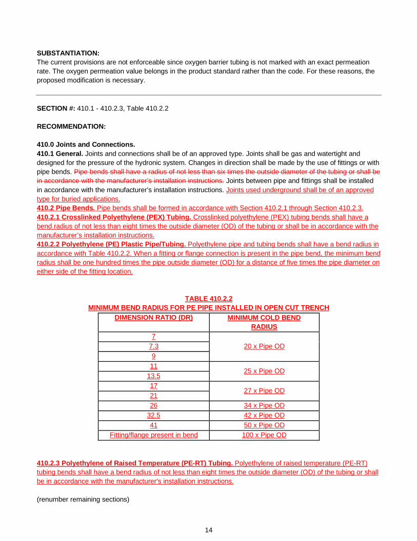
SUBSTANTIATION: The current provisions are not enforceable since oxygen barrier tubing is not marked with an exact permeation rate. The oxygen permeation value belongs in the product standard rather than the code. For these reasons, the proposed modification is necessary. SECTION #: 410.1 - 410.2.3, Table 410.2.2 RECOMMENDATION: 410.0 Joints and Connections. 410.1 General. Joints and connections shall be of an approved type. Joints shall be gas and watertight and designed for the pressure of the hydronic system. Changes in direction shall be made by the use of fittings or with pipe bends. Pipe bends shall have a radius of not less than six times the outside diameter of the tubing or shall be in accordance with the manufacturer’s installation instructions. Joints between pipe and fittings shall be installed in accordance with the manufacturer’s installation instructions. Joints used underground shall be of an approved type for buried applications. 410.2 Pipe Bends. Pipe bends shall be formed in accordance with Section 410.2.1 through Section 410.2.3. 410.2.1 Crosslinked Polyethylene (PEX) Tubing. Crosslinked polyethylene (PEX) tubing bends shall have a bend radius of not less than eight times the outside diameter (OD) of the tubing or shall be in accordance with the manufacturer’s installation instructions. 410.2.2 Polyethylene (PE) Plastic Pipe/Tubing. Polyethylene pipe and tubing bends shall have a bend radius in accordance with Table 410.2.2. When a fitting or flange connection is present in the pipe bend, the minimum bend radius shall be one hundred times the pipe outside diameter (OD) for a distance of five times the pipe diameter on either side of the fitting location.
TABLE 410.2.2 MINIMUM BEND RADIUS FOR PE PIPE INSTALLED IN OPEN CUT TRENCH
DIMENSION RATIO (DR) MINIMUM COLD BEND RADIUS
7 20 x Pipe OD 7.3
9 11
25 x Pipe OD 13.5 17
27 x Pipe OD 21 26 34 x Pipe OD
32.5 42 x Pipe OD 41 50 x Pipe OD
Fitting/flange present in bend 100 x Pipe OD 410.2.3 Polyethylene of Raised Temperature (PE-RT) Tubing. Polyethylene of raised temperature (PE-RT) tubing bends shall have a bend radius of not less than eight times the outside diameter (OD) of the tubing or shall be in accordance with the manufacturer’s installation instructions. (renumber remaining sections)
14

SUBSTANTIATION: The existing language in Section 410.1 regarding pipe bends having a radius of not less than six times the OD is not correct for any of the plastic pipe materials found within Section 410.0. The proposed new language for piping/tubing bend radii are from various publications of The Plastics Pipe Institute (PPI). For PE piping/tubing, the new language including Table 410.2.2 is taken from the PPI “Handbook of Polyethylene Pipe, Second Edition” Chapter 7. For PEX tubing, the new language is taken from the “Design Guide – Residential PEX Water Supply Plumbing Systems” Chapter 9, a joint publication of PPI, PPFA, and the Home Innovation Research Labs. For PE-RT tubing, the new language is supported and recommended by PPI. SECTION #: 410.2, 410.3 RECOMMENDATION: 410.0 Joints and Connections. 410.2 Chlorinated Polyvinyl Chloride (CPVC) Pipe. Joints between chlorinated polyvinyl chloride (CPVC) pipe and fittings shall be installed in accordance with one of the following methods: (1) Mechanical joints shall include, but not be limited to, flanged, grooved, and push fit fittings. Removable and nonremovable push fit fittings with an elastomeric o-ring that employ quick assembly push fit connectors shall be in accordance with ASSE 1061. (2) Solvent cement joints for CPVC pipe and fittings shall be clean from dirt and moisture. Solvent cements in accordance with ASTM F493, requiring the use of a primer shall be orange in color. The primer shall be colored and be in accordance with ASTM F656. Listed solvent cement in accordance with ASTM F493 that does not require the use of primers, yellow, green, or red in color, shall be permitted for pipe and fittings manufactured in accordance with ASTM D2846, 1/2 of an inch (15 mm) through 2 inches (50 mm) in diameter or ASTM F442, 1/2 of an inch (15 mm) through 3 inches (80 mm) in diameter. Apply primer where required inside the fitting and to the depth of the fitting on pipe. Apply liberal coat of cement to the outside surface of pipe to depth of fitting and inside of fitting. Place pipe inside fitting to forcefully bottom the pipe in the socket and hold together until joint is set. (3) (remaining text unchanged) 410.3 CPVC/AL/CPVC Plastic Pipe and Joints. Joints between chlorinated polyvinyl chloride/aluminum/ chlorinated polyvinyl chloride (CPVC/AL/CPVC) pipe and fittings shall be installed in accordance with one of the following methods: (1) Mechanical joints shall include, but not be limited to, flanged, grooved and push-fit fittings. (2) (remaining text unchanged) SUBSTANTIATION: The above minor revisions are being made for correlation with the mechanical code.
15
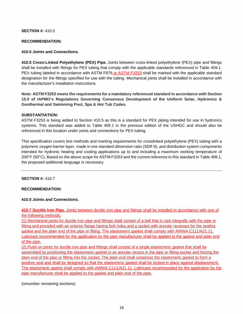
SECTION #: 410.5 RECOMMENDATION: 410.0 Joints and Connections. 410.5 Cross-Linked Polyethylene (PEX) Pipe. Joints between cross-linked polyethylene (PEX) pipe and fittings shall be installed with fittings for PEX tubing that comply with the applicable standards referenced in Table 409.1. PEX tubing labeled in accordance with ASTM F876 or ASTM F3253 shall be marked with the applicable standard designation for the fittings specified for use with the tubing. Mechanical joints shall be installed in accordance with the manufacturer’s installation instructions. Note: ASTM F3253 meets the requirements for a mandatory referenced standard in accordance with Section 15.0 of IAPMO’s Regulations Governing Consensus Development of the Uniform Solar, Hydronics & Geothermal and Swimming Pool, Spa & Hot Tub Codes. SUBSTANTIATION: ASTM F3253 is being added to Section 410.5 as this is a standard for PEX piping intended for use in hydronics systems. This standard was added to Table 409.1 in the previous edition of the USHGC and should also be referenced in this location under joints and connections for PEX tubing. This specification covers test methods and marking requirements for crosslinked polyethylene (PEX) tubing with a polymeric oxygen barrier layer, made in one standard dimension ratio (SDR 9), and distribution system components intended for hydronic heating and cooling applications up to and including a maximum working temperature of 200°F (93°C). Based on the above scope for ASTM F3253 and the current reference to this standard in Table 409.1, the proposed additional language is necessary. SECTION #: 410.7 RECOMMENDATION: 410.0 Joints and Connections. 410.7 Ductile Iron Pipe. Joints between ductile iron pipe and fittings shall be installed in accordance with one of the following methods: (1) Mechanical joints for ductile iron pipe and fittings shall consist of a bell that is cast integrally with the pipe or fitting and provided with an exterior flange having bolt holes and a socket with annular recesses for the sealing gasket and the plain end of the pipe or fitting. The elastomeric gasket shall comply with AWWA C111/A21.11. Lubricant recommended for the application by the pipe manufacturer shall be applied to the gasket and plain end of the pipe. (2) Push-on joints for ductile iron pipe and fittings shall consist of a single elastomeric gasket that shall be assembled by positioning the elastomeric gasket in an annular recess in the pipe or fitting socket and forcing the plain end of the pipe or fitting into the socket. The plain end shall compress the elastomeric gasket to form a positive seal and shall be designed so that the elastomeric gasket shall be locked in place against displacement. The elastomeric gasket shall comply with AWWA C111/A21.11. Lubricant recommended for the application by the pipe manufacturer shall be applied to the gasket and plain end of the pipe. (renumber remaining sections)
16
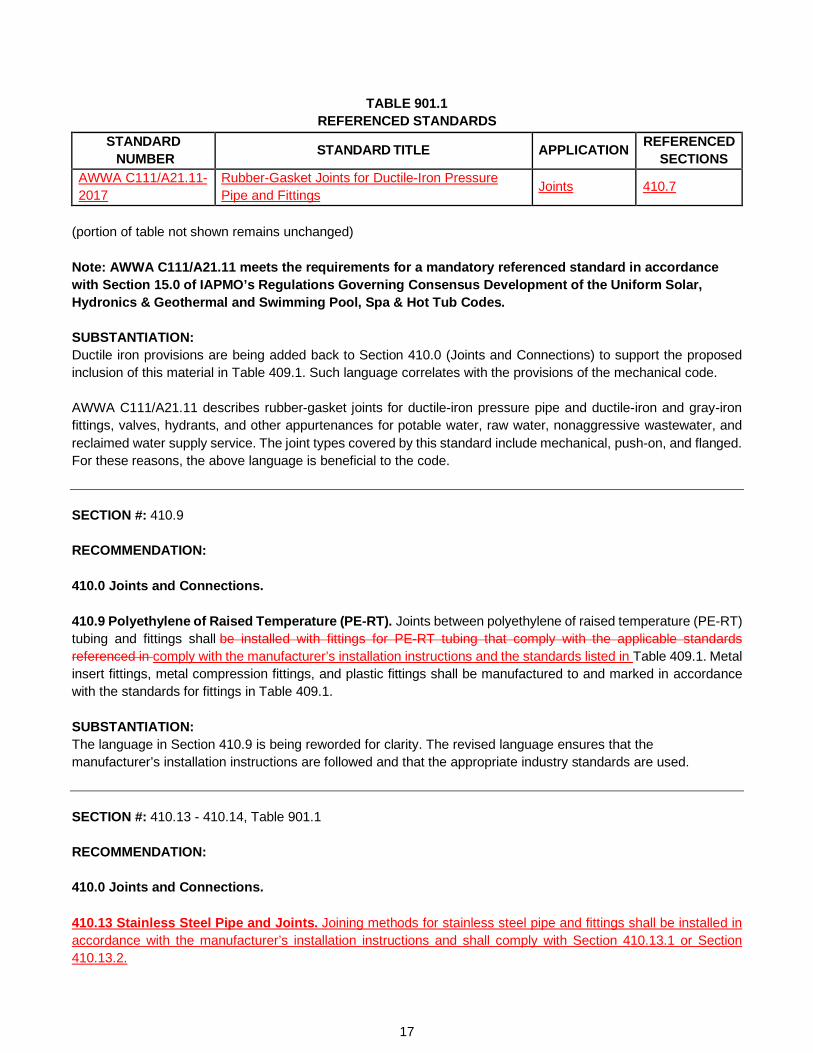
TABLE 901.1 REFERENCED STANDARDS
STANDARD NUMBER
STANDARD TITLE APPLICATION REFERENCED SECTIONS
AWWA C111/A21.11-2017
Rubber-Gasket Joints for Ductile-Iron Pressure Pipe and Fittings
Joints 410.7
(portion of table not shown remains unchanged) Note: AWWA C111/A21.11 meets the requirements for a mandatory referenced standard in accordance with Section 15.0 of IAPMO’s Regulations Governing Consensus Development of the Uniform Solar, Hydronics & Geothermal and Swimming Pool, Spa & Hot Tub Codes. SUBSTANTIATION: Ductile iron provisions are being added back to Section 410.0 (Joints and Connections) to support the proposed inclusion of this material in Table 409.1. Such language correlates with the provisions of the mechanical code. AWWA C111/A21.11 describes rubber-gasket joints for ductile-iron pressure pipe and ductile-iron and gray-iron fittings, valves, hydrants, and other appurtenances for potable water, raw water, nonaggressive wastewater, and reclaimed water supply service. The joint types covered by this standard include mechanical, push-on, and flanged. For these reasons, the above language is beneficial to the code. SECTION #: 410.9 RECOMMENDATION: 410.0 Joints and Connections. 410.9 Polyethylene of Raised Temperature (PE-RT). Joints between polyethylene of raised temperature (PE-RT) tubing and fittings shall be installed with fittings for PE-RT tubing that comply with the applicable standards referenced in comply with the manufacturer’s installation instructions and the standards listed in Table 409.1. Metal insert fittings, metal compression fittings, and plastic fittings shall be manufactured to and marked in accordance with the standards for fittings in Table 409.1. SUBSTANTIATION: The language in Section 410.9 is being reworded for clarity. The revised language ensures that the manufacturer’s installation instructions are followed and that the appropriate industry standards are used. SECTION #: 410.13 - 410.14, Table 901.1 RECOMMENDATION: 410.0 Joints and Connections. 410.13 Stainless Steel Pipe and Joints. Joining methods for stainless steel pipe and fittings shall be installed in accordance with the manufacturer’s installation instructions and shall comply with Section 410.13.1 or Section 410.13.2.
17

410.13.1 Mechanical Joints. Mechanical joints shall be designed for their intended use. Such joints shall include compression, flanged, grooved, press-connect, and threaded. 410.13.2 Welded Joints. Welded joints shall be either fusion or resistance welded based on the selection of the base metal. The chemical composition of the filler metal shall comply with AWS A5.9 based on the alloy content of the piping material. 410.14 Dielectric Unions. Dielectric unions shall comply with ASSE 1079 or IAPMO PS 66. (renumber remaining sections)
TABLE 901.1 REFERENCED STANDARDS
STANDARD NUMBER STANDARD TITLE APPLICATION REFERENCED SECTIONS
AWS A5.9/A5.9M-2017
Welding Consumables - Wire Electrodes, Strip Electrodes, Wires, and Rods for Arc Welding of Stainless and Heat Resisting Steels - Classification
Joints 410.13.2
IAPMO PS 66-2015 Dielectric Fittings Joints 410.14 (portion of table not shown remains unchanged) Note: ASSE 1079, AWS A5.9/A5.9M, and IAPMO PS 66 meet the requirements for mandatory referenced standards in accordance with Section 15.0 of IAPMO’s Regulations Governing Consensus Development of the Uniform Solar, Hydronics & Geothermal and Swimming Pool, Spa & Hot Tub Codes. SUBSTANTIATION: The new language supports the materials listed in Table 409.1 by addressing joining methods for stainless steel pipe and fittings. AWS A5.9/A5.9M is appropriate for reference under Section 410.13.1 (Mechanical Joints) as this standard prescribes requirements for the classification of bare stainless steel wire electrodes (including stranded wire in which all wires in the strand are from one heat), strip electrodes, wires, and rods for gas metal arc welding, gas tungsten arc welding, plasma arc welding, submerged arc welding, electro-slag welding, and laser beam welding of stainless and heat-resisting steels. Proposed Section 410.14 (Dielectric Unions) references ASSE 1079 and IAPMO PS 66 for the following reasons:
• ASSE 1079 provides performance requirements for dielectric pipe unions. These devices are metallic and join metallic pipe in a similar manner to standard pipe unions and flanges, with the added ability to electrically insulate one pipe section from another.
• IAPMO PS 66 covers insulated, dielectric fittings with male threads, grooved ends, or plain ends, intended to reduce galvanic corrosion in plumbing systems by isolating dissimilar metal piping sections, and specifies requirements for materials, physical characteristics, performance testing, and markings.
18
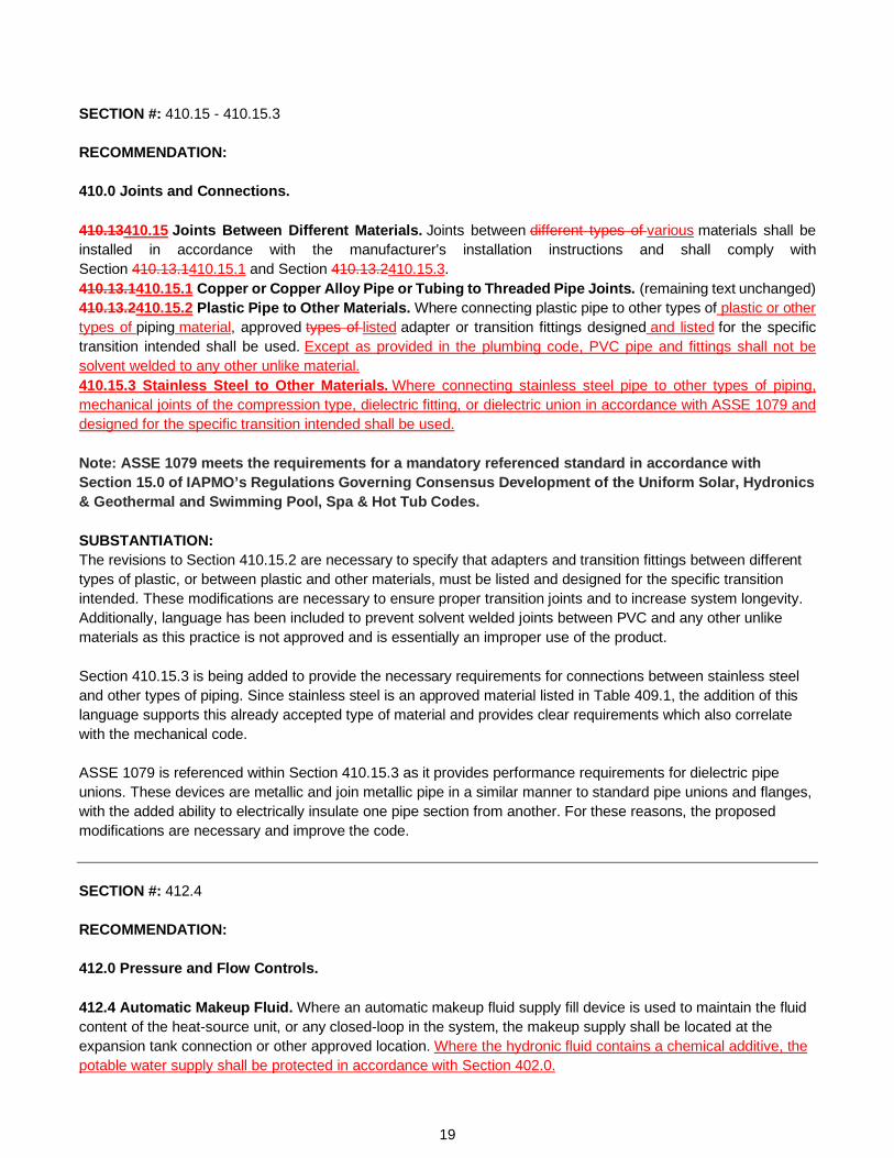
SECTION #: 410.15 - 410.15.3 RECOMMENDATION: 410.0 Joints and Connections. 410.13410.15 Joints Between Different Materials. Joints between different types of various materials shall be installed in accordance with the manufacturer’s installation instructions and shall comply with Section 410.13.1410.15.1 and Section 410.13.2410.15.3. 410.13.1410.15.1 Copper or Copper Alloy Pipe or Tubing to Threaded Pipe Joints. (remaining text unchanged) 410.13.2410.15.2 Plastic Pipe to Other Materials. Where connecting plastic pipe to other types of plastic or other types of piping material, approved types of listed adapter or transition fittings designed and listed for the specific transition intended shall be used. Except as provided in the plumbing code, PVC pipe and fittings shall not be solvent welded to any other unlike material. 410.15.3 Stainless Steel to Other Materials. Where connecting stainless steel pipe to other types of piping, mechanical joints of the compression type, dielectric fitting, or dielectric union in accordance with ASSE 1079 and designed for the specific transition intended shall be used. Note: ASSE 1079 meets the requirements for a mandatory referenced standard in accordance with Section 15.0 of IAPMO’s Regulations Governing Consensus Development of the Uniform Solar, Hydronics & Geothermal and Swimming Pool, Spa & Hot Tub Codes. SUBSTANTIATION: The revisions to Section 410.15.2 are necessary to specify that adapters and transition fittings between different types of plastic, or between plastic and other materials, must be listed and designed for the specific transition intended. These modifications are necessary to ensure proper transition joints and to increase system longevity. Additionally, language has been included to prevent solvent welded joints between PVC and any other unlike materials as this practice is not approved and is essentially an improper use of the product. Section 410.15.3 is being added to provide the necessary requirements for connections between stainless steel and other types of piping. Since stainless steel is an approved material listed in Table 409.1, the addition of this language supports this already accepted type of material and provides clear requirements which also correlate with the mechanical code. ASSE 1079 is referenced within Section 410.15.3 as it provides performance requirements for dielectric pipe unions. These devices are metallic and join metallic pipe in a similar manner to standard pipe unions and flanges, with the added ability to electrically insulate one pipe section from another. For these reasons, the proposed modifications are necessary and improve the code. SECTION #: 412.4 RECOMMENDATION: 412.0 Pressure and Flow Controls. 412.4 Automatic Makeup Fluid. Where an automatic makeup fluid supply fill device is used to maintain the fluid content of the heat-source unit, or any closed-loop in the system, the makeup supply shall be located at the expansion tank connection or other approved location. Where the hydronic fluid contains a chemical additive, the potable water supply shall be protected in accordance with Section 402.0.
19
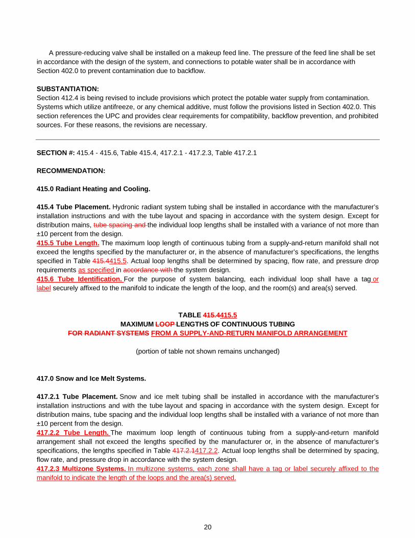
A pressure-reducing valve shall be installed on a makeup feed line. The pressure of the feed line shall be set in accordance with the design of the system, and connections to potable water shall be in accordance with Section 402.0 to prevent contamination due to backflow.
SUBSTANTIATION: Section 412.4 is being revised to include provisions which protect the potable water supply from contamination. Systems which utilize antifreeze, or any chemical additive, must follow the provisions listed in Section 402.0. This section references the UPC and provides clear requirements for compatibility, backflow prevention, and prohibited sources. For these reasons, the revisions are necessary. SECTION #: 415.4 - 415.6, Table 415.4, 417.2.1 - 417.2.3, Table 417.2.1 RECOMMENDATION: 415.0 Radiant Heating and Cooling. 415.4 Tube Placement. Hydronic radiant system tubing shall be installed in accordance with the manufacturer’s installation instructions and with the tube layout and spacing in accordance with the system design. Except for distribution mains, tube spacing and the individual loop lengths shall be installed with a variance of not more than ±10 percent from the design. 415.5 Tube Length. The maximum loop length of continuous tubing from a supply-and-return manifold shall not exceed the lengths specified by the manufacturer or, in the absence of manufacturer’s specifications, the lengths specified in Table 415.4415.5. Actual loop lengths shall be determined by spacing, flow rate, and pressure drop requirements as specified in accordance with the system design. 415.6 Tube Identification. For the purpose of system balancing, each individual loop shall have a tag or label securely affixed to the manifold to indicate the length of the loop, and the room(s) and area(s) served.
TABLE 415.4415.5 MAXIMUM LOOP LENGTHS OF CONTINUOUS TUBING
FOR RADIANT SYSTEMS FROM A SUPPLY-AND-RETURN MANIFOLD ARRANGEMENT
(portion of table not shown remains unchanged) 417.0 Snow and Ice Melt Systems. 417.2.1 Tube Placement. Snow and ice melt tubing shall be installed in accordance with the manufacturer’s installation instructions and with the tube layout and spacing in accordance with the system design. Except for distribution mains, tube spacing and the individual loop lengths shall be installed with a variance of not more than ±10 percent from the design. 417.2.2 Tube Length. The maximum loop length of continuous tubing from a supply-and-return manifold arrangement shall not exceed the lengths specified by the manufacturer or, in the absence of manufacturer’s specifications, the lengths specified in Table 417.2.1417.2.2. Actual loop lengths shall be determined by spacing, flow rate, and pressure drop in accordance with the system design. 417.2.3 Multizone Systems. In multizone systems, each zone shall have a tag or label securely affixed to the manifold to indicate the length of the loops and the area(s) served.
20

TABLE 417.2.1417.2.2 MAXIMUM LOOP LENGTHS FOR SNOW AND ICE MELT SYSTEMS1, 2
NOMINAL TUBE SIZE
(inches)
MAXIMUM ACTIVE LOOP LENGTH
(feet)
TOTAL LOOP LENGTH
(feet) PE-RT and PEX Tubing
1/2 130 150 5/8 225 250 3/4 300 325 1 450 475
Copper Tubing3 1/2 - 140 3/4 - 280
For SI units: 1 inch = 25 mm, 1 foot = 304.8 mm Notes: 1 The total PE-
RT or and PEX loop lengths consist of two separate sections, the active loop, and the leader length. The active loop is installed within the heated slab. The leader length is the total distance to and from the manifold and heated slab, including any vertical distances.
2 The manifolds shall be installed as close to the snow melt area as possible. 3 In concrete use not less than Type L copper water tubing. In bituminous pavement use a Type K copper
water tubing. SUBSTANTIATION: Section 415.4 and Section 417.2.1 are being split to differentiate between tube placement, tube length, and tube/manifold identification. For snow and ice melt systems, identification labels are only needed on large-scale systems, particularly on systems with multiple activation sensors. The proposed language in Section 417.2.3 now addresses these larger systems and is better organized for clarity and ease of use. Furthermore, the title of Table 415.5 is being updated for consistency with the description of provisions in Section 415.5. Table 417.2.2 is also being revised to correlate with the mechanical code. SECTION #: 415.7 RECOMMENDATION: 415.0 Radiant Heating and Cooling. 415.7 Wall and Ceiling Panels. Where radiant tubing piping is installed in the wall stud cavity or the ceiling joist cavity, the cavity shall be insulated with material having an R-value of not less than R-12. The insulation shall be installed in such a manner as to prevent uncontrolled heat transfer to and from the space assembly, the tubing shall be located on the interior side of the insulation to direct the transfer of thermal energy between the tubing and the conditioned space.
An air space of not less than 1 inch (25.4 mm) and not more than 3 inches (76 mm) shall be maintained between the insulation and the interior surface of the panel unless a conductive plate is installed.
21

SUBSTANTIATION: Since the listed provisions are applicable to only radiant heating and cooling systems, referring to radiant tubing rather than piping is technically correct. Additionally, reference to the ceiling "assembly" rather than "joist cavity" allows for the requirements of the section to be more inclusive. Also, the listed insulation value of R-12 is being removed since insulation values vary based on geographical location, and providing a universal minimum value is impractical and not applicable nationally. To add further clarity, tubing location in relation to the insulation is now specified within the new proposed language. The purpose of this tubing location has also been provided to support this requirement. SECTION #: 415.9.1 RECOMMENDATION: 415.0 Radiant Heating and Cooling. 415.9 Radiant Heating and Cooling Panels. (remaining text unchanged) 415.9.1 Electric Heating Panel Systems. Clearances for electric heating panels or between outlets, junction boxes, mounting luminaries, ventilating, or other openings shall comply with NFPA 70. (renumber remaining sections) Note: NFPA 70 meets the requirements for a mandatory referenced standard in accordance with Section 15.0 of IAPMO’s Regulations Governing Consensus Development of the Uniform Solar, Hydronics & Geothermal and Swimming Pool, Spa & Hot Tub Codes. SUBSTANTIATION: Section 415.9.1 is being added to provide necessary electrical requirements and clearances for electrical radiant heating panel systems. Reference to NFPA 70 within this section is beneficial as this standard addresses the safe installation of electrical wiring and equipment. For these reasons, the above provisions are necessary and beneficial to the code. SECTION #: 417.2 RECOMMENDATION: 417.0 Snow and Ice Melt Systems. 417.2 Snow and Ice Melt Controls. An automatic operating control device that controls the supply hydronic fluid temperature to the snow and ice melt area shall be installed in the system. A means shall be provided to prevent low return hydronic solution temperature in accordance with Section 401.5. Snow and ice melt systems shall be protected from freezing with a mixture of propylene glycol or ethylene glycol, and water or other approved fluid. Automotive antifreeze shall not be used. Ethylene glycol shall not be used in one- and two-unit residential systems. Where the hydronic fluid contains a chemical additive, a potable water supply shall be protected in accordance with Section 402.0.
22
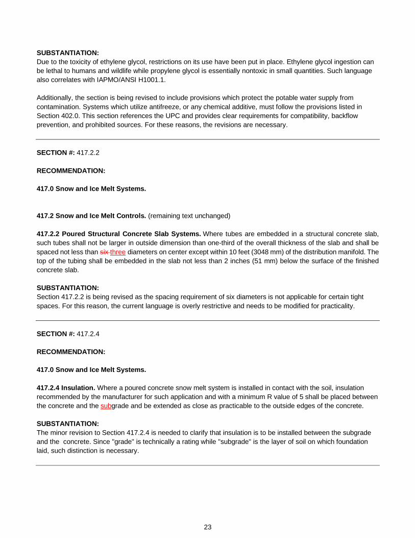
SUBSTANTIATION: Due to the toxicity of ethylene glycol, restrictions on its use have been put in place. Ethylene glycol ingestion can be lethal to humans and wildlife while propylene glycol is essentially nontoxic in small quantities. Such language also correlates with IAPMO/ANSI H1001.1. Additionally, the section is being revised to include provisions which protect the potable water supply from contamination. Systems which utilize antifreeze, or any chemical additive, must follow the provisions listed in Section 402.0. This section references the UPC and provides clear requirements for compatibility, backflow prevention, and prohibited sources. For these reasons, the revisions are necessary. SECTION #: 417.2.2 RECOMMENDATION: 417.0 Snow and Ice Melt Systems. 417.2 Snow and Ice Melt Controls. (remaining text unchanged) 417.2.2 Poured Structural Concrete Slab Systems. Where tubes are embedded in a structural concrete slab, such tubes shall not be larger in outside dimension than one-third of the overall thickness of the slab and shall be spaced not less than six three diameters on center except within 10 feet (3048 mm) of the distribution manifold. The top of the tubing shall be embedded in the slab not less than 2 inches (51 mm) below the surface of the finished concrete slab. SUBSTANTIATION: Section 417.2.2 is being revised as the spacing requirement of six diameters is not applicable for certain tight spaces. For this reason, the current language is overly restrictive and needs to be modified for practicality. SECTION #: 417.2.4 RECOMMENDATION: 417.0 Snow and Ice Melt Systems. 417.2.4 Insulation. Where a poured concrete snow melt system is installed in contact with the soil, insulation recommended by the manufacturer for such application and with a minimum R value of 5 shall be placed between the concrete and the subgrade and be extended as close as practicable to the outside edges of the concrete. SUBSTANTIATION: The minor revision to Section 417.2.4 is needed to clarify that insulation is to be installed between the subgrade and the concrete. Since "grade" is technically a rating while "subgrade" is the layer of soil on which foundation laid, such distinction is necessary.
23

SECTION #: 418.2.3 RECOMMENDATION: 418.0 Piping Installation. 418.2 Embedded Piping Materials and Joints. (remaining text unchanged) 418.2.3 Plastics. Plastic pipe and tubing shall be installed in continuous lengths or shall be joined by heat fusion methods or other approved fittings in accordance with Table 409.1 and the manufacturer’s installation instructions. Exception: Solvent cement joints shall not be used in embedded applications. SUBSTANTIATION: The proposed revision is needed to clarify that the language is a requirement rather than an exception.
24


Net Zero Task Group
Report


Net Zero Task Group Report
Task Group Members: Representation: Melanie Kwong (Chair) City of LA Department of Water and Power David Gordon City and County of San Francisco Adam Chrisman SunEarth Inc. Edmond Murray Aztec Solar Inc. Mark Rodriguez Sunrun Cary Smith Sound Geothermal Corporation Amir Tabakh City of LA Department of Water and Power Andy Williams Endo Enterprises (UK) Ltd During the Uniform Solar, Hydronics & Geothermal Code Technical Committee (USHGC TC) Teleconference Meeting on September 14, 2021, the USHGC TC requested that a Net Zero Task Group be formed. The scope of the Net Zero Task Group, as approved by the USHGC TC, was to generate guidelines for net zero through the use of renewable energy systems, reduction of energy demand, and increased system efficiency. During the first meeting, the Task Group determined that their recommendations were to be submitted in the form of a new appendix including information covering the design and construction of net zero and net positive buildings. By the conclusion of the second meeting, an outline of the appendix was developed including topics such as general regulations, certification requirements, energy loading order, and sustainable practices. The third meeting was focused on drafting the applicability to properly reflect the purpose of the appendix. Language was also drafted to link renewable energy systems covered within the USHGC to their applicable chapters or industry standards. Water efficiency and conservation were also addressed through reference to the Water Efficiency and Sanitation Standard (WE•Stand). Additionally, a list of reputable net zero certification agencies was inserted into the recommendations. Research was then completed between the third and fourth meeting to identify the optimal energy loading order for design and construction of net zero buildings. From this research, the Task Group agreed upon the generated loading order and provided supporting terminology. Language was also extracted from the UMC pertaining to HVAC system commissioning. The final Task Group meeting was held to identify and gather additional needed terminology. During this meeting, the Task Group also completed a comprehensive review of all recommendations generated and addressed any final concerns. Upon completion of this meeting, 1 proposal was generated and submitted to the USHGC TC for consideration during the June 21, 2022 USHGC Technical Committee Meeting.
1
SECTION #: Appendix E, Table 901.2
RECOMMENDATION:
APPENDIX E NET ZERO AND NET POSITIVE APPLICATIONS
E 101.0 General. E 101.1 Applicability. The purpose of this appendix is to provide guidelines for achieving net zero energy and net positive energy buildings through the use of energy efficient equipment and renewable energy systems.
E 102.0 Definitions. E 102.1 General. For the purposes of this appendix, the following definitions shall apply: Energy Loading Order. A design pathway aligned with achieving net zero energy consumption through energy efficient strategies and measures. Energy Star. A joint program of the U.S. Environmental Protection Agency and the U.S. Department of Energy. Energy Star is a voluntary program designed to identify and promote energy-efficient products and practices. Net Zero Energy Building. A building with net zero energy consumption; the total annual amount of energy consumed by a building is equal to the amount of on-site renewable energy generated. Renewable Energy Sources. Energy from solar, wind, biomass, or hydro, or extracted from hot fluid or steam heated within the earth.
E 103.0 General Regulations. E 103.1 Installation. Systems covered by this appendix shall be installed in accordance with this code, other applicable codes, and the manufacturer’s installation and operating instructions. E 103.1.1 Renewable Energy Systems. Renewable energy systems shall be designed and installed as follows: (1) Solar thermal systems in accordance with Chapter 5.(2) Geothermal energy systems in accordance with Chapter 7.(3) Solar photovoltaic systems in accordance with Chapter 8 and IAPMO IS 34.E 103.1.2 Water Conservation. Water efficiency and conservation shall be in accordance with the WaterEfficiency and Sanitation Standard (WE•Stand).E 103.2 Qualifications. Where permits are required, the Authority Having Jurisdiction shall have the authority torequire contractors, installers, or service technicians to demonstrate competency. Where determined by theAuthority Having Jurisdiction, the contractor, installer, or service technician shall be licensed to perform suchwork.
E 104.0 Certification. E 104.1 General. Net zero buildings shall be certified by one of the following agencies: (1) U.S. Green Building Council (USGBC);(2) International Living Future Institute (ILFI);(3) Department of Energy (DOE);(4) Earth Advantage; or(5) Other equivalent approved agencies.
E 105.0 Energy Loading Order. E 105.1 General. New and retrofit construction of residential and commercial buildings shall be designed and installed in the following energy loading order: (1) Building envelope(a) Reduction of infiltration(b) Insulation
2

(c) Glazing of windows and doors (2) Water heating appliances in accordance with the Energy Star program. (3) Space heating (4) Lighting (5) Other appliances (6) Air-Conditioning (7) Renewable energy systems E 106.0 Sustainable Practices. E 106.1 General. This section covers provisions that promote sustainable practices by enhancing the design and construction of mechanical systems to result in a positive long-term environmental impact. (See Figure E 106.1.)
Notes: 1 The delivered energy may consist of renewable and nonrenewable sources while only renewable energy is exported from the site boundary. 2 Renewable energy generation may be from bulk power systems with utility-scale solar, geothermal, hydro, and biomass facilities. 3 The dashed lines represent the site boundary.
FIGURE E 106.1 ENERGY TRANSFER FOR NET ZERO ENERGY PROJECTS
E 106.2 Use of Reclaimed (Recycled) and Onsite Treated Nonpotable Water for Cooling. Where approved for use by the water or wastewater utility and the Authority Having Jurisdiction, reclaimed(recycled), or on-site treated nonpotable water shall be permitted to be used for industrial and commercial cooling or air-conditioning. E 106.3 Heating, Ventilation, and Air Conditioning Systems Commissioning. The provisions of this section apply to the commissioning of commercial and institutional HVAC systems. E 106.3.1 Commissioning Requirements. HVAC commissioning shall be included in the design and construction processes of the project to verify compliance with this appendix and verify that the HVAC systems and components meet the owner’s project requirements. Commissioning shall be performed in accordance with this appendix by personnel trained and certified in commissioning by a nationally recognized organization. Commissioning requirements shall include the following: (1) Owner’s project requirements. (2) Basis of design. (3) Commissioning measures shown in the construction documents.
3
(4) Commissioning plan. (5) Functional performance. (6) Testing. (7) Post construction documentation and training. (8) Commissioning report. HVAC systems and components covered by this appendix, as well as process equipment and controls, and renewable energy systems, shall be included in the scope of the commissioning requirements. E 106.3.2 Owner’s Project Requirements (OPR). The performance goals and requirements of the HVAC system shall be documented before the design phase of the project begins. This documentation shall include not less than the following: (1) Environmental and sustainability goals. (2) Energy efficiency goals. (3) Indoor environmental quality requirements. (4) Equipment and systems performance goals. (5) Building occupant and operations and maintenance (O&M) personnel expectations. E 106.3.3 Basis of Design (BOD). A written explanation of how the design of the HVAC system meets the owner’s project requirements shall be completed at the design phase of the building project and updated as necessary during the design and construction phases. The basis of design document shall cover not less than the following systems: (1) Heating, ventilation, air conditioning (HVAC) systems and controls. (2) Water heating systems. (3) Renewable energy systems. E 106.3.4 Commissioning Plan. A commissioning plan shall be completed to document the approach of how the project will be commissioned and shall be started during the design phase of the building project. The commissioning plan shall include not less than the following: (1) General project information. (2) Commissioning goals. (3) Systems to be commissioned. Plans to test systems and components shall include at least the following information: (a) A detailed explanation of the original design intent. (b) Equipment and systems to be tested, including the extent of tests. (c) Functions to be tested. (d) Conditions under which the test shall be performed. (e) Measurable criteria for acceptable performance. (4) Commissioning team information. (5) Commissioning process activities, schedules, and responsibilities. Plans for the completion of commissioning requirements listed in Section E 106.3.5 through Section E 106.5 shall be included. E 106.3.5 Functional Performance Testing. Functional performance tests shall demonstrate the correct installation and operation of each component, system, and system-to-system interface in accordance with the approved plans and specifications. Functional performance testing reports shall contain information addressing each of the building components tested, the testing methods utilized, and readings and adjustments made. E 106.4 Construction Documents. Details of commissioning acceptance requirements shall be incorporated into the construction documents, including information that describes the details of the functional tests to be performed. This information shall be permitted to be integrated into the specifications for testing and air balancing, energy management and control systems, and equipment startup procedures or commissioning. It is possible that the work will be performed by a combination of the test and balance (TAB) contractor, mechanical/electrical contractor, and the energy management control system (EMCS) contractor; so applicable roles and responsibilities shall be clearly called out.
4

E 106.5 Commissioning Tests. Functional tests shall be performed on new equipment and systems installed in either new construction or retrofit applications in accordance with the mechanical code and the Authority Having Jurisdiction. The appropriate certificate of acceptance form along with each specific test shall be completed and submitted to the Authority Having Jurisdiction before a final occupancy permit can be granted. E 106.6 Minimum Equipment Efficiency Tables. The minimum efficiency requirements for listed equipment shall comply with ASHRAE 90.1.
TABLE 901.2 STANDARDS, PUBLICATIONS, PRACTICES, AND GUIDES
DOCUMENT NUMBER
DOCUMENT TITLE APPLICATION
IAPMO IS 34-2020 Residential Solar Photovoltaic and Energy Storage Systems Solar PV Systems IAPMO/ANSI WE•Stand-2020
Water Efficiency and Sanitation Standard for the Built Environment Water Conservation
(portion of table not shown remains unchanged)
SUBSTANTIATION: The proposed new appendix provides guidelines for achieving net zero energy and net positive energy buildings through the use of energy-efficient equipment and renewable energy systems. Net zero energy buildings combine energy efficiency and renewable energy generation to consume only as much energy as can be produced on-site through renewable resources. Although achieving net zero energy buildings requires a combination of sustainable engineering methods in order to be successful, there is a growing desire for such design and construction in both private and commercial applications. Section E 103.0 (General Regulations) and supporting subsections address the use of renewable energy systems with appropriate design and installation requirements. Specific reference to other chapters and industry standards has been provided for solar thermal systems, geothermal energy systems, and solar photovoltaic systems. Other renewable energy systems not addressed by this appendix are required to comply with the applicable recognized standards approved by the AHJ. As an additional means of environmental consciousness, the WE-Stand was referenced to cover water efficiency and conservation. Section E 104.0 (Certification) is intended to provide users of the code with available certification agencies/programs. The U.S. Green Building Council (USGBC) developed LEED certifications from their green building rating system, and now offer LEED Zero for verification of meeting net zero goals for carbon emissions, source energy usage, potable water usage, and zero waste. The International Living Future Institute (ILFI) Zero Energy Certification is an international third-party performance certification based on actual performance reviewed by an auditor. This agency provides a case study platform for projects to assist and accelerate zero energy efforts. The DOE Zero Energy Ready Home (ZERH) program is based on the comprehensive building science requirements of ENERGY STAR for Homes, along with proven Building America innovations and best practices. DOE Zero Energy Ready Homes are verified by a qualified third-party and are at least 40%-50% more energy-efficient than a typical new home.
5
Earth Advantage Zero Energy Certification is designed to create a standard for homes that wish to achieve a higher level of energy performance while still maintaining a sustainable approach to building. They also offer the Zero Energy Ready certification which focuses on buildings which are “ready” for adding the actual physical renewable systems in the future. Furthermore, the provided energy efficient loading order in Section E 105.0 is necessary as it significantly reduces energy consumption of both residential and commercial buildings. This loading order is a design pathway for achieving net zero and provides the necessary decision making processes for energy efficient strategies and measures for various construction projects. Although the methodology is simple, the inclusion of the energy loading order within the recommendations of this appendix serve meaningful and effective. Section E 106.0 (Sustainable Practices) and all subsections were gathered from the mechanical code. Such recommendations promote sustainable practices by enhancing the design and construction of mechanical systems for a positive long-term environmental impact. Figure E 106.1 has been provided as it offers a simplified energy flow diagram for net zero applications. The diagram includes a site boundary with directional delivered and exported energy and lists the possible building needs as well as the types of onsite renewable energy use and generation. Section E 106.2 was included as it promotes water conversation through the use of reclaimed (recycled) or onsite treated nonpotable water for industrial and commercial cooling or air-conditioning. In order to provide comprehensive provisions for net zero applications, the Task Group decided to also include requirements for commissioning of commercial and institutional HVAC systems. The listed subsections offer provisional language pertaining to performance goals and requirements, proper documentation, written explanation or basis of design, commissioning plans, as well as functional performance and commissioning testing. Such language also correlates with the sustainable practices as depicted within the mechanical code.
6


Solar Thermal Systems
Task Group Report


Solar Thermal Systems Task Group Report
Task Group Members: Representation: Adam Chrisman (Chair) SunEarth Inc. James Majerowicz Plumbers Local 130, UA Edmond Murray Aztec Solar Inc. Cary Smith Sound Geothermal Corporation Amir Tabakh, Principal James Kemper, Alternate
City of LA Department of Water and Power
During the Uniform Solar, Hydronics & Geothermal Code Technical Committee (USHGC TC) Teleconference Meeting on September 14, 2021, the USHGC TC requested that a Solar Thermal Systems Task Group be formed. The scope of the Solar Thermal Systems Task Group, as approved by the USHGC TC, was to review and update current provisions for solar thermal systems to improve requirements for design, construction, and installation in both residential and commercial applications. The Task Group reviewed the provisions listed within Chapter 5 (Solar Thermal Systems) of the USHGC and generated recommendations for Technical Committee consideration. Five meetings were conducted to complete this review and discussion. During the first Task Group meeting, all sections of Chapter 5 were reviewed and discussed. Areas requiring additional research were identified for discussion at the next meeting. From this research, provisions for freeze protection of air heating systems and tables for piping and tubing insulation thicknesses were deleted. In addition, the materials listed in Table 409.1 (Materials for Hydronic and Solar Thermal System Piping, Tubing, and Fittings) were confirmed as appropriate for solar thermal applications. The third meeting resulted in recommendations pertaining to materials, adhesives, automatic air vents, piping slopes, drainback systems, protection against decay, insulation of exterior applications, and proper disposal and recycling of solar thermal collectors. The fourth meeting included a review of the generated recommendations along with the corresponding drafted technical justifications. The Task Group also reviewed the notes and conversions listed under Table 503.6 (Insulation of Ducts). The fifth meeting was held to address any final concerns and approve all recommendations for submission as proposals. Upon completion of the final Task Group meeting, 14 proposals were generated and submitted to the USHGC TC for consideration during the June 21, 2022 USHGC Technical Committee Meeting.
1
SECTION #: 501.4, 501.13.7
RECOMMENDATION:
501.0 General.
501.4 Draining. Solar thermal system piping shall be installed to permit draining of the system. Drainback system piping above the fluid level of the drainback reservoir shall have a slope of not less than 1/4 inch per foot (20.8 mm/m).
501.13 Freeze Protection. (remaining text unchanged)
501.13.7 Piping. Fittings, pipe slopes, and collectors shall be designed and installed to allow for manual gravity draining and air filling of solar thermal system components and piping. Pipe slope for gravity draining shall be not less than 1/4 inch per foot (20.8 mm/m) of horizontal length. Collector header pipes or absorber plate riser tubes internal to the collector shall be sloped in accordance with the manufacturer’s instructions. Where a means to drain the system is provided a drain valve shall be installed.
SUBSTANTIATION: The provided slope of ¼ inch per foot was derived from sanitary drainage piping requirements for the transport of solid waste. Solar thermal systems do not require the same slope since only fluids are circulated through the system. Requiring systems to have the same slope as sanitary drainage piping is overly restrictive and serves no purpose.
SECTION #: 501.5
RECOMMENDATION:
501.0 General.
501.5 Materials. Piping, tubing and fittings materials shall comply with Table 409.1 and shall be approved by the manufacturer for the intended application. Joining methods shall be in accordance with Section 410.0. Materials in contact with heat transfer medium shall be approved for such use. Galvanized steel shall not be used for solar thermal piping systems containing antifreeze. Black steel shall not be used in systems with entrapped or entrained air. Unions between dissimilar metals shall comply with Section 305.2 and Section 410.13. The material used shall be capable of withstanding the maximum temperature and pressure of the system.
SUBSTANTIATION: Although Table 409.1 (Materials for Hydronic and Solar Thermal System Piping, Tubing, and Fittings) includes approved material standards, a specification should also be included to ensure that the materials being used are approved by the manufacturer for the intended application.
Entrained air refers to air bubbles smaller than 0.04 inch, and any air bubbles larger are considered entrapped. Including both of these terms is appropriate and provides additional clarity.
2
SECTION #: 501.5.3 RECOMMENDATION: 501.0 General. 501.5 Materials. (remaining text unchanged) 501.5.3 Adhesives. Adhesives used in a solar thermal collector shall not vaporize at the design temperature and shall be approved for the intended use. SUBSTANTIATION: Section 501.5.3 is being revised to clarify the type of solar collector being referenced. Although this Chapter is specific to solar thermal systems, this distinction is necessary. Furthermore, requiring the adhesives used to be approved for the intended application is also necessary as adhesives have varying properties including, but not limited to, environmental resistance to withstand UV radiation and weathering, and elasticity to compensate for varying coefficients of expansion. SECTION #: 501.7 RECOMMENDATION: 501.0 General. 501.7 Drainback Systems. The circulating pump shall be sized to overcome the static head pressure height of the collector, pressure losses, and provide the required flow rate to the collector. The drainback reservoir shall be located in a conditioned space to prevent freezing. A sight glass, or other method of monitoring the level of fluid in the solar loop shall be installed in the solar loop, or on the drainback reservoir. A drainback system shall be capable of being manually isolated and drained. SUBSTANTIATION: The provisions listed for drainback systems read similarly to terminology rather than requirements. Additionally, the language is unclear, and requiring drainback vessels to be in a conditioned space is impractical and overly restrictive. For these reasons, the provisions for drainback systems are being stricken. SECTION #: 501.10 RECOMMENDATION: 501.0 General. 501.10 Automatic Air Vents. Where installed, automatic air release vents shall be installed located at high points of the solar thermal system with isolation valves for maintenance and removal in accordance with the system design requirements and manufacturer’s installation instructions.
3

SUBSTANTIATION: Trapped air will naturally accumulate at high points within the system. The purpose of air vents is to continually release excess air out of the system, resulting in smooth and efficient operation. However, automatic air vents are often failure points within these systems and must be installed with isolation valves to allow for removal and to prevent system failure. SECTION #: 501.13.5 RECOMMENDATION: 501.0 General. 501.13 Freeze Protection. (remaining text unchanged) 501.13.5 Air Heating Systems. Air solar heating systems shall be permitted to be used in accordance with the manufacturer’s instructions. SUBSTANTIATION: A solar air heater is a type of solar thermal system where air is heated in a collector and either transferred directly to the interior space or to a storage medium. Since these systems convey air and not a heat transfer fluid, there is no need for freeze protection. Additionally, no other location within Chapter 5 was found to be suitable for permitting air heating systems, and there is nothing within the USHGC that prohibits their use. Therefore, the language is both misplaced and unnecessary. SECTION #: 501.15 RECOMMENDATION: 502.0 Solar Collectors. 502.5 Installation. (remaining text unchanged) 501.15502.5.1 Protection Against Decay. Wood used in the construction of collector or system mounting, and exposed to outdoor conditions shall be pressure-treated with preservative or shall be a naturally durable, decay resistant species of lumber. Wood shall not be used in the construction of collector or system mounting. SUBSTANTIATION: The use of wood should be prohibited as the industry has moved away from using this material. Since these collectors will be mounted for long periods of time, more robust mounting systems should be required which can withstand weathering and degradation by light and moisture. Additionally, this section has been moved to a more appropriate location.
4
SECTION #: 502.2 RECOMMENDATION: 502.0 Solar Collectors. 502.2 Fire Safety Requirements. Collectors that function as building components shall be in accordance with the building code and the fire code. SUBSTANTIATION: In order to ensure compliance with building and fire safety requirements when installing solar thermal systems, reference to the fire code has been added to Section 502.2. SECTION #: 502.5 RECOMMENDATION: 502.0 Solar Collectors.
502.5 Installation. Solar collectors shall be ballasted or anchored to roof structures or other surfaces in accordance with Section 317.1. Collectors shall be mounted as to minimize the accumulation of debris. Connecting pipes shall not be used to provide support for a solar collector. Collectors shall be installed in accordance with the manufacturer’s installation instructions. SUBSTANTIATION: The current language is overly restrictive in that it only permits the use of anchored systems. It is not uncommon for low-sloped roofs or ground-mounted systems to have solar ballasts which serve as an alternative to roof and ground penetrations. Ballasted mounts offer the benefits of solar thermal collectors without the impact on the roof resulting from penetrations into the roof rafters. Instead, they sit directly on top, cemented to the surface with concrete blocks. For these reasons the proposed revision is necessary. SECTION #: 502.7 RECOMMENDATION: 502.0 Solar Collectors. 502.7 Disposal and/or Reuse. Solar collectors made of plastic or copper shall be disposed of and/or reused in accordance with the Authority Having Jurisdiction. SUBSTANTIATION: The proposed section ensures proper disposal and reuse/recycling of collector materials. In turn, this requirement also promotes more sustainable practices for solar collectors at end of life. Since there are varying disposal requirements based on the type of collector and local jurisdiction, such disposal and/or reuse must be left up to the AHJ.
5
SECTION #: 503.2, Table 503.3(1), Table 503.3(2) RECOMMENDATION: 503.0 Insulation. 503.2 Heat Loss. Insulation shall be installed on interconnecting solar and hot water piping. The final 5 feet (1524 mm) of the cold water supply line, or the entire length where less than 5 feet (1524 mm), shall be insulated. The insulation thickness shall be in accordance with Table 503.3(1) or Table 503.3(2), or the insulation installed shall have an R-value of not less than R-2.6 degree Fahrenheit hour square foot per British thermal unit (°F•h•ft2/Btu) (R-0.46 m2•K/W). Piping, storage tanks, and circulating air ductwork shall be insulated. Ductwork and piping shall be permitted to not be insulated where exposed in conditioned spaces, and the heat loss from such ducts or piping does not otherwise contribute to the heating or cooling load within such space. Exception: Low temperature, aboveground piping installed for swimming pools, spas, and hot tubs in accordance with the manufacturer’s installation instructions unless such piping is located within a building.
TABLE 503.3(1) PIPE INSULATION THICKNESS
(remove table in its entirety)
TABLE 503.3(2) STANDARD TUBING INSULATION THICKNESS
(remove table in its entirety)
SUBSTANTIATION: Table 503.3(1) and Table 503.3(2) are being deleted as these tables have been removed from the original source document of which they were derived. In addition, these tables provide insulation thickness to the overall outside diameter of the pipe assembly rather than required R-values. It is better suited to provide a minimum R-value for ease of use, and the R-value of 2.6 currently provided in Section 503.2 is sufficient for ensuring adequate insulation of the piping system. SECTION #: 503.5 RECOMMENDATION: 503.0 Insulation. 503.5 Installation. Insulation shall be finished with a jacket or facing with the laps sealed with adhesives or staples so as to secure the insulation on the pipe. Insulation jacket seams shall be on the underside of the piping and shall overlap in accordance with the manufacturer’s installation instructions. Joints and seams shall be sealed with a sealant that is approved for both the material and environmental conditions. In lieu of jackets, molded insulation shall be permitted to be secured with approved fasteners 16 gauge galvanized wire ties not exceeding 9 inches (229 mm) on center.
6

SUBSTANTIATION: Section 503.5 is being revised to remove the language which permits exclusively the use of 16 gauge galvanized wire ties. Rather than limiting the permitted methods of securing molded insulation, the language should allow for the use of any approved fasteners as there are various solutions available which are appropriate for this application. For these reasons, the modifications are necessary and improve the code. SECTION #: 503.5.1 RECOMMENDATION: 503.0 Insulation. 503.5 Installation. (remaining text unchanged) 503.5.1 Exterior Applications. Insulation for exterior applications shall be finished with an approved jacket, coating, or facing with the surfaces and laps sealed. Jacketing, coating, facing, and tape used for exterior applications shall be designed for such use. Where flexible insulation is used, it shall be wrapped and sealed against water penetration. Insulation used for exterior applications shall be resistant to extreme temperatures, UV exposure, and moisture. Means shall be provided to prevent damage from rodents. SUBSTANTIATION: Section 503.5.1 is being revised to also include "coating" as an approved finishing for insulation installed in exterior applications. Coating is not categorized as a type of facing or jacketing and should therefore be included in the listed approved types. This modification improves the code and prevents overly restrictive language. Furthermore, rodent proofing is being added to the list of insulation protection requirements. SECTION #: Table 503.6 RECOMMENDATION:
TABLE 503.6
INSULATION OF DUCTS5
DUCT LOCATION INSULATION TYPES MECHANICALLY COOLED4
HEATING ZONES1 INSULATION TYPES HEATING ONLY4
On roof or on exterior of building
C, V2 and W I II III A and W B and W C and W
Attics, and garages and crawl spaces
A and V2 I II III A A B
In walls,3 within floor-ceiling spaces3
A and V2 I II III A A B
Within the conditioned space, or in basements; return ducts in air plenums
None required –– None required
Cement slab or within ground None required –– None required
7

Notes: 1 - 3 (remaining text unchanged) 4 The examples of materials listed under each type of insulation is not meant to limit other available thickness and density combinations with the equivalent installed conductance or resistance based on the insulation only. Insulation Types (Applicable to only glazed collectors): A = Materials with an installed conductance of 0.48 British thermal unit per degree Fahrenheit hour square foot [Btu/(°F•h•ft2)] [2.7 W/(m2•K)] or the equivalent thermal resistance of 2.1 degree Fahrenheit hour square foot per British thermal unit [(°F•h•ft2)/Btu] [0.37 (m2•K)/W]. Examples of materials capable of meeting the above requirements: (a) One inch (25.4 mm), 0.60 pounds per cubic feet (lb/ft3) (9.61 kg/m3) mineral fiber (rock, slag, or glass) blanket. (b) One-half inch (12.7 mm), 1.5 lb/ft3 to 3 lb/ft3 (24 kg/m3 to 48 kg/m3) mineral fiber blanket duct liner. (c) One-half inch (12.7 mm), 3 lb/ft3 to 10 lb/ft3 (48 kg/m3 to 160 kg/m3) mineral fiber board. B = Materials with an installed conductance of 0.24 British thermal unit per degree Fahrenheit hour square foot [Btu/(°F•h•ft2)] [1.4 W/(m2•K)] or the equivalent thermal resistance of 4.2 degree Fahrenheit hour square foot per British thermal unit [(°F•h•ft2)/Btu] [0.74 (m2•K)/W]. Examples of materials meeting the above requirements: Two-inch (51 mm), 0.60 lb/ft3 (9.61 kg/m3) mineral fiber blanket. One inch (25.4 mm), 1.5 lb/ft3 to 3 lb/ft3 (24 kg/m3 to 48 kg/m3) mineral fiber blanket duct liner. One inch (25.4 mm), 3 lb/ft3 to 10 lb/ft3 (48 kg/m3 to 160 kg/m3) mineral fiber board. C = Materials with an installed conductance 0.16 British thermal unit per degree Fahrenheit hour square foot [Btu/(°F•h•ft2)] [0.91 W/(m2•K)] or the equivalent thermal resistance 6.3 degree Fahrenheit hour square foot per British thermal unit [(°F•h•ft2)/Btu] [1.11 (m2•K)/W]. Examples of materials meeting the above requirements: Three-inch (76 mm), 0.60 lb/ft3 (9.61 kg/m3) mineral fiber blanket. One-and-one-half inch (38 mm), 1.5 lb/ft3 to 3 lb/ft3 (24 kg/m3 to 48 kg/m3) mineral blanket duct liner. One-and-one-half inch (38 mm), 3 lb/ft3 to 10 lb/ft3 (48 kg/m3 to 160 kg/m3) mineral fiber board. V = Vapor barrier: Material with a perm rating not exceeding 0.5 perm [2.9 E-11 kg/(Pa•s•m2)]. Joints shall be sealed. W = Approved weatherproof barrier. 5 (remaining text unchanged) SUBSTANTIATION: The proposed revision to Note (4) of Table 503.6 is necessary since plastic or unglazed panels do not require insulation, and the operation temperatures are within 15 to 20 degrees of the ambient temperature. For these reasons, the additional language is needed.
8


