Embed Size (px)
Citation preview

Triumph Tiger 800 and Tiger SOOXC
(Including ABS models)
Motorcycle Service Manual
Part Number 3856760, issue 1, 12.2010
This document is protected by copyright and may not, in whole or part be stored in a retrieval system, or transmitted in
any form or by any means, copied, photocopied, translated or reduced to any machine-readable form without prior consent in writing from Triumph Motorcycles Limited.
No liability can be accepted for any inaccuracies or omissions in this publication, although every possible care has been
taken to make it as complete and accurate as possible.
Triumph Motorcycles Limited reserves the right to make changes and alter specifications without prior notice and without
incurring an obligation to make such changes to products manufactured previously. See your authorised Triumph dealer
for the latest information on product improvements incorporated after this publication.
All information contained in this publication is based on the latest product information available at the time of publication.
Illustrations in this publication are intended for reference use only and may not depict actual model component parts.
© Triumph Motorcycles Ltd. 2010
SeiVice Manual - Tiger 800 and Tiger 800XC

11 · SeiVice Manual - Tiger 800 and Tiger 800XC
Table of Contents
Introduction
General Information
Scheduled Maintenance
Cylinder Head
Clutch
Crankshaft, Connecting Rods and Pistons
Balancer
Transmission
Lubrication .
Engine Removal/Refit
Fuel System/Engine Management
Cooling
Rear Suspension
Front Suspension
Brakes
Wheels/Tyres
Frame and Bodywork
Electrical
SeiVice Manual - Tiger 800 and Tiger 800XC iii

This page intentionally left blan k
iv SeNice Manual - Tiger 800 and Tiger 800XC
Introduction Table of Contents
How to use this manual . . . . . . . . . . . . . . . . . . . . . . . . . . . . . . . . . . . . . . . . . . . . . . . . . . . . . . . . . . . . . . . . . . . . .vi
Warnings, Cautions and Notes . . . . . . . . . . . . . . . . . . . . . . . . . . . . . . . . . . . . . . . . . . . . . . . . . . . . . . . . . . . . . . .vi
Tampering with Noise Control System Prohibited . . . . . . . . . . . . . . . . . . . . . . . . . . . . . . . . . . . . . . . . . . . . . .vi i
References . . . . . . . . . . . . . . . . . . . . . . . . . . . . . . . . . . . . . . . . . . . . . . . . . . . . . . . . . . . . . . . . . . . . . . . . . . . . . . .vi i
Dimensions . . . . . . . . . . . . . . . . . . . . . . . . . . . . . . . . . . . . . . . . . . . . . . . . . . . . . . . . . . . . . . . . . . . . . . . . . . . . . .vi i
Repairs and Replacements . . . . . . . . . . . . . . . . . . . . . . . . . . . . . . . . . . . . . . . . . . . . . . . . . . . . . . . . . . . . . . . . . .vi i
Force . . . . . . . . . . . . . . . . . . . . . . . . . . . . . . . . . . . . . . . . . . . . . . . . . . . . . . . . . . . . . . . . . . . . . . . . . . . . . . . . . . . .vi i
Edges . . . . . . . . . . . . . . . . . . . . . . . . . . . . . . . . . . . . . . . . . . . . . . . . . . . . . . . . . . . . . . . . . . . . . . . . . . : . . . . . . . .vi i
Tightening procedure . . . . . . . . . . . . . . . . . . . . . . . . . . . . . . . . . . . . . . . . . . . . . . . . . . . . . . . . . . . . . . . . . . . . . .vii
I� SeiVice Manual � Tiger 800 and Tiger 800XC V
Introduction
This manual is designed primarily for use by trained technicians in a properly equipped workshop. However, it contains enough detail and basic information to make it useful to the owner who desires to perform his own basic maintenance and repair work. The work can only be carried out if the owner has the necessary hand and special service tools to complete the job.
A basic knowledge of mechanics, including the proper use of tools and workshop procedures is necessary in order to carry out maintenance and repair work satisfactorily. Whenever the owner has insufficient experience or doubts his ability to do the work, an authorised Triumph dealer must undertake all adjustments, maintenance, and repair work.
In order to perform the work efficiently and to avoid costly mistakes, read the text and thoroughly familiarise yourself with procedures before starting work.
All work should be performed with great care and in a clean working area with adequate lighting.
Always use the correct special service tools or equipment specified. Under no circumstances use makeshift tools or equipment since the use of substitutes may adversely affect safe operation.
Where accurate measurements are required, they can only be made using calibrated, precision instruments.
For the duration of the warranty period, an authorised Triumph dealer must perform all repairs and scheduled maintenance.
To maximise the life of your Motorcycle: •
•
Accurately fol low the maintenance requirements of the periodic maintenance chart in the service manua l.
Do not allow problems to develop . Investigate unusual noises and changes in the riding characteristics of the motorcycle. Recti fy al l problems as soon as possible (immediately if safety related ).
Use only gen uine Triumph parts as listed in the parts catalogue/parts microfiche.
• Follow the procedures in this manual careful ly and completely. Do not take short cuts.
Keep complete records of al l maintenance and repairs with dates and any new parts installed.
Use only a pproved lubricants, as specified in the owner's handbook, i n the maintenance of the motorcycle.
How to use this manual To assist in the use of this manual, the section title is given at the top of each page.
Each major section starts with a contents page, listing the information contained in the section.
The individual steps comprising repair operations are to be followed in the sequence in which they appear.
Adjustment and repair operations include reference to service tool numbers and the associated illustration depicts the tool.
Where usage is not obvious, the tool is shown in u.se.
Adjustment and repair operations also include reference to wear limits, relevant data, torque figures, specialist information and useful assembly details.
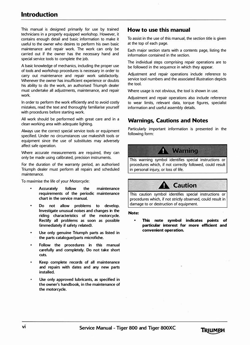
Warnings, Cautions and Notes Particularly important information is presented in the following form:
This warning symbol identifies special instructions or procedures which, if not correctly followed, could result in personal injury, or loss of life.
This caution symbol identifies special instructions or procedures which, if not strictly observed, could result in damage to or destruction of equipment.
Note:
• This note symbol indicates points of particular interest for more efficient and convenient operation.
VI SeiVice Manual - Tiger 800 and Tiger 800XC
Tampering with Noise Control System Prohibited Owners are warned that the law may prohibit:
a> The removal or rendering inoperative by any person other than for purposes of maintenance, repair or replacement, of any device or element of design incorporated into any new veh icle for the purpose of noise control prior to its sale or del ivery to the ultimate purchaser or while it is in use; and
b) the use of the vehicle after such device or element of design has been removed or rendered inoperative by any person.
References References to the left-hand or right-hand side given in this manual are made when viewing the motorcycle from the rear.
Operations covered in this manual do not always include reference to testing the motorcycle after repair. lt is essential that work is inspected and tested after completion and if necessary a road test of the motorcycle is carried out particularly where safety related items are concerned.
Dimensions The dimensions quoted are to design engineering specification with service limits where applicable.
During the period of running-in from new, certain adjustments may vary from the specification figures given in this manual. These will be reset by the dealer at the 500 mile/800 km service, and thereafter should be maintained at the figures specified in this manual.
Repairs and Replacements Before removal and disassembly, thoroughly clean the motorcycle. Any dirt entering the engine gr other parts will work as an abrasive and shorten the life of the motorcycle. Particular attention should be paid when installing a new part, that any dust or metal filings are cleared from the immediate area.
Introduction
Force Common sense should dictate how much force is necessary in assembly and disassembly. If a part seems especially difficult to remove or install, stop and examine what may be causing the problem. Never lever a component as this will cause damage both to the component itself and to the surface being levered against.
Whenever tapping to aid removal of an item is necessary, tap lightly using a hide or plastic faced mallet.
Edges Watch for sharp edges, especially during engine disassembly and assembly. Protect the hands with industrial quality gloves.
When replacement parts are required, it is essential that only genuine Triumph parts are used.
Safety features and corrosion prevention treatments embodied in the motorcycle may be impaired if other than genuine Triumph parts are fitted. In certain territories, legislation prohibits the fitting of parts not to the manufacturer's specification.
Tightening procedure Generally, when installing a part with several bolts, nuts or screws, they should all be started in their holes and tightened to a snug fit, evenly and in a cross pattern. This is to avoid distortion of the part and/or causing gas or oil leakage. Conversely, bolts, nuts, or screws, should all be loosened (in sequence if specified) by about a quarter of a turn and then removed.
Where there is a tightening sequence specified in this Service Manual, the bolts, nuts, or screws must be tightened in the order and by the method indicated.
Torque wrench setting figures given in this Manual must be observed. The torque tools used must be of accurate calibration.
Locking devices, where specified, must be fitted. If the efficiency of a locking device is impaired during removal it must be renewed. This applies particularly to microencapsulated fixings which must always be replaced if disturbed. Where necessary, the text in this manual will indicate where such a fixing is used.
SeiVice Manual - Tiger 800 and Tiger 800XC VII

Introduction
This page intentional ly left blank
viii SeiVice Manual - Tiger 800 and Tiger 800XC
1 General Information Table of Contents
Ignition System Safety Precautions . . . . . . . . . . . . . . . . . . . . . . . . . . . . . . . . . . . . . . . . . . . . . . . . . . . . . . . . . . . 1.4
Dangerous Substances . . . . . . . . . . . . . . . . . . . . . . . . . . . . . . . . . . . . . . . . . . . . . . . . . . . . . . . . . . . . . . . . . . . . . 1.4
Third Party Products . . . . . . . . . . . . . . . . . . . . . . . . . . . . . . . . . . . . . . . . . . . . . . . . . . . . . . . . . . . , . . . . . . . . . . . 1.4
Fluoroelastomers . . . . . . . . . . . . . . . . . . . . . . . . . . . . . . . . . . . . . . . . . . . . . . . . . . . . . . . . . . . . . . . . . . . . . . . . . . 1.4
Oils . . . . . . . . . . . . . . . . . . . . . . . . . . . . . . . . . . . . . . . . . . . . . . . . . . . . . . . . . . . . . . . . . . . . . . . . . . . . . . . . . . . . . 1.4
Health Protection Precautions . . . . . . . . . . . . . . . . . . . . . . . . . . . . . . . . . . . . . . . . . . . . . . . . . . . . . . . . . . 1.5
Environmental Protection Precautions . . . . . . . . . . . . . . . . . . . . . . . . . . . . . . . . . . . . . . . . . . . . . . . . . . . . . . . . 1.5
Brakes . . . . . . . . . . . . . . . . . . . . . . . . . . . . . . . . . . . . . . . . . . . . . . . . . . . . . . . . . . . . . . . . . . . . . . . . . . . . . . . . . . . 1.5
Safety Instructions . . . . . . . . . . . . . . . . . . . . . . . . . . . . . . . . . . . . . . . . . . . . . . . . . . . . . . . . . . . . . . . . . . . . . . . . . 1.6
Jacking and Lifting . . . . . . . . . . . . . . . . . . . . . . . . . . . . . . . . . . . . . . . . . . . . . . . . . . . . . . . . . . . . . . . . . . . . 1.6 Precautions against Damage . . . . . . . �. . . . . . . . . . . . . . . . . . . . . . . . . . . . . . . . . . . . . . . . . . . . . . . . . . . 1.6 Coolant . . . . . . . . . . . . . . . . . . . . . . . . . . . . . . . . . . . . . . . . . . . . . . . . . . . . . . . . . . . . . . . . . . . . . . . . . . . . . 1.6 Cleaning Components. . . . . . . . . . . . . . . . . . . . . . . . . . . . . . . . . . . . . . . . . . . . . . . . . . . . . . . . . . . . . . . . . 1.7 Lubrication . . . . . . . . . . . . . . . . . . . . . . . . . . . . . . . . . . . . . . . . . . . . . . . . . . . . . . . . . . . . . . . . . . . . . . . . . . 1.7 Joints and Joint Faces _ . . . . . . . . . . . . . . . . . . . . . . . . . . . . . . . . . . . . . . . . . . . . . . . . . . . . . . . . . . . . . . . . . 1.7 Gaskets, 0-rin gs . . . . . . . . . . . . . . . . . . . . . . . . . . . . . . . . . . . . . . · . . . . . . . . . . . . . . . . . . . . . . . . . . . . . . . . 1.7 Liquid Gasket, Non-permanent Locking Agent . . . . . . . . . . . . . . . . . . . . . . . . . . . . . . . . . . . . . . . . . . . . 1.7 Screw Threads . . . . . . . . . . . . . . . . . . . . . . . . . . . . . . . . . . . . . . . . . . . . . . . . . . . . . . . . . . . . . . . . . . . . . . . 1.7 Locking Devices . . . . . . . . . . . . . . . . . . . . . . . . . . . . . . . . . . . . . . . . . . . . . . . . . . . . . . . . . . . . . . . . . . . . . . 1.8 Fitting a Split Pin . . . . . . . . . . . . . . . . . . . . . . . . . . . . . . . . . . . . . . . . . . . . . . . . . . . . . . . . . . . . . . . . . . . . . 1.8 Circl ips, Retaining Rings . . . . . . . . . . . . . . . . . . . . . . . . . . . . . . . . . . . . . . . . . . . . . . . . . . . . . . . . . . . . . . . 1.8 Self Locking Nuts . . . . . . . . . . . . . . . . . . . . . , . . . . . . . . . . . . . . . . . . . . . . . . . . . . . . . . . . . . . . . . . . . . . . . . 1.8 Encapsulated Bolts . . . . . . . . . . . . . . . . . . . . . . . . . . . . . . . . . . . . . . . . . . . . . . . . . . . . . . . . . . . . . . . . . . . . 1.8 ·
Oil and Grease Seals . . . . . . . . . . . . . . . . . . . . . . . . . . . . . . . . . . . . . . . . . . . . . . . . . . . . . . . . . . . . . . . . . . 1.8 Press . . . . . . . . . . . . . . . . . . . . . . . . . . . . . . . . . . . . . . . . . . . . . . . . . . . . . . . . . . . . . . . . . . . . . . . . . . . . . . . 1.8 Ball Bearings . . . . . . . . . . . . . . . . . . . . . . . . . . . . . . . . . . . . . . . . . . . . . , . . . . . . . . . . . . . . . . . . . . . . . . . . . 1.8 Chassis Bearing Lubrication . . . . . . . . . . . . . . . . . . . . . . . . . . . . . . . . . . . . . . . . . . . . . . . . . . . . . . . . . . . . 1.8 Metal bushes . . . . . . . . . . . . . . . . . . . . . . . . . . . . . . . . . . . . . . . . . . . . . . . . . . . . . . . . . . . . . . . . . . . . . . . 1.1 0
Fuel Handling Precautions . . . . . . . . . . . . . . . . . . . . . . . . . . . . . . . . . . . . . . . . . . . . . . . . . . . . . . . . . . . . . . . . . 1.1 0
General . . . . . . . . . . . . . . . . . . . . . . . . . . . . . . . . . . . . . . . . . . . . . . . . . . . . . . . . . . . . . . . . . . . . . . . . . . . . 1.1 0 Petrol - Gasoline . . . . . . . . . . . . . . . . . . . . . . . . . . . . . . . . . . . . . . . . . . . . . . . . . . . . . . . . . . . . . . . . . . . . . 1.1 0 Fuel Tank Removal . . . . . . . . . . . . . . . . . . . . . . . . . . . . . . . . . . . . . . . . . . . . . . . . . . . . . . . . . . . . . . . . . . . 1.1 1
Chassis Repairs . . . . . . . . . . . . . . . . . . . . . . . . . . . . . . . . . . . . . . . . . . . . . .' . . . . . . . . . . . . . . . . . . . . . . . . . . . . 1.1 1
Electrical Precautions . . . . . . . . . . . . . . . . . . . . . . . . . . . . . . . . . . . . . . . . . . . . . . . . . . . . . . . . . . . . . . . . . . . . . 1.1 2
SeiVice Manual - Tiger 800 and Tiger 800XC 1.1

General Information
1.2
Battery Disconnecting . . . . . . . . . . . . . . . . . . . . . . . . . . . . • . . . . . . . . . . . . . . . . . . . . . . . . . . . . . . . . . . .
Discipl ines . . . . . . . . . . . . . . . . . . . . . . . . . . . . . . . . . . . . . . . . . . . . . . . . . . . . . . . . . . . . . . . . . . . . . . . . . .
Electrical Wires . . . . . . . . . . . . . . . . . . . . . . . . . . . . . . . . . . . . . . . . . . . . . . . . . . . . . . . . . . . . . . . . . . . . . .
Electrical Testing . . . . . . . . . . . . . . . . . . . . . . . . . . . . . . . . . . . . . . . . . . . . . . . . . . . . . . . . . . . . . . . . . . . . . . . . .
Ohm's Law . . . . . . . . . . . . . . . . . . . . . . . . . . . . . . . . . . . . . . . . . . . . . . . . . . . . . . . . . . . . . . . . . . . . . . . . .
Basic Electrical Circuits . . . . . . . . . . . . . . . . . . . . . . . . . . . . . . . . . . . . . . . . . . . . . . . . . . . . . . . . . . . . . . .
Circuit Diagrams . . . . . . . . . . . . . . . . . . . . . . . . . . . . . . . . . . . . . . . . . . . . . . . . . . . . . . . . . . . . . . • . . . . . . . . . .
Glossary of Circuit Diagram Symbols . . . . . . . . . . . . . . . . . . . . . . . . . . . . . . . . . . . . . . . . . . . . . . . . . . . . . . . .
Tracing Circuits . . . . . . . . . . . . . . . . . . . . . . . . . . . . . . . . . . . . . . . . . . . . . . . . . . . . . . . . . : . . . . . : . . . . . . . . . . .
To Check Continuity: . . . . . . . . . . . . . . . . . . . . . . . . . . . . . . . . . . . . . . . . . . . . . . . . . . . . . . . . . . . . . . . . .
To Measure Voltage: . . . . . . . . . . . . . . . . . . . . . . . . . . . . . . . . . . . . . . . . . . . . . . . . . . . . . . . . . . . . . . . . .
Splices . . . . . . . . . . . . . . . . . . . . . . . . . . . . . . . . . . . . . . . , . . . . . . . . . . . . . . . . . . . . . . . . . . . . . . . . . . . . .
CAN <Controller Area Networking) . . . . . . . . . . . . . . . . . . . . . . . . . . . . . . . . . . . . . . . . . . . . . . . . . . . . . . . . .
Alternator/Charging System . . . . . . . . . . . . . . . . . . . . . . . . . . . . . . . . . . . . . . . . . . . . . . . . . . . . . . . . . . . . . . .
Diagnosis - Charging Circuit . . . . . . . . . . . . . . . . . . . . . . . . . . . . . . . . . . . . . . . . . . . . . . . . . . . . . . . . . .
Starting Circuit . . . . . . . . . . . . . . . . . . . . . . . . . . . . . . . . . . . . . . . . . . . . . . . . . . . . . . . . . . . . . . . . . . . . . . . . . .
General Fault Finding - Starter Motor and Relay . . . . . . . . . . . . . . . . . . . . . . . . . . . . . . . . . . . . . . . . . . . . . .
Diagnosis - Starter Circuit . . . . . . . . . . . . . . . . . . . . . . . . . . . . . . . . . . . . . . . . . . . . . . . . . . . . . . . . . . . . . . . . .
Inspection . . . . . . . . . . . . . . . . . . . . . . . . . . . . . . . . . . . . . . . . . . . . . . . . . . . . . . . . . . . . . . . . . . . . . . . . . . . : . . .
Replacement Parts . . . . . . . . . . . . . . . . . . . . . . . . . . . . . . . . . . . . . . . . . . . . . . . . . . . . . . . . . . . . . . . . . . . . . . .
SeiVice Data . . . . . . . . . . . . . . . . . . . . . :· ...................................................... .
Specification . . . . . . . . . . . . . . . . . . . . . . . . . . . . . . . . . . . . . . . . . . . . . . . . . . . . . . . . . . . . . . . . . . . . . . . . . . . . .
Se iVice Tools and Garage Equipment . . . . . . . . . . . . . . . . . . . . . . . . . . . . . . . . . . . . . . . . . . . . . . . . . . . . . . . .
Ful l Specification . . . . . . . . . . . . . . . . . . . . . . . . . . . . . . . . . . . . . . . . . . . . . . . . . . . . . . . . . . . . . . . . . . . . . . . . .
1.1 2 1.1 2 1.1 3
1.1 3
1.1 3 1.1 3
1.1 4
1.1 4
1.1 6
1.1 6 1.17 1.17
1.1 8
1.19
1.19
1.20
1.20
1.21
1.22
1.22
1.22
1.22
1.23
1.28
Engine . . . . . . . . . . . . . . . . . . . . . . . . . . . . . . . . . . . . . . . . . . . . . . . . . . . . . . . . . . . . . . . . . . . . . . . . . . . . . 1.28 Cyli nder Head & Valves . . . . . . . . . . . . . . . . . . . . . . . . . . . . . . • . . . . . . . . . . . . . . . . . . . . . . . . . . . . . . . 1.29 Cylinder Head & Valves <continued> . . . . . . . . . . . . . . . . . . . . . . . . . . . . . . . . . . . . . . . . . . . . . . . . . . . . 1.30 Camshafts . . . . . . . . . . . . . . . . . . . . . . . . . . . . . . . . . . . . . . . . . . . . . . . . . . . . . . . . . . . . . . . . . . . . . . . . . . 1.30 Clutch/Primary Drive . . . . . . . . . . . . . . . . . . . . . . . . . . . . . . . . . . . . . . . . . . . . . . . . . . . . . . . . . . . . . . . . 1.31 Pistons . . . . . . . . . . . . . . . . . . . . . . . . . . . . . . . . . . . . . . . . . . . . . . . . . . . . . . . . . . . . . . . . . . . . . . . . . . . . . 1.31 Connecting Rods . . . . . . . . . . . . . . . . . . . . . . . . . . . . . . . . . . . . . . . . . . . . . . . . . . . . . . . . . . . . . . . . . . . . 1.31 Crankshaft . . . . . . . . . . . . . . . . . . . . . . . . . . . . . . . . . . . . . . . . . . . . . . . . . . . . . . . . . . . . . . . . . . . . . . . . . 1.32 Transmission . . . . . . . . . . . . . . . . . . . . . . . . . . . . ,, . . . . . . . . . . . . . . . . . . . . . . . . . . . . . . . . . . . . . . . . . . . 1.32 Final Drive. . . . . . . . . . . . . . . . . . . . . . . . . . . . . . . . . . . . . . . . . . . . . . . . . . . . . . . . . . . . . . . . . . . . . . . . . . 1.32 Lubrication . . . . . . . . . . . . . . . . . . . . . . . . . . . . . . . . . . . . . . . . . . . . . . . . . . . . . . . . . . . . . . . . . . . . . . . . . 1.33 Ignition System . . . . . . . . . . . . . . . . . . . . . . . . . . . . . . . . . . . . . . . . . . . . . . . . . . . . . . . . . . . . . . . . . . . . . 1.33 Fuel System . . . . . . . . . . . . . . . . . . . . . . . . . . . . . . . . . . . . . . . . . . . . . . . . . : . . . . . . . . . . . . . . . . . . . . . . 1.33 Coolant System . . . . . . . . . . . . . . . . . . . . . . . . . . . . . . . . . . . . . . . . . . . . . . . . . . . . . . . . . . . . . . . . . . . . . 1.34 Suspension . . . . . . . . . . . . . . . . . . . . . . . . . . . . . . . . . . . . . . . . . . . . . . . . . . . . . . . . . . . . . . . . . . . . . . . . . 1.34 Fuel Injection System . . . . . . . . . . . . . . . . . . . . . . . . . . . . . . . . . . . . . . . . . . . . . . . . . . . . . . . . . . . . . . . . 1.35 Emissions Controls. . . . . . . . . . . . . . . . . . . . . . . . . . . . . . . . . . . . . . . . . . . . . . . . . . . . . . . . . . . . . . . . . . . 1.35 Brakes . . . . . . . . . . . . . . . . . . . . . . . . . . . . . . . . . . . . . . . . . . . . . . . . . . . . . . . . . . . . . . . . . . . . . . . . . . . . . 1.35 Brakes (continued). . . . . . . . . . . . . . . . . . . . . . . . . . . . . . . . . . . . . . . . . . . . . . . . . . . . . . . . . . . . . . . . . . . 1.36 Wheels and Tyres. . . . . . . . . . . . . . . . . . . . . . . . . . . . . . . . . . . . . . . . . . . . . . . . . . . . . . . . . . . . . . . . . . . . 1.36 Frame . . . . . . . . . . . . . . . . . . . . . . . . . . . . . . . . . . . . . . . . . . . . . . . . . . . . . . . . . . . . � . . . . . . . . . . . . . . . . 1.37 Electrical Equipment . . . . . . . . . . . . . . . . . . . . . . . . . . . . . . . . . . . . . . . . . . . . . . . . . . . . . . . . . . . . . . . . . 1.37
SeiVice Manual - Tiger 800 and Tiger 800XC
General Information
Torque Wrench Settings . . . . . . . . . . . . . . . . . . . . . . . . . . . . . . . . . . . . . . . . . . . . . . . . . . . . . . . . . . . . . . . . . . . 1.38
Cylinder Head Area . . . . . . . . . . . . . . . . . . . . . . . . . . . . . . . . . . . . . . . . . . . . . . . . . . . . . . . . . . . . . . . . . 1.38 Clutch . . . . . . . . . . . . . . . . . . . . . . . . . . . . . . . . . . . . . . . . . . . . . . . . . . . . . . . . . . . . . . . . . . . . . . . . . . . . 1.38 Crankshaft, Crankcase and Sprag . . . . . . . . . . . . . . . . . . . . . . . . . . . . . . . . . . . . . . . . . . . . . . . . . . . . . 1.39 Engine Covers . . . . . . . . . . . . . . . . . . . . . . . . . . . . . . . . . . . . . . . . . . . . . . . . . . . . . . . . . . . . . . . . . . . . . 1.39 Transmission . . . . . . . . . . . . . . . . . . . . . . . . . . . . . . . . . . . . . . . . . . . . . . . . . . . . . . . . . . . . . . . . . . . . . . . 1.39 Lubrication System . . . . . . . . . . . . . . . . . . . . . . . . . . . . . . . . . . . . . . . . . . . . . . . . . . . . . . . . . . . . . . . . . 1.40 Final D rive . . . . . . . . . . . . . . . . . . . . . . . . . . . . . . . . . . . . . . . . . . . . . . . . . . . . . . . . . . . . . . . . . . . . . . . . . 1.40 Cooling System . . . . . . . . . . . . . . . . . . . . . . . . . . . . . . . . . . . . . . . . . . . . . . . . . . . . . . . . . . . . . . . . . . . . . 1.41 Fuel System, Exhaust System and Airbox . . . . . . . . . . . . . . . . . . . . . . . . . . . . . . . . . . . . . . . . . . . . . . . 1.42 Rear Suspension. . . . . . . . . . . . . . . . . . . . . . . . . . . . . . . . . . . . . . . . . . . . . . . . . . . . . . . . . . . . . . . . . . . . 1.43 Front Suspension . . . . . . . . . . . . . . . . . . . . . . . . . . . . . . . . . . . . . . . . . . . . . . . . . . . . . . . . . . . . . . . . . . . 1.43 Wheels. . . . . . . . . . . . . . . . . . . . . . . . . . . . . . . . . . . . . . . . . . . . . . . . . . . . . . . . . . . . . . . . . . . . . . . . . . . . 1.43 Front Brakes . . . . . . . . . . . . . . . . . . . . . . . . . . . . . . . . . . . . . . . . . . . . . . . . . . . . . . . . . . . . . . . . . . . . . . . 1.44 Rear Brakes. . . . . . . . . . . . . . . . . . . . . . . . . . . . . . . . . . . . . . . . . . . . . . . . . . . . . . . . . . . . . . . . . . . . . . . . 1.44 ABS System . . . . . . . . . . . . . . . . . . . . . . . . . . . . . . . . . . . . . . . . . . . . . . . . . . . . . . . . . . . . . . . . . . . . . . . 1.45 Frame, Footrests, Control Plates and Engine Mountings . . . . . . . . . . . . . . . . . . . . . . . . . . . . . . . . . . . 1.45 Electrical . . . . . . . . . . . .. . . . . . . . . . . . . . . . . . . . . . . . . . . . . . . . . . . . . . . . . . . . . . . . . . . . . . . . . . . . . . . 1.46 Bodywork . . . . . . . . . . . . . . . . . . . . . . . . . . . . . . . . . . . . . . . . . . . . . . . . . . . . . . . . . . . . . . . . . . . . . . . . . . 1.47
Clutch Cable Routing . . . . . . . . . . . . .. . . . . . . . . . . . . . . . . . . . . . . . . . . . . . . . . . . . . . . . . . . . . . . . . . . . . . . . . 1.48
Throttle Cable Routing . . . . . . . . . . . . . . . . . . . . . . . . . . . . . . . . . . . . . . . . . . . . . . . . . . . . . . . . . . . . . . . . . . . . 1.49
Main Wiring Harness Routing . . . . . . . . . . . . . . . . . . . . . . . . . . . . . . . . . . . . . . . . . . . . . . . . . . . . . . ; . . . . . . . 1.50
Front and Rear Brake Hose Routing - Models Without ABS . . . . . . . . . . . . . . . . . . . . . . . . . . . . . . . . . . . . . 1.51
ABS Hose Routing. . . . . . . . . . . . . . . . . . . . . . . . . . . . . . . . . . . . . . . . . . . . . . . . . . . . . . . . . . . . . . . . . . . . . . . . 1.52
Fuel Tan k Breather Hose Routing . . . . . . . . . . . . . . . . . . . . . . . . . . . . . . . . . . . . . . . . . . . . . . . . . . . . . . . . . . . 1.53
SeiVice Manual - Tiger 800 and Tiger 800XC 1.3
General Information
Ignition System Safety Precautions
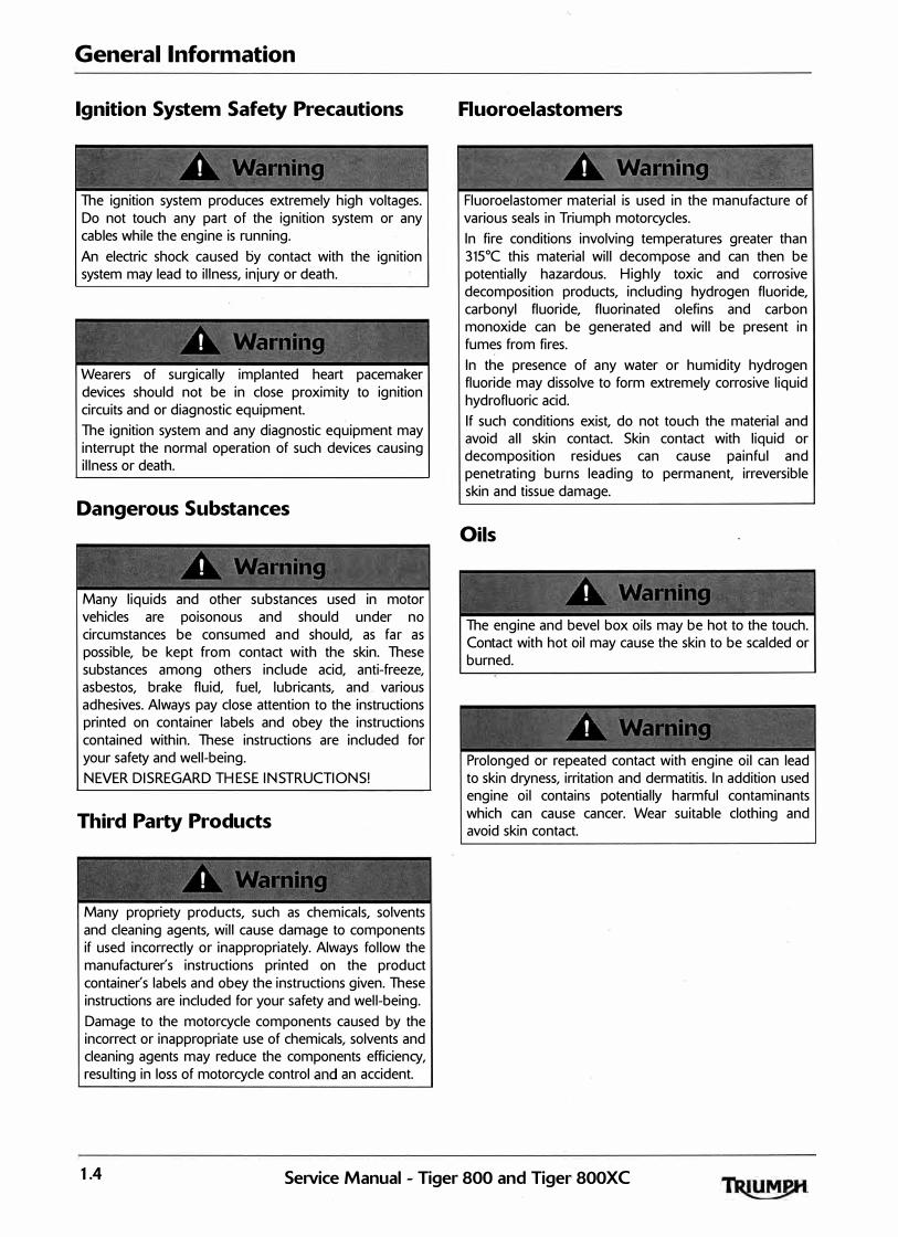
The ignition system produces extremely high voltages. Do not touch any part of the ignition system or any cables while the engine is running. An electric shock caused by contact with the ignition system may lead to illness, injury or death.
Wearers of surgically implanted heart pacemaker devices should not be in close proximity to ignition circuits and or diagnostic equipment. The ignition system and any diagnostic equipment may interrupt the normal operation of such devices causing illness or death.
Dangerous Substances
Many liquids and other substances used in motor vehicles are poisonous and should under no circumstances be consumed and should, as far as possible, be kept from contact with the skin. These substances among others include acid, anti-freeze, asbestos, brake fluid, fuel, lubricants, and various adhesives. Always pay close attention to the instructions printed on container labels and obey the instructions contained within. These instructions are included for your safety and well-being. NEVER DISREGARD T H ESE INST RUCT IONS!
Third Party Products
Many propriety products, such as chemicals, solvents and cleaning agents, will cause damage to components if used incorrectly or inappropriately. Always follow the manufacturer's instructions printed on the product container's labels and obey the instructions given. These instructions are included for your safety and well-being. Damage to the motorcycle components caused by the incorrect or inappropriate use of chemicals, solvents and cleaning agents may reduce the components efficiency, resulting in loss of motorcycle control and an accident.
Fluoroelastomers
Fluoroelastomer material is used in the manufacture of various seals in Triumph motorcycles. In fire conditions involving temperatures greater than 315°C this material will decompose and can then be potentially hazardous. Highly toxic and corrosive decomposition products, including hydrogen fluoride, carbonyl fluoride, fluorinated olefins and carbon monoxide can be generated and will be present in fumes from fires. In the presence of any water or humidity hydrogen fluoride may dissolve to form extremely corrosive liquid hydrofluoric acid. If such conditions exist, do not touch the material and avoid all skin contact. Skin contact with liquid or decomposition residues can cause painful and penetrating burns leading to permanent, irreversible skin and tissue damage.
Oils
The engine and bevel box oils may be hot to the touch. Contact with hot oil may cause the skin to be scalded or burned.
Prolonged or repeated contact with engine oil can lead to skin dryness, irritation and dermatitis. In addition used engine oil contains potentially harmful contaminants which can cause cancer. Wear suitable clothing and avoid skin contact.
1.4 SeiVice Manual - Tiger 800 and Tiger 800XC

-
Health Protection Precautions
Avoid prolonged and repeated contact with oils, particularly used engine oils.
Wear protective clothing, including impervious gloves where practicable.
Do not put oily rags in pockets.
Overalls must be cleaned regularly. Discard heavi ly soiled clothing and oil impregnated footwear.
First aid treatment should be obtained immediately for open cuts and wounds. Always be aware of who your nearest firstaider is and where the medical facil ities are kept.
• Use barrier creams, applying before each work period to protect the skin from the effects of oil and grease and to aid removal of the same after completing work.
• Wash with soap and water to ensure al l oil is removed <skin cleansers and nai l brushes will help>. Preparations containin g lanolin replace the natural skin oils which have been removed.
• Do not use petrol, kerosene, diesel fuel, gas oil, thinners or solvents for cleaning skin.
• If skin disorders develop, obtain me .d ical advice without del ay.
Where practicable, de-grease components prior to handling.
Any risk of eye injury must be avoided. Always wear eye protection when using a hammer, air line, cleaning agent or where there is ANY risk of flying debris or chemical splashing.
General Information
Environmental Protection Precautions
Do not pour oil on the ground, down sewers or drains, or into water courses. To prevent pollution of watercourses etc., dispose of used oil sensibly. If in doubt contact your local authority.
Burning of used engine oil in small space heaters or boilers can be recommended only for units of approved design. If in doubt, check with the appropriate local authority and/or manufacturer of the approved appliance.
Dispose of used oil and used filters through authorised waste disposal contractors, to licensed waste disposal sites, or to the waste oil reclamation trade. If in doubt, contact your local authority for advice on disposal facilities.
Brakes
Brake fluid is hygroscopic which means it will absorb moisture from the air. Any absorbed moisture will greatly reduce the boiling point of the brake fluid causing a reduction in braking efficiency. Replace brake fluid in line with the routine maintenance schedule. A dangerous riding condition could result if this important maintenance item is neglected! Do not spill brake fluid onto any area of the bodywork as this will damage any painted or plastic surface. Always use new brake fluid from a sealed container and never use fluid from an unsealed container or from one that has been previously opened. Do not mix different brands of fluid. Check for fluid leakage around brake fittings, seals and joints. Check regularly for brake hose damage. FAILURE TO OBSERVE ANY OF T H E ABOVE WARNINGS MAY REDUCE B RAKING EFF ICIENCY LEADING TO AN ACCIDENT.
"
SeiVice Manual - Tiger 800 and Tiger 800XC 1.5

General Information
If there has been an appreciable drop in the level of the fluid in either brake fluid reservoir, consult your authorised Triumph dealer for advice before riding. If the brake lever or pedal feels soft when it is applied, or if the lever/pedal travel becomes excessive, there may be air in the brake lines or the brake may be defective. lt is dangerous to operate the motorcycle under such conditions and remedial action must be taken by your authorised Triumph dealer before riding the motorcycle. Failure to take remedial action may reduce braking efficiency leading to an accident.
Use only DOT 4 specification brake fluid as listed in the general information section of this manual. The use of brake fluids other than those DOT 4 fluids listed in the general information section may reduce the efficiency of the braking system leading to an acci�ent. Failure to change the brake fluid at the interval specified in the routine maintenance schedule may reduce braking efficiency resulting in an accident.
' ' ' � e � < � "' I
� �"'�'"" �� � � � �
Never use mineral based grease in any part of the braking system or in any area where contact with the braking system is possible. Mineral based grease will damage the hydraulic seals in the calipers and master cylinders. Damage caused by contact with mineral based grease may reduce braking efficiency resulting in an accident.
' ' ' ' ' • ' %' t ""' l "'"' ' '
Before installation, all internal brake components should be cleaned and lubricated with clean n�w DOT 4 brake fluid. Never use solvents, petrol (gasoline), engine oil, or any other petroleum distillate on internal brake components as this will cause deterioration of the hydraulic seals in the calipers and master cylinders. A dangerous riding condition leading to loss of motorcycle control and an accident could result if this warning is ignored.
Safety Instructions
Jacking and Lifting
Always ensure that any lifting apparatus has adequate load and safety capacity for the weight to be lifted. Ensure the motorcycle is well supported to prevent any possibility of the machine falling during lifting or jacking, or while repairs and servicing are carried out. Never rely on a single means of support when working with the motorcycle. Use additional safety supports and straps to prevent toppling. Do not leave tools, lifting equipment, spilt oil, etc. in a place where they could become a hazard to health. Always work in a clean, tidy area and put all tools away when the work is finished.
Precautions against Damage
Avoid spilling brake fluid or battery acid on any part of the bodywork. Wash spillages off with water immediately.
Disconnect the battery earth lead before starting work, see ELECT RICAL P R ECAUTIONS.
Always use the recommended service tool where specified.
Protect exposed bearing and sealing surfaces, and screw threads from damage.
Coolant
! t d
Coolant mixture, which is blended with anti-freeze !3nd corrosion inhibitors contains toxic chemicals which are harmful to the human body. Never swallow anti-freeze, corrosion inhibitors or any of the motorcycle coolant.
Do not remove the radiator cap when the engine is hot. When the engine is hot, the coolant inside the radiator is hot and also under pressure. Contact with the pressurised coolant will cause scalds and skin damage.
1.6 SeJVice Manual - Tiger 800 and Tiger 800XC

The coolant anti-freeze contains a corrosion inhibitor which helps prevent damage to the metal surfaces inside the cooling system. Without this inhibitor, the coolant would 'attack' the metals and the resulting corrosion would cause blockages in the cooling system leading to engine overheating and.damage. Always use the correct anti-freeze as specified in the Owner's Handbook. Never use a methanol based anti-freeze as this does not contain the required corrosion inhibition properties.
Distilled water must be used with the anti-freeze (see specification for anti-freeze) in the cooling system. If hard water is used in the system, it causes scale accumulation in the water passages, and considerably reduces the efficiency of the cooling system. Reduced cooling system efficiency may lead to the engine overheating and engine damage.
Cleaning Components J
A high flash-point solvent is recommended to reduce fire hazard.
Always follow container directions regarding the use of any solvent.
Always use the recommended cleaning agent or equivalent.
Do not use degreasing equipment for components containing items which could be damaged by the use of this process. Whenever possible, clean components and the area surrounding them before removal. Always observe scrupulous cleanliness when cleaning dismantled components.
Lubrication
The majority of engine wear occurs while the engine is warming up and before all the rubbing surfaces have an adequate lubrication film. During assembly, oil or grease <whichever is more suitable) should be applied to any rubbing surface, which has lost its, lubrication film. Old grease and dirty oil should be cleaned off. This is because used lubricants , will have lost some lubrication qualities and may contain abrasive foreign particles.
Use recommended lubricants. Some oils and greases in particular should be used only in certain applications and may be harmful if used in an application for which they are not intended. This manual makes reference to molybdenum disulphide grease in the assembly of certain engine and chassis . parts. Always check manufacturer recommendations before using such special lubricants.
General Information
Joints and Joint Faces
Assemble joints dry unless otherwise specified in this manual.
If gaskets and/or jointing compound is recommended for use, remove all traces of old jointing material prior to reassembly. Do not use a tool which will damage the joint faces and smooth out any scratches or burrs on the joint faces using an oil stone. Do not allow dirt or jointing material to enter any tapped holes.
Gaskets, 0-rings
Do not re-use a gasket or 0-ring once it has been in service. The mating surfaces around the gasket should be free of foreign matter and perfectly smooth to avoid oil or compression leaks.
Liquid Gasket, Non-permanent Locking Agent
Follow manufacturer's directions for cleaning and preparing surfaces where these compounds will be used. Apply sparingly as excessive amounts of sealer may block engine oil passages and cause serious damage.
Prior to re-assembly, blow through any pipes, channels or crevices with compressed air.
To prevent injury, always use eye, face and ear protection when using compressed air. Always wear protective gloves if the compressed air is to be directed in proximity to the skin.
Screw Threads
Metric threads to ISO standard are used. '
Damaged nuts, bolts and screws must always be discarded.
Castellated nuts must not be slackened back to accept a split-pin, except in those recommended cases when this forms part of an adjustment.
Do not allow oil or grease to enter blind threaded holes. The hydraulic action on screwing in the bolt or stud could split the housing.
Always tighten a nut or bolt to the recommended torque figure. Damaged or corroded thread� can affect the torque reading.
Unless specified, threaded fixings must always be fitted dry (no lubrication).
Service Manual - Tiger 800 and Tiger 800XC 1.7
General Information
Never lubricate a thread unless instructed to do so. When a thread of a fixing is lubricated, the thread friction is reduced. When the fixing is tightened, reduced friction will cause overtightening and possible fixing failure. A fixing which fails in service could cause component
. detachment leading to loss of control and an accident.
Locking Devices
Always release locking tabs and fit new locking washers, do not re-use locking tabs.
Fitting a Split Pin
Always fit new split-pins of the correct size for the hole in the bolt or stud. Do not slacken back castle nuts when fitting split pin, except in those recommended cases when this forms part of an adjustment.
Always fit new roll pins of an interference fit in the hole.
Circlips, Retaining Rings
Replace any circlips and retaining rings that are removed. Removal weakens and deforms circlips causing looseness in the circlip groove. When installing circlips and retaining rings, take care to compress or expand them only enough to install them.
Always use the correct replacement circlip as recommended in the Triumph Parts Catalogue.
Self Locking Nuts
Self-locking nuts can be re-used, providing resistance can be felt when the locking portion passes over the thread of the bolt or stud.
DO NOT re-use self-locking nuts in critical locations, e.g. suspension components. Always use the correct replacement self-locking nut.
Encapsulated Bolts
An encapsulated bolt can be identified by a coloured section of thread which is treated with a locking agent.
Unless a specifi�d repair procedure states otherwise, encapsulated bolts cannot be reused and M UST be replaced if disturbed or removed.
Failure to replace an encapsulated bolt could lead to a dangerous riding condition. Always replace encapsulated bolts.
Oil and Grease Seals
Replace any oil or grease seals that are removed. Removal will cause damage to an oil seal which, if re-used, would cause an oil leak.
Ensure the surface on which the new seal is to run is free of burrs or scratches. Renew the component if the original sealing surface cannot be completely restored.
Protect the seal from any surface which could cause damage to the seal lips when it is being fitted. Use a protective sleeve or tape to cover the relevant surface and avoid touching the sealing lip.
Lubricate the sealing lips with a recommended lubricant. This will help to prevent damage- in initial use. On dual lipped seals, smear the area between the lips with appropriate grease.
When pressing in a seal which has manufacturer's marks, press in with the marks facing out.
Seals must be pressed into place using a suitable driver. Use of improper tools will damage the seal.
Press
A part installed using a press or driver, such as a wheel bearing, should first be coated with oil or grease on its outer or inner circumference so that it will locate smoothly.
Ball Bearings
When installing a ball bearing, the bearing race which is an interference fit should be pushed by a suitable driver. This prevents severe stress or damage to the load carrying components. Press a ball bearing until it touches the shoulder in the bore or on the shaft.
Press or drift seals to the depth of its housing, with the sealing lip facing the lubricant to be retained if the housing is shoulderea, or flush with the face of the housing where no shoulder is provided.
Chassis Bearing Lubrication
Note:
• This information relates only to bearing lubrication. For the procedures necessary to replace a bearing, always refer to the relevant section of this service manual.
• Bearings installed in engine and transmission applications are not covered by this information. Refer to the lubrication chapter or the relevant engine chapter for additional information.
1.8 SeiVice Manual - Tiger 800 and Tiger- 800XC

General
For a bearing to be serviceable for its anticipated life span it must be checked, adjusted and lubricated at regular intervals, as specified in the service schedules given in the owner's handbook and this service manual. ·
A correctly lubricated bearing will have a film of lubrication that separates the moving parts, disperses heat and protects the bearing _surfaces from corrosion.
Note:
• In all cases, use the lubricant recommended in the seiVice manual.
• Grease the bearing, not the cavity where it is located.
• A bearing that is not regularly checked and lubricated will have a reduced life span.
New Bearings
New bearings are typically protected with an oil preservative to prevent corrosion etc. during storage. This is NOT the lubrication for the bearing but DOES NOT need to be washed off prior to assembly and in-service lubrication.
When lubricating a new bearing with grease the following steps should be taken:
1. Do not clean off the oil preservative. 2. Grease must be forced between the roller elements
and the roller cage. 3. Rotate the bearing to ensure that the grease is
distributed over the entire circumference of the internal parts.
4. Any excess grease should be smeared on the outside of the rollers.
Lubrication and Checks While SeiVicing a Bearing
1. Disassemble parts as necessary to access the bearing. Refer to the relevant service manual.
2. Inspect the old grease covering the bearing, looking for signs of bearing damage, i.e. flakes or specks of metal.
3. Remove the old grease.
General Information
4. Check the bearing for smooth operation and visually check for corrosion, dents and flaking in the bearing race, rollers or cage. Replace if necessary. Refer to the relevant service manual.
Below/overleaf several common bearing types and the lubrication procedures for each are identified:
eon
Sealed bearings <wheel bearings & swinging arm, depending on the model>
Note:
• Sealed bearings can be identified by their integrated seals.
• Sealed bearings are lubricated for life by the manufacturer.
• Any attempt to change the grease in a sealed bearing will damage the integrated seals. If the seals are damaged dirt and water will ingress and the life of the bearing will be greatly reduced.
ceon Taper bearings <swinging arm & headstock,
depending on the model>
1. Grease must be forced between the inner race and the roller carrier.
2. Rotate the bearing to ensure that the grease is distributed 'over the entire circumference of the internal parts.
SeNice Manual - Tiger 800 and Tiger 800XC 1.9

General Information
3. Any excess grease should be smeared on the outside of the rol lers.
Angular contact and ball bearings (headstock>
1. Grease the bearing races and the bal l bearing carrier.
2. Rotate the bearing to ensure that the grease is distributed over the entire circumference of the internal parts.
Needle roller bearings <swinging arm, rear hub, rear suspension linkages, depending on the model>
1. Coat the needle rollers with grease.
2. Ensure the needle rol lers turn so that the grease is distributed over the entire circumference of the internal parts.
3. Assemble the parts, adjust and check as necessary.
Metal bushes
1. Disassemble the parts as necessary to access the bush. Refer to the relevant service manual.
2. Remove the old grease.
3. Apply fresh grease to the metal bush.
Fuel Handling Precautions
General
The fol lowing information provides basic precautions which must be observed if petrol <gasol ine> is to be handled safely. lt also outlines other areas of risk which must not be ignored. This information is issued for basic guidance only and, if in doubt, appropriate enquiries should be made of your local Fire Officer.
Petrol - Gasoline
When petrol <gasol ine> evaporates it produces 150 times its own volume in vapour which when di luted with air becomes a readily ignitable mixture. The vapour is heavier than air and will always fa l l to the lowest level. lt can readi ly be distributed throughout any indoor environment by air currents, consequently, even a smal l spil lage of petrol (gasol ine) is potential ly very dangerous.
Petrol <gasol ine> is highly flammable and can be explosive under certain conditions. When opening the fuel tank cap always observe all the fol lowing items:
Turn the motorcycle ignition switch OFF.
Do not smoke. Always have a fire extinguisher containing FOAM, C02, HALON or POWDER close at hand when handl ing or draining fuel or fuel systems. Fire extinguishers must also be present in areas where fuel is stored.
Always d isconnect the vehicle battery, negative (black> lead first, before carrying out dismantling or draining work on a fuel system.
Whenever petrol (gasol ine) is being handled, drained, stored or when fuel systems are being dismantled, make sure the area is well venti lated. All potential forms of ignition must be extingu ished or removed (th is includes any appl iance with a pi lot l ight). Any lead-lamps must be flame-proof and kept clear of any fuel spi l lage.
Warning notices must be posted at a safe d istance from the site of the work to warn others that petrol is being openly hand led. The notice must instruct the reader of the precautions which must be taken. Fai lure to observe any of the above warnings may lead to a fire hazard which could result in personal injury.
1.10 SeiVice Manual - Tiger 800 and Tiger 800XC

No one should be permitted to repair components associated with petrol/gasol ine without first having special ist training on the fire hazards which may be created by incorrect insta l lation and repair of items associated with petrol/gasol ine.
Repairs carried out by untrained personnel could bring about a safety hazard leading to a risk of personal injury.
Draining or extraction of petrol/gasol ine from a vehicle fuel tank must be carried out in a wel l venti lated area. The receptacle used to contain the petrol/ gasol ine must be more than adequate for the fu l l amount of fuel to be extracted or drained. The receptacle should be clearly marked with its contents, and placed in a safe storage area which meets the requirements of loca l authority regulations.
When petrol/gasol ine has been extracted or drained from a fuel tank,' the precautions governing naked l ights and ignition sources should be mainta ined.
Fa i lure to observe any of the above warnings could bring about a safety hazard leading to a r isk of personal injury.
General Information
Fuel Tank Removal
Fuel tanks should have a ' PETROL <GASOLI N E> VAPOU R' warning label attached to them as soon as they are removed from the vehicle. In a l l cases, they must be stored in a secured, marked area.
Chassis Repairs
If the motorcycle is involved in an 'accident or col l ision it must be taken to an authorised Triumph dealer for repair or inspection. Any accident can cause damage to the motorcycle, which if n6t correctly repaired, may cause a second accident which may result in injury or death.
The frame must not be modified as any modification to the frame such as welding or dri l l ing may weaken the frame resulting in an accident.
SeiVice Manual - Tiger 800 and Tiger 800XC 1.11
General Information
Electrical Precautions The fol lowing guidelines are intended to ensure the safety of the operator whilst preventing damage to the electrica l and electronic components fitted to the motorcycle. Where necessary, specific precautions are detai led in the relevant sections of this manual which should be referred to prior to commencing repair operations.
Equipment - Prior to commencing any test procedure on the motorcycle ensure that the relevant test equipment is working correctly and any harness or connectors are in good condition, in particu lar mains leads and plugs.
The ignition system produces extremely high voltages. Do not touch any part of the ignition system or any cables while the engine is running. An electric shock caused by contact with the ignition system may lead to i l lness, injury or death.
Wearers of surg ical ly implanted heart pacemaker devices should not be in close proximity to ignition circuits and or diagnostic equipment.
The ignition system and any diagnostic equipment may interrupt the normal operation of such devices causing i l lness or death.
The battery contains harmful materia ls. Always keep children away from the battery whether or not it is fitted in the motorcycle. Do not jump start the battery, touch the battery cables together or reverse the polarity of the cables as any of these actions may cause a spark which would ignite battery gasses causing a risk of personal injury.
High Voltage Circuits - Whenever disconnecting l ive High Tension <H.T.> circuits always use insulated pliers. Exercise caution when measuring the voltage on the coil terminals while the engine is running, high voltage spikes can occur on these terminals.
Connectors and Harness - The engine of a motorcycle is a particularly hosti le environment for electrical components and connectors. Always ensure these items are dry and oil free before disconnecting and connecting test equipment. Never force connectors apart either by using tools or by pul l ing on the wiring itself. Always ensure locking mechanisms are disengaged before removal and note the orientation to enable correct reconnection. Ensure that any protective covers and substances are replaced if disturbed.
Having confirmed a component to be faulty, switch off the ignition and disconnect the battery negative (black) lead first. Remove the component and support the disconnected harness. When replacing the component keep oily hands away from electrical connection areas and push connectors home unti l any locking mechanism becomes ful ly engaged.
Battery Disconnecting
Before disconnecting the battery, switch off a l l electrical equipment.
To prevent the risk of a battery exploding and to prevent damage to electrical components ALWAYS d isconnect the battery negative <black) lead first. When reconnecting the battery, always connect the positive (red) lead first, then the negative <black) lead. Always d isconnect the battery when working on any part of the electrical system. Fai lure to observe the above warnings may lead to electrical damage and a fire hazard wh ich could cause personal injury.
Always ensure that battery leads are routed correctly and are not close to any potential chafing points.
Disciplines
Switch off the ignition prior to making any connection or -disconnection in the system. An electrical surge can be caused by disconnecting ' l ive' connections which can damage electronic components.
Ensure hands and work surfaces are clean and free of grease, swarf, etc. as grease col lects dirt wh ich can cause tracking or h igh-resistance contacts.
Prior to commencing any test, and periodically during any test, touch a good earth to discharge body static. This is because some electronic components are vulnerable to static electricity.
1.1 2 SeiVice Manual - Tiger 800 and Tiger SOOXC
Electrical Wires
All the electrical wires are either single-colour or twocolour and, with only a few exceptions, must be connected to wires of the same colour. On any of the two-colour wires there is a greater amount of one colour and a lesser amount of a second colour. A two-colour wire is identified by first the primary colour and then the secondary colour. For example, a yel low wire with thin red stripes is referred to as a 'yellow/red' wire; it would be a ' red/yellow' wire if the colours were reversed to make red the main colour.
Electrical Testing For any electrical system to work, electricity must be able to flow in a complete circuit from the power source (the battery) via the components and back to the battery. No circu it means no electrica l flow. Once the power has left the positive side of the battery and run through the component it must then return to the battery on its negative side (th is is ca lled earth or ground). To save on wiring, connections and space, the negative side of the battery is connected directly to the frame or engine. Around the frame and engine wil l be various other ground points to which the wiring coming from components wi l l be connected. In the case of the starter motor it bolts directly to the engine, which is bolted to the frame. Therefore the frame and engine also form part of the earth return path.
Ohm's Law
The relationship between voltage, current and resistance is defined by Ohm's Law.
The potentia l of a battery is measured in Volts M.
The flow of current in a circuit (I) is measured in Amperes.
• The power rating of a consumer is measured in Watts <W>.
The resistance <R> of a circuit is measured in Ohms cm.
Ohms law, for practica l work can be described as -
Voltage . C
= Resistance urrent ,
Power is calculated by multiplying Volts x Amps -
Watts = Volts x Amps
By transposing either of these formulae, the value of any unit can be calcu lated if the other two values are known.
, General Information
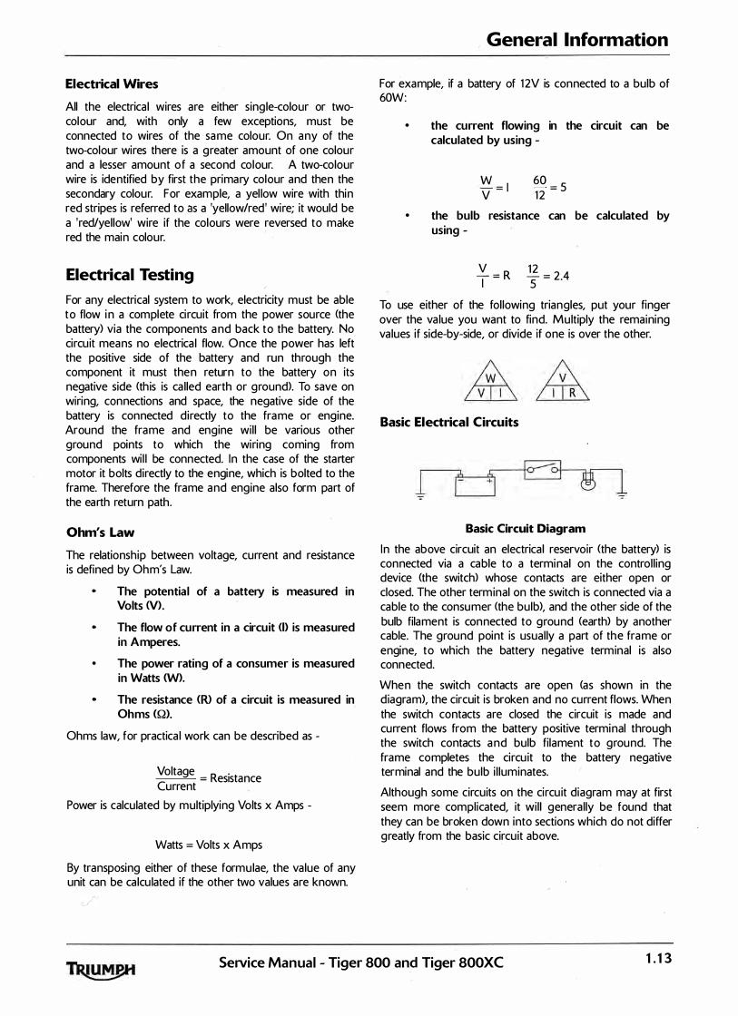
For example, if a battery of 1 2V is connected to a bulb of 60W:
• the current flowing in the circuit can be calculated by using -
W = I
60 = 5
V 1 2
• the bulb resistance can be calculated by using -
� = R I
g = 2 4 5
.
To use either of the fol lowing triangles, put your finger over the va lue you want to find. Multiply the remaining values if side-by-side, or divide if one is over the other.
Basic Electrical Circuits
Basic Circuit Diagram
In the above circuit an electrical reservoir (the battery) is connected via a cable to a terminal on the control l ing device (the switch) whose contacts are either open or closed. The other terminal on the switch is connected via a cable to the consumer (the bulb), and the other side of the bulb filament is connected to ground (earth) by another cable. The ground point is usual ly a part of the frame or engine, to which the battery negative terminal is also connected.
When the switch contacts are open (as shown in the d iagram>, the circuit is broken and no current flows. When the switch contacts are closed the circuit is made and current flows from the battery positive terminal through the switch contacts and bulb filament to ground. The frame completes the circu it to the battery negative terminal and the bulb i l luminates.
Although some circuits on the circu it diagram may at first seem more complicated, it wil l generally be found that they can be broken down into sections which do not differ greatly from the basic circu it above.
SeiVice Manual - Tiger 800 and Tiger 800XC 1.13

General Information
Circuit Diagrams Circuit diagrams are created to provide a 'picture' of the electrical system and to identify the route taken by each individual wire through the system, in order to identify which components it feeds and which connectors the wire runs through. Circu it diagrams are an essential tool for fault finding, as it is possible to locate start and finish points for a circu it without l')aving to manual ly trace the wire through the motorcycle itself. Circu its diagrams may look confusing at first but when they are studied closely they soon become log ical .
Due to the complex circu its and the number of individual wires, Triumph uses two types of circuit diagram in its service manuals.
c
• Within the manua'l conventional circuit
diagrams are used to show the layout of the main circuits of the motorcycle. These are : Engine managemenUig nition, Lighting, Starting and Charging and Auxil iary and Accessory. In these diagrams no attempt is made to show the components of the system in any particular order or position in relation to the motorcycle.
At the back of the service manual a ful l colour layout circuit d iagram is used to show the main electrical components in a position similar to the actual position on the motorcycle.
Both of these circuit diagrams use similar symbols to i l lustrate the various system components and wil l be accompanied by a key to circu it diagram components and wiring colour codes.
Circuit diagrams also depict the inner workings of a switch cube ( I .E. which wire connects to which when a switch is turned from one position to another) so that a test of that switch can be made using the wire terminals in the connector instead of disassembling the switch itself.
Glossary of Circuit Diagram Symbols The following is a description of the symbols found in the circuit diagrams used in all Triumph service manuals.
Connector
This i l lustration is used to show al l multi-plug type electrical connectors on Triumph circu it diagrams. The numbers in the box relate to the terminal numbers of the connector pins. On ECMs with two connectors, the number would be prefixed with the letters 'A' or 'B' to identify each connector. An additional number outside the box wi l l identify the component.
Diode
An electrical one-way va lve. Diodes a l low current to flow in one direction but wil l not al low it to return. The arrow, which forms part of the diode symbol, ind icates the direction of current flow.
Electromagnetic Winding <solenoid)
An electromagnetic winding (or solenoid) is used to convert an electrical current into a lateral movement. This can then be used to operate switches (as used in relays> or other components such as fuel injectors or secondary air injection solenoids.
Fuse
�2 or �3 A fuse is a device which protects a circu it in the event of a fault. The fuse wil l 'blow' should a short circu it occur, protecting that circu it from further damage. The number next to the fuse on the circu it diagram ind icates the position of the fuse in the fusebox.
1.14 SeiVice Manual - Tiger 800 and Tiger-800XC

Ground or Earth Point
1 or 1 This symbol is used to show ground points. This is the negative connection to either the frame or engine, and is a common cause of intermittent faults due to loose or corroded connections.
Lamp or Bulb
This symbol is used to show all types of l ight bulbs. The numbers in the box relate to the terminal numbers of the connector pins. An additional number outside the box wil l identify the component.
LED <Light Emitting Diode)
Triumph use LEDs for the alarm warning l ight, instrument i l lumination and warning l ights, gear change l ights and rear l ight/brake l ights on various models.
Motor
An electric motor. This could be the starter motor or a motor within an actuator, for example within the ABS modulator.
Relay
A relay is effectively an electromagnetic switch. To close the relay contacts and complete the circu it, an electromagnet in the relay is energised which causes the
-,relay contacts to close, making the circu it complete.
Relays are used when the electrical current is too great for a mechanical switch, usual ly when the switching must be done quickly to prevent arcing across the switch contacts. If a mechanical switch were used, the mechanical switch contacts would quickly burn away.
, General Information
Resistor
A device placed in a cable to reduce a voltage or restrict the maximum current a device can draw.
Splice
+ A hard cable joint where two or more cables are joined in the wiring harness. A potentia l source of both open and short circuits.
Switches
Normally Open
�0
or
0 0
Normally Closed
or
0 0
Change Over
Q _ _ _ Q
0
or
; ;
0
,0
Cf---0 A mechanical device for completing or breaking a circu it. There are three common types of switch : Normally open, normally closed and change-over.
SeiVice Manual - Tiger 800 and Tiger 800XC 1.15

General Information
Tracing Circuits
The following is a description of two types of common electrical failures, and some of the methods which may be used to find them.
Open circuit
Break
l_
A break in an electrical circuit - current cannot flow. Usually caused by a break in a wire or cablec or by a loose connection. Open circu its can often by intermittent, making diagnosis difficult.
Short circuit
A 'short cut' in an electrical circuit - current by-passes the intended circuit, either to earth or to another, different circuit. Often caused by failure of the cable insulation due to chafing or trapping of the wire. There are two different types of short circuit - short to ground and short to Vbatt.
A short to ground means that the current is going to earth before it reaches the component it is supposed to feed. These are often caused by chafing of the harness to the frame or wires trapped between a bolted component, and will often blow the fuse on that circuit.
A short to Vbatt is a short to battery voltage ( 1 2 Volts) and is caused by a l ive power supply wire contacting an adjacent cable. Note that it is a lso possible for a 5 Volt sensor reference voltage to short to an adjacent circu it, which can also cause electrica l fai lures and DTCs <Diagnostic Trouble Code) to be stored.
When tracing a wire that is suspect, carefu lly check the circuit diagram before starting. Remember:
• a wire may diverge at a spl ice and go off to feed other circuits. If these circuits are working, check for wiring faults from the spl ice onwards.
• the circuit diagram is not an accurate guide to the actual location of the parts when fitted on the bike. lt is a schematic diagram of the circuits.
particularly where engine management items are concerned, the circuit is only completed by the ECM. If the ECM is not connected, the circuit may register as open.
To Check Continuity:
Ensure the circu it being tested is switched off before measuring continuity. Damage to the Digita l Multi Meter <DM M> may result from testing a 'l ive' ci rcu it with the meter set to resistance (Q).
In the example below, the ground circuit continuity is being tested from the battery to the frame.
•
•
•
•
•
•
Continuity <resistance) Check
locate each end of the wire .
Set the Digita l Multi Meter <DMM> to resistance check (Q).
Probe each end of the wire.
If there is continuity, the meter will usually bleep or register the resistance of the cable.
A high resistance figu re could indicate a dirty or corroded connection.
'
If there is a break in the wire, the meter will not bleep or register a resistance.
By probing the wire in various places, the position of a high resistance or break in the wire (open circuit> can be narrowed down u ntil it is found.
1.1 6 SeNice Manual - Tiger 800 and Tiger 800XC
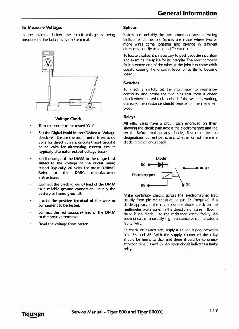
To Measure Voltage:
In the example below, the circu it voltage is being measured at the bulb positive (+) terminal.
•
Voltage Check
Turn the circuit to be tested 'ON'
Set the Digital Multi Meter <DMM> to Voltage check N). Ensure the multi meter is set to de volts for direct current circuits <most circuits) or ac volts for alternating current circuits (typically alternator output voltage tests>.
Set the range of the DMM to the range best suited to the voltage of the circuit being tested (typical ly 20 volts for most DMMs>. Refer to the DMM manufacturers instructions.
Con nect the black (ground) lead of the DMM to a reliable ground connection (usually the battery or frame ground>.
Locate the positive terminal of the wire or component to be tested.
con nect the red (positive) lead of the DMM to the positive terminal.
Read the voltage from meter.
General Information
Splices
Spl ices are probably the most common cause of wiring fau lts after connectors. Spl ices are made where two or more wires come together and diverge in different directions, usually to feed a d ifferent circu it.
To locate a spl ice, it is necessary to peel back the insulation and examine the spl ice for its integrity. The most common fau lt is where one of the wires at the joint has come adrift usually causing the circu it it feeds or earths to become 'dead'.
Switches
To check a switch, set the multimeter to resistance/ continuity and probe the two pins that form a closed circuit when the switch is pushed. If the switch is working correctly, the resistance should reg ister or the meter wi l l bleep.
Relays
Al l relay cases have a circu it path engraved on them showing the circu it path across the electromagnet and the switch. Before making any checks, first note the pin designations, current paths, and whether or not there is a diode in either circu it path.
Diode
86 • • • 87
Electromagnet
30
Make continuity checks across the electromagnet first, usually from pin ,86 (positive> to pin 85 <negative>. If a diode appears in the circu it use the d iode check on the multimeter <volts scale) in the direction of current flow. If there is no diode, use the resistance check faci l ity. An open circuit or unusually high resistance value indicates a faulty relay.
To check the switch side, apply a 1 2 volt supply between pins 86 and 85. With the supply connected the relay should be heard to cl ick and there should be continuity between pins 30 and 8Z An open circu it indicates a faulty relay.
SeiVice Manual - Tiger 800 and Tiger 800XC 1.17

General Information
CAN <Controller Area Networking} CAN (sometimes ca lled CANbus) is a protocol for data communication between Electronic Control Modules <ECMs). Each ECM on the network is connected by a single pair of twisted wires (or bus) which are used for the transmission of vehicle sensor data. By using CAN, the overal l number of system sensors, and the amount of cabl ing required to al low ECMs to communicate with each other is greatly reduced.
This saves cost, weight and space, and makes the system more rel iable, as the physical number of wires and connections is reduced.
Pair of Twisted R Wires
B28
B27 u
.----
ECM
A34
�
4
5 Instrument
Pack 16
1 KY
3 2
Veh1cle Speed Sensor
Extract 'from the circuit diagram showing CAN connection between ECMs
CAN works by each ECM sending out 'packets' of information. <such as engine speed or fuel consumption information) on to the network bus <note that the network must be free of data before any ECM is al lowed to transmit>. Tni§_ data is g iven a priority according to its importance (for example 'engine speed' may have a higher priority than ' low fuel level '), so that even if two ECMs send data at the same time, high priority information is always sent first. Lower priority data is then resent after the high priority data has been received by al l ECMs on the network.
The receiving ECM confirms the data has been received correctly and that the data is val id, and th is information is then used by the ECM as necessary. Specific data not required by an ECM will sti l l be received and acknowledged as correct but then disregarded (for example if an ECM does not require 'clutch switch position' information, th is data packet would' be ignored).
This al lows for a very high speed system of communication, which is also very rel iable. Should one ECM fai l or transmit corrupted or otherwise incorrect messages, none of the other ECMs on the network wil l be affected, and after a certain time that ECM wil l be prevented from transmitting further messages until the fault is rectified. This stops the ECM from clogging the network with incorrect data and preventing other messages from getting through. The fault would then be reported by a DTC <Diagnostic Trouble Code).
Triumph currently use CAN for communication between the engine ECM and the instruments.
1.18 Service Manual - Tiger 800 and Tiger 800XC
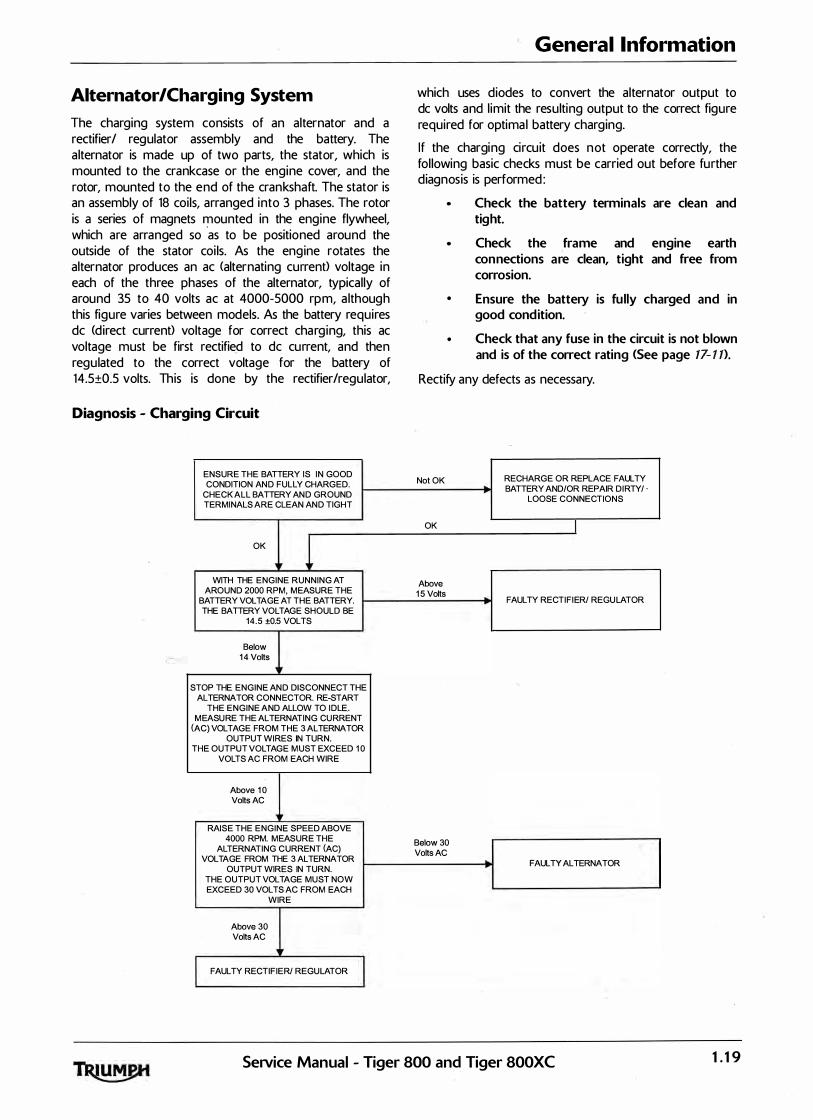
Alternator/Charging System The charging system consists of an alternator and a rectifier/ regulator assembly and the battery. The alternator is made up of two parts, the stator, which is mounted to the crankcase or the engine cover, and the rotor, mounted to the end of the crankshaft. The stator is an assembly of 18 coils, arranged into 3 phases. The rotor is a series of magnets mounted in the engine flywheel, which are arranged so
·as to be positioned around the
outside of the stator coi ls. As the engine rotates the alternator produces an ac <alternating current) voltage in each of the three phases of the alternator, typically of around 35 to 40 volts ac at 4000-5000 rpm, a lthough this figure varies between models. As the battery requires de (d irect current) voltage for correct charg ing, this ac voltage must be first rectified to de current, and then regulated to the correct voltage for the battery of 14.5±0.5 volts. This is done by the rectifier/regulator,
Diagnosis - Charging Circuit
ENSURE THE BATTERY IS I N GOOD CONDITION AN D FULLY CHARGED.
CHECK ALL BATTERY AN D GROUND TERMI NALS ARE CLEAN AN D TIGHT
OK 1 WITH THE ENGINE RUNNING AT
AROUND 2000 RPM, MEASURE THE BATTERY VOLTAGE AT THE BATTERY. THE BATTERY VOLTAGE SHOULD BE
1 4 . 5 ±0.5 VOLTS
Below 0 1 4 Volts
lr STOP THE ENGINE AN D DISCONNECT THE
ALTERNATOR CONN ECTOR. RE-START THE ENGINE AND ALLOW TO I DLE..
M EASU RE THE ALTERNATING CU RRENT (AC) VOLTAGE FROM THE 3 ALTERNATOR
OUTPUT WIRES IN TURN. THE OUTPUT VOLTAGE M UST EXCEED 1 0
VOLTS AC FROM EACH WIRE
Above 1 0 Volts AC
RAISE THE ENGINE SPEED ABOVE 4000 RPM. MEASURE THE
ALTERNATING CURRENT (AC) VOLTAGE FROM THE 3 ALTERNATOR
OUTPUT WIRES IN TURN. THE OUTPUT VOLTAGE MUST NOW EXCEED 30 VOLTS AC FROM EACH
WIRE
Above 30 Volts AC
FAULTY RECTIFIER/ REGU lATOR
General Information
which uses diodes to convert the alternator output to de volts and l imit the resulting output to the correct figure required for optimal battery charging.
If the charging circu it does not operate correctly, the fol lowing basic checks must be carried out before further diagnosis is performed:
Check the battery terminals are clean and tight.
Check the frame and engine earth con nections are clean, tight and free from corrosion.
• Ensure the battery is fu lly charged and in good cond ition.
Check that any fuse in the circuit is not blown and is of the correct rating <See page 17- 1 1>.
Rectify any defects as necessary.
Not OK RECHARGE OR REPlACE FAULTY BATTERY AND/OR REPAIR DI RTY/ ·
LOOSE CONNECTIONS
OK I
Above 1 5 Volts
FAULTY RECTIFI ER/ REGU lATOR
'
Below 30 r Volts AC
FAULTY ALTERNATOR
SeiVice Manual - Tiger 800 and Tiger 800XC 1.19

General Information
Starting Circuit All Triumph models are equipped with an electric start system. This system consists of a starter relay, starter motor, starter switch, sidestand switch, engine stop switch, clutch switch and the sprag clutch. The starter motor is connected to the starter relay and the battery by heavy duty cables in order to supply the large currents required by the motor to start the engine. When the starter button is pressed the relay is energised, which then al lows current to the starter motor. The starter motor will not operate unless the clutch lever is pul led in. Also, the starter will not operate if the sidestand is down, unless the transmission is in neutra l. If the starter motor does not operate, the fol lowing basic checks must be carried out before further diagnosis is performed:
Check the engine · stop switch is in the ' RU N' position.
• Check the battery terminals are clean and tight.
Check the frame and engine earth connections are clean, tight and free from corrosion.
Ensure the battery is fully charged and in good condition.
• Check that any fuse in the circuit is not blown and is of the correct rating.
• Using the triumph diagnostic tool, check the operation of the neutral switch or gear position sensor (if fitted), sidestand and clutch switches.
Note:
• On all new models from Daytona 675 onwards, which use a CAN connection between the instruments and the ECM, the engine will not crank if the instruments are disconnected.
Rectify any defects as necessary.
General Fault Finding - Starter Motor and Relay
Symptom ' Possible cause<s>
Starter relay does not click, starter motor does not turn Battery discharged or defective
Blown main or starter relay fuse
Defective starter relay wiring or starter switch
Check that the sidestand, transmission and clutch lever are positioned for engine starting I .E. transmission in neutra l, clutch lever pul led in and the sidestand down
Defective alarm system � ensure any alarm fitted is working correctly
Starter motor turns slowly Battery d ischarged or defective
Loose, corroded or dirty battery connections
Loose, corroded or dirty starter motor or starter relay connections
Defective starter motor
Loose, corroded or dirty battery ground connections
Starter relay cl icks but engine does turn over Battery discharged or defective
Crankshaft does not turn due to engine defect
Defective starter motor
Starter cable open circu it
Defective starter relay
Starter motor turns but engine does not turn over Defective sprag clutch
Defective idler gear, reduction gear or starter motor
1.20 SeNice Manual - Tiger 800 and Tiger 800XC
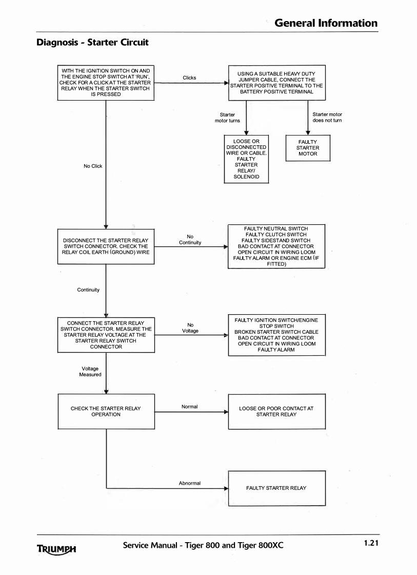
General Information
Diagnosis - Starter Circuit
WITH THE I G N ITION SWITCH ON AN D THE E N G I N E STO P SWITCH AT 'RU N ' Cl icks
U S I N G A SUITABLE H EAVY DUTY
CHECK FOR A CLICK AT THE STARTER t----------+1 J U M PER CABLE, CONN ECT T H E
RELAY WHEN T H E STARTER SWITCH --,. STARTER POSITIVE TERM I NAL TO T H E
IS PRESSED BATTERY POSITIVE TERM I NAL
No Cl ick
(, DISCON N ECT T H E STARTER RELAY SWITCH CON NECTOR. CH ECK THE
RELAY COIL EARTH (GRO U N D ) WIRE
Continu ity
CON N ECT THE STARTER RELAY SWITCH CONN ECTOR. M EASURE THE
STARTER RELAY VOLTAG E AT TH E STARTER RELAY SWITCH
CONN ECTOR
Voltage Measured
'
CH ECK THE STARTER RELAY OPERATION
No Continuity
No Voltage
Normal
Abnormal
Starter motor turns
Starter motor does not turn
.
LOOSE OR D I SCONN ECTED WIRE OR CABLE.
FAULTY STARTER
RELAY/ SOL E N O I D
FAULTY STARTE R
MOTOR
FAU LTY N E UTRAL SWITCH FAULTY CLUTCH SWITCH
FAULTY S I DESTAND SWITCH BAD CONTACT AT CON N E CTOR OPEN C I RCUIT IN WIRING LOOM
FAULTY ALARM OR E NG I N E ECM ( I F F ITTED)
FAULTY I G N ITION SWITCH/E NG I N E STOP SWITCH
BROKEN STARTER SWITCH CABLE BAD CONTACT AT CON N E CTOR OPEN C I RCUIT IN WIRING LOOM
FAl)L TY ALARM
LOOSE OR POOR CONTACT AT STARTER RELAY
FAU LTY STARTER RELAY
Service Manual - Tiger 800 and Tiger 800XC 1 .2 1

General Information
Inspection Disassembled parts should be visual ly inspected and replaced with new ones if there are any signs of the following:
Abrasions, cracks, hardening, warping, bending, dents, scratches, colour changes, deterioration, seizure or damage of any nature.
Replacement Parts
Only Triumph genuine parts should be used to service, repair or convert Triumph motorcycles. To ensure that Triumph genuine parts are used, always order parts, accessories and conversions from an authorised Triumph dealer. The fitting of non-approved parts, accessories or conversions may adversely affect the handl ing, stabil ity or other aspects of the motorcycle operation which may result in an accident causing serious injury or death.
Always Triumph genuine parts, accessories conversions fitted by an authorised Triumph dealer. The fitment of parts, accessories and conversions by a dealer who is not an authorised Triumph dealer may affect the handl ing, stabil ity or other aspects of the motorcycle operation which may result in an accident causing serious injury or death .
Always have Triumph approved parts, accessories and conversions fitted by a trained technician. To ensure that a trained technician is used, have an authorised Triumph dealer fit the parts. The fitment of parts, accessories and conversions by personnel other than a trained technician at an authorised Triumph dealer may affect the handl ing, stabil ity or other aspects of the motorcycle operation which may result in an accident causing serious injury or death.
Service Data The service data listed in th is manual g ives dimensions and specifications for brand new, original parts. Where it is permissible to al low a part to exceed these figures, then the service l imit is g iven.
The terms of the motorcycle warranty wil l be inval idated by the fitting of other than genuine Triumph parts.
Al l genu ine Triumph parts have the ful l backing of the motorcycle warranty. Triumph dealers are obl iged to supply only genuine Triumph recommended parts.
Specification Triumph are constantly seeking to improve the specification, design and production of their motorcycles and alterations take place accordingly.
While every effort has been made to ensure the accuracy of this Manual, it should not be regarded as an infal l ible guide to current specifications of any particular motorcycle.
Authorised Triumph dealers are not agents of Triumph and have no authority to bind the manufacturer by any expressed or implied undertaking or representation.
1.22 SeiVice Manual - Tiger 800 and Tiger 800XC

General Information
Service Tools and Garage Equipment Special service tools have been developed to facil itate removal, dismantl ing and assembly of certain mechanical components in a practical manner without causing damage. Some operations in this Service Manual cannot be carried out without the aid of the relevant service tools. Where this is the case, the tools required will be described during the procedure.
Special SeiVice Tools
T3880105 - Angular Torque Gauge
cbxt
T3 880101 - Extractor, Cyl inder Liners
I ncrement
Ymarkings
T388031 5 - Extractor, Cyl inder Liner <use with adaptor T3880101 )
gakh
T3880156 - Holder, Balancer Gear
SeNice Manual - Tiger 800 and Tiger 800XC 1 .23

General Information
T3 880102 - Wrench, Camshaft Turning T3 880026 - Clutch Holding Tool, Universal
cdpr
T38803 65 - Pul ler, Alternator Rotor T3 880375 - Alternator Rotor Holder
T3880313 - Oil Fi lter Wrench T3880057 - Engine Management Diagnostics
gahc
1.24 SeJVice Manual - Tiger 800 and Tiger 800XC

General Information
T3880027 - Chain Link Took Kit T3 880166 - Wrench, Engine Mounting Adjuster
3880160-T0301 - Fork Fil ler/Evacuator T3 880158 - Collet, Nylon, Fork Support - Tiger 800
ccha
T3 880154 - Col let, Nylon, Fork Support - Tiger 800XC T3 880067 - Fork Spring Compressor
\ ccgw
SeiVice Manual - Tiger 800 and Tiger 800XC 1.25

General Information
T3 880153 - Support Plate T3 880003 - Fork Seal and Bush Fitment - Tiger 800
ccxa_1 ccxb
T3 880157 - Fork Seal and Bush Fitment - Tiger 800XC T3 88005 3 - Extraction Kit, Wheel Bearing
ccxb
3880070 - T0301 - Bearing Instal ler 3 880065 - T0301 - Bearing Instal ler
1 .26 SeiVice Manual - Tiger 800 and Tiger 800XC
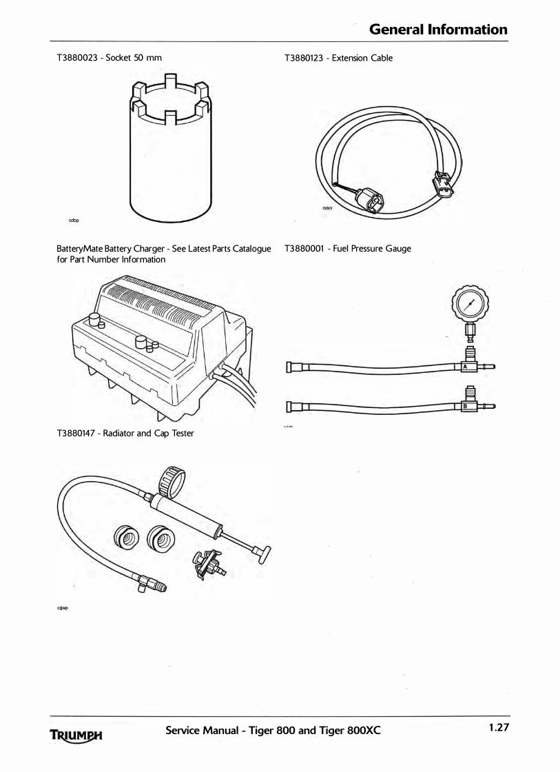
General Information
T3880023 - Socket 50 mm T38801 23 - Extension Cable
cdbp
BatteryMate Battery Charger - See Latest Parts Catalogue T3 880001 - Fuel Pressure Gauge for Part Number Information
�ol=·=----------------=��dJ3�A�a� {9
0 I ! I la I D
T3880147 - Radiator and Cap Tester
cgwp
SeiVice Manual - Tiger 800 and Tiger 800XC 1 .27

General Information
Full Specification Full Specification
Engine
Engine Configuration
Arrangement
Displacement
Bore x Stroke
Compression Ratio
Cylinder numbering
Cyl inder Sequence
Firing order
Maximum Power
Maximum Torque
Tiger 800
3 Cyl inder 12 valve DOHC
Transverse in-l ine
800 cc
74 x 61.94 mm
1 1.1 : 1
Left to Right <no.3 adjacent to camchain)
Number 1 at left
1 -2-3
70 kW at 9,300 rpm (95 PS/94 bhp>
79 Nm at 7,850 rpm (58 lb-ft}
Tiger SOOXC
3 Cyl inder 1 2 valve DOHC
Transverse in-l ine
800 cc
74 x 61.94 mm
1 1 .1 : 1
Left to Right (no.3 adjacent to camcha in)
Number 1 at left
1 -2-3
70 kW at 9,300 rpm (95 PS/94 bhp)
79 Nm at 7,850 rpm (58 lb-ft)
1 .28 SeiVice Manual - Tiger 800 and Tiger 800XC

General Information
Full Specification Tiger 800 Tiger 800XC
Cylinder Head & Valves
Valve Head Diameter In 30.50 mm 30.50 mm
Ex 25.50 mm 25.50 mm
Valve Lift In Z59 mm Z59 mm
Ex Z25 mm Z25 mm
Valve Stem Diameter In 3 .975-3.990 mm 3 .975-3 .990 mm
Service Limit 3 .965 mm 3.965 mm
Valve Stem Diameter Ex 3.955-3.970 mm 3.955-3.970 mm
Service Limit 3 .945 mm 3.945 mm
Valve Guide Bore Diameter In 4.000-4.01 5 mm 4.000-4.015 mm
Service Limit 4.043 mm 4.043 mm
Valve Guide Bore Diameter Ex 4.000-4.015 mm 4.000-4.015 mm
Service Limit 4.043 mm 4.043 mm
Valve Stem to Guide In 0.010-0.040 mm 0.010-0.040 mm Clearance
Service Limit 0.078 mm 0.078 mm
Valve Stem to Guide Ex 0.030-0.060 mm 0.030-0.060 mm Clearance
Service Limit 0.098 mm 0.098 mm
Valve Seat Width (in head) In 0.80- 1 .20 mm 0.80- 1 .20 mm
Service Limit 1 .50 mm 1 .50 mm
Valve Seat Width (in head> Ex 1 .00� 1.40 mm 1 .00- 1.40 mm
Service Limit 1 .70 mm 1 .70 mm
Valve Seat Width (valve) In 0.99 - 1 .86 mm 0.99 - 1 .86 mm
Ex 1.06 - 1 .93 mm 1.06 - 1 .93 mm
Valve Seat Angle 45 .25° 45 .25°
Inlet/Exhaust Valve Spring 'Load at Length' 508 N +/-25 N at 2Z5 mm 508 N +/-25 N at 2Z5 mm
Valve Clearance In 0.10-0.20 mm 0.10-0.20 mm
Ex 0.3 25-0.375 mm 0.3 25-0.3 75 mm
SeiVice Manual - Tiger 800 and Tiger 800XC 1 .29
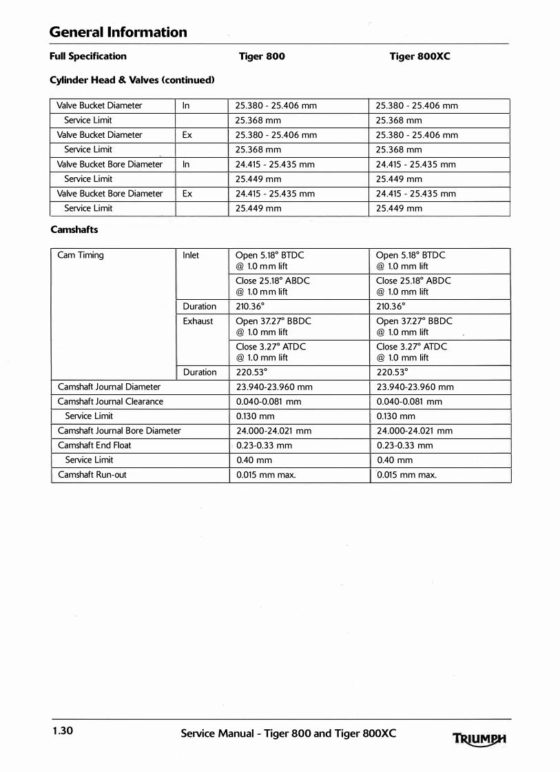
General Information
Full Specification Tiger 800 Tiger SOOXC
Cylinder Head & Valves (continued)
Valve Bucket Diameter In 25 .380 - 25 .406 mm 25 .380 - 25 .406 mm
Service Limit 25 .368 mm 25 .368 mm
Valve Bucket Diameter Ex 25 .380 - 25 .406 mm 25 .380 - 25 .406 mm
Service Limit 25 .368 mm 25 .368 mm
Valve Bucket Bore Diameter In 24.415 - 25 .435 mm 24.415 - 2 5.43 5 mm
Service Limit 25 .449 mm 25 .449 mm
Valve Bucket Bore Diameter Ex 24.415 - 25 .435 mm 24.415 - 2 5 .43 5 mm
Service Limit 25 .449 mm 25 .449 mm
Camshafts
Cam Timing Inlet Open 5.18° BTDC Open 5.18° BTDC @ 1 .0 mm lift @ 1 .0 mm lift
Close 25 .18° ABDC Close 25 .1 8° AB DC @ 1 .0 mm l ift @ 1 .0 mm l ift
Duration 210.36° 210.3 6°
Exhaust Open 3Z27° B B DC Open 3Z27o B B DC @ 1 .0 mm lift @ 1 .0 mm l ift
Close 3 .2r ATDC Close 3 .27° ATDC @ 1 .0 mm lift @ 1 .0 mm l ift
Duration 220.53° 220.5 3°
Camshaft Journal Diameter 23 .940-23.960 mm 2 3 .940-23.960 mm
Camshaft Journal Clearance 0.040-0.081 mm 0.040-0.081 mm
Service Limit 0.1 30 mm 0.1 30 mm
Camshaft Journal Bore Diameter 24.000-24.021 mm 24.000-24.021 mm
Camshaft End Float 0.2 3-0.33 mm 0.23-0.33 mm
Service Limit 0.40 mm 0.40 mm
Camshaft Run-out 0.015 mm max. 0.01 5 mm max.
1 .30 SeiVice Manual - Tiger 800 and Tiger SOOXC
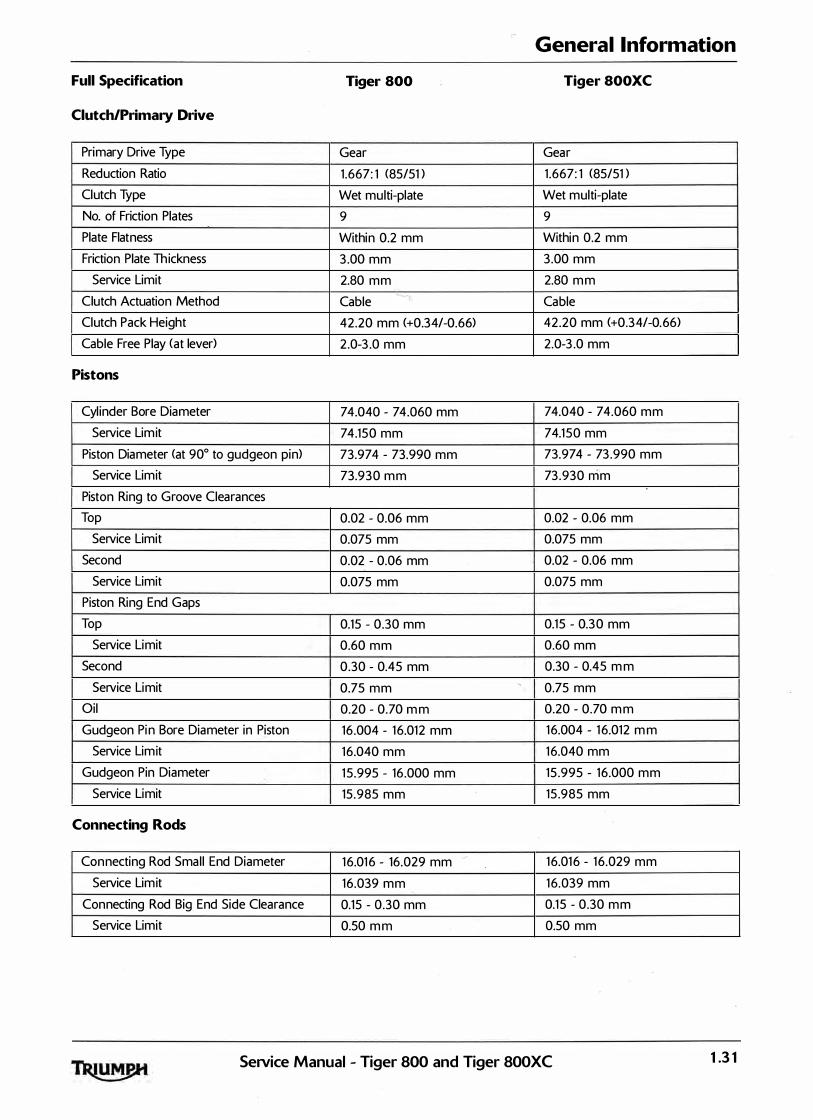
General Information
Full Specification Tiger 800 Tiger SOOXC
Clutch/Primary Drive
Primary Drive Type Gear Gear
Reduction Ratio 1 .667: 1 (85/51 ) 1 .667: 1 (85/51 )
Clutch Type Wet multi-plate Wet multi-plate
No. of Friction Plates 9 9
Plate Flatness Within 0.2 mm Within 0.2 mm
Friction Plate Th ickness 3 .00 mm 3.00 mm
Service Limit 2.80 mm 2.80 mm
Clutch Actuation Method Cable � Cable
Clutch Pack Height 42.20 mm (+0.34/-0.66) 42 .20 mm (+0.34/-0.66)
Cable Free Play (at lever) 2 .0-3 .0 mm 2.0-3 .0 mm
Pistons
Cyl inder Bore Diameter 74.040 - 74.060 mm 74.040 - 74.060 mm
Service Limit 74.150 mm 74.1 50 mm
Piston Diameter <at 90° to gudgeon pin> 73.974 - 73.990 mm 73.974 - 73 .990 mm
Service Limit 73.930 mm 73 .930 mm
Piston Ring to Groove Clearances
Top 0.02 - 0.06 mm 0.02 - 0.06 mm
Service Limit 0.075 mm 0.075 mm
Second 0.02 - 0.06 mm 0.02 - 0.06 mm
Service Limit 0.075 mm 0.075 mm
Piston Ring End Gaps
Top 0.15 - 0.30 mm 0.15 - 0.30 mm
Service Limit 0.60 mm 0.60 mm
Second 0.30 - 0.45 mm 0.30 - 0.45 mm
Service Limit 0.75 mm ' 0.75 mm
Oil 0.20 - 0.70 mm 0.20 - 0.70 mm
Gudgeon Pin Bore Diameter in Piston 16 .004 - 16.012 mm 16.004 - 1 6.012 mm
Service Limit 16.040 mm 16.040 mm
Gudgeon Pin Diameter 1 5 .995 - 16 .000 mm 15 .995 - 16.000 mm
Service Limit 15 .985 mm 15 .985 mm
Connecting Rods
Connecting Rod Smal l End Diameter 1 6.01 6 - 16.029 mm 0
1 6.01 6 - 1 6.029 mm
Service Limit 16.039 mm 16.039 mm
Connecting Rod Big End Side Clearance 0.15 - 0.30 mm 0.1 5 - 0.30 mm
Service Limit 0.50 mm 0.50 mm
SeiVice Manual - Tiger 800 and Tiger 800XC 1 .3 1

General Information
Full Specification Tiger 800 Tiger 800XC
Crankshaft
Crankshaft Big End Journal Diameter 3 2 .984-3 3.000 mm 3 2.984-3 3 .000 mm
Service Limit 3 2.960 mm 3 2.960 mm
Crankshaft Big End Bearing Clearance 0.03 5-0.065 mm 0.03 5-0.065 mm
Service Limit 0.070 mm 0.070 mm
Crankshaft Main Bearing Journal Diameter 3 2 .984-3 3 .000 mm 3 2.984-3 3 .000 mm
Service Limit 3 2.960 mm 32 .960 mm
Crankshaft Main Bearing Clearance 0.020-0.044 mm 0.020-0.044 mm
Service Limit 0.070 mm 0�
0.070 mm
Crankshaft End Float 0.1 5-0.30 mm 0.15-0.30 mm
Crankshaft Run-out 0.02 mm or less 0.02 mm or less
Service Limit 0.05 mm 0.05 mm
Transmission
Type 6 Speed, Constant Mesh 6 Speed, Constant Mesh
Gear Ratios 1 st 2 .31 3 : 1 (37/16) 2.31 3 : 1 (37/1 6)
2nd 1 .857: 1 (39/21 ) 1 .857: 1 (39/21 )
3 rd 1 .500: 1 (3 6/24) 1 .500: 1 (3 6/24)
4th 1 .285 : 1 (27/21 ) 1 .285 : 1 (27/21 )
5th 1 .1 36 : 1 (25/22) 1 .1 3 6: 1 (25/2 2)
6th 1 .043 : 1 (24/23) 1 .043 : 1 (24/23)
Gear Selector Fork Thickness 5 .9-6.0 mm 5.9-6.0 mm
Service Limit 5.80 mm 5.80 mm
Gear Selector Groove Width 6.10-6.17 mm 6.10-6.17 mm
Service Limit . 6 .27 mm 6.27 mm
Gear Selector Fork to Groove Clearance 0.47 mm max. 0.47 mm max.
Final Drive
Fina l Drive Chain Chain
Final Drive Ratio 3 .1 25 : 1 (50/16) 3 .1 2 5 : 1 (50/1 6)
Chain Type RK 0-ring RK 0-ring
Number of Links 1 2 2 1 24
20 Link Length 319 mm 319 mm
Drive Chain Play 1 5-25 mm 20.:30 mm
Chain Lubrication Chain spray suitable for 0-ring Chain spray su itable for 0-ring chains chains
-
1 .32 Service Manual - Tiger 800 and Tiger 800XC
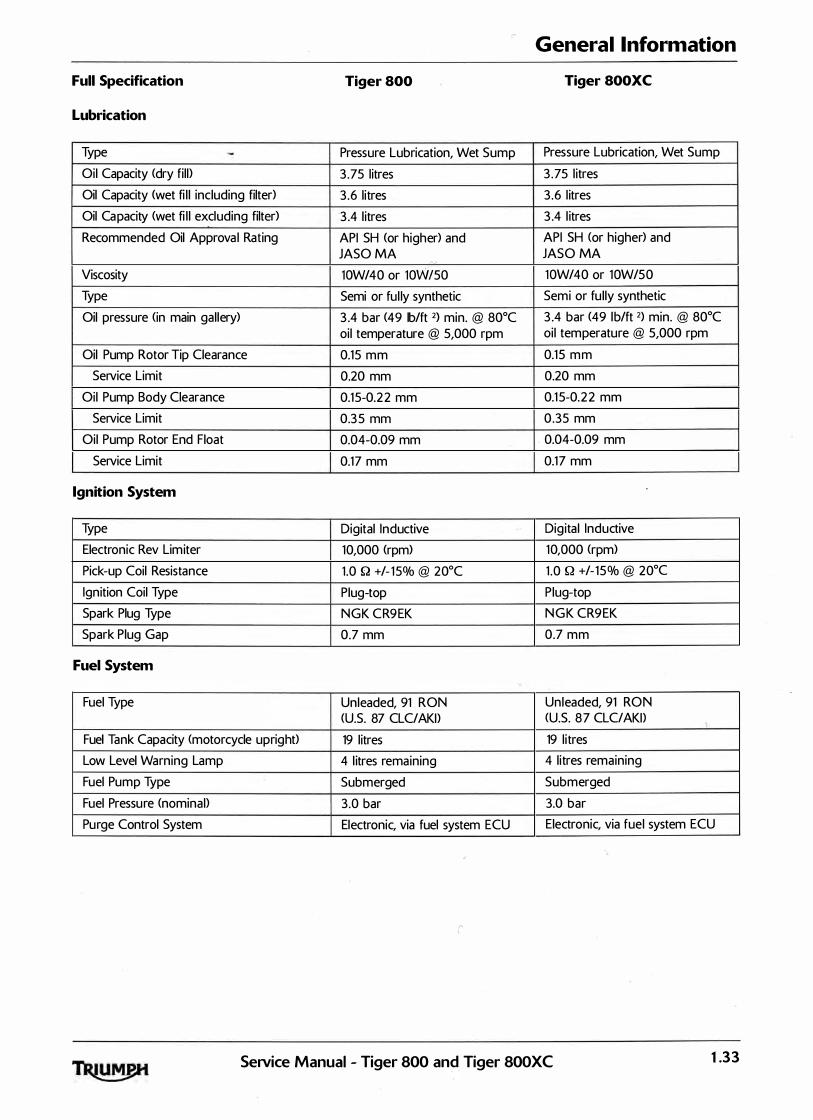
General Information
Full Specification Tiger 800 Tiger SOOXC
Lubrication
Type - Pressure Lubrication, Wet Sump Pressure Lubrication, Wet Sump
Oil Capacity (dry fill> 3 .75 l itres 3 .75 l itres
Oil Capacity (wet fi l l including filter) 3 .6 litres 3 .6 l itres
Oil Capacity <wet fi l l excluding filter) 3 .4 l itres 3 .4 l itres
Recommended Oil Approval Rating API SH (or higher) and API SH (or higher) and JASO MA JASO MA
�
Viscosity lOW/40 or lOW/50 lOW/40 or lOW/50
Type Semi or ful ly synthetic Semi or fu l ly synthetic
Oil pressure (in main gallery) 3 .4 bar (49 lb/ft 2) min. @ 80°C 3 .4 bar (49 lb/ft 2) min. @ 80°C oil temperature @ 5,000 rpm oil temperature @ 5,000 rpm
Oil Pump Rotor Tip Clearance 0.15 mm 0.15 mm
Service Limit 0.20 mm 0.20 mm
Oil Pump Body Clearance 0.1 5-0.2 2 mm 0.1 5-0.2 2 mm
Service Limit 0.3 5 mm 0.35 mm
Oil Pump Rotor End Float 0.04-0.09 mm 0.04-0.09 mm
Service Limit 0.17 mm 0.17 mm
Ignition System
Type Digital Inductive Dig ital Inductive
Electronic Rev Limiter 10,000 (rpm> 10,000 <rpm)
Pick-up Coil Resistance 1 .0 Q +/- 1 5% @ 20°C 1 .0 Q +/- 15% @ 20°C
Ignition Coil Type Plug-top Plug-top
Spark Plug Type NGK CR9EK NGK CR9EK
Spark Plug Gap 0.7 mm 0.7 mm
Fuel System
Fuel Type Unleaded, 91 RON Unleaded, 91 RON <U.S. 87 CLC/AKD <U.S. 87 CLC/AKD i
Fuel Tank Capacity <motorcycle upright> 19 l itres 19 l itres
Low Level Warning Lamp 4 l itres remaining 4 l itres remaining
Fuel Pump Type Submerged Submerged
Fuel Pressure (nominal> 3 .0 bar 3.0 bar
Purge Control System Electronic, via fuel system ECU Electronic, via fuel system ECU
r
SeiVice Manual - Tiger 800 and Tiger 800XC 1 .33
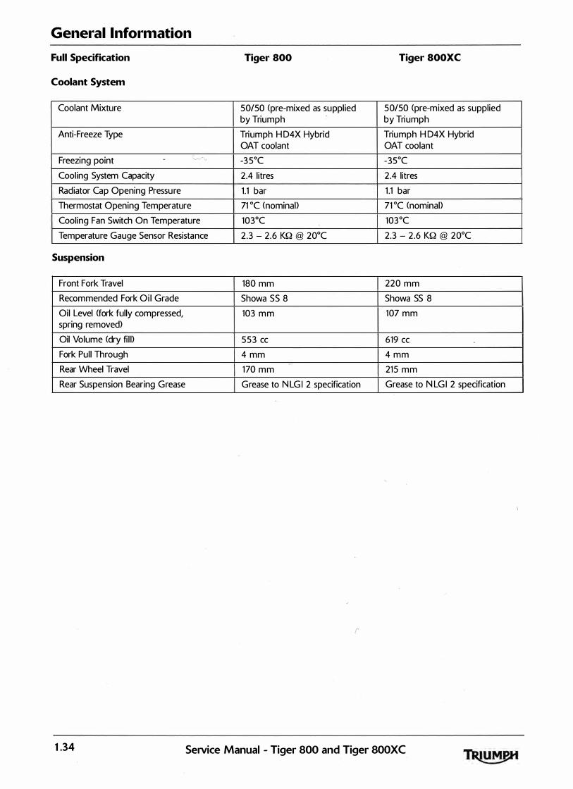
General Information
Full Specification Tiger 800 Tiger 800XC
Coolant System
Coolant Mixture 50150 <pre-mixed as suppl ied 50150 <pre-mixed as supplied by Triumph by Triumph
Anti-Freeze Type Triumph H D4X Hybrid Triumph H D4X Hybrid OAT coolant OAT coolant
Freezing point c �, -3 5°C -35°C
Cooling System Capacity 2.4 litres 2 .4 litres
Radiator Cap Opening Pressure 1.1 bar 1 .1 bar
Thermostat Opening Temperature 71 oc (nominal> 71 oc <nominal>
Cooling Fan Switch On Temperature 103°C 103°C
Temperature Gauge Sensor Resistance 2 .3 - 2.6 KQ @ 20°C 2.3 - 2.6 KQ @ 20°C
Suspension
Front Fork Travel 180 mm 220 mm
Recommended Fork Oi l Grade Showa SS 8 Showa SS 8
Oil Level (fork fully compressed, 103 mm 107 mm spring removed)
Oil Volume (dry fi l l> 553 cc 619 cc
Fork Pul l Through 4 mm 4 mm
Rear Wheel Travel 170 mm 215 mm
Rear Suspension Bearing Grease Grease to N LG I 2 specification Grease to N LG I 2 specification
r
1 .34 SeiVice Manual - Tiger 800 and Tiger SOOXC

General Information
Full Specification Tiger 800 Tiger 800XC
Fuel Injection System
Type Electronic, sequentia l Electronic, sequential
Idle Speed 1,100 rpm 1,100 rpm
In jector Type Twin jet, solenoid operated Twin jet, solenoid operated plate valve plate valve
Throttle Cable/twist grip/electronic Cable/twist grip/electronic throttle potentiometer throttle potentiometer
Control Sensors Barometric pressure, throttle Barometric pressure, throttle position, coolant temperature, position, coolant temperature, crankshaft position, vehicle crankshaft position, vehicle speed, lambda sensor, intake air speed, lambda sensor, intake air temperature, gear position, MAP temperature, gear position, MAP
Emissions Controls
Catalysts 1, in down pipe 1, in down pipe
Oxygen sensor Heated, in down pipe Heated, in down pipe
Evaporative Control Activated carbon canister Activated carbon canister <Certain markets only) <Certain markets on ly)
Brakes
Front Type Two hydraul ically actuated twin Two hydraul ical ly actuated twin piston sl iding cal ipers acting on piston sl iding cal ipers acting on twin discs twin discs
Cal iper Piston Diameter 2 x 2ZOO mm 2 x 2ZOO mm
Disc Diameter 305 mm 305 mm
Disc Thickness 4.5 mm 4.5 mm
Service Limit 4.0 mm 4.0 mm
Disc Run-out 0.15 mm Max. 0.1 5 mm Max.
Master Cyl inder Diameter 14.00 mm 0 14.00 mm
Recommended Fluid DOT 4 Brake and Clutch Fluid DOT 4 Brake and Clutch Fluid
r
SeiVice Manual - Tiger 800 and Tiger 800XC 1 .35
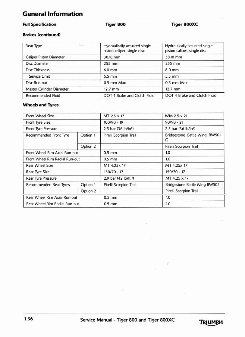
General Information
Full Specification Tiger 800 Tiger 800XC
Brakes (continued)
Rear Type �r., Hydraul ical ly actuated single Hydraul ically actuated single piston cal iper, single d isc piston ca liper, single disc
Caliper Piston Diameter 3 8.18 mm 38.18 mm
Disc Diameter 255 mm 255 mm
Disc Thickness 6.0 mm 6 .0 mm
Service Limit 5 .5 mm 5.5 mm
Disc Run-out 0.5 mm Max. 0.5 mm Max.
Master Cyl inder Diameter 12 .7 mm 12 .7 mm
Recommended Fluid DOT 4 Brake and Clutch Fluid DOT 4 Brake and Clutch Fluid
Wheels and Tyres
Front Wheel Size MT 2.5 X 17 WM 2.5 X 21
Front Tyre Size 100/90 - 19 90/90 - 21
Front Tyre Pressure 2 .5 bar (3 6 lb/in2) 2 .5 bar (3 6 lb/in2)
Recommended Front Tyre Option 1 Pirel l i Scorpion Tra il Bridgestone Battle Wing BW501 G
Option 2 Pirel l i Scorpion Trai l
Front Wheel Rim Axia l Run-out 0.5 mm 1 .0
Front Wheel Rim Radial Run-out 0.5 mm 1 .0
Rear Wheel Size MT 4.25x 17 MT 4 .25x 17
Rear Tyre Size 150/70 � 17 150/70 - 17
Rear Tyre Pressure 2.9 bar (42 lb/ft 2) MT 4.25 x 17
Recommended Rear Tyres Option 1 Pirel l i Scorpion Trai l Bridgestone Battle Wing BW502
Option 2 Pirel l i Scorpion Trai l
Rear Wheel Rim Axial Run-out 0.5 mm 1.0
Rear Wheel Rim Radial Run-out 0.5 mm 1 .0
r
1 .36 SeNice Manual - Tiger soo · and Tiger 800XC
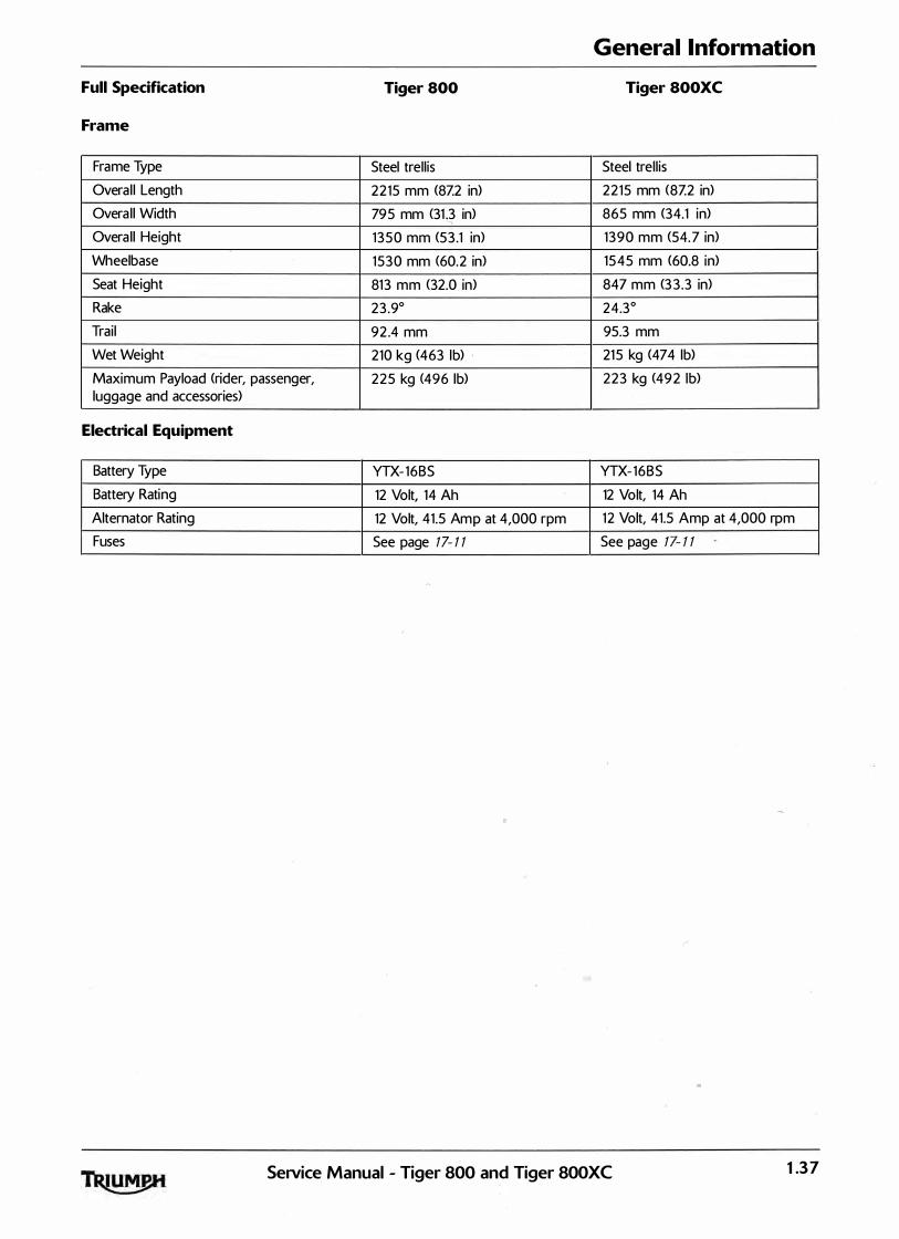
General Information
Full Specification Tiger 800 Tiger SOOXC
Frame
Frame Type Steel trell is Steel trel l is
Overal l Length 2215 mm (8Z2 in) 22 15 mm (8Z2 in)
Overa ll Width 795 mm (31�3 in) 865 mm (34.1 in) '
Overall Height 1 350 mm (53 .1 in) 1390 mm (54. 7 in)
Wheelbase 1530 mm (60.2 in) 1545 mm (60.8 in)
Seat Height 813 mm (32.0 in) 847 mm (3 3 .3 in)
Rake 23 .9° 24.3°
Trail 92 .4 mm 95.3 mm
Wet Weight 210 kg (463 lb) . 21 5 kg (474 lb)
Maximum Payload (rider, passenger, 225 kg (496 lb) 223 kg (49 2 lb) luggage and accessories)
Electrical Equipment
Battery Type YTX- 16BS YTX- 16BS
Battery Rating 12 Volt, 14 Ah 12 Volt, 14 Ah
Alternator Rating 12 Volt, 41.5 Amp at 4,000 rpm 12 Volt, 41.5 Amp at 4,000 rpm
Fuses See page 17- 1 1 See page 17- 1 1
SeiVice Manual - Tiger 800 and Tiger 800XC 1 .3 7
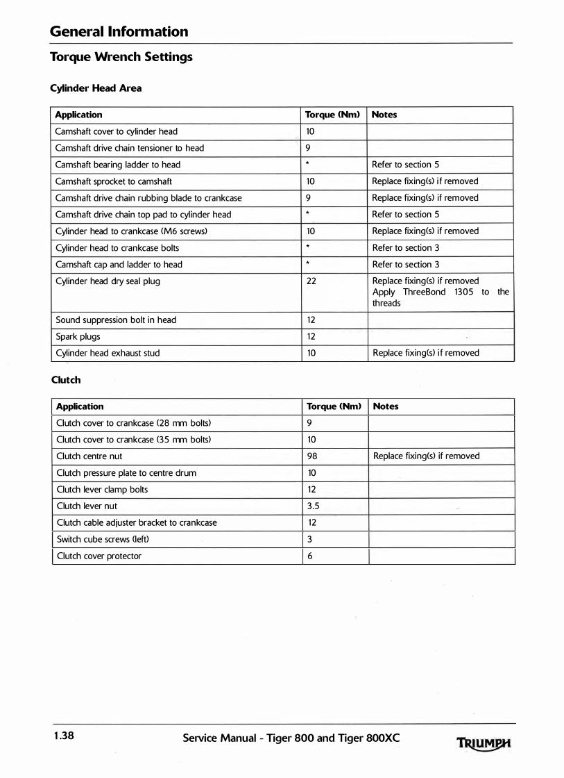
General Information
Torque Wrench Settings
Cylinder Head Area
Application Torque <Nm> Notes
Camshaft cover to cylinder head 10 r-
Camshaft drive chain tensioner to head 9
Camshaft bearing ladder to head * Refer to section 5
Camshaft sprocket to camshaft 10 Replace fixing(s) i f removed
Camshaft drive chain rubbing blade to crankcase 9 Replace fixing(s) if removed
Camshaft drive chain top pad to cyl inder head * Refer to section 5
Cylinder head to crankcase (M6 screws) 10 Replace fixing(s) if removed
Cyl inder head to crankcase bolts * Refer to section 3
Camshaft cap and ladder to head * Refer to section 3
Cyl inder head dry sea l plug 22 Replace fixing(s) if removed Apply ThreeBond 1305 to the threads
Sound suppression bolt in head 1 2
Spark plugs 1 2
Cyl inder head exhaust stud 10 Replace fixing(s) i f removed
Clutch
Application Torque <Nm> Notes
Clutch cover to crankcase (28 mm bolts) 9
Clutch cover to crankcase (3 5 mm bolts) 10
Clutch centre nut 98 Replace fixing(s) if removed
Clutch pressure plate to centre drum 10
Clutch lever clamp bolts 1 2
Clutch lever nut 3 .5 �
Clutch cable adjuster bracket to crankcase 1 2
Switch cube screws (left) 3
Clutch cover protector 6
1 .38 SeiVice Manual - Tiger 800 and Tiger 800XC

General Information
Crankshaft, Crankcase and Sprag
Application Torque <Nm) Notes
Crankcase upper to lower (M8 fixings) * Refer to section 5
Crankcase upper to lower (M6 fixings) * Refer to section 5
Crankcase dry sea l plug 2 2 Replace fixing(s) i f removed
Breather cover to crankcase 9 Replace fixing(s) if removed
Connecting rod big end nut * Refer to section 5
Camshaft drive sprocket gear to crankshaft 27 Replace fixing(s) if removed
Sprag clutch to alternator rotor Refer to section 7
Engine Covers
Application Torque <Nm) Notes
Clutch cover to crankcase 9
Sprocket cover to crankcase 9
Alternator cover (25 mm bolts) to crankcase 8
Alternator cover (3 5 mm bolts) to crankcase 9
Wire retainer on a lternator cover 6
Crank cover (25 mm bolts) to crankcase 8
Crank cover (35 mm bolts> to crankcase 9
Balancer cover to crankcase 8
Transmission
Application Torque <Nm) Notes
Output sprocket to output shaft 85 Use new tab washers
Detent wheel to selector drum 12 Replace fixing(s) if removed
Detent arm bolt 1 2 Replace fixing(s) i f removed
Input shaft bearing carrier/retainer 1 2� Replace fixing(s) if removed
Selector shaft retainer 1 2 Replace fixing(s) i f removed
Spring abutment bolt 20
Gear position sensor 5 Replace fixing<s> if removed
Gear selector arm pinch bolt 9 Replace fixing<s> if removed
Gear pedal pivot bolt 2 2
Gear change rod adjuster nuts 6
Sprag housing to rotor 1 6
SeiVice Manual - Tiger 800 and Tiger 800XC 1 .39
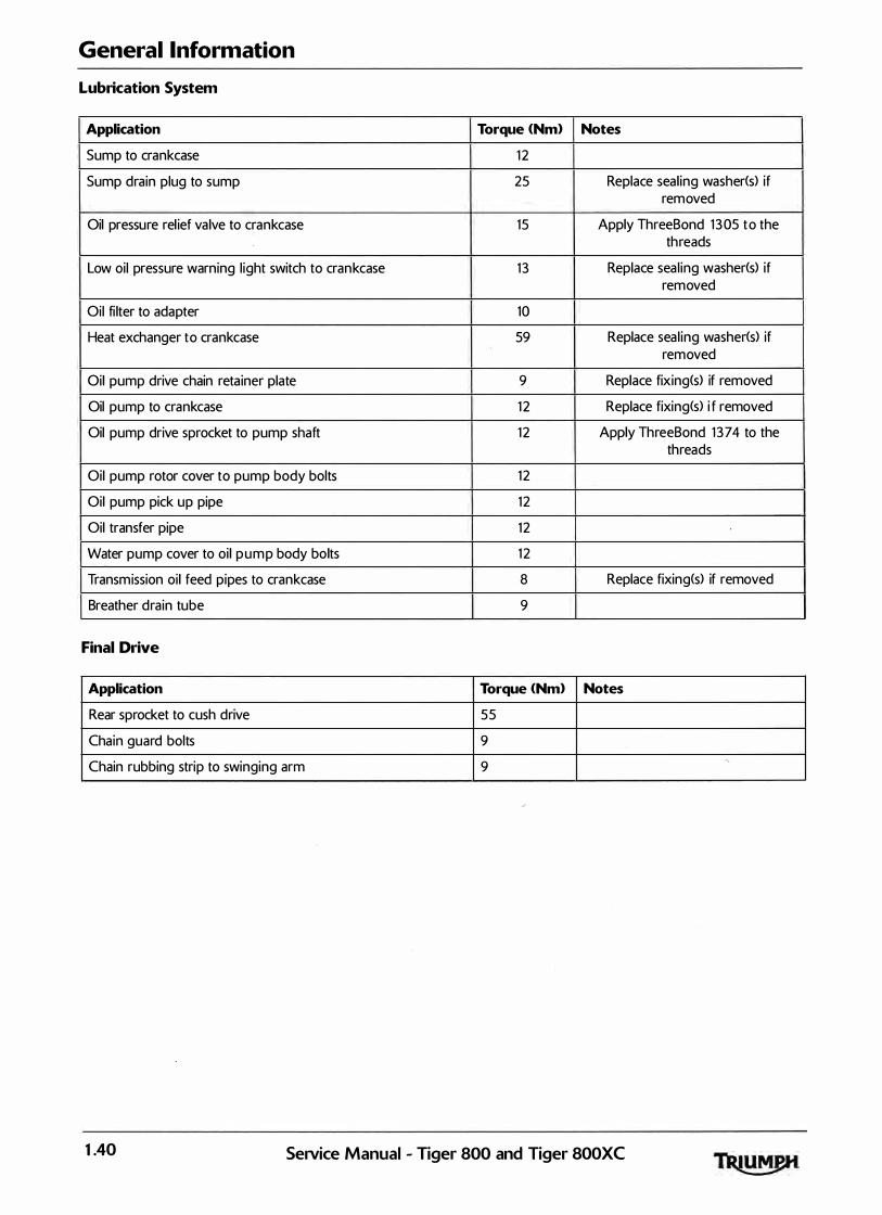
General Information
Lubrication System
Application Torque <Nm> Notes
Sump to crankcase 1 2
Sump drain plug to sump 25 Replace seal ing washer(s) if removed
Oil pressure rel ief valve to crankcase 15 Apply ThreeBond 1 305 to the threads
Low oil pressure warning l ight switch to crankcase 1 3 Replace seal ing washer(s) if removed
Oil fi lter to adapter 10
Heat exchanger to crankcase 59 Replace seal ing washer(s) if removed
Oil pump drive chain retainer plate 9 Replace fixing(s) if removed
Oil pump to crankcase 1 2 Replace fixing(s) i f removed
Oil pump drive sprocket to pump shaft 1 2 Apply ThreeBond 1 374 to the threads
Oil pump rotor cover to pump body bolts 1 2
Oil pump pick up pipe 1 2
Oil transfer pipe 1 2
Water pump cover to oil pump body bolts 1 2
Transmission oil feed pipes to crankcase 8 Replace fixing(s) if removed
Breather drain tube 9
Final Drive
Application Torque <Nm> Notes
Rear sprocket to cush drive 55
Chain guard bolts 9
Chain rubbing strip to swinging arm 9 -,_
1 .40 SeiVice Manual - Tiger 800 and Tiger SOOXC

General Information
Cooling System
Application Torque <Nm> Notes
Radiator to frame 6
Coolant bypass to head 1 5
Thermostat housing to head 9
Water elbow to crankcase (left hand> 9
Water elbow to crankcase (right hand and upper fixing only) 1 2
Fan shroud to radiator 2 .5
Water temperature sensor 18
Radiator lower bracket to radiator 6
Radiator lower bracket to water outlet bracket 6
Expansion tank to frame 3
Expansion tank cover to frame 3
Radiator bleed screw 1 .5
Top hose bleed screw 1
Water pump outlet pipe 1 2 Replace fixing<s> i f removed
Water pump inlet pipe 1 2 Replace fixing<s> i f removed
Coolant hose clips 2
Service Manual - Tiger 800 and Tiger SOOXC 1 .4 1
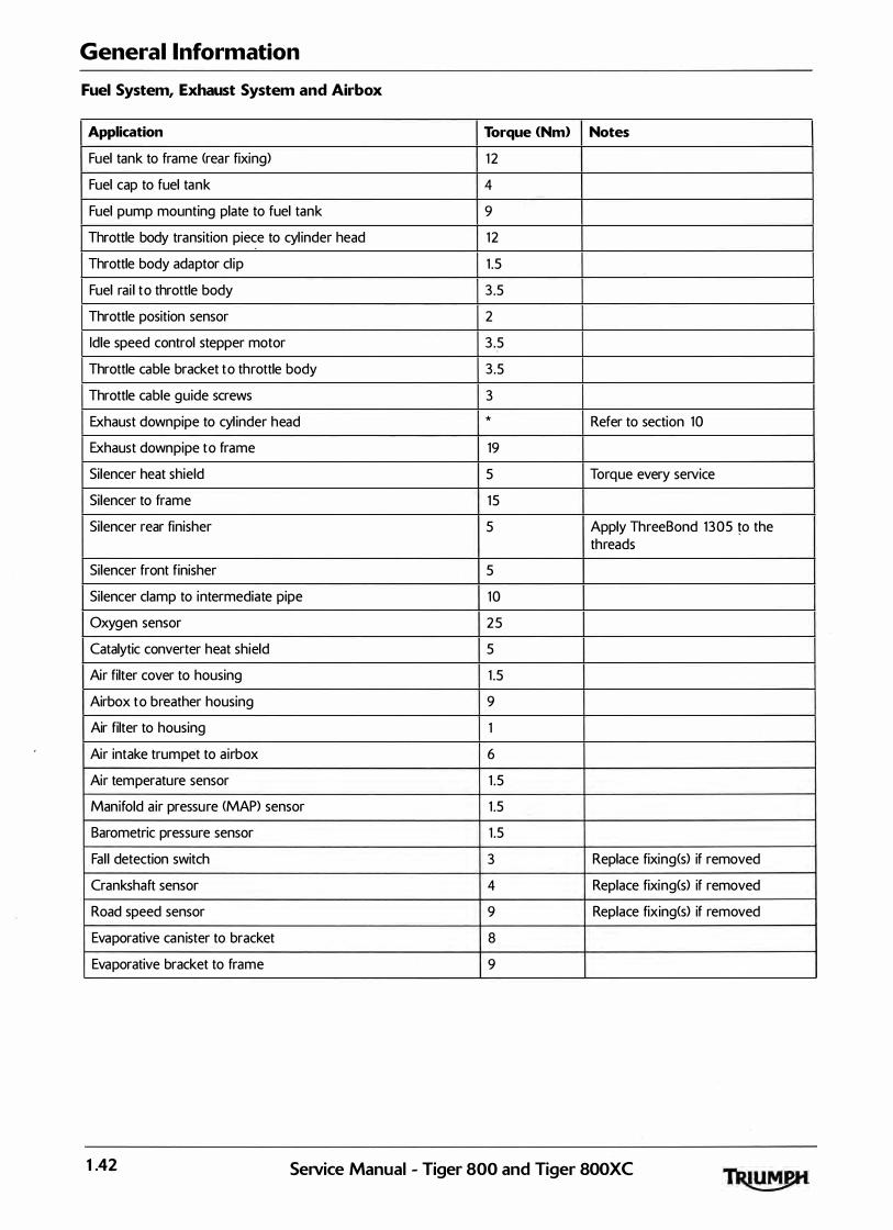
General Information
Fuel System, Exhaust System and Airbox
Application Torque <Nm> Notes
Fuel tank to frame (rear fixing) 1 2
Fuel cap to fuel tank 4
Fuel pump mounting plate to fuel tank 9
Throttle body transition piece to cyl inder head 1 2
Throttle body adaptor cl ip 1 .5
Fuel rai l to throttle body 3 .5
Throttle position sensor 2
Idle speed control stepper motor 3 .5
Throttle cable bracket to throttle body 3 .5
Throttle cable guide screws 3
Exhaust downpipe to cyl inder head * Refer to section 10
Exhaust downpipe to frame 19
Silencer heat shield 5 Torque every service
Silencer to frame 15
Silencer rear finisher 5 Apply ThreeBond 1305 �o the threads
Silencer front finisher 5
Silencer clamp to intermediate pipe 10
Oxygen sensor 2 5
Catalytic converter heat shield 5
Air filter cover to housing 1 .5
Airbox to breather housing 9
Air filter to housing 1
Air intake trumpet to airbox 6
Air temperature sensor 1 .5
Manifold air pressure <MAP> sensor 1 .5
Barometric pressure sensor 1 .5
Fal l detection switch 3 Replace fixing<s> if removed
Crankshaft sensor 4 Replace fixing(s) if removed
Road speed sensor 9 Replace fixing<s> if removed
Evaporative canister to bracket 8
Evaporative bracket to frame 9
1 .42 Service Manual - Tiger 800 and Tiger 800XC

General Information
Rear Suspension
Application Torque <Nm> Notes
Swinging arm spindle nut 1 10 Replace fixing<s> if removed <locknut>
Chain rubbing strip to swinging arm 9
Rear suspension unit upper mounting bolt 48
Rear suspension unit lower mounting bolt to drop l ink 80
Rear suspension reservoir 3
Drag l ink pivot at frame 80
Drop l inks to swinging arm 80
Chain guard <upper and lower) 9
Front Suspension
Application Torque <Nm> Notes
Upper yoke pinch bolt 20
Lower yoke pinch bolt 20
Upper yoke centre nut 90
Fork top cap 3 5
Damping cyl inder bolt 20 Replace seal ing washer<s> if removed
Damping rod to top cap 20
Handlebar clamp riser to top yoke ( 10 mm bolt> 3 5
Handlebar upper clamp to lower clamp ( 8 mm bolt> 2 6 Lubricate threads with engine oil
Handlebar end weights 5
Switch cube screws 3
Mirror 2 5
Wheels
Application Torque <Nm> Notes
Front wheel spindle/axle bolt 65
Front wheel spindle pinch bolts 2 2
Rear wheel spindle 1 10
Chain adjuster locknut 15
Rear sprocket to cush drive 5 5 Replace fixing<s> i f removed
Service Manual - Tiger 800 and Tiger 800XC 1 .43

General Information
Front Brakes
Application Torque <Nm) Notes
Front brake cal iper to fork 28
Front brake pad reta ining pin 18
Front brake pad retaining pin plug 3
Front brake cal iper bleed screw 6
Front brake hose to cal iper 2 5 Replace seal ing washer(s) if removed
Front brake master cyl inder to handlebar 1 2
Front brake hose to master cylinder 2 5 Replace seal ing washer(s) if removed
Front brake disc to wheel 2 2 Replace fixing(s) i f removed
Brake lever pivot bolt 1
Brake lever pivot bolt locknut 6
Master cyl inder brake hose clamp to fork leg 6
Brake hose wire guide 7
Rear Brakes
Application Torque <Nm> Notes
Rear brake cal iper to carrier 2 2
Rear brake cal iper sl iding bolt 27
Rear brake pad reta ining pin 1 8
Rear brake pad retaining pin plug 3
Rear brake caliper bleed screw 6
Rear brake hose to ca l iper 2 5 Replace seal ing washer(s) if removed
Rear brake master cyl inder to frame 1 6
Rear brake master cyl inder reservoir to mounting 7
Rear brake master cyl inder pushrod locknut 1 8
Rear brake l ight switch 1 5 Replace seal ing washer(s) if removed
Brake pedal pivot bolt 2 2
Brake hose P-clip bolt 6
Rear brake disc to wheel 2 2 Replace fixing(s) i f removed
1 .44 SeiVice Manual - Tiger 800 and Tiger 800XC

General Information
ABS System
Application Torque <Nm> Notes
ABS module to bracket 9
ABS bracket to frame 9
ABS pulser ring to brake disc 5 Replace fixing(s) if removed
ABS sensor to bracket 9 Replace fixing(s) if removed
ABS l ines to modulator 25
ABS hard l ine to front brake hose 17
Frame, Footrests, Control Plates and Engine Mountings
Application Torque <Nm> Notes
Lower crankcase to frame 48 Refer to section 9
Cyl inder head to frame 48 Refer to section 9
Heel guard to frame 1 2
Side stand mounting bracket 45
Side stand pivot bolt 20
Side stand pivot bolt 45
Side stand switch 7 Replace fixing(s) if removed
Seat lock to frame 5
Front subframe 15
Lower rear engine mounting frame adjuster 3
SeiVice Manual - Tiger 800 and Tiger 800XC 1 .45
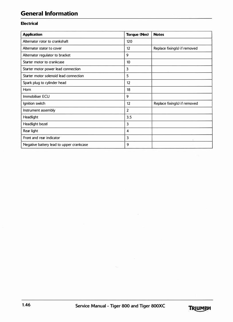
General Information
Electrical
Application Torque <Nm> Notes
Alternator rotor to crankshaft 120
Alternator stator to cover 1 2 Replace fixing(s) i f removed
Alternator regu lator to bracket 9
Starter motor to crankcase 10
Starter motor power lead connection 3
Starter motor solenoid lead connection 5
Spark plug to cyl inder head 1 2
Horn 1 8
Immobil iser ECU 9
Ignition switch 1 2 Replace fixing(s) i f removed
Instrument assembly 2
Headlight 3 .5
Headlight bezel 3
Rear l ight 4
Front and rear indicator 3
Negative battery lead to upper crankcase 9 .
1 .46 SeiVice Manual - Tiger 800 and Tiger 800XC

General Information
Bodywork
Application Torque <Nm> Notes
Mudguard extension bracket 9 Replace fixing<s> if removed
Front mudguard to forks - Tiger 800 6 Replace fixing<s> if removed
Front mudguard to forks - lower - Tiger 800XC 6 Replace fixing(s) if removed
Front mudguard to forks - upper - Tiger 800XC 6 Replace fixing<s> if removed
Handguard bracket to lever pivot bolt 1
Handguard to bracket 9
Handguard to handlebar spacer 6 Replace fixing<s> if removed
Sumpguard nuts 10
Sumpguard rubber to sump 3
Sumpguard Bracket 1 5
Sumpguard front bolts 1 5 Replace fixing(s) i f removed
Screen fixings to brackets 3
Screen bracket (pressed, at side> 5
Screen bracket (cast, at fronO 5
Centre panel <Tiger 800> or Beak support moulding 5
<Tiger 800XC> to subframe (nut and screw>
' Beak to beak support moulding 3
Beak support moulding to subframe 5
Cockpit infi l l panels to cockpit moulding 3
Ignition switch cover 5
Fuel tank panel, front 5
Lower radiator panel 3
Upper radiator panel 5
Radiator infi l l panel lower fixing 6 Replace fixing(s) if removed
Radiator infi l l panel upper fixing 3 Replace fixing<s> if removed
Battery tray 6 Apply ThreeBond 1 3 60 to the threads
Rear mudguard upper fixing 3
Rear mudguard lower fixing 5 Replace fixing<s> if removed
Rear mudguard splash cover 3
Rear panel M6 bolts 5
Rear panel M8 bolts 20
Grab rail to subframe bolts 20
Rear rack 3 �
Front seat bridge 5
Fuel tank infi l l 3
Rear seat bracket lower fixing 5
Rear seat bracket upper fixing 5
SeNice Manual - Tiger 800 and Tiger 800XC 1 .47
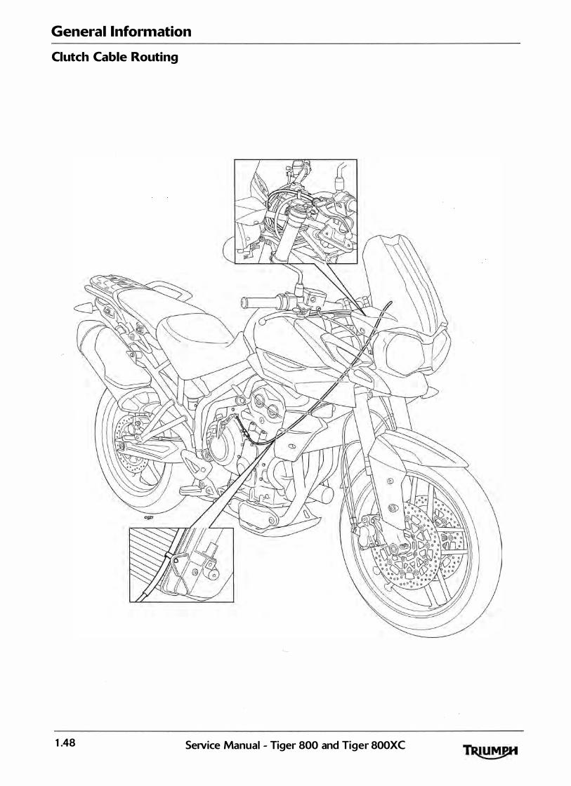
General Information
Clutch Cable Routing
1 .48 SeiVice Manual - Tiger 800 and Tiger 800XC

General Information
Throttle Cable Routing
SeiVice Manual - Tiger 800 and Tiger SOOXC 1 .49

General Information
Main Wiring Harness Routing
1 .50 SeiVice Manual - Tiger 800 and Tiger 800XC
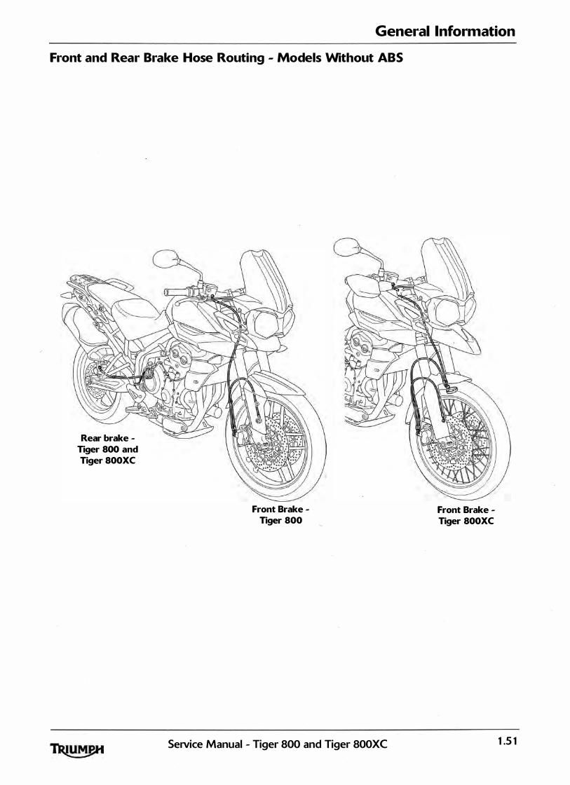
General Information
Front and Rear Brake Hose Routing - Models Without ABS
Rear brake Tiger 800 and Tiger 800XC
Front Brake -Tiger 800
SeiVice Manual - Tiger 800 and Tiger 800XC
Front Brake -Tiger 800XC
1 .5 1
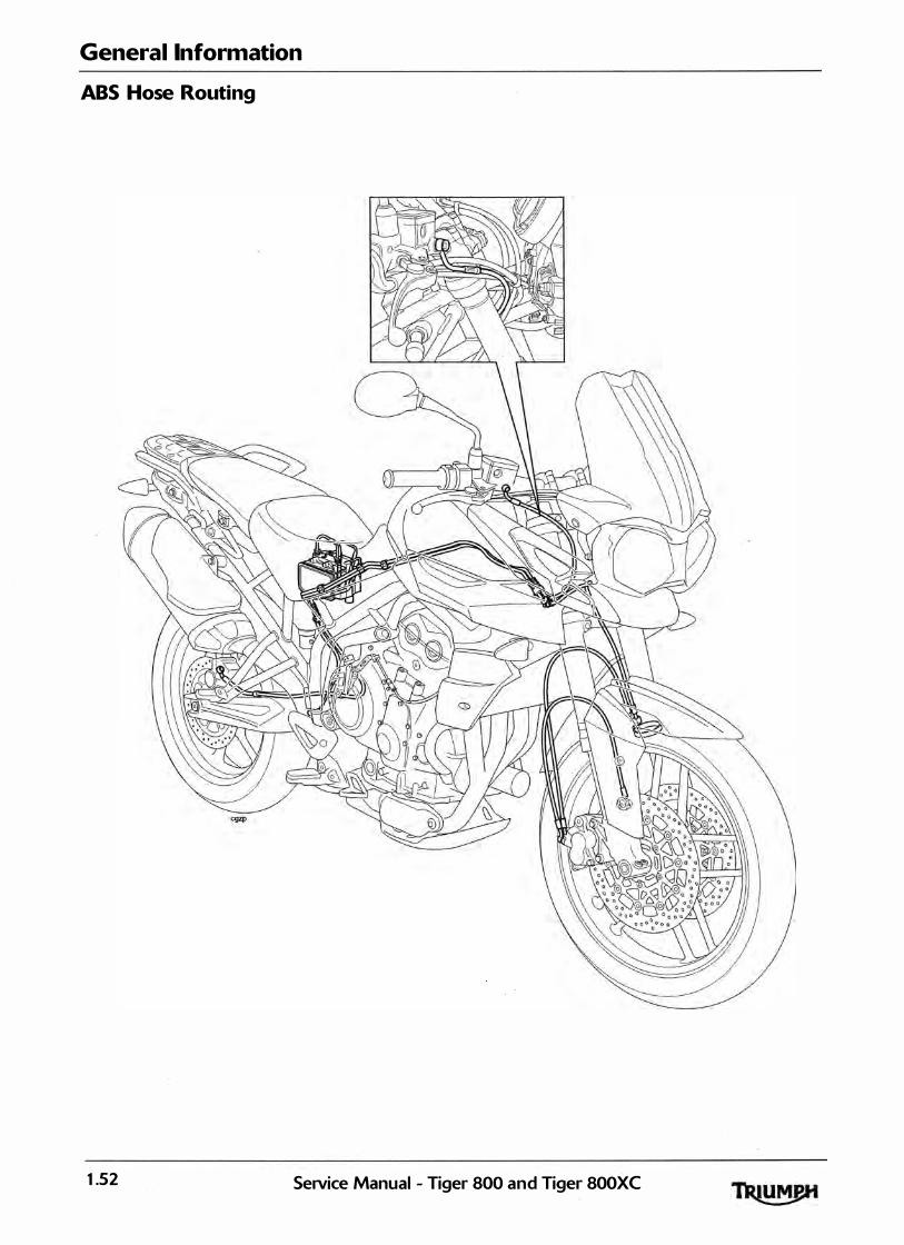
General Information
ABS Hose Routing
1 .52 SeiVice Manual - Tiger 800 and Tiger 800XC

General Information
Fuel Tank Breather Hose Routing
SeiVice Manual - Tiger 800 and Tiger SOOXC 1 .53

General Information
This page intentionally left blank
1 .54 Service Manual - Tiger 800 and Tiger 800XC

2 Scheduled Maintenance Table of Contents
Introduction . . . . . . . . . . . . . . . . . . . . . . . . . . . . . . . . . . . . . . . . . . . . . . . . . . . . . . . . . . . . . . . . . . . . . . . . . . . . . . 2.2
Scheduled Maintenance Chart . . . . . . . . . . . . . . . . . . . . . . . . . . . . . . . . . . . . . . . . . . . . . . . . . . . . . . . . . . . . . . 2.3
SeiVice Manual - Tiger 800 and Tiger 800XC 2. 1
Scheduled Maintenance
Introduction To maintain the motorcycle in a safe and rel iable condition, the maintenance and adjustments outl ined in this section must be carried out as specified in the schedule of daily checks, and also in l ine with the schedu led maintenance chart.
Weather, terrain and geographical location affects maintenance. The maintenance schedule should be adjusted to match the particu lar environment in which the vehicle is used and the demands of the individual owner. For advice on adjusting the service schedule, consult your authorised Triumph dealer.
! ' . -
In order to correctly carry out the maintenance items l isted in the scheduled maintenance chart, special tools and specia list knowledge wil l be required. As only an authorised Triumph dealer wi l l have this knowledge and equipment, Triumph strongly recommends that your authorised Triumph dealer carries out a l l scheduled maintenance.
A dangerous riding condition could result from incorrect maintenance leading to loss of motorcycle control and an accident.
All maintenance is vitally important and must not be neglected. Incorrect maintenance or adjustment may cause one or more parts of the motorcycle to malfunction. A malfunctioning motorcycle is dangerous and may lead to an accident.
Triumph Motorcycles cannot accept any responsibil ity for · damage or in jury resulting from incorrect maintenance or improper adjustment carried out by the owner.
Since incorrect or neglected maintenance can lead to a dangerous riding condition, always have an authorised Triumph dealer carry out the scheduled maintenance of this motorcycle.
2.2 SeiVice Manual - Tiger 800 and Tiger 800XC

Scheduled Maintenance
Scheduled Maintenance Chart
Operation Description Odometer Reading in Miles <Kmsl or time period,
whichever comes first
First A Service B Service C Service D Service
Service
500 6,000 1 2,000 18,000 24,000
Every (800) ( 10,000) (20,000) (30,000) (40,000)
1 month 1 year 2 years 3 years 4 years
Engine oil cooler - check for leaks Day • • • • •
Engine oil - renew - • • • • •
Engine oil filter - renew - • • • • •
Valve clearances - check - • •
Air cleaner - renew - • •
Autoscan - carry out a ful l Autoscan using the Triumph d iagnostic tool - • • •
Engine ECM - check for stored DTCs - • • •
ABS ECM - check for stored DTCs - • • • • •
Spark plugs - check - • •
Spark plugs - renew - • •
Throttle bodies - balance - • • • • (
Throttle cables - check/adjust Day • • • • •
Cooling system - check for leaks Day • • • . . •
Coolant level - check/adjust Day • • •
Coolant - renew - • •
Fuel system - check for leaks Day • • • • •
Lights, instruments & electrical systems - check Day • • • • •
Steering - check for free operation Day • • • • •
Headstock bearings - check/adjust - • • • •
Headstock bearings - lubricate - • •
Forks - check for leaks/smooth operation Day • • • • •
Fork oil - renew - •
Brake fluid levels - check Day • • • • •
Brake fluid - renew - • •
Brake pad wear - check Day • • • • •
Brake master cylinders - check for oil leaks Day • • • • •
Brake calipers - check for leaks and seized pistons Day • • • • •
Rear suspension l inkage - check/lubricate - • •
Drive chain - lubricate Every 200 miles <300 kms>
Drive chain - wear check Every SOOmi les (800kms>
Drive chain slack - check/adjust Day • • • • •
Drive rubbing strip - renew - • • • •
Fasteners - inspect visually for security Day • • • • •
Wheels - inspect for damage Day • • • • • r--
Wheels - check wheels for broken or damaged spokes and check Day • • • • •
spoke tightness mger 800XC models only)
Wheel bearings - check for wear/smooth operation - • • • • •
SeiVice Manual - Tiger 800 and Tiger 800XC 2.3

Scheduled Maintenance
Operation Description Every Odometer Reading in Miles <Kmsl or time period,
whichever comes first
500 6,000 1 2,000 1 8,000 24,000
(800) ( 10,000) (20,000) (30,000) (40,000)
1 month 1 year 2 years 3 years 4 years
Tyre wear/tyre damage - check Day • • • • •
Tyre pressures - check/adjust Day • • • • •
Clutch cable - check/adjust Day • • • • •
Stand - check operation Day • • • • •
Secondary exhaust clamp bolts - check/adjust - • • • • •
Accessory rack sliding carriage - check for correct operation* - • • • • •
Accessory pannier l ink bar - check for correct operation and - • • • • •
adjustment:!=
Fuel and evaporative loss* hoses - renew - •
*Evaporative system fitted to California models only. r
*Only if fitted.
2.4 SeNice Manual - Tiger 800 and Tiger 800XC

3 Cylinder Head Table of Contents
Exploded View - Cylinder Head and Valves . . . . . . . . . . . . . . . . . . . . . . . . . . . . . . . . . . . . . . . . . . . . . . . . . . . . 3.3
Exploded View - Camshaft Cover . . . . . . . . . . . . . . . . . . . . . . . . . . . . . . . . . . . . . . . . . . . . . . . . . . . . . . . . . . . . 3.4
Exploded View - Camshaft and Camshaft Drive . . . . . . . . . . . . . . . . . . . . . . . . . . . . . . . . . . . . . . . . . . . . . . . . 3.5
Cylinder Head Description . . . . . . . . . . . . . . . . . . . . . . . . . . . . . . . . . . . . . . . . . . . . . . . . . . . . . . . . . . . . . . . . . . 3.6
Camshaft Cover. . . . . . . . . . . . . . . . . . . . . . . . . . . . . . . . . . . . . . . . . . . . . . . . . . . . . . . . . . . . . . . . . . . . . . . . . . . 3.6
Removal . . . . . . . . . . . . . . . . . . . . . . . . . . . . . . . . . . . . . . . . . . . . . . . . . . . . . . . . . . . . . . . . . . . . . . . . . . . 3.6 Instal lation . . . . . . . . . . . . . . . . . . . . . . . . . . . . . . . . . . . . . . . . . . . . . . . . . . . . . . . . . . . . . . . . . . . . . . . . . . 3.7
Camshaft Drive Chain Tensioner - al l Models . . . . . . . . . . . . . . . . . . . . . . . . . . . . . . . . . . . . . . . . . : . . . . . . . . 3.8
Removal . . . . . . . . . . . . . . . . . . . . . . . . . . . . . . . . . . . . . . . . . . . . . . . . . . . . . . . . . . . . . . . . . . . . . . . . . . . 3.8 Instal lation. . . . . . . . . . . . . . . . . . . . . . . . . . . . . . . . . . . . . . . . . . . . . . . . . . . . . . . . . . . . . . . . . . . . . . . . . . 3.9
Camshaft Drive Chain Tensioner Blade. . . . . . . . . . . . . . . . . . . . . . . . . . . . . . . . . . . . . . . . . . . . . . . . . . . . . . . 3.1 2
Disassembly . . . . . . . . . . . . . . . . . . . . . . . . . . . . . . . . . . . . . . . . . . . . . . . . . . . . . . . . . . . . . . . . . . . . . . . . 3.1 2 Assembly. . . . . . . . . . . . . . . . . . . . . . . . . . . . . . . . . . . . . . . . . . . . . . . . . . . . . . . . . . . . . . . . . . . . . . . . . . . 3.1 2
Camshafts. . . . . . . . . . . . . . . . . . . . . . . . . . . . . . . . .. . . . . . . . . . . . . . . . . . . . . . . . . . . . . . . . . . . . . . . . . . . . . . . 3.1 3
Removal . . . . . . . . . . . . . . . . . . . . . . . . . . . . . . . . . . . . . . . . . . . . . . . . . . . . . . . . . . . . . . . . . . . . . . . . . . . 3.1 3 Camshaft and Bearing Cap Inspection . . . . . . . . . . . . . . . . . . . . . . . . . . . . . . . . . . . . . . . . . . . . . . . . . . 3.14 Installation. . . . . . . . . . . . . . . . . . . . . . . . . . . . . . . . . . . . . . . . . . . . . . . . . . . . . . . . . . . . . . . . . . . . . . . . . . 3.1 5 Stage 1 . . . . . . . . . . . . . . . . . . . . . . . . . . . . . . . . . . . . . . . . . . . . . . . . . . . . . . . . . . . . . . . . . . . . . . . . . . . . 3.1 5 Stage 2 . . . . . . . . . . . . . . . . . . . . . . . . . . . . . . . . . . . . . . . . . . . . . . . . . . . . . . . . . . . . . . . . . . . . - . . . . . . . . 3.1 6
Valve Clearances . . . . . . . . . . . . . . . . . . . . . . . . . . . . . . . . . . . . . . . . . . . . . . . . . . . . . . . . . . . . . . . . . . . . . . . . .
Valve Clearance Measurement . . . . . . . . . . . . . . . . . . . . . . . . . . . . . . . . . . . . . . . . . . . . . . . . . . . . . . . . .
Valve Clearance Adjustment. . . . . . . . . . . . . . . . . . . . . . . . . . . . . . . . . . . . . . . . . . . . . . . . . . . . . . . . . . .
Camshaft Drive Chain . . "\J . . . . . . . . . . . . . . . . . . . . . . . . . . . . . . . . . . . . . . . . . . . . . . . . . . . . . . . . . . . . . . .
Removal . . . . . . . . . . . . . . . . . . . . . . . . . . . . . . . . . . . . . . . . . . . . . . . . . . . . . . . . . . . . . . . . . . . . . . . . . . .
3.17
3.17 3.1 8
3.18
3.18 I nspection . . . . . . . . . . . . . . . . . . . . . . . . . . . . . . . . . . . . . . . . . . . . . . . . . . . . . . . . . . . . . . . . . . . . . . . . . . 3.19 Insta llation . . . . . . . . . . . . . . . . . . . . . . . . . . . . . . . . . . . . . . . . . . . . . . . . . . . . . . . . . . . . . . . . . . . . . . . . . 3.20
Cylinder Head . . . . . . . . . . . . . . . . . . . . . . . . . . . . . . . . . . . . . . . . . . . . . . . . . . . . . . . . . . . . . . . . . . . . . . . . . . . 3.20
Removal . . . . . . . . . . . . . . . . . . . . . . . . . . . . . . . . . . . . . . . . . . . . . . . . . . . . . . . . . . . . . . . . . . . . . . . . . . 3.20 Inspection . . . . . . . . . . . . . . . . . . . . . . . . . . . . . . . . . . . . . . . . . . . . . . . . . . . . . . . . . . . . . . . . . . . . . . . . . 3.21 Insta l lation. . . . . . . . . . . . . . . . . . . . . . . . . . . . . . . . . . . . . . . . . . . . . . . . . . . . . . . . . . . . . . . . . . . . . . . . . 3.22
Valves and Valve Stem Seals . . . . . . . . . . . . . . . . . . . . . . . . . . . . . . . . . . . . . . . . . . . . . . . . . . . . . . . . . . . . . . . 3.23
Removal from the Cylinder Head . . . . . . . . . . . . . . . . . . . . . . . . . . . . . . . . . . . . . . . . . . . . . . . . . . . . . 3.23 Instal lation. . . . . . . . . . . . . . . . . . . . . . . . . . . . . . . . . . . . . . . . . . . . . . . . . . . . . . . . . . . . . . . . . . . . . . . . . 3.24
SeiVice Manual - Tiger 800 and Tiger 800XC 3 . 1
Cylinder Head
Valve to Valve Guide Clearance . . . . . . . . . . . . . . . . . . . . . . . . . . . . . . . . . . . . . . . . · · · · · · · · · · · · · · ·
Valve Guides . . . . . . . . . . . . . . . . . . . . . . . . . . . . . . . . . . . . . . . . . . . . . . . · · · · · · · · · · · · · · · · · · · · · · ·
Valve Face Inspection . . . . . . . . . . . . . . . . . . . . . . . . . . . . . . . . . . . . . . . . . . . . . . . . · · · · · · · · · · · · · · ·
3.2 SeNice Manual - Tiger 800 and Tiger 800XC
3.25 3.25 3.25
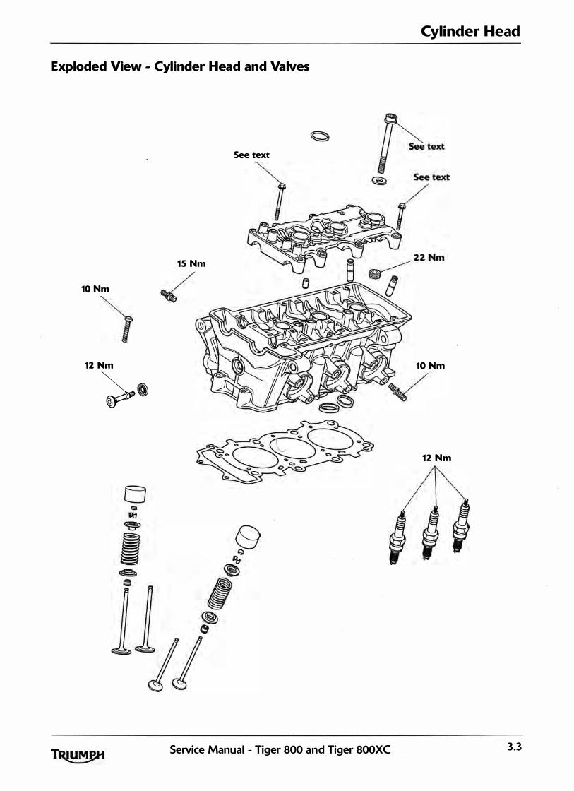
Cylinder Head
Exploded View - Cylinder Head and Valves
See text
1 5 Nm
10 Nm
) 12 Nm 10 N m
�0
1 2 N m
SeiVice Manual - Tiger 800 and Tiger 800XC 3.3
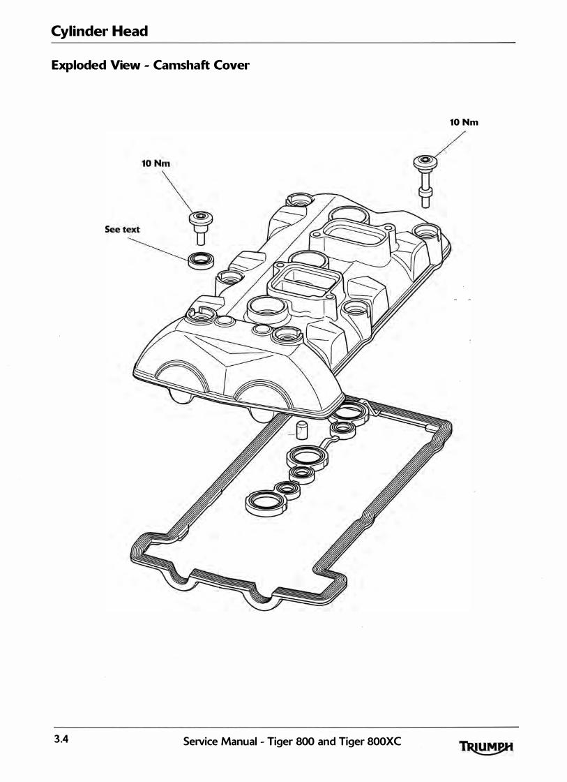
Cylinder Head
Exploded View - Camshaft Cover
10 Nm
3.4 SeiVice Manual - Tiger 800 and Tiger 800XC

Cylinder Head
Exploded View - Camshaft and Camshaft Drive
9 Nm
SeiVice Manual - Tiger 800 and Tiger 800XC 3.5
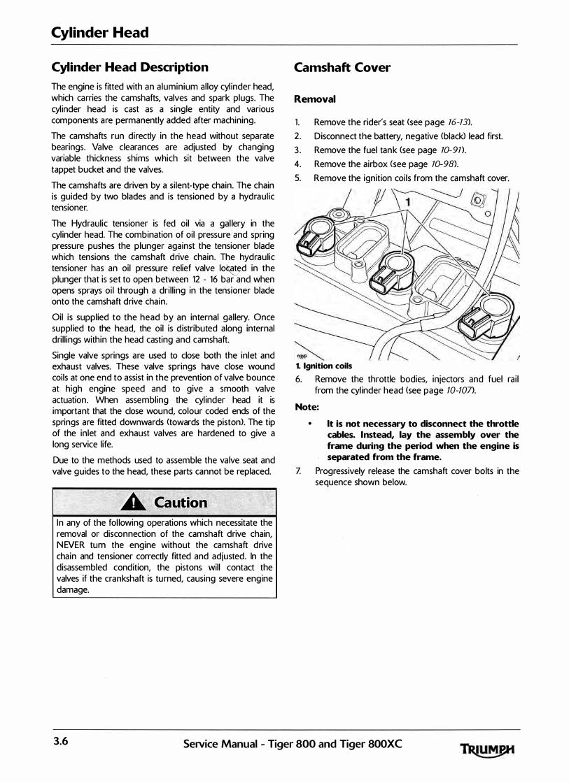
Cylinder Head
Cylinder Head Description
The engine is fitted with an a luminium al loy cyl inder head, which carries the camshafts, valves and spark plugs. The cyl inder head is cast as a single entity and various components are permanently added after machining.
The camshafts run directly in the head without separate bearings. Valve clearances are adjusted by changing variable thickness shims which sit between the va lve tappet bucket and the valves.
The camshafts are driven by a silent-type chain. The chain is guided by two blades and is tensioned by a hydraul ic tensioner.
The Hydraul ic tensioner is fed oil via a gal lery in the cyl inder head. The combination of oil pressure and spring pressure pushes the plunger against the tensioner blade which tensions the camshaft drive chain. The hydraulic tensioner has an oil pressi,.Jre relief valve lo�d in the plunger that is set to open between 12 - 16 bar and when opens sprays oi l through a dri l l ing in the tensioner blade onto the camshaft drive chain.
Oil is supplied to the head by an internal gal lery. Once suppl ied to the head, the oil is d istributed along internal dri l l ings within the head casting and camshaft.
Single valve springs are used to close both the inlet and exhaust valves. These valve springs have close wound coils at one end to assist in the prevention of valve bounce at high engine speed and to give a smooth va lve actuation. When assembling the cyl inder head it is important that the close wound, colour coded ends of the springs are fitted downwards <towards the piston>. The tip of the inlet and exhaust valves are hardened to give a long service l ife.
Due to the methods used to assemble the va lve seat and valve guides to the head, these parts cannot be replaced.
In any of the fol lowing operations which necessitate the removal or disconnection of the camshaft drive chain, N EVER tum the engine without the camshaft drive chain and tensioner correctly fitted and adjusted. In the disassembled condition, the pistons will contact the valves if the crankshaft is turned, causing severe engine damage.
Camshaft Cover
Removal
1 . Remove the rider's seat <see page 16-13).
2 . Disconnect the battery, negative (black> lead first.
3 . Remove the fuel tank <see page 10-91>.
4. Remove the airbox <see page 10-98).
5. Remove the ignition coi ls from the camshaft cover.
1. Ignition coils
6. Remove the throttle bodies, in jectors and fuel rai l from the cyl inder head (see page 10-107>.
Note:
• lt is not necessary to disconnect the throttle cables. Instead, lay the assembly over the frame during the period when the engine is separated from the frame.
Z Progressively release the camshaft cover bolts in the sequence shown below.
3.6 SeiVice Manual - Tiger 800 and Tiger 800XC
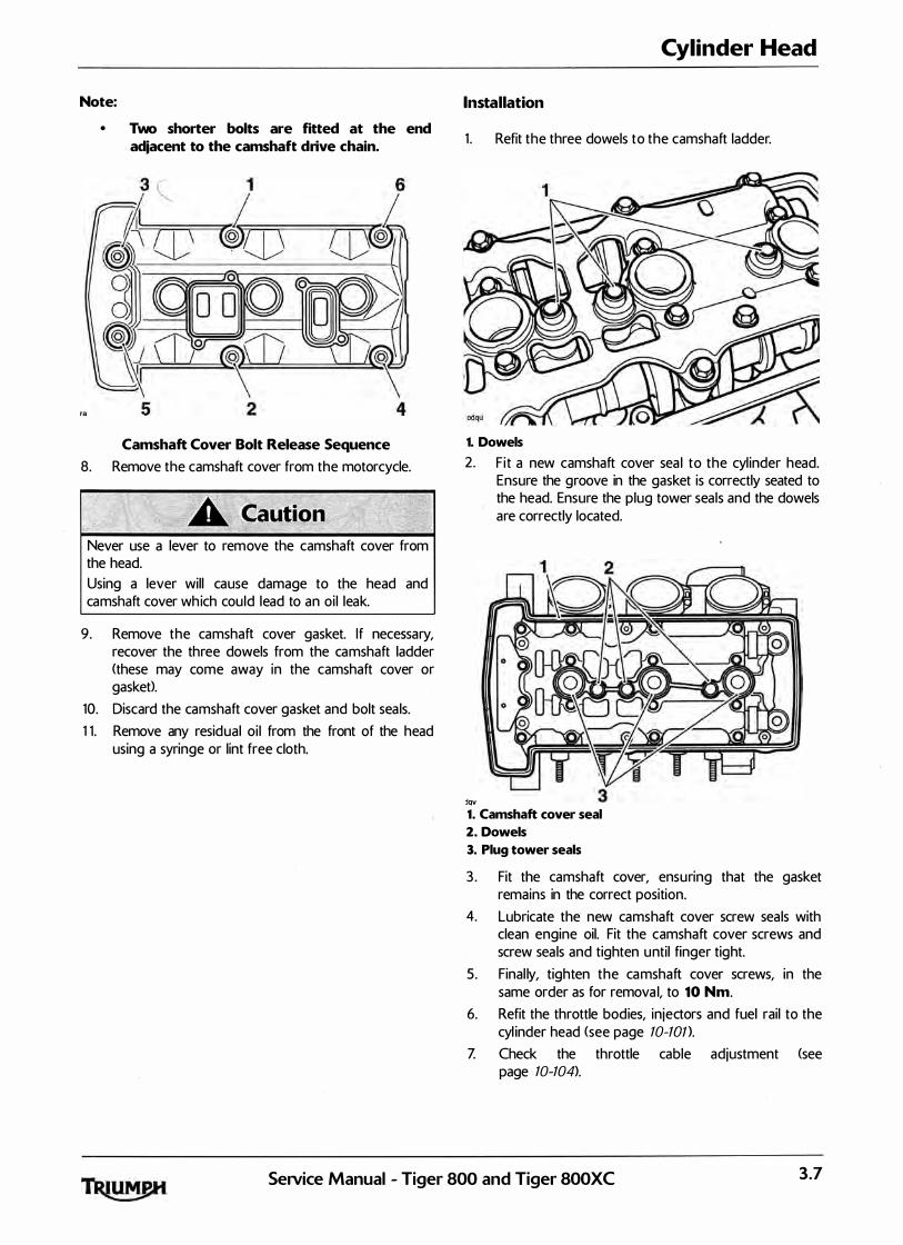
Note:
ra
• Two shorter bolts are fitted at the end adjacent to the camshaft drive chain.
Camshaft Cover Bolt Release Sequence
8. Remove the camshaft cover from the motorcycle.
Never use a lever to remove the camshaft cover from the head. Using a lever will cause damage to the head and camshaft cover wh ich could lead to an oi l leak.
9. Remove the camshaft cover gasket. If necessary, recover the three dowels from the camshaft ladder <these may come away in the camshaft cover or gasket>.
10. Discard the camshaft cover gasket and bolt seals.
1 1 . Remove any residual oi l from the front of the head using a syringe or lint free cloth.
Cylinder Head
Installation
1 . Refit the three dowels to the camshaft ladder.
1. Dowels
2. F it a new camshaft cover sea l to the cyl inder head.
JQV
Ensure the groove in the gasket is correctly seated to the head. Ensure the plug tower seals and the dowels are correctly located.
1. Camshaft cover seal
2. Dowels
3. Plug tower seals
3 . Fit the camshaft cover, ensuring that the gasket remains in the correct position.
4. Lubricate the new camshaft cover screw seals with clean engine oil. Fit the camshaft cover screws and screw seals and tighten until finger tight.
5 . Final ly, tighten the camshaft cover screws, in the same order as for remova l, to 10 Nm.
6. Refit the throttle bodies, injectors and fuel rail to the cyl inder head <see page 10-ton.
Z Check the throttle cable adjustment (see page 10-104>.
Service Manual - Tiger 800 and Tiger SOOXC 3.7
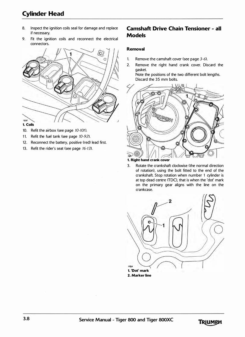
Cylinder Head
8. Inspect the ign ition coils seal for damage and replace if necessary.
9. Fit the ign ition coils and reconnect the electrical connectors.
1. Coils
10. Refit the airbox (see page 10-ton.
1 1 . Refit the fuel tank (see page 10-92).
12 . Reconnect the battery, positive (red) lead first.
13 . Refit the rider's seat <see page 16-13).
Camshaft Drive Chain Tensioner - all
Models
Removal
1 . Remove the camshaft cover <see page 3-6).
2. Remove the right hand crank cover. Discard the gasket. Note the positions of the two different bolt lengths. Discard the 3 5 mm bolts.
1. Right hand crank cover
3 . Rotate the crankshaft clockwise (the normal d irection of rotation), using the bolt fitted to the end of the crankshaft. Stop rotation when number 1 cylinder is at top dead centre <TDO, that is when the 'dot' mark on the primary gear al igns with the line on the crankcase.
1. 'Dot' mark
2. Marker line
3.8 SeNice Manual - Tiger 800 and Tiger 800XC

Note:
•
•
gaaal
In addition to the 'dot' mark alignment, at TDC, the alignment marks on the camshaft sprockets will point inwards at a point level yvith the joint face.
the Tiger 800 and Tiger 800XC camshaft sprockets are common to Daytona 675 and Street Triple models, but use different timing marks. · The timing marks for Tiger 800 and Tiger 800 XC are identified by the number 8 next to the timing mark.
Camshaft to Cylinder Head Alignment Marks
4. Place a suitable wedge between the camshaft drive chain tensioner blade and crankcase, to hold the camshaft drive chain taut during removal of the tensioner.
The hydraul ic tensioner is under spring tension. Always wear hand, eye, and face protection when withdrawing the tensioner mounting bolts and take great care to minimise the risk of in jury and loss of components.
Note:
•
5.
6 .
Note the orientation of the hydraulic tensioner.
Even ly release the hydraul ic tensioner mounting bolts until the plunger spring tension has been released.
Remove the hydraul ic tensioner and discard the 0-ring and gasket.
Cylinder Head
Installation
1. Check that number 1 cyl inder is sti l l at top dead centre <TDC>.
2. Ensure that the wedge fitted earlier is sti l l holding the camshaft drive cha in tensioner blade in contact with the camshaft drive chain. Check that the camshaft timing marks (identified with a number 8) point inwards and are level with the joint face of the head.
3. To set the hydraul ic tensioner onto the first tooth of the ratchet (i.e. minimum extension) carry out the fol lowing:
Note:
• If installing a new hydraulic tensioner, do not release the plunger before fitting.
• If installing the original hydraulic tensioner, the engine oil must be drained out of the tensioner to enable the plunger to be set onto the first tooth of the ratchet.
4. Hold the resister ring ends together and pul l out the plunger.
cfei_2
1. Resister ring ends
2. Plunger
J
SeNice Manual - Tiger 800 and Tiger 800XC 3.9
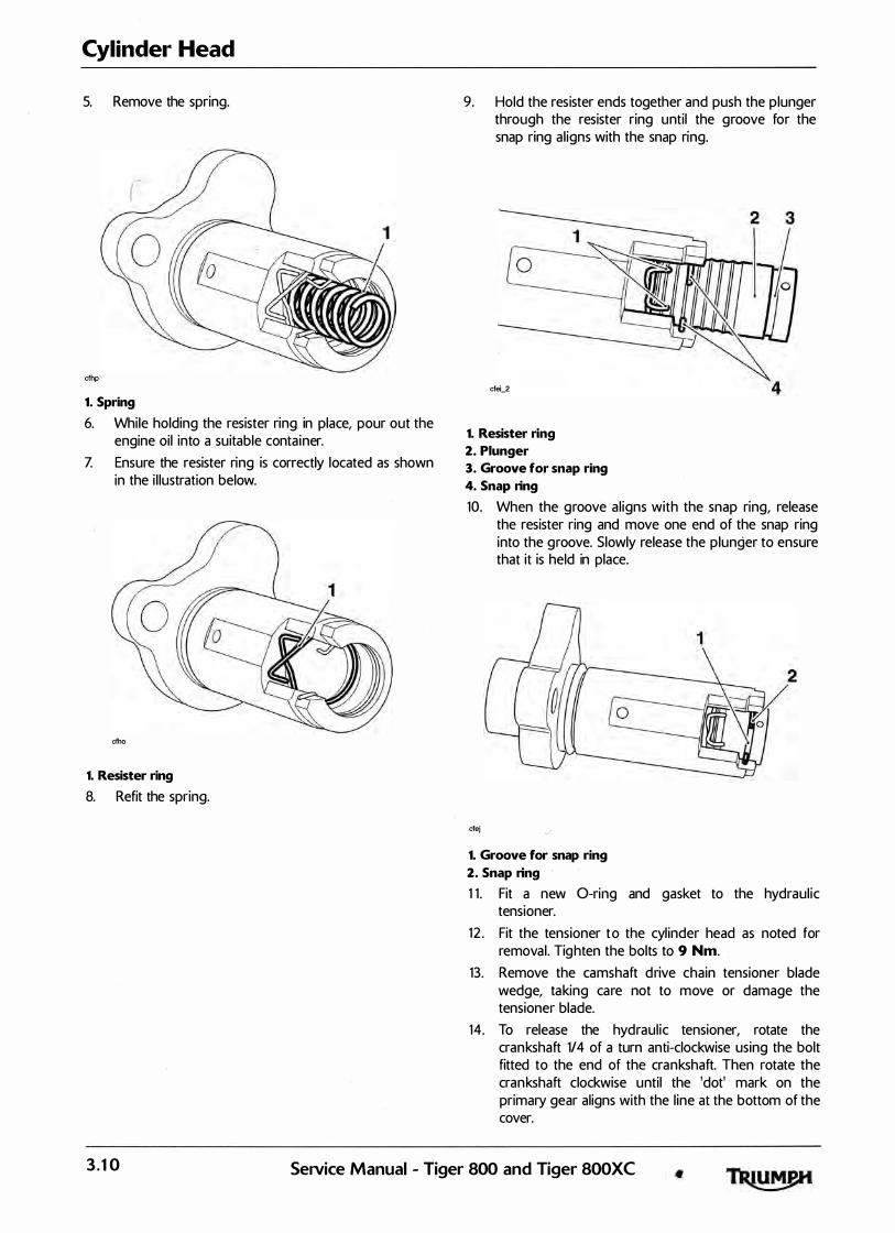
Cylinder Head
5. Remove the spring.
cfhp
1. Spring
6. While holding the resister ring in place, pour out the engine oil into a suitable container.
Z Ensure the resister ring is correctly located as shown in the i l lustration below.
cfho
1. Resister ring
8. Refit the spring.
9. Hold the resister ends together and push the plunger through the resister ring until the groove for the snap ring al igns with the snap ring.
cfei_2 4
1. Resister ring
2. Plunger
3. Groove for snap ring
4. Snap ring
10. When the groove al igns with the snap ring, release the resister ring and move one end of the snap ring into the groove. Slowly release the plunger to ensure that it is held in place.
2
cfej J
1. Groove for snap ring
2. Snap ring
1 1 . Fit a new 0-ring and gasket to the hydraul ic tension er.
12 . Fit the tensioner to the cyl inder head as noted for removal . Tighten the bolts to 9 Nm.
13. Remove the camshaft drive chain tensioner blade wedge, taking care not to move or damage the tensioner blade.
14. To release the hydraul ic tensioner, rotate the crankshaft 114 of a turn anti-clockwise using the bolt fitted to the end of the crankshaft. Then rotate the crankshaft clockwise until the 'dot' mark on the primary gear aligns with the l ine at the bottom of the cover.
3 . 1 0 SeNice Manual - Tiger 800 and Tiger 800XC
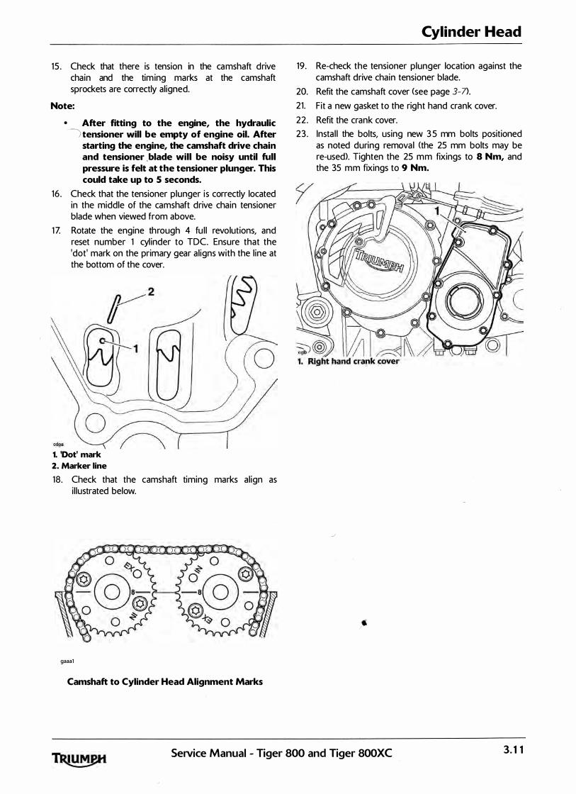
15 . Check that there is tension in the camshaft drive chain and the tim ing marks at the camshaft sprockets are correctly al igned.
Note:
• After fitting to the engine, the hydraulic ) tensioner will be empty of engine oil. After
starting the engine, the camshaft drive chain and tensioner . blade will be noisy until full pressure is felt at the tensioner plunger. This could take up to 5 seconds.
16 . Check that the tensioner plunger i s correctly located in the middle of the camshaft drive chain tensioner blade when viewed from above.
1 Z Rotate the engine through 4 fu l l revolutions, and reset number 1 cyl inder to TDC. Ensure that the 'dot' mark on the primary gear al igns with the l ine at the bottom of the cover.
1. 'Dot' mark
2. Marker line
18 . Check that the camshaft timing marks al ign as i l lustrated below.
gaaal
Camshaft to Cylinder Head Alignment Marks
Cylinder Head
19. Re-check the tensioner plunger location against the camshaft drive chain tensioner blade.
20. Refit the camshaft cover (see page 3-7>.
21. Fit a new gasket to the right hand crank cover.
22 . Refit the crank cover.
23 . Instal l the bolts, using new 3 5 mm bolts positioned as noted during removal (the 25 mm bolts may be re-used). Tighten the 25 mm fixings to 8 Nm, and the 35 mm fixings to 9 Nm.
J
SeNice Manual - Tiger 800 and Tiger 800XC 3. 1 1
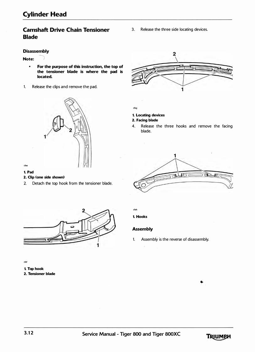
Cylinder Head
Camshaft Drive Chain Tensioner
Blade
Disassembly
Note: ) • For the purpose of this instruction, the top of
the tensioner blade is where the pad is located.
1 . Release the clips and remove the pad.
cfee n
1. Pad
2. Clip (one side shown>
2. Detach the top hook from the tensioner blade.
cfef
1. Top hook
2. Tensioner blade
3 . Release the three side locating devices.
cfeg
1. Locating devices
2. Facing blade
4. Release the three hooks and remove the facing blade.
1
cfeh
1. Hooks
Assembly
J
1 . Assembly is the reverse of d isassembly.
3. 1 2 SeNice Manual - Tiger 800 and Tiger 800XC
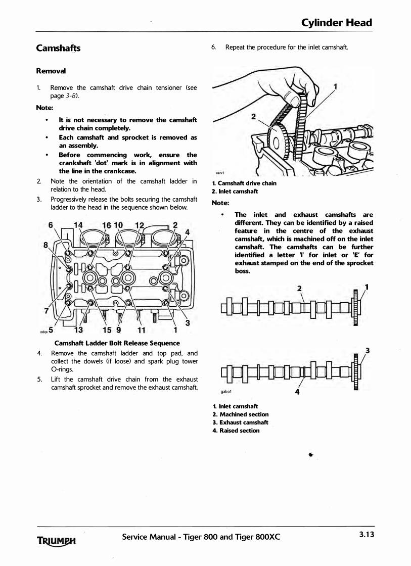
CamshaOs
Removal
1 . Remove the camshaft drive chain tensioner (see page 3-8).
Note:
• lt is not necessary to remove the camshaft drive chain completely.
• Each camshaft and sprocket is removed as an assembly.
• Before commencing work, ensure the crankshaft 'dot' mark is in alignment with the line in the crankcase.
2. Note the orientation of the camshaft ladder in relation to the head.
3 . Progressively release the bolts securing the camshaft ladder to the head in the sequence shown below.
Camshaft Ladder Bolt Release Sequence
4. Remove the camshaft ladder and top pad, and col lect the dowels (if loose> and spark plug tower 0-rings.
5. Lift the camshaft drive chain from the exhaust camshaft sprocket and remove the exhaust camshaft.
Cylinder Head
6. Repeat the procedure for the inlet camshaft.
1. Camshaft drive chain
2. Inlet camshaft
Note:
• The inlet and exhaust camshafts are different. They can be identified by a raised feature in the centre of the exhaust camshaft, which is machined off on the inlet camshaft. The camshafts can be further identified a letter 'I' for inlet or 'E' for exhaust stamped on the end of the sprocket boss.
3
gabol 4
1. Inlet camshaft
2. Machined section
3. Exhaust camshaft
4. Raised section
SeiVice Manual - Tiger 800 and Tiger 800XC 3. 1 3

Cylinder Head
Camshaft andJearing Cap Inspection
1 . Inspect the camshaft sprockets for damaged and worn teeth. Replace as necessary.
The same sprocket is used for both in let and exhaust camshafts. To attach the · sprocket to the different camshafts, different bolt holes are used.
Never fit a camshaft sprocket to a camshaft using incorrectly identified bolt holes. Severe engine damage will result from incorrect attachment.
1
2
1. Inlet camshaft bolt holes
2. Exhaust camshaft bolt holes
2. Measure the camshaft journals with a micrometer. I f any journal is outside the specified tolerance, replace the camshaft.
Standard Journal Diameters
Standard : 2 3 .940 - 23 .960 mm
1 . Standard journal
3. Examine the camshaft and camshaft ladder for excessive wear and damage.
4. Check the journal-to-head clearances, using 'Piastigage' <Triumph part number 3 880150-T0301 > as fol lows:
a) Ensuring that the camshaft sprocket al ignment marking is located as for removal, assemble one camshaft to the head and progressively tighten the camshaft ladder in the sequence shown overleaf <see page 3-15>.
b) Remove the camshaft ladder using the bolt release sequence given earlier. Wipe the exposed areas of both the camshaft journal and a single cap area of the ladder.
c) Apply a thi n smear of g rease to the jou rnal and a smal l quantity of si l icone release agent to the camshaft cap area of the ladder.
d) Size a length of the Plastigage to fit across the camshaft journal. Fit the Plastigage to the camshaft journal using the grease to hold the strip in place.
e) Refit the camshaft ladder then evenly and progressively tighten al l the camshaft ladder bolts in the correct sequence <see camshaft instal lation>.
f) Release the bolts and remove the camshaft ladder. Using the gauge provided with the Plastigage kit, measure the width of the now compressed Plastigage.
Note:
• The camshaft ladder is unique to each cylinder head and is, therefore, not available individually. If the camshaft ladder is worn or damaged, the complete cylinder head must be replaced.
Measuring the Compressed Plastigage.
5. Calculate the journal clearance �sing the Plastigage chart supplied with the Plastigage kit�
3. 1 4 SeiVice Manual - Tiger 800 and Tiger 800XC
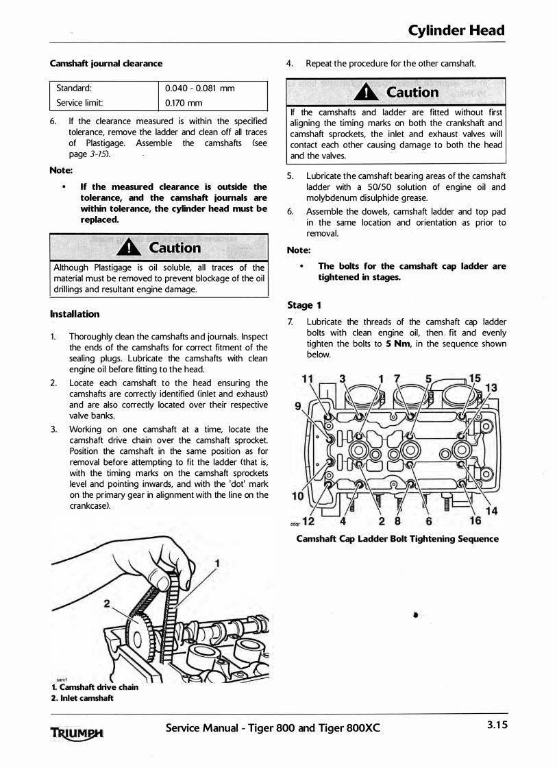
Camshaft journal clearance
Standard:
Service l imit:
0.040 - 0.081 mm
0.170 mm
6. If the clearance measured is within the specified tolerance, remove the ladder and clean off all traces of Plastigage. Assemble the camshafts (see page 3-15>.
Note:
• If the measured clearance is outside the tolerance, and the camshaft journals are within tolerance, the cylinder head must be replaced.
Although Plastigage is oi l soluble, al l traces material must be removed to prevent blockage of the oil dri l l ings and resultant engine damage.
Installation
1 . Thoroughly clean the camshafts and journals. Inspect the ends of the camshafts for correct fitment of the seal ing plugs. Lubricate the camshafts with clean engine oi l before fitting to the head.
2 . Locate each camshaft to the head ensuring the camshafts are correctly identified (in let and exhausO and are also correctly located over their respective va lve banks.
3. Working on one camshaft at a time, locate the camshaft drive chain over the camshaft sprocket. Position the camshaft in the same position as for removal before attempting to fit the ladder (that is, with the timing marks on the camshaft sprockets level and pointing inwards, and with the 'dot' mark on the primary gear in al ignment with the l ine on the crankcase>.
1. Camshaft drive chain
2. Inlet camshaft
Cylinder Head
4. Repeat the procedure for the other camshaft.
If the camshafts and ladder are fitted without first al igning the timing marks on both the crankshaft and camshaft sprockets, the inlet and exhaust valves wi l l contact each other causing damage to both the head and the valves.
5 . Lubricate the camshaft bearing areas of the camshaft ladder with a S0/50 solution of engine oil and molybdenum disulphide grease.
6. Assemble the dowels, camshaft ladder and top pad in the same location and orientation as prior to removal.
Note:
• The bolts for the camshaft cap ladder are tightened in stages.
Stage 1 <
Z Lubricate the threads of the camshaft cap ladder bolts with clean engine oil, then . fit and evenly tighten the bolts to 5 N m, in the sequence shown below.
Camshaft Cap Ladder Bolt Tightening Sequence
SeiVice Manual - Tiger 800 and Tiger 800XC 3. 1 5

Cylinder Head
Stage 2
8. I n the sequence shown above, tighten the bolts to 10 Nm.
9. Before fitting the camshaft drive chain tensioner, ensure that each camshaft rotates freely using service tool T3 880102. Do not rotate either camshaft by more than 5°.
1. Exhaust camshaft
2. Tool T3880102
I f any components have been renewed, the va lve clearances must be checked and adjusted. Running with incorrectly adjusted valve clearances may cause excess engine noise, rough running and engine damage.
10. Refit the camshaft drive chain tensioner <see page 3-9).
1 1 . Rotate the engine through 4 ful l revolutions, and reset number 1 cylinder to TDC. Ensure that the 'got' mark on the primary gear al igns with the l ine on the crankcase.
1. 'Dot' mark
2. Marker line
Note:
• In addition to the 'dot' mark alignment, at TDC, the alignment marks on the camshaft sprockets will point inwards at a point level with the joint face.
12 . Check that the camshaft timing marks al ign as i l lustrated below. Rectify any misal ignment before proceeding.
Note:
• The Tiger 800 and Tiger 800XC camshaft sprockets are common to Daytona 675 and Street Triple models, but use different timing marks. The timing marks for Tiger 800 and Tiger 800 XC are identified by the number 8 next to the timing mark.
gaaal
Camshaft to Cylinder Head Alignment Marks
1 3 . Check the valve clearances. Adjust a s necessary <see page 3-18>.
3. 1 6 SeiVice Manual - Tiger 800 and Tiger 800XC
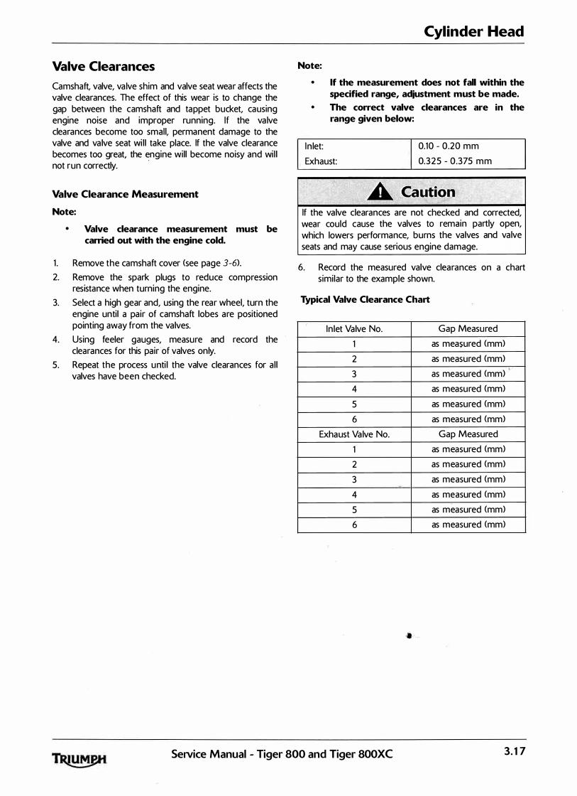
Valve Clearances
Camshaft, valve, va lve shim and valve seat wear affects the valve clearances. The effect of this wear is to change the gap between the camshaft and tappet bucket, causing engine noise and improper running. If the va lve clearances become too small, permanent damage to the valve and va lve seat wi l l take place. If the valve clearance becomes too great, the engine wil l become noisy and wi l l not run correctly.
·
Valve Clearance Measurement
Note:
• Valve clearance measurement must be carried out with the engine cold.
1 . Remove the camshaft cover (see page 3-6).
2. Remove the spark plugs to reduce compression resistance when turning the engine.
3. Select a high gear and, using the rear wheel, turn the engine unti l a pair of camshaft lobes are positioned pointing away from the valves.
4. Using feeler gauges, measure and record the clearances for this pair of valves only.
5. Repeat the process unti l the valve clearances for a l l valves have been checked.
Cylinder Head
Note:
• If the measurement does not fall within the specified range, adjustment must be made.
• The correct valve clearances are in the range given below:
I n let: 0.10 - 0.20 mm
0.325 - 0.375 mm Exhaust:
If the valve clearances are not checked and corrected, wear could cause the valves to remain partly open, which lowers performance, burns the valves and valve seats and may cause serious engine damage.
6. Record the measured valve clearances on a chart similar to the example shown.
Typical Valve Clearance Chart
( I n let Valve No. Gap Measured
1 as measured (mm)
2 as measured (mm)
3 as measured (mm)·
·
4 as measured (mm)
5 as measured (mm)
6 as measured <mm>
Exhaust Valve No. Gap Measured
1 as measured (mm)
2 as measured <mm>
3 as measured (mm) -
4 as measured (mm>
5 as measured (mm)
6 as measured (mm)
SeJVice Manual - Tiger 800 and Tiger 800XC 3. 1 7
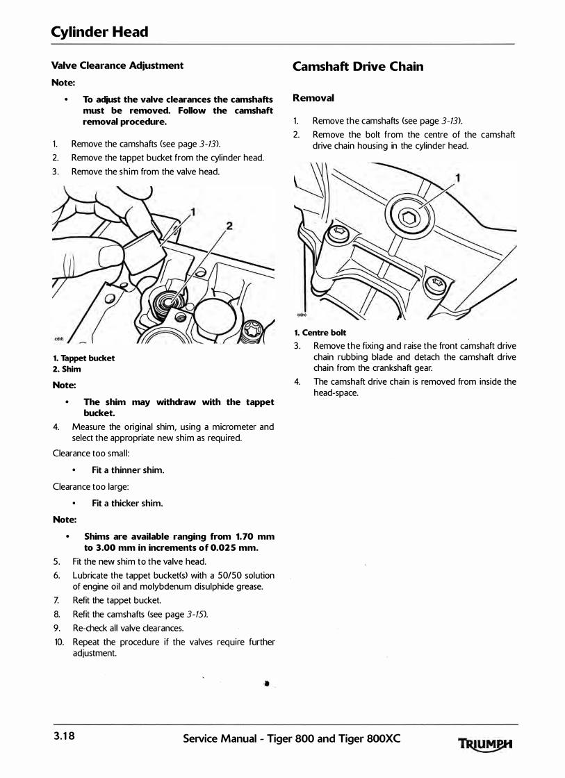
Cylinder Head
Valve Clearance Adjustment
Note:
• To adjust the valve clearances the camshafts must be removed. Follow the camshaft removal procedure.
1 . Remove the camshafts (see page 3-13>.
2. Remove the tappet bucket from the cyl inder head.
3 . Remove the sh im from the valve head.
1. Tappet bucket
2. Shim
Note:
• The shim may withdraw with the tappet bucket.
4. Measure the original shim, using a micrometer and select the appropriate new shim as required.
Clearance too smal l :
• Fit a thinner shim.
Clearance too large:
Fit a thicker shim.
Note:
• Shims are available ranging from 1. 70 mm to 3.00 mm in increments of 0.025 mm.
5. Fit the new shim to the valve head.
6. Lubricate the tappet bucket(s) with a 50/50 solution of engine oi l and molybdenum disulphide grease.
Z Refit the tappet bucket.
8. Refit the camshafts <see page 3-15>.
9. Re-check al l valve clearances.
10. Repeat the procedure if the valves require further adjustment.
Camshaft Drive Chain
Removal
1 . Remove the camshafts (see page 3-13>.
2. Remove the bolt from the centre of the camshaft drive chain housing in the cylinder head.
1. Centre bolt
3 . Remove the fixing and raise the front camshaft drive chain rubbing blade and detach the camshaft drive chain from the crankshaft gear.
4. The camshaft drive chain is removed from inside the head-space.
3. 1 8 SeiVice Manual - Tiger 800 and Tiger 800XC
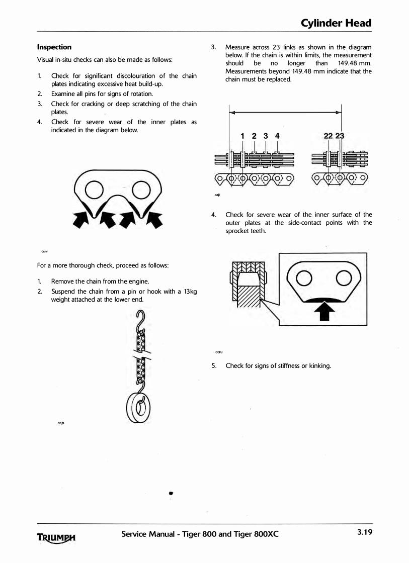
Inspection
Visual in-situ checks can also be made as fol lows:
1 . Check for significant discolouration of the chain plates ind icating excessive heat bui ld-up.
2. Examine al l pins for signs of rotation.
3. Check for cracking or deep scratching of the cha in plates.
4. Check for severe wear of the inner plates as indicated in the diagram below.
ccrv
For a more thorough check, proceed as fol lows:
1 . Remove the chain from the engine.
2. Suspend the chain from a pin or hook with a 1 3 kg weight attached at the lower end.
cajs
•
Cylinder Head
3 . Measure across 2 3 l inks as shown in the diagram below. If the chain is within l imits, the measurement should be no longer than 149.48 mm. Measurements beyond 149.48 mm indicate that the cha in must be replaced.
1 2 3 4
4. Check for severe wear of the inner surface of the outer plates at the side-contact points with the sprocket teeth.
ecru
5. Check for signs of stiffness or kinking.
SeiVice Manual - Tiger 800 and Tiger 800XC 3. 1 9

Cylinder Head
6. Check for severe wear of the plates in the area shown below.
caju
If any of these symptoms are evident, the camshaft drive chain must be replaced.
Installation
1 . Fit the camshaft drive chain and locate the lower end around the crankshaft gear.
2 . Incorporating a new seal, refit the bolt to the centre of the camshaft drive chain housing in the cylinder head, tightening to 12 Nm.
3. Refit the camshafts (see page 3-15>.
Cylinder Head
Removal
Note:
• Removal of the cylinder head is not possible with the engine in the frame.
1 . Remove the engine from the frame (see page 9-3>.
2 . Remove the camshafts <see page 3-13).
3. Remove the camshaft drive chain (see page 3-18).
4. Remove the camshaft drive chain tensioner blades.
5. Note the position of all tappet buckets and shims such that they can be refitted in the same positions. Remove al l the tappet buckets and shims.
1. Tappet bucket
2. Shim
Note: !
• • To prevent the tappet buckets and shims from becoming mixed, place the shim and tappet together in a marked container. The components must be refitted in their original positions.
6. Disconnect the coolant bypass hose from the rear of the cylinder head.
3.20 SeNice Manual - Tiger 8QQ, and Tiger 800XC
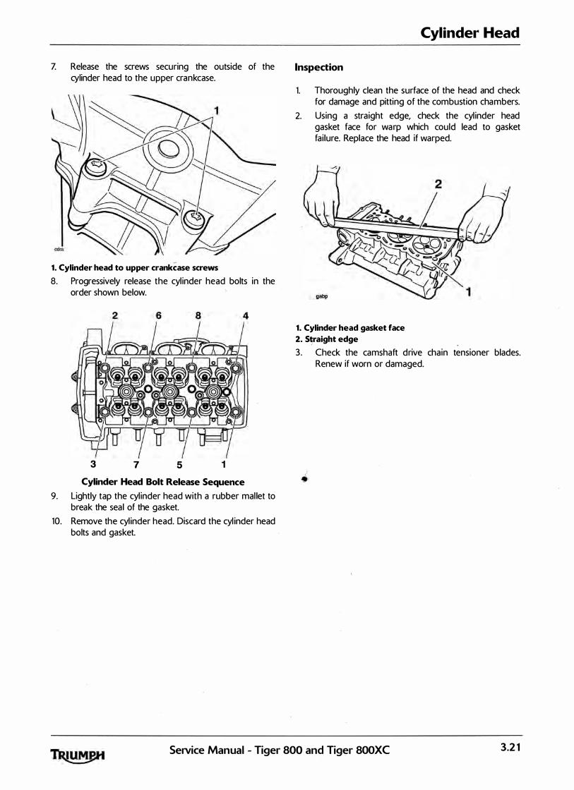
7. Release the screws securing the outside of the cylinder head to the upper crankcase.
1. Cylinder head to upper crankCase screws 8. Progressively release the cyl inder head bolts in the
order shown below.
3 7 5 1
Cylinder Head
Inspection
1.
2.
Thoroughly clean the surface of the head and check for damage and pitting of the combustion chambers.
Using a straight edge, check the cyl inder head gasket face for warp which could lead to gasket fai lure. Replace the head if warped.
1. Cylinder head gasket face 2. �aight edge 3 . Check the camshaft drive chain tensioner blades.
Renew if worn or damaged.
( Cylinder Head Bolt Release Sequence •
9. Lightly tap the cyl inder head with a rubber mal let to break the seal of the gasket.
10. Remove the cyl inder head. Discard the cyl inder head bolts and gasket.
SeiVice Manual - Tiger 800 and Tiger 800XC 3.2 1
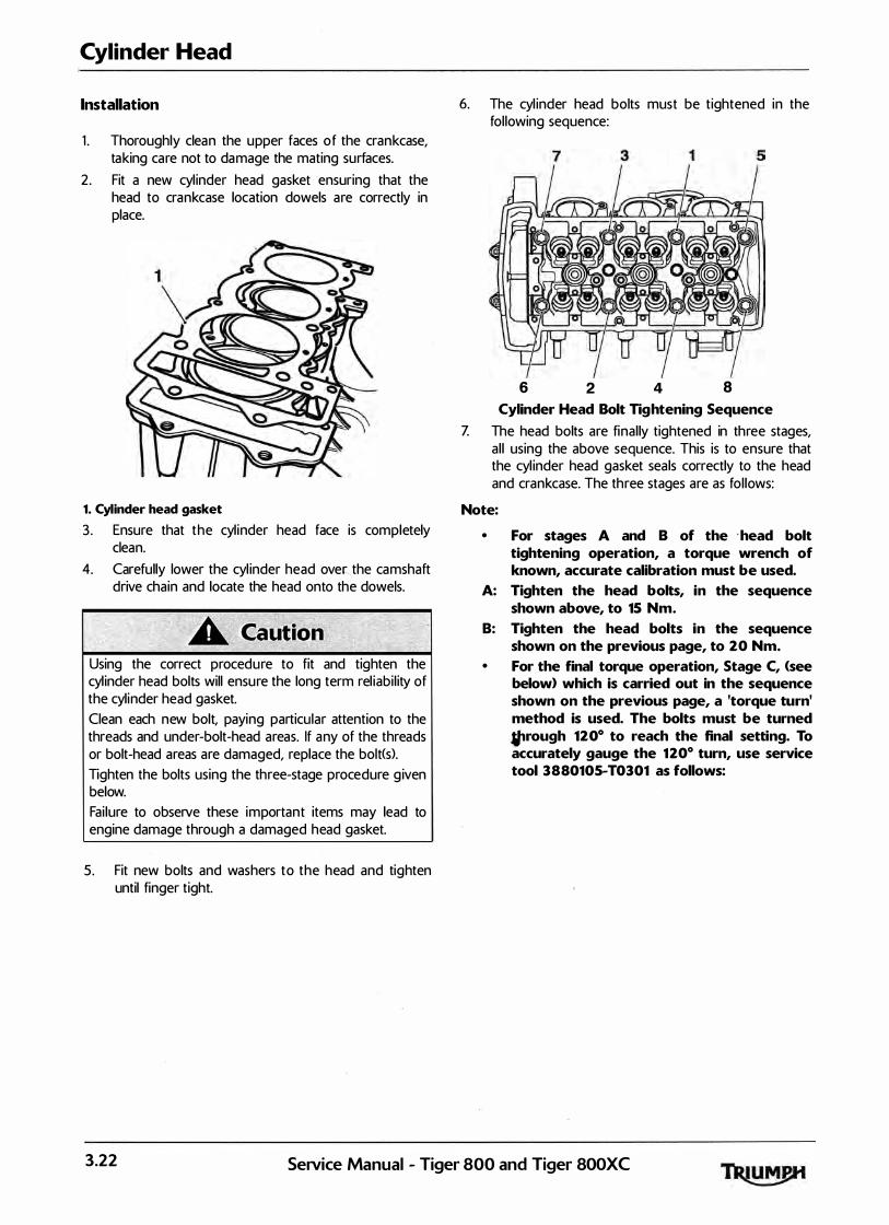
Cylinder Head
Installation
1 . Thoroughly clean the upper faces of the crankcase, taking care not to damage the mating surfaces.
2 . Fit a new cyl inder head gasket ensuring that the head to crankcase location dowels are correctly in place.
1. Cylinder head gasket 3. Ensure that the cyl inder head face is completely
clean.
4. Carefully lower the cyl inder head over�.the camshaft drive chain and locate the head onto th� dowels.
Using the correct procedure to fit and tighten the cyl inder head bolts will ensure the long term rel iabi l ity of the cylinder head gasket.
Clean each new bolt, paying particular attention to the threads and under-bolt-head areas. If any of the threads or bolt-head areas are damaged, replace the bolt(s).
Tighten the bolts using the three-stage procedure g iven below. Fai lure to observe these important items may lead to engine damage through a damaged head gasket.
5 . Fit new bolts and washers to the head and tighten until finger tight.
6. The cyl inder head bolts must be tightened in the fol lowing sequence:
6 2 4 8
Cylinder Head Bolt Tightening Sequence
Z The head bolts are final ly tightened in three stages, al l using the above sequence. This is to ensure that the cyl inder head gasket seals correctly to the head and crankcase. The three stages are as fol lows:
Note:
• For stages A and B of the · head bolt tightening operation, a torque wrench of known, accurate calibration must be used.
A: Tighten the head bolts, in the sequence shown above, to 15 Nm.
B: Tighten the head bolts in the sequence shown on the previous page, to 20 Nm.
• For the final torque operation, Stage C, (see below> which is carried out in the sequence shown on the previous page, a 'torque turn' method is used. The bolts must be turned #Jrough 120° to reach the final setting. To accurately gauge the 1 20° turn, use service tool 3880105-T0301 as follows:
3.22 SeNice Manual - Tiger 800 and Tiger 800XC
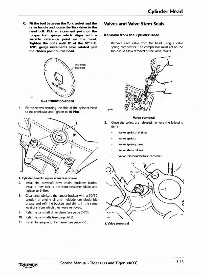
C: Fit the tool between the Torx socket and the drive handle and locate the Torx drive to the head bolt. Pick an increment point on the torque turn gauge which aligns with a suitable reference point on the head. Tighten the bolts until 12 of the 10° <I.E. 120°) gauge increments have rotated past the chosen point on the head.
Increment
V markings
Tool T3880105-T0301
6. Fit the screws securing the side of the cylinder head to the crankcase and tighten to 10 Nm.
1. Cylinder head to upper crankcase screws Z Instal l the camshaft drive chain tensioner blades.
Instal l a new bolt to the front tensioner blade and tighten to 9 Nm.
8. Clean and lubricate the tappet buckets with a 50150 solution of engine oil and molybdenum disulphide grease and refit the buckets and shims in the same locations from which they were removed.
9. Refit the camshaft drive chain (see page 3-20).
10. Refit the camshafts (see page 3-15>.
1 1 . Instal l the engine to the frame (see page 9-S>.
Cylinder Head
Valves and Valve Stem Seals
Removal from the Cylinder Head
1. Remove each valve from the head using a valve spring compressor. The compressor must act on the top cup to al low removal of the va lve col lets.
gadh
Valve removal
2. Once the collets are released, remove the following items:
• valve spring retainer
• valve spring
• valve spring base
• valve stem oil seal
• valve (de-burr before removal)
1. Valve stem seal
SeNice Manual - Tiger 800 and Tiger 800XC 3.23
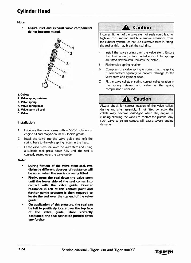
Cylinder Head
Note:
• Ensure inlet and exhaust valve components do not become mixed.
1. Collets 2. Valve spring retainer 3. Valve spring 4. Valve spring base S. Valve stem oil seal 6. Valve
Installation
1 . Lubricate the valve stems with a 50150 solution of engine oil and molybdenum disulphide grease.
2 . Instal l the valve into the valve guide and refit the spring base to the valve spring recess in the head.
3 . Fit the valve stem seal over the valve stem and, using a suitable tool, press down fu l ly until the seal is correctly seated over the valve guide.
Note:
• During fitment of the valve stem seal, two distinctly different degrees of resistance will be noted when the seal is correctly fitted.
• Firsdy, press the seal down the valve stem until the lower side of the seal comes into contact with the valve guide. Greater resistance is felt at
' this contact point and
further gentle pressure is then required to locate the seal over the top end of the valve guide.
• On application of this pressure, the seal can be felt to positively locate over the top face of the valve guide. Once correctly positioned, the seal cannot be pushed down any further.
Incorrect fitment of the va lve stem oi l sea ls could lead to h igh oil consumption and blue smoke emissions from the exhaust system. Do not use excessive force in fitting the seal as this may break the seal ring.
4. Instal l the valve spring over the valve stem. Ensure the close wound, colour coded ends of the springs are fitted downwards <towards the piston).
5. F it the valve spring retainer.
6. Compress the valve spring ensuring that the spring is compressed squarely to prevent damage to the valve stem and cyl inder head.
Z Fit the valve col lets ensuring correct col let location in the spring retainer and valve as the spring compressor is released.
Always check for correct location of the valve col lets during and after assembly. If not fitted correctly, the col lets may become dislodged when th� engine is running a l lowing the va lves to contact the pistons. Any such valve to piston contact wi l l cause severe engine damage.
3.24 Service Manual - Tiger 800 and Tiger 800XC

Valve to Valve Guide Clearance
I f the valve gu ides are worn beyond the service l imit g iven below, the cyl inder head must be replaced.
Valve Stem to Guide Clearance
In let: 0.010 - 0.040 mm
Service l imit 0.078 mm
Exhaust: 0.030 - 0.060 mm
Service l imit 0.098 mm
Cylinder Head
Valve Guides
I f a valve guide is found to be worn beyond the service l imit, the complete cyl inder head must be renewed.
Valve Face Inspection
Remove any carbon bui ld-up from the valve head area. Examine the valve seat face, checking in particu lar for signs of cracking or pitting.
SeiVice Manual - Tiger 800 and Tiger SOOXC 3.25

Cylinder Head
This page intentionally left blank
3.26 SeNice Manual - Tiger 800 and Tiger SOOXC
4 Ciutch Table of Contents
Exploded View - Clutch Cover. . . . . . . . . . . . . . . . . . . . . . . . . . . . . . . . . . . . . . . . . . . . . . . . . . . . . . . . . . . . . . . 4.2
Exploded View - Clutch Assembly . . . . . . . . . . . . . . . . . . . . . . . . . . . . . . . . . . . . . . . . . . . . . . . . . . . . . . . . . . . 4.3
Exploded View - Clutch Controls . . . . . . . . . . . . . . . . . . . . . . . . . . . . . . . . . . . . . . . . . . . . . . . . . . . . . . . . . . . . 4.4
Clutch Cable . . . . . . . . . . . . . . . . . . . . . . . . . . . . . . . . . . . . . . . . . . . . . . . . . . . . . . . . . . . . . . . . . . . . . . . . . . . . . 4.5
Removal . . . . . . . . . . . . . . . . . . . . . . . . . . . . . . . . . . . . . . . . . . . . . . . . . . . . . . . . . . . . . . . . . . . . . . . . . . . 4.5 Inspection . . . . . . . . . . . . . . . . . . . . . . . . . . . . . . . . . . . . . . . . . . . . . . . . . . . . . . . . . . . . . . . . . . . . . . . . . . 4.5 Assembly. . . . . . . . . . . . . . . . . . . . . . . . . . . . . . . . . . . . . . . . . . . . . . . . . . . . . . . . . . . . . . . . . . . . . . . . . . . 4.5
Clutch . . . . . . . . . . . . . . . . . . . . . . . . . . . . . . . . . . . . . . . . . . . . . . . . . . . . . . . . . . . . . . . . . . . . . . . . . . : . . . . . . . . 4.6
Disassembly . . . . . . . . . . . . . . . . . . . . . . : . . . . . . . . . . . . . . . . . . . . . . . . . . . . . . . . . . . . . . . . . . . . . . . . . 4.6
Clutch Plate Inspection . . . . . . . . . . . . . . . . . . . . . . . . . . . . . . . . . . . . . . . . . . . . . . . . . . . . . . . . . . . . . . . . . . . . . 4.7
Friction Plate Thickness . . . . . . . . . . . . . . . . . . . . . . . . . . . . . . . . . . . . . . . . . . . . . . . . . . . . . . . . . . . . . . . 4.7 Steel Plate Bend/warp . . . . . . . . . . . . . . . . . . . . . . . . . . . . . . . . . . . . . . . . . . . . . . . . . . . . . . . . . . . . . . . . 4.8 Clutch Pack Height . . . . . . . . . . . . . . . . . . . . . . . . . . . . . . . . . . . . . . . . . . . . . . . . . . . . . . . . . . . . . . . . . . 4.8 Assembly. . . . . . . . . . . . . . . . . . . . . . . . . . . . . . . . . . . . . . . . . . . . . . . . . . . . . . . . . . . . . . . . . . . . . . . . . . . 4.1 0
Setvice Manual - Tiger 800 and Tiger 800XC 4. 1

Clutch
Exploded View - Clutch Cover
12 Nm
9 Nm
9 Nm
4.2 SeiVice Manual - Tiger 800 and Tiger SOOXC

Clutch
Exploded View - Clutch Assembly
98 Nm
SeiVice Manual - Tiger 800 and Tiger 800XC 4.3
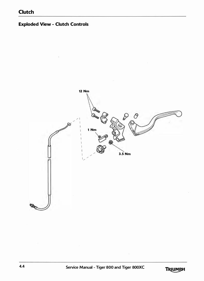
Clutch
Exploded View - Clutch Controls
4.4
12 Nm
/ 1 MJ / I 'Q
1 Nm
I / /
/
�� V �
/ � 3.5 Nm
SeiVice Manual - Tiger 800 and Tiger 800XC

Clutch Cable
Removal
1 . Remove the rider's seat <see page 16- 13).
2. Disconnect the battery, negative <black> lead first.
3 . Slacken the cable locknut and release the adjuster at the clutch cover end to give maximum play in the cable.
4. Release the clutch cable from the actuating arm by pushing the inner cable nipple through the arm and sl iding the cable out of the slot. Detach the cable from the bracket.
1. Clutch cable 2. Adjuster 3. Inner cable nipple 4. Actuating arm 5. Align the cable adjuster and lever bracket slots.
6. Pul l in the clutch lever and turn the inner cable, anticlockwise through the slots in the adjuster, until the cable can be detached from the lever by pushing downwards.
gaau
1. Cable adjuster/lever bracket slots 2. Cable release point
Clutch
Z Remove the cable from the motorcycle noting the cable routing.
Inspection
1. Check the inner cable for free movement through the outer cable.
2. Examine the inner cable for frayed strands.
3. Examine the two inner cable nipples for signs of looseness and damage. Replace the cable if necessary.
Assembly
1 . Position the cable to the motorcycle us ing the same routing as noted during removal .
2 . Attach the inner cable to the clutch lever and actuating arm using a reversal of the removal process.
3 . Refit the outer cable to the adjuster bracket at the clutch end.
Note:
• Ensure that the two adjuster nuts are positioned one either side of the bracket.
4. Set the lever adjuster to a point where an equal adjustment is possible in both directions.
5 . Set the adjuster at the clutch end to g ive a prel iminary setting of 2-3 mm of free play as measured at the lever. Tighten the locknuts.
6. Operate the clutch lever severa l times and recheck the amount of free-play present.
Z Set the final adjustment of the cable to give 2-3 mm of free-play at the lever by turn ing the adjuster nut and locknut at the lever end.
1. Clutch lever 2. Correct setting, 2-3 mm 8. Reconnect the battery, positive (red) lead first.
9. _ Refit the rider's seat <see page 16- 13).
SeiVice Manual - Tiger 800 and Tiger 800XC 4.5
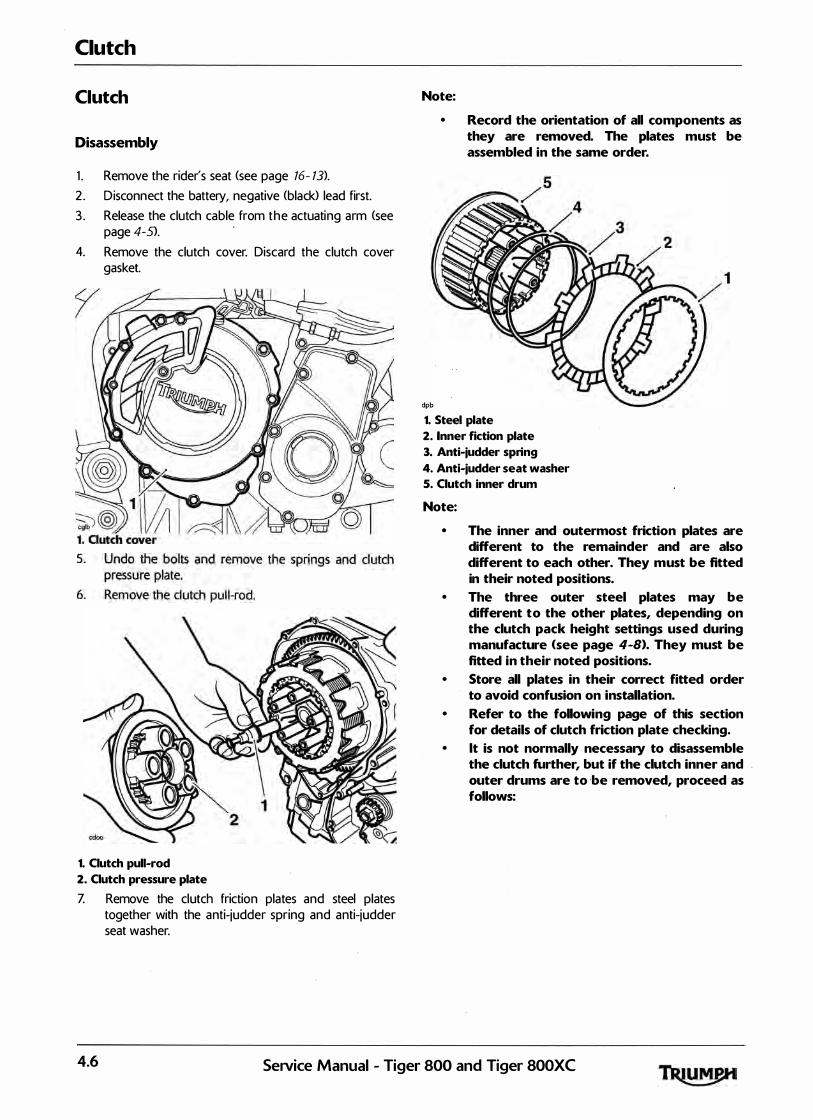
Clutch
Clutch
Disassembly
1 . Remove the rider's seat (see page 16- 13).
2 . Disconnect the battery, negative (black> lead first.
3 . Release the clutch cable from the actuating arm (see page 4-S>.
4. Remove the clutch cover. Discard the clutch cover gasket.
1. Clutch pull-rod 2. Outch pressure plate Z Remove the clutch friction plates and steel plates
together with the anti-judder spring and anti-judder seat washer.
Note:
dpb
• Record the orientation of all components as they are removed. The plates must be assembled in the same order.
1. Steel plate 2. Inner fiction plate 3. Anti-judder spring 4. Anti-judder seat washer 5. Clutch inner drum
Note:
• The inner and outermost friction plates are different to the remainder and are also different to each other. They must be fitted in their noted positions.
• The three outer steel plates may be different to the other plates, depending on the clutch pack height settings used during manufacture <see page 4-B>. They must be fitted in their noted positions.
• Store all plates in their correct fitted order to avoid confusion on installation.
• Refer to the following page of this section for details of clutch friction plate checking.
• lt is not normally necessary to disassemble the clutch further, but if the clutch inner and outer drums are to ·be removed, proceed as follows:
4.6 SeNice Manual - Tiger 800 and Tiger SOOXC
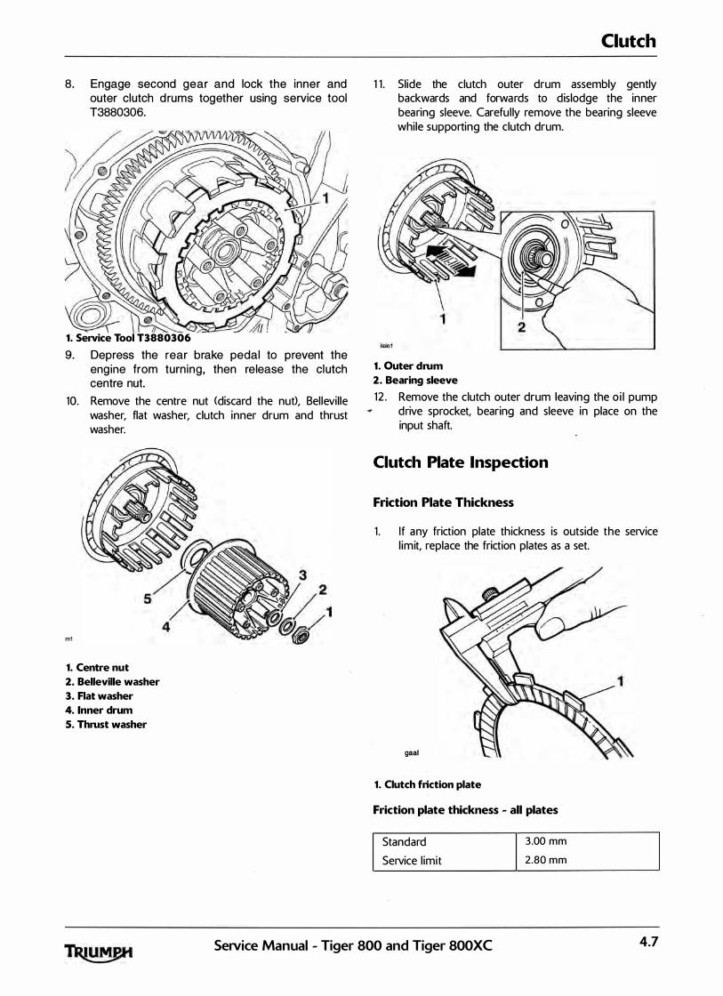
8. Engage second gear and lock the inner and outer clutch d rums together using service tool T3880306.
1. Service Tool T3880306
9. Depress the rear brake pedal to prevent the eng ine from turn ing , then release the clutch centre nut.
10. Remove the centre nut <discard the nut), Bel levil le washer, flat washer, clutch inner drum and thrust washer.
m1
1. Centre nut 2. Belleville washer 3. Flat washer 4. Inner drum 5. Thrust washer
Clutch
1 1 . Sl ide the clutch outer drum assembly gently backwards and forwards to dislodge the inner bearing sleeve. Carefu l ly remove the bearing sleeve while supporting the clutch drum.
1. Outer drum 2. Bearing sleeve 12 . Remove the clutch outer drum leaving the o i l pump
drive sprocket, bearing and sleeve in place on the input shaft.
Clutch Plate Inspection
Friction Plate Thickness
1 . I f any friction plate thickness is outside the service l imit, replace the friction plates as a set.
gaal
1. Clutch friction plate
Friction plate thickness - all plates
Standard
Service l imit
3.00 m m
2.80 m m
SeiVice Manual - Tiger 800 and Tiger 800XC 4.7
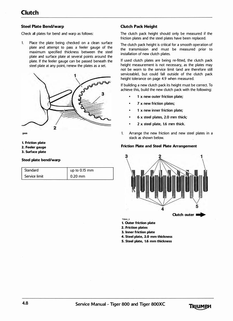
Clutch
Steel Plate Bend/warp
Check all plates for bend and warp as fol lows:
1 . P lace the plate being checked on a clean surface plate and attempt to pass a feeler gauge of the maximum specified thickness between the steel plate and surface plate at several points around the plate. If the feeler gauge can be passed beneath the steel plate at any point, renew the plates as a set.
2 gaas
1. Friction plate
2. Feeler gauge
3. Surface plate
Steel plate bend/warp
Standard
Service l imit
1�
up to 0.15 mm
0.20 mm
Clutch Pack Height
The clutch pack height should only be measured if the friction plates and the steel plates have been replaced.
The clutch pack height is critical for a smooth operation of the transmission and must be measured prior to instal lation of new clutch plates.
If used clutch plates are being re-fitted, the clutch pack height measurement is not necessary, as the plates may not be worn to the service l imit (and are therefore sti l l serviceable), but could fal l outside of the clutch pack height tolerance on page 4.9 when measured.
If bui lding a new clutch pack its height must be correct. To achieve this, bui ld the new clutch pack with the fol lowing:
• 1 x new outer friction plate;
• 7 x new friction plates;
• 1 x new inner friction plate;
• 6 x steel plates, 2.0 mm thick;
• 2 x steel plate, 1.6 mm thick.
1 . Arrange the new friction and new steel plates in a stack as shown below.
Friction Plate and Steel Plate Arrangement
3
Clutch outer � T0944_3
1. Outer friction plate
2. Friction plates
3. Inner friction plate
4. Steel plate, 2.0 mm thickness
5. Steel plate, 1.6 mm thickness
4.8 SeiVice Manual - Tiger 800 and Tiger 800XC

2 . Place the assembled clutch pack on a flat surface and measure its height as shown below.
T0943_1 1. autch pack height
3. The correct clutch pack height for this clutch assembly is shown in the table below.
Standard height in mm Tolerance in mm
42.20 +0.34/-0.66
4. If the clutch pack height measurement is incorrect, proceed as described below/opposite:
Clutch Pack Height Too High
Note:
• No more than three 1.6 mm thick steel plates are to be used in the clutch pack.
1 . Replace the 2.0 mm steel plate next to the 1 .6 mm steel plate (indicated below) with a new 1 .6 mm steel plate.
Clutch outer ...
1. 2.0 mm steel plate to be replaced
2. 1.6 mm steel plates
2. Re-check the clutch pack height as described earlier.
Clutch
Clutch Pack Height Too Low
Note:
•
1 .
At least one 1.6 mm steel plate must be in the clutch pack.
If the clutch pack height is too low, replace the 1 .6 mm steel plate indicated below with a new 2.0 mm steel plate.
����������������� I 1
Clutch outer ... T0944_2
1. 1.6 mm steel plate to be replaced
2. Re-check the clutch pack height as described earl ier.
SeiVice Manual - Tiger 800 and Tiger SOOXC 4.9
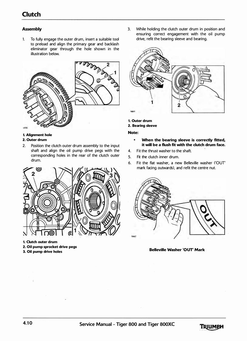
Clutch
Assembly
1 . To ful ly engage the outer drum, insert a su itable tool to preload and a l ign the primary gear and backlash el iminator gear through the hole shown in the i l lustration below.
1. Alignment hole
2. Outer drum
2. Position the clutch outer drum assembly to the input shaft and al ign the oi l pump drive pegs with the corresponding holes in the rear of the clutch outer drum.
1. Clutch outer drum
2. Oil pump sprocket drive pegs
3. Oil pump drive holes
3. While holding the clutch outer drum in position and ensuring correct engagement with the o i l pump drive, refit the bearing sleeve and bearing.
1. Outer drum
2. Bearing sleeve
Note:
• When the bearing sleeve is correctly fitted, it will be a flush fit with the clutch drum face.
4. Fit the thrust washer to the shaft. 5. Fit the clutch inner drum. 6. Fit the flat washer, a new Bellevil le washer <'OUT'
mark facing outwards), and refit the centre nut.
Belleville Washer 'OUT' Mark
4.10 SeNice Manual - Tiger 800 and Tiger 800XC

Z Lock the inner and outer drums together using service tool T3880306. Depress the rear brake pedal to prevent the engine from turning, and tighten the clutch centre nut to 98 Nm. Remove the service tool.
8. Using a suitable pin punch, stake the nut to the shaft. ����:::---.�
1. Service tool T3880306
9. Disengage second gear and check for free rotation of the clutch inner drum.
10. Coat al l clutch friction plates in clean engine oil before fitting the friction plates, steel plates, anti-judder spring and anti-judder seat washer to the clutch basket in the same order and orientation as noted during removal.
Note:
• The inner and outermost friction plates are different to the remainder and are also different to each other. They must be fitted in their noted positions.
Clutch
• The three outer steel plates may be different to the other plates, depending on the clutch pack height settings used during manufacture <see page 4-8). They must be fitted in their noted positions.
1. Steel plate
2. Inner fiction plate
3. Anti-judder spring
4. Anti-judder seat washer
5. Clutch inner drum
SeiVice Manual - Tiger 800 and Tiger 800XC 4.11

Clutch
1 1 . Refit the clutch pul l-rod. 12. Refit the clutch pressure plate together with the
springs and bolts. Tighten the bolts to 10 Nm.
Note:
• The pull-rod should be free to move in and out and also it should be free to turn.
13 . Clean and refit the clutch cover incorporating a new gasket. Tighten the clutch cover bolts to 9 Nm.
14. Refit the clutch cable to the actuating arm at the clutch end <see page 4-5>.
15 . Set the clutch adjustment (see page 4-5>. 16 . Reconnect the battery positive (red) lead first. 1Z Refit the rider's seat <see page 16- 13).
4.12 Setvice Manual - Tiger 800 and Tiger 800XC
5 Crankshaft, Connecting Rods and Pistons
Table of Contents
Exploded View - Crankshaft, Connecting Rod, Piston and Liner. . . . . . . . . . . . . . . . . . . . . . . . . . . . . . . . . . . 5 . 2
Exploded View - Crankcase . . . . . . . . . . . . . . . . . . . . . . . . . . . . . . . . . . . . . . . . . . . . . . . . . . . . . . . . . . . . . . . . . 5 . 3
Crankcases . . . . . . . . . . . . . . . . . . . . . . . . . . . . . . . . . . . . . . . . . . . . . . . . . . . . . . . . . . . . . . . . . . . . . . . . . . . . . . . 5 . 4 Disassembly . . . . . . . . . . . . . . . . . . . . . . . . . . . . . . . . . . . . . . . . . . . . . . . . . . . . . . . . . . . . . . . . . . . . . . . . 5 . 4 Assembly. . . . . . . . . . . . . . . . . . . . . . . . . . . . . . . . . . . . . . . . . . . . . . . . . . . . . . . . . . . . . . . . . . . . . . . . . . . 5 . 4
Crankshaft . . . . . . . . . . . . . . . . . . . . . . . . . . . . . . . . . . . . . . . . . . . . . . . . . . . . . . . . . . . . . . . . . . . . . . . . . . . . . . . 5 . 6 Removal . . . . . . . . . . . . . . . . . . . . . . . . . . . . . . . . . . . . . . . . . . . . . . . . . . . . . . . . . . . . . . . . . . . . . . . . . . . 5 . 6 Instal lation. . . . . . . . . . . . . . . . . . . . . . . . . . . . . . . . . . . . . . . . . . . . . . . . . . . . . . . . . . . . . . . . . .. . . . . . . . . 5 . 6
Connecting Rods . . . . . . . . . . . . . . . . . . . . . . . . . . . . . . . . . . . . . . . . . . . . . . . . . . . . . . . . . . . . . . . . . . . . . . . . . . 5 . 8 Removal . . . . . . . . . . . . . . . . . . . . . . . . . . . . . . . . . . . . . . . . . . . . . . . . . . . . . . . . . . . . . . . . . . . . . . . . . . . 5 . 8 Installation . . . . . . . . . . . . . . . . . . . . . . . . . . . . . . . . . . . . . . . . . . . . . . . . . . . . . . . . . . . . . . . . . . . . . . . . . . 5 . 8
Connecting Rod Big End Bearing Selection/Crankshaft Journal Wear Check . . . . . . . . . . . . . . . . . . . . . . . 5 . 10 Checking the Measured Clearance . . . . . . . . . . . . . . . . . . . . . . . . . . . . . . . . . . . . . . . . . . . . . . . . . . . . . 5 . 10 Connecting Rod Bearing Selection . . . . . . . . . . . . . . . . . . . . . . . . . . . . . . . . . . . . . . . . . . . . . . . . . . . . . 5 . 1 1 Crankshaft main bearing/journal wear . . . . . . . . . . . . . . . . . . . . . . . . . . . . . . . . . . . . . . . . . . . . . . . . . . 5 . 12
Pistons. . . . . . . . . . . . . . . . . . . . . . . . . . . . . . . . . . . . . . . . . . . . . . . . . . . . . . . . . . . . . . . . . . . . . . . . . . . . . . . . . . 5 . 13 Disassembly . . . . . . . . . . . . . . . . . . . . . . . . . . . . . . . . . . . . . . . . . . . . . . . . . . . . . . . . . . . . . . . . . . . . . . . . 5 . 13 Piston Wear Check. . . . . . . . . . . . . . . . . . . . . . . . . . . . . . . . . . . . . . . . . . . . . . . . . . . . . . . . . . . . . . . . . . . 5 . 14 Cylinder Wear. . . . . . . . . . . . . . . . . . . . . . . . . . . . . . . . . . . . . . . . . . . . . . . . . . . . . . . . . . . . . . . . . . . . . . . 5 . 16
Cylinder Liners. . . . . . . . . . . . . . . . . . . . . . . . . . . . . . . . . . . . . . . . . . . . . . . . . . . . . . . . . . . . . . . . . . . . . . . . . . . 5 . 17 Removal . . . . . . . . . . . . . . . . . . . . . . . . . . . . . . . . . . . . . . . . . . . . . . . . . . . . . . . . . . . . . . . . . . . . . . . . . . . 5 . 17 Instal lation . . . . . . . . .. . . . . . . . . . . . . . . -.. . . . . . . . . . . . . . . . . . . . . . . . . . . . . . . . . . . . . . . . . . . . . . . . . . . 5 . 18
Crankcase Breather. . . . . . . . . . . . . . . . . . . . . . . . . . . . . . . . . . . . . . . . . . . . . . . . . . . . . . . . . . . . . . . . . . . . . . . 5 . 18
SeNice Manual - Tiger 800 and Tiger 800XC 5.1
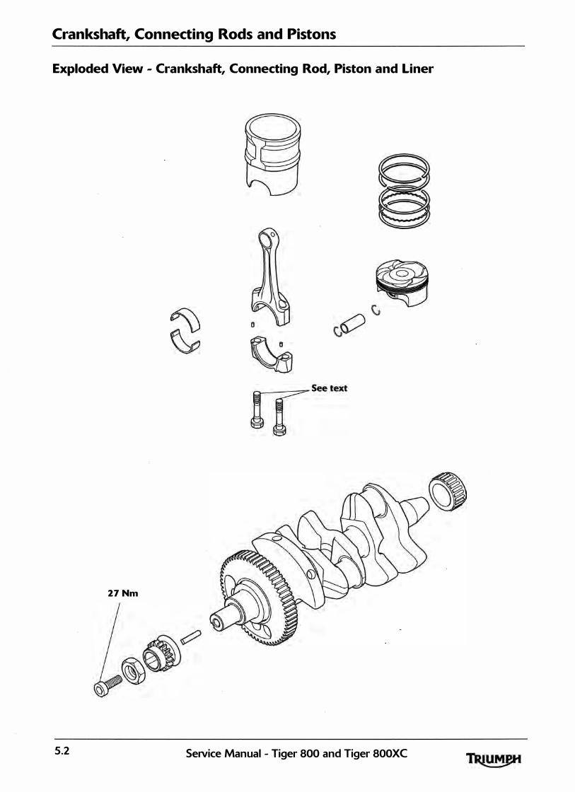
Crankshaft, Connecting Rods and Pistons
Exploded View - Crankshaft, Connecting Rod, Piston and Liner
27 Nm
5.2 Service Manual - Tiger 800 and Tiger 800XC

Crankshaft, Connecting Rods and Pistons
Exploded View - Crankcase
22 Nm
i I 8
22 Nm
SeNice Manual - Tiger 800 and Tiger 800XC 5.3

Crankshaft, Connecting Rods and Pistons
Crankcases
The upper and lower crankcases are machined as a matched set and must never be assembled to nonmatching ha lves. Doing so may cause seizure of the engine.
1. Remove the engine from the frame (see page 9-3).
2. Remove the sump <see page 8-15>.
3. Remove the engine covers (see pages 3-8, 4-6 and 7-21}.
4. Remove the clutch <see page 4-6>. 5 . Remove the oil pump (see page 8-8>.
Disassembly
Fai lure to fol low the correct screw release sequence may result in permanent crankcase damage.
1 . Invert the engine to give access to the lower crankcase bolts.
2 . Release the lower crankcase bolts in the sequence shown in the diagram below. Note the position of the hardened washers under bolts 19 to 26.
5 7 6 13 10 Crankcase Bolt Release Sequence
3 . Separate the lower and upper crankcases ensuring that the 3 locating dowels remain in the upper crankcase.
Do not use. levers to separate the upper and lower sections of the crankcase or damage to the crankcases could result.
Note:
• At this point the transmission shafts, balancer, crankshaft, bearings etc. can be removed.
Note:
• The position of each individual bearing shell prior to removal.
• Collect the piston cooling jets from below the upper main bearings, noting that the piston cooling jet for number 3 cylinder is longer and has a larger diameter drilling than the piston cooling jets for number 1 and 2 cylinders. lt can also be identified by its smaller outside diameter and a groove around its circumference.
Assembly
1 . Use h igh flash-point solvent to clean the crankcase mating faces. Wipe the surfaces clean with a l int-free cloth.
2. Fit the gearbox shafts (if removed), ensuring the locating ring and dowels on the output shaft bearings are positioned correctly in the crankcase.
3 . Ensure that the transmission i s in neutra l. 4. Ensure that the 3 locating dowels are in position in
the upper crankcase.
1
cdmx
1. Locating dowels
5.4 Service Manual - Tiger 800 and Tiger 800XC
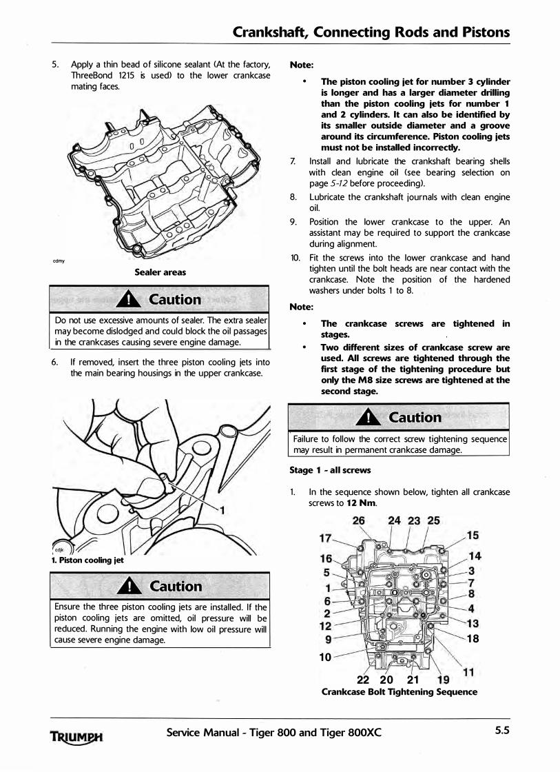
Crankshaft, Connecting Rods and Pistons
5 . Apply a thin bead of si l icone sealant <At the factory, ThreeBond 1215 is used> to the lower crankcase mating faces.
cdmy
Sealer areas
Do not use excessive amounts of sealer. The extra sealer may become dislodged and could block the oi l passages in the crankcases causing severe engine damage.
6. If removed, insert the three piston cooling jets into the main bearing housings in the upper crankcase.
1. Piston cooling jet
Ensure the three piston cooling jets are instal led. I f the piston cooling jets are omitted, oi l pressure will be reduced. Running the engine with low oil pressure will cause severe engine damage.
Note:
• The piston cooling iet for number 3 cylinder is longer and has a larger diameter drilling than the piston cooling iets for number 1 and 2 cylinders. lt can also be identified by its smaller outside diameter and a groove around its circumference. Piston cooling iets must not be installed incorrectly.
Z Insta l l and lubricate the crankshaft bearing shells with clean engine oil <see bearing selection on page 5-12 before proceeding>.
8. Lubricate the crankshaft journals with clean engine oi l .
9� Position the lower crankcase to the upper. An assistant may be required to support the crankcase during al ignment.
10. Fit the screws into the lower crankcase and hand tighten unti l the bolt heads are near contact with the crankcase. Note the position of the hardened washers under bolts 1 to 8.
Note:
• The crankcase screws are tightened in stages.
• Two different sizes of crankcase screw are used. All screws are tightened through the first stage of the tightening procedure but only the MS size screws are tightened at the second stage.
Fai lure to fol low the correct screw tightening sequence may result in permanent crankcase damage.
Stage 1 - all screws
1 . I n the sequence shown below, tighten a l l crankcase screws to 12 Nm.
10
22 20 21
18
Crankcase Bolt Tightening Sequence
Service Manual - Tiger 800 and Tiger 800XC 5.5
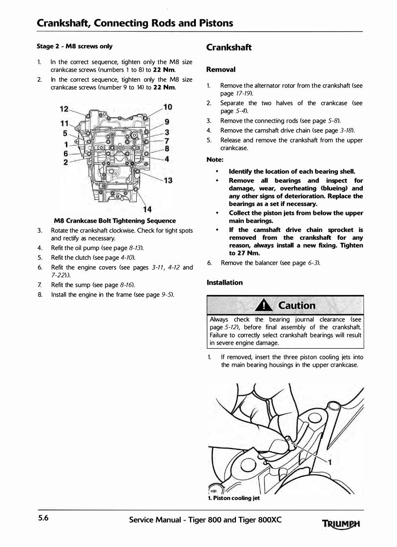
Crankshaft, Connecting Rods and Pistons
Stage 2 - MS screws only
1 . I n the correct sequence, tighten only the M8 size crankcase screws (numbers 1 to 8) to 22 Nm.
2. In the correct sequence, tighten only the M8 size crankcase screws (number 9 to 14) to 22 Nm.
MS Crankcase Bolt Tightening Sequence
3 . Rotate the crankshaft clockwise. Check for tight spots and rectify as necessary.
4. Refit the oi l pump <see page 8-13). 5. Refit the clutch (see page 4-10>. 6. Refit the engine covers (see pages 3-11, 4-12 and
7-22>.>.
Z Refit the sump <see page 8-16>. 8. Insta l l the engine in the frame <see page 9-5).
Crankshaft
Removal
1 . Remove the alternator rotor from the crankshaft (see page 17- 19>.
2. Separate the two halves of the crankcase <see page 5-4).
3 . Remove the connecting rods (see page 5-8>. 4. Remove the camshaft drive chain <see page 3-18>.
5. Release and remove the crankshaft from the upper crankcase.
Note:
• Identify the location of each bearing shell. • Remove all bearings and inspect for
damage, wear, overheating (blueing) and any other signs of deterioration. Replace the bearings as a set if necessary.
• Collect the piston jets from below the upper main bearings.
• If the camshaft drive chain sprocket is removed from the crankshaft for any reason, always install a new fixing. Tighten to 27 Nm.
6. Remove the balancer <see page 6-3>.
Installation
Always check the bearing journal clearance (see page 5-12), before final assembly of the crankshaft. Fai lure to correctly select crankshaft bearings wi l l result in severe engine damage.
1. I f removed, insert the three piston cool ing jets into the main bearing housings in the upper crankcase.
1. Piston cooling jet
5.6 SeiVice Manual - Tiger 800 and Tiger 800XC

Crankshaft, Connecting Rods and Pistons
Ensure the three piston cooling jets are insta l led. If the piston cooling jets are omitted, oi l pressure will be reduced. Running the engine with low oil pressure will cause severe engine damage.
Note:
• The piston cooling jet for number 3 cylinder is longer and has a larger diameter drilling than the piston cooling jets for number 1 and 2 cylinders. lt can also be identified by its smaller outside diameter and a groove around its circumference. Piston cooling jets cannot be installed incorrectly.
2. Select and fit new main and big end shel l bearings <see page 5-12).
1
cdmx
1. Big end shells
3. Lubricate al l bearings with a 50150 solution of engine oil and molybdenum disulphide grease.
4. Ensure that the crankshaft is clean, and that the oi lways within the crank are clean and free from blockages and debris.
5. Refit the balancer (see page 6-4).
6. Insta l l the crankshaft ensuring that the crank pins a l ign with the big ends and that the crankshaft and balancer gear markings al ign as shown in the next i l lustration.
1. Balancer backlash and drive gear markings
2. Crankshaft markings
Z Refit the connecting rods <see page 5-8>.
8. If removed, refit the transmission shafts. 9. Assemble the crankcases (see page 5-4). 10. Assemble the a lternator rotor <see page 17-20>.
1 1 . Refit the camshaft drive chain <see page 3-20>.
SeiVice Manual - Tiger 800 and Tiger 800XC 5.7

Crankshaft, Connecting Rods and Pistons
Connecting Rods
Removal
Connecting rods may be removed from the engine after first removing it from the frame. The cyl inder head must be removed and the crankcase halves separated.
1. Mark each big end cap and connecting rod to identify both items as a matched pair and to identify the correct orientation of the bearing cap to the connecting rod.
2. Release the connecting rod bolts and remove the big end cap. Ensure that the bearing shel l remains in place in the cap.
1. Big end cap
2. Connecting rod bolt
Note:
• lt may be necessary to gently tap the big end cap with a rubber mallet to release the cap.
3. Push the connecting rod up through the crankcase and collect the piston and connecting rod from the top.
4. Label the assembly to identify the cylinder from which it was removed.
Never re-use connecting rod bolts. I f the connecting rod cap is disturbed, a lways renew the bolts. Using the original bolts may lead to severe engine damage.
5. Remove the l iner using tool T3 880101 (see page 5-17>.
6. Detach the piston from the connecting rod <see page 5-13>.
Installation
Note:
• Connecting rod bolts are treated with an anti-rust solution which must not be removed.
• Clean the connecting rod with high flashpoint solvent.
• Remove all bearings and inspect for damage, wear and any signs of deterioration and replace as necessary.
I , "
Connecting rod bolts MUST only be used once. If the bolts are removed or undone for any reason, new bolts MUST always be used. Re-using bolts can cause connecting rods and their caps to detach from the crankshaft causing severe engine damage, loss of motorcycle control and an accident.
Note:
• Ensure the piston is fitted correctly to the connecting rod.
·
• If a previously run engine is being rebuilt, always ensure that the piston and con-rod are assembled in the same orientation, and to the same cylinder, as prior to strip-down.
1. Fit the piston onto the connecting rod (see page 5-15>.
2. Apply si l icone sealer to the l iner-to-crankcase mating face <At the factory, Three Bond 1 21 5 is used>.
cbef_1_1
1. Liner
2. Sealer area
3 . Fit the piston and connecting rod assembly into the l iner from the bottom.
4. Fit the l iner into the crankcase ensuring that the arrow on the piston faces forward.
5.8 SeJVice Manual - Tiger 800 and Tiger 800XC

Crankshaft, Connecting Rods and Pistons
5. The l iners must be positioned such they do not touch each other - it must be possible to pass a 0.1 mm feeler gauge between the centre l iner and its adjacent l iner on either side. If the l iners touch at any point, rotate the l iners until there is a minimum 0.1 mm clearance.
1. Liners
Note:
• Ensure that the piston/liner/connecting rod assembly aligns correctly with the crankshaft journal during assembly into the crankcase.
6. Select the big end bearing shells <see page 5-10>. Z Fit the bearing shells to the connecting rod and big
end cap and lubricate with a 50/50 solution of engine oil and molybdenum disulphide grease.
8. Al ign the connecting rod to the crankshaft and fit the big end cap.
1. Big end cap
2. Connecting rod bolt
The torque characteristics of the connecting rod bolts are sensitive to the correct lubrication being appl ied. I f the threads and under head areas are not lubricated with molydenum disuplhide grease, the bolts may be stretched and may become loose when in service resulting in an expensive engine fai lure.
9. Lubricate the threads and under-head area of the new bolts with molybdenum disulphide grease. Tighten the bolts evenly and progressively in five stages as fol lows:
The torque characteristics of the connecting rod bolts are sensitive to the rate at which they are tightened. If a l l the torque is appl ied in one action, the bolt may be stretched and may become loose when in service resulting in an expensive engine fai lure.
a) tighten to 22 Nm;
b) release 120°;
cl tighten to 10 Nm;
d) tighten to 14 Nm;
e) tighten through 120° of bolt rotation as measured using the Triumph torque turn gauge
cbxt
3 8 8 0 105 -T03 0 1.
Increment
V markings
SeiVice Tool 3880105-T0301
SeiVice Manual - Tiger 800 and Tiger 800XC 5.9
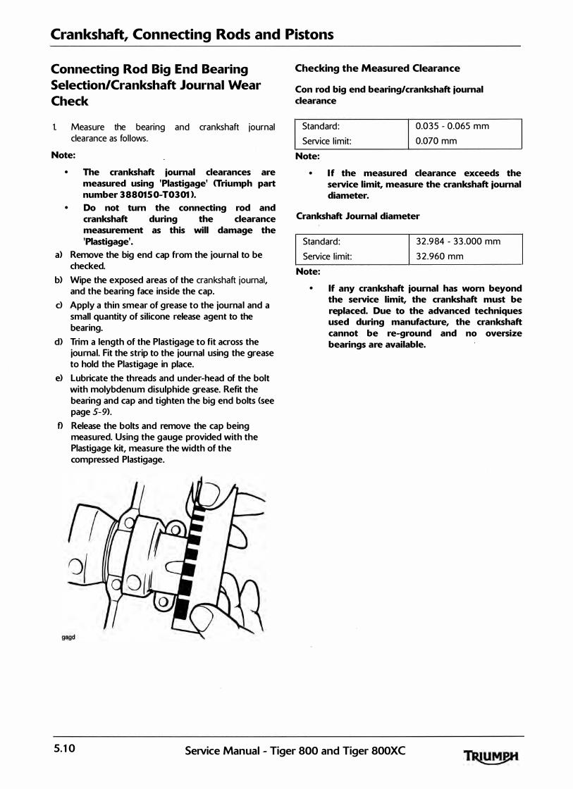
Crankshaft, Connecting Rods and Pistons
Connecting Rod Big End Bearing
Selection/Crankshaft Journal Wear
Check
1. Measure the bearing and crankshaft journal clearance as fol lows.
Note:
• The crankshaft journal clearances are measured using 'Piastigage' <Triumph part number 3880150-T0301 ).
• Do not turn the connecting rod and crankshaft during the clearance measurement as this will damage the 'Piastigage'.
a> Remove the big end cap from the journal to be checked.
b) Wipe the exposed areas of the crankshaft journal, and the bearing face inside the cap.
d Apply a thin smear of grease to the journal and a small quantity of sil icone release agent to the bearing.
d) Trim a length of the Plastigage to fit across the journal. Fit the strip to the journal using the grease to hold the Plastigage in place.
e> Lubricate the threads and under-head of the bolt with molybdenum disulphide grease. Refit the bearing and cap and tighten the big end bolts (see page 5-9).
f) Release the bolts and remove the cap being measured. Using the gauge provided with the Plastigage kit, measure the width of the compressed Plastigage.
Checking the Measured Clearance
Con rod big end bearing/crankshaft journal clearance
Standard : Service l imit:
Note:
0.035 - 0.065 mm 0.070 mm
• If the measured clearance exceeds the service limit, measure the crankshaft journal diameter.
Crankshaft Journal diameter
Standard : Service l imit:
Note:
32 .984 - 33 .000 mm 3 2.960 mm
• If any crankshaft journal has worn beyond the service limit, the crankshaft must be replaced. Due to the advanced techniques used during manufacture, the crankshaft cannot be re-ground and no oversize bearings are available.
5.10 SeNice Manual - Tiger 800 and Tiger SOOXC

Crankshaft, Connecting Rods and Pistons
Connecting Rod Bearing Selection
Minor differences in crankshaft dimensions are compensated for by using selective bearings. For further information on bearing part number to colour cross-references, see the latest parts information.
1. Select the correct big end bearing shel l as fol lows:
Measure eac h crankshaft journal diameter. • Select the co rrect bearings by matching the
information found with the chart below.
Note:
• All dimensions in millimetres.
Big end bearing selection chart
Shell Colour White Con-rod Big End 3 6.009 Bore Dia. 3 6.000 Crankshaft Journal 33 .000 Dia. 3 2 .992 Running Clearance
For instance:
Con-rod Big End Diameter
Crankshaft Journal Diameter
Required Bearing
Note:
0.065 0.03 5
3 6.002
3 2.987
Red
Red 3 6.009 3 6.000 3 2.991 3 2.984
• Repeat the measurements for all connecting rods and their respective crankshaft journals.
• lt is normal for the bearings selected to differ from one connecting rod to another.
2. Instal l the new bearings in the connecting rod.
1
cdmx
1. Big end bearings
Always confirm, using the Plastigage method, that the running clearance is correct before final assembly. Severe engine damage could result from incorrect clearance.
Service Manual - Tiger 800 and Tiger 800XC 5.11
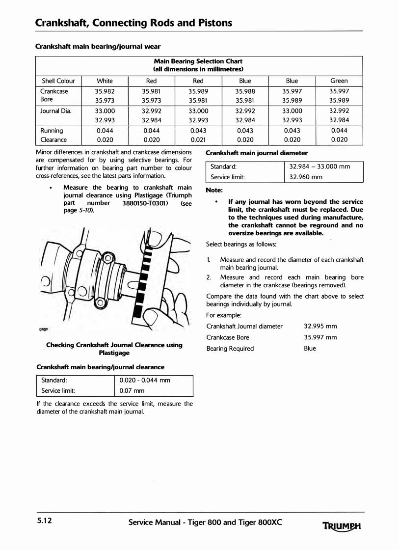
Crankshaft, Connecting Rods and Pistons
Crankshaft main bearing/journal wear
Main Bearing Selection Chart <all dimensions in millimetres>
Shell Colour White Red Red Blue Blue Green
Crankcase 3 5.982 35 .981 3 5.989 3 5.988 35 .997 3 5.997 Bore 35 .973 3 5.973 3 5.981 35 .981 35 .989 35 .989
Journal Dia. 3 3 .000 3 2.992 3 3.000 3 2.992 3 3 .000 3 2.992 3 2.993 3 2.984 3 2.993 3 2.984 3 2.993 3 2.984
Running 0.044 0.044 0.043 0.043 0.043 0.044 Clearance 0.020 0.020 0.021
Minor differences in crankshaft and crankcase dimensions are compensated for by using selective bearings. For further information on bearing part number to colour cross-references, see the latest parts information.
• Measure the bearing to crankshaft main journal clearance using Plastigage <Triumph part number 3 8 8 0 15 0-T 0 3 0 1) <see page 5-10>.
Checking Crankshaft Journal Clearance using Plastigage
Crankshaft main bearing/journal clearance
Standard : Service l imit:
0.020 - 0.044 mm 0.07 mm
If the clearance exceeds the service l imit, measure the diameter of the crankshaft main journal .
0.020 0.020 0.020
Crankshaft main journal diameter
Standard: Service l imit:
Note:
32 .984- 33 .000 mm 3 2 .960 mm
• If any journal has worn beyond the service limit, the crankshaft must be replaced. Due to the techniques used during manufacture, the crankshaft cannot be reground and no oversize bearings are available.
Select bearings as fol lows:
1. Measure and record the diameter of each crankshaft main bearing journal .
2 . Measure and record each main bearing bore diameter in the crankcase <bearings removed>.
Compare the data found with the chart above to select bearings individual ly by journal.
For example:
Crankshaft Journal diameter
Crankcase Bore
Bearing Required
3 2.995 mm
3 5.997 m m
Blue
5.12 SeNice Manual - Tiger 800 and Tiger 800XC

Crankshaft, Connecting Rods and Pistons
Note:
• lt is normal for the bearings selected to differ from one journal to another.
• lt is also normal for there to �e two options of bearing shell colour. In such cases, pick the shell size which gives the greater running clearance.
Always confirm, using the Plastigage method, that the running clearance is correct before final assembly. Severe engine damage could result from incorrect clearance.
Crankshaft End Float
I Standard 0.1 5 - 0.30 mm
Note:
• Crankshaft end float is controlled by the tolerances in crankshaft and crankcase machining. No thrust washers are used. If the crankshaft end float is outside the specified limit, the crankshaft and/or the crankcases must be replaced.
Pistons
Disassembly
Note:
• lt is not necessary to remove the connecting rods from the crankshaft.
1 . Remove the cyl inder head (see page 3- 2 0>. 2 . Remove the l iner, · using the frame from tool
T3 880315, and tool T3 880101 <see page 5-17>. 3 . Remove and discard the gudgeon p in circl ip from
one side of the piston.
cape
Removing the Gudgeon Pin Circlip
4. Remove the gudgeon pin by pushing the pin through the piston and rod toward the side from which the circl ip was removed.
Never force the gudgeon pin through the piston. This may cause damage to the piston which may also damage the l iner when assembled.
Note:
• If the gudgeon pin is found to be tight in the piston, check the piston for a witness mark caused by the circlip. Carefully remove the mark to allow the pin to be removed.
5. Piston rings must be removed from the piston using hand pressure only. Do not over-extend the piston rings during removal .
Note:
• If the piston rings are to be re-used, note the orientation of the oil control rings prior to removal.
SeiVice Manual - Tiger 800 and Tiger 800XC 5.13

Crankshaft, Connecting Rods and Pistons
Piston Wear Check
1 . Measure the piston outside d iameter, 8 mm up from the bottom of the piston and at 90° to the direction of the gudgeon pin.
cap!
1. Piston outside diameter
2. Measurement point
3. Circlip removal groove
All Cyl inders Service l imit
73.974 - 73.990 mm 73.930 mm
Replace the piston if the measured diameter fal ls outside the specified l imit.
Piston Rings/Ring Grooves
Check the pistons for uneven groove wear by visual ly inspecting the ring grooves.
If a l l the rings do not fit paral lel to the groove upper and lower surfaces, the piston must be replaced.
Clean the piston ring grooves.
Fit the piston rings to the pistons. Check, using feeler gauges, for the correct clearance between the ring grooves and the rings. Replace the piston and rings if outside the specified l imit.
capg
Piston Ring to Ring Groove Clearance Check
Piston ring/Groove Clearance
Top ring 0.020 - 0.060 mm
Service l imit 0.075 mm
Second 0.020 - 0.060 mm
Service l imit 0.075 mm
5.14 Service Manual - Tiger 800 and Tiger 800XC
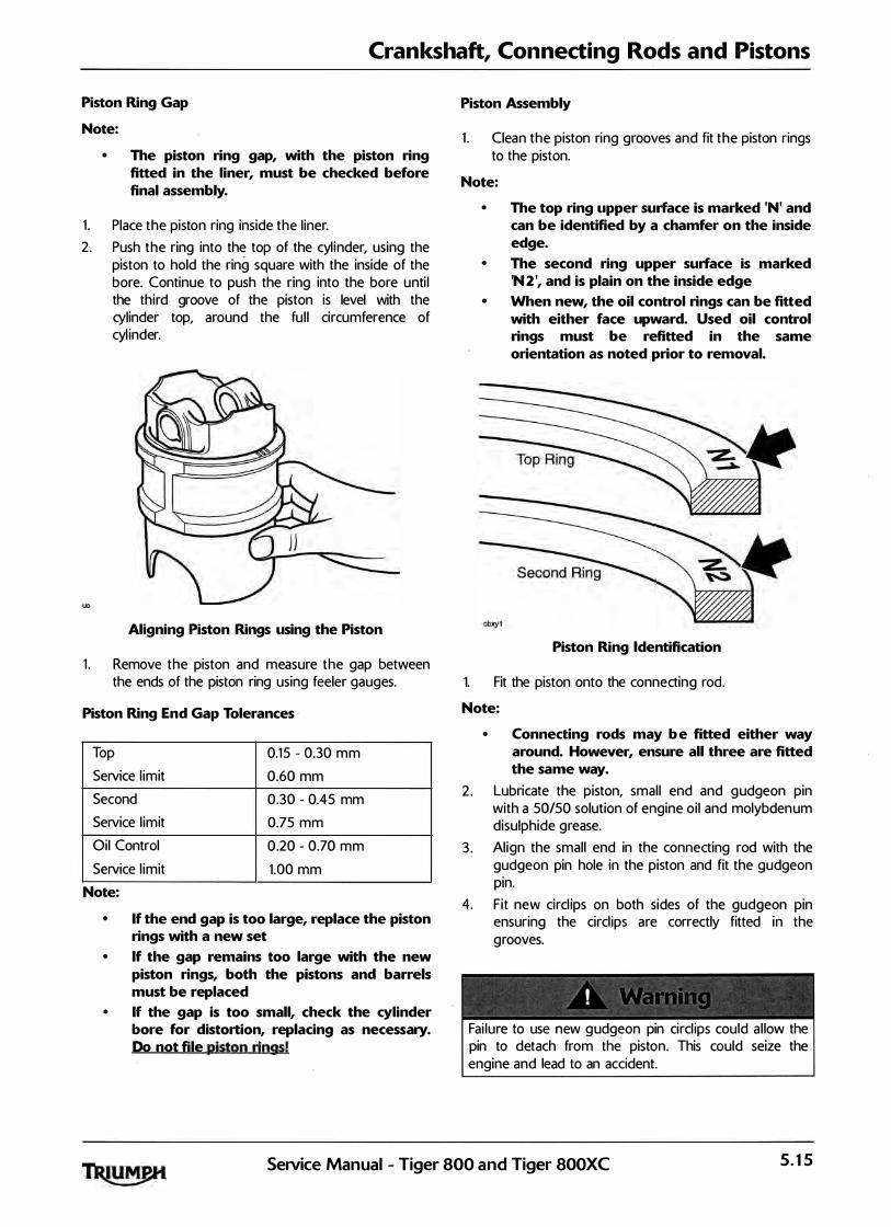
Crankshaft, Connecting Rods and Pistons
Piston Ring Gap
Note:
• The piston ring gap, with the piston ring fitted in the liner, must be checked before final assembly.
1 . Place the piston ring inside the l iner. 2 . Push the ring into the top of the cyl inder, using the
piston to hold the ring square with the inside of the bore. Continue to push the ring into the bore unti l the third groove of the piston is level with the cylinder top, around the fu l l circumference of cyl inder.
:uo
Aligning Piston Rings using the Piston
1 . Remove the piston and measure the gap between the ends of the piston ring using feeler gauges.
Piston Ring End Gap Tolerances
Top 0.15 - 0.30 mm Service l imit 0.60 mm Second 0.30 - 0.45 mm Service l imit 0.75 mm Oil Control 0.20 - 0.70 mm Service l imit 1 .00 mm
Note:
• If the end gap is too large, replace the piston rings with a new set
• If the gap remains too large with the new piston rings, both the pistons and barrels must be replaced
• If the gap is too small, check the cylinder bore for distortion, replacing as necessary. Do not file piston rings!
Piston Assembly
1 . Clean the piston ring grooves and fit the piston rings to the piston.
Note:
• The top ring upper surface is marked 'N' and can be identified by a chamfer on the inside edge.
• The second ring upper surface is marked 'N2 ', and is plain on the inside edge
• When new, the oil control rings can be fitted with either face upward. Used oil control rings must be refitted in the same orientation as noted prior to removal.
Piston Ring Identification
1. Fit the piston onto the connecting rod.
Note:
•
2 .
3 .
Connecting rods may b e fitted either way around. However, ensure all three are fitted the same way.
Lubricate the piston, smal l end and gudgeon pin with a 50150 solution of engine oi l and molybdenum disulphide grease. Al ign the small end in the connecting rod with the gudgeon pin hole in the piston and fit the gudgeon pin.
4. Fit new circl ips on both sides of the gudgeon pin ensuring the circl ips are correctly fitted in the grooves.
Fai lure to use new gudgeon pin circl ips could a l low the pin to detach from the piston. This could seize the engine and lead to an accident.
Service Manual - Tiger 800 and Tiger 800XC 5.15
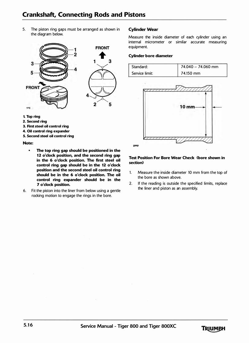
Crankshaft, Connecting Rods and Pistons
5. The piston ring gaps must be arranged as shown in the d iagram below.
1. Top ring
2. Second ring
3. First steel oil control ring
4. Oil control ring expander
5. Second steel oil control ring
Note:
FRONT
+ 1 3
�-·/ 11
4"-..1 " /'�
2 5
• The top ring gap should be positioned in the 12 o'clock position, and the second ring gap in the 6 o'clock position. The first steel oil control ring gap should be in the 12 o'clock position and the second steel oil control ring should be in the 6 o'clock position. The oil control ring expander should be in the 7 o'clock position.
6. Fit the piston into the l iner from below using a gentle rocking motion to engage the rings in the bore.
Cylinder Wear
Measure the inside diameter of each cylinder using an internal micrometer or similar accurate measuring equipment.
Cylinder bore diameter
Standard : Service l imit:
gaep
74.040- 74.060 mm 74.150 mm
Test Position For Bore Wear Check (bore shown in section>
1 . Measure the inside diameter 10 mm from the top of the bore as shown above.
2 . I f the reading is outside the specified l imits, replace the l iner and piston as an assembly.
5.16 SeJVice Manual - Tiger 800 and Tiger 800XC

Crankshaft, Connecting Rods and Pistons
Cylinder Liners
Removal
1 . Assemble the frame from tool T3 880315 to tool T3 880101 as shown below.
gakh_2
1. Frame from tool T388031S
2. Tool T3880101
ccuo
1. Paint mark
2. Mark each l iner to identify correct orientation and the cyl inder number from which it has been removed.
3. Turn the crankshaft until the piston in the l iner to be removed is at the bottom of its stroke.
1. Tool T3 88031S and T3880101
2. Extraction nut
3 . Locking nut
4. Check that the locking nut on tool T3880101 is loose, then fu lly unscrew the extraction nut.
5 . Careful ly fit the tool fu lly into the cyl inder bore, positioning the tool legs on the crarkcase. Turn the locking nut clockwise until the rubber sleeve on the tool tightly grips the bore of the l iner.
6. Check that the tool legs are positioned to al low withdrawal of the l iner, then turn the extraction nut clockwise to extract the l iner. Take care to ensure that the piston/connecting rod is not al lowed to fal l against the inside of the crankcase.
Z Turn the locking nut counter-clockwise to release the l iner.
Note:
• The tool must be used to release the seal between the liner and the crankcase.
• lt is not intended that the tool is used to fully extract the liner. Once the seal is released, the tool must be removed and the liner extracted by hand.
SeiVice Manual - Tiger 800 and Tiger 800XC 5.17

Crankshaft, Connecting Rods and Pistons
Installation
1 . Thoroughly clean the l iner removing al l traces of old si l icone sealer.
2. Remove al l traces of sea ler from the crankcase bores. 3 . Apply si l icone sealer to the l iner to crankcase mating
face <at the factory, ThreeBond 12 15 is used).
4. Fit each l iner over the piston using a gentle rocking motion to al low compression of the piston rings.
cbef_3
1. Liner
2. Sealer area
3. Cha mfer
Note:
• The liners have a large chamfer at the bottom of the bore enabling fitting of the piston without need for a piston ring compressor.
Fit each l iner over whichever piston is at TDC. When turning the engine, do not al low the pistons to contact the inside of the crankcase and a lso do not a l low fitted l iners to l ift off the crankcase base.
5 . Continue fitting each l iner in turn unti l a l l are fitted and sealed.
Note:
• When the liners have been fitted, they should not be disturbed. If it is necessary to remove the liner after fitting, the sealer must be re-applied.
Crankcase Breather
The upper crankcase is fitted with a labyrinth type breather system, which requires no maintenance. During engine disassembly and overhaul, check the oi l drain tube for blockage and contamination.
5.18 SeiVice Manual - Tiger 800 and Tiger 800XC

6 Balancer
Table of Contents
Exploded View - Balancer Shaft. . . . . . . . . . . . . . . . . . . . . . . . . . . . . . . . . . . . . . . . . . . . . . . . . . . . . . . . . . . . . . 6. 2
Balancer . . . . . . . . . . . . . . . . . . . . . . . . . . . . . . . . . . . . . . . . . . . . . . . . . . . . . . . . . . . . . . . . . . . . . . . . . . . . . . . . . 6. 3 Removal . . . . . . . . . . . . . . . . . . . . . . . . . . . . . . . . . . . . . . . . . . . . . . . . . . . . . . . . . . . . . . . . . . . . . . . . . . . 6. 3 I . nspect 1on . . . . . . . . . . . . . . . . . . . . . . . . . . . . . . . . . . . . . . . . . . . . . . . . . . . . . . . . . . . . . . . . . . . . . . . . . . 6. 3 Assembly/Installation . . . . . . . . . . . . . . . . . . . . . . . . . . . . . . . . . . . . . . . . . . . . . . . . . . . . . . . . . . . . . . . . . 6. 4
SeNice Manual - Tiger 800 and Tiger 800XC 6.1
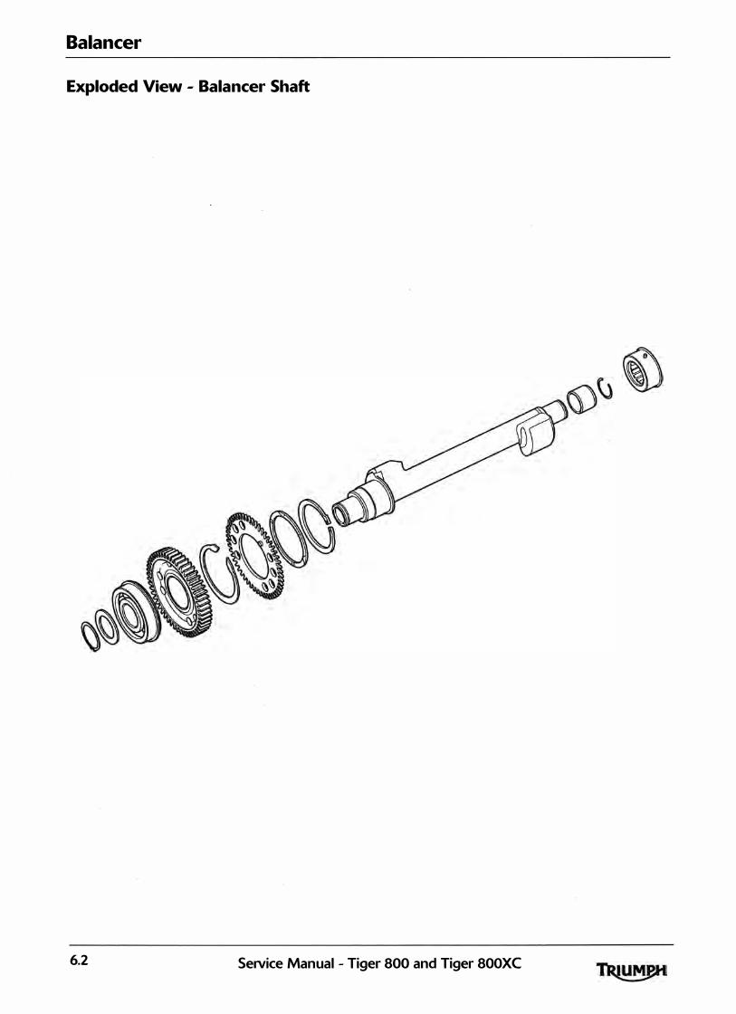
Balancer
Exploded View - Balancer Shaft
6.2 Service Manual - Tiger 800 and Tiger 800XC

Balancer
The balancer is fitted to control 'pulsing' with in the engine. Without any form of balancer, the engine would 'pu lse' each time the crankshaft rotated. This 'pulsing' would be felt as a vibration which would amplify as the engine speed was increased.
The balancer has the effect of a pair of counterbalance weights which create an- equal amount of energy in the opposite direction, and at the same time as that produced by the crankshaft, pistons and connecting rods. Because the opposing pulses occur at the same point of crankshaft rotation, and are of an equal magnitude, a state of equil ibrium or balance is reached.
Removal
1 . Separate the crankcase halves (see page 5-4). 2 . With the crankcase halves separated, l ift out the
balancer shaft complete with the shaft bearings/ circl ips.
Note:
• As the shaft is released from the crankcase, the backlash eliminator gear will spring out of alignment with the crankshaft.
3. To remove the left hand bearing, s l ide the bearing, circl ip and bearing sleeve from the balancer shaft. Note the orientation of the bearing prior to removal.
4. To remove the right hand bearing, remove the circl ip and washer, and, using a press and press bars remove the bearing race from the shaft, ensuring the inner bearing race is supported. Note the orientation of the bearing prior to removal. DO NOT remove the drive gear from the shaft.
When using a press, a lways wear overal ls, eye face and hand protection. Objects such as bearings frequently break-up under load and the debris caused during break-up may cause damage and injury to unprotected parts of the body. Never wear loose clothing, which could become trapped in the press and cause crushing injury to the hand, arms or other parts of the anatomy.
Do not remove the drive gear from the balancer shaft. The drive gear is al igned to the shaft. If the balancer and drive gear are not correctly al igned, severe engine vibration will occur leading to damage to components.
Balancer
5. To strip the backlash el iminator from the drive gear, release the circl ip and remove the wave-washer, backlash gear and spring.
cdon
1. Balancer shaft
2. Wave washer
3. Circlip
Inspection
1 . Inspect a l l gears for chipped or missing teeth. 2. Inspect al l bearings for signs of overheating <blue
discolouration), seized or damaged rollers, and any other damage.
3. Inspect the backlash spring for deformities, damage etc.
4. Inspect the gear teeth for overheating (blue d iscolouration).
SeiVice Manual - Tiger 800 and Tiger 800XC 6.3
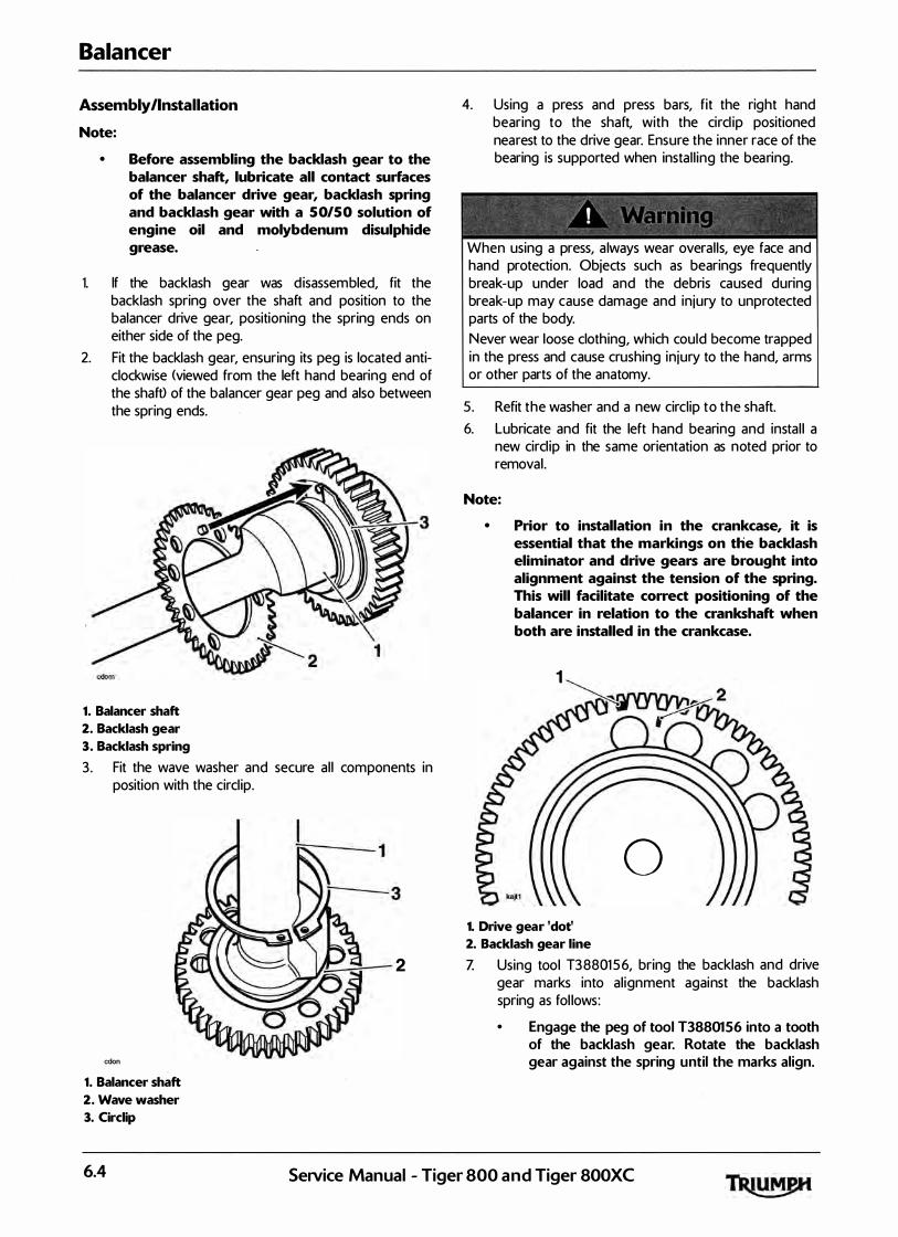
Balancer
Assembly/Installation
Note:
• Before assembling the backlash gear to the balancer shaft, lubricate all contact surfaces of the balancer drive gear, backlash spring and backlash gear with a 50/50 solution of engine oil and molybdenum disulphide grease.
1. If the backlash gear was d isassembled, fit the backlash spring over the shaft and position to the balancer drive gear, positioning the spring ends on either side of the peg.
2. Fit the backlash gear, ensuring its peg is located anticlockwise (viewed from the left hand bearing end of the shaft) of the balancer gear peg and also between the spring ends.
4. Using a press and press bars, fit the right hand bearing to the shaft, with the circl ip positioned nearest to the drive gear. Ensure the inner race of the bearing is supported when instal l ing the bearing.
When using a press, a lways wear overal ls, eye face and hand protection. Objects such as bearings frequently break-up under load and the debris caused during break-up may cause damage and injury to unprotected parts of the body. Never wear loose clothing, which could become trapped in the press and cause crushing in jury to the hand, arms or other parts of the anatomy.
5 . Refit the washer and a new circl ip to the shaft. 6. Lubricate and fit the left hand bearing and insta l l a
new circl ip in the same orientation as noted prior to removal .
Note:
'���-T-3 • Prior to installation in the crankcase, it is
1. Balancer shaft
2. Backlash gear
3. Backlash spring
essential that the markings on the backlash eliminator and drive gears are brought into alignment against the tension of the spring. This will facilitate correct positioning of the balancer in relation to the crankshaft when both are installed in the crankcase.
1 �2 M
3. Fit the wave washer and secure al l components in position with the circl ip.
cdon
1. Balancer shaft
2. Wave washer
3. Circlip
6.4
0 1. Drive gear 'dot'
2. Backlash gear line
If.!---=:-:-- 2 Z Using tool T38801 5 6, bring the backlash and drive gear marks into al ignment against the backlash spring as fol lows: • Engage the peg of tool T 3 8 8 015 6 into a tooth
of the backlash gear. Rotate the backlash gear against the spring until the marks align.
SeiVice Manual - Tiger 800 and Tiger 800XC

Note:
• When in alignment, the line on the backlash gear must be located directly above the drive gear tooth marked with a 'dot'.
• Since the drive gear 'dot' cannot be seen when the backlash gear is in alignment, always mark the 'dot'-marked gear tooth with a paint mark in order that it can always be identified. ·
8. Secure the backlash gear in position with the fixture supplied with the tool by placing the fixture pegs across two gear teeth (ensure that the fixture will not be in the way when assembling the balancer to the crank).
cdon
1. Tool T3 8801 56
2. Securing fixture
3. Balancer backlash gear marking
I f the balancer and crankshaft are not correctly al igned, severe engine vibration wi l l occur leading to damage to components.
Balancer
9. With the drive and backlash el iminator gears sti l l correctly al igned, locate the balancer to the crankcase. Align the balancer gears and crankshaft as shown in the i l lustration below.
1. Balancer gear marking
2. Crankshaft markings
10. Ensure that the right hand bearing circl ip and dowel locate correctly in the corresponding groove in the crankcase.
1. Balancer shaft (right hand bearing)
2. Circlip
3. Dowel
SeiVice Manual - Tiger 800 and Tiger 800XC 6.5

Balancer
1 1 . Ensure that the left hand bearing circl ip and dowel locate correctly in the corresponding groove in the crankcase
2 cdok
1. Balancer shaft (left hand bearing)
2. Circlip
3. Dowel
12 . Remove the securing fixture. 1 3 . Check that the balancer and crankshaft are correctly
al igned before continuing to assemble the crankcase halves.
14. Assemble the crankcase ha lves (see page 5-4).
6.6 SeiVice Manual - Tiger 800 and Tiger 800XC
7 Transmission
Table of Contents
Exploded View - Input and Output Shafts . . . . . . . . . . . . . . . . . . . . . . . . . . . . . . . . . . . . . . . . . . . . . . . . . . . . . 7. 2
Exploded View - Sprag Clutch and Starter Gears. . . . . . . . . . . . . . . . . . . . . . . . . . . . . . . . . . . . . . . . . . . . . . . 7. 3
Exploded View - Gear Selectors and Drum . . . . . . . . . . . . . . . . . . . . . . . . . . . . . . . . . . . . . . . . . . . . . . . . . . . . 7. 4
Exploded View - Gear Change Mechanism . . . . . . . . . . . . . . . . . . . . . . . . . . . . . . . . . . . . . . . . . . . . . . . . . . . . ZS
Selector Shaft. . . . . . . . . . . . . . . . . . . . . . . . . . . . . . . . . . . . . . . . . . . . . . . . . . . . . . . . . . . . . . . . . . . . . . . . . . . . . Z 6 Removal . . . . . . . . . . . . . . . . . . . . . . . . . . . . . . . . . . . . . . . . . . . . . . . . . . . . . . . . . . . . . . . . . . . . . . . . . . . . Z 6 Installation. . . . . . . . . . . . . . . . . . . . . . . . . . . . . . . . . . . . . . . . . . . . . . . . . . . . . . . . . . . . . . . . . . . . . . . . . . . Z 6
Selector Forks and Drum . . . . . . . . . . . . . . . . . . . . . . . . . . . . . . . . . . . . . . . . . . . . . . . . . . . . . . . . . . ·. . . . . . . . . 7. 7 Removal . . . . . . . . . . . . . . . . . . . . . . . . . . . . . . . . . . . . . . . . . . . . . . . . . . . . . . . . . . . . . . . . . . . . . . . . . . . . Z 7 Inspection . . . . . . . . . . . . . . . . . . . . . . . . . . . . . . . . . . . . . . . . . . . . . . . . . . . . . . . . . . . . . . . . . . . . . . . . . . . Z 8 Installation. . . . . . . . . . . . . . . . . . . . . . . . . . . . . . . . . . . . . . . . . . . . . . . . . . . . . . . . . . . . . . . . . . . . . . . . . . . Z9
Input and Output Shafts Assemblies . . . . . . . . . . . . . . . . . . . . . . . . . . . . . . . . . . . . . . . . . . . . . . . . . . . . . . . . 7. 10 Removal . . . . . . . . . . . . . . . . . . . . . . . . . . . . . . . . . . . . . . . . . . . . . . . . . . . . . . . . . . . . . . . . . . . . . . . . . . . Z 10 Instal lation. . . . . . . . . . . . . . . . . . . . . . . . . . . . . . . . . . . . . . . . . . . . . . . . . . . . . . . . . . . . . . . . . . . . . . . . . . Z 1 1
Input Shaft. . . . . . . . . . . . . . . . . . . . . . . . . . . . . . . . . . . . . . . . . . . . . . . . . . . . . . . . . . . . . . . . . . . . . . . . . . . . . . Z 12 Disassembly . . . . . . . . . . . . . . . . . . . . . . . . . . . . . . . . . . . . . . . . . . . . . . . . . . . . . . . . . . . . . . . . . . . . . . . . Z 12 Inspection . . . . . . . . . . . . . . . . . . . . . . . . . . . . . . . . . . . . . . . . . . . . . . . . . . . . . . . . . . . . . . . . . . . . . . . . . . 7. 13 Exploded View - Input Shaft. . . . . . . . . . . . . . . . . . . . . . . . . . . . . . . . . . . . . . . . . . . . . . . . . . . . . . . . . . . 7. 14 Assembly. . . . . . . . . . . . . . . . . . . . . . . . . . . . . . . . . . . . . . . . . . . . . . . . . . . . . . . . . . . . . . . . . . . . . . . . . . . Z 15
Output Shaft . . . . . . . . . . . . . . . . . . . . . . . . . . . . . . . . . . . . . . . . . . . . . . . . . . . . . . . . . . . . . . . . . . . . . . . . . . . . Z 17 Disassembly . . . . . . . . . . . . . . . . . . . . . . . . . . . . . . . . . . . . . . . . . . . . . . . . . . . . . . . . . . . . . . . . . . . . . . . . 7. 17 Inspection . . . . . . . . . . . . . . . . . . . . . . . . . . . . . . . . . . . . . . . . . . . . . . . . . . . . . . . . . . . . . . . . . . . . . . . . . . Z 17 Exploded View - Output Shaft. . . . . . . . . . . . . . . . . . . . . . . . . . . . . . . . . . . . . . . . . . . . . . . . . . . . . . . . . 7. 18 Assembly . . . . . . . . . . . . . . . . . : . . . . . . . . . . . . . . . . . . . . . . . . . . . . . . . . . . . . . . . . . . . . . . . . . . . . . . . . . 7. 19
Starter Drive Gears/Sprag Clutch . . . . . . . . . . . . . . . . . . . . . . . . . . . . . . . . . . . . . . . . . . . . . . . . . . . . . . . . . . . Z 2 1 Removal . . . . . . . . . . . . . . . . . . . . . . . . . . . . . . . . . . . . . . . . . . . . . . . . . . . . . . . . . . . . . . . . . . . . . . . . . . . Z 2 1 Inspection . . . . . . . . . . . . . . . . . . . . . . . . . . . . . . . . . . . . . . . . . . . . . . . . . . . . . . . . . . . . . . . . . . . . . . . . . . Z 2 1 Installation. . . . . . . . . . . . . . . . . . . . . . . . . . . . . . . . . . . . . . . . . . . . . . . . . . . . . . . . . . . . . . . . . . . . . . . . . 7. 2 2
SeiVice Manual - Tiger 800 and Tiger 800XC 7.1
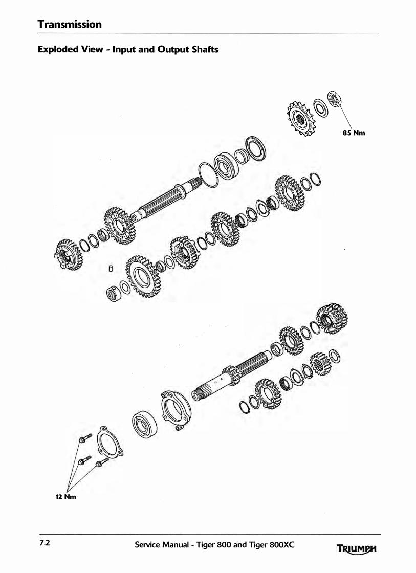
Transmission
Exploded v· 1ew - In
12 Nm ·
7.2
put and 0 utput Shafts
��\ 85 Nm
SeJVic M e anual - Ti ger 800 and r· •ger 800XC

Transmission
Exploded View - Sprag Clutch and Starter Gears
16 Nm
SeiVice Manual - Tiger 800 and Tiger BOOXC 7.3
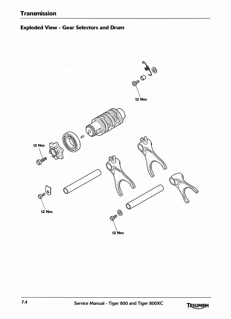
Transmission
Exploded View - Gear Selectors and Drum
\� \6)
12 Nm
\l;) 12 Nm �
\ 12 Nm
7.4 Service Manual - Tiger 800 and Tiger 800XC

Transmission
Exploded View - Gear Change Mechanism
6 Nm
/ 22 Nm
j
20 m
Seavice Manual - Tiger 800 and Tiger 800XC 7.5
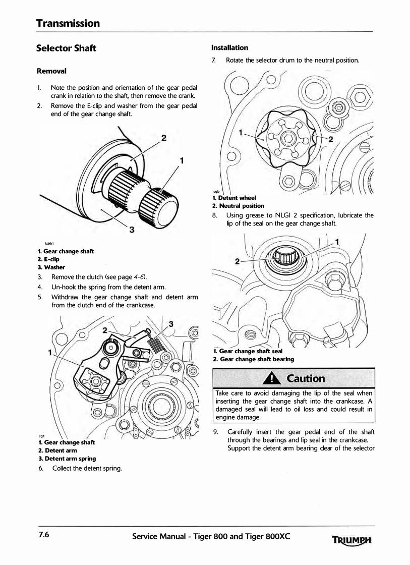
Transmission
Selector Shaft
Removal
1 . Note the position and orientation of the gear pedal crank in relation to the shaft, then remove the crank.
2. Remove the E-clip and washer from the gear pedal end of the gear change -shaft.
kakh1
1. Gear change shaft
2. E-clip
3. Washer
3. Remove the clutch (see page 4-6>.
4. Un-hook the spring from the detent arm.
1
5. Withdraw the gear change shaft and detent arm from the clutch end of the crankcase.
cgh
1. Gear change shaft
2. Detent arm
3. Detent arm spring
6. Col lect the detent spring.
Installation
Z Rotate the selector drum to the neutra l position.
0
cglv
1. Detent wheel
2. Neutral position
8. Using grease to N LG I 2 specification, lubricate the lip of the seal on the gear change shaft.
-�� . ( 1. Gear change shaft seal
2. Gear change shaft bearing
Take care to avoid damaging the l ip of the seal when inserting the gear change shaft into the crankcase. A damaged seal wil l lead to oil loss and could result in engine damage.
9. Carefully insert the gear pedal end of the shaft through the bearings and l ip seal in the crankcase. Support the detent arm bearing clear of the selector
7.6 SeiVice Manual - Tiger 800 and Tiger 800XC

cg�
drum as · the selector shaft is ful ly instal led, and ensure the selector shaft spring fits either s ide of the abutment bolt.
1. Gearchange shaft
2. Abutment bolt
3 . Spring
10. Fit the washer and E-cl ip to the gear pedal end of the gear change shaft.
kakh1
1. Gear change shaft
2. E-clip
3. Washer
1 1 . Fit the gear pedal crank to the shaft in the same orientation as noted prior to removal . Ensure the 'dot' mark on the shaft al igns with the· split line on the gear pedal crank. Tighten the fixing to 9 Nm.
12 . Refit the spring to the detent arm. 1 3 . Refit the clutch (see page 4-10>.
Transmission
Selector Forks and Drum
Removal
1 . Remove the engine from the frame <see page 9-3>.
2. Separate the two halves of the crankcase (see page 5-4>.
3 . Remove the output shaft from the crankcase <see page 7-70>.
4. Remove the selector shaft (see page 7-6). 5. Remove and discard the two selector fork shaft
retaining fixings, noting the position of the washer and the selector drum keeper plate.
0
1 �
2��'="'/---' 1. Selector drum keeper plate
2. Output selector fork shaft fixing
3. Input selector fork shaft fixing and washer
The two output shaft selector forks incorrectly. Ensure the position and orientation of the selector forks are marked prior to removal . Incorrect fitting of the selector forks wil l cause gearbox damage.
SeNice Manual - Tiger 800 and Tiger 800XC 7.7

Transmission
6. Noting the positions of the selector forks, sl ide the output selector shaft from the crankcase in the direction of the clutch. Collect the two selector forks as they are released by the selector fork shaft.
1. Output selector shaft
2. Sixth gear selector fork
3. Fifth gear selector fork
Z Noting the position of the selector fork, remove the input selector shaft, leaving the selector fork in the gearbox.
1. Input selector shaft
2. Selector fork
8. Remove the gear position sensor.
the selector drum from within the crankcase.
1. Selector drum removal
10. Col lect the input shaft selector fork from the crankcase.
Inspection
1 . Examine a l l components for damage and/or wear, paying particular attention to the selector forks and selector drum. Replace any parts that are damaged and/or worn.
Gear selector fork thickness
Standard
Service l imit
Gear selector groove width
Standard
Service l imit
5.90 - 6.00 mm 5.80 mm
6.10 - 6 . 17 mm
6.27 mm
7.8 SeiVice Manual - Tiger 800 and Tiger 800XC
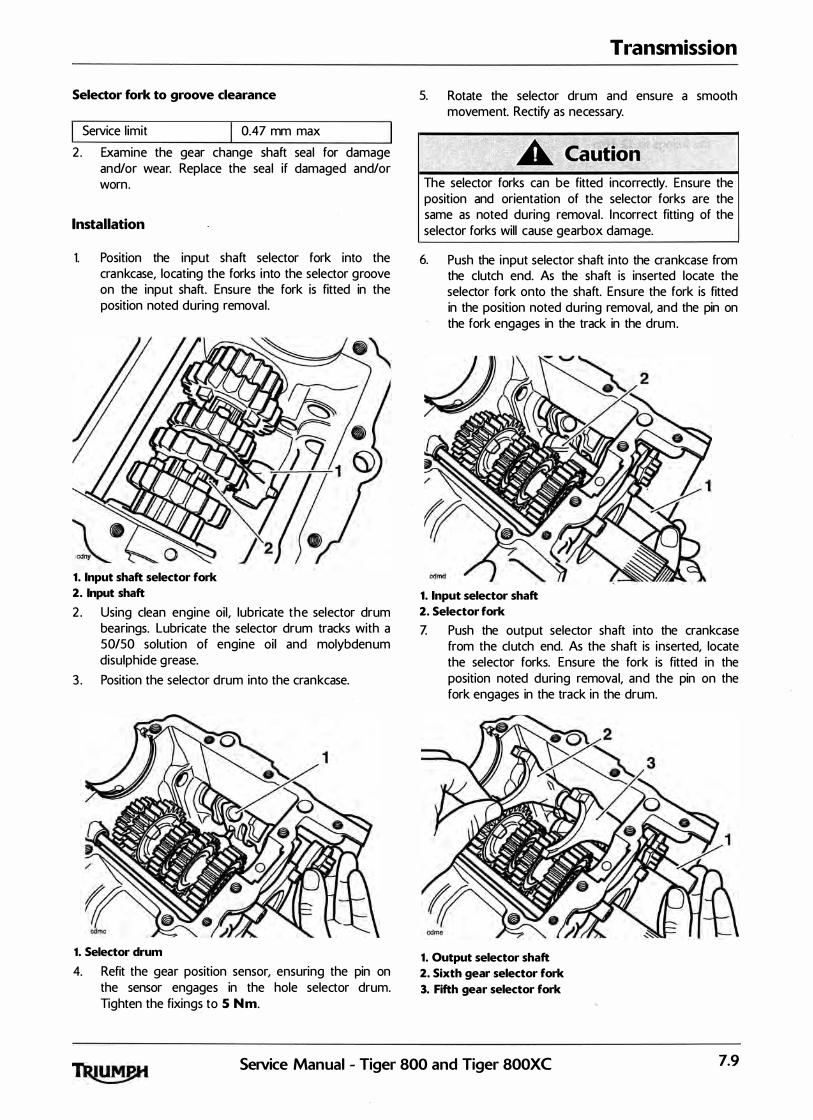
Selector fork to groove clearance
I Service l imit I 0.47 mm max
2 . Examine the gear change shaft seal for damage and/or wear. Replace the sea l if damaged and/or worn.
Installation
1. Position the input shaft selector fork into the crankcase, locating the forks into the selector groove on the input shaft. Ensure the fork is fitted in the position noted during removal.
1. Input shaft selector fork
2. Input shaft
2 . Using clean engine oil, lubricate the selector drum bearings. Lubricate the selector drum tracks with a 50150 solution of engine oil and molybdenum disulphide grease.
3 . Position the selector drum into the crankcase.
1. Selector drum
4. Refit the gear position sensor, ensuring the pin on the sensor engages in the hole selector drum. Tighten the fixings to 5 Nm.
Transmission
5. Rotate the selector drum and ensure a smooth movement. Rectify as necessary.
The selector forks can be fitted incorrectly. Ensure the position and orientation of the selector forks are the same as noted during removal . Incorrect fitting of the selector forks will cause gearbox damage.
6. Push the input selector shaft into the crankcase from the clutch end. As the shaft is inserted locate the selector fork onto the shaft. Ensure the fork is fitted in the position noted during removal, and the pin on the fork engages in the track in the drum.
1. Input selector shaft
2. Selector fork
Z Push the output selector shaft into the crankcase from the clutch end. As the shaft is inserted, locate the selector forks. Ensure the fork is fitted in the position noted during removal, and the pin on the fork engages in the track in the drum.
1. Output selector shaft
2. Sixth gear selector fork
3. Fifth gear selector fork
Service Manual - Tiger 800 and Tiger 800XC 7.9
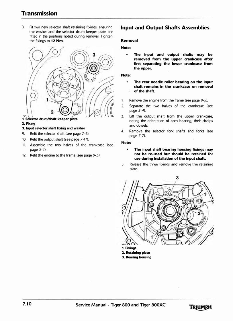
Transmission
8. Fit two new selector shaft retaining fixings, ensuring the washer and the selector drum keeper plate are fitted in the positions noted during removal. Tighten the fixings to 12 Nm.
0
cglv
1. Selector drum/shaft keeper plate
2. Fixing
3. Input selector shaft fixing and washer
9. Refit the selector shaft <see page 7-6).
10. Refit the output shaft (see page 7-T n.
1 1 . Assemble the two halves of the crankcase <see page 5-4).
12 . Refit the engine to the frame <see page 9-5>.
Input and Output Shafts Assemblies
Removal
Note:
• The input and output shafts may be removed from the upper crankcase after first separating the lower crankcase from the upper.
Note:
• The rear needle roller bearing on the input shaft remains in the crankcase on removal of the shaft.
1 . Remove the engine from the frame <see page 9-3>.
2. Separate the two halves of the crankcase <see page 5-4>.
3 . Lift the output shaft from the upper crankcase, noting the orientation of each bearing, their circl ips and dowels.
4. Remove the selector fork shafts and forks (see page 7-7>.
Note:
• The input shaft bearing housing fixings may not be re-used but should be retained for use during installation of the input shaft.
5 . Release the three fixings and remove the retaining plate.
1. Fixings
2. Retaining plate
3. Bearing housing
7.10 SeNice Manual - Tiger 800 and Tiger 800XC
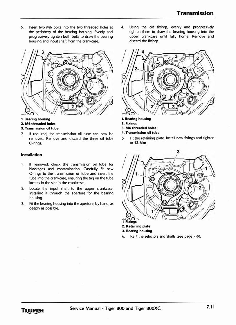
6. Insert two M6 bolts into the two threaded holes at the periphery of the bearing housing. Evenly and progressively tighten both bolts to draw the bearing housing and input shaft from the crankcase.
1. Bearing housing
2. M6 threaded holes
3. Transmission oil tube
Z If required, the transmission oil tube can now be removed. Remove and discard the three oi l tube 0-rings.
Installation
1 . I f removed, check the transm1ss1on o i l tube for blockages and contamination. Carefully fit new 0-rings to the transmission oil tube and insert the tube into the crankcase, ensuring the tag on the tube locates in the slot in the crankcase.
2. Locate the input shaft to the upper crankcase, instal l ing it through the aperture for the bearing housing.
3. Fit the bearing housing into the aperture, by hand, as deeply as possible.
Transmission
4. Using the old fixings, evenly and progressively tighten them to draw the bearing housing into the upper crankcase unti l fu lly home. Remove and discard the fixings.
1. Bearing housing
2. Fixings
3. M6 threaded holes
4. Transmission oil tube
5. Fit the retaining plate. Instal l new fixings and tighten to 12 Nm.
jn 1. Fixings
2. Retaining plate
3. Bearing housing
6. Refit the selectors and shafts <see page 7-9).
SeiVice Manual - Tiger 800 and Tiger 800XC 7.11
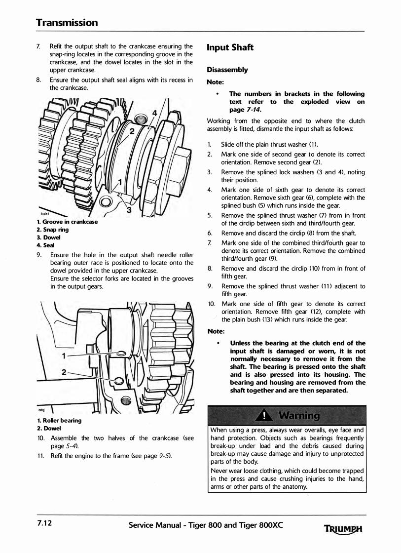
Transmission
Z Refit the output shaft to the crankcase ensuring the snap-ring locates in the corresponding groove in the crankcase, and the dowel locates in the slot in the upper crankcase.
8. Ensure the output shaft seal al igns with its recess in the crankcase.
� 1. Groove in crankcase
2. Snap ring
3. Dowel
4. Seal
9. Ensure the hole in the output shaft needle roller bearing outer race is positioned to locate onto the dowel provided in the upper crankcase.
cdqj
Ensure the selector forks are located in the grooves in the output gears.
1. Roller bearing
2. Dowel
10. Assemble the two halves of the crankcase <see page 5-4>.
1 1 . Refit the engine to the frame (see page 9-5>.
Input Shaft
Disassembly
Note:
• The numbers in brackets in the following text refer to the exploded view on page 7-14.
Working from the opposite . end to where the clutch assembly is fitted, dismantle the input shaft as fol lows:
1 . Slide off the plain thrust washer ( 1 > .
2 . Mark one s ide of second gear to denote its correct orientation. Remove second gear (2).
3 . Remove the spl ined lock washers (3 and 4), noting their position.
4. Mark one side of sixth gear to denote its correct orientation. Remove sixth gear (6), complete with the splined bush (5) which runs inside the gear.
5 . Remove the splined thrust washer (7) from in front of the circl ip between sixth and third/fourth gear.
6. Remove and discard the circl ip <8> from the shaft. Z Mark one side of the combined third/fourth gear to
denote its correct orientation. Remove the combined third/fourth gear (9).
8. Remove and discard the circl ip ( 10) from in front of fifth gear.
9 . Remove the spl ined thrust washer ( 1 1 ) adjacent to fifth gear.
10. Mark one side of fifth gear to denote its correct orientation. Remove fifth gear ( 1 2), complete with the plain bush ( 1 3 ) which runs inside the gear.
Note:
• Unless the bearing at the clutch end of the input shaft is damaged or worn, it is not normally necessary to remove it from the shaft. The bearing is pressed onto the shaft and is also pressed into its housing. The bearing and housing are removed from the shaft together and are then separated.
! ' '
When using a press, a lways wear overal ls, eye face and hand protection. Objects such as bearings frequently break-up under load and the debris caused during break-up may cause damage and injury to unprotected parts of the body. Never wear loose cloth ing, which could become trapped in the press and cause crushing in juries to the hand, arms or other parts of the anatomy.
7.12 SetVice Manual - Tiger 800 and Tiger 800XC
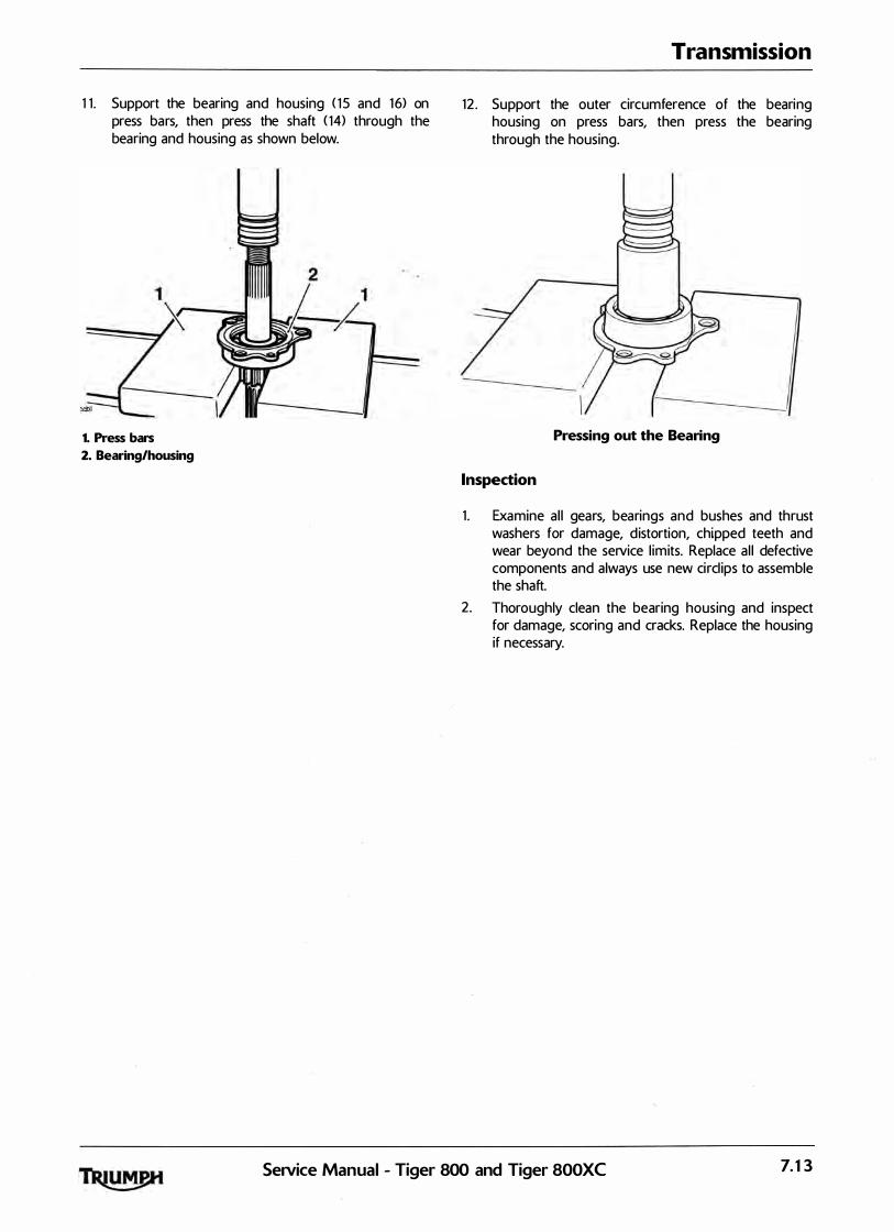
1 1 . Support the bearing and housing ( 1 5 and 16) on press bars, then press the shaft ( 14) through the bearing and housing as shown below.
1
1. Press bars
2. Bearing/housing
Transmission
12 . Support the outer circumference of the bearing housing on press bars, then press the bearing through the housing.
----\
Pressing out the Bearing
Inspection
1 . Examine a l l gears, bearings and bushes and thrust washers for damage, d istortion, chipped teeth and wear beyond the service l imits. Replace a l l defective components and always use new circl ips to assemble the shaft.
2. Thoroughly clean the bearing housing and inspect for damage, scoring and cracks. Replace the housing if necessary.
Service Manual - Tiger 800 and Tiger 800XC 7.13

Transmission
Exploded View - Input Shaft
1. Thrust washer
2. Second gear
3. Lock washer
4. Splined washer
5. Splined bush
6. Sixth gear
7. Splined thrust washer
8. Circlip
9. Third/fourth gear
7.14
8 � 7 ----o 6 -o
17 � 16
15
5 � 14 4 ----@ 3 ----0> � 13 2 � G- 12
______--© � 1 1 � 10 9
10. Circlip
1 1. Splined thrust washer
12. Fifth gear
1 3 . Plain bush
14. Input shaft
15. Bearing housing
16. Bearing
1 7. Bearing retainer
SeiVice Manual - Tiger 800 and Tiger 800XC
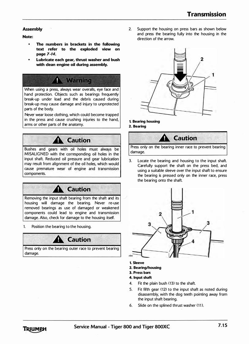
Assembly
Note:
• The numbers in brackets in the following text refer to the exploded view on page 7-14.
• Lubricate each gear, thrust washer and bush with clean engine oil during assembly.
! ' ' '
When using a press, a lways wear overal ls, eye face and hand protection. Objects such as bearings frequently break-up under load and the debris caused during break-up may cause damage and injury to unprotected parts of the body. Never wear loose cloth ing, which could become trapped in the press and cause crushing in juries to the hand, arms or other parts of the anatomy.
Removing the input shaft bearing from the shaft and its housing wil l damage the bearing. Never re-use removed bearings as use of damaged or weakened components could lead to engine and transmission damage. Also, check for damage to the housing itself.
1 . Position the bearing to the housing.
Press only on the bearing outer race to prevent bearing damage.
Transmission
2. Support the housing on press bars as shown below and press the bearing fu lly into the housing in the direction of the arrow.
1. Bearing housing
2. Bearing
2
Press only on the bearing inner race to prevent bearing damage.
·
3. Locate the bearing and housing to the input shaft. Carefully support the shaft on the press bed, and using a suitable sleeve over the input shaft to ensure the bearing is pressed only on the inner race, press the bearing onto the shaft.
1. Sleeve
2. Bearing/housing
3. Press bars
4. Input shaft
4. Fit the plain bush < 1 3> to the shaft. 5. Fit fifth gear ( 1 2) to the input shaft as noted during
d isassembly, with the dog teeth pointing away from the input shaft bearing.
6. Sl ide on the splined thrust washer ( 1 1 > .
SeNice Manual - Tiger 800 and Tiger 800XC 7.15

Transmission
7. Fit a new circl ip ( 10> to the input shaft ensuring that the clip is located in the circl ip groove as shown below.
cdmo
1. F"lfth gear
2. Thrust washer
3. Circlip
8. Fit the combined third/fourth gear (9) as noted during disassembly, with the larger gear facing toward fifth gear. Ensure that the oil hole in the input shaft DOES NOT al ign with the oi l hole in the gear.
If the oil hole in the th ird/fourth gear is al igned with the corresponding hole in the input shaft, engine oil pressure and gear lubrication wil l be reduced. Reduced oil pressure and gear lubrication wil l cause engine damage and could also lead to engine seizure resu lting in loss of motorcycle control and an accident
9. Fit a new circl ip (8) to the input shaft ensuring that the circl ip is located in the circl ip groove as shown below.
cdmp 1. Sixth gear .
2. Thrust washer
3. Circlip
10. Fit the spl ined thrust washer (7) to the input shaft and slide up the shaft until in contact with the circl ip.
1 1 . Fit the splined bush (5) from sixth gear. Ensure that the oil hole in the input shaft DOES NOT al ign with the oil hole in the bush.
12 . Fit sixth gear (6) as noted during disassembly, with the dog teeth facing third/fourth gear.
1 3 . Fit the splined and lock washers (4 and 3), ensuring the tabs in the smaller washer (3) locate in the slots in the larger (4) washer. ·
cdmq
1. Second gear
2. Large splined lock washer
3. Small splined lock washer
14. Fit second gear (2) to the shaft as noted during disassembly.
15 . Fit the plain thrust washer ( 1 > adjacent to second gear.
7.16 SeiVice Manual - Tiger 800 and Tiger 800XC

Output Shaft
Note:
• The numbers in brackets in the following text refer to the exploded view on page 7-18.
·
Working from the opposite end to the drive sprocket, dismantle the output shaft as fol lows.
Disassembly
1 . Remove the output shaft bearing ( 1 ) and plain thrust washer <2>.
2. Mark one side of first gear to denote its correct orientation. Remove first gear (3) from the shaft, complete with the plain bush (4) which runs inside the gear.
3 . Remove the plain thrust washer (5). 4. Mark one side of fifth gear to denote its correct
orientation. Remove fifth gear (6) from the shaft. 5 . Remove the circl ip (7) and splined thrust washer (8)
from in front of fourth gear. 6. Mark one side of fourth gear to denote its correct
orientation. Remove fourth gear (9) complete with the spl ined bush which runs inside the gear ( 10>.
Z Remove the splined lock washers ( 1 1 and 1 2) noting their positions.
8. Mark one side of third gear to denote its correct orientation. Remove third gear ( 14) off the shaft complete with the spl ined bush ( 1 3) which runs inside the gear.
9. Remove the splined thrust washer ( 1 5). 10. Remove the circl ip ( 1 6) from in front of sixth gear. 1 1 . Mark one side of sixth gear to denote its correct
orientation. Remove sixth gear ( 17) from the shaft. 12 . Remove the circl ip ( 1 8) from in front of second gear.
Transmission
1 3 . Remove the splined thrust washer ( 19). 14. Mark one side of second gear to denote its correct
orientation. Remove second gear (21 > from the shaft, complete with the plain bush (20> which runs inside the gear.
15 . Position the output shaft (22) in a vice with soft jaws fitted. Tighten the vice to prevent the shaft from turning and release the tab washer (28) from the output sprocket nut (29), then release the nut.
16 . Remove the output sprocket nut (29), tab washer (28) and sprocket (27).
1 Z Collect the output shaft seal (2 6). 1 8. If it is found necessary to replace the large
bearing (24) at the end of the shaft, use a press to remove both the bearing and output shaft sprocket spacer (25) together.
When removing the output shaft bearing, a lways wear overal ls, eye, face and hand protection. The bearing races are hardened and are l iable to spl inter if broken. Debris from broken bearings could cause in jury to eyes, face and any unprotected parts of the body.
Inspection
1 . Examine a l l gears, bearings and bushes and thrust washers for damage, d istortion, chipped teeth and wear beyond the service l imits. Replace all defective components and a lways use new circl ips, a new output shaft seal and a new sprocket tab washel" to assemble the shaft.
Service Manual - Tiger 800 and Tiger 800XC 7.17

Transmission
Exploded View - Output Shaft
1. Bearing
2. Thrust washer
3. First gear
4. Plain bush
5. Thrust washer
6. Fifth gear
7. Circlip
8. 5plined thrust washer
9. Fourth gear
10. Splined bush
1 1. Lock washer
12. Splined washer
13. Splined bush
14. Third gear
15. Splined washer
7.18
3 4 5
9 10 1 1 ----o 12 ___---© 13 14 15 ::===8 16
o- 23 � � 24 � 25 � 26 � 27 @-___ 28 �--- 29
16. Circlip
1 7. Sixth gear
18. Circlip
19. Splined thrust washer
20. Plain bush
21. Second gear
22. Output shaft
23. Snap ring
24. Bearing
25. Sprocket spacer
26. Output shaft seal
27. Output sprocket
28. Tab washer
29. Output sprocket nut
SeJVice Manual - Tiger 800 and Tiger 800XC

Assembly
Note:
• The numbers in brackets in the following text refer to the exploded view on page 7-18.
• Lubricate each gear and bush with clean engine oil during assembly.
' ' . ' '
When using a press, always wear overal ls, eye face and hand protection. Objects such as bearings frequently break-up under load and the debris caused during break-up may cause. damage and injury to unprotected parts of the body. Never wear loose cloth ing, which could become trapped in the press and cause crushing in juries to the hand, arms or other parts of the anatomy.
Bushes and gears with oil holes must always be MISALIGNED with the corresponding oi l holes in the output shaft. Reduced oi l pressure and gear lubrication may result from al ignment of the oil holes, which would cause premature wear of engine and transmission components.
Removing the output shaft bearing from the shaft wil l damage the bearing and snap ring. Never re-use removed bearings or snap rings as use of damaged or weakened components could lead to engine and transmission damage.
Press only on the bearing inner race to prevent bearing damage.
Transmission
1 . If removed, working from the output sprocket end of the shaft, fit a new bearing (24) and a new sprocket spacer (25) to the shaft using a press and press bars. Fit the sleeve with the large chamfer facing outwards.
1. Output shaft
2. Bearing
3. Press bars
2. Lubricate and fit a new output shaft seal (2 6). 3 . If removed, transfer the shaft to the vice and secure
between soft jaws. Fit the output sprocket (2 7), new tab washer (28) and nut (29). Tighten the nut to 85 Nm. Close the tab washer.
4. Withdraw the shaft from the vice and continue to assemble from the opposite end to the output sprocket.
5 . Fit the plain bush (20> to the shaft. 6. Locate second gear <21 ) to the shaft as noted during
d isassembly, with the large step side facing towards \ the output sprocket end. Fit the splined thrust
washer ( 19) and retain with a new circl ip ( 18) as shown below.
1. Second gear
2. Thrust washer
3. Circlip
Service Manual - Tiger 800 and Tiger 800XC 7.19
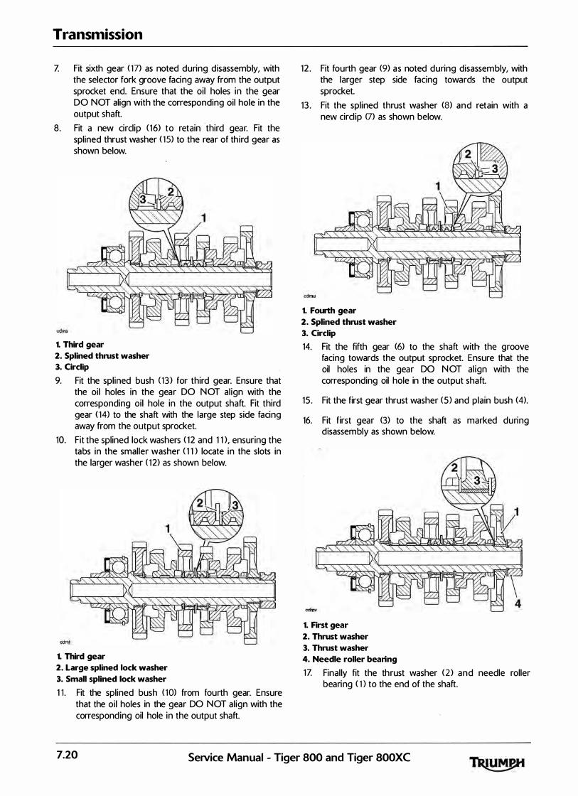
Transmission
Z Fit sixth gear ( 1 7) as noted during d isassembly, with the selector fork groove facing away from the output sprocket end. Ensure that the oil holes in the gear DO NOT align with the corresponding oil hole in the output shaft.
8 . Fit a new circl ip ( 16) to retain third gear. Fit the splined thrust washer ( 1 5) to the rear of th ird gear as shown below.
1. Third gear
2. Splined thrust washer
3. Circlip
9. Fit the spl ined bush ( 1 3 ) for third gear. Ensure that the oil holes in the gear DO NOT al ign with the corresponding oi l hole in the output shaft. Fit third gear ( 14) to the shaft with the large step side facing away from the output sprocket.
10. Fit the splined lock washers ( 1 2 and 1 1 ), ensuring the tabs in the smaller washer ( 1 1 ) locate in the slots in the larger washer ( 1 2) as shown below.
1. Third gear
2. Large splined lock washer
3. Small splined lock washer
1 1 . Fit the splined bush ( 10> from fourth gear. Ensure that the oi l holes in the gear DO NOT al ign with the corresponding oil hole in the output shaft.
12 . Fit fourth gear (9) as noted during disassembly, with the larger step side facing towards the output sprocket.
13 . Fit the splined thrust washer (8) and retain with a new circl ip (7) as shown below.
1. Fourth gear
2. Splined thrust washer
3. Circlip
14. Fit the fifth gear (6) to the shaft with the groove facing towards the output sprocket. Ensure that the oil holes in the gear DO N OT al ign with the corresponding oil hole in the output shaft.
15 . Fit the first gear thrust washer (5 ) and plain bush (4).
16. Fit first gear (3) to the shaft as marked during d isassembly as shown below.
1. First gear
2. Thrust washer
3. Thrust washer
4. Needle roller bearing
1Z Final ly fit the thrust washer (2 ) and needle roller bearing ( 1 ) to the end of the shaft.
7.20 SeiVice Manual - Tiger 800 and Tiger 800XC
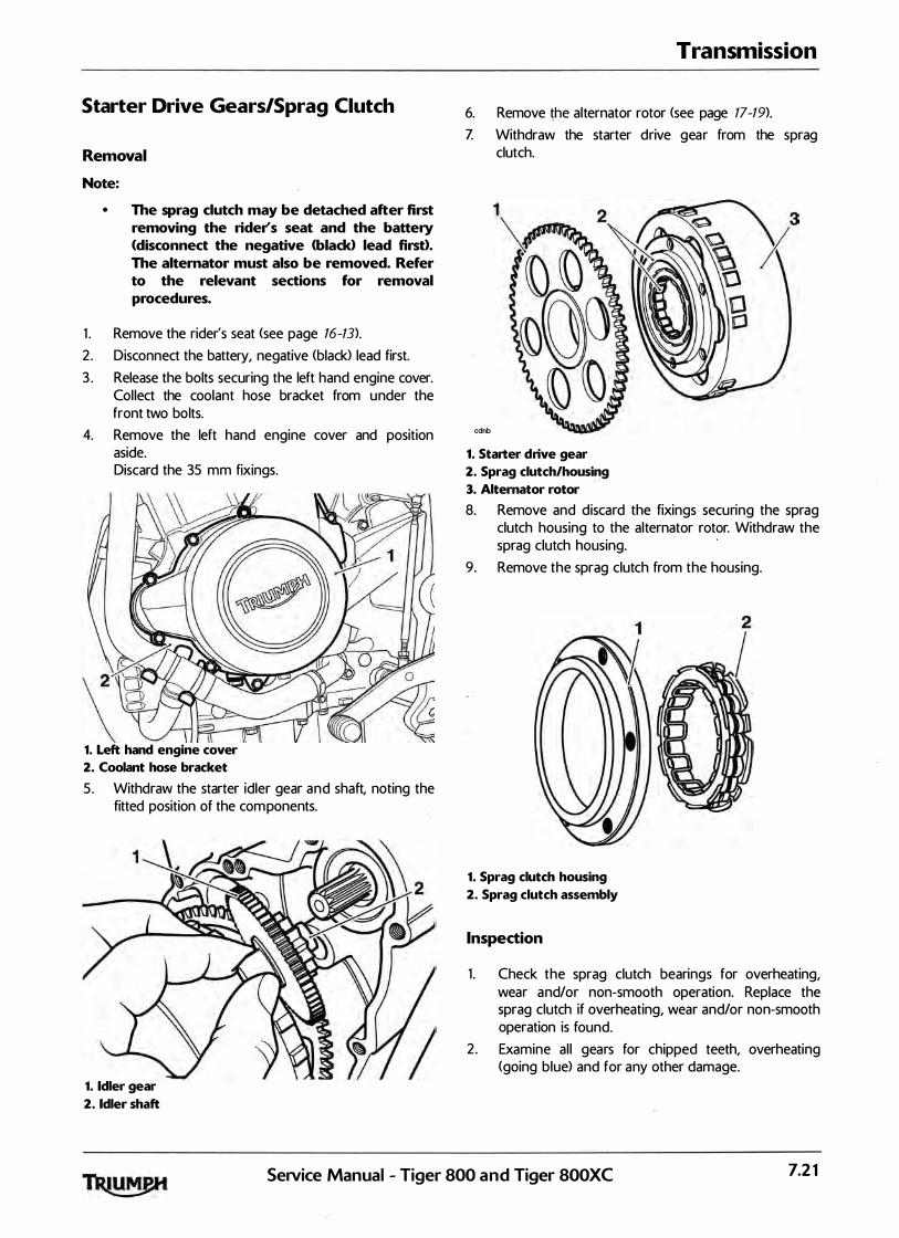
Starter Drive Gears/Sprag Clutch
Removal
Note:
• The sprag clutch may be detached after first removing the rider's seat and the battery <disconnect the negative <black> lead first). The alternator must also be removed. Refer to the relevant sections for removal procedures.
1 . Remove the rider's seat <see page 16-13).
2 . Disconnect the battery, negative (black> lead first. 3 . Release the bolts securing the left hand engine cover.
Col lect the coolant hose bracket from under the front two bolts.
4. Remove the left hand engine cover and position aside. Discard the 35 mm fixings.
V� \ g
1. Left hand engine cover
2. Coolant hose bracket
5 . Withdraw the starter idler gear and shaft, noting the fitted position of the components.
1. Idler gear
2. Idler shaft
Transmission
6. Remove !b_,e alternator rotor (see page 17-19).
Z Withdraw the starter drive gear from the sprag clutch.
cdnb
1. Starter drive gear
2. Sprag clutch/housing
3. Alternator rotor
8. Remove and discard the fixings securing the sprag clutch housing to the alternator rotor. Withdraw the sprag clutch housing.
·
9. Remove the sprag clutch from the housing.
1. Sprag clutch housing
2. Sprag clutch assembly
Inspection
1 . Check the sprag clutch bearings for overheating, wear and/or non-smooth operation. Replace the sprag clutch if overheating, wear and/or non-smooth operation is found.
2. Examine al l gears for chipped teeth, overheating (going blue) and for any other damage.
SeiVice Manual - Tiger 800 and Tiger 800XC 7.21

Transmission
3 . With the sprag clutch mounted in the housing, check the sprag clutch for smooth, free movement in one direction only (as indicated by the arrow marked on the sprag clutch body>.
Installation
1 . Locate the sprag clutch to the housing as shown below. Push firmly . until the lip seats in the recess provided in the housing.
1. Sprag clutch housing
2. Fit the housing to the alternator rotor. 3 . Ensure that the housing i s squarely seated ·and is not
jammed on the rotor. I nsta l l new fixings. 4. Working in the sequence shown, tighten the bolts to
16 Nm. Once a l l six bolts have been tightened, go around again in sequence and recheck each bolt is correctly torqued, if any bolt moves, go around again. Repeatedly check the bolts in sequence until all are correctly torqued and do not move when checked, th is wil l ensure the sprag clutch housing is correctly seated on the rotor.
2. Sprag clutch assembly Bolt Tightening Sequence
7.22
5. Fit the starter drive gear to the sprag clutch.
cdnb
1. Starter drive gear
2. Sprag clutch housing
3. Alternator rotor
SeNice Manual - Tiger 800 and Tiger 800XC
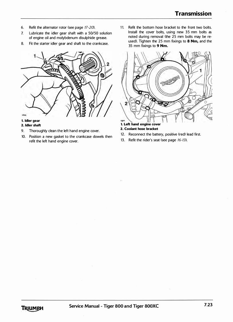
6. Refit the a lternator rotor <see page 17-20>.
Z Lubricate the idler gear shaft with a 50/50 solution of engine oil and molybdenum disulphide grease.
8. Fit the starter idler gear and shaft to the crankcase.
1. Idler gear
2. Idler shaft
9. Thoroughly clean the left hand engine cover. 10. Position a new gasket to the crankcase dowels then
refit the left hand engine cover.
Transmission
1 1 . Refit the bottom hose bracket to the front two bolts.
XX
I nsta l l the cover bolts, using new 3 5 mm bolts as noted during removal (the 25 mm bolts may be reused). Tighten the 25 mm fixings to 8 Nm, and the 35 mm fixings to 9 Nm.
2� g
1. Left hand engine cover
2. Coolant hose bracket
12 . Reconnect the battery, positive <red) lead first. 1 3 . Refit the rider's seat (see page 16-13).
SeNice Manual - Tiger 800 and Tiger 800XC 7.23
Transmission
This page intentionally left blank
7.24 SeJVice Manual - Tiger 800 and Tiger 800XC

8 Lubrication
Table of Contents
Exploded View - Sump . . . . . . . . . . . . . . . . . . . . . . . . . . . . . . . . . . . . . . . . . . . . . . . . . . . . . . . . . . . . . . . . . . . . . 8. 2
Exploded View - Oil Pump/Water Pump, Gears and Heat Exchanger . . . . . . . . . . . . . . . . . . . . . . . . . . . . . . 8. 3
Engine Oil Circuit . . . . . . . . . . . . . . . . . . . . . . . . . . . . . . . . . . . . . . . . . . . . . . . . . . . . . . . . . . . . . . . . . . . . . . . . . 8. 4
Engine Oil Circuit Description . . . . . . . . . . . . . . . . . . . . . . . . . . . . . . . . . . . . . . . . . . . . . . . . . . . . . . . . . . . . . . . 8.5
Heat Exchanger . . . . . . . . . . . . . . . . . . . . . . . . . . . . . . . . . . . . . . . . . . . . . . . . . . . . . . . . . . . . . . . . . . . . . . . . . . . 8.5
Engine Oil . . . . . . . . . . . . . . . . . . . . . . . . . . . . . . . . . . . . . . . . . . . . . . . . . . . . . . . . . . . . . . . . . . . . . . . . . . . . . . . 8. 6 Specification . . . . . . . . . . . . . . . . . . . . . . . . . . . . . . . . . . . . . . . . . . . . . . . . . . . . . . . . . . . . . . . . . . . . . . . . 8. 6 Triumph Engine Oil . . . . . . . . . . . . . . . . . . . . . . . . . . . . . . . . . . . . . . . . . . . . . . . . . . . . . . . . . ·. . . . . . . . . 8. 6
Oil Level Inspection . . . . . . . . . . . . . . . . . . . . . . . . . . :·. . . . . . . . . . . . . . . . . . . . . . . . . . . . . . . . . . . . . . . . . . . . . 8. 6
Oil and Oil Fi lter Change . . . . . . . . . . . . . . . . . . . . . . . . . . . . . . . . . . . . . . . . . . . . . . . . . . . . . . . . . . . . . . . . . . . 8. 7 Disposal of Used Engine Oil . . . . . . . . . . . . . . . . . . . . . . . . . . . . . . . . . . . . . . . . . . . . . . . . . . . . . . . . . . . 8. 8
Oil Pump . . . . . . . . . . . . . . . . . . . . . . . . . . . . . . . . . . . . . . . . . . . . . . . . . . . . . . . . . . . . . . . . . . . . . . . . . . . . . . . . 8. 8 Removal . . . . . . . . . . . . . . . . . . . . . . . . . . . . . . . . . . . . . . . . . . . . . . . . . . . . . . . . . . . . . . . . . . . . . . . . . . . 8. 8 Inspection . . . . . . . . . . . . . . . . . . . . . . . . . . . . . . . . . . . . . . . . . . . . . . . . . . . . . . . . . . . . . . . . . . . . . . . . . . 8. 1 1 Assembly. . . . . . . . . . . . . . . . . . . . . . . . . . . . . . . . . . . . . . . . . . . . . . . . . . . . . . . . . . . . . . . . . . . . . . . . . . . 8. 12 Installation . . . . . . . . . . . . . . . . . . . . . . . . . . . . . . . . . . . . . . . . . . . . . . . . . . . . . . . . . . . . . . . . . . . . . . . . . . 8. 13
Low Oil Pressure Warning Light Switch . . . . . . . . . . . . . . . . . . . . . . . . . . . . . . . . . . . . . . . . . . . . . . . . . . . . . . 8. 14 Removal . . . . . . . . . . . . . . . . . . . . . . . . . . . . . . . . . . . . . . . . . . . . . . . . . . . . . . . . . . . . . . . . . . . . . . . . . . . 8. 14 Installation . . . . . . . . . . . . . . . . . . . . . . . . . . . . . . . . . . . . . . . . . . . . . . . . . . . . . . . . . . . . . . . . . . . . . . . . . . 8. 14
Sump . . . . . . . . . . . . . . . . . . . . . . . . . . . . . . . . . . . . . . . . . . . . . . . . . . . . . . . . . . . . . . . . . . . . . . . . . . . . . . . . . . 8. 15 Removal . . . . . . . . . . . . . . . . . . . . . . . . . . . . . . . . . . . . . . . . . . . . . . . . . . . . . . . . . . . . . . . . . . . . . . . . . . . 8. 15 Instal lation . . . . . . . . . . . . . . . . . . . . . . . . . . . . . . . . . . . . . . . . . . . . . . . . . . . . . . . . . . . . . . . . . . . . . . . . . . 8. 16
Heat Exchanger . . . . . . . . . . . . . . . . . . . . . . . . . . . . . . . . . . . . . . . . . . . . . . . . . . . . . . . . . . . . . . . . . . . . . . . . . . 8. 17 Removal . . . . . . . . . . . . . . . . . . . . . . . . . . . . . . . . . . . . . . . . . . . . . . . . . . . . . . . . . . . . . . . . . . . . . . . . . . . 8. 17 Inspection . . . . . . . . . . . . . . . . . . . . . . . . . . . . . . . . . . . . . . . . . . . . . . . . . . . . . . . . . . . . . . . . . . . . . . . . . . 8. 17 Instal lation . . . . . . . . . . . . . . . . . . . . . . . . . . . . . . . . . . . . . . . . . . . . . . . . . . . . . . . . . . . . . . . . . . . . . . . . . . 8. 18
SeNice Manual - Tiger 800 and Tiger 800XC 8.1
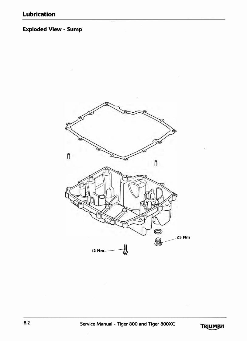
Lubrication
Exploded View - Sump
�
12 Nm---! � 25 Nm
8.2 SeiVice Manual - Tiger 800 and Tiger 800XC

Lubrication
Exploded View - Oil Pump/Water Pump, Gears and Heat Exchanger
13 Nm 10 Nm
59 Nm
12 Nm
SeiVice Manual - Tiger 800 and Tiger 800XC 8.3

Lubrication
Engine Oil Circuit
.A. - COOLED OIL 6. - U NCOOLED OIL
cdah
8.4 Service Manual - Tiger 800 and Tiger 800XC
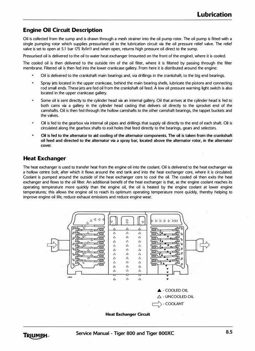
Lubrication
Engine Oil Circuit Description
Oil is col lected from the sump and is drawn through a mesh strainer into the oil pump rotor. The oi l pump is fitted with a single pumping rotor which suppl ies pressurised oil to the lubrication circuit via the oi l pressure rel ief valve. The relief valve is set to open at 5.1 bar (75 lb/in2) and when open, returns high pressure oi l direct to the sump.
Pressurised oil is del ivered to the oil to water heat exchanger <mounted on the front of the engine), where it is cooled.
The cooled oi l is then del ivered to the outside rim of the oil fi lter, where it is fi ltered by passing through the fi lter membrane. Filtered oil is then fed into the lower crankcase gal lery. From here it is distributed around the engine:
Oil is del ivered to the crankshaft main bearings and, via dri l l ings in the crankshaft, to the big end bearings.
Spray jets located in the upper crankcase, behind the main bearing shel ls, lubricate the pistons and connecting rod small ends. These jets are fed oil from the crankshaft oi l feed. A low oil pressure warning light switch is also located in the upper crankcase gal lery.
Some oil is sent directly to the cylinder head via an internal gal lery. Oil that arrives at the cyl inder head is fed to both cams via a gal lery in the cylinder head casting that del ivers oil directly to the sprocket end of the camshafts. Oil is then fed through the hollow camshafts to the other camshaft bearings, the tappet buckets and the valves.
Oil is fed to the gearbox via internal oil pipes and dri l l ings that supply oil directly to the end of each shaft. Oil is circu lated along the gearbox shafts to exit holes that feed directly to the bearings, gears and selectors.
Oil is fed to the a lternator to aid cooling of the alternator components. The oil is taken from the crankshaft oil feed and directed to the alternator via a spray bar, located above the alternator rotor, in the alternator cover.
Heat Exchanger
The heat exchanger is used to transfer heat from the engine oil into the coolant. Oil is del ivered to the heat exchanger via a hol low centre bolt, after which it flows around the end tank and into the heat exchanger core, where it is circu lated. Coolant is pumped around the outside of the heat exchanger core to cool the oil. The cooled oil then exits the heat exchanger and flows to the oil filter. An additional benefit of the heat exchanger is that, as the engine coolant reaches its operating temperature more quickly than the engine oil, the oi l is heated by the engine coolant at lower engine temperatures; this a l lows the engine oil to reach its optimum operating temperature more quickly, thereby helping to improve engine oil l ife, reduce exhaust emissions and reduce engine wear.
Heat Exchanger Circuit
.A. - COOLED O IL t6. - UNCOOLED O IL
c:=> - COOLANT
SeiVice Manual - Tiger 800 and Tiger 800XC 8.5

Lubrication
Engine Oil
Specification
Use semi or fu lly synthetic lOW/40 or lSW/50 motorcycle engine oil which meets specification API SH (or higher) and JASO MA, such as Castrol Power 1 Racing 4T, sold as Castrol Power RS Racing 4T in some countries.
Triumph high performance fuel in jected engines are designed to use semi or fu lly synthetic motorcycle engine oil which meets specification API SH <or higher> AN D JASO MA. Do not add any chemica l additives to the engine oi l . The engine oil a lso lubricates the clutch and any additives could cause the clutch to sl ip. Do not use minera l, vegetable, non-detergent oi l, castor based oils or any oil not conforming to the required specification. The use of these oils may cause instant, severe engine damage. Ensure no foreign matter enters the crankcase during an oil change or top-up.
Triumph Engine Oil
Your Triumph Motorcycle is a qual ity engineered product which has been carefu lly bui lt and tested to exacting standards. Triumph Motorcycles are keen to ensure that you enjoy optimum performance from your machine and with this objective in mind have tested many of the engine lubricants currently avai lable to the l imits of their performance.
Oil Level Inspection
In order for the engine, transmission, and clutch to function correctly, mainta in the engine oil at the correct level, and change the oil and oil filter in accordance with schedu led maintenance requirements.
Never start the engine or run the engine in a confined area. Exhaust fumes are poisonous and can cause loss of consciousness and death with in a short period of time. Always operate your motorcycle in the open-air or in an area with adequate venti lation.
Motorcycle operation with insufficient, deteriorated, or contaminated engine oi l wi l l cause accelerated engine wear and may result in engine or transmission seizure. Seizure of the engine or transmission may lead to loss of motorcycle control and an accident.
Running the engine with insufficient oil will cause engine damage. If the low oil pressure indicator remains on, stop the engine immediately and investigate the cause.
1 . Start the engine and run a t idle for approximately five minutes.
2. Stop the engine, then wait for at least three minutes to a l low the oil to settle.
3 . Note the o i l level visible in the sight g lass.
1. Filler
2. Sight glass
3. Oil level <correct level shown>
4. Crankcase oil level lines
8.6 SeNice Manual - Tiger 800 and Tiger 800XC

4. When correct, oi l should be visible in the sight-g lass at a point mid-way between the two horizontal l ines marked on the crankcase.
Note:
• An accurate indication of the level of oil in the engine is only shown when the engine is at normal operating temperature . and the motorcycle is upright <not on the side stand).
5. If it is necessary to top up the o i l level, remove the fi l ler plug and add oil, a l ittle at a time, until the level registered in the sight g lass is correct.
6. Once the correct level is reached, fit and tighten the filler plug.
Lubrication
Oil and Oil Filter Change
Prolonged or repeated contact with engine oil can lead to skin dryness, irritation and dermatitis. In addition, used engine oil conta ins potentia l ly harmful contamination which can cause cancer. Wear su itable cloth ing and avoid skin contact. The engine oil and filter must be replaced in accordance with scheduled maintenance requirements.
1. Warm up the engine thoroughly, and then stop the engine.
2. Place an o i l pan beneath the engine.
The oil may be hot to the touch. Contact with hot oil may cause the skin to be scalded or burned.
3. Remove the oil drain plug.
1. Oil drain plug
2. Oil filter
4. With the motorcycle on level ground, and on the sidestand, a l low the oi l to completely drain .
5. Unscrew and remove the oi l filter using Triumph service tool T3 880313 .
6. Dispose of the o ld filter in an environmentally friendly way.
Z Apply a smear of clean engine oi l to the seal ing ring of the new oil filter.
8. Fit the oil filter and tighten to 10 Nm using Triumph service tool T3 880313 .
9 . After the o i l has completely drained out, fit a new seal ing washer to the drain plug. Fit and tighten the plug to 25 Nm.
SeiVice Manual - Tiger 800 and Tiger 800XC 8.7

Lubrication
10. Fi l l the engine with new oil of the type and grade l isted previously and in the specification section.
1 1 . Start the engine and al low it to idle for a minimum of 30 seconds.
Raising the engine speed above idle before the oil reaches al l parts of the engine can cause engine damage or seizure. Only raise engine speed after running the engine for 30 seconds to al low the oil to circulate fu l ly.
12 . Ensure that the oi l pressure warning l ight extinguishes shortly after starting.
If the engine oi l pressure is too low, the low oil pressure warning l ight wil l i l luminate. If this l ight stays on when the engine is running, stop the engine immediately and investigate the cause. Running the engine with low oil pressure wi l l cause engine damage.
13 . Stop the engine and check the oi l level . Adjust if necessary.
Disposal of Used Engine Oil
To protect the environment, do not pour oil on the ground, down sewers or drains, or into water courses. Dispose of used oil sensibly. If in doubt contact your local authority.
Oil Pump
' � . � - - " � -� -
/ t ' I , " ' j ! , J • f • ,. il t J l �
� " "
Prolonged or repeated contact with engine oi l can lead to skin dryness, irritation and dermatitis. Furthermore, used engine oi l contains potential ly harmful contaminants which can cause cancer. When handl ing used engine oil, a lways wear protective clothing and avoid any skin contact with the oi l .
Do not pour engine oil on the ground, down sewers or drains, or into water courses. To prevent pol lution of water courses etc., d ispose of used oil sensibly. If in doubt contact your loca l authority.
Removal
Note:
• The oil pump and water pump are supplied as an assembly and cannot be · separated. This procedure covers the removal of the oil and water pump assembly.
1 . Remove the rider's seat <see page 16- 13).
2. Disconnect the battery, negative (black> lead first. 3 . Drain the coolant <see page 1 1-S>.
4. Drain the engine oi l <see page 8- 7>.
The oil may be hot to the touch. Contact with hot oi l may cause the skin to be scalded or burned.
8.8 SeiVice Manual - Tiger 800 and Tiger 800XC
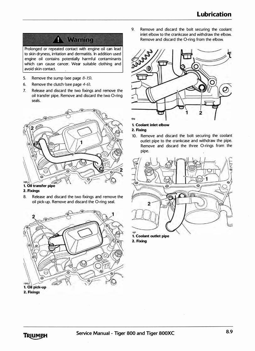
� �� - - ' -- - - �,-- - � r- -
I 1, , "' t • :: ! � ) � • � 1 • • ' j
Prolonged or repeated contact with engine oi l can lead to skin dryness, irritation and dermatitis. In addition used engine oil contains potential ly harmful contaminants which can cause cancer. Wear su itable clothing and avoid skin contact.
5. Remove the sump (see page 8- 15). 6. Remove the clutch (see page 4-6).
Z Release and discard the two fixings and remove the oil transfer pipe. Remove and discard the two 0-ring seals.
j 8 @ �"-../ � �
1. Oil transfer pipe
2. Fixings
8. Release and discard the two fixings and remove the oil pick-up. Remove and discard the 0-ring seal .
Lubrication
9. Remove and discard the bolt securing the coolant in let elbow to the crankcase and withdraw the elbow. Remove and discard the 0-ring from the elbow.
1. Coolant inlet elbow
2. Fixing
10. Remove and discard the bolt securing the coolant outlet pipe to the crankcase and withdraw the pipe. Remove and discard the three 0-rings from the pipe.
cglr
1. Coolant outlet pipe
2. Fixing
SeJVice Manual - Tiger 800 and Tiger 800XC 8.9
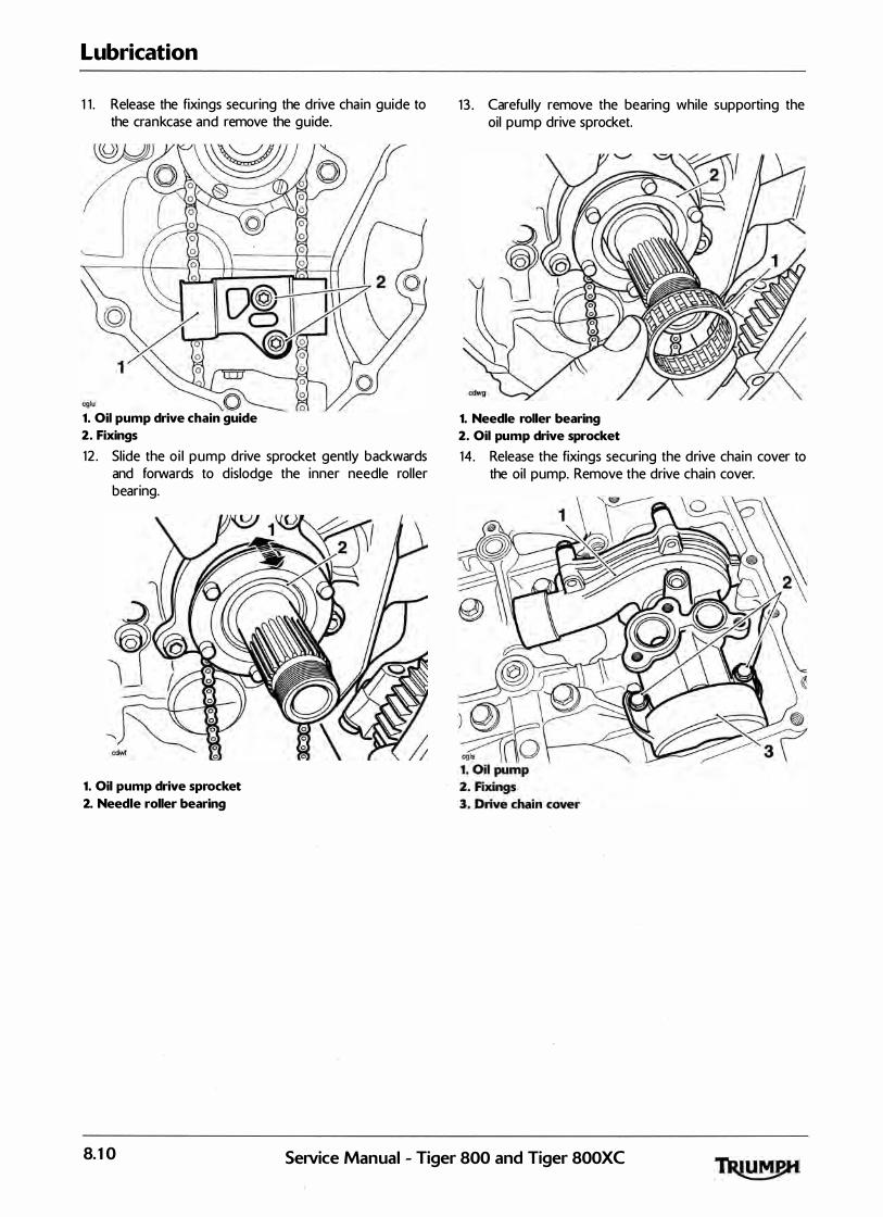
Lubrication
1 1 . Release the fixings securing the drive cha in guide to the crankcase and remove the guide.
1. Oil pump drive chain guide
2. Fixings
12 . Slide the o i l pump drive sprocket gently backwards and forwards to d islodge the inner needle roller bearing.
1. Oil pump drive sprocket
2. Needle roller bearing
1 3 . Careful ly remove the bearing while supporting the oil pump drive sprocket.
1. Needle roller bearing
2. Oil pump drive sprocket
14. Release the fixings securing the drive chain cover to the oil pump. Remove the drive chain cover.
8.10 Service Manual - Tiger 800 and Tiger 800XC
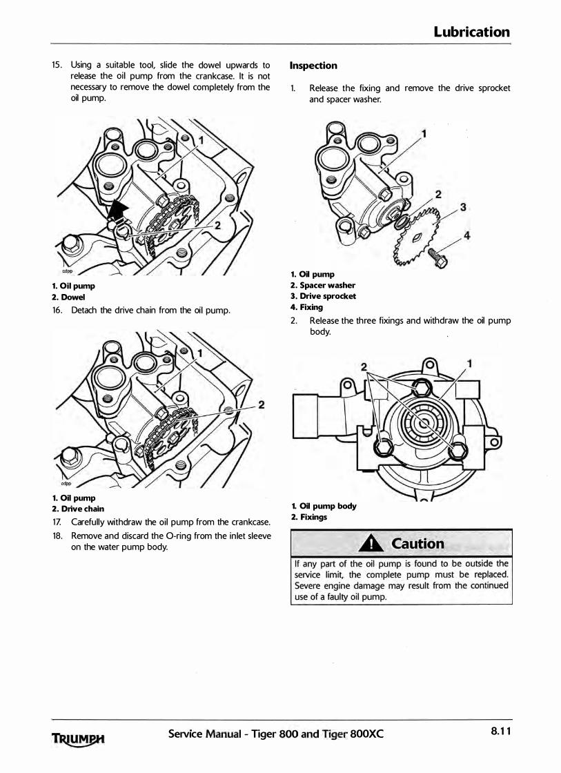
dowel upwards to . ble tool, sl ide the nkcase. lt is not
15 . Using a hSUI�
I pump from thel ��pletely from the
release t e the dowe c necessary to remove
oil pump.
1 Oil pump •
· 1 ump 2. Dowel
. h ·n from the Ol p . Detach the dnve c al 16 .
1. o;o pump.
the crankcase. D ·ve cham
. 1 pump from 2. n
'thdraw the oo h in let sleeve
Z Carefully Wl h O-ring from t e
1 . d discard t e 18. Remove a
tner pump body. on the wa
Inspection
· and Release the fixmg 1. and spacer washer.
1 Oil pump .
S cer washer
Lubrication
the drive sprocket remove
2· pa
ket 3 Drive sproc
the oil pump
•
· hdraw 4. Fixing
hree fixings and Wit Release the t .
2. body.
1. Oil pump body
2. Fixings
-----=��i·Q ler f800XC ---- . , .
r 800 and T•ger . Manual - T•ge Se1V1ce 8.11
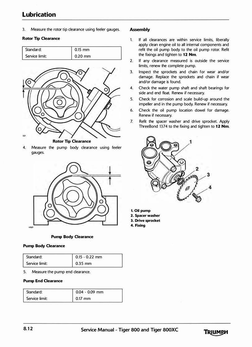
Lubrication
3 . Measure the rotor t ip clearance using feeler gauges.
Rotor Tip Clearance
Standard: Service l imit:
0.1 5 mm 0.20 mm
Rotor Tip Clearance
4. Measure the pump body clearance using feeler gauges.
cdqh
Pump Body Clearance
Pump Body Clearance
Standard: Service l imit:
0.15 - 0 .22 mm 0.3 5 mm
5. Measure the pump end clearance.
Pump End Clearance
Standard: Service l imit:
0.04 - 0.09 mm 0.17 mm
Assembly
1 . I f a l l clearances are within service l imits, l iberal ly apply clean engine oil to al l interna l components and refit the oi l pump body to the oi l pump rotor. Refit the fixings and tighten to 12 Nm.
2. If any clearance measured is outside the service l im its, renew the complete pump.
3. I nspect the sprockets and chain for wear and/or damage. Replace the sprockets and cha in if wear and/or damage is found.
4. Check the water pump shaft and shaft bearings for side and end float. Renew if necessary.
5. Check for corrosion and scale bui ld-up around the impeller and in the pump body. Renew if necessary.
6. Check the oil pump location dowel for damage. Renew if necessary.
Z Refit the spacer washer and drive sprocket. Apply ThreeBond 1 374 to the fixing and tighten to 12 Nm.
1. Oil pump
2. Spacer washer
3. Drive sprocket
4. Fixing
8.12 SeiVice Manual - Tiger 800 and Tiger 800XC
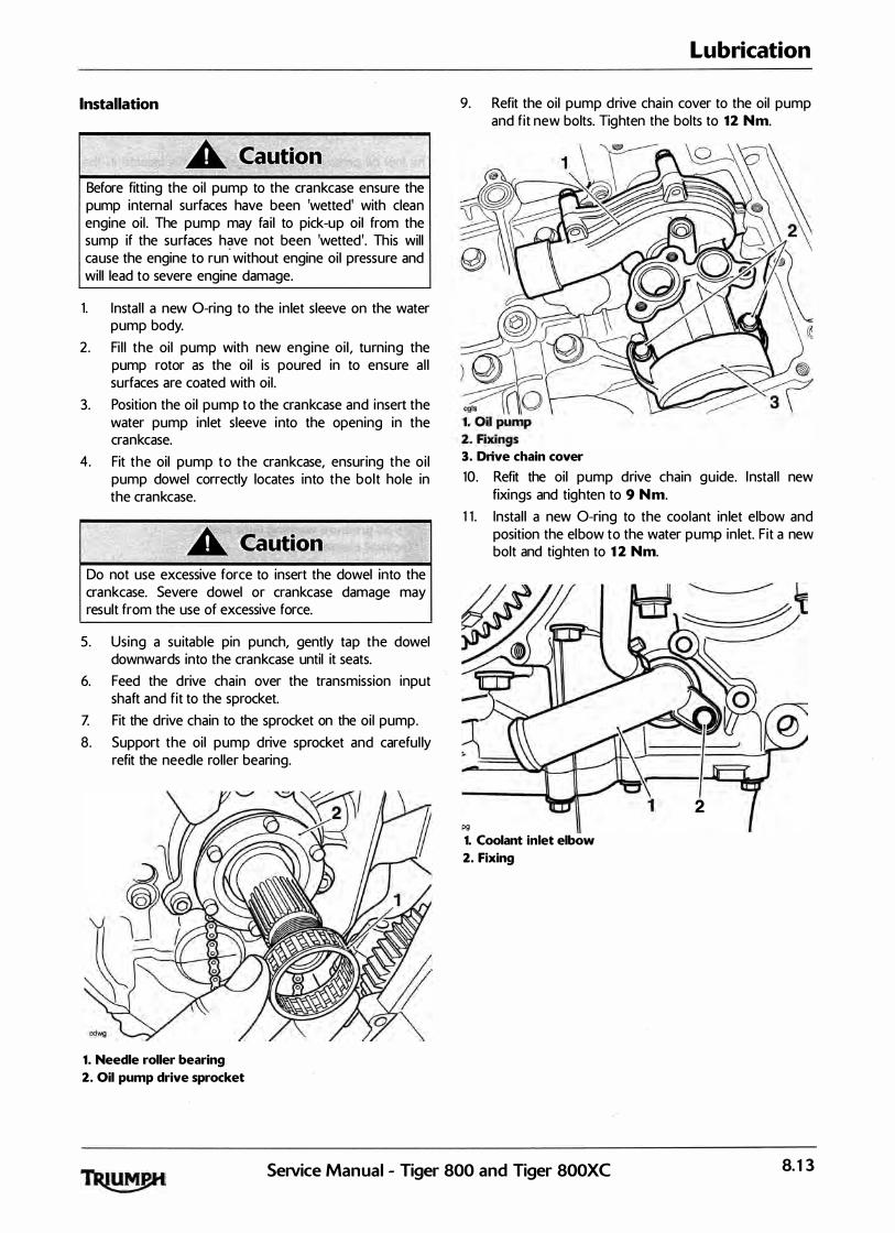
Installation
Before fitting the oil pump to the crankcase ensure the pump internal surfaces have been 'wetted' with clean engine oil . The pump may fa i l to pick-up oil from the sump if the surfaces have not been 'wetted'. This will cause the engine to run without engine oil pressure and will lead to severe engine damage.
1. Instal l a new 0-ring to the inlet sleeve on the water pump body.
2. Fi l l the oil pump with new engine oi l , turning the pump rotor as the oil is poured in to ensure a l l surfaces are coated with oil .
3. Position the oil pump to the crankcase and insert the water pump inlet sleeve into the opening in the crankcase.
4. Fit the oil pump to the crankcase, ensuring the oi l pump dowel correctly locates into the bolt hole in the crankcase.
Do not use excessive force to insert the dowel into the crankcase. Severe dowel or crankcase damage may result from the use of excessive force.
5. Using a su itable pin punch, gently tap the dowel downwards into the crankcase until it seats.
6. Feed the drive chain over the transmission input shaft and fit to the sprocket.
Z Fit the drive chain to the sprocket on the oi l pump. 8. Support the oil pump drive sprocket and careful ly
refit the needle roller bearing.
1. Needle roller bearing
2. Oil pump drive sprocket
Lubrication
9. Refit the oil pump drive cha in cover to the oil pump and fit new bolts. Tighten the bolts to 12 Nm.
3. Drive chain cover
10. Refit the oil pump drive chain guide. I nstal l new fixings and tighten to 9 Nm.
1 1 . Instal l a new 0-ring to the coolant in let elbow and position the elbow to the water pump in let. Fit a new bolt and tighten to 12 Nm.
2 pg
1. Coolant inlet elbow
2. Fixing
Service Manual - Tiger 800 and Tiger 800XC 8.13

Lubrication
12 . Insta l l three new 0-rings to the coolant outlet pipe and position the pipe through the crankcase, locating it to the water pump outlet. Instal l a new fixing and tighten to 12 Nm.
cglr
1. Coolant outlet pipe
2. Fixing
1 3 . Instal l a new 0-ring to the o i l pick-up and refit the oil pick-up. Fit new bolts and tighten to 12 Nm.
14. Instal l two new 0-rings to the oi l transfer pipe and refit the oil transfer pipe. Fit new bolts and tighten to 12 Nm.
15 . Refit the clutch (see page 4- 10>.
16 . Refit the sump, ensuring the water pump drain tube is correctly insta l led (see page 8- 16).
1Z Reconnect the battery, positive <red lead) first. 18 . Refit the rider's seat <see page 16- 13).
19. Refi l l the engine with oi l (see page 8-7>.
20. Refi l l the cooling system (see page 1 1 -5>.
Low Oil Pressure Warning Light
Switch
The low oil pressure warning l ight switch is located in the upper crankcase, behind the cyl inder head.
Removal
1. Low oil pressure warning light switch
2. Electrical connection
1 . Remove the rider's seat <see page 16- 13>.
2. Disconnect the battery, negative <black> lead first. 3 . Disconnect the electrical connection to the switch. 4. Remove the switch and col lect the copper washer.
Installation
1 . I ncorporating a new copper washer, f it the switch and tighten to 13 Nm.
2. Refit the electrical connection. 3 . Reconnect the battery, positive (red) lead first. 4. Refit the rider's seat <see page 16- 13).
8.14 SeNice Manual - Tiger 800 and Tiger 800XC
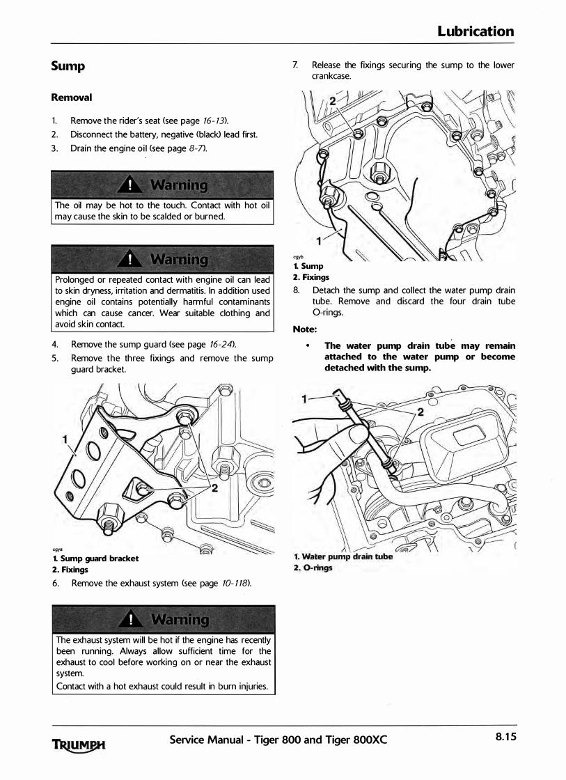
Sump
Removal
1 . Remove the rider's seat <see page 16- 13).
2 . Disconnect the battery, negative <black> lead first. 3 . Drain the engine o i l <see page 8-7>.
The oil may be hot to the touch. Contact with hot oil may cause the skin to be sca lded or burned.
Prolonged or repeated contact with engine oi l can lead to skin dryness, irritation and dermatitis. In addition used engine oil contains · potential ly harmful contaminants which can cause cancer. Wear su itable clothing and avoid skin contact.
4. Remove the sump guard (see page 16-24).
5. Remove the three fixings and remove the sump guard bracket.
cgya
1. Sump guard bracket
2. Fixings
6. Remove the exhaust system (see page 10- 1 18>.
The exhaust system wil l be hot if the engine has recently been running. Always a l low sufficient time for the exhaust to cool before working on or near the exhaust system. Contact with a hot exhaust could result in burn injuries.
Lubrication
Z Release the fixings securing the sump to the lower crankcase.
cgyb
1. Sump
2. Fixings
8. Detach the sump and col lect the water pump drain tube. Remove and discard the four drain tube 0-rings.
Note:
• The water pump drain tube may remain attached to the water pump or become detached with the sump.
Service Manual - Tiger 800 and Tiger 800XC 8.15

Lubrication
Installation
1 . Incorporating new 0-rings (two each end of the tube), position the water pump drain tube to the oil pump.
8 @
� � c::iif7 \\
1 . Water pump drain tube
2. 0-rings
2. Incorporating a new sump gasket/baffle, position the sump to the lower crankcase.
3 . Tighten the sump fixings to 12 Nm.
5. Refit the sump guard bracket and secure with the three fixings. Tighten to 15 Nm.
1. Sump guard bracket
2. Fixings
6. Refit the sump guard (see page 16-2T> .
Note:
• Use new exhaust gaskets at the downpipe connections with the cylinder head.
Z Fil l the engine with the correct grade of engine oi l <see page 8-6>.
8. Reconnect the battery, positive <red> lead first. 9. Start the engine and ensure that the low oil pressure
warning l ight goes out shortly after starting. 10. Stop the engine and check the engine oi l level.
Adjust if necessary (see page 8-6) . . 1 1 . Refit the rider's seat <see page 16- 13).
8.16 SeNice Manual - Tiger 800 and Tiger 800XC
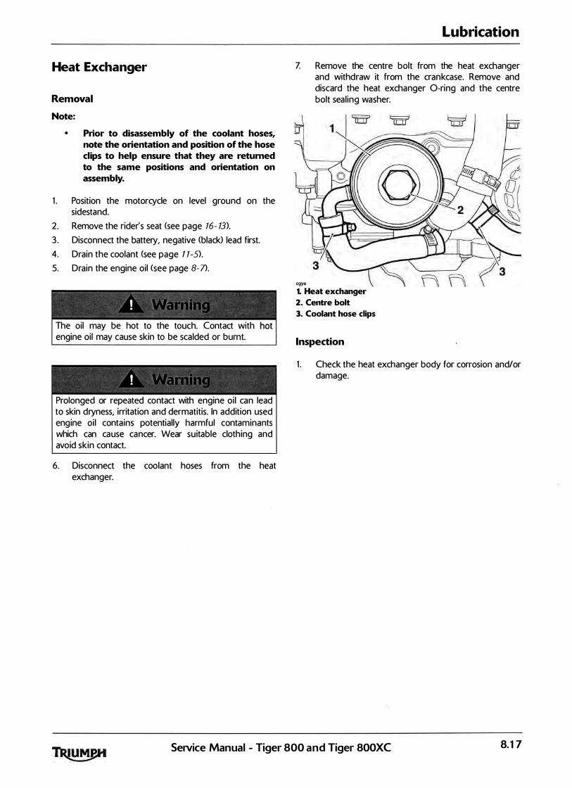
Heat Exchanger
Removal
Note:
• Prior to disassembly of the coolant hoses, note the orientation and position of the hose clips to help ensure that they are returned to the same positions and orientation on assembly.
1 . Position the motorcycle on , level ground on the sidestand.
2. Remove the rider's seat (see page 16- 13>.
3 . Disconnect the battery, negative (black) lead first. 4. Drain the coolant (see page 1 1-S>.
5. Drain the engine oil <see page 8-7>.
The oil may be hot to the touch. Contact with engine oi l may cause skin to be scalded or burnt.
Prolonged or repeated contact with engine oi l can lead to skin dryness, irritation and dermatitis. In addition used engine oi l contains potential ly harmful contaminants which can cause cancer. Wear su itable cloth ing and avoid skin contact.
6. Disconnect the coolant hoses from the heat exchanger.
Lubrication
Z Remove the centre bolt from the heat exchanger and withdraw it from the crankcase. Remove and discard the heat exchanger 0-ring and the centre bolt seal ing washer.
cgye 1. Heat exchanger
2. Centre bolt
3. Coolant hose clips
Inspection
1 . Check the heat exchanger body for corrosion and/or damage.
SeiVice Manual - Tiger 800 and Tiger 800XC 8.17
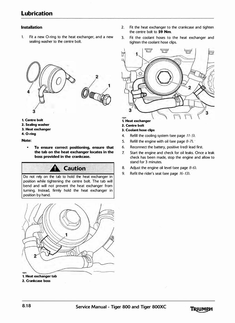
Lubrication
Installation
1 . Fit a new 0-ring to the heat exchanger, and a new seal ing washer to the centre bolt.
1. Centre bolt
2. Sealing washer
3. Heat exchanger
4. 0-ring
Note:
• To ensure correct positioning, ensure that the tab on the heat exchanger locates in the boss provided in the crankcase.
Do not rely on the tab to hold the heat exchanger in position whi le tightening the centre bolt. The tab wi l l bend and wil l not prevent the heat exchanger from turning. Instead, firmly hold the heat exchanger in position by hand.
cgyq
1. Heat exchanger tab
2. Crankcase boss
2. Fit the heat exchanger to the crankcase and tighten the centre bolt to 59 Nm.
3. Fit the coolant hoses to the heat exchanger and tighten the coolant hose clips.
cgye 1. Heat exchanger
2. Centre bolt
3. Coolant hose clips
4. Refi l l the cooling system (see page 1 1-S>.
5. Refi l l the engine with oi l <see page 8- 7>. · 6. Reconnect the battery, positive <red) lead first. Z Start the engine and check for oi l leaks. Once a leak
check has been made, stop the engine and al low to stand for 3 minutes.
8. Adjust the engine oil level (see page 8-6>. 9. Refit the rider's seat <see page 16- W.
8.18 SeiVice Manual - Tiger 800 and Tiger 800XC

9 Engine Removal/Refit
Table of Contents
Exploded View - Frame Fixings . . . . . . . . . . . . . . . . . . . . . . . . . . . . . . . . . . . . . . . . . . . . . . . . . . . . . . . . . . . . . . 9. 2
Engine Removal/Refit . . . . . . . . . . . . . . . . . . . . . . . . . . . . . . . . . . . . . . . . . . . . . . . . . . . . . . . . . . . . . . . . . . . . . . 9. 3 Removal . . . . . . . . . . . . . . . . . . . . . . . . . . . . . . . . . . . . . . . . . . . . . . . . . . . . . . . . . . . . . . . . . . . . . . . . . . . 9. 3 Insta llation . . . . . . . . . . . . . . . . . . . . . . . . . . . . . . . . . . . . . . . . . . . . . . . . . . . . . . . . . . . . . . . . . . . . . . . . . . 9.5
SeiVice Manual - Tiger 800 and Tiger 800XC 9.1

Engine Removal/Refit
Exploded View - Frame Fixings
48 Nm
::\ � 48 Nm
48 Nm
48 Nm
9.2 Service Manual - Tiger 800 and Tiger 800XC
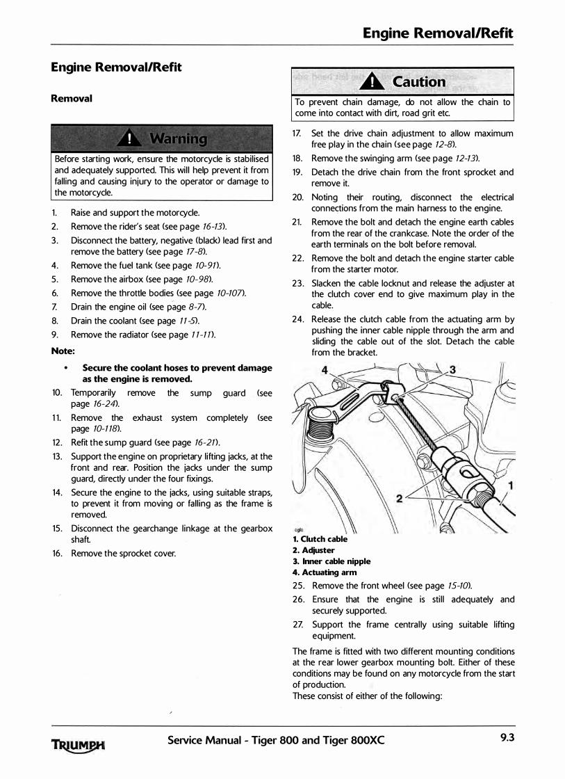
Engine Removal/Refit
Removal
� � �
' ' 0 '
Before starting work, ensure the motorcycle is stabi l ised and adequately supported. This wi l l help prevent it from fal l ing and causing injury to the operator or damage to the motorcycle.
1 . Ra ise and support the motorcycle. 2 . Remove the rider's seat <see page 16-13).
3 . Disconnect the battery, negative (black> lead first and remove the battery (see page 17-8>.
4. Remove the fuel tank <see page 10-91).
5. Remove the airbox <see page 10-98>.
6. Remove the throttle bodies <see page 10-107>.
Z Drain the engine oi l (see page 8-7>.
8. Drain the coolant (see page 1 1 -5).
9. Remove the radiator <see page 1 1 -1 n.
Note:
• Secure the coolant hoses to prevent damage as the engine is removed.
10. Temporarily remove the sump guard . (see page 16-24>.
1 1 . Remove the exhaust system completely <see page 10- 1 18>.
12 . Refit the sump guard <see page 16-21) .
13 . Support the engine on proprietary l ifting jacks, at the front and rear. Position the jacks under the sump guard, directly under the four fixings.
14. Secure the engine to the jacks, using suitable straps, to prevent it from moving or fal l ing as the frame is removed.
15 . Disconnect the gearchange l inkage at the gearbox shaft.
16 . Remove the sprocket cover.
/
Engine Removal/Refit
To prevent chain damage, do not a l low the chain to come into contact with dirt, road grit etc.
1Z Set the drive cha in adjustment to a l low maximum free play in the cha in <see page 12-8>.
18 . Remove the swinging arm (see page 12-13).
19. Detach the drive chain from the front sprocket and remove it.
20. Noting their routing, d isconnect the electrical connections from the main harness to the engine.
21 . Remove the bolt and detach the engine earth cables from the rear of the crankcase. Note the order of the earth terminals on the bolt before removal.
22 . Remove the bolt and detach the engine starter cable from the starter motor.
23 . Slacken the cable locknut and release the adjuster at the clutch cover end to give maximum play in the cable.
24. Release the clutch cable from the actuating arm by pushing the inner cable nipple through the arm and sliding the cable out of the slot. Detach the cable from the bracket.
1. Clutch cable
2. Adjuster
3. Inner cable nipple
4. Actuating arm
25 . Remove the front wheel <see page 15-10>.
26. Ensure that the engine is sti l l adequately and securely supported.
2Z Support the frame centra l ly using suitable l ifting equipment.
The frame is fitted with two different mounting conditions at the rear lower gearbox mounting bolt. Either of these conditions may be found on any motorcycle from the start of production. These consist of either of the fol lowing:
SeNice Manual - Tiger 800 and Tiger 800XC 9.3

Engine Removal/Refit
•
the frame is fitted with a conventional adjuster sleeve, located on the left hand side of the frame;
the frame is fitted with a shim (available in varying thicknesses) located between the crankcase and the engine mounting boss. This arrangement is also fitted with a spacer plate, permanently fitted to the crankcase. A frame adjuster sleeve is fitted to the frame, however this is fitted from the outside of the frame (so that the adjuster slots are inside the frame). This sleeve is not used for frame adjustment; it is only for bolt location purposes.
28. Noting the mounting arrangement described above, release the nut securing the rear lower gearbox mounting bolt. Collect the hardened washer from under the nut.
29. Remove the bolt.
Models Fitted with a Frame Adjustment Shim
1 . Col lect and retain the shim.
cgyk
1. Crankcase plate
2. Frame boss
3. Shim
Models Fitted with a Frame Adjuster Sleeve
1 . Using tool T38801 66 loosen the frame adjuster and unscrew it fu l ly to a l low clearance between the frame and engine.
1. Rear lower frame adjuster sleeve
2. Tool T3880166
All Models:
1 . Note the position of the two spacers insta l led to the two cyl inder head bolts, on the left hand side of the engine.
2. Remove the rear cyl inder head mounting bolts. Col lect the spacer from between the left hand mounting and the frame.
3. Remove the front cyl inder head mounting bolts. Collect the spacer from between the left hand mounting and the frame, and the washer from under the right hand bolt head.
Damage to painted surfaces, such as the frame, cyl inder head or crankcases, could result from inadequate care during this process.
4. Carefully lower the frame at the front and ra ise it at the rear until the rear lower mount clears the crankcase.
5. Careful ly l i ft the frame from the engine in an upwards direction, ensuring the front cyl inder head mounts are clear of the cyl inder head, and the rear mounting is clear of the crankcase.
9.4 SeNice Manual - Tiger 800 and Tiger 800XC
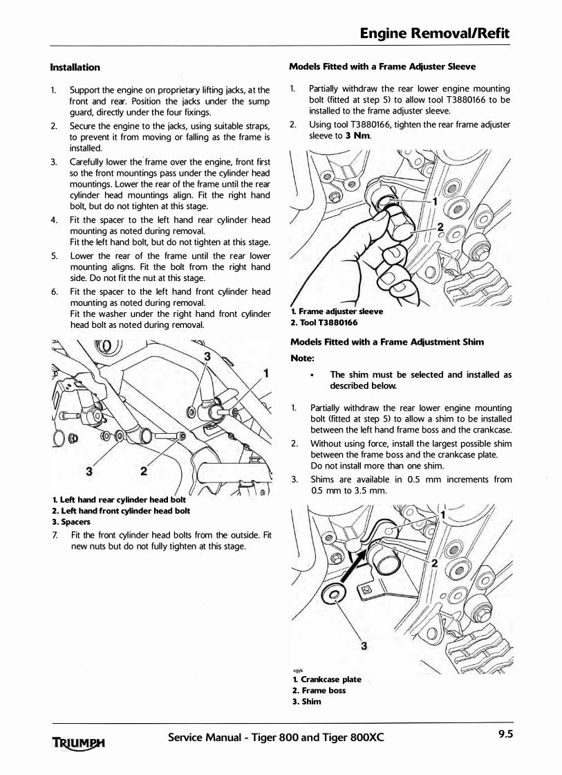
Installation
1 . Support the engine on proprietary l ifting jacks, a t the front and rear. Position the jacks under the sump guard, directly under the four fixings.
2. Secure the engine to the jacks, using suitable straps, to prevent it from moving or fal l ing as the frame is instal led.
3. Carefully lower the . frame over the engine, front first so the front mountings pass under the cyl inder head mountings. Lower the rear of the frame unti l the rear cyl inder head mountings al ign. Fit the right hand bolt, but do not tighten at th is stage.
4. Fit the spacer to the left hand rear cylinder head mounting as noted during removal. Fit the left hand bolt, but do not tighten at this stage.
5. Lower the rear of the frame until the rear lower mounting al igns. Fit the bolt from the right hand side. Do not fit the nut at this stage.
6. Fit the spacer to the left hand front cyl inder head mounting as noted during removal. Fit the washer under the right hand front cyl inder head bolt as noted during removal.
2Y) 1. Left hand rear cylinder head bolt
2. Left hand front cylinder head bolt
3. Spacers
Z Fit the front cyl inder head bolts from the outside. Fit new nuts but do not ful ly tighten at this stage.
Engine Removal/Refit
Models Fitted with a Frame Adjuster Sleeve
1 . Partial ly withdraw the rear lower engine mounting bolt (fitted at step 5) to al low tool T3880166 to be instal led to the frame adjuster sleeve.
2. Using tool T3 880166, tighten the rear frame adjuster sleeve to 3 Nm.
1. Frame adjuster sleeve
2. Tool T3880166
Models Fitted with a Frame Adjustment Shim
Note:
The shim must be selected and installed as described below.
1 . Partia l ly withdraw the rear lower engine mounting bolt (fitted at step 5) to a l low a shim to be insta l led between the left hang frame boss and the crankcase.
2 . Without using force, insta l l the largest possible shim between the frame boss and the crankcase plate. Do not instal l more than one shim.
3. Shims are avai lable in 0.5 mm increments from 0.5 mm to 3 .5 mm.
cgyk
1. Crankcase plate
2. Frame boss
3. Shim
SeiVice Manual - Tiger 800 and Tiger 800XC 9.5

Engine Removal/Refit
All models
1 . Fully insert the lower rear gearbox mounting bolt, refit the hardened washer and fit a new nut. Do not fu lly tighten at this stage.
Unless the fol lowing engine mounting bolt instal lation/ tightening sequence is precisely fol lowed, severe frame damage can occur.
2 . Tighten the engine mounting bolts as shown below.
•
•
Tighten the right hand rear cylinder head ( 1 > bolt to 48 Nm.
Tighten the right hand front cylinder head ( 2) bolt to 48 Nm.
Tighten the left hand rear cylinder head bolt (3) to 48 Nm.
Tighten the left hand front cylinder head bolt ( 4) to 48 Nm.
Tighten the rear lower rear gearbox mounting bolt <S> to 48 Nm.
7� 5
1. Right hand rear cylinder head bolt
2. Right hand front cylinder head bolt
3. Left hand rear cylinder head bolt
4. Left hand front cylinder head bolt
5. Rear lower rear gearbox mounting bolt
3. Refit the swinging arm (see page 12-15>.
4. Refit the clutch cable <see page 4-S>. 5. Reconnect a l l electrica l connections to the engine. 6. Refit the gearchange l inkage, al igning the slot in the
gear selector arm with the dot on the gear change shaft. Refit the bolt and tighten to 9 Nm.
Z Refit the sprocket cover and tighten the bolts to 9 Nm . ·
8. Fit new exhaust seals to the cyl inder head. Ensure that the face of the sea l with the tab is facing the cylinder head.
1. Cylinder head
2. Seal
3. Seal tab
9. Refit the exhaust system <see page 10-95>.
10. Refit the radiator (see page 1 1- 12).
1 1 . Fi l l the engine with oi l of the correct grade and viscosity <see page 8-7>.
12 . Refit the throttle bodies <see page 10-101).
Operation of the motorcycle with incorrectly adjusted, incorrectly routed or damaged throttle cables could interfere with the operation of the brakes, clutch or the throttle itself. Any of these conditions could result in loss of motorcycle control and an accident.
Move the handlebars to left and right ful l lock while checking that cables and harnesses do not bind. Cables or harness that bind wil l restrict the steering and may cause loss of motorcycle contro l and an accident.
9.6 SeiVice Manual - Tiger 800 and Tiger 800XC

13 . Check the throttle cable adjustment <see page 10-104>.
14. Refit the airbox <see page 10-101).
15 . Refit the fuel tank <see page 10-92).
16 . Refit the battery to the battery box and reconnect, positive (red) lead first <see page 17-8>.
Engine Removal/Refit
1Z Refi l l the cooling system <see page 1 1-S>.
18 . Remove the motorcycle from the paddock stand and place on the s ide stand.
19. Refit the seats (see page 16-13).
SeiVice Manual - Tiger 800 and Tiger 800XC 9.7

Engine Removal/Refit
This page intentionally left blank
9.8 SeiVice Manual - Tiger 800 and Tiger 800XC
10 Fuel System/Engine Management
Table of Contents
Exploded View - Fuel Tank and Fuel Pump . . . . . . . . . . . . . . . . . . . . . . . . . . . . . . . . . . . . . . . . . . . . . . . . . . . 10. 7
Exploded View - Fuel Rai l, Throttles and Injectors . . . . . . . . . . . . . . . . . . . . . . . . . . . . . . . . . . . . . . . . . . . . . 10. 8
Exploded View - Airbox . . . . . . . . . . . . . . . . . . . . . . . . . . . . . . . . . . . . . . . . . . . . . . . . . . . . . . . . . . . . . . . . . . . 10.9
Exploded View - Exhaust System . . . . . . . . . . . . . . . . . . . . . . . . . . . . . . . . . . . . . . . . . . . . . . . . . . . . . . . . . . 10. 10
Exploded View - Evaporative System . . . . . . . . . . . . . . . . . . . . . . . . . . . . . . . . . . . . . . . . . . . . . . . . . . . . . . . 10. 1 1
Fuel Requirements . . . . . . . . . . . . . . . . . . . . . . . . . . . . . . . . . . . . . . . . . . . . . . . . . . . . . . . . . . . . . . . . . . . . . . 10. 12 Fuel Requirements - al l countries except USA . . . . . . . . . . . . . . . . . . . . . . . . . . . . . . . . . . . . . . . . . . . 10. 12 Fuel Requirements - U SA . . . . . . . . . . . . . . . . . . . . . . . . . . . . . . . . . . . . . . . . . . . . . . . . . . . . :· . . . . . . . 10. 12 Oxygenated Gasoline . . . . . . . . . . . . . . . . . . . . . . . . . . . . . . . . . . . . . . . . . . . . . . . . . . . . . . . . . . . . . . . 10. 12 Ethanol . . . . . . . . . . . . . . . . . . . . . . . . . . . . . . . . . . . . . . . . . . . . . . . . . . . . . . . . . . . . . . . . . . . . . . . . . . . 10. 12 Methanol . . . . . . . . . . . . . . . . . . . . . . . . . . . . . . . . . . . . . . . . . . . . . . . . . . . . . . . . . . . . . . . . . . . . . . . . . . 10. 12 MTB E <Methyl Tertiary Butyl Ether) . . . . . . . . . . . . . . . . . . . . . . . . . . . . . . . . . . . . . . . . . . . . . . . . . . . . 10. 12
Glossary of Terms . . . . . . . . . . . . . . . . . . . . . . . . . . . . . . . . . . . . . . . . . . . . . . . . . . . . . . . . . . . . . . . . . . . . . . . 10. 13 Air temperature . . . . . . . . . . . . . . . . . . . . . . . . . . . . . . . . . . . . . . . . . . . . . . . . . . . . . . . . . . . . . . . . . . . . 10. 13 Air temperature sensor . . . . . . . . . . . . . . . . . . . . . . . . . . . . . . . . . . . . . . . . . . . . . . . . . . . . . . . . . . . . . . 10. 13 ATDC . . . . . . . . . . . . . . . . . . . . . . . . . . . . . . . . . . . . . . . . . . . . . . . . . . . . . . . . . . . . . . . . . . . . . . . . . . . . . 10. 13 Barometric pressure . . . . . . . . . . . . . . . . . . . . . . . . . . . . . . . . . . . . . . . . . . . . . . . . . . . . . . . . . . . . . . . . . 10. 13 Battery voltage . . . . . . . . . . . . . . . . . . . . . . . . . . . . . . . . . . . . . . . . . . . . . . . . . . . . . . . . . . . . . . . . . . . . . 10. 13 BTDC . . . . . . . . . . . . . . . . . . . . . . . . . . . . . . . . . . . . . . . . . . . . . . . . . . . . . . . . . . . . . . . . . . . . . . . . . . . . . 10. 13 Catalyst . . . . . . . . . . . . . . . . . . . . . . . . . . . . . . . . . . . . . . . . . . . . . . . . . . . . . . . . . . . . . . . . . . . . . . . . . . . 10. 13 Closed throttle position . . . . . . . . . . . . . . . . . . . . . . . . . . . . . . . . . . . . . . . . . . . . . . . . . . . . . . . . . . . . . . 10.13 Coolant temperature . . . . . . . . . . . . . . . . . . . . . . . . . . . . . . . . . . . . . . . . . . . . . . . . . . . . . . . . . . . . . . . . 10. 13 Coolant temperature sensor . . . . . . . . . . . . . . . . . . . . . . . . . . . . . . . . . . . . . . . . . . . . . . . . . . . . . . . . . . 10. 13 Cooling fan status . . . . . . . . . . . . . . . . . . . . . . . . . . . . . . . . . . . . . . . . . . . ". . . . . . . . . . . . . . . . . . . . . . . 10. 13 DTC . . . . . . . . . . . . . . . . . . . . . . . . . . . . . . . . . . . . . . . . . . . . . . . . . . . . . . . . . . . . . . . . . . . . . . . . . . . . . . 10. 13 ECM . . . . . . . . . .' . . . . . . . . . . . . . . . . . . . . . . . . . . . . . . . . . . . . . . . . . . . . . . . . . . . . . . . . . . . . . . . . . . . . 10. 13 Engine speed . . . . . . . . . . . . . . . . . . . . . . . . . . . . . . . . . . . . . . . . . . . . . . . . . . . . . . . . . . . . . . . . . . . . . . 10. 13 Fal l detection . . . . . . . . . . . . . . . . . . . . . . . . . . . . . . . . . . . . . . . . . . . . . . . . . . . . . . . . . . . . . . . . . . . . . . 10. 13 Freeze frame. . . . . . . . . . . . . . . . . . . . . . . . . . . . . . . . . . . . . . . . . . . . . . . . . . . . . . . . . . . . . . . . . . . . . . . 10. 13 Gear position sensor . . . . . . . . . . . . . . . . . . . . . . . . . . . . . . . . . . . . . . . . . . . . . . . . . . . . . . . . . . . . . . . . 10. 13 Idle fuel trim . . . . . . . . . . . . . . . . . . . . . . . . . . . . . . . . . . . . . . . . . . . . . . . . . . . . . . . . . . . . . . . . . . . . . . . 10. 13 Idle fuel ing . . . . . . . . . . . . . . . . . . . . . . . . . . . . . . . . . . . . . . . . . . . . . . . . . . . . . . . . . . . . . . . . . . . . . . . . 10. 14 Idle reference speed . . . . . . . . . . . . . . . . . . . . . . . . . . . . . . . . . . . . . . . . . . . . . . . . . . . . . . . . . . . . . . . . 10. 14 Ignition advance . . . . . . . . . . . . . . . . . . . . . . . . . . . . . . . . . . . . . . . . . . . ,. . . . . . . . .. . . . . . . . . . . . . . . . . 10. 14 Ignition switch position . . . . . . . . . . . . . . . . . . . . . . . . . . . . . . . . . . . . . . . . . . . . . . . . . . . . . . . . . . . . . . 10. 14
SeiVice Manual - Tiger 800 and Tiger 800XC 10.1

Fuel System/Engine Management
10.2
Ignition timing . . . . . . . . . . . . . . . . . . . . . . . . . . . . . . . . . . . . . . . . . . . . . . . . . . . . . . . . . . . . . . . . . . . . . 1 0.1 4 Immobiliser and Tyre Pressure Monitoring System <TPMS> Control Module. . . . . . . . . . . . . . . . . . 1 0.1 4 Injector pulse time . . . . . . . . . . . . . . . . . . . . . . . . . . . . . . . . . . . . . . . . . . . . . . . . . . . . . . . . . . . . . . . . . . 1 0.1 4 Lambda 02 Sensor . . . . . . . . . . . . . . . . . . . . . . . . . . . . . . . . . . . . . . . . . . . . . . . . . . . . . . . . . . . . . . . . . 1 0.1 4 Long term fuel trim . . . . . . . . . . . . . . . . . . . . . . . . . . . . . . . . . . . . . . . . . . . . . . . . . . . . . . . . . . . . . . . . . 1 0.1 4 MAP sensor . . . . . . . . . . . . . . . . . . . . . . . . . . . . . . . . . . . . . . . . . . . . . . . . . . . . . . . . . . . . . . . . . . . . . . . 1 0.1 4 M I L . . . . . . . . . . . . . . . . . . . . . . . . . . . . . . . . . . . . . . . . . . . . . . . . . . . . . . . . . . . . . . . . . . . . . . . . . . . . . . 1 0.1 4 Open circuit . , . . . . . . . . . . . . . . . . . . . . . . . . . . . . . . . . . . . . . . . . . . . . . . . . . . . . . . . . . . . . . . . . . . . . . 1 0.1 4 Over temp . . . . . . . . . . . . . . . . . . . . . . . . . . . . . . . . . . . . . . . . . . . . . . . . . . . . . . . . . . . . . . . . . . . . . . . . 1 0.1 4 Primary throttle position sensor. . . . . . . . . . . . . . . . . . . . . . . . . . . . . . . . . . . . . . . . . . . . . . . . . . . . . . . 1 0.1 4 Primary throttle stepper motor . . . . . . . . . . . . . . . . . . . . . . . . . . . . . . . . . . . . . . . . . . . . . . . . . . . . . . . 1 0.1 4 Purge valve duty cycle . . . . . . . . . . . . . . . . . . . . . . . . . . . . . . . . . � . . . . . . . . . . . . . . . . . . . . . . . . . . . . 1 0.1 4 Road speed sensor . . . . . . . . . . . . . . . . . . . . . . . . . . . . .. . . . . . . . . . . . . . . . . . . . . . . . . . . . . . . . . . . . . 1 0.1 4 Secondary air injection . . . . . . . . . . . . . . . . . . . . . . . . . . . . . . . . . . . . . . . . . . . . . . . . . . . . . . . . . . . . . . 1 0.1 4 Sensor supply voltage . . . . . . . . . . . . . . . . . . . . . . . . . . . . . . . . . . . . . . . . . . . . . . . . . . . . . . . . . . . . . . . 1 0.14 Short circuit . . . . . . . . . . . . . . . . . . . . . . . . . . . . . . . . . . . . . . . . . . . . . . . . . . . . . . . . . . . . . . . . . . . . . . . 1 0.1 5 Short term fuel trim . . . . . . . . . . . . . . . . . . . . . . . . . . . . . . . . . . . . . . . . . . . . . . . . . . . . . . . . . . . . . . . . 1 0.1 5 Sidestand status . . . . . . . . . . . . . . . . . . . . . . . . . . . . . . . . . . . . . . . . . . . . . . . . . . . . . . . . . . . . . . . . . . . . 1 0.1 5 Target dwell time . . . . . . . . . . . . . . . . . . . . . . . . . . . . . . . . . . . . . . . . . . . . . . . . . . . . . . . . . . . . . . . . . . . 1 0.1 5 Throttle position . . . . . . . . . . . . . . . . . . . . . . . . . . . . . . . . . . . . . . . . . . . . . . . . . . . . . . . . . . . . . . . . . . . . 1 0.1 5 Throttle voltage . . . . . . . . . . . . . . . . . . . . . . . . . . . . . . . . . . . . . . . . . . . . . . . . . . . . . . . . . . . . . . . . . . . . 1 0.1 5 TDC . . . . . . . . . . . . . . . . . . . . . . . . . . . . . . . . . . . . . . . . . . . . . . . . . . . . . . . . . . . . . . . . . . . . . . . . . . . . . . 1 0.1 5 TPMS . . . . . . . . . . . . . . . . . . . . . . . . . . . . . . . . . . . . . . . . . . . . . . . . . . . . . . . . . . . . . . . . . . . . . . . . . . . . 1 0.1 5 Transponder . . . . . . . . . . . . . . . . . . . . . . . . . . . . . . . . . . . . . . . . . . . . . . . . . . . . . . . . . . . . . . . . . . . . . . . 1 0.1 5 Vbatt . . . . . . . . . . . . . . . . . . . . . . . . . . . . . . . . . . . . . . . . . . . . . . . . . . . . . . . . . . . . . . . . . . . . . . . . . . . . . 1 0.1 5
Engine Management System. . . . . . . . . . . . . . . . . . . . . . . . . . . . . . . . . . . . . . . . . . . . . . . . . . . . . . . . . . . . . . 1 0.1 6 System Description . . . . . . . . . . . . . . . . . . . . . . . . . . . . . . . . . . . . . . . . . . . . . . . . . . . . . . . . . . . . . . . . . 1 0.1 6 System Sensors . . . . . . . . . . . . . . . . . . . . . . . . . . . . . . . . . . . . . . . . . . . . . . . . . . . . . . . . . . . . . . . . . . . . 1 0.1 6 Sensor Locations . . . . . . . . . . . . . . . . . . . . . . . . . . . . . . . . . . . . . . . . . . . . . . . . . . . . . . . . . . . . . . . . . . . 1 0.1 7 System Actuators. . . . . . . . . . . . . . . . . . . . . . . . . . . . . . . . . . . . . . . . . . . . . . . . . . . . . . . . . . . . . . . . . . . 1 0.1 8 Actuator Locations. . . . . . . . . . . . . . . . . . . . . . . . . . . . . . . . . . . . . . . . . . . . . . . . . . . . . . . . . . . . . . . . . . 1 0.19
Immobiliser System . . . . . . . . . . . . . . . . . . . . . . . . . . . . . . . . . . . . . . . . . . . . . . . . . . . . . . . . . . . . . . . . . . . . . 1 0.2 0 System Description . . . . . . . . . . . . . . . . . . . . . . . . . . . . . . . . . . . . . . . . . . . . . . . . . . . . . . . . . . . . . . . . 1 0.2 0 System Components and Operation . . . . . . . . . . . . . . . . . . . . . . . . . . . . . . . . . . . . . . . . . . . . . . . . . . 1 0.2 0 Keys. . . . . . . . . . . . . . . . . . . . . . . . . . . . . . . . . . . . . . . . . . . . . . . . . . . . . . . . . . . . . . . . . . . . . . . . . . . . . 1 0.2 0 Diagnostics . . . . . . . . . . . . . . . . . . . . . . . . . . . . . . . . . . . . . . . . . . . . . . . . . . . . . . . . . . . . . . . . . . . . . . . 1 0.2 0 Further Diagnosis. . . . . . .. . . . . . . . . . . . . . . . . . . . . . . . . . . . . . . . . . . . . . . . . . . . . . . . . . . . . . . . . . . . 1 0.2 0 Components Location . . . . . . . . . . . . . . . . . . . . . . . . . . . . . . . . . . . . . . . . . . . : . . . . . . . . . . . . . . . . . . . 1 0.21
Tyre Pressure Monitoring System <TPMS> . . . . . . . . . . . . . . . . . . . . . . . . . . . . . . . . . . . . . . . . . . . . . . . . . . . 1 0.22 System Description . . . . . . . . . . . . . . . . . . . . . . . . . . . . . . . . . . . . . . . . . . . . . . . . . . . . . . . . . . . . . . . . 1 0.22 System Components and Operation . . . . . . . . . . . . . . . . . . . . . . . . . . . . . . . . . . . . . . . . . . . . . . . . . . 1 0.22 Compliance . . . . . . . . . . . . . . . . . . . . . . . . . . . . . . . . . . . . . . . . . . . . . . . . . . . . . . . . . . . . . . . . . . . . . . 1 0.22 Diagnostics . . . . . . . . . . . . . . . . . . . . . . . . . . . . . . . . . . . . . . . . . . . . . . . . . . . . . . . . . . . . . . . . . . . . . . . 1 0.22 Further Diagnosis. . . . . . . . . . . . . . . . . . . . . . . . . . . . . . . . . . . . . . . . . . . . . . . . . . . . . . . . . . . . . . . . . . 1 0.22 Component Locations . . . . . . . . . . . . . . . . . . . . . . . . . . . . . . . . . . . . . . . . . . . . . . . . . . . . . . . . . . . . . . 1 0.2 3
Engine Management Circuit Diagram - Tiger 8 0 0 . . . . . . . . . . . . . . . . . . . . . . . . . . . . . . . . . . . . . . . . . . . . 1 0.2 4
Engine Management Circuit Diagram - Tiger 8 0 0 . . . . . . . . . . . . . . . . . . . . . . . . . . . . . . . . . . . . . . . . . . . . 1 0.25
Engine Management Circuit Diagram - Tiger 8 0 0 XC . . . . . . . . . . . . . . . . . . . . . . . . . . . . . . . � . . . . . . . . . 1 0.2 6
SeiVice Manual - Tiger 800 and Tiger 800XC

Fuel System/Engine Management
Engine Management Circuit Diagram - Tiger 8 0 0 XC . . . . . . . . . . . . . . . . . . . . . . . . . . . . . . . . . . . . . . . . . 1 0.27
System Diagnostics . . . . . . . . . . . . . . . . . . . . . . . . . . . . . . . . . . . . . . . . . . . . . . . . . . . . . . . . . . . . . . . . . . . . . . 1 0. 2 8 On-board Fault Detection System . . . . . . . . . . . . . . . . . . . . . . . . . . . . . . . . . . . . . . . . . . . . . . . . . . . . 1 0. 2 8 Diagnostic Tool Connection . . . . . . . . . . . . . . . . . . . . . . . . . . . . . . . . . . . . . . . . . . . . . . . . . . . . . . . . . 1 0. 29
Triumph Diagnostic Software . . . . . . . . . . . . . . . . . . . . . . . . . . . . . . . . . . . . . . . . . . . . . . . . . . . . . . . . . . . . . . 1 0. 29 Bu�d Data . . . . . . . . . . . . . . . . . . . . . . . . . . . . . . . . . . . . . . . . . . . . . . . . . . . . . . . . . . . . . . . . . . . . . . . . 1 0. 29 Current Data . . . . . . . . . . . . . . . . . . . . . . . . . . . . . . . . . . . . . . . . . . . . . . . . . . . . . . . . . . . . . . . . . . . . . . 1 0. 3 0 Sensor Data . . . . . . . . . . . . . . . . . . . . . . . . . . . . . . . . . . . . . . . . . . . . . . . . . . . . . . . . . . . . . . . . . . . . . . . 1 0. 31 Adaption Status . . . . . . . . . . . . . . . . . . . . . . . . . . . . . . . . . . . . . . . . . . . . . . . . . . . . . . . . . . . . . . . . . . . 1 0. 3 3 Function Tests . . . . . . . . . . . . . . . . . . . . . . . . . . . . . . . . . . . . . . . . . . . . . . . . . . . . . . . . . . . . . . . . . . . . . 1 0. 3 4 Adjust Tune. . . . . . . . . . . . . . . . . . . . . . . . . . . . . . . . . . . . . . . . . . . . . . . . . . . . . . . . . . . . . . . . . . . . . . . 1 0. 3 5 Freeze-frame Data . . . . . . . . . . . . . . . . . . . . . . . . . .. . . . . . . . . . . . . . . . . . . . . . . . . . . . . . . . . . . . . . . . 1 0. 3 5 Diagnostic Trouble Codes . . . . . . . . . . . . . . . . . . . . . . . . . . . . . . . . . . . . . . . . . . . . . . . . . . . . . . . . . . . 1 0. 3 6
Electrical Connectors. . . . . . . . . . . . . . . . . . . . . . . . . . . . . . . . . . . . . . . . . . . . . . . . . . . . . . . . . . . . . . . . . . . . . 1 0.39 Before Disconnection: . . . . . . . . . . . . . . . . . . . . . . . . . . . . . . . . . . . . . . . . . . . . . . . . . . . . . . . . . . . . . . 1 0. 39 When Disconnecting a Connector. . . . . . . . . . . . . . . . . . . . . . . . . . . . . . . . . . . . . . . . . . . . . . . . . . . . 1 0. 39 When Inspecting a Connector. . . . . . . . . . . . . . . . . . . . . . . . . . . . . . . . . . . . . . . . . . . . . . . . . . . . . . . . 1 0. 39 When Connecting a Connector: . . . . . . . . . . . . . . . . . . . . . . . . . . . . . . . . . . . . . . . . . . . . . . . . . . . . . . 1 0. 39 Disconnection of ECM connectors . . . . . . . . . . . . . . . . . . . . . . . . . . . . . . . . . . . . . . . . . . . . . . . . . . . . 1 0.39 Reconnection of ECM connectors . . . . . . . . . . . . . . . . . . . . . . . . . . . . . . . . . . . . . . . . . . . . . . . . . . . . 1 0. 4 0
Further Diagnosis . . . . . . . . . . . . . . . . . . . . . . . . . . . . . . . . . . . . . . . . . . . . . . . . . . . . . . . . . . . . . . . . · . . . . . . . 1 0. 4 0
Crankshaft Sensor . . . . . . . . . . . . . . . . . . . . . . . . . . . . . . . . . . . . . . . . . . . . . . . . . . . . . . . . . . . . . . . . . . . . . . . 1 0. 41
Idle Speed Control . . . . . . . . . . . . . . . . . . . . . . . . . . . . . . . . . . . . . . . . . . . . . . . . . . . . . . . . . . . . . . . . . . . . . . 1 0. 4 2
Fuel Injectors . . . . . . . . . . . . . . . . . . . . . . . . . . . . . . . . . . . . . . . . . . . . . . . . . . . . . . . . . . . . . . . . . . . . . . . . . . . 1 0. 4 4
Throttle Position Sensor . . . . . . . . . . . . . . . . . . . . . . . . . . . . . . . . . . . . . . . . . . . . . . . . . . . . . . . . . . . . . . . . . . 1 0. 4 6
Purge Valve . . . . . . . . . . . . . . . . . . . . . . . . . . . . . . . . . . . . . . . . . . . . . . . . . . . . . . . . . . . . . . . . . . . . . . . . . . . . 1 0. 4 8
Ignition Coils . . . . . . . . . . . . . . . . . . . . . . . . . . . . . . . . . . . . . . . . . . . . . . . . . . . . . . . . . . . . . . . . . . . . . . . . . . . 1 0.5 0
Coolant Temperature Sensor . . . . . . . . . . . . . . . . . . . . . . . . . . . . . . . . . . . . . . . . . . . . . . . . . . . . . . . . . . . . . . 1 0.5 2
Intake Air Temperature Sensor . . . . . . . . . . . . . . . . . . . . . . . . . . . . . . . . . . . . . . . . . . . . . . . . . . . . . . . . . . . . 10.5 4
System Voltage . . . . . . . . . . . . . . . . . . . . . . . . . . . . . . . . . . . . . . . . . . . . . . . . . . . . . . . . . . . . . . . . . . . . . . . . . 1 0.5 6
Cooling Fan Relay . . . . . . . . . . . . . . . . . . . . . . . . . . . . . . . . . . . . . . . . . . . . . . . . . . . . . . . . . . . . . . . . . . . . . . . 10.5 7
Oxygen Sensor . . . . . . . . . . . . . . . . . . . . . . . . . . . . . . . . . . . . . . . . . . . . . . . . . . . . . . . . . . . . . . . . . . . . . . . . . 1 0.5 8
Oxygen Sensor Heater . . . . . . . . . . . . . . . . . . . . . . . . . . . . . . . . . . . . . . . . . . . . . . . . . . . . . . . . . . . . . . . . . . . 10.5 9
EEPROM Error. . . . . . . . . . . . . . . . . . . . . . . . . . . . . . . . . . . . . . . . . . . . . . . . . . . . . . . . . . . . . . . . . . . . . . . . . . 1 0. 6 0
Fall Detection Switch . . . . . . . . . . . . . . . . . . . . . . . . . . . . . . . . . . . . . . . . . . . . . . . . . . . . . . . . . . . . . . . . . . . . . 10. 61
Vehicle Speed Sensor . . . . . . . . . . . . . . . . . . . . . . . . . . . . . . . . . . . . . . . . . . . . . . . . . . . . . . . . . . . . . . . . . . . . 1 0. 6 2
CAN Communication . . . . . . . . . . . . . . . . . . . . . . . . . . . . . . . . . . . . . . . . . . . . . . . . . . . . . . . . . . . . . . . . . . . . 10. 6 3
Instrument Communication <CAN> . . . . . . . . . . . . . . . . . . . . . . . . . . . . . . . . . . . . . . . . . . . . . . . . . . . . . . . . . 1 0. 6 4
Fuel Level Sensor . . . . . . . . . . . . . . . . . . . . . . . . . . . . . . . . . . . . . . . . . . . . . . . . . . . . . . . . . . . . . . . . . . . . . . . 1 0. 65
Ambient <Barometric> Pressure Sensor. . . . . . . . . . . . . . . . . . . . . . . . . . . . . . . . . . . . . . . . . . . . . . . . . . . . . . 1 0. 6 6
Manifold Absolute Pressure <Map) Sensor . . . . . . . . . . . . . . . . . . . . . . . . . . . . . . . . . . . . . . . . . . . . . . . . . . . 10. 67
Gear Position Sensor. . . . . . . . . . . . . . . . . . . . . . . . . . . . . . . . . . . . . . . . . . . . . . . . . . . . . . . . . . . . . . . . . . . . . 1 0. 6 8
Setvice Manual - Tiger 800 and Tiger 800XC 10.3
Fuel System/Engine Management
10.4
Fuel Pump . . . . . . . . . . . . . . . . . . . . . . . . . . . . . . . . . . . . . . . . . . . . . . . . . . . . . . . . . . . . . . . . . . . . . . . . . . . . . 1 0.70
EMS Main Relay Circuit . . . . . . . . . . . . . . . . . . . . . . . . . . . . . . . . . . . . . . . . . . . . . . . . . . . . . . . . . . . . . . . . . . 1 0.72
EMS Ignition Voltage Input Circuit . . . . . . . . . . . . . . . . . . . . . . . . . . . . . . . . . . . . . . . . . . . . . . . . . . . . . . . . . 1 0.74
5 Volt Sensor Supply Circuit . . . . . . . . . . . . . . . . . . . . . . . . . . . . . . . . . . . . . . . . . . . . . . . . . . . . . . . . . . . . . . 1 0.75
Tune Lock. . . . . . . . . . . . . . . . . . . . . . . . . . . . . . . . . . . . . . . . . . . . . . . . . . . . . . . . . . . . . . . . . . . . . . . . . . . . . . 1 0.76
ECM or Tune I D Incorrect . . . . . . . . . . . . . . . . . . . . . . . . . . . . . . . . . . . . . . . . . . . . . . . . . . . . . . . . . . . . . . . . 1 0. 7 7
Immobiliser and TPMS Control Module Communication . . . . . . . . . . . . . . . . . . . . . . . . . . . . . . . . . . . . . . 1 0. 78
Immobil iser and TPMS Control Module I D Incompatible . . . . . . . . . . . . . . . . . . . . . . . . . . . . . . . . . . . . . . 1 0.79
ABS Modulator I D Incompatible . . . . . . . . . . . . . . . . . . . . . . . . . . . . . . . . . . . . . . . . . . . . . . . . . . . . . . . . . . . 1 0. 8 0
ABS Modulator Communication . . . . . . . . . . . . . . . . . . . . . . . . . . . . . . . . . . . . . . . . . . . . . . . . . . . . . . . . . . . 1 0. 81
Fault Finding - Non Electrical . . . . . . . . . . . . . . . . . . . . . . . . . . . . . . . . . . . . . . . . . . . . . . . . . . . . . . . . . . . . . . 1 0. 8 2
Front Wheel Unit Sensor Battery Alert. . . . . . . . . . . . . . . . . . . . . . . . . . . . . . . . . . . . . . . . . . . . . . . . . . . . . . 1 0. 8 3
Rear Wheel Unit Sensor Battery Alert . . . . . . . . . . . . . . . . . . . . . . . . . . . . . . . . . . . . . . . . . . . . . . . . . . . . . . 1 0. 8 4
Front Wheel Unit Sensor Fault Alert. . . . . . . . . . . . . . . . . . . . . . . . . . . . . . . . . . . . . . . . . . . . . . . . . . . . . . . . 1 0. 85
Rear Wheel Unit Sensor Fault Alert . . . . . . . . . . . . . . . . . . . . . . . . . . . . . . . . . . . . . . . . . . . . . . . . . . . . . . . . 10. 8 6
Front Wheel Unit Sensor Loss of Communication . . . . . . . . . . . . . . . . . . . . . . . . . . . . . . . . . . . . . . . . . . . . 1 0. 8 7
Rear Wheel Unit Sensor Loss of Communication . . . . . . . . . . . . . . . . . . . . . . . . . . . . . . . . . . . . . . . . . . . . . 1 0. 8 8
lmmobiliser/TPMS Control Module Fault . . . . . . . . . . . . . . . . . . . . . . . . . . . . . . . . . . . . . . . . . . . . . . . . . . . 10. 89
Invalid Key: Key Authentication U nsuccessfu l . . . . . . . . . . . . . . . . . . . . . . . . . . . . . . . . . . . . . . . . . . . . . . . . 1 0.9 0
Fuel Tank . . . . . . . . . . . . . . . . . . . . . . . . . . . . . . . . . . . . . . . . . . . . . . . . . . . . . . . . . . . . . . . . . . . . . . . . . . . . . . 10.9 1 Removal . . . . . . . . . . . . . . . . . . . . . . . . . . . . . . . . . . . . . . . . . . . . . . . . . . . . . . . . . . . . . . . . . . . . . . . . . . 1 0.9 1 Instal lation . . . . . . . . . . . . . . . . . . . . . . . . . . . . . . . . . . . . . . . . . . . . . . . . . . . . . . . . . . . . . . . . . . . . . . . 1 0.9 2
Fuel Pump and Filter Assembly . . . . . . . . . . . . . . . . . . . . . . . . . . . . . . . . . . . . . . . . . . . . . . . . . . . . . . . . . . . . 10.9 3 Removal . . . . . . . . . . . . . . . . . . . . . . . . . . . . . . . . . . . . . . . . . . . . . . . . . . . . . . . . . . . . . . . . . . . . . . . . . 1 0.9 3 Instal lation . . . . . . . . . . . . . . . . . . . . . . . . . . . . . . . . . . . . . . . . . . . . . . . . . . . . . . . . . . . . . . . . . . . . . . . 1 0.9 4
Fuel Level Sender Assembly . . . . . . . . . . . . . . . . . . . . . . . . . . . . . . . . . . . . . . . . . . . . . . . . . . . . . . . . . . . . . . 1 0.95 Removal . . . . . . . . . . . . . . . . . . . . . . . . . . . . . . . . . . . . . . . . . . . . . . . . . . . . . . . . . . . . . . . . . . . . . . . . . 1 0.95 Assembly . . . . . . . . . . . . . . . . . . . . . . . . . . . . . . . . . . . . . . . . . . . . . . . . . . . . . . . . . . . . . . . . . . . . . . . . 1 0.95
Fuel Pressure Checking . . . . . . . . . . . . . . . . . . . . . . . . . . . . . . . . . . . . . . . . . . . . . . . . . . . . . . . . . . . . . . . . . . 10.9 6
Fuel Delivery System . . . . . . . . . . . . . . . . . . . . . . . . . . . . . . . . . . . . . . . . . . . . . . . . . . . . . . . . . . . . . . . . . . . . 1 0.9 7
Airbox . . . . . . . . . . . . . . . . . . . . . . . . . . . . . . . . . . . . . . . . . . . . . . . . . . . . . . . . . . . . . . . . . . . . . . . . . . . . . . . . 1 0.9 8 Removal . . . . . . . . . . . . . . . . . . . . . . . . . . . . . . . . . . . . . . . . . . . . . . . . . . . . . . . . . . . . . . . . . . . . . . . . . 1 0.9 8 Inspection . . . . . . . . . . . . . . . . . . . . . . . . . . . . . . . . . . . . . . . . . . . . . . . . . . . . . . . . . . . . . . . . . . . . . . . . 10.99 Installation . . . . . . . . . . . . . . . . . . . . . . . . . . . . . . . . . . . . . . . . . . . . . . . . . . . . . . . . . . . . . . . . . . . . . . . 10.1 0 0
Air Fi lter Element . . . . . . . . . . . . . . . . . . . . . . . . . . . . . . . . . . . . . . . . . . . . . . . . . . . . . . . . . . . . . . . . . . . . . . 10. 10 0 Removal . . . . . . . . . . . . . . . . . . . . . . . . . . . . . . . . . . . . . . . . . . . . . . . . . . . . . . . . . . . . . . . . . . . . . . . . . 1 0.1 0 0 Installation . . . . . . . . . . . . . . . . . . . . . . . . . . . . . . . . . . . . . . . . . . . . . . . . . . . . . . . . . . . . . . . . . . . . . . . 10. 10 0
Intake Air Temperature Sensor . . . . . . . . . . . . . . . . . . . . . . . . . . . . . . . . . . . . . . . . . . . . . . . . . . . . . . . . . . . 1 0.1 01 Removal . . . . . . . . . . . . . . . . . . . . . . . . . . . . . . . . . . . . . . . . . . . . . . . . . . . . . . . . . . . . . . . . . . . . . . . . . 1 0.1 0 1 ·Installation . . . . . . . . . . . . . . . . . . . . . . . . . . . . . . . . . . . . . . . . . . . . . . . . . . . . . . . . . . . . . . . . . . . . . . . . 10. 10 1
MAP Sensor . . . . . . . . . . . . . . . . . . . . . . . . . . . . . . . . . . . . . . . . . . . . . . . . . . . . . . . . . . . . . . . . . . . ,, . . . . . . . 10. 101
SeNice Manual - Tiger 800 and Tiger 800XC

Fuel System/Engine Management
Removal . . . . . . . . . . . . . . . . . . . . . . . . . . . . . . . . . . . . . . . . . . . . . . . . . . . . . . . . . . . . . . . . . . . . . . . . . 10. 10 1 Instal lation. . . . . . . . . . . . . . . . . . . . . . . . . . . . . . . . . . . . . . . . . . . . . . . . . . . . . . . . . . . . . . . . . . . . . . . . 10. 101
Barometric Pressure Sensor . . . . . . . . . . . . . . . . . . . . . . . . . . . . . . . . . . . . . . . . . . . . . . . . . . . . . . . . . . . . . . 10. 10 2 Removal . . . . . . . . . . . . . . . . . . . . . . . . . . . . . . . . . . . . . . . . . . . . . . . . . . . . . . . . . . . . . . . . . . . . . . . . . 10. 10 2 Installation . . . . . . . . . . . . . . . . . . . . . . . . . . . . . . . . . . . . . . . . . . . . . . . . . . . . . . . . . . . . . . . . . . . . . . . . 10. 10 2
Fall Detection Switch . . . . . . . . . . . . . . . . . . . . . . . . . . . . . . . . . . . . . . . . . . . . . . . . . . . . . . . . . . . . . . . . . . . . 10. 10 2 Removal . . . . . . . . . . . . . . . . . . . . . . . . . . . . . . . . . . . . . . . . . . . . . . . . . . . . . . . . . . . . . . . . . . . . . . . . . . 10. 10 2 Instal lation. . . . . . . . . . . . . . . . . . . . . . . . . . . . . . . . . . . . . . . . . . . . . . . . . . . . . . . . . . . . . . . . . . . . . . . . 10. 10 2
Crankshaft Position Sensor. . . . . . . . . . . . . . . . . . . . . . . . . . . . . . . . . . . . . . . . . . . . . . . . . . . . . . . . . . . . . . . 10. 10 3 Removal . . . . . . . . . . . . . . . . . . . . . . . . . . . . . . . . . . . . . . . . . . . . . . . . . . . . . . . . . . . . . . . . . . . . . . . . . 10. 10 3 Installation . . . . . . . . . . . . . . . . . . . . . . . . . . . . . . . . . . . . . . . . . . . . . . . . . . . . . . . . . . . . . . . . . . . . . . . . 10. 10 3
Immobiliser and TPMS Control Module. . . . . . . . . . . . . . . . . . . . . . . . . . . . . . . . . . . . . . . . . . . . . . . . . . . . 10. 10 3 Removal . . . . . . . . . . . . . . . . . . . . . . . . . . . . . . . . . . . . . . . . . . . . . . . . . . . . . . . . . . . . . . . . . . . . . . . . . 10. 10 3 Instal lation. . . . . . . . . . . . . . . . . . . . . . . . . . . . . . . . . . . . . . . . . . . . . . . . . . . . . . . . . . . . . . . . . . . . . . . . 10. 10 3
Ignition Switch and Immobiliser Antenna . . . . . . . . . . . . . . . . . . . . . . . . . . . . . . . . . . . . . . . . . . . . . . . . . . 10. 10 4 Removal . . . . . . . . . . . . . . . . . . . . . . . . . . . . . . . . . . . . . . . . . . . . . . . . . . . . . . . . . . . . . . . . . . . . . . . . . 10. 10 4 Instal lation . . . . . . . . . . . . . . . . . . . . . . . . . . . . . . . . . . . . . . . . . . . . . . . . . . . . . . . . . . . . . . . . . . . . . . . . 10. 10 4
Throttle Cable . . . . . . . . . . . . . . . . . . . . . . . . . . . . . . . . . . . . . . . . . . . . . . . . . . . . . . . . . . . . . . . . . . . . . . . . . 10. 10 4 Adjustment . . . . . . . . . . . . . . . . . . . . . . . . . . . . . . . . . . . . . . . . . . . . . . . . . . . . . . . . . . . . . . . . . . . . . . . 10. 10 4 Removal . . . . . . . . . . . . . . . . . . . . . . . . . . . . . . . . . . . . . . . . . . . . . . . . . . . . . . . . . . . . . . . . . . ·. . . . . . . 10. 105 Inspection . . . . . . . . . . . . . . . . . . . . . . . . . . . . . . . . . . . . . . . . . . . . . . . . . . . . . . . . . . . . . . . . . . . . . . . . 10. 10 6 Insta l lation. . . . . . . . . . . . . . . . . . . . . . . . . . . . . . . . . . . . . . . . . . . . . . . . . . . . . . . . . . . . . . . . . . . . . . . . 10. 10 6
Throttle Bodies/Injectors. . . . . . . . . . . . . . . . . . . . . . . . . . . . . . . . . . . . . . . . . . . . . . . . . . . . . . . . . . . . . . . . . 10. 10 7 Removal . . . . . . . . . . . . . . . . . . . . . . . . . . . . . . . . . . . . . . . . . . . . . . . . . . . . . . . . . . . . . . . . . . . . . . . . . 10. 10 7 Inspection . . . . . . . . . . . . . . . . . . . . . . . . . . . . . . . . . . . . . . . . . . . . . . . . . . . . . . . . . . . . . . . . . . . . . . . . 10. 10 8 Installation. . . . . . . . . . . . . . . . . . . . . . . . . . . . . . . . . . . . . . . . . . . . . . . . . . . . . . . . . . . . . . . . . . . . . . . . 10. 109
Throttle Body Balancing . . . . . . . . . . . . . . . . . . . . . . . . . . . . . . . . . . . . . . . . . . . . . . . . . . . . . . . . . . . . . . . . . 10. 1 10
Throttle Position Sensor . . . . . . . . . . . . . . . . . . . . . . . . . . . . . . . . . . . . . . . . . . . . . . . . . . . . . . . . . . . . . . . . . 10. 1 12 Removal . . . . . . . . . . . . . . . . . . . . . . . . . . . . . . . . . . . . . . . . . . . . . . . . . . . . . . . . . . . . . . . . . . . . . . . . . 10. 1 12 Instal lation. . . . . . . . . . . . . . . . . . . . . . . . . . . . . . . . . . . . . . . . . . . . . . . . . . . . . . . . . . . . . . . . . . . . . . . . 10. 1 12
Idle Speed Control Stepper Motor . . . . . . . . . . . . . . . . . . . . . . . . . . . . . . . . . . . . . . . . . . . . . . . . . . . . . . . . 10. 1 13 Removal . . . . . . . . . . . . . . . . . . . . . . . . . . . . . . . . . . . . . . . . . . . . . . . . . . . . . . . . . . . . . . . . . . . . . . . . . 10. 113 Instal lation . . . . . . . . . . . . . . . . . . . . . . . . . . . . . . . . . . . . . . . . . . . . . . . . . . . . . . . . . . . . . . . . . . . . . . . . 10. 1 14
Engine Management Adaption . . . . . . . . . . . . . . . . . . . . . . . . . . . . . . . . . . . . . . . . . . . . . . . . . . . . . . . . . . . 10. 1 16 General Information . . . . . . . . . . . . . . . . . . . . . . . . . . . . . . . . . . . . . . . . . . . . . . . . . . . . . . . . . . . . . . . 10. 1 16 Adaption Status . . . . . . . . . . . . . . . . . . . . . . . . . . . . . . . . . . . . . . . . . . . . . . . . . . . . . . . . . . . . . . . . . . . 10. 1 16 Terminology . . . . . . . . . . . . . . . . . . . . . . . . . . . . . . . . . . . . . . . . . . . . . . . . . . . . . . . . . . . . . . . . . . . . . . 10. 1 16 Typical Values . . . . . . . . . . . . . . . . . . . . . . . . . . . . . . . . . . . . . . . . . . . . . . . . . . . . . . . . . . . . . . . . . . . . . 10. 1 17 Forcing adaption to take place . . . . . . . . . . . . . . . . . . . . . . . . . . . . . . . . . . . . . . . . . . . . . . . . . . . . . . . 10. 1 17
Exhaust System . . . . . . . . . . . . . . . . . . . . . . . . . . . . . . . . . . . . . . . . . . . . . . . . . . . . . . . . . . . . . . . . . . . . . . . . 10. 1 18 Removal . . . . . . . . . . . . . . . . . . . . . . . . . . . . . . . . . . . . . . . . . . . . . . . . . . . . . . . . . . . . . . . . . . . . . . . . . 10. 1 18 Assembly. . . . . . . . . . . . . . . . . . . . . . . . . . . . . . . . . . . . . . . . . . . . . . . . . . . . . . . . . . . . . . . . . . . . . . . . . 10. 1 19
SeiVice Manual - Tiger 800 and Tiger 800XC 10.5

Fuel System/Engine Management
10.6
Evaporative Emissions Control System . . . . . . . . . . . . . . . . . . . . . . . . . . . . . . . . . . . . . . . . . . . . . . . . . . . . . 1 0.1 21 Cal ifornia Models Only . . . . . . . . . . . . . . . . . . . . . . . . . . . . . . . . . . . . . . . . . . . . . . . . . . . . . . . . . . . . . 1 0.1 21 Component Locations . . . . . . . . . . . . . . . . . . . . . . . . . . . . . . . . . . . . . . . . . . . . . . . . . . . . . . . . . . . . . . 1 0. 121 Evaporative Control System - Engine Off . . . . . . . . . . . . . . . . . . . . . . . . . . . . . . . . . . . . . . . . . . . . . . 1 0.1 2 2 Evaporative Control System - Engine Running . . . . . . . . . . . . . . . . . . . . . . . . . . . . . . . . . . . . . . . . . 1 0.1 2 3
SeiVice Manual - Tiger 800 and Tiger 800XC
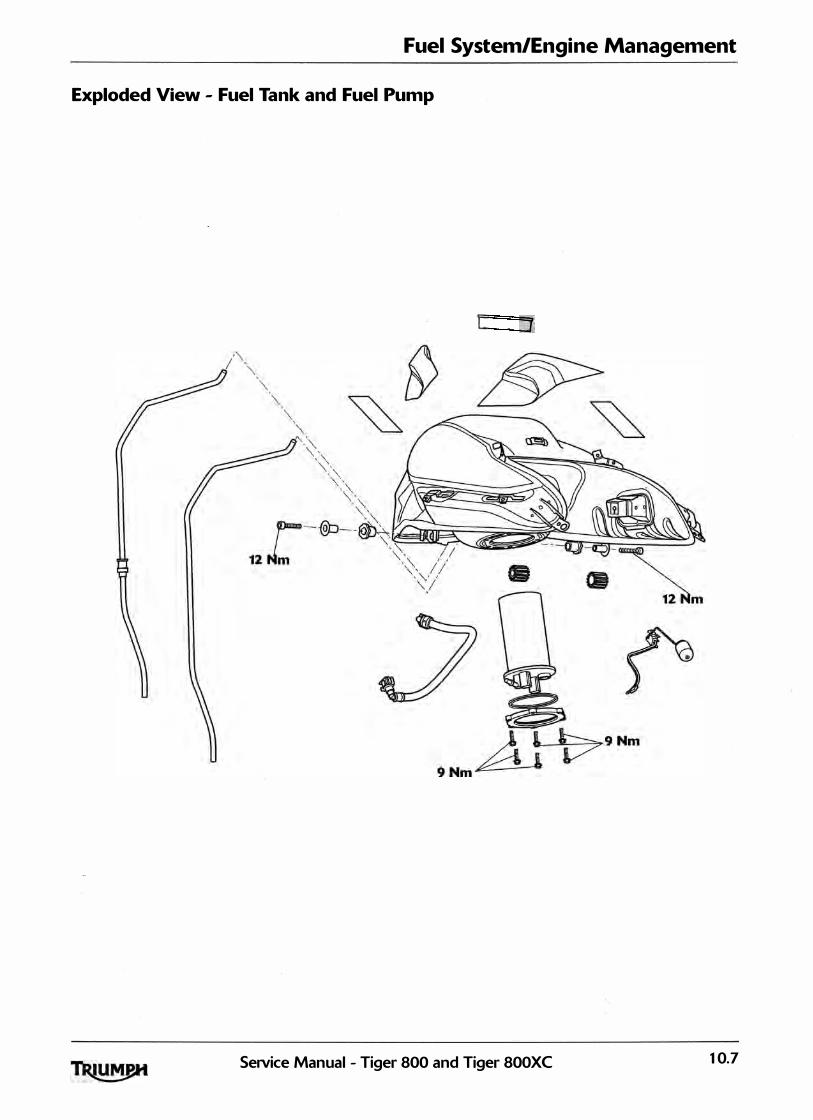
Fuel System/Engine Management
Exploded View - Fuel Tank and Fuel Pump
[ j
SeiVice Manual - Tiger 800 and Tiger 800XC 1 0.7

Fuel System/Engine Management
Exploded View - Fuel Rail, T hrottles and lniectors
3.5 Nm
� � 3.5 Nm
3.5 Nm
12 Nm
r 2 Nm
1.5 Nm
10.8 SeiVice Manual - Tiger 800 and Tiger 800XC

Fuel System/Engine Management
Exploded View - Airbox
1.5 Nm 1.5 Nm
SeNice Manual - Tiger 800 and Tiger 800XC 10.9
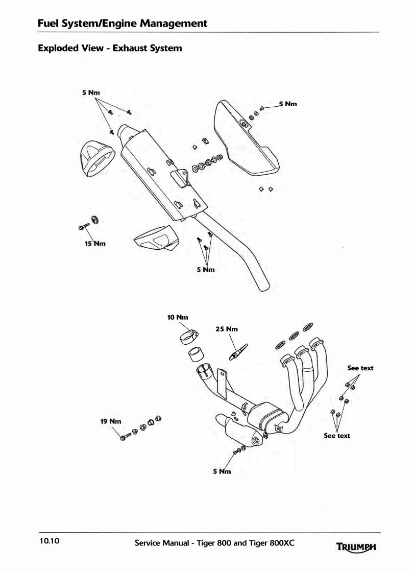
Fuel System/Engine Management
Exploded View - Exhaust System
10 Nm
� e
25 Nm
y
10.10 Se1Vice Manual - Tiger 800 and Tiger 800XC
See text
See text
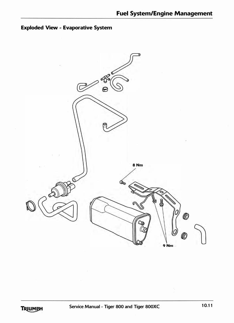
Fuel System/Engine Management
Exploded View - Evaporative System
SeNice Manual - Tiger 800 and Tiger 800XC 10.11

Fuel System/Engine Management
Fuel Requirements
Fuel Requirements - all countries except USA
Outside of America, Tiger 800 and Tiger 800XC models must be run on 91 RON (or higher) unleaded fuel.
Fuel Requirements - USA
In the United States of America where the octane rating of fuel is measured in a different way, the fol lowing information may be applied:
Tiger 800 and Tiger 800XC are designed to run on unleaded gasoline with a CLC or AKI octane rating <R+M)/2 of 87 or h igher.
Note:
• If 'knocking' or 'pinking' occurs at a steady engine speed under normal load, use a different brand of gasoline or a higher octane rating.
The use of leaded gasol ine is i l legal in some countries, states or territories and wi l l inva lidate the vehicle and emissions control warranties. Additional ly, leaded gasoline wil l cause damage to emissions control components.
Oxygenated Gasoline
To help in meeting clean air standards, some areas of the U.S. use oxygenated gasol ine to help reduce harmful emissions. This model wil l g ive best performance when using unleaded gasol ine. However, the fol lowing should be used as a guide to the use of oxygenated fuels.
Because of the general ly higher volati l ity of oxygenated fuels, starting, engine response and fuel consumption may be adversely affected by their use. Should any of these difficulties be experienced, run the motorcycle on normal un leaded gasol ine.
Ethanol
Ethanol fuel is a mixture of 15% ethanol and 85% gasol ine and is often described under the names 'gasohol', 'ethanol enhanced', or 'conta ins ethanol ' . This fuel may be used in Triumph motorcycles.
Methanol
conta ining methanol should not be used in Triumph motorcycles as damage to components in the fuel system can be caused by contact with methanol.
MTBE (Methyl Tertiary Butyl Ether)
The use of gasolines contain ing up to 15% MTBE <Methyl Tertiary Butyl Ether> is permitted in Triumph motorcycles.
10.12 Service Manual - Tiger 800 and Tiger 800XC

Glossary of Terms
The fol lowing terms and abbreviations will be found in this section. Below is given a brief explanation of what some of the more common terms and abbreviations mean.
Air temperature
The air temperature in the air box and intake system.
Air temperature sensor
Sensor located in the airbox to detect the temperature of the incoming air.
ATDC
After Top Dead Centre ITDC>.
Barometric pressure
Pressure of the ambient air.
Battery voltage
The voltage at the input to the Electronic Control Module <ECM>.
BTDC
Before Top Dead Centre ITDC>.
Catalyst
Device placed in the exhaust system which reduces exhaust emissions by stimulating secondary combustion of the exhaust gases.
Closed throttle position
Throttle position at idle (i.e. against end stop), measured as a voltage and expressed as percentage.
Fuel System/Engine Management
Coolant temperature
The coolant temperature in the cyl inder head.
Coolant temperature sensor
Sensor which detects coolant temperature.
Cooling fan status
The 'on' or 'off' condition of the cool ing fan.
DTC
Diagnostic Trouble Code.
ECM
Eng ine Control Module.
Engine speed
The crankshaft revolutions per minute.
Fall detection
The fa l l detection switch wil l detect if the motorcycle is on its side and wi l l cut power to the ECM immediately.
Freeze frame
A data set captured at the time a Diagnostic Trouble Code <DTC> is set.
Gear position sensor
Gearbox mounted sensor which del ivers information to the ECM. This is converted to the gear position value that is displayed on the instrument's gear position indicator and/or neutral lamp.
Idle fuel trim
The percentage above or below the nominal fuel requirement for the volume of air entering at idle.
SeiVice Manual - Tiger 800 and Tiger 800XC 1 0. 1 3
Fuel System/Engine Management
Idle fueling
Adjustment of fuel ing at idle to suit the actual air inducted.
Idle reference speed
The target idle speed as determined by the Electronic Control Module <ECM>. (lt should be the same as the actual idle speed if the motorcycle is operating correctly.>
Ignition advance
The timing of the ignition at the spark plug relative to top dead centre <TDO.
Ignition switch position
The 'ON' or 'OFF' position of either or both the ignition switch and the engine stop switch.
Ignition timing
Same as ' ignition advance'.
Immobiliser and Tyre Pressure Monitoring System <TPMS> Control Module
The control module for the Immobil iser and TPMS system.
lniector pulse time
The time during which an injector remains open (i.e. delivering fuel>.
Lambda 02 Sensor
The Lambda sensor measures the Oxygen levels in the exhaust gases and feeds this information to the ECM. Based on this information, adjustments to air/fuel ratio are made.
Long term fuel trim
Fuel ing after adapting to the engine's long term fuel ing requirements <closed loop only). See also short term fuel trim.
MAP sensor
Manifold Absolute Pressure (the air pressure in the intake system). Measured after the throttle va lves. This reading is compared to the ambient pressure reading to al low the ECM to calcu late engine load.
MIL
Malfunction Indicator Lamp.
I l luminates when most Diagnostic Trouble Codes <DTCs) are set.
Open circuit
A break in an electrical circuit - current cannot flow.
Over temp
High temperature within the Electronic Control Module <ECM> caused by an internal or external fai lure.
Primary throttle position sensor
Sensor for the primary <lower) throttle position.
Primary throttle stepper motor
Stepper motor used to vary throttle opening at idle and when the engine is cold.
Purge valve duty cycle
The time the purge valve is open in an open/close cycle, expressed as a percentage of the cycle time.
Road speed sensor
Gearbox mounted sensor which del ivers information to the ECM. This is converted to the road speed value that is then displayed on the speedometer.
Non ABS models on ly. ABS models use the rear ABS wheel speed sensor to supply road speed sensor to the ECM.
Sensor supply voltage
Supply voltage to the system sensors <nominal ly 5 Volts>.
10.14 Service Manual - Tiger 800 and Tiger SOOXC
Short circuit
A 'short cut' in an electrical circuit - current by-passes the intended circu it (usua l ly to earth>.
Short term fuel trim
A correction appl ied to the fuel mixture during closed loop catalyst operation. This, in turn has an effect on the long term fuel trim in that, if an engine constantly requires mixture correction, the long term fuel trim wi l l adapt to this requirement thus reducing the need for constant short term adjustment.
Sidestand status
The 'up' or 'down' position of the side stand.
Target dwell time
The actua l time from coi l 'on' to coil 'off.
Fuel System/Engine Management
Throttle position
The position of the throttle butterfly g iven as a percentage of the movement range. When the data is displayed on the diagnostic software, fu l ly open need not be 100% nor fu l ly closed 0%.
Throttle voltage
Voltage at the throttle potentiometer.
TDC
Top Dead Centre.
TPMS
Tyre Pressure Monitoring System.
Transponder
A transmitter-responder chip located in the ignition key. The transponder is activated by a radio signal sent out by the immobil iser and TPMS control module, via an antenna located around the ignition switch. If the immobil iser and TPMS control module 'does not receive the correct code signal from the transponder, the immobil iser wil l remain active and the engine wil l not start.
Vbatt
Battery voltage.
SeiVice Manual - Tiger 800 and Tiger 800XC 10.15

Fuel System/Engine Management
Engine Management System
System Description
The Tiger 800 and Tiger 800XC models are fitted with an electronic engine management system which encompasses control of both ignition and fuel del ivery. The electronic control module <ECM> draws information from sensors positioned around the engine, cool ing and air intake systems and precisely ca lculates ign ition advance and fuel ing requirements for a l l engine speeds and loads.
In addition, the system has an on-board d iagnostic function. For additional information, see page 10-28.
System Sensors
• Intake air temperature sensor - situated in the top of the airbox. As the density of the air (and therefore the amount of oxygen available to ignite the fuel> changes with temperature, an intake air temperature sensor is fitted. Changes in air temperature <and therefore air density) are compensated for by adjusting the amount of fuel injected to a level consistent with clean combustion and low emissions.
Barometric pressure sensor - situated below the battery. The barometric pressure sensor measures atmospheric air pressure. With this information, the amount of fuel injected is adjusted to suit the prevail ing conditions.
• Manifold Absolute Pressure <MAP> sensor -
situated to the front of the airbox, connected to each of the three throttle bodies by equal length tubes. The MAP sensor provides information to the ECM which is used at shallow throttle angles <very small throttle openings> to provide accurate engine load indications to the ECM. This degree of engine load accuracy al lows the ECM to make very small adjustments to fuel and ignition which would otherwise not be possible from throttle angle data alone.
• Clutch switch - situated on the clutch lever. The clutch must be pulled in for the starter motor to operate.
• Crankshaft position sensor - situated in the alternator cover. The crankshaft position sensor detects movement of teeth attached to the alternator rotor. The toothed rotor gives a reference point from which the actual crankshaft position is calculated. The crankshaft position sensor information is used by the ECM to determine engine speed and crankshaft position in
relation to the point where fuel is injected and ignition of the fuel occurs.
• Engine coolant temperature sensor -situated at the rear of the cylinder head. Coolant temperature information, received by the ECM, is used to optimise fueling at al l engine temperatures and to calculate hot and cold start fuel ing requirements.
• Throttle position sensor - situated at the right end of the throttle body. Used to relay throttle position information to the ECM. Throttle opening angle is used by the ECM to determine fueling and ignition requirements for all throttle positions.
• Road speed sensor - situated in the upper crankcase, in front of the engine breather. The road speed sensor provides the ECM with data from which road speed is calculated and displayed on the speedometer.
• Lambda sensor - situated in the exhaust header system upstream of the catalyst The lambda sensor constantly feeds information to the ECM on the content of the exhaust gases. Based on this information, adjustments to the air/fuel ratio are made.
• Side stand switch - situated at the top of the sidestand leg. If the sidestand is in the down position, the engine will not run u nless the transmission is in neutral.
• Gear position sensor - situated in the upper crankcase, behind the gearbox output sprocket cover, on the left hand side of the engine. The gear position sensor provides the ECM with selected gear i nformation. This is used to prevent the engine from sta rting if the transmission is in gear. The sensor also provides information to the gear position indicator and the neutral lamp in the instruments.
• Fall detection switch - situated on the relay and fuse box bracket below the fuel tank The fal l detection switch will detect if the motorcycle is on its side and will cut power to the ECM immediately. This prevents the engine from running and the fuel pump from delivering fuel. In the event of a fal l, the switch is reset by returning the bike to an upright position and switching the ignition off then back on again.
10.16 SeNice Manual - Tiger 800 and Tiger 800XC
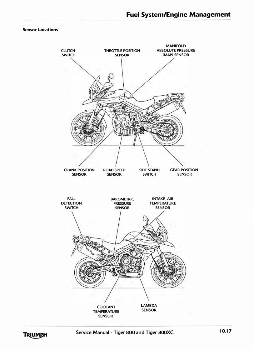
Sensor Locations
Fuel System/Engine Management
CLUTCH
SWITCH
TH ROTTLE POSITION
SENSOR
MAN I FOLD
ABSOLUTE PRESSU RE
<MAP> SENSOR
CRAN K POSITION
SENSOR
ROAD SPEED
SENSOR
FAll
DETECTION
SWITCH
BAROM ETRIC
PRESSURE
SENSOR
COOLANT
TEMPERATU RE
SENSOR
SIDE STAN D
SWITCH
G EAR POSITION
SENSOR
I NTAKE AI R
TEMPERATURE
SENSOR
lAMBDA
SENSOR
SeNice Manual - Tiger 800 and Tiger 800XC 10.17
Fuel System/Engine Management
System Actuators
I n response to signals received from the sensors, the ECM controls and directs messages to a series of electronic and electro-mechanica l actuators. The function and location of the actuators is given below.
Throttle stepper motor - situated between the throttle bodies of cylinders two and three. The throttle stepper actuates a cam/lever which causes variations in the closed throttle position. Although used primari ly to ensure target idle speed is maintained, it also increases throttle opening when the engine is cold.
• Canister purge valve <California models only> - situated in the vapour return l ine between the carbon canister and the throttle bodies. The purge valve controls the return of vapour which has been stored in the carbon canister during the period when the engine is switched off. The valve is 'pulsed' by the ECM to give control over the rate at which the canister is purged.
• Injectors - located on the throttle body. The engine is fitted with three injectors. The spray pattern of the injectors is fixed but the length of time each injector can remain open is variable according to operating conditions. The duration of each injection is calculated by the ECM using data received from the various sensors in the system.
• Ignition coils - plug-top coils are located in the cam cover. There are three coils fitted, one for each spark plug. The ECM controls the point at which the coils are switched on and off. In calculating the switch-on time, the ECM allows sufficient time for the coils to charge to a level where a spark can be produced. The coils are switched off at the point of ignition, the timing of which is optimised for good engine performance.
EMS main relay - situated behind the battery. When the ignition is switched on, the EMS main relay is powered up to provide a stable voltage supply for the ECM. When the ignition is turned off, the ECM carries out a power down sequence during which the EMS main relay remains powered by the ECM for 1 minute. The ECM power down sequence includes: writing the adaption data to ECM memory and referencing the position of the throttle stepper motor.
• Fuel pump - located inside the fuel tank. The electric pump delivers fuel into the fuel system, via a pressure regulator, at a constant 3 bar pressure. The pump is run continuously
Note:
when the engine is operating and is a lso run briefly when the ignition is first switched on to ensure that 3 bar is avai lable to the system as soon as the engine is cranked. Fuel pressure is controlled by a regulator also situated inside the fuel tan k.
Cooling fan - located behind the radiator. The ECM controls switching on and off of the cooling fan in response to a signal received from the coolant temperature sensor. When the coolant temperature rises to a level where the cooling effect of natura l airflow is insufficient, the cooling fan is turned on by the ECM. When the coolant temperature falls sufficiently, the ECM turns the cool ing fan off. The fan only becomes operational when the engine is running. lt will not operate at any other time.
• In this system, the starter lockout system (clutch switch, gear position sensor, sidestand switch> all operate through the engine management ECM.
1 0.18 SeiVice Manual - Tiger 800 and Tiger 800XC
\
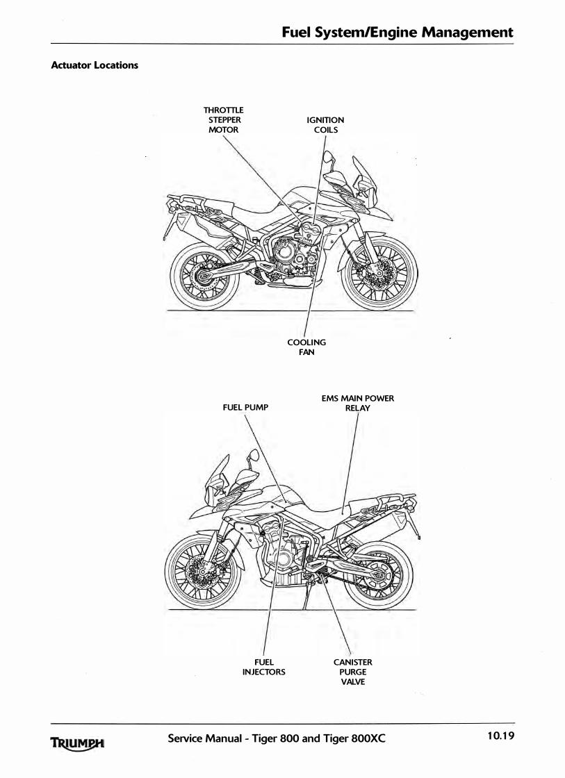
Actuator Locations
Fuel System/Engine Management
TH ROTILE
STEPPER
MOTOR
FUEL PUMP
FUEL
INJECTORS
IGNITION
COILS
COOLI NG
FAN
EMS MAI N POWER
RELAY
CAN ISTER
PURG E
VALVE
SeNice Manual - Tiger 800 and Tiger 800XC 10.19
Fuel System/Engine Management
Immobiliser System
System Description
The Tiger 800 and Tiger 800XC models are fitted with an electronic immobil iser system to help protect against theft. This system has to be paired with the ECM and the ignition key which conta ins a transponder chip. If all the components are correctly paired, the immobil iser wil l al low the engine to start. The Triumph diagnostic tool is the only way these components can be paired. In addition, the system has an on-board diagnostic function. This ensures that, should a malfunction occur in the immobiliser system, a malfunction code is stored in the immobiliser/tyre pressure monitoring system <TPMS> control modules memory. This stored data can then be recovered using the Triumph diagnostic tool (see page 10-28).
System Components and Operation
Transponder chip - Situated inside the ignition key. The chip is activated by the antenna coi l when the ign ition switch is turned to the ON position.
Antenna coil - Situated around the ignition switch. When the ignition switch is turned to the ON position, and the transponder chip is activated, the signal from the chip is sent to the immobil iser/TPMS control module.
lmmobiliser/TPMS Control Module Situated under the headstock. This control module communicates with the transponder chip in the key and the ECM and wil l only al low the engine to start if a matching signal is received.
Alarm/immobiliser warning indicator light - Situated in the instrument pack. The l ight wi l l flash on and off for 24 hours to show that the engine immobil iser is on. When the ignition switch is turned to the ON position the immobil iser and the indicator light will be off. I f the indicator l ight remains on i t indicates that the immobil iser has a malfunction that requires investigation. If an accessory alarm is fitted, the immobil iser indicator l ight will only i l luminate when the conditions described in the accessory alarm instructions are met.
Keys
When the motorcycle is del ivered from the factory it is supplied with two keys. Keys can be deleted or added to the immobil iser system using the Triumph diagnostic tool. A maximum of four keys can be added to the system. To ensure the immobil iser system functions correctly note the fol lowing:
Do not put any magnetic materials on the same key ring as the motorcycle key;
Do not put any other ignition key with a transponder ch ip fitted near the motorcycle key when in use;
• Do not modify the immobi l iser system;
Do not submerge the key in water or any other flu id;
Do not drop or strike the key against hard materia l .
Diagnostics
To fully diagnose the immobil iser system it is necessary to check for fault codes in the immobil iser/TP.MS control module using the Triumph diagnostic tool (see page 10-28>.
Further Diagnosis
The tables that start on page 10-41 , if used correctly, help to pinpoint a fault in the system once a diagnostic trouble code has been stored.
10.20 SeNice Manual - Tiger 800 and Tiger 800XC
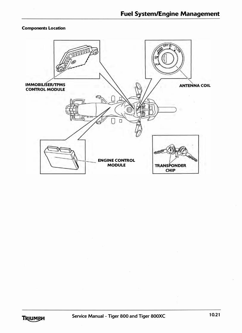
Fuel System/Engine Management
Components Location
� ENGI N E CONTROL MODU LE
SeNice Manual - Tiger 800 and Tiger 800XC 10.21

Fuel System/Engine Management
Tyre Pressure Monitoring System
<TPMS>
System Description
The Tiger 800 can be fitted with the accessory tyre pressure monitoring system <TPMS>. When fitted the eyre pressures shown on the instrument panel ind icate the actual tyre pressure at the time of selecting the d isplay. This may differ from the inflation pressure set when the tyres are cold because tyres become warmer during riding, causing the air in the tyre to expand and the pressure to increase. The cold inflation pressures specified by Triumph take account of this. In addition, the system has an on-board d iagnostic function. This ensures that, should a malfunction occur in the immobil iser system, a malfunction code is stored in the immobil iser/tyre pressure monitoring system <TPMS> control modules memory. This stored data can then be recovered using the Triumph diagnostic tool <see page 10-28).
Owners must only adjust tyre pressures when the tyres are cold using an accurate tyre pressure gauge and must not use the tyre pressure d isplay on the instruments.
The tyre pressure monitoring system is not to be used as a tyre pressure gauge when adjusting the tyre pressures. For correct tyre pressures, a lways check the tyre pressures when the tyres are cold and using an accurate tyre pressure gauge. Use of the TPMS system to set inflation pressures may lead to incorrect tyre pressures leading to loss of motorcycle control and an accident.
When fitting the TPMS, the insta llation flow-chart detai led in the Triumph diagnostic tool user guide must be fol lowed.
System Components and Operation
Instruments - Used to d isplay . the tyre pressure value, the tyre symbol and the TPMS warning l ight.
lmmobiliser/TPMS control module Receives the data from the tyre pressure sensors and sends the information to the instrument pack.
Tyre pressure sensor - Situated inside the front and rear wheel. Each sensor has its own unique ID number and must be recorded in the spaces provided in the owner's handbook. These sensors measure the a ir pressure inside the tyre and transmit pressure data to the instruments. These sensors wil l not transmit the data until the motorcycle is travel l ing at a speed greater than 12 mph (20 km/h). Two dashes wi l l be visible in the display area until the tyre pressure signal is received. The wheel sensor is a sealed unit and must not be opened. The battery inside the sensor is not replaceable and a new sensor must be fitted when the battery voltage becomes too low.
Compliance
This device compl ies with part 1 5 of the FCC Rules. Operation is subject to the fol lowing two conditions:
This device may not cause harmful interference;
This device must accept any interference received, including interference that may cause undesired operation.
Changes or modifications to the device could void the user's authority to operate the equipment.
Diagnostics
When a fault condition with the TPMS is detected, the red warning l ight in the instrument pack wil l i l luminate and the tyre symbol wil l flash repeatedly. The red warning l ight and flashing symbol wil l also occur if the TPMS has been enabled in the instrument pack but not in the immobil iser/TPMS control module. Before proceeding to the diagnostics, check that the motorcycle has wheel sensors fitted and that the option for the TPMS has been enabled in the immobil iser/TPMS control modu le.
Further Diagnosis
The tables that start on page 10-41 , if used correctly, help to pinpoint a fault in the system once a diagnostic trouble code has been stored.
10.22 SeiVice Manual - Tiger 800 and Tiger 800XC
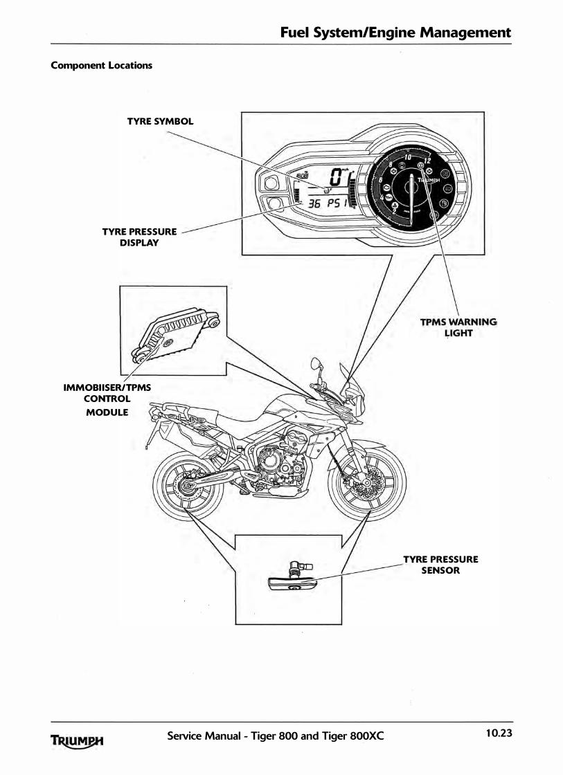
Component Locations
TYRE SYMBOL
TYRE PRESSURE DISPLAY
IMMOBI ISERITPMS CONTROL
MODU LE
Fuel System/Engine Management
TYRE PRESSU RE S ENSOR
SeiVice Manual - Tiger 800 and Tiger 800XC 10.23
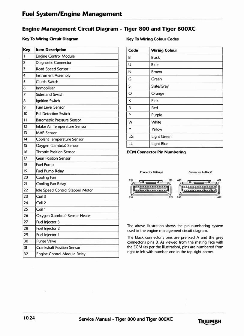
Fuel System/Engine Management
Engine Management Circuit Diagram - Tiger 800 and Tiger SOOXC
Key To Wiring Circuit Diagram
Key Item Description
1 Engine Control Module
2 Diagnostic Connector
3 Road Speed Sensor ·
4 Instrument Assembly
5 Clutch Switch
6 Immobil iser
7 Sidestand Switch
8 Ignition Switch
9 Fuel Level Sensor
10 Fa l l Detection Switch
1 1 Barometric Pressure Sensor
12 Intake Air Temperature Sensor
13 MAP Sensor
14 Coolant Temperature Sensor
15 Oxygen <Lambda) Sensor
16 Throttle Position Sensor
17 Gear Position Sensor
18 Fuel Pump
19 Fuel Pump Relay
20 Cooling Fan
21 Cooling Fan Relay
22 Idle Speed Control Stepper Motor
23 Coil 3
24 Coil 2
25 Coil 1
26 Oxygen <Lambda> Sensor Heater
27 Fuel Injector 3
28 Fuel Injector 2
29 Fuel In jector 1
30 Purge Valve
31 Crankshaft Position Sensor
32 Engine Control Module Relay
Key To Wiring Colour Codes
Code Wiring Colour
B Black
u Blue
N Brown
G Green
s Slate/Grey
0 Orange
K Pink
R Red
p Purple
w White
y Yel low
LG Light Green
LU Light Blue
ECM Connector Pin Numbering
Connector B <Grey) Connector A <Black>
The above i l lustration shows the pin numbering system used in the engine management circuit diagram.
The black connector's p ins are prefixed A and the grey connector's pins B. As viewed from the mating face with the ECM (as per the i l lustration), pins are numbered from right to left with number one in the top right corner.
10.24 SeNice Manual - Tiger 800 and Tiger 800XC

Fuel System/Engine Management
Engine Management Circuit Diagram - Tiger 800 and Tiger SOOXC
32
00 31 ll-uP
L_0-us ---p- AOI
UB- A09
30
r------+-----NK--E3-YR--YR- 809
NI(- """
29
------- NK� --YK- A15
YP- A14
27 '----NK� --'11 1- All
w- 814 Lm L--
----NK
ill
26
r--------NK--E3-GK--GK- A18
25
t---------NX--E3-GP--GP- 818
24
'--------NK--E3-GB--GB- 817
23
ON- A12
ow- All
ou- AlO 22 OK- All W 21 �:=::: B- 816
l 1 2 5 B- A35 .___
!1! iolr
-
-BYY - 830
L--_ --su-@s j_ 20 IJEJ
19
18
I !...__ __ @·� �
A14 f-;lG
Al4 f-KY
828 i-R 827 1-u
A32 f-B0-8--B 5 1
AJJ i-BR:g _r- B 2 7
804 -BG
821 -KU
801 -K
All -KP 820 -KB
All f-Ko
A28 I-K5
A29 I-KG
A16 1- B
AIO GY
All BW
824 i-BK
�
1\
J r
2
17
SeNice Manual - Tiger 800 and Tiger 800XC
rE BG 7 2 R 6
u 14
�tl} re 2
R 5 4 'ill u 4
IT�m6
BG[O s
BGm9
fJ 10
fJ 1 1
KB 2
u K
K
KP KB
B �; I
0 KB =[] 12
KB KS K f]
13
KG KB
KB K G
=[] 14 _____.JI1s
y{] 16
10.25
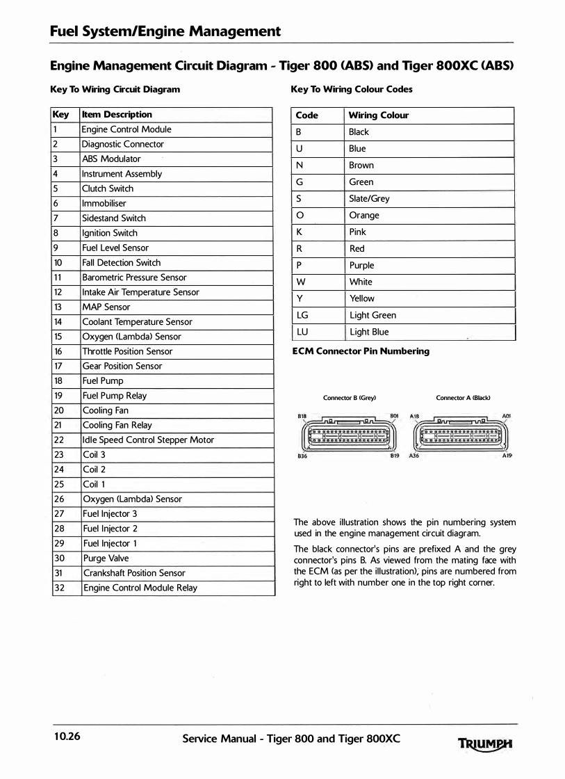
Fuel System/Engine Management
Engine Management Circuit Diagram - Tiger 800 CABS> and Tiger SOOXC CABS>
Key To Wiring Circuit Diagram
Key Item Description
1 Engine Control Module
2 Diagnostic Connector
3 ABS Modulator
4 Instrument Assembly
5 Clutch Switch
6 Immobil iser
7 Sidestand Switch
8 Ignition Switch
9 Fuel Level Sensor
10 Fa l l Detection Switch
1 1 Barometric Pressure Sensor
12 Intake Air Temperature Sensor
13 MAP Sensor
14 Coolant Temperature Sensor
15 Oxygen (Lambda) Sensor
16 Throttle Position Sensor
17 Gear Position Sensor
18 Fuel Pump
19 Fuel Pump Relay
20 Cooling Fan
21 Cooling Fan Relay
22 Id le Speed Control Stepper Motor
23 Coil 3
24 Coil 2
25 Coil 1
26 Oxygen (lambda) Sensor
27 Fuel In jector 3
28 Fuel In jector 2
29 Fuel Injector 1
30 Purge Valve
31 Crankshaft Position Sensor
32 Engine Control Module Relay
Key To Wiring Colour Codes
Code Wiring Colour
B Black
u Blue
N Brown
G Green
s Slate/Grey
0 Orange
K Pink
R Red
p Purple
w White
V Yel low
LG Light Green
LU Light Blue
ECM Connector Pin Numbering
Connector B <Grey) Connector A (Biackl
The above i l lustration shows the pin numbering system used in the engine management circuit diagram.
The black connector's pins are prefixed A and the grey connector's pins B. As viewed from the mating face with the ECM (as per the i l lustration>; pins are numbered from right to left with number one in the top right corner.
10.26 Service Manual - Tiger 800 and Tiger 800XC
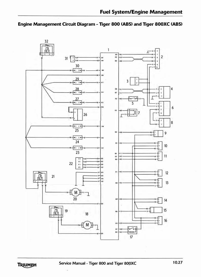
Fuel System/Engine Management
Engine Management Circuit Diagram - Tiger 800 CABS> and Tiger SOOXC CABS>
32
m 31
r-;-}uP p- AOl L..0-us ---us- A09
30
.-------+-----NK-E3-YR YR- 809
r---------NK- A06
29
------ NK-E3-v< --YK- AlS
28 '----NK-E3-YP ----'YP - A14
27 "-----NK�B ----'\'8 - A13
L ....---�-,�-� -w-
814
L...------INK l
26
,---------NK--E2::3-GK--GK- AlB
25
t--------NK--E2::3-GP--GP- 818
24
'---------NK--E2::3-G8--G8- 817
23
22 r::l:l =--=--=---c:·w-1:: �--01( All
21 �:::: B 816 l 1 l S 8 AlS
!!! i:;IL.__ ,L---1_
-_
-_
-_e
u-@
-'-- 2�-
2
-
8
j_-8Y- 830
A24� BG 7 Bl3i-BY� BY
BOSi-BN� BN 8
3
:: �: _ __/----...__...J..+-_:m. 4
1s
, A32 �BO�B _l_
51 m
m �--�� 7 IT�ru 6 ·-fTl BG-LLJ 8
B04 BG----- BGm 9 �--KS l
Bll KU--.._t---�����K{]
10
801 -K K
t]
A27 KP -�f-----KP l 1 1 820 -KB K8 1
An f-<o ---++-----<o -f.l 12 .,___--KSt_j
A2S 1-•s----+-l---:fl 13 �---·U
A29i-KG,---+-l�--KG n 14 '---- KS-\:._j
A26l-8--++-- 8�; I l15
L__---+--
-�=fl16 AlO 1-GY'-----l--GYU
All 1-sw·-------E--
824 i-8K -----i!-=---1
17
SeiVice Manual - Tiger 800 and Tiger 800XC 10.27

Fuel System/Engine Management
System Diagnostics
The engine management system has an on-board diagnostics feature which al lows se rvice techn icians to retrieve stored data from the ECM using the Triumph diagnostic sof tware. Full details of the Triumph diagnostic software operation and how to interpret the results are given in the Triumph Diagnostic Tool User Guide.
The software is connected, via an interface cable, to the motorcycle using a dedicated diagnostic plug situated beneath the seats. By using a dedicated plug, no electrica l connectors associated with the system are disturbed, reducing potential connector damage.
The software al lows the user to retrieve data associated with the system sensors and actuators, test various component functions, read build data and make minor adjustments to the set -up of the system. The data and tests available are described on the fol lowing pages.
On-board Fault Detection System
The on -board diagnostic system has two stages to fault detection. When a fault is detected, the DSM <Diagnostic Status Manager> raises a flag to indicate that a fault is present and increments a counter. The counter checks the number of instances that the fault is noted. For example, if there is a fault in the crankshaft position sensor, the counter will increment its count each time the crankshaft turns through 3 60°, provided the fau lt is sti l l present.
When the count begins, the fault is detected but not confirmed. If the fau lt continues to be detected and the count reaches a pre-determined threshold, the fault becomes confirmed. If the fault is an emissions related fault or a serious malfunction affecting engine performance, a DTC <Diagnostic Trouble Code) and freeze-frame data wil l be logged in the ECM's memory and the M I L <Malfunction Indicator Lamp> on the motorcycle instrument panel is i l luminated. Once a fault is confirmed, the number of warm-up cycles made by the engine is counted. If the fault clears, the warm -up cycle counter will extinguish the M I L <Malfunction I ndicator Lamp) at a pre determined count, and erase the DTC and freeze frame data from the ECM memory at another (higher) count.
A single warm -up cycle is deemed to have taken place when the following criteria have been met :
•
•
•
The coolant temperature must be raised to
no c or more.
The coolant temperature must have risen by
23° C or more from its start temperature, when no C is reached.
A controlled power-down sequence must
take place.
Note:
• When a fault has been rectified, the M I L will remain illuminated until sufficient non-fault warm-up cycles have taken place to turn it off. The M I L will be immediately extinguished if, after first rectifying the fault, the DTC <diagnostic trouble code> that caused the M I L illumination is erased from
the ECM memory using the Triumph diagnostic software.
Note:
• In most cases, when a fault is detected, the engine management system will revert to a 'limp-home' mode. In this mode, the engine will still function though the performance and fuel economy may be marginally affected. In some cases, the rider may not notice any appreciable difference from normal operation.
10.28 SeNice Manual - Tiger 800 and Tiger 800XC

Diagnostic Tool Connection
1. To connect the Triumph diagnostic interface to the motorcycle, remove the pi l l ion seat <see page 16-13) and release the d iagnostic connector from its locating tang.
2 . Plug the diagnostic interface directly in to the diagnostic connector.
1. Diagnostic connector
Diagnostic Interface
3. When the diagnostic session is completed, disconnect the Triumph diagnostic interface.
4. Refit the diagnostic connector to its locating tang and refit the pi l l ion seat (see page 16-13).
Fuel System/Engine Management
Triumph Diagnostic Software
Described on the fol lowing pages is the range of information wh ich can be retrieved from the ECM's memory and the adjustments which can be performed using the Triumph diagnostic software.
The tables indicate which tests are performed by the on-board system and what information can be retrieved by the Triumph diagnostic software.
Note:
• Full details of how to operate the software and how to interpret the data can be found in the Triumph Diagnostic Tool User Guide, which can be downloaded by authorised Triumph dealers from
www.triumphonline.net.
Build Data
The Build Data screen wil l d isplay the fol lowing information :
• Motorcycle model;
• Vehicle Identification Number <VJN>;
• ECM type;
• ECM ID;
• ECM serial number;
• Tune number;
• Date of last tune download;
• Total tune downloads since manufacture;
• The Jock status of the ECM <ECM Locked,
Unlocked or Not Applicable).
SeiVice Manual - Tiger 800 and Tiger 800XC 10.29

Fuel System/Engine Management
Current Data
The data available under Current Data is:
Function Examined Result Reported <Scale)
Fuel system status 1 open or closed loop operation
Calculated load value %
Engine coolant temperature - oc
Short term fuel trim -Bank 1 %
Intake manifold absolute pressure mm/hg
Engine speed RPM
Vehicle speed km/h
Ignition timing advance -cyl inder 1 degrees
Intake air temperature oc
Absolute throttle position %
Bank 1 - oxygen sensor 1 Volts
Bank 1 -oxygen sensor 1 -short term fuel trim %
10.30 Service Manual - Tiger 800 and Tiger 800XC
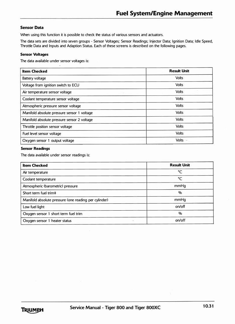
Fuel System/Engine Management
Sensor Data
When using this function it is possible to check the status of various sensors and actuators.
The data sets are d ivided into seven groups - Sensor Voltages ; Sensor Readings ; In jector Data ; Ignition Data ; Id le Speed, Throttle Data and Inputs and Adaption Status. Each of these screens is described on the fol lowing pages.
Sensor Voltages
The data avai lable under sensor voltages is:
Item Checked Result Unit
Battery voltage Volts
Voltage from ignition switch to ECU Volts
Air temperature sensor voltage Volts
Coolant temperature sensor voltage Volts
Atmospheric pressure sensor voltage Volts
Manifold absolute pressure sensor 1 voltage Volts
Manifold absolute pressure sensor 2 voltage Volts
Throttle position sensor voltage Volts
Fuel level sensor voltage Volts
Oxygen sensor 1 output voltage Volts
Sensor Readings
The data avai lable under sensor readings is:
Item Checked Result Unit
Air temperature oc
Coolant temperature oc
Atmospheric (barometric> pressure mmHg
Short term fuel trim * %
Manifold absolute pressure <one reading per cyl inder> mmHg
Low fuel l ight on/o ff
Oxygen sensor 1 short term fuel trim %
Oxygen sensor 1 heater status on/off
SeiVice Manual - Tiger 800 and Tiger 800XC 10.3 1

Fuel System/Engine Management
Injector Data
The data avai lable under injector data is:
Item Checked Result Unit
In jector 1 pu lse time mi l l iseconds
Injector 2 pulse time mi l l iseconds
Injector 3 pulse time mi l l iseconds
Ignition Data
The data avai lable under ignition data is:
Item Checked Result Unit
Ignition timing cyl 1 degrees BTDC
Ignition timing cyl 2 degrees BTDC
Ignition timing cyl 3 degrees BTDC
Coil dwell time mi l l iseconds
Idle Speed and Throttle Data
The data avai lable under idle speed and throttle data is:
Item Checked Result Unit
Engine speed RPM
Idle reference speed RPM
Idle speed control current steps numeric
Idle speed control target steps numeric
Throttle position % open
10.32 SeiVice Manual - Tiger 800 and Tiger SOOXC
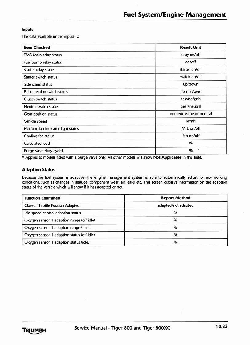
Fuel System/Engine Management
Inputs
The data available under inputs is:
Item Checked Result Unit
EMS Main relay status relay on/off
Fuel pump relay status on/off
Starter relay status starter on/off
Starter switch status switch on/off
Side stand status up/down
Fal l detection switch status normal/over
Clutch switch status release/grip
Neutral switch status gear/neutral
Gear position status numeric value or neutral
Vehicle speed km/h
Malfunction indicator l ight status M I L on/off
Cool ing fan status fan on/off
Calcu lated load %
Purge valve duty cycle:t: %
* Apphes to models f1tted w1th a purge valve on ly. All other models w1l l show Not Applicable m th1s field.
Adaption Status
Because the fuel system is adaptive, the engine management system is able to automatical ly adjust to new working conditions, such as changes in a ltitude, component wear, air leaks etc. This screen displays information on the adaption status of the vehicle which will show if it has adapted or not.
Function Examined Report Method
Closed Throttle Position Adapted adapted/not adapted
Idle speed control adaption status %
Oxygen sensor 1 adaption range (off idle) %
Oxygen sensor 1 adaption range (idle) %
Oxygen sensor 1 adaption status (off idle> %
Oxygen sensor 1 adaption status (id le) %
SeiVice Manual - Tiger 800 and Tiger 800XC 10.33

Fuel System/Engine Management
Function Tests
The system al lows the diagnostic software to perform a series of function tests on various actuators in the engine management system. In some cases it is necessary to make a visual observation of a component and in others, if faults are present, DTCs wil l be logged.
The function tests avai lable are:
Function Examined Report Method
Instrument Panel Observe instrument panel, refer to service manual
Idle Air Control Stepper Motor Observe throttle position/Stored fault code*
Purge Valvet Listen for valve operation/Stored fault code*
Fuel Pump - Priming Listen for fuel pump operation/Stored fault code*
Fuel Pump - Continuous Operation Fuel pressure test/Listen for fuel pump operation/Stored fault code*
Cooling Fan Controlt Observe the cool ing fan/Stored fault code*
* If a fault 1s detected.
Instrument Panel Function Test
On the diagnostic software navigate to and select the 'FU NCTION TESTS' option.
Click the start button and observe the instruments for the fol lowing:
tachometer needle moves to 7,500 rpm;
the neutral indicator, fuel warning and malfunction indicator light <MID lights alternate on and off;
coolant temperature increments up to maximum temperature;
• coolant warning light illuminates when coolant temperature gauge is at maximum;
end of test. Instruments return to normal operation.
10.34 SeiVice Manual - Tiger 800 and Tiger 800XC

Fuel System/Engine Management
Adiust Tune
Using the Triumph diagnostic software, it is possible to:
• reset the adaptions;
balance the throttle bodies.
Further functions are provided to a l low correct replacement and adjustment of the:
throttle position sensor;
• idle speed control stepper motor.
These functions are needed as, after replacement of the parts concerned, adjustments have to be made to specific Voltage settings, with the throttles set in a specific position.
To reset adaptions, see page 10-1 16.
To replace and adjust the throttle position sensor, see page 10-1 1 2.
To replace and adjust the ISC stepper motor, see page 10-113.
To balance the throttles, see page 10- 1 10.
Freeze-frame Data
Freeze frame data is stored at the time a DTC is recorded <confirmed) by the ECM. If multiple DTCs are recorded, the freeze-frame data which is stored wil l relate to the first recorded DTC only.
By cal l ing up freeze frame data associated with the first recorded DTC, the technician can check the engine condition at the time the fault occurred. The data ava ilable is:
·
Function Examined Result Reported <Scale)
DTC Diagnostic Trouble Code <DTC> number
Fuel system status 1 open or closed loop operation
Calculated load %
Coolant temperature oc
Short term fuel trim - bank 1 %
Intake man ifold absolute pressure mm/hg
Engine speed RPM
Vehicle speed km/h
Ignition advance degrees
Intake air temperature oc
Throttle position %
Oxygen sensor 1 output Voltage Volts
Oxygen sensor 1 short term fuel trim %
SeiVice Manual - Tiger 800 and Tiger 800XC 10.35

Fuel System/Engine Management
Diagnostic Trouble Codes
Diagnostic trouble codes <DTCs> are logged in the ECM memory when there is a confirmed fault in the system.
The codes are reported to the Triumph diagnostic software as a four digit code.
As mentioned earl ier, when the system detects a fault, it begins to count the number of times the fau lt occurs before i l luminating the M I L and storing a fault code.
Similarly, if a fault clears, the ECM also records this fact and will turn off the M I L when sufficient no-fault warm-up cycles have taken place. Any fault c9des wi l l remain in the ECM memory until the required number of no-fault warm-up cycles have taken place. The number of warm-up cycles required to extinguish the M I L wil l a lways be less than the number required to remove a DTC from the ECM memory. DTCs can be removed at any time using the Triumph diagnostic software.
The system wi l l log the diagnostic trouble codes l isted below/over:
Diagnostic Fault Description Number of Number of M I L
Trouble no-fault no-fault illuminated
Code <DTC> cycles cycles when fault
before before is logged
turning off DTC is M I L erased
P0201 Injector 1 circuit malfunction 3 40 Yes
P0202 Injector 2 circuit malfunction 3 40 Yes
P0203 Injector 3 circu it malfunction 3 40 Yes
P 1201 Injector 1 open circuit/short to ground 3 40 Yes
P 1202 Injector 2 open circu it/short to ground 3 40 Yes
P 1203 In jector 3 open circuit/short to ground 3 40 Yes
P03 51 Ignition coi l 1 circuit malfunction 3 40 Yes
P03 52 Ign ition coi l 2 circuit malfunction 3 40 Yes
P03 53 Ign ition coi l 3 circuit malfunction 3 40 Yes
P03 3 5 Crankshaft sensor circuit malfunction 3 40 Yes
P0032 Oxygen sensor heater short circuit to battery 3 40 Yes
P0031 Oxygen sensor heater open circuit/short to ground 3 40 Yes
P0030 Oxygen sensor heater circu it malfunction 3 40 Yes
P0136 Oxygen sensor circuit malfunction 3 40 Yes
P0122 Throttle position sensor low input 3 40 Yes
P0123 Throttle position sensor high input 3 40 Yes
P0107 Manifold absolute pressure sensor low voltage 3 40 Yes
P0108 Manifold absolute pressure sensor high voltage 3 40 Yes
P 1 105 Manifold absolute pressure sensor pipe malfunction 3 40 Yes
P 1 107 Ambient air pressure sensor circuit low voltage 3 40 Yes
P 1 108 Ambient air pressure sensor circuit high voltage 3 40 Yes
P01 12 Intake air temperature too high 3 40 Yes
P01 13 Intake a i r temperature too low 3 40 Yes
P01 17 Engine coolant temperature too high 3 40 Yes
P01 18 Engine coolant temperature too low 3 40 Yes
10.36 SeNice Manual - Tiger 800 and Tiger 800XC

Fuel System/Engine Management
Diagnostic Fault Description Number of Number of M I L
Trouble no-fault no-fault illuminated
Code cycles cycles when fault
<DTC> before before is logged
turning off DTC is
M I L erased
POSOO Vehicle speed sensor malfunction 3 40 Yes
P 1552 Cooling fan short circu it/open circuit 3 40 Yes
P 1553 Cool ing fan short to battery voltage/over temperature 3 40 Yes
P 1 628 Fuel pump short circuit to ground or open circuit 3 40 Yes
P 1231 Fuel pump relay short circuit to ground or open circuit 3 40 Yes
P 1232 fuel pump relay short circuit to battery 3 40 Yes
P 1 629 Fuel pump short circuit to battery 3 40 Yes
P0444 Purge valve system short circuit to ground or open circuit 3 40 Yes
P0445 Purge valve system short circuit to battery 3 40 Yes
P0617 Starter relay short circuit to battery 3 40 Yes
P0616 Starter relay short circuit to ground or open circu it 3 40 Yes
PO SOS Idle speed control system malfunction 3 40 Yes
P 1 631 Fa l l detection sensor circuit low voltage 3 40 Yes
P 1632 Fa l l detection sensor circuit high voltage 3 40 Yes
P0560 System voltage - battery circu it malfunction 3 40 Yes
P 1500 Vehicle speed output circuit malfunction* 0 40 No
P0654 Tachometer circuit malfunction* 0 40 No
P 1 1 1 5 Coolant temperature gauge circuit malfunction* 0 40 No
P0460 Fuel level sensor circuit malfunction* 3 40 Yes
P0 70S Gear position sensor circuit malfunction* 0 40 No
P0630 EEPROM fault* 0 40 No
P 1690 CAN communication fault N/A 40 No
*Supported by DTC P 1 690
SeiVice Manual - Tiger 800 and Tiger 800XC 10.37

Fuel System/Engine Management
Diagnostic Fault Description Number of Number of M I L
Trouble no-fault no-fault illuminated
Code cycles cycles when fault
<DTC> before before is logged
turning off DTC is M I L erased
P 1 685 EMS main relay circu it malfunction 3 40 Yes
P 1 659 EMS ign ition·voltage input malfunction 3 40 Yes
P 1 698 Sensor supply Nee> circu it malfunction 3 40 Yes
P 1 602 Tunelock Only if Flashing Tunelock is unlocked
P 1 614 ECM or tune ID Incorrect Only if Flashing Instrument
I D Matching
P 1 508 lmmobil iser!TPMS control module I D incompatable 3 40 Flashing
P 1520 ABS modulator ID incompatable 3 40 Flashing
P 1521 Lost communication with the ABS modulator 3 40 Yes
10.38 SeiVice Manual - Tiger 800 and Tiger 800XC
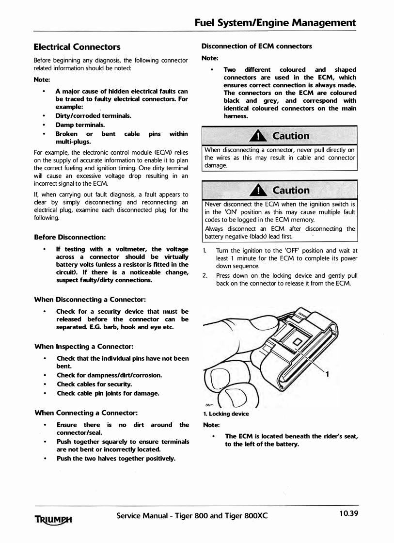
Electrical Connectors
Before beginning any diagnosis, the fol lowing connector related information should be noted:
Note:
• A major cause of hidden electrical faults can be traced to faulty electrical connectors. For example:
• Dirty/corroded terminals. • Damp terminals. • Broken or bent cable pins within
multi-plugs.
For example, the electronic control module <ECM> rel ies on the supply of accurate information to enable it to plan the correct fueling and ignition timing. One dirty terminal wil l cause an excessive voltage drop resulting in an incorrect s ignal to the ECM.
If, when carrying out fault diagnosis, a fault appears to clear by simply disconnecting and reconnecting an electrical plug, examine each disconnected plug for the fol lowing.
Before Disconnection:
• If testing with a voltmeter, the voltage across a connector should be virtually battery volts <unless a resistor is fitted in the circuit>. If there is a noticeable change, suspect faulty/dirty connections.
When Disconnecting a Connector:
• Check for a security device that must be released before the connector can be separated. E.G. barb, hook and eye etc.
When Inspecting a Connector:
• Check that the individual pins have not been bent.
• Check for dampness/dirt/corrosion.
• Check cables for security.
• Check cable pin joints for damage.
When Connecting a Connector:
• Ensure there is no dirt around the connector/seal.
• Push together squarely to ensure terminals are not bent or incorrectly located.
• Push the two halves together positively.
Fuel System/Engine Management
Disconnection of ECM connectors
Note:
• Two different coloured and shaped connectors are used in the ECM, which ensures correct connection is always made. The connectors on the ECM are coloured black and grey, and correspond with identical coloured connectors on the main harness.
When disconnecting a connector, never pul l directly on the wires as this may result in cable and connector damage.
Never disconnect the ECM when the ign ition switch is in the 'ON' position as this may cause multiple fault codes to be logged in the ECM memory.
Always d isconnect an ECM after d isconnecting the battery negative <black> lead first.
1 . Turn the ignition to the 'OFF' position and wait at least 1 minute for the ECM to complete its power down sequence.
2 . Press down on the locking device and gently pu l l back on the connector to release it from the ECM.
1. Locking device
Note:
• The ECM is located beneath the rider's seat, to the left of the battery.
SeNice Manual - Tiger 800 and Tiger 800XC 10.39
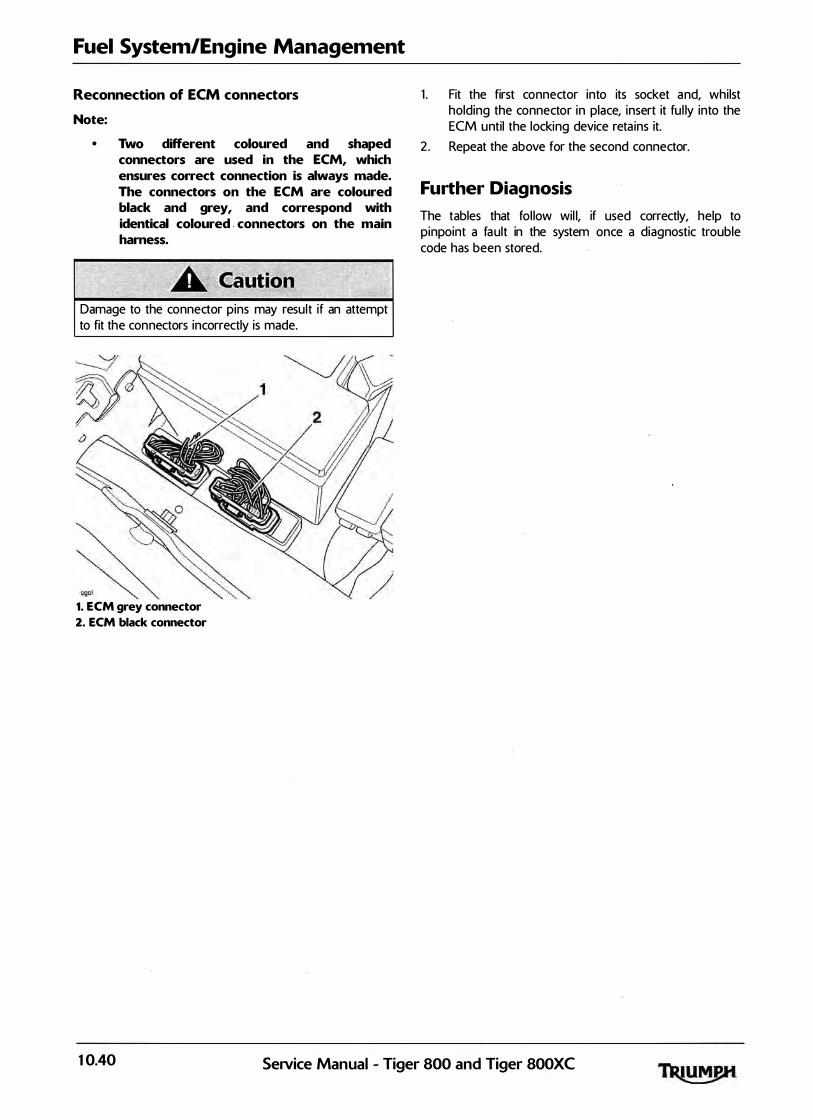
Fuel System/Engine Management
Reconnection of ECM connectors
Note:
• Two different coloured and shaped connectors are used in the ECM, which ensures correct connection is always made. The connectors on the ECM are coloured black and grey, and correspond with identical coloured . connectors on the main harness.
Damage to the connector pins may result if an attempt to fit the connectors incorrectly is made.
1. ECM grey connector
2. ECM black connector
1 . Fit the first connector into its socket and, whilst holding the connector in place, insert it fu l ly into the ECM until the locking device reta ins it.
2 . Repeat the above for the second connector.
Further Diagnosis
The tables that fol low wil l, if used correctly, help to pinpoint a fault in the system once a diagnostic trouble code has been stored.
10.40 Service Manual - Tiger 800 and Tiger 800XC
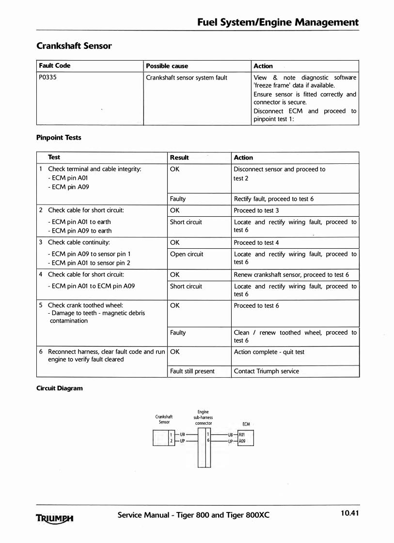
Fuel System/Engine Management
Crankshaft Sensor
Fault Code Possible cause
P0335 Crankshaft sensor system fault
Pinpoint Tests
Test Result
1 Check terminal and cable integrity: OK
- ECM p in A01
- ECM pin A09
Faulty
2 Check cable for short circuit: OK
- ECM p in A01 to earth Short circuit
- ECM pin A09 to earth
3 Check cable continu ity: OK
- ECM pin A09 to sensor p in 1 Open circuit
- ECM pin A01 to sensor pin 2
4 Check cable for short circuit: OK
- ECM p in A01 to ECM p in A09 Short circuit
5 Check crank toothed wheel : OK - Damage to teeth - magnetic debris contamination
Faulty
6 Reconnect harness, clear fault code and run OK engine to verify fault cleared
Circuit Diagram
Fault sti l l present
Crankshaft Sensor
llil-us L£j- UP
Engine sub-harness connector
Action
View & note diagnostic software 'freeze frame' data if avai lable.
Ensure sensor is fitted correctly and connector is secure.
Disconnect ECM and proceed to pinpoint test 1 :
Action
Disconnect sensor and proceed to
test 2
Rectify fault, proceed to test 6
Proceed to test 3
Locate and rectify wiring fault, proceed to test 6
Proceed to test 4
Locate and rectify wiring fault, proceed to test 6
Renew crankshaft sensor, proceed to test 6
Locate and rectify wiring fault, proceed to test 6
Proceed to test 6
Clean I renew toothed wheel, test 6
Action complete - quit test
Contact Triumph service
ECM
us-iAoll UP�
proceed to
SeiVice Manual - Tiger 800 and Tiger 800XC 10.4 1
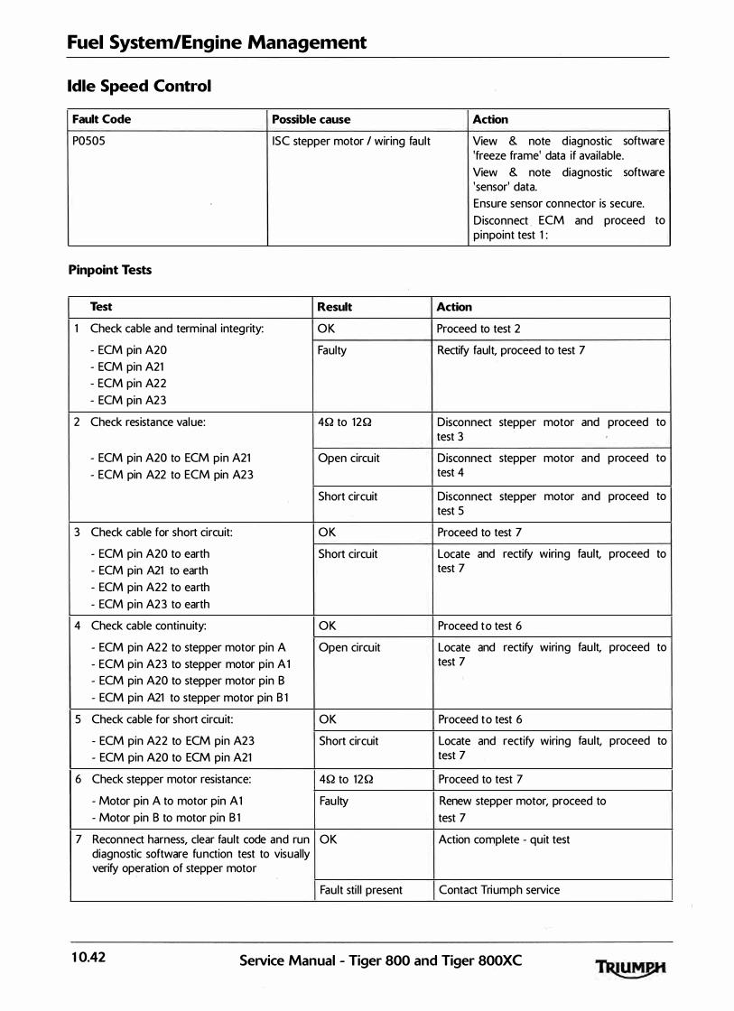
Fuel System/Engine Management
Idle Speed Control
Fault Code Possible cause Action
P0505 ISC stepper motor I wiring fault View & note d iagnostic software 'freeze frame' data if avai lable.
View & note diagnostic software 'sensor' data.
Ensure sensor connector is secure.
Disconnect ECM and proceed to pinpoint test 1 :
Pinpoint Tests
Test Result Action
1 Check cable and terminal integrity: OK Proceed to test 2
- ECM pin A20 Faulty Rectify fault, proceed to test 7
- ECM pin A21
- ECM pin A22
- ECM pin A23
2 Check resistance value: 4Q to 12Q Disconnect stepper motor and proceed to test 3
- ECM pin A20 to ECM pin A21 Open circu it Disconnect stepper motor and proceed to
- ECM pin A22 to ECM pin A23 test 4
Short circuit Disconnect stepper motor and proceed to test 5
3 Check cable for short circuit: OK Proceed to test 7
- ECM pin A20 to earth Short circuit Locate and rectify wiring fault, proceed to
- ECM pin A21 to earth test 7
- ECM pin A22 to earth
- ECM pin A23 to earth
4 Check cable continuity: OK Proceed to test 6
- ECM pin A22 to stepper motor pin A Open circu it Locate and rectify wiring fau lt, proceed to
- ECM pin A23 to stepper motor pin A 1 test 7
- ECM pin A20 to stepper motor pin B
- ECM pin A21 to stepper motor pin B 1
5 Check cable for short circuit: OK Proceed to test 6
- ECM pin A22 to ECM pin A23 Short circuit Locate and rectify wiring fault, proceed to
- ECM pin A20 to ECM pin A21 test 7
6 Check stepper motor resistance: 4Q to 12Q Proceed to test 7
- Motor pin A to motor pin A 1 Fau lty Renew stepper motor, proceed to
- Motor pin B to motor pin B 1 test 7
7 Reconnect harness, clear fault code and run OK Action complete - quit test diagnostic software function test to visual ly verify operation of stepper motor
Fault sti l l present Contact Triumph service
10.42 SeiVice Manual - Tiger 800 and Tiger 800XC

Circuit Diagram
Idle Speed Control Stepper Motor
Fuel System/Engine Management
�w-------IN ou OK
ECM
SeNice Manual - Tiger 800 and Tiger 800XC 10.43

Fuel System/Engine Management
Fuel lniectors
Fault Code Possible cause Action
P0201102/03 In jection system fault - injector 11 2/3 View & note diagnostic software - Misfire indicates open circu it 'freeze frame' data if avai lable.
- Flooding indicates short circu it Ensure relevant injector connector is secure. Disconnect ECM and proceed to pinpoint test 1 :
Pinpoint Tests
Test Result Action
1 Check cable and terminal integrity: OK Proceed to test 2
- ECM pin A15 Faulty Rectify fault, proceed to test 7
- ECM pin A14
- ECM pin A13
2 Check resistance value: 1 1 .0Qto 12 .5Q Proceed to test 3
- ECM pin A06 to ECM pin A 15 (in jector 1 )
- ECM pin A06 to ECM pin A 14 (in jector 2)
- ECM pin A06 to ECM pin A 13 (in jector 3)
Open circuit Disconnect relevant injector and ·proceed to test 4
Short circuit Disconnect relevant in jector and proceed to test 5
3 Check cable for short circuit to ground: OK Proceed to test 7
- ECM pin A 15 to earth Short circuit Locate and rectify wiring fault, proceed to
- ECM pin A 14 to earth test 7
- ECM pin A 13 to earth
4 Check cable continu ity: OK Proceed to test 6
- ECM pin A06 to relevant in jector pin 2 Open circu it Locate and rectify wiring fault, proceed to
- ECM pin A 15 to in jector 1 pin 1 test 7
- ECM pin A 14 to injector 2 pin 1
- ECM pin A 13 to in jector 3 pin 1
5 Check cable for short circu it to supply box: OK Proceed to test 6
- ECM pin A06 to ECM pin A 15 (ilij 1 > Short circuit Locate and rectify wiring fault, proceed to
- ECM pin A06 to ECM pin A 14 (inj 2) test 7
- ECM pin A06 to ECM pin A 13 ( inj 3)
6 Check relevant injector resistance: 1 1 .0Q to 1 2 .5Q Proceed to test 7
- In jector pin 1 to injector pin 2 Faulty Renew relevant injector, proceed to test 7
7 Reconnect harness, clear fault code and run OK Action complete - quit test engine to verify fault cleared
Fault sti l l present Contact Triumph service
10.44 SeiVice Manual - Tiger 800 and Tiger 800XC

Circuit Diagram
EMS Main Relay
Fuel System/Engine Management
NK
1-'----------YK
�=:; 1-'----------YP
�=::;! 1-'----------YB
«::::._ _ _J
Fuel Injectors
ECM
SeiVice Manual - Tiger 800 and Tiger 800XC 10.45

Fuel System/Engine Management
Throttle Position Sensor
Fault Code Possible cause Action
P0122 Throttle position sensor low input View & note diagnostic software
P0123 voltage <short to ground or open 'freeze frame' data if avai lable. circuit> View & note diagnostic software Throttle position sensor high input 'sensor' data. voltage <short circuit to sensor supply) Ensure sensor connector is secure.
Disconnect ECM and proceed to pinpoint test 1 :
Pinpoint Tests
Test Result Action
1 Check cable and terminal integrity: OK Disconnect sensor and proceed to
- ECM pin 801 test 2
- ECM pin 820
- ECM pin A10
Faulty Rectify fault, proceed to test 5
2 Check cable for short circuit: OK Proceed to test 3
- ECM pin A 10 to ground
Short circuit Locate and rectify wiring fau lt, proceed to test 5
3 Check cable continu ity: OK Proceed to test 4
- ECM pin A 10 to sensor pin 1
- ECM pin 820 to sensor pin 2
- ECM pin 801 to sensor pin 3
Open circuit Locate and rectify wiring fau lt, proceed to test 5
4 Check cable for short circuit: OK Renew throttle position sensor, proceed to
- ECM pin A 10 to ECM pin 801 test 5
- ECM pin A 10 to ECM pin 820
Short circuit Locate and rectify wiring fault, proceed to test 5
5 Reconnect harness, clear fault code and run OK Action complete - qu it test engine to verify fault cleared
Fault sti l l present Contact Triumph service
10.46 SeNice Manual - Tiger 800 and Tiger 800XC

Circuit Diagram
Fuel System/Engine Management
Throttle Position Sensor
0-----� ECM
SeiVice Manual - Tiger 800 and Tiger SOOXC 10.47

Fuel System/Engine Management
Purge Valve
Fault Code Possible cause Action
P0444 Open circu it or short circuit to earth View & note diagnostic software 'sensor' data.
Ensure purge va lve connector is secure.
Disconnect ECM and proceed to pinpoint test 1 :
P0445 Short circu it to battery+ Disconnect purge valve and proceed to pinpoint test 5 :
Pinpoint Tests
Test Result Action
1 Check cable and terminal integrity: OK Proceed to test 2
- ECM pin 809 Faulty Rectify fault, proceed to test 7
2 Check resistance value: 24Q to 28Q Disconnect purge valve and proceed to test 3
- ECM pin A06 to ECM pin 809 Open circu it Proceed to test 4
Short circuit Disconnect purge valve and proceed to test 5
3 Check cable for short circuit: OK Disconnect purge valve and proceed to test 7
- ECM pin 809 to earth Short circuit Locate and rectify wiring fau lt, proceed to test 7
4 Check cable continuity: OK Proceed to test 6
- ECM pin 809 to valve pin 2 Open circu it Locate and rectify wiring fau lt, proceed to
- ECM pin A06 to va lve pin 1 test 7
5 Check cable for short circuit: OK Proceed to test 6
- ECM pin A06 to ECM pin 809 Short circuit Locate and rectify wiring fau lt, proceed to test 7
6 Check purge valve resistance: 24Q to 28Q Proceed to test 7
- Valve pin 1 to valve pin 2 Fau lty Renew purge valve, proceed to test 7
7 Reconnect harness, clear fau lt code and run OK Action complete - quit test diagnostic software function test to visual ly verify operation of purge valve
Fault sti l l present Contact Triumph service
10.48 Service Manual - Tiger 800 and Tiger 800XC

Circuit Diagram
Fuel System/Engine Management
EMS Main Relay
Purge Valve
1 �2 NK�YR
ECM
SeiVice Manual - Tiger 800 and Tiger 800XC 10.49

Fuel System/Engine Management
Ignition Coils
Fault Code Possible cause Action
P03 51152/53 Ignition system fault - ignition View & note d iagnostic software coi l 11 2/3 'freeze frame' data if avai lable.
Ensure relevant ignition coi l connector is secure. Disconnect ECM and proceed to pinpoint test 1 :
Pinpoint Tests
Test Result Action
1 Check cable and terminal integrity: OK Proceed to test 2
- ECM pin B 17 Faulty Rectify fault, proceed to test 7 - ECM pin A18 - ECM p in B 18
2 Check resistance value: 0.8Q to 1 .2Q Proceed to test 3 ECM pin A06 to - ECM pin (ignition coi l 1 > B17 - ECM p in (ign ition coi l 2 ) A 18 - ECM p in (ignition coi l 3) B 18
Open circuit Disconnect relevant ignition coi l and proceed to test 4
Short circuit Disconnect relevant ignition coi l and proceed to test 5
3 Check cable for short circu it: OK Proceed to test 7
- ECM pin B 17 to earth Short circuit Locate and rectify wiring fault, proceed to - ECM pin A 18 to earth test 7 - ECM pin B 18 to earth
4 Check cable continuity: OK Proceed to test 6
EMS main relay pin 5 to any ign ition coi l Open circuit Locate and rectify wiring fault, proceed to pin 2 test 7 - ECM pin B 17 to ignition coi l 1 pin 1 - ECM pin A 18 to ignition coil 2 pin 1 - ECM pin B 18 to ignition coi l 3 pin 1
5 Check cable for short circu it: OK Proceed to test 6
ECM pin A06 to Short circuit Locate and rectify wiring fault, proceed to - ECM pin <ignition coi l 1 ) B 17 test 7 - ECM pin <ignition coi l 2) A 18 - ECM p in (ignition coi l 3) B 18
6 Check relevant ignition coi l resistance: 0.8Q to 1 .2Q Proceed to test 7
- Ignition coi l pin 1 to ignition coi l pin 2 Faulty Renew relevant ignition coi l, proceed to test 7
7 Reconnect harness, clear fault code and run OK Action complete - quit test engine to verify fault cleared
Fault sti l l present Contact Triumph service
10.50 Service Manual - Tiger 800 and Tiger SOOXC

Circuit Diagram
Fuel System/Engine Management
EMS Main Relay
<llo::----NK�GK
K�GP
NK�GB
Ignition Coils
ECM
Service Manual - Tiger 800 and Tiger 800XC 10.5 1

Fuel System/Engine Management
Coolant Temperature Sensor
Fault Code Possible cause Action
P01 18 Open circuit, or short circuit to View 8. note diagnostic software battery+ 'freeze frame' data if avai lable.
View 8. note diagnostic software 'sensor' data.
Ensure sensor connector is secure. Disconnect ECM and proceed to pinpoint test 1 :
POl l? Short circu it to ground Disconnect sensor and proceed to test 6 :
Pinpoint Tests
Test Result Action
1 Check cable and terminal integrity: OK Proceed to test 2
- ECM pin A29 Faulty Rectify fault, proceed to test 7 - ECM pin 820
2 Check resistance value: OK Disconnect temp sensor and proceed to test 6
- ECM pin A29 to ECM pin 820 Open circu it Disconnect sensor and proceed to· test 3 <Temperature dependent - see below)
Short circuit Disconnect temp sensor and proceed to test 4
3 Check cable continuity: OK Proceed to test 5
- ECM pin A29 to sensor pin 1 Open circu it Locate and rectify wiring fault, proceed to - ECM pin 820 to sensor pin 2 test 7
4 Check cable for short circuit: OK Proceed to test 5
- ECM pin A29 to ECM pin 820 Short circuit Locate and rectify wiring fault, proceed to test 7
5 Check sensor resistance: OK Proceed to test 7
- Sensor pin 1 to sensor pin 2 Faulty Renew temp sensor, proceed to test 7 <Temperature dependent - see below>
6 Check cable for short circuit: OK Proceed to test 7
- ECM pin A29 to ground Short circuit Locate and rectify wiring fault, proceed to test 7
7 Reconnect harness, clear fau lt code and run OK Action complete - quit test engine to verify fault cleared
Fault sti l l present Contact Triumph service
10.52 Service Manual - Tiger 800 and Tiger 800XC
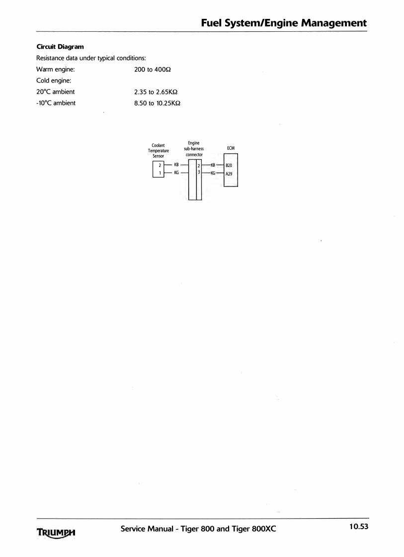
Fuel System/Engine Management
Circuit Diagram
Resistance data under typical conditions:
Warm engine:
Cold engine:
20°C ambient
- 10oC ambient
200 to 400Q
2 .35 to 2 .65KQ
8.50 to 10.25KQ
Coolant Engine
Temperature sub-harness
Sensor connector
[]=�:
ECM
KB-+=l KGLJ
Service Manual - Tiger 800 and Tiger 800XC 10.53

Fuel System/Engine Management
Intake Air Temperature Sensor
Fault Code Possible cause Action
P01 13 Open circuit, or short circu it to View & note diagnostic software battery+ 'freeze frame' data if avai lable.
View & note d iagnostic software 'sensor' data.
Ensure sensor connector is secure. Disconnect ECM and proceed to pinpoint test 1 :
P01 12 Short circuit to ground Disconnect sensor and proceed to pinpoint test 6 :
Pinpoint Tests
Test Result Action
1 Check cable and terminal integrity: OK Proceed to test 2
- ECM pin A1 1 Fau lty Rectify fault, proceed to test 7 - ECM pin B20
2 Check resistance value: OK Disconnect temp sensor and proceed to test 6 - ECM pin A 1 1 to ECM pin B20
<Temperature dependent - see below) Open circuit Disconnect temp sensor and proceed to test 3
Short circuit Disconnect temp sensor and proceed to test 4
3 Check cable continuity: OK Proceed to test 5
- ECM pin A 1 1 to sensor pin 1 Open circu it Locate and rectify wiring fault, proceed to - ECM pin B20 to sensor pin 2 test 7
4 Check cable for short circuit: OK Proceed to test 5
- ECM pin A 1 1 to ECM pin B20 Short circuit Locate and rectify wiring fau lt, proceed to test 7
5 Check sensor resistance: OK Proceed to test 7
- Sensor pin 1 to sensor pin 2 Faulty Renew temp sensor, proceed to test 7 <Temperature dependent - see below)
6 Check cable for short circuit: OK Proceed to test 7
- ECM pin A 1 1 to ground Short circuit Locate and rectify wiring fault, proceed to test 7
7 Reconnect harness, clear fault code and run OK Action complete - quit test engine to verify fault cleared
Fault sti l l present Contact Triumph service
10.54 SeNice Manual - Tiger 800 and Tiger 800XC
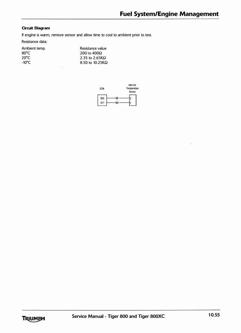
Fuel System/Engine Management
Circuit Diagram
If engine is warm, remove sensor and a l low time to cool to ambient prior to test.
Resistance data :
Ambient temp 80°C 20°C -10°C
Resistance va lue 200 to 400Q 2 .35 to 2 .6SKQ 8.50 to 10 .2SKQ
Inlet Air ECM Temperature
Sensor �KB--n �Ko--u
SeiVice Manual - Tiger 800 and Tiger 800XC 10.55
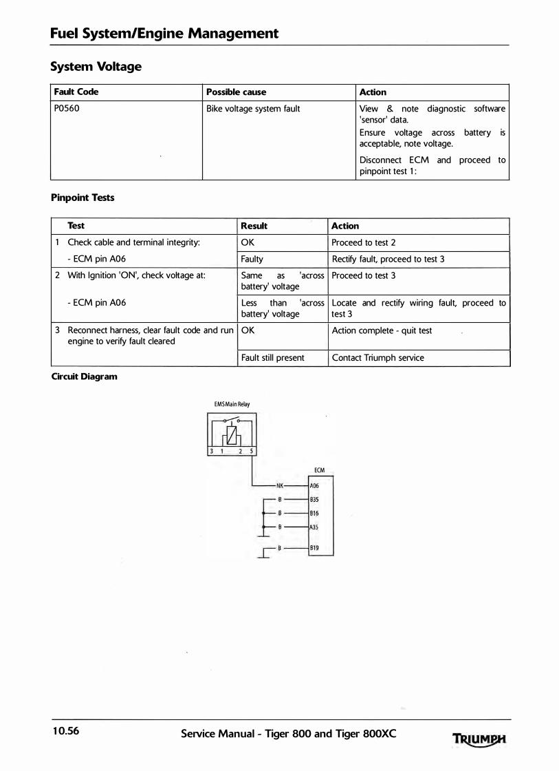
Fuel System/Engine Management
System Voltage
Fault Code Possible cause Action
P0560 Bike voltage system fault View & note d iagnostic software 'sensor' data.
Ensure voltage across battery is acceptable, note voltage.
Disconnect ECM and proceed to pinpoint test 1 :
Pinpoint Tests
Test Result Action
1 Check cable and terminal integrity: OK Proceed to test 2
- ECM pin A06 Faulty Rectify fault, proceed to test 3
2 With Ign ition 'ON', check voltage at: Same as 'across Proceed to test 3 battery' voltage
- ECM pin A06 Less than 'across Locate and rectify wiring fault, proceed to battery' voltage test 3
3 Reconnect harness, clear fault code and run OK Action complete - qu it test engine to verify fault cleared
Fault sti l l present Contact Triumph service
Circuit Diagram
EMS Main Relay
ECM
10.56 SeiVice Manual - Tiger 800 and Tiger 800XC
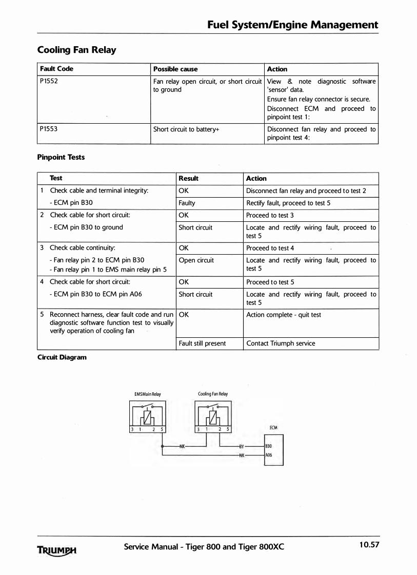
Fuel System/Engine Management
Cooling Fan Relay
Fault Code Possible cause Action
P 1552 Fan relay open circu it, or short circuit View & note diagnostic software to ground 'sensor' data.
Ensure fan relay connector is secure.
Disconnect ECM and proceed to pinpoint test 1 :
P 1553 Short circuit to battery+ Disconnect fan relay and proceed to pinpoint test 4 :
Pinpoint Tests
Test Result Action
1 Check cable and terminal integrity: OK Disconnect fan relay and proceed to test 2
- ECM pin B30 Faulty Rectify fault, proceed to test 5
2 Check cable for short circuit: OK Proceed to test 3
- ECM pin B30 to ground Short circuit Locate and rectify wiring fault, proceed to test 5
3 Check cable continuity: OK Proceed to test 4
- Fan relay pin 2 to ECM pin B30 Open circuit Locate and rectify wiring fault, proceed to
- Fan relay pin 1 to EMS main relay pin 5 test 5
4 Check cable for short circuit: OK Proceed to test 5
- ECM pin B30 to ECM pin A06 Short circuit Locate and rectify wiring fault, proceed to test 5
5 Reconnect harness, clear fault code and run OK Action complete - quit test d iagnostic software function test to visual ly verify operation of cooling fan
Fault sti l l present Contact Triumph service
Circuit Diagram
EMS Main Relay Cooling Fan Relay
SeNice Manual - Tiger 800 and Tiger 800XC 10.57

Fuel System/Engine Management
Oxygen Sensor
Fault Code Possible cause Action
P0130 Oxygen sensor circuit fault View & note 'freeze frame' data if avai lable.
View & note 'sensor' data .
· Ensure sensor connector is secure.
Disconnect ECM and proceed to pinpoint test 1 :
Pinpoint Tests
Test Result Action
1 Check cable and terminal integrity: OK Disconnect oxygen sensor and proceed to test 2
- ECM pin A26 Fau lty Rectify fau lt, proceed to test 4
- ECM pin 820
2 Check cable for short circuit: OK Proceed to test 3
- ECM pin A26 to ECM pin 820 Short circuit Locate and rectify wiring fau lt, proceed to
- ECM pin A26 to ECM pin A06 test 4
3 Check cable continuity: OK Proceed to test 4
- ECM pin A26 to sensor pin 2 Open circu it Locate and rectify wiring fau lt, proceed to
- ECM pin 820 to sensor pin 1 test 4
4 Reconnect harness, clear fault code and run OK Action complete - qu it test engine. Check adaptation status
Fault sti l l present Contact Triumph service
Circuit Diagram
EMS Main Relay Lambda Sensor
ECM
t---{-JK
L------------NK
10.58 SeiVice Manual - Tiger 800 and Tiger 800XC
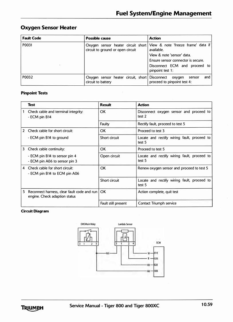
Fuel System/Engine Management
Oxygen Sensor Heater
Fault Code Possible cause Action
P0031 Oxygen sensor heater circuit short View & note 'freeze frame' data if circuit to ground or open circuit avai lable.
View & note 'sensor' data.
Ensure sensor connector is secure.
Disconnect ECM and proceed to pinpoint test 1 :
P003 2 Oxygen sensor heater circuit, short Disconnect oxygen sensor and circuit to battery proceed to pinpoint test 4 :
Pinpoint Tests
Test Result Action
1 Check cable and terminal integrity: OK Disconnect oxygen sensor and proceed to
- ECM pin 8 14 test 2
Faulty Rectify fault, proceed to test 5
2 Check cable for short circu it: OK Proceed to test 3
- ECM pin B 14 to ground Short circu it Locate and rectify wiring fa.ult, proceed to test 5
3 Check cable continuity: OK Proceed to test 5
- ECM pin B 14 to sensor pin 4 Open circuit Locate and rectify wiring fault, proceed to
- ECM pin A06 to sensor pin 3 test 5
4 Check cable for short circuit: OK Renew oxygen sensor and proceed to test 5
- ECM pin B 14 to ECM pin A06
Short circuit Locate and rectify wiring fault, proceed to test 5
5 Reconnect harness, clear fault code and run OK Action complete, quit test engine. Check adaption status
Fault sti l l present Contact Triumph service
Circuit Diagram
EMS Main Relay Lambda Sensor
Service Manual - Tiger 800 and Tiger 800XC 10.59

Fuel System/Engine Management
EEPROM Error
Fault Code Possible cause Action
P0603 EEPROM error View & note 'freeze frame' data if avai lable.
No tests avai lable - contact Triumph service.
10.60 Se1Vice Manual - Tiger 800 and Tiger SOOXC

Fuel System/Engine Management
Fall Detection Switch
Fault Code Possible cause Action
P 1 631 Fal l detection switch low input voltage View & note 'freeze frame' data if
P 1632 Fa l l detection switch h igh input avai lable.
voltage or open circuit View & note 'sensor' data
Ensure switch connector is secure.
Disconnect ECM and proceed to pinpoint test 1 :
Pinpoint Tests
Test Result Action
1 Check cable and terminal integrity: OK Disconnect sensor and proceed to test 2
- ECM pin B21 Faulty Rectify fau lt, proceed to test 6
2 Check cable for short circuit: OK Proceed to test 3
- ECM pin B21 to ground Short circuit Locate and rectify wiring fault, proceed to test 6
3 Check cable continuity: OK Proceed to test 4
- ECM pin B01 to sensor pin 4 Open circuit Locate and rectify wiring fault, proceed to
- ECM pin B21 to sensor pin 5 test 6
- ECM pin B20 to sensor pin 6
4 Check cable for short circuit: OK Connect ECM and proceed to test 5
- ECM pin B21 to ECM pin B 1 Short circuit Locate and rectify wiring fau lt, proceed to
- ECM pin B21 to ECM pin B20 test 6
5 Check voltage (with ignition 'ON'> between: 5V Renew fal l detection switch and proceed to
- Sensor pin 4 and sensor pin 6
6 Reconnect harness, clear fault code
Circuit Diagram
Less than 4 .8V
OK
Fault sti l l present
Fall ECM Detection
Switch
ffi=;=tJ
test 6
Locate and rectify wiring test 6
Action complete, quit test
Contact Triumph service
SeiVice Manual - Tiger 800 and Tiger 800XC
fault, proceed to
10.6 1

Fuel System/Engine Management
Vehicle Speed Sensor
Fault Code Possible cause Action
POSOO Vehicle speed sensor circu it fault - View & note 'freeze frame' data if Tiger 800 and Tiger 800XC without avai lable. ABS View & note 'sensor' data .
Ensure sensor connector is secure.
Disconnect ECM and proceed to pinpoint test 1 :
Rear wheel speed sensor - Tiger 800 Refer to C 1 613 (see page 14-60> and Tiger 800XC with ABS
Pinpoint Tests
Test Result
1 Check cable and terminal integrity: OK
- ECM p in A34 Faulty
- Instrument pin 9
2 Check cable for short circuit: OK
- ECM p in A34 to ground Fau lty
- ECM pin A34 to Instruments pin 9
3 Check cable for continu ity: OK
- ECM pin A34 to sensor p i n 3 Open circu it
- Sensor pin 2 to ground
- Instruments pin 9 to sensor pin 1
4 Reconnect harness, clear fault code and run OK engine
Fault sti l l present
Circuit Diagram
Alarm Control Unit
�
'Fi,.J L. Lt BY
Engine ·stop Switch
ECM
KY -------1
Road Speed Sensor
B j_
Action
Disconnect sensor and proceed to test 2
Rectify fault, proceed to test 4
Proceed to test 3
Locate and rectify wiring fault, .proceed to test 4
Renew vehicle speed sensor and proceed to test 4
Locate and rectify wiring fault, proceed to test 4
Action complete, quit test
Contact Triumph service
Fuse Box r - - - - - -, I 2 I
G l c:=:J 0 1 l O A
l _ _ _ _ _ _j
10.62 SeNice Manual - Tiger 800 and Tiger 800XC
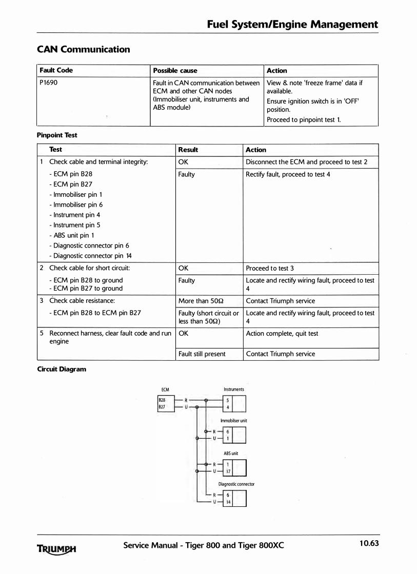
Fuel System/Engine Management
CAN Communication
Fault Code Possible cause Action
P 1 690 Fault in CAN communication between View & note 'freeze frame' data if ECM and other CAN nodes avai lable. ( Immobil iser un it, instruments and Ensure ignition switch is in 'OFF' ABS module> position.
Proceed to pinpoint test 1 .
Pinpoint Test
Test Result Action
1 Check cable and terminal integrity: OK Disconnect the ECM and proceed to test 2
- ECM pin B28 Faulty Rectify fault, proceed to test 4
- ECM pin B27
- Immobil iser pin 1
- Immobil iser pin 6
- Instrument pin 4
- Instrument pin 5
- ABS unit pin 1
- Diagnostic connector pin 6
- Diagnostic connector pin 14
2 Check cable for short circu it: OK Proceed to test 3
- ECM pin B28 to ground Faulty Locate and rectify wiring fault, proceed to test - ECM pin B27 to ground 4
3 Check cable resistance: More than 50Q Contact Triumph service
- ECM pin B28 to ECM pin B27 Fau lty <short circuit or Locate and rectify wiring fault, proceed to test less than 50Q) 4
5 Reconnect harness, clear fault code and run OK Action complete, quit test engine
Circuit Diagram
ECM
Fault sti l l present Contact Triumph service
Instruments
lmmobilser unit
R � u �
ABS unit r
R --fiTI u �
Diagnostic connector
R � u --L2:L_j
SeiVice Manual - Tiger 800 and Tiger 800XC 10.63

Fuel System/Engine Management
Instrument Communication <CAN>
Fault Code Possible cause Action
P 1690 Fault in CAN communication between View & note 'freeze frame' data if ECM and instrument pack.
Pinpoint Tests
Test Result
1 Check cable and terminal integrity: OK
- ECM p in B27 Fau lty
- ECM pin B28
- Instrument pin 4
- Instrument pin 5
2 Check cable for short circuit: OK
- ECM p in B27 to B28 Faulty
- ECM pin B27 to ground - ECM pin B28 to ground
3 Check cable continu ity: OK
- ECM pin B28 to Instrument pin 4 Open circu it
- ECM pin B27 to Instrument pin 5
4 Reconnect harness, clear fault code and run OK engine
Circuit Diagram
Fault sti l l present
Instruments ECM
IT41-- R � L____l1-- u -E._j
avai lable.
View & note 'sensor' data .
Ensure instrument connector is secure.
Disconnect ECM and proceed to pinpoint test 1 :
Action
Disconnect instruments and proceed to test 2
Rectify fault, proceed to test 4
Proceed to test 3
Locate and rectify wiring fault, proceed to test 4
Contact Triumph service
Locate and rectify wiring fault, proceed to test 4
Action complete, quit test
Contact Triumph service
10.64 SeiVice Manual - Tiger 800 and Tiger 800XC
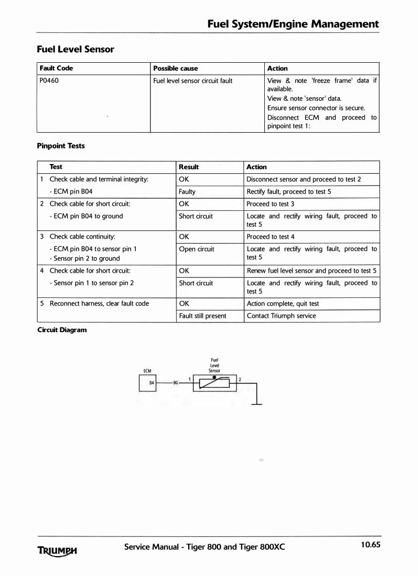
Fuel System/Engine Management
Fuel level Sensor
Fault Code Possible cause
P0460 Fuel level sensor circuit fault
Pinpoint Tests
Test Result
1 Check cable and terminal integrity: OK
- ECM p in 804 Fau lty
2 Check cable for short circuit: OK
- ECM pin 804 to ground Short circuit
3 Check cable continuity: OK
- ECM pin 804 to sensor pin 1 Open circuit
- Sensor pin 2 to ground
4 Check cable for short circu it: OK
- Sensor pin 1 to sensor pin 2 Short circuit
5 Reconnect harness, clear fault code OK
Circuit Diagram
Fault sti l l present
Fuel Level
ECM Sensor
G--sG----+i/<=1 1 2
Action
View & note 'freeze frame' data if avai lable.
View & note 'sensor' data.
Ensure sensor connector is secure.
Disconnect ECM and proceed to pinpoint test 1 :
Action
Disconnect sensor and proceed to test 2
Rectify fault, proceed to test 5
Proceed to test 3
Locate and rectify wiring fault, proceed to test 5
Proceed to test 4
Locate and rectify wiring fau l t, proceed to test 5
Renew fuel level sensor and proceed to test 5
Locate and rectify wiring fault, proceed to test 5
Action complete, quit test
Contact Triumph service
1
SeJVice Manual - Tiger 800 and Tiger SOOXC 10.65

Fuel System/Engine Management
Ambient <Barometric> Pressure Sensor
Fault Code Possible cause Action
P 1 107 Ambient pressure sensor circuit short View & note 'freeze frame' data if ci rcuit to ground avai lable.
View & note 'sensor' data.
Ensure sensor connector is secure.
Disconnect ECM and proceed to pinpoint test 1 :
P 1 108 Ambient pressure sensor circuit, short Disconnect ambient pressure sensor circu it to supply or open circuit and proceed to pinpoint test 4 :
Pinpoint Tests
Test Result Action
1 Check cable and terminal integrity: OK Disconnect ambient pressure sensor and proceed to test 2
- ECM pin A27 Faulty Rectify fault, proceed to test 5
- ECM pin 820
- ECM pin 801
2 Check cable for short circuit: OK Proceed to test 3
- ECM pin A27 to ECM 820 Short circuit . Locate and rectify wiring fault, proceed to
- ECM pin A27 to ground test 5
3 Check cable for continu ity: OK Renew ambient pressure sensor and proceed to test 5
- ECM pin A27 to sensor pin 1 Open circu it Locate and rectify wiring fau lt, proceed to
- ECM pin 820 to sensor pin 2 test 5
- ECM pin 801 to sensor pin 3
4 Check cable for short circuit: OK Renew ambient pressure sensor and proceed
- ECM pin A27 to ECM pin 801 to test 5
Short circuit Locate and rectify wiring fault, proceed to test 5
5 Reconnect harness, clear fault code and run OK Action complete, quit test engine
Circuit Diagram
10.66
Fault sti l l present
ECM
Ambient Pressure Sensor
:=fl K=tJ
Contact Triumph service
SeNice Manual - Tiger 800 and Tiger 800XC

Fuel System/Engine Management
Manifold Absolute Pressure <Map> Sensor
Fault Code Possible cause Action
P0107 MAP sensor circuit short circuit to View & note 'freeze frame' data if ground avai lable.
View & note 'sensor' data.
Ensure sensor connector is secure.
Disconnect ECM and proceed to pinpoint test 1 :
P0108 MAP sensor circuit, short circu it to Disconnect MAP sensor and proceed supply or open circuit to test 4 :
P 1 105 MAP sensor pipe fault Check connection/condition of pipe from MAP sensor to throttle body.
Pinpoint Tests
Test Result Action
1 Check cable and terminal integrity: OK Disconnect MAP sensor and proceed to test 2
- ECM pin A28 Faulty Rectify fault, proceed to test 5
- ECM pin 820
- ECM pin 801
2 Check cable for short circuit: OK Proceed to test 3
- ECM pin A28 to ECM 820 Short circuit Locate and rectify wiring fau lt, proceed to
- ECM pin A28 to ground test 5
3 Check cable for continuity: OK Renew MAP sensor and proceed to test 5
- ECM pin A28 to sensor pin 1 Open circuit Locate and rectify wiring fault, proceed to
- ECM pin 820 to sensor pin 2 test 5
- ECM pin 801 to sensor pin 3
4 Check cable for short circuit: OK Renew MAP sensor and proceed to test 5
- ECM pin A28 to ECM pin 801
Short circuit Locate and rectify wiring fault, proceed to test 5
5 Reconnect harness, clear fault code and run OK Action complete, qu it test engine
Circuit Diagram
Fault sti l l present
ECM MAP Sensor
KB=t] KS 1
K 3
Contact Triumph service
SeiVice Manual - Tiger 800 and Tiger 800XC 10.67

Fuel System/Engine Management
Gear Position Sensor
Fault Code Possible cause Action
P0705 Gear position sensor circu it fault View & note 'freeze frame' data if avai lable.
View & note 'sensor' data.
Ensure sensor connector is secure.
Disconnect ECM and proceed to pinpoint test 1 :
Pinpoint Tests
Test Result Action
1 Check cable and terminal integrity: OK Disconnect sensor and proceed to test 2
- ECM pin 824 Fau lty Rectify fault, proceed to test 5
2 Check cable for short circuit: OK Proceed to test 3
- ECM pin 824 to ground Short circuit Locate and rectify wiring fau lt, proceed to test 5
3 Check cable for continuity: OK Proceed to test 4
- ECM pin 824 to sensor pin 1 Open circu it Locate and rectify wiring fault, ·proceed to
- ECM pin 820 to sensor pin 2 test 5
- ECM pin A31 to sensor pin 3
4 Check cable for short circuit: OK Renew gear position sensor and contact pin
- Sensor pin 1 to sensor pin 2 and proceed to test 5
- Sensor pin 1 to sensor pin 3
Short circuit Locate and rectify wiring fault, proceed to test 5
5 Reconnect harness, clear fault code OK Action complete, quit test
Fault sti l l present Contact Triumph service
10.68 SeiVice Manual - Tiger 800 and Tiger 800XC
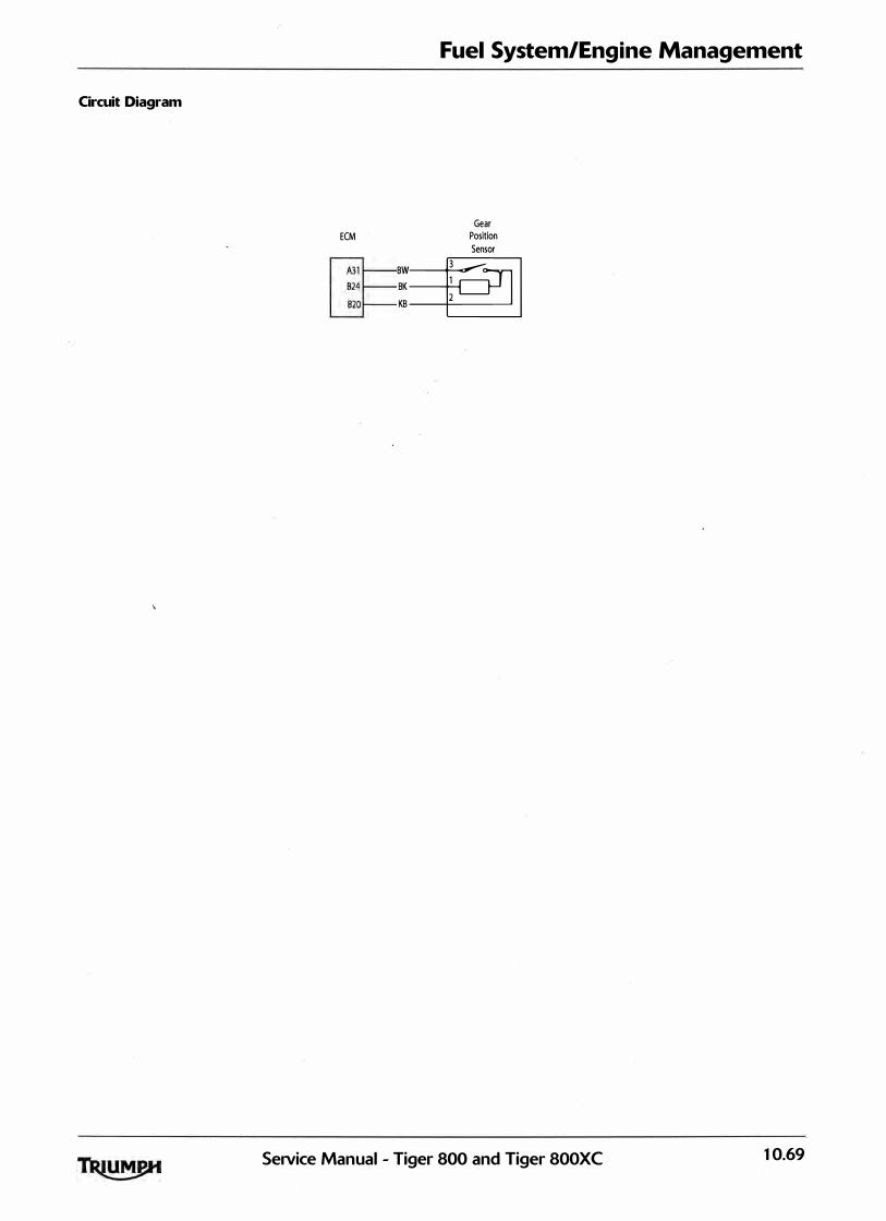
Circuit Diagram
Fuel System/Engine Management
ECM Gear
Position Sensor
BW� BK
1
KB 2
SeiVice Manual - Tiger 800 and Tiger 800XC 10.69
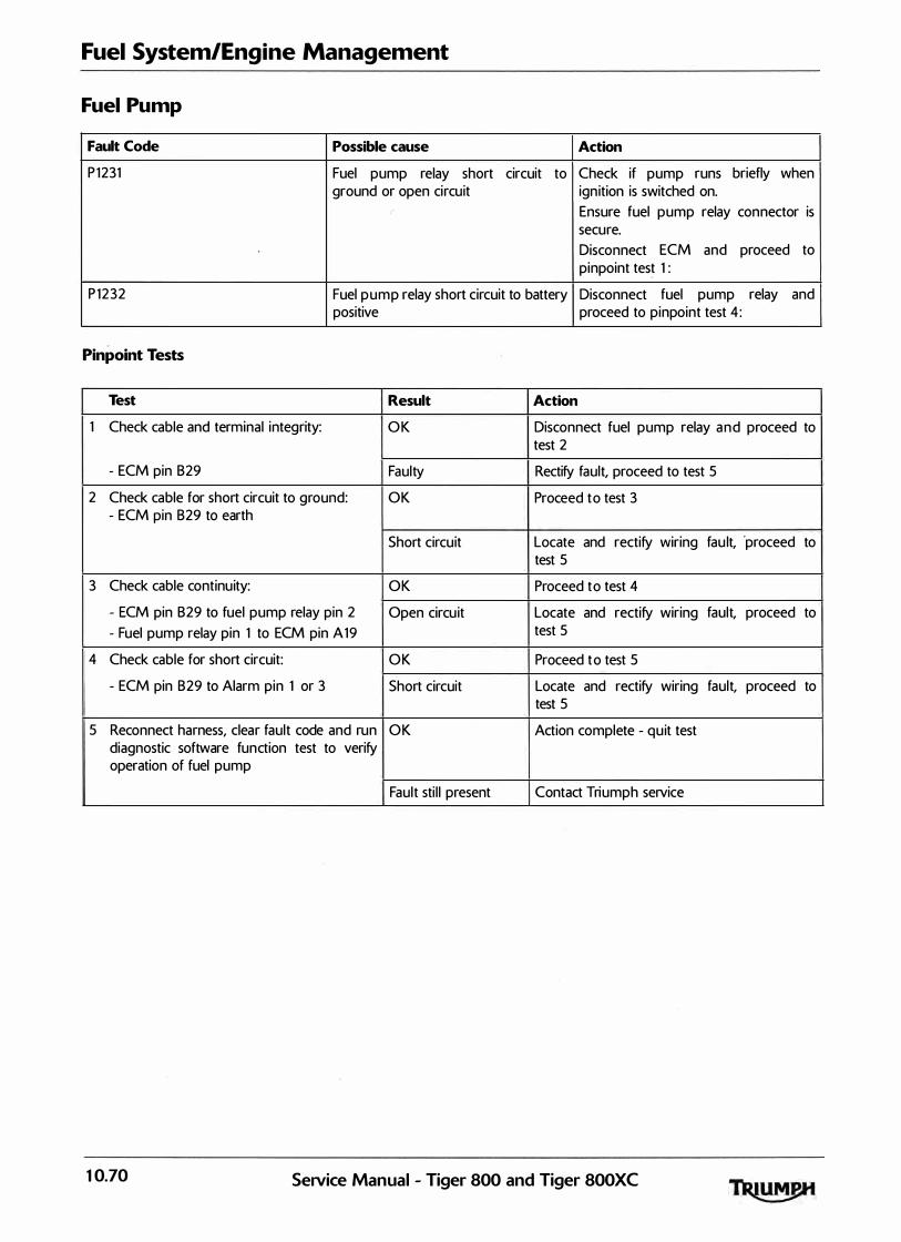
Fuel System/Engine Management
Fuel Pump
Fault Code Possible cause Action
P 1231 Fuel pump relay short circuit to Check if pump runs briefly when ground or open circuit ign ition is switched on.
Ensure fuel pump relay connector is secure.
Disconnect ECM and proceed to pinpoint test 1 :
P 1232 Fuel pump relay short circuit to battery Disconnect fuel pump relay and positive proceed to pinpoint test 4 :
Pinpoint Tests
Test Result Action
1 Check cable and terminal integrity: OK Disconnect fuel pump relay and proceed to test 2
- ECM pin 829 Faulty Rectify fault, proceed to test 5
2 Check cable for short circuit to ground: OK Proceed to test 3 - ECM pin 829 to earth
Short circuit Locate and rectify wiring fau lt, ·proceed to test 5
3 Check cable continuity: OK Proceed to test 4
- ECM pin 829 to fuel pump relay pin 2 Open circu it Locate and rectify wiring fault, proceed to
- Fuel pump relay pin 1 to ECM pin A 19 test 5
4 Check cable for short circuit: OK Proceed to test 5
- ECM pin 829 to Alarm pin 1 or 3 Short circuit Locate and rectify wiring fault, proceed to test 5
5 Reconnect harness, clear fault code and run OK Action complete - qu it test diagnostic software function test to verify operation of fuel pump
Fault sti l l present Contact Triumph service
10.70 SeNice Manual - Tiger 800 and Tiger 800XC

Fuel System/Engine Management
Circuit Diagram
Fuel Pump Main Relay
GR
ECM
Alarm � BP
Q=·
GR
B
A19
SeiVice Manual - Tiger 800 and Tiger 800XC 10.7 1
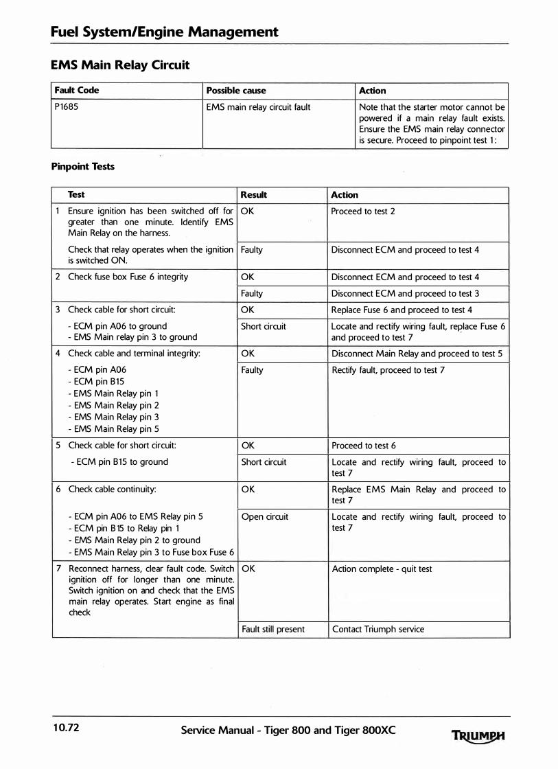
Fuel System/Engine Management
EMS Main Relay Circuit
Fault Code Possible cause Action
P 1685 EMS main relay circu it fault Note that the starter motor cannot be powered if a main relay fau lt exists. Ensure the EMS main relay connector is secure. Proceed to pinpoint test 1 :
Pinpoint Tests
Test Result Action
1 Ensure ignition has been switched off for OK Proceed to test 2 greater than one minute. Identify EMS Main Relay on the harness.
Check that relay operates when the ign ition Faulty Disconnect ECM and proceed to test 4 is switched ON.
2 Check fuse box Fuse 6 integrity OK Disconnect ECM and proceed to test 4
Faulty Disconnect ECM and proceed to test 3
3 Check cable for short circuit: OK Replace Fuse 6 and proceed to test 4
- ECM pin A06 to ground Short circuit Locate and rectify wiring fault, replace Fuse 6 - EMS Main relay pin 3 to ground and proceed to test 7
4 Check cable and terminal integrity: OK Disconnect Main Relay and proceed to test 5
- ECM pin A06 Faulty Rectify fault, proceed to test 7 - ECM pin B 1 5 - EMS Main Relay pin 1 - EMS Main Relay pin 2 - EMS Main Relay pin 3 - EMS Main Relay pin 5
5 Check cable for short circuit: OK Proceed to test 6
- ECM pin B 1 5 to ground Short circuit Locate and rectify wiring fault, proceed to test 7
6 Check cable continuity: OK Replace EMS Main Relay and proceed to test 7
- ECM pin A06 to EMS Relay pin 5 Open circu it Locate and rectify wiring fault, proceed to - ECM pin B 15 to Relay pin 1 test 7
- EMS Main Relay pin 2 to ground - EMS Main Relay pin 3 to Fuse box Fuse 6
7 Reconnect harness, clear fault code. Switch OK Action complete - qu it test ignition off for longer than one minute. Switch ignition on and check that the EMS main relay operates. Start engine as final check
Fault sti l l present Contact Triumph service
10.72 Service Manual - Tiger 800 and Tiger 800XC
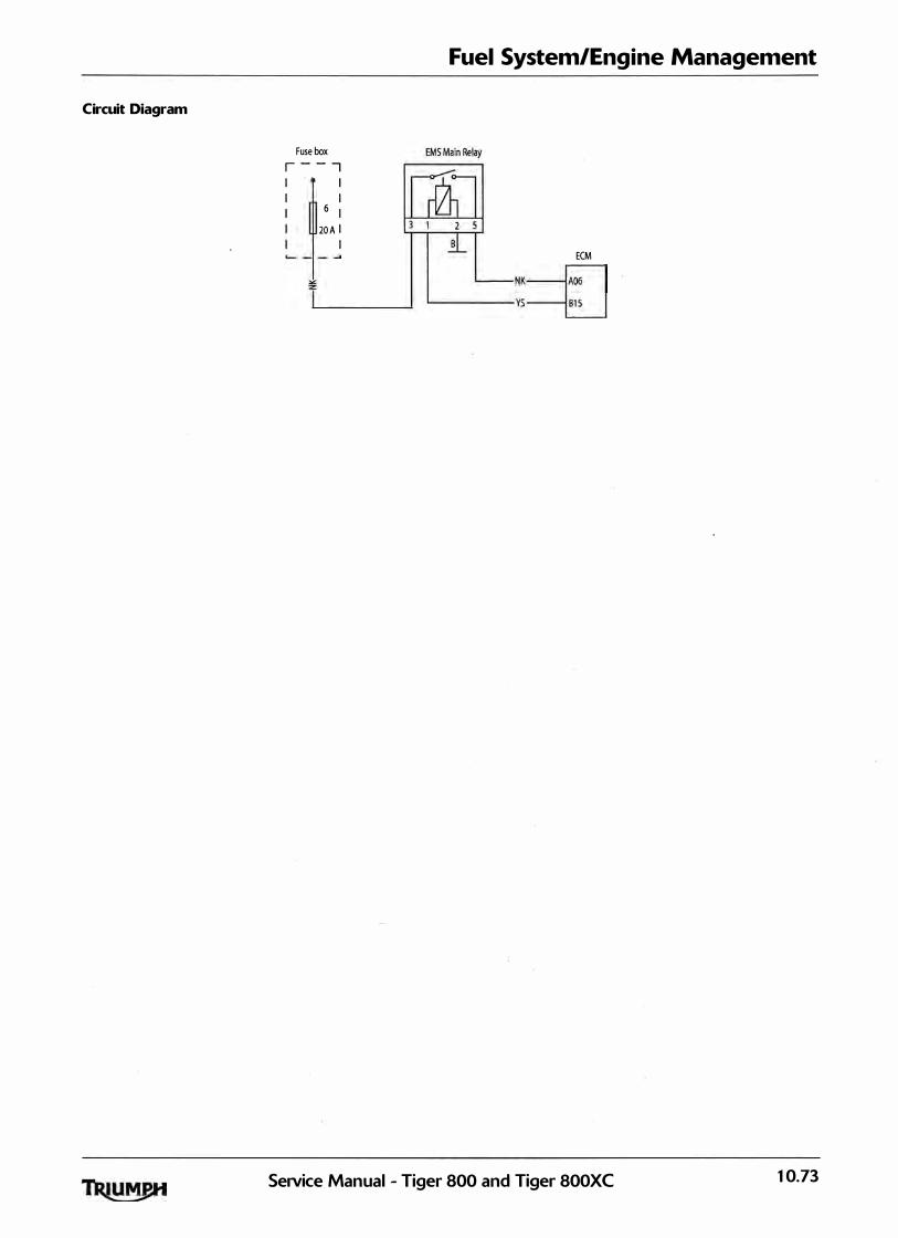
Circuit Diagram
Fuse box r - - -, I I I I I 6 I
20 A I I
Fuel System/Engine Management
ECM NK� '----- vs-----E__j
SeiVice Manual - Tiger 800 and Tiger 800XC 10.73

Fuel System/Engine Management
EMS Ignition Voltage Input Circuit
Fault Code Possible cause Action
P 1 659 EMS ignition voltage input circuit fault Disconnect ECM and proceed to pinpoint test 1 :
Pinpoint Tests
Test Result Action
1 Check Fuse box Fuse 2 integrity OK Proceed to test 3
Faulty Proceed to test 2
2 Check cable for short circuit: OK Replace Fuse 2 and proceed to test 3 - ECM pin A 19 to ground
Short circuit Locate and rectify wiring fault, replace Fuse 2
3 Check cable and terminal integrity: OK
- ECM pin A19 Faulty
- Alarm Connector pin 1
- Alarm Connector pin 2
- Right hand switchcube pin 2
- Right hand switchcube pin 5
4 Check cable continu ity: OK
- ECM pin A 19 to fuse box Fuse 2, note that Open circuit
and proceed to test 5
Proceed to test 4
Rectify fault, proceed to test 5
Proceed to test 5
Locate and rectify 0 0
w1nng, immobil iser the engine stop switch must be in the engine stop switch fault, proceed to test 5 'RU N' position and any Alarm fitted must be disarmed
5 Reconnect harness, clear fault code and run OK Action complete - quit test engine to verify fault cleared
Fault sti l l present Contact Triumph service
Circuit Diagram
10.74
Fuse Box r - - - - - -. I 2 I I • c=::::3 I G l O A l _ _ _ _ _ ..J
Engine Stop
Switch
Alarm
Control Unit
� OCM
GN_j LGR--EJ
Service Manual - Tiger 800 and Tiger 800XC
or

Fuel System/Engine Management
5 Volt Sensor Supply Circuit
Fault Code Possible cause Action
P 1 698 Sensor supply circu it shorted Sensor View & note 'sensor' data. Note ECM supply circu it shorted to ground sensors requiring a power supply will
Sensor supply circuit shorted to not be active. Disconnect ECM and
battery positive proceed to pinpoint test 1 :
Pinpoint Tests
Test Result Action
1 Check cable and terminal integrity: OK Proceed to test 2
- ECM pin B01 Faulty Rectify fault, proceed to test 5 - ECM pin B20
2 Check cable for short circuit OK Proceed to test 4 - ECM pin B01 to ECM pin B20
Faulty Proceed to test 3
3 Disconnect the fol lowing sensors in turn : OK Replace sensor last removed and proceed to test 5
- MAP sensor Faulty Proceed to test 4 - Ambient pressure sensor - Throttle position switch - Exhaust control valve actuator - Fal l detection sensor and retest for short circuit - ECM pin B01 to ECM pin B20
4 Check cable for short circuit: OK Proceed to test 5
- ECM pin B01 to ground Short circuit Locate and rectify wiring fault, proceed to - ECM pin B20 to ground test 5
- ECM pin B01 to A06 - ECM pin B20 to A06 - ECM pin B01 to battery positive - ECM pin B20 to battery positive
5 Reconnect harness, clear fault code and use OK Action complete - quit test service software to check for correct sensor outputs and 5V sensor supply voltage level
Fault sti l l present Contact Triumph service
Circuit Diagram
Ambient Exhaust Valve Pressure MAP Sensor Fal l Detection Throttle Position Sensor Sensor Switch Position
I , 3 1
q q
1 6 4 1 1 2 3 1 ECM l I I I I I [3=� K
Setvice Manual - Tiger 800 and Tiger 800XC 10.75

Fuel System/Engine Management
Tune Lock
Fault Code Possible cause Action
P 1602 ECM is locked to prevent the This is also identified by a fast flashing motorcycle from being operated M I L indication, and a disabled engine
management system. Unlock the ECM using the diagnostic software and suppl ied unlock code from Triumph service.
10.76 SeNice Manual - Tiger 800 and Tiger 800XC

Fuel System/Engine Management
ECM or Tune ID Incorrect
Fault Code Possible cause Action
P 1614 ECM or tune is incorrect, causing the This is also identified by a fast flashing ECM to be disabled to prevent the M I L ind ication, and a d isabled engine motorcycle from being operated management system.
Pinpoint Tests
Test Result Action
1 Check ECM part number is correct for the OK Proceed to test 2 motorcycle
I ncorrect Replace ECM with correct part and proceed to test 3
2 Check that the tune is correct for the OK Proceed to test 3 motorcycle, using the diagnostic software
Incorrect Update tune using the diagnostic software, proceed to test 3
3 Clear fault code, check for normal operation OK Action complete - quit test
Fault sti l l present Contact Triumph service
SeiVice Manual - Tiger 800 and Tiger 800XC 10.77
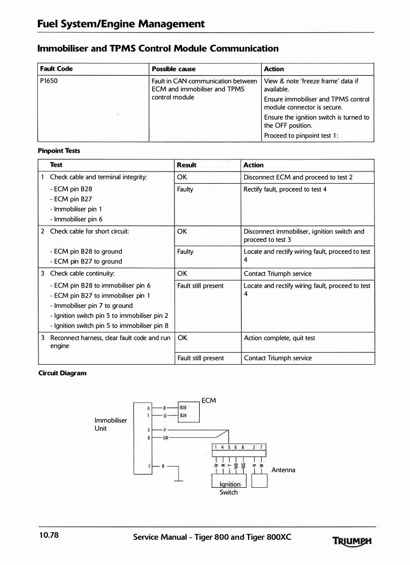
Fuel System/Engine Management
Immobiliser and TPMS Control Module Communication
Fault Code Possible cause Action
P 1650 Fault in CAN communication between View & note 'freeze frame' data if ECM and immobil iser and TPMS avai lable. control module Ensure immobil iser and TPMS control
module connector is secure.
Ensure the ignition switch is turned to the OFF position.
Proceed to pinpoint test 1 :
Pinpoint Tests
Test Result Action
1 Check cable and terminal integrity: OK Disconnect ECM and proceed to test 2
- ECM pin 828 Fau lty Rectify fault, proceed to test 4
- ECM pin 827
- Immobil iser pin 1
- Immobil iser pin 6
2 Check cable for short circu it: OK Disconnect immobil iser, ign ition switch and proceed to test 3
- ECM pin 828 to ground Faulty Locate and rectify wiring fault, proceed to test
- ECM pin 827 to ground 4
3 Check cable continu ity: OK Contact Triumph service
- ECM pin 828 to immobi l iser pin 6 Fault sti l l present Locate and rectify wiring fault, proceed to test
- ECM pin 827 to immobi l iser pin 1 4
- Immobil iser pin 7 to ground
- Ignition switch pin 5 to immobil iser pin 2
- Ignition switch pin 5 to immobil iser pin 8
3 Reconnect harness, clear fault code and run OK Action complete, quit test engine
Circuit Diagram
10.78
Immobil iser Unit
Fault sti l l present Contact Triumph service
R� u� ECM
GR �
I,q. , .
�I l l B j_ � Z >- � �
� Switch
2 7 1 I z � b Antenna
SeiVice Manual - Tiger 800 and Tiger 800XC

Fuel System/Engine Management
Immobiliser and TPMS Control Module ID Incompatible
Fault Code Possible cause Action
P 1508 There is a mismatch between the This is also identified by a fast flashing ECM and the immobil iser and TPMS M I L ind ication and a d isabled engine control module, causing the ECM to management system. be d isabled to prevent the motorcycle from being operated
Pinpoint Tests
Test Result Action
1 Fol low the Pair ECM and Immobil ise OK Action complete, qu it test procedure as described in the Triumph Diagnostic Tool user guide
Fault sti l l present Contact Triumph service
SeiVice Manual - Tiger 800 and Tiger SOOXC 10.79
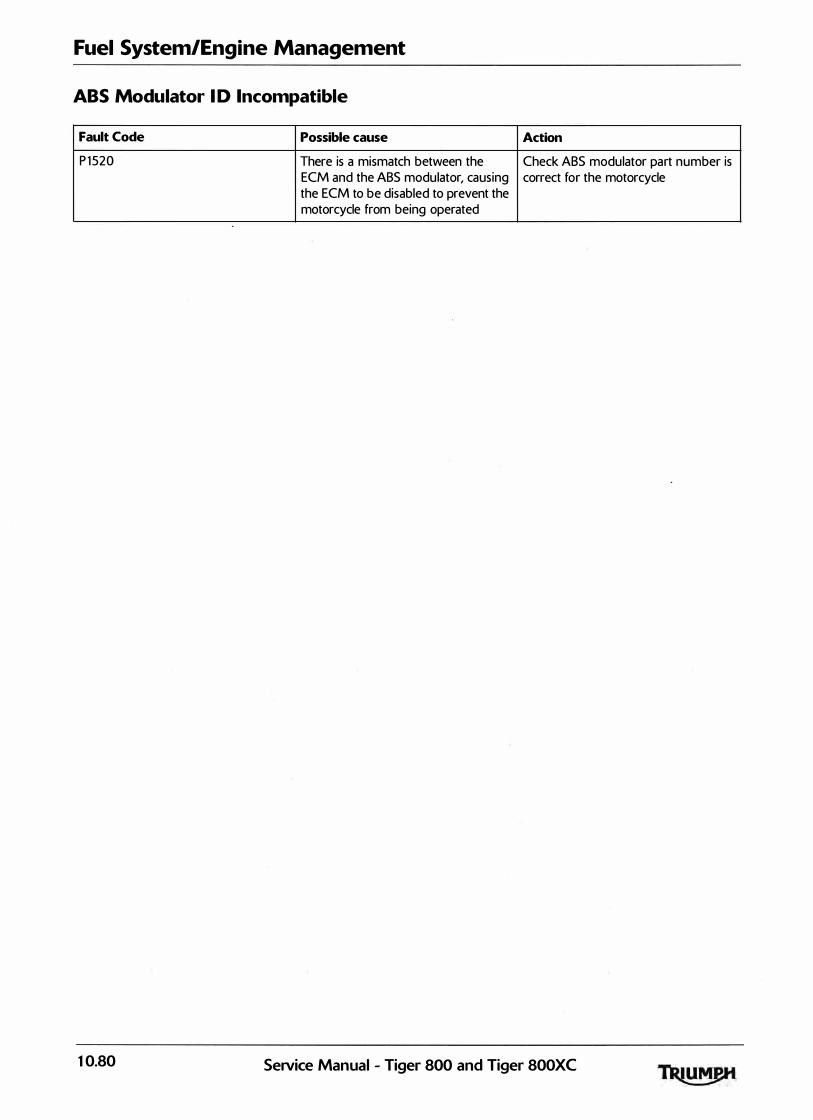
Fuel System/Engine Management
ABS Modulator I D Incompatible
Fault Code Possible cause Action
P 1 520 There is a mismatch between the Check ABS modulator part number is ECM and the ABS modulator, causing correct for the motorcycle the ECM to be disabled to prevent the motorcycle . from being operated
10.80 SeiVice Manual - Tiger 800 and Tiger 800XC

Fuel System/Engine Management
ABS Modulator Communication
Fault Code Possible cause Action
P 1521 Fault in CAN communication between View &. note 'freeze frame' data if ECM and ABS modulator
Pinpoint Test
Test Result
1 Check cable and terminal integrity: OK
- ECM pin B28 Faulty
- ECM pin B27
- ABS modulator pin 1
- ABS modulator pin 17
2 Check cable for short circu it: OK
- ECM p in B28 to ground Faulty
- ECM pin B27 to ground
3 Check cable continuity: OK
- ECM pin B28 to ABS modulator pin 1 Fault sti l l present
- ECM pin B27 to ABS modulator pin 17
3 Reconnect harness, clear fault code and run OK engine
Fault sti l l present
Circuit Diagram
ABS Modulator
Q=R=f]28
U B27
avai lable.
Ensure ABS modulator connector is secure.
Proceed to pinpoint test 1 :
Action
Disconnect ECM and proceed to test 2
Rectify fault, proceed to test 4
Disconnect ABS modulator and proceed to test 3
Locate and rectify wiring fault, proceed to test 4
Contact Triumph service
Locate and rectify wiring fau lt, proceed to test 4
Action complete, quit test
Contact Triumph service
ECM
Service Manual - Tiger 800 and Tiger 800XC 10.8 1

Fuel System/Engine Management
Fault Finding - Non Electrical
Symptom Possible cause<s>
Poor throttle response at low RPM Low fuel pressure caused by fi lter blockage/leaks
Cutting out at idle Throttle bodies out of balance
ISC <Idle Speed Control> actuator inoperative
Low fuel pressure
Weak mixture caused by air leak at the throttle body/transition piece to cyl inder head face
Idle speed too low/high I SC (Idle Speed Control> actuator sticking
Incorrect closed throttle position setting
Mechanical fault with the throttle l inkage
Diagnostic software malfunctions during tune download Low battery voltage procedure
Throttle hang-up I ncorrect closed throttle position setting
Motorcycle wil l start but cuts out immediately ISC motor stuck
Low fuel pressure caused by fi lter blockage/leaks
Abnormal ly high fuel pressure Fuel pressure regulator inoperative
Temperature gauge reads cooler than normal Cooling system air-locked resulting in coolant temperature sensor operating in air instead of coolant
Motorcycle wil l not start Check the immobil iser system for fau lts
Ensure that the keys, ECM and immobil iser/TPMS control module are a l l correctly paired
10.82 SeiVice Manual - Tiger 800 and Tiger 800XC

Fuel System/Engine Management
Front Wheel Unit Sensor Battery Alert
Note:
• All the fault codes for the tyre pressure monitoring system and the immobiliser system can only be viewed in the Safety/Security section of the Triumph diagnostic software.
Fault Code Possible cause Action
L0001 Low battery voltage Replace the front wheel pressure
or sensor fol lowing the procedure
The TPMS tyre symbol in the described in the Triumph diagnostic
instrument pack wil l be on for 8 tool user guide.
seconds with the 'F' symbol with 'lo Record the new sensor's ID number
bAtt' shown in the display screen into the owner handbook before fitting.
SeNice Manual - Tiger 800 and Tiger 800XC 10.83

Fuel System/Engine Management
Rear Wheel Unit Sensor Battery Alert
Fault Code Possible cause Action
L0002 Low battery voltage Replace the rear wheel pressure
or sensor fol lowing the procedure
The TPMS tyre symbol in the described in the Triumph diagnostic
instrument pack wil l be on for 8 tool . user gu ide.
seconds with the 'F' symbol with ' lo Record the new sensor's ID number
bAtt' shown in the display screen into the owner handbook before fitting.
10.84 SeNice Manual - Tiger 800 and Tiger 800XC
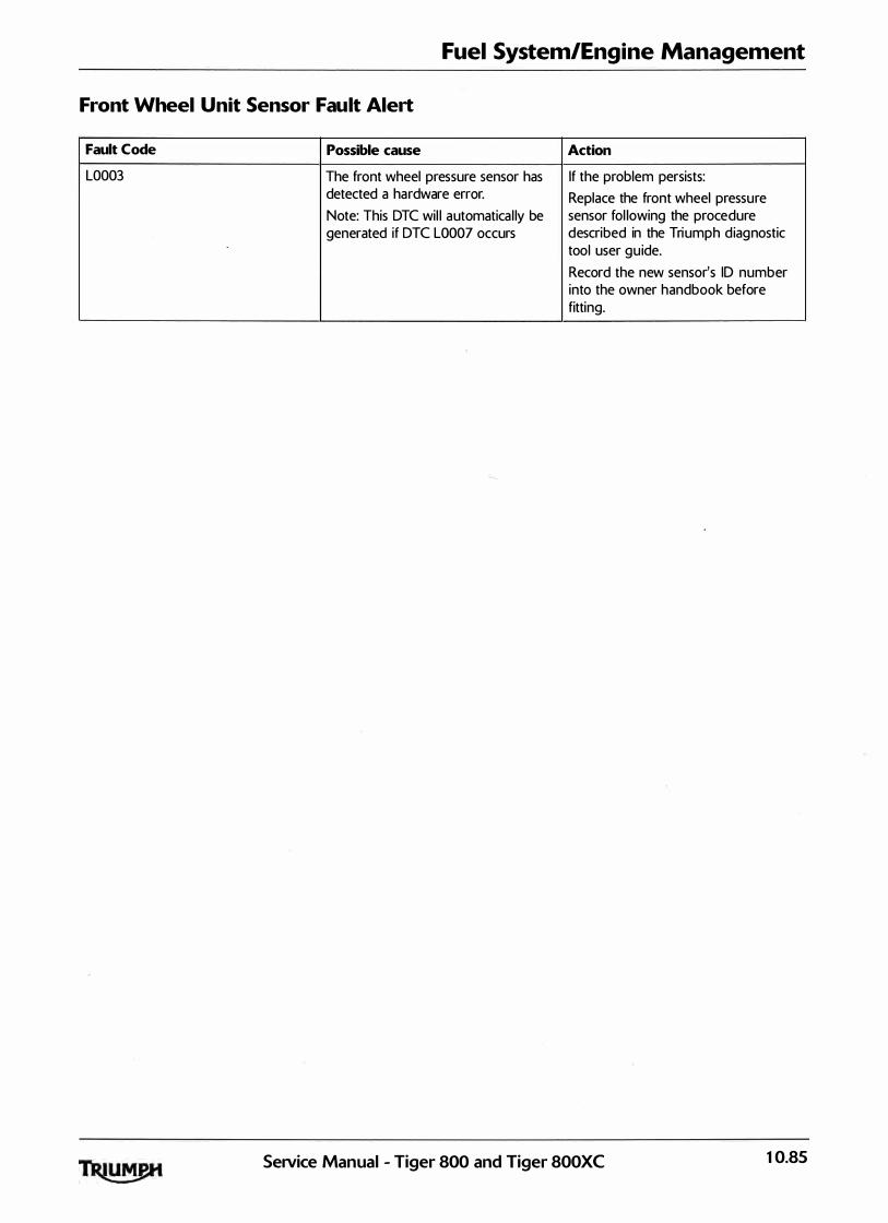
Fuel System/Engine Management
Front Wheel Unit Sensor Fault Alert
Fault Code Possible cause Action
L0003 The front wheel pressure sensor has If the problem persists: detected a hardware error. Replace the front wheel pressure Note: This DTC wil l automatica l ly be sensor fol lowing the procedure generated if DTC L0007 occurs described in the Triumph diagnostic
tool user guide.
Record the new sensor's ID number into the owner handbook before fitting.
Service Manual - Tiger 800 and Tiger 800XC 10.85

Fuel System/Engine Management
Rear Wheel Unit Sensor Fault Alert
Fault Code Possible cause Action
L0004 The rear wheel pressure sensor has If the problem persists: detected a hardware error. Replace the rear wheel pressure Note: This DTC wil l automatical ly be sensor fol lowing the procedure generated if DTC L0007 occurs described in the Triumph diagnostic
tool user guide.
Record the new sensor's I D number into the owner handbook before fitting.
10.86 Service Manual - Tiger 800 and Tiger 800XC

Fuel System/Engine Management
Front Wheel Unit Sensor Loss of Communication
Note:
• Refer to the owner's handbook for the wheel pressure sensors ID numbers .
Fault Code Possible cause Action
LOOOS lmmobil iser/TPMS control module If the problem persists: has lost communication with the front Using the Triumph diagnostic tool, wheel sensor unit. check that the correct I D number for Low battery voltage. the front wheel pressure sensor is
Wrong sensor ID number has been registered to the lmmobil iser/TPMS
registered in the immobil iser/TPMS control module.
control module Replace the front wheel pressure sensor fol lowing the procedure described in the Triumph diagnostic tool user gu ide.
Record the new sensor's ID number into the owner handbook before fitting.
SeiVice Manual - Tiger 800 and Tiger 800XC 10.87

Fuel System/Engine Management
Rear Wheel Unit Sensor Loss of Communication
Note:
• Refer to the owner's handbook for the wheel pressure sensors ID numbers.
Fault Code Possible cause Action
L0006 lmmobil iser!TPMS control module If the problem persists: has lost communication with the rear Using the Triumph diagnostic tool, wheel sensor unit. check that the correct I D number for Low battery voltage. the rear wheel pressure sensor is
Wrong sensor I D number has been registered to the lmmobil iser!TPMS
registered in the immobil iser!TPMS control module.
control module Replace the rear wheel pressure sensor fol lowing the procedure described in the Triumph d iagnostic tool user guide.
Record the new sensor's I D number into the owner handbook before fitting.
10.88 Service Manual - Tiger 800 and Tiger 800XC

Fuel System/Engine Management
lmmobiliser/TPMS Control Module Fault
Note:
• Refer to the owner's handbook for the wheel pressure sensors I D numbers .
Fault Code Possible cause Action
L0007 lmmobil iser/TPMS control module Using the Triumph diagnostic tool, has lost communication with the front check that the correct I D numbers for and rear wheel sensor units. the wheel pressure sensors are
Low battery voltage. registered to the lmmobil iser/TPMS
Wrong sensor ID numbers have been control module.
registered in the immobil iser/TPMS If the correct I Ds are registered,
control module replace the front and rear wheel pressure sensor fol lowing the procedure described in the Triumph diagnostic tool user guide.
Record the new sensor's ID number into the owner handbook before fitting.
SeiVice Manual - Tiger 800 and Tiger 800XC 10.89

Fuel System/Engine Management
Invalid Key: Key Authentication Unsuccessful
Fault Code Possible cause Action
L0008 lmmobil iserfTPMS control module Check that the key has been
or cannot identify the transponder chip registered with the immobil iserfTPMS
Alarm/immobil iser warning indicator in the key
l ight is on when the ignition switch is at the ON position <on ly visible on motorcycles without the accessory alarm fitted>
Pinpoint Tests
Test Result
1 If available, try to start the motorcycle with OK the second registered key:
Faulty
2 Check the condition of cable, connector OK housing and terminals for the fol lowing:
- Ign ition switch Faulty
- Immobil iser and TPMS control module
3 Check antenna coi l resistance: 7Q to 13Q
- Ignition switch pin 2 to ignition switch Fau lty pin 7
4 Check cable continuity: OK
- Ignition switch p in 7 to Immobil iser and Fau lty TPMS control module pin 10
- Ignition switch pin 2 to Immobi l iser and TPMS control module pin 5
5 Reconnect harness, clear fault code and run OK engine
Fault sti l l present
Circuit Diagram
..----- BG
lil "" I I 2 7 I
I I I I I I I
Ignition Switch a
:z ;;:::
tL
control modu le, if it is a new key or an additional key.
Check that there are no additional keys with a transponder chip fitted close to the ign ition key and proceed to pinpoint test 1 :
Action
Transponder chip in the key not functioning correctly. Register a new key using the Triumph diagnostic tool then proceed to test 5
Proceed to test 2
Disconnect the ignition switch, proceed to test 3
Rectify fault, proceed to test 5
Proceed to test 4
Replace the ignition switch, register new keys and proceed to test 5
Contact Triumph service
Rectify fault, proceed to test 5
Action complete - quit test
Contact Triumph service
Immobil iser Unit
10.90 SeiVice Manual - Tiger 800 and Tiger 800XC
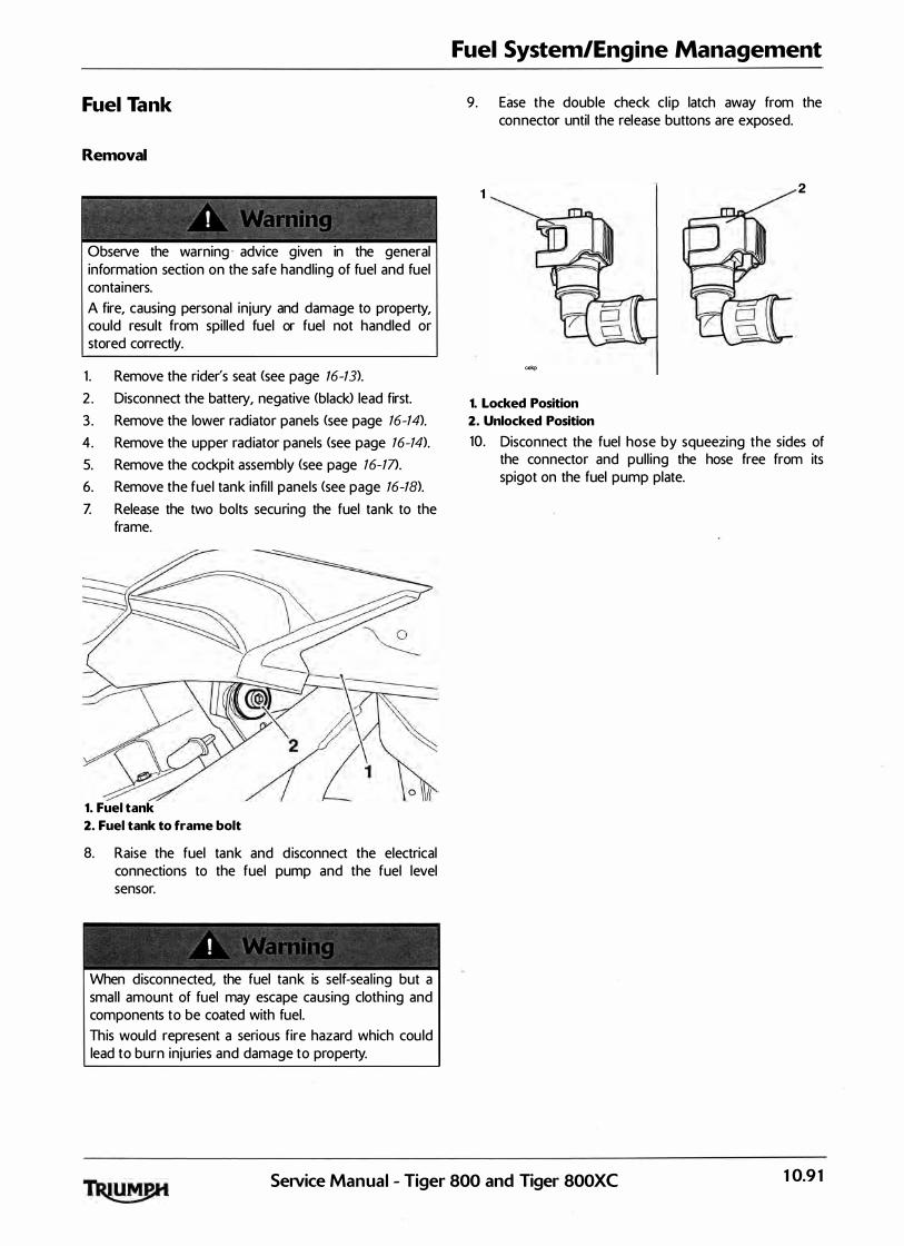
Fuel Tank
Removal
Observe the warning · advice given in the general information section on the safe handling of fuel and fuel containers.
A fire, causing personal injury and damage to property, could result from spil led fuel or fuel not handled or stored correctly.
1 . Remove the rider's seat <see page 16-13>.
2 . Disconnect the battery, negative (black> lead first.
3 . Remove the lower radiator panels <see page 16-14).
4. Remove the upper radiator panels <see page 16-14).
5. Remove the cockpit assembly (see page 16-17>.
6. Remove the fuel tank infi l l panels <see page 16-18).
Z Release the two bolts securing the fuel tank to the frame.
1. Fuel tank
2. Fuel tank to frame bolt
8. Raise the fuel tank and d isconnect the electrical connections to the fuel pump and the fuel level sensor.
When disconnected, the fuel tank is self-seal ing but a smal l amount of fuel may escape causing cloth ing and components to be coated with fuel.
This would represent a serious fire hazard which cou ld lead to burn injuries and damage to property.
Fuel System/Engine Management
9. Ease the double check c l ip latch away from the connector until the release buttons are exposed.
1 2
ookp
1. Locked Position
2. Unlocked Position
10. Disconnect the fuel hose by squeezing the sides of the connector and pul l ing the hose free from its spigot on the fuel pump plate.
SeiVice Manual - Tiger 800 and Tiger 800XC 10.9 1

Fuel System/Engine Management
Note:
• Before disconnection, note the position of the two breather hoses so that they can be returned to the same locations when refitting the tank.
1 1 . Disconnect the two breather hoses.
1. Breather hose - fuel tank vent
2. Breather hose - filler neck over flow
12 . Remove the fuel tank from the frame.
Installation
1 . Position the fuel tank to the frame.
2. Connect the two breather hoses as previously noted.
Note:
• The fuel hose -has different coloured connectors on each end, to aid orientation.
The grey end must be fitted to the fuel tank, the orange end must be fitted to the fuel rail.
3. Reconnect the fuel feed hose by gently pushing inwards until the hose engages with a click.
4. Sl ide the double check latch down <i .e. towards the spigot> until the release buttons are covered. I f the latch will not sl ide into position, then the fuel hose is not ful ly home on its spigot and must therefore be refitted correctly.
5. Reconnect the fuel pump electrical connection.
6. Reconnect the fuel level sensor.
1. Fuel hose
2. Fuel pump electrical connection
3. Fuel level sensor connection
Z Al ign the fuel tank to the mounting points. Fit and tighten the two rear bolts to 1 2 Nm.
8. Refit the fuel tank infi l l panels (see page 16-21).
9. Refit the cockpit assembly <see page 16-21).
10. Refit the upper radiator panels (see page 16-21).
1 1 . Refit the lower radiator panels <see page 16-21).
12 . Reconnect the battery, positive (red) lead first.
1 3 . Start the engine and check careful ly for fuel leaks. Rectify as necessary.
14. Refit the rider's seat <see page 16-13).
10.92 SeiVice Manual - Tiger 800 and Tiger SOOXC
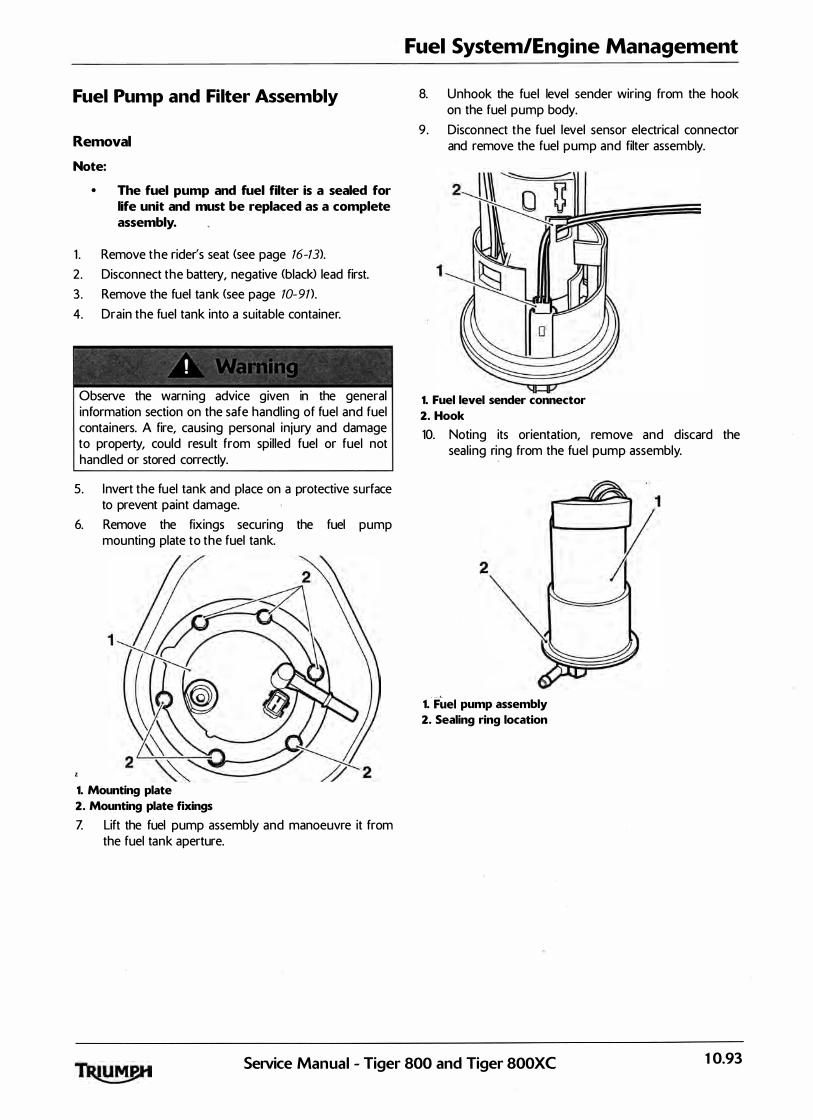
Fuel Pump and Filter Assembly
Removal
Note:
• The fuel pump and fuel filter is a sealed for life unit and must be replaced as a complete assembly.
1 . Remove the rider's seat <see page 16-13).
2. Disconnect the battery, negative <black> lead first.
3 . Remove the fuel tank (see page 10-91}.
4. Drain the fuel tank into a suitable container.
Observe the warning advice given in the general information section on the safe handling of fuel and fuel containers. A fire, causing personal injury and damage to property, could result from spilled fuel or fuel not handled or stored correctly.
5. Invert the fuel tank and place on a protective surface to prevent paint damage.
6. Remove the fixings securing the fuel pump mounting plate to the fuel tank.
1. Mounting plate
2. Mounting plate fixings
Z Lift the fuel pump assembly and manoeuvre it from the fuel tank aperture.
Fuel System/Engine Management
8. Unhook the fuel level sender wiring from the hook on the fuel pump body.
9 . Disconnect the fuel level sensor electrica l connector and remove th-e fuel pump and filter assembly.
1. Fuel level sender connector
2. Hook
10. Noting its orientation, remove and discard the seal ing ring from the fuel pump assembly.
1. Fuel pump assembly
2. Sealing ring location
SeiVice Manual - Tiger 800 and Tiger 800XC 10.93
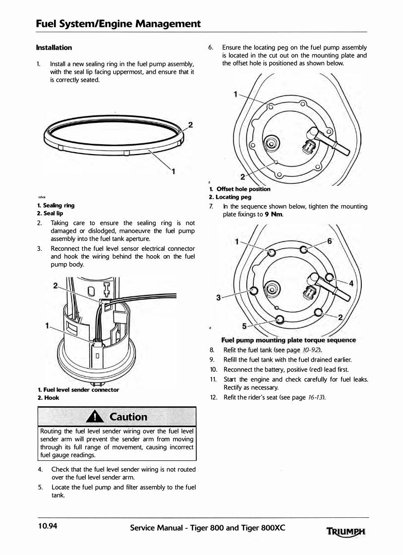
Fuel System/Engine Management
Installation
1 . Instal l a new seal ing ring in the fuel p u m p assembly, with the seal l ip facing uppermost, and ensure that it is correctly seated.
cdva
1. Sealing ring
2. Seal lip
2. Taking care to ensure the seal ing ring is not damaged or dislodged, manoeuvre the fuel pump assembly into the fuel tank aperture.
3 . Reconnect the fuel level sensor electrical connector and hook the wiring behind the hook on the fuel pump body.
1. Fuel level sender connector
2. Hook
Routing the fuel level sender wiring over the fuel level sender arm wil l prevent the sender arm from moving through its ful l range of movement, causing incorrect fuel gauge readings.
4. Check that the fuel level sender wiring is not routed over the fuel level sender arm.
5. Locate the fuel pump and fi lter assembly to the fuel tank.
6. Ensure the locating peg on the fuel pump assembly is located in the cut out on the mounting plate and the offset hole is positioned as shown below.
1. Offset hole position
2. Locating peg
Z In the sequence shown below, tighten the mounting plate fixings to 9 Nm.
IZ
8.
9. Refil l the fuel tank with the fuel d rained earlier.
10. Reconnect the battery, positive <red> lead first.
1 1 . Start the engine and check careful ly for fuel leaks. Rectify as necessary.
12 . Refit the rider's seat (see page 16-13>.
10.94 SeiVice Manual - Tiger 800 and Tiger 800XC
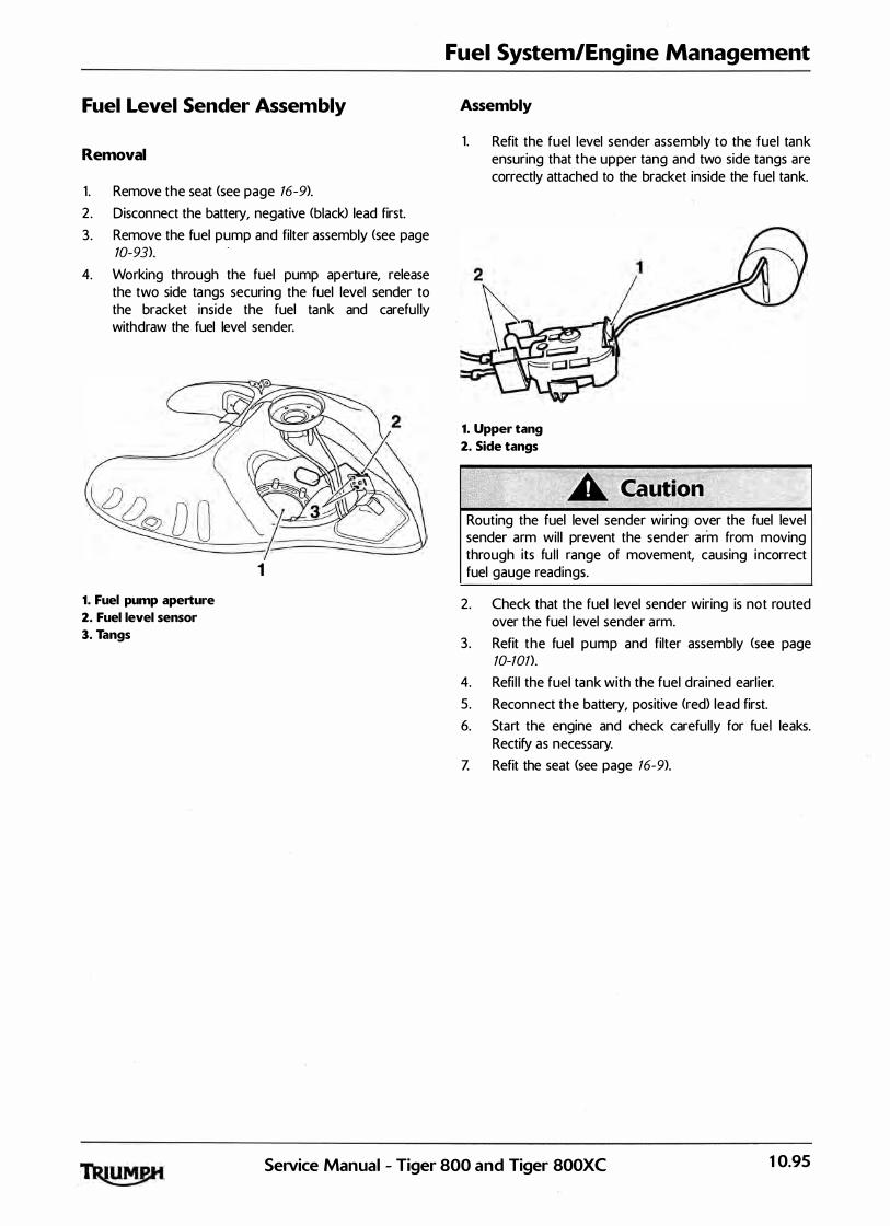
Fuel Level Sender Assembly
Removal
1 . Remove the seat (see page 16-9).
2. Disconnect the battery, negative (black> lead first.
3. Remove the fuel pump and filter assembly (see page 10-93).
4. Working through the fuel pump apertu re, release the two side ta ngs securing the fuel level sender to the bracket inside the fuel tank and carefu l ly withdraw the fuel level sender.
1
1. Fuel pump aperture
2. Fuel level sensor
3. Tangs
Fuel System/Engine Management
Assembly
1 . Refit the fuel level sender assembly to the fuel tank ensuring that the upper tang and two side tangs are correctly attached to the bracket inside the fuel tank.
1. Upper tang
2. Side tangs
Routing the fuel level sender wiring over the fuel level sender arm wil l prevent the sender arm from moving through its fu l l range of movement, causing incorrect fuel gauge readings.
2. Check that the fuel level sender wiring is not routed over the fuel level sender arm.
3. Refit the fuel pump and filter assembly <see page 10-101>.
4. Refi l l the fuel tank with the fuel dra ined earl ier.
5. Reconnect the battery, positive (red> lead first.
6. Start the engine and check carefu l ly for fuel leaks. Rectify as necessary.
Z Refit the seat (see page 16-9).
SeiVice Manual - Tiger 800 and Tiger SOOXC 10.95

Fuel System/Engine Management
Fuel Pressure Checking
Observe the fuel handling general information section.
Fuel pressure is checked using service tool T3880001 .
0 1 1
�n==-------------�r•ocJS�no cdgh
Tool T3880001
1. Remove the rider's seat <see page 16-13>.
2. Remove the fuel tank <see page 70-91 ) and place on a suitable support, close to the motorcycle.
3. Using the extension cable T3880123, careful ly connect the fuel pump connection to the fuel tank. Connect the other end of the extension cable to the motorcycle main harness.
4. Select the fuel pressure gauge adapter ma rked ' B' from service tool T3880001.
Always us the correct fuel pressure gauge adapter (adapter 'B' for Tiger 800 and Tiger SOOXC>. Use of an incorrect adapter wi l l result in a fuel leak. A fuel leak can result in a fire causing damage to property and injury to persons.
5. Connect the adapter hose to the fuel pump plate outlet as shown in the i l lustration below.
1. Adaptor hose 'B'
2. Fuel pump plate outlet
3. Extension cable T3880123
6. Connect the fuel hose to the adaptor hose as shown in the i l lustration below.
1. Motorcycle fuel hose
2. Adaptor hose 'B'
3. Wiring extension T3880123
4. Fuel pump connection
5. Fuel pump plate outlet
10.96 Service Manual - Tiger 800 and Tiger 800XC
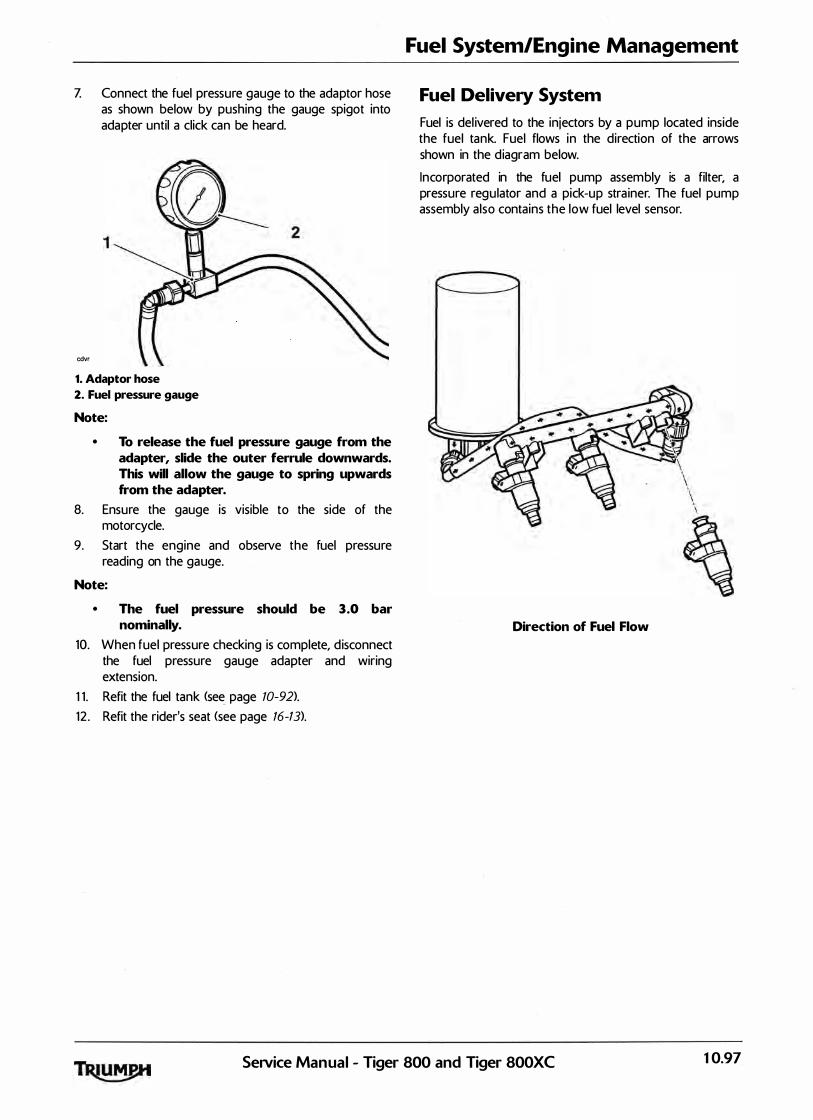
Z Connect the fuel pressure gauge to the ada ptor hose as shown below by pushing the gauge spigot into adapter until a click can be heard.
cdvr
1. Adaptor hose
2. Fuel pressure gauge
Note:
• To release the fuel pressure gauge from the adapter, slide the outer ferrule downwards. This will allow the gauge to spring upwards from the adapter.
8. Ensure the gauge is visible to the side of the motorcycle.
9. Start the engine and observe the fuel pressure reading on the gauge.
Note:
• The fuel pressure should be 3.0 bar nominally.
10. When fuel pressure checking is complete, d isconnect the fuel pressure gauge adapter and wiring extension.
1 1 . Refit the fuel tank <see page 10-92).
12 . Refit the rider's seat <see page 16-13).
Fuel System/Engine Management
Fuel Delivery System
Fuel is del ivered to the injectors by a pump located inside the fuel tank. Fuel flows in the direction of the arrows shown in the d iagram below.
Incorporated in the fuel pump assem bly is a filter, a pressure regulator and a pick-up stra iner. The fuel pump assembly a lso contains the low fuel level sensor.
Direction of Fuel Flow
SeiVice Manual - Tiger 800 and Tiger 800XC 10.97

Fuel System/Engine Management
Airbox
Removal
1 . Remove the rider's seat (see page 16-13).
2. Disconnect the battery, negative (black> lead first.
3 . Remove the fixing a n d remove the a i r intake duct from the airbox.
_.--,.,, 1. Air intake duct
2. Fixing
4. Remove the fuel tan k <see page 10-91).
5. Disconnect the intake a ir temperature sensor multi-plug.
1. Intake air temperature sensor
2. Multi-plug
6. Disconnect the MAP sensor multi-plug and hose.
�� 1. Map sensor
2. Multi-plug
3. Hose
� -------
Z Release the 1 1 fixings and remove the a irbox upper section.
1. Airbox upper section
2. Fixings
10.98 SeNice Manual - Tiger 800 and Tiger 800XC

8. Release the s ix fixings and remove the airbox intake trumpets.
cgot 1. Airbox intake trumpet fixings
2. Air filter fixings
3. Air filter
4. Air filter fixings
9. Remove the two fixings and remove the air fi lter element.
10. Remove the airbox rear fixing, located below the a ir fi lter.
Fuel System/Engine Management
1 1 . Ra ise the airbox and disconnect the engine breather hose at the airbox.
cooo / 1. Engine breather hose
2. Spring hose clip
12. Remove the airbox from the motorcycle.
�nspection
1. Thoroughly clean the inside and outside of the airbox.
2. Check the airbox and intake trumpets for damage.
Service Manual - Tiger 800 and Tiger 800XC 10.99
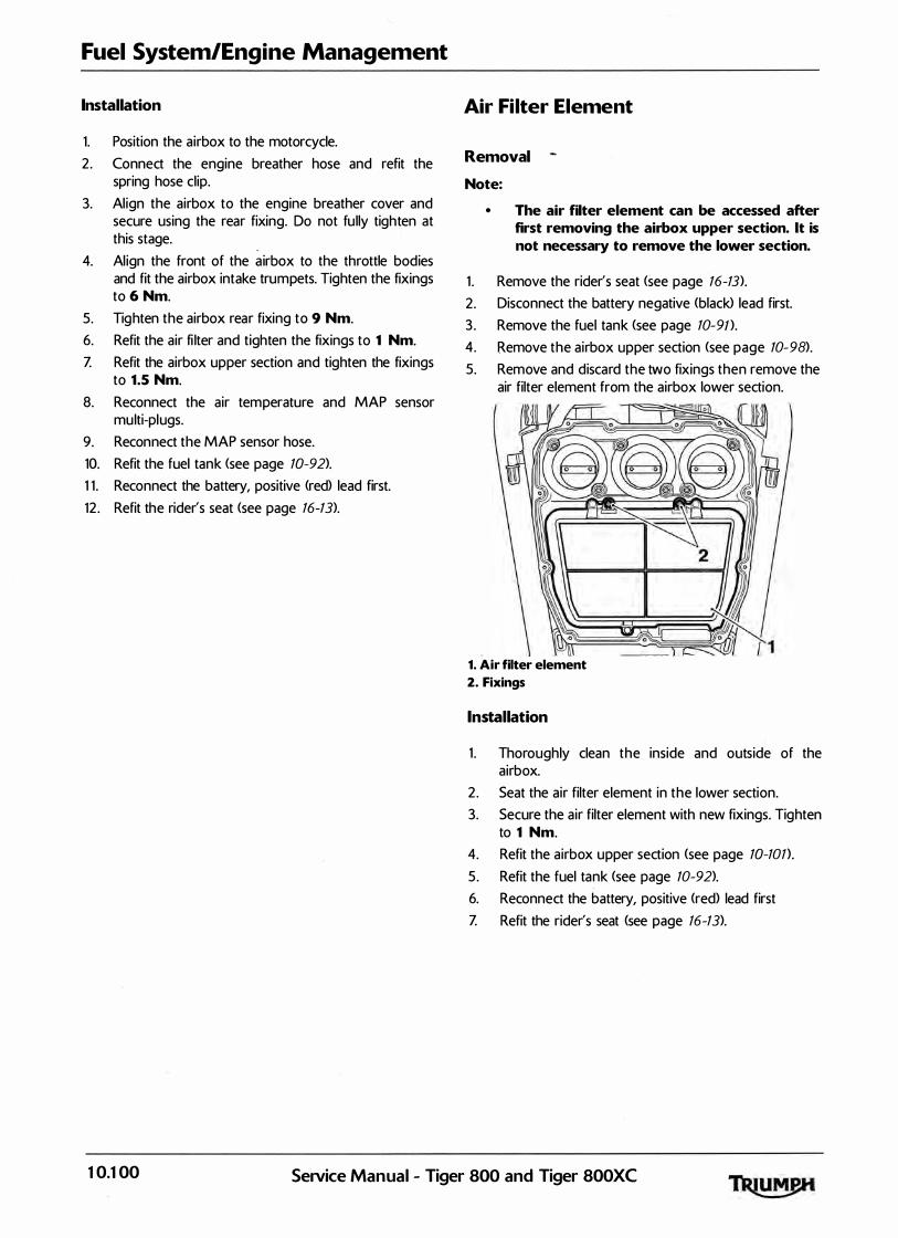
Fuel System/Engine Management
Installation
1. Position the airbox to the motorcycle.
2. Connect the engine breather hose and refit the spring hose clip.
3. Align the airbox to the engine breather cover and secure using the rear fixing. Do not fu lly tighten at this stage.
4. Align the front of the � irbox to the throttle bodies and fit the airbox intake trumpets. Tighten the fixings to 6 Nm.
5. Tig hten the airbox rear fixing to 9 Nm.
6. Refit the air fi lter and tighten the fixings to 1 Nm.
Z Refit the airbox upper section and tighten the fixings to 1.5 Nm.
8. Reconnect the air temperature and MAP sensor multi-plugs.
9. Reconnect the MAP sensor hose.
10. Refit the fuel tank <see page 10-92).
1 1 . Reconnect the battery, positive (red) lead first.
12 . Refit the rider's seat <see page 16-13).
Air Filter Element
Removal
Note:
1 .
2.
• The air filter element can be accessed after first removing the airbox upper section. lt is not necessary to remove the lower section.
Remove the rider's seat <see page 16-13).
Disconnect the battery negative (black> lead first.
3 . Remove the fuel tank (see page 10-9n.
4. Remove the airbox upper section <see page 10-98).
5. Remove and discard the two fixings then remove the air filter element from the airbox lower section.
1. Air filter element
2. Fixings
Installation
1 . Thoroughly clean the inside and outside of the airbox.
2. Seat the air filter element in the lower section.
3. Secure the air filter element with new fixings. Tighten to 1 Nm.
4. Refit the airbox upper section (see page 10-101).
5. Refit the fuel tank <see page 10-92).
6. Reconnect the battery, positive <red) lead first
Z Refit the rider's seat (see page 16-13).
10.100 SeiVice Manual - Tiger 800 and Tiger SOOXC

Intake Air Temperature Sensor
Removal
1 . Remove the rider's seat <see page 16-13).
2. Disconnect the battery, negative (black> lead first.
3. Remove the fuel tank (see page 10-9T>.
4. Disconnect the intake a ir temperature sensor multi-plug.
1. Intake air temperature sensor
2. Multi-plug
5. Remove and discard the sensor fixing.
6. Remove the sensor from the airbox.
Installation
1 . Fit the air tem perature sensor to the airbox. Secure with a new screw and tighten to 1.5 Nm.
2. Reconnect the intake a ir temperature sensor m ulti-plug.
3. Refit the fuel tank <see page 10-92).
4. Reconnect the battery, positive (red) lead first.
5. Refit the rider's seat (see page 16-13).
Fuel System/Engine Management
MAP Sensor
Removal
1. Remove the rider's seat (see page 16-73).
2. Disconnect the battery, negative (black> lead first.
3 . Remove the fuel tank (see page 70-91>.
4. Disconnect the MAP sensor multi-plug.
���-v/ �/l 1. MAP sensor
2. Multi-plug
3. Fixing
4. Vacuum hose
5. Disconnect the vacu um hose from the sensor.
6. Release the fixing screw securing the sensor to the airbox and remove the sensor.
Installation
1 . Fit the sensor to the airbox, tightening the fixing to 1.5 Nm.
2. Refit the vacuum hose.
3. Reconnect the MAP sensor m ulti-plug.
4. Refit the fuel tank <see page 10-92).
5. Reconnect the battery, positive (red) lead first.
6. Refit the rider's seat (see page 16-13).
SeiVice Manual - Tiger 800 and Tiger 800XC 10. 10 1
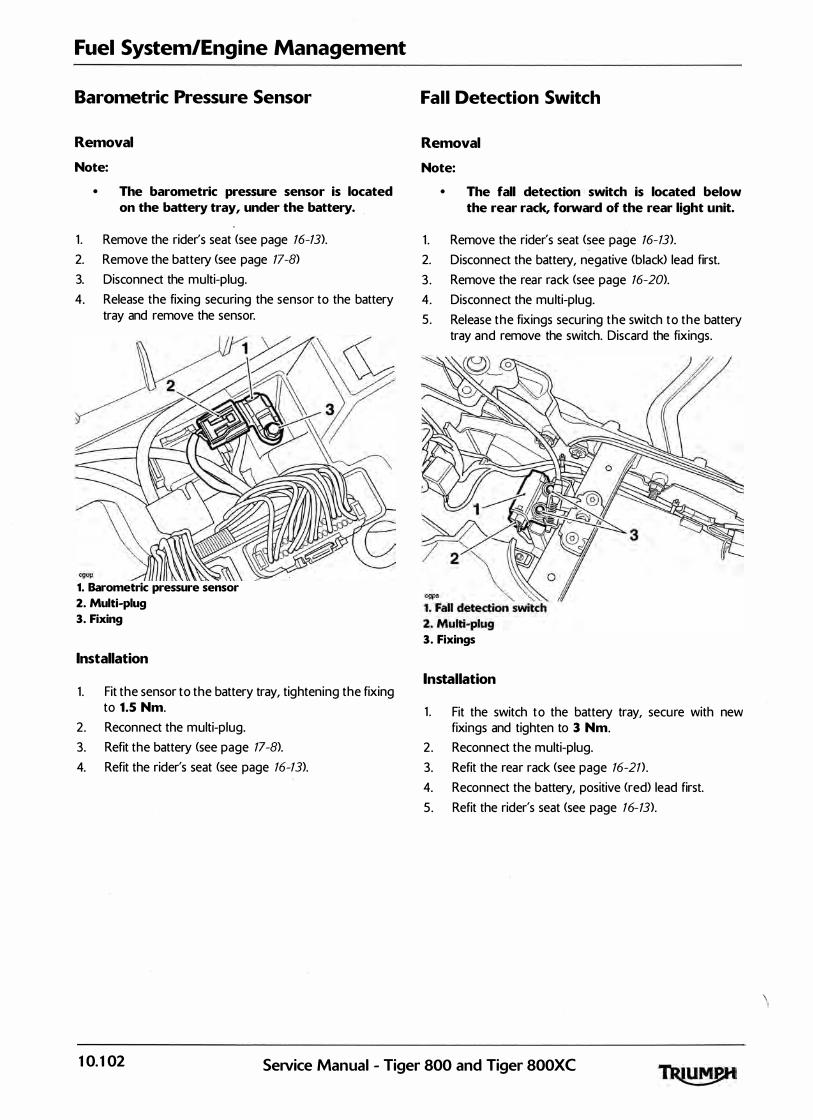
Fuel System/Engine Management
Barometric Pressure Sensor
Removal
Note:
• The barometric pressure sensor is located on the battery tray, under the battery.
1 . Remove the rider's seat (see page 16-13).
2. Remove the battery (see page 17-8)
3. Disconnect the multi-plug.
4. Release the fixing securing the sensor to the battery tray and remove the sensor.
1. Barometric pressure sensor
2. Multi-plug
3. Fixing
Installation
1 . Fit the sensor to the battery tray, tightening the fixing to 1.5 Nm.
2. Reconnect the multi-plug.
3. Refit the battery <see page 17-8).
4. Refit the rider's seat <see page 16-13).
Fall Detection Switch
Removal
Note:
• The fall detection switch is located below the rear rack, forward of the rear light unit.
1 . Remove the rider's seat (see page 16-13>.
2. Disconnect the battery, negative (black) lead first.
3 . Remove the rear rack <see page 16-20>.
4. Disconnect the mu lti-plug.
5. Release the fixings securing the switch to the battery tray and remove the switch. Discard the fixings.
3. Fixings
Installation
1 . Fit the switch to the battery tray, secu re with new fixings and tighten to 3 Nm.
2. Reconnect the multi-plug.
3. Refit the rear rack <see page 16-21} ,
4. Reconnect the battery, positive (red) lead first.
5. Refit the rider's seat (see page 16-13).
10. 102 Seavice Manual - Tiger 800 and Tiger 800XC
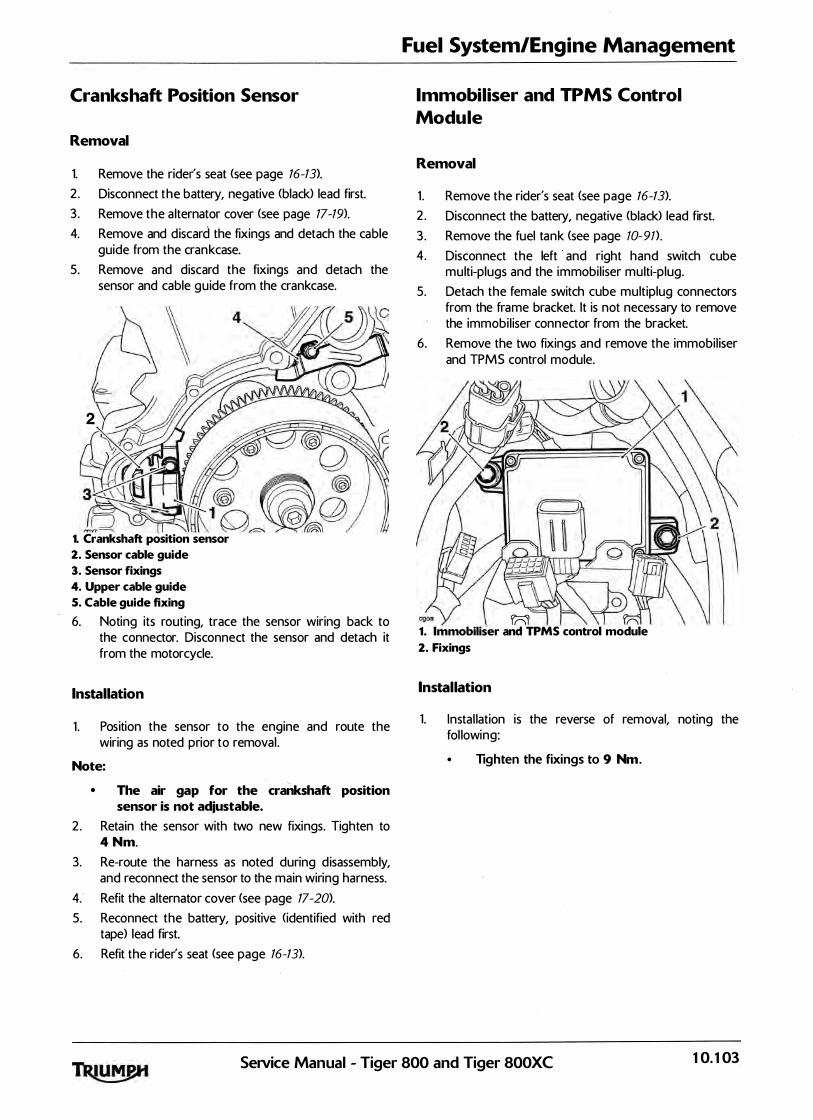
Crankshaft Position Sensor
Removal
1. Remove the rider's seat <see page 16-13).
2. Disconnect the battery, negative <black> lead first.
3. Remove the a lternator cover <see page 17-19>.
4. Remove and d iscard the fixings and detach the cable guide from the cran kcase.
5. Remove and discard the fixings and detach the sensor and cable guide from the crankcase.
2
lE�� ��K1 W�
1. Crankshaft position sensor
2. Sensor cable guide
3. Sensor fixings
4. Upper cable guide
S. Cable guide fixing
6. Noting its routing, trace the sensor wiring back to the connector. Disconnect the sensor and detach it from the motorcycle.
Installation
1 . Position the sensor to the engine and route the wiring as noted prior to removal .
Note:
• The air gap for the crankshaft position sensor is not adjustable.
2. Retain the sensor with two new fixings. Tighten to 4 Nm.
3. Re-route the harness as noted during d isassembly, and reconnect the sensor to the main wiring harness.
4. Refit the alternator cover (see page 17-20>.
5. Reconnect the battery, positive <identified with red tape) lead first.
6. Refit the rider's seat <see page 16-13).
Fuel System/Engine Management
Immobiliser and TPMS Control
Module
Removal
1 . Remove the rider's seat <see page 16-13>.
2. Disconnect the battery, negative <black> lead first.
3 . Remove the fuel tank (see page 10-91}.
4. Disconnect the left and right hand switch cube multi-plugs and the immobil iser multi-plug.
5. Detach the female switch cube multiplug connectors from the frame bracket. lt is not necessary to remove the immobil iser connector from the bracket.
6. Remove the two fixings and remove the immobil iser and TPM S control module.
rnl (\ 1. Immobiliser and TPMS control module
2. Fixings
Installation
1. Instal lation is the reverse of removal, noting the fol lowing:
• Tighten the fixings to 9 Nm .
SeiVice Manual - Tiger 800 and Tiger 800XC 10. 103

Fuel System/Engine Management
Ignition Switch and Immobiliser
Antenna
Note:
• The immobiliser antenna is integral to the ignition switch and cannot be serviced separately.
Removal
1 . Remove the rider's seat <see page 16-13>.
2 . Disconnect the battery, negative (black> lead first.
3 . Remove the fuel tank (see page 10-91).
4. Remove the two screws and remove the ignition switch cover.
5. Without damaging the ignition switch and us ing a suitable dri l l, careful ly dri l l out the head of the shear bolts securing the ignition switch to the frame.
1. Ignition switch and immobiliser antenna
2. Shear bolts
6. Disconnect the ignition switch m ultiplug.
Z Noting the harness routing, remove ignition switch.
8. Remove the remainder of the shea r bolt from the frame.
Installation
1 . Instal lation is the reverse of removal, noting the fol lowing:
• Install new shear bolts and tighten until the
heads shear off.
Throttle Cable
Adjustment
Note:
• Minor adjustments to the opening cable can be made using the adjuster near the throttle grip end of the throttle. Where a correct setting cannot be achieved this way, the adjusters at the throttle end of both cables must be used. The opening cable must be set first followed by the closing cable.
1. Throttle grip
2. Correct setting, 2-3 mm
1 . Remove the rider's seat (see page 16-13>.
2. Disconnect the battery, negative (black> lead first.
3 . Set the 'opening' cable adjuster a t the throttle grip end such that it has an equal amount of adjustment in each direction. nghten the locknut.
4. Remove the fuel tank (see page 10-91>.
10.104 SeNice Manual - Tiger 800 and Tiger 800XC
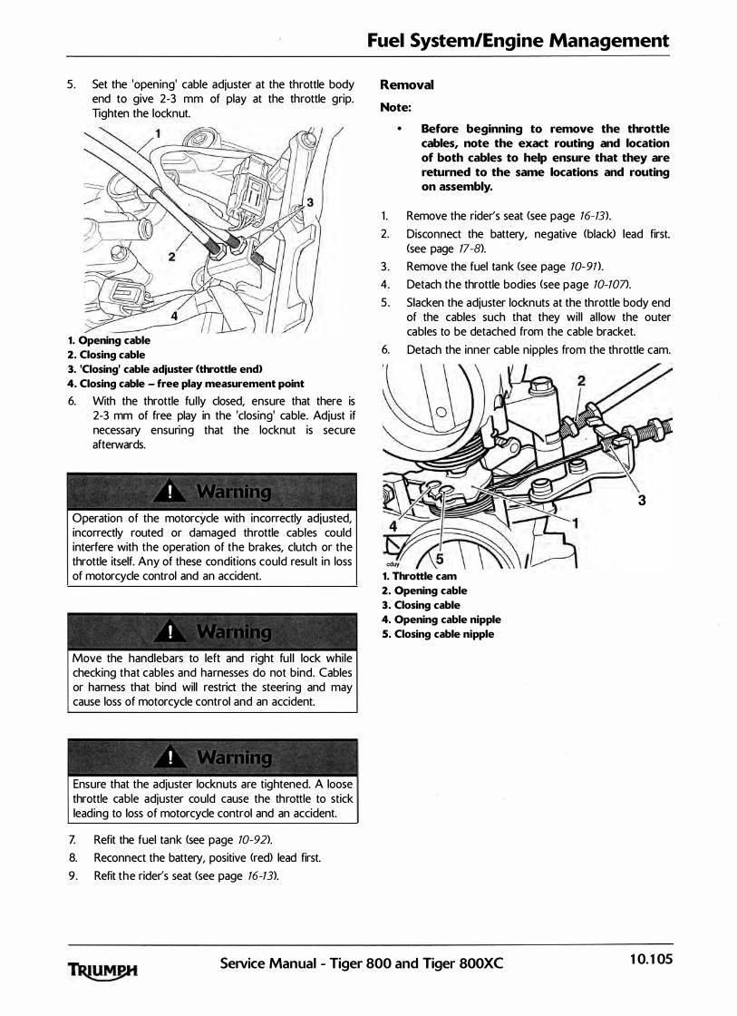
5. Set the 'opening' cable adjuster at the throttle body end to give 2-3 mm of play at the throttle grip. Tighten the locknut.
1. Opening cable
2. Closing cable
3. 'Closing' cable adjuster (throttle end>
4. Closing cable - free play measurement point
6. With the throttle fu l ly closed, ensure that there is 2-3 mm of free play in the 'closing' cable. Adjust if necessary ensuring that the locknut is secure afterwards.
Operation of the motorcycle with incorrectly adjusted, incorrectly routed or damaged throttle cables could interfere with the operation of the bra kes, clutch or the throttle itself. Any of these conditions could result in loss of motorcycle control and an accident.
Move the handlebars to left and right fu l l lock while checking that cables and harnesses do not bind. Cables or harness that bind will restrict the steering and may cause loss of motorcycle control and an accident.
Ensure that the adjuster locknuts are tightened. A loose throttle cable adjuster could cause the throttle to stick leading to loss of motorcycle control and an accident.
Z Refit the fuel tank (see page 10-92).
8. Reconnect the battery, positive <red) lead first.
9. Refit the rider's seat <see page 16-13).
Fuel System/Engine Management
Removal
Note:
• Before beginning to remove the throttle cables, note the exact routing and location of both cables to help ensure that they are returned to the same locations and routing on assembly.
1 . Remove the rider's seat (see page 16-13).
2. Disconnect the battery, negative <black> lead first. <see page 17-8).
3 . Remove the fuel ta nk (see page 10-9n.
4. Detach the throttle bodies (see page 10-107>.
5 . Slacken the adjuster locknuts at the throttle body end of the cables such that they wil l a l low the outer cables to be detached from the cable bracket.
6. Detach the inner cable nipples from the th rottle cam.
3
cduy
1. Throttle cam
2. Opening cable
3. Closing cable
4. Opening cable nipple
5. Closing cable nipple
SeiVice Manual - Tiger 800 and Tiger 800XC 10. 105
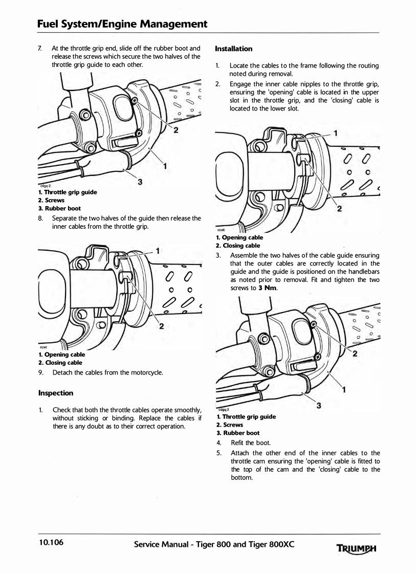
Fuel System/Engine Management
Z At the throttle grip end, sl ide off the rubber boot and release the screws which secure the two ha lves of the throttle grip guide to each other.
cdgq 2 1. Throttle grip guide
2. Screws
3. Rubber boot
8. Separate the two halves of the guide then release the inner cables from the throttle grip.
0 0 0 0
t?J t?J t
1. Opening cable
2. Oosing cable
9. Detach the cables from the motorcycle.
Inspection
0 0
1 . Check that both the throttle cables operate smoothly, without sticking or binding. Replace the cables if there is any doubt as to their correct operation.
Installation
1 . Locate the cables to the frame fol lowing the routing noted during removal .
2. Engage the inner cable nipples to the throttle grip, ensuring the 'opening' cable is located in the upper slot in the throttle g rip, and the 'closing' cable is located to the lower slot.
t
1. Opening cable
2. Closing cable
3 . Assemble the two halves o f the cable guide ensuring that the outer cables are correctly located in the guide and the guide is positioned on the handlebars as noted prior to removal . Fit and tighten the two screws to 3 Nm.
cdgq 2
1. Throttle grip guide
2. Screws
3. Rubber boot
4. Refit the boot.
5. Attach the other end · of the inner cables to the throttle cam ensuring the 'opening' cable is fitted to the top of the cam and the 'closing' cable to the bottom.
10. 106 SeiVice Manual - Tiger 800 and Tiger 800XC

6. Locate the outer cables to the bracket and adjust until the start of the thread is 14 mm away from the back of the throttle cable bracket. Secure the adjuster and locknuts.
1. Opening cable
2. Closing cable
Z Refit the throttle bodies <see page 10-101).
8. Set the throttle cable adjustment <see page 10-104>.
9. Refit the airbox <see page 10-101).
10. Refit the fuel tank <see page 10-92>.
1 1 . Reconnect the battery, positive (red) lead first
12 . Refit the rider's seat <see page 16-13).
Fuel System/Engine Management
Throttle Bodies/lniectors
Removal
Note:
• Because fuel stored in the fuel rail will be at 3 bar pressure, it is essential that the fuel
pressure is reduced before any dismantling of the fuel rail takes place. To reduce
pressure, briefly crank the engine with the fuel pump disconnected.
If the fuel rai l is dismantled without first reducing pressure fuel may escape causing cloth ing and components to be coated with fuel.
This would represent a serious fire haza rd wh ich could lead to burn in juries and damage to property.
1 . Remove the rider's seat (see page 16-13).
2 . Disconnect the battery, negative (black> lead first.
3 . Remove the fuel tank (see page 10-91).
4. Remove the airbox (see page 10-98).
5 . Disconnect the throttle position sensor multi-plug.
6. Disconnect the fuel in jector mu lti-plugs.
Z Disconnect the idle speed control stepper motor multi-plug.
8. Release the cl ips securing the throttle bodies to the transition pieces.
1. Transition piece Cone per cylinder>
2. Clip location (throttle bodies removed for clarity>
9. Ease the throttle bodies from the transition pieces and lay the assembly careful ly on the cam cover.
10. Release both th rottle cables from the throttle cam <see page 10-105>.
Se1Vice Manual - Tiger 800 and Tiger 800XC 10. 107
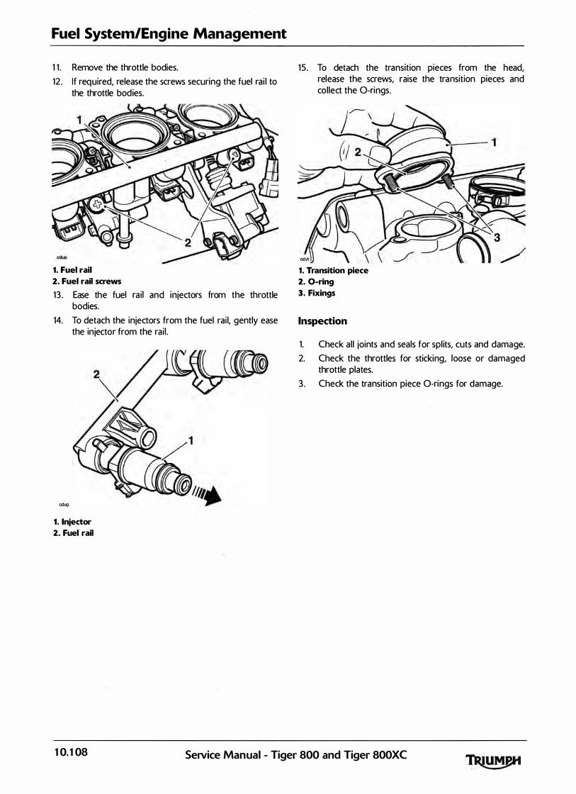
Fuel System/Engine Management
1 1 . Remove the throttle bodies.
12 . I f required, release the screws securing the fuel rai l to the throttle bodies.
1. Fuel rail
2. Fuel rail screws
13 . Ease the fuel ra i l and in jectors from the throttle bodies.
14. To detach the injectors from the fuel rai l, gently ease the in jector from the rai l .
cdvp
1. 1njector
2. Fuel rail
15 . To detach the transition pieces from the head, release the screws, raise the tra nsition pieces and collect the 0-rings.
1. Transition piece
2. 0-ring
3. Fixings
Inspection
1. Check al l joints and seals for spl its, cuts and damage.
2. Check the throttles for sticking, loose or damaged throttle plates.
3 . Check the transition piece 0-rings for damage.
10. 108 SeNice Manual - Tiger 800 and Tiger 800XC

Installation
1 . Thoroughly clean the transition piece to cyl inder head mating faces.
2. Refit the transition pieces to the head incorporating new 0-rings to the joint face. Tighten the transition piece fixings to 12 Nm.
1. Transition piece
2. 0-ring
3. Fixings
3. I f the in jectors have been removed from the fuel rail, refit them to the rail, ensu ring the injector locating peg is ful ly engaged in the slot in the rai l .
cdvp1 1. 1njector
2. Fuel rail
3. Locating peg
4. Check the injector 0-rings for spl its and other damage. Replace as necessary.
Fuel System/Engine Management
5. Refit the in jectors and fuel ra i l to the throttle bodies. Tighten the fuel rai l screws to 3.5 Nm.
1. Fuel rail
2. Fuel rail screws
6. Re-attach the throttle cables (see page 10-104>.
The throttle body clips must be positioned as shown below. If the cl ips are not positioned as shown th is could cause the throttle to stick, leading to loss of motorcycle control and an accident.
Z Refit the throttle bodies to the transition pieces and secure with the cl ips.
1. Transition piece {one per cylinder)
2. Clip location <throttle bodies removed for clarity)
8. Adjust the throttle cables <see page 10-104>.
9 . Reconnect the idle speed control stepper motor mu lti-plug.
10. Reconnect the fuel in jector multi-plugs.
1 1 . Reconnect the throttle position sensor multi-plug.
12 . Refit the airbox (see page 10-107 >.
13 . Refit the fuel tank (see page 10-92).
14. Reconnect the battery, positive (red) lead first.
1 5 . Refit the rider's seat <see page 16-13>.
SeiVice Manual - Tiger 800 and Tiger 800XC 10. 109

Fuel System/Engine Management
Throttle Body Balancing
Note:
• The throttles cannot be balanced using equipment to measure vacuum in each throttle. Instead, the Triumph diagnostic software must be used.
1. Remove the rider's seat'<see page 16-13>.
2. Remove the fuel tank <see page 10-91) and place on a suitable support, close to the motorcycle.
3 . Remove the airbox <see page 10-98>.
! � ' '
If the engine has recently been running, the components beneath the fuel tank may be hot to the touch.
4. Turn the ign ition to the 'OFF' position.
5. Using the extension cable T3880123, carefu lly connect the fuel pump connection on the main harness to the fuel tank. Connect the other end of the harness extension to the motorcycle main harness.
6. Select the fuel pressure gauge adapter marked 'B' from service tool T3 880001.
! r •
Always us the correct fuel pressure gauge adapter (adapter 'B' for Tiger 800 and Tiger SOOXC. Use of an incorrect adapter will result in a fuel leak. A fuel leak can result in a fire causing damage to property and injury to persons.
Z Connect the adapter hose to the fuel pump plate outlet as shown in the i l lustration below.
1. Adaptor hose 'B'
2. Fuel pump plate outlet
3. Tool T3880123
8. Connect the fuel hose to the adaptor hose as shown in the i l lustration below.
1. Motorcycle fuel hose
2. Adaptor hose 'B'
3. Fuel purnp connection
4. Wiring extension T3880123
5 . Fuel pump connection
6. Fuel pump plate outlet
9. Attach exhaust extraction hoses to the si lencer.
10. Attach the Triumph diagnostic tool to the dedicated plug, refer to the Triumph Diagnostic Tool User Guide. Start the engine, and a l low to idle.
1 1 . On the diagnostic software navigate to 'ADJ UST TU N E'.
12. Select 'BALANCE TH ROTTLES'.
10.1 10 SeiVice Manual - Tiger 800 and Tiger 800XC

1 3 . Cl ick the Adjust button.
Adjust Tune Procedure
Adjust the throttle balance as described in the service manual until balanced
Press cancel to cancel the adjustment process Press OK to finish
Throttle Status : Throttles Balanced
Cylinder 1 MAP Pressu re:
Cyl inder 2 MAP Pressu re:
Cyl inder 3 MAP Pressu re:
Adjusting parameter - Balance Throttles
Balance Throttles Screen
Note:
480 mmHg
481 mmHg
480 mmHg
• The balance throttle screen will show the vacuum value of each throttle in mm/Hg. In addition, when the throttles are balanced to an acceptable range of each other the word 'THROTTLES BALANCED' in green text will appear on the right of the screen. At this point, no further adjustment is necessary or productive.
• If the throttles are not balanced to each other the word 'TH ROTTLES U N BALANCED' in red text will appear on the right of the screen. At this point adjustment will be necessary.
• The adjusters operate on the outer cylinders only <cylinders 1 and 3). The centre throttle (cylinder 2) adjustment is fixed, this being controlled by the idle speed control stepper motor. Note that the centre reading will alter slightly as the two outer cylinders are adjusted.
• DO NOT attempt to adjust the centre throttle stop screw, located below the idle stepper motor. The stop screw is set at the factory during manufacture, and must not be adjusted.
Fuel System/Engine Management
14. Using the throttle adjusters, make adjustments to the two outer cyl inders until the word 'TH ROTILES BALANCED' in green text appears.
1. Adjusters
15 . When balanced, stop the engine and disconnect the d iagnostic tool .
16 . Disconnect the fuel pressure gauge adapter and wiring extension.
1Z Refit the airbox <see page 10-101). ·
18. Refit the fuel tank <see page 10-92).
19 . Remove the exhaust extraction hoses from the silencer.
20. Refit the rider's seat <see page 16-13).
SeiVice Manual - Tiger 800 and Tiger 800XC 10. 1 1 1

Fuel System/Engine Management
Throttle Position Sensor
Removal
1 . Remove the rider's seat <see page 16-13).
2. Disconnect the battery, negative <black> lead first.
3 . Remove the fuel tank <see page 10-91).
4. Remove the airbox <see page 10-98).
5. Remove the throttle body assembly <see page 10-107>.
6. Release the two screws and rotate the throttle position sensor clockwise through 45° to remove it from the left hand end of the throttle body. Col lect the 0-ring on disassembly.
1. Throttle position sensor
2. Screws
3. 0-ring
Installation r
1 . Fit the replacement throttle position sensor ensuring the 0-ring is positioned correctly between the sensor and throttle body. Rotate the sensor through 45° anti-clockwise until the screw holes al ign.
2 . Engage the new screws and washers' suppl ied and part tighten such that the sensor can sti l l be rotated.
3. Position the throttle body assembly near to its fitted position and reconnect the sensor and a l l other throttle body electrical connectors.
4. Reconnect the battery, positive (red) lead first.
5 . Attach the Triumph diagnostic tool to the ded icated plug, refer to the Triumph Diagnostic Tool User Guide.
6. Turn the ign ition to the 'ON' position.
Z On the diagnostic software navigate to and select the 'ADJ UST TU N E' option.
.
8. At the next screen, select Throttle Position Sensor Adjust then click the 'Adjust' button.
9. On pressing the adjust button, the diagnostic tool wil l send a command, which drives the primary throttle to the fu l ly closed position. The tool wil l also d isplay the voltage reading coming from the throttle position sensor.
Adjust Tune Procedu re
Adjust the throttle position sensor as described in the service manual until the voltage reading is with in the range shown below Press OK when the adjustment is complete Press cancel to cancel the adjustment process
Throttle Voltage: 0 . 59 V
Target Voltage Range: 0 . 58 V - 0.62 V
G Adjusting parameter - Throttle Position Sensor Adjust
Adjust Tune Screen
Gently rotate the new throttle position sensor until the voltage reading on the software shows 0.6 Volts +/- 0.02 Volts. The reading on the screen wil l turn green, ind icating that the reading is correct.
Note:
• This is a setting voltage only. Because of the adaptive nature of the engine management system, the in-service voltage may vary from this setting figure.
10. Tighten the sensor retaining screws to 2 Nm and recheck the voltage reading shown on the tool . Repeat the adjustment if the reading is outside the specified range.
1 1 . Click on the OK button to return the throttle to normal control and return the diagnostic tool to the 'ADJ UST TU N E' menu.
12 . Disconnect the diagnostic tool .
13. Check that the throttle opens and closes without obstruction/sticking and has a smooth action throughout the ful l range of its movement. Rectify as necessary.
10.1 12 SeiVice Manual - Tiger 800 and Tiger 800XC
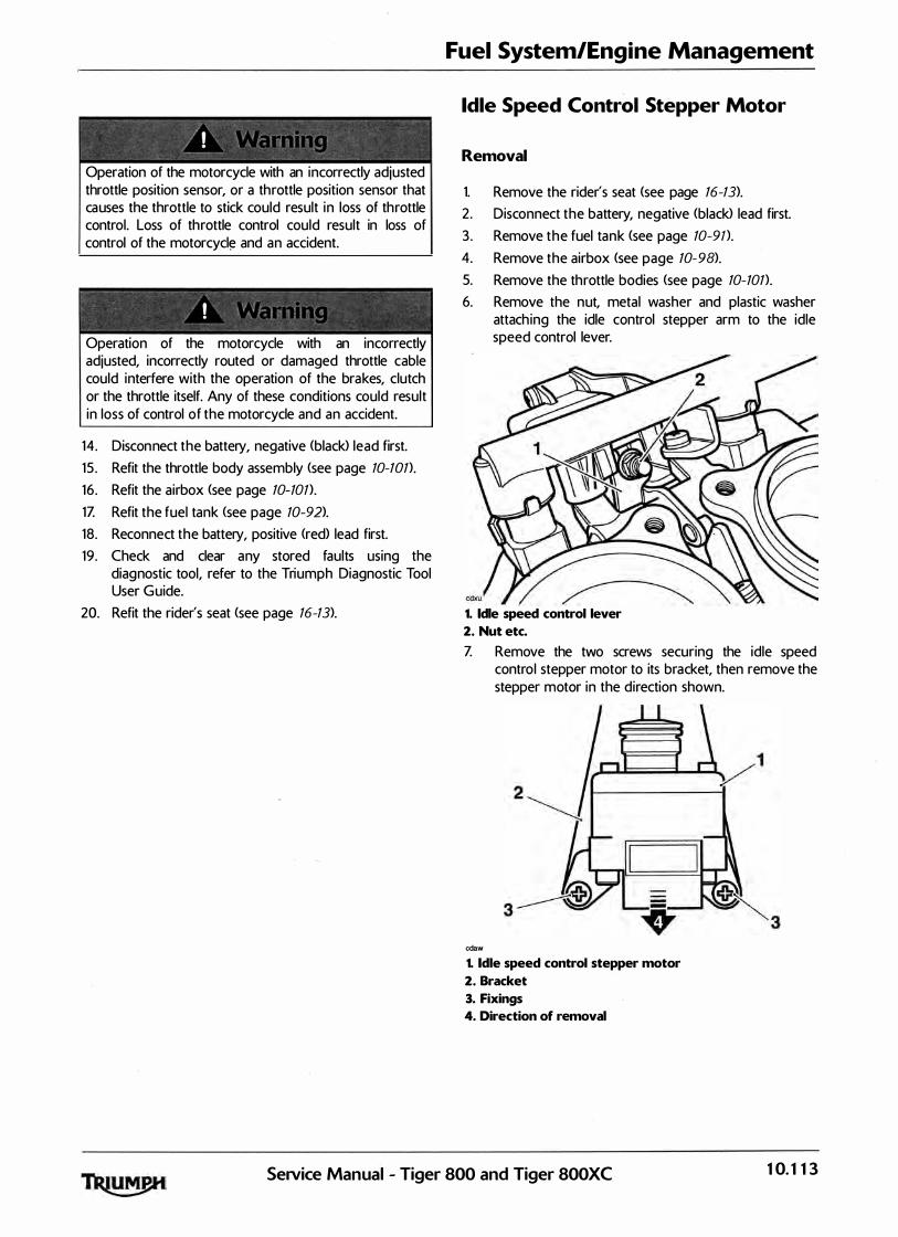
Operation of the motorcycle with an incorrectly adjusted throttle position sensor, or a throttle position sensor that causes the throttle to stick could result in loss of throttle control. Loss of throttle control could result in loss of control of the motorcycl� and an accident.
! . . ;
Operation of the motorcycle with an incorrectly adjusted, incorrectly routed or damaged throttle cable could interfere with the operation of the brakes, clutch or the throttle itself. Any of these conditions could result in loss of control of the motorcycle and an accident.
14. Disconnect the battery, negative (black> lead first.
15 . Refit the throttle body assembly <see page 10-101>.
16 . Refit the airbox (see page 10-101>.
1Z Refit the fuel tank (see page 10-92).
18. Reconnect the battery, positive (red) lead first.
19 . Check and clear any stored faults using the diagnostic tool, refer to the Triumph Diagnostic Tool User Guide.
20. Refit the rider's seat <see page 16-13).
Fuel System/Engine Management
Idle Speed Control Stepper Motor
Removal
1. Remove the rider's seat <see page 16-13>.
2. Disconnect the battery, negative (black> lead first.
3 . Remove the fuel tank (see page 10-9n.
4. Remove the airbox <see page 10-98).
5. Remove the throttle bodies (see page 10-101>.
6. Remove the nut, metal washer and plastic washer attaching the idle control stepper arm to the idle speed control lever.
1. Idle speed control lever
2. Nut etc.
Z Remove the two screws securing the idle speed control stepper motor to its bracket, then remove the stepper motor in the direction shown.
cdaw
1. Idle speed control stepper motor
2. Bracket
3. Fixings
4. Direction of removal
Service Manual - Tiger 800 and Tiger 800XC 10. 1 13
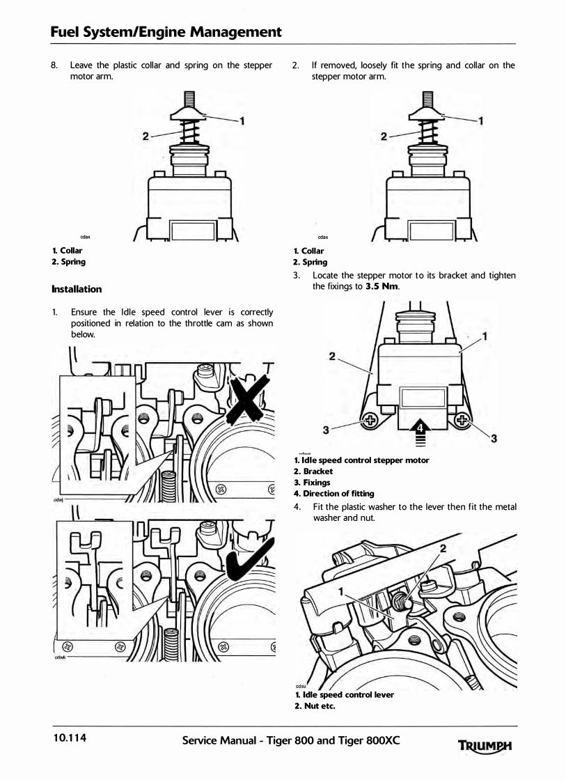
Fuel System/Engine Mana·gement
8. Leave the plastic col lar and spring on the stepper motor arm.
cdax
1. Collar
2. Spring
Installation
1 . Ensure the Id le speed control lever i s correctly positioned in relation to the throttle cam as shown below.
2. If removed, loosely fit the spring and col lar on the stepper motor arm.
cdax
1. Collar
2. Spring
3 . Locate the stepper motor to its bracket and tighten the fixings to 3.5 Nm.
1. Idle speed control stepper motor
2. Bracket
3. Fixings
4. Direction of fitting
4. Fit the plastic washer to the lever then f it the metal washer and nut.
1. Idle speed control lever
2. Nut etc.
10. 1 14 SeNice Manual - Tiger 800 and Tiger 800XC

5. Mount the throttle body onto the engine.
6. Temporarily reconnect the battery, positive (red> lead first.
Z Attach the Triumph diagnostic tool to the dedicated plug, refer to the Triumph Diagnostic Tool User Guide.
8. Turn the ignition to the 'ON' position.
9. On the diagnostic tool navigate to 'Engine Diagnostics' and select the 'Adjust Tune' button.
10. Select ' Id le Speed Control Stepper Renew' then press the 'Ad just' button.
1 1 . On pressing the 'Adjust' key, the diagnostic tool wi l l send a command that drives the throttle to the fu l ly closed position. The tool wil l a lso display the voltage reading coming from the throttle position sensor which should be between the target voltage range of 0.58V and 0.62V.
Adjust Tune Procedure
Adjust the throttle position sensor as described in the service manual until the voltage reading is within the range shown below Press OK when the adjustment is complete
Press cancel to cancel the adjustment process
Throttle Voltage: 0.59 V
Target Voltage Range: 0.58 V - 0.62 V
Adjusting parameter - Throttle Position Sensor Adjust
Adjust Tune Screen
12 . Tighten the stepper arm nut on the idle speed stepper motor until a clearance of 0.5 mm can be measured between the idle speed control cam and the throttle rol ler.
1. Idle speed control lever
2. Throttle roller
Fuel System/Engine Management
13 . Check the voltage reading shown on the software. I f the reading i s between the target voltage range, then proceed to step 1Z If the reading is not within this range, adjustment must be made as described in steps 14 to 1 6.
14. Slacken the screws on the throttle position sensor.
15 . Gently turn the throttle position sensor unti l the voltage reading shown on the software is between the target voltage range.
16. Tighten the sensor retaining screws to 2 Nm and recheck the voltage reading shown on the software. Repeat the adjustment if the reading is outside the specified range.
1Z Click the 'OK' button to progress to the next adjustment.
Note:
• The diagnostic software will calculate the target voltage range for when the throttle is in the fully open position.
18 . On pressing the 'OK' button, the d iagnostic tool wil l send a command that drives the throttle to the ful ly open position. The tool wi l l also display the voltage reading coming from the throttle. position sensor which should be between the target voltage range calculated by the software and shown on the screen.
19. With the stepper fu l ly opened, check the voltage shown on the software and, if necessary, adjust the nut on the top of the stepper arm until the software shows a voltage within the target voltage range shown on the screen. The reading on the screen wil l change from red to green, indicating that the reading is correct.
� 1. Adjustment nut
SeiVice Manual - Tiger 800 and Tiger 800XC 10. 1 15
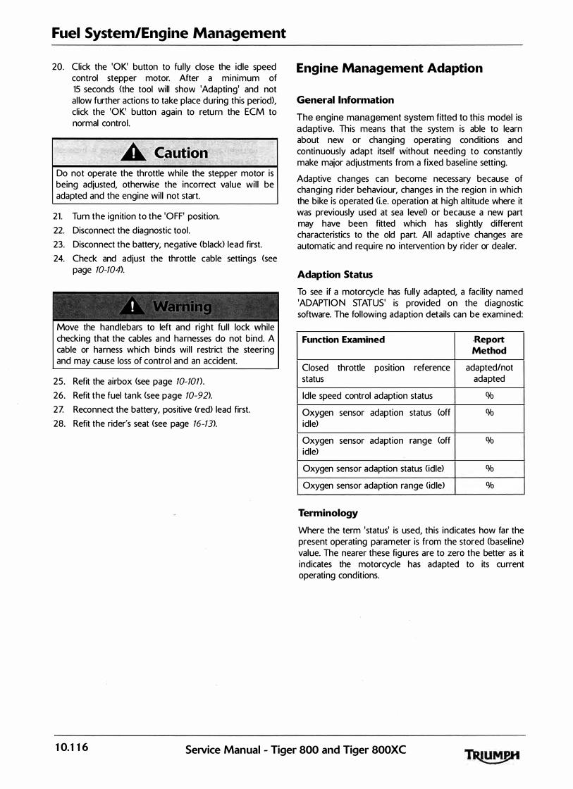
Fuel System/Engine Management
20. Click the 'OK' button to fu l ly close the idle speed control stepper motor. After a minimum of 15 seconds (the tool will show 'Adapting' and not al low further actions to take place during this period), click the 'OK' button again to return the ECM to normal control.
Do not operate the throttle while the stepper motor is being adjusted, otherwise the incorrect value wil l be adapted and the engine will not start.
21 . Turn the ign ition to the 'OFF' position.
22. Disconnect the d iagnostic tool .
23. Disconnect the battery, negative (black> lead first.
24. Check and adjust the throttle cable settings (see page 10-104>.
! ' '
Move the handlebars to left and right ful l lock while checking that the cables and harnesses do not bind. A cable or harness which binds wi l l restrict the steering and may cause loss of control and an accident.
25 . Refit the airbox (see page 10-101) .
26. Refit the fuel tank (see page 10-92).
2Z Reconnect the battery, positive <red) lead first.
28. Refit the rider's seat <see page 16-13).
Engine Management Adaption
General Information
The engine management system fitted to this model is adaptive. This means that the system is able to learn about new or changing , operating conditions and continuously adapt itself without needing to constantly make major adjustments from a fixed basel ine setting.
Adaptive changes can become necessary because of changing rider behaviour, changes in the region in which the bike is operated (i.e. operation at high a ltitude where it was previously used at sea level> or because a new part may have been fitted which has sl ightly different characteristics to the old part. Al l adaptive changes are automatic and require no intervention by rider or dea ler.
Adaption Status
To see if a motorcycle has ful ly adapted, a facil ity named 'ADAPTIO N STATUS' is provided on the diagnostic software. The fol lowing adaption details can be examined:
Function Examined -Report Method
Closed throttle position reference adapted/not status adapted
Idle speed control adaption status %
Oxygen sensor adaption status <off % idle)
Oxygen sensor adaption range (off % idle)
Oxygen sensor adaption status (idle) %
Oxygen sensor adaption range (id le) %
Terminology
Where the term 'status' is used, this indicates how far the present operating parameter is from the stored (basel ine) value. The nearer these figures are to zero the better as it indicates the motorcycle has adapted to its current operating conditions.
10.1 16 SeiVice Manual - Tiger 800 and Tiger 800XC
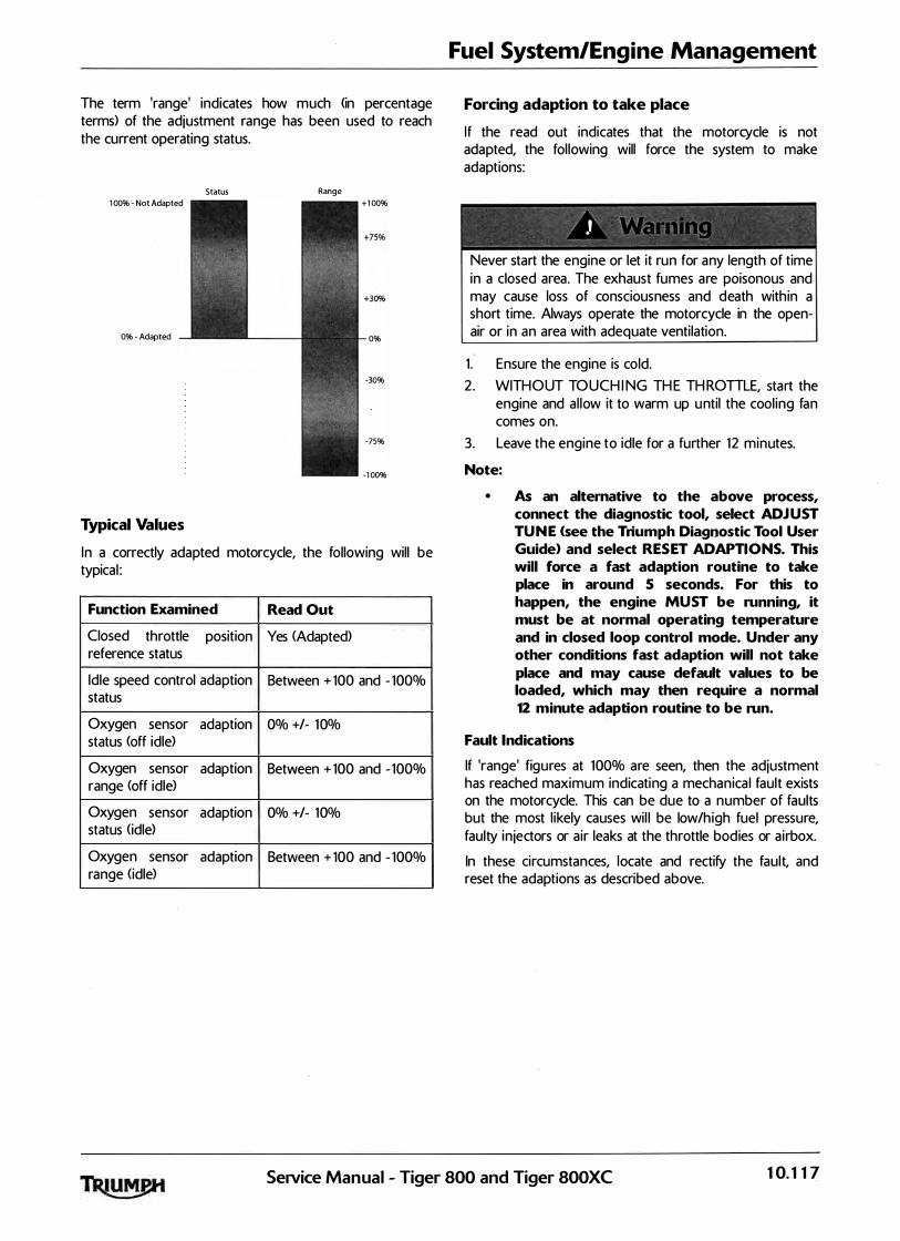
The term 'range' indicates how much <in percentage terms) of the adjustment range has been used to reach the current operating status.
Status Range 1 00% - Not Adapted +1 00%
0% - Adapted 0%
-30%
-75%
-1 00%
Typical Values
In a correctly adapted motorcycle, the following will be typical :
Function Examined Read Out
Closed throttle position Yes <Adapted) reference status
Idle speed control adaption Between + 100 and - 100% status
Oxygen sensor adaption 0% +/- 10% status (off idle)
Oxygen sensor adaption Between + 100 and - 100% range (off idle)
Oxygen sensor adaptio"n 0% +!- 10% status <idle>
Oxygen sensor adaption Between + 100 and - 100% range <idle>
Fuel System/Engine Management
Forcing adaption to take place
If the read out indicates that the motorcycle is not adapted, the fol lowing will force the system to make adaptions:
' - ' ' . '
-
Never start the engine or let it run for any length of time in a closed area. The exhaust fumes are poisonous and may cause loss of consciousness and death within a short time. Always operate the motorcycle in the openair or in an area with adequate venti lation.
1 . Ensure the engine is cold.
2 . WITHOUT TOUCH I NG TH E TH ROTILE, start the engine and al low it to warm up until the cool ing fan comes on.
3. Leave the engine to idle for a further 12 minutes.
Note:
• As an alternative to the above process, connect the diagnostic tool, select ADJ UST TU N E <see the Triumph Diagnostic Tool User Guide> and select RES ET ADAPTIONS. This will force a fast adaption routine to take place in around 5 seconds. For this to happen, the engine MU ST be running, it must be at normal operating temperature and in closed loop control mode. Under any other conditions fast adaption will not take
place and may cause default values to be loaded, which may then require a normal 12 minute adaption routine to be run.
Fault Indications
If 'range' figures at 100% are seen, then the adjustment has reached maximum indicating a mechanica l fault exists on the motorcycle. This can be due to a number of faults but the most l ikely causes wil l be low/high fuel pressure, faulty in jectors or air leaks at the throttle bodies or a irbox.
In these circumstances, locate and rectify the fault, and reset the adaptions as described above.
SeiVice Manual - Tiger 800 and Tiger 800XC 10. 1 17

Fuel System/Engine Management
Exhaust System
Removal
! ' ' ' :
If the engine has recently been running, the exhaust system wil l be hot. Before working on or near the exhaust system, a l low sufficient time for the exhaust system to cool as touching any part of a hot exhaust system could cause burn in juries.
1. Remove the rider's seat (see page 16-13).
2. Disconnect the battery, negative (black> lead first.
3 . Release the clamp securing the si lencer to the header pipe.
cgph
1. Silencer
2. Clamp
3. Header pipe
4. Support the right hand si lencer and release the bolt and nut securing the si lencer mounting bracket to the rear frame.
Move the si lencer rearwards to disengage it from the header pipe and remove.
6. Remove the sump guard <see page 16-24>.
Z Disconnect the oxygen sensor from the main harness.
·
8. Remove the radiator <see page 1 1-1 n. 9. Release the fixings securing the header pipe joints to
the cyl inder head. Discard the fixings.
1
I cdpa \-
1 . Header pipes
2. Fixings
10. 1 18 SeiVice Manual - Tiger 800 and Tiger 800XC

10. Remove the bolt from the header pipe rear mounting point.
1. Header pipe rear mounting bolt
1 1 . Detach the header pipe assembly and col lect the seals from the cyl inder head ports.
1 2 . I f necessary, remove the remove the oxygen sensor.
Fuel System/Engine Management
Assembly
1 . If removed, insta l l the oxygen sensor and tighten to 2 5 Nm.
2. F it new seals to the cylinder head. Ensure that the face of the sea l with the tab is facing the cylinder head.
Note:
• A smear of grease may be used to retain the
seals in the cylinder head during assembly.
1. Cylinder head
2. Seal
3. Seal tab
3 . Locate the header pipes and a l ign the header pipe flanges to the fixing points. Fit new nuts and hand tighten.
4. Assemble the rear mounting point fixing but do not tighten at this stage.
SeiVice Manual - Tiger 800 and Tiger 800XC 10. 1 19

Fuel System/Engine Management
5. Tighten the header pipe to cyl inder head nuts in the sequence shown below:
• Stage 1 : Tighten the header pipe nuts to
2 Nm.
• Stage 2: Tighten the header pipe nuts to
19 Nm.
Header Pipe Tightening Sequence
6. Tighten the rear mounting point fixing to 19 Nm.
Z Refit the radiator and refi l l the cool ing system <see page 1 1-12>.
8. Reconnect the oxygen sensor and route the harness under the sump guard as noted on disassembly.
9. Refit the sump guard (see page 16-21).
10. Position and engage the si lencer to the header pipe. Do not tighten the clamp at th is stage.
1 1 . Align the si lencer mounting bracket to the rear frame bracket. Refit the nut. Tighten the fixings to 1 5 Nm.
Align the clamp for the si lencer to header pipe joint as shown below and tighten to 10 Nm.
1. Silencer intermediate pipe
2. Clamp
3. Header pipe
13 . Reconnect the battery, positive (red> lead first.
Do not instal l the exhaust system or run the engine without the exhaust heatsh ields fitted. Components protected by the exhaust heatshields may suffer severe damage or a fire if the motorcycle is operated without the heatshields being fitted.
14. Start the engine and check for exhaust gas leaks. Rectify if necessary.
15 . Refit the rider's seat <see page 16-13>.
10. 120 SeJVice Manual - Tiger 800 and Tiger 800XC

Fuel System/Engine Management
Evaporative Emissions Control System
California Models Only
All Cal ifornia models are fitted with a system to control the evaporation of fuel vapour to the atmosphere.
A carbon fi l led canister absorbs vapour while the engine is not running. When the engine is started, the vapour is returned to the engine and burnt.
There are two distinct phases to the system's operation, engine off and engine running. These two conditions are explained overleaf.
Component Locations
Carbon Filled Canister (2) - below the swinging arm.
Purge Control Valve <3>- adjacent to frame, left hand s ide (electronical ly control led by the ECM>.
1. Breather hoses
2. Carbon filled canister
3. Purge valve
4. Purge hose to throttle bodies
5. Fuel tank filler drain
SeiVice Manual - Tiger 800 and Tiger 800XC 10. 12 1
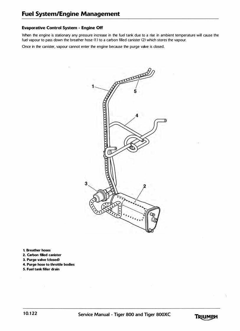
Fuel System/Engine Management
Evaporative Control System - Engine Off
When the engine is stationary any pressure increase in the fuel tank due to a rise in ambient temperature wil l cause the fuel vapour to pass down the breather hose (1 > to a carbon fi l led canister (2) which stores the vapour.
Once in the canister, vapour cannot enter the engine because the purge valve is closed .
1. Breather hoses
2. Carbon filled canister
3. Purge valve (closed}
4. Purge hose to throttle bodies
S. Fuel tank filler drain
10. 122
..
SeiVice Manual - Tiger 800 and Tiger 800XC
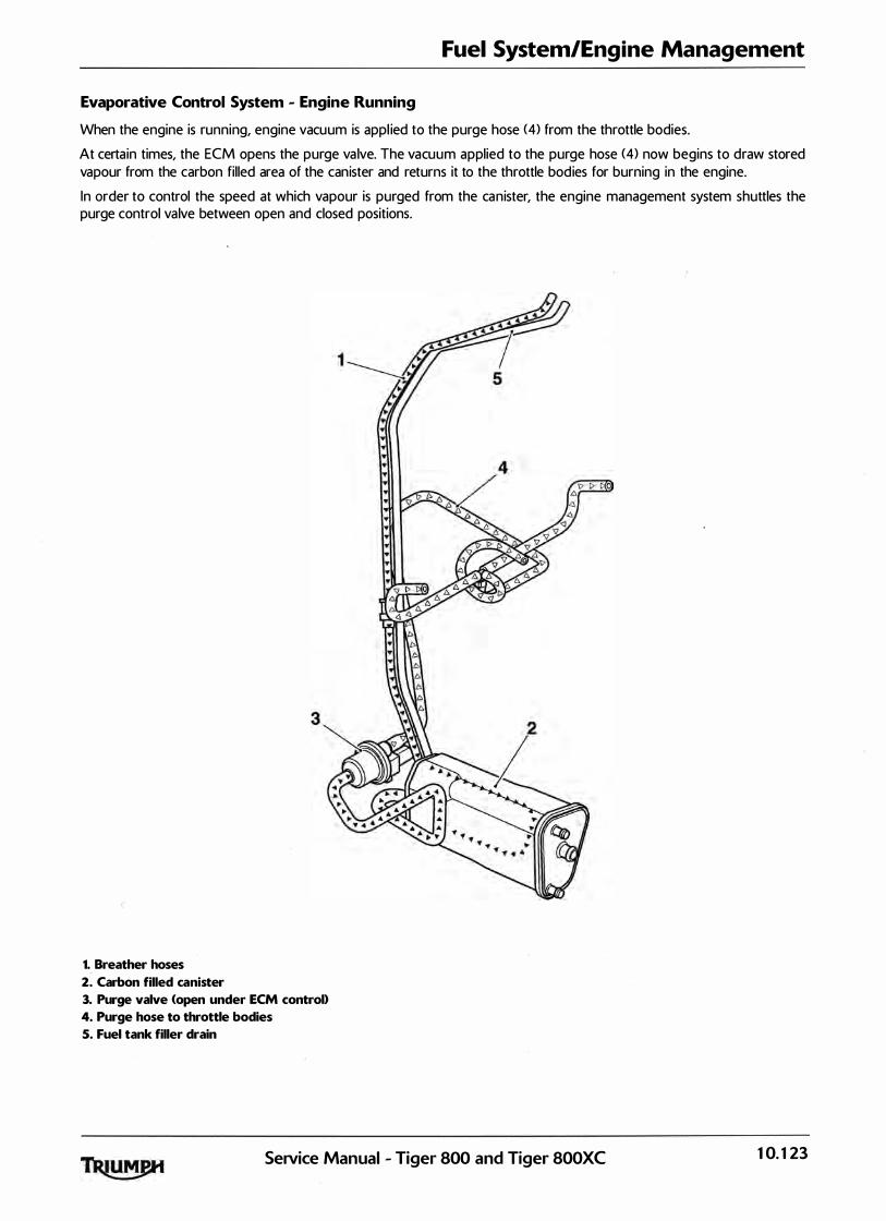
Fuel System/Engine Management
Evaporative Control System - Engine Running
When the engine is running, engine vacuum is appl ied to the purge hose (4) from the throttle bodies.
At certain times, the ECM opens the purge va lve. The vacuum applied to the purge hose (4) now begins to draw stored vapour from the carbon filled area of the canister and returns it to the throttle bodies for burning in the engine.
In order to control the speed at which vapour is purged from the canister, the engine management system shuttles the purge control valve between open and closed positions .
.,
1. Breather hoses
2. Carbon filled canister
3. Purge valve <open under ECM control}
4. Purge hose to throttle bodies
5. Fuel tank filler drain
SeNice Manual - Tiger 800 and Tiger 800XC 10. 123

Fuel System/Engine Management
This page intentionally left blank
10. 124 SeiVice Manual - Tiger 800 and Tiger 800XC
11 Cooling
Table of Contents
Exploded View - Cooling System . . . . . . . . . . . . . . . . . . . . . . . . . . . . . . . . . . . . . . . . . . . . . . . . . . . . . . . . . . . 11.2
Coolant . . . . . . . . . . . . . . . . . . . . . . . . . . . . . . . . . . . . . . . . . . . . . . . . . . . . . . . . . . . . . . . . . . . . . . . . . . . . . . . . . 11.3
Radiator Hoses. . . . . . . . . . . . . . . . . . . . . . . . . . . . . . . . . . . . . . . . . . . . . . . . . . . . . . . . . . . . . . . . .. . . . . . . . . . . 11.4
Radiator and Cooling Fan. . . . . . . . . . . . . . . . . . . . . . . . . . . . . . . . . . . . . . . . . . . . . . . . . . . . . . . . . . . . . . . . . . 11.4
Coolant Level Inspection . . . . . . . . . . . . . . . . . . . . . . . . . . . . . . . . . . . . . . . . . . . . . . . . . . . . . . . . . . . . . . . . . . 11.4
Coolant Replacement . . . . . . . . . . . . . . . . . . . . . . . . . . . . . . . . . . . . . . . . . . . . . . . . . . . . . . . . . . . . . . . . . . . . . 11.5
Drainage . . . . . . . . . . . . . . . . . . . . . . . . . . . . . . . . . . . . . . . . . . . . . . . . . . . . . . . . . . . . . . . . . . . . . . . . . . . 11.5
Filling . . . . . . . . . . . . . . . . . . . . . . . . . . . . . . . . . . . . . . . . . . . . . . . . . . . . . . . . . . . . . . . . . . . . : . . . . . . . . . 11.5
Water Pump. . . . . . . . . . . . . . . . . . . . . . . . . . . . . . . . . . . . . . . . . . . . . . . . . . . . . . . . . . . . . . . . . . . . . . . . . . . . . 11.7
Coolant Pressure Cap and Coolant System . . . . . . . . . . . . . . . . . . . . . . . . . . . . . . . . . . . . . . . . . . . . . . . . . . . 11.7
Inspection and Testing. . . . . . . . . . . . . . . . . . . . . . . . . . . . . . . . . . . . . . . . . . . . . . . . . . . . . . . . . . . . . . . . 11.7
Thermostat. . . . . . . . . . . . . . . . . . . . . . . . . . . . . . . . . . . . . . . . . . . . . . . . . . . . . . . . . . . . . . . . . . . . . . . . . . . . . . 11.9
Removal . . . . . . . . . . . . . . . . . . . . . . . . . . . . . . . . . . . . . . . . . . . . . . . . . . . . . . . . . . . . . . . . . . . . . . . . . . . 11.9
Inspection . . . . . . . . . . . . . . . . . . . . . . . . . . . . . . . . . . . . . . . . . . . . . . . . . . . . . . . . . . . . . . . . . . . . . . . . . 11.10
Installation. . . . . . . . . . . . . . . . . . . . . . . . . . . . . . . . . . . . . . . . . . . . . . . . . . . . . . . . . . . . . . . . . . . . . . . . . 11.10
Radiator . . . . . . . . . . . . . . . . . . . . . . . . . . . . . . . . . . . . . . . . . . . . . . . . . . . . . . . . . . . . . . . . . . . . . . . . . . . . . . . 11.11
Removal . . . . . . . . . . . . . . . . . . . . . . . . . . . . . . . . . . . . . . . . . . . . . . . . . . . . . . . . . . . . . . . . . . . . . . . . . . 11.11
Inspection . . . . . . . . . . . . . . . . . . . . . . . . . . . . . . . . . . . . . . . . . . . . . . . . . . . . . . . . . . . . . . . . . . . . . . . . . 11.12
Installation. . . . . . . . . . . . . . . . . . . . . . . . . . . . . . . . . . . . . . . . . . . . . . . . . . . . . . . . . . . . . . . . . . . . . . . . . 11.12
SeiVice Manual - Tiger 800 and Tiger 800XC 11.1
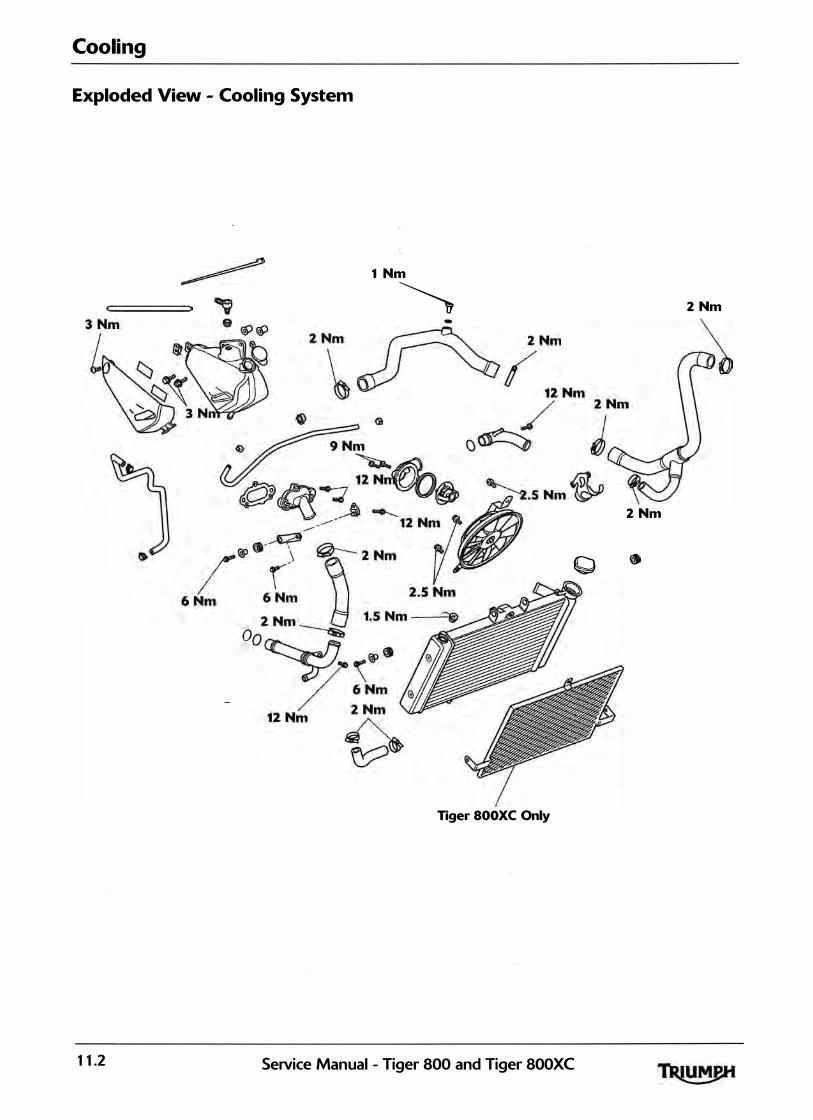
Cooling
Exploded View - Cooling System
1 Nm
� 2 Nm -·
2 Nm
Q
Tiger SOO XC Only
11.2 SeNice Manual - Tiger 800 and Tiger 800XC

Coolant
A permanent type of anti-freeze is insta l led in the cooling system when the motorcycle leaves the factory.
A year-round, Hybrid Organic Acid Technology (known as Hybrid OAT or HOAD coolant is instal led in the cooling system. lt is coloured green, conta ins a 50% solution of ethylene glycol based antifreeze, and has a freezing point of -3 5°C (-31 °F>. .
Note:
HD4X Hybrid OAT coolant, as supplied by
Triumph, is pre-mixed and does not need to be diluted prior to filling or topping up the
cooling system.
All models
Always change the coolant at the intervals specified in the scheduled maintenance chart.
Cooling
The coolant mixture contains anti-freeze and corrosion inhibitors, which both contain toxic chemicals which are harmful to the human body. Never swal low anti-freeze or any of the motorcycle coolant.
The coolant mixture conta ins a corrosion inhibitor which helps prevent damage to the metal surfaces inside the coq l ing system. Without this inhibitor, the coolant would 'attack' the metals and the resulting corrosion would cause blockages in the cool ing system leading to engine overheating 'and damage. Always use the correct antifreeze as specif ied in the owner's handbook. Never use a methanol based anti-freeze as this does not contain the required corrosion inhibition properties.
Disti l led water must be used with the anti-freeze (see specification for anti-freeze) in the cool ing system. If hard water is used in the system, it causes scale accumulation in the water passages, and considerably reduces the efficiency of the cool ing system. Reduced cooling system efficiency may cause the engine to overheat and suffer severe damage.
Service Manual - Tiger 800 and Tiger 800XC 11.3

Cooling
Radiator Hoses
Regularly check a l l radiator hoses and hose clips for cracks, leaks or deterioration in accordance with the scheduled maintenance chart.
Radiator and Cooling Fan
Check the radiator fins for obstruction by insects, mud, leaves and general debris. Clean off any obstructions by hand or with a stream of low pressure water.
The cooling fan operates automatica l ly. To prevent injury, keep hands and cloth ing away from the fan blades at al l times.
Using h igh-pressure water sprays can damage the radiator fins and impair the radiator's efficiency. Do not obstruct or deflect airflow through the radiator by instal l ing unauthorized accessories in front of the radiator or behind the cooling fan. Interference with the radiator airflow can lead to overheating and consequent engine damage.
Coolant Level Inspection
���� � - �
I '''' ' ' . ' I ) ,· .· / • '! ' ' � ' •
� � � �
Do not remove the coolant pressure cap when the engine is hot. When the engine is hot, the coolant inside the radiator is hot and also under pressure. Contact with the pressurised coolant will cause scalds and skin damage.
Note:
• Only inspect the coolant level when the engine is cold.
1 . Position the_ motorcycle on level ground and in an upright posit ion.
2 . The expansion tank can be viewed from the right hand side of the motorcycle, below and towards the front of the fuel tank. The coolant level should be between the 'MAX' and 'M I N. ' marks.
"'
1. Expansion tank (fuel tank shown removed for clarity}
2. Expansion tank filler cap
3. 'MAX' mark
4. 'MI N.' mark
3 . If the level of coolant i s low, remove the cap from the expansion tank and add coolant mixture as necessary to bring the level up to the 'MAX' mark. Refit the cap.
If the coolant level is found to be low, or if coolant has to be added regularly, inspect the cool ing system for coolant leaks. I f necessary, pressure test the system to locate the source of the leak and rectify as necessary. Loss of coolant may cause the engine to overheat and suffer severe damage.
11.4 SeiVice Manual - Tiger 800 and Tiger SOOXC
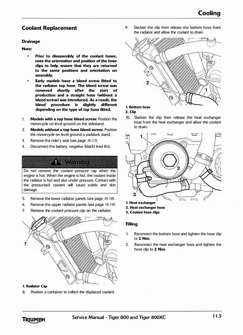
Coolant Replacement
Drainage
Note:
• Prior to disassembly of the coolant hoses, note the orientation and position of the hose clips to help e.nsure that they are returned to the same positions and orientation on assembly.
• Early models have a bleed screw fitted to the radiator top hose. The bleed screw was removed shortly after the start of production and a straight hose (without a bleed screw> was introduced. As a result, the bleed procedure is slightly different depending on the type of top hose fitted.
1 . Models with a top hose bleed screw: Position the motorcycle on level ground on the sidestand.
2 . Models without a top hose bleed screw: Position the motorcycle on level ground a paddock stand.
3 . Remove the rider's seat <see page 16-13).
4. Disconnect the battery, negative <black> lead first.
Do not remove the coolant pressure cap when· the engine is hot. When the engine is hot, the coolant inside the radiator is hot and also under pressure. Contact with the pressurised coolant will cause scalds and skin damage.
5. Remove the lower radiator panels <see page 16-14).
6. Remove the upper radiator panels <see page 16-14).
Z Remove the coolant pressure cap on the radiator.
1
1. Radiator Cap
8. Position a container to col lect the displaced coolant.
Cooling
9. Slacken the clip then release the bottom hose from the radiator and al low the coolant to drain.
1. Bottom hose
2. Ciip
10. Slacken the cl ip then release the heat exchanger hose from the heat exchanger and al low the coolant to drain.
3 1. Heat exchanger
2. Heat exchanger hose
3. Coolant hose clips
Filling
1. Reconnect the bottom hose and tighten the hose cl ip to 2 Nm.
2 . Reconnect the heat exchanger hose and tighten the hose clip to 2 Nm.
Setvice Manual - Tiger 800 and Tiger 800XC 11.5

Cooling
3 . Remove the bleed screw from the right hand side of the radiator.
1. Top hose
2. Bleed screw (if fitted)
Note:
• During filling, squeezing the bottom hose with both hands will help to pump coolant around the system and remove trapped air.
5. Slowly add coolant mixture to the system, through the fi l ler opening in the radiator, until the system is ful l .
6. If the system has fi l led correctly and ful ly, there should be coolant visible through the:
radiator bleed screw opening;
top hose bleed screw opening (if fitted>;
radiator fi l ler opening.
Z If there is no coolant visible through the radiator bleed screw opening, but the fi l ler side appears to be fu ll, attach a length of clear tubing to the radiator bleed screw spigot and syphon coolant into the bleed screw side of the radiator.
Note:
• A hand operated vacuum pump or similar should be used to syphon the coolant through the system.
8. If necessary, top up the system through the fi l ler and refit the pressure cap.
9. I nstal l the rad iator bleed screw and tighten to 1. 5 Nm.
10. I f fitted, insta l l the top hose bleed screw and tighten to 1 Nm.
1 1 . With the aid of an assistant, lean the motorcycle fully over to the right hand side, and then the left hand side, to release air trapped in the cool ing system. Repeat as necessary.
12 . Reconnect the battery, positive (red) lead first. 1 3 . Start the motorcycle and al low to run for
approximately 20 to 30 seconds. Briefly raise the engine speed several times to a l low any air to be expelled from the system.
14. Stop the engine. Check and top up the coolant level as necessary.
15 . With the a id of an assistant, lean the motorcycle fu lly over to the right hand side, and then the left hand side, to release air trapped in the cooling system.
16 . Start the motorcycle. Briefly ra ise the engine speed severa l times to al low any air to be expelled from the system.
1Z Allow the engine to run until the cool ing fan operates.
18 . Stop the motorcycle and al low the engine to cool.
Do not remove the coolant pressure cap when the engine is hot. When the engine is hot, the coolant inside the cooling system is hot and a lso under pressure. Contact with the pressurised coolant wil l cause scalds and skin damage.
19 . Check and top up the coolant level as necessary. 20. Refit the upper radiator panels (see page 16-14). 21 . Refit the lower radiator panels (see page 16-14>. 22 . Check the expansion tank level and top up if
necessary. 23 . Refit the rider's seat <see page 16-13).
1 1.6 SeiVice Manual - Tiger 800 and Tiger SOOXC

Water Pump
Note:
• The oil pump and water pump are supplied as an assembly and cannot be separated. For additional information, refer to Oil Pump <see page 8-8 for removal and page 8-13 for installation>.
Cooling
Coolant Pressure Cap and Coolant System Testing
Inspection and Testing
F=< � =� - - o/ - � ' , , ! ,•, ; ; : !L!: � � � Do not remove the coolant pressure cap when the engine is hot. When the engine is hot, the coolant inside the radiator is hot and also under pressure. Contact with the pressurised coolant wil l cause scalds and skin damage.
1 . Allow the engine temperature to cool for at least 30 minutes.
2 . Remove the coolant pressure cap. 3. Check the condition of the upper and lower seals of
the coolant pressure cap.
cawr
1. Lower seal
2. Upper seal
3. Spring
Note:
• If there is any sign of damage or deterioration replace the cap.
4. Pressure test the cap and cool ing system to the blow off pressure of 1 .1 bar as described below using T3 88014Z If the cap opens at a lower pressure or fai ls to open at 1.1 bar, replace the cap.
Note:
• lt is recommended to carry out coolant pressure cap and cooling system pressure tests consecutively.
Service Manual - Tiger 800 and Tiger 800XC 11.7
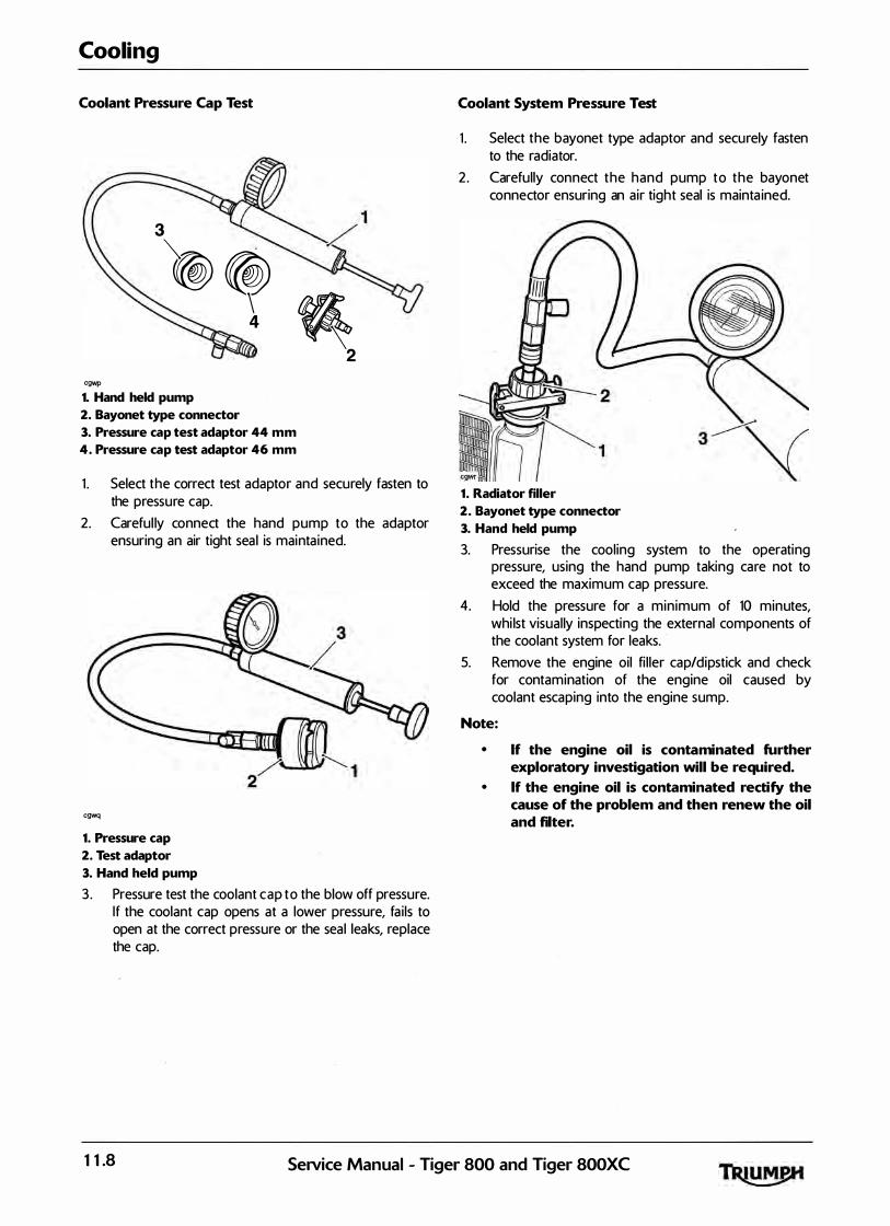
Cooling
Coolant Pressure Cap Test
3
�((®) ��
cgwp
1. Hand held pump
I�I,IIUA 2
2. Bayonet type connector
3. Pressure cap test adaptor 44 mm
4. Pressure cap test adaptor 46 mm
1 . Select the correct test adaptor and securely fasten to the pressure cap.
2. Careful ly connect the hand pump to the adaptor ensuring an air tight sea l is mainta ined.
cgwq
1. Pressure cap
2. Test adaptor
3. Hand held pump
3 . Pressure test the coolant cap to the blow off pressure. If the coolant cap opens at a lower pressure, fa i ls to open at the correct pressure or the seal leaks, replace the cap.
Coolant System Pressure Test
1 . Select the bayonet type adaptor and securely fasten to the radiator.
2 . Carefully connect the hand pump to the bayonet connector ensuring an air tight seal is mainta ined.
1. Radiator filler
2. Bayonet type connector
3. Hand held pump
3. Pressurise the cooling system to the operating pressure, using the hand pump taking care not to exceed the maximum cap pressure.
4. Hold the pressure for a minimum of 10 minutes, whi lst visual ly inspecting the external components of the coolant system for leaks.
5. Remove the engine oil fi l ler cap/dipstick and check for contamination of the engine oil caused by coolant escaping into the engine sump.
Note:
• If the engine oil is contaminated further exploratory investigation will be required.
• If the engine oil is contaminated rectify the cause of the problem and then renew the oil and filter.
11.8 SeiVice Manual - Tiger 800 and Tiger 800XC

6. Depressurise the coolant test kit using the pressure release valve.
1. Radiator filler
2. Bayonet type connector
3. Hand held pump
4. Pressure release valve
Z Refit the coolant cap. 8. Fi l l the coolant to the maximum mark (see
page 1 1-S>.
Thermostat
Removal
Note:
Cooling
• Prior to disassembly of the coolant hoses, note the orientation and position of the hose clips to help ensure that they are returned to the same positions and orientation on assembly.
1 . Remove the rider's seat <see page 16-13>. 2 . Disconnect the battery, negative <black> lead first. 3: Drain the coolant (see page 11-S>. 4. Remove the fuel tank (see page 10-9 1>. 5 . Remove the airbox (see page 10-98>. 6. Remove the throttle bodies (see page 10-107>.
Do not remove the coolant pressure cap when the engine is hot. When the engine is hot, the coolant inside the radiator is hot and also under pressure. Contact with the pressurised coolant wil l cause scalds and skin damage.
Z Detach the top hose from the thermostat elbow. 8. Release the fixings securing the thermostat elbow to
the cylinder head. 9. Remove the thermostat housing.
1. Thermostat housing
2. Fixings
SeiVice Manual - Tiger 800 and Tiger 800XC 1 1.9

Cooling
10. Remove the thermostat from the cyl inder head. Discard the seal .
1. Thermostat
2. Bleed valve
Inspection
1 . Inspect the thermostat at room temperature. I f the valve is open, the thermostat must be replaced.
2. To check the valve opening temperature, suspend the thermostat in a container of water and raise the temperature of the water until the thermostat opens. The thermostat should start to open at 71 oc +I- 5°C.
3 . If the temperature at which thermostat opening takes place is incorrect, replace the thermostat.
Installation
1 . Fit a new seal to the thermostat. 2 . Locate the thermostat into the cyl inder head. Ensure
the bleed va lve is uppermost as shown below.
1. Thermostat
2. Bleed valve
3 . Refit the thermostat housing and tighten the fixings to 9 Nm.
4. Reconnect the top hose and tighten the cl ip. Tighten to 2 Nm.
5. Refit the throttle bodies (see page 10-101>. 6. Refit the airbox <see page 10-101>. Z Refit the fuel tank <see page 10-91} . 8. Reconnect the battery positive <red) lead first. 9 . Refit the rider's seat <see page 16-13). 10. Refi l l the cooling system (see page 11-.5).
11.10 Service Manual - Tiger 800 and Tiger 800XC
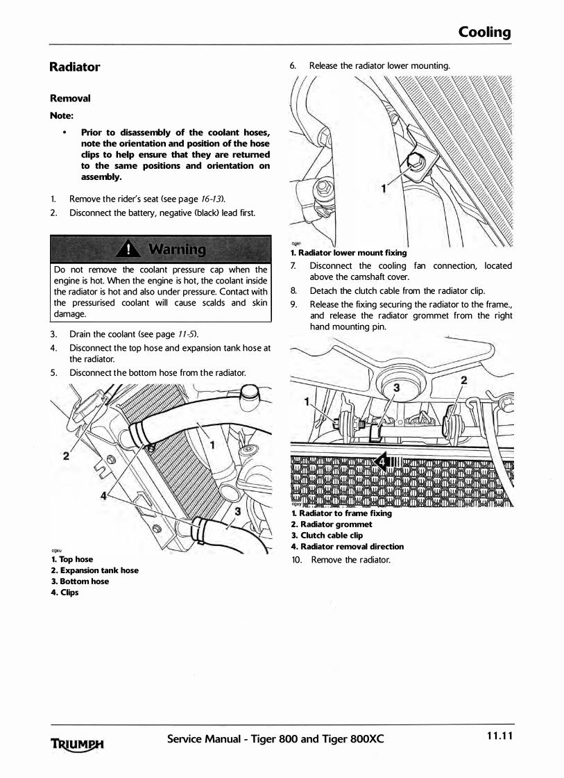
Radiator
Removal
Note:
• Prior to disassembly of the coolant hoses, note the orientation and position of the hose clips to help ensure that they are returned to the same positions and orientation on assembly.
1 . Remove the rider's seat <see page 16-13>. 2 . Disconnect the battery, negative (black> lead first.
! • I
Do not remove the coolant pressure cap when the engine is hot. When the engine is hot, the coolant inside the radiator is hot and also under pressure. Contact with the pressurised coolant wil l cause scalds and skin damage.
3 . Drain the coolant (see page 1 1-5). 4. Disconnect the top hose and expansion tank hose at
the radiator. 5 . Disconnect the bottom hose from the radiator.
cgxu
1. Top hose
2. Expansion tank hose
3. Bottom hose
4. Ciips
6. Release the radiator lower mounting.
1. Radiator lower mount fixing
Cooling
Z Disconnect the cool ing fan connection, located above the camshaft cover.
8. Detach the clutch cable from the radiator clip. 9. Release the fixing securing the radiator to the frame.,
and release the radiator grommet from the right hand mounting pin.
cgxy ' ' " . . -
1. Radiator to frame fixing
2. Radiator grommet
3. Clutch cable clip
4. Radiator removal direction
10. Remove the radiator.
SetVice Manual - Tiger 800 and Tiger 800XC 11.11
Cooling
Inspection
1 . Check the radiator for stone damage. 2 . Check the radiator core for damage to the fins or
obstructions to air flow. 3 . Repair any damage and clear a l l obstructions.
To avoid overheating and consequent engine damage, replace the radiator if the cores are blocked or if the fins are badly deformed or broken.
4. Check that the fan spins freely and without tight spots.
5. Check the fan blades for signs of heat distortion.
Installation
1 . Al ign the radiator grommet to the frame stud. Fit the upper mounting bolt and tighten the bolt to 6 Nm.
2. Align the radiator lower mounting to the bracket on the engine. Fit and tighten the lower mounting bolt to 6 Nm.
3. Reconnect the cooling fan. 4. Reconnect the expansion tank, and top and bottom
hoses. Tighten the hose clips to 2 Nm, ensuring they are repositioned as noted prior to disassembly.
5 . Refi l l the cooling system (see page 1 1 -5). 6. Reconnect the battery, positive (red) lead first. Z Refit the rider's seat (see page 16-13).
1 1. 12 Service Manual - Tiger 800 and Tiger 800XC
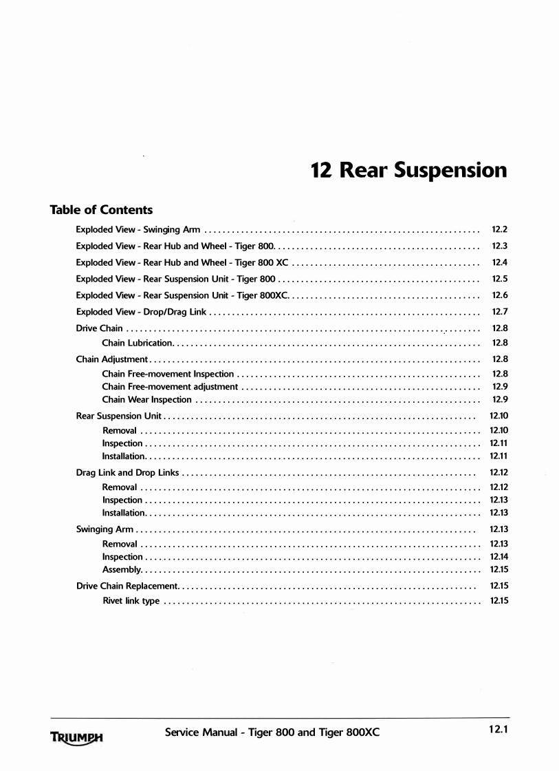
12 Rear Suspension
Table of Contents
Exploded View - Swinging Arm . . . . . . . . . . . . . . . . . . . . . . . . . . . . . . . . . . . . . . . . . . . . . . . . . . . . . . . . . . . . 12.2
Exploded View - Rear Hub and Wheel -Tiger 800. . . . . . . . . . . . . . . . . . . . . . . . . . . . . . . . . . . . . . . . . . . . . 12.3
Exploded View- Rear Hub and Wheel -Tiger 800 XC . . . . . . . . . . . . . . . . . . . . . . . . . . . . . . . . . . . . . . . . . 12.4
Exploded View- Rear Suspension Unit -Tiger 800 . . . . . . . . . . . . . . . . . . . . . . . . . . . . . . . . . . . . . . . . . . . . 12.5
Exploded View - Rear Suspension Unit -Tiger 800XC. . . . . . . . . . . . . . . . . . . . . . . . . . . . . . . . . . . . . . . . . . 12.6
Exploded View - Drop/Drag Link . . . . . . . . . . . . . . . . . . . . . . . . . . . . . . . . . . . . . . . . . . . . . . . . . . . . . . . . . . . 12.7
Drive Chain . . . . . . . . . . . . . . . . . . . . . . . . . . . . . . . . . . . . . . . . . . . . . . . . . . . . . . . . . . . . . . . . . . . . . . . . . . . . . 12.8
Chain Lubrication. . . . . . . . . . . . . . . . . . . . . . . . . . . . . . . . . . . . . . . . . . . . . . . . . . . . . . . . . . . . . . . . . . . 12.8
Chain Adjustment . . . . . . . . . . . . . . . . . . . . . . . . . . . . . . . . . . . . . . . . . . . . . . . . . . . . . . . . . . . . . . . . . . . . . . . . 12.8
Chain Free-movement Inspection . . . . . . . . . . . . . . . . . . . . . . . . . . . . . . . . . . . . . . . . . . . . . . . . . . . . . 12.8
Chain Free-movement adjustment . . . . . . . . . . . . . . . . . . . . . . . . . . . . . . . . . . . . . . . . . . . . . . . . . . . . 12.9
Chain Wear Inspection . . . . . . . . . . . . . . . . . . . . . . . . . . . . . . . . . . . . . . . . . . . . . . . . . . . . . . . . . . . . . . 12.9
Rear Suspension Unit . . . . . . . . . . . . . . . . . . . . . . . . . . . . . . . . . . . . . . . . . . . . . . . . . . . . . . . . . . . . . . . . . . . . 12.10
Removal . . . . . . . . . . . . . . . . . . . . . . . . . . . . . . . . . . . . . . . . . . . . . . . . . . . . . . . . . . . . . . . . . . . . . . . . . . 12.10
Inspection . . . . . . . . . . . . . . . . . . . . . . . . . . . . . . . . . . . . . . . . . . . . . . . . . . . . . . . . . . . . . . . . . . . . . . . . . 12.11
Installation. . . . . . . . . . . . . . . . . . . . . . . . . . . . . . . . . . . . . . . . . . . . . . . . . . . . . . . . . . . . . . . . . . . . . . . . . 12.11
Drag Link and Drop Links . . . . . . . . . . . . . . . . . . . . . . . . . . . . . . . . . . . . . . . . . . . . . . . . . . . . . . . . . . . . . . . . 12.12
Removal . . . . . . . . . . . . . . . . . . . . . . . . . . . . . . . . . . . . . . . . . . . . . . . . . . . . . . . . . . . . . . . . . . . . . . . . . . 12.12
Inspection . . . . . . . . . . . . . . . . . . . . . . . . . . . . . . . . . . . . . . . . . . . . . . . . . . . . . . . . . . . . . . . . . . . . . . . . . 12.13
Installation. . . . . . . . . . . . . . . . . . . . . . . . . . . . . . . . . . . . . . . . . . . . . . . . . . . . . . . . . . . . . . . . . . . . . . . . . 12.l3
Swinging Arm . . . . . . . . . . . . . . . . . . . . . . . . . . . . . . . . . . . . . . . . . . . . . . . . . . . . . . . . . . . . . . . . . . . . . . . . . . 12.13
Removal . . . . . . . . . . . . . . . . . . . . . . . . . . . . . . . . . . . . . . . . . . . . . . . . . . . . . . . . . . . . . . . . . . . . . . . . . . 12.13
Inspection . . . . .. . . . . . . . . . . . . . . . . . . . . . . . . . . . . . . . . . . . . . . . . . . . . . . . . . . . . . . . . . . . . . . . . . . . . 12.14
Assembly. . . . . . . . . . . . . . . . . . . . . . . . . . . . . . . . . . . . . . . . . . . . . . . . . . . . . . . . . . . . . . . . . . . . . . . . . . 12.15
Drive Chain Replacement. . . . . . . . . . . . . . . . . . . . . . . . . . . . . . . . . . . . . . . . . . . . . . . . . . . . . . . . . . . . . . . . . 12.15
Rivet link type . . . . . . . . . . . . . . . . . . . . . . . . . . . . . . . . . . . . . . . . . . . . . . . . . . . . . . . . . . . . . . . . . . . . . 12.15
Setvice Manual - Tiger 800 and Tiger SOOXC 12.1

Rear Suspension
Exploded View - Swinging Arm
9 Nm
�� 110Nm
9 Nm
12.2 SeiVice Manual - Tiger 800 and Tiger 800XC

Rear Suspension
Exploded View - Rear Hub and Wheel - Tiger 800
110Nm
L---------------------------------------l-1
I
-------- - ---- -- ----- - ----- - - - ----- - --- �
I __.)
Service Manual - Tiger 800 and Tiger 800XC 12.3
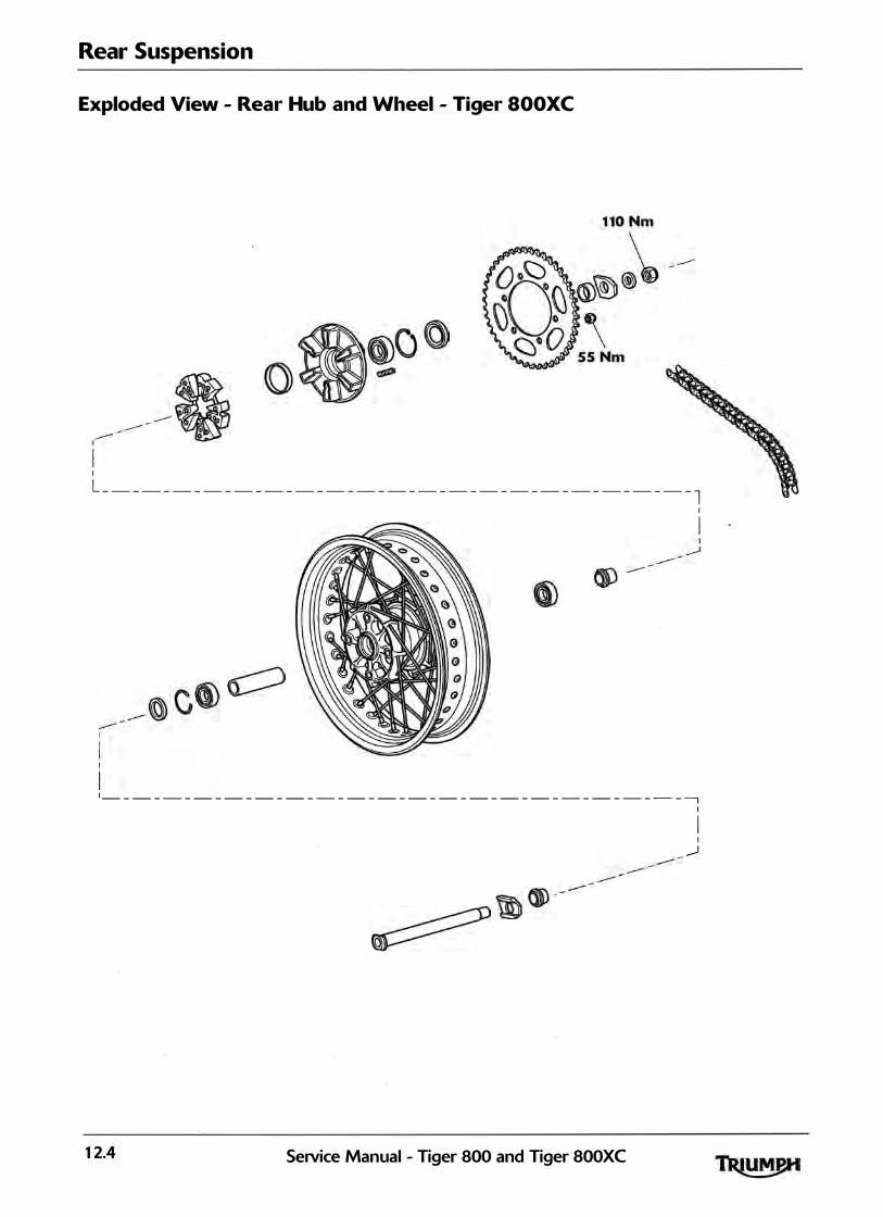
Rear Suspension
Exploded View - Rear Hub and Wheel - Tiger SOOXC
I
L _______________________________________ l I
I
�--------------------------------------� I
I I
__.J
12.4 SeiVice Manual - Tiger 800 and Tiger SOOXC
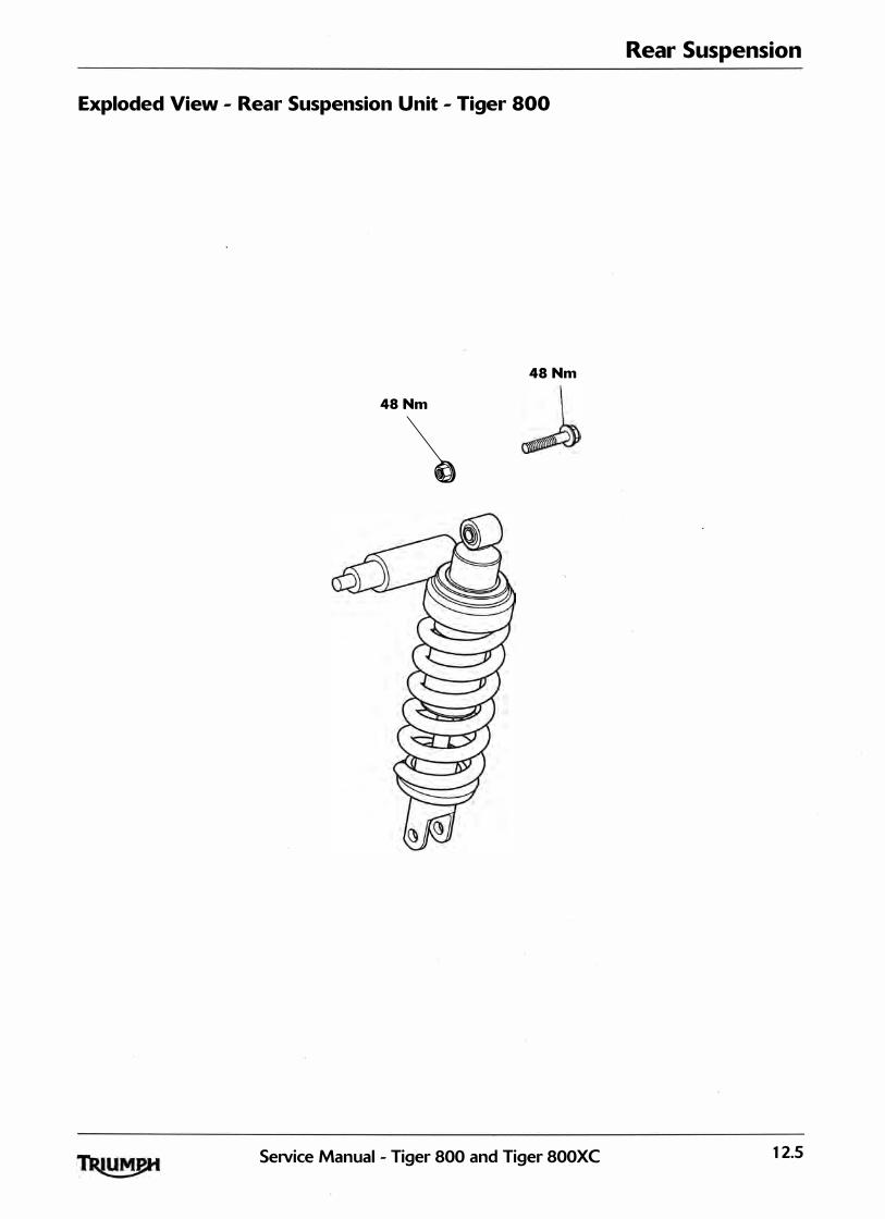
Rear Suspension
Exploded View - Rear Suspension Unit - Tiger 800
48Nm
48Nm
\
Service Manual - Tiger 800 and Tiger 800XC 12.5

Rear Suspension
Exploded View - Rear Suspension Unit - Tiger SOOXC
3Nm
48Nm
\
12.6 SeiVice Manual - Tiger 800 and Tiger 800XC
Exploded v· lew - Dr I op Drag Link
80Nm
80Nm
�tDCCD 0 � ())�
? � c:==J ())[) 0
aoNm r ([]())�� 80Nm
SeiVice M anual - Ti ger 800 and T •ger800XC
Rear Suspension
80Nm
80Nm
80Nm
12.7

Rear Suspension
Drive Chain
For safety and to prevent excessive wear, the drive chain must be checked, adjusted and lubricated in accordance with scheduled maintenance requirements. Checking, adjustment and lubrication must be carried out more frequently for extreme conditions such as salty or heavily gritted roads.
If the chain is badly worn or incorrectly adjusted <either too loose or too tight> the cha in could jump off the sprockets or break.
! ' '
A chain that breaks or jumps off the sprockets could snag on the engine sprocket or lock the rear wheel, severely damaging the motorcycle and causing an accident. Never neglect chain maintenance.
Note:
• Lubrication of the drive chain should ideally be carried out with the motorcycle set up so that the rear suspension hangs free.
• The chain must be adjusted with the motorcycle in an upright position, resting on its wheels, and with no additional weight on it.
Chain Lubrication
Lubrication is necessary every 200 miles (300 Km> and also after riding in wet weather, on wet roads, or any time that the chain appears dry.
Use the specia l chain lubricant as recommended in the specification section.
Correct appl ication is critical for chain lubrication. Apply the lubricant for one ful l chain revolution only, then leave for eight hours before riding. This al lows the lubricant's solvent <used to thin the oil> to evaporate and the oil to 'soak' into a l l parts of the chain. If the lubricant is appl ied and the motorcycle is ridden shortly afterwards, the lubricant is unl ikely to reach all parts and the majority wi l l be flung off and wasted. Applying excessive amounts is not helpful under any circumstances.
lt should be noted that the lubricant is appl ied to the chain to lubricate its action across the sprockets. In an 0-ring chain, external lubrication does not penetrate to the bushes and rol lers as the 0-ring sea ls prevents th is from happening.
Do not use a power ' jet' wash to clean the chain as this may cause damage to the chain components.
Chain Adiustment
Chain Free-movement Inspection
cgjt 1. Maximum movement position
Before starting work, ensure the motorcycle· is stabi l ised and adequately supported. This will help prevent it from fal l ing and causing in jury to the operator or damage to the motorcycle.
1. Place the motorcycle on a level surface and hold it in an upright position with no weight on it.
2. Rotate the rear wheel by pushing the motorcycle to find the position where the chain has least slack. Measure the chains vertical movement, mid-way between sprockets.
3 . If correct, the vertical movement of the drive chain midway between the sprockets should be:
• 15 - 25 mm for the Tiger 800;
• 20 - 30 mm for Tiger 800XC.
12.8 SeNice Manual - Tiger 800 and Tiger 800XC
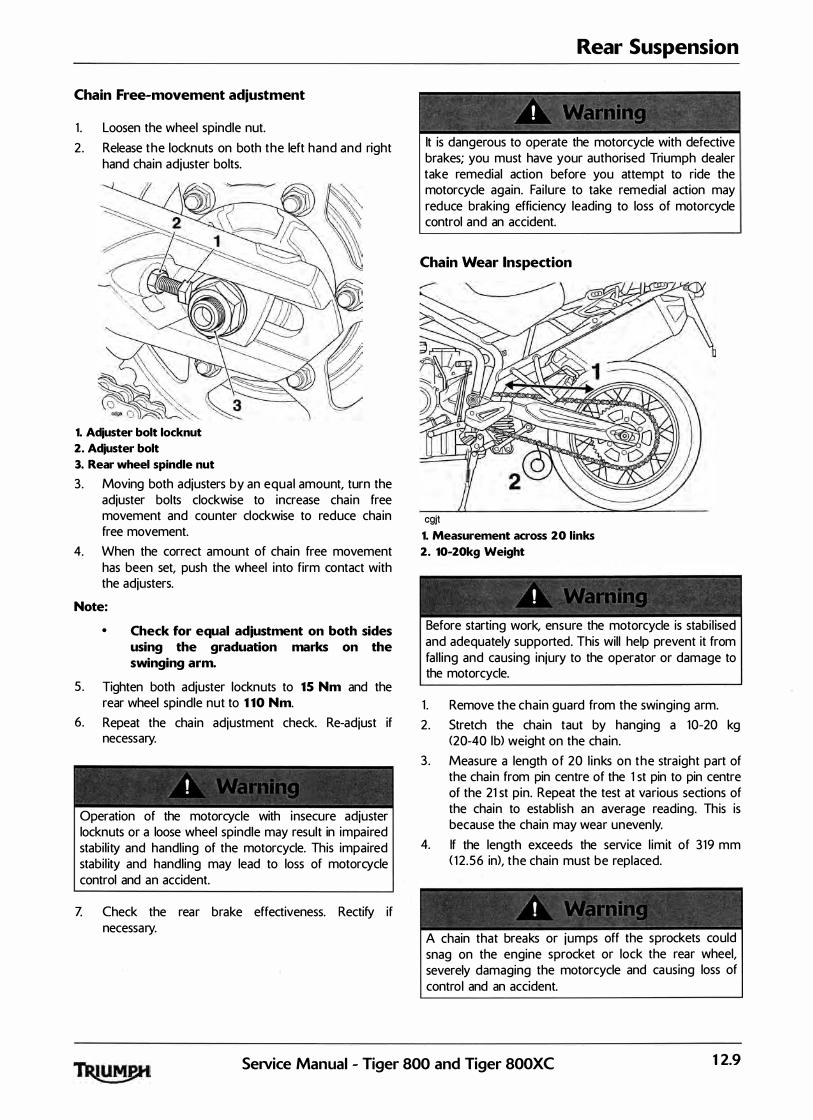
Chain Free-movement adjustment
1 . Loosen the wheel spindle nut. 2 . Release the locknuts on both the left hand and right
hand chain adjuster bolts.
� 1. Adjuster bolt locknut
2. Adjuster bolt
3. Rear wheel spindle nut
3. Moving both adjusters by an equal amount, turn the adjuster bolts clockwise to increase chain free movement and counter clockwise to reduce cha in free movement.
4. When the correct amount of chain free movement has been set, push the wheel into firm contact with the adjusters.
Note:
5.
6.
• Check for equal adiustment on both sides using the graduation marks on the swinging arm.
Tighten both adjuster locknuts to 15 Nm and the rear wheel spindle nut to 110 Nm.
Repeat the cha in adjustment check. Re-adjust if necessary.
Operation of the motorcycle with insecure adjuster locknuts or a loose wheel spindle may result in impaired stabil ity and handling of the motorcycle. This impaired stabil ity and handling may lead to loss of motorcycle control and an accident.
Z Check the rear brake effectiveness. Rectify if necessary.
Rear Suspension
�
I \, : 1 1, • > ;; 1i • "
" �
lt is dangerous to operate the motorcycle with defective brakes; you must have your authorised Triumph dealer take remedial action before you attempt to ride the motorcycle again. Fai lure to take remedial action may reduce braking efficiency leading to loss of motorcycle control and an accident.
Chain Wear Inspection
cgjt 1. Measurement across 20 links
2. 10-20kg Weight
Before starting work, ensure the motorcycle is stabi l ised and adequately supported. This will help prevent it from fal l ing and causing injury to the operator or damage to the motorcycle.
1 . Remove the chain guard from the swinging arm. 2. Stretch the chain taut by hanging a 10-20 kg
<20-40 lb) weight on the chain. 3 . Measure a length of 20 l inks on the stra ight part of
the chain from pin centre of the 1 st pin to pin centre of the 21 st pin. Repeat the test at various sections of the chain to establ ish an average reading. This is because the chain may wear unevenly.
4. If the length exceeds the service l imit of 319 mm ( 1 2.56 in), the chain must be replaced.
A chain that breaks or jumps off the sprockets could snag on the engine sprocket or lock the rear wheel, severely damaging the motorcycle and causing loss of control and an accident.
SeiVice Manual - Tiger 800 and Tiger 800XC 12.9

Rear Suspension
5. Examine the whole length of the chain. I f there are any excessively tight or loose sections, loose pins or damaged rol lers, the chain should be replaced.
6. Inspect sprockets for unevenly or excessively worn teeth. Also examine the sprockets for damaged teeth.
WORN TOOTH WORN TOOTH (ENGINE SPROCKET) (REAR SPROCKET)
l. J a
Note:
• Sprocket wear is exaggerated for illustration purposes.
The use of non-approved chains may result in a broken chain or may cause the chain to jump off the sprockets. Use a genuine Triumph suppl ied chain as specified in the Triumph Parts Catalogue. Never neglect cha in maintenance and always have cha ins insta l led by an authorised Triumph dealer.
Z If there is any irregularity found in any of the components, replace the drive chain and/or any other damaged components.
8. Refit the chain guard, tighten ing the fixings to 9 Nm.
Rear Suspension Unit
Removal
� - - � -- "' � ' �� -�--
I � �
• t, r; I ; I � .
If the engine has recently been running, the exhaust system wil l be hot. Before working on or near the exhaust system, al low suffic ient time for the exhaust system to cool as touching any part of a hot exhaust system could cause burn in juries.
/ ! . .
Before starting work, ensure the motorcycle is stabi l ised and adequately supported. This will help prevent it from fal l ing and causing injury to the operator or damage to the motorcycle.
1 . Raise and support the rear of the motorcycle under the frame or engine. Position a block to support the rear wheel.
2. Remove the seats <see page 16-13). 3 . Disconnect the battery, negative <black> lead first. 4. Tiger 800XC models only: Remove the fuel tank
infi l l panel (see page 16.:. 18). 5 . Loosen the two clips and detach the rear suspension
unit remote reservoir from the frame.
80� I 1. Remote reseiVoir
2. Clips
6. All models: Remove the drag l ink to rear suspension unit fixing. Discard the nut.
Z Remove the drop l ink to swinging arm fixing. Discard the nut.
12. 10 Service Manual - Tiger 800 and Tiger 800XC
\
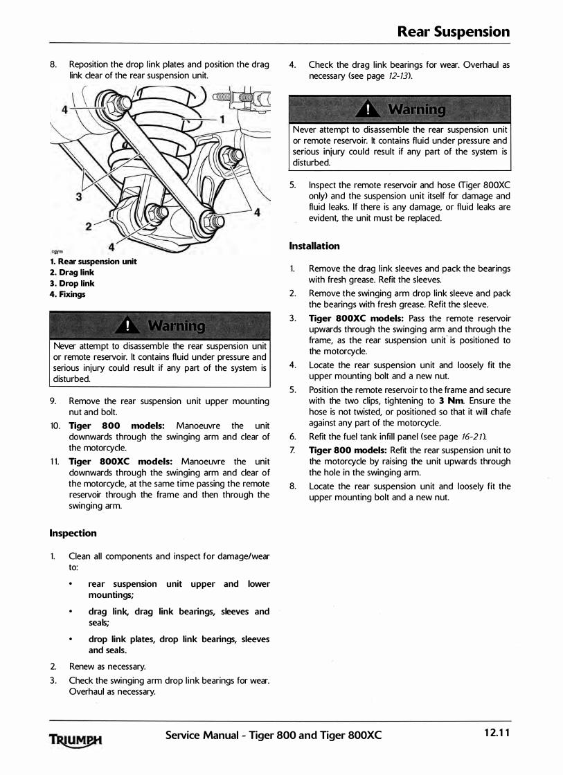
8. Reposition the drop l ink plates and position the drag link clear of the rear suspension unit.
1. Rear suspension unit
2. Drag link
3. Drop link
4. Fixings
! ' Never attempt to d isassemble the rear suspension unit or remote reservoir. lt contains fluid under pressure and serious injury could result if any part of the system is disturbed.
9. Remove the rear suspension unit upper mounting nut and bolt.
10. Tiger 800 models: Manoeuvre the unit downwards through the swinging arm and clear of the motorcycle.
1 1 . Tiger 800XC models: Manoeuvre the unit downwards through the swinging arm and clear of the motorcycle, at the same time passing the remote reservoir through the frame and then through the swinging arm.
Inspection
1 . Clean al l components and inspect for damage/wear to:
• rear suspension unit upper and lower mountings;
• drag link, drag l ink bearings, sleeves and
seals;
• drop link plates, drop link bearings, sleeves and seals.
2. Renew as necessary. 3 . Check the swinging arm drop l ink bearings for wear.
Overhaul as necessary.
Rear Suspension
4. Check the drag l ink bearings for wear. Overhaul as necessary (see page 12-13>.
Never attempt to disassemble the rear suspension unit or remote reservoir. lt conta ins fluid under pressure and serious injury could result if any part of the system is d isturbed.
5. Inspect the remote reservoir and hose <Tiger 800XC only) and the suspension unit itself for damage and fluid leaks. If there is any damage, or fluid leaks are evident, the unit must be replaced.
Installation
1 . Remove the drag l ink sleeves and pack the bearings with fresh grease. Refit the sleeves.
2 . Remove the swinging arm drop l ink sleeve and pack the bearings with fresh grease. Refit the sleeve.
3 . Tiger 800XC models: Pass the remote reservoir upwards through the swinging arm and through the frame, as the rear suspension un it' is positioned to the motorcycle.
4. Locate the rear suspension unit and loosely fit the upper mounting bolt and a new nut.
5 . Position the remote reservoir to the frame and secure with the two clips, tighten ing to 3 Nm. Ensure the hose is not twisted, or positioned so that it will chafe aga inst any part of the motorcycle.
6. Refit the fuel tank infi l l panel (see page 16-2n. Z Tiger 800 models: Refit the rear suspension unit to
the motorcycle by raising the unit upwards through the hole in the swinging arm.
8. Locate the rear suspension unit and loosely fit the upper mounting bolt and a new nut.
SeNice Manual - Tiger 800 and Tiger 800XC 12.11

Rear Suspension
9. All models: Locate the drag l ink to the rear suspension unit and, from the left hand side, loosely fit the bolt and a new nut.
10. Reposition the drop l ink plates and, from the left hand side, loosely fit the bolt and a new nut.
4. Fixings
1 1 . Tighten the drop l ink fixing to 80 Nm.
12 . Tighten the drag l ink to rear suspension unit fixing to 80Nm.
13 . With the weight of the motorcycle on its wheels, tighten the rear suspension unit upper mounting to 48Nm.
14. Connect the battery, red <positive> lead first. 15 . Fit the seats <see page 16-13>.
Drag Link and Drop Links
Removal
I f the engine has recently been running, the exhaust system wil l be hot. Before
. working on or near the
exhaust system, a l low sufficient time for the exhaust system to cool as touching any part of a hot exhaust system could cause burn in juries.
! '. t • '
Before starting work, ensure the motorcycle is stabi l ised and adequately supported. This will help prevent it from fal l ing and causing in jury to the operator or damage to the motorcycle.
1. Raise and support the rear of the motorcycle beneath the frame or engine. Position a block to support the rear wheel.
2. Remove the seats <see page 16-13>. 3. Disconnect the battery, negative (black> lead first. 4. Remove the fixings securing the drop l inks to the
swinging arm and drag l ink, and remove the drop l ink plates.
5. Remove the two fixings securing the drag l ink to the frame and rear suspension unit.
6. Remove the drag l ink.
cgym
1. Drag link
2. Drop links
3. Fixings
12. 12 SeiVice Manual - Tiger 800 and Tiger 800XC

Inspection
1 . Clean al l components and inspect the drag l ink and bearings for damage/wear.
2 . Check the rear suspension unit lower bearings for wear.
3 . Check the drop l ink bearings for wear. 4. Renew as necessary.
Installation
1 . Remove the drag l ink sleeves and pack the bearings with fresh grease. Refit the sleeves.
2 . Remove the swinging arm drop l ink sleeve and pack the bearings with fresh grease. Refit the sleeve.
3 . Refit the drag l ink to the frame and rear suspension unit, instal l ing the bolts from the left hand side.
4. Fit new nuts, tightening to 80 Nm.
5. Refit the drop l ink plates, instal l ing the bolts from the left hand side.
6. Fit new nuts, tightening to 80 Nm.
Z Connect the battery, red (positive) lead first. 8. Fit the seats <see page 16-13).
Rear Suspension
Swinging Arm
Removal
I f the engine has recently been running, the exhaust system wil l be hot. Before working on or near the exhaust system, al low sufficient time for the exhaust system to cool as touching any part of a hot exhaust system could cause burn injuries.
Before starting work, ensure the motorcycle is stabi l ised and adequately supported. This will help prevent it from fal l ing and causing injury to the operator or damage to the motorcycle.
1 . Remove the seats (see page 16-13). 2. Disconnect the battery, negative (bl�ck> lead first. 3 . Remove the exhaust si lencer <see page 10-118>. 4 . Remove the rear wheel <see page 15-12). 5 . Support the swinging arm and remove the drop l ink
to swinging arm nut and bolt. Discard the nut.
cgym
1. Drop links
2. Fixing
6. Remove the sprocket cover. Z Detach the cha in from the output sprocket.
SeNice Manual - Tiger 800 and Tiger 800XC 12.13

Rear Suspension
' � �� - - -� - '�
I ! ' ! ," I ; • I ,, 'I ! Do not al low the ca liper to hang on the brake hose as this may damage the hose and could lead to an accident.
8. Release the brake hose clips from the swinging arm and tie the rear brake ca l iper to one side.
cgyl
1. Rear brake hose clips
2. Fixings
9. Remove the swinging arm spindle nut. Discard the nut.
10. Withdraw the swinging arm spindle from the right hand side and remove the swinging arm, unhooking it from the drive chain as you do so.
• Support the drive chain while the swinging arm is being removed to protect it from contamination.
Disassembly
1 . Remove the dust covers from both sides. 2. Remove the bearing sleeves from both sides. 3 . Remove the four seals
4. Remove the bearings by drifting through from the outside.
1. Dust cover
2. Bearing sleeve
3. Seal
4. Needle roller bearing
5. Remove the drive chain rubbing strip.
Inspection
1 . Check a l l swinging ann bearings for damage, pitting, and cracks. Replace as necessary.
2 . Check the swinging arm for damage. Replace as necessary.
3 . Check the rear wheel bearings for damage, pitting, and cracks. Replace as necessary.
4. Check a l l bearing sea ls for damage, spl its etc. Replace as necessary.
5 . Check the drive chain for wear, damage etc. Replace as necessary.
6. Check both sprockets for wear, damage etc. Replace as necessary.
Z Check the drive cha in rubbing strip for wear and damage. Replace as necessary.
12.14 SeiVice Manual - Tiger 800 and Tiger 800XC

Assembly
1 . Instal l the bearings <marked faces outwards), sleeves etc. into the swinging arm in the order shown on the previous page. Use new seals and dust covers throughout.
2 . Fit the drive cha in rubbing strip and tighten the fixing to 9 Nm.
3 . Fit the drive chain to the output sprocket. 4. Position the swinging arm to the frame ensuring the
drive chain is in position on the rubbing strip. 5. Refit the swinging arm spindle from the right hand
side. 6. Fit a new swinging arm spindle nut and tighten to
110 Nm.
Z Refit the sprocket cover and tighten the bolts to 9 Nm.
8. Release the caliper and refit the rear brake hose cl ips to the swinging arm. Tighten the fixings to 6 Nm.
cgyl
1. Rear brake hose clips
2. Fixings
9. Refit the rear wheel <see page 15-12). 10. Refit the exhaust si lencer (see page 10-95>. 1 1. Connect the battery, red (positive) lead first. 12 . Fit the seats <see page 16-13). 1 3 . Pump the rear brake pedal severa l times to position
the brake pads in the cal iper. Rectify as necessary if correct brake operation is not restored (see page 14-23).
lt is dangerous to operate the motorcycle with defective brakes; you must have your authorised Triumph dealer take remedial action before you ride the motorcycle again. Fai lure to take remedial action may result in reduced braking efficiency leading to loss of motorcycle control and an accident.
Rear Suspension
Drive Chain Replacement
Rivet link type
The fo l lowing instr uctions for the replace ment of r ivet l ink type dr ive cha ins req uires the use of service too l T3880027.
Before starting work, ensure the motorcycle is stabi l ised and adequately supported. This wi l l help prevent it from fal l ing and causing injury to the operator or damage to the motorcycle.
1. S u pport the motorcyc le on a sta nd so the rear whee l is c lear of the gro und.
1 . Support the motorcycle on a stand so the rear wheel is clear of the ground.
2 . Insert the hollow chain cutting tail piece into the tool body so its larger diameter end is facing towards the large pressure screw as shown.
2
1
cdqk
1. TooiT3880027
2. Large pressure screw
3. Chain cutting tail piece
SeNice Manual - Tiger 800 and Tiger 800XC 12. 15
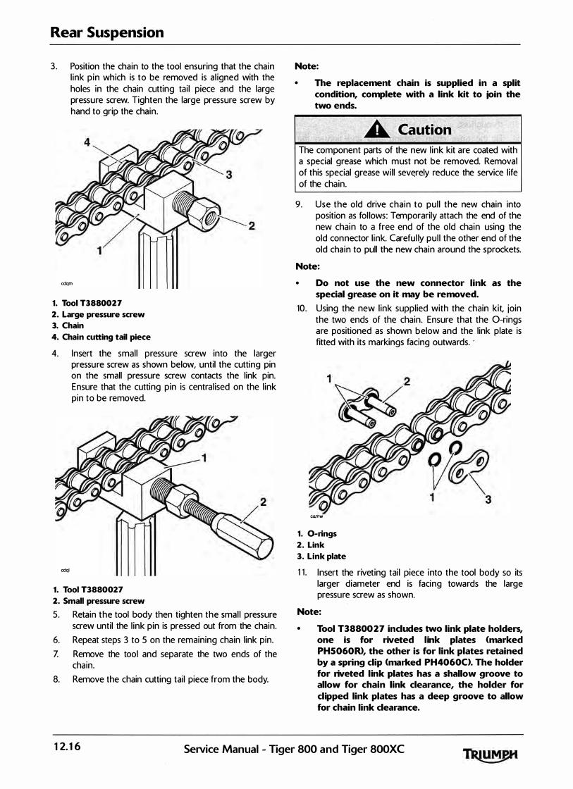
Rear Suspension
3 . Position the chain to the tool ensuring that the chain l ink p in which is to be removed is a l igned with the holes in the chain cutting tai l piece and the large pressure screw. Tighten the large pressure screw by hand to grip the chain.
cdqm
1. Tool T3880027
2. Large pressure screw
3. Chain
4. Chain cutting tail piece
4. Insert the smal l pressure screw into the larger pressure screw as shown below, until the cutting pin on the small pressure screw contacts the link pin. Ensure that the cutting pin is centra l ised on the l ink pin to be removed.
cdql
1. Tool T3880027
2. Small pressure screw
5. Retain the tool body then tighten the smal l pressure screw until the l ink pin is pressed out from the chain.
6. Repeat steps 3 to 5 on the remaining cha in l ink pin. Z Remove the tool and separate the two ends of the
chain. 8. Remove the chain cutting tail piece from the body.
Note:
• The replacement chain is supplied in a split condition, complete with a link kit to join the two ends.
The component parts of the new l ink kit are coated with a special grease which must not be removed. Removal of this special grease wil l severely reduce the service life of the cha in.
9 . Use the old drive chain to pul l the new chain into position as fol lows: Temporarily attach the end of the new chain to a free end of the old chain using the old connector l ink. Careful ly pul l the other end of the old chain to pull the new chain around the sprockets.
Note:
• Do not use the new connector link as the special grease on it may be removed.
10. Using the new l ink suppl ied with the chain kit, join the two ends of the cha in. Ensure that the 0-rings are positioned as shown below and the link plate is fitted with its markings facing outwards. ·
camw
1. 0-rings
2. Link
3. Link plate
1 1 . Insert the riveting tail piece into the tool body so its larger diameter end is facing towards the large pressure screw as shown.
Note:
• Tool T3880027 includes two link plate holders, one is for riveted link plates (marked PH 5 06 0R>, the other is for link plates retained by a spring clip (marked PH406 0C>. The holder for riveted link plates has a shallow groove to allow for chain link clearance, the holder for clipped link plates has a deep groove to allow for chain link clearance.
12. 16 SeiVice Manual - Tiger 800 and Tiger 800XC
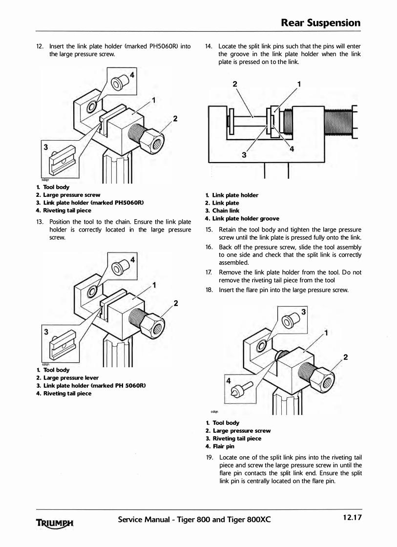
12 . Insert the l ink plate holder (marked PH5060R> into the large pressure screw.
2
1. Tool body
2. Large pressure screw
3. Link plate holder <marked PH5060R>
4. Riveting tail piece
1 3 . Position the tool to the chain. Ensure the l i nk plate holder is correctly located in the large pressure screw.
2
1. Tool body
2. Large pressure lever
3. Link plate holder <marked PH 5060R>
4. Riveting tail piece
Rear Suspension
14. Locate the split l ink pins such that the pins wi l l enter the groove in the l ink plate holder when the l ink p late is pressed on to the l ink.
2 1
3
1. Link plate holder
2. Link plate
3. Chain link
4. Link plate holder groove
15 . Retain the tool body and tighten the large pressure screw until the l ink plate is pressed fu l ly onto the l ink.
16 . Back off the pressure screw, s l ide the tool assembly to one side and check that the spl it l ink is correctly assembled.
1Z Remove the l ink plate holder from the tool. Do not remove the riveting tai l piece from the tool
18. I nsert the flare pin into the large pressure screw.
2
cdqn
1. Tool body
2. Large pressure screw
3. Riveting tail piece
4. Rair pin
19 . Locate one of the spl i t l ink pins into the riveting tai l piece ,and screw the large pressure screw in unti l the flare pin contacts the split l ink end. Ensure the split l ink pin is central ly located on the flare pin.
Setvice Manual - Tiger 800 and Tiger 800XC 12. 17

Rear Suspension
20. Reta in the tool body and tighten the large pressure screw until the split l ink end is riveted-over.
cdqn
1. Tool body
2. Large pressure screw
3. Flare pin
21. Back off the large pressure screw and rivet the remaining split l ink pin as described above.
22. Remove the tool from the chain and check that both the spl it l ink pins are correctly riveted as shown below.
1 2 3 4
cana
1 . Correct riveting 2. Insufficient riveting 3. Excessive riveting 4. Riveting off-centre
If either spl it l ink p in is not correctly riveted , the spl it l ink must be removed and replaced with a new l ink. N ever operate the motorcycl e with an incorrectly riveted spl it l ink as the l ink could fai l resu lti ng in an u nsafe r iding condition leading to loss of control and an accident.
12.18 SeNice Manual - Tiger 800 and Tiger 800XC
13 Front Suspension
Table of Contents
Exploded View - Front Fork -Tiger 800 . . . . . . . . . . . . . . . . . . . . . . . . . . . . . . . . . . . . . . . . . . . . . . . . . . . . . . 13. 2
Exploded View- Front Fork -Tiger 800 XC. . . . . . . . . . . . . . . . . . . . . . . . . . . . . . . . . . . . . . . . . . . . . . . . . . . 13.3
Exploded View - Handlebars . . . . . . . . . . . . . . . . . . . . . . . . . . . . . . . . . . . . . . . . . . . . . . . . . . . . . . . . . . . . . . . 13.4
Front Suspension. . . . . . . . . . . . . . . . . . . . . . . . . . . . . . . . . . . . . . . . . . . . . . . . . . . . . . . . . . . . . . . . . . . . . . . . . 13.5
Fork Inspection. . . . . . . . . . . . . . . . . . . . . . . . . . . . . . . . . . . . . . . . . . . . . . . . . . . . . . . . . . . . . . . . . . . . . 13.5
Front Fork. . . . . . . . . . . . . . . . . . . . . . . . . . . . . . . . . . . . . . . . . . . . . . . . . . . . . . . . . . . . . . . . . . . . . . . . . . . . . . . 13.5
Removal . . . . . . . . . . . . . . . . . . . . . . . . . . . . . . . . . . . . . . . . . . . . . . . . . . . . . . . . . . . . . . . . . . . . . . . . . . 13.5
Installation . . . . . . . . . . . . . . . . . . . . . . . . . . . . . . . . . . . . . . . . . . . . . . : . . . . . . . . . . . . . . . . . : . . . . . . . . 13.6
Fork Oil Change . . . . . . . . . . . . . . . . . . . . . . . . . . . . . . . . . . . . . . . . . . . . . . . . . . . . . . . . . . . . . . . . . . . . . . . . . 13.7
Draining . . . . . . . . . . . . . . . . . . . . . . . . . . . . . . . . . . . . . . . . . . . . . . . . . . . . . . . . . . . . . . . . . . . . . . . . . . 13.7
Oil Refilling . . . . . . . . . . . . . . . . . . . . . . . . . . . . . . . . . . . . . . . . . . . . . . . . . . . . . . . . . . . . . . . . . . . . . . . . 13.7
Fork Oil Level Chart. . . . . . . . . . . . . . . . . . . . . . . . . . . . . . . . . . . . . . . . . . . . . . . . . . . . . . . . . . . . . . . . . 13.8
Front Fork. . . . . . . . . . . . . . . . . . . . . . . . . . . . . . . . . . . . . . . . . . . . . . . . . . . . . . . . . . . . . . . . . . . . . . . . . . . . . . . 13.9
Disassembly . . . . . . . . . . . . . . . . . . . . . . . . . . . . . . . . . . . . . . . . . . . . . . . . . . . . . . . . . . . . . . . . . . . . . . . 13.9
Inspection . . . . . . . . . . . . . . . . . . . . . . . . . . . . . . . . . . . . . . . . . . . . . . . . . . . . . . . . . . . . . . . . . . . . . . . . . 13.12
Assembly. . . . . . . . . . . . . . . . . . . . . . . . . . . . . . . . . . . . . . . . . . . . . . . . . . . . . . . . . . . . . . . . . . . . . . . . . . 13.12
Headstock Bearing Check/Adjustment. . . . . . . . . . . . . . . . . . . . . . . . . . . . . . . . . . . . . . . . . . . . . . . . . . . . . . 13.15
Check . . . . . . . . . . . . . . . . . . . . . . . . . . . . . . . . . . . . . . . . . . . . . . . . . . . . . . . . . . . . . . . . . . . . . . . . . . . . 13.15
Adjustment . . . . . . . . . . . . . . . . . . . . . . . . . . . . . . . . . . . . . . . . . . . . . . . . . . . . . . . . . . . . . . . . . . . . . . . . 13.15
Headstock Bearing Removal . . . . . . . . . . . . . . . . . . . . . . . . . . . . . . . . . . . . . . . . . . . . . . . . . . . . . . . . . . . . . . 13.17
Inspection . . . . . . . . . . . . . . . . . . . . . . . . . . . . . . . . . . . . . . . . . . . . . . . . . . . . . . . . . . . . . . . . . . . . . . . . . 13.18
Installation. . . . . . . . . . . . . . . . . . . . . . . . . . . . . . . . . . . . . . . . . . . . . . . . . . . . . . . . . . . . . . . . . . . . . . . . . 13.18
Handlebars . . . . . . . . . . . . . . . . . . . . . . . . . . . . . . . . . . . . . . . . . . . . . . . . . . . . . . . . . . . . . . . . . . . . . . . . . . . . . 13.19
Removal . . . . . . . . . . . . . . . . . . . . . . . . . . . . . . . . . . . . . . . . . . . . . . . . . . . . . . . . . . . . . . . . . . . . . . . . . . 13.19
Installation. . . . . . . . . . . . . . . . . . . . . . . . . . . . . . . . . . . . . . . . . . . . . . . . . . . . . . . . . . . . . . . . . . . . . . . . . 13.21
SeiVice Manual - Tiger 800 and Tiger 800XC 13.1
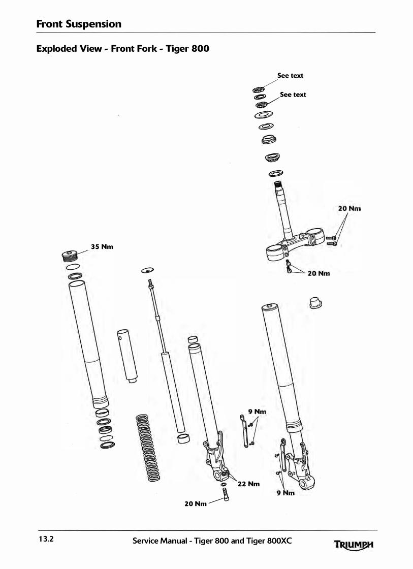
Front Suspension
Exploded View - Front Fork - Tiger 800
35 Nm
0
2 0Nm �
See text : See text
� t;§;J
�
@
22 Nm
e �
13.2 SeiVice Manual - Tiger 800 and Tiger 800XC
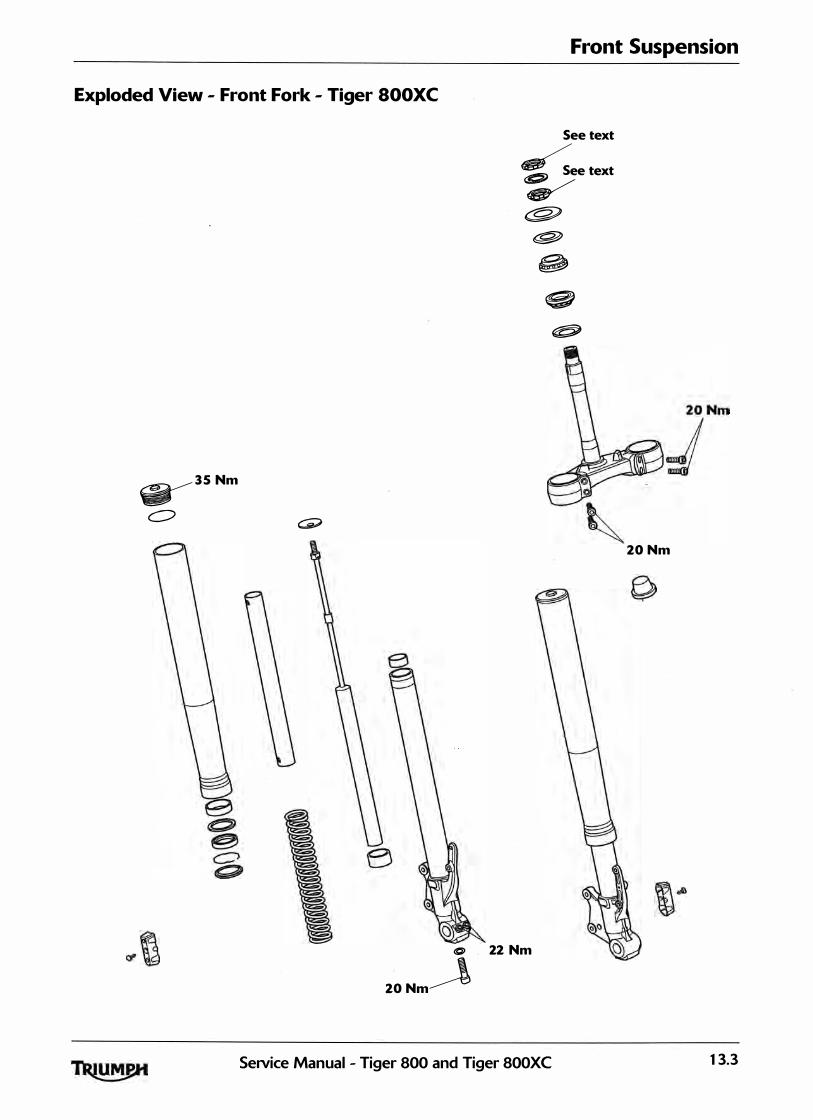
Front Suspension
Exploded View - Front Fork - Tiger SOOXC
�35 Nm
�
See text :See text
� c:f?J
�
c , 22 Nm
2 0Nm�
� e; �
SeiVice Manual - Tiger 800 and Tiger 800XC
2 0Nm
13.3
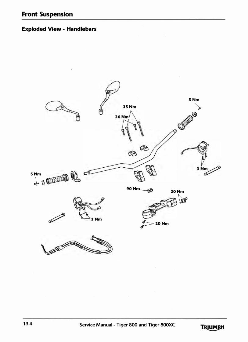
Front Suspension
Exploded View - Handlebars
5 Nm
.L �
35 Nm
5 Nm
� � A ov
9 0Nm� 2 0Nm
�
� 2 0Nm
13.4 Service Manual - Tiger 800 and Tiger 800XC

Front Suspension
The Tiger 800 and Tiger 800XC models are equipped with hydraul ic, telescopic front forks. The front suspension has no adjustments.
Periodic inspection for damage and fluid leaks is essential for safe riding. Always fol low the inspection instructions at the intervals stated in the scheduled maintenance chart.
Fork Inspection
Examine each fork for any sign of damage or scratch ing of the sl ider surface or for oil leaks.
If any damage or oi l leakage is found, strip and repair as described in this section or consult an authorised Triumph dealer.
Check for smooth operation of the forks as fol lows:
• Place the motorcycle on level ground.
• While holding the handlebars and applying the front brake, pump the forks up and down
several times.
If roughness or excessive stiffness is detected, repair as described in this section or consult an authorised Triumph dealer.
Riding the motorcycle with defective or damaged suspension can cause loss of motorcycle control and an accident. Never ride with damaged or defective suspension.
Front Suspension
Front Fork
Removal
Before starting work, ensure the motorcycle is stabi l ised and adequately supported. This wi l l help prevent it from fal l ing and causing in jury to the operator or damage to the motorcycle.
1 . Raise and support the front of the motorcycle. 2: Remove the front wheel <see page 15- 10>. 3 . Remove the front mudguard (see page 16- 19 Tiger
800 for and 16-20 for Tiger 800XO. 4. Detach and support the front brake ca l ipers (see
page 14- 16>.
Never a l low the brake cal ipers to hang on the brake hoses as this may damage the hoses. A damaged brake hose can cause a reduction in braking efficiency leading to loss of motorcycle control and an accident.
Note:
• If the forks are to be dismantled, slacken the fork top cap, and if the damper cylinder is to be removed, slacken the lower damper cylinder bolt.
5. Release the fixing and detach the brake hose from the cl ip on the fork leg.
1. Brake hose
2. Brake hose clip
3. Fixing
SeiVice Manual - Tiger 800 and Tiger 800XC 13.5

Front Suspension
6. Slacken the top yoke clamp bolts.
Care must be taken when removing the forks, to ensure that the outer surfaces do not become scratched.
Z Slacken the bottom yoke clamp bolts.
� 1. Bottom yoke clamp bolts
8. Using a downward, twisting action, withdraw the forks from between the yokes.
Installation
1. Position the forks with in the yokes so that the lip of the outer tube, not the top cap, is 4 mm above the upper surface of the top yoke.
1. Outer tube
2. Top cap
3. Top yoke
2. Tighten the bottom yoke clam p bolts to· 20 Nm.
3 . Tighten the top yoke clamp bolts to 20 Nm.
Note:
• If the forks have been dismantled, tighten the fork top caps to 3 5 Nm, and if removed, the lower damper cylinder bolt to 2 0 Nm.
4. Refit the front mudguard <see page 16-21 Tiger 800 for and 16-21 for Tiger 800XO.
13.6 SeiVice Manual - Tiger 800 and Tiger 800XC
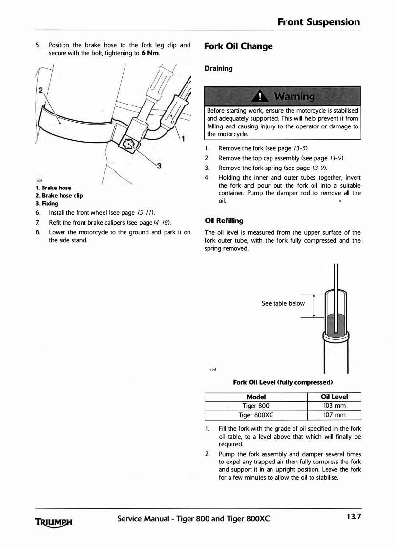
5 . Position the brake hose to the fork leg cl ip and secure with the bolt, tightening to 6 Nm.
1. Brake hose
2. Brake hose clip
3. Fixing
6. Instal l the front wheel (see page 15- 1 n.
Z Refit the front brake cal ipers (see page 14- 18>. 8. Lower the motorcycle to the ground and park it on
the side stand.
Front Suspension
Fork Oil Change
Draining
Before starting work, ensure the motorcycle is stabi l ised and adequately supported. This will help prevent it from fal l ing and causing injury to the operator or damage to the motorcycle.
1 . Remove the fork <see page 13-S>. 2: Remove the top cap assembly (see page 13-9). 3. Remove the fork spring (see page 13-9). 4. Holding the inner and outer tubes together, invert
the fork and pour out the fork oi l into a suitable conta iner. Pump the damper rod to remove all the oil. •
Oil Refilling
The oi l level is measured from the upper surface of the fork outer tube, with the fork ful ly compressed and the spring removed.
See table below
cbyf
Fork Oil Level (fully compressed)
Model Oil Level
Tiger 800 103 mm Tiger 800XC 107 mm
1. Fi l l the fork with the grade of oil specified in the fork oil table, to a level above that which wil l final ly be required.
2. Pump the fork assembly and damper severa l times to expel any trapped air then fu lly compress the fork and support it in an upright position. Leave the fork for a few minutes to al low the oil to stabi l ise.
SeiVice Manual - Tiger 800 and Tiger 800XC 13.7

Front Suspension
3 . Refer to the fork o i l level chart and set the scale on tool 3880160-T0301 to the relevant distance, as shown below.
Refer to fork oil level chart
cbyg
1. Tool 3880160-T0301
2. Adjustment plate
3. Scale area
4. Hole <zero position>
Note:
• Zero level on the tool is set at the small exit hole in the side of the scale tube, NOT AT THE END TIP. Do not attempt to block this side hole as this will cause the final fluid level to be incorrect.
4. Insert the scale end of the tool into the fork inner tube.
5. Hold the tool adjuster plate level with the upper surface of the fork inner tube and draw flu id into the syringe until fluid flow ceases (empty the syringe if the body becomes fu l l before fluid flow stops>.
6. The fluid level in the fork is now set to the height set on the tool sca le. Check the tool scale setting and repeat the process if incorrectly set.
Incorrect fork oil levels could result in an unsafe riding condition leading to loss of control and an accident.
Z Assemble the fork <see page 13- 12>. 8. Refit the fork <see page 13-6).
Fork Oil Level Chart
Tiger 800
Oil Oil Oil Grade Fork Pul l Level* Volume Through
103 mm 553 cc Showa SS 8 Top of the inner tube 4 mm above the upper face of the top yoke
Tiger SOO XC
Oil Oil Oil Grade Fork Pul l Level* Volume Through
107 mm 619 cc Showa SS 8 Top of the inner tube 4 mm above the upper face of the top yoke
*Fork Fully Compressed
13.8 SeiVice Manual - Tiger 800 and Tiger 800XC
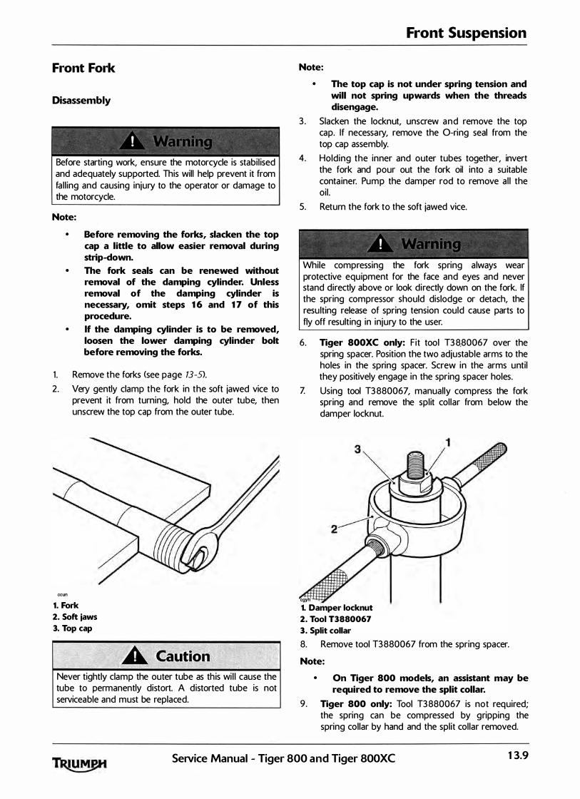
Front Fork
Disassembly
� � " » � - � � =
' \ " " ' ' ' • V t "
Before starting work, ensure the motorcycle is stabi l ised and adequately supported. This will help prevent it from fa l l ing and causing injury to the operator or damage to the motorcycle.
Note:
• Before removing the forks, slacken the top cap a little to allow easier removal during strip-down.
• The fork seals can be renewed without removal of the damping cylinder. Unless removal of the damping cylinder is necessary, omit steps 16 and 17 of this procedure.
• If the damping cylinder is to be removed, loosen the lower damping cylinder bolt before removing the forks.
1 . Remove the forks <see page 13-S>. 2. Very gently clamp the fork in the soft jawed vice to
prevent it from turning, hold the outer tube, then unscrew the top cap from the outer tube.
ccun
1. Fork
2. Soft jaws
3. Top cap
Never tightly clamp the outer tube as th is wi l l cause the tube to permanently distort. A distorted tube is not serviceable and must be replaced.
Front Suspension
Note:
• The top cap is not under spring tension and will not spring upwards when the threads disengage.
3 . Slacken the locknut, unscrew and remove the top cap. If necessary, remove the 0-ring seal from the top cap assembly.
4. Holding the inner and outer tubes together, invert the fork and pour out the fork oil into a su itable conta iner. Pump the damper rod to remove al l the oi l .
5. Return the fork to the soft jawed vice.
"
' f ' I •
"" }
While compressing the fork spring a lways wear protective equipment for the face and eyes and never stand directly above or look directly down on the fork. If the spring compressor should dislodge or detach, the resu lting release of spring tension could cause parts to fly off resulting in injury to the user.
6. Tiger 800XC only: Fit tool T3 8.80067 over the spring spacer. Position the two adjustable arms to the holes in the spring spacer. Screw in the arms until they positively engage in the spring spacer holes.
Z Using tool T3 880067, manual ly compress the fork spring and remove the spl it col lar from below the damper locknut.
cgyh
1. Damper locknut
2. Tool T3880067
3. Split collar
8. Remove tool T3880067 from the spring spacer.
Note:
• On Tiger 800 models, an assistant may be required to remove the split collar.
9. Tiger 800 only: Tool T3880067 is not required; the spring can be compressed by gripping the spring collar by hand and the split col lar removed.
Service Manual - Tiger 800 and Tiger 800XC 13.9

Front Suspension
� - �� � �
! :1 t ! "' r s I
While compressing the fork spring always wear protective equipment for the face and eyes and never stand directly above or look directly down on the fork. If the spring compressor should dislodge or detach, the resulting release of spring t.ension could cause parts to fly off resulting in injury to the user.
Note:
• On Tiger 800 models, the spring has a smaller coil diameter at both ends, and can be fitted either way up.
• On Tiger SOO XC models, the spring has a smaller coil diameter at its upper end. Note the orientation of the spring before removal.
10. Remove the spring spacer and spring.
cdno
1. Washer
2. Spring spacer <Tiger 800 shown>
3. Spring
4. Damper rod
Note:
• To help with identification of the service tools, tool T3880158 has a single groove turned on its outside circumference. Tool T3880154 does not have a groove.
1 1 . Fit both ha lves of tool T3 880158 (for Tiger 800 models> or tool T3880154 (for Tiger 800XC models> to the outer tube as shown below and hold in position.
cgrc
1. Outer tube
2. Tool T38801S8 <Tiger 800> or T38801S4 <Tiger 800XC>
12 . Invert and mount the fork assembly to tool T3880153 .
cgrd
1. Tool T38801 S 3
2 . Tool T38801S8 <Tiger 800) or T38801S4 <Tiger 800XC>
13. 10 Sesvice Manual - Tiger 800 and Tiger 800XC
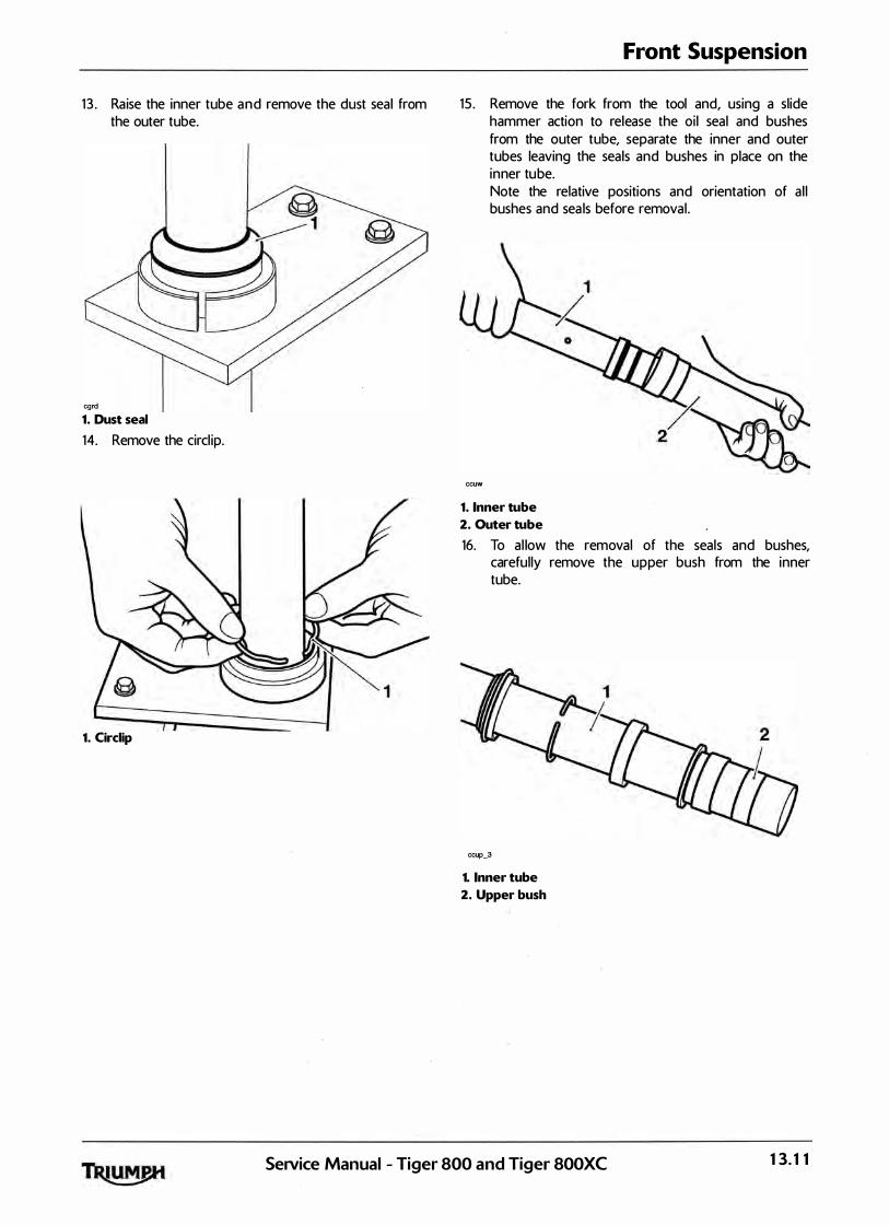
1 3 . Ra ise the inner tube and remove the dust seal from the outer tube.
cgrd
1. Dust seal
14. Remove the circl ip.
1. Circlip
Front Suspension
15 . Remove the fork from the tool and, using a slide hammer action to release the oi l seal and bushes from the outer tube, separate the inner and outer tubes leaving the seals and bushes in place on the inner tube.
ccuw
Note the relative positions and orientation of a l l bushes and sea ls before removal .
1. Inner tube
2. Outer tube
16. To al low the removal of the seals and bushes, carefully remove the upper bush from the inner tube.
ccup_3
1. Inner tube
2. Upper bush
Service Manual - Tiger 800 and Tiger 800XC 13. 1 1

Front Suspension
lZ If removal of the damping cyl inder is required, unscrew the damping cylinder bolt from the bottom of the lower fork, then sl ide the damping cyl inder out of the inner tube.
�cuy
Collect the centering col lar from the lower end of the damping cyl inder.
1. Damping cylinder
Inspection
1 . Inspect the inner tube for stone chips, scoring, scratches, excessive wear and any other damage. Renew as necessary.
Note:
• Small inclusions in the inner tube may be removed using a fine grade stone or similar.
2. Inspect the spring for damage, cracks and deformation. Renew the spring if necessary.
3 . I nspect a l l the bushes and seals for damage. Renew any damaged items if necessary.
Assembly
= � � � � • /
/ I ,,! ,·; I I ' ' I : / • d � �� w -� �
The front forks comprise many precision machined parts. Total cleanl iness must be observed at al l times and assembly must take place in a dirt/dust-free environment. Dirt ingress may cause damage to the fork parts, leading to incorrect operation, instabil ity, loss of control or an accident.
Note:
• If the damping cylinder has not been removed, omit steps 1 to 3.
1 . Fit the centering col lar to the lower end of the damping cylinder.
2 . Fit the damping cylinder to the inner tube. 3 . Clean the threads o f the damping cylinder bolt and
fit a new seal ing washer. Prevent the cyl inder from turning while tightening the damping cylinder securing bolt to 2 0 Nm.
Note:
• To help with identification of the service tools, tool T3880158 has a single groove turned on its outside circumference. Tool T3880154 does not have a groove.
4. Fit both halves of tool T3 880158 ITiger 800 models> or tool T3 880154 ITiger 800XC models> to the outer tube as shown below and hold in position.
cgrd_1
1. Outer tube
2. Tool T3880158 <Tiger 800) or T3880154 <Tiger BOOXC>
13.12 SeiVice Manual - Tiger 800 and Tiger 800XC
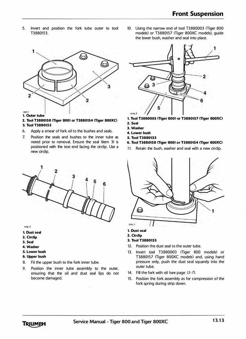
5. Invert and position the fork tube outer to tool T3880153 .
cgrd_1
1. Outer tube
2. Tool T3880158 mger 800) or T3880154 mger 800XC>
3. Tool T38801 5 3
6. Apply a smear of fork oi l to the bushes and seals. Z Position the seals and bushes to the inner tube as
noted prior to removal. Ensure the seal (item 3) is positioned with the text end facing the circl ip. Use a new circl ip.
ccup_2
1. Dust seal
2. Circlip
3. Seal
4. Washer
5. Lower bush
6. Upper bush
8. Fit the upper bush to the fork inner tube. 9. Position the inner tube assembly to the outer,
ensuring that the oil and dust seal l ips do not become damaged.
Front Suspension
10. Using the narrow end of tool T3 880003 <Tiger 800 models) or T3 880157 <Tiger 800XC models), guide the lower bush, washer and seal into place.
1. Tool T3880003 mger 800) or T3880157 mger 800XC>
2. Seal
3. Washer
4. Lower bush
5. Tool T38801 53
6. Tool T3880158 mger 800) or T3880154 mger 800XC>
1 1 . Retain the bush, washer and seal with a new circl ip.
1. Dust seal
2. Circlip
3. Tool T38801 53
12 . Position the dust seal to the outer tube. 1 3 . Invert tool T3 880003 <Tiger 800 models) or
T3880157 <Tiger 800XC models) and, using hand pressure only, push the dust seal squarely into the outer tube.
14. Fil l the fork with oi l <see page 13-7}.
15 . Position the fork assembly as for compression of the fork spring during strip down.
SeiVice Manual - Tiger 800 and Tiger SOOXC 13.13
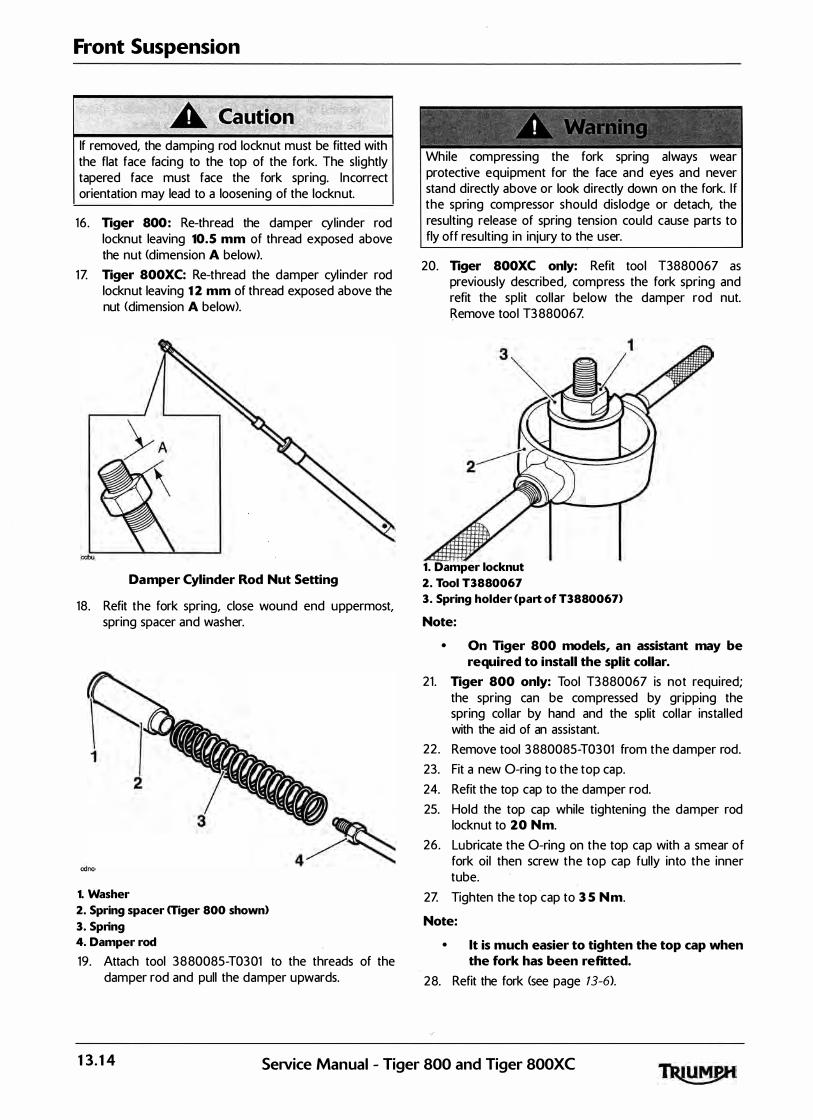
Front Suspension
If removed, the damping rod locknut must be fitted with the flat face facing to the top of the fork. The sl ightly tapered face must face the fork spring. Incorrect orientation may lead to a loosening of the locknut.
16 . Tiger 800: Re-thread the damper cylinder rod locknut leaving 10. 5 mm of thread exposed above the nut (dimension A below>.
1Z Tiger 800XC: Re-thread the damper cyl inder rod locknut leaving 12 mm of thread exposed above the nut <dimension A below).
Damper Cylinder Rod Nut Setting
18. Refit the fork spring, close wound end uppermost, spring spacer and washer.
1. Washer
2. Spring spacer mger 800 shown>
3. Spring
4. Damper rod
19. Attach tool 3880085-T0301 to the threads of the damper rod and pull the damper upwards.
While compressing the fork spring always wear protective equipment for the face and eyes and never stand directly above or look directly down on the fork. I f the spring compressor should dislodge or detach, the resulting release of spring tension could cause parts to fly off resulting in injury to the user.
20. Tiger 800XC only: Refit tool T3880067 as previously described, compress the fork spring and refit the spl it col lar below the damper rod nut. Remove tool T3 88006Z
1. Damper locknut
2. Tool T3880067
3. Spring holder <part of T3880067)
Note:
• On Tiger 800 models, an assistant may be required to install the split collar.
21 . Tiger 800 only: Tool T3880067 is not required; the spring can be compressed by gripping the spring col lar by hand and the split col lar instal led with the aid of an assistant.
22 . Remove tool 3 880085-T0301 from the damper rod. 23. Fit a new 0-ring to the top cap. 24. Refit the top cap to the damper rod. 25. Hold the top cap while tightening the damper rod
locknut to 2 0 Nm.
26. Lubricate the 0-ring on the top cap with a smear of fork oil then screw the top cap fully into the inner tube.
2Z Tighten the top cap to 35 Nm.
Note:
• lt is much easier to tighten the top cap when the fork has been refitted.
28. Refit the fork <see page 13-6).
13. 14 Service Manual - Tiger 800 and Tiger 800XC

Headstock Bearing Check/ Adiustment
Check
1 . Ra ise and support the front of the motorcycle.
Before starting work, ensure the motorcycle is stabi l ised and adequately supported. This wil l help prevent it from fa l l ing and causing injury to the operator or damage to the motorcycle.
cgjt Checking Headstock Bearing Adjustment
2. Hold the lower end of the front forks as i l lustrated and 'rock' with a front-to-rear motion. If free play can be detected, the headstock bearings require adjustment.
Front Suspension
Adjustment
Always return the handlebars and risers to their original position as noted in paragraph 1 . Operating the motorcycle with a handlebar position that is unfamil iar may lead to loss of control or an accident.
1 . Note the orig inal position of the handlebars, and orientation of the adjustable risers, in order that they can be returned to the same position when the repair operation is complete.
2: Raise and support the front of the motorcycle. 3 . Release the fixings securing the handlebar clamps to
the risers, detach the clamps and release the handlebar.
4. As an assembly, raise the handle bars unti l clear of the top yoke. Rest the assembly forward of the steering stem such that access to the headstock top nut and the adjustment nuts is unrestricted. Ensure the master cyl inder remains in an upright position.
5 . Slacken the top yoke clamp bolts. .
If the lower yoke fixings are also slackened, the forks wil l no longer support the weight of the motorcycle. Do not slacken the lower yoke fixings as, in this condition, the motorcycle could topple over causing damage and/or risk of injury.
Care must be taken when removing the headstock top nut, to ensure that the top nut and top yoke do not become scratched. Protect the surfaces with a su itable cloth or tape to prevent scratch ing.
6. Slacken the headstock top nut.
SeiVice Manual - Tiger 800 and Tiger 800XC 13.15

Front Suspension
cgjo 1. Headstock top nut
Z Ease the top yoke from the forks and support while detached.
8. Adjust the bearing free-play as fol lows, all using tool T3 88002 3 :
Remove the locknut and tab washer.
Slacken the adjuster nut then tighten to 40Nm.
• Slacken the adjuster nut, then re-tighten to 15 Nm.
• Fit the tab washer and lock nut
- -' " ! �1 4 � t �� i ; � l
� - -lt is essential that the adjuster nut is not over-tightened. If the adjuster is over-tightened it wil l cause a pre-load on the headstock bearings. This will introduce tight steering, which could cause loss of control and an accident.
• Hold the adjuster nut in position while tightening the locknut to 40 Nm.
cdbp
Tool T3880023
1. Adjuster nut
2. Locknut
13.16 Service Manual - Tiger 800 and Tiger 800XC

9. Refit the top yoke assembly to the forks. 10. Tighten the top nut to 90 Nm.
1 1 . Tighten the top yoke clamp bolts to 2 0 Nm.
12 . Locate the handlebar assembly in the lower halves of the clamps. Fit the upper clamps and 10 mm bolts.
13 . Rotate the handlebar so that the etched centre <longer) marking on the handlebar al igns with the split l ine on the upper damps/risers.
14. Tighten the 10 mm bolts to 35 Nm.
1. Upper clamp
2. Clamp split line
3. Centre marking
15 . Refit the 8 mm bolts to the and tighten to 26 Nm.
16 . Recheck the bearing adjustment <see page 13- 15).
Front Suspension
Headstock Bearing Removal
Before starting work, ensure the motorcycle is stabi l ised and adequately supported. Th is will help to prevent it fa l l ing and causing injury to the operator or damage to the motorcycle.
1 . Remove both forks <see page 13-S>.
Care must be taken when removing the headstock top nut, to ensure that the top nut and headstock do not become scratched. Protect the surfaces with a suitable cloth or tape to prevent scratching.
2 . Remove the headstock top nut.
1. Headstock top nut
3 . As an assembly, raise the top yoke and handle bars until clear of the steering stem. Rest the assembly forward of the steering stem such that access to the adjustment nuts is unrestricted. Ensure the master cyl inder remains in an upright position.
SeNice Manual - Tiger 800 and Tiger 800XC 13.17

Front Suspension
4. Using tool T3880023, remove the locknut and tab washer. Discard the tab washer.
cdbp
Tool T3880023
5. Using the same tool, remove the adjuster nut. 6. Remove the bearing cover and dust seal . Z Remove the bottom yoke from below the frame
headstock.
Always wear eye, hand and face protection when using a hammer and drift. Use of a hammer and drift can cause bearings to fragment. Pieces of fragmented bearing could cause eye and soft tissue in juries if suitable protective apparel is not worn.
8. Using a suitable drift, evenly and progressively drive the bearing races from the frame headstock.
9. Remove the inner race and dust sea l from the bottom yoke using a press or pul ler. ·
Inspection
- - � � �
c ! r • 1 : · r � . . .
Only remove raised witness marks from with in the frame. Removal of material below any raised areas wi l l reduce the level of interference between the frame and the bearings. Loss of interference could cause the bearing to become loose in the frame lead ing to loss of motorcycle control and an accident.
1 . Examine the frame for any ra ised witness marks caused by the removal process. Remove any such marks with fine emery paper or a gentle file.
13.18 SeiVice Manual - Tiger 800 and Tiger 800XC

Installation
1 . Fit a new dust seal to the steering stem on the bottom yoke.
cdgo1
1. Steering stem
2. Dust shield
Protect the threads of the bottom yoke when using a press or pul ler as damaged threads may mean replacing the yoke completely.
2 . Press a new lower bearing inner race onto the steering stem of the bottom yoke.
1. Bearing
2. Bottom yoke
3. Press bed
3 . Evenly and progressively drive a new complete upper bearing into the frame headstock.
4. Lubricate the lower bearing using mu lti-purpose grease.
5 . Drive a new lower outer bearing into the frame headstock.
Front Suspension
6. Lubricate the upper bearing using multi-purpose grease.
Z Insert the lower yoke to the frame, fit the upper bearing and race.
8. Fit a new upper dust seal and bearing cover, and retain with the adjuster nut.
9 . Adjust the headstock bearings <see page 13- 15>.
10. Locate the upper yoke to the steering stem. Insta l l but do not fu l ly tighten the headstock top nut at this stage.
1 1 . Fit the forks (see page 13- 6).
12 . Tighten the headstock top nut to 90 Nm.
13 . Check that no freeplay exists in the headstock bearings. Adjust as necessary (see page 13- 15>.
Service Manual - Tiger 800 and Tiger 800XC 13. 19
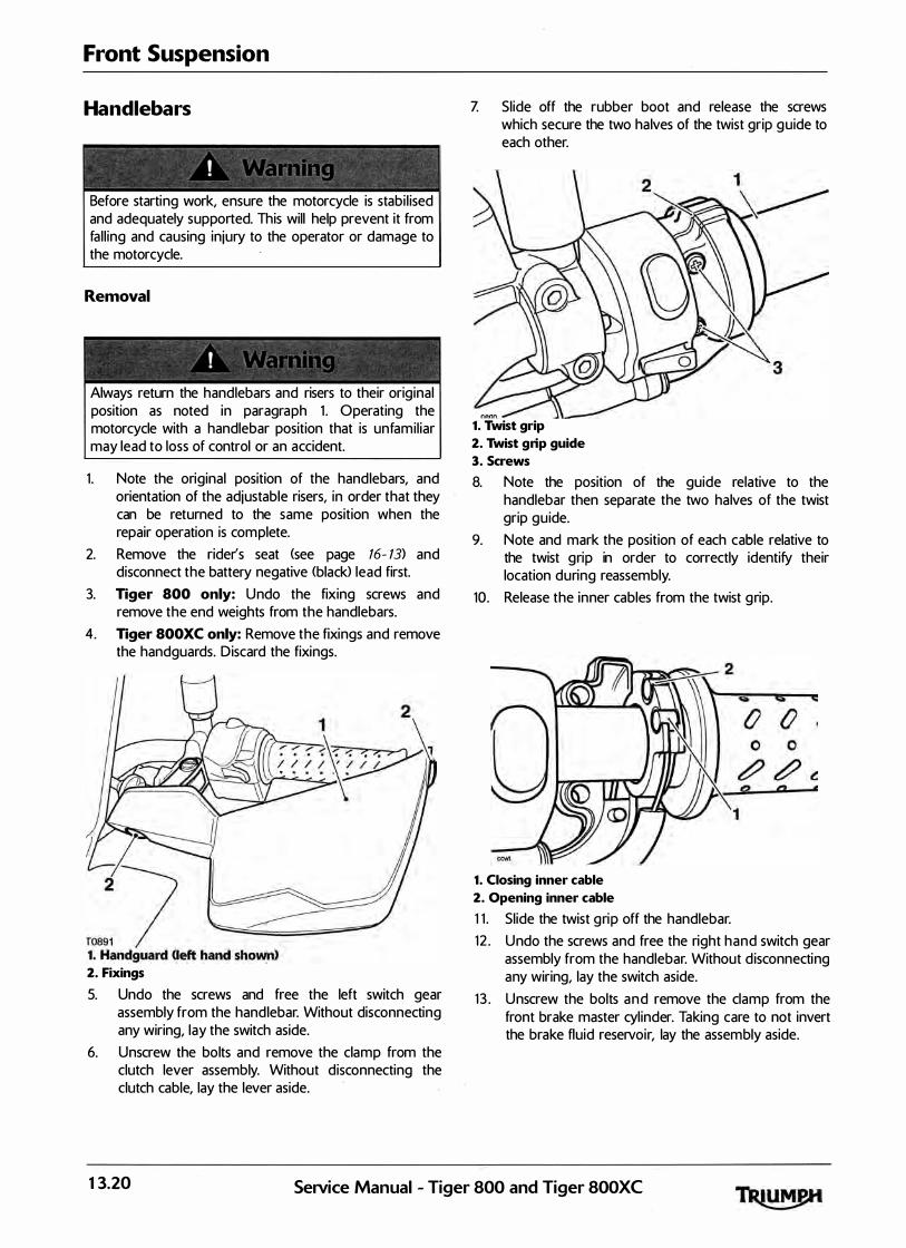
Front Suspension
Handlebars
Before starting work, ensure the motorcycle is stabi l ised and adequately supported. This will help prevent it from fal l ing and causing injury to the operator or damage to the motorcycle.
Removal
Always return the handlebars and risers to their original position as noted in paragraph 1 . Operating the motorcycle with a handlebar position that is unfamil iar may lead to loss of control or an accident.
1 . Note the original position of the handlebars, and orientation of the adjustable risers, in order that they can be returned to the same position when the repair operation is complete.
2. Remove the rider's seat (see page 16- 13) and disconnect the battery negative (black> lead first.
3. Tiger 800 only: Undo the fixing screws and remove the end weights from the handlebars.
4. Tiger SOO XC only: Remove the fixings and remove the handguards. Discard the fixings.
2. Fixings
5. Undo the screws and free the left switch gear assembly from the handlebar. Without disconnecting any wiring, lay the switch aside.
6. Unscrew the bolts and remove the clamp from the clutch lever assembly. Without disconnecting the clutch cable, lay the lever aside.
Z Slide off the rubber boot and release the screws which secure the two halves of the twist grip guide to each other.
r.Ann
1. Twist grip
2. Twist grip guide
3. Screws
8. Note the position of the guide relative to the handlebar then separate the two halves of the twist grip guide.
9. Note and mark the position of each cable relative to the twist grip in order to correctly identify their location during reassembly.
10. Release the inner cables from the twist grip.
1. Closing inner cable
2. Opening inner cable
1 1 . Slide the twist grip off the handlebar. 12 . Undo the screws and free the right hand switch gear
assembly from the handlebar. Without d isconnecting any wiring, lay the switch aside.
1 3 . Unscrew the bolts and remove the clamp from the front brake master cyl inder. Taking care to not invert the brake fluid reservoir, lay the assembly aside.
13.20 SeiVice Manual - Tiger 800 and Tiger 800XC

14. Release the fixings securing the handlebar clamps to the risers, detach the clamps and col lect the handlebar.
1. Upper Clamp
2. Handlebar
3. Riser
15 . If required, remove the left hand handlebar grip.
Front Suspension
Installation
1 . Locate the handlebar assembly in the lower halves of the clamps. Fit the upper clamps and 10 mm bolts.
2. Rotate the handlebar so that the etched centre <longer> marking on the handlebar al igns with the split l ine on the upper clamps/risers.
3 . Tighten the 10 mm bolts to 35 Nm.
1. Upper clamp
2. Clamp split line
3. Centre marking
4. Refit the 8 mm bolts and tighten to 26 Nm.
5. Fit the left hand handlebar grip. 6. Position the clutch lever to the handlebar. Fit the
clamp <U P arrow pointing upwards) and clamp bolts. Z Align the spl it l ine of the clutch lever with the '+'
mark on the upper surface of the handlebar, then tighten the clamp bolts, upper first, to 12 Nm.
8. Align the left hand switch cube to the handlebar and secure with the screws. Tighten the screws to 3 Nm.
9 . Sl ide the twist grip onto the right hand side of the handlebar.
Service Manual - Tiger 800 and Tiger 800XC 13.2 1

Front Suspension
10. Reconnect the inner throttle cables as noted during removal. Ensure that the positions of the opening and closing cables are not transposed.
0 t?? t. a c
1. Closing inner cable
2. Opening inner cable
1 1 . Assemble the two ha lves of the cable guide ensuring · that the outer cables are correctly located in the guide and the guide is positioned on the handlebars as prior to removal .
Crwist grip
2. Twist grip guide
3. Screws
12 . Tighten the cable guide fixings to 3 Nm.
1 3 . Position the right hand switch cube to the handlebar and tighten the fixings to 3 Nm.
14. Position the front brake master cyl inder assembly to the handlebar. Fit the clamp <Up arrow pointing upwards) and clamp fixings.
15 . Align the split l ine of the master cylinder clamp to the '+' mark on the upper surface of the handlebar and tighten the clamp fixings to 12 Nm.
16 . Tiger 800 only: Fit the handlebar end weights, tighten ing the fixings to 5 Nm.
1Z Tiger SOO XC only: Position the handguards to the handlebar and secure with the two fixings, using new fixings at the handguard to spacer position. Tighten the handguard to spacer fixing to 6 Nm and the handguard to bracket fixing to 9 Nm.
18 .
19 . 20. 21 .
Check the throttle cable free play setting. Adjust as necessary <see page 10- 104>. Reconnect the battery, positive (red) lead first. Refit the seats. Check for correct operation of the front brake and clutch. Check that the throttle opens and closes without sticking and that the cables do not bind or restrict the steering when the handlebars are turned from lock-to-lock. Rectify as necessary.
/ ! ' :; f : : '
Operation of the motorcycle with incorrectly adjusted, incorrectly routed or damaged throttle cables could interfere with the operation of the brakes, clutch or the throttle itself. Any of these conditions could result in loss of control of the motorcycle and an accident.
Move the handlebars to left and right ful l lock while checking that cables and harnesses do not bind or that the steering feels tight or d ifficult to turn. A cable or harness that binds, or steering that is tight/difficult to turn will restrict the steering and may cause loss of control and an accident.
13.22 SeiVice Manual - Tiger 800 and Tiger SOOXC
14 Brakes
Table of Contents
Exploded View - Front Brake Master Cylinder -Tiger 800 . . . . . . . . . . . . . . . . . . . . . . . . . . . . . . . . . . . . . . 14.4
Exploded View - Front Brake Master Cylinder -Tiger 800 XC . . . . . . . . . . . . . . . . . . . . . . . . . . . . . . . . . . . 14.5
Exploded View - Front Brake Caliper . . . . . . . . . . . . . . . . . . . . . . . . . . . . . . . . . . . . . . . . . . . . . . . . . . . . . . . . 14.6
Exploded View - Rear Brake Master Cylinder . . . . . . . . . . . . . . . . . . . . . . . . . . . . . . . . . . . . . . . . . . . . . . . . . 14.7
Exploded View - Rear Brake Caliper. . . . . . . . . . . . . . . . . . . . . . . . . . . . . . . . . . . . . . . . . . . . . . . . . . . . . . . . . 14. 8
Exploded View - ABS System . . . . . . . . . . . . . . . . . . . . . . . . . . . . . . . . . . . . . . . . . . . . . . . . . . . . . . . . . . . . . . 14.9
Braking System Maintenance Safety Precautions . . . . . . . . . . . . . . . . . . . . . . . . . . . . . . . . . . . . . . . · . . . . . . 14.10
Front Brake Fluid Level Inspection . . . . . . . . . . . . . . . . . . . . . . . . . . . . . . . . . . . . . . . . . . . . . . . . . . . . . . . . . 14.10
Rear Brake Fluid Level Inspection . . . . . . . . . . . . . . . . . . . . . . . . . . . . . . . . . . . . . . . . . . . . . . . . . . . . . . . . . . 14.11
Changing Brake Fluid . . . . . . . . . . . . . . . . . . . . . . . . . . . . . . . . . . . . . . . . . . . . . . . . . . . . . . . . . . . . . . . . . . . . 14.12
Brake Pads . . . . . . . . . . . . . . . . . . . . . . . . . . . . . . . . . . . . . . . . . . . . . . . . . . . . . . . . . . . . . . . . . . . . . . . . . . . . . 14.12
Brake Wear Inspection . . . . . . . . . . . . . . . . . . . . . . . . . . . . . . . . . . . . . . . . . . . . . . . . . . . . . . . . . . . . . . . . . . . 14.12
Breaking-in New Brake Pads and Discs. . . . . . . . . . . . . . . . . . . . . . . . . . . . . . . . . . . . . . . . . . . . . . . . . 14.12
Bleeding the Front Brakes, Renewing Brake Fluid . . . . . . . . . . . . . . . . . . . . . . . . . . . . . . . . . . . . . . . . . . . . 14.12
Front Brake Pads . . . . . . . . . . . . . . . . . . . . . . . . . . . . . . . . . . . . . . . . . . . . . . . . . . . . . . . . . . . . . . . . . . . . . . . . 14.14
Removal . . . . . . . . . . . . . . . . . . . . . . . . . . . . . . . . . . . . . . . . . . . . . . . . . . . . . . . . . . . . . . . . . . . . . . . . . . 14.14
Inspection . . . . . . . . . . . . . . . . . . . . . . . . . . . . . . . . . . . . . . . . . . . . . . . . . . . . . . . . . . . . . . . . . . . . . . . . . 14.15
Installation. . . . . . . . . . . . . . . . . . . . . . . . . . . . . . . . . . . . . . . . . . . . . . . . . . . . . . . . . . . . . . . . . . . . . . . . . 14.15
Front Brake Caliper . . . . . . . . . . . . . . . . . . . . . . . . . . . . . . . . . . . . . . . . . . . . . . . . . . . . . . . . . . . . . . . . . . . . . . 14J6
Removal . . . . . . . . . . . . . . . . . . . . . . . . . . . . . . . . . . . . . . . . . . . . . . . . . . . . . . . . . . . . . . . . . . . . . . . . . . 14.16
Disassembly . . . . . . . . . . . . . . . . . . . . . . . . . . . . . . . . . . . . . . . . . . . . . . . . . . . . . . . . . . . . . . . . . . . . . . . 14.17
Installation. . . . . . . . . . . . . . . . . . . . . . . . . . . . . . . . . . . . . . . . . . . . . . . . . . . . . . . . . . . . . . . . . . . . . . . . . 14.18
Front Discs . . . . . . . . . . . . . . . . . . . . . . . . . . . . . . . . . . . . . . . . . . . . . . . . . . . . . . . . . . . . . . . . . . . . . . . . . . . . . 14.19
Wear . . . . . . . . . . . . . . . . . . . . . . . . . . . . . . . . . . . . . . . . . . . . . . . . . . . . . . . . . . . . . . . . . . . . . . . . . . . . . 14.19
Removal . . . . . . . . . . . . . . . . . . . . . . . . . . . . . . . . . . . . . . . . . . . . . . . . . . . . . . . . . . . . . . . . . . . . . . . . . . 14.19
Installation. . . . . . . . . . . . . . . . . . . . . . . . . . . . . . . . . . . . . . . . . . . . . . . . . . . . . . . . . . . . . . . . . . . . . . . . 14.20
Front Brake Master Cyl inder . . . . . . . . . . . . . . . . . . . . . . . . . . . . . . . . . . . . . . . . . . . . . . . . . . . . . . . . . . . . . . 14.20
Removal . . . . . . . . . . . . . . . . . . . . . . . . . . . . . . . . . . . . . . . . . . . . . . . . . . . . . . . . . . . . . . . . . . . . . . . . . 14.20
Disassembly . . . . . . . . . . . . . . . . . . . . . . . . . . . . . . . . . . . . . . . . . . . . . . . . . . . . . . . . . . . . . . . . . . . . . . . 14.21
Inspection . . . . . . . . . . . . . . . . . . . . . . . . . . . . · . . . . . . . . . . . . . . . . . . . . . . . . . . . . . . . . . . . . . . . . . . . . . . 14.21
Assembly. . . . . . . . . . . . . . . . . . . . . . . . . . . . . . . . . . . . . . . . . . . . . . . . . . . . . . . . . . . . . . . . . . . . . . . . . 14.22
Installation. . . . . . . . . . . . . . . . . . . . . . . . . . . . . . . . . . . . . . . . . . . . . . . . . . . . . . . . . . . . . . . . . . . . . . . . 14.22
SeNice Manual - Tiger 800 and Tiger 800XC 14.1
Brakes
14.2
Bleeding the Rear Brakes, Renewing Brake Fluid . . . . . . . . . . . . . . . . . . . . . . . . . . . . . . . . . . . . . . . . . . . . . 14.23
Rear Brake Pads . . . . . . . . . . . . . . . . . . . . . . . . . . . . . . . . . . . . . . . . . . . . . . . . . . . . . . . . . . . . . . . . . . . . . . . . 14.25
Installation . . . . . . . . . . . . . . . . . . . . . . . . . . . . . . . . . . . . . . . . . . . . . . . . . . . . . . . . . . . . . . . . . . . . . . . 14.26
Rear Brake Caliper . . . . . . . . . . . . . . . . . . . . . . . . . . . . . . . . . . . . . . . . . . . . . . . . . . . . . . . . . . . . . . . . . . . . . . 14.27
Removal . . . . . . . . . . . . . . . . . . . . . . . . . . . . . . . . . . . . . . . . . . . . . . . . . . . . . . . . . . . . . . . . . . . . . . . . . 14.27
Disassembly . . . . . . . . . . . . . . . . . . . . . . . . . . . . . . . . . . . . . . . . . . . . . . . . . . . . . . . . . . . . . . . . . . . . . . 14.27
Inspection . . . .. . . . . . . . . . . . . . . . . . . . . . . . . . . . . . . . . . . . . . . . . . . . . . . . . . . . . . . . . . . . . . . . . . . . . 14.27
Assembly . . . . . . . . . . . . . . . . . . . . . . . . . . . . . . . . . . . . . . . . . . . . . . . . . . . . . . . . . . . . . . . . . . . . . . . . 14.28
Installation . . . . . . . . . . . . . . . . . . . . . . . . . . . . . . . . . . . . . . . . . . . . . . . . . . . . . . . . . . . . . . . . . . . . . . . 14.29
Rear Brake Disc. . . . . . . . . . . . . . . . . . . . . . . . . . . . . . . . . . . . . . . . . . . . . . . . . . . . . . . . . . . . . . . . . . . . . . . . . 14.30
Wear . . . . . . . . . . . . . . . . . . . . . . . . . . . . . . . . . . . . . . . . . . . . . . . . . . . . . . . . . . . . . . . . . . . . . . . . . . . . 14.30
Rear Master Cylinder . . . . . . . . . . . . . . . . . . . . . . . . . . . . . . . . . . . . . . . . . . . . . . . . . . . . . . . . . . . . . . . . . . . . 14.30
Removal . . . . . . . . . . . . . . . . . . . . . . . . . . . . . . . . . . . . . . . . . . . . . . . . . . . . . . . . . . . . . . . . . . . . . . . . . 14.30
Disassembly . . . . . . . . . . . . . . . . . . . . . . . . . . . . . . . . . . . . . . . . . . . . . . . . . . . . . . . . . . . . . . . . . . . . . . . 14.31
Inspection . . . . . . . . . . . . . . . . . . . . . . . . . . . . . . . . . . . . . . . . . . . . . . . . . . . . . . . . . . . . . . . . . . . . . . . . . 14.31
Assembly . . . . . . . . . . . . . . . . . . . . . . . . . . . . . . . . . . . . . . . . . . . . . . . . . . . . . . . . . . . . . •' . . . . . . . . . . . 14.31
Installation . . . . . . . . . . . . . . . . . . . . . . . . . . . . . . . . . . . . . . . . . . . . . . . . . . . . . . . . . . . . . . . . . . . . . . . 14.32
Bleeding the Front Brakes - Motorcycles with ABS . . . . . . . . . . . . . . . . . . . . . . . . . . . . . . . . . . . . . . . . . . . 14.33
Front ABS Wheel Sensor . . . . . . . . . . . . . . . . . . . . . . . . . . . . . . . . . . . . . . . . . . . . . . . . . . . . . . . . . . . . . . . . . 14.34
Removal . . . . . . . . . . . . . . . . . . . . . . . . . . . . . . . . . . . . . . . . . . . . . . . . . . . . . . . . . . . . . . . . . . . . . . . . . 14.34
Installation . . . . . . . . . . . . . . . . . . . . . . . . . . . . . . . . . . . . . . . . . . . . . . . . . . . . . . . . . . . . . . . . . . . . . . . 14.34
Front ABS Pulser Ring . . . . . . . . . . . . . . . . . . . . . . . . . . . . . . . . . . . . . . . . . . . . . . . . . . . . . . . . . . . . . . . . . . . 14.35
Removal . . . . . . . . . . . . . . . . . . . . . . . . . . . . . . . . . . . . . . . . . . . . . . . . . . . . . . . . . . . . . . . . . . . . . . . . . 14.35
Inspection . . . . . . . . . . . . . . . . . . . . . . . . . . . . . . . . . . . . . . . . . . . . . . . . . . . . . . . . . . . . . . . . . . . . . . . . 14.35
Installation . . . . . . . . . . . . . . . . . . . . . . . . . . . . . . . . . . . . . . . . . . . . . . . . . . . . . . . . . . . . . . . . . . . . . . . 14.35
Bleeding the Rear Brake Fluid - Motorcycles with ABS . . . . . . . . . . . . . . . . . . . . . . . . . . . . . . . . . . . . . . . . 14.36
Rear ABS Wheel Speed Sensor. . . . . . . . . . . . . . . . . . . . . . . . . . . . . . . . . . . . . . . . . . . . . . . . . . . . . . . . . . . . 14.37
Removal . . . . . . . . . . . . . . . . . . . . . . . . . . . . . . . . . . . . . . . . . . . . . . . . . . . . . . . . . . . . . . . . . . . . . . . . . . 14.37
Installation . . . . . . . . . . . . . . . . . . . . . . . . . . . . . . . . . . . . . . . . . . . . . . . . . . . . . . . . . . . . . . . . . . . . . . . . 14.37
Rear ABS Pulser Ring . . . . . . . . . . . . . . . . . . . . . . . . . . . . . . . . . . . . . . . . . . . . . . . . . . . . . . . . . . . . . . . . . . . . 14.38
Removal . . . . . . . . . . . . . . . . . . . . . . . . . . . . . . . . . . . . . . . . . . . . . . . . . . . . . . . . . . . . . . . . . . . . . . . . . 14.38
Inspection . . . . . . . . . . . . . . . . . . . . . . . . . . . . . . . . . . . . . . . . . . . . . . . . . . . . . . . . . . . . . . . . . . . . . . . . 14.38
Installation . . . . . . . . . . . . . . . . . . . . . . . . . . . . . . . . . . . . . . . . . . . . . . . . . . . . . . . . . . . . . . . . . . . . . . . 14.38
Air Gap Measurement - Front and Rear Wheel Speed Sensors . . . . . . . . . . . . . . . . . . . . . . . . . . . . . . . . . 14.38
ABS Hydraulic Modulator/ECM . . . . . . . . . . . . . . . . . . . . . . . . . . . . . . . . . . . . . . . . . . . . . . . . . . . . . . . . . . . 14.39
Removal . . . . . . . . . . . . . . . . . . . . . . . . . . . . . . . . . . . . . . . . . . . . . . . . . . . . . . . . . . . . . . . . . . . . .. . . . . 14.39
Installation . . . . . . . . . . . . . . . . . . . . . . . . . . . . . . . . . . . . . . . . . . . . . . . . . . . . . . . . . . . . . . . . . . . . . . . 14.42
ABS . . . . . . . . . . . . . . . . . . . . . . . . . . . . . . . . . . . . . . . . . . . . . . . . . . . . . . . ; . . . . . . . . . . . . . . . . . . . . . . . . . . . 14.44
System Description . . . . . . . . . . . . . . . . . . . . . . . . . . . . . . . . . . . . . . . . . . . . . . . . . . . . . . . . . . . . . . . . 14.44
Component Location. . . . . . . . . . . . . . . . . . . . . . . . . . . . . . . . . . . . . . . . . . . . . . . . . . . . . . . . . . . . . . . 14.45
ABS System Circuit Diagram. . . . . . . . . . . . . . . . . . . . . . . . . . . . . . . . . . . . . . . . . . . . . . . . . . . . . . . . . . . . . . 14.46
Key to Wiring Diagram . . . . . . . . . . . . . . . . . . . . . . . . . . . . . . . . . . . . . . . . . . . . . . . . . . . . . . . . . . . . . 14.46
ABS System Circuit Diagram . . . . . . . . . . . . . . � . . . . . . . . . . . . . . . . . . . . . . . . . . . . . . . . . . . . . . . . . . 14.47
System Diagnostics . . . . . . . . . . . . . . . . . . . . . . . . . . . . . . . . . . . . . . . . . . . . . . . . . . . . . . . . . . . . . . . . . . . . . . 14.48
SeiVice Manual - Tiger 800 and Tiger 800XC
Brakes
Diagnostic Tool Connection . . . . . . . . . . . . . . . . . . . . . . . . . . . . . . . . . . . . . . . . . . . . . . . . . . . . . . . . . 14.49
Triumph Diagnostic Tool. . . . . . . . . . . . . . . . . . . . . . . . . . . . . . . . . . . . . . . . . . . . . . . . . . . . . . . . . . . . . . . . . . 14.50
Build Data . . . . . . . . . . . . . . . . . . . . . . . . . . . . . . . . . . . . . . . . . . . . . . . . . . . . . . . . . . . . . . . . . . . . . . . . 14.50
Current Data. . . . . . . . . . . . . . . . . . . . . . . . . . . . . . . . . . . . . . . . . . . . . . . . . . . . . . . . . . . . . . . . . . . . . . 14.50
Bleed System . . . . . . . . . . . . . . . . . . . . . . . . . . . . . . . . . . . . . . . . . . . . . . . . . . . . . . . . . . . . . . . . . . . . . 14.50
Diagnostic Trouble Codes . . . . . . . . . . . . . . . . . . . . . . . . . . . . . . . . . . . . . , . . . . . . . . . . . . . . . . . . . . . . . . . . . 14.50
Diagnostic. Trouble Codes . . . . . . . . . . . . . . . . . . . . . . . . . . . . . . . . . . . . . . . . . . . . . . . . . . . . . . . . . . . 14.52
Electrical Connectors. . . . . . . . . . . . . . . . . . . . . . . . . . . . . . . . . . . . . . . . . . . . . . . . . . . . . . . . . . . . . . . . . . . . . . 14.54
Before Disconnection: . . . . . . . . . . . . . . . . . . . . . . . . . . . . . . . . . . . . . . . . . . . . . . . . . . . . . . . . . . . . . . 14.54
When Disconnecting a Connector: . . . . . . . . . . . . . . . . . . . . . . . . . . . . . . . . . . . . . . . . . . . . . . . . . . . 14.54
When Inspecting a Connector: . . . . . . . . . . . . . . . . . . . . . . . . . . . . . . . . . . . . . . . . . . . . . . . . . . . . . . . 14.54
When Connecting a Connector. . . . . . . . . . . . . . . . . . . . . . . . . . . . . . . . . . . . . . . . . . . . . . . . . . . . . . . 14.54
Disconnection of ABS ECM Connector . . . . . . . . . . . . . . . . . . . . . . . . . . . . . . . . . . . . . . . . . . . . . . . . 14.55
Reconnection of ABS ECM Connector . . . . . . . . . . . . . . . . . . . . . . . . . . . . . . . . . . . . . . . . . . . . . . . . 14.56
Further Diagnosis . . . . . . . . . . . . . . . . . . . . . . . . . . . . . . . . . . . . . . . . . . . . . . . . . . . . . . . . . . . . . . . . . . . . . . . 14.57
ABS Warning Light O N <No DTCs Stored). . . . . . . . . . . . . . . . . . . . . . . . . . . . . . . . . . . . . . . . . . . . . . . . . . . 14.58
ABS Warning Light Does Not Illuminate <No DTCs Stored). . . . . . . . . . . . . . . . . . . . . . . . . . . . . . . . . . . . . 14.59
Front Wheel Sensor Open Circuit/Short Circuit . . . . . . . . . . . . . . . . . . . . . . . . . . . . . . . . . . . . . . . . . . . . . . 14.61
Rear Wheel Sensor Open Circuit/Short Circuit . . . . . . . . . . . . . . . . . . . . . . . . . . . . . . . . . . . . . . . . .. . . . . . . 14.63
Front Wheel Sensor Abnormal Input/losing Contact . . . . . . . . . . . . . . . . . . . . . . . . . . . . . . . . . . . . . . . . . . 14.65
Rear Wheel Sensor Abnormal Input/Losing Contact . . . . . . . . . . . . . . . . . . . . . . . . . . . . . . . . . . . . . . . . . . 14.66
Front Wheel Pulser Gear Missing Teeth . . . . . . . . . . . . . . . . . . . . . . . . . . . . . . . . . . . . . . . . . . . . . . . . . . . . . 14.67
Rear Wheel Pulser Gear Missing Teeth. . . . . . . . . . . . . . . . . . . . . . . . . . . . . . . . . . . . . . . . . . . . . . . . . . . . . . 14.68
Front or Rear Input/Output Solenoid Open/Short Circuit . . . . . . . . . . . . . . . . . . . . . . . . . . . . . . . . . . . . . . 14.69
Front or Rear Wheel Actuator <Hydraulic Control> Wheel Lock . . . . . . . . . . . . . . . . . . . . . . . . . . . . . . . . . 14.70
Motor - Lock; Motor Stuck OFF; Motor Stuck ON . . . . . . . . . . . . . . . . . . . . . . . . . . . . . . . . . . . . . . . . . . . . 14. 71
Power Source Voltage DropNoltage Rise . . . . . . . . . . . . . . . . . . . . . . . . . . . . . . . . . . . . . . . . . . . . . . . . . . . 14.72
Different Tyre Diameter . . . . . . . . . . . . . . . . . . . . . . . . . . . . . . . . . . . . . . . . . . . . . . . . . . . . . . . . . . . . . . . . . . 14.73
Abnormal ECU . . . . . . . . . . . . . . . . . . . . . . . . . . . . . . . . . . . . . . . . . . . . . . . . . . . . . . . . . . . . . . . . . . . . . . . . . 14.74
ABS Hydraulic Circuit Layout . . . . . . . . . . . . . . . . . . . . . . . . . . . . . . . . . . . . . . . . . . . . . . . . . . . . . . . . . . . . . 14.75
SeiVice Manual - Tiger 800 and Tiger 800XC 14.3

Brakes
Exploded View - Front Brake Master Cylinder - Tiger 800
12 Nm
J 25 Nm
6 Nm 6 Nm
.J' 1 Nm �
;-o 25 Nm
25 Nm
14.4 SeiVice Manual - Tiger 800 and Tiger 800XC

Brakes
Exploded View - Front Brake Master Cylinder - Tiger SOOXC
12 Nm
()
J 25 Nm
JIP 7 Nm ,/ 6 Nm
J
2 5 Nm
SeNice Manual - Tiger 800 and Tiger 800XC 14.5
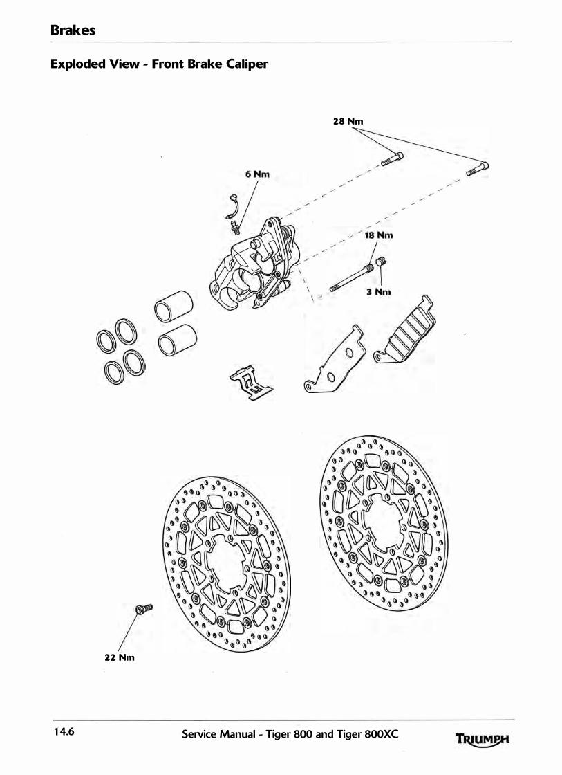
Brakes
Exploded View - Front Brake Caliper
28Nm
22 Nm
�•
14.6 SeiVice Manual - Tiger 800 and Tiger 800XC
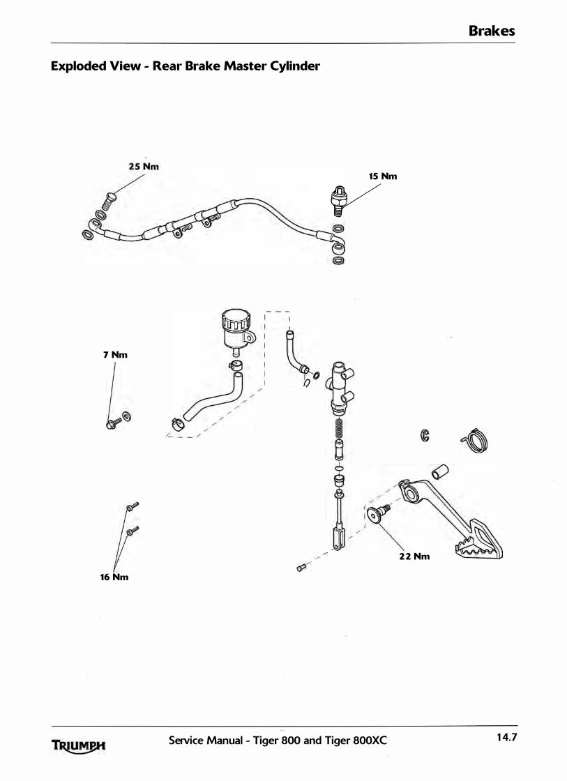
Brakes
Exploded View - Rear Brake Master Cylinder
15 Nm
V
7 Nm
2 2 Nm
16 Nm
Setvice Manual - Tiger 800 and Tiger 800XC 14.7
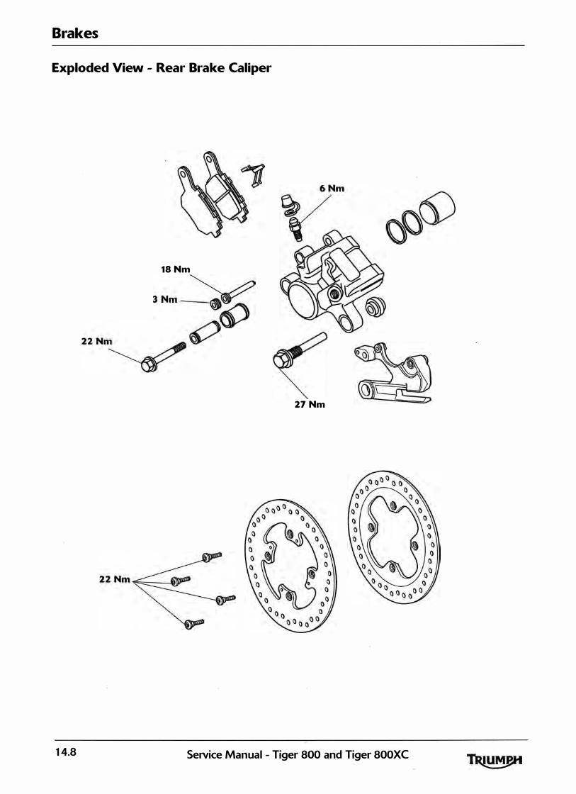
Brakes
Exploded View - Rear Brake Caliper
18Nm
3 Nm � ZZ Nm��
27 Nm
14.8 SeiVice Manual - Tiger 800 and Tiger 800XC

Brakes
Exploded View - ABS System
9 Nm
(
SeiVice Manual - Tiger 800 and Tiger 800XC 14.9

Brakes
Braking System Maintenance Safety Precautions
I , , , ; I , ,�, ) [ l • f 1 " J
Brake fluid is hygroscopic which means it wil l absorb moisture from the air. The absorbed moisture wil l greatly reduce the boi l ing point of the brake fluid causing a reduction in braking efficiency. Replace brake fluid in l ine with the scheduled maintenance chart. A dangerous rid ing condition could result if this important maintenance item is neglected. Do not spi l l brake fluid onto any area of the bodywork as this wil l damage any painted or plastic surface. Always use new brake fluid from a sealed container and never use fluid from an unsea led conta iner or from one which has been previously opened. Do not mix different brands of fluid. Check for fluid leakage around brake fittings, seals and joints. Check regularly for brake hose damage. FAILURE TO OBSERVE ANY OF THE ABOVE WARNINGS MAY REDUCE BRAKING EFFICIENCY LEADING TO AN ACCIDENT.
I f there has been an appreciable drop in the level of the fluid in either brake fluid reservoir, consult your authorised Triumph dealer for advice before rid ing. If the brake lever or pedal feels soft when it is appl ied, or if the lever/pedal travel becomes excessive, there may be air in the brake l ines or the brake may be defective. lt is dangerous to operate the motorcycle under such conditions and remedial action must be taken by your authorised Triumph dealer before riding the motorcycle. Fai lure to take remedial action may reduce braking efficiency leading to an accident.
Use only DOT 4 specification brake fluid as l isted in the general information section of this manual . The use of brake flu ids other than those DOT 4 fluids l isted in the general information section may reduce the efficiency of the braking system leading to an accident. Fai lure to change the brake fluid at the interval specified in the scheduled maintenance chart may reduce braking efficiency resu lting in an accident.
Never use mineral based grease (such as l ithium or copper based grease> in any area where contact with the braking system hydraul ic seals and dust seals is possible. Mineral based grease wi l l damage the hydrau l ic sea ls and dust seals in the calipers and master cyl inders. Damage caused by contact with minera l based grease may reduce braking efficiency resulting in an accident.
14.10 SeJVice Manual - Tiger 800 and Tiger 800XC
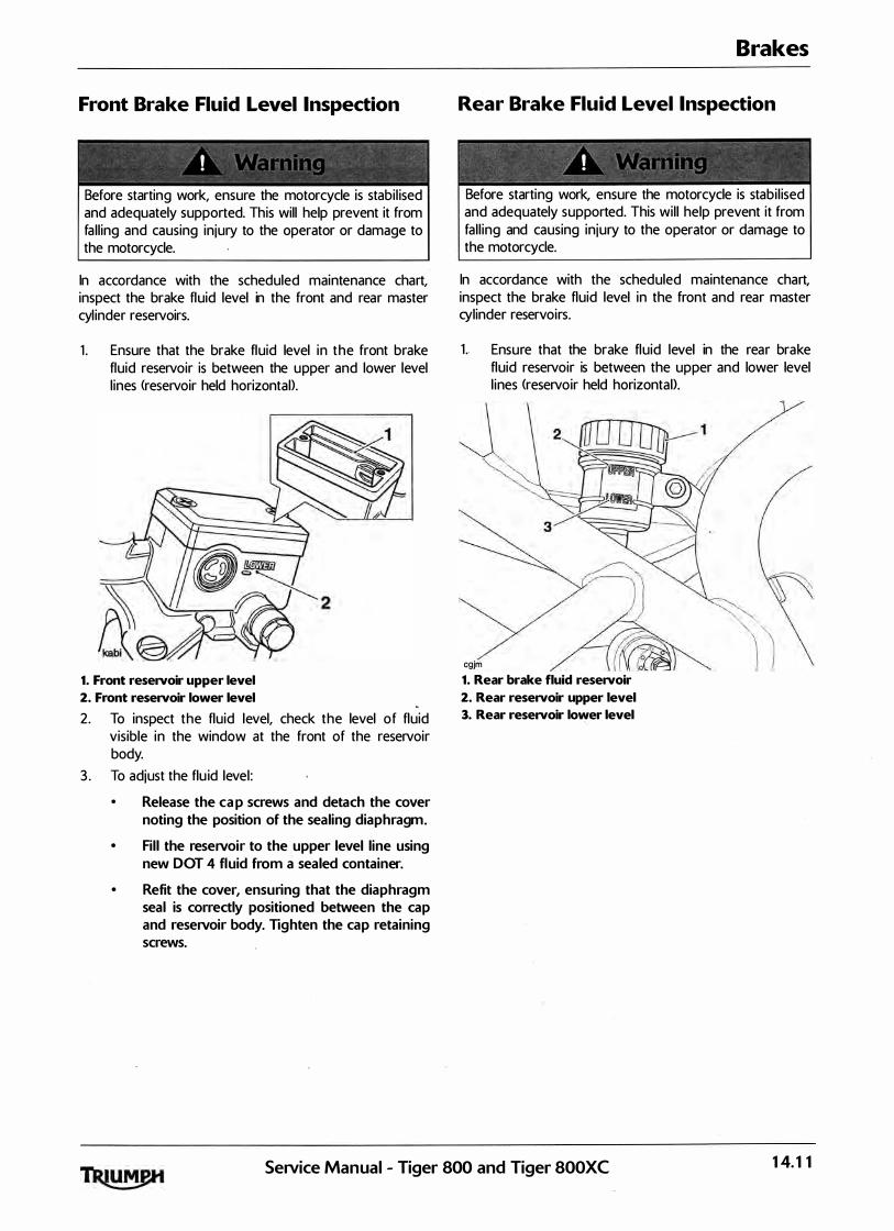
Front Brake Fluid Level Inspection
- -=·
! ( J : ! '
Before starting work, ensure the motorcycle is stabi l ised and adequately supported. This will help prevent it from fa l l ing and causing injury to the operator or damage to the motorcycle.
In accordance with the scheduled maintenance chart, inspect the brake fluid level in the front and rear master cyl inder reservoirs.
1 . Ensure that the brake fluid level in the front brake fluid reservoir is between the upper and lower level l ines (reservoir held horizontal>.
1. Front reseNoir upper level
2. Front reseNoir lower level
2. To inspect the fluid level, check the level of fluid visible in the window at the front of the reservoir body.
3 . To adjust the flu id level:
Release the cap screws and detach the cover
noting the position of the sealing diaphragm.
• Fill the reservoir to the upper level line using
new DOT 4 fluid from a sealed container.
• Refit the cover, ensuring that the diaphragm seal is correctly positioned between the cap
and reservoir body. Tighten the cap retaining
screws.
Brakes
Rear Brake Fluid Level Inspection
Before starting work, ensure the motorcycle is stabi l ised and adequately supported. This wil l help prevent it from fal l ing and causing injury to the operator or damage to the motorcycle.
In accordance with the scheduled maintenance chart, inspect the brake fluid level in the front and rear master cylinder reservoirs.
1. Ensure that the brake fluid level in the rear brake fluid reservoir is between the upper and lower level l ines (reservoir held horizontal>.
cgjm 1. Rear brake fluid reseNoir
2. Rear reseNoir upper level
3. Rear reseNoir lower level
SeiVice Manual - Tiger 800 and Tiger 800XC 1 4. 1 1

Brakes
Changing Brake Fluid
Brake fluid should be changed at the interval specified in the scheduled maintenance chart.
Brake Pads
Front and rear pad wear is automatical ly compensated for and has no effect on brake lever or pedal action.
Brake Wear Inspection
In accordance with the scheduled maintenance chart, inspect the brake pads for wear. The minimum thickness of l in ing materia l for any front or rear brake pad is 1. 5 mm. I f any pad has worn to the bottom of the groove in the pad centre, replace a l l the brake pads on that wheel .
1
cbmz
1. Lining material thickness
2. Minimum thickness line
Do not replace individual brake pads, replace both pads in the brake cal iper. On the front where two calipers are mounted on the same wheel, a l l the pads in both cal ipers must be replaced together. Replacing individual pads wi l l reduce braking efficiency and may cause an accident.
Breaking-in New Brake Pads and Discs
After replacement brake discs and/or pads have been fitted to the motorcycle, we recommend a period of careful breaking-in that wi l l optimise the performance and longevity of the discs and pads. The recommended distance for breaking-in new pads and discs is 200 miles (300 km>.
Bleeding the Front Brakes, Renewing Brake Fluid
Before starting work, ensure the motorcycle is stabi l ised and adequately supported. This will help prevent it from fal l ing and causing injury to the operator or damage to the motorcycle.
1. Note the original setting of the brake lever adjuster in order that it can be returned to the same position when the bleeding operation is complete. Set the brake lever adjuster to position No.1.
jaay 1. Adjuster wheel
2. Triangular mark
2. Turn the handlebars to bring the fluid reservoir to a level position.
Ensure absolute cleanl iness when adding brake flu id to the brake fluid reservoir. Do not a l low moisture or debris to enter the cyl inder, as this wil l adversely affect the fluid properties. Always use fluid from a sealed container and do not use fluid from a container that has been opened for any period of time. Always check for flu id leakage around hydraul ic fittings and for damage to hoses. A dangerous riding condition leading to loss of motorcycle control and an accident could resu lt if this warning is ignored.
To prevent paint damage, do not spill brake fluid onto any area of the bodywork. Spi l led brake fluid wil l damage paintwork.
14. 12 SeiVice Manual - Tiger 800 and Tiger 800XC
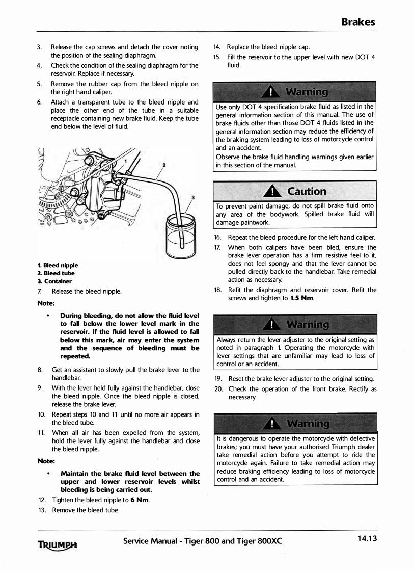
3 . Release the cap screws and detach the cover noting the position of the seal ing diaphragm.
4. Check the condition of the seal ing diaphragm for the reservoir. Replace if necessary.
5 . Remove the rubber cap from the bleed nipple on the right hand caliper.
6. Attach a transparent tube to the bleed nipple and place the other end of the tube in a suitable receptacle containing new brake fluid. Keep the tube end below the level of flu id.
1. Bleed nipple
2. Bleed tube
3. Container
Z Release the bleed nipple.
Note:
• During bleeding, do not allow the fluid level to fall below the lower level mark in the reservoir. If the fluid level is allowed to fall below this mark, air may enter the system and the sequence of bleeding must be repeated.
8. Get an assistant to slowly pul l the brake lever to the handlebar.
9 . With the lever held fu l ly against the handlebar, close the bleed n ipple. Once the bleed nipple is closed, release the brake lever.
10. Repeat steps 10 and 1 1 until no more air appears in the bleed tube.
1 1 . When a l l air has been expelled from the system, hold the lever fu l ly against the handlebar and close the bleed nipple.
Note:
• Maintain the brake fluid level between the upper and lower reservoir levels whilst bleeding is being carried out.
12 . Tighten the bleed n ipple to 6 Nm.
1 3 . Remove the bleed tube.
14. Replace the bleed nipple cap.
Brakes
15 . Fi l l the reservoir to the upper level with new DOT 4 fluid.
Use only DOT 4 specification brake fluid as l isted in the genera l information section of this manual . The use of brake fluids other than those DOT 4 fluids l isted in the general information section may reduce the efficiency of the braking system leading to loss of motorcycle control and an accident. Observe the brake fluid handl ing warnings given earlier ih th is section of the manual.
To prevent paint damage, do not spi l l brake fluid onto any area of the bodywork. Spi l led brake fluid wil l damage paintwork.
16 . Repeat the bleed procedure for the left hand ca l iper. 1Z When both calipers have been bled, ensure the
brake lever operation has a firm resistive feel to it, does not feel spongy and that the lever cannot be pul led directly back to the handlebar. Take remedial action as necessary.
18 . Refit the diaphragm and reservoir cover. Refit the screws and tighten to 1. 5 Nm.
I I ' ' • ' *
Always return the lever adjuster to the orig inal setting as noted in paragraph 1. Operating the motorcycle with lever settings that are unfamil iar may lead to loss of control or an accident.
19 . Reset the brake lever adjuster to the original setting. 20. Check the operation of the front brake. Rectify as
necessary.
lt is dangerous to operate the motorcycle with defective brakes; you must have your authorised Triumph dealer take remedial action before you attempt to ride the motorcycle again. Fai lure to take remedial action may reduce braking efficiency leading to loss of motorcycle control and an accident.
SeiVice Manual - Tiger 800 and Tiger 800XC 14.13
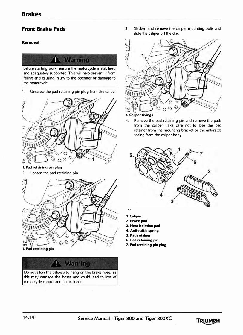
Brakes
Front Brake Pads
Removal
Before starting work, ensure the motorcycle is stabi l ised and adequately supported. This will help prevent it from fal l ing and causing injury to the operator or damage to the motorcycle.
1 . Unscrew the pad retaining pin p lug from the cal iper.
1. Pad retaining pin plug
2. Loosen the pad retaining pin.
Do not al low the calipers to hang on the brake hoses as th is may damage the hoses and could lead to loss of motorcycle control and an accident.
3 . Slacken and remove the caliper mounting bolts and sl ide the caliper off the d isc.
cgyz Q 1. Caliper fixings
4. Remove the pad reta ining pin and remove the pads from the cal iper. Take care not to lose the pad retainer from the mounting bracket or the anti-rattle spring from the caliper body.
ceqv
1. Caliper
2. Brake pad
3. Heat isolation pad
4. Anti-rattle spring
5. Pad retainer
6. Pad retaining pin
7. Pad retaining pin plug
14.14 SeiVice Manual - Tiger 800 and Tiger 800XC

Inspection
1. Check the pad retainer, anti-rattle spring and reta ining pin. Renew any component which shows signs of damage or corrosion.
2. Check the cal iper body sl ides easily on the mounting bracket pins and check there is no sign of leakage from the piston seals. Rectify any problems before instal l ing the pads. ·
Note:
• Complete the assembly of the brake pads to one caliper <see assembly for details) before removing the pads from the other caliper.
Brakes
Installation
Never use mineral based grease (such as l ith ium or copper based grease) in any area where contact with the braking system hydraul ic seals and dust seals is possible. Mineral based grease wil l damage the hydraul ic seals and dust seals in the cal ipers and master cyl inders. Damage caused by contact with minera l based grease may reduce braking efficiency resulting in an accident.
Never lever directly against the d isc, ca l iper or the pad l in ing materia l as this wil l damage these components. Always use a levering tool made from a soft material which wil l not cause damage to the load bearing surfaces. Brake fluid wil l be d isplaced as the cal iper pistons are compressed. To prevent body damage, ensure that the displaced fluid does not come into contact with any part of the bodywork.
1 . If new pads are being instal led, push the pistons ful ly back into the caliper body. Keep an eye on the fluid level in the reservoir whilst retracting the pistons to prevent fluid spi l lage.
2 . Ensure the pad retainer is correctly fitted to the mounting bracket and the anti-rattle spring is securely clipped onto the caliper body.
Do not apply more than a minimum coating of grease to the pad retaining pins. Excess grease may contaminate the brake pads, hydraul ic seals and discs causing reduced braking efficiency and an accident.
3 . Lubricate the pad retaining p in with a thin smear of proprietary high temperature copper based grease.
4. Ensure the heat isolation pads are fitted to the back of each brake pad. Fit the pads to the caliper with their friction material surfaces facing each other. Locate the pad upper ends in the mounting bracket retainer then al ign them with the cal iper body and insert the retaining pin.
5. Sl ide the caliper onto the d isc, ensuring the pads pass either side, and fit the mounting bolts. Tighten the mounting bolts to 28 Nm.
6. Tighten the pad retaining pin to 18 Nm.
SeiVice Manual - Tiger 800 and Tiger 800XC 14.15

Brakes
Z Fit the pad reta1mng pin plug to the cal iper and tighten to 3 Nm.
cgyz � 1. Pad retaining pin plug
8. Pump the brake lever to correctly position the cal iper pistons.
9 . Repeat the removal, inspection and instal lation process for the other caliper.
Use only DOT 4 specification brake fluid as l isted in the genera l information section of this manual . The use of brake fluids other than those DOT 4 fluids l isted in the genera l information section may reduce the efficiency of the braking system leading to loss of motorcycle control and an accident. Observe the brake fluid handling warnings g iven earl ier in this section of the manual .
10. Check the front brake fluid level and top up as required with new DOT 4 fluid.
1 1 . Check for correct brake operation. Rectify as necessary.
lt is dangerous to operate the motorcycle with defective brakes; you must have your authorised Triumph dealer take remedial action before you ride the motorcycle again. Fai lure to take remedial action may resu lt in reduced braking efficiency leading to loss of motorcycle control and an accident.
Front Brake Caliper
Removal
Before starting work, ensure the motorcycle is stabi l ised and adequately supported. This will help prevent it from fal l ing and causing injury to the operator or damage to the motorcycle.
To prevent paint damage, do not spi l l brake fluid onto any area of the bodywork. Spi l led brake fluid wil l damage paintwork.
1 . Remove the brake pads (see page 14-14). 2 . Disconnect the brake hose at the cal iper (two hoses
on right hand cal iper), and place the free end of the hose(s) in a suitable conta iner to col lect the brake fluid.
14.16 SeiVice Manual - Tiger 800 and Tiger 800XC

Disassembly
� - - �
I I ) 'y ". � i f ' l
To prevent injury, never place fingers or hands inside the cal iper opening when removing the pistons. Always wear eye, hand and face protection when using compressed air. Eye, face and skin damage wil l result from direct contact with compressed air.
1 . Separate the caliper and mounting bracket. 2 . Cover the cal iper opening with a clean, heavy cloth
and, using either compressed air or by reconnecting the master cyl inder and pumping the brake lever, eject both pistons from the ca l iper at the same time.
1. Dust seals
2. Piston seals
3. Pistons
Ensure the seal grooves in the ca l iper bores are not damaged during the removal of the sea ls. Damage to the seal grooves may a l low brake fluid to leak past the seals resu lting in a dangerous riding cond ition leading to loss of motorcycle control and an accident.
3 . Extract the dust sea ls and piston seals, taking care not to damage the caliper bores.
4. Check the pistons, caliper and mounting bracket for signs of damage, paying particu lar attention to the cal iper bores and pistons. If damage is present, renew the worn component or the complete cal iper assembly.
5 . If a l l components are serviceable, obtain a piston sea l kit and reassemble the cal iper as fol lows:
Brakes
Always renew cal iper seals after removal of the pistons. An effective hydraul ic seal can only be made if new seals are fitted. A dangerous rid ing condition leading to an accident could result if this warning is ignored.
� -
' t ' . 0 ' •
Before insta l lation, a l l interna l brake components should be cleaned and lubricated with clean new DOT 4 brake flu id. Never use solvents, petrol (gasol ine>, engine oil, or any other petroleum disti l late on internal brake components as this wil l cause deterioration of the hydraul ic seals in the ca l ipers and master cylinders. A dangerous riding condition leading to loss of motorcycle control and an accident could result if this warning is ignored.
6. Ensure a l l components are clean, then fit the new seals to their grooves in the cal iper bores.
Z Lubricate the fluid seals, caliper bore and the outside of the pistons with clean DOT 4 brake fluid.
8. Ease the pistons squarely back into the bores, taking care not to displace the seals.
Never use mineral based grease <such as l ith ium or copper based grease) in any area where contact with the braking system hydraul ic seals and dust seals is possible. Mineral based grease wil l damage the hydraul ic seals and dust seals in the cal ipers and master cyl inders. Damage caused by contact with mineral based grease may reduce braking efficiency resulting in an accident.
SeiVice Manual - Tiger 800 and Tiger 800XC 14.17

Brakes
9. Lubricate the mounting bracket pins with a suitable si l icone based brake grease then reassemble the bracket and ca l iper. Ensure the pin gaiters are correctly located on both the bracket and caliper.
cfgg
1. Caliper sliding pin
2. Caliper bracket sliding pin
Installation
1 . Fit the brake pads (see page 14-37>. 2. Connect the brake hose(s) to the cal iper
incorporating new seal ing washers on each side of al l hose connections.
3. Tighten the banjo bolt to 2 5 Nm.
Use only DOT 4 specification brake fluid as l isted in the general information section of this manual . The use of brake flu ids other than those DOT 4 fluids l isted in the general information section may reduce the efficiency of the braking system leading to loss of motorcycle control and an accident. Observe the brake fluid handl ing warnings g iven earl ier in this section of the manual .
4. F i l l the master cylinder with new, DOT 4 brake fluid from a sealed container.
5 . Bleed the front brake l ine <see page 14-12). 6. Check for correct brake operation.
lt is dangerous to operate the motorcycle with defective brakes; you must have your authorised Triumph dealer take remedial action before you ride the motorcycle again. Fai lure to take remedial action may result in reduced braking efficiency leading to loss of motorcycle control and an accident.
14. 18 SeNice Manual - Tiger 800 and Tiger 800XC
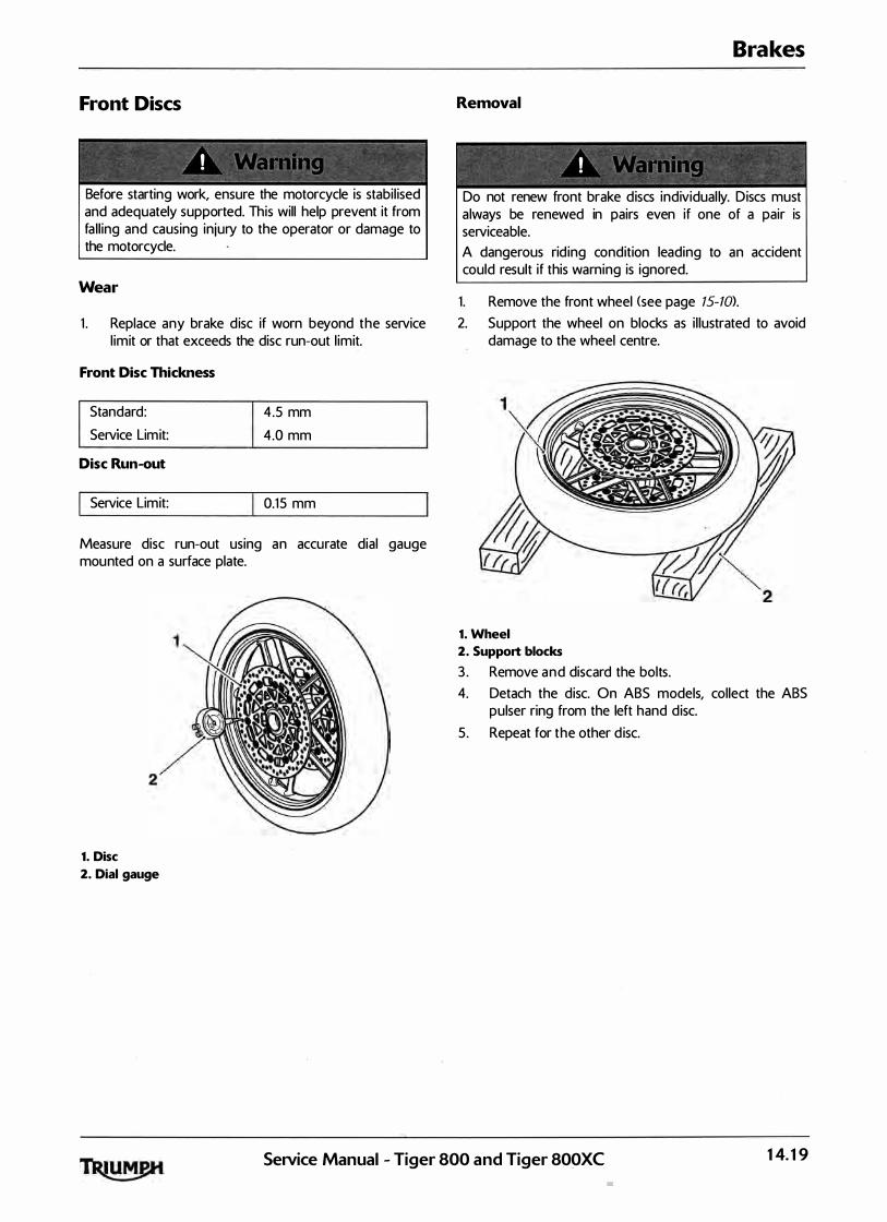
Front Discs
� ' - . - - �
. . ' . ' ' . . • ' '� 4
Before starting work, ensure the motorcycle is stabil ised and adequately supported. This will help prevent it from fa l l ing and causing injury to the operator or damage to the motorcycle.
Wear
1 . Replace any brake disc if worn beyond the service l imit or that exceeds the disc run-out l imit.
Front Disc Thickness
I Standard:
Serv1ce Limit:
Disc Run-out
I Service Limit:
4 .5 mm
4.0 mm
0.15 mm
Measure disc run-out using an accurate dial gauge mounted on a surface plate.
1. Disc
2. Dial gauge
Removal
�· .
I . . , . : t, •.::
Brakes
� � � �-� -
Do not renew front brake discs individual ly. Discs must always be renewed in pairs even if one of a pair is serviceable. A dangerous rid ing condition leading to an accident could result if this warning is ignored.
1. Remove the front wheel <see page 15-10>.
2. Support the wheel on blocks as i l lustrated to avoid damage to the wheel centre.
1. Wheel
2. Support blocks
3 . Remove and discard the bolts. 4. Detach the disc. On ABS models, collect the ABS
pulser ring from the left hand disc. 5 . Repeat for the other d isc.
SeiVice Manual - Tiger 800 and Tiger 800XC 14.19
Brakes
Installation
1 . Locate the first disc to the wheel. On ABS models, refit the ABS pulser ring.
2 . Fit new bolts and tighten to 22 Nm.
3 . Fit the other disc in the same way. 4. Refit the front wheel (see page 15-1 1 ). 5. Check for correct br-ake operation. Rectify as
necessary.
I : · · r . '
lt is dangerous to operate the motorcycle with defective brakes; you must have your authorised Triumph dealer take remedial action before you ride the motorcycle again. Fai lure to take remedial action may resu lt in reduced braking efficiency leading to loss of motorcycle control and an accident.
Front Brake Master Cylinder
Removal
Before starting work, ensure the motorcycle is stabi l ised and adequately supported. This will help prevent it from fal l ing and causing in jury to the operator or damage to the motorcycle.
1 . Remove the rider's seat <see page 16- 13).
2. Disconnect the battery, negative (black> lead first.
To prevent paint damage, do not spi l l brake fluid onto any area of the bodywork. Spi l led brake fluid wil l damage paintwork.
3 . To drain the fluid from the master cylinder, attach a tube to the right hand cal iper bleed nipple, slacken the nipple and al low the fluid to drain into a suitable conta iner. Operate the brake lever until al l fluid has been expelled.
4. Note the setting of the brake lever adjuster to ensure it is returned to the same position when the overhaul operation is complete.
5. Remove the pivot locknut and bolt securing the brake lever to the master cyl inder, and remove the lever.
6. Disconnect from th� master cylinder the:
• brake hose,
brake light switch connections.
Z Release the clamp screws from the handlebar to remove the master cyl inder.
14.20 SeiVice Manual - Tiger 800 and Tiger SOOXC
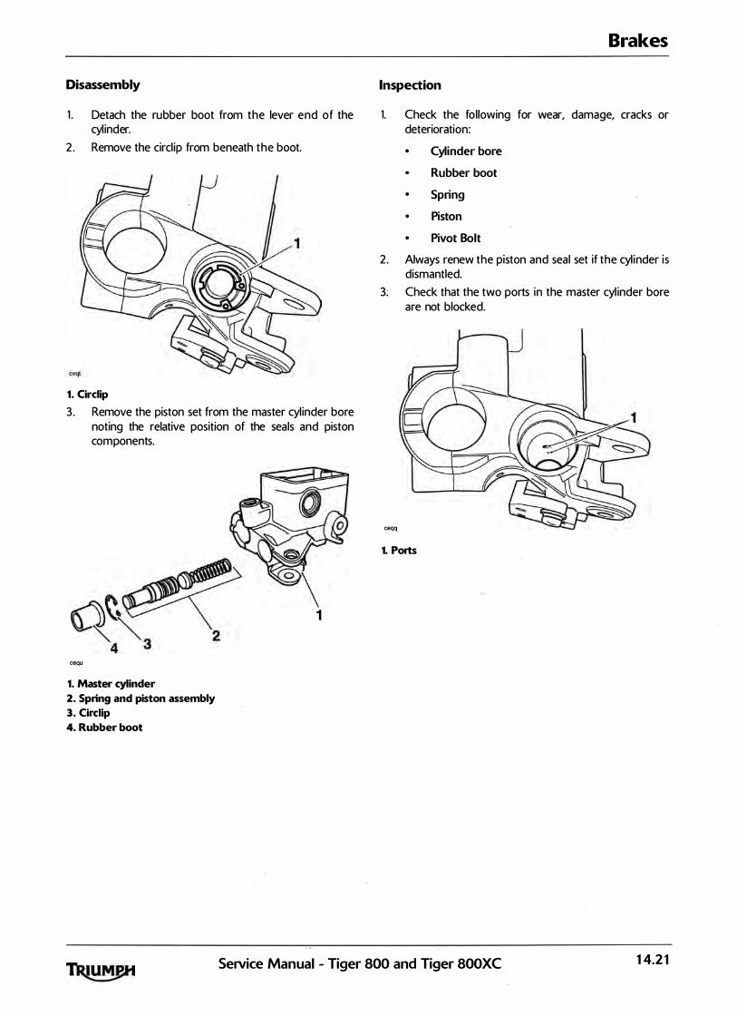
Disassembly
1 . Detach the rubber boot from the lever end of the cyl inder.
2 . Remove the circl ip from beneath the boot.
1. Circlip
3 . Remove the piston set from the master cyl inder bore noting the relative position of the seals and piston components.
1
cequ
1. Master cylinder
2. Spring and piston assembly
3. Circlip
4. Rubber boot
Brakes
Inspection
1. Check the following for wear, damage, cracks or deterioration:
• Cylinder bore
Rubber boot
• Spring
• Piston
• Pivot Bolt
2. Always renew the piston and seal set if the cyl inder is dismantled.
3. Check that the two ports in the master cyl inder bore are not blocked.
ceqq
1. Ports
Service Manual - Tiger 800 and Tiger 800XC 14.21

Brakes
Assembly
�
' ' ' ' I ' (� . ..
Never use mineral based grease (such as l ith ium or copper based grease) in any area where contact with the braking system hydraulic sea ls and dust seals is possible. Mineral based grease wi l l damage the hydraul ic seals and dust seals in the ca l ipers and master cyl inders. Damage caused by contact with minera l based grease may reduce braking efficiency resulting in an accident.
' ' ' ' • 0
Before instal lation, a l l internal brake components should be cleaned and lubricated with clean new DOT 4 brake fluid. Never use solvents, petrol <gasoline>, engine oi l, or any other petroleum disti l late on internal brake components as this wi l l cause deterioration of the hydraul ic sea ls in the cal ipers and master cyl inders. A dangerous riding condition leading to loss of motorcycle control and an accident could result if this warning is ignored.
1. Lubricate the piston and cyl inder with new, clean brake fluid.
Ensure that the piston and piston seal are fitted facing the same way as noted during removal . A dangerous riding condition leading to an accident could result from incorrect assembly of the master cyl inder.
2. Fit the new piston set into the master cylinder and retain with a new circl ip.
3. Refit the master cylinder boot.
Installation
1 . Locate the master cylinder to the handlebars and position the clamp with the ' U P' arrow pointing upwards.
1. 'UP' Arrow
2. 'Dot' mark
2. Al ign the master cyl inder/clamp spl it l ine with the 'dot' mark on the handlebar.
3 . Tighten the clamp bolts, upper first and then the lower to 12 Nm.
4. Connect the brake hose to the master cyl inder incorporating new seal ing washers. Tighten the banjo bolt to 25 Nm.
5. Connect the brake l ight switch connections. 6. Position the brake lever ensuring that the pivot boss
is correctly a l igned to the push rod. Fit and tighten the pivot bolt to 1 Nm, and the locknut to 6 Nm.
Use only DOT 4 specification brake fluid as l isted in the general information section of this manual . The use of brake flu ids other than those DOT 4 fluids l isted in the general information section may reduce the efficiency of the braking system leading to loss of motorcycle control and an accident. Observe the brake fluid handl ing warnings g iven earl ier in this section of the manual .
14.22 SeNice Manual - Tiger 800 and Tiger 800XC
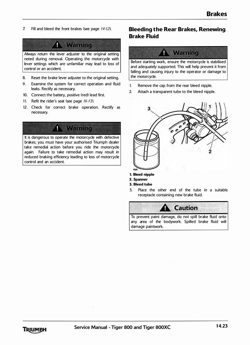
Z Fi l l and bleed the front brakes (see page 14-12>.
-' . '
Always return the lever adjuster to the orig inal setting noted during removal . Operating the motorcycle with lever settings which are unfamil iar may lead to loss of control or an accident. .
8. Reset the brake lever adjuster to the original setting. 9. Examine the system for correct operation and fluid
leaks. Rectify as necessary. 10. Connect the battery, positive (red) lead first. 1 1 . Refit the rider's seat (see page 16-13). 12 . Check for correct brake operation. Rectify as
necessary.
! . '
lt is dangerous to operate the motorcycle with defective brakes; you must have your authorised Triumph dealer take remedial action before you ride the motorcycle again. Fai lure to take remedial action may result in reduced braking efficiency leading to loss of motorcycle control and an accident.
Brakes
Bleeding the Rear Brakes, Renewing Brake Fluid
Before starting work, ensure the motorcycle is stabi l ised and adequately supported. This will help prevent it from fa l l ing and causing injury to the operator or damage to the motorcycle.
1. Remove the cap from the rear bleed nipple. 2. Attach a transparent tube to the bleed nipple.
1. Bleed nipple
2. Spanner
3. Bleed tube
3. Place the other end of the tube in a suitable receptacle containing new brake fluid.
To prevent paint damage, do not spi l l brake fluid onto any area of the bodywork. Spi l led brake fluid wil l damage paintwork.
SeiVice Manual - Tiger 800 and Tiger 800XC 14.23

Brakes
4. Unscrew and remove the rear brake reservoir cover taking care not to spi l l any fluid.
cgjm 1. Rear reservoir
2. Rear reservoir upper level
3. Rear reservoir lower level
Ensure absolute cleanl iness when adding brake fluid to the brake fluid reservoir. Do not al low moisture or debris to enter the cylinder as this wil l adversely affect the fluid properties. Always use fluid from a sealed conta iner and do not use fluid from a conta iner which has been opened for any period of time. Always check for fluid leakage around hydraul ic fittings and for damage to hoses. A dangerous riding condition leading to an accident could result if this warning is ignored.
5. Check the condition of the seal ing diaphragm. Replace the diaphragm as necessary.
6. Release the bleed nipple.
Note:
• During bleeding, do not allow the fluid level to fall below the lower level mark in the reservoir. If the level is allowed to fall below this mark, air may enter the system and the sequence of bleeding must be repeated.
Z Slowly depress the brake pedal and, holding the pedal fu l ly down, close the bleed nipple.
8. Repeat steps 6 and 7 until no more air appears in the bleed tube.
9. Maintain the brake fluid level between the upper and lower reservoir levels whilst bleeding is being carried out.
10. When all air has been expelled from the system, hold down the brake peda l and close the bleed nipple. Tighten the nipple to 6 Nm.
1 1 . Fi l l the reservoir to the maximum level with new DOT 4 flu id.
Use only DOT 4 specification brake fluid as l isted in the general information section of this manual . The use of brake fluids other than those DOT 4 fluids l isted in the general information section may reduce the efficiency of the braking system leading to loss of motorcycle control and an accident. Observe the brake fluid handl ing warnings g iven earl ier in this section of the manual .
12 . Fit the reservoir cover and diaphragm. Check for correct diaphragm fitment before final tightening of the cover.
1 3 . Remove the bleed tube from the nipple. 14. Replace the bleed nipple cap. 15. Check for correct brake operation.. Rectify as
necessary.
lt is dangerous to operate the motorcycle with defective brakes; you must have your authorised Triumph dealer take remedial action before you ride the motorcycle again. Fai lure to take remedial action may result in reduced braking efficiency leading to loss of motorcycle control and an accident.
14.24 SeiVice Manual - Tiger 800 and Tiger 800XC

Rear Brake Pads
Before starting work, ensure the motorcycle is stabi l ised and adequately supported. This wi l l help prevent it from fa l l ing and causing injury to the operator or damage to the motorcycle.
1. Push the brake cal iper inwards towards the wheel in order to displace the cal iper piston.
2. Remove the plug protecting the pad retaining pin.
1. Plug
2. Pad retaining pin
Note:
• Before removing the brake pads, note the relationship of the pads to the caliper and ensure that, on assembly, they are fitted in the same way.
Do not al low the cal iper to hang on the brake hoses as this may damage the hoses and could lead to loss of motorcycle control and an accident.
Brakes
3 . Remove the brake cal iper bolts and raise the ca liper.
1. Brake caliper bolt
2. Brake pads
3. Pad retaining pin
4. Remove the pad retaining pin and remove the pads. 5. Remove the anti-rattle spring and inspect for
damage.
1. Anti-rattle spring
Service Manual - Tiger 800 and Tiger 800XC 14.25
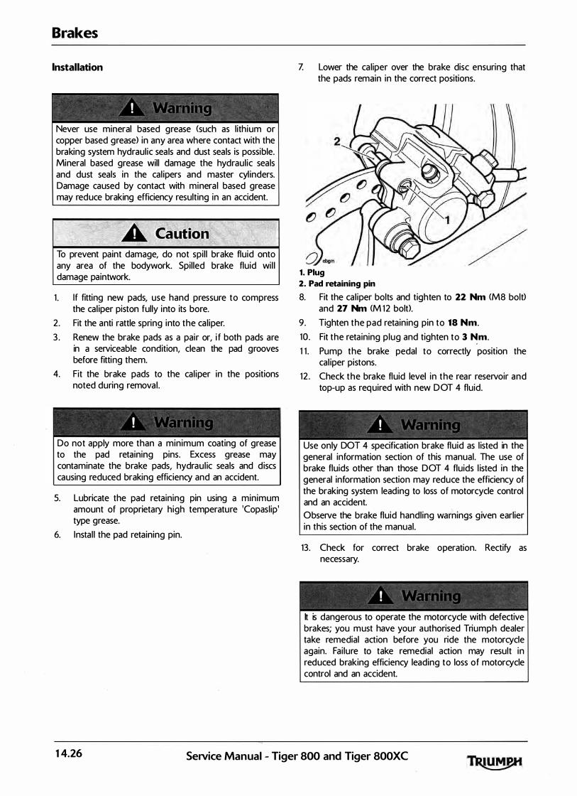
Brakes
Installation
� "" . �
' ' ' . • l � d
- - -�
Never use mineral based grease <such as l ith ium or copper based grease> in any area where contact with the braking system hydraul ic sea ls and dust seals is possible. Mineral based grease will damage the hydraul ic seals and dust seals in the cal ipers and master cyl inders. Damage caused by contact with minera l based grease may reduce braking efficiency resulting in an accident.
To prevent paint damage, do not spi l l brake fluid onto any area of the bodywork. Spil led brake fluid wi l l damage paintwork.
1 . If fitting new pads, use hand pressure to compress the cal iper piston fully into its bore.
2 . Fit the anti rattle spring into the ca l iper. 3 . Renew the brake pads as a pair or, i f both pads are
in a serviceable condition, clean the pad grooves before fitting them.
4. Fit the brake pads to the cal iper in the positions noted during removal .
Do not apply more than a minimum coating of grease to the pad retaining pins. Excess grease may contaminate the brake pads, hydraul ic seals and discs causing reduced braking efficiency and an accident.
5. Lubricate the pad retaining pin using a minimum amount of proprietary high temperature 'Copasl ip' type grease.
6. Instal l the pad retaining pin.
Z Lower the ca liper over the brake disc ensuring that the pads remain in the correct positions.
1. Plug
2. Pad retaining pin
8. Fit the ca l iper bolts and tighten to 22 Nm <MS bolt> and 27 Nm <M 12 bolt>.
9 . Tighten the pad retaining pin to 18 Nm. 10 . Fit the reta ining p lug and tighten to 3 �m. 1 1 . Pump the brake pedal to correctly position the
cal iper pistons. 12 . Check the brake fluid level in the rear reservoir and
top-up as required with new DOT 4 fluid.
' ' / .
Use only DOT 4 specification brake fluid as l isted in the general information section of this manual . The use of brake fluids other than those DOT 4 fluids l isted in the general information section may reduce the efficiency of the braking system leading to loss of motorcycle control and an accident. Observe the brake fluid handl ing warnings g iven earlier in this section of the manual .
13. Check for correct brake operation. Rectify as necessary.
lt is dangerous to operate the motorcycle with defective brakes; you must have your authorised Triumph dealer take remedial action before you ride the motorcycle again. Fai lure to take remedial action may result in reduced braking efficiency leading to loss of motorcycle control and an accident.
14.26 SeiVice Manual - Tiger 800 and Tiger 800XC
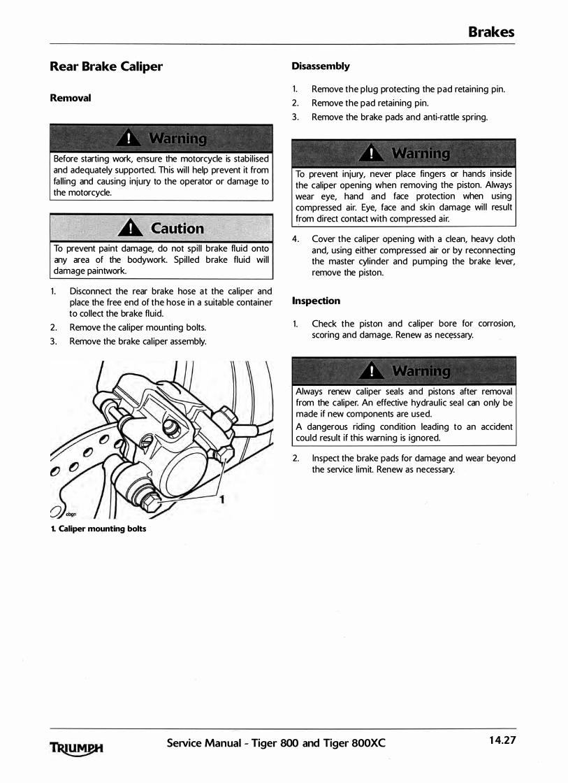
Rear Brake Caliper
Removal
Before starting work, ensure the motorcycle is stabi l ised and adequately supported. This wil l help prevent it from fa l l ing and causing injury to the operator or damage to the motorcycle.
To prevent paint damage, do not spi l l brake fluid onto any area of the bodywork. Spil led brake fluid wil l damage paintwork.
1 . Disconnect the rear brake hose a t the ca l iper and place the free end of the hose in a suitable container to collect the brake fluid.
2 . Remove the cal iper mounting bolts. 3 . Remove the brake cal iper assembly.
1. Caliper mounting bolts
Brakes
Disassembly
1 . Remove the p lug protecting the pad retaining pin. 2 . Remove the pad retaining pin. 3 . Remove the brake pads and anti-rattle spring.
·�- � � � -/ ' ' � I 1 J � �
f • j "' 1 ' t - - � -
To prevent injury, never place fingers or hands inside the caliper opening when removing the piston. Always wear eye, hand and face protection when using compressed air. Eye, face and skin damage wi l l result from direct contact with compressed a ir.
4. Cover the cal iper opening with a clean, heavy cloth and, using either compressed air or by reconnecting the master cyl inder and pumping the brake lever, remove the piston.
Inspection
1 . Check the piston and caliper bore for corrosion, scoring and damage. Renew as nec�ssary.
Always renew cal iper seals and pistons after removal from the caliper. An effective hydraul ic sea l can only be made if new components are used. A dangerous riding condition leading to an accident could result if this warning is ignored.
2. Inspect the brake pads for damage and wear beyond the service l imit. Renew as necessary.
Service Manual - Tiger 800 and Tiger 800XC 14.27

Brakes
Assembly
f ' , i " I ' . ' '
Never use mineral based grease <such as l ith ium or copper based grease> in any area where contact with the braking system hydraul ic seals and dust seals is possible. Mineral based grease wi l l damage the hydraul ic seals and dust seals in the cal ipers and master cyl inders. Damage caused by contact with minera l based grease may reduce braking efficiency resulting in an accident.
! ' -
Ensure that the cal iper bores do not become scratched during removal and assembly. A dangerous riding condition leading to an accident could result if this warning is ignored.
Before insta l lation, a l l internal brake components should be cleaned and lubricated with clean new DOT 4 brake fluid. Never use solvents, petrol (gasol ine), engine oil, or any other petroleum disti l late on internal brake components as this wil l cause deterioration of the hydraul ic sea ls in the cal ipers and master cylinders. A dangerous riding condition leading to loss of motorcycle control and an accident could result if this warning is ignored.
1. Fit new flu id seals to the cal iper. Apply brake fluid to the outside of the cal iper piston and fluid seal .
2
1
1. Piston
2. Seals
Ensure that the piston does not tip during assembly as this could damage the ca l iper. A dangerous rid ing condition leading to an accident could result if this warning is ignored.
2. Carefu l ly push the piston into the cal iper by hand. 3 . I nstal l the anti-rattle spring into the caliper. 4. Position the brake pads in the ca l iper.
Do not apply more than a minimum coating of grease to the pad reta in ing pins. Excess grease may contaminate the brake pads, hydraul ic seals and discs causing reduced braking efficiency and an accident.
5 . Lubricate the pad retaining pin us ing a min imum amount of proprietary high temperature 'Copasl ip' type grease.
6. Fit and tighten the pad retaining pin to 18 Nm.
Z Fit the reta ining plug and tighten to 3 Nm.
8. Apply a thin smear of si l icone based brake grease to the outside of the sleeve and the sl iding section of the bolt as shown below. Do not apply grease to the threads of the bolt.
1. Bolt
2. Sleeve
14.28 Service Manual - Tiger 800 and Tiger 800XC
Installation
1 . Position the cal iper over the disc ensuring the pads are correctly al igned on both sides of the d isc.
2. Fit the cal iper reta ining bolts and tighten to 22 Nm (M8 boiO and 27 Nm <M 12 boiO.
3. Connect the brake hose to the cal iper incorporating new washers on each side of the banjo bolt
4. Tighten the banjo bolt to 2 5 Nm.
' ' 1 I
Use only DOT 4 specification brake fluid as l isted in the genera l information section of this manual. The use of brake flu ids other than those DOT 4 flu ids l isted in the genera l information section may reduce the efficiency of the braking system leading to loss of motorcycle control and an accident. Observe the brake fluid handl ing warnings given earlier in this section of the manual.
Brakes
5. F i l l the master cyl inder with new, DOT 4 brake fluid from a sea led container.
6. Bleed the rear brake <see page 14-23). Z Check for correct brake operation. Rectify as
necessary.
' 1 • 1 • '
lt is dangerous to operate the motorcycle with defective brakes; you must have your authorised Triumph dealer take remedial action before you ride the motorcycle again. Fai lure to take remedial action may result in reduced braking efficiency leading to loss of motorcycle control and an accident.
Setvice Manual - Tiger 800 and Tiger 800XC 14.29

Brakes
Rear Brake Disc
Wear
Before starting work, ensure the motorcycle is stabi l ised and adequately supported. This will help prevent it from fa l l ing and causing injury to the operator or damage to the motorcycle.
1 . Replace any brake disc worn beyond the service l imit or that exceeds the disc run-out l imit.
Rear Disc Thickness
I Standard:
Serv1ce Limit:
Disc Run-out
I Service Limit:
6.0 mm
5.5 mm
0.50 mm
Measure disc run-out using an accurate d ia l gauge mounted on a surface plate.
1. Disc
2. Dial gauge
Note:
• Details of rear brake disc removal and installation can be found in the wheel section.
Rear Master Cylinder
Removal
- � ; � � - -#'"
/ ' '.1 ',' l ' 1 • .::; t �
Before starting work, ensure the motorcycle is stabi l ised and adequately supported. This will help prevent it from fal l ing and causing injury to the operator or damage to the motorcycle.
1 . Remove the rider's seat <see page 16-13).
2. Disconnect the battery, negative (black> lead first.
To prevent paint damage, do not spi l l brake flu id onto any area of the bodywork. Spi l led brake fluid wi l l damage paintwork.
3 . Remove the two fixings and remove the heel guard. 4. Drain the fluid from the master cylinder. by bleeding
the system at the rear caliper until a l l fluid has been expel led.
5. Remove the cl ip from the clevis pin at the lower end of the brake pushrod.
6. Remove the clevis pin. Z Disconnect the rear brake l ight switch. 8. Remove the rear brake l ight and disconnect the rear
brake hose from the master cylinder, noting its orientation.
9. Remove the screws securing the master cyl inder to the frame and detach the master cyl inder.
cgyv
1. Master cylinder
2. Master cylinder fixings
3. Clevis pin
4. Ciip
14.30 SeiVice Manual - Tiger 800 and Tiger SOOXC

10. Disconnect the reservoir hose and remove the master cyl inder.
Disassembly
1 . Remove the boot from the cyl inder and pushrod. 2. Remove the circl ip retaining the pushrod to the
cyl inder. 3 . Remove the pushrod and piston set from the master
cyl inder bore, noting the relative position of the seals and piston components.
Inspection
1 . Visually inspect the master cyl inder bore for wear, scratches or corrosion. Replace as necessary.
2 . Check the piston and cyl inder bore for damage, wear or deterioration. Replace as necessary.
3 . Always renew the piston and seal set i f the cylinder i s dismantled.
4. Examine the pushrod for bends and damage. Replace as necessary.
Assembly
Never use minera l based grease <such as l ithium or copper based grease> in any area where contact with the braking system hydraul ic seals and dust sea ls is possible. Mineral based grease will damage the hydraul ic seals and dust seals in the calipers and master cylinders. Damage caused by contact with mineral based grease may reduce braking efficiency resulting in an accident.
Before instal lation, all internal brake components should be cleaned and lubricated with clean new DOT 4 brake fluid. Never use solvents, petrol (gasoline>, engine oil, or any other petroleum disti l late on internal brake components as this wil l cause deterioration of the hydraul ic seals in the calipers and master cyl inders. A dangerous riding condition leading to loss of motorcycle control and an accident could result if this warning is ignored.
Brakes
1 . Clean the master cyl inder bore, piston and seals, with new brake fluid.
2 . Ensure a l l ports are clear of obstruction.
� - - � - - =
/ I f.� , '"' ' J I { � • '\ \" ! � ' • "
� � �
Ensure that the piston and piston seal are fitted facing the same way as noted during removal. A dangerous riding condition leading to an accident could result from incorrect assembly of the master cyl inder.
3 . Insta l l the spring and piston set together. 4. Apply a small amount of brake grease to the
push rod. 5 . Instal l the pushrod in the master cyl inder and reta in
with a new circl ip. 6. Refit the boot.
cdlu1
1. ReseNoir hose
2. Piston set
3. Dust boot
4. Push rod
5. Clevis pin
6. Ciip
7. Circlip
Service Manual - Tiger 800 and Tiger 800XC 14.3 1

Brakes
Z If the pushrod has been disassembled, adjust the length of the pushrod as shown below:
75.5 m m
1 . Pushrod
2. Locknut
8. Set the pushrod free length to 75.5 mm. 9. Tighten the locknut to 18 Nm.
Installation
1 . Fit the reservoir hose to the master cyl inder. 2 . Secure the master cyl inder to the frame. Tighten the
securing screws to 16 Nm.
3 . Connect the push rod to the brake pedal using a new clevis pin and cl ip.
4. Incorporating new washers, fit the brake hose to the master cyl inder. Ensuring correct orientation of the brake hose, tighten the brake l ight switch to 15 Nm.
Use only DOT 4 specification brake fluid as l isted in the genera l information section of this manual . The use of brake flu ids other than those DOT 4 fluids l isted in the general information section may reduce the efficiency of the braking system leading to loss of motorcycle control and an accident. Observe the brake fluid handl ing warnings g iven earl ier in this section of the manual .
5 . Fi l l and bleed the rear brake system (see page 14-23).
6. Refit the heel guard, tightening the fixings to 12 Nm.
Z Reconnect the battery, positive (red) lead first. 8. Refit the rider's seat <see page 16-13). 9. Check for correct brake operation. Rectify as
necessary.
I , , . "
lt is dangerous to operate the motorcycle with defective brakes; you must have your authorised Triumph dealer take remedial action before you ride the motorcycle again. Fai lure to take remedial action may result in reduced braking efficiency leading to loss of motorcycle control and an accident.
14.32 SeNice Manual - Tiger 800 and Tiger 800XC

Bleeding the Front Brakes -Motorcycles with ABS
Before starting work, ensure the motorcycle is stabi l ised and adequately supported. This wi l l help prevent it from fa l l ing and causing injury to the operator or damage to the motorcycle.
1 . Complete the brake bleed procedure as for models without ABS brakes <see page 14-12).
2. Connect the Triumph diagnostic tool <See page 14-48).
3 . Fol low the on screen menu to ABS Diagnostics. From the menu, select 'B LEED SYSTEM' <see the Triumph Diagnostic Tool User Guide).
Note:
• On pressing the Start button, the diagnostic software will send a command to the ABS ECM to open the 2"d circuit solenoid.
• The front brake lever travel will increase as ABS modulator solenoids are opened and will then decrease as the solenoids are automatically closed.
• Pressure must be applied to the front brake lever before operating the bleed sequence on the diagnostic tool. An assistant will be required to open the bleed nipple while pressure is applied to the brake lever.
4. Apply pressure to the front brake lever, press the Start button to activate the bleed sequence on the diagnostic tool, and with assistance, release one of the bleed nipples.
5. Get an assistant to slowly pull the brake lever to the handlebar.
6. With the lever held ful ly against the handlebar, close the bleed n ipple. Once the bleed nipple is closed, release the brake lever.
Z Repeat steps 5 and 6 until no more air appears in the bleed tube, maintaining the brake fluid level between the upper and lower reservoir levels whi lst bleeding is being carried out.
8. The bleed sequence wil l run for a maximum of 90 seconds. Press the Stop button to end the bleed sequence at any time. Once the bleed sequence has completed the diagnostic tool wil l display a message 'ABS system bleed complete'.
Brakes
The ABS modulator must be al lowed to cool between bleeding operations. Always al low the ABS modulator to cool for 5 minutes before starting the bleed procedure again. Fai lure to fol low this instruction may result in damage to the ABS modulator.
9 . Repeat the above procedure as necessary until a l l a i r is expelled from the system.
10. When al l air has been expelled from the system, apply pressure to the brake lever and close the bleed nipple. Tighten the nipple to 6 Nm.
1 1 . Repeat the brake bleed procedure as for models without ABS brakes (see page 14-12>.
Service Manual - Tiger 800 and Tiger 800XC 14.33

Brakes
Front ABS Wheel Sensor
Removal
� � �
! 1 f t· � · ' l f ', ; : "
Before starting work, ensure the motorcycle is stabi l ised and adequately supported. This will help prevent it from fa l l ing and causing injury to the operator or damage to the motorcycle.
1 . Disconnect the battery negative (black> lead first. 2 . Remove the rider's seat (see page 16-13>. 3 . Remove the fuel tank (see page 10-91>.
Note:
• Note the routing of the harness and its retaining clips for installation.
4. Disconnect the wheel speed sensor multiplug, Identified as the white connector, located below the ignition switch.
5 . Release the wheel speed sensor harness from the brake hose cl ips.
6. Release the bolt and remove the sensor. Col lect the shim from between the sensor and fork leg and discard the bolt.
cgzb [) 1. Front ABS wheel speed sensor
2. Bolt
Installation
Note:
• Check the condition of the shim before use. Do not use a shim which is bent or damaged.
1 . Position the wheel speed sensor to the fork leg with its shim between the sensor and fork leg. Temporarily fit the orig inal bolt and tighten to 9 Nm.
2. The air gap between the wheel speed sensor and the pulser ring must be between 0.1 mm and 1.5 mm. Check and adjust the wheel speed sensor air gap as described on page 14-3 8.
3 . Once the wheel speed sensor a i r gap measurement is correct, insta l l a new bolt (if not already replaced during air gap adjustment) and tighten to 9 Nm.
4. Route the harness and secure to the brake hose clips as noted for removal .
5. Connect the wheel speed sensor multiplug. 6. Refit the fuel tank (see page 10-91> . Z Connect the battery, positive (red) lead first. 8. Refit the rider's seat (see page 16-13). 9 . Check that the brakes operate correctly.
14.34 SeNice Manual - Tiger 800 and Tiger SOOXC

Front ABS Pulser Ring
Removal
Before starting work, ensure the motorcycle is stabi l ised and adequately supported. This will help prevent it from fa l l ing and causing in jury to the operator or damage to the motorcycle
1 . Remove the front wheel (see page 15-10).
Damage to the wheel centre could cause misal ignment of the wheel when refitted. A dangerous riding condition leading to an accident could result if this warning is ignored.
2. Support the wheel on blocks as i l lustrated below.
1. Wheel
2. Support block
Brakes
3 . Remove and discard the five d isc bolts and remove the pulser ring.
1. Pulser ring
2. Disc bolt
Inspection
1 . Check the pulser r ing for damage, missing or cracked teeth or d istortion. Renew the pulser ring as necessary.
Installation
1 . Locate the pu lser ring on to the wheel, fit new disc bolts and tighten to 22 Nm.
2. Refit the front wheel (see page 15-1 n. 3 . Check, and if necessary, adjust the air gap between
the front wheel speed sensor and the pulser ring <see page 14-38).
4. Check that the brakes operate correctly.
SeiVice Manual - Tiger 800 and Tiger 800XC 14.35

Brakes
Bleeding the Rear Brake Fluid -Motorcycles with ABS
I , ' ' i I <', • J
Before starting work, ensure the motorcycle is stabi l ised and adequately supported. This will help prevent it from fal l ing and causing injury to. the operator or damage to the motorcycle.
1 . Complete the brake bleed procedure as for models without ABS brakes (see page 14-23).
2. Connect the Triumph diagnostic tool <See page 14-48).
3 . Fol low the on screen menu to ABS Diagnostics. From the menu, select B LEED SYSTEM (see the Triumph Diagnostic Tool User Guide).
Note:
• On pressing the Start button, the diagnostic software will send a command to the ABS ECM to open the 2nd circuit solenoid.
• The rear brake pedal travel will increase as ABS modulator solenoids are opened and will then decrease as the solenoids are automatically closed.
• Pressure must be applied to the rear brake pedal before operating the bleed sequence on the diagnostic tool. An assistant will be required to open the bleed nipple while pressure is applied to the brake pedal.
4. Apply pressure to the rear brake pedal, press the Start button to activate the bleed sequence on the diagnostic tool, and with assistance, release the bleed nipple.
5. Slowly depress the brake pedal and, holding the pedal ful ly down, close the bleed n ipple. Repeat unti l no more air appears in the bleed tube, maintaining the brake fluid level between the upper and lower reservoir levels whilst bleeding is being carried out.
6. The bleed sequence wil l run for a maximum of 90 seconds. Press the Stop button to end the bleed sequence at any time. Once the bleed sequence has completed the diagnostic tool wil l display a message 'ABS system bleed complete'.
The ABS modulator must be al lowed to cool between bleeding operations. Always a l low the ABS modulator to cool for 5 minutes before starting the bleed procedure again. Fai lure to fol low this instruction may result in damage to the ABS modulator.
Z Repeat the above procedure as necessary until a l l a ir is expelled from the system.
8. When all air has been expelled from the system, hold down the brake peda l and close the bleed nipple. Tighten the nipple to 6 Nm.
9. Repeat the brake bleed procedure as for models without ABS brakes <see page 14-23>.
14.36 SeNice Manual - Tiger 800 and Tiger 800XC

Rear ABS Wheel Speed Sensor
Removal
Before starting work, ensure the motorcycle is stabi l ised and adequately supported. This wi l l help prevent it from fa l l ing and causing in jury to the operator or damage to the motorcycle.
1 . Remove the rider's seat <see page 16-13). 2 . Remove the battery <see page 17-8) 3 . Disconnect the wheel speed sensor multiplug,
located under the battery. • Note the routing of the ABS sensor harness
for installation.
4. Detach the ABS sensor harness from its cl ips on the rear brake hose.
5 . Release the fixing securing the wheel speed sensor to the rear brake caliper carrier and remove the sensor. Col lect the shim and discard the fixing.
1. ABS sensor
2. ABS harness bracket
3. Fixing
4. Shim<s>
Brakes
Installation
Note:
1 .
2 .
3 .
4.
5 .
6 . z 8.
• Check the condition of the shim before use. Do not use a shim which is bent or damaged.
Position the shim to the fixing such that it wi l l be instal led between the wheel speed sensor and the brake cal iper carrier. Fit the wheel speed sensor, harness bracket and shim to the brake cal iper carrier as noted during removal . Temporarily fit the orig inal bolt and tighten to 9 Nm.
The air gap between the wheel speed sensor and the pulser ring must be between 0.1 mm and 1.5 mm. Check and adjust the wheel speed sensor air gap as described on page 14-3 8. Once the wheel speed sensor air gap measurement is correct, insta l l a new bolt (if not a lready replaced during air gap adjustmenO and tighten to 9 Nm.
Attach the ABS sensor harness to its clips on the brake hose. Connect the wheel speed sensor multiplug. Refit the battery (see page 17-8). Refit the rider's seat (see page 16-13).
9. Check that the brakes operate correctly.
SeiVice Manual - Tiger 800 and Tiger 800XC 14.37

Brakes
Rear ABS Pulser Ring
Removal
Before starting work, ensure the motorcycle is stabil ised and adequately supported. This will help prevent it from fa l l ing and causing injury to the operator or damage to the motorcycle.
1 . Remove the rear wheel <see page 15-12>. 2 . Remove and discard the four screws and remove the
pulser ring.
� / 1. Axle shaft
2. Pulser ring
3. Brake disc
Inspection
1 . Check the pulser r ing for damaged, m1ss 1ng or cracked teeth or distortion. Renew the pulser r ing as necessary.
Installation
1 . Locate the pulser r ing to the rear brake disc. 2. I nsta l l new screws and tighten to 5 Nm.
3 . Refit the rear wheel (see page 15-12>. 4. Check, and if necessary, adjust the air gap between
the rear wheel speed sensor and the pulser ring <see page 14-38>.
5 . Check that the brakes operate correctly.
Air Gap Measurement - Front and Rear Wheel Speed Sensors
1 . Using feeler gauges, measure the air gap between the wheel speed sensor and the pulser ring.
I
I i i i i i i i i __..; f.-
0.1 mm - 1 .5mm cdhL1
1. ABS sensor
2. Shim
3. Pulser ring
4. Fixing
2. Rotate the wheel and repeat the measurement in severa l places to ensure the pulser ring is not distorted or bent. Renew a damaged pulser ring.
3. Adjust the air gap using the correct shim<s> to achieve an air gap between 0.1 mm to 1.5 mm.
Note:
• Shims are available in the following sizes, 0.8 mm and 1.6 mm.
• Do not install more than two shims. If the required air gap cannot be acheived using two shims, investigate and rectify the cause before proceding.
4. If necessary, remove the wheel speed sensor, fit the correct thickness shim(s) and refit the wheel speed sensor.
5 . If removed, insta l l a new fixing and tighten to 9 Nm.
6. Repeat the air gap measurement. Re-adjust as necessary.
14.38 Service Manual - Tiger 800 and Tiger 800XC

ABS Hydraulic Modulator/ECM
Removal
Before starting work, ensure the motorcycle is stabil ised and adequately supported. This will help prevent it from fa l l ing and causing injury to the operator or damage to the motorcycle.
1 . Remove the rider's seat (see page 16-73).
2 . Disconnect the battery, negative (black> lead first. 3 . Remove the fuel tank <see page 10-91). 4. Remove the airbox (see page 10-98). 5 . Remove the upper ABS modulator fixing. 6. Remove the four fixings and remove the front seat
bridge.
1. Front seat bridge
2. ABS modulator upper fixing
To prevent body damage, do not spi l l brake fluid onto any area of the bodywork or wheels.
Z Drain the brake fluid from the front and rear master cyl inders (for front brake master cylinder see page 14-12, and for rear brake master cyl inder see page 14-23).
Brakes
8. Remove the three fixings and detach the rear brake hose P-cl ips from the rear swinging arm and ABS modulator bracket <located under the rear mudguard).
cgyl
1. P-clips
2. Fixings
9. Detach the ABS wheel speed sensor cable from the rear brake hose.
10. Disconnect the ABS modulator mu ltiplug <See page 14-53).
SeiVice Manual - Tiger 800 and Tiger 800XC 14.39
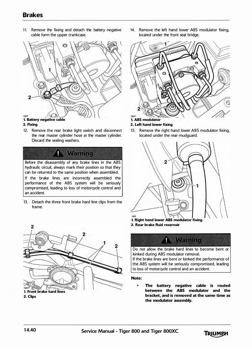
Brakes
1 1 . Remove the fixing and detach the battery negative cable form the upper crankcase.
cgyw 1. Battery negative cable
2. Fixing
12 . Remove the rear brake l ight switch and disconnect the rear master cylinder hose at the master cyl inder. Discard the seal ing washers.
Before the disassembly of any brake l ines in the ABS hydraul ic circu it, always mark their position so that they can be returned to the same position when assembled. If the brake l ines are incorrectly assembled the performance of the ABS system wi l l be seriously compromised, leading to loss of motorcycle control and an accident.
13 . Detach the three front brake hard l ine clips from the frame.
��� 1. Front brake hard lines
2. Clips
14. Remove the left hand lower ABS modulator fixing, located under the front seat bridge.
2. Left hand lower fixing
1 5 . Remove the right hand lower ABS modulator fixing, located under the rear mudguard.
cgyx 1. Right hand lower ABS modulator fixing
2. Rear brake fluid reservoir
Do not a l low the brake hard l ines to become bent or kinked during ABS modulator removal . If the brake l ines are bent or kinked the performance of the ABS system wil l be seriously compromised, leading to loss of motorcycle control and an accident.
Note:
• The battery negative cable is routed between the ABS modulator and the bracket, and is removed at the same time as the modulator assembly.
14.40 SeNice Manual - Tiger 800 and Tiger 800XC
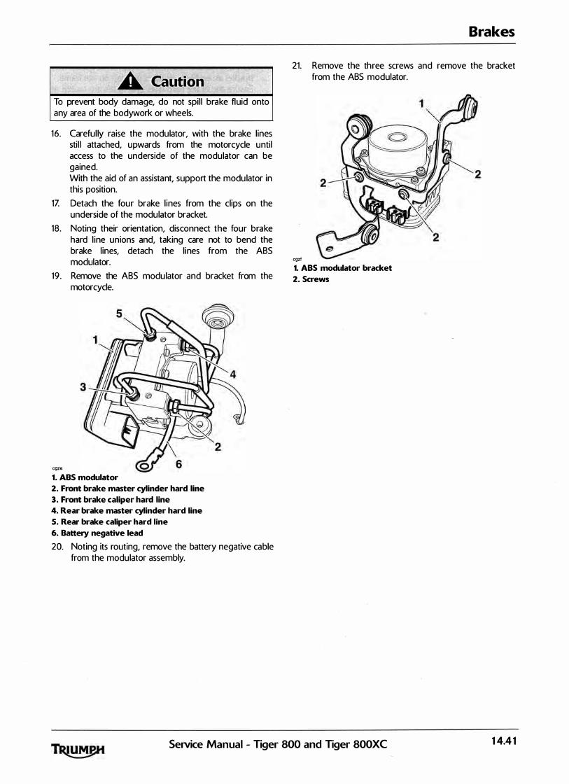
To prevent body damage, do not spi l l brake fluid onto any area of the bodywork or wheels.
16. Careful ly raise the modulator, with the brake l ines sti l l attached, upwards from the motorcycle until access to the underside of the modulator can be gained. With the aid of an assistant, support the modu lator in this position.
1Z Detach the four brake l ines from the clips on the underside of the modulator bracket.
18. Noting their orientation, disconnect the four brake hard l ine unions and, taking care not to bend the brake l ines, detach the l ines from the ABS modulator.
19 . Remove the ABS modu lator and bracket from the motorcycle.
cgze
1. ABS modulator
2. Front brake master cylinder hard line
3. Front brake caliper hard line
4. Rear brake master cylinder hard line
5. Rear brake caliper hard line
6. Battery negative lead
20. Noting its routing, remove the battery negative cable from the modulator assembly.
Brakes
21. Remove the three screws and remove the bracket from the ABS modulator.
cgzl
1. ABS modulator bracket
2. Screws
SeiVice Manual - Tiger 800 and Tiger 800XC 14.41

Brakes
Installation
1 . Al ign the ABS modulator to its bracket, fit new screws and tighten to 9 Nm.
cgzf
1. ABS modulator
2. Screws
2. Re-route the battery negtive lead between the modulator and bracket as noted during removal .
3 . Reposition the modulator to the two front brake l ines and screw the brake line unions in to the modulator. Do not tighten the brake l ine unions at this stage.
4. Refit the brake l ines in to the cl ip on the underside of the modulator.
5 . Reposition the two rear brake l ines to the modulator and screw the brake l ine unions in to the modu lator. Do not tighten the brake l ine unions at this stage.
6. Refit the brake l ines in to the cl ip on the underside of the modulator.
cgze
1. ABS modulator
2. Front brake master cylinder hard line
3. Front brake caliper hard line
4. Rear brake master cylinder hard line
S. Rear brake caliper hard line
6. Battery negative lead
Z Careful ly manoeuvre the ABS modulator and bracket assembly to its fitted position on the frame. Ensure the brake hard l ines and hoses are routed as noted during disassembly.
8. Fit the two lower ABS modu lator fixings and washers. Tighten to 9 Nm.
9. Tighten the four unions to 2 5 Nm, taking care to ensure the brake l ines do not twist during tightening.
10. Refit the battery negative lead to the upper crankcase, tightening the fixing to 9 Nm.
1 1 . Refit the three front brake hard l ine clips to the frame.
14.42 SeJVice Manual - Tiger 800 and Tiger 800XC

12 . Incorporating new washers, fit the rear master cyl inder hose to the master cylinder. Ensuring correct orientation of the brake hose, tighten the rear brake light switch to 1 5 Nm.
1 3 . Connect the brake hose to the ca l iper incorporating new washers on each side of the banjo bolt.
14. Tighten the banjo bolt to 25 Nm.
15. Refit the three rear brake hose P-cl ips, tightening the fixings to 6 Nm.
·
16 . Clip the rear ABS sensor cable to the rear brake hose.
1Z Reconnect the ABS modu lator multiplug, and ensure the locking device is fu lly engaged (see page 14-53).
18. Refit the front seat bridge, tightening the fixings to 5 Nm.
19 . Refit the upper ABS modulator fixing and tighten to 9 Nm.
20. Refit the airbox <see page 10-101>. 21 . Refit the fuel tank <see page 10-92). 22. Reconnect the battery, positive (red) lead first.
Brakes
Use only DOT 4 specification brake fluid as l isted in the general information section of this manual . The use of brake fluids other than those DOT 4 fluids l isted in the general information section may reduce the efficiency of the braking system leading to an accident. Observe the brake fluid handl ing warnings given earlier in th is section of the manual .
23 . Bleed the front brakes <see page 14-33). 24. Bleed the rear brakes <see page 14-36). 25 . Refit the rider's seat <see page 16-13).
lt is dangerous to operate the motorcycle with defective brakes; you must have your authorised Triumph Dealer take remedial action. Fai lure to take remedial action may reduce braking efficiency leading to loss of motorcycle control and an accident.
26. Check that the brakes operate corre.ctly.
SeiVice Manual - Tiger 800 and· Tiger 800XC 14.43

Brakes
ABS
System Description
The ABS versions of the Tiger 800 and Tiger 800XC are fitted with an electronic anti-lock brake system <ABS> which is designed to prevent the wheels from locking or skidding by reducing braking effort to the front or rear brake ca l iper when wheel-lock is detected.
The system consists of a hydraul ic modulator and ECM assembly mounted to a bracket to the rear of the airbox, a front wheel speed sensor mounted to the front fork, and a rear wheel speed sensor mounted to the rear brake cal iper carrier.
Both front and rear wheels have a pulser ring mounted on to the wheel, the front being mounted to the wheel hub, the rear being mounted to the rear brake disc.
The front and rear master cyl inders are connected via l ines to the modu lator and from the modulator the pipes connect to the brake cal ipers. The cal ipers and master cyl inders are identical to the non-ABS equipped motorcycle.
The front and rear brake circuits operate as separate systems. The front and rear brakes are not connected in any way inside the modulator.
The modulator ECM continuously calculates the front and rear wheel speeds, and from these inputs the ECM calculates the estimated motorcycle speed, wheel deceleration/acceleration, the wheel speed difference and the wheel slip <skid) rate. This is ca lculated by comparing the calculated wheel speeds with the calcu lated vehicle speed, so that if one wheel speed deviates sign ificantly from the other two readings, th is wheel is determined to be skidding.
Under braking, if the modulator detects that either wheel is about to s l ip, due to the brake force exceeding the available traction between the tyre and road surface (the wheel wil l beg in to sl ip or 'skid'), the ECM very rapidly releases and re-appl ies the brake pressure to prevent the wheel from skidding.
This is felt through the brake pedal or lever as a rapid 'pulsing' .
If the rider reduces braking effort, or traction increases <so that traction exceeds braking force, the wheel wi l l rotate once more) the wheel wil l no longer lock up. The ABS system wil l detect this and stop control l ing brake pressure, and return to its mon itoring state.
The system has a self diagnostic function bui lt-in which mon itors the fai l safe relay, solenoid valves, motor relay, wheel speed sensors, power supply and ground, as wel l as internal ECM functions. In the event of a malfunction being detected, the ECM will i l luminate the ABS warning l ight, and store a diagnostic trouble code in the system memory. This stored data can then be recovered using a special service tool which is mandatory for a l l Triumph dealers. I n this way, precise d iagnosis of a fault can be made and the fault qu ickly rectified.
Under normal operation, the ABS warning l ight wi l l flash on and off after ignition on unti l the vehicle speed exceeds 6 mph ( 10 km/h). If a trouble code is stored the ABS warning l ight wi l l stay i l luminated and the ABS wil l not function, however the brakes wi l l operate normal ly. If the ABS warn ing l ight does not extinguish, or i l luminates whilst the motorcycle is being ridden, refer. to the ABS system diagnostics <see page 14-48).
14.44 SeiVice Manual - Tiger 800 and Tiger 800XC

Component Location
FRO NT PULSER RING
REAR WHEEL SPEED
SENSOR
FRONT WHEEL SPEED
SENSOR
REAR PULSER RING
FRONT BRAKE ""/ LIG HT /� SWITCH
SeiVice Manual - Tiger 800 a!ld� Tiger 800XC
Brakes
14.45

Brakes
ABS System Circuit Diagram
Key to Wiring Diagram
Key Item Description
1 ABS Modulator
2 Rear Fuse Box <Fuses· 1 and 2)
3 Headlamp Relay
4 Front Brake Light Switch
5 Brake Light
6 Rear Brake Light Switch
7 Front Wheel Speed Sensor
8 Rear Wheel Speed Sensor
9 Instruments
10 Diagnostic Connector
1 1 Engine Control Module
Key to wiring colour codes
Code Wiring Colour
B Black
u Blue
N Brown
G Green
s Slate/Grey
0 Orange
K Pink
R Red
p Purple
w White
y Yellow
LG Light Green
LU Light Blue
ABS ECM Connector Pin Numbering
cdhg
1 0
1 7 23 1 6 24 25
llu�Jtlg�g�g�g�g g� o l't:::::==V-���\ 1 7 8 9
The above i l lustration shows the pin numbering system used in the ABS circuit diagram.
As viewed on the mating face with the ABS ECM (as per the i l lustration), pins are numbered from left to right with number one in the bottom left hand corner.
14.46 SeNice Manual - Tiger 800 and Tiger 800XC

ABS System Circuit Diagram
3
r----- -� I I
2 I 2 I I I lOA lOA '-- - - ..J
m--·-------,.-------------! 16
1 7 2
10 UWI--� 8G 12
81._____ ____.___.1:1�------ :_18 ,...---GP-------------------_j
6 go---oc----121 GP ---'---------41: E I I 1
GP---l ...... 5 ......
SeiVice Manual - Tiger 800 and�Tiger 800XC
Brakes
1
14.47
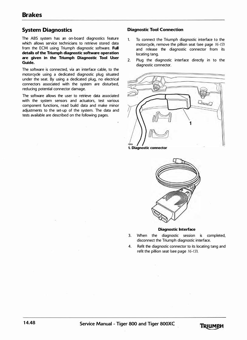
Brakes
System Diagnostics
The ABS system has an on-board diagnostics feature which al lows service techn icians to retrieve stored data from the ECM using Triumph diagnostic software. Full details of the Triumph diagnostic software operation are given in the Triumph Diagnostic Tool User Guide.
The software is connected, via an interface cable, to the motorcycle using a dedicated diagnostic plug situated under the seat. By using a dedicated pl ug, no electrical connectors associated with the system are disturbed, red ucing potential connector damage.
The software al lows the user to retrieve data associated with the system sensors and actuators, test various component fu nctions, read build data and make minor adjustments to the set-up of the system. The data and tests available are described on the fol lowing pages.
Diagnostic Tool Connection
1 . To connect the Triumph diagnostic interface to the motorcycle, remove the pi l l ion seat <see page 16-13>
and release the diagnostic connector from its locating tang.
2 . Plug the diagnostic interface directly in to the diag nostic connector.
1
cgog 1. Diagnostic connector
Diagnostic Interface
3 . When the diagnostic session is completed, d isconnect the Triumph diagnostic interface.
4. Refit the diag nostic connector to its locating tang and refit the pi l l ion seat <see page 16-13).
14.48 Service Manual - Tiger 800 and Tiger 800XC
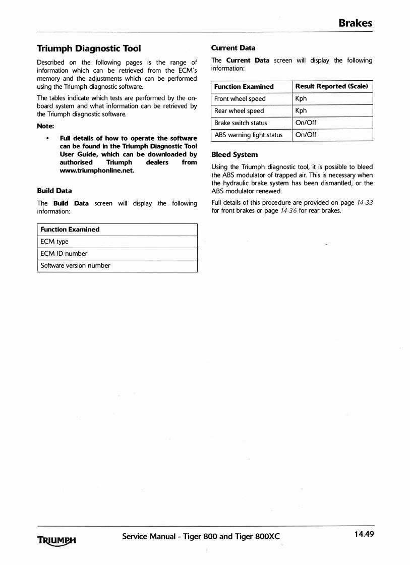
Triumph Diagnostic Tool
Described on the fol lowing pages is the range of information which can be retrieved from the ECM's memory and the adjustments which can be performed using the Triumph diagnostic software.
The tables indicate which tests are performed by the onboard system and what information can be retrieved by the Triumph diagnostic softwa re.
N9te:
• Full details of how to operate the software can be found in the Triumph Diagnostic Tool User Guide, which can be downloaded by authorised Triumph dealers from www.triumphonline.net.
Build Data
The Build Data screen wil l d isplay the fol lowing information:
Function Examined
ECM type
ECM I D number
Software version number
Brakes
Current Data
The Current Data screen wil l d isplay the fol lowing information :
Function Examined Result Reported <Scale>
Front wheel speed Kph
Rear wheel speed Kph
Brake switch status On/Off
ABS warning l ight status On/Off
Bleed System
Using the Triumph diagnostic tool, it is possible to bleed the ABS modulator of trapped a ir. This is necessary when the hydraul ic brake system has been dismantled, or the ABS mod ulator renewed.
Fu l l deta ils of this procedure are provided on page 14-33
for front brakes or page 14-36 for rear brakes.
SeiVice Manual - Tiger 800 and' Tiger SOOXC 14.49

Brakes
Diagnostic Trouble Codes
Diagnostic trouble codes <DT<:s> are logged in the ABS ECM memory when there is a confi rmed fault in the system.
The codes are reported to the Triumph diagnostic tool as a four digit code.
DTCs can be removed at any time using the Triumph diagnostic tool .
The system wil l log the diagnostic trouble codes l isted below:
Diagnostic Trouble Code Fault Description <DTO
C 1 61 1 Front Wheel Sensor Open Circuit/Short Circuit
C 1 61 2 Front Wheel Sensor Abnormal Input/Losing Contact
C 1 61 3 Rear Wheel Sens-9r Open Circu it/Short Circu it
C 1 614 Rear Wheel Sensor Abnormal Input/Losing Contact
C 1 621 Front Wheel Pulser Gear Missing Teeth
C 1 6 2 3 Rear Wheel Pulser Gear Missing Teeth
C 1 631 Front Wheel Input Solenoid Open/Short Circu it
C 1 6 3 2 Front Wheel Output Solenoid Open/Short Circu it
C 1 6 3 3 Rear Wheel Input Solenoid Open/Short Circu it
C1634 Rear Wheel Output Solenoid Open/Short Circuit
C 1 641 Front Wheel Actuator <Hydraul ic Control> Wheel Lock
C 1 64 3 Rear Wheel Actuator <Hydraul ic Control> Wheel Lock
C 1 6 51 Motor - Lock
C 1 6 5 2 Motor - Stuck O F F
C 1 6 5 3 Motor - Stuck O N
C1654 Solenoid Relay - Stuck OFF/ON
C 1 661 Power Source Voltage Drop
C 1 6 6 2 Power Source Voltage Rise
C 1 671 Different Tyre Diameter
C 1 681 Abnormal ECU
14.50 SeiVice Manual - Tiger 800 and Tiger 800XC

Diagnostic Trouble Codes
Dependant on the DTC stored, the AB$ ECM wil l act in one of two ways:
a) Inhibit ABS operation immediately, irrespective of the ABS operating mode;
or
b) Al low the ABS operation to complete before inhibiting the ABS.
Once the ABS ECM has inhibited ABS function, the ECM wil l act in one of three ways:
a> Allow the ABS to resume operation if the fault clears;
or
b) Allow ABS operation after an ignition cycle if the fault clears;
or
c) Inhibit the ABS function unti l the fault is rectified and the DTC erased.
Brakes
The AB$ system wil l act on the DTC stored according to the tables on the fol lowing pages:
Fault Description ABS warning ABS ABS continues ABS will resume operation light operation is to operate if fault clears illuminated inhibited when fault is when fault is when fault is logged logged logged <Only when
ABS is Active. When ABS is no longer active, operation is inhibited)
Front Wheel Sensor Open Yes Yes No Circu it/Short Circuit
Front Wheel Sensor Abnormal Yes Yes Yes Yes, if after ign ition cycle, no Input/Losing Contact fault is detected. DTC
oremains stored
Rear Wheel Sensor Open Yes Yes No Circu it/Short Circuit
Rear Wheel Sensor Abnormal Yes Yes Yes Yes, if after ign ition cycle, no Input/Losing Contact fault is detected. DTC remains
stored
Front Wheel Pulser Gear Yes Yes Yes, if after ign ition cycle, no Missing Teeth fault is detected for 1 second
and speed exceeds 30 km/h. DTC remains stored
Rear Wheel Puis er Gear Yes Yes Yes, if after ignition cycle, no Missing Teeth fault is detected for 1 second
and speed exceeds 30 km/h. DTC remains stored
Front Wheel Input Solenoid Yes Yes No Open/Short Circuit
Front Wheel Output Solenoid Yes Yes No Open/Short Circuit
Service Manual - Tiger 800 and' Tiger SOOXC 14.51

Brakes
Fault Descnption ABS warnmg ABS l ABS continues 1 ABS will resume operat1on light operation is to operate when if fault clears illuminated inhibited fault is logged when fault is when fault is <Only when ABS logged logged is Active. When
ABS is no longer active, operation is inhibited)
Rear Wheel Input Solenoid Yes Yes No Open/Short Circuit
Rear Wheel Output Solenoid Yes Yes No -"
Open/Short Circuit
Front Wheel Actuator Yes Yes Yes, if after ignition cycle, no <Hydraul ic Control> Wheel fault is detected. DTC remains Lock stored
Rear Wheel Actuator Yes Yes Yes, if after ignition cycle, no <Hydraul ic Control> Wheel fault is detected. DTC remains Lock stored
Motor - Lock Yes Yes No
Motor - Stuck OFF Yes Yes N o
Motor - Stuck O N Yes Yes No
Solenoid Relay - Stuck OFF/ Yes Yes No ON
Power Source Voltage Drop Yes, Light wil l Yes Yes, if voltage rises above a exting uish if preset threshold for more fault clears than 1 0 seconds
Power Source Voltage Rise Yes, Light wil l Yes Yes, if voltage drops below a extinguish if preset threshold for more fault clears than 10 seconds
Different Tyre Diameter Yes Yes No
Abnormal ECU Yes Yes No
14.52 Service Manual - Tiger 800 and Tiger 800XC
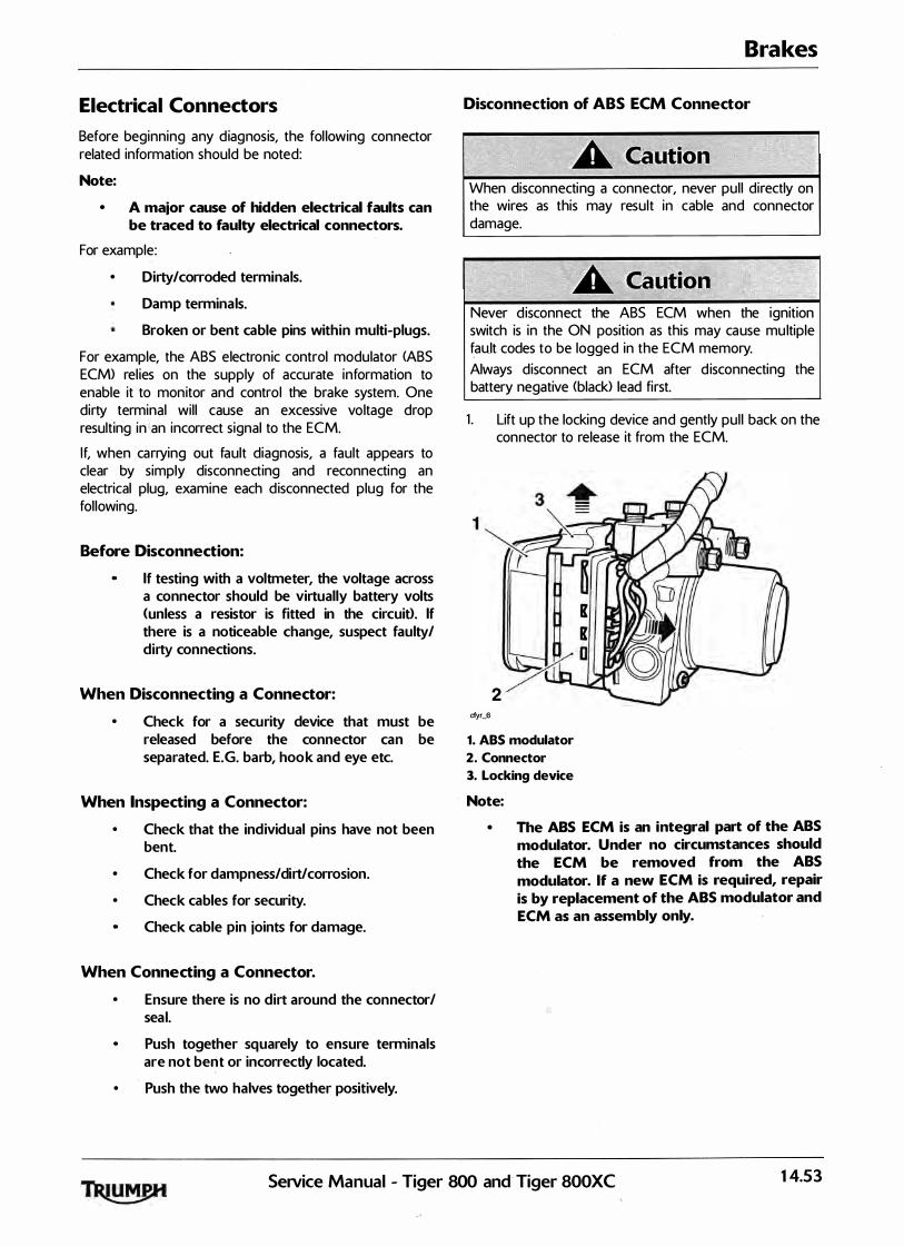
Electrical Connectors
Before beginning any d iagnosis, the following connector related information should be noted:
Note:
• A major cause of hidden electrical faults can be traced to faulty electrical connectors.
For example:
• Dirty/corroded terminals.
Damp terminals.
Broken or bent cable pins within multi-plugs.
For example, the ABS electronic control modulator <ABS ECM> rel ies on the supply of accurate information to enable it to monitor and control the brake system. One dirty terminal wil l cause an excessive voltage drop resulting in an incorrect signal to the ECM.
If, when carrying out fault diagnosis, a fault appears to clear by simply disconnecting and reconnecting an electrical plug, examine each d isconnected plug for the fol lowing.
Before Disconnection:
If testing with a voltmeter, the voltage across a connector should be virtually battery volts <unless a resistor is fitted in the circuit>. If there is a noticeable change, suspect faulty/ dirty connections.
When Disconnecting a Connector:
• Check for a security device that must be released before the connector can be separated. E.G. barb, hook and eye etc.
When Inspecting a Connector:
•
•
•
Check that the individual pins have not been bent.
Check for dampness/dirt/corrosion .
Check cables for security .
Check cable pin joints for damage.
When Connecting a Connector.
• Ensure there is no dirt around the connector/ seal.
Push together squarely to ensure terminals are not bent or incorrectly located.
• Push the two halves together posit ively.
Brakes
Disconnection of ABS ECM Connector
When disconnecting a connector, never pul l directly on the wires as this may result in cable and connector damage.
Never d isconnect the ABS ECM when the ignition switch is in the ON position as this may ca use mu ltiple fault codes to be logged in the ECM memory. Always disconnect an ECM after d isconnecting the battery negative (black> lead first.
1 . Lift up the locking device and gently pul l back on the connector to release it from the ECM.
K K
2
�0 cfyr_6
1. ABS modulator
2. Connector
3. Locking device
Note:
• The ABS ECM is an integral part of the ABS modulator. Under no circumstances should the ECM be removed from the ABS modulator. If a new ECM is required, repair is by replacement of the ABS modulator and ECM as an assembly only.
SeiVice Manual - Tiger 800 and Tiger 800XC 14.53

Brakes
Reconnection of ABS ECM Connector
Damage to the connector pins may resu lt if an attempt to fit the connectors incorrectly is made.
K K
2
�0 cfyr_6
1. ABS modulator
2. Connector
3. Locking device
1 . Fit the connector into its socket and, whi lst holding the connector in place, push down gently on the locking device until it locks.
Further Diagnosis
The tables that fol low wil l, if used correctly, help to pinpoint a fa ult in the system once a diagnostic trouble code has been stored.
Pinpoint Tests
Before starting pinpoint tests
1 . Delete the stored DTCs.
2. Switch the ignition OFF and ON.
I f the ABS is not functioning, the brake system wil l continue to fu nction as a non-ABS braking system. Do not continue to ride for longer than is necessary with the indicator l ight i l luminated. Ride with extreme caution when performing diagnostic troubleshooting on a nonfunctioning ABS system. I n this situation bra king too hard wil l cause the wheels to lock resu lting in loss of motorcycle control and an accident.
3 . Ride the motorcycle at a road speed in ·excess of 3 0
Km/h. If the DTC is repeated proceed t o the relevant pinpoint test.
4. I f the DTC is not repeated this indicates the DTC may have been stored due to external influences such as bad road surfaces or electrical interference.
After completion of the pinpoint tests
1 . Delete the stored DTCs.
2 . Switch the ignition OFF and ON.
3 . Ride the motorcycle at a road speed in excess o f 3 0 Km/h. If the DTC i s repeated proceed to the relevant pinpoint test.
4 . I f a DTC is stored there is a fu rther fault. Read the stored DTC and refer to the relevant _p inpoint test.
14.54 Service Manual - Tiger 800 and Tiger 800XC
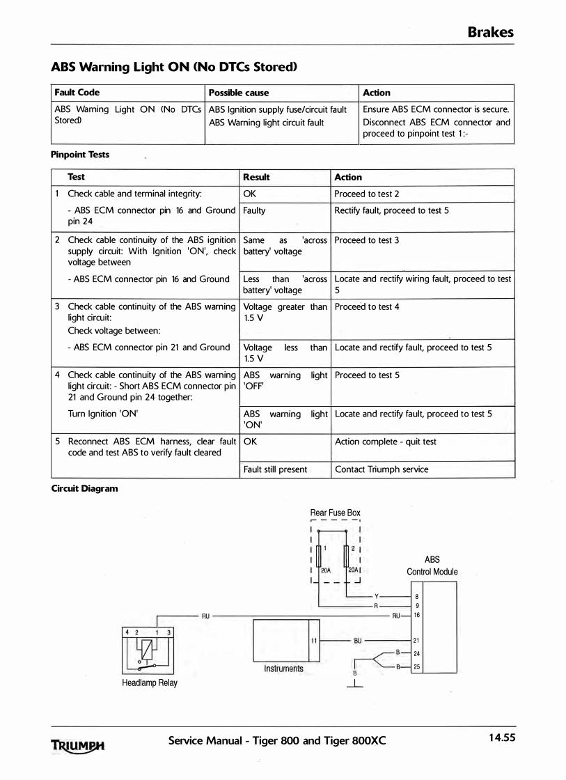
Brakes
ABS Warning Light ON <No DTCs Stored)
Fault Code Possible cause Action
ABS Wa rning Light O N <No DTCs ABS Ign ition supply fuse/circuit fault Ensure ABS ECM connector is secure. Stored) ABS Warning l ight ci rcu it fau lt Disconnect ABS ECM connector and
Pinpoint Tests
Test
1 Check cable and terminal integrity:
- ABS ECM connector pin 16 and G round pin 24
2 Check cable continuity of the ABS ignition supply ci rcu it: With Ign ition 'ON', check voltage between
- ABS ECM connector pin 16 and G round
3 Check cable continu ity of the ABS warn ing l ight circu it: Check voltage between :
- ABS ECM connector pin 21 and G round
4 Check cable continuity of the ABS warn ing l ight circuit: - Short ABS ECM connector pin 21 and G round pin 24 together:
Turn Ign ition 'ON'
5 Reconnect ABS ECM harness, clear fault code and test ABS to verify fault cleared
Circuit Diagram
proceed to pinpoint test 1 :-
Result Action
OK Proceed to test 2
Faulty Rectify fault, proceed to test 5
Same as 'across Proceed to test 3 battery' voltage
Less than 'across Locate and rectify wiring fault, proceed to test battery' voltage 5
Voltage greater than Proceed to test 4 1 .5 V
Voltage less than Locate and rectify fau lt, proceed to test 5 1 .5 V
ABS warning l ight Proceed to test 5 'OFF'
ABS warning l ight Locate and rectify fault, proceed to test 5 'ON'
O K Action complete - quit test
Fault sti l l present Contact Triumph service
Rear Fuse Box � --- -·
y R
ABS Control Module
8 9
.------RU ------�========�-------
�HI---� RU- 16
Headlamp Relay Instruments � "--
_L
Se1Vice Manual - Tiger 800 and Tiger 800XC
21
B- 24
B- 25
14.55

Brakes
ABS Warning Light Does Not Il luminate <No DTCs Stored)
Fault Code Possible cause Action
ABS Warning Light OFF <No DTCs Warn ing l ight ci rcu it fault Ensure ABS ECM connector is secure. Stored) ABS ECM g round circuit fault Ensure ABS ECM ground connection
is secure. Disconnect ABS ECM connector and proceed to pinpoint test 1 :-
Pinpoint Tests
Test Result Action
1 Check cable and terminal integ rity: O K Proceed to test 2
- ABS ECM connector pin 1 6 and Ground Faulty Rectify fau lt, proceed to test 6
2 Check the ABS warning l ight circuit fuse O K Proceed to test 3 (front fuse box, fuses 1 and 2):
Faulty Replace fuse, proceed to test 6
3 Check cable for short to voltage: With ov Proceed to test 4 Ignition 'O FF', check voltage between
- ABS ECM con nector pin 1 6 and Ground Above 3 V Locate and rectify wiring fault, proceed to test 6
4 Check cable for short to ground: With Voltage greater than Proceed to test 5 ignition 'ON', Check the ABS warning l ight 1 .5 V circuit voltage between :
- ABS ECM connector pin 21 and Ground Voltage less than 1 .5 Locate and rectify fault, proceed to test 6 V
5 Check cable for continu ity: ABS ECM O K Proceed t o test 6 connector pin 24 and Ground:
Turn Ignition 'ON' Faulty Locate and rectify fau lt, proceed to test 6
6 Reconnect ABS ECM harness, clear fault OK Action complete - quit test code and test ABS to verify fault cleared
Fau lt sti l l present Contact Triumph service
14.56 SeiVice Manual - Tiger 800 and Tiger 800XC
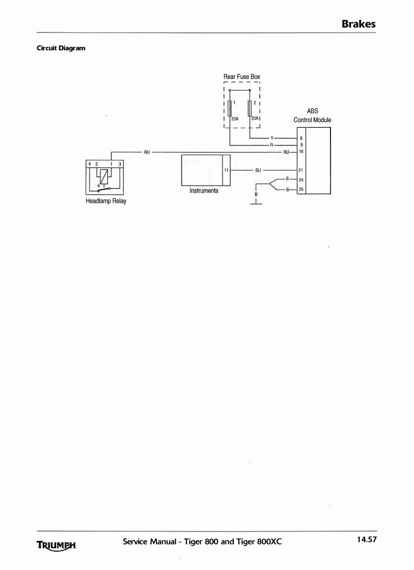
Circuit Diagram
Headlamp Relay
Rear Fuse Box r- - - - -·
20A
2 I
I 20AI
_J y R
SeiVice Manual - Tiger 800 and Tiger 800XC
ABS Control Module
8 9
RU- 16
21
B- 24
8- 25
Brakes
14.57

Brakes
Front Wheel Sensor Open Circuit/Short Circuit
Fault Code Possible cause Action
C 1 61 1 Front wheel speed sensor circu it fault Ensure ABS ECM connector is secure. Ensure wheel speed sensor connector is secure. Disconnect ABS ECM connector and proceed to pinpoint test 1 :-
Pinpoint Tests
Test Result Action
1 Check cable and terminal integrity: O K Proceed to test 2
- ABS ECM connector pin 3 and ABS ECM Faulty Rectify fault, proceed to test 9 connector pin 1 2
2 Check cable for short circuit: O K Proceed t o test 4
- ABS ECM connector pin 1 2 and Ground Short circu it Proceed to test 3
3 Disconnect the front wheel speed sensor O K Replace the wheel speed sensor, proceed to connector. Check ca ble for short ci rcuit: test 9
Wheel speed sensor connector pin 2 Short ci rcu it Locate and rectify wiring harness fault, (motorcycle harness side) and Ground proceed to test 9
4 Check cable for short circuit: O K Proceed to test 6
- ABS ECM connector pin 3 and Ground Short ci rcu it Proceed to test 5
5 Check cable for short circuit: O K Replace the wheel speed sensor, proceed to test 9
- Wheel speed sensor connector pin 1 Short ci rcuit Locate and rectify wiring harness fault, (motorcycle harness side) and Ground proceed to test 9
6 Check cable continuity: O K Proceed to test 7
- ABS ECM connector pin 1 2 and Wheel Open circuit Locate and rectify wiring harness fault, speed sensor connector pin 2 (motorcycle proceed to test 9 harness side>
7 Check cable continuity: O K Proceed to test 8
- ABS ECM connector pin 3 and Wheel Open circuit Locate and rectify wiring harness fa ult, speed sensor connector pin 1 <motorcycle proceed to test 9 harness side)
8 Reconnect the front wheel speed sensor 3 mA to 14 mA Proceed to test 9 connector. Check the wheel speed sensor operation:
- Connect a suita ble voltage supply Faulty Replace the wheel speed sensor, proceed to between 4.5 V and 1 6 v between ABS ECM test.9 connector pin 1 2 <positive> and pin 3 (negative), and measure the current consumption of the wheel speed sensor
9 Reconnect ABS ECM harness, clear fault O K Action complete - quit test code and test ABS to verify fault cleared
Fault sti l l present Contact Triumph service
14.58 SeiVice Manual - Tiger 800 and Tiger 800XC

Brakes
Circuit Diagram
Wheel speed sensor current consumption data under typical conditions:
Voltage M in Typical Max
Low (4.5 V> 3 .1 mA 4.1 mA 5.3 mA
High ( 1 6V> 8.1 mA 10.5 mA 1 3 . 6 mA
Front Wheel ABS Speed Sensor Control Module
I: I uw I:, I BG
SeiVice Manual - Tiger 800 and Tiger 800XC 14.59

Brakes
Rear Wheel Sensor Open Circuit/Short Circuit
Fault Code Possible cause Action
C 1 61 3 Rear wheel speed sensor circu it fault Ensure ABS ECM connector is secure. Ensure wheel speed sensor connector is secure. Disconnect ABS ECM con nector and proceed to pinpoint test 1 :-
Pinpoint Tests
Test Result Action
1 Check ca ble and terminal integrity: O K Proceed to test 2
- ABS ECM con nector pin 2 and ABS ECM Faulty Rectify fault, proceed to test 9 connector pin 1 8
2 Check cable for short circu it: O K Proceed to test 4
- ABS ECM connector pin 2 and Ground Short circuit Proceed to test 3
3 Disconnect the front wheel speed sensor O K Replace the wheel speed sensor, proceed to connector. Check ca ble for short ci rcuit: test 9
- Wheel speed sensor connector pin 2 Short ci rcu it Locate and rectify wiring harness fau lt, (motorcycle harness side) and Ground proceed to test 9
4 Check cable for short circuit: OK Proceed to test 6
- ABS ECM con nector pin 1 8 and Ground Short circuit Proceed to test 5
5 Check cable for short circuit: O K Replace the wheel speed sensor, proceed to test 9
- Wheel speed sensor connector pin 1 Short circuit Locate and rectify wiring harness fau lt, <motorcycle harness side) and Ground proceed to test 9
6 Check cable continu ity: O K Proceed to test 7
- ABS ECM connector pin 2 and Wheel Open circuit Locate and rectify wiring harness fau lt, speed sensor connector pin 2 (motorcycle proceed to test 9 harness side)
7 Check cable continuity: O K Proceed to test 8
- ABS ECM connector pin 1 8 and Wheel Open circu it Locate and rectify wiring harness fau lt, speed sensor connector pin 1 <motorcycle proceed to test 9 harness side)
8 Reconnect the front wheel speed sensor 3 mA to 14 mA Proceed to test 9 connector. Check the wheel speed sensor operation:
- Connect a suitable voltage supply Faulty Replace the wheel speed sensor, proceed to between 4.5 V and 1 6 v between ABS ECM test 9 connector pin 2 <positive) and pin 18 (negative), and measure the current consum ption of the wheel speed sensor
9 Reconnect ABS ECM harness, clear fault OK Action complete - quit test code and test ABS to verify fault cleared
Fault sti l l present Contact Triumph service
14.60 SeiVice Manual - Tiger 800 and Tiger 800XC

Brakes
Circuit Diagram
Wheel speed sensor current consumption data under typical conditions:
Voltage M in Typical Max
Low (4.5 \/) 3 .1 mA 4.1 mA 5 .3 mA
High ( 1 6\/) 8.1 mA 10.5 mA 1 3 . 6 mA
Rear Wheel ABS Speed Sensor Control Module
I : I BG I:.[ UR
SeiVice Manual - Tiger 800 and' Tiger 800XC 14.61

Brakes
Front Wheel Sensor Abnormal Input/losing Contact
Fault Code Possible cause Action
C 1 61 2 Front wheel speed sensor poor signal Ensure ABS ECM connector is secure. Incorrect Wheel speed sensor a ir gap Ensure wheel speed sensor connector Damaged or dirty pulser ring is secure.
Loose or incorrectly instal led wheel Proceed to pinpoint test 1 :-speed sensor
Pinpoint Tests
Test Result Action
1 Measure the air gap of the front wheel O K Proceed t o test 2 speed sensor between the sensor and the pulser ring:
-Air gap between 0.1 mm to 1 .5 m m Faulty Rectify the fau lt and proceed to test 5
2 Check the pulser ring for damage or O K Proceed t o test 3 contamination by road grime or ferrous metal fi l ings
Faulty Clean or replace the ABS pulser ring, proceed to test 5
3 Check the wheel speed sensors for correct O K Proceed t o test 4 instal lation, and the fixings for correct torque
Faulty Rectify the fault and proceed to test 5
4 Check the wheel speed sensor circuit <See O K Contact Triumph service page 14-58)
Faulty Rectify the fault and proceed to test 5
5 Clear fault code and test ABS to verify fault O K Action complete - q uit test cleared
Fault sti l l present Contact Triumph service
14.62 SeiVice Manual - Tiger 800 and Tiger 800XC
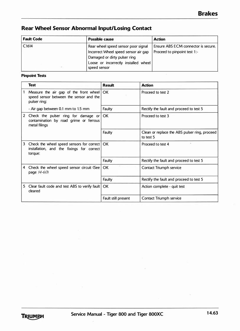
Brakes
Rear Wheel Sensor Abnormal Input/Losing Contact
Fault Code Possible cause Action
C 1 614 Rear wheel speed sensor poor signal Ensure ABS ECM connector is secure.
Incorrect Wheel speed sensor a ir gap Proceed to pinpoint test 1 :-Damaged or dirty pulser ring Loose or incorrectly instal led wheel speed sensor
Pinpoint Tests
Test Result Action
1 Measure the air gap of the front wheel O K Proceed to test 2 speed sensor between the sensor and the pulser ring:
- Air gap between 0.1 m m to 1 .5 mm Faulty Rectify the fault and proceed to test 5
2 Check the pu lser ring for damage or OK Proceed to test 3 contamination by road g rime or ferrous meta l fi l ings
Faulty Clean or replace the ABS pulser ring, proceed to test 5
3 Check the wheel speed sensors for correct O K Proceed t o test 4 instal lation, and the fixings for correct torque:
Faulty Rectify the fault and proceed to test 5
4 Check the wheel speed sensor circuit <See OK Contact Triumph service page 14-60>
Faulty Rectify the fault and proceed to test 5
5 Clear fau lt code and test ABS to verify fault OK Action complete - quit test cleared
Fault sti l l present Contact Triumph service
SeiVice Manual - Tiger 800 and Tiger 800XC 14.63
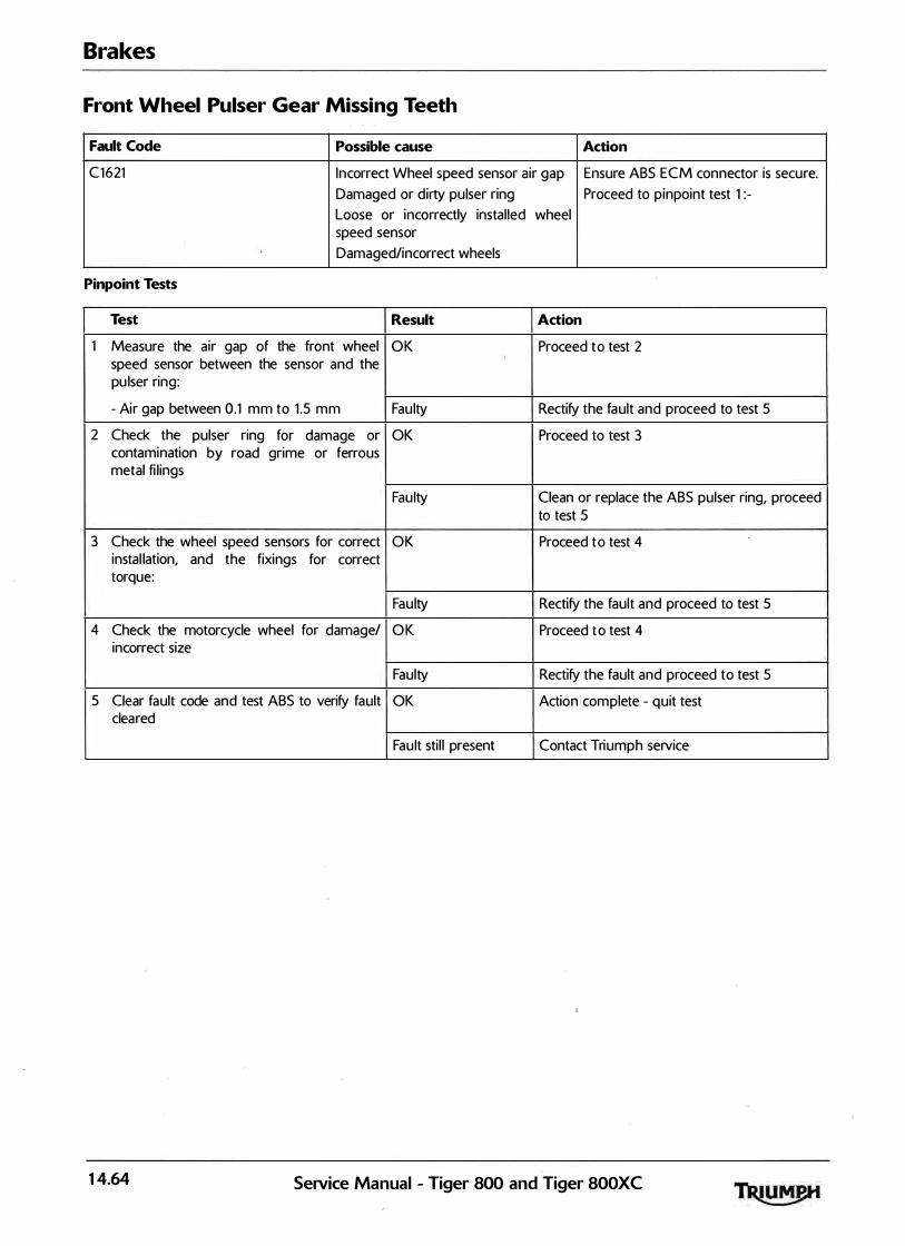
Brakes
Front Wheel Pulser Gear Missing Teeth
Fault Code Possible cause Action
C 1 6 21 Incorrect Wheel speed sensor air gap Ensure ABS ECM connector is secure. Damaged or dirty pulser ring Proceed to pinpoint test 1 :-Loose or incorrectly instal led wheel speed sensor Damaged/incorrect wheels
Pinpoint Tests
Test Result Action
1 Measure the air gap of the front wheel O K Proceed t o test 2 speed sensor between the sensor and the pu lser ring:
- Air gap between 0.1 m m to 1 .5 m m Faulty Rectify the fa ult and proceed to test 5
2 Check the pulser ring for damage or OK Proceed to test 3 contamination by road grime or ferrous metal fi l ings
Fau lty Clean or replace the ABS pulser ring, proceed to test 5
3 Check the wheel speed sensors for correct O K Proceed t o test 4 instal lation, and the fixings for correct torque:
Fau lty Rectify the fault and proceed to test 5
4 Check the motorcycle wheel for damage/ O K Proceed t o test 4 incorrect size
Faulty Rectify the fault and proceed to test 5
5 Clear fault code and test ABS to verify fault OK ActionJcom plete - q uit test cleared
Fault sti l l present Contact Triumph service
14.64 SeiVice Manual - Tiger 800 and Tiger 800XC

Brakes
Rear Wheel Pulser Gear Missing Teeth
Fault Code Possible cause Action
C 1 623 Incorrect Wheel speed sensor air gap Ensure ABS ECM connector is secure.
Damaged or dirty pulser ring Proceed to pinpoint test 1 :-Loose or incorrectly insta lled wheel speed sensor Damaged/incorrect wheels
Pinpoint Tests
Test Result Action
1 Measure the a ir gap of the front wheel OK Proceed to test 2 speed sensor between the sensor and the pulser ring:
- Air gap between 0.1 mm to 1 .5 mm Faulty Rectify the fau lt and proceed to test 5
2 Check the pulser ring for damage or O K Proceed to test 3 contamination by road grime or ferrous meta l fi l ings
Faulty Clean or replace the ABS pulser ring, proceed to test 5
3 Check the wheel speed sensors for correct OK Proceed to test 4 instal lation, and the fixings for correct torque:
Faulty Rectify the fault and proceed to test 5
4 Check the motorcycle wheel for da mage/ OK Proceed to test 4 incorrect s ize
Faulty Rectify the fault and proceed to test 5
5 Clear fau lt code and test ABS to verify fault OK Action complete - q uit test cleared.
Fault sti l l present Contact Triumph service
SeiVice Manual - Tiger 800 and' Tiger SOOXC 14.65

Brakes
Front or Rear Input/Output Solenoid Open/Short Circuit
Fault Code Possible cause
Front: C 1 6 31 ; C 1 6 3 2 ABS solenoid circuit fault Rear: C 1 63 3; C 1 6 3 4 C 1 654
Pinpoint Tests
Test Result
1 Check cable and terminal integrity: O K
- ABS ECM connector p i n 9 a n d Ground Faulty
2 Check the ABS solenoid fuse (front fuse O K box fuse 1 ) :
Faulty
3 Check cable continu ity: With Ignition 'ON', Same as 'across check voltage between battery' voltage
- ABS ECM connector pin 9 and Ground Less than 'across battery' voltage
4 Check cable for continu ity: O K
- ABS ECM connector pin 24 a n d Ground Faulty
5 Clear fault code and test ABS to verify fault OK cleared
Fault sti l l present
Circuit Diagram
Rear Fuse Box ,------ -,
20A
Action
Ensure ABS ECM connector is secure. Disconnect ABS ECM connector and proceed to pinpoint test 1 :-
Action
Proceed to test 2
Rectify fault, proceed to test 5
Proceed to test 3
Replace fuse, proceed to test 5 ·
Proceed to test 4
Locate and rectify wiring fault, proceed to test 5
Proceed to test 5
Locate and rectify fau lt, proceed to test 5
Action complete - qu it test
Contact Triumph service
ABS Control Module
I .------------1 IL.......L.,__� I -------' 8
l_
14.66 Service Manual - Tiger 800 and Tiger 800XC
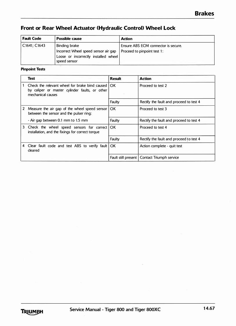
Brakes
Front or Rear Wheel Actuator <Hydraulic Control> Wheel Lock
Fault Code Possible cause Action
C 1 641 ; C 1 643 Binding bra ke Ensure ABS ECM connector is secure. I ncorrect Wheel speed sensor air gap Proceed to pinpoint test 1 : Loose or incorrectly insta lled wheel speed sensor
Pinpoint Tests
Test Result Action
1 Check the relevant wheel for brake bind caused O K Proceed to test 2 by ca l iper or master cylinder faults, or other mechanical causes
Fau lty Rectify the fault and proceed to test 4
2 Measure the a ir gap of the wheel speed sensor O K Proceed to test 3 between the sensor and the pulser ring:
- Air gap between 0. 1 mm to 1 .5 mm Faulty Rectify the fault and proceed to test 4
3 . Check the wheel speed sensors for correct O K Proceed to test 4 instal lation, and the fixings for correct torque
Faulty Rectify the fault and proceed �o test 4
4 Clear fault code and test ABS to verify fault OK Action complete - quit test cleared
Fau lt sti l l present Contact Triumph service
SeiVice Manual - Tiger 800 and Tiger 800XC 14.67

Brakes
Motor - Lock; Motor Stuck OFF; Motor Stuck ON
Fault Code Possible cause Action
C 1 651 ; C 1 6 5 2; Motor circuit fault Ensu re ABS ECM connector is secure. C 1 6 5 3 Motor runs continual ly Turn the ignition 'ON' .
Motor does not ru n at a l l Proceed to pinpoint test 1 :
Pinpoint Tests
Test Result Action
1 Check the motor function: OK Proceed to test 2
Check that with the motorcycle stationary and the Motor runs Contact Triumph service ABS ACM modulator connected, the motor does continual ly not operate
2 Check the ABS motor circuit fuse front fuse box, O K Proceed to test 3 (fuse 2)
Fau lty Replace fuse and proceed to test 5
3 Check cable continuity: With Ignition 'ON', check Same as 'across Proceed to test 4 voltage between: battery' voltage
- ABS ECM connector pin 8 and Ground Less than 'across Locate and rectify wiring fau lt, proceed battery' voltage test 5
4 Check cable for continuity: O K Proceed t o test 5
- ABS ECM connector pin 25 and Ground Faulty Locate and rectify fau lt, proceed to test 5
5 Reconnect ABS ECM harness, clear fault code O K Action complete - quit test and test ABS to verify fault cleared
Circuit Diagram
Fault sti l l present Contact Triumph service
Rear Fuse Box r-------,
I I I
�OA I
·----- - ..J
Control Module
Y----1 8
� B--�2-SL---�
14.68 SeiVice Manual - Tiger 800 and Tiger 800XC
to

Brakes
Power Source Voltage Drop/Voltage Rise
Fault Code Possible cause Action
C 1 6 61 ; C 1 6 6 2 Power supply circuit fault Ensure ABS ECM connector is secure. Battery cha rging circu it fau lt Disconnect ABS ECM connector and proceed to pinpoint
test 1 :
Pinpoint Tests
Test Result Action
1 Check cable and terminal integ rity: O K Proceed to test 2
- ABS ECM connector pin 1 6 and Ground pin 24 Faulty Rectify fault, proceed to test 5
2 Check the cable for continu ity: O K Proceed t o test 3
- ABS ECM connector pin 24 and Ground Faulty Rectify wiring harness fault, proceed to test 5
3 Check battery voltage: With ignition 'ON', Check Voltage g reater Proceed to test 4 the voltage between: than 10 V
- ABS ECM connector pin 1 6 and Ground pin 24 Voltage less Locate and rectify fault, proceed to test 5 than 10 V
4 Check battery voltage: Reconnect ABS ECM Voltage Proceed to test 4 connector and start the engine, Check the between 10 V voltage between: and 16 V
- Battery positive (red) terminal and negative Voltage greater Check the battery charging circu it. Locate and (black> terminal than 1 6 V rectify fau lt, proceed to test 5
5 Clear fault code and test ABS to verify fau lt O K Action com plete - quit test clea red
Fault sti l l present Contact Triumph service
Circuit Diagram
Rear Fuse Box ,..... --- -·
y R
ABS Control Module
8 9
.------RU ------�========�------- RU- 16
Headlamp Relay
��"�1----� Instruments � """--
_:_I_
SeiVice Manual - Tiger 800 and Tiger 800XC
21 B- 24 B- 25
14.69

Brakes
Different Tyre Diameter \..
Fault Code Possible cause Action
C 1 671 Incorrect diameter wheels instal led Ensure ABS ECM connector is secure. Incorrect tyre pressures Proceed to pinpoint test 1 : Incorrect wheel speed sensor a ir gap Damaged or d irty pulser ring
Pinpoint Tests
Test Result Action
1 Check for instal lation of wheels and tyres of the O K Proceed to test 2 correct size
Faulty Rectify fault, proceed to test 5
2 Check the tyre pressures OK Proceed to test 3
Faulty Rectify fault, proceed to test 5
3 Check the pulser ring for damage or OK Proceed to test 4 contamination by road grime or ferrous meta l fi l ings
Faulty Clean or replace the ABS pulser ring, proceed to test 5
4 Measure the a ir gap of the front wheel speed O K Proceed to test 5 sensor between the sensor and the pulser ring:
- Air gap between 0.1 m m to 1 .5 mm Faulty Rectify the fault and proceed to test 5
5 Clear fault code and test ABS to verify fault OK Action complete - qu i t test cleared
Fault sti l l present Contact Triumph service
14.70 SeiVice Manual - Tiger 800 and Tiger SOOXC

Brakes
Abnormal ECU
Fault Code Possible cause Action
C 1 681 Incorrect Wheel speed sensor air gap Ensure ABS ECM connector is secure. Damaged or dirty pulser ring Proceed to pinpoint test 1 : Loose or incorrectly instal led wheel speed sensor
Pinpoint Tests
Test Result Action
1 Measure the a ir gap of the wheel speed sensors O K Proceed to test 1 between the sensor and the pulser ring:
- Air gap between 0.1 m m to 1 .5 mm Faulty Rectify the fault and proceed to test 4
2 Check the pulser rings for damage or OK Proceed to test 2 contamination by road g rime or ferrous metal fi l ings
Fau lty Clean or replace the ABS pulser ring, proceed to test 4
3 Check the wheel speed sensors for correct O K Proceed to test 4 instal lation, and the fixings for correct torque
Faulty Rectify the fault and proceed to test 4
4 Clear fault code and test ABS to verify fau lt OK Action com plete - qu i t test cleared
Fault sti l l present Contact Triumph service
SeNice Manual - Tiger 800 and Tiger 800XC 14.71
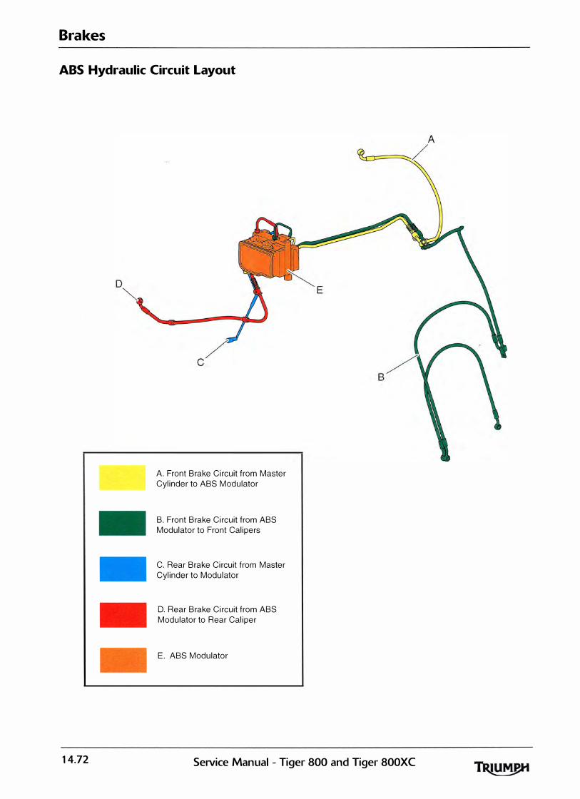
Brakes
ABS Hydraulic Circuit Layout
14.72
A. Front Brake Circuit from Master Cylinder to ABS Modulator
B. Front Brake Circuit from ABS Modulator to Front Calipers
C. Rear Brake Circuit from Master Cylinder to Modulator
D. Rear Brake Circuit from ABS Modulator to Rear Caliper
E. ABS Modulator
Setvice Manual- Tiger 800 and Tiger 800XC
1 5 Wheels/Tyres Table of Contents
Exploded view - Front Wheel - Tiger 800 . . . . . . . . . . . . . . . . . . . . . . . . . . . . . . . . . . . . . . . . . . . . . . . . . . . . 1 5.2
Exploded view - Front Wheel - Tiger 800 XC . . . . . . . . . . . . . . . . . . . . . . . . . . . . . . . . . . . . . . . . . . . . . . . . . 1 5.3
Exploded View - Rear Wheel 8. Final Drive - Tiger 800 . . . . . . . . . . . . . . . . . . . . . . . . . . . . . . . . . . . . . . . . . 15.4
Exploded View - Rear Wheel 8. Final Drive - Tiger 800 XC . . . . . . . . . . . . . . . . . . . . . . . . . . . . . . . . . . . . . . 1 5.5
Tyres . . . . . . . . . . . . . . . . . . . . . . . . . . . . . . . . . . . . . . . . . . . . . . . . . . . . . . . . . . . . . . . . . . . . . . . . . . . . . . . . . . . 15.6
Tyre Pressures. . . . . . . . . . . . . . . . . . . . . . . . . . . . . . . . . . . . . . . . . . . . . . . . . . . . . . . . . . . . . . . . . . . . . . 15.7
Tyre Wear/Wheel Inspection. . . . . . . . . . . . . . . . . . . . . . . . . . . . . . . . . . . . . . . . . . . . . . . . . . . . . . . . . . 15.8
Important Tyre Information . . . . . . . . . . . . . . . . . . . . . . . . . . . . . . . . . . . . . . . . . . . . . . . . . . ·. . . . . . . . 15.8
Front Wheel . . . . . . . . . . . . . . . . . . . . . . . . . . . . . . . . . . . . . . . . . . . . . . . . . . . . . . . . . . . . . . . . . . . . . . . . . . . . 15.10
Removal . . . . . . . . . . . . . . . . . . . . . . . . . . . . . . . . . . . . . . . . . . . . . . . . . . . . . . . . . . . . . . . . . . . . . . . . . . 1 5.10
Installation. . . . . . . . . . . . . . . . . . . . . . . . . . . . . . . . . . . . . . . . . . . . . . . . . . . . . . . . . . . . . . . . . . . . . . . . . 15.1 1 (' Rear Wheel . . . . . . . . . . . . . . . . . . . . . . . . . . . . . . . . . . . . . . . . . . . . . . . . . . . . . . . . . . . . . . . . . . . . . . . . . . . . 15.1 1
Removal . . . . . . . . . . . . . . . . . . . . . . . . . . . . . . . . . . . . . . . . . . . . . . . . . . . . . . . . . . . . . . . . . . . . . . . . . . 1 5.1 1
Installation. . . . . . . . . . . . . . . . . . . . . . . . . . . . . . . . . . . . . . . . . . . . . . . . . . . . . . . . . . . . . . . . . . . . . . . . . 15.12
Front Wheel Bearings . . . . . . . . . . . . . . . . . . . . . . . . . . . . . . . . . . . . . . . . . . . . . . . . . . . . . . . . . . . . . . . . . . . . 1 5.13
Removal . . . . . . . . . . . . . . . . . . . . . . . . . . . . . . . . . . . . . . . . . . . . . . . . . . . . . . . . . . . . . . . . . . . . . . . . . . 1 5.1 3
Inspection . . . . . . . . . . . . . . . . . . . . . . . . . . . . . . . . . . . . . . . . . . . . . . . . . . . . . . . . . . . . . . . . . . . . . . . . . 15.14
Installation . . . . . . . . . . . . . . . . . . . . . . . . . . . . . . . . . . . . . . . . . . . . . . . . . . . . . . . . . . . . . . . . . . . . . . . . . 15.14
Rear Wheel Bearings. . . . . . . . . . . . . . . . . . . . . . . . . . . . . . . . . . . . . . . . . . . . . . . . . . . . . . . . . . . . . . . . . . . . . 1 5.15
Removal . . . . . . . . . . . . . . . . . . . . . . . . . . . . . . . . . . . . . . . . . . . . . . . . . . . . . . . . . . . . . . . . . . . . . . . . . . 1 5.15
Inspection . . . . . . . . . . . . . . . . . . . . . . . . . . . . . . . . . . . . . . . . . . . . . . . . . . . . . . . . . . . . . . . . . . . . . . . . . 15.15
Installation . . . . . . . . , . . . . . . . . . . . . . . . . . . . . . . . . . . . . . . . . . . . . . . . . . . . . . . . . . . . . . . . . . . . . . . . . 1 5.15
Final Drive . . . . . . . . . . . . . . . . . . . . . . . . . . . . . . . . . . . . . . . . . . . . . . . . . . . . . . . . . . . . . . . . . . . . . . . . . . . . . 1 5.1 6
Removal . . . . . . . . . . . . . . . . . . . . . . . . . . . . . . . . . . . . . . . . . . . . . . . . . . . . . . . . . . . . . . . . . . . . . . . . . . 1 5.1 6
Inspection . . . . . . . . . . . . . . . . . . . . . . . . . . . . . . . . . . . . . . . . . . . . . . . . . . . . . . . . . . . . . . . . . . . . . . . . . 1 5.17
Installation . . . . . . . . . . . . . . . . . . . . . . . . . . . . . . . . . . . . . . . . . . . . . . . . . . . . . . . . . . . . . . . . . . . . . . . . . 1 5.17
SeJVice Manual - Tiger 800 and Tiger 800XC 15.1

Wheels/Tyres
Exploded view - Front Wheel - Tiger 800
65 Nm
15.2 SeiVice Manual - Tiger 800 and Tiger SOOXC
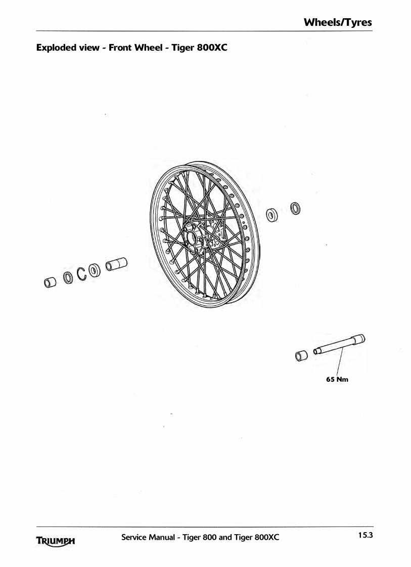
Wheels/Tyres
Exploded view - Front Wheel - Tiger SOOXC
65 Nm
SeiVice Manual - Tiger 800 and Tiger 800XC 15.3
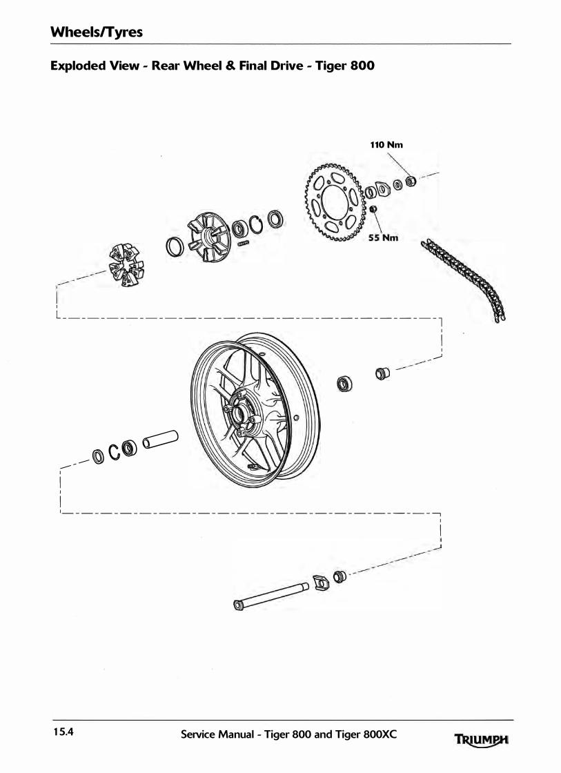
Wheels/Tyres
Exploded View - Rear Wheel & Final Drive - Tiger 800
1 10 Nm
I L _ _ _ _ _ _ _ _ _ _ _ _ _ _ _ _ _ _ _ _ _ _ _ _ _ _ _ _ _ _ _ _ _ _ _ _ _ _ _ l
I I I ---'
0 -- � c(ID ---1 I I I � - - - - - - - - - - - - - - - - - - - - - - - - - - - - - - - - - - - - - - � I
I
15.4 Seavice Manual - Tiger 800 and Tiger 800XC
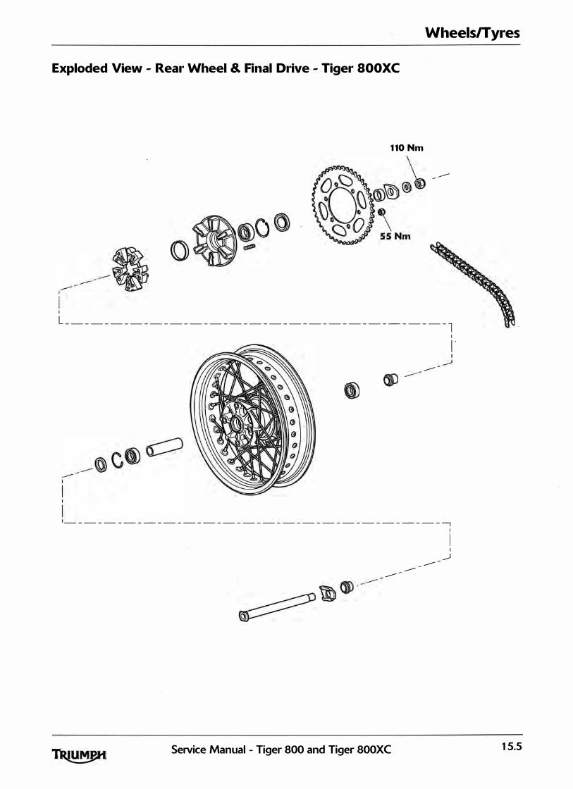
Wheels/Tyres
Exploded View - Rear Wheel & Final Drive - Tiger SOOXC
1 10 Nm
I
L _ _ _ _ _ _ _ _ _ _ _ _ _ _ _ _ _ _ _ _ _ _ _ _ _ _ _ _ _ _ _ _ _ _ _ _ _ _ _ l I , .
---
- - - - - - - - - - - - - - - - - - - - - - - - - - - - - - - - - - - - - - --,
I _..J ---------
Service Manual - Tiger 800 and Tiger 800XC 15.5

Wheels/Tyres
Tyres
Tiger 800 models are equipped with tubeless tyres, valves and wheel rims. Use only tyres marked 'TU BELESS' and tubeless va lves on r ims marked 'SU ITAB LE FOR TU B ELESS TYRES'.
T U B E L E SS RAD I A L
==============---� Typical Tyre Marking - Tubeless Tyre
Do not insta l l tube-type tyres on tubeless rims. The bead will not seat and the tyres could s l ip on the rims, causing rapid tyre deflation that may result in a loss of vehicle control and an accident. Never insta l l an inner tube inside a tubeless tyre. This will cause friction inside the tyre and the resulting heat bui ld-up may cause the tube to burst resu lting in rapid tyre deflation, loss of veh icle control and an accident.
Tiger aooxc models are fitted with spoked wheels which require a tyre su itable for use with an inner tube.
Fai lure to use an inner tube in a spoked wheel wil l cause deflation of the tyre resulting in loss of motorcycle control and an accident.
Typical Tyre Marking - Tubed Tyre
Typical Tyre Marking - Tubeless Wheel
15.6 SeiVice Manual - Tiger 800 and Tiger 800XC

- -
! ' ' I f (
Inner tubes must only be used on motorcycles fitted with spoked wheels and with tyres marked 'TU B E TYPE'. Some brands of approved tyre marked 'TU B ELESS' may be su itable for use .with an inner tube. Where this is the case, the tyre wal l wil l be marked with text permitting the fitment of an in ner tube <see i l lustration below). Use of an inner tube with a tyre marked 'TU B ELESS', and NOT marked as su itable for use with an inner tube, or use of an inner tube on an a l loy wheel marked 'SU ITABLE FOR TU B ELESS TYRES' wil l cause deflation of the tyre resulting in loss of motorcycle control and an accident.
Typical Tyre Marking - Tubeless Tyre Suitable For Use With An Inner Tube
Tyres that have been used on a rol l ing road dynamometer may become damaged. In some cases, the damage may not be visible on the external surface of the tyre.
Tyres must be replaced after such use as contin ued use of a damaged tyre may lead to instabi l ity, loss of control and an accident.
Wheels/Tyres
Tyre Pressures
Correct inflation pressure wi l l provide maximum stabil ity, rider comfort and tyre l ife.
Always check tyre pressures before riding when the tyres are cold. Check tyre pressures dai ly and adjust if necessary.
Correct on-road tyre pressures are:
Tiger 800 and Tiger 800XC
Tyre Pressure - Front 2.5 bar (3 6 psi>
Tyre Pressure - Rear 2.90 bar (42 psi>
Tyre pressures which have been reduced for off-road riding wil l impair on-road stabil ity. Always ensure the tyre pressures are set as described above for on-road use. Operation of the motorcycle with incorrect tyre pressures may cause loss of motorcycle control leading to an accident.
Correct off-road tyre pressures are:
Tiger 800XC Only
Tyre Pressure - Front 1 .5 bar <2 2 psi)
Tyre Pressure - Rear 1 .5 bar (2 2 psi)
I ncorrect tyre inflation wil l cause and instabi l ity problems which may control and an accident. Under-inflation may result in the tyre sl ipping on, or coming off the r im. Over-inflation wil l cause instabi l ity and accelerated tread wear. Both conditions are dangerous as they may cause loss of control leading to an accident.
Tyre pressures which have been reduced for off-road riding wil l impair on-road sta bi l ity. Always ensure the tyre pressu re are set as described in the Specification section for on-road use. Operation of the motorcycle with incorrect tyre pressures may cause loss of motorcycle control leading to an accident.
Service Manual - Tiger 800 and Tiger 800XC 15.7
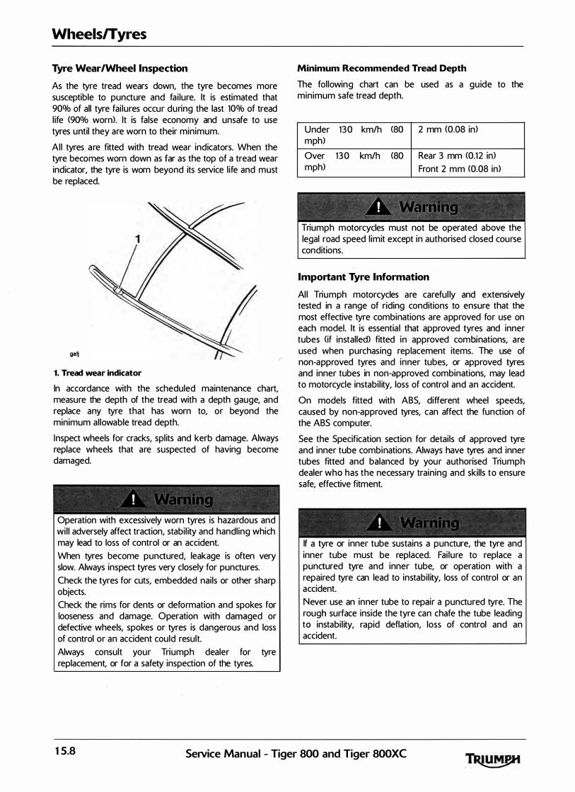
Wheels/Tyres
Tyre Wear/Wheel Inspection
As the tyre tread wears down, the tyre becomes more susceptible to puncture and fa i lure. lt is estimated that 90% of all tyre fai lures occur during the last 10% of tread l ife (90% worn). lt is false economy and unsafe to use tyres until they are worn to their minimum.
Al l tyres a re fitted with tread wear indicators. When the tyre becomes worn down as far as the top of a tread wear indicator, the tyre is worn beyond its service l ife and must be replaced.
gafj
1. Tread wear indicator
In accordance with the scheduled maintenance chart, measure the depth of the tread with a depth gauge, and replace any tyre that has worn to, or beyond the minimum al lowable tread depth.
Inspect wheels for cracks, spl its and kerb damage. Always replace wheels that are suspected of having become damaged.
Operation with excessively worn tyres is haza rdous and wi l l adversely affect traction, stabi l ity and handl ing which may lead to loss of control or an accident. When tyres become punctured, leakage is often very slow. Always inspect tyres very closely for punctures. Check the tyres for cuts, embedded nai ls or other sharp objects. Check the rims for dents or deformation and spokes for looseness and damage. Operation with damaged or defective wheels, spokes or tyres is dangerous and loss of control or an accident could result. Always consult your Triumph dealer for tyre replacement, or for a safety inspection of the tyres.
Minimum Recommended Tread Depth
The fol lowing chart can be used as a gu ide to the minimum safe tread depth.
U nder m ph)
Over m ph)
1 3 0 km/h (80 2 mm (0.08 in)
1 3 0 km/h (80 Rear 3 mm <0.1 2 in) Front 2 m m <0.08 in>
�/, < ' ' � ( • � " I \ " ' ' '
Triumph motorcycles must not be operated above the legal road speed l imit except in authorised closed course conditions.
Important Tyre Information
Al l Triumph motorcycles are careful ly and extensively tested in a range of riding conditions to ensure that the most effective tyre combinations are a pproved for use on each model. lt is essentia l that approved tyres and inner tubes (if installed> fitted in approved combinations, are used when purchasing replacement items. The use of non-a pproved tyres and inner tubes, or approved tyres and inner tubes in non-approved combinations, may lead to motorcycle instabi l ity, loss of control and an accident.
On models fitted with ABS, different wheel speeds, caused by non-approved tyres, can affect the function of the ABS computer.
See the Specification section for detai ls of approved tyre and inner tube combinations. Always have tyres and inner tubes fitted and balanced by you r authorised Triumph dealer who has the necessa ry training and skil ls to ensure safe, effective fitment.
If a tyre or inner tube sustains a puncture, the tyre and inner tube must be replaced. Fai lure to replace a punctured tyre and inner tube, or operation with a repaired tyre can lead to instabi l ity, loss of control or an accident. Never use an inner tube to repair a punctured tyre. The rough surface inside the tyre can chafe the tube leading to instabi l ity, rapid deflation, loss of control and an accident.
15.8 Service Manual - Tiger 800 and Tiger 800XC
� -� - � � � "
/ ' I ; " ! ,� J . '
The use of tyres other than those l isted in the specification section of the owner's handbook may adversely affect handling leading to loss of control or an accident. Use the recom mended tyre options only in the combinations given in the owner's handbook. Do not mix tyres from different manufacturers or tyres from the same manufacturer but from another option.
' ' . ' '
Always check tyre pressures before riding when the tyres are cold. Operation with incorrectly inflated tyres may affect handling leading to loss of control and an accident.
Operation with excessively worn or damaged tyres wil l adversely affect handl ing a n d control leading t o loss o f control or a n accident.
Do not instal l tube-type tyres on tubeless rims. The bead will not seat and the tyres could slip on the rims, causing tyre deflation that may result in a loss of vehicle control and an accident. Do not instal l an inner tube inside a tubeless tyre. This may cause instabil ity and excessive heat bui ld-up may cause the tube to burst resulting in rapid tyre deflation, loss of vehicle control and an accident.
Accurate wheel balance is necessary for safe, stable handling of the motorcycle. Do not remove or change any wheel balance weig hts. Incorrect wheel balance may cause instabi l ity leading to loss of control and an accident. When wheel balancing is required, such as after tyre replacement, see your authorised Triumph dealer. Only use self-adhesive weights. Clip on weig hts wil l damage the wheel and tyre resu lting in tyre deflation, loss of control and an accident.
Wheels/Tyres
When replacement tyres or inner tubes are required, consult your authorised Triumph dealer who wil l arra nge for the tyres and inner tubes to be selected, in a correct combination, from the approved l ist and fitted according to the tyre and inner tube manufacturer's instructions. When tyres and inner tubes are replaced, a l low time for the tyres and inner tubes to seat to the rim <approximately 24 hours). During this seating period, ride cautiously as an incorrectly seated tyre or inner tube could cause instabi l ity, loss of motorcycle control and an accident. In itial ly, the new tyres and inner tubes will not produce the same handl ing characteristics as the worn tyres and inner tubes and the rider must a l low adequate riding distance <approximately 100 mi les) to become accustomed to the new handl ing characteristics. 24 hours after fitting, the tyre pressures must be checked and adjusted, and the tyres and inner tubes examined for correct seating. Rectification must be carried out as necessary. The same checks and adjustments must also be carried out when 100 mi les have been travelled after fitting. Use of a motorcycle with incorrectly seated tyres or inner tubes, incorrectly adjusted tyre pressures, or when not accustomed to its handl ing characteristics may lead to loss of motorcycle control and an accident.
Note:
• Some brands of approved tyre marked 'TU BELESS' may be suitable for use with an inner tube. Where this is the case, the tyre wall will be marked with text permitting the fitment of an inner tube.
Service Manual - Tiger 800 and Tiger 800XC 15.9
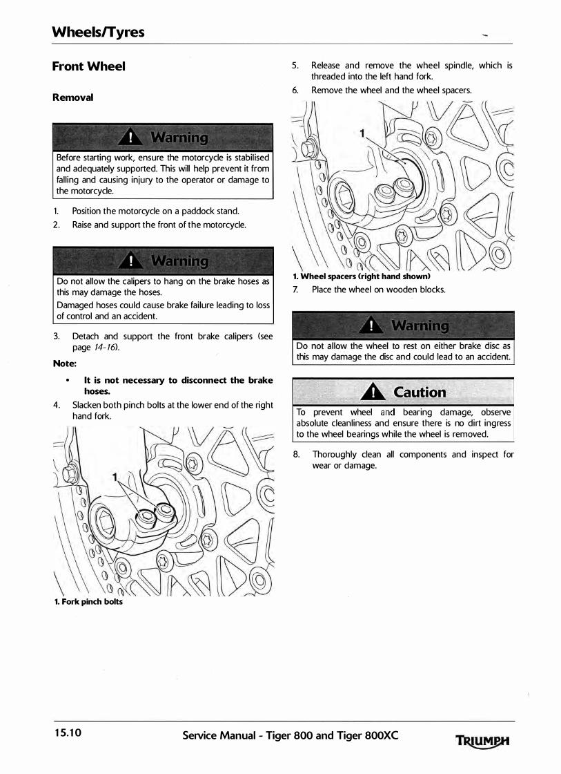
Wheels/Tyres
Front Wheel
Removal
Before starting work, ensure the motorcycle is stabil ised and adequately supported. This will help prevent it from fal l ing and causing in jury to the operator or damage to the motorcycle.
1 . Position the motorcycle on a paddock stand.
2 . Raise and support the front of the motorcycle.
Do not al low the calipers to hang on the bra ke hoses as this may damage the hoses. Damaged hoses could cause brake fai lure leading to loss of control and a n accident.
3. Detach and support the front brake cal ipers (see page 14- 16>.
Note:
• lt is not necessary to disconnect the brake hoses.
4. Slacken both pinch bolts at the lower end of the right hand fork.
1. Fork pinch bolts
5. Release and remove the wheel spindle, which is threaded into the left hand fork.
6. Remove the wheel a nd the wheel spacers.
1. Wheel spacers <right hand shown)
Z Place the wheel on wooden blocks.
this may damage the disc and could lead to an accident.
To prevent wheel bearing damage, a bsolute cleanl iness and ensure there is no d irt ingress to the wheel bearings while the wheel is removed.
8. Thoroughly clean all components and inspect for wear or damage.
15.10 SeNice Manual - Tiger 800 and Tiger 800XC
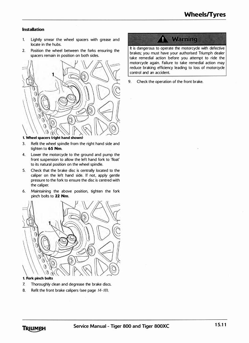
Installation
1 . Lightly smear the wheel spacers with g rease and locate in the hubs.
2. Position the wheel between the forks ensuring the spacers remain in position on both sides.
1. Wheel spacers (right hand shown)
3 . Refit the wheel spindle from the right hand side and tighten to 65 Nm.
4. Lower the motorcycle to the ground and pump the front suspension to a l low the left hand fork to 'float' to its natura l position on the wheel spind le.
5. Check that the brake disc is centra l ly located to the cal iper on the left hand side. I f not, apply gentle pressure to the fork to ensure the d isc is centred with the cal iper.
6. Maintaining the above position, tighten the fork pinch bolts to 22 Nm.
1. Fork pinch bolts
Z Thoroughly clean and degrease the brake discs.
8. Refit the front brake cal ipers (see page 14- 18).
Wheels/Tyres
lt is dangerous to operate the motorcycle with defective brakes; you must have your authorised Triumph dealer take remedial action before you attempt to ride the motorcycle again. Fai lure to take remedial action may reduce braking efficiency leading to loss of motorcycle control and an accident.
9. Check the operation of the front brake.
Service Manual - Tiger 800 and Tiger 800XC 15.11
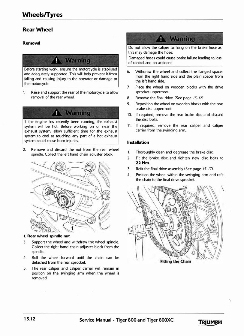
Wheels/Tyres
Rear Wheel
Removal
Before starting work, ensure the motorcycle is stabil ised and adequately supported. This will help prevent it from fal l ing and causing in jury to the operator or damage to the motorcycle.
1 . Raise and support the rear of the motorcycle to a l low removal of the rear wheel.
! " '
If the engine has recently been running, the exhaust system wil l be hot. Before working on or near the exhaust system, al low sufficient time for the exhaust system to cool as touching any part of a hot exhaust system could cause burn in juries.
2. Remove and discard the nut from the rear wheel spindle. Collect the left hand chain adjuster block.
1. Rear wheel spindle nut
3. Support the wheel and withd raw the wheel spindle. Collect the right hand chain adjuster block from the spindle.
4. Rol l the wheel forward until the cha in can be detached from the rear sprocket.
5. The rear cal iper and cal iper carrier wil l remain in position on the swinging a rm when the wheel is removed.
Do not al low the ca l iper to hang on the brake hose as this may damage the hose. Damaged hoses could cause brake fai lure leading to loss of control and an accident.
6. Withdraw the wheel and col lect the flanged spacer from the right hand side and the plain spacer from the left hand side.
Z Place the wheel on wooden blocks with the drive sprocket u ppermost.
8. Remove the final drive. (See page 15- 17>.
9. Reposition the wheel on wooden blocks with the rear brake disc uppermost.
10. If required, remove the rear brake disc and discard the disc bolts.
1 1 . If required, remove the rear cal iper and ca l iper carrier from the swinging arm.
Installation
1. Thoroughly clean and degrease the brake d isc.
2 . Fit the brake d isc and tighten new d isc bolts to 22 Nm.
3. Refit the final drive assembly <See page 15- 17>.
4. Position the wheel within the swinging arm and refit the chain to the final drive sprocket.
15.12 SeiVice Manual - Tiger 800 and Tiger 800XC
\
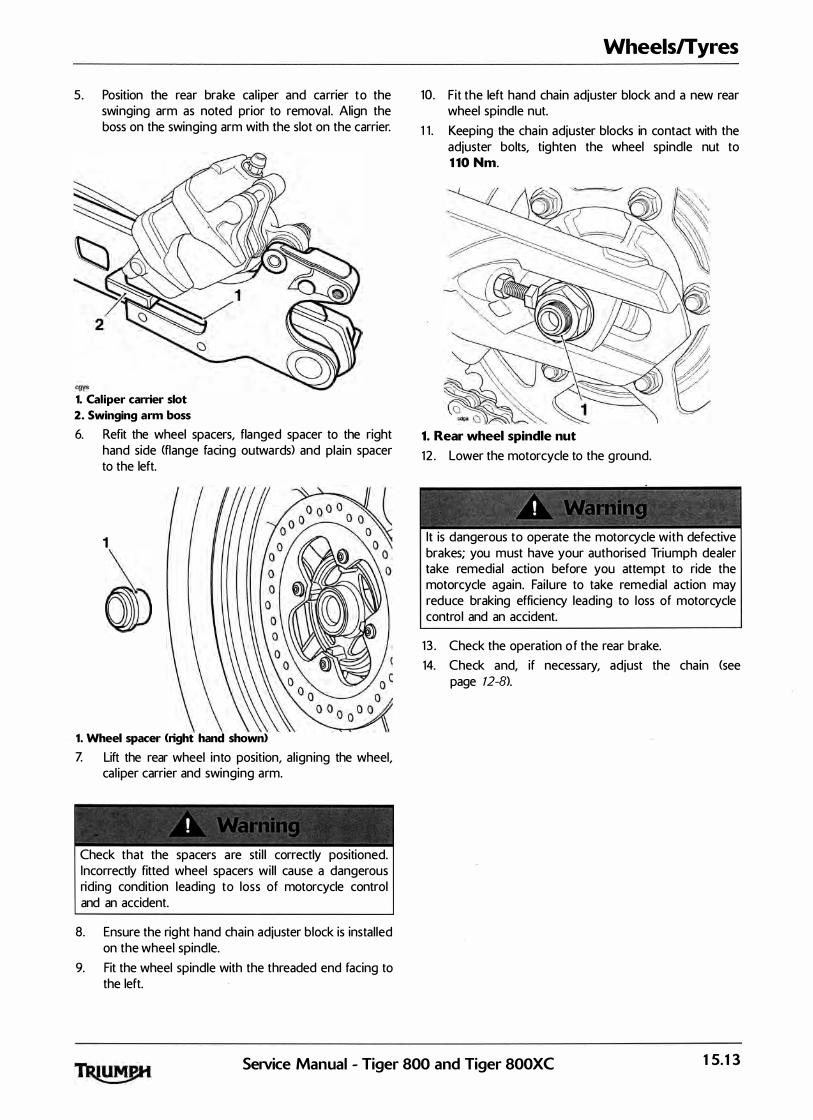
5. Position the rear brake cal iper and carrier to the swinging arm as noted prior to removal. Align the boss on the swinging arm with the slot on the carrier.
1. Caliper carrier slot 2. Swinging arm boss
6. Refit the wheel spacers, flanged spacer to the right hand side (flange facing outwards> and plain spacer to the left.
1
~ 1. Wheel spacer (right hand shown>
Z Lift the rear wheel into position, al ign ing the wheel, cal iper carrier and swinging arm.
Check that the spacers are sti l l correctly positioned. Incorrectly fitted wheel spacers wil l cause a dangerous riding condition leading to loss of motorcycle control and an accident.
8. Ensure the rig ht hand chain adjuster block is instal led on the wheel spindle.
9. Fit the wheel spindle with the threaded end facing to the left.
Wheels/Tyres
10. Fit the left hand chain adjuster block and a new rear wheel spindle nut.
1 1 . Keeping the cha in adjuster blocks in contact with the adjuster bolts, tighten the wheel spindle nut to 1 10 Nm.
1. Rear wheel spindle nut
1 2 . Lower the motorcycle to the g round.
lt is dangerous to operate the motorcycle with defective brakes; you must have your authorised Triumph dealer take remedial action before you attempt to ride the motorcycle again. Fai lure to take remedial action may reduce braking efficiency leading to loss of motorcycle control and an accident.
1 3 . Check the operation o f the rear brake.
14. Check and, if necessary, adjust the chain (see page 12-8>.
Service Manual - Tiger 800 and Tiger 800XC 15.13

Wheels/Tyres
Front Wheel Bearings
Removal
1 . Remove the front wheel <see page 15- 10>.
Do not al low the wheel to rest on the brake d iscs, as this may damage the discs. Support the wheel on wooden blocks, equal ly spaced around the rim, such that the brake discs are raised above the g round.
2. Place the wheel on wooden blocks to prevent damage to the brake discs.
3. Remove and d iscard the seals and the bearing circl ip.
Always wear eye, hand and face protection when using a hammer and drift. Use of a hammer and drift can cause bearings to fragment. Pieces of fragmented bearing could cause eye and soft tissue in juries if suitable protective apparel is not worn. "
To prevent wheel damage and to aid bearing removal, always apply force evenly on both sides of the bea ring to prevent it from 'tipping' and becoming stuck. Application of uneven force wil l lead to difficulty in removing the bearing and to a damaged wheel.
4. Using a suitable pin punch, through the centre of the wheel, drift out the wheel bearings. Collect the centre sleeve.
Wheel Bearing Remov<il
Inspection
- -I ' ' 1 I "· ·� � • o t ; ' l ;: • " ' ! " d
� � � " -
Only remove raised witness marks from with in the wheel. Removal of material below any ra ised areas will reduce the level of interference between the wheel and the bearings. Loss of interference could cause the bearing to become loose in the wheel leading to loss of motorcycle control and an accident.
1 . Examine the wheel for any raised witness marks caused by the removal process. Remove any such marks with fine emery paper or a gentle file.
Installation Note:
• Refer to the chart below for the correct tool and tool face when inserting bearings. Bearings are inserted by means of a draw-bolt acting on the insertion tool. A support tool is located on the Ol;)posite side of the wheel to the insertion tool and as the bolt is tightened, the bearing is drawn into the wheel.
• Insert bearings with the marked or shielded side facing outwards and always fit a new bearing circlip and seals.
Bearing insertion Support tool tool
Left bearing T3 8800 5 3 3 8 80070 - T03 01 Large face to Large face to bearing Wheel
Right bearing T3 88005 3 3 8 80070 - T0301 Large face to Large face to bearing wheel
15.14 Service Manual - Tiger 800 and Tiger 800XC

1 . Fit the wheel bearings and centre sleeve using the method described opposite.
1. Tool T3880053
2. F it a new circl ip.
3. Lubricate and fit new seals to the front wheel. Lubricate the seal's kn ife-edge with g rease to N LG I 2 specification <we recom mend Mobil H P2 2 2).
4. Fit the front wheel <see page 15- 1 1 }.
Wheels/Tyres
Rear Wheel Bearings
Removal
1 . Remove the rear wheel <see page 15- 12).
Do not al low the wheel to rest on the brake disc, as this may damage the disc. Support the wheel on wooden blocks, equal ly spaced around the rim, such that the brake disc is raised above the g round.
2� Place the wheel on wooden blocks to prevent damage to the brake disc.
3 . Remove and discard the seals and the bearing circl ip.
- � = =
! " y �A 0: ; t j t f
� = " �
Always wear eye, hand and face protection when using a hammer and drift. Use of a hammer and drift can cause bearings to fragment. Pieces of fragmented bearing could cause eye and soft tissue in juries if suitable protective apparel is not worn.
To prevent wheel damage and to aid bearing removal, always a pply force evenly on both sides of the bearing to prevent it from 'tipping' and becoming stuck. Appl ication of uneven force wil l lead to d ifficu lty in removing the bearing and to a damaged wheel.
4. Using a suitable pin punch, through the centre of the wheel, drift out the wheel bearings. Col lect the centre sleeve.
gaeo Rear Wheel Bearing Removal
SeNice Manual - Tiger 800 and Tiger SOOXC 15.15
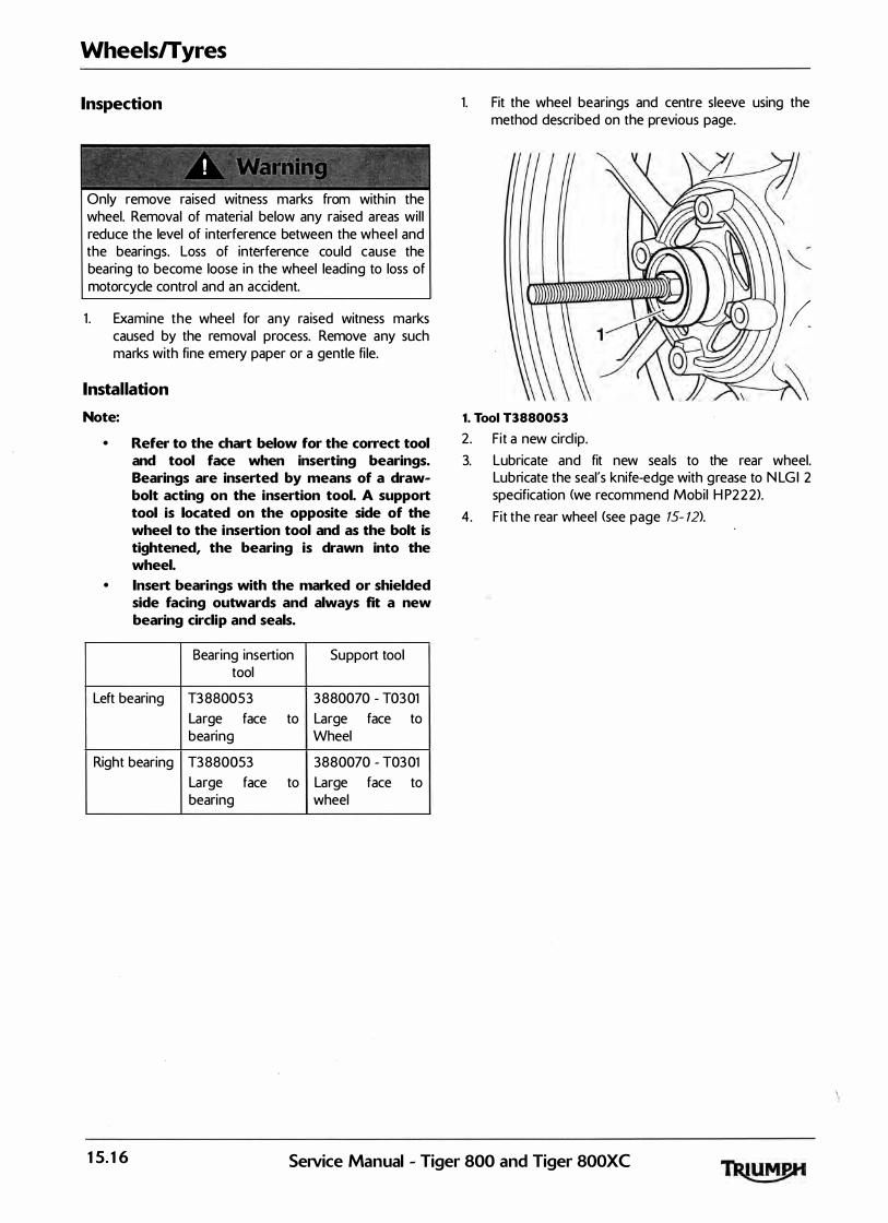
Wheels/Tyres
Inspection
�� �� � � ! , /\'1 �-� � � :� ; ! " {j
" � / - - -Only remove raised witness marks from with in the wheel. Removal of material below any raised areas wil l reduce the level of interference between the wheel and the bearings. Loss of interference could cause the bearing to become loose in the wheel leading to loss of motorcycle control and an accident.
1 . Examine the wheel for any raised witness marks caused by the removal process. Remove any such marks with fine emery paper or a gentle fi le.
Installation Note:
• Refer to the chart below for the correct tool and tool face when inserting bearings. Bearings are inserted by means of a drawbolt acting on the insertion tool. A support tool is located on the opposite side of the wheel to the insertion tool and as the bolt is tightened, the bearing is drawn into the wheel.
• Insert bearings with the marked or shielded side facing outwards and always fit a new bearing circlip and seals.
Bearing insertion Support tool tool
Left bearing T3 8800 5 3 3 880070 - T03 01 Large face to Large face to bearing Wheel
Right bearing T3 880053 3880070 - T03 01 Large face to Large face to bearing wheel
1. Fit the wheel bearings and centre sleeve using the method described on the previous page.
1. Tool T388005 3
2. F it a new circl ip.
(
3. Lubricate and fit new sea ls to the rear wheel. Lubricate the seal's knife-edge with g rease to N LG I 2 specification <we recommend Mobil H P2 2 2).
4. F it the rear wheel (see page 15- 12>.
15.16 Service Manual - Tiger 800 and Tiger SOOXC

Final Drive
Removal
� �= - � � �-=
, "� I , 1
Before starting work, ensure the motorcycle is stabi l ised and adequately supported. This will help prevent it from fa l l ing and causing injury to the operator or damage to the motorcycle.
1 . Remove the rear wheel <see page 15- 12).
Do not al low the wheel to rest on the brake d isc, as this may damage the disc. Support the wheel on wooden blocks, equally spaced around the rim, such that the brake disc is ra ised above the ground.
2 . Place the wheel on wooden blocks with the drive sprocket uppermost.
3 . Gently lever the drive flange from the wheel hub.
1. Rear wheel
2. Drive flange
Wheels/Tyres
4. Remove the cush drive rubber.
1. Cush drive rubber
Inspection
1 . Check the cush drive rubbers for deterioration, cracks etc.
2 . I nspect the sprocket teeth for wear, damage and chip�
·
3 . Check the wheel a n d drive flange for wear, cracks and damage.
(' Installation
1 . Instal l the cush drive rubbers to the wheel.
2. Refit the drive flange to the wheel.
3 . Refit the rear wheel <see page 15- 12).
SeNice Manual - Tiger 800 and Tiger 800XC 15.17

Wheels/Tyres
This page intentional ly left blank
15.18 SeiVice Manual - Tiger 800 and Tiger 800XC

1 6 Frame and Bodywork Table of Contents
Exploded View - Frame - all Models . . . . . . . . . . . . . . . . . . . . . . . . . . . . . . . . . . . . . . . . . . . . . . . . . . . . . . . . . 1 6.3
Exploded View - Cockpit and Mountings - Tiger 800 . . . . . . . . . . . . . . . . . . . . . . . . . . . . . . . . . . . . . . . . . . 1 6.4
Exploded View - Cockpit and Mountings - Tiger 800 XC . . . . . . . . . . . . . . . . . . . . . . . . . . . . . . . . . . . . . . . 16.5
Exploded View - Lower Panels and Sumpguard - all Models . . . . . . . . . . . . . . . . . . . . . . . . . . . . . . . . . . . . 1 6.6
Exploded View - Rear Panels - al l Models . . . . . . . . . . . . . . . . . . . . . . . . . . . . . . . . . . . . . . . . . . . . . . . . . . . . 1 6.7
Exploded View - Footrests and Mountings - all Models . . . . . . . . . . . . . . . . . . . . . . . . . . . . . . . . . . . . . . . . . 1 6.8
Exploded View - Sidestand - all Models . . . . . . . . . . . . . . . . . . . . . . . . . . . . . . . . . . . . . . . . . . . . . .. . . . . . . . . 1 6.9
Exploded View - Front Mudguard - Tiger 800 . . . . . . . . . . . . . . . . . . . . . . . . . . . . . . . . . . . . . . . . . . . . . . . 16.10
Exploded View - Front Mudguard - Tiger 800 XC . . . . . . . . . . . . . . . . . . . . . . . . . . . . . . . . . . . . . . . . . . . . 16.1 1
Exploded View - Rear Mudguard - all Models . . . . . . . . ('. . . . . . . . . . . . . . . . . . . . . . . . . . . . . . . . . . . . . . . . 16.1 2
Rear Seat . . . . . . . . . . . . . . . . . . . . . . . . . . . . . . . . . ': . . . . . . . . . . . . . . . . . . . . . . . . . . . . . . . . . . . . . . . . . . . . 16.13
Removal . . . . . . . . . . . . . . . . . . . . . . . . . . . . . . . . . . . . . . . . . . . . . . . . . . . . . . . . . . . . . . . . . . . . . . . . . . 16.13
Rider's Seat . . . . . . . . . . . . . . . . . . . . . . . . . . . . . . . . . . . . . . . . . . . . . . . . . . . . . . . . . . . . . . . . . . . . . . . . . . . . 16.13
Removal . . . . . . . . . . . . . . . . . . . . . . . . . . . . . . . . . . . . . . . . . . . . . . . . . . . . . . . . . . . . . . . . . . . . . . . . . . 16.13
Lower Radiator Panel . . . . . . . . . . . . . . . . . . . . . . . . . . . . . . . . . . . . . . . . . . . . . . . . . . . . . . . . . . . . . . . . . . . . 16.14
Removal . . . . . . . . . . . . . . . . . . . . . . . . . . . . . . . . . . . . . . . . . . . . . . . . . . . . . . . . . . . . . . . . . . . . . . . . . . 16.14
Installation . . . . . . . . . . . . . . . . . . . . . . . . . . . . . . . . . . . . . . . . . . . . . . . . . . . . . . . . . . . . . . . . . . . . . . . . . 16.14
Upper Radiator Panel . . . . . . . . . . . . . . . . . . . . . . . . . . . . . . . . . . . ·. . . . . . . . . . . . . . . . . . . . . . . . . . . . . . . . . 16.14
Removal . . . . . . . . . . . . . . . . . . . . . . . . . . . . . . . . . . . . . . . . . . . . . . . . . . . . . . . . . . . . . . . . . . . . . . . . . . 16.14
Installation . . . . . . . . . . . . . . . . . . . . . . . . . . . . . . . . . . . . . . . . . . . . . . . . . . . . . . . . . . . . . . . . . . . . . . . . . 16.15
Radiator lnfi l l Panel . . . . . . . . . . . . . . . . . . . . . . . . . . . . . . . . . . . . . . . . . . . . . . . . . . . . . . . . . . . . . . . . . . . . . . 16.1 5
Removal . . . . . . . . . . . . . . . . . . . . . . . . . . . . . . . . . . . . . . . . . . . . . . . . . . . . . . . . . . . . . . . . . . . . . . . . . . 16.15
Installation. . . . . . . . . . . . . . . . . . . . . . . . . . . . . . . . . . . . . . . . . . . . . . . . . . . . . . . . . . . . . . . . . . . . . . . . . 16.16
Beak - Tiger 800 XC only . . . . . . . . . . . . . . . . . . . . . . . . . . . . . . . . . . . . . . . . . . . . . . . . . . . . . . . . . . . . . . . . . 16.16
Removal . . . . . . . . . . . . . . . . . . . . . . . . . . . . . . . . . . . . . . . . . . . . . . . . . . . . . . . . . . . . . . . . . . . . . . . . . . 16.16
Instal lation . . . . . . . . . . . . . . . . . . . . . . . . . . . . . . . . . . . . . . . . . . . . . . . . . . . . . . . . . . . . . . . . . . . . . . . . . 16.1 6
Cockpit Assembly . . . . . . . . . . . . . . . . . . . . . . . . . . . . . . . . . . . . . . . . . . . . . . . . . . . . . . . . . . . . . . . . . . . . . . . 1 6.17
Removal . . . . . . . . . . . . . . . . . . . . . . . . . . . . . . . . . . . . . . . . . . . . . . . . . . . . . . . . . . . . . . . . . . . . . . . . . . 16.17
Disassembly . . . . . . . . . . . . . . . . . . . . . . . . . . . . . . . . . . . . . . . . . . . . . . . . . . . . . . . . . . . . . . . . . . . . . . . 1 6.17
Assembly . . . , . . . . . . . ·. . . . . . . . . . . . . . . . . . . . . . . . . . . . . . . . . . . . . . . . . . . . . . . . . . . . . . . . . . . . . . . 16.18
Installation . . . . . . . . . . . . . . . . . . . . . . . . . . . . . . . . . . . . . . . . . . . . . . . . . . . . . . . . . . . . . . . . . . . . . . . . . 16.18
Fuel Tank lnfi l l Panel . . . . . . . . . . . . . . . . . . . . . . . . . . . . . . . . . . . . . . . . . . . . . . . . . . . . . . . . . . . . . . . . . . . . . 16.18
Service Manual - Tiger 800 and Tiger 800XC 16.1

Frame and Bodywork
16.2
Removal . . . . . . . . . . . . . . . . . . . . . . . . . . . . . . . . . . . . . . . . . . . . . . . . . . . . . . . . . . . . . . . . . . . . . . . . . . 1 6.18
Installation . . . . . . . . . . . . . . . . . . . . . . . . . . . . . . . . . . . . . . . . . . . . . . . . . . . . . . . . . . . . . . . . . . . . . . . . 1 6.18
Windscreen . . . . . . . . . . . . . . . . . . . . . . . . . . . . . . . . . . . . . . . . . . . . . . . . . . . . . . . . . . . . . . . . . . . . . . . . . . . . 1 6.19
Removal . . . . . . . . . . . . . . . . . . . . . . . . . . . . . . . . . . . . . . . . . . . . . . . . . . . . . . . . . . . . . . . . . . . . . . . . . . 1 6.19
Installation . . . . . . . . . . . . . . . . . . . . . . . . . . . . . . . . . . . . . . . . . . . . . . . . . . . . . . . . . . . . . . . . . . . . . . . . 1 6.19
Front Mudguard - Tiger 800 . . . . . . . . . . . . . . . . . . . . . . . . . . . . . . . . . . . . . . . . . . . . . . . . . . . . . . . . . . . . . . 1 6.19
Removal . . . . .. . . . . . . . . . . . . . . . . . . . . . . . . . . . . . . . . . . . . . . . . . . . . . . . . . . . . . . . . . . . . . . . . . . . . . 16.19
Installation . . . . . . . . . . . . . . . . . . . . . . . . . . . . . . . . . . . . . . . . . . . . . . . . . . . . . . . . . . . . . . . . . . . . . . . . 1 6.19
Front Mudguard - Tiger 800 XC . . . . . . . . . . . . . . . . . . . . . . . . . . . . . . . . . . . . . . . . . . . . . . . . . . . . . . . . . . . 1 6.20
Removal . . . . . . . . . . . . . . . . . . . . . . . . . . . . . . . . . . . . . . . . . . . . . . . . . . . . . . . . . . . . . . . . . . . . . . . . . 1 6.20
Instal lation . . . . . . . . . . . . . . . . . . . . . . . . . . . . . . . . . . . . . . . . . . . . . . . . . . . . . . . : . . . . . . . . . . . . . . . 16.20
Rear Rack . . . . . . . . . . . . . . . : . . . . . . . . . . . . . . . . . . . . . . . . . . . . . . . . . . . . . . . . . . . . . . . . . . . . . . . . . . . . . . 1 6.20
Removal . . . . . . . . . . . . . . . . . . . . . . . . . . . . . . . . . . . . . . . . . . . . . . . . . . . . . . . . . . . . . . . . . . . . . . . . . 1 6.20
Installation . . . . . . . . . . . . . . . . . . . . . . . . . . . . . . . . . . . . . . . . . . . . . . . . . . . . . . . . . . . . . . . . . . . . . . . 16.20
Rear Side Panel . . . . . . . . . . . . . . . . . . . . . . . . . . . . . . . . . . . . . . . . . . . . . . . . . . . . . . . . . . . . . . . . . . . . . . . . . 1 6.21
Removal . . . . . . . . . . . . . . . . . . . . . . . . . . . . . . . . . . . . . . . . . . . . . . . . . . . . . . . . . . . . . . . . . . . . . . . . . . 1 6.21
Instal lation . . . . . . . . . . . . . . . . . . . . . . . . . . . . . . . . . . . . . . . . . . . . . . . . . . . . . . . . . . . . . . . . . . . . . . . . 1 6.21
Rear Mudguard . . . . . . . . . . . . . . . . . . . . . . . . . . . . . . . . . . . . . . . . . . . . . . . . . . . . . . . . . . . . . . . . . . . . . . . . . 16.22
Removal . . . . . . . . . . . . . . . . . . . . . . . . . . . . . . . . . . . . . . . . . . . . . . . . . . . . . . . . . . . . . . . . . . . . . . . . . 1 6.22
Installation . . . . . . . . . . . . . . . . . . . . . . . . . . . . . . . . . . . . . . . . . . . . . . . . . . . . . . . . . . . . . . . . . . . . . . . 16.23
Sump Guard . . . . . . . . . . . . . . . . . . . . . . . . . . . . . . . . . . . . . . . . . . . . . . . . . . . . . . . . . . . . . . . . . . . . . . . . . . . 16.24
Removal . . . . . . . . . . . . . . . . . . . . . . . . . . . . . . . . . . . . "' " . . . . . . . . . . . . . . . . . . . . . . . . . . . . . . . . . . . 1 6.24
Installation . . . . . . . . . . . . . . . . . . . . . . . . . . . . . . . . . . . . . . . . . . . . . . . . . . . . . . . . . . . . . . . . . . . . . . . 16.24
Frame, Footrests and Fixings . . . . . . . . . . . . . . . . . . . . . . . . . . . . . . . . . . . . . . . . . . . . . . . . . . . . . . . . . . . . . . 1 6.24
Inspection . . . . . . . . . . . . . . . . . . . . . . . . . . . . . . . . . . . . . . . . . . . . . . . . . . . . . . . . . . . . . . . . . . . . . . . . 1 6.24
Service Manual - Tiger 800 and Tiger 800XC
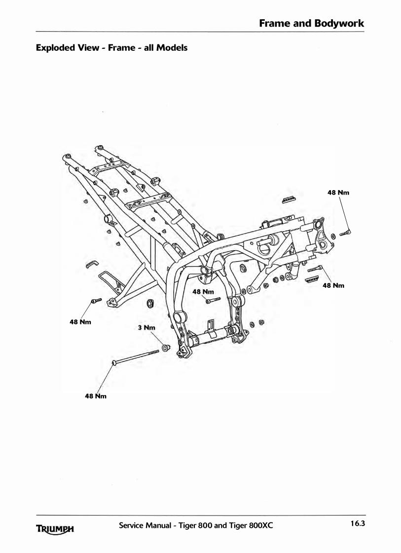
Frame and Bodywork
Exploded View - Frame - all Models
48 Nm
� � �
48 Nm
/ ' 48 Nm
48 Nm
Service Manual - Tiger 800 and Tiger 800XC 16.3

Frame and Bodywork
Exploded View - Cockpit and Mountings - Tiger 800
5 Nm
�
3 Nm'----- � $ /" 'fJ 0"if • " / Nm v / 5 Nm � 7
5 Nm 3 Nm� 5 Nm �3 Nm @) �
@ � � ·� · � li � e
� 5 Nm
5 Nm
16.4 SeiVice Manual - Tiger 800 and Tiger 800XC
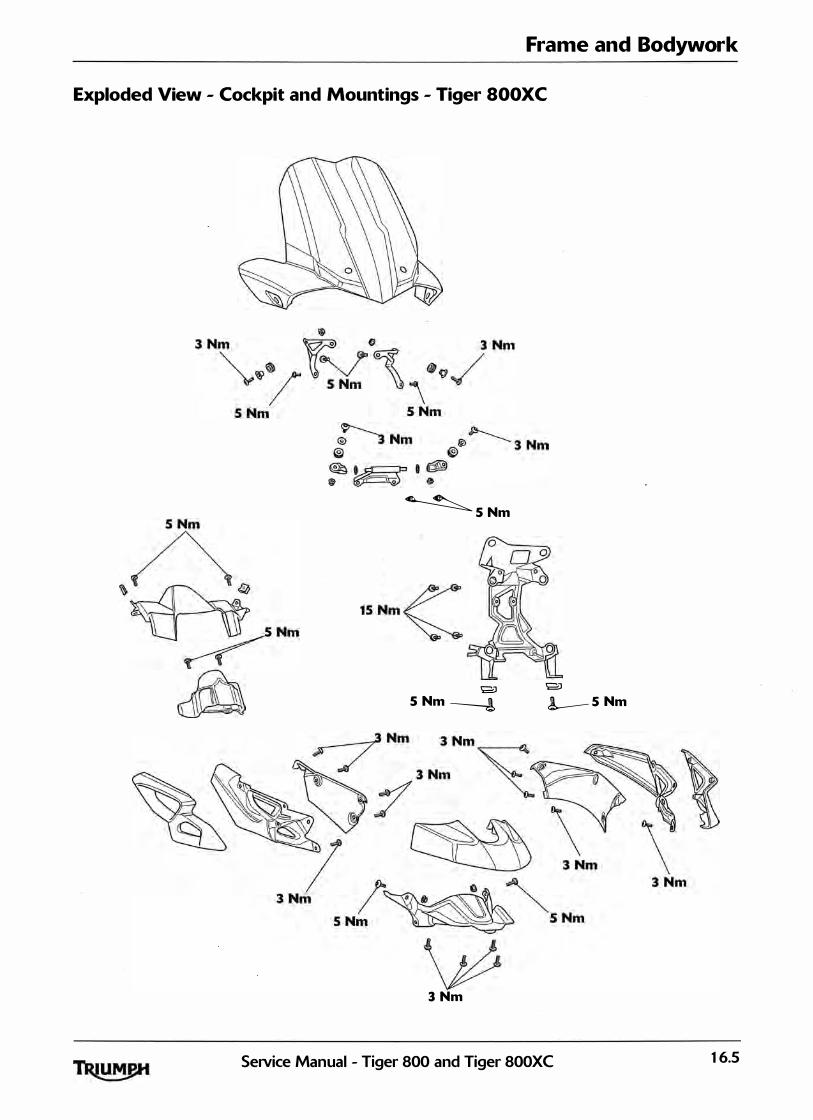
Frame and Bodywork
Exploded View - Cockpit and Mountings - Tiger SOOXC
�S Nm
Jjl
� S Nm
g) 5 Nm ----!
3 Nm
g) !--S Nm
SeiVice Manual - Tiger 800 and Tiger 800XC 16.5
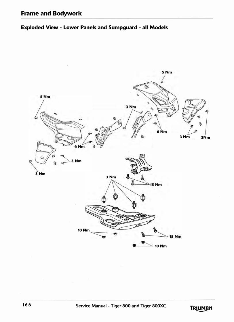
Frame and Bodywork
Exploded View - Lower Panels and Sumpguard - all Models
� 3 Nm
3 Nm 3 Nm ~ � I S Nm
[.. � 3 Nm 3Nm
10 Nm � 8 \ · � 15 Nm
10 Nm
16.6 SeiVice Manual - Tiger 800 and Tiger 800XC
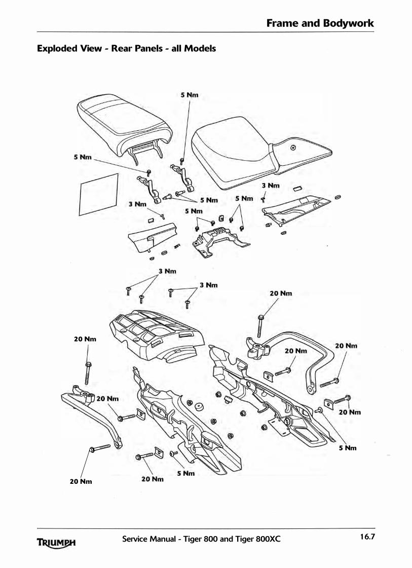
Frame and Bodywork
Exploded View - Rear Panels - all Models
20 Nm
r S Nm
20 Nm
SeNice Manual - Tiger 800 and Tiger 800XC 16.7

Frame and Bodywork
Exploded View - Footrests and Mountings - all Models
16.8 Service Manual - Tiger 800 and Tiger 800XC
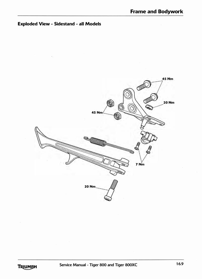
Frame and Bodywork
Exploded View - Sidestand - all Models
45 Nm
7 Nm
20 Nm
SeiVice Manual - Tiger 800 and Tiger 800XC 16.9
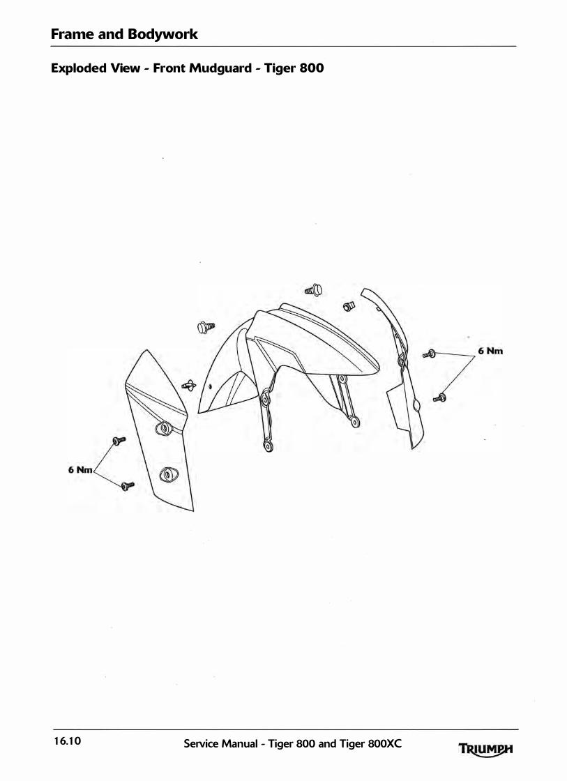
Frame and Bodywork
Exploded View - Front Mudguard - Tiger 800
16.10 SeiVice Manual - Tiger 800 and Tiger 800XC

Frame and Bodywork
Exploded View - Front Mudguard - Tiger SOOXC
6 Nm �
�6Nm
6 Nmz::
SeiVice Manual - Tiger 800 and Tiger 800XC 16.11

Frame and Bodywork
Exploded View - Rear Mudguard - all Models
6 Nm
�
� 6 Nm
3 Nm
16.12 SeiVice Manual - Tiger 800 and Tiger 800XC

Rear Seat
Removal
The seat lock is located on the rear mudguard, below the rear l ight un it. To remove the seat, insert the ignition key into the seat lock and turn it anti-clockwise while pressing down on the rear of the seat. This wil l release the seat from its lock and a l low it lo be sl id rearwards for complete removal from the motorcycle.
To refit the seat, engage the seat's two brackets under the loops on the su bframe and press down at the rear to engage in the seat lock.
To prevent detachment of the seat during rid ing, after fitting always g rasp the seat and pul l fi rmly upwards. I f the seat is not correctly secu red, it wi l l detach from the lock. A loose or detached seat could cause loss of motorcycle control and an accident.
Frame and Bodywork
Rider's Seat
Removal
To remove the rider's seat, remove the rear seat (see page 16- 13>.
Grasp the riders seat on either side, and sl ide it rearwards and upwards for complete removal from the motorcycle.
To refit the seat, engage the seat's front rai l into the bracket at the rear of the fuel tank and lower the rear rai l in to the rear brackets. Push down fi rm ly on the rear of the seat. Refit the rear seat (see page 16- 13).
1. Rider's seat
To refit the seat, engage the seat's tongue under the fuel tank and press down at the rear to engage in the seat lock.
To prevent detachment of the seat during rid ing, after fitting a lways grasp the seat and pul l firm ly upwards. I f the seat is not correctly secu red it wil l detach from the lock, A loose or detached seat could cause loss of motorcycle control and an accident.
To prevent damage to the seat and its cover, care m ust be taken not to drop the seat. Do not lean the seat against the motorcycle or a wal l as it may fal l . I nstead, place the seat, with the seat cover facing up, on a flat surface which is covered with a soft cloth.
SeiVice Manual - Tiger 800 and Tiger 800XC 16.13

Frame and Bodywork
Lower Radiator Panel
Removal
1 . Remove the two radiator infi l l fixings.
1. Radiator infill
2. Fixings
2. Remove the fixing and remove the panel towards the rear of the motorcycle.
Installation
1 . Al ign the panel t h e hook on t h e upper radiator panel and secure with the three fixings.
2 . Tighten the screws to 3 Nm.
Upper Radiator Panel
Removal
1 . Remove the rider's seat (see page 76- 13).
2. Disconnect the battery, negative (black> lead first.
3 . Remove the lower radiator panel (see page 16- 14).
4. Remove and disca rd the radiator infi l l panel fixing.
1. Radiator infill panel
2. Fixing
�- Remove the rear fixing and un hook the panel from the cockpit panel and fuel tank.
1. Upper radiator panel
2. Fixing
6. Disconnect the direction indicator connectors and remove the panel.
16.14 Se1Vice Manual - Tiger 800 and Tiger 800XC
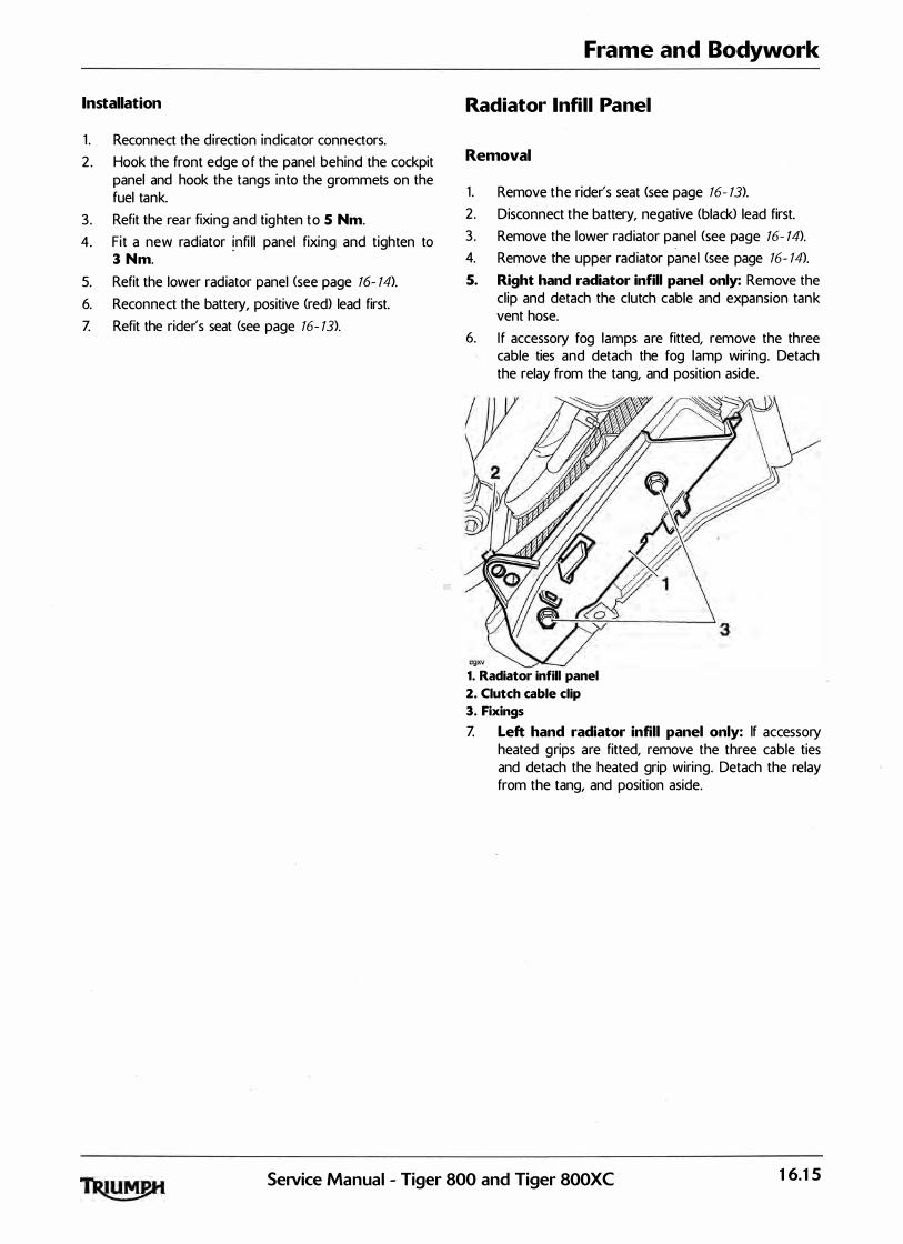
Installation
1 . Reconnect the direction ind icator connectors.
2 . Hook the front edge o f the panel behind the cockpit panel and hook the tangs into the grommets on the fuel tank.
3 . Refit the rear fixing and tig hten to 5 Nm.
4. Fit a new radiator infi l l panel fixing and tighten to 3 Nm.
5. Refit the lower radiator panel (see page 16- 14).
6. Reconnect the battery, positive (red) lead first.
Z Refit the rider's seat (see page 16- 13).
Frame and Bodywork
Radiator lnfill Panel
Removal
1 . Remove the rider's seat (see page 16- 13).
2 . Disconnect the battery, negative (black> lead first.
3 . Remove the lower rad iator panel (see page 16- 14).
4. Remove the upper rad iator panel (see page 16- 14).
5. Right hand radiator infill panel only: Remove the cl ip and detach the clutch cable and expansion tank vent hose.
6. I f accessory fog lamps are fitted, remove the three cable ties and detach the fog lamp wiring. Detach the relay from the tang, and position aside.
1. Radiator infill panel
2. Clutch cable clip
3. Fixings
Z Left hand radiator infill panel only: If accessory heated grips are fitted, remove the three cable ties and detach the heated grip wiring. Detach the relay from the tang, and position aside.
SeNice Manual - Tiger 800 and Tiger 800XC 16.15

Frame and Bodywork
8. Remove the two fixings and remove the rad iator infi l l panel.
cgxt 1. Radiator infill panel
2. Fixings
9. Tiger SOOXC only: Collect the radiator guard.
Installation
1 . Tiger SOOXC only: Refit the radiator guard.
2 . Al ign the rad iator inf i l l panel to the rad iator and secure with two new fixings. Tighten to 6 Nm.
3. Right hand radiator infill panel only: Refit the clutch cable and expansion tan k vent hose cl ip to the rear of the radiator infill panel.
4. If accessory fog lamps are fitted, reposition the fog lamp wiring and secure with new cable ties. Attach the relay to the tang.
5 . Left hand radiator infill panel only: I f accessory heated grips are fitted, reposition the heated grip wiring and secure with new cable ties. Attach the relay to the tang.
6. Refit the upper rad iator panel (see page 16- 14).
Z Refit the lower radiator panel <see page 16- 14).
8. Reconnect the battery, positive <red) lead first.
9 . Refit the rider's seat (see page 16- 13>.
Beak - Tiger SOOXC only
Removal
1 . Remove the four fixings and remove the beak in an upwards direction.
1. Beak
2. Fixings
Installation
' i . Installation is the reverse of removal noting the fol lowing:
Note:
• Tighten the fixings to 3 Nm.
16.16 SeiVice Manual - Tiger 800 and Tiger 800XC ·
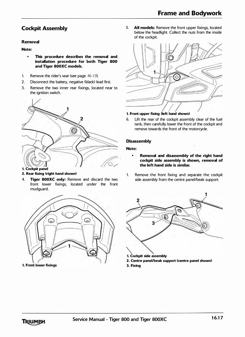
Cockpit Assembly
Removal
Note:
• This procedure describes the removal and installation procedure for both Tiger 800 and Tiger SOO)_(C models.
1 . Remove the rider's seat <see page 16- 13).
2 . Disconnect the battery, negative (black> lead first.
3 . Remove the two in ner rear fixings, located near to the ignition switch.
1 ' 2 �
� �� -��c 1. Cockpit panel
2. Rear fixing <right hand shown)
4. Tiger SOOXC only: Remove and d iscard the two front lower fixings, located under the front mudguard.
Frame and Bodywork
5. All models: Remove the front upper fixings, located below the headl ight. Collect the nuts from the inside of the cockpit.
I� �o 4�� \) ) v � �c:::: 1�() � �
��� I\ I
1. Front upper fixing <left hand shown>
6. Lift the rear of the cockpit assem bly clear of the fuel tank, then carefu l ly lower the front of the cockpit and remove towards the front of the motorcycle.
'Disassembly
Note:
• Removal and disassembly of the right hand cockpit side assembly is shown, removal of the left hand side is similar.
1 . Remove the front fixing and separate the cockpit side assembly from the centre panel/beak support.
1
"' 1. Cockpit side assembly
2. Centre panel/beak support <centre panel shown)
3. Fixing
SeiVice Manual - Tiger 800 and Tiger 800XC 16.17

Frame and Bodywork
2. Remove the three fixings and separate the cockpit infi l l and cockpit screen panels from the cockpit panel.
1. Cockpit infill 2. Cockpit panel 3. Cockpit screen panels 4. Fixings
Assembly
1 . Align the cockpit infi l l and cockpit screen panels to the cockpit panel. I nstal l the th ree fixings and tighten to 3 Nm.
2. Align the cockpit side assembly to the centre panel/ beak support. I nstal l the fixing and tighten to 3 Nm.
Installation
1 . Position the cockpit assembly t o the motorcycle. Pass the cockpit side assembl ies either side of the front forks and u p over the front edge of the fuel tan k.
2 . Position the rear of each cockpit side assembly to the fuel tank and clip the tabs. on the panel into the lower edge of the ignition switch cover.
3 . Refit the two inner rear fixings and tighten to 5 Nm.
4. Tiger SOOXC only: Fit two new front lower fixings and tighten to 5 Nm.
5. All models: Refit the front upper fixings, located below the headl ight. Secure with the nuts and tighten to 5 Nm.
·
6. Reconnect the battery, positive (red) lead first.
Z Refit the rider's seat <see page 16- 13).
Fuel Tank lnfil l Panel
Removal
1 . Remove the rider's seat (see page 76- 13>.
2 . Remove the rear fixing, located to the rea r of the airbox.
1. Fuel tank infill panel 2. Rear fixing (right hand shown>
�· Rear tang 4. Front tang location
3 . Lift the infi l l panel u pwards, releasing the rear tang from the frame grommet.
4. Sl ide the infi l l towards the rear of the motorcycle and release the front mounting tang from the frame g rommet.
Installation
1 . Installation is the reverse of removal noting the fol lowing:
Note:
• Tighten the fixing to 3 Nm.
16.18 SeNice Manual - Tiger 800 and Tiger 800XC
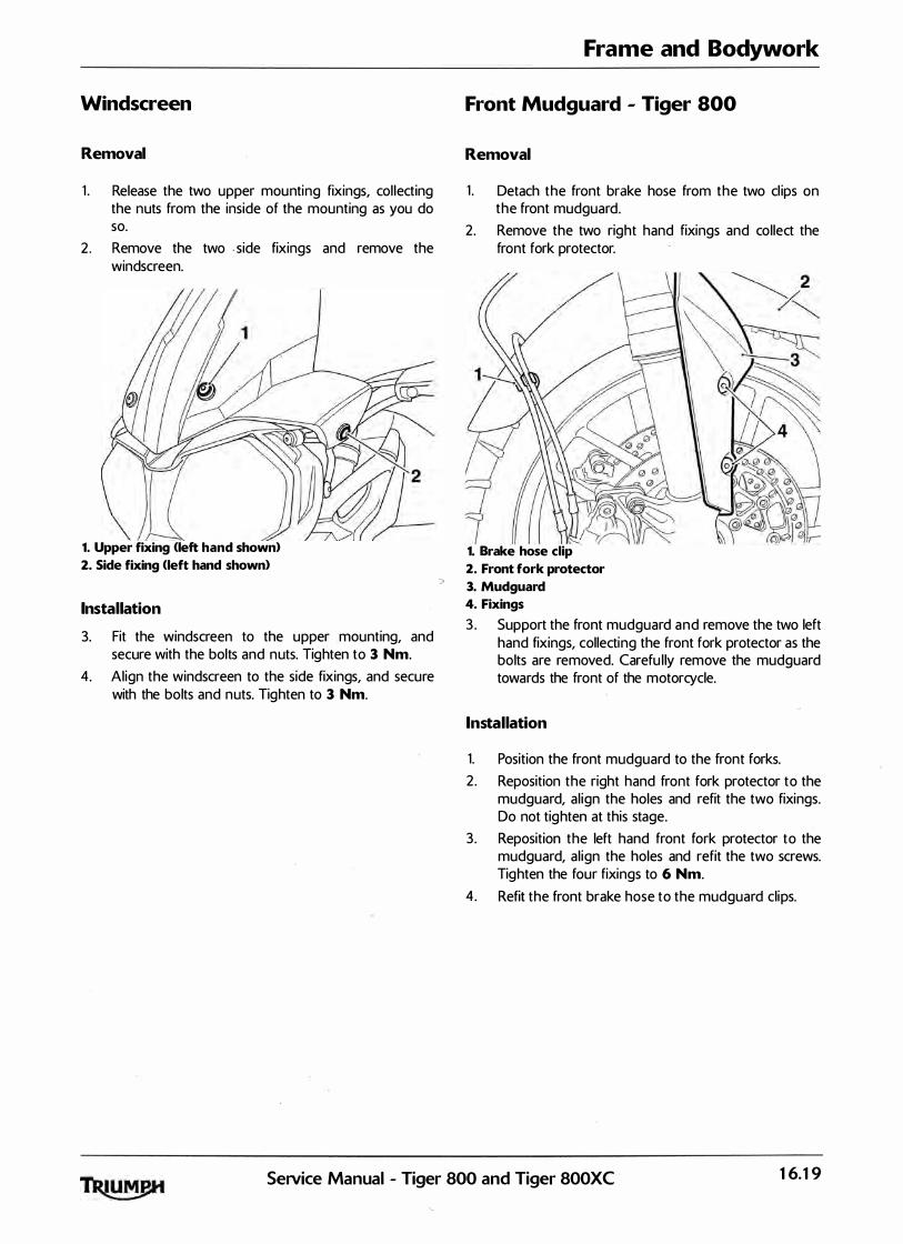
Windscreen
Removal
1 . Release the two upper mou nting fixings, col lecting the nuts from the inside of the mounting as you do so.
2 . Remove the two . side fixings and remove the windscreen.
1. Upper fixing <left hand shown>
2. Side fixing (left hand shown>
Installation
3. Fit the windscreen to the upper mounting, and secure with the bolts and n uts. Tighten to 3 Nm.
4. Al ign the windscreen to the side fixings, and secure with the bolts and n uts. Tighten to 3 Nm.
Frame and Bodywork
Front Mudguard - Tiger 800
Removal
1 . Detach the front brake hose from the two cl ips on the front mudguard.
2. Remove the two right hand fixings and collect the front fork protector.
(! 1. Brake hose clip
2. Front fork protector
3. Mudguard
4. Fixings
3 . Support the front mudguard a n d remove the two left hand fixings, collecting the front fork protector as the bolts are removed. Carefu l ly remove the mudguard towards the front of the motorcycle.
Installation
1. Position the front mudguard to the front forks.
2 . Reposition the right hand front fork protector to the mudguard, a l ign the holes and refit the two fixings. Do not tig hten at this stage.
3 . Reposition the left hand front fork protector to the mudguard, a l ign the holes and refit the two screws. Tighten the four fixings to 6 Nm.
4. Refit the front brake hose to the mudguard clips.
SeiVice Manual - Tiger 800 and Tiger 800XC 16.19

Frame and Bodywork
Front Mudguard - Tiger 800XC
Removal
1 . Detach the front brake hose from the two cl ips on the front mudguard.
2. Remove and d isca rd the two rear fixings.
3. Support the front mudguard and remove the four lower fixings. Discard the fixings.
4. Remove the m udguard towards the front of the motorcycle.
4. Lower fixings
Installation
1 . Position the front mudguard to the front forks.
2. F it fou r new lower fixings and tighten to 6 Nm.
3. Fit two new rear fixings and tighten to 6 Nm.
4. Refit the front brake hose to the mudguard cl ips.
Rear Rack
Removal
1 . Remove the rear seat (see page 16- 13>.
2. Remove the four fixings and remove the rack.
2. Fixings
Installation
1. Position the rear rack to the motorcycle.
2. Refit the fou r fixings and tighten to 3 Nm.
3. Refit the rear seat <see page 16- 13).
16.20 SeiVice Manual - Tiger 800 and Tiger 800XC
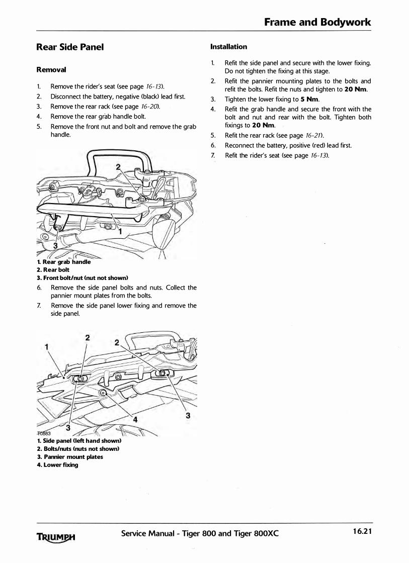
Rear Side Panel
Removal
1 . Remove the rider's seat <see page 16- 13}.
2. Disconnect the battery, negative (black> lead first.
3 . Remove the rear rack (see page 16-20>.
4. Remove the rear grab handle bolt.
5 . Remove the front nut and bolt and remove the grab handle.
1. Rear grab handle
2. Rear bolt
3. Front bolt/nut <nut not shown>
6. Remove the side panel bolts and nuts. Collect the pannier mount plates from the bolts.
Z Remove the side panel lower fixing and remove the side panel.
1. Side panel <left hand shown>
2. Bolts/nuts <nuts not shown)
3. Pannier mount plates
4. Lower fixing
Frame and Bodywork
Installation
1. Refit the side panel and secure with the lower fixing. Do not tighten the fixing at this stage.
2. Refit the pan nier mounting plates to the bolts and refit the bolts. Refit the n uts and tighten to 20 Nm.
3. Tighten the lower fixing to 5 Nm.
4. Refit the grab handle and secure the front with the bolt and nut and rear with the bolt. Tig hten both fixings to 20 Nm.
5. Refit the rear rack (see page 16-21).
6. Reconnect the battery, positive <red> lead first.
Z Refit the rider's seat (see page 16- 13).
SeiVice Manual - Tiger 800 and Tiger 800XC 16.21
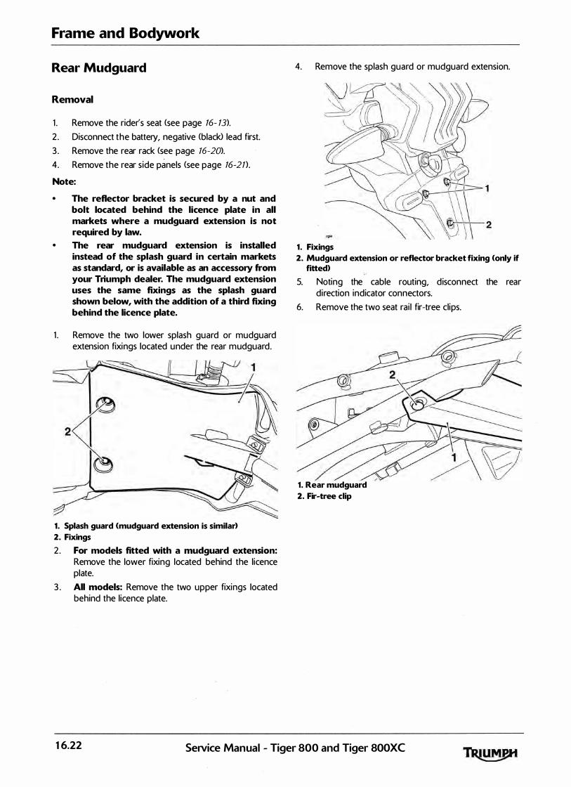
Frame and Bodywork
Rear Mudguard
Removal
1 . Remove the rider's seat <see page 16- 13).
2 . Disconnect the battery, negative <black) lead first.
3 . Remove the rear rack <see page 76-20>.
4. Remove the rear s ide panels <see page 16-21).
Note:
• The reflector bracket is secured by a nut and bolt located behind the licence plate in all markets where a mudguard extension is not required by law.
• The rear mudguard extension is installed instead of the splash guard in certain markets as standard, or is available as an accessory from your Triumph dealer. The mudguard extension uses the same fixings as the splash guard shown below, with the addition of a third fixing behind the licence plate.
1 . Remove the two lower splash guard or mudguard extension fixings located u nder the rear m udguard.
1. Splash guard (mudguard extension is similar)
2. Fixings
2. For models fitted with a mudguard extension: Remove the lower fixing located behind the l icence plate.
3 . All models: Remove the two upper fixings located behind the l icence plate.
4. Remove the splash guard or mudguard extension.
1 . Fixings
2. Mudguard extension or reflector bracket fixing (only if fitted> >-'
5. Noting the cable routing, d isconnect the rear direction indicator connectors.
6. Remove the two seat rai l fir-tree clips.
1. Rear mudguard
2. Fir-tree clip
16.22 SeiVice Manual - Tiger 800 and Tiger 800XC

Z Lift the rear mudguard off the two rear seat rai l lugs, along with the rear l ight and seat lock assembly.
/ /'(_V � � 1. Rear mudguard
2. Seat rail lugs
8. Carefu lly separate the rear mudguard from the rear l ight and seat lock assembly and remove from the motorcycle. Do not al low the rear l ight and seat lock assembly to hang from the rear l ight harness or seat lock cable.
Frame and Bodywork
Installation
1 . Al ign the rear mudguard to the rear l ight and seat lock assembly.
2. Position the rear mudguard to the seat rai ls, and locate the holes in the mudguard over the lugs on the frame.
3 . Secure the rear mudguard t o t h e seat rai ls using new fir-tree cl ips.
4. Fol lowing the routing noted during disassembly, recon nect the rear direction ind icators.
5 . Refit the splash guard or m udguard extension. Secure the splash guard or mudguard extension with the four screws and tighten to 3 Nm.
6. I nsta l l the lower mudguard extension or reflector bracket fixing and tighten to 5 Nm.
Z All 111odels: Refit the rear side panels <see page 16-2T>.
u
8. Refit the rear rack <see page 16-21) .
9 . Reconnect the battery, positive <red) lead first.
10. Refit the rider's seat (see page 16- 13>.
Service Manual - Tiger 800 and Tiger 800XC 16.23
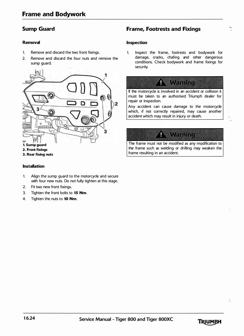
Frame and Bodywork
Sump Guard
Removal
1 . Remove and d iscard the two front fixings.
2. Remove and discard the fou r nuts and remove the sump guard.
1. Sump guard
2. Front fixings
3. Rear fixing nuts
Installation
1 . Align the sump guard to the motorcycle and secure with four new nuts. Do not ful ly tighten at this stage.
2. Fit two new front fixings.
3. Tighten the front bolts to 15 Nm.
4. Tighten the nuts to 10 Nm.
Frame, Footrests and Fixings
Inspection
1. Inspect the frame, footrests and bodywork for damage, cracks, chafing and other dangerous conditions. Check bodywork and frame fixings for security.
If the motorcycle is involved in an accident or col l ision it m ust be taken to an authorised Triumph dealer for repair or inspection. Any accident can cause damage to the motorcycle which, if not correctly repaired, may cause another accident which may result in injury or death. ,,
! ' '
The frame m ust not be modified as any mqdification to the frame such as welding or dri l l ing may weaken the frame resulting in an accident.
16.24 SeNice Manual - Tiger 800 and Tiger 800XC

1 7 Electrical Table of Contents
Exploded View - Instruments. . . . . . . . . . . . . . . . . . . . . . . . . . . . . . . . . . . . . . . . . . . . . . . . . . . . . . . . . . . . . . . 17.3
Exploded View - Headlight . . . . . . . . . . . . . . . . . . . . . . . . . . . . . . . . . . . . . . . . . . . . . . . . . . . . . . . . . . . . . . . . 17.4
Exploded View - Rear Light 8. Reflectors . . . . . . . . . . . . . . . . . . . . . . . . . . . . . . . . . . . . . . . . . . . . . . . . . . . . . 17.5
Exploded View - Direction Indicators . . . . . . . . . . . . . . . . . . . . . . . . . . . . . . : '. . . . . . . . . . . . . . . . . . . . . . . . . 17.6
Exploded View - Alternator, Starter and Immobiliser . . . . . . . . . . . . . . . . . . . . . . . . . . . . . . . . . . . . . . . . . . . 17.7
Battery . . . . . . . . . . . . . . . . . . . . . . . . . . . . . . . . . . . . . . . . . . . . . . . . . . . . . . . . . . . . . . . . . . . . . . . . . . . . . . . . . 17.8
Battery Removal . . . . . . . . . . . . . . . . . . . . . . . . . . . . . . . . . . . . . . . . . . . . . . . . . . . . . . . . . . . . . . . . . . . . . 17.8
Battery Refit . . . . . . . . . . . . . . . . . . . . . . . . . . . . . . . . . . . . . . . . . . . . . . . . . . . . . . . . . . . . . . : . . . . . . . . . 17.8
Battery Commissioning and Charging . . . . . . . . . . . . . . . . . . . . . . . . . . . . . . . . . . . . . . . . . . . . . . . . . . 17.9
New Battery . . . . . . . . . . . . . . . . . . . . . . . . . . . . . . . . . . . . . . . . . . . . . . . . . . . . . . . . . . . . . . . . . . . . . . . . 17.9
Battery Maintenance . . . . . . . . . . . . . . . . . . . . . . . . . . . . . . . . . . . . . . . . . . . . . . . . . . . . . . . . . . . . . . . . 17.10
Battery Already in Service. . . . . . . . . . . . . . . . . . . . . . . . . . . . . . . . . . . . . . . . . . . . . . . . . . . . . . . . . . . . 17.10
Table of Battery Charging Times . . . . . . . . . . . . . . . . . . . . . . . . . . . . . . . . . . . . . . . . . . . . . . . . . . . . . . 17.10
Relays . . . . . . . . . . . . . . . . . . . . . . . . . . . . . . . . . . . . . . . . . . . . . . . . . . . . . . . . . . . . . . . . . . . . . . . . . . . . . . . . . . 17.1 1
Relay Identification. . . . . . . . . . . . . . . . . . . . . . . . . . . . . . . . . . . . . . . . . . . . . . . . . . . . . . . . . . . . . . . . . . 17.1 1
Direction Indicator Unit. . . . . . . . . . . . . . . . . . . . . . . . . . . . . . . . . . . . . . . . . . . . . . . . . . . . . . . . . . . . . . 17.1 1
Fuses . . . . . . . . . . . . . . . . . . . . . . . . . . . . . . . . . . . . . . . . . . . . . . . . . . . . . . . . . . . . . . . . . . . . . . . . . . . . . . . . . . . 17.1 1
Fuse Identification . . . . . . . . . . . . . . . . . . . . . . . . . . . . . . . . . . . . . . . . . . . . . . . . . . . . . . . . . . . . . . . . . . 17.1 1
Front fuse box . . . . . . . . . . . . . . . . . . . . . . . . . . . . . . . . . . . . . . . . . . . . . . . . . . . . . . . . . . . . . . . . . . . . . 17.12
Rear fuse box . . . . . . . . . . . . . . . . . . . . . . . . . . . . . . . . . . . . . . . . . . . . . . . . . . . . . . . . . . . . . . . . . . . . . . 17.1 2
Instrument Pack. . . . . . . . . . . . . . . . . . . . . . . . . . . . . . . . . . . . . . . . . . . . . . . . . . . . . . . . . . . . . . . . . . . . . . . . . . 17.13
Removal . . . . . . . . . . . . . . . . . . . . . . . . . . . . . . . . . . . . . . . . . . . . . . . . . . . . . . . . . . . . . . . . . . . . . . . . . . 17.13
Installation . . . . . . . . . . . . . . . . . . . . . . . . . . . . . . . . . . . . . . . . . . . . . . . . . . . . . . . . . . . . . . . . . . . . . . . . . 17.13
Headlights . . . . . . . . . . . . . . . . . . . . . . . . . . . . . . . . . . . . . . . . . . . . . . . . . . . . . . . . . . . . . . . . . . . . . . . . . . . . . . 17.14
Headlight Adjustment . . . . . . . . . . . . . . . . . . . . . . . . . . . . . . . . . . . . . . . . . . . . . . . . . . . . . . . . . . . . . . . 17.14
Headlight Bulb Replacement . . . . . . . . . . . . . . . . . . . . . . . . . . . . . . . . . . . . . . . . . . . . . . . . . . . . . . . . . 17.14
Installation . . . . . . . . . . . . . . . . . . . . . . . . . . . . . . . . . . . . . . . . . . . . . . . . . . . . . . . . . . . . . . . . . . . . . . . . . 17.14
Position Lamp Bulb Replacement. . . . . . . . . . . . . . . . . . . . . . . . . . . . . . . . . . . . . . . . . . . . . . . . . . . . . . 17.1 5
Installation . . . . . . . . . . . . . . . . . . . . . . . . . . . . . . . . . . . . . . . . . . . . . . . . . . . . . . . . . . . . . . . . . . . . . . . . . 17.1 5
Headlight Assembly . . . . . . . . . . . . . · . . . . . . . . . . . . . . . . . . . . . . . . . . . . . . . . . . . . . . . . . . . . . . . . . . . . . . . . . 17.1 5
Removal . . . . . . . . . . . . . . . . . . . . . . . . . . . . . . . . . . . . . . . . . . . . . . . . . . . . . . . . . . . . . . . . . . . . . . . . . . 17.1 5
Installation . . . . . . . . . . ·. . . . . . . . . . . . . . . . . . . . . . . . . . . . . . . . . . . . . . . . . . . . . . . . . . . . . . . . . . . . . . . 17.1 5
Rear Light. . . . . . . . . . . . . . . . . . . . . . . . . . . . . . . . . . . . . . . . . . . . . . . . . . . . . . . . . . . . . . . . . . . . . . . . . . . . . . . 17.16
SeiVice Manual - Tiger 800 and Tiger 800XC 17.1

Electrical
17.2
Removal . . . . . . . . . . . . . . . . . . . . . . . . . . . . . . . . . . . . . . . . . . . . . . . . . . . . . . . . . . . . . . . . . . . . . . . . . . 17.16
Installation . . . . . . . . . . . . . . . . . . . . . . . . . . . . . . . . . . . . . . . . . . . . . . . . . . . . . . . . . . . . . . . . . . . . . . . . 17.16
Direction Indicators . . . . . . . . . . . . . . . . . . . . . . . . . . . . . . . . . . . . . . . . . . . . . . . . . . . . . . . . . . . . . . . . . . . . . . . 17.1 6
Bulb Replacement . . . . . . . . . . . . . . . . . . . . . . . . . . . . . . . . . . . . . . . . . . . . . . . . . . . . . . . . . . . . . . . . . . 17.16
Rear Direction Indicator . . . . . . . . . . . . . . . . . . . . . . . . . . . . . . . . . . . . . . . . . . . . . . . . . . . . . . . . . . . . . . . . . . . 17.17
Removal . . . . . . . . . . . . . . . . . . . . . . . . . . . . . . . . . . . . . . . . . . . . . . . . . . . . . . . . . . . . . . . . . . . . . . . . . . 17.17
Installation . . • . . . . . . . . . . . . . . . . . . . . . . . . . . . . . . . . . . . . . . . . . . . . . . . . . . . . . . . . . : . . . . . . . . . . . 17.17
Front Direction Indicator . . . . . . . . . . . . . . . . . . . . . . . . . . . . . . . . . . . . . . . . . . . . . . . . . . . . . . . . . . . . . . . . . . 17.17
Removal . . . . . . . . . . . . . . . . . . . . . . . . . . . . . . . . . . . . . . . . . . . . . . . . . . . . . . . . . . . . . . . . . . . . . . . . . . 17.17
Installation . . . . . . . . . . . . . . . . . . . . . . . . . . . . . . . . . . . . . . . . . . . . . . . . . . . . . . . . . . . . . . . . . . . . . . . . 17.17
Starter Motor. . . . . . . . . . . . . . . . . . . . . . . . . . . . . . . . . . . . . . . . . . . . . . . . . . . . . . . . . . . . . . . . . . . . . . . . . . . . 17.18
Removal . . . . . . . . . . . . . . . . . . . . . . . . . . . . . . . . . . . . . . . . . . . . . . . . . . . . . . . . . . . . . . . . . . . . . . . . . . 17.18
Inspection . . . . . . . . . . . . . . . . . . . . . . . . . . . . . . . . . . . . . . . . . . . . . . . . . . . . . . . . . . . . . . . . . . . . . . . . . 17.18
Installation . . . . . . . . . . . . . . . . . . . . . . . . . . . . . . . . . . . . . . . . . . . . . . . . . . . . . . . . . . . . . . . . . . . . . . . . 17.18
Alternator . . . . . . . . . . . . . . . . . . . . . . . . . . . . . . . . . . . . . . . . . . . . . . . . . . , . . . . . . . . . . . . . . . . . . . . . . . . . . . . . 17.19
Removal . . . . . . . . . . . . . . . . . . . . . . . . . . . . . . . . . . . . . . . . . . . . . . . . . . . . . . . . . . . . . . . . . . . . . . . . . . 17.19
Assembly . . . . . . . . . . . . . . . . . . . . . . . . . . . . . . . . . . . . . . . . . . . . . . . . . . . . . . . . . . . . . . . . . . . . . . . . . 17.20
Alternator Rectifier . . . . . . . . . . . . . . . . . . . . . . . . . . . . . . . . . . . . . . . . . . . . . . . . . . . . . . . . . . . . . . . . . . . . . . 17.21
Alternator Stator . . . . . . . . . . . . . . . . . . . . . . . . . . . . . . . . . . . . . . . . . . . . . . . . . . . . . . . . . . . . . . . . . . . . , . . . 17.22
Pinpoint Tests . . . . . . . . . . . . . . . . . . . . . . . . . . . . . . . . . . . . . . . . . . . . . . . . . . . . . . . . . . . . . . . . . . . . . . 17.22
Rectifier/Regulator . . . . . . . . . . . . . . . . . . . . . . . . . . . . . . . . . . . . . . . . . . . . . . . . . . . . . . . . . . . . . . . . . . . . . . 17.24
Pinpoint Tests . . . . . . . . . . . . . . . . . . . . . . . . . . . . . . . . . . . . . . . . . . . . . . . . . . . . . . . . . . . . . . . . . . . . . . 17.24
Lighting Circuit . . . . . . . . . . . . . . . . . . . . . . . . . . . . . . . . . . . . . . . . . . . . . . . . . . . . . . . . . . . . . . . . . . . . . . . . . 17.26
Key to circuit diagram . . . . . . . . . . . . . . . . . . . . . . . . . . . . . . . . . . . . . . . . . . . . . . . . . . . . . . . . . . . . . . . 17.26
Key to wiring colours. . . . . . . . . . . . . . . . . . . . . . . . . . . . . . . . . . . . . . . . . . . . . . . . . . . . . . . . . . . . . . . . 17.26
Starting and Charging Circuit . . . . . . . . . . . . . . . . . . . . . . . . . . . . . . . . . . . . . . . . . . . . . . . . . . . . . . . . . . . . . 17.28
Key to circuit diagram . . . . . . . . . . . . . . . . . . . . . . . . . . . . . . . . . . . . . . . . . . . . . . . . . . . . . . . . . . . . . . . 17.28
Key to wiring colours. . . . . . . . . . . . . . . . . . . . . . . . . . . . . . . . . . . . . . . . . . . . . . . . . . . . . . . . . . . . . . . . 17.28
Auxiliary and Accessory Circuit. . . . . . . . . . . . . . . . . . . . . . . . . . . . . . . . . . . . . . . . . . . . . . . . . . . . . . . . . . . . 17.30
Key to circuit diagram . . . . . . . . . . . . . . . . . . . . . . . . . . . . . . . . . . . . . . . . . . . . . . . . . . . . . . . . . . . . . . . 17.30
Key to wiring colours. . . . . . . . . . . . . . . . . . . . . . . . . . . . . . . . . . . . . . . . . . . . . . . . . . . . . . . . . . . . . . . . 17.30
Engine Management Circuit Diagram - Tiger 800 and Tiger 800XC . . . . . . . . . . . . . . . . . . . . . . . . . . . . . 17.3 2
Key To Wiring Circuit Diagram . . . . . . . . . . . . . . . . . . . . . . . . . . . . . . . . . . . . . . . . . . . . . . . . . . . . . . . 17.32
Key To Wiring Colour Codes . . . . . . . . . . . . . . . . . . . . . . . . . . . . . . . . . . . . . . . . . . . . . . . . . . . . . . . . . 17.3 2
Engine Management Circuit Diagram - Tiger 800 <ABS> and Tiger 800XC <ABS> . . . . . . . . . . . . . . . . . . 17.34
Key To Wiring Circuit Diagram . . . . . . . . . . . . . . . . . . . . . . . . . . . . . . . . . . . . . . . . . . . . . . . . . . . . . . . 17.34
Key To Wiring Colour Codes . . . . . . . . . . . . . . . . . . . . . . . . . . . . . . . . . . . . . . . . . . . . . . . . . . . . . . . . . 17.34
Complete System - Tiger 800 and Tiger 800XC - without ABS . . . . . . . . . . . . . . . . . . . . . . . . . . . . . . . . . 17.36
Key to circuit diagram . . . . . . . . . . . . . . . . . . . . . . . . . . . . . . . . . . . . . . . . . . . . . . . . . . . . . . . . . . . . . . . 17.36
Complete System - Tiger 800 and Tiger 800XC - with ABS . . . . . . . . . . . . . . . . . . . . . . . . . . . . . . . . . . . . 17.38
Key to circuit diagram . . . . . . . . . . . . . . . . . . . . . . . . . . . . . . . . . . . . . . . . . . . . . . . . . . . . . . . . . . . . . . . 17.38
SeiVice Manual - Tiger 800 and Tiger 800XC

. w - Instruments Exploded VIe
(f) 2 Nm �
. 800XC
. r 800 and Tiger
. Manual - T•ge Se1V1ce
Electrical
17.3
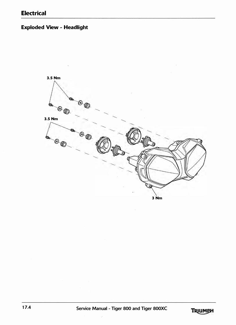
Electrical
Exploded View - Headlight
3.5 Nm
3.5 Nm
3 Nm
17.4 SeiVice Manual - Tiger 800 and Tiger 800XC
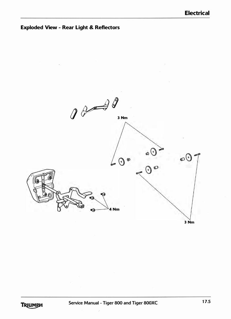
Exploded View - Rear Light & Reflectors
� g c
(} , , 3 Nm
SeiVice Manual - Tiger 800 and Tiger 800XC
Electrical
3 Nm
17.5

Electrical
Exploded View - Direction Indicators
3 Nm 3 Nm
�
3 Nm
�
17.6 SeNice Manual - Tiger 800 and Tiger 800XC

Electrical
Exploded View - Alternator, Starter and Immobiliser
9 Nm
12 Nm
120 Nm
SeiVice Manual - Tiger 800 and Tiger 800XC 17.7

Electrical
Battery
The battery g ives off explosive gases; keep sparks, flames and cigarettes away. Provide adequate ventilation when charging or using the battery in an enclosed space. The battery contains sulphuric acid (electrolyte). Contact with skin or eyes may cause severe burns. Wear protective clothing and a face shield.
If electrolyte gets on your skin, flush with water immediately.
If electrolyte gets in you r eyes, flush with water for at least 15 minutes and SEEK MEDICAL ATTENTION IMMEDIATELY.
If electrolyte is swallowed, drink large quantities of water and SEEK M EDICAL ATTENTION IMM EDIATELY.
KEEP ELECTROLYTE O UT O F TH E REACH O F CH I LDREN.
The battery contains harmful materials. Always keep ch ildren away from the battery whether or not it is fitted in the motorcycle. Do not jump start the battery, touch the battery cables together or reverse the polarity of the cables as any of these actions may cause a spark which would ignite battery gasses causing a risk of personal in jury.
The battery electrolyte is corrosive and poisonous. Never swal low battery electrolyte or a l low electrolyte to come into contact with the skin. Always wear eye and skin protection when adjusting the electrolyte level.
Battery Removal
1. Battery
2. Negative {-) terminal
3. Positive <+> terminal
4. Battery strap
1 . Remove the rider's seat (see page 16-13).
2. Disconnect the battery, negative <black> lead first.
3 . Remove the battery strap.
4. Take the battery out of the case.
' ' , . ,
Ensure that the battery term inals do not touch the motorcycle frame as th is may cause a short circuit or spark which would ign ite battery gases causing a r isk of personal in jury.
Battery Refit
Ensure that the battery term inals do not touch the motorcycle frame as this may cause a short circu it or spark which would ign ite battery gases causing a risk of personal in jury.
1 . Place the battery in the battery case.
2. Reconnect the battery, positive (red) lead first.
3 . Apply a l ight coat of grease t o the terminals to prevent corrosion.
4. Cover the terminals with the protective caps.
5. Refit the battery strap.
6. Refit the rider's seat <see page 16- 13>.
1 7.8 Service Manual - Tiger 800 and Tiger 800XC

Battery Commissioning and Charging
New Battery
In order to correctly and safely commission a new battery, the battery comm issioning pr9cedu�e l isted below must be carefu l ly fol lowed. This is the only battery commissioning procedure that Triumph recommends. The procedure is designed to ensure that the battery is at its best when fitted to the motorcycle, and will provide the best possible performance and rel iabil ity.
Fai lure to comply with th is procedure may lead to reduced battery performance and/or shorten the l ife of the battery.
The battery g ives off explosive gases; keep sparks, flames and cigarettes away. Provide adeq uate ventilation when charging or using the battery in an enclosed space. The battery contains sulphuric acid (electrolyte). Contact with skin or eyes may cause severe burns. Wear protective clothing and a face shield.
If electrolyte gets on you r skin, flush with water immediately.
• If electrolyte gets in you r eyes, flush with water for at least 15 minutes and SEEK MEDICAL ATTENTION IMMEDIATELY.
• If electrolyte is swallowed, drink large quantities of water and SEEK MEDICAL ATTENTION I M M EDIATELY.
KEEP ELECTROLYTE O UT O F TH E REACH O F CH I LDREN.
1 . Ensure the V I N number printed on the anti-tamper label attached to the battery matches the motorcycle VI N.
2. Read the instructions and warnings del ivered with the battery.
3 . Place the battery on a flat level surface a n d remove the seal ing foi l .
Ensure the electrolyte conta iner part number matches the battery part number to be fi l led. Battery l ife will be greatly reduced if the incorrect volume <either too l ittle or too much) of acid is added to the battery.
4. Remove the battery seal ing strip from the electrolyte container (if appl icable) and s�ve for later in this procedure. Place the seal ing strip on a clean surface,
Electrical
with the upper side facing downwards to avoid contamination of the seal ing strip. Do not break the sea l on the electrolyte container.
5. Place the electrolyte conta iner and adapter <if appl icable) on the battery and fi l l the battery according to the manufacturers instructions.
6. After starting to fi l l the battery with electrolyte, a l low the battery to stand for 30 minutes with the fi l l ing conta iner in place.
Z Check that a l l of the electrolyte has drained from the conta iner. Do not remove the conta iner at this point. If the container has not completely d rained, tap the sides of the container to start the electrolyte flowing again.
8. After the electrolyte has drained into the battery, al low the battery to sta nd with the electrolyte container in place for a further 30 minutes for batteries 3Ah - 1 2Ah or 1 hour for batteries g reater than 1 2Ah.
9. Remove the electrolyte container and ada pter careful ly, and dispose of immediately.
10. Place the seal ing cap strip LOOSELY over the fi l l ing holes of the battery.
1 1 . Charge the battery using the BatteryMate 1 5 0-9. Refer to the instructions suppl ied with the BatteryMate 1 5 0-9.
The caps must be fitted (after charging) within two hours of fi l l ing the battery with acid. Leaving the battery open to the atmosphere for longer than is necessary wil l start to reverse the chemical reaction which takes place within the battery, g reatly reducing the battery l ife.
1 2 . After charging is complete, press down firmly with both hands to seat the caps <do not use tools or force the caps into position).
1 3 . Disconnect the charger and a l low the battery to stand for 1 hour before fitting to the motorcycle.
14. F it the battery to the motorcycle, positive <red) lead first.
SeiVice Manual - Tiger 800 and Tiger 800XC 17.9
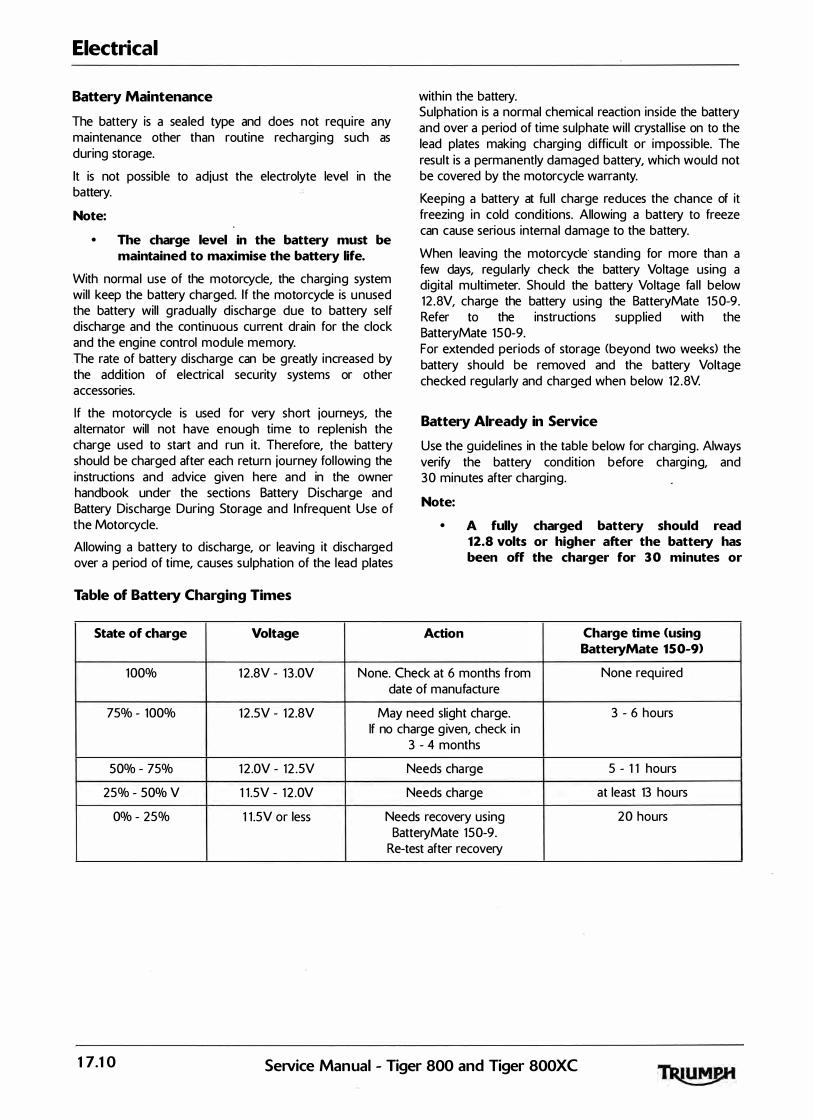
Electrical
Battery Maintenance
The battery is a sea led type and does not require any maintenance other than routine recharging such as during storage.
lt is not possible to adjust the electrolyte level in the battery.
Note:
• The charge level in the battery must be maintained to maximise the battery life.
With normal use of the motorcycle, the charging system will keep the battery charged. If the motorcycle is u nused the battery will gradual ly discharge due to battery self discharge and the continuous current drain for the clock and the engine control module memory. The rate of battery discharge can be greatly increased by the addition of electrica l security systems or other accessories.
If the motorcycle is used for very short journeys, the alternator will not have enough time to replenish the charge used to start and run it. Therefore, the battery should be charged after each return journey fol lowing the instructions and advice g iven here and in the owner handbook under the sections Battery Discharge and Battery Discharge During Storage and I nfrequent Use of the Motorcycle.
Allowing a battery to d ischarge, or leaving it discharged over a period of time, causes sulphation of the lead plates
Table of Battery Charging Times
State of charge Voltage
within the battery. Sulphation is a normal chemical reaction inside the battery and over a period of time sulphate wil l crystal l ise on to the lead plates making charging difficult or impossible. The result is a permanently damaged battery, which would not be covered by the motorcycle warranty.
Keeping a battery at fu l l charge reduces the chance of it freezing in cold conditions. Allowing a battery to freeze can cause serious internal damage to the battery.
When leaving the motorcycle standing for more than a few days, regularly check the battery Voltage using a digital multimeter. Should the battery Voltage fa l l below 12 .8V, charge the battery using the BatteryMate 1 5 0-9. Refer to the instructions suppl ied with the BatteryMate 1 5 0-9. For extended periods of storage (beyond two weeks) the battery should be removed and the battery Voltage checked regularly and charged when below 12 .8V.
Battery Already in Service
Use the gu idelines in the table below for charging. Always verify the battery condition before charg ing, and 3 0 minutes after charging.
Note:
• A fully charged battery should read 12.8 volts or higher after the battery has been off the charger for 3 0 minutes or
Action Charge time <using BatteryMate 150-9)
1 00% 1 2.8V - 1 3 .0V None. Check at 6 months from None requ i red date of manufacture
75% - 100% 1 2 .5V - 1 2.8V May need slight charge. 3 - 6 hours If no charge g iven, check in
3 - 4 months
SO% � 75% 1 2 .0V - 1 2 .5V Needs cha rge 5 - 1 1 hours
25% - SOOJo V 1 1 .5V - 1 2 .0V Needs charge at least 13 hours
0% - 25% 1 1 .5V or less Needs recovery using 2 0 hours BatteryMate 1 5 0-9.
Re-test after recovery
17.10 SeiVice Manual - Tiger 800 and Tiger 800XC

Relays
The relay pack is located beneath the rider's seat, ad jacent to the fuse boxes. To gain access to the relays, remove the rider's seat (see page 16-13).
Relay Identification
cgzj � 1. Cooling fan relay
2. Engine management system <EMS> main relay
3. Starter relay
4. Fuel pump relay
5. Headlamp relay
Direction Indicator Unit
The direction ind icator un it is located below the rear rack, adjacent to the rear l ight u nit. To gain access to the relays, remove the rear rack <see page 16-20).
Electrical
Fuses
I f a fuse fails during operation, inspect the electrica l system to determ ine the cause, and then replace it with a new fuse of the correct current rating.
A blown fuse is ind icated when al l of the systems protected by that fuse become inoperative. When checking for a blown fuse, use the table below to establish which fuse has blown.
Note:
• The starter solenoid has an additional 3 0 Amp fuse attached directly to the solenoid, beneath the rider's seat.
� "' - �= �� � �
/ I , , ' . '
Always replace blown fuses with new- ones of the correct current rating <as specified on the fuse box cover) and never use a fuse of higher rating. Use of an incorrect fuse could lead to an electrical problem, resu lting in motorcycle damage, loss of motorcycle control and an accident.
Fuse Identification
The fuse boxes are located beneath the rider's seat.
To al low access to the fuse boxes, the rider's seat must be removed (see page 16-13).
2. Rear fuse box
SeiVice Manual - Tiger 800 and Tiger 800XC 17.11

Electrical
Front fuse box
Fuse No. Circuits Protected Fuse Rating
1 Cool ing fan -1 5
2 Accessory l ights 1 5
3 Auxi l iary l ighting 10
4 Heated grips 10
5 Accessory sockets 1 5
6 Not used -
The fuse identification numbers l isted correspond with those printed on the fuse box cover.
Rear fuse box
Fuse No.
1
2
3
4
5
. 6
cebw Front of Motorcycle 1. Front fuse box cover
2. Front fuse box
3. Spar� fuses
4. Rear fuse box
5. Rear fuse box cover
Circuits Protected
ABS
ABS
Alarm, instruments, ECM
Engine management
Alarm, diagnostic con nector, instruments
Dip and main beam headl ights, starter relay
17.12 SeiVice Manual - Tiger 800 and Tiger 800XC
Fuse Rating
20
20
10
20
5
1 5
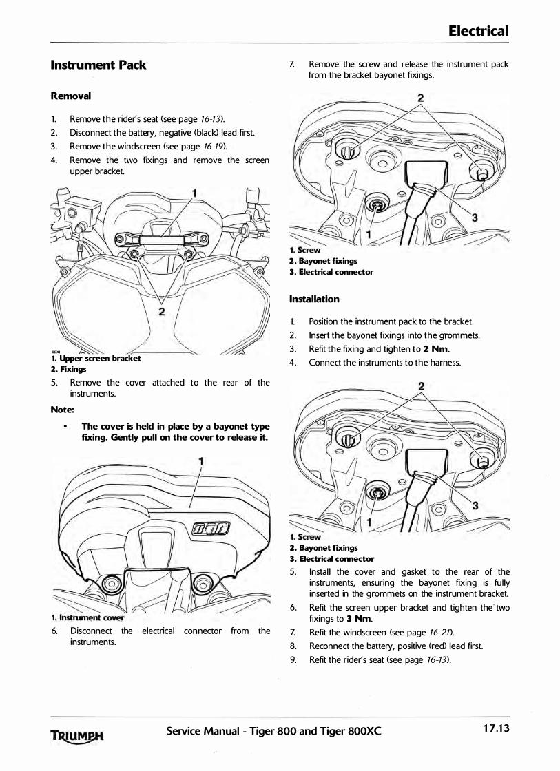
Instrument Pack
Removal
1 . Remove the rider's seat (see page 16-13).
2. Disconnect the battery, negative (black> lead first.
3 . Remove the windscreen (see page 16-19).
4. Remove the two fixings and remove the screen upper bracket.
CQXi -1. Upper screen bracket
2. Fixings
5. Remove the cover attached to the rear of the instruments.
Note:
• The cover is held in place by a bayonet type fixing. Gently pull on the cover to release it.
6. Disconnect the electrical con nector from the instruments.
Electrical
Z Remove the screw and release the instrument pack from the bracket bayonet fixings.
2. Bayonet fixings
3. Electrical connector
Installation
1 . Position the instrument pack to the bracket.
2 . Insert the bayonet fixings into the grom mets.
3 . Refit the fixing and tighten to 2 Nm.
4. Connect the instruments to the harness.
2. Bayonet fixings
3. Electrical connector
5. Instal l the cover and gasket to the rear of the instruments, ensuring the bayonet fixing is fu l ly inserted in the g rommets on the instrument bracket.
6. Refit the screen upper bracket and tighten the · two fixings to 3 Nm.
Z Refit the windscreen <see page 16-21) .
8. Reconnect the battery, positive (red) lead first.
9. Refit the rider's seat (see page 16-13).
SeNice Manual - Tiger 800 and Tiger 800XC 17.13

Electrical
Headlights
Headlight Adiustment
Note:
• The headlight can be adjusted by means of vertical and horizontal adjustment screws located on the real;' of the headlight.
1. Horizontal adjustment screw
2. Vertical adjustment screw
3. Headlight adjuster lever for loaded conditions
1 . Switch the headl ight dipped beam on.
2. Turn the vertical adjustment screw on the headl ighf clockwise to raise the beam or anti-clockwise to lower the beam.
3. Turn the horizontal adjustment screw clockwise to move the beam to the right or anti-clockwise to move the beam to the left.
4. Switch the headl ights off when the beam settings are satisfactory.
Adjust road speed tq suit the visibi l ity and weather conditions in which the motorcycle is being operated. Ensure that the beam is adjusted to i l luminate the road surface sufficiently far ahead without dazzl ing oncoming traffic. An incorrectly adjusted headl ight may impair visibi l ity causing an accident.
! ' Never attempt to adjust a headl ight beam when the motorcycle is in motion. Any attempt to adjust a headl ight beam when the motorcycle is in motion may result in loss of control and an accident.
Headlight Bulb Replacement
2
... 1. Bulb retainer {right hand shown>
2. Bulb retainer hook
3. Bulb
Each headl ight bulb can be replaced as fol lows:
The bulb becomes hot during use. Arways al low sufficient time for the bulb to cool before handl ing. Avoid touching the g lass part of the bulb. I f the g lass is touched o r gets d irty, clean with alcohol before re-use.
Do not reconnect the battery until the assembly process has been com pleted. Premature battery reconnection could result in ign ition of the battery gases causing risk of in jury.
1 . Remove the rider's seat <see page 16-13).
2. Disconnect the battery, negative (black> lead first.
3 . Remove the bulb cover from the bulb t o be replaced by rotating it anti-clockwise.
4. Disconnect the multi-plug from the bulb reta iner.
5 . Detach the bulb retainer from the hook on the headl ight assembly and rotate it away from the bulb as shown.
6. Remove the bulb from the bulb retainer.
Installation
1. Instal lation is the reverse of removal, noting the fol lowing:
Note:
• When reconnecting the battery, connect the positive (red) lead first.
17.14 SeiVice Manual - Tiger 800 and Tiger 800XC
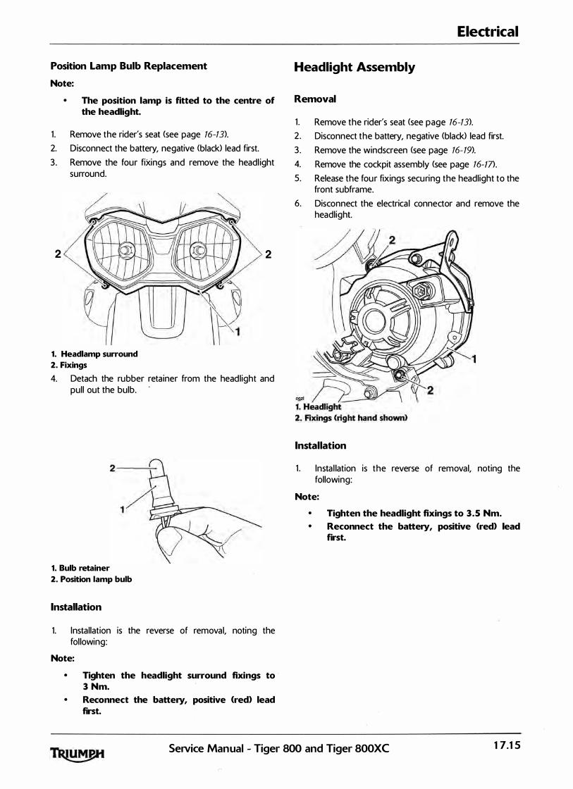
Position Lamp Bulb Replacement
Note:
• The position lamp is fitted to the centre of the headlight.
1 . Remove the rider's seat (see-page 16-13).
2. Disconnect the battery, negative <black> lead first.
3 . Remove the four fixings and remove the headl ight surround.
2 2
1. Headlamp surround
2. Fixings
4. Detach the rubber reta iner from the headl ight and pul l out the bulb.
1. Bulb retainer
2. Position lamp bulb
Installation
1. Installation is the reverse of removal, noting the fol lowing:
Note:
• Tighten the headlight surround fixings to 3 Nm.
• Reconnect the battery, positive (red) lead first.
Electrical
Headlight Assembly
Removal
1 . Remove the rider's seat (see page 16-13).
2. Disconnect the battery, negative <black> lead first.
3 . Remove the windscreen <see page 16- 19).
4. Remove the cockpit assembly (see page 16-m.
5. Release the fou r fixings securing the headlight to the front subframe.
6. Disconnect the electrica l connector and remove the headl ight.
Installation
1 . Insta l lation is the reverse of removal, noting the following:
Note:
• Tighten the headlight fixings to 3 .5 Nm. • Reconnect the battery, positive <red) lead
first.
Service Manual - Tiger 800 and Tiger 800XC 17.15
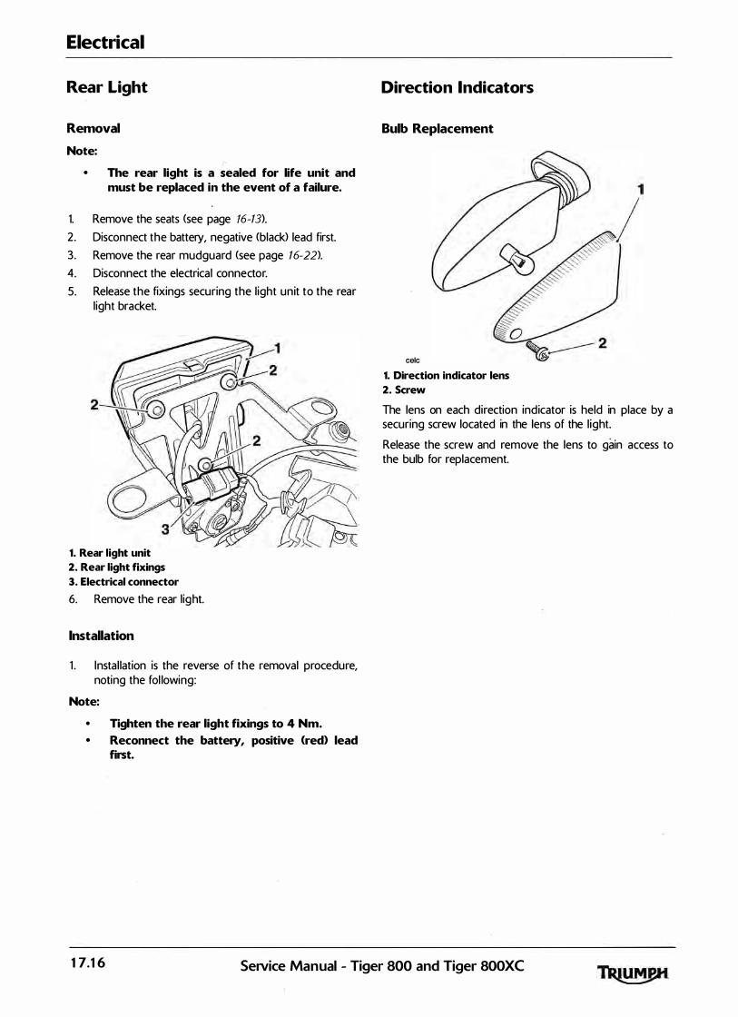
Electrical
Rear Light
Removal
Note: (' • The rear light is a sealed for life unit and
must be replaced in the event of a failure.
1. Remove the seats (see page 76-13).
2. Disconnect the battery, negative (black> lead first.
3 . Remove the rear mudguard (see page 16-22>.
4. Disconnect the electrical connector.
5. Release the fixings securing the l ight un it to the rear l ight bracket.
1. Rear light unit
2. Rear light fixings
3. Electrical connector
6. Remove the rear l ig ht.
Installation
1 . Instal lation is the reverse of t h e removal procedure, noting the fol lowing:
Note:
• Tighten the rear light fixings to 4 Nm. • Reconnect the battery, positive (red) lead
first.
Direction Indicators
Bulb Replacement
celc 1. Direction indicator lens
2. Screw
The lens on each direction ind icator is held in place by a securing screw located in the lens of the l ight.
Release the screw and remove the lens to gain access to the bulb for replacement.
17.16 SeiVice Manual - Tiger 800 and Tiger 800XC
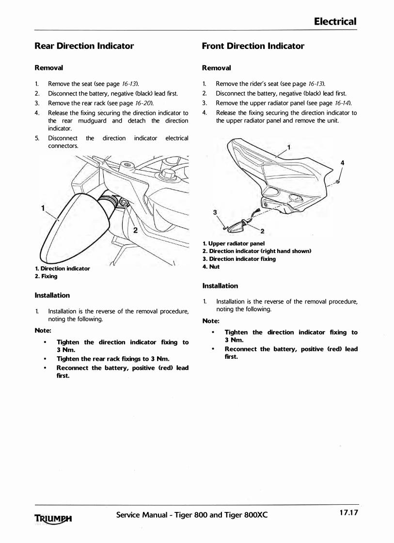
Rear Direction Indicator
Removal
1 . Remove the seat <see page 16-13).
2. Disconnect the battery, negative <black) lead first.
3 . Remove the rear rack <see' page 76-20>.
4. Release the fixing securing the direction indicator to the rear mudguard and detach the direction indicator.
5. Disconnect the direction indicator electrical connectors.
1. Direction indicator
2. Fixing
Installation
1. Instal lation is the reverse of the removal procedu re, noting the fol lowing.
Note:
• Tighten the direction indicator fixing to 3 Nm.
• Tighten t!1e rear rack fixings to 3 Nm. • Reconnect the battery, positive <red> lead
first.
Electrical
Front Direction Indicator
Removal
1 . Remove the rider's seat <see page 76-13>.
2. Disconnect the battery, negative (black) lead first.
3 . Remove the upper rad iator panel (see page 76-14>.
4. Release the fixing securing the direction indicator to the upper radiator panel and remove the unit.
1. Upper radiator panel
2. Direction indicator <right hand shown>
3. Direction indicator fixing
4. Nut
Installation
4
I /@;
1 . Instal lation is the reverse of the removal procedure, noting the following.
Note:
• Tighten the direction indicator fixing to 3 Nm.
• Reconnect the battery, positive (red> lead first.
Service Manual - Tiger 800 and Tiger 800XC 17.17

Electrical
Starter Motor
Removal
1 . Remove the rider's seat <see page 16-13).
2. Disconnect the battery, negative (black) lead first.
3 . Remove the fuel tan k <see page 10-91).
4. Remove the airbox <see page 10-98).
5. Remove the throttle bodies (see page 10-107>.
6. Disconnect the low oil pressure warning light switch.
Z Ease the boot from the starter cable terminal and then release the cable bolt.
8. Detach the cable.
9. Release the fixings securing the starter motor to the crankcase.
1. Starter motor
2. Starter cable fixing
3. Fixings
10. Ease the starter motor from the upper crankcase.
Inspection
1 . Ensure the starter turns freely and without binding.
2 . Check the starter 0-ring for damage and deterioration. Replace as necessa ry.
Installation
1. Lubricate the sta rter motor 0-ring with a smal l amount of petroleum jel ly
2 . F it the starter motor to the upper cra nkcase ensuring that the 0-ring does not become damaged during instal lation.
3. Fit and tighten the starter bolts to 10 Nm.
4. Refit the starter cable and secure with the bolt. Tighten to 3 Nm.
5. Refit the starter cable boot.
6 . Connect the low oil pressure warning l ight switch.
Z Refit the throttle bodies (see page 10-101).
8. Refit the airbox (see page 10-101
9. Refit the fuel tan k <see page 10-92).
10. Reconnect the battery, positive (red) lead first.
1 1 . Refit the rider's seat <see page 16- 13).
1 7.18 SeNice Manual - Tiger 800 and Tiger 800XC
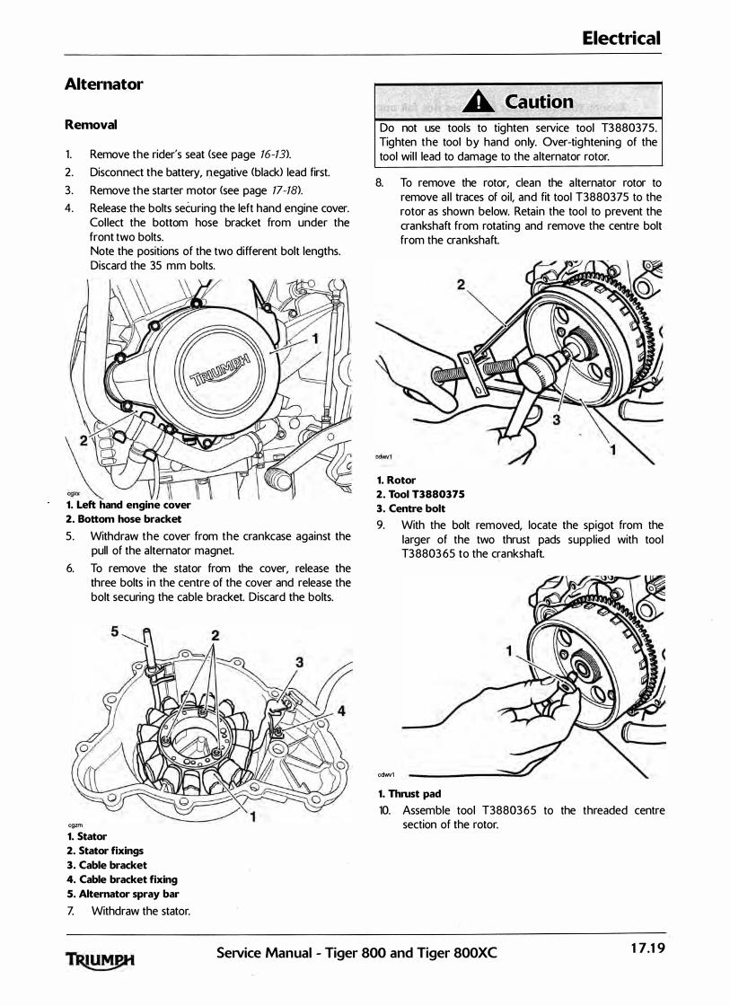
Alternator
Removal
1 . Remove the rider's seat <see page 16-13>. 2. Disconnect the battery, 1;\egative (black) lead first.
3 . Remove the starter motor <see page 17-18). 4. Release the bolts securing the left hand engine cover.
Col lect the bottom hose bracket from under the front two bolts. Note the positions of the two different bolt lengths. Discard the 35 mm bolts.
2� g XX
1. Left hand engine cover
2. Bottom hose bracket
5. Withdraw the cover from the crankcase against the pull of the alternator magnet.
6. To remove the stator from the cover, release the three bolts in the centre of the cover and release the bolt securing the cable bracket. Discard the bolts.
cgzm 1. Stator
2. Stator fixings
3. Cable bracket
4. Cable bracket fixing
S. Alternator spray bar
Z Withdraw the stator.
Electrical
Do not use tools to tighten service tool T3 880375. Tighten the tool by hand only. Over-tig htening of the tool wil l lead to damage to the a lternator rotor.
8. To remove the rotor, clean the a lternator rotor to remove a l l traces of oi l, and fit tool T3880375 to the rotor as shown below. Retain the tool to prevent the crankshaft from rotating and remove the centre bolt from the crankshaft.
1. Rotor
2. Tool T3880375
3. Centre bolt
9. With the bolt removed, locate the spigot from the larger of the two thrust pads suppl ied with tool T3 8803 65 to the crankshaft.
cdwv1 1. Thrust pad
10. Assemble tool T38803 6 5 to the threaded centre section of the rotor.
SeiVice Manual - Tiger 800 and Tiger 800XC 17.19

Electrical
Note:
• Ensure that the thrust pad does not fall out during assembly of the tool.
1 1 . Hold the centre of the tool to prevent rotation then tighten the draw-bolt in the centre of the tool to release the taper seating of the rotor from the crankshaft.
1. Rotor
2. Tool T3880365
12. Withdraw the rotor and tool as an assembly and then separate the tool from the rotor. Collect the Woodruff Key and the tool thrust pad from the crankshaft.
Assembly
1 . Refit the Woodruff key to the crankshaft.
2 . Assemble the rotor to the keyway on the cran kshaft, ensuring the Woodruff key remains in position.
Do not use tools to tig hten service tool Tighten the tool by hand only. Over-tightening of the tool will lead to damage to the a lternator rotor.
3 . Refit tool T3880375 to prevent the crankshaft from rotating, ensuring the rotor is free from oi l and the tool is not over-tightened.
4. Tighten the rotor retaining bolt to 120 Nm.
1. Rotor
2. Tool T3880375
3. Centre bolt
5. Remove tool T3 880375.
6 . Instal l a new 0-ring to the alternator spray bar.
Z Locate the stator to the engine cover.
8. Fit the cable retainer bracket and tighten a new retainer bolt to 6 Nm.
9. Tighten the new stator bolts to 12 N m.
17.20 Service Manual - Tiger 800 and Tiger 800XC
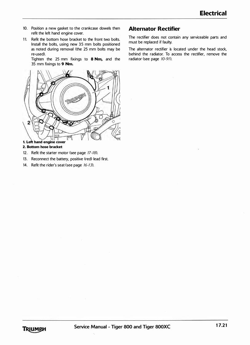
10. Position a new gasket to the crankcase dowels then refit the left hand engine cover.
1 1 . Refit the bottom hose bracket to the front two bolts. Instal l the bolts, using new 3 5 mm bolts positioned as noted during removal <the 25 mm bolts may be re-used). Tighten the 25 mm fixings to 8 Nm, and the 35 mm fixings to 9 Nm.
2� \g 1. Left hand engine cover
2. Bottom hose bracket
12 . Refit the starter motor <see page 17-18).
1 3 . Reconnect the battery, positive <red> lead first.
14. Refit the rider's seat <see page 16-13).
Electrical
Alternator Rectifier
The rectifier does not conta in any serviceable parts and must be replaced if faulty.
The alternator rectifier is located under the head stock, behind the radiator. To access the rectifier, remove the radiator (see page 10-91 ).
SeiVice Manual - Tiger 800 and Tiger 800XC 17.21

Electrical
Alternator Stator
The stator is an assembly of 18 coi ls, arranged into three phases. lt is possible to check for continuity and short circu its through the coi ls and to earth.
Note:
• Only repair the stator harness between the rectifier and where the harness goes into the crankcase. • Do not attempt to repair the stator coils. • If the battery is not fully charged, the charging voltage may be lower than specified when checking at
2,000 rpm. • Ensure all additional accessories (auxiliary lights, heated grips etc.> are switched off.
Fault Possible cause Action
Battery not charging Battery Check the condition of the battery. Test the battery using the BatteryMate 1 5 0-9. Refer to the instructions suppl ied with the BatteryMate 1 5 0-9. Ensure the battery is serviceable:-
Alternator Proceed to pinpoint test 1 :-
Rectifier/Regulator Test the rectifier/regulator (see page 17-24)
Pinpoint Tests
Test Result Action
1 Check cable and terminal integrity: O K Disconnect the battery leads, negative (black>
- Battery positive (+) lead first. Disconnect rectifier/regulator black
- Battery negative (-) connector and proceed to test 2
- Rectifier/regulator black connector pin 1 Faulty Rectify fault, proceed to test 4
- Rectifier/regulator black connector pin 3
- Rectifier/regulator grey connector pin 1
- Rectifier/regulator g rey connector pin 2
- Rectifier/regulator grey connector pin 3
2 Check cable continuity OK Recon nect the battery leads, positive <red> lead
- Rectifier/regulator black con nector pin 1 to first. Reconnect the rectifier/regulator black
battery lead negative con nector connector. Disconnect the rectifier/regulator
- Rectifier/regulator black con nector pin 3 to g rey con nector and proceed to test 3
battery lead positive connector Open circuit Locate and rectify wiring fau lt, proceed to test 4
3 Check resistance through the coi ls : 0.14Q to 0.1 8Q Proceed to test 4
- Alternator pin 1 to pin 2 Open circuit or I f the fault is between the rectifier and the
- Alternator pin 2 to pin 3 short circuit crankcase, repai r the harness. Proceed to test 4
- Alternator pin 3 to pin 1 If the fa ult is after the crankcase, replace the unit. Proceed to test 5
4 Reconnect the harness and run the engine. 1 3 .5V - 1 5V Action complete - quit test Check the charging Voltage at 2,000 rpm :
Fault sti l l present Disconnect the rectifier/regulator g rey con nector and proceed to test 5
17.22 SeiVice Manual - Tiger 800 and Tiger 800XC
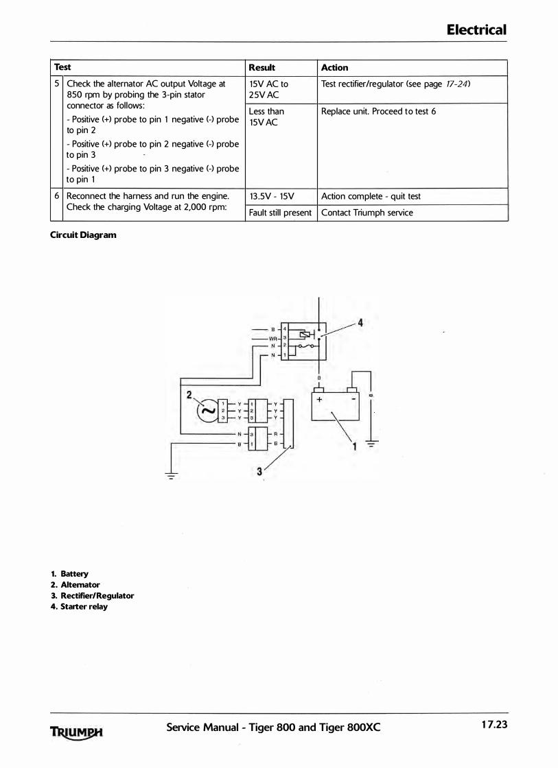
Electrical
Test Result Action
5 Check the alternator AC output Voltage at 1 5V AC to Test rectifier/regulator <see page 17-24>
850 rpm by probing the 3-pin stator 2 5V AC connector as fol lows:
Less than Replace unit. Proceed to test 6 - Positive (+) probe to pin 1 negative (-) probe 1 5V AC to pin 2
- Positive (+) probe to pin 2 negative (-) probe to pin 3
- Positive (+) probe to pin 3 negative (-) probe to pin 1
6 Reconnect the harness and run the engine. 1 3 .5V - 1 5V Action com plete - quit test Check the charging Voltage at 2,000 rpm:
Fault sti l l present Contact Triumph service
Circuit Diagram
1. Battery
2. Alternator
3. Rectifier/Regulator
4. Starter relay
Service Manual - Tiger 800 and Tiger 800XC 17.23

Electrical
Rectifier/Regulator
I nternal ly the rectifier/regulator consists of three diodes, one between each input and the positive terminal, and three Field Effect Transistors <FETs), one between each input and the ground terminal .
As the voltage of the AC signal from the generator rises, the voltage control ler switches the FETs to avoid over voltage on the output.
The diodes and FETs can be checked using a multimeter on D I O D E setting. Disconnect the two electrical connectors from the rectifier/regulator and check the readings as indicated below.
Note:
• This test does not check for voltage regulation.
Fault Possible cause Action
Battery not charging Fuse 1 1 Check the condition of fuse 1 1 :-
Battery Check the condition of the battery. Test the battery using the BatteryMate 1 5 0-9. Refer to the instructions suppl ied with the BatteryMate 1 5 0-9. Ensure the battery is serviceable:-
Rectifier/Reg ulator Discon nect the black and the grey connectors from the rectifier/ regulator and proceed to pinpoint test 1 :-
Alternator Test the alternato r stator (see page 17-22>
Pinpoint Tests
Test Result Action
1 Check diodes forward bias: 0.4V to 0.7V Proceed to test 2
- Positive (+) probe to rectifier black socket pin 1 to : Open circuit or Replace the unit. Proceed to test 4 Negative (-) probe to rectifier grey socket pin 1 short circuit
Negative (-) probe to rectifier grey socket pin 2
Negative (-) probe to rectifier g rey socket pin 3
2 Check FET function forward bias: 0.1 V to 0.3V Proceed to test 3
- Negative (-) probe to rectifier black socket pin 3 to: Open circuit or Replace the unit. Proceed to test 4 Positive (+) probe to rectifier grey socket pin 1 short circuit
Positive (+) probe to rectifier grey socket pin 2
Positive (+) probe to rectifier grey socket pin 3
3 Check diodes reverse bias: More than 1 .4V Proceed to test 4
- Negative (-) probe to rectifier black socket pin 1 to: or OL on meter
Positive (+) probe to rectifier grey socket pin 1 Less than 1 .4V or Replace the un it. Proceed to test 4
Positive (+) probe to rectifier grey socket pin 2 short circuit
Positive (+) probe to rectifier grey socket pin 3
- Positive (+) probe to rectifier black socket pin 3 to:
Negative (-) probe to rectifier grey socket pin 1
Negative (-) probe to rectifier grey socket pin 2
Negative (-) probe to rectifier g rey socket pin 3
17.24 Service Manual - Tiger 800 and Tiger 800XC

Electrical
Test Result Action
4 Reconnect the harness and run the engine. Check 13V - 1 5V Action complete - quit test the charg ing Voltage at 2,000 rpm:
Fault sti l l present Test alternator stator <see page 17-22)
Circuit Diagram
Grey Socket for Alternator
-3 2
I 1 '----
If a lternator stator is serviceable, contact Triumph service
i � � � �
Voltage Controller
�l �1 l � I 1 --
Voltage
�i< ii=-s-.� Coo� �
� � � �� ��
+
I
7' � ""' ""' Black
Socket for
�
I I
Grey Socket for Alternator Rectifier Out
SeiVice Manual - Tiger 800 and Tiger 800XC
� Black Socket for
Rectifier Out
17.25

Electrical
Lighting Circuit
Key to circuit diagram Key to wiring colours
Key Item Description Key Wiring Colour
1 Fuses <Front, Fuses 2 And 3) B Black
2 Ignition Switch u Blue
3 Rear Light N Brown
4 Instrument Assembly G Green
5 Oil Pressure LED s Slate I Grey
6 Oil Pressure Switch 0 Orange
7 Main Beam LED K Pink
8 Headl ights R Red
9 Pass Light Switch p Purple
10 Headl ight Switch w White
1 1 Left Hand Switch Cube y Yel low
1 2 Heated Grips LG Light Green
1 3 Headlight Relay LU Light Blue
14 Starter Relay
1 5 Accessory Lights
17.26 Service Manual - Tiger 800 and Tiger 800XC

Lighting Circuit
I 2 3 I
' j- - j- - � � - - �
p y
1 5 [l-t--+----___J 1 4 1� ; 1 2 1 H.!-----'
1 1 r-------1 2 f-u--
1 0 CE
9 �
1 Y UR 1 I T l UW B UR Y
l
�-�1 1 i i 8 6
o -� 0 0
P -
y hl @]3 B- 8
6 _rs+- · 1 B- 1
J•r 13
Service Manual - Tiger 800 and Tiger 800XC
Electrical
2
4
�\ 5
7 I
17.27
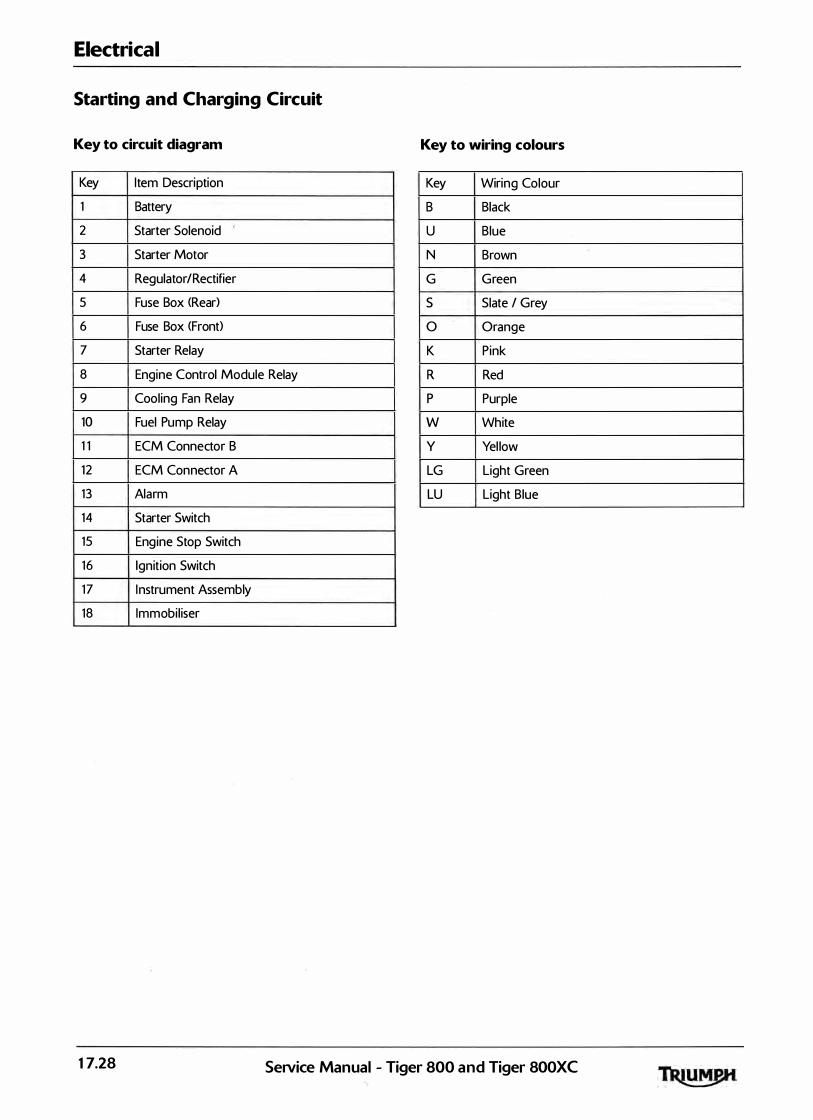
Electrical
Starting and Charging Circuit
Key to circuit diagram Key to wiring colours
Key Item Description Key Wiring Colour
1 Battery B Black
2 Starter Solenoid u Blue
3 Starter Motor N Brown
4 Regulator/Rectifier G Green
5 Fuse Box <Rear) s Slate I Grey
6 Fuse Box <Front> 0 Orange
7 Starter Relay K Pink
8 Engine Control Module Relay R Red
9 Cool ing Fan Relay p Purple
10 Fuel Pump Relay w White
1 1 ECM Connector B y Yel low
1 2 ECM Connector A LG Light Green
1 3 Alarm LU Light Blue
14 Starter Switch
15 Engine Stop Switch
1 6 Ignition Switch
1 7 I nstrument Assembly
18 Immobil iser
17.28 Service Manual - Tiger 800 and Tiger 800XC
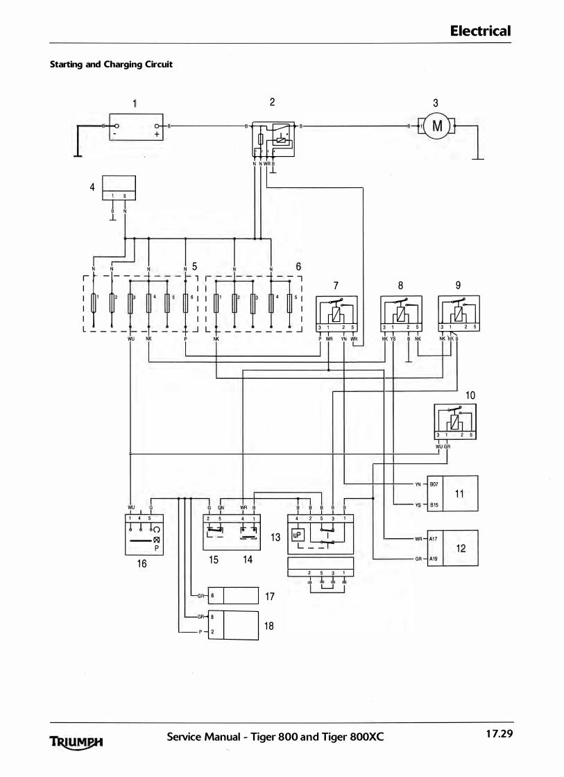
Starting and Charging Circuit
l 4
Bt
~ B N l_
1 1 2 3 I I
rrB
�rN _1N_ - -
L _ _ _ _ _ _ _ _ _
WU NK l
wu ! 1 4 5
0 -- �
p 1 6
Electrical
2 3 ·m ·
' ' . . . N N WR B l_
' 5� � - -'- - -rr s 1 1 1 2 3 4 5 I
I I I I I I
_] L _ _ _ _ _ _ _ _]
7 8 9
00 00 00 .I NK
! JN WR �
� = 1 3 1 5 1 4 GR+ 1 7 1I] 1a
YN t_ Nr YS I T NK T B P WR .
1 0 00 3 1
� � 1 B � T 4 2 5 3 1
� I Y L _ _ r
2 5 3 1 I 1 1 Jl 1 LJ I
wu y YN 807 1
'--- vs 815
WR A1 7 1 GR A19
SeiVice Manual - Tiger 800 and Tiger 800XC 17.29
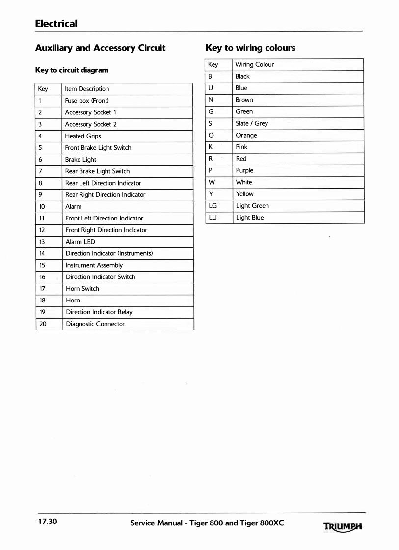
Electrical
Auxiliary and Accessory Circuit Key to wiring colours
Key to circuit diagram Key Wiring Colour
B Black
Key Item Description u Blue
1 Fuse box <Front) N Brown
2 Accessory Socket 1 G Green
3 Accessory Socket 2 s Slate I Grey
4 Heated Grips 0 Orange
5 Front Brake Light Switch K Pink
6 Brake Light R Red
7 Rear Brake Light Switch p Purple
8 Rear Left Direction Indicator w White
9 Rear Right Direction Ind icator y Yellow
10 Alarm LG Light Green
1 1 Front Left Direction Ind icator LU Light Blue
12 Front Right Direction Indicator
1 3 Alarm LED
14 Direction Ind icator ( Instruments)
1 5 Instrument Assembly
1 6 Direction I ndicator Switch
1 7 Horn Switch
1 8 Horn
19 Direction Indicator Relay
20 Diagnostic Connector
17.30 SeNice Manual - Tiger 800 and Tiger 800XC

Auxiliary and Accessory Circuit
1 9
1 7
1 6
1 6 20 CB p
R
1 5
>- 1 l- OG
- 2 1-LGN-
6 1-- PB 8 1--B� 5
3 4
p
R
""']_ w
LGN -
GR G'N---
�
"'
1 2 � B _j_
1 8
""' J
a: "'
1 1 � B _j_
r - - -., . - - - - - , I I I I 1 I I
5 I I 5 I I I I I I I
L _ _j L _ _ J a. a. a.
I I
7
�ID
'f 'f 'f' f 'l' 6 1 0 1 1 8 7
1 0
SeiVice Manual - Tiger 800 and Tiger 800XC
Electrical
I p
p
p
BU 3 ,------GP 6
6 >---GP- 1
_LB- 2
�9 � 8 B B
_j_ _j_
17.31

Electrical
Engine Management Circuit Diagram - Tiger 800 and Tiger SOOXC
Key To Wiring Circuit Diagram Key To Wiring Colour Codes
Key Item Description Code Wiring Colour
1 Engine Control Module B Black 2 Diagnostic Connector u Blue 3 Road Speed Sensor
N Brown 4 I nstrument Assembly
5 Clutch Switch G Green
6 Immobil iser s Slate/Grey
7 Sidestand Switch 0 Orange
8 Ignition Switch K Pink
9 Fuel Level Sensor R Red
10 Fal l Detection Switch p Purple 1 1 Barometric Pressure Sensor w White 12 Intake Air Tem perature Sensor V Yel low 1 3 MAP Sensor
14 Coolant Temperature Sensor LG Light Green
15 Oxygen <Lambda) Sensor LU Light Blue
16 Throttle Position Sensor
1 7 Gear Position Sensor
18 Fuel Pump
19 Fuel Pump Relay
20 Cool ing Fan
21 Cool ing Fan Relay
2 2 Idle Speed Control Stepper Motor
23 Coil 3
24 Coi l 2
25 Coil 1
26 Oxygen <Lambda> Sensor Heater
27 Fuel I n jector 3 1 28 Fuel In jector 2
29 Fuel In jector 1
30 Purge Valve
31 Crankshaft Position Sensor
3 2 Engine Control Module Relay
17.32 Service Manual - Tiger 800 and Tiger 800XC

Engine Management Circuit Diagram -Tiger 800 and Tiger SOOXC
1/ 1\
32 m 31 l
w 21 lii �
CJ:p
B 30 NK�YR
29 NK�K
28 NK�YP
2 7 NK�
[m 26 K 3
NK�K 2 5 NK�GP
24 NK�GB 23 m 22 1
u K
1p- AOl
18- Af1J
YR- Bf1J
NK- ... YK- A15
yp- A14
B A13
w 814
GK- A18
GP- 818
GB- 817
ON- All
ow- A23
ou- A20
OK- All
��� 819
835
816
A35
T
11
BU-@- 8 � 20
BY- 830
00 19 18
[' �
-@-8
1 BP - 829
A24 f-KG
A34 1-KY
828 1- R
827 f- U
All f-eo--8-s 5 1 A33 f-BR=:g _r---8 l 7
804 f-BG
821 1-KU
801 f- K
A27 f-KP 820 f-t<s
All f-Ko
A28 f-K5
A29 -KG
A26 1- B
AlO f-GY
All 1-sw
814 f-BK 17
SeiVice Manual - Tiger 800 and Tiger 800XC
Electrical
rE BG 7 2 R 6
u 14
B l �:rn3 R 5 4 ·m u 4
��6 GITJ s
BGm9
KB l
8 �: I
K 4 10 "{] 8 6
KP l 11 K t] KB 1
0=[] KB l
KBtJ K5 l
K 3
12 13
KG=[] 14 KB l
l15 KBi] K 3 16
GY 1
17.33

Electrical
Engine Management Circuit Diagram - Tiger 800 CABS> and Tiger SOOXC CABS>
Key To Wiring Circuit Diagram Key To Wiring Colour Codes
Key Item Description Code Wiring Colour
1 Engine Control Module B Black
2 Diagnostic Connector u Blue 3 ABS Modulator
N Brown 4 Instrument Assembly
5 Clutch Switch G Green
6 Immobiliser s Slate/Grey
7 Sidestand Switch 0 Orange
8 Ignition Switch K Pink
9 Fuel Level Sensor R Red
10 Fall Detection Switch p Purple
11 Barometric Pressure Sensor w White 12 Intake Air Temperature Sensor
y Yellow 13 MAP Sensor
14 Coolant Temperature Sensor LG Light Green
15 Oxygen <Lambda) Sensor LU Light Blue
16 Throttle Position Sensor
17 Gear Position Sensor
18 Fuel Pump
19 Fuel Pump Relay
20 Cooling Fan
21 Cooling Fan Relay
22 Idle Speed Control Stepper Motor
23 Coil3
24 Coil2
25 Coil1
26 Oxygen <Lambda) Sensor
27 Fuel Injector 3
28 Fuel Injector 2
29 Fuel Injector 1
3 0 Purge Valve
31 Crankshaft Position Sensor
32 Engine Control Module Relay
17.34 SeiVice Manual - Tiger 800 and Tiger BOOXC
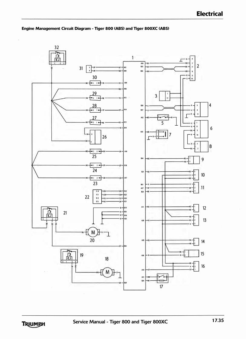
Electrical
Engine Management Circuit Diagram - Tiger 800 <ABS> and Tiger 800XC <ABS>
32 m
�
A24
1p- A01 823
UB- A09 805 31 D=UP
U8 30 NK�YR YR- 809
N1(- ArK> 29 NK� YK- All 28 828
NK�YP --YP A14 827 27 A32
NK� All
w 814
A3l
[m 26 K l
K- A18 NK-E3-GK :--GK 25 804
NK-E3-GP ,p- 818 24 821
NK-E3-GB ,8- 817 23 801
A27 N- A22 820 'w-All
u- A20 ·- A21
22 [],====; B- 819 All
8- 835 8- 816 8- A3S
A28
A29
Y- 830
m21 �
. I ·.___·�·-i �-----------------
A26
AlO
A31
824 829
t- BG-
f-sv�8Y-
1-sN__r----\..___BN-
3DJ= R
1-u �
r--R-r- u -
u 4
f-so�8 _L 5 1 L-
Rrn 4 8 11
urn HR:g _r-8 l 7
1-BG
f-KU
f- K
f-KP
f-<s
"""
1-Ks
I-KG
1\ 8
GY
l 2 8W
8K V 17
L-- R 6 6 IT BG S
8 10
8 -fTl
BGi_lj8
BG K8
8 �: I
1 2
K
K
KP
K8
0
K8 ::(] 12 K8 KS
K f]13 KG =[] 14 _I 15
K8
K8
K GY tJ 16
SeiVice Manual - Tiger 800 and Tiger 800XC 17.35
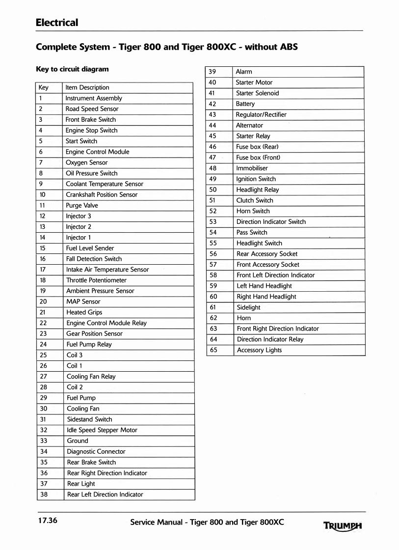
Electrical
Complete System - Tiger 800 and Tiger SOOXC - without ABS
Key to circuit diagram
Key Item Description
1 Instrument Assembly
2 Road Speed Sensor
3 Front Brake Switch
4 Engine Stop Switch
5 Start Switch
6 Engine Control Module
7 Oxygen Sensor
8 Oil Pressure Switch
9 Coolant Temperature Sensor
10 Crankshaft Position Sensor
1 1 Purge Valve
12 Injector 3
13 Injector 2
14 Injector 1
15 Fuel Level Sender
16 Fall Detection Switch
17 Intake Air Temperature Sensor
18 Throttle Potentiometer
19 Ambient Pressure Sensor
20 MAP Sensor
21 Heated Grips
22 Engine Control Module Relay
23 Gear Position Sensor
24 Fuel Pump Relay
25 Coil3
26 Coil 1
27 Cooling Fan Relay
28 Coil2
29 Fuel Pump
30 Cooling Fan
31 Sidestand Switch
32 Idle Speed Stepper Motor
33 Ground
34 Diagnostic Connector
35 Rear Brake Switch
36 Rear Right Direction Indicator .
37 Rear Light
38 Rear Left Direction Indicator
39 Alarm
40 Starter Motor
41 Starter Solenoid
42 Battery
43 Regulator/Rectifier
44 Alternator
45 Starter Relay
46 Fuse box <Rear)
4 7 Fuse box <Front>
48 Immobiliser
49 Ignition Switch
SO Headlight Relay
51 Clutch Switch
52 Horn Switch
53 Direction Indicator Switch
54 Pass Switch
55 Headlight Switch
56 Rear Accessory Socket
57 Front Accessory Socket
58 Front Left Direction Indicator
59 Left Hand Headlight
60 Right Hand Headlight
61 Sidelight
62 Horn
63 Front Right Direction Indicator
64 Direction Indicator Relay
65 . Accessory Lights
17.36 Service Manual - Tiger 800 and Tiger 800XC


Electrical
Complete System - Tiger 800 and Tiger SOOXC - with ABS
Key to circuit diagram 39 Alarm
Item Description Key
Instrument Assembly 1
2 Accessory Lights
3 Front Brake Switch
40 Starter Motor
41 Starter Solenoid
42 Battery
43 Regulator/Rectifier
4 Engine Stop Switch
5 Start Switch
44 Alternator
45 Starter Relay
6 Engine Control Module
7 Oxygen Sensor
8 Oil Pressure Switch
46 Fuse box <Rear>
47 Fuse box <Front>
48 Immobiliser
9 Coolant Temp
10 Crankshaft Position Sensor
1 1 Purge Valve
12 Injector 3
13 Injector 2
14 Injector 1
15 Fuel Level Sender
49 Ignition Switch
50 Headlight Relay � 51 Clutch Switch
52 Horn Switch
53 Indicator Switch
54 Pass Switch
55 Headlight Switch
16 Fall Detection Switch 56 Rear Wheel Speed Sensor
17 Intake Air Temperature Sensor
18 Throttle Potentiometer
57 Front Wheel Speed Sensor
58 ABS Module
19 Ambient Pressure Sensor 59 Rear Accessory Socket
20 MAP Sensor 60 Front Accessory Socket
21 Heated Grips
22 Engine Control Module Relay
23 Gear Position Sensor
61 Front Left Direction Indicator
62 Left Hand Headlight
63 Right Hand Headlight
24 Fuel Pump Relay
25 Coil3
64 Sidelight ''F
65 Horn
26 Coil 1 66 Front Right Direction Indicator
27 Cooling Fan Relay 67 Direction Indicator Relay
28 Coil2
29 Fuel Pump
30 Cooling Fan
31 Sidestand Switch
32 Idle Speed Stepper Motor
33 Ground
34 Diagnostic Connector
35 Rear Brake Switch
36 Rear Right Direction Indicator
37 Rear Light
38 Rear Left Direction Indicator
17.38 SeiVice Manual - Tiger 800 and Tiger 800XC

Electrical
This page intentionally left blank
17.40 Setvice Manual - Tiger 800 and Tiger 800XC


![Abs NANTECHNOLOGY- 4105[1]](https://img.dokumen.tips/doc/110x75/6321487bf2b35f3bd10fcf9c/abs-nantechnology-41051.jpg)