Embed Size (px)
Citation preview
TECHNICAL BULLETINLT206-00204 MAY 2005
© Jaguar Land Rover Limited
A ll rights reserved.
This bulletin supersedes TSB L8890bu/2004 dated 02 OCT 2004, which should either bedestroyed or clearly marked to show it is no longer valid (e.g. with a line across the page). Onlyrefer to the electronic version of this Technical Bulletin in TOPIx.This bulletin supersedes TSB L8914bu/2004 dated 10 FEB 2004, which should either bedestroyed or clearly marked to show it is no longer valid (e.g. with a line across the page). Onlyrefer to the electronic version of this Technical Bulletin in TOPIx.
SECTION: 206-09 (70 - Brakes)
Discovery II - LHD ABS Overlay Harness
AFFECTED VEHICLE RANGE:
Discovery Series II (LT) -Left-hand drive vehicles only
VIN: XA200000-4A870624
MARKETS:All
CONDITION SUMMARY:
Situation:
Introduction of new anti-lock braking (ABS) sensor overlay harness - left-hand drive vehicles. Thisharness deletes the front connectors located on the inner wing/fenders and bypasses the rear harnessconnector located at the front bulkhead.
This new ABS overlay harness has been made available for service. The harness MUST be used insteadof renewing the main harness for ABS sensor harness concerns (e.g. open circuit).
Should a concern with the front ABS sensor harness exist, follow the appropriate rectification proceduredetailed in this bulletin to install a new ABS sensor overlay harness.
PARTS:
SSW500020 Service Sensor kit - Front Quantity: 1
SSW500030 Service Sensor kit - Rear Quantity: 1
WARRANTY:
NOTE: Repair procedures are under constant review, and therefore times are subject tochange; those quoted here must be taken as guidance only. Always refer to TOPIx to obtainthe latest repair time.
NOTE: DDW requires the use of causal part numbers. Labor only claims must show thecausal part number with a quantity of zero.
NOTE: Repair procedures are under constant review, and therefore times are subject tochange; those quoted here must be taken as guidance only. Always refer to DDW to obtainthe latest repair time.
DESCRIPTION SRO TIMECONDITION
CODECAUSAL
PART
Renew ABS sensor and lead - front - RIGHT-HAND
70.65.89/412.10hours
79 SSW500020
Renew ABS sensor and lead - front - LEFT-HAND
70.65.89/422.20hours
Renew ABS sensor and lead - rear - RIGHT-HAND
70.65.89/432.20hours
Renew ABS sensor and lead - rear - LEFT- 2.30

HAND 70.65.89/44 hours
NOTE: Normal Warranty procedures apply.
SERVICE PROCEDURE:
Left-hand drive vehicles only
Right-Hand Front ABS Sensor/Harness - Renew
1Disconnect the battery ground lead. For additional information, refer to Discovery Series II WorkshopManual Section CHARGING AND STARTING, Battery (86.15.01).
If a fuel burning heater (FBH) is installed carry out steps 2 to 5 for removal, otherwise continue from step 6.
2Remove the nut securing the FBH exhaust pipeclip to the rubber mounting.
3Release the exhaust pipe clip from the rubber mounting.
4Remove the Torx bolt securing the FBH to thebulkhead mounting bracket.
5Release the FBH from the mounting bracket and move aside for access.
6Disconnect the white ABS connector at the right-hand suspension turret.
7Release ABS sensor grommet and harness from inner wing.
8Withdraw the harness through the aperture into the wheelarch.
9Remove the right-hand front wheel.
10Release the harness from the brackets on the
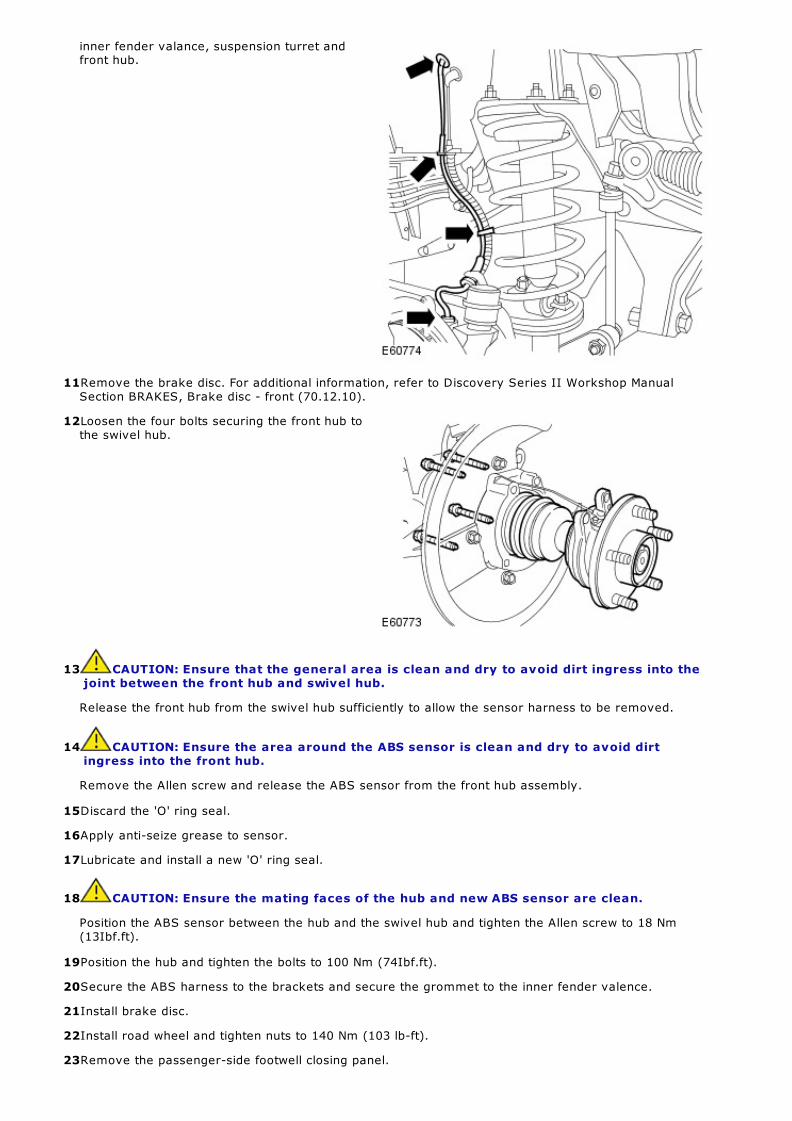
inner fender valance, suspension turret andfront hub.
11Remove the brake disc. For additional information, refer to Discovery Series II Workshop ManualSection BRAKES, Brake disc - front (70.12.10).
12Loosen the four bolts securing the front hub tothe swivel hub.
13 CAUTION: Ensure that the general area is clean and dry to avoid dirt ingress into thejoint between the front hub and swivel hub.
Release the front hub from the swivel hub sufficiently to allow the sensor harness to be removed.
14 CAUTION: Ensure the area around the ABS sensor is clean and dry to avoid dirtingress into the front hub.
Remove the Allen screw and release the ABS sensor from the front hub assembly.
15Discard the 'O' ring seal.
16Apply anti-seize grease to sensor.
17Lubricate and install a new 'O' ring seal.
18 CAUTION: Ensure the mating faces of the hub and new ABS sensor are clean.
Position the ABS sensor between the hub and the swivel hub and tighten the Allen screw to 18 Nm(13Ibf.ft).
19Position the hub and tighten the bolts to 100 Nm (74Ibf.ft).
20Secure the ABS harness to the brackets and secure the grommet to the inner fender valence.
21Install brake disc.
22Install road wheel and tighten nuts to 140 Nm (103 lb-ft).
23Remove the passenger-side footwell closing panel.

24Remove the A-pillar lower finisher.
25From inside the vehicle (passenger side), carefully reposition the carpet/NVH cover from the bulkheadto expose the bulkhead grommet.
26From the engine bay, carefully pull the NVHcover away from the bulkhead and remove thegrommet.
27Make an incision in the center of the grommet and pass the new ABS harness through the grommet.
28Pass the new harness through the bulkhead and install the grommet.
29Secure the harness using cable ties wherenecessary and route the harness to the self-leveling and anti-lock braking (SLABS) electroniccontrol unit (ECU). For additional information,refer to Discovery Series II Workshop ManualSection BRAKES, ECU - Self levelling and antilocking brakes (SLABS) (70.65.01).
30Cut away any excess harness and carefully remove approximately 50mm of outer insulation.
31Strip the wire insulation to expose the wires conductors.
32 Install the crimp terminals supplied in the repair kit.
33Disconnect connector C0505 from the SL/ABSECU. For additional information, refer toDiscovery Series II Electrical Library WorkshopManual Section Connectors, Connector Views(C0505).
34 CAUTION: This step refers to connector termination for theRIGHT-HAND FRONTSENSOR - LEFT-HAND DRIVE VEHICLES ONLY. Release the specified terminals only.
NOTE: The new harness terminals may be connected in either cavity of the connector.They are not polarity sensitive.
Release terminals four and five from the connector and insert the new terminals.
35Cut off the removed redundant terminals and secure back to the main harness using a suitableelectrical tape.
36Connect the SLABS connector.
37Install the passenger-side footwell closing panel.
38Install the A-pillar lower finisher.
If a fuel burning heater (FBH) is installed carry out steps from 39 for installation, otherwise continue fromstep 41.
39Align the FBH to the mounting bracket and install the Torx bolt. Tighten to 25 Nm (18 lb-ft).
40Locate the FBH exhaust pipe clip to the rubber mounting, install the nut and tighten to 6 Nm (4 lb-ft).
41Connect the battery ground lead. For additional information, refer to Discovery Series II WorkshopManual Section CHARGING AND STARTING, Battery (86.15.01).
42Using T4:
1. C lear the fault codes from SLABS ECU.
2. Raise the RHF corner of the vehicle.
3. Select the T4 overview screen.
4. With ignition at position two, spin the RHF wheel and check the input from the sensor is operatingcorrectly.
43Disconnect T4 and lower the vehicle.
44Road test the vehicle.
SERVICE PROCEDURE:
Left-hand drive vehicles only
Left-Hand Front ABS Sensor/Harness - Renew
1Disconnect the battery ground lead. For additional information, refer to Discovery Series II WorkshopManual Section CHARGING AND STARTING, Battery (86.15.01).
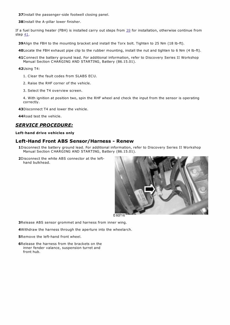
2Disconnect the white ABS connector at the left-hand bulkhead.
3Release ABS sensor grommet and harness from inner wing.
4Withdraw the harness through the aperture into the wheelarch.
5Remove the left-hand front wheel.
6Release the harness from the brackets on theinner fender valance, suspension turret andfront hub.
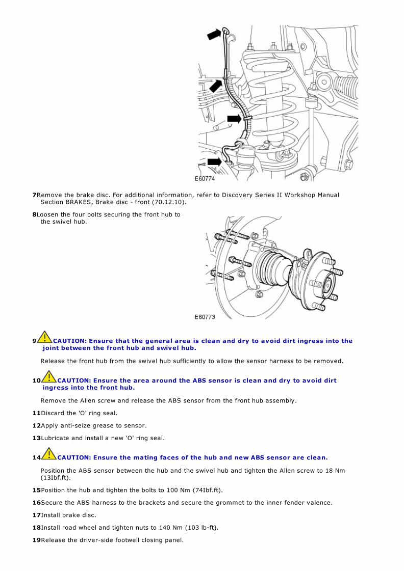
7Remove the brake disc. For additional information, refer to Discovery Series II Workshop ManualSection BRAKES, Brake disc - front (70.12.10).
8Loosen the four bolts securing the front hub tothe swivel hub.
9 CAUTION: Ensure that the general area is clean and dry to avoid dirt ingress into thejoint between the front hub and swivel hub.
Release the front hub from the swivel hub sufficiently to allow the sensor harness to be removed.
10 CAUTION: Ensure the area around the ABS sensor is clean and dry to avoid dirtingress into the front hub.
Remove the Allen screw and release the ABS sensor from the front hub assembly.
11Discard the 'O' ring seal.
12Apply anti-seize grease to sensor.
13Lubricate and install a new 'O' ring seal.
14 CAUTION: Ensure the mating faces of the hub and new ABS sensor are clean.
Position the ABS sensor between the hub and the swivel hub and tighten the Allen screw to 18 Nm(13Ibf.ft).
15Position the hub and tighten the bolts to 100 Nm (74Ibf.ft).
16Secure the ABS harness to the brackets and secure the grommet to the inner fender valence.
17Install brake disc.
18Install road wheel and tighten nuts to 140 Nm (103 lb-ft).
19Release the driver-side footwell closing panel.
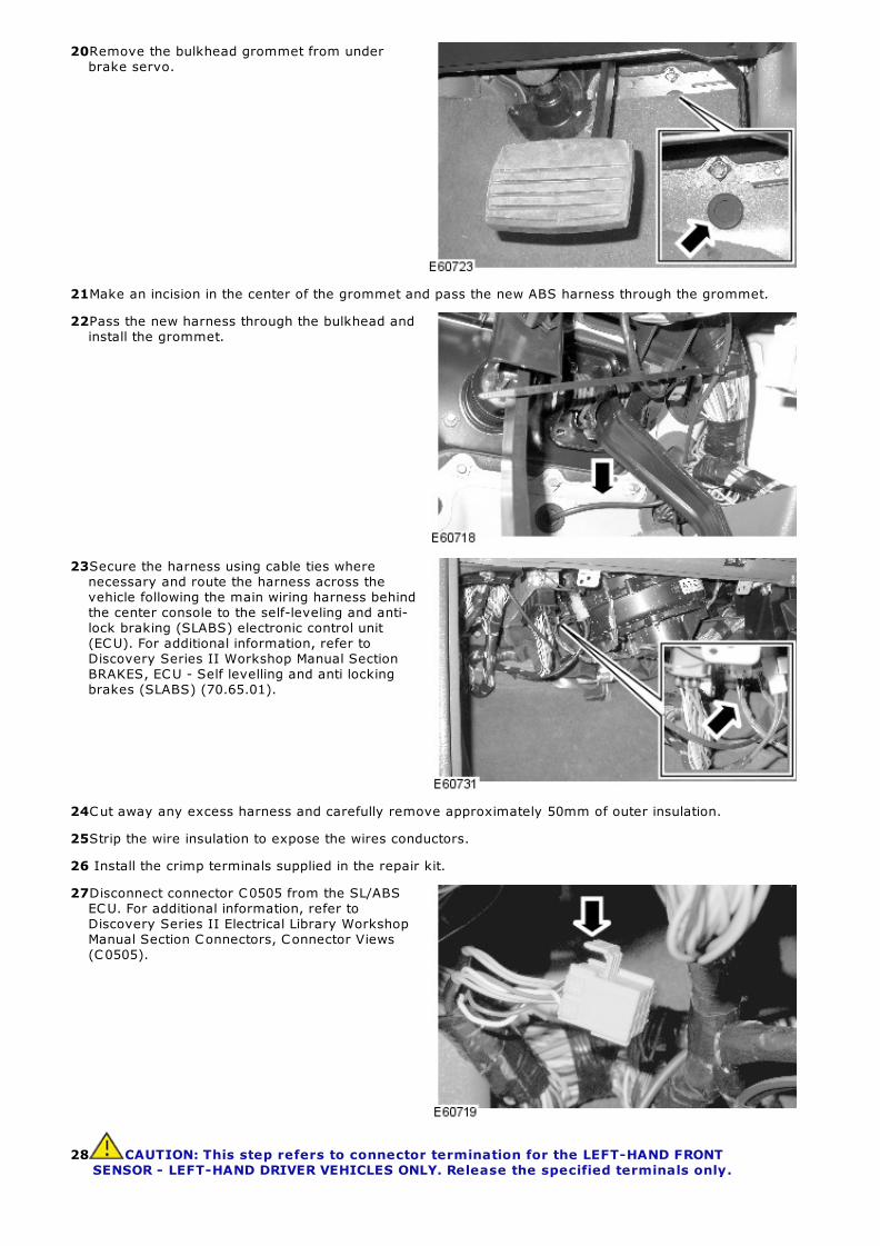
20Remove the bulkhead grommet from underbrake servo.
21Make an incision in the center of the grommet and pass the new ABS harness through the grommet.
22Pass the new harness through the bulkhead andinstall the grommet.
23Secure the harness using cable ties wherenecessary and route the harness across thevehicle following the main wiring harness behindthe center console to the self-leveling and anti-lock braking (SLABS) electronic control unit(ECU). For additional information, refer toDiscovery Series II Workshop Manual SectionBRAKES, ECU - Self levelling and anti lockingbrakes (SLABS) (70.65.01).
24Cut away any excess harness and carefully remove approximately 50mm of outer insulation.
25Strip the wire insulation to expose the wires conductors.
26 Install the crimp terminals supplied in the repair kit.
27Disconnect connector C0505 from the SL/ABSECU. For additional information, refer toDiscovery Series II Electrical Library WorkshopManual Section Connectors, Connector Views(C0505).
28 CAUTION: This step refers to connector termination for the LEFT-HAND FRONTSENSOR - LEFT-HAND DRIVER VEHICLES ONLY. Release the specified terminals only.

NOTE: The new harness terminals may be connected in either cavity of the connector.They are not polarity sensitive.
Release terminals one and two from the connector and insert the new terminals.
29Secure the removed redundant terminals back to the main harness using a suitable electrical tape.
30Connect the SLABS connector.
31Install the footwell closure panel.
32Connect the battery ground lead. For additional information, refer to Discovery Series II WorkshopManual Section CHARGING AND STARTING, Battery (86.15.01).
33Using T4:
1. C lear the fault codes from SLABS ECU.
2. Raise the LHF corner of the vehicle.
3. Select the T4 overview screen.
4. With ignition at position two, spin the RHF wheel and check the input from the sensor is operatingcorrectly.
34Disconnect T4 and lower the vehicle.
35Road test the vehicle.
SERVICE PROCEDURE:
Left-Hand Drive Vehicles Only
Rear ABS Sensor/Harness - Renew
1Disconnect the battery ground lead. For additional information, refer to Discovery Series II WorkshopManual Section CHARGING AND STARTING, Battery (86.15.01).
2Remove the relevant rear wheel.
3Release the ABS sensor harness connector fromthe clip on the body and disconnect theconnector.
4Cut off the redundant ABS sensor connector lead back to the main harness and tape the exposed endto the main harness with insulating tape.
5Release the harness from the brake flexible hose and hose brackets.

6Remove the brake disc. For additional information, refer to Discovery Series II Workshop ManualSection BRAKES, Brake disc - rear (70.12.33).
7Remove the Allen screw and release the ABS sensor.
8Discard the 'O' ring seal.
9Apply anti-seize grease to sensor.
10Lubricate and install a new 'O' ring seal.
11 CAUTION: Ensure the mating faces of the hub and new ABS sensor are clean.
Install the ABS sensor and tighten the Allen screw to 18 Nm (13Ibf.ft).
12Install the harness into brake flexible hose clips on the brake hose.
13Install the brake disc. For additional information, refer to Discovery Series II Workshop ManualSection BRAKES, Brake disc - rear (70.12.33).
14 CAUTION: Do not secure theharness to brake or fuel lines.
Secure the new ABS harness following theroute of the main ABS harness to the front ofthe vehicle (passenger side bulkhead area).
15Install the road wheel and tighten nuts to 140 Nm (103 lb-ft).
16Remove the passenger-side footwell closing panel.
17Remove the driver-side footwell closing panel.
18From inside the vehicle (passenger side), carefully reposition the carpet/NVH cover from the bulkheadto expose the bulkhead grommet.
19From the engine bay, carefully pull the NVHcover away from the bulkhead and remove thegrommet

20Make an incision in the center of the grommet and pass the new ABS harness through the grommet.
21Pass the new harness through the bulkhead and install the grommet.
22Secure the harness using cable ties wherenecessary and route the harness to the self-leveling and anti-lock braking (SLABS) electroniccontrol unit (ECU). For additional information,refer to Discovery Series II Workshop ManualSection BRAKES, ECU - Self levelling and antilocking brakes (SLABS) (70.65.01).
23Cut away any excess harness and carefully remove approximately 50mm of outer insulation.
24Strip the wire insulation to expose the wires conductors.
25 Install the crimp terminals supplied in the repair kit.
26Disconnect connector C0505 from the SL/ABSECU. For additional information, refer toDiscovery Series II Electrical Library WorkshopManual Section Connectors, Connector Views(C0505).
27 CAUTION: This step refers to connector termination for LEFT HAND DRIVE vehiclesONLY. Release the specified terminals only.
NOTE: The new harness terminals may be connected in either cavity of the connector.They are not polarity sensitive.
For the left-hand rear sensor, release terminals seven and eight from the connector and insert thenew terminals.
For the right-hand rear sensor, release terminals three and six from the connector and insert thenew terminals.
28Cut off the removed redundant terminals and secure back to the main harness using a suitableelectrical tape.
29Connect the SLABS connector.

30Install the footwell closure panels.
31Connect the battery ground lead. For additional information, refer to Discovery Series II WorkshopManual Section CHARGING AND STARTING, Battery (86.15.01).
32Using T4:
1. C lear the fault codes from SLABS ECU.
2. Raise the relevant corner of the vehicle.
3. Select the T4 overview screen.
4. With ignition at position two, spin the relevant rear wheel and check the input from the sensor isoperating correctly.
33Disconnect T4 and lower the vehicle.
34Road test the vehicle.


