Embed Size (px)
Citation preview
SERVICE STATION MANUAL2Q000105
V7 II ABS
SERVICE STATIONMANUAL
V7 II ABS
THE VALUE OF SERVICEAs a result of continuous updates and specific technical training programmes for Moto Guzzi products,only Moto Guzzi Official Network mechanics know this vehicle fully and have the specific tools necessary
to carry out maintenance and repair operations correctly.The reliability of the vehicle also depends on its mechanical conditions. Checking the vehicle before ridingit, its regular maintenance and the use of original Moto Guzzi spare parts only are essential factors!
For information on the nearest Official Dealer and/or Service Centre consult our website:www.motoguzzi.com
Only by requesting Moto Guzzi original spare parts can you be sure of purchasing products that weredeveloped and tested during the actual vehicle design stage. All Moto Guzzi original spare parts undergo
quality control procedures to guarantee reliability and durability.The descriptions and images in this publication are given for illustrative purposes only and are not binding.While the basic characteristics as described and illustrated in this booklet remain unchanged, Piaggio &C. S.p.A. reserves the right, at any time and without being required to update this publication beforehand,to make any changes to components, parts or accessories, which it considers necessary to improve the
product or which are required for manufacturing or construction reasons.Not all versions/models shown in this publication are available in all countries. The availability of individual
versions should be checked with the Official Moto Guzzi sales network.The Moto Guzzi brand is owned by Piaggio & C. S.p.A.
© Copyright 2016 - Piaggio & C. S.p.A. All rights reserved. Reproduction of this publication in whole orin part is prohibited.
Piaggio & C. S.p.A. Viale Rinaldo Piaggio, 25 - 56025 PONTEDERA (PI), Italywww.piaggio.com
SERVICE STATION MANUALV7 II ABS
This manual provides the main information to carry out regular maintenance operations on your vehicle.This manual is intended to Moto Guzzi Dealers and their qualified mechanics; several concepts havebeen deliberately omitted as they are considered unnecessary. As it is not possible to include completemechanical notions in this manual, users should have basic mechanical knowledge or minimumknowledge about the procedures involved when repairing scooters. Without this knowledge, repairing orchecking the vehicle may be inefficient or even dangerous. As the vehicle repair and check proceduresare not described in detail, be extremely cautious so as not to damage components or injure individuals.In order to optimise customer satisfaction when using our vehicles, Moto Guzzi commits itself tocontinually improve its products and the relative documentation. The main technical modifications andchanges in repair procedures are communicated to all Moto Guzzi Sales Outlets and its InternationalSubsidiaries. These changes will be introduced in the subsequent editions of the manual. In case ofneed or further queries on repair and check procedures, consult Moto Guzzi CUSTOMERDEPARTMENT, which will be prepared to provide any information on the subject and any furthercommunications on updates and technical changes related to the vehicle.
NOTE Provides key information to make the procedure easier to understand and carry out.
CAUTION Refers to specific procedures to carry out for preventing damages to the vehicle.
WARNING Refers to specific procedures to carry out to prevent injuries to the repairer.
Personal safety Failure to completely observe these instructions will result in serious risk of personalinjury.
Safeguarding the environment Sections marked with this symbol indicate the correct use of the vehicleto prevent damaging the environment.
Vehicle intactness The incomplete or non-observance of these regulations leads to the risk of seriousdamage to the vehicle and sometimes even the invalidity of the guarantee
INDEX OF TOPICS
CHARACTERISTICS CHAR
SPECIAL TOOLS S-TOOLS
MAINTENANCE MAIN
ELECTRICAL SYSTEM ELE SYS
ENGINE FROM VEHICLE ENG VE
ENGINE ENG
POWER SUPPLY P SUPP
SUSPENSIONS SUSP
CHASSIS CHAS
BRAKING SYSTEM BRAK SYS
BODYWORK BODYW
PRE-DELIVERY PRE DE

INDEX OF TOPICS
CHARACTERISTICS CHAR
Rules
Safety rules
Carbon monoxide
If you need to keep the engine running while working on the vehicle, please ensure that you do so in
an open or very well ventilated area. Never run the engine in an enclosed area. If you do work in an
enclosed area, make sure to use a fume extraction system.CAUTION
EXHAUST EMISSIONS CONTAIN CARBON MONOXIDE, A POISONOUS GAS WHICH CAN CAUSELOSS OF CONSCIOUSNESS AND EVEN DEATH.FuelCAUTION
THE FUEL USED TO POWER INTERNAL COMBUSTION ENGINES IS HIGHLY FLAMMABLE ANDMAY BE EXPLOSIVE UNDER CERTAIN CONDITIONS. IT IS THEREFORE RECOMMENDED TOCARRY OUT REFUELLING AND MAINTENANCE PROCEDURES IN A VENTILATED AREA WITHTHE ENGINE SWITCHED OFF. DO NOT SMOKE DURING REFUELLING AND NEAR FUEL VA-POURS, AVOIDING ANY CONTACT WITH NAKED FLAMES, SPARKS OR OTHER SOURCESWHICH MAY CAUSE THEM TO IGNITE OR EXPLODE.DO NOT DISPERSE FUEL IN THE ENVIRONMENT.KEEP OUT OF THE REACH OF CHILDRENHot components
The engine and the exhaust system components become very hot and remain hot for some time after
the engine has been switched off. When handling these components, wear insulating gloves or wait
until the engine and the exhaust system have cooled down.
Used engine oil and transmission oilCAUTION
IT IS ADVISABLE TO WEAR PROTECTIVE IMPERMEABLE GLOVES WHEN SERVICING THE VE-HICLE.THE ENGINE OR GEARBOX OIL MAY CAUSE SERIOUS INJURIES TO THE SKIN IF HANDLEDFOR PROLONGED PERIODS OF TIME AND ON A REGULAR BASIS.WASH YOUR HANDS CAREFULLY AFTER HANDLING OIL.HAND THE OIL OVER TO OR HAVE IT COLLECTED BY THE NEAREST USED OIL RECYCLINGCOMPANY OR THE SUPPLIER.DO NOT DISPOSE OF OIL IN THE ENVIRONMENTKEEP OUT OF THE REACH OF CHILDREN
V7 II ABS Characteristics
CHAR - 7
Brake and clutch fluid
BRAKE AND CLUTCH FLUIDS CAN DAMAGE THE PLASTIC OR RUBBER PAINTED SURFACES.WHEN SERVICING THE BRAKING SYSTEM OR THE CLUTCH SYSTEM, PROTECT THESE COM-PONENTS WITH A CLEAN CLOTH. ALWAYS WEAR PROTECTIVE GOGGLES WHEN SERVICINGTHESE SYSTEMS. BRAKE AND CLUTCH FLUIDS ARE EXTREMELY HARMFUL FOR YOUREYES. IN THE EVENT OF ACCIDENTAL CONTACT WITH THE EYES, RINSE THEM IMMEDIATELYWITH ABUNDANT COLD, CLEAN WATER AND SEEK MEDICAL ADVICE.KEEP OUT OF THE REACH OF CHILDREN
Battery electrolyte and hydrogen gasCAUTION
THE BATTERY ELECTROLYTE IS TOXIC, CORROSIVE AND AS IT CONTAINS SULPHURIC ACID,IT CAN CAUSE BURNS WHEN IN CONTACT WITH THE SKIN. WHEN HANDLING BATTERYELECTROLYTE, WEAR TIGHT-FITTING GLOVES AND PROTECTIVE APPAREL. IN THE EVENTOF SKIN CONTACT WITH THE ELECTROLYTIC FLUID, RINSE WELL WITH PLENTY OF CLEANWATER. IT IS PARTICULARLY IMPORTANT TO PROTECT YOUR EYES BECAUSE EVEN TINYAMOUNTS OF BATTERY ACID MAY CAUSE BLINDNESS. IF THE FLUID GETS IN CONTACT WITHYOUR EYES, WASH WITH ABUNDANT WATER FOR FIFTEEN MINUTES AND CONSULT AN EYESPECIALIST IMMEDIATELY. THE BATTERY RELEASES EXPLOSIVE GASES; KEEP IT AWAYFROM FLAMES, SPARKS, CIGARETTES OR ANY OTHER HEAT SOURCES. ENSURE ADE-QUATE VENTILATION WHEN SERVICING OR RECHARGING THE BATTERY.KEEP OUT OF THE REACH OF CHILDRENBATTERY LIQUID IS CORROSIVE. DO NOT POUR IT OR SPILL IT, PARTICULARLY ON PLASTICCOMPONENTS. ENSURE THAT THE ELECTROLYTIC ACID IS COMPATIBLE WITH THE BAT-TERY TO BE ACTIVATED.
Maintenance rules
GENERAL PRECAUTIONS AND INFORMATION
When repairing, dismantling and reassembling the vehicle follow the recommendations reported below
carefully.
BEFORE REMOVING COMPONENTS
• Before dismantling components, remove dirt, mud, dust and foreign bodies from the vehicle.
Use the special tools designed for this bike, as required.
COMPONENTS REMOVAL
• Do not loosen and/or tighten screws and nuts using pliers or any other tools than the specific
wrench.
• Mark the positions on all connection joints (pipes, cables, etc.) before separating them, and
identify them with different distinctive symbols.
• Each component needs to be clearly marked to enable identification during reassembly.
• Clean and wash the dismantled components carefully using a low-flammability detergent.
• Keep mated parts together since they have "adjusted" to each other due to normal wear.
Characteristics V7 II ABS
CHAR - 8
• Some components must be used together or replaced altogether.
• Keep away from heat sources.
REASSEMBLY OF COMPONENTSCAUTIONBEARINGS MUST BE ABLE TO ROTATE FREELY, WITHOUT JAMMING AND/OR NOISE: OTH-ERWISE, THEY NEED TO BE REPLACED.
• Only use ORIGINAL Moto Guzzi SPARE PARTS.
• Comply with lubricant and consumables use guidelines.
• Lubricate parts (whenever possible) before reassembling them.
• When tightening nuts and screws, start from the ones with the largest section or from the
internal ones, moving diagonally. Tighten nuts and screws in successive steps before ap-
plying the tightening torque.
• Always replace self-locking nuts, washers, sealing rings, circlips, O-rings (OR), cotter pins
and screws with new ones if their tread is damaged.
• When assembling the bearings, make sure to lubricate them well.
• Check that each component is assembled correctly.
• After a repair or routine maintenance procedure, carry out pre-ride checks and test the ve-
hicle on private grounds or in an area with low traffic density.
• Clean all coupling surfaces, oil guard rims and gaskets before refitting them. Smear a light
layer of lithium-based grease on the oil guard rims. Reassemble oil guards and bearings
with the brand or lot number facing outward (visible side).
ELECTRIC CONNECTORS
Electric connectors must be disconnected as described below; failure to comply with this procedure
causes irreparable damage to both the connector and the wiring harness:
Press the relevant safety hooks, if any.
• Grip the two connectors and disconnect them by pulling them in opposite directions.
• If any signs of dirt, rust, moisture, etc. are noted, clean the inside of the connector carefully
with a jet of compressed air.
• Ensure that the cables are correctly fastened to the internal connector terminals.
• Then connect the two connectors, ensuring that they couple correctly (if fitted with clips, you
will hear them "click" into place).CAUTIONTO DISCONNECT THE TWO CONNECTORS, DO NOT PULL THE CABLES.NOTETHE TWO CONNECTORS CONNECT ONLY FROM ONE SIDE: CONNECT THEM THE RIGHT WAYROUND.TIGHTENING TORQUESCAUTIONIF UNSCREWING A SELF-LOCKING NUT, IT MUST BE REPLACED WITH A NEW ONE.CAUTIONDO NOT FORGET THAT THE TIGHTENING TORQUES OF ALL FASTENING ELEMENTS ONWHEELS, BRAKES, WHEEL BOLTS AND ANY OTHER SUSPENSION COMPONENTS PLAY A
V7 II ABS Characteristics
CHAR - 9
KEY ROLE IN ENSURING VEHICLE SAFETY AND MUST COMPLY WITH SPECIFIED VALUES.CHECK THE TIGHTENING TORQUES OF FASTENING PARTS ON A REGULAR BASIS AND AL-WAYS USE A TORQUE WRENCH TO REASSEMBLE THESE COMPONENTS. FAILURE TO COM-PLY WITH THESE RECOMMENDATIONS MAY CAUSE ONE OF THESE COMPONENTS TO GETLOOSE AND EVEN DETACHED, THUS BLOCKING A WHEEL, OR OTHERWISE COMPROMISEVEHICLE HANDLING. THIS CAN LEAD TO FALLS, WITH THE RISK OF SERIOUS INJURY ORDEATH.
Running-in
Engine run-in is essential to ensure engine long life and correct operation. Twisty roads and gradients
are ideal to run in engine, brakes and suspensions effectively. Vary your riding speed during the run-
in. This ensures that components operate under both "loaded" and "unloaded" conditions, allowing the
engine components to cool.CAUTION
THE CLUTCH MAY EMIT A SLIGHT BURNING SMELL WHEN FIRST USED. THIS PHENOMENONSHOULD BE CONSIDERED NORMAL AND WILL DISAPPEAR AS SOON AS THE CLUTCHPLATES GET ADAPTED.IT IS IMPORTANT TO STRAIN ENGINE COMPONENTS DURING RUN-IN, HOWEVER, MAKE SURENOT TO OVERDO THIS.CAUTION
THE FULL PERFORMANCE OF THE VEHICLE IS ONLY AVAILABLE AFTER THE SERVICE ATTHE END OF THE RUNNING IN PERIOD.
Follow these guidelines:
• Do not twist the throttle grip abruptly and completely when the engine is working at a low
revs, either during or after run-in.
• During the first 100 Km (62 miles) use the brakes gently, avoiding sudden or prolonged
braking. That is to permit the adequate adjustment of the pad friction material to the brake
discs.
AFTER THE SPECIFIED MILEAGE, TAKE THE VEHICLE TO AN OFFICIAL Moto Guzzi DEALERFOR THE CHECKS INDICATED IN THE "AFTER RUN-IN" TABLE IN THE SCHEDULED MAINTE-NANCE SECTION TO AVOID INJURING YOURSELF, OTHERS AND /OR DAMAGING THE VEHI-CLE.
Vehicle identification
SERIAL NUMBER LOCATION
These numbers are necessary for vehicle registration.NOTE
ALTERING IDENTIFICATION NUMBERS MAY BE SERIOUSLY PUNISHABLE BY LAW. IN PAR-TICULAR, MODIFYING THE FRAME NUMBER IMMEDIATELY VOIDS THE WARRANTY.
Characteristics V7 II ABS
CHAR - 10
This number consists of numbers and letters, as in
the example shown below.
ZGULW10015MXXXXXX
KEY:
ZGU: WMI (World manufacturer identifier) code;
LW: model;
1/00 (V7 Stone), 2/00 (V7 Special), 3/00 (V7 Rac-
er), 6/00 (V7 Stornello) : versions;
0: free digit
15: variable year of manufacture (15 - for 2015)
M: production plant (M= Mandello del Lario);
XXXXXX: serial number (6 digits);
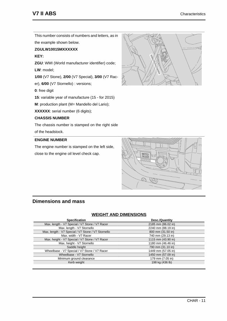
CHASSIS NUMBER
The chassis number is stamped on the right side
of the headstock.
ENGINE NUMBER
The engine number is stamped on the left side,
close to the engine oil level check cap.
Dimensions and mass
WEIGHT AND DIMENSIONSSpecification Desc./Quantity
Max. length - V7 Special / V7 Stone / V7 Racer 2185 mm (86.02 in)Max. length - V7 Stornello 2240 mm (88.19 in)
Max. length - V7 Special / V7 Stone / V7 Stornello 800 mm (31.50 in)Max. width - V7 Racer 740 mm (29.13 in)
Max. height - V7 Special / V7 Stone / V7 Racer 1115 mm (43.90 in)Max. height - V7 Stornello 1180 mm (46.46 in)
Saddle height 790 mm (31.10 in)Wheelbase - V7 Special / V7 Stone / V7 Racer 1449 mm (57.05 in)
Wheelbase - V7 Stornello 1450 mm (57.09 in)Minimum ground clearance 179 mm (7.05 in)
Kerb weight 198 kg (436 lb)
V7 II ABS Characteristics
CHAR - 11
Engine
ENGINESpecification Desc./Quantity
Type traverse-mounted twin-cylinder four-stroke V 90°Cylinder number 2Engine capacity 744 cm³ (45.40 cu.in)
Bore / stroke 80x74 mm (3.15x2.91 in)Compression ratio - V7 Special / V7 Stone / V7 Racer 10.4 : 1
Compression ratio - V7 Stornello 10.5 ± 0.5 : 1Electric Electric starter
Engine idle speed 1,250 +/- 100 rpmIntake valve clearance 0.15 mm (0.0059 in)
Exhaust valve clearance 0.20 mm (0.0079 in)Clutch dry single-disc clutch with flexible coupling
Lubrication system Pressure-fed, controlled by valves and trochoidal pumpAir filter cartridge-type dry filterCooling air
Transmission
TRANSMISSIONSpecification Desc./QuantityPrimary drive with gears, ratio: 18 / 23 = 1 : 1.277
Gear ratios, 1st gear 14 / 37 = 1 : 2.642Gear ratios, 2nd gear 18 / 32 = 1 : 1.777Gear ratios, 3rd gear 21 / 28 = 1 : 1.333Gear ratios, 4th gear 24 / 26 = 1 : 1.083Gear ratios, 5th gear 25 / 24 = 1 : 0.96Gear ratios, 6th gear 27 / 24 = 1 : 0.888
Final drive with cardan shaft, ratio: 8 / 33 = 1 : 4.125
Capacities
CAPACITYSpecification Desc./Quantity
Fuel tank (reserve included) 21 l (4.62 UKgal; 5.55 US gal)Fuel tank reserve 4 l (0.88 UKgal; 1.06 US gal)
Engine oil Oil change and oil filter replacement: 2000 cm³ (122.05 cu.in)Gearbox oil 500 cm³ (30.51 cu.in)
Transmission oil 170 cm³ (10.37 cu.in)Seats - V7 Special / V7 Stone / V7 Stornello 2
Seats - V7 Racer 1 + 1*Maximum carrying load 401 kg (884.05 lb) (rider + passenger + luggage)
* 2 seats, if vehicle is fitted with long two-seater saddle, passen-ger footpegs, passenger grab handles (necessitating rearshock absorbers to be installed upside-down) and exhaust
mounts.In this case, the user is responsible for finding out the correctprocedures for revising the vehicle's road registration docu-
mentation from the relevant local authorities.
Electrical system
ELECTRICAL SYSTEMSpecification Desc./Quantity
Battery 12 V - 12 Ah
Characteristics V7 II ABS
CHAR - 12
Specification Desc./QuantityFuses 5 (2) - 15 (3) - 20 - 30 A
Permanent magnet alternator 12V - 270W
SPARK PLUGSSpecification Desc./Quantity
Standard NGK CPR8EB-9Spark plug electrode gap 0.6 - 0.7 mm (0.024 - 0.027 in)
Resistance 5 kOhm
BULBSSpecification Desc./Quantity
Low/high beam light (halogen) 12 V - 55 W / 60 W H4Front daylight running lights 12V - 5W
Turn indicator light 12 V - 10 W (orange RY 10 W bulb)tail light /stop lights 12 V - 5 / 21 WDashboard lighting LED
WARNING LIGHTSSpecification Desc./QuantityGear in neutral LEDTurn indicators LEDFuel reserve LED
High beam light LEDEngine oil pressure LED
MI warning light LEDABS Warning Light LEDMGCT warning light LED
Frame and suspensions
FRAMESpecification Desc./Quantity
Type Modular double cradle, high strength steel tubular chassisSteering rake 27.5°
Trail 117 mm (4.61 in)
SUSPENSIONSSpecification Desc./Quantity
Front hydraulic telescopic fork, Ø 40 mm (1.57 in)Stroke 137 mm (5.39 in)
Rear - V7 Special / V7 Stone / V7 Stornello Swingarm in die-cast light alloy, 2 shock absorbers with ad-justable spring preloading
Rear - V7 Racer die-cast light alloy swingarm with 2 adjustable shock absorbersStroke - V7 Special / V7 Stone / V7 Stornello 85 mm (3.35 in)
Stroke- V7 Racer 75 mm (2.95 in)
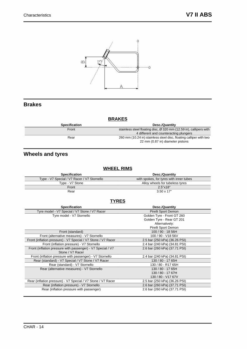
SIZES A AND BSpecification Desc./Quantity
Size A 692 mm (27.24 in)Size B 186 mm (7.32 in)
V7 II ABS Characteristics
CHAR - 13
Brakes
BRAKESSpecification Desc./Quantity
Front stainless steel floating disc, Ø 320 mm (12.59 in), callipers with4 different and counteracting plungers
Rear 260 mm (10.24 in) stainless steel disc, floating calliper with two22 mm (0.87 in) diameter pistons
Wheels and tyres
WHEEL RIMSSpecification Desc./Quantity
Type - V7 Special / V7 Racer / V7 Stornello with spokes, for tyres with inner tubesType - V7 Stone Alloy wheels for tubeless tyres
Front 2.5''x18''Rear 3.50 x 17''
TYRESSpecification Desc./Quantity
Tyre model - V7 Special / V7 Stone / V7 Racer Pirelli Sport DemonTyre model - V7 Stornello Golden Tyre - Front GT 260
Golden Tyre - Rear GT 201Alternatively:
Pirelli Sport DemonFront (standard) 100 / 90 - 18 56H
Front (alternative measures) - V7 Stornello 100 / 90 - V18 56VFront (inflation pressure) - V7 Special / V7 Stone / V7 Racer 2.5 bar (250 kPa) (36.26 PSI)
Front (inflation pressure) - V7 Stornello 2.4 bar (240 kPa) (34.81 PSI)Front (inflation pressure with passenger) - V7 Special / V7
Stone / V7 Racer2.6 bar (260 kPa) (37.71 PSI)
Front (inflation pressure with passenger) - V7 Stornello 2.4 bar (240 kPa) (34.81 PSI)Rear (standard) - V7 Special / V7 Stone / V7 Racer 130 / 80 - 17 65H
Rear (standard) - V7 Stornello 130 / 80 - R17 65HRear (alternative measures) - V7 Stornello 130 / 80 - 17 65H
130 / 80 - 17 67H130 / 80 - V17 67V
Rear (inflation pressure) - V7 Special / V7 Stone / V7 Racer 2.5 bar (250 kPa) (36.26 PSI)Rear (inflation pressure) - V7 Stornello 2.6 bar (260 kPa) (37.71 PSI)
Rear (inflation pressure with passenger) 2.6 bar (260 kPa) (37.71 PSI)
Characteristics V7 II ABS
CHAR - 14
Supply
FUEL SYSTEMSpecification Desc./Quantity
Type Electronic injection (Marelli MIU G3)Diffuser Ø 38 mm (1.50 in)
Fuel Premium unleaded petrol, minimum octane rating of 95(NORM) and 85 (NOMM)
Tightening Torques
Chassis
V7 II ABS Characteristics
CHAR - 15

Front side
FRONT SUSPENSION - STEERINGpos. Description Type Quantity Torque Notes
1 Stanchion cap - 1 + 1 50 Nm (36.88 lb ft) -2 Calliper bracket fixing screws M6x30 2 10 Nm (7.38 lb ft) -3 Screws fixing fork stanchions to upper and low-
er plateM10x40 2 + 2 50 Nm (36.88 lb ft) -
4 Headstock fixing ring nut M25x1 1 7 Nm (5.16 lb ft) The fork must fall to oneside by itself
Characteristics V7 II ABS
CHAR - 16
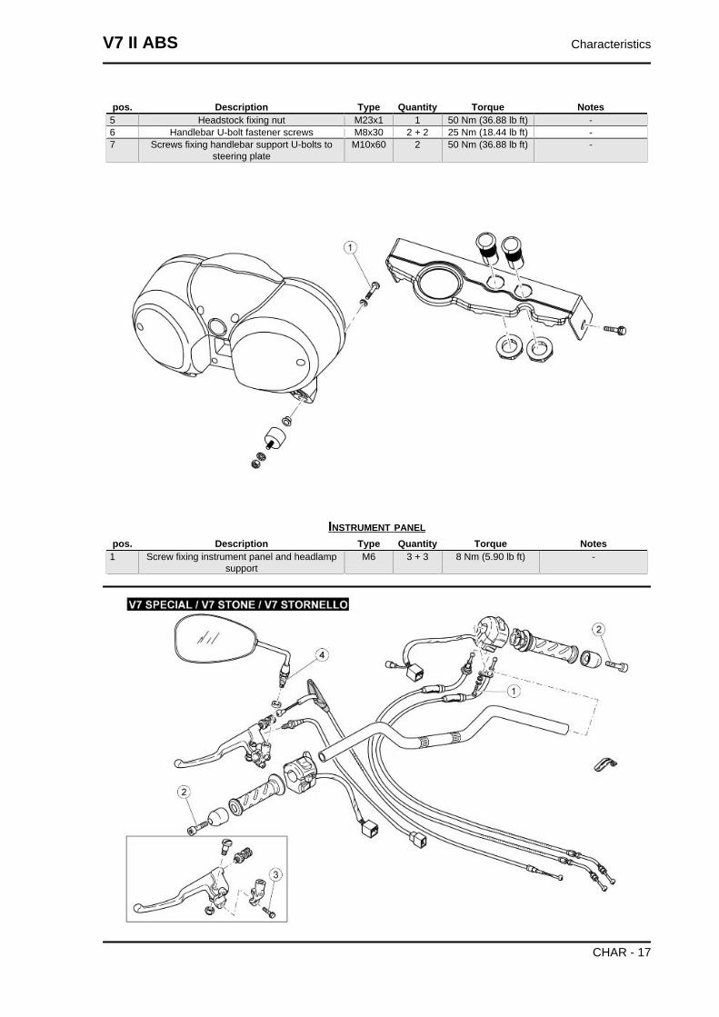
pos. Description Type Quantity Torque Notes5 Headstock fixing nut M23x1 1 50 Nm (36.88 lb ft) -6 Handlebar U-bolt fastener screws M8x30 2 + 2 25 Nm (18.44 lb ft) -7 Screws fixing handlebar support U-bolts to
steering plateM10x60 2 50 Nm (36.88 lb ft) -
INSTRUMENT PANELpos. Description Type Quantity Torque Notes
1 Screw fixing instrument panel and headlampsupport
M6 3 + 3 8 Nm (5.90 lb ft) -
V7 II ABS Characteristics
CHAR - 17
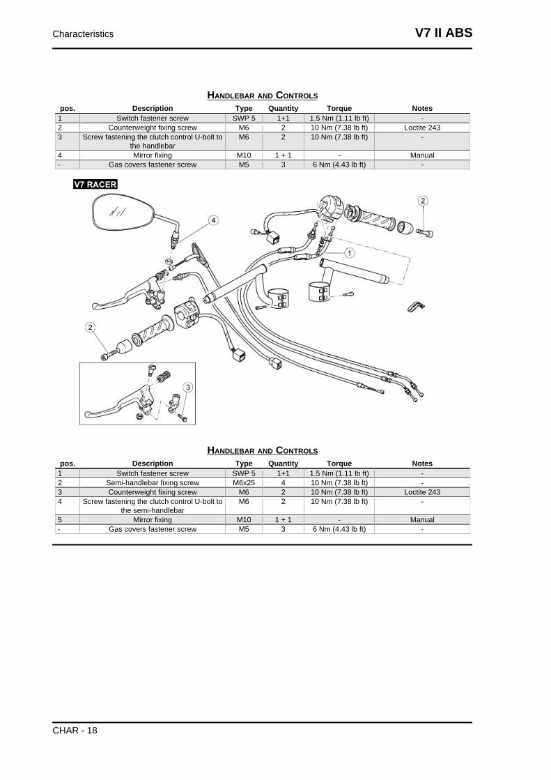
HANDLEBAR AND CONTROLSpos. Description Type Quantity Torque Notes
1 Switch fastener screw SWP 5 1+1 1.5 Nm (1.11 lb ft) -2 Counterweight fixing screw M6 2 10 Nm (7.38 lb ft) Loctite 2433 Screw fastening the clutch control U-bolt to
the handlebarM6 2 10 Nm (7.38 lb ft) -
4 Mirror fixing M10 1 + 1 - Manual- Gas covers fastener screw M5 3 6 Nm (4.43 lb ft) -
HANDLEBAR AND CONTROLSpos. Description Type Quantity Torque Notes
1 Switch fastener screw SWP 5 1+1 1.5 Nm (1.11 lb ft) -2 Semi-handlebar fixing screw M6x25 4 10 Nm (7.38 lb ft) -3 Counterweight fixing screw M6 2 10 Nm (7.38 lb ft) Loctite 2434 Screw fastening the clutch control U-bolt to
the semi-handlebarM6 2 10 Nm (7.38 lb ft) -
5 Mirror fixing M10 1 + 1 - Manual- Gas covers fastener screw M5 3 6 Nm (4.43 lb ft) -
Characteristics V7 II ABS
CHAR - 18
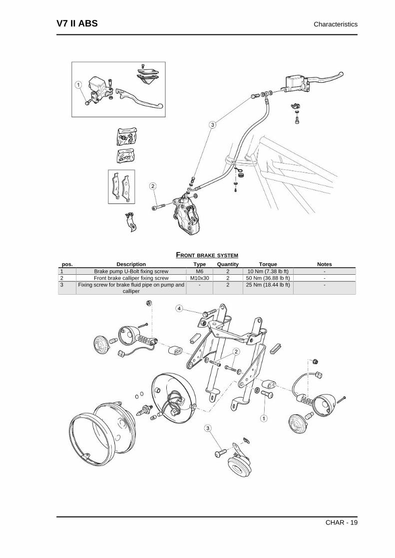
FRONT BRAKE SYSTEMpos. Description Type Quantity Torque Notes
1 Brake pump U-Bolt fixing screw M6 2 10 Nm (7.38 lb ft) -2 Front brake calliper fixing screw M10x30 2 50 Nm (36.88 lb ft) -3 Fixing screw for brake fluid pipe on pump and
calliper- 2 25 Nm (18.44 lb ft) -
V7 II ABS Characteristics
CHAR - 19
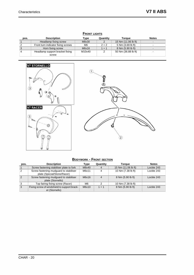
FRONT LIGHTSpos. Description Type Quantity Torque Notes
1 Headlamp fixing screw M8x30 2 15 Nm (11.06 lb ft) -2 Front turn indicator fixing screws M6 2 + 2 5 Nm (3.69 lb ft) -3 Horn fixing screw M6x16 1 + 1 8 Nm (5.90 lb ft) -4 Headlamp support bracket fixing
screwM10x40 2 50 Nm (36.88 lb ft) -
BODYWORK - FRONT SECTIONpos. Description Type Quantity Torque Notes
1 Screw fastening stabiliser plate to fork M8x40 4 15 Nm (11.06 lb ft) Loctite 2432 Screw fastening mudguard to stabiliser
plate (Special/Stone/Racer)M6x11 4 10 Nm (7.38 lb ft) Loctite 243
2 Screw fastening mudguard to stabiliserplate (Stornello)
M6x16 4 8 Nm (5.90 lb ft) Loctite 243
3 Top fairing fixing screw (Racer) M6 2 10 Nm (7.38 lb ft)3 Fixing screw of windshield to support brack-
et (Stornello)M6x10 1 + 1 8 Nm (5.90 lb ft) Loctite 243
Characteristics V7 II ABS
CHAR - 20
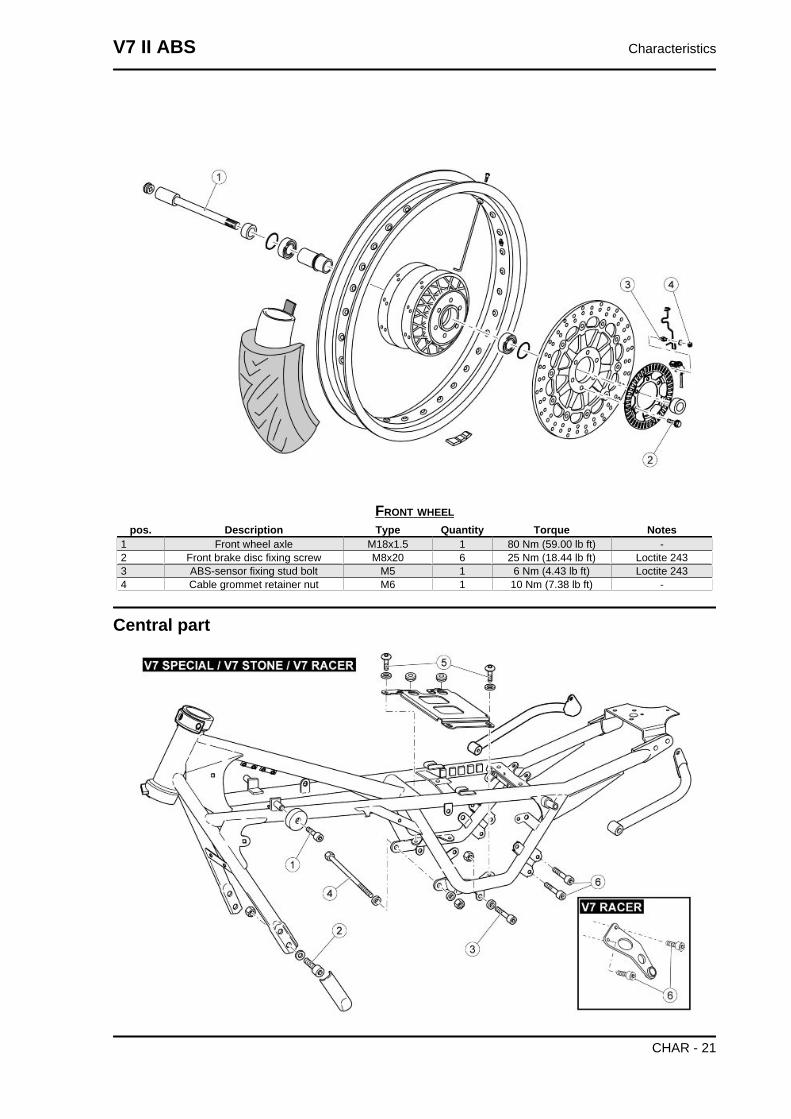
FRONT WHEELpos. Description Type Quantity Torque Notes
1 Front wheel axle M18x1.5 1 80 Nm (59.00 lb ft) -2 Front brake disc fixing screw M8x20 6 25 Nm (18.44 lb ft) Loctite 2433 ABS-sensor fixing stud bolt M5 1 6 Nm (4.43 lb ft) Loctite 2434 Cable grommet retainer nut M6 1 10 Nm (7.38 lb ft) -
Central part
V7 II ABS Characteristics
CHAR - 21
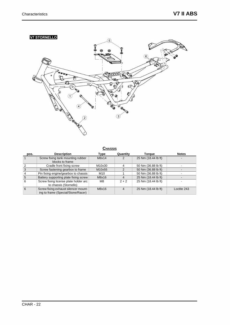
CHASSISpos. Description Type Quantity Torque Notes
1 Screw fixing tank mounting rubberblocks to frame
M8x14 2 25 Nm (18.44 lb ft) -
2 Cradle front fixing screw M10x30 4 50 Nm (36.88 lb ft) -3 Screw fastening gearbox to frame M10x55 2 50 Nm (36.88 lb ft) -4 Pin fixing engine/gearbox to chassis M10 1 50 Nm (36.88 lb ft) -5 Battery supporting plate fixing screw M8x16 4 25 Nm (18.44 lb ft) -6 Screw fixing license plate holder arc
to chassis (Stornello)M8 2 + 2 25 Nm (18.44 lb ft) -
6 Screw fixing exhaust silencer mount-ing to frame (Special/Stone/Racer)
M8x16 4 25 Nm (18.44 lb ft) Loctite 243
Characteristics V7 II ABS
CHAR - 22
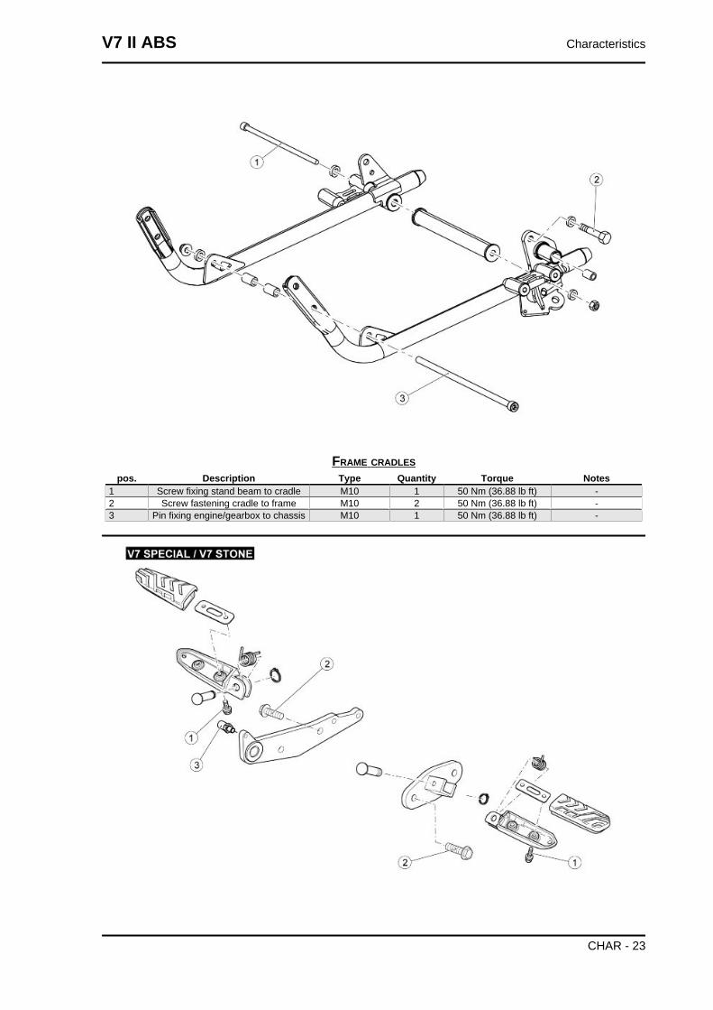
FRAME CRADLESpos. Description Type Quantity Torque Notes
1 Screw fixing stand beam to cradle M10 1 50 Nm (36.88 lb ft) -2 Screw fastening cradle to frame M10 2 50 Nm (36.88 lb ft) -3 Pin fixing engine/gearbox to chassis M10 1 50 Nm (36.88 lb ft) -
V7 II ABS Characteristics
CHAR - 23
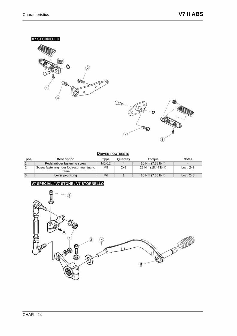
DRIVER FOOTRESTSpos. Description Type Quantity Torque Notes
1 Pedal rubber fastening screw M6x12 4 10 Nm (7.38 lb ft) -2 Screw fastening rider footrest mounting to
frameM8 2+2 25 Nm (18.44 lb ft) Loct. 243
3 Lever peg fixing M6 1 10 Nm (7.38 lb ft) Loct. 243
Characteristics V7 II ABS
CHAR - 24
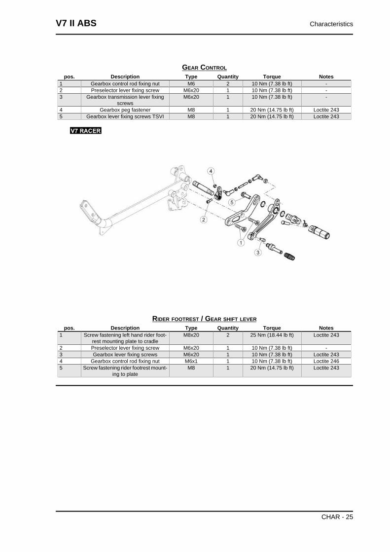
GEAR CONTROLpos. Description Type Quantity Torque Notes
1 Gearbox control rod fixing nut M6 2 10 Nm (7.38 lb ft) -2 Preselector lever fixing screw M6x20 1 10 Nm (7.38 lb ft) -3 Gearbox transmission lever fixing
screwsM6x20 1 10 Nm (7.38 lb ft) -
4 Gearbox peg fastener M8 1 20 Nm (14.75 lb ft) Loctite 2435 Gearbox lever fixing screws TSVI M8 1 20 Nm (14.75 lb ft) Loctite 243
RIDER FOOTREST / GEAR SHIFT LEVERpos. Description Type Quantity Torque Notes
1 Screw fastening left hand rider foot-rest mounting plate to cradle
M8x20 2 25 Nm (18.44 lb ft) Loctite 243
2 Preselector lever fixing screw M6x20 1 10 Nm (7.38 lb ft) -3 Gearbox lever fixing screws M6x20 1 10 Nm (7.38 lb ft) Loctite 2434 Gearbox control rod fixing nut M6x1 1 10 Nm (7.38 lb ft) Loctite 2465 Screw fastening rider footrest mount-
ing to plateM8 1 20 Nm (14.75 lb ft) Loctite 243
V7 II ABS Characteristics
CHAR - 25
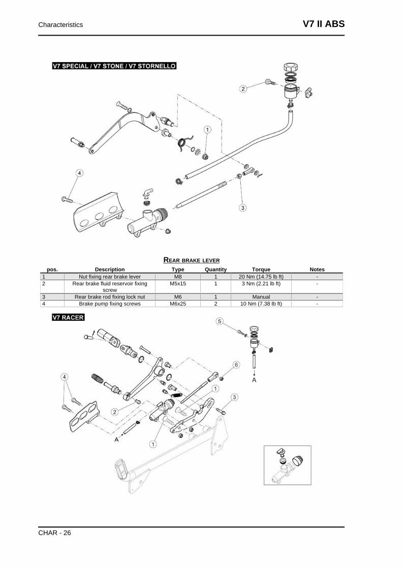
REAR BRAKE LEVERpos. Description Type Quantity Torque Notes
1 Nut fixing rear brake lever M8 1 20 Nm (14.75 lb ft) -2 Rear brake fluid reservoir fixing
screwM5x15 1 3 Nm (2.21 lb ft) -
3 Rear brake rod fixing lock nut M6 1 Manual -4 Brake pump fixing screws M6x25 2 10 Nm (7.38 lb ft) -
Characteristics V7 II ABS
CHAR - 26
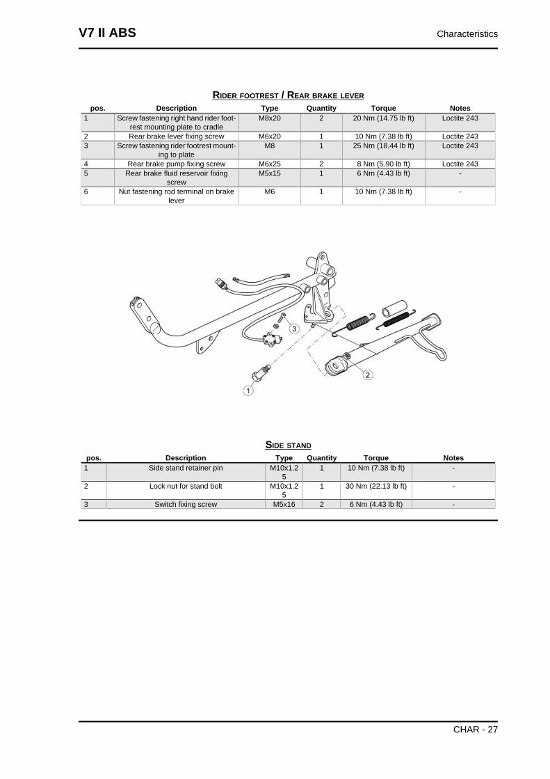
RIDER FOOTREST / REAR BRAKE LEVERpos. Description Type Quantity Torque Notes
1 Screw fastening right hand rider foot-rest mounting plate to cradle
M8x20 2 20 Nm (14.75 lb ft) Loctite 243
2 Rear brake lever fixing screw M6x20 1 10 Nm (7.38 lb ft) Loctite 2433 Screw fastening rider footrest mount-
ing to plateM8 1 25 Nm (18.44 lb ft) Loctite 243
4 Rear brake pump fixing screw M6x25 2 8 Nm (5.90 lb ft) Loctite 2435 Rear brake fluid reservoir fixing
screwM5x15 1 6 Nm (4.43 lb ft) -
6 Nut fastening rod terminal on brakelever
M6 1 10 Nm (7.38 lb ft) -
SIDE STANDpos. Description Type Quantity Torque Notes
1 Side stand retainer pin M10x1.25
1 10 Nm (7.38 lb ft) -
2 Lock nut for stand bolt M10x1.25
1 30 Nm (22.13 lb ft) -
3 Switch fixing screw M5x16 2 6 Nm (4.43 lb ft) -
V7 II ABS Characteristics
CHAR - 27
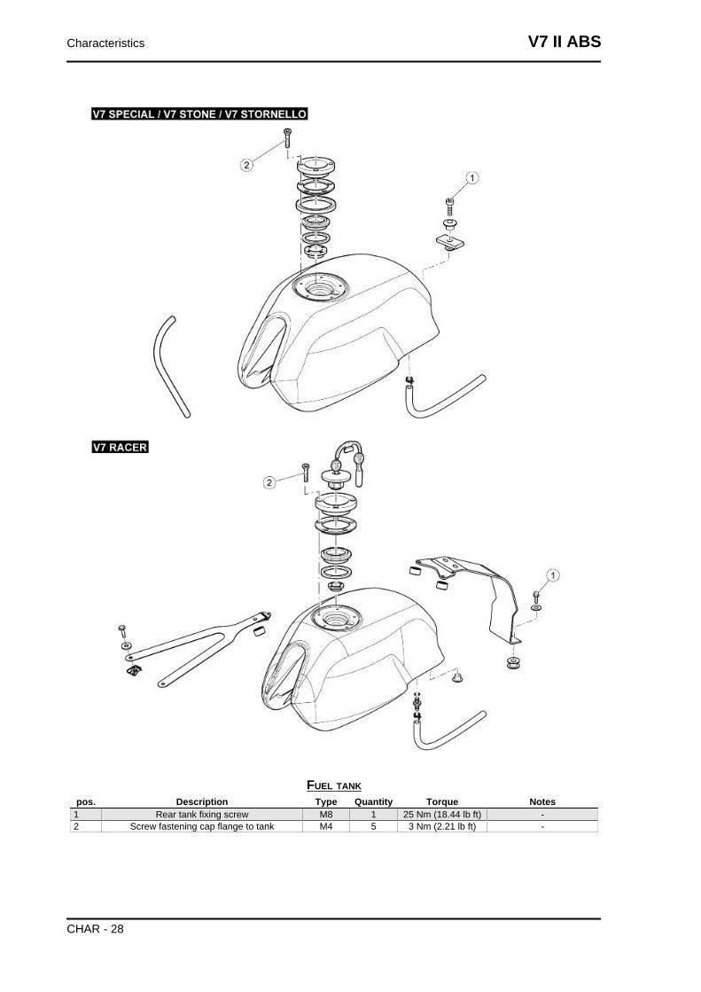
FUEL TANKpos. Description Type Quantity Torque Notes
1 Rear tank fixing screw M8 1 25 Nm (18.44 lb ft) -2 Screw fastening cap flange to tank M4 5 3 Nm (2.21 lb ft) -
Characteristics V7 II ABS
CHAR - 28
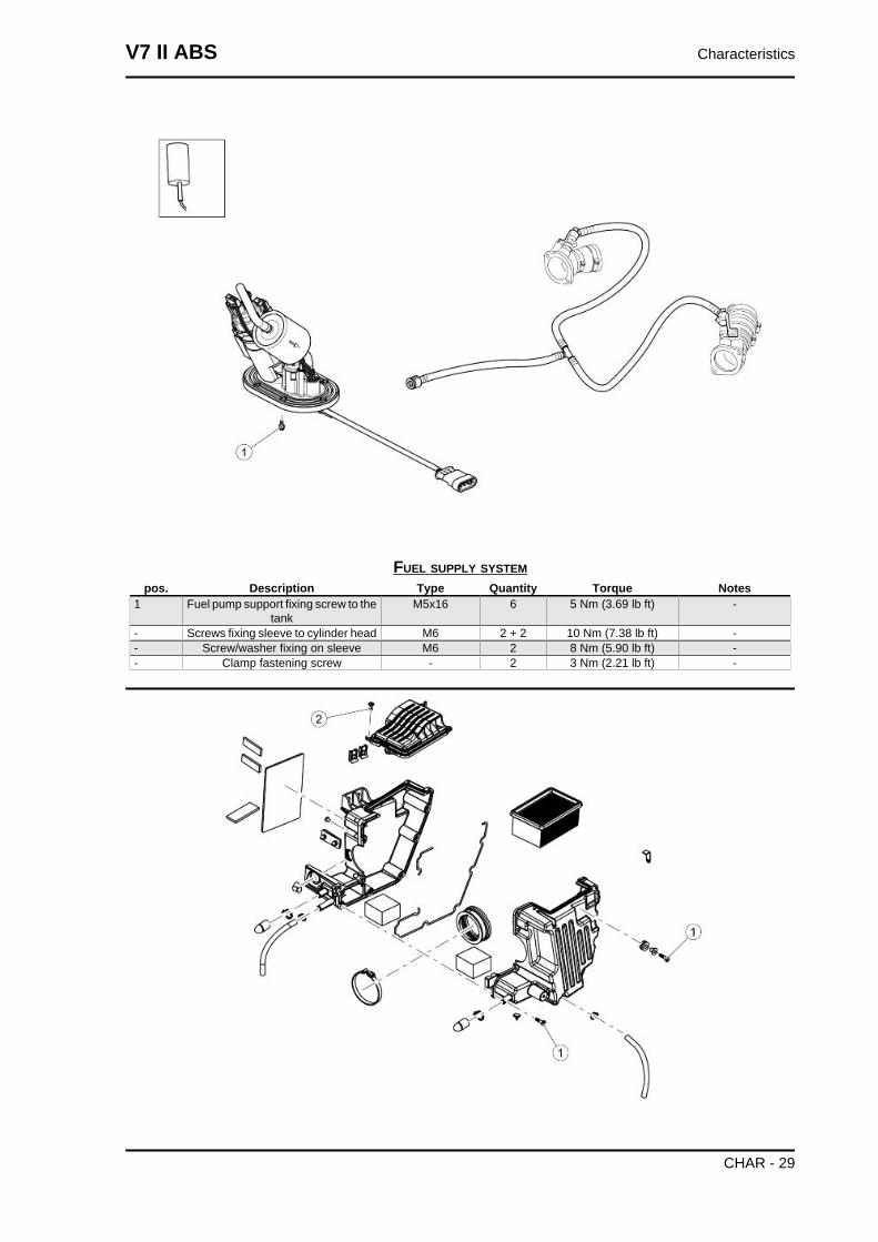
FUEL SUPPLY SYSTEMpos. Description Type Quantity Torque Notes
1 Fuel pump support fixing screw to thetank
M5x16 6 5 Nm (3.69 lb ft) -
- Screws fixing sleeve to cylinder head M6 2 + 2 10 Nm (7.38 lb ft) -- Screw/washer fixing on sleeve M6 2 8 Nm (5.90 lb ft) -- Clamp fastening screw - 2 3 Nm (2.21 lb ft) -
V7 II ABS Characteristics
CHAR - 29
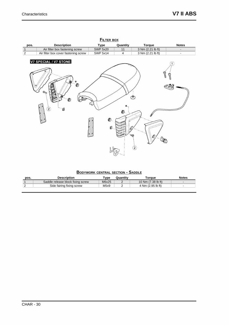
FILTER BOXpos. Description Type Quantity Torque Notes
1 Air filter box fastening screw SWP 5x20 11 3 Nm (2.21 lb ft) -2 Air filter box cover fastening screw SWP 5x14 4 3 Nm (2.21 lb ft) -
BODYWORK CENTRAL SECTION - SADDLEpos. Description Type Quantity Torque Notes
1 Saddle release block fixing screw M6x25 2 10 Nm (7.38 lb ft) -2 Side fairing fixing screw M5x9 2 4 Nm (2.95 lb ft) -
Characteristics V7 II ABS
CHAR - 30
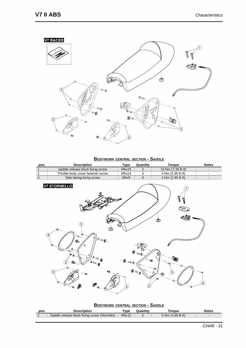
BODYWORK CENTRAL SECTION - SADDLEpos. Description Type Quantity Torque Notes
1 Saddle release block fixing screw M6x25 2 10 Nm (7.38 lb ft) -2 Throttle body cover fastener screw M5x14 4 4 Nm (2.95 lb ft) -3 Side fairing fixing screw M5x9 6 4 Nm (2.95 lb ft) -
BODYWORK CENTRAL SECTION - SADDLEpos. Description Type Quantity Torque Notes
1 Saddle release block fixing screw (Stornello) M5x12 2 5 Nm (3.69 lb ft) -
V7 II ABS Characteristics
CHAR - 31
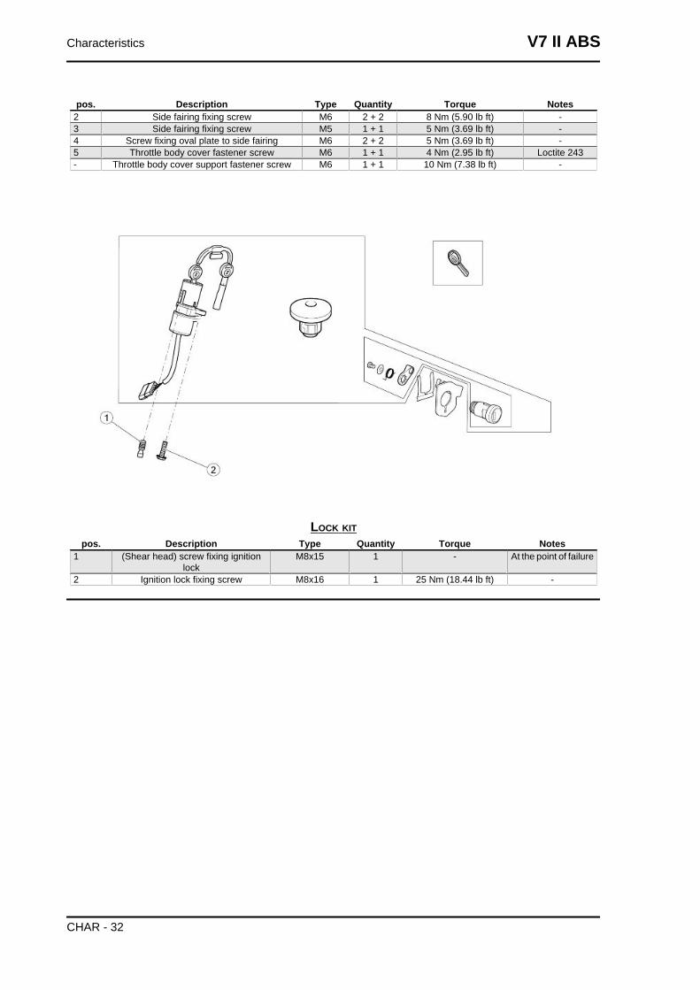
pos. Description Type Quantity Torque Notes2 Side fairing fixing screw M6 2 + 2 8 Nm (5.90 lb ft) -3 Side fairing fixing screw M5 1 + 1 5 Nm (3.69 lb ft) -4 Screw fixing oval plate to side fairing M6 2 + 2 5 Nm (3.69 lb ft) -5 Throttle body cover fastener screw M6 1 + 1 4 Nm (2.95 lb ft) Loctite 243- Throttle body cover support fastener screw M6 1 + 1 10 Nm (7.38 lb ft) -
LOCK KITpos. Description Type Quantity Torque Notes
1 (Shear head) screw fixing ignitionlock
M8x15 1 - At the point of failure
2 Ignition lock fixing screw M8x16 1 25 Nm (18.44 lb ft) -
Characteristics V7 II ABS
CHAR - 32
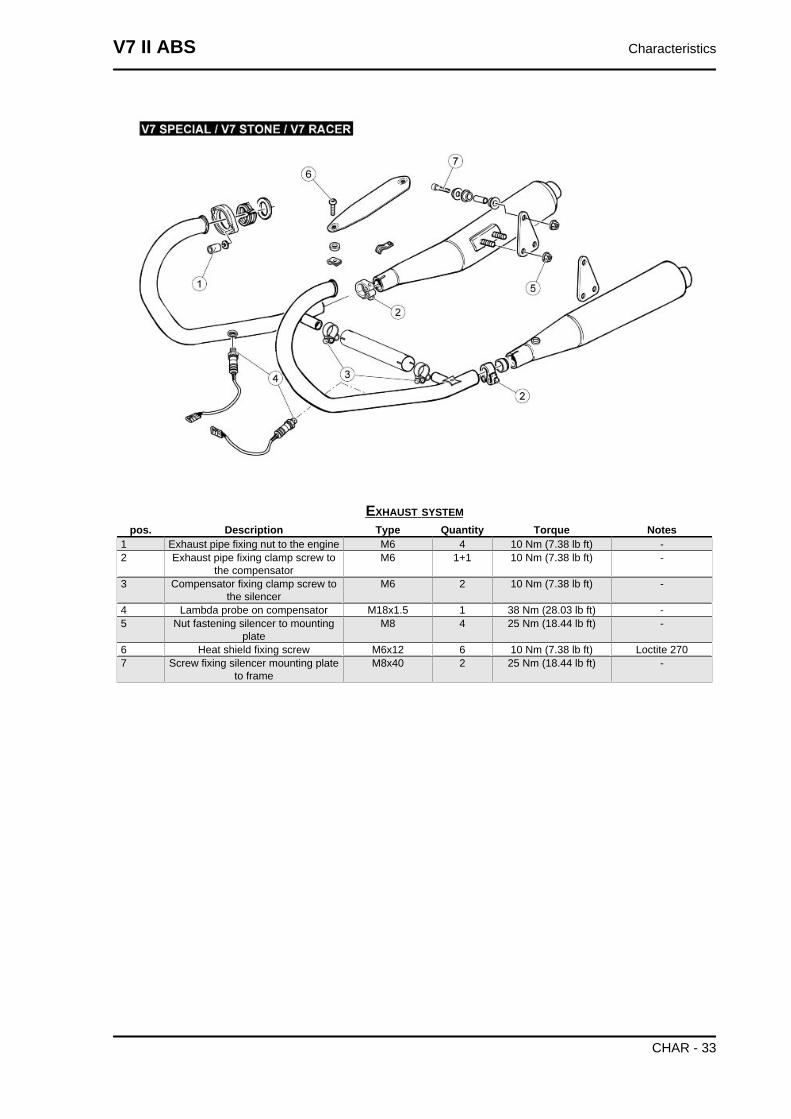
EXHAUST SYSTEMpos. Description Type Quantity Torque Notes
1 Exhaust pipe fixing nut to the engine M6 4 10 Nm (7.38 lb ft) -2 Exhaust pipe fixing clamp screw to
the compensatorM6 1+1 10 Nm (7.38 lb ft) -
3 Compensator fixing clamp screw tothe silencer
M6 2 10 Nm (7.38 lb ft) -
4 Lambda probe on compensator M18x1.5 1 38 Nm (28.03 lb ft) -5 Nut fastening silencer to mounting
plateM8 4 25 Nm (18.44 lb ft) -
6 Heat shield fixing screw M6x12 6 10 Nm (7.38 lb ft) Loctite 2707 Screw fixing silencer mounting plate
to frameM8x40 2 25 Nm (18.44 lb ft) -
V7 II ABS Characteristics
CHAR - 33
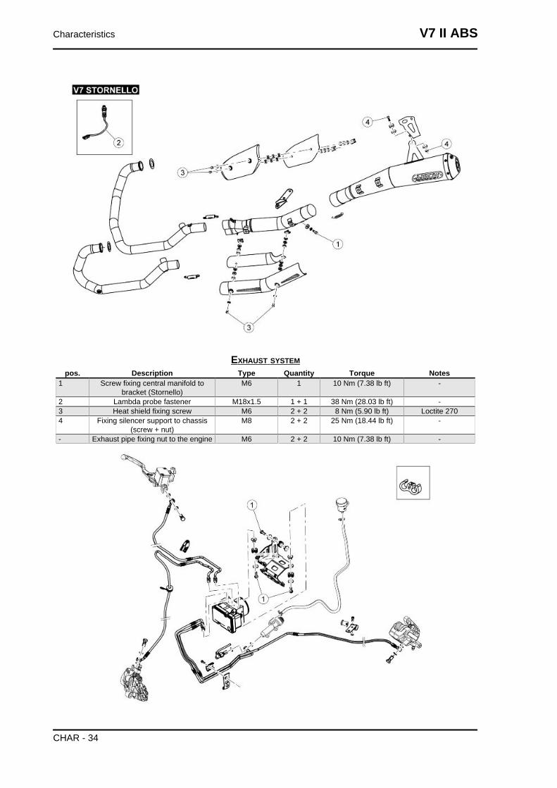
EXHAUST SYSTEMpos. Description Type Quantity Torque Notes
1 Screw fixing central manifold tobracket (Stornello)
M6 1 10 Nm (7.38 lb ft) -
2 Lambda probe fastener M18x1.5 1 + 1 38 Nm (28.03 lb ft) -3 Heat shield fixing screw M6 2 + 2 8 Nm (5.90 lb ft) Loctite 2704 Fixing silencer support to chassis
(screw + nut)M8 2 + 2 25 Nm (18.44 lb ft) -
- Exhaust pipe fixing nut to the engine M6 2 + 2 10 Nm (7.38 lb ft) -
Characteristics V7 II ABS
CHAR - 34
ABS SYSTEMpos. Description Type Quantity Torque Notes
1 Screw fixing ABS control unit supportto chassis
M6 3 10 Nm (7.38 lb ft) -
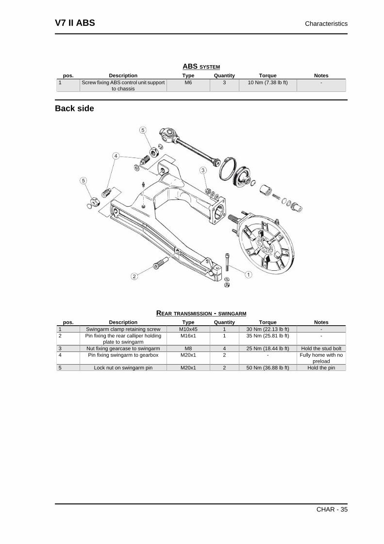
Back side
REAR TRANSMISSION - SWINGARMpos. Description Type Quantity Torque Notes
1 Swingarm clamp retaining screw M10x45 1 30 Nm (22.13 lb ft) -2 Pin fixing the rear calliper holding
plate to swingarmM16x1 1 35 Nm (25.81 lb ft) -
3 Nut fixing gearcase to swingarm M8 4 25 Nm (18.44 lb ft) Hold the stud bolt4 Pin fixing swingarm to gearbox M20x1 2 - Fully home with no
preload5 Lock nut on swingarm pin M20x1 2 50 Nm (36.88 lb ft) Hold the pin
V7 II ABS Characteristics
CHAR - 35
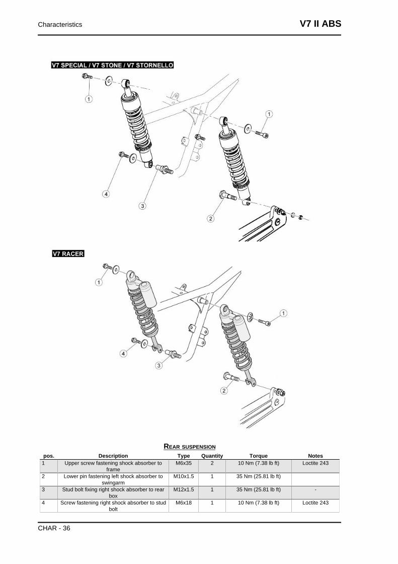
REAR SUSPENSIONpos. Description Type Quantity Torque Notes
1 Upper screw fastening shock absorber toframe
M6x35 2 10 Nm (7.38 lb ft) Loctite 243
2 Lower pin fastening left shock absorber toswingarm
M10x1.5 1 35 Nm (25.81 lb ft)
3 Stud bolt fixing right shock absorber to rearbox
M12x1.5 1 35 Nm (25.81 lb ft) -
4 Screw fastening right shock absorber to studbolt
M6x18 1 10 Nm (7.38 lb ft) Loctite 243
Characteristics V7 II ABS
CHAR - 36
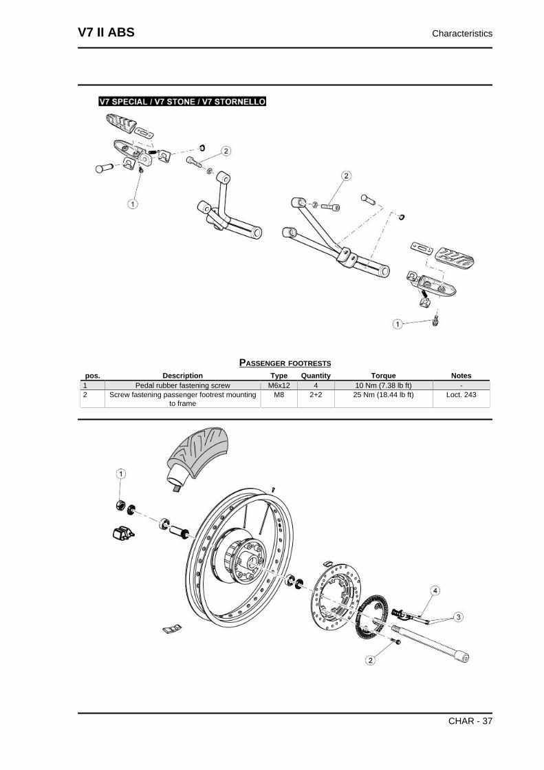
PASSENGER FOOTRESTSpos. Description Type Quantity Torque Notes
1 Pedal rubber fastening screw M6x12 4 10 Nm (7.38 lb ft) -2 Screw fastening passenger footrest mounting
to frameM8 2+2 25 Nm (18.44 lb ft) Loct. 243
V7 II ABS Characteristics
CHAR - 37
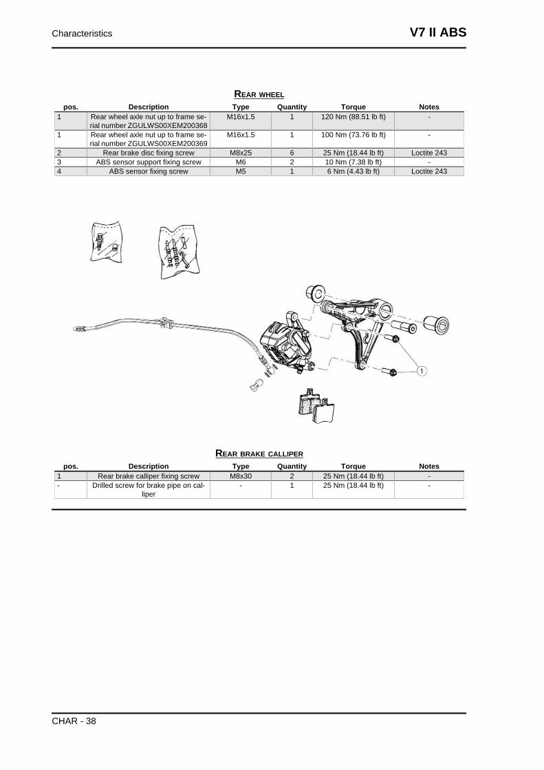
REAR WHEELpos. Description Type Quantity Torque Notes
1 Rear wheel axle nut up to frame se-rial number ZGULWS00XEM200368
M16x1.5 1 120 Nm (88.51 lb ft) -
1 Rear wheel axle nut up to frame se-rial number ZGULWS00XEM200369
M16x1.5 1 100 Nm (73.76 lb ft) -
2 Rear brake disc fixing screw M8x25 6 25 Nm (18.44 lb ft) Loctite 2433 ABS sensor support fixing screw M6 2 10 Nm (7.38 lb ft) -4 ABS sensor fixing screw M5 1 6 Nm (4.43 lb ft) Loctite 243
REAR BRAKE CALLIPERpos. Description Type Quantity Torque Notes
1 Rear brake calliper fixing screw M8x30 2 25 Nm (18.44 lb ft) -- Drilled screw for brake pipe on cal-
liper- 1 25 Nm (18.44 lb ft) -
Characteristics V7 II ABS
CHAR - 38
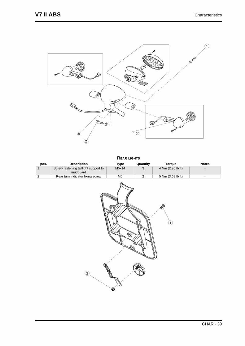
REAR LIGHTSpos. Description Type Quantity Torque Notes
1 Screw fastening taillight support tomudguard
M5x14 3 4 Nm (2.95 lb ft) -
2 Rear turn indicator fixing screw M6 2 5 Nm (3.69 lb ft) -
V7 II ABS Characteristics
CHAR - 39
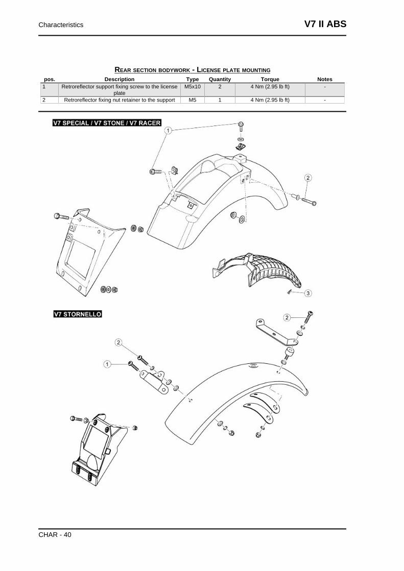
REAR SECTION BODYWORK - LICENSE PLATE MOUNTINGpos. Description Type Quantity Torque Notes
1 Retroreflector support fixing screw to the licenseplate
M5x10 2 4 Nm (2.95 lb ft) -
2 Retroreflector fixing nut retainer to the support M5 1 4 Nm (2.95 lb ft) -
Characteristics V7 II ABS
CHAR - 40
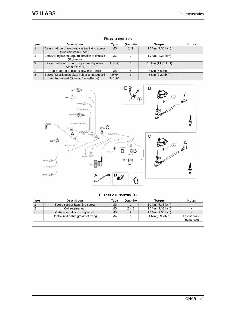
REAR MUDGUARDpos. Description Type Quantity Torque Notes
1 Rear mudguard front and central fixing screw(Special/Stone/Racer)
M6 2+1 10 Nm (7.38 lb ft)
1 Screw fixing rear mudguard bracket to chassis(Stornello)
M6 2 10 Nm (7.38 lb ft)
2 Rear mudguard side fixing screw (Special/Stone/Racer)
M8x30 2 20 Nm (14.75 lb ft)
2 Rear mudguard fixing screw (Stornello) M6 4 8 Nm (5.90 lb ft)3 Screw fixing license plate holder to mudguard
reinforcement (Special/Stone/Racer)SWP
M5x203 3 Nm (2.21 lb ft)
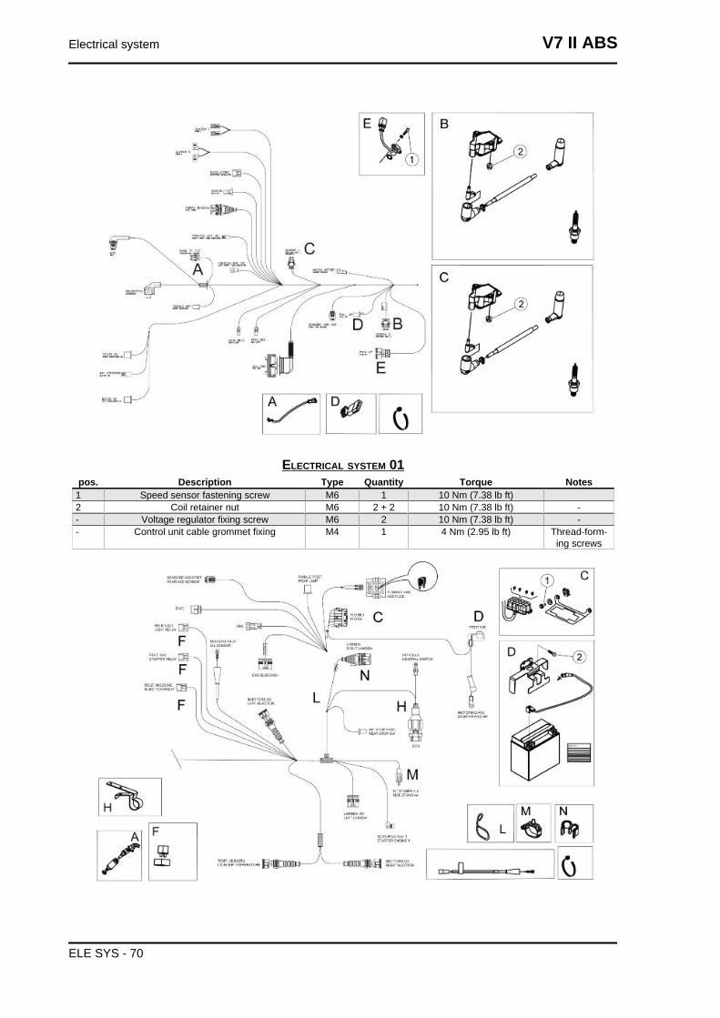
ELECTRICAL SYSTEM 01pos. Description Type Quantity Torque Notes
1 Speed sensor fastening screw M6 1 10 Nm (7.38 lb ft)2 Coil retainer nut M6 2 + 2 10 Nm (7.38 lb ft) -- Voltage regulator fixing screw M6 2 10 Nm (7.38 lb ft) -- Control unit cable grommet fixing M4 1 4 Nm (2.95 lb ft) Thread-form-
ing screws
V7 II ABS Characteristics
CHAR - 41
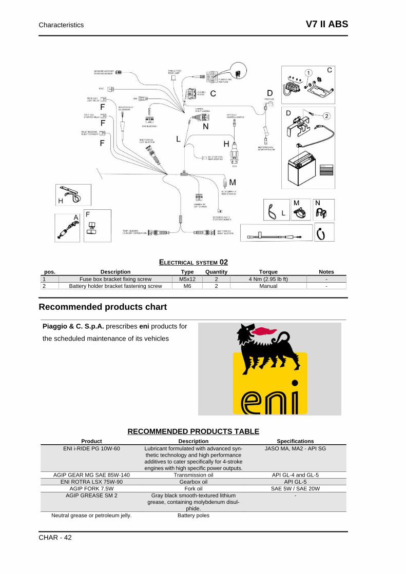
ELECTRICAL SYSTEM 02pos. Description Type Quantity Torque Notes
1 Fuse box bracket fixing screw M5x12 2 4 Nm (2.95 lb ft) -2 Battery holder bracket fastening screw M6 2 Manual -
Recommended products chart
Piaggio & C. S.p.A. prescribes eni products for
the scheduled maintenance of its vehicles
RECOMMENDED PRODUCTS TABLEProduct Description Specifications
ENI i-RIDE PG 10W-60 Lubricant formulated with advanced syn-thetic technology and high performanceadditives to cater specifically for 4-strokeengines with high specific power outputs.
JASO MA, MA2 - API SG
AGIP GEAR MG SAE 85W-140 Transmission oil API GL-4 and GL-5ENI ROTRA LSX 75W-90 Gearbox oil API GL-5
AGIP FORK 7.5W Fork oil SAE 5W / SAE 20WAGIP GREASE SM 2 Gray black smooth-textured lithium
grease, containing molybdenum disul-phide.
-
Neutral grease or petroleum jelly. Battery poles
Characteristics V7 II ABS
CHAR - 42
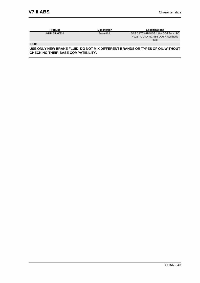
Product Description SpecificationsAGIP BRAKE 4 Brake fluid SAE J 1703 -FMVSS 116 - DOT 3/4 - ISO
4925 - CUNA NC 956 DOT 4 syntheticfluid
NOTE
USE ONLY NEW BRAKE FLUID. DO NOT MIX DIFFERENT BRANDS OR TYPES OF OIL WITHOUTCHECKING THEIR BASE COMPATIBILITY.
V7 II ABS Characteristics
CHAR - 43

INDEX OF TOPICS
SPECIAL TOOLS S-TOOLS
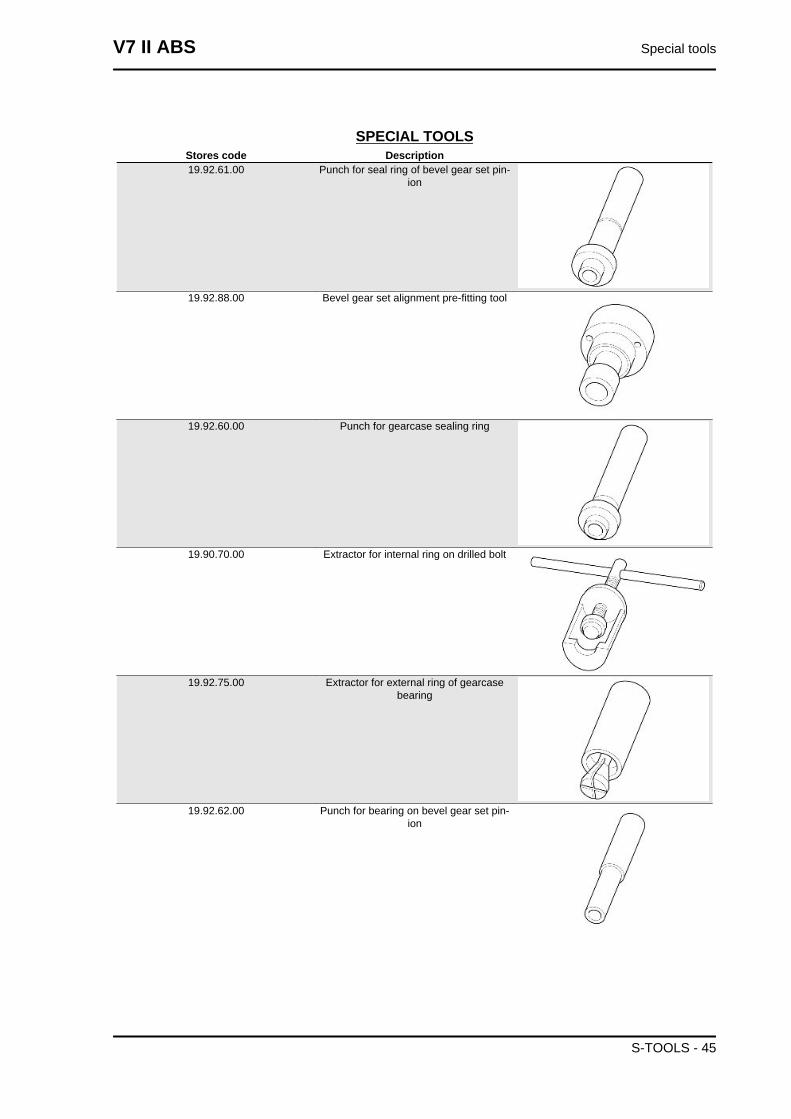
SPECIAL TOOLSStores code Description19.92.61.00 Punch for seal ring of bevel gear set pin-
ion
19.92.88.00 Bevel gear set alignment pre-fitting tool
19.92.60.00 Punch for gearcase sealing ring
19.90.70.00 Extractor for internal ring on drilled bolt
19.92.75.00 Extractor for external ring of gearcasebearing
19.92.62.00 Punch for bearing on bevel gear set pin-ion
V7 II ABS Special tools
S-TOOLS - 45
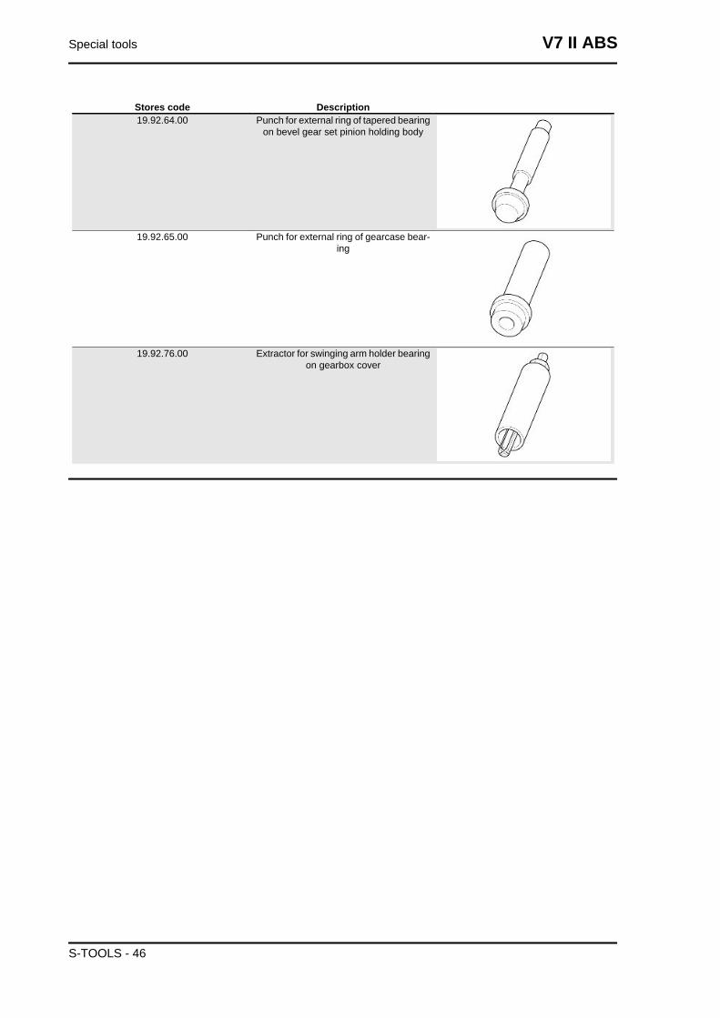
Stores code Description19.92.64.00 Punch for external ring of tapered bearing
on bevel gear set pinion holding body
19.92.65.00 Punch for external ring of gearcase bear-ing
19.92.76.00 Extractor for swinging arm holder bearingon gearbox cover
Special tools V7 II ABS
S-TOOLS - 46

INDEX OF TOPICS
MAINTENANCE MAIN
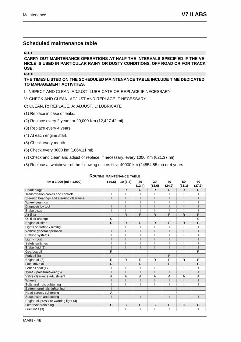
Scheduled maintenance tableNOTE
CARRY OUT MAINTENANCE OPERATIONS AT HALF THE INTERVALS SPECIFIED IF THE VE-HICLE IS USED IN PARTICULAR RAINY OR DUSTY CONDITIONS, OFF ROAD OR FOR TRACKUSE.NOTE
THE TIMES LISTED ON THE SCHEDULED MAINTENANCE TABLE INCLUDE TIME DEDICATEDTO MANAGEMENT ACTIVITIES.
I: INSPECT AND CLEAN, ADJUST, LUBRICATE OR REPLACE IF NECESSARY
V: CHECK AND CLEAN, ADJUST AND REPLACE IF NECESSARY
C: CLEAN, R: REPLACE, A: ADJUST, L: LUBRICATE
(1) Replace in case of leaks.
(2) Replace every 2 years or 20,000 Km (12,427.42 mi).
(3) Replace every 4 years.
(4) At each engine start.
(5) Check every month.
(6) Check every 3000 km (1864.11 mi)
(7) Check and clean and adjust or replace, if necessary, every 1000 Km (621.37 mi)
(8) Replace at whichever of the following occurs first: 40000 km (24854.85 mi) or 4 years
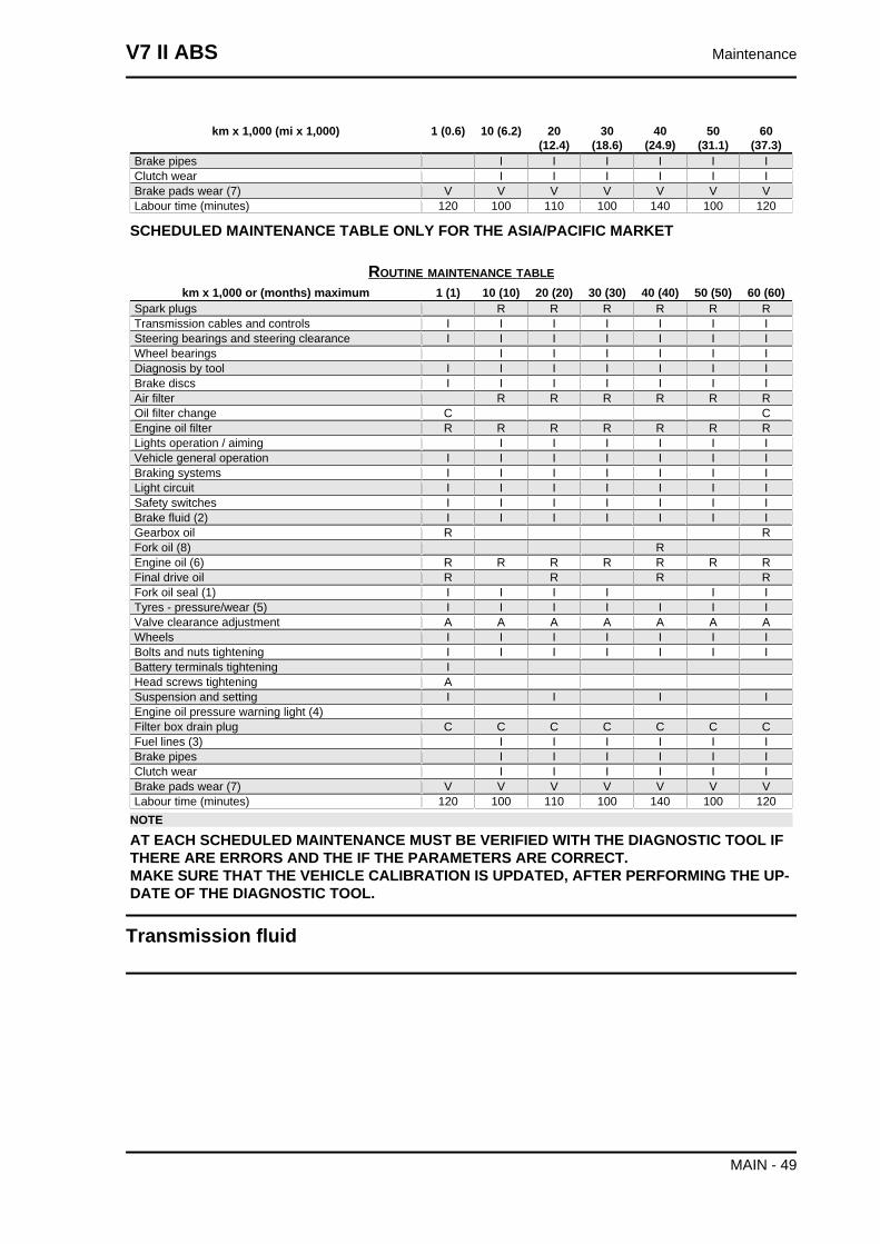
ROUTINE MAINTENANCE TABLEkm x 1,000 (mi x 1,000) 1 (0.6) 10 (6.2) 20
(12.4)30
(18.6)40
(24.9)50
(31.1)60
(37.3)Spark plugs R R R R R RTransmission cables and controls I I I I I I ISteering bearings and steering clearance I I I I I I IWheel bearings I I I I I IDiagnosis by tool I I I I I I IBrake discs I I I I I I IAir filter R R R R R ROil filter change C CEngine oil filter R R R R R R RLights operation / aiming I I I I I IVehicle general operation I I I I I I IBraking systems I I I I I I ILight circuit I I I I I I ISafety switches I I I I I I IBrake fluid (2) I I I I I I IGearbox oil R RFork oil (8) REngine oil (6) R R R R R R RFinal drive oil R R R RFork oil seal (1) I I I I I ITyres - pressure/wear (5) I I I I I I IValve clearance adjustment A A A A A A AWheels I I I I I I IBolts and nuts tightening I I I I I I IBattery terminals tightening IHead screws tightening ASuspension and setting I I I IEngine oil pressure warning light (4)Filter box drain plug C C C C C C CFuel lines (3) I I I I I I
Maintenance V7 II ABS
MAIN - 48
km x 1,000 (mi x 1,000) 1 (0.6) 10 (6.2) 20(12.4)
30(18.6)
40(24.9)
50(31.1)
60(37.3)
Brake pipes I I I I I IClutch wear I I I I I IBrake pads wear (7) V V V V V V VLabour time (minutes) 120 100 110 100 140 100 120
SCHEDULED MAINTENANCE TABLE ONLY FOR THE ASIA/PACIFIC MARKET
ROUTINE MAINTENANCE TABLEkm x 1,000 or (months) maximum 1 (1) 10 (10) 20 (20) 30 (30) 40 (40) 50 (50) 60 (60)
Spark plugs R R R R R RTransmission cables and controls I I I I I I ISteering bearings and steering clearance I I I I I I IWheel bearings I I I I I IDiagnosis by tool I I I I I I IBrake discs I I I I I I IAir filter R R R R R ROil filter change C CEngine oil filter R R R R R R RLights operation / aiming I I I I I IVehicle general operation I I I I I I IBraking systems I I I I I I ILight circuit I I I I I I ISafety switches I I I I I I IBrake fluid (2) I I I I I I IGearbox oil R RFork oil (8) REngine oil (6) R R R R R R RFinal drive oil R R R RFork oil seal (1) I I I I I ITyres - pressure/wear (5) I I I I I I IValve clearance adjustment A A A A A A AWheels I I I I I I IBolts and nuts tightening I I I I I I IBattery terminals tightening IHead screws tightening ASuspension and setting I I I IEngine oil pressure warning light (4)Filter box drain plug C C C C C C CFuel lines (3) I I I I I IBrake pipes I I I I I IClutch wear I I I I I IBrake pads wear (7) V V V V V V VLabour time (minutes) 120 100 110 100 140 100 120
NOTE
AT EACH SCHEDULED MAINTENANCE MUST BE VERIFIED WITH THE DIAGNOSTIC TOOL IFTHERE ARE ERRORS AND THE IF THE PARAMETERS ARE CORRECT.MAKE SURE THAT THE VEHICLE CALIBRATION IS UPDATED, AFTER PERFORMING THE UP-DATE OF THE DIAGNOSTIC TOOL.
Transmission fluid
V7 II ABS Maintenance
MAIN - 49
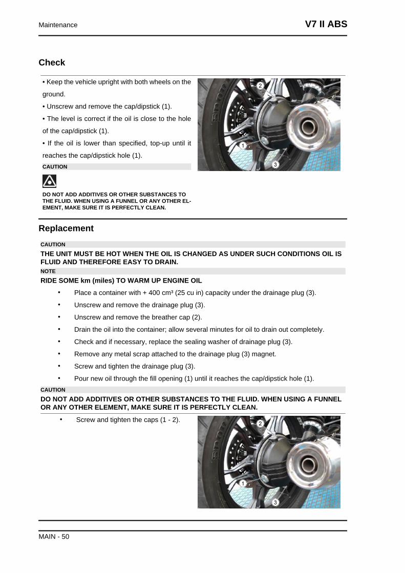
Check
• Keep the vehicle upright with both wheels on the
ground.
• Unscrew and remove the cap/dipstick (1).
• The level is correct if the oil is close to the hole
of the cap/dipstick (1).
• If the oil is lower than specified, top-up until it
reaches the cap/dipstick hole (1).CAUTION
DO NOT ADD ADDITIVES OR OTHER SUBSTANCES TOTHE FLUID. WHEN USING A FUNNEL OR ANY OTHER EL-EMENT, MAKE SURE IT IS PERFECTLY CLEAN.
ReplacementCAUTION
THE UNIT MUST BE HOT WHEN THE OIL IS CHANGED AS UNDER SUCH CONDITIONS OIL ISFLUID AND THEREFORE EASY TO DRAIN.NOTE
RIDE SOME km (miles) TO WARM UP ENGINE OIL• Place a container with + 400 cm³ (25 cu in) capacity under the drainage plug (3).
• Unscrew and remove the drainage plug (3).
• Unscrew and remove the breather cap (2).
• Drain the oil into the container; allow several minutes for oil to drain out completely.
• Check and if necessary, replace the sealing washer of drainage plug (3).
• Remove any metal scrap attached to the drainage plug (3) magnet.
• Screw and tighten the drainage plug (3).
• Pour new oil through the fill opening (1) until it reaches the cap/dipstick hole (1).CAUTION
DO NOT ADD ADDITIVES OR OTHER SUBSTANCES TO THE FLUID. WHEN USING A FUNNELOR ANY OTHER ELEMENT, MAKE SURE IT IS PERFECTLY CLEAN.
• Screw and tighten the caps (1 - 2).
Maintenance V7 II ABS
MAIN - 50
Engine oil
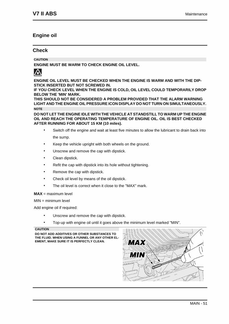
CheckCAUTION
ENGINE MUST BE WARM TO CHECK ENGINE OIL LEVEL.
ENGINE OIL LEVEL MUST BE CHECKED WHEN THE ENGINE IS WARM AND WITH THE DIP-STICK INSERTED BUT NOT SCREWED IN.IF YOU CHECK LEVEL WHEN THE ENGINE IS COLD, OIL LEVEL COULD TEMPORARILY DROPBELOW THE 'MIN' MARK.THIS SHOULD NOT BE CONSIDERED A PROBLEM PROVIDED THAT THE ALARM WARNINGLIGHT AND THE ENGINE OIL PRESSURE ICON DISPLAY DO NOT TURN ON SIMULTANEOUSLY.NOTE
DO NOT LET THE ENGINE IDLE WITH THE VEHICLE AT STANDSTILL TO WARM UP THE ENGINEOIL AND REACH THE OPERATING TEMPERATURE OF ENGINE OIL. OIL IS BEST CHECKEDAFTER RUNNING FOR ABOUT 15 KM (10 miles).
• Switch off the engine and wait at least five minutes to allow the lubricant to drain back into
the sump.
• Keep the vehicle upright with both wheels on the ground.
• Unscrew and remove the cap with dipstick.
• Clean dipstick.
• Refit the cap with dipstick into its hole without tightening.
• Remove the cap with dipstick.
• Check oil level by means of the oil dipstick.
• The oil level is correct when it close to the "MAX" mark.
MAX = maximum level
MIN = minimum level
Add engine oil if required:
• Unscrew and remove the cap with dipstick.
• Top-up with engine oil until it goes above the minimum level marked "MIN".CAUTIONDO NOT ADD ADDITIVES OR OTHER SUBSTANCES TOTHE FLUID. WHEN USING A FUNNEL OR ANY OTHER EL-EMENT, MAKE SURE IT IS PERFECTLY CLEAN.
V7 II ABS Maintenance
MAIN - 51
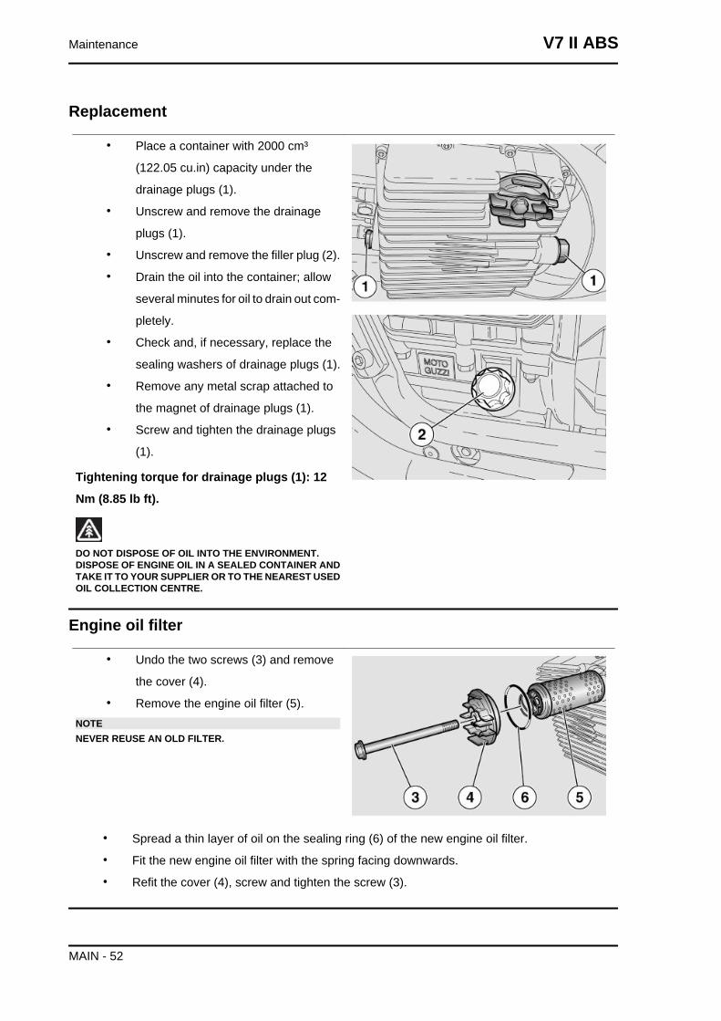
Replacement
• Place a container with 2000 cm³
(122.05 cu.in) capacity under the
drainage plugs (1).
• Unscrew and remove the drainage
plugs (1).
• Unscrew and remove the filler plug (2).
• Drain the oil into the container; allow
several minutes for oil to drain out com-
pletely.
• Check and, if necessary, replace the
sealing washers of drainage plugs (1).
• Remove any metal scrap attached to
the magnet of drainage plugs (1).
• Screw and tighten the drainage plugs
(1).
Tightening torque for drainage plugs (1): 12
Nm (8.85 lb ft).
DO NOT DISPOSE OF OIL INTO THE ENVIRONMENT.DISPOSE OF ENGINE OIL IN A SEALED CONTAINER ANDTAKE IT TO YOUR SUPPLIER OR TO THE NEAREST USEDOIL COLLECTION CENTRE.
Engine oil filter
• Undo the two screws (3) and remove
the cover (4).
• Remove the engine oil filter (5).NOTENEVER REUSE AN OLD FILTER.
• Spread a thin layer of oil on the sealing ring (6) of the new engine oil filter.
• Fit the new engine oil filter with the spring facing downwards.
• Refit the cover (4), screw and tighten the screw (3).
Maintenance V7 II ABS
MAIN - 52
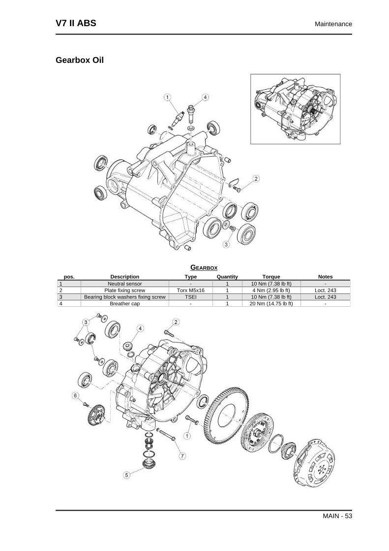
Gearbox Oil
GEARBOXpos. Description Type Quantity Torque Notes
1 Neutral sensor - 1 10 Nm (7.38 lb ft) -2 Plate fixing screw Torx M5x16 1 4 Nm (2.95 lb ft) Loct. 2433 Bearing block washers fixing screw TSEI 1 10 Nm (7.38 lb ft) Loct. 2434 Breather cap - 1 20 Nm (14.75 lb ft) -
V7 II ABS Maintenance
MAIN - 53
CLUTCH Ipos. Description Type Quantity Torque Notes
1 Crown screws M6x16 6 10 Nm (7.38 lb ft) Loctite 2432 Gearbox screws M8x35 5 25 Nm (18.44 lb ft) -3 Bearing block washers fixing screws TSEI 4 10 Nm (7.38 lb ft) Loct. 2434 Oil load cap - 1 25 Nm (18.44 lb ft) -5 Oil filter cap - 1 .. Nm (... lb ft) -6 Oil pump fixing screw Torx M5x16 1 6 Nm (4.42 lb ft) Loct. 2437 Gearbox fixing screws TCEI M6x55 14 10 Nm (7.38 lb ft) -
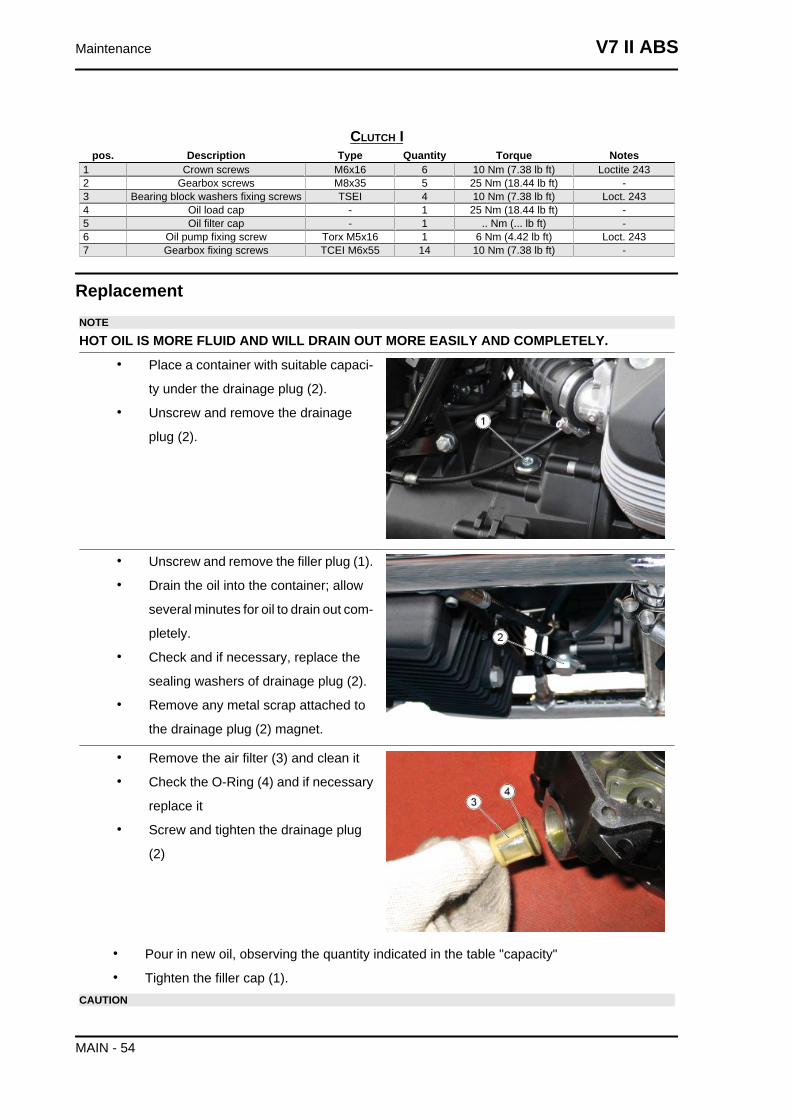
ReplacementNOTE
HOT OIL IS MORE FLUID AND WILL DRAIN OUT MORE EASILY AND COMPLETELY.• Place a container with suitable capaci-
ty under the drainage plug (2).
• Unscrew and remove the drainage
plug (2).
• Unscrew and remove the filler plug (1).
• Drain the oil into the container; allow
several minutes for oil to drain out com-
pletely.
• Check and if necessary, replace the
sealing washers of drainage plug (2).
• Remove any metal scrap attached to
the drainage plug (2) magnet.
• Remove the air filter (3) and clean it
• Check the O-Ring (4) and if necessary
replace it
• Screw and tighten the drainage plug
(2)
• Pour in new oil, observing the quantity indicated in the table "capacity"
• Tighten the filler cap (1).CAUTION
Maintenance V7 II ABS
MAIN - 54
DO NOT ADD ADDITIVES OR OTHER SUBSTANCES TO THE FLUID. WHEN USING A FUNNELOR ANY OTHER ELEMENT, MAKE SURE IT IS PERFECTLY CLEAN.
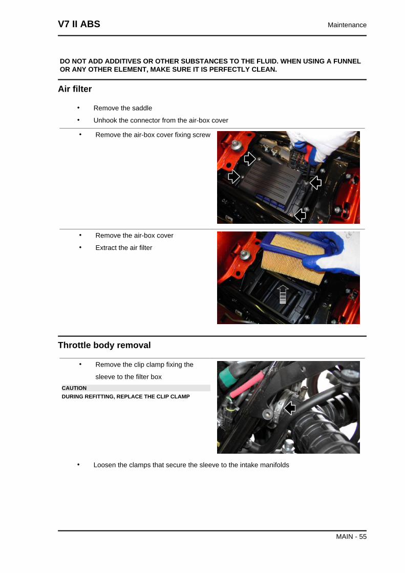
Air filter
• Remove the saddle
• Unhook the connector from the air-box cover
• Remove the air-box cover fixing screw
• Remove the air-box cover
• Extract the air filter
Throttle body removal
• Remove the clip clamp fixing the
sleeve to the filter boxCAUTIONDURING REFITTING, REPLACE THE CLIP CLAMP
• Loosen the clamps that secure the sleeve to the intake manifolds
V7 II ABS Maintenance
MAIN - 55
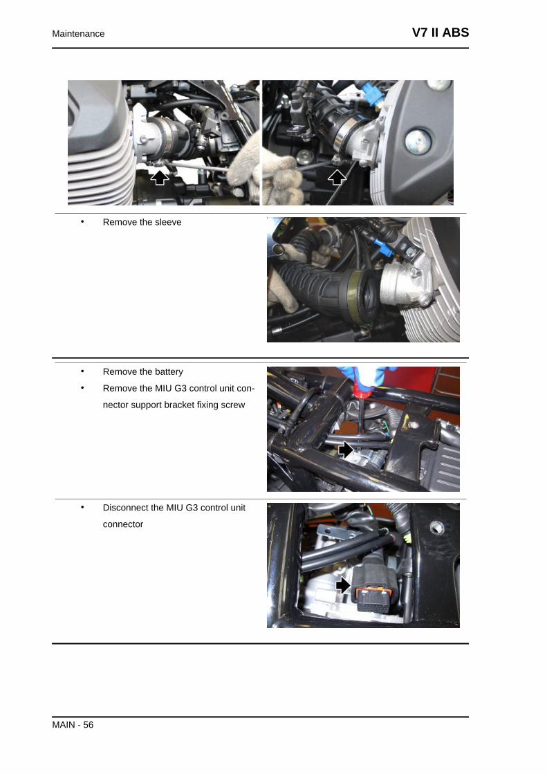
• Remove the sleeve
• Remove the battery
• Remove the MIU G3 control unit con-
nector support bracket fixing screw
• Disconnect the MIU G3 control unit
connector
Maintenance V7 II ABS
MAIN - 56
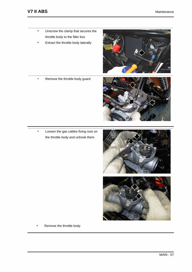
• Unscrew the clamp that secures the
throttle body to the filter box
• Extract the throttle body laterally
• Remove the throttle body guard
• Loosen the gas cables fixing nuts on
the throttle body and unhook them
• Remove the throttle body
V7 II ABS Maintenance
MAIN - 57
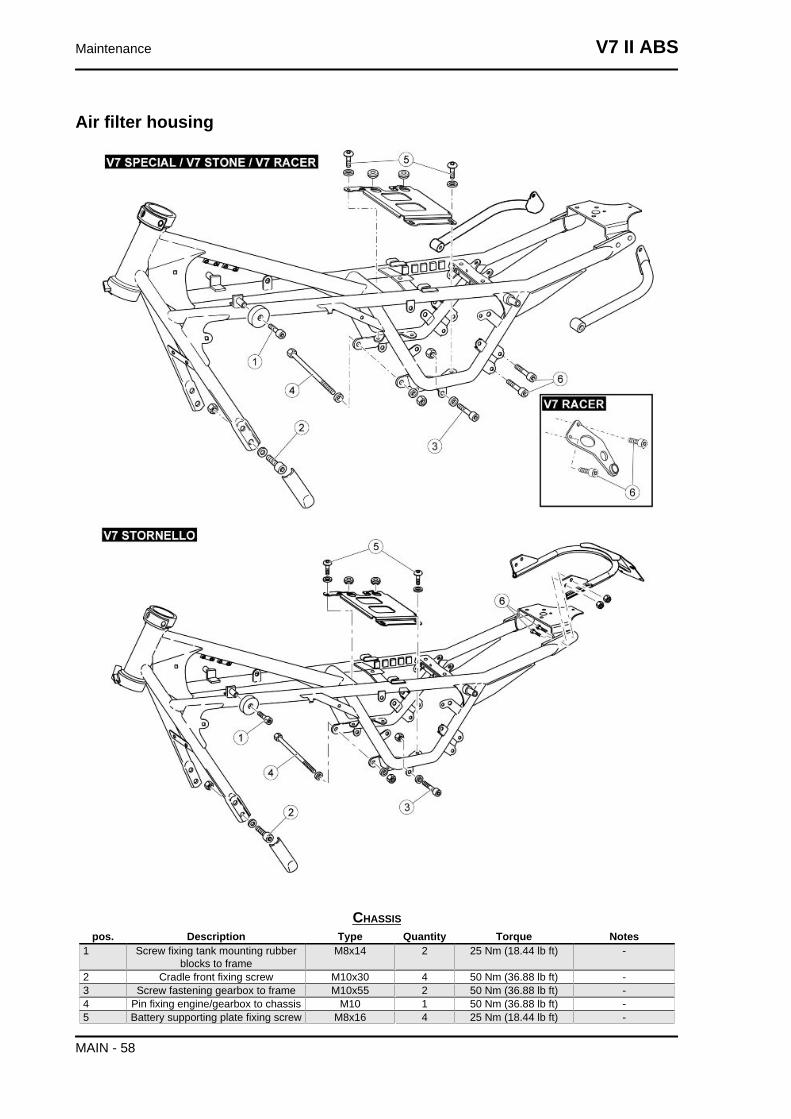
Air filter housing
CHASSISpos. Description Type Quantity Torque Notes
1 Screw fixing tank mounting rubberblocks to frame
M8x14 2 25 Nm (18.44 lb ft) -
2 Cradle front fixing screw M10x30 4 50 Nm (36.88 lb ft) -3 Screw fastening gearbox to frame M10x55 2 50 Nm (36.88 lb ft) -4 Pin fixing engine/gearbox to chassis M10 1 50 Nm (36.88 lb ft) -5 Battery supporting plate fixing screw M8x16 4 25 Nm (18.44 lb ft) -
Maintenance V7 II ABS
MAIN - 58
pos. Description Type Quantity Torque Notes6 Screw fixing license plate holder arc
to chassis (Stornello)M8 2 + 2 25 Nm (18.44 lb ft) -
6 Screw fixing exhaust silencer mount-ing to frame (Special/Stone/Racer)
M8x16 4 25 Nm (18.44 lb ft) Loctite 243
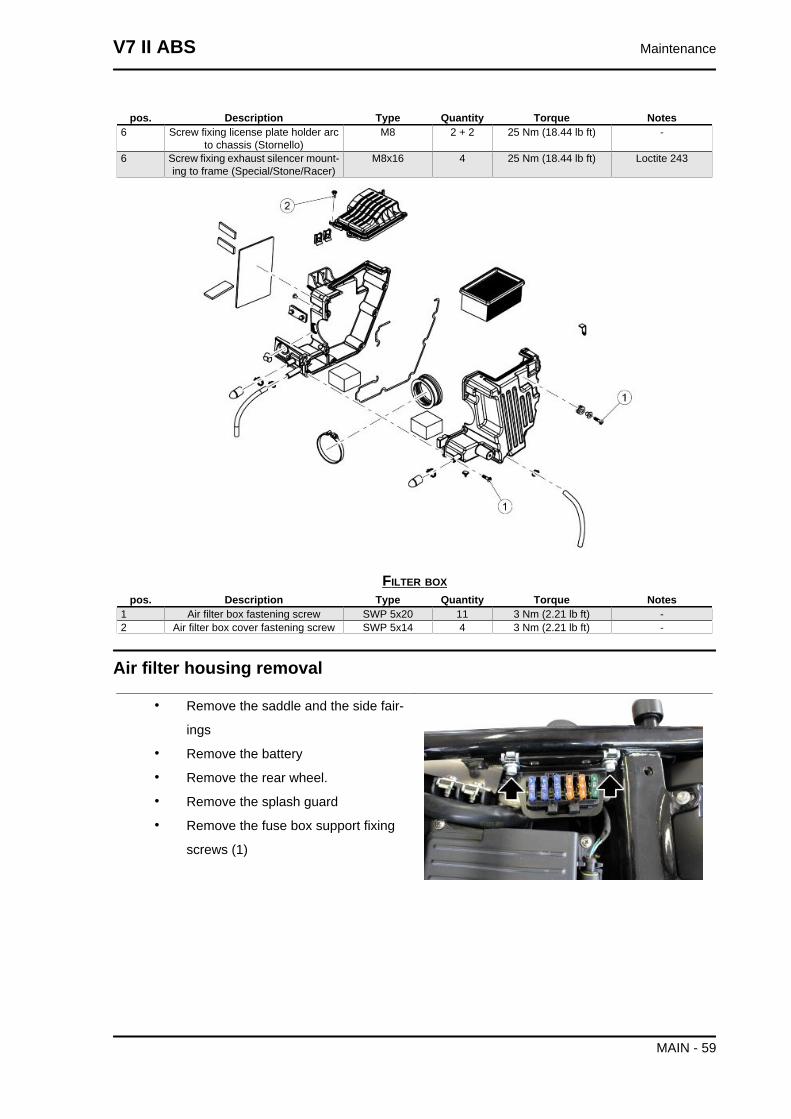
FILTER BOXpos. Description Type Quantity Torque Notes
1 Air filter box fastening screw SWP 5x20 11 3 Nm (2.21 lb ft) -2 Air filter box cover fastening screw SWP 5x14 4 3 Nm (2.21 lb ft) -
Air filter housing removal
• Remove the saddle and the side fair-
ings
• Remove the battery
• Remove the rear wheel.
• Remove the splash guard
• Remove the fuse box support fixing
screws (1)
V7 II ABS Maintenance
MAIN - 59
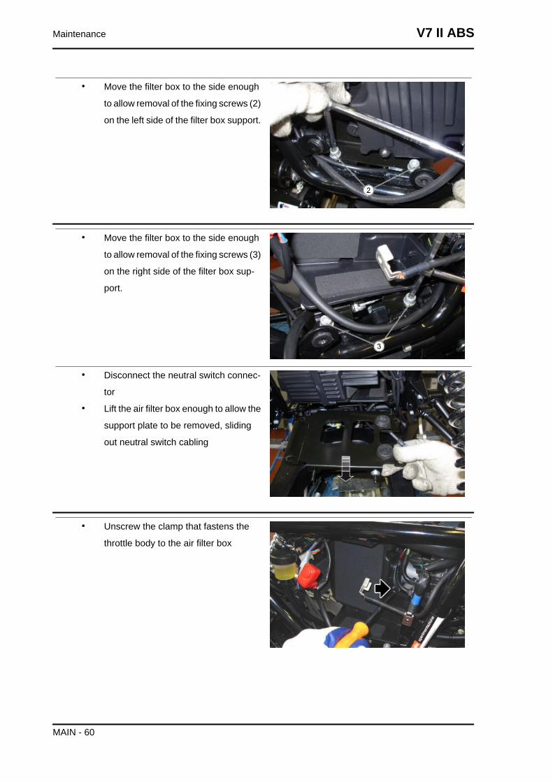
• Move the filter box to the side enough
to allow removal of the fixing screws (2)
on the left side of the filter box support.
• Move the filter box to the side enough
to allow removal of the fixing screws (3)
on the right side of the filter box sup-
port.
• Disconnect the neutral switch connec-
tor
• Lift the air filter box enough to allow the
support plate to be removed, sliding
out neutral switch cabling
• Unscrew the clamp that fastens the
throttle body to the air filter box
Maintenance V7 II ABS
MAIN - 60
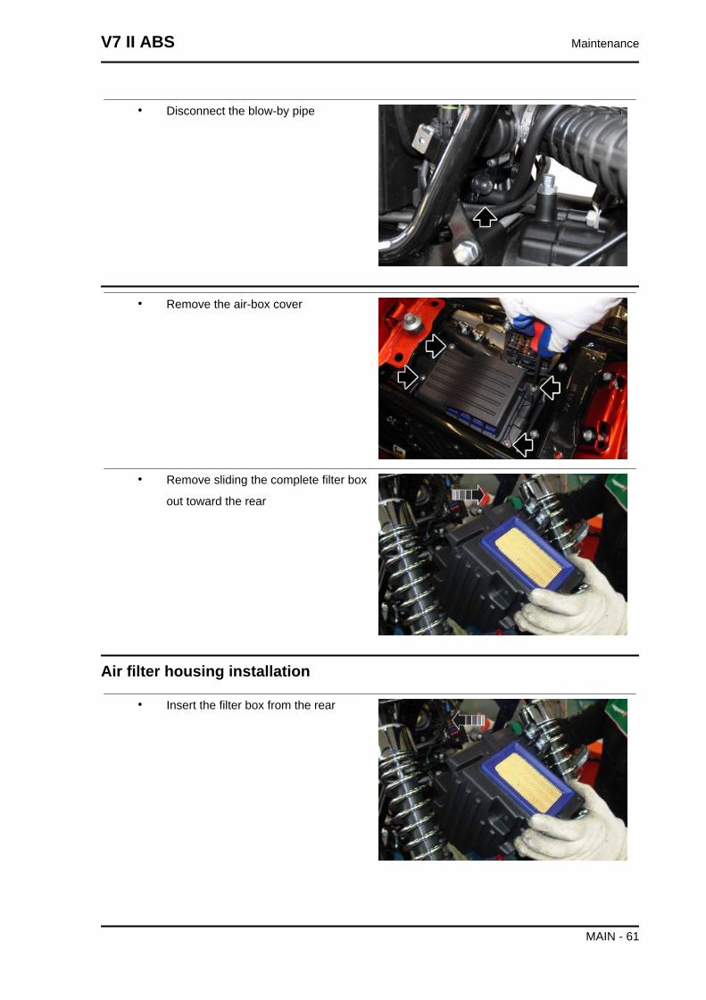
• Disconnect the blow-by pipe
• Remove the air-box cover
• Remove sliding the complete filter box
out toward the rear
Air filter housing installation
• Insert the filter box from the rear
V7 II ABS Maintenance
MAIN - 61
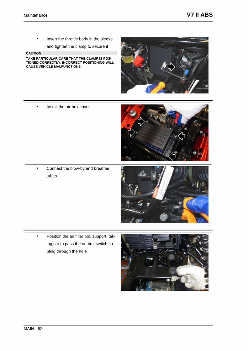
• Insert the throttle body in the sleeve
and tighten the clamp to secure itCAUTIONTAKE PARTICULAR CARE THAT THE CLAMP IS POSI-TIONED CORRECTLY. INCORRECT POSITIONING WILLCAUSE VEHICLE MALFUNCTIONS
• Install the air-box cover
• Connect the blow-by and breather
tubes
• Position the air filter box support, tak-
ing car to pass the neutral switch ca-
bling through the hole
Maintenance V7 II ABS
MAIN - 62
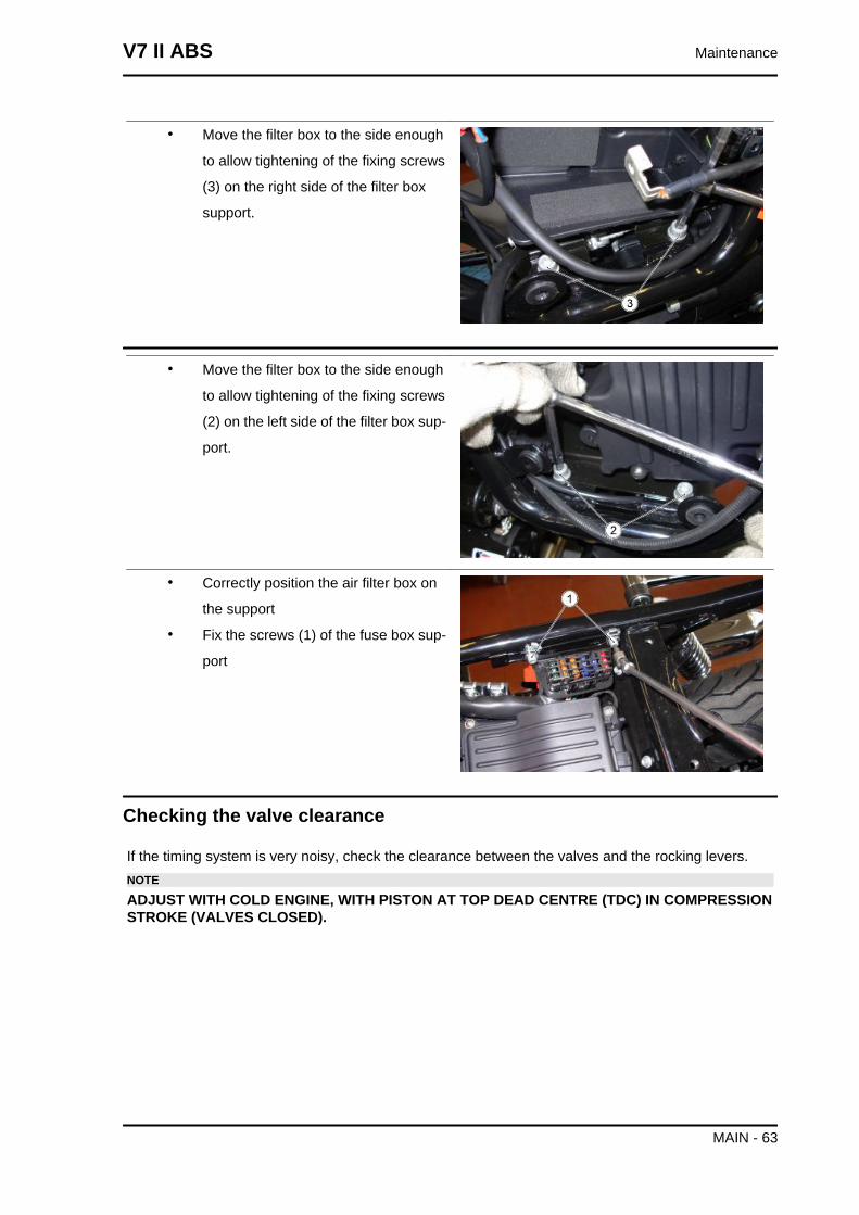
• Move the filter box to the side enough
to allow tightening of the fixing screws
(3) on the right side of the filter box
support.
• Move the filter box to the side enough
to allow tightening of the fixing screws
(2) on the left side of the filter box sup-
port.
• Correctly position the air filter box on
the support
• Fix the screws (1) of the fuse box sup-
port
Checking the valve clearance
If the timing system is very noisy, check the clearance between the valves and the rocking levers.NOTE
ADJUST WITH COLD ENGINE, WITH PISTON AT TOP DEAD CENTRE (TDC) IN COMPRESSIONSTROKE (VALVES CLOSED).
V7 II ABS Maintenance
MAIN - 63
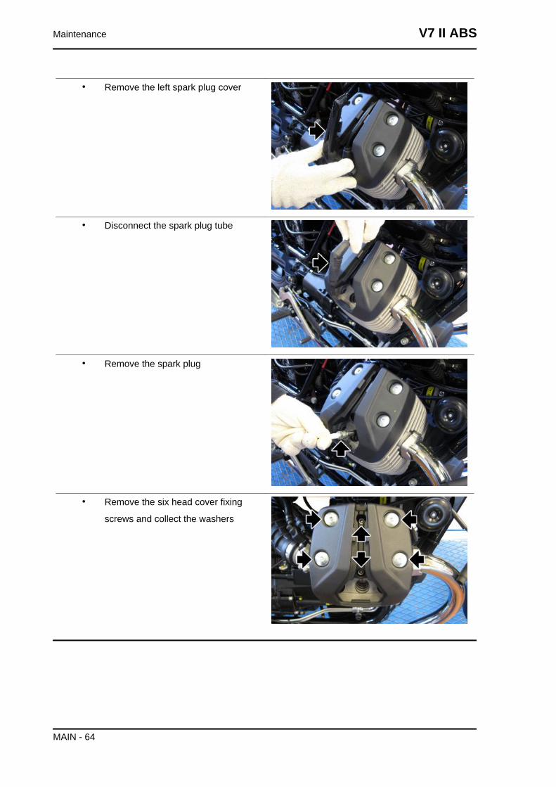
• Remove the left spark plug cover
• Disconnect the spark plug tube
• Remove the spark plug
• Remove the six head cover fixing
screws and collect the washers
Maintenance V7 II ABS
MAIN - 64
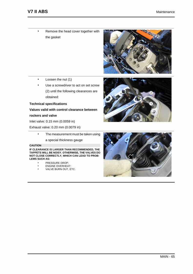
• Remove the head cover together with
the gasket
• Loosen the nut (1)
• Use a screwdriver to act on set screw
(2) until the following clearances are
obtained:
Technical specifications
Values valid with control clearance between
rockers and valve
Inlet valve: 0.15 mm (0.0059 in)
Exhaust valve: 0.20 mm (0.0079 in)
• The measurement must be taken using
a special thickness gaugeCAUTIONIF CLEARANCE IS LARGER THAN RECOMMENDED, THETAPPETS WILL BE NOISY. OTHERWISE, THE VALVES DONOT CLOSE CORRECTLY, WHICH CAN LEAD TO PROB-LEMS SUCH AS:
• PRESSURE DROP;• ENGINE OVERHEAT;• VALVE BURN OUT, ETC.
V7 II ABS Maintenance
MAIN - 65
Braking system
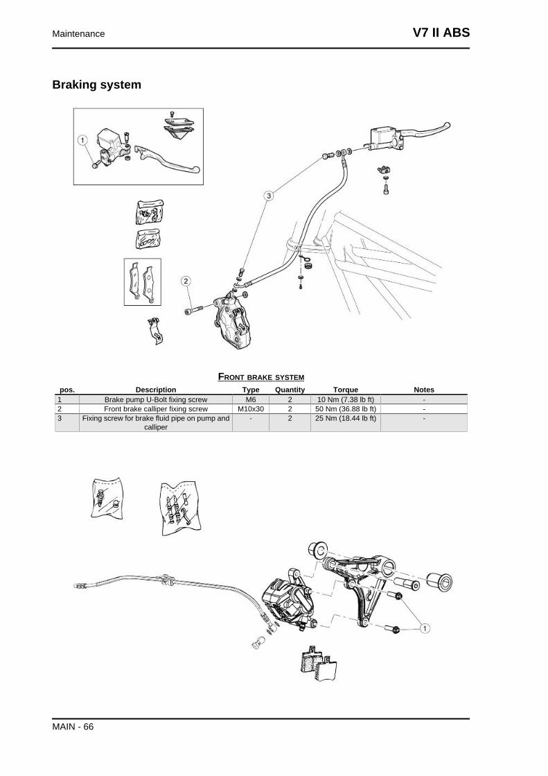
FRONT BRAKE SYSTEMpos. Description Type Quantity Torque Notes
1 Brake pump U-Bolt fixing screw M6 2 10 Nm (7.38 lb ft) -2 Front brake calliper fixing screw M10x30 2 50 Nm (36.88 lb ft) -3 Fixing screw for brake fluid pipe on pump and
calliper- 2 25 Nm (18.44 lb ft) -
Maintenance V7 II ABS
MAIN - 66
REAR BRAKE CALLIPERpos. Description Type Quantity Torque Notes
1 Rear brake calliper fixing screw M8x30 2 25 Nm (18.44 lb ft) -- Drilled screw for brake pipe on cal-
liper- 1 25 Nm (18.44 lb ft) -
Level check
Brake fluid check
• Rest the vehicle on its stand.
• For the front brake, turn the handlebar fully to the right.
• For the rear brake, keep the vehicle upright so that the fluid in the reservoir is at the same
level with the plug.
• Make sure that the fluid level in the reservoir is above the "MIN" reference mark:
MIN = minimum level
MAX = maximum level
If the fluid does not reach at least the "MIN" reference mark:
• Check brake pads and disc for wear.
• If the pads and/or the disc do not need replacing, top-up the fluid.
Top-up
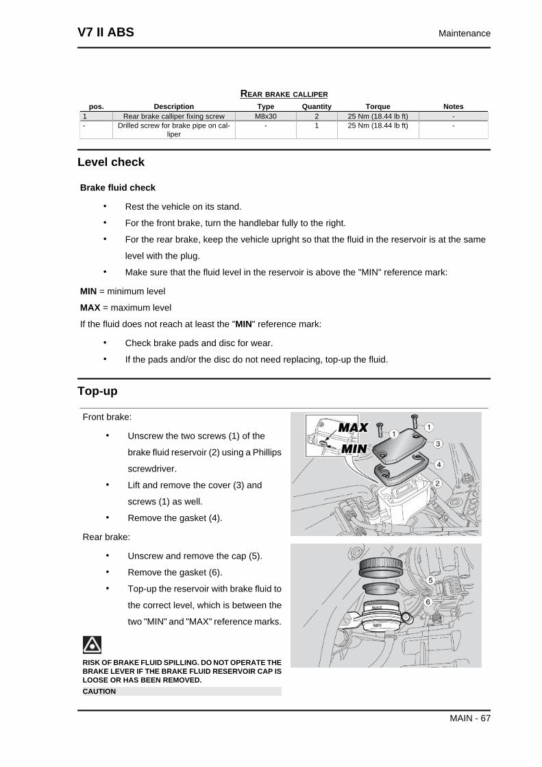
Front brake:
• Unscrew the two screws (1) of the
brake fluid reservoir (2) using a Phillips
screwdriver.
• Lift and remove the cover (3) and
screws (1) as well.
• Remove the gasket (4).
Rear brake:
• Unscrew and remove the cap (5).
• Remove the gasket (6).
• Top-up the reservoir with brake fluid to
the correct level, which is between the
two "MIN" and "MAX" reference marks.
RISK OF BRAKE FLUID SPILLING. DO NOT OPERATE THEBRAKE LEVER IF THE BRAKE FLUID RESERVOIR CAP ISLOOSE OR HAS BEEN REMOVED.CAUTION
V7 II ABS Maintenance
MAIN - 67
AVOID PROLONGED AIR EXPOSURE OF THE BRAKEFLUID. BRAKE FLUID IS HYGROSCOPIC AND ABSORBSMOISTURE WHEN IN CONTACT WITH AIR. LEAVE THEBRAKE FLUID RESERVOIR OPEN ONLY FOR THE TIMENEEDED TO COMPLETE THE TOPPING-UP PROCEDURE.
TO AVOID SPILLING FLUID WHILE TOPPING-UP, KEEPTHE TANK PARALLEL TO THE RESERVOIR EDGE (INHORIZONTAL POSITION).
DO NOT ADD ADDITIVES OR OTHER SUBSTANCES TOTHE FLUID.
WHEN USING A FUNNEL OR ANY OTHER ELEMENT,MAKE SURE IT IS PERFECTLY CLEAN.
DO NOT EXCEED THE "MAX" LEVEL MARK WHEN TOP-PING UP.TOP-UP TO "MAX" LEVEL MARK ONLY WHEN BRAKEPADS ARE NEW. WHEN TOPPING UP DO NOT EXCEEDTHE "MAX" LEVEL MARK WHEN BRAKE PADS AREWORN AS YOU RISK SPILLING FLUID WHEN CHANGINGTHE BRAKE PADS.CHECK BRAKING EFFICIENCY. IN CASE OF EXCESSIVETRAVEL OF THE BRAKE LEVER OR POOR PERFORM-ANCE OF THE BRAKING SYSTEM, TAKE YOUR VEHICLETO AN Official Moto Guzzi Dealer, AS IT MAY BE NECES-SARY TO PURGE THE AIR IN THE SYSTEM.
Maintenance V7 II ABS
MAIN - 68

INDEX OF TOPICS
ELECTRICAL SYSTEM ELE SYS
ELECTRICAL SYSTEM 01pos. Description Type Quantity Torque Notes
1 Speed sensor fastening screw M6 1 10 Nm (7.38 lb ft)2 Coil retainer nut M6 2 + 2 10 Nm (7.38 lb ft) -- Voltage regulator fixing screw M6 2 10 Nm (7.38 lb ft) -- Control unit cable grommet fixing M4 1 4 Nm (2.95 lb ft) Thread-form-
ing screws
Electrical system V7 II ABS
ELE SYS - 70
ELECTRICAL SYSTEM 02pos. Description Type Quantity Torque Notes
1 Fuse box bracket fixing screw M5x12 2 4 Nm (2.95 lb ft) -2 Battery holder bracket fastening screw M6 2 Manual -
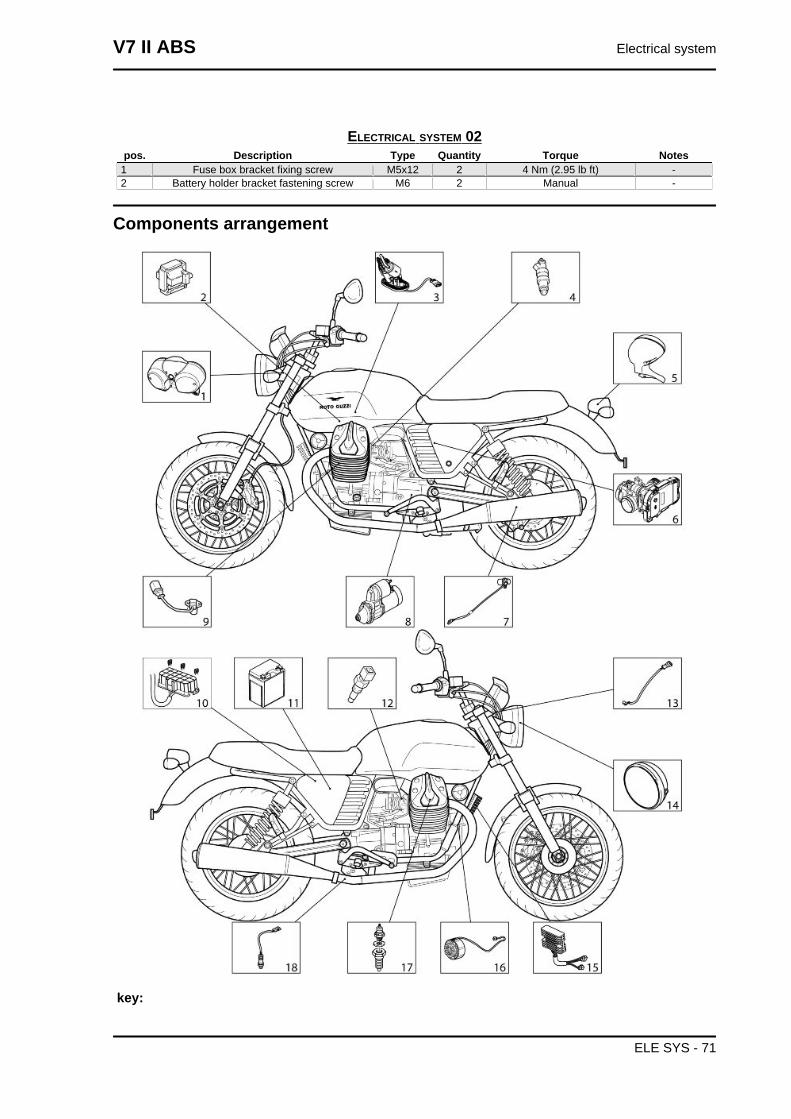
Components arrangement
key:
V7 II ABS Electrical system
ELE SYS - 71
1. Instrument panel
2. Coil
3. Fuel pump
4. Injector
5. Taillight
6. MIU G3 Control Unit
7. Speed sensor
8. Starter motor
9. Engine speed sensor
10.Fuses
11.Battery
12.Head temperature sensor
13.Instrument panel air sensor
14.Headlamp
15.Voltage regulator
16.Alternator
17.Oil pressure sensor
18.Lambda probes
Electrical system installation
INTRODUCTION
Scope and applicability
The position of the cable harnesses, how they are fixed to the motorcycle and potential problems are
defined on the following sections in order to reach the objectives of vehicle reliability.
Materials used and corresponding quantities
The electrical system consists of the following cable harnesses and parts:
• 1 Main Cable Harness
• 1 Ground cable Negative - Engine
• 1 Left H.V. Cable
• 1 Left H.V. Cable Sheath (Grey)
• 1 Right H.V. Cable.
• 1 Right H.V. Cable Sheath (Black)
• 3 Relays 12V 30A
• 1 Pull Up Module (resistance-diode)
• 1 Stand switch
• 2 Lambda probes
• 2 CAI Plug Caps
Electrical system V7 II ABS
ELE SYS - 72
• 1 shield
Small parts and mountings
• Large black 290x4.5 clamps
• Medium black 190x4.5 clamps
• Small black 160x2.5 clamps
• Cable guide
• Cable grommet (there are various types of cable grommets)
• Profile guards (140mm long)
• Bracket Miu3
• SHC M8x40 screw
• Black sheath D16 S0.4.
• Cable guides (there are various types of cable guides)
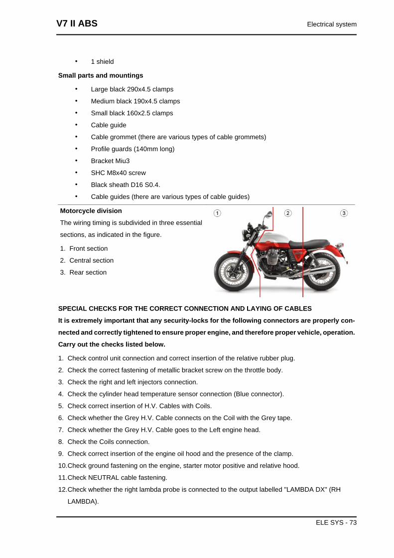
Motorcycle division
The wiring timing is subdivided in three essential
sections, as indicated in the figure.
1. Front section
2. Central section
3. Rear section
SPECIAL CHECKS FOR THE CORRECT CONNECTION AND LAYING OF CABLES
It is extremely important that any security-locks for the following connectors are properly con-
nected and correctly tightened to ensure proper engine, and therefore proper vehicle, operation.
Carry out the checks listed below.
1. Check control unit connection and correct insertion of the relative rubber plug.
2. Check the correct fastening of metallic bracket screw on the throttle body.
3. Check the right and left injectors connection.
4. Check the cylinder head temperature sensor connection (Blue connector).
5. Check correct insertion of H.V. Cables with Coils.
6. Check whether the Grey H.V. Cable connects on the Coil with the Grey tape.
7. Check whether the Grey H.V. Cable goes to the Left engine head.
8. Check the Coils connection.
9. Check correct insertion of the engine oil hood and the presence of the clamp.
10.Check ground fastening on the engine, starter motor positive and relative hood.
11.Check NEUTRAL cable fastening.
12.Check whether the right lambda probe is connected to the output labelled "LAMBDA DX" (RH
LAMBDA).
V7 II ABS Electrical system
ELE SYS - 73
13.Check Regulator and Flywheel connection.
14.Check whether the right lambda probe is inserted on the cable grommet under the clutch housing.
15.Check right and left Lambda connections.
16.Check the presence of the Pull Up module and the presence of the black hose under the trans-
parent one.
17.Check the Pick Up connection.
18.Check correct insertion of the starter motor hood
19.Check the presence of the Red protective hood on the battery Positive.
20.Check that the stand switch connector is blue and clamped.
21.Check the side stand connection and left lambda.
22.Check that the H.V. cables are connected well to with the CAI plug caps.
23.Check the stand switch cable ties on the frame under the vehicle
24.Check that the key switch cable has no voltage
25.Check the speed sensors connections
26.Check the correct ABS connector connection
• THE ENCIRCLED CONNECTORS ARE CONSIDERED CRITICAL IN COMPARISON
WITH ANY OTHER BECAUSE THE VEHICLE WILL STOP OR PRESENT A MALFUNC-
TION IF THEY ARE ACCIDENTALLY DISCONNECTED.Undoubtedly the connection of the
rest of connectors is also important and essential for the correct operation of the vehicle. It
is also important and essential that the instructions regarding the routing and fixing of the
cable harness in the various areas are followed meticulously in order to guarantee func-
tionality and reliability
Front side
(V7 SPECIAL / V7 STONE / V7 STORNELLO)
Electrical system V7 II ABS
ELE SYS - 74
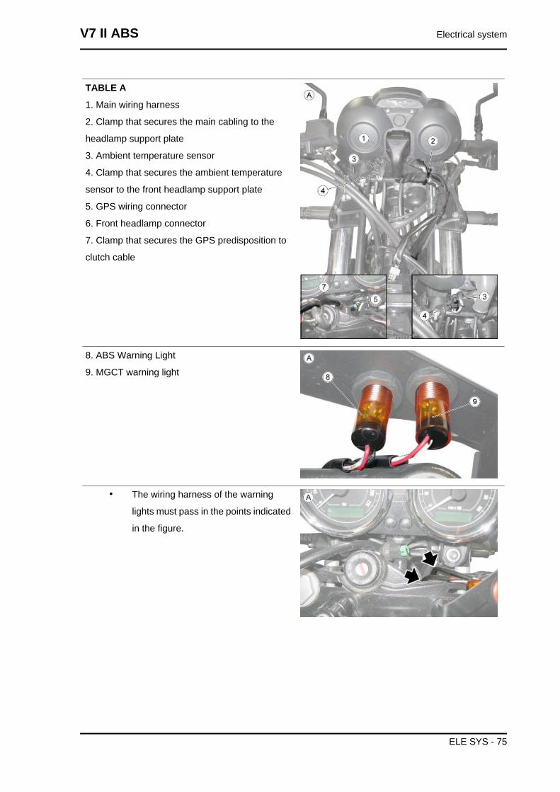
TABLE A
1. Main wiring harness
2. Clamp that secures the main cabling to the
headlamp support plate
3. Ambient temperature sensor
4. Clamp that secures the ambient temperature
sensor to the front headlamp support plate
5. GPS wiring connector
6. Front headlamp connector
7. Clamp that secures the GPS predisposition to
clutch cable
8. ABS Warning Light
9. MGCT warning light
• The wiring harness of the warning
lights must pass in the points indicated
in the figure.
V7 II ABS Electrical system
ELE SYS - 75
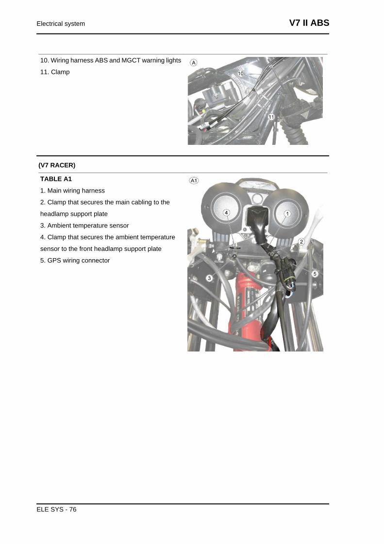
10. Wiring harness ABS and MGCT warning lights
11. Clamp
(V7 RACER)
TABLE A1
1. Main wiring harness
2. Clamp that secures the main cabling to the
headlamp support plate
3. Ambient temperature sensor
4. Clamp that secures the ambient temperature
sensor to the front headlamp support plate
5. GPS wiring connector
Electrical system V7 II ABS
ELE SYS - 76
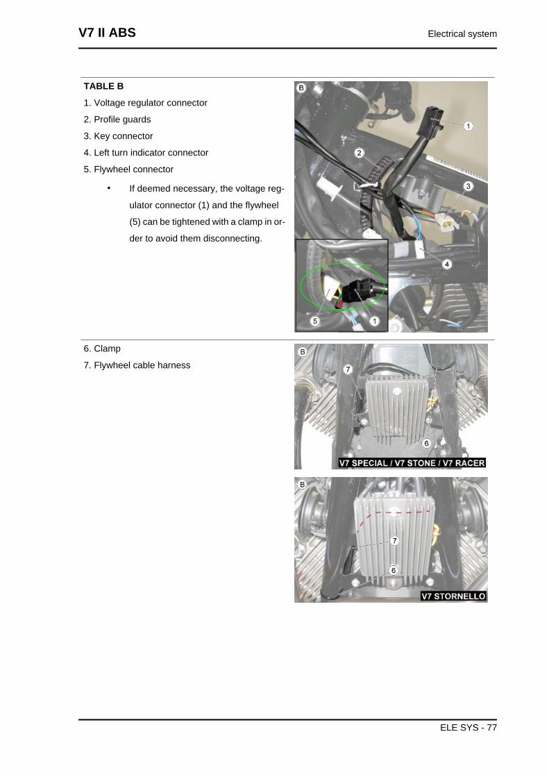
TABLE B
1. Voltage regulator connector
2. Profile guards
3. Key connector
4. Left turn indicator connector
5. Flywheel connector
• If deemed necessary, the voltage reg-
ulator connector (1) and the flywheel
(5) can be tightened with a clamp in or-
der to avoid them disconnecting.
6. Clamp
7. Flywheel cable harness
V7 II ABS Electrical system
ELE SYS - 77
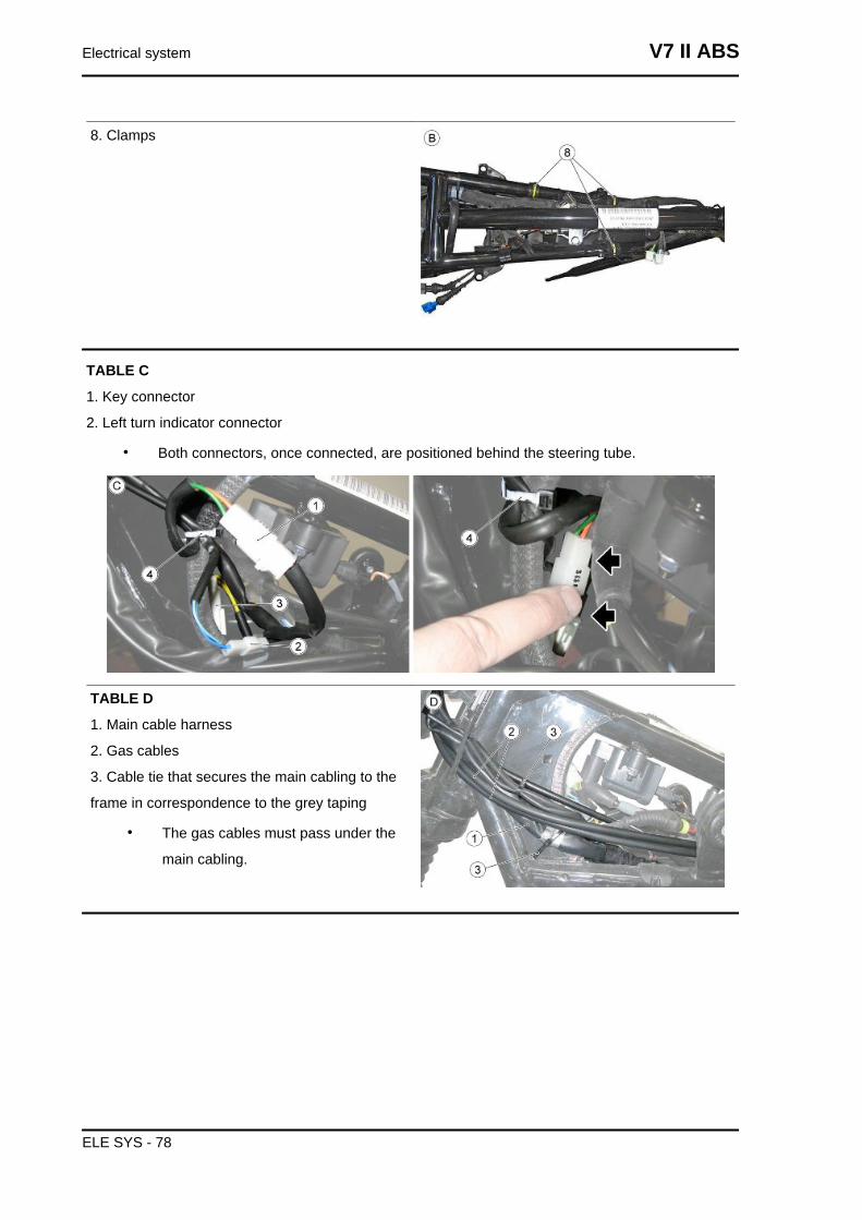
8. Clamps
TABLE C
1. Key connector
2. Left turn indicator connector
• Both connectors, once connected, are positioned behind the steering tube.
TABLE D
1. Main cable harness
2. Gas cables
3. Cable tie that secures the main cabling to the
frame in correspondence to the grey taping
• The gas cables must pass under the
main cabling.
Electrical system V7 II ABS
ELE SYS - 78
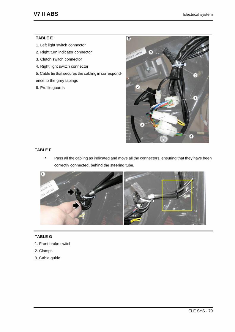
TABLE E
1. Left light switch connector
2. Right turn indicator connector
3. Clutch switch connector
4. Right light switch connector
5. Cable tie that secures the cabling in correspond-
ence to the grey tapings
6. Profile guards
TABLE F
• Pass all the cabling as indicated and move all the connectors, ensuring that they have been
correctly connected, behind the steering tube.
TABLE G
1. Front brake switch
2. Clamps
3. Cable guide
V7 II ABS Electrical system
ELE SYS - 79
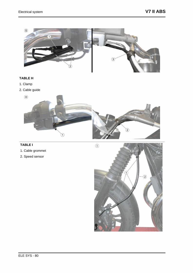
TABLE H
1. Clamp
2. Cable guide
TABLE I
1. Cable grommet
2. Speed sensor
Electrical system V7 II ABS
ELE SYS - 80
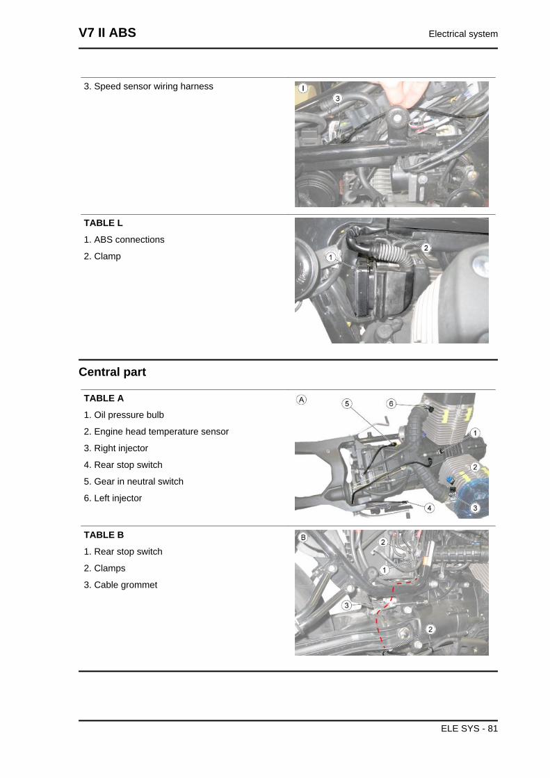
3. Speed sensor wiring harness
TABLE L
1. ABS connections
2. Clamp
Central part
TABLE A
1. Oil pressure bulb
2. Engine head temperature sensor
3. Right injector
4. Rear stop switch
5. Gear in neutral switch
6. Left injector
TABLE B
1. Rear stop switch
2. Clamps
3. Cable grommet
V7 II ABS Electrical system
ELE SYS - 81
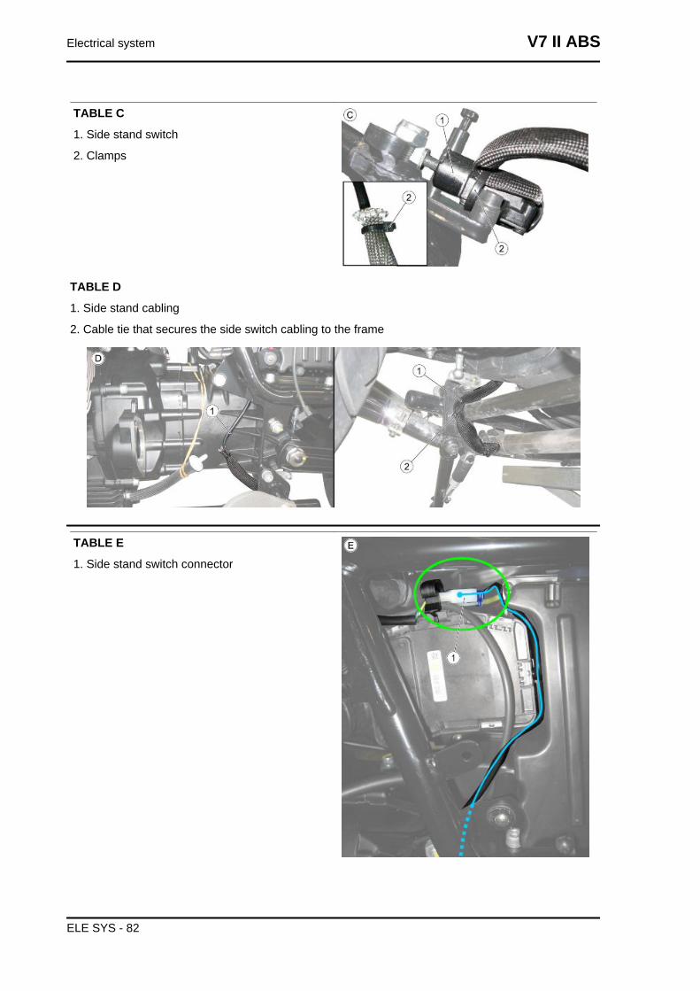
TABLE C
1. Side stand switch
2. Clamps
TABLE D
1. Side stand cabling
2. Cable tie that secures the side switch cabling to the frame
TABLE E
1. Side stand switch connector
Electrical system V7 II ABS
ELE SYS - 82
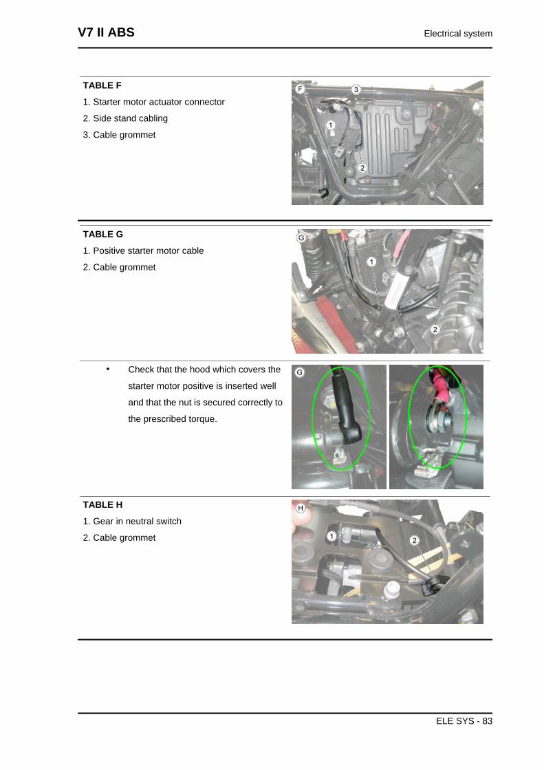
TABLE F
1. Starter motor actuator connector
2. Side stand cabling
3. Cable grommet
TABLE G
1. Positive starter motor cable
2. Cable grommet
• Check that the hood which covers the
starter motor positive is inserted well
and that the nut is secured correctly to
the prescribed torque.
TABLE H
1. Gear in neutral switch
2. Cable grommet
V7 II ABS Electrical system
ELE SYS - 83
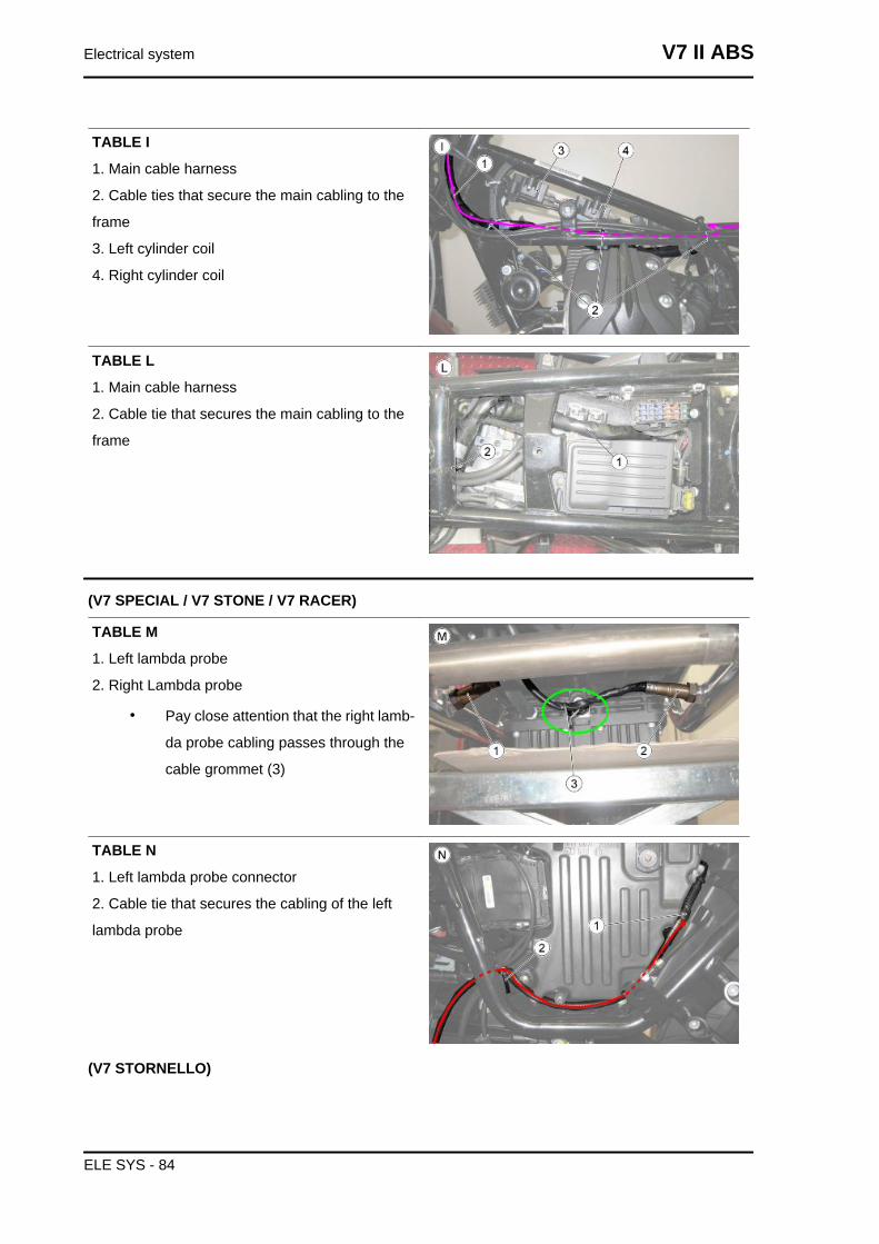
TABLE I
1. Main cable harness
2. Cable ties that secure the main cabling to the
frame
3. Left cylinder coil
4. Right cylinder coil
TABLE L
1. Main cable harness
2. Cable tie that secures the main cabling to the
frame
(V7 SPECIAL / V7 STONE / V7 RACER)
TABLE M
1. Left lambda probe
2. Right Lambda probe
• Pay close attention that the right lamb-
da probe cabling passes through the
cable grommet (3)
TABLE N
1. Left lambda probe connector
2. Cable tie that secures the cabling of the left
lambda probe
(V7 STORNELLO)
Electrical system V7 II ABS
ELE SYS - 84
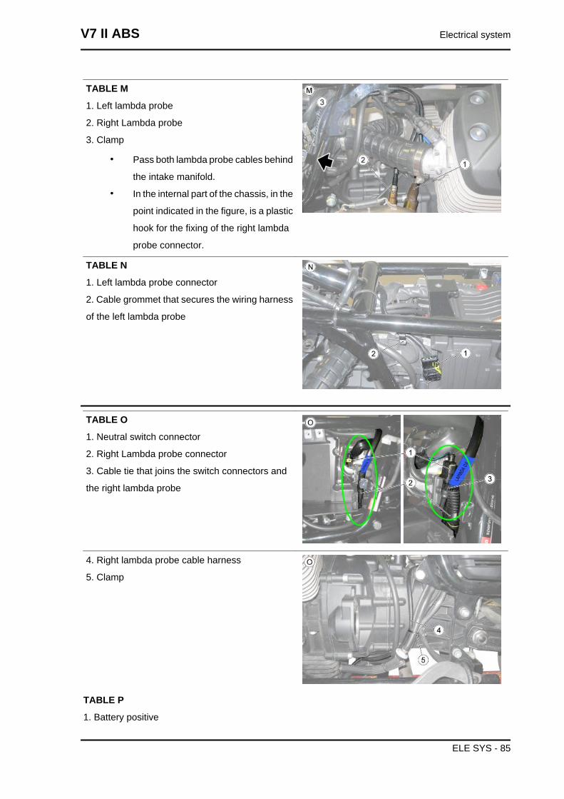
TABLE M
1. Left lambda probe
2. Right Lambda probe
3. Clamp
• Pass both lambda probe cables behind
the intake manifold.
• In the internal part of the chassis, in the
point indicated in the figure, is a plastic
hook for the fixing of the right lambda
probe connector.
TABLE N
1. Left lambda probe connector
2. Cable grommet that secures the wiring harness
of the left lambda probe
TABLE O
1. Neutral switch connector
2. Right Lambda probe connector
3. Cable tie that joins the switch connectors and
the right lambda probe
4. Right lambda probe cable harness
5. Clamp
TABLE P
1. Battery positive
V7 II ABS Electrical system
ELE SYS - 85
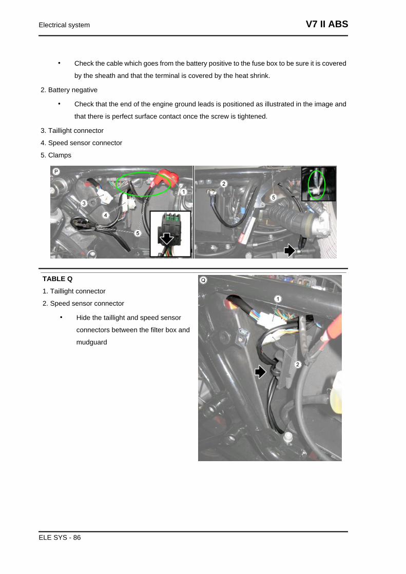
• Check the cable which goes from the battery positive to the fuse box to be sure it is covered
by the sheath and that the terminal is covered by the heat shrink.
2. Battery negative
• Check that the end of the engine ground leads is positioned as illustrated in the image and
that there is perfect surface contact once the screw is tightened.
3. Taillight connector
4. Speed sensor connector
5. Clamps
TABLE Q
1. Taillight connector
2. Speed sensor connector
• Hide the taillight and speed sensor
connectors between the filter box and
mudguard
Electrical system V7 II ABS
ELE SYS - 86
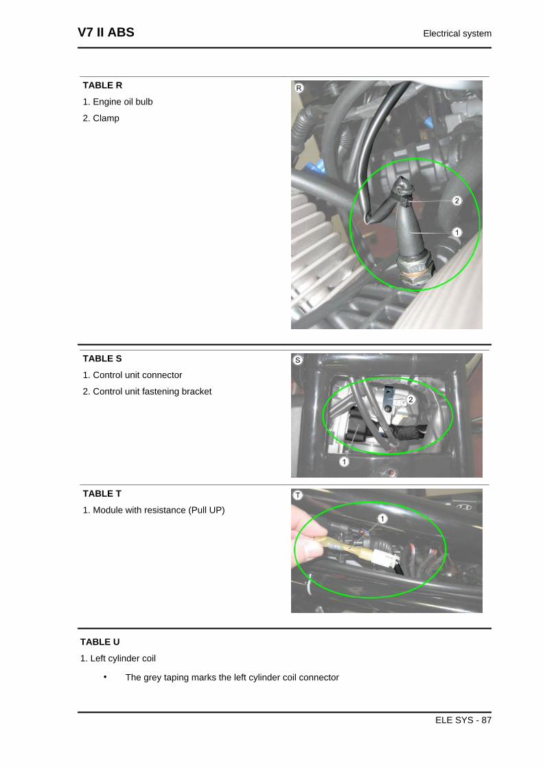
TABLE R
1. Engine oil bulb
2. Clamp
TABLE S
1. Control unit connector
2. Control unit fastening bracket
TABLE T
1. Module with resistance (Pull UP)
TABLE U
1. Left cylinder coil
• The grey taping marks the left cylinder coil connector
V7 II ABS Electrical system
ELE SYS - 87
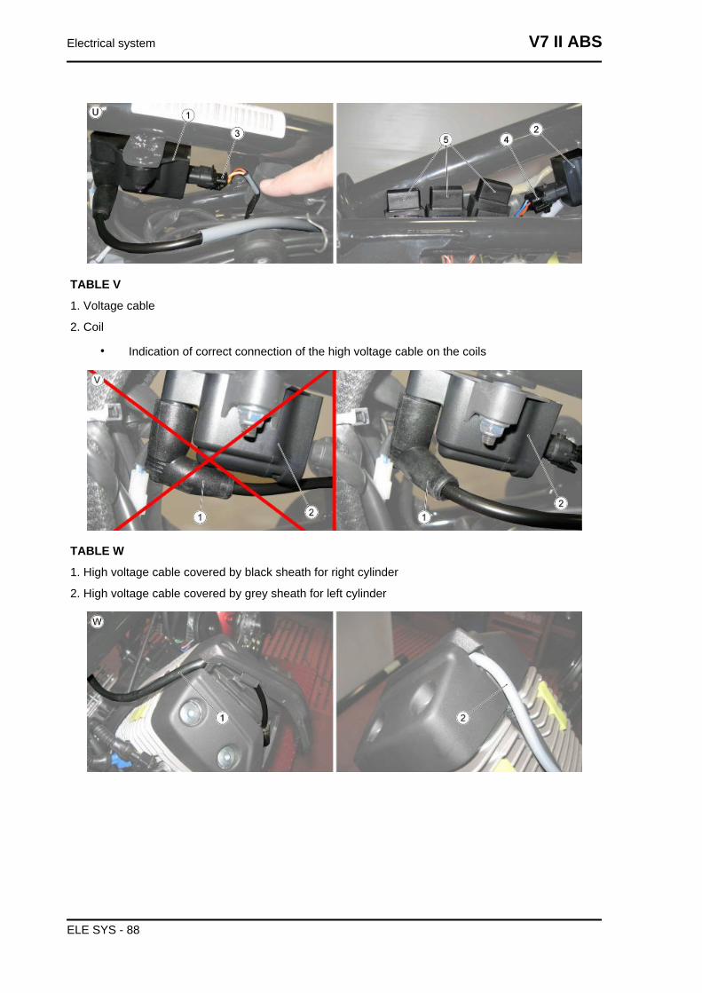
TABLE V
1. Voltage cable
2. Coil
• Indication of correct connection of the high voltage cable on the coils
TABLE W
1. High voltage cable covered by black sheath for right cylinder
2. High voltage cable covered by grey sheath for left cylinder
Electrical system V7 II ABS
ELE SYS - 88
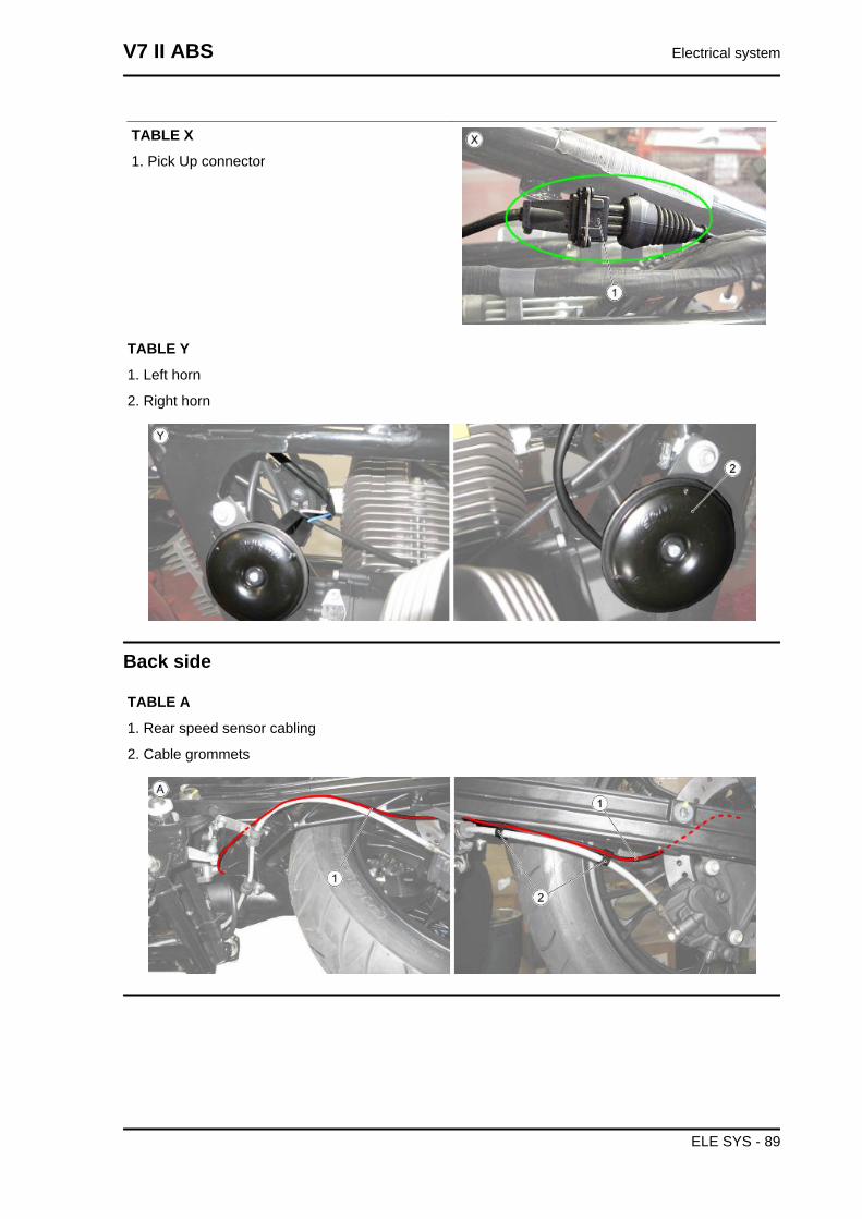
TABLE X
1. Pick Up connector
TABLE Y
1. Left horn
2. Right horn
Back side
TABLE A
1. Rear speed sensor cabling
2. Cable grommets
V7 II ABS Electrical system
ELE SYS - 89
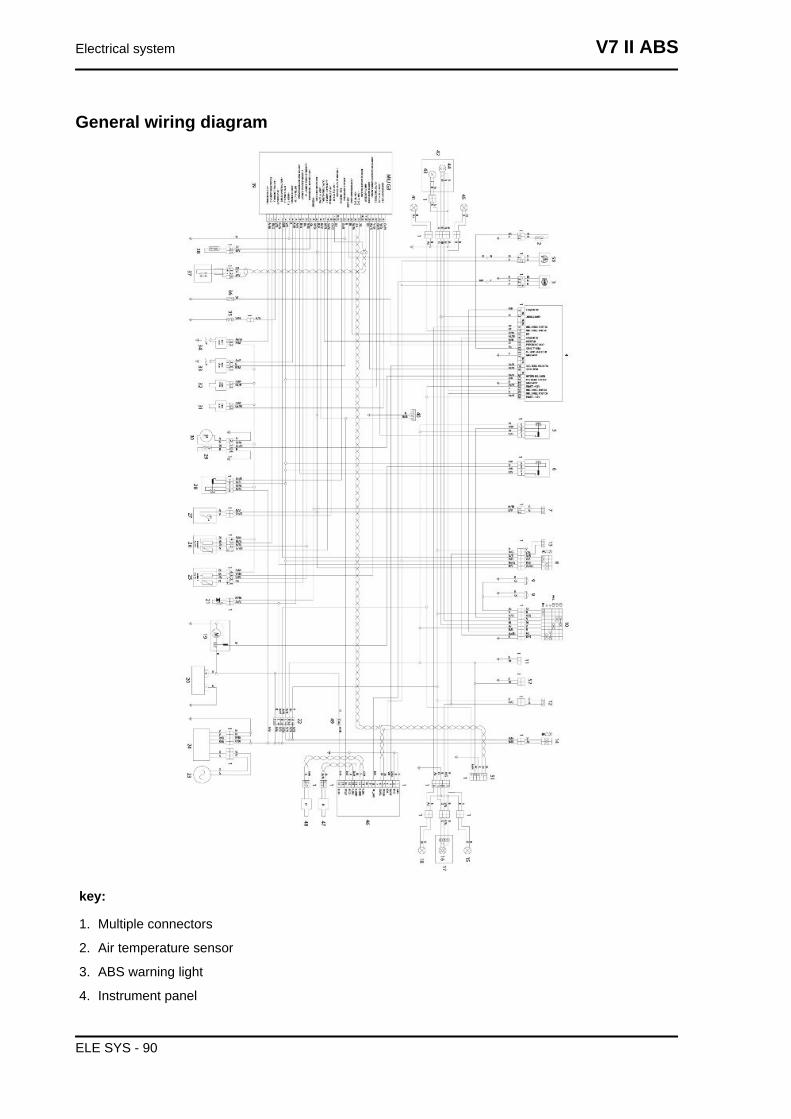
General wiring diagram
key:
1. Multiple connectors
2. Air temperature sensor
3. ABS warning light
4. Instrument panel
Electrical system V7 II ABS
ELE SYS - 90
5. Light relay
6. Starter motor relay
7. Clutch switch
8. Right hand light switch
9. Horn
10.Left light switch
11.GPS wiring
12.Rear stop switch
13.Front stop switch
14.Ignition switch
15.Rear right turn indicator
16.Stop - position bulb
17.Taillight
18.Rear left turn indicator
19.Starter motor
20.Battery
21.Pull Up (resistance)
22.Fuses
23.Flywheel
24.Regulator
25.Lambda 1 (left exhaust)
26.Lambda 2 (right exhaust)
27.Side stand switch
28.Injection load relay
29.Fuel reserve sensor
30.Fuel pump
31.Injector 1 (left cylinder)
32.Injector 2 (right cylinder)
33.Coil 2 (right cylinder)
34.Coil 1 (left cylinder)
35.Neutral sensor
36.Oil sensor
37.Pick UP
38.Engine head temperature sensor
39.MIU G3 control unit
40.Diagnosis
41.Front left turn indicator
42.Headlight
V7 II ABS Electrical system
ELE SYS - 91
43.Front position
44.High/low beam bulb
45.Front right turn indicator
46.ABS control unit
47.Front ABS sensor
48.Rear ABS sensor
49.ABS Fuse
50.MGCT warning light
51.Bluedash pre-installation
52.USB pre-installation
Cable colour:
Ar orange
Az sky blue
B blue
Bi white
G yellow
Gr grey
M brown
N black
R red
Ro pink
V green
Vi purple
Checks and inspections
Dashboard
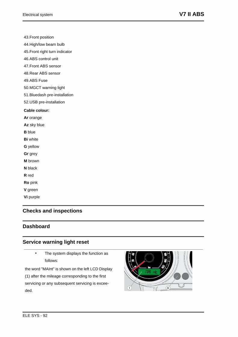
Service warning light reset
• The system displays the function as
follows:
the word "MAInt" is shown on the left LCD Display
(1) after the mileage corresponding to the first
servicing or any subsequent servicing is excee-
ded.
Electrical system V7 II ABS
ELE SYS - 92
• This is shown only after each start-up
for 5 seconds; afterwards, it will shift to
the standard view.
To reset Service proceed as follows:
• Hold down the key (A).
• Turn the ignition key to "ON".
• Wait for the Key OFF.
The next time the vehicle is started, the value will
be reset and the word "MAInt" will not be displayed
until the next mileage for which maintenance is
foreseen.
Battery recharge circuit
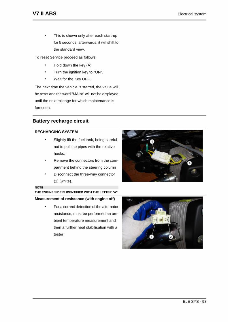
RECHARGING SYSTEM
• Slightly lift the fuel tank, being careful
not to pull the pipes with the relative
hooks;
• Remove the connectors from the com-
partment behind the steering column
• Disconnect the three-way connector
(1) (white).NOTETHE ENGINE SIDE IS IDENTIFIED WITH THE LETTER "A"
Measurement of resistance (with engine off)
• For a correct detection of the alternator
resistance, must be performed an am-
bient temperature measurement and
then a further heat stabilisation with a
tester.
V7 II ABS Electrical system
ELE SYS - 93
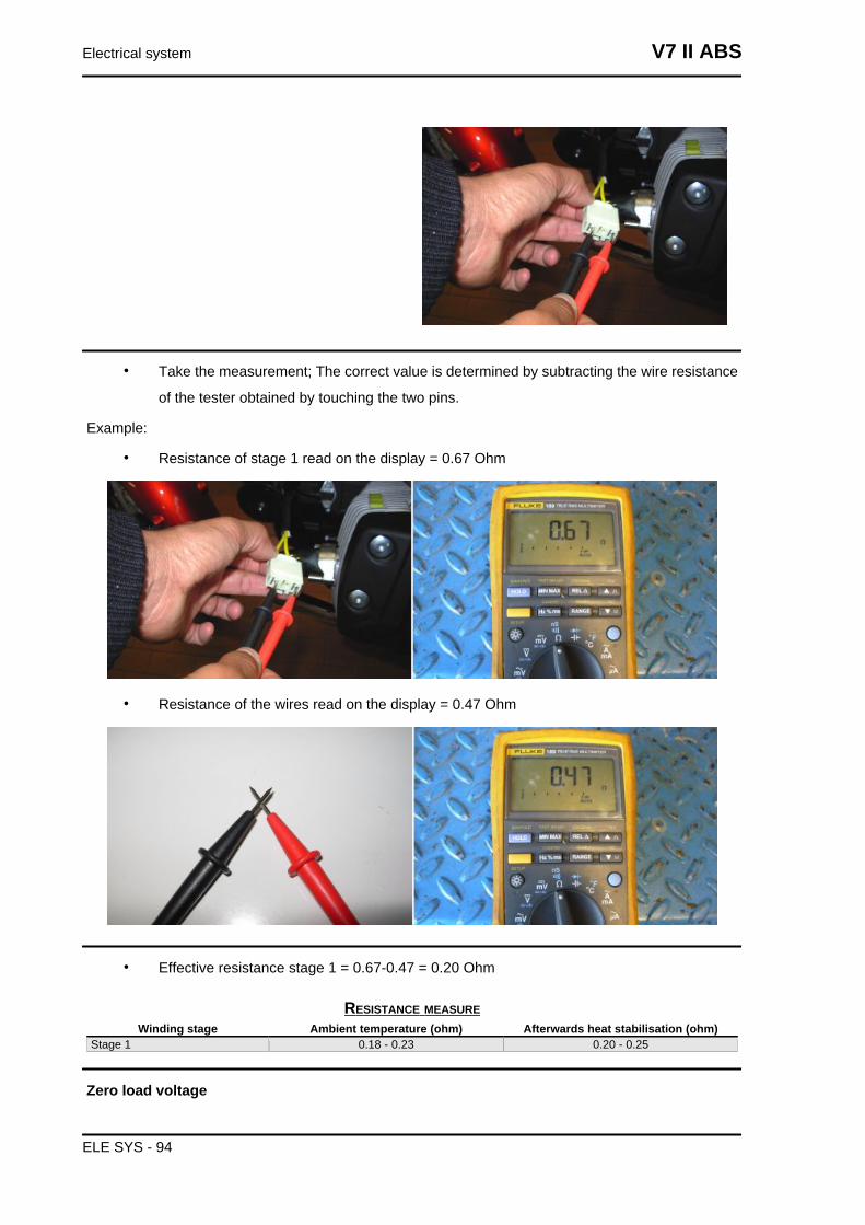
• Take the measurement; The correct value is determined by subtracting the wire resistance
of the tester obtained by touching the two pins.
Example:
• Resistance of stage 1 read on the display = 0.67 Ohm
• Resistance of the wires read on the display = 0.47 Ohm
• Effective resistance stage 1 = 0.67-0.47 = 0.20 Ohm
RESISTANCE MEASUREWinding stage Ambient temperature (ohm) Afterwards heat stabilisation (ohm)
Stage 1 0.18 - 0.23 0.20 - 0.25
Zero load voltage
Electrical system V7 II ABS
ELE SYS - 94
• Disconnect the three-way connector (1);
• For a correct detection of the alternator voltage, a measurement must be carried out using
alternatively the 3 engine side connector pins: stage "1" (pin 1-2), stage "2" (pin 1-3), stage
"3" (pin 2-3)
• Take the measurements;
• If there is a significant difference between one stage and another (other than 15 V), this
means that the alternator is defective and must be replaced.CAUTION
WITH THE ENGINE HOT THE VALUES RECORDED ARE ON AVERAGE 4-5 V LESS THAN THOSEDETECTED WITH THE ENGINE COLD.
TENSIONE A VUOTOGiri / min 2000 4000 6000
Vm tensione concatenata Valori di riferimento ( Vrms )
40 - 45 82 - 87 132 - 138
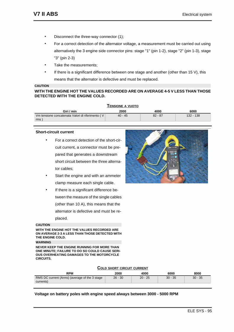
Short-circuit current
• For a correct detection of the short-cir-
cuit current, a connector must be pre-
pared that generates a downstream
short circuit between the three alterna-
tor cables;
• Start the engine and with an ammeter
clamp measure each single cable.
• If there is a significant difference be-
tween the measure of the single cables
(other than 10 A), this means that the
alternator is defective and must be re-
placed.CAUTIONWITH THE ENGINE HOT THE VALUES RECORDED AREON AVERAGE 2-3 A LESS THAN THOSE DETECTED WITHTHE ENGINE COLD.WARNINGNEVER KEEP THE ENGINE RUNNING FOR MORE THANONE MINUTE; FAILURE TO DO SO COULD CAUSE SERI-OUS OVERHEATING DAMAGES TO THE MOTORCYCLECIRCUITS.
COLD SHORT CIRCUIT CURRENTRPM 2000 4000 6000 8000
RMS DC current (Arms) (average of the 3 stagecurrents)
26 - 30 20 - 25 30 - 35 30 - 35
Voltage on battery poles with engine speed always between 3000 - 5000 RPM
V7 II ABS Electrical system
ELE SYS - 95
• Start the engine, after about one minute of operating bring the speed to 3000-5000 RPM,
then measure with a tester the voltage at the battery poles that must always be between
13V and 15V. Otherwise, if the correct operation of the alternator has already been checked,
replace the regulator.CAUTIONPERFORM THE CHECK DESCRIBED ABOVE WITH A BATTERY IN GOOD CONDITION (STARTVOLTAGE ABOUT 13V) MAKING SURE THAT THERE ARE NO ELEMENTS IN THE SHORT CIR-CUIT.
Start-up system check
pick-up input about 100 A
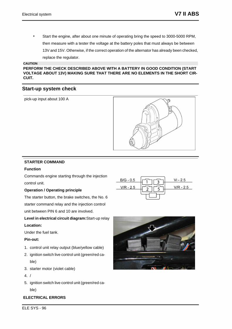
STARTER COMMAND
Function
Commands engine starting through the injection
control unit.
Operation / Operating principle
The starter button, the brake switches, the No. 6
starter command relay and the injection control
unit between PIN 6 and 10 are involved.
Level in electrical circuit diagram:Start-up relay
Location:
Under the fuel tank.
Pin-out:
1. control unit relay output (blue/yellow cable)
2. ignition switch live control unit (green/red ca-
ble)
3. starter motor (violet cable)
4. /
5. ignition switch live control unit (green/red ca-
ble)
ELECTRICAL ERRORS
Electrical system V7 II ABS
ELE SYS - 96
Starter command P0170 - shorted to positive.
Error cause
Shorted to positive: excessive voltage at PIN 10 of the control unit connector.
Troubleshooting
Shorted to positive:
• This malfunction is detected with a brake activated and the starter button pressed (voltage
of 12V read at PIN 6).
• If the battery voltage does not drop (thanks to the absorption of the No. 6 starter command
relay excitation coil) the control unit understands that PIN 10 is shorted to battery.
• Restore the cabling (if the short is in the cabling) or the relay (if the short is in the relay).NOTEIN CASE OF SHORT TO GROUND / OPEN CIRCUIT NO ERROR WILL APPEAR: SEE THE TROU-BLESHOOTING CHAPTER, THE ENGINE DOES NOT START.
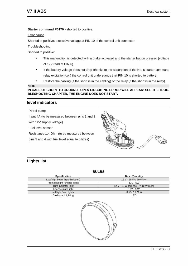
level indicators
Petrol pump:
Input 4A (to be measured between pins 1 and 2
with 12V supply voltage)
Fuel level sensor:
Resistance 1.4 Ohm (to be measured between
pins 3 and 4 with fuel level equal to 0 litres)
Lights list
BULBSSpecification Desc./Quantity
Low/high beam light (halogen) 12 V - 55 W / 60 W H4Front daylight running lights 12V - 5W
Turn indicator light 12 V - 10 W (orange RY 10 W bulb)License plate light 12V - 5 Wtail light /stop lights 12 V - 5 / 21 WDashboard lighting LED
V7 II ABS Electrical system
ELE SYS - 97
Fuses
FUSE LOCATION
A) Stop lights, tail lights, horn (15 A).
B) GPS predisposition, low beam / high beam, passing, USB, bluedash (15 A).
C) ECU, engine kill, start relay, instrument panel, injection loads relay (15 A).
D) (Battery positive) Instrument panel, turn indicators, bluedash (5 A).
E) (Battery positive) MIU G3 ECU (5 A).
F) Main fuse, coil 1 and 2, injectors 1 and 2, lambda 1 and 2 (30 A).
ABS FUSE DISTRIBUTION
A) ABS Control unit (20 A).
B) Spare fuses (20 A).
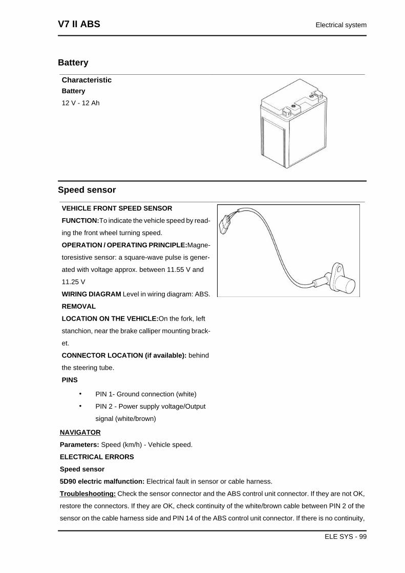
Control unit
Engine control unit Magneti Marelli MIU G3
Electrical system V7 II ABS
ELE SYS - 98
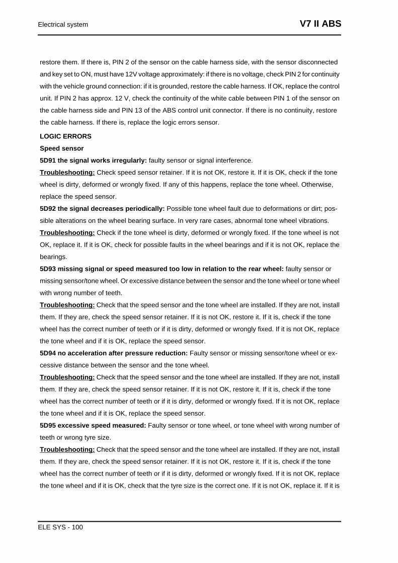
Battery
CharacteristicBattery12 V - 12 Ah
Speed sensor
VEHICLE FRONT SPEED SENSOR
FUNCTION:To indicate the vehicle speed by read-
ing the front wheel turning speed.
OPERATION / OPERATING PRINCIPLE:Magne-
toresistive sensor: a square-wave pulse is gener-
ated with voltage approx. between 11.55 V and
11.25 V
WIRING DIAGRAM Level in wiring diagram: ABS.
REMOVAL
LOCATION ON THE VEHICLE:On the fork, left
stanchion, near the brake calliper mounting brack-
et.
CONNECTOR LOCATION (if available): behind
the steering tube.
PINS
• PIN 1- Ground connection (white)
• PIN 2 - Power supply voltage/Output
signal (white/brown)
NAVIGATOR
Parameters: Speed (km/h) - Vehicle speed.
ELECTRICAL ERRORS
Speed sensor
5D90 electric malfunction: Electrical fault in sensor or cable harness.
Troubleshooting: Check the sensor connector and the ABS control unit connector. If they are not OK,
restore the connectors. If they are OK, check continuity of the white/brown cable between PIN 2 of the
sensor on the cable harness side and PIN 14 of the ABS control unit connector. If there is no continuity,
V7 II ABS Electrical system
ELE SYS - 99
restore them. If there is, PIN 2 of the sensor on the cable harness side, with the sensor disconnected
and key set to ON, must have 12V voltage approximately: if there is no voltage, check PIN 2 for continuity
with the vehicle ground connection: if it is grounded, restore the cable harness. If OK, replace the control
unit. If PIN 2 has approx. 12 V, check the continuity of the white cable between PIN 1 of the sensor on
the cable harness side and PIN 13 of the ABS control unit connector. If there is no continuity, restore
the cable harness. If there is, replace the logic errors sensor.
LOGIC ERRORS
Speed sensor
5D91 the signal works irregularly: faulty sensor or signal interference.
Troubleshooting: Check speed sensor retainer. If it is not OK, restore it. If it is OK, check if the tone
wheel is dirty, deformed or wrongly fixed. If any of this happens, replace the tone wheel. Otherwise,
replace the speed sensor.
5D92 the signal decreases periodically: Possible tone wheel fault due to deformations or dirt; pos-
sible alterations on the wheel bearing surface. In very rare cases, abnormal tone wheel vibrations.
Troubleshooting: Check if the tone wheel is dirty, deformed or wrongly fixed. If the tone wheel is not
OK, replace it. If it is OK, check for possible faults in the wheel bearings and if it is not OK, replace the
bearings.
5D93 missing signal or speed measured too low in relation to the rear wheel: faulty sensor or
missing sensor/tone wheel. Or excessive distance between the sensor and the tone wheel or tone wheel
with wrong number of teeth.
Troubleshooting: Check that the speed sensor and the tone wheel are installed. If they are not, install
them. If they are, check the speed sensor retainer. If it is not OK, restore it. If it is, check if the tone
wheel has the correct number of teeth or if it is dirty, deformed or wrongly fixed. If it is not OK, replace
the tone wheel and if it is OK, replace the speed sensor.
5D94 no acceleration after pressure reduction: Faulty sensor or missing sensor/tone wheel or ex-
cessive distance between the sensor and the tone wheel.
Troubleshooting: Check that the speed sensor and the tone wheel are installed. If they are not, install
them. If they are, check the speed sensor retainer. If it is not OK, restore it. If it is, check if the tone
wheel has the correct number of teeth or if it is dirty, deformed or wrongly fixed. If it is not OK, replace
the tone wheel and if it is OK, replace the speed sensor.
5D95 excessive speed measured: Faulty sensor or tone wheel, or tone wheel with wrong number of
teeth or wrong tyre size.
Troubleshooting: Check that the speed sensor and the tone wheel are installed. If they are not, install
them. If they are, check the speed sensor retainer. If it is not OK, restore it. If it is, check if the tone
wheel has the correct number of teeth or if it is dirty, deformed or wrongly fixed. If it is not OK, replace
the tone wheel and if it is OK, check that the tyre size is the correct one. If it is not OK, replace it. If it is
Electrical system V7 II ABS
ELE SYS - 100
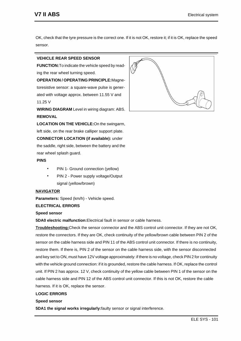
OK, check that the tyre pressure is the correct one. If it is not OK, restore it; if it is OK, replace the speed
sensor.
VEHICLE REAR SPEED SENSOR
FUNCTION:To indicate the vehicle speed by read-
ing the rear wheel turning speed.
OPERATION / OPERATING PRINCIPLE:Magne-
toresistive sensor: a square-wave pulse is gener-
ated with voltage approx. between 11.55 V and
11.25 V
WIRING DIAGRAM Level in wiring diagram: ABS.
REMOVAL
LOCATION ON THE VEHICLE:On the swingarm,
left side, on the rear brake calliper support plate.
CONNECTOR LOCATION (if available): under
the saddle, right side, between the battery and the
rear wheel splash guard.
PINS
• PIN 1- Ground connection (yellow)
• PIN 2 - Power supply voltage/Output
signal (yellow/brown)
NAVIGATOR
Parameters: Speed (km/h) - Vehicle speed.
ELECTRICAL ERRORS
Speed sensor
5DA0 electric malfunction:Electrical fault in sensor or cable harness.
Troubleshooting:Check the sensor connector and the ABS control unit connector. If they are not OK,
restore the connectors. If they are OK, check continuity of the yellow/brown cable between PIN 2 of the
sensor on the cable harness side and PIN 11 of the ABS control unit connector. If there is no continuity,
restore them. If there is, PIN 2 of the sensor on the cable harness side, with the sensor disconnected
and key set to ON, must have 12V voltage approximately: if there is no voltage, check PIN 2 for continuity
with the vehicle ground connection: if it is grounded, restore the cable harness. If OK, replace the control
unit. If PIN 2 has approx. 12 V, check continuity of the yellow cable between PIN 1 of the sensor on the
cable harness side and PIN 12 of the ABS control unit connector. If this is not OK, restore the cable
harness. If it is OK, replace the sensor.
LOGIC ERRORS
Speed sensor
5DA1 the signal works irregularly:faulty sensor or signal interference.
V7 II ABS Electrical system
ELE SYS - 101
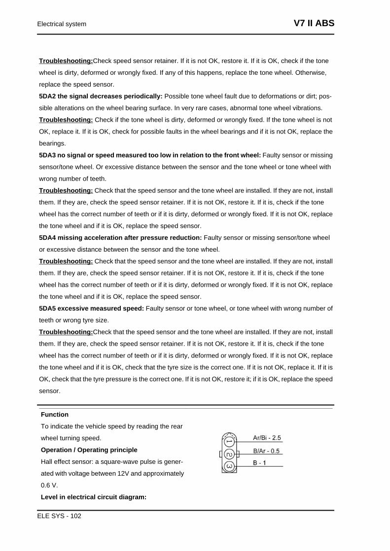
Troubleshooting:Check speed sensor retainer. If it is not OK, restore it. If it is OK, check if the tone
wheel is dirty, deformed or wrongly fixed. If any of this happens, replace the tone wheel. Otherwise,
replace the speed sensor.
5DA2 the signal decreases periodically: Possible tone wheel fault due to deformations or dirt; pos-
sible alterations on the wheel bearing surface. In very rare cases, abnormal tone wheel vibrations.
Troubleshooting: Check if the tone wheel is dirty, deformed or wrongly fixed. If the tone wheel is not
OK, replace it. If it is OK, check for possible faults in the wheel bearings and if it is not OK, replace the
bearings.
5DA3 no signal or speed measured too low in relation to the front wheel: Faulty sensor or missing
sensor/tone wheel. Or excessive distance between the sensor and the tone wheel or tone wheel with
wrong number of teeth.
Troubleshooting: Check that the speed sensor and the tone wheel are installed. If they are not, install
them. If they are, check the speed sensor retainer. If it is not OK, restore it. If it is, check if the tone
wheel has the correct number of teeth or if it is dirty, deformed or wrongly fixed. If it is not OK, replace
the tone wheel and if it is OK, replace the speed sensor.
5DA4 missing acceleration after pressure reduction: Faulty sensor or missing sensor/tone wheel
or excessive distance between the sensor and the tone wheel.
Troubleshooting: Check that the speed sensor and the tone wheel are installed. If they are not, install
them. If they are, check the speed sensor retainer. If it is not OK, restore it. If it is, check if the tone
wheel has the correct number of teeth or if it is dirty, deformed or wrongly fixed. If it is not OK, replace
the tone wheel and if it is OK, replace the speed sensor.
5DA5 excessive measured speed: Faulty sensor or tone wheel, or tone wheel with wrong number of
teeth or wrong tyre size.
Troubleshooting:Check that the speed sensor and the tone wheel are installed. If they are not, install
them. If they are, check the speed sensor retainer. If it is not OK, restore it. If it is, check if the tone
wheel has the correct number of teeth or if it is dirty, deformed or wrongly fixed. If it is not OK, replace
the tone wheel and if it is OK, check that the tyre size is the correct one. If it is not OK, replace it. If it is
OK, check that the tyre pressure is the correct one. If it is not OK, restore it; if it is OK, replace the speed
sensor.
Function
To indicate the vehicle speed by reading the rear
wheel turning speed.
Operation / Operating principle
Hall effect sensor: a square-wave pulse is gener-
ated with voltage between 12V and approximately
0.6 V.
Level in electrical circuit diagram:
Electrical system V7 II ABS
ELE SYS - 102
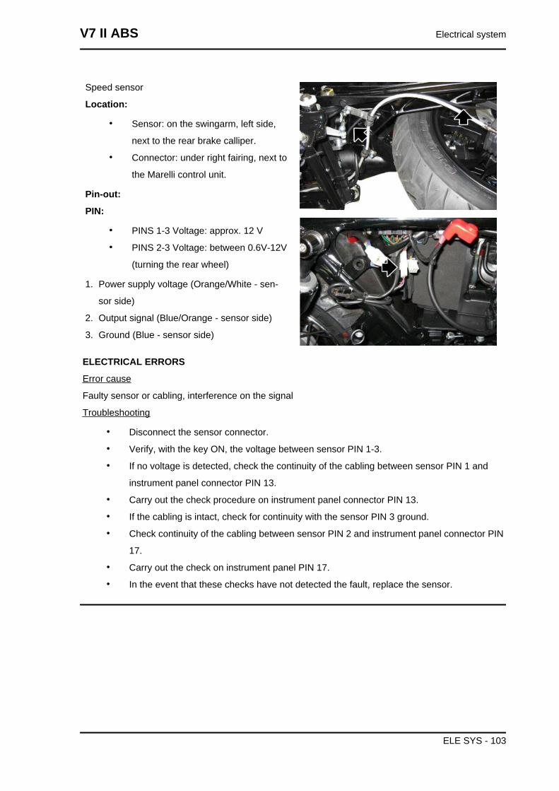
Speed sensor
Location:
• Sensor: on the swingarm, left side,
next to the rear brake calliper.
• Connector: under right fairing, next to
the Marelli control unit.
Pin-out:
PIN:
• PINS 1-3 Voltage: approx. 12 V
• PINS 2-3 Voltage: between 0.6V-12V
(turning the rear wheel)
1. Power supply voltage (Orange/White - sen-
sor side)
2. Output signal (Blue/Orange - sensor side)
3. Ground (Blue - sensor side)
ELECTRICAL ERRORS
Error cause
Faulty sensor or cabling, interference on the signal
Troubleshooting
• Disconnect the sensor connector.
• Verify, with the key ON, the voltage between sensor PIN 1-3.
• If no voltage is detected, check the continuity of the cabling between sensor PIN 1 and
instrument panel connector PIN 13.
• Carry out the check procedure on instrument panel connector PIN 13.
• If the cabling is intact, check for continuity with the sensor PIN 3 ground.
• Check continuity of the cabling between sensor PIN 2 and instrument panel connector PIN
17.
• Carry out the check on instrument panel PIN 17.
• In the event that these checks have not detected the fault, replace the sensor.
V7 II ABS Electrical system
ELE SYS - 103
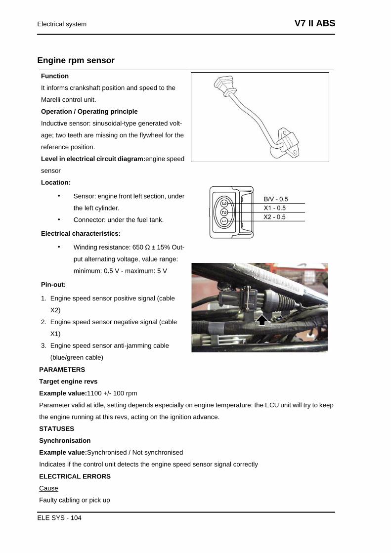
Engine rpm sensorFunction
It informs crankshaft position and speed to the
Marelli control unit.
Operation / Operating principle
Inductive sensor: sinusoidal-type generated volt-
age; two teeth are missing on the flywheel for the
reference position.
Level in electrical circuit diagram:engine speed
sensor
Location:
• Sensor: engine front left section, under
the left cylinder.
• Connector: under the fuel tank.
Electrical characteristics:
• Winding resistance: 650 Ω ± 15% Out-
put alternating voltage, value range:
minimum: 0.5 V - maximum: 5 V
Pin-out:
1. Engine speed sensor positive signal (cable
X2)
2. Engine speed sensor negative signal (cable
X1)
3. Engine speed sensor anti-jamming cable
(blue/green cable)
PARAMETERS
Target engine revs
Example value:1100 +/- 100 rpm
Parameter valid at idle, setting depends especially on engine temperature: the ECU unit will try to keep
the engine running at this revs, acting on the ignition advance.
STATUSES
Synchronisation
Example value:Synchronised / Not synchronised
Indicates if the control unit detects the engine speed sensor signal correctly
ELECTRICAL ERRORS
Cause
Faulty cabling or pick up
Electrical system V7 II ABS
ELE SYS - 104
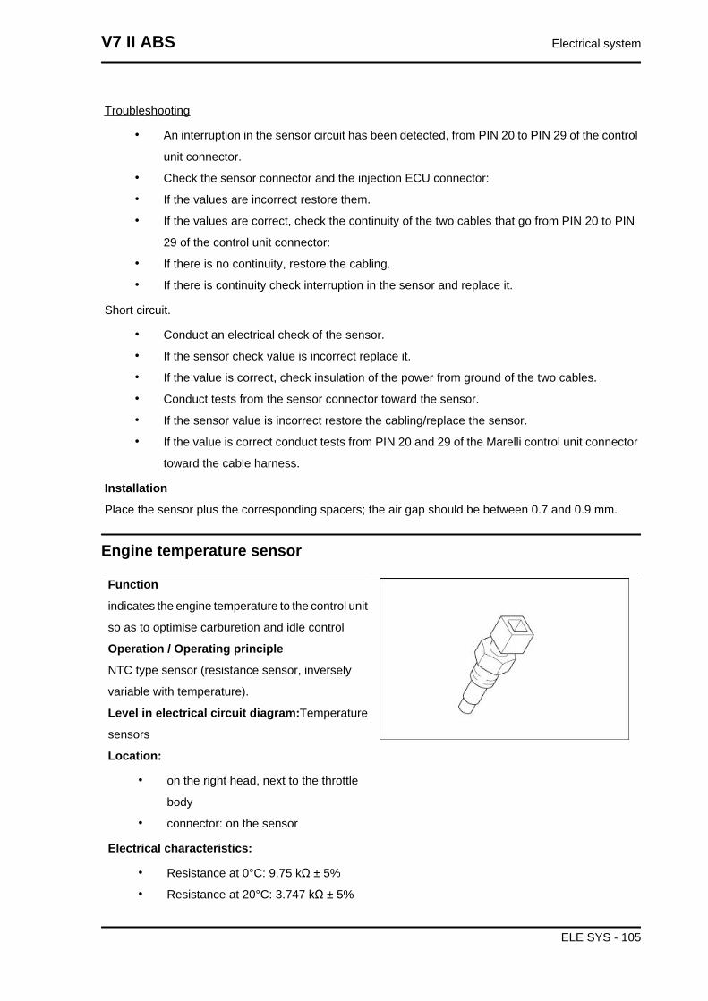
Troubleshooting
• An interruption in the sensor circuit has been detected, from PIN 20 to PIN 29 of the control
unit connector.
• Check the sensor connector and the injection ECU connector:
• If the values are incorrect restore them.
• If the values are correct, check the continuity of the two cables that go from PIN 20 to PIN
29 of the control unit connector:
• If there is no continuity, restore the cabling.
• If there is continuity check interruption in the sensor and replace it.
Short circuit.
• Conduct an electrical check of the sensor.
• If the sensor check value is incorrect replace it.
• If the value is correct, check insulation of the power from ground of the two cables.
• Conduct tests from the sensor connector toward the sensor.
• If the sensor value is incorrect restore the cabling/replace the sensor.
• If the value is correct conduct tests from PIN 20 and 29 of the Marelli control unit connector
toward the cable harness.
Installation
Place the sensor plus the corresponding spacers; the air gap should be between 0.7 and 0.9 mm.
Engine temperature sensor
Function
indicates the engine temperature to the control unit
so as to optimise carburetion and idle control
Operation / Operating principle
NTC type sensor (resistance sensor, inversely
variable with temperature).
Level in electrical circuit diagram:Temperature
sensors
Location:
• on the right head, next to the throttle
body
• connector: on the sensor
Electrical characteristics:
• Resistance at 0°C: 9.75 kΩ ± 5%
• Resistance at 20°C: 3.747 kΩ ± 5%
V7 II ABS Electrical system
ELE SYS - 105
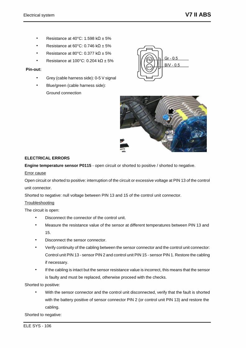
• Resistance at 40°C: 1.598 kΩ ± 5%
• Resistance at 60°C: 0.746 kΩ ± 5%
• Resistance at 80°C: 0.377 kΩ ± 5%
• Resistance at 100°C: 0.204 kΩ ± 5%
Pin-out:
• Grey (cable harness side): 0-5 V signal
• Blue/green (cable harness side):
Ground connection
ELECTRICAL ERRORS
Engine temperature sensor P0115 - open circuit or shorted to positive / shorted to negative.
Error cause
Open circuit or shorted to positive: interruption of the circuit or excessive voltage at PIN 13 of the control
unit connector.
Shorted to negative: null voltage between PIN 13 and 15 of the control unit connector.
Troubleshooting
The circuit is open:
• Disconnect the connector of the control unit.
• Measure the resistance value of the sensor at different temperatures between PIN 13 and
15.
• Disconnect the sensor connector.
• Verify continuity of the cabling between the sensor connector and the control unit connector:
Control unit PIN 13 - sensor PIN 2 and control unit PIN 15 - sensor PIN 1. Restore the cabling
if necessary.
• If the cabling is intact but the sensor resistance value is incorrect, this means that the sensor
is faulty and must be replaced, otherwise proceed with the checks.
Shorted to positive:
• With the sensor connector and the control unit disconnected, verify that the fault is shorted
with the battery positive of sensor connector PIN 2 (or control unit PIN 13) and restore the
cabling.
Shorted to negative:
Electrical system V7 II ABS
ELE SYS - 106
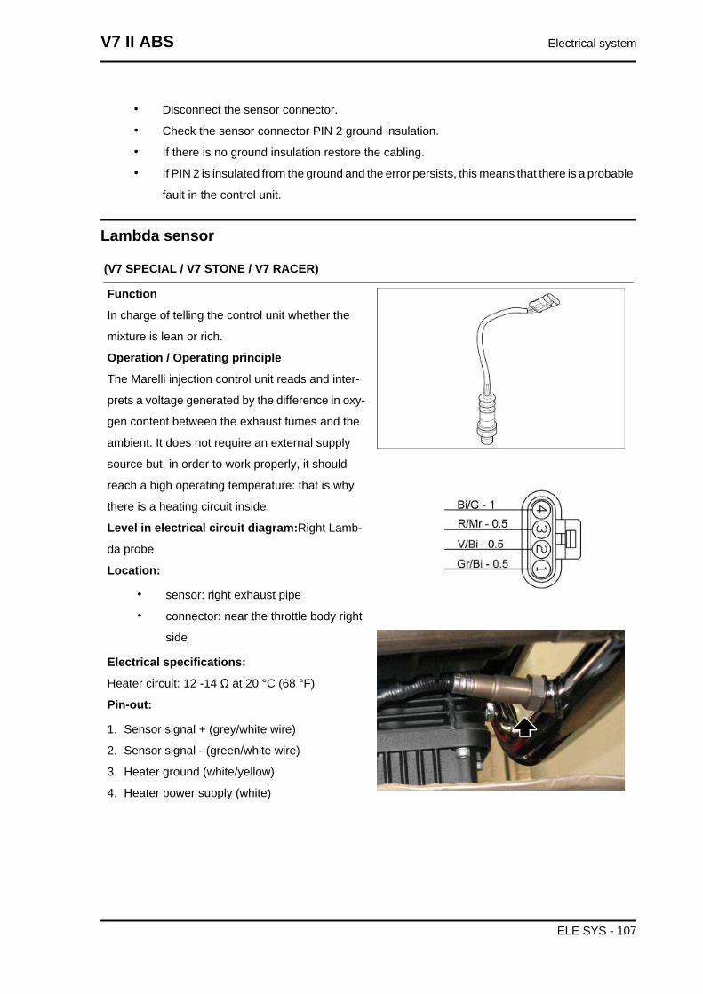
• Disconnect the sensor connector.
• Check the sensor connector PIN 2 ground insulation.
• If there is no ground insulation restore the cabling.
• If PIN 2 is insulated from the ground and the error persists, this means that there is a probable
fault in the control unit.
Lambda sensor
(V7 SPECIAL / V7 STONE / V7 RACER)
Function
In charge of telling the control unit whether the
mixture is lean or rich.
Operation / Operating principle
The Marelli injection control unit reads and inter-
prets a voltage generated by the difference in oxy-
gen content between the exhaust fumes and the
ambient. It does not require an external supply
source but, in order to work properly, it should
reach a high operating temperature: that is why
there is a heating circuit inside.
Level in electrical circuit diagram:Right Lamb-
da probe
Location:
• sensor: right exhaust pipe
• connector: near the throttle body right
side
Electrical specifications:
Heater circuit: 12 -14 Ω at 20 °C (68 °F)
Pin-out:
1. Sensor signal + (grey/white wire)
2. Sensor signal - (green/white wire)
3. Heater ground (white/yellow)
4. Heater power supply (white)
V7 II ABS Electrical system
ELE SYS - 107
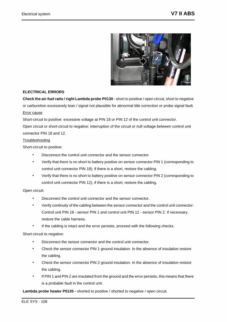
ELECTRICAL ERRORS
Check the air-fuel ratio / right Lambda probe P0130 - short to positive / open circuit, short to negative
or carburetion excessively lean / signal not plausible for abnormal title correction or probe signal fault.
Error cause
Short-circuit to positive: excessive voltage at PIN 18 or PIN 12 of the control unit connector.
Open circuit or short-circuit to negative: interruption of the circuit or null voltage between control unit
connector PIN 18 and 12.
Troubleshooting
Short-circuit to positive:
• Disconnect the control unit connector and the sensor connector.
• Verify that there is no short to battery positive on sensor connector PIN 1 (corresponding to
control unit connector PIN 18); if there is a short, restore the cabling.
• Verify that there is no short to battery positive on sensor connector PIN 2 (corresponding to
control unit connector PIN 12); if there is a short, restore the cabling.
Open circuit:
• Disconnect the control unit connector and the sensor connector.
• Verify continuity of the cabling between the sensor connector and the control unit connector:
Control unit PIN 18 - sensor PIN 1 and control unit PIN 12 - sensor PIN 2. If necessary,
restore the cable harness.
• If the cabling is intact and the error persists, proceed with the following checks.
Short-circuit to negative:
• Disconnect the sensor connector and the control unit connector.
• Check the sensor connector PIN 1 ground insulation. In the absence of insulation restore
the cabling.
• Check the sensor connector PIN 2 ground insulation. In the absence of insulation restore
the cabling.
• If PIN 1 and PIN 2 are insulated from the ground and the error persists, this means that there
is a probable fault in the control unit.
Lambda probe heater P0135 - shorted to positive / shorted to negative / open circuit.
Electrical system V7 II ABS
ELE SYS - 108
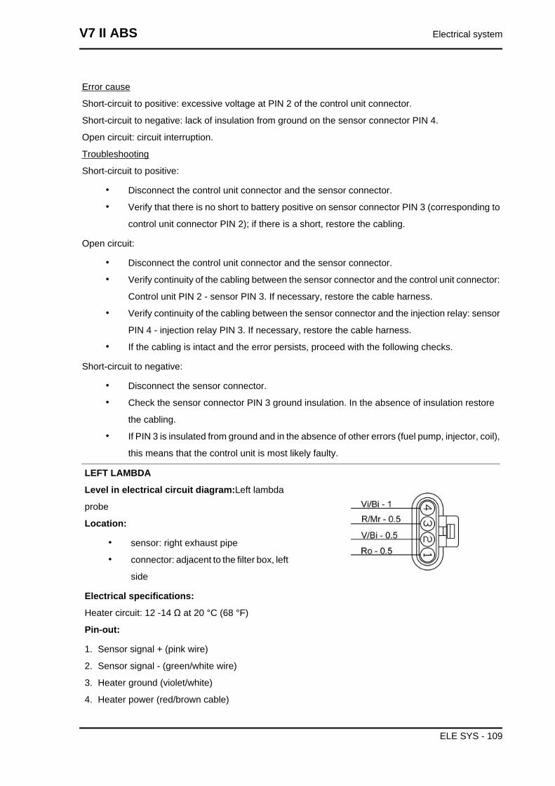
Error cause
Short-circuit to positive: excessive voltage at PIN 2 of the control unit connector.
Short-circuit to negative: lack of insulation from ground on the sensor connector PIN 4.
Open circuit: circuit interruption.
Troubleshooting
Short-circuit to positive:
• Disconnect the control unit connector and the sensor connector.
• Verify that there is no short to battery positive on sensor connector PIN 3 (corresponding to
control unit connector PIN 2); if there is a short, restore the cabling.
Open circuit:
• Disconnect the control unit connector and the sensor connector.
• Verify continuity of the cabling between the sensor connector and the control unit connector:
Control unit PIN 2 - sensor PIN 3. If necessary, restore the cable harness.
• Verify continuity of the cabling between the sensor connector and the injection relay: sensor
PIN 4 - injection relay PIN 3. If necessary, restore the cable harness.
• If the cabling is intact and the error persists, proceed with the following checks.
Short-circuit to negative:
• Disconnect the sensor connector.
• Check the sensor connector PIN 3 ground insulation. In the absence of insulation restore
the cabling.
• If PIN 3 is insulated from ground and in the absence of other errors (fuel pump, injector, coil),
this means that the control unit is most likely faulty.
LEFT LAMBDA
Level in electrical circuit diagram:Left lambda
probe
Location:
• sensor: right exhaust pipe
• connector: adjacent to the filter box, left
side
Electrical specifications:
Heater circuit: 12 -14 Ω at 20 °C (68 °F)
Pin-out:
1. Sensor signal + (pink wire)
2. Sensor signal - (green/white wire)
3. Heater ground (violet/white)
4. Heater power (red/brown cable)
V7 II ABS Electrical system
ELE SYS - 109
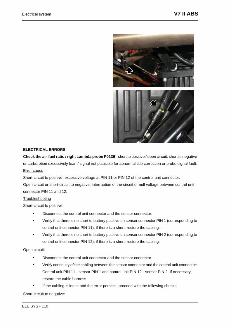
ELECTRICAL ERRORS
Check the air-fuel ratio / right Lambda probe P0136 - short to positive / open circuit, short to negative
or carburetion excessively lean / signal not plausible for abnormal title correction or probe signal fault.
Error cause
Short-circuit to positive: excessive voltage at PIN 11 or PIN 12 of the control unit connector.
Open circuit or short-circuit to negative: interruption of the circuit or null voltage between control unit
connector PIN 11 and 12.
Troubleshooting
Short-circuit to positive:
• Disconnect the control unit connector and the sensor connector.
• Verify that there is no short to battery positive on sensor connector PIN 1 (corresponding to
control unit connector PIN 11); if there is a short, restore the cabling.
• Verify that there is no short to battery positive on sensor connector PIN 2 (corresponding to
control unit connector PIN 12); if there is a short, restore the cabling.
Open circuit:
• Disconnect the control unit connector and the sensor connector.
• Verify continuity of the cabling between the sensor connector and the control unit connector:
Control unit PIN 11 - sensor PIN 1 and control unit PIN 12 - sensor PIN 2. If necessary,
restore the cable harness.
• If the cabling is intact and the error persists, proceed with the following checks.
Short-circuit to negative:
Electrical system V7 II ABS
ELE SYS - 110
• Disconnect the sensor connector and the control unit connector.
• Check the sensor connector PIN 1 ground insulation. In the absence of insulation restore
the cabling.
• Check the sensor connector PIN 2 ground insulation. In the absence of insulation restore
the cabling.
• If PIN 1 and PIN 2 are insulated from the ground and the error persists, this means that there
is a probable fault in the control unit.
Lambda probe heater P0141 - shorted to positive / shorted to negative / open circuit.
Error cause
Short-circuit to positive: excessive voltage at PIN 35 of the control unit connector.
Short-circuit to negative: lack of insulation from ground on the sensor connector PIN 4.
Open circuit: circuit interruption.
Troubleshooting
Short-circuit to positive:
• Disconnect the control unit connector and the sensor connector.
• Verify that there is no short to battery positive on sensor connector PIN 3 (corresponding to
control unit connector PIN 31); if there is a short, restore the cabling.
Open circuit:
• Disconnect the control unit connector and the sensor connector.
• Verify continuity of the cabling between the sensor connector and the control unit connector:
Control unit PIN 31 - sensor PIN 3. If necessary, restore the cable harness.
• Verify continuity of the cabling between the sensor connector and the injection relay: sensor
PIN 4 - injection relay PIN 3. If necessary, restore the cable harness.
• If the cabling is intact and the error persists, proceed with the following checks.
Short-circuit to negative:
• Disconnect the sensor connector.
• Check the sensor connector PIN 3 ground insulation. In the absence of insulation restore
the cabling.
• If PIN 3 is insulated from ground and in the absence of other errors (fuel pump, injector, coil),
this means that the control unit is most likely faulty.
(V7 STORNELLO)
V7 II ABS Electrical system
ELE SYS - 111
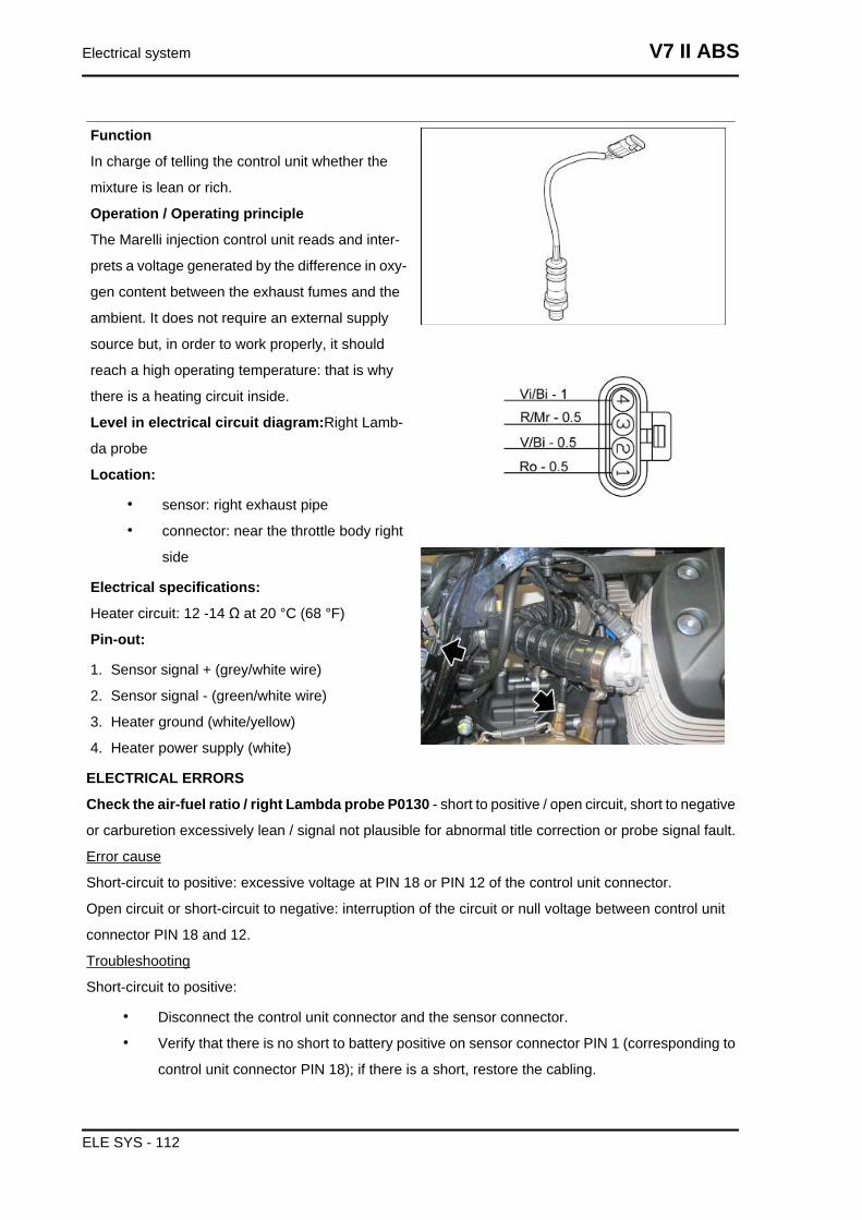
Function
In charge of telling the control unit whether the
mixture is lean or rich.
Operation / Operating principle
The Marelli injection control unit reads and inter-
prets a voltage generated by the difference in oxy-
gen content between the exhaust fumes and the
ambient. It does not require an external supply
source but, in order to work properly, it should
reach a high operating temperature: that is why
there is a heating circuit inside.
Level in electrical circuit diagram:Right Lamb-
da probe
Location:
• sensor: right exhaust pipe
• connector: near the throttle body right
side
Electrical specifications:
Heater circuit: 12 -14 Ω at 20 °C (68 °F)
Pin-out:
1. Sensor signal + (grey/white wire)
2. Sensor signal - (green/white wire)
3. Heater ground (white/yellow)
4. Heater power supply (white)
ELECTRICAL ERRORS
Check the air-fuel ratio / right Lambda probe P0130 - short to positive / open circuit, short to negative
or carburetion excessively lean / signal not plausible for abnormal title correction or probe signal fault.
Error cause
Short-circuit to positive: excessive voltage at PIN 18 or PIN 12 of the control unit connector.
Open circuit or short-circuit to negative: interruption of the circuit or null voltage between control unit
connector PIN 18 and 12.
Troubleshooting
Short-circuit to positive:
• Disconnect the control unit connector and the sensor connector.
• Verify that there is no short to battery positive on sensor connector PIN 1 (corresponding to
control unit connector PIN 18); if there is a short, restore the cabling.
Electrical system V7 II ABS
ELE SYS - 112
• Verify that there is no short to battery positive on sensor connector PIN 2 (corresponding to
control unit connector PIN 12); if there is a short, restore the cabling.
Open circuit:
• Disconnect the control unit connector and the sensor connector.
• Verify continuity of the cabling between the sensor connector and the control unit connector:
Control unit PIN 18 - sensor PIN 1 and control unit PIN 12 - sensor PIN 2. If necessary,
restore the cable harness.
• If the cabling is intact and the error persists, proceed with the following checks.
Short-circuit to negative:
• Disconnect the sensor connector and the control unit connector.
• Check the sensor connector PIN 1 ground insulation. In the absence of insulation restore
the cabling.
• Check the sensor connector PIN 2 ground insulation. In the absence of insulation restore
the cabling.
• If PIN 1 and PIN 2 are insulated from the ground and the error persists, this means that there
is a probable fault in the control unit.
Lambda probe heater P0135 - shorted to positive / shorted to negative / open circuit.
Error cause
Short-circuit to positive: excessive voltage at PIN 2 of the control unit connector.
Short-circuit to negative: lack of insulation from ground on the sensor connector PIN 4.
Open circuit: circuit interruption.
Troubleshooting
Short-circuit to positive:
• Disconnect the control unit connector and the sensor connector.
• Verify that there is no short to battery positive on sensor connector PIN 3 (corresponding to
control unit connector PIN 2); if there is a short, restore the cabling.
Open circuit:
• Disconnect the control unit connector and the sensor connector.
• Verify continuity of the cabling between the sensor connector and the control unit connector:
Control unit PIN 2 - sensor PIN 3. If necessary, restore the cable harness.
• Verify continuity of the cabling between the sensor connector and the injection relay: sensor
PIN 4 - injection relay PIN 3. If necessary, restore the cable harness.
• If the cabling is intact and the error persists, proceed with the following checks.
Short-circuit to negative:
• Disconnect the sensor connector.
V7 II ABS Electrical system
ELE SYS - 113
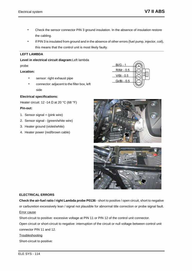
• Check the sensor connector PIN 3 ground insulation. In the absence of insulation restore
the cabling.
• If PIN 3 is insulated from ground and in the absence of other errors (fuel pump, injector, coil),
this means that the control unit is most likely faulty.
LEFT LAMBDA
Level in electrical circuit diagram:Left lambda
probe
Location:
• sensor: right exhaust pipe
• connector: adjacent to the filter box, left
side
Electrical specifications:
Heater circuit: 12 -14 Ω at 20 °C (68 °F)
Pin-out:
1. Sensor signal + (pink wire)
2. Sensor signal - (green/white wire)
3. Heater ground (violet/white)
4. Heater power (red/brown cable)
ELECTRICAL ERRORS
Check the air-fuel ratio / right Lambda probe P0136 - short to positive / open circuit, short to negative
or carburetion excessively lean / signal not plausible for abnormal title correction or probe signal fault.
Error cause
Short-circuit to positive: excessive voltage at PIN 11 or PIN 12 of the control unit connector.
Open circuit or short-circuit to negative: interruption of the circuit or null voltage between control unit
connector PIN 11 and 12.
Troubleshooting
Short-circuit to positive:
Electrical system V7 II ABS
ELE SYS - 114
• Disconnect the control unit connector and the sensor connector.
• Verify that there is no short to battery positive on sensor connector PIN 1 (corresponding to
control unit connector PIN 11); if there is a short, restore the cabling.
• Verify that there is no short to battery positive on sensor connector PIN 2 (corresponding to
control unit connector PIN 12); if there is a short, restore the cabling.
Open circuit:
• Disconnect the control unit connector and the sensor connector.
• Verify continuity of the cabling between the sensor connector and the control unit connector:
Control unit PIN 11 - sensor PIN 1 and control unit PIN 12 - sensor PIN 2. If necessary,
restore the cable harness.
• If the cabling is intact and the error persists, proceed with the following checks.
Short-circuit to negative:
• Disconnect the sensor connector and the control unit connector.
• Check the sensor connector PIN 1 ground insulation. In the absence of insulation restore
the cabling.
• Check the sensor connector PIN 2 ground insulation. In the absence of insulation restore
the cabling.
• If PIN 1 and PIN 2 are insulated from the ground and the error persists, this means that there
is a probable fault in the control unit.
Lambda probe heater P0141 - shorted to positive / shorted to negative / open circuit.
Error cause
Short-circuit to positive: excessive voltage at PIN 35 of the control unit connector.
Short-circuit to negative: lack of insulation from ground on the sensor connector PIN 4.
Open circuit: circuit interruption.
Troubleshooting
Short-circuit to positive:
• Disconnect the control unit connector and the sensor connector.
• Verify that there is no short to battery positive on sensor connector PIN 3 (corresponding to
control unit connector PIN 31); if there is a short, restore the cabling.
Open circuit:
• Disconnect the control unit connector and the sensor connector.
• Verify continuity of the cabling between the sensor connector and the control unit connector:
Control unit PIN 31 - sensor PIN 3. If necessary, restore the cable harness.
• Verify continuity of the cabling between the sensor connector and the injection relay: sensor
PIN 4 - injection relay PIN 3. If necessary, restore the cable harness.
• If the cabling is intact and the error persists, proceed with the following checks.
Short-circuit to negative:
V7 II ABS Electrical system
ELE SYS - 115
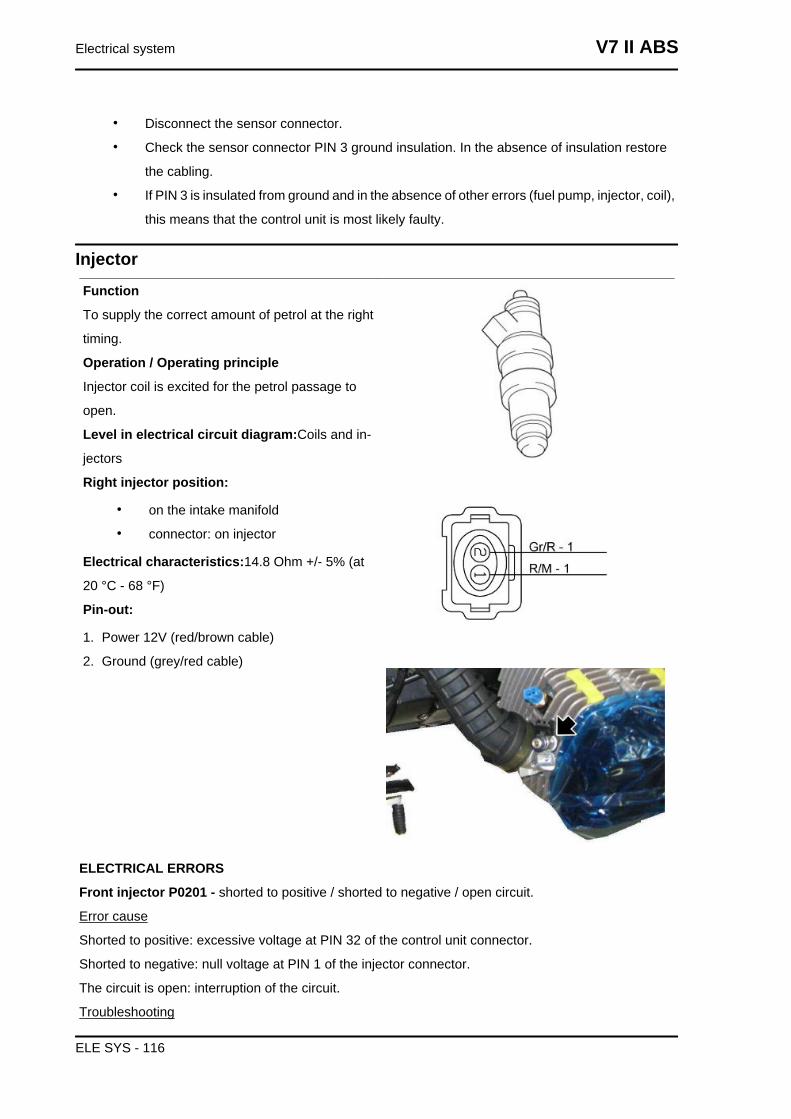
• Disconnect the sensor connector.
• Check the sensor connector PIN 3 ground insulation. In the absence of insulation restore
the cabling.
• If PIN 3 is insulated from ground and in the absence of other errors (fuel pump, injector, coil),
this means that the control unit is most likely faulty.
InjectorFunction
To supply the correct amount of petrol at the right
timing.
Operation / Operating principle
Injector coil is excited for the petrol passage to
open.
Level in electrical circuit diagram:Coils and in-
jectors
Right injector position:
• on the intake manifold
• connector: on injector
Electrical characteristics:14.8 Ohm +/- 5% (at
20 °C - 68 °F)
Pin-out:
1. Power 12V (red/brown cable)
2. Ground (grey/red cable)
ELECTRICAL ERRORS
Front injector P0201 - shorted to positive / shorted to negative / open circuit.
Error cause
Shorted to positive: excessive voltage at PIN 32 of the control unit connector.
Shorted to negative: null voltage at PIN 1 of the injector connector.
The circuit is open: interruption of the circuit.
Troubleshooting
Electrical system V7 II ABS
ELE SYS - 116
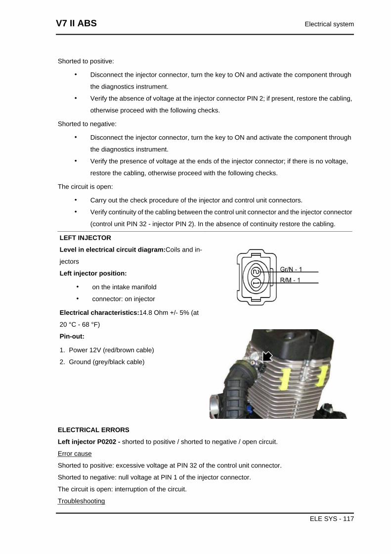
Shorted to positive:
• Disconnect the injector connector, turn the key to ON and activate the component through
the diagnostics instrument.
• Verify the absence of voltage at the injector connector PIN 2; if present, restore the cabling,
otherwise proceed with the following checks.
Shorted to negative:
• Disconnect the injector connector, turn the key to ON and activate the component through
the diagnostics instrument.
• Verify the presence of voltage at the ends of the injector connector; if there is no voltage,
restore the cabling, otherwise proceed with the following checks.
The circuit is open:
• Carry out the check procedure of the injector and control unit connectors.
• Verify continuity of the cabling between the control unit connector and the injector connector
(control unit PIN 32 - injector PIN 2). In the absence of continuity restore the cabling.
LEFT INJECTOR
Level in electrical circuit diagram:Coils and in-
jectors
Left injector position:
• on the intake manifold
• connector: on injector
Electrical characteristics:14.8 Ohm +/- 5% (at
20 °C - 68 °F)
Pin-out:
1. Power 12V (red/brown cable)
2. Ground (grey/black cable)
ELECTRICAL ERRORS
Left injector P0202 - shorted to positive / shorted to negative / open circuit.
Error cause
Shorted to positive: excessive voltage at PIN 32 of the control unit connector.
Shorted to negative: null voltage at PIN 1 of the injector connector.
The circuit is open: interruption of the circuit.
Troubleshooting
V7 II ABS Electrical system
ELE SYS - 117
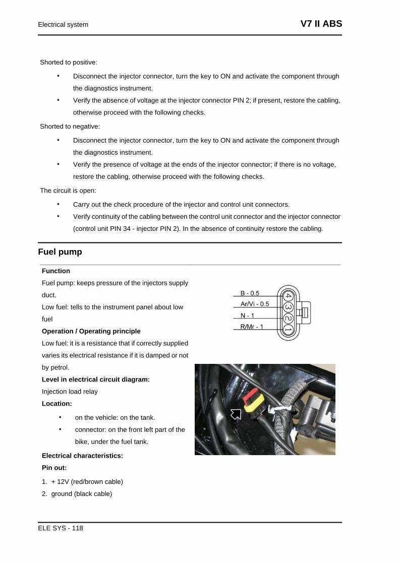
Shorted to positive:
• Disconnect the injector connector, turn the key to ON and activate the component through
the diagnostics instrument.
• Verify the absence of voltage at the injector connector PIN 2; if present, restore the cabling,
otherwise proceed with the following checks.
Shorted to negative:
• Disconnect the injector connector, turn the key to ON and activate the component through
the diagnostics instrument.
• Verify the presence of voltage at the ends of the injector connector; if there is no voltage,
restore the cabling, otherwise proceed with the following checks.
The circuit is open:
• Carry out the check procedure of the injector and control unit connectors.
• Verify continuity of the cabling between the control unit connector and the injector connector
(control unit PIN 34 - injector PIN 2). In the absence of continuity restore the cabling.
Fuel pump
Function
Fuel pump: keeps pressure of the injectors supply
duct.
Low fuel: tells to the instrument panel about low
fuel
Operation / Operating principle
Low fuel: it is a resistance that if correctly supplied
varies its electrical resistance if it is damped or not
by petrol.
Level in electrical circuit diagram:
Injection load relay
Location:
• on the vehicle: on the tank.
• connector: on the front left part of the
bike, under the fuel tank.
Electrical characteristics:
Pin out:
1. + 12V (red/brown cable)
2. ground (black cable)
Electrical system V7 II ABS
ELE SYS - 118
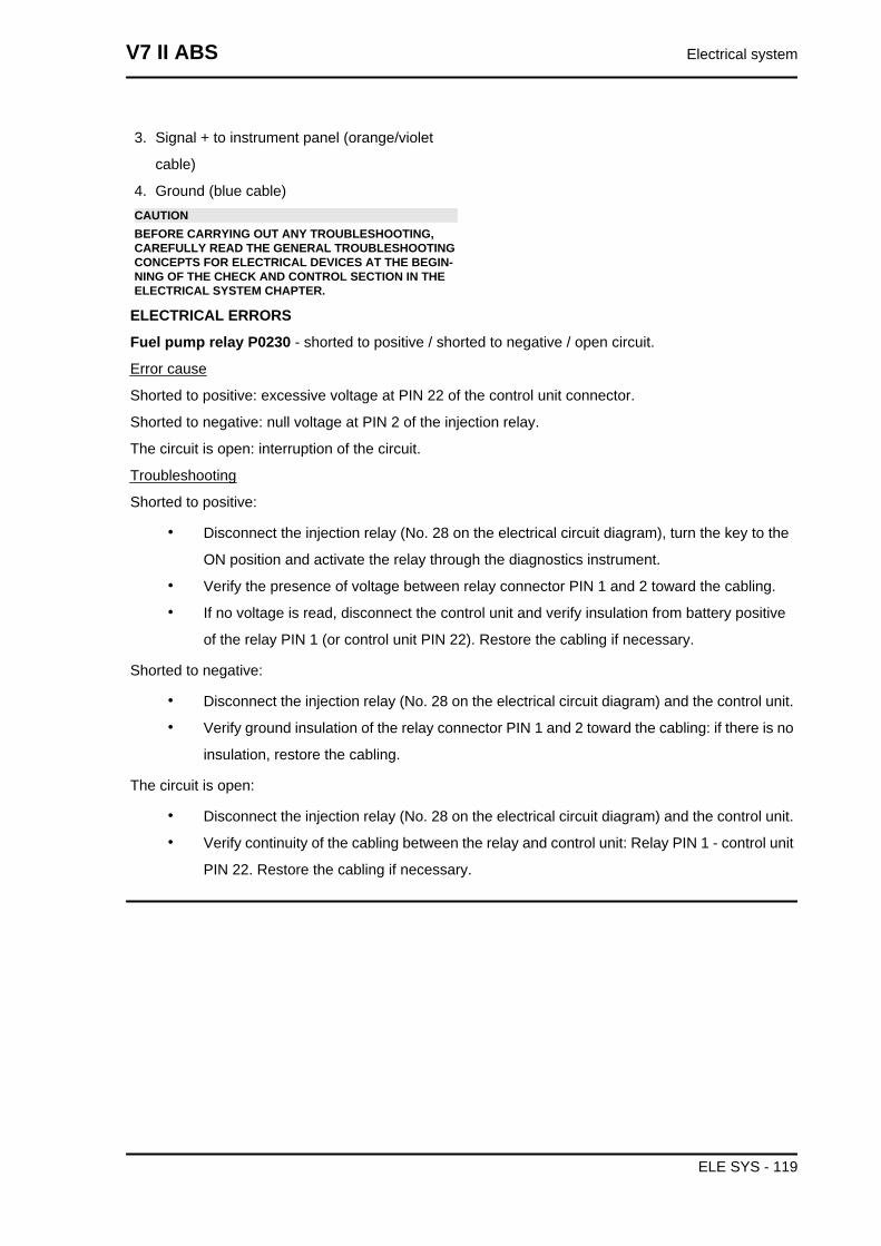
3. Signal + to instrument panel (orange/violet
cable)
4. Ground (blue cable)CAUTIONBEFORE CARRYING OUT ANY TROUBLESHOOTING,CAREFULLY READ THE GENERAL TROUBLESHOOTINGCONCEPTS FOR ELECTRICAL DEVICES AT THE BEGIN-NING OF THE CHECK AND CONTROL SECTION IN THEELECTRICAL SYSTEM CHAPTER.
ELECTRICAL ERRORS
Fuel pump relay P0230 - shorted to positive / shorted to negative / open circuit.
Error cause
Shorted to positive: excessive voltage at PIN 22 of the control unit connector.
Shorted to negative: null voltage at PIN 2 of the injection relay.
The circuit is open: interruption of the circuit.
Troubleshooting
Shorted to positive:
• Disconnect the injection relay (No. 28 on the electrical circuit diagram), turn the key to the
ON position and activate the relay through the diagnostics instrument.
• Verify the presence of voltage between relay connector PIN 1 and 2 toward the cabling.
• If no voltage is read, disconnect the control unit and verify insulation from battery positive
of the relay PIN 1 (or control unit PIN 22). Restore the cabling if necessary.
Shorted to negative:
• Disconnect the injection relay (No. 28 on the electrical circuit diagram) and the control unit.
• Verify ground insulation of the relay connector PIN 1 and 2 toward the cabling: if there is no
insulation, restore the cabling.
The circuit is open:
• Disconnect the injection relay (No. 28 on the electrical circuit diagram) and the control unit.
• Verify continuity of the cabling between the relay and control unit: Relay PIN 1 - control unit
PIN 22. Restore the cabling if necessary.
V7 II ABS Electrical system
ELE SYS - 119
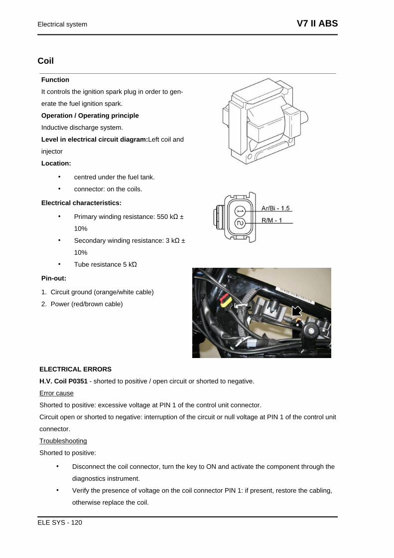
Coil
Function
It controls the ignition spark plug in order to gen-
erate the fuel ignition spark.
Operation / Operating principle
Inductive discharge system.
Level in electrical circuit diagram:Left coil and
injector
Location:
• centred under the fuel tank.
• connector: on the coils.
Electrical characteristics:
• Primary winding resistance: 550 kΩ ±
10%
• Secondary winding resistance: 3 kΩ ±
10%
• Tube resistance 5 kΏ
Pin-out:
1. Circuit ground (orange/white cable)
2. Power (red/brown cable)
ELECTRICAL ERRORS
H.V. Coil P0351 - shorted to positive / open circuit or shorted to negative.
Error cause
Shorted to positive: excessive voltage at PIN 1 of the control unit connector.
Circuit open or shorted to negative: interruption of the circuit or null voltage at PIN 1 of the control unit
connector.
Troubleshooting
Shorted to positive:
• Disconnect the coil connector, turn the key to ON and activate the component through the
diagnostics instrument.
• Verify the presence of voltage on the coil connector PIN 1: if present, restore the cabling,
otherwise replace the coil.
Electrical system V7 II ABS
ELE SYS - 120
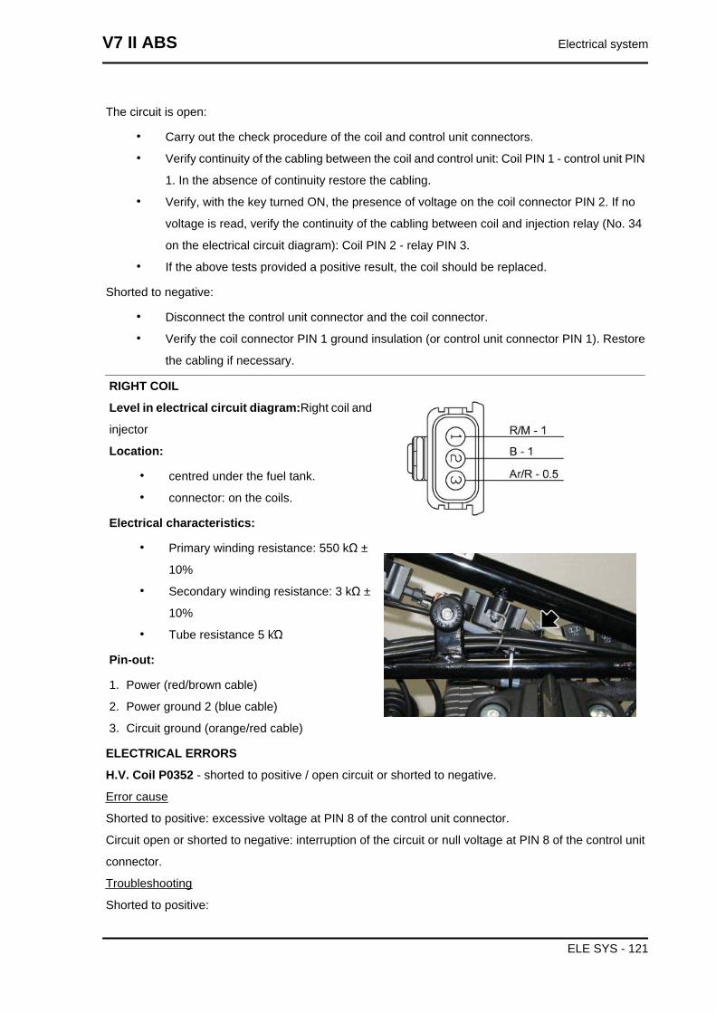
The circuit is open:
• Carry out the check procedure of the coil and control unit connectors.
• Verify continuity of the cabling between the coil and control unit: Coil PIN 1 - control unit PIN
1. In the absence of continuity restore the cabling.
• Verify, with the key turned ON, the presence of voltage on the coil connector PIN 2. If no
voltage is read, verify the continuity of the cabling between coil and injection relay (No. 34
on the electrical circuit diagram): Coil PIN 2 - relay PIN 3.
• If the above tests provided a positive result, the coil should be replaced.
Shorted to negative:
• Disconnect the control unit connector and the coil connector.
• Verify the coil connector PIN 1 ground insulation (or control unit connector PIN 1). Restore
the cabling if necessary.
RIGHT COIL
Level in electrical circuit diagram:Right coil and
injector
Location:
• centred under the fuel tank.
• connector: on the coils.
Electrical characteristics:
• Primary winding resistance: 550 kΩ ±
10%
• Secondary winding resistance: 3 kΩ ±
10%
• Tube resistance 5 kΏ
Pin-out:
1. Power (red/brown cable)
2. Power ground 2 (blue cable)
3. Circuit ground (orange/red cable)
ELECTRICAL ERRORS
H.V. Coil P0352 - shorted to positive / open circuit or shorted to negative.
Error cause
Shorted to positive: excessive voltage at PIN 8 of the control unit connector.
Circuit open or shorted to negative: interruption of the circuit or null voltage at PIN 8 of the control unit
connector.
Troubleshooting
Shorted to positive:
V7 II ABS Electrical system
ELE SYS - 121
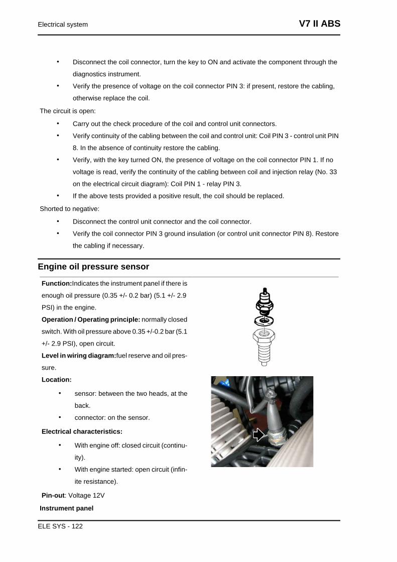
• Disconnect the coil connector, turn the key to ON and activate the component through the
diagnostics instrument.
• Verify the presence of voltage on the coil connector PIN 3: if present, restore the cabling,
otherwise replace the coil.
The circuit is open:
• Carry out the check procedure of the coil and control unit connectors.
• Verify continuity of the cabling between the coil and control unit: Coil PIN 3 - control unit PIN
8. In the absence of continuity restore the cabling.
• Verify, with the key turned ON, the presence of voltage on the coil connector PIN 1. If no
voltage is read, verify the continuity of the cabling between coil and injection relay (No. 33
on the electrical circuit diagram): Coil PIN 1 - relay PIN 3.
• If the above tests provided a positive result, the coil should be replaced.
Shorted to negative:
• Disconnect the control unit connector and the coil connector.
• Verify the coil connector PIN 3 ground insulation (or control unit connector PIN 8). Restore
the cabling if necessary.
Engine oil pressure sensor
Function:Indicates the instrument panel if there is
enough oil pressure (0.35 +/- 0.2 bar) (5.1 +/- 2.9
PSI) in the engine.
Operation / Operating principle: normally closed
switch. With oil pressure above 0.35 +/-0.2 bar (5.1
+/- 2.9 PSI), open circuit.
Level in wiring diagram:fuel reserve and oil pres-
sure.
Location:
• sensor: between the two heads, at the
back.
• connector: on the sensor.
Electrical characteristics:
• With engine off: closed circuit (continu-
ity).
• With engine started: open circuit (infin-
ite resistance).
Pin-out: Voltage 12V
Instrument panel
Electrical system V7 II ABS
ELE SYS - 122
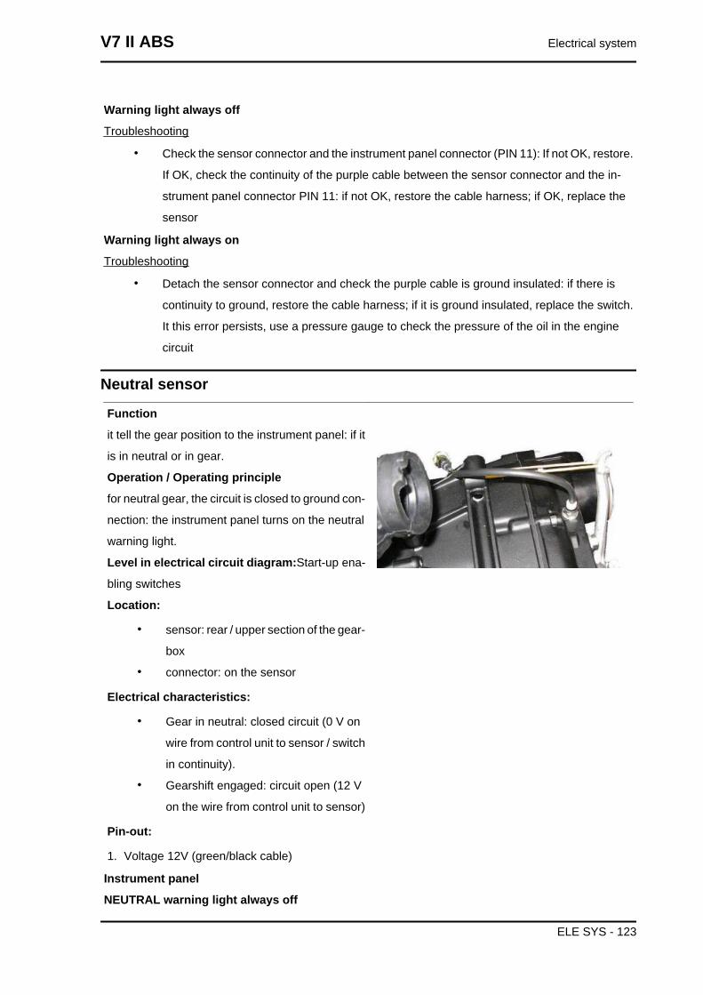
Warning light always off
Troubleshooting
• Check the sensor connector and the instrument panel connector (PIN 11): If not OK, restore.
If OK, check the continuity of the purple cable between the sensor connector and the in-
strument panel connector PIN 11: if not OK, restore the cable harness; if OK, replace the
sensor
Warning light always on
Troubleshooting
• Detach the sensor connector and check the purple cable is ground insulated: if there is
continuity to ground, restore the cable harness; if it is ground insulated, replace the switch.
It this error persists, use a pressure gauge to check the pressure of the oil in the engine
circuit
Neutral sensor
Function
it tell the gear position to the instrument panel: if it
is in neutral or in gear.
Operation / Operating principle
for neutral gear, the circuit is closed to ground con-
nection: the instrument panel turns on the neutral
warning light.
Level in electrical circuit diagram:Start-up ena-
bling switches
Location:
• sensor: rear / upper section of the gear-
box
• connector: on the sensor
Electrical characteristics:
• Gear in neutral: closed circuit (0 V on
wire from control unit to sensor / switch
in continuity).
• Gearshift engaged: circuit open (12 V
on the wire from control unit to sensor)
Pin-out:
1. Voltage 12V (green/black cable)
Instrument panel
NEUTRAL warning light always off
V7 II ABS Electrical system
ELE SYS - 123
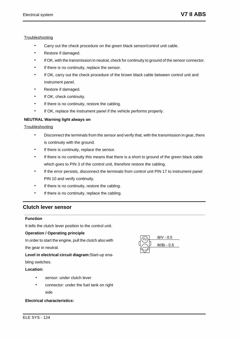
Troubleshooting
• Carry out the check procedure on the green black sensor/control unit cable.
• Restore if damaged.
• If OK, with the transmission in neutral, check for continuity to ground of the sensor connector.
• If there is no continuity, replace the sensor.
• If OK, carry out the check procedure of the brown black cable between control unit and
instrument panel.
• Restore if damaged.
• If OK, check continuity.
• If there is no continuity, restore the cabling.
• If OK, replace the instrument panel if the vehicle performs properly.
NEUTRAL Warning light always on
Troubleshooting
• Disconnect the terminals from the sensor and verify that, with the transmission in gear, there
is continuity with the ground.
• If there is continuity, replace the sensor.
• If there is no continuity this means that there is a short to ground of the green black cable
which goes to PIN 3 of the control unit, therefore restore the cabling.
• If the error persists, disconnect the terminals from control unit PIN 17 to instrument panel
PIN 10 and verify continuity.
• If there is no continuity, restore the cabling.
• If there is no continuity, replace the cabling.
Clutch lever sensor
Function
It tells the clutch lever position to the control unit.
Operation / Operating principle
In order to start the engine, pull the clutch also with
the gear in neutral.
Level in electrical circuit diagram:Start-up ena-
bling switches.
Location:
• sensor: under clutch lever
• connector: under the fuel tank on right
side
Electrical characteristics:
Electrical system V7 II ABS
ELE SYS - 124
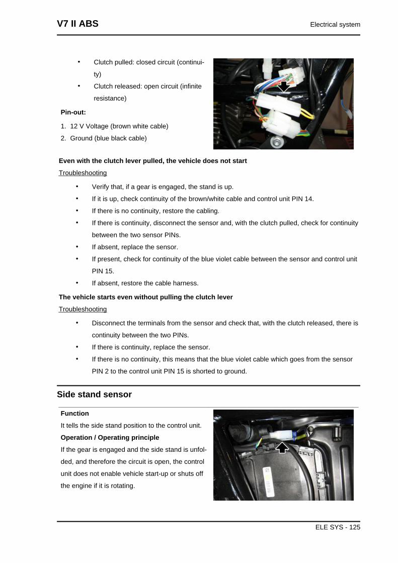
• Clutch pulled: closed circuit (continui-
ty)
• Clutch released: open circuit (infinite
resistance)
Pin-out:
1. 12 V Voltage (brown white cable)
2. Ground (blue black cable)
Even with the clutch lever pulled, the vehicle does not start
Troubleshooting
• Verify that, if a gear is engaged, the stand is up.
• If it is up, check continuity of the brown/white cable and control unit PIN 14.
• If there is no continuity, restore the cabling.
• If there is continuity, disconnect the sensor and, with the clutch pulled, check for continuity
between the two sensor PINs.
• If absent, replace the sensor.
• If present, check for continuity of the blue violet cable between the sensor and control unit
PIN 15.
• If absent, restore the cable harness.
The vehicle starts even without pulling the clutch lever
Troubleshooting
• Disconnect the terminals from the sensor and check that, with the clutch released, there is
continuity between the two PINs.
• If there is continuity, replace the sensor.
• If there is no continuity, this means that the blue violet cable which goes from the sensor
PIN 2 to the control unit PIN 15 is shorted to ground.
Side stand sensor
Function
It tells the side stand position to the control unit.
Operation / Operating principle
If the gear is engaged and the side stand is unfol-
ded, and therefore the circuit is open, the control
unit does not enable vehicle start-up or shuts off
the engine if it is rotating.
V7 II ABS Electrical system
ELE SYS - 125
Level in electrical circuit diagram:Start-up ena-
bling switches
Location:
• sensor: on side stand supporting plate
• connector: left side, near the starter
motor
Electrical characteristics:
• Side Stand Up: closed circuit (continu-
ity)
• Side Stand Down: open circuit (infinite
resistance)
Pin-out:
• Blue green (cable harness side):
ground connection
• Grey yellow (cable harness side): Volt-
age 12V
Troubleshooting
• The vehicle with clutch pulled, gear engaged and side stand retracted does not start (side
stand switch always open): verify continuity of the grey/yellow cable between the sensor and
PIN 19 of the control unit.
• If absent, restore the cable harness, if present, with the stand up, check for continuity be-
tween the 2 PINs on the sensor. If absent, replace the sensor. If present, check for continuity
to ground of the blue/green cable on the cable harness side connector.
• The vehicle, with clutch operated and gear engaged, starts but with the side stand extended:
disconnect the sensor connector and check that, with side stand extended, there is not
continuity between the 2 PINS.
• If present, replace the sensor. If absent, disconnect from control unit PIN 19 and check
insulation from the ground of the grey/yellow cable between sensor and control unit.
Electrical system V7 II ABS
ELE SYS - 126
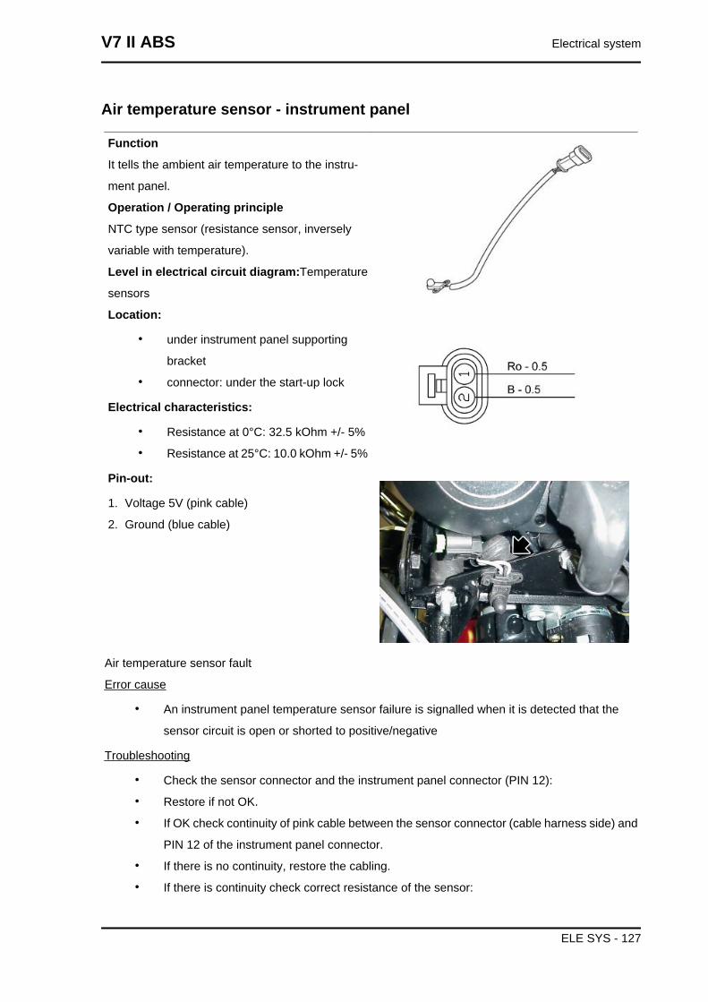
Air temperature sensor - instrument panel
Function
It tells the ambient air temperature to the instru-
ment panel.
Operation / Operating principle
NTC type sensor (resistance sensor, inversely
variable with temperature).
Level in electrical circuit diagram:Temperature
sensors
Location:
• under instrument panel supporting
bracket
• connector: under the start-up lock
Electrical characteristics:
• Resistance at 0°C: 32.5 kOhm +/- 5%
• Resistance at 25°C: 10.0 kOhm +/- 5%
Pin-out:
1. Voltage 5V (pink cable)
2. Ground (blue cable)
Air temperature sensor fault
Error cause
• An instrument panel temperature sensor failure is signalled when it is detected that the
sensor circuit is open or shorted to positive/negative
Troubleshooting
• Check the sensor connector and the instrument panel connector (PIN 12):
• Restore if not OK.
• If OK check continuity of pink cable between the sensor connector (cable harness side) and
PIN 12 of the instrument panel connector.
• If there is no continuity, restore the cabling.
• If there is continuity check correct resistance of the sensor:
V7 II ABS Electrical system
ELE SYS - 127
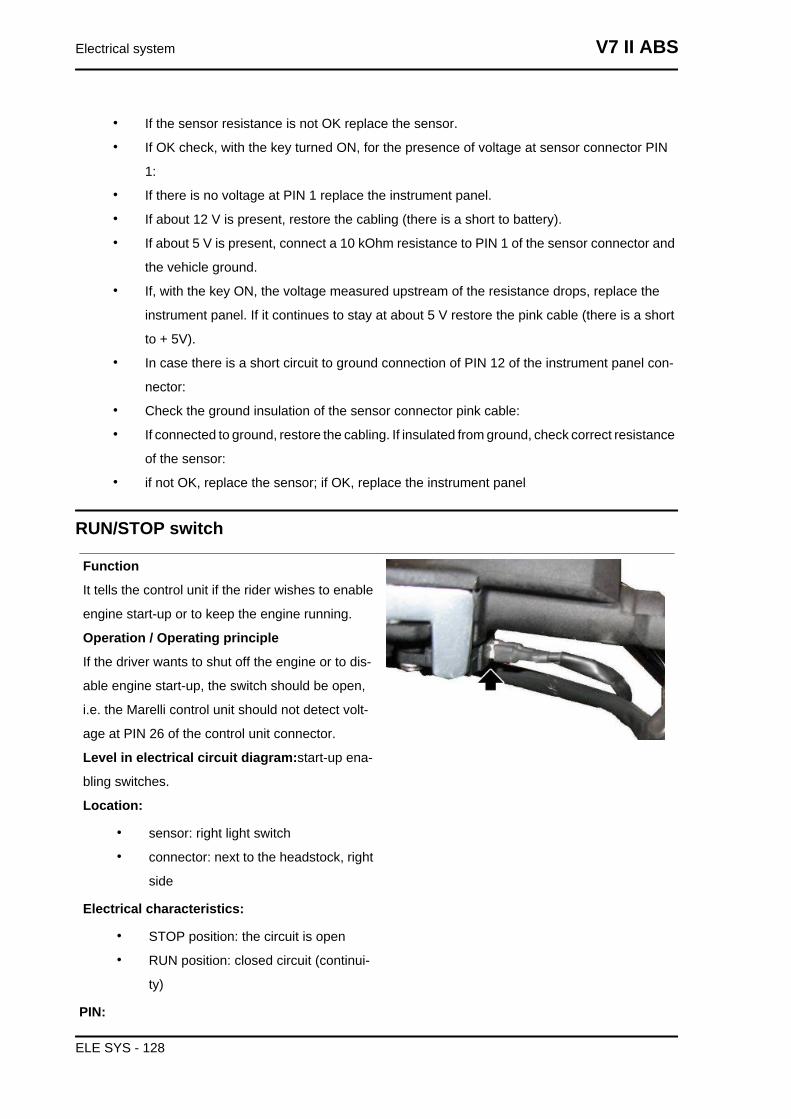
• If the sensor resistance is not OK replace the sensor.
• If OK check, with the key turned ON, for the presence of voltage at sensor connector PIN
1:
• If there is no voltage at PIN 1 replace the instrument panel.
• If about 12 V is present, restore the cabling (there is a short to battery).
• If about 5 V is present, connect a 10 kOhm resistance to PIN 1 of the sensor connector and
the vehicle ground.
• If, with the key ON, the voltage measured upstream of the resistance drops, replace the
instrument panel. If it continues to stay at about 5 V restore the pink cable (there is a short
to + 5V).
• In case there is a short circuit to ground connection of PIN 12 of the instrument panel con-
nector:
• Check the ground insulation of the sensor connector pink cable:
• If connected to ground, restore the cabling. If insulated from ground, check correct resistance
of the sensor:
• if not OK, replace the sensor; if OK, replace the instrument panel
RUN/STOP switch
Function
It tells the control unit if the rider wishes to enable
engine start-up or to keep the engine running.
Operation / Operating principle
If the driver wants to shut off the engine or to dis-
able engine start-up, the switch should be open,
i.e. the Marelli control unit should not detect volt-
age at PIN 26 of the control unit connector.
Level in electrical circuit diagram:start-up ena-
bling switches.
Location:
• sensor: right light switch
• connector: next to the headstock, right
side
Electrical characteristics:
• STOP position: the circuit is open
• RUN position: closed circuit (continui-
ty)
PIN:
Electrical system V7 II ABS
ELE SYS - 128
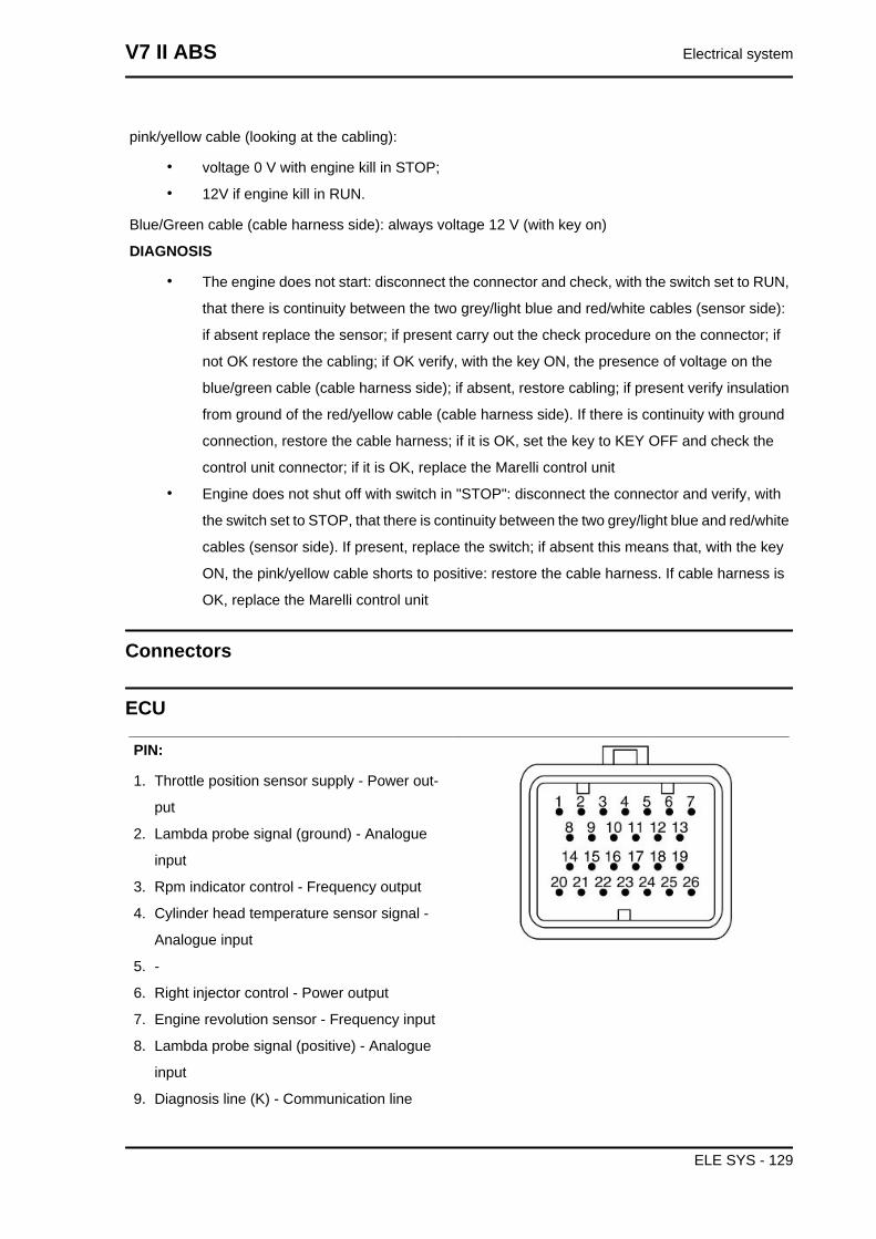
pink/yellow cable (looking at the cabling):
• voltage 0 V with engine kill in STOP;
• 12V if engine kill in RUN.
Blue/Green cable (cable harness side): always voltage 12 V (with key on)
DIAGNOSIS
• The engine does not start: disconnect the connector and check, with the switch set to RUN,
that there is continuity between the two grey/light blue and red/white cables (sensor side):
if absent replace the sensor; if present carry out the check procedure on the connector; if
not OK restore the cabling; if OK verify, with the key ON, the presence of voltage on the
blue/green cable (cable harness side); if absent, restore cabling; if present verify insulation
from ground of the red/yellow cable (cable harness side). If there is continuity with ground
connection, restore the cable harness; if it is OK, set the key to KEY OFF and check the
control unit connector; if it is OK, replace the Marelli control unit
• Engine does not shut off with switch in "STOP": disconnect the connector and verify, with
the switch set to STOP, that there is continuity between the two grey/light blue and red/white
cables (sensor side). If present, replace the switch; if absent this means that, with the key
ON, the pink/yellow cable shorts to positive: restore the cable harness. If cable harness is
OK, replace the Marelli control unit
Connectors
ECU
PIN:
1. Throttle position sensor supply - Power out-
put
2. Lambda probe signal (ground) - Analogue
input
3. Rpm indicator control - Frequency output
4. Cylinder head temperature sensor signal -
Analogue input
5. -
6. Right injector control - Power output
7. Engine revolution sensor - Frequency input
8. Lambda probe signal (positive) - Analogue
input
9. Diagnosis line (K) - Communication line
V7 II ABS Electrical system
ELE SYS - 129
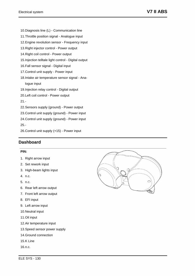
10.Diagnosis line (L) - Communication line
11.Throttle position signal - Analogue input
12.Engine revolution sensor - Frequency input
13.Right injector control - Power output
14.Right coil control - Power output
15.Injection telltale light control - Digital output
16.Fall sensor signal - Digital input
17.Control unit supply - Power input
18.Intake air temperature sensor signal - Ana-
logue input
19.Injection relay control - Digital output
20.Left coil control - Power output
21.-
22.Sensors supply (ground) - Power output
23.Control unit supply (ground) - Power input
24.Control unit supply (ground) - Power input
25.-
26.Control unit supply (+15) - Power input
Dashboard
PIN:
1. Right arrow input
2. Set rework input
3. High-beam lights input
4. n.c.
5. n.c.
6. Rear left arrow output
7. Front left arrow output
8. EFI input
9. Left arrow input
10.Neutral input
11.Oil input
12.Air temperature input
13.Speed sensor power supply
14.Ground connection
15.K Line
16.n.c.
Electrical system V7 II ABS
ELE SYS - 130
17.Speed input
18.Engine revs input
19.n.c.
20.Reserve input
21.Key
22.Ground connection
23.Battery
24.Front right arrow output
25.Rear right arrow output
26.Battery
V7 II ABS Electrical system
ELE SYS - 131
INDEX OF TOPICS
ENGINE FROM VEHICLE ENG VE
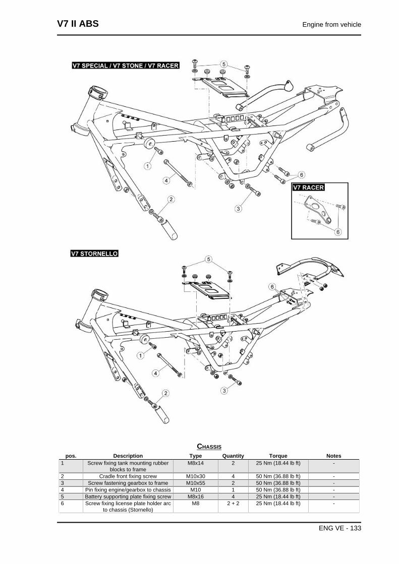
CHASSISpos. Description Type Quantity Torque Notes
1 Screw fixing tank mounting rubberblocks to frame
M8x14 2 25 Nm (18.44 lb ft) -
2 Cradle front fixing screw M10x30 4 50 Nm (36.88 lb ft) -3 Screw fastening gearbox to frame M10x55 2 50 Nm (36.88 lb ft) -4 Pin fixing engine/gearbox to chassis M10 1 50 Nm (36.88 lb ft) -5 Battery supporting plate fixing screw M8x16 4 25 Nm (18.44 lb ft) -6 Screw fixing license plate holder arc
to chassis (Stornello)M8 2 + 2 25 Nm (18.44 lb ft) -
V7 II ABS Engine from vehicle
ENG VE - 133
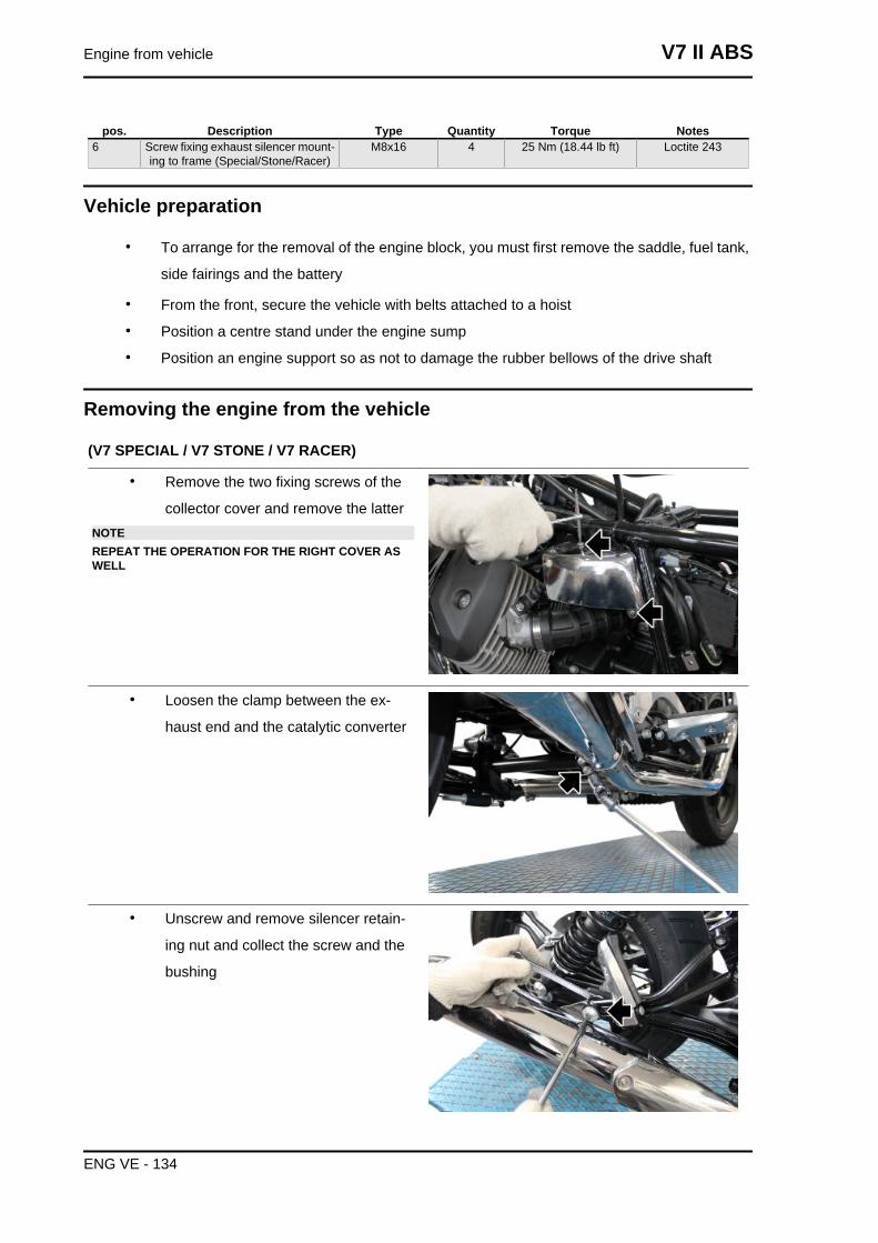
pos. Description Type Quantity Torque Notes6 Screw fixing exhaust silencer mount-
ing to frame (Special/Stone/Racer)M8x16 4 25 Nm (18.44 lb ft) Loctite 243
Vehicle preparation
• To arrange for the removal of the engine block, you must first remove the saddle, fuel tank,
side fairings and the battery
• From the front, secure the vehicle with belts attached to a hoist
• Position a centre stand under the engine sump
• Position an engine support so as not to damage the rubber bellows of the drive shaft
Removing the engine from the vehicle
(V7 SPECIAL / V7 STONE / V7 RACER)
• Remove the two fixing screws of the
collector cover and remove the latterNOTEREPEAT THE OPERATION FOR THE RIGHT COVER ASWELL
• Loosen the clamp between the ex-
haust end and the catalytic converter
• Unscrew and remove silencer retain-
ing nut and collect the screw and the
bushing
Engine from vehicle V7 II ABS
ENG VE - 134
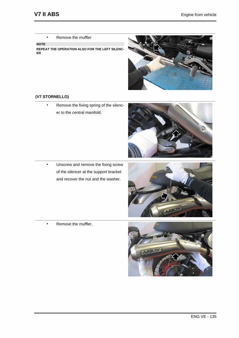
• Remove the mufflerNOTEREPEAT THE OPERATION ALSO FOR THE LEFT SILENC-ER
(V7 STORNELLO)
• Remove the fixing spring of the silenc-
er to the central manifold.
• Unscrew and remove the fixing screw
of the silencer at the support bracket
and recover the nut and the washer.
• Remove the muffler.
V7 II ABS Engine from vehicle
ENG VE - 135
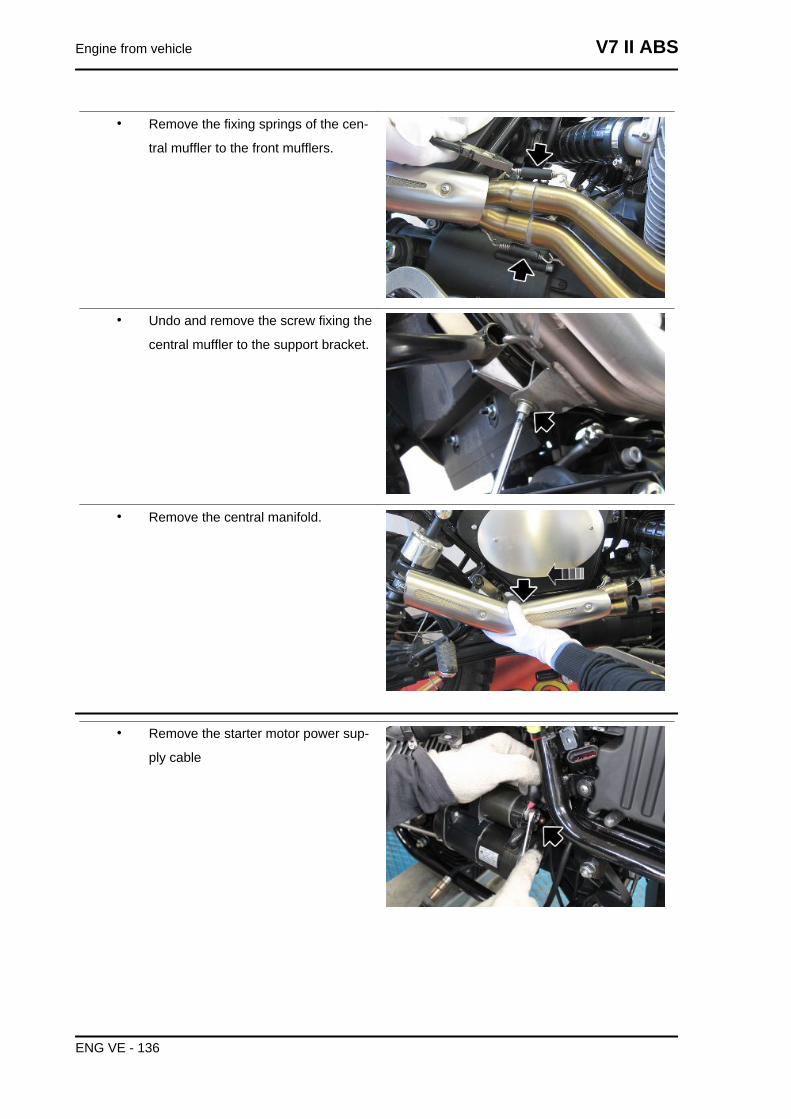
• Remove the fixing springs of the cen-
tral muffler to the front mufflers.
• Undo and remove the screw fixing the
central muffler to the support bracket.
• Remove the central manifold.
• Remove the starter motor power sup-
ply cable
Engine from vehicle V7 II ABS
ENG VE - 136
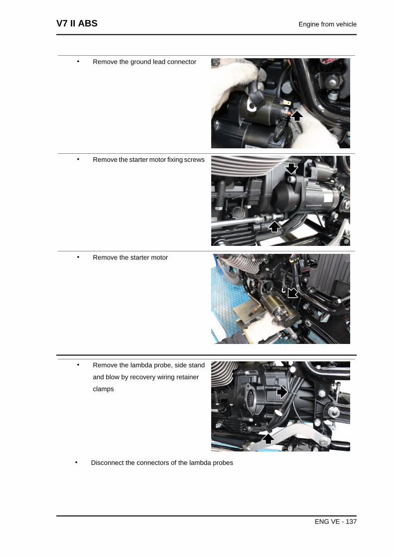
• Remove the ground lead connector
• Remove the starter motor fixing screws
• Remove the starter motor
• Remove the lambda probe, side stand
and blow by recovery wiring retainer
clamps
• Disconnect the connectors of the lambda probes
V7 II ABS Engine from vehicle
ENG VE - 137
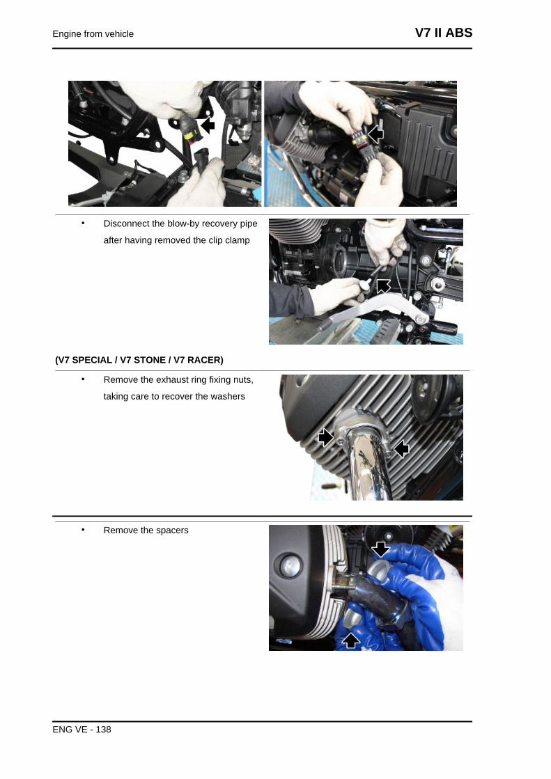
• Disconnect the blow-by recovery pipe
after having removed the clip clamp
(V7 SPECIAL / V7 STONE / V7 RACER)
• Remove the exhaust ring fixing nuts,
taking care to recover the washers
• Remove the spacers
Engine from vehicle V7 II ABS
ENG VE - 138
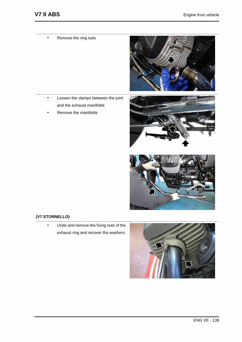
• Remove the ring nuts
• Loosen the clamps between the joint
and the exhaust manifolds
• Remove the manifolds
(V7 STORNELLO)
• Undo and remove the fixing nuts of the
exhaust ring and recover the washers.
V7 II ABS Engine from vehicle
ENG VE - 139
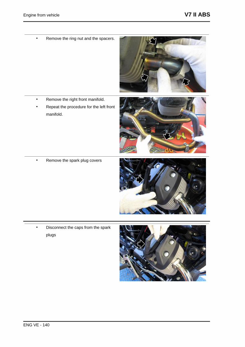
• Remove the ring nut and the spacers.
• Remove the right front manifold.
• Repeat the procedure for the left front
manifold.
• Remove the spark plug covers
• Disconnect the caps from the spark
plugs
Engine from vehicle V7 II ABS
ENG VE - 140
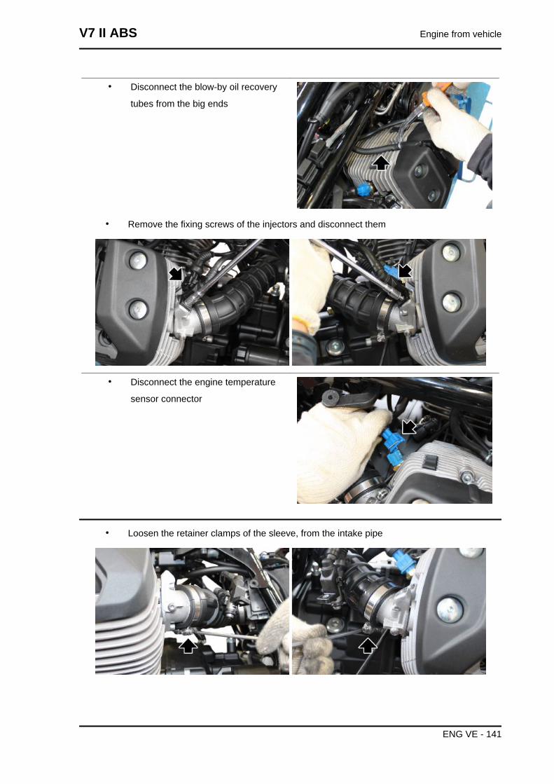
• Disconnect the blow-by oil recovery
tubes from the big ends
• Remove the fixing screws of the injectors and disconnect them
• Disconnect the engine temperature
sensor connector
• Loosen the retainer clamps of the sleeve, from the intake pipe
V7 II ABS Engine from vehicle
ENG VE - 141
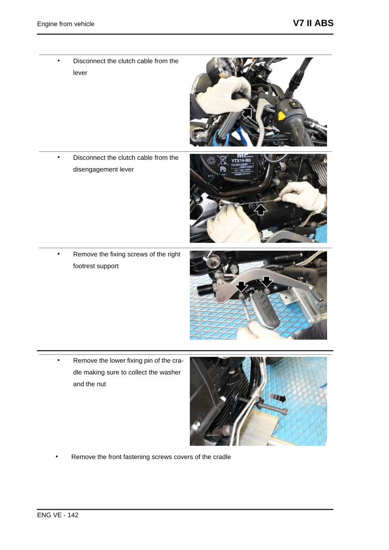
• Disconnect the clutch cable from the
lever
• Disconnect the clutch cable from the
disengagement lever
• Remove the fixing screws of the right
footrest support
• Remove the lower fixing pin of the cra-
dle making sure to collect the washer
and the nut
• Remove the front fastening screws covers of the cradle
Engine from vehicle V7 II ABS
ENG VE - 142
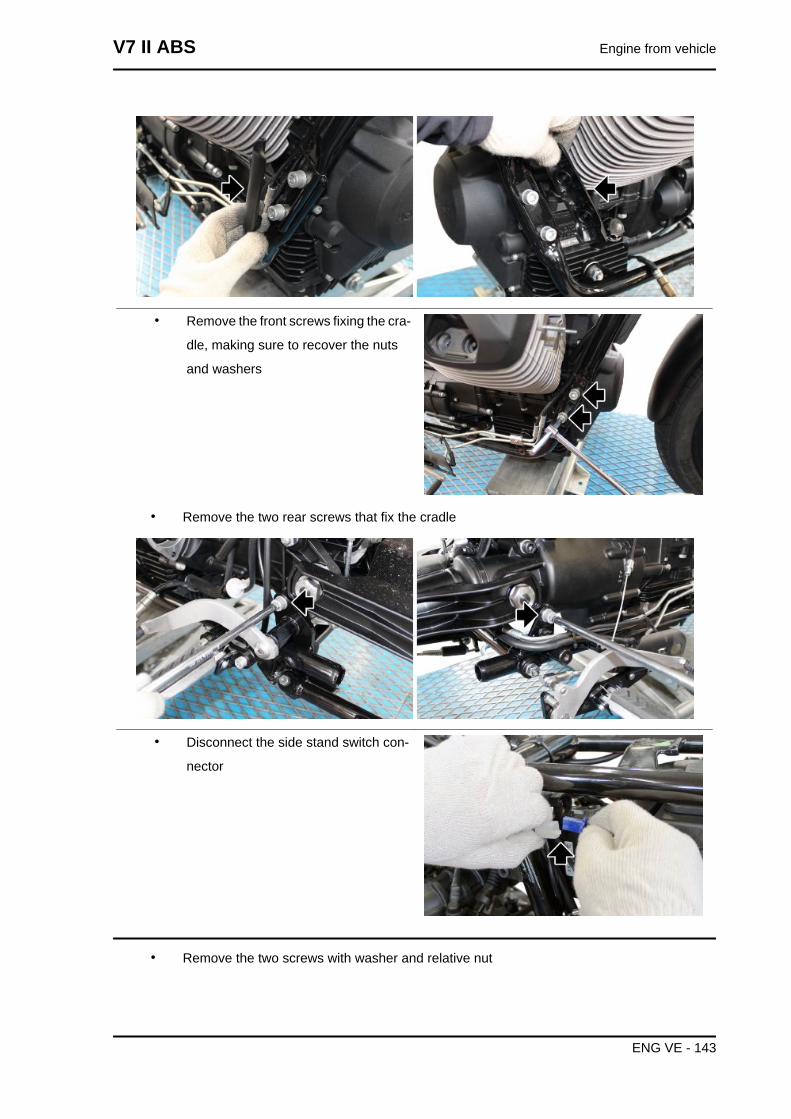
• Remove the front screws fixing the cra-
dle, making sure to recover the nuts
and washers
• Remove the two rear screws that fix the cradle
• Disconnect the side stand switch con-
nector
• Remove the two screws with washer and relative nut
V7 II ABS Engine from vehicle
ENG VE - 143
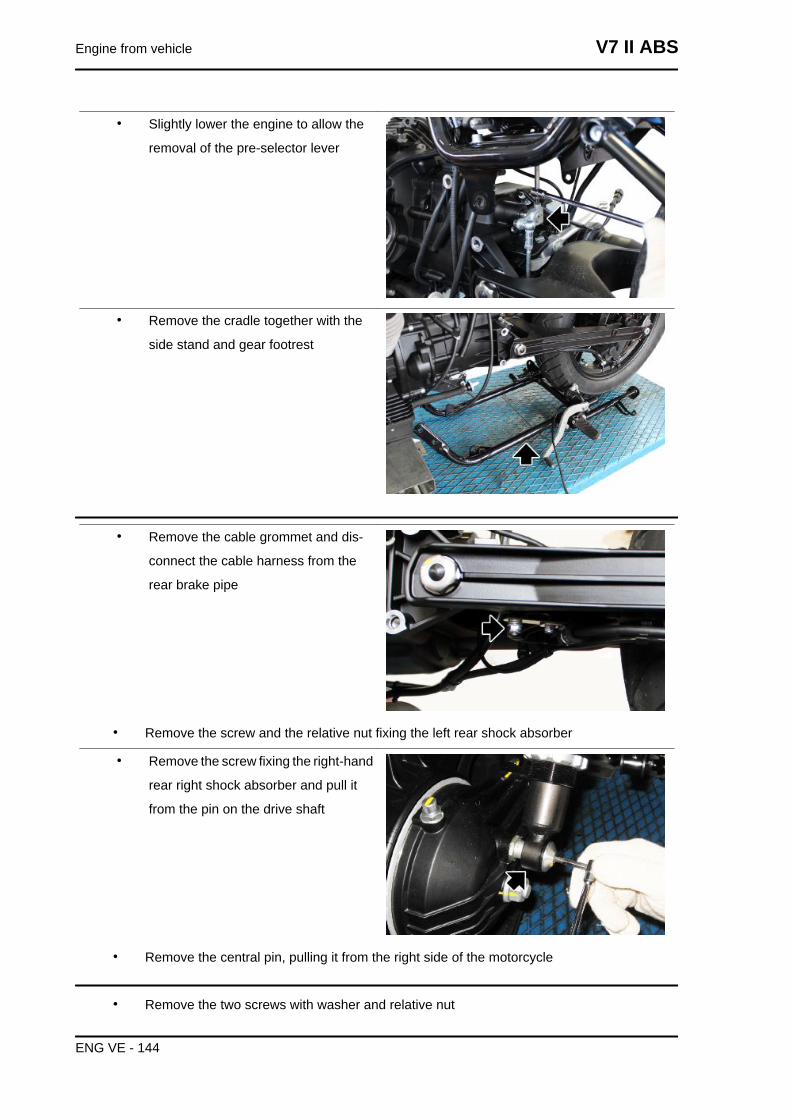
• Slightly lower the engine to allow the
removal of the pre-selector lever
• Remove the cradle together with the
side stand and gear footrest
• Remove the cable grommet and dis-
connect the cable harness from the
rear brake pipe
• Remove the screw and the relative nut fixing the left rear shock absorber
• Remove the screw fixing the right-hand
rear right shock absorber and pull it
from the pin on the drive shaft
• Remove the central pin, pulling it from the right side of the motorcycle
• Remove the two screws with washer and relative nut
Engine from vehicle V7 II ABS
ENG VE - 144
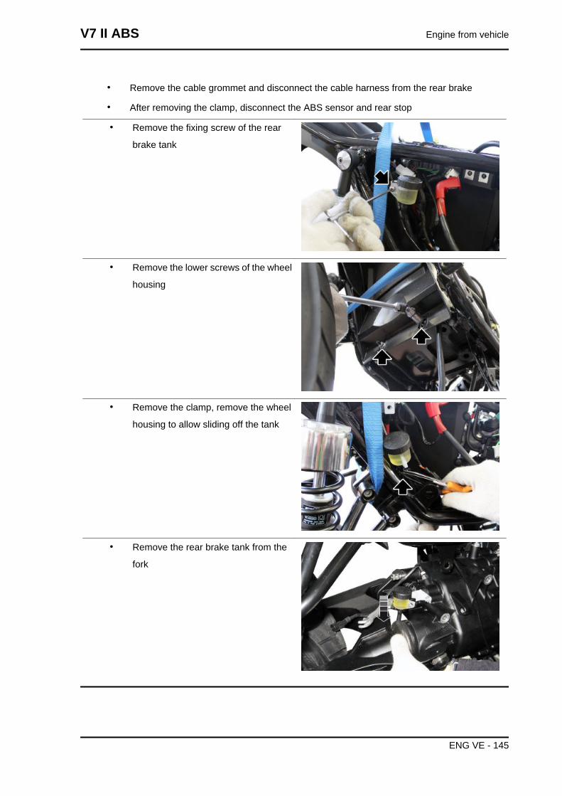
• Remove the cable grommet and disconnect the cable harness from the rear brake
• After removing the clamp, disconnect the ABS sensor and rear stop
• Remove the fixing screw of the rear
brake tank
• Remove the lower screws of the wheel
housing
• Remove the clamp, remove the wheel
housing to allow sliding off the tank
• Remove the rear brake tank from the
fork
V7 II ABS Engine from vehicle
ENG VE - 145
INDEX OF TOPICS
ENGINE ENG
TO CONSULT THE CHAPTER ABOUT THE ENGINE AND ITS COMPONENTS PLEASE REFER TO
THE APPROPRIATE MANUAL:
"MSS Engine V750 IE My2012"
V7 II ABS Engine
ENG - 147
INDEX OF TOPICS
POWER SUPPLY P SUPP
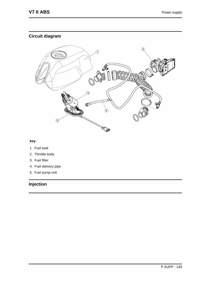
Circuit diagram
key:
1. Fuel tank
2. Throttle body
3. Fuel filter
4. Fuel delivery pipe
5. Fuel pump unit
Injection
V7 II ABS Power supply
P SUPP - 149
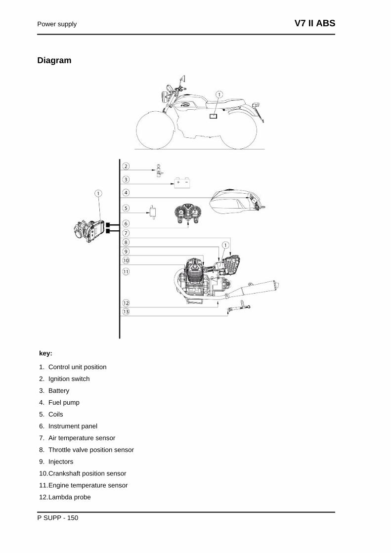
Diagram
key:
1. Control unit position
2. Ignition switch
3. Battery
4. Fuel pump
5. Coils
6. Instrument panel
7. Air temperature sensor
8. Throttle valve position sensor
9. Injectors
10.Crankshaft position sensor
11.Engine temperature sensor
12.Lambda probe
Power supply V7 II ABS
P SUPP - 150
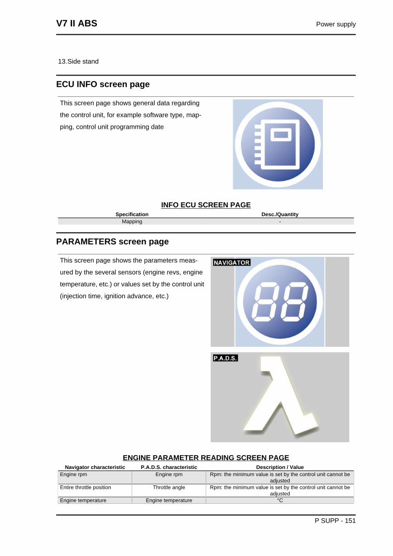
13.Side stand
ECU INFO screen page
This screen page shows general data regarding
the control unit, for example software type, map-
ping, control unit programming date
INFO ECU SCREEN PAGESpecification Desc./Quantity
Mapping -
PARAMETERS screen page
This screen page shows the parameters meas-
ured by the several sensors (engine revs, engine
temperature, etc.) or values set by the control unit
(injection time, ignition advance, etc.)
ENGINE PARAMETER READING SCREEN PAGENavigator characteristic P.A.D.S. characteristic Description / Value
Engine rpm Engine rpm Rpm: the minimum value is set by the control unit cannot beadjusted
Entire throttle position Throttle angle Rpm: the minimum value is set by the control unit cannot beadjusted
Engine temperature Engine temperature °C
V7 II ABS Power supply
P SUPP - 151
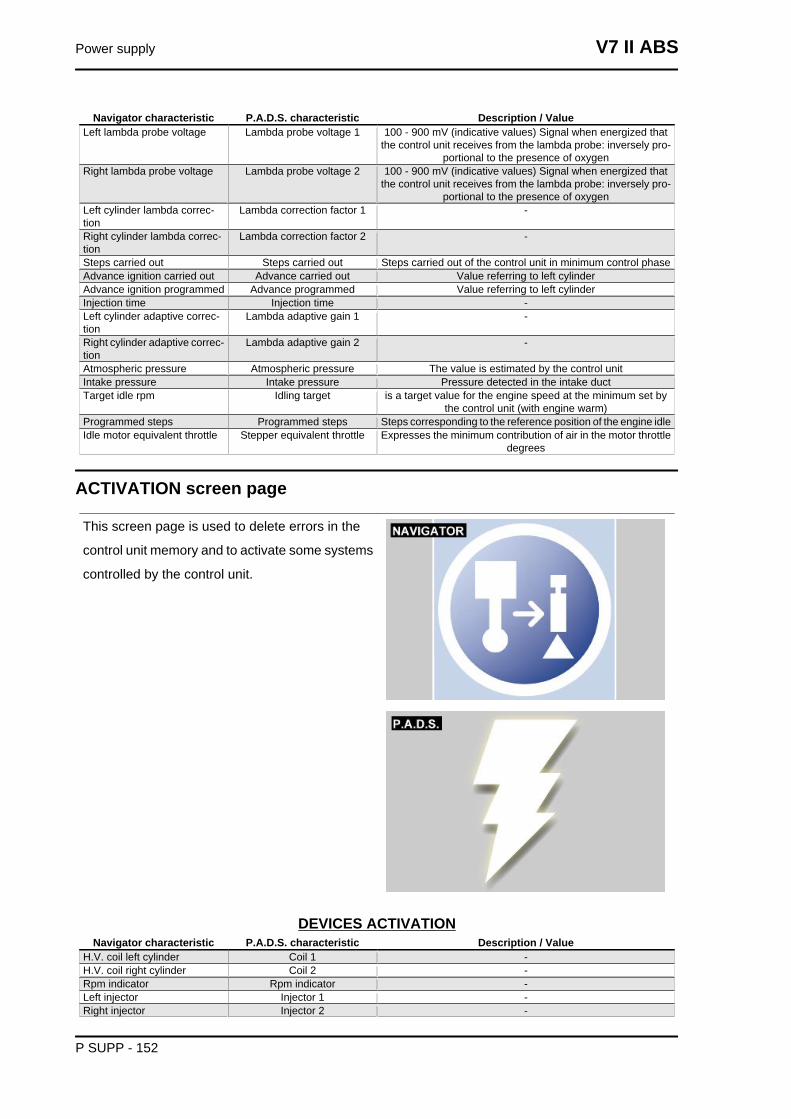
Navigator characteristic P.A.D.S. characteristic Description / ValueLeft lambda probe voltage Lambda probe voltage 1 100 - 900 mV (indicative values) Signal when energized that
the control unit receives from the lambda probe: inversely pro-portional to the presence of oxygen
Right lambda probe voltage Lambda probe voltage 2 100 - 900 mV (indicative values) Signal when energized thatthe control unit receives from the lambda probe: inversely pro-
portional to the presence of oxygenLeft cylinder lambda correc-tion
Lambda correction factor 1 -
Right cylinder lambda correc-tion
Lambda correction factor 2 -
Steps carried out Steps carried out Steps carried out of the control unit in minimum control phaseAdvance ignition carried out Advance carried out Value referring to left cylinderAdvance ignition programmed Advance programmed Value referring to left cylinderInjection time Injection time -Left cylinder adaptive correc-tion
Lambda adaptive gain 1 -
Right cylinder adaptive correc-tion
Lambda adaptive gain 2 -
Atmospheric pressure Atmospheric pressure The value is estimated by the control unitIntake pressure Intake pressure Pressure detected in the intake ductTarget idle rpm Idling target is a target value for the engine speed at the minimum set by
the control unit (with engine warm)Programmed steps Programmed steps Steps corresponding to the reference position of the engine idleIdle motor equivalent throttle Stepper equivalent throttle Expresses the minimum contribution of air in the motor throttle
degrees
ACTIVATION screen page
This screen page is used to delete errors in the
control unit memory and to activate some systems
controlled by the control unit.
DEVICES ACTIVATIONNavigator characteristic P.A.D.S. characteristic Description / Value
H.V. coil left cylinder Coil 1 -H.V. coil right cylinder Coil 2 -Rpm indicator Rpm indicator -Left injector Injector 1 -Right injector Injector 2 -
Power supply V7 II ABS
P SUPP - 152
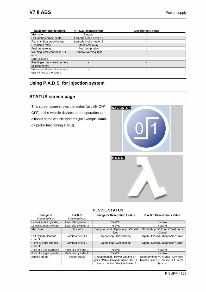
Navigator characteristic P.A.D.S. characteristic Description / ValueIdle motor Stepper -Left lambda probe heater Lambda probe heater 1 -Right lambda probe heater Lambda probe heater 2 -Headlamp relay Headlamp relay -Fuel pump relay Fuel pump relay -Warning lamp control or EFIicon
General warning light -
Error clearing - -Reading errors of environmen-tal parameters
- -
Freezes and saves the param-eter values of the states
- -
Using P.A.D.S. for injection system
STATUS screen page
This screen page shows the status (usually ON/
OFF) of the vehicle devices or the operation con-
dition of some vehicle systems (for example, lamb-
da probe functioning status).
DEVICE STATUSNavigator
characteristicP.A.D.S.
characteristicNavigator Description / Value P.A.D.S Description / Value
Lean title (left cylinder) Lean title cylinder 1 Yes/No Yes/NoLean title (right cylinder) Lean title cylinder 2 Yes/No Yes/NoIdle motor Idle motor Ready for start / Open loop / Closed
loopOK start-up / O.Loop / ClosLoop /
ClosedLeft cylinder lambdacontrol
Lambda circuit 1 Open loop / Closed loop Open / Closed / Diagnosis / Error
Right cylinder lambdacontrol
Lambda circuit 2 Open loop / Closed loop Open / Closed / Diagnosis / Error
Rich title (left cylinder) Rich title cylinder 1 Yes/No Yes/NoRich title (right cylinder) Rich title cylinder 2 Yes/No Yes/NoEngine status Engine status Undetermined / Power-On and En-
gine Off/ Key-On and Engine Off/ En-gine in rotation / Engine Stalled /
Undetermined / ON/Stop / Key/Stop /Rotat. / Stall / PL course / PL Term /
Sync_4t
V7 II ABS Power supply
P SUPP - 153
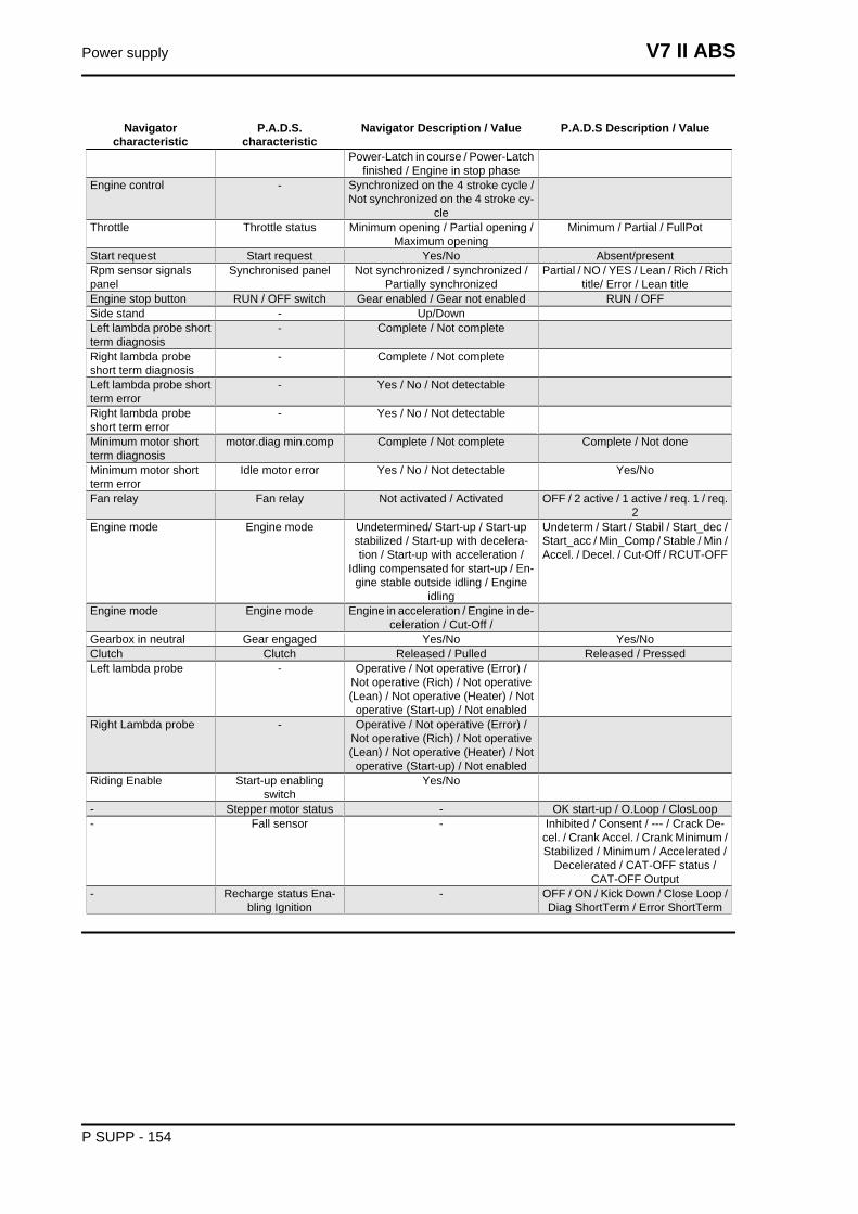
Navigatorcharacteristic
P.A.D.S.characteristic
Navigator Description / Value P.A.D.S Description / Value
Power-Latch in course / Power-Latchfinished / Engine in stop phase
Engine control - Synchronized on the 4 stroke cycle /Not synchronized on the 4 stroke cy-
cleThrottle Throttle status Minimum opening / Partial opening /
Maximum openingMinimum / Partial / FullPot
Start request Start request Yes/No Absent/presentRpm sensor signalspanel
Synchronised panel Not synchronized / synchronized /Partially synchronized
Partial / NO / YES / Lean / Rich / Richtitle/ Error / Lean title
Engine stop button RUN / OFF switch Gear enabled / Gear not enabled RUN / OFFSide stand - Up/DownLeft lambda probe shortterm diagnosis
- Complete / Not complete
Right lambda probeshort term diagnosis
- Complete / Not complete
Left lambda probe shortterm error
- Yes / No / Not detectable
Right lambda probeshort term error
- Yes / No / Not detectable
Minimum motor shortterm diagnosis
motor.diag min.comp Complete / Not complete Complete / Not done
Minimum motor shortterm error
Idle motor error Yes / No / Not detectable Yes/No
Fan relay Fan relay Not activated / Activated OFF / 2 active / 1 active / req. 1 / req.2
Engine mode Engine mode Undetermined/ Start-up / Start-upstabilized / Start-up with decelera-tion / Start-up with acceleration /
Idling compensated for start-up / En-gine stable outside idling / Engine
idling
Undeterm / Start / Stabil / Start_dec /Start_acc / Min_Comp / Stable / Min /Accel. / Decel. / Cut-Off / RCUT-OFF
Engine mode Engine mode Engine in acceleration / Engine in de-celeration / Cut-Off /
Gearbox in neutral Gear engaged Yes/No Yes/NoClutch Clutch Released / Pulled Released / PressedLeft lambda probe - Operative / Not operative (Error) /
Not operative (Rich) / Not operative(Lean) / Not operative (Heater) / Not
operative (Start-up) / Not enabledRight Lambda probe - Operative / Not operative (Error) /
Not operative (Rich) / Not operative(Lean) / Not operative (Heater) / Not
operative (Start-up) / Not enabledRiding Enable Start-up enabling
switchYes/No
- Stepper motor status - OK start-up / O.Loop / ClosLoop- Fall sensor - Inhibited / Consent / --- / Crack De-
cel. / Crank Accel. / Crank Minimum /Stabilized / Minimum / Accelerated /
Decelerated / CAT-OFF status /CAT-OFF Output
- Recharge status Ena-bling Ignition
- OFF / ON / Kick Down / Close Loop /Diag ShortTerm / Error ShortTerm
Power supply V7 II ABS
P SUPP - 154
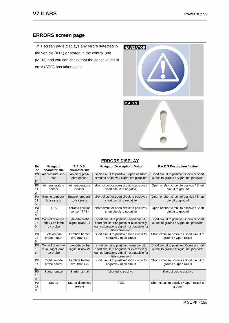
ERRORS screen page
This screen page displays any errors detected in
the vehicle (ATT) or stored in the control unit
(MEM) and you can check that the cancellation of
error (STO) has taken place.
ERRORS DISPLAYError
Navigatorcharacteristic
P.A.D.S.characteristic
Navigator Description / Value P.A.D.S Description / Value
P0105
Air pressure sen-sor
Ambient pres-sure sensor
short circuit to positive / open or shortcircuit to negative / signal not plausible
Short circuit to positive / Open or shortcircuit to ground / Signal not plausible
P0110
Air temperaturesensor
Air temperaturesensor
short circuit or open circuit to positive /short circuit to negative
Open or short circuit to positive / Shortcircuit to ground
P0115
Engine tempera-ture sensor
Engine tempera-ture sensor
short circuit or open circuit to positive /short circuit to negative
Open or short circuit to positive / Shortcircuit to ground
P0120
TPS Throttle positionsensor (TPS)
short circuit or open circuit to positive /short circuit to negative
Open or short circuit to positive / Shortcircuit to ground
P0130
Control of air-fuelratio / Left lamb-
da probe
Lambda probesignal (Bank 1)
short circuit to positive / open circuit,short circuit to negative or excessively
lean carburation / signal not plausible fortitle correction
Short circuit to positive / Open or shortcircuit to ground / Signal not plausible
P0135
Left lambdaprobe heater
Lambda heatercirc. (Bank 1)
short circuit to positive/ short circuit tonegative / open circuit
Short circuit to positive / Short circuit toground / Open circuit
P0136
Control of air-fuelratio / Right lamb-
da probe
Lambda probesignal (Bank 2)
short circuit to positive / open circuit,short circuit to negative or excessively
lean carburation / signal not plausible fortitle correction
Short circuit to positive / Open or shortcircuit to ground / Signal not plausible
P0141
Right lambdaprobe heater
Lambda heatercirc. (Bank 2)
short circuit to positive/ short circuit tonegative / open circuit
Short circuit to positive / Short circuit toground / Open circuit
P0169
Starter button Starter signal shorted to positive Short circuit to positive
P0170
Starter Starter diagnosis(relay)
TBD Short circuit to positive / Open circuit toground
V7 II ABS Power supply
P SUPP - 155
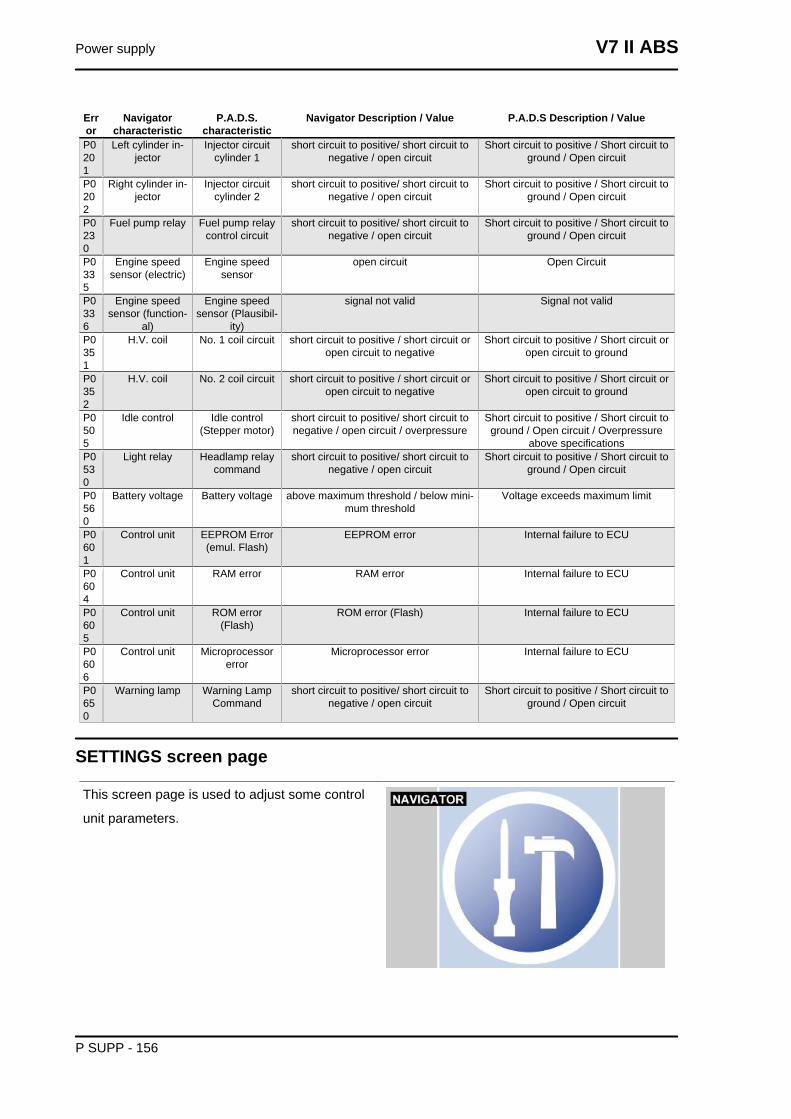
Error
Navigatorcharacteristic
P.A.D.S.characteristic
Navigator Description / Value P.A.D.S Description / Value
P0201
Left cylinder in-jector
Injector circuitcylinder 1
short circuit to positive/ short circuit tonegative / open circuit
Short circuit to positive / Short circuit toground / Open circuit
P0202
Right cylinder in-jector
Injector circuitcylinder 2
short circuit to positive/ short circuit tonegative / open circuit
Short circuit to positive / Short circuit toground / Open circuit
P0230
Fuel pump relay Fuel pump relaycontrol circuit
short circuit to positive/ short circuit tonegative / open circuit
Short circuit to positive / Short circuit toground / Open circuit
P0335
Engine speedsensor (electric)
Engine speedsensor
open circuit Open Circuit
P0336
Engine speedsensor (function-
al)
Engine speedsensor (Plausibil-
ity)
signal not valid Signal not valid
P0351
H.V. coil No. 1 coil circuit short circuit to positive / short circuit oropen circuit to negative
Short circuit to positive / Short circuit oropen circuit to ground
P0352
H.V. coil No. 2 coil circuit short circuit to positive / short circuit oropen circuit to negative
Short circuit to positive / Short circuit oropen circuit to ground
P0505
Idle control Idle control(Stepper motor)
short circuit to positive/ short circuit tonegative / open circuit / overpressure
Short circuit to positive / Short circuit toground / Open circuit / Overpressure
above specificationsP0530
Light relay Headlamp relaycommand
short circuit to positive/ short circuit tonegative / open circuit
Short circuit to positive / Short circuit toground / Open circuit
P0560
Battery voltage Battery voltage above maximum threshold / below mini-mum threshold
Voltage exceeds maximum limit
P0601
Control unit EEPROM Error(emul. Flash)
EEPROM error Internal failure to ECU
P0604
Control unit RAM error RAM error Internal failure to ECU
P0605
Control unit ROM error(Flash)
ROM error (Flash) Internal failure to ECU
P0606
Control unit Microprocessorerror
Microprocessor error Internal failure to ECU
P0650
Warning lamp Warning LampCommand
short circuit to positive/ short circuit tonegative / open circuit
Short circuit to positive / Short circuit toground / Open circuit
SETTINGS screen page
This screen page is used to adjust some control
unit parameters.
Power supply V7 II ABS
P SUPP - 156
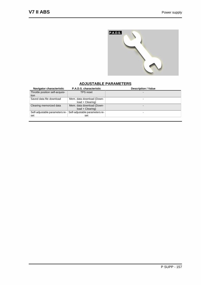
ADJUSTABLE PARAMETERSNavigator characteristic P.A.D.S. characteristic Description / Value
Throttle position self-acquisi-tion
TPS reset -
Saved data file download Mem. data download (Down-load + Clearing)
-
Clearing memorized data Mem. data download (Down-load + Clearing)
-
Self-adjustable parameters re-set
Self-adjustable parameters re-set
-
V7 II ABS Power supply
P SUPP - 157
INDEX OF TOPICS
SUSPENSIONS SUSP
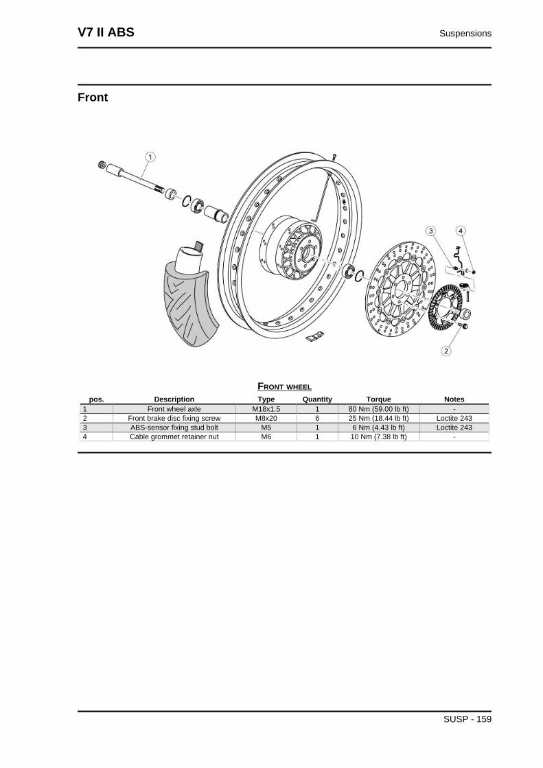
Front
FRONT WHEELpos. Description Type Quantity Torque Notes
1 Front wheel axle M18x1.5 1 80 Nm (59.00 lb ft) -2 Front brake disc fixing screw M8x20 6 25 Nm (18.44 lb ft) Loctite 2433 ABS-sensor fixing stud bolt M5 1 6 Nm (4.43 lb ft) Loctite 2434 Cable grommet retainer nut M6 1 10 Nm (7.38 lb ft) -
V7 II ABS Suspensions
SUSP - 159
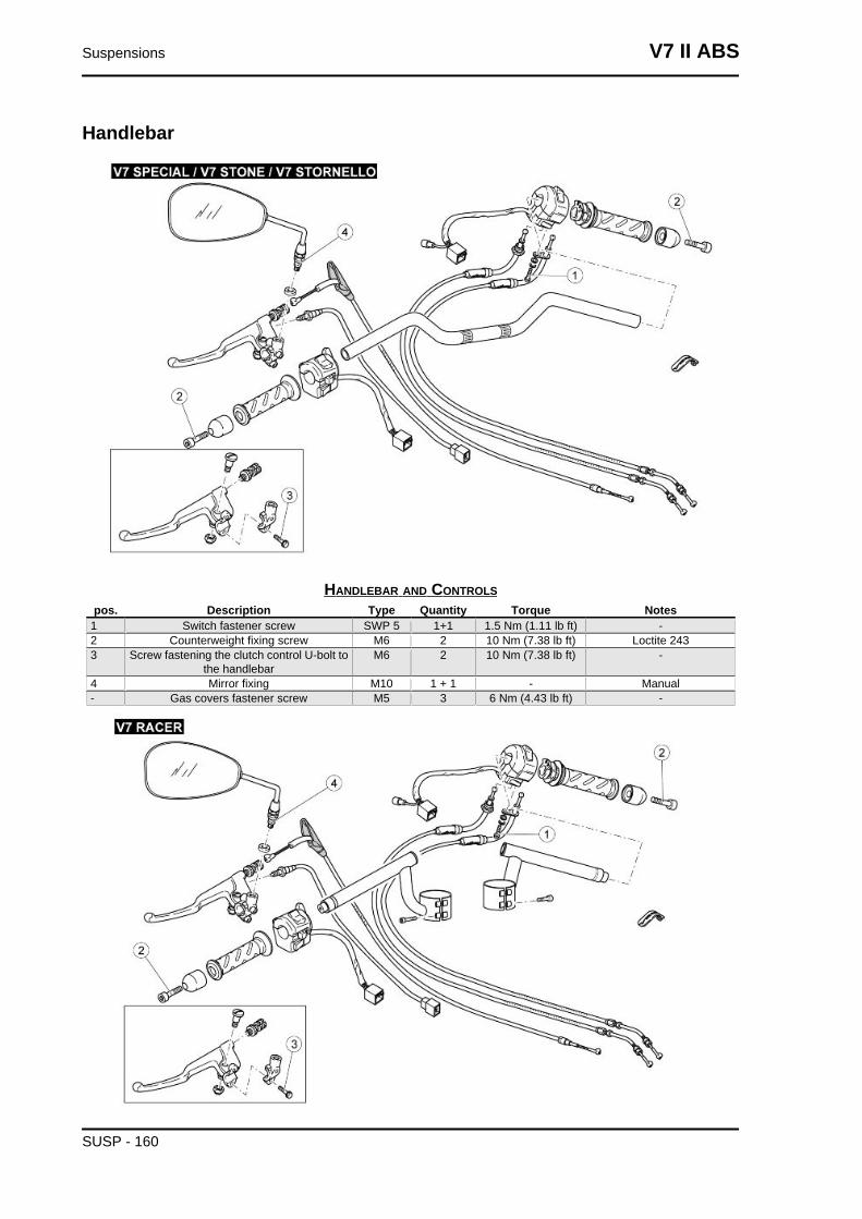
Handlebar
HANDLEBAR AND CONTROLSpos. Description Type Quantity Torque Notes
1 Switch fastener screw SWP 5 1+1 1.5 Nm (1.11 lb ft) -2 Counterweight fixing screw M6 2 10 Nm (7.38 lb ft) Loctite 2433 Screw fastening the clutch control U-bolt to
the handlebarM6 2 10 Nm (7.38 lb ft) -
4 Mirror fixing M10 1 + 1 - Manual- Gas covers fastener screw M5 3 6 Nm (4.43 lb ft) -
Suspensions V7 II ABS
SUSP - 160
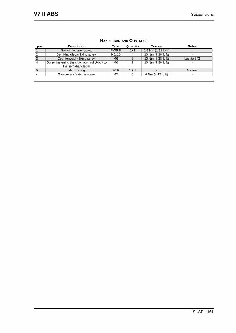
HANDLEBAR AND CONTROLSpos. Description Type Quantity Torque Notes
1 Switch fastener screw SWP 5 1+1 1.5 Nm (1.11 lb ft) -2 Semi-handlebar fixing screw M6x25 4 10 Nm (7.38 lb ft) -3 Counterweight fixing screw M6 2 10 Nm (7.38 lb ft) Loctite 2434 Screw fastening the clutch control U-bolt to
the semi-handlebarM6 2 10 Nm (7.38 lb ft) -
5 Mirror fixing M10 1 + 1 - Manual- Gas covers fastener screw M5 3 6 Nm (4.43 lb ft) -
V7 II ABS Suspensions
SUSP - 161

Front fork
FRONT SUSPENSION - STEERINGpos. Description Type Quantity Torque Notes
1 Stanchion cap - 1 + 1 50 Nm (36.88 lb ft) -2 Calliper bracket fixing screws M6x30 2 10 Nm (7.38 lb ft) -3 Screws fixing fork stanchions to upper and low-
er plateM10x40 2 + 2 50 Nm (36.88 lb ft) -
4 Headstock fixing ring nut M25x1 1 7 Nm (5.16 lb ft) The fork must fall to oneside by itself
Suspensions V7 II ABS
SUSP - 162
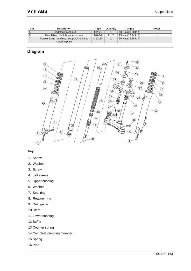
pos. Description Type Quantity Torque Notes5 Headstock fixing nut M23x1 1 50 Nm (36.88 lb ft) -6 Handlebar U-bolt fastener screws M8x30 2 + 2 25 Nm (18.44 lb ft) -7 Screws fixing handlebar support U-bolts to
steering plateM10x60 2 50 Nm (36.88 lb ft) -
Diagram
key:
1. Screw
2. Washer
3. Screw
4. Left sleeve
5. Upper bushing
6. Washer
7. Seal ring
8. Retainer ring
9. Dust gaiter
10.Stem
11.Lower bushing
12.Buffer
13.Counter spring
14.Complete pumping member
15.Spring
16.Pipe
V7 II ABS Suspensions
SUSP - 163
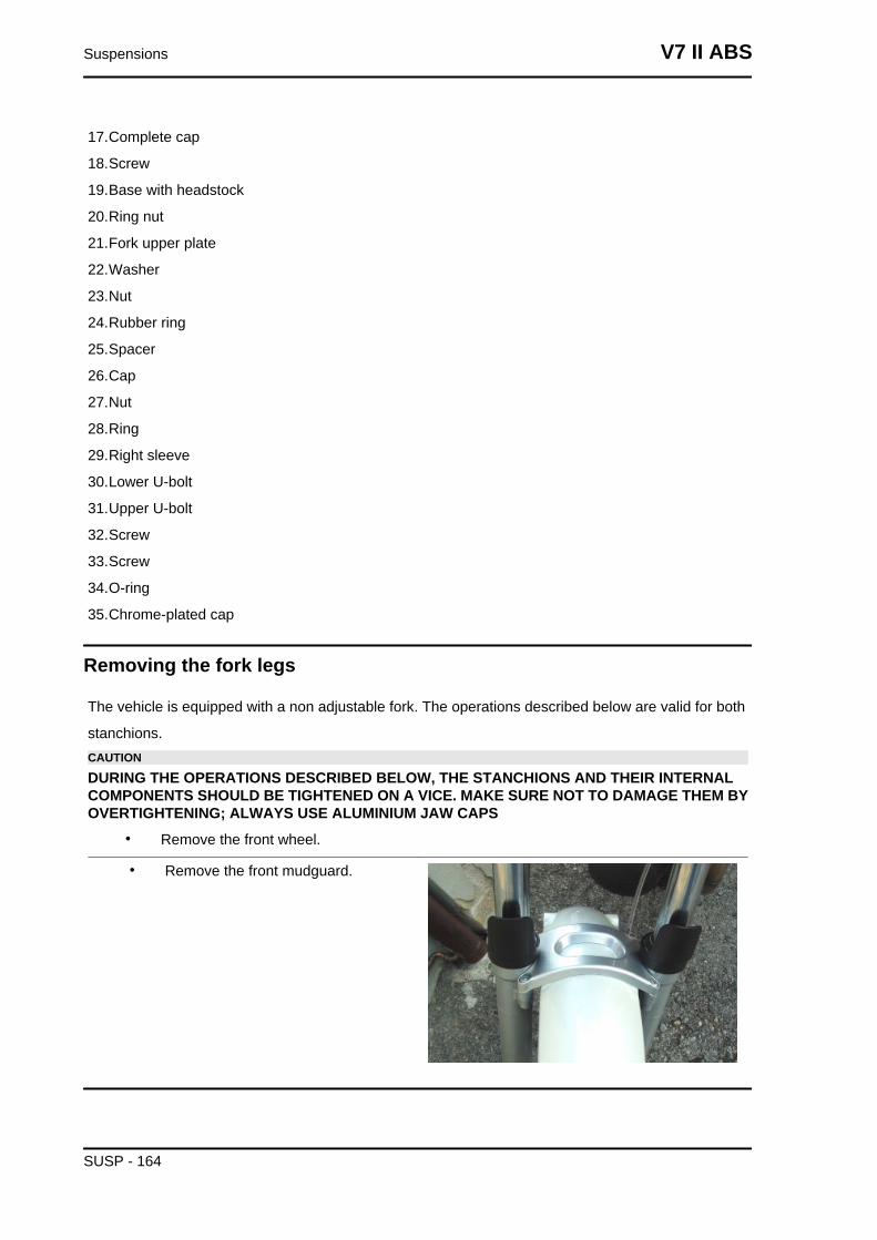
17.Complete cap
18.Screw
19.Base with headstock
20.Ring nut
21.Fork upper plate
22.Washer
23.Nut
24.Rubber ring
25.Spacer
26.Cap
27.Nut
28.Ring
29.Right sleeve
30.Lower U-bolt
31.Upper U-bolt
32.Screw
33.Screw
34.O-ring
35.Chrome-plated cap
Removing the fork legs
The vehicle is equipped with a non adjustable fork. The operations described below are valid for both
stanchions.CAUTION
DURING THE OPERATIONS DESCRIBED BELOW, THE STANCHIONS AND THEIR INTERNALCOMPONENTS SHOULD BE TIGHTENED ON A VICE. MAKE SURE NOT TO DAMAGE THEM BYOVERTIGHTENING; ALWAYS USE ALUMINIUM JAW CAPS
• Remove the front wheel.
• Remove the front mudguard.
Suspensions V7 II ABS
SUSP - 164
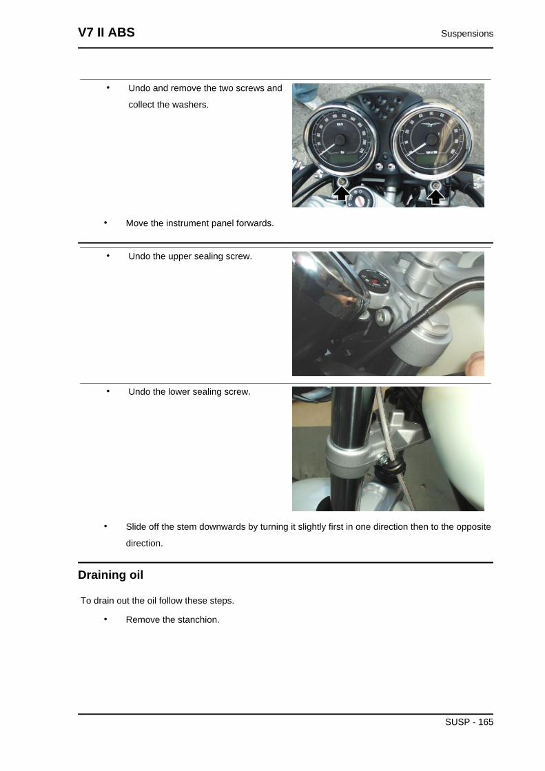
• Undo and remove the two screws and
collect the washers.
• Move the instrument panel forwards.
• Undo the upper sealing screw.
• Undo the lower sealing screw.
• Slide off the stem downwards by turning it slightly first in one direction then to the opposite
direction.
Draining oil
To drain out the oil follow these steps.
• Remove the stanchion.
V7 II ABS Suspensions
SUSP - 165
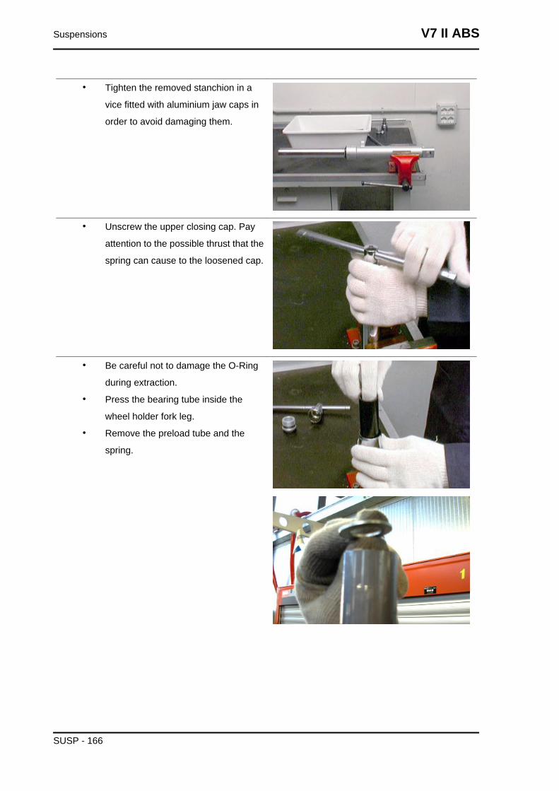
• Tighten the removed stanchion in a
vice fitted with aluminium jaw caps in
order to avoid damaging them.
• Unscrew the upper closing cap. Pay
attention to the possible thrust that the
spring can cause to the loosened cap.
• Be careful not to damage the O-Ring
during extraction.
• Press the bearing tube inside the
wheel holder fork leg.
• Remove the preload tube and the
spring.
Suspensions V7 II ABS
SUSP - 166
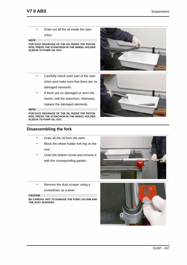
• Drain out all the oil inside the stan-
chion.NOTEFOR EASY DRAINAGE OF THE OIL INSIDE THE PISTONROD, PRESS THE STANCHION IN THE WHEEL HOLDERSLEEVE TO PUMP OIL OUT.
• Carefully check each part of the stan-
chion and make sure that there are no
damaged elements.
• If there are no damaged or worn ele-
ments, refit the stanchion; otherwise,
replace the damaged elements.NOTEFOR EASY DRAINAGE OF THE OIL INSIDE THE PISTONROD, PRESS THE STANCHION IN THE WHEEL HOLDERSLEEVE TO PUMP OIL OUT.
Disassembling the fork
• Drain all the oil from the stem.
• Block the wheel holder fork leg on the
vice.
• Undo the bottom screw and remove it
with the corresponding gasket.
• Remove the dust scraper using a
screwdriver as a lever.CAUTIONBE CAREFUL NOT TO DAMAGE THE FORK LEG RIM ANDTHE DUST SCRAPER.
V7 II ABS Suspensions
SUSP - 167
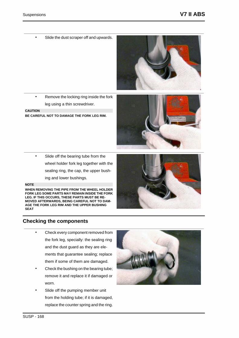
• Slide the dust scraper off and upwards.
• Remove the locking ring inside the fork
leg using a thin screwdriver.CAUTIONBE CAREFUL NOT TO DAMAGE THE FORK LEG RIM.
• Slide off the bearing tube from the
wheel holder fork leg together with the
sealing ring, the cap, the upper bush-
ing and lower bushings.NOTEWHEN REMOVING THE PIPE FROM THE WHEEL HOLDERFORK LEG SOME PARTS MAY REMAIN INSIDE THE FORKLEG. IF THIS OCCURS, THESE PARTS MUST BE RE-MOVED AFTERWARDS, BEING CAREFUL NOT TO DAM-AGE THE FORK LEG RIM AND THE UPPER BUSHINGSEAT
Checking the components
• Check every component removed from
the fork leg, specially: the sealing ring
and the dust guard as they are ele-
ments that guarantee sealing; replace
them if some of them are damaged.
• Check the bushing on the bearing tube;
remove it and replace it if damaged or
worn.
• Slide off the pumping member unit
from the holding tube; if it is damaged,
replace the counter spring and the ring.
Suspensions V7 II ABS
SUSP - 168
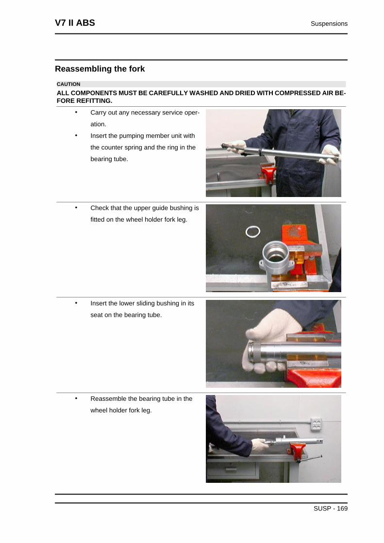
Reassembling the forkCAUTION
ALL COMPONENTS MUST BE CAREFULLY WASHED AND DRIED WITH COMPRESSED AIR BE-FORE REFITTING.
• Carry out any necessary service oper-
ation.
• Insert the pumping member unit with
the counter spring and the ring in the
bearing tube.
• Check that the upper guide bushing is
fitted on the wheel holder fork leg.
• Insert the lower sliding bushing in its
seat on the bearing tube.
• Reassemble the bearing tube in the
wheel holder fork leg.
V7 II ABS Suspensions
SUSP - 169
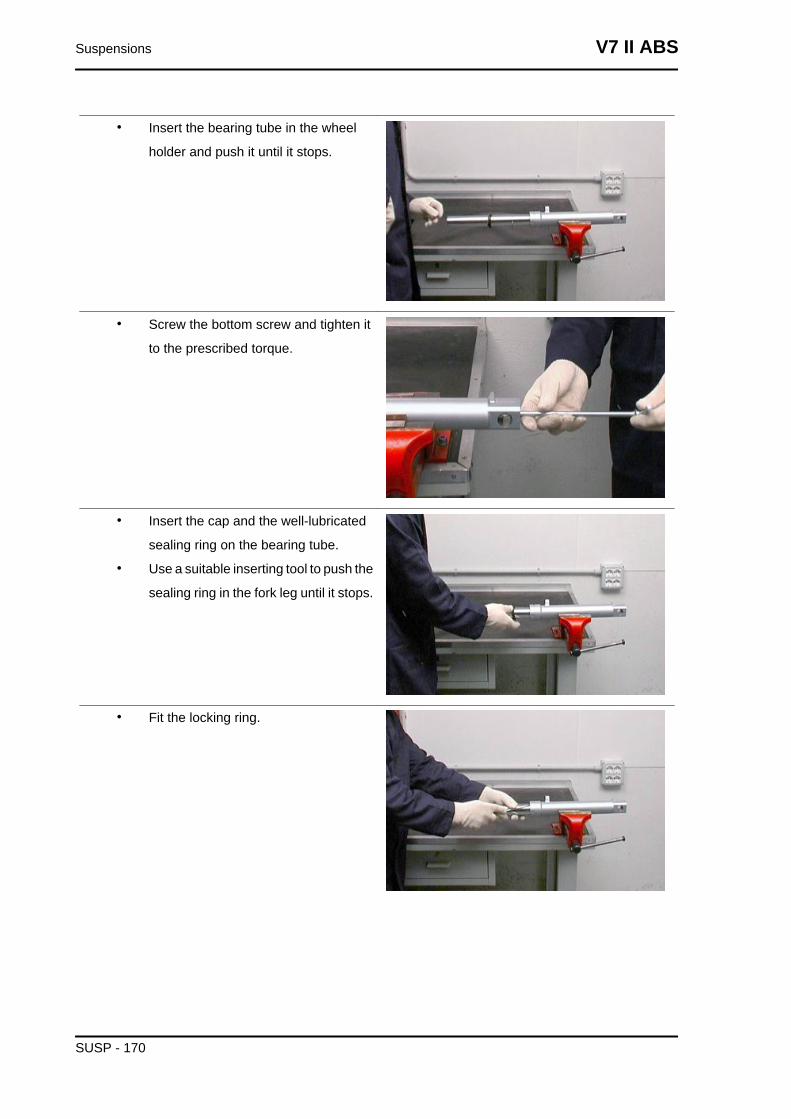
• Insert the bearing tube in the wheel
holder and push it until it stops.
• Screw the bottom screw and tighten it
to the prescribed torque.
• Insert the cap and the well-lubricated
sealing ring on the bearing tube.
• Use a suitable inserting tool to push the
sealing ring in the fork leg until it stops.
• Fit the locking ring.
Suspensions V7 II ABS
SUSP - 170
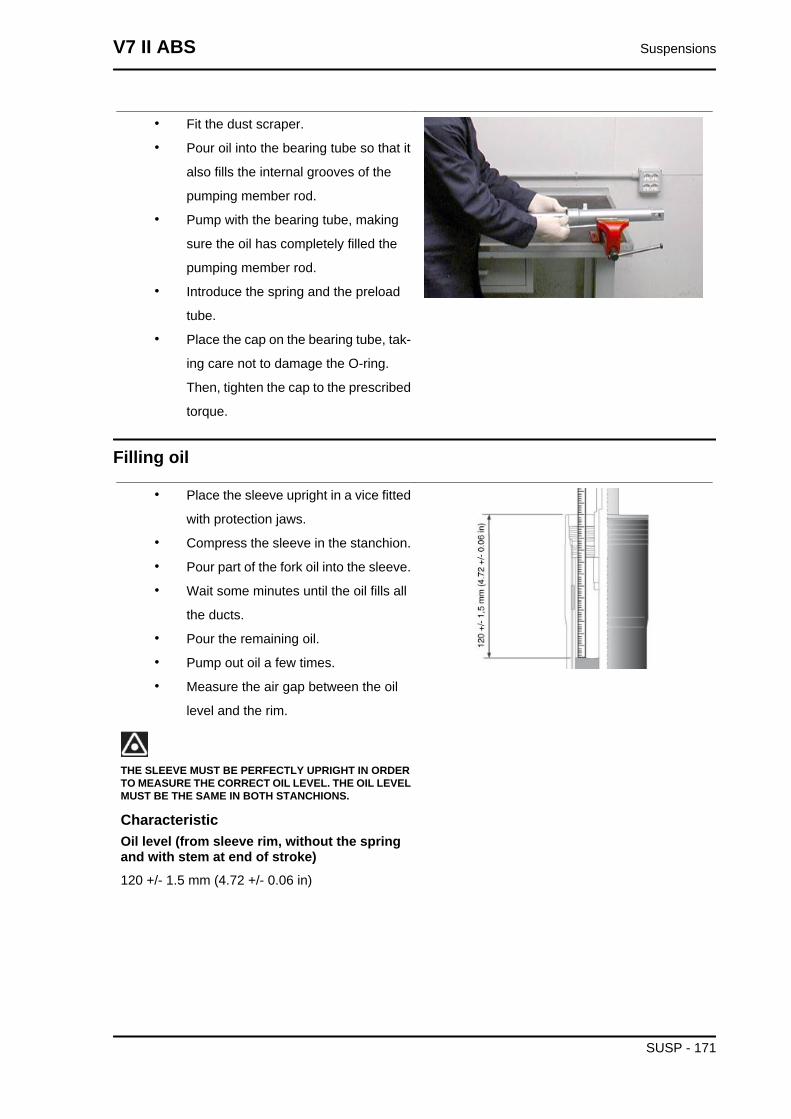
• Fit the dust scraper.
• Pour oil into the bearing tube so that it
also fills the internal grooves of the
pumping member rod.
• Pump with the bearing tube, making
sure the oil has completely filled the
pumping member rod.
• Introduce the spring and the preload
tube.
• Place the cap on the bearing tube, tak-
ing care not to damage the O-ring.
Then, tighten the cap to the prescribed
torque.
Filling oil
• Place the sleeve upright in a vice fitted
with protection jaws.
• Compress the sleeve in the stanchion.
• Pour part of the fork oil into the sleeve.
• Wait some minutes until the oil fills all
the ducts.
• Pour the remaining oil.
• Pump out oil a few times.
• Measure the air gap between the oil
level and the rim.
THE SLEEVE MUST BE PERFECTLY UPRIGHT IN ORDERTO MEASURE THE CORRECT OIL LEVEL. THE OIL LEVELMUST BE THE SAME IN BOTH STANCHIONS.
CharacteristicOil level (from sleeve rim, without the springand with stem at end of stroke)120 +/- 1.5 mm (4.72 +/- 0.06 in)
V7 II ABS Suspensions
SUSP - 171
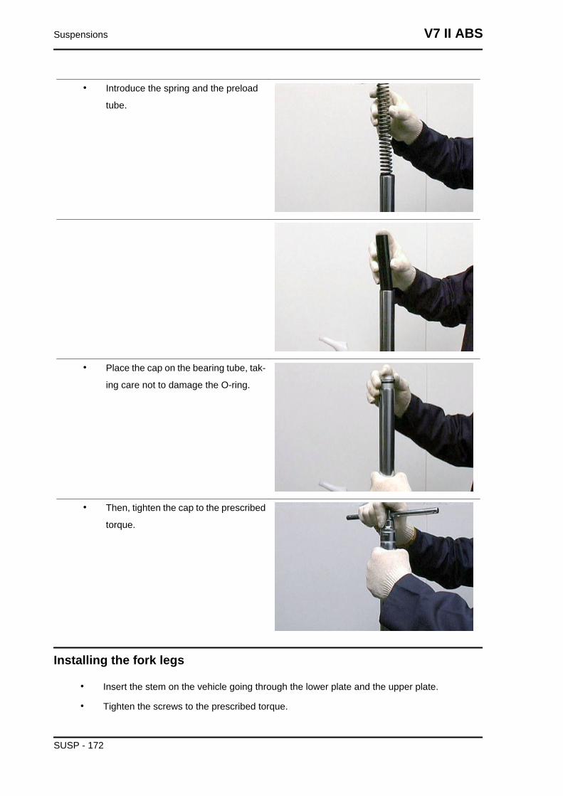
• Introduce the spring and the preload
tube.
• Place the cap on the bearing tube, tak-
ing care not to damage the O-ring.
• Then, tighten the cap to the prescribed
torque.
Installing the fork legs
• Insert the stem on the vehicle going through the lower plate and the upper plate.
• Tighten the screws to the prescribed torque.
Suspensions V7 II ABS
SUSP - 172
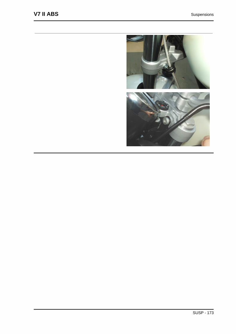
V7 II ABS Suspensions
SUSP - 173
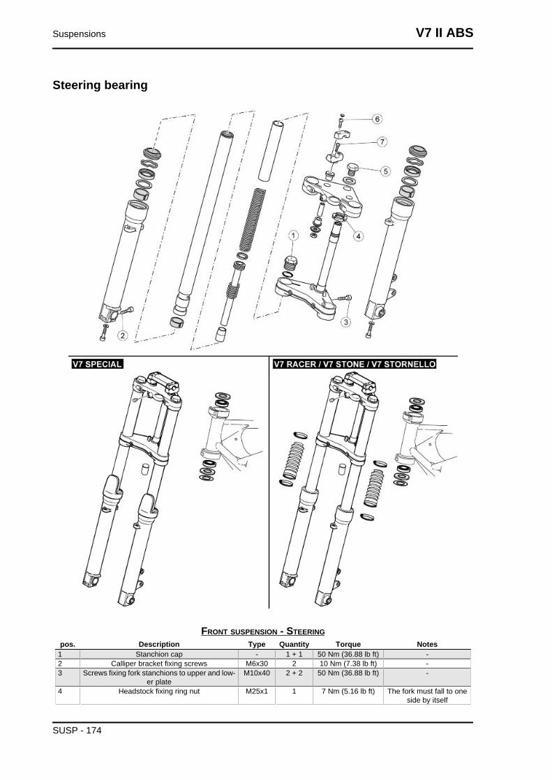
Steering bearing
FRONT SUSPENSION - STEERINGpos. Description Type Quantity Torque Notes
1 Stanchion cap - 1 + 1 50 Nm (36.88 lb ft) -2 Calliper bracket fixing screws M6x30 2 10 Nm (7.38 lb ft) -3 Screws fixing fork stanchions to upper and low-
er plateM10x40 2 + 2 50 Nm (36.88 lb ft) -
4 Headstock fixing ring nut M25x1 1 7 Nm (5.16 lb ft) The fork must fall to oneside by itself
Suspensions V7 II ABS
SUSP - 174
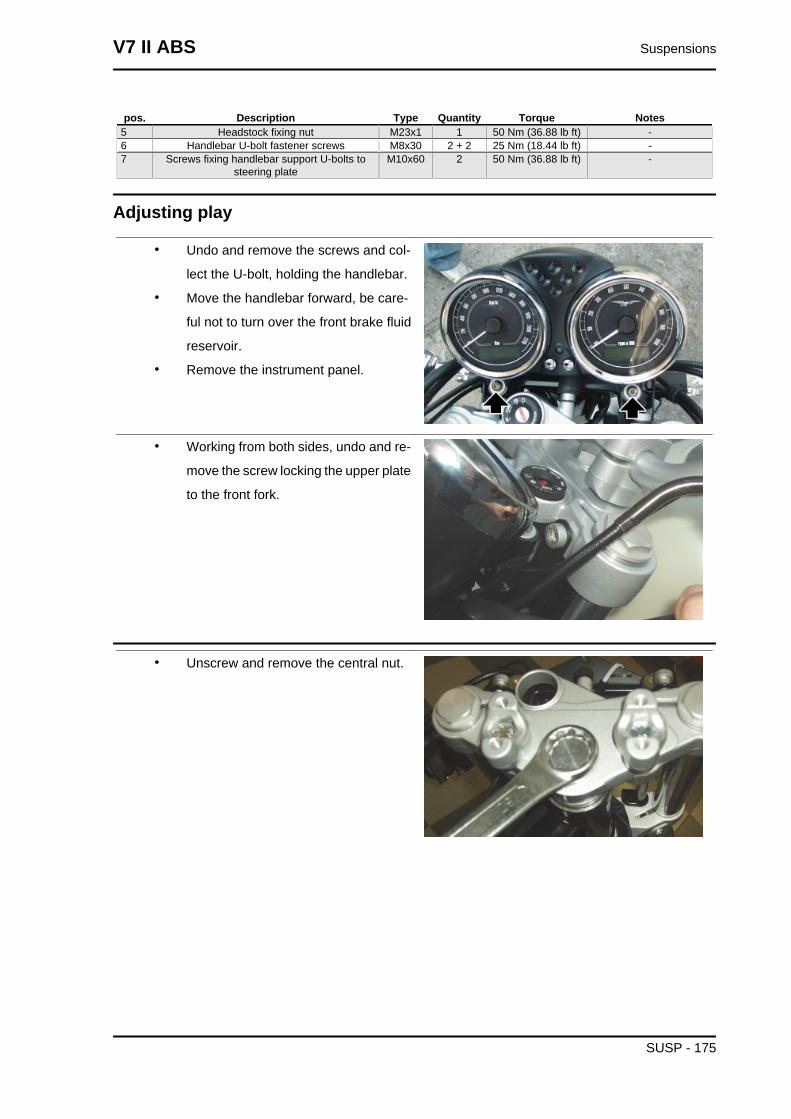
pos. Description Type Quantity Torque Notes5 Headstock fixing nut M23x1 1 50 Nm (36.88 lb ft) -6 Handlebar U-bolt fastener screws M8x30 2 + 2 25 Nm (18.44 lb ft) -7 Screws fixing handlebar support U-bolts to
steering plateM10x60 2 50 Nm (36.88 lb ft) -
Adjusting play
• Undo and remove the screws and col-
lect the U-bolt, holding the handlebar.
• Move the handlebar forward, be care-
ful not to turn over the front brake fluid
reservoir.
• Remove the instrument panel.
• Working from both sides, undo and re-
move the screw locking the upper plate
to the front fork.
• Unscrew and remove the central nut.
V7 II ABS Suspensions
SUSP - 175
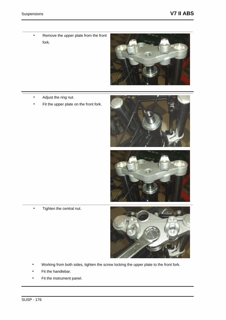
• Remove the upper plate from the front
fork.
• Adjust the ring nut.
• Fit the upper plate on the front fork.
• Tighten the central nut.
• Working from both sides, tighten the screw locking the upper plate to the front fork.
• Fit the handlebar.
• Fit the instrument panel.
Suspensions V7 II ABS
SUSP - 176
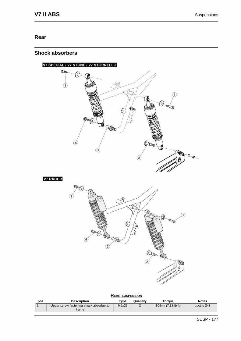
Rear
Shock absorbers
REAR SUSPENSIONpos. Description Type Quantity Torque Notes
1 Upper screw fastening shock absorber toframe
M6x35 2 10 Nm (7.38 lb ft) Loctite 243
V7 II ABS Suspensions
SUSP - 177
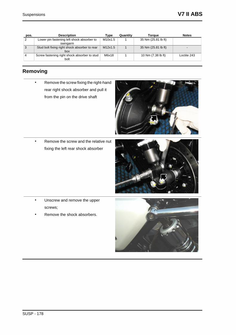
pos. Description Type Quantity Torque Notes2 Lower pin fastening left shock absorber to
swingarmM10x1.5 1 35 Nm (25.81 lb ft)
3 Stud bolt fixing right shock absorber to rearbox
M12x1.5 1 35 Nm (25.81 lb ft) -
4 Screw fastening right shock absorber to studbolt
M6x18 1 10 Nm (7.38 lb ft) Loctite 243
Removing
• Remove the screw fixing the right-hand
rear right shock absorber and pull it
from the pin on the drive shaft
• Remove the screw and the relative nut
fixing the left rear shock absorber
• Unscrew and remove the upper
screws;
• Remove the shock absorbers.
Suspensions V7 II ABS
SUSP - 178
INDEX OF TOPICS
CHASSIS CHAS
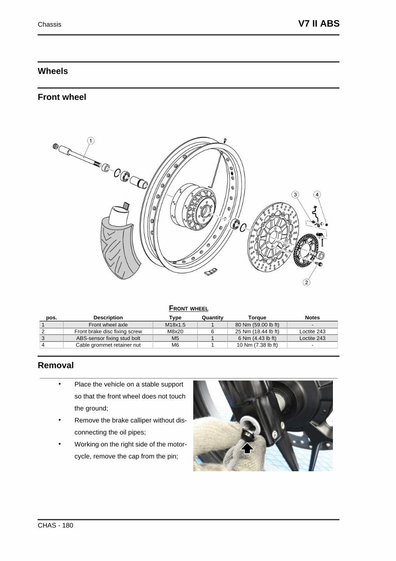
Wheels
Front wheel
FRONT WHEELpos. Description Type Quantity Torque Notes
1 Front wheel axle M18x1.5 1 80 Nm (59.00 lb ft) -2 Front brake disc fixing screw M8x20 6 25 Nm (18.44 lb ft) Loctite 2433 ABS-sensor fixing stud bolt M5 1 6 Nm (4.43 lb ft) Loctite 2434 Cable grommet retainer nut M6 1 10 Nm (7.38 lb ft) -
Removal
• Place the vehicle on a stable support
so that the front wheel does not touch
the ground;
• Remove the brake calliper without dis-
connecting the oil pipes;
• Working on the right side of the motor-
cycle, remove the cap from the pin;
Chassis V7 II ABS
CHAS - 180
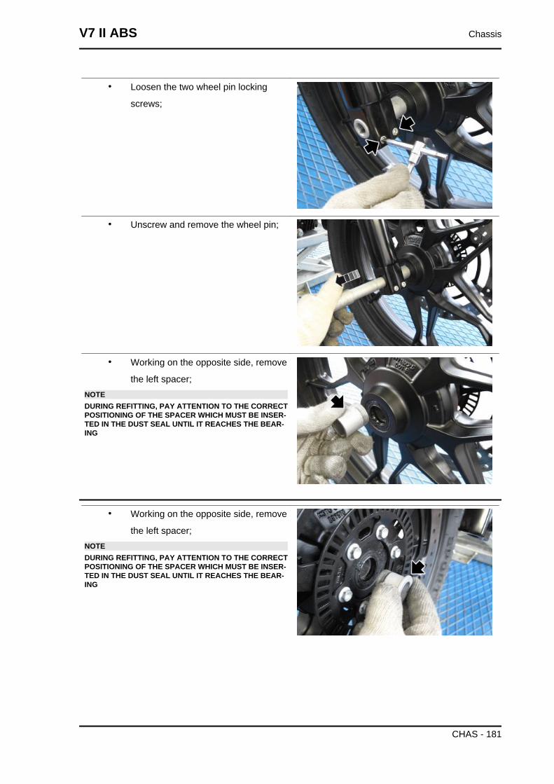
• Loosen the two wheel pin locking
screws;
• Unscrew and remove the wheel pin;
• Working on the opposite side, remove
the left spacer;NOTEDURING REFITTING, PAY ATTENTION TO THE CORRECTPOSITIONING OF THE SPACER WHICH MUST BE INSER-TED IN THE DUST SEAL UNTIL IT REACHES THE BEAR-ING
• Working on the opposite side, remove
the left spacer;NOTEDURING REFITTING, PAY ATTENTION TO THE CORRECTPOSITIONING OF THE SPACER WHICH MUST BE INSER-TED IN THE DUST SEAL UNTIL IT REACHES THE BEAR-ING
V7 II ABS Chassis
CHAS - 181
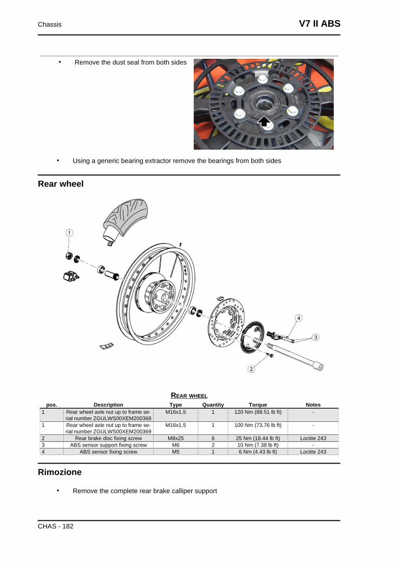
• Remove the dust seal from both sides
• Using a generic bearing extractor remove the bearings from both sides
Rear wheel
REAR WHEELpos. Description Type Quantity Torque Notes
1 Rear wheel axle nut up to frame se-rial number ZGULWS00XEM200368
M16x1.5 1 120 Nm (88.51 lb ft) -
1 Rear wheel axle nut up to frame se-rial number ZGULWS00XEM200369
M16x1.5 1 100 Nm (73.76 lb ft) -
2 Rear brake disc fixing screw M8x25 6 25 Nm (18.44 lb ft) Loctite 2433 ABS sensor support fixing screw M6 2 10 Nm (7.38 lb ft) -4 ABS sensor fixing screw M5 1 6 Nm (4.43 lb ft) Loctite 243
Rimozione
• Remove the complete rear brake calliper support
Chassis V7 II ABS
CHAS - 182
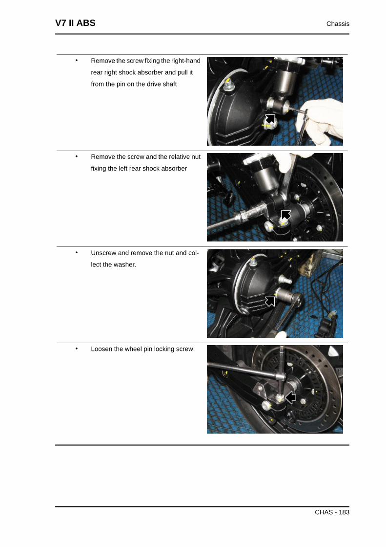
• Remove the screw fixing the right-hand
rear right shock absorber and pull it
from the pin on the drive shaft
• Remove the screw and the relative nut
fixing the left rear shock absorber
• Unscrew and remove the nut and col-
lect the washer.
• Loosen the wheel pin locking screw.
V7 II ABS Chassis
CHAS - 183
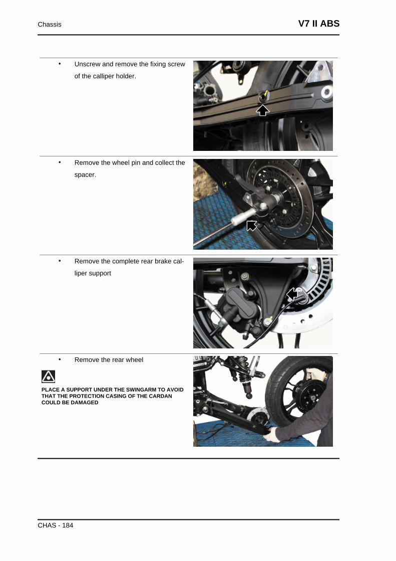
• Unscrew and remove the fixing screw
of the calliper holder.
• Remove the wheel pin and collect the
spacer.
• Remove the complete rear brake cal-
liper support
• Remove the rear wheel
PLACE A SUPPORT UNDER THE SWINGARM TO AVOIDTHAT THE PROTECTION CASING OF THE CARDANCOULD BE DAMAGED
Chassis V7 II ABS
CHAS - 184
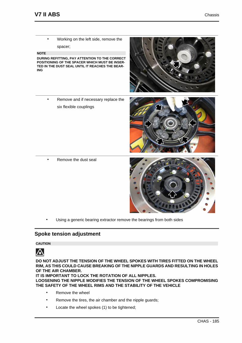
• Working on the left side, remove the
spacer;NOTEDURING REFITTING, PAY ATTENTION TO THE CORRECTPOSITIONING OF THE SPACER WHICH MUST BE INSER-TED IN THE DUST SEAL UNTIL IT REACHES THE BEAR-ING
• Remove and if necessary replace the
six flexible couplings
• Remove the dust seal
• Using a generic bearing extractor remove the bearings from both sides
Spoke tension adjustmentCAUTION
DO NOT ADJUST THE TENSION OF THE WHEEL SPOKES WITH TIRES FITTED ON THE WHEELRIM, AS THIS COULD CAUSE BREAKING OF THE NIPPLE GUARDS AND RESULTING IN HOLESOF THE AIR CHAMBER.IT IS IMPORTANT TO LOCK THE ROTATION OF ALL NIPPLES.LOOSENING THE NIPPLE MODIFIES THE TENSION OF THE WHEEL SPOKES COMPROMISINGTHE SAFETY OF THE WHEEL RIMS AND THE STABILITY OF THE VEHICLE
• Remove the wheel
• Remove the tires, the air chamber and the nipple guards;
• Locate the wheel spokes (1) to be tightened;
V7 II ABS Chassis
CHAS - 185
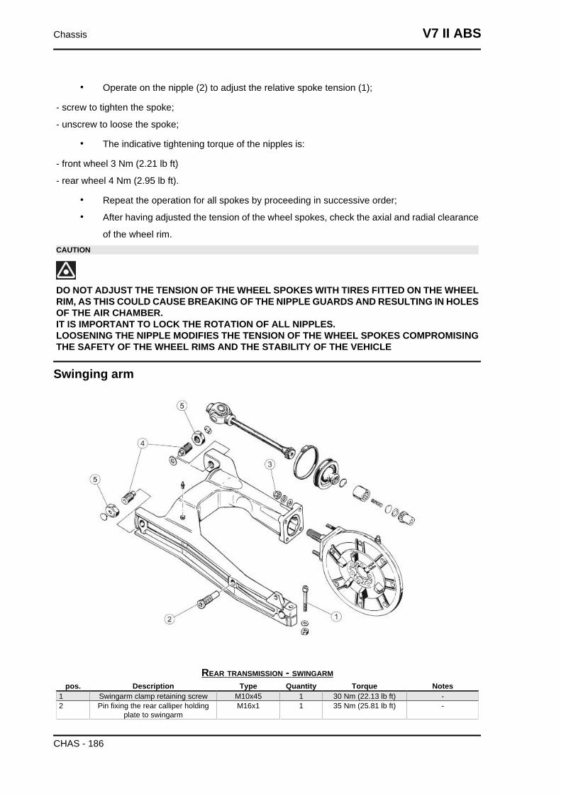
• Operate on the nipple (2) to adjust the relative spoke tension (1);
- screw to tighten the spoke;
- unscrew to loose the spoke;
• The indicative tightening torque of the nipples is:
- front wheel 3 Nm (2.21 lb ft)
- rear wheel 4 Nm (2.95 lb ft).
• Repeat the operation for all spokes by proceeding in successive order;
• After having adjusted the tension of the wheel spokes, check the axial and radial clearance
of the wheel rim.CAUTION
DO NOT ADJUST THE TENSION OF THE WHEEL SPOKES WITH TIRES FITTED ON THE WHEELRIM, AS THIS COULD CAUSE BREAKING OF THE NIPPLE GUARDS AND RESULTING IN HOLESOF THE AIR CHAMBER.IT IS IMPORTANT TO LOCK THE ROTATION OF ALL NIPPLES.LOOSENING THE NIPPLE MODIFIES THE TENSION OF THE WHEEL SPOKES COMPROMISINGTHE SAFETY OF THE WHEEL RIMS AND THE STABILITY OF THE VEHICLE
Swinging arm
REAR TRANSMISSION - SWINGARMpos. Description Type Quantity Torque Notes
1 Swingarm clamp retaining screw M10x45 1 30 Nm (22.13 lb ft) -2 Pin fixing the rear calliper holding
plate to swingarmM16x1 1 35 Nm (25.81 lb ft) -
Chassis V7 II ABS
CHAS - 186
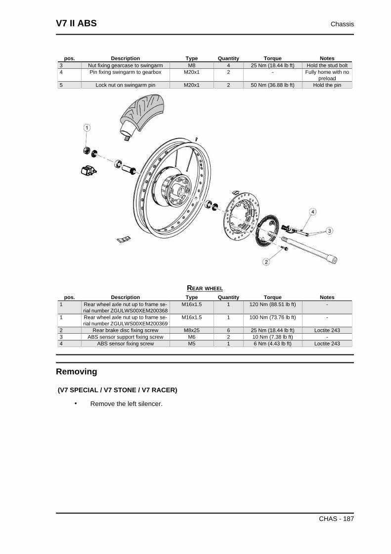
pos. Description Type Quantity Torque Notes3 Nut fixing gearcase to swingarm M8 4 25 Nm (18.44 lb ft) Hold the stud bolt4 Pin fixing swingarm to gearbox M20x1 2 - Fully home with no
preload5 Lock nut on swingarm pin M20x1 2 50 Nm (36.88 lb ft) Hold the pin
REAR WHEELpos. Description Type Quantity Torque Notes
1 Rear wheel axle nut up to frame se-rial number ZGULWS00XEM200368
M16x1.5 1 120 Nm (88.51 lb ft) -
1 Rear wheel axle nut up to frame se-rial number ZGULWS00XEM200369
M16x1.5 1 100 Nm (73.76 lb ft) -
2 Rear brake disc fixing screw M8x25 6 25 Nm (18.44 lb ft) Loctite 2433 ABS sensor support fixing screw M6 2 10 Nm (7.38 lb ft) -4 ABS sensor fixing screw M5 1 6 Nm (4.43 lb ft) Loctite 243
Removing
(V7 SPECIAL / V7 STONE / V7 RACER)
• Remove the left silencer.
V7 II ABS Chassis
CHAS - 187
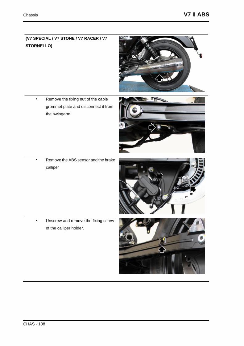
(V7 SPECIAL / V7 STONE / V7 RACER / V7
STORNELLO)
• Remove the fixing nut of the cable
grommet plate and disconnect it from
the swingarm
• Remove the ABS sensor and the brake
calliper
• Unscrew and remove the fixing screw
of the calliper holder.
Chassis V7 II ABS
CHAS - 188
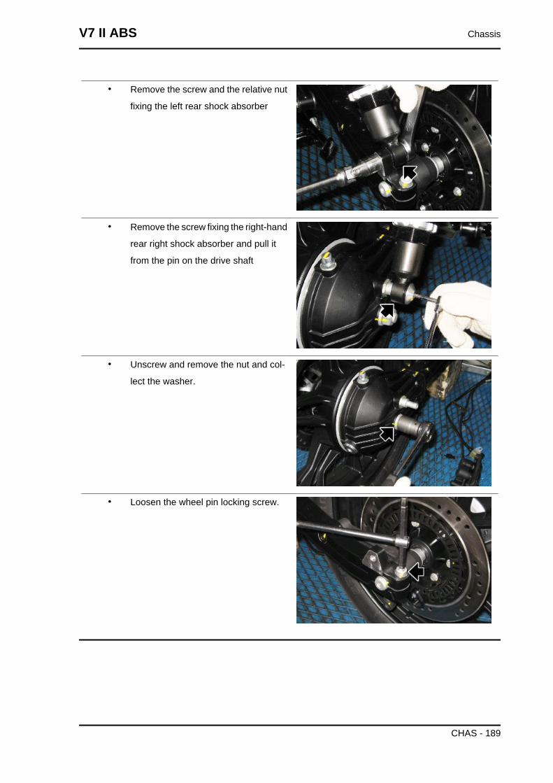
• Remove the screw and the relative nut
fixing the left rear shock absorber
• Remove the screw fixing the right-hand
rear right shock absorber and pull it
from the pin on the drive shaft
• Unscrew and remove the nut and col-
lect the washer.
• Loosen the wheel pin locking screw.
V7 II ABS Chassis
CHAS - 189
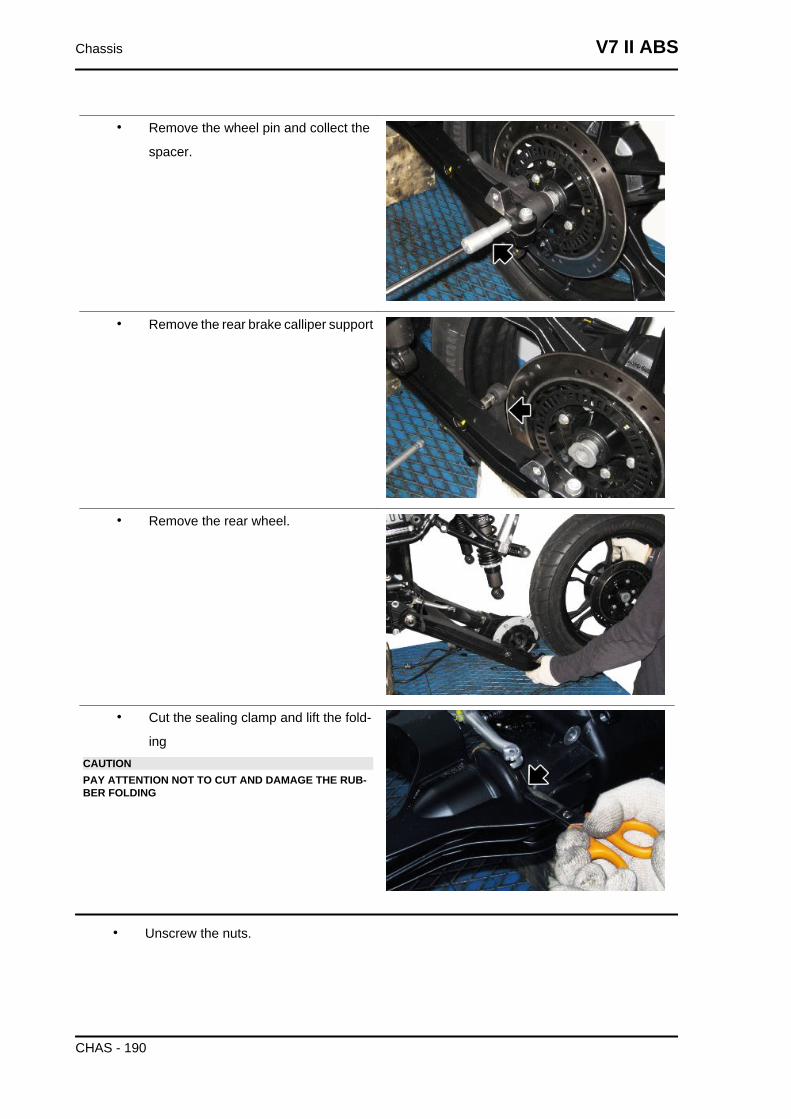
• Remove the wheel pin and collect the
spacer.
• Remove the rear brake calliper support
• Remove the rear wheel.
• Cut the sealing clamp and lift the fold-
ingCAUTIONPAY ATTENTION NOT TO CUT AND DAMAGE THE RUB-BER FOLDING
• Unscrew the nuts.
Chassis V7 II ABS
CHAS - 190
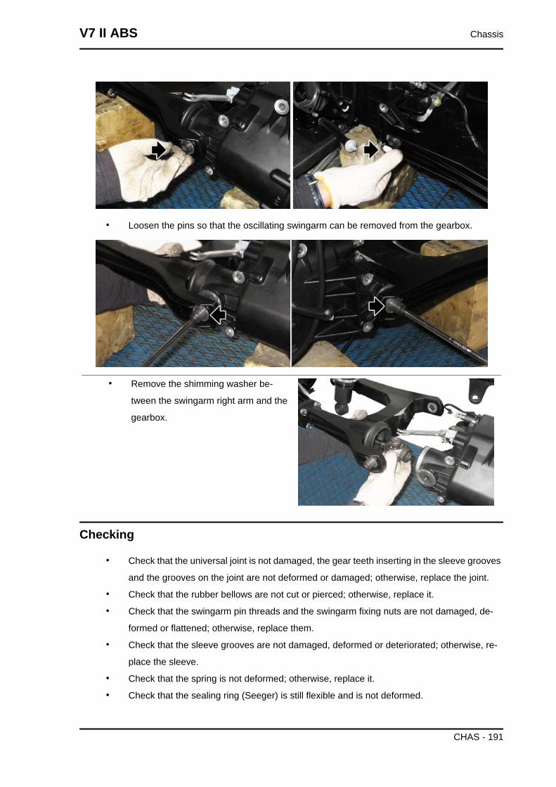
• Loosen the pins so that the oscillating swingarm can be removed from the gearbox.
• Remove the shimming washer be-
tween the swingarm right arm and the
gearbox.
Checking
• Check that the universal joint is not damaged, the gear teeth inserting in the sleeve grooves
and the grooves on the joint are not deformed or damaged; otherwise, replace the joint.
• Check that the rubber bellows are not cut or pierced; otherwise, replace it.
• Check that the swingarm pin threads and the swingarm fixing nuts are not damaged, de-
formed or flattened; otherwise, replace them.
• Check that the sleeve grooves are not damaged, deformed or deteriorated; otherwise, re-
place the sleeve.
• Check that the spring is not deformed; otherwise, replace it.
• Check that the sealing ring (Seeger) is still flexible and is not deformed.
V7 II ABS Chassis
CHAS - 191
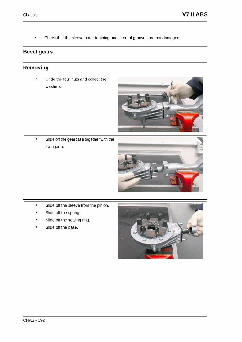
• Check that the sleeve outer toothing and internal grooves are not damaged.
Bevel gears
Removing
• Undo the four nuts and collect the
washers.
• Slide off the gearcase together with the
swingarm.
• Slide off the sleeve from the pinion.
• Slide off the spring.
• Slide off the sealing ring.
• Slide off the base.
Chassis V7 II ABS
CHAS - 192
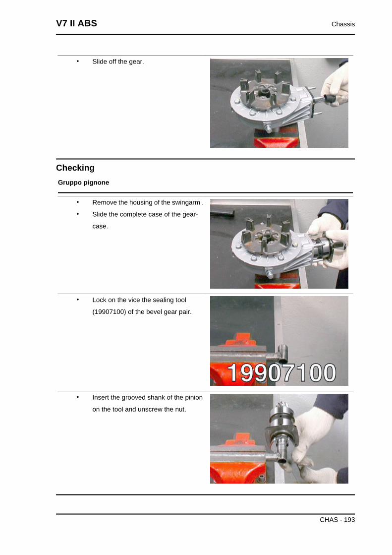
• Slide off the gear.
CheckingGruppo pignone
• Remove the housing of the swingarm .
• Slide the complete case of the gear-
case.
• Lock on the vice the sealing tool
(19907100) of the bevel gear pair.
• Insert the grooved shank of the pinion
on the tool and unscrew the nut.
V7 II ABS Chassis
CHAS - 193
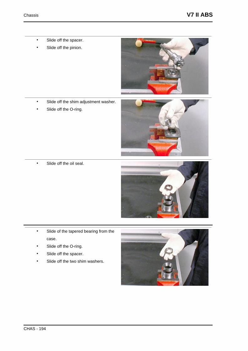
• Slide off the spacer.
• Slide off the pinion.
• Slide off the shim adjustment washer.
• Slide off the O-ring.
• Slide off the oil seal.
• Slide of the tapered bearing from the
case.
• Slide off the O-ring.
• Slide off the spacer.
• Slide off the two shim washers.
Chassis V7 II ABS
CHAS - 194
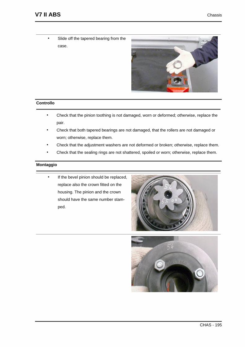
• Slide off the tapered bearing from the
case.
Controllo
• Check that the pinion toothing is not damaged, worn or deformed; otherwise, replace the
pair.
• Check that both tapered bearings are not damaged, that the rollers are not damaged or
worn; otherwise, replace them.
• Check that the adjustment washers are not deformed or broken; otherwise, replace them.
• Check that the sealing rings are not shattered, spoiled or worn; otherwise, replace them.
Montaggio
• If the bevel pinion should be replaced,
replace also the crown fitted on the
housing. The pinion and the crown
should have the same number stam-
ped.
V7 II ABS Chassis
CHAS - 195
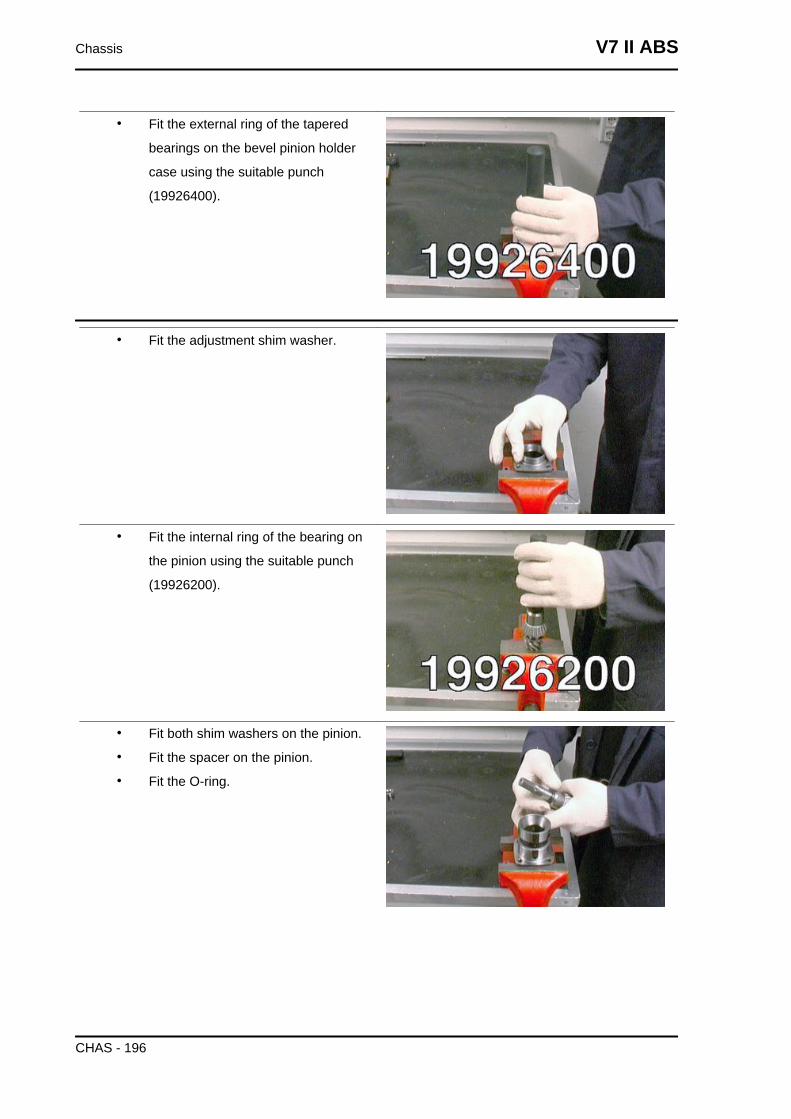
• Fit the external ring of the tapered
bearings on the bevel pinion holder
case using the suitable punch
(19926400).
• Fit the adjustment shim washer.
• Fit the internal ring of the bearing on
the pinion using the suitable punch
(19926200).
• Fit both shim washers on the pinion.
• Fit the spacer on the pinion.
• Fit the O-ring.
Chassis V7 II ABS
CHAS - 196
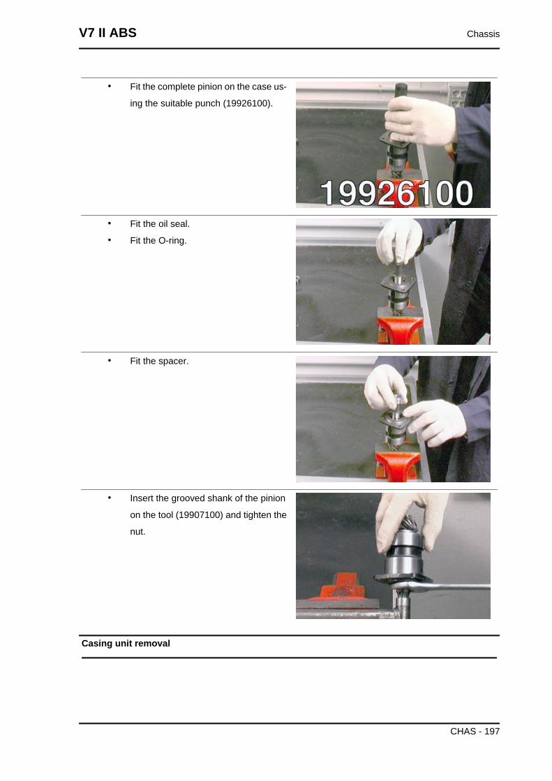
• Fit the complete pinion on the case us-
ing the suitable punch (19926100).
• Fit the oil seal.
• Fit the O-ring.
• Fit the spacer.
• Insert the grooved shank of the pinion
on the tool (19907100) and tighten the
nut.
Casing unit removal
V7 II ABS Chassis
CHAS - 197
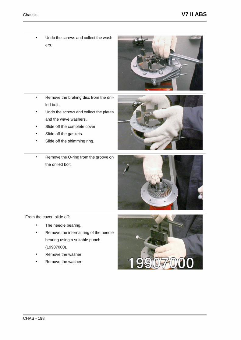
• Undo the screws and collect the wash-
ers.
• Remove the braking disc from the dril-
led bolt.
• Undo the screws and collect the plates
and the wave washers.
• Slide off the complete cover.
• Slide off the gaskets.
• Slide off the shimming ring.
• Remove the O-ring from the groove on
the drilled bolt.
From the cover, slide off:
• The needle bearing.
• Remove the internal ring of the needle
bearing using a suitable punch
(19907000).
• Remove the washer.
• Remove the washer.
Chassis V7 II ABS
CHAS - 198
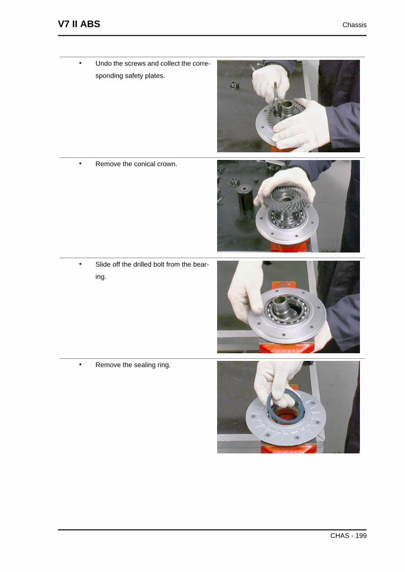
• Undo the screws and collect the corre-
sponding safety plates.
• Remove the conical crown.
• Slide off the drilled bolt from the bear-
ing.
• Remove the sealing ring.
V7 II ABS Chassis
CHAS - 199
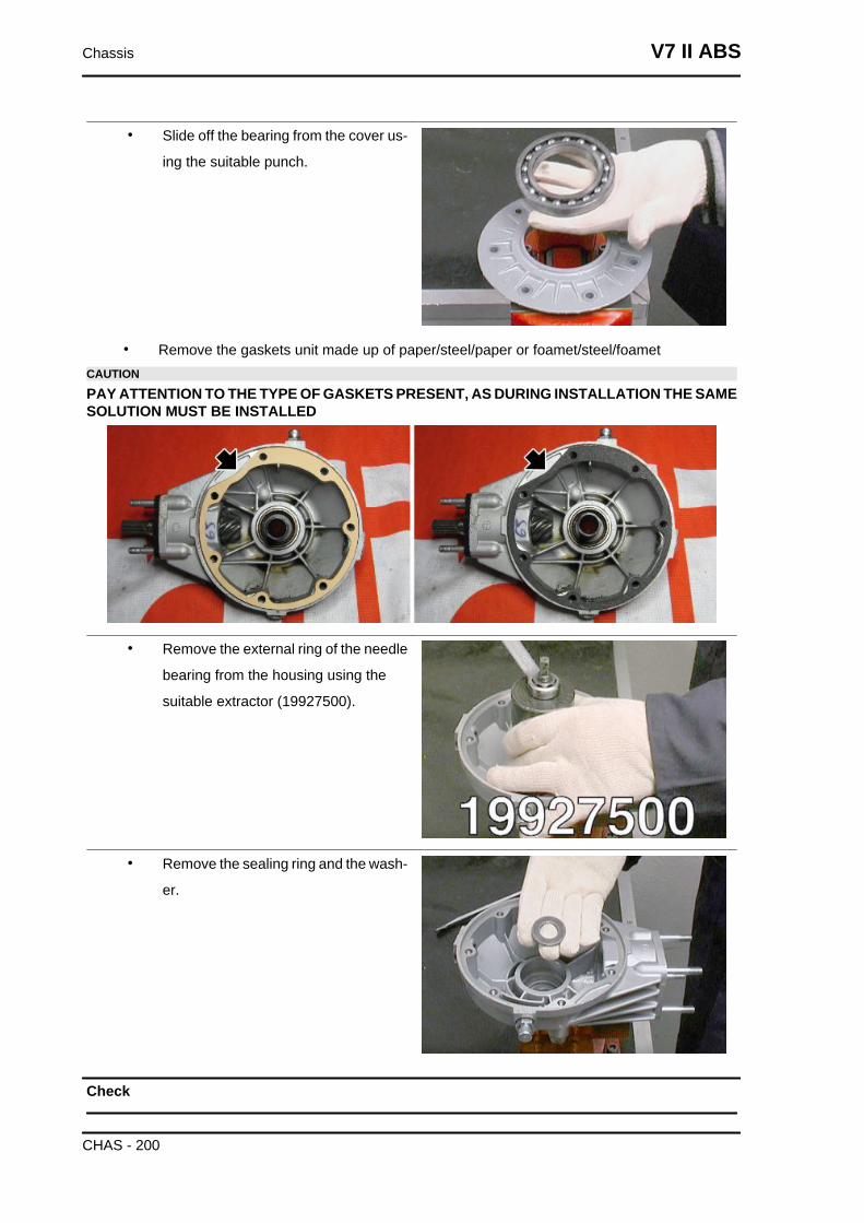
• Slide off the bearing from the cover us-
ing the suitable punch.
• Remove the gaskets unit made up of paper/steel/paper or foamet/steel/foametCAUTION
PAY ATTENTION TO THE TYPE OF GASKETS PRESENT, AS DURING INSTALLATION THE SAMESOLUTION MUST BE INSTALLED
• Remove the external ring of the needle
bearing from the housing using the
suitable extractor (19927500).
• Remove the sealing ring and the wash-
er.
Check
Chassis V7 II ABS
CHAS - 200
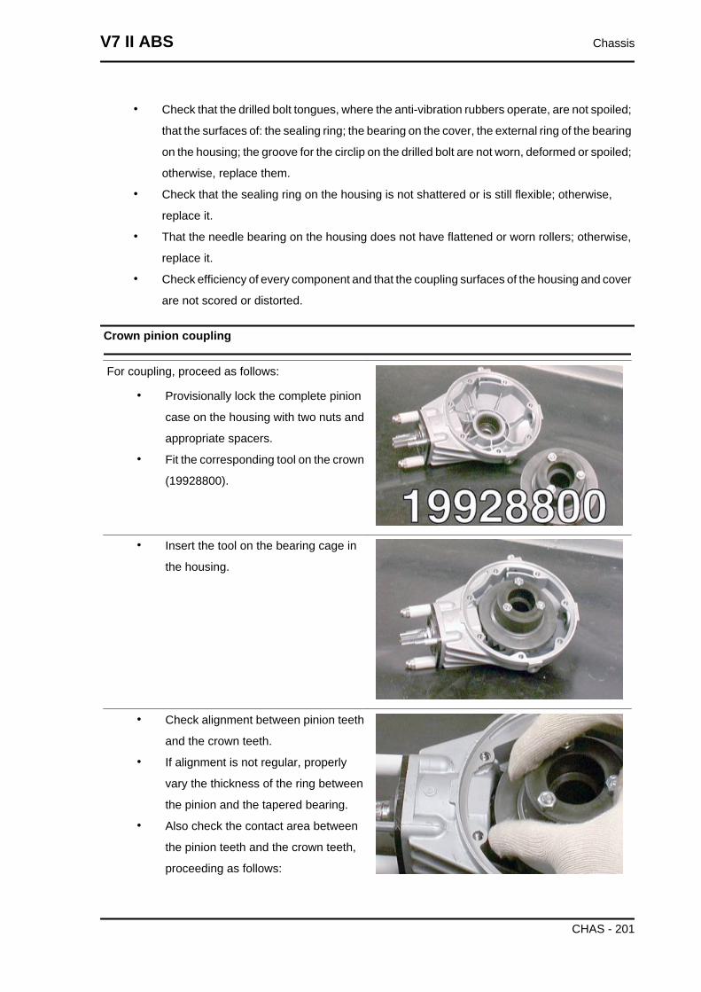
• Check that the drilled bolt tongues, where the anti-vibration rubbers operate, are not spoiled;
that the surfaces of: the sealing ring; the bearing on the cover, the external ring of the bearing
on the housing; the groove for the circlip on the drilled bolt are not worn, deformed or spoiled;
otherwise, replace them.
• Check that the sealing ring on the housing is not shattered or is still flexible; otherwise,
replace it.
• That the needle bearing on the housing does not have flattened or worn rollers; otherwise,
replace it.
• Check efficiency of every component and that the coupling surfaces of the housing and cover
are not scored or distorted.
Crown pinion coupling
For coupling, proceed as follows:
• Provisionally lock the complete pinion
case on the housing with two nuts and
appropriate spacers.
• Fit the corresponding tool on the crown
(19928800).
• Insert the tool on the bearing cage in
the housing.
• Check alignment between pinion teeth
and the crown teeth.
• If alignment is not regular, properly
vary the thickness of the ring between
the pinion and the tapered bearing.
• Also check the contact area between
the pinion teeth and the crown teeth,
proceeding as follows:
V7 II ABS Chassis
CHAS - 201
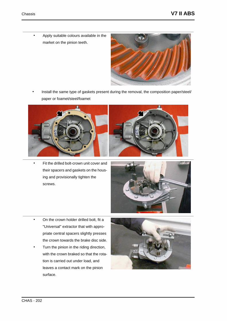
• Apply suitable colours available in the
market on the pinion teeth.
• Install the same type of gaskets present during the removal, the composition paper/steel/
paper or foamet/steel/foamet
• Fit the drilled bolt-crown unit cover and
their spacers and gaskets on the hous-
ing and provisionally tighten the
screws.
• On the crown holder drilled bolt, fit a
"Universal" extractor that with appro-
priate central spacers slightly presses
the crown towards the brake disc side.
• Turn the pinion in the riding direction,
with the crown braked so that the rota-
tion is carried out under load, and
leaves a contact mark on the pinion
surface.
Chassis V7 II ABS
CHAS - 202
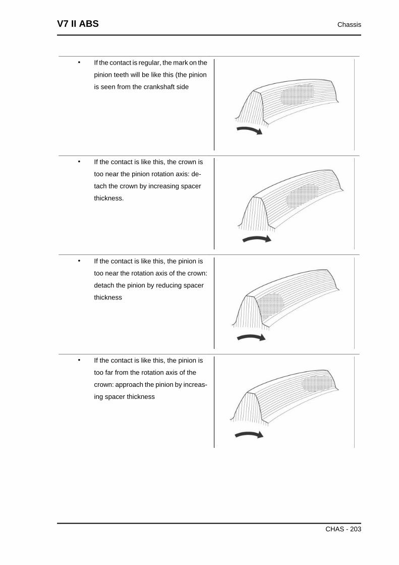
• If the contact is regular, the mark on the
pinion teeth will be like this (the pinion
is seen from the crankshaft side
• If the contact is like this, the crown is
too near the pinion rotation axis: de-
tach the crown by increasing spacer
thickness.
• If the contact is like this, the pinion is
too near the rotation axis of the crown:
detach the pinion by reducing spacer
thickness
• If the contact is like this, the pinion is
too far from the rotation axis of the
crown: approach the pinion by increas-
ing spacer thickness
V7 II ABS Chassis
CHAS - 203
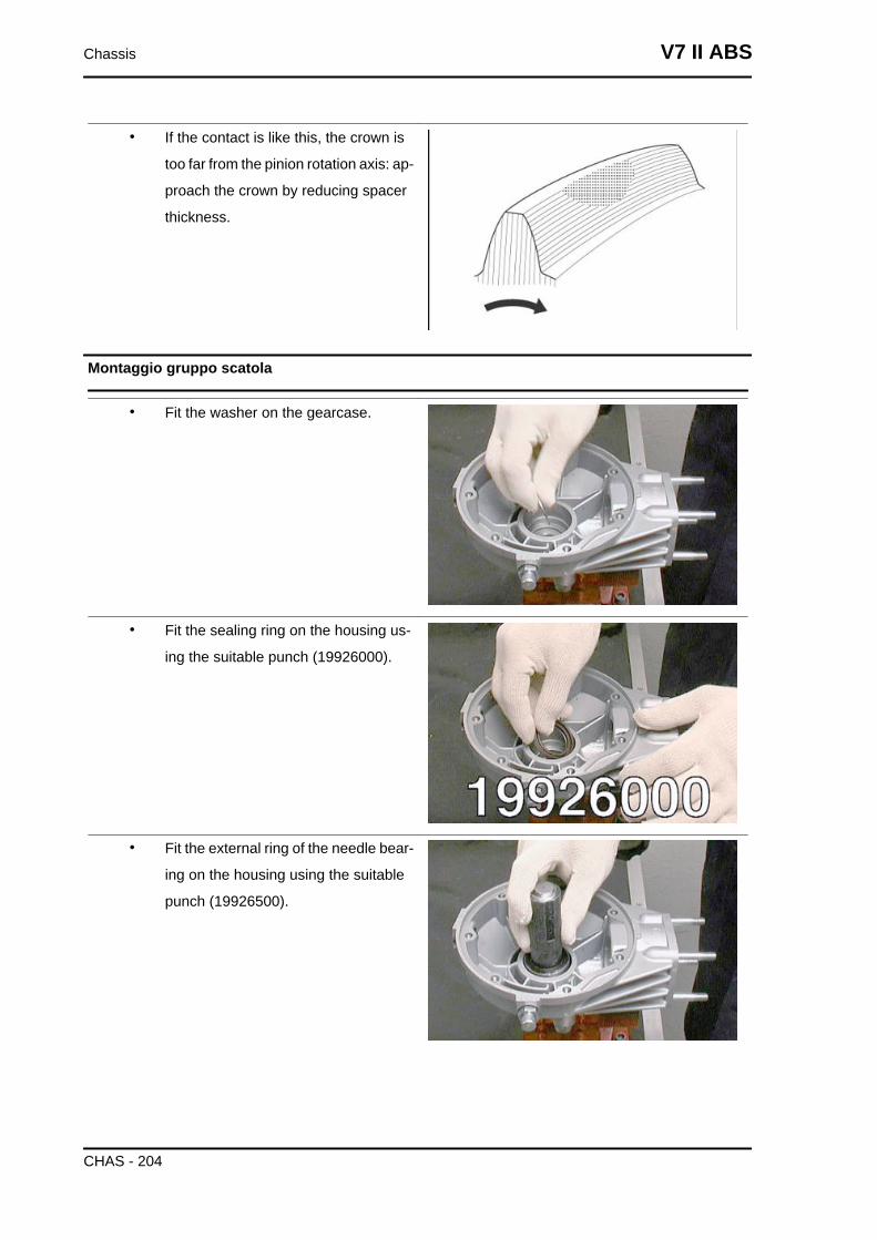
• If the contact is like this, the crown is
too far from the pinion rotation axis: ap-
proach the crown by reducing spacer
thickness.
Montaggio gruppo scatola
• Fit the washer on the gearcase.
• Fit the sealing ring on the housing us-
ing the suitable punch (19926000).
• Fit the external ring of the needle bear-
ing on the housing using the suitable
punch (19926500).
Chassis V7 II ABS
CHAS - 204
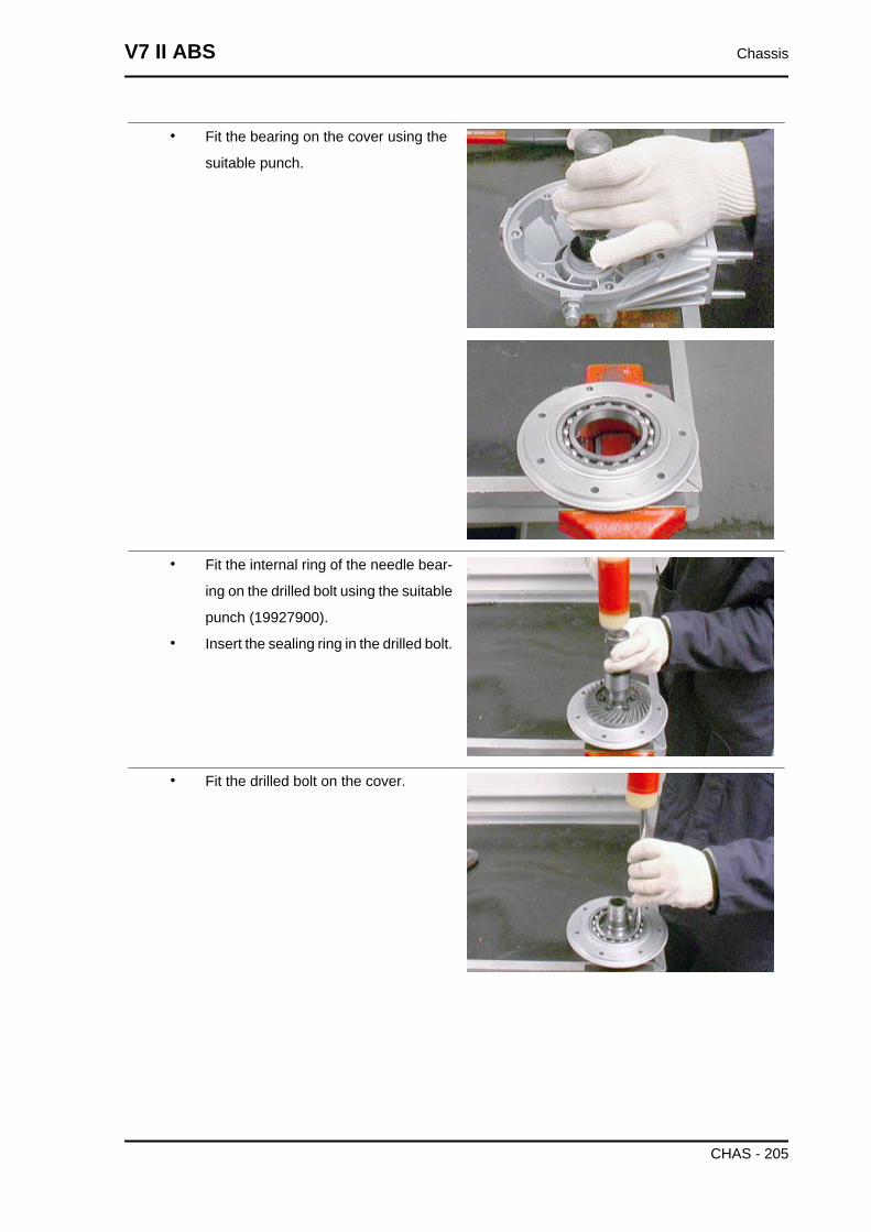
• Fit the bearing on the cover using the
suitable punch.
• Fit the internal ring of the needle bear-
ing on the drilled bolt using the suitable
punch (19927900).
• Insert the sealing ring in the drilled bolt.
• Fit the drilled bolt on the cover.
V7 II ABS Chassis
CHAS - 205
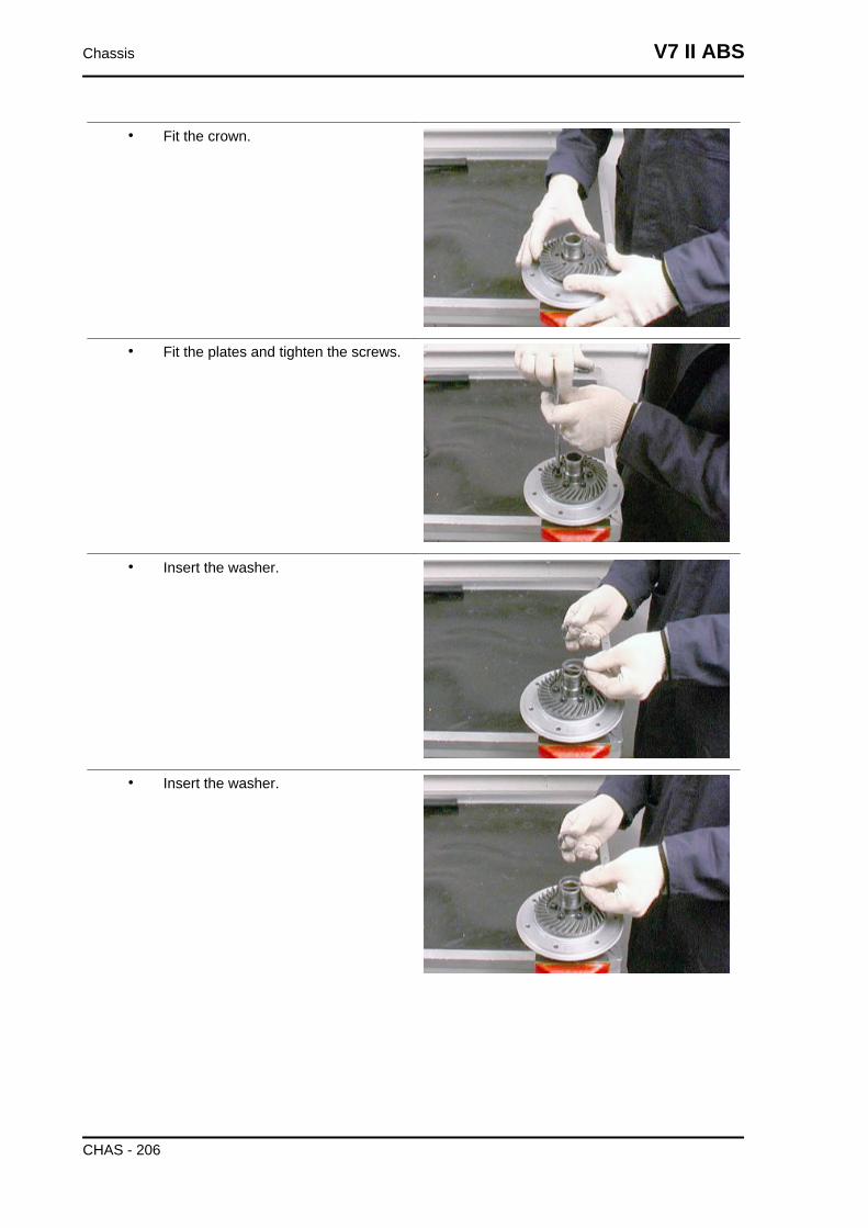
• Fit the crown.
• Fit the plates and tighten the screws.
• Insert the washer.
• Insert the washer.
Chassis V7 II ABS
CHAS - 206
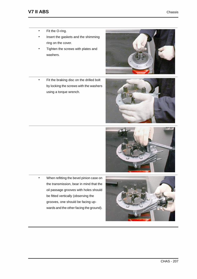
• Fit the O-ring.
• Insert the gaskets and the shimming
ring on the cover.
• Tighten the screws with plates and
washers.
• Fit the braking disc on the drilled bolt
by locking the screws with the washers
using a torque wrench.
• When refitting the bevel pinion case on
the transmission, bear in mind that the
oil passage grooves with holes should
be fitted vertically (observing the
grooves, one should be facing up-
wards and the other facing the ground).
V7 II ABS Chassis
CHAS - 207
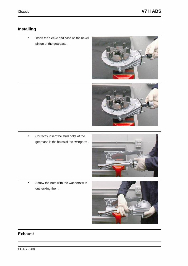
Installing
• Insert the sleeve and base on the bevel
pinion of the gearcase.
• Correctly insert the stud bolts of the
gearcase in the holes of the swingarm .
• Screw the nuts with the washers with-
out locking them.
Exhaust
Chassis V7 II ABS
CHAS - 208
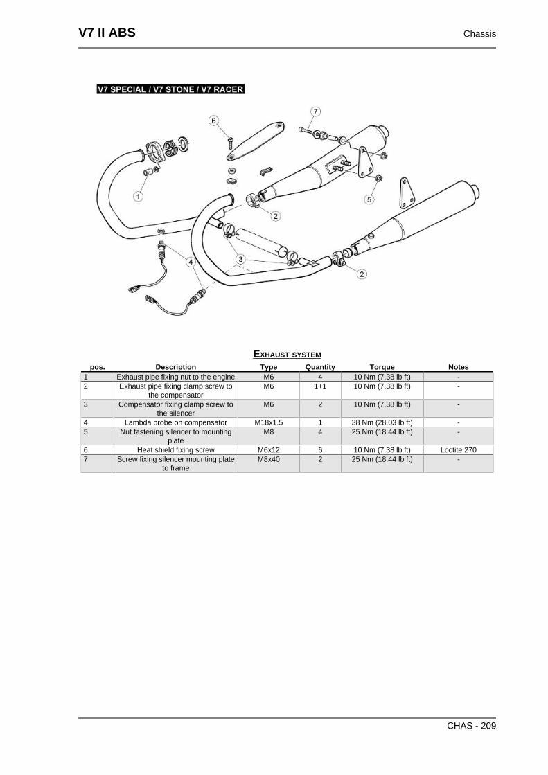
EXHAUST SYSTEMpos. Description Type Quantity Torque Notes
1 Exhaust pipe fixing nut to the engine M6 4 10 Nm (7.38 lb ft) -2 Exhaust pipe fixing clamp screw to
the compensatorM6 1+1 10 Nm (7.38 lb ft) -
3 Compensator fixing clamp screw tothe silencer
M6 2 10 Nm (7.38 lb ft) -
4 Lambda probe on compensator M18x1.5 1 38 Nm (28.03 lb ft) -5 Nut fastening silencer to mounting
plateM8 4 25 Nm (18.44 lb ft) -
6 Heat shield fixing screw M6x12 6 10 Nm (7.38 lb ft) Loctite 2707 Screw fixing silencer mounting plate
to frameM8x40 2 25 Nm (18.44 lb ft) -
V7 II ABS Chassis
CHAS - 209
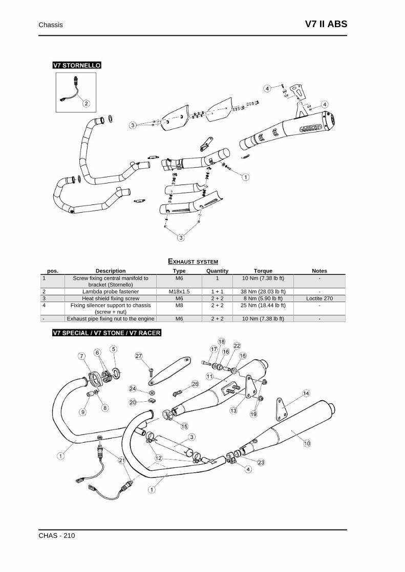
EXHAUST SYSTEMpos. Description Type Quantity Torque Notes
1 Screw fixing central manifold tobracket (Stornello)
M6 1 10 Nm (7.38 lb ft) -
2 Lambda probe fastener M18x1.5 1 + 1 38 Nm (28.03 lb ft) -3 Heat shield fixing screw M6 2 + 2 8 Nm (5.90 lb ft) Loctite 2704 Fixing silencer support to chassis
(screw + nut)M8 2 + 2 25 Nm (18.44 lb ft) -
- Exhaust pipe fixing nut to the engine M6 2 + 2 10 Nm (7.38 lb ft) -
Chassis V7 II ABS
CHAS - 210
key:
1. Right exhaust pipe
2. Left exhaust pipe
3. Exhaust manifold fitting
4. Left silencer clamp
5. Gasket
6. Spacer
7. Ring nut
8. Washer
9. Nut
10.Left silencer
11.Right silencer
12.Clamp
13.Right plate
14.Left plate
15.Right silencer clamp
16.Muffler rubber ring
17.SHC screw
18.Silencer fixing bushing
19.Nut
20.Elastic plate
21.Lambda probe
22.Spacer
23.Bushing
24.Insulating washer
25.Silencer heat protection
26.U-bolt
27.Flanged TBEI screw
V7 II ABS Chassis
CHAS - 211
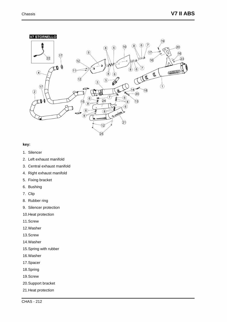
key:
1. Silencer
2. Left exhaust manifold
3. Central exhaust manifold
4. Right exhaust manifold
5. Fixing bracket
6. Bushing
7. Clip
8. Rubber ring
9. Silencer protection
10.Heat protection
11.Screw
12.Washer
13.Screw
14.Washer
15.Spring with rubber
16.Washer
17.Spacer
18.Spring
19.Screw
20.Support bracket
21.Heat protection
Chassis V7 II ABS
CHAS - 212
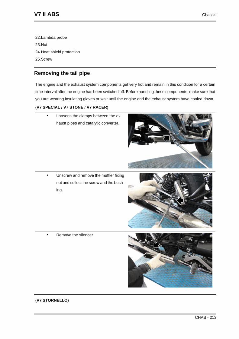
22.Lambda probe
23.Nut
24.Heat shield protection
25.Screw
Removing the tail pipe
The engine and the exhaust system components get very hot and remain in this condition for a certain
time interval after the engine has been switched off. Before handling these components, make sure that
you are wearing insulating gloves or wait until the engine and the exhaust system have cooled down.
(V7 SPECIAL / V7 STONE / V7 RACER)
• Loosens the clamps between the ex-
haust pipes and catalytic converter.
• Unscrew and remove the muffler fixing
nut and collect the screw and the bush-
ing.
• Remove the silencer
(V7 STORNELLO)
V7 II ABS Chassis
CHAS - 213
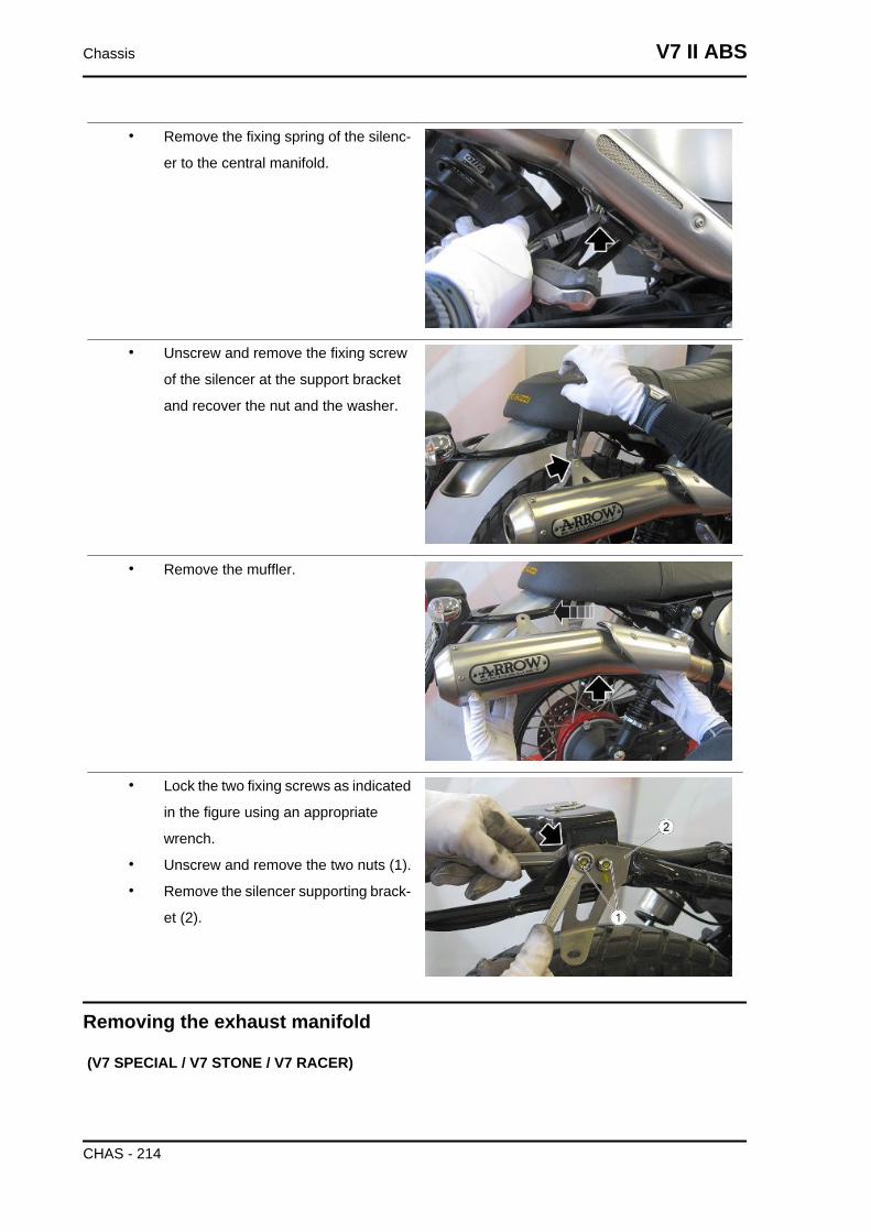
• Remove the fixing spring of the silenc-
er to the central manifold.
• Unscrew and remove the fixing screw
of the silencer at the support bracket
and recover the nut and the washer.
• Remove the muffler.
• Lock the two fixing screws as indicated
in the figure using an appropriate
wrench.
• Unscrew and remove the two nuts (1).
• Remove the silencer supporting brack-
et (2).
Removing the exhaust manifold
(V7 SPECIAL / V7 STONE / V7 RACER)
Chassis V7 II ABS
CHAS - 214
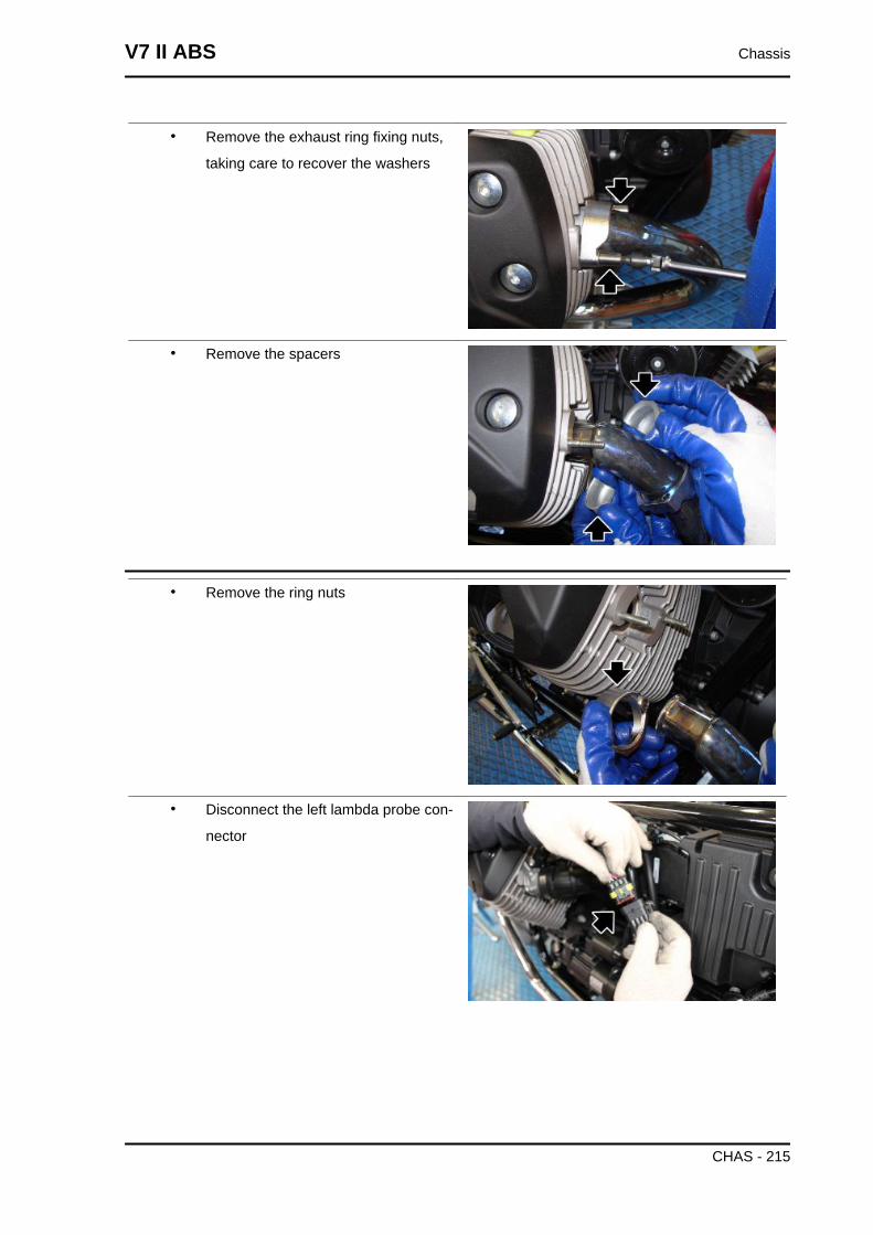
• Remove the exhaust ring fixing nuts,
taking care to recover the washers
• Remove the spacers
• Remove the ring nuts
• Disconnect the left lambda probe con-
nector
V7 II ABS Chassis
CHAS - 215
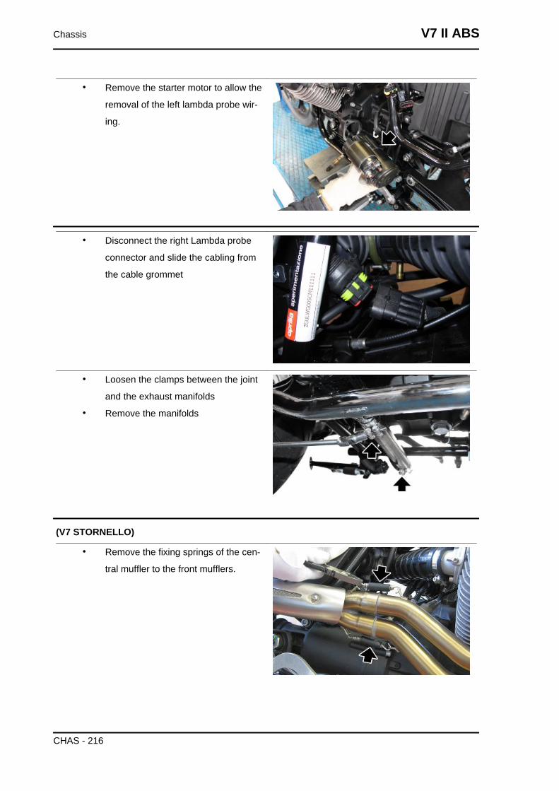
• Remove the starter motor to allow the
removal of the left lambda probe wir-
ing.
• Disconnect the right Lambda probe
connector and slide the cabling from
the cable grommet
• Loosen the clamps between the joint
and the exhaust manifolds
• Remove the manifolds
(V7 STORNELLO)
• Remove the fixing springs of the cen-
tral muffler to the front mufflers.
Chassis V7 II ABS
CHAS - 216
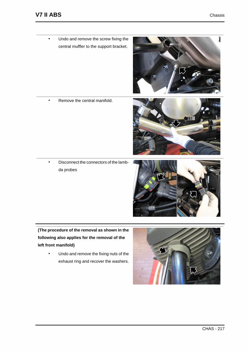
• Undo and remove the screw fixing the
central muffler to the support bracket.
• Remove the central manifold.
• Disconnect the connectors of the lamb-
da probes
(The procedure of the removal as shown in the
following also applies for the removal of the
left front manifold)
• Undo and remove the fixing nuts of the
exhaust ring and recover the washers.
V7 II ABS Chassis
CHAS - 217
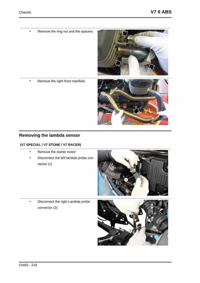
• Remove the ring nut and the spacers.
• Remove the right front manifold.
Removing the lambda sensor
(V7 SPECIAL / V7 STONE / V7 RACER)
• Remove the starter motor
• Disconnect the left lambda probe con-
nector (1)
• Disconnect the right Lambda probe
connector (2)
Chassis V7 II ABS
CHAS - 218
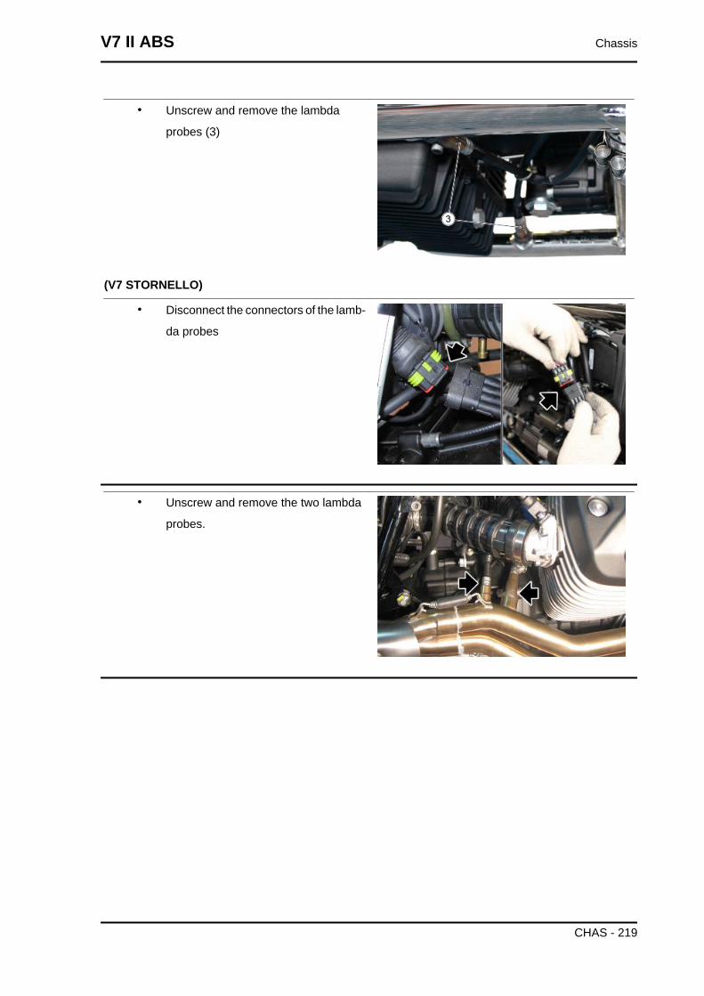
• Unscrew and remove the lambda
probes (3)
(V7 STORNELLO)
• Disconnect the connectors of the lamb-
da probes
• Unscrew and remove the two lambda
probes.
V7 II ABS Chassis
CHAS - 219
INDEX OF TOPICS
BRAKING SYSTEM BRAK SYS
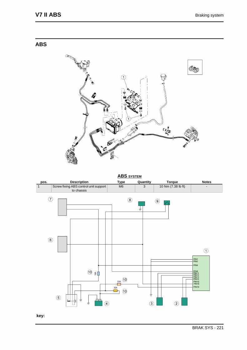
ABS
ABS SYSTEMpos. Description Type Quantity Torque Notes
1 Screw fixing ABS control unit supportto chassis
M6 3 10 Nm (7.38 lb ft) -
key:
V7 II ABS Braking system
BRAK SYS - 221
1. ABS ECU control unit
2. Front ABS sensor
3. Rear ABS sensor
4. Battery
5. Main relay
6. ECU
7. Instrument panel
8. K line (diagnosis)
9. Key
10.Fuses
ABS ECU control unit pin configuration
• PIN 1 - GND - Ground
• PIN 2 - PCC1 - Vehicle identification ground connection
• PIN 4 - IGN - Injection
• PIN 8 - WL - Alarm warning light
• PIN 11 - R_SIGN - Rear ABS sensor signal
• PIN 12 - R_GND - Rear ABS sensor ground connection
• PIN 13 - F_GND - Front ABS sensor ground connection
• PIN 14 - F_SIG - Front ABS sensor signal
• PIN 15 - PCC2 - Vehicle identification ground connection
• PIN 16 - ISO_K - K line (diagnosis)
• PIN 18 - KL30 - Power supply
Braking system V7 II ABS
BRAK SYS - 222
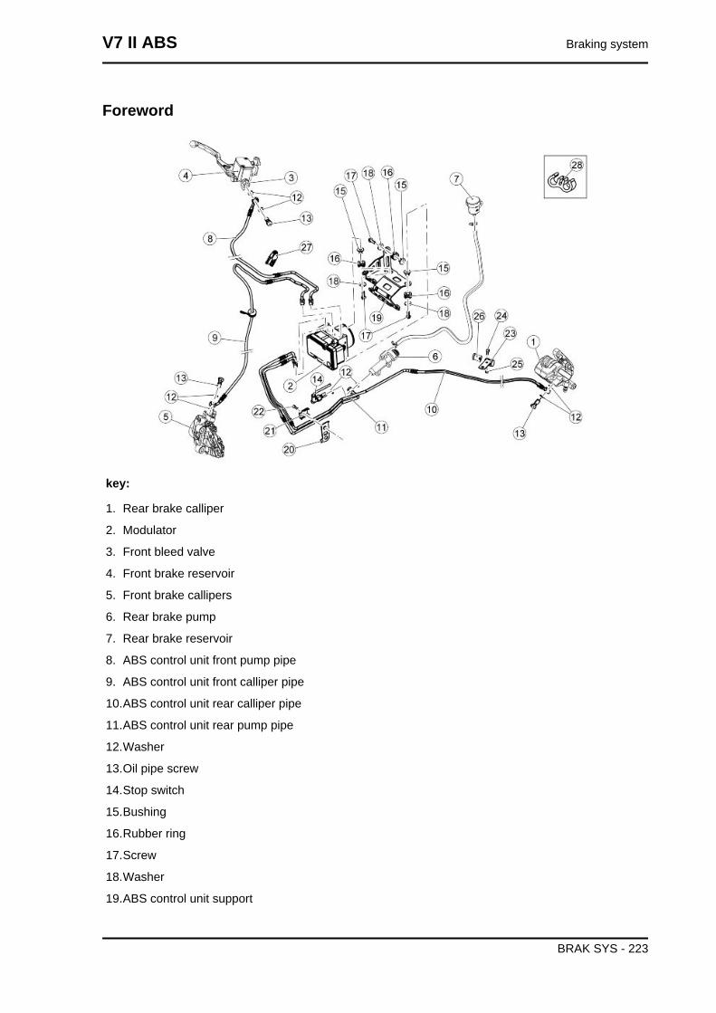
Foreword
key:
1. Rear brake calliper
2. Modulator
3. Front bleed valve
4. Front brake reservoir
5. Front brake callipers
6. Rear brake pump
7. Rear brake reservoir
8. ABS control unit front pump pipe
9. ABS control unit front calliper pipe
10.ABS control unit rear calliper pipe
11.ABS control unit rear pump pipe
12.Washer
13.Oil pipe screw
14.Stop switch
15.Bushing
16.Rubber ring
17.Screw
18.Washer
19.ABS control unit support
V7 II ABS Braking system
BRAK SYS - 223
20.Brake pipe mounting plate
21.Pipes fixing plate
22.Screw
23.Clamp
24.Screw
25.Nut
26.Ring
27.Brake pipe support
28.Clip
Braking system V7 II ABS
BRAK SYS - 224
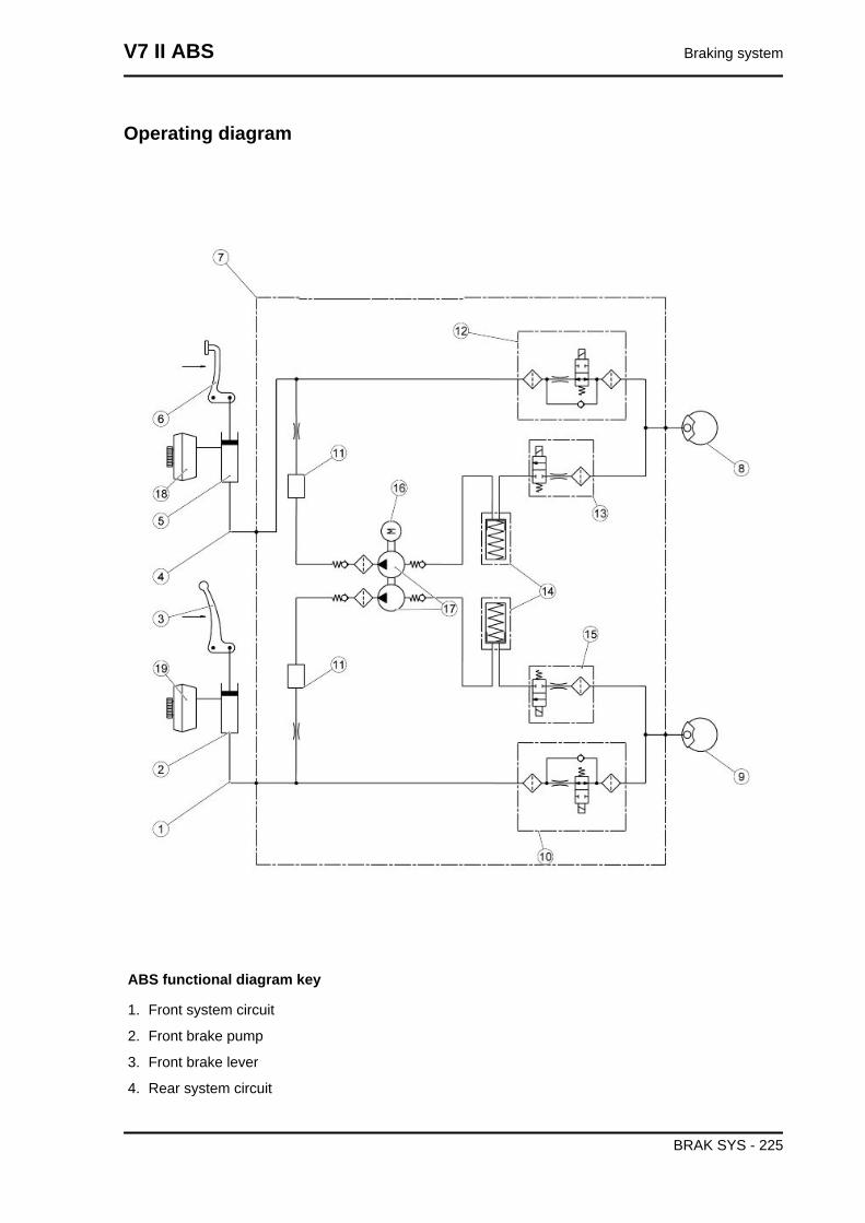
Operating diagram
ABS functional diagram key
1. Front system circuit
2. Front brake pump
3. Front brake lever
4. Rear system circuit
V7 II ABS Braking system
BRAK SYS - 225
5. Rear brake pump
6. Rear brake pedal control
7. ABS control unit
8. Rear brake calliper
9. Front Calliper
10.Front brake circuit intake solenoid valve (normally open)
11.Humidifier
12.Rear brake circuit intake solenoid valve (normally open)
13.Rear brake exhaust circuit solenoid valve (normally closed)
14.Rear/front brake circuit low pressure accumulator
15.Front brake exhaust circuit solenoid valve (normally closed)
16.DC electric motor
17.Double circuit hydraulic pump (ABS)
18.Rear brake reservoir
19.Front brake reservoir
ABS OPERATION
General specifications:
The front circuit is similar to the rear circuit.
• The ABS inlet valve (10 - 12) is normally open and it is closed only when the system inter-
venes to avoid wheel locking.
• The outlet valve (13 - 15) is normally closed and it is opened only when the system intervenes
to avoid wheel locking.
• When the system is in standby, the ABS processor never stops monitoring the speed of the
wheels in order to assess potential wheel slippage.
• When in standby, the system does not intervene at all when the rider brakes; the braking
system is the same as the one without ABS.
Stages in ABS cycle (the following operations refer to the front circuit but are also applicable to
the rear one):
A - Brake activation: the rider starts braking as he would usually do.
B - Pressure reduction: it coincides with danger recognition (wheel slippage above threshold): the
system closes the inlet valve (10-12) and opens the outlet valve (13-15) temporarily.
At this stage the rider cannot increase the pressure on the callipers (8-9) and the system reduces the
pressure on the callipers partially. The excess fluid temporarily fills the front reservoir (18-19) until the
ABS pump (17) self-activates and delivers the fluid back to the brake pump (2-5).
C - Pressure maintained: the pressure in the callipers (8-9) remains low until total recovery of speed /
wheel grip.
The system restores the fluid taken from the calliper (8-9) in the section of the system between the
brake pump (2-5) and the ABS inlet valve (10-12).
Braking system V7 II ABS
BRAK SYS - 226
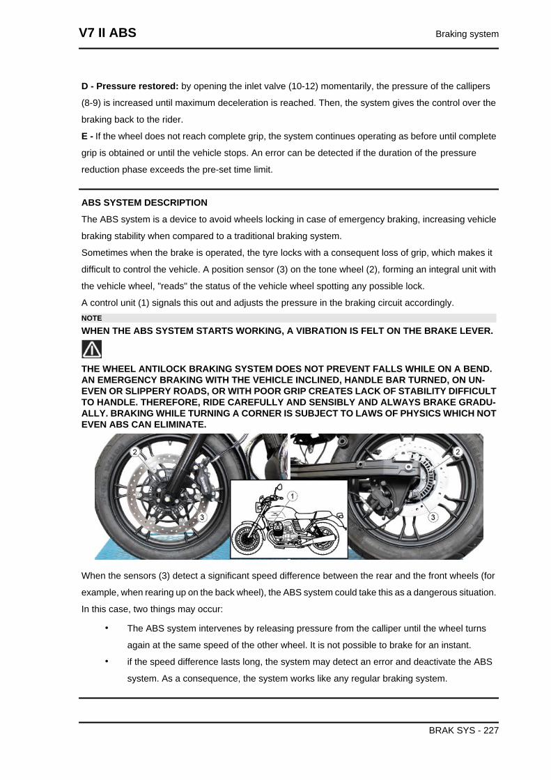
D - Pressure restored: by opening the inlet valve (10-12) momentarily, the pressure of the callipers
(8-9) is increased until maximum deceleration is reached. Then, the system gives the control over the
braking back to the rider.
E - If the wheel does not reach complete grip, the system continues operating as before until complete
grip is obtained or until the vehicle stops. An error can be detected if the duration of the pressure
reduction phase exceeds the pre-set time limit.
ABS SYSTEM DESCRIPTION
The ABS system is a device to avoid wheels locking in case of emergency braking, increasing vehicle
braking stability when compared to a traditional braking system.
Sometimes when the brake is operated, the tyre locks with a consequent loss of grip, which makes it
difficult to control the vehicle. A position sensor (3) on the tone wheel (2), forming an integral unit with
the vehicle wheel, "reads" the status of the vehicle wheel spotting any possible lock.
A control unit (1) signals this out and adjusts the pressure in the braking circuit accordingly.NOTE
WHEN THE ABS SYSTEM STARTS WORKING, A VIBRATION IS FELT ON THE BRAKE LEVER.
THE WHEEL ANTILOCK BRAKING SYSTEM DOES NOT PREVENT FALLS WHILE ON A BEND.AN EMERGENCY BRAKING WITH THE VEHICLE INCLINED, HANDLE BAR TURNED, ON UN-EVEN OR SLIPPERY ROADS, OR WITH POOR GRIP CREATES LACK OF STABILITY DIFFICULTTO HANDLE. THEREFORE, RIDE CAREFULLY AND SENSIBLY AND ALWAYS BRAKE GRADU-ALLY. BRAKING WHILE TURNING A CORNER IS SUBJECT TO LAWS OF PHYSICS WHICH NOTEVEN ABS CAN ELIMINATE.
When the sensors (3) detect a significant speed difference between the rear and the front wheels (for
example, when rearing up on the back wheel), the ABS system could take this as a dangerous situation.
In this case, two things may occur:
• The ABS system intervenes by releasing pressure from the calliper until the wheel turns
again at the same speed of the other wheel. It is not possible to brake for an instant.
• if the speed difference lasts long, the system may detect an error and deactivate the ABS
system. As a consequence, the system works like any regular braking system.
V7 II ABS Braking system
BRAK SYS - 227
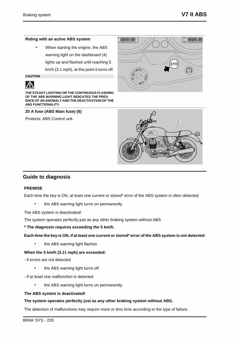
Riding with an active ABS system
• When starting the engine, the ABS
warning light on the dashboard (4)
lights up and flashed until reaching 5
km/h (3.1 mph), at this point it turns off.CAUTION
THE STEADY LIGHTING OR THE CONTINUOUS FLASHINGOF THE ABS WARNING LIGHT INDICATES THE PRES-ENCE OF AN ANOMALY AND THE DEACTIVATION OF THEABS FUNCTIONALITY.
20 A fuse (ABS Main fuse) (6)
Protects: ABS Control unit.
Guide to diagnosis
PREMISE
Each time the key is ON, at least one current or stored* error of the ABS system is often detected:
• the ABS warning light turns on permanently
The ABS system is deactivated!
The system operates perfectly just as any other braking system without ABS
* The diagnosis requires exceeding the 5 km/h.
Each time the key is ON, if at least one current or stored* error of the ABS system is not detected:
• the ABS warning light flashes
When the 5 km/h (3.11 mph) are exceeded:
- if errors are not detected
• the ABS warning light turns off
- if at least one malfunction is detected
• the ABS warning light turns on permanently
The ABS system is deactivated!
The system operates perfectly just as any other braking system without ABS.
The detection of malfunctions may require more or less time according to the type of failure.
Braking system V7 II ABS
BRAK SYS - 228
Error detection logic foresees that for the errors to be diagnosed one or more conditions must persist
within a given time.
If during this given time one of the conditions is missing but then it comes back, the timer is reset and
the system is no longer able to diagnose the error.
The ABS system is still inactive.
Example:
- error code 5D93 requires some minutes before it is diagnosed during the given time:
• the ABS warning light ABS keeps flashing
GUIDE TO ABS FAULT DIAGNOSIS
1. ABS LAMP ON
2. CONNECT PADS
PADS COMMUNICATE? (NO, go to 3; YES, go to 4)
3. PERFORM THESE CHECKS:
• A. PIN 1 Ground connection
• B. +12V at PIN 18
• C. +12V at PIN 4 with key ON
4. ARE THERE ANY ERRORS? YES, go to point 5; NO, go to 6)
5. CHECK THE ERRORS TABLE
6. ABS WARNING LIGHT ACTIVATION
IS IT ACTIVATED?(YES, go to point 7; NO, go to point 8)
7. CONTACT TECHNICAL SERVICE
8. PERFORM THESE CHECKS:
• A. Cable continuity between PIN8 of the ABS control unit connector and the instrument panel
warning light.
• B. Check connectors - refer to the operations described in the chapter
If the above checks are OK, the causes can be:
• C. ABS Control unit malfunction
• D. Instrument panel malfunction
NOTE: to carry out a check using the diagnostic tool on the wheel speed sensor, refer to the
operations described in chapter ""ELECTRICAL SYSTEM/CHECKS AND CONTROLS/SPEED
SENSOR" chapter.
Use of diagnostics instrument for ABS system
V7 II ABS Braking system
BRAK SYS - 229
Abs screen pages
ECU INFO screen page
This screen page shows general data regarding
the control unit, for example software type, map-
ping, control unit programming date
PARAMETERS screen page
This screen page shows the parameters meas-
ured by the several sensors (engine revs, engine
temperature, etc.) or values set by the control unit
(injection time, ignition advance, etc.)
PARAMETERSP.A.D.S. characteristic Value/example Unit of
measurement
Notes
Front wheel speed - km/h -Rear wheel speed - km/h -Battery voltage - V -Front brake circuit pressure - bar -
Quality test of the sensors
When turning the wheel or acting on the brake, a variation of parameters must be detected.
Braking system V7 II ABS
BRAK SYS - 230
ACTIVATION screen page
This screen page is used to delete errors in the
control unit memory and to activate some systems
controlled by the control unit.
ACTIVATIONP.A.D.S. characteristic Value/example Unit of
measurement
Notes
ABS warning lightError clearingFreezes and saves the parameterand states values
ERRORS screen page
This screen page displays any errors detected in
the vehicle (ATT) or stored in the control unit
(MEM) and you can check that the cancellation of
error (STO) has taken place.
ERRORSP.A.D.S. characteristic. Value/example Units of
measurement
Notes
Comparison of front and rear wheel C1024 Excessive differenceRear wheel speed sensor electricaldiagnosis
C1031 Short circuit or open circuit to negative or shortcircuit to positive
Rear wheel speed sensor functionaldiagnosis
C1032 Signal not valid
Front wheel speed sensor electricaldiagnosis
C1033 Short circuit or open circuit to negative or shortcircuit to positive
Front wheel speed sensor functionaldiagnosis
C1034 Signal not valid
Inside error C1014 Solenoid valve relay failureInside error C1015 Recirculation pump failureInside error C1021 Control unit failureInside error C1048 Rear circuit output solenoid valve failureInside error C1049 Rear circuit output solenoid valve failureInside error C1052 Rear circuit input solenoid valve failureInside error C1054 Front circuit inlet solenoid valve failure
V7 II ABS Braking system
BRAK SYS - 231
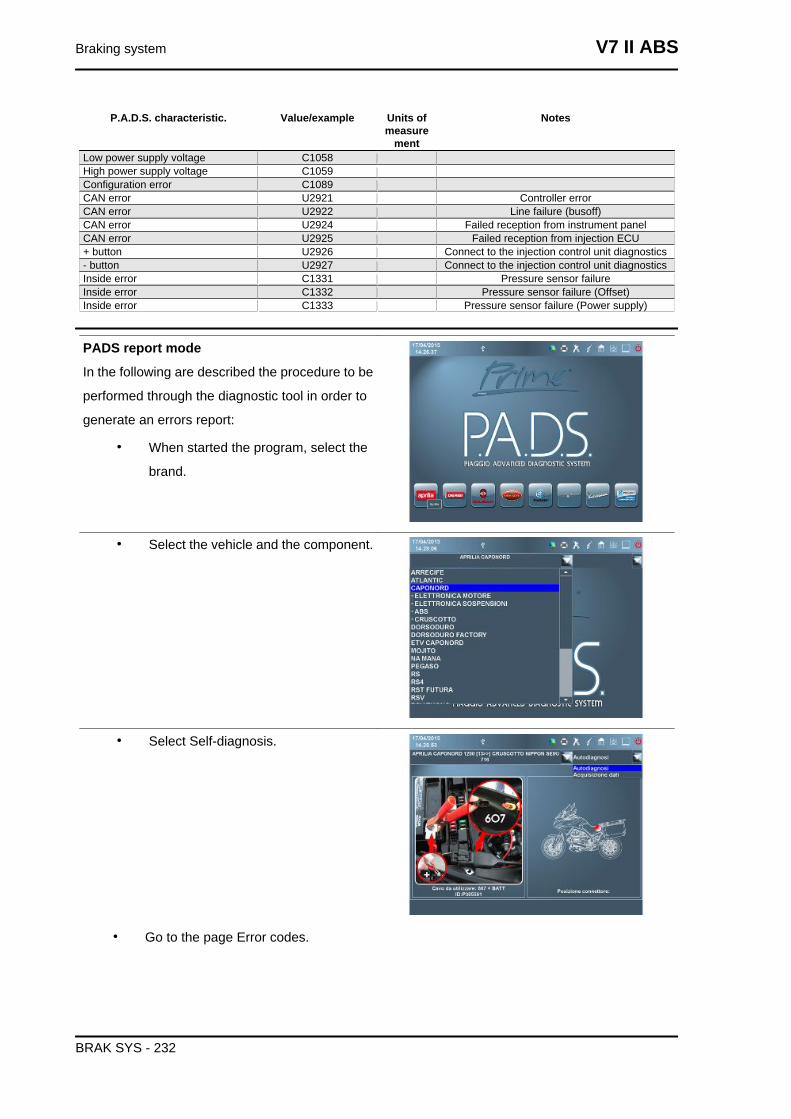
P.A.D.S. characteristic. Value/example Units ofmeasure
ment
Notes
Low power supply voltage C1058High power supply voltage C1059Configuration error C1089CAN error U2921 Controller errorCAN error U2922 Line failure (busoff)CAN error U2924 Failed reception from instrument panelCAN error U2925 Failed reception from injection ECU+ button U2926 Connect to the injection control unit diagnostics- button U2927 Connect to the injection control unit diagnosticsInside error C1331 Pressure sensor failureInside error C1332 Pressure sensor failure (Offset)Inside error C1333 Pressure sensor failure (Power supply)
PADS report mode
In the following are described the procedure to be
performed through the diagnostic tool in order to
generate an errors report:
• When started the program, select the
brand.
• Select the vehicle and the component.
• Select Self-diagnosis.
• Go to the page Error codes.
Braking system V7 II ABS
BRAK SYS - 232
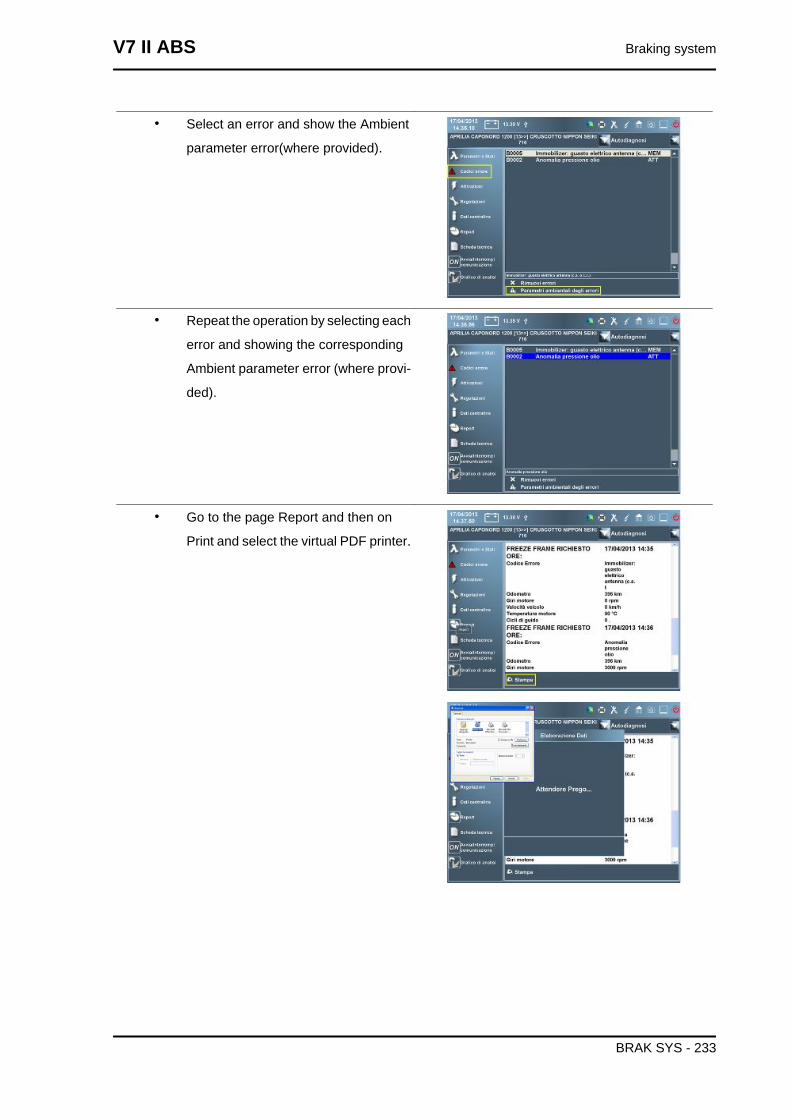
• Select an error and show the Ambient
parameter error(where provided).
• Repeat the operation by selecting each
error and showing the corresponding
Ambient parameter error (where provi-
ded).
• Go to the page Report and then on
Print and select the virtual PDF printer.
V7 II ABS Braking system
BRAK SYS - 233
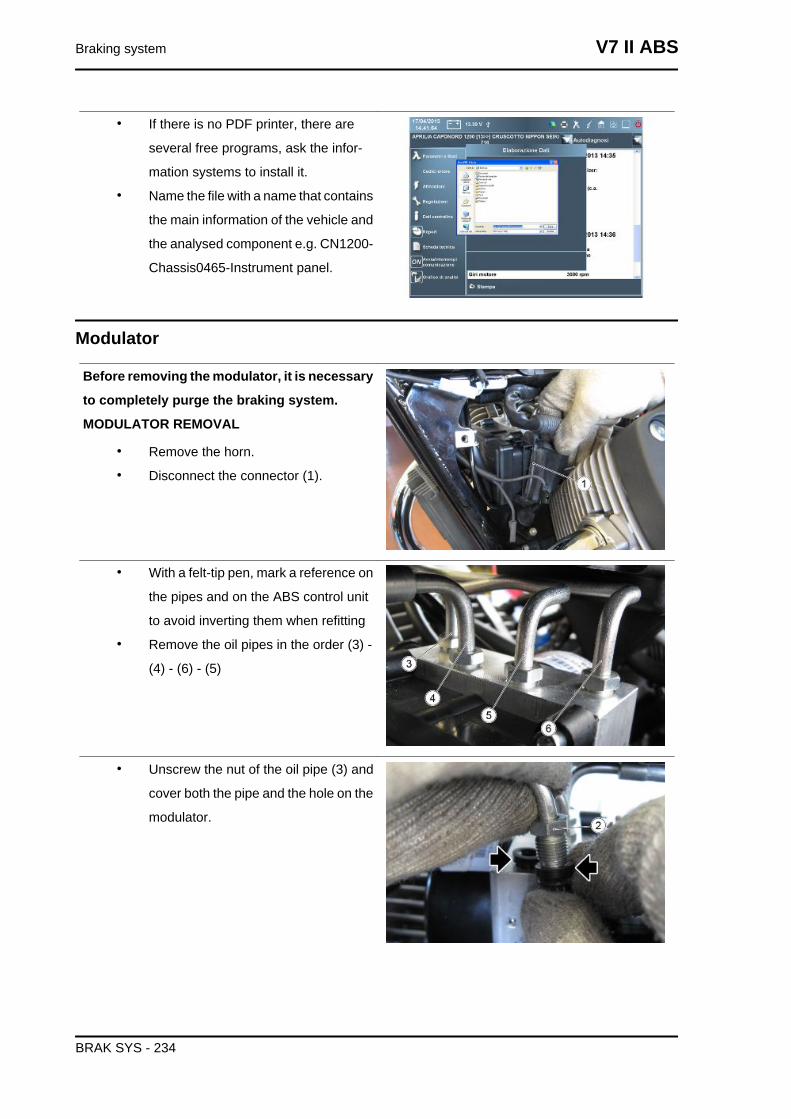
• If there is no PDF printer, there are
several free programs, ask the infor-
mation systems to install it.
• Name the file with a name that contains
the main information of the vehicle and
the analysed component e.g. CN1200-
Chassis0465-Instrument panel.
Modulator
Before removing the modulator, it is necessary
to completely purge the braking system.
MODULATOR REMOVAL
• Remove the horn.
• Disconnect the connector (1).
• With a felt-tip pen, mark a reference on
the pipes and on the ABS control unit
to avoid inverting them when refitting
• Remove the oil pipes in the order (3) -
(4) - (6) - (5)
• Unscrew the nut of the oil pipe (3) and
cover both the pipe and the hole on the
modulator.
Braking system V7 II ABS
BRAK SYS - 234
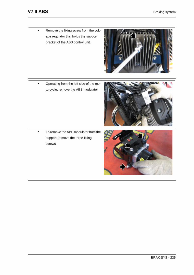
• Remove the fixing screw from the volt-
age regulator that holds the support
bracket of the ABS control unit.
• Operating from the left side of the mo-
torcycle, remove the ABS modulator
• To remove the ABS modulator from the
support, remove the three fixing
screws
V7 II ABS Braking system
BRAK SYS - 235
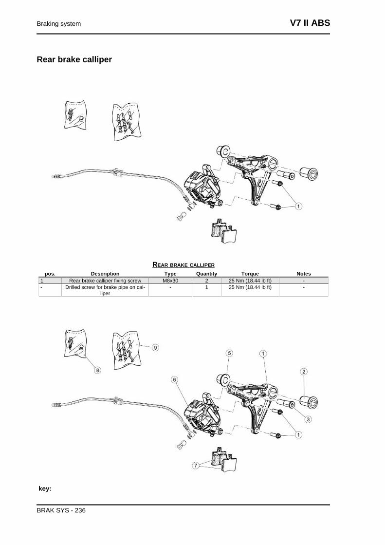
Rear brake calliper
REAR BRAKE CALLIPERpos. Description Type Quantity Torque Notes
1 Rear brake calliper fixing screw M8x30 2 25 Nm (18.44 lb ft) -- Drilled screw for brake pipe on cal-
liper- 1 25 Nm (18.44 lb ft) -
key:
Braking system V7 II ABS
BRAK SYS - 236
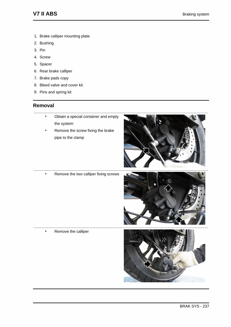
1. Brake calliper mounting plate
2. Bushing
3. Pin
4. Screw
5. Spacer
6. Rear brake calliper
7. Brake pads copy
8. Bleed valve and cover kit
9. Pins and spring kit
Removal
• Obtain a special container and empty
the system
• Remove the screw fixing the brake
pipe to the clamp
• Remove the two calliper fixing screws
• Remove the calliper
V7 II ABS Braking system
BRAK SYS - 237
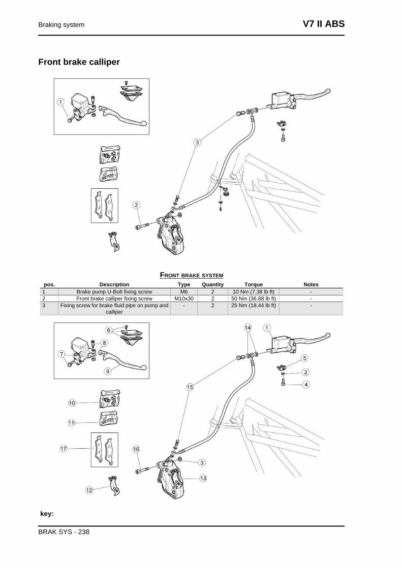
Front brake calliper
FRONT BRAKE SYSTEMpos. Description Type Quantity Torque Notes
1 Brake pump U-Bolt fixing screw M6 2 10 Nm (7.38 lb ft) -2 Front brake calliper fixing screw M10x30 2 50 Nm (36.88 lb ft) -3 Fixing screw for brake fluid pipe on pump and
calliper- 2 25 Nm (18.44 lb ft) -
key:
Braking system V7 II ABS
BRAK SYS - 238
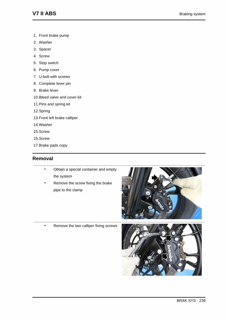
1. Front brake pump
2. Washer
3. Spacer
4. Screw
5. Stop switch
6. Pump cover
7. U-bolt with screws
8. Complete lever pin
9. Brake lever
10.Bleed valve and cover kit
11.Pins and spring kit
12.Spring
13.Front left brake calliper
14.Washer
15.Screw
16.Screw
17.Brake pads copy
Removal
• Obtain a special container and empty
the system
• Remove the screw fixing the brake
pipe to the clamp
• Remove the two calliper fixing screws
V7 II ABS Braking system
BRAK SYS - 239
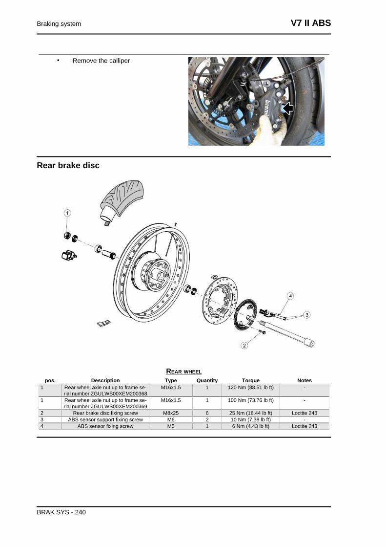
• Remove the calliper
Rear brake disc
REAR WHEELpos. Description Type Quantity Torque Notes
1 Rear wheel axle nut up to frame se-rial number ZGULWS00XEM200368
M16x1.5 1 120 Nm (88.51 lb ft) -
1 Rear wheel axle nut up to frame se-rial number ZGULWS00XEM200369
M16x1.5 1 100 Nm (73.76 lb ft) -
2 Rear brake disc fixing screw M8x25 6 25 Nm (18.44 lb ft) Loctite 2433 ABS sensor support fixing screw M6 2 10 Nm (7.38 lb ft) -4 ABS sensor fixing screw M5 1 6 Nm (4.43 lb ft) Loctite 243
Braking system V7 II ABS
BRAK SYS - 240
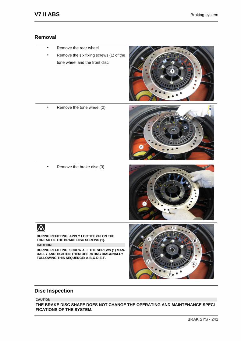
Removal
• Remove the rear wheel
• Remove the six fixing screws (1) of the
tone wheel and the front disc
• Remove the tone wheel (2)
• Remove the brake disc (3)
DURING REFITTING, APPLY LOCTITE 243 ON THETHREAD OF THE BRAKE DISC SCREWS (1).CAUTIONDURING REFITTING, SCREW ALL THE SCREWS (1) MAN-UALLY AND TIGHTEN THEM OPERATING DIAGONALLYFOLLOWING THIS SEQUENCE: A-B-C-D-E-F.
Disc InspectionCAUTIONTHE BRAKE DISC SHAPE DOES NOT CHANGE THE OPERATING AND MAINTENANCE SPECI-FICATIONS OF THE SYSTEM.
V7 II ABS Braking system
BRAK SYS - 241
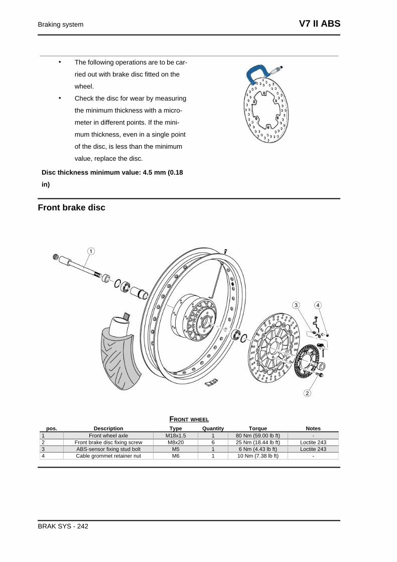
• The following operations are to be car-
ried out with brake disc fitted on the
wheel.
• Check the disc for wear by measuring
the minimum thickness with a micro-
meter in different points. If the mini-
mum thickness, even in a single point
of the disc, is less than the minimum
value, replace the disc.
Disc thickness minimum value: 4.5 mm (0.18
in)
Front brake disc
FRONT WHEELpos. Description Type Quantity Torque Notes
1 Front wheel axle M18x1.5 1 80 Nm (59.00 lb ft) -2 Front brake disc fixing screw M8x20 6 25 Nm (18.44 lb ft) Loctite 2433 ABS-sensor fixing stud bolt M5 1 6 Nm (4.43 lb ft) Loctite 2434 Cable grommet retainer nut M6 1 10 Nm (7.38 lb ft) -
Braking system V7 II ABS
BRAK SYS - 242
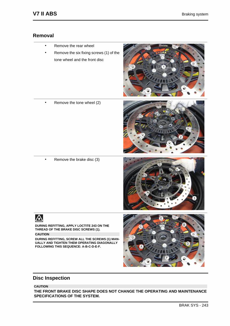
Removal
• Remove the rear wheel
• Remove the six fixing screws (1) of the
tone wheel and the front disc
• Remove the tone wheel (2)
• Remove the brake disc (3)
DURING REFITTING, APPLY LOCTITE 243 ON THETHREAD OF THE BRAKE DISC SCREWS (1).CAUTIONDURING REFITTING, SCREW ALL THE SCREWS (1) MAN-UALLY AND TIGHTEN THEM OPERATING DIAGONALLYFOLLOWING THIS SEQUENCE: A-B-C-D-E-F.
Disc InspectionCAUTIONTHE FRONT BRAKE DISC SHAPE DOES NOT CHANGE THE OPERATING AND MAINTENANCESPECIFICATIONS OF THE SYSTEM.
V7 II ABS Braking system
BRAK SYS - 243
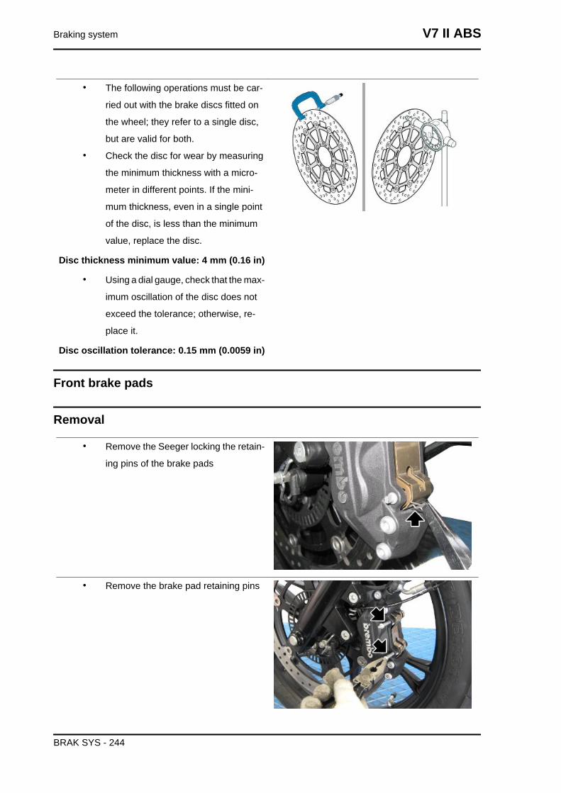
• The following operations must be car-
ried out with the brake discs fitted on
the wheel; they refer to a single disc,
but are valid for both.
• Check the disc for wear by measuring
the minimum thickness with a micro-
meter in different points. If the mini-
mum thickness, even in a single point
of the disc, is less than the minimum
value, replace the disc.
Disc thickness minimum value: 4 mm (0.16 in)
• Using a dial gauge, check that the max-
imum oscillation of the disc does not
exceed the tolerance; otherwise, re-
place it.
Disc oscillation tolerance: 0.15 mm (0.0059 in)
Front brake pads
Removal
• Remove the Seeger locking the retain-
ing pins of the brake pads
• Remove the brake pad retaining pins
Braking system V7 II ABS
BRAK SYS - 244
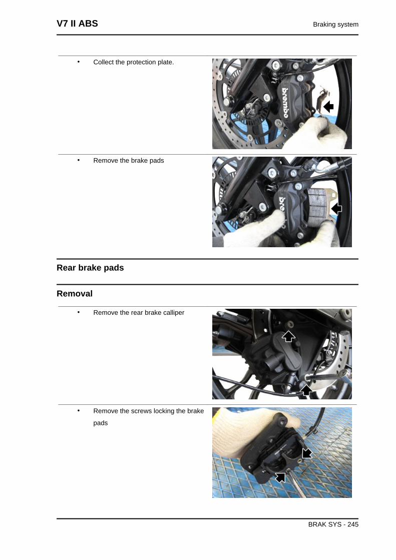
• Collect the protection plate.
• Remove the brake pads
Rear brake pads
Removal
• Remove the rear brake calliper
• Remove the screws locking the brake
pads
V7 II ABS Braking system
BRAK SYS - 245
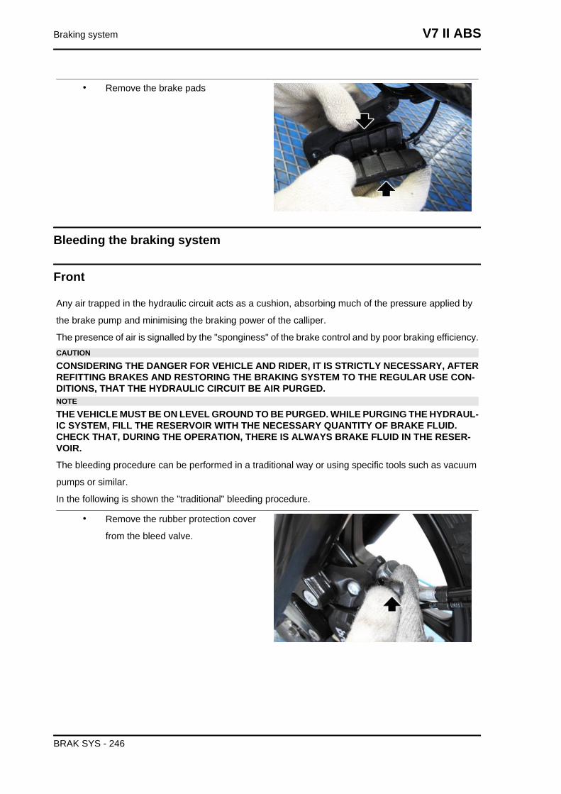
• Remove the brake pads
Bleeding the braking system
Front
Any air trapped in the hydraulic circuit acts as a cushion, absorbing much of the pressure applied by
the brake pump and minimising the braking power of the calliper.
The presence of air is signalled by the "sponginess" of the brake control and by poor braking efficiency.CAUTION
CONSIDERING THE DANGER FOR VEHICLE AND RIDER, IT IS STRICTLY NECESSARY, AFTERREFITTING BRAKES AND RESTORING THE BRAKING SYSTEM TO THE REGULAR USE CON-DITIONS, THAT THE HYDRAULIC CIRCUIT BE AIR PURGED.NOTE
THE VEHICLE MUST BE ON LEVEL GROUND TO BE PURGED. WHILE PURGING THE HYDRAUL-IC SYSTEM, FILL THE RESERVOIR WITH THE NECESSARY QUANTITY OF BRAKE FLUID.CHECK THAT, DURING THE OPERATION, THERE IS ALWAYS BRAKE FLUID IN THE RESER-VOIR.
The bleeding procedure can be performed in a traditional way or using specific tools such as vacuum
pumps or similar.
In the following is shown the "traditional" bleeding procedure.
• Remove the rubber protection cover
from the bleed valve.
Braking system V7 II ABS
BRAK SYS - 246
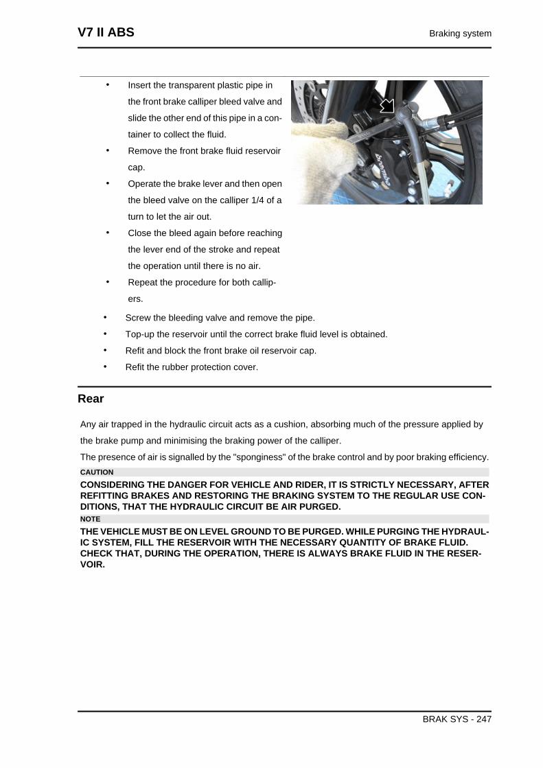
• Insert the transparent plastic pipe in
the front brake calliper bleed valve and
slide the other end of this pipe in a con-
tainer to collect the fluid.
• Remove the front brake fluid reservoir
cap.
• Operate the brake lever and then open
the bleed valve on the calliper 1/4 of a
turn to let the air out.
• Close the bleed again before reaching
the lever end of the stroke and repeat
the operation until there is no air.
• Repeat the procedure for both callip-
ers.
• Screw the bleeding valve and remove the pipe.
• Top-up the reservoir until the correct brake fluid level is obtained.
• Refit and block the front brake oil reservoir cap.
• Refit the rubber protection cover.
Rear
Any air trapped in the hydraulic circuit acts as a cushion, absorbing much of the pressure applied by
the brake pump and minimising the braking power of the calliper.
The presence of air is signalled by the "sponginess" of the brake control and by poor braking efficiency.CAUTION
CONSIDERING THE DANGER FOR VEHICLE AND RIDER, IT IS STRICTLY NECESSARY, AFTERREFITTING BRAKES AND RESTORING THE BRAKING SYSTEM TO THE REGULAR USE CON-DITIONS, THAT THE HYDRAULIC CIRCUIT BE AIR PURGED.NOTE
THE VEHICLE MUST BE ON LEVEL GROUND TO BE PURGED. WHILE PURGING THE HYDRAUL-IC SYSTEM, FILL THE RESERVOIR WITH THE NECESSARY QUANTITY OF BRAKE FLUID.CHECK THAT, DURING THE OPERATION, THERE IS ALWAYS BRAKE FLUID IN THE RESER-VOIR.
V7 II ABS Braking system
BRAK SYS - 247
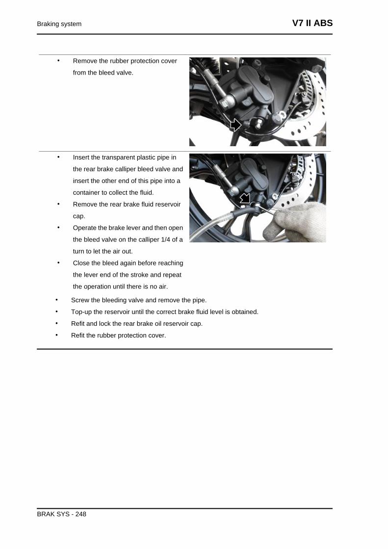
• Remove the rubber protection cover
from the bleed valve.
• Insert the transparent plastic pipe in
the rear brake calliper bleed valve and
insert the other end of this pipe into a
container to collect the fluid.
• Remove the rear brake fluid reservoir
cap.
• Operate the brake lever and then open
the bleed valve on the calliper 1/4 of a
turn to let the air out.
• Close the bleed again before reaching
the lever end of the stroke and repeat
the operation until there is no air.
• Screw the bleeding valve and remove the pipe.
• Top-up the reservoir until the correct brake fluid level is obtained.
• Refit and lock the rear brake oil reservoir cap.
• Refit the rubber protection cover.
Braking system V7 II ABS
BRAK SYS - 248
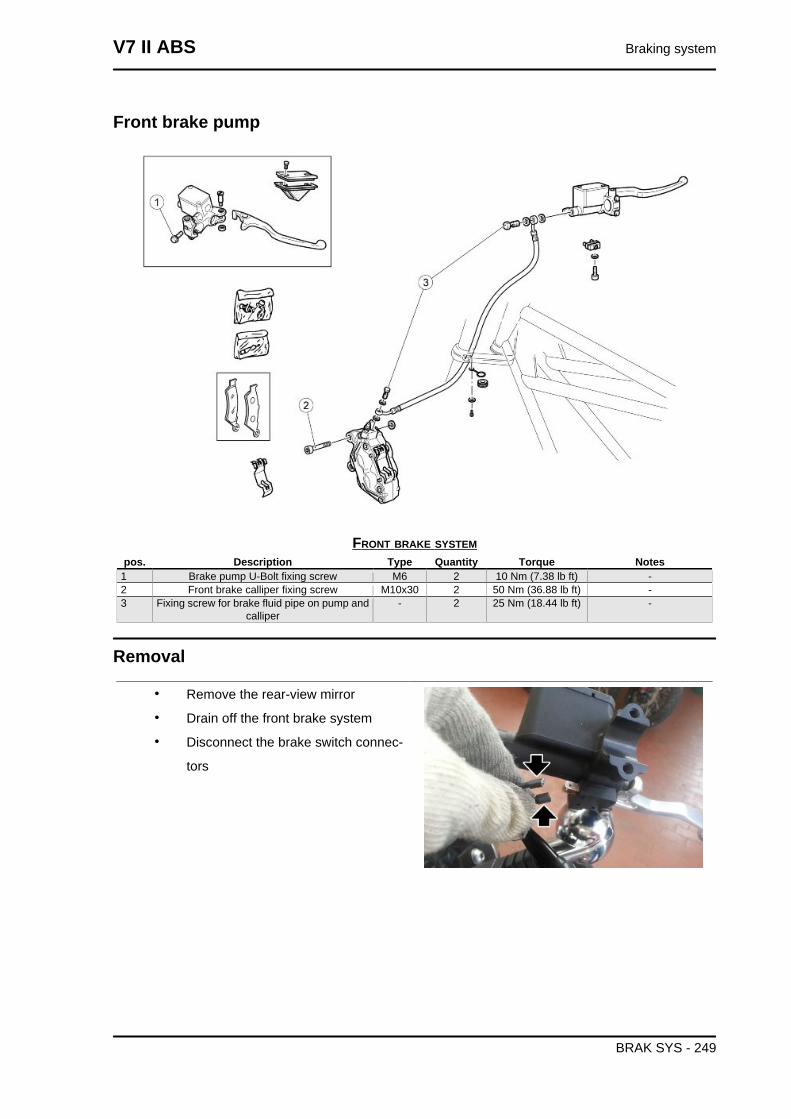
Front brake pump
FRONT BRAKE SYSTEMpos. Description Type Quantity Torque Notes
1 Brake pump U-Bolt fixing screw M6 2 10 Nm (7.38 lb ft) -2 Front brake calliper fixing screw M10x30 2 50 Nm (36.88 lb ft) -3 Fixing screw for brake fluid pipe on pump and
calliper- 2 25 Nm (18.44 lb ft) -
Removal
• Remove the rear-view mirror
• Drain off the front brake system
• Disconnect the brake switch connec-
tors
V7 II ABS Braking system
BRAK SYS - 249
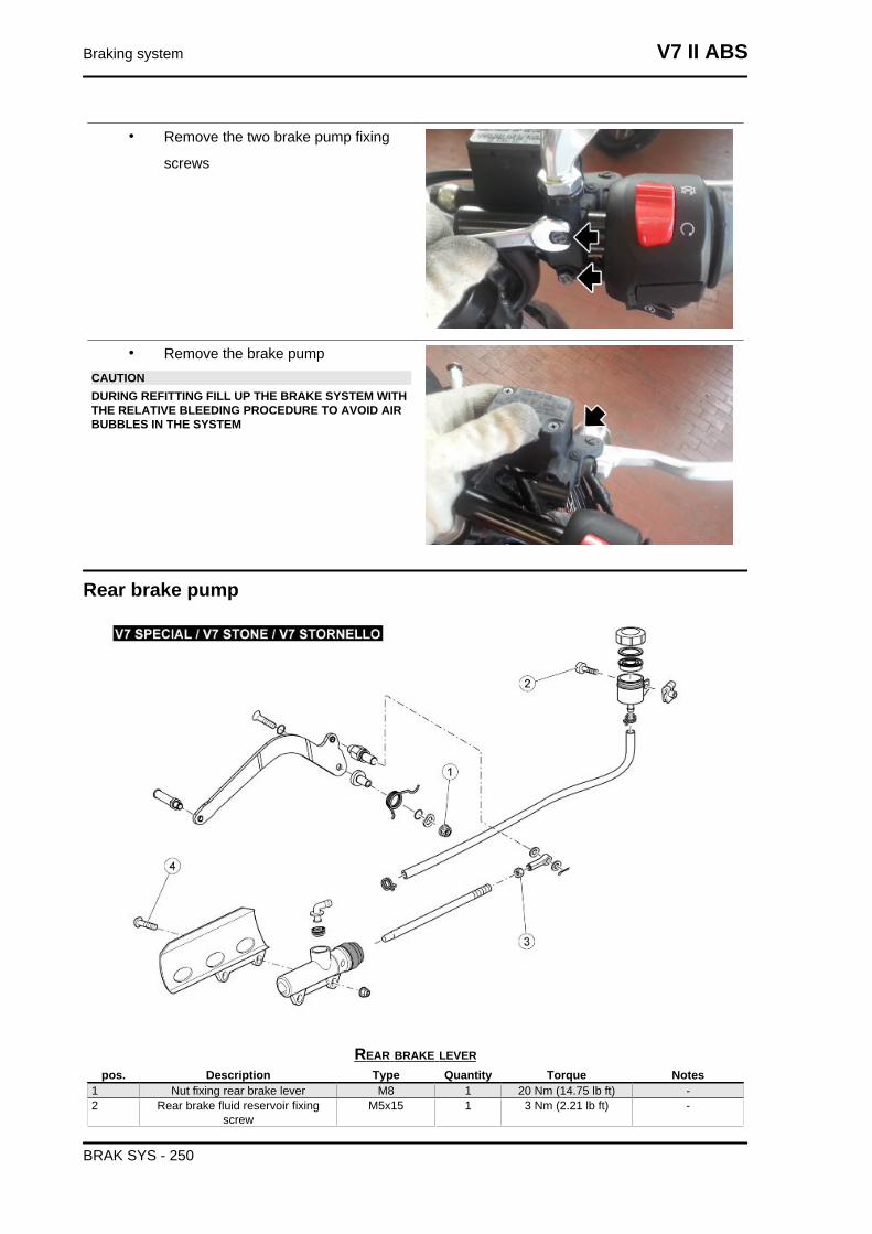
• Remove the two brake pump fixing
screws
• Remove the brake pumpCAUTIONDURING REFITTING FILL UP THE BRAKE SYSTEM WITHTHE RELATIVE BLEEDING PROCEDURE TO AVOID AIRBUBBLES IN THE SYSTEM
Rear brake pump
REAR BRAKE LEVERpos. Description Type Quantity Torque Notes
1 Nut fixing rear brake lever M8 1 20 Nm (14.75 lb ft) -2 Rear brake fluid reservoir fixing
screwM5x15 1 3 Nm (2.21 lb ft) -
Braking system V7 II ABS
BRAK SYS - 250
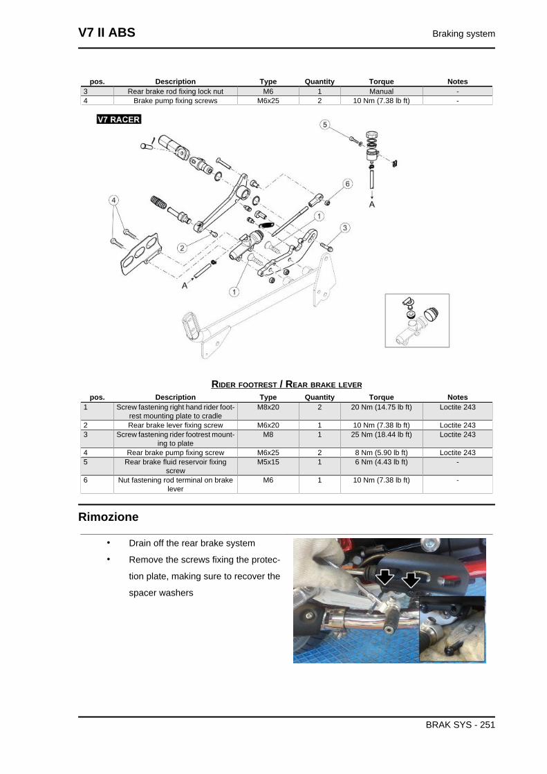
pos. Description Type Quantity Torque Notes3 Rear brake rod fixing lock nut M6 1 Manual -4 Brake pump fixing screws M6x25 2 10 Nm (7.38 lb ft) -
RIDER FOOTREST / REAR BRAKE LEVERpos. Description Type Quantity Torque Notes
1 Screw fastening right hand rider foot-rest mounting plate to cradle
M8x20 2 20 Nm (14.75 lb ft) Loctite 243
2 Rear brake lever fixing screw M6x20 1 10 Nm (7.38 lb ft) Loctite 2433 Screw fastening rider footrest mount-
ing to plateM8 1 25 Nm (18.44 lb ft) Loctite 243
4 Rear brake pump fixing screw M6x25 2 8 Nm (5.90 lb ft) Loctite 2435 Rear brake fluid reservoir fixing
screwM5x15 1 6 Nm (4.43 lb ft) -
6 Nut fastening rod terminal on brakelever
M6 1 10 Nm (7.38 lb ft) -
Rimozione
• Drain off the rear brake system
• Remove the screws fixing the protec-
tion plate, making sure to recover the
spacer washers
V7 II ABS Braking system
BRAK SYS - 251
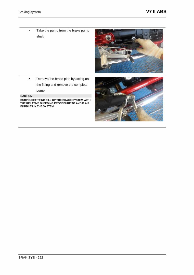
• Take the pump from the brake pump
shaft
• Remove the brake pipe by acting on
the fitting and remove the complete
pumpCAUTIONDURING REFITTING FILL UP THE BRAKE SYSTEM WITHTHE RELATIVE BLEEDING PROCEDURE TO AVOID AIRBUBBLES IN THE SYSTEM
Braking system V7 II ABS
BRAK SYS - 252
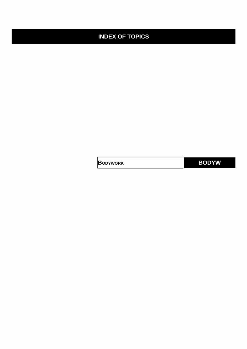
INDEX OF TOPICS
BODYWORK BODYW

BODYWORK CENTRAL SECTION - SADDLEpos. Description Type Quantity Torque Notes
1 Saddle release block fixing screw M6x25 2 10 Nm (7.38 lb ft) -2 Side fairing fixing screw M5x9 2 4 Nm (2.95 lb ft) -
BODYWORK CENTRAL SECTION - SADDLEpos. Description Type Quantity Torque Notes
1 Saddle release block fixing screw M6x25 2 10 Nm (7.38 lb ft) -2 Throttle body cover fastener screw M5x14 4 4 Nm (2.95 lb ft) -
Bodywork V7 II ABS
BODYW - 254
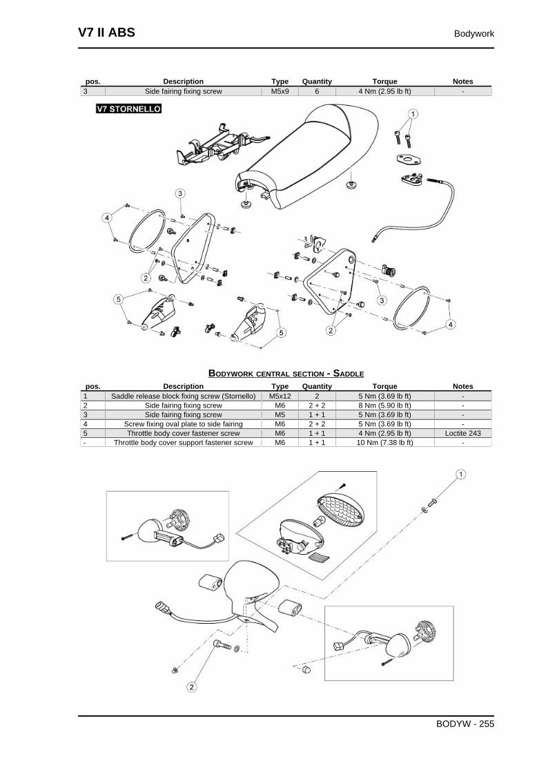
pos. Description Type Quantity Torque Notes3 Side fairing fixing screw M5x9 6 4 Nm (2.95 lb ft) -
BODYWORK CENTRAL SECTION - SADDLEpos. Description Type Quantity Torque Notes
1 Saddle release block fixing screw (Stornello) M5x12 2 5 Nm (3.69 lb ft) -2 Side fairing fixing screw M6 2 + 2 8 Nm (5.90 lb ft) -3 Side fairing fixing screw M5 1 + 1 5 Nm (3.69 lb ft) -4 Screw fixing oval plate to side fairing M6 2 + 2 5 Nm (3.69 lb ft) -5 Throttle body cover fastener screw M6 1 + 1 4 Nm (2.95 lb ft) Loctite 243- Throttle body cover support fastener screw M6 1 + 1 10 Nm (7.38 lb ft) -
V7 II ABS Bodywork
BODYW - 255
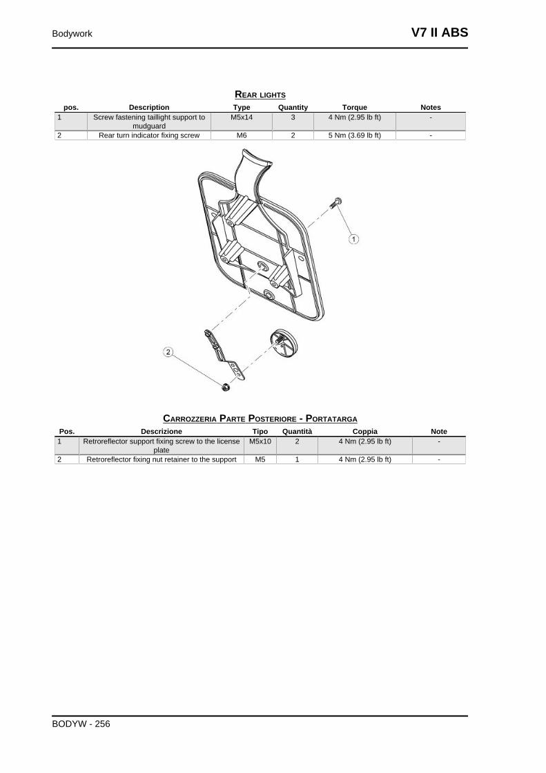
REAR LIGHTSpos. Description Type Quantity Torque Notes
1 Screw fastening taillight support tomudguard
M5x14 3 4 Nm (2.95 lb ft) -
2 Rear turn indicator fixing screw M6 2 5 Nm (3.69 lb ft) -
CARROZZERIA PARTE POSTERIORE - PORTATARGAPos. Descrizione Tipo Quantità Coppia Note1 Retroreflector support fixing screw to the license
plateM5x10 2 4 Nm (2.95 lb ft) -
2 Retroreflector fixing nut retainer to the support M5 1 4 Nm (2.95 lb ft) -
Bodywork V7 II ABS
BODYW - 256
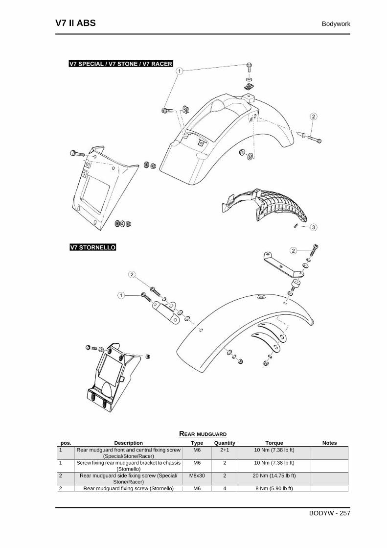
REAR MUDGUARDpos. Description Type Quantity Torque Notes
1 Rear mudguard front and central fixing screw(Special/Stone/Racer)
M6 2+1 10 Nm (7.38 lb ft)
1 Screw fixing rear mudguard bracket to chassis(Stornello)
M6 2 10 Nm (7.38 lb ft)
2 Rear mudguard side fixing screw (Special/Stone/Racer)
M8x30 2 20 Nm (14.75 lb ft)
2 Rear mudguard fixing screw (Stornello) M6 4 8 Nm (5.90 lb ft)
V7 II ABS Bodywork
BODYW - 257
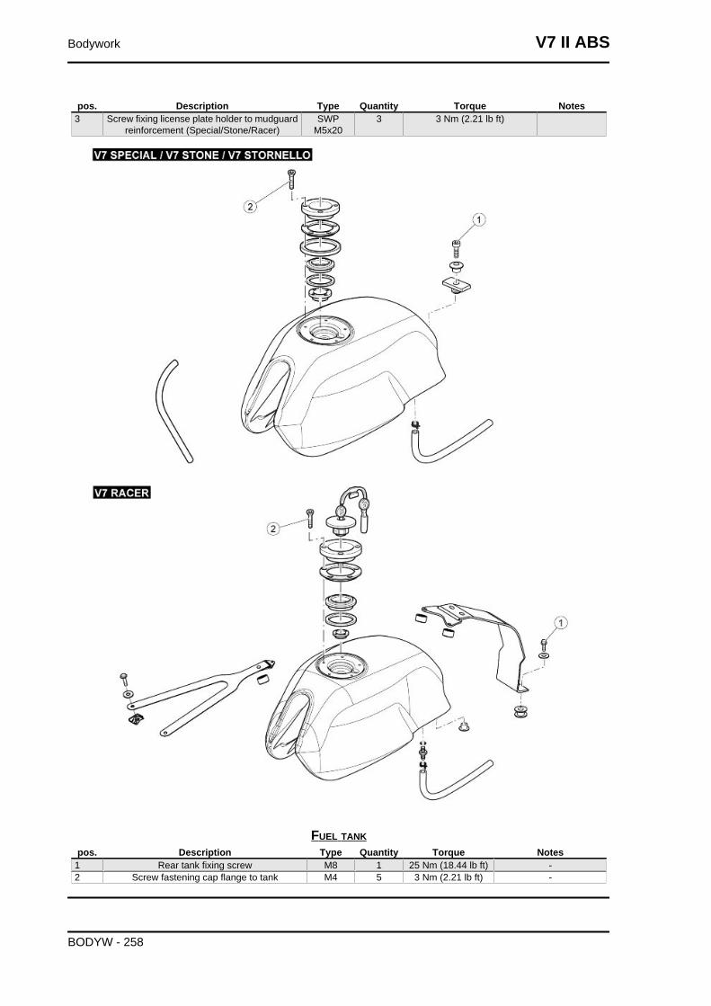
pos. Description Type Quantity Torque Notes3 Screw fixing license plate holder to mudguard
reinforcement (Special/Stone/Racer)SWP
M5x203 3 Nm (2.21 lb ft)
FUEL TANKpos. Description Type Quantity Torque Notes
1 Rear tank fixing screw M8 1 25 Nm (18.44 lb ft) -2 Screw fastening cap flange to tank M4 5 3 Nm (2.21 lb ft) -
Bodywork V7 II ABS
BODYW - 258
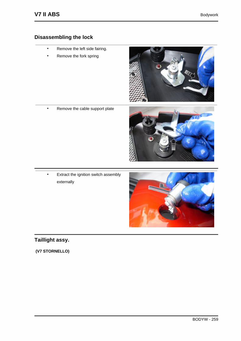
Disassembling the lock
• Remove the left side fairing.
• Remove the fork spring
• Remove the cable support plate
• Extract the ignition switch assembly
externally
Taillight assy.
(V7 STORNELLO)
V7 II ABS Bodywork
BODYW - 259
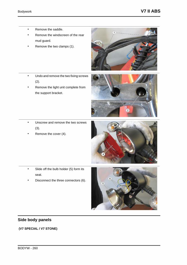
• Remove the saddle.
• Remove the windscreen of the rear
mud guard.
• Remove the two clamps (1).
• Undo and remove the two fixing screws
(2).
• Remove the light unit complete from
the support bracket.
• Unscrew and remove the two screws
(3).
• Remove the cover (4).
• Slide off the bulb holder (5) form its
seat.
• Disconnect the three connectors (6).
Side body panels
(V7 SPECIAL / V7 STONE)
Bodywork V7 II ABS
BODYW - 260
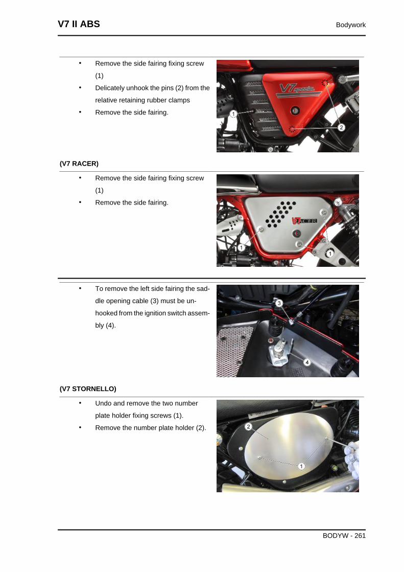
• Remove the side fairing fixing screw
(1)
• Delicately unhook the pins (2) from the
relative retaining rubber clamps
• Remove the side fairing.
(V7 RACER)
• Remove the side fairing fixing screw
(1)
• Remove the side fairing.
• To remove the left side fairing the sad-
dle opening cable (3) must be un-
hooked from the ignition switch assem-
bly (4).
(V7 STORNELLO)
• Undo and remove the two number
plate holder fixing screws (1).
• Remove the number plate holder (2).
V7 II ABS Bodywork
BODYW - 261
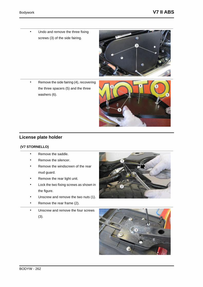
• Undo and remove the three fixing
screws (3) of the side fairing.
• Remove the side fairing (4), recovering
the three spacers (5) and the three
washers (6).
License plate holder
(V7 STORNELLO)
• Remove the saddle.
• Remove the silencer.
• Remove the windscreen of the rear
mud guard.
• Remove the rear light unit.
• Lock the two fixing screws as shown in
the figure.
• Unscrew and remove the two nuts (1).
• Remove the rear frame (2).
• Unscrew and remove the four screws
(3).
Bodywork V7 II ABS
BODYW - 262
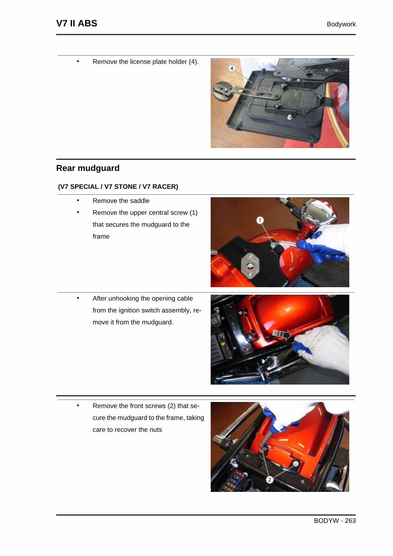
• Remove the license plate holder (4).
Rear mudguard
(V7 SPECIAL / V7 STONE / V7 RACER)
• Remove the saddle
• Remove the upper central screw (1)
that secures the mudguard to the
frame
• After unhooking the opening cable
from the ignition switch assembly, re-
move it from the mudguard.
• Remove the front screws (2) that se-
cure the mudguard to the frame, taking
care to recover the nuts
V7 II ABS Bodywork
BODYW - 263
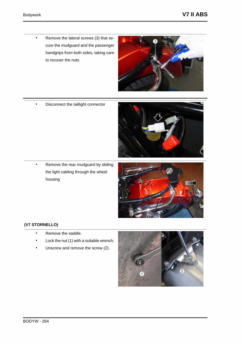
• Remove the lateral screws (3) that se-
cure the mudguard and the passenger
handgrips from both sides, taking care
to recover the nuts
• Disconnect the taillight connector
• Remove the rear mudguard by sliding
the light cabling through the wheel
housing
(V7 STORNELLO)
• Remove the saddle.
• Lock the nut (1) with a suitable wrench.
• Unscrew and remove the screw (2).
Bodywork V7 II ABS
BODYW - 264
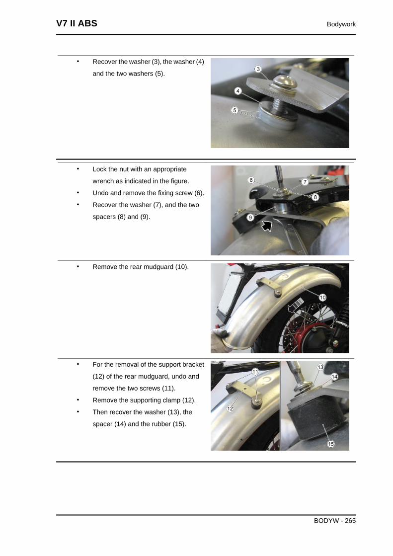
• Recover the washer (3), the washer (4)
and the two washers (5).
• Lock the nut with an appropriate
wrench as indicated in the figure.
• Undo and remove the fixing screw (6).
• Recover the washer (7), and the two
spacers (8) and (9).
• Remove the rear mudguard (10).
• For the removal of the support bracket
(12) of the rear mudguard, undo and
remove the two screws (11).
• Remove the supporting clamp (12).
• Then recover the washer (13), the
spacer (14) and the rubber (15).
V7 II ABS Bodywork
BODYW - 265
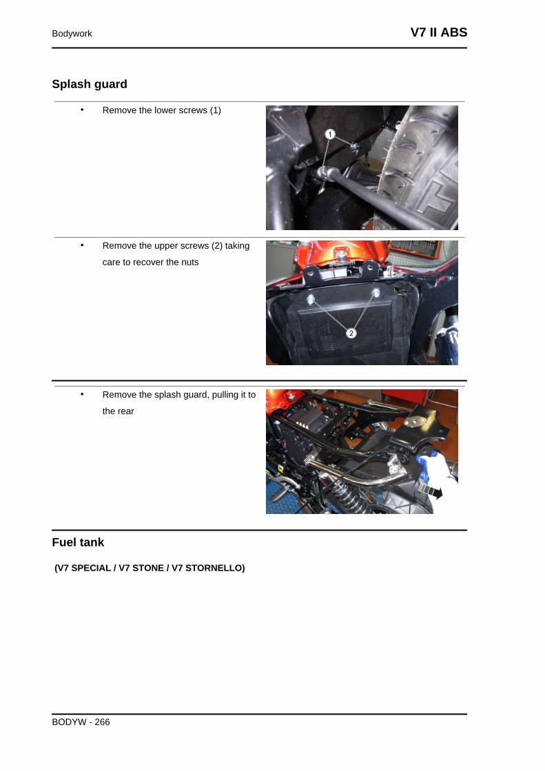
Splash guard
• Remove the lower screws (1)
• Remove the upper screws (2) taking
care to recover the nuts
• Remove the splash guard, pulling it to
the rear
Fuel tank
(V7 SPECIAL / V7 STONE / V7 STORNELLO)
Bodywork V7 II ABS
BODYW - 266
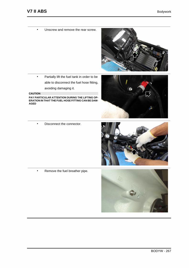
• Unscrew and remove the rear screw.
• Partially lift the fuel tank in order to be
able to disconnect the fuel hose fitting,
avoiding damaging it.CAUTIONPAY PARTICULAR ATTENTION DURING THE LIFTING OP-ERATION IN THAT THE FUEL HOSE FITTING CAN BE DAM-AGED
• Disconnect the connector.
• Remove the fuel breather pipe.
V7 II ABS Bodywork
BODYW - 267
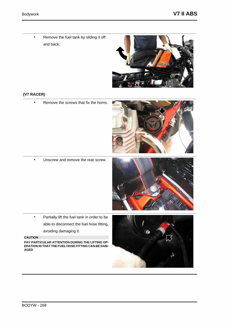
• Remove the fuel tank by sliding it off
and back.
(V7 RACER)
• Remove the screws that fix the horns.
• Unscrew and remove the rear screw.
• Partially lift the fuel tank in order to be
able to disconnect the fuel hose fitting,
avoiding damaging it.CAUTIONPAY PARTICULAR ATTENTION DURING THE LIFTING OP-ERATION IN THAT THE FUEL HOSE FITTING CAN BE DAM-AGED
Bodywork V7 II ABS
BODYW - 268
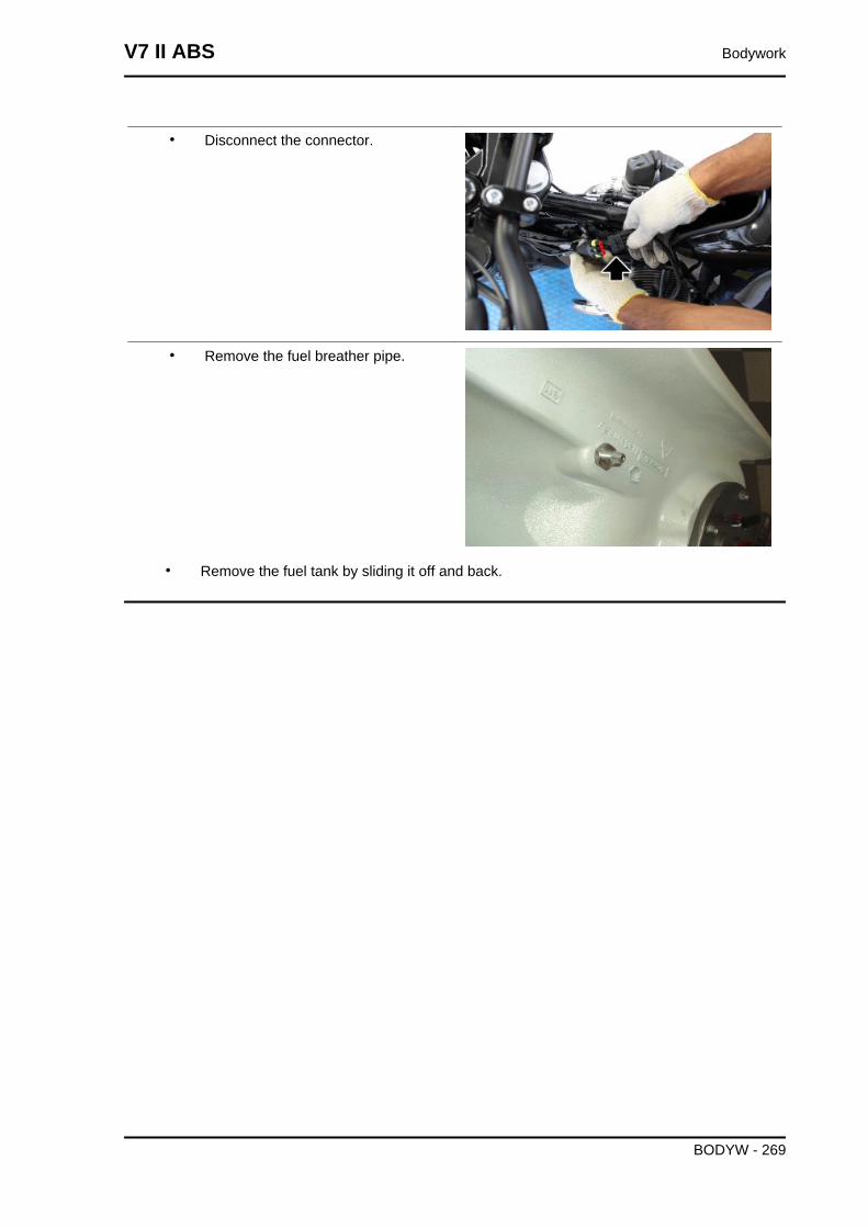
• Disconnect the connector.
• Remove the fuel breather pipe.
• Remove the fuel tank by sliding it off and back.
V7 II ABS Bodywork
BODYW - 269
INDEX OF TOPICS
PRE-DELIVERY PRE DE
Carry out the listed checks before delivering the motorcycle.WARNING
HANDLE FUEL WITH CARE.
Aesthetic inspection
- Paintwork
- Fitting of Plastic Parts
- Scratches
- Dirt
Tightening torques inspection
- Safety fasteners:
front and rear suspension unit
front and rear brake calliper retainer unit
front and rear wheel unit
engine - chassis retainers
steering assembly
- Plastic parts fixing screws
Electrical system
- Main switch
- Headlamps: high beam lights, low beam lights, tail lights (front and rear) and their warning lights
- Headlight adjustment according to regulations in force
- Front and rear stop light switches and their bulbs
- Turn indicators and their warning lights
- Instrument panel lights
- Instrument panel: fuel and temperature indicator (if present)
- Instrument panel warning lights
- Horn
- Electric starter
- Engine stop via emergency stop switch and side stand
- Through the diagnosis tool, check that the last mapping version is present in the control unit/s and, if
required, program the control unit/s again: consult the technical service website to know about available
upgrades and details regarding the operation.
V7 II ABS Pre-delivery
PRE DE - 271
CAUTION
TO ENSURE MAXIMUM PERFORMANCE, THE BATTERY MUST BE CHARGED BEFORE USE.INADEQUATE CHARGING OF THE BATTERY WITH A LOW LEVEL OF ELECTROLYTE BEFOREIT IS FIRST USED SHORTENS BATTERY LIFE.CAUTION
WHEN INSTALLING THE BATTERY, ATTACH THE POSITIVE LEAD FIRST AND THEN THE NEG-ATIVE ONE, AND PERFORM THE REVERSE OPERATION DURING REMOVAL.CAUTION
THE BATTERY ELECTROLYTE IS TOXIC, CORROSIVE AND AS IT CONTAINS SULPHURIC ACID,IT CAN CAUSE BURNS WHEN IN CONTACT WITH THE SKIN. WHEN HANDLING BATTERYELECTROLYTE, WEAR TIGHT-FITTING GLOVES AND PROTECTIVE APPAREL. IN THE EVENTOF SKIN CONTACT WITH THE ELECTROLYTIC FLUID, RINSE WELL WITH PLENTY OF CLEANWATER. IT IS PARTICULARLY IMPORTANT TO PROTECT YOUR EYES BECAUSE EVEN TINYAMOUNTS OF BATTERY ACID MAY CAUSE BLINDNESS. IF THE FLUID GETS IN CONTACT WITHYOUR EYES, WASH WITH ABUNDANT WATER FOR FIFTEEN MINUTES AND CONSULT AN EYESPECIALIST IMMEDIATELY. THE BATTERY RELEASES EXPLOSIVE GASES; KEEP IT AWAYFROM FLAMES, SPARKS, CIGARETTES OR ANY OTHER HEAT SOURCES. ENSURE ADE-QUATE VENTILATION WHEN SERVICING OR RECHARGING THE BATTERY.KEEP OUT OF THE REACH OF CHILDRENBATTERY LIQUID IS CORROSIVE. DO NOT POUR IT OR SPILL IT, PARTICULARLY ON PLASTICCOMPONENTS. ENSURE THAT THE ELECTROLYTIC ACID IS COMPATIBLE WITH THE BAT-TERY TO BE ACTIVATED.CAUTION
NEVER USE FUSES WITH A CAPACITY HIGHER THAN THE RECOMMENDED CAPACITY. USINGA FUSE OF UNSUITABLE RATING MAY SERIOUSLY DAMAGE THE VEHICLE OR EVEN CAUSEA FIRE.
Levels check
- Hydraulic braking system fluid level
- Clutch system fluid level (if present)
- Gearbox oil level (if present)
- Transmission oil level (if present)
- Engine coolant level (if present)
- Engine oil level
- Mixer oil level (if present)
Road test
- Cold start
- Instrument panel operation
Pre-delivery V7 II ABS
PRE DE - 272
- Response to throttle control
- Stability when accelerating and braking
- Front and rear brake efficiency
- Front and rear suspension efficiency
- Abnormal noise
Static test
Static check after test drive:
- Restarting when warmed up
- Starter operation (if present)
- Minimum holding (turning the handlebar)
- Uniform turning of the steering
- Possible leaks
- Radiator electric fan operation (if present)
Functional inspection
- Hydraulic braking system
- Stroke of brake and clutch levers (if present)
- Clutch - Check for correct operation
- Engine - Check for correct general operation and absence of abnormal noise
- Other
- Documentation check:
- Chassis and engine numbers check
- Supplied tools check
- License plate fitting
- Locks checking
- Tyre pressure check
- Installation of mirrors and any possible accessories
NEVER EXCEED THE RECOMMENDED INFLATION PRESSURES AS TYRES MAY BURST.CAUTION
CHECK AND ADJUST TYRE PRESSURE WITH TYRES AT AMBIENT TEMPERATURE.
Specific operations for the vehicle
(V7 RACER)
V7 II ABS Pre-delivery
PRE DE - 273
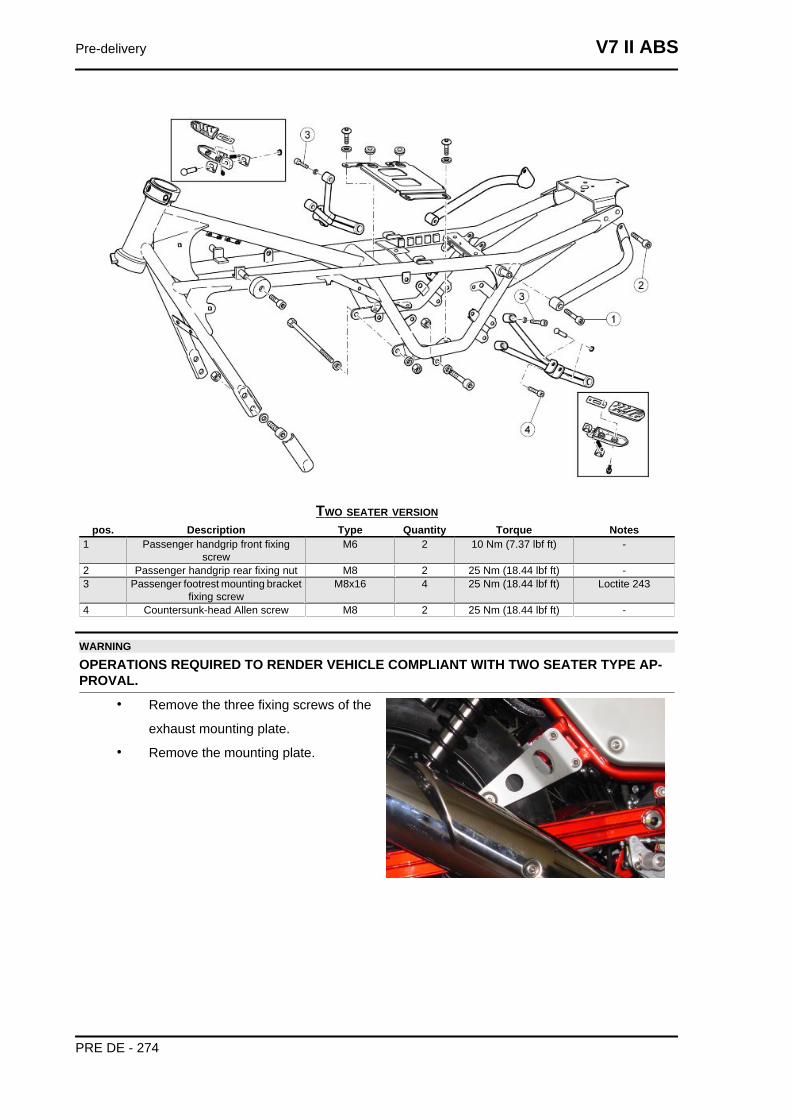
TWO SEATER VERSIONpos. Description Type Quantity Torque Notes
1 Passenger handgrip front fixingscrew
M6 2 10 Nm (7.37 lbf ft) -
2 Passenger handgrip rear fixing nut M8 2 25 Nm (18.44 lbf ft) -3 Passenger footrest mounting bracket
fixing screwM8x16 4 25 Nm (18.44 lbf ft) Loctite 243
4 Countersunk-head Allen screw M8 2 25 Nm (18.44 lbf ft) -
WARNING
OPERATIONS REQUIRED TO RENDER VEHICLE COMPLIANT WITH TWO SEATER TYPE AP-PROVAL.
• Remove the three fixing screws of the
exhaust mounting plate.
• Remove the mounting plate.
Pre-delivery V7 II ABS
PRE DE - 274
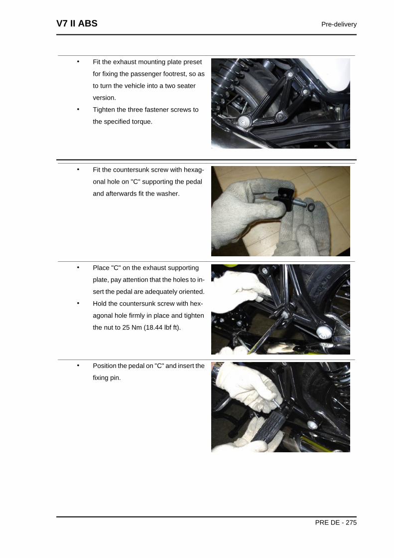
• Fit the exhaust mounting plate preset
for fixing the passenger footrest, so as
to turn the vehicle into a two seater
version.
• Tighten the three fastener screws to
the specified torque.
• Fit the countersunk screw with hexag-
onal hole on "C" supporting the pedal
and afterwards fit the washer.
• Place "C" on the exhaust supporting
plate, pay attention that the holes to in-
sert the pedal are adequately oriented.
• Hold the countersunk screw with hex-
agonal hole firmly in place and tighten
the nut to 25 Nm (18.44 lbf ft).
• Position the pedal on "C" and insert the
fixing pin.
V7 II ABS Pre-delivery
PRE DE - 275
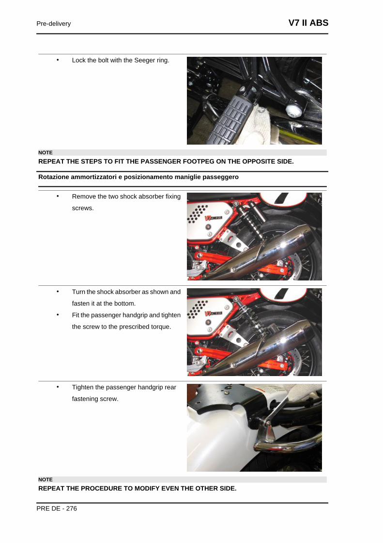
• Lock the bolt with the Seeger ring.
NOTE
REPEAT THE STEPS TO FIT THE PASSENGER FOOTPEG ON THE OPPOSITE SIDE.
Rotazione ammortizzatori e posizionamento maniglie passeggero
• Remove the two shock absorber fixing
screws.
• Turn the shock absorber as shown and
fasten it at the bottom.
• Fit the passenger handgrip and tighten
the screw to the prescribed torque.
• Tighten the passenger handgrip rear
fastening screw.
NOTE
REPEAT THE PROCEDURE TO MODIFY EVEN THE OTHER SIDE.
Pre-delivery V7 II ABS
PRE DE - 276
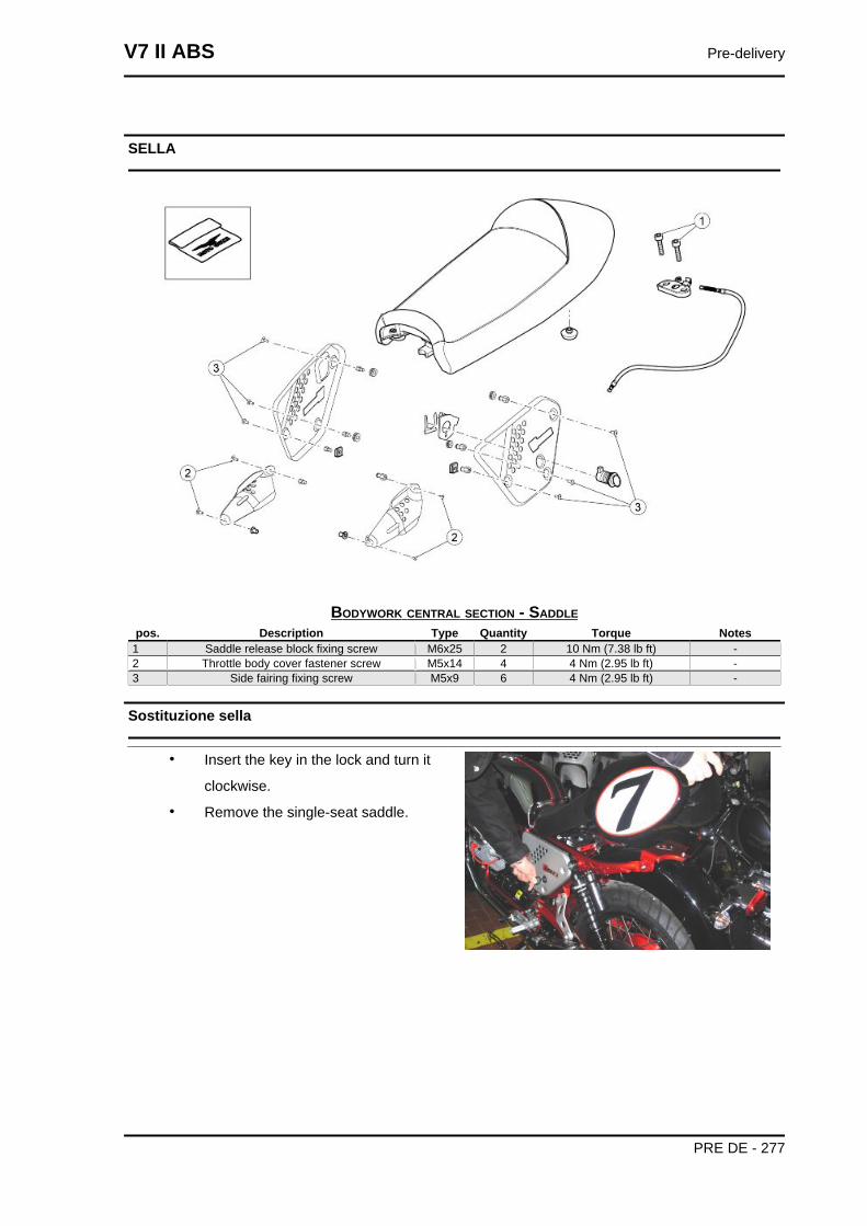
SELLA
BODYWORK CENTRAL SECTION - SADDLEpos. Description Type Quantity Torque Notes
1 Saddle release block fixing screw M6x25 2 10 Nm (7.38 lb ft) -2 Throttle body cover fastener screw M5x14 4 4 Nm (2.95 lb ft) -3 Side fairing fixing screw M5x9 6 4 Nm (2.95 lb ft) -
Sostituzione sella
• Insert the key in the lock and turn it
clockwise.
• Remove the single-seat saddle.
V7 II ABS Pre-delivery
PRE DE - 277
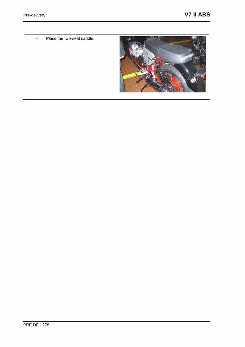
• Place the two-seat saddle.
Pre-delivery V7 II ABS
PRE DE - 278
AABS: 221, 229, 230Air filter: 55, 58, 59, 61Air temperature sensor: 127
BBattery: 93, 99Brake: 236, 238, 240, 242, 244, 245, 249, 250Brake calliper: 236, 238Brake disc: 240, 242Brake lever: Brake pads: 244, 245Brake pump: 249, 250Bulbs:
CClutch: 124Coil: 120Connectors: 129
DDiagnostics: 229Display:
EECU: 129, 151, 230Electrical system: 12, 70, 72, 271Engine oil: 51Engine temperature sensor: 105Exhaust: 208, 214Exhaust manifold: 214
FFilter box: Fork: 162, 164, 167, 169, 172Front wheel: 180Fuel: 118, 266Fuel pump: 118Fuses: 98
GGearbox oil: 53
HHandlebar: 160
IIdentification: 10
Instrument panel: 127
LLicense plate holder: 262
MMaintenance: 8, 48Maintenance Table: Mudguard: 263
OOil filter: 52Oil pressure sensor: 122
RRear wheel: 182Recommended products: 42Run/Stop switch: 128
SSaddle: Scheduled maintenance: 48Shock absorbers: 177Side stand: 125Side stand sensor: 125Spark plugs: Speed sensor: 99Stand: 125Start-up: 96
TTank: 266Throttle body: 55Transmission: 12, 49Tyres: 14
UUse: 229
WWarning lights: Wiring diagram: 90


![Abs NANTECHNOLOGY- 4105[1]](https://img.dokumen.tips/doc/110x75/6321487bf2b35f3bd10fcf9c/abs-nantechnology-41051.jpg)


