Embed Size (px)
Citation preview
TOMMUNOM U HAT MAN HAR US009895730B2
( 12 ) United States Patent Hoag et al .
( 10 ) Patent No . : US 9 , 895 , 730 B2 ( 45 ) Date of Patent : Feb . 20 , 2018
( 58 ) ( 54 ) METHOD FOR EXTRACTION AND SURFACTANT ENHANCED SUBSURFACE CONTAMINANT RECOVERY
Field of Classification Search None See application file for complete search history .
( 56 ) References Cited ( 75 ) Inventors : George E . Hoag , Bloomfield , CT ( US ) ; John B . Collins , Bloomfield , CT ( US ) ; Douglas K . Anderson , Bloomfield , CT ( US )
U . S . PATENT DOCUMENTS
3 , 640 , 821 A 3 , 938 , 590 A @ ( 73 ) Assignee : Ethical Solutions , LLC , South
Windsor , CT ( US )
2 / 1972 Sweeny et al . 2 / 1976 Redford et al .
( Continued ) ( * ) Notice : FOREIGN PATENT DOCUMENTS Subject to any disclaimer , the term of this
patent is extended or adjusted under 35 U . S . C . 154 ( b ) by 0 days . EP 0706427 Ai 4 / 1996
WOWO - 1995 / 001232 A11 / 1995 ( Continued )
OTHER PUBLICATIONS
( 21 ) Appl . No . : 12 / 667 , 478 ( 22 ) PCT Filed : Sep . 26 , 2008 ( 86 ) PCT No . : PCT / US2008 / 011229
$ 371 ( c ) ( 1 ) , ( 2 ) , ( 4 ) Date : Mar . 18 , 2010
( 87 ) PCT Pub . No . : WO2009 / 042224 PCT Pub . Date : Apr . 2 , 2009
( 65 ) Prior Publication Data US 2010 / 0185039 A1 Jul . 22 , 2010
Nadagouda , M . et al “ Green Synthesis of Au Nanostructures at Room Temperature Using Biodegradable Plant surfactants ” Crystal Growth Design . vol . 9 , 4979 - 4983 ( 2009 ) . *
( Continued )
Primary Examiner — Sheng H Davis ( 74 ) Attorney , Agent , or Firm — Alix , Yale & Ristas , LLP
( 57 ) ABSTRACT Related U . S . Application Data ( 60 ) Provisional application No . 60 / 960 , 347 , filed on Sep .
26 , 2007 , provisional application No . 61 / 071 , 526 , filed on May 5 , 2008 .
( 51 ) Int . Ci . B09C 1 / 08 ( 2006 . 01 ) B09C 1 / 00 ( 2006 . 01 ) B09C 1 / 02 ( 2006 . 01 )
( 52 ) U . S . CI . CPC . . . . . . . . . . . . . . . . . . . . . . . B09C 1 / 08 ( 2013 . 01 ) ; B09C 1 / 00
( 2013 . 01 ) ; B09C 1 / 002 ( 2013 . 01 ) ; B09C 1 / 02 ( 2013 . 01 )
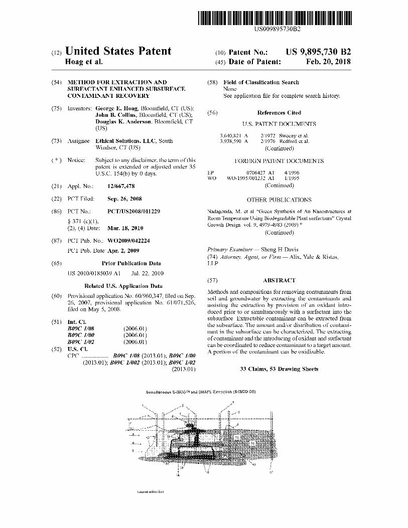
Methods and compositions for removing contaminants from soil and groundwater by extracting the contaminants and assisting the extraction by provision of an oxidant intro duced prior to or simultaneously with a surfactant into the subsurface . Extractable contaminant can be extracted from the subsurface . The amount and / or distribution of contami nant in the subsurface can be characterized . The extracting of contaminant and the introducing of oxidant and surfactant can be coordinated to reduce contaminant to a target amount . A portion of the contaminant can be oxidizable .
33 Claims , 53 Drawing Sheets
Shauseous S 8000 ONÁLexirsasco - 06 * * *
* . * * *
* * * . .
.
200 20 0 . . . . .
. . . . . . .
28 *
US 9 , 895 , 730 B2 Page 2
( 56 ) References Cited U . S . PATENT DOCUMENTS
res . . . . . . . . . . . . . . . . . . .
7 , 431 , 775 B2 10 / 2008 Wang et al . 7 , 553 , 105 B1 * 6 / 2009 Dugan et al . . 405 / 128 . 75
2002 / 0011442 A1 1 / 2002 McMurtrey et al . 2002 / 0030022 A1 * 3 / 2002 Bradley . . . . . . . . . . . . . 210 / 752 2002 / 0179530 A1 * 12 / 2002 Cowdery et al . . . . . . . . . . . . . . 210 / 638 2003 / 0059926 A1 * 3 / 2003 de Torres 435 / 262 . 5 2003 / 0175081 A1 * 9 / 2003 Shiau . . . . . . . . . . 405 / 128 . 7 2004 / 0228690 A1 * 11 / 2004 Stegemeier et al . . . . . . 405 / 128 . 45 2005 / 0077242 A14 / 2005 Karlsson 2005 / 0119353 A1 6 / 2005 Detorres 2005 / 0191131 A1 9 / 2005 Shiau 2005 / 0197267 A1 9 / 2005 Zaki et al . 2006 / 0046297 AL 3 / 2006 Ball 2006 / 0054570 A1 * 3 / 2006 Block et al . . . . . . . . . . 210 / 759 2006 / 0175266 A1 * 8 / 2006 Rima et al . . . . . . . . . . . . 210 / 764 2007 / 0116524 AL 5 / 2007 Shiau 2008 / 0003687 A11 / 2008 Satoh et al . 2008 / 0207981 AL 8 / 2008 Hoag et al . 2008 / 0237141 A1 * 10 / 2008 Kerfoot . . . . . . . . . . 210 / 739 2009 / 0245939 A1 * 10 / 2009 Burns et al . 405 / 128 . 75 2010 / 0209193 AL 8 / 2010 Hoag et al . 2010 / 0209194 AL 8 / 2010 Guite et al .
FOREIGN PATENT DOCUMENTS WO wo WO WO wo Wo WO WO WO WO WO
WO - 1998 / 025857 A WO - 2003 / 068324 WO - 2009 / 042228 WO - 2006 / 055054 Al WO - 2006 / 068354 Al WO - 2007 / 126779 A2 WO - 2009 / 014697 WO - 2009 / 042223 A2 WO - 2009 / 042224 A1 WO - 2009 / 140694
W O - 2009 / 114145 A2
6 / 1998 8 / 2003 4 / 2006 5 / 2006 6 / 2006 11 / 2007 1 / 2009 4 / 2009 4 / 2009 5 / 2009 9 / 2009
OTHER PUBLICATIONS
4 , 068 , 717 A 1 / 1978 Needham 4 , 101 , 172 A 7 / 1978 Rabbitts 4 , 229 , 281 A 10 / 1980 Alquist et al . 4 , 321 , 147 A 3 / 1982 McCoy et al . 4 , 338 , 185 A 7 / 1982 Noelle 4 , 353 , 806 A 10 / 1982 Canter et al . 4 , 360 , 061 A 11 / 1982 Canter et al . 4 , 368 , 111 A 1 / 1983 Siefkin et al . 4 , 389 , 399 A 6 / 1983 Murdock 4 , 405 , 015 A 9 / 1983 McCoy et al . 4 , 470 , 899 A 9 / 1984 Miller et al . 4 , 474 , 616 A 10 / 1984 Smith et al . 4 , 968 , 412 A 11 / 1990 Guymon 5 , 000 , 872 A 3 / 1991 Olah 5 , 009 , 773 A 4 / 1991 Schramm et al . 5 , 143 , 598 A 9 / 1992 Graham et al . 5 , 286 , 141 A 2 / 1994 Vigneri 5 , 319 , 966 A 6 / 1994 Jackson et al . 5 , 340 , 467 A 8 / 1994 Gregoli et al . 5 , 399 , 350 A 3 / 1995 Potter 5 , 414 , 207 A * 5 / 1995 Ritter 588 / 317 5 , 484 , 549 A * 1 / 1996 Hei et al . . . . . . . . . . . . . . . . . . . . . 510 / 370 5 , 546 , 134 A 8 / 1996 Lee 5 , 560 , 737 A * 10 / 1996 Schuring et al . . . . . . . . . 405 / 128 . 45 5 , 602 , 090 A 2 / 1997 Melikyan et al . 5 , 622 , 641 A 4 / 1997 Kim et al . 5 , 641 , 020 A 6 / 1997 Cherry et al . 5 , 741 , 427 A * 4 / 1998 Watts et al . . . . . 210 / 747 5 , 829 , 691 A * 11 / 1998 Gaudin . . . . . . . . . 241 / 46 . 01 5 , 846 , 434 A 12 / 1998 Seaman et al . 5 , 849 , 201 A 12 / 1998 Bradley 5 , 905 , 036 A 5 / 1999 Pope et al . 5 , 948 , 242 A 9 / 1999 Ohsol et al . 5 , 968 , 249 A 10 / 1999 Duyvesteyn et al . 6 , 003 , 206 A 12 / 1999 Hall et al . 6 , 019 , 548 A * 2 / 2000 Hoag et al . . . 405 / 128 . 5 6 , 019 , 888 A 2 / 2000 Mishra et al . 6 , 039 , 882 A 3 / 2000 Wolfe et al . 6 , 099 , 206 A 8 / 2000 Pennell 6 , 127 , 319 A 10 / 2000 House 6 , 158 , 924 A 12 / 2000 Athens et al . 6 , 242 , 663 B1 6 / 2001 Ponder et al . 6 , 261 , 463 B1 7 / 2001 Jacob et al . 6 , 261 , 986 B1 7 / 2001 Bowman et al . 6 , 274 , 048 B1 8 / 2001 Parker et al . 6 , 315 , 494 B1 11 / 2001 Oberle 6 , 321 , 595 B1 11 / 2001 Pope et al . 6 , 352 , 387 B1 * 3 / 2002 Briggs et al . . . . . . . . . . . . . 405 / 128 . 25 6 , 387 , 278 B1 * 5 / 2002 Leif et al . . . . . . . . 210 / 747 6 , 474 , 908 B1 11 / 2002 Hoag et al . 6 , 511 , 954 B1 1 / 2003 Wilbur et al . 6 , 596 , 190 B1 7 / 2003 Igawa et al . 6 , 623 , 211 B2 9 / 2003 Kukor et al . 6 , 689 , 485 B2 2 / 2004 Ponder et al . 6 , 719 , 902 B1 4 / 2004 Alvarez et al . 6 , 726 , 406 B2 4 / 2004 Gilmore et al . 6 , 777 , 449 B2 8 / 2004 Vance et al . 6 , 869 , 535 B2 3 / 2005 Cowdery et al . 6 , 881 , 490 B2 4 / 2005 Kambe et al . 6 , 913 , 419 B2 7 / 2005 Shiau 6 , 945 , 734 B1 9 / 2005 Hayes et al . 7 , 021 , 863 B2 4 / 2006 Shiau 7 , 056 , 061 B2 6 / 2006 Kukor et al . 7 , 066 , 254 B2 6 / 2006 Vinegar et al . 7 , 128 , 841 B2 10 / 2006 Zhang 7 , 141 , 162 B2 11 / 2006 Garner et al . 7 , 175 , 717 B2 2 / 2007 Song et al . 7 , 186 , 673 B2 3 / 2007 Varadaraj et al . 7 , 192 , 092 B2 3 / 2007 Watson 7 , 226 , 966 B26 / 2007 Kambe et al . 7 , 229 , 950 B2 6 / 2007 Shpakoff et al . 7 , 300 , 227 B2 * 11 / 2007 Li B09C 1 / 00
210 / 747 . 7 7 , 334 , 965 B2 2 / 2008 Yang 7 , 364 , 386 B2 4 / 2008 Shiau
Diallo , M . et al . “ solubilization of Nonaqueous Phase liquid Hydro carbons in Micellar Solutions of Dodecyl Alcohol Ethoxylates ” Enviorn . Sci . Technol . 28 , 1929 - 1837 ( 1994 ) . * Adventus Group , Products : Overview for Accelerated Bioremedia tion Accessed Apr . 15 , 2007 , www . adventusgroup . com / products / technologies . shtml . Adventus Group . Groundwater Solutions . Accessed Apr . 15 , 2007 , www . adventusgroup . com / solutions / groundwater . shtml . Anastas PT , Warner JC . Green Chemistry : Theory and Practice , Oxford University Press , Inc : New York . 1998 . Arcadis . Perchlorate . www . arcadis - us . com . Beal DR , Faircloth H , Tackling Tough Groundwater Contaminants : the presence of dense non - aqueous - phase liquids ( DNAPLs ) in the sub - surfaces requires some unconventional approaches to site inves tigation and remediation , Chemical Engineering , Mar . 2002 , 91 - 94 . Bergendahl J , Thies T . Fenton ' s Oxidation of MTBE with Zero valent Iron . 2004 . Water Research . 38 : 327 - 334 . Block , PA , Brown RA , Robinson , D . Novel activation technologies for sodium persulfate in situ chemical oxidation . Proceedings of the Fourth International Conference on the Remediation of Chlorinated and Recalcitrant Compounds , Monterey , CA , May 2004 . Batelle Press , Columbus , OH . 2004 . Boussahel R , Hark D , Mammar M , Lanara - Mohamed S . Degrada tion of Obsolete DDT by Fenton Oxidation with Zero - Valent Iron . , Desalination 2007 , 206 : 369 - 372 . Presented at the EuroMed 2006 Conference on Desalination Strategies in South Mediterranean Countries , Montpellier , France May 21 - 25 , 2006 . Carvel DD , Cartwright RT Innovative heavy oil contaminant remediation at typical MGP remediation sites . 2005 . Unpublished data from web sites : http : / / www . mecx . net / services1 . html . Choi CW , Kin SC , Hwang SS , Choi BK , Ahn HJ , Lee MY , Park SH , Kim SK . Antioxidant activity and free radical scavenging capacity between Korean medicinal plants and flavonoid by assay - guided comparison . Plant Science 2002 , 16 : 1161 - 1168 . Chun H , Scriven LE . Hydrodynamic model of steady movement of a solid / liquid / fluid contact line . J . Colloid Interface Sci . 1971 , 35 : 85 - 101 .
US 9 , 895 , 730 B2 Page 3
( 56 ) References Cited
OTHER PUBLICATIONS
Collins , John and Hoag , George . Coelution Technologies and Surfactant - Enhanced in Situ Oxidation as new breakthrough tech nologies in the treatmen of toxic subsurface contaminants . 11th Annual Green Chemistry and Engineering Conference . 2007 . Retrieved Mar . 25 , 2009 . http : / / acs . confex . com / acs / green07 / techprogram / P42826 . htm . Coutteneye RA , Huang KC , Hoag GE , Suib SL . Evidence of Sulfate Free Radical ( SO4 - " ) Formation under Heat - assisted Persulf ate Oxidation of MTBE . Proceedings of the 19th Petroleum Hydrocar bons and Organic Chemicals in Ground Water : Prevention , Assess ment , and Remediation , Conference and Exposition , Atlanta , GA , United States , Nov . 5 - 8 , 2002 , 345 - 350 . Dahl JA , Maddux LS , Hutchison JE , Toward Greener Nanosynthesis , Chem . Rev . 2007 , 107 : 2228 . Das , SK , Butler , R M . Mechanism of the Vapor Extraction Process for Heavy Oil and Bitumen . J Petroleum Sci . and Eng . 1998 . 21 : 43 - 59 . Diallo et al . Solubilization of nonaqueous phase liquid hydrocar bons in micellar solution of dodecyl alcohol ethoxylates . Environ . Sci . Technol . 1994 . 1829 - 1837 . Edwards , DA , Luthy , RG , Lly , Z . Solubilization of Polycyclic Hydrocarbons in Micellar Nonionic Surfactant Solutions . 1991 Environ . Sci . Technol . 25 : 127 - 133 . EOS Remediation Inc . Emulsified Edible Oils for Anaerobic Bioremediation . Accessed Apr . 15 , 2007 , www . eosremediation . com . Falta RW . Using Phase Diagrams to Predict the Performance of Cosolvent Floods for NAPL Remediation . Ground Water Monit . Rem . 1998 , 18 ( 3 ) : 227 - 232 . Fang , J , You H , Kong P , Yi Y , Song X , Ding B . Dendritic Silver Nanostructure Growth and Evolution in Replacement Reaction . Crystal Growth and Design 2007 , 7 : 864 . Flaming JE , Knox RC , Sabatini DA , Kibbey TC , Surfactant Effects on Residual Water and Oil Saturations in Porous Media . 2003 , Vadose Zone Journal 2 : 168 - 176 . Florida Chemical Company , Material Safety Data Sheet for Citrus Burst 3 . Jul . 2007 , Winter Haven , FL . Frankel AJ , Owsianiak , LM , Wuerl , BJ , Horst , JF . In - Situ Anaerobic Remediation of Perchlorate - Impacted Soils . Arcadis US . Georgetti SR , Casagrande R , Di Mambro , VM , Azzolini , AECS , Fonseca , MJV . Evaluation of the Antioxidant of Different Flavonoids by the Chemiluminescence Method . AAPA PharmSci . 2003 . 5 ( 2 ) Article 20 . Gillham RW , O ' Hannesin SF . Enhanced degradation of halogenated aliphatics by zero - valent iron . Ground Water 1994 , 32 ( 6 ) : 959 - 967 . Goi et al . Combined chemcial and biological treatment of oil contaminated soil . Chemosphere . Pergamon Press . Oxford . GB . 2006 . vol . 63 : 10 . 1754 - 1763 . Guha S , Jaffe PR . Biodegradation kinetics of phenanthrene parti tioned into the micellar phase of nonionic surfactants . Env . Sci . & Tech . 1996 , 30 : 605 - 611 . Hatano T , Kagawa H , Yasuhara T , Okuda T . Two new flavonoids and other constituents in licorice root : their relative astringency and radical scavenging effect . Chem . Phar . Bull . 1998 , 36 : 2090 - 2097 . He F , Zhao D . Preparation and characterization of a new class of starch - stabilized bimetallic nanoparticles for degradation of chlori nated hydrocarbons in water . Environ Sci Technol . 2005 , 39 : 3314 - 3320 . House DA , Kinetics and Mechanism of Oxidations by Peroxydisulfate , Chemistry Review 1962 , 62 : 185 - 200 . Huang K , Couttenye RA , Hoag G . Kinetics of heat - assisted persulfate exidation of methyl tert - butyl ether ( MTBE ) . Chemosphere 2002 , 49 ( 4 ) , 413 - 420 . International Search Report and the Written Opinion of the Inter national Searching Authority for PCT / US2007 / 007517 , dated Nov . 27 , 2008 . International Search Report and Written Opinion for PCT / US08 / 011228 dated May 28 , 2009 .
International Search Report and Written Opinion issued in Interna tional Application No . PCT / US2008 / 011235 , dated Dec . 19 , 2008 . International Search Report and Written Opinion issued in Interna tional Application No . PCT / US2008 / 11229 , dated Dec . 9 , 2008 . International Search Report and Written Opinon for PCT / US2008 / 008905 dated May 7 , 2009 . International Search Report for International Application No . PCT / US2009 / 044402 , dated Apr . 12 , 2010 . Interstate Technology & Regulatory Council Dense Nonaqueous Phase Liquids Team , Technical and Regulatory Guidance for Surfactant / Cosolvent Flushing of DNAPL Source Zones , Apr . 2003 . Jafvert CT , Technology Evaluation Report : Surfactants / Cosolvents . Dec . 1996 , Gound - Wter Remediation Analysis Center , Pittsburgh , PA . Jawitz , JW , Annable , MD , Rao , PSC , Rhue , RD . Field Implemen tation of a Winsor Type 1 Surfactant . Alcohol Mixture for in Situ Solubilization of a Complex LNAPL as a Single - Phase Microemul sion . 1998 . Environ . Sci . Technol . , 32 : 523 - 530 . Kile , DE , Chiou , CT . Water Solubility Enhancements of DDT and Trichlorobenzene by Some Surfactants Below and Above the Criti cal Micelle Concentration . Environ . Sci . Technol . 1989 , 23 : 832 838 . Kislenko VN , Berlin AA , Litovchenko NV , Kinetics of Oxidation of Glucose by Persulfate Ions in the Presence of Mn ( II ) Ions , Kinetics and Catalysis 1997 , 38 ( 3 ) : 391 - 396 . Kolthoff IM , Medalia AI , Raaen HP , The Reaction Between Ferrous Iron and Peroxides IV Reaction with Potassium Sulfate , Journal of American Chemical Society 1951 , 73 : 1733 - 1739 . Kotterman MJ , Rietberg HJ , Hage A , Field JA . Polycyclic aromatic hydrocarbon oxidation by white - rot fungus Bjerkandera sp . Strain BOS55 in the presence of non - ionic surfactants . Biotechnology and Bioengineering 1997 , 57 : 220 - 227 . Kumar A , Vemula PK , Ajayan PM , John G . , Silver Nanoparticle Embedded Antimicrobial Paints Based on Vegetable Oil , Nature Materials 2008 , 7 : 236 - 241 . Li Zhaohui , Surfactant - enhanced oxidation of trichloroethylene by permanganate - proof of concept . Chemosphere 2004 , 54 : 419 - 423 . Liang CJ , Bruell CH , Marley MC , Sperry , KL . Thermally activated persulfate oxidation of trichloroethylene ( TCE ) and 1 , 1 , 1 trichloroethane ( TCA ) in aqueous systems and soil slurries . 2003 . Soil & Sediment Contamination 2003 , 12 ( 2 ) : 207 - 228 . Liang CJ , Bruell CJ , Marley MC , Sperry KL . Persulfate oxidation for in situ remediation of TCE I : Activated by ferrous ion with and without a persulfate - thiosulfate redox couple . Chemosphere 2004 , 55 ( 9 ) , 1213 - 1223 . Luong HV , Lin HK . Controlling Fenton reaction for soil remedia tion . Analytical Letters 2000 , 33 ( 14 ) , 3051 - 3065 . Martel R , Gelinas P . Surfactant solutions developed for NAPL recovery in contaminated aquifers . Ground Water 1996 , 34 : 143 154 . Martel R , Gelinas PJ , Desnoyers JE , Masson A . Phase Diagrams to Optimize Surfactant Solutions for Oil and DNAPL Recovery in Aquifers , Ground Water 1993 , 31 : 789 - 800 . Moschopedis SE . et al . Surface - active materials from Athabasca oil sands . Fuel processing Technology 1980 , 3 : 55 - 61 . Murphy CJ , Gole AM , Hunyadi SE , Orendorff CJ . One - Dimen sional Colloidai Gold and Silver Nanostructures . Inorg Chem 2006 , 45 ( 19 ) : 7544 - 7554 . Nadagouda MN , Varma RS , Green Chem . 2007 , 9 : 632 . Nadagouda MN , Varma RS . A Greener Synthesis of Core ( Fe , Cu ) - Shell ( Au , Pt , Pd and Ag ) Nanocrystals Using Aqueous Vitamin C , Crystal Growth and Design 2007 , 7 ( 12 ) : 2582 - 2587 . Nadagouda MN , Varma RS . Green and Controlled Synthesis of Gold and Platinum Nanomaterials Using Vitamin B2 : Density Assisted Self Assembly of Nanospheres , Wires and Rods , Green Chem . 2006 , 8 : 516 . Nadagouda MN , Varma RS . Green synthesis of silver and palladium nanoparticles at room temperature using coffe and tea extract . Royal Society of Chemistry . Green Chem 2008 , 10 : 859 - 862 . Nadagouda MN , Varma RS . Microwave Assisted Shape Controlled Bulk Synthesis of Ag and Fe Nanorods in Poly ( ethylene glycol ) Solutions , Crystal Growth and Design 2008 , 8 ( 1 ) : 291 - 295 .
US 9 , 895 , 730 B2 Page 4
( 56 ) References Cited OTHER PUBLICATIONS
778
Nadagouda MN , Varma RS . Microwave Assisted Shape Controlled Bulk Synthesis of Noble Nanocrystals and Their Catalytic Proper ties , Crystal Growth and Design 2007 , 7 ( 4 ) : 686 - 690 . Nadagouda MN , Varma RS . Preparation of novel metallic and bimetallic cross - linked poly ( vinly alcohol ) nanocomposites under microwave irradiation . Macromolecular Rapid Communications 2007 , 28 : 465 - 472 . Nadagouda MN , Varma RS . Synthesis of Thermally stable carboyxmethyl cellulose / metal biodegradable nanocomposites for potential biological application . Biomacromolecules 2007 , 8 ( 9 ) : 2762 - 2767 . Naik RR , Stringer SJ , Agarwal G , Jones SE , Stone MO . Nature Mater . 2002 , 1 : 169 . Narayan A , Landstrom L , Boman M . Laser - assisted synthesis of ultra small metal nanoparticles . Appl . Surf Sci 2003 , 137 : 208 . Niu S - F , Liu Y , Xu X - H , Lou Z - H . Removal of hexavalent chro mium from aqueous solution by iron Nanoparticles . J . Zhejiang Univ Sci B 2005 , 6 ( 10 ) : 1022 - 1027 . Office Action for U . S . Appl . No . 12 / 068 , 653 , dated May , 26 , 2010 . Office Action in U . S . Appl . No . 12 / 771 , 210 dated Aug . 20 , 2010 . Peters , S . M . et al . A Laboratory Study on the Degradation of Gasoline Contamination Using Fenton ' s Reagent , Proceedings 54th Canadian Geotechnical Conference , 2001 An Earth Odyssey , p . 1170 - 1177 . Pirkanniemi K , Sillanpaa M , Sorokin A . Degradative Science of the Total Environment 2003 , 307 : 1 - 3 , 11 - 18 . Ponder S , Darab JG , Bucher J , Caulder D , Craig I , Davis L , Edelstein N , Lukens W , Nitsche H , Rao L , Shuh DK , Mallouk TE . Surface chemistry and electrochemistry of supported zerovalent iron nanoparticles in the remediation of aqueous metal contami nants . Chem . Mater . 2001 , 13 ( 2 ) : 479 - 486 . Ponder SM , Darab JG , Mallouk TE . Remediation of Cr ( VI ) and Pb ( II ) aqueous solutions using supported , nanoscale zero - valent iron . Environ . Sci . Technol . 2000 , 34 : 2564 - 2569 . Powell RM , Puls RW , Hightower SK , Sabatini DA . Coupled Iron Corrosion and Chromate Reduction : Mechanisms for Subsurface Remediation . Environ . Sci . Technol . 1995 , 29 : 1913 - 1922 . Raveendran P , Fu J , Wallen SL . Completely “ Green ” Synthesis and Stabilization of Metal Nanoparticles , J . Am . Chem . Soc . 2003 , 125 : 13940 . Regenesis . Chemical Oxidation . Accessed Apr . 15 , 2007 , www . regenesis . com / products / chemOx / . Regenesis . Enhanced Aerobic Bioremediation , Accessed Apr . 15 , 2007 , www . regenesis . com / products / enhAer / . Regenesis . Remediation Products . Accessed Apr . 15 , 2007 , www . regenesis . com Roote , Diane S . Technology Status Report In Situ Flushing : Ground - Water Remediation Technologies Analysis Center , Pittsburg , PA , Nov . 1998 . Schramm et al . The Influence of Interfacial tension in the recovery of bitumen by water - based conditioning and flotation of Athabasca oil sands . Fuel Processing Technology 2003 , 80 : 101 - 118 . Schrick B , Blough J , Jones A , Mallouk TE . Hydrodechlorination of trichloroethylene to hydrocarbons using bimetallic nickel - iron nanoparticles . Chem . Mater . 2002 , 14 ( 12 ) : 5140 - 5147 . Shiau BJ , Sabatini DA , Harwell JH . Solubilization and mobilization of DNAPLs using direct food additive ( edible ) surfactants . Ground Water 1994 , 32 : 561 - 569 . Sundstrom DW , Allen JS , Fenton SS , Salimi FE , Walsh KJ , Treat ment of Chelated Iron and Copper Wastes by Chemical Oxidation , J Environ Sci Health 1996 , A31 : 1215 .
Swe , MM , Yu , LE , Hung , KC , Chen , BH . Solubilization of Selected Polycyclic Aromatic Compounds by Nonionic Surfactants . Journal of Surfactants and Detergents . 2006 , 9 : 3 , 237 - 244 . Sweeny , KH . 1981 a . The Reductive Treatment of Industrial Waste water : II . Process Applications . American Institute of Chemical Engineers , Symposium Series , Water — 1980 Fd . G . F . Nennett . 209 ( 77 ) : 67 - 71 . Sweeny , KH . 1981 b . The Reductive Treatment of Industrial Waste water : I . Process Description . American Institute of Chemical Engineers , Symposium Series , Water - 1980 Ed . GF Nennett , 209 ( 77 ) : 72 - 78 . Tetrachloroethylene . Accessed Nov . 19 , 2010 . http : / / en . wikipedia . org / w / index . php ? title = Tetrachloroethylene & printable = yes . USDA 2007 . Oxygen Radical Absorbance Capacity ( ORAC ) of Selected Foods - 2007 . Nutrient Data Laboratory , Beltsville Human Nutrition Research Center , Agricultural Research Service . Uyeda R . Studies of Ultrafine Particles in Japan : Crystallography , Methods of Preparation and Technological Applications . Prog . Mater . Sci . 1991 , 35 : 1 . Wang C - B , Zhang W . Synthesizing nanoscale iron particles for rapid and complete dechlorination of TCE and PCBs . Environ . Sci . Technol . 1997 , 31 ( 7 ) : 2154 - 2156 . Wang CC , Chen DH , Huang TC , Synthesis of palladium nanaparticles in water - in - oil microemulsions . Colloids ad Surfaces A : Physicochemical and Engineering Aspects 2001 , 189 : 145 . Wang X , Li Y . Monodisperse nanocrystals : general synthesis , assembly , and their applications . Chem Commun Camb 2007 , 28 : 2901 - 2910 . Wei JJ , Xu XH , Liu Y . Kinetics and mechanism of dechlorination of 0 - chlorophenol by nanoscale . Pd / Fe . Chem Res Chinese U . 2004 ; 20 : 73 - 76 . Wu X , Beecher GR , Holden JM , Haytowitz DB , Gebhardt SE , Prior RL . Lipophilic and hydrophilic antioxidant capacities of common foods in the United States . Journal of Agricultural and Food Chemistry 2004 , 52 : 4026 - 4037 . Xu Y , Zhang W . Subcolloidal Fe / Ag particles for reductive dehalogenation of chlorinated benzenes . Ind . Eng . Chem . Res . 2000 , 39 ( 7 ) : 2238 - 2244 . Yen GC , Chen F . Antioxidant activity of various tea extracts in relation to their antimutagenicity . Journal of Agricultural and Food Chemistry 1995 , 45 : 27 - 32 . Yeom IT , Ghosh MM . Mass transfer limitation in PAH - contami nated soil remediation . Water Sci . Tech 1998 , 37 : 111 - 118 . Zeveloff J , Inventor Sues Soil Remediation Co . Over Patents . Portfolio Media . Inc . , Oct . 2008 , New York NY Zhang H , Jin Z - H , Han L , Qin C - H . Synthesis of nanoscale zero - valent iron supported on exfoliated graphite for removal of nitrate . Transactions of Nonferrous Metals Society of China 2006 , 16 ( 1 ) : s345 - s349 . Zhang W , Wang C , Lien H . Treatment of chlorinated organic contaminants with nanoscale bimetallic particles . Catal . Today 1998 , 40 ( 4 ) : 387 - 395 . Zhang W - X . Nanoscale iron particles for environmental remedia tion : An overview . J . Nanoparticle Research 2003 , 5 : 323 - 332 . Zheng Z , Obbard JP . Polycyclic Aromatic Hydrocarbon Removal from Soil by Surfactant Solubilization and Phanerochaete chrysosporium Oxidation . J . Environ . Qual . 2002 , 31 : 1842 - 1847 . Office Action issued by the USPTO for U . S . Appl . No . 12 / 771 , 210 dated Jul . 27 , 2011 . Siegrist , et al . , “ Reaction and Transport Process Controlling In Situ Chemical Oxidation of DNAPLs , ” SERDP Project CU - 1290 , Nov . 1 , 2006 . Office Action in U . S . Appl . No . 12 / 670 , 373 dated Jul . 30 , 2012 .
* cited by examiner
U . S . Patent Feb . 20 , 2018 Sheet 1 of 53 US 9 , 895 , 730 B2
. . . . . . . .
Simultaneous Suscons and ONAPL . Extraction ( S - sco - 08 ) * *
. .
* * * * * *
* * * * * * * * :
*
wwwwwww ww wwwwwwwwwwwwwwwwwww . * * * * * * * * wanneer www * *
* *
nevaru wanancing
vi
FIGURE 1 Legero esimea text
U . S . Patent Feb . 20 , 2018 Sheet 2 of 53 US 9 , 895 , 730 B2
Enhanced Dissolution of MGP DNAPL with Citrus Burst - 3
3000
ar egen
h
Total VOCs and SVOCs ( mg / L )
Da j
. 0 10 20 60 70 80 90 30 40 50
VeruSOL Concentration ( g / L ) FIGURE 2 .
U . S . Patent Feb . 20 , 2018 Sheet 3 of 53 US 9 , 895 , 730 B2
Solubility of Selected PAH compounds with Citrus Burst - 3 and MGP DNAPL
1400000
1200000 . - .
. - . - 1000000 - - Naphthalon
Mothytnaphthalons Aconapthono
fluoranthono 800000 vend .
- * - . - . . . . . .
PAH Concentration ( g / L ) . -
600000 me . -
. 400000 .
200000
10 20 60 70 BO 90 40 60 Concentration ( g / L )
FIGURE 3 . Solubility Enhancement Factors for Former MGP DNAPL Dissolution with Citrus
Burst - 3
CB - 3 @ 0 . 8 g / L @ CB - 3 @ 16 . 7 g / L SCB - 3 @ 83 . 3 g / L 300
250 +
200 mm
150 Solubility Enhancement Factor 100
50
3 . 14 Birylbenzone 3 . 37 Naphthalene 3 . 65
log ( Kowi 1 , 2 , 4 - Trimethyborzene 3 . 86 2 - Methytraphthalene
FIGURE 4 .
U . S . Patent Feb . 20 , 2018 Sheet 4 of 53 US 9 , 895 , 730 B2
MGP Dissolution - IFT Relationship 10000
1000
total dissolved VOCs + SVOCs ( mg / L ) 100
WO
IFT ( MN / m ) FIGURE 5 .
Solubility Enhancement Factor for Carbon Tetrachloride ( CTC ) , Tetrachloroethene ( PCE ) , and Hexachlorobutadiene ( HCBD ) at
varying doses of Citrus Burst - 3 Ex 1 ( VeruSOL @ 0 . 8 g / L ) Ex 3 ( VeruSOL @ 4 . 2 g / L )
Q Ex 5 VeruSOL 16 . 7 g / L ) Ex 6 VeruSOL 83 . 8 g / L ) 800 s
§
§ Solubility Enhancement Factors co g
URTER º
CTC 2 . 83 PCE 3 . 4 Ep 4 . 9
log ( Kow ) FIGURE 6 .
U . S . Patent Feb . 20 , 2018 Sheet 5 of 53 US 9 , 895 , 730 B2
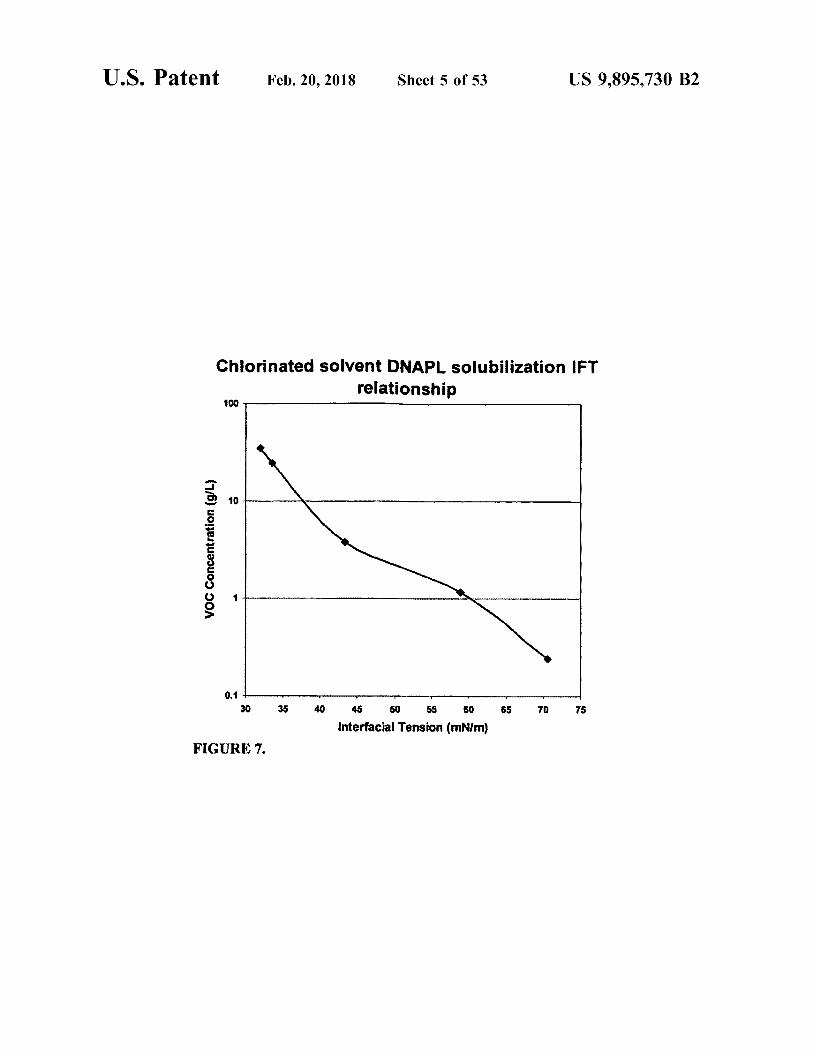
Chlorinated solvent DNAPL solubilization IFT relationship
100
VOC Concentration ( g / L )
0 . 1 30 35 40 65 70 75 45 50 55 60
Interfacial Tension ( mN / m ) FIGURE 7 .
U . S . Patent Feb . 20 , 2018 Sheet 6 of 53 US 9 , 895 , 730 B2
mm
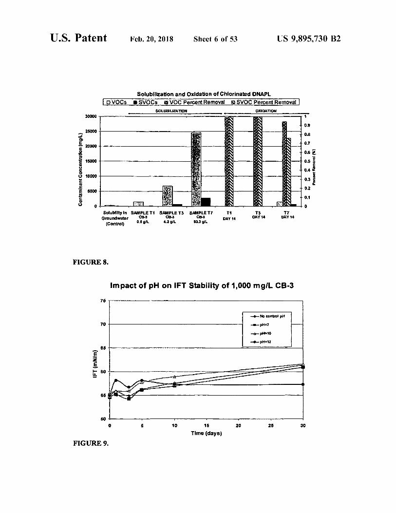
Solubilization and Oxidation of Chlorinated DNAPL DVOCS I SVOCs @ VOC Percent Removal S SVOC Percent Removal
SOLUBILIZATION OXIDATION w . .
30000 www . . . . . . . . . . . . . . . .
25000
20000
PAN 15000 make . co Contaminant Concentration ( mg / ) . | Porcont Removal ( % )
10000
5000
Solubility In SAMPLETI SAMPLE T3 SAMPLE TT Groundwater CB - 3
0 . 8 al 4 . 2 OL ( Control ) 8313 gL
T1 DAY 14 TO Dette blive T7
DAY 14 DAY 14
FIGURE 8 .
Impact of pH on IFT Stability of 1 , 000 mg / L CB - 3
wensenteret No control pH ? pH = 7
P10 pH = 12 -
so
IFT ( mN / m )
e
20 25 30 16 Time ( days )
FIGURE 9 .
U . S . Patent Feb . 20 , 2018 Sheet 7 of 53 US 9 , 895 , 730 B2
IFT Stability with Alkaline Persulfate at pH = 12 O
l
en
( WNW ) 131 se neslimonene
- CB - 1 C8 - 2
* _ EZ Mutse
ot * * 60 L
10 16 2026 20 25 Time ( days )
FIGURE 10 .
IFT Stability with Persulfate and Activated Persulfate
IFT ( MN / m )
: in e te
- 50 OL SP . 1000mgr CB2 con glima 60 g / L SP + 1000mgr . co vor 50 OL SP1000mg AM53
de 60 OR SP . 1000mor CB2 . 250 mgr og si 1000mg CB3 250 mgh masa rocamgil A163 • 250 mol Fe IDETA PODSTA
Time ( days )
FIGURE 11 .
U . S . Patent Feb . 20 , 2018 Sheet 8 of 53 US 9 , 895 , 730 B2
IFT Stability with Fe ( II ) - EDTA Activated Persulfate Citrus Burst - 3 constant for all experiments @ 2000 mg / l
Fe ( IN - EDTA constant for all experiments @ 250 mg / l 8
8
8
8
IFT ( mNim ) 8
8
w 1 - 1 ( Persuitata wenyewen - 3 ( Persultate
6 g / L ) 26 g / L ) one
- 2 ( Persulfato @ 10 g / L ) 14 Control )
8
10 12 14 16 Time ( days )
FIGURE 12
U . S . Patent Feb . 20 , 2018 Sheet 9 of 53 US 9 , 895 , 730 B2
IFT Stability with Peroxide Activated Persulfate Citrus Burst - 3 for all Experiments @ 2000 mg / l Sodium Persuttate for all experiments @ 25 g / L
eso es por
y IFT ( MN / M )
III - 1 ( Hydrogen peroxide @ 1 % meme 111 3 ( Hydrogen peroxide @ 3 %
II 1 - 2 ( Hydrogen peroxide @ 2 % ) werden ! 1 - 4 ( Control )
ô
10 12 14 16 Time ( days )
FIGURE 13 ,
U . S . Patent Feb . 20 , 2018 Sheet 10 of 53 US 9 , 895 , 730 B2
MGP Site - Soil Oxidant Demand
ã a Remaining Persulfate
ã
ã Soil Oxidant Demand
SOD ( g / kg dry ) Sodium Persulfate ( % )
SOD gikg dry - ORemaining
.
50 100 150 250 200 Initial Sodium Persulfate Concentration , g / L
FIGURE 14 .
Interfacial Tension of Surfactants and Cosolvent / Surfactants with MGP Site DNAPL og
?
sound and Tween 80 - * • Alloterra 53
E - Z - Mulse . . . Citrus Burst 2
Alloterra 55 Alfoterra 145 - 490
- O Citrus Burst 1 0 - dimonene en China Burana
Maia . . . . . . . . . . . . . .
8
Interfacial Tension ( mNm ) 8
- . .
. . .
- nomen - - - - - - - - - X . . . . . .
?
0 50 100 450 150 200 250 300 350 400 Surfactant Concentration ( mg / L )
Note : 3 mL DNAPL in 35mL site groundwater .
FIGURE 15 .
U . S . Patent Feb . 20 , 2018 Sheet 11 of 53 US 9 , 895 , 730 B2
MGP COC Removal in Soil Columns Flushed with various Surfactant and Cosolvent - Surtactant Mixtures
2 . 0507 Total Moles COCs Removed
0 Total Moles VOCs Removed Total Moles SVOCs Removed
25602
20602
1 . 5602 Tota COCs Remored ( metaj IIIIIII 1 . 0802
5 . 0503
Rafi 0 . 0E + OOL Groundwater Alons Citrus Burot - 2 Citrus Burst - 3 AMoterya - 53 Activated Porsumate .
500 mgr . CB - 2 , 50 gr Sodlum Persulate ,
Fa ( 11 ) - OTA - 250 mg / l as Fe
FIGURE 16 .
S - ISCO Soil Slurry MGP Site Treatment
COCs OVOCs svocs
Soil Concentration ( mol / kg )
Day O ( SO ) Day 30 Reaction Data ( SO )
Time ( day ) FIGURE 17 .
US 9 , 895 , 7300 B2 Sheet 12 of 53 _ Feb . 20 , 2018 U , S , Patent
& ? ? ? ? ? ? % % % % % fif SQ S - SCV ? ? ? ? ? ? ? ? ? ? ? ? ? ? ? ? ? ? ? . . . - - - - - - ? ? ? ? ? ? ? ? ? ? ? ? ? ? ? ? ?
? . . . . . . . . . . . . . . . . . . . . . . . . . . . . . . ?
? ? . . . . . . . . . . . .
? ? ???? ? ? ? ? ? ? ? ? ? ? ? ? ? ? ? ? ? ? ? ? ? ? ? ? ? ? ? ? ? ? ? ? ? ? ? ? ? ? ? ? ? ? ? ? ???? ? ????????????????????? . . . . . . . . . . . . . . . . . . . . . . . . . . . . . . . . . … . . . . . . . . . . . . . . . ? ? ? ? ? ? ? ? ? . . . . . . . ? ? ? ? ? ? ? ?
. . . . . . . .
? ? ? ? ? ? ? ? ? ? ? ? ? ? ? ? ? ? . . . ? ? ? ? ? ? ? ? ? ? ? ? ? ? ? ? ? ? ? ? ? ? ? ? ? ? ? ? ? ? ? ? ? . ? ?
??????? ?? ? ? ? ??? - - - - - ? ??????????????? ? ?????????? - - - - - ???? - ?? - ? ? ? - ????????????? ? ? ?????? ???????? ????? ?? ??????? ? ? ?
? ? ? ? ? ? . . . . . . . . ? ? . . ? ??? . ? ? ? ? ? ? ? ? ? ?
? ????? ?
? ????? ? ????????? ? ? ?
& » ) * ? ? ? ? ? ? ?
US 9 , 895 , 7300 B2 Sheet 13 of 53 _ Feb . 20 , 2018 U , S , Patent
Soil Column Treatability Test . . . . ' . . . . . . . . .
????????????? ? ???????????? ? ? ?????????????????? : » www ???????????????? ? ? ? ? ? ? ? ? ? . . . ? ? ? ? ? ? ? ? ? ? ? ? ? ? ?
??????????? ? ? ? ? ? ? ? ? ? ? ? ? ? ? ? ? ? ? ? ? ? ? ? ? ? ? . . . . . . - . . . ? ? ?????????????????????????????????? ? ? ???? ? ? ????????????????????????????? ?
? ? ? ? ?????????????? . - - ' - - ' - ' - ' - ' - x ' xxx ????????????????? * * - ' x ' r * * * * * * * * * * * * wwwhwww ? ? ? ? ? ? ? ? ? ?
??? . ? ? ? ? ? ? ? ? ? ? ? ? ? ? ? ? ? ? . . . . . . . . ? ? ? ? ? ? ? ? ? ? ? ? ? ? ? ? ? ? ? ? ? ? ? ? ? ? ? ? ? ? ? ? ? ? ? ? ? ? ? ? ? ?
% 83 % ? ?
- . . . . . . . . . . . . . . . . . ? ? ? ? ? ? ? ? ? ? ? ? ? ? ? ? ? ? ? ? ? ? ? ? ? ? ? ? ? ? ? ? ? ? ? ??? ??? . * - - - ' - " ??? , ? ? ? ? ? ?
?
?
?
? ?
. . . ? ? ? ? ? ? . ??????? ? ; ? ? ? ? ? ? ? ? ? ? ? ? ? ? ? ? ? ? ? ? ? ? ?????? ? ? ? ? | ? 8 < > ? 8
? ? ? ? ? ? ? ? . . . . ??????? . ??????????????? ?
?
. . : ? ? ? ? ? ? ? ??? ???? ? ? ? ? ? ? ? ? * * * * * * * * * * *
? ? ? ? ? ? ? ? ??????????????? ? . ? > ? .
. ? ? ? ? ? ? ? ? ? ? ? ? ? ? ? ? ? ? ? ? ? ? ? ? ? ? ? ? ? ? ?
? ? ? ? ? ? ? ? ?
atent
COLUMN EXPERIMENTS FINAL SOIL TPH CONCENTRATIONS
8 , 000
- 6 , 800 6 , 800
Feb . 20 , 2018
5 , 500
4 , 900
TPH ( mg / kg ) Î Ñ Ñ Ï Ï Ï Ï 3 , 000
2 , 500
T
340
Sheet 14 of 53
270
410
100 VenuSOL - 3
DIWATER + HEAT ( 50C )
1001 VeruSOL - 3 + 8 % H2O3 + Fe ( NTA )
8 % M702 + Fe ( NTA )
0 100L VeruSOL - 3 + 8 % H20 + 16 . 801 NaHCO3
0
10g
VenuSOL - 314 % HO VeruSOL - 312 % H202 + 8401 + 8491 . NaHCO3 NaHCO3
Tar Sands + 1001 VeruSOL - 318 % H202 + 16 . 80L NaHCO3
VeruSOL - 34 4mimin NITROGEN AR
DI WATER + 4 mlimin NITROGEN AIR
FIG . 20a
US 9 , 895 , 730 B2
U . S . Patent Feb . 20 , 2018 Sheet 15 of 53 US 9 , 895 , 730 B2
MGP column experiments , 10 gil VeruSOUX influent effect on MGP DNAPL ( before and after 14 - day experiment )
Experimental Codos own cimensions 2009 0 calon sokeo wa
orama VOA ONARU : Row yote @ mimo swinar x 4 days .
U . S . Patent Feb . 20 , 2018 Sheet 16 of 53 US 9 , 895 , 730 B2
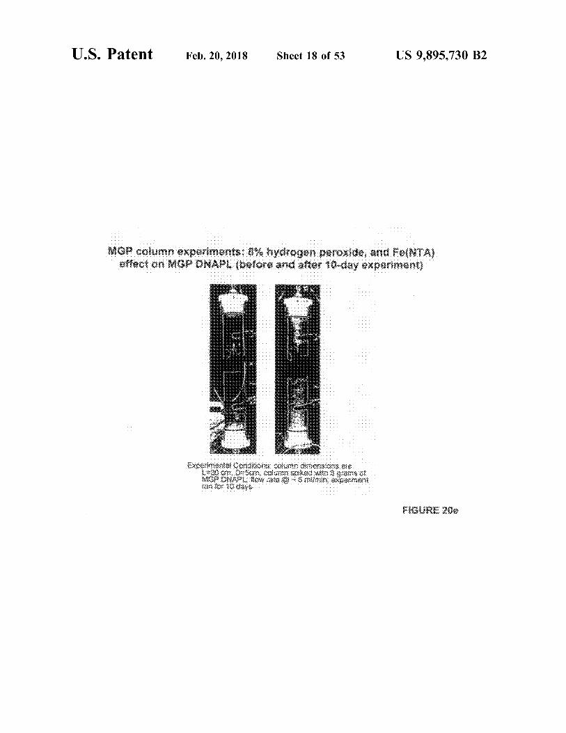
ou experi MGR ONAPL ( before and after 8 - day experiment )
Experimentsi Conditions column in mansiona ure 30 cm 0 cm coexi spiked with a
GERGA ONA wote mumi excamom on for days in incubator seta
FIGURE 200
U . S . Patent Feb . 20 , 2018 Sheet 17 of 53 US 9 , 895 , 730 B2
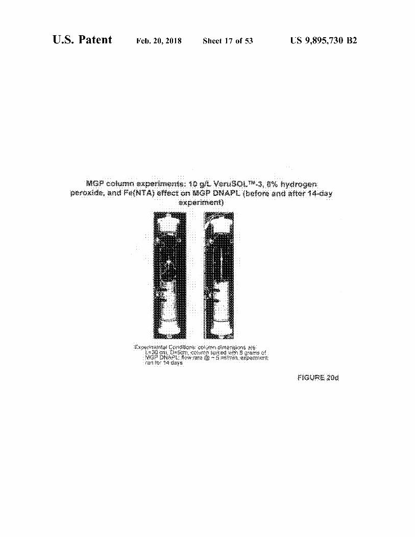
. . . . . MGP column experiments : 10 g / l VeruSOLM . 3 , 8 % hydrogen peroxide , and Fe ( NTA ) effect on MGP DNAPL ( before and after 14 - day
experiment )
Experimente Conditions pour mongoos ar 30 02 05 Co So win 8 oans on
29R ONAP How me @ mommin e pare autor $ 4 days
FIGURE 200
U . S . Patent Feb . 20 , 2018 Sheet 18 of 53 US 9 , 895 , 730 B2
. . . . . . . . . . . . . . . . . . . . . . . . .
Experimento Coxokous K i mensions are XG ONA Bow as 390 10 days Guwow
FIGURE 209

U . S . Patent Feb . 20 , 2018 Sheet 19 of 53 US 9 , 895 , 730 B2
. . . . . . . . . . . . . . . . . . . . . . . . . . . . . . . . . . . . . . . . . . . . . . . . . . . . and 16 . 8 gil Naco , effect on NGP DNAPL ( before and after 3 - day experiment )
. . . . . . . . . . . . . . .
. . . . . . . . . .
. . . . . . . . . . . .
Experimenta Conos oxin mersions se 30a Osnoux Skod vas is a
KOPONAPO Wow stes sonen for 3 days
FIGURE 201
U . S . Patent Feb . 20 , 2018 Sheet 20 of 53 US 9 , 895 , 730 B2
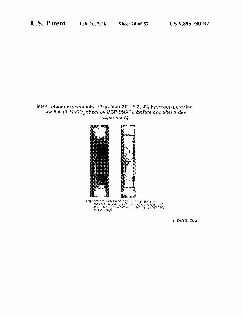
MGP column experiments : 10 g / l VerusoLW . 3 , 4 % hydrogen peroxide , and 8 . 4 gl . Naco , effect on MCP ONAPL before and after 3 day
experiment )
Experiments Comme : vun dersom 3000 , 0 - 60m uma soko win a grains of
WGR ONAS . , owoce Sinumin atpament 2 or 3 y ' s
FIGURE 200
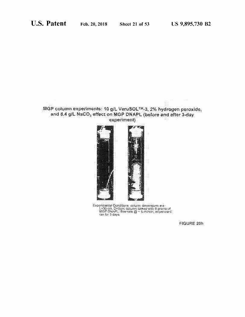
U . S . Patent Feb . 20 , 2018 Sheet 21 of 53 US 9 , 895 , 730 B2
( bojore 4 g / l Naco , effect o experiment )
experimenta con toda coluna dimensions 500 * 300 * 0 . 0 3 w grans AGA ONAR . Kowalec xgerie
Wys
FIGURE 201
U . S . Patent Feb . 20 , 2018 Sheet 22 of 53 US 9 , 895 , 730 B2
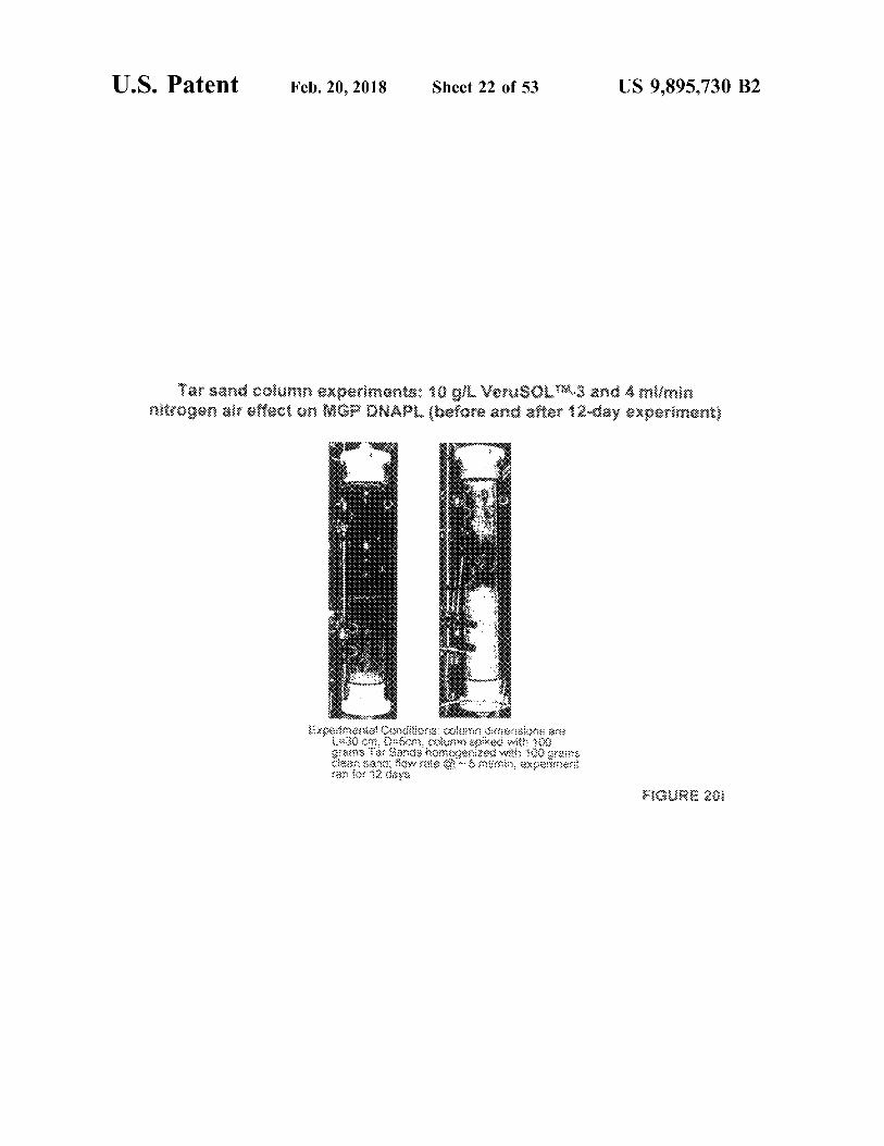
Tar sand column experiments : 10 g / l VeruSOLW . 3 and 4 ml / min ( quounodxa Kepave oue joj8Q ) AVNO JOW 10 32000 je 08000U
picavaweo 08 09 : imo i 29000 paxs 200 soe : 6 Soves 2 : 06W M S488 0
dxa vosses MO Des 1890 ve : SRC Z
HIGURE 201
U . S . Patent Feb . 20 , 2018 Sheet 23 of 53 US 9 , 895 , 730 B2
nexpert ton MGPL
in nitrogo air ofte experiment
experimental Contons Coluna dimensions are x30 cm Om ook soks98 993788 VOR ONAPL towe Smkn Xaximeo
FIGURE 201
U . S . Patent Feb . 20 , 2018 Sheet 24 of 53 US 9 , 895 , 730 B2
nis : delona water and ay experiment ) alr effect on MOP C after
www .
xgermenisi Conditions . lungo omencions are 30 . 01 . 06 . Com søke Win 8 grama od
MGA ONAPE Nowrate s mimin exoxunnen en los 2 days
FIGURE 20K
U . S . Patent Feb . 20 , 2018 Sheet 25 of 53 US 9 , 895 , 730 B2
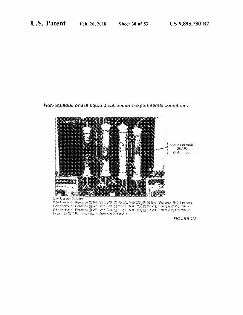
Non - aqueous phase liquid displacement experimental conditions onditio
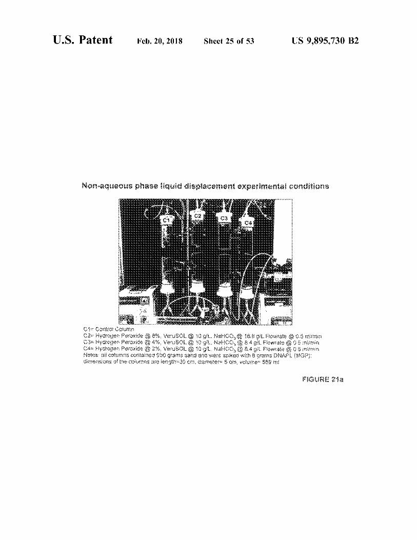
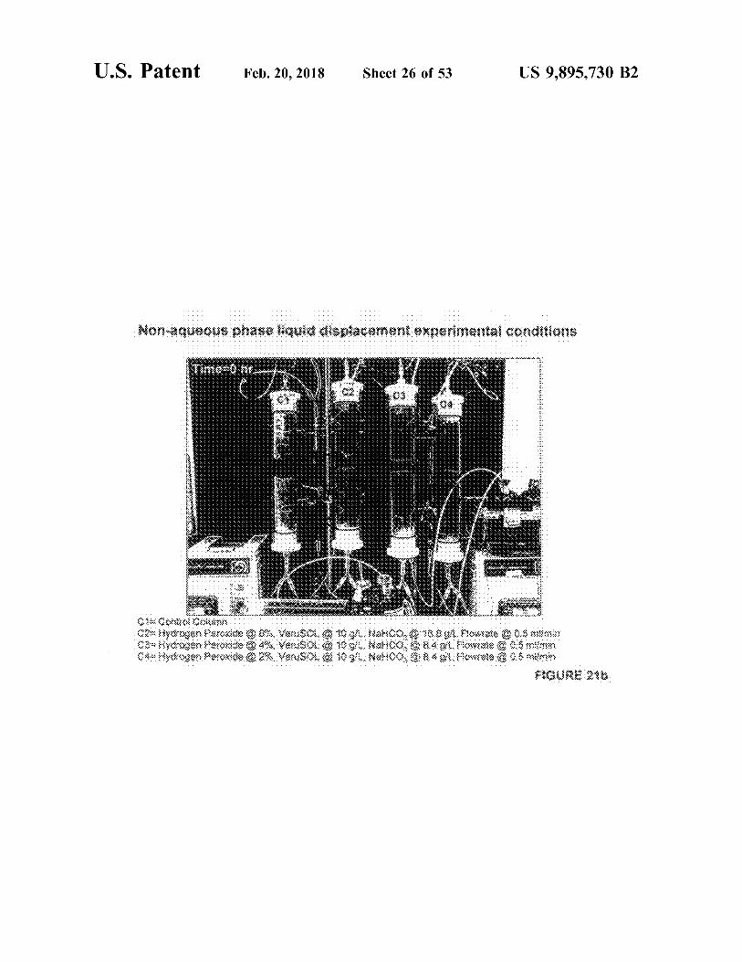
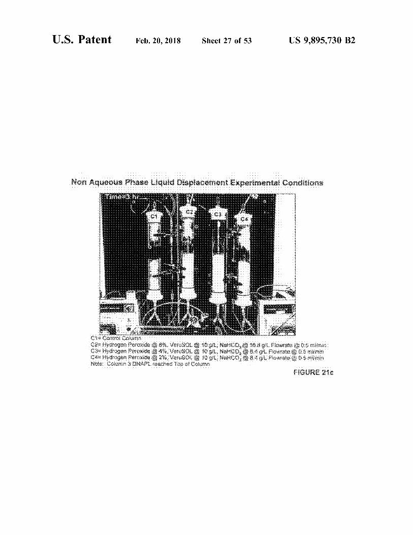
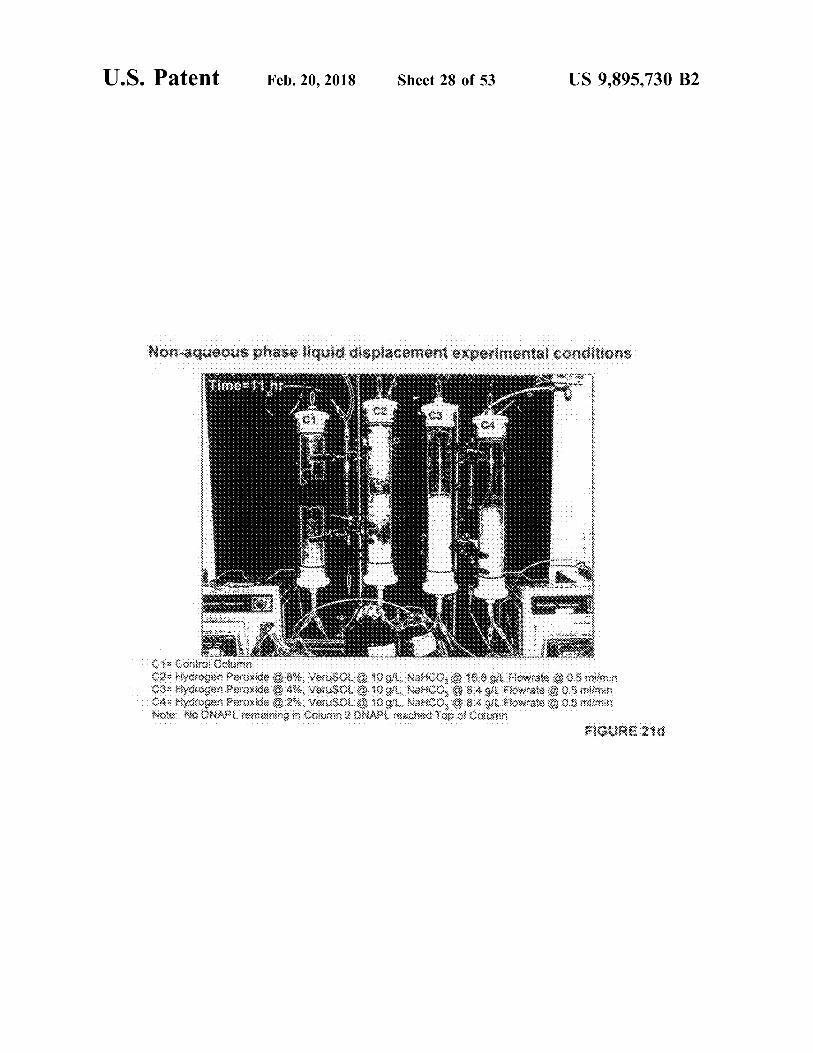
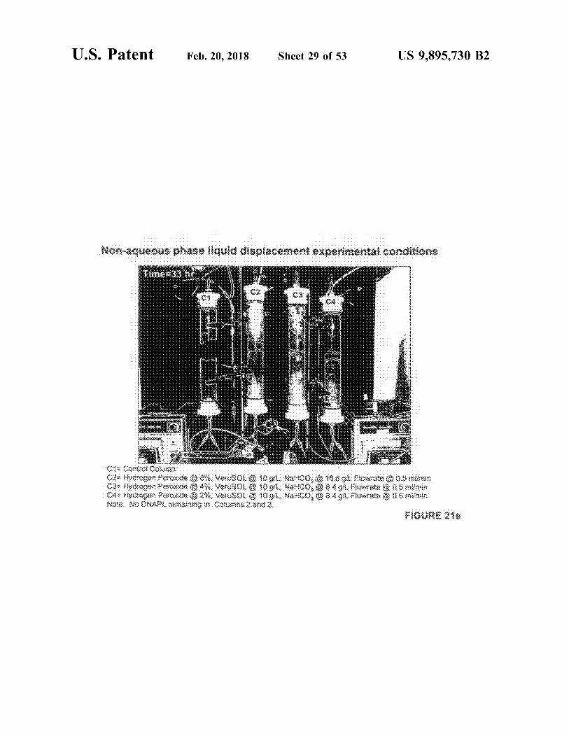
K AUW O Contro Column 02xverogen peroxide @ 8 % . VeuSO100ot . Natico , 16 . 61 Fowrate 0 . 5 maymin C3 Kydrogen peroxide 4 % : Verusol @ 10gu . Nalico , 8 . 4 91 . Fowate 0 0 6 inimin C4 Hydrogen peroxido O 2 % . VASOL 0 10911 . Natco , 8 . 4 g / l Flowate 06 mimin Notes al columos contained 950 grams sand and ware spiked with a grains DNAPI . MOP ; Oisterxions or oxumine 3x8 lengi3007 , gemelos 60 , Voice : 58 % 33
FIGURE 21a
U . S . Patent Feb . 20 , 2018 Sheet 26 of 53 US 9 , 895 , 730 B2
. . . . . . . . . . . . . . . . . . . . . . . . . . . . . . . . . . . . . . . . . . . . . . . . . . . . . . . . . . . . . . . . . . . . . . . . . . . . . . . . . . . . . . . . . .
Non aqueous phase liquid displacement experimental conditions
memo hr
Cool Coun 2 Hydrogen peroxide @ 6x Varusot @ 08 . Nahoo , @ 16 . 09 . Howrate 0 5
Hydrogen peroxide @ 8 % Vousou o 1000 Malia , 8 . 4 . Hovu 0 Strains C * * Hydrogen peroxido O 2 Varuson 010 Marco , 40 rosu Osman
FIGURE 20
US 9 . 895 , 730 B2
WWW MW W
W
- A * - * - * - * - * * * - * - * - * - * - * - * - * - * - * - * - * - * - * - * - * * * * * * *
* * * * * * * * * * - - * * -
?? : ?
Sheet 27 of 53
? 20533
????
? ??? ? ?
?? , ?????? : ?
42 :
? : : ? ??
( 33 ? : 23 : 38 :
: : ?
Feb . 20 , 2018
: : : : : : :
???
U . S . Patent
????????
U . S . Patent Feb . 20 , 2018 Sheet 28 of 53 US 9 . 895 , 730 B2
. . . . . . . : : iii ii i iiiiiiiiiiiiiiiiii , , , , , , , , , , , , . . . . . .
?????? ????????? : - -
h
tttttttttttttttt - + - + - + - + - + - + - + - + - + - + - + - + - + + + + + +
?? ? * wereserversoww ? s iunts . . . … .
htnish - it - thurushih - thustrustrustrurustrustruttituttitutest
w www - rw rw rw - - - - - - - * -
? RSS : ? ?? , ????????
?? , , ?? ? ????? ? ?? , ? ?????? ?? ? ???? ? ?? ? ?
?????
U . S . Patent Feb . 20 , 2018 Sheet 29 of 53 US 9 , 895 , 730 B2
nditions Time 33 h wvwwwwwwwwwww
WW W
C 0x lycogen peroxida
odagen pero C4 Hycoon Peroxide NO ONART . COM
8 . Verusou 10 gu Var00 . 0 108 or flowste 205 mimo * * Vouso 109 NAMCO 08 . 4 g Fiowate 0 . 2 % Venusol @ 10 gu Namco , 08 . 40 Howate 0 . 5 mm
X2 380 FIGURE 21
Fm
U . S . Patent Feb . 20 , 2018 Sheet 30 of 53 US 9 . 895 , 730 B2
???? ???????????????????
??
33?? :
2 . ? »
? ? . . : : ?? , ????? , ??? , ? ? ??? , ? : ?????
? , ?? : ??
, ?
U . S . Patent Feb . 20 , 2018 Sheet 31 of 53 US 9 , 895 , 730 B2
. . . . . . . . . . . . . . . . . . Non - aqueous phase displacement exper
. . . . . . . . . . . . . .
. . . . . . . . . . .
* * *
- -
4 - - 49
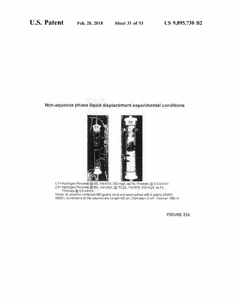
C oroa soroxide 6 899 . FoVIA 250 moyu & Fe , nowate 0 . 5 is 02 yoxca xoxide 8 % VATUSOL 300 M 250ml ,
How to 0 . 8 mumin Notes at cous contained 980 goamia sarid and were spiked with grams ONAR
39 W !
FIGURE 220
U . S . Patent Feb . 20 , 2018 Sheet 32 of 53 US 9 , 895 , 730 B2
Non - aqueous phase displacement . . III . II . . . . . . . . . . . . . . . . . . . . . . . . . . . . . . . . . . . . . . . . . .
W
' - ' * ' ' - - ' - '
W
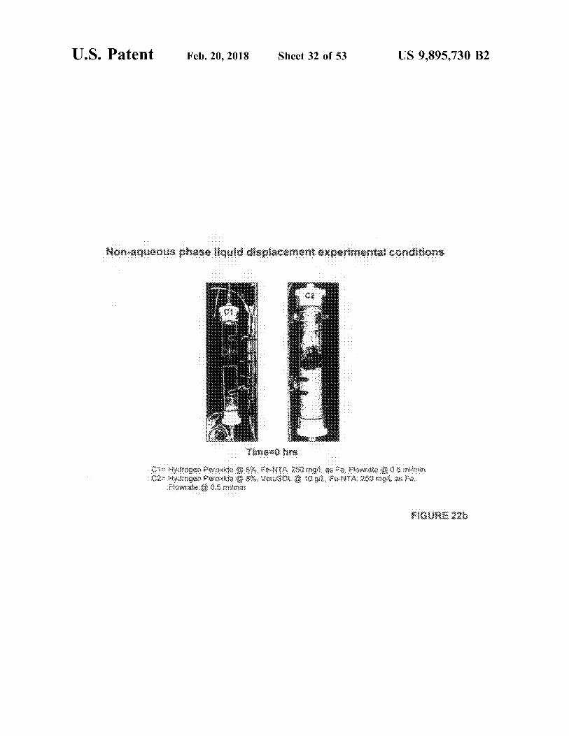
Time 0 hrs Citykoosneroxide @ S % FONTA 280 mg as a wowote 06 min 02 Myotrogen Peroxido x Varuso1 O 109 FANTA 280 mot a fer
Home 008 maria
FIGURE 220
U . S . Patent Feb . 20 , 2018 Sheet 33 of 53 US 9 , 895 , 730 B2
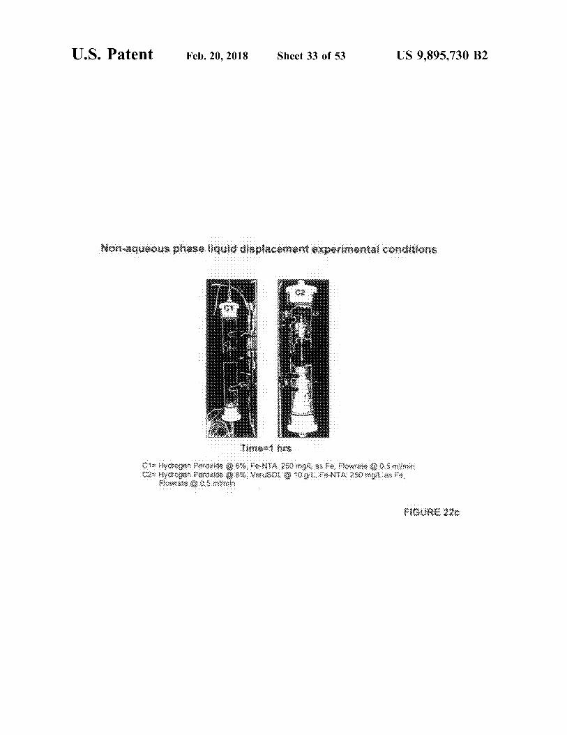
Non - aqueous phase liquid displacement experimental conditions
* * * * *
* *
*
mos min C * * Hydrogao Aeroxide @ 8 % NA 850 molt as Fe , fumat 0 0
02 byorogon Peroxide 0 0 % Vouson 0109 FAVIA 250 noles Monste 05 min
FIGURE 220
U . S . Patent Feb . 20 , 2018 Sheet 34 of 53 US 9 , 895 , 730 B2
Non - aqueous phase display . . . . . . . . .
. . . . . . . . . . . . . . . . . . .
. . . . . . . . . . . . . . . .
COOBY Timang hos
CRMyorogen peroxius @ 6 % , FNYA 250 mgl as to howalo 0 mimin 92 Hydrogen peroksia 8 % Verusou 10gu FONTA : 250 mgi as fed
Flowale 003 min
FIGURE 220
U . S . Patent Feb . 20 , 2018 Sheet 35 of 53 US 9 , 895 , 730 B2
Non aqueous phase liquid displacement experimental conditions
Umem12 hrs - Hydrogen peroxide
02 Bytogen Peroxide mlowat 0 . 5 m
8 % PA NIA 20 molesta flowest 0 . 5 mln B , Venusov 0 1000 NIA 250pt as
U . S . Patent Feb . 20 , 2018 Sheet 36 of 53 US 9 , 895 , 730 B2
. . . . . . . . . . . . . .
Non - aqueous phase liquid displacement experimental conditions
WWW
Uime 24 or
C4 Mydrogen perox0 0 6X , PORTA 250 molas Fa , Fowkie osmimin 22 stydrogen peroxos © X Varuso 090 NIA : 250 ml as
Howa 0 . 5 x : :
MOURE 22
U . S . Patent Feb . 20 , 2018 Sheet 37 of 53 US 9 , 895 , 730 B2
. . . . . . . . . : 9447 . .
.
.
.
. . .
sies .
. . . . . . . . . . . . . . . . . . . . . . . . . . . . . . . . . . .
. . . . . . . ! HOTTE . '
Som 54 * www : * : *
FIGURE 20 ,
WWWX
: : : : : : : : : : : : : : : : : : : : : : : : : :
HIGURE 24 .
U . S , Patent Feb . 20 , 2018 Sheet 38 of 53 . US 9 , 895 , 730 82
• • • • • • • • • • • • • • • • • • • • •
- wwwzz •••••••••••••••4444 4 4444444444 + + + + + + + + - - - - - - - - - + + + + + • • • • • • • • • • • • •
• • • • • , , , , , , , , , , , , , 1 1 1 * * * * * * * * * * * * , , , , , , , , , , , , , * * * * * . , * * * . . . . . . . ,
* * * * * *
????? , ' no ' c ' end ' # + + + + + + + + + + + + + + + + + + + + + + +
+ + + +
4 : 4² : 04 : + + + + + + + + + + + + ' ' , * * * ••••••••••••••44448444444YvxNpo
* { { *
+ + + + + + + + + + + + + + + + + + + + + + + + + + + + + + + + + + + + + +
????? ????
U . S . Patent Feb . 20 , 2018 Sheet 39 of 53 US 9 , 895 , 730 B2
Emulsion Supernatant TPH Concentrations for Two VeruSOLD - Surfactants
1800 1600
100
TPH Concentration ( mga ) Verus OL - 9
400 - Verus OL - 10 200
40 60 80 100 20 VeruS OLH Concentation ( 8 Akg )
FIGURE 27 .
SIZE DYSTRIBUTION BY NIENSITY
INTENSITY ( % )
1000 10000 AHLI tutti
100 SIZE ( dam )
RECORD 28 : STEEL _ SOL _ 5A5 - 81 - - - - - - RECORD 29 . STEEL _ SOL _ SA5 - 8 2 ] - RECORD 30 : STEEL SOL 5A5 - B 3 .
FIGURE 28 .
U . S . Patent Feb . 20 , 2018 Sheet 40 of 53 US 9 , 895 , 730 B2
SIZE DISTRIBUTION BY INTENSITY
INTENSITY ( % )
t hen there that 10 100 1000 10000 SIZE ( dam )
RECORD 34 : STEEL SOL _ 5A6B1 - - - - - - RECORD 35 . STEEL _ SOL _ 5A682 - RECORD 35 : STEEL SOL 5A683
FIGURE 29 .
SIZE DISTRIBUTION BY INTENSITY
convenient INTENSITY ( % )
ON A het to t + +
100 1000 10000 SIZE ( d . nm )
RECORD 40 : STEEL _ SOL _ 547 - 81 - - - - - - RECORD 41 : STEEL _ SOL _ 547 - 82 RECORD 42 : STEEL SOL 5A7 - 83
-
FIGURE 30 .
U . S . Patent Feb . 20 , 2018 Sheet 41 of 53 US 9 , 895 , 730 B2
SIZE DISTRIBUTION BY NTBUSITY
INTENSITY 1 % programas farane garneforeningen en promene fanten
Sometimes throughowanie Oeuf aut o n tietote 10 1000
* 10000
SIZE ( drum ) RECORD 46 : STEEL _ SOL 5AB - 81 - - - - - - RECORD 47 : STEEL SOL SAB - 82
- - - - - - RECORD 48 : STEEL _ SOL 5AB - 83
FIGURE 31 ,
TPH Decrease in Soil Columns
14000 13000 12000 11 , 000
21 % reduction 11000 10000 9000
TPH ( mg / kg ) IT Total hitval Mass o Mass at End 3 , 300 76 % reduction 2 , 600
81 % reduction 4000 3000 2000 1000
Control SEPR Column S - ISCO Column
FIGURE 32 .
U . S . Patent Feb . 20 , 2018 Sheet 42 of 53 US 9 , 895 , 730 B2
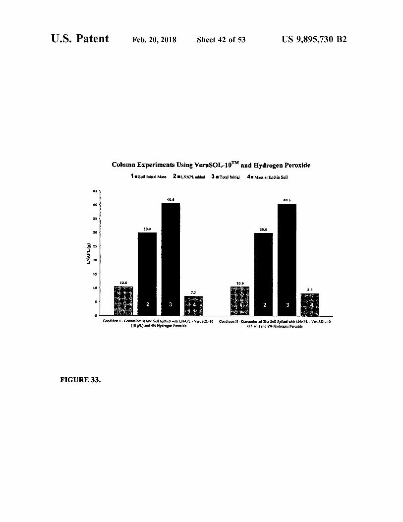
Column Experiments Using VeruSOL - 10 ' M and Hydrogen peroxide 1 . Soil Initial Mass 2 . LNAPL added 3 . Total loitial 4 . Mass at End in Soil
40 . 6 40 . 6
30 . 0 30 . 0
LNAPL ( 8 ) wl all . 10 . 6 10 . 6 nice ano very 8 . 3
* * 7 . 2
Condition 1 . Contaminated Site Soil Spiked with LNAPL - VETUSOL - 10 ( 10 g / L ) and 4 % Hydrogen peroxide
Condition 11 - Contaminated Site Sail Spiked with LNAPL - VauSOL - 10 ( 25 g / L ) and 8 % Hydrogen peroxide
FIGURE 33 .
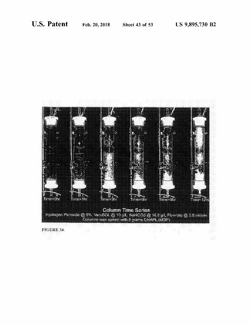
U . S . Patent Feb . 20 , 2018 Sheet 43 of 53 US 9 , 895 , 730 B2
me his 333 Like Time to UOME
Column Time Series Hydrogen peroxade @ 87€ . VeruSOL @ 10 9 , Nam003 @ 16 . 8
W IRS Was spiked with 8 grams DNAPDM L slowrale @ 0 . 5 mlimin
WIGURE 34 .
U . S . Patent Feb . 20 , 2018 Sheet 44 of 53 US 9 , 895 , 730 B2
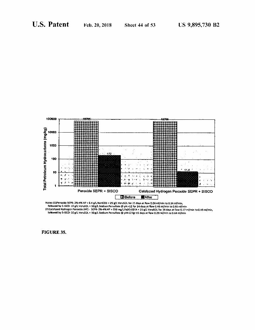
100000 68788
1 172 . . ö ??? Total Petroleum Hydrocarbons ( mg / kg )
1 . .
t . LL ! * 11 . 4 * . : . . .
. . . * M
mama to en i medias * * * * ,
Peroxide SEPR + SISCO Catalyzed Hydrogen peroxide SEPR + SISCO 3 Before After
Notes : ( 1 ) Peroxide SEPR - 2 % - 4 % HP + 8 . 4 g / L NaHCO3 + 25 g / l Verusol for 21 days at flow 0 . 06 ml / min to 0 . 34 ml / min , followed by S - ISCO 10 g / l VeruSOL + 50 G / L Sodium Persulfate @ pH > 12 for 14 days at flow 0 . 46 ml / min to 0 . 66 ml / min
( 2 ) Catalyzed Hydrogen peroxide ( HP ) - SEPR - 2 % - 4 % HP + 250 mg / l Fefil ) - EDTA + 25 g / l VeruSOL for 16 days at flow 0 . 17 ml / min to 0 . 49 ml / min , followed by S - ISCO 10 g / l VeruSOL + 50 g / L Sodium Persulfate @ pH > 12 fgr 15 days at flow 0 . 29 ml / min to 0 . 64 ml / min
FIGURE 35 .
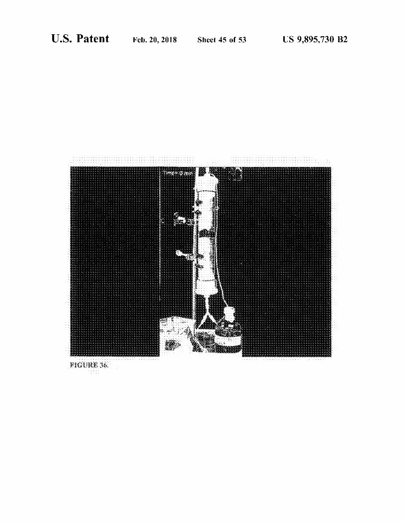
U . S . Patent Feb . 20 , 2018 Sheet 45 of 53 US 9 , 895 , 730 B2
om
.
7
HIGURE 36 .
U . S . Patent Feb . 20 , 2018 Sheet 46 of 53 US 9 , 895 , 730 B2
CHP with VeruSOL - 3 TM CHP
pa ; - * B
aw *
*
21 .
. .
na west Press the entero tempo ht . .
common 2 .
42
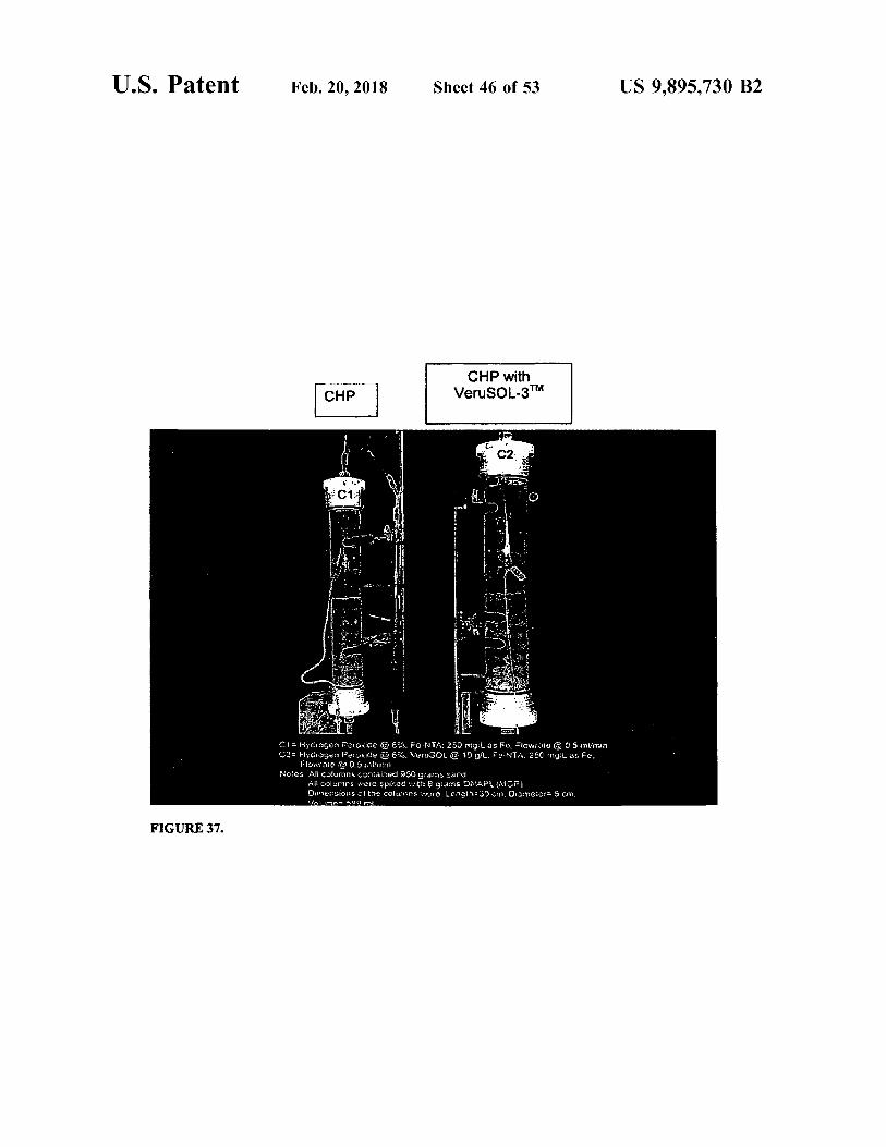
CI Ciocun Peroxice caro - NTA : 250 mil as fe . Flowrate Q 05 mumu C2 - Hydrogen peroxide @ 8 % . VeruSOL @ 10 L . Fe - NT : 250 mg , l as e .
Flowrate 0 . 5 Hallitsin cs All Thns and gas
All columns were spiegne grams DNAPL ( 10 ) Ouer : sions of the columnns wore , Longin - 30 11 . Obnictor - 5 CM . WURA - 500 ml
FIGURE 37 .
U . S . Patent Feb . 20 , 2018 Sheet 47 of 53 US 9 , 895 , 730 B2
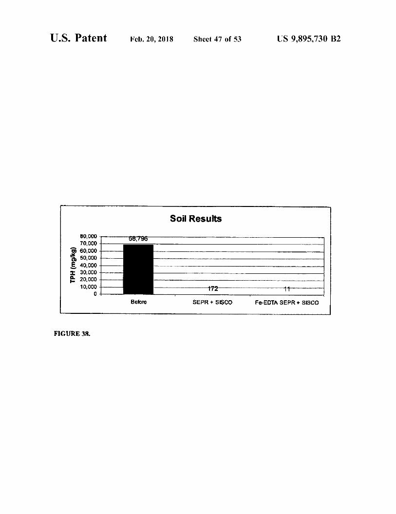
Soil Results 58 , 796
TPH ( mg / kg )
80 , 000 70 , 000 60 , 000 50 , 000 40 , 000 30 , 000 20 , 000 10 , 000 172
Before SEPR + SISCO Fe - EDTA SEPR + SISCO
FIGURE 38 .
I
U . S . Patent Feb . 20 , 2018 Sheet 48 of 53 US 9 , 895 , 730 B2
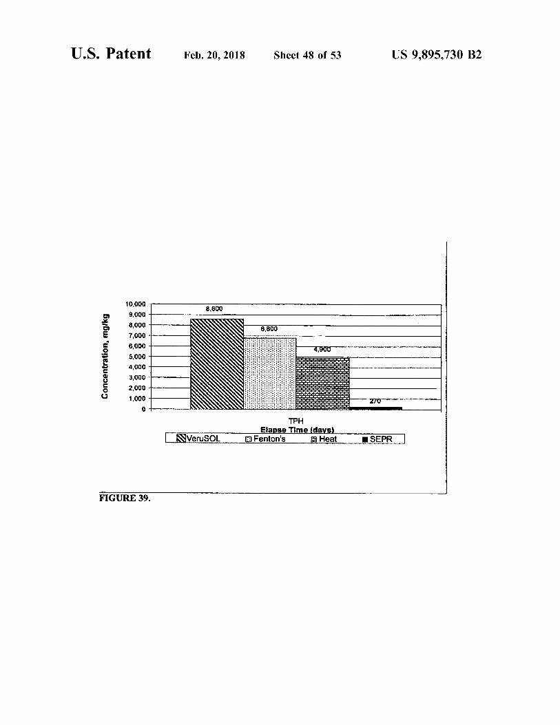
8 , 600
.
.
#
. . .
#
. . .
#
10 , 000 9 , 000 8 , 000 7 , 000 6 , 000 5 , 000 4 , 000 3 , 000 2 , 000 1 , 000
4 , 900 . .
. .
Concentration , mg / kg . .
IET + FIFT + EF * .
. .
. .
.
.
# #
.
. .
#
.
. .
PU .
. .
.
. .
. . . .
. .
.
. .
.
. .
. . .
.
.
. . 270 .
.
.
??? Elapse Time ( days )
a Fenton ' s Heat NVeruSOL ISEPR
FIGURE 39 .
U . S . Patent Feb . 20 , 2018 Sheet 49 of 53 US 9 , 895 , 730 B2
PT + + Direct
Inaction Paris up Apl Product Gr Monitoring Well / Optional
Recovery Well NAPL Product Recovery Well
leton Surtace Grade Level
Monitoring Well Optional
Recovery well
Unsaturated Zone Smear Zone
Hydrogen peroxide , Sodium Bicarbonate , and cosolvent / surfactant blend injected into smear zone t
* * .
+ ! !
* * * .
.
. . . *
I
.
.
. .
+
HII + + + + +
ETIF + +
. .
+
. . .
+
+
+ + +
+
+
.
. .
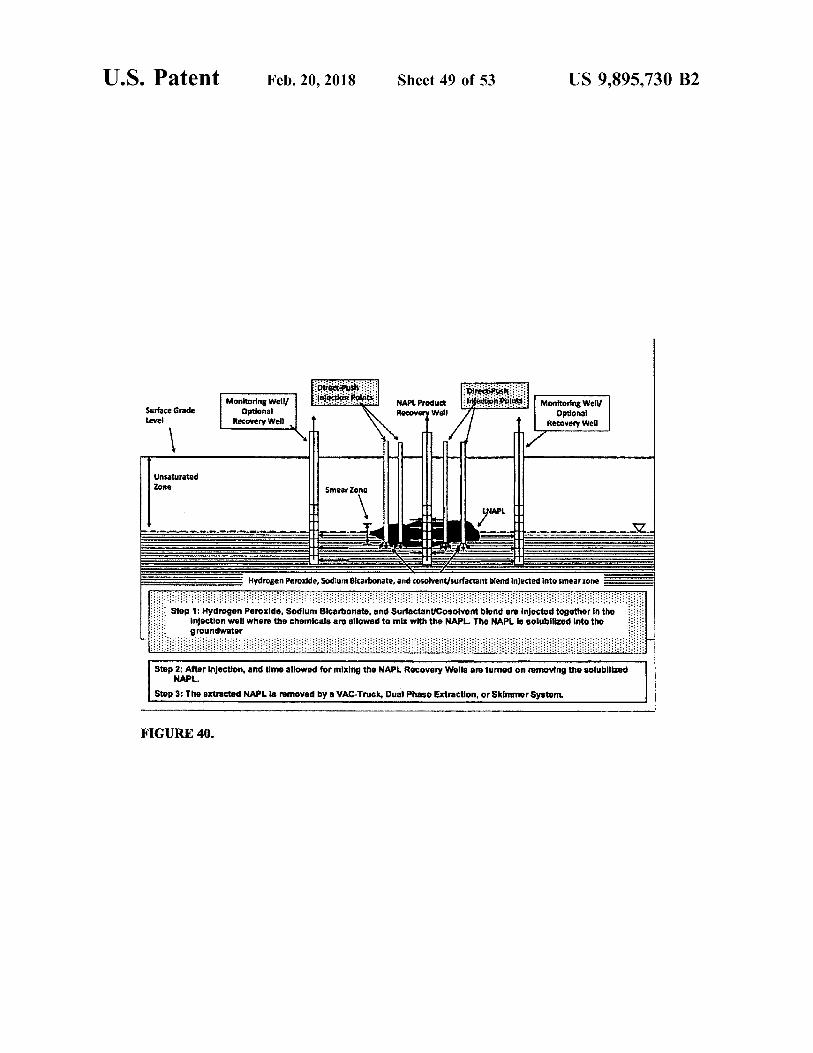
Step 1 : Hydrogen peroxide , Sodlum Bicarbonato , and Surfactanucosolvent blond are injected together in the Injection well where the chemicals are allowed to mix with the NAPL . The NAPL 18 solubilized into the groundwater
.
. . .
W +
. #
. . .
F + .
+
. . EPF * *
. . +
+
+
Step 2 : After Injection , and tlme allowed for mixing the NAPL Recovery Wolls are turned on romoving the solubilized NAPL .
Stop 3 : The extracted NAPL is removed by a VAC - Truck , Dual Phase Extraction , or Skimmer System
FIGURE 40 .
U . S . Patent Feb . 20 , 2018 Sheet 50 of 53 US 9 , 895 , 730 B2
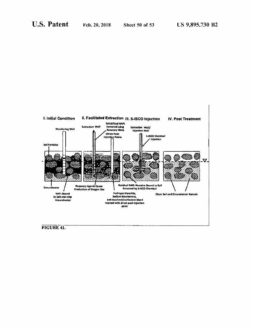
1 . Initial Condition IV . Post Treatment
Monitoring Well
11 . Facilitated Extraction UI . S - ISCO Injection Solubilized NAPL
Extraction Welt Removed using Extraction Well Recovery Wells Injection Well Direct - Push
Injection Points SSCO Chemical Injection
Soil Partides ITT ROLAIN Groundwater
NAPL Bound to Soll and atop Groundwater
Recovery Agents Cause Residual NAPL Remains Bound to Soil Production of Oxygen Gas Removed by S - ISCO Chemical
Hydrogen peroxide , Clean Soil and Groundwater Remain Sodium Bicarbonate , and cosolven / surfactant blend
Injected with direct push injection point
FIGURE 41 .
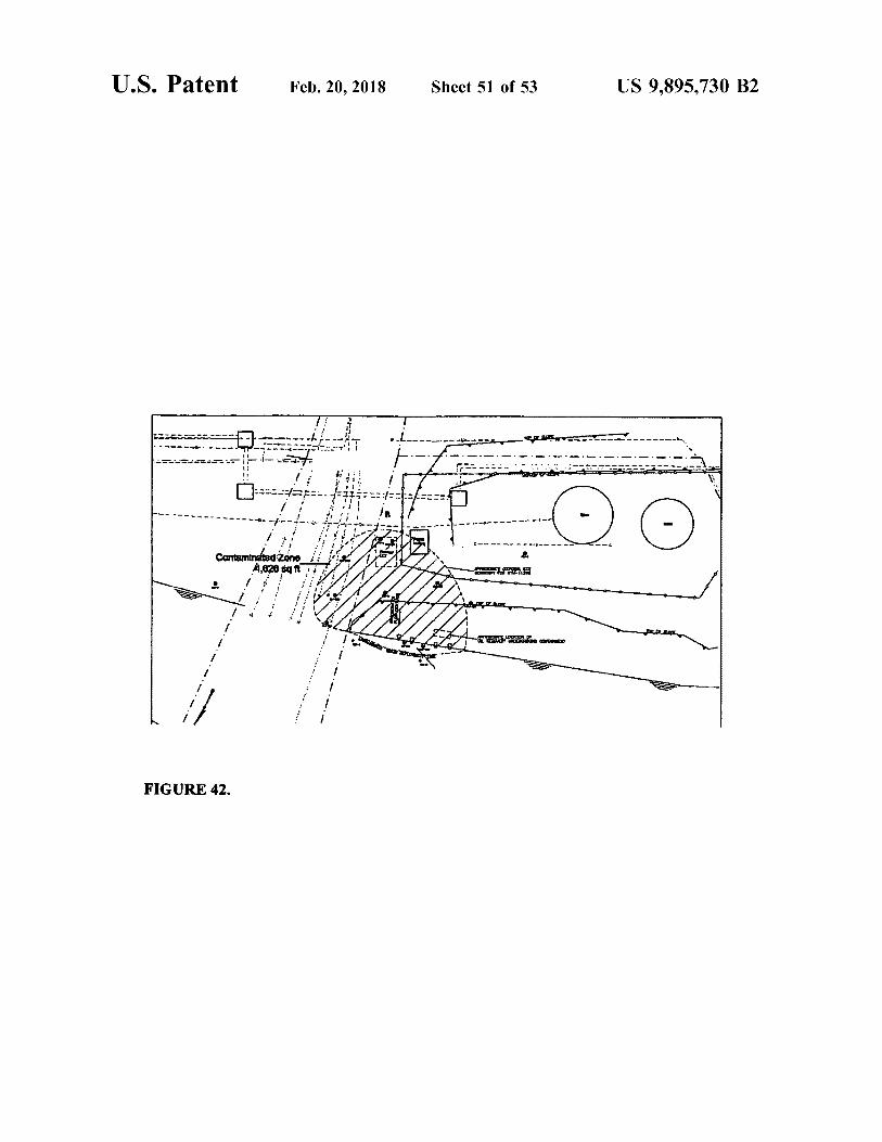
U . S . Patent Feb . 20 , 2018 Sheet 51 of 53 US 9 , 895 , 730 B2
wwwwwwwwww
i il ! 090 * | | - - : = = = = = = = iti * * la - - - - - - - - - - - - - -
. * * * * * * * * * * *
. . . . . . Contaminated zone
A , 020 6 * * en og . .
* * * *
* * * . . .
* * *
FIGURE 42 .
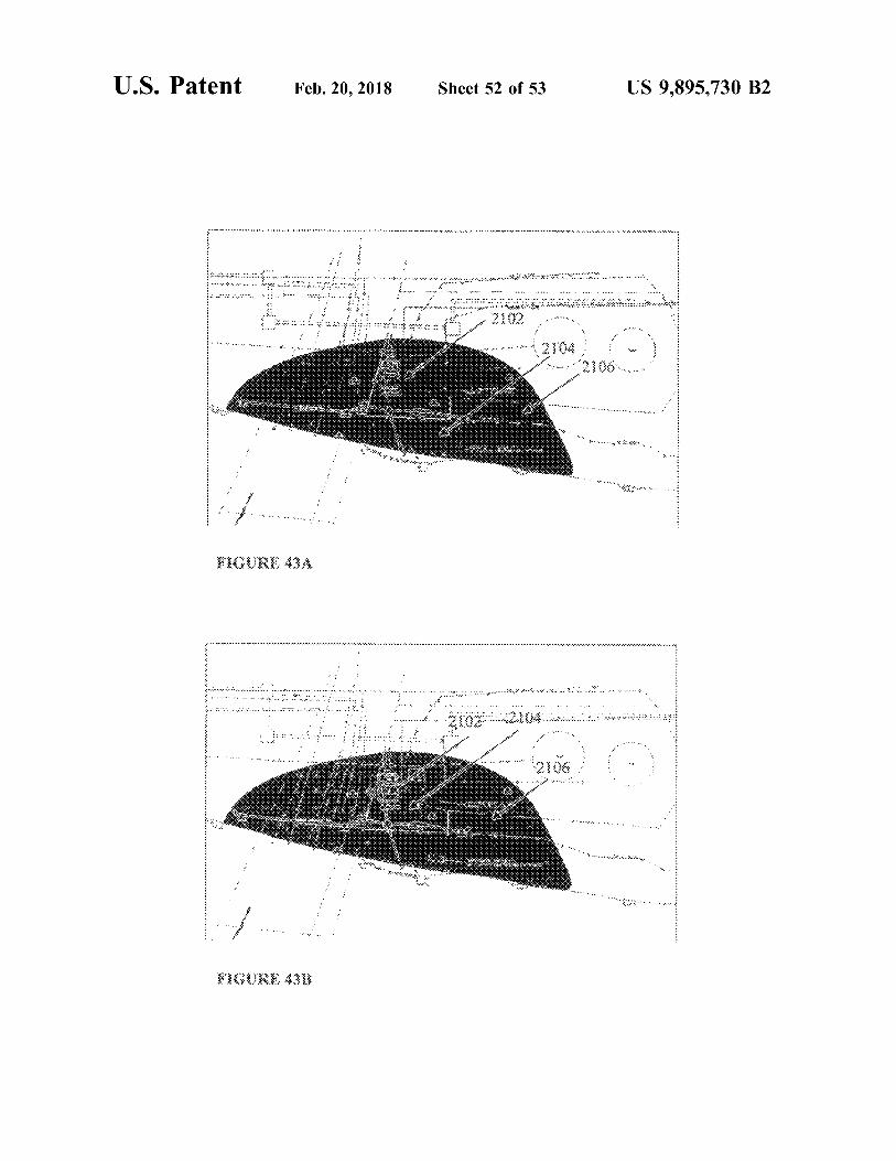
U . S . Patent Feb . 20 , 2018 Sheet 52 of 53 US 9 , 895 , 730 B2
. K . . . . . . . . . . . . . :
: . : . : : . . . . . . . y
* *
. . . . . . . . . . . m . . . . . .
. . . . . . . . .
. . . . * :
.
2102 .
2104 2106
. . * * * . . . . . .
.
. . "
. . . . .
. . . . . . . . . . .
FIGURE 434
. . . . . . . . . . . . . . . . . . . . . . . . . . . . . . . . . . . . . . . . . . . . . . . . . . . . * * * * * * * * . . . . . . . . . . . . . . . . . . .
. . . . . . . . . . . . . . . . . . . . . . . . . . ' . . . . . . . . . .
S . . . ' . . . . . . * * * * * * * *
* * * *
12106 . . . aba wa
PROV . . . . . .
. . . .
. . . . .
KIGURE 43B
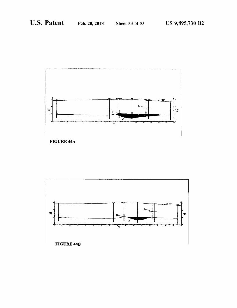
U . S . Patent Feb . 20 , 2018 Sheet 53 of 53 US 9 , 895 , 730 B2
Song
FIGURE 44A
nombre comencementenguilas
FIGURE 44B
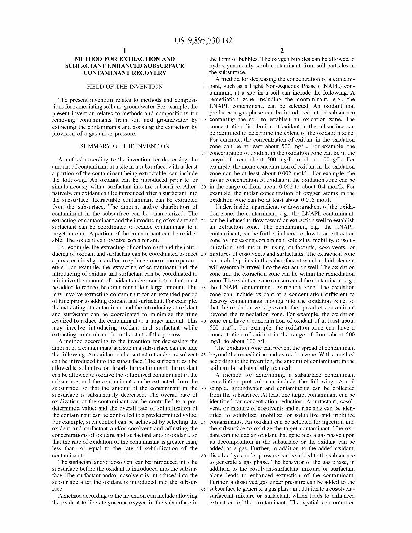
US 9 , 895 , 730 B2
METHOD FOR EXTRACTION AND the form of bubbles . The oxygen bubbles can be allowed to SURFACTANT ENHANCED SUBSURFACE hydrodynamically scrub contaminant from soil particles in
CONTAMINANT RECOVERY the subsurface . A method for decreasing the concentration of a contami
FIELD OF THE INVENTION 5 nant , such as a Light Non - Aqueous Phase ( LNAPL ) con taminant , at a site in a soil can include the following . A
The present invention relates to methods and composi - remediation zone including the contaminant , e . g . , the tions for remediating soil and groundwater . For example , the LNAPL contaminant , can be selected . An oxidant that present invention relates to methods and compositions for produces a gas phase can be introduced into a subsurface removing contaminants from soil and groundwater by 10 containing the soil to establish an oxidation zone . The extracting the contaminants and assisting the extraction by concentration distribution of oxidant in the subsurface can provision of a gas under pressure . be identified to determine the extent of the oxidation zone .
For example , the concentration of oxidant in the oxidation SUMMARY OF THE INVENTION zone can be at least about 500 mg / L . For example , the
15 concentration of oxidant in the oxidation zone can be in the A method according to the invention for decreasing the range of from about 500 mg / L to about 100 g / L . For
amount of contaminant at a site in a subsurface , with at least example , the molar concentration of oxidant in the oxidation a portion of the contaminant being extractable , can include zone can be at least about 0 . 002 mol / L . For example , the the following . An oxidant can be introduced prior to or molar concentration of oxidant in the oxidation zone can be simultaneously with a surfactant into the subsurface . Alter - 20 in the range of from about 0 . 002 to about 0 . 4 mol / L . For natively , an oxidant can be introduced after a surfactant into example , the molar concentration of oxygen atoms in the the subsurface . Extractable contaminant can be extracted oxidation zone can be at least about 0 . 015 mol / L . from the subsurface . The amount and / or distribution of Under , inside , upgradient , or downgradient of the oxida contaminant in the subsurface can be characterized . The tion zone , the contaminant , e . g . , the LNAPL contaminant , extracting of contaminant and the introducing of oxidant and 25 can be induced to flow toward an extraction well to establish surfactant can be coordinated to reduce contaminant to a an extraction zone . The contaminant , e . g . , the LNAPL target amount . A portion of the contaminant can be oxidiz - contaminant , can be further induced to flow to an extraction able . The oxidant can oxidize contaminant . zone by increasing contaminant solubility , mobility , or solu
For example , the extracting of contaminant and the intro - bilization and mobility using surfactants , cosolvents , or ducing of oxidant and surfactant can be coordinated to meet 30 mixtures of cosolvents and surfactants . The extraction zone a predetermined goal and / or to optimize one or more param - can include points in the subsurface at which a fluid element eters . For example , the extracting of contaminant and the will eventually travel into the extraction well . The oxidation introducing of oxidant and surfactant can be coordinated to zone and the extraction zone can lie within the remediation minimize the amount of oxidant and / or surfactant that must zone . The oxidation zone can surround the contaminant , e . g . , be added to reduce the contaminant to a target amount . This 35 the LNAPL contaminant , extraction zone . The oxidation may involve extracting contaminant for an extended period zone can include oxidant at a concentration sufficient to of time prior to adding oxidant and surfactant . For example , destroy contaminants moving into the oxidation zone , so the extracting of contaminant and the introducing of oxidant that the oxidation zone prevents the spread of contaminant and surfactant can be coordinated to minimize the time beyond the remediation zone . For example , the oxidation required to reduce the contaminant to a target amount . This 40 zone can have a concentration of oxidant of at least about may involve introducing oxidant and surfactant while 500 mg / L . For example , the oxidation zone can have a extracting contaminant from the start of the process . concentration of oxidant in the range of from about 500
A method according to the invention for decreasing the mg / L to about 100 g / L . amount of a contaminant at a site in a subsurface can include The oxidation zone can prevent the spread of contaminant the following . An oxidant and a surfactant and / or cosolvent 45 beyond the remediation and extraction zone . With a method can be introduced into the subsurface . The surfactant can be according to the invention , the amount of contaminant in the allowed to solubilize or desorb the contaminant ; the oxidant soil can be substantially reduced . can be allowed to oxidize the solubilized contaminant in the A method for determining a subsurface contaminant subsurface ; and the contaminant can be extracted from the remediation protocol can include the following . A soil subsurface , so that the amount of the contaminant in the 50 sample , groundwater and contaminants can be collected subsurface is substantially decreased . The overall rate of from the subsurface . At least one target contaminant can be oxidization of the contaminant can be controlled to a pre - identified for concentration reduction . A surfactant , cosol determined value ; and the overall rate of solubilization of vent , or mixture of cosolvents and surfactants can be iden the contaminant can be controlled to a predetermined value . tified to solubilize , mobilize , or solubilize and mobilize For example , such control can be achieved by selecting the 55 contaminants . An oxidant can be selected for injection into oxidant and surfactant and / or cosolvent and adjusting the the subsurface to oxidize the target contaminant . The oxi concentrations of oxidant and surfactant and / or oxidant , so dant can include an oxidant that generates a gas phase upon that the rate of oxidation of the contaminant is greater than , its decomposition in the subsurface or the oxidant can be less than , or equal to the rate of solubilization of the added as a gas . Further , in addition to the added oxidant , contaminant . 60 dissolved gas under pressure can be added to the subsurface
The surfactant and / or cosolvent can be introduced into the to generate a gas phase . The behavior of the gas phase , in subsurface before the oxidant is introduced into the subsur - addition to the cosolvent - surfactant mixture or surfactant face . The surfactant and / or cosolvent is introduced into the alone leads to enhanced extraction of the contaminant . subsurface after the oxidant is introduced into the subsur - Further , a dissolved gas under pressure can be added to the face . 65 subsurface to generate a gas phase in addition to a cosolvent
A method according to the invention can include allowing surfactant mixture or surfactant , which leads to enhanced the oxidant to liberate gaseous oxygen in the subsurface in extraction of the contaminant . The spatial concentration
US 9 , 895 , 730 B2 distribution of the target contaminant can be determined . A A method can include monitoring the concentration and / hydrogeological property of the subsurface can be deter - or spatial distribution of hydrogen peroxide , another oxi mined . The determined spatial concentration distribution of dant , a surfactant , a cosolvent , a contaminant , and / or prod the target contaminant and the hydrogeological property can ucts of contaminant oxidation in a subsurface . be used to determine a target depth for the oxidant , gas phase 5 A method of designing a procedure for reducing the generating oxidant , or pressurized dissolved gas in liquid , concentration of a contaminant at a site in a subsurface can cosolvent - surfactant or surfactant and injection site ( s ) of the include the following . A sample can be obtained from a above injectants , and an extraction site for the contaminant . contaminated site of interest , e . g . a core sample , or a
A method for reducing the concentration of a contaminant simulated or analogous sample can be composed . The at a site in a subsurface can include the following . The the following The 10 sample can be tested with various concentrations of hydro contaminant can include a non - aqueous phase liquid gen peroxide , other oxidants , and surfactants and / or co
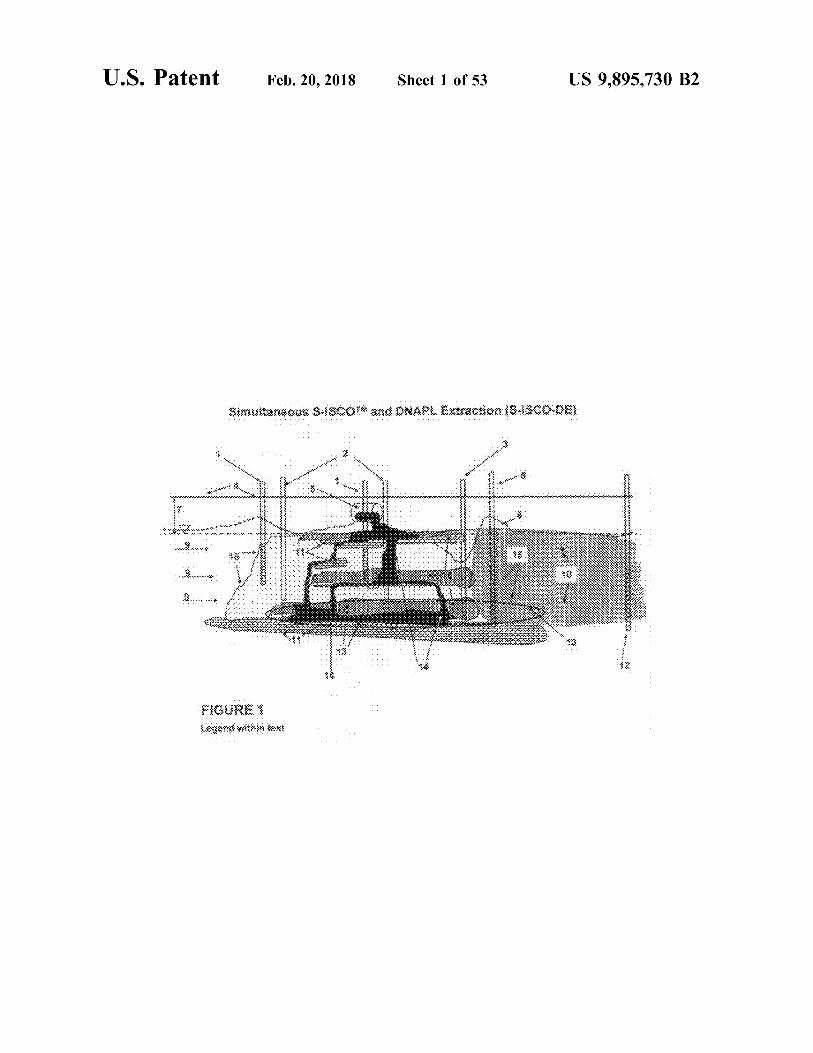
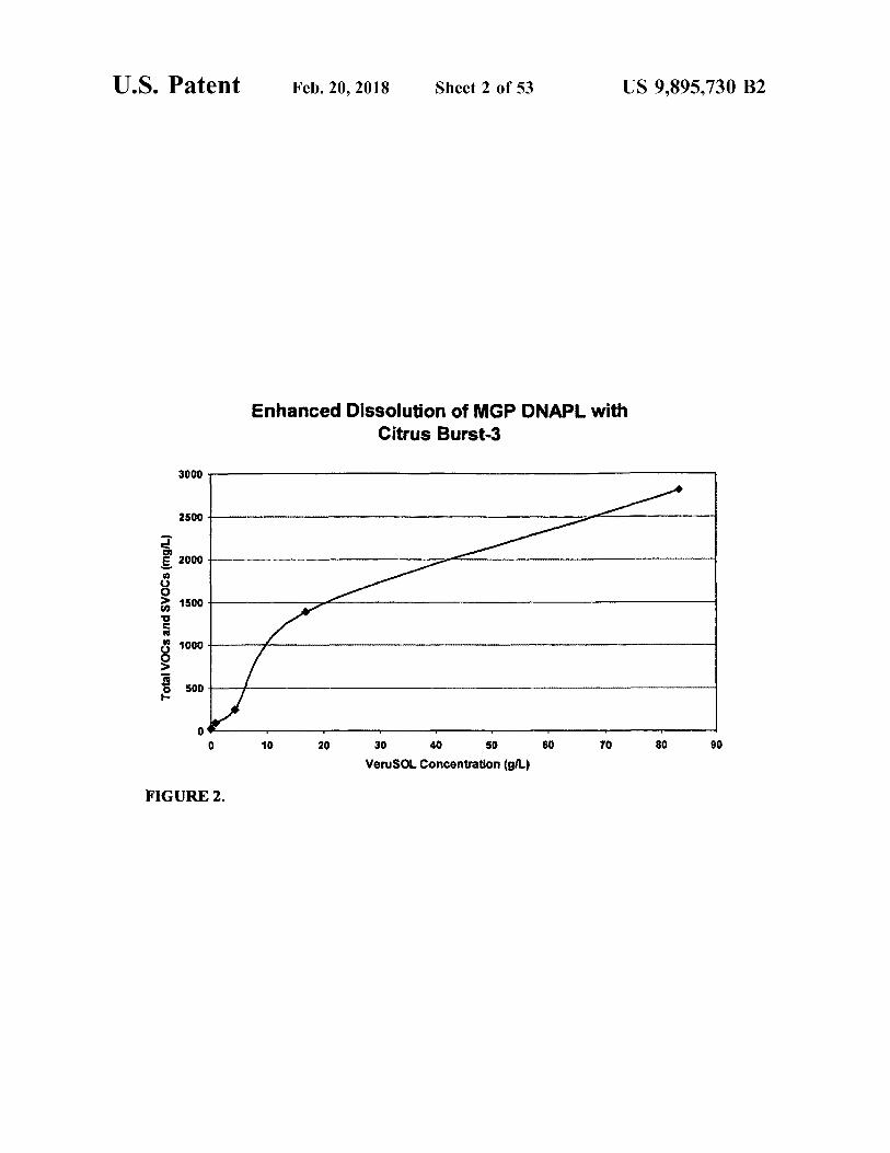
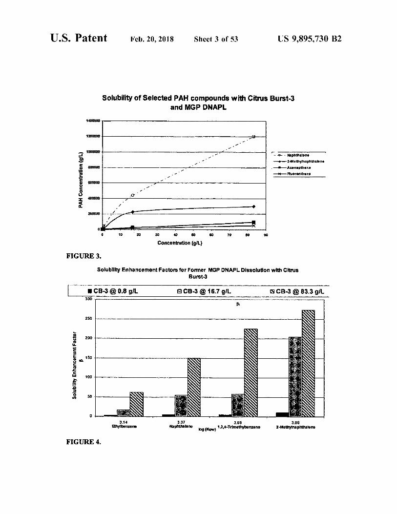
solvents , e . g . , VeruSOL . The sample can be tested under ( NAPL ) , a dense non - aqueous phase liquid ( DNAPL ) , and / various conditions of temperature , pressure , and flow rate . or a light non - aqueous phase liquid ( LNAPL ) . An extraction The rate of mobilization of the contaminant under the well can be provided in the subsurface . An injection fluid 15 various conditions can be determined . An optimum set of can be injected at an injection locus into the subsurface . The conditions for reducing the concentration of the contaminant injection fluid can include hydrogen peroxide and / or another at the site in the subsurface can be selected . oxidant , or another gas phase generating oxidant or pressure In an embodiment , a kit for reducing the concentration of dissolved gas in a liquid . The hydrogen peroxide and / or the a contaminant at a site in a subsurface includes an injection other oxidant or dissolved gas can be allowed to decompose 20 fluid injection system , a contaminant extraction system , and to liberate oxygen or dissolved gas in the subsurface . The an injection fluid . The injection fluid can include hydrogen other oxidant can be , for example , ozone , a persulfate , peroxide , another oxidant , a surfactant , and / or a cosolvent . sodium persulfate , or a percarbonate . The injection fluid can include a liquid , e . g . , water , and a dissolved gas , e . g . , oxygen DESCRIPTION OF THE DRAWINGS and / or carbon dioxide , and the dissolved gas can effervesce 25 as a liberated gas upon a decrease of pressure on the FIG . 1 is a cartoon depicting a process of simultaneous injection fluid in the subsurface . The injection fluid can S - ISCOTM ( surfactant enhanced in situ oxidation ) and include a compressed gas and / or a supercritical fluid under DNAPL extraction ( S - ISCO - DE ) . a pressure greater than atmospheric . An injected gas can FIG . 2 is a graph depicting the concentration of dissolved include , for example , oxygen , carbon dioxide , nitrogen , air , 30 VOCs and SVOCs together as a function of VeruSOLTM an inert gas , helium , argon , another gas , or combinations of ( Citrus Burst 3 ) concentration . The relationship between the these . For example , the injection fluid can include dissolved dose of VeruSOLTM and solubilized Total VOCs and SVOCs carbon dioxide obtained from emissions of a fossil - fuel from an MGP DNAPL is shown in FIG . 2 . This relationship consuming power generation plant . The injection fluid can indicates that as the concentration of VeruSOLTM is include a surfactant and / or a cosolvent , for example , the 35 increased the total VOC and SVOCs concentration dissolved injection fluid can include VeruSOL . The injection fluid can and emulsified as a result of the VeruSOLTM increases as include an alkali carbonate or bicarbonate , such as sodium well . bicarbonate . For example , the sodium bicarbonate can be at FIG . 3 is a graph depicting the solubility of selected PAH a concentration in a range of from about 1 g / L to about 200 compounds as a function of Citrus Burst 3 concentration . As g / L , or from about 8 g / L to about 16 g / L . 40 the concentration of VeruSOLTM is increased , similarly , the
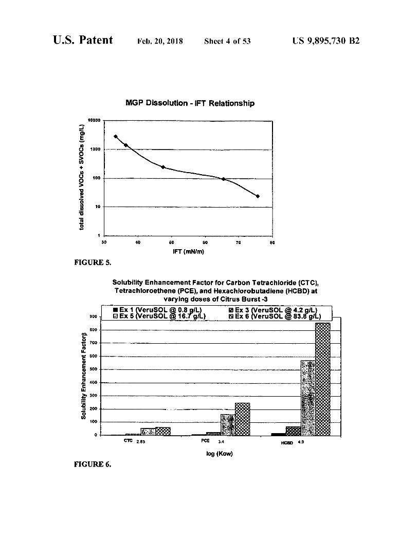
The injection fluid can include an activator , for example , concentrations of naphthalene , 2 - methylnaphthalene , ace a metal activator , a chelated metal activator , a chelated iron napthene , and fluoranthene increases as well . Naphthalene activator , Fe - NTA ( iron - nitrilotriacetic acid ) , Fe ( II ) - EDTA concentrations increase the most ; the naphthalene makes up ( iron II - ethylenediaminetetraacetic acid ) , Fe ( III ) - EDTA approximately 40 percent of the MGP DNAPL . ( iron III - ethylenediaminetetraacetic acid ) , Fe ( II ) - citric acid , 45 FIG . 4 is a bar graph depicting solubility enhancement Fe ( III ) - citric acid , Fe ( II ) - EDDS ( iron Il - ethylenediamin - factors for several different molecules having different octa edisuccinic acid ) , or Fe ( III ) - EDDS ( iron III - ethylenediamin - nol - water partition coefficients at three different concentra edisuccinic acid ) , Fe ( II ) - DTPA ( iron II - diethylenetriamine tions of Citrus Burst 3 . pentaacetic acid ) , or Fe ( III ) - DTPA ( iron III - FIG . 5 is a semilog plot depicting the total concentration diethylenetriaminepentaacetic acid ) . For example , the iron 50 of dissolved VOCs and SVOCs as a function of interfacial of Fe - NTA can be at a concentration in the injection fluid in surface tension . a range of from about 10 mg / L to about 5000 mg / L , or can FIG . 6 is a bar graph depicting solubility enhancement be about 250 mg / L . The injection fluid can include an factors for three different chlorinated molecules having antioxidant . The oxygen and / or the gas produced from different octanol - water partition coefficients at four different reaction of the oxygen , hydrogen peroxide , and / or other 55 concentrations of VeruSOLTM - 3 . oxidant with the contaminant , e . g . , carbon dioxide , can be FIG . 7 is a semilog plot depicting the concentration of allowed to impose pressure to force the contaminant to flow dissolved VOCs as a function of interfacial surface tension . through the subsurface toward the extraction well . The FIG . 8 is a bar graph depicting the concentration of VOC contaminant can be removed from the extraction well to a and SVOC contaminants upon solubilization and following surface above the subsurface . The contaminant can then be 60 oxidation . The percentages of VOC and SVOC contami stored , for example , in a storage tank , or can be disposed of , nants removed are also depicted . for example , in a waste destruction facility . For example , the FIG . 9 is a graph depicting the interfacial surface tension hydrogen peroxide in the injection fluid can be in the form a s a function of time for solutions of Citrus Burst 3 in water of a solution of hydrogen peroxide in water . For example , at three different pH values . the hydrogen peroxide can be at a concentration in a range 65 FIG . 10 is a graph depicting the interfacial surface tension of from about 0 . 5 wt % to about 20 wt % , or from about 2 as a function of time at a pH of 12 for solutions of several wt % to about 8 wt % . different cosolvents and surfactants ( d - limonene , Citrus
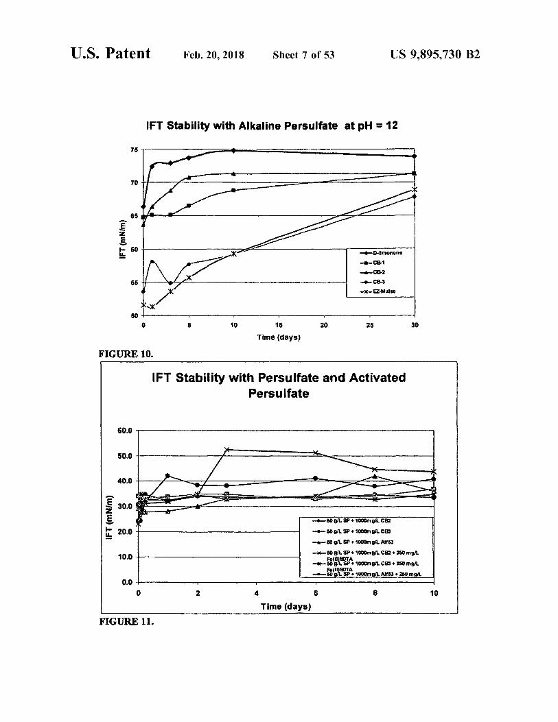
US 9 , 895 , 730 B2 5
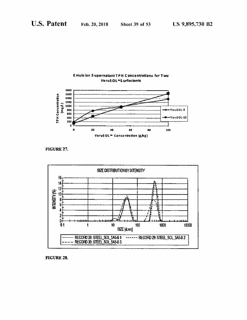
Burst 1 ( CB - 1 ) , Citrus Burst 2 ( CB - 2 ) , Citrus Burst 3 FIG . 27 presents emulsion supernatant TPH concentra ( CB - 3 ) , and EZ - Mulse ) in water . tions as a function of VeruSOLTM concentration for two
FIG . 11 is a graph depicting the interfacial surface tension VeruSOLTM Surfactants . ( IFT ) as a function of time for solutions of three different FIG . 28 presents a graph of intensity as a function of surfactants ( Citrus Burst 2 ( CB2 ) , Citrus Burst 3 ( CB3 ) , and 5 particle size as indicative of colloid particle size distribution Alfoterra 53 ( Alf53 ) ) and sodium persulfate in water , both ( Aqueous Control with Site LNAPL ) . with Fe ( II ) EDTA activator and without activator . FIG . 29 presents a graph of intensity as a function of
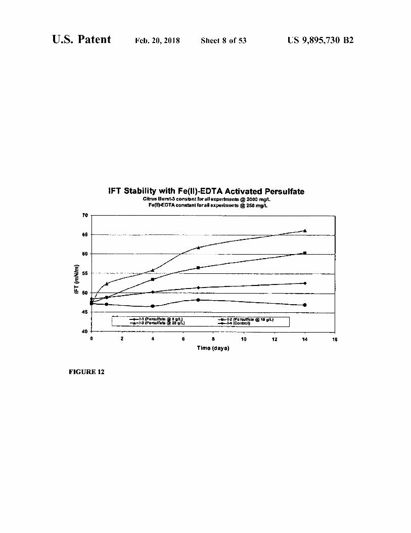
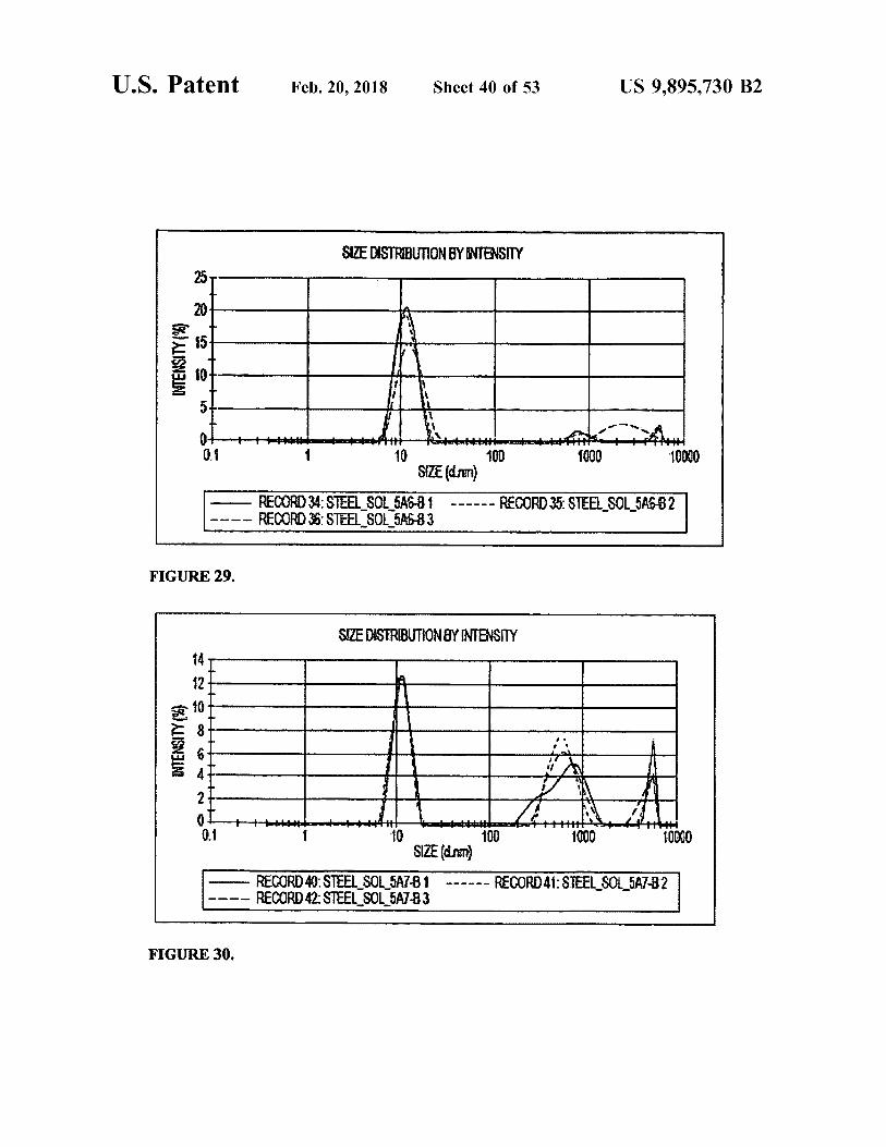
FIG . 12 is a graph depicting the interfacial surface tension particle size as indicative of colloid particle size distribution as a function of time for solutions of Citrus Burst 3 and with VeruSOL - 10TM at 20 g / kg . Fe ( II ) - EDTA in water with various concentrations of sodium FIG . 30 presents a graph of intensity as a function of persulfate . particle size as indicative of colloid particle size distribution
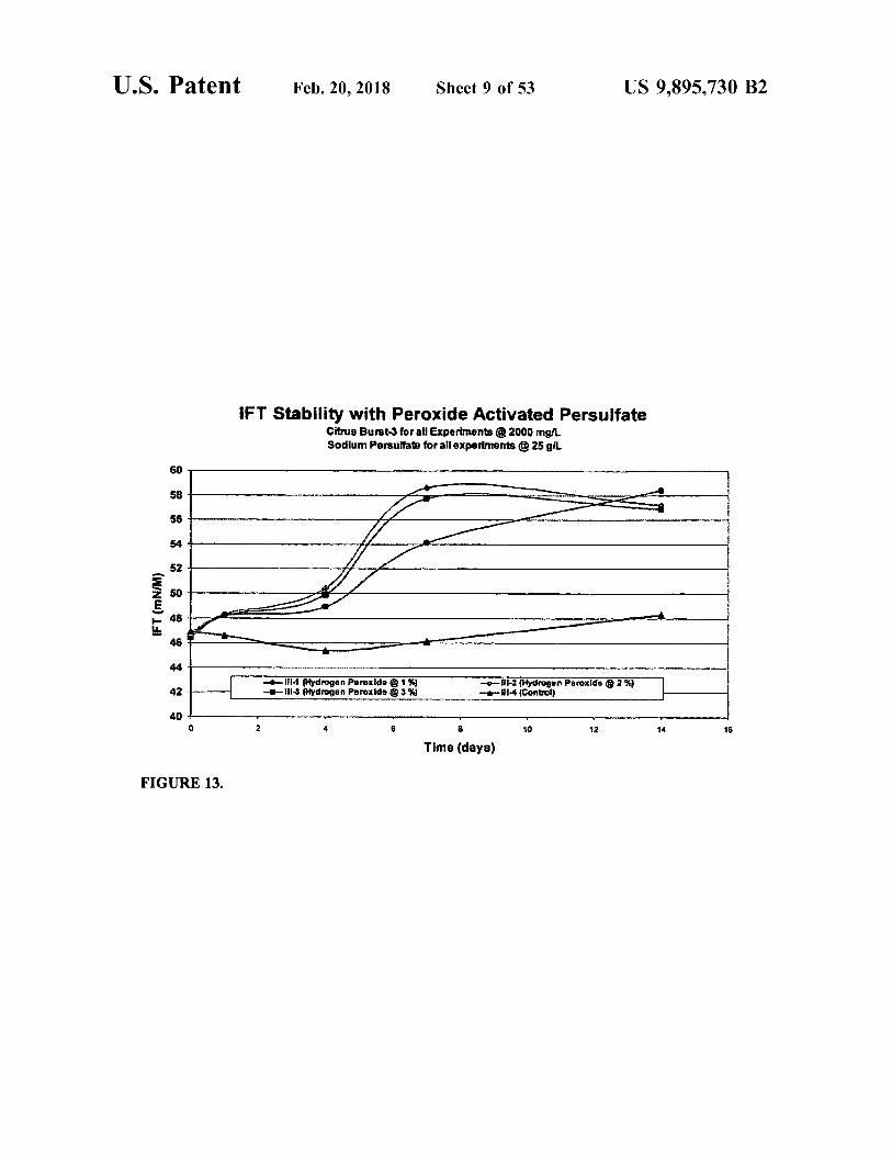
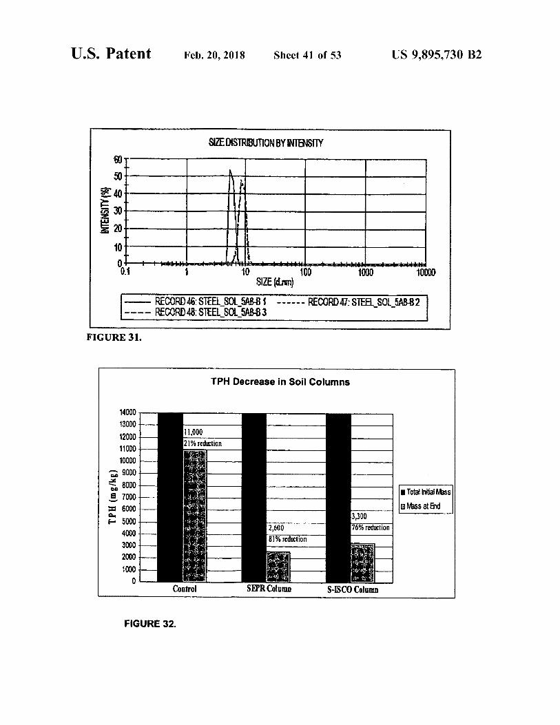
FIG . 13 is a graph depicting the interfacial surface tension with VeruSOL - 10TM at 50 g / kg . OFT ) as a function of time for solutions of Citrus Burst 3 FIG . 31 presents a graph of intensity as a function of and sodium persulfate in water with various concentrations 15 particle size as indicative of colloid particle size distribution of hydrogen peroxide . with VeruSOL - 10TM at 100 g / kg .
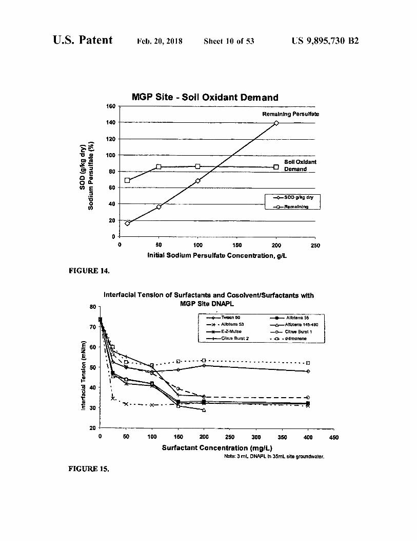
FIG . 14 is a graph depicting the results of soil oxidant FIG . 32 presents results of the treatment of soil columns demand ( SOD ) testing . with the SEPRTM and S - ISCOTM processes in Phase I of a
FIG . 15 is a graph depicting interfacial tension of a study . DNAPL - water mixture as a function of surfactant concen - 20 FIG . 33 presents results of the treatment of soil columns tration for various surfactants . with the SEPRTM process in Phase II of a study .
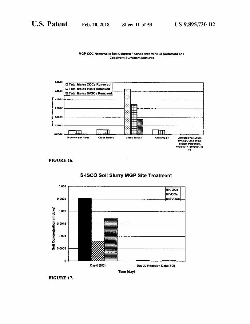
FIG . 16 is a bar graph depicting the results of column tests FIG . 34 presents photographs at different times of a soil performed under various conditions . column treated with the SEPRTM process .
FIG . 17 is a bar graph depicting the results of 30 - day soil FIG . 35 presents a comparison of soil column surfactant slurry testing using Fe ( II ) - EDTA activated persulfate and 25 enhanced product recovery ( SEPRTM ) using hydrogen per Citrus Burst - 1 . oxide and using catalyzed hydrogen peroxide .
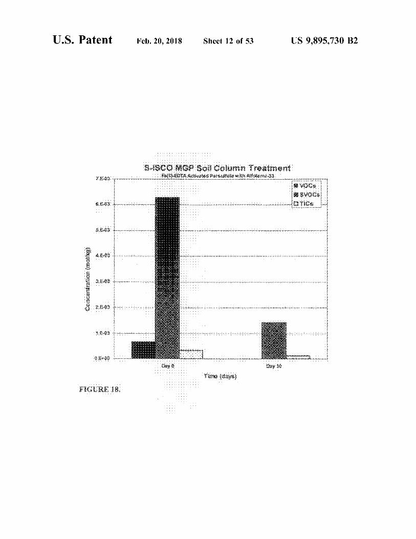
FIG . 18 is a bar graph depicting the results of column FIG . 36 presents a photograph of a soil column to which testing using Fe ( II ) - EDTA activated persulfate with Alfo the SEPRTM process is being applied . terra - 53 . FIG . 37 presents photographs of a soil column treated
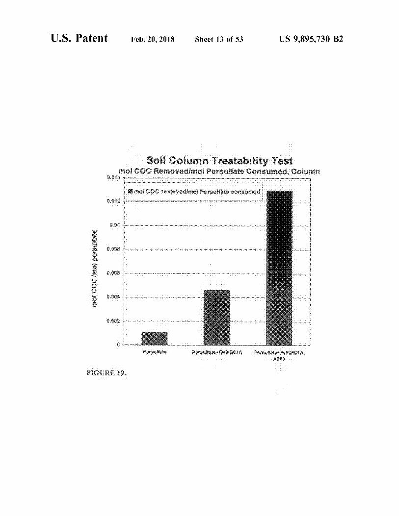
FIG . 19 is a bar graph depicting the results of column 30 with hydrogen peroxide and a soil column treated with testing performed under various conditions . Results from hydrogen peroxide and VeruSOL " . three different column tests are presented . One column had FIG . 38 presents results for treatment of contaminated soil only persulfate injected , a second column had persulfate with the SEPRTM and S - ISCOTM processes with and without
the inclusion of Fe - EDTA in the SEPRTM process . plus Fe ( II ) - EDTA added as an activator , and a third column 24 35 FIG . 39 presents a comparison of the results of treatment had persulfate plus Fe ( II ) - EDTA and Alfoterra - 53 ( a S - ISCO of contaminated soil with VeruSOLTM with Fenton ' s test ) . The molar ratio of moles of total COCs to moles of reagent , with heat , and with the SEPRTM process . persulfate consumed increased significantly in the S - ISCO FIG . 40 presents a cartoon illustrating the SEPRTM ( facili ( column 3 ) in comparison to the ISCO alone ( columns 1 and tated remediation ) process . 2 ) . 40 FIG . 41 presents a cartoon illustrating the SEPRTM ( facili
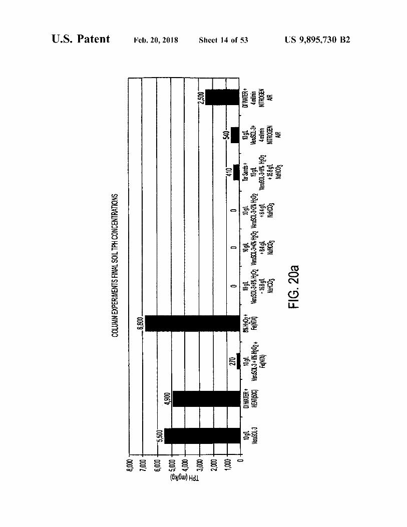
FIG . 20a depicts a bar graph presenting the final soil TPH t ated remediation ) process . ( total petroleum hydrocarbons ) concentrations in several FIG . 42 presents a plan view of a site undergoing reme columns through which various fluids ( e . g . , VeruSOL - 3 , diation . H202 ( hydrogen peroxide ) , and nitrogen gas are flowed . FIG . 43A presents a plan view of the site prior to
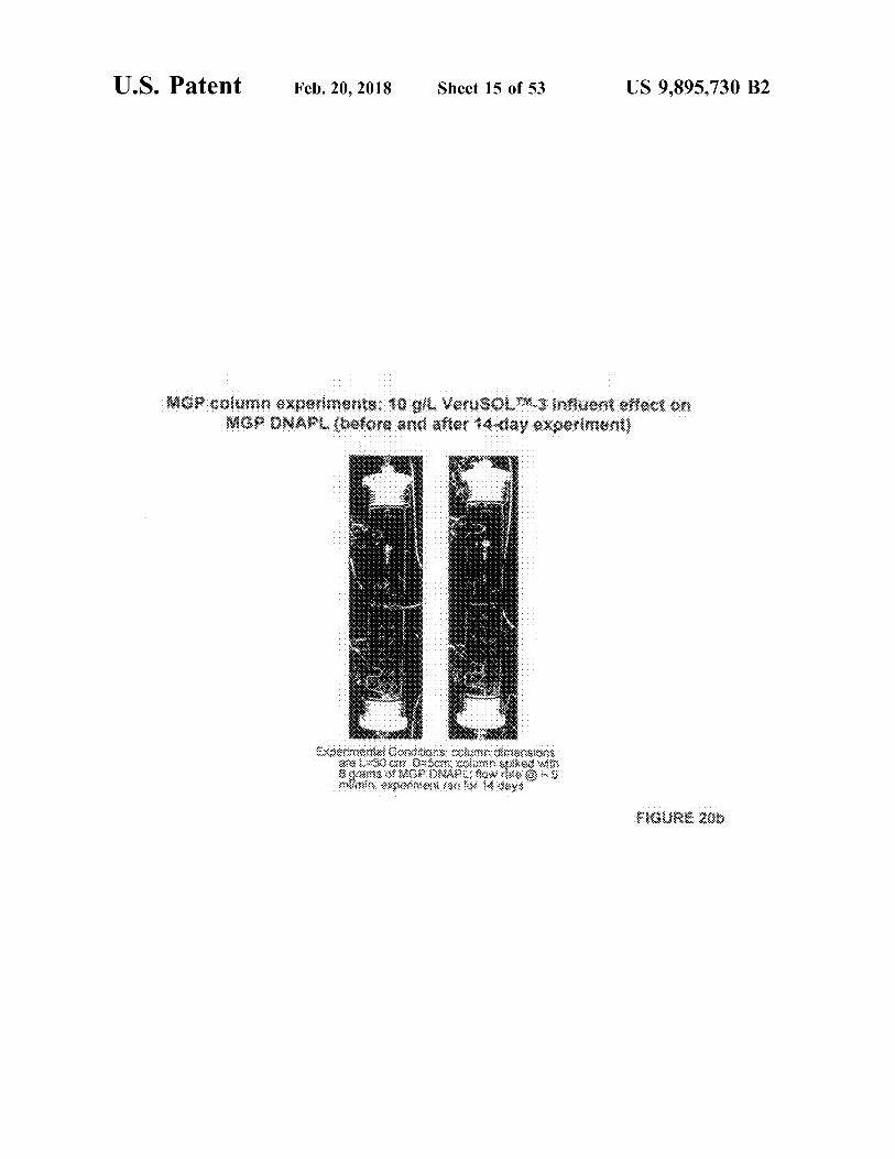
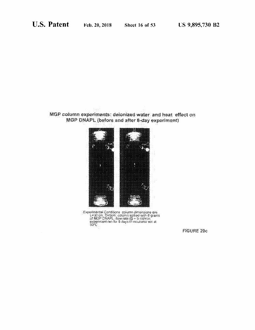
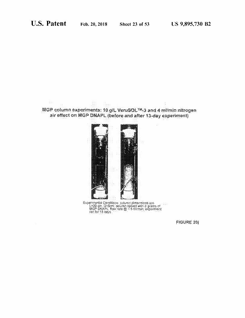
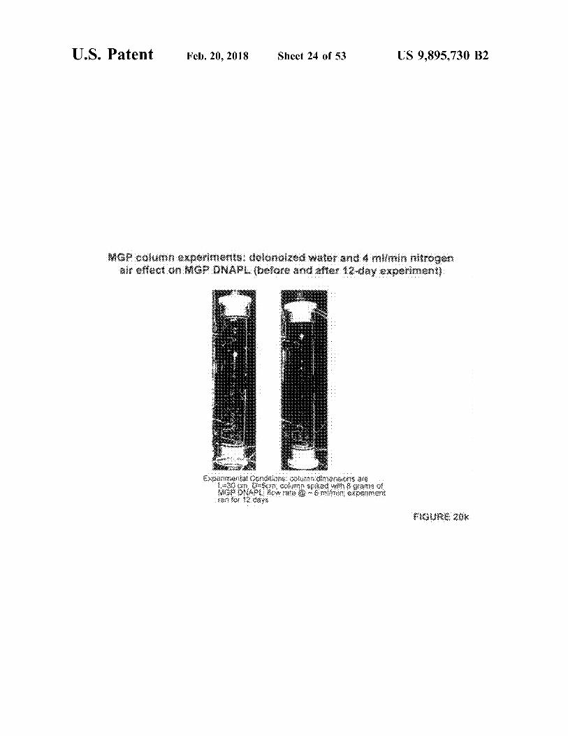
FIGS . 205 to 20k present images of the columns for which 45 treatment . final soil TPH concentrations are shown in FIG . 20a before FIG . 43B presents a plan view of the site after 4 weeks of fluid is flowed through the column and after a period of SEPRTM treatment . flowing fluid through the column . FIG . 44A presents an elevation view of the site .
FIGS . 21a to 21f present images of columns that depict FIG . 44B presents an elevation view of the site after five displacement of NAPL in several columns through which 50 weeks of treatment . hydrogen peroxide ( H , O , ) , sodium bicarbonate ( NaHCO3 ) , and VeruSOL are flowed at various concentrations . DETAILED DESCRIPTION
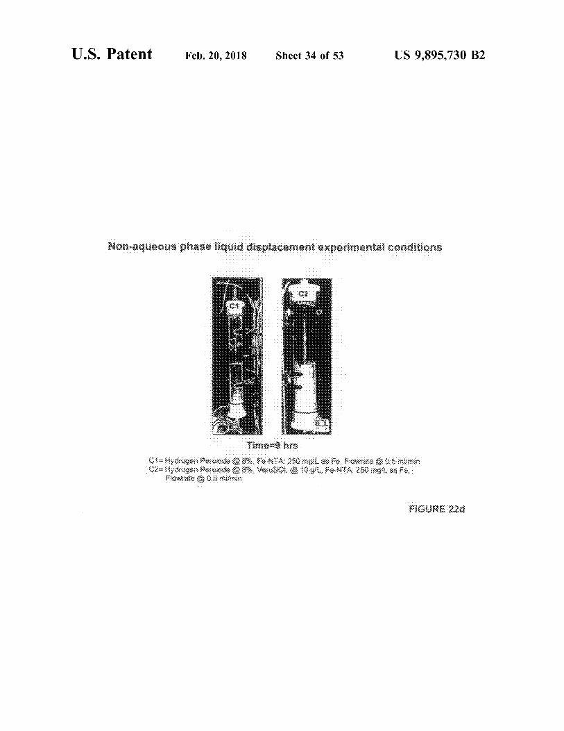
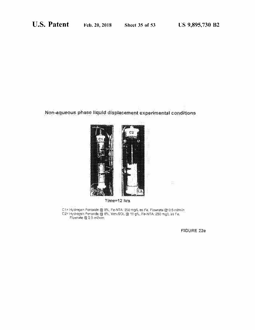
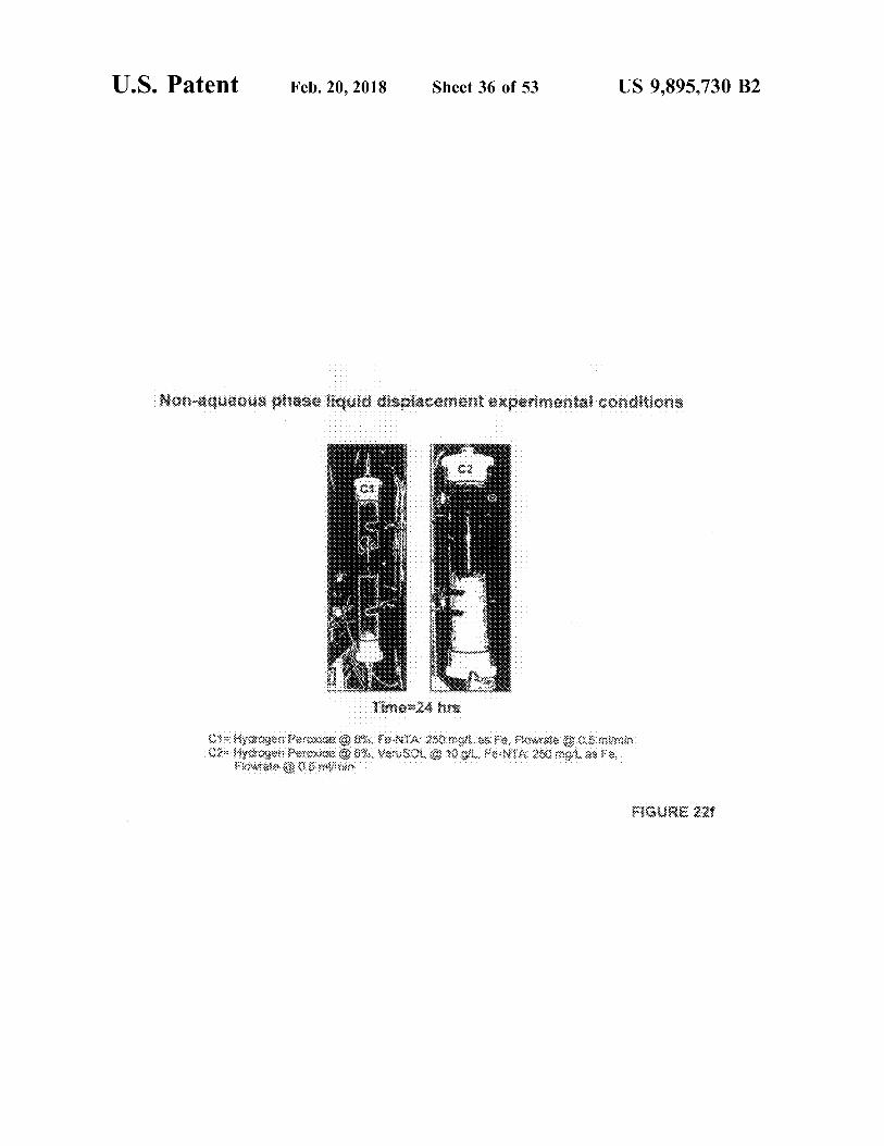
FIGS . 22a to 22f present images of columns that depict displacement of NAPL in columns through which hydrogen Embodiments of the invention are discussed in detail peroxide ( H2O2 ) and Fe - NTA is flowed , with and without 55 below . In describing embodiments , specific terminology is VeruSOL . employed for the sake of clarity . However , the invention is
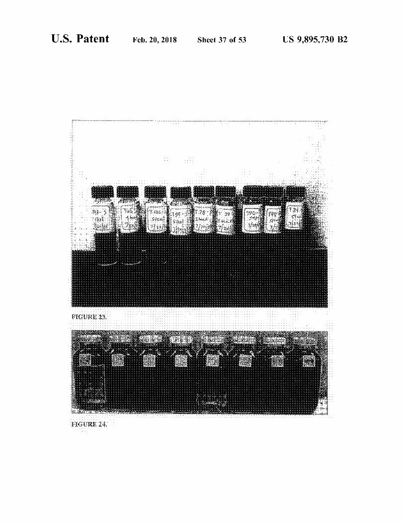
FIG . 23 presents a photograph showing the results of an not intended to be limited to the specific terminology so emulsification screening study . selected . A person skilled in the relevant art will recognize
FIG . 24 presents a photograph showing the results of that other equivalent parts can be employed and other emulsification tests 5 minutes after removal from a shaker 60 methods developed without parting from the spirit and scope table . of the invention . All references cited herein are incorporated
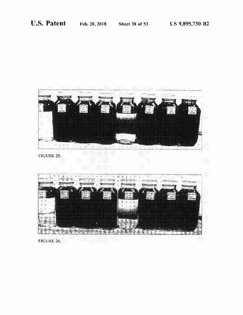
FIG . 25 presents a photograph showing the results of by reference as if each had been individually incorporated . emulsification tests 30 minutes after removal from a shaker It is to be understood that the term “ surfactant ” encom table . passes a single surfactant , a mixture of surfactants , and one
FIG . 26 presents a photograph showing the results of 65 or more surfactants together with one or more cosolvents , emulsification tests 60 minutes after removal from a shaker unless the context in which the term " surfactant ” is used table . indicates otherwise .
US 9 , 895 , 730 B2
" Contaminants " encompasses any substance present in a oxidation ( S - ISCO ) process uses the simultaneous applica location that , by its presence , diminishes the usefulness of tion of low concentrations of surfactants and cosolvents with the location for productive activity or natural resources , or chemical oxidants . The S - ISCO process simultaneously would diminish such usefulness if present in greater solubilizes and oxidizes contaminants , thereby saving time , amounts or if left in the location for a length of time . The 5 energy , and cost . The S - ISCO process inherently rapidly location may be subsurface , on land , in or under the sea or destroys solubilized LNAPL and DNAPL compounds and in the air . As used herein , " contaminated soil ” encompasses minimizes or eliminates the risk of not recovering solubi any soil that contains at least one contaminant according to lized , emulsified , and / or mobilized LNAPL and DNAPL the present invention . “ Contaminant ” thus can encompass contaminants . trace amounts or quantities of such a substance . Examples of 10 A goal in the remediation of sites containing large quan productive activities include , without limitation , recreation ; tities of contaminants , such as LNAPLs and DNAPLs , is to residential use ; industrial use ; habitation by animal , plant , or obtain the benefits of ISCO ( in - situ chemical oxidation ) or other life form , including humans ; and similar such activi - S - ISCO ( surfactant enhanced in - situ chemical oxidation ) in ties . Examples of natural resources are aquifers , wetlands , destroying the contaminants without mobilizing them off sediments , soils , plant life , animal life , and ambient air 15 site , while reducing the quantity and thus the cost of the quality . oxidant injected .
" Introduce ” means to cause to be present in a location . A In a method according to the invention , a user creates a material or item can be introduced into a location even if the localized zone in the subsurface for the extraction of large material or item is released somewhere else and must travel quantities of contaminants , such as LNAPLs or DNAPLS some distance in order to reach the location . For example , if 20 ( extraction zone ) , while having chemical oxidation of the a substance is released at location A , and the substance will contaminants take place in the subsurface beyond the extrac migrate over time to location B , the substance has been tion zone . The extraction zone can include points in the " introduced ” into location B when it is released at location subsurface at which a fluid element will eventually travel A . An item can be introduced in any manner appropriate into an extraction well or other facility for removing the fluid under the circumstances for the substance to be introduced 25 element from the subsurface . The contaminants extracted into the location . may either be in a phase - separated state or in a solubilized An " effective amount ” encompasses an amount of a or emulsified state . By creating a zone of chemical oxidation
material or item that will bring about a decrease in the of the contaminants beyond the localized extraction zone , amount of one or more contaminants in a location . An the risks associated with incomplete extraction of contami " effective amount " also encompasses an amount that brings 30 nants , such as LNAPLs or DNAPLs , inherent in traditional about a stabilization of contaminant amounts or quantities in SEAR ( surfactant - enhanced aquifer remediation ) applica a location where they would otherwise increase or remain tions are minimized or eliminated . That is , in a process constant . It also encompasses an amount that brings about a according the invention , a zone of chemical oxidation ( oxi reduction in the rate of increase of the amount or quantity of dation zone ) surrounding the extraction zone serves to a contaminant in a location , as compared to the rate that 35 destroy any contaminant that migrates out of the extraction would have obtained had the material or item not been zone , and thus prevents the spread of contaminant . Thus , the introduced simultaneous use of the S - ISCO ( surfactant enhanced in - situ
" Activate ” means to modify or alter a substance in such chemical oxidation ) process with extraction of the solubi a way that the substance is able to perform a function it was lized or emulsified LNAPLs and / or DNAPLs minimizes the unable , or less able to perform prior to activation . For 40 risk from migration of NAPLs . example , " activation " encompasses the conversion of a At the same time , by employing liquid extraction using persulfate ion into sulfate free radical , which is then able to single and / or dual phase pumping systems , for example , of oxidize other substances in a location . the types that are commonly known in the art , the amount of
“ Expose ” means to cause to be , or become , available for oxidant chemical required may be less than that when ISCO interaction with other substances in the surroundings . For 45 ( in - situ chemical oxidation ) or S - ISCO ( surfactant enhanced example , once a polymer - coated nanoparticle is “ exposed , " in - situ chemical oxidation ) is used alone . At sites with large it is available to come into contact , chemically react , or quantities of LNAPLs and / or DNAPLs , the cost of liquid otherwise interact with chemicals in the location into which extraction of contaminants , such as LNAPLs and / or DNA it has been introduced . PLs , coupled with ISCO or S - ISCO may be less than using
A " reducing environment ” or “ reducing zone ” is an 50 ISCO or S - ISCO alone . That is , the cost of extraction and environment in which substances are generally more likely subsequent on site treatment or off - site disposal of the to be reduced - e . g . , have their oxidation numbers reduced , contaminants may be offset by the savings represented by or gain electrons — than they are in another location . A the decrease in the quantity of oxidant and / or other chemi reducing environment can also be conducive to the growth cals required . Thus , sites containing large quantities of and metabolism of anaerobic organisms , as a reducing 55 contaminants , such as LNAPLs or DNAPLs , can be cost environment will eliminate species , such as oxygen , that effectively treated . might otherwise interfere with their growth or development . A method for reducing the concentration of a contami
An " oxidizing environment " or " oxidizing zone ” is an nant , such as a Light Non - Aqueous Phase ( LNAPL ) con environment in which substances are generally more likely taminant , at a site in a soil can include the following . A to be oxidized - e . g . , have their oxidation numbers 60 remediation zone including the contaminant , e . g . , the increased , or lose electrons — than they are in another loca - LNAPL contaminant , can be selected . An oxidant that tion . An oxidizing environment can also be conducive to the produces a gas phase can be introduced into a subsurface growth and metabolism of aerobic organisms . containing the soil to establish an oxidation zone . The
The Hoag - Collins in - situ chemical oxidation ( ISCO ) pro concentration distribution of oxidant in the subsurface can cess uses the injection of chemical oxidants into a subsur - 65 be identified to determine the extent of the oxidation zone . face to destroy contaminants such as LNAPLs and DNA - Under , inside , upgradient , or downgradient of the oxidation PLs . The Hoag - Collins surfactant - enhanced in - situ chemical zone , the contaminant , e . g . , the LNAPL contaminant , can be
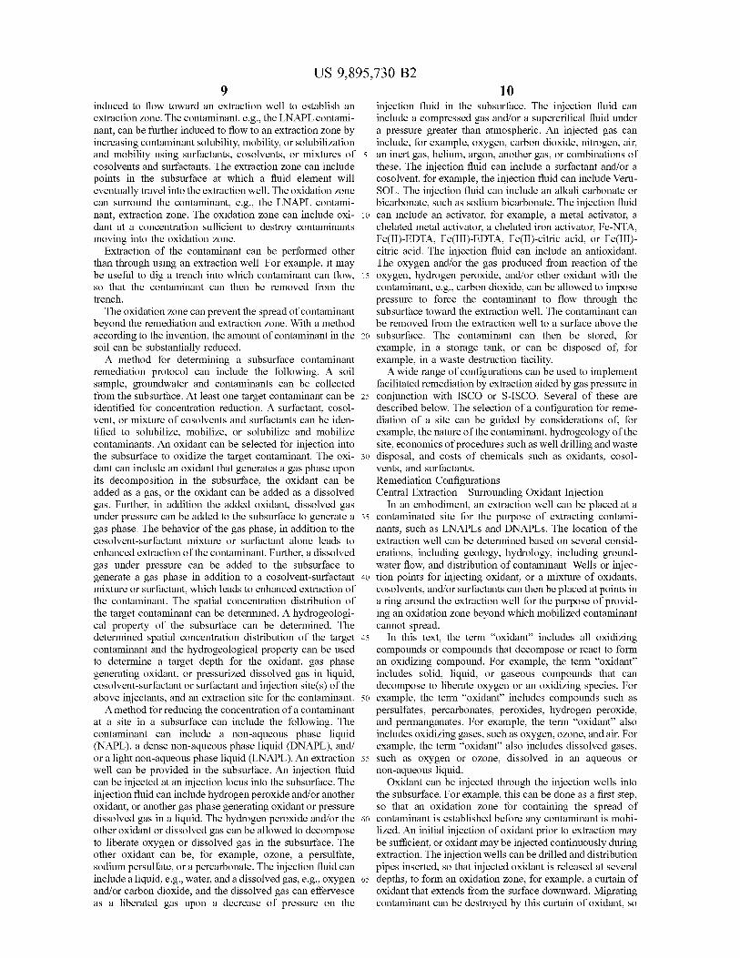
US 9 , 895 , 730 B2 10
induced to flow toward an extraction well to establish an injection fluid in the subsurface . The injection fluid can extraction zone . The contaminant , e . g . , the LNAPL contami - include a compressed gas and / or a supercritical fluid under nant , can be further induced to flow to an extraction zone by a pressure greater than atmospheric . An injected gas can increasing contaminant solubility , mobility , or solubilization include , for example , oxygen , carbon dioxide , nitrogen , air , and mobility using surfactants , cosolvents , or mixtures of 5 an inert gas , helium , argon , another gas , or combinations of cosolvents and surfactants . The extraction zone can include these . The injection fluid can include a surfactant and / or a points in the subsurface at which a fluid element will cosolvent , for example , the injection fluid can include Veru eventually travel into the extraction well . The oxidation zone SOL . The injection fluid can include an alkali carbonate or can surround the contaminant , e . g . , the LNAPL contami - bicarbonate , such as sodium bicarbonate . The injection fluid nant , extraction zone . The oxidation zone can include oxi - 10 can include an activator , for example , a metal activator , a dant at a concentration sufficient to destroy contaminants chelated metal activator , a chelated iron activator , Fe - NTA , moving into the oxidation zone . Fe ( II ) - EDTA , Fe ( III ) - EDTA , Fe ( II ) - citric acid , or Fe ( III )
Extraction of the contaminant can be performed other citric acid . The injection fluid can include an antioxidant . than through using an extraction well . For example , it may The oxygen and / or the gas produced from reaction of the be useful to dig a trench into which contaminant can flow , 15 oxygen , hydrogen peroxide , and / or other oxidant with the so that the contaminant can then be removed from the contaminant , e . g . , carbon dioxide , can be allowed to impose trench . pressure to force the contaminant to flow through the
The oxidation zone can prevent the spread of contaminant subsurface toward the extraction well . The contaminant can beyond the remediation and extraction zone . With a method be removed from the extraction well to a surface above the according to the invention , the amount of contaminant in the 20 subsurface . The contaminant can then be stored , for soil can be substantially reduced . example , in a storage tank , or can be disposed of , for
A method for determining a subsurface contaminant example , in a waste destruction facility . remediation protocol can include the following . A soil re A wide range of configurations can be used to implement sample , groundwater and contaminants can be collected facilitated remediation by extraction aided by gas pressure in from the subsurface . At least one target contaminant can be 25 conjunction with ISCO or S - ISCO . Several of these are identified for concentration reduction . A surfactant , cosol described below . The selection of a configuration for reme vent , or mixture of cosolvents and surfactants can be iden diation of a site can be guided by considerations of , for tified to solubilize , mobilize , or solubilize and mobilize example , the nature of the contaminant , hydrogeology of the contaminants . An oxidant can be selected for injection into site , economics of procedures such as well drilling and waste the subsurface to oxidize the target contaminant . The oxi - 30 disposal , and costs of chemicals such as oxidants , cosol dant can include an oxidant that generates a gas phase upon vents , and surfactants . its decomposition in the subsurface , the oxidant can be Remediation Configurations added as a gas , or the oxidant can be added as a dissolved Central Extraction Surrounding Oxidant Injection gas . Further , in addition the added oxidant , dissolved gas In an embodiment , an extraction well can be placed at a under pressure can be added to the subsurface to generate a 35 contaminated site for the purpose of extracting contami gas phase . The behavior of the gas phase , in addition to the nants , such as LNAPLs and DNAPLs . The location of the cosolvent - surfactant mixture or surfactant alone leads to extraction well can be determined based on several consid enhanced extraction of the contaminant . Further , a dissolved erations , including geology , hydrology , including ground gas under pressure can be added to the subsurface to water flow , and distribution of contaminant . Wells or injec generate a gas phase in addition to a cosolvent - surfactant 40 tion points for injecting oxidant , or a mixture of oxidants , mixture or surfactant , which leads to enhanced extraction of cosolvents , and / or surfactants can then be placed at points in the contaminant . The spatial concentration distribution of a ring around the extraction well for the purpose of provid the target contaminant can be determined . A hydrogeologi - ing an oxidation zone beyond which mobilized contaminant cal property of the subsurface can be determined . The cannot spread . determined spatial concentration distribution of the target 45 In this text , the term “ oxidant ” includes all oxidizing contaminant and the hydrogeological property can be used compounds or compounds that decompose or react to form to determine a target depth for the oxidant , gas phase an oxidizing compound . For example , the term " oxidant " generating oxidant , or pressurized dissolved gas in liquid , includes solid , liquid , or gaseous compounds that can cosolvent - surfactant or surfactant and injection site ( s ) of the decompose to liberate oxygen or an oxidizing species . For above injectants , and an extraction site for the contaminant . 50 example , the term " oxidant ” includes compounds such as
A method for reducing the concentration of a contaminant persulfates , percarbonates , peroxides , hydrogen peroxide , at a site in a subsurface can include the following . The and permanganates . For example , the term " oxidant ” also contaminant can include a non - aqueous phase liquid includes oxidizing gases , such as oxygen , ozone , and air . For ( NAPL ) , a dense non - aqueous phase liquid ( DNAPL ) , and example , the term “ oxidant " also includes dissolved gases , or a light non - aqueous phase liquid ( LNAPL ) . An extraction 55 such as oxygen or ozone , dissolved in an aqueous or well can be provided in the subsurface . An injection fluid non - aqueous liquid . can be injected at an injection locus into the subsurface . The Oxidant can be injected through the injection wells into injection fluid can include hydrogen peroxide and / or another the subsurface . For example , this can be done as a first step , oxidant , or another gas phase generating oxidant or pressure so that an oxidation zone for containing the spread of dissolved gas in a liquid . The hydrogen peroxide and / or the 60 contaminant is established before any contaminant is mobi other oxidant or dissolved gas can be allowed to decompose lized . An initial injection of oxidant prior to extraction may to liberate oxygen or dissolved gas in the subsurface . The be sufficient , or oxidant may be injected continuously during other oxidant can be , for example , ozone , a persulfate , extraction . The injection wells can be drilled and distribution sodium persulfate , or a percarbonate . The injection fluid can pipes inserted , so that injected oxidant is released at several include a liquid , e . g . , water , and a dissolved gas , e . g . , oxygen 65 depths , to form an oxidation zone , for example , a curtain of and / or carbon dioxide , and the dissolved gas can effervesce oxidant that extends from the surface downward . Migrating as a liberated gas upon a decrease of pressure on the contaminant can be destroyed by this curtain of oxidant , so
sa
US 9 , 895 , 730 B2 12
that it cannot leave the site . For example , the injection wells Central Extraction Downgradient Oxidant Injection can be designed , so that the curtain of oxidant extends down If a site has a pronounced groundwater flow , contaminant to strata that are impermeable or have low permeability with may essentially only migrate in the direction of groundwater respect to a targeted contaminant , for example , a DNAPL . flow , that is , in the downgradient direction . In this case , it Alternatively , the injection wells can be designed , so that the 5 may be sufficient to place oxidant injection wells downgra oxidant spreads in a layer underneath the contaminant site dient of the extraction well and any separate surfactant or and any downward migrating contaminant will be destroyed cosolvent injection wells . That is , instead of forming an once it reaches this underlying layer of oxidant . The oxidant oxidation zone that completely rings the extraction well and zone can be created by injection wells screened at specific any cosolvent injection wells , it may be sufficient to estab depth intervals and / or multiple depth intervals , and strate - 10 lish an oxidation zone located downstream of the extraction gically placed to maximize the effectiveness of the oxidation well and any cosolvent injection wells . In other words , the zone in treating any contaminant not extracted in the extrac oxidation zone can be located such that it intercepts the tion zone . The oxidant zone and the extraction zone can be streamlines passing through points in the subsurface located created using injection and extraction trenches , emplaced in the extraction zone , downgradient of the extraction zone . fractures in the subsurface , and / or injection into fractures in 15 Circumferential Extraction bedrock . The oxidation zone is considered to enclose the For certain contaminated sites , more than one extraction extraction zone in the subsurface either if it forms a con - well may be required . For example , a ring of extraction wells tinuous shell in the subsurface which isolates the extraction located around the region of greatest contamination may zone from other points in the subsurface , or if the oxidation serve to intercept migrating contaminant , and help prevent it zone together with a layer of subsurface that is impermeable 20 from spreading further . However , such a ring of extraction to contaminant that can reach that layer isolates the extrac wells alone may not suffice to prevent contaminant from tion zone from other points in the subsurface . migrating and contaminating a greater area .
In another approach , oxidant can be initially injected However , an oxidation zone established by a ring of through a central well , to establish an oxidation zone extend oxidant injection wells surrounding the ring of extraction ing outward from the central well . Once this oxidation zone 25 wells can serve to destroy migrating contaminant and to is established , contaminant can be extracted through the prevent the contamination from spreading beyond the oxi same central well . The extraction can be also done in a dation zone . trench or a barrier trench and recovery system . Alternatively , an oxidant injection well or several oxidant
Contaminants , along with other subsurface fluids , such as injection wells can be centrally located and surrounded by a groundwater , can be removed by , for example , applying a 30 ring of extraction wells . The oxidant injection well or wells vacuum to the extraction well or activating a pump at the can then introduce oxidant into the subsurface , which can bottom of or at some other location in the extraction well . If spread to form an oxidation zone extending beyond the ring contaminant is mobilized and , instead of entering the extrac - of extraction wells . Then , when contaminant is extracted tion well , migrates to the periphery of the site , the contami through the extraction wells , the oxidation zone extending nant can be oxidized by the oxidation zone established by 35 beyond the extraction wells can serve to prevent contami the injection of oxidant , either through surrounding injection nant from migrating beyond the oxidation zone , and thus wells or previously through a central well . prevent the contaminant from spreading .
Extraction of contaminant can be promoted by , for To promote mobilization of contaminant within the oxi example , introducing surfactants or cosolvents into the dation zone , so that the contaminant can be more readily subsurface . Such surfactants or cosolvents can promote 40 extracted and / or oxidized , surfactant and / or cosolvent can be solubilization , emulsification , or mobilization of non - aque - injected through one or more wells within the oxidation ous phase liquids ( NAPLs ) such LNAPLs and DNAPLs that perimeter . For example , surfactant and / or cosolvent can be are adsorbed onto solid surfaces or present in a separate injected into the subsurface through a central well located phase , so that such NAPL contaminants become more within the ring of extraction wells . mobile and more readily migrate to the extraction well . 45 The design of the remediation system can be modified if Surfactants and oxidants can be , for example , injected pronounced groundwater flow exists at the site , so that through the extraction well prior to extraction , or can be contaminant moves in essentially one direction , i . e . , down injected in separate wells , either prior to extraction or gradient with the groundwater . For example , a line of wells continuously and simultaneously with extraction . For for injecting surfactant and / or cosolvent can be placed example , wells for injecting surfactant and / or cosolvents can 50 upgradient of the contaminated region , so as to promote the be placed in a ring around the extraction well and within the mobilization and downgradient migration of contaminants , ring formed by the oxidant injection wells . If , instead of such as LNAPLs and DNAPLs . For example , this line of migrating to the extraction well , NAPL contaminants wells for injecting surfactant and / or cosolvent can be placed migrate to the periphery of the site , they can be oxidized and to lie perpendicular to the streamlines of flowing ground destroyed at the oxidation zone . 55 water . A second line of extraction wells can be placed
In addition to promoting the extraction of contaminants , downgradient of the contaminated region , so that a fraction , such as LNAPLs and / or DNAPLs , by injecting surfactants perhaps the greatest part , of the mobilized contaminant is and / or cosolvents to solubilize and / or emulsify the contami - removed . For example , this line of extraction wells can be nants , a variety of techniques , such as those using foaming , placed to lie perpendicular to the streamlines of flowing floatation , hydrological , thermal , hydrothermal , and / or 60 groundwater . A third line of oxidant injection wells can be hydrochemical means exist to extract contaminants such as placed downgradient of the contaminated region and of the LNAPLs and / or DNAPLs . In some cases , it may be prefer - line of extraction wells . For example , this line of oxidant able to modify the density of solubilized and / or emulsified injection wells can be placed to lie perpendicular to the contaminants , such as LNAPLs and / or DNAPLs , for streamlines of flowing groundwater . An oxidation zone example , by the injection of chemicals used for ISCO or 65 established by the line of oxidant injection wells can destroy S - ISCO or other chemicals , such as salts , to facilitate contaminant that is not removed by the extraction wells extraction of the contaminants from the subsurface . before the contaminant migrates any further downgradient .
13 US 9 , 895 , 730 B2
14 Establishment of Zones of Dominant Solubilization and extending downgradient from the oxidant injection well 6 . Zones of Dominant Oxidation In either case , the contaminant is destroyed before it
FIG . 1 describes simultaneous S - ISCOTM and DNAPL migrates too far downgradient from the region of greatest extraction ( S - ISCO - DE ) . The following are present . A contamination , so that the contamination does not spread . S - ISCO injection well 1 can be used to inject oxidant , 5 In applying S - ISCO , surfactant and / or cosolvent can be surfactant and / or cosolvent , and / or other materials into the injected along with oxidant through the oxidant injection subsurface . For example , the injected material can induces a well 6 . The injection of surfactant and / or cosolvent may be rate of solubilization about equal to the rate of oxidation of useful to maintain migrating contaminant in a solubilized or contaminant . An enhanced S - ISCO injection well 2 , can emulsified state and thereby promote the reaction of con induce a rate of solubilization greater than the rate of 10 taminant with oxidant . For example , the surfactant and / or oxidation . An extraction well 3 can be used to extract cosolvent injected upgradient in wells 2 may be degraded by contaminant and other matter , which can be pumped to a the oxidant present , so that a supplemental injection of facility for treatment or recycling . The surface grade level 4 surfactant and / or cosolvent at oxidant injection well 6 is is shown . A source of DNAPL contaminant 5 can be , for advantageous . However , the ratio of the flow rate of oxidant example , a buried drum . An oxidant injection well 6 can be 15 to the flow rate of surfactant and / or cosolvent injected at used to induce a rate of oxidation greater than the rate of oxidant injection well 6 can be selected , so that the rate of solubilization and can serve to establish an oxidation perim - oxidation dominates over the rate of mobilization in the eter . An unsaturated zone 7 can be present in the subsurface . chemical oxidation zone downgradient of the oxidant injec It may be necessary to consider the groundwater elevation 8 tion well 6 . In this way , the contaminant is destroyed in the and the groundwater flow 9 in designing and conducting 20 chemical oxidation zone and the injected surfactant and / or treatment ( remediation ) . A chemical oxidation zone 10 ( di - cosolvent is destroyed in the chemical oxidation zone , so agonal lines ) is shown . A continuous low permeability lens that contaminant and excess surfactant and / or cosolvent 11 horizontal brick pattern may be present in the subsurface . does not spread to pollute the environment . A monitoring well 12 can be used , for example , to determine In other words , by using the approach of extraction in the concentration of contaminant , oxidant , surfactant , and / or 25 conjunction with ISCO or S - ISCO , a local rate of solubili cosolvent before and during treatment . A zone of surfactant / zation and / or emulsification of a contaminant , such as cosolvent flushing 13 ( oval shown by a black line ) can be LNAPL and / or DNAPL , can greatly exceed the local rate of established . A DNAPL contaminated zone where DNAPL chemical oxidation , provided that the excess LNAPL and concentration is too low to economically flush 14 ( solid DNAPL solubilized and / or emulsified is captured and black area ) or where the risk of undesired mobilization 30 removed from the subsurface by extraction and that cross caused by flushing alone that results in the spread of and / or downgradient zones of chemical oxidation , e . g . , contaminant 15 ( dotted area ) would be too great may be oxidation zones , have been created in the subsurface to present . A zone 16 ( vertical brick pattern ) in which the ensure complete oxidation of any solubilized chemicals not DNAPL contaminant is hydraulically captured by the extracted . extraction well 3 , i . e . , an extraction zone , and / or is oxidized 35 The overall rate of oxidation can be controlled by con can be established . trolling the concentration of oxidant in the subsurface . For
FIG . 1 illustrates an example of a contaminated site with example , if a greater mass of oxidant is introduced into a a pronounced groundwater flow . Wells for injecting oxidant given volume of subsurface , then the concentration of oxi and surfactant and / or cosolvent can be placed within the dant in that volume will be greater and the rate of oxidation region of greatest contamination and upgradient of the 40 will be faster . On the other hand , if a lesser mass of oxidant region of greatest contamination , e . g . , enhanced S - ISCO is introduced into a given volume of subsurface , then the injection wells 2 . The ratio of the injection flow rate of concentration of oxidant in that volume will be lesser and the oxidant to that of surfactant and / or cosolvent can be rate of oxidation will be slower . The overall oxidation rate adjusted , so that solubilization dominates , that is , more can be controlled by selection of the specific oxidant used , contaminant is mobilized than is oxidized . This differs from 45 as well as the concentration of the oxidant . a standard S - ISCO approach , in which the ratio of the Selection of a Remediation Configuration injection flow rate of oxidant to surfactant and / or cosolvent Consideration of factors such as the nature of the con is set so that essentially all mobilized contaminant is oxi - taminant , distribution of the contaminant , geology , and dized . In the remediation design illustrated by FIG . 1 , it can hydrogeology , e . g . , groundwater flow , of a site to be reme be appropriate for more contaminant to be mobilized upgra - 50 diated can indicate the most appropriate configuration of an dient of and within the region of greatest contamination , oxidant injection well ( s ) , surfactant injection well ( s ) , and / or because the mobilized contaminant is later removed further extraction well ( s ) . Selection of an appropriate configuration downgradient , as now described . An extraction well 3 will prevent the spread of contaminant beyond a user located downgradient of the region of greatest contamina - selected remediation zone in the subsurface . For example , if tion can serve to remove some , possibly the majority , of the 55 the oxidant zone or a combination of the oxidant zone and mobilized contaminant . a geological feature , such as a stratum impermeable to the An oxidation zone can be established by injecting oxidant identified contaminant that completely separates the reme
through an oxidant injection well 6 located downgradient of diation zone from the rest of the subsurface , i . e . , the oxida the extraction well 3 . In applying ISCO , only oxidant ( with tion zone encloses the extraction zone in the subsurface , the any carrier fluid , such as water ) is injected through the 60 oxidation zone can prevent the spread of the targeted con oxidant injection well 6 . The injected oxidant serves to taminant beyond the remediation zone . Alternatively , if the destroy contaminant that migrates past the extraction well . groundwater flow is such that essentially all the contaminant Depending on the identity and concentration of the contami - flows in one direction away from the contaminated site , then nant and the oxidant , the contaminant can be destroyed an oxidation zone can be established that intercepts the within a short distance of the oxidant injection well 6 . Or the 65 flowing groundwater and contaminant downstream of the oxidant can travel downgradient with the contaminant , contaminated site , and thereby prevent the spread of con destroying the contaminant in a chemical oxidation zone 10 taminant beyond a remediation zone established by the
??
US 9 , 895 , 730 B2 15 16
groundwater flow and the oxidation zone . Alternatively , the or concentration of inorganic compounds or ions , such as geology and hydrogeology surrounding a contaminated site sodium , potassium , ammonium , chloride , persulfate , sulfate , may be such that contaminant does not migrate in one permanganate , manganese , radical scavenging species , inor direction , but is still limited to migrate in certain directions ganic carbon species , nitrate , nitrite , phosphorous species , without migrating in other directions . Such a more complex 5 activators , antioxidants , radical scavengers , stabilizers , pattern of contaminant migration can be considered by a metal species , and iron species . Organic chemical compound user in selecting a remediation zone and a configuration of characteristics to be monitored can include , for example , extraction well ( s ) , oxidant injection well ( s ) , and surfactant surfactants , cosolvents , priority pollutants , organic carbon injection well ( s ) , so that contaminant does not migrate species , total petroleum hydrocarbon species , LNAPL and beyond the remediation zone , while realizing savings by not 10 DNAPL chemical constituents , chelates , activators , antioxi placing extraction , oxidant injection , and / or surfactant injec dants , radical scavengers , and stabilizers . Subsurface moni tion well ( s ) in areas through which the contaminant will not toring can be used to confirm that a zone of chemical migrate . For example , oxidant zone ( s ) can be established to oxidation , e . g . , an oxidation zone , exists in the subsurface in intersect all streamlines on which contaminant is present that the intended or actual remediation zone , such as in localized originated from the contaminated site . 15 area ( s ) for extraction , as well as cross - and down - gradient of
Auser ' s selection of a remediation zone and configuration the localized extraction zone . For example , after such a zone for remediation will be governed by a number of factors , that of chemical oxidation is confirmed , extraction of contami may include distribution of contaminant , nature of the nant and / or injection of concentrations of surfactants and / or contaminant ( e . g . , solubility in water ) , geology , hydrogeol - cosolvents for solubilization and / or emulsification of the ogy , cost of well drilling , cost of chemicals such as oxidants 20 LNAPL or DNAPL can commence . The existence of a and / or surfactants , intended future use of the contaminated confirmed zone ( s ) of chemical oxidation can ensure that any site once remediated , property rights , state and federal solubilized or emulsified LNAPLs and / or DNAPLs not environmental regulations , and potential liability if the con captured by extraction are treated , i . e . , destroyed , in the taminant spreads beyond property controlled by the indi - chemical oxidation zone , e . g . , at the oxidation zone . vidual or organization responsible for the cleanup ( e . g . , 25 When surfactants and / or cosolvents are injected into the possibly greater if a residential area surrounds the contami - subsurface to promote the extraction and / or oxidation of nated site than if an industrial area surrounds the contami - contaminants , such as LNAPLs and / or DNAPLs , the sur nated site ) . In certain cases , a user may find it necessary to factants and / or cosolvents can be injected in a range of low reduce any further spread of contaminant to a minimum , and concentrations , so that above ground recycling of surfactants thus select a small remediation zone around the contami - 30 and / or cosolvents extracted is not required . For example , nated site and completely surround the site with an oxidant such a low range of surfactant and / or cosolvent concentra zone to prevent the spread of contaminant beyond the tion can range from about 0 . 05 weight percent ( wt % ) to remediation zone . In other cases , a user may find it accept - about 1 wt % . However , at certain contaminated sites , for able to allow some further spread of the contaminant if doing example , certain sites with high concentrations of LNAPLs so will reduce the expense of remediation . For example , if 35 and / or DNAPLs , pooled DNAPLs , or LNAPLs floating on the groundwater flow is such that streamlines passing the water table , increasing the concentration of injected through the contaminated site converge at a point downgra - surfactants and / or cosolvents up to about 5 % may be used to dient of the contaminated site , it may be cost effective and more cost - effectively extract the contaminant than if the environmentally acceptable to provide an oxidant zone at the surfactants and / or cosolvents were injected at lower con point where the streamlines converge . 40 centration . For example , any extracted surfactants and / or
In all remediation approaches using extraction wells in cosolvents may be treated or recycled above ground . conjunction with ISCO or S - ISCO , monitoring wells can be ISCO or S - ISCO can be combined with a traditional used . For example , monitoring wells can be used to identify SEAR method using a water in oil system , for example , a the extent of an oxidation zone created by injection of Winsor type 2 system , to remediate a contaminated site . For oxidant into the subsurface . For example , as illustrated in 45 example , where NAPL mobilization and extraction is FIG . 1 , a monitoring well 12 can be located within or desired , with or without above ground treatment and recy downgradient of a chemical oxidation zone extending down cling of injected surfactants and / or cosolvents , ISCO or gradient from an oxidant injection well 6 . The monitoring S - ISCO can be used cross - and / or down - gradient from the well 12 can be used to verify whether the concentration of SEAR treatment zone to ensure that mobilized NAPLs that contaminant has been reduced to an acceptable level and 50 are not extracted and / or surfactant and / or cosolvent mixtures whether the concentrations of injected chemicals such as are destroyed by chemical oxidants . This enables a safer oxidant , surfactant , and / or cosolvent are at or below accept application of SEAR , with a reduction of potential environ able levels . Monitoring wells can also be used , for example , mental and health risks associated with using SEAR alone . to determine the flow of groundwater , for example , by Such an application of ISCO or S - ISCO in conjunction with injecting tracer chemicals , and to determine progress in 55 SEAR can involve the installation of ISCO or S - ISCO remediating contamination at the site . injections immediately down - gradient from the SEAR appli
For example , confirmation that a zone of either ISCO or cation . Alternatively , such an application of ISCO or S - ISCO exists in the subsurface can be made by monitoring S - ISCO in conjunction with SEAR can involve injections of physical and / or chemical characteristics of soil and ground - ISCO or SISCO chemicals to establish an oxidation zone water in and around the subsurface zone where the solubi - 60 downgradient from the SEAR application zone . The specific lized or emulsified LNAPLs or DNAPLs are to be extracted . chemical oxidants , surfactants , and / or cosolvents used to Physical characteristics to be monitored can include pH , destroy any mobilized contaminants , such as LNAPLs and / temperature , specific conductance or electrolytic conductiv - or DNAPLs , and / or surfactants and / or cosolvents associated ity , turbidity , dissolved oxygen , surface tension ( or interfa - with the SEAR process that are not recovered by extraction cial tension ) , particle size distribution of emulsions , density , 65 can be selected through prior laboratory experimentation . and viscosity . Chemical characteristics to be monitored can For example , surfactants and / or cosolvents can be selected include , for example , oxidation reduction potential , presence to be effective at mobilizing the target contaminant ( s ) .
US 9 , 895 , 730 B2 18
Surfactants and / or cosolvents can be selected to be environ - S - ISCO Ordering of Surfactant and Oxidant Injection mentally harmless and / or biodegradable . Oxidants can be In implementing S - ISCO , the surfactant or surfactant selected to destroy the target contaminant ( s ) and other cosolvent mixture can be introduced sequentially or simul SEAR chemicals used , such as surfactants and / or cosol - taneously ( together ) into a subsurface . For example , the vents , and harmful degradation products of contaminants , 5 surfactant or surfactant - cosolvent mixture can first be intro surfactants and / or cosolvents . Once the SEAR process is duced , then the oxidant and / or other injectants can be completed , ISCO or S - ISCO treatment can be applied within introduced . Alternatively , the oxidant can first be introduced , the zone of former SEAR treatment to ensure that contami then the surfactant or surfactant - cosolvent mixture can be nants are eliminated or reduced to an acceptable level . introduced . Alternatively , the oxidant and the surfactant or ISCO or S - ISCO can be applied at sites where SEAR has 10 surfactant - cosolvent mixture can be introduced simultane been used in the past , and contamination still remains as a ously . Simultaneously can mean that the oxidant and the result of incomplete treatment and / or undesirable by - prod surfactant and / or cosolvent are introduced within 6 months ucts from the SEAR process remain . of each other , within 2 months of each other , within 1 month Control Over Surfactant Oxidant Systems for Remediation
An amount of surfactant or surfactant - cosolvent mixture 15 01 eac tant - cosolvent mixture 15 of each other , within 1 week of each other , within 1 day of can be introduced into a subsurface , for example , rock , soil , each other , within one hour of each other , or together , for or groundwater , including a contaminant , for example , a example , as a mixture of oxidant with surfactant and / or NAPL , to form a Winsor Type I system . In order to form a cosolvent . In each case , the oxidant is present in sufficient Winsor Type I system , the amount of surfactant or surfac amounts at the right time , together with the surfactant , to tant - cosolvent mixture added is controlled and restricted ; 20 oxidize contaminants as they are solubilized or mobilized by that is , not so much of a surfactant or surfactant - cosolvent surfactant or cosolvent - surfactant mixture . mixture is added to induce the formation of a Winsor Type Form of Injected Treatment Chemicals II system , but enough to result in increased solubilization of The introduced compositions , which can include oxidant , the NAPL above the aqueous critical micelle concentration . surfactant , activator , cosolvent , and / or salts , can be intro Thus , the formation of a Winsor Type II system and the 25 duced into the subsurface in the solid phase . For example , mobilization of contaminant , for example , NAPL , associ - the location where the compositions are introduced can be ated with a Winsor Type II system , is avoided or minimized . selected so that groundwater can dissolve the introduced By avoiding or minimizing the mobilization of contaminant , compositions and convey them to where the contaminant is . the problem of contaminant migrating to areas not being Alternatively , the introduced compositions such as oxidant , treated can be avoided . For example , sufficient surfactant 30 surfactant , activator , cosolvent , and salts can be introduced can be injected into a region that serves as an oxidation zone into the subsurface as an aqueous solution or aqueous to increase the amount of a NAPL contaminant in the solutions . Alternatively , some compositions can be intro aqueous phase , for the purpose of increasing the rate of duced in the solid phase and some can be introduced in oxidation of the contaminant . At the same time , the amount aqueous solution . of surfactant injected can be kept sufficiently small so that a 35 Physical Injection Parameters : Delivery of Treatment Winsor Type I , and not a Winsor Type II system is formed . Chemicals to Contaminant By forming a Winsor Type I system in the oxidation zone , In an embodiment of the invention , the contaminated zone mobilization of contaminant , such as a NAPL , beyond the to be treated can be the subsurface . Alternatively , the con oxidation zone is minimized . taminated zone to be treated can be above ground , for
Contaminant in a subsurface can be locally mobilized in 40 example , in treatment cells , tanks , windrows , or other a controlled manner ; then , the mobilized contaminant can be above - ground treatment configurations . oxidized . For example , at a site contaminated with NAPLs , In an embodiment of the invention , the introduced com the NAPLs may accumulate in sufficient thicknesses that the positions may be applied to the subsurface using injection relative permeability to water in the NAPL accumulation wells , point injection systems , such as auger , direct push or zone is very low and injected chemicals simply pass over , 45 other hydraulic or percussion methods , trenches , ditches , under or around the NAPL accumulation zone , leaving the and / or by using manual or automated methods . In an area untreated . A Winsor Type II or Type III system can be embodiment of the invention , the introduced compositions locally formed , for example , near such a NAPL accumula - may be applied to the subsurface using emplaced fractures tion zone in the subsurface to mobilize the NAPLs to travel using hydraulic or sonic methods or directly into fractures into subsurface zones where they are more available to and 50 and / or fracture networks that exist in bedrock . have greater contact with oxidant chemicals in the aqueous An embodiment of the invention involves the use of phase . The emulsion then can be broken , for example , with controlling the specific gravity of the introduced composi an oxidant or other emulsion breaker , to create , for example , tions , consisting of oxidants , activating solutions , salts , a Winsor Type I system to make the NAPL more available surfactants , and / or surfactant - cosolvent mixtures . By con to react with the oxidant solution . For example , a Winsor 55 trolling the specific gravity of the injected solutions , greater Type III system can mobilize a contaminant phase , for control of the vertical interval of the volume of soil treated example , a NAPL phase , in the microemulsion . For can be achieved . Sites with high concentrations of NAPL or example , when the NAPL content of soil in a subsurface is sorbed organic chemicals in soils generally require higher low , a Winsor Type III middle phase microemulsion can be concentrations of oxidants than needed at sites with lower formed to mobilize the NAPL into a bulk pore space and 60 concentration of contaminants . Injecting oxidant / activator / then oxidize the emulsified NAPL in the bulk pore space , for surfactant chemicals into the subsurface at sites with a high example , by chemical oxidation . For example , surfactant demand for these injected chemicals can result in solutions can be injected into the subsurface to form a Winsor Type II with densities great enough to induce downward density or Type III system in the vicinity of the extraction well . The driven flow caused by gravitational effects . Variation of the Winsor Type II or Type III can effectively mobilize the 65 concentration of salts associated with either the oxidant or NAPL to enhance its extraction by the well from the externally added salts affects the density , which affects the subsurface . vertical interval of soil contacted by the injected liquids .
19 US 9 , 895 , 730 B2
20 Controlling the density of the injected liquids enables a ( 60 ) castor oil , or polyoxyethylene ( 20 ) castor oil ( ether , controlled and deliberate treatment of contaminated inter ester ) . An ethoxylated coconut fatty acid can include , for vals in the subsurface . example , CAS No . 39287 - 84 - 8 , CAS No . 61791 - 29 - 5 , CAS
The injection flow rate is another parameter which can be No . 68921 - 12 - 0 , CAS No . 8051 - 46 - 5 , CAS No . 8051 - 92 - 1 , controlled to deliver treatment chemicals , e . g . , oxidant , 5 ethoxylated coconut fatty acid , polyethylene glycol ester of activator , and surfactant , to where chemicals of concern coconut fatty acid , ethoxylated coconut oil acid , polyethyl ( COCs ) reside . ene glycol monoester of coconut oil fatty acid , ethoxylated For example , if dense non - aqueous phase liquids ( DNA - coco fatty acid , PEG - 15 cocoate , PEG - 5 cocoate , PEG - 8
PLs ) are to be targeted , the density of the injected liquids can cocoate , polyethylene glycol ( 15 ) monococoate , polyethyl be selected to be from about as great to greater than the 10 ene glycol ( 5 ) monococoate , polyethylene glycol 400 mono density of water . For example , the density of the injected cocoate , polyethylene glycol monococonut ester , monoco liquids can be selected to be in the range of from about 1 . 0 conate polyethylene glycol , monococonut oil fatty acid ester gram / cm² to about 1 . 5 gram / cm * . of polyethylene glycol , polyoxyethylene ( 15 ) monococoate , For example , shallow contamination near the water table polyoxyethylene ( 5 ) monococoate , or polyoxyethylene ( 8 )
can be effectively targeted by using persulfate concentra - 15 monococoate . An amidified , ethoxylated coconut fatty acid tions in the , say , 10 g / L ( grams per liter ) to 15 g / L range and can include , for example , CAS No . 61791 - 08 - 0 , ethoxylated moderately high injection flowrates , e . g . , up to 30 gpm reaction products of coco fatty acids with ethanolamine , ( gallons per minute ) per injection location , dependent on the PEG - 11 cocamide , PEG - 20 cocamide , PEG - 3 cocamide , geometry of the injection trench or wells . For intermediate PEG - 5 cocamide , PEG - 6 cocamide , PEG - 7 cocamide , poly depth locations , persulfate concentrations up to , say , 25 g / L 20 ethylene glycol ( 11 ) coconut amide , polyethylene glycol ( 3 ) can be used with , e . g . , up to 20 gpm per injection , dependent coconut amide , polyethylene glycol ( 5 ) coconut amide , on the geometry of the injection trench or wells . For deeper polyethylene glycol ( 7 ) coconut amide , polyethylene glycol DNAPL contamination , persulfate concentrations up to 100 1000 coconut amide , polyethylene glycol 300 coconut g / L can be used dependent on the nature of the DNAPL amide , polyoxyethylene ( 11 ) coconut amide , polyoxyethyl distributions and concentrations . Injection flowrates for deep 25 ene ( 20 ) coconut amide , polyoxyethylene ( 3 ) coconut amide , DNAPL applications can be up to , say , 20 gpm per well , if polyoxyethylene ( 5 ) coconut amide , polyoxyethylene ( 6 ) injected above the lower permeability layers and up to , say , coconut amide , or polyoxyethylene ( 7 ) coconut amide . 10 gpm per well , if injected in the lower permeability unit . Examples of cosolvents which preferentially partition into Unlike permanganate , persulfate forms no significant solid the NAPL phase include higher molecular weight miscible phase precipitates . 30 alcohols such as isopropyl and tert - butyl alcohol . Alcohols
In an embodiment of S - ISCO remediation , a formulation with a limited aqueous solubility such as butanol , pentanol , can be introduced into the subsurface above the water table , hexanol , and heptanol can be blended with the water mis that is , into the unsaturated or vadose zone . The introduced cible alcohols to improve the overall phase behavior . Given composition can include cosolvent , surfactant , or a cosol a sufficiently high initial cosolvent concentration in the vent / surfactant mixture , can include an oxidant , and can 35 aqueous phase ( the flooding fluid ) , large amounts of cosol optionally further include an activator . The density of the vent partition into the NAPL . As a result of this partitioning , introduced composition can be adjusted to be less than that the NAPL phase expands , and formerly discontinuous of water . Introducing such a composition into the subsurface NAPL ganglia can become continuous , and hence mobile . above the water table can be used to control the volatiliza - This expanding NAPL phase behavior , along with large tion of volatile inorganic and / or organic chemicals from the 40 interfacial tension reductions , allows the NAPL phase to saturated zone into the unsaturated zone in order to prevent concentrate at the leading edge of the cosolvent slug , thereby or minimize the risk of exposure of people to vapors of these increasing the mobility of the NAPL . Under certain condi volatile inorganic and / or organic chemicals . tions , a highly efficient piston - like displacement of the Composition of Injected Materials : Surfactants , Cosolvents NAPL is possible . Because the cosolvent also has the effect
Surfactant or surfactant - cosolvent mixtures to solubilize 45 of increasing the NAPL solubility in the aqueous phase , NAPL components and desorb contaminants of concern small fractions of the NAPL which are not mobilized by the ( COCs ) from site soils or from NAPL in water mixtures can above mechanism are dissolved by the cosolvent slug . be screened for use in a combined surfactant - oxidant treat - Activation of Oxidant ment . For example , blends of biodegradable citrus - based An activator can be , for example , a chemical molecule or solvents ( for example , d - limonene ) and degradable surfac - 50 compound , or another external agent or condition , such as tants derived from natural oils and products can be used . heat , temperature , or pH , that increases the rate of or hastens
For example , a composition of surfactant and cosolvent a chemical reaction . The activator may or may not be can include at least one citrus terpene and at least one transformed during the chemical reaction that it hastens . surfactant . A citrus terpene may be , for example , CAS No . Examples of activators which are chemical compounds 94266 - 47 - 4 , citrus peels extract ( citrus spp . ) , citrus extract , 55 include a metal , a transition metal , a chelated metal , a Curacao peel extract ( Citrus aurantium L . ) , EINECS No . complexed metal , a metallorganic complex , and hydrogen 304 - 454 - 3 , FEMA No . 2318 , or FEMA No . 2344 . A surfac - peroxide . Examples of activators which are other external tant may be a nonionic surfactant . For example , a surfactant agents or conditions include heat , temperature , and high pH . may be an ethoxylated castor oil , an ethoxylated coconut Preferred activators include Fe ( II ) , Fe ( III ) , Fe ( II ) - EDTA , fatty acid , or an amidified , ethoxylated coconut fatty acid . 60 Fe ( III ) - EDTA , Fe ( II ) - EDDS , Fe ( III ) - EDDS , Fe ( II ) - citric An ethoxylated castor oil can include , for example , a poly - acid , Fe ( III ) - citric acid , hydrogen peroxide , high pH , and oxyethylene ( 20 ) castor oil , CAS No . 61791 - 12 - 6 , PEG heat . ( polyethylene glycol ) - 10 castor oil , PEG - 20 castor oil , Non - thermal ISCO using persulfate requires activation by PEG - 3 castor oil , PEG - 40 castor oil , PEG - 50 castor oil , ferrous ions , Hoag , G . et al . ( 2000 ) ( ref . 12 ) but preferen PEG - 60 castor oil , POE ( polyoxyethylene ) ( 10 ) castor oil , 65 tially chelated metals Brown , R . et al . ( 2002 ) , Hoag , G . and POE ( 20 ) castor oil ; POE ( 20 ) castor oil ( ether , ester ) ; POE Mao , F . ( 2004 ) , Liang , C . et al . ( 2004 ) ( ref . 13 ) . Chelated ( 3 ) castor oil , POE ( 40 ) castor oil , POE ( 50 ) castor oil , POE iron has been demonstrated to prolong the activation of
US 9 , 895 , 730 B2 21 22
persulfate enabling activation to take place at substantial ineffective or not cost - effective . Thus , the new approach distances from injection wells . presented in this application enables more efficient , effec
Several practical sources of Fe ( II ) or Fe ( III ) can be tive , and optimal treatment of contaminated soils , for considered for activation of persulfate . Iron present in the example , soils contaminated with NAPLs and / or other soil minerals that can be leached by injection of a free - 5 organic chemicals , for example , benzene , toluene , ethyl chelate ( a chelate not complexed with iron , but usually Na + benzene , xylene , and polyaromatic hydrocarbons . and H + ) can be a source . Injection of soluble iron as part of The oxidant and surfactant or surfactant - cosolvent mix a chelate complex , such as Fe ( II ) - EDTA , Fe ( II ) - NTA or ture can be selected so that the oxidant does not substantially Fe ( II ) - Citric Acid ( other Fe - chelates are available ) can be a react with the surfactant or cosolvent . Alternatively , the source . Indigenous dissolved iron resulting from reducing 10 oxidant and surfactant or surfactant - cosolvent mixture can conditions present in the subsurface ( common at many MGP sites ) can be a source . For the Pilot Test , discussed as an be selected so that the surfactant can function to solubilize
contaminant , for example , NAPL , even if the oxidant reacts example below , Fe ( II ) - EDTA was used . with the surfactant or cosolvent . Alternatively , the oxidant An example of an oxidant is persulfate , e . g . , sodium persulfate , of an activator is Fe ( II ) - EDTA . of a surfactant is 15 and surfactant or surfactant - cosolvent mixture can be Alfoterra 53 , and of a cosolvent - surfactant mixture is a selected so that the oxidant reacts with the surfactant so as mixture of d - limonene and biodegradable surfactants , for example , Citrus Burst 3 . Citrus Burst 3 includes a surfactant NAPL . For example , the oxidant may react with the surfac blend of ethoxylated monoethanolamides of fatty acids of tant to alter the chemistry of the surfactant , so that the altered coconut oil and polyoxyethylene castor oil and d - limonene . 20 surfactant selectively solubilizes certain contaminants . For An embodiment of the invention is the simultaneous or example , an oxidant can be chosen that controls the inter
sequential use of the oxidant persulfate , and an activator to facial tension of the resultant soil NAPL / water interface and raise the pH of the groundwater to above 10 . 5 by the promotes selective solubilization of surface contaminants . addition of Cao , Ca ( OH ) , NaOH , or KOH , an example of Field applications of S - ISCO technologies at sites with a cosolvent - surfactant is Citrus Burst 3 . 25 organic contaminants in either or both of the LNAPL and Testing for Remediation Configuration Development DNAPL phases or with sorbed phases are dependent on Several surfactants , cosolvents , or surfactant - cosolvent several factors for successful achievement of removal of the
mixtures for dissolution and / or desorption of a given NAPL NAPL or sorbed phases with this new method and process . or sorbed organic chemical ( or mixture of chemicals ) can be These factors can include the following : screened to develop a customized and optimal surfactant , 30 11 30 1 ) Effective delivery of injected oxidants , activating solu cosolvent , or surfactant - cosolvent mixture to dissolve either tions , and surfactants or surfactant - cosolvent mixture into some or all of the NAPLs or sorbed chemicals . In order to the subsurface . dissolve some or all of the NAPLs or sorbed chemicals , a 2 ) Travel of oxidant , activator , and surfactant solutions to the surfactant or mixture of surfactants alone , a cosolvent or mixture of cosolvents alone , or a mixture of surfactants and 35 26 desired treatment interval in the soil . cosolvents can be used . For example , certain volatile con 3 ) Selection of surfactants or cosolvent - surfactant mixtures stituents in the NAPLs may pose a health or ecological risk and oxidants to ensure coelution of the surfactants or cosol at a particular site , that is , be contaminants of concern vent - surfactant mixtures and oxidants enabling travel of the ( COCs ) , but the NAPLs may contain many other com - injected species to the desired treatment interval in the soil . pounds that do not result in risks . This invention presents 404 ) Desorption and apparent solubilization of residual NAPL methods to screen different types of surfactants , cosolvents , phases into the aqueous phase for destruction by the oxidant and cosolvent - surfactant mixtures to obtain an optimal dis and radical species . solution or desorption of the contaminants of concern , 5 ) Reactions of oxidant and radical species with target resulting in the oxidation predominantly only of those mobilized contaminants of concern ( COCs ) . compounds that need to be treated to reduce risk or reach 45 6 ) Production of by - products from oxidation and any other remediation goals for a given site . injected solutions , including organic or metal species that
The surfactants and / or cosolvents can be chosen to selec - are below concentrations of regulatory thresholds . tively solubilize contaminants , for example , certain NAPLS , 7 ) Oxidation or natural or enhanced biodegradation of the that pose a risk to public health and / or the environment , surfactant or surfactant - cosolvent mixture . without solubilizing other compounds . Similarly , by choos - 50 8 ) Adequate monitoring of COCs , injected oxidant and ing an oxidant that is capable of only oxidizing certain activator solutions , essential geochemical parameters and classes of compounds , one can select an oxidant that only any other environmental media potentially affected by the treats selected solubilized target compounds . For example , treatment . persulfate that is not activated effectively treats volatile The method of using this new S - ISCO technology may organic compounds ( VOCs ) but does not effectively treat 55 involve separate screening and testing of the surfactant and other compounds such as certain hydrocarbons including cosolvents , separate testing of optimal oxidant ( to meet site some PAHs . Additionally , permanganate can effectively needs ) and then testing the technologies together . This work treat chloroethene compounds , but does not effectively treat can be done in the laboratory environment or in a combi certain chloroethane compounds . The method of screening nation of the laboratory environment and during field test surfactants and cosolvents to determine which compounds in 60 ing . This method can involve following steps . the NAPL , solid , or sorbed phases can be dissolved or Collection of site soils and groundwater representative of emulsified in an oil in water emulsion or soluble micelle , the highly contaminated soils targeted for S - ISCO treatment . then selecting an oxidant that is also selective in terms of In some cases it may be desirable to add NAPL from the site what compounds are treated creates a system not previously to the test soils . ( One objective of this step is to provide discovered that is a powerful tool to cost - effectively treat 65 information concerning potential remedies for a range of soil sites , where simple injection of a surfactant or surfactant - contaminant conditions , including conditions approaching cosolvent mixture alone or oxidant alone would be slower , the most contaminated on the site . )
re
US 9 , 895 , 730 B2 23 24
Aqueous phase screening can be used for the selection of unit contact time in the batch or column test , rates of COC appropriate oxidants with and without activators or cosol destruction , rates of oxidant utilization , and loading rates of vents for the destruction of selected COCs in collected chemicals . groundwater from the site . Methods for Determining Contaminant Remediation Proto
A catalyst is a substance that increases or hastens the rate 5 cols of a chemical reaction , but which is not physically or A method for determining a contaminant remediation chemically changed during the reaction . For example , a protocol , for example , of a protocol for remediating soil in preferred oxidant to use is persulfate , e . g . , sodium persul a subsurface contaminated with NAPL or other organic fate . Attributed to its relatively high stability under normal chemicals , can include the following steps . Site soil samples subsurface conditions , persulfate more effectively travels 10 can be collected under zero headspace conditions ( e . g . , if
volatile chemicals are present ) ; for example , samples rep through the subsurface into the target contaminant zone , in resentative of the most highly contaminated soils can be comparison to hydrogen peroxide associated with Fenton ' s collected . The samples can be homogenized for further or Modified Fenton ' s Chemistry . Other oxidants include analysis . A target contaminant or target contaminants in the ozone and permanganate , percarbonates , hydrogen perox - 15 soil can be identified . The demand of a sample of oxidant per ide , and various hydrogen peroxide or Fenton ' s Reagent unit soil mass can be determined ; for example , the demand mixtures . A control system should be run to compare the of a soil sample for a persulfate oxidant . such as sodium treatment conditions to those with no treatment . Addition - persulfate , can be determined . An oxidant is , for example , a ally , tests of the stability of the surfactant or surfactant chemical or agent that removes electrons from a compound cosolvent mixture can be necessary to ensure that the 20 or element , increases the valence state of an element , or oxidant does not immediately , or too quickly , oxidize the takes away hydrogen by the addition of oxygen . A suitable surfactant or cosolvent - surfactant mixture rendering it use - oxidant and / or a suitable mixture of an oxidant and an less for subsequent dissolution . activator for oxidizing the target contaminant can be
Soil slurry tests can be run on selected combinations of selected . Suitable surfactants , mixtures of surfactants , and / or surfactant or surfactant - cosolvent mixtures to determine the 25 mixtures of surfactants , cosolvents , and / or solvents capable solubilization of specific COCs relative to site cleanup of solubilizing and / or desorbing the target contaminant or criteria . Additionally , soil slurry tests can be run to screen contaminants can be identified ; for example , suitable bio and determine optimal dosing of chemical oxidants for both degradable surfactants can be tested . Suitable solvents dosing requirements and COCs treated . The technology of capable of solubilizing and / or desorbing the target contami combining enhanced solubilization by surfactants or surfac - 30 nant or contaminants can be identified ; for example , suitable tant - cosolvent mixtures with chemical oxidation is a more biodegradable solvents such as d - limonene can be tested . aggressive approach to desorb residual tars , oils , and other Various concentrations of cosolvent - surfactant mixtures or NAPLs from the soils and simultaneously oxidize the des - surfactants alone can be added to water or groundwater from orbed COCs with the chosen chemical oxidant . A soil slurry a site along with controlled quantities of NAPLs . Relation control system can be run to compare the treatment condi - 35 ships of the extent of dissolution of the NAPL compounds tions with no treatment . with the varying concentrations of the cosolvent - surfactant
Soil column tests can be run to closely simulate treatment mixtures or surfactants can be established by measuring the performance and COC destruction using soil cores obtained concentrations of the NAPL compounds that enter the aque from the most highly contaminated soils associated with the ous phase . Relationships between the interfacial tension and proposed surface enhanced in situ chemical oxidation 40 solubilized NAPL compounds and their molecular proper ( S - ISCOTM ) treatment areas of a site . Results from soil ties , such as the octanol - water partition coefficient ( Kow ) can column tests can be used to identify the treatment conditions also be established that enable optimal design of the disso and concentrations of chemicals to be evaluated . The soil lution portion of the S - ISCO process . Various concentrations column tests can consist of using one oxidant alone or a of cosolvent - surfactant mixtures or surfactants alone can be mixture of oxidants simultaneously with a surfactant or a 45 added to water or groundwater from a site along with mixture of surfactants or a cosolvent - surfactant mixture ; controlled quantities of contaminated soils from the site . various configurations or concentrations of oxidants or mix - Relationships of the extent of solubilization of the sorbed tures of oxidants used alone or simultaneously with a COC compounds with the varying concentrations of the surfactant or a cosolvent - surfactant mixture can be selected cosolvent - surfactant mixtures or surfactants can be estab for study based on soil slurry tests . Different activation 50 lished by measuring the concentrations of the sorbed COCs methods can additionally be tested using soil column testing that enter the aqueous phase . Relationships between the By monitoring surfactant concentrations and / or interfacial interfacial tension and desorbed and solubilized compounds tension in the effluent of the soil columns , the reactivity of and their molecular properties , such as the octanol water the surfactant and cosolvents with the oxidants can be partition coefficient ( K . ) , can also be established that determined to determine compatibility of oxidants with 55 enable optimal design of the dissolution portion of the surfactants and cosolvents . Monitoring of COC concentra - S - ISCO process . The simultaneous use of oxidants and tions in the effluent of the column can also determine the surfactants or cosolvent - surfactant mixtures in decontami ability of the oxidant to destroy the cosolvent - surfactant or nating soil can be tested . For example , the effect of the surfactant micelles or emulsions and react with the COCs . oxidant on the solubilization characteristics of the surfactant
Data analysis of processes monitored , as described above , 60 can be evaluated , to ensure that the oxidant and surfactant enables design criteria for the development of pilot - and can function together to solubilize and oxidize the contami full - scale implementation of the S - ISCO technology to be nant . The quantity of surfactant for injection into the sub implemented in the field . Design parameters include moles surface can be chosen to form a Winsor I system or a of oxidant used in the tests per mole of COCs destroyed , microemulsion . moles of oxidant used per mass of soil treated , moles of 65 For example , the type and quantity of surfactants and surfactant utilized per mole of COC solubilized , moles of optionally of cosolvent required to solubilize the target surfactant or of cosolvent - surfactant mixture destroyed per contaminant can be determined in a batch experiment .
US 9 , 895 , 730 B2 25 26
It can be important that the oxidant not react with the molecular species in the water phase are measured . The surfactant so fast that the surfactant is consumed before the partitioning of the organic species between the octanol and surfactant can solubilize the contaminant . On the other hand , water phases is a property of organic chemicals reported in the surfactant should not reside in the subsurface indefi - the literature from both experimental measurements and nitely , to avoid being a contaminant itself . This degradation 5 theoretical approximations . Relationships between the octa can be caused by living organisms , such as bacterial , through nol - water partition coefficients of particular COCs and their a biodegradation process . On the other hand , the surfactant solubilization in cosolvent - surfactant or surfactant systems can be selected to slowly react with the oxidant , so that the is important in the evaluation and optimal design of the oxidant survives sufficiently long to solubilize the contami - S - ISCO process . nant for the purpose of enhancing its oxidation , but once the 10 The surfactant mixtures in the series can have various contaminant has been oxidized , the surfactant itself is oxi - HLB value distributions . For example , a surfactant mixture dized by the remaining oxidant . can have a narrow HLB value distribution and can have a
At the oxidation zone , it may be acceptable for the oxidant either high average HLB values , for example 12 to 15 , or to rapidly degrade the surfactant . If the surfactant is low average HLB values 10 to 12 . Alternatively , a surfac degraded , oxidation of the contaminant may be slowed , 15 tant - cosolvent mixture can have a broad HLB value distri because only a small amount of contaminant is in the bution with HLB values variable depending on the particular aqueous phase . However , at the same time , the contaminant NAPL or sorbed chemical species requiring treatment . may be effectively immobilized . This immobilization can T he surfactant mixtures in the series can have various prevent the contaminant from passing through the oxidation molecular weight distributions . For example , a surfactant zone . Thus , even if the oxidant rapidly degrades the surfac - 20 mixture can have a narrow molecular weight distribution tant , the objective of preventing the contaminant from and can have a low or a high average molecular weight . spreading beyond the oxidation zone may still be achieved . Alternatively , a surfactant - cosolvent mixture can have a
Experimentation on the effects of various oxidants , com broad molecular weight distribution . binations of oxidants , and activators on the stability and study included preparation of a series of surfactant activity of cosolvent - surfactant mixtures and surfactants can 25 cosolvent mixtures in which the EO / PO ratio and average be readily conducted to provide information to optimize molecular weight were varied for different COCs ( Diallo et S - ISCO treatment conditions . Testing of the sorption or al . ( 1994 ) ) . Batch testing was performed on the ability of a reaction of the surfactant or surfactant - cosolvent mixture surfactant - cosolvent mixture to solubilize a hydrocarbon , can be conducted to determine the transport and fate prop - e . g . , a contaminant targeted for remediation . It was observed erties of the surfactant or surfactant - cosolvent mixture in 30 that as the HLB of the surfactant increased that the solubi soils , rock and groundwater . Testing is conducted in batch lization of COC increased through a maximum , then aqueous or soil slurry tests in which individual cosolvent - decreased as the HLB further increased . surfactant mixtures or surfactants at specified initial con - Thus for a given molecular contaminant species there is centrations are mixed together with individual oxidants or an optimal value of HLB for the surfactant to solubilize it . mixtures of oxidants and activators . The duration of the tests 35 For a distribution of contaminant molecules there is an is a minimum of 10 days and as long as 120 days , dependent optimal distribution of HLB values . Thus , an aspect of the on the stability of the oxidant - surfactant system needed for method presented here is determining an optimal surfactant a particular application . or cosolvent - surfactant mixture , based on the HLB for Selection of Surfactant System which solubilization is maximized for subsequent or simul Development of a surfactant system for use in S - ISCO 40 taneous oxidation of the solubilized species . An advantage
remediation can include preparing a series of surfactants or of this approach is that , should circumstances require , e . g . , surfactant - cosolvent mixtures . One characteristic of a sur - a change in government regulations or cost of a particular factant - cosolvent mixture is the ratio of the number of surfactant , a different surfactant having a similar HLB can ethylene oxide groups to propylene oxide groups ( EO / PO be substituted for a surfactant in a treatment composition . ratio ) in the backbones of the constituent molecules . The 45 The ability to tailor the EO / PO ratio and the molecular surfactant - cosolvent mixtures in the series can have a range weight distribution of molecules in the surfactant - cosolvent of EO / PO ratios . The EO / PO ratio of a mixture can be mixture and thereby adjust the HLB of the surfactant allows determined from knowledge of the EO / PO ratios of the the surfactant - cosolvent mixture to be optimized for a tar constituent molecules and the molar fraction of each type of geted contaminant and for sequential or simultaneous oxi constituent molecule in the mixture . The hydrophobicity of 50 dation . the surfactant - cosolvent mixture can be tailored by adjusting The transport properties of the surfactant or surfactant the EO / PO ratio through varying the types of surfactant and cosolvent mixture in the soil of the site to be remediated can cosolvent molecules in the mixture , or by varying the also be tested , for example , in soil - column tests . Character concentrations of the types of surfactant and cosolvent istics of the soil , for example , surface chemistry , clay molecules in the mixture . 55 mineralogy , and / or pH may affect the transport properties of
The hydrophilic - lipophilic balance ( HLB ) is a character the surfactant or surfactant - cosolvent mixture through the istic of a surfactant . An HLB of less than 10 indicates a soil . The results of testing of transport properties , or obser surfactant in which the oleophilic ( hydrophobic ) property is vations of transport properties in the field of the surfactant stronger than the hydrophilic property of the surfactant . An or surfactant - cosolvent mixture may indicate further tailor HLB of greater than 10 indicates a surfactant in which the 60 ing of the hydrophilic characteristics of the surfactant . It hydrophilic property is stronger than the oleophilic ( hydro - may be indicated to trade - off some of the desired solubili phobic ) property of the surfactant . zation characteristics for required transport characteristics in
A characteristic of organic chemicals is a characteristic developing a surfactant or surfactant - cosolvent mixture that known as the octanol - water partition coefficient ( Kw ) . The is optimal for the site to be remediated . Kow can be determined , for example , in a batch test in which 65 Testing of Compositions for Injection the concentrations of an organic molecular species ( such as Testing of oxidants , surfactants , activators , cosolvents COCs ) in the octanol phase and the concentration of the and / or solvents can be conducted with the contaminant in
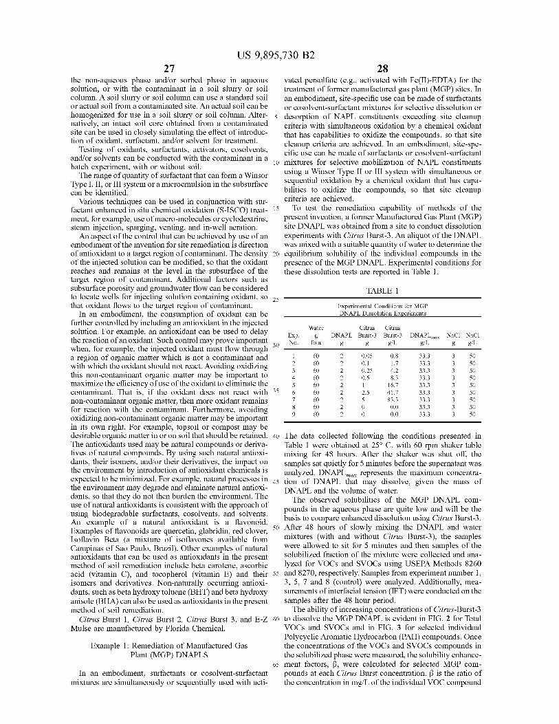
? |
US 9 , 895 , 730 B2 28
the non - aqueous phase and / or sorbed phase in aqueous vated persulfate ( e . g . , activated with Fe ( II ) - EDTA ) for the solution , or with the contaminant in a soil slurry or soil treatment of former manufactured gas plant ( MGP ) sites . In column . A soil slurry or soil column can use a standard soil an embodiment , site - specific use can be made of surfactants or actual soil from a contaminated site . An actual soil can be or cosolvent - surfactant mixtures for selective dissolution or homogenized for use in a soil slurry or soil column . Alter - 5 desorption of NAPL constituents exceeding site cleanup natively , an intact soil core obtained from a contaminated criteria with simultaneous oxidation by a chemical oxidant site can be used in closely simulating the effect of introduc that has capabilities to oxidize the compounds , so that site tion of oxidant , surfactant , and / or solvent for treatment . cleanup criteria are achieved . In an embodiment , site - spe Testing of oxidants , surfactants , activators , cosolvents , cific use can be made of surfactants or cosolvent - surfactant and / or solvents can be conducted with the contaminant in a 10 10 mixtures for selective mobilization of NAPL constituents batch experiment , with or without soil .
The range of quantity of surfactant that can form a Winsor using a Winsor Type II or III system with simultaneous or sequential oxidation by a chemical oxidant that has capa Type I , II , or III system or a microemulsion in the subsurface
can be identified . bilities to oxidize the compounds , so that site cleanup Various techniques can be used in conjunction with sur criteria are achieved .
factant enhanced in situ chemical oxidation ( S - ISCO ) treat - 15 To test the remediation capability of methods of the ment , for example , use of macro - molecules or cyclodextrins , present invention , a former Manufactured Gas Plant ( MGP ) steam injection , sparging , venting , and in - well aeration . site DNAPL was obtained from a site to conduct dissolution An aspect of the control that can be achieved by use of an experiments with Citrus Burst - 3 . An aliquot of the DNAPL
embodiment of the invention for site remediation is direction was mixed with a suitable quantity of water to determine the of antioxidant to a target region of contaminant . The density 20 equilibrium solubility of the individual compounds in the of the injected solution can be modified , so that the oxidant presence of the MGP DNAPL . Experimental conditions for reaches and remains at the level in the subsurface of the these dissolution tests are reported in Table 1 . target region of contaminant . Additional factors such as subsurface porosity and groundwater flow can be considered TABLE 1 to locate wells for injecting solution containing oxidant , so 25 that oxidant flows to the target region of contaminant . Experimental Conditions for MGP
In an embodiment , the consumption of oxidant can be DNAPL Dissolution Experiments
further controlled by including an antioxidant in the injected Water Citrus Citrus solution . For example , an antioxidant can be used to delay Exp . g DNAPL Burst - 3 Burst - 3 DNAPL max NaCl NaCl me reaction 01 an Oxidant . Such control may prove mportant 30 the reaction of an oxidant . Such control may prove important No . No . Total g g g / L g / L g g / L when , for example , the injected oxidant must flow through
1 60 0 . 05 a region of organic matter which is not a contaminant and 2 0 . 8 0 . 05 0 . 8 33 . 3 33 . 3 50 3 0 . 1 with which the oxidant should not react . Avoiding oxidizing 602 0 . 1 1 . 7 33 . 3 33 . 3 3 50
3 60 2 0 . 25 0 . 25 4 . 2 33 . 3 33 . 3 this non - contaminant organic matter may be important to 2 0 . 5 8 . 3 8 . 3 33 . 3 33 . 3 50 maximize the efficiency of use of the oxidant to eliminate the 2 1 16 . 7 16 . 7 33 . 3 33 . 3 contaminant . That is , if the oxidant does not react with 35 41 . 7 33 . 3 50 non - contaminant organic matter , then more oxidant remains 83 . 3 33 . 3
0 . 0 33 . 3 for reaction with the contaminant . Furthermore , avoiding 0 0 . 0 0 . 0 3 oxidizing non - contaminant organic matter may be important in its own right . For example , topsoil or compost may be desirable organic matter in or on soil that should be retained . 40 The data collected following the conditions presented in The antioxidants used may be natural compounds or deriva - Table 1 were obtained at 25° C . with 60 rpm shaker table tives of natural compounds . By using such natural antioxi mixing for 48 hours . After the shaker was shut off , the dants , their isomers , and / or their derivatives , the impact on samples sat quietly for 5 minutes before the supernatant was the environment by introduction of antioxidant chemicals is analyzed . DNAPL represents the maximum concentra expected to be minimized . For example , natural processes in 45 tion of DNAPL that may dissolve , given the mass of the environment may degrade and eliminate natural antioxi DNAPL and the volume of water . dants , so that they do not then burden the environment . The The observed solubilities of the MGP DNAPL com use of natural antioxidants is consistent with the approach of pounds in the aqueous phase are quite low and will be the using biodegradable surfactants , cosolvents , and solvents . basis to compare enhanced dissolution using Citrus Burst - 3 . An example of a natural antioxidant is a flavonoid . Examples of flavonoids are quercetin , glabridin , red clover , of 50 After 48 hours of slowly mixing the DNAPL and water Isoflavin Beta ( a mixture of isoflavones available from mixtures ( with and without Citrus Burst - 3 ) , the samples Campinas of Sao Paulo , Brazil ) . Other examples of natural were allowed to sit for 5 minutes and then samples of the antioxidants that can be used as antioxidants in the present solubilized fraction of the mixture were collected and ana method of soil remediation include beta carotene , ascorbic lyzed for VOCs and SVOCs using USEPA Methods 8260 acid ( vitamin C ) , and tocopherol ( vitamin E ) and their 55 and 8270 , respectively . Samples from experiment number 1 , isomers and derivatives . Non - naturally occurring antioxi 3 , 5 , 7 and 8 ( control ) were analyzed . Additionally , mea dants , such as beta hydroxy toluene ( BHT ) and beta hydroxy surements of interfacial tension ( IFT ) were conducted on the anisole ( BHA ) can also be used as antioxidants in the present samples after the 48 hour period . method of soil remediation . The ability of increasing concentrations of Citrus - Burst - 3
Citrus Burst 1 , Citrus Burst 2 , Citrus Burst 3 , and E - Z 60 to dissolve the MGP DNAPL is evident in FIG . 2 for Total Mulse are manufactured by Florida Chemical . VOCs and SVOCs and in FIG . 3 for selected individual
Polycyclic Aromatic Hydrocarbon ( PAH ) compounds . Once Example 1 : Remediation of Manufactured Gas the concentrations of the VOCs and SVOCs compounds in
Plant ( MGP ) DNAPLS the solubilized phase were measured , the solubility enhance 65 ment factors , ß , were calculated for selected MGP com
In an embodiment , surfactants or cosolvent - surfactant pounds at each Citrus Burst concentration . B is the ratio of mixtures are simultaneously or sequentially used with acti - the concentration in mg / L of the individual VOC compound
1 . 7 4 . 2 50
0 . 5 888888888 INNNNNNNNN 50 ??? ?? ?? ??? ?? ?? ??? ?? ??
coinoo 50 50 50 33 . 3
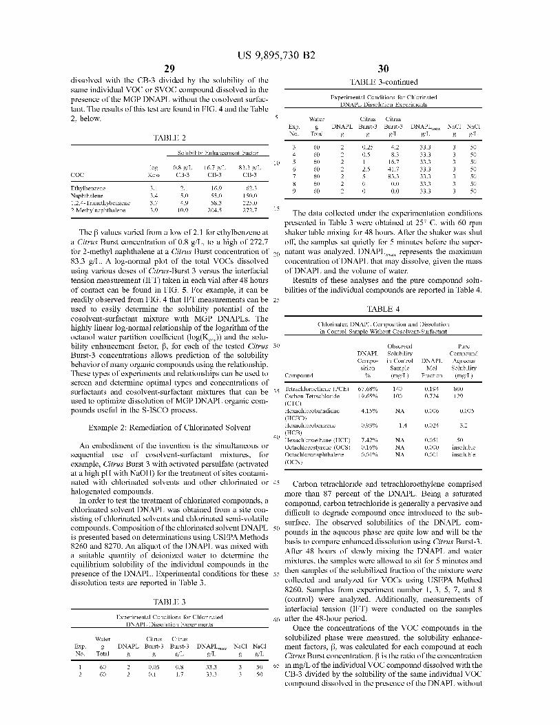
30
5 Exp .
g / L
60 SO 33 . 3 Ovauw NNNNNNN 09
2 . 5 888883 Kow ?? ?? ?? ?? ??
DO UN ??? ??? ??? ??? ??? ???
3 . 1 3 . 4
58 . 3 15
US 9 , 895 , 730 B2 29
dissolved with the CB - 3 divided by the solubility of the TABLE 3 - continued same individual VOC or SVOC compound dissolved in the presence of the MGP DNAPL without the cosolvent surfac Experimental Conditions for Chlorinated
DNAPL Dissolution Experiments tant . The results of this test are found in FIG . 4 and the Table 2 , below . Water Citrus Citrus
DNAPL Burst - 3 Burst - 3 DNAPL max NaCl NaCl No . Total g TABLE 2 g g / L g / L g / L gg / L
0 . 25 4 . 2 33 . 3 3 50 Solubility Enhancement Factor 0 . 5 8 . 3
2 1 1 16 . 7 16 . 7 33 . 3 33 . 3 log 0 . 8 g / L 16 . 7 g / L 83 . 3 g / L 2 . 5 41 . 7 41 . 7 33 . 3 33 . 3 COC CB - 3 CB - 3 CB - 3 83 . 3 33 . 3
0 . 0 33 . 3 Ethylbenzene 2 . 1 16 . 9 62 . 3 0 0 . 0 33 . 3 Naphthalene 5 . 0 55 . 0 150 . 0 1 , 2 , 4 - Trimethybenzene 4 . 9 225 . 0 2 - Methylnaphthalene 10 . 9 204 . 5 272 . 7 272 . 7 15 TL The data collected under the experimentation conditions
presented in Table 3 were obtained at 25° C . with 60 rpm The B values varied from a low of 2 . 1 for ethylbenzene at shaker table mixing for 48 hours . After the shaker was shut
a Citrus Burst concentration of 0 . 8 g / L , to a high of 272 . 7 off , the samples sat quietly for 5 minutes before the super for 2 - methyl naphthalene at a Citrus Burst concentration of 20 natant was analyzed . DNAPL mor represents the maximum 83 . 3 g / L . A log - normal plot of the total VOCs dissolved concentration of DNAPL that may dissolve , given the mass using various doses of Citrus - Burst 3 versus the interfacial of DNAPL and the volume of water . tension measurement ( IFT ) taken in each vial after 48 hours Results of these analyses and the pure compound solu of contact can be found in FIG . 5 . For example , it can be bilities of the individual compounds are reported in Table 4 . readily observed from FIG . 4 that IFT measurements can be 25 used to easily determine the solubility potential of the TABLE 4 cosolvent - surfactant mixture with MGP DNAPLs . The Chlorinated DNAPL Composition and Dissolution highly linear log - normal relationship of the logarithm of the in Control Sample Without Cosolvent - Surfactant octanol water partition coefficient ( log ( Kw ) ) and the solu bility enhancement factor , B , for each of the tested Citrus 30 Observed Pure Burst - 3 concentrations allows prediction of the solubility DNAPL Solubility Compound
Compo - in Control DNAPL Aqueous behavior of many organic compounds using the relationship . sition Sample Mol Solubility These types of experiments and relationships can be used to Compound % ( mg / L ) Fraction ( mg / L ) screen and determine optimal types and concentrations of con he 35 Tetrachloroethene ( PCE ) 140 67 . 68 % surfactants and cosolvent - surfactant mixtures that can be 35 0 . 194
Carbon Tetrachloride 19 . 65 % 100 0 . 724 129 used to optimize dissolution of MGP DNAPL organic com ( CTC ) pounds useful in the S - ISCO process . Hexachlorobutadiene 4 . 15 % NA 0 . 006 0 . 005
( HCBD ) Example 2 : Remediation of Chlorinated Solvent Hexachlorobenzene 0 . 93 % 0 . 93 % 1 . 4 1 . 4 0 . 024 0 . 024 3 . 2 3 . 2
( HCB ) 40 Hexachloroethane ( HCE ) 7 . 42 % NA 0 . 051 An embodiment of the invention is the simultaneous or Octachlorostyrene ( OCS ) 0 . 16 % NA 0 . 000 insoluble
sequential use of cosolvent - surfactant mixtures , for Octachloronaphthalene 0 . 01 % NA 0 . 001 insoluble
example , Citrus Burst 3 with activated persulfate ( activated ( OCN ) at a high pH with NaOH ) for the treatment of sites contami nated with chlorinated solvents and other chlorinated or 45 Carbon tetrachloride and tetrachloroethylene comprised halogenated compounds . more than 87 percent of the DNAPL . Being a saturated
In order to test the treatment of chlorinated compounds , a compound , carbon tetrachloride is generally a pervasive and chlorinated solvent DNAPL was obtained from a site con difficult to degrade compound once introduced to the sub sisting of chlorinated solvents and chlorinated semi - volatile surface . The observed solubilities of the DNAPL com compounds . Composition of the chlorinated solvent DNAPL 50 pounds in the aqueous phase are quite low and will be the is presented based on determinations using USEPA Methods basis to compare enhanced dissolution using Citrus Burst - 3 . 8260 and 8270 . An aliquot of the DNAPL was mixed with After 48 hours of slowly mixing the DNAPL and water a suitable quantity of deionized water to determine the mixtures , the samples were allowed to sit for 5 minutes and equilibrium solubility of the individual compounds in the presence of the DNAPL . Experimental conditions for these 55 then samples of the solubilized fraction of the mixture were dissolution tests are reported in Table 3 . collected and analyzed for VOCs using USEPA Method
8260 . Samples from experiment number 1 , 3 , 5 , 7 , and 8 TABLE 3 ( control ) were analyzed . Additionally , measurements of
interfacial tension ( IFT ) were conducted on the samples Experimental Conditions for Chlorinated 60 after the 48 - hour period .
DNAPL Dissolution Experiments Once the concentrations of the VOC compounds in the Citrus Citrus solubilized phase were measured , the solubility enhance
Exp . g DNAPL Burst - 3 Burst - 3 DNAPL max NaCl NaCl ment factors , ß , was calculated for each compound at each No . Total g g g / L g / L g g / L Citrus Burst concentration . B is the ratio of the concentration
2 0 . 05 0 . 05 0 . 8 0 . 8 3 50 65 in mg / L of the individual VOC compound dissolved with the ? 60 2 0 . 1 0 . 1 1 . 7 1 . 7 33 . 3 33 . 3 § 50 CB - 3 divided by the solubility of the same individual VOC
compound dissolved in the presence of the DNAPL without
800
50
Water
60 NN 09 33 . 3 ww09 50
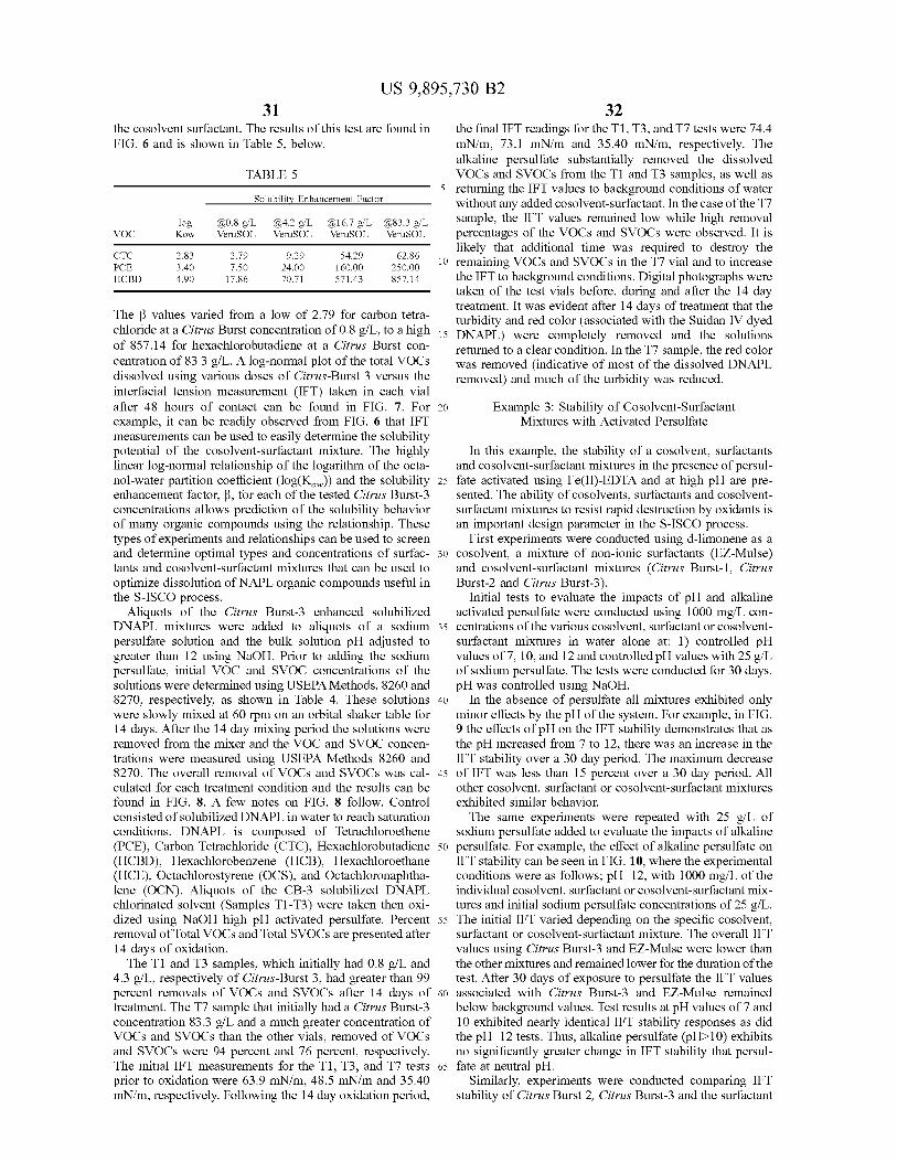
US 9 , 895 , 730 B2
VOC
the cosolvent surfactant . The results of this test are found in the final IFT readings for the T1 , T3 , and T7 tests were 74 . 4 FIG . 6 and is shown in Table 5 , below . mN / m , 73 . 1 mN / m and 35 . 40 mN / m , respectively . The
alkaline persulfate substantially removed the dissolved TABLE 5 VOCs and SVOCs from the T1 and T3 samples , as well as
5 returning the IFT values to background conditions of water Solubility Enhancement Factor without any added cosolvent - surfactant . In the case of the 17
log @ 0 . 8 g / L @ 4 . 2 g / L @ 16 . 7 g / L @ 83 . 3 g / L sample , the IFT values remained low while high removal VOC Kow VeruSOL VeruSOL VeruSOL VeruSOL percentages of the VOCs and SVOCs were observed . It is
likely that additional time was required to destroy the CTC 2 . 83 2 . 79 9 . 29 54 . 29 62 . 86 3 . 40 ??? 10 remaining VOCs and SVOCs in the T7 vial and to increase 7 . 50 24 . 00 160 . 00 250 . 00
HCBD HCBD 4 . 90 4 . 90 17 . 86 17 . 86 . 70 . 71 571 . 43 857 . 14 the IFT to background conditions . Digital photographs were taken of the test vials before , during and after the 14 day treatment . It was evident after 14 days of treatment that the The ß values varied from a low of 2 . 79 for carbon tetra turbidity and red color ( associated with the Suidan IV dyed
chloride at a Citrus Burst concentration of 0 . 8 g / L , to a high 15 DNAPL ) were completely removed and the solutions of 857 . 14 for hexachlorobutadiene at a Citrus Burst con returned to a clear condition . In the 17 sample , the red color centration of 83 . 3 g / L . A log - normal plot of the total VOCs was removed ( indicative of most of the dissolved DNAPL dissolved using various doses of Citrus - Burst 3 versus the removed ) and much of the turbidity was reduced . interfacial tension measurement ( IFT ) taken in each vial after 48 hours of contact can be found in FIG . 7 . For 20 Example 3 : Stability of Cosolvent - Surfactant example , it can be readily observed from FIG . 6 that IFT Mixtures with Activated Persulfate measurements can be used to easily determine the solubility potential of the cosolvent - surfactant mixture . The highly In this example , the stability of a cosolvent , surfactants linear log - normal relationship of the logarithm of the octa and cosolvent - surfactant mixtures in the presence of persul nol - water partition coefficient ( log ( Kw ) ) and the solubility 25 fate activated using Fe ( II ) - EDTA and at high pH are pre enhancement factor , B , for each of the tested Citrus Burst - 3 sented . The ability of cosolvents , surfactants and cosolvent concentrations allows prediction of the solubility behavior surfactant mixtures to resist rapid destruction by oxidants is of many organic compounds using the relationship . These an important design parameter in the S - ISCO process . types of experiments and relationships can be used to screen First experiments were conducted using d - limonene as a and determine optimal types and concentrations of surfac - 30 cosolvent , a mixture of non - ionic surfactants ( EZ - Mulse ) tants and cosolvent - surfactant mixtures that can be used to and cosolvent - surfactant mixtures ( Citrus Burst - 1 , Citrus optimize dissolution of NAPL organic compounds useful in Burst - 2 and Citrus Burst - 3 ) . the S - ISCO process . Initial tests to evaluate the impacts of pH and alkaline
Aliquots of the Citrus Burst - 3 enhanced solubilized activated persulfate were conducted using 1000 mg / L con DNAPL mixtures were added to aliquots of a sodium 35 centrations of the various cosolvent , surfactant or cosolvent persulfate solution and the bulk solution pH adjusted to surfactant mixtures in water alone at : 1 ) controlled pH greater than 12 using NaOH . Prior to adding the sodium values of 7 , 10 , and 12 and controlled pH values with 25 g / L persulfate , initial VOC and SVOC concentrations of the of sodium persulfate . The tests were conducted for 30 days . solutions were determined using USEPA Methods , 8260 and pH was controlled using NaOH . 8270 , respectively , as shown in Table 4 . These solutions 40 In the absence of persulfate all mixtures exhibited only were slowly mixed at 60 rpm on an orbital shaker table for minor effects by the pH of the system . For example , in FIG . 14 days . After the 14 day mixing period the solutions were 9 the effects of pH on the IFT stability demonstrates that as removed from the mixer and the VOC and SVOC concen - the pH increased from 7 to 12 , there was an increase in the trations were measured using USEPA Methods 8260 and IFT stability over a 30 day period . The maximum decrease 8270 . The overall removal of VOCs and SVOCs was cal - 45 of IFT was less than 15 percent over a 30 day period . All culated for each treatment condition and the results can be other cosolvent , surfactant or cosolvent - surfactant mixtures found in FIG . 8 . A few notes on FIG . 8 follow . Control exhibited similar behavior . consisted of solubilized DNAPL in water to reach saturation The same experiments were repeated with 25 g / L of conditions . DNAPL is composed of Tetrachloroethene sodium persulfate added to evaluate the impacts of alkaline ( PCE ) , Carbon Tetrachloride ( CTC ) , Hexachlorobutadiene 50 persulfate . For example , the effect of alkaline persulfate on ( HCBD ) , Hexachlorobenzene ( HCB ) , Hexachloroethane IFT stability can be seen in FIG . 10 , where the experimental ( HCE ) , Octachlorostyrene ( OCS ) , and Octachloronaphtha - conditions were as follows ; pH = 12 , with 1000 mg / L of the lene ( OCN ) . Aliquots of the CB - 3 solubilized DNAPL individual cosolvent , surfactant or cosolvent - surfactant mix chlorinated solvent ( Samples T1 - T3 ) were taken then oxi - tures and initial sodium persulfate concentrations of 25 g / L . dized using NaOH high pH activated persulfate . Percent 55 The initial IFT varied depending on the specific cosolvent , removal of Total VOCs and Total SVOCs are presented after surfactant or cosolvent - surfactant mixture . The overall IFT 14 days of oxidation . values using Citrus Burst - 3 and EZ - Mulse were lower than
The T1 and T3 samples , which initially had 0 . 8 g / L and the other mixtures and remained lower for the duration of the 4 . 3 g / L , respectively of Citrus - Burst 3 , had greater than 99 test . After 30 days of exposure to persulfate the IFT values percent removals of VOCs and SVOCs after 14 days of 60 associated with Citrus Burst - 3 and EZ - Mulse remained treatment . The 17 sample that initially had a Citrus Burst - 3 below background values . Test results at pH values of 7 and concentration 83 . 3 g / L and a much greater concentration of 10 exhibited nearly identical IFT stability responses as did VOCs and SVOCs than the other vials , removed of VOCs the pH = 12 tests . Thus , alkaline persulfate ( pH > 10 ) exhibits and SVOCs were 94 percent and 76 percent , respectively . no significantly greater change in IFT stability that persul The initial IFT measurements for the T1 , T3 , and T7 tests 65 fate at neutral pH . prior to oxidation were 63 . 9 mN / m , 48 . 5 mN / m and 35 . 40 Similarly , experiments were conducted comparing IFT mN / m , respectively . Following the 14 day oxidation period , stability of Citrus Burst 2 , Citrus Burst - 3 and the surfactant
33 US 9 , 895 , 730 B2
34 Alfoterra 53 with sodium persulfate alone at 50 g / L and iron complexed with chelating agents including ethylene sodium persulfate at 50 g / L with 250 mg / L as Fe of diamine tetra acetate ( EDTA ) and citric acid are used as the Fe ( II ) - EDTA . These experiments were run for a 10 day compounds to activate persulfate necessary to enhance oxi period . In FIG . 11 , it can be seen that the IFT initially d ation strength by increasing the formation of free radicals . increased with all systems tested , then generally stabilized 5 The dual oxidant persulfate - hydrogen peroxide system may after this initial period . All systems had a greater increase in promote a multi - radical attack , but requires low concentra IFT when the persulfate was activated with Fe ( II ) - EDTA , tions of hydrogen peroxide to minimize gas phase forma with the exception of Citrus Burst - 3 , which had only a minor tion . Biodegradable cosolvent - surfactants are additionally change in IFT stability . Additional experiments were con - investigated to determine their effect on increasing the rate ducted on the IFT stability of Citrus Burst - 3 at a concen - 10 of remediation achievable at the site . tration of 2000 mg / L using Fe ( II ) - EDTA activated persul To determine which process is more economically and fate . In this example , the initial Fe ( II ) - EDTA activator technically effective in the remediation of the contaminated concentration was fixed at 250 mg / L as Fe and the sodium soils at the site , several experimental systems are evaluated persulfate concentration was varied from 0 g / L to 25 g / L . and are discussed in the following sections . Increasing the concentration of sodium persulfate , resulted 15 Several tasks produce information regarding the reactivity in increases in the IFT over the 14 day test period as shown and persistence of persulfate with the site soils , the reduction in FIG . 12 . However , the IFT values remained at or below of COC concentrations in soils and groundwater by several 60 mN / m with the 5 g / L and 10 g / L sodium persulfate activation methods , production of byproducts from activated concentrations . At the 25 g / L sodium persulfate concentra persulfate oxidations , effects of cosolvent - surfactants on tion , the IFT value was measured at 66 . 2 mN / m after the 14 20 system performance and design parameters for both Pilot day test period . and Full - Scale application of activated persulfate at the Site .
Experiments were conducted on the effects of perman Task I - Determination of the Persulfate Soil Oxidant ganate on the stability of IFT in systems with 2000 mg / L Demand ( SOD ) Citrus Burst - 3 with varying concentrations of permangan - The batch test persulfate SOD is determined on the ate . Results from these experiments in FIG . 12 indicate that 25 homogenized contaminated soil . These data are used for the permanganate concentrations of 5 g / L and 10 g / L affected determination of oxidant concentrations and estimates of the IFT of these systems , but the IFT values remained below chemicals needed for the subsequent treatability tests . The background conditions . When the permanganate concentra - batch test persulfate SOD is run using persulfate alone to tion was increased to 25 g / L , the IFT values increased to identify the reactivity of the soil matrix and site groundwater background conditions after 5 days . 30 with the oxidant .
Similarly , experiments were conducted on the effects of Several initial Na , , o , concentrations are used in the test hydrogen peroxide activated persulfate with increasing con - to estimate the SOD as a function of initial persulfate centration of hydrogen peroxide at 0 percent , 1 percent , 2 concentration . A total of four persulfate doses are used to percent and 3 percent hydrogen peroxide at sodium persul - determine the SOD . Control tests use deionized ( DI ) water fate concentrations at 25 g / L and Citrus Burst - 3 concentra - 35 in place of Na S , Og . Contaminated site groundwater is also tions at 2000 mg / L . In FIG . 13 , it can be seen that there are screened to determine the oxidant demand of the matrix . effects of hydrogen peroxide on IFT values , however , all IFT After preparation , amber glass bottles are capped and the values remain below 60 mN / m . Increasing the hydrogen contents slowly mixed on a shaker table . Samples for pH , peroxide concentration above 2 percent had no significant ORP , residual persulfate concentration are collected from impact on IFT values . 40 the bottles and analyzed just prior to the persulfate addition
Exposing various specific cosolvents , surfactants or and then on days 1 , 10 , and 20 . cosolvent - surfactant mixtures to various oxidant and oxi The oxidant demand is calculated based on the persulfate dant - activator systems can be used as a screening and design concentrations , measured after 10 days using Equation 1 , method for the optimal development of surfactant and SOD = V ( Co - C ) / msoil ( Eq . 1 ) cosolvent - surfactant systems for specific and oxidant - acti - 45 vator systems . Using the experimental method described where V = total volume of persulfate solution in the vials , above for specific NAPL or sorbed phase contaminants and Co = initial persulfate concentration , Cs = persulfate concen various specific cosolvents , surfactants or cosolvent - surfac - tration at the relatively steady state or the reaction period of tant mixtures to various oxidant and oxidant - activator sys - 10th day , and mor = the mass of dry soil in reactors . A tems will lead to customized and optimized formulations of 50 relationship is developed relating the persulfate oxidant the S - ISCO process . demand and initial concentration of persulfate used in the
tests . Results of the SOD tests for the tested MGP site soils Example 4 : Treatability Test for Soil are found in FIG . 14 .
Decontamination Task II Batch and Column Cosolvent - Surfactant Screen 55 ing
Bench - scale tests are used to evaluate the efficiency of The cosolvent proposed for use in the treatability studies dissolving and oxidizing former Manufactured Gas Plant is d - limonene . This cosolvent is a 100 percent biodegrad ( MGP ) site contaminants including polycyclic aromatic a ble , naturally occurring chemical and is a natural product hydrocarbons ( PAHs ) , total petroleum hydrocarbons ( TPH ) , derived from citrus crops . d - Limonene is not miscible with and volatile organic compounds ( VOCs ) in site soils and 60 water and requires a surfactant to form an emulsion creating groundwater matrices with several selected chemical oxida tion processes : 1 ) activated persulfate oxidation ; 2 ) persul - food grade form and is also used in many household fate - hydrogen peroxide dual oxidant system ; and 3 ) cosol - cleaning chemicals . When mixed with surfactants , the emul vent - surfactant activated persulfate . All of the selected sion has the ability to dissolve and displace oils and tars . oxidation processes generate highly reactive free radicals in 65 As part of Task II , several d - limonene and surfactant the systems and have a great capability of degrading the blends are screened for their ability to solubilize NAPLs and targeted contaminants of concern ( COCs ) at the site . Ferrous tars from an MGP Site . Several test surfactants and cosol
35 US 9 , 895 , 730 B2
36 vent - surfactant blends are mixed with NAPL phase and site to the moles of MGP COCs removed from soil slurry tests groundwater . The phase behavior is monitored by the exami - per moles of sodium persulfate utilized during the 30 day nation of the extent of NAPL solubilization , emulsion for testing period . mation , critical micelle formation , and interfacial tension . Simple replicate soil column tests were conducted with FIG . 15 illustrates the use of this methodology of adding 5 homogenized soils . The results of the S - ISCO soil column successively increasing concentrations of the surfactants and using Fe ( II ) - EDTA activated persulfate with Alfoterra - 53 , in cosolvent - surfactant blends to the MGP DNAPL and water FIG . 18 , had the highest removal of MGP VOCs , SVOCs mixtures and recording interfacial tension ( IFT ) measure and tentatively identified compounds ( TICs ) in comparison ments . This procedure can be used to measure the critical with other soil columns using Fe ( II ) - EDTA activated per micelle concentration if the system was solely in the aque - 10 sulfate and persulfate alone . In FIG . 19 , the efficiency of the ous phase . A log - normal plot can also be used to interpret the S - ISCO process ( Fe ( II ) - EDTA activated persulfate with critical micelle concentration . In this case MGP DNAPL is Alfoterra - 53 ) is compared to that of persulfate alone , Fe ( II ) present causing the CMC to be greater than in a pure EDTA activated persulfate in a soil column study . The aqueous system alone . efficiency was 65 percent greater using the S - ISCO Process
Soil column tests were run using homogeneous soil from 15 with Fe ( II ) - EDTA activated persulfate and Citrus Burst - 2 . an MGP site and spiking the soil with DNAPL from the Surfactant Systems and S - ISCO MGP site to approximate residual saturation with respect to Surfactant enhanced in situ chemical oxidation ( S - ISCO ) MGP DNAPL . Various surfactants and cosolvent - surfactant remediation depends on choosing the correct surfactants or mixtures were flushed through replicate columns and vari - surfactant - cosolvent mixtures that create the most effective ous process parameters were measured in the column efflu - 20 solubilized micelle or microemulsion with the NAPL pres ent , such as turbidity , oxidation - reduction potential , pH , ent in the soil , such that a Winsor Type I phenomenon occurs electrolytic conductivity , temperature , dissolved oxygen . and other Winsor type behaviors are generally avoided . Additionally , VOCs and SVOCs were periodically moni Once an adequate Winsor Type I solubilized micelle or tored in the column effluent using USEPA Methods 8260 and microemulsion has formed and thus increases the apparent 8270 . Results from the column tests are shown in FIG . 16 in 25 solubility of the NAPL , the solubilized micelle or micro which the total effluent VOCs and SVOCs ( in molar units ) emulsed NAPL is able to enter into “ aqueous phase reac for each of the column run conditions , including a run in tions ” and in the case of S - ISCOTM remediation , it can be which Fe ( II ) - EDTA activated persulfate was flushed through oxidized using a chemical oxidant such as permanganate , a replicate spiked soil column . Citrus Burst - 3 exhibited the ozone , persulfate , activated persulfate , percarbonate , acti greatest potential for solubilizing the MGP DNAPL com - 30 vated percarbonate , or hydrogen peroxide , or ultraviolet pounds in comparison to the other tested surfactants and ( UV ) light or any combination of these oxidants with or cosolvent - surfactant mixtures . The simultaneous addition of without uV light . It is well known in the literature that Fe ( II ) - EDTA activated persulfate to a column being flushed several methods can be used to activate or catalyze peroxide with Citrus - Burst - 2 reduced total effluent COCs flushed and persulfate to form free radicals such as free or chelated from the column by 87 percent . 35 transition metals and uV light . Persulfate can be additionally
Task III Batch Aqueous and Soil Slurry Activated Per activated at both high and low pH , by heat or by peroxides , sulfate including calcium peroxides . Persulfate and ozone can be
Experiments in this task relate the reduction of MGP COC used in a dual oxidant mode with hydrogen peroxide . concentrations in both aqueous and soil slurry batch sys - S - ISCO can make use of increased solubilization of tems . The initial persulfate concentration may be varied , 40 NAPL or sorbed contaminants in Winsor Type I systems . In based on the persulfate SOD tests , which are run first . situ chemical oxidation of the solubilized or microemulsed Because the stability of the Fe ( II ) - chelates in the presence of NAPLs in a Winsor Type I system eliminates the necessity persulfate determines the extent of reaction ( i . e . , zone of of complete liquid pumping extraction recovery of the reaction influence at full - scale ) in the subsurface at the site , solubilized NAPL . Elimination of extraction systems avoids it is important that the optimal chelate be used . Prior work 45 technical challenges associated with costly complete plume has indicated the stability of EDTA is greater than that of capture , costly above ground treatment systems , require citric acid in the neutral pH range ( 12 ) . During all of the ments to recycle surfactant or surfactant - cosolvent mixtures , proposed tests as part of Task II , persulfate and the metal and to dispose or reinject the bulk liquid back into the chelate concentration are measured to determine the longev - subsurface . Martel et al . ( 22 , 23 ) proposed the use of Winsor ity of the chelate complex in the persulfate solution . During 50 Type I microemulsions to solubilize NAPLs without NAPL the aqueous phase tests , COCs are analyzed at various times . mobilization . These systems have the advantage of high Based on the aqueous phase results , a chelate can be chosen solubilization of NAPLs ( although not as high as middle to be used in a soil slurry tests . phase microemulsions ) with relatively low amounts of
In the soil slurry tests , COCs are measured at Time = 0 , 1 , chemical additives required . Chun - Huh ( 24 ) showed that , in 5 and 30 days . The chelate used is based on the results of the 55 microemulsions , solubilization of the oil phase into the aqueous phase comparison of EDTA and citric acid The best microemulsion is related to interfacial tension by an inverse performing persulfate activation method from the aqueous squared relationship . Remediation systems that rely on phase tests is used in these soil slurry tests . Results of the Winsor Type I solubilized micelle or microemulsification are 30 - day soil slurry test using Fe ( II ) - EDTA activated persul necessarily less efficient than those that rely on Winsor Type fate and Citrus Burst - 1 indicate that there was a 98 . 9 percent 60 III microemulsions and mobilization , since solubilization is removal of total COCs in this soil slurry test as shown in lower at the higher interfacial tensions required to prevent FIG . 17 . In comparison to other soil slurry treatments with mobilization . However , desorption and solubilization of a dual oxidant hydrogen peroxide - persulfate , Fe ( II ) - EDTA contaminants using Winsor Type I microemulsions are con activated persulfate and Fe ( II ) - EDTA activated persulfate trollable such that the risk of off - site mobilization of NAPL with Alfoterra 53 ( S - ISCO process ) , the greatest removal 65 contaminants of concern ( COCs ) is minimal . This type of and efficiency was with the S - ISCO soil slurry test . The behavior is the focus of S - ISCOTM ( surfactant enhanced in efficiency of the S - ISCO process was evaluated with respect situ chemical oxidation ) remediation and can be useful in
US 9 , 895 , 730 B2 37 38
remedying manufactured gas plant ( MGP ) sites as well as Surfactant Solubilization , Surfactant Mobilization , and sites with chlorinated solvents , petroleum hydrocarbons , Microemulsions pesticides , herbicides , polychlorinated biphenyls , and other Surfactants are surface active agents . They are molecules NAPL or sorbed COCs . Under solubilizing conditions , the that have both hydrophilic and lipophilic parts ( Shiau et al . , NAPL removal rate is dependent on the increase in solubility 5 5 1994 ) ( 21 ) . The amphophilic nature of surfactant molecules of the NAPL in the surfactant mixture . Under desorbing ( having both positive and negative charged parts ) causes
them when injected into aquifers to accumulate at the conditions , the sorbed COC species removal rate is depen water - solid interface . Furthermore , surfactant molecules can dent on the rate of desorption of the COC into the surfactant coagulate into aggregates known as micelles . Micelles are or surfactant - cosolvent mixture . colloidal - sized aggregates . The surfactant concentration at
The invention involves a method and process of increas - " which micelle formation begins is known as the critical 10
ing the solubility of contaminants , such as normally low micelle concentration ( CMC ) . Determining the CMC of a solubility nonaqueous phase liquids ( NAPLs ) , sorbed con - surfactant or a cosolvent - surfactant mixture is an important taminants , or other chemicals in soils in surface and ground component in managing S - ISCO remediation . Micelle for water , and simultaneously or subsequently oxidizing the mation generally distinguishes surfactants from amphophilic
15 molecules ( for example , alcohols ) that do not form micelles chemicals using a chemical oxidant without the need of and have lower surface activity . extraction wells for the purpose of recovering the injected Surfactant addition above the CMC results in the forma cosolvents and / or surfactants with NAPL compounds . tion of additional micelles . Winsor Type behavior describes Examples of contaminants are dense nonaqueous phase different types of micelle formation that is relevant to liquids ( DNAPLs ) , light nonaqueous phase liquids ( LNA - 20 remediation of sites with NAPLs or sorbed COCs . Winsor PLs ) , polycyclic aromatic hydrocarbons ( PAHs ) , chlorinated Type I micelles have a hydrophilic exterior ( the hydrophilic solvents , pesticides , polychlorinated biphenyls and various heads are oriented toward the exterior of the aggregate ) and organic chemicals , such as petroleum products . Contami - a hydrophobic interior ( the hydrophobic tails are oriented nants can be associated with , for example , manufactured gas toward the interior of the aggregate ) . This type of micelle plant residuals , creosote wood treating liquids , petroleum 25 can be likened to dispersed oil drops or molecules ; the residuals , pesticide , or polychlorinated biphenyl ( PCB ) hydrophobic inside of the micelle acts as an oil sink into residuals and other waste products or byproducts of indus which hydrophobic contaminants can partition . The trial processes and commercial activities . Contaminants may increased scale aqueous solubility of organic compounds at be in the liquid phase , for example , NAPLs , sorbed to the concentrations above the CMC is referred to as " solubiliza
soil matrix or in the solid phase , for example , certain in 30 tion . ” During solubilization , surfactant concentration increases , additional micelles are formed and the contami pesticides . nant solubility continues to increase . S - ISCOTM remediation The term “ solubilize ” as used herein can refer to , for optimizes and controls solubilization reactions at NAPL and example , one or more of incorporating a contaminant in the sorbed COC sites . aqueous phase , forming a molecular scale mixture of con 35 Winsor Type II surfactants are oil soluble and have a low taminant and water , incorporating contaminant at a micellar hydrophile - lipophile balance ( HLB ) . These type of surfac interface , and incorporating contaminant in a hydrophobic tants partition into the oil phase , and may form reverse
core of a micelle . The term “ solution ” as used herein can micelles . A reverse micelle has a hydrophilic interior and refer to , for example , a contaminant in the aqueous phase , a lipophilic exterior . The resulting phenomenon is similar to molecular scale mixture of contaminant and water , a con - 40 dispersed water drops in the oil phase . Surfactant systems taminant at a micellar interface , and a contaminant in a intermediate between micelles and reverse micelles can hydrophobic core of a micelle . result in a third phase ( Winsor Type III system ) known as a
Minimal mobilization can be defined as follows . NAPL middle - phase microemulsion . The middle phase system is may move through colloidal transport but bulk ( macro - known to coincide with very low interfacial tensions ( IFTs ) scopic ) movement of NAPL downward or horizontal is not 45 and can be used for bulk ( pump - and - treat ) extraction of occurring . contaminants from residual saturation . Surfactant - enhanced
The subsurface can include any and all materials below remediation by this approach is often referred to as mobi the surface of the ground , for example , groundwater , soils , lization . The surfactants or cosolvent - surfactant mixtures rock , man - made structures , naturally occurring or man - used and the chemical conditions under which solubilization made contaminants , waste materials , or products . Knowl - 50 and mobilization occur are very different . Solubilization can edge of the distribution of hydraulic conductivity in the soil be effected at very low surfactant concentrations that can be and other physical hydrogeological subsurface properties , orders of magnitude below that at which mobilization such as hydraulic gradient , saturated thickness , soil hetero occurs . geneity , and soil type is desirable to determine the relative Microemulsions are a special class of a Winsor Type I contribution of downward vertical density driven flow to 55 system in which the droplet diameter of the dispersed phase normal advection in the subsurface . is very small and uniform . Droplet diameters of oil - in - water
The phase behavior of the specific system is controllable . microemulsions generally range between 0 . 01 and 0 . 10 um . Laboratory experiments have shown that surfactant / cosol ( Tawitz , et al . , 1998 ) ( 26 ) . These microemulsions are single vents that preferentially stay with the aqueous phase can phase , optically transparent , low viscosity , thermodynami dramatically increase the solubility of NAPL components in 60 ?ally stable systems that form spontaneously on contact with the aqueous phase ( Falta , 1998 ) ( 20 ) . In cases where the an oil or NAPL phase . A properly designed microemulsion solvent preferentially partitions into the aqueous phase , system is dilutable with water and can be transported separate phase NAPL mobilization is not observed and the through porous media by miscible displacement . This is in NAPL removal occurs by enhanced dissolution . Solubiliza contrast to surfactant - based technologies that utilize Winsor tion has the added benefit of increasing bioavailability of the 65 Type III middle - phase microemulsions which depend on contaminants and increasing the rate of biological degrada mobilization to transport the NAPL phase as an immiscible tion of the contaminants . displacement process .
US 9 , 895 , 730 B2 39 40
Microemulsions are usually stabilized by a surfactant and and / or cosolvents can be applied first and then the gas a cosolvent . A mixture of water , surfactant , and cosolvent pressure can be applied , or the surfactants and / or cosolvents form the microemulsion “ precursor ” ; this " precursor ” can be applied simultaneously with the gas pressure . The gas should be a stable single - phase , low viscosity system . When can be created by injecting a liquid at an injection locus into this precursor is injected into a porous medium containing 5 a subsurface , so that upon contact of the liquid with sub residual NAPL , the NAPL is microemulsified and can be surface materials the liquid decomposes into a gas ( e . g . , transported to an extraction well as a single phase , low hydrogen peroxide solution that decomposes into oxygen viscosity fluid . Suitable cosolvents are low - molecular - and water ) . The gas phase can be created by pressurizing a weight alcohols ( propanol , butanol , pentanol , hexanol , etc . ) , gas phase into water ( or another injected liquid ) above organic acids , and amines . There are many surfactants that 10 ground or while injecting , so that upon release in the form oil - in - water microemulsions in the presence of alcohol subsurface at lower pressure the dissolved gas comes out of cosolvents . Some of these surfactants have been given direct solution and forms a gas phase . As an additional example , food additive status by the FDA , are non - toxic , and are the gas may be injected as a compressed gas or a supercriti readily biodegradable . cal fluid . The gas can include , for example , air , oxygen , Any surfactant - based remediation technology must utilize 15 nitrogen , carbon dioxide , or a noble ( inert ) gas or a combi
surfactants with optimum efficiency ( i . e . , minimal losses to nation of gases . Carbon dioxide ( CO2 ) may be useful as a sorption , precipitation , coacervate formation , crystalliza - gas ; its use can serve the dual purpose of recovering or tion , or phase changes ) , environmental acceptance , and extracting contaminant from a subsurface and sequestering biodegradability . Surfactants can be lost from a solution by the carbon dioxide , a greenhouse gas . adsorption onto aquifer solid phases and by precipitation 20 Such an approach of facilitated remediation , when a gas with polyvalent cations dissolved in ground water or injected into the subsurface under pressure acts to mobilize adsorbed onto cation exchange sites . Surfactants without a contaminant to flow to an extraction well , can , for cosolvents sometimes create viscous macromolecules or example , be combined with any of the above - identified liquid crystals when they combine with the contaminants approaches in which a contaminant , such as a NAPL , essentially blocking fluid flow . Cosolvents can be used to 25 LNAPL , or DNAPL , is oxidized in and / or extracted from a stabilize the system and avoid macromolecule formation . It subsurface . In general , whenever in this text the injection of has been suggested that chromatographic separation of sur - an oxidant is described , the description can also be consid factants and cosolvents could reduce microemulsification ered to include the case of a gas evolving material , e . g . , efficiency . However , experimental observations on systems H202 , a dissolved gas , a compressed gas , or a supercritical containing 10 to 15 percent residual NAPL saturation indi - 30 fluid being administered . The gas evolving material , dis cate that , if chromatographic separation occurred , its effect solved gas , compressed gas , or supercritical fluid can either on microemulsification was negligible . itself be the oxidant , e . g . , H2O2 that decomposes to form
In the embodiments described above , contaminants , or oxygen , or the gas evolving material , dissolved gas , com chemicals of concern ( COCs ) can be effectively removed , pressed gas , or supercritical fluid can be administered as an because of the control achieved by the methods presented 35 adjuvant to an oxidant , for example , an oxidant such as herein over several aspects of the remediation process . sodium persulfate . Surfactants and cosolvent - surfactant mixtures and oxidants Factors influencing the selection of a mobilizing fluid , can be selected , so that the oxidant does not prematurely such as a gas evolving material , a dissolved gas , a com degrade the surfactant , and the surfactant can effectively pressed gas , or a supercritical fluid , for injection into a solubilize the COCs . On the other hand , the oxidation zone 40 subsurface to promote movement of contaminant to an can be designed , so that the surfactant is rapidly oxidized at extraction well can include the following . The solubility of the oxidation zone , and the COCs thereby immobilized , so the contaminant , e . g . , a NAPL , LNAPL , or DNAPL , in the that they do not spread beyond the oxidation zone . The mobilizing fluid can be considered . For example , it can be oxidant can travel through the soil without prematurely advantageous to select a mobilizing fluid , such as a super reacting , so that it efficiently destroys the COCs . Control of 45 critical fluid , in which the contaminant , surfactant , and / or where the oxidant reacts can be further enhanced by use of cosolvent is soluble . Such a mobilizing fluid that solubilizes an antioxidant . The components of the injected treatment the contaminant can remove the contaminant from the solution , e . g . , oxidant , activator , and surfactant , can be matrix in the subsurface , for example , soil , and convey it to co - eluted , so that they can effectively work in conjunction to an extraction well . Alternatively , it can be advantageous to destroy COCs . The density of the injected solution can be 50 select a mobilizing fluid in which the contaminant is not controlled , so that the surfactant , oxidant , activator and other soluble . Such a mobilizing fluid that does not solubilize the injected components travel downward to where COCs tar - contaminant can act as a piston to push the contaminant in geted for destruction are located . The treatment solution can a separate phase to an extraction well . The mobilizing fluid be injected to remove COCs residing at a downgradient can be selected to oxidize as well as promote the extraction location where it is not practical or economical to inject 55 of contaminant , and therefore promote the in situ destruction solution , e . g . , under a building or railroad track . of contaminant . For example , hydrogen peroxide , oxygen
dissolved in a liquid , or compressed air can be used as the Example 5 : Facilitated Remediation mobilizing fluid . The selection of an oxidizing material as
the mobilizing fluid can be more strongly indicated when the A surfactant or a mixture of surfactants and cosolvents 60 contaminant that is of primary concern can readily be
can be simultaneously or sequentially be applied with a gas oxidized , than when the contaminant is resistant to oxida to a contaminated subsurface , for example , a subsurface tion . contaminated with a non - aqueous phase liquid ( NAPL ) , a Alternatively , a mobilizing fluid may be selected because light non - aqueous phase liquid ( LNAPL ) , or a dense non - it is abundant or must be disposed of . For example , if a fossil aqueous phase liquid ( DNAPL ) . The gas can provide a 65 fuel power generation plant is located near to a contaminated hydraulic potential ( pressure ) to push or mobilize the con - site , such as a manufactured gas plant ( MGP ) site , the carbon taminant to a recovery or extraction well . The surfactant dioxide emitted by the power generation plant may be
US 9 , 895 , 730 B2 42
captured and used as the mobilizing fluid to drive contami - injection to the extraction wells , the supercritical fluid nant in a subsurface , e . g . , NAPL , LNAPL , or DNAPL experiences pressures and temperatures such that a surfac associated at the MGP site , to extraction wells . Such use of tant and / or cosolvent to be injected with the supercritical carbon dioxide as the mobilizing fluid may also allow for the fluid remains in solution in the supercritical fluid . underground sequestration of carbon dioxide , a greenhouse 5 The composition of a surfactant and / or cosolvent liquid gas . The geology of the subsurface in which the contaminant amendment for injection into a subsurface can include a resides may influence the selection of the mobilizing fluid . natural surfactant or a surfactant derived from a natural For example , if many channels from the subsurface to the product , such as a plant oil or plant extract . Mixtures of these surface exist , such that gas injected into the subsurface will natural surfactants or surfactants derived from natural prod rapidly migrate to the surface and escape into the atmo - 10 ucts can be chosen to best emulsify the subsurface contami sphere , and it is considered important to sequester carbon nant , e . g . , NAPL , LNAPL , or DNAPL , such that a mobile dioxide for long periods of time , this may contraindicate the phase emulsion is formed with greatly differing properties use of carbon dioxide to mobilize contaminant in the sub - from the source contaminant . The choice of surfactants surface to an extraction well . and / or cosolvents can be based on the testing of the source
Examples of other gases than can be liberated by an 15 contaminant . For example , a surfactant and / or cosolvent injected material or by reaction of an injected material with mixture can be selected to produce a low interfacial tension a contaminant , can be dissolved in a liquid injected with the that enables the formation of either Winsor Type I , Winsor injection fluid , and / or can be introduced as a supercritical Type II , or Winsor Type III systems . A preferred formation fluid or compressed gas include nitrogen , air , an inert gas of microemulsions is to form Winsor Type III microemul such as helium or argon , and other gases . 20 sions or Winsor Type I microemulsions . Frequently the
A mobilizing fluid can be selected , because a surfactant preferred natural solvent such as those derived from plants and / or cosolvent to be administered is soluble in the mobi are generally biodegradable , including terpenes . Terpenes lizing fluid . For example , a dissolved gas may be selected as are natural products extracted from conifer and citrus plants , the mobilizing fluid , because the surfactant and / or cosolvent as well as many other essential oil producing species . The is also soluble in the liquid in which the gas is dissolved . As 25 combination of cosolvent and surfactants enhances the for another example , a supercritical fluid may be selected as the mation of microemulsions from a contaminant , e . g . , a mobilizing fluid , because the contaminant , surfactant , and / or NAPL , LNAPL , or DNAPL . The specific choice of natural cosolvent is soluble in the supercritical fluid at pressures and cosolvents and the ratio of cosolvent to surfactant can be temperatures in the subsurface to be remediated . In some based on laboratory tests conducted on the contaminant to be cases , the design of the remediation process can include 30 emulsified . All of the above natural surfactants , surfactants tuning one or more properties of the supercritical fluid , such derived from natural oils and natural cosolvents can be as the ability to dissolve contaminant , surfactant , and / or combined into formulations to form non - or low - toxicity cosolvent , for example , through selection of the pressure macroemulsions and microemulsions , with contaminants , and / or temperature imposed on the supercritical fluid in the enhancing their recovery , and , thus , elimination from a subsurface , to be optimal for the remediation process . On the 35 contaminated subsurface . Once emulsified , the contaminant other hand , if , for example , the temperatures and pressures surfactant - cosolvent system is formed , so that the contami in a portion of the subsurface will be such that a supercritical nant is amenable to become mobile in the subsurface . fluid will change to the gas state and the surfactant and / or Compositions for use as surfactant and / or cosolvent liquid cosolvent will come out of solution , the use of the super - amendments for subsurface injection can include natural critical fluid as the mobilizing fluid , or as the only fluid to 40 biodegradable surfactants and cosolvents . Natural biode be introduced , may be contraindicated . In other cases , it may gradable surfactants can include those that occur naturally , be acceptable or even desirable for the mobilizing fluid to be such as yucca extract , soapwood extract , and other natural in one state , e . g . , a supercritical state , in one region of a plants that produce saponins , such as horse chestnuts ( Aes subsurface , and in another state , e . g . , a gaseous state , in culus ) , climbing ivy ( Hedera ) , peas ( Pisum ) , cowslip , another region of the subsurface . For example , if the con - 45 ( Primula ) , soapbark ( Quillaja ) , soapwort ( Saponaria ) , sugar taminant in the subsurface is initially localized adjacent to beet ( Beta ) and balanites ( Balanites aegyptiaca ) . Many water , such as if the contaminant is an LNAPL lying above surfactants derived from natural plant oils are known to a pool of water or a DNAPL lying below a pool of water , the exhibit excellent surfactant power , and are biodegradable remediation process may be designed , so that the mobilizing and do not degrade into more toxic intermediary com fluid is in a supercritical state between the injection well and 50 pounds . the contaminant , so that the mobilizing fluid transports Examples of surfactants and / or cosolvents that can be solubilized surfactant and / or cosolvent to the contaminant , used include terpenes , citrus - derived terpenes , limonene , but that between where the contaminant is initially localized d - limonene , castor oil , coca oil , coconut oil , soy oil , tallow and the extraction well , the mobilization fluid changes from oil , cotton seed oil , and a naturally occurring plant oil . For a supercritical to a gas state . The change to a gas state may 55 example , additionally or alternatively , the surfactant can be acceptable because the pool of water may act to solubilize comprise Citrus Burst 1 , Citrus Burst 2 , Citrus Burst 3 , or the surfactant and / or cosolvent as well as , say , emulsify the E - Z Mulse . For example , the surfactant and / or cosolvent can contaminant . The viscosity of the emulsified contaminant be a nonionic surfactant , such as ethoxylated soybean oil , may be lower than the viscosity of the contaminant alone , so ethoxylated castor oil , ethoxylated coconut fatty acid , and that the contaminant is more rapidly transported to the 60 amidified , ethoxylated coconut fatty acid . For example , the extraction well . surfactant and / or cosolvent can be ALFOTERRA 53 , ALFO
The placement of injection wells and / or extraction wells TERRA 123 - 8S , ALFOTERRA 145 - 8S , ALFOTERRA may be influenced by the selection of a mobilizing fluid , e . g . , L167 - 7S , ETHOX HCO - 5 , ETHOX HCO - 25 , ETHOX a gas evolving material , a dissolved gas , a compressed gas , CO - 5 , ETHOX CO - 40 , ETHOX ML - 5 , ETHAL LA - 4 , or a supercritical fluid . For example , if a supercritical fluid 65 AG - 6202 , AG - 6206 , ETHOX CO - 36 , ETHOX CO - 81 , is to serve as the mobilizing fluid , the injection and extrac - ETHOX CO - 25 , ETHOX TO - 16 , ETHSORBOX L - 20 , tion wells can be placed such that in traveling from the ETHOX MO - 14 , S - MAZ 8OK , T - MAZ 60 K 60 , TERGI
44 US 9 , 895 , 730 B2
43 TOL L - 64 , DOWFAX 8390 , ALFOTERRA L167 - 4S , ( for example , oxygen and CO , in the case of peroxide and ALFOTERRA L123 - 4S , and ALFOTERRA L145 - 4S . CO , in the case of persulfate ) . Additionally , the oxidants can
For example , the surfactant can comprise a surfactant / co - used to pre - treat a contaminated subsurface to condition the solvent mixture , in which case , the co - solvent can comprise contaminant , e . g . , a NAPL , LNAPL , or DNAPL , to make of dilimnone , terpinoids , alchohols , or plant - based solvents . 5 the contaminant more amenable to emulsification and / or For example , a composition of surfactant and cosolvent can transport . Mineral amendments may be added to optimize include at least one citrus terpene and at least one surfactant . emulsification and / or transport of a contaminant . Mineral A citrus terpene may be , for example , CAS No . 94266 - 47 - 4 , amendments include salts , such as sodium chloride ( NaCl ) , citrus peels extract ( citrus spp . ) , citrus extract , Curacao peel bases , such as sodium hydroxide ( NaOH ) , and acids . The extract ( Citrus aurantium L . ) , EINECS No . 304 - 454 - 3 , 10 addition of NaCl may be particularly useful in low salt FEMA No . 2318 , or FEMA No . 2344 . A surfactant may be conditions where the destabilization of clay colloids , that a nonionic surfactant . For example , a surfactant may be an may impact efficient and effective contaminant recovery or ethoxylated castor oil , an ethoxylated coconut fatty acid , or extraction , can be facilitated by the addition of salt . The an amidified , ethoxylated coconut fatty acid . An ethoxylated addition of acids and bases may also be utilized under castor oil can include , for example , a polyoxyethylene ( 20 ) 15 conditions where destabilization of clay colloids is desir castor oil , CAS No . 61791 - 12 - 6 , PEG ( polyethylene glycol ) able . Finally heat may be added to initially decrease the 10 castor oil , PEG - 20 castor oil , PEG - 3 castor oil , PEG - 40 viscosity of a viscous contaminant , such as coal tar , to castor oil , PEG - 50 castor oil , PEG - 60 castor oil , POE enhance emulsion formation . ( polyoxyethylene ) ( 10 ) castor oil , POE ( 20 ) castor oil , POE The composition using natural surfactants and mixtures of ( 20 ) castor oil ( ether , ester ) , POE ( 3 ) castor oil , POE ( 40 ) 20 natural surfactants , natural biopolymers , natural cosolvents castor oil , POE ( 50 ) castor oil , POE ( 60 ) castor oil , or to extract contaminant from a subsurface is novel and has polyoxyethylene ( 20 ) castor oil ( ether , ester ) . An ethoxy - not been practiced in the past . The combination of mixtures lated coconut fatty acid can include , for example , CAS No . of natural surfactants , natural biopolymers , natural cosol 39287 - 84 - 8 , CAS No . 61791 - 29 - 5 , CAS No . 68921 - 12 - 0 , vents with chemical oxidants to condition the contaminant CAS No . 8051 - 46 - 5 , CAS No . 8051 - 92 - 1 , ethyoxylated 25 prior to treatment with natural surfactants , natural biopoly coconut fatty acid , polyethylene glycol ester of coconut fatty mers , or natural cosolvents is novel . The use of salts , acids , acid , ethoxylated coconut oil acid , polyethylene glycol and bases with natural surfactants , natural biopolymers , monoester of coconut oil fatty acid , ethoxylated coco fatty natural cosolvents , and oxidants is novel . These processes acid , PEG - 15 cocoate , PEG - 5 cocoate , PEG - 8 cocoate , enable the use of renewable resources to extract contami polyethylene glycol ( 15 ) monococoate , polyethylene glycol 30 nants from subsurfaces where the contaminants would not ( 5 ) monococoate , polyethylene glycol 400 monococoate , otherwise be recoverable . polyethylene glycol monococonut ester , monococonate In an embodiment , the injection fluid for injection at an polyethylene glycol , monococonut oil fatty acid ester of injection locus , e . g . , and injection well , into the subsurface polyethylene glycol , polyoxyethylene ( 15 ) monococoate , of a contaminated site includes hydrogen peroxide . When polyoxyethylene ( 5 ) monococoate , or polyoxyethylene ( 8 ) 35 the injection fluid leaves the injection well and travels monococoate . An amidified , ethoxylated coconut fatty acid through the subsurface , it can decompose to liberate oxygen can include , for example , CAS No . 61791 - 08 - 0 , ethoxylated and water . The liberated oxygen gas provides pressure that reaction products of coco fatty acids with ethanolamine , can mobilize the contaminant to travel to an extraction well , PEG - 11 cocamide , PEG - 20 cocamide , PEG - 3 cocamide , the extraction well being at a lower pressure , e . g . , atmo PEG - 5 cocamide , PEG - 6 cocamide , PEG - 7 cocamide , poly - 40 spheric pressure . The liberated oxygen gas can also react ethylene glycol ( 11 ) coconut amide , polyethylene glycol ( 3 ) with and oxidize the contaminant . The contaminant can be coconut amide , polyethylene glycol ( 5 ) coconut amide , fully oxidized by the oxygen , for example , a hydrocarbon polyethylene glycol ( 7 ) coconut amide , polyethylene glycol contaminant can be oxidized to carbon dioxide and water , 1000 coconut amide , polyethylene glycol 300 coconut rendering it harmless . Alternatively , the contaminant can be amide , polyoxyethylene ( 11 ) coconut amide , polyoxyethyl - 45 partially oxidized by the oxygen , so as to reduce the molecu ene ( 20 ) coconut amide , polyoxyethylene ( 3 ) coconut amide , lar weight of the contaminant . A reduction in the molecular polyoxyethylene ( 5 ) coconut amide , polyoxyethylene ( 6 ) weight of the contaminant may reduce its viscosity , and thus coconut amide , or polyoxyethylene ( 7 ) coconut amide . promote flow of the contaminant to an extraction well . A Examples of surfactants derived from natural plant oils reduction in the molecular weight of the contaminant may
are ethoxylated coca oils , coconut oils , soybean oils , castor 50 also render the contaminant more susceptible to other deg oils , corn oils and palm oils . A surfactant and / or cosolvent radation processes , for example , another step of oxidation by can be or can be derived from a plant extract or a biode - the oxygen gas or another oxidant , or microbial degradation . gradable plant extract . Many of these natural plant oils are Alternatively , partial oxidation of the contaminant , even if it U . S . FDA GRAS ( Generally Recognized As Safe ) . The does not substantially lower the molecular weight of the addition of biopolymers to the surfactant - cosolvent mixture 55 contaminant , may change the contaminant to a chemical may be used to thicken the emulsion to enhance hydrocar form that is more susceptible to other degradation processes , bon recovery efforts . Biopolymers can be useful in increas for example , another step of oxidation by the oxygen gas or ing the viscosity of the emulsion enabling the emulsified another oxidant , or microbial degradation . The hydrogen contaminant , such as an emulsified NAPL , LNAPL , or peroxide can also oxidize the contaminant directly , before DNAPL , to be pushed to an extraction well with a lower cost 60 the liberation of oxygen gas . Other oxidants that decompose bulk liquid injectant such as a water or brine solution . to liberate oxygen gas or that oxidize the contaminant Similarly , the microemulsion can be followed by an injec - directly , such as ozone , a persulfate , sodium persulfate , or a tion of a biopolymer to shield the microemulsion from the percarbonate , can be used together with or instead of hydro bulk liquid injectant used to push the microemulsion to an gen peroxide . Reaction of liberated oxygen with the con extraction well . The addition of a chemical oxidant , such as 65 taminant can produce carbon dioxide . This carbon dioxide hydrogen peroxide and / or sodium persulfate , can enhance can also serve to provide pressure to drive the contaminant the extraction of the contaminant by the buildup of pressure to an extraction well .
US 9 , 895 , 730 B2 45 46
The decomposition of the hydrogen peroxide ( and / or injection fluid and remove contaminant to effect sufficient other oxidant ) , as well as the oxidation of the contaminant remediation of the subsurface . by liberated oxygen gas and / or hydrogen peroxide ( and / or surfactant and / or cosolvent can be injected into the other oxidant ) can liberate heat . This heat can act to increase subsurface before injection of an injection fluid comprising the temperature of the contaminant . The increase in tem - 5 hydrogen peroxide and / or another oxidant . Alternatively , the perature of the contaminant can have a feedback effect on surfactant and / or cosolvent can be injected into the subsur the oxidation reaction ( s ) and further increase the rate of face simultaneously with the injection of an injection fluid oxidation . The increase in temperature of the contaminant comprising hydrogen peroxide and / or another oxidant . The can also decrease the viscosity of the contaminant , so that design of the remediation process can guide whether the the contaminant flows at a greater volumetric rate to an 10 surfactant and / or cosolvent is injected before or simultane extraction well . ously with an injection fluid comprising hydrogen peroxide
At the extraction well , the contaminant can be removed to and / or another oxidant . For example , if the injection fluid is the surface . Removal of contaminant to the surface can be capable of solubilizing the surfactant and / or cosolvent , for effected by , for example , the pressure of gas in the subsur - example , if the injection fluid is a liquid in which gas is face , e . g . , of oxygen liberated from hydrogen peroxide or 15 dissolved or is a supercritical fluid , then the injection fluid another oxidant or carbon dioxide formed from the oxidation and the surfactant and / or cosolvent may be injected simul of contaminant . Removal of contaminant to the surface can taneously . Alternatively , if the injection or mobilization fluid be effected by applying a partial or a full vacuum to the cannot solubilize the surfactant and / or cosolvent , for extraction well , to promote movement of the contaminant to example , if the injection or mobilization fluid is a com the surface . Removal of contaminant to the surface can be 20 pressed gas , then the surfactant and / or cosolvent may be effected by pumping the contaminant out of the extraction injected first , for example , as an aqueous solution , and then well , e . g . , with a pump that is located at the bottom of or at the injection or mobilization fluid may be injected . For another point in the extraction well . example , in this way , the injection or mobilization fluid may
The injection of the injection fluid and the extraction of be in a phase separate from the contaminant , surfactant , the contaminant can proceed sequentially . For example , a 25 and / or cosolvent , and act as a piston to drive the contaminant mobilizing fluid , such as hydrogen peroxide , a gas dissolved toward an extraction well . in a liquid , a compressed gas , or a supercritical fluid , can be Before , during , and after the injection of injection fluid injected into the subsurface at an injection locus , such as an and the removal of contaminant , the subsurface can be injection well , in a first step . After the injection , pressure monitored to ensure that the remediation process is proceed imposed by the injected or liberated gas in the subsurface 30 ing satisfactorily . For example , the concentration and / or can be released at the injection locus , so that contaminant , as spatial distribution of hydrogen peroxide , another oxidant , a well as residual mobilizing fluid , can be removed to the surfactant , and / or a cosolvent that have been injected into surface through the sample injection well , which can now the subsurface can be monitored continuously , periodically , serve as an extraction well . or sporadically , for example , to ensure that the hydrogen
Alternatively , the injection of the injection fluid and the 35 peroxide , another oxidant , a surfactant , and / or a cosolvent extraction of the contaminant can proceed simultaneously . are being transported to regions of the subsurface where they For example , the injection fluid can be injected into the can promote the oxidation of contaminant and mobilization subsurface through an injection well , and the contaminant of contaminant to an extraction well . For example , the can be removed through a separate extraction well . Alter - concentration and / or spatial distribution of the contaminant , natively , a single well can be used to introduce the injection 40 one or more components of the contaminant , the product of fluid and to remove the contaminant . For example , a pipe , contaminant oxidation , and / or one or more components of through which the injection fluid can be introduced , can be the product of contaminant oxidation can be monitored included in the well , so that the injection fluid is released continuously , periodically , or sporadically . For example , into the subsurface at a predetermined depth in the well . such monitoring can ensure that the contaminant is being Another pipe , through which the contaminant can be 45 destroyed by oxidation , modified by oxidation , so that it is removed from the subsurface to the surface can also be more susceptible to degradation , e . g . , by a chemical or included in the well . For example , the pipe for removal of microbial process , being mobilized to an extraction well , contaminant can have an inlet at a predetermined depth , say , and / or not being mobilized to a region in which the con below the depth at which injection fluid is released and taminant can have a more deleterious impact , e . g . , below a below the level of a contaminant liquid , e . g . , a NAPL , 50 residential area , than the region where the contaminant was LNAPL , or DNAPL , to be removed . Thus , the gas liberated located prior to starting remediation . from the injection fluid can impose a pressure that acts on Additional surfactants , cosolvents , and oxidants are pre the contaminant liquid and drives to the surface ( or assis sented in published PCT international application number tants in moving to the surface ) the contaminant through the WO2007 / 126779 , which is hereby incorporated by refer pipe for removal of contaminant . 55 ence . The surfactant and / or cosolvent can be any combina
The design of a process for remediating a contaminated tion of the above compounds . The oxidant can be any subsurface can be influenced by , for example , the distribu - combination of the above compounds . tion of contaminant , the geology of the site , and economic factors . For example , when a liquid contaminant is pooled in Experiments a limited volume of the subsurface , sufficient remediation 60 may be achieved by using a single well , and either sequen In several columns discussed in the following Examples , tially or simultaneously injecting injection fluid and remov - MGP ( Manufactured Gas Plant ) DNAPL ( Dense Non - Aque ing the contaminant . Such a design can be economical , in ous Phase Liquid ) , that is , the tarry residue generated as that only one well must be dug . Alternatively , if the con - waste at MGP sites , was used as the contaminant in assess taminant is distributed over a large volume of the subsur - 65 ing the ability of various fluids to extract contaminants . face , it may be necessary to dig at least an injection well and MGP DNAPL has a consistency similar to that of the at least an extraction well and to simultaneously inject bitumen found in tar sands .
47
15
US 9 , 895 , 730 B2 48
In general , development and design of a process for noted that the photos in FIGS . 206 - 20k were taken after the recovery or extraction of a contaminant from a subsurface , experiment was allowed to run for differing amounts of time such as from a NAPL , LNAPL , or DNAPL contaminated in each experiment . site , can make use of actual samples of the contaminated subsurface to be remediated , for example , core samples , 5 Experiment 2 and / or can make use of simulated or analogous samples . For example , a simulated or analogous sample may be formed To measure the effects of H2O2 and NaHCO3 on contami by mixing a sand similar to that present in the subsurface of nant , e . g . , NAPL , LNAPL , or DNAPL , displacement , an the contaminated site with a contaminant , e . g . , a NAPL , experiment was set up as follows and as shown in FIG . 21a . LNAPL , or DNAPL , similar to that present in the site of 10 950 g of sand and 8 g of DNAPL ( MPG ) were placed in each interest in proportions representative of those found in the of four columns of 30 cm length , 5 cm diameter , and 589 ml subsurface of the contaminated site of interest . The actual , volume . Varying amounts of 1 , 0 , and NaHCO , were added simulated , or analogous sample can then be tested under to each column , along with 10 g / L of VeruSOL . A flow rate
of 0 . 5 ml / min was induced . FIGS . 21b - 21f are photos of the regimes of exposure to injection or mobilization fluids having various concentrations of hydrogen peroxide and / or experimental set - up at varying time intervals over the course
of 54 hours . FIG . 21f shows that after 54 hours of running other oxidants , with gas liberated from the decomposition of the experiment , no DNAPL remained in any of the columns an added ( injected ) material or from the reaction of an added containing H2O2 , VeruSOL , and NaHCO3 . ( injected ) material with the contaminant , and / or with gas dissolved in an injection fluid , or with gas in the form of a 20 Experiment 3 supercritical fluid or compressed gas . Conditions such as temperature , pressure , and flow rate of the injection or To measure the efficacy of VeruSOL on displacing con mobilization fluid can be varied and results such as the rate taminant , such as a NAPL , LNAPL , or DNAPL , an experi of mobilization of the contaminant under these various ment was set up as follows and as shown in FIG . 22a . As in conditions can be observed . Results obtained with such tests 25 Example 2 , columns were prepared containing sand and or experiments can be compared in selecting an optimum set DNAPL ( MGP ) . Each column also contained 8 % H , O , and of conditions for reducing the concentration of the contami - Fe - NTA ( 250 mg / L as Fe ( iron ) ) , and had a flow rate of 0 . 5 nant at the site in the subsurface . ml / min . Column 2 had 10 g / L of VeruSOL added to it , while
In an embodiment , a kit for reducing the concentration of column 1 had no VeruSOL added . FIGS . 225 - 22f are photos a contaminant at a site in a subsurface can be provided . The 30 of the experimental set - up at varying time intervals over the kit can include an injection or mobilization fluid injection course of 24 hours . FIG . 22f shows that after 24 hours of system , that can , for example include a reservoir for the running the experiment , there was greater DNAPL displace
ment in column 2 . injection or mobilization fluid , and piping to convey the injection or mobilization fluid to a predetermined depth in an 36 ephan 35 Example 6 : Surfactant Enhanced Product Recovery injection well . The kit can include a contaminant extraction ( SEPRTM ) system , that can , for example , include a storage tank or other disposal facility for the extracted contaminant , and piping to VeruTEK ’ s Surfactant Enhanced Product Recovery remove the contaminant from the subsurface to the surface ( SEPRTM ) and Surfactant Enhanced In Situ Chemical Oxi and to the storage tank or other disposal facility through an 40 dation ( S - ISCOTM ) processes can be implemented cost extraction well . The kit can include an injection fluid includ - effectively and safely to extract and destroy soil contami ing hydrogen peroxide and / or another oxidant , a liquid and nants , such as hydraulic oil contaminants . Several laboratory a dissolved gas , a compressed gas , and / or a supercritical tests that were conducted to develop the SEPRTM and fluid . The injection fluid can include a surfactant and / or a S - ISCOTM processes . cosolvent . 45 The SEPRTM and S - ISCOTM treatment processes can be
applied sequentially to remediate a contaminated site . For Experiment 1 example , the SEPRTM process can be applied first , in order
to reduce the amount of contaminant at the site , for example , To measure the effect on final soil total petroleum hydro - in a contaminated subsurface . By extracting the contami
carbon ( TPH ) of VeruSOL - 3 , H202 , heat and nitrogen air , 50 nant , the amount of oxidant and of surfactant and / or cosol an experiment was set - up as follows . Ten columns were vent that must be used is decreased , which can result in a set - up , each column having a length of 30 cm and a diameter decrease of total cost of remediation . In some cases , the of 5 cm . All columns were spiked with 8 g of MGP extracted contaminant can be recycled or otherwise pro ( Manufactured Gas Plant ) DNAPL ( Dense Non - Aqueous cessed into a useful product , which can be used or sold , Phase Liquid ) , and a flow rate of about 5 ml / min was 55 further improving the economics of remediation of the site .
The S - ISCOTM process can then be applied , to decrease , for induced . Columns also contained varying amounts of Veru example , to destroy , the small amount of contaminant SOL - 3 , deionized water , hydrogen peroxide ( H2O2 ) , nitrilo remaining at the site , which may be difficult to extract , for acetic acid chelated iron ( Fe ( NTA ) ) , sodium bicarbonate example , because the contaminant is adhered to soil par ( NaHCO3 ) , tar sands and / or nitrogen air , as indicated on the ed on the 60 ticles . Applying the SEPRTM and S - ISCOTM processes in x - axis of the chart in FIG . 20a . FIG . 20a shows that the tandem can result in elimination of 99 % of contaminant columns with a mixture of VeruSOL - 3 , hydrogen peroxide from a site , for example , a subsurface . and either Fe ( NTA ) or NaHCO3 have the lowest final soil From visual inspection of the soil received from the Site , TPH concentrations . VeruSOL - 3 includes citrus terpenes the LNAPL appeared to be dispersed throughout the soil in and plant - derived surfactants . 65 small lenses of oil . Significant product thicknesses ( ~ 10 feet
A comparison of each of these experimental set - ups maximum ) were reported over a several year period , and due against a control is available in FIGS . 206 - 20k . It should be to the viscosity of the oil , conventional product recovery
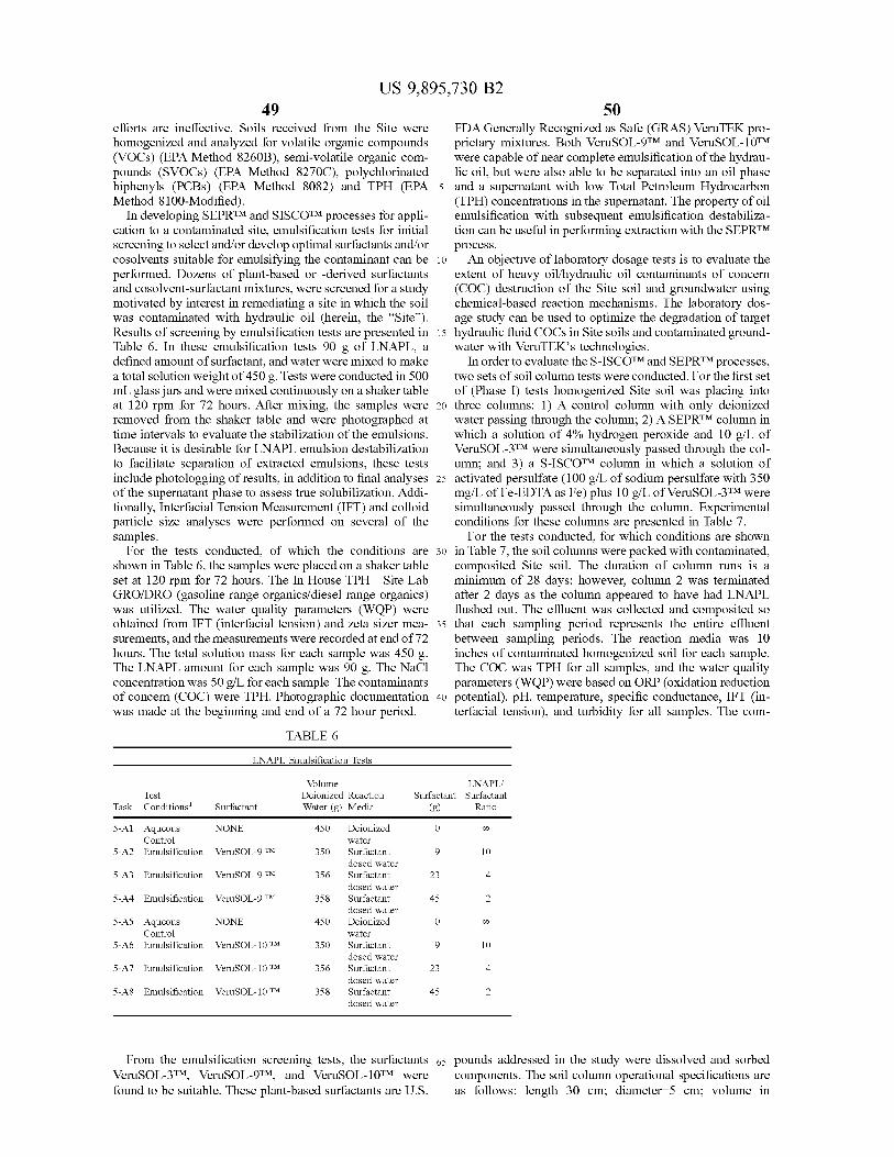
US 9 , 895 , 730 B2 49 50
efforts are ineffective . Soils received from the Site were FDA Generally Recognized as Safe ( GRAS ) VeruTEK pro homogenized and analyzed for volatile organic compounds prietary mixtures . Both VeruSOL - 9TM and VeruSOL - 10TM ( VOCs ) ( EPA Method 8260B ) , semi - volatile organic com were capable of near complete emulsification of the hydrau pounds ( SVOCs ) ( EPA Method 8270C ) , polychlorinated lic oil , but were also able to be separated into an oil phase biphenyls ( PCBs ) ( EPA Method 8082 ) and TPH ( EPA 5 and a supernatant with low Total Petroleum Hydrocarbon Method 8100 - Modified ) . ( TPH ) concentrations in the supernatant . The property of oil
In developing SEPRTM and SISCOTM processes for appli emulsification with subsequent emulsification destabiliza cation to a contaminated site , emulsification tests for initial tion can be useful in performing extraction with the SEPRTM screening to select and / or develop optimal surfactants and / or process . cosolvents suitable for emulsifying the contaminant can be 10 An objective of laboratory dosage tests is to evaluate the performed . Dozens of plant - based or - derived surfactants extent of heavy oil / hydraulic oil contaminants of concern and cosolvent - surfactant mixtures , were screened for a study ( COC ) destruction of the Site soil and groundwater using motivated by interest in remediating a site in which the soil chemical - based reaction mechanisms . The laboratory dos was contaminated with hydraulic oil ( herein , the " Site " ) . age study can be used to optimize the degradation of target Results of screening by emulsification tests are presented in 15 hydraulic fluid COCs in Site soils and contaminated ground Table 6 . In these emulsification tests 90 g of LNAPL , a water with VeruTEK ' s technologies . defined amount of surfactant , and water were mixed to make In order to evaluate the S - ISCOTM and SEPRTM processes , a total solution weight of 450 g . Tests were conducted in 500 two sets of soil column tests were conducted . For the first set mL glass jars and were mixed continuously on a shaker table of ( Phase I ) tests homogenized Site soil was placing into at 120 rpm for 72 hours . After mixing , the samples were 20 three columns : 1 ) A control column with only deionized removed from the shaker table and were photographed at water passing through the column ; 2 ) A SEPRTM column in time intervals to evaluate the stabilization of the emulsions . which a solution of 4 % hydrogen peroxide and 10 g / L of Because it is desirable for LNAPL emulsion destabilization VeruSOL - 3TM were simultaneously passed through the col to facilitate separation of extracted emulsions , these tests umn ; and 3 ) a S - ISCOTM column in which a solution of include photologging of results , in addition to final analyses 25 activated persulfate ( 100 g / L of sodium persulfate with 350 of the supernatant phase to assess true solubilization . Addi - mg / L of Fe - EDTA as Fe ) plus 10 g / L of VeruSOL - 3TM were tionally , Interfacial Tension Measurement ( IFT ) and colloid simultaneously passed through the column . Experimental particle size analyses were performed on several of the conditions for these columns are presented in Table 7 . samples . For the tests conducted , for which conditions are shown
For the tests conducted , of which the conditions are 30 in Table 7 , the soil columns were packed with contaminated , shown in Table 6 , the samples were placed on a shaker table composited Site soil . The duration of column runs is a set at 120 rpm for 72 hours . The In House TPH — Site Lab minimum of 28 days ; however , column 2 was terminated GRO / DRO ( gasoline range organics / diesel range organics ) after 2 days as the column appeared to have had LNAPL was utilized . The water quality parameters ( WQP ) were flushed out . The effluent was collected and composited so obtained from IFT ( interfacial tension ) and zeta sizer mea - 35 that each sampling period represents the entire effluent surements , and the measurements were recorded at end of 72 between sampling periods . The reaction media was 10 hours . The total solution mass for each sample was 450 g . inches of contaminated homogenized soil for each sample . The LNAPL amount for each sample was 90 g . The NaCl The COC was TPH for all samples , and the water quality concentration was 50 g / L for each sample . The contaminants parameters ( WQP ) were based on ORP ( oxidation reduction of concern ( COC ) were TPH . Photographic documentation 40 potential ) , pH , temperature , specific conductance , IFT ( in was made at the beginning and end of a 72 hour period . terfacial tension ) , and turbidity for all samples . The com
TABLE 6 LNAPL Emulsification Tests
Test Conditions
Volume Deionized Reaction Water ( g ) Media
LNAPL / Surfactant Surfactant
( g ) Ratio Task Surfactant
NONE 450 8 5 - A1 Aqueous Control
5 - A2 Emulsification a
VeruSOL - 9 TM 350 9
5 - A3 Emulsification VeruSOL - 9 TM 356 7
5 - A4 Emulsification VeruSOL - 9 TM 358 0
NONE 450
Deionized water Surfactant dosed water Surfactant dosed water Surfactant dosed water Deionized water Surfactant dosed water Surfactant dosed water Surfactant dosed water
5 - A5 Aqueous Control
5 - A6 Emulsification
re pe o ar 8
VeruSOL - 10 TM 350 9
5 - A7 Emulsification VeruSOL - 10 TM 356 7
5 - A8 Emulsification VeruSOL - 10 TM 358 le
From the emulsification screening tests , the surfactants 65 pounds addressed in the study were dissolved and sorbed VeruSOL - 3TM , VeruSOL - 9TM , and VeruSOL - 10TM were components . The soil column operational specifications are found to be suitable . These plant - based surfactants are U . S . as follows : length 30 cm ; diameter = 5 cm ; volume in
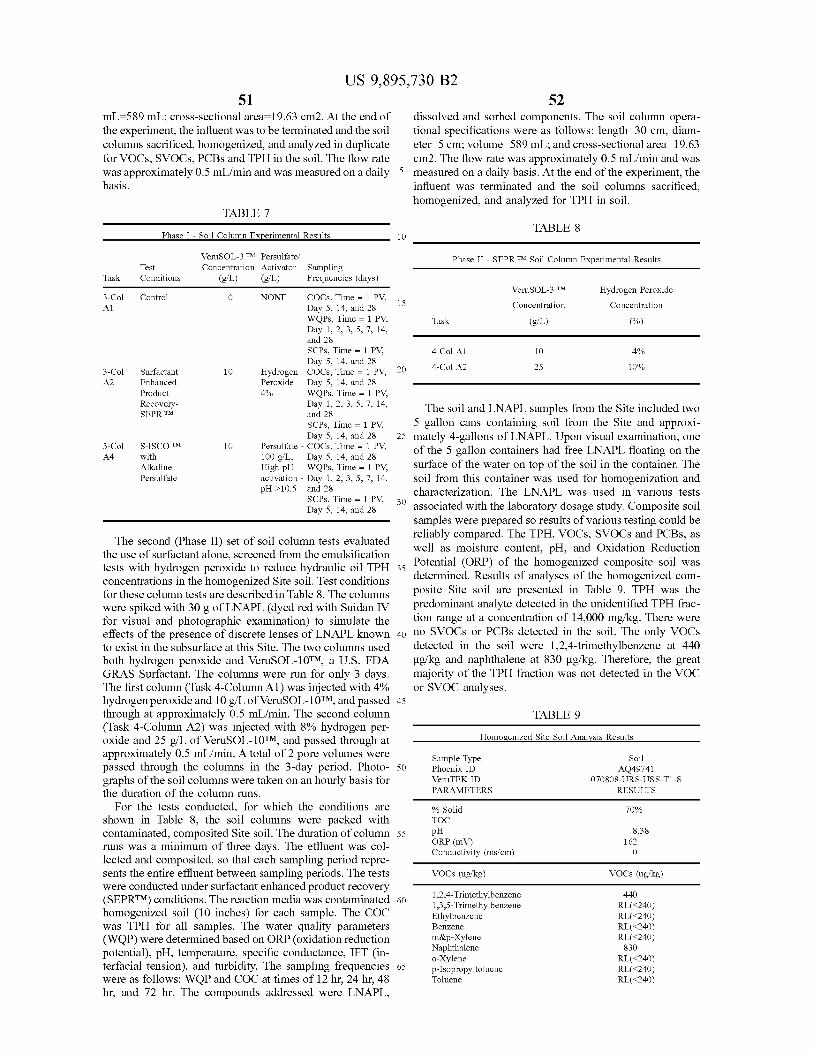
US 9 , 895 , 730 B2 51 52
mL = 589 mL ; cross - sectional area = 19 . 63 cm2 . At the end of dissolved and sorbed components . The soil column opera the experiment , the influent was to be terminated and the soil tional specifications were as follows : length = 30 cm , diam columns sacrificed , homogenized , and analyzed in duplicate eter = 5 cm ; volume = 589 mL ; and cross - sectional area = 19 . 63 for VOCs , SVOCs , PCBs and TPH in the soil . The flow rate cm2 . The flow rate was approximately 0 . 5 mL / min and was was approximately 0 . 5 mL / min and was measured on a daily 5 measured on a daily basis . At the end of the experiment , the basis . influent was terminated and the soil columns sacrificed ,
homogenized , and analyzed for TPH in soil . TABLE 7
TABLE 8 Phase I - Soil Column Experimental Results
Blº ( g / L )
25 . A2
.
VeruSOL - 3 TM Persulfate / Phase II - SEPR TM Soil Column Experimental Results Test Test Concentration Activator Sampling Task Conditions ( g / L ) ( g / L ) Frequencies ( days )
VeruSOL - 3 TM Hydrogen Peroxide 3 - Col Control O NONE COCs , Time = 1 PV , 15 A1 Day 5 , 14 , and 28 Concentration Concentration
WQPs , Time = 1 PV , Task ( % ) Day 1 , 2 , 3 , 5 , 7 , 14 , and 28 SCPs , Time = 1 PV , 4 - Col A1 4 % Day 5 , 14 , and 28 4 - Col A2 10 % 3 - Col Surfactant 20 10 Hydrogen COCs , Time = 1 PV .
Enhanced Peroxide - Day 5 , 14 , and 28 Product 4 % WQPs , Time = 1 PV , Recovery Day 1 , 2 , 3 , 5 , 7 , 14 , The soil and LNAPL samples from the Site included two SEPR TM and 28
SCPs , Time = 1 PV , 5 gallon cans containing soil from the Site and approxi Day 5 , 14 , and 28 25 mately 4 - gallons of LNAPL . Upon visual examination , one
3 - Col S - ISCO TM Persulfate - COCs , Time = 1 PV , of the 5 gallon containers had free LNAPL floating on the A4 with 100 g / L , Day 5 , 14 , and 28 Alkaline High pH WQPs , Time = 1 PV , surface of the water on top of the soil in the container . The Persulfate activation - Day 1 , 2 , 3 , 5 , 7 , 14 , soil from this container was used for homogenization and
pH > 10 . 5 and 28 characterization . The LNAPL was used in various tests SCPs , Time = 1 PV , 30 Day 5 , 14 , and 28 associated with the laboratory dosage study . Composite soil
samples were prepared so results of various testing could be reliably compared . The TPH , VOCs , SVOCs and PCBs , as The second ( Phase II ) set of soil column tests evaluated well as moisture content , pH , and Oxidation Reduction the use of surfactant alone , screened from the emulsification Potential ( ORP ) of the homogenized composite soil was tests with hydrogen peroxide to reduce hydraulic oil TPH 35
concentrations in the homogenized Site soil . Test conditions determined . Results of analyses of the homogenized com for these column tests are described in Table 8 . The columns posite Site soil are presented in Table 9 . TPH was the were spiked with 30 g of LNAPL ( dyed red with Suidan IV predominant analyte detected in the unidentified TPH frac for visual and photographic examination ) to simulate the tion range at a concentration of 14 , 000 mg / kg . There were effects of the presence of discrete lenses of LNAPL known 40 no SVOCs or PCBs detected in the soil . The only VOCs to exist in the subsurface at this Site . The two columns used detected in the soil were 1 , 2 , 4 - trimethylbenzene at 440 both hydrogen peroxide and VeruSOL - 10TM , a U . S . FDA ug / kg and naphthalene at 830 ug / kg . Therefore , the great GRAS Surfactant . The columns were run for only 3 days . majority of the TPH fraction was not detected in the VOC The first column ( Task 4 - Column Al ) was injected with 4 % or SVOC analyses . hydrogen peroxide and 10 g / L of VeruSOL - 10TM , and passed 45 through at approximately 0 . 5 mL / min . The second column TABLE 9 ( Task 4 - Column A2 ) was injected with 8 % hydrogen per oxide and 25 g / L of VeruSOL - 10TM , and passed through at Homogenized Site Soil Analysis Results
approximately 0 . 5 mL / min . A total of 2 pore volumes were Sample Type Soil passed through the columns in the 3 - day period . Photo - 50 Phoenix ID AQ49741 graphs of the soil columns were taken on an hourly basis for VeruTEK ID 070808 - URS - USS - T1 - S
PARAMETERS the duration of the column runs . RESULTS
For the tests conducted , for which the conditions are % Solid 70 % shown in Table 8 , the soil columns were packed with TOC
contaminated , composited Site soil . The duration of column 55 8 . 38 ORP ( mV ) 162 runs was a minimum of three days . The effluent was col Conductivity ( ms / cm ) lected and composited , so that each sampling period repre
sents the entire effluent between sampling periods . The tests VOCs ( ug / kg ) VOCs ( ug / kg ) were conducted under surfactant enhanced product recovery 1 , 2 , 4 - Trimethylbenzene 440 ( SEPRTM ) conditions . The reaction media was contaminated 60 1 , 3 , 5 - Trimethylbenzene RL ( < 240 ) homogenized soil ( 10 inches ) for each sample . The COC Ethylbenzene RL ( < 240 ) was TPH for all samples . The water quality parameters Benzene RL ( < 240 ) ( WQP ) were determined based on ORP ( oxidation reduction m & p - Xylene RL ( < 240 )
Naphthalene 830 potential ) , pH , temperature , specific conductance , IFT ( in 0 - Xylene RL ( < 240 ) terfacial tension ) , and turbidity . The sampling frequencies 65 p - Isopropyltoluene RL ( < 240 ) were as follows : WQP and COC at times of 12 hr , 24 hr , 48 Toluene RL ( < 240 ) hr , and 72 hr . The compounds addressed were LNAPL ,
pH
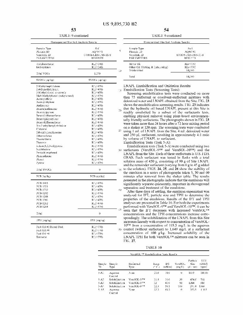
US 9 , 895 , 730 B2 54 53
TABLE 9 - continued TABLE 9 - continued Homogenized Site Soil Analysis Results Homogenized Site Soil Analysis Results
Soil 5
Sample Type Phoenix ID VeruTEK ID PARAMETERS
Soil AQ49741
070808 - URS - USS - T1 - S RESULTS
Sample Type Phoenix ID VeruTEK ID PARAMETERS
AQ49741 070808 - URS - USS - T1 - S
RESULTS Trichloroethene total - xylenes
RL ( < 240 ) RL ( < 240 )
Motor Oil Other Oil ( Cutting & Lubricating ) Unidentified
RL ( < 770 ) RL ( < 770 )
14 , 000 Total VOCs 1 , 270
Total 14 , 000 SVOCs ( ug / kg ) SVOCs ( ug / kg ) 2 - Methylnaphthalene 2 , 4 - Dimethylphenol 2 - Methylphenol ( o - cresol ) 3 & 4 - Methylphenol ( m & p - cresol ) Acenaphthene Acenaphthylene Anthracene Benz ( a ) anthracene Benzo ( a ) pyrene Benzo ( b ) fluoranthene Benzo ( ghi ) perylene Benzo ( k ) fluoranthene Bis ( 2 - ethylhexyl ) phthalate Chrysene Dibenz ( a , h ) anthracene Dibenzofuran Fluoranthene Fluorene Indeno ( 1 , 2 , 3 - cd ) pyrene Naphthalene Pentachlorophenol Phenanthrene Phenol Pyrene
RL ( < 470 ) RL ( < 470 ) RL ( < 470 ) RL ( < 470 ) RL ( < 470 ) RL ( < 470 ) RL ( < 470 ) RL ( < 470 ) RL ( < 470 ) RL ( < 470 ) RL ( < 470 ) RL ( < 470 ) RL ( < 470 ) RL ( < 470 ) RL ( < 470 ) RL ( < 470 ) RL ( < 470 ) RL ( < 470 ) RL ( < 470 ) RL ( < 470 ) RL ( < 470 ) RL ( < 470 ) RL ( < 470 ) RL ( < 470 )
LNAPL Emulsification and Oxidation Results 15 Emulsification Tests ( Screening Tests ) :
Screening emulsification tests were conducted on more than 75 surfactant or cosolvent - surfactant mixtures with deionized water and LNAPL obtained from the Site . FIG . 23 shows the emulsification screening results . FIG . 23 indicates that the hydraulic oil based LNAPL present at this Site is 20 readily emulsified by a subset of the surfactants tests , enabling physical removal using plant - based environmen tally friendly surfactants . The photographs shown in FIG . 23 were taken more than 24 hours after a 72 hour mixing period on a shaker at 120 rpm . The screening tests were conducted
25 using 1 mL of LNAPL from the Site , 4 mL deionized water and 250 uL surfactant , resulting in approximately 4 : 1 ratio by volume of LNAPL to surfactant . Emulsification Tests ( Task 5 - A ) :
Emulsification tests ( Task 5 - A ) were conducted using two 30 surfactants ( VeruSOL - STM and VeruSOL - 10TM ) and the
LNAPL from the Site . Each of these surfactants is U . S . FDA GRAS . Each surfactant was tested in flasks with a total solution mass of 450 g , consisting of 90 g of Site LNAPL and the remainder surfactant ( varying from 0 g to 45 g added
35 to the solution ) . FIGS . 24 , 25 , and 26 show the stability of the emulsion in a series of photographs taken 5 , 30 and 60 minutes after removal from the shaker table . The results presented in the photographs indicate that the emulsions will significantly separate quiescently , important in aboveground separation and treatment of the emulsions .
After three days of settling , the emulsion supernatant was analyzed for IFT , particle size and TPH to determine the properties of the emulsions . Results of the IFT and TPH analyses are presented in Table 10 . For both the experiments performed with VeruSOL - 9TM and VeruSOL - 10TM , it can be
45 seen that the IFT decreases with increased VeruSOLTM concentrations and the TPH concentrations increase corre spondingly . The solubilization of the LNAPL from this Site increases linearly with respect to concentration of VeruSOL 10TM from a concentration of 118 . 5 mg / L in the aqueous
50 control ( without surfactant ) to 1 , 649 mg / L at a surfactant concentration of 100 g / kg . Increased solubility of the LNAPL TPH for both VeruSOLTM mixtures can be seen in FIG . 27 .
Total SVOCs
PCB ( ug / kg ) PCB ( ug / kg )
PCB - 1016 PCB - 1221 PCB - 1232 PCB - 1242 PCB - 1248 PCB - 1260 PCB - 1262 PCB - 1268
RL ( < 470 ) RL ( < 470 ) RL ( < 470 ) RL ( < 470 ) RL ( < 470 ) RL ( < 470 ) RL ( < 470 ) RL ( < 470 )
Total 0
TPH ( mg / kg ) TPH ( mg / kg )
Fuel Oil # 2 / Diesel Fuel Fuel Oil # 4 Fuel Oil # 6 Kerosene
RLK770 ) RL ( < 770 ) RL ( < 770 ) RL ( < 770 )
TABLE 10 VeruSOL TM Emulsification Tests Results
Sample ID
Sample Type
Surfactant Type
Temp . IFT ( ° C . ) ( mN / m )
VeruSOL ( mg / L )
Particle TPH Size ( DRO )
( d . nm ) ( ppm ) 5 - A1 None 21 . 9 78 . 0 1953 186 . 85
5 - A2 5 - A3 5 - A4 5 - A5
Aqueous Control Solubilization Solubilization Solubilization Aqueous Control
VeruSOL - 9 TM VeruSOL - 9 TM VeruSOL - 9 TM None
21 . 8 22 22 . 3 22 . 3 22 . 3
39 . 0 40 . 0 39 . 1 69 . 3 69 . 3
20 50
100 0
474 . 6 761 1284 986 247 . 4 1369 353 . 5 118 . 5
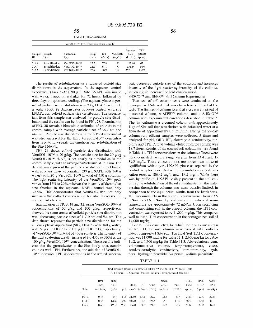
US 9 , 895 , 730 B2 55 TABLE 10 - continued
56
VeruSOL TM Emulsification Tests Results
Sample Sample ID Type
Surfactant Type
Temp . ( C . )
IFT ( mN / m )
VeruSOL ( mg / L )
Particle TPH Size ( DRO )
( d . nm ) ( ppm ) 20 5 - A6
5 - A7 5 - A8
Solubilization Solubilization Solubilization
VeruSOL - 10 TM VeruSOL - 10 TM VeruSOL - 10 TM
22 . 5 22 . 6 22 . 7
37 . 8 38 . 1 38 . 9
50 22 . 09 131 . 9
3523
471 956 1649 100
The results of solubilization tests impacted colloid size tant , decreases particle size of the colloids , and increases distributions in the supernatant . In the aqueous control intensity of the light scattering intensity of the colloids , experiment ( Task 5 - A5 ) , 90 g of Site LNAPL was mixed indicating an increased colloid concentration . with water , placed on a shaker for 72 hours , followed by S - ISCOTM and SEPRTM Soil Column Experiments three days of quiescent settling . ( The aqueous phase super Two sets of soil column tests were conducted on the natant particle size distribution was 90 g LNAPL with 360 homogenized Site soil that was characterized for all of the g water . ) FIG . 28 demonstrates aqueous control with site tests . The first set of column tests that were run consisted of LNAPL and colloid particle size distribution . The superna - 2o a control column , a SEPRTM column , and a S - ISCOTM tant from this sample was analyzed for particle size distri column with experimental conditions described in Table 7 . bution and the results can be found in FIG . 28 . Examination The first column was a control column with approximately of FIG . 28 reveals a binomial distribution of colloids in the 1 kg of Site soil that was flushed with deionized water at a control sample with average particle sizes of 36 . 9 nm and flowrate of approximately 0 . 5 mL / min . During the 27 - day 442 nm . Particle size distribution in the settled supernatant . 25 column run , effluent samples were collected 5 times and was also analyzed for the three VeruSOL - 10TM concentra analyzed for pH , ORP , IFT , electrolytic conductivity , tur tions used to investigate the emulsion and solubilization of bidity and TPH . A total volume eluted from the column was the Site LNAPL . 18 . 7 liters . Results of the control soil column test are found FIG . 29 shows colloid particle size distribution with in Table 11 . TPH concentrations in the column effluent were VeruSOL - 10TM at 20 g / kg . The particle size for the 20 g / kg , 30 quite consistent , with a range varying from 33 . 4 mg / L to VeruSOL - 10TM , 5 - A7 , is not nearly as bimodal as in the control sample , with an average particle size of 13 . 1 nm . The 39 . 8 mg / L . These concentrations are lower than those at data shown represent the particle size distribution obtained equilibrium with a pure LNAPL phase as reported in the with aqueous phase supernatant ( 90 g LNAPL with 360 g control samples associated with the emulsification / solubili water ) with 20 g VeruSOL - 10TM in total of 450 g solution . , zation tests , at 186 . 85 mg / L and 118 . 5 mg / L . While there The light scattering intensity of the VeruSOL - 10TM peak was hydraulic oil LNAPL visibly present in the soil col varies from 15 % to 20 % , whereas the intensity of the smaller umns , the solubilization of the oil constituents into the water size fraction in the aqueous - LNAPL control was only passing through the columns was mass transfer limited , in ~ 2 . 5 % . This demonstrates that VeruSOL - 10TM not only comparison to the equilibrium results from the batch tests . increases the colloid concentration but also decreases the 10 IFT measurements in the control column varied from 67 . 5 colloid particle size . mN / m to 77 . 6 mN / m . Typical water IFT values at room
Examination of FIGS . 30 and 31 , using VeruSOL - 10TM at temperature are approximately 72 mN / m . Upon sacrificing concentrations of 50 g / kg and 100 g / kg , respectively , and compositing soil in the control column , the TPH con showed the same trends of colloid particle size distribution centration was reported to be 11 , 000 mg / kg . This compares with decreasing particle sizes of 11 . 10 nm and 9 . 4 nm . The 15 well to initial TPH concentration in the homogenized soil of data shown represent the particle size distribution for the 14 , 000 mg / kg . aqueous phase supernatant ( 90 g LNAPL with 360 g water ) For the tests conducted , for which the results are shown with 50 g ( for FIG . 30 ) or 100 g ( for FIG . 31 ) , respectively , in Table 11 , the soil columns were packed with contami of VeruSOL - 10TM in total of 450 g solution . The intensity of nated , composited Site soil . The final Soil TPH Concentra the light scattering greatly increased to 45 % to 50 % ) at the sotion was 11 , 000 mg / kg for Table 11 . 1 , 2 , 600 mg / kg for Table 100 g / kg VeruSOL - 10TM concentration . These results indi - 11 . 2 , and 3 , 300 mg / kg for Table 11 . 3 . Abbreviations : cum . cate that the groundwater at the Site likely does contain vol . = cumulative volume , temp . = temperature , electr . colloids with TPH . Furthermore , the addition of VeruSOL cond . - electrolytic conductivity , turb . turbidity , hydr . 10TM increases TPH concentrations in the settled superna perx . = hydrogen peroxide ; Na perslf . = sodium persulfate .
TABLE 11 . 1
Soil Column Results for Control , SEPR TM and S - ISCO TM Tests : Task 3 - Column - 1 - Aqueous Control Column - Homogenized Site Soil
cum . flow
rate vol . ( mL / min ) ( mL )
electr . ORP IFT temp . cond . turb .
pH ( mV ) ( mN / m ) ( °C . ) ( mS / cm ) ( NTU )
TPH , D / M ( ppm )
TPH , total G RO TPH ( ppm ) ( mg / kg ) Date
10 - Jul
11 - Jul 16 - Jul
0 . 48 0 . 55 0 . 63
687 1476 4702
8 . 16 6 . 97 7 . 33
312 . 0 246 . 0 304 . 0
67 . 5 71 . 6 77 . 6
22 . 7 22 . 6 21 . 5
0 0
0 . 83 . 51 . 22
6 . 7 11 . 6 2 . 5
27 . 80 20 . 50 21 . 80
12 . 00 17 . 50 13 . 00
39 . 8 38 34 . 8
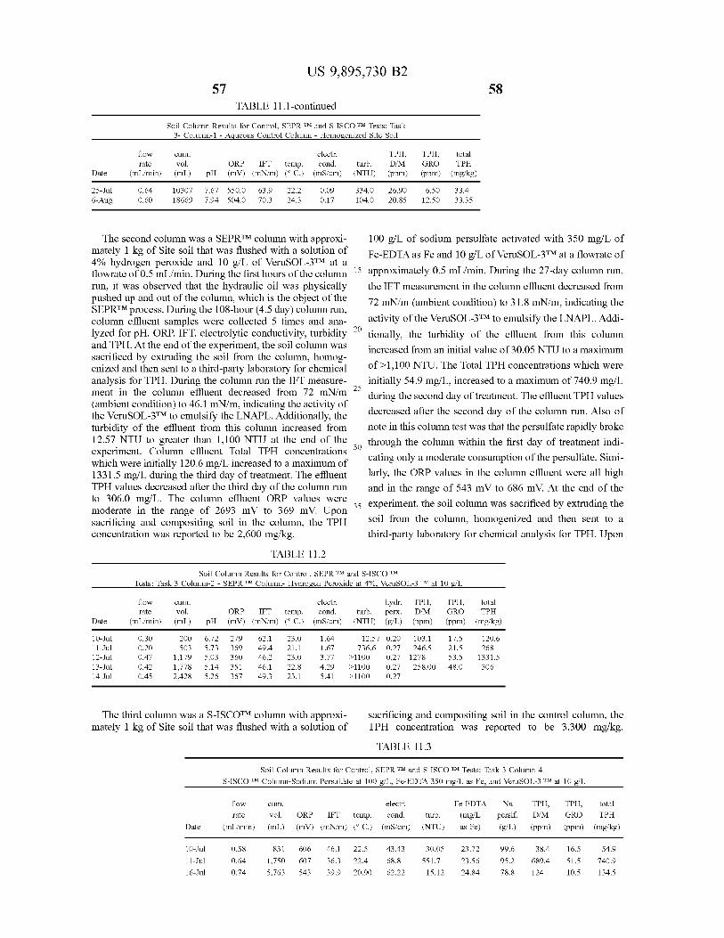
US 9 , 895 , 730 B2 57 58
TABLE 11 . 1 - continued Soil Column Results for Control , SEPR TM and S - ISCO TM Tests : Task
3 - Column - 1 - Aqueous Control Column - Homogenized Site Soil
TPH , flow rate
( mL / min )
cum . vol . ( mL )
electr . electr . ORP IFT temp . cond . ( mV ) ( mN / m ) ( °C . ) ( mS / cm )
turb . TPH , TPH , D / M ( ppm )
TPH , total total GRO TPH ( ppm ) ( mg / kg ) Date pH ( NTU )
25 - Jul 6 - Aug
0 . 64 0 . 60
10307 7 . 67 186697 . 94
550 . 0 504 . 0
63 . 9 70 . 3
22 . 2 24 . 3
0 . 09 0 . 17
334 . 0 104 . 0
26 . 90 20 . 85
6 . 50 12 . 50
33 . 4 33 . 35
The second column was a SEPRTM column with approxi - 100 g / L of sodium persulfate activated with 350 mg / L of mately 1 kg of Site soil that was flushed with a solution of Fe - EDTA as Fe and 10 g / L of VeruSOL - 3TM at a flowrate of Fe - EDTA as Fe and 10 g / L 4 % hydrogen peroxide and 10 g / L of VeruSOL - 3TM at a flowrate of 0 . 5 mL / min . During the first hours of the column 15 approximately 0 . 5 mL / min . During the 27 - day column run , run , it was observed that the hydraulic oil was physically the IFT measurement in the column effluent decreased from pushed up and out of the column , which is the object of the 72 mN / m ( ambient condition ) to 31 . 8 mN / m , indicating the SEPRTM process . During the 108 - hour ( 4 . 5 day ) column run , column effluent samples were collected 5 times and ana activity of the VeruSOL - 3TM to emulsify the LNAPL . Addi lyzed for pH , ORP , IFT , electrolytic conductivity , turbidity 20 tionally , the turbidity of the effluent from this column and TPH . At the end of the experiment , the soil column was increased from an initial value of 30 . 05 NTU to a maximum sacrificed by extruding the soil from the column , homog enized and then sent to a third - party laboratory for chemical of > 1 , 100 NTU . The Total TPH concentrations which were analysis for TPH . During the column run the IFT measure initially 54 . 9 mg / L , increased to a maximum of 740 . 9 mg / L ment in the column effluent decreased from 72 mN / m 25 during the second day of treatment . The effluent TPH values ( ambient condition ) to 46 . 1 mN / m , indicating the activity of the VeruSOL - 3TM to emulsify the LNAPL . Additionally , the decreased after the second day of the column run . Also of turbidity of the effluent from this column increased from note in this column test was that the persulfate rapidly broke 12 . 57 NTU to greater than 1 , 100 NTU at the end of the through the column within the first day of treatment indi experiment . Column effluent Total TPH concentrations which were initially 120 . 6 mg / L increased to a maximum of cating only a moderate consumption of the persulfate . Simi 1331 . 5 mg / L during the third day of treatment . The effluent larly , the ORP values in the column effluent were all high TPH values decreased after the third day of the column run and in the range of 543 mV to 686 mV . At the end of the to 306 . 0 mg / L . The column effluent ORP values were 35 experiment , the soil column was sacrificed by extruding the moderate in the range of 2693 mV to 369 mV . Upon sacrificing and compositing soil in the column , the TPH soil from the column , homogenized and then sent to a concentration was reported to be 2 , 600 mg / kg . third - party laboratory for chemical analysis for TPH . Upon
TABLE 11 . 2 Soil Column Results for Control , SEPR TM and S - ISCO TM
Tests : Task 3 Column - 2 - SEPR TM Column - Hydrogen Peroxide at 4 % . VeruSOL - 3 TM at 10 g / L
cum . flow rate
( mL / min ) vol . ( mL )
electr . ORP IFT temp . cond . ( mV ) ( mN / m ) ( °C . ) ( mS / cm )
hydr . TPH , turb . perx . D / M ( NTU ) ( g / L ) ( ppm )
TPH , total GRO TPH ( ppm ) ( mg / kg ) Date pH
10 - Jul 11 - Jul 12 - Jul 13 - Jul 14 - Jul
0 . 30 0 . 20 0 . 47 0 . 42 0 . 45
200 5 03 1 , 179 1 , 778 2 , 428
6 . 72 5 . 73 5 . 03 5 . 14 5 . 26
279 369 360 351 367
62 . 1 49 . 4 46 . 2 46 . 1 49 . 3
23 . 0 21 . 1 23 . 0 22 . 8 23 . 1
1 . 64 1 . 67 3 . 77 4 . 29 5 . 41
12 . 57 0 . 20 736 . 6 0 . 27
> 1100 0 . 27 > 1100 0 . 27 > 1100 0 . 27
103 . 1 246 . 5
1278 258 . 00
17 . 5 21 . 5 53 . 5 48 . 0
120 . 6 268
1331 . 5 306
The third column was a S - ISCOTM column with approxi - mately 1 kg of Site soil that was flushed with a solution of
sacrificing and compositing soil in the control column , the TPH concentration was reported to be 3 , 300 mg / kg . TABLE 11 . 3
Soil Column Results for Control , SEPR TM and S - ISCO TM Tests : Task 3 Column - 4 - S - ISCO TM Column - Sodium Persulfate at 100 g / L , Fe - EDTA 350 mg / L as Fe , and VeruSOL - 3 TM at 10 g / L
cum . TPH , flow
rate ( mL / min )
vol . ( mL )
electr .
ORP IFT temp . cond . ( mV ) ( mN / m ) ( °C . ) ( mS / cm )
turb . ( NTU )
Fe - EDTA ( mg / L as Fe )
Na perslf . ( g / L )
TPH , D / M ( ppm )
total
GRO TPH ( ppm ) ( mg / kg ) Date
0 . 58 10 - Jul 11 - Jul 16 - Jul
0 . 64 0 . 74
831 1 , 750 5 , 763
606 607 543
46 . 1 36 . 3 39 . 9
22 . 5 22 . 4 20 . 90
43 . 43 68 . 8 62 . 22
30 . 05 551 . 7
15 . 12
23 . 72 23 . 56 24 . 84
99 . 6 95 . 2 78 . 8
38 . 4 689 . 4 124
16 . 5 5 1 . 5 10 . 5
54 . 9 740 . 9 134 . 5
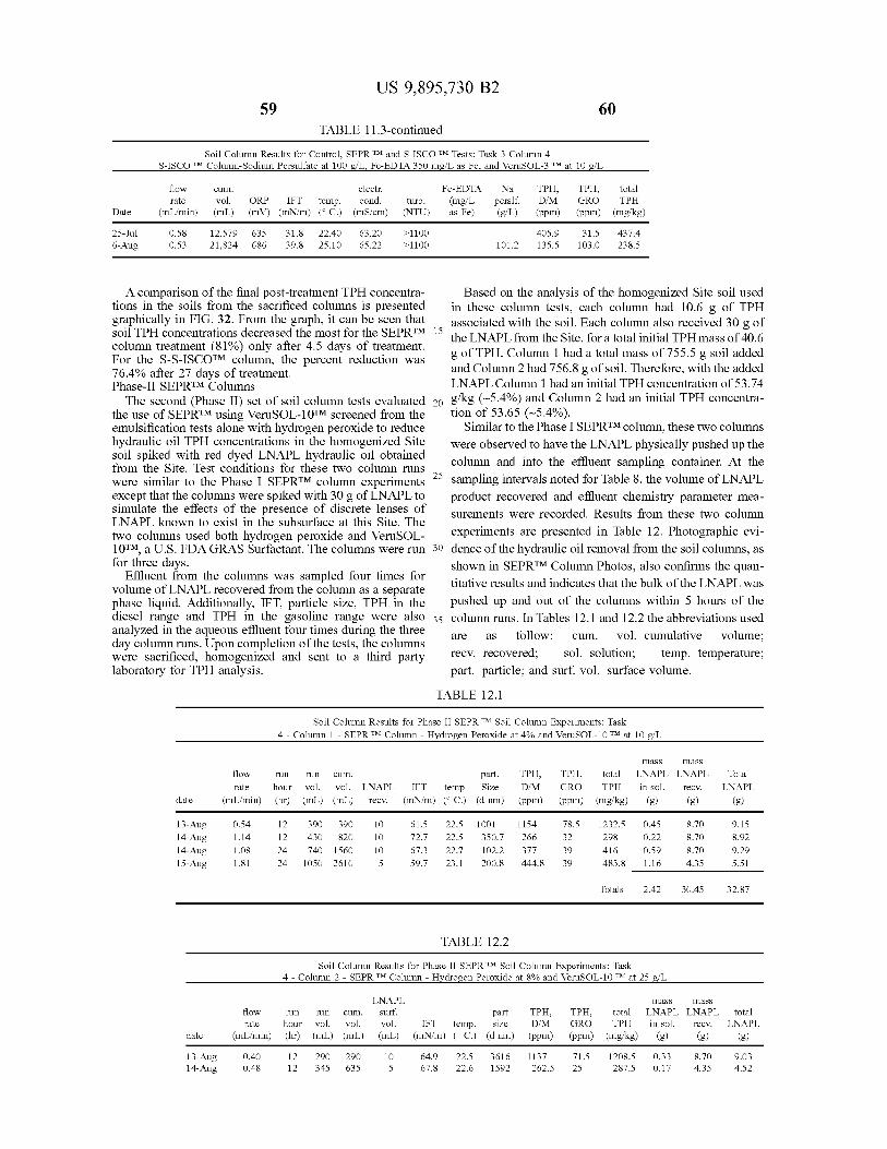
US 9 , 895 , 730 B2 59
TABLE 11 . 3 - continued
Soil Column Results for Control , SEPR TM and S - ISCO TM Tests : Task 3 Column - 4 - S - ISCO TM Column - Sodium Persulfate at 100 g / L , Fe - EDTA 350 mg / L as Fe , and VeruSOL - 3 TM at 10 g / L
flow rate
( mL / min )
cum .
vol . ( mL )
electr . ORP IFT temp . cond . ( mV ) ( mN / m ) ( °C . ) ( mS / cm )
turb . ( NTU )
Fe - EDTA ( mg / L as Fe )
Na perslf . ( g / L )
??? , D / M ( ppm )
TPH , total GRO TPH ( ppm ) ( mg / kg ) Date
25 - Jul 6 - Aug
0 . 58 0 . 53
12 , 579 21 , 824
635 686
31 . 8 39 . 8
22 . 40 25 . 10
63 . 20 65 . 22
> 1100 > 1100
405 . 9 135 . 5
31 . 5 103 . 0
437 . 4 238 . 5 101 . 2
A comparison of the final post - treatment TPH concentra Based on the analysis of the homogenized Site soil used tions in the soils from the sacrificed columns is presented in these column tests , each column had 10 . 6 g of TPH graphically in FIG . 32 . From the graph , it can be seen that associated with the soil . Each column also received 30 g of soil TPH concentrations decreased the most for the SEPRTM 15 the LNAPL from the Site , for a total initial TPH mass of 40 . 6 column treatment ( 81 % ) only after 4 . 5 days of treatment . g of TPH . Column 1 had a total mass of 755 . 5 g soil added For the S - S - ISCOTM column , the percent reduction was 76 . 4 % after 27 days of treatment . and Column 2 had 756 . 8 g of soil . Therefore , with the added Phase - II SEPRTM Columns LNAPL Column 1 had an initial TPH concentration of 53 . 74
The second ( Phase II ) set of soil column tests evaluated 20 g / kg ( ~ 5 . 4 % ) and Column 2 had an initial TPH concentra the use of SEPRTM using VeruSOL - 10TM screened from the tion of 53 . 65 ( ~ 5 . 4 % ) . emulsification tests alone with hydrogen peroxide to reduce Similar to the Phase I SEPRTM column , these two columns hydraulic oil TPH concentrations in the homogenized Site were observed to have the LNAPL physically pushed up the soil spiked with red dyed LNAPL hydraulic oil obtained from the Site . Test conditions for these two column runs column and into the effluent sampling container . At the were similar to the Phase I SEPRTM column experiments 25 sampling intervals noted for Table 8 , the volume of LNAPL except that the columns were spiked with 30 g of LNAPL to product recovered and effluent chemistry parameter mea simulate the effects of the presence of discrete lenses of surements were recorded . Results from these two column LNAPL known to exist in the subsurface at this Site . The two columns used both hydrogen peroxide and VeruSOL experiments are presented in Table 12 . Photographic evi 10TM , a U . S . FDA GRAS Surfactant . The columns were run 30 dence of the hydraulic oil removal from the soil columns , as for three days . shown in SEPRTM Column Photos , also confirms the quan Effluent from the columns was sampled four times for volume of LNAPL recovered from the column as a separate titative results and indicates that the bulk of the LNAPL was phase liquid . Additionally , IFT , particle size , TPH in the pushed up and out of the columns within 5 hours of the diesel range and TPH in the gasoline range were also 35 column runs . In Tables 12 . 1 and 12 . 2 the abbreviations used analyzed in the aqueous effluent four times during the three are as follow : cum . vol . = cumulative volume ; day column runs . Upon completion of the tests , the columns were sacrificed , homogenized and sent to a third party recv . = recovered ; sol . - solution ; temp . temperature ; laboratory for TPH analysis . part . = particle ; and surf . vol . = surface volume .
TABLE 12 . 1
Soil Column Results for Phase II SEPR TM Soil Column Experiments : Task 4 - Column 1 - SEPR TM Column - Hydrogen peroxide at 4 % and VeruSOL - 10 TM at 10 g / L
flow rate
( mL / min )
run run cum . hour vol . vol . LNAPL ( hr ) ( mL ) ( mL ) recv .
part . IFT temp Size
( mN / m ) ( °C . ) ( d nm )
TPH , D / M ( ppm )
TPH , GRO ( ppm )
total TPH
( mg / kg )
mass mass LNAPL LNAPL in sol . recv .
( g ) ( g )
Total LNAPL
( g ) date
78 . 5 32
13 - Aug 14 - Aug 14 - Aug 15 - Aug
0 . 54 1 . 14 1 . 08 1 . 81
12 12 24 24
390 430 740 1050
390 820
1560 2610
10 10 10 5
61 . 5 72 . 7 67 . 3 59 . 7
22 . 5 22 . 5 22 . 7 23 . 1
1001 350 . 7 102 . 2 200 . 8
1154 266 377 444 . 8
1232 . 5 298 416
4 83 . 8
0 . 45 0 . 22 0 . 59 1 . 16
8 . 70 8 . 70 8 . 70 4 . 35
9 . 15 8 . 92 9 . 29 5 . 51 39
Totals 2 . 42 30 . 45 32 . 87
TABLE 12 . 2 Soil Column Results for Phase II SEPR IM Soil Column Experiments : Task
4 - Column 2 - SEPR TM Column - Hydrogen peroxide at 8 % and VeruSOL - 10 TM at 25 g / L
part flow run run cum . rate hour vol . vol .
( mL / min ) ( hr ) ( mL ) ( mL )
LNAPL surf . vol . ( mL )
TPH , D / M ( ppm )
IF temp . size ( mN / m ) ( C . ) ( d nm )
TPH , total GRO TPH ( ppm ) ( mg / kg )
mass mass LNAPL LNAPL in sol . recv .
( g ) ( g )
total LNAPL
( g ) date 13 - Aug 14 - Aug
0 . 40 0 . 48
12 12
290 345
290 635
10 5
64 . 9 67 . 8
22 . 5 22 . 6
3616 1592
1137 262 . 5
7 1 . 5 25
1208 . 5 287 . 5
0 . 338 . 70 0 . 17 4 . 35
9 . 03 4 . 52
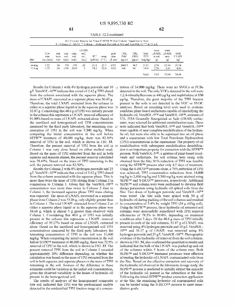
US 9 , 895 , 730 B2 TABLE 12 . 2 - continued
Soil Column Results for Phase II SEPR TM Soil Column Experiments : Task 4 - Column 2 - SEPR TM Column - Hydrogen peroxide at 8 % and VeruSOL - 10 TM at 25 g / L
flow rate
( mL / min )
run hour ( hr )
run cum . vol . vol . ( mL ) ( mL )
LNAPL surf . vol .
( mL )
part IFT temp . size
( mN / m ) ( °C . ) ( d nm )
TPH , D / M
( ppm )
TPH , GRO ( ppm )
mass mass total LNAPL LNAPL total TPH in sol . recv . LNAPL
( mg / kg ) ( g ) ( g ) ( g ) date 14 - Aug 15 - Aug
0 . 52 0 . 73
24 2 4
750 1385 1050 2435
20 3
69 . 1 74 . 1
22 . 7 22 . 6
1555 1632
2048 . 5 940
84 . 5 69
2133 1 009
2 . 84 2 . 29
17 . 40 2 . 61
20 . 24 4 . 90
Total 5 . 62 33 . 06 38 . 68
Results for Column 1 with 4 % hydrogen peroxide and 10 15 tration of 14 , 000 mg / kg . There were no SVOCs or PCBs g / L VeruSOL - 10TM indicate that a total of 2 . 42 g TPH eluted detected in the soil . The only VOCs detected in the soil were from the column associated with the aqueous phase . The 1 , 2 , 4 - trimethylbenzene at 440 ug / kg and naphthalene at 830 mass of LNAPL recovered as a separate phase was 30 . 45 g . ug / kg . Therefore , the great majority of the TPH fraction Therefore , the total LNAPL extracted from the column in present in the soils is not detected in the VOC or SVOC either as a separate phase liquid or in the aqueous phase was 20 analyses . Based on screening level tests used to evaluate 32 . 87 g . Considering that 40 . 6 g of TPH was initially present candidate plant - based surfactants capable of emulsifying the in the column this represents a LNAPL removal efficiency of hydraulic oil , VeruSOL - 9TM and VeruSOL - 10TM , mixtures of 81 . 00 % based on mass of LNAPL extracted alone . Based on U . S . FDA Generally Recognized as Safe ( GRAS ) surfac the sacrificed and homogenized soil TPH concentrations tants , were selected for additional emulsification tests . These measured by the third party laboratory , the remaining con - 25 tests indicated that both VeruSOL - STM and VeruSOL - 10TM centration of TPH in the soil was 9 , 500 mg / kg . When were capable of near complete emulsification of the hydrau comparing the initial concentration in the soil before lic oil , but were also able to be separated into an oil phase SEPRTM treatment of 40 , 600 mg / kg , there was 82 . 30 % and a supernatant with low Total Petroleum Hydrocarbon removal of TPH in the soil , which is shown in FIG . 33 . ( TPH ) concentrations in the supernatant . The property of oil Therefore , the percent removal of TPH from the soil in 30 emulsification with subsequent emulsification destabiliza Column 1 was very close based on either method used . tion is an important property for extraction with the SEPRTM Based on the mass of TPH extracted from the soil in both process . With VeruSOL - 3TM , a mixture of plant - based cosol aqueous and separate phases , the percent removal calculated vents and surfactants , for soil column tests using soils was 78 . 49 % . Based on the mass of TPH remaining in the obtained from the Site , 81 % reduction of TPH was feasible soil , the percent removal was 82 . 30 % . 35 using the SEPRTM process after only 4 . 5 days of treatment .
Results for Column 2 with 8 % hydrogen peroxide and 25 Using the S - ISCOTM process alone , a 76 % reduction of TPH g / L VeruSOL - 10TM indicate that a total of 5 . 62 g TPH eluted was achieved . TPH concentration reductions from 14 , 000 from the column associated with the aqueous phase . This is mg / kg to 2 , 600 mg / kg and 3 , 300 mg / kg were attained using more than twice the mass of TPH eluting from Column 2 in SEPRTM and S - ISCOTM processes , respectively . Additional comparison to Column 1 . Given that the VeruSOL - 10TM 40 SEPRTM soil column tests were performed to develop field concentration was more than twice in Column 2 than in design parameters using hydraulic oil spiked soils from the Column 1 , the increased aqueous phase TPH mass eluting Site . Two doses of hydrogen peroxide and VeruSOL - 10TM was expected . The mass of LNAPL recovered as a separate were tested . The Site soils were spiked with 30 g of phase from Column 2 was 33 . 06 g , only slightly greater than hydraulic oil during packing of the soil columns and resulted in Column 1 . The total LNAPL extracted from Column 2 as 45 in concentration of 5 . 4 % by weight TPH ( 54 g oil / kg soil ) . either a separate phase liquid or in the aqueous phase was Using the SEPRTM process , these hydraulic oil saturated soil 38 . 68 g , which is almost 5 g greater than observed with columns were successfully remediated with TPH removal Column 1 . Considering that 40 . 6 g of TPH was initially efficiencies of 78 . 5 % to 89 . 0 % , depending on treatment present in the column this represents a LNAPL removal conditions after 3 days . Of the 40 . 6 g mass of TPH initially efficiency of 95 . 27 % based on mass of LNAPL extracted 50 present in each of the soil columns , 31 . 87 g of LNAPL was alone . Based on the sacrificed and homogenized soil TPH removed using 4 % hydrogen peroxide and 10 g / L VeruSOL concentrations measured by the third party laboratory the 10TM and 36 . 17 g of LNAPL was removed using 8 % remaining concentration of TPH in the soil was 11 , 000 hydrogen peroxide and 25 g / L VeruSOL - 10TM . Photographic mg / kg . When comparing the initial concentration in the soil evidence of the hydraulic oil removal from the soil columns , before SEPRTM treatment of 40 , 600 mg / kg , there was 72 . 9 % 55 shown in FIG . 34 , also confirmed the quantitative results and removal of TPH in the soil , which is shown in FIG . 33 . The indicated that the bulk of the LNAPL was pushed up and out percent removal TPH from the soil in Column 2 revealed of the columns within 5 hours of the column runs . Both approximately 10 % difference depending on whether the SEPRTM and S - ISCOTM treatment processes were effective calculation was based on the mass of TPH extracted from the at treating the hydraulic oil LNAPL contaminated soils from soil in both aqueous and separate phases or the mass of TPH 60 the Site . Based on the effective extraction and recovery of remaining in the soil . Sources of the difference in these the hydraulic oil observed in the laboratory dosage study , the estimates could be variation in the initial soil concentration , SEPRTM process is predicted to initially extract the majority given the observed variability in the lenses of hydraulic oil of the hydraulic oil present in the subsurface at the Site . present in the homogenized soil . Following the initial SEPRTM product extraction application
The results of analyses of the homogenized composite 65 at the Site , the remaining hydraulic oil contaminated soils Site soil indicated that TPH was the predominant analyte can be treated using the S - ISCOTM process to meet reme detected in the unidentified TPH fraction range at a concen d iation goals .
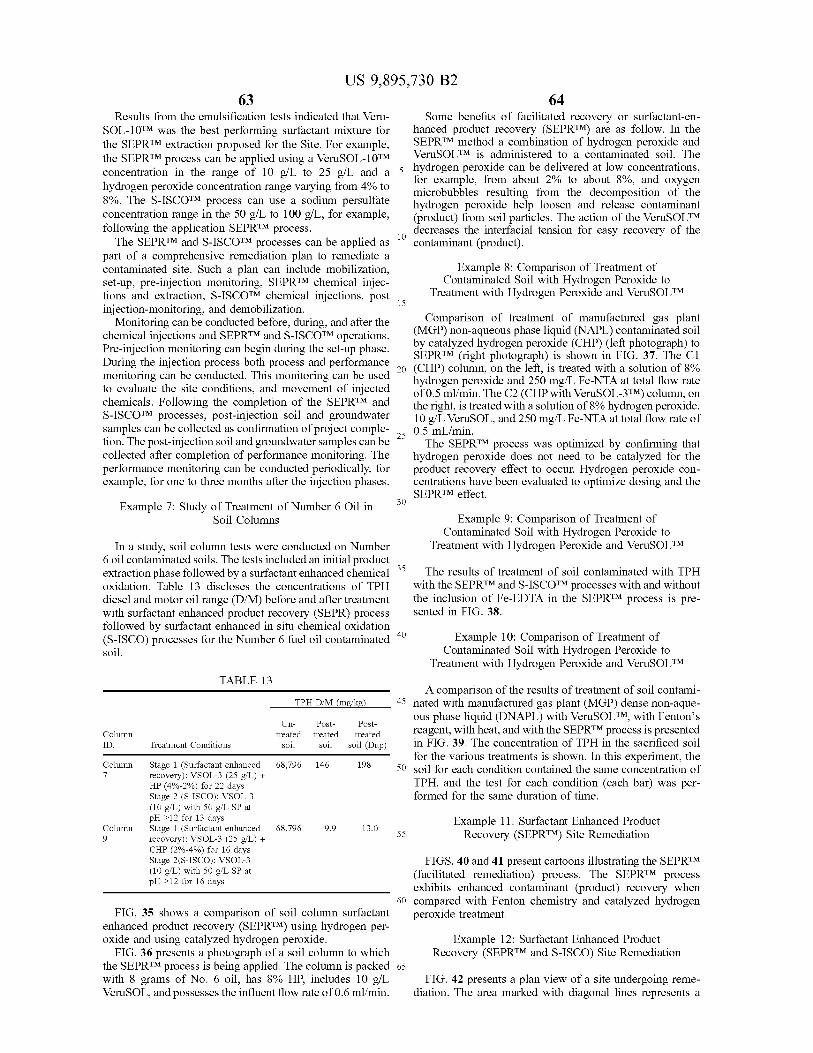
US 9 , 895 , 730 B2 64
Results from the emulsification tests indicated that Veru - Some benefits of facilitated recovery or surfactant - en SOL - 10TM was the best performing surfactant mixture for hanced product recovery ( SEPRTM ) are as follow . In the the SEPRTM extraction proposed for the Site . For example , SEPRTM method a combination of hydrogen peroxide and the SEPRTM process can be applied using a VeruSOL - 10TM VeruSOLTM is administered to a contaminated soil . The concentration in the range of 10 g / L to 25 g / L and a 5 ay da 5 hydrogen peroxide can be delivered at low concentrations ,
for example , from about 2 % to about 8 % , and oxygen hydrogen peroxide concentration range varying from 4 % to microbubbles resulting from the decomposition of the 8 % . The S - ISCOTM process can use a sodium persulfate hydrogen peroxide help loosen and release contaminant concentration range in the 50 g / L to 100 g / L , for example , ( product ) from soil particles . The action of the VeruSOLTM following the application SEPRTM process . decreases the interfacial tension for easy recovery of the
The SEPRTM and S - ISCOTM processes can be applied as contaminant ( product ) . part of a comprehensive remediation plan to remediate a contaminated site . Such a plan can include mobilization , Example 8 : Comparison of Treatment of set - up , pre - injection monitoring , SEPRTM chemical injec Contaminated Soil with Hydrogen Peroxide to tions and extraction , S - ISCOTM chemical injections , post Treatment with Hydrogen Peroxide and VeruSOLTM
15 injection - monitoring , and demobilization . Monitoring can be conducted before , during , and after the Comparison of treatment of manufactured gas plant
chemical injections and SEPRTM and S - ISCOTM operations . ( MGP ) non - aqueous phase liquid ( NAPL ) contaminated soil Pre - injection monitoring can begin during the set - up phase . by catalyzed hydrogen peroxide ( CHP ) ( left photograph ) to
SEPRTM ( right photograph ) is shown in FIG . 37 . The C1 During the injection process both process and performance 20 ( CHP ) column , on the left , is treated with a solution of 8 % monitoring can be conducted . This monitoring can be used - hydrogen peroxide and 250 mg / L Fe - NTA at total flow rate to evaluate the site conditions , and movement of injected of 0 . 5 ml / min . The C2 ( CHP with VeruSOL - 3TM ) column , on chemicals . Following the completion of the SEPRTM and the right , is treated with a solution of 8 % hydrogen peroxide , S - ISCOTM processes , post - injection soil and groundwater 10 g / L VeruSOL , and 250 mg / L Fe - NTA at total flow rate of samples can be collected as confirmation of project comple - sc 0 . 5 mL / min . tion . The post - injection soil and groundwater samples can be The SEPRTM process was optimized by confirming that collected after completion of performance monitoring . The hydrogen peroxide does not need to be catalyzed for the performance monitoring can be conducted periodically , for product recovery effect to occur . Hydrogen peroxide con example , for one to three months after the injection phases . centrations have been evaluated to optimize dosing and the
SEPRTM effect . Example 7 : Study of Treatment of Number 6 Oil in 30
Soil Columns Example 9 : Comparison of Treatment of Contaminated Soil with Hydrogen Peroxide to
In a study , soil column tests were conducted on Number Treatment with Hydrogen Peroxide and VeruSOLTM 6 oil contaminated soils . The tests included an initial product extraction phase followed by a surfactant enhanced chemical 35 The results of treatment of soil contaminated with TPH oxidation . Table 13 discloses the concentrations of TPH with the SEPRTM and S - ISCOTM processes with and without diesel and motor oil range ( D / M ) before and after treatment the inclusion of Fe - EDTA in the SEPRTM process is pre with surfactant enhanced product recovery ( SEPR ) process sented in FIG . 38 . followed by surfactant enhanced in situ chemical oxidation ( S - ISCO ) processes for the Number 6 fuel oil contaminated 40 Example 10 : Comparison of Treatment of soil . Contaminated Soil with Hydrogen Peroxide to
Treatment with Hydrogen peroxide and VeruSOLTM TABLE 13
A comparison of the results of treatment of soil contami TPH D / M ( mg / kg ) 45 nated with manufactured gas plant ( MGP ) dense non - aque
ous phase liquid ( DNAPL ) with VeruSOLTM , with Fenton ' s Un - Post - Post Column treated treated reagent , with heat , and with the SEPRTM process is presented treated ID . Treatment Conditions soil soil soil ( Dup ) in FIG . 39 . The concentration of TPH in the sacrificed soil
for the various treatments is shown . In this experiment , the Column Stage 1 ( Surfactant enhanced 68 , 796 146 198 50 soil for each condition contained the same concentration of recovery ) : VSOL - 3 ( 25 g / L ) +
HP ( 4 % - 2 % ) for 22 days TPH , and the test for each condition ( each bar ) was per Stage 2 ( S - ISCO ) : VSOL - 3 formed for the same duration of time . ( 10 g / L ) with 50 g / L SP at pH > 12 for 13 days Example 11 : Surfactant Enhanced Product Column Stage 1 ( Surfactant enhanced 68 , 796 9 . 9 13 . 0 recovery ) : VSOL - 3 ( 25 g / L ) + Recovery ( SEPRTM ) Site Remediation CHP ( 2 % - 4 % ) for 16 days Stage 2 ( S - ISCO ) : VSOL - 3 FIGS . 40 and 41 present cartoons illustrating the SEPRTM ( 10 g / L ) with 50 g / L SP at ( facilitated remediation ) process . The SEPRTM process pH > 12 for 16 days exhibits enhanced contaminant ( product ) recovery when
60 compared with Fenton chemistry and catalyzed hydrogen FIG . 35 shows a comparison of soil column surfactant n of soil column surfactant peroxide treatment .
enhanced product recovery ( SEPRTM ) using hydrogen per oxide and using catalyzed hydrogen peroxide . Example 12 : Surfactant Enhanced Product
FIG . 36 presents a photograph of a soil column to which Recovery ( SEPRTM and S - ISCO ) Site Remediation the SEPRTM process is being applied . The column is packed 65 with 8 grams of No . 6 oil , has 8 % HP , includes 10 g / L FIG . 42 presents a plan view of a site undergoing reme VeruSOL , and possesses the influent flow rate of 0 . 6 ml / min . diation . The area marked with diagonal lines represents a
7
55
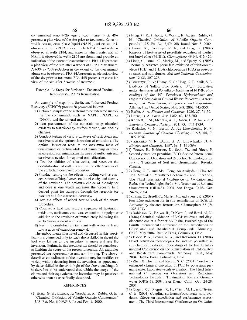
10
15 15
US 9 , 895 , 730 B2 65 66
contaminated zone 4626 square feet in area . FIG . 43A ( 2 ) Hoag , G . E . ; Chheda , P . ; Woody , B . A . ; and Dobbs , G . presents a plan view of the site prior to treatment . Zones in M . " Chemical Oxidation of Volatile Organic Com which non - aqueous phase liquid ( NAPL ) and no water is pounds , ” U . S . Pat . No . 6 , 474 , 908 . Issued Nov . 5 , 2002 . observed in wells 2102 , zones in which NAPL and water is ( 3 ) Huang , K . , Couttenye , R . A . , and Hoag , G . ( 2002 ) observed in wells 2104 , and zones in which water and no 5 Kinetics of heat - assisted persulfate oxidation of methyl NAPL is observed in wells 2106 are shown and provide an tert - butyl ether ( MTBE ) . Chemosphere 49 ( 4 ) , 413 - 420 . indication of the extent of contamination . FIG . 43B presents ( 4 ) Liang , C . , Bruell , C . , Marley , M . , and Sperry , K . ( 2003 ) a plan view of the site after 4 weeks of SEPRTM treatment . Thermally activated persulfate oxidation of trichloroeth A 60 % to 75 % reduction in the extent of the contaminant ylene ( TCE ) and 1 , 1 , 1 - trichloroethane ( TCA ) in aqueous plume can be observed . FIG . 44A presents an elevation view systems and soil slurries . Soil and Sediment Contamina of the site prior to treatment . FIG . 44B presents an elevation tion 12 ( 2 ) , 207 - 228 . view of the site after 5 weeks of treatment . ( 5 ) Couttenye , R . A . ; Huang , K . C . ; Hoag , G . E . ; Suib , S . L .
Evidence of Sulfate Free Radical ( S04 . ) Formation Example 13 : Steps for Surfactant Enhanced Product under Heat - assisted Persulfate Oxidation of MTBE . Pro
Recovery ( SEPRTM ) Remediation ceedings of the 19th Petroleum Hydrocarbons and Organic Chemicals in Ground Water : Prevention , Assess
An example of steps in a Surfactant Enhanced Product ment , and Remediation , Conference and Exposition , Recovery ( SEPRTM ) process is presented below : Atlanta , Ga . , United States , Nov . 5 - 8 , 2002 , 345 - 350 .
1 ) Obtain a sample of the material to be extracted includ - 20 ( 6 ) Berlin , A . A . Kinetics and Catalysis . 1986 , 27 , 34 - 39 . ing the contaminant , such as NAPL , LNAPL , or ( 7 ) House , D . A . Chem . Rev . 1962 , 62 , 185 - 200 . DNAPL , and the mineral matrix . ( 8 ) Kolthoff , I . M . ; Medalia , A . I . ; Raaen , H . P . Journal of
2 ) Test pretreatment of the materials using chemical American Chemical Society . 1951 , 73 , 1733 - 1739 . oxidants to test viscosity , surface tension , and density ( 9 ) Kislenko , V . N . ; Berlin , A . A . ; Litovchenko , N . V . changes . 25 Russian Journal of General Chemistry . 1995 , 65 , 7 ,
3 ) Conduct testing of various mixtures of surfactants and 1092 - 1096 . cosolvents of the optimal formation of emulsions . The ( 10 ) Kislenko , V . N . ; Berlin , A . A . ; Litovchenko , N . V . optimal formation leads to the maximum mass of Kinetics and Catalysis . 1997 , 38 , 3 , 391 - 396 . contaminant extraction while still maintaining an emul ( 11 ) Brown , R . , Robinson , D . , Sethi , D . , and Block , P . sion system and minimizing the mass of surfactants and 30 Second generation persulfate ISCO . Second International cosolvents needed for optimal emulsification . Conference on Oxidation and Reduction Technologies for
4 ) Test the addition of salts , acids , and bases on the In - Situ Treatment of Soil and Groundwater . Toronto , destabilization of colloids and on the effectiveness of Canada . the surfactant - cosolvent properties . ( 12 ) Hoag , G . E . , and Mao , Feng , An Analysis of Chelated
5 ) Conduct testing on the effects of adding various con - * Iron Activated Persulfate - Mechanisms and Reactions , centrations of biopolymers on the viscosity and density The Third International Conference on Oxidation and of the emulsion . The optimum choice of biopolymer Reduction Technologies for In - Situ Treatment of Soil and and dose is one which increases the viscosity to a Groundwater ( ORTs - 3 ) . 2004 . San Diego , Calif . , Oct . desired point for transport through the reservoir ( or 40 24 - 28 , 2004 . reactor ) and for extraction recovery . ( 13 ) Liang , C . , Bruell , C . , Marley , M . , and Sperry , K . ( 2004 )
6 ) Test the effects of added heat on each of the above Persulfate oxidation for in situ remediation of TCE : II . properties . Activated by chelated ferrous ion . Chemosphere 55 ( 9 ) ,
7 ) Conduct a field test using a sequence of treatment , 1225 - 1233 . oxidation , surfactant - cosolvent extraction , biopolymer 45 ( 14 ) Robinson , D . , Brown , R . , Dablow , J , and Rowland , K . addition to the emulsion or immediately following the ( 2004 ) Chemical oxidation of MGP residuals and dicy surfactant - cosolvent addition . clopentadiene at a former MGP site , Proceedings of the
8 ) Push the emulsified contaminant with water or brine Fourth International Conference on the Remediation of into a zone of extraction removal . Chlorinated and Recalcitrant Compounds , Monterey ,
The embodiments illustrated and discussed in this speci - 50 Calif . , May 2004 . Batelle Press , Columbus , Ohio . fication are intended only to teach those skilled in the art the ( 15 ) Block , P . A . , Brown , R . A . , and Robinson , D . ( 2004 ) best way known to the inventors to make and use the Novel activation technologies for sodium persulfate in invention . Nothing in this specification should be considered situ chemical oxidation , Proceedings of the Fourth Inter as limiting the scope of the present invention . All examples national Conference on the Remediation of Chlorinated presented are representative and non - limiting . The above - 55 and Recalcitrant Compounds , Monterey , Calif . , May described embodiments of the invention may be modified or 2004 . Batelle Press , Columbus , Ohio . varied , without departing from the invention , as appreciated ( 16 ) Zhai , X , Hua , I . , and Rao , P . S . C . ( 2004 ) Cosolvent by those skilled in the art in light of the above teachings . It enhanced chemical oxidation of PCE by potassium per is therefore to be understood that , within the scope of the manganate : Laboratory - scale evaluation , The Third Inter claims and their equivalents , the invention may be practiced 60 national Conference on Oxidation and Reduction otherwise than as specifically described . Technologies for In - Situ Treatment of Soil and Ground
water ( ORTS - 3 ) . 2004 . San Diego , Calif . , Oct . 24 - 28 , REFERENCES 2004 .
( 17 ) Dugan , P . J . , Siegrist , R . L . , Crimi , M . L . , and Divinr , ( 1 ) Hoag , G . E . ; Chheda , P . ; Woody , B . A . ; Dobbs , G . M . 65 C . E . ( 2004 ) Coupling surfactants / cosolvents with oxi
“ Chemical Oxidation of Volatile Organic Compounds , ” dants : Effects on remediation and performance assess U . S . Pat . No . 6 , 019 , 548 . Issued Feb . 1 , 2000 . ment , The Third International Conference on Oxidation
US 9 , 895 , 730 B2 68
and Reduction Technologies for In - Situ Treatment of Soil providing an extraction well ; and and Groundwater ( ORTS - 3 ) . 2004 . San Diego , Calif . , Oct . inducing the flow of contaminant toward the extraction 24 - 28 , 2004 . well to establish an extraction zone ,
( 18 ) Young , C . M . , Dwarakanath , V . , Mailk , T . , Milner , L , wherein the oxidation zone and the extraction zone lie Chittet , J . , Jazdanian , A . , Huston , N , and Weerasooryia , V . 5 within the remediation zone , and the oxidation zone ( 2002 ) In - situ remediation of Coal - Tar Impacted Soil by prevents spread of the contaminant beyond the reme Biopolymer - surfactant flooding , Proceedings of the Sec diation zone . ond International Conference on the Remediation of 4 . The method of claim 3 , wherein the contaminant Chlorinated and Recalcitrant Compounds , Monterey , migrates downgradient along streamlines that pass through Calif . , May 2002 . Batelle Press , Columbus , Ohio . 10 the contaminated site and wherein the oxidation zone inter ( 19 ) Carvel , D . D . , and Cartwright , R . T . ( 2005 ) Innovative cepts the streamlines that pass through the contaminated heavy oil contaminant remediation at typical MGP reme diation sites . Unpublished data from web sites : http : / / site . www . mecx . net / services1 . html . 5 . The method of claim 3 , wherein the oxidant is intro
( 20 ) Falta , R . W . ( 1998 ) Using Phase Diagrams to Predict 15 auc ict 15 duced into the subsurface at an injection locus , and wherein the Performance of Cosolvent Floods for NAPL Reme - the injection locus is the extraction well . diation . Ground Water Monit . Rem . 18 ( 3 ) . 227 - 232 . 6 . The method of claim 3 , wherein the oxidant is intro
( 21 ) Shiau , B . J . , Sabatini , D . A . , and Harwell , J . H . ( 1994 ) duced into the subsurface in an injection well , and wherein Solubilization and mobilization of DNAPLs using direct a plurality of extraction wells surrounds the injection well . food additive ( edible ) surfactants . Ground Water 32 , 561 - 20 7 . The method of claim 3 , wherein the oxidant is intro 569 . duced into the subsurface through a plurality of injection
( 22 ) Martel , R . ; Gelinas , P . J . ; Desnoyers , J . E . ; Masson , A . wells , and wherein the plurality of injection wells surrounds ( 1993 ) Phase Diagrams to Optimize Surfactant Solutions the extraction well . for Oil and DNAPL Recovery in Aquifers , Ground Water , 8 . The method of claim 3 , wherein the surfactant is 31 , 789 - 800 . 25 injected through a well upgradient of the contaminated site .
( 23 ) Martel , R . , and Gelinas , P . ( 1996 ) Surfactant solutions 9 . The method of claim 1 , further comprising introducing developed for NAPL recovery in contaminated aquifers an iron nanoparticle into the subsurface . Ground Water , 34 , 143 - 154 . 10 . The method of claim 1 , wherein the surfactant is a ( 24 ) Chun , H . and Scriven , L . E . Hydrodynamic model of biodegradable surfactant , is a naturally occurring plant bic steady movement of a solid / liquid / fluid contact line . J . 30 30 extract , or is made from a naturally occurring plant extract . Colloid Interface Sci . , 35 : 85 - 101 , 1971 . 11 . The method of claim 1 , further comprising introducing ( 25 ) Kotterman , M . J . J . , Rietberg , H . J . , Hage , A . , Field , J . a base selected from the group consisting of sodium hydrox A . ( 1997 ) Polycyclic aromatic hydrocarbon oxidation by white - rot fungus Bjerkandera sp . Strain BOS55 in the ide , alkali carbonate , alkali bicarbonate , and sodium bicar presence of non - ionic surfactants . Biotechnology and 35 25 bonate into the subsurface . Bioengineering , 57 , 220 - 227 . 12 . The method of claim 1 , comprising introducing a
( 26 ) Tawitz , J . W . , Annable , M . D . , Rao , P . S . C . , and Rhue , chelated metal activator into the subsurface . R . D . ( 1998 ) Field implementation of a Winsor Type I 13 . The method of claim 12 , wherein the chelated metal surfactant / alcohol mixture for in situ solubilization of a activator is selected from the group consisted of a chelated complex LNAPL as a single phase microemulsion . Envi - 40 iron activator , Fe - NTA ( iron - nitrilotriacetic acid ) , Fe ( II ) ronmental Science and Technology , 32 , 523 - 530 . EDTA ( iron Il - ethylenediaminetetraacetic acid ) , Fe ( III ) We claim : EDTA ( iron III - ethylenediaminetetraacetic acid ) , Fe ( II ) - cit 1 . A method for decreasing an amount of a contaminant at ric acid , Fe ( III ) - citric acid , Fe ( II ) - EDDS ( iron
a site in a subsurface , wherein at least a portion of the II - ethylenediaminedisuccinic acid ) , Fe ( III ) - EDDS ( iron III contaminant is non - aqueous phase liquid ( NAPL ) , compris - 45 ethylenediaminedisuccinic acid ) , Fe ( II ) - DTPA ( iron ( II ) - di ing : ethylenetriaminepentaacetic acid ) , Fe ( III ) - DPTA ( iron ( III )
introducing a liquid oxidant prior to or simultaneously diethlyenetriaminepentaacetic acid ) , and combinations . with a surfactant into the subsurface ; 14 . The method of claim 1 , wherein the introduction of the
generating gaseous oxygen in the subsurface in the form oxidant and the surfactant and the extraction of the contami of bubbles by decomposition of the liquid oxidant ; 50 nant produced simultaneously .
allowing the oxygen bubbles to hydrodynamically scrub 15 . The method of claim 1 , wherein a mixture in the soil particles in the subsurface sufficient to release subsurface comprising the contaminant and the surfactant contaminant from the soil particles and form extract - has an interfacial tension of at least the interfacial tension able NAPL contaminant in the subsurface ; associated with the critical micelle concentration of the
extracting NAPL contaminant from the subsurface ; 55 surfactant . wherein the liquid oxidant is a gas phase generating 16 . The method of claim 1 , further comprising :
oxidant ; and allowing the surfactant to solubilize and / or desorb con wherein the extracting of NAPL reduces the amount of the taminant ; and
contaminant in the subsurface . allowing the oxidant to oxidize contaminant , 2 . The method of claim 1 , wherein the contaminant is 60 wherein an overall rate of oxidation of contaminant is
extracted from the subsurface through an extraction well , controlled to a predetermined value and an overall rate and the surfactant is introduced as a fluid into the subsurface of solubilization of contaminant is controlled to a at an injection locus . predetermined value by selecting the oxidant and sur
3 . The method of claim 1 , further comprising : factant and adjusting the concentrations of oxidant and selecting a remediation zone including the contaminant ; 65 surfactant , so that the rate of oxidation of contaminant allowing the oxidant to establish an oxidation zone in the is greater than , less than , or equal to the rate of
subsurface ; solubilization of contaminant .
69 US 9 , 895 , 730 B2
70 17 . The method of claim 1 , further comprising : contaminant from the soil particles and form extract obtaining a sample from the contaminated site or com able contaminant in the subsurface ; posing a simulated or analogous sample ; extracting extractable contaminant from the subsurface ;
testing the sample with various concentrations of oxidant wherein the oxidant is a gas phase generating oxidant ; and surfactant under various conditions of temperature , 5 and wherein the extracting of NAPL contaminant reduces pressure , and flow rate of oxidant and surfactant ; the amount of the contaminant in the subsurface .
determining the rate of mobilization of the contaminant 26 . The method of claim 25 , wherein the surfactant has a under the various conditions ; and hydrophilic - lipophilic balance ( HLB ) value within the range selecting optimum oxidant and surfactant for introduction of between 10 and 15 . into the subsurface , optimum concentrations of oxidant 10 27 . The method of claim 26 , wherein the surfactant has an and surfactant for injection into the subsurface , and HLB value within the range of 10 to 12 . optimum temperature , pressure , and flow rate condi 28 . The method of claim 26 , wherein the surfactant has an tions for decreasing the amount of contaminant and the site of the subsurface . HLB value within the range of 12 to 15 .
18 . The method of claim 1 , wherein the oxidant comprises 15 . 15 . 29 . The method of claim 25 , comprising the step of a peroxide or hydrogen peroxide . introducing an iron nanoparticle into the subsurface .
19 . The method of claim 1 , wherein the surfactant is a 30 . A method for decreasing an amount of a contaminant non - ionic surfactant . at a site in a subsurface , wherein at least a portion of the
20 . The method of claim 1 , comprising introducing an contaminant is extractable , comprising : activator . 20 introducing an oxidant prior to or simultaneously with a
21 . The method of claim 1 , wherein the surfactant has a surfactant into the subsurface ; hydrophilic - lipophilic balance ( HLB ) value within the range introducing an antioxidant into the subsurface ; of between 10 and 15 . extracting extractable contaminant from the subsurface ;
22 . The method of claim 21 , wherein the surfactant has an characterizing the amount and / or distribution of contami HLB value within the range of 10 to 12 . 25 nant in the subsurface ;
23 . The method of claim 21 , wherein the surfactant has an wherein the extracting of contaminant and the introducing HLB value within the range of 12 to 15 . of oxidant and surfactant reduces the amount of the 24 . The method of claim 1 , comprising the step of contaminant . introducing an iron nanoparticle into the subsurface . 31 . The method of claim 30 , wherein the surfactant has a 25 . A method for decreasing an amount of a contaminant 30 hud hydrophilic - lipophilic balance ( HLB ) value within the range at a site in a subsurface , wherein at least a portion of the of between approximately 10 and approximately 15 . contaminant is non - aqueous phase liquid ( NAPL ) , compris 32 . The method of claim 31 , wherein the surfactant has an ing : HLB value within the range of approximately 10 to approxi introducing an oxidant prior to or simultaneously with a mately 12 . surfactant into the subsurface ;
generating gaseous oxygen in the subsurface in the form 33 . The method of claim 31 , wherein the surfactant has an of bubbles by decomposition of the oxidant ; HLB value within the range of approximately 12 to approxi
allowing the oxygen bubbles to hydrodynamically scrub mately 15 . soil particles in the subsurface sufficient to release * * * * *
25