Embed Size (px)
Citation preview
CITY OF MEDICINE HAT
UTILITIES DIVISION MANUAL FOR ELECTRIC UTILITY
WORKING PROCEDURES AND GUIDELINES FOR
CONSTRUCTION, REPAIR AND CONNECTION OF
CONSUMER SERVICES
These "Working Procedures and Guidelines" are issued as a supplement to and under the authority of the City of Medicine Hat
Electrical By-Law 2244 as amended.
Original Date of Issue April 5, 1983 First General Revision March, 1992 Second General Revision April, 2001 Third General Revision October 2006 Fourth General Revision May 2011 Fifth General Revision Dec 2013
____________________________________________________________________________ L:\Elec\shared\Electric Utility\Policies and Procedures Book\2013 Policies and Procedures Book.docx
Page 1 of 72
1. GENERAL INFORMATION 8 1.1.1 Application .......................................................................................................................... 8 1.1.2 Regulations ......................................................................................................................... 8 1.1.3 Before Construction Begins ................................................................................................ 8 1.1.4 Electric Department Service Application Form .................................................................... 8 1.1.5 Sign-On At Utility Billing Department ................................................................................... 8 1.1.6 Energizing Equipment ......................................................................................................... 8 1.1.7 Large Motor Starting Limitations ......................................................................................... 9 1.1.8 Use of High Surge Equipment ............................................................................................. 9
2. CONSUMER METERING AND SERVICE REQUIREMENTS 10 2.1 SCOPE 10
2.1.1 General ............................................................................................................................. 10 2.2 GENERAL INFORMATION 10
2.2.1 Supply and Metering Voltage ............................................................................................ 10 2.2.2 Meter Sockets ................................................................................................................... 10 2.2.3 Drawings and Specifications ............................................................................................. 10 2.2.4 Owner's and/or Electric Contractor's Responsibilities With Respect to Existing Services .. 11 2.2.5 Combining Metered Services ............................................................................................ 11 2.2.6 Separating Single Metered Services ................................................................................. 11
2.3 SAFETY REQUIREMENTS 11 2.3.1 Safe Working Space ......................................................................................................... 11 2.3.2 Hazardous Locations ........................................................................................................ 12 2.3.3 Proximity of Other Equipment ........................................................................................... 12 2.3.4 Illumination and Electrical Outlets ..................................................................................... 12 2.3.5 Service Entrance Equipment Requirements ...................................................................... 12
2.4 ACCESS TO METERING EQUIPMENT 13 2.4.1 Meter Access .................................................................................................................... 13 2.4.2 Lock Box and Key ............................................................................................................. 13
2.5 LOCATION OF METERS 13 2.5.1 General ............................................................................................................................. 13
2.6 SERVICES REQUIRING SELF-CONTAINED TYPE METERS 13 2.6.1 General ............................................................................................................................. 13
2.7 SINGLE METER INSTALLATION 13 2.7.1 Indoor Or Outdoor Installation ........................................................................................... 13 2.7.2 Mounting Height................................................................................................................ 14
2.8 MULTIPLE METER INSTALLATIONS 14 2.8.1 General ............................................................................................................................. 14 2.8.2 Apartments ....................................................................................................................... 14 2.8.3 Identification Of Metered Services .................................................................................... 14 2.8.4 Mounting Height................................................................................................................ 14 2.8.5 Consumer Distribution Panel (CDP) .................................................................................. 14
2.9 MULTI-RESIDENCE METERING POLICY 14 2.9.1 General ............................................................................................................................. 14
2.10 SERVICE REQUIRING INSTRUMENT TRANSFORMER TYPE METERS 15 ____________________________________________________________________________ L:\Elec\shared\Electric Utility\Policies and Procedures Book\2013 Policies and Procedures Book.docx
Page 2 of 72

2.10.1 General ............................................................................................................................. 15 2.10.2 Supply of Metering Equipment .......................................................................................... 15 2.10.3 Metering Conductors and Cable Lugs ............................................................................... 15 2.10.4 Using Reduced Neutral Conductor.................................................................................... 15 2.10.5 Instrument Transformer Enclosures .................................................................................. 16 2.10.6 Location of Instrument Metering Equipment ...................................................................... 16 2.10.7 Conduit Requirements ...................................................................................................... 17
2.11 CONSUMER INSTRUMENTATION AND FIRE ALARMS 17 2.11.1 Consumer Instrumentation ................................................................................................ 17
2.12 DRAWING: Residential Meter Socket and Conduit Installation 18 2.13 DRAWING: Residential Meter Socket and Conduit Installation 19 2.14 DRAWING: Instrument Transformer Enclosure 20 2.15 DRAWING: Meter Locations Underground Residential Subdivision 21
3. RESIDENTIAL SERVICE 22 3.1 GENERAL 22
3.1.1 Voltage ............................................................................................................................. 22 3.1.2 Service Capacity ............................................................................................................... 22 3.1.3 Meter Location .................................................................................................................. 22 3.1.4 Construction Contribution ................................................................................................. 22 3.1.5 Temporary Disconnection of Service ................................................................................ 23 3.1.6 Meters to be Re-located to Outside of the House .............................................................. 23
3.2 RESIDENTIAL SERVICE - OVERHEAD 23 3.2.1 Service Location ............................................................................................................... 23 3.2.2 Consumer's Responsibility for Service Mast ..................................................................... 23 3.2.3 Service Conductors .......................................................................................................... 24 3.2.4 Height of Conductors ........................................................................................................ 24 3.2.5 Installation of Service Conductors ..................................................................................... 24 3.2.6 Disconnection of Service at the Pole ................................................................................. 24
3.3 RESIDENTIAL SERVICE - UNDERGROUND 25 3.3.1 Supply and Installation of Service Cables ......................................................................... 25 3.3.2 Trenching and Backfilling For Services Installed By The Electric Department: .................. 25 3.3.3 Electric Service in Proximity To Gas Line.......................................................................... 26
3.4 RESIDENTIAL SERVICES – U/G IN O/H DISTRIBUTION AREA 26 3.4.1 Request for Service .......................................................................................................... 26 3.4.2 Trench and Backfilling....................................................................................................... 26
4. RURAL SERVICE 27 4.1 GENERAL 27
4.1.1 Where Applicable .............................................................................................................. 27 4.1.2 Land Use Designation....................................................................................................... 27 4.1.3 Type of Service ................................................................................................................. 27 4.1.4 Secondary Voltage ........................................................................................................... 27 4.1.5 Billing Rate ....................................................................................................................... 27 4.1.6 Meter Location .................................................................................................................. 27 4.1.7 Requirement To Go Underground ..................................................................................... 28
____________________________________________________________________________ L:\Elec\shared\Electric Utility\Policies and Procedures Book\2013 Policies and Procedures Book.docx
Page 3 of 72
4.1.8 Payment Of Charges ........................................................................................................ 28 4.2 RURAL SERVICE - OVERHEAD 28
4.2.1 Maximum Unsupported Span Length ................................................................................ 28 4.2.2 Clearance Height of Conductors ....................................................................................... 28 4.2.3 Customer Service Pole ..................................................................................................... 28 4.2.4 Existing Services .............................................................................................................. 29
4.3 RURAL SERVICE - UNDERGROUND 29 4.3.1 Supply and Installation of Service conductors ................................................................... 29 4.3.2 Trench and Backfilling....................................................................................................... 29
4.4 DRAWING: Farm Metering Pole 30 5. COMMERCIAL SERVICE 31
5.1 GENERAL 31 5.1.1 Scope ............................................................................................................................... 31 5.1.2 Contacting Communication Companies ............................................................................ 31 5.1.3 Requirements For Underground Service ........................................................................... 31 5.1.4 Cost of Service ................................................................................................................. 31 5.1.5 Service Voltages ............................................................................................................... 31 5.1.6 Single Phasing Prevention ................................................................................................ 32 5.1.7 Fault Capacity ................................................................................................................... 32
5.2 COMMERCIAL UNDERGROUND SERVICE 32 5.2.1 Service Capacity ............................................................................................................... 32 5.2.2 Trenching and Backfilling .................................................................................................. 32 5.2.3 Easements ........................................................................................................................ 32 5.2.4 Conduit For Primary Conductors ....................................................................................... 32 5.2.5 Size of Primary Conduit .................................................................................................... 32 5.2.6 Type of Conduit Allowed ................................................................................................... 32 5.2.7 Depth of Conduit ............................................................................................................... 33 5.2.8 Inspection ......................................................................................................................... 33 5.2.9 Number of Conduit Bends Allowed ................................................................................... 33 5.2.10 Maximum Distance Between Pulling Points ...................................................................... 33 5.2.11 Pulling String .................................................................................................................... 33 5.2.12 Conduit For Secondary Service Conductors ..................................................................... 33 5.2.13 Number of Conduits Required ........................................................................................... 33 5.2.14 Secondary Service Conductors ......................................................................................... 33 5.2.15 Size of Conductor ............................................................................................................. 34 5.2.16 Number of Conductors ...................................................................................................... 34 5.2.17 Cable Lugs ....................................................................................................................... 34 5.2.18 Secondary Cable Termination ........................................................................................... 34 5.2.19 Installation Requiring Padmounted Transformer ............................................................... 34 5.2.20 Location of Concrete Pad for Padmount Transformer ....................................................... 35 5.2.21 Inspection of Concrete Pad for Padmount Transformer .................................................... 35 5.2.22 Location of Padmount Transformer ................................................................................... 35
5.3 COMMERCIAL OVERHEAD SERVICE 39 5.3.1 Service Capacity ............................................................................................................... 39 5.3.2 Service Attachment Clearances ........................................................................................ 39 5.3.3 Point of Attachment to the Building ................................................................................... 39
____________________________________________________________________________ L:\Elec\shared\Electric Utility\Policies and Procedures Book\2013 Policies and Procedures Book.docx
Page 4 of 72
5.3.4 Service Conductors .......................................................................................................... 39 5.3.5 Installation of Overhead Secondary Conductors ............................................................... 40
6. DOWNTOWN NETWORK SERVICE 41 6.1 GENERAL 41
6.1.1 Location ............................................................................................................................ 41 6.1.2 New Services .................................................................................................................... 41 6.1.3 Size of Single Phase Service Allowed ............................................................................... 41 6.1.4 Service Voltage................................................................................................................. 41 6.1.5 Maximum Service Capacity .............................................................................................. 41 6.1.6 Fault Capacity ................................................................................................................... 41
6.2 SECONDARY SERVICE CONDUIT 41 6.2.1 Type of Conduit Allowed ................................................................................................... 41 6.2.2 Supply and Installation of Conduit ..................................................................................... 42 6.2.3 Size of Conduit ................................................................................................................. 42 6.2.4 Number of Conduits Required ........................................................................................... 42 6.2.5 Work At Electric Department Vault .................................................................................... 42 6.2.6 Avoiding Water from Electric Department Vault ................................................................ 42
6.3 SERVICE CONDUCTORS 42 6.3.1 Supply and Installation of Service Conductors .................................................................. 42 6.3.2 Type Of Cable .................................................................................................................. 42
6.4 CONSUMER’S SERVICE EQUIPMENT 43 6.4.1 Main Disconnect ............................................................................................................... 43 6.4.2 Fuses for Disconnecting Switches .................................................................................... 43 6.4.3 Transformer Vault, Enclosure or Room ............................................................................. 43
7. PRIMARY METERED CONSUMER SERVICES 44 7.1 GENERAL 44
7.1.1 Scope ............................................................................................................................... 44 7.1.2 Service Voltage................................................................................................................. 44 7.1.3 Electric Service Request Form .......................................................................................... 44 7.1.4 Detailed Design Drawings ................................................................................................. 44 7.1.5 Padmounted Group Operated Isolating Switch ................................................................. 44 7.1.6 Fault Capacity ................................................................................................................... 44 7.1.7 Primary Protection Coordination ....................................................................................... 44 7.1.8 Customer Power Transformer Connections and Loading .................................................. 45
7.2 Service Equipment 45 7.2.1 Supply And Installation of Equipment and Cable............................................................... 45 7.2.2 Maintenance ..................................................................................................................... 45 7.2.3 Primary Overhead Service Lines ...................................................................................... 45 7.2.4 Insulation Value For Customer Equipment ........................................................................ 45 7.2.5 Metering ........................................................................................................................... 46 7.2.6 Current Transformers........................................................................................................ 46 7.2.7 Potential Transformers ...................................................................................................... 47 7.2.8 Terminal Block .................................................................................................................. 47 7.2.9 Metering Cabinet .............................................................................................................. 48 7.2.10 13-Jaw Meter Socket ........................................................................................................ 48
____________________________________________________________________________ L:\Elec\shared\Electric Utility\Policies and Procedures Book\2013 Policies and Procedures Book.docx
Page 5 of 72

7.2.11 Main Incoming Three Phase Protective Device ................................................................. 48 7.2.12 General Considerations .................................................................................................... 48 7.2.13 DRAWING E.M.18.A – Customer Switchgear Metering – Single Line Drawing ................. 50 7.2.14 DRAWING E.M.19.A – Customer Switchgear Metering – Requirements For Utility 3
Element Metering ............................................................................................................. 51 7.2.15 DRAWING E.M.20.A – Customer Switchgear Utility Metering Cell Layout ........................ 52 7.2.16 DRAWING E.M.22.A – Customer Switchgear Utility Metering Cell Labeling and Termination
Details ............................................................................................................................. 53 7.2.17 DRAWING E.M.28.A – Primary Underground Cable Layout and Termination Details –
Utility Source to Customer Switchgear ............................................................................. 54 7.2.18 DRAWING E.M.28.A – Customer Isolation Switch - Primary Conduit Details .................... 55
8. MICROGENERATION INTERCONNECTION TO ELECTRIC DISTRIBUTION SYSTEM 56 8.1 Scope 56
8.1.1 General ............................................................................................................................ 56 8.2 Purpose 56
8.2.1 General ............................................................................................................................. 56 8.3 Maximum Size of Service 57
8.3.1 Residential ........................................................................................................................ 57 8.3.2 Commercial ...................................................................................................................... 57
8.4 General Interconnection and Protection Requirements 57 8.4.1 Applicable Safety Codes ................................................................................................... 57 8.4.2 Good Electrical Practice .................................................................................................... 57
8.5 Distribution System 57 8.5.1 Inverter Certification .......................................................................................................... 57 8.5.2 System Frequency ............................................................................................................ 58 8.5.3 System Voltage................................................................................................................. 58
8.6 Micro Generation Equipment 58 8.6.1 Inverter Operational Settings Sheet .................................................................................. 58 8.6.2 Synchronism ..................................................................................................................... 58 8.6.3 Voltage Regulation and Power Factor ............................................................................... 58 8.6.4 Frequency Control ............................................................................................................ 58
8.7 Interconnection Facility 58 8.7.1 Safety ............................................................................................................................... 58 8.7.2 Point of Common Coupling (PCC) .................................................................................... 59 8.7.3 Point of Disconnection ...................................................................................................... 59 8.7.4 Interconnection Grounding ................................................................................................ 60 8.7.5 Phase and Ground Fault Protection .................................................................................. 61 8.7.6 Over-Voltage and Under-Voltage Protection ..................................................................... 61 8.7.7 Over-Frequency and Under-Frequency Protection ............................................................ 62 8.7.8 Anti-Islanding .................................................................................................................... 62 8.7.9 Special Interconnection Protection .................................................................................... 62 8.7.10 Flicker ............................................................................................................................... 62 8.7.11 Harmonics ........................................................................................................................ 62
8.8 Typical Interconnection Requirements 63 8.8.1 General ............................................................................................................................. 63
____________________________________________________________________________ L:\Elec\shared\Electric Utility\Policies and Procedures Book\2013 Policies and Procedures Book.docx
Page 6 of 72

8.8.2 Single-Phase Inverters ...................................................................................................... 63 8.8.3 Three-Phase Inverters ...................................................................................................... 63 8.8.4 Mitigation of Protection Scheme Failure ............................................................................ 63 8.8.5 Maximum Generator Power to be Exported ...................................................................... 63
8.9 Interconnection Protection Approval 63 8.10 CONSTRUCTION 64
8.10.1 General ............................................................................................................................. 64 8.11 METERING 64
8.11.1 General ............................................................................................................................. 64 8.11.2 Meter Requirements ......................................................................................................... 64
8.12 NET BILLING 64 8.12.1 General ............................................................................................................................. 64
8.13 INSPECTION 64 8.13.1 General ............................................................................................................................. 64
8.14 TESTING 65 8.14.1 Type Testing ..................................................................................................................... 65 8.14.2 Verification Testing ........................................................................................................... 65 8.14.3 Protective Function Testing .............................................................................................. 65
8.15 INFORMATION AND DRAWING REQUIREMENTS 65 8.16 MARKING AND TAGGING 66
8.16.1 Disconnecting means ..................................................................................................... 66 8.16.2 Warning Tags ................................................................................................................... 66
8.17 MAINTENANCE 66 8.17.1 Routine Maintenance ..................................................................................................... 66
8.18 TABLE 1: Recommended Service Voltage Variation Limits 67 8.19 TABLE 2: Single Phase Interconnection Protection Function Requirements 68 8.20 TABLE 3: Three Phase Interconnection Protection Function Requirements 69 8.21 APPENDIX 1: Defintions 70 8.22 APPENDIX 2: Single Line Diagram for Grid-Dependent Microgeneration Systems 71 8.23 APPENDIX 3: Single Line Diagram For Grid-Interactive MicroGeneration Systems 72
____________________________________________________________________________ L:\Elec\shared\Electric Utility\Policies and Procedures Book\2013 Policies and Procedures Book.docx
Page 7 of 72
CITY OF MEDICINE HAT ELECTRIC DISTRIBUTION DEPARTMENT WORKING PROCEDURES & GUIDELINES
1. GENERAL INFORMATION 1.1.1 Application
This guide and the information contained within, has been compiled to inform 1.1.1.1electrical contractors, consultants and others in the electrical trade of the Electric Department's requirements for the provision of electric services..
1.1.2 Regulations In addition to the requirements outlined within, all electrical installations shall meet 1.1.2.1
the requirements of the Canadian Electrical Code Part 1 and the Safety Codes Act and Regulations.
All electrical equipment used shall be manufactured in accordance with the latest 1.1.2.2Canadian Standards Association (C.S.A.) standards.
1.1.3 Before Construction Begins Consumers who are planning additions or alterations to their premises and/or 1.1.3.1
electrical system are advised to contact and discuss their needs with the Electric Department prior to ordering materials or commencing work. It is recommended that the electrical service requirements be discussed with the Electric Department at the earliest possible date.
1.1.4 Electric Department Service Application Form For any new electric service or change to existing electric service, an Electric 1.1.4.1
Department Service Application Form must be completed and sent to the Electric Department.
Commercial and residential service application forms are available on the City of 1.1.4.2Medicine Hat’s web site www.medicinehat.ca►City Services► Electric Utilities► Commercial Service Application or Residential Service Application.
1.1.5 Sign-On At Utility Billing Department Customers requesting a new electric service must open a utility billing account at 1.1.5.1
City Hall Medicine Hat (580-1st Street SE) before service can be connected by the Electric Department.
1.1.6 Energizing Equipment The Electric Department reserves the right to refuse to energize service entrance or 1.1.6.1
switchgear equipment until its design, construction, location and application are acceptable to both the Electrical Inspection agency having jurisdiction in the area where the service is being installed and the Electric Department.
____________________________________________________________________________ L:\Elec\shared\Electric Utility\Policies and Procedures Book\2013 Policies and Procedures Book.docx
Page 8 of 72

1.1.7 Large Motor Starting Limitations The maximum size (in horsepower) of electric motors which will normally be 1.1.7.1
permitted to “start across the line voltage” on any electric service from City Electric will be limited by the size and voltage of the customer’s main service. See table below:
Size of main 120/240v 1-phase 120/208v 3-phase 277/480v 3-phase 347/600v 3-phase 100 amps 3 10 25 30 200 amps 5 20 50 50 300 amps 10 30 75 100 400 amps 20 40 100 500 amps 60 600 amps 75 700 amps 100 800 amps
Use of motors larger in size than normally permitted will be permitted if motors have 1.1.7.2starting equipment which will reduce the motor starting current/voltage to an acceptable level which will be determined by City Electric.
City Electric reserves the right to insist on the addition of starting equipment which 1.1.7.3will reduce the starting current/voltage if motor starting reduces line voltage by 5% or objectionable voltage flicker is produced. All costs for such equipment will be borne by the customer.
1.1.8 Use of High Surge Equipment High surge equipment such as welders, x-ray machines, furnaces and similar load 1.1.8.1
types may be connected to the Electric system but City Electric reserves the right to insist on the installation of equipment required to reduce or correct voltage flicker problems. Where such equipment is required to be installed on the Electric system, City Electric will charge to cover the cost of same.
____________________________________________________________________________ L:\Elec\shared\Electric Utility\Policies and Procedures Book\2013 Policies and Procedures Book.docx
Page 9 of 72
CITY OF MEDICINE HAT ELECTRIC DISTRIBUTION DEPARTMENT WORKING PROCEDURES & GUIDELINES
2. CONSUMER METERING AND SERVICE REQUIREMENTS
2.1 SCOPE 2.1.1 General
This part, and information contained within, has been compiled to inform electrical 2.1.1.1contractors, consultants and others in the electrical trade of the Electric Department's requirements for revenue metering on services operating at a voltage of less than 750 volts and with an installed capacity of less than 2,000 amps.
2.2 GENERAL INFORMATION 2.2.1 Supply and Metering Voltage
Although every effort will be made to comply with the consumer's request, the 2.2.1.1Electric Department reserves the right to determine the voltage at which the service shall be metered. Factors taken into consideration include the voltage of the existing distribution system.
All three phase services will be supplied as three phase, four wire systems. 2.2.1.2
2.2.2 Meter Sockets It is the responsibility of the consumer and the electrical contractor to supply and 2.2.2.1
install the electric meter socket where it is applicable to use one. All meter sockets must be of a type acceptable to the Electric Department. All residential meter sockets for single family dwellings shall be mounted outside in an approved manner. Copies of an approved installation drawing are available from the Electric Department. Meter sockets used on residential services must be securely fastened with four screws and placed against a flat vertical surface. Tapered siding must be built around the socket.
2.2.3 Drawings and Specifications At least three copies of equipment drawings, which must include switchgear 2.2.3.1
drawings and elevation and section views of the physical arrangement of the service entrance, shall be provided to the Electric Department. Dimensions shall be shown in sufficient detail to clearly illustrate provisions for revenue metering equipment.
Revenue metering equipment shall mean all meters, instruments, transformers and 2.2.3.2secondary wiring to be utilized exclusively for the purpose of billing.
Drawings of the area which will contain the revenue metering equipment, switchgear 2.2.3.3and service entrance equipment shall be provided, complete with details of grade, entrance, wall and roof clearances, number and size of consumers services and the position of switchgear and/or service entrance equipment.
____________________________________________________________________________ L:\Elec\shared\Electric Utility\Policies and Procedures Book\2013 Policies and Procedures Book.docx
Page 10 of 72

2.2.4 Owner's and/or Electric Contractor's Responsibilities With Respect to Existing Services
The Electric Department shall be notified of any proposed changes and/or additions 2.2.4.1to load.
No alteration shall be made to revenue metering and/or service entrance equipment 2.2.4.2without the permission of the Electric Department.
2.2.5 Combining Metered Services Where building renovations have the effect of combining previously distinct and 2.2.5.1
segregated portions of the area supplied by a single electrical service which were supplied through separate meters prior to the renovations, the Consumer shall be responsible:
2.2.5.1.1 at his sole expense to carry out all necessary rewiring to enable consolidation under a single meter of the previously distinct and segregated portions of the area supplied by the electrical service, and
2.2.5.1.2 to inform the City as soon as practicable in advance of the fact that building renovations are about to occur.
2.2.6 Separating Single Metered Services Where building renovations have the effect of partitioning a distinct and segregated 2.2.6.1
area previously supplied by a single electrical service, the Consumer shall be responsible:
2.2.6.1.1 at his sole expense to carry out all necessary rewiring to enable metering for each of the distinct and segregated portions of the area created by the partitioning and
2.2.6.1.2 to inform the City as soon as practicable in advance of the fact that building renovations are about to occur.
2.3 SAFETY REQUIREMENTS 2.3.1 Safe Working Space
A clear minimum working space of 1,000 mm shall be provided and maintained in 2.3.1.1front of all metering equipment.
When access to equipment in switchgear is required through a side or rear panel or 2.3.1.2door a clear unobstructed minimum working space of 1,000 mm shall be maintained at the side and/or rear of switchgear.
A clear headroom of not less than 2,000 mm shall be maintained for the area defined 2.3.1.3above.
A clear passageway of at least 1,000 mm wide, and not less than 2,000 mm high 2.3.1.4shall be maintained as an exit route from the area defined above. Any exit door from the passageway shall be minimum of 750 mm by 2,000 mm.
Where a hinged door or panel in an open position would block an exit route, a clear 2.3.1.5minimum space of 600 mm shall be maintained to pass by the edge of the door or panel in such an open position.
____________________________________________________________________________ L:\Elec\shared\Electric Utility\Policies and Procedures Book\2013 Policies and Procedures Book.docx
Page 11 of 72
2.3.2 Hazardous Locations Where there is possibility of danger to City Staff or damage to equipment from 2.3.2.1
moving machinery, dust, fumes, moisture, etc. protective arrangements shall be provided by the consumer, satisfactory to both the Electric Department and the Inspection Authority. Where the hazardous environment occurs within the building, the metering may be installed outside in an approved weatherproof enclosure with special permission from the Electric Department.
The Electric Department does not normally require a meter enclosure for self-2.3.2.2contained meters except in locations where the meter may be subject to damage.
2.3.3 Proximity of Other Equipment It is not permissible to mount water, gas, sewer or any other equipment foreign to the 2.3.3.1
electrical installation, directly above the revenue metering equipment or to encroach on the area designated as "safe working space."
Electric meter to be a minimum of 1000mm away from Gas meter. 2.3.3.2
2.3.4 Illumination and Electrical Outlets All electrical rooms and areas defined as "safe working space" shall have adequate 2.3.4.1
illumination.
Lighting shall be controlled by wall switches located at the point of entrance to 2.3.4.2electrical rooms and to areas defined as "safe working space." Switches shall be positioned on the inside wall of electrical rooms, on the latched side of the door, within reaching distance of the entrance way.
One duplex 15 amp 120 volts receptacle is required within the electrical room or in 2.3.4.3close proximity to the area defined as "safe working space."
2.3.5 Service Entrance Equipment Requirements Hinged doors or cover plates shall be installed over all live electrical equipment 2.3.5.1
where the Electric Department staff may be required to work. This shall include live splitters, un-metered sections of switchgear, breakers and switches. All such hinged doors and cover plates shall have provision for sealing or padlocking. Where bolts are used they shall be of the captive knurled type.
All outer hinged doors shall open either left or right no less than 110 degrees. All 2.3.5.2inner hinged doors shall open either left or right to 90 degrees. All cover plates shall be removable from the front. One exception to the direction of opening is the horizontally mounted splitter box which shall open downwards.
Barriers shall be provided in each section of switchgear or service entrance 2.3.5.3equipment, between metered and unmetered conductors, and between those sections reserved for Electric Department's use and sections reserved for the consumer's use.
____________________________________________________________________________ L:\Elec\shared\Electric Utility\Policies and Procedures Book\2013 Policies and Procedures Book.docx
Page 12 of 72
2.4 ACCESS TO METERING EQUIPMENT 2.4.1 Meter Access
In all metering installations the Electric Department's and Utility Billing (meter 2.4.1.1readers) staff must have reasonable access to all metering equipment for the purpose of changing, servicing and reading of such equipment.
2.4.2 Lock Box and Key Where the Electric Department's staff is not able to gain access to metering 2.4.2.1
equipment due to locked doors, the Electric Department shall be provided with a key.
Lock boxes (key safe) supplied the Utility and installed by the customer will be 2.4.2.2mounted on exterior of building to house customer key.
Failure to provide a key where premises are locked or to not provide ready access to 2.4.2.3metering equipment could result in disconnection of existing service until the situation has been remedied.
2.5 LOCATION OF METERS 2.5.1 General
Meters shall be located as close as possible to the service base in a clean, readily 2.5.1.1accessible area free from severe or continual vibration and in accordance with the Canadian Electrical Code, latest edition.
Meters shall not be installed in any location which may be hazardous to persons 2.5.1.2engaged in reading, installing or testing such meters.
All meters must be mounted level on the horizontal and vertical planes in a location 2.5.1.3acceptable to the Electric Department.
2.6 SERVICES REQUIRING SELF-CONTAINED TYPE METERS 2.6.1 General
Self-contained type meters may be used on services up to and including 200 amps 2.6.1.1per phase.
Where a self-contained meter is to be used, the consumer or his electrical contractor 2.6.1.2shall supply a meter socket and install it in a location acceptable to the Electric Department.
2.7 SINGLE METER INSTALLATION 2.7.1 Indoor Or Outdoor Installation
Other than residential homes and those commercial services where the main 2.7.1.1disconnect does not exceed 100 amps, all single self-contained meters shall be located indoors and be connected on the load side of the service disconnect switch or main breaker.
____________________________________________________________________________ L:\Elec\shared\Electric Utility\Policies and Procedures Book\2013 Policies and Procedures Book.docx
Page 13 of 72

2.7.2 Mounting Height Indoor meters shall be mounted at a height such that the centre line of the meter is 2.7.2.1
between 1500 mm and 1800 mm above the floor level.
2.8 MULTIPLE METER INSTALLATIONS 2.8.1 General
Generally, all meters in a multiple meter installation shall be located indoors, grouped 2.8.1.1together in an approved location and connected on the load side of the service box. The only exception would be in the case of multi-family dwellings containing up to 4 units where a multi-gang meter base can be utilized.
2.8.2 Apartments Large apartments shall have all meters located in one central meter room. The space 2.8.2.1
requirements for self-contained meters used on multiple domestic services shall be as per drawing E.M.13.A. For other services the minimum required space for self-contained meters shall be 300 mm wide by 550 mm high.
2.8.3 Identification Of Metered Services For all multiple meter installations the owner or his electrical contractor shall correctly 2.8.3.1
identify all metered services with respect to the address and/or unit number of each consumer's services. This identification shall be permanent and legibly and shall be applied to all main switches and breakers and to all enclosures, splitters or meter sockets that are not immediately adjacent to the main switches or breakers. Other components of any service arrangement that the Electric Department deems necessary shall be identified.
2.8.4 Mounting Height The mounting height of meters in a multiple meter installation (other than for an 2.8.4.1
apartment service) shall be in accordance with those for a single meter indoor installation.
2.8.5 Consumer Distribution Panel (CDP) Where factory-assembled switching and metering centres are used, all requirements 2.8.5.1
with regard to spacing, location and connection etc. as outlined in this section shall apply.
2.9 MULTI-RESIDENCE METERING POLICY 2.9.1 General
Single (bulk) metering or multi-meters in one central location will be acceptable for 2.9.1.1any new multi-residence or apartment building service.
____________________________________________________________________________ L:\Elec\shared\Electric Utility\Policies and Procedures Book\2013 Policies and Procedures Book.docx
Page 14 of 72

2.10 SERVICE REQUIRING INSTRUMENT TRANSFORMER TYPE METERS
2.10.1 General Instrument transformer type metering must be used on all services exceeding 200 2.10.1.1
amps per phase.
2.10.2 Supply of Metering Equipment The Electric Department shall supply and install all instrument transformers, , neutral 2.10.2.1
blocks, secondary wiring and associated equipment. The consumer will pay a construction contribution charge to the Electric Department for the above.
The Electric Department shall supply and install all revenue meters. 2.10.2.2
The consumer shall supply and install the following equipment: 2.10.2.3
2.10.2.3.1 A meter socket in accordance with the Electric Department standard. (E.M.12.A.)
2.10.2.3.2 An instrument transformer enclosure in accordance with the Electric Department standard. (E.M.12.A)
2.10.2.3.3 Empty conduit system as required.
2.10.2.3.4 All hardware, bus work, termination and/or copper cable required for the primary connection to the current transformer.
All equipment supplied by the Electric Department will be made available to the 2.10.2.4consumer or his electrical contractor through the Electric Meter Shop.
When ordering a custom made service panel for commercial building, the metering 2.10.2.5transformers may be included. The specification for the metering transformers shall be obtained from the Electric Department at the design stage.
Upon request and after written Electric Department approval of the appropriate 2.10.2.6drawings, arrangements may be made for delivery of any or all of the equipment (except revenue meters) supplied by the Electric Department (F.O.B. the switchgear manufacturer's plant) for installation in the switchgear. If this procedure is desired it must be requested at the earliest possible date.
2.10.3 Metering Conductors and Cable Lugs Aluminum cable is not acceptable for instrument transformer wiring. 2.10.3.1
Maximum size of copper conductor used cannot exceed 500mcm. 2.10.3.2
The number of conductors per phase cannot exceed 2. 2.10.3.3
Maximum size of service to be metered using copper conductors is 800 amps. If 2.10.3.4service size exceeds 800 amps bus bar connections must be used.
Electric Department will supply compression type lugs with one (1) NEMA hole for 2.10.3.5use with the copper instrument metering conductors.
2.10.4 Using Reduced Neutral Conductor For 3-phase 4-wire services, the neutral conductor shall be the same size as the 2.10.4.1
phase conductors.
____________________________________________________________________________ L:\Elec\shared\Electric Utility\Policies and Procedures Book\2013 Policies and Procedures Book.docx
Page 15 of 72
If service is supplying only 3-phase 3-wire loads (no single phase load) or feeds 2.10.4.2directly into a Delta-Wye transformer, the size of the neutral conductor coming from the Electrical Utility’s point of supply shall be as indicated by the Canadian Electrical Code Part 1.
2.10.4.2.1 For all main services which have no sub-services exceeding 200 amps and are using a reduced neutral, the neutral conductor must be terminated in the main disconnect.
2.10.4.2.2 For services over 200 amps with a single billing meter, the reduced neutral conductor must be terminated in the main disconnect. A metering neutral conductor no smaller than #6 AWG copper must be terminated to the neutral connection in the main disconnect and installed into the revenue meter’s current transformer enclosure.
2.10.4.2.3 For services under 200 amps that use a reduced neutral conductor, the neutral conductor must be terminated in the main disconnect. A metering neutral conductor no smaller than #6 AWG copper must be terminated in the main disconnect and installed to the Isolated Neutral Block of a 7-jaw Jumbo meter socket.
2.10.5 Instrument Transformer Enclosures A separate instrument transformer enclosure shall be provided for each service 2.10.5.1
requiring instrument transformers. One enclosure to be provided for each single circuit set of instrument transformer.
The instrument transformer enclosure shall be made of sheet steel and be 2.10.5.2constructed in accordance with the appropriate C.S.A. specifications. Minimum dimensions and metal gauges shall be as outlined on drawing E.M.12.A.
All instrument transformer enclosures shall be equipped with a sheet steel, 2.10.5.3removable, interior mounting panel of a minimum of 12 gauge. The panel shall be 150 mm narrower than the width and 75 mm shorter than the height of the enclosure, and mounted to permit a clearance of 6 mm behind it.
The instrument transformer enclosure shall be equipped with vertically hinged doors 2.10.5.4which are non-removable when in the closed position. These doors shall have provision for the attachment of an Electric Department padlock or seal which will effectively prevent the enclosure door from being opened.
2.10.6 Location of Instrument Metering Equipment All instrument metering equipment shall normally be installed indoors in a location 2.10.6.1
acceptable to the Electric Department and the Inspection Authority and which confirms to all safety requirements outlined in this part.
Instrument metering equipment may be installed outdoors only with special written 2.10.6.2permission from the Electric Department.
All instrument metering must be located according to the following requirements: 2.10.6.3
2.10.6.3.1 The meter must be level on the horizontal and vertical plane.
2.10.6.3.2 The centre line of the meter enclosure must be at height between 1500 mm and 1800 mm above the floor.
____________________________________________________________________________ L:\Elec\shared\Electric Utility\Policies and Procedures Book\2013 Policies and Procedures Book.docx
Page 16 of 72

2.10.6.3.3 The secondary metering conductors running between the meter and instrument transformer enclosures must be 9.0 metres or less in length unless special permission provided by Electric Department.
2.10.6.3.4 The instrument transformers must be as close as possible to and connected on the load side of the service box (main disconnect).
2.10.6.3.5 The meter enclosure and the instrument transformer enclosure must not be separated by a wall of any type or be located in different rooms unless special permission to do so is granted by Electric Department.
2.10.6.3.6 All equipment must be located in a clean readily accessible area free from severe or continual vibration.
2.10.6.3.7 "Safe work space" as defined in this part must also be maintained.
2.10.6.3.8 Cover plates are not acceptable on instrument transformer enclosures.
2.10.7 Conduit Requirements A metal or metallic flex conduit of not less than 1-1/4 inches diameter for the 2.10.7.1
exclusive use of the Electric Department shall be installed between the instrument transformer enclosure and the meter enclosure. The conduit shall be terminated with lock nuts and bushings, except where threaded hubs are supplied.
No L.B.'s or similar conduit fittings which allow access to the metering circuits shall 2.10.7.2be allowed except when a C.S.A. approved sealable "L" fitting is used. If such fittings are used they must be clearly visible.
A separate conduit is required between the instrument transformer enclosure and its 2.10.7.3associated meter enclosure for each separately metered service. When a set of potential transformers are located in the same enclosure as the current transformer, \only one conduit is required.
If the route for the instrument transformer wiring must pass through associated 2.10.7.4electrical equipment, the 1 ¼” conduit must be continuous from the instrument transformer enclosure to the meter socket.
2.11 CONSUMER INSTRUMENTATION AND FIRE ALARMS 2.11.1 Consumer Instrumentation
Consumer relays, instruments or other devices shall not be connected in the Electric 2.11.1.1Department revenue metering circuits or mounted on any meter enclosures, instrument transformer enclosures or any other equipment supplied by the Electric Department.
All consumer instrumentation shall be connected on the load side of the Electric 2.11.1.2Department revenue metering circuits.
Isolated signals may be provided from the Electric Department revenue metering 2.11.1.3equipment or any associated electric circuits for the purpose of consumer load control.
____________________________________________________________________________ L:\Elec\shared\Electric Utility\Policies and Procedures Book\2013 Policies and Procedures Book.docx
Page 17 of 72

2.12 DRAWING: Residential Meter Socket and Conduit Installation
____________________________________________________________________________ L:\Elec\shared\Electric Utility\Policies and Procedures Book\2013 Policies and Procedures Book.docx
Page 18 of 72
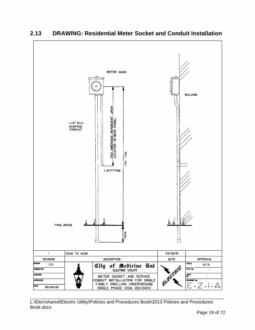
2.13 DRAWING: Residential Meter Socket and Conduit Installation
____________________________________________________________________________ L:\Elec\shared\Electric Utility\Policies and Procedures Book\2013 Policies and Procedures Book.docx
Page 19 of 72

2.14 DRAWING: Instrument Transformer Enclosure
____________________________________________________________________________ L:\Elec\shared\Electric Utility\Policies and Procedures Book\2013 Policies and Procedures Book.docx
Page 20 of 72

2.15 DRAWING: Meter Locations Underground Residential Subdivision
____________________________________________________________________________ L:\Elec\shared\Electric Utility\Policies and Procedures Book\2013 Policies and Procedures Book.docx
Page 21 of 72
CITY OF MEDICINE HAT ELECTRIC DISTRIBUTION DEPARTMENT WORKING PROCEDURES & GUIDELINES
3. RESIDENTIAL SERVICE
3.1 GENERAL 3.1.1 Voltage
Most residential areas are served by a 120/240 volt three wire single phase system. 3.1.1.1Residential services on the fringe of commercial area may be serviced by a 120/208 volt three wire single phase system.
3.1.2 Service Capacity 100 amp or 200 amp services are available. 3.1.2.1
The minimum size of the electrical service shall meet the requirements of the 3.1.2.2Canadian Electrical Code.
3.1.3 Meter Location Meter location must be approved by the Electric Department and the Electrical 3.1.3.1
Inspection Agency having jurisdiction .
For front servicing, the meter is to be located on the side wall nearest the service 3.1.3.2point designated by the Electric Department.
Meter is to be installed within 2 metres of the front of the residence. 3.1.3.3
For rear servicing, the meter can be located: 3.1.3.4
3.1.3.4.1 On the side wall nearest the service point designated by the Electric Department and within 2 metres of the back of the building
3.1.3.4.2 On the back wall nearest the service point and not more than ½ way across the width of the back wall.
Meters will not be installed on outside walls which have an attached deck. 3.1.3.5
3.1.3.5.1 Where proposed renovations will result in the existing meter being located above a deck floor, the meter must be relocated prior to construction.
The meter must be mounted level on the horizontal and vertical planes on the 3.1.3.6outside wall at a height between 1,500 mm to 1,800 mm above the finished grade.
For rear serviced lots, the electric meter can be located on the garage provided 3.1.3.7service point is closer to the garage than the residence.
3.1.3.7.1 Customer is responsible for installation of power supply to the residence.
3.1.4 Construction Contribution The property owner will pay a construction charge to the Electric Department for that 3.1.4.1
portion installed from the source of power to the meter base. The Electric Department will require full payment before connection is made.
____________________________________________________________________________ L:\Elec\shared\Electric Utility\Policies and Procedures Book\2013 Policies and Procedures Book.docx
Page 22 of 72
3.1.5 Temporary Disconnection of Service Removal of Meter 3.1.5.1
3.1.5.1.1 Under emergency conditions such as fire or severe safety hazard (i.e. life threatening situations) the meter may be removed to disconnect the service but the person removing the meter must notify the Electric Department within 24 hours. The reconnection fee may be charged to the homeowner or to the Electrical Contractor who acted as the homeowner's agent.
3.1.5.1.2 If the Electric Department is NOT notified within 24 hours, it will be considered as an unlawful removal of the meter and will be considered as a violation of the by-law.
Change of Meter Location or Up-grading of Main Panel 3.1.5.2
3.1.5.2.1 Homeowner or the Electrical Contractor acting as the agent of the homeowner must obtain the permission of the Electric Department prior to any alteration.
3.1.5.2.2 In homes where the service is installed without a main breaker and the only method of interrupting the service is by removing the meter, the homeowner or his Electrical Contractor must contact the Electric Department for a site visit prior to arranging any renovation.
3.1.5.2.3 Depending upon the nature of the job, the Electrical Contractor may be given written permission by the Electric Department to remove and re-install the meter. The Electrical Contractor must contact the Electric Department for inspection and reseal.
3.1.5.2.4 If the meter is to be removed, later installed and resealed, the disconnection and reconnection fees may be charged. The Electric Department will require payment before reconnection is made.
3.1.6 Meters to be Re-located to Outside of the House Where a meter is installed inside a residential home and any electrical renovations 3.1.6.1
are going to be carried out, the meter is to be relocated to the outside wall in a location approved by the Utility at no cost to the Electric Department.
3.2 RESIDENTIAL SERVICE - OVERHEAD 3.2.1 Service Location
The point of attachment for the Electric Department's overhead service conductors to 3.2.1.1the consumer's service shall be on the side of the building or structure which is closest to the Electric Department's distribution supply pole.
On consumer change-of-service projects where the existing service is not on the 3.2.1.2distribution supply pole side of the building, the electrical contractor must get the approval of the Electric Department before using the existing location for the new service.
3.2.2 Consumer's Responsibility for Service Mast
____________________________________________________________________________ L:\Elec\shared\Electric Utility\Policies and Procedures Book\2013 Policies and Procedures Book.docx
Page 23 of 72
The consumer is responsible for supplying and maintaining the support bracket for 3.2.2.1attaching the Electric Department's service wires. The pull-off bracket must be of a type approved by the Electric Department and the Electrical Inspection having jurisdiction.
3.2.3 Service Conductors The service conductors shall be aluminum triplex wire as per the Electric Department 3.2.3.1
Standard.
Maximum length of unsupported drop for 100 amp service is 30 meters. 3.2.3.2
Maximum length of unsupported drop for 200 amp service is 15 meters. 3.2.3.3
3.2.4 Height of Conductors The service support bracket shall be installed such that the minimum clearance of 3.2.4.1
supply conductors above finished grade shall not be less than the following:
3.2.4.1.1 Across/along highways, streets, and lanes alleys 5.5 meters (18’). 3.2.4.1.2 Across/along driveways to residences or residential garages: 4.5 meters (15’). 3.2.4.1.3 Across/along ground normally accessible to pedestrians only: 4.0 meters (13’).
Electric Department will not connect a new overhead service which does meet the 3.2.4.2required above ground clearances.
Any work being done on an existing service will require that the necessary above 3.2.4.3ground clearances be provided prior to reconnection by the Electrical Utility.
3.2.5 Installation of Service Conductors The Electric Department will supply and install the overhead service. 3.2.5.1
The property owner will pay a construction contribution charge to the Electric 3.2.5.2Department for that portion installed from the source of power to the consumer's service mast.
The connection at the mast will be done by the Electric Department. 3.2.5.3
The Electric Department will require payment for servicing before connection is 3.2.5.4made.
3.2.6 Disconnection of Service at the Pole If the service is to be disconnected at the pole or new service wires are to be 3.2.6.1
installed, additional charges are applicable. Such charges can be obtained from the Electric Department.
____________________________________________________________________________ L:\Elec\shared\Electric Utility\Policies and Procedures Book\2013 Policies and Procedures Book.docx
Page 24 of 72
3.3 RESIDENTIAL SERVICE - UNDERGROUND 3.3.1 Supply and Installation of Service Cables
Single Family, Duplexes and Triplexes 3.3.1.1
3.3.1.1.1 The Electric Department will supply, install and maintain the underground service cable for single family residences, side by side duplexes and triplexes that are situated on their own lot and have their own street address.
3.3.1.1.2 The property owner will pay a construction contribution to the Electric Department for that portion installed from the source of power based on a standard charge as determined by the Electric Department.
3.3.1.1.3 The Electric Department will require payment for servicing before connection is made.
3.3.1.1.4 The Electric Department will connect the service wires to supply line side of the property owner's meter socket.
Bareland Condominium 3.3.1.2
3.3.1.2.1 Includes all unit dwellings on bareland condominium lots.
3.3.1.2.2 Will be treated as commercial construction with an electrical contractor supplying cable and conduit.
3.3.1.2.3 The condominium association or their agent is responsible for the maintenance of the service cable.
Manufactured Home Parks 3.3.1.3
3.3.1.3.1 Will be treated as commercial construction with an electrical contractor supplying cable and conduit.
3.3.1.3.2 The property owner is responsible for the maintenance of the service cable.
All Other Residential Services 3.3.1.4
3.3.1.4.1 Will be treated as commercial construction with an electrical contractor supplying cable and conduit.
3.3.1.4.2 The property owner is responsible for the maintenance of the service cable.
3.3.2 Trenching and Backfilling For Services Installed By The Electric Department:
3.3.2.1.1 In Medicine Hat and Redcliff the Electric Department will excavate and backfill the service trench for residences being constructed in new subdivisions.
3.3.2.1.2 In Cypress County the customer is responsible for excavating and backfilling the service trench for residences being constructed in new subdivisions.
3.3.2.1.3 In Medicine Hat, Redcliff and Cypress County the customer will be required to excavate and backfill the service trench required for installation of new service conductors required for an increase to the size of the main disconnect or for relocating an overhead service to underground.
____________________________________________________________________________ L:\Elec\shared\Electric Utility\Policies and Procedures Book\2013 Policies and Procedures Book.docx
Page 25 of 72

Depth of Trench 3.3.2.2
3.3.2.2.1 The recommended depth of the trench for the service conductor is 1200 mm from the finished grade.
3.3.2.2.2 Minimum depth of service conductor that will be energized is 900 mm from finished grade.
3.3.3 Electric Service in Proximity To Gas Line Electric service shall not cross the natural gas service line. 3.3.3.1
Electric service and gas service lines can be buried in the same trench provided a 3.3.3.2minimum horizontal separation of 300mm is maintained between the service lines.
Electric meter must be mounted at least 1 metre from the gas meter. 3.3.3.3
3.4 RESIDENTIAL SERVICES – U/G IN O/H DISTRIBUTION AREA 3.4.1 Request for Service
Consumers may request an underground secondary service from an overhead 3.4.1.1distribution system (existing area serviced overhead). The Electric Department shall supply and install the copper cable from the source of supply to the meter base.
All requirements of "RESIDENTIAL SERVICES - UNDERGROUND" are applicable. 3.4.1.2
Owner to contact cable and telephone providers to arrange for installation of their 3.4.1.3service lines.
3.4.2 Trench and Backfilling The consumer shall be responsible for digging the necessary trench and backfilling 3.4.2.1
same after the installation of cables. The service will not be energized until backfilling is completed to the satisfaction of the Electric Department.
____________________________________________________________________________ L:\Elec\shared\Electric Utility\Policies and Procedures Book\2013 Policies and Procedures Book.docx
Page 26 of 72

CITY OF MEDICINE HAT ELECTRIC DISTRIBUTION DEPARTMENT WORKING PROCEDURES & GUIDELINES
4. RURAL SERVICE
4.1 GENERAL 4.1.1 Where Applicable
Rural services may be installed: 4.1.1.1
4.1.1.1.1 Inside the City of Medicine Hat corporate boundaries on land designated Urban Reserve
4.1.1.1.2 Outside the corporate boundaries of Redcliff.
4.1.1.1.3 Outside the corporate boundaries of Dunmore.
4.1.1.1.4 Outside the corporate boundaries of Veinerville.
4.1.2 Land Use Designation Rural services may be installed on land designated: 4.1.2.1
4.1.2.1.1 Agricultural
4.1.2.1.2 Urban Reserve
4.1.2.1.3 Country Residential
4.1.3 Type of Service Single phase three wire service available to customers within reach of the Electric 4.1.3.1
Department's distribution lines.
4.1.4 Secondary Voltage Secondary voltage will be 120/240 volts 4.1.4.1
4.1.5 Billing Rate The service will be billed under the Farm rate if: 4.1.5.1
4.1.5.1.1 The service is supplied from its own designated transformer.
4.1.5.1.2 Maximum service size does not exceed 200 amps.
The service will be billed under the Residential rate if: 4.1.5.2
4.1.5.2.1 The service is supplied from a shared transformer.
4.1.5.2.2 Maximum size of service does not exceed 200 amps.
Any service which exceeds 200 amps will be billed at the applicable commercial rate. 4.1.5.3
4.1.6 Meter Location Meter location must be approved by the Electric Department and the Electrical 4.1.6.1
Inspection Agency having jurisdiction. ____________________________________________________________________________ L:\Elec\shared\Electric Utility\Policies and Procedures Book\2013 Policies and Procedures Book.docx
Page 27 of 72

4.1.7 Requirement To Go Underground A rural service will need to be installed underground from the Electric Department 4.1.7.1
service point if:
4.1.7.1.1 Length of overhead service drop for a 100 amp service exceeds 30 meters.
4.1.7.1.2 Service point is on the opposite side of a registered road right-of-way from the residence that it will be supplying.
4.1.7.1.3 Point of attachment will not provide the required minimum above ground clearance.
4.1.8 Payment Of Charges The property owner will pay a construction contribution charge to the Electric 4.1.8.1
Department for that portion of the rural service installed from the service point up to and including the customer service pole or the residence.
The Electric Department will require full payment before final connection is made. 4.1.8.2
4.2 RURAL SERVICE - OVERHEAD 4.2.1 Maximum Unsupported Span Length
Maximum distance of customer service pole or exterior wall of residence from 4.2.1.1Electric Department service point shall not exceed:
4.2.1.1.1 30 meters for a 100 amp service.
4.2.1.1.2 15 meters for a 200 amp service.
4.2.2 Clearance Height of Conductors The service support bracket shall be installed such that the minimum clearance of 4.2.2.1
supply conductors above finished grade shall not be less than the following:
4.2.2.1.1 Across/along ground accessible to farm vehicles: 5.5 meters (18’). 4.2.2.1.2 Across/along driveways to residences or residential garages: 4.5 meters (15’). 4.2.2.1.3 Across/along ground normally accessible to pedestrians only: 4.0 meters (13’).
Electric Department will not connect a new overhead service which does meet the 4.2.2.2required above ground clearances.
Any work being done on an existing service will require that the necessary above 4.2.2.3ground clearances be provided prior to reconnection by the Electrical Utility.
4.2.3 Customer Service Pole The Electric Department will supply and install the customer service pole. 4.2.3.1
The Electric Department will supply and install the overhead service cable from the 4.2.3.2service point to the customer service pole or exterior wall of the residence.
The owner or his Electrical Contractor will supply at the customer service pole: 4.2.3.31. a meter socket
2. a main breaker
____________________________________________________________________________ L:\Elec\shared\Electric Utility\Policies and Procedures Book\2013 Policies and Procedures Book.docx
Page 28 of 72
3. service mast conduit c/w cable and weatherhead
4. eyebolt for attaching Electric Department O/H triplex
5. grounding as required
All material required to complete installation from customer service pole to residence 4.2.3.4or other out buildings will be supplied and installed by the owner or his contractor.
4.2.4 Existing Services The consumer or the Electrical Contractor will notify the Electric Department of any 4.2.4.1
changes required to the service.
Neither the consumer or the Electrical Contractor is to climb or connect to wires on 4.2.4.2the poles which form part of the Electric Department's supply of electricity up to and including the metering pole unless permission has first been obtained from the Electric Department.
Any changes to an existing rural service which has a Utility supplied farm metering 4.2.4.3switch assembly installed:
4.2.4.3.1 on the transformer pole, will require a new customer service pole complete with main disconnect and meter base to be installed.
4.2.4.3.2 on an existing secondary pole will require a new main disconnect and meter base. If existing pole is deemed suitable as a customer service pole by the Electric Department, a new customer service pole will not be required.
4.2.4.3.3 existing farm metering switch assembly will be removed.
4.3 RURAL SERVICE - UNDERGROUND 4.3.1 Supply and Installation of Service conductors
The customer will be required to supply and install the service conductors from the 4.3.1.1service point to the line side of the meter.
Depth of Trench 4.3.1.2
4.3.1.2.1 The recommended depth of the trench for the service conductor is 1200 mm from the finished grade.
4.3.1.2.2 Minimum depth of service conductor that will be energized is 900 mm from finished grade.
4.3.1 Trench and Backfilling The consumer shall be responsible for digging the necessary trench and backfilling 4.3.1.1
same after the installation of cables. The service will not be energized until backfilling is completed to the satisfaction of the Electric Department.
Owner to contact cable television and telephone providers to arrange for installation 4.3.1.2of their service lines.
____________________________________________________________________________ L:\Elec\shared\Electric Utility\Policies and Procedures Book\2013 Policies and Procedures Book.docx
Page 29 of 72
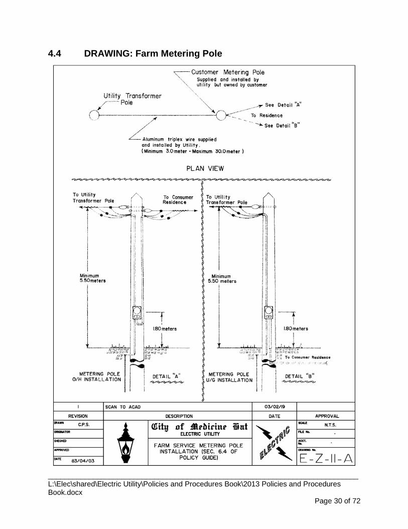
4.4 DRAWING: Farm Metering Pole
____________________________________________________________________________ L:\Elec\shared\Electric Utility\Policies and Procedures Book\2013 Policies and Procedures Book.docx
Page 30 of 72
CITY OF MEDICINE HAT ELECTRIC DISTRIBUTION DEPARTMENT WORKING PROCEDURES & GUIDELINES
5. COMMERCIAL SERVICE
5.1 GENERAL 5.1.1 Scope
Commercial places of business, stores, shops, hotels, institutions, irrigation systems, 5.1.1.1temporary services (unless otherwise stated) and other general consumers shall be considered as Commercial Services.
Apartments, townhouses, bareland condominiums and manufactured home parks 5.1.1.2shall be considered as Commercial Services for installation of secondary service cables only.
5.1.2 Contacting Communication Companies It is the responsibility of the owner or his agent to contact and coordinate the 5.1.2.1
installation of any telecommunication or cable television service lines at the time of electrical servicing.
5.1.3 Requirements For Underground Service The Electric Department may request services to be installed underground under the 5.1.3.1
following conditions:
5.1.3.1.1 If the service is in an underground distribution area.
5.1.3.1.2 If the span length of the service (from the source of power to the attachment on the building) is more than 30 metres for 100 amp service.
5.1.3.1.3 If the span length of the service (from the source of power to the attachment on the building) is more than 15 metres for 200 amp.
5.1.3.1.4 If the service requirement is more than: 200 amps 120/208 volts, 150 amps 277/480 volts 150 amps 347/600 volts
5.1.4 Cost of Service Customer is required to pay a fixed cost as calculated by the Electric Department for 5.1.4.1
installation of the electric service.
Capacity Charge shall form part of the fixed cost. 5.1.4.2
5.1.5 Service Voltages Depending upon the electrical service requirements and location in the Utility Service
Areas, the following service voltages may be available: 120/240 volts, single phase, 3 wire.
____________________________________________________________________________ L:\Elec\shared\Electric Utility\Policies and Procedures Book\2013 Policies and Procedures Book.docx
Page 31 of 72

120/208 volts, 3 phase 4 wire.
277/480 volts, 3 phase, 4 wire
347/600 volts, 3 phase, 4 wire
5.1.6 Single Phasing Prevention The owner or his agent shall design the service equipment such that all three phases 5.1.6.1
are interrupted when single phasing occurs. (i.e. if one or two phases of the supply service is interrupted at the source of power).
The Electric Department accepts no liability for consumer claims or losses due to 5.1.6.2single phasing.
5.1.7 Fault Capacity Fault current capacity of service may be obtained from the Electric Department 5.1.7.1
Office at the design stage.
5.2 COMMERCIAL UNDERGROUND SERVICE 5.2.1 Service Capacity
Up to 1,600 amps (500kVa) at 120/208 volts. 5.2.1.1
Up to 1,200 amps (1,000kVa) at 277/480 volts. 5.2.1.2
Up to 2,000 amps (1,500kVa) at 347/600 volts. 5.2.1.3
5.2.2 Trenching and Backfilling The owner or his agent is responsible for all trenching and backfilling required to 5.2.2.1
install the service conduit and cables.
For conduits installed along/across the road/lane right-of-way the method of back-5.2.2.2filling, compaction and re-surfacing shall be as per the Road Authority having jurisdiction.
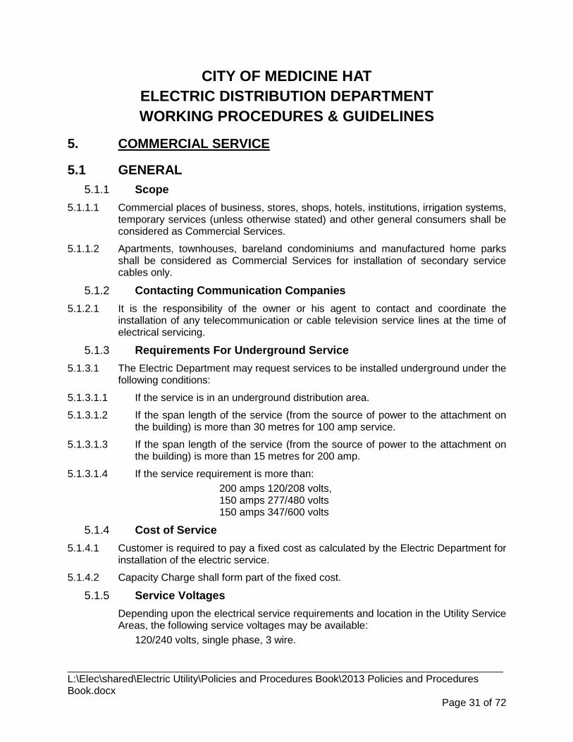
5.2.3 Easements Where the Electric Department determines that a padmounted transformer/switching 5.2.3.1
enclosure located on private property will be shared by two or more parties, the owner of the property upon which the padmounted equipment is installed shall grant to the City of Medicine Hat the necessary easement for the installation at no cost to the City.
Costs related to registering easement will be born by the Electric Department. 5.2.3.2
5.2.4 Conduit For Primary Conductors Will be supplied and installed by the Electrical Contractor as per drawing provided by 5.2.4.1
the Electric Department.
5.2.5 Size of Primary Conduit All primary conduit will be 100 mm in diameter 5.2.5.1
5.2.6 Type of Conduit Allowed Only Fiber Reinforced Epoxy (FRE) Conduit can be used for the installation of 5.2.6.1
____________________________________________________________________________ L:\Elec\shared\Electric Utility\Policies and Procedures Book\2013 Policies and Procedures Book.docx
Page 32 of 72

primary underground cable. Conduit can be direct buried in sand or clean back-fill or concrete encased.
5.2.7 Depth of Conduit The depth of the top of the conduit shall be 1,200 mm below finished grade. 5.2.7.1
5.2.8 Inspection Conduit installed for primary cable must be inspected by the Electric Department 5.2.8.1
prior to backfilling.
5.2.9 Number of Conduit Bends Allowed Not more than two 90° bends or combinations of bends totaling 180° is typically 5.2.9.1
permitted in the conduit run. If more bends are required, a pulling manhole (as per Electric Department Standard) will need to be installed.
Pulling manhole components will be supplied and installed by the Electrical 5.2.9.2Contractor with the exception of the metal fastening ring and cover which will be supplied by the Electric Department.
5.2.10 Maximum Distance Between Pulling Points Not more than 120 meters allowed without pulling manhole where 3 conductors 5.2.10.1
installed in one conduit.
Not more than 150 meters allowed without pulling manhole where 1 conductor is 5.2.10.2installed in the conduit.
5.2.11 Pulling String To be supplied and installed by Electrical Contractor. 5.2.11.1
Pull string to have a minimum breaking strength of 440 pounds. 5.2.11.2
5.2.12 Conduit For Secondary Service Conductors Type of conduit installed shall be as permitted by current edition of Canadian 5.2.12.1
Electrical Code Part 1.
Secondary conduit(s) will be supplied and installed by the Electrical Contractor as 5.2.12.2per drawing provided by the Electric Department.
5.2.13 Number of Conduits Required 1. up to 400 amps – 1 conduit
2. 401 – 800 amps – 2 conduits
3. 801 – 1200 amps – 3 conduits
4. 1201 – 1600 amps – 4 conduits
5. 1601 – 2000 amps – 5 conduits
5.2.14 Secondary Service Conductors The Electrical Contractor shall supply and install the secondary service cables from 5.2.14.1
the designated point of supply to service equipment at the building.
____________________________________________________________________________ L:\Elec\shared\Electric Utility\Policies and Procedures Book\2013 Policies and Procedures Book.docx
Page 33 of 72

5.2.15 Size of Conductor Maximum size not to exceed 500 MCM for copper conductors and 750 MCM for 5.2.15.1
aluminum conductors.
5.2.16 Number of Conductors 1. up to 400 amps: 1 conductor per phase 2. 401 to 800 amps: 2 conductors per phase 3. 801 to 1,200 amps: 3 conductors per phase 4. 1201 to 1,600 amps: 4 conductors per phase 5. 1,601 to 2,000 amps: 5 conductors per phase
5.2.17 Cable Lugs For copper service conductors, the Electric Department shall supply and install the 5.2.17.1
required NEMA 2-hole long barrel secondary compression lugs for the following conductor sizes:
#1 2/0 250 MCM 400 MCM #2 3/0 300 MCM 500 MCM 1/0 4/0 350 MCM
For aluminum service conductors, the Electrical Contractor will provide the required 5.2.17.2NEMA 2-hole long barrel secondary compression lugs:
5.2.17.2.1 Only compression spade connectors with a tongue width of 1.75” or less and a tongue thickness of .12” or less will be accepted by the Electric Department for use with aluminum conductors (allows installation of up to 4 – 750 mcm conductors back to back on standard 4 hole NEMA secondary spade inside of padmount transformers) .
5.2.17.2.2 Electric Department will supply the compression tool and dies for terminating aluminum lugs for the following conductor sizes
#2 3/0 300 MCM 500 MCM 1/0 4/0 350 MCM 750 MCM 2/0 250 MCM 400 MCM
5.2.17.2.3 Aluminum conductors are not to be installed on load side of main disconnect for services over 200 amps which require current transformers.
5.2.18 Secondary Cable Termination Secondary service cables at the transformer shall be terminated by the Electric 5.2.18.1
Department.
Secondary service cables at the service equipment shall be terminated by the 5.2.18.2electrical contractor with the exception of connections to current transformers and Electric Department billing meter(s).
5.2.19 Installation Requiring Padmounted Transformer The transformer pad, grounding grid and protection posts (if requested by the 5.2.19.1
Electric Department), will be supplied and installed by the Electrical Contractor at no cost to the Electric Department and must comply with the requirements of the Electric Department.
____________________________________________________________________________ L:\Elec\shared\Electric Utility\Policies and Procedures Book\2013 Policies and Procedures Book.docx
Page 34 of 72

5.2.20 Location of Concrete Pad for Padmount Transformer Maintain 1000 mm minimum clearance from near edge of concrete pad to building 5.2.20.1
wall or any other permanent structure.
Maintain 3000 mm minimum clear working space in front of the concrete pad to 5.2.20.2allow for opening of access doors to and hot stick operation of the padmount transformer.
5.2.21 Inspection of Concrete Pad for Padmount Transformer Electric Contractor will contact the Electric Department to inspect the transformer 5.2.21.1
pad installation prior to pouring of the concrete.
5.2.22 Location of Padmount Transformer If clearances indicated in 1.5.4.1 cannot be obtained, a cinder block wall will need to 5.2.22.1
be constructed as per Electric Department drawing.
____________________________________________________________________________ L:\Elec\shared\Electric Utility\Policies and Procedures Book\2013 Policies and Procedures Book.docx
Page 35 of 72
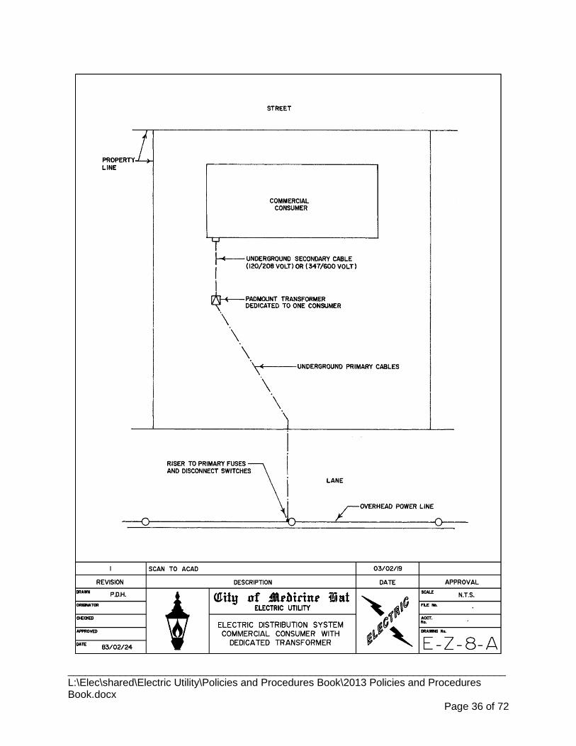
____________________________________________________________________________ L:\Elec\shared\Electric Utility\Policies and Procedures Book\2013 Policies and Procedures Book.docx
Page 36 of 72
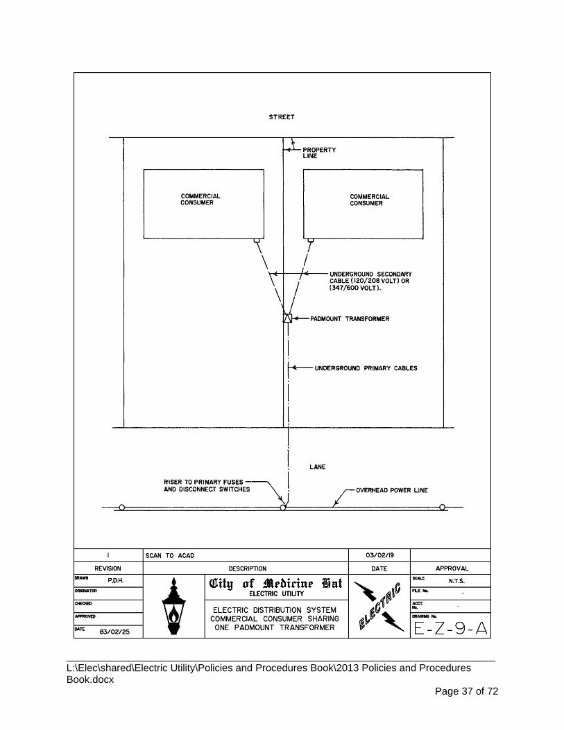
____________________________________________________________________________ L:\Elec\shared\Electric Utility\Policies and Procedures Book\2013 Policies and Procedures Book.docx
Page 37 of 72
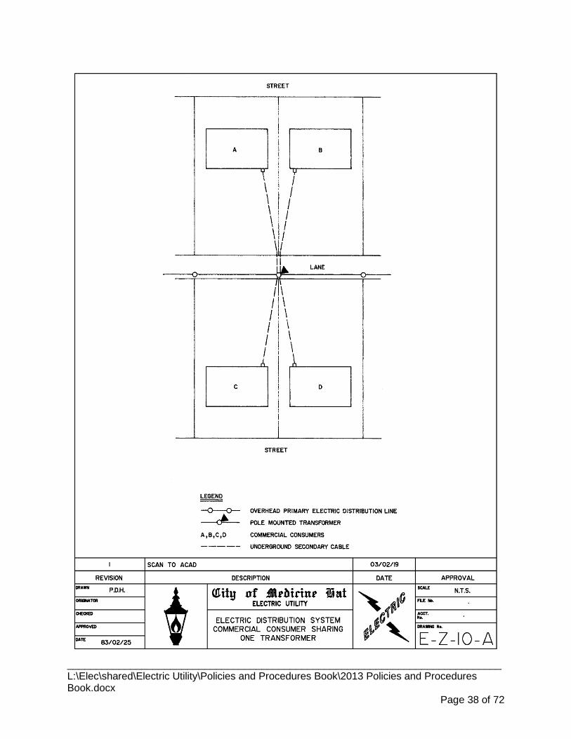
____________________________________________________________________________ L:\Elec\shared\Electric Utility\Policies and Procedures Book\2013 Policies and Procedures Book.docx
Page 38 of 72

5.3 COMMERCIAL OVERHEAD SERVICE 5.3.1 Service Capacity
200 amps 120/208volts 3 phase 4 wire.
150 amps 277/480 volts 3 phase 4 wire.
150 amps 347/600 volts 3 phase 4 wire.
200 amps 120/240 volts single phase 3 wire.
5.3.2 Service Attachment Clearances The service support bracket shall be installed such that the minimum clearance of 5.3.2.1
supply conductors above finished grade shall not be less than the following:
5.3.2.1.1 Across/along highways, streets, lanes, alleys and driveways to commercial and industrial premises: 5.5 meters (18’).
5.3.2.1.2 Across/along driveways to residences or residential garages: 4.5 meters (15’).
5.3.2.1.3 Across/along ground normally accessible to pedestrians only: 4.0 meters (13’).
Electric Department will not connect a new overhead service which does meet the 5.3.2.2required above ground clearances.
Any work being done on an existing service will require that the necessary above 5.3.2.3ground clearances be provided prior to reconnection by the Electrical Utility.
5.3.3 Point of Attachment to the Building The point of attachment to the buildings shall be on the exterior side of the building 5.3.3.1
most directly facing the pole line and as close as practical to the Electric Department service pole.
5.3.3.1.1 If renovations are done to an existing building such that the point of attachment will no longer be on the exterior wall of the building, the Electrical Contractor must relocate the point of attachment to the exterior of the new building wall nearest to the Electric Department’s point of supply.
The customer is responsible for supplying and maintaining the support bracket for 5.3.3.2attaching the Electric Department's service wires.
5.3.3.2.1 In the event that the support bracket is damaged, an Electrical Contractor will be required to repair/replace the support bracket prior to reconnection of the service conductors by the Electric Department
5.3.3.2.2 Any costs associated with the repair of the support bracket will be borne by the customer.
The support bracket must be of a type approved by the Electric Department and the 5.3.3.3Electrical Inspection Agency.
5.3.4 Service Conductors Service conductors shall be aluminum multiplex cable as per the Electric Department 5.3.4.1
____________________________________________________________________________ L:\Elec\shared\Electric Utility\Policies and Procedures Book\2013 Policies and Procedures Book.docx
Page 39 of 72

Standard.
Consumer Service Ampacity (Service Breaker)
Maximum Unsupported Span Length
(meters) Multiplex Cable Size
200 15 2/0 AWG AL 100 30 #2 AWG AL
5.3.5 Installation of Overhead Secondary Conductors The Electric Department will supply and install the multiplex cable from the source of 5.3.5.1
power to the consumer’s service mast.
The connection at the service mast shall be done by the Electric Department. 5.3.5.2
The property owner will pay a construction contribution charge to the Electric 5.3.5.3Department for that portion installed from the point of supply to the service mast. The Electric Department will require payment for services before commencement of work.
____________________________________________________________________________ L:\Elec\shared\Electric Utility\Policies and Procedures Book\2013 Policies and Procedures Book.docx
Page 40 of 72
CITY OF MEDICINE HAT ELECTRIC DISTRIBUTION DEPARTMENT WORKING PROCEDURES & GUIDELINES
6. DOWNTOWN NETWORK SERVICE
6.1 GENERAL 6.1.1 Location
The downtown business district has a networked underground electric distribution 6.1.1.1system.
Boundaries of the Network Service Area are from 4th Ave/MacLeod Trail SE to South 6.1.1.2Railway Street SE from First Street to 5th Street SE.
6.1.2 New Services Any new service or change-of-service in this area must be underground. 6.1.2.1
All services must be individually approved by the Electric Department before the 6.1.2.2installation is started.
6.1.3 Size of Single Phase Service Allowed Single phase services are limited to 100 amps or less. 6.1.3.1
It is desirable to have all new services at three phase. 6.1.3.2
6.1.4 Service Voltage 120/208 volt, 3 phase, 4 wire service is standard. To determine if other voltages are 6.1.4.1
available please contact the Electric Engineering office.
6.1.5 Maximum Service Capacity Up to 300 kVA at 208 volts. 6.1.5.1
Contact the Electric Department if service size exceeds 800 amps at 208 volts or a 6.1.5.2voltage other than 208 volts is required.
6.1.6 Fault Capacity The fault current capacity of the network system is 50 MVA or 140,000 amps at 208 6.1.6.1
volts. Consumers equipment must be designed to withstand this fault current.
6.2 SECONDARY SERVICE CONDUIT 6.2.1 Type of Conduit Allowed
Fiber Reinforced Epoxy FRE direct buried. 6.2.1.1
Polyvinyl Chloride PVC concrete encased. 6.2.1.2
____________________________________________________________________________ L:\Elec\shared\Electric Utility\Policies and Procedures Book\2013 Policies and Procedures Book.docx
Page 41 of 72
6.2.2 Supply and Installation of Conduit Service conduit will be supplied and installed by the Electrical Contractor as per 6.2.2.1
drawing provided by the Electric Department.
6.2.3 Size of Conduit All service conduit to be 100 mm in diameter. 6.2.3.1
6.2.4 Number of Conduits Required 1. up to 400 amps – 1 conduit
2. 401 – 800 amps – 2 conduits
6.2.5 Work At Electric Department Vault The service conduit bank connection to the Electric Department vault is to be done 6.2.5.1
under the direct supervision of Electric Department staff.
6.2.6 Avoiding Water from Electric Department Vault The Electric Department vault is liable to be flooded particularly during spring run-off. 6.2.6.1
It is the responsibility of the owner or his agent to design the service duct to avoid water entering the building from the Electric Department vaults.
The duct bank should be sloped towards the Electric Department vault at a minimum 6.2.6.2height of 1,500 mm from the floor of the vault. This will help to prevent water flowing from the Utility vault to consumer's building.
6.3 SERVICE CONDUCTORS 6.3.1 Supply and Installation of Service Conductors
The Electrical Contractor will supply the service conductors. 6.3.1.1
The Electrical Contractor with the assistance of the Electric Department will install 6.3.1.2the conductors.
6.3.2 Type Of Cable Service conductors shall be copper cable with minimum 600 volt insulation level as 6.3.2.1
per the Electric Department Standard indicated below:
Consumer’s Main Disconnect Rated Ampacity Cable Size 100 Amp 1 - #2 AWG per phase 200 Amp 1 – 4/0 AWG per phase 201 to 400 Amp 1 – 500 MCM per
401 to 800 Amp 2 – 500 MCM per
____________________________________________________________________________ L:\Elec\shared\Electric Utility\Policies and Procedures Book\2013 Policies and Procedures Book.docx
Page 42 of 72
6.4 CONSUMER’S SERVICE EQUIPMENT 6.4.1 Main Disconnect
There shall be a fused main switch or main breaker installed on all network services 6.4.1.1capable of withstanding the available fault current.
The main switch or breaker shall be installed on the supply side of all equipment 6.4.1.2including meters or metering equipment
6.4.2 Fuses for Disconnecting Switches High rupturing capacity fuses must be used with disconnecting switches used in lieu 6.4.2.1
of breakers.
Either Form I or Form II may be used but where Form II fuses are used, adequate 6.4.2.2overload protection shall also be provided.
6.4.3 Transformer Vault, Enclosure or Room Any service over 400 amps may require a transformer vault, enclosure or room. 6.4.3.1
If such requirement arises, the transformer vault, enclosure or room will be supplied 6.4.3.2and installed by the owner at his own cost, and must comply with the requirements of the Electric Department.
____________________________________________________________________________ L:\Elec\shared\Electric Utility\Policies and Procedures Book\2013 Policies and Procedures Book.docx
Page 43 of 72

CITY OF MEDICINE HAT ELECTRIC DISTRIBUTION DEPARTMENT WORKING PROCEDURES & GUIDELINES
7. PRIMARY METERED CONSUMER SERVICES
7.1 GENERAL 7.1.1 Scope
Available to industrial, commercial or large institutional businesses who have a 7.1.1.1constant operating demand of not less than 1000 KVA.
7.1.2 Service Voltage Service voltage will be 13,800/8,000 volt, 3-phase, 4-wire. 7.1.2.1
7.1.3 Electric Service Request Form For any new electric service or change to an existing electric service, an Electric 7.1.3.1
Service Request Form must be completed and sent to the Electric Department.
Service request forms are available on the City of Medicine Hat’s web site 7.1.3.2www.medicinehat.ca►City Services► Electric Utilities► Commercial Service Application.
7.1.4 Detailed Design Drawings Must be approved in detail by the Electric Department. Up to 20 working days should 7.1.4.1
be allowed for review of each drawing submission.
One (1) set of all equipment shop drawings to be provided for review and approval 7.1.4.2including:
7.1.4.2.1 Group Operated Padmounted Isolating Switch
7.1.4.2.2 Customer Switchgear
7.1.5 Padmounted Group Operated Isolating Switch All primary metered services will require a remote padmounted group operated 7.1.5.1
switch to be installed at the location where City Electric 13,800 volt underground service cables enter the customer’s property.
7.1.6 Fault Capacity It is the responsibility of the customer to contact the Electric Department to confirm 7.1.6.1
the fault capacity at the proposed service site.
7.1.7 Primary Protection Coordination Overcurrent protection shall be provided in accordance with the Canadian Electrical 7.1.7.1
Code.
It is the responsibility of the customer to contact the Electric Department to request 7.1.7.2the existing feeder protection relay settings.
____________________________________________________________________________ L:\Elec\shared\Electric Utility\Policies and Procedures Book\2013 Policies and Procedures Book.docx
Page 44 of 72

The Electric Department requires up to 20 working days to review and approve the 7.1.7.3proposed protection relay settings at the customer's main breaker prior to energizing the electrical equipment.
The Electric Department may require the witnessing of the initial relay calibration and 7.1.7.4trip checks in order to confirm the operational readiness of the customer's main breaker relay protection scheme. Copies of all supporting commissioning documentation including protective relay test sheets must be supplied to the Electric Department at least 2 working days prior to energizing the equipment.
It will be the responsibility of the customer to carry out relay maintenance. 7.1.7.5
7.1.8 Customer Power Transformer Connections and Loading Customer transformers must be connected either delta/delta or delta/star. Star/star 7.1.8.1
connections will not be permitted.
Customer loading must be balanced across all 3-phases to provide an effectively 7.1.8.2balanced total load. Special single-phase loads resulting in unbalance total load will only be permitted by special written permission from the Electric Department.
7.2 Service Equipment 7.2.1 Supply And Installation of Equipment and Cable
The underground cable from the Electric Department system to the line side of the 7.2.1.1padmounted group operated isolation switch will be supplied and installed by the Electric Department and costs for same will be charged to the customer.
The customer or his agent shall supply and install all other equipment and material. 7.2.1.2
The customer will be required to install four (4) Fiber Reinforced Epoxy (FRE) 7.2.1.3conduit complete with pulling strings at 1.2 meters below finished grade from the Electric Department’s point of supply to the line side of the padmounted group operated isolation switch.
7.2.2 Maintenance The customer will own and be responsible for the maintenance of all equipment on 7.2.2.1
his property including the padmounted group operated isolating switch.
The underground cable from the Electric Department system to the line side of the 7.2.2.2pad mounted group operated switch will be maintained by the Electric Department at no cost to the customer.
7.2.3 Primary Overhead Service Lines Customer owned overhead 13,800 volt service lines will not be allowed to run from 7.2.3.1
the Electric Department System to the line side of the customer’s metering equipment.
7.2.4 Insulation Value For Customer Equipment On all 13,800 volt installations, the dielectric insulation must have a level of 15 KV on 7.2.4.1
cables and all insulators used within the customer switchgear including the primary neutral conductors and the insulators used with the primary neutral conductors.
____________________________________________________________________________ L:\Elec\shared\Electric Utility\Policies and Procedures Book\2013 Policies and Procedures Book.docx
Page 45 of 72

7.2.5 Metering The cubicle incorporating Electric Department metering equipment must be 7.2.5.1
constructed such that all metering is readily accessible without removing additional equipment.
Adequate working space must be provided for testing or replacing all metering 7.2.5.2equipment.
Access to the front and back of the metering cubicle must be designed to be pad-7.2.5.3locked with a lock supplied by the Electric Department.
Front access to the metering cell must have hinged door with latch that can be 7.2.5.4locked by an Electric Department pad lock.
The hinged door must have a bonding ground strap of copper braid solidly connected 7.2.5.5to the door and the grounded meter enclosure, bonding strap equivalent to minimum #6.
All potential and current transformers must be installed such that they may be 7.2.5.6isolated electrically from both supply and load.
A grounding bus must be provided adjacent to the metering transformers. 7.2.5.7Transformer cases are to be bonded to ground.
7.2.6 Current Transformers Current transformers should be mounted with consideration given to standard 7.2.6.1
clearances and best engineering practices.
Three (3) current transformers are required: 7.2.6.2
7.2.6.2.1 Accuracy class 0.3 B 2.0
7.2.6.2.2 Ratio: will depend on power requirements
7.2.6.2.3 Thermal rating factor: minimum of 1.5 @ 30°C (ambient)
7.2.6.2.4 Indoor type
7.2.6.2.5 15KV voltage class
7.2.6.2.6 Must have Measurement Canada approval number.
7.2.6.2.7 All secondary connections are to be brought out to an Electric Department metering terminal connection block that is located in the Electric Department metering cell.
7.2.6.2.8 Labeling and connections should be as per Drawing E-M-22-A.
7.2.6.2.9 Should be mounted in an accessible enclosure that is accessible by removing the rear access cover of the Electric Department metering cell.
7.2.6.2.10 Connections will be grounded by the Electric Department in the metering cell. Customer is not to ground these connections at the current transformers.
____________________________________________________________________________ L:\Elec\shared\Electric Utility\Policies and Procedures Book\2013 Policies and Procedures Book.docx
Page 46 of 72

7.2.7 Potential Transformers Potential transformers must be mounted with consideration given to standard 7.2.7.1
clearances and best engineering practices.
Three (3) potential transformers are required as per the following: 7.2.7.2
7.2.7.2.1 Accuracy class 0.3 WXYZ
7.2.7.2.2 Ratio: 8400/120, 70:1
7.2.7.2.3 Thermal rating: 1500 VA minimum @ 30°C (ambient)
7.2.7.2.4 Indoor type
7.2.7.2.5 15KV voltage class
7.2.7.2.6 Must have Measurement Canada approval number.
7.2.7.2.7 Primary connection conductors must be equipped with one 1.0E fuse and mounting clip.
7.2.7.2.8 Must be mounted in a partial draw-out drawer. Retraction of the drawer must:
a) disconnect all three high voltage phases b) disconnect all the low voltage connections c) ground the high voltage connections
7.2.7.2.9 Neutral connection is not required to be disconnected when drawer is drawn out. Neutral conductor must be of sufficient length so as not to restrict or interfere with the draw out of the potential transformer drawer.
7.2.7.2.10 Draw out-drawer must be grounded in all positions.
7.2.7.2.11 All secondary connections are to be brought out to a metering terminal connection block that is located in the Electric Department metering cell.
7.2.7.2.12 Labeling and connections should be as per Drawing E-M-22-A
7.2.7.2.13 Connection of the primary side must be on the line side of the current transformers.
7.2.7.2.14 Secondary connections will be grounded by the Electric Department in the metering enclosure. The customer is not to ground the connections at the potential transformer.
7.2.7.2.15 Secondary conductor shall be fused at 5 amp (Cooper Busman BAF or approved equal). The fuse holder type terminals must accept a 13/32” x 1½” fuse.
7.2.8 Terminal Block See Electric Department drawing E-M-22-A. 7.2.8.1
To be located in the Electric Department metering cell. 7.2.8.2
Must be 13 pole (6 current transformer connections, 6 potential transformer 7.2.8.3connections, 1 ground connection).
____________________________________________________________________________ L:\Elec\shared\Electric Utility\Policies and Procedures Book\2013 Policies and Procedures Book.docx
Page 47 of 72
The current transformer connection must be of such design that the current 7.2.8.4transformer secondary wires can be shorted on the current transformer side of the terminal without removal of any wires.
To accommodate A.W.G. #10 wire except for the ground terminal. 7.2.8.5
The ground wire to the ground terminal shall be not smaller than #6AWG. 7.2.8.6
7.2.9 Metering Cabinet Must have minimum dimensions - 762 mm wide x 762 mm high x 381 mm deep(30" 7.2.9.1
x 30" x 15").
Must have a 13-jaw meter socket mounted securely with appropriate spacing from 7.2.9.2other equipment to give reasonable room for Electric Department wiring requirements.
Must be readily accessible. 7.2.9.3
Must have a minimum of 1 m clearance in front of the cabinet. 7.2.9.4
Must be located so that meter can be mounted at eye level approx. 1524 mm - 1828 7.2.9.5mm (5' - 6').
7.2.10 13-Jaw Meter Socket Must be Form 9S socket. 7.2.10.1
Thomas and Betts Catalogue #CT113-SWL or equivalent. 7.2.10.2
Must have internally mounted and wired ten (10) position test switch. 7.2.10.3
7.2.11 Main Incoming Three Phase Protective Device It is recommended that the equipment be designed such that all three phases are 7.2.11.1
interrupted when single phasing occurs.
Phase time over-current, instantaneous over-current, ground fault and single phasing 7.2.11.2protection shall be incorporated into a single device.
Shall be solid state microprocessor based multi-function type that operates from the 7.2.11.3secondary output of the current transformers. Fuses are not acceptable to perform this function.
The protection curves shall be field programmable for close coordination with 7.2.11.4upstream and down stream devices.
Shall be suitable for operating temperatures from -40 degrees to +55 degrees C and 7.2.11.5for operating with 0 to 95% relative humidity (non-condensing).
Alarm and/or trip contacts shall not change state if power is lost or an under-voltage 7.2.11.6occurs. These contacts shall only cause a trip upon detection of an over-current or fault condition based upon programmed settings
7.2.12 General Considerations All secondary metering conductors to be a minimum of #10 A.W.G. copper stranded 7.2.12.1
wire.
____________________________________________________________________________ L:\Elec\shared\Electric Utility\Policies and Procedures Book\2013 Policies and Procedures Book.docx
Page 48 of 72

Phase to ground grounding ball studs to be provided in each phase buss conductor 7.2.12.2and the ground buss conductor for grounding the phases during servicing of equipment.
7.2.12.2.1 Ball stud to be 25 mm (1”) diameter complete with stud cover.
7.2.12.2.2 Stud to be Salisbury #21191 or approved equivalent.
7.2.12.2.3 Stud Cover to be Salisbury #21236 or approved equivalent.
All required wiring to be marked at both ends of termination with specified labels. 7.2.12.3
Ground wire from the meter connection terminal strip(s) shall terminate at the 7.2.12.4switchgear ground bus.
All wire runs shall be as short as possible and no longer than 15.24 m (50') one-way. 7.2.12.5
All wire runs shall be properly secured and protected from high voltage conductors 7.2.12.6and mechanical damage.
Primary neutral conductor is to be connected to a designated neutral buss that is 7.2.12.7insulated from the switchgear ground.
Neutral buss is to be bonded to the switchgear ground. 7.2.12.8
____________________________________________________________________________ L:\Elec\shared\Electric Utility\Policies and Procedures Book\2013 Policies and Procedures Book.docx
Page 49 of 72

7.2.13 DRAWING E.M.18.A – Customer Switchgear Metering – Single Line Drawing
____________________________________________________________________________ L:\Elec\shared\Electric Utility\Policies and Procedures Book\2013 Policies and Procedures Book.docx
Page 50 of 72

7.2.14 DRAWING E.M.19.A – Customer Switchgear Metering – Requirements For Utility 3 Element Metering
____________________________________________________________________________ L:\Elec\shared\Electric Utility\Policies and Procedures Book\2013 Policies and Procedures Book.docx
Page 51 of 72

7.2.15 DRAWING E.M.20.A – Customer Switchgear Utility Metering Cell Layout
____________________________________________________________________________ L:\Elec\shared\Electric Utility\Policies and Procedures Book\2013 Policies and Procedures Book.docx
Page 52 of 72

7.2.16 DRAWING E.M.22.A – Customer Switchgear Utility Metering Cell Labeling and Termination Details
____________________________________________________________________________ L:\Elec\shared\Electric Utility\Policies and Procedures Book\2013 Policies and Procedures Book.docx
Page 53 of 72

7.2.17 DRAWING E.M.28.A – Primary Underground Cable Layout and Termination Details – Utility Source to Customer Switchgear
____________________________________________________________________________ L:\Elec\shared\Electric Utility\Policies and Procedures Book\2013 Policies and Procedures Book.docx
Page 54 of 72

7.2.18 DRAWING E.M.29.A – Customer Isolation Switch - Primary Conduit Details
____________________________________________________________________________ L:\Elec\shared\Electric Utility\Policies and Procedures Book\2013 Policies and Procedures Book.docx
Page 55 of 72
CITY OF MEDICINE HAT ELECTRIC DISTRIBUTION DEPARTMENT WORKING PROCEDURES & GUIDELINES
8. MICROGENERATION INTERCONNECTION TO ELECTRIC DISTRIBUTION SYSTEM
8.1 Scope 8.1.1 General
This Guide is issued as a supplement to and under the authority of the City of 8.1.1.1Medicine Hat Electrical By-Law 2244.
The intent of this Guide is to establish the interconnection requirements of 8.1.1.2microgeneration with the City of Medicine Hat Electric (City Electric) distribution system.
While every precaution has been taken in the preparation of this Guide, it may contain 8.1.1.3inaccuracies or inconsistencies.
The authors of this Guide assume no liability for errors or omissions, or damages 8.1.1.4resulting from the use or reliance upon the information contained herein.
This Guide has been developed without regard to whether its adoption may involve 8.1.1.5patents on articles, materials, or processes. Such adoption does not assume any liability to any patent owner, nor does it assume any obligation whatsoever to parties adopting this Guide.
8.2 Purpose 8.2.1 General
This document is an interconnection application guide that applies to grid dependent 8.2.1.1and grid interactive microgeneration systems.
It establishes minimum uniform requirements relevant to the performance, operation, 8.2.1.2testing, safety considerations, and maintenance of the interconnection of microgeneration systems with the City Electric distribution system and is based on the following principles:
8.2.1.2.1 The addition of microgeneration systems to the distribution system will not appreciably change the distribution system and its characteristics.
8.2.1.2.2 The microgeneration inverter must meet the requirements of this Guide.
8.2.1.2.3 Users, owners, and operators of microgeneration systems need not have any technical expertise.
8.2.1.2.4 The installation shall meet the requirements of the latest version of the Canadian Electrical Code.
8.2.1.2.5 Microgeneration systems are deemed to be operating unattended.
8.2.1.2.6 Microgeneration installations shall require a permit from the City of ____________________________________________________________________________ L:\Elec\shared\Electric Utility\Policies and Procedures Book\2013 Policies and Procedures Book.docx
Page 56 of 72
Medicine Hat Safety Code Services or the authority having jurisdiction in the City of Medicine Hat Electric service area outside the corporate boundaries of Medicine Hat.
City Electric personnel will need to be aware of the microgeneration system 8.2.1.3specifications, operating characteristics, and installed location.
8.3 Maximum Size of Service 8.3.1 Residential
The criteria and requirements in this guide are applicable to residential single phase 8.3.1.1microgeneration facilities with a rated generation capacity of 5 kW or less per service.
The microgeneration service must use a single phase inverter to generate AC 8.3.1.2electricity that is in parallel with the City Electric distribution system and has a nominal operating voltage of 208 or 240 volts phase to phase.
8.3.2 Commercial The criteria and requirements in this guide are applicable to commercial single phase 8.3.2.1
or three-phase microgeneration facilities with a rated generation capacity of 10 kW or less per service.
The microgeneration service must use a single phase or three-phase inverter to 8.3.2.2generate AC electricity that is in parallel with the City Electric distribution system and has a nominal operating phase to phase voltage of 240 volts single phase or 208, 480 or 600 volts three phase.
8.4 General Interconnection and Protection Requirements 8.4.1 Applicable Safety Codes
The Microgenerator’s interconnection installation must meet all applicable national, 8.4.1.1provincial and local construction and safety codes.
8.4.2 Good Electrical Practice The Microgenerator is required to install, operate and maintain in good order and 8.4.2.1
repair at all times, in conformity with good electrical practice, the equipment required by this Guide for the safe parallel operation with the City Electric distribution system.
8.5 Distribution System 8.5.1 Inverter Certification
A Microgenerator's inverter shall be certified to meet this Guide's provisions as 8.5.1.1detailed in Section 4.1 which defines the power quality and characteristics of the City Electric system to which the Microgenerator is interconnecting.
It is the manufacturer's responsibility to ensure that the inverter operates in this 8.5.1.2environment.
____________________________________________________________________________ L:\Elec\shared\Electric Utility\Policies and Procedures Book\2013 Policies and Procedures Book.docx
Page 57 of 72
8.5.2 System Frequency The distribution system operates at 60 hertz. Frequency deviations are typically 59.7 8.5.2.1
hz to 60.2 Hz.
8.5.3 System Voltage See Table 1
8.6 Micro Generation Equipment 8.6.1 Inverter Operational Settings Sheet
The Microgenerator owner needs to ensure that the inverter has an Inverter 8.6.1.1Operational Settings Sheet (IOS) document.
The IOS document must certify that the inverter operates within the ranges specified 8.6.1.2in Section 8.5.
8.6.2 Synchronism Inverters will automatically restart following automatic re-closing of distribution facility 8.6.2.1
electrical equipment as per CSA 22.2#107.1 (or other equivalent and recognized standard such as UL1741).
It will not be possible for City Electric to co-ordinate inverter restart. 8.6.2.2
A synchronizing scheme does not have to be submitted for grid-dependent inverters. 8.6.2.3
8.6.3 Voltage Regulation and Power Factor The Microgenerator shall be responsible for ensuring that the voltage levels at the 8.6.3.1
point of interconnection are maintained within the guidelines prescribed by City Electric and/or at least equal to the voltage levels, at all feeder load conditions, prior to the interconnection. City
Electric will decide if voltage regulation is expected to be a concern and identify 8.6.3.2possible solutions at time of application.
The Microgenerator is not required to be capable of adjusting the power factor but shall operate in the range of ±0.9.
City Electric will not require the inverter to operate in a power factor control mode.
8.6.4 Frequency Control A Microgenerator's operating frequency must lie between 59.5 and 60.5 Hz. 8.6.4.1
Under-frequency over-frequency protection that automatically disconnects the 8.6.4.2Microgenerator from City Electric shall not operate for frequencies in the range of 59.5 to 60.5 Hz.
The Microgenerator is not required to remain synchronously connected for any 8.6.4.3frequency excursions beyond this range.
8.7 Interconnection Facility 8.7.1 Safety
Safety of personnel, the public and of equipment is of primary concern in the 8.7.1.1____________________________________________________________________________ L:\Elec\shared\Electric Utility\Policies and Procedures Book\2013 Policies and Procedures Book.docx
Page 58 of 72
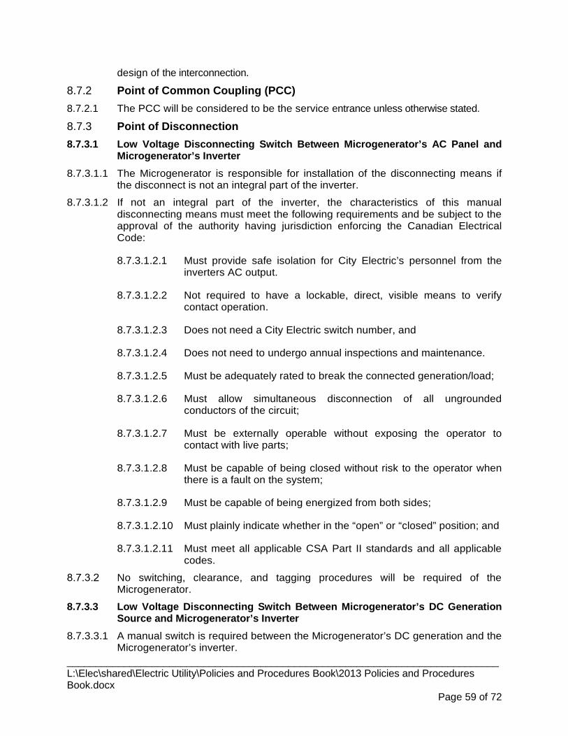
design of the interconnection.
8.7.2 Point of Common Coupling (PCC) The PCC will be considered to be the service entrance unless otherwise stated. 8.7.2.1
8.7.3 Point of Disconnection Low Voltage Disconnecting Switch Between Microgenerator’s AC Panel and 8.7.3.1
Microgenerator’s Inverter 8.7.3.1.1 The Microgenerator is responsible for installation of the disconnecting means if
the disconnect is not an integral part of the inverter.
8.7.3.1.2 If not an integral part of the inverter, the characteristics of this manual disconnecting means must meet the following requirements and be subject to the approval of the authority having jurisdiction enforcing the Canadian Electrical Code:
8.7.3.1.2.1 Must provide safe isolation for City Electric’s personnel from the inverters AC output.
8.7.3.1.2.2 Not required to have a lockable, direct, visible means to verify contact operation.
8.7.3.1.2.3 Does not need a City Electric switch number, and
8.7.3.1.2.4 Does not need to undergo annual inspections and maintenance.
8.7.3.1.2.5 Must be adequately rated to break the connected generation/load;
8.7.3.1.2.6 Must allow simultaneous disconnection of all ungrounded conductors of the circuit;
8.7.3.1.2.7 Must be externally operable without exposing the operator to contact with live parts;
8.7.3.1.2.8 Must be capable of being closed without risk to the operator when there is a fault on the system;
8.7.3.1.2.9 Must be capable of being energized from both sides;
8.7.3.1.2.10 Must plainly indicate whether in the “open” or “closed” position; and
8.7.3.1.2.11 Must meet all applicable CSA Part II standards and all applicable codes.
No switching, clearance, and tagging procedures will be required of the Microgenerator.
Low Voltage Disconnecting Switch Between Microgenerator’s DC Generation 8.7.3.3Source and Microgenerator’s Inverter
8.7.3.3.1 A manual switch is required between the Microgenerator’s DC generation and the Microgenerator’s inverter.
____________________________________________________________________________ L:\Elec\shared\Electric Utility\Policies and Procedures Book\2013 Policies and Procedures Book.docx
Page 59 of 72

8.7.3.3.2 The Microgenerator is responsible for installation of the disconnecting switch.
8.7.3.3.3 The characteristics of this switch must meet the following requirements and be subject to the approval of the authority having jurisdiction enforcing the Canadian Electrical Code:
8.7.3.3.3.1 Must be on line side of relay controlled contact on DC supply line.
8.7.3.3.3.2 Must be located as close as possible to the DC microgeneration source.
8.7.3.3.3.3 Not required to have a lockable, direct, visible means to verify contact operation.
8.7.3.3.3.4 Does not need a City Electric switch number.
8.7.3.3.3.5 Does not need to undergo annual inspections and maintenance.
8.7.3.3.3.6 Must be adequately rated to break the connected generation load.
8.7.3.3.3.7 Must allow simultaneous disconnection of all ungrounded conductors of the circuit.
8.7.3.3.3.8 Must be externally operable without exposing the operator to contact with live parts.
8.7.3.3.3.9 Must be capable of being closed without risk to the operator when there is a fault on the system.
8.7.3.3.3.10 Must be capable of being energized from both sides.
8.7.3.3.3.11 Must plainly indicate whether in the “open” or “closed” position.
8.7.3.3.3.12 Must meet all applicable CSA Part II standards and all applicable codes.
Low Voltage Disconnecting Contact Between Microgenerator’s DC Generation 8.7.3.4Source and Microgenerator’s Inverter
8.7.3.4.1 To enable City Emergency Service personnel to enter the premises during a fire or other site specific emergency, a relay controlled contact is required on the DC supply line between the Microgenerator’s DC generation source and the Microgenerator’s inverter.
8.7.3.4.2 Contact must be located on load side of and in close proximity to the manual disconnect switch.
8.7.3.4.3 Contact must be rated for operation at the maximum DC output voltage of the microgeneration source.
8.7.3.4.4 Contact must be rated to operate at the maximum DC current produced by the microgeneration source.
8.7.4 Interconnection Grounding ____________________________________________________________________________ L:\Elec\shared\Electric Utility\Policies and Procedures Book\2013 Policies and Procedures Book.docx
Page 60 of 72

Single-phase generating systems must be grounded as per the manufacturer’s recommendations and the Canadian Electric Code Part 1.
The inverter manufacturer shall certify that their inverter isolates all sources of fault contribution from a faulted line or distribution element, blocks the transmission of harmonic currents and voltages; and protects the low voltage side from high fault current damage.
8.7.5 Phase and Ground Fault Protection The Microgenerator shall use an inverter that detects faults or power outages
occurring on all ungrounded conductors to which it is connected and then promptly ceases to energize such conductors and does not re-energize until at least 5 minutes after the normal voltage of the City Electric system is restored.
The Microgenerator shall employ over-current protection in their interconnection equipment if the inverter is capable of producing current greater than the ratings of the interconnection equipment
8.7.6 Over-Voltage and Under-Voltage Protection Provided that the inverter utilized by the Microgenerator is certified to CSA 22.2
#107.1 (or other equivalent and recognized standard such as UL 1741), the Microgenerator will not be required to install additional relays to trip the circuit breaker when the voltage, measured phase to ground is outside the predetermined limits in 8.5.3. This recognizes:
8.7.6.1.1 The certification to CSA 22.2 #107.1 (or other equivalent and recognized standard such as UL 1741) guarantees and tests the appropriate protection functionality to operate on abnormal voltage.
8.7.6.1.2 The Microgenerator's generating equipment operates automatically and unattended.
8.7.6.1.3 The generating facility is not manually controlled nor operated by the Microgenerator beyond being turned off and on.
8.7.6.1.4 It is acceptable that the under-voltage and over-voltage set points and reaction times are not adjustable for Microgenerator inverters.
The inverter manufacturer shall indicate the time delay for reconnection after City Electric’s distribution system voltage and frequency return to normal range and are stabilized.
8.7.6.2.1 Minimum time for reconnection to be 5 minutes as per CSA C22.2 No. 107.1.
The Microgenerator and City Electric will work together to arrive at a solution to any concerns about the voltage levels on the distribution facility.
The Microgenerator's automatic reconnection will not be governed by any local operating orders that require manual reconnection upon authorization from City Electric.
____________________________________________________________________________ L:\Elec\shared\Electric Utility\Policies and Procedures Book\2013 Policies and Procedures Book.docx
Page 61 of 72
8.7.7 Over-Frequency and Under-Frequency Protection City Electric recognizes that the Microgenerator's generating equipment
disconnects on manufacturer preset over-frequency and under-frequency conditions and at manufacturer preset delay times.
Additional frequency selective relays to separate the inverter(s) from the electric system in cases of extreme variations in frequency will not be required.
8.7.8 Anti-Islanding The Microgenerator’s generation facility must be equipped with protective
hardware and software designed to prevent the generator from being connected to a de-energized circuit owned by City Electric.
Certification of the Microgenerator's inverter by an accredited certification organization shall be deemed to meet the anti-islanding requirements of this Guide without any further assessment requirements
The Microgenerator is responsible for any damage caused to his equipment or City Electric’s infrastructure resulting from improper operation of the Microgenerator’s anti-islanding protection.
In spite of the above certification of inverters, it is recognized that the effect on anti-islanding schemes used by different inverters may require on site testing and/or further evaluation when there is a mixture of generation connected to the same feeder.
8.7.9 Special Interconnection Protection No special inverter-specific protection and controls, such as out-of-step or loss of
synchronism, will be required.
City Electric recognizes that the Microgenerator's inverter and its manufacturer 8.7.9.2preset protection limits are the prime protection mechanism that the Microgenerator will be employing. No additional protection other than the already specified will be required.
8.7.10 Flicker The microgeneration system shall not cause objectionable flicker on the
distribution system. It is recognized that flicker is a site-dependent condition. See CAN/CSA-C61000-2-2 and City Electric for specific site requirements.
8.7.11 Harmonics The microgeneration system employing an inverter certified to CSA C22.2 No.
107.1 is assumed to comply with harmonic distortion limits of City Electric. It is recognized that voltage harmonics is a site-dependent condition. Exceeding the limits may require the Microgenerator or City Electric to take compensatory measures the cost of which would be borne by the Microgenerator.
Current harmonics are specified in CSA C22.2 No. 107.1.
____________________________________________________________________________ L:\Elec\shared\Electric Utility\Policies and Procedures Book\2013 Policies and Procedures Book.docx
Page 62 of 72

8.8 Typical Interconnection Requirements 8.8.1 General
An Inverter Operational Settings document shall be made available by the Microgenerator to the City Electric to determine if the interconnection equipment and settings are acceptable to its system requirements.
The City Electric will work closely with customer to determine whether interconnection and operation within a specific distribution facility is possible.
The interconnection equipment shall meet the required protective functions 8.8.1.3specified in Table 2.
8.8.2 Single-Phase Inverters Table 2 of this Guide shows the protective functions required to meet this Guide.
Inverters must be certified to CSA 22.2 #107.1 (or other equivalent and recognized standard such as UL 1741).
8.8.3 Three-Phase Inverters Table 3 of this Guide shows the protective functions required to meet this Guide.
Inverters must be certified to CSA 22.2 #107.1 (or other equivalent and recognized standard such as UL 1741).
8.8.4 Mitigation of Protection Scheme Failure If the protective device functions required in Table 2 and Table 3 are performed
by the microgenerator’s control, then the microgeneration shall be designed to have self-diagnostic and fail-safe features.
In case of failure of the microgeneration’s protection function, the microgeneration shall automatically cease to operate in parallel with the City Electric’s system.
8.8.5 Maximum Generator Power to be Exported A Microgenerator's residential system output shall never exceed 5 kW.
A Microgenerator's commercial system output shall never exceed 10 kW.
8.9 Interconnection Protection Approval The Microgenerator shall provide to City Electric complete inverter documentation
for review against the requirements of this Guide and for potential impacts on the City Electric distribution system.
The documentation should include:
8.9.1.2.1 A completed application form.
8.9.1.2.2 An overall description of the inverter and its protection functions, including the manufacturer, model, and Inverter Operational Settings document along with Independent Testing Laboratory certification documentation or equivalent documentation provided by the inverter manufacturer that describes its protection settings.
8.9.1.2.3 A detailed single line diagram if the system is different than shown in Appendix 2 or Appendix 3.
____________________________________________________________________________ L:\Elec\shared\Electric Utility\Policies and Procedures Book\2013 Policies and Procedures Book.docx
Page 63 of 72

8.9.1.2.4 The disconnecting means details (i.e., manufacturer, model and associated certification).
The Microgenerator shall revise and re-submit the inverter or protection information for any proposed modification.
8.10 CONSTRUCTION 8.10.1 General
The Microgenerator’s generation facility must be constructed and installed to meet all 8.10.1.1applicable regulations.
All permitting and safety code requirements must be completed and copies of inspection reports must be provided to City Electric.
All Single Line Diagrams provided to the City Electric shall be drawn in accordance with IEEE standards and conventions.
Professional stamps shall only be required where required by permitting authorities.
8.11 METERING 8.11.1 General
Metering must comply with Measurement Canada requirements and the latest revision of City Electric’s By-law 2244.
Bi-directional metering shall be installed so that kWh (delivered) and kWh (received) are separately recorded.
8.11.2 Meter Requirements For microgeneration systems the bi-directional billing meter will be supplied and
installed by City Electric.
Cost of bi-directional meter and the cost to install same will be borne by City Electric.
8.12 NET BILLING 8.12.1 General
Customers are given credit for the excess power generated from their 8.12.1.1microgeneration system up to a maximum of their energy usage in any twelve month period.
Customers are still assessed the ‘non-energy’ variable charges based on their usage 8.12.1.2of the distribution system.
8.13 INSPECTION 8.13.1 General
The Microgenerator shall maintain a quality control and inspection program 8.13.1.1according to the recommendations of the inverter manufacturer.
____________________________________________________________________________ L:\Elec\shared\Electric Utility\Policies and Procedures Book\2013 Policies and Procedures Book.docx
Page 64 of 72

In addition to the Microgenerator's normal inspection procedures, the City Electric 8.13.1.2reserves the right to witness any part of work that concerns the subject equipment; to inspect materials, documents and installation procedures, to witness tests and to evaluate results of non-destructive examinations.
The Microgenerator shall supply the City Electric with a complete set of detailed 8.13.1.3drawings, which will be used by the City Electric to assist in the inspection during the testing of equipment.
8.14 TESTING 8.14.1 Type Testing
Must be performed or witnessed once by an independent testing laboratory for a 8.14.1.1specific protection package.
Once a package meets the type testing criteria described in this section, the design 8.14.1.2is accepted by City Electric.
8.14.2 Verification Testing Prior to completion of commissioning of a microgeneration system, or when 8.14.2.1
interconnection system hardware or software is changed, a verification test shall be performed.
City Electric reserves the right to witness verification testing or to require written 8.14.2.2certification that the testing was performed.
All verification tests relating to the interconnection system prescribed by the 8.14.2.3manufacturer or developed by the Microgenerator that are agreed to by City Electric shall be performed prior to interconnection.
The Microgenerator shall maintain verification test reports for inspection by City 8.14.2.4Electric.
Any system that depends upon a battery for trip power shall be verified to be of fail-8.14.2.5safe design by disconnecting the battery and verifying that the system ceases to energize the distribution system.
8.14.3 Protective Function Testing If microprocessor-controlled protective functions are used, and production line 8.14.3.1
testing has been done according to section 8.1, then a repeat of the production line testing (subject to item 8.14.3.2) in the field is not required.
The non-islanding function shall be checked by operating a disconnecting means to 8.14.3.2verify that the inverter ceases to energize its output terminals and does not restart for the required time delay after the disconnecting means is closed.
8.15 INFORMATION AND DRAWING REQUIREMENTS
The following table identifies the drawings and information the Microgenerator is required to submit to the City Electric when applying for interconnection to City Electric’s distribution system.
____________________________________________________________________________ L:\Elec\shared\Electric Utility\Policies and Procedures Book\2013 Policies and Procedures Book.docx
Page 65 of 72
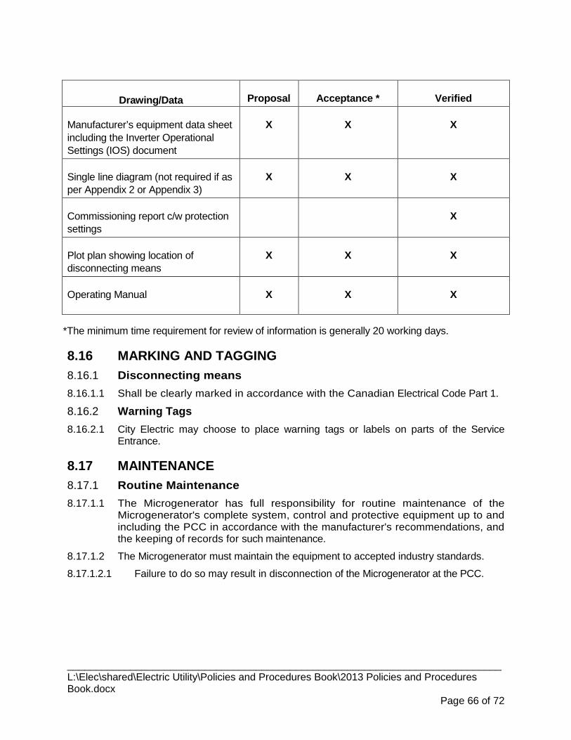
Drawing/Data Proposal Acceptance * Verified
Manufacturer’s equipment data sheet including the Inverter Operational Settings (IOS) document
X
X
X
Single line diagram (not required if as per Appendix 2 or Appendix 3)
X
X
X
Commissioning report c/w protection settings
X
Plot plan showing location of disconnecting means
X
X
X
Operating Manual
X
X
X
*The minimum time requirement for review of information is generally 20 working days.
8.16 MARKING AND TAGGING 8.16.1 Disconnecting means
Shall be clearly marked in accordance with the Canadian Electrical Code Part 1. 8.16.1.1
8.16.2 Warning Tags City Electric may choose to place warning tags or labels on parts of the Service 8.16.2.1
Entrance.
8.17 MAINTENANCE 8.17.1 Routine Maintenance
The Microgenerator has full responsibility for routine maintenance of the 8.17.1.1Microgenerator's complete system, control and protective equipment up to and including the PCC in accordance with the manufacturer's recommendations, and the keeping of records for such maintenance.
The Microgenerator must maintain the equipment to accepted industry standards. 8.17.1.2
8.17.1.2.1 Failure to do so may result in disconnection of the Microgenerator at the PCC.
____________________________________________________________________________ L:\Elec\shared\Electric Utility\Policies and Procedures Book\2013 Policies and Procedures Book.docx
Page 66 of 72
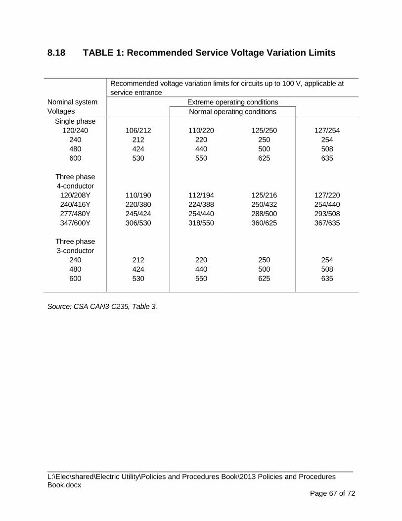
8.18 TABLE 1: Recommended Service Voltage Variation Limits
Nominal system Voltages
Recommended voltage variation limits for circuits up to 100 V, applicable at service entrance
Extreme operating conditions Normal operating conditions
Single phase 120/240
240 480 600
Three phase 4-conductor 120/208Y 240/416Y 277/480Y 347/600Y
Three phase 3-conductor
240 480 600
106/212
212 424 530
110/190 220/380 245/424 306/530
212 424 530
110/220
220 440 550
112/194 224/388 254/440 318/550
220 440 550
125/250
250 500 625
125/216 250/432 288/500 360/625
250 500 625
127/254
254 508 635
127/220 254/440 293/508 367/635
254 508 635
Source: CSA CAN3-C235, Table 3.
____________________________________________________________________________ L:\Elec\shared\Electric Utility\Policies and Procedures Book\2013 Policies and Procedures Book.docx
Page 67 of 72
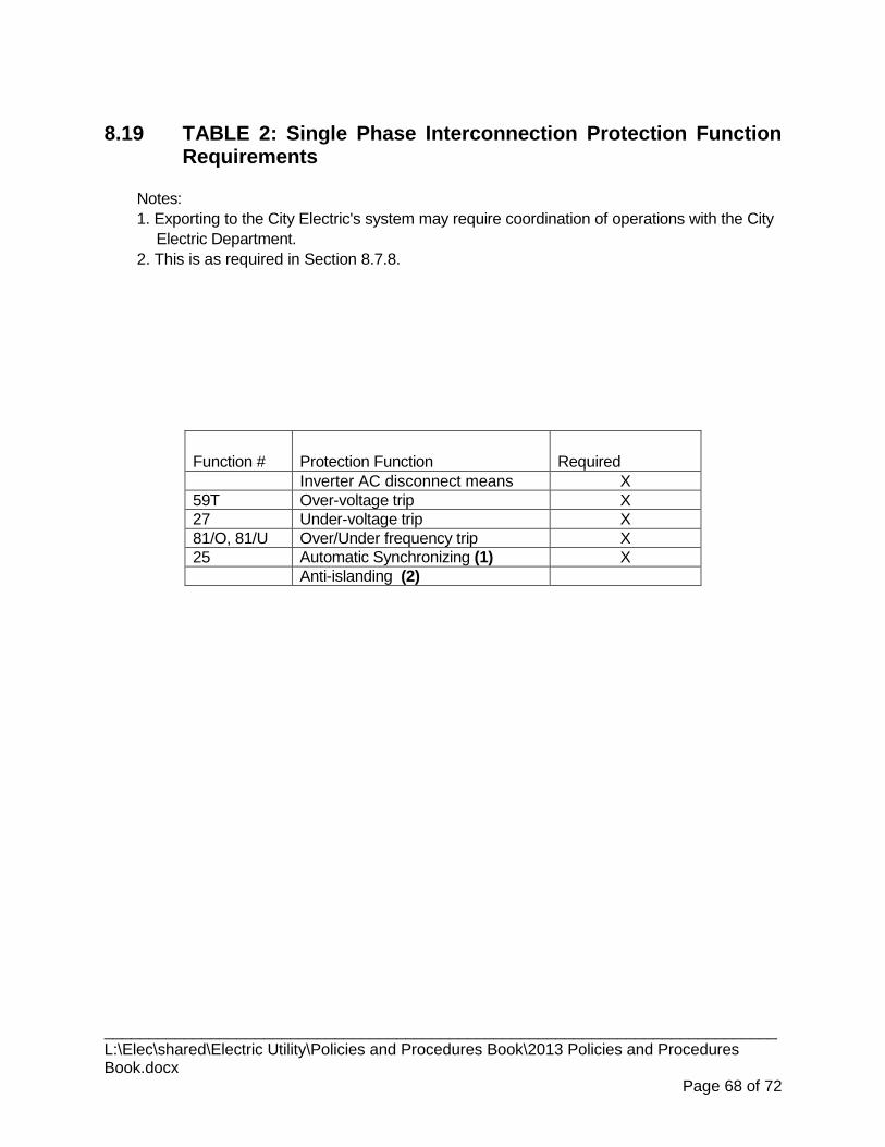
8.19 TABLE 2: Single Phase Interconnection Protection Function Requirements
Notes: 1. Exporting to the City Electric's system may require coordination of operations with the City
Electric Department. 2. This is as required in Section 8.7.8.
Function # Protection Function Required Inverter AC disconnect means X 59T Over-voltage trip X 27 Under-voltage trip X 81/O, 81/U Over/Under frequency trip X 25 Automatic Synchronizing (1) X Anti-islanding (2)
____________________________________________________________________________ L:\Elec\shared\Electric Utility\Policies and Procedures Book\2013 Policies and Procedures Book.docx
Page 68 of 72
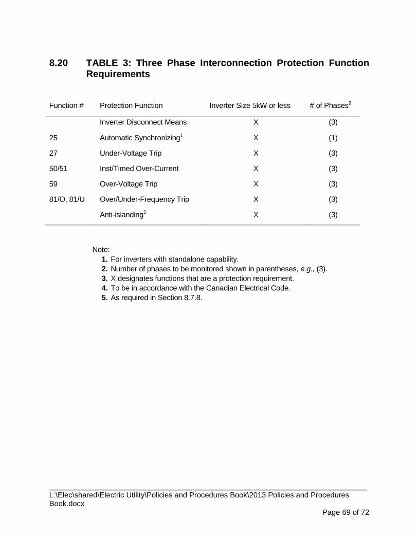
8.20 TABLE 3: Three Phase Interconnection Protection Function Requirements
Function # Protection Function Inverter Size 5kW or less # of Phases2
Inverter Disconnect Means X (3)
25 Automatic Synchronizing1 X (1)
27 Under-Voltage Trip X (3)
50/51 Inst/Timed Over-Current X (3)
59 Over-Voltage Trip X (3)
81/O, 81/U Over/Under-Frequency Trip X (3)
Anti-islanding5 X (3)
Note: 1. For inverters with standalone capability. 2. Number of phases to be monitored shown in parentheses, e.g., (3). 3. X designates functions that are a protection requirement. 4. To be in accordance with the Canadian Electrical Code. 5. As required in Section 8.7.8.
____________________________________________________________________________ L:\Elec\shared\Electric Utility\Policies and Procedures Book\2013 Policies and Procedures Book.docx
Page 69 of 72

8.21 APPENDIX 1: Definitions
The following terms are defined here to assist in the understanding of microgeneration. Though some of these terms are not used in this Guide, they may arise in discussions of microgeneration systems and so would be useful to understand.
1. Microgenerator Distributed generation up to 5 kW typically installed in a
residential or small business building. It is deemed to be operating unattended using untrained personnel.
2. Inverter An electronic device that converts DC electricity to AC electricity.
3. Voltage-following inverter An inverter in which the output follows the waveform of an external device.
4. Stand-alone mode An inverter which operates in isolation from the City of Medicine Hat Electric Distribution System (City Electric).
5. Grid-interactive mode An inverter which operates in parallel with City Electric and contains provision for synchronizing with City Electric.
6. Grid-dependent mode An inverter which automatically ceases to operate upon loss of voltage from City Electric and resumes operation when City Electric voltage is restored.
7. Single phase inverter An inverter that generates a single phase electrical output.
8. Point of common coupling (PPC)
The point where City Electric is connected to the Microgenerator’s facility.
9. Disconnecting means A device which disconnects a circuit from its source of supply.
10. Islanding A condition in which a portion of City Electric is energized by a Microgeneration facility thru a PCC while that portion of City Electric is separated from the rest of City Electric distribution system.
____________________________________________________________________________ L:\Elec\shared\Electric Utility\Policies and Procedures Book\2013 Policies and Procedures Book.docx
Page 70 of 72

8.22 APPENDIX 2: Single Line Diagram for Grid-Dependent Microgeneration Systems
____________________________________________________________________________ L:\Elec\shared\Electric Utility\Policies and Procedures Book\2013 Policies and Procedures Book.docx
Page 71 of 72

8.23 APPENDIX 3: Single Line Diagram For Grid-Interactive MicroGeneration Systems
____________________________________________________________________________ L:\Elec\shared\Electric Utility\Policies and Procedures Book\2013 Policies and Procedures Book.docx
Page 72 of 72