Embed Size (px)
Citation preview

Computer Science & Engineering: An International Journal (CSEIJ), Vol.3, No.1, February 2013
DOI : 10.5121/cseij.2013.3101 1
THROUGHPUT/AREA TRADE-OFFS OF LOOP-UNROLLING, FUNCTIONAL, AND STRUCTURAL
PIPELINE FOR SKEIN HASH FUNCTION
George S. Athanasiou1, Elias Tsingkas1, Harris E. Michail2, George Theodoridis1
and Costas E. Goutis1
1Department of Electrical and Computer Engineering, University of Patras, [email protected]
2Department of Electrical Engineering, Computer Engineering and Informatics, CyprusUniversity of Technology, Limassol, Cyprus
ABSTRACT
In this paper, a design space exploration is performed aiming at developing high-performance hardwarearchitectures for the new cryptographic hash function Skein-512. Three well-known design optimizationtechniques namely, the loop unrolling, the structural and functional pipeline, are applied, while severaldesign alternatives have been explored to derive optimized FPGA implementations. The proposedarchitectures have been implemented and evaluated in three Xilinx technologies (Virtex-4, Virtex-5, andVirtex-6). Based on the experimental results, when all the three techniques are applied, the bestarchitecture is the 8-round_unroll one with two functional and three structural pipeline stages. To the bestof the authors’ knowledge, it is the first time that all these three techniques are studied and exploitedtogether for the Skein algorithm. Also, the proposed architectures outperform the corresponding existingones in terms of Throughput/Area factor from 27% up to 192%, respectively.
KEYWORDS
Security, Authentication, Hash functions, Skein, FPGA
1. INTRODUCTION
21st century is considered to be the era of mass communication and electronic informationexchange. However, this advancement goes in parallel with serious considerations regarding thesecurity of the exchanged information, especially when this information is sensitive and/orconfidential. To overcome this problem, advanced security mechanisms are included in moderncommunication protocols as well as in data transmission and communication systems. Typicalexamples are the encryption and authentication which are performed in every transmitted datapacket by the forthcoming Internet Protocol version 6 (IPv6) [1] via the Internet Protocol Security(IPSec) [2]. Regarding authentication, which is an important feature of IPSec, it is realized usinga standard hash algorithm [3]. Beyond that, hash functions are among the crucial building blocksof many popular security systems and applications like Secure Electronic Transactions (SET) [4],IEEE 802.16 standard [5] for Local and Metropolitan Networks, digital signature schemes [6] andweb protocols [7].
Skein [10], [17] is a new cryptographic hash function, introduced in the end of 2010. It combinesspeed, security, simplicity, and a great deal of flexibility in a modular package that is easy to
Computer Science & Engineering: An International Journal (CSEIJ), Vol.3, No.1, February 2013
2
analyze. In fact, it was one of the five finalists of the international hash function competition,launched by NIST [10].
It is well-known that the computational complexity of security algorithms often becomes the hostsystem’s bottleneck [11], [44]. This becomes more pronounced when hard real-time constraintsmust be satisfied or high-speed communication networks (e.g. optical networks) are used. In thelast case, a large amount of the available bandwidth may not be utilized if the employed systemsare characterized by low throughput processing [43]. To overcome these bottlenecks, high-throughput architectures are demanded, which is mainly achieved by implementing the securityalgorithms in hardware [11, 12, 13].
Regarding Skein hash function, there are few software implementations in the literature, such as[17-20]. Regarding the hardware implementations of Skein, the works presented in literature canbe classified in two main categories. The first category includes the works that performcomparative studies among the candidates of NIST’s hash competition [24-41]. The main goal ofthese works is not to develop sophisticated architectures but to study the performance of thesealgorithms when they are implemented in hardware. For that reason, different architectures foreach algorithm are proposed applying general design techniques (e.g. pipeline). Then, theintroduced architectures are implemented in hardware using mainly FPGA technologies and theyare compared in terms of area, frequency, and throughput. The second category includes theworks which target at developing advanced hardware architecture for the Skein algorithm only.The main goal of these works is the development of architectures characterized by highthroughput and low area. In [21] the loop unrolling technique was applied in order to improvedelay and throughput. In [22], novel architectures for all the three types of Skein algorithm (256,512, and 1024) were proposed using an 8-round unrolled data-path. Walker et al. in [23] proposed4 different architectures depending on the number of pipeline stages, namely zero, two, four andeight, employing the 8-round unrolled data-path. Finally, in [42], a low-area coprocessor for theinternal structure of Skein, named Threefish, is designed, exploiting interleaving and parallelism.
In this paper, a design space exploration is performed aiming at developing hardwarearchitectures for the Skein-512 algorithm characterized by high performance in terms ofThroughput/Area metric. Three design optimization techniques namely, the loop unrolling, thestructural, and functional pipeline are studied and 10 different architectures, which vary in thenumber of the applied loop unrolling depth and pipeline stages, are proposed. These architecturesare categorized in three sets. The first set includes the architectures which are produced byapplying the loop unrolling technique, the second set corresponds to the architectures which arederived by utilizing the loop unrolling and structural pipeline, while the last one includes thearchitectures which are produced by applying both the three above techniques. To the best of theauthors’ knowledge, it is the first time that all these three techniques are used to develop hardwarearchitectures for the Skein algorithm. Moreover, all the introduced architectures have beendeveloped to be used either as simple hash modules on MAC ones. Also, special effort has beenpaid and different design alternatives have been explored to derive optimized FPGAimplementations. The proposed architectures have been implemented in three Xilinx technologies(Virtex-4, Virtex-5, and Virtex-6) and evaluated in terms of Throughput/Area. Based on theexperimental results, when only loop unrolling is applied, the architecture with unrolling depthequal to 8 (8-round_unroll) is the best, while when loop unrolling and functional pipeline are usedtogether the 8-round_unroll architecture with two pipeline stages outperform the correspondingones. Finally, when all the three techniques are used, the best architecture is the 8-round_unrollone with two functional and three structural pipeline stages. Moreover, the proposed architecturesoutperform the existing ones in terms of Throughput/Area, from 27% up to 151%, and from 43%up to 192%, respectively.

Computer Science & Engineering: An International Journal (CSEIJ), Vol.3, No.1, February 2013
3
The rest of the paper is organized as follows. In Section 2 the Skein algorithm is described. InSection 3 the design space exploration is analyzed and the proposed architectures are presented indetails. The experimental results and comparisons with similar existing architectures are providedin Section 4. Finally, Section 5 concludes the paper.
2. THE SKEIN HASH FAMILY
Skein is a family of hash algorithms with three different internal state sizes: 256, 512, and 1024bits. Skein-512 is the primary algorithm of the family and can be used for all current hashingapplications of modern security systems. Skein-1024 has the same characteristics as Skein-512but its internal size is twice than the Skein-512. Finally, Skein-256 is the low-memory variant ofthe algorithm but offers less security than the above two. Skein-512 is considered to be the bestchoice for drop-in replacement of the existing SHA-family functions in security systems [17].
The basic concept of Skein algorithm is to build a hash function out of a tweakable block cipher.The use of a tweakable block cipher allows the hashing of configuration data along with the inputtext in every block, making every instance of the compression (hash) function unique. Thisproperty directly addresses many attacks on hash functions and greatly improves Skein'sflexibility [17]. Specifically, Skein is built by the following three components: (a)Threefish: it is atweakable block cipher at the core of Skein algorithm, (b)Unique Block Iteration (UBI): it is achaining mode that uses Threefish to build a compression function that maps an arbitrary inputsize to a fixed output size, and (c)Optional Argument System (OAS): it is a set of optional featuresthat are supported by Skein, without imposing any overhead on implementations that do not usethem. In the following sub-Sections, the main components (Threefish and UBI) of Skeinalgorithm are presented. More details for Skein hash function can be found in [17].
2.1. Threefish Component
Threefish, is used in Matyas-Meyer-Oseas mode to construct the Skein compression function[17]. During the Threefish process, the N-bit plaintext is portioned in w=N/64 64-bit words. Thesewords are grouped in pairs of two, let (W0, W1), for each round and serve as input in a MIXfunction, which is described by the following equation:
[ ] ( )0 1 0 1 1 0 1, , ( )MIX W W W W W R W W = + << ⊕ + (1)
where << and ⊕ the denote left rotation by R bits and XOR operations, respectively. It should benoticed that the constant R depends on N and it is different for each MIX function.
Threefish-512 iterates 72 times (72 rounds), while each round includes w/2 = 512/128 = 4 MIXfunctions. According to the definition of Threefish-512, the rotation constants, R, are different forthe first eight rounds and then they are repeated every eight rounds. Also, they are properlychosen to maximize the diffusion among the bits of the word. Just after the MIX stage, there isthe permutation one, which is the same for every round. Its purpose is to permute the w wordsbetween rounds, r, so that different words to be used as input in the MIX function of each round.MIX functions and permutation stages are used consecutively so as to build Threefish-512.Specifically, every four MIX functions are followed by a permutation of the eight 64-bit words.Moreover, a sub-key (skey) is inserted every four rounds, which is added with the outputs of thecorresponding permute stage. These keys are generated by a special component called KeySchedule applying a specific procedure. Particularly, at the beginning, two new words, Kw and T2,are computed as shown in Eq. 2.
Computer Science & Engineering: An International Journal (CSEIJ), Vol.3, No.1, February 2013
4
0 1 1 240
2 0 1
W WK K K K C
T T T−= ⊕ ⊕ ⊕ ⊕
= ⊕
(2)
where K0 … Kw-1 are the “w-1” keys, T0 and T1 are the first two tweak factors and C240 is aconstant that ensures that the extended key will not be all zeroes. Then the scheduling of theround keys is defined as indicated below:
( ) ( )
( ) ( )
( ) ( ) ( )
( ) ( )
, mod 1
, mod3mod 1
, mod 1 1 mod3
, mod 1
for 0,1, , 4
+ T for 3
+ T for 2
+ for 1
s i s i w
s i ss i w
s i s i w s
s i s i w
K K i w
K K i w
K K i w
K K s i w
+ +
+ +
+ + +
+ +
= = −
= = −
= = −
= = −
(3)
where / 4s r= denoted the number of the subkey and i the number of the word.
2.2. UBI Chaining Mode
The UBI chaining mode employs consecutive instances of Threefish module to replace theexisting Merkle–Damgård constructions. In a UBI chain for Skein-512 that incorporates threeThreefish-512 modules for processing a 166-byte (three blocks) input, the message blocks M0 andM1 are of 64 bytes and M2 is padded and contains the remaining 38 bytes. The tweak value ofeach block encodes how many bytes have been processed so far, and whether this is the firstand/or last block of the message. In order to construct a straightforward hash function by usingthe Skein algorithm, the tweak also encodes a “type” field that distinguishes the differentoperational modes of each UBI inside the hash structure. It consists of a UBI for initialconfiguration, the main UBI for message processing, and the output UBI for the finalization ofthe hash output. To turn a Skein hash structure to MAC is simple. Instead of starting with zeroand processing the configuration block, start with zero, process the key, and then theconfiguration. More details about UBI chaining of Skein hash function can be found in [17].
3. PROPOSED ARCHITECTURES
As it has been mentioned, the goal of the paper is to propose advanced hardware architectures forSkein hash function characterized by high throughput values and low area overhead. For thatreason, three design optimization methods, namely the loop unrolling, functional and structuralpipeline are studied in depth and three sets of architectures are proposed. The first set includes thearchitectures where the loop unrolling technique is applied, the second set contains thearchitectures where both loop unrolling and functional pipeline are applied, whereas the last onecontains the architectures where loop unrolling, functional, and structural pipeline are applied.
3.1. Loop-Unrolling Exploration
The loop unrolling optimization technique deals with the unfolding the body of a computational-intensive loop by a factor m called loop unrolling factor in order to expose and exploit theparallelism which may exist among the computations of the loop body. Thus: (a) the total numberof the performed iterations decreases and (b) the m iterations of the loop are executed in shortertime than before. Thus, higher throughput rates are resulted.
However, the application of loop unrolling imposes significant area overhead. Specifically, thearea of the data-path increases because more functional units are demanded to execute the
Computer Science & Engineering: An International Journal (CSEIJ), Vol.3, No.1, February 2013
5
computations of m iterations of the loop, whereas the control unit also becomes more complex.Hence, a careful study is required to determine the best unrolling factor in terms ofThroughput/Area metric.
The straightforward design of Skein-512 function corresponds to one MIX-permute pair (with nounrolling) plus the appropriate 64-bit adders for the keys’ additions. Due to the fact that the sub-keys are inserted every four rounds, another approach is the 4-round unrolled alternative that isfollowed in many works [27], [29], [36-38], [41]. Additionally, the fact that the round constants,R, are different for the first eight rounds and then they are repeated every eight rounds, the thirdalternative for unrolling is the 8-round unrolled one, which is also followed by many researchers,as well as the creators of the Skein family [17], [22], [37-38], [41]. Due to the above facts, all theintermediate possible alternatives with different unrolling factor are considered as non-effectivein terms of area because they demand more steering logic for the sub-keys and the rotationconstants resulting in an increase of the critical path.
In order to accurately determine the best from the above alternatives, we developed and set forevaluation three different architectures of Skein-512 algorithm, which are the 1-round (m=1), 4-round (m=4), and 8-round unrolled (m=8). We applied the same design optimization techniques,aiming at achieving the best results by all the architectures and we compared them in terms ofthroughput, area, and throughput/area.
3.1.1. 1-round Unrolled Architecture
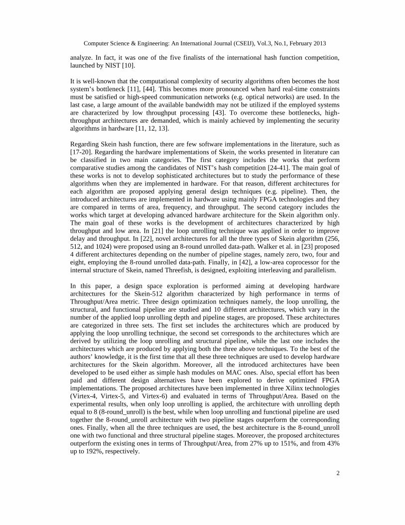
The block diagram of the 1-round unrolled architecture (1-round_unroll) is shown in Figure 1. Itconsists of six main components, which are the Input Block, Rounds, Key Generator, TweakGenerator and Output Block and the Control Unit. Concerning the I/O interface, it is formed by 5inputs (sel_mac, msg, length, new_msg, last_block) and 2 outputs (md, valid).
>
>
Figure 1. 1-round unrolled Skein-512 Hash/MAC Architecture
Computer Science & Engineering: An International Journal (CSEIJ), Vol.3, No.1, February 2013
6
The architecture is able to operate either as Hash or MAC module depending on the user’s choice.For that reason, the sel_mac signal is used to determine the type of operation (Hash or MAC).Concerning the input message, this is fed in through the msg input in 64-bit words, while the 7-bitlength input denotes the number of the bits of the last active data of the input message. Also, thesignals new_msg and last_block are active when a new message exists and the last message blockis inserted, respectively. The architecture outputs the hash value in 64-bit words through the mdoutput, whereas the valid signal is set to high level during this procedure. To perform a completeSkein operation, 73 clock cycles are demanded. Specifically, 72 clock cycles are needed toexecute the 72 rounds of Threefish-512 components, whereas one more cycle is spent for thecomputation of the first sub-key. More details, on the required clock cycles are given in thepresentation of the control unit.
The Input Block component contains the Padding unit, which is responsible to form the 512-bitinput block for the hash computation and the Starting Signal Production unit, which producesfour signals. The three of them (first, final, position) are used as input in the Teak Generator forthe production of the teak values, while the forth signal (start_keygen) is fed in the Control Unitin order to start the computation of the sub-keys. The Control Unit itself sends twosynchronization signals (start_counter, rst_inp) to the Input Block to start a new padding.
The Tweak Generator component is responsible for producing the appropriate teak values foreach operation mode [17]. It uses the first, final, pad (non-zero when padding was performed inInput Block) bits, along with the 96-bit position quantity that indicates the number of messagebytes that have already been processed, and forms the teak value through concatenation (asimposed by the standard [17]).
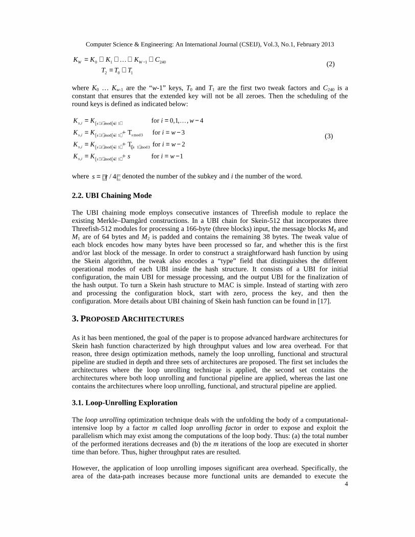
The main part of the computations is performed by the Rounds component, which is illustrated inFigure 2. Its organization is based on the MIX-permute pairing structure of the algorithm. Inparticular, it consists of four MIX and one permutation module, while eight 64-bit adders are alsoincluded for adding the sub-keys. Regarding the MIX and Permute modules, they have beendesigned as described in the algorithm’s specifications (Section 2 and [17]). Due to the fact thatevery four rounds a different sub-key is added, there is a 512-bit 2to1 multiplexer before the MIXmodules. Moreover, as it shown in Figure 1, just before the Rounds component, there is a 4to1multiplexer that is responsible of feeding it with the appropriate input. If a configuration UBI hasto take place, then the input of the Rounds is the predetermined input for it, as described by thealgorithm, while if an output UBI is to begin, then the input is set to “0”. To start the hashcomputation of a new message, the output of the Input Block is chosen, while if a multi-blockmessage is processed, the multiplexer feeds back the 512-bit output.
Figure 2. The Rounds component
Computer Science & Engineering: An International Journal (CSEIJ), Vol.3, No.1, February 2013
7
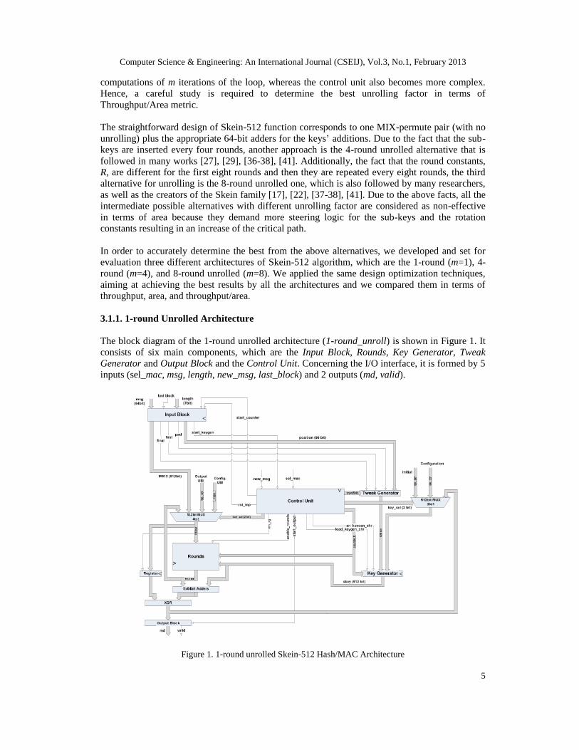
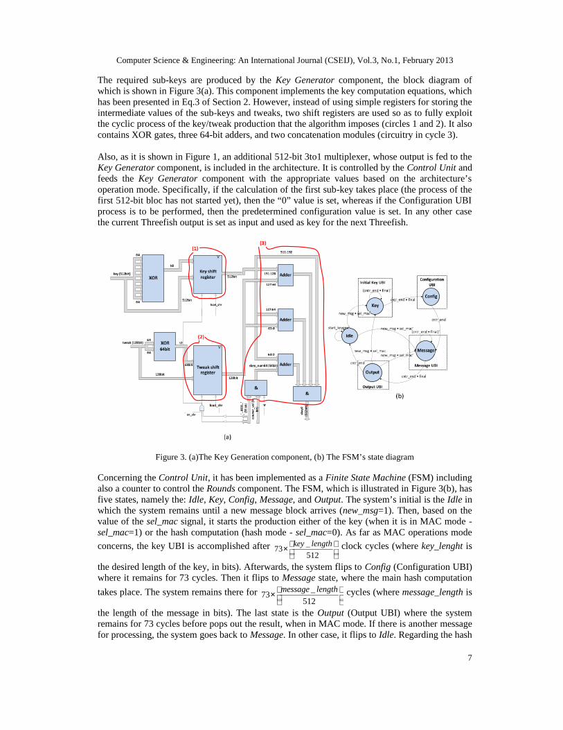
The required sub-keys are produced by the Key Generator component, the block diagram ofwhich is shown in Figure 3(a). This component implements the key computation equations, whichhas been presented in Eq.3 of Section 2. However, instead of using simple registers for storing theintermediate values of the sub-keys and tweaks, two shift registers are used so as to fully exploitthe cyclic process of the key/tweak production that the algorithm imposes (circles 1 and 2). It alsocontains XOR gates, three 64-bit adders, and two concatenation modules (circuitry in cycle 3).
Also, as it is shown in Figure 1, an additional 512-bit 3to1 multiplexer, whose output is fed to theKey Generator component, is included in the architecture. It is controlled by the Control Unit andfeeds the Key Generator component with the appropriate values based on the architecture’soperation mode. Specifically, if the calculation of the first sub-key takes place (the process of thefirst 512-bit bloc has not started yet), then the “0” value is set, whereas if the Configuration UBIprocess is to be performed, then the predetermined configuration value is set. In any other casethe current Threefish output is set as input and used as key for the next Threefish.
>
>>
Figure 3. (a)The Key Generation component, (b) The FSM’s state diagram
Concerning the Control Unit, it has been implemented as a Finite State Machine (FSM) includingalso a counter to control the Rounds component. The FSM, which is illustrated in Figure 3(b), hasfive states, namely the: Idle, Key, Config, Message, and Output. The system’s initial is the Idle inwhich the system remains until a new message block arrives (new_msg=1). Then, based on thevalue of the sel_mac signal, it starts the production either of the key (when it is in MAC mode -sel_mac=1) or the hash computation (hash mode - sel_mac=0). As far as MAC operations mode
concerns, the key UBI is accomplished after _73
512
key length × clock cycles (where key_lenght is
the desired length of the key, in bits). Afterwards, the system flips to Config (Configuration UBI)where it remains for 73 cycles. Then it flips to Message state, where the main hash computation
takes place. The system remains there for _73
512
message length × cycles (where message_length is
the length of the message in bits). The last state is the Output (Output UBI) where the systemremains for 73 cycles before pops out the result, when in MAC mode. If there is another messagefor processing, the system goes back to Message. In other case, it flips to Idle. Regarding the hash
Computer Science & Engineering: An International Journal (CSEIJ), Vol.3, No.1, February 2013
8
mode, the computation, after the Idle state, continues to Message and then to Output, similarly toabove.
The Control Unit’s circuitry contains a counter and simple logic modules, such as logic gates,flip-flops etc. Additionally to the above control component, there is a smaller counter that countsup to 8 inside the Input Block component. This small counter is responsible for the appropriatesynchronization of the padding procedure with the rest of the architecture and the indicating thatnew data can be inserted for padding.
3.1.2. 4-round Unrolled Architecture
Regarding the 4-round unrolled architecture (4-round_unroll), there are few differences comparedto the 1-round unrolled one, mainly concerning the organization of the Rounds and Control Unit.The other components have negligible, logic-level, differences. In particular, in the Roundscomponent, 4 MIX-permute pairs are sequentially connected resulting in 16 MIX and 4 Permutemodules. Also, there are eight 64-bit adders for the subkeys. Due to the fact that every fourrounds a different subkey is added, there is a 2to1 multiplexer before the MIXes.
Concerning the Control Unit, it is similar to the one presented in Figure 3(b). However, tocorrectly control the current architecture, the internal counter counts up to 17. Thus, theConfig_1, Message_2, and Output_1 states iterate (when desired) 17 times. The rest functionalityof the Control Unit is the same as described in 3.1.1.
3.1.3. 8-round Unrolled Architecture
As in 4-round unrolled architecture, the differences between the 8-round (8-round_unroll) and the1-round unrolled architectures, mainly concern the Rounds and the Control Unit. Regarding theRounds component, there are 32 MIX and 8 Permute modules in total. Additionally, due to theapplied eight times loop unrolling, the Rounds component has two separate inputs for sub-keys.Also, just before the Rounds component, there is a 4to1 multiplexer that is responsible of feedingit with the appropriate input.
Furthermore, due to the 8-round unrolling and the fact that a sub-key is need every 4 rounds, theKey Generator produces two sub-keys at the same time. The block diagram of this Key Generatoris similar to one of Figure 3(a), however it has some modifications. Instead of simple registers forstoring the intermediate values of the sub-keys and tweaks, two shift registers are used again, tofully exploit the cyclic process of the keys and tweaks that the algorithm imposes (Section 2 and[17]). However, it contains twice the circuitry of circle 3 in Figure3 (a) (6 64-bit adders and 4concatenation modules) so as to feed the Rounds component with two sub-keys per clock cycle.Concerning the Control Unit, is similar to the one presented in Figure 3(b), however, to correctcontrol the current architecture, the internal counter counts up to 8. Thus, the Config_1,Message_2, and Output_1 states iterate (when desired) 8 times. The rest functionality of the s isthe same as described in 3.1.1).
3.2. Pipeline Exploration
As it is known, a widely-used method to improve throughput is pipeline. This is accomplishedsplitting the critical path in shorter ones by inserting registers in proper positions creating pipelinestages, which are located between the pipeline registers. In that way, after a latency delay,different input data are processed concurrently in the pipeline stages resulting in significantthroughput improvement. However, the use of the pipeline registers results in area increase, whilethe control unit also becomes more complex. Moreover, after a certain point, the increase of the

Computer Science & Engineering: An International Journal (CSEIJ), Vol.3, No.1, February 2013
9
number of pipeline stages results in negligible throughput improvements. Hence, in order todevelop an architecture characterized by high Throughput/Area values, a careful study isdemanded to determine the number and position of the pipeline stages.
3.2.1. Functional Pipeline
Concerning the Skein algorithm, a way of applying the pipeline technique is the insertion ofpipeline registers inside the Round component and specifically between the consecutive executedrounds. This kind of pipeline is denoted as Functional Pipeline. As it will be reported anddiscussed in the experimental results (Section 4.1), the 8-round unroll architecture is the best interms of Throughput/Area factor. Thus, it is considered as the base architecture on which thefunctional pipeline is applied. Due to the 8 times loop unfolding, the Round component executes8 iterations together. Thus, as the aim is the insertion of pipeline registers between theconsecutive rounds without causing significant synchronization overheads, three designalternatives exist. These are the 2, 4, and 8-staged pipelined architectures.
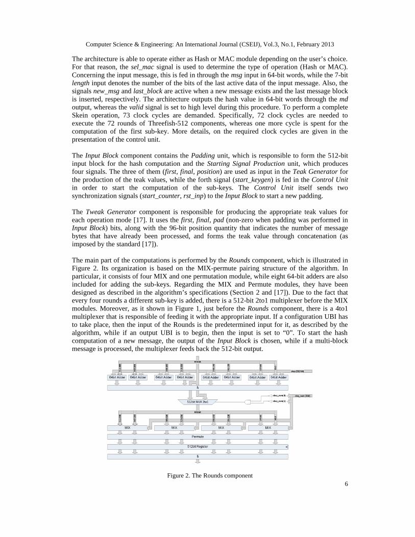
A general block diagram of a p-stage (p =2, 4, 8) pipelined architecture is shown in Figure 4.Comparing this architecture to that of Figure 1, they differ in three points. First, in the Roundscomponent, there are 8/p MIX-Permute pairs followed by a pipeline register. The triplet (MIX-permute) - Register - (MIX-Permute) is repeated p/2 times before and after the 8 64-bit addersthat are located in the middle. Additionally, there are p registers on the left of Rounds componentfor the correct synchronization of the appropriate input block that is to be XORed with thecorresponding output. Also, for synchronization reasons, there are (p-1) additional registers at theXORs output that is fed in the 3to1 multiplexer that feeds the Key Generators.
>
>
>
>
>
>
>
>
>
Figure 4. N-staged pipelined architecture based on the 8-round unrolled Skein-512 one

Computer Science & Engineering: An International Journal (CSEIJ), Vol.3, No.1, February 2013
10
In order to support the Rounds component with the required sub-keys, the Key Generatorcomponent has to be modified as well. The straightforward choice would be the incorporation ofp Key Generator components, each one responsible for the corresponding message block that isprocessed in each one of the p stages. However, this would lead to significant increase of theoccupied area. To overcome this issue without increasing the critical path, which is located insidethe Rounds component, a different approach was followed. Specifically, two Key Generatorcomponents were designed (Key Generator 0 and Key Generator 1). Each one includes p/2 shiftregisters (same as those inside circles 1 and 2 of Figure 3(a)), which are responsible for producingthe appropriate sub-key and tweak values for the corresponding message block. In every clockcycle, one key shift-register-tweak shift-register pair will operate, supporting the correspondingmessage block that is processed. This way, there are only three adders and two concatenationmodules (same circuitry as in circle 3 of Figure 3(a)) that are shared among the shift-registers,leading to significant area decrease compared to the straightforward choice. To correctly controlthe above procedure and selecting the working shift-register, additional steering logic is usedconsisting of two p/2_to_1 multiplexers before the above circuitry.
Regarding the Control Unit it is also developed as hardwired FSM and it is similar to that ofFigure 3(b). However, it is larger as additional control signals must be produced. Also it containsa counter that counts up to a number which depends on the number of the employed pipelinestages p. To compute a hash value of a 512-bit message block, the Round component iterates 72/8= 9 times (due to the 8-round unrolling), but now its iteration last p clock cycles. An additionalclock cycle for producing the first sub-key is required (similarly to the designs with no pipeline ofsub-Section 4.1), as well as one more for synchronization purposes of the last pipeline stage withthe rest ones. Hence, the total clock cycles of the above designs functionality, regarding the hashprocessing of a message block, are: (9 × p) + 2, and specifically 20, 38, and 74 clock cycles for 2,4, and 8-staged pipelined designs, respectively.
3.2.2. Structural Pipeline
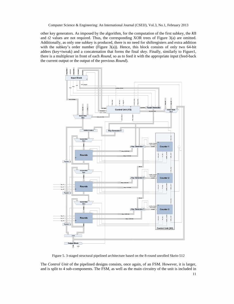
Another pipeline topology that could be considered for the Skein algorithm is the structural one.This is accomplished by repeating consecutively modules of Threefish module, which operate ondata of different message blocks independently from one to another. Taking into account that the8-round unrolled module is the best choice for the Threefish module, a structural pipelinedarchitecture considering three of the above modules is constructed, as illustrated in Figure 5. As itis shown, there are three independent 8-round unrolled Threefish modules (Round) consecutivelyconnected. Each one of them performs three iterations, so as the design to perform (3 × 8) × 3 =72.
Regarding the Key Generator component, it is split to three different ones, which are the KeyGenerator 1, 2, and 3. Each one of them is responsible to feed the corresponding Roundcomponent with the required sub-keys. Concerning their internal organization, the Key Generator1 is similar to the one shown in Figure 4, with an additional output for feeding the Key Generator2 with the appropriate sub-keys and tweaks for its computation, through parallel loading of itsshift registers. Key Generator 2 is similar to Key Generator 1 without the XOR trees before theshift registers (see Figure 3(a)). Finally, the Key Generator 3 is similar to Key Generator 2without the output for parallel loading.
As discussed in sub-Section 3.1.3, the 8-round unrolled architecture requires one extra clockcycle for the computation of the first sub-key. Hence, in the 3-staged structural pipelinedarchitecture three additional clock cycles would be required. To avoid the delay of these cycles,there is an additional one (Key Generation 0) just before the first Round component, which isresponsible for the computation of the first sub-key. This component is much simpler than the
Computer Science & Engineering: An International Journal (CSEIJ), Vol.3, No.1, February 2013
11
other key generators. As imposed by the algorithm, for the computation of the first subkey, the K8and t2 values are not required. Thus, the corresponding XOR trees of Figure 3(a) are omitted.Additionally, as only one subkey is produced, there is no need for shiftregisters and extra additionwith the subkey’s order number (Figure 3(a)). Hence, this block consists of only two 64-bitadders (key+tweak) and a concatenation that forms the final skey. Finally, similarly to Figure1,there is a multiplexer in front of each Round, so as to feed it with the appropriate input (feed-backthe current output or the output of the previous Round).
>
>
>
>
>>
>
Figure 5. 3-staged structural pipelined architecture based on the 8-round unrolled Skein-512
The Control Unit of the pipelined designs consists, once again, of an FSM. However, it is larger,and is split to 4 sub-components. The FSM, as well as the main circuitry of the unit is included in
Computer Science & Engineering: An International Journal (CSEIJ), Vol.3, No.1, February 2013
12
the Control Unit 1/2, while the rest is included in the Control Unit 2/2. The latter consists of threecounters, each one of them counting up to and producing the additional control signals, requiredby its corresponding Round and Key Generator.
3.2.3. Combination of Functional and Structural Pipeline
The two pipeline styles (functional and structural) can be combined leading to more effectivedesigns in terms of throughput. However, this results in important area overhead. Hence, anexploration is required in order to develop an architecture characterized by improvedThroughput/Area values. To accomplish this exploration, three more architectures weredeveloped, which incorporated 2, 4, and 8 stages of functional pipelining inside the Roundscomponent. Regarding the rest components (e.g. Key Generators, Control Unit(s), etc), acombination of the above topologies was accomplished. For clarity reasons, as well as to avoidincreased length of the manuscript, the block diagrams of these architectures are not presented.
4. EXPERIMENTAL RESULTS AND COMPARISONS
The above-introduced architectures were captured in VHDL, synthesized, and implemented inFPGA technology using the Xilinx ISE Design Suite v.13.1. Also, for the implementation of thearchitectures, the Virtex-4 (xc4vlx160-FF1148) and Virtex-5 (xc5vfx130t-FF1738), and Virtex-6(xc6vlx365t-FF1759) FPGA families were selected. The correct functionality of the architectureswas initially verified through Post-Place and Route (Post-P&R) simulations using the ModelSimsimulator. Thereafter, downloading to FPGA boards was performed and the functionality of eachimplementation was verified on the board using the Xilinx ChipScope tool.
The comparisons among all the proposed architectures are accomplished in terms Delay,Throughput, Area, and Throughput/Area cost factor. Similarly to previous works dealing withhardware implementations of Skein hash family, Throughput is calculated by Eq. 4:
c
fbitsThroughput
×= )#(
(4)
where f and c correspond to the frequency and the consumed clock cycles, while #bits denotes thedata bits that are processed in each cycle. The total number of clock cycles includes the cyclesconsumed to input data, to execute hashing process in the core function block, to perform thefinal calculation process and to output the hash results. However, when the hashing concerns longmessages (which is the real world case), given the fact that the Throughput, in most of the cases,is the maximum sustainable throughput for a given frequency, the potential cycles for insertingdata, performing the final calculation process and popping out the hash result are negligible andignored.
In the following sections the experimental results are presented and discussed. Firstly, we presentthe performance results of the proposed architectures and we discuss and evaluate the applicationof the applied optimization techniques (loop unrolling, functional, and structural pipeline). Then,comparisons between the introduced and existing works are presented.
4.1. Loop-Unrolling Evaluation
As stated above, the critical path of all the three architectures is located inside the Roundscomponent. In particular, the 1-round_unrolled architecture presents the smallest critical path(one MIX-permute pair, one 64-bit adder, one 512-bit 2to1 multiplexer, and one 512-bit 4to1
Computer Science & Engineering: An International Journal (CSEIJ), Vol.3, No.1, February 2013
13
multiplexer). Moreover, it occupies the least area among the three architectures. Consequently, asthe unrolling factor increases from one to four and then to 8, the occupied area increases and thecritical path gets longer. Additionally, due to the unrolling application, the c variable in Eq. 4 israther smaller in 4-round_unrolled and 8-round_unrolled architectures (19 and 10 respectively)compared to the corresponding one of 1-round_unrolled architecture (73). However, thebehaviour of the Throughput metric, as the unrolling factor increases cannot be fully theoreticallydetermined.
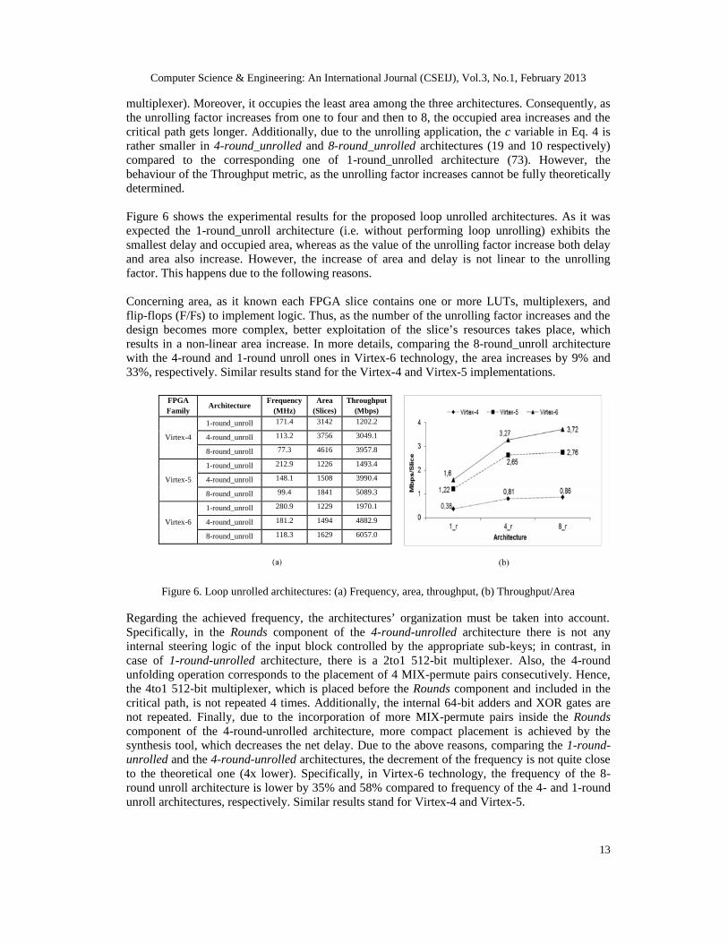
Figure 6 shows the experimental results for the proposed loop unrolled architectures. As it wasexpected the 1-round_unroll architecture (i.e. without performing loop unrolling) exhibits thesmallest delay and occupied area, whereas as the value of the unrolling factor increase both delayand area also increase. However, the increase of area and delay is not linear to the unrollingfactor. This happens due to the following reasons.
Concerning area, as it known each FPGA slice contains one or more LUTs, multiplexers, andflip-flops (F/Fs) to implement logic. Thus, as the number of the unrolling factor increases and thedesign becomes more complex, better exploitation of the slice’s resources takes place, whichresults in a non-linear area increase. In more details, comparing the 8-round_unroll architecturewith the 4-round and 1-round unroll ones in Virtex-6 technology, the area increases by 9% and33%, respectively. Similar results stand for the Virtex-4 and Virtex-5 implementations.
FPGAFamily
ArchitectureFrequency
(MHz)Area
(Slices)Throughput
(Mbps)
Virtex-4
1-round_unroll 171.4 3142 1202.2
4-round_unroll 113.2 3756 3049.1
8-round_unroll 77.3 4616 3957.8
Virtex-5
1-round_unroll 212.9 1226 1493.4
4-round_unroll 148.1 1508 3990.4
8-round_unroll 99.4 1841 5089.3
Virtex-6
1-round_unroll 280.9 1229 1970.1
4-round_unroll 181.2 1494 4882.9
8-round_unroll 118.3 1629 6057.0
Figure 6. Loop unrolled architectures: (a) Frequency, area, throughput, (b) Throughput/Area
Regarding the achieved frequency, the architectures’ organization must be taken into account.Specifically, in the Rounds component of the 4-round-unrolled architecture there is not anyinternal steering logic of the input block controlled by the appropriate sub-keys; in contrast, incase of 1-round-unrolled architecture, there is a 2to1 512-bit multiplexer. Also, the 4-roundunfolding operation corresponds to the placement of 4 MIX-permute pairs consecutively. Hence,the 4to1 512-bit multiplexer, which is placed before the Rounds component and included in thecritical path, is not repeated 4 times. Additionally, the internal 64-bit adders and XOR gates arenot repeated. Finally, due to the incorporation of more MIX-permute pairs inside the Roundscomponent of the 4-round-unrolled architecture, more compact placement is achieved by thesynthesis tool, which decreases the net delay. Due to the above reasons, comparing the 1-round-unrolled and the 4-round-unrolled architectures, the decrement of the frequency is not quite closeto the theoretical one (4x lower). Specifically, in Virtex-6 technology, the frequency of the 8-round unroll architecture is lower by 35% and 58% compared to frequency of the 4- and 1-roundunroll architectures, respectively. Similar results stand for Virtex-4 and Virtex-5.

Computer Science & Engineering: An International Journal (CSEIJ), Vol.3, No.1, February 2013
14
Studying the achieved throughput it is clear that it is improved with the increase of the unrollingfactor and the best architecture in terms of throughput in all technologies is the 8-round unrolledone. As it has been explained in Section 3, 8 iterations of the algorithm are executed in each clockcycle, which results in a drastic decrease of the clock cycles. In Virtex-6, the throughput of the 8-round unroll architecture is improved by 24% and 207% compared to the throughput of the 4- and1-round unroll architectures, respectively. The corresponding improvements in Virtex-5technology are 28% and 241%, whereas in Virtex-4 they are 30% and 229%.
To perform a more accurate and fair evaluation of the proposed architectures, theThroughput/Area metric is studied. As it shown in Figure 6(b), the Throughput/Area factor isimproved when the unrolling factor increases. Specifically, comparing the 8-round unrolledarchitecture with the 4-round and 1-round unrolled ones in Virtex-6 technology, theThroughput/Area factor is improved by 14% and 133%, respectively. Similar results also hold forthe Virtex-4 and Virtex-5 implementations. Finally, the 8-round unroll architecture achieves thehigher Throughput/Area value among all the implementations of all architectures in alltechnologies. For that reason, this architecture was selected as the base one to apply the functionaland structural pipeline techniques.
4.2. Functional Pipeline Evaluation
In Figure 7 the experimental results of the pipelined architectures are presented. Four pipelinedarchitectures are studied, which are the 8r_nFp, 8r_2Fp, 8r_4Fp, and 8r_8Fp with none, two, four,and eight pipeline stages, respectively. For the reason explained above, the 8-round unroll onewas used as the base architecture in which pipeline was applied.
As expected, the frequency, area, and throughput increase as the number of the stages increases.Also, the above metrics are improved when the modern Virtex-6 FPGA technology is used.Specifically, in Virtex-6, the frequency improvements of the 8r_2Fp, 8r_4Fp, and 8r_8Fparchitectures over the 8r_nFp one are 75%, 109%, and 125%, respectively. Also, comparing the8r_nFp design with the 8r_2Fp, 8r_4Fp, and 8r_8Fp ones, the throughput improvements are 75%,109%, and 125%, whereas the area increases by 36%, 98%, and 162%, respectively.
Family Architecture Frequency(MHz)
Area(Slices)
Throughput(Mbps)
Virtex-4
8r_nFp 77.3 4616 3957.8
8r_2Fp 108.5 6133 5556.2
8r_4Fp 124.2 8465 6359.0
8r_8Fp 133.5 11369 6835.2
Virtex-5
8r_nFp 99.4 1841 5089.3
8r_2Fp 162.3 2675 8309.8
8r_4Fp 191.6 4082 9809.9
8r_8Fp 199.3 5506 10204.2
Virtex-6
8r_nFp 118.3 1629 6057.0
8r_2Fp 206.6 2212 10579.5
8r_4Fp 247.0 3219 12647.9
8r_8Fp 266.4 4272 13639.2
Figure 7. Functional pipelined architectures: (a) Freq., area, throughput, (b) Throughput/Area
It should be mentioned that the frequency improvement is not proportional to the number of thepipeline stages because increasing the pipeline stages the design becomes more complex makingdifficult the efficient implementation (e.g. placement) of the logic in the FPGA resources. Thisresults in high routing overhead which strongly affects the final delay. Concerning the area

Computer Science & Engineering: An International Journal (CSEIJ), Vol.3, No.1, February 2013
15
increase, it is also exhibits a similar behaviour and the explanation of this is the same as in loopunrolled architectures discussed above.
Observing the Throughput/Area metric, the 8r_2Fp architecture exhibits the best performance inall technologies. Moreover, as it is shown in Figure 15(b), the Throughput/Area factor is reducedsignificantly in all FPGA technologies, when the number of the pipeline stages increases beyondtwo. Furthermore, comparing the 8-round unrolled (Section 5.1) and 8r_2Fp architectures interms of Throughput/Area, it derived that the 8r_2Fp architecture outperforms the 8-roundunrolled one in all technologies. Specifically, the Throughput/Area factor is improved by 5.9%,17.4%, and 28.4% in Virtex-4, Virtex-5, and Virtex-6 technologies, respectively. Theseimprovements justify the worth of the application of the functional pipeline and its combinationwith the loop unrolling technique.
4.3. Mixed (Functional and Structural) Pipeline Evaluation
Figure 8 shows the experimental results for the proposed mixed-pipelined architectures whereboth loop unrolling, functional, and structural pipeline are applied. Specifically, 3 additionalstructural pipeline stages (3Sp) are applied in each architecture. Again, the frequency, area, andthroughput increase with the number of the pipeline stages, while the implementations on theVirtex-6 technology outperform those on the Virtex-5 and Virtex-4 devices.
Family Architecture Frequency(MHz)
Area(slices)
Throughput(Mbps)
Virtex-4
8r_nFp_3Sp 71.3 14563 12166.88r_2Fp_3Sp 106.8 18064 18227.28r_4Fp_3Sp 122.6 24839 20923.78r_8Fp_3Sp 130.2 25301 22220.8
Virtex-5
8r_nFp_3Sp 91.1 6798 15547.78r_2Fp_3Sp 154.1 8525 26299.78r_4Fp_3Sp 185.5 11646 31658.78r_8Fp_3Sp 196.2 16832 33484.8
Virtex-6
8r_nFp_3Sp 110.0 5229 18764.88r_2Fp_3Sp 189.6 6789 32358.48r_4Fp_3Sp 228.9 9025 39065.68r_8Fp_3Sp 237.1 12043 40465.1
Figure 8. Mixed pipelined architectures: (a) Frequency, area, throughput, (b) Throughput/Area
Comparing these architectures with those where only functional pipeline is applied, it is derivedthat the throughput of the mixed-pipeline designs is improved drastically. For instance, for theimplementations on the Virtex-6 technology, the throughput of the 8r_8Fp_3Sp architecture isimproved by 197% compared to the 8r_8Fp architecture. The corresponding improvements of the8r_nFp_3Sp, 8r_2Fp_3Sp, 8r_4Fp_3Sp architectures are 210%, 206%, and 209%, respectively.However, this improvement comes with a significant area increase.
Studying the Throughput/Area ratios (Figure 7(b) and Figure 8(b)), it is derived that the mixedpipelined architecture is slightly better compared to functional pipelined one. However, as it ismentioned previously, in the mixed pipelined architectures the throughput is improved drastically.Thus, these architectures can be used when the time constraints are very hard and the designer canafford the corresponding area increase.

Computer Science & Engineering: An International Journal (CSEIJ), Vol.3, No.1, February 2013
16
4.4. Comparisons with Previous Works
As reported in the Introduction, there are many works published in previous years regarding theimplementation of Skein algorithm(s) on FPGA technology. In this Section, we compare anddiscuss these architectures with the corresponding proposed ones. Initially, the comparison amongthe un-optimized architectures and the proposed 1-round unroll architecture takes place. In thesearchitectures neither loop unrolling nor pipeline is applied. Then, we compare the architectures inwhich loop unrolling is applied. Finally, the comparison among the architectures in which loopunrolling and (or) functional pipeline are applied takes place. In the following tables the mark “-”denotes that the corresponding metric is not provided. Also, as in some works the area ismeasured in terms of LUTs-FF pairs, we include this metric in the provided results. It must benoticed that we do not compare the proposed mixed-pipelined architectures as it is the first timethat such kind of architecture is presented.
4.4.1. Un-optimized Architectures
Figure 9 shows the comparison of the proposed un-optimized architecture (1-round unroll) withthe existing ones for implementations on Virtex-5 and Virtex-6 technologies. The proposedarchitecture outperforms the existing ones in terms of throughput in Virtex-6 technology, wherethe throughput improvement ranges from 45% up to 2363%. Regarding the Virtex-5implementations, the throughput of the proposed architecture is higher by 13% up to 4167% thanthat of [37], [38], and [40], whereas the throughput of [34] is better by 3%.
Family Architecture Frequency(MHz)
AreaThroughput
(Mbps)Slices LUTs–FF Pairs
Virtex-5
[34] 27.2 2120 − 1547.32
[37] − 1457 − 1325.00
[38] − 1457 − 1325.00
[40] − 207 − 35.00
[21] 114.94 − 7508 817.401-roundunroll
212.9 1226 5196 1493,36
Virtex-6
[37] − 1155 − 1356.00
[38] − 1155 − 1356.00
[39] 160 240 − 179.00
[39] 200 291 − 223.00
[40] − 238 − 304.20[42] 276 132 − 80.00
1-roundunroll
280.9 1229 − 1970.15
Virtex-5
0.730.91 0.91
0.17
1.22
0.0
0.5
1.0
[34] [37] [38] [40] 1rArchitecture
Mbp
s/sl
ice
Figure 9. Un-optimized architectures: (a) Frequency, area, throughput, (b) Throughput/Area for Virtex-5technology, (c) Throughput/Area for Virtex-6 technology
However, as it shown in Figure 9(b) and (c), the proposed architectures outperform all existingones in terms of Throughput/Area factor in both technologies (34% up to 620% and from 25% upto 165% on Virtex-5 and Virtex-6, respectively).
4.4.2. Loop-Unrolled Architectures
Figure 10 presents the comparisons of the proposed 4-round loop unrolled with correspondingexisting ones. As it is shown, the proposed architecture outperforms the existing ones in terms of

Computer Science & Engineering: An International Journal (CSEIJ), Vol.3, No.1, February 2013
17
throughput in all technologies. Specifically, the throughput improvements range from 25% up to105% and from 30% up to 61% in Virtex-5 and Virtex-6 technologies, respectively. Comparingthe proposed architecture with the existing ones in terms of Throughput/Area factor, it isimproved from 4% up to 275% and from 18% up to 30% in Virtex-5 and Virtex-6 technologies,respectively.
FPGAFamily Architecture Frequency
MHz)Area
(Slices)Throughput
(Mbps)
Virtex-4[27] 63.9 3670 1718.6
4-round_unroll (4r) 113.2 3726 3049.1
Virtex-5
[27] 119.09 1718 3204.82[29] 83.6 1786 1945.00[36] 77.1 788 2000.00[37] − 1537 2999.00[38] − 1537 2999.00[41] 113.6 1544 3060.00
4-round_unroll (4r) 148.1 1508 3990.37
Virtex-6
[27] 138.5 1356 3743.91[37] − 1258 3321.00[38] − 1258 3321.00[41] 112.4 1203 3030.00
4-round_unroll (4r) 181.22 1494 4882.86
Figure 10. 4-round unrolled architectures: (a) Frequency, area, throughput, (b) Throughput/Area for Virtex-5 technology, (c) Throughput/Area for Virtex-6 technology
In Figure 11 the comparisons of the proposed 8-round loop unrolled architecture with existingcorresponding ones are presented. Again, the proposed architecture outperforms the existing onesin terms of throughput and Throughput/Area metrics in all the considered technologies (from 44%up to 259% and from 27% up to 151%, respectively, in Virtex-5).
FPGAFamily Architecture Frequency
MHz)Area
(Slices)Throughput
(Mbps)
Virtex-5
[22] 69.04 1632 3535.00[32] 49,79 1312 1416.10[37] − 1658 2810.00[38] − 1658 2810.00[21] 40.81 − 1160.80
8-round_ unroll (8r) 99.4 1841 5089.28
Virtex-6[38] − 1591 3113.00
8-round_ unroll (8r) 118.30 1629 6056.96
Figure 11. 8-round unrolled architectures: (a) Freq., area, throughput, (b) Throughput/Area for Virtex-5technology
4.4.3. Loop-Unrolled and Pipelined Architectures
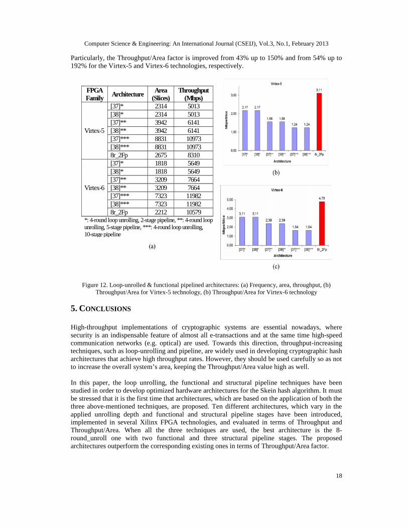
Figure 12 presents the comparisons of the proposed 8-round loop unrolled with two functionalpipeline stages (8r_2Fp) architecture with corresponding ones presented in literature. Theproposed architecture outperforms the existing ones in terms of throughput in the consideredtechnologies except of the architectures of [37]*** and [38]***. There, the throughput is higherby 24% and 12% in Virtex-5 and Virtex-6 technologies, respectively. In all other, cases thethroughput is improved from 36% to 66% (Virtex-5) and from 38% to 87% (Virtex-6). However,concerning the Throughput/Area factor, the proposed designs achieve the highest values.
Computer Science & Engineering: An International Journal (CSEIJ), Vol.3, No.1, February 2013
18
Particularly, the Throughput/Area factor is improved from 43% up to 150% and from 54% up to192% for the Virtex-5 and Virtex-6 technologies, respectively.
FPGAFamily Architecture Area
(Slices)Throughput
(Mbps)
Virtex-5
[37]* 2314 5013[38]* 2314 5013[37]** 3942 6141[38]** 3942 6141[37]*** 8831 10973[38]*** 8831 109738r_2Fp 2675 8310
Virtex-6
[37]* 1818 5649[38]* 1818 5649[37]** 3209 7664[38]** 3209 7664[37]*** 7323 11982[38]*** 7323 119828r_2Fp 2212 10579
*: 4-round loop unrolling, 2-stage pipeline, **: 4-round loopunrolling, 5-stage pipeline, ***: 4-round loop unrolling,10-stage pipeline
Figure 12. Loop-unrolled & functional pipelined architectures: (a) Frequency, area, throughput, (b)Throughput/Area for Virtex-5 technology, (b) Throughput/Area for Virtex-6 technology
5. CONCLUSIONS
High-throughput implementations of cryptographic systems are essential nowadays, wheresecurity is an indispensable feature of almost all e-transactions and at the same time high-speedcommunication networks (e.g. optical) are used. Towards this direction, throughput-increasingtechniques, such as loop-unrolling and pipeline, are widely used in developing cryptographic hasharchitectures that achieve high throughput rates. However, they should be used carefully so as notto increase the overall system’s area, keeping the Throughput/Area value high as well.
In this paper, the loop unrolling, the functional and structural pipeline techniques have beenstudied in order to develop optimized hardware architectures for the Skein hash algorithm. It mustbe stressed that it is the first time that architectures, which are based on the application of both thethree above-mentioned techniques, are proposed. Ten different architectures, which vary in theapplied unrolling depth and functional and structural pipeline stages have been introduced,implemented in several Xilinx FPGA technologies, and evaluated in terms of Throughput andThroughput/Area. When all the three techniques are used, the best architecture is the 8-round_unroll one with two functional and three structural pipeline stages. The proposedarchitectures outperform the corresponding existing ones in terms of Throughput/Area factor.
Computer Science & Engineering: An International Journal (CSEIJ), Vol.3, No.1, February 2013
19
REFERENCES
[1] Loshin, P. (2004) IPv6: Theory, Protocol and Practice. Elsevier Publications, USA.[2] NIST-SP800-77 (2005) Guide to IPSec VPN’s. NIST Publications.[3] NIST-FIPS 198 (2002) The Keyed-Hash message authentication code (HMAC). NIST Publications.[4] Loeb, L. (1998) Secure Electronic Transactions: Introduction and Technical Reference. Artech House
Publishers. Norwood, USA.[5] Johnston, D., Walker, J. (2004) Overview of IEEE 802.16. IEEE Security & Privacy, 35, 40-48.[6] NIST-FIPS 186-1 (1998) Digital Signature Standard (DSS). NIST Publications.[7] Thomas, S. (2000) SSL & TLS Essentials: Securing the Web. John Wiley & sons Publications.[8] NIST-FIPS 180-3 (2008) Secure Hash Standard (SHS). NIST Publications.[9] Wang, X., Yin, Y., L., & Yu, H. (2005) Finding collisions in the full SHA1. Proc. Int. Conf. Crypto.
Springer Berlin/Heidelberg, Lecture Notes in Computer Science (LNCS). 3621 17-36.[10] NIST SHA-3 competition. http://csrc.nist.gov/groups/ST/hash/sha-3/index.html.[11] Michail, H.E. (2010) Cryptography in the Dawn of IPv6. IEEE GOLDRush Newsletter, 17.[12] Michail, H., Kakarountas, A., Milidonis, A., & Goutis, C. (2009) A Top-Down Design Methodology
for Ultra High-Performance Hashing Cores. IEEE Trans. Depend. Sec. Comp., 6(4), 255-268.[13] Michail, H. E., Athanasiou, G. S., Kelefouras, V., Theodoridis, G. & Goutis, C. E., (2011) On the
Exploitation of as High-Throughput SHA-256 FPGA design for HMAC. ACM Trans. Reconf. Tec.Sys. (ACM TRETS), 5(1), 1–28.
[14] Hensen, L., Aumasson, W. M. & Phan R., C.-W. (2011) VLSI Characterization of the CryptographicHash Function BLAKE. IEEE Trans. on VLSI, 19(10), 1746-1753.
[15] Tilich, S. (2010) Hardware Implementation of the SHA-3 Candidate Skein. IACR Cryptology ePrintArchive, http://eprint.iacr.org/2010/159.pdf.
[16] Athanasiou, G.S., Chalkou, Ch.I., Bardis, D., Michail, H.E., Theodoridis, G. & Goutis, C.E. (2012)High-Throughput Hardware Architectures of the JH Round-three SHA-3 Candidate. Proceedings ofINSTICC SECRYPT 2012, Rome, Italy, 24-27 July, pp. XXX-XXX.
[17] Ferguson, N., Lucks., S., Schneier, B., Whiting, D., Bellare, M., Kohno, T., Callas, J. amd Walker, J.(2008) The Skein Hash Function Family. http://www.skein-hash.info/sites/default/files/skein1.1.pdf.
[18] Finne, S. (2009) A Cryptol Implementation of Skein. http://www.galois.com/blog/2009/01/23/a-cryptol-implementation-of-skein/.
[19] Fürstenau, H., (2010) Skein extension module for Python 3.0. http://packages.python.org/pyskein/.[20] Krishnan, S., (2011) NSkein – a Skein implementation in .NET. http://github.com/sriramk/nskein.[21] Long, M., (2009) Implementing Skein Hash Function on Xilinx Virtex-5 FPGA Platform. Intel
Corporation Report Reports. http://www.skein-hash.info/sites/default/files/skein_fpga.pdf.[22] Tilich, S. (2009) Hardware Implementation of the SHA-3 Candidate Skein. IACR Cryptology ePrint
Archive[23] Walker, J., Sheikh, F., Mathew, S.K. & Krishnamurthy, R. (2010) A Skein-512 Hardware
Implementation. http://csrc.nist.gov/groups/ST/hash/sha-3/Round2/Aug2010/documents/papers.[24] Guo, X., Huang, S., Nazhandali, L. & Shaumont, P. (2010) Fair and Comprehensive Performance
Evaluation of 14 Second Round SHA-3 ASIC Implementations. Proceedings of NIST 2nd SHA-3Candidate Conference, Santa Barbara, California, USA, 23-24 August.
[25] Namin, A.H., Hasan, M.A. (2010) Implementation of the compression function for selected SHA-3candidates on FPGA. Proc. of IEEE Int. Symp. Par. Dist. Proc. (IPDPSW), 19-23 April, pp. 1-4
[26] Tilich, S., Feldhofer, M., Issovits, W., Kern, T., Kurreck, H., Mühlberghuber, M., Neubauer, G.,Reiter, A., Köfler, A. & Mayrhofer, M. (2009) Compact Hardware Implementations of the SHA-3Candidates ARIRANG, BLAKE, Grøstl, and Skein. IACR Cryptology ePrint Archive.
[27] Homrisikamol, E., Rogawski, M. & Gaj, K. (2010) Comparing Hardware Performance of FourteenRound Two SHA-3 Candidates Using FPGAs. IACR Cryptology ePrint Archive.
[28] Tilich, S., Feldhofer, M., Kirschbaum, M., Plos, T., Schmidt, J.M. & Szekely, A. (2009) High-SpeedHardware Implementations of BLAKE, BlueMidnight Wish, CubeHash, ECHO, Fugue, Grostl,Keccak, Luffa, Shabal, SHAvite-3, SIMD, and Skein. IACR Cryptology ePrint Archive.
[29] Baldwin, B., Byrne, A., Liang, Lu, Hamilton, M., Hanley, N., O'Neill, M. & Marnane, W.P. (2010)FPGA Implementations of the Round Two SHA-3 Candidates. Proceedings of Int. Conf. on FieldProgrammable Logic & Applications (FPL). 31 August - 2 September, pp. 400-407
[30] Matsuo, S., Knežević, M., Schaumont, P., Verbauwhede, I., Satoh, A., Sakiyama, K. & Ohta, K.(2010) Proc. of NIST 2nd SHA-3 Candidate Conference, Santa Barbara, California, USA, 23-24 Aug.
Computer Science & Engineering: An International Journal (CSEIJ), Vol.3, No.1, February 2013
20
[31] Kobayashi, K., Ikegami, J., Matsuo, S., Sakiyama, K. & Ohta K. (2010) Evaluation of HardwarePerformance for the SHA-3 Candidates Using SASEBO-GII. IACR Cryptology ePrint Archive.
[32] Gaj, K., Homsirikamol, E. & Rogawski, M. (2010) Fair and Comprehensive Methodology forComparing Hardware Performance of Fourteen Round Two SHA-3 Candidates Using FPGAs.Proceedings of 12th Intern. Conf. on Crypt. Hardware & Embed. Sys. (CHES 2010), California, USA,17-20 August, pp. 264-278
[33] Henzen, L., Gendotti, P., Guillet, P. Pargaetzi, E., Zoller, M. & Gürkaynak, F. (2010) Developing aHardware Evaluation Method for SHA-3 Candidates. Proceedings of 12th Intern. Conf. on Crypt.Hardware & Embed. Sys. (CHES 2010), Santa Barbara, California, USA, 17-20 August, pp. 248-263
[34] Gaj, K., Homsirikamol, E. & Rogawski, M. (2010) Comprehensive Comparison of HardwarePerformance of Fourteen Round 2 SHA-3 Candidates with 512-bit Outputs Using FieldProgrammable Gate Arrays. Proc. of NIST 2nd SHA-3 Cand. Conf., California, USA, 23-24 Aug.
[35] Tilich, S., Feldhofer, M., Kirschbaum, M., Plos, T., Schmidt, J.M. & Szekely, A. (2010) UniformEvaluation of Hardware Implementations of the Round-Two SHA-3 Candidates. Proceedings of NIST2nd SHA-3 Cand. Conf., Santa Barbara, California, USA, 23-24 Aug.
[36] Guo, X., Huang, S., Nazhandali, L. & Shaumont, P. (2010) On The Impact of Target Technology inSHA-3 Hardware Benchmark Rankings. IACR Cryptology ePrint Archive.
[37] Homsirikamol, E., Rogawski, M. & Gaj, K. (2011) Throughput vs. Area Trade-offs in High-SpeedArchitectures of Five Round 3 SHA-3 Candidates Implemented Using Xilinx and Altera FPGAs.Proceedings of 13th Intern. Conf. on Crypt. Hardware & Embed. Sys. (CHES 2011), Japan, 28 Sept.-1 Oct., pp. 491-506
[38] Homsirikamol, E., Rogawski, M. & Gaj, K. (2011) Comparing Hardware Performance of Round 3SHA-3 Candidates using Multiple Hardware Architectures in Xilinx and Altera FPGAs. Proceedingsof Ecrypt II Hash Workshop, Tallinn, Estonia, 19-20 May, pp. 30-45.
[39] Kerckhof, S., Durvaux, F., Veyrat-Charvillon, N., Regazzoni, F., Meurice de Dormale, G. &Standaert F.X. (2011) Compact FPGA Implementations of the Five SHA-3 Finalists. Proceedings ofCARDIS 2011, Leuven, Belgium, 14-16 Sptember, pp. 217-233.
[40] Jens-Peter Kaps, J.-P., Yalla, P., Surapathi, K.K., Habib, B., Vadlamudi, S., Gurung, S. & Pham J.(2011) Lightweight Implementations of SHA-3 Candidates on FPGAs. Proc. of 2th Int. Conf. onCryptology in India (INDOCRYPT 2011), 11-14 December, Chennai, India, pp. 270-289.
[41] Latif, K., Rao, M.M., Aziz, A. & Mahboob, A. (2012) Efficient Hardware Implementations andHardware Performance Evaluation of SHA-3 Finalists. Proc. of NIST 3nd SHA-3 Cand. Conf.,Washington D.C., USA, 22-23 March.
[42] At, N., Beauchat, J.-L. & San, I. (2012) Compact Implementation of Threefish and Skein on FPGA.IACR Cryptology ePrint Archive.
[43] Sanchez-Elez, M. & Roman, S. (2012) Reconfiguration Strategies for Online Hardware Multitaskingin Embedded Systems. Comp. Sc. Eng.: Int. J. (CSEIJ), AIRCC Publications, 2(6), 1-16
[44] KaghazGaran, M.R. & KaghazGaran A. (2011) Performance and Simulation Study of the ProposedDirect, Indirect Trust Distribution Security Architecture InWireless Sensor Network. Comp. Sc. Eng.:Int. J. (CSEIJ), AIRCC Publications, 1(4), 27-47
Computer Science & Engineering: An International Journal (CSEIJ), Vol.3, No.1, February 2013
21
AUTHORS
George S. Athanasiou received his 5-year Diploma on Electronic and ComputerEngineering, from Technical University of Crete, Greece in 2008, achieving a graduationdegree of Excellence with Honors. Since then he has been working towards his PhDdegree, in the Electrical and Computer Engineering Department, University of Patras,Greece. His research interests include: Cryptography and VLSI Design. Until today hehas 6 journal publications, 8 conference publications, and 1 book chapter.
Elias Tsingkas graduated from the Electrical and Computer Engineering Department ofthe University of Patras, Greece in 2012. He is now a M.Sc. student in the sameDepartment, working on Integrated Software and Hardware Systems. He holds 1publication in the Proc. of IEEE Inter. Conf. on Industrial Technology (ICIT 2012).
Harris E Michail received the Dipl. Eng and Ph.D from the Electrical & Computer Eng.Dept., University of Patras, Greece. From 2009 to 2011, he was Visiting Assist. Prof. inthe Dept. of Computer Eng. of University of Patras. In January 2012 he joined the Dept.of Electrical Eng., Computer Eng., and Information Technology, Cyprus University ofTechnology. He has (co-)authored more than 50 papers in inter. journals andconferences. His research interests include Security and Embedded Systems.
George Theodoridis Assist. Professor George Theodoridis received Dipl. Eng inElectrical Eng. and the Ph.D. degree in Electrical and Computer Eng. from University ofPatras, Greece, in 1994 and 2001, respectively. In 2001 he co-founded ALMATechnologies. S.A., Athens, Greece. From 2003 to 2009 he was Lecturer in the Dept. ofPhysics of Aristotle University of Thessaloniki, Greece. In 2009 he joined as Assist.Prof. the Dept. of Electrical and Computer Eng. of Patras University. His researchinterests include low-power VLSI design, reconfigurable computing and embeddedsystems.
Costas E. Goutis Emer. Professor Costas E. Goutis received his B.Sc. in Physics fromUniversity of Athens, Greece in 1966. In 1974 he received his M.Sc. in DigitalTelecommunications from Heriot-Watt University (UK) and in 1978 he received hisPh.D. in Digital Image Processing from the Southampton University, UK. Since 1985he has been Assoc. Full and Emeritus Professor in the ECE Dept. of University ofPatras, Greece. His research interests include: VLSI Design and High- LevelArchitecture Synthesis. He has more than 300 publications in int. journals andconferences, and 2 best paper awards.


